


Bahasa
Halaman
Hukum

5/15/2013
1
Dr. Sathyan Krishnan
Dept. of Mechanical Engineering MACHINE DESIGN
College of Engineering, PMU
Mechanical Engineering Design IIIMEEN :3393
Dr. Sathyan KrishnanRoom- S044
Ph: 8498532, Email: [email protected] of Mechanical EngineeringPrince Mohammed Bin Fahd University
LOAD AND STRESS ANALYSIS
Dr. Sathyan Krishnan
Dept. of Mechanical Engineering MACHINE DESIGN
College of Engineering, PMU
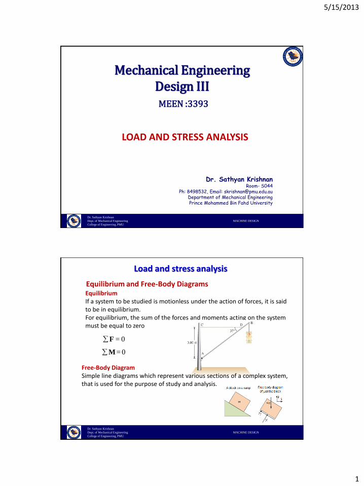
Equilibrium and Free-Body DiagramsEquilibriumIf a system to be studied is motionless under the action of forces, it is said to be in equilibrium.For equilibrium, the sum of the forces and moments acting on the system must be equal to zero
0
0
=
=
F
M
Free-Body DiagramSimple line diagrams which represent various sections of a complex system, that is used for the purpose of study and analysis.
Load and stress analysis
5/15/2013
2
Dr. Sathyan Krishnan
Dept. of Mechanical Engineering MACHINE DESIGN
College of Engineering, PMU
Advantages:1. Easy to study and analyze complicated systems by breaking down to segments2. Easy way of communicating thoughts to others3. It simplifies the thinking process4. Helps to understand the dimensions and various forces and moments acting on
the system
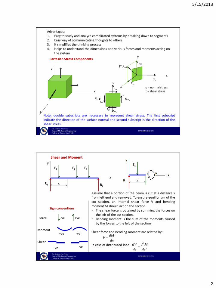
Cartesian Stress Components
σx
x
y
zτxz
τxy(τx)net
σ = normal stressτ = shear stress
Note: double subscripts are necessary to represent shear stress. The first subscriptindicate the direction of the surface normal and second subscript is the direction of theshear stress.
x
y
z
σxσx
σy
σy
τxy
τxy
τyx
τyx
Dr. Sathyan Krishnan
Dept. of Mechanical Engineering MACHINE DESIGN
College of Engineering, PMU
Shear and Moment
x
F1 F3F2
R1 R2
x
y
Sign conventions
Force -ve +ve
-ve+ve
+ve -ve
Moment
Shear
Assume that a portion of the beam is cut at a distance xfrom left end and removed. To ensure equilibrium of thecut section, an internal shear force V and bendingmoment M should act on the section.• The shear force is obtained by summing the forces on
the left of the cut section.• Bending moment is the sum of the moments caused
by the forces to the left of the section
Shear force and Bending moment are related by:
In case of distributed load
dMV =
dx2
2
dV d M=
dx dx
5/15/2013
3
Dr. Sathyan Krishnan
Dept. of Mechanical Engineering MACHINE DESIGN
College of Engineering, PMU
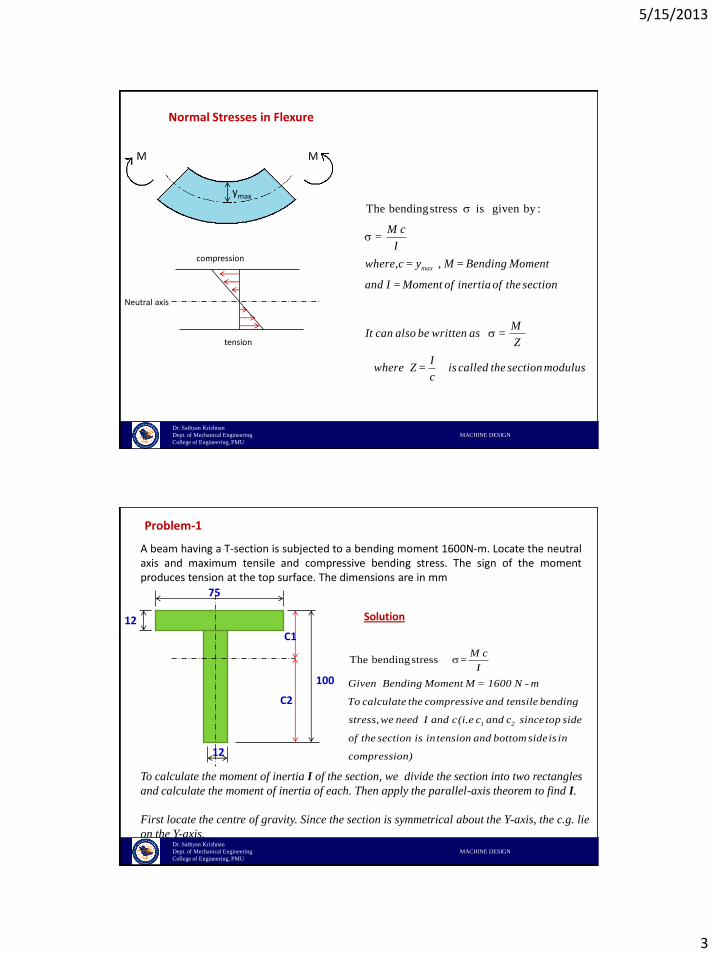
Normal Stresses in Flexure
ymax
M M
The bendingstress is given by :
max
M c=
I
where,c = y , M = Bending Moment
and I = Moment of inertia of the section
MIt can also be written as =
Z
Iwhere Z = is called the section modulus
c
compression
tension
Neutral axis
Dr. Sathyan Krishnan
Dept. of Mechanical Engineering MACHINE DESIGN
College of Engineering, PMU
Problem-1
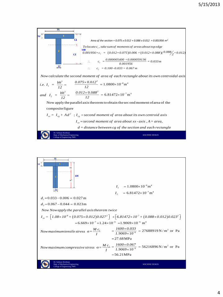
A beam having a T-section is subjected to a bending moment 1600N-m. Locate the neutralaxis and maximum tensile and compressive bending stress. The sign of the momentproduces tension at the top surface. The dimensions are in mm
12
12
75
100
C2
C1
Solution
The bendingstress
1 2
M c=
I
Given Bending Moment M = 1600 N - m
To calculate the compressive and tensile bending
stress, we need I and c(i.e c and c sincetop side
of the section is in tension and bottom sideis in
compression)
To calculate the moment of inertia I of the section, we divide the section into two rectangles
and calculate the moment of inertia of each. Then apply the parallel-axis theorem to find I.
First locate the centre of gravity. Since the section is symmetrical about the Y-axis, the c.g. lie
on the Y-axis.
5/15/2013
4
Dr. Sathyan Krishnan
Dept. of Mechanical Engineering MACHINE DESIGN
College of Engineering, PMU
Area of the section = 0.075 x 0.012 + 0.088 x 0.012 = 0.001956 m2
1
1
Tolocatec , take sumof moments of areas about top edge
0.0880.001956×c = 0.012×0.075 0.006 + 0.012×0.088 ( +0.012)2
3
1
3
2
Now calculate the second moment of area of each rectangle about its own centroidal axis
bhi.e. I =
12
bhand I =
12
1
2
0.000005400 +0.000059136c = = 0.033m
0.001956
c = 0.100 -0.033 = 0.067 m
Now apply the parallelaxis theorem toobtain thesecond moment ofarea of the
composite figure
;2
xx cg cg
xx
I = I + Ad I second moment of area about its own centroid axis
I second moment of area about xx - axis , A= area,
d = distance between cg of the section and each rectangle
8 4
7 4
0.01.0800 10 m
0.06.81472 10 m
3
3
0.075 12
12
0.012 88
12
Dr. Sathyan Krishnan
Dept. of Mechanical Engineering MACHINE DESIGN
College of Engineering, PMU
0.033 0.006 0.027 m
0.067 0.044 0.023m
1
2
-8 2 -7 2
xx
d
d
Now Nowapply the parallel axis theorem twice
I = 1.08 10 + 0.075 0.012 0.027 6.81472 10 + 0.088 0.012 0.023
8 4
7 4
1.0800 10 m
6.81472 10 m
1
2
I
I
7 6 6 46.669 10 1.24 10 1.9069 10 m
1
2
M cNowmaximumtensile stress =
I
M cNowmaximumcompressive stress =
I
2
6
2
6
27688919 N / m or Pa10
27.68MPa
56216896 N / m or Pa10
56.21MPa
1600 0.033
1.9069
1600 0.067
1.9069
5/15/2013
5
Dr. Sathyan Krishnan
Dept. of Mechanical Engineering MACHINE DESIGN
College of Engineering, PMU
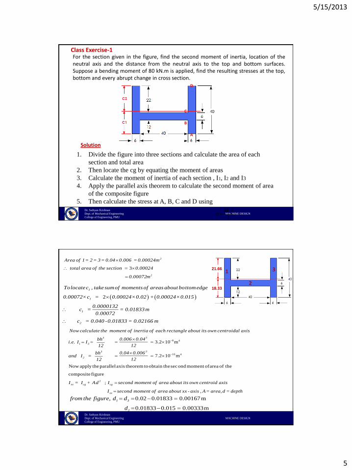
Class Exercise-1For the section given in the figure, find the second moment of inertia, location of theneutral axis and the distance from the neutral axis to the top and bottom surfaces.Suppose a bending moment of 80 kN.m is applied, find the resulting stresses at the top,bottom and every abrupt change in cross section.
Solution
1. Divide the figure into three sections and calculate the area of each
section and total area
2. Then locate the cg by equating the moment of areas
3. Calculate the moment of inertia of each section , I1, I2 and I3
4. Apply the parallel axis theorem to calculate the second moment of area
of the composite figure
5. Then calculate the stress at A, B, C and D using
M y=
I
A
B
C
D
Dr. Sathyan Krishnan
Dept. of Mechanical Engineering MACHINE DESIGN
College of Engineering, PMU
1
2
33
2
2
Area of 1= 2 = 3 = 0.04 0.006 = 0.00024m
total area of the section 0.00024
0.00072m
2
1
1
1
2
Tolocatec , take sumof moments of areas about bottomedge
0.00072×c = 0.00024×0.02 + 0.00024×0.015
0.0000132c = = 0.01833m
0.00072
c = 0.040 -0.01833 = 0.02166 m
18.33
21.66
Now apply the parallelaxis theorem toobtain thesecond moment ofarea of the
composite figure
3
1 3
3
2
xx c
Now calculate the moment of inertia of each rectangle about its own centroidal axis
bhi.e. I I =
12
bhand I =
12
I = I
;2
g cg
xx
+ Ad I second moment of area about its own centroid axis
I second moment of area about xx - axis , A= area, d = depth
0.02 0.01833 0.00167m
0.01833 0.015 0.00333m
1 3
2
from the figure, d d
d
8 4
10 4
3.2 10 m
7.2 10 m
3
3
0.006 0.04
12
0.04 0.006
12
5/15/2013
6
Dr. Sathyan Krishnan
Dept. of Mechanical Engineering MACHINE DESIGN
College of Engineering, PMU
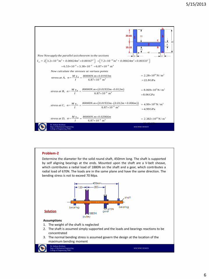
8 4 10 42 3.2 10 m 7.2 10 m2 2 2 2
xx
Now Nowapply the parallel axis theorem to the sections
I = + 0.00024m 0.00167 + 0.00024m 0.00333
1
2
3
19.33
20.66
A
B
C
D
8 4
8 4
y
6.87 10 m
y
6.87 10 m
y
6.87 10
A
B
C
Now calculate the stresses at variuos points
M 80000N.m 0.01933mstress at A, =
I
80000N.m 0.01933m -0.012mMstress at B, =
I
80000N.m 0.01933m - 0.012m+0.006mMstress at C, =
I
8 4
8 4
m
y
6.87 10 m
DM 80000N.m 0.02066mstress at D, =
I
8 9 8 46.53 10 3.38 10 6.87 10 m
10 2
9 2
9 2
10 2
2.28 10 N / m
22.8GPa
8.069 10 N / m
8.06GPa
4.99 10 N / m
4.99GPa
2.382 10 N / m
23.82GPa
Dr. Sathyan Krishnan
Dept. of Mechanical Engineering MACHINE DESIGN
College of Engineering, PMU
Problem-2
Determine the diameter for the solid round shaft, 450mm long. The shaft is supportedby self aligning bearings at the ends. Mounted upon the shaft are a V-belt sheave,which contributes a radial load of 1880N on the shaft and a gear, which contributes aradial load of 670N. The loads are in the same plane and have the same direction. Thebending stress is not to exceed 70 Mpa.
Solution
Assumptions1. The weight of the shaft is neglected2. The shaft is assumed simply supported and the loads and bearings reactions to be
concentrated3. The normal bending stress is assumed govern the design at the location of the
maximum bending moment
5/15/2013
7
Dr. Sathyan Krishnan
Dept. of Mechanical Engineering MACHINE DESIGN
College of Engineering, PMU
BA CO
R1=1402N R2=1148N
1880N 670N
150 200
Free-body diagram
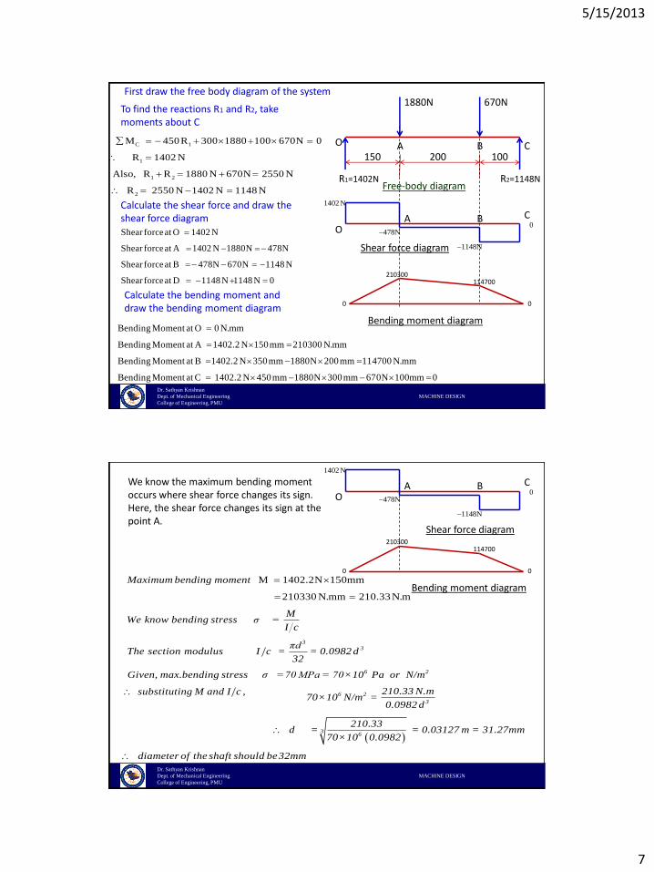
To find the reactions R1 and R2, take moments about C
C 1
1
1 2
2
M 450R 300 1880 100 670N 0
R 1402 N
Also, R R 1880 N 670N 2550 N
R 2550 N 1402 N 1148 N
Calculate the shear force and draw the shear force diagram BA C
O
1402N
478NShear forceat O 1402 N
Shear forceat A 1402 N 1880N 478N
Shear forceat B 478N 670N 1148 N
Shear forceat D 1148 N 1148 N 0
1148N
0
Calculate the bending moment and draw the bending moment diagram
Bending Moment at O 0 N.mm
Bending Moment at A 1402.2 N 150mm 210300 N.mm
Bending Moment at B 1402.2 N 350mm 1880N 200mm 114700 N.mm
Bending Moment at C 1402.2 N 450mm 1880N 300mm 670N 100mm 0
210300114700
0 0
Shear force diagram
Bending moment diagram
First draw the free body diagram of the system
100
Dr. Sathyan Krishnan
Dept. of Mechanical Engineering MACHINE DESIGN
College of Engineering, PMU
We know the maximum bending moment occurs where shear force changes its sign. Here, the shear force changes its sign at the point A.
M 1402.2N 150mm
210330 N.mm 210.33N.m
33
6 2
Maximum bending moment
MWe know bending stress σ =
I c
πdThe section modulus I c = = 0.0982 d
32
Given, max.bending stress σ =70 MPa = 70×10 Pa or N/m
substituting M and I c ,
BA C
O
1402N
478N
1148N
0
210300114700
0 0
Shear force diagram
Bending moment diagram
6 2
3
36
210.33 N.m 70×10 N/m =
0.0982 d
210.33d = = 0.03127 m = 31.27mm
70×10 0.0982
diameter of the shaft should be32mm
5/15/2013
8
Dr. Sathyan Krishnan
Dept. of Mechanical Engineering MACHINE DESIGN
College of Engineering, PMU
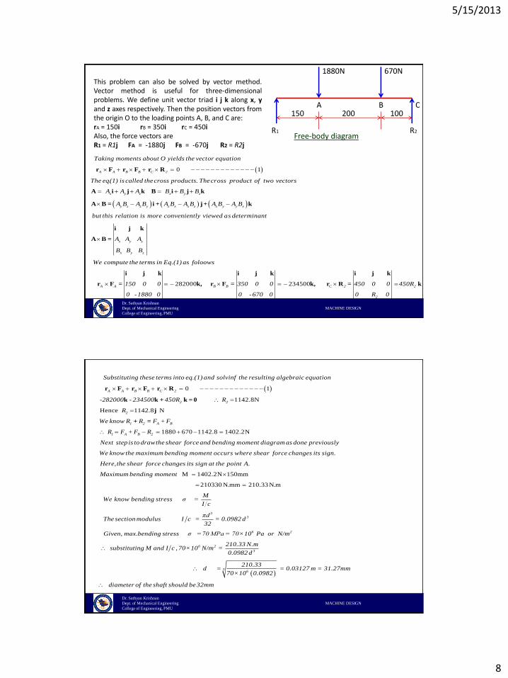
This problem can also be solved by vector method.Vector method is useful for three-dimensionalproblems. We define unit vector triad i j k along x, yand z axes respectively. Then the position vectors fromthe origin O to the loading points A, B, and C are:rA = 150i rB = 350i rC = 450iAlso, the force vectors areR1 = R1j FA = -1880j FB = -670j R2 = R2j
BA C
R1 R2
1880N 670N
150 200
Free-body diagram
0 1A A B B C 2
x y z x y z
y z z y z x x
Taking moments about O yields the vector equation
The eq.(1) is called thecross products. Thecross product of two vectors
A A A B B B
A B A B A B A
r F r F r R
A i j k B i j k
A B = i +
282000
z x y y x
x y z
x y z
A A B B
B A B A B
but this relation is more conveniently viewed as determinant
A A A
B B B
We compute the terms in Eq.(1) as foloows
150 0 0
0 -1880 0
j+ k
i j k
A B =
i j k i
r F = k, r F = 234500 C 2 2
2
350 0 0 450 0 0 450R
0 -670 0 0 R 0
j k i j k
k, r R = k
100
Dr. Sathyan Krishnan
Dept. of Mechanical Engineering MACHINE DESIGN
College of Engineering, PMU
0 1
1142.8N
Hence 1142.8 N
A A B B C 2
2 2
2
1 2
Substituting these terms into eq.(1) and solvinf the resulting algebraic equation
-282000 - 234500 450R R
R
We know R R
r F r F r R
k k + k = 0
j
+
1880 670 1142.8 1402.2N
A B
1 A B 2
F + F
R F + F R
Next step is to drawthe shear force and bending moment diagram as done previously
We know the maximum bending moment occurs where shear force changes its sign.
Here, the s
=
M 1402.2N 150mm
210330 N.mm 210.33N.m
33
6
hear force changes its sign at the point A.
Maximum bending moment
MWe know bending stress σ =
I c
πdThe section modulus I c = = 0.0982 d
32
Given, max.bending stress σ =70 MPa = 70×10 Pa
2
6 2
3
36
or N/m
210.33 N.msubstituting M and I c , 70×10 N/m =
0.0982 d
210.33d = = 0.03127 m = 31.27mm
70×10 0.0982
diameter of the shaft should be32mm
5/15/2013
9
Dr. Sathyan Krishnan
Dept. of Mechanical Engineering MACHINE DESIGN
College of Engineering, PMU
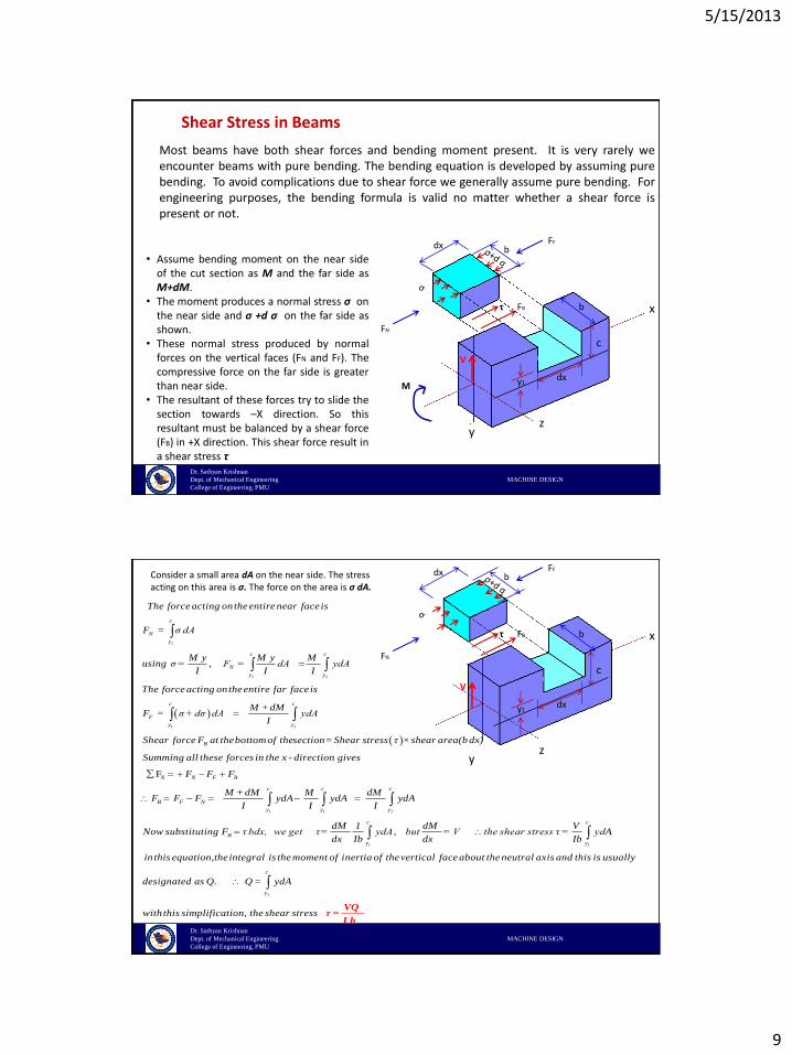
Shear Stress in Beams
Most beams have both shear forces and bending moment present. It is very rarely weencounter beams with pure bending. The bending equation is developed by assuming purebending. To avoid complications due to shear force we generally assume pure bending. Forengineering purposes, the bending formula is valid no matter whether a shear force ispresent or not.
y
x
z
dx
c
y1
bdx
b
FF
FN
τ FB
V
• Assume bending moment on the near sideof the cut section as M and the far side asM+dM.
• The moment produces a normal stress σ onthe near side and σ +d σ on the far side asshown.
• These normal stress produced by normalforces on the vertical faces (FN and FF). Thecompressive force on the far side is greaterthan near side.
• The resultant of these forces try to slide thesection towards –X direction. So thisresultant must be balanced by a shear force(FB) in +X direction. This shear force result ina shear stress τ
M
Dr. Sathyan Krishnan
Dept. of Mechanical Engineering MACHINE DESIGN
College of Engineering, PMU
y
x
z
dx
c
y1
bdx
b
FF
FN
τ FB
V
Consider a small area dA on the near side. The stress acting on this area is σ. The force on the area is σ dA.
,
1
1 1
1 1
c
N
y
c c
N
y y
c c
F
y y
The force acting ontheentire near faceis
F = σ dA
M y M y Musing σ = F = dA ydA
I I I
The force acting ontheentire far faceis
M +dMF = σ +dσ dA ydA
I
XF
1 1 1
B
N F B
c c c
B F N
y y y
B
Shear force F at thebottomof thesection= Shear stress τ ×shear area(b dx)
Summing all these forces in the x - direction gives
F F F
M +dM M dMF F F ydA ydA ydA
I I I
Now substituting F τ bdx, we get
,
1 1
c c
y y
dM 1 dM V τ= ydA but = V the shear stress τ = ydA
dx Ib dx Ib
in this equation,theintegral is the moment of inertia of thevertical face about the neutral axis and this is usually
designated as Q. Q = y
1
c
y
dA
with this simplification, the shear stress
VQτ =
I b
5/15/2013
10
Dr. Sathyan Krishnan
Dept. of Mechanical Engineering MACHINE DESIGN
College of Engineering, PMU
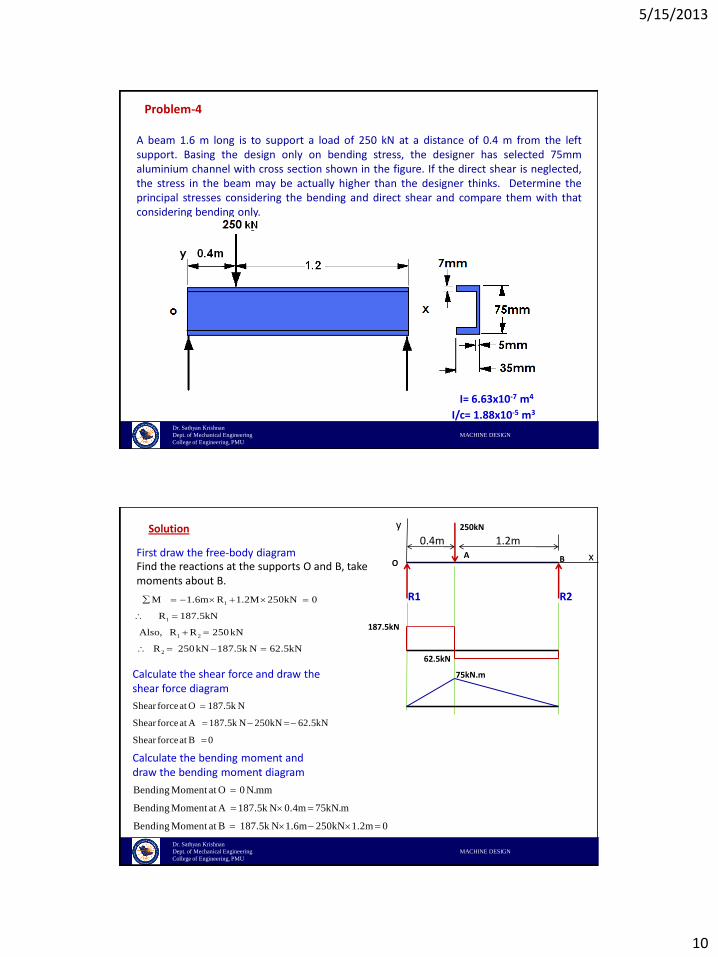
Problem-4
A beam 1.6 m long is to support a load of 250 kN at a distance of 0.4 m from the leftsupport. Basing the design only on bending stress, the designer has selected 75mmaluminium channel with cross section shown in the figure. If the direct shear is neglected,the stress in the beam may be actually higher than the designer thinks. Determine theprincipal stresses considering the bending and direct shear and compare them with thatconsidering bending only.
I= 6.63x10⁻⁷ m4
I/c= 1.88x10⁻⁵ m3
Dr. Sathyan Krishnan
Dept. of Mechanical Engineering MACHINE DESIGN
College of Engineering, PMU
First draw the free-body diagram
Solution
x
y
OA B
250kN
0.4m 1.2m
Find the reactions at the supports O and B, take moments about B.
1
1
1 2
2
M 1.6m R 1.2M 250kN 0
R 187.5kN
Also, R R 250kN
R 250kN 187.5k N 62.5kN
R1 R2
Calculate the shear force and draw the shear force diagram
Shear forceat O 187.5k N
Shear forceat A 187.5k N 250kN 62.5kN
Shear forceat B 0
187.5kN
62.5kN
Bending Moment at O 0 N.mm
Bending Moment at A 187.5k N 0.4m 75kN.m
Bending Moment at B 187.5k N 1.6m 250kN 1.2m 0
Calculate the bending moment and draw the bending moment diagram
75kN.m
5/15/2013
11
Dr. Sathyan Krishnan
Dept. of Mechanical Engineering MACHINE DESIGN
College of Engineering, PMU
x
y
OA B
250kN
0.4m 1.2m
R1 R2
187.5kN
62.5kN
75kN.m
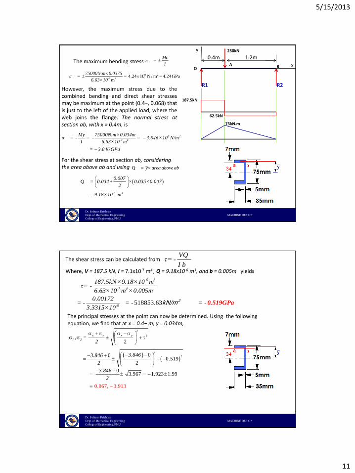
The maximum bending stressMc
σ =I
9 2
44.24 10 N / m 4.24GPa
m
-7
75000N.m 0.0375σ =
6.63 10
However, the maximum stress due to thecombined bending and direct shear stressesmay be maximum at the point (0.4−, 0.068) thatis just to the left of the applied load, where theweb joins the flange. The normal stress atsection ab, with x = 0.4m, is
9 2
-7 4
My 75000N.m×0.034mσ = - = - = 3.846×10 N/m
I 6.63×10 m
= 3.846 GPa
For the shear stress at section ab, considering the area above ab and using Q = y area above ab
-6 3
0.007Q = 0.034+ × 0.035×0.007
2
= 9.18×10 m
Dr. Sathyan Krishnan
Dept. of Mechanical Engineering MACHINE DESIGN
College of Engineering, PMU
The shear stress can be calculated fromVQ
τ= - I b
Where, V = 187.5 kN, I = 7.1x10⁻⁷ m4 , Q = 9.18x10⁻⁶ m3, and b = 0.005m yields
-6 3
-7 4
187.5kN×9.18×10 mτ= -
6.63×10 m × 0.005m
The principal stresses at the point can now be determined. Using the following equation, we find that at x = 0.4− m, y = 0.034m,
2
2
2
2
,2
000.519
2
x y x y
1 2 =2
3.8463.846
2
518853.63-9
0.00172= - = - =
3.3315×10- 0.519GPa
2kN/m
03.967 1.923 1.99
0.067, 3.913
3.846
2
5/15/2013
12
Dr. Sathyan Krishnan
Dept. of Mechanical Engineering MACHINE DESIGN
College of Engineering, PMU
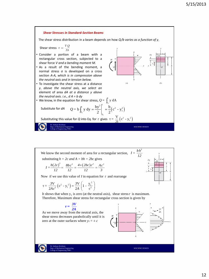
Shear Stresses in Standard-Section Beams
The shear stress distribution in a beam depends on how Q/b varies as a function of y1
Shear stress
• Consider a portion of a beam with arectangular cross section, subjected to ashear force V and a bending moment M.
• As a result of the bending moment, anormal stress σ is developed on a crosssection A-A, which is in compression abovethe neutral axis and in tension below.
• To investigate the shear stress at a distancey1 above the neutral axis, we select anelement of area dA at a distance y abovethe neutral axis. i.e., d A = b dy
• We know, in the equation for shear stress,
1
1
c2
c2 2
1y
y
by b= b y dy c - y
2 2Q
1
c
y= y dAQ
Substitute for dA
Substituting this value for Q into Eq. for gives 2 2
1
V= c - y
2I
Dr. Sathyan Krishnan
Dept. of Mechanical Engineering MACHINE DESIGN
College of Engineering, PMU
We know the second moment of area for a rectangular section, = 3bh
I 12
substituting h = 2c and A = bh = 2bc gives
=
3 23 2b 2c 4 2bc c8bc AcI
12 12 12 3
Now if we use this value of I in equation for and rearrange
2
2 2 11 2
yV V= c - y 1 -
2 2 c2
3 3
Ac A
It shows that when y1 is zero (at the neutral axis), shear stress is maximum.
Therefore, Maximum shear stress for rectangular cross section is given by
3Vτ =
2AAs we move away from the neutral axis, the
shear stress decreases parabolically until it is
zero at the outer surfaces where y1 = ± c
5/15/2013
13
Dr. Sathyan Krishnan
Dept. of Mechanical Engineering MACHINE DESIGN
College of Engineering, PMU
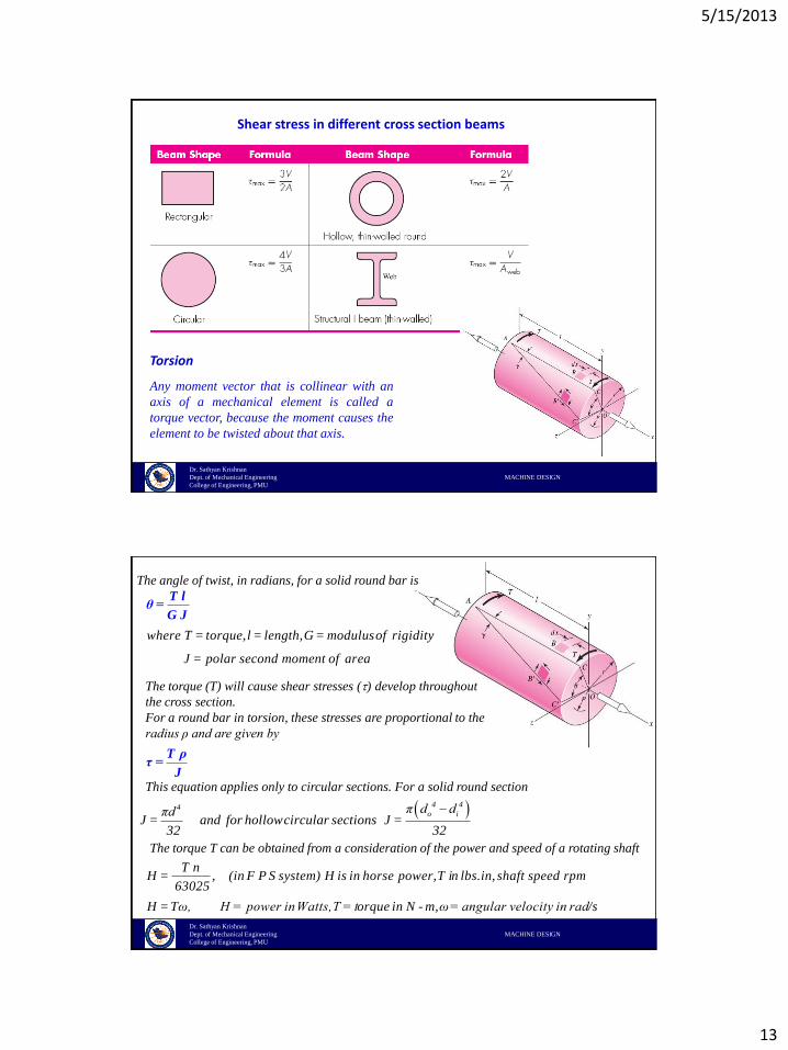
Torsion
Any moment vector that is collinear with an
axis of a mechanical element is called a
torque vector, because the moment causes the
element to be twisted about that axis.
Shear stress in different cross section beams
Dr. Sathyan Krishnan
Dept. of Mechanical Engineering MACHINE DESIGN
College of Engineering, PMU
The angle of twist, in radians, for a solid round bar is
where T = torque, l = length, G = modulus of rigidity
J = polar second moment of area
T lθ =
G J
The torque (T) will cause shear stresses () develop throughout
the cross section.
For a round bar in torsion, these stresses are proportional to the
radius ρ and are given by
T ρτ =
JThis equation applies only to circular sections. For a solid round section
4 44o iπ d dπd
J = and for hollowcircular sections J = 32 32
The torque T can be obtained from a consideration of the power and speed of a rotating shaft
,T n
H = (in F P S system) H is in horse power, T in lbs.in, shaft speed rpm 63025
H = Tω, H = power in Watts, T = torque in N - m, ω= angular velocity in rad/s
5/15/2013
14
Dr. Sathyan Krishnan
Dept. of Mechanical Engineering MACHINE DESIGN
College of Engineering, PMU
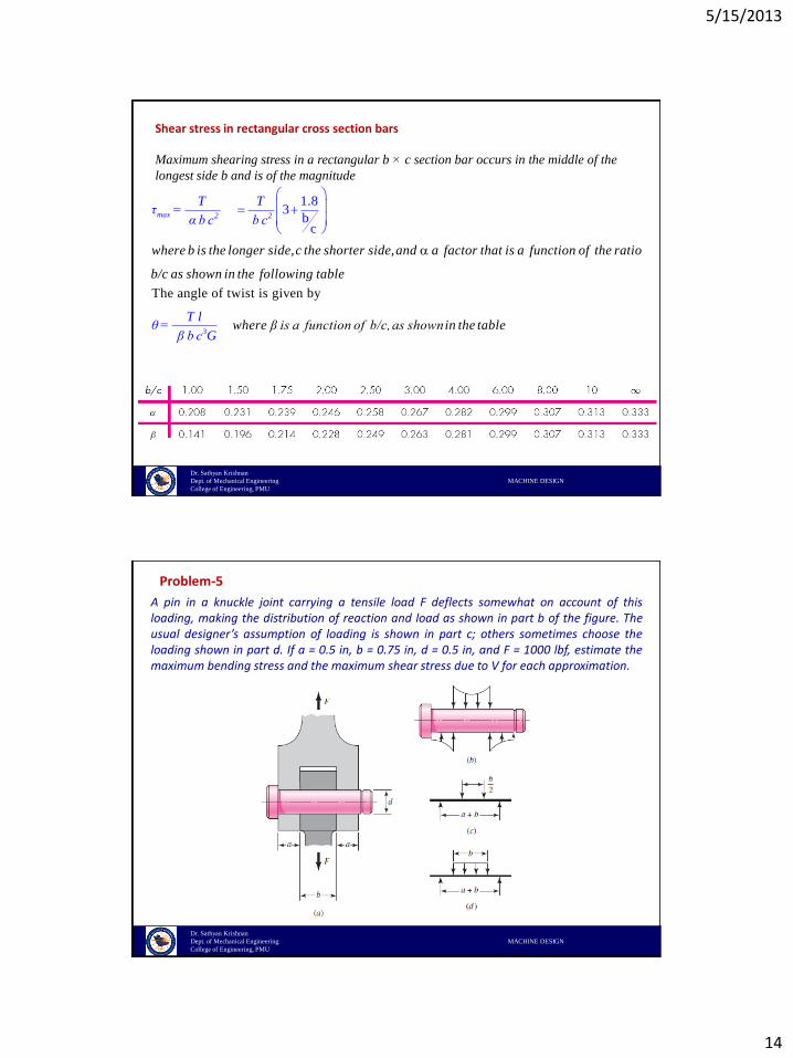
Shear stress in rectangular cross section bars
Maximum shearing stress in a rectangular b × c section bar occurs in the middle of the
longest side b and is of the magnitude
1.83
bc
max 2 2
where b is the longer side, c the shorter side, and a factor that is a function of the ratio
b/c as shown in the following
T Tτ =
table
α b c b c
The angle of twist is given by
3where β is a function of b/c, as shown
T lθ =
β b c in the
G table
Dr. Sathyan Krishnan
Dept. of Mechanical Engineering MACHINE DESIGN
College of Engineering, PMU
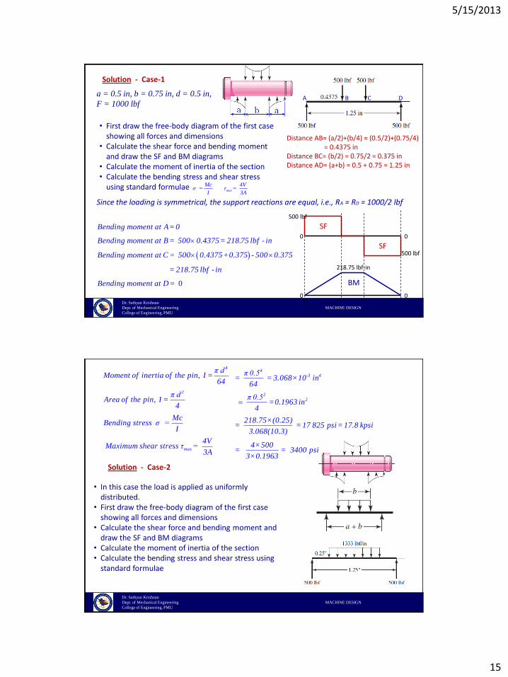
A pin in a knuckle joint carrying a tensile load F deflects somewhat on account of thisloading, making the distribution of reaction and load as shown in part b of the figure. Theusual designer’s assumption of loading is shown in part c; others sometimes choose theloading shown in part d. If a = 0.5 in, b = 0.75 in, d = 0.5 in, and F = 1000 lbf, estimate themaximum bending stress and the maximum shear stress due to V for each approximation.
Problem-5
5/15/2013
15
Dr. Sathyan Krishnan
Dept. of Mechanical Engineering MACHINE DESIGN
College of Engineering, PMU
Solution - Case-1
A B C D
• First draw the free-body diagram of the first case showing all forces and dimensions
• Calculate the shear force and bending moment and draw the SF and BM diagrams
• Calculate the moment of inertia of the section• Calculate the bending stress and shear stress
using standard formulae
Distance AB= (a/2)+(b/4) = (0.5/2)+(0.75/4)= 0.4375 in
Distance BC= (b/2) = 0.75/2 = 0.375 inDistance AD= (a+b) = 0.5 + 0.75 = 1.25 in
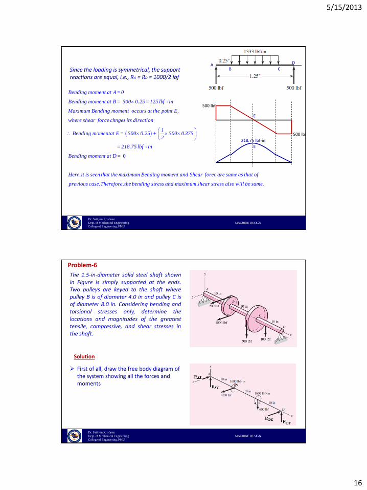
Since the loading is symmetrical, the support reactions are equal, i.e., RA = RD = 1000/2 lbf
Bending moment at A = 0
Bending moment at B = 500 0.4375 = 218.75 lbf - in
Bending moment at C = 500 0.4375+0.375 - 500 0.375
= 218.75 lbf - in
Bending moment at D =
0
500 lbf
500 lbf
218.75 lbf-in
0 0
0 0
SF
SF
BM
Mcσ =
Imax
4Vτ =
3A
a = 0.5 in, b = 0.75 in, d = 0.5 in,
F = 1000 lbf
Dr. Sathyan Krishnan
Dept. of Mechanical Engineering MACHINE DESIGN
College of Engineering, PMU
4
2
max
π dMoment of inertia of the pin, I =
64
π dArea of the pin, I =
4
McBending stress σ =
I
4V Maximum shear stress τ =
3A
Solution - Case-2
• In this case the load is applied as uniformly distributed.
• First draw the free-body diagram of the first case showing all forces and dimensions
• Calculate the shear force and bending moment and draw the SF and BM diagrams
• Calculate the moment of inertia of the section• Calculate the bending stress and shear stress using
standard formulae
4-3 4
22
π 0.5= = 3.068×10 in
64
π 0.5=0.1963 in
4
218.75×(0.25)= = 17 825 psi = 17.8 kpsi
3.068(10.3)
4×500= = 3400 psi
3×0.1963
5/15/2013
16
Dr. Sathyan Krishnan
Dept. of Mechanical Engineering MACHINE DESIGN
College of Engineering, PMU
500 lbf
500 lbf
Since the loading is symmetrical, the support reactions are equal, i.e., RA = RD = 1000/2 lbf
Bending moment at A = 0
Bending moment at B = 500 0.25 = 125 lbf - in
Maximum Bending moment occurs at the point E,
where shear force chnges its direction
1Bending momentat E = 500 0.25 + 500 0.3
2
0
75
= 218.75 lbf - in
Bending moment at D =
Here, it is seen that the maximum Bending moment and Shear forec are same as that of
previous case. Therefore, the
bending stress and maximum shear stress also will be same.
AB C
D
E
E
218.75 lbf-in
Dr. Sathyan Krishnan
Dept. of Mechanical Engineering MACHINE DESIGN
College of Engineering, PMU
Problem-6
The 1.5-in-diameter solid steel shaft shownin Figure is simply supported at the ends.Two pulleys are keyed to the shaft wherepulley B is of diameter 4.0 in and pulley C isof diameter 8.0 in. Considering bending andtorsional stresses only, determine thelocations and magnitudes of the greatesttensile, compressive, and shear stresses inthe shaft.
Solution
First of all, draw the free body diagram of the system showing all the forces and moments
5/15/2013
17
Dr. Sathyan Krishnan
Dept. of Mechanical Engineering MACHINE DESIGN
College of Engineering, PMU
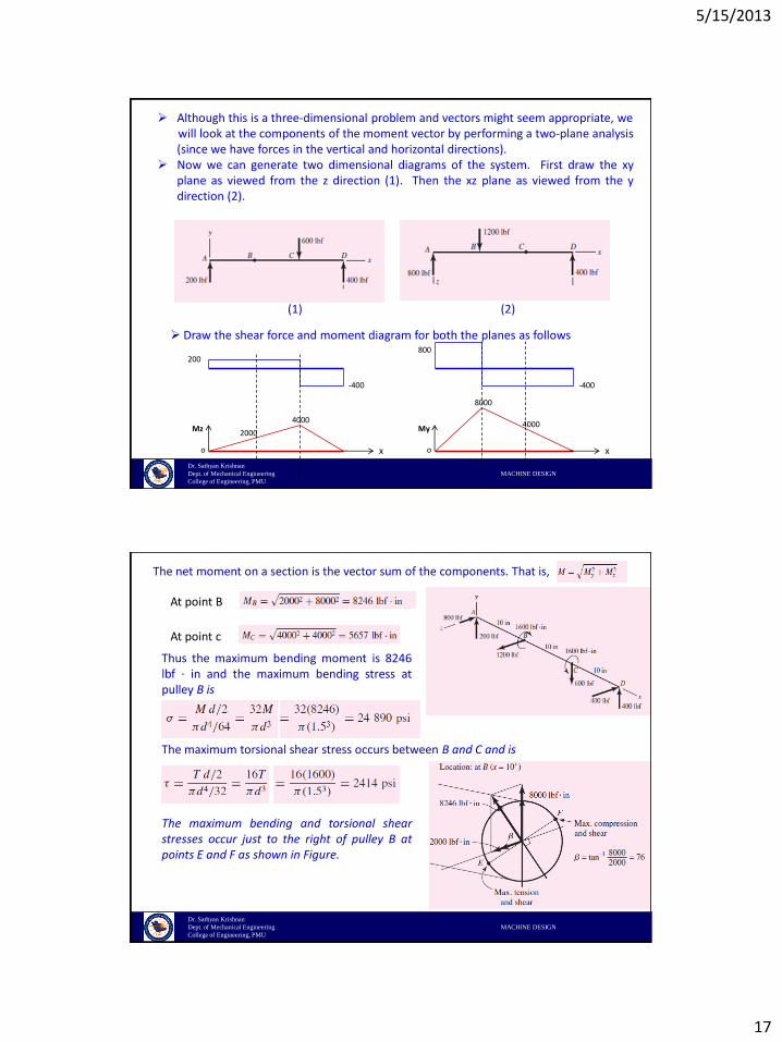
Although this is a three-dimensional problem and vectors might seem appropriate, wewill look at the components of the moment vector by performing a two-plane analysis(since we have forces in the vertical and horizontal directions).
Now we can generate two dimensional diagrams of the system. First draw the xyplane as viewed from the z direction (1). Then the xz plane as viewed from the ydirection (2).
(1) (2)
Draw the shear force and moment diagram for both the planes as follows
200
-400
800
-400
4000
8000
Mz My
o ox x
20004000
Dr. Sathyan Krishnan
Dept. of Mechanical Engineering MACHINE DESIGN
College of Engineering, PMU
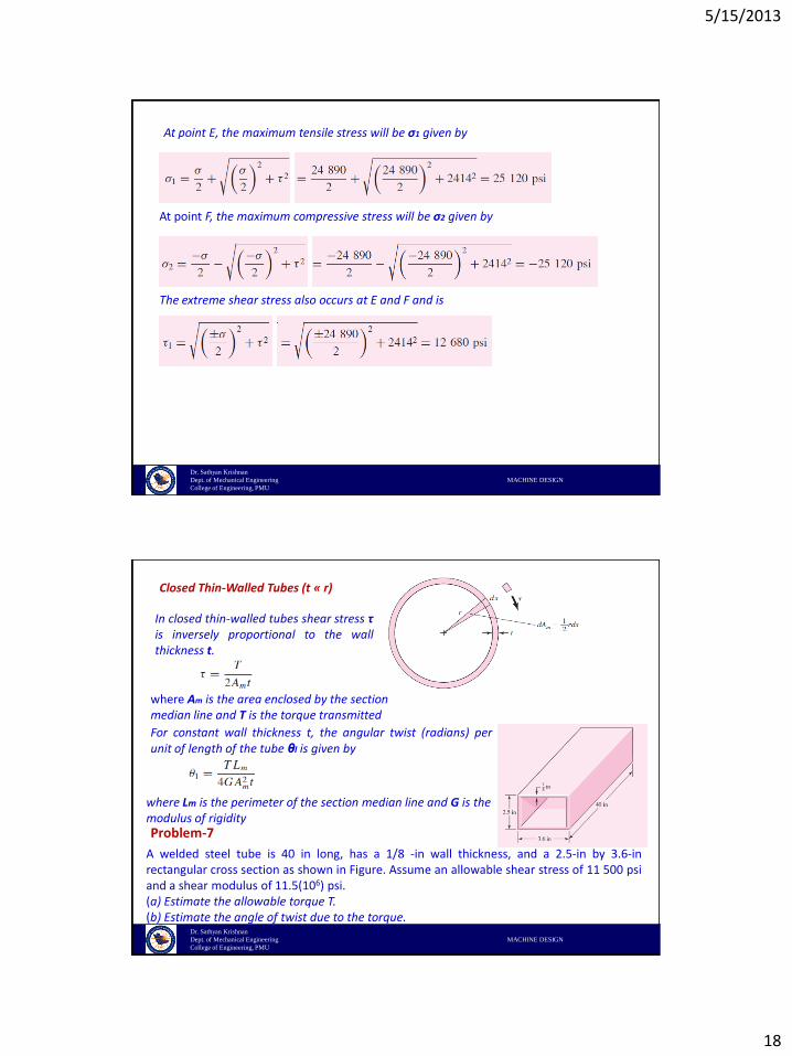
The net moment on a section is the vector sum of the components. That is,
At point B
At point c
Thus the maximum bending moment is 8246lbf · in and the maximum bending stress atpulley B is
The maximum torsional shear stress occurs between B and C and is
The maximum bending and torsional shearstresses occur just to the right of pulley B atpoints E and F as shown in Figure.
5/15/2013
18
Dr. Sathyan Krishnan
Dept. of Mechanical Engineering MACHINE DESIGN
College of Engineering, PMU
At point E, the maximum tensile stress will be σ1 given by
At point F, the maximum compressive stress will be σ2 given by
The extreme shear stress also occurs at E and F and is
Dr. Sathyan Krishnan
Dept. of Mechanical Engineering MACHINE DESIGN
College of Engineering, PMU
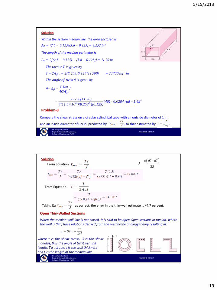
Closed Thin-Walled Tubes (t « r)
In closed thin-walled tubes shear stress τis inversely proportional to the wallthickness t.
where Am is the area enclosed by the section median line and T is the torque transmitted
For constant wall thickness t, the angular twist (radians) perunit of length of the tube θl is given by
where Lm is the perimeter of the section median line and G is the modulus of rigidity
A welded steel tube is 40 in long, has a 1/8 -in wall thickness, and a 2.5-in by 3.6-inrectangular cross section as shown in Figure. Assume an allowable shear stress of 11 500 psiand a shear modulus of 11.5(106) psi.(a) Estimate the allowable torque T.(b) Estimate the angle of twist due to the torque.
Problem-7
5/15/2013
19
Dr. Sathyan Krishnan
Dept. of Mechanical Engineering MACHINE DESIGN
College of Engineering, PMU
m
1 2
m
The torque T is given by
T = 2A t τ = 2(8.253)0.125(11 500)
The angle of twist θ is given by
T Lmθ = θ l = l
4GA t
Within the section median line, the area enclosed is
The length of the median perimeter is
Am = (2.5 − 0.125)(3.6 − 0.125) = 8.253 in2
Lm = 2[(2.5 − 0.125) + (3.6 − 0.125)] = 11.70 in
Solution
Compare the shear stress on a circular cylindrical tube with an outside diameter of 1 in
and an inside diameter of 0.9 in, predicted by , to that estimated by
Problem-8
0
6 2
= 23 730 lbf · in
23 730(11.70) = (40) = 0.0284 rad = 1.62
4(11.5 ×10 )(8.253 )(0.125)
Dr. Sathyan Krishnan
Dept. of Mechanical Engineering MACHINE DESIGN
College of Engineering, PMU
From Equation.
From Equation.
Taking Eq. as correct, the error in the thin-wall estimate is −4.7 percent.
Solution o i
4 4π d - dJ =
32
Open Thin-Walled Sections
When the median wall line is not closed, it is said to be open Open sections in torsion, wherethe wall is thin, have relations derived from the membrane analogy theory resulting in:
where τ is the shear stress, G is the shearmodulus, θl is the angle of twist per unitlength, T is torque, c is the wall thickness and L is the length of the median line.
5/15/2013
20
Dr. Sathyan Krishnan
Dept. of Mechanical Engineering MACHINE DESIGN
College of Engineering, PMU
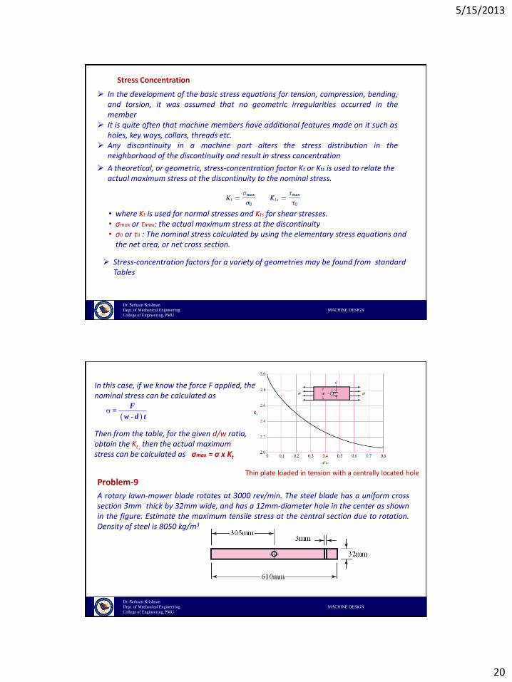
Stress Concentration
In the development of the basic stress equations for tension, compression, bending,and torsion, it was assumed that no geometric irregularities occurred in themember
It is quite often that machine members have additional features made on it such asholes, key ways, collars, threads etc.
Any discontinuity in a machine part alters the stress distribution in theneighborhood of the discontinuity and result in stress concentration
• where Kt is used for normal stresses and Kts for shear stresses.• σmax or τmax: the actual maximum stress at the discontinuity• σ0 or τ0 : The nominal stress calculated by using the elementary stress equations and
the net area, or net cross section.
Stress-concentration factors for a variety of geometries may be found from standard Tables
A theoretical, or geometric, stress-concentration factor Kt or Kts is used to relate the actual maximum stress at the discontinuity to the nominal stress.
Dr. Sathyan Krishnan
Dept. of Mechanical Engineering MACHINE DESIGN
College of Engineering, PMU
Thin plate loaded in tension with a centrally located hole
In this case, if we know the force F applied, the nominal stress can be calculated as
F =
w - d t
Then from the table, for the given d/w ratio, obtain the Kt , then the actual maximum stress can be calculated as σmax = σ x Kt
Problem-9
A rotary lawn-mower blade rotates at 3000 rev/min. The steel blade has a uniform crosssection 3mm thick by 32mm wide, and has a 12mm-diameter hole in the center as shownin the figure. Estimate the maximum tensile stress at the central section due to rotation.Density of steel is 8050 kg/m3
5/15/2013
21
Dr. Sathyan Krishnan
Dept. of Mechanical Engineering MACHINE DESIGN
College of Engineering, PMU
nom
2
The nominal stress is given by
Force Fσ = =
actual cross sectional area w - d t
Here,the force is due to the rotation of the bladei.e.,centrifugal force
F = m ω r where m is the mass of the blade,r is the radius, ω is the angular velocity
Solution
2
2
mass m =volume×density = 0.610×0.032×0.003 ×8050 = 0.471kg
2π n 2×3.14×3000ω= = = 314.2 rad/s
60 60
Nominal area of cs = w - d t = 0.032 - 0.012 ×0.003=
we need toconsider only half of the mass sin0.471F = kg×0.305m× 314.2 rad/s
2
0.00006m
2
2
nom 2
t
max nom
cethebladeis
rotating about the hole as centre
= 7090.92 kg m/s =
7090.92 Nσ = =11818214 N/m or Pascal =
0.00006m
d 12From table for = = 0.375, K = 2.25w 32
the actual maximum st
7090.92 N
118
ress σ
.1MPa
= σ × K
t = 118.1MPa× 2. 26525 = .9 MPa
Dr. Sathyan Krishnan
Dept. of Mechanical Engineering MACHINE DESIGN
College of Engineering, PMU
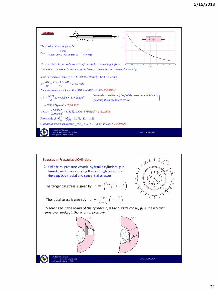
Stresses in Pressurized Cylinders
Cylindrical pressure vessels, hydraulic cylinders, gun barrels, and pipes carrying fluids at high pressures develop both radial and tangential stresses
The tangential stress is given by
The radial stress is given by
Where ri the inside radius of the cylinder, ro is the outside radius, pi is the internal pressure, and po is the external pressure.
Tangential stress distribution Radial stress distribution
5/15/2013
22
Dr. Sathyan Krishnan
Dept. of Mechanical Engineering MACHINE DESIGN
College of Engineering, PMU
The longitudinal stresses exist in the vessel when the end reactions to the internalpressure are taken by the pressure vessel itself
Longitudinal stress is obtained by
Thin-Walled Vessels
The wall thickness of a cylindrical pressure vessel is less than one-tenth of its radius The radial stress that results from pressurizing the vessel is quite small compared with
the tangential stress
The average tangential stress is given by
The maximum tangential stress is obtained by
where (di + t) is the average diameter
In case of a closed cylinder, the longitudinal stress σl is obtained by
Dr. Sathyan Krishnan
Dept. of Mechanical Engineering MACHINE DESIGN
College of Engineering, PMU
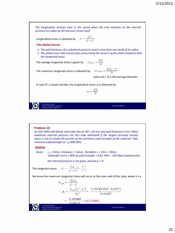
An AISI 1040 cold-drawn steel tube has an OD = 50 mm and wall thickness 6 mm. Whatmaximum external pressure can this tube withstand if the largest principal normalstress is not to exceed 80 percent of the minimum yield strength of the material? Takeminimum yield strength as Sy=490 MPa
Solution
Problem-10
The tangential stress
Given: ro = 25mm, thickness t = 6mm, therefore ri = 25-6 = 19mmallowable stress = 80% of yield strength = 0.8x -490 = -392 Mpa (compressive)
the internal pressure is not given, assume pi = 0
We know the maximum tangential stress will occur at the inner wall of the tube, where r = ri
2 2 2 2
t max o i
o 2 2
o
σ r - r -392 0.025 -0.019p = - = -
2 r 2×0.025
0.103488= =
0.00182. a
2579 MP
5/15/2013
23
Dr. Sathyan Krishnan
Dept. of Mechanical Engineering MACHINE DESIGN
College of Engineering, PMU
Stresses in Rotating Rings
Many rotating elements, such as flywheels and blowers, can be simplified to a rotating ring to determine the stresses
The tangential and radial stresses so found are subject to the following restrictions:• The outside radius of the ring, or disk, is large compared with the thickness ro ≥ 10t.• The thickness of the ring or disk is constant.• The stresses are constant over the thickness.
The tangential and radial stress are obtained by
where r is the radius to the stress element under consideration, ρ is the mass density, ν isthe Poisson ratio and ω is the angular velocity of the ring in radians per second. For arotating disk, use ri = 0 in these equations.
Dr. Sathyan Krishnan
Dept. of Mechanical Engineering MACHINE DESIGN
College of Engineering, PMU
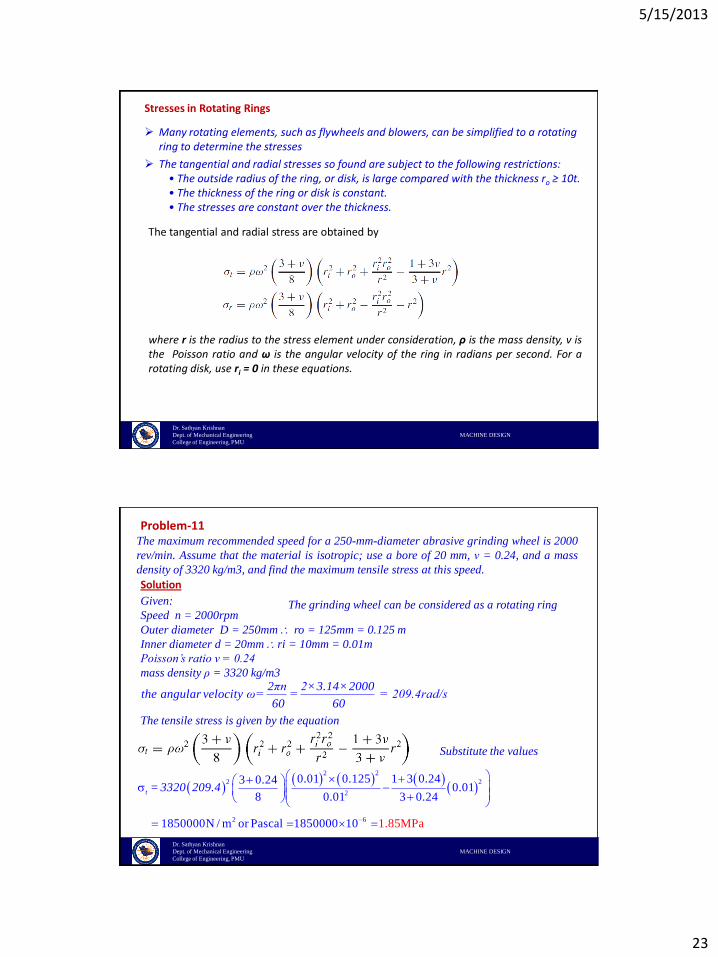
The maximum recommended speed for a 250-mm-diameter abrasive grinding wheel is 2000
rev/min. Assume that the material is isotropic; use a bore of 20 mm, ν = 0.24, and a mass
density of 3320 kg/m3, and find the maximum tensile stress at this speed.
Problem-11
Solution
Given:
Speed n = 2000rpm
Outer diameter D = 250mm ro = 125mm = 0.125 m
Inner diameter d = 20mm ri = 10mm = 0.01m
Poisson’s ratio ν = 0.24
mass density ρ = 3320 kg/m3
2πn 2×3.14×2000the angular velocity ω = = = 209.4rad/s
60 60
The grinding wheel can be considered as a rotating ring
The tensile stress is given by the equation
2 2
2 2
2
2 6
0.01 0.125 1 3 0.243 0.240.01
8 0.01 3 0.24
1850000N / m or Pascal 1850000 10 1.85MPa
t = 3320 209.4
Substitute the values
5/15/2013
24
Dr. Sathyan Krishnan
Dept. of Mechanical Engineering MACHINE DESIGN
College of Engineering, PMU
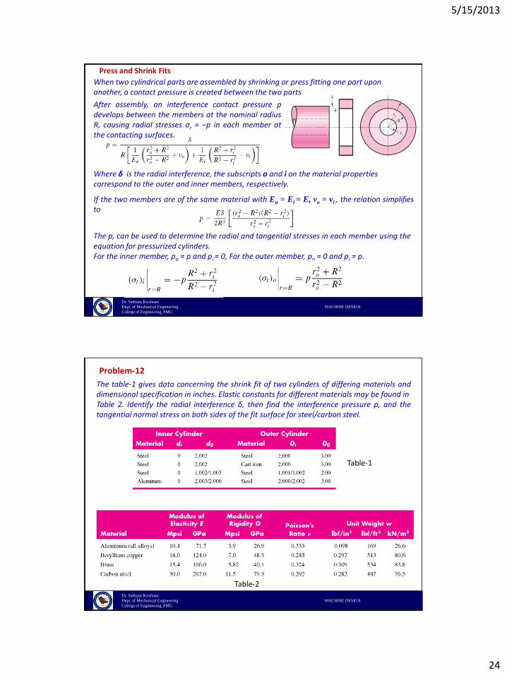
After assembly, an interference contact pressure pdevelops between the members at the nominal radiusR, causing radial stresses σr = −p in each member atthe contacting surfaces.
Where δ is the radial interference, the subscripts o and i on the material properties correspond to the outer and inner members, respectively.
If the two members are of the same material with Eo = Ei = E, νo = vi , the relation simplifiesto
The p, can be used to determine the radial and tangential stresses in each member using theequation for pressurized cylinders.For the inner member, po = p and pi = 0, For the outer member, po = 0 and pi = p.
Press and Shrink Fits
When two cylindrical parts are assembled by shrinking or press fitting one part uponanother, a contact pressure is created between the two parts
Dr. Sathyan Krishnan
Dept. of Mechanical Engineering MACHINE DESIGN
College of Engineering, PMU
The table-1 gives data concerning the shrink fit of two cylinders of differing materials anddimensional specification in inches. Elastic constants for different materials may be found inTable 2. Identify the radial interference δ, then find the interference pressure p, and thetangential normal stress on both sides of the fit surface for steel/carbon steel.
Problem-12
Table-1
Table-2
5/15/2013
25
Dr. Sathyan Krishnan
Dept. of Mechanical Engineering MACHINE DESIGN
College of Engineering, PMU
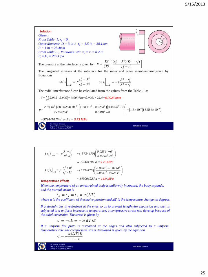
SolutionGiven:
From Table -1, ri = 0,
Outer diameter D = 3 in ro = 1.5 in = 38.1mm
R = 1 in = 25.4mm
From Table -2, Poisson’s ratio νo = νi = 0.292
Ei = Eo = 207 Gpa
The pressure at the interface is given by
The radial interference can be calculated from the values from the Table -1 as
1
δ = 2.002 - 2.000 =0.0001in=0.0001×25 0.002.4=2
54mm
3 2 2
10 410 0.0254 0.0254 0
1.6 10 3.584 100
9 2
3 2
2
207 10 0.00254 0.0381p = =
2 0.0254 0.0381
=5734470 N/m or Pa =
5.73 MPa
The tangential stresses at the interface for the inner and outer members are given by
Equations
Dr. Sathyan Krishnan
Dept. of Mechanical Engineering MACHINE DESIGN
College of Engineering, PMU
r R
r R
2 2
it 2 2i
i
2 2
ot 2 2o
o
R +rσ = - p
R - r
r + Rσ = p
r - R
Temperature Effects
When the temperature of an unrestrained body is uniformly increased, the body expands,
and the normal strain is
where α is the coefficient of thermal expansion and T is the temperature change, in degrees.
If a straight bar is restrained at the ends so as to prevent lengthwise expansion and then is
subjected to a uniform increase in temperature, a compressive stress will develop because of
the axial constraint. The stress is given by
If a uniform flat plate is restrained at the edges and also subjected to a uniform
temperature rise, the compressive stress developed is given by the equation
2 2
2 2
2 2
2 2
0.0254 +0-5734470
0.0254 -0
-5734470 Pa =
0.0381 +0.02545734470
0.0381 -0.0254
= 149096
5.73 MPa
14.9 a2 MP2 Pa =
5/15/2013
26
Dr. Sathyan Krishnan
Dept. of Mechanical Engineering MACHINE DESIGN
College of Engineering, PMU
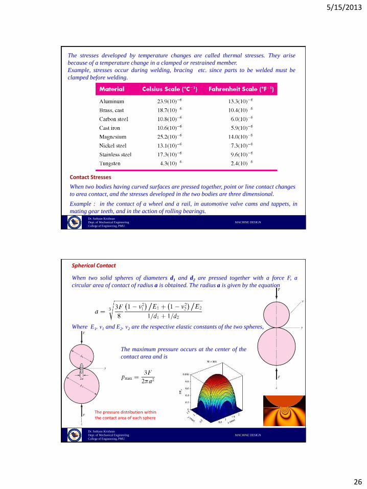
The stresses developed by temperature changes are called thermal stresses. They arise
because of a temperature change in a clamped or restrained member.
Example, stresses occur during welding, bracing etc. since parts to be welded must be
clamped before welding.
Contact Stresses
When two bodies having curved surfaces are pressed together, point or line contact changes
to area contact, and the stresses developed in the two bodies are three dimensional.
Example : in the contact of a wheel and a rail, in automotive valve cams and tappets, in
mating gear teeth, and in the action of rolling bearings.
Dr. Sathyan Krishnan
Dept. of Mechanical Engineering MACHINE DESIGN
College of Engineering, PMU
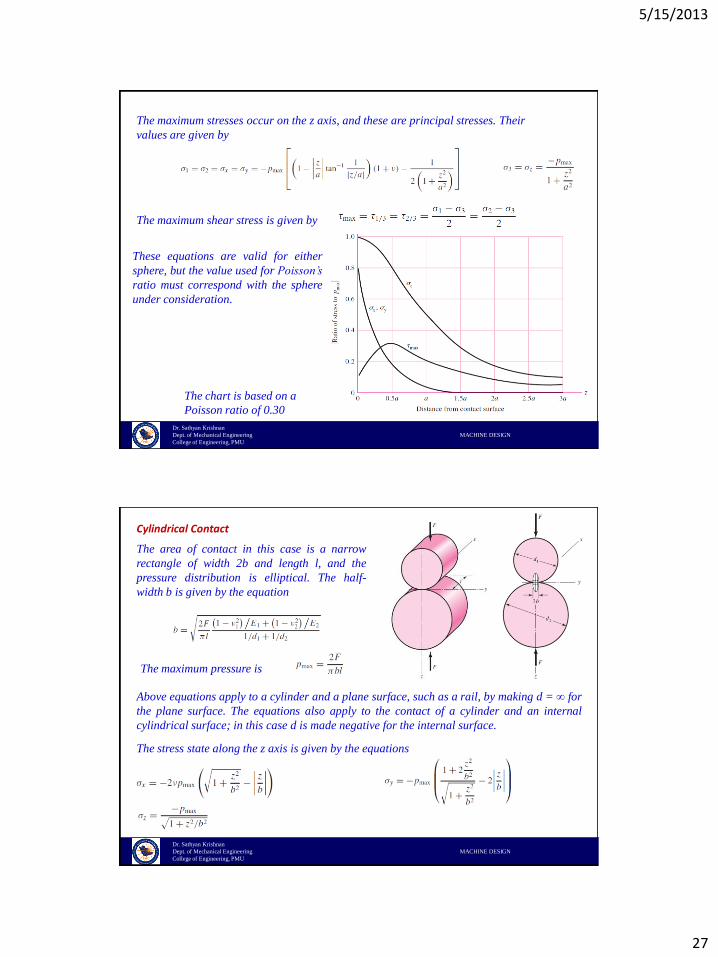
Spherical Contact
When two solid spheres of diameters d1 and d2 are pressed together with a force F, a
circular area of contact of radius a is obtained. The radius a is given by the equation
Where E1, ν1 and E2, ν2 are the respective elastic constants of the two spheres,
The maximum pressure occurs at the center of the
contact area and is
The pressure distribution within the contact area of each sphere
wikipedia.org
5/15/2013
27
Dr. Sathyan Krishnan
Dept. of Mechanical Engineering MACHINE DESIGN
College of Engineering, PMU
The maximum stresses occur on the z axis, and these are principal stresses. Their
values are given by
These equations are valid for either
sphere, but the value used for Poisson’s
ratio must correspond with the sphere
under consideration.
The maximum shear stress is given by
The chart is based on a
Poisson ratio of 0.30
Dr. Sathyan Krishnan
Dept. of Mechanical Engineering MACHINE DESIGN
College of Engineering, PMU
Cylindrical Contact
The area of contact in this case is a narrow
rectangle of width 2b and length l, and the
pressure distribution is elliptical. The half-
width b is given by the equation
The maximum pressure is
Above equations apply to a cylinder and a plane surface, such as a rail, by making d = ∞ for
the plane surface. The equations also apply to the contact of a cylinder and an internal
cylindrical surface; in this case d is made negative for the internal surface.
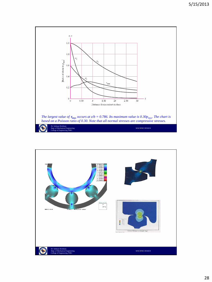
The stress state along the z axis is given by the equations
5/15/2013
28
Dr. Sathyan Krishnan
Dept. of Mechanical Engineering MACHINE DESIGN
College of Engineering, PMU
The largest value of max occurs at z/b = 0.786. Its maximum value is 0.30pmax. The chart is
based on a Poisson ratio of 0.30. Note that all normal stresses are compressive stresses.
Dr. Sathyan Krishnan
Dept. of Mechanical Engineering MACHINE DESIGN
College of Engineering, PMU
5/15/2013
29
Dr. Sathyan Krishnan
Dept. of Mechanical Engineering MACHINE DESIGN
College of Engineering, PMU
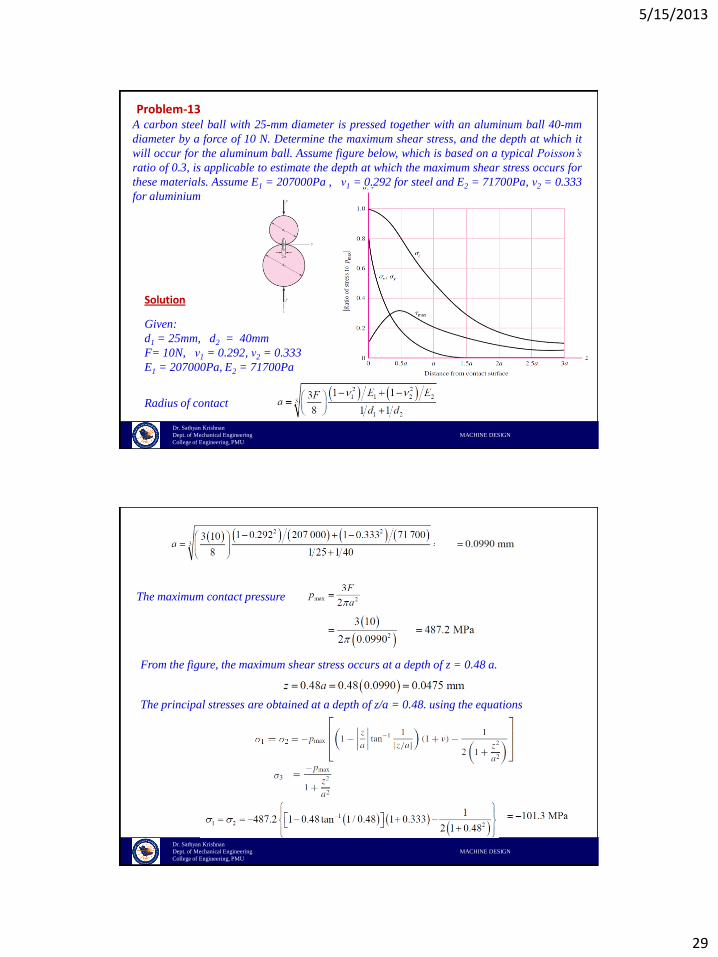
A carbon steel ball with 25-mm diameter is pressed together with an aluminum ball 40-mm
diameter by a force of 10 N. Determine the maximum shear stress, and the depth at which it
will occur for the aluminum ball. Assume figure below, which is based on a typical Poisson’s
ratio of 0.3, is applicable to estimate the depth at which the maximum shear stress occurs for
these materials. Assume E1 = 207000Pa , ν1 = 0.292 for steel and E2 = 71700Pa, ν2 = 0.333
for aluminium
Problem-13
Solution
Given:
d1 = 25mm, d2 = 40mm
F= 10N, ν1 = 0.292, ν2 = 0.333
E1 = 207000Pa, E2 = 71700Pa
Radius of contact
Dr. Sathyan Krishnan
Dept. of Mechanical Engineering MACHINE DESIGN
College of Engineering, PMU
The maximum contact pressure
From the figure, the maximum shear stress occurs at a depth of z = 0.48 a.
The principal stresses are obtained at a depth of z/a = 0.48. using the equations
5/15/2013
30
Dr. Sathyan Krishnan
Dept. of Mechanical Engineering MACHINE DESIGN
College of Engineering, PMU
The maximum shear stress
Copyright © 2022 FDOKUMEN

