


Bahasa
Halaman
Hukum

Faculty of engineering
Automotive engineering department
2013/2014
Faculty of engineering
Automotive engineering department
Project on
“Electrolysis of salt water using solar energyand using it as a fuel for internal combustion
engines”
Page 0 of 69
BY ENG: MOSTAFA MOHAMMED SIAM UNDER SUPERVISION OF: DR ADHAM MOHAMMED ABD-ELKADER
Table of contentSubject Page
Introduction 3Solar energy 5
Hydrogen gas 13Generating HHO gas theory 15Pre-experiment calculations 21
Modification on engine 25The experiment
New methods of hydrogengeneration
27
41
References 47Index of tables
Table no . Page 1 72 193 244 345 356 367 378 38
Page 1 of 69

Table of figuresFig. no Page
1 62 14
3.a 213.b ,3.c 22
4 255 296 327 398 399 40
Page 2 of 69

IntroductionProblem of energy: The world is now facing a big problem in energy. Fossil fuels of oil and natural gas is about to run out. If there was not a way or a new way to produce energy world will return to the dark ages. We need energy in everything in our lives. Torun cars, factories, power generation, food preparation and a lot of industries.
Fossil fuels as the name suggests are derivatives of plant and animal fossils that are million years old. These are primarily formed from the remains of the decayed plants and animals of the carboniferous era. The three fuel sources coal,natural gas and oil/petroleum helps to meet the energy and electricity demands oftoday’s world. The demand for energy will never be in the declining graph. Industrial revolution has shown the way and it’s still going on
Fossil fuels are the major energy sources but still when over consumption takes place lead to disastrous effects such as air pollution. Burning of fossil fuels releases carbon dioxide, nitrogen monoxide, nitrogen dioxide, sulphur dioxide, carbon monoxide etc. that have severe consequences on the habitats. They also affect human health.
Coal Power PlantThey are non-renewable sources of energy as they are derived from pre-historic fossils and are no longer available if once used. Their source is limited and they are depleting at a faster rate. When extracted it poses a severe damage to the landscape as they are to be dig out from underground wells.
Disadvantages of Fossil Fuels1. Environmental Hazards: Pollution is the major disadvantage that is formed due to fossil fuels. When burnt they give out carbon dioxide, a greenhouse gas which is the main aspect of global warming. Rise in temperature of earth have resulted in melting of polar ice caps, flooding of low lying areas, rise in sea levels. Ifsuch conditions conquer the face of earth will face radical changes.
2. Rising Prices: Middle-east countries have huge reserves of oil and natural gasand many other countries are dependent on them for constant supply of these fuels. Organization of the Petroleum Exporting Countries (OPEC) is a group of 13 countries including Iran, Iraq, Kuwait, Qatar, Saudi Arabia and UAE. They are responsible for 40 percent of the world’s oil production and hold the majority ofthe world’s oil reserves, according to the Energy Information Administration
Page 3 of 69

(EIA). OPEC constantly monitor the volume of oil consumed and then adjusts its own production to maintain its desired barrel price. This result in worldwide price fluctuations, according to the U.S. Department of Energy.
3. Acid Rain: When burnt, sulphur dioxide gas is also produced which is the factor for acid rain. Acid rain leads to destruction of monuments made up of brickwork or marbles, even crops are affected due to acidification of loams. Coalmining results in destruction of abundant lands and also endangers the lives of mineworkers. The natural gas causes nasty smells and also a lot of problems with transportation. Transportation of crude oil causes oil spills over seas reasoningto hazards to the aquatic life by lessening the oxygen content of water.
4. Human Health Getting Affected: The ozone layer is being worn-out due to the release of greenhouse gases from the fuels. Hence, ozone holes are being created from which harmful UV rays enter the earth surface that affect human life causingdiseases like cancer. The melanin present in the skin reacts with these high waveradiations. Skin cancer is the major form of disease that is caused due to the reaction of infra-red rays and the pigment present in the skin.
5. Non-Renewable: As the fossil fuels are extracted to an unlimited level it is for sure that they will deplete some day or the other. Since they are non-renewable it is likely that fuels expenses will face a hike in near future. It would take millions of years to replace coal, and oil, and we are using them quickly. There is a limited amount of these fuels available and we are not actually sure where that limit is.
6. Impact on Aquatic Life by Oil Spill: Fossil fuels are needed in huge reserves wherever their plants are set up. This requires them to be transported to the desired location via truck, train, ship or airplane. Often we hear of some leaks in oil tankers or ship getting drowned deep under the sea that were carrying crude oil to get refined. The impact of this is that crude oil contains some toxic substances which when mixed up with water pose serious hazards to aquatic life.
7. Coal Mining: Extraction of coal from areas that have huge reserves is not onlya difficult and dangerous task but also pose health hazard to the lives of several workers who work there. The coal mining destroys wide areas of land and results in ecological imbalance.
8. Need Huge Amount of Reserves: The coal power plants needs huge and regular supply of coal to produce large amount of electricity on a constant basis. This means they need reserves of coal almost train-loads of fuel near power stations to carry out the process of generating electricity. This is required since today also many nations are dependent on coal as a major source of producing power.
Page 4 of 69
9. The efficiency of fossil fuels to produce electricity and run factories and cars do not exceed 40% of its content are spending to get rid of excess energy such as heat in vehicles engines.
Technologies to get more out of the earth are progressing, but they don’t seem tobe doing it as quickly as our demand is growing. In addition, while coal is much more abundant than oil, extraction of coal can be very unsafe, and is damaging tothe environment on a large scale, causing erosion, acidification of the environment, and destruction of wild lands. Though the fossil fuels meet our energy and fuel needs, still it’s a high time to look forward for the alternativerenewable sources of energy such as wind turbines, solar panels, tidal generatorsand compost. As said by a great man, there is enough for everyone’s need but not enough for everyone’s greed.
Solution:
The environment around us is full of many forms of renewable energy sources and clean water as energy, wind and solar power, but it needs time to see how the production of energy equivalent to what is produced from fossil fuels required for the administration to factories, power generation and propulsion vehicles
1. For vehicles thought scientists in a way to reduce the consumption of fossilfuels in cars add electric system to power next to fossil fuels, which has amarked effect in raising fuel consumption and combustion at speeds normal upto 60 km/h and but needs to develop for using it at high speeds
2. Energy generated from nuclear reactors, which is a very high cut-off enough to run factories and power generation, but remnants of nuclear reactions destructive to the environment and human and in addition to that cannot be used in cars
3. Wind power you need for places wide open to take advantage of them in generating electricity available in Egypt's Western Desert and Eastern but inevitably Look need expensive means of transport for the transfer of this energy
4. Water energy needs water from waterfalls or dams to generate electricity, and this far and you need to either a high cost to build a water catchment engineering (dams) and to move generated electricity from the waterfalls to places of consumptions.
5. Solar energy is available in abundance in our Arab countries very most days of the year, but its problem lies in how to store thermal energy or electricity generated from solar cells in the night. The advantage of solar energy that it is free and can be used anywhere at day light
Page 5 of 69
Chapter 1: Solar energySolar energy is quite simply the energy produced directly by the sun and collected elsewhere, normally the Earth. The sun creates its energy through a thermonuclear process that converts about 650, 000,0001 tons of hydrogen to helium every second. The process creates heat and electromagnetic radiation. The heat remains in the sun and is instrumental in maintaining the thermonuclear reaction. Theelectromagnetic radiation (including visible light, infra-red light, and ultra-violetradiation) streams out into space in all directions.
Solar energy is radiant light and heat from the sun harnessed using a range of ever-evolving technologies such as solar heating, solar photovoltaic, solar thermal electricity, solar architecture and artificial photosynthesis.
Solar technologies are broadly characterized as either passive solar or active solar depending on the way they capture, convert and distribute solar energy. Active solar techniques include the use of photovoltaic panels and solar thermal collectors to harness the energy. Passive solar techniques include orienting a building to the Sun, selecting materials with favorable thermal mass or light dispersing properties, and designing spaces that naturally circulate air.
In 2011, the International Energy Agency said that "the development of affordable, inexhaustible and clean solar energy technologies will have huge longer-term benefits. It will increase countries’ energy security through reliance on an indigenous, inexhaustible and mostly import-independent resource, enhance sustainability, reduce pollution, lower the costs of mitigating climate change, and keep fossil fuel prices lower than otherwise. These advantages are global. Hence the additional costs of the incentives for early deployment should be considered learning investments; they must be wisely spent and need to be widely shared".
Page 6 of 69
Energy from the Sun
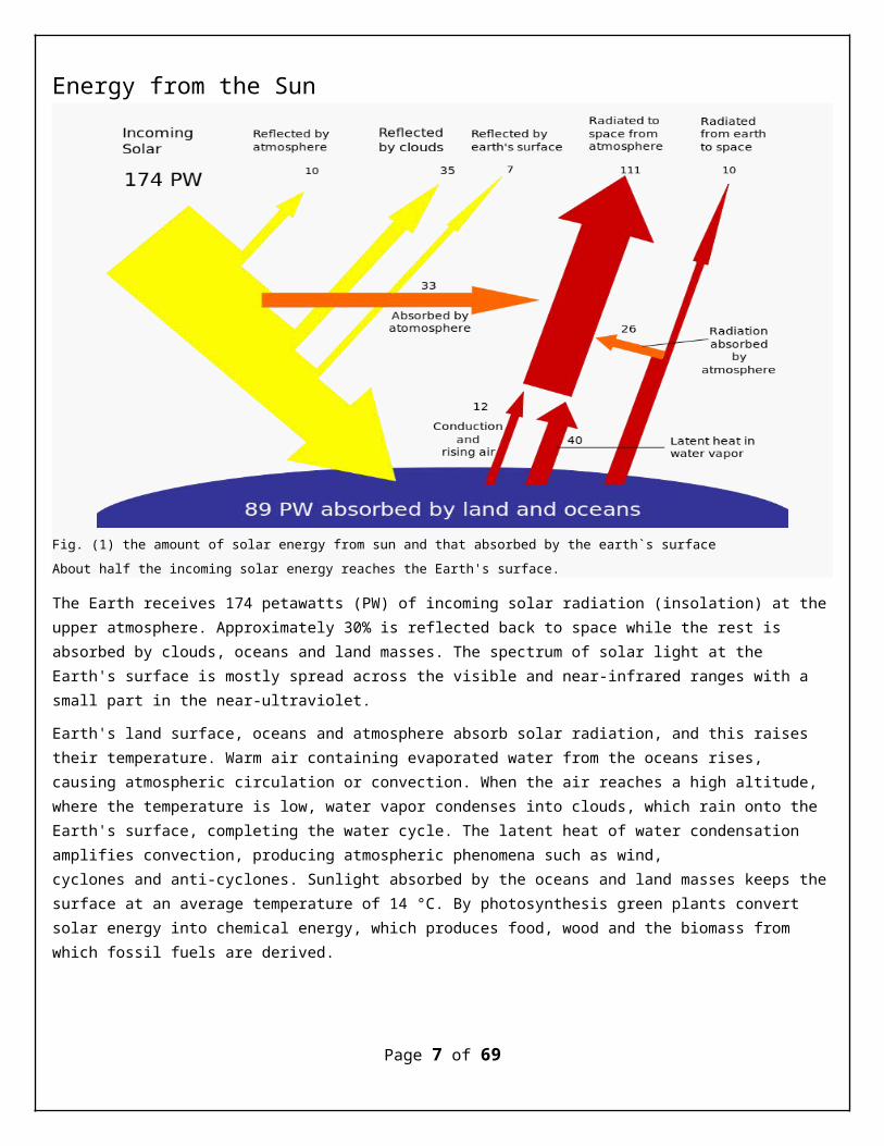
Fig. (1) the amount of solar energy from sun and that absorbed by the earth`s surface About half the incoming solar energy reaches the Earth's surface.
The Earth receives 174 petawatts (PW) of incoming solar radiation (insolation) at theupper atmosphere. Approximately 30% is reflected back to space while the rest is absorbed by clouds, oceans and land masses. The spectrum of solar light at the Earth's surface is mostly spread across the visible and near-infrared ranges with a small part in the near-ultraviolet.
Earth's land surface, oceans and atmosphere absorb solar radiation, and this raises their temperature. Warm air containing evaporated water from the oceans rises, causing atmospheric circulation or convection. When the air reaches a high altitude, where the temperature is low, water vapor condenses into clouds, which rain onto the Earth's surface, completing the water cycle. The latent heat of water condensation amplifies convection, producing atmospheric phenomena such as wind, cyclones and anti-cyclones. Sunlight absorbed by the oceans and land masses keeps thesurface at an average temperature of 14 °C. By photosynthesis green plants convert solar energy into chemical energy, which produces food, wood and the biomass from which fossil fuels are derived.
Page 7 of 69
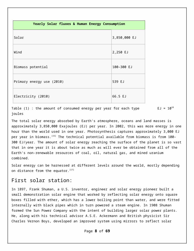
Yearly Solar fluxes & Human Energy Consumption
Solar 3,850,000 EJ
Wind 2,250 EJ
Biomass potential 100–300 EJ
Primary energy use (2010) 539 EJ
Electricity (2010) 66.5 EJ
Table (1) : the amount of consumed energy per year for each type EJ = 1018 joules
The total solar energy absorbed by Earth's atmosphere, oceans and land masses is approximately 3,850,000 Exajoules (EJ) per year. In 2002, this was more energy in onehour than the world used in one year. Photosynthesis captures approximately 3,000 EJ per year in biomass.[15] The technical potential available from biomass is from 100–300 EJ/year. The amount of solar energy reaching the surface of the planet is so vastthat in one year it is about twice as much as will ever be obtained from all of the Earth's non-renewable resources of coal, oil, natural gas, and mined uranium combined.
Solar energy can be harnessed at different levels around the world, mostly depending on distance from the equator.[17]
First solar station:In 1897, Frank Shuman, a U.S. inventor, engineer and solar energy pioneer built a small demonstration solar engine that worked by reflecting solar energy onto square boxes filled with ether, which has a lower boiling point than water, and were fitted internally with black pipes which in turn powered a steam engine. In 1908 Shuman formed the Sun Power Company with the intent of building larger solar power plants. He, along with his technical advisor A.S.E. Ackermann and British physicist Sir Charles Vernon Boys, developed an improved system using mirrors to reflect solar
Page 8 of 69
energy upon collector boxes, increasing heating capacity to the extent that water could now be used instead of ether. Shuman then constructed a full-scale steam enginepowered by low-pressure water, enabling him to patent the entire solar engine system by 1912.
Shuman built the world’s first solar thermal power station in Maadi, Egypt between 1912 and 1913. Shuman’s plant used parabolic troughs to power a 45-52 kilowatt (60-70H.P.) engine that pumped more than 22,000 liters of water per minute from the Nile River to adjacent cotton fields. Although the outbreak of World War I and the discovery of cheap oil in the 1930s discouraged the advancement of solar energy, Shuman’s vision and basic design were resurrected in the 1970s with a new wave of interest in solar thermal energy. In 1916 Shuman was quoted in the media advocating solar energy's utilization, saying:
“We have proved the commercial profit of sun power in the tropics and have more particularly proved that after our stores of oil and coal are exhausted the human race can receive unlimited power from the rays of the sun.”
—Frank Shuman, New York Times, July 2, 1916
Generate and sore energy:
Due to the nature of solar energy, two components are required to have a functional solar energy generator. These two components are a collector and a storage unit. The collector simply collects the radiation that falls on it and converts a fraction of it to other forms of energy (either electricity and heat or heat alone). The storage unit is required because of the non-constant nature of solar energy; at certain times only a very small amount of radiation will be received. At night or during heavy cloudcover, for example, the amount of energy produced by the collector will be quite small. The storage unit can hold the excess energy produced during the periods of maximum pro- ductivity, and release it when the productivity drops. In practice, a backup power supply is usually added, too, for the situations when the amount of energy required is greater thanboth what is being produced and what is stored in the container.
Methods of collecting and storing solar energy
In general, there are three types of collectors and many forms of storage units.
The three types of collectors are flat-plate collectors, focusing collectors, andpassive collectors. Flat-plate collectors are the more commonly used type of collector today. They are arrays of solar panels arranged in a simple plane. Theycan be of nearly any size, and have an output that is directly related to a few variables including size, facing, and cleanliness. These variables all affect theamount of radiation that falls on the collector. Often these collector panels have automated machinery that keeps them facing the sun. The additional energy
Page 9 of 69
they take in due to the correction of facing more than compensates for the energyneeded to drive the extra machinery.
Focusing collectors are essentially flat-plane collectors with optical devices arranged to maximize the radiation falling on the focus of the collector. These are currently used only in a few scattered areas. Solar furnaces are examples of this type of collector. Although they can produce far greater amounts of energy at a single point than the flat-plane collectors can, they lose some of the radiation that the flat-plane panels do not. Radiation reflected off the ground will be used by flat-plane panels but usually will be ignored by focusing collectors (in snow covered regions, this reflected radiation can be significant). One other problem with focusing collectors in general is due to temperature. The fragile silicon components that absorb the incoming radiation lose efficiency at high temperatures, and if they get too hot they can even be permanently damaged. The focusing collectors by their very nature can create muchhigher temperatures and need more safeguards to protect their silicon components.
Passive collectors are completely different from the other two types of collectors. The passive col- lectors absorb radiation and convert it to heat naturally, without being designed and built to do so. All objects have this property to some extent, but only some objects (like walls) will be able to produce enough heat to make it worthwhile. Often their natural ability to convertradiation to heat is enhanced in some way or another (by being painted black, forexample) and a system for transferring the heat to a different location is generally added.
People use energy for many things, but a few general tasks consume most of the energy. These tasks include transportation, heating, cooling, and the generation of electricity. Solar energy can be applied to all four of these tasks with different levels of successUses of solar energy:
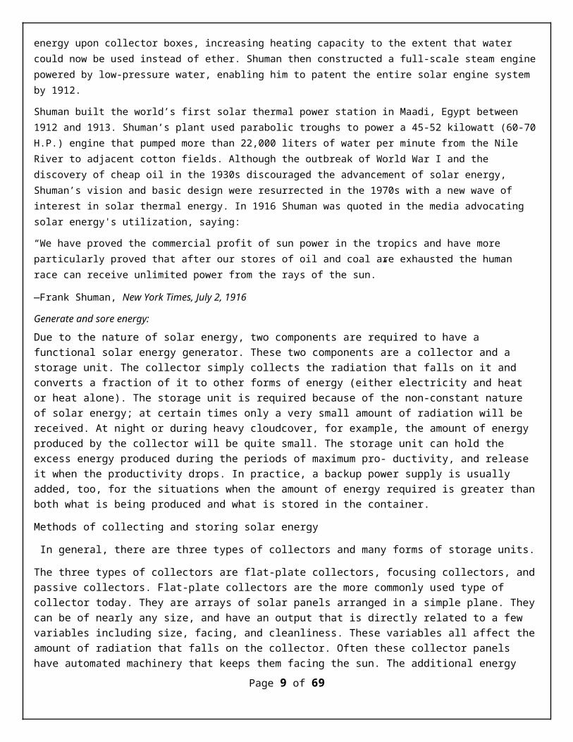
Transport and reconnaissance
Page 10 of 69

Australia hosts the World Solar Challenge where solar cars like the Nuna3 race through a 3,021 km (1,877 mi) course from Darwin to Adelaide.
Development of a solar-powered car has been an engineering goal since the 1980s. The World Solar Challenge is a biannual solar-powered car race, where teams from universities and enterprises compete over 3,021 kilometers (1,877 mi) across central Australia from Darwin to Adelaide.
In 1987, when it was founded, the winner's average speed was 67 kilometers per hour (42 mph) and by 2007 the winner's average speed had improved to 90.87 kilometers per hour (56.46 mph). The North American Solar Challenge and the planned South African Solar Challenge are comparable competitions that reflect an international interest inthe engineering and development of solar powered vehicles.
Some vehicles use solar panels for auxiliary power, such as for air conditioning, to keep the interior cool, thus reducing fuel consumption.
In 1975, the first practical solar boat was constructed in England. By 1995, passenger boats incorporating PV panels began appearing and are now used extensively. In 1996, Kenichi Horie made the first solar powered crossing of the Pacific Ocean, and the sun21 catamaran made the first solar powered crossing of the Atlantic Ocean in the winter of 2006–2007. There are plans to circumnavigate the globe in 2010.
Helios UAV in solar powered flight.
In 1974, the unmanned AstroFlight Sunrise plane made the first solar flight. On 29 April 1979, the Solar Riser made the first flight in a solar-powered, fully controlled, man carrying flying machine, reaching an altitude of 40 feet (12 m). In 1980, the Gossamer Penguin made the first piloted flights powered solely by photovoltaic. This was quickly followed by the Solar Challenger which crossed the English Channel in July 1981. In 1990 Eric Scott Raymond in 21 hops flew from California to North Carolina using solar power. Developments then turned back to unmanned aerial vehicles (UAV) with the Pathfinder (1997) and subsequent designs, culminating in the Helios which set thealtitude record for a non-rocket-propelled aircraft at 29,524 meters (96,864 ft.) in 2001. The Zephyr, developed by BAE Systems, is the latest in a line of record-breaking
Page 11 of 69
solar aircraft, making a 54-hour flight in 2007, and month-long flights are envisioned by 2010.
A solar balloon is a black balloon that is filled with ordinary air. As sunlight shines on the balloon, the air inside is heated and expands causing an upward buoyancy force, much like an artificially heated hot air balloon. Some solar balloons are large enough for human flight, but usage is generally limited to the toymarket as the surface-area to payload-weight ratio is relatively high.
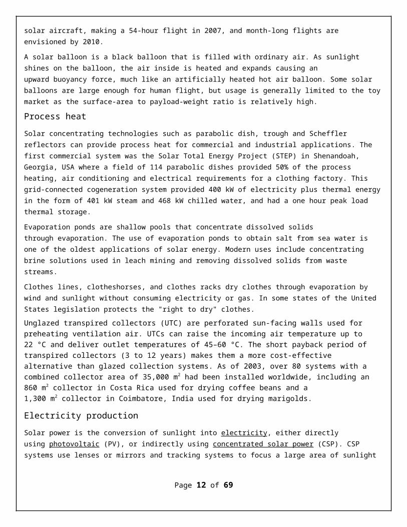
Process heatSolar concentrating technologies such as parabolic dish, trough and Scheffler reflectors can provide process heat for commercial and industrial applications. The first commercial system was the Solar Total Energy Project (STEP) in Shenandoah, Georgia, USA where a field of 114 parabolic dishes provided 50% of the process heating, air conditioning and electrical requirements for a clothing factory. This grid-connected cogeneration system provided 400 kW of electricity plus thermal energyin the form of 401 kW steam and 468 kW chilled water, and had a one hour peak load thermal storage.
Evaporation ponds are shallow pools that concentrate dissolved solids through evaporation. The use of evaporation ponds to obtain salt from sea water is one of the oldest applications of solar energy. Modern uses include concentrating brine solutions used in leach mining and removing dissolved solids from waste streams.
Clothes lines, clotheshorses, and clothes racks dry clothes through evaporation by wind and sunlight without consuming electricity or gas. In some states of the United States legislation protects the "right to dry" clothes. Unglazed transpired collectors (UTC) are perforated sun-facing walls used for preheating ventilation air. UTCs can raise the incoming air temperature up to 22 °C and deliver outlet temperatures of 45–60 °C. The short payback period of transpired collectors (3 to 12 years) makes them a more cost-effective alternative than glazed collection systems. As of 2003, over 80 systems with a combined collector area of 35,000 m2 had been installed worldwide, including an 860 m2 collector in Costa Rica used for drying coffee beans and a 1,300 m2 collector in Coimbatore, India used for drying marigolds.
Electricity productionSolar power is the conversion of sunlight into electricity, either directly using photovoltaic (PV), or indirectly using concentrated solar power (CSP). CSP systems use lenses or mirrors and tracking systems to focus a large area of sunlight
Page 12 of 69
into a small beam. PV converts light into electric current using the photoelectric effect.
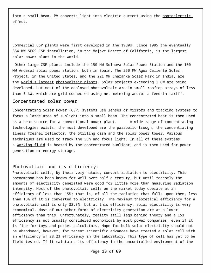
Commercial CSP plants were first developed in the 1980s. Since 1985 the eventually 354 MW SEGS CSP installation, in the Mojave Desert of California, is the largest solar power plant in the world.
Other large CSP plants include the 150 MW Solnova Solar Power Station and the 100 MW Andasol solar power station, both in Spain. The 250 MW Agua Caliente Solar Project, in the United States, and the 221 MW Charanka Solar Park in India, are the world’s largest photovoltaic plants. Solar projects exceeding 1 GW are being developed, but most of the deployed photovoltaic are in small rooftop arrays of less than 5 kW, which are grid connected using net metering and/or a feed-in tariff.
Concentrated solar powerConcentrating Solar Power (CSP) systems use lenses or mirrors and tracking systems tofocus a large area of sunlight into a small beam. The concentrated heat is then used as a heat source for a conventional power plant. A wide range of concentrating technologies exists; the most developed are the parabolic trough, the concentrating linear fresnel reflector, the Stirling dish and the solar power tower. Various techniques are used to track the Sun and focus light. In all of these systems a working fluid is heated by the concentrated sunlight, and is then used for power generation or energy storage.
Photovoltaic and its efficiency:Photovoltaic cells, by their very nature, convert radiation to electricity. This phenomenon has been known for well over half a century, but until recently the amounts of electricity generated were good for little more than measuring radiation intensity. Most of the photovoltaic cells on the market today operate at an efficiency of less than 15%; that is, of all the radiation that falls upon them, lessthan 15% of it is converted to electricity. The maximum theoretical efficiency for a photovoltaic cell is only 32.3%, but at this efficiency, solar electricity is very economical. Most of our other forms of electricity generation are at a lower efficiency than this. Unfortunately, reality still lags behind theory and a 15% efficiency is not usually considered economical by most power companies, even if it is fine for toys and pocket calculators. Hope for bulk solar electricity should not be abandoned, however, for recent scientific advances have created a solar cell with an efficiency of 28.2% efficiency in the laboratory. This type of cell has yet to be field tested. If it maintains its efficiency in the uncontrolled environment of the
Page 13 of 69
outside world, and if it does not have a tendency to break down, it will be economical for power companies to build solar power facilities after all.
Of the main types of energy usage, the least suited to solar power is transportation.While large, relatively slow vehicles like ships could power themselves with large onboard solar panels, small constantly turning vehicles like cars could not. The onlypossible way a car could be completely solar powered would be through the use of battery that was charged by solar power at some stationary point and then later loaded into the car. Electric cars that are partially powered by solar energy are available now, but it is unlikely that solar power will provide the world's transportation costs in the near future.
Advantages:
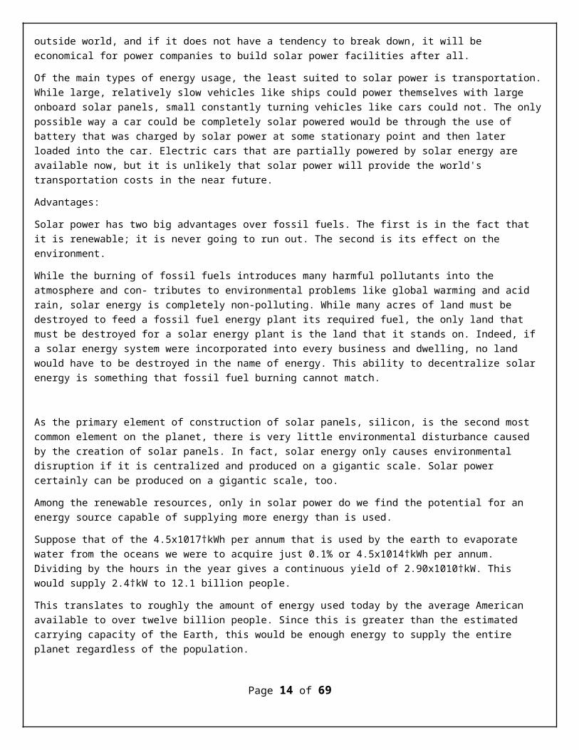
Solar power has two big advantages over fossil fuels. The first is in the fact that it is renewable; it is never going to run out. The second is its effect on the environment.
While the burning of fossil fuels introduces many harmful pollutants into the atmosphere and con- tributes to environmental problems like global warming and acid rain, solar energy is completely non-polluting. While many acres of land must be destroyed to feed a fossil fuel energy plant its required fuel, the only land that must be destroyed for a solar energy plant is the land that it stands on. Indeed, if a solar energy system were incorporated into every business and dwelling, no land would have to be destroyed in the name of energy. This ability to decentralize solar energy is something that fossil fuel burning cannot match.
As the primary element of construction of solar panels, silicon, is the second most common element on the planet, there is very little environmental disturbance caused by the creation of solar panels. In fact, solar energy only causes environmental disruption if it is centralized and produced on a gigantic scale. Solar power certainly can be produced on a gigantic scale, too.
Among the renewable resources, only in solar power do we find the potential for an energy source capable of supplying more energy than is used.
Suppose that of the 4.5x10¹⁷†kWh per annum that is used by the earth to evaporate water from the oceans we were to acquire just 0.1% or 4.5x10¹⁴†kWh per annum. Dividing by the hours in the year gives a continuous yield of 2.90x10¹⁰†kW. This would supply 2.4†kW to 12.1 billion people.
This translates to roughly the amount of energy used today by the average American available to over twelve billion people. Since this is greater than the estimated carrying capacity of the Earth, this would be enough energy to supply the entire planet regardless of the population.
Page 14 of 69
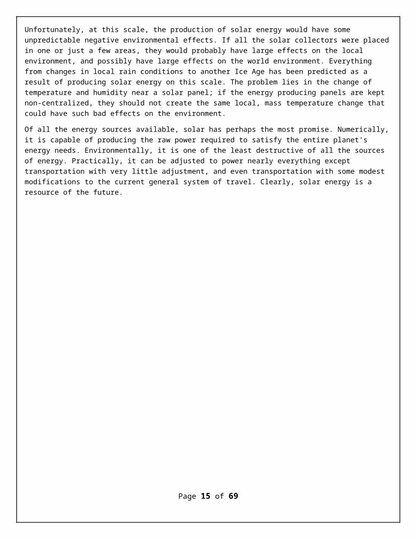
Unfortunately, at this scale, the production of solar energy would have some unpredictable negative environmental effects. If all the solar collectors were placedin one or just a few areas, they would probably have large effects on the local environment, and possibly have large effects on the world environment. Everything from changes in local rain conditions to another Ice Age has been predicted as a result of producing solar energy on this scale. The problem lies in the change of temperature and humidity near a solar panel; if the energy producing panels are kept non-centralized, they should not create the same local, mass temperature change that could have such bad effects on the environment.
Of all the energy sources available, solar has perhaps the most promise. Numerically,it is capable of producing the raw power required to satisfy the entire planet's energy needs. Environmentally, it is one of the least destructive of all the sources of energy. Practically, it can be adjusted to power nearly everything except transportation with very little adjustment, and even transportation with some modest modifications to the current general system of travel. Clearly, solar energy is a resource of the future.
Page 15 of 69
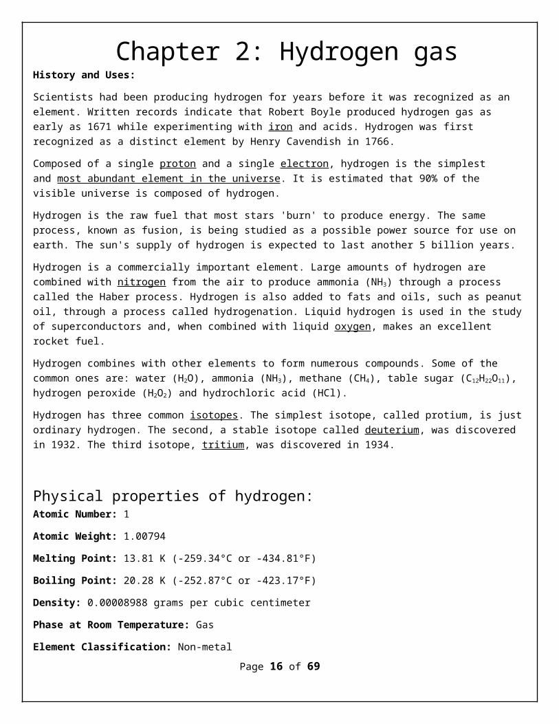
Chapter 2: Hydrogen gasHistory and Uses:
Scientists had been producing hydrogen for years before it was recognized as an element. Written records indicate that Robert Boyle produced hydrogen gas as early as 1671 while experimenting with iron and acids. Hydrogen was first recognized as a distinct element by Henry Cavendish in 1766.
Composed of a single proton and a single electron, hydrogen is the simplest and most abundant element in the universe. It is estimated that 90% of the visible universe is composed of hydrogen.
Hydrogen is the raw fuel that most stars 'burn' to produce energy. The same process, known as fusion, is being studied as a possible power source for use on earth. The sun's supply of hydrogen is expected to last another 5 billion years.
Hydrogen is a commercially important element. Large amounts of hydrogen are combined with nitrogen from the air to produce ammonia (NH3) through a process called the Haber process. Hydrogen is also added to fats and oils, such as peanutoil, through a process called hydrogenation. Liquid hydrogen is used in the studyof superconductors and, when combined with liquid oxygen, makes an excellent rocket fuel.
Hydrogen combines with other elements to form numerous compounds. Some of the common ones are: water (H2O), ammonia (NH3), methane (CH4), table sugar (C12H22O11), hydrogen peroxide (H2O2) and hydrochloric acid (HCl).
Hydrogen has three common isotopes. The simplest isotope, called protium, is justordinary hydrogen. The second, a stable isotope called deuterium, was discovered in 1932. The third isotope, tritium, was discovered in 1934.
Physical properties of hydrogen:Atomic Number: 1
Atomic Weight: 1.00794
Melting Point: 13.81 K (-259.34°C or -434.81°F)
Boiling Point: 20.28 K (-252.87°C or -423.17°F)
Density: 0.00008988 grams per cubic centimeter
Phase at Room Temperature: Gas
Element Classification: Non-metalPage 16 of 69

Period Number: 1 Group Number: 1 Group Name: none
What's in a name? From the Greek words hydro and genes, which together mean "water forming."
Estimated Crustal Abundance: 1.40×10³ milligrams per kilogram
Estimated Oceanic Abundance: 1.08×10⁵ milligrams per liter
Number of Stable Isotopes: 2
Ionization Energy: 13.598 eV
Oxidation States: +1, -1
Page 17 of 69
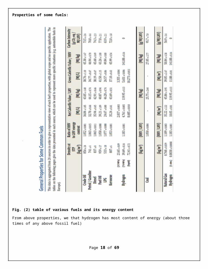
Properties of some fuels:
Fig. (2) table of various fuels and its energy content
From above properties, we that hydrogen has most content of energy (about three times of any above fossil fuel)
Page 18 of 69

Chapter 3: Generating HHO gastheory
Introduction:HHO Generators/Cells are being manufactured by a lot of companies that only know what theysee other companies doing; they copy. They have no clue as to why the cell makes as littleor as much HHO as it does. All they know is it pumps out HHO when the amps are increased. Most likely, you do not understand either. Not to worry, I will explain it for you as we go.
But, before I get into the topic, I should warn you; HHO companies make sales by boasting about Liter per Minute (LPM). They measure HHO with any kind of flow meter that will indicate higher LPM; it makes their product look better. To my knowledge, no one, using a flow meter, is measuring it accurate. Not even those that use Aliant Scientific Flow Meters, or Dwyer Hydroxyl Flow Meters. I take that back, Green fuel H2O is using an Alicatcorrectly; he even compares it with the water bottle test. It requires drying the gas before it enters the meter. With this in mind, I came up with a method of predicting the HHO output of a cell --- before you start the task of building it. The method is based on:
1. operating voltage2. current used3. number of plates4. size of plates: area of plates5. the number of cell stacks: works as no.of generators in series
My method is proven to be accurate when compared to measurements taken by timing how long it takes to fill a 1 liter bottle, and by green fuel H2O`s Alicat measurements. It works with Flat Plates and with Tubes. The plate arrangement can be Unipolar, Bipolar, or a combination of both. There is a Configurator is available to download Free, but first I think it would help you to know more about how it works.
I searched the web extensively looking for formulas that I could understand; formulas Icould work with; there's some complicated stuff out there. What I found, what I used, andthe way I used it came about by trial and error; lots of it. I did not get it right, untilI got the Cell Theory right. It was a learning process that I am about to share with you;for Free.
The Configurator will help you understand what variables affect HHO gas production. Youwill be able to size an efficient cell capable of producing the LPM you desire, and knowahead of time the amount of amperage needed to accomplish it. That means no more guessing.
Page 19 of 69
That will save you both time and money; and it is Free. My Serbian friend, Milos Panic waskind enough to contribute to the cause by converting my Microsoft Excel Configurator intoan Executable Windows Program.
Calculations are made in both inches and centimeters. Calculations can include actualdimensions of the assembled cell (if you want to pursue it); including the new SeparationCell design. Did I mention it is all free?
The theory:The following bullets are key points of my research and reasoning:
Faraday told us that 1.24 volts is the minimum voltage for electrolysis efficiency.... that is, with the least amount of energy lost to heat. That is, 1.24 volts of electrical pressure between 2 plates that make a water compartment. Higher voltage results in increased heat energy. Yule Brown used 1.48 volts and Bob Boyce uses 2.0 to 3.0 volts. Through trial and error, I have concluded that Faraday's 1.24 volts and Brown's 1.48 volts are impractical when using straight DC as a power source; it is because of the amount of electrolyte needed to lower the resistance ofthe water. 1.24 volts is very little electrical pressure; it requires a lot of electrolyte. That is a big factor. Voltage is the prime controller of heat and anything above 1.24 volts causes more of it. So if you need 24 hour operating time, 7 days a week, you had best configure for lower voltage across the plates. But wait;consider the following:
Electrolyte voltage I discovered that the electrolyte determines the minimum voltage needed for electrolysis to take place. Faraday's 1.24 volt minimum was based on the use of Battery Acid. I discovered that NaOH minimum voltage is 1.69, and KOH minimum voltage is 1.67. As it turns out, the electrolyte solution is affected by the voltage drop. Now I know why my 8, 9, 10, and 11 plate series cells would not produce much amperage --- when using a 12 to 14 volt DC power source.
Type of connections
The most efficient cell configuration has one Positive plate and one Negative plate, withNeutral plates between them; that is a Series Configuration. The same electrical currentpasses from the negative plate (-) to each neutral plate on its way to the positive plate.It looks something like this (- n n n n n n n n + ). The neutral plates cause voltagedrops between plates. It is that voltage drop that we need to create.... for efficiency.Simply counting all of the water spaces, regardless of the number of positive and negativeplates, will not cut it if there are multiple positive and or negatives. If the voltage
Page 20 of 69

drop in each cell (between positive and negative), does not add up to the value of theoperating supply voltage, then you are not doing correct measuring.
Series Parallel cells have multiple Series cell stacks in Parallel; sharing positives andor negatives (- n n n + n n n -). A Series Parallel Cell is actually 2 Series cells (- n nn +) and (+ n n n -). They cannot be calculated as 1 cell. The reason is, they are 2 cells(stacks). The cell voltage is cut in half, every time a neutral is added between + and -.No neutrals means full battery voltage or alternator voltage. One neutral cuts that inhalf. Two neutrals cuts it in half again; etc. etc. etc. My Configurator calculates theseas Stacks.
Parallel: If your cell has alternating positive and negative plates, you will neverachieve operating efficiency (+ - + - + - + - ). You will always have operating voltage supplied to each cell. That isabout as Brute as you can get. It will make a lot of gas and it will make a lot ofheat.... unless you add enough stacks to lower the amp flow..... Through each stack (astack is a set of + & - plates. Adding more sets will prolong the inevitable heat buildup.In addition, the amperage will eat up the positive plates faster than any otherconfiguration. Have you ever seen a Wire cell? Hello ! They make good water heaters. Youpour the amperage to them in order to get them to make gas. It does not take long for themto heat up and deteriorate. What Wire cells do best is create water vapor. It is thatwater vapor that is providing most of the fuel efficiency increase results. It has to be.Wire cells just do not make enough HHO to account for the benefit they provide. (ok Ozie,your secret is out).
Continuing on, we know that the cell plate voltage is obtained by dividing the Operating Voltage" supply by the number of cells in Series with it (isolated water compartments located between positive and negative electrodes). A 12 volt power source needs 10 water compartments in order to drop the voltage to 1.2 volts per cell. That cell configuration looks like this (+ n n n n n n n n n -). That is an 11 plate series cell. HHO is produced in each of the 12 water compartment at the rate of 10.44 MLPM for each ampere; says the late great “Michael Faraday”.
Maximum Current Density: Any electron flow produces heat; any. Our goal is to minimize the heat. We know that each square inch of a plate surface, on one side of a plate, efficiently passes 0.54 amps of electrical current (Current Density). For HHO purposes, we need to base our calculation on the surface area between the gasket; inside the gasket area. this is where amperage is going to flow from in order to cross the water. This is the area electron flow is going to be condensed into using. This is where the plate is going to get the hottest. Higher amperage, per square inch, increases HHO production, but also causes even more heat; the more amperage, the more heat (along with more HHO). There needs to be enough surface areainside the gasket area to handle the amperage you intend on using. This is a major factor in cell efficiency that is being overlooked or exaggerated. This is what
Page 21 of 69
plate size is all about. Plate size does not increase HHO production, it establishesa maximum efficient Current Density (maximum operating amperage). If enough surface area is not available to handle the amperage passing across a plate, electron flow will pile up at the nearest water crossing...and heat that area. Electrons need enough room to move freely across the plate, without getting piled up; you will findexcess heat where they pile up. Examples: as a wire get too hot because its thickness was too small
(Physics defines Current Density as: The number of subatomic particles per unit of time, crossing a unit area, in a designated plane, perpendicular to the direction ofmovement of the particles). I interpret that as "The number of Electrons, crossing an electrode surface, perpendicular to the direction of travel".
We also know that the amount of HHO gas produced is in direct proportion to the amount of power we use; Volts x Amps = Watts of Power. Thus, more surface area will increase he current density maximum (or optimal) operating amperage we are wanting to use. Surface area can be increased by increasing the size of the plates, but it does not increase gas production; number of plates accomplishes that without increasing amperage in a series arrangements of plates. faraday law:
We also know that Hydrogen and Oxygen are produced on opposing plates. Faraday tellsus Hydrogen is equal to Amps x 0.000246 CFM, and Oxygen is equal to Amps x 0.0001229CFM. That gives us an HHO total of0.0003689 CFM per Water Cell area. It needs to be converted to Liters Per Minute: “multiply by 28.3 to get Liters”
That is my theory of understanding efficient electrolysis of water.
Conclusionso, now we have come full circle. As experimenters, we started out with Brute Forcealternating positive and negative plates. Then we figured out that a series of Neutralplates lowered the heat and produced more gas. Then we figured out how to combine twoseries cells into one bigger cell, and how to maximize the efficiency and produce more gaswith less heat. All along the way, the ratio of gas increased while the water vapordecreased. We did this because the experts warned us to keep the water vapor out of theengine. It is bad for the engine. It will rust the engine. It will rust the injectors.Your engine was designed to handle the vapor. Hydrocarbon fuels are made up of Hydrogenand Carbon (mostly). When Hydrogen mixes with Oxygen in the combustion chamber..... The byproduct is Water. Did you catch that? Burning Gasoline and Diesel produces a by-product ofwater - in the combustion chambers.
In closing, I offer one suggestion. If you want to make HHO and or water vapor, start witha safe container; one that can take the Heat.
Page 22 of 69

1. 7 plates seems to be the best hho producer, with the best efficiency, when using 12 to 15 volts DC. Tests with 8 or more plates increases the resistance of the water somuch that very large amounts of electrolyte are needed to get electrolysis started.
2. The purpose of the calculator is to establish the number of plates needed for a particular operating voltage, and to establish the operating amperage for the squareinch surface area of those plates. I think this will help experimenters understand what efficiency is ... and how to build around it.
3. The configurator now calculates the size and depth of Separation Cells. It provides the number of additional gaskets that will be needed. Basically, it is one more per water area; and of course your membranes.
4. Feb. 10th, added Tube Cells to the configurator. Once I understood the relationship between Amperage and Number of Water Cells, Tubes were easy to configure. It was a learning process.
HHO generators models:Hopefully, the information on this page will help you understand how using Neutral Plates can improve the operating efficiency of your HHO Generators; including Separation Generators. Without neutrals, your voltage supply is appliedto each set of plates. If using 12 V_DC, each set of plates operates off of 12 V_DC. The problem is, the voltage is too high for efficiency. It causes excess heat; which in turn increases amperage; which causes more heat; which increases amperage until it boils the water out of your cell. Using multiple sets of these plates will slow down thermal runaway, but efficiency cannot hold a candle to Series configurations using neutral plates. A combination of Unipolar and Bipolarconfigurations comes close, but at an expense. In the long run, it is better to build a 7 plate series configuration if you are using 12 V_DC powering systems.
7 Plate Series Cell + n n n n n -
Construction consists of 1 positive plate, 5 neutral plates, and 1 negative plate. The cell is capable of producing 1 Liter per Minute using 16 amps. If you want to operate this cell continuously, without it overheating, the Active Plate Surface needs to be a minimum of 5.5 inches x 5.5 inches
6 Plate Series Cell + n n n n -
Construction consists of 1 positive plate, 4 neutral plates, and 1 negative plate. The cell is capable of producing 1 Liter per Minute using 19.2 amps. If you want to operate this cell continuously, without it overheating, the Active Plate Surface needs to be a minimum of 6 inches x 6 inches
Page 23 of 69
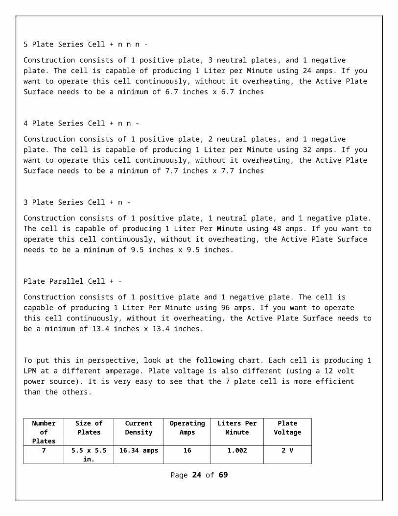
5 Plate Series Cell + n n n -
Construction consists of 1 positive plate, 3 neutral plates, and 1 negative plate. The cell is capable of producing 1 Liter per Minute using 24 amps. If you want to operate this cell continuously, without it overheating, the Active Plate Surface needs to be a minimum of 6.7 inches x 6.7 inches
4 Plate Series Cell + n n -
Construction consists of 1 positive plate, 2 neutral plates, and 1 negative plate. The cell is capable of producing 1 Liter per Minute using 32 amps. If you want to operate this cell continuously, without it overheating, the Active Plate Surface needs to be a minimum of 7.7 inches x 7.7 inches
3 Plate Series Cell + n -
Construction consists of 1 positive plate, 1 neutral plate, and 1 negative plate.The cell is capable of producing 1 Liter Per Minute using 48 amps. If you want tooperate this cell continuously, without it overheating, the Active Plate Surface needs to be a minimum of 9.5 inches x 9.5 inches.
Plate Parallel Cell + -
Construction consists of 1 positive plate and 1 negative plate. The cell is capable of producing 1 Liter Per Minute using 96 amps. If you want to operate this cell continuously, without it overheating, the Active Plate Surface needs tobe a minimum of 13.4 inches x 13.4 inches.
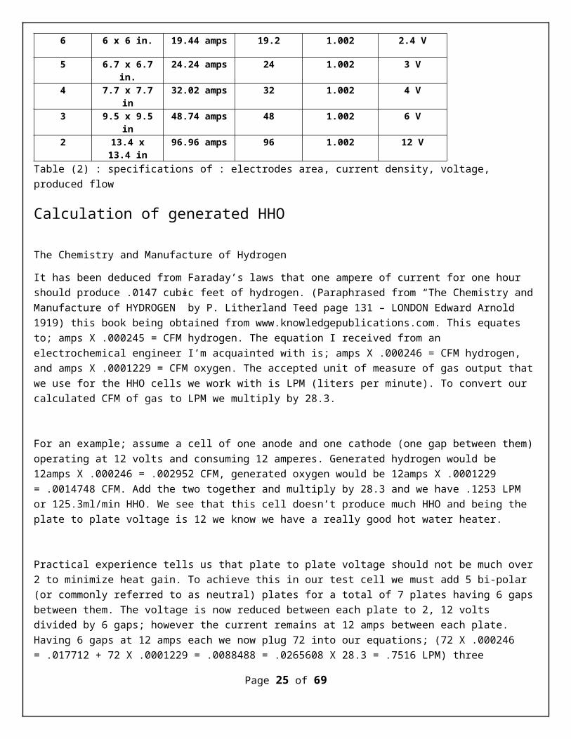
To put this in perspective, look at the following chart. Each cell is producing 1LPM at a different amperage. Plate voltage is also different (using a 12 volt power source). It is very easy to see that the 7 plate cell is more efficient than the others.
Numberof
Plates
Size ofPlates
CurrentDensity
OperatingAmps
Liters PerMinute
PlateVoltage
7 5.5 x 5.5in.
16.34 amps 16 1.002 2 V
Page 24 of 69
6 6 x 6 in. 19.44 amps 19.2 1.002 2.4 V
5 6.7 x 6.7in.
24.24 amps 24 1.002 3 V
4 7.7 x 7.7in
32.02 amps 32 1.002 4 V
3 9.5 x 9.5in
48.74 amps 48 1.002 6 V
2 13.4 x13.4 in
96.96 amps 96 1.002 12 V
Table (2) : specifications of : electrodes area, current density, voltage, produced flow
Calculation of generated HHO
The Chemistry and Manufacture of Hydrogen
It has been deduced from Faraday’s laws that one ampere of current for one hour should produce .0147 cubic feet of hydrogen. (Paraphrased from “The Chemistry andManufacture of HYDROGEN” by P. Litherland Teed page 131 – LONDON Edward Arnold 1919) this book being obtained from www.knowledgepublications.com. This equates to; amps X .000245 = CFM hydrogen. The equation I received from an electrochemical engineer I’m acquainted with is; amps X .000246 = CFM hydrogen, and amps X .0001229 = CFM oxygen. The accepted unit of measure of gas output thatwe use for the HHO cells we work with is LPM (liters per minute). To convert our calculated CFM of gas to LPM we multiply by 28.3.
For an example; assume a cell of one anode and one cathode (one gap between them)operating at 12 volts and consuming 12 amperes. Generated hydrogen would be 12amps X .000246 = .002952 CFM, generated oxygen would be 12amps X .0001229 = .0014748 CFM. Add the two together and multiply by 28.3 and we have .1253 LPM or 125.3ml/min HHO. We see that this cell doesn’t produce much HHO and being the plate to plate voltage is 12 we know we have a really good hot water heater.
Practical experience tells us that plate to plate voltage should not be much over2 to minimize heat gain. To achieve this in our test cell we must add 5 bi-polar (or commonly referred to as neutral) plates for a total of 7 plates having 6 gapsbetween them. The voltage is now reduced between each plate to 2, 12 volts divided by 6 gaps; however the current remains at 12 amps between each plate. Having 6 gaps at 12 amps each we now plug 72 into our equations; (72 X .000246 = .017712 + 72 X .0001229 = .0088488 = .0265608 X 28.3 = .7516 LPM) three
Page 25 of 69

quarters of a liter at 12 amps, not bad and very little heat gain. We can increase our gas volume, along with current consumption, without additional heat gain, by connecting two or more of our seven plate cells electrically in parallel.
When I first came upon these equations I wondered how close they were to the realworld. Through empirical testing on the calibrated flow bench, of several different cells, I found that these equations are accurate. Some cells getting closer to calculated output than others, none getting more, due most likely to efficiencies of design.
There are many parameters involved when designing a cell; gas quantity desired, sustained current available, and space required for mounting are primary concerns. We now see how we can calculate gas volume using available current. When designing for space requirements we need to consider how much current will be passing each plate. Heat generation results from a combination of voltage and current. We have seen that voltage can be controlled by the number of plates we use in each cell. We can control current via external means by using a pulse width modulator; there are some very good ones available. However, in the design process of our cell, by juggling the amount of parallel cells, the current to be used and the size of the plates, we are able to get a pretty good handle on the heat gain we will experience. An important consideration is current density on each plate in the cell. A good rule of thumb is to try to achieve a current density of .5 amps per square inch or less.
In our test example above running at 12 amps, in order to achieve our .5 amps /sq. inch, since we have 12 amps flowing through each plate, we’ll need plates equaling 24 sq. inch each. Possibly 3 X 8 inches or maybe 4 X 6 inches. If we have room and can make the plates larger, all the better, it will lower the current density and or allow for the use of more current thus producing more gas.
As we have seen, we are able to closely calculate the expected HHO output of celldesigns, albeit there are many factors to consider when starting with a clean sheet of paper.
Physics defines Current Density. The number of subatomic particles per unit time crossing a unit area in a designated plane perpendicular to the direction of movement of the particles.
Page 26 of 69
Chapter 4: Pre-experimentcalculations
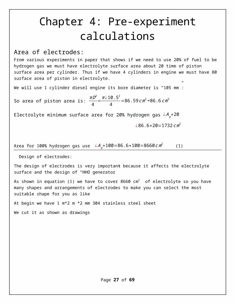
Area of electrodes: From various experiments in paper that shows if we need to use 20% of fuel to be hydrogen gas we must have electrolyte surface area about 20 time of piston surface area per cylinder. Thus if we have 4 cylinders in engine we must have 80 surface area of piston in electrolyte.
We will use 1 cylinder diesel engine its bore diameter is “105 mm”:
So area of piston area is: πD2
4=π ¿10.52
4=86.59cm2≃86.6cm2
Electrolyte minimum surface area for 20% hydrogen gas ¿Ap∗20
¿86.6∗20=1732cm2
Area for 100% hydrogen gas use ¿Ap∗100=86.6∗100=8660cm2 (1)
Design of electrodes:
The design of electrodes is very important because it affects the electrolyte surface and the design of “HHO generator”
As shown in equation (1) we have to cover 8660 cm2 of electrolyte so you have many shapes and arrangements of electrodes to make you can select the most suitable shape for you as like
At begin we have 1 m*2 m *2 mm 304 stainless steel sheet
We cut it as shown as drawings
Page 27 of 69
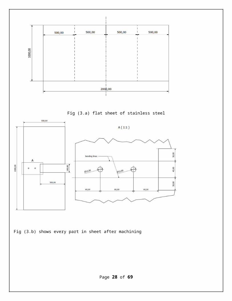
Fig (3.a) flat sheet of stainless steel
Fig (3.b) shows every part in sheet after machining
Page 28 of 69
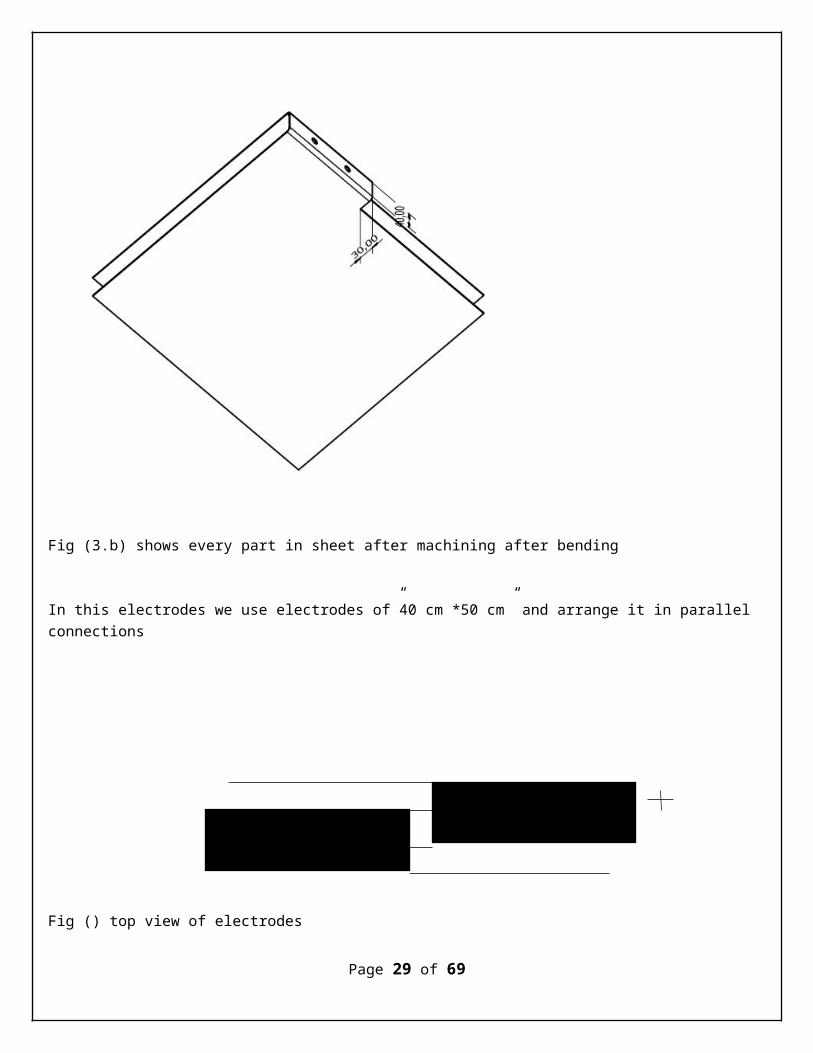
Fig (3.b) shows every part in sheet after machining after bending
In this electrodes we use electrodes of”40 cm *50 cm” and arrange it in parallel connections
__
Fig () top view of electrodes
Page 29 of 69
This arrangement offers us 5 surfaces of electrolyte each have “50*40=2000 cm2”
We have now “10000 cm2” area of electrolyte and it is very enough to generate hydrogen for full use.
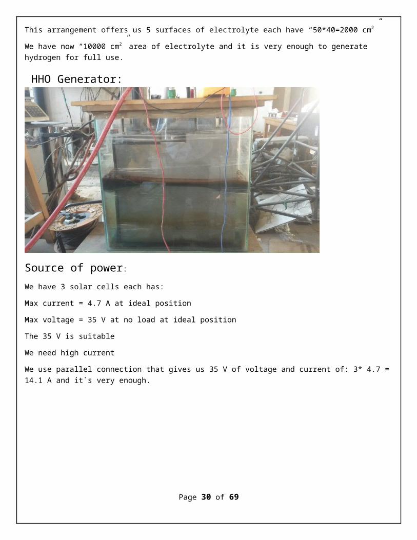
HHO Generator:
Source of power:We have 3 solar cells each has:
Max current = 4.7 A at ideal position
Max voltage = 35 V at no load at ideal position
The 35 V is suitable
We need high current
We use parallel connection that gives us 35 V of voltage and current of: 3* 4.7 =14.1 A and it`s very enough.
Page 30 of 69
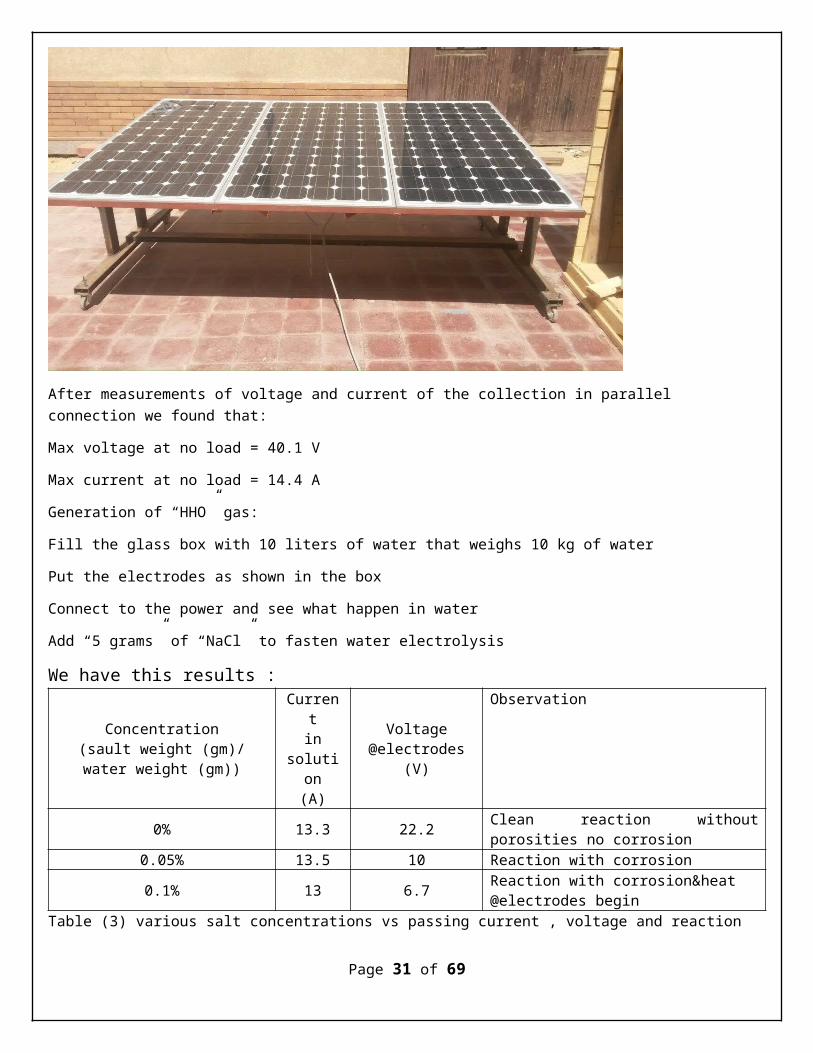
After measurements of voltage and current of the collection in parallel connection we found that:
Max voltage at no load = 40.1 V
Max current at no load = 14.4 A
Generation of “HHO” gas:
Fill the glass box with 10 liters of water that weighs 10 kg of water
Put the electrodes as shown in the box
Connect to the power and see what happen in water
Add “5 grams” of “NaCl” to fasten water electrolysis
We have this results :
Concentration(sault weight (gm)/water weight (gm))
Currentin
solution(A)
Voltage@electrodes
(V)
Observation
0% 13.3 22.2 Clean reaction withoutporosities no corrosion
0.05% 13.5 10 Reaction with corrosion
0.1% 13 6.7 Reaction with corrosion&heat @electrodes begin
Table (3) various salt concentrations vs passing current , voltage and reaction
Page 31 of 69

Thus, form above readings I won`t use more than 0.05% concentration of (NaCl) salt
Page 32 of 69
Chapter 5: Modification on engineFor a proposed ratio of fuel (diesel-hydrogen) to hydrogen fuel, we must do somemodifications for the engine to suit the engine operation conditions. We need todesign suitable Venturi dimensions to meet the requirements of mixing fuels
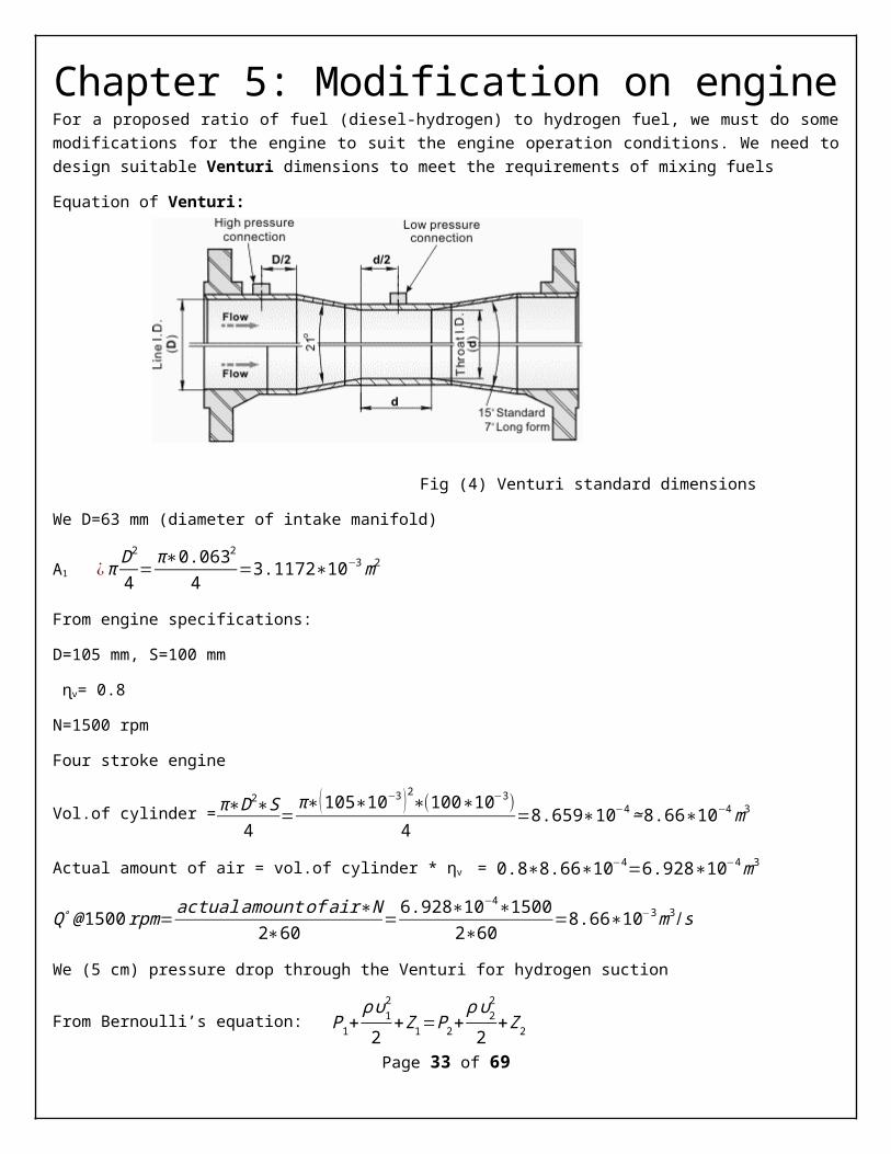
Equation of Venturi:
Fig (4) Venturi standard dimensions
We D=63 mm (diameter of intake manifold)
A1 ¿π D2
4 =π∗0.0632
4 =3.1172∗10−3m2
From engine specifications:
D=105 mm, S=100 mm
ɳv= 0.8
N=1500 rpm
Four stroke engine
Vol.of cylinder =π∗D2∗S4
=π∗(105∗10−3 )2∗(100∗10−3)
4=8.659∗10−4≃8.66∗10−4m3
Actual amount of air = vol.of cylinder * ηv = 0.8∗8.66∗10−4=6.928∗10−4m3
Q∘@1500rpm=actualamountofair∗N
2∗60=6.928∗10−4∗1500
2∗60=8.66∗10−3m3/s
We (5 cm) pressure drop through the Venturi for hydrogen suction
From Bernoulli’s equation: P1+ρυ1
2
2+Ζ1=P2+
ρυ22
2+Ζ2
Page 33 of 69
Though because of the venture is in horizontal plan Ζ1= Ζ2
Thus the equation becomes:
P1+ρυ1
2
2=P2+
ρυ22
2
v1=Q∘
A1=
8.66∗10−3
3.1172∗10−3=2.778m /s
υ22=
2∗(P1−P2)ρair
+υ12
Q∘= 8.66∗10−3 m3
s A1=3.1172∗10−3m2
ΔP=5cm water
ρair=1.1588kgm3
υ22=2∗(0.05∗9.81∗10000)
1.1588+2.7782
v2=29.2281m /s
υ22=854.2827m2/s2
A2=Q∘
v2=8.66810−3
29.2281=2.9629∗10−4m /s
d2=√4∗2.9692∗10−4
πd2=√4∗A2
π=0.01944m=19.4mm
Length of Venturi:
From standards
l1 : Entrance distance = 0.25D−0.75Dtake it 0.5D=0.5∗63=31.5mm
l2: convergent distance = D−d
2tan (θ)=
63−202tan(11)
=110.6mm
l3 : Throat distance = d=20mm
Page 34 of 69

l4: Diverging distance = D−d
2tan (θ)= 63−202tan(7)
=175.1mm
l5: Exit distance = 0.25D-0.5D take it 0.5D=0.5∗63=31.5mm
Overall length ¿l1+l2+l3+l4+l5=31.5+11.6+20+175.1+31.5=269.7mm
Page 35 of 69

Page 36 of 69

Chapter 6: The experimentWe first measure the mass flow rate of fuel with diesel only @ different loads and then repeat it with HHO&diesel @ different loads to avoid residual HHO gas ingenerator and hose from entering the engine when measure performance with diesel only
We have the components:
The engine-generator: it have the following specifications :
Max.Power: 5.7 Kw @1500rpm
FIL: 511
Page 37 of 69
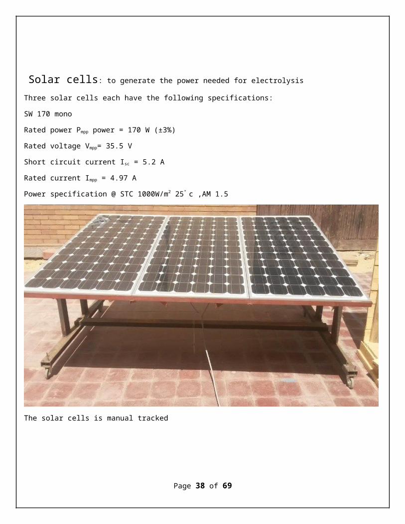
Solar cells: to generate the power needed for electrolysisThree solar cells each have the following specifications:
SW 170 mono
Rated power Pmpp power = 170 W (±3%)
Rated voltage Vmpp= 35.5 V
Short circuit current Isc = 5.2 A
Rated current Impp = 4.97 A
Power specification @ STC 1000W/m2 25° c ,AM 1.5
The solar cells is manual tracked
Page 38 of 69
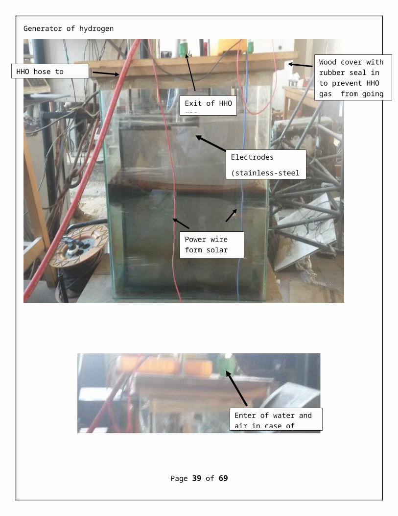
Generator of hydrogen
Page 39 of 69
HHO hose to
Exit of HHOgas
Wood cover withrubber seal in to prevent HHO gas from going
Power wire form solar cells
Electrodes
(stainless-steel
Enter of water and air in case of

Fig (5) HHO generator compenets
Page 40 of 69
Page 41 of 69
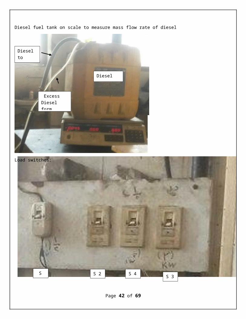
Diesel fuel tank on scale to measure mass flow rate of diesel
Load switches:
Page 42 of 69
Diesel to engine
Excess Diesel form
Diesel tank
S 1 S 3S 4S 2
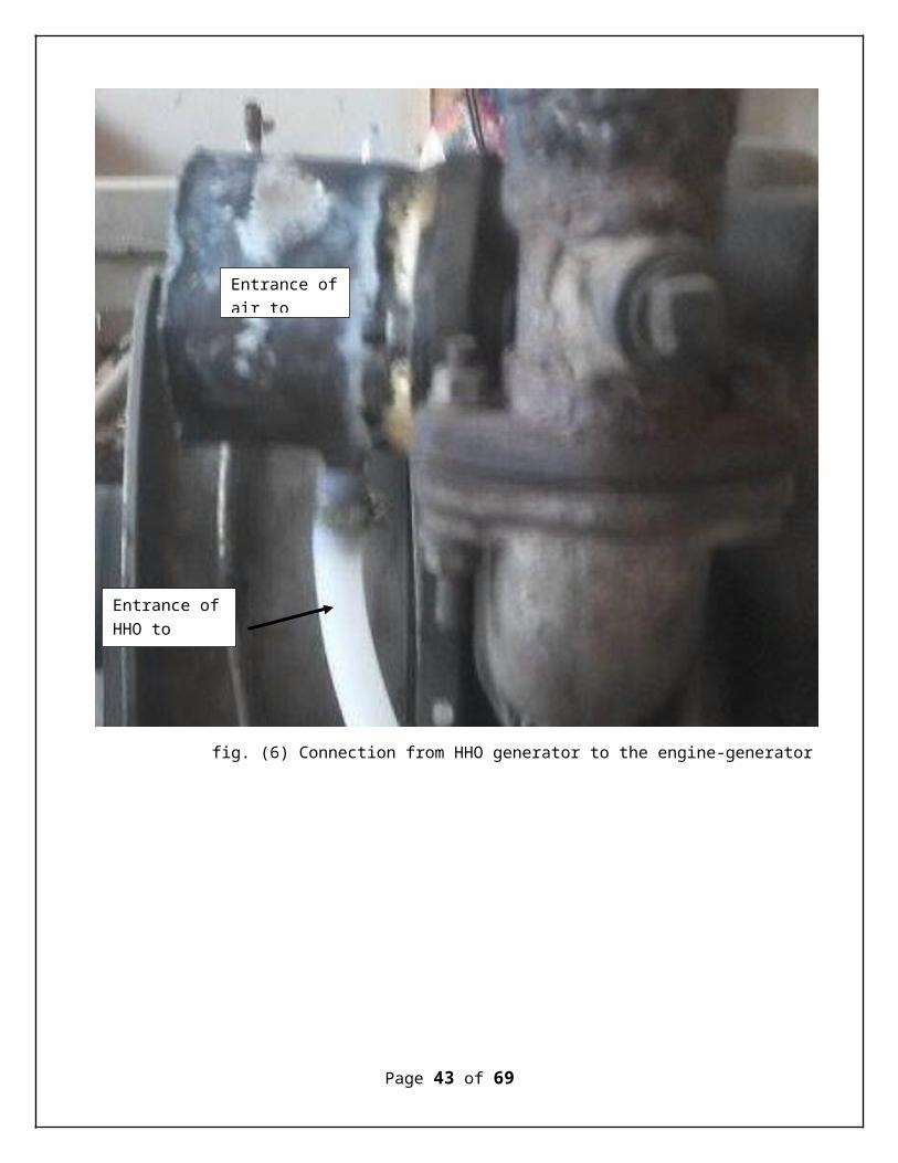
fig. (6) Connection from HHO generator to the engine-generator
Page 43 of 69
Entrance ofair to
Entrance ofHHO to engine

Experiment procedureFirst I made the experiment with “diesel” only @ various loads, then I repeated it with “diesel & HHO” with the operated loads before
A. Experiment with diesel only:1. Turn on the engine 2. Switch on all loads (s 2,3,4)3. Adjust the velocity of engine @ 1500 rpm (50 Hz)4. Measure the output voltage and current of the generator 5. Measure the time of consumption of 100 gm diesel6. Reduce loads (switch off one of loads) part load 60%7. Repeat the steps from 3 to 5 8. Reduce loads (switch off one of loads) part load 30%9. Repeat the steps from 3 to 5 10. Reduce loads (switch off one of loads) no load 0%11. Repeat the steps from 3 to 512. Write down all previous readings in table as shown in page()
B. Experiment with diesel &HHO:1. Fill the HHO generator pool with 35 liter water (35 kg water)2. Put 20 gm of NaCl in the water not more (0.05% of weight concentration) to
avoid heat in wires this isn’t preferred 3. Spool well the mixture 4. Put the electrodes ( stainless steel plates “304” )5. Cover the HHO generator with the sealed cover ensure no leakage will happen 6. Tie the hoses of water entrance and HHO exit and not to tie the other end of
HHO gas hose to engine generator7. Adjust solar panels to perfect position at good time and measure the output
voltage and current from them8. Take the power form solar panels in some good cable and tie them to
electrodes 9. Put the generator on weight scale to measure HHO flow from generator 10. Wait for reaction to be stable11. Tie the hose from the HHO generator to the engine to supply HHO in
engine-generator12. Turn on the engine 13. Switch on all loads (s 2,3,4)14. Adjust the velocity of engine @ 1500 rpm (50 Hz)15. Measure the output voltage and current of the generator 16. Measure the time of consumption of 100 gm diesel
Page 44 of 69
17. Reduce loads (switch off one of loads) part load 60%18. Repeat the steps from 3 to 5 19. Reduce loads (switch off one of loads) part load 30%20. Repeat the steps from 3 to 5 21. Reduce loads (switch off one of loads) no load 0%22. Repeat the steps from 3 to 523. Write down all previous readings in table as shown in page ()C. Make calculation on previous reading and draw curves for performance with
different loads
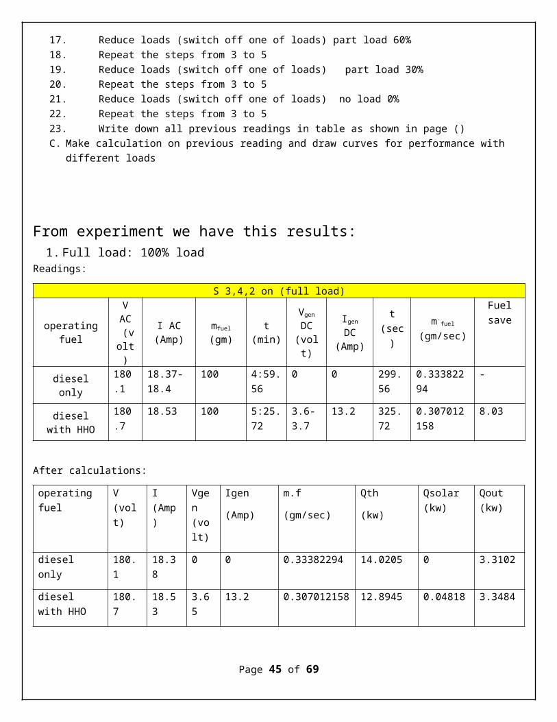
From experiment we have this results:1. Full load: 100% load
Readings:
S 3,4,2 on (full load)
operatingfuel
VAC (volt)
I AC(Amp)
mfuel
(gm)t
(min)
Vgen
DC(volt)
Igen
DC(Amp)
t(sec)
m.fuel
(gm/sec)
Fuelsave
dieselonly
180.1
18.37-18.4
100 4:59.56
0 0 299.56
0.33382294
-
dieselwith HHO
180.7
18.53 100 5:25.72
3.6-3.7
13.2 325.72
0.307012158
8.03
After calculations:
operating fuel
V (volt)
I (Amp)
Vgen (volt)
Igen
(Amp)
m.f
(gm/sec)
Qth
(kw)
Qsolar (kw)
Qout (kw)
diesel only
180.1
18.38
0 0 0.33382294 14.0205 0 3.3102
diesel with HHO
180.7
18.53
3.65
13.2 0.307012158 12.8945 0.04818 3.3484
Page 45 of 69
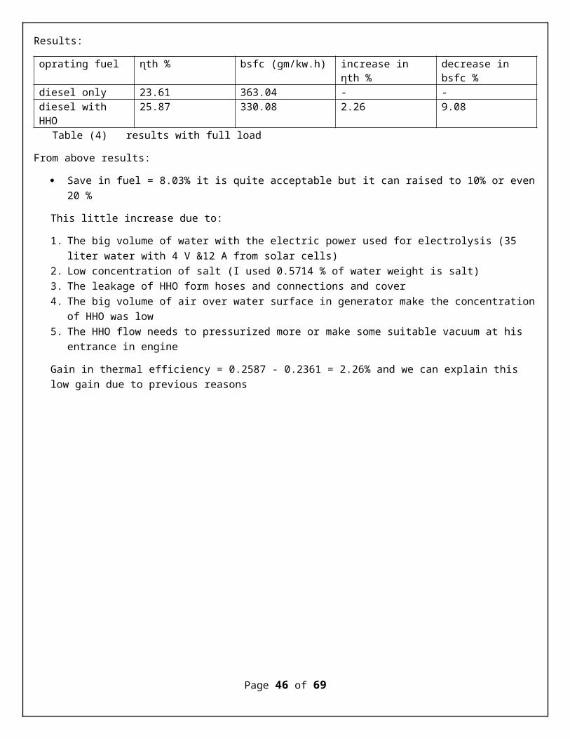
Results:
oprating fuel ɳth % bsfc (gm/kw.h) increase in ηth %
decrease in bsfc %
diesel only 23.61 363.04 - -diesel with HHO
25.87 330.08 2.26 9.08
Table (4) results with full load
From above results:
Save in fuel = 8.03% it is quite acceptable but it can raised to 10% or even20 %
This little increase due to:
1. The big volume of water with the electric power used for electrolysis (35 liter water with 4 V &12 A from solar cells)
2. Low concentration of salt (I used 0.5714 % of water weight is salt)3. The leakage of HHO form hoses and connections and cover 4. The big volume of air over water surface in generator make the concentration
of HHO was low 5. The HHO flow needs to pressurized more or make some suitable vacuum at his
entrance in engine
Gain in thermal efficiency = 0.2587 - 0.2361 = 2.26% and we can explain this low gain due to previous reasons
Page 46 of 69
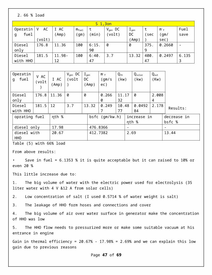
2. 66 % load
S 1,3onOperating fuel
V AC (volt)
I AC (Amp)
mfuel
(gm)t (min)
Vgen DC (volt)
Igen DC(Amp)
t (sec)
m.f
(gm/sec)
Fuel save
Diesel only
176.8 11.36 100 6:15.90
0 0 375.9
0.2660 -
Diesel with HHO
181.5 11.98-12
100 6:40.47
3.7 13.32 400.47
0.2497 6.1353
Results:
oprating fuel ɳth % bsfc (gm/kw.h) increase in ηth %
decrease in bsfc %
diesel only 17.98 476.8366 - -diesel with HHO
20.67 412.7382 2.69 13.44
Table (5) with 66% load
From above results:
• Save in fuel = 6.1353 % it is quite acceptable but it can raised to 10% or even 20 %
This little increase due to:
1. The big volume of water with the electric power used for electrolysis (35 liter water with 4 V &12 A from solar cells)
2. Low concentration of salt (I used 0.5714 % of water weight is salt)
3. The leakage of HHO form hoses and connections and cover
4. The big volume of air over water surface in generator make the concentrationof HHO was low
5. The HHO flow needs to pressurized more or make some suitable vacuum at his entrance in engine
Gain in thermal efficiency = 20.67% - 17.98% = 2.69% and we can explain this low gain due to previous reasons
Page 47 of 69
Operating fuel V AC
(volt)
I AC(Amp)
Vgen DC(volt)
Igen DC(Amp)
m.f
(gm/sec)
Qth (kw)
Qsolar
(kw)Qout (Kw)
Diesel only
176.8 11.36 0 0 0.2660
11.1732
0 2.0084
Diesel with HHO
181.5 12 3.7 13.32 0.2497
10.4877
0.049284
2.178

Page 48 of 69
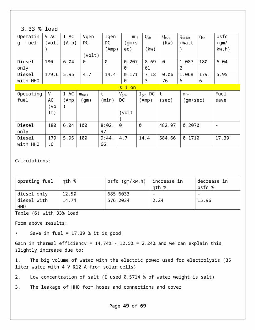
3. 33 % load Operating fuel
V AC(volt)
I AC(Amp)
Vgen DC (volt)
Igen DC(Amp)
m.f
(gm/sec)
Qth
(kw)
Qout
(Kw)Qsolar (watt)
ηth bsfc(gm/kw.h)
Diesel only
180 6.04 0 0 0.2070
8.6961
0 1.0872
180 6.04
Diesel with HHO
179.6 5.95 4.7 14.4 0.1710
7.183
0.0676
1.0686
179.6
5.95
s 1 onOperatingfuel
V AC(volt)
I AC(Amp)
mfuel
(gm)t (min)
Vgen DC (volt)
Igen DC(Amp)
t (sec)
m.f
(gm/sec)Fuel save
Diesel only
180 6.04 100 8:02.97
0 0 482.97 0.2070 -
Diesel with HHO
179.6
5.95 100 9:44.66
4.7 14.4 584.66 0.1710 17.39
Calculations:
oprating fuel ɳth % bsfc (gm/kw.h) increase in ηth %
decrease in bsfc %
diesel only 12.50 685.6033 - -diesel with HHO
14.74 576.2034 2.24 15.96
Table (6) with 33% load
From above results:
• Save in fuel = 17.39 % it is good
Gain in thermal efficiency = 14.74% - 12.5% = 2.24% and we can explain this slightly increase due to:
1. The big volume of water with the electric power used for electrolysis (35 liter water with 4 V &12 A from solar cells)
2. Low concentration of salt (I used 0.5714 % of water weight is salt)
3. The leakage of HHO form hoses and connections and cover
Page 49 of 69

4. The big volume of air over water surface in generator make the concentrationof HHO was low
5. The HHO flow needs to pressurized more or make some suitable vacuum at his entrance in engine
Page 50 of 69
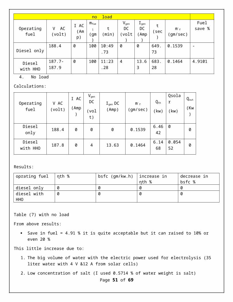
no load
Operatingfuel
V AC(volt)
I AC (Amp)
mfue
l (gm)
t(min)
Vgen
DC(volt)
Igen
DC(Amp)
t(sec)
m.f
(gm/sec)
Fuelsave %
Diesel only 188.4 0 100 10:49
.730 0 649.
730.1539 -
Dieselwith HHO
187.7-187.9
0 100 11:23.28
4 13.63
683.28
0.1464 4.9101
4. No load
Calculations:
Operatingfuel
V AC(volt)
I AC
(Amp)
Vgen
DC
(volt)
Igen DC(Amp)
m.f
(gm/sec)Qth
(kw)
Qsolar
(kw)
Qout
(Kw)
Dieselonly 188.4 0 0 0 0.1539 6.46
420 0
Dieselwith HHO 187.8 0 4 13.63 0.1464 6.14
680.05452 0
Results:
oprating fuel ɳth % bsfc (gm/kw.h) increase in ηth %
decrease in bsfc %
diesel only 0 0 0 0diesel with HHO
0 0 0 0
Table (7) with no load
From above results:
Save in fuel = 4.91 % it is quite acceptable but it can raised to 10% or even 20 %
This little increase due to:
1. The big volume of water with the electric power used for electrolysis (35 liter water with 4 V &12 A from solar cells)
2. Low concentration of salt (I used 0.5714 % of water weight is salt)Page 51 of 69

3. The leakage of HHO form hoses and connections and cover
4. The big volume of air over water surface in generator make the concentrationof HHO was low
5. The HHO flow needs to pressurized more or make some suitable vacuum at his entrance in engine
Page 52 of 69
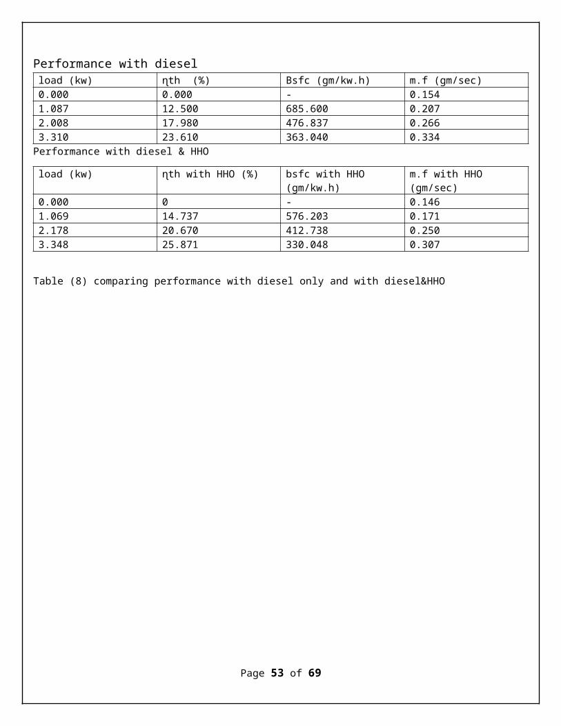
Performance with diesel load (kw) ɳth (%) Bsfc (gm/kw.h) m.f (gm/sec)0.000 0.000 - 0.1541.087 12.500 685.600 0.2072.008 17.980 476.837 0.2663.310 23.610 363.040 0.334Performance with diesel & HHO
load (kw) ɳth with HHO (%) bsfc with HHO (gm/kw.h)
m.f with HHO (gm/sec)
0.000 0 - 0.1461.069 14.737 576.203 0.1712.178 20.670 412.738 0.2503.348 25.871 330.048 0.307
Table (8) comparing performance with diesel only and with diesel&HHO
Page 53 of 69
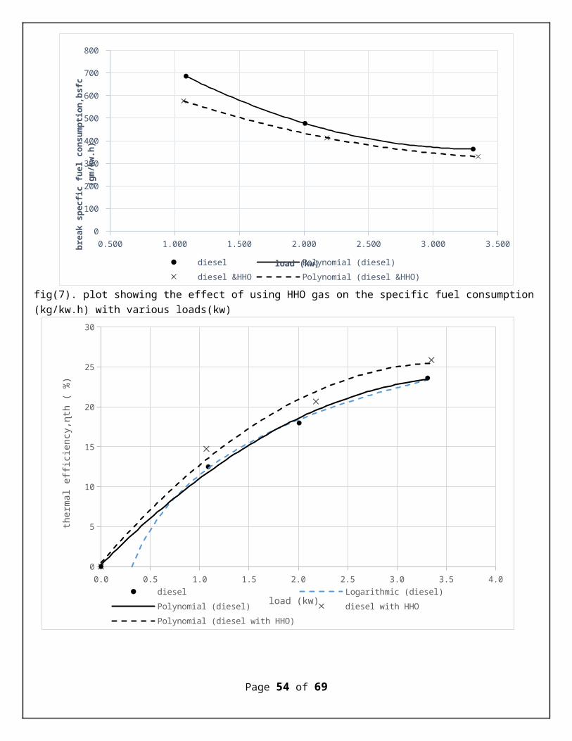
fig(7). plot showing the effect of using HHO gas on the specific fuel consumption(kg/kw.h) with various loads(kw)
Page 54 of 69
0.0 0.5 1.0 1.5 2.0 2.5 3.0 3.5 4.00
5
10
15
20
25
30
diesel Logarithmic (diesel)Polynomial (diesel) diesel with HHOPolynomial (diesel with HHO)
load (kw)
therma
l efficiency,ɳth ( %)
0.500 1.000 1.500 2.000 2.500 3.000 3.5000
100
200
300
400
500
600
700
800
diesel Polynomial (diesel)diesel &HHO Polynomial (diesel &HHO)
load (kw)
break specfic fuel consumption,bsfc
(gm/kw.h)

fig(8). plot showing the effect of using HHO gas on the thermal efficiency (ɳth%) with various loads(kw)
Page 55 of 69
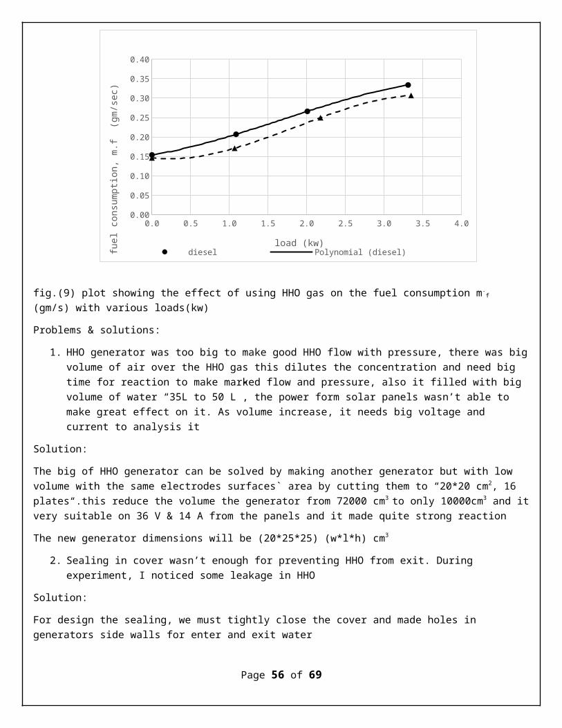
fig.(9) plot showing the effect of using HHO gas on the fuel consumption m.f
(gm/s) with various loads(kw)
Problems & solutions:
1. HHO generator was too big to make good HHO flow with pressure, there was bigvolume of air over the HHO gas this dilutes the concentration and need big time for reaction to make marked flow and pressure, also it filled with big volume of water “35L to 50 L”, the power form solar panels wasn’t able to make great effect on it. As volume increase, it needs big voltage and current to analysis it
Solution:
The big of HHO generator can be solved by making another generator but with low volume with the same electrodes surfaces` area by cutting them to “20*20 cm2, 16 plates“.this reduce the volume the generator from 72000 cm3 to only 10000cm3 and itvery suitable on 36 V & 14 A from the panels and it made quite strong reaction
The new generator dimensions will be (20*25*25) (w*l*h) cm3
2. Sealing in cover wasn’t enough for preventing HHO from exit. During experiment, I noticed some leakage in HHO
Solution:
For design the sealing, we must tightly close the cover and made holes in generators side walls for enter and exit water
Page 56 of 69
0.0 0.5 1.0 1.5 2.0 2.5 3.0 3.5 4.00.00
0.05
0.10
0.15
0.20
0.25
0.30
0.35
0.40
diesel Polynomial (diesel)load (kw)
fuel
con
sumpti
on,
m.f
(gm
/sec)

And make another hole in top face to make the exit of HHO gas these holes are easy sealed by silicon
3. The suction of HHO wasn`t enough to take large amount of HHO, and form venture calculations I found its length is 35 cm and above and it is very difficult to work in operational conditions due to vibration of the engine-generator.
Solution:
We have to make HHO flow with high pressure instead of sucking it
Page 57 of 69
Chapter 7: New methods ofhydrogen generation
Scientist searches carefully for other methods to produce hydrogen efficiently there are many ways for producing hydrogen gas
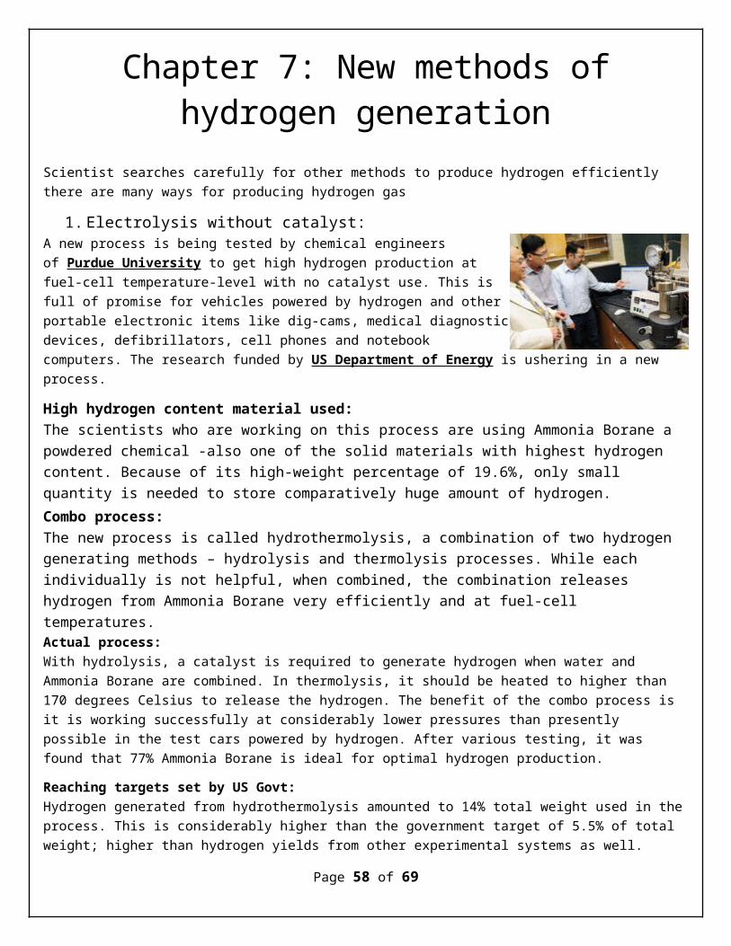
1. Electrolysis without catalyst:A new process is being tested by chemical engineersof Purdue University to get high hydrogen production atfuel-cell temperature-level with no catalyst use. This isfull of promise for vehicles powered by hydrogen and otherportable electronic items like dig-cams, medical diagnosticdevices, defibrillators, cell phones and notebookcomputers. The research funded by US Department of Energy is ushering in a new process.
High hydrogen content material used:The scientists who are working on this process are using Ammonia Borane a powdered chemical -also one of the solid materials with highest hydrogen content. Because of its high-weight percentage of 19.6%, only small quantity is needed to store comparatively huge amount of hydrogen.Combo process:The new process is called hydrothermolysis, a combination of two hydrogen generating methods – hydrolysis and thermolysis processes. While each individually is not helpful, when combined, the combination releases hydrogen from Ammonia Borane very efficiently and at fuel-cell temperatures.Actual process:With hydrolysis, a catalyst is required to generate hydrogen when water and Ammonia Borane are combined. In thermolysis, it should be heated to higher than 170 degrees Celsius to release the hydrogen. The benefit of the combo process is it is working successfully at considerably lower pressures than presently possible in the test cars powered by hydrogen. After various testing, it was found that 77% Ammonia Borane is ideal for optimal hydrogen production.
Reaching targets set by US Govt:Hydrogen generated from hydrothermolysis amounted to 14% total weight used in theprocess. This is considerably higher than the government target of 5.5% of total weight; higher than hydrogen yields from other experimental systems as well.
Page 58 of 69

Research team:The research team consisting of Moiz Diwan, former Purdue doctoral student, Hyun Tae, Hwang Purdue postdoctoral researcher, Ahmad Al-Kukhun, doctoral student – isheaded by Arvind Varma, R., Games Slayter Distinguished Professor of Chemical Engineering, School of Chemical Engineering. They presented their findings on June15, 2010 at International Symposium on Chemical Reaction Engineering in Philadelphia. Also online, AIChE Journal will publish these findings.
Future plans:Producing hydrogen economically and efficiently will go hand in hand with research into technologies for recycling waste residual products back into Ammonia Borane. This will go a long way in making this process a viable option for hydrogen powered cars to run about 350 miles before re-fuelling!
Page 59 of 69
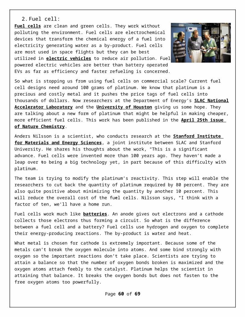
2. Fuel cell:Fuel cells are clean and green cells. They work withoutpolluting the environment. Fuel cells are electrochemicaldevices that transform the chemical energy of a fuel intoelectricity generating water as a by-product. Fuel cellsare most used in space flights but they can be bestutilized in electric vehicles to reduce air pollution. Fuelpowered electric vehicles are better than battery operatedEVs as far as efficiency and faster refueling is concerned.
So what is stopping us from using fuel cells on commercial scale? Current fuel cell designs need around 100 grams of platinum. We know that platinum is a precious and costly metal and it pushes the price tags of fuel cells into thousands of dollars. Now researchers at the Department of Energy’s SLAC NationalAccelerator Laboratory and the University of Houston giving us some hope. They are talking about a new form of platinum that might be helpful in making cheaper,more efficient fuel cells. This work has been published in the April 25th issue of Nature Chemistry.
Anders Nilsson is a scientist, who conducts research at the Stanford Institute for Materials and Energy Sciences, a joint institute between SLAC and Stanford University. He shares his thoughts about the work, “This is a significant advance. Fuel cells were invented more than 100 years ago. They haven’t made a leap over to being a big technology yet, in part because of this difficulty with platinum.”
The team is trying to modify the platinum’s reactivity. This step will enable theresearchers to cut back the quantity of platinum required by 80 percent. They arealso quite positive about minimizing the quantity by another 10 percent. This will reduce the overall cost of the fuel cells. Nilsson says, “I think with a factor of ten, we’ll have a home run.”
Fuel cells work much like batteries. An anode gives out electrons and a cathode collects those electrons thus forming a circuit. So what is the difference between a fuel cell and a battery? Fuel cells use hydrogen and oxygen to completetheir energy-producing reactions. The by-product is water and heat.
What metal is chosen for cathode is extremely important. Because some of the metals can’t break the oxygen molecule into atoms. And some bind strongly with oxygen so the important reactions don’t take place. Scientists are trying to attain a balance so that the number of oxygen bonds broken is maximized and the oxygen atoms attach feebly to the catalyst. Platinum helps the scientist in attaining that balance. It breaks the oxygen bonds but does not fasten to the free oxygen atoms too powerfully.
Page 60 of 69

Since 2005, Peter Strasser of the University of Houston was trying to find a way out. He tried to make platinum more reactive. Strasser along with his team tried de-alloying. First they created a copper-platinum alloy. Then they removed the copper from the platinum. They found that this alloy was much more reactive. Now the team will try to produce a potential replacement not only for petrol engines but also for the batteries found in small electronic devices.
Page 61 of 69
3. Hydrogen Gas Production Doubled with New Super Bacterium
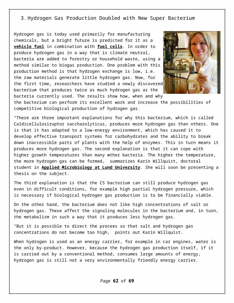
Hydrogen gas is today used primarily for manufacturingchemicals, but a bright future is predicted for it as a vehicle fuel in combination with fuel cells. In order toproduce hydrogen gas in a way that is climate neutral,bacteria are added to forestry or household waste, using amethod similar to biogas production. One problem with thisproduction method is that hydrogen exchange is low, i.e.the raw materials generate little hydrogen gas. Now, forthe first time, researchers have studied a newly discoveredbacterium that produces twice as much hydrogen gas as thebacteria currently used. The results show how, when and whythe bacterium can perform its excellent work and increase the possibilities of competitive biological production of hydrogen gas.
“There are three important explanations for why this bacterium, which is called Caldicellulosiruptor saccharolyticus, produces more hydrogen gas than others. Oneis that it has adapted to a low-energy environment, which has caused it to develop effective transport systems for carbohydrates and the ability to break down inaccessible parts of plants with the help of enzymes. This in turn means itproduces more hydrogen gas. The second explanation is that it can cope with higher growth temperatures than many other bacteria. The higher the temperature, the more hydrogen gas can be formed,” summarizes Karin Willquist, doctoral student in Applied Microbiology at Lund University. She will soon be presenting athesis on the subject.
The third explanation is that the CS bacterium can still produce hydrogen gas even in difficult conditions, for example high partial hydrogen pressure, which is necessary if biological hydrogen gas production is to be financially viable.
On the other hand, the bacterium does not like high concentrations of salt or hydrogen gas. These affect the signaling molecules in the bacterium and, in turn,the metabolism in such a way that it produces less hydrogen gas.
“But it is possible to direct the process so that salt and hydrogen gas concentrations do not become too high,” points out Karin Willquist.
When hydrogen is used as an energy carrier, for example in car engines, water is the only by-product. However, because the hydrogen gas production itself, if it is carried out by a conventional method, consumes large amounts of energy, hydrogen gas is still not a very environmentally friendly energy carrier.
Page 62 of 69
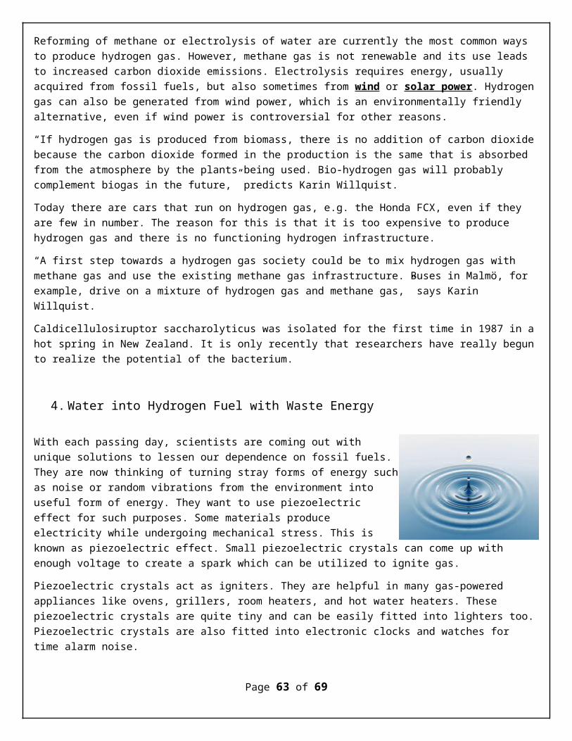
Reforming of methane or electrolysis of water are currently the most common ways to produce hydrogen gas. However, methane gas is not renewable and its use leads to increased carbon dioxide emissions. Electrolysis requires energy, usually acquired from fossil fuels, but also sometimes from wind or solar power. Hydrogengas can also be generated from wind power, which is an environmentally friendly alternative, even if wind power is controversial for other reasons.
“If hydrogen gas is produced from biomass, there is no addition of carbon dioxidebecause the carbon dioxide formed in the production is the same that is absorbed from the atmosphere by the plants being used. Bio-hydrogen gas will probably complement biogas in the future,” predicts Karin Willquist.
Today there are cars that run on hydrogen gas, e.g. the Honda FCX, even if they are few in number. The reason for this is that it is too expensive to produce hydrogen gas and there is no functioning hydrogen infrastructure.
“A first step towards a hydrogen gas society could be to mix hydrogen gas with methane gas and use the existing methane gas infrastructure. Buses in Malmö, for example, drive on a mixture of hydrogen gas and methane gas,” says Karin Willquist.
Caldicellulosiruptor saccharolyticus was isolated for the first time in 1987 in ahot spring in New Zealand. It is only recently that researchers have really begunto realize the potential of the bacterium.
4. Water into Hydrogen Fuel with Waste Energy
With each passing day, scientists are coming out withunique solutions to lessen our dependence on fossil fuels.They are now thinking of turning stray forms of energy suchas noise or random vibrations from the environment intouseful form of energy. They want to use piezoelectriceffect for such purposes. Some materials produceelectricity while undergoing mechanical stress. This isknown as piezoelectric effect. Small piezoelectric crystals can come up with enough voltage to create a spark which can be utilized to ignite gas.
Piezoelectric crystals act as igniters. They are helpful in many gas-powered appliances like ovens, grillers, room heaters, and hot water heaters. These piezoelectric crystals are quite tiny and can be easily fitted into lighters too.Piezoelectric crystals are also fitted into electronic clocks and watches for time alarm noise.
Page 63 of 69
Materials scientists at the University of Wisconsin-Madison have taken the help of piezoelectric effect to harness random energy available in the atmosphere to turn water into usable hydrogen fuel. It might prove a simple, efficient method to recycle waste energy. The research team is led by Huifang Xu, who is a UW-Madison geologist and crystal specialist. They took nanocrystals of zinc oxide and Barium Titanate. These two nanocrystals were put in water. When these crystals received ultrasonic vibrations, the nanofibers flexed and catalyzed a chemical reaction. This whole process resulted in splitting the water molecules into hydrogen and oxygen.
Huifang Xu along with his team has published their work in the Journal of Physical Chemistry Letters. They wrote in the journal, “This study provides a simple and cost-effective technology for direct water splitting that may generatehydrogen fuels by scavenging energy wastes such as noise or stray vibrations fromthe environment. This new discovery may have potential implications in solving the challenging energy and environmental issues that we are facing today and in the future.”
Xu and his colleagues applied the piezoelectric effect to the nanocrystal fibers successfully. Xu says, “The bulk materials are brittle, but at the nanoscale theyare flexible.” It is akin to the difference between fiberglass and a pane of glass.
It has been noted that smaller fibers exhibit more flexibility than larger crystals. Therefore smaller fibers can generate electric charges without difficulty. The project team has extracted an impressive 18 percent efficiency with the nanocrystals, higher than most experimental energy sources. Xu shares his views, “because we can tune the fiber and plate sizes, we can use even small amounts of [mechanical] noise — like a vibration or water flowing — to bend the fibers and plates. With this kind of technology, we can scavenge energy waste andconvert it into useful chemical energy.” What a fantastic idea.
But scientists didn’t utilize this electrical energy straightaway. They use this energy in breaking the chemical bonds in water to split oxygen and hydrogen. Xu explains, “This is a new phenomenon, converting mechanical energy directly to chemical energy.” Xu calls it a Piezo-Electrochemical (PZEC) effect. Why it seemsthat scientists are beating around the bush? Because chemical energy of hydrogen fuel is more stable than the electric charge. Storage of hydrogen fuel is easy and would not lose potency over time.
With the right technology, Xu foresees this method to be utilized where small amount of power is needed. Now we can imagine charging a cell phone while taking our morning walk or we can enjoy cool breeze that can power street lights. Xu says, “We have limited areas to collect large energy differences, like a
Page 64 of 69

waterfall or a big dam. But we have lots of places with small energies. If we canharvest that energy, it would be tremendous.”
5. Honda Solar Hydrogen Station Introduced to Green Car Market
Honda finally unveiled their new solar hydrogen solarstation and all signs point to a dramatic success. Thestation is smaller than previous models and enables anelectric car owner to refill their fuel cell overnight. Theunit should easily fit into a homeowners’ garage taking upsignificantly less space than previous models. The oldermodel required a compressor and electrolyzer for it to beoperational. One of the reasons the units were so big wasbecause of the compressor that was required to run the unit. Not only that, the compressor was also the reason that the units were so expensive to produce and purchase.
Honda has totally changed the components of the unit and eliminated the need for the compressor and this new slim model is the result. The unit is also “smart grid friendly” and will not require any hydrogen storage for the fuel cell to recharge. Because of this, the Honda Solar Hydrogen Station will lower CO2 emissions even further and allow the car owner to use off peak electricity to recharge the car. This makes everything more cost effective all the way around.
The Honda Solar Hydrogen Station is built to recharge the car on an overnight 8-hour fill. The power that was replenished would typically power the car for a full day of average driving. In most cases, that single fill will be able to get just about anyone through their day and back home without having to worry about arecharge.
However, the design of this new station also has talked of setting up an actual string of charging stations that would enable someone to travel much longer distances. The station was built with fast fill capabilities and any car that hasthis technology would be able to benefit from the public charging stations.
The Honda FCX is just such a car and can travel 240 miles on a single fill and has the capability to do a fast fill in about five minutes. This dramatically increases the travel range of a car and if the traveler was able to find a location that would allow the car to have a slow 8-hour overnight fill, there would literally be no limitation to the distance that the car could travel.
Honda is continuing its development of this concept and the coast to coast fueling stations will likely become a reality before long. It is a matter of
Page 65 of 69

getting investors onboard to support the stations and then there is no telling what will happen.
Page 66 of 69

6. The East Coast is about to Become the Hydrogen Highway
Everyone is excited about hydrogen cars, but there isalways the challenge of how they are going to fill up. Mostcars are restricted by the distance that they can travel ona full tank and nothing more. Few places, especially on theEast Coast, offer a refueling station to allow the cars totravel any further. If the hydrogen highway plan comes tofruition, that will finally change.
The reality of the situation is that something has to change if we are going to cut back on the massive carbon footprint that is being left because of daily commuting. There has been a lot of progress in the electric cars, but there are still a lot of challenges. There is a nice little niche of green people that believe that the hydrogen powered cars are the true out to get away from gasolinepowered vehicles.
The challenge of course is that they can only travel where a single tank will take them. Sun Hydro is trying to change all of that as they are making plans to literally create a hydrogen highway that will enable cars on the East Coast to travel from the tip of Maine to the southern-most point of Florida. All in all, the plan calls for 11 solar refueling stations.
There will need to be some public support if they are going to be successful. Thestations are not exactly cheap and need public funding in order for them to be installed. At $3,000,000 each, it is quite a bit to ask from John Q. Public. For this to work, we will need private investors and companies that have the foresight to invest in something that is obviously the future of motor vehicles. Things are going to change, it just a matter of who is going to be smart enough to jump on ship and make it happen sooner.
Page 67 of 69

ReferencesGenerating HHO gas theory: http://www.hho4free.com/configurator/cell_configurator.htm
New methods of generating hydrogen: http://www.alternative-energy-news.info/technology/hydrogen-fuel/
Solar energy: http://www.ccs.neu.edu/home/feneric/Papers/solar.pdf
Fig.(2) general properties for some fuel :http://wogone.com/science/the_energy_and_fuel_data_sheet.pdf
Page 68 of 69
Top Related
Copyright © 2022 FDOKUMEN

