


Bahasa
Halaman
Hukum

7/25/2019 POGO Para LEad Free
http://slidepdf.com/reader/full/pogo-para-lead-free 1/6
Lead-Free Pogo ® Contacts
C O N T A C T P R O D U C T S G R O U P
7/25/2019 POGO Para LEad Free
http://slidepdf.com/reader/full/pogo-para-lead-free 2/6
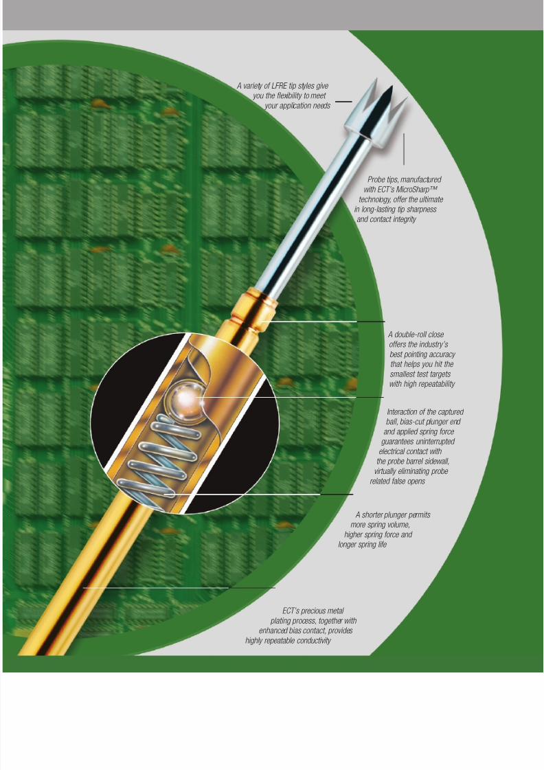
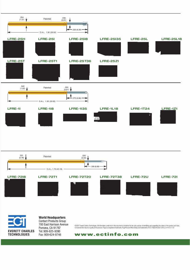
A variety of LFRE tip styles give
you the flexibility to meet
your application needs
Interaction of the captured
ball, bias-cut plunger end
and applied spring force
guarantees uninterrupted
electrical contact with
the probe barrel sidewall,
virtually eliminating probe
related false opens
A shorter plunger permits
more spring volume,
higher spring force and
longer spring life
A double-roll close
offers the industry’s
best pointing accuracy
that helps you hit the
smallest test targets
with high repeatability
Probe tips, manufactured
with ECT’s MicroSharp™
technology, offer the ultimate
in long-lasting tip sharpness
and contact integrity
ECT’s precious metal
plating process, together with
enhanced bias contact, provides
highly repeatable conductivity
7/25/2019 POGO Para LEad Free
http://slidepdf.com/reader/full/pogo-para-lead-free 3/6
ECT LFRE: C leaner Probes ,
Cleaner Environment.
The Lead Free Challenge
Lead free solder can cause many problemsin Circuit Testing. Lead Free Solder has ahigher reflow temperature, which can resultin harder and stickier solder flux resin and a
thicker, harder oxide layer. This thicker layer ofresin and oxide is more difficult to penetrate andincreases wear on the pogo pin. Lead free solder resin and oxides canalso increase debris transfer to spring probes. These are many of theissues found in OSP and No-Clean applications. ECT has developed anew test probe, specifically designed to solve these problems.
ECT New Lead Free POGO ® SeriesECT’s new Lead Free probe line incorporates a number of featuresthat will significantly reduce the issues that arise when switching to
lead free solder as well as those contact issues that arise with OSPand No-Clean solder flux.
• New Proprietary Plating
Our new Lead Free probe incorporates a new Harder and Slicker platingthat not only resists wear but also reduces solder and debris transfer.
• Higher Preload
All of our new Lead Free probes incorporate higher preloads. Higherpreload reduces spring force variation with board flex and increasesthe initial impact penetration, resulting in higher first pass yields.
• PogoPlus Bias Ball Design
The PogoPlus internal bias ball design guarantees uninterruptedelectrical contact with the probe sidewall virtually eliminating proberelated false opens.
• Range of Spring Force Choices:
Compared to competitors’ products, which offer limited spring forceoptions, ECT’s LFRE Pogos are available in a variety of spring force
choices in 100 mil, 75 mil and 50 mil centers.
• Spring Life
All of ECT’s Lead Free (LFRE) probes have a spring fatigue life thatsurpasses 500,000 cycles. Competitors’ lead free products mayincrease preload but dramatically lower cycle life, in some cases,
at or below 50,000 cycles.
• Pointing Accuracy
ECT’s new Lead Free probe incorporates a double roll close, whichoffers the industries best pointing accuracy. Increased pointing
accuracy is of benefit when using Lead Free solder and/or No-Cleanas the probe is less likely to touch the edge of the pad where thesolder flux accumulates.
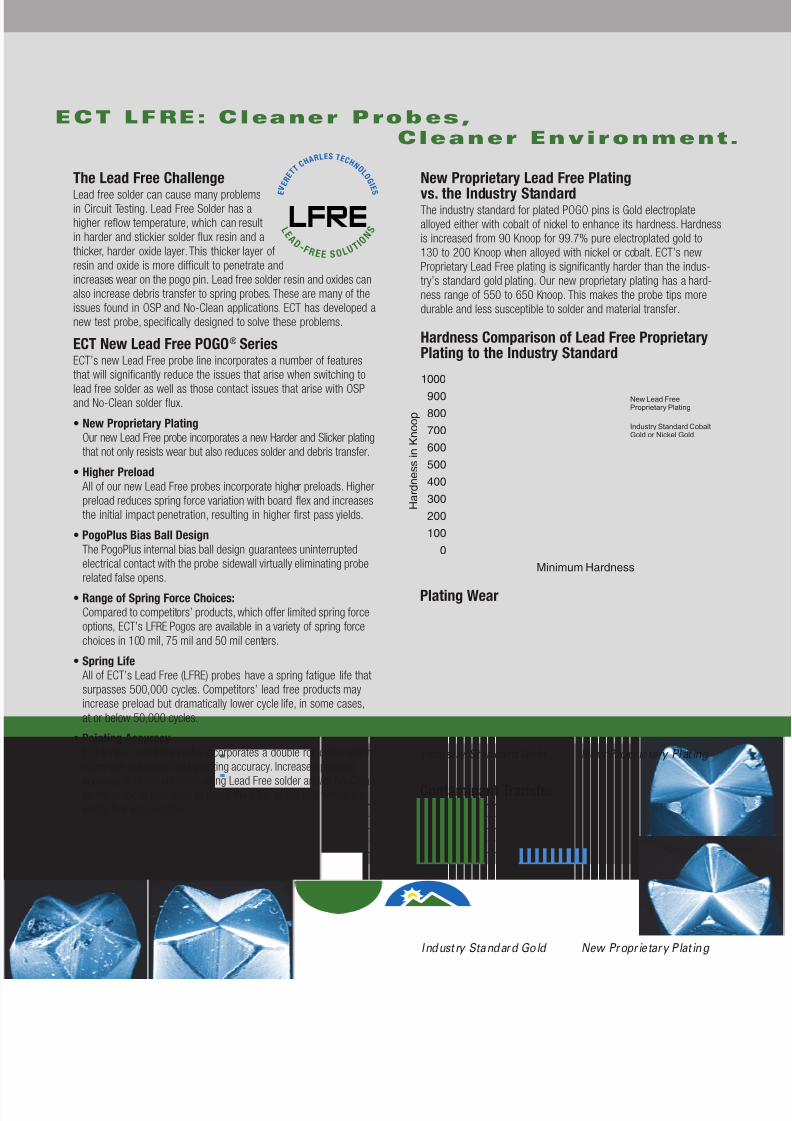
New Proprietary Lead Free Plating
vs. the Industry StandardThe industry standard for plated POGO pins is Gold electroplatealloyed either with cobalt of nickel to enhance its hardness. Hardnessis increased from 90 Knoop for 99.7% pure electroplated gold to130 to 200 Knoop when alloyed with nickel or cobalt. ECT’s newProprietary Lead Free plating is significantly harder than the indus-try’s standard gold plating. Our new proprietary plating has a hard-ness range of 550 to 650 Knoop. This makes the probe tips moredurable and less susceptible to solder and material transfer.
Hardness Comparison of Lead Free ProprietaryPlating to the Industry Standard
L E A D
- F R E E S O L
U T I O
N S
LFRE
E V E R E T
T
C H A R LE
S T E C H N O
L O G
I E S
Contaminant Transfer
Plating Wear
Industry Standard Gold New Propr ietary Plat ing
Industry Standard Gold New Propr ietary Plat ing
0
100
200
300
400
500
600
700
800
900
1000
H a r d n e s s i n K n o o p
Minimum Hardness
New Lead FreeProprietary Plating
Industry Standard CobaltGold or Nickel Gold
7/25/2019 POGO Para LEad Free
http://slidepdf.com/reader/full/pogo-para-lead-free 4/6
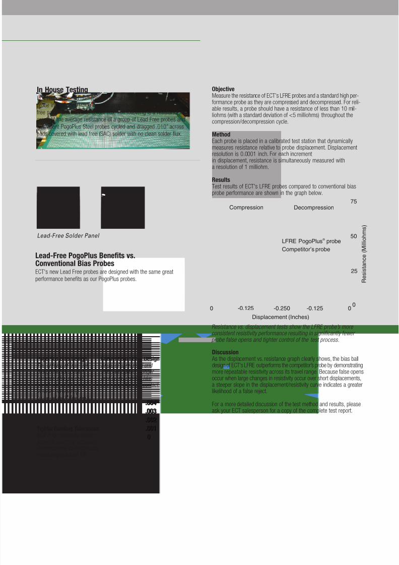
Resistance vs. displacement tests show the LFRE probe’s more consistent resistivity performance resulting in significantly fewer probe false opens and tighter control of the test process.
ObjectiveMeasure the resistance of ECT’s LFRE probes and a standard high per-formance probe as they are compressed and decompressed. For reli-able results, a probe should have a resistance of less than 10 mil-liohms (with a standard deviation of <5 milliohms) throughout thecompression/decompression cycle.
MethodEach probe is placed in a calibrated test station that dynamicallymeasures resistance relative to probe displacement. Displacementresolution is 0.0001 inch. For each incrementin displacement, resistance is simultaneously measured witha resolution of 1 milliohm.
ResultsTest results of ECT's LFRE probes compared to conventional biasprobe performance are shown in the graph below.
Discussion As the displacement vs. resistance graph clearly shows, the bias balldesign of ECT's LFRE outperforms the competitor’s probe by demonstratingmore repeatable resistivity across its travel range. Because false opensoccur when large changes in resistivity occur over short displacements,a steeper slope in the displacement/resistivity curve indicates a greaterlikelihood of a false reject.
For a more detailed discussion of the test method and results, pleaseask your ECT salesperson for a copy of the complete test report.
PogoPlus Bias DesignThe enhanced bias-ball design forces contact between plunger andbarrel wall at all times,virtually eliminating
probe-related false opens..004"
.003
.002
.001
0
.004"
.003
.002
.001
0
Tighter Pointing TolerancesECT Pogo contacts deliversuperior pointing accuracy demonstrated by test results measuring sideload TIR.
Conventional Bias Design Angle of spring coil end matches biased plungerend, compromising biasforce and electrical contact.
In House Testing
ECT has performed numerous in house tests on our new Lead Freeprobe in order determine its wear properties and its life against leadfree solder and no clean solder flux. The following is a resistancegraph of the average resistance of a group of Lead Free probes and
Equivalent PogoPlus Steel probes cycled and dragged .010” acrosspads covered with lead free (SAC) solder with no clean solder flux.
Lead-Free Solder Panel
Lead-Free PogoPlus Benefits vs.Conventional Bias ProbesECT's new Lead Free probes are designed with the same greatperformance benefits as our PogoPlus probes.
LFRE PogoPlus ® probe
Competitor’s probe
00
25
50
75
-0.125-0.250-0.1250
Compression Decompression
Displacement (Inches)
R e s i s t a n c e ( M i l l i o h m s )
7/25/2019 POGO Para LEad Free
http://slidepdf.com/reader/full/pogo-para-lead-free 5/6
LFRE-72
Test Centers.050" (1.27mm)
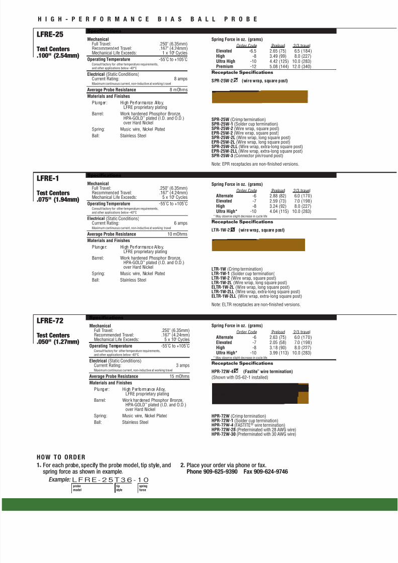
LFRE-25
Test Centers.100" (2.54mm)
H I G H - P E R F O R M A N C E B I A S B A L L P R O B E
Specifications
MechanicalFull Travel: .250" (6.35mm)Recommended Travel: .167" (4.24mm)Mechanical Life Exceeds: 5 x 10⁵ Cycles
Operating Temperature -55˚C to +105˚CConsult factory for other temperature requirements,and other applications below -40°C
Electrical (Static Conditions)Current Rating: 3 ampsMaximum continuous current, non-inductive at working travel
Average Probe Resistance 15 mOhms
Materials and Finishes
Plunger: High Performance Alloy,
LFRE proprietary platingBarrel: Work hardened Phosphor Bronze,
HPA-GOLD™ plated (I.D. and O.D.)over Hard Nickel
Spring: Music wire, Nickel Plated
Ball: Stainless Steel
Specifications
MechanicalFull Travel: .250" (6.35mm)Recommended Travel: .167" (4.24mm)Mechanical Life Exceeds: 1 x 10⁶ Cycles
Operating Temperature -55˚C to +105˚CConsult factory for other temperature requirements,and other applications below -40°C
Electrical (Static Conditions)Current Rating: 8 ampsMaximum continuous current, non-inductive at working t ravel
Average Probe Resistance 8 mOhms
Materials and FinishesPlunger: High Performance Al loy,LFRE proprietary plating
Barrel: Work hardened Phosphor Bronze,HPA-GOLD™ plated (I.D. and O.D.)over Hard Nickel
Spring: Music wire, Nickel Plated
Ball: Stainless Steel
HOW TO ORDER
1. For each probe, specify the probe model, tip style, andspring force as shown in example.
Example:
2. Place your order via phone or fax.Phone 909-625-9390 Fax 909-624-9746
probemodel
tipstyle
springforce
LFRE -25T36 -10
Spring Force in oz. (grams)
Order Code Preload 2/3 travelAlternate -6 2.63 (75) 6.0 (170)Elevated -7 2.05 (58) 7.0 (198)High -8 3.18 (90) 8.0 (227)Ultra High* -10 3.99 (113) 10.0 (283)
* May observe slight decrease in cycle life
Receptacle Specifications
HPR-72W-4 (Fastite™ wire termination)
(Shown with DS-62-1 installed)
HPR-72W (Crimp termination)HPR-72W-1 (Solder cup termination)HPR-72W-4 (FASTITE® wire termination)HPR-72W-28 (Preterminated with 28 AWG wire)HPR-72W-30 (Preterminated with 30 AWG wire)
Spring Force in oz. (grams)
Order Code Preload 2/3 travelElevated -6.5 2.65 (75) 6.5 (184)High -8 3.49 (99) 8.0 (227)Ultra High -10 4.42 (125) 10.0 (283)Premium -12 5.08 (144) 12.0 (340)
Receptacle Specifications
SPR-25W-2 (wire wrap, square post)
SPR-25W (Crimp termination)SPR-25W-1 (Solder cup termination)SPR-25W-2 (Wire wrap, square post)EPR-25W-2 (Wire wrap, square post)SPR-25W-2L (Wire wrap, long square post)EPR-25W-2L (Wire wrap, long square post)SPR-25W-2LL (Wire wrap, extra-long square post)EPR-25W-2LL (Wire wrap, extra-long square post)SPR-25W-3 (Connector pin/round post)
Note: EPR receptacles are non-finished versions.
.038(0.97)
1.72(43.69)
.350(8.89)
.047 (1.19)
.025 (0.64)
1.69 (42.93)Typical.500 (12.70)
LFRE-1
Test Centers.075" (1.94mm)
Spring Force in oz. (grams)
Order Code Preload 2/3 travel
Alternate -6 2.88 (82) 6.0 (170)Elevated -7 2.59 (73) 7.0 (198)High -8 3.24 (92) 8.0 (227)Ultra High* -10 4.04 (115) 10.0 (283)
* May observe slight decrease in cycle life
Receptacle Specifications
LTR-1W-2 (wire wrap, square post)
LTR-1W (Crimp termination)LTR-1W-1 (Solder cup termination)LTR-1W-2 (Wire wrap, square post)LTR-1W-2L (Wire wrap, long square post)ELTR-1W-2L (Wire wrap, long square post)LTR-1W-2LL (Wire wrap, extra-long square post)
ELTR-1W-2LL (Wire wrap, extra-long square post)
Note: ELTR receptacles are non-finished versions.
.025 (0.64)
1.69 (42.93)
.500 (12.70)
Specifications
MechanicalFull Travel: .250" (6.35mm)Recommended Travel: .167" (4.24mm)
Mechanical Life Exceeds: 5 x 10⁵ CyclesOperating Temperature -55˚C to +105˚C
Consult factory for other temperature requirements,and other applications below -40°C
Electrical (Static Conditions)Current Rating: 6 ampsMaximum continuous current, non-inductive at working travel
Average Probe Resistance 10 mOhms
Materials and Finishes
Plunger: High Performance Al loy,LFRE proprietary plating
Barrel: Work hardened Phosphor Bronze,HPA-GOLD™ plated (I.D. and O.D.)over Hard Nickel
Spring: Music wire, Nickel Plated
Ball: Stainless Steel
7/25/2019 POGO Para LEad Free
http://slidepdf.com/reader/full/pogo-para-lead-free 6/6
World HeadquartersContact Products Group700 East Harrison AvenuePomona, CA 91767Tel: 909-625-9390Fax: 909-624-9746
.031
(0.78).020
(0.50)
LFRE-25H
.054
(1.37).036
(0.91)Patented
O.A.L. 1.30 (33.02)
.330 (8.38)
.270 (6.86)
O.A.L. 1.70 (43.18)
.040
(1.02) .024
(0.61)
O.A.L. 1.30 (33.02)
Patented
Patented
EVERETT CHARLESTECHNOLOGIES
©2007 Everett Charles Technologies. All information contained in this document is furnished for the sole purpose of identifying and suggesting the nature of the product and not warrant the nature or quality of the product. Pogo is a registered trademark; PogoPlus and MicroSharp are trademarks of ECT. Patent #5,801,544.Lit. #1473-1-07
www.ectinfo.com
LFRE-72I8 LFRE-72T20 LFRE-72T38 LFRE-72U
.030(0.76)
.019(0.48)
.038(0.97)
45°
60°
LFRE-72T1
LFRE-25I8
LFRE-25T LFRE-25T1
LFRE-25I
90°
.036(0.91)
LFRE-25 T36 LFRE-25 Z1
.018(0.46)
.080(2.03)
LFRE-1L18 LFRE-1T24 LFRE-1Z1.020(0.51)
.038(0.97)
LFRE-1I LFRE-1I8
.020(0.50)
10° .020(0.50)
60°
.018
(0.46) Self Cleaning.020
(0.50)
LFRE-72I
.024(0.61)
°
.020(0.50)
90°
.024 (0.61)
15°
.035(0.89)
LFRE-25I35
35°
.036(0.91)
.150(3.81)
.036(0.91) Typ
.018(0.46)
LFRE-25L
.050(1.27)
Self Cleaning
LFRE-25L
.036(0.91)
.032(0.81)
.067(1.70)
10°
.036(0.91)
15°
.024(0.61)
LFRE-1I35
35°
.080 (2.03)
.051(1.30)
30°
060.52)
.330 (8.38)
Top Related
Copyright © 2022 FDOKUMEN

