YUAA Turbojet Engine Project: End of Year Report - Siemon
12
YUAA Turbojet Engine Project: End of Year Report September 2016 - April 2017 ◊ Project Summary: The primary aim of this project is to design and construct a centrifugal-flow turbojet engine as a proof-of-concept. The project was one of four undertakings by the Yale Undergraduate Aerospace Association during the 2016-2017 academic year, as well as the organization’s first attempt at non-rocket propulsion. The engine was not intended for use on any actual vehicle, sitting in a still frame that houses all the supporting equipment, for the ease of storage and transportation. The goal of the project is simple due to the difficulty and safety concerns: to have the engine perform sustained combustion without external shaft power input. At the conclusion of the project, the majority of the engine has been completed, awaiting safety review and test run. ◊ Team Management: The team composition has been constantly changing throughout the project, while human resource management is vital for its smooth operation. The team was originally intended to have four distinct divisions: combustion chamber design, control and monitoring electronics, frame and support system, oil system and fuel supply components. The break out made sense from a functional perspective, yet it dwelled on a few assumptions that our situation clearly lacked. Certain parts of the design must happen after key parameters have been confirmed for the combustion chamber, and the workload across divisions and time is never evenly distributed. In the beginning of the semester, the team had about twenty members expressing interest in joining, while the initial design phase did not require a large number of people. On the contrary, during later phases of the project, the dwindling membership made it hard for manufacturing and assembly that required a lot of man-hours, while designs that depended largely on other components must take place now that the engine was taking its shape. The paradox forced us to abandon the four division system early in the design process. Instead the team tackles individual design tasks as they come up and are assigned to individual team members. Effective communication and documentation of ideas, tasks, parameters and progress was crucial to the continuity of the teamwork and efficiency of collaboration, especially given that YUAA does not mandate attendance and commitment for its members. An online project management board called Trello was initially chosen and populated with material for the
-
Upload
khangminh22 -
Category
Documents
-
view
1 -
download
0
Transcript of YUAA Turbojet Engine Project: End of Year Report - Siemon
YUAA Turbojet Engine Project: End of Year Report
September 2016 - April 2017
◊ Project Summary:
The primary aim of this project is to design and construct a centrifugal-flow turbojet
engine as a proof-of-concept. The project was one of four undertakings by the Yale
Undergraduate Aerospace Association during the 2016-2017 academic year, as well as the
organization’s first attempt at non-rocket propulsion. The engine was not intended for use on any
actual vehicle, sitting in a still frame that houses all the supporting equipment, for the ease of
storage and transportation. The goal of the project is simple due to the difficulty and safety
concerns: to have the engine perform sustained combustion without external shaft power input.
At the conclusion of the project, the majority of the engine has been completed, awaiting safety
review and test run.
◊ Team Management:
The team composition has been constantly changing throughout the project, while human
resource management is vital for its smooth operation. The team was originally intended to have
four distinct divisions: combustion chamber design, control and monitoring electronics, frame
and support system, oil system and fuel supply components. The break out made sense from a
functional perspective, yet it dwelled on a few assumptions that our situation clearly lacked.
Certain parts of the design must happen after key parameters have been confirmed for the
combustion chamber, and the workload across divisions and time is never evenly distributed. In
the beginning of the semester, the team had about twenty members expressing interest in joining,
while the initial design phase did not require a large number of people. On the contrary, during
later phases of the project, the dwindling membership made it hard for manufacturing and
assembly that required a lot of man-hours, while designs that depended largely on other
components must take place now that the engine was taking its shape. The paradox forced us to
abandon the four division system early in the design process. Instead the team tackles individual
design tasks as they come up and are assigned to individual team members.
Effective communication and documentation of ideas, tasks, parameters and progress was
crucial to the continuity of the teamwork and efficiency of collaboration, especially given that
YUAA does not mandate attendance and commitment for its members. An online project
management board called Trello was initially chosen and populated with material for the
purpose, to be used in conjunction with Google Drive for file storage. However, due to the
aforementioned problem with team dynamic and poor integration with Google Services, Trello
proved to be ineffective to organize and visualize ideas across the team. Eventually, the team
communicates design parameters by separate Google Docs documenting each component, with a
master “Turbojet Project Board” actively updated to reflect pending tasks, color coded with
urgency and nature, directing team members to take on different works. Although the method
still lacks the clarity and structure intended for the project, it worked well as it made it easy for
the team to find work, and improved the sense of ownership to the project.
The lack of experience across the team posed yet another set of challenges to the project.
Since most of the team consisted of freshmen with little to no experience with mechanical design
and the manufacturing process the project used, preserving experienced membership and
building the skills became a high priority early on. All interested members were sped through
CEID machine shop Phase I training, learning about band saws, belt sanders and drill presses. A
few members of the team also got training on the lathe, mill and welding. Though some trained
members left the team without ever contributing, the remaining members still laid the foundation
for the manufacturing phase. Two members of the team who showed extraordinary dedication,
engineering skills and leadership were made parts of the “core team,” with comprehensive
knowledge of all components of the system and capable of making crucial decisions quickly.
With these strategies, the team was able to make the most of its expertise, allowing members to
grow their skills while giving credits to those who made great contributions.
◊ Actual Timeline:
- September
1. Crash course on jet engine technology.
2. Acquisition of the turbocharger, which will function as the compressor and turbine of the
jet engine.
3. Preliminary dimensioning. Measurement was taken near the intake, exhaust openings of
the turbine and the compressor. At the time, these figures did not make too much sense,
as the team was unfamiliar with standard dimensions used in the DIY automotive
community.
- October
1. Dimensions of the combustion chamber was discussed and calculated.
2. CADs were made for the preliminary combustion chamber design.
- November
1. Research was done for the material.
2. The combustion chamber CAD was finalized and assembled.
3. Research was done for the control and monitoring electronics.
- December
1. The core team visited the test site and discussed the basic requirements for design and
protocols for testing.
2. Coding began for the Arduino board as well as the GUI controller (on Qt).
- January
1. Preparation for machining
2. Testing the electronics (which did not work, so we were forced to put them off and focus
on mechanical construction)
- February
1. Machining the parts (weekday shifts in Nick’s shop. No midweek meetings)
2. Welding training began for interested members.
3. Finalizing supporting frame dimensions and purchased the frame.
- March
1. Machining wrapped up, welding began.
2. Finalizing plumbing systems.
- April
Welding completed. Final assembly began.
◊ Design and Construction Process:
Over the summer, the project was set to be going on the track that most amateur builders
used when constructing a turbojet engine: using a turbocharger as the main spinning component.
Compared to building everything ourselves, using an off-the-shelf product ensures that the fast-
spinning component under high temperature is quality-built with a proven design. Although in
retrospect, the turbocharger we bought could entirely be donated or salvaged from a nearby scrap
yard. In addition, due to the lack of understanding regarding the DIY turbocharger market, we
could have bought one from non-ebay sources that had better documentation of key dimensions
and thermodynamic classifications. The process of “reverse engineering” these numbers delayed
the project significantly, and caused huge concerns among advisors of the project. Primary
design parameters were eventually settled down using empirical formulae provided online, with
little consideration on the physical constraints posed by the geometries of the turbocharger.
During construction, it was discovered that the turbocharger’s compressor housing was in the
way of the combustion chamber’s cylindrical shape, forcing us to add an off-the-shelf exhaust
flange adapter to act as a spacer. The material was stainless steel (generously donated by Mr.
Kevin Smith), with four quarter-inch plates used to machine the top and bottom plates (rounds),
and two identical rings with bolt circles that will be welded to the outer tube. Two stainless steel
pipes (of 8 inch and 6 inch diameters) were used to produce the outer tube and inner tube
(combustion lining). Large holes on the combustion lining were drilled to help ventilation,
mixing of air and fuel, as well as cooling, but in reality they were difficult, if not dangerous, to
drill. Large holes required more steps of smaller sized drill bits before the final drill bit could be
used, and the hardness of the stainless steel meant the mill/ drill press had a hard time sustaining
operation. A large quantity of cutting oil was always required during the entire manufacturing
process. Holes on the lining were spotted using a paper sketch transferred onto the tube, marked
with sharpie then center-drilled. The outer tube had one 2-inch hole, which was CNC milled
instead of drilled. The operation took a lot of effort, as the original vise must be removed for a
special clamp to be installed in order to prevent the circular tube from moving around. All four
plates were milled using CNC programmed at 0.2 inches of thickness per round. Each plate took
many hours as a result (stainless was incredibly difficult to work with in the machine shop). The
outer shape (circular) was cut at last by placing a sacrificial piece down on the vise, and the
plates were bolted using the intended bolts onto the sacrificial piece (aluminum for ease of
machining). Only one calibration was done during the entire CNC process (because all four
plates had similar dimensions). The steps taken for each one are detailed below:
Exhaust plate:
1. The stock piece was clamped down onto the vise by itself, and milled using a 0.25” bit.
Nick Bernardo helped us zeroed the axes, and started cutting the cutting the square
opening in the middle using the CNC functionalities on the mill.
2. The built-in CNC programs allowed us to cut the exhaust hole and bolt-ring holes
automatically, and are set according to the drawing. Multiple passes were used and a very
slow feed rate was set to prevent any accident. During the (very time-consuming)
process, one mill bit was still damaged by the excessive heat caused by chewing into hard
material too quickly. Oil must be constantly brushed on the cut, and chips flying around
did pose a significant hazard to the operating team member.
3. All subsequent cuts on square stocks used the coordinates zeroed by this cut. In addition,
all parts were initially left square until a scrap piece of aluminum that has a flat (stock)
side, from which we milled the whole piece down to a square the same size as the parts.
Four equidistant holes on the scrap were drilled and tapped following the same bolt ring
configuration, allowing parts to be secured above it. The square plates that already had
the rectangular exhaust hole bored and holes drilled were elevated by the said aluminum
scrap, bolted down on the four holes. Using the scrap as a sacrifice, the exhaust plate (and
subsequent parts) were made round.
Bolt rings:
1. Following similar procedures as the exhaust plate, the CNC capabilities made the 8 bolt
holes fairly easy and quick. The center of the bolt ring used the circle-cut routine on the
mill, but a thin tab with a smaller radius was used towards the bottom to allow for more
contact while welding. This is advised by Mr. David Johnson in Yale Wright Lab, who
suggested that simply welding the outer tube to the inner surface of the ring will create
too much shear stress.
2. During the process, the excessive amount of material to be removed caused warping in
the two rings, let alone wasting precious high quality steel. This affected final assembly,
and was indeed a lesson to be learned.
Bottom plate:
The bottom plate was fairly straightforward and similar to the bolt rings, except that it
was still kept as a circular plate with smaller holes in the middle for the nozzle (lathed
down on the top half from the McMaster Carr’s hexagonal nozzle) to press-fit. A hole
was also drilled and tapped for the spark plug to screw in.
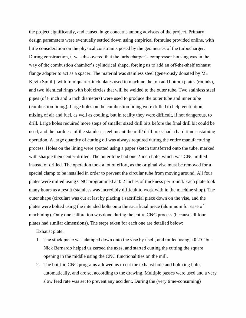
The final assembly began with welding the parts of the combustion chamber together. An
angle-fitting and a threaded section of steel pipe was used to connect the compressor outlet to the
outer tube of the combustion chamber. The operation was performed in Mr. David Johnson’s
shop in Yale Wright Lab. Before the actual welding, a team-wide welding try-out was organized.
Around 7 team members attempted welding simple steel angles in an educational, relaxed
setting. Trevor Chan ‘20 decided proved to be “natural” in the try-out and with more practice, he
was assigned the task of welding all parts of the engine. The outer tube’s edges that interface
with the bolt rings were slightly lathed down a few thousandths of an inch to 1) ensure it’s round
and 2) provide the tolerance necessary for a rough press-fit. Four bolts were used in each
married-pair of bolt rings and plates (bottom or exhaust). To visualize the final assembly and
prepare for welding, a test-fit was performed using the flatbed of a mill. The bottom plate and the
top ring, bolted together, was clamped down to the flatbed. The inner tube (combustion lining),
one end of which lathed flat earlier to allow for better contact, was placed in the center of the
bottom plate (to be welded). The outer rube was fit into the ring, stopped by the previous “tab”
made on the mill, which now turned out to be incredibly helpful. The pipe was inserted into the
hole and required length marked. During this process, the orientation with regards to the
turbocharger was also ascertained after the exhaust-ring plates were added on top. The pipe was
cut and the two threaded ends were tightly screwed and thread-locked into the angle fitting,
creating the desired inlet geometry. Welding happened next and the final product was shown
below.
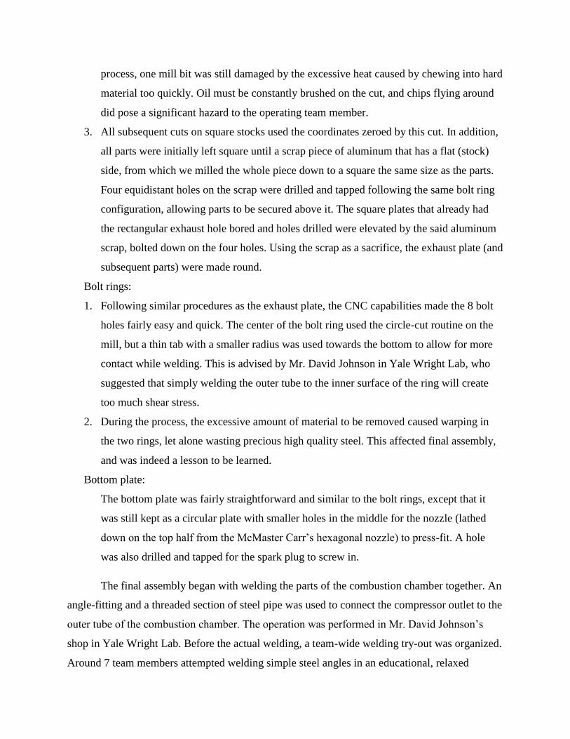
As one can see, the compressor outlet (shown on top left of the last picture) was
connected to the inlet pipe via metal zip ties over a silicone coupler designed to withstand high
temperatures. This design was chosen mainly because there are no other alternatives to join the
two parts together, added by the facts that:
1. It was not the hottest part of the engine.
2. It provided much needed flexibility when assembling the combustion chamber with the
turbocharger. If everything’s rigid, the assembly would have been impossible.
3. The engine was not intended for long, continued operation.
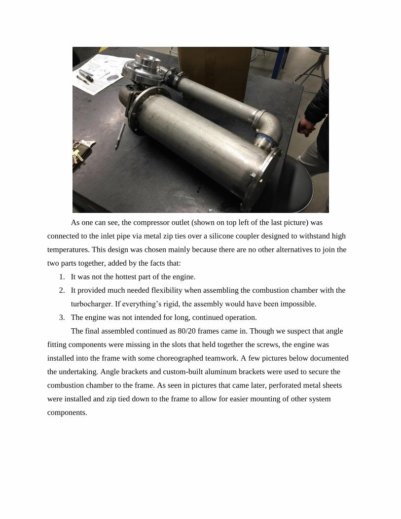
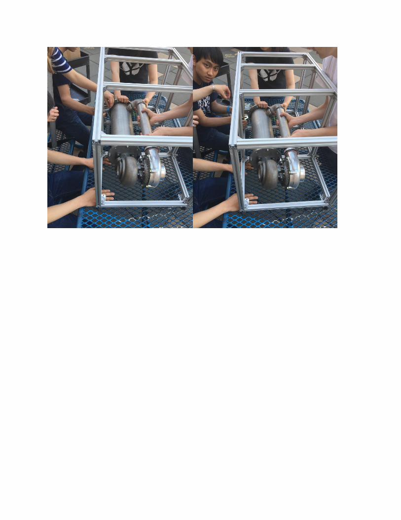
The final assembled continued as 80/20 frames came in. Though we suspect that angle
fitting components were missing in the slots that held together the screws, the engine was
installed into the frame with some choreographed teamwork. A few pictures below documented
the undertaking. Angle brackets and custom-built aluminum brackets were used to secure the
combustion chamber to the frame. As seen in pictures that came later, perforated metal sheets
were installed and zip tied down to the frame to allow for easier mounting of other system
components.
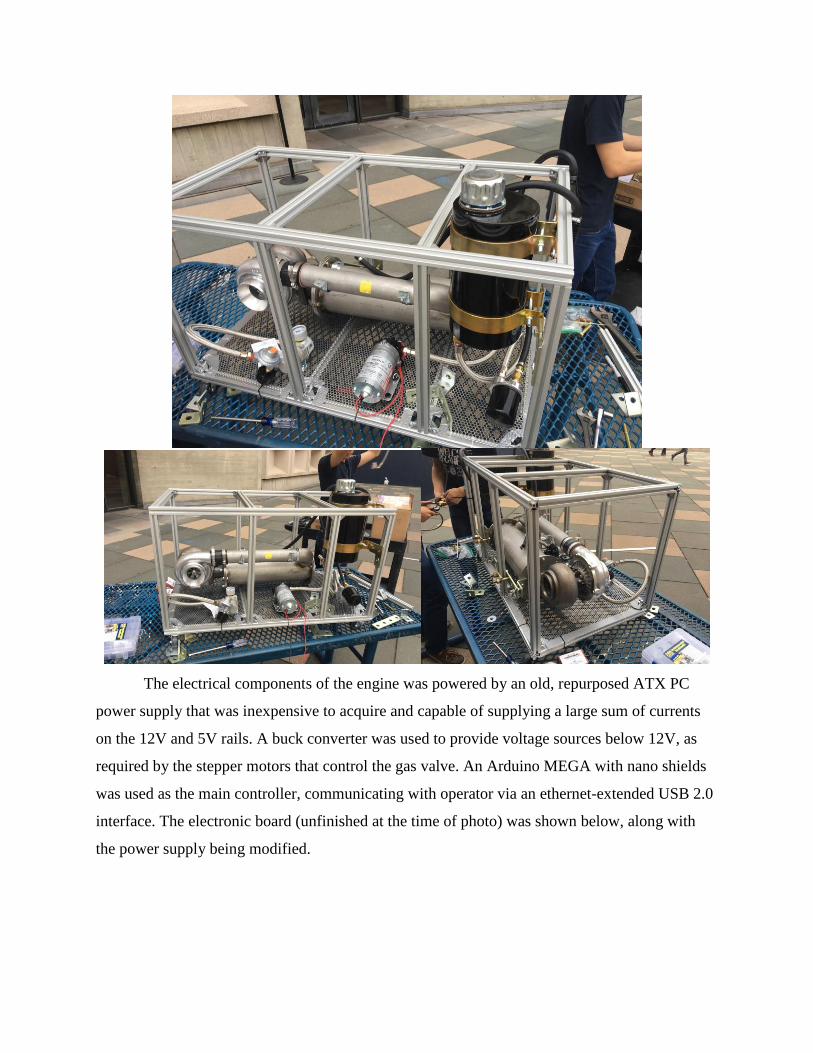
The electrical components of the engine was powered by an old, repurposed ATX PC
power supply that was inexpensive to acquire and capable of supplying a large sum of currents
on the 12V and 5V rails. A buck converter was used to provide voltage sources below 12V, as
required by the stepper motors that control the gas valve. An Arduino MEGA with nano shields
was used as the main controller, communicating with operator via an ethernet-extended USB 2.0
interface. The electronic board (unfinished at the time of photo) was shown below, along with
the power supply being modified.
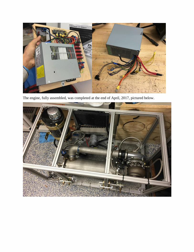
The engine, fully assembled, was completed at the end of April, 2017, pictured below.
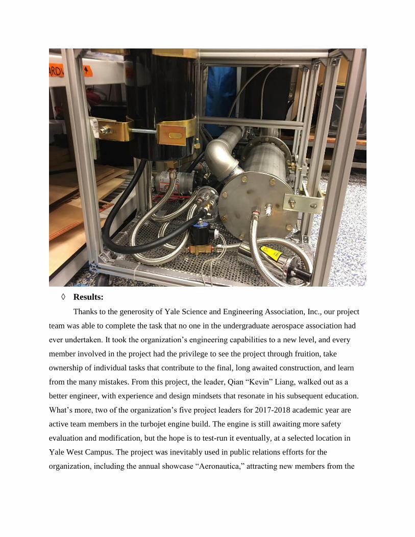
◊ Results:
Thanks to the generosity of Yale Science and Engineering Association, Inc., our project
team was able to complete the task that no one in the undergraduate aerospace association had
ever undertaken. It took the organization’s engineering capabilities to a new level, and every
member involved in the project had the privilege to see the project through fruition, take
ownership of individual tasks that contribute to the final, long awaited construction, and learn
from the many mistakes. From this project, the leader, Qian “Kevin” Liang, walked out as a
better engineer, with experience and design mindsets that resonate in his subsequent education.
What’s more, two of the organization’s five project leaders for 2017-2018 academic year are
active team members in the turbojet engine build. The engine is still awaiting more safety
evaluation and modification, but the hope is to test-run it eventually, at a selected location in
Yale West Campus. The project was inevitably used in public relations efforts for the
organization, including the annual showcase “Aeronautica,” attracting new members from the
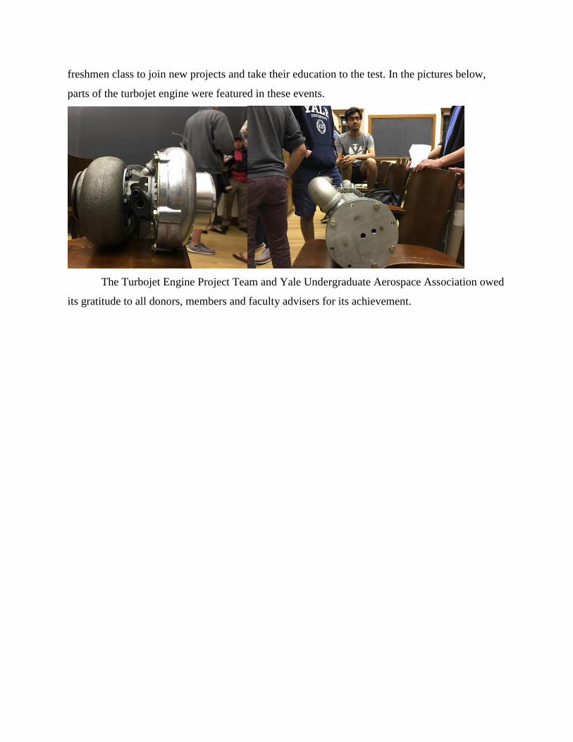
freshmen class to join new projects and take their education to the test. In the pictures below,
parts of the turbojet engine were featured in these events.
The Turbojet Engine Project Team and Yale Undergraduate Aerospace Association owed
its gratitude to all donors, members and faculty advisers for its achievement.