Yamaha SST List.pdf
86
-
Upload
khangminh22 -
Category
Documents
-
view
2 -
download
0
Transcript of Yamaha SST List.pdf


SPECIAL SERVICE TOOL LIST©2004 Yamaha Motor Co.,Ltd.
1st Edition, August 2004All rights reserved.
Any reprinting or unauthorized usewithout the written permission of
Yamaha Motor Co.,Ltd.is expressly prohibited.
Printed in Japan
LISTE DES OUTILS D’ENTRETIEN SPÉCIAUX©2004 Yamaha Motor Co., Ltd.
1ère Edition, Août 2004Tous droits réservés.
Toute réimpression ou utilisationsans la permission écrite de la
Yamaha Motor Co., Ltd.est formellement interdite.
Imprimé en Japon
LISTA DE HERRAMIENTAS ESPECIALES DESERVICIO
©2004 Yamaha Motor Co., Ltd.1ª edición, Agosto 2004
Reservados todos los derechos.Se prohíbe expresamente toda reimpresióno utilización no autorizada de este manual
sin el consentimiento por escrito deYamaha Motor Co., Ltd.
Impreso en Japón
E
NOTICEThis list of special service tools has been prepared for quick and easy reference, to enable you tofind the appropriate service tool(s) for each model.The special service tools have been improved and upgraded for each new model. However, yourexisting service manual does not include the latest information. Also, the list does not cover themodels of which information could not be obtained at the time of preparation of the manual. Theinformation will be provided through the next issue of the special service tool list.
Outboard motor models : All models to be released only in this fiscal year (except those ofwhich information can not be obtained )
Watercraft models : All models including those released in several years ago to the lat-est models (The new models of this fiscal year may be excludedbecause the development period of watercrafts is different from thatof the outboard motors.)
The special service tools mentioned in the service manual of each model are listed here.Tool numbers in round brackets indicate current tool numbers, and will be replaced with the replace-ment tool numbers (not in brackets) when stock runs out.In addition, the tool names always appear in English in this manual.
MANUAL FORMATAPPLICATION CHARTSTool numbers and the outboard motor/watercraft models to which they apply are shown in thecharts.Tools, which are to be supplied in an assembly, are listed with a dot (•) in front of the tool name.(•) :Dots in round brackets indicate that the particular tool is not absolutely necessary and which
can be substituted by another tool.[ ] :Square brackets indicate that the tool applies only to models in square brackets in the corre-
sponding column header.
TOOL DESCRIPTIONSThe tool number, name, illustration, and description of its use are shown. The required tool size isalso given to assist in the identification of the correct tool.The construction and meaning of each section are as follows:
Measuring tool : Mechanical or electrical precision tools (Some measuring tools maybe listed in one of the following sections instead.)
Engine servicing : Special tool for engine servicingLower unit/jet pump servicing : Special tool for lower unit/jet pump servicingShim selection, PTT tool : Special tool for shim selection and power trim and tilt unit servicing
REPAIR KITS (RECONDITION TOOL)The following kits can be used for repairing/replacing damaged parts, avoiding the need to replacethe whole unit. Some skill is required to use these.
“Heli-sert” kit : For reconditioning damaged bolt threadsMarine terminal kit : For repairing conventional marine round plug/socket and eye termi-
nals This water-resistant and rust-resistant connector type, althoughsimilar, is different from that on a motorcycle.
Coupler kit : For repairing water-resistant multiple pole couplers
NOTE:Identify the correct coupler and do not try to use a coupler of the incorrect type.
INDEXFind the desired tool through its number (part number) in order to determine the page in the APPLI-CATION CHARTS and TOOL DESCRIPTIONS, where a more detailed explanation of the tool canbe found.
F
NOTECette liste d'outils spéciaux a été préparée afin que les mécaniciens puissent trouver rapidement et aisément le ou les out-ils spéciaux requis selon les modèles.Yamaha a modifié et amélioré certains outils d'entretien spéciaux pour les nouveaux modèles. Toutefois, votre manueld'atelier existant ne comprend pas ces nouvelles informations. De même, la liste ne concerne pas les modèles dont on nedisposait pas d'informations au moment de la préparation du manuel. Les informations seront présentées dans la prochainepublication de la liste d'outils spéciaux.
Modèles de moteur hors-bord : Tous les modèles à sortir cette année fiscale(à l’exception de ceux à propos desquels on ne peut pas obtenir d’informations)
Modèles de scooters nautiques : Tous les modèles de ceux sortis il y a plusieurs années aux modèles les plus récents(Les nouveaux modèles de cette année fiscale peuvent être exclus car la périodededéveloppement des scooters nautiques est différente de celle des moteurs hors-bord)
Les outils d'entretien spéciaux mentionnés dans le manuel d'atelier pour chaque modèle sont mentionnés ici.Les numéros d’outils entre parenthèses indiquent les numéros des outils actuels et seront remplacés par les numéros desoutils de rechange (pas entre parenthèses) à l’épuisement du stock.Le nom des outils figure en anglais.
ORGANISATION DU MANUELTABLEAUX D'APPLICATION (APPLICATION CHARTS)Le numéro des outils spéciaux ainsi que les modèles de moteur hors-bord/de scooter nautique auxquels les outils spéciauxs'appliquent sont indiqués dans des tableaux.Dans ce catalogue, les outils qui sont fournis dans un ensemble sont précédés d'un point (•).(•) : Les points entre parenthèses indique que l’outil n’est pas absolument nécessaire et qu’il peut être remplacé par un
autre outil.[ ] : Les crochets indiquent que l’outil ne s’appliquent qu’aux modèles qui sont entre crochets dans l’en-tête de colonne
correspondante.
FONCTION DES OUTILS (TOOL DESCRIPTIONS)Les informations données pour chacun de ces outils comprennent leur numéro, leur nom, une représentation graphiqueet leur fonction.Pour plus de commodité d'identification des outils, la taille requise pour l'outil est également indiquée.Les outils spéciaux sont répartis dans les sections suivantes :
Outil de mesure : Outil de précision mécanique ou électronique (Tous les outils de mesure ne figurentpas nécessairement dans cette section. Contrôler la liste des sections suiantes.)
Entretien du moteur : Outil spécial requis pour l'entretien du moteurEntretien du boîtier d'hélice/ : Outil spécial requis pour l'entretien du boîtier d'hélice/pompe de propulsionpompe de propulsionSélection de cales, outil pour PTT : Outil spécial requis pour la sélection de cales et l'entretien du système d'assiette et
d'inclinaison assistées pour PTT
KITS DE REPARATION (OUTIL DE RECONDITIONNEMENT)Les kits suivants permettent de réparer/remplacer des pièces endommagées et d'ainsi éviter de devoir remplacer lesassemblages.L'emploi de ces kits de réparation requiert certaines compétences.
Kit de taraudage : Pour le reconditionnement des filetages de boulon endommagésKit de bornes marines : Pour la réparation des fiches/prise rondes marines classiques et les cosses. Ce type
de connecteur résistant à l'eau et à la corrosion est différent de celui d'une motocy-clettes, bien qu'il soit similaire.
Kit de coupleur : Pour la réparation de coupleurs à multipôles étanches
N.B.:Identifiez le coupleur correct et n'essayez pas d'utiliser un coupleur d'un type incorrect.
INDEXLes outils sont classés d'après leur numéro. Se servir de ce numéro pour trouver la page des sections Tableaux d'appli-cation (APPLICATION CHARTS) et Fonction des outils (TOOL DESCRIPTIONS) contenant les renseignements détail-lés de l'outil recherché.

ES
AVISOEsta lista de herramientas de servicio especiales ha sido preparada para encontrar rápida y fácilmente la(s)herramienta(s) de servicio necesarias para cada modelo respectivo.Las herramientas de servicio especiales han sido mejoradas para ser utilizadas en los nuevos modelos.Sin embargo, su manual de servicio existente no cubre la información más reciente. Además, la lista noincluye los modelos sobre los cuales no pudo obtenerse información en el momento de preparación del man-ual. Esta información se facilitará en la próxima publicación de la lista de herramientas especiales de servi-cio.
Modelos de motores fueraborda : Sólo todos los modelos que se lancen en este año fiscal (exceptoaquellos sobre los cuales no puede obtenerse información)
Modelos de embarcaciones : Todos los modelos, incluidos los lanzados, desde hace varios añoshasta los últimos modelos (los modelos nuevos de este año fiscalpueden ser excluidos porque el período de desarrollo de las embar-caciones es distinto del de los motores fueraborda).
Aquí se enumeran las herramientas especiales de servicio mencionadas en el manual de servicio de cadamodelo.Los números de herramientas entre paréntesis indican los números de las herramientas nuevas y debensustituirse por los números de las herramientas de repuesto (no entre paréntesis) cuando se agoten las exis-tencias.Además, los nombres de las herramientas siempre aparecen en inglés en este manual.
FORMATO DEL MANUALTABLAS DE APLICACIÓNEn las tablas se muestran los números de herramienta y los modelos aplicables de motores fueraborda ymoto de agua.Las herramientas suministradas como conjunto se señalan con un punto (•) que precede al nombre de la her-ramienta.(•) : Los puntos entre paréntesis indican que no es absolutamente necesaria la herramienta específica y que
puede sustituirse por otra herramienta.[ ] : Los corchetes indican que la herramienta se aplica sólo a los modelos entre corchetes en el encabezado
de columna correspondiente.
DESCRIPCION DE LAS HERRAMIENTASSe muestran el número, el nombre, y la ilustración de las herramientas, y la descripción de su utilización.Se indica también el tamaño de la herramienta necesaria para ayudarle a identificarla con más facilidad.La construcción y el significado de los elementos son los siguientes:
Herramienta de medición : Herramientas de precisión mecánicas o eléctricas (Algunas herramientasde medición pueden estar enumeradas en una las secciones siguientes.)
Servicio del motor : Herramienta especial para el servicio del motorServicio de la unidad inferior/ : Herramienta especial para el servicio de la unidad inferior/bomba de inyec-bomba de inyección ciónSelección de laminillas, : Herramienta especial para la selección de laminillas y el servicio de la un-herramienta PTT idad de estibado e inclinación motorizados
JUEGOS DE REPARACION (HERRAMIENTA DE REACONDICIONAMIENTO)Los juegos siguientes pueden utilizarse para la reparación/reemplazo de las partes dañadas para evitar elreemplazo de toda la unidad. Para emplear estos juegos se necesita experiencia práctica.
Juego “Heli-sert” : Para reacondicionar las roscas de los pernos dañadasJuego de terminales marinos : Para reparar los terminales de ojal y acopladores redondos convencionales
de uso marino. Este tipo de conector resistente al agua e inoxidable,aunque similar, es diferente del de una motocicleta.
Juego de acoplador : Para reparar los acopladores multipolares resistentes al agua
NOTA:Identifique el acoplador correcto y no trate de utilizar un acoplador del tipo incorrecto.
ÍNDICEPodrá encontrar las herramientas que busca empleando su número (numero de parte) para poder determi-nar la página de las TABLAS DE APLICACIÓN y de la DESCRIPCIÓN DE LAS HERRAMIENTAS, donde seda una explicación más detallada de las herramientas.

E
CONTENTS
1.APPLICATION CHARTOUTBOARDS MOTOR TOOL ........................................................................................ 1-1
MEASURING TOOL/PEAK VOLTAGE MEASUREMENT (2 stroke model) .................. 1-1MEASURING TOOL/PEAK VOLTAGE MEASUREMENT
(Enduro/Kerosene model, 4 stroke model) ................................................................. 1-3ENGINE SERVICE (2 stroke model) ............................................................................. 1-5ENGINE SERVICE (Enduro/Kerosine nodel, 4-stroke model) ...................................... 1-7ENGINE SERVICE (4 stroke model) ............................................................................. 1-9
VALVE SEAT CUTTER (Refering) ........................................................................ 1-10ENGINE SERVICE (Test propeller) ............................................................................... 1-11ENGINE SERVICE (Crankshaft disassembly and reassembly) .................................... 1-13LOWER UNIT SERVICE (2 stroke model) .................................................................... 1-15LOWER UNIT SERVICE (Enduro/Kerosine nodel, 4-stroke model) ............................. 1-19SHIM SELECTION/PTT TOOL (2 stroke model) ........................................................... 1-23SHIM SELECTION/PTT TOOL (Enduro/Kerosine nodel, 4-stroke model) .................... 1-25
WATERCRAFT TOOL ............................................................................................. 1-27MEASURING TOOL/PEAK VOLTAGE MEASUREMENT ............................................. 1-27ENGINE SERVICE ........................................................................................................ 1-27ENGINE SERVICE/JET PUMP SERVICE ..................................................................... 1-29
2.TOOL DESCRIPTIONMEASURING TOOL....................................................................................................... 2-1PEAK VOLTAGE MEASUREMENT ............................................................................... 2-7ENGINE SERVICE ........................................................................................................ 2-8
4 stroke ................................................................................................................. 2-13Watercraft .............................................................................................................. 2-16Crankshaft disassembly and reassembly ............................................................. 2-17Test propeller ........................................................................................................ 2-18
LOWER UNIT SERVICE/JET PUMP SERVICE ............................................................ 2-19SHIM SELECTION......................................................................................................... 2-29PTT TOOL ...................................................................................................................... 2-31
3.RECONDITION TOOLHELI-SERT KIT (90890-05155) ..................................................................................... 3-1MARINE TERMINAL KIT (90890-05354)....................................................................... 3-2COUPLER KIT A (61A) (90890-05353) ......................................................................... 3-3OPTIONAL PARTS ........................................................................................................ 3-4
4.INDEXINDEX ............................................................................................................................ 4-1

F
TABLE DES MATIERES
1.TABLEAUXD’APPLICATION (APPLICATION CHART)OUTILS POUR LES MOTEURS HORS-BORD .......................................................................... 1-1
OUTIL DE MESURE/MESURE DE CRÊTES DE TENSION (modèle 2 temps) ...................... 1-1OUTIL DE MESURE/MESURE DE CRÊTES DE TENSION
(modèle enduro/kérosène model, modèle 4 temps) ................................................................... 1-3D’ENTRETIEN MOTEUR (modèle 2 temps) ............................................................................. 1-5D’ENTRETIEN MOTEUR (modèle enduro/kérosène model, modèle 4 temps) ......................... 1-7D’ENTRETIEN MOTEUR (modèle 4 temps) ............................................................................. 1-9
FRAISE A SIEGE DE SOUPAPE (référence) .................................................................... 1-10D’ENTRETIEN MOTEUR (Hélices d’essai) .............................................................................. 1-11D’ENTRETIEN MOTEUR (Depose et le remontage du vilebreguin) ........................................ 1-13D’ENTRETIEN BOÎTIER D’HÉLICE (modèle 2 temps) ........................................................... 1-15D’ENTRETIEN BOÎTIER D’HÉLICE (modèle enduro/kérosène model, modèle 4 temps) ...... 1-19SÉLECTION DE CALES/OUTIL POUR PTT (modèle 2 temps) ............................................... 1-23SÉLECTION DE CALES/OUTIL POUR PTT
(modèle enduro/kérosène model, modèle 4 temps) ................................................................... 1-25
OUTILS POUR LES SCOOTER NAUTIQUES .................................................................... 1-27OUTIL DE MESURE/MESURE DE CRÊTES DE TENSION ................................................... 1-27D’ENTRETIEN MOTEUR .......................................................................................................... 1-27D’ENTRETIEN MOTEUR/D’ENTRETIEN POMPE DE PROPULSION ................................ 1-29
2.FONCTION DES OUTILS (TOOL DESCRIPTION)OUTIL DE MESURE ................................................................................................................... 2-1MESURE DE CRÊTES DE TENSION........................................................................................ 2-7D’ENTRETIEN MOTEUR .......................................................................................................... 2-8
4 temps ................................................................................................................................ 2-13Scooter Nautiques ............................................................................................................... 2-16Depose et le remontage du vilebreguin ............................................................................... 2-17Hélices d’essai ..................................................................................................................... 2-18
D’ENTRETIEN BOÎTIER D’HÉLICE/D’ENTRETIEN POMPE DE PROPULSION .............. 2-19SÉLECTION DE CALES ............................................................................................................. 2-29OUTIL POUR PTT ....................................................................................................................... 2-31
3.OUTIL DE REVISION (RECONDITION TOOL)KIT DE TARAUDAGE (90890-05155) ....................................................................................... 3-1KIT DE BORNES (90890-05354) ................................................................................................ 3-2KIT DE COUPLEURS A (61A) (90890-05353) .......................................................................... 3-3PIÈCES EN OPTION ................................................................................................................... 3-4
4.INDEX (INDEX)INDEX .......................................................................................................................................... 4-1
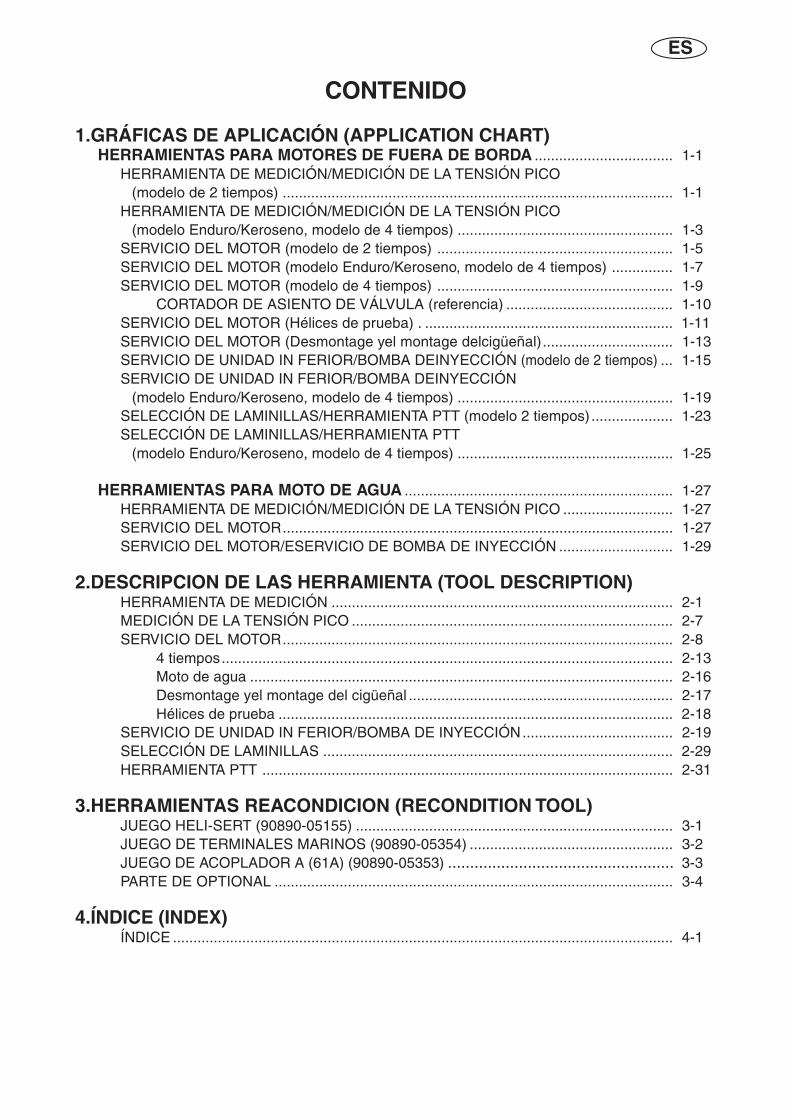
ES
CONTENIDO
1.GRÁFICAS DE APLICACIÓN (APPLICATION CHART)HERRAMIENTAS PARA MOTORES DE FUERA DE BORDA .................................. 1-1
HERRAMIENTA DE MEDICIÓN/MEDICIÓN DE LA TENSIÓN PICO(modelo de 2 tiempos) ................................................................................................ 1-1
HERRAMIENTA DE MEDICIÓN/MEDICIÓN DE LA TENSIÓN PICO(modelo Enduro/Keroseno, modelo de 4 tiempos) ..................................................... 1-3
SERVICIO DEL MOTOR (modelo de 2 tiempos) .......................................................... 1-5SERVICIO DEL MOTOR (modelo Enduro/Keroseno, modelo de 4 tiempos) ............... 1-7SERVICIO DEL MOTOR (modelo de 4 tiempos) .......................................................... 1-9
CORTADOR DE ASIENTO DE VÁLVULA (referencia) ......................................... 1-10SERVICIO DEL MOTOR (Hélices de prueba) . ............................................................. 1-11SERVICIO DEL MOTOR (Desmontage yel montage delcigüeñal)................................ 1-13SERVICIO DE UNIDAD IN FERIOR/BOMBA DEINYECCIÓN (modelo de 2 tiempos) ... 1-15SERVICIO DE UNIDAD IN FERIOR/BOMBA DEINYECCIÓN
(modelo Enduro/Keroseno, modelo de 4 tiempos) ..................................................... 1-19SELECCIÓN DE LAMINILLAS/HERRAMIENTA PTT (modelo 2 tiempos) .................... 1-23SELECCIÓN DE LAMINILLAS/HERRAMIENTA PTT
(modelo Enduro/Keroseno, modelo de 4 tiempos) ..................................................... 1-25
HERRAMIENTAS PARA MOTO DE AGUA .................................................................. 1-27HERRAMIENTA DE MEDICIÓN/MEDICIÓN DE LA TENSIÓN PICO ........................... 1-27SERVICIO DEL MOTOR................................................................................................ 1-27SERVICIO DEL MOTOR/ESERVICIO DE BOMBA DE INYECCIÓN ............................ 1-29
2.DESCRIPCION DE LAS HERRAMIENTA (TOOL DESCRIPTION)HERRAMIENTA DE MEDICIÓN .................................................................................... 2-1MEDICIÓN DE LA TENSIÓN PICO ............................................................................... 2-7SERVICIO DEL MOTOR................................................................................................ 2-8
4 tiempos............................................................................................................... 2-13Moto de agua ........................................................................................................ 2-16Desmontage yel montage del cigüeñal ................................................................. 2-17Hélices de prueba ................................................................................................. 2-18
SERVICIO DE UNIDAD IN FERIOR/BOMBA DE INYECCIÓN..................................... 2-19SELECCIÓN DE LAMINILLAS ...................................................................................... 2-29HERRAMIENTA PTT ..................................................................................................... 2-31
3.HERRAMIENTAS REACONDICION (RECONDITION TOOL)JUEGO HELI-SERT (90890-05155) .............................................................................. 3-1JUEGO DE TERMINALES MARINOS (90890-05354) .................................................. 3-2JUEGO DE ACOPLADOR A (61A) (90890-05353) ................................................... 3-3PARTE DE OPTIONAL .................................................................................................. 3-4
4.ÍNDICE (INDEX)ÍNDICE ........................................................................................................................... 4-1
1-1
APPLICATION CHART
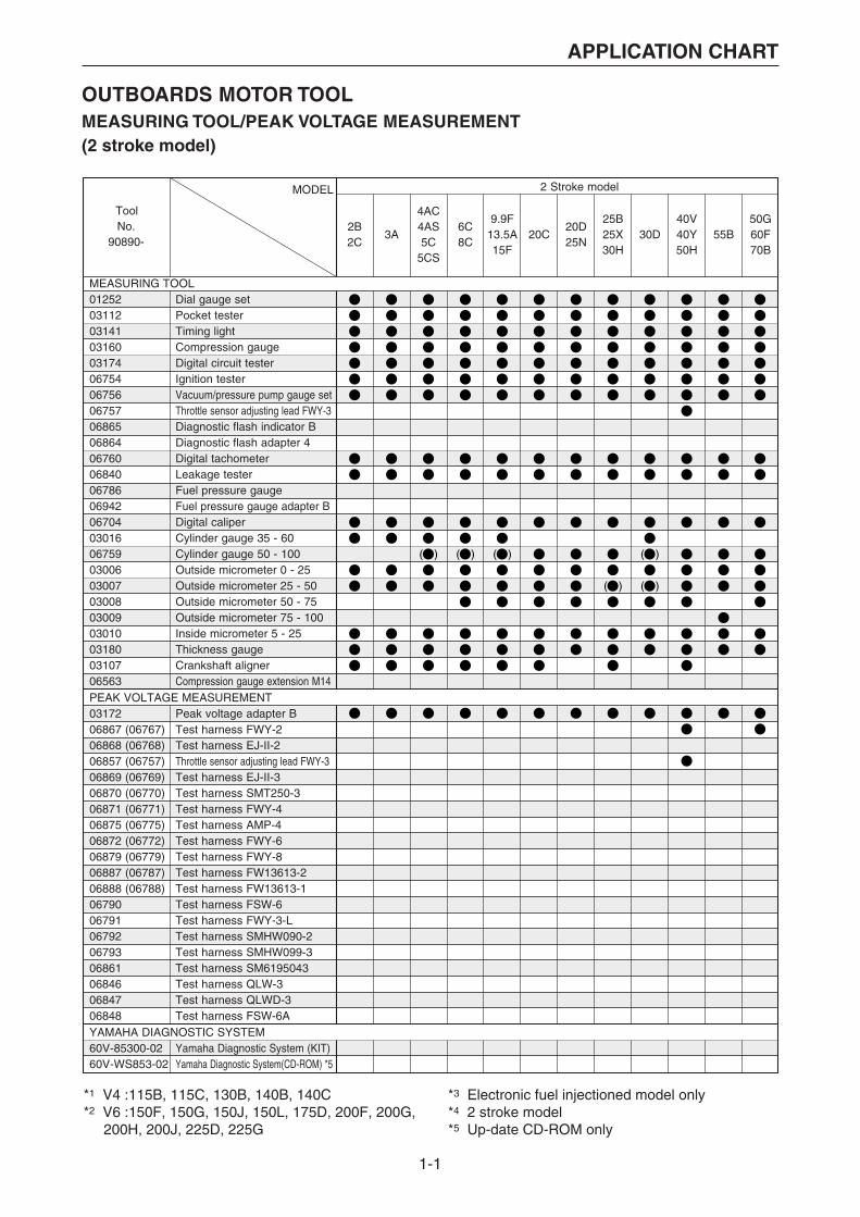
OUTBOARDS MOTOR TOOLMEASURING TOOL/PEAK VOLTAGE MEASUREMENT(2 stroke model)
MODEL 2 Stroke model
2B2C
3A
4AC4AS5C
5CS
6C8C
20C20D25N
25B25X30H
30D40V40Y50H
55B50G60F70B
9.9F13.5A15F
MEASURING TOOL
ToolNo.
90890-
01252031120314103160031740675406756067570686506864067600684006786069420670403016067590300603007030080300903010031800310706563
Dial gauge setPocket testerTiming lightCompression gaugeDigital circuit testerIgnition testerVacuum/pressure pump gauge setThrottle sensor adjusting lead FWY-3Diagnostic flash indicator BDiagnostic flash adapter 4Digital tachometerLeakage testerFuel pressure gaugeFuel pressure gauge adapter B Digital caliperCylinder gauge 35 - 60Cylinder gauge 50 - 100Outside micrometer 0 - 25Outside micrometer 25 - 50Outside micrometer 50 - 75Outside micrometer 75 - 100Inside micrometer 5 - 25Thickness gaugeCrankshaft alignerCompression gauge extension M14
PEAK VOLTAGE MEASUREMENT0317206867 (06767)06868 (06768)06857 (06757)06869 (06769)06870 (06770)06871 (06771)06875 (06775)06872 (06772)06879 (06779)06887 (06787)06888 (06788)0679006791067920679306861068460684706848
Peak voltage adapter BTest harness FWY-2Test harness EJ-II-2Throttle sensor adjusting lead FWY-3Test harness EJ-II-3Test harness SMT250-3Test harness FWY-4Test harness AMP-4Test harness FWY-6Test harness FWY-8Test harness FW13613-2Test harness FW13613-1Test harness FSW-6Test harness FWY-3-LTest harness SMHW090-2Test harness SMHW099-3Test harness SM6195043Test harness QLW-3Test harness QLWD-3Test harness FSW-6A
YAMAHA DIAGNOSTIC SYSTEM60V-85300-0260V-WS853-02
Yamaha Diagnostic System (KIT)Yamaha Diagnostic System(CD-ROM) *5
*1 V4 :115B, 115C, 130B, 140B, 140C*2 V6 :150F, 150G, 150J, 150L, 175D, 200F, 200G, 200H, 200J, 225D, 225G
*3 Electronic fuel injectioned model only*4 2 stroke model*5 Up-date CD-ROM only

1-2
APPLICATION CHART
2 Stroke model
60V-85300-0260V-WS853-02
ToolNo.
90890-
55D75A75B85A
75C80A90A
V4*1 L130B V6*2 D150N150A175A200A
L150FL150JL200FL200J
225C250A225F250B
L225CL250AL225FL250B
Z150PZ150QZ175GZ175HZ200NZ200P
LZ150PLZ200N
Z225HZ250F
Z250DZ300AZ300B
LZ250DLZ300A
L150AL200A
01252031120314103160031740675406756067570686506864067600684006786069420670403016067590300603007030080300903010031800310706563
0317206867 (06767)06868 (06768)06857 (06757)06869 (06769)06870 (06770)06871 (06771)06875 (06775)06872 (06772)06879 (06779)06887 (06787)06888 (06788)0679006791067920679306861068460684706848

1-3
APPLICATION CHART
MEASURING TOOL/PEAK VOLTAGE MEASUREMENT(Enduro/Kerosene model, 4 stroke model)
MODEL Enduro/Kerosene model 4 Stroke model
MEASURING TOOL
PEAK VOLTAGE MEASUREMENT
YAMAHA DIAGNOSTIC SYSTEM60V-85300-0260V-WS853-02
Yamaha Diagnostic System (KIT)Yamaha Diagnostic System(CD-ROM) *5
ToolNo.
90890-E8DEK8D
E9.9DE15D
EK9.9DEK15DEK9.9JEK15PEK9.9HEK15N
40G*4
E40GEK40G
E40X40X*4
40J*4
K40JE48CE55C
E60HK50E
E60JE65AE75B
E115AE25BEK25BE30H
F2.5A F4A
*1 V4 :115B, 115C, 130B, 140B, 140C*2 V6 :150F, 150G, 150J, 150L, 175D, 200F, 200G, 200H, 200J, 225D, 225G
*3 Electronic fuel injectioned model only*4 2 stroke model*5 Up-date CD-ROM only
01252031120314103160031740675406756067570686506864067600684006786069420670403016067590300603007030080300903010031800310706563
Dial gauge setPocket testerTiming lightCompression gaugeDigital circuit testerIgnition testerVacuum/pressure pump gauge setThrottle sensor adjusting lead FWY-3Diagnostic flash indicator BDiagnostic flash adapter 4Digital tachometerLeakage testerFuel pressure gaugeFuel pressure gauge adapter BDigital caliperCylinder gauge 35 - 60Cylinder gauge 50 - 100Outside micrometer 0 - 25Outside micrometer 25 - 50Outside micrometer 50 - 75Outside micrometer 75 - 100Inside micrometer 5 - 25Thickness gaugeCrankshaft alignerCompression gauge extension M14
0317206867 (06767)06868 (06768)06857 (06757)06869 (06769)06870 (06770)06871 (06771)06875 (06775)06872 (06772)06879 (06779)06887 (06787)06888 (06788)0679006791067920679306861068460684706848
Peak voltage adapter BTest harness FWY-2Test harness EJ-II-2Throttle sensor adjusting lead FWY-3Test harness EJ-II-3Test harness SMT250-3Test harness FWY-4Test harness AMP-4Test harness FWY-6Test harness FWY-8Test harness FW13613-2Test harness FW13613-1Test harness FSW-6Test harness FWY-3-LTest harness SMHW090-2Test harness SMHW099-3Test harness SM6195043Test harness QLW-3Test harness QLWD-3Test harness FSW-6A
F6AF6BF8C
1-4
APPLICATION CHART
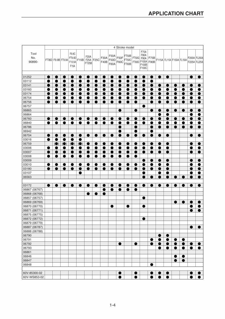
4 Stroke model
ToolNo.
90890-F150A FL150AFT8D F9.9B F15B F25CFT9.9A
F9.9CFT9.9DF13.5AF15A
F50F FT50GF60C FT60D
F20AF25A
FT25B
F50AF50DF60A
FT50BFT50CFT60B
F75AF80AF90AF100AF100BF100C
F115A FL115AF200AF225A
F75BF90B
FL200AFL225A
F30AF40B
01252031120314103160031740675406756067570686506864067600684006786069420670403016067590300603007030080300903010031800310706563
0317206867 (06767)06868 (06768)06857 (06757)06869 (06769)06870 (06770)06871 (06771)06875 (06775)06872 (06772)06879 (06779)06887 (06787)06888 (06788)0679006791067920679306861068460684706848
60V-85300-0260V-WS853-02

1-5
APPLICATION CHART
ENGINE SERVICE(2 stroke model)
*1 V4 :115B, 115C, 130B, 140B, 140C*2 V6 :150F, 150G, 150J, 150L, 175D, 200F, 200G, 200H, 200J, 225D, 225G
*3 Electronic fuel injectioned model only*4 2 stroke model
MODEL 2 Stroke model
GENERAL TOOL
ToolNo.
90890-2B2C
3A
4AC4AS5C
5CS
6C8C
20C20D25N
25B25X30H
30D40V40Y50H
55B50G60F70B
9.9F13.5A15F
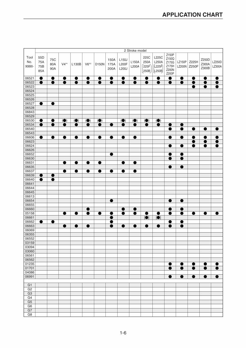
065210652206523065240652506526065270652806843065290653006534065400654306606066230662406626066520663006631066350663706639066400664106644066450661306654066550666005158066610666206663060690635506552031590309403060065610656201235017010408606991
Flywheel pullerFlywheel holderBearing outer race puller AssySmall end bearing installerSmall end bearing installerSmall end bearing installerSmall end bearing installerSmall end bearing installerPiston slider ø58Piston slider ø70Piston slider ø85Bearing separatorGear pullerSmall end bearing installerDriver rod LSBearing outer race attachmentBearing outer race attachmentBearing outer race attachmentDriver rod L3Ball bearing attachmentBall bearing attachmentBall bearing attachmentBall bearing attachmentBearing inner race attachmentBearing inner race attachmentBearing inner race attachmentBearing inner race attachmentBearing inner race attachmentNeedle bearing attachmentNeedle bearing attachmentBall bearing attachmentBearing inner race attachmentPiston ring compressorBearing inner race attachmentBearing inner race attachmentBall bearing attachmentShaft holderCrankshaft holder 16Crankshaft holder 20Vacuum gaugeVacuum gauge [Selector type]• AttachmentCrankshaft holder 12Crankshaft holder 18Rotor holderSheave holderUniversal clutch holderInjector grease
G1G2G3G4G5G6G7G8
Deep socket 1 (30 X 100)Deep socket 2 (36 X 100)Deep socket 3 (41 X 100)Deep socket 4 (46 X 100)T-type TORX socket T55E-type TORX socket E10TORX tamper resistant driver T20TORX tamper resistant driver T25
1-6
APPLICATION CHART
2 Stroke model
ToolNo.
90890-
55D75A75B85A
75C80A90A
V4*1 L130B V6*2 D150N150A175A200A
L150JL200FL200J
L225CL250AL225FL250B
Z150PZ150QZ175GZ175HZ200NZ200P
LZ150PLZ200N
Z225HZ250F
Z250DZ300AZ300B
LZ250DLZ300A
225C250A225F250B
L150AL200A
065210652206523065240652506526065270652806843065290653006534065400654306606066230662406626066520663006631066350663706639066400664106644066450661306654066550666005158066610666206663060690635506552031590309403060065610656201235017010408606991
G1G2G3G4G5G6G7G8
1-7
APPLICATION CHART
E60HK50E
E60JE65AE75B
E115A F2.5A F4A
Enduro/Kerosene model
E8DEK8D
E9.9DE15D
EK9.9DEK15DEK9.9JEK15PEK9.9HEK15N
E25BEK25BE30H
40G*4
E40GEK40G
40J*4
K40JE48CE55C
E40X40X*4
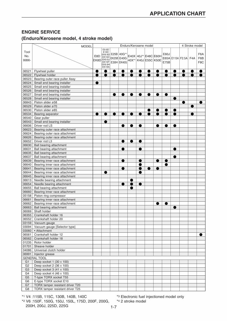
4 Stroke modelMODEL
ToolNo.
90890-
065210652206523065240652506526065270652806843065290653006534065400654306606066230662406626066520663006631066350663706639066400664106644066450661306654066550666005158066610666206663060690635506552031590309403060065610656201235017010408606991
Flywheel pullerFlywheel holderBearing outer race puller AssySmall end bearing installerSmall end bearing installerSmall end bearing installerSmall end bearing installerSmall end bearing installerPiston slider ø58Piston slider ø70Piston slider ø85Bearing separatorGear pullerSmall end bearing installerDriver rod LSBearing outer race attachmentBearing outer race attachmentBearing outer race attachmentDriver rod L3Ball bearing attachmentBall bearing attachmentBall bearing attachmentBall bearing attachmentBearing inner race attachmentBearing inner race attachmentBearing inner race attachmentBearing inner race attachmentBearing inner race attachmentNeedle bearing attachmentNeedle bearing attachmentBall bearing attachmentBearing inner race attachmentPiston ring compressorBearing inner race attachmentBearing inner race attachmentBall bearing attachmentShaft holderCrankshaft holder 16Crankshaft holder 20Vacuum gaugeVacuum gauge [Selector type]• AttachmentCrankshaft holder 12Crankshaft holder 18Rotor holderSheave holderUniversal clutch holderInjector grease
GENERAL TOOLG1G2G3G4G5G6G7G8
Deep socket 1 (30 X 100)Deep socket 2 (36 X 100)Deep socket 3 (41 X 100)Deep socket 4 (46 X 100)T-type TORX socket T55E-type TORX socket E10TORX tamper resistant driver T20TORX tamper resistant driver T25
*1 V4 :115B, 115C, 130B, 140B, 140C*2 V6 :150F, 150G, 150J, 150L, 175D, 200F, 200G, 200H, 200J, 225D, 225G
*3 Electronic fuel injectioned model only*4 2 stroke model
F6AF6BF8C
ENGINE SERVICE(Enduro/Kerosene model, 4 stroke model)
1-8
APPLICATION CHART
F115A FL115A F150A FL150AF200AF225A
F75BF90B
FL200AFL225A
F75AF80AF90A
F100AF100BF100C
4 Stroke model
F9.9B F15B F25CFT9.9A
F9.9CFT9.9DF13.5AF15A
F50F FT50GF60C FT60D
F20AF25A
FT25B
F30AF40B
F50AF50DF60A
FT50BFT50CFT60B
FT8D
ToolNo.
90890-
065210652206523065240652506526065270652806843065290653006534065400654306606066230662406626066520663006631066350663706639066400664106644066450661306654066550666005158066610666206663060690635506552031590309403060065610656201235017010408606991
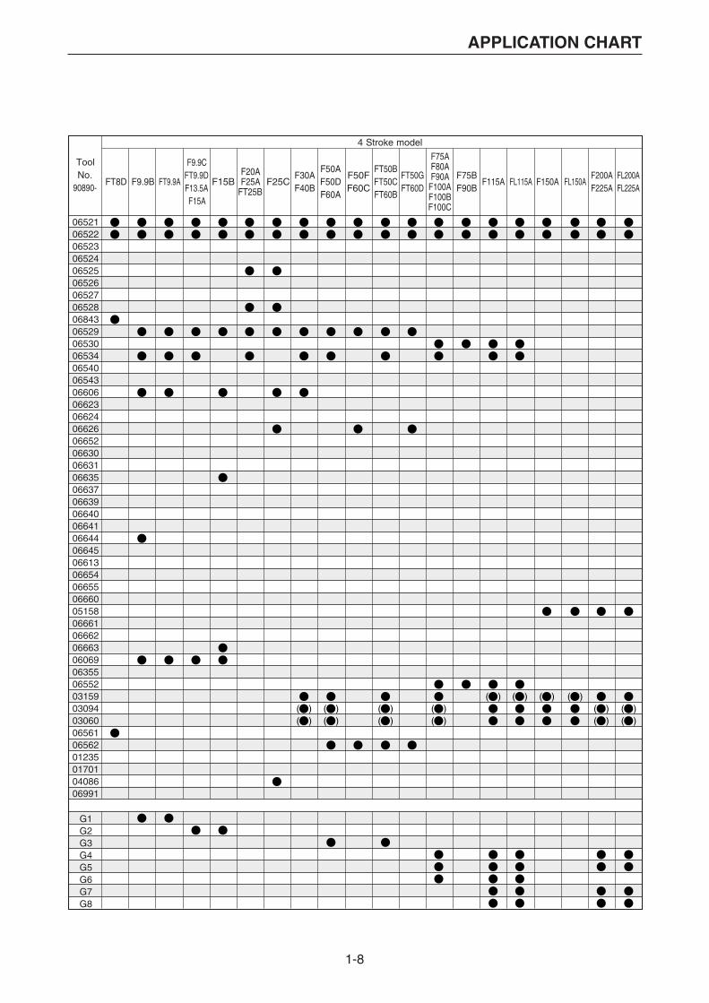
G1G2G3G4G5G6G7G8
1-9
APPLICATION CHART
MODEL 4 Stroke model
ToolNo.
90890-F2.5A F4A
F6AF6BF8C
F9.9B F15B F25CFT9.9A
F9.9CFT9.9DF13.5AF15A
F20AF25A
FT25B
F30AF40B
F50AF50DF60A
FT8D
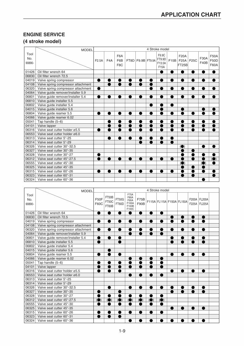
014260683004019041080632004064068010681006802040150680404066050410410106316065530631306314063260632706328063120655506325063150632306324
Oil filter wrench 64Oil filter wrench 72.5Valve spring compressorValve spring compressor attachmentValve spring compressor attachmentValve guide remover/installer 5.9Valve guide remover/installer 5.4Valve guide installer 5.5Valve guide installer 5.4Valve guide installer 5.6Valve guide reamer 5.5Valve guide reamer 6.02Tap handle (5–6)Valve lapperValve seat cutter holder ø5.5Valve seat cutter holder ø6.0Valve seat cutter 5°-25Valve seat cutter 5°-29Valve seat cutter 30°-32.5Valve seat cutter 30°-35Valve seat cutter 30°-27Valve seat cutter 45°-27.5Valve seat cutter 45°-30Valve seat cutter 45°-35Valve seat cutter 60°-26Valve seat cutter 60°-31Valve seat cutter 60°-36
MODEL 4 Stroke model
ToolNo.
90890-F50FF60C
F75BF90B
F200AF225A
FL200AFL225A
FT50GFT60D
014260683004019041080632004064068010681006802040150680404066050410410106316065530631306314063260632706328063120655506325063150632306324
Oil filter wrench 64Oil filter wrench 72.5Valve spring compressorValve spring compressor attachmentValve spring compressor attachmentValve guide remover/installer 5.9Valve guide remover/installer 5.4Valve guide installer 5.5Valve guide installer 5.4Valve guide installer 5.6Valve guide reamer 5.5Valve guide reamer 6.02Tap handle (5–6)Valve lapperValve seat cutter holder ø5.5Valve seat cutter holder ø6.0Valve seat cutter 5°-25Valve seat cutter 5°-29Valve seat cutter 30°-32.5Valve seat cutter 30°-35Valve seat cutter 30°-27Valve seat cutter 45°-27.5Valve seat cutter 45°-30Valve seat cutter 45°-35Valve seat cutter 60°-26Valve seat cutter 60°-31Valve seat cutter 60°-36
F75AF80AF90A
F100AF100BF100C
FT50BFT50C F115A FL115A F150A FL150AFT60B
ENGINE SERVICE(4 stroke model)

1-10
APPLICATION CHART
AB
C
AB
C
F20A/F25A/FT25BF30A/F40BMODEL
Part of port
TOOL No.90890-06316 (ø5.5 mm holder)06312 (45°, ø27.5 mm)06313 (5°, ø25 mm)06314 (5°, ø29 mm)06315 (60°, ø26 mm)06553 (ø6.0 mm holder)06555 (45°, ø30 mm)06323 (60°, ø31 mm)06324 (60°, ø36 mm)06325 (45°, ø35 mm)06326 (30°, ø32.5 mm)06327 (30°, ø35 mm) New06328 (30°, ø27 mm)
In. A In. B In. C Ex. A Ex. B Ex. C In. A In. B In. C Ex. A Ex. B Ex. C In. A In. B In. C Ex. A Ex. B Ex. C In. A In. B In. C Ex. A Ex. B Ex. C
F2.5AF4A/F6A
F6BF8C/FT8D
F9.9A/F9.9BF9.9C/F9.9D
F13.5A/F15A/F15B
MODEL
Part of port
TOOL No.90890-06316 (ø5.5 mm holder)06312 (45°, ø27.5 mm)06313 (5°, ø25 mm)06314 (5°, ø29 mm)06315 (60°, ø26 mm)06553 (ø6.0 mm holder)06555 (45°, ø30 mm)06323 (60°, ø31 mm)06324 (60°, ø36 mm)06325 (45°, ø35 mm)06326 (30°, ø32.5 mm)06327 (30°, ø35 mm) New06328 (30°, ø27 mm)
In. A In. B In. C Ex. A Ex. B Ex. C In. A In. B In. C Ex. A Ex. B Ex. C In. A In. B In. C Ex. A Ex. B Ex. C In. A In. B In. C Ex. A Ex. B Ex. C
F25C F50F/FT50G/F60C/FT60DF50A/F60A/FT60BFT50B/FT50C/F50D
F75A/F75B/F80A/F90AF90B/F100A/F100B
F100C/F115A/FL115A
MODEL
Part of port
TOOL No.90890-06316 (ø5.5 mm holder)06312 (45°, ø27.5 mm)06313 (5°, ø25 mm)06314 (5°, ø29 mm)06315 (60°, ø26 mm)06553 (ø6.0 mm holder)06555 (45°, ø30 mm)06323 (60°, ø31 mm)06324 (60°, ø36 mm)06325 (45°, ø35 mm)06326 (30°, ø32.5 mm)06327 (30°, ø35 mm) New06328 (30°, ø27 mm)
In. A In. B In. C Ex. A Ex. B Ex. C
F150A/F200A/FL200AFL150A/F225A/FL225A
VALVE SEAT CUTTER (Refering)

1-11
APPLICATION CHART
MODEL 2 Stroke model
ToolNo.
90890-
*1 V4 :115B, 115C, 130B, 140B, 140C*2 V6 :150F, 150G, 150J, 150L, 175D, 200F, 200G, 200H, 200J, 225D, 225G*3 Electronic fuel injectioned model only*4 2 stroke modelNA : Not availables
2B2C
3A4AS5C
5CS
6C8C
20C20D25N
25B25X30H
30D40V40Y50H
55B50G60F70B
9.9F13.5A15F
016010160901611016130161801619016200162101624016250162601627016290163001631
Test propeller (646)Test propeller (647)Test propeller (663)Test propeller (664)Test propeller (676)Test propeller (683)Test propeller (688)Test propeller (689)Test propeller (6E5)Test propeller (6G1)Test propeller (6G5)Test propeller (6G8)Test propeller (61N)Test propeller (6L5)Test propeller (6L6)
55D75A75B85A
75C80A90A
MODEL 2 Stroke model
ToolNo.
90890-
016010160901611016130161801619016200162101624016250162601627016290163001631
Test propeller (646)Test propeller (647)Test propeller (663)Test propeller (664)Test propeller (676)Test propeller (683)Test propeller (688)Test propeller (689)Test propeller (6E5)Test propeller (6G1)Test propeller (6G5)Test propeller (6G8)Test propeller (61N)Test propeller (6L5)Test propeller (6L6)
NA NA NA NA NA NA NA NA NA
V4*1 L130B V6*2 D150N
150A175A200A
L200A
L150FL150JL200FL200J
L225CL250AL225FL250B
Z150PZ150QZ175GZ175HZ200NZ200P
LZ150PLZ200N
Z225HZ250F
Z250DZ300AZ300B
LZ250DLZ300A
225C250A225F250B
L150AL200A
ENGINE SERVICE(Test propeller)(2 stroke model)
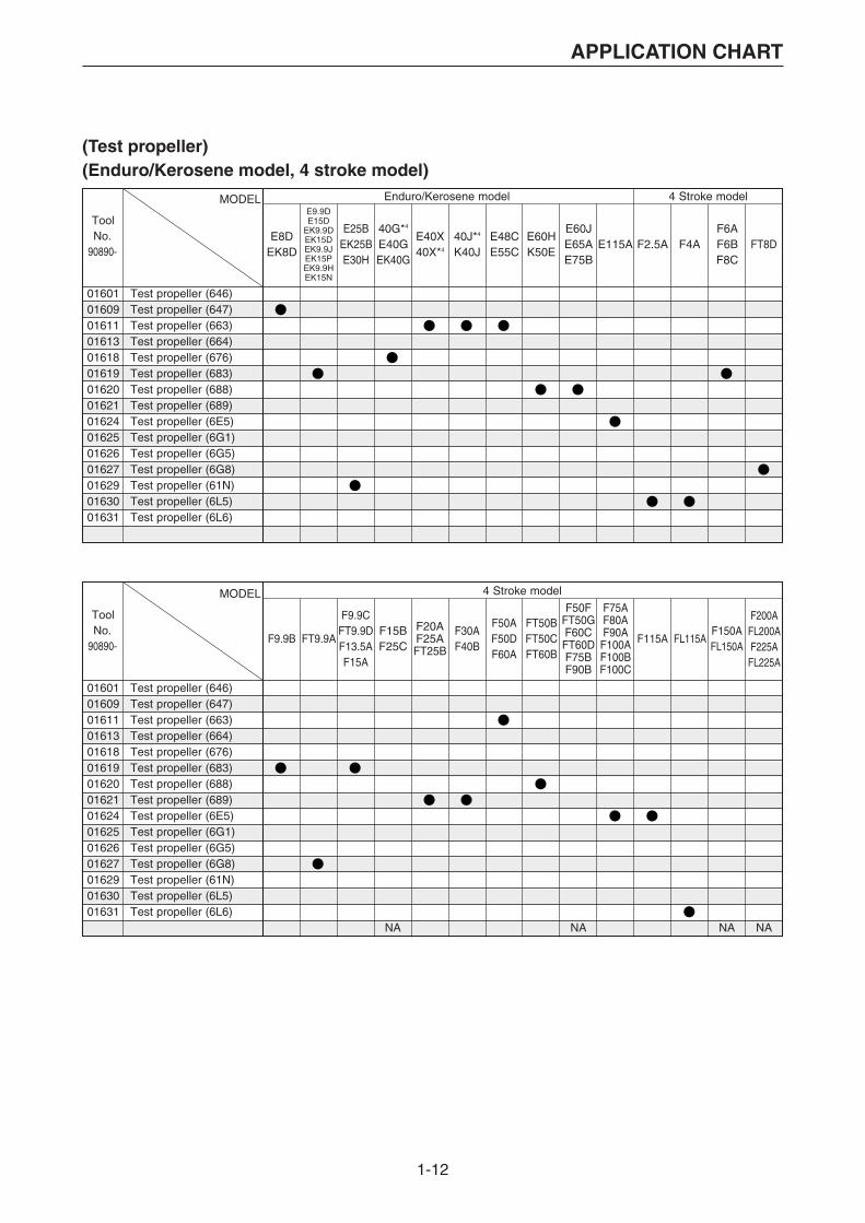
1-12
APPLICATION CHART
F6AF6BF8C
FT8D
F9.9B FT9.9A
F9.9CFT9.9DF13.5AF15A
F20AF25AFT25B
F50AF50DF60A
FT50BFT50CFT60B
F75AF80AF90AF100AF100BF100C
F115A FL115A
F200AFL200AF150A
FL150A F225AFL225A
F30AF40B
MODEL Enduro/Kerosene model 4 Stroke model
ToolNo.
90890-E8D
EK8D
E9.9DE15D
EK9.9DEK15DEK9.9JEK15PEK9.9HEK15N
40G*4
E40GEK40G
E40X40X*4
40J*4
K40JE48CE55C
E60HK50E
E60JE65AE75B
E115AE25B
EK25BE30H
F2.5A F4A
016010160901611016130161801619016200162101624016250162601627016290163001631
Test propeller (646)Test propeller (647)Test propeller (663)Test propeller (664)Test propeller (676)Test propeller (683)Test propeller (688)Test propeller (689)Test propeller (6E5)Test propeller (6G1)Test propeller (6G5)Test propeller (6G8)Test propeller (61N)Test propeller (6L5)Test propeller (6L6)
MODEL 4 Stroke model
ToolNo.
90890-
016010160901611016130161801619016200162101624016250162601627016290163001631
Test propeller (646)Test propeller (647)Test propeller (663)Test propeller (664)Test propeller (676)Test propeller (683)Test propeller (688)Test propeller (689)Test propeller (6E5)Test propeller (6G1)Test propeller (6G5)Test propeller (6G8)Test propeller (61N)Test propeller (6L5)Test propeller (6L6)
NA NA
F15BF25C
NA
F50FFT50GF60CFT60DF75BF90B
NA
(Test propeller)(Enduro/Kerosene model, 4 stroke model)

1-13
APPLICATION CHART
MODEL 2 stroke model
Q’ty
ToolNo.
90890-3A
6C8C
9.9F13.5A15F
20C20D25N
25B25X30H
4AC4AS5C
5CS
2B2C
024220235102352023530235402355023570235802359023610236302365023660239902367023690237102376023770237902384023850238602387023880238902390023910239202393023940239502396024190240102402024030240406590
024160240702408024090241002411
0241702412024130241402415
02418
Crank shaft jig set• Flange• Body• Bolt• Washer• Bushing-1 (D15)• Bushing-3 (D20)• Bushing-4 (D22)• Bushing-5 (D25)• Bushing-7 (D29)• Bushing-9 (D30)• Bushing-1 (B11)• Bushing-12 (D35)• Bushing-13 (D20)• Height ring-1 (H28)• Height-ring-3 (H40)• Height ring-5 (H47)• Height ring-10 (H53)• Height ring-5 (H54)• Height ring-13 (H57)• Pressure plate• Press body• Plate A• Plate B• Bolt• Pressure pin A• Pressure pin B• Bearing pressure A• Bearing pressure B• Bearing pressure C• Support• Spacer A• Spacer B• Bushing 14 (E25A/25V)• Height ring (E40G/J)• Plate C• Pressure pin C• Spacer C• Height ring 640 (H-19)
Disassembling kit• Nut• Pressure plate• Pole• Plate A• Plate B
Assembling kit• Guide• Guide plate• Guide pole• Base
Crank separater kit (set 02416 + 02417)
111441212111121111111112211111211112111
161311
13111
–
ENGINE SERVICE(Crankshaft disassembly and reassembly)(2 stroke model)
The tools on these pages (1-13 and 1-14) can be ordered from
the Marine Service Division of Yamaha Motor Co., Ltd.
Q’ty : The figure for this part indicates the quantity of the parts ordered in a set or a kit.

1-14
APPLICATION CHART
MODEL Enduro/Kerosene model
Q’ty
ToolNo.
90890-
E9.9DE15D
EK9.9DEK15DEK9.9JEK15PEK9.9HEK15N
40G*1
E40GEK40G
E40X40X*1
40J*1
K40JE48CE55C
E60HK50E
E25BEK25BE30H
E8DEK8D
*1 2 stroke model
024220235102352023530235402355023570235802359023610236302365023660239902367023690237102376023770237902384023850238602387023880238902390023910239202393023940239502396024190240102402024030240406590
024160240702408024090241002411
0241702412024130241402415
02418
Crank shaft jig set• Flange• Body• Bolt• Washer• Bushing-1 (D15)• Bushing-3 (D20)• Bushing-4 (D22)• Bushing-5 (D25)• Bushing-7 (D29)• Bushing-9 (D30)• Bushing-1 (B11)• Bushing-12 (D35)• Bushing-13 (D20)• Height ring-1 (H28)• Height-ring-3 (H40)• Height ring-5 (H47)• Height ring-10 (H53)• Height ring-5 (H54)• Height ring-13 (H57)• Pressure plate• Press body• Plate A• Plate B• Bolt• Pressure pin A• Pressure pin B• Bearing pressure A• Bearing pressure B• Bearing pressure C• Support• Spacer A• Spacer B• Bushing 14 (E25A/25V)• Height ring (E40G/J)• Plate C• Pressure pin C• Spacer C• Height ring 640 (H-19)
Disassembling kit• Nut• Pressure plate• Pole• Plate A• Plate B
Assembling kit• Guide• Guide plate• Guide pole• Base
Crank separater kit (set 02416 + 02417)
111441212111121111111112211111211112111
161311
13111
–
(Crankshaft disassembly and reassembly)(Enduro/Kerosene model)
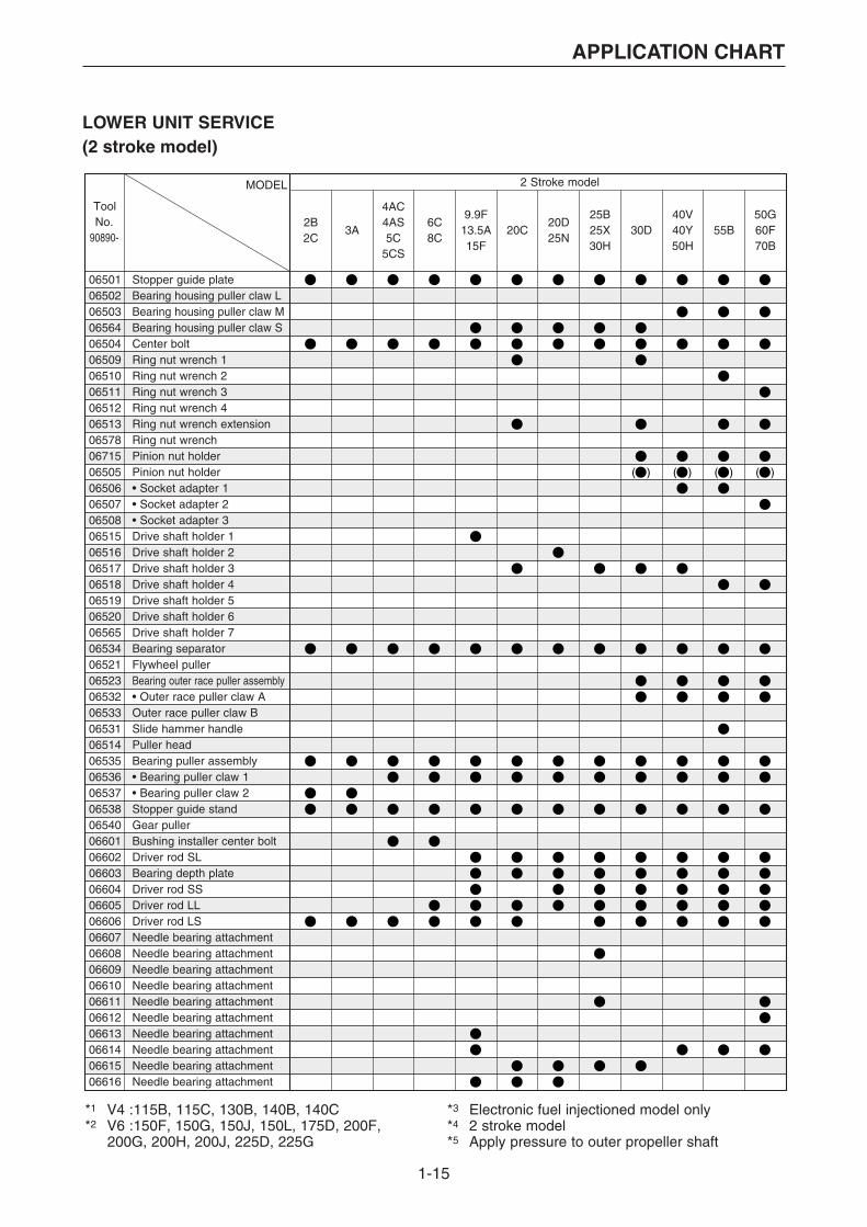
1-15
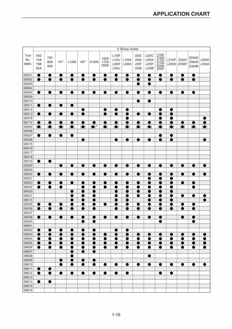
APPLICATION CHART
LOWER UNIT SERVICE(2 stroke model)
MODEL 2 Stroke model
ToolNo.
90890-2B2C
3A
4AC4AS5C
5CS
6C8C
20C20D25N
25B25X30H
30D40V40Y50H
55B50G60F70B
9.9F13.5A15F
*1 V4 :115B, 115C, 130B, 140B, 140C*2 V6 :150F, 150G, 150J, 150L, 175D, 200F, 200G, 200H, 200J, 225D, 225G
*3 Electronic fuel injectioned model only*4 2 stroke model*5 Apply pressure to outer propeller shaft
065010650206503065640650406509065100651106512065130657806715065050650606507065080651506516065170651806519065200656506534065210652306532065330653106514065350653606537065380654006601066020660306604066050660606607066080660906610066110661206613066140661506616
Stopper guide plateBearing housing puller claw LBearing housing puller claw MBearing housing puller claw SCenter boltRing nut wrench 1Ring nut wrench 2Ring nut wrench 3Ring nut wrench 4Ring nut wrench extensionRing nut wrenchPinion nut holderPinion nut holder• Socket adapter 1• Socket adapter 2• Socket adapter 3Drive shaft holder 1Drive shaft holder 2Drive shaft holder 3Drive shaft holder 4Drive shaft holder 5Drive shaft holder 6Drive shaft holder 7Bearing separatorFlywheel pullerBearing outer race puller assembly• Outer race puller claw AOuter race puller claw BSlide hammer handlePuller headBearing puller assembly• Bearing puller claw 1• Bearing puller claw 2Stopper guide standGear pullerBushing installer center boltDriver rod SLBearing depth plateDriver rod SSDriver rod LLDriver rod LSNeedle bearing attachmentNeedle bearing attachmentNeedle bearing attachmentNeedle bearing attachmentNeedle bearing attachmentNeedle bearing attachmentNeedle bearing attachmentNeedle bearing attachmentNeedle bearing attachmentNeedle bearing attachment
1-16
APPLICATION CHART
55D75A75B85A
75C80A90A
V4*1 L130B V6*2 D150N150A175A200A
L150FL150JL200FL200J
225C250A225F250B
L225CL250AL225FL250B
Z150PZ150QZ175GZ175HZ200NZ200P
LZ150PLZ200N
Z225HZ250F
Z250DZ300AZ300B
LZ250DLZ300A
L150AL200A
2 Stroke model
ToolNo.
90890-
065010650206503065640650406509065100651106512065130657806715065050650606507065080651506516065170651806519065200656506534065210652306532065330653106514065350653606537065380654006601066020660306604066050660606607066080660906610066110661206613066140661506616
1-17
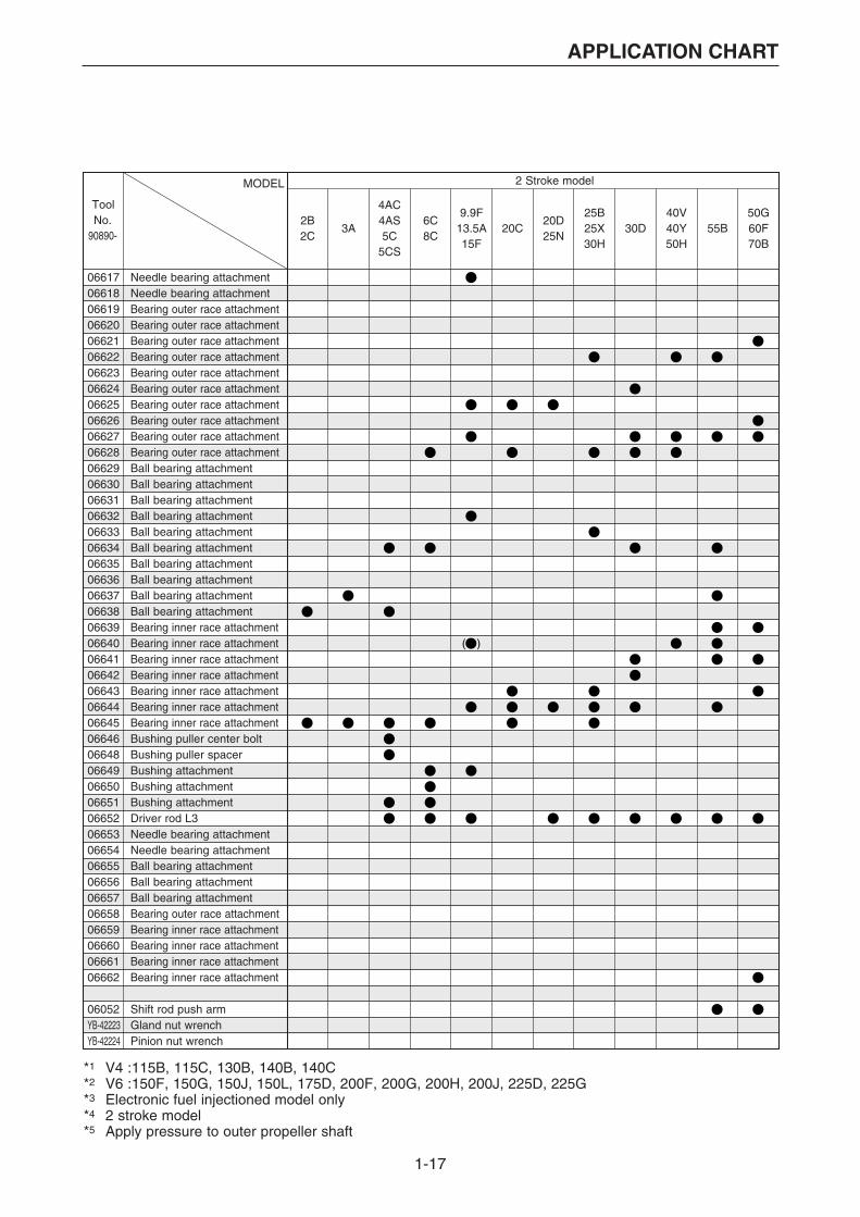
APPLICATION CHART
MODEL 2 Stroke model
ToolNo.
90890-2B2C
3A
4AC4AS5C
5CS
6C8C
20C20D25N
25B25X30H
30D40V40Y50H
55B50G60F70B
9.9F13.5A15F
*1 V4 :115B, 115C, 130B, 140B, 140C*2 V6 :150F, 150G, 150J, 150L, 175D, 200F, 200G, 200H, 200J, 225D, 225G*3 Electronic fuel injectioned model only*4 2 stroke model*5 Apply pressure to outer propeller shaft
066170661806619066200662106622066230662406625066260662706628066290663006631066320663306634066350663606637066380663906640066410664206643066440664506646066480664906650066510665206653066540665506656066570665806659066600666106662
06052YB-42223YB-42224
Needle bearing attachmentNeedle bearing attachmentBearing outer race attachmentBearing outer race attachmentBearing outer race attachmentBearing outer race attachmentBearing outer race attachmentBearing outer race attachmentBearing outer race attachmentBearing outer race attachmentBearing outer race attachmentBearing outer race attachmentBall bearing attachmentBall bearing attachmentBall bearing attachmentBall bearing attachmentBall bearing attachmentBall bearing attachmentBall bearing attachmentBall bearing attachmentBall bearing attachmentBall bearing attachmentBearing inner race attachmentBearing inner race attachmentBearing inner race attachmentBearing inner race attachmentBearing inner race attachmentBearing inner race attachmentBearing inner race attachmentBushing puller center boltBushing puller spacerBushing attachmentBushing attachmentBushing attachmentDriver rod L3Needle bearing attachmentNeedle bearing attachmentBall bearing attachmentBall bearing attachmentBall bearing attachmentBearing outer race attachmentBearing inner race attachmentBearing inner race attachmentBearing inner race attachmentBearing inner race attachment
Shift rod push armGland nut wrenchPinion nut wrench

1-18
APPLICATION CHART
55D75A75B85A
75C80A90A
V4*1 L130B V6*2 D150N150A175A200A
L150FL150JL200FL200J
225C250A225F250B
L225CL250AL225FL250B
Z150PZ150QZ175GZ175HZ200NZ200P
LZ150PLZ200N
Z225HZ250F
Z250DZ300AZ300B
LZ250DLZ300A
L150AL200A
2 Stroke model
ToolNo.
90890-
066170661806619066200662106622066230662406625066260662706628066290663006631066320663306634066350663606637066380663906640066410664206643066440664506646066480664906650066510665206653066540665506656066570665806659066600666106662
06052YB-42223YB-42224
1-19
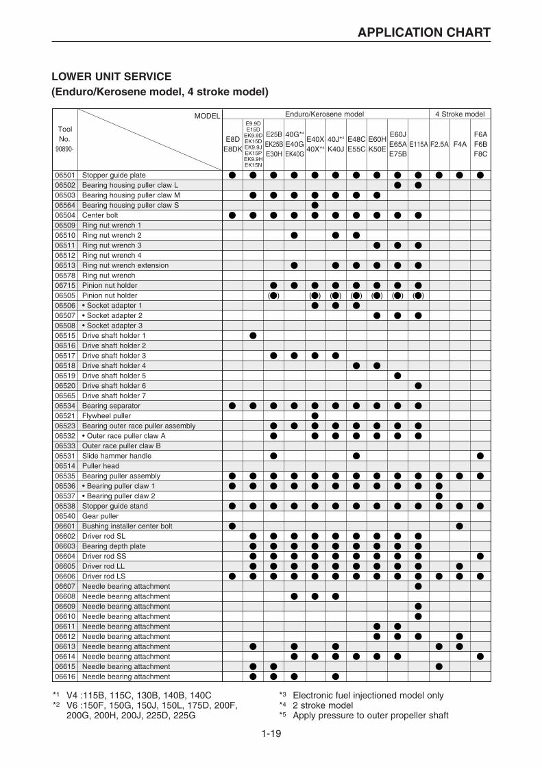
APPLICATION CHART
MODEL Enduro/Kerosene model 4 Stroke model
E8DE8DK
E9.9D
40G*4
E40GEK40G
E40X40X*4
40J*4
K40JE48CE55C
E60HK50E
E60JE65AE75B
F6AF6BF8C
E115AE25BEK25BE30H
F2.5A F4A
E15DEK9.9DEK15DEK9.9JEK15PEK9.9HEK15N
ToolNo.
90890-
065010650206503065640650406509065100651106512065130657806715065050650606507065080651506516065170651806519065200656506534065210652306532065330653106514065350653606537065380654006601066020660306604066050660606607066080660906610066110661206613066140661506616
Stopper guide plateBearing housing puller claw LBearing housing puller claw MBearing housing puller claw SCenter boltRing nut wrench 1Ring nut wrench 2Ring nut wrench 3Ring nut wrench 4Ring nut wrench extensionRing nut wrenchPinion nut holderPinion nut holder• Socket adapter 1• Socket adapter 2• Socket adapter 3Drive shaft holder 1Drive shaft holder 2Drive shaft holder 3Drive shaft holder 4Drive shaft holder 5Drive shaft holder 6Drive shaft holder 7Bearing separatorFlywheel pullerBearing outer race puller assembly• Outer race puller claw AOuter race puller claw BSlide hammer handlePuller headBearing puller assembly• Bearing puller claw 1• Bearing puller claw 2Stopper guide standGear pullerBushing installer center boltDriver rod SLBearing depth plateDriver rod SSDriver rod LLDriver rod LSNeedle bearing attachmentNeedle bearing attachmentNeedle bearing attachmentNeedle bearing attachmentNeedle bearing attachmentNeedle bearing attachmentNeedle bearing attachmentNeedle bearing attachmentNeedle bearing attachmentNeedle bearing attachment
*1 V4 :115B, 115C, 130B, 140B, 140C*2 V6 :150F, 150G, 150J, 150L, 175D, 200F, 200G, 200H, 200J, 225D, 225G
*3 Electronic fuel injectioned model only*4 2 stroke model*5 Apply pressure to outer propeller shaft
LOWER UNIT SERVICE(Enduro/Kerosene model, 4 stroke model)
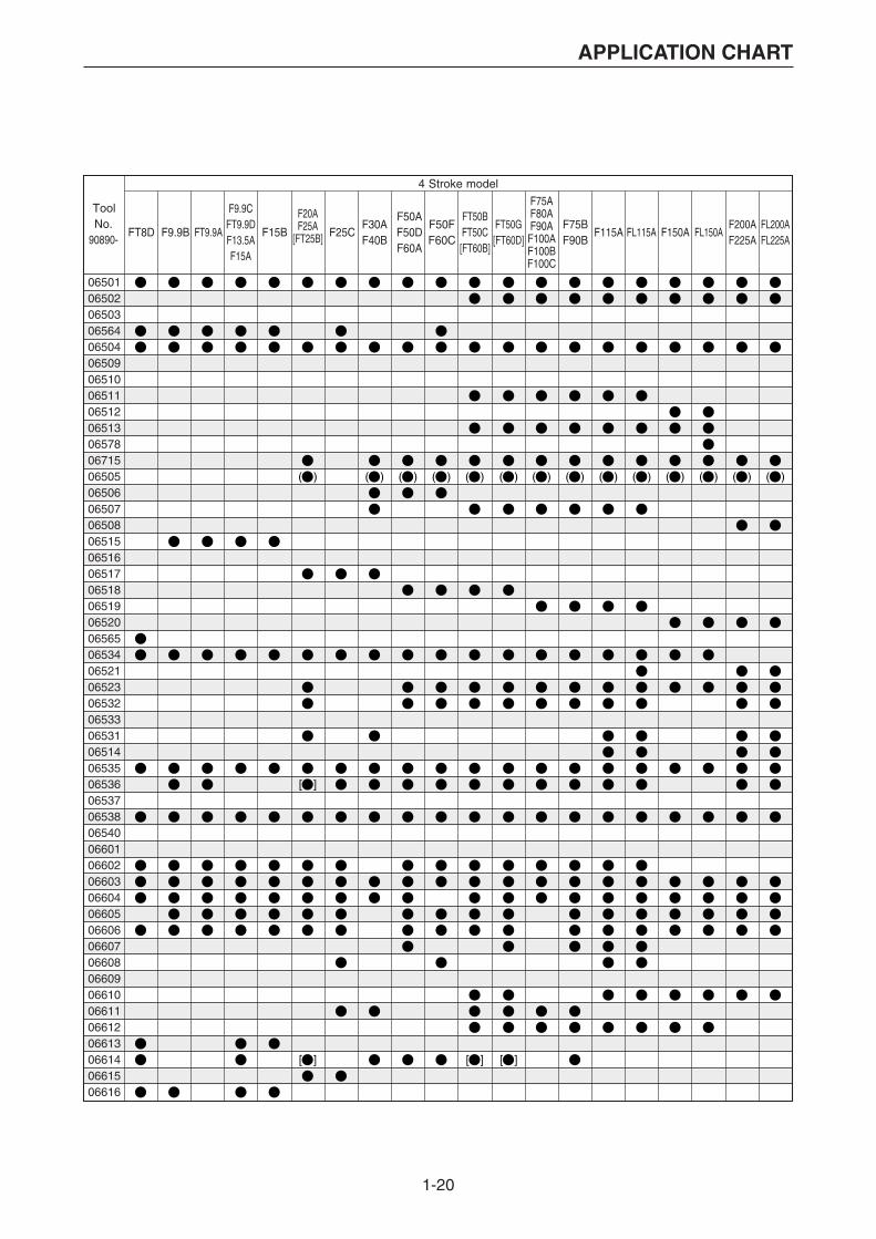
1-20
APPLICATION CHART
4 Stroke model
ToolNo.
90890-FT8D F9.9B F15B F25CFT9.9A
F9.9CFT9.9DF13.5AF15A
F20AF25A
[FT25B]
F50AF50DF60A
FT50BFT50C[FT60B]
F75AF80AF90A
F100AF100BF100C
F115A FL115AF200AF225A
F75BF90B
FT50G[FT60D]
F50FF60C
FL200AFL225A
F30AF40B
F150A FL150A
065010650206503065640650406509065100651106512065130657806715065050650606507065080651506516065170651806519065200656506534065210652306532065330653106514065350653606537065380654006601066020660306604066050660606607066080660906610066110661206613066140661506616
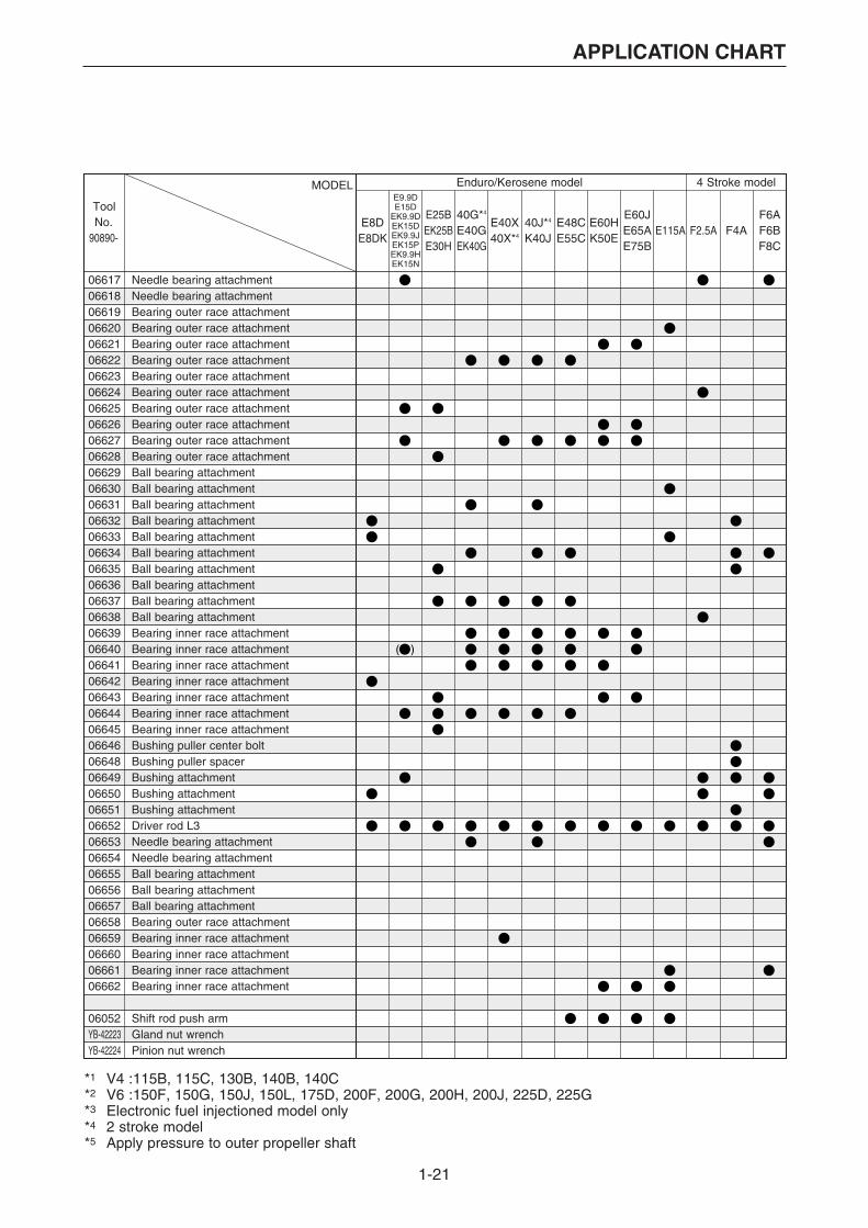
1-21
APPLICATION CHART
MODEL Enduro/Kerosene model 4 Stroke model
ToolNo.
90890-E8D
E8DK
E9.9DE15D
EK9.9DEK15DEK9.9JEK15PEK9.9HEK15N
40G*4
E40GEK40G
E40X40X*4
40J*4
K40JE48CE55C
E60HK50E
E60JE65AE75B
F6AF6BF8C
E115AE25BEK25BE30H
F2.5A F4A
*1 V4 :115B, 115C, 130B, 140B, 140C*2 V6 :150F, 150G, 150J, 150L, 175D, 200F, 200G, 200H, 200J, 225D, 225G*3 Electronic fuel injectioned model only*4 2 stroke model*5 Apply pressure to outer propeller shaft
066170661806619066200662106622066230662406625066260662706628066290663006631066320663306634066350663606637066380663906640066410664206643066440664506646066480664906650066510665206653066540665506656066570665806659066600666106662
06052YB-42223YB-42224
Needle bearing attachmentNeedle bearing attachmentBearing outer race attachmentBearing outer race attachmentBearing outer race attachmentBearing outer race attachmentBearing outer race attachmentBearing outer race attachmentBearing outer race attachmentBearing outer race attachmentBearing outer race attachmentBearing outer race attachmentBall bearing attachmentBall bearing attachmentBall bearing attachmentBall bearing attachmentBall bearing attachmentBall bearing attachmentBall bearing attachmentBall bearing attachmentBall bearing attachmentBall bearing attachmentBearing inner race attachmentBearing inner race attachmentBearing inner race attachmentBearing inner race attachmentBearing inner race attachmentBearing inner race attachmentBearing inner race attachmentBushing puller center boltBushing puller spacerBushing attachmentBushing attachmentBushing attachmentDriver rod L3Needle bearing attachmentNeedle bearing attachmentBall bearing attachmentBall bearing attachmentBall bearing attachmentBearing outer race attachmentBearing inner race attachmentBearing inner race attachmentBearing inner race attachmentBearing inner race attachment
Shift rod push armGland nut wrenchPinion nut wrench
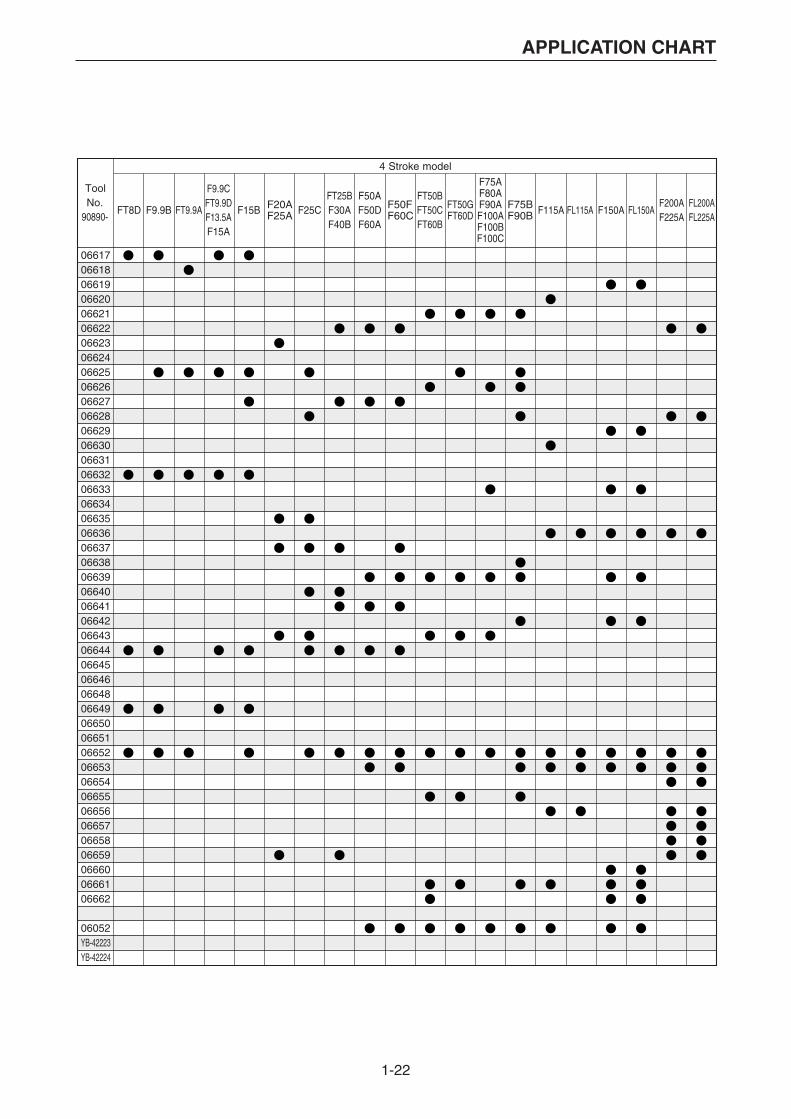
1-22
APPLICATION CHART
4 Stroke model
ToolNo.
90890-FT8D F15B F25CF9.9B FT9.9A
F9.9CFT9.9DF13.5AF15A
F20AF25A
F50FF60C
F75BF90B
FT50GFT60D
F50AF50DF60A
FT50BFT50CFT60B
F75AF80AF90AF100AF100BF100C
F115A FL115A F150A FL150AFT25BF30AF40B
F200AF225A
FL200AFL225A
066170661806619066200662106622066230662406625066260662706628066290663006631066320663306634066350663606637066380663906640066410664206643066440664506646066480664906650066510665206653066540665506656066570665806659066600666106662
06052YB-42223YB-42224

1-23
APPLICATION CHART
SHIM SELECTION / PTT TOOL(2 stroke model)
MODEL 2 Stroke model
SHIM SELECTION
PTT TOOL
ToolNo.
90890-2B2C
3A
4AC4AS5C
5CS
6C8C
20C20D25N
25B25X30H
30D40V40Y50H
55B50G60F70B
9.9F13.5A15F
*1 V4 :115B, 115C, 130B, 140B, 140C*2 V6 :150F, 150G, 150J, 150L, 175D, 200F, 200G, 200H, 200J, 225D, 225G
06701067100671106712067030670406844067060700301252
Shimming platePinion height gauge• Pinion height gauge plate APinion height gauge plate BPinion height plateDigital caliperMagnet baseBacklash indicatorMagnet base plateDial gauge set
06568(06544)06587(06548)065880677306774067760656006580065810656906572
Cylinder-end screw wrenchCylinder-end screw wrenchTrim & tilt wrenchTrim & tilt wrenchPTT wrench 46Up relief fittingDown relief fittingHydraulic pressure gaugePower tilt wrenchPTT oil pressure gauge assemblyPTT oil pressure gauge adapterTitle rod wrenchPTT piston vice attachment

1-24
APPLICATION CHART
Z150P
Z200P
LZ250DLZ300A
2 Stroke model
55D75A75B85A
75C80A90A
V4*1 L130B V6*2 D150N150A175A200A
L150FL150JL200FL200J
225C250A225F250B
L225CL250AL225FL250B
Z150QZ175GZ175HZ200N
LZ150PLZ200N
Z225HZ250F
Z250DZ300AZ300B
L150AL200A
ToolNo.
90890-
06701067100671106712067030670406844067060700301252
06568(06544)06587(06548)065880677306774067760656006580065810656906572
1-25
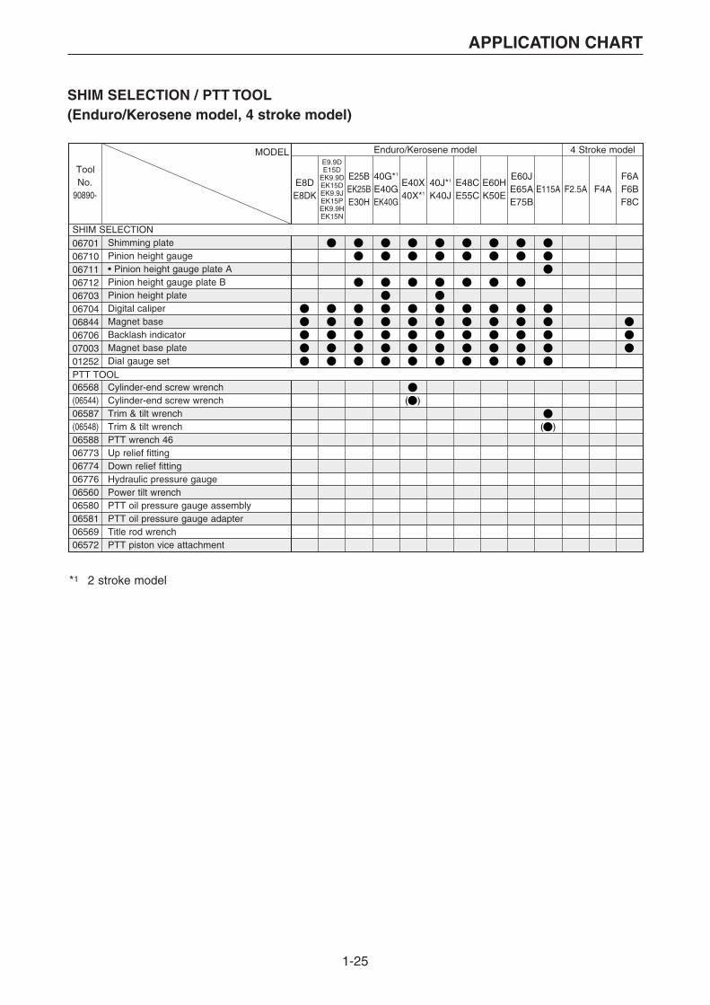
APPLICATION CHART
SHIM SELECTION / PTT TOOL(Enduro/Kerosene model, 4 stroke model)
*1 2 stroke model
MODEL Enduro/Kerosene model 4 Stroke model
SHIM SELECTION
PTT TOOL
ToolNo.
90890-E8DE8DK
E9.9DE15D
EK9.9DEK15DEK9.9JEK15PEK9.9HEK15N
40G*1
E40GEK40G
E40X40X*1
40J*1
K40JE48CE55C
E60HK50E
E60JE65AE75B
F6AF6BF8C
E115AE25BEK25BE30H
F2.5A F4A
06701067100671106712067030670406844067060700301252
06568(06544)06587(06548)065880677306774067760656006580065810656906572
Shimming platePinion height gauge• Pinion height gauge plate APinion height gauge plate BPinion height plateDigital caliperMagnet baseBacklash indicatorMagnet base plateDial gauge set
Cylinder-end screw wrenchCylinder-end screw wrenchTrim & tilt wrenchTrim & tilt wrenchPTT wrench 46Up relief fittingDown relief fittingHydraulic pressure gaugePower tilt wrenchPTT oil pressure gauge assemblyPTT oil pressure gauge adapterTitle rod wrenchPTT piston vice attachment
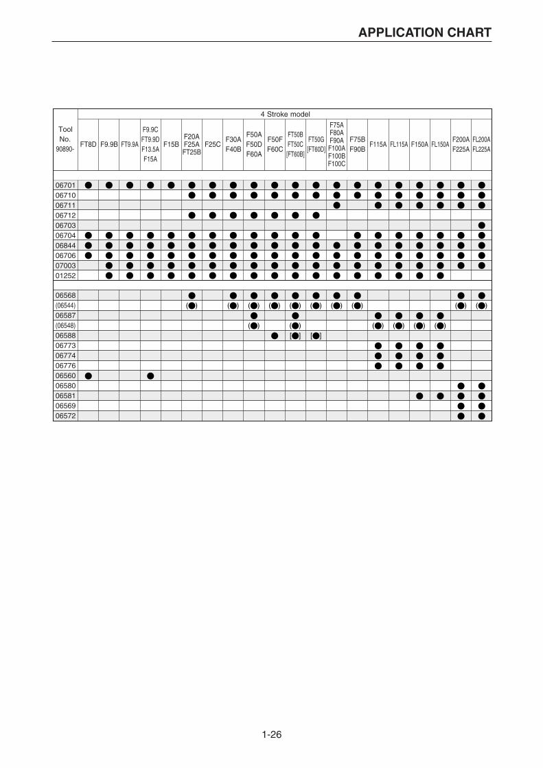
1-26
APPLICATION CHART
06701067100671106712067030670406844067060700301252
06568(06544)06587(06548)065880677306774067760656006580065810656906572
4 Stroke model
ToolNo.
90890-FT8D F25CF15BF9.9B FT9.9A
F9.9CFT9.9DF13.5AF15A
F20AF25AFT25B
F50AF50DF60A
FT50BFT50C[FT60B]
F75AF80AF90AF100AF100BF100C
F115A FL115A F150A FL150AF30AF40B
F50FF60C
F75BF90B
FT50G[FT60D]
F200AF225A
FL200AFL225A

1-27
APPLICATION CHART
WATERCRAFT TOOLMEASURING TOOL/PEAK VOLTAGE MEASUREMENTENGINE SERVICE
MODEL
Tool nameMEASURING TOOL/PEAK VOLTAGE MEASUREMENT
ENGINE SERVICE
ToolNo.
90890-SJ700A WB700A WB760 WB800 WVT700B XL700 XL760 XL800 XL800A
0125206585065840658303006030070300803009030100675903180031120317403160065820678606842067540675606760031720676906867 (06767)06871 (06771)06877 (06777)06878 (06778)06879 (06779)06880 (06780)06870 (06770)067900679106792067930684806849068620108060V-85300-0260V-WS853-02
06521065220655006534064250654606551066060662406626
Dial gauge setDial gauge stand set• Dial gauge needle 173• Dial gauge stand 173Outside micrometer 0 - 25Outside micrometer 25 - 50Outside micrometer 50 - 75Outside micrometer 75 - 100Inside micrometer 5 - 25Cylinder gauge 50 - 100Thickness gaugePocket testerDigital circuit testerCompression gaugeCompression gauge extension M10Fuel pressure gaugeFuel pressure gauge adapterIgnition testerVacuum/ presure pump gauge setDigital tachometerPeak voltage adapter BTest harness EJ-II-3Test harness FWY-2Test harness FWY-4Test harness HM090-3Test harness 090-4Test harness FWY-8Test harness SMT618-6Test harness SMT250-3Test harness FSW-6Test harness FWY-3-LTest harness SMHW090-2Test harness SMHW090-3Test harness FSW-6ATest harness SM6195021-6Test connector FMY-8Rotor pullerYamaha Diagnostic System (KIT)Yamaha Diagnostic System (CD-ROM) *2
Flywheel pullerFlywheel holderFlywheel holderBearing separatorCoupler wrenchCoupler wrenchCoupler wrenchDriver rod LSBearing outer race attachmentBearing outer race attachment
*1 Available separately (set 06585=06584+06583)*2 Up-date CD-ROM only
FX700

1-28
APPLICATION CHART
XL1200
ToolNo.
90890-XL1200Ltd XLT1200 GP760 GP800 GP800R GP1200 GP1200R EXT1200 EXS1200 SUV1200 SUV1200Z
FX140/Cruiser
FX160/Cruiser
GP1300R
0125206585065840658303006030070300803009030100675903180031120317403160065820678606842067540675606760031720676906867 (06767)06871 (06771)06877 (06777)06878 (06778)06879 (06779)06880 (06780)06870 (06770)067900679106792067930684806849068620108060V-85300-0260V-WS853-02
06521065220655006534064250654606551066060662406626
XLT800
1-29
APPLICATION CHART
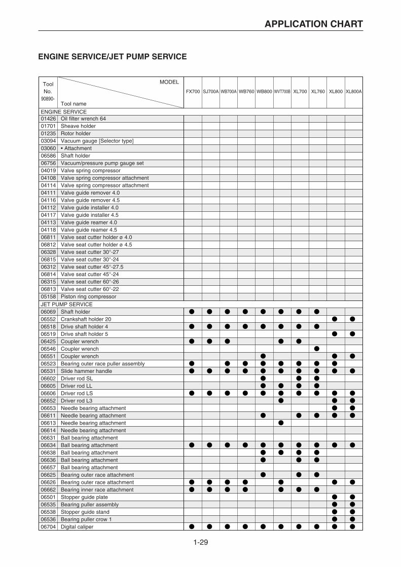
ENGINE SERVICE/JET PUMP SERVICE
Tool name
MODEL
ENGINE SERVICE
JET PUMP SERVICE
ToolNo.
90890-SJ700A WB700A WB760 WB800 WVT700B XL700 XL760 XL800 XL800A
01426017010123503094030600658606756040190410804114041110411604112041170411304118068110681206328068150631206814063150681305158
Oil filter wrench 64Sheave holderRotor holderVacuum gauge [Selector type]• AttachmentShaft holderVacuum/pressure pump gauge setValve spring compressorValve spring compressor attachmentValve spring compressor attachmentValve guide remover 4.0Valve guide remover 4.5Valve guide installer 4.0Valve guide installer 4.5Valve guide reamer 4.0Valve guide reamer 4.5Valve seat cutter holder ø 4.0Valve seat cutter holder ø 4.5Valve seat cutter 30°-27Valve seat cutter 30°-24Valve seat cutter 45°-27.5Valve seat cutter 45°-24Valve seat cutter 60°-26Valve seat cutter 60°-22Piston ring compressor
060690655206518065190642506546065510652306531066020660506606066520665306611066130661406631066340663806636066570662506626066620650106535065380653606704
Shaft holderCrankshaft holder 20Drive shaft holder 4Drive shaft holder 5Coupler wrenchCoupler wrenchCoupler wrenchBearing outer race puller assemblySlide hammer handleDriver rod SLDriver rod LLDriver rod LSDriver rod L3Needle bearing attachmentNeedle bearing attachmentNeedle bearing attachmentNeedle bearing attachmentBall bearing attachmentBall bearing attachmentBall bearing attachmentBall bearing attachmentBall bearing attachmentBearing outer race attachmentBearing outer race attachmentBearing inner race attachmentStopper guide plateBearing puller assemblyStopper guide standBearing puller crow 1Digital caliper
FX700

1-30
APPLICATION CHART
XL1200 XL1200Ltd XLT1200 GP760 GP800 GP800R GP1200 GP1200R EXT1200 EXS1200 SUV1200 SUV1200ZFX140/Cruiser
FX160/Cruiser
ToolNo.
90890-GP1300R
01426017010123503094030600658606756040190410804114041110411604112041170411304118068110681206328068150631206814063150681305158
060690655206518065190642506546065510652306531066020660506606066520665306611066130661406631066340663806636066570662506626066620650106535065380653606704
XLT800

2-1
TOOL DESCRIPTION
MEASURING TOOL
Tool No. Tool name Usage Note90890-
06760 Digital tachometer
03141 Timing light
03160 Compression gauge Plug type:B, C & D0—1500 kPa
06754 Ignition tester(Spark gap tester)
06563 Compression gaugeextension M14
06582 Compression gaugeextension M10
06563d1:M14Sd2:19L1:13506582d1:M10Sd2:14L1:165
L1
d2
d1

2-2
TOOL DESCRIPTION
Tool No. Tool name Usage Note90890-
Vacuum0—(-100) kPa
Pressure0—50 kPa
06756 Vacuum/pressurepump gauge set
0—250 kPa
0—600 kPa
06785Q ty=3pcs/pack
use with 06786
use with 06786
06842 Fuel pressure gaugeadapter
06786
06942
06840 Leakage tester
06786 Fuel pressure gauge06785 • Mouth feel rubber
06942 Fuel pressure gaugeadapter B
2-3
TOOL DESCRIPTION
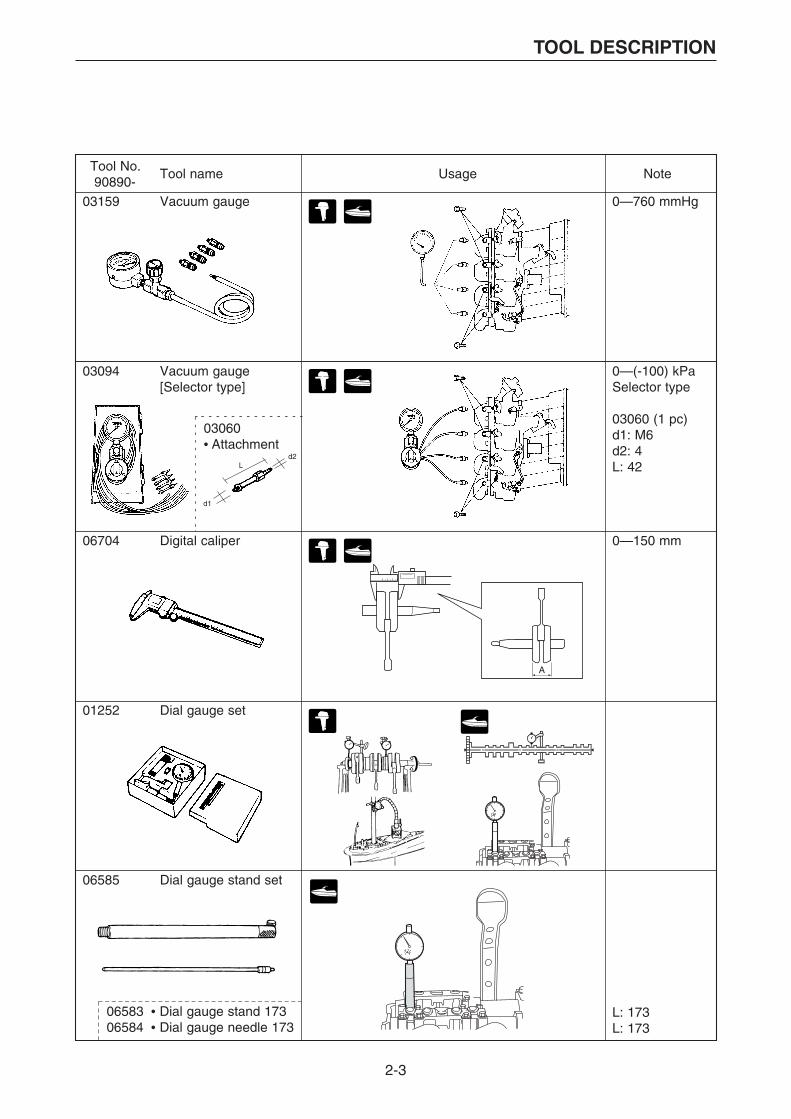
Tool No. Tool name Usage Note90890-
0—760 mmHg
0—(-100) kPaSelector type
03060 (1 pc)d1: M6d2: 4L: 42
03159 Vacuum gauge
Ld2
d1
03094 Vacuum gauge[Selector type]
03060• Attachment
0—150 mm06704 Digital caliper
A
01252 Dial gauge set
06585 Dial gauge stand set
L: 173L: 173
06583 • Dial gauge stand 17306584 • Dial gauge needle 173

2-4
TOOL DESCRIPTION
Tool No. Tool name Usage Note90890-
03107 Crankshaft aligner
03016 Cylinder gauge 35 - 6006759 Cylinder gauge 50 - 100
03006 Outside micrometer 0-2503007 Outside micrometer 25-5003008 Outside micrometer 50-7503009 Outside micrometer 75-100
0301635—60 mm
0675950—100 mm
Use withdial gauge01252
030060—25 mm
0300725—50 mm
0300850—75 mm
0300975—100 mm
5—25 mm 03010 Inside micrometer5 - 25
06844 Magnet base B

2-5
TOOL DESCRIPTION
Tool No. Tool name Usage Note90890-
0.03, 0.05, 0.100.15, 0.20, 0.250.30, 0.35, 0.400.50L: 75B1: 6.0B2: 12.7
L
B1 B2
03180 Thickness gauge(Feeler gauge)
0.25
0.10
0.03
0.020.05
0.15 0.20
01399 Special thicknessgauge
03112 Pocket tester
03174 Digital circuit tester
03172 Peak voltageadapter B 03174
03172
Connector
Test harness
2-6
TOOL DESCRIPTION
60V-85300-02Yamaha Diagnostic System (KIT)
60V-WS853-02 *1
Yamaha Diagnostic System (CD-ROM)
*1 Up-date CD-ROM only
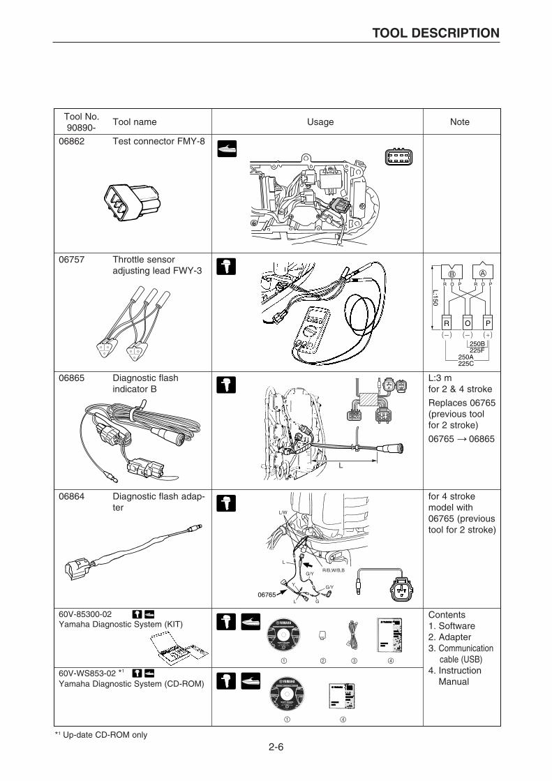
Tool No. Tool name Usage Note90890-
L:3 mfor 2 & 4 stroke
Replaces 06765(previous tool for 2 stroke)
06765 06865
for 4 strokemodel with06765 (previoustool for 2 stroke)
06864 Diagnostic flash adap-ter
06757 Throttle sensoradjusting lead FWY-3
06865 Diagnostic flashindicator B
L
L/W
L
G/Y
G/Y
R/B,W/B,B
L
Y
G06765
250B225F
L:150
250A225C
R O P
R O PR O P
06862 Test connector FMY-8
Contents1. Software2. Adapter3. Communication cable (USB)4. Instruction Manual
2-7
TOOL DESCRIPTION
Tool No.Tool name90890-
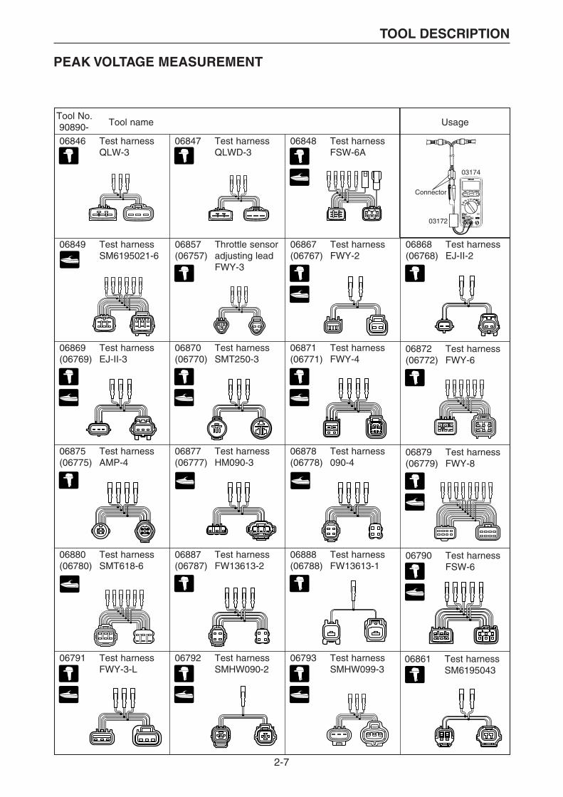
06846 Test harnessQLW-3
06847 Test harnessQLWD-3
06848 Test harnessFSW-6A
03174
03172
Connector
06857 Throttle sensoradjusting leadFWY-3
(06757)06867(06767)
Test harnessFWY-2
06868(06768)
Test harnessEJ-II-2
06869(06769)
Test harnessEJ-II-3
06870(06770)
Test harnessSMT250-3
06871(06771)
Test harnessFWY-4
06872(06772)
Test harnessFWY-6
06875(06775)
Test harnessAMP-4
06877(06777)
Test harnessHM090-3
06878(06778)
Test harness090-4
06879(06779)
Test harnessFWY-8
06880(06780)
Test harnessSMT618-6
06887(06787)
Test harnessFW13613-2
06888(06788)
Test harnessFW13613-1
06790 Test harnessFSW-6
06791 Test harnessFWY-3-L
06792 Test harnessSMHW090-2
06793 Test harnessSMHW099-3
06861 Test harnessSM6195043
06849 Test harnessSM6195021-6
Usage
PEAK VOLTAGE MEASUREMENT
2-8
TOOL DESCRIPTION
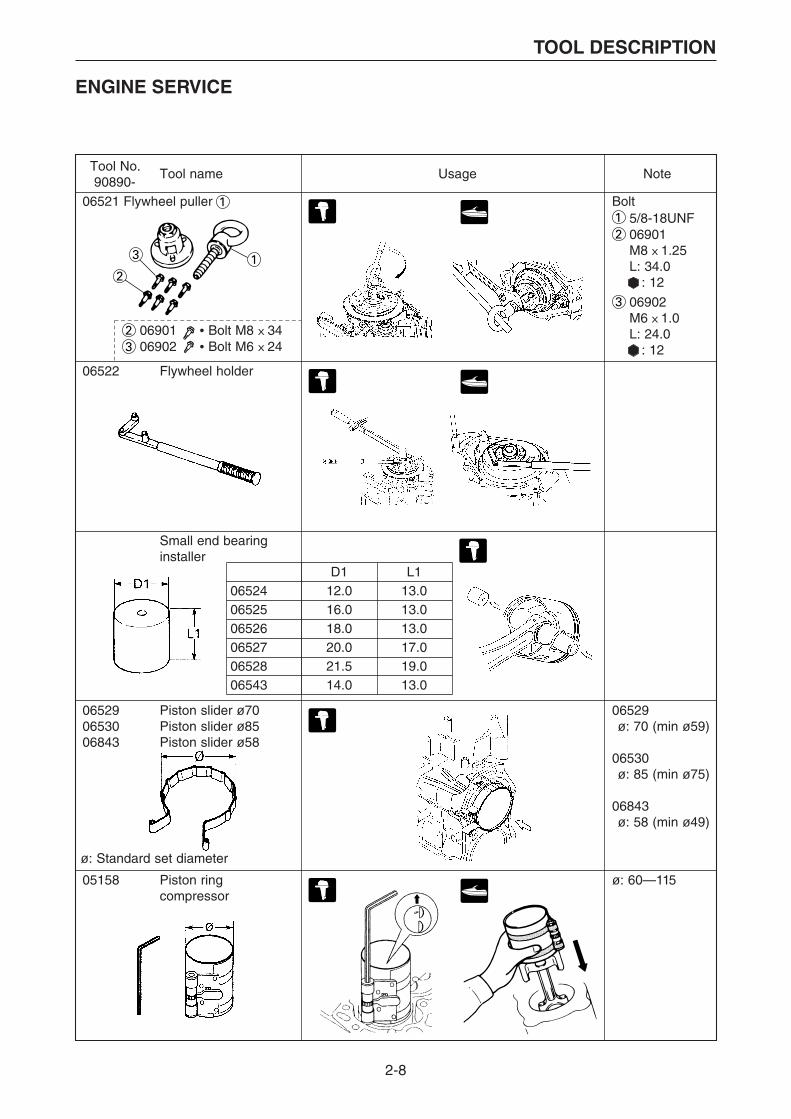
Tool No. Tool name Usage Note90890-
06521 Flywheel puller
06901 • Bolt M8 X 34 06902 • Bolt M6 X 24
06522 Flywheel holder
Bolt5/8-18UNF06901M8 X 1.25 L: 34.0 : 12
06902M6 X 1.0 L: 24.0 : 12
06529ø: 70 (min ø59)
06530ø: 85 (min ø75)
06843ø: 58 (min ø49)
ø: 60—115
D112.016.018.020.021.514.0
L113.013.013.017.019.013.0
065240652506526065270652806543
Small end bearinginstaller
065290653006843
Piston slider ø70Piston slider ø85 Piston slider ø58
05158 Piston ringcompressor
ø: Standard set diameter
ENGINE SERVICE
2-9
TOOL DESCRIPTION
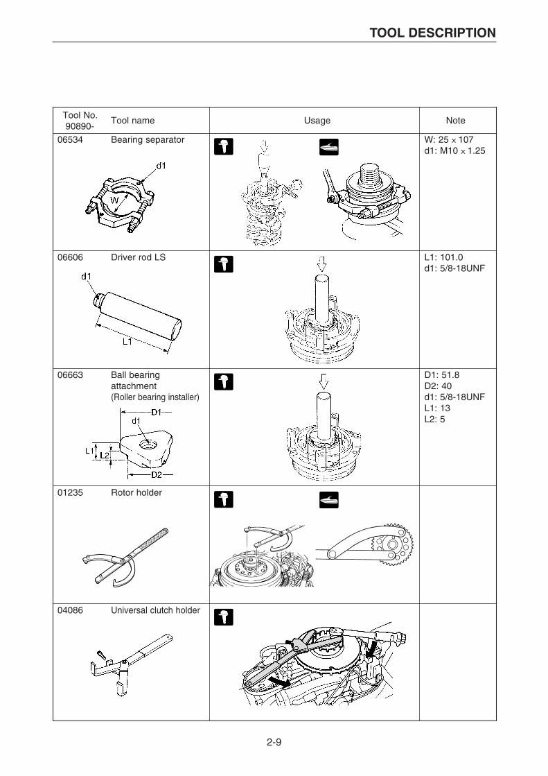
Tool No. Tool name Usage Note90890-
06534 Bearing separator
06606 Driver rod LS
W: 25 X 107d1: M10 X 1.25
L1: 101.0d1: 5/8-18UNF
D1: 51.8D2: 40d1: 5/8-18UNFL1: 13L2: 5
06663 Ball bearingattachment(Roller bearing installer)
01235 Rotor holder
04086 Universal clutch holder
2-10
TOOL DESCRIPTION
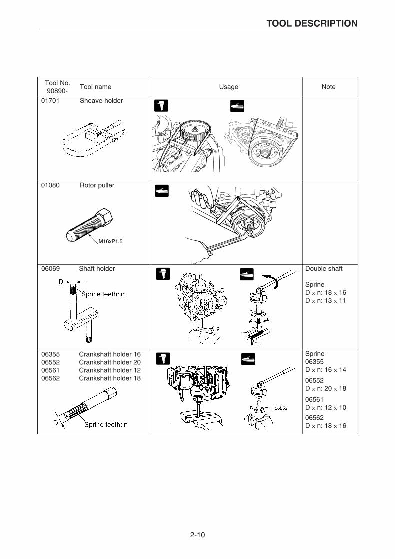
Tool No. Tool name Usage Note90890-
M16xP1.5
01080 Rotor puller
01701 Sheave holder
06069 Shaft holder Double shaft
SprineD X n: 18 X 16D X n: 13 X 11
06355065520656106562
Crankshaft holder 16Crankshaft holder 20Crankshaft holder 12Crankshaft holder 18
Sprine06355D X n: 16 X 14
06552D X n: 20 X 18
06561D X n: 12 X 10
06562D X n: 18 X 16
2-11
TOOL DESCRIPTION
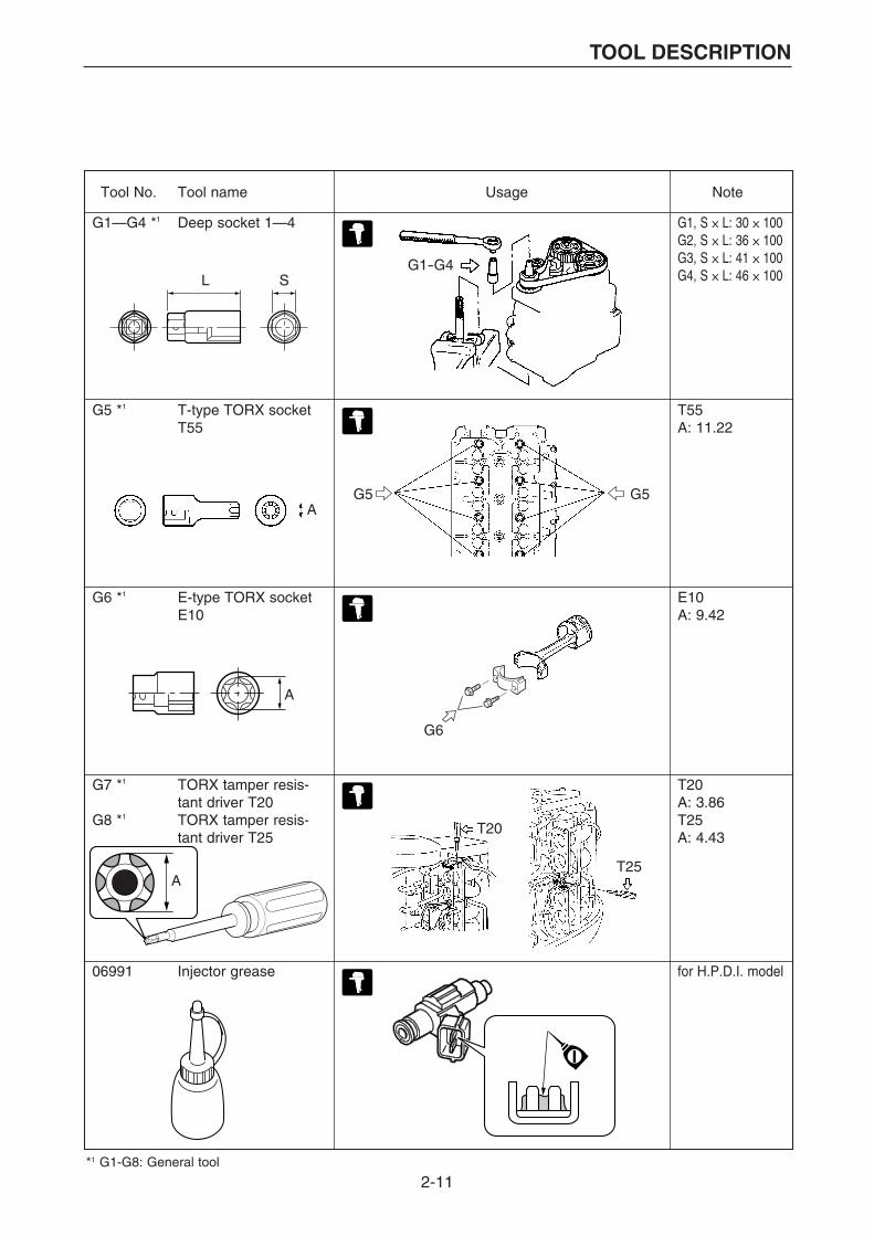
Tool No. Tool name Usage Note
G1—G4 *1 Deep socket 1—4
G5 *1 T-type TORX socketT55
G1, S X L: 30 X 100G2, S X L: 36 X 100G3, S X L: 41 X 100G4, S X L: 46 X 100
T55A: 11.22
E10A: 9.42
T20A: 3.86T25A: 4.43
A
T20
T25
A
G6 *1 E-type TORX socketE10
A
G7 *1 TORX tamper resis-tant driver T20
G8 *1 TORX tamper resis-tant driver T25
*1 G1-G8: General tool
G6
G5
L S
G5
G1-G4
06991 Injector grease for H.P.D.I. model
2-12
TOOL DESCRIPTION
Tool No.90890-
Tool name Usage Note
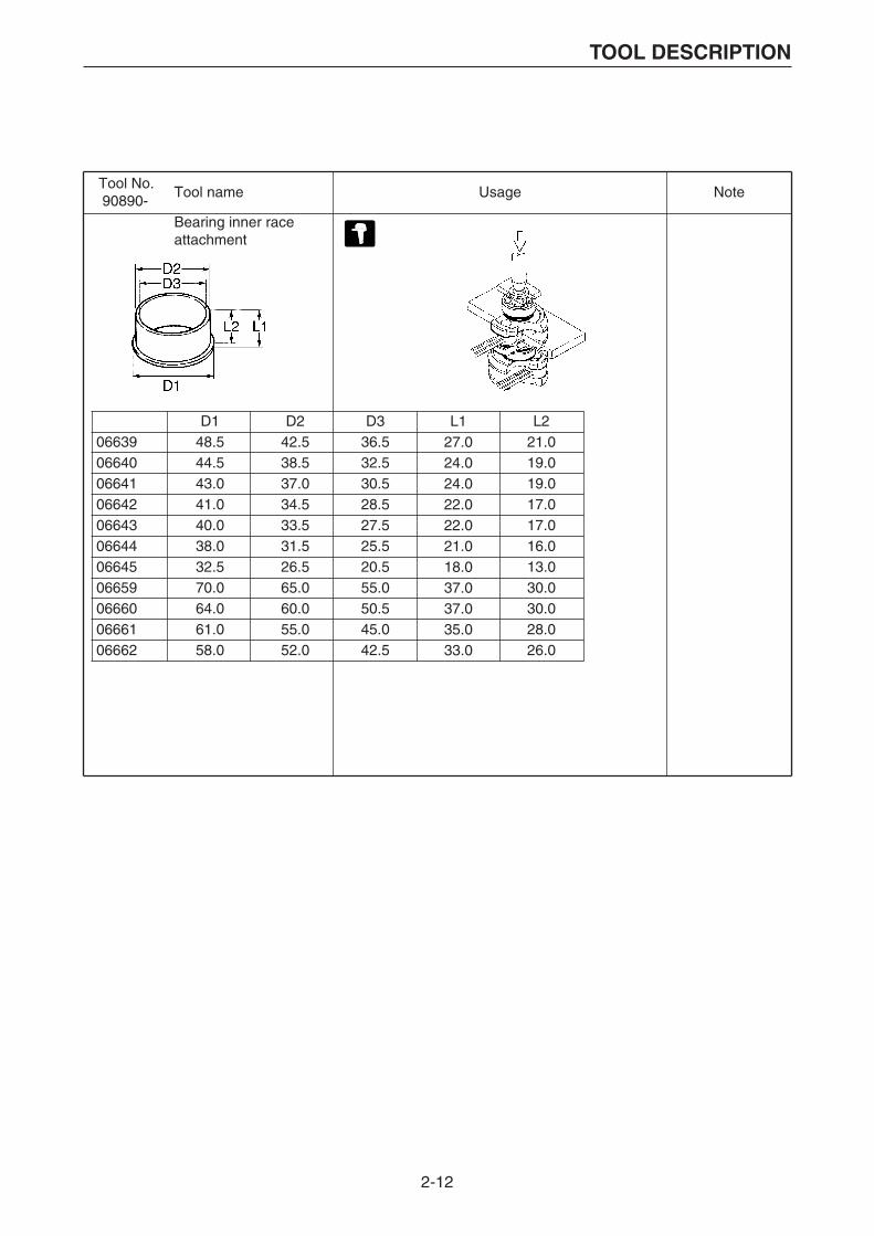
Bearing inner raceattachment
D148.544.543.041.040.038.032.570.064.061.058.0
D242.538.537.034.533.531.526.565.060.055.052.0
D336.532.530.528.527.525.520.555.050.545.042.5
L221.019.019.017.017.016.013.030.030.028.026.0
0663906640066410664206643066440664506659066600666106662
L127.024.024.022.022.021.018.037.037.035.033.0
2-13
TOOL DESCRIPTION
4 stroke
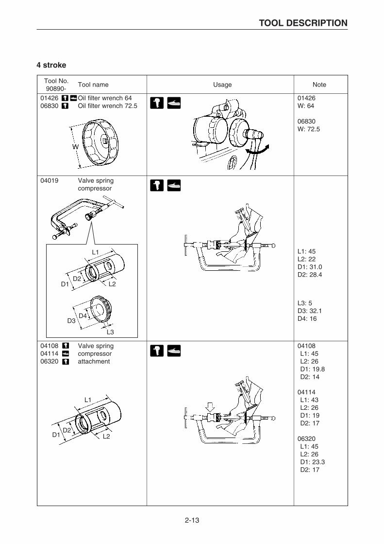
Tool No. Tool name Usage Note90890-
0142606830
Oil filter wrench 64Oil filter wrench 72.5
04019 Valve springcompressor
01426W: 64
06830W: 72.5
L1: 45L2: 22D1: 31.0D2: 28.4
L3: 5D3: 32.1D4: 16
04108L1: 45L2: 26D1: 19.8D2: 14
04114L1: 43L2: 26D1: 19D2: 17
Valve springcompressorattachment
06320L1: 45L2: 26D1: 23.3D2: 17
041080411406320
L1
L2D2
D1
L1
L2
L3
D2
D3D4
D1

2-14
TOOL DESCRIPTION
Tool No. Tool name Usage Note90890-
Valve guideremover/installer 5.4Valve guideremover/installer 5.9Valve guide remover 4.0Valve guide remover 4.5
Valve guide installer 5.4Valve guide installer 5.6Valve guide installer 5.5Valve guide installer 4.0Valve guide installer 4.5
06801L1: 40.0D1: 9.0D2: 5.4
04064L1: 45D1: 10D2: 5.9
05041 for 5–6 mm
L: 145D: 14
Valve guide reamer 5.5Valve guide reamer 6.0Valve guide reamer 4.0Valve guide reamer 4.5
05041 Tap handle (5–6)
04101 Valve lapper
04111L1: 30.0D1: 9.0D2: 4.0
04116L1: 30.0D1: 9.0D2: 4.5
06802L2: 13D3: 5.4D4: 9.2D5: 12.0H: 8.1
04015L2: 25D3: 5.6D4: 12.5D5: 15.1H: —
06810L2: 22D3: 5.5D4: 9.9D5: 12.0H: —
04112L2: 25D3: 4.0D4: 7.35D5: 9.1H: 7.35
04117L2: 22D3: 4.5D4: 8.3D5: 10.0H: 7.0
06804 L3: 65 D6: 5.5
04066 L3: 65 D6: 6.0
04113 L3: 53 D6: 4.0
04118 L3: 45 D6: 4.5
06801
04064
0411104116
0680204015068100411204117
06804040660411304118
2-15
TOOL DESCRIPTION
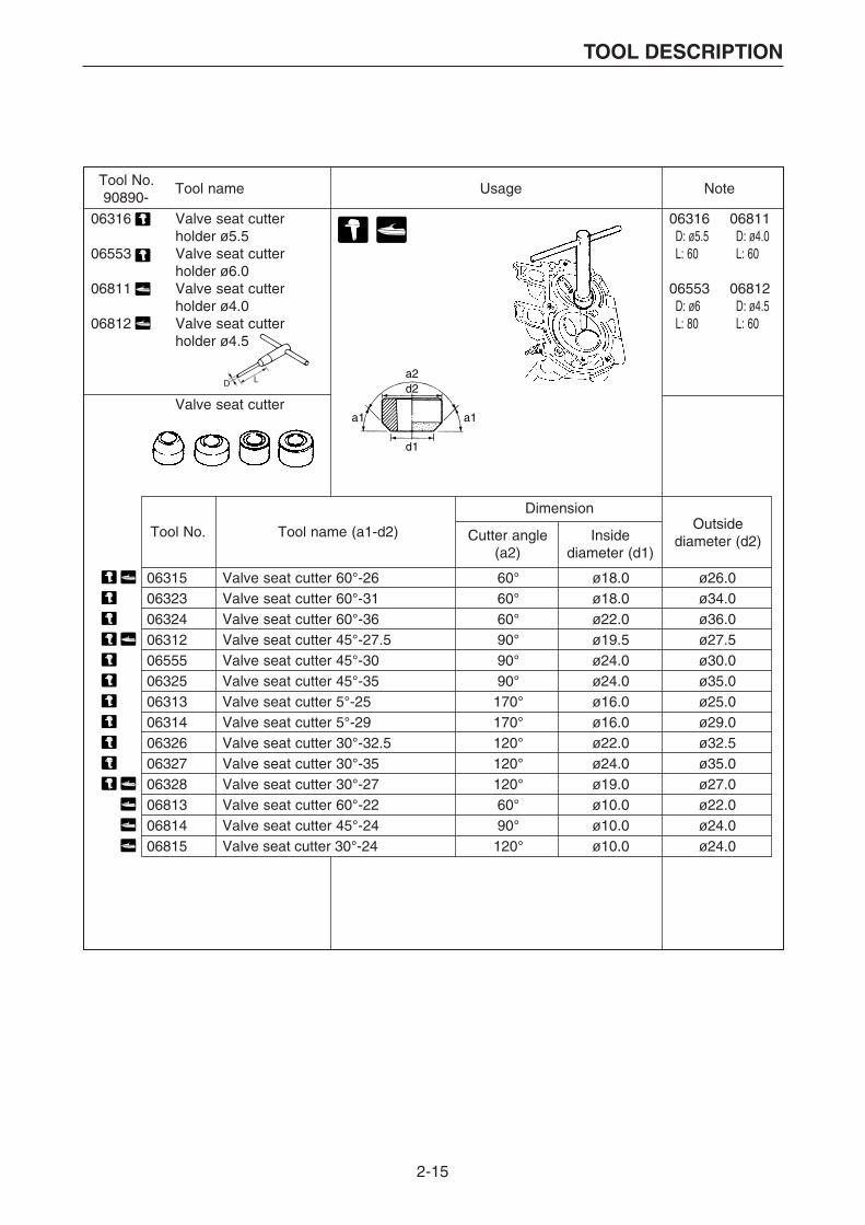
Tool No. Tool name Usage Note90890-
Valve seat cutter
06316D: ø5.5L: 60
06553D: ø6L: 80
a2
a1a1
d2
d1
06811D: ø4.0L: 60
06812D: ø4.5L: 60
06316 Valve seat cutterholder ø5.5
06553 Valve seat cutterholder ø6.0
06811 Valve seat cutterholder ø4.0
06812 Valve seat cutterholder ø4.5
DimensionOutside
diameter (d2)Tool No. Tool name (a1-d2) Cutter angle
(a2)Inside
diameter (d1)
0631506323063240631206555063250631306314063260632706328068130681406815
Valve seat cutter 60°-26Valve seat cutter 60°-31Valve seat cutter 60°-36Valve seat cutter 45°-27.5Valve seat cutter 45°-30Valve seat cutter 45°-35Valve seat cutter 5°-25Valve seat cutter 5°-29Valve seat cutter 30°-32.5Valve seat cutter 30°-35Valve seat cutter 30°-27Valve seat cutter 60°-22Valve seat cutter 45°-24Valve seat cutter 30°-24
60°60°60°90°90°90°
170°170°120°120°120°60°90°
120°
ø18.0ø18.0ø22.0ø19.5ø24.0ø24.0ø16.0ø16.0ø22.0ø24.0ø19.0ø10.0ø10.0ø10.0
ø26.0ø34.0ø36.0ø27.5ø30.0ø35.0ø25.0ø29.0ø32.5ø35.0ø27.0ø22.0ø24.0ø24.0

2-16
TOOL DESCRIPTION
Tool No. Tool name Usage Note90890-
3 petalsD1: 55D2: 99.6
5 petals06546D1: 58D2: 96
06551D1: 52D2: 96
W: 38N: 13(Number of teeth)L1: 100d: 25(Shaft)
d
L1
W
06550 Flywheel holder
06425 Coupler wrench
06546 Coupler wrench06551 Coupler wrench
06586 Shaft holder
Watercraft

2-17
TOOL DESCRIPTION
Tool No.90890-02422 Crank shaft jig set02351 02352 02353 02354
4 pc-set*1 4 pc-set*1 2 pc-set*1
2 pc-set*1
2 pc-set*1
2 pc-set*12 pc-set*1
6 pc-set*1
3 pc-set*1
3 pc-set*1
2 pc-set*1
2 pc-set*1
02355 02357 02359
02361 02363 02366 02367 02369 02371 02376
02379 02384 02385 02386 02387 02388 02389
02390 02391 02392 02393 02394 02395 02396
02399 02401 02402 02403 02404 02419 06590
90890-02418 Crank separater kit (set 02416 + 02417)90890-02416 Disassembling kit
02407 0240902408 02410 02411
90890-0241702412 0241402413 02415
B-4
02358 02365 02377
Assembling kit
Crankshaft disassembly and reassembly The tools on this page can be ordered from
the Marine Service Division of Yamaha Motor Co., Ltd.
*1 The figure for this part indicates the quantity of the parts ordered in a set or a kit.

2-18
TOOL DESCRIPTION
Tool No.90890-
Tool name
01601 Test propeller(646)
01609 Test propeller(647)
01611 Test propeller(663)
01613 Test propeller(664)
01618 Test propeller(676)
01619 Test propeller(683)
01620 Test propeller(688)
01621 Test propeller(689)
01624 Test propeller(6E5)
01625 Test propeller(6G1)
01626 Test propeller(6G5)
01627 Test propeller(6G8)
01629 Test propeller(61N)
01630 Test propeller(6L5)
01631 Test propeller(6L6)
19mm
19mm
17mm
17mm
Test propeller
2-19
TOOL DESCRIPTION
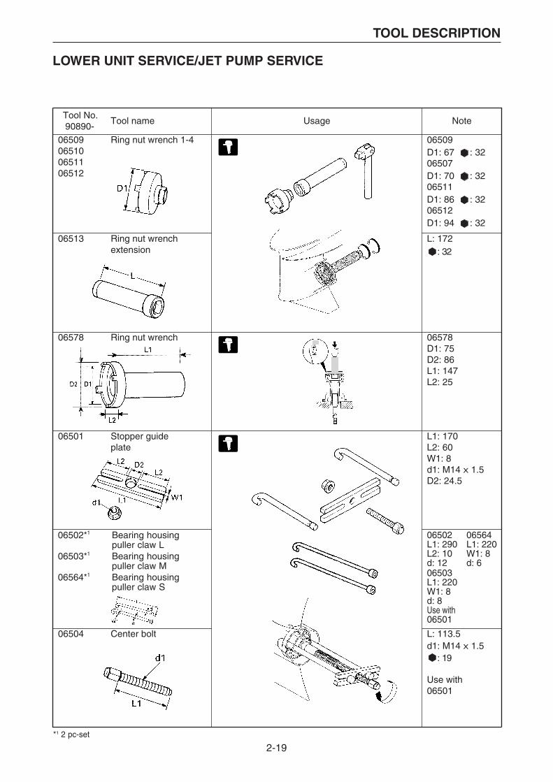
LOWER UNIT SERVICE/JET PUMP SERVICE
Tool No.90890-
Tool name Usage Note
06509065100651106512
Ring nut wrench 1-4 06509D1: 67 : 3206507D1: 70 : 3206511D1: 86 : 3206512D1: 94 : 32
06513 Ring nut wrenchextension
L: 172 : 32
06578 Ring nut wrench 06578D1: 75D2: 86L1: 147L2: 25
06501 Stopper guideplate
L1: 170L2: 60W1: 8d1: M14 X 1.5D2: 24.5
06502L1: 290L2: 10d: 1206503L1: 220W1: 8d: 8Use with06501
06564L1: 220W1: 8d: 6
06504 Center bolt L: 113.5d1: M14 X 1.5 : 19
Use with06501
06502*1 Bearing housingpuller claw L
06503*1 Bearing housingpuller claw M
06564*1 Bearing housingpuller claw S
*1 2 pc-set
2-20
TOOL DESCRIPTION
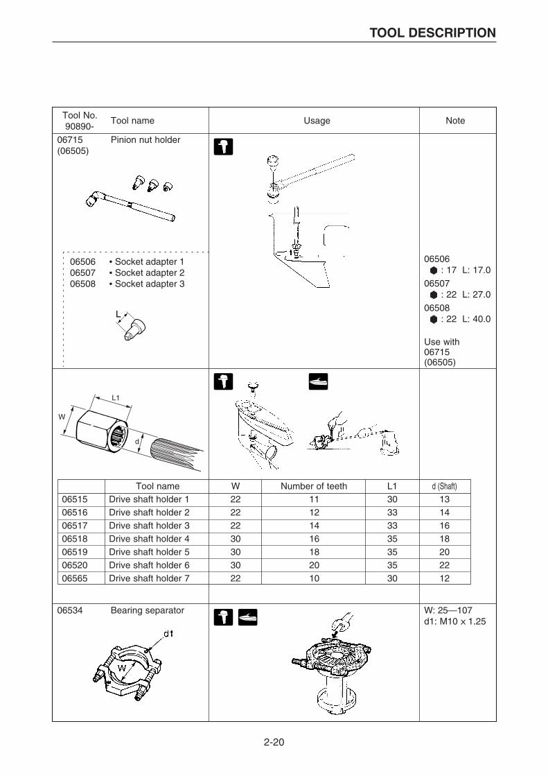
Tool No. Tool name Usage Note90890-
065060650706508
• Socket adapter 1• Socket adapter 2• Socket adapter 3
06715(06505)
Pinion nut holder
06506 : 17 L: 17.0
06507 : 22 L: 27.0
06508 : 22 L: 40.0
Use with06715(06505)
W: 25—107d1: M10 X 1.25
W
L1
d
Tool name W Number of teeth L1 d (Shaft)06515065160651706518065190652006565
Drive shaft holder 1Drive shaft holder 2Drive shaft holder 3Drive shaft holder 4Drive shaft holder 5Drive shaft holder 6Drive shaft holder 7
22222230303022
11121416182010
30333335353530
13141618202212
06534 Bearing separator
2-21
TOOL DESCRIPTION
Tool No.90890-
Tool name Usage Note
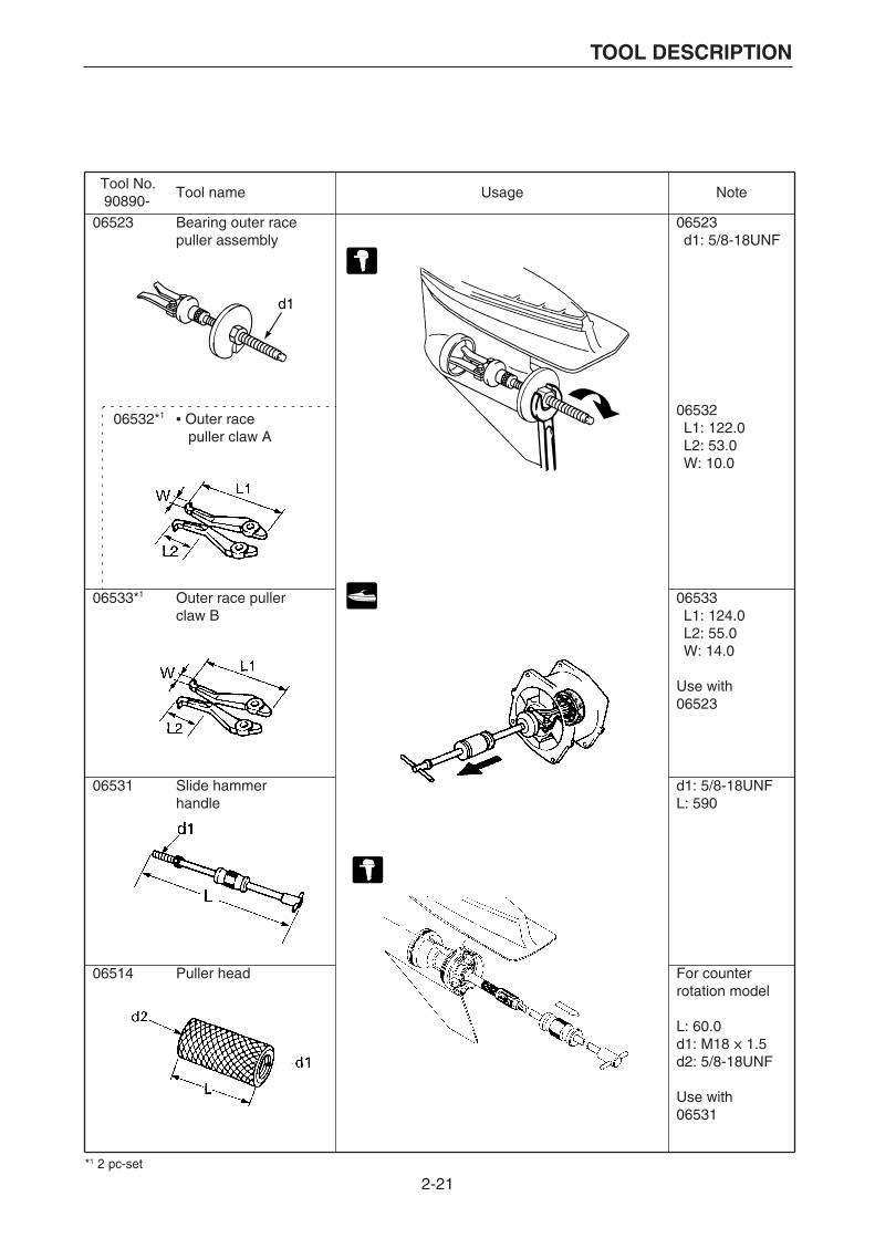
06523 Bearing outer race puller assembly
06523d1: 5/8-18UNF
06532*1 • Outer race puller claw A
06532
06533*1 Outer race pullerclaw B
06533
Use with06523
06531 Slide hammerhandle
d1: 5/8-18UNFL: 590
06514 Puller head For counterrotation model
L: 60.0d1: M18 X 1.5d2: 5/8-18UNF
Use with 06531
d1
L1: 124.0L2: 55.0W: 14.0
L1: 122.0L2: 53.0W: 10.0
*1 2 pc-set

2-22
TOOL DESCRIPTION
Tool No.90890-
Tool name Usage Note
06535 Bearing puller assemblyL: 185.0d1: M14 X 1.5
06536
06535
L1: 86.0L2: 48.0T: 10.0
06537L1: 71.5L2: 27.5T: 6.0
06536*1
06537*1
• Bearing puller claw 1• Bearing puller claw 2
06538*1 Stopper guidestand
L1: 100.0d1: M8 X 1.25d2: M8 X 1.25
Use with06501
06646 Bushing puller center bolt
L: 170.0d1: M14 X 1.5
06648 Bushing puller spacer
06648L: 44.0D: 15.0T: 4.6
*1 2 pc-set
2-23
TOOL DESCRIPTION
Tool No.90890-
Tool name Usage Note
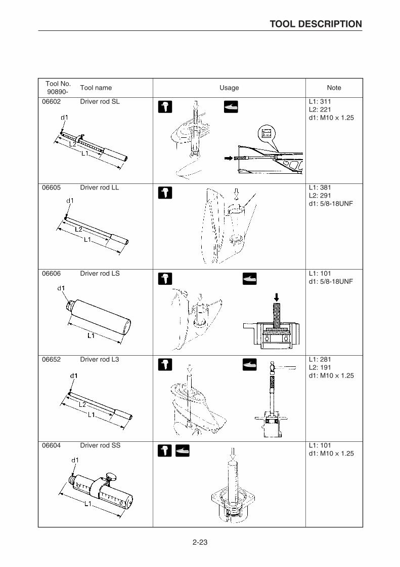
06602 Driver rod SL L1: 311L2: 221d1: M10 X 1.25
06605 Driver rod LL L1: 381L2: 291d1: 5/8-18UNF
06606 Driver rod LS L1: 101d1: 5/8-18UNF
06652 Driver rod L3 L1: 281L2: 191d1: M10 X 1.25
06604 Driver rod SS L1: 101d1: M10 X 1.25
2-24
TOOL DESCRIPTION
Tool No.90890-
Tool name Usage Note
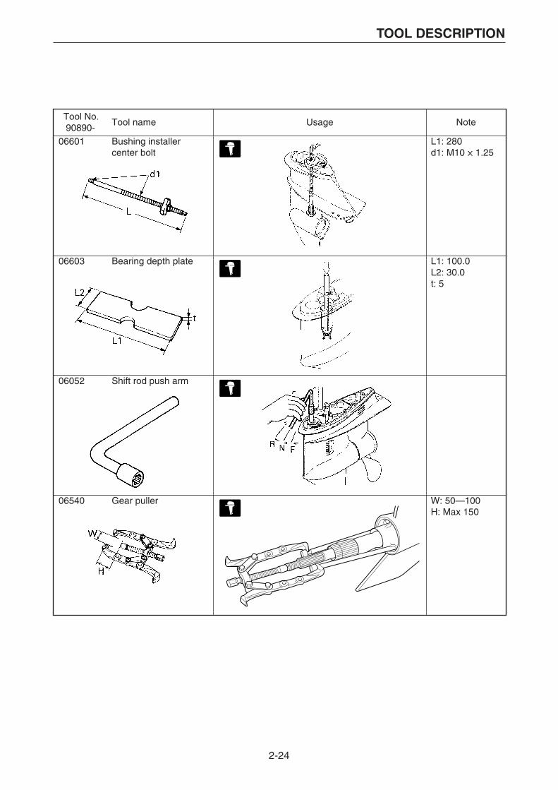
06601 Bushing installer center bolt
L1: 280d1: M10 X 1.25
06603 Bearing depth plate L1: 100.0L2: 30.0t: 5
06052 Shift rod push arm
06540 Gear puller W: 50—100H: Max 150
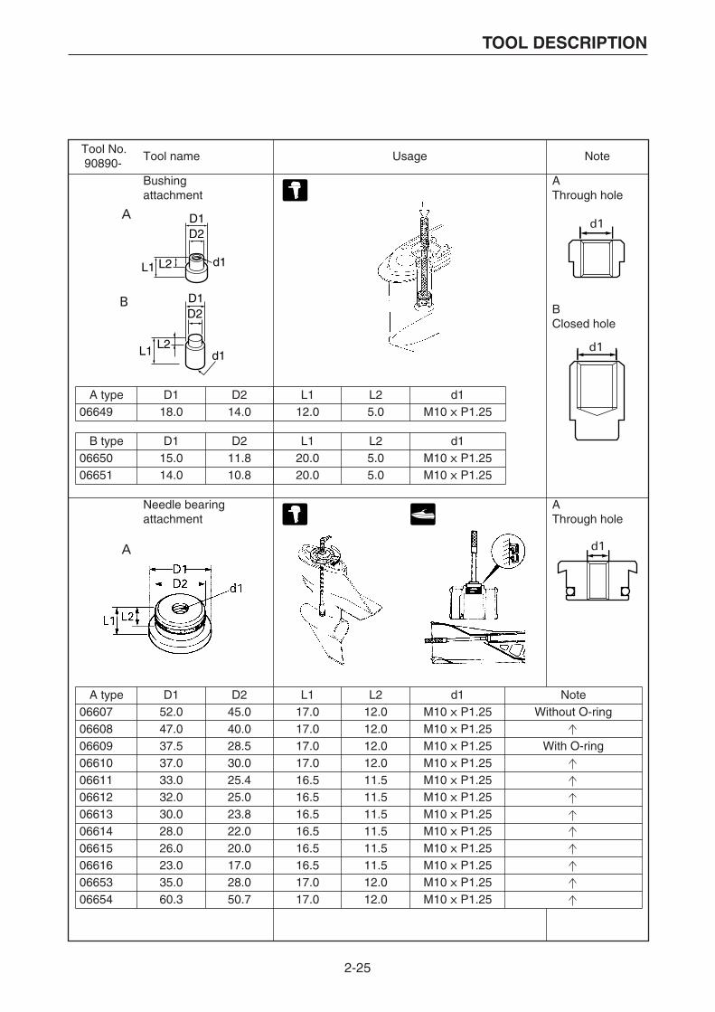
2-25
TOOL DESCRIPTION
Tool No.90890-
Tool name Usage Note
Bushing attachment
AThrough hole
BClosed hole
Needle bearing attachment
AThrough hole
A type D1 D2 L1 L2 d106649 18.0 14.0 12.0 5.0 M10 X P1.25
B type D1 D2 L1 L2 d10665006651
15.014.0
11.810.8
20.020.0
5.05.0
M10 X P1.25M10 X P1.25
A type D1 D2 L1 L2 d1 Note066070660806609066100661106612066130661406615066160665306654
52.047.037.537.033.032.030.028.026.023.035.060.3
45.040.028.530.025.425.023.822.020.017.028.050.7
17.017.017.017.016.516.516.516.516.516.517.017.0
12.012.012.012.011.511.511.511.511.511.512.012.0
M10 X P1.25M10 X P1.25M10 X P1.25M10 X P1.25M10 X P1.25M10 X P1.25M10 X P1.25M10 X P1.25M10 X P1.25M10 X P1.25M10 X P1.25M10 X P1.25
Without O-ring
With O-ring
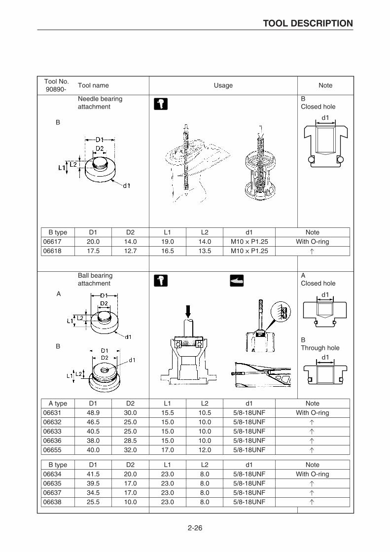
2-26
TOOL DESCRIPTION
Tool No.90890-
Tool name Usage Note
B
Needle bearingattachment
BClosed hole
Ball bearingattachment
AClosed hole
BThrough hole
A
B
B type D1 D2 L1 L2 d1 Note0661706618
20.017.5
14.012.7
19.016.5
14.013.5
M10 X P1.25M10 X P1.25
With O-ring
A type D1 D2 L1 L2 d1 Note0663106632066330663606655
48.946.540.538.040.0
30.025.025.028.532.0
15.515.015.015.017.0
10.510.010.010.012.0
5/8-18UNF5/8-18UNF5/8-18UNF5/8-18UNF5/8-18UNF
With O-ring
B type D1 D2 L1 L2 d1 Note06634066350663706638
41.539.534.525.5
20.017.017.010.0
23.023.023.023.0
8.08.08.08.0
5/8-18UNF5/8-18UNF5/8-18UNF5/8-18UNF
With O-ring

2-27
TOOL DESCRIPTION
Tool No.90890-
Tool name Usage Note
Ball bearing attachment
Bearing inner race attachment
D189.059.589.070.0
D259.045.049.550.8
D3—
33.038.038.0
L121.521.521.521.5
L213.513.513.513.5
d15/8-18UNF5/8-18UNF5/8-18UNF5/8-18UNF
NoteWith O-ring06629
066300665606657
D148.544.543.041.040.038.032.570.064.061.058.0
D242.538.537.034.533.531.526.565.060.055.052.0
D336.532.530.528.527.525.520.555.050.545.042.5
L221.019.019.017.017.016.013.030.030.028.026.0
0663906640066410664206643066440664506659066600666106662
L127.024.024.022.022.021.018.037.037.035.033.0
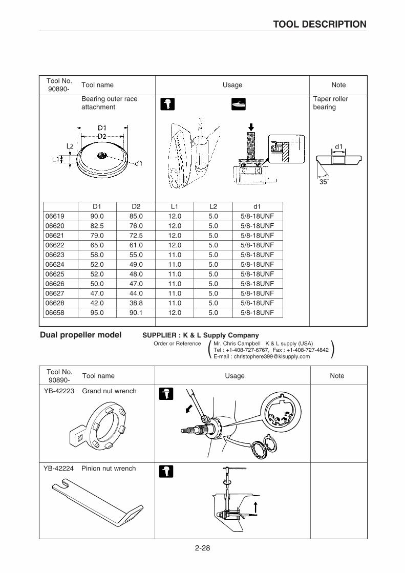
2-28
TOOL DESCRIPTION
Tool No.90890-
Tool name Usage Note
Bearing outer race attachment
Taper roller bearing
Dual propeller model SUPPLIER : K & L Supply CompanyOrder or Reference Mr. Chris Campbell K & L supply (USA)
Tel : +1-408-727-6767, Fax : +1-408-727-4842E-mail : [email protected]
Tool No. Tool name Usage Note90890-
YB-42223 Grand nut wrench
YB-42224 Pinion nut wrench
( )
D190.082.579.065.058.052.052.050.047.042.095.0
D285.076.072.561.055.049.048.047.044.038.890.1
L112.012.012.012.011.011.011.011.011.011.012.0
L25.05.05.05.05.05.05.05.05.05.05.0
d15/8-18UNF5/8-18UNF5/8-18UNF5/8-18UNF5/8-18UNF5/8-18UNF5/8-18UNF5/8-18UNF5/8-18UNF5/8-18UNF5/8-18UNF
0661906620066210662206623066240662506626066270662806658
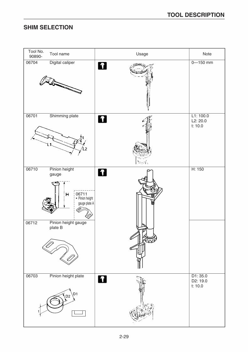
2-29
TOOL DESCRIPTION
SHIM SELECTION
Tool No.90890-
Tool name Usage Note
06701 Shimming plate L1: 100.0L2: 20.0t: 10.0
06710 Pinion height gauge
H: 150
Pinion height gaugeplate B
06703 Pinion height plate D1: 35.0D2: 19.0t: 10.0
t
06712
06711• Pinion height gauge plate A
06704 Digital caliper 0—150 mm

2-30
TOOL DESCRIPTION
Tool No.90890-
Tool name Usage Note
06706 Backlash indicator L1: 26.8L2: 9.0
07003 Magnet base plate L1: 200L2: 80t: 12d1: 11.5d2: 8
06844 Magnet base B
01252 07003
06844
06706
01252 Dial gauge set
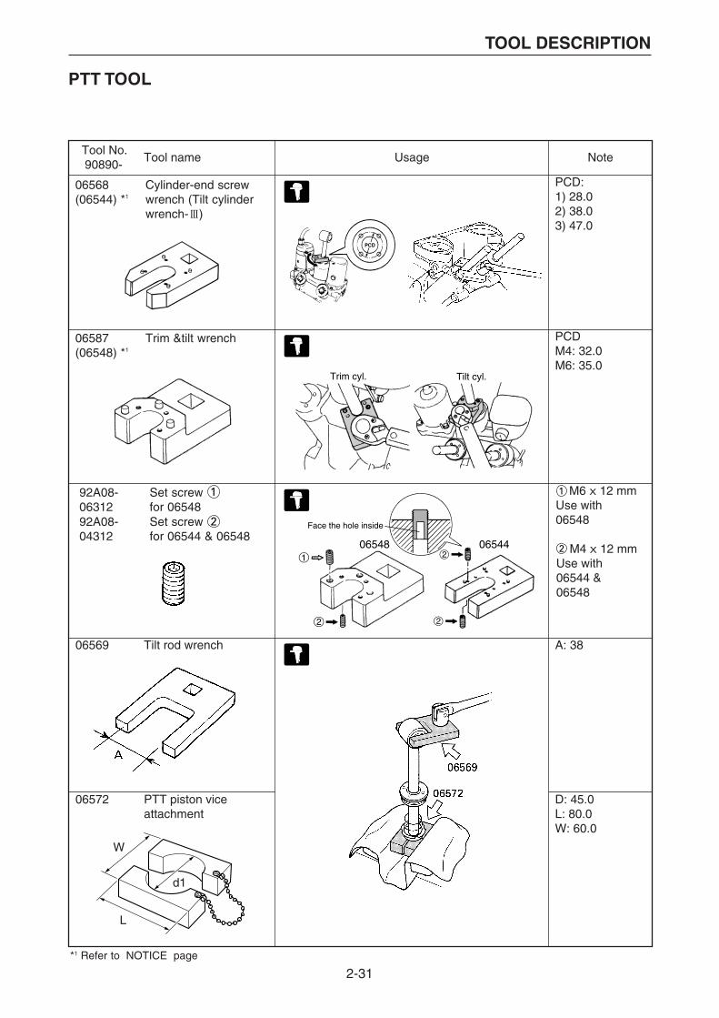
2-31
TOOL DESCRIPTION
Tool No.90890-
Tool name Usage Note
PCD: 1) 28.02) 38.03) 47.0
PCDM4: 32.0M6: 35.0
M6 X 12 mmUse with06548
M4 X 12 mmUse with 06544 & 06548
06569 Tilt rod wrench A: 38
06572 PTT piston viceattachment
D: 45.0L: 80.0W: 60.0
Trim cyl. Tilt cyl.
06568(06544) *1
Cylinder-end screw wrench (Tilt cylinderwrench- III)
06587(06548) *1
Trim &tilt wrench
06548 06544
Face the hole inside
W
L
d1
92A08-06312
Set screw for 06548
92A08-04312
Set screw for 06544 & 06548
*1 Refer to NOTICE page
PTT TOOL

2-32
TOOL DESCRIPTION
Tool No. Tool name Usage Note90890-
06776
0677306774
Hydraulic pressure gauge[PTToil pressure]Up relief fittingDown relief fitting[PTToil pressure]
06560 Power tilt wrench
0-16 Mpa06773:
06774:
Use with 06776
A: 35B: 25.4
A: 46
0-16 Mpa
d1: N10 x 1.0W: 19d2: 9.5
06588 PTT wrench 46
06580 PTT oil pressure gauge assembly
06581 PTT oil pressure gauge adapter
Up
Down

3-1
RECONDITION TOOL
HELI-SERT KIT (90890-05155)
No.
1
2
3
4
5
6
7
8
9
Q’ty
20
20
20
20
20
20
20
20
1
No.
10
11
12
13
14
15
16
17
18
Q’ty
1
1
1
1
1
1
1
1
1
No.
19
20
21
22
23
24
25
26
27
Q’ty
1
1
1
1
1
1
1
1
1
Description
Heli-sert M5 X 0.8 X 1.5D
Heli-sert M5 X 0.8 X 2D
Heli-sert M6 X 1.0 X 1.5D
Heli-sert M6 X 1.0 X 2D
Heli-sert M8 X 1.25 X 1.5D
Heli-sert M8 X 1.25 X 2D
Heli-sert M10 X 1.25 X 1.5D
Heli-sert M10 X 1.25 X 2D
Tap M5 X 0.8 No.2
Description
Tap M5 X 0.8 No.3
Tap M6 X 1.0 No.2
Tap M6 X 1.0 No.3
Tap M8 X 1.25 No.2
Tap M8 X 1.25 No.3
Tap M10 X 1.25 No.2
Tap M10 X 1.25 No.3
Inserting tool (P-type)
Inserting tool (S-type)
Description
Inserting tool (S-type)
Inserting tool (S-type)
Tang break tool M5
Tang break tool M6
Tang break tool M8
Tang break tool M10
Extracting tool M3–5
Extracting tool M6–10
Tool box

3-2
RECONDITION TOOL
MARINE TERMINAL KIT (90890-05354)
No.
1
2
3
4
5
6
7
8
Name
Crimper
Sleeve, plug
Sleeve, socket
Sleeve, socket
Round plug
Round socket
Eye terminal
Eye terminal
P/No.
90890-05357
9E312-00617
9E312-10735
9E312-20735
9E212-10400
9E212-11400
9E110-10510
90890-05207
Order Q’ty
1
1
1
1
1
1
1
1
Piece(s)
1
100
100
20
100
100
100
100
REPLENISHMENTS
No.
1
2
3
4
5
6
7
8
Name
Crimper
Sleeve, plug
Sleeve, socket
Sleeve, socket
Round plug
Round socket
Eye terminal
Eye terminal
Note
for round plug
for round socket
for 2 wires
Galvanized
Galvanized
for 5 mm screw
for 4 mm screw
Q’ty
1
20
20
20
20
20
20
20

3-3
RECONDITION TOOL
COUPLER KIT A(61A) (90890-05353)
No.
1
2
3
4
5
6
7
8
9
10
11
12
13
14
15
16
17
Name
Crimper
Terminal pick
Coupler housing
Coupler housing
Terminal, male
Terminal, female
Grommet
Coupler housing
Coupler housing
Coupler housing
Coupler housing
Coupler housing
Coupler housing
Terminal, male
Terminal, female
Grommet
Plug
Note
2 types in 1 set
2P, Male (Water craft, Start SW)
2P, Female (Water craft, Start SW)
for Watercraft
for Watercraft
for Watercraft
2P, Male (Outboard Motor)
2P, Female (Outboard Motor)
3P, Male (Outboard Motor)
3P, Female (Outboard Motor)
4P, Male (Outboard Motor)
4P, Female (Outboard Motor)
for Outboard Motor
for Outboard Motor
for Outboard Motor
for Outboard Motor
Q’ty
1
1
1
1
20
20
40
1
1
1
1
1
1
20
20
40
20

3-4
RECONDITION TOOL
OPTIONAL PARTSCommon use
Watercraft
No.
1
2
Name
Crimper coupler (61A)
Terminal pick (61A)
Specification P/No.
90890-05356
90890-05361
Order Q’ty
1
1
Piece(s)
1
1
Note
2 types in 1 set
No.
3
4
5
6
7
8
9
10
11
12
13
14
15
16
17
18
19
Name
Coupler housing
Coupler housing
Coupler housing
Coupler housing
Coupler housing
Coupler housing
Coupler housing
Coupler housing
Coupler housing
Coupler housing
Coupler housing
Coupler housing
Coupler housing
Coupler housing
Terminal, male
Terminal, female
Grommet
Specification
2P, Male, White
2P, Male, Black
2P, Female, White
2P, Female, Black
2P, Male, White
2P, Female, White
3P, Male, White
3P, Male, Black
3P, Female, White
3P, Female, Black
3P, Male, White
3P, Female, White
4P, Male, White
4P, Female, White
4P, Male, White
4P, Female, White
6P, Male, White
6P, Female, White
P/No.
9E450-02433
9E451-02433
9E450-02533
9E451-02533
9E470-02413
9E470-02513
9E450-03433
9E451-03433
9E450-03533
9E451-03533
9E470-03413
9E470-03513
9E450-04433
9E450-04533
9E470-04413
9E470-04513
9E450-06433
9E450-06523
9E212-10303
9E212-11303
9E322-90606
Order Q’ty
1
1
1
1
1
1
1
1
1
1
1
1
1
1
1
1
1
1
1
1
1
Piece(s)
10
10
10
10
10
5
10
10
10
10
5
5
5
5
5
5
5
5
50
50
50
Note
Start sw.-harness
Stop sw.-harness
Start sw.-harness
Stop sw.-harness
Oil level gauge
Oil level gauge
Charge coil-CDI
Pulser coil-CDI
Charge coil-CDI
Pulser coil-CDI
Speed sensor
Speed sensor
Oil level gauge, trim gaugeand remote oil tank
Meter unit-harness
Meter unit-harness
(64T)
(64T)
for above #3 –#16
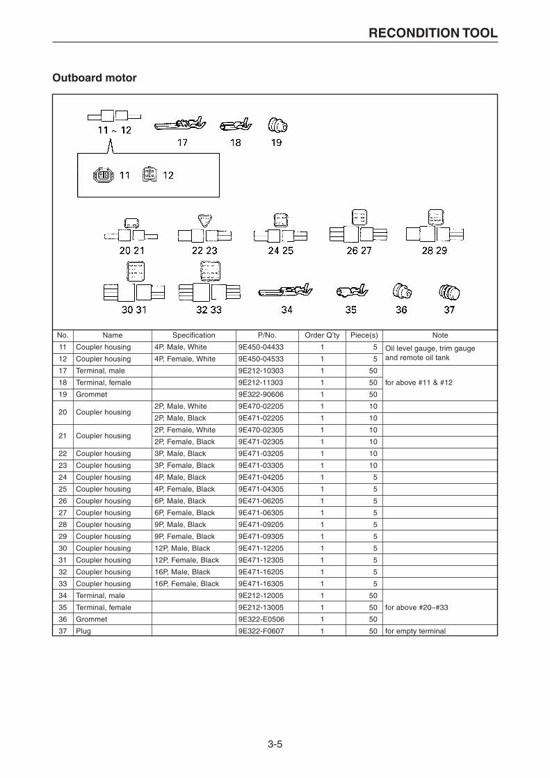
3-5
RECONDITION TOOL
Outboard motor
No.
11
12
17
18
19
20
21
22
23
24
25
26
27
28
29
30
31
32
33
34
35
36
37
Name
Coupler housing
Coupler housing
Terminal, male
Terminal, female
Grommet
Coupler housing
Coupler housing
Coupler housing
Coupler housing
Coupler housing
Coupler housing
Coupler housing
Coupler housing
Coupler housing
Coupler housing
Coupler housing
Coupler housing
Coupler housing
Coupler housing
Terminal, male
Terminal, female
Grommet
Plug
Specification
4P, Male, White
4P, Female, White
2P, Male, White
2P, Male, Black
2P, Female, White
2P, Female, Black
3P, Male, Black
3P, Female, Black
4P, Male, Black
4P, Female, Black
6P, Male, Black
6P, Female, Black
9P, Male, Black
9P, Female, Black
12P, Male, Black
12P, Female, Black
16P, Male, Black
16P, Female, Black
P/No.
9E450-04433
9E450-04533
9E212-10303
9E212-11303
9E322-90606
9E470-02205
9E471-02205
9E470-02305
9E471-02305
9E471-03205
9E471-03305
9E471-04205
9E471-04305
9E471-06205
9E471-06305
9E471-09205
9E471-09305
9E471-12205
9E471-12305
9E471-16205
9E471-16305
9E212-12005
9E212-13005
9E322-E0506
9E322-F0607
Order Q’ty
1
1
1
1
1
1
1
1
1
1
1
1
1
1
1
1
1
1
1
1
1
1
1
1
1
Piece(s)
5
5
50
50
50
10
10
10
10
10
10
5
5
5
5
5
5
5
5
5
5
50
50
50
50
Note
Oil level gauge, trim gaugeand remote oil tank
for above #11 & #12
for above #20–#33
for empty terminal
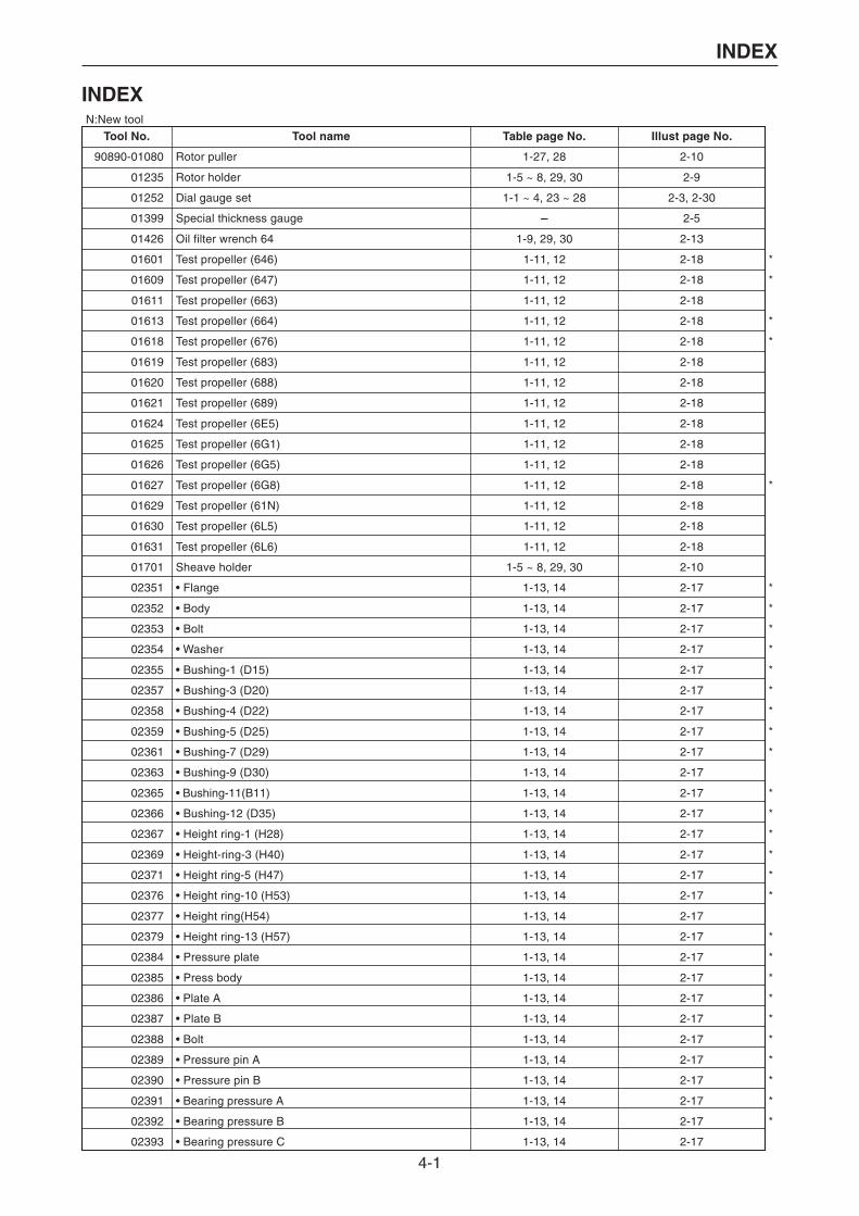
4-1
INDEX
INDEX
Tool No. Tool name Table page No. Illust page No.
90890-01080
90890-01235
90890-01252
90890-01399
90890-01426
90890-01601
90890-01609
90890-01611
90890-01613
90890-01618
90890-01619
90890-01620
90890-01621
90890-01624
90890-01625
90890-01626
90890-01627
90890-01629
90890-01630
90890-01631
90890-01701
90890-02351
90890-02352
90890-02353
90890-02354
90890-02355
90890-02357
90890-02358
90890-02359
90890-02361
90890-02363
90890-02365
90890-02366
90890-02367
90890-02369
90890-02371
90890-02376
90890-02377
90890-02379
90890-02384
90890-02385
90890-02386
90890-02387
90890-02388
90890-02389
90890-02390
90890-02391
90890-02392
90890-02393
Rotor puller
Rotor holder
Dial gauge set
Special thickness gauge
Oil filter wrench 64
Test propeller (646)
Test propeller (647)
Test propeller (663)
Test propeller (664)
Test propeller (676)
Test propeller (683)
Test propeller (688)
Test propeller (689)
Test propeller (6E5)
Test propeller (6G1)
Test propeller (6G5)
Test propeller (6G8)
Test propeller (61N)
Test propeller (6L5)
Test propeller (6L6)
Sheave holder
• Flange
• Body
• Bolt
• Washer
• Bushing-1 (D15)
• Bushing-3 (D20)
• Bushing-4 (D22)
• Bushing-5 (D25)
• Bushing-7 (D29)
• Bushing-9 (D30)
• Bushing-11(B11)
• Bushing-12 (D35)
• Height ring-1 (H28)
• Height-ring-3 (H40)
• Height ring-5 (H47)
• Height ring-10 (H53)
• Height ring(H54)
• Height ring-13 (H57)
• Pressure plate
• Press body
• Plate A
• Plate B
• Bolt
• Pressure pin A
• Pressure pin B
• Bearing pressure A
• Bearing pressure B
• Bearing pressure C
1-27, 28
1-5 ~ 8, 29, 30
1-1 ~ 4, 23 ~ 28
-
1-9, 29, 30
1-11, 12
1-11, 12
1-11, 12
1-11, 12
1-11, 12
1-11, 12
1-11, 12
1-11, 12
1-11, 12
1-11, 12
1-11, 12
1-11, 12
1-11, 12
1-11, 12
1-11, 12
1-5 ~ 8, 29, 30
1-13, 14
1-13, 14
1-13, 14
1-13, 14
1-13, 14
1-13, 14
1-13, 14
1-13, 14
1-13, 14
1-13, 14
1-13, 14
1-13, 14
1-13, 14
1-13, 14
1-13, 14
1-13, 14
1-13, 14
1-13, 14
1-13, 14
1-13, 14
1-13, 14
1-13, 14
1-13, 14
1-13, 14
1-13, 14
1-13, 14
1-13, 14
1-13, 14
2-10
2-9
2-3, 2-30
2-5
2-13
2-18
2-18
2-18
2-18
2-18
2-18
2-18
2-18
2-18
2-18
2-18
2-18
2-18
2-18
2-18
2-10
2-17
2-17
2-17
2-17
2-17
2-17
2-17
2-17
2-17
2-17
2-17
2-17
2-17
2-17
2-17
2-17
2-17
2-17
2-17
2-17
2-17
2-17
2-17
2-17
2-17
2-17
2-17
2-17
*
*
*
*
*
*
*
*
*
*
*
*
*
*
*
*
*
*
*
*
*
*
*
*
*
*
*
*
*
*
N:New tool
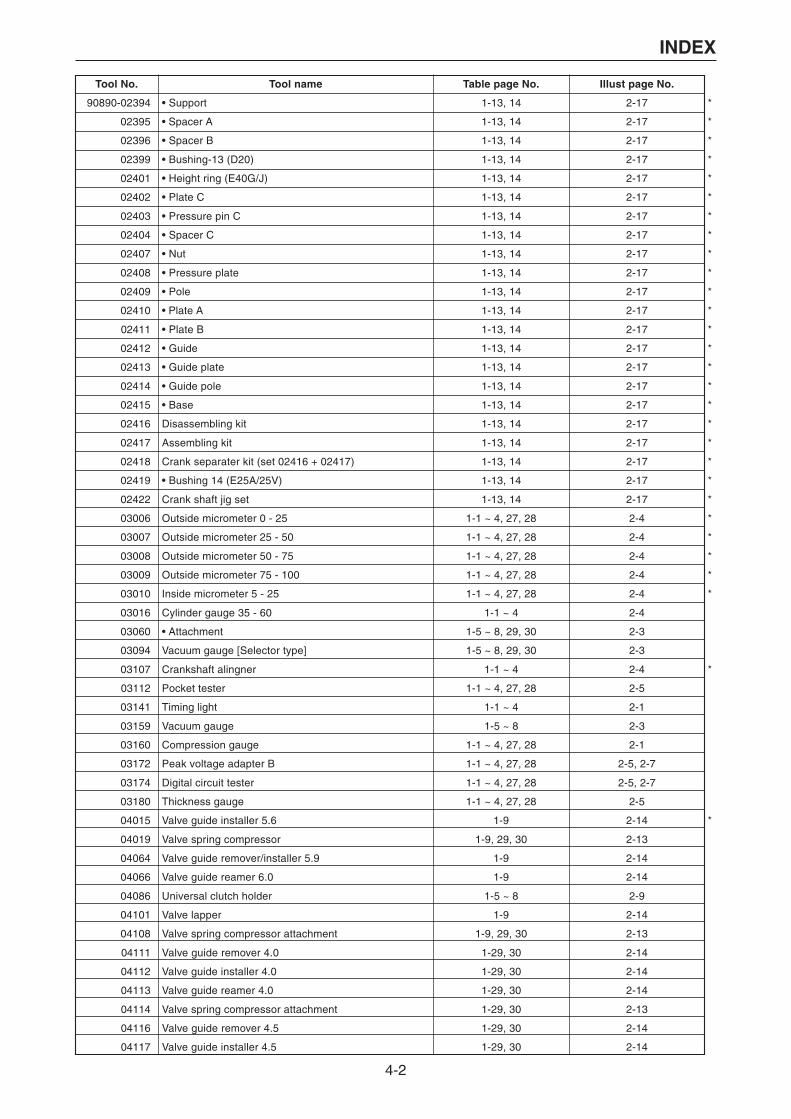
4-2
INDEX
Tool No. Tool name Table page No. Illust page No.
90890-02394
90890-02395
90890-02396
90890-02399
90890-02401
90890-02402
90890-02403
90890-02404
90890-02407
90890-02408
90890-02409
90890-02410
90890-02411
90890-02412
90890-02413
90890-02414
90890-02415
90890-02416
90890-02417
90890-02418
90890-02419
90890-02422
90890-03006
90890-03007
90890-03008
90890-03009
90890-03010
90890-03016
90890-03060
90890-03094
90890-03107
90890-03112
90890-03141
90890-03159
90890-03160
90890-03172
90890-03174
90890-03180
90890-04015
90890-04019
90890-04064
90890-04066
90890-04086
90890-04101
90890-04108
90890-04111
90890-04112
90890-04113
90890-04114
90890-04116
90890-04117
• Support
• Spacer A
• Spacer B
• Bushing-13 (D20)
• Height ring (E40G/J)
• Plate C
• Pressure pin C
• Spacer C
• Nut
• Pressure plate
• Pole
• Plate A
• Plate B
• Guide
• Guide plate
• Guide pole
• Base
Disassembling kit
Assembling kit
Crank separater kit (set 02416 + 02417)
• Bushing 14 (E25A/25V)
Crank shaft jig set
Outside micrometer 0 - 25
Outside micrometer 25 - 50
Outside micrometer 50 - 75
Outside micrometer 75 - 100
Inside micrometer 5 - 25
Cylinder gauge 35 - 60
• Attachment
Vacuum gauge [Selector type]
Crankshaft alingner
Pocket tester
Timing light
Vacuum gauge
Compression gauge
Peak voltage adapter B
Digital circuit tester
Thickness gauge
Valve guide installer 5.6
Valve spring compressor
Valve guide remover/installer 5.9
Valve guide reamer 6.0
Universal clutch holder
Valve lapper
Valve spring compressor attachment
Valve guide remover 4.0
Valve guide installer 4.0
Valve guide reamer 4.0
Valve spring compressor attachment
Valve guide remover 4.5
Valve guide installer 4.5
1-13, 14
1-13, 14
1-13, 14
1-13, 14
1-13, 14
1-13, 14
1-13, 14
1-13, 14
1-13, 14
1-13, 14
1-13, 14
1-13, 14
1-13, 14
1-13, 14
1-13, 14
1-13, 14
1-13, 14
1-13, 14
1-13, 14
1-13, 14
1-13, 14
1-13, 14
1-1 ~ 4, 27, 28
1-1 ~ 4, 27, 28
1-1 ~ 4, 27, 28
1-1 ~ 4, 27, 28
1-1 ~ 4, 27, 28
1-1 ~ 4
1-5 ~ 8, 29, 30
1-5 ~ 8, 29, 30
1-1 ~ 4
1-1 ~ 4, 27, 28
1-1 ~ 4
1-5 ~ 8
1-1 ~ 4, 27, 28
1-1 ~ 4, 27, 28
1-1 ~ 4, 27, 28
1-1 ~ 4, 27, 28
1-9
1-9, 29, 30
1-9
1-9
1-5 ~ 8
1-9
1-9, 29, 30
1-29, 30
1-29, 30
1-29, 30
1-29, 30
1-29, 30
1-29, 30
2-17
2-17
2-17
2-17
2-17
2-17
2-17
2-17
2-17
2-17
2-17
2-17
2-17
2-17
2-17
2-17
2-17
2-17
2-17
2-17
2-17
2-17
2-4
2-4
2-4
2-4
2-4
2-4
2-3
2-3
2-4
2-5
2-1
2-3
2-1
2-5, 2-7
2-5, 2-7
2-5
2-14
2-13
2-14
2-14
2-9
2-14
2-13
2-14
2-14
2-14
2-13
2-14
2-14
*
*
*
*
*
*
*
*
*
*
*
*
*
*
*
*
*
*
*
*
*
*
*
*
*
*
*
*
*

4-3
INDEX
Tool No. Tool name Table page No. Illust page No.
90890-04118
90890-05041
90890-05155
90890-05158
90890-05353
90890-05354
90890-05356
90890-05357
90890-05361
90890-06052
90890-06069
90890-06312
90890-06313
90890-06314
90890-06315
90890-06316
90890-06320
90890-06323
90890-06324
90890-06325
90890-06326
90890-06327
90890-06328
90890-06355
90890-06425
90890-06501
90890-06502
90890-06503
90890-06504
90890-06505
90890-06506
90890-06507
90890-06508
90890-06509
90890-06510
90890-06511
90890-06512
90890-06513
90890-06514
90890-06515
90890-06516
90890-06517
90890-06518
90890-06519
90890-06520
90890-06521
90890-06522
90890-06523
90890-06524
90890-06525
90890-06526
Valve guide reamer 4.5
Tap handle (5–6)
Heli-sert kit A
Piston ring compressor
Coupler kit A (61A)
Marine terminal kit
Crimper coupler (61A)
Crimper
Terminal pick (61A)
Shift rod push arm
Shaft holder
Valve seat cutter 45°-27.5
Valve seat cutter 5°-25
Valve seat cutter 5°-29
Valve seat cutter 60°-26
Valve seat cutter holder ø5.5
Valve spring compressor attachment
Valve seat cutter 60°-31
Valve seat cutter 60°-36
Valve seat cutter 45°-35
Valve seat cutter 30°-32.5
Valve seat cutter 30°-35
Valve seat cutter 30°-27
Crankshaft holder 16
Coupler wrench
Stopper guide plate
Bearing housing puller claw L
Bearing housing puller claw M
Center bolt
Pinion nut holder
• Socket adapter 1
• Socket adapter 2
• Socket adapter 3
Ring nut wrench 1
Ring nut wrench 2
Ring nut wrench 3
Ring nut wrench 4
Ring nut wrench extension
Puller head
Drive shaft holder 1
Drive shaft holder 2
Drive shaft holder 3
Drive shaft holder 4
Drive shaft holder 5
Drive shaft holder 6
Flywheel puller
Flywheel holder
Bearing outer race puller assembly
Small end bearing installer
Small end bearing installer
Small end bearing installer
1-29, 30
1-9
3-1
1-5 ~ 8, 29, 30
3-3
3-2
3-4
3-2
3-4
1-17, 18, 21, 22
1-5 ~ 8, 29, 30
1-9, 10, 29, 30
1-9, 10
1-9, 10, 29, 30
1-9, 10, 29, 30
1-9, 10
1-9
1-9, 10
1-9, 10
1-9, 10
1-9, 10
1-9, 10
1-9, 10, 29, 30
1-5 ~ 8
1-27 ~ 30
1-15, 16, 19, 20, 29, 30
1-15, 16, 19, 20
1-15, 16, 19, 20
1-15, 16, 19, 20
1-15, 16, 19, 20
1-15, 16, 19, 20
1-15, 16, 19, 20
1-15, 16, 19, 20
1-15, 16, 19, 20
1-15, 16, 19, 20
1-15, 16, 19, 20
1-15, 16, 19, 20
1-15, 16, 19, 20
1-15, 16, 19, 20
1-15, 16, 19, 20
1-15, 16, 19, 20
1-15, 16, 19, 20
1-15, 16, 19, 20, 29, 30
1-15, 16, 19, 20, 29, 30
1-15, 16, 19, 20
1-5 ~ 8, 15, 16, 19, 20, 27, 28
1-5 ~ 8, 27, 28
1-5 ~ 8, 15, 16, 19, 20, 29, 30
1-5 ~ 8
1-5 ~ 8
1-5 ~ 8
2-14
2-14
3-1
2-8
3-3
3-2
3-4
3-2
3-4
2-24
2-10
2-15
2-15
2-15
2-15
2-15
2-13
2-15
2-15
2-15
2-15
2-15
2-15
2-10
2-16
2-19
2-19
2-19
2-19
2-20
2-20
2-20
2-20
2-19
2-19
2-19
2-19
2-19
2-21
2-20
2-20
2-20
2-20
2-20
2-20
2-8
2-8
2-21
2-8
2-8
2-8
*
*
*
*
*
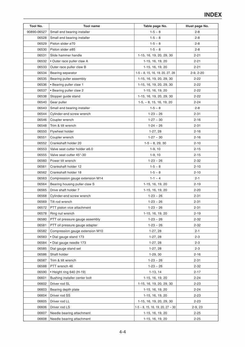
4-4
INDEX
Tool No. Tool name Table page No. Illust page No.
90890-06527
90890-06528
90890-06529
90890-06530
90890-06531
90890-06532
90890-06533
90890-06534
90890-06535
90890-06536
90890-06537
90890-06538
90890-06540
90890-06543
90890-06544
90890-06546
90890-06548
90890-06550
90890-06551
90890-06552
90890-06553
90890-06555
90890-06560
90890-06561
90890-06562
90890-06563
90890-06564
90890-06565
90890-06568
90890-06569
90890-06572
90890-06578
90890-06580
90890-06581
90890-06582
90890-06583
90890-06584
90890-06585
90890-06586
90890-06587
90890-06588
90890-06590
90890-06601
90890-06602
90890-06603
90890-06604
90890-06605
90890-06606
90890-06607
90890-06608
Small end bearing installer
Small end bearing installer
Piston slider ø70
Piston slider ø85
Slide hammer handle
• Outer race puller claw A
Outer race puller claw B
Bearing separator
Bearing puller assembly
• Bearing puller claw 1
• Bearing puller claw 2
Stopper guide stand
Gear puller
Small end bearing installer
Cylinder-end screw wrench
Coupler wrench
Trim & tilt wrench
Flywheel holder
Coupler wrench
Crankshaft holder 20
Valve seat cutter holder ø6.0
Valve seat cutter 45°-30
Power tilt wrench
Crankshaft holder 12
Crankshaft holder 18
Compression gauge extension M14
Bearing housing puller claw S
Drive shaft holder 7
Cylinder-end screw wrench
Tilt rod wrench
PTT piston vice attachment
Ring nut wrench
PTT oil pressure gauge assembly
PTT oil pressure gauge adapter
Compression gauge extension M10
• Dial gauge stand 173
• Dial gauge needle 173
Dial gauge stand set
Shaft holder
Trim & tilt wrench
PTT wrench 46
• Height ring 640 (H-19)
Bushing installer center bolt
Driver rod SL
Bearing depth plate
Driver rod SS
Driver rod LL
Driver rod LS
Needle bearing attachment
Needle bearing attachment
1-5 ~ 8
1-5 ~ 8
1-5 ~ 8
1-5 ~ 8
1-15, 16, 19, 20, 29, 30
1-15, 16, 19, 20
1-15, 16, 19, 20
1-5 ~ 8, 15, 16, 19, 20, 27, 28
1-15, 16, 19, 20, 29, 30
1-15, 16, 19, 20, 29, 30
1-15, 16, 19, 20
1-15, 16, 19, 20, 29, 30
1-5, ~ 8, 15, 16, 19, 20
1-5 ~ 8
1-23 ~ 26
1-27 ~ 30
1-24 ~ 26
1-27, 28
1-27 ~ 30
1-5 ~ 8, 29, 30
1-9, 10
1-9, 10
1-23 ~ 26
1-5 ~ 8
1-5 ~ 8
1-1 ~ 4
1-15, 16, 19, 20
1-15, 16, 19, 20
1-23 ~ 26
1-23 ~ 26
1-23 ~ 26
1-15, 16, 19, 20
1-23 ~ 26
1-23 ~ 26
1-27, 28
1-27, 28
1-27, 28
1-27, 28
1-29, 30
1-23 ~ 26
1-23 ~ 26
1-13, 14
1-15, 16, 19, 20
1-15, 16, 19, 20, 29, 30
1-15, 16, 19, 20
1-15, 16, 19, 20
1-15, 16, 19, 20, 29, 30
1-5 ~ 8, 15, 16, 19, 20, 27 ~ 30
1-15, 16, 19, 20
1-15, 16, 19, 20
2-8
2-8
2-8
2-8
2-21
2-21
2-21
2-9, 2-20
2-22
2-22
2-22
2-22
2-24
2-8
2-31
2-16
2-31
2-16
2-16
2-10
2-15
2-15
2-32
2-10
2-10
2-1
2-19
2-20
2-31
2-31
2-31
2-19
2-32
2-32
2-1
2-3
2-3
2-3
2-16
2-31
2-32
2-17
2-24
2-23
2-24
2-23
2-23
2-9, 23
2-25
2-25
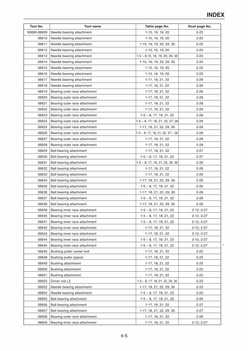
4-5
INDEX
Tool No. Tool name Table page No. Illust page No.
90890-06609
90890-06610
90890-06611
90890-06612
90890-06613
90890-06614
90890-06615
90890-06616
90890-06617
90890-06618
90890-06619
90890-06620
90890-06621
90890-06622
90890-06623
90890-06624
90890-06625
90890-06626
90890-06627
90890-06628
90890-06629
90890-06630
90890-06631
90890-06632
90890-06633
90890-06634
90890-06635
90890-06636
90890-06637
90890-06638
90890-06639
90890-06640
90890-06641
90890-06642
90890-06643
90890-06644
90890-06645
90890-06646
90890-06648
90890-06649
90890-06650
90890-06651
90890-06652
90890-06653
90890-06654
90890-06655
90890-06656
90890-06657
90890-06658
90890-06659
Needle bearing attachment
Needle bearing attachment
Needle bearing attachment
Needle bearing attachment
Needle bearing attachment
Needle bearing attachment
Needle bearing attachment
Needle bearing attachment
Needle bearing attachment
Needle bearing attachment
Bearing outer race attachment
Bearing outer race attachment
Bearing outer race attachment
Bearing outer race attachment
Bearing outer race attachment
Bearing outer race attachment
Bearing outer race attachment
Bearing outer race attachment
Bearing outer race attachment
Bearing outer race attachment
Ball bearing attachment
Ball bearing attachment
Ball bearing attachment
Ball bearing attachment
Ball bearing attachment
Ball bearing attachment
Ball bearing attachment
Ball bearing attachment
Ball bearing attachment
Ball bearing attachment
Bearing inner race attachment
Bearing inner race attachment
Bearing inner race attachment
Bearing inner race attachment
Bearing inner race attachment
Bearing inner race attachment
Bearing inner race attachment
Bushing puller center bolt
Bushing puller spacer
Bushing attachment
Bushing attachment
Bushing attachment
Driver rod L3
Needle bearing attachment
Needle bearing attachment
Ball bearing attachment
Ball bearing attachment
Ball bearing attachment
Bearing outer race attachment
Bearing inner race attachment
1-15, 16, 19, 20
1-15, 16, 19, 20
1-15, 16, 19, 20, 29, 30
1-15, 16, 19, 20
1-5 ~ 8,15, 16, 19, 20, 29, 30
1-15, 16, 19, 20, 29, 30
1-15, 16, 19, 20
1-15, 16, 19, 20
1-17, 18, 21, 22
1-17, 18, 21, 22
1-17, 18, 21, 22
1-17, 18, 21, 22
1-17, 18, 21, 22
1-17, 18, 21, 22
1-5 ~ 8, 17, 18, 21, 22
1-5 ~ 8, 17, 18, 21, 22, 27, 28
1-17, 18, 21, 22, 29, 30
1-5 ~ 8, 17, 18, 21, 22, 27 ~ 30
1-17, 18, 21, 22
1-17, 18, 21, 22
1-17, 18, 21, 22
1-5 ~ 8, 17, 18, 21, 22
1-5 ~ 8, 17, 18, 21, 22, 29, 30
1-17, 18, 21, 22
1-17, 18, 21, 22
1-17, 18, 21, 22, 29, 30
1-5 ~ 8, 17, 18, 21, 22
1-17, 18, 21, 22, 29, 30
1-5 ~ 8, 17, 18, 21, 22
1-17, 18, 21, 22, 29, 30
1-5 ~ 8, 17, 18, 21, 22
1-5 ~ 8, 17, 18, 21, 22
1-5 ~ 8, 17, 18, 21, 22
1-17, 18, 21, 22
1-17, 18, 21, 22
1-5 ~ 8, 17, 18, 21, 22
1-5 ~ 8, 17, 18, 21, 22
1-17, 18, 21, 22
1-17, 18, 21, 22
1-17, 18, 21, 22
1-17, 18, 21, 22
1-17, 18, 21, 22
1-5 ~ 8, 17, 18, 21, 22, 29, 30
1-17, 18, 21, 22, 29, 30
1-5 ~ 8, 17, 18, 21, 22
1-5 ~ 8, 17, 18, 21, 22
1-17, 18, 21, 22
1-17, 18, 21, 22, 29, 30
1-17, 18, 21, 22
1-17, 18, 21, 22
2-25
2-25
2-25
2-25
2-25
2-25
2-25
2-25
2-26
2-26
2-28
2-28
2-28
2-28
2-28
2-28
2-28
2-28
2-28
2-28
2-27
2-27
2-26
2-26
2-26
2-26
2-26
2-26
2-26
2-26
2-12, 2-27
2-12, 2-27
2-12, 2-27
2-12, 2-27
2-12, 2-27
2-12, 2-27
2-12, 2-27
2-22
2-22
2-25
2-25
2-25
2-23
2-25
2-25
2-26
2-27
2-27
2-28
2-12, 2-27
*
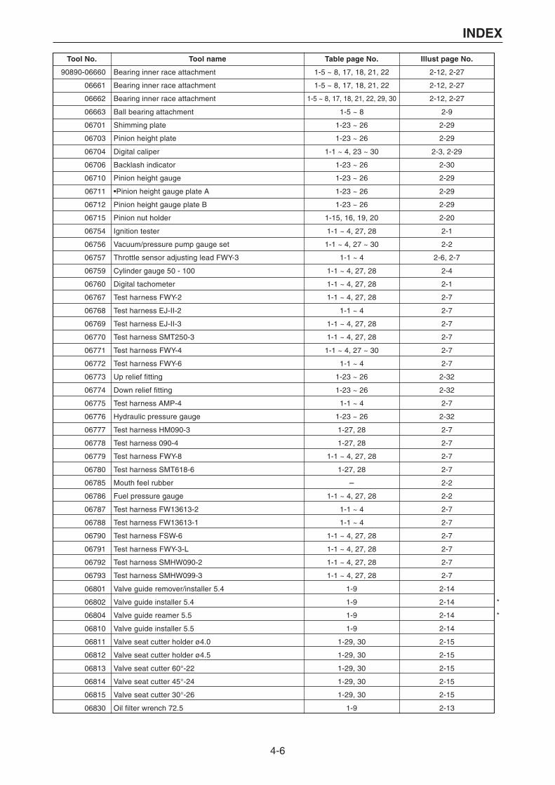
4-6
INDEX
Tool No. Tool name Table page No. Illust page No.
90890-06660
90890-06661
90890-06662
90890-06663
90890-06701
90890-06703
90890-06704
90890-06706
90890-06710
90890-06711
90890-06712
90890-06715
90890-06754
90890-06756
90890-06757
90890-06759
90890-06760
90890-06767
90890-06768
90890-06769
90890-06770
90890-06771
90890-06772
90890-06773
90890-06774
90890-06775
90890-06776
90890-06777
90890-06778
90890-06779
90890-06780
90890-06785
90890-06786
90890-06787
90890-06788
90890-06790
90890-06791
90890-06792
90890-06793
90890-06801
90890-06802
90890-06804
90890-06810
90890-06811
90890-06812
90890-06813
90890-06814
90890-06815
90890-06830
Bearing inner race attachment
Bearing inner race attachment
Bearing inner race attachment
Ball bearing attachment
Shimming plate
Pinion height plate
Digital caliper
Backlash indicator
Pinion height gauge
•Pinion height gauge plate A
Pinion height gauge plate B
Pinion nut holder
Ignition tester
Vacuum/pressure pump gauge set
Throttle sensor adjusting lead FWY-3
Cylinder gauge 50 - 100
Digital tachometer
Test harness FWY-2
Test harness EJ-II-2
Test harness EJ-II-3
Test harness SMT250-3
Test harness FWY-4
Test harness FWY-6
Up relief fitting
Down relief fitting
Test harness AMP-4
Hydraulic pressure gauge
Test harness HM090-3
Test harness 090-4
Test harness FWY-8
Test harness SMT618-6
Mouth feel rubber
Fuel pressure gauge
Test harness FW13613-2
Test harness FW13613-1
Test harness FSW-6
Test harness FWY-3-L
Test harness SMHW090-2
Test harness SMHW099-3
Valve guide remover/installer 5.4
Valve guide installer 5.4
Valve guide reamer 5.5
Valve guide installer 5.5
Valve seat cutter holder ø4.0
Valve seat cutter holder ø4.5
Valve seat cutter 60°-22
Valve seat cutter 45°-24
Valve seat cutter 30°-26
Oil filter wrench 72.5
1-5 ~ 8, 17, 18, 21, 22
1-5 ~ 8, 17, 18, 21, 22
1-5 ~ 8, 17, 18, 21, 22, 29, 30
1-5 ~ 8
1-23 ~ 26
1-23 ~ 26
1-1 ~ 4, 23 ~ 30
1-23 ~ 26
1-23 ~ 26
1-23 ~ 26
1-23 ~ 26
1-15, 16, 19, 20
1-1 ~ 4, 27, 28
1-1 ~ 4, 27 ~ 30
1-1 ~ 4
1-1 ~ 4, 27, 28
1-1 ~ 4, 27, 28
1-1 ~ 4, 27, 28
1-1 ~ 4
1-1 ~ 4, 27, 28
1-1 ~ 4, 27, 28
1-1 ~ 4, 27 ~ 30
1-1 ~ 4
1-23 ~ 26
1-23 ~ 26
1-1 ~ 4
1-23 ~ 26
1-27, 28
1-27, 28
1-1 ~ 4, 27, 28
1-27, 28
-
1-1 ~ 4, 27, 28
1-1 ~ 4
1-1 ~ 4
1-1 ~ 4, 27, 28
1-1 ~ 4, 27, 28
1-1 ~ 4, 27, 28
1-1 ~ 4, 27, 28
1-9
1-9
1-9
1-9
1-29, 30
1-29, 30
1-29, 30
1-29, 30
1-29, 30
1-9
2-12, 2-27
2-12, 2-27
2-12, 2-27
2-9
2-29
2-29
2-3, 2-29
2-30
2-29
2-29
2-29
2-20
2-1
2-2
2-6, 2-7
2-4
2-1
2-7
2-7
2-7
2-7
2-7
2-7
2-32
2-32
2-7
2-32
2-7
2-7
2-7
2-7
2-2
2-2
2-7
2-7
2-7
2-7
2-7
2-7
2-14
2-14
2-14
2-14
2-15
2-15
2-15
2-15
2-15
2-13
*
*
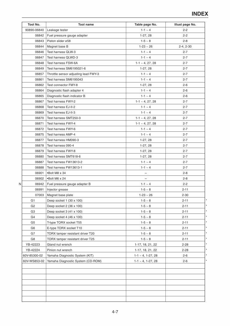
4-7
INDEX
Tool No. Tool name Table page No. Illust page No.
90890-06840
90890-06842
90890-06843
90890-06844
90890-06846
90890-06847
90890-06848
90890-06849
90890-06857
90890-06861
90890-06862
90890-06864
90890-06865
90890-06867
90890-06868
90890-06869
90890-06870
90890-06871
90890-06872
90890-06875
90890-06877
90890-06878
90890-06879
90890-06880
90890-06887
90890-06888
90890-06901
90890-06902
90890-06942
06991
90890-07003
G1
G2
G3
G4
G5
G6
G7
G8
YB-42223
YB-42224
60V-85300-02
60V-WS853-02
Leakage tester
Fuel pressure gauge adapter
Piston slider ø58
Magnet base B
Test harness QLW-3
Test harness QLWD-3
Test harness FSW-6A
Test harness SM6195021-6
Throttle sensor adjusting lead FWY-3
Test harness SM6195043
Test connector FMY-8
Diagnostic flash adapter 4
Diagnostic flash indicator B
Test harness FWY-2
Test harness EJ-II-2
Test harness EJ-II-3
Test harness SMT250-3
Test harness FWY-4
Test harness FWY-6
Test harness AMP-4
Test harness HM090-3
Test harness 090-4
Test harness FWY-8
Test harness SMT618-6
Test harness FW13613-2
Test harness FW13613-1
•Bolt M8 x 34
•Bolt M6 x 24
Fuel pressure gauge adapter B
Injector grease
Magnet base plate
Deep socket 1 (30 x 100)
Deep socket 2 (36 x 100)
Deep socket 3 (41 x 100)
Deep socket 4 (46 x 100)
T-type TORX socket T55
E-type TORX socket T10
TORX tamper resistant driver T20
TORX tamper resistant driver T25
Gland nut wrench
Pinion nut wrench
Yamaha Diagnostic System (KIT)
Yamaha Diagnostic System (CD-ROM)
1-1 ~ 4
1-27, 28
1-5 ~ 8
1-23 ~ 26
1-1 ~ 4
1-1 ~ 4
1-1 ~ 4, 27, 28
1-27, 28
1-1 ~ 4
1-1 ~ 4
1-27, 28
1-1 ~ 4
1-1 ~ 4
1-1 ~ 4, 27, 28
1-1 ~ 4
1-1 ~ 4
1-1 ~ 4, 27, 28
1-1 ~ 4, 27, 28
1-1 ~ 4
1-1 ~ 4
1-27, 28
1-27, 28
1-27, 28
1-27, 28
1-1 ~ 4
1-1 ~ 4
-
-
1-1 ~ 4
1-5 ~ 8
1-23 ~ 26
1-5 ~ 8
1-5 ~ 8
1-5 ~ 8
1-5 ~ 8
1-5 ~ 8
1-5 ~ 8
1-5 ~ 8
1-5 ~ 8
1-17, 18, 21, 22
1-17, 18, 21, 22
1-1 ~ 4, 1-27, 28
1-1 ~ 4, 1-27, 28
2-2
2-2
2-8
2-4, 2-30
2-7
2-7
2-7
2-7
2-7
2-7
2-6
2-6
2-6
2-7
2-7
2-7
2-7
2-7
2-7
2-7
2-7
2-7
2-7
2-7
2-7
2-7
2-8
2-8
2-2
2-11
2-30
2-11
2-11
2-11
2-11
2-11
2-11
2-11
2-11
2-28
2-28
2-6
2-6
*
*
*
*
*
*
*
*
*
*
*
*
N

-MEMO-