
XS5/XS2 Assembly Tooling and Accessories
10
XS5/XS2 Assembly Tooling and Accessories 157 XS5/XS2 Assembly Tooling and Accessories Tooling Use the Crimp Tool to crimp a cable core to the XS5U or XS2U Crimping Pin used with the XS@C or XS@G Crimping Connector. • The XY2F-0002 Crimp Tool is DMC's AFM8 (M22520/2-01). • Mount the XY2F-0003 Locator (sold separately) to the locator guide of the Crimp Tool with a screw provided with the XY2F-0003 Locator. Extraction Procedure 1. Disconnecting Components • Disconnect all components on the cap side from the cover. 2. Extracting Pin Block • Insert the claws of theTool into the four holes of the cover. • Make sure that the pin block is outside the Tool. • Press the Tool so that the guides of the Tool are in close contact. Then pull the pin block straight. Precaution for Safe Use • The pin block must not be extracted from the same Connector more than 3 times, otherwise the proper degree of protection of the pin block or Connector will not be maintained. Crimp Tool XY2F-0002 Locator XY2F-0003 5 4 3 2 1 8 7 6 R A I S E T O R O T A T E SEL. NO. P U S H P O S I T I O N E R A N D R O T A T E 9 0 ° T O I N S T A L L R O T A T E 9 0 ° T O I N S T A L L Tool in open position Tool in closed position XY2F-0002 Crimp Tool XY2F-0003 Locator Selector dial (Set to 6.) Locator guide Model XY2F-0002 XY2F-0003 Pin-block Extraction Tool XY2F-0001 Use this tool to extract a Pin Block from the covers in order to make wiring changes or corrections after the cover has been mounted to the pin block for Connector Assemblies (XS@C/XS@G, soldering/crimping). Model XY2F-0001 Pin block Cover Rubber bushing Cable clamp Cap Holes Claws Tool Pin block Guide Cover Cover Pin block Guide Extracting direction
-
Upload
khangminh22 -
Category
Documents
-
view
1 -
download
0
Transcript of XS5/XS2 Assembly Tooling and Accessories

XS5/XS2 Assembly Tooling and Accessories 157
XS5/XS2 Assembly Tooling and Accessories
Tooling
Use the Crimp Tool to crimp a cable core to the XS5U or XS2U CrimpingPin used with the XS@C or XS@G Crimping Connector.
• The XY2F-0002 Crimp Tool is DMC's AFM8 (M22520/2-01).
• Mount the XY2F-0003 Locator (sold separately) to the locatorguide of the Crimp Tool with a screw provided with theXY2F-0003 Locator.
Extraction Procedure1. Disconnecting Components
• Disconnect all components on the cap side from the cover.
2. Extracting Pin Block• Insert the claws of the Tool into the four holes of the cover.
• Make sure that the pin block is outside the Tool.
• Press the Tool so that the guides of the Tool are in close contact.Then pull the pin block straight.
Precaution for Safe Use• The pin block must not be extracted from the same Connector
more than 3 times, otherwise the proper degree of protection ofthe pin block or Connector will not be maintained.
Crimp ToolXY2F-0002
LocatorXY2F-0003
5 4
3
2
1
8
7
6
RAISE TO ROTATE SEL.
NO.
PU
SH
PO
SI
TIONER AND ROTATE
90° TO INSTALL
ROTA
TE
90°
TO INSTALL
Tool in open position
Tool in closed position
XY2F-0002Crimp Tool
XY2F-0003 Locator
Selector dial (Set to 6.) Locator guide
Model
XY2F-0002
XY2F-0003
Pin-block Extraction ToolXY2F-0001
Use this tool to extract a Pin Block from the covers in order to makewiring changes or corrections after the cover has been mounted to thepin block for Connector Assemblies (XS@C/XS@G, soldering/crimping).
Model
XY2F-0001
Pin block Cover Rubberbushing
Cableclamp
Cap
Holes
Claws
Tool
Pin block
GuideCoverCover
Pin blockGuide
Extractingdirection
158 XS5/XS2 Assembly Tooling and Accessories
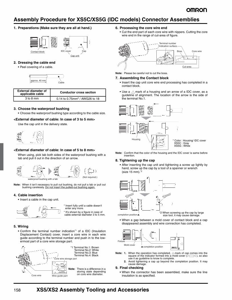
Assembly Procedure for XS5C/XS5G (IDC models) Connector Assemblies1. Preparations (Make sure they are all at hand.)
2. Dressing the cable end• Peel covering of a cable.
3. Choose the waterproof bushing• Choose the waterproof bushing type according to the cable size.
<External diameter of cable: In case of 3 to 5 mm>Use the cap unit in the delivery state.
<External diameter of cable: In case of 5 to 8 mm>When using, pick tab both sides of the waterproof bushing with atab and pull it out in the direction of an arrow.
Note: When it isn't necessary to pull out bushing, do not pull a tab or pull outbushing carelessly. Do not insert the pulled-out bushing again.
4. Cable insertion• Insert a cable in the cap unit.
5. Wiring• Confirm the terminal number indication*1 of a IDC (Insulation
Displacement Contact) cover, insert a core wire in each wireguide according to the terminal number and push in to the low-ermost part of a core wire storage part.
6. Processing the core wire end• Cut the end part of each core wire with nippers. Cutting the core
wire end in the range of cut-area of figure.
Note: Please be careful not to cut the boss.
7. Assembling the Contact block• Insert the cap unit core wire end processing has completed in a
contact block.
• Use a mark of a housing and an arrow of a IDC cover, as aguideline of alignment. The location of the arrow is the side ofthe terminal No.1.
Note: Confirm that the color of the housing and the IDC cover is same beforeinsertion.
8. Tightening up the cap• After inserting the cap unit and tightening a screw up lightly by
hand, screw up the cap by a tool of a spanner or wrench(size 15 mm).*2
• When a gap between a mold cover of contact block and a capdisappeared assembly and wire connection has completed.
Note: 1. When the operation has completed, mark of cap comes into thesquare of the indicator formed into a mold cover ( ), so alsouse it as guideline to know to complete.
2. Avoid tightening a cap up beyond the completion position. It maycause damage.
9. Final checking• When the connector has been assembled, make sure the line
insulation is as specified.
External diameter ofapplicable cable Conductor cross section
3 to 8 mm 0.14 to 0.75mm2 / AWG26 to 18
Cap unit
Contact block IDC cover Cap
approx. 40 mmCable
(Not required.)waterproof bushing with a tab
* Insert fully until a cable doesn'tenter any more.
* It's shown by a figure in case ofcable external diameter 3 to 5 mm.
Core wire storage part
Wire guide partCore wire
*1 Terminal No.1: BrownTerminal No.2: WhiteTerminal No.3: BlueTerminal No.4: Black
Note: There is a difference in astoring state dependingon core wire diameter.
Terminal numberindication surface
Boss
Cut-area
Core wire
Housing * Color : Housing/ IDC coverXS5C : GrayXS5G : White
completion position*2 When screwing up the cap by large
size tool, it may cause damage.
completion positionMold cover
Fixture
XS5/XS2 Assembly Tooling and Accessories 159
Cap unit removal• When releasing wire connection, remove the cap unit in the
opposite procedure of assembly work. [ from (8) to (7) ]
Note: 1. The core wire remain connected to the IDC connection part rarely. Inthat case, remove core wire end part to the vertical direction bytweezers etc. Do not touch the IDC contact directly at that time.
2. When IDC cover was left on the housing side, remove it by pulling acable. In case IDC cover has been removed by holding strongly andpulling, it may cause damage.
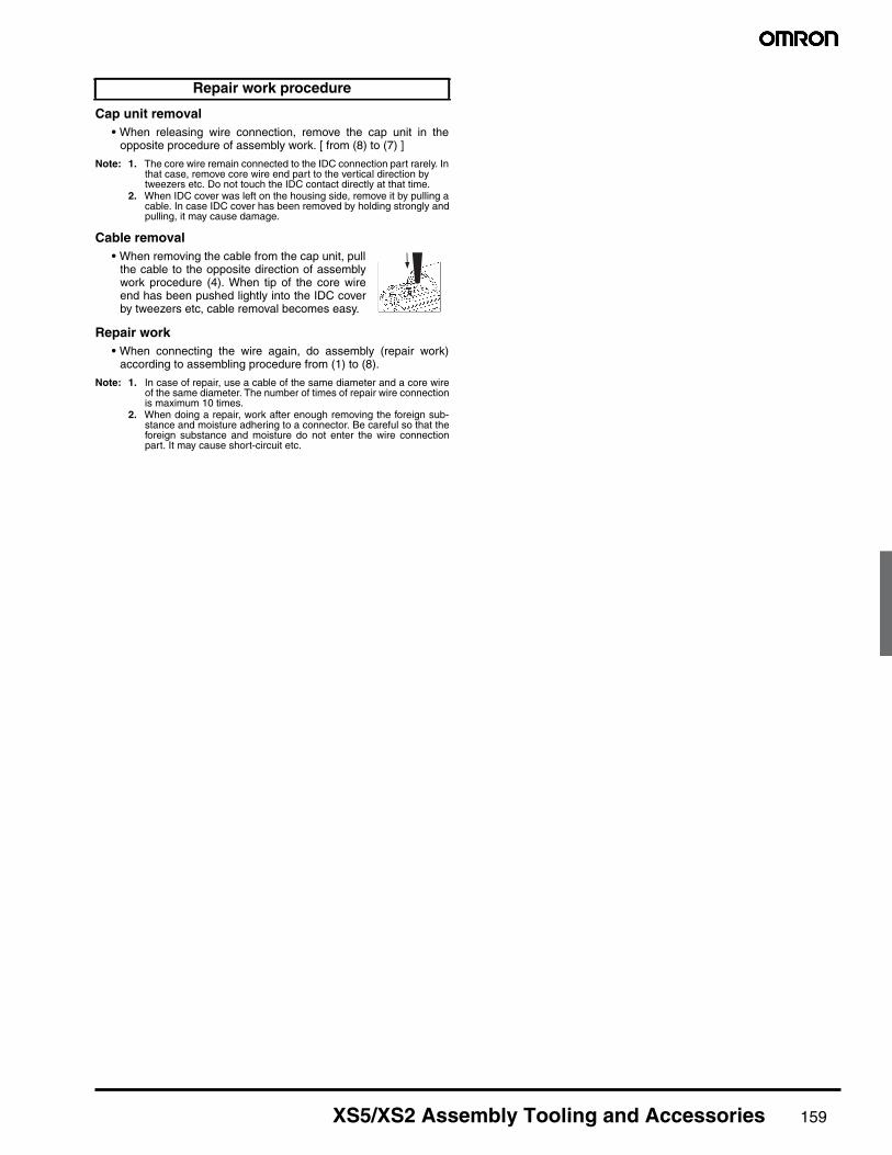
Cable removal• When removing the cable from the cap unit, pull
the cable to the opposite direction of assemblywork procedure (4). When tip of the core wireend has been pushed lightly into the IDC coverby tweezers etc, cable removal becomes easy.
Repair work• When connecting the wire again, do assembly (repair work)
according to assembling procedure from (1) to (8).
Note: 1. In case of repair, use a cable of the same diameter and a core wireof the same diameter. The number of times of repair wire connectionis maximum 10 times.
2. When doing a repair, work after enough removing the foreign sub-stance and moisture adhering to a connector. Be careful so that theforeign substance and moisture do not enter the wire connectionpart. It may cause short-circuit etc.
Repair work procedure

160 XS5/XS2 Assembly Tooling and Accessories
Assembly Procedure for XS@C/XS@G Connector Assemblies1. Connector and Cable External Diameters
• Connectors for 6-, 4-, and 3-mm-diameter Cables (i.e., Cables thatare 5 to 6, 4 to 5, and 3 to 4 mm in diameter respectively) areavailable. When assembling a Connector used with a cable, makesure that the external diameter of the Connector is suited to that ofthe cable.
• Connectors for 6-mm-diameter Cables use white cable clamps.Connectors for 4- and 3-mm-diameter Cables use black cableclamps.A watertight bushing for 6-mm-diameter Cable has no stripe, thatfor 4-mm-diameter Cable has a single stripe, and that for 3-mm-diameter Cable has two stripes.
Note: When connecting a commercially available cable to aconnector assembly, use a cable with an outside diameter of 3to 6 mm and core sizes of 0.18 to 0.75 mm2 for crimpingconnectors and 0.5 mm2 maximum for soldering connectors.
2. Component Insertion
• As shown in the above illustration, connect the above componentsto the Cable with its end processed.
3. Wiring (Processing Cable Ends)
• Strip 10 mm of the Cable sheath and 4 mm of each core.
• Before soldering cores and solder cup pins together, solder-coateach of them.
• The following conditions are recommended for soldering eachsolder cup pin.Soldering iron: 30 to 60 WSoldering temperature: 280°C to 340°CSoldering period: 3 s max.
• The length marked *A should be 6.5 mm max., otherwise theproper degree of protection of the connector will not be maintained.
• Strip 14 mm of the Cable sheath and 4 mm of each core.
• Make sure that each core is not damaged and its end strands arenot spread out.
• Mount the XY2F-0003 Locator to XY2F-0002 Crimping Tool, both ofwhich are sold separately, and set the selector dial of the CrimpingTool to 6 for the XS5U-@@21 (XS2U-@@21) and to 7 for theXS5U-@@22 (XS2U-@@22).
• After mounting the crimping pins to the Locator, fully insert thecores to the crimping pins.
• Squeeze the handle of the Crimp Tool to press-fit the cores tothe crimping pins.(Squeeze the handle firmly until the handle automaticallyreturns to the release position.)
• After press-fitting the cores to the pins, insert the pins into the pinclamp as shown in the illustration. Then make sure that the leadcolors correspond to the pin clamp numbers that are identical tothe connector pin numbers.
Crimping/Soldering Connectors
Screw-on Connectors
CoverWatertightbushing
Cableclamp Cap
Cover
Ring (Angled models only) *
Watertightbushing
Cable clamp Cap
Straight Connectors
Angled Connectors
* A ring is not required for Screw-on Connectors.
Cover
Cover
Watertight bushing
Watertightbushing
Cable clamp
Cable clamp
Cap
Cap
Ring *1
(*2 )
Confirm that you have all of the required parts.
Insulation caps and insulation tubes are included with5-pole Connectors (XS@C-D5S@ and XS@G-D5S@).
*1. Rings are not required with 7-mm and 8-mm cables.*2. Insert the waterproof bushing for 7-mm and 8-mm
cables in the direction shown in the diagram.
Soldering Connectors
Crimping Connectors
46
6±0.5 *A
410 0
−4
Crimping
Pin clamp Press
1 to 1.5
Wiring

XS5/XS2 Assembly Tooling and Accessories 161
Assembly Procedure (continued)
• Tentatively insert the pins to the pin block holes so that the key onthe pin block will coincide with the key groove on the pin clamp.Then insert the cable along with the pin clamp.
• Loosen the screws on pins 1 to 4 and insert the cores according tothe pin numbers.
• Use the dedicated Screwdriver (XW4Z-00B)* and tighten thescrews securely so that the cores do not pull out (tightening torque:0.15 to 0.2 N·m).
· Five-pole Connectors• Strip the cable sheath for a total of 15 mm and strip the core
covering for 8 mm for the core to connect to pin 5.
• Connect the core to pin 5 (in the center) first.
• Insert the core from the side of the hold with the tab and tighten thescrew securely (tightening torque: 0.15 to 0.2 N·m), and then cutoff the excess wire with wire cutters.
• Bend the cable as shown below, attached the enclosed insulationcap, and then strip the other cores.
• Connect the cores to pins 1 to 4.
Connecting Shielded Cables to Five-pole Connectors• Place the insulation tub on the drain line of the shield and connect
it to the terminal.
• Tighten the screw and then check visually to see if there isinsulation between the cores.
• Connect the cores to pins 1 to 4.
* When tightening the screws, use the dedicated XW4Z-00BScrewdriver that matches with the screw-slot dimensions.
4. Inserting Pin Block
• Mount the cover to the pin block so that the triangle mark on the pinblock will coincide with the triangle mark on the cover.
• If the cover is used for an Angled model, the relationship betweenthe position of the polarity key on the engaged side and cableconnection direction will be determined by the direction in whichthe positioning key is inserted into the cover, which can berotated by 90°.
• Fully insert the positioning key until the positioning key is hidden bythe casing.
Screw-on Connectors
Pin Block Pin Clamp Key groove Key groove
Key XS@C use XS@G use
6±0.5
Insertion
8
12
12±0.5
Cable End Processing· Four-pole Connectors
8 7
812 Conductors for
pins 1 to 4
Conductors forpin 5
Screw
Dedicatedscrewdriver
Dedicatedscrewdriver
Screw
Tab
Insulation cap
Insulation tube
Drain line
XW4Z-00BScrewdriver
Lock springO-ring
Triangle markPositioning key(triangle mark)
Polarity key
Pin Block(Soldering Model)
Cover(Straight Model)
(Crimping Model) (Angled Model)

162 XS5/XS2 Assembly Tooling and Accessories
• Align the triangular marks on the pin block and cover and insert thepin block into the cover.
• Press them together firmly (0.39 to 0.49 N·m) until the pin blockdoes not come out of the cover.
5. Mounting Cap• After mounting the cover to the pin block and the cover snaps
into place, tighten the cap securely by hand within a torque of0.39 and 0.49 N·m.
Note: If the cap is not tighten securely enough, the degree ofprotection (IP67) may not be maintained or vibration maycause the cap to become loose. Do not tighten the cap withpliers or similar tools; they may damage the cap.
• After fully tightening the cap, length A should be approximately oneof the following according to the cable external diameter and theConnector model.
6. After Assembly• Confirm the insulation between cores after completing assembly.
Recommended CablesWhen connecting a commercially available cable to a connectorassembly, use a cable with an outside diameter of 3 to 6 mm and coresizes of 0.18 to 0.75 mm2 for crimping connectors and 0.5 mm2
maximum for soldering connectors.
Connector ArrangementFor safety, when constructing a connection system between a Sensorand panel with a connector, make sure that the connector plug is onthe Sensor side and the connector socket is on the panel side (i.e.,the female pins are located on the power-supply side).
Connecting the XS51. Connecting the XS5 Plug and Socket
• Align the projection on the plug cover with the polarity key on thesocket, then insert the plug all the way in.
• Hold the knurled socket grip, then insert the projection on the pluginto the groove of the socket.
• Turn the knurled grips of the socket clockwise approximately45 degrees in respect to the plug. A click will indicate that theConnectors are locked. The locking condition can also beconfirmed by the alignment marks on the plug and socket.
2. Connecting the XS5 and XS2• Align the projection on the plug cover with the polarity key on the
socket, then insert the plug all the way in.
• In the same way as when connecting two XS2 Connectors, screwthe knurled grip in the clockwise direction.
• Use your fingers to tighten the Connectors sufficiently.
ConnectorCable external diameter (mm)
6 mm 5 mm 4 mm 3 mm
For 6-mm-dia. cable 1 0 --- ---
For 4-mm-dia. cable --- 2 1 ---
For 3-mm-dia. cable --- --- 2 1
Triangle mark
Pin blockCover lock
Pin Block(Screw-mounting Connectors) Cover
CapA
Sensor Side Connecting Cable Panel Side(Power-supply Side)
(Plug) (Socket) (Plug) (Socket)
Polarity keyProtrusion oncover aligns with polarity key.
Alignment marks

XS5/XS2 Assembly Tooling and Accessories 163
Accessories
■ Connector CoversWater-resistive Covers
Dust Covers
Sputter Protective Cover
Model Minimum order MaterialSuitable connector
Model Mounting portion
XS2Z-1150 Brass/nickel plated
XS2G/XS2H/XS2M/XS2R/XS2W/XS5G/XS5H/XS5M/XS5R/XS5W M12 male screw
XS2Z-22 XS2C/XS2R/XS2F/XS2P/XS2W/XS5C/XS5R/XS5F/XS5P/XS5W/XW3D M12 female screw (thread bracket)
M12
XS2Z-11 M12 male screwXS2Z-11
XS2Z-22 M12 M12 × 1.0 female screw (thread bracket)XS2Z-22 The Water-resistive Cover ensures IP67.
When mounting the Water-resistive Cover to aConnector, be sure to apply a torque rangebetween 0.39 and 0.49 N·m to tighten theWater-resistive Cover.
Model Minimum order MaterialSuitable connector
Model Mounting portion
XS2Z-13
50 Rubber/black
XS2G/XS2H/XS2M/XS2R/XS2W/XS5G/XS5H/XS5M/XS5R/XS5W M12 male screw
XS2Z-14 XS2C/XS2R/XS2F/XS2P/XS2W/XS5C/XS5R/XS5F/XS5P/XS5W/XW3D
Pin block (female pins)
XS2Z-15 M12 female screw (thread bracket)
XS2Z-13 M12 male screwXS2Z-13
XS2Z-15 XS2Z-14M12 female screw (thread bracket)
Pin block (female pins)
XS2Z-15/XS2Z-14 The Dust Cover is for dust prevention and does notensure IP67 degree of protection.
When mounting the Dust Cover to a connector, besure to press the Dust Cover onto the Connectoruntil the Connector is fully inserted into the DustCover.
XS2Z-31M12 female screw (thread bracket)
Pin block (female contact)
XS2Z-31The Sputter Protective Cover protects the con-nector from weld sputter.
Make sure it covers the entire connector.
Model Material Applicable connector
XS2Z-31 Silicone rubber/black XS2F/XS2H/XS2WXS5F/XS5H/XS5W

164 XS5/XS2 Assembly Tooling and Accessories
Safety Precautions
Do not use the Connectors in an atmosphere or environment thatexceeds the specifications.
Connector Connection and Disconnection• When connecting or disconnecting Connectors, be sure to hold the
Connectors by hand.
• Do not hold the cable when disconnecting Connectors.
• When mating Connectors, be sure to insert the plug all the way tothe back of the socket before attempting to lock the Connectors.
• Do not use tools of any sort to mate the Connectors. Always useyour hands. Pliers or other tools may damage the Connectors.
• When mating the Connectors to XS2, XS5 or other M12 Connec-tors, tighten the lock by hand to a torque of 0.39 to 0.49 N⋅m.
• When disconnecting Connectors, be sure to loosen the threadbrackets first. Do not loosen the caps.
• Thread brackets must be loosened in the cutout direction.
Wiring• Always confirm wiring diagrams before wiring sensors, limit
switches, or other devices.
• Lay the cables so that external force is not applied to theConnectors. Otherwise, the degree of protection (IP67) may notbe achieved.
Degree of Protection• Do not impose external force continuously on the joints of pin
blocks and covers, otherwise the Connectors may not keep theirproper degree of protection (i.e., IP67).
• The degree of protection of Connectors (IP67) is not for a fullywatertight structure. Do not the Connectors underwater.
• Do not step on or place any objects on the Connectors. Doing somay damage the Connectors.
General Precautions• Do not pull excessively on the Connectors or cables. Do not install
the Connectors or cables in any way that would place a loaddirectly on the mating section or cable connections. Doing so candamage the Connectors or break the wires inside the cables.
• Install the Connectors and cables where they will not be steppedon to prevent the wires inside the cables from being broken and toprevent the Connectors from being damaged. If the Connectors orcables must be installed where they might be stepped on, protectthem with covers.
• Refer to the specifications for your cables before bending thecables and do not bend them past their minimum bending radius.
• Cables supplied by Omron should not be bent near the base ofthe unit and must have a minimum radius of 40 mm.
• If sensors or switches are not attached during installation, protectthe mating surface of the Connector with a XS2Z-22 WaterproofCover of XS2Z-14/15 Dust Cover.
Precautions for Correct Use
Loosen
Cutout
Threadbracket

XS5/XS2 Assembly Tooling and Accessories 165
Smartclick XS5 - Problem Solving
1
All combinations are connectable.
2
3
4
Problem Solution
It is troublesome to screw the connectors together. It’s a twist-and-click connection.An innovative new lock structure makes connection extremely simple.The lock mechanism is internal, so it will no longer become jammed bysputtered fluids or dust. Also the use of a movable lock bolt makes it pos-sible to connect the Smartclick XS5 to a screw-type M12 connector.
XS5 Smartclick Plug Connector M12 plug connector
XS5 Smartclick Socket Connector Twist-and-click connection Screw connection
M12 socket connector Screw connection Screw connection
Problem Solution
There’s nothing to tell you that it’s connected. The Smartclick XS5 “clicks” to tell you it’s connected.A positive clicking feel tells you for sure that the Connector is securelylocked.
Problem Solution
It’s difficult to keep track of locking torque values. Locking is done with approximately 1/8th of a turn.The Smartclick XS5 has the industry’s shortest locking rotation of 1/8thof a turn. There’s no need to keep track of locking torque, and this greatlyreduces time and effort when wiring.
Problem Solution
The connection sometimes vibrates loose. A bayonet lock mechanism is used.By using a bayonet mechanism, which is a common locking method, theSmartclick XS5 eliminates any concerns about loosening.
ALL DIMENSIONS SHOWN ARE IN MILLIMETERS.To convert millimeters into inches, multiply by 0.03937. To convert grams into ounces, multiply by 0.03527.

Cat. No. X304-E-1A 07/13 Specifications subject to change without notice. Printed in USA