What is AxesBrain
110
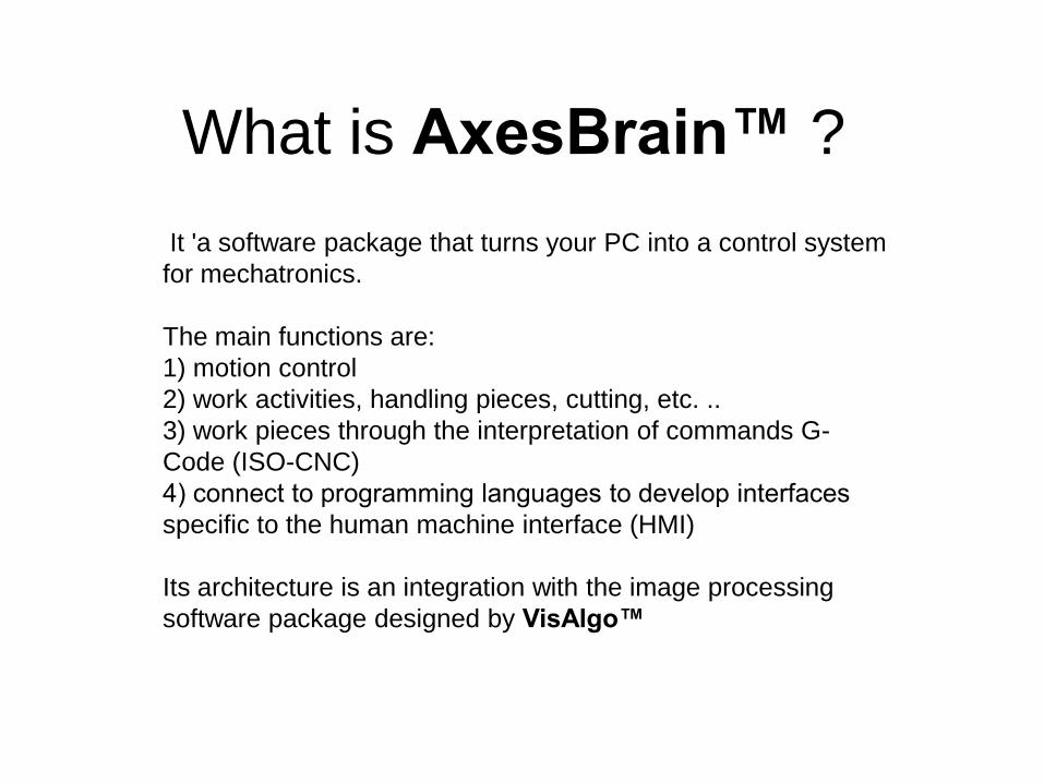
What is AxesBrain™ ? It 'a software package that turns your PC into a control system for mechatronics. The main functions are: 1) motion control 2) work activities, handling pieces, cutting, etc. .. 3) work pieces through the interpretation of commands G- Code (ISO-CNC) 4) connect to programming languages to develop interfaces specific to the human machine interface (HMI) Its architecture is an integration with the image processing software package designed by VisAlgo™
-
Upload
khangminh22 -
Category
Documents
-
view
1 -
download
0
Transcript of What is AxesBrain
What is AxesBrain™ ?
It 'a software package that turns your PC into a control system
for mechatronics.
The main functions are:
1) motion control
2) work activities, handling pieces, cutting, etc. ..
3) work pieces through the interpretation of commands G-
Code (ISO-CNC)
4) connect to programming languages to develop interfaces
specific to the human machine interface (HMI)
Its architecture is an integration with the image processing
software package designed by VisAlgo™
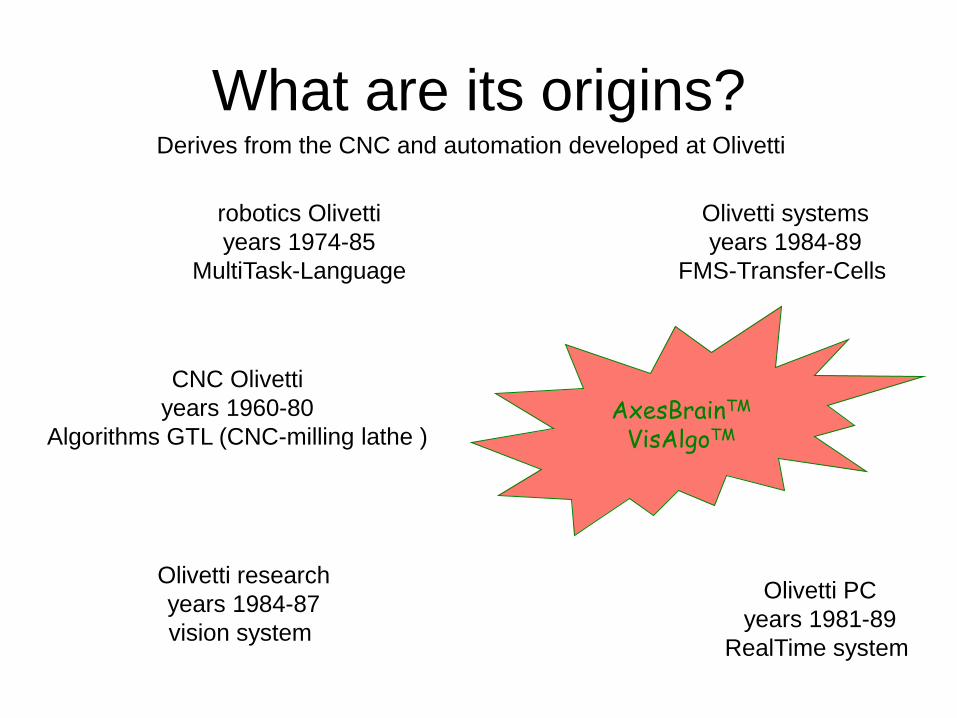
What are its origins? Derives from the CNC and automation developed at Olivetti
robotics Olivetti
years 1974-85
MultiTask-Language
AxesBrainTM
VisAlgoTM
CNC Olivetti
years 1960-80
Algorithms GTL (CNC-milling lathe )
Olivetti systems
years 1984-89
FMS-Transfer-Cells
Olivetti PC
years 1981-89
RealTime system
Olivetti research
years 1984-87
vision system
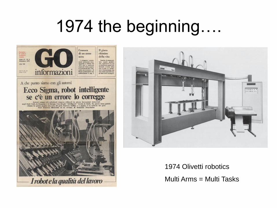
1974 the beginning….
1974 Olivetti robotics
Multi Arms = Multi Tasks

The first micromill….
1975 ISO G-Code for micromill maschine
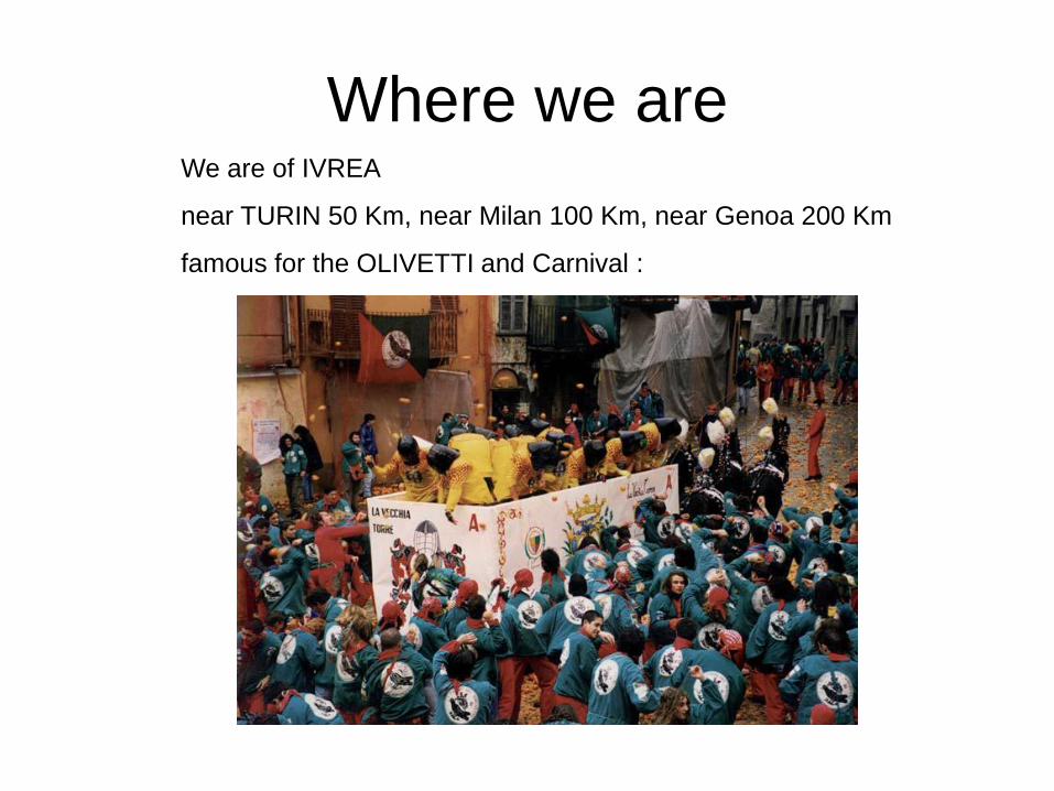
Where we are We are of IVREA
near TURIN 50 Km, near Milan 100 Km, near Genoa 200 Km
famous for the OLIVETTI and Carnival :

Resources and field devices
Digital input and output, physical and virtual
Analog input and output
Physical and virtual axes
Spindles
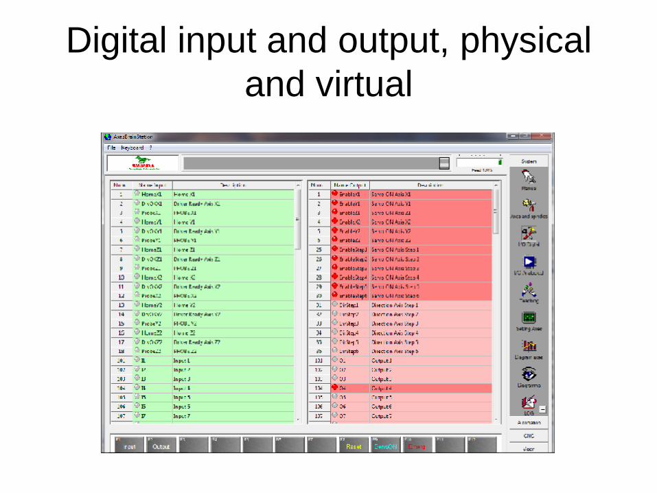
Digital input and output, physical
and virtual
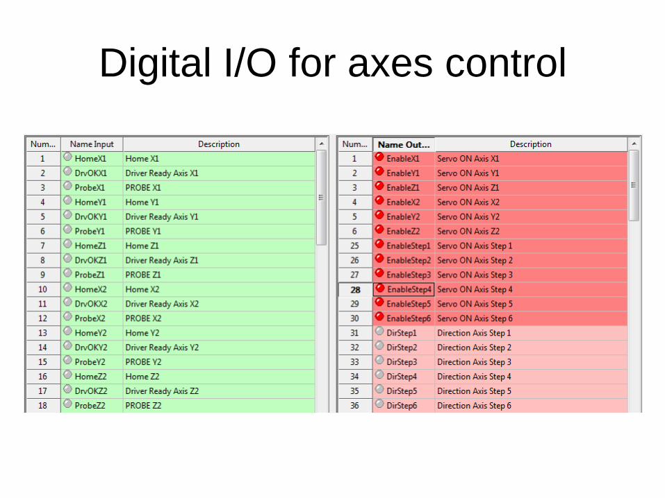
Digital I/O for axes control

Digital I/O

Virtual digital I/O

Analog input and output

Physical axes and Spindles

Physical, virtual axes and Spindles

Virtual axes for SCARA
[Xs]
i=VIRTUAL_AXES_NAME( "Xs" , "Ys" )
b={
Description="SCARA"
Kind_Axis="ARM"
Kind_Axis_0=0x00010000 // Type SCARA Kind_Axis_1=0x00000000
Axis_name_ascisse="Xs"
Axis_name_ordinate="Ys"
Axis_name_1=“Step1" // A1 AXIS ANGLE ARM
Axis_name_2=“Step2" // B1 AXIS ANGLE FOREARM
Axis_name_3=“Step3" // C1 AXIS ROTARY (PULSE)
Axis_name_4="" // X1 ADDITIONAL AXIS MOTION Lenght_arm_1=200.0
Lenght_arm_2=200.0
Abs_offset_A=100.0
Vel_max_axis_A=20000.0
Acc_max_axis_A=200.0
Dec_max_axis_A=200.0
Abs_offset_O=100.0
Vel_max_axis_O=20000.0
Acc_max_axis_O=1000.0
Dec_max_axis_O=1000.0
e=}
X1
A1B1
C1
Z1

Virtual axes for CYLINDRICAL
[Xp]
i=VIRTUAL_AXES_NAME( "Xp" , "Yp" )
b={
Kind_Axis="ARM"
Kind_Axis_0=0x00080000 // CYLINDRICAL SLEEVE
Kind_Axis_1=0x00000000
Axis_name_ascisse="Xc"
Axis_name_ordinate="Yc"
Axis_name_1=“Step4" // A1 AXIS ANGLE ARM
Axis_name_2=“Step5" // B1 AXIS LINEAR (SLEEVE)
Axis_name_3=“Step6" // C1 AXIS ROTARY (PULSE)
Axis_name_4="" // X1 ADDITIONAL AXIS MOTION
Lenght_arm_1=000.0
Lenght_arm_2=200.0
Abs_offset_A=150.0
Vel_max_axis_A=50000.0
Acc_max_axis_A=1000.0
Dec_max_axis_A=1000.0
Abs_offset_O=100.0
Vel_max_axis_O=50000.0
Acc_max_axis_O=1000.0
Dec_max_axis_O=1000.0
e=}
A1
X1
C1
Z1
B1

Manual system motion axes
Setting axes +-10Volt PID
The analog +-Volt is a velocity reference, the error of position is
used to correct the velocity by PID feedback .
1) Proportional error
2) Integrative error
3) Derivative error
Volt= Kc*( P*error+I*Sum of errors+D*Variation of error )

PID Calibration
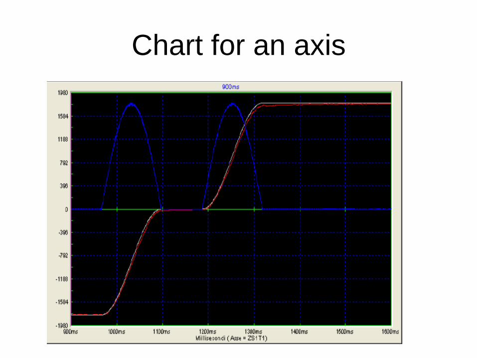
Chart for an axis

Structure mechatronics

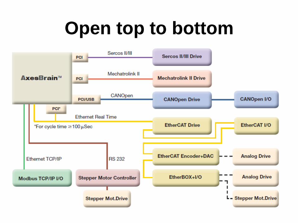
Types of openings
Open top to bottom:Ability to use the most common fieldbus and drive both analog and digital
(fieldbus interface)
Opening up:possibility of using high level languages to create their own user interface
(Man-to-machine interface)
Open top to bottom

Opening up
The Distributed Component Object Model (DCOM known by the acronym,
English for distributed component object model) is a computer technology
introduced by Microsoft in 1996.
DCOM allows you to make remote procedure calls across a network, taking
care of all the mediations necessary, independently of the language, presents
to the application of specific services, which in general can be used by
applications "Customers" on the same PC or PC remote.
You can then use languages like VC + +, VB, C #. Net, etc ... to create their
own HMI

AxesBrain™
One mind, many tasks at once AxesBrain ™ is a software component for the motion control, with Multitask
capabilities for automation and Multiprocess capabilities for the CNC
The winning of AxesBrain ™ is its ability to handle multiple processes,
multiple axes and multiple tasks in parallel.
In fact you can run to 32 fi CNC ISO processes simultaneous and activities
up to 1024 GP-PLC simultaneously.
These are particularly useful feature for transfer, machines with automatic
loading-unloading and special machines in general, where processes are
required parallel working.
AxesBrain ™ is a control designed to connect to all major fieldbus handling
axis and the management of I / O.
It also connects in digital mode by ethernet to drive analog.This flexibility
offers a wide choice that guarantees a reduction in costs.

AxesBrain™ features
• CNC-ISO (milling, lathe)
• 1024 GP-PLC Tasks
• ISO 32 CNC Processes
• Transformation axes in the plane
• 64 axes (16 axes interpolated)
• 4096 I / O
• Linear compensation, quadrature, matrix
• Gantry
• Anti-collision
• Electronic Cam

Realtime Ethernet technology
The technology is based on a few points:
1) For the wiring you use the Ethernet cable
2) The master (typically a PC) transmits and receives an Ethernet frame
using the "standard" the concept of frame is the same as when it transmits
and receives information on the Internet Traditional
3) The slave devices do not receive and retransmit the frame next to the
slave, but they see him pass.
4) Finally, the FRAME returns to the Master who receives the complete
data of all slaves.

How to combine the traditional
world with the Ethenet RealTime
solution
6 Motor Drive
+- 10Volt
Ethernet RealTime
with Board EtherBOX
PC-OS+AxesBrain™
32I+32O
3DAC+3ADC
6 Motor Drive
frequency
6 Motor Drive
+- 10Volt
32I+32O
3DAC+3ADC
6 Motor Drive
frequency
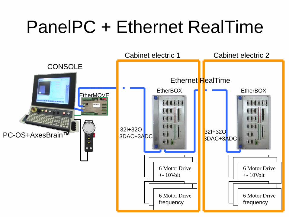
PanelPC + Ethernet RealTime
6 Motor Drive
+- 10Volt
6 Motor Drive
frequency
32I+32O
3DAC+3ADC
6 Motor Drive
+- 10Volt
6 Motor Drive
frequency
32I+32O
3DAC+3ADC
EtherMOVEEtherBOX EtherBOX
CONSOLE
Cabinet electric 1 Cabinet electric 2
PC-OS+AxesBrain™
Ethernet RealTime

WorkStation +AxesBrain™ +
Ethernet RealTime
6 Motor Drive
+- 10Volt
6 Motor Drive
frequency
32I+32O
3DAC+3ADC
EtherMOVEEtherBOX
Cabinet electric
PC-OS+AxesBrain™
Ethernet RealTime
CAD/CAM WorkStation
Ethernet TCP/IP

EtherCAT communication standard
Ethernet RealTime
EtherCAT Motor-Drives
EtherCAT I/OPC-OS+AxesBrain™
EtherCAT

PanelPC + EtherCAT
EtherCAT Motor-Drives
EtherCAT I/O
EtherCAT
EtherCAT I/O
CONSOLE
Cabinet electric
PC-OS+AxesBrain™

WorkStation +AxesBrain™ +
EtherCAT
EtherCAT Motor-Drives
EtherCAT I/O
EtherCAT
EtherCAT I/OCabinet electric
PC-OS+AxesBrain™
CAD/CAM WorkStation Ethernet TCP/IP
Ethernet TCP/IP

PROGRAMMING LANGUAGES
There are two types of languages:
Those oriented to the programming of the machine
PLC (Programmable Logic Controller), of which there are several types, some
standards (IEC 61131-3), owners of other manufacturer, are used to program
the functionality of the machine.
This language must be known by the applicator or the manufacturer's
GP-PLC is AxesBrain ™ programming language of the machine
Those oriented to the programming of the workpiece
ISO CNC G code has also said a common part to all controls G0, G1, G2, G3,
G4 + a specific part for each manufacturer which is home to parametric test
functions and subroutines, canned cycles, macros, etc. ...
This language must be known by the operator of the machine.

Language GP-PLC
It 'a proprietary language type IL (Instruction List), multitasking oriented axis
movement.
For the management of type AWL PLC I / O, possibility to integrate the
functions of vision VisAlgo ™.
It has the event management for synchronizing tasks
Provides message management for HMI

Language ISO-CNC G-Code
ISO CNC G code has also said a common part to all controls G0, G1, G2, G3,
G4 + a specific part for each manufacturer which is home to parametric test
functions and subroutines, canned cycles, macros, etc. ...
This language is used by the operator of the machine, program the machining
of the part defining the tool path, the cycles that the machine must be done in
several phases.
The name that identifies the location of the axes are: X Y Z A B C U V W

Image Processing The cameras are in the world of the ideal solutions for some problems, let's
see in detail.
1) Increase the precision of the machine through two measures
The number one trick is to make the work known through a grid, detected
by video camera on a work sample
The trick number two is to mount a camera on each machine or more, to
acquire two or more references on a piece placed on the equipment, so you
know the real translation to be performed on the rotary machining program.
2) Checking the upstream and recognition of parts prior to machining
3) Control of downstream parts after machining

Vision System ™ VisAlgo
VisAlgo ™ is a library of functions for the recognition
and image processing
STRATEGIES FOR RECOGNITION OF OBJECTS
PATTERN MATCHING
Within an image
is searched for any
a figure learned previously,
even if rotated
than the original.
BLOB ANALYSIS
In the picture are
detected by contrast
any figure,
that you can
to calculate the center of gravity,
area, perimeter, roundness
and orientation
in the plan.
EDGE DETECTION
It is able to recognize
edges and these
figures
obtain the properties
such as thickness,
center,
rays and orientation
in the plan.

Integration with the visionImage acquisition
Rectangles of pixels
640 x 480 768 x 574 1240 x 1000 ... ....
To define a ROI
Determine the BLOB
Extract the geometric features
Pull out the figures to a similar sample (Pattern-maching)
Pull out the characteristics of position coordinates and angle
Pixels / mm
Program the "vision" through –ARI (GP-PLC) or by DLL Application

Programming language for
automation GP-PLC
Born from the specific CODE (LANGUAGE SIGMA) 1976 Olivetti, one of the
first programming languages of special machines for assembly of parts, has
been expanded to meet the modern needs of integration and flexibility.
Reference to: "Robot Technology at Olivetti: the sigma system" Olivetti, Milan
1976.
One of his prerogative beyond the simple syntax is the ability to have the
multiprogramming each cycle, the prerogative to perform essential tasks of
assembly and manipulation of parts.
To describe the work cycle of a manipulator or an automatic you need a language
capable of learning how to evolve the phases. There are many programming
languages, most of them are "owners" of the company. The specific language
that must have are multiple, parallel programming phases, synchronization
between the activities planned, high integration with external devices (vision,
laser, etc.).

The structure of GP-PLC
Sequential language
( Newman )
Logic language
( Bool )
Procedure ( CALL )
and
Process ( Task )
Local variables ( L )
and
Global variables ( G )

How Start first GP-PLCWhen AxesBrainServer start on PC automaticly start also an GP-PLC program is loaded and running, the
name is found in “SISTEMA.TXT” in DAT directory.
In segment: [ParametriAUTOMAZIONE]
and parameter : NomePartProgramLancio=
Example
[ParametriAUTOMAZIONE]
StringaLancio=
NomePartProgramLancio=LogicaMacc.PP
In this case LogicaMacc.PP is loaded and runnig:
Loop -TMM/100
-NET/1
-LDN/T1
-TON/2,1000
-NET/2
-LD/T2
-TON/1,1000
-NET/3
-LD/T2
-PEX/-DIS/11,10:PLC running...
-NOT
-PEX/-DIS/11,10:
-JMP/Loop
-RET
Architecture GP-PLC
The architecture of the sub-system automation is the ability to perform the work
cycles in parallel with synchronizing events.
Each program has its own internal proprietary area where local variables are
allocated, which among other things, the call parameters are stored.
When the program is put into execution, by an explicit command or called by a
CALL instruction or TSK, its source code is loaded into memory and
automatically pre-filled, will remain in memory until an explicit command or
command to delete subsystem RESET.
The programs are combined with a work owner HANDLER on which hang all
the activities of the cycle, we have an almost infinite number of handlers, with
this mode you can have very flexible plant configuration, such as lines of
robots, machines, special multi-head, loading and unloading machines with
integrated, multifunctional machines, etc.
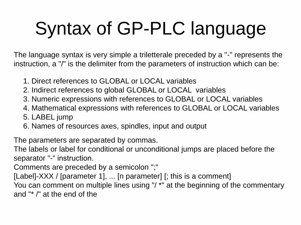
Syntax of GP-PLC language
The language syntax is very simple a triletterale preceded by a "-" represents the
instruction, a "/" is the delimiter from the parameters of instruction which can be:
1. Direct references to GLOBAL or LOCAL variables
2. Indirect references to global GLOBAL or LOCAL variables
3. Numeric expressions with references to GLOBAL or LOCAL variables
4. Mathematical expressions with references to GLOBAL or LOCAL variables
5. LABEL jump
6. Names of resources axes, spindles, input and output
The parameters are separated by commas.
The labels or label for conditional or unconditional jumps are placed before the
separator "-“ instruction.
Comments are preceded by a semicolon ";"
[Label]-XXX / [parameter 1], ... [n parameter] [; this is a comment]
You can comment on multiple lines using "/ *" at the beginning of the commentary
and "* /" at the end of the

Example of Syntax GP-PLC
-LET/L1,500.089 ; Load value 500.089 in LOCAL variable L1
-LET/G100,0 ; Load value 0 in GLOBAL variable G100
BeginCount- ; LABEL BeginCount
-LET/G100,G100+11.23 ; Adds the value 11.23 to the variable G100
-JLT/G100,L1,BeginCount ; Continue adding until the value
; of the G100 is not equal to or greater than
; indicated in L1 (500.089)
; We use the indirect method to address the Global 100
-LET/L2,100 ; Load value 100 in LOCAL variable L2
-LET/G(L2),0 ; Load value 0 in GLOBAL variable G100
BeginCB- ; LABEL BeginCB
-LET/G(L2),G(L2)+11.23 ; Adds the value to the variable G100 11.23
-JLT/G(L2),L1,BeginCB ; Continue adding until the value
; of the G100 is not equal to or greater than
; indicated in L1 (500.089)

Mathematical operators
+ sum
- subtraction
/ division
* multiplication
^ high
(Open bracket
) Parenthesis

Mathematical expressions have the
following functions abs Absolute numbers
acos Arc cosine
and And boolean
asin Arc sine
atan Arc tangent
atanw Arc tangent of Y, X
ceil Rounding up a decimal to an integer
cos Cosine
cosh Hyperbolic cosine
deg Transformation in degrees of an angle
in radians
exp Exponential
floor Rounding down floor of a decimal
number
logd Decimal logarithm
logn Natural logarithm
lshift Shift to the left of a number
max Maximus
min Minimum
mod Module of two numbers
not Not boolean
or Or boolean
pi PI greek
rad Transformation in radians of an
angle expressed in degrees
rshift Shift to the right of a number
sin Sine
sinh Hyperbolic sine
sqr Square root
tan Tangent
tanh Hyperbolic tangent
xor Exclusive Or boolean
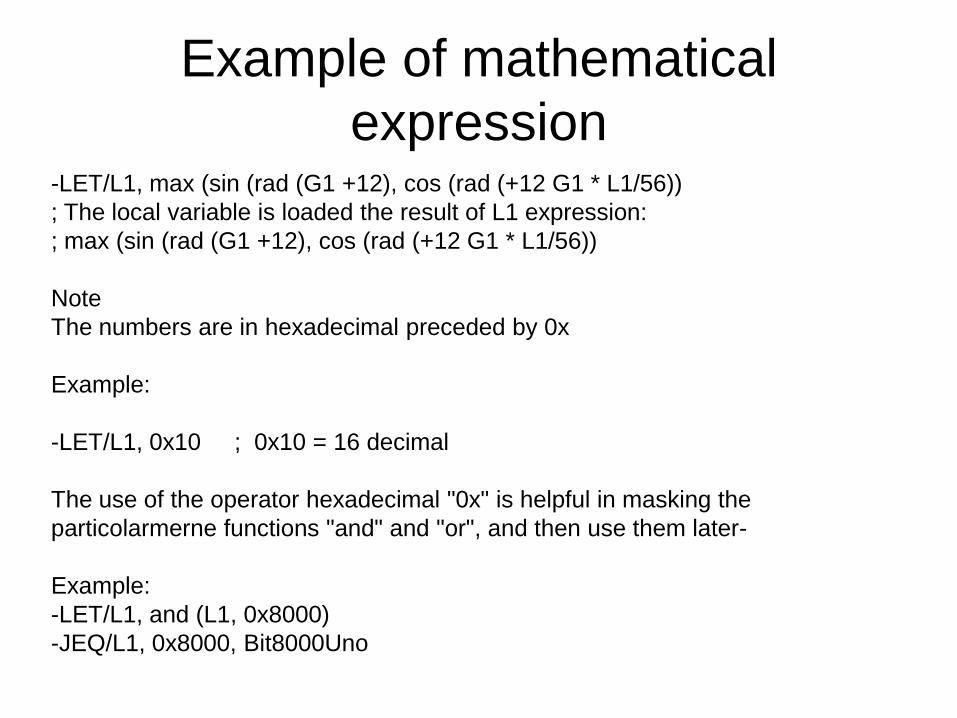
Example of mathematical
expression-LET/L1, max (sin (rad (G1 +12), cos (rad (+12 G1 * L1/56))
; The local variable is loaded the result of L1 expression:
; max (sin (rad (G1 +12), cos (rad (+12 G1 * L1/56))
Note
The numbers are in hexadecimal preceded by 0x
Example:
-LET/L1, 0x10 ; 0x10 = 16 decimal
The use of the operator hexadecimal "0x" is helpful in masking the
particolarmerne functions "and" and "or", and then use them later-
Example:
-LET/L1, and (L1, 0x8000)
-JEQ/L1, 0x8000, Bit8000Uno

Dimensions of the parameters can
be called up
GLOBAL 32,767
LOCAL = NumeroLocali configured in the voice of the configuration file
"SISTEMA.TXT" (expanded from -DIM/Number LOCAL)
WATCH 16
DRT 6
DIS 17 lines
Columns DIS 128
NETwork 128 for instance
Timer (T) 128 for instance
Counter (C) 128 for instance
Global and Local variables
In order to perform logical operations, are required to read and write numeric
variables.
The sub-system AXESBRAIN provides two types of variables:
LOCAL
GLOBAL
Each program recruits is allocated a number of variables equal to that configured
in the system, are all cleared and are available to the instructions of that
program, the first variables are set with the call parameters of the command
execution , the variables remain in memory available for query and visualization
operations.
LocalThe number of spaces may be changed from that provided in the "SISTEMA.TXT" to
segment [ParametriGenerali] and parameter "NumeroLocali =“.
Using -DIM/numero local education, which is defined only for that instance of the
task.
A special case are the programs called by the instructions of "CAL" and "TSK" with
parameters in these cases the first local variables are loaded with parameters
positional calls in the same order, if there are parameters in the call LOCAL the new
value will be loaded with the return of the program called.
-CAL/, routinemia: L9,12,23, G1+89, L7
when the return from "routinemia" L9 and L7 have the value defined in the routine, in this case L9 has a
value of 11 and L7 will have a value of 3
In fact, the code "routinemia" is as follows:
-LET/L1, 11
-LET/L5, 3
Upon execution of the local variables of "routinemia" are:
L1 = value of the calling program L9
L2 = 12
L3 = 23
L4 = value of variable 89 + G1
L5 = L7 value of the calling program

Global
Besides the Local variables in the automation system are expected 32767
GLOBAL variables that are invoked with the letter "G" and the number thereof.
All are saved to HardDisk GLOBAL, which can then be used to store persistent
data.
The Global HardDisk output is stored on the system or procedure "SHUT
DOWN" you can still do this with instruction SGL.
The write operation is performed with the Global COMMIT mode to ensure the
integrity with the last save.
To index global or local, you can use the parenthesis followed by global or local use
as an index.
Example:
And this is an example of indexed programming
-LET/ L1, 1
-LET/ G (L1), 0
here -TMM/50
-JNE / G (L1) 1, here ; expects the value of global variable G1 is set to 1
MultiTask
An important feature in automation is being able to perform multiple tasks
together, coordinate with each other or not, so we need to have the
functionality of "MULTITASK".
A cycle of activities can be performed with an explicit command, or by an
instruction "-TSK", the cycle or program is combined with a business owner
HANDLER on which hang all the activities of the cycle, we have an almost
infinite number of HANDLER.
A "TASK" can be deleted by another task or itself with the statement "-TKM"
or when RESET is performed in the automation system.
The concept of HANDLER is also useful to see it as a channel on which
operations are conducted continuously beginning of the movement,
movement combinations, until the movements are completed.
Anticollision between axes
With this architecture we are able to see the movement system as a device
with several "arms" that work together or not coordinated, dynamically
aggregating groups of axes.
An interesting example may be to imagine the filling of a tray of glasses, at an
early stage we have two "arms" that fill the glasses separately, the system
handles the collision, and so we have two sets of axes which work separately,
when the glasses are been filled the system, bringing together the two arms
the way a waiter brings the tray to the unloading area.
As first revealed during the filling of glasses, the two arms of the same affecting
physical axis X, thanks to the management of collision is possible to program
two independent cycles of filling, synchronize the two to complete their
respective stages, then program a single cycle drain tray with a unique
grouping of the two arms.

Mathematical Instructions
1-LET (SET) Set the value of a variable (LET)
2-ADD Sum the value of a variable (added)
3 -MUL Multiply the value of a variable
4-DIV Divide a variable with the value of the expression (Divided)
5-NEG Negate the value of a variable (negation)
6-LBF Set to an array of variables at the value (Load buffer)

Control Instructions 1-JMP Jump unconditionally to a label (jump)
.2-JEQ Jump to a label if the two expressions are equal (Jump if Equal)
.3-JNE Jump to a label if the two expressions are not equal (in the Jump Not Equal)
.4-JLT Jump to a label if the value of the first parameter is less than the second (Jump if Less Then)
.5-JLE Jump to a label if the value of the first parameter is less than or equal to the second (Jump if
Less then and Equal)
.6-JGT Jump to a label if the value of the first parameter is greater than the second (jump if Great
Then)
.7-JGE Jump to a label if the value of the first parameter is greater than the second (and then Great
Jump if Equal)
.8-JRN jump if the value of the parameter is within the range (Jump if Range)
.9-JNR jump if the value of the parameter is out of range (Jump If Not Range)
.10-JOS Skip if at least one bit of the parameter value is one (Or Jump if Bit Set)
.11-JOC Skip if at least one bit of the parameter value is zero (Or Jump if Bit Clear)
.12 JAS jump if all bits of the value of a parameter are (Jump And if Bit Set)
.13-JAC Jump if all bits of the parameter value is zero (Jump And if Bit Clear)
.14 CAL Call-part program, passing parameters (CALL)
.15-RET Return to the caller of the program (Return)
.16-END Process END (END)
.17-TSK executes in parallel a series of work (task)
.18-TKM restore and delete a cycle of work (Task manegement)
.19-DIM Dimensions variable number L of a part pogram
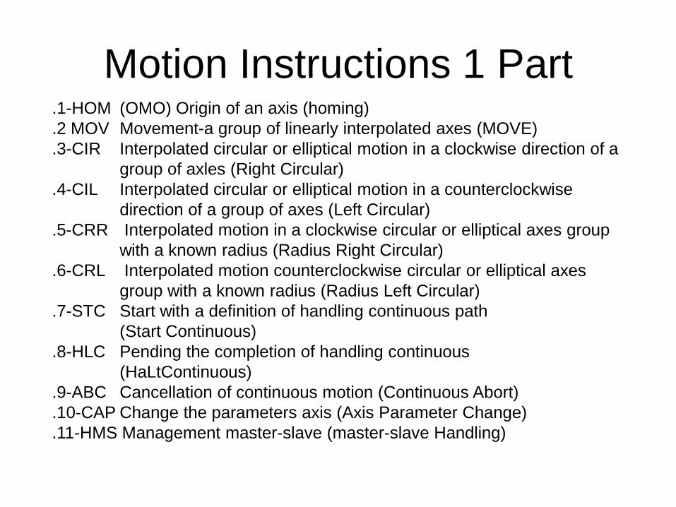
Motion Instructions 1 Part.1-HOM (OMO) Origin of an axis (homing)
.2 MOV Movement-a group of linearly interpolated axes (MOVE)
.3-CIR Interpolated circular or elliptical motion in a clockwise direction of a
group of axles (Right Circular)
.4-CIL Interpolated circular or elliptical motion in a counterclockwise
direction of a group of axes (Left Circular)
.5-CRR Interpolated motion in a clockwise circular or elliptical axes group
with a known radius (Radius Right Circular)
.6-CRL Interpolated motion counterclockwise circular or elliptical axes
group with a known radius (Radius Left Circular)
.7-STC Start with a definition of handling continuous path
(Start Continuous)
.8-HLC Pending the completion of handling continuous
(HaLtContinuous)
.9-ABC Cancellation of continuous motion (Continuous Abort)
.10-CAP Change the parameters axis (Axis Parameter Change)
.11-HMS Management master-slave (master-slave Handling)
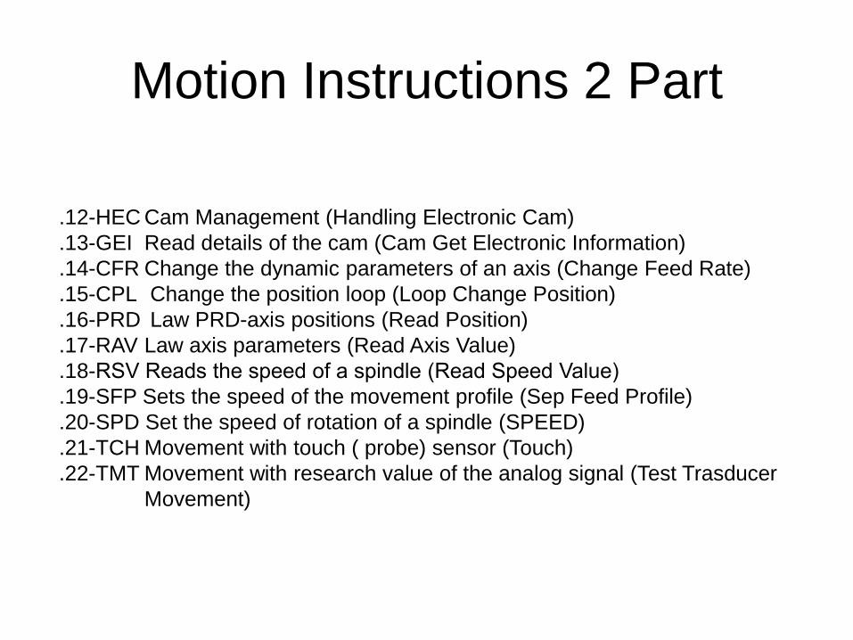
Motion Instructions 2 Part
.12-HEC Cam Management (Handling Electronic Cam)
.13-GEI Read details of the cam (Cam Get Electronic Information)
.14-CFR Change the dynamic parameters of an axis (Change Feed Rate)
.15-CPL Change the position loop (Loop Change Position)
.16-PRD Law PRD-axis positions (Read Position)
.17-RAV Law axis parameters (Read Axis Value)
.18-RSV Reads the speed of a spindle (Read Speed Value)
.19-SFP Sets the speed of the movement profile (Sep Feed Profile)
.20-SPD Set the speed of rotation of a spindle (SPEED)
.21-TCH Movement with touch ( probe) sensor (Touch)
.22-TMT Movement with research value of the analog signal (Test Trasducer
Movement)

Motion Instructions 3 Part
.23-TMS Movement with research value of the digital sensor (Sensor Movement Test)
.24-TPE Enabled the probe (Touch Probe Enable)
.25-SZP Define the position of zeros of a set machine (Set Zero Point)
.26-LZP Enable a set of zeros car (Zero Point Load)
.27-PIN (INQ) Flag on an axis incremental (Incremental Position)
.28-PAB (ABS) Flag on an axis of absolute (Absolute Position)
.29-MMA Moves an axis with a manual movement (Move Axis Manual)
.30-OPT Opens a file of points (PoINT Open file)
.31-MOR Linearly interpolated movement of an axle group advance
(Re MOV)
.32-DCT Controlled movement with depth probe (Deep Touch Control)
.33-DCS Movement with depth controlled by digital input (Deep Control Sensor)
.34-GRM Commands to the axes and spindles grouped (Group Management)

I/O Instructions 1 Part
.1-WDI (WIN) Waits for a signal digital input for a given state (Wait Digital Input)
.2-WAI Waits for an input signal and analog ports to a given state
(Wait Analog Input)
.3-AIN Wait for analog inputs on the G or L (Analog Input)
.4-TDI (TES) Performs a test on a digital input signal (Test Digital Input)
.5-TDO Performs a test on a digital output signal (Test Digital Output)
.6-IDI Performs a test on a digital input signal (If Digital Input)
.7-IDO Performs a test on a digital output signal (If Digital Output)
.8-TAI Performs a test on an analog input signal(Test Analog Input)
.9-SDO (SAX) Sets or resets the digital output signals (Set Digital Output)
.10-EDO Sets or resets the digital output signals on the basis of a test
(Enanced Digital Output)

I/O Instructions 2 Part
.11-SAO(SAC) Writes the value of an analog signal output (Set Analog Output)
.12-GDI (RBI) Reads the value of a digital signal input (Get Digital Input)
.13-GDO Reads the value of a digital signal output (Get Digital Output)
.14-GAI (RAI) Reads the value of an analog input signal (Get Analog Input)
.15-WBD (BPO) Writes a block of output digital signals (digital inputs Write
Buffer)
.16-RBD (BPI) Reads a block of digital input signals (Read Digital Input Buffer)
.17-CPI Waits for a digital input signal undergoes a change
.18-CDI At the changing digital input signal activates a task or process
.19-CDO At the change of digital input signal activates a task or process
.20-RDI Take action test on a digital input signal by activating a task if
the test is positive (Run Digital Input)
.21-RDO Take action test on a digital output signal activating a task if the
test is positive (Run Digital Output)
Synchronization Instructions
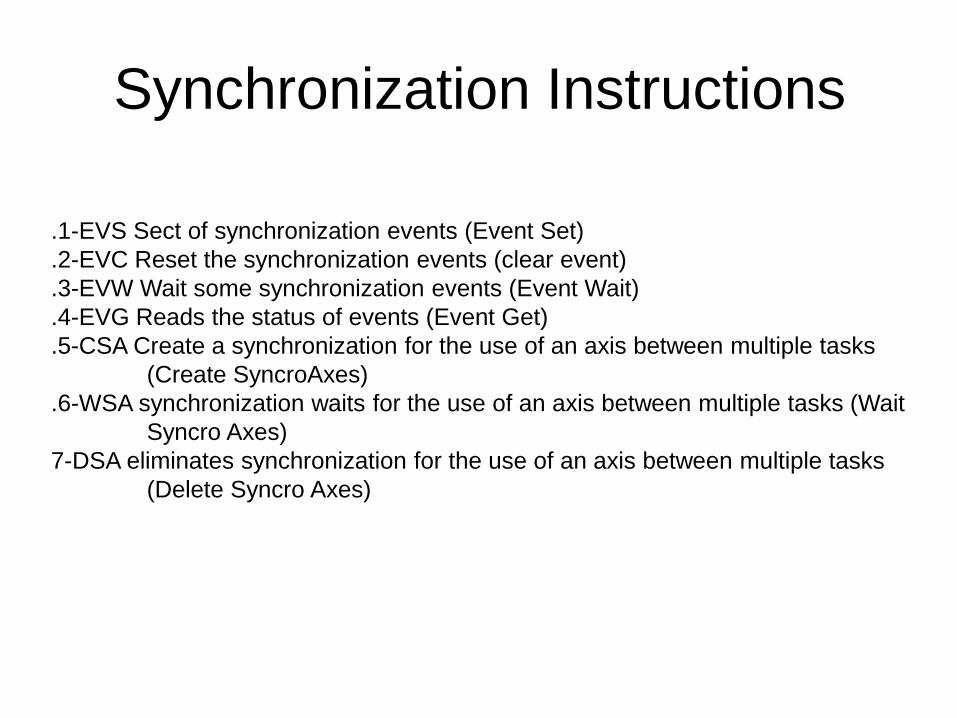
.1-EVS Sect of synchronization events (Event Set)
.2-EVC Reset the synchronization events (clear event)
.3-EVW Wait some synchronization events (Event Wait)
.4-EVG Reads the status of events (Event Get)
.5-CSA Create a synchronization for the use of an axis between multiple tasks
(Create SyncroAxes)
.6-WSA synchronization waits for the use of an axis between multiple tasks (Wait
Syncro Axes)
7-DSA eliminates synchronization for the use of an axis between multiple tasks
(Delete Syncro Axes)

Service Instructions 1 Part
.1-FOC (AZZ) Clears the contents of a file or create if not exists (Create File
Open)
.2-FWR (SCR) Writes a record to file (File write)
.3-FWA Writes a record to file (ASCII File Write)
.4-FRD (LEG) Reads a record from a file (Read Files)
.5-TIM Timer in seconds (TIME)
.6-TMM Timer in milliseconds (Time Millisecond)
.7-SWA Initialize a watch (Start Watch)
.8-RWA Read a watch (Read Watch)
.9-HWA Halt a watch (Halt Watch)
.10-CWA Continue a watch (Continue Watch)
.11-KYB Waits for an Keyboard (Keyboard)
.12-DRT Continuously displays the values of axes, global signals (Real
Time Display)
.13-DIS Displays a line message (Display)

Service Instructions 2 Part.14-HLD Send a system in the state of Cycle Stop (HOLD)
.15-PWO Send in the state of the system power on (poweron)
.16-EMC Send in the state of the system on Emergency (Emergency)
.17-LCK Lock the task and possibly a SEC report
.18-ULK Release all tasks in a state of LOCK
.19-RST system reset (RESET)
.20-SDW Shut down the system (shutdown)
.21-SOR Sorting a sequence of values (SORT)
.22-GTK Detect information related to a task or process (Get Task
information)
.23-MDI Performs a ISO program - GCode (MDI)
.24-OTC Set ISO tables Origin Tool Corrector - GCode (OTC)
.25-ISO Performs a ISO program - GCode (ISO)
.26-WND Wait a reporting error state resources or spindle axis
(Wait Notify Detected)
.27 WKY Waits press a button (Wait Keyboard)
.28-NHL No Hold
.29 YHL Hold Yes

Service Instructions 3 Part
.30-GDT Get Date and Time
.31-GAT Get Absolute Date and Time
.32-GLN Get Local Number
.33-GMI Motion Get Information
.34-RTC Read Timer or Counter
.35-SGL Save Global
.36-SHL Shell or application procedures
.37-G80 G80 End fixedcycle (G80)
.38-G81-89 G81 .. G89 Activate fixed cycle specified
.39-ESE Performs sequences external (Exec Sequence) system ETEL
.40-ERR View logs external (External Read Registry) system ETEL
.41-EWR Write registers external (External Write Registry) system ETEL
.42-ECM Runs an external command (External Command) system ETEL
.43-EWS Waits for a (External Wait Signal) system ETEL
.44-CLM Machine System Command to Logic ETEL
.45-SND Please issue a WAV file on 'PC audio output

Instructions for integration with
other environments
.1-ARI Request execution of an instruction to the environment specified in the
first parameter and waits for a response (return made with the function
of "WriteServiceParametersAndContinue" subsystem automation
AXESBRAIN)
(Ambient Request Instruction)
.2-SEC Set client event

Comunication Instructions 1 Part
.1-CSO Connection to a socket (TCP / IP Socket Connect)
.2-LSO Listen to a TCP / IP socket (Listen Socket)
.3-RSO Read data traveling over a TCP / IP socket (Socket Read)
.4-TSO Writes on a TCP / IP socket (Socket Write)
.5-DSO Delete a connection to a TCP / IP socket (Socket Destroy)
.6-FSO Clear any data received on a TCP / IP socket (Socket Free)
7-GSO Captures information from a TCP / IP socket (get information
sockets)
.8-OSL Opens a serial port (Serial Line Open)
.9-RXL Receive data from a serial line (Receive Serial Line)
.10-TXL Transmits data over a serial line (Serial Line Transmit)
.11-CSL Closes the serial port (Serial Line Close)
.12-FSL Clear any data received from a serial line (Serial Line Free)
.13-RFB Read data FieldBus
.13-WFB Write data on FieldBus

Comunication Instructions 2 Part
.15-RGS Reset line GSM / GPRS
.16-SMS Send SMS on GSM / GPRS
.17-WMS Wait SMS message from GSM / GPRS
.18-CGS Makes a call on GSM / GPRS
.19-WRG Wait a call from GSM / GPRS
.20-CTL Please call on phone line
.21-WTL Wait a call from the telephone line
.22-STL Closes the telephone line
.23-GTL Acquires a number from the telephone line
.24-PTL Send a file recorded on the telephone line
.25-EML Send a E-Mail

AWL GP-PLC Special Operations
Ladder 1 Part
The normally open contact is closed (on) if the bit value of the address n is 1.
In AWL, the Normally Open contact is represented by operations such as:
Upload operation, combines the bit through And, combines the value of bits by
OR. These operations, respectively, load the value in the value of n bits from the
top of the stack, or combine with AND or OR value with the value of n bits of the
top of the stack.
Normally closed contact is closed (on) if the address bit value is 0 n
In AWL, the normally closed contact is represented by operations such as:
Load the value of bits denied, combines the bit And by Denied, denied Combine
the value of bits by OR.
This loads the value in the value of n bits from the top of the stack, or combine
with And or Or the value of n bits of the highest value of the stack.
AWL GP-PLC Special Operations
Ladder 2 Part
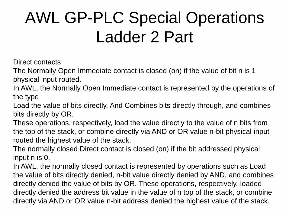
Direct contacts
The Normally Open Immediate contact is closed (on) if the value of bit n is 1
physical input routed.
In AWL, the Normally Open Immediate contact is represented by the operations of
the type
Load the value of bits directly, And Combines bits directly through, and combines
bits directly by OR.
These operations, respectively, load the value directly to the value of n bits from
the top of the stack, or combine directly via AND or OR value n-bit physical input
routed the highest value of the stack.
The normally closed Direct contact is closed (on) if the bit addressed physical
input n is 0.
In AWL, the normally closed contact is represented by operations such as Load
the value of bits directly denied, n-bit value directly denied by AND, and combines
directly denied the value of bits by OR. These operations, respectively, loaded
directly denied the address bit value in the value of n top of the stack, or combine
directly via AND or OR value n-bit address denied the highest value of the stack.

AWL GP-PLC Special Operations
Ladder 3 Part
Not Contact
Contact NOT change the status of the signals. If the current flow reaches Not the
contact is blocked. If the flow does not reach the contact Not, this generates current
flow.
In AWL, the operation denial of higher value than the value of the stack changes
from 0 to 1 or from 1 to O.
Semantic Rules
The character '#' indicates that the value of the numeric value is interpreted as 0 or
1.
Example 1:
-NET / 1
-LD / # 1 ; the value 1 is loaded into the STACK
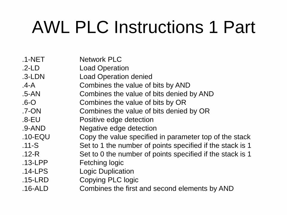
AWL PLC Instructions 1 Part
.1-NET Network PLC
.2-LD Load Operation
.3-LDN Load Operation denied
.4-A Combines the value of bits by AND
.5-AN Combines the value of bits denied by AND
.6-O Combines the value of bits by OR
.7-ON Combines the value of bits denied by OR
.8-EU Positive edge detection
.9-AND Negative edge detection
.10-EQU Copy the value specified in parameter top of the stack
.11-S Set to 1 the number of points specified if the stack is 1
.12-R Set to 0 the number of points specified if the stack is 1
.13-LPP Fetching logic
.14-LPS Logic Duplication
.15-LRD Copying PLC logic
.16-ALD Combines the first and second elements by AND
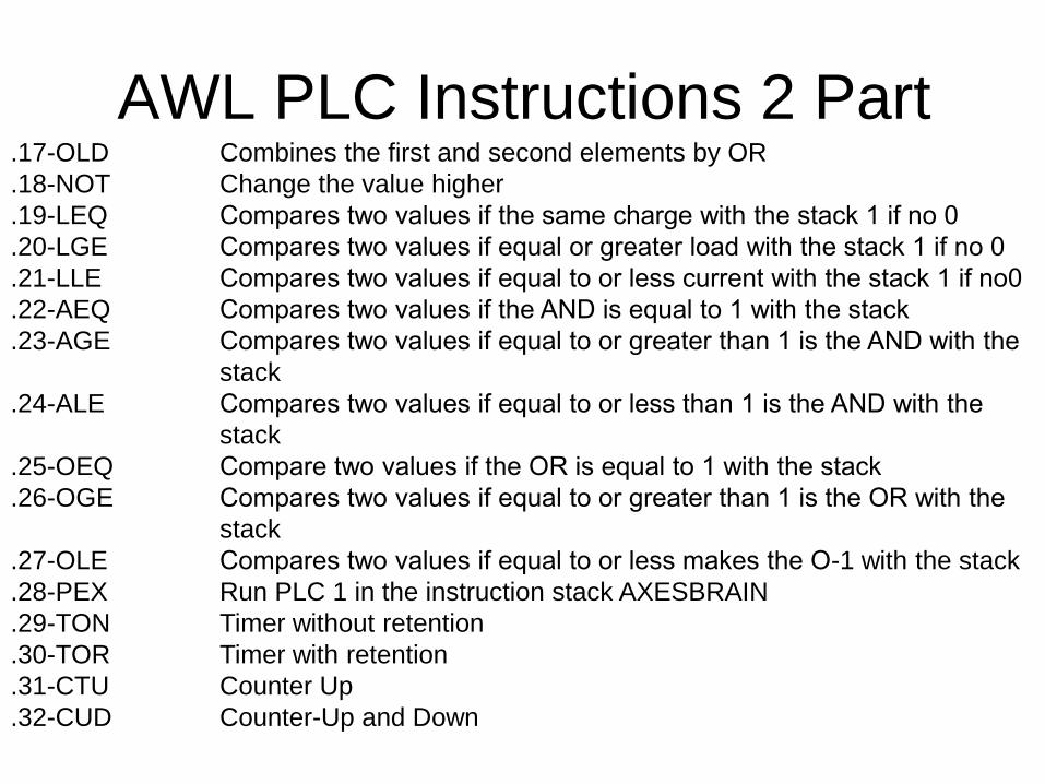
AWL PLC Instructions 2 Part.17-OLD Combines the first and second elements by OR
.18-NOT Change the value higher
.19-LEQ Compares two values if the same charge with the stack 1 if no 0
.20-LGE Compares two values if equal or greater load with the stack 1 if no 0
.21-LLE Compares two values if equal to or less current with the stack 1 if no0
.22-AEQ Compares two values if the AND is equal to 1 with the stack
.23-AGE Compares two values if equal to or greater than 1 is the AND with the
stack
.24-ALE Compares two values if equal to or less than 1 is the AND with the
stack
.25-OEQ Compare two values if the OR is equal to 1 with the stack
.26-OGE Compares two values if equal to or greater than 1 is the OR with the
stack
.27-OLE Compares two values if equal to or less makes the O-1 with the stack
.28-PEX Run PLC 1 in the instruction stack AXESBRAIN
.29-TON Timer without retention
.30-TOR Timer with retention
.31-CTU Counter Up
.32-CUD Counter-Up and Down

Virtual Axes SCARA

Virtual Axes Cylindrical
Control axis handwheel
The positioning of an axis in manual mode can be combined with a device called
a flyer that is seen by the system as an axis of read-only.
The value read from the wheel position change the position of the combined, so
you can give to the micrometer increments' axis itself.
The leaflet is seen as an axis of read-only, and through appropriate command is
coupled to a shaft that will remain controlled.
In AXESBRAIN automation language, the instruction "-HMS" allows arming and
disarming of a wheel axle "master" to a positioning axis "slave".
To manage the combined wheel axle axis positioning in a "DCOM", the service
must be used "WriteAxesRegister" for both axes.
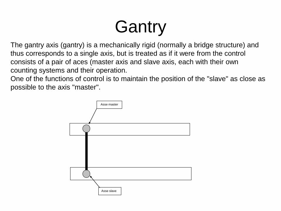
GantryThe gantry axis (gantry) is a mechanically rigid (normally a bridge structure) and
thus corresponds to a single axis, but is treated as if it were from the control
consists of a pair of aces (master axis and slave axis, each with their own
counting systems and their operation.
One of the functions of control is to maintain the position of the "slave" as close as
possible to the axis "master".
Asse master
Asse slave
Electronic Cams The cam allows you to match the position of an axle group to an axis "master" and
a table of multiple locations.
And 'it can electronically simulate the behavior of the cams, replace the
mechanical operation with a similar system consisting of a group of axles coupled
to an axis "master" that can be read-only.
The laws of motion of the sellers is defined as a table of vectors, which defisse
positions relative to the moving cam.
In AXESBRAIN automation language, the statement "HEC-" allows the
management of electronic cams.
To manage the cams electrical environment "DCOM", the service must be used
"WriteAxesRegister" for all axes.

Automation HMI Generic

Automation HMI Editor
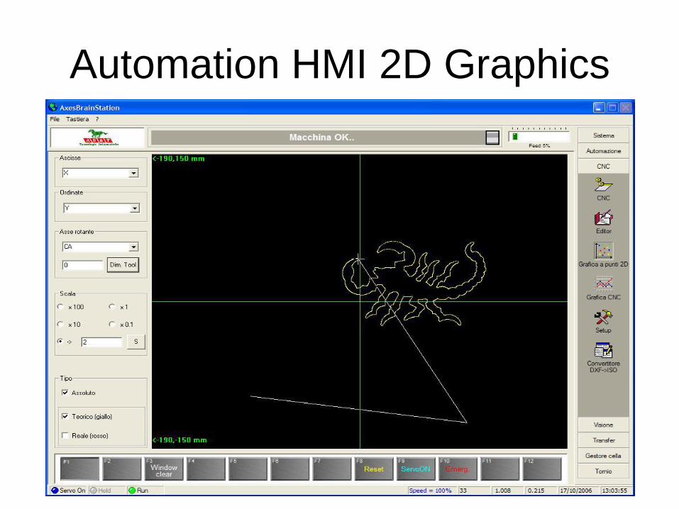
Automation HMI 2D Graphics

Automation HMI 3D Graphics

Automation HMI Debug

Automation HMI Globals View
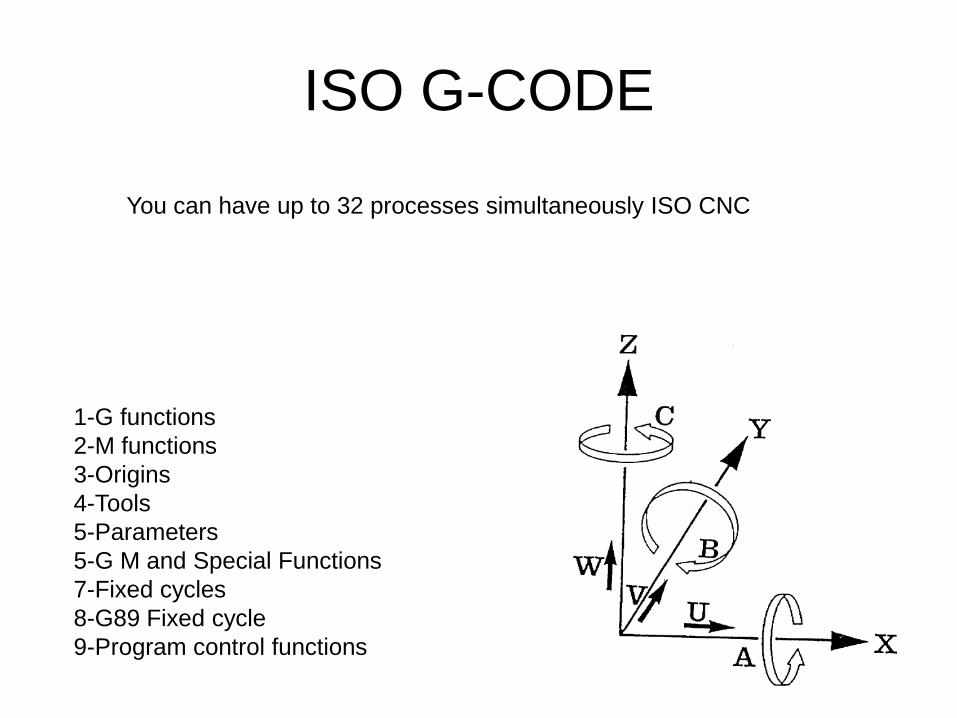
ISO G-CODE
1-G functions
2-M functions
3-Origins
4-Tools
5-Parameters
5-G M and Special Functions
7-Fixed cycles
8-G89 Fixed cycle
9-Program control functions
You can have up to 32 processes simultaneously ISO CNC

G Fucntions Part 1
G00 Rapid positioning axes
G01 Linear interpolation
G02 circular interpolation or spiral clockwise
G03 circular or helical interpolation CCW
G04 timed pause, pause time scheduled.
G08 deceleration at the end of the block that contains
G09 activation mode "Looking Forward"
G17 specific XY and Z axis perpendicular to work surface
G18 ZX as a specific work plan and Y-axis perpendicular
G19 YZ as a specific work plan and X axis perpendicular
G30 deceleration at the end of the block that contains it and reboot continuously
G32 End subroutine
G40 cancels G41 and G42
G41 activation radius, tool on the left of the profile
G42 activation radius, the right of the profile tool
G49-range value statement
G50 end rototranslation
G51 rototranslation

G Fucntions Part 2
G52 G92 shift of the origins equal
G54 X mirror
G55 Y-Mirror
G56 Z-mirrors
G57 X and Y mirrors
G58 Z and X mirror
G59 mirrors Y and Z
G60 end of the scale factor
G61 scaling factor
G62 absolute center of the circle K1 K2 Incremental
G70 Programming in inches G70
G71 mm programming
G75 programming Cartesian
G76 Polar programming
G78 Tangential to the path setting
G79 Tangential to the path setting end
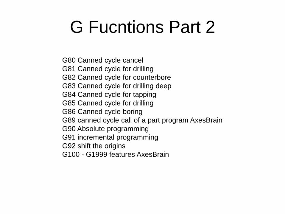
G Fucntions Part 2
G80 Canned cycle cancel
G81 Canned cycle for drilling
G82 Canned cycle for counterbore
G83 Canned cycle for drilling deep
G84 Canned cycle for tapping
G85 Canned cycle for drilling
G86 Canned cycle boring
G89 canned cycle call of a part program AxesBrain
G90 Absolute programming
G91 incremental programming
G92 shift the origins
G100 - G1999 features AxesBrain

M Functions
M00 Stop
M03 Clockwise rotation of the spindle
M04 Vnti-clockwise rotation of the spindle
M05 Spindle stop
M06 Tool change
M07 Activation of the secondary coolant
M08 Vctivation of primary coolant
M09 Coolant Off
M10 Locking axis activation
M11 Locking off-axis
M13 Clockwise spindle and coolant activation
M14 Anticlockwise spindle and coolant activation
M19 Spindle orientation
M30 Program end, clears the active auxiliary functions
M31 - M1999 Customer features

Origins
The table of the Origins is used for activating or to disarm (O0) the origins during
the workmanship, and it is situated in the in the file of the origins.
Every process ISO works on a table proper of Origins, through the session
[AbbinamentoOrigini] of the file “sistema.txt” it is possible to specify the whole
run and the containing filename the table.
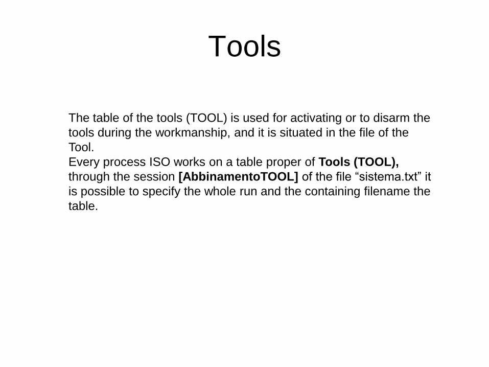
Tools
The table of the tools (TOOL) is used for activating or to disarm the
tools during the workmanship, and it is situated in the file of the
Tool.
Every process ISO works on a table proper of Tools (TOOL),
through the session [AbbinamentoTOOL] of the file “sistema.txt” it
is possible to specify the whole run and the containing filename the
table.
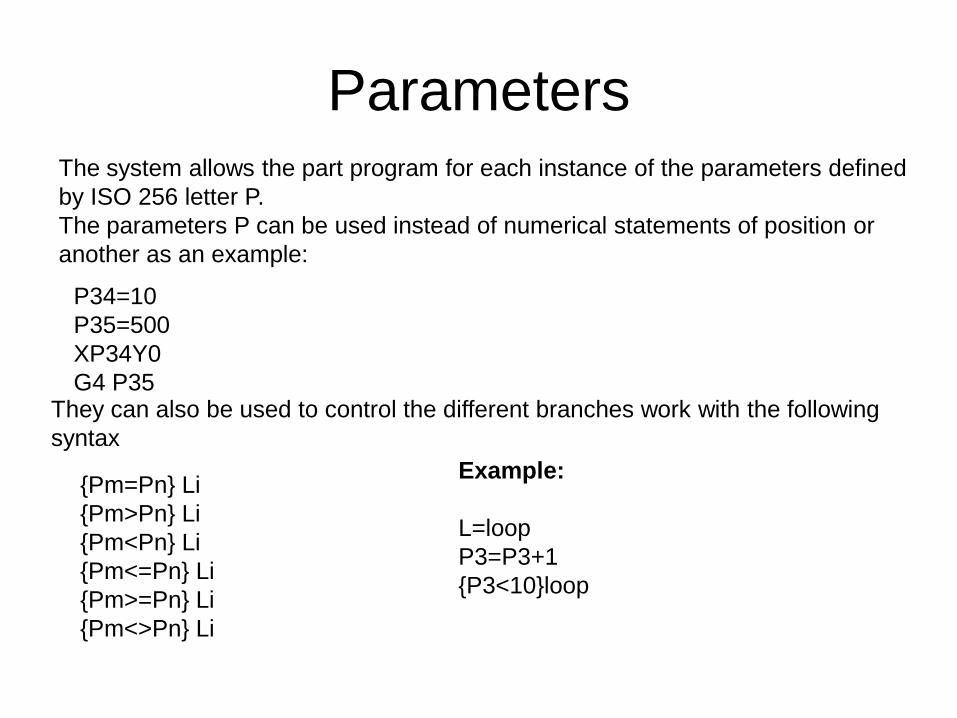
ParametersThe system allows the part program for each instance of the parameters defined
by ISO 256 letter P.
The parameters P can be used instead of numerical statements of position or
another as an example:
P34=10
P35=500
XP34Y0
G4 P35They can also be used to control the different branches work with the following
syntax
{Pm=Pn} Li
{Pm>Pn} Li
{Pm<Pn} Li
{Pm<=Pn} Li
{Pm>=Pn} Li
{Pm<>Pn} Li
Example:
L=loop
P3=P3+1
{P3<10}loop

G M and Special Functions
The special functions G or M or H call a GP-PLC program with these L
Local variables set:
L1 = Number Z-axis with respect to the Work Plan
L2 = Spindle number
L3 = 0, or AS number AxisSpindle
L4 = Number of head defined in "Base_NumeroTesta" or 0
L5 = Spindle Speed
L6 = 1 if M, 2 if G, if H 3
L7 = G or M number of caller
L11 = K
L12 = Q
L13 = J
L14 = I
L15 = H
L16 = Number Origin
L17 = Number Tool
L18 = Number Correction
Fixed cycles
A fixed cycle drilling in an NC program is always scheduled in the following
partial steps:
Assign parameters
Select the desired drive cycle
Move to the working position in X and Y (once or repeatedly)
Automatically call and execute the selected fixed cycle after reaching the
working position
Clear the cycle

G89 Fixed cycle
The function G89 Fixed Cycle if declared in the file "sistema.txt" under section
PartProgramG89 ParametriGenerali, activates the part program of automation.
[ParametriGenerali]
PartProgramG89 = [name of the part program automation]
For each movement if they follow the G89 function, the part program is called
automation defined in the file "sistema.txt", with the passing of parameters:
L1 = Number Z-axis with respect to the Work Plan
L2 = Spindle number
L3 = 0, or AS number AxisSpindle
L4 = Number of head defined in "Base_NumeroTesta" or 0
L5 = Spindle Speed (speed value of the active block included)
L6 = PosZ_start
L7 = PosZ_drill
L8 = PosZ_Return
L9 = VelZ_drilling or Step
L10 = Time in milliseconds, or strain rate
L11 = First PosZ_start increase from
L12 = Increment
L13 = Increased Safety

Program control functionsPatterns of part of the program
Using the ” L” codes can be repeated n times a program or part of it. The
maximum number is 32767.
The part of the program you want to repeat is enclosed between a reference
definition of "label" Education jump to the label followed by the number of
repetitions.
The number of repetitions can be a number or a parameter.
Subroutines inside the program
Is defined as a sequence of sub-blocks that can be called from different parts of
the main program (for example, the sequence of several points on which to apply
the different canned, drilling, casing, drilling, etc..) Or a profile to be called several
times in different locations or with different ray correctors.
The subroutine is called scheduling function L followed by the number of the sub.
The subroutines inside the main program must be scheduled at the end of it,
upon the function M30.
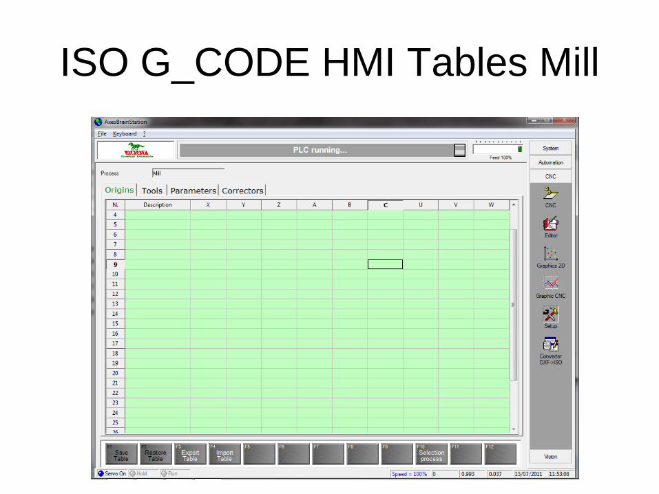
ISO G_CODE HMI Tables Mill
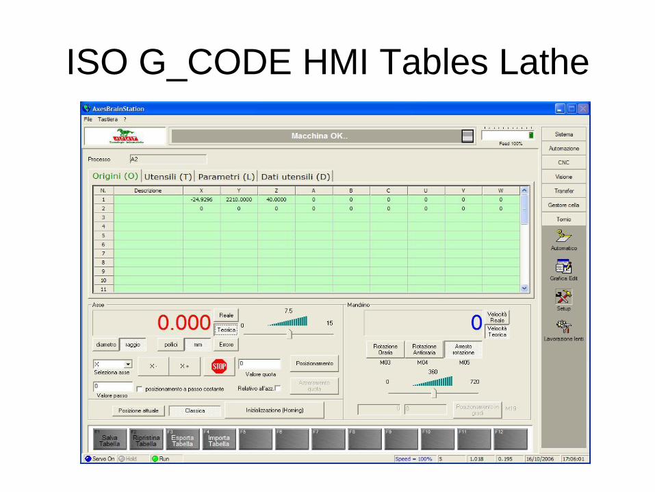
ISO G_CODE HMI Tables Lathe

ISO G_CODE HMI DXF->ISO

ISO G_CODE HMI CNC Mill

ISO G_CODE HMI Grafic Mill
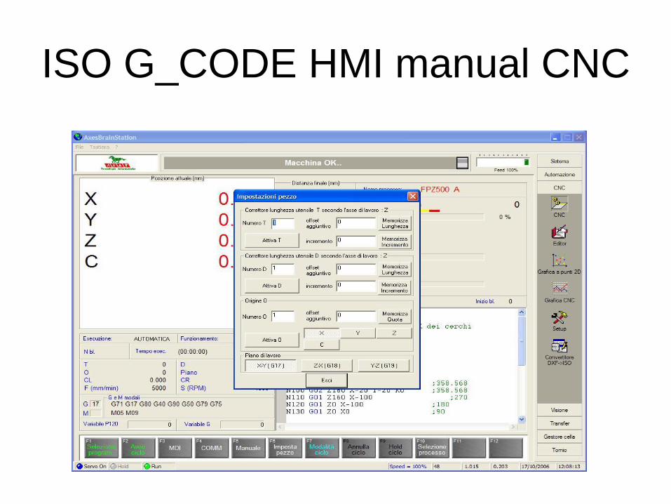
ISO G_CODE HMI manual CNC

ISO G_CODE HMI Editor Mill
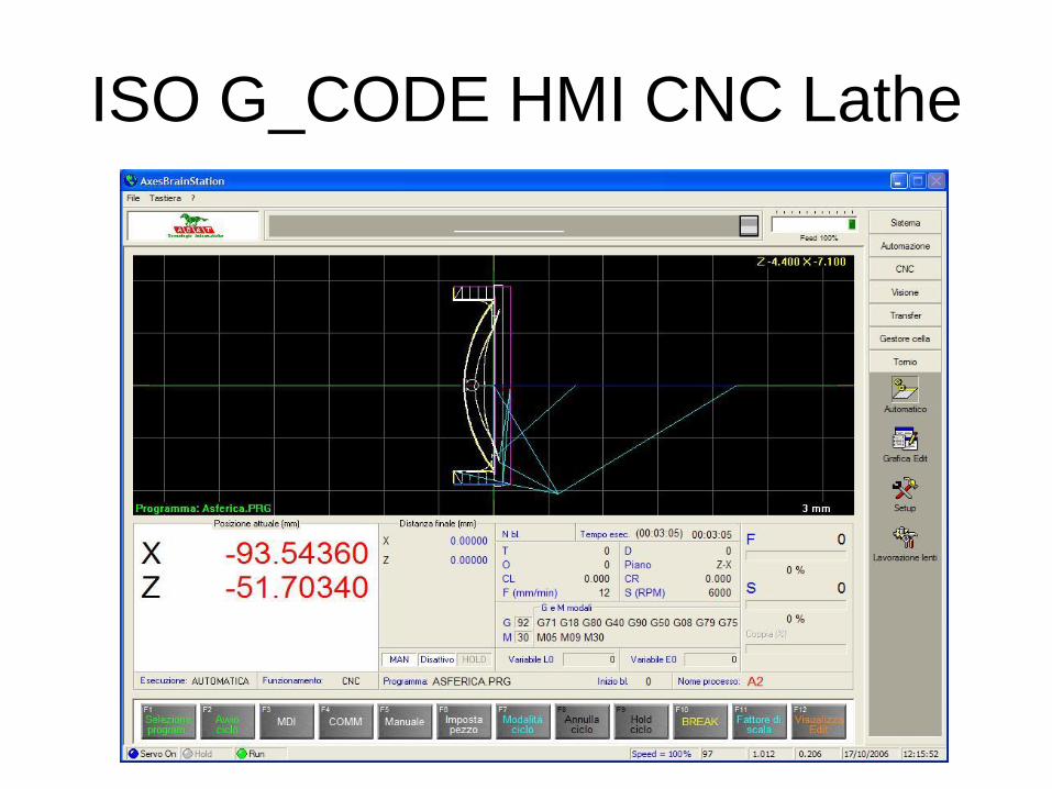
ISO G_CODE HMI CNC Lathe

ISO G_CODE HMI Editor Lathe

Stepper motors and drive
frequency The pilot of the motor drive system is now a standard and consists of two inputs for
the drive 5Volt, a signal called DIR is the direction of motor rotation
5Volt if (logic one) clockwise if 0Volt (logical zero) counterclockwise rotation, a
second signal called PULSE, which every change of state from 0 to 5Volt causes a
release of a fraction of a step motor (subway), in pilot mode called frequency.
The customization of the drive, it says how many underpasses is divided by the
step (STEP), you get up to 256 underpasses in almost all drives, usually to make
a round engine requires about 200 steps, with a divider so that we 256, the
motor revolution is divided into 51200 shares.
If we combine a relationship to motor around 10mm, we have a subway (a pulse)
of 0.0002 mm, all with a technology very economic cost of a drive-by-step starting
at 120 € and an engine from 0.5 Nm cost € 40 with a motor drive cables to be
compared even compared to other solutions, bringing to less than 200 €, the
equivalent of drive / brushless motor and cables you get to about 800 €, but where
the information of the position are available (encoder or resolver on the motor).
Divider step by Drive To keep the cost of the application does not match an "encoder" or a ladder to
read the position, therefore you lose a precision reference as the "marker", but we
must be satisfied with the accuracy and repeatability of a microswitch signal given
by mechanical or electronic, the lack of pace combined with the possible loss due
to a possible hard mechanical means that can not be used as the axis of
particularly high-speed machining, but only as an ironing service.
In the field dell'obbistica (drills homemade), is of course only use stepper motors
are also used as a machining axes, but we are in another reality.
Another feature of the step motor drives to take into account is the maximum
frequency of the signal PULSE, a good drive now comes as a maximum
frequency of 150KHz, see what this means in our example 150000 pulses in a
second means 3 rev / sec so in our example of 30mm per second, or 1.8 m / min
which is a very slow speed, you have to use a divider to raise it up much less of,
say, 16 instead of 256, which allows us to arrive at a reasonable speed of 28.8 m /
minute, however, the positioning accuracy of 0.0002mm to 0.0015mm has grown
from.
If we spend an eighth step of 57.6 m / min mm to 0,003 mm, which is a good
compromise, the only flaw is that as you go down to division of the pass is lost in
engine performance.

Pilot frequency for motor drives and
brushless DCThe driving of motor drives using a frequency pulse instead of an analog
reference + - 10V has always been adopted by Japanese manufacturers since
the 60's, this can not have the CONTROL PID position control, greatly
simplifying it.
Today many manufacturers refer to this possibility of piloting an alternative to
the reference voltage, thus extending the use of axes also handling low-end
PLC.
The frequency control at the bottom of the universal standard is also to say
how many units of the drive to position (position control rather than speed).
So the pilot frequency, more direction, has conformed to traditional stepper
motors and motion control also allowed the low-end PLC.
Two issues remain in this mode of driving:
1) The voltage of the two signals allows 5Volt distances greater than 1 or 2
meters between control and drive.
2) The pulsed signals with frequencies that can be up to 250Khz is easily
disturbed from external sources, with a dramatic influence on the final
positioning
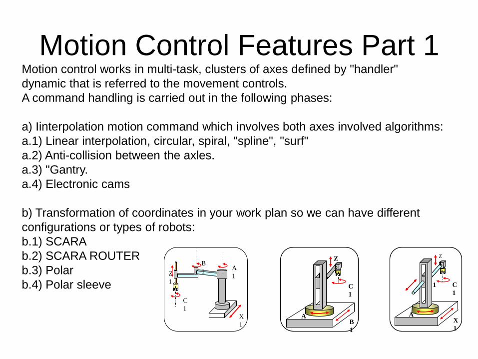
Motion Control Features Part 1Motion control works in multi-task, clusters of axes defined by "handler"
dynamic that is referred to the movement controls.
A command handling is carried out in the following phases:
a) Iinterpolation motion command which involves both axes involved algorithms:
a.1) Linear interpolation, circular, spiral, "spline", "surf"
a.2) Anti-collision between the axles.
a.3) "Gantry.
a.4) Electronic cams
b) Transformation of coordinates in your work plan so we can have different
configurations or types of robots:
b.1) SCARA
b.2) SCARA ROUTER
b.3) Polar
b.4) Polar sleeve
A
1 X
1
C
1
Z
1
1
X
1
A
1
B
1
C
1
Z
1
A
1 B
1
C
1
Z
1

Motion Control Features Part 2
c) Calculate the theoretical position of instantaneous
In calculating the actual position must comply with the laws of motion,
accelerating, maintaining speed and finally programmed to decelerate.
The accelerations and decelerations can be:
c.1) Linear
c.2) "S_Curve"
c.3) Sinusoidal
d) Correcting the theoretical with the matrix, or vectors of linear compensation,
balancing, rolling and pitching.
e) Monitoring the position of course, this feature is necessary if the command is
given to the drive is speed or torque.
This capability is realized with the method of feedback PID (Proportional
Derivative integrations)

DCOMThe product "AxesBrain" was developed to provide handling services to user applications, using
technology "DCOM", it will be possible to have access to these services not only from the same
PC, but also integrated into the local network or PC connected through the Internet.
To use the services of handling can be used two main roads or functions using direct resources
axes, spindles and output-input signals, or using programmed cycles. Using programming
languages are defined in procedures or courses of paths of the axes and handling and
processing, in our case we have two languages available: GP-PLCL and AxesBrainISO that you
can use depending on the type of application that comes to present.
The handling services are:
Direct FUNCTIONS
commands to the axes and the output signals of fattening
acquisition of values from the field, reading boards, I / O, sensors, etc..
mode settings for the trajectories, acquisitions, etc..
CYCLES processing and manipulation with programming by:
GP-PLC - proprietary language suitable to describe the cycles for the automation of handling
general
AxesBrainISO - ISO standard language suitable to describe the typical cycles of milling and
turning.