Web based system architecture for long pulse remote experimentation
6
Web based system architecture for long pulse remote experimentation E. de las Heras 3 '*, D. Lastra a ,J. Vega b , R. Castro b , M. Ruiz c , E. Barrera c a INDRA Sistemas, S.A. Unidad de Sistemas de Control de Energia, Direction de Tecnologia Energetica, Madrid, Spain b Asociacion EURATOM/CIEMATpara Fusion, Madrid, Spain c Universidad Politecnica de Madrid, Departamento de Sistemas Eiectronicos y de Control, Madrid, Spain ARTICLE INFO ABSTRACT Keywords: Long pulse JINI technology JNLP BeansNet(C)INDRA SOA Remote experimentation (RE) methods will be essential in next generation fusion devices. Requirements for long pulse RE will be: on-line data visualization, on-line data acquisition processes monitoring and on- line data acquisition systems interactions (start, stop or set-up modifications). Note that these methods are not oriented to real-time control of fusion plant devices. INDRA Sistemas S.A., CIEMAT (Centro de Investigaciones Energeticas Medioambientales y Tecnolog- icas) and UPM (Universidad Politecnica de Madrid) have designed a specific software architecture for these purposes. The architecture can be supported on the BeansNet platform, whose integration with an application server provides an adequate solution to the requirements. BeansNet is a JINI based framework developed by INDRA, which makes easy the implementation of a remote experimentation model based on a Service Oriented Architecture. The new software architecture has been designed on the basis of the experience acquired in the development of an upgrade of the TJ-II remote experimentation system. 1. Remote Experimentation overview Geographical situation of a large international research facility should not be a drawback for collaboration of research personnel, despite of his work place.This is the case of the large fusion research facilities, as ITER. These installations should give remote access mechanisms to the acquisition devices, in a time scale compatible with the physical process. These access mechanisms could also be used from local experimentation sites, with any type of communi- cations: Local or Wide Area Networks (LAN, WAN), Virtual Private Networks (VPN), etc. Long pulse tokamak fusion devices, like ITER, present new chal- lenges for Remote Experimentation (RE), as it gives the opportunity for interaction with the experiment during the shots. In this con- text, long pulse fusion devices demand a type of open system architecture that could give to remote research applications a safe and effective on-line access to the experiments in the same time they are happen. This type of architecture should offer adequate interfaces in order to: • Configure the acquisition devices. • On-line monitoring of acquisition systems. • On-line access to acquired data and diagnostics. • Handle the acquisition devices during the experiments. Note that these functionalities are not oriented to real-time con- trol of fusion plant devices. Security is a particular concern; as all these features should be available only in the case of remote users and applications have the appropriate access rights to specific devices and data. Furthermore, in addition to remote access to acquisition sys- tems, this architecture must meet a number of typical requirements for distributed applications and, in general, enterprise applications: Security: access authentication and authorization. Scalability: large growing capacity to follow the evolution of the experimental environment. Flexibility: adaptation capacity to different acquisition technolo- gies, security platforms, access modes, etc. Technology platform independence: transparent operation over different HW (Hardware) and OS (Operating System) platforms. On-line messaging: application-to-application messaging for monitoring, notification, etc. 2. REAL: Remote Experimentation Architecture for long pulse In a simple view, the experimentation environment of fusion facilities leans on the acquisition systems (supported by acquisi- tion hosts), that can be accessed through the plant network from different access services.
-
Upload
independent -
Category
Documents
-
view
1 -
download
0
Transcript of Web based system architecture for long pulse remote experimentation

Web based system architecture for long pulse remote experimentation E. de las Heras3'*, D. Lastraa,J. Vegab, R. Castrob, M. Ruizc, E. Barrerac
a INDRA Sistemas, S.A. Unidad de Sistemas de Control de Energia, Direction de Tecnologia Energetica, Madrid, Spain b Asociacion EURATOM/CIEMATpara Fusion, Madrid, Spain c Universidad Politecnica de Madrid, Departamento de Sistemas Eiectronicos y de Control, Madrid, Spain
A R T I C L E I N F O A B S T R A C T
Keywords: Long pulse JINI technology JNLP BeansNet(C)INDRA SOA
Remote experimentation (RE) methods will be essential in next generation fusion devices. Requirements for long pulse RE will be: on-line data visualization, on-line data acquisition processes monitoring and online data acquisition systems interactions (start, stop or set-up modifications). Note that these methods are not oriented to real-time control of fusion plant devices.
INDRA Sistemas S.A., CIEMAT (Centro de Investigaciones Energeticas Medioambientales y Tecnolog-icas) and UPM (Universidad Politecnica de Madrid) have designed a specific software architecture for these purposes. The architecture can be supported on the BeansNet platform, whose integration with an application server provides an adequate solution to the requirements. BeansNet is a JINI based framework developed by INDRA, which makes easy the implementation of a remote experimentation model based on a Service Oriented Architecture. The new software architecture has been designed on the basis of the experience acquired in the development of an upgrade of the TJ-II remote experimentation system.
1. Remote Experimentation overview
Geographical situation of a large international research facility should not be a drawback for collaboration of research personnel, despite of his work place.This is the case of the large fusion research facilities, as ITER. These installations should give remote access mechanisms to the acquisition devices, in a time scale compatible with the physical process. These access mechanisms could also be used from local experimentation sites, with any type of communications: Local or Wide Area Networks (LAN, WAN), Virtual Private Networks (VPN), etc.
Long pulse tokamak fusion devices, like ITER, present new challenges for Remote Experimentation (RE), as it gives the opportunity for interaction with the experiment during the shots. In this context, long pulse fusion devices demand a type of open system architecture that could give to remote research applications a safe and effective on-line access to the experiments in the same time they are happen. This type of architecture should offer adequate interfaces in order to:
• Configure the acquisition devices. • On-line monitoring of acquisition systems. • On-line access to acquired data and diagnostics. • Handle the acquisition devices during the experiments.
Note that these functionalities are not oriented to real-time control of fusion plant devices.
Security is a particular concern; as all these features should be available only in the case of remote users and applications have the appropriate access rights to specific devices and data.
Furthermore, in addition to remote access to acquisition systems, this architecture must meet a number of typical requirements for distributed applications and, in general, enterprise applications:
Security: access authentication and authorization. Scalability: large growing capacity to follow the evolution of the experimental environment. Flexibility: adaptation capacity to different acquisition technologies, security platforms, access modes, etc. Technology platform independence: transparent operation over different HW (Hardware) and OS (Operating System) platforms. On-line messaging: application-to-application messaging for monitoring, notification, etc.
2. REAL: Remote Experimentation Architecture for long pulse
In a simple view, the experimentation environment of fusion facilities leans on the acquisition systems (supported by acquisition hosts), that can be accessed through the plant network from different access services.

Acquisition System
Acquisition Network
Fig. 1. REAL architecture: deployment overview.
For RE these access services can be invoked from remote (or local) places, through suited communications (LAN, WAN, VPN, etc.), protocols, gateways and security systems.
To face the RE requirements, the approach proposed here is a Service Oriented Architecture (SOA), including some main types of services for configuration, monitoring or data access, all of them to be customized.
This "Remote Experimentation Architecture for long pulse" (REAL) is a set of open JAVA technologies, mainly JINI [1] andJNLP (Java Network Launch Protocol) [2a]:
• JINI provides a services repository where clients may take contact with servers through a Lookup Service. It supports a very robust communication, scalability, availability, flexibility and easy evolution.
• JNLP allows remotely running JAVA applications from any network environment. JWS (Java Web Start) [2b] is the reference implementation of JNLP specification. Both have big advantages like: remote application delivery and automatic SW (Software) download as well as control of versions.
On the other hand, for long pulse is mandatory on-line system monitoring, that allows remote clients access to any type of information in the moment it is generated. For a correct support of this capability, we propose the use of HTTP under MultipartResponse configurations (see Section 2.3).
Fig. 1 shows the typical deployment of REAL technologies in an experimental environment of a fusion device. In this schema several JINI service providers constitute a network that gives support to the access requests coming from JNLP clients in different exper-
Acquisition Sensors
Fig. 2. REAL architecture: software components.

imentation sites. It also shows the case of some of the JINI services that could be implemented in acquisition system hosts. In order to provide a complete view, the figure also shows other systems in the experimental environment that render several services to the users and could interact with the acquisition systems and JINI services.
2.2. REAL software architecture
Fig. 2 represents a SW layer schema that shows the interaction of REAL architecture technologies, one to each other and with the underlying SW technologies. This interaction sets in communication the acquisition systems in a long pulse experimental environment with remote experimental applications.
More in detail, to support this capability, the typical SW configuration of REAL includes:
• Some type of JNLP client application, that takes advantage of the on-line access to acquisition systems.
• Some type of communication (LAN, WAN, VPN, other) supporting MultipartResponse HTTP protocol.
• A Web Application Server that supports: • Access control. • A JINI client, as the "entry point" to the JINI network.
• The JINI network, that offers different services over the acquisition systems, through the JINI Lookup Service (or Service Locator). These services could run in one or more machines and have different purposes: • Acquisition systems configuration. • Acquisition systems monitoring. • Experimental data access.
Likewise, in most advanced experimental environments, these JINI services could also be installed in the acquisition system hosts [3]
2.2. Security. Access control
As mentioned before, a key feature of such RE architectures for long pulse, probably the most important, is the ability of enabling remote testing under a secure environment.
REAL architecture proposed here is based on Java 2 platform standards. Therefore, it may adopt any security mechanism supported in the underlying security architecture, in order to support:
• Authentication: user recognition to access into the environment. • Authorization: privileges of using different functionalities.
For users outside the experimental environment, access to services is always done through the Application Server. Therefore, the Application Server is responsible for implementing the security and access control. Under these context circumstances, our architecture can be adapted to use the specific security infrastructure of the organization where it is being implemented.
This capability makes REAL architecture totally independent of the underlying security platform, which could have different approaches, e.g.:
• User/Password • Security Smartcards • PKI (Public Key Infrastructure) [4].
2.3. On-line messaging and remote monitoring. HTTP MultipartResponse
As it has been mentioned, remote monitoring is one of the key aspects in REAL architecture. It means that services should be aware
Polling Technique
I.WTH.W-g^l
MultipartResponse Technique
l.*ffSI"H?B!l
HTTPMultipartResponse
HTTPM ulbpah Response'
HTT PMU itipanR esponse*
:-!j:.-.-,.-r r-F
System Stale
SystemSlate
Systems tale
u
Fig. 3. Polling technique and MultipartResponse technique comparison,
on-line of all changes in the acquisition system status:
• Every acquisition system must be able to notify its status at every moment.
• Every monitoring application must be able to display the notified changes.
• All this must be done on-line.
Our approach is based on the use of the MultipartResponse HTTP protocol capacity, which means the ability to send a response split in several "pieces". In this way, a continuous client-server connection can be maintained as long as needed.
MultipartResponse HTTP improves dramatically the performance versus the "Polling technique", that is the most popular approach to implement on-line notifications in Web environments.
As it can be seen in Fig. 3, using a "Polling technique", on-line notification of status changes or data responses is being simulated, although this should not be considered as really on-line monitoring. In this approach the time delay from change to notification t\ is bigger, since it is affected by the polling time cycle, added to the network delay for request and answer. The approach proposed here, based in the use of the MultipartResponse HTTP protocol capacity, means to send a response split in several "pieces". In this way a continuous client-server connection is maintained as long as needed and the server notifies its changes when they occur. Therefore, the time delay from change to notification tj is the minimum, since it is not affected by the polling time cycle. Instead of this, it only includes the network delay for the answer.
Obviously the delay time is a variable very dependent on the bandwidth of the communication network. Please note that here, "remote client" is used in a wide sense, as clients can be placed in the same experiment site or in other place, using communications through a LAN, WAN, VPN or other suitable.
3. BeansNet solution
REAL architecture showed here is totally "open source" and can be implemented "totally free" in several ways. Nevertheless a suited environment could simplify the work needed to configure a RE environment under REAL architecture.
Editable Logic Diagram of
BeansNet Service
BeansNet Component
Libraries
. C T • • - , ^ " W * Technology
Fig. 4. BeansNet on REAL architecture.
BeansNetOINDRA is an application development environment based on the same SW standards as REAL ones (SOAJINI, JNLP, etc.) that strongly eases the deployment and support of services in the JINI network of REAL, giving several additional advantages. In short, BeansNet is a JAVA application container. Applications running on BeansNet are component based, i.e. they comply with Component-Based Software Engineering (CBSE) paradigm [5].JavaBeans are the standard software components for BeansNet. These components can be made to interact one to each other in the container, under an "ad hoc" configuration that can be specified through a suited graphical tool, the BeansNet Assembler (see Section 3.1).
A set of interacting software components, JavaBeans, compounds a BeansNet Service. BeansNet Services are announced as software services, i.e. BeansNet establishes a Service Oriented Architecture (SOA).
Fig. 4 shows how BeansNet is integrated in a Java environment, supporting the REAL architecture. A BeansNet service is composed by an ensemble of Java Beans that interact one to each other bringing the advantages of component-based applications (e.g. reusability). Otherwise, since they are JINI services, BeansNet services also have the advantages of those ones (high scalability, robustness, high availability, etc.). For the same reason, the access to these services is very easy through a JINI client. Actually, BeansNet offers the possibility to implement our own Servlet Proxy as a JINI client, which supports the remote access to the properties belonging to the Java Beans that compound a BeansNet service.
BeansNet Services also may interact to create new loosely coupled services to support the requirements of experimental processes and users. Actually, BeansNet Assembler is a special kind of service with capabilities such as add and remove components in other services, or change component properties values.
There is no need to stop or restart a service after its updation or remodeling. This BeansNet feature increases the operative availability of services and allows on-line modification of services.
3.1. The BeansNet Assembler
BeansNet Services are modeled with the BeansNet Assembler tool (see Fig. 5), where the components,Java Beans, are represented as if they were hardware chipsets, in order to make the work easier and intuitive. Chipset pins represent the component properties (e.g. a PXI card identification, a channel speed, etc.), whose values can be modified by other components that have a connection with it. The change of component connections modifies the way a BeansNet Service works. An individual component may modify its behavior when contains a Customizer, which provides a complete custom GUI (Graphical User Interface) for customizing a target Java Bean.
A BeansNet service may be conceived as a "big chipset". Registered services may interact in the same way as components do, creating new loosely coupled services. Anyway, a standalone BeansNet Service should provide fully functionality when it is properly modeled.
- _ = J
L i =J
BeansNet Services Manager
BeansNet Service Available Properties
Fig. 5. BeansNet Assembler tool.
3.2. BeansNet security
BeansNet contains a set of packages that enables services to authenticate and enforce access controls upon users. It implements a version of the ACEGI framework [6], a powerful and flexible security solution for Java enterprise applications, and supports user-based authorization. In this environment, BeansNet integration with other security frameworks is implemented with a set of common interfaces that allows support and interaction with any security platform.
BeansNet security also features the so called "security enabled services", which means that those services can be built and edited according to security permissions. Finally, BeansNet security configuration used to be stored in an XML file although could also be loaded from a database or a LDAP (Lightweight Directory Access Protocol) server [7].
3.3. BeansNet database interaction
BeansNet database interaction is done through HIBERNATE [8], an open source data persistence solution. Hibernate is an Object Relational Mapping (ORM) tool that supports most of the databases with JDBC (Java Database Connectivity) drivers [9], providing an easy-to-use framework for mapping an object-oriented domain model into a traditional relational database.
4. Implementation of a Remote Experimentation environment with BeansNet
A relevant reference of the use of REAL, implemented under BeansNet, is the upgrade of the Remote Experimentation system of TJ-II fusion facility, in CIEMAT (Spain).
4.1. TJ-II data acquisition processes
TJ-II is a short pulse machine (Cycles: a pulse every lOmin, 500 ms pulse time). There are two main processes for TJ-II data collection during experiments:
• Experiment Launch Process. TJ-II Central System runs a Server Socket process that notifies to every Client Socket connected when a new experiment is launched. After a launching event, PXI Nodes [10,11] receive the configuration about the way TJ-II data must be collected.

«l_inux R T A I »
PXI Acquisition Platform
«lnterface» Card Conf Server Socket
«L inux R T A I »
PXI Acquisition Platform
« L a b v i e w »
« l n t e r f a c e » Card Conf Server Socket
<<Fusion Device>>
TJ-II
<<Core Experimental Environment^
Central System
«Hardware Tr igger» Start Experiment
<Central System lnterface> Server Socket
Expert merit Startu p
«J i n i Node>>
BeansNet Node
•Jini App: Lookup Service
«=BeansNet Serv ice^ Config Experimental Apps
c<component>^ Socket
Config PXI-1
«componen t» Config PXI-1
•^comp orients-Socket Start Experiment
<<Apache + Tomcat>>
Web Application Portal
«component>> Config PXI-N
•=<component» Socket
Config P5<l-N
«componen t» DAO Cards
Config
_̂ N
«Database>>
SQLServer
Security
« T a b l e s » Cards
Configuration
<-WAR>> BeansNet P roxy Seru let
"Secur i ty Provider*? PAP! < -
" J a v a Web Star ts PXI Devices Configuration
« lntranet Node>>
Desktop Client
<<BeansNet Assembler» Client Application
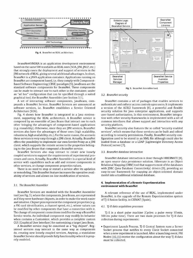
Fig. 6. TJ-II RE solution using BeansNet. Deployment diagram (UML notation).
• Card Configuration Process. An authorized user may gain access to the system in order to individually change PXI cards configuration values on a chassis. PXI cards load their last configurations provided by users during experiment launch and while running.
4.2. RE solution deployment using BeansNet
BeansNet RE solution implemented in TJ-II is a facade reengi-neering of a well-tested architecture designed byj. Vega et al. When it was introduced, the former TJ-II remote participation system design was extensively discussed, selecting Web andjava technologies as the best suited to this type of applications [12-14].
The new BeansNet implementation includes (see UML deployment schema in Fig. 6):
• JINI Node: it is the core application for TJ-II acquisition services. Contains: The JINI Lookup Service, where BeansNet services are registered, and the BeansNet service for PXI cards configuration.
• Apache Tomcat node: the application web portal, accessible both for remote and local users. Tomcat server contains two HTTP applications, under PAPI security [15]: • A Java Swing application for PXI cards customization. Every
component in a BeansNet Service has a set of properties, Java Beans getters and setters, which can be modified during service execution.
• A Java Web application acting as an http proxy for the Swing application.
• Intranet node: the desktop client. Any PC on the intranet can run the BeansNet Assembler that allows Intranet users access to the repository for services creation or modification (obviously this requires security permissions over BeansNet Assembler and BeansNet Services).
Obviously, TJ-II did not take full advantage of the on-line REAL capabilities, since it is a short pulse device, but allowed testing most of REAL capabilities like: remote access for hardware reconfiguration and collected data processing after pulses, adaptation to the security implementation of the environment (here PAPI), etc.
In the other hand, BeansNet contributed with its features to improve the TJ-II RE environment, such as:
1 Service Oriented Architecture with thin client RE graphical applications, executed from a Web browser, to access acquisition and diagnostics equipment.
1 Graphical composition of access services. 1 JINI advantages: scalability, robustness, high availability, flexibil
ity and easy evolution. 1 JNLP/JWS advantages as remote application delivery and auto
matic SW download and control of versions.
5. Summary
REAL is a totally open architecture for Remote Experimentation in long pulse fusion facilities. By itself, REAL offers significant advantages that are essential for long pulse fusion experimentation:
On-line access to acquisition systems for monitoring, configuration and data use. Access authentication and authorization under multiple security implementations. Local or remote network access: LAN, WAN, VPN, etc. Scalability, flexibility, robustness, platform independence, etc.

REAL can be implemented under BeansNet that is an application development environment based on the same SW standards. This gives additional advantages, as:
• Easy implementation. • Graphical tool for service composition and configuration. • Availability & hot-swap (on-line change) of services. No need to
stop or restart services after update or remodeling. • INDRA support.
Finally, it is worth to mention that BeansNet is a well-tested platform in very diverse data acquisition and control systems such as high speed train control system, electricity metering systems or defense aircraft automatic maintenance systems [16-18].
References
[1] JINI Network Technology: http://www.jini.org/wiki/Main_Page. [2] (a) JNLP: http://java.sun.com/docs/books/tutorial/deployment/deploymentIn
Depth/jnlp.html.: (b)JWS http://today.java.net/pub/a/today/2005/08/ll/webstart.html.
[3] J. Gonzalez, M. Ruiz, E. Barrera, J.M. Lopez, G. de Areas, J. Vega, Services oriented architecture for adaptive and intelligent data acquisition and processing systems in long pulse fusion experiments, in: IAEATM2009 Proceedings, 2009.
[4] PKI: http://www.sun.com/blueprints/0801/publickey.pdf. [5] CBSE: J.Q. Ning, Component-based software engineering (CBSE), in:
SAST Proceedings, 5th International Symposium on Assessment of Software Tools (SAST '97), 1997, p. 0034, http://doi.ieeecomputersociety.org/ 10.1109/AST.l 997.599909.
[6] ACEGI: http://www.acegisecurity.org/. [7J LDAP: T.A. Howes, M.C. Smith, G.S. Good, Understanding and Deploying LDAP
Directory Services, 2nd Ed., Addison-Wesley, 2003, ISBN 0-672-32316-8. [8] HIBERNATE: Christian Bauer, Gavin King, Java Persistence with Hibernate.
Second Edition of Hibernate in Action, Manning Publications Co., 2006, ISBN 1-932394-88-5.
[9] JDBC: http://java.sun.eom/javase/6/docs/technotes/guides/jdbc/. [10] M. Ruiz, S. Lopez, E. Barrera, J. Vega, E. Sanchez, Distributed real time data
processing architecture for the TJ II data acquisition system, Rev. Sci. Instrum. 75 (10) (2004) 4261-4264.
[11] E. Barrera, M. Ruiz, S. Lopez, D. Machon, J. Vega, PXI-based architecture for real time data acquisition and distributed dynamic data processing, IEEE TNS 53-3 (2006) 923-926.
[12] J. Vega, E. Sanchez, A. Lopez, A. Portas, M. Ochando, A. Mollinedo, et al., Design of the TJ II remote participation system, Rev. Sci. Instrum. 74 (3) (2003) 1773-1777.
[13] J. Vega, E. Sanchez, A. Portas, M. Ruiz, E. Barrera, S. Lopez, Multi-tier approach for data acquisition programming in the TJ-II remote participation system, Rev. Sci. Instrum. 75 (10) (2004) 4251-4253.
114] J. Vega, E. Sanchez, A. Portas, A. Pereira, A. Mollinedo.J.A. Mufioz, et al., Overview of the TJ-II remote participation system, Fusion Eng. Des. 81 (2006) 2045-2050.
[15] R. Castro, D.R. Lopez, J. Vega, An authentication and authorization infrastructure: the PAPI system, Fusion Eng. Des. 81 (2006) 2057-2061.
[16] http://www.indra.es/servlet/ContentServer?pagename=IndraES/Proyecto_FA/ DetalleProyecto&cid=1118068281697&pid=l 100590229116&Language=en_ GB&opc=T5.
[17] http://www.indra.es/servlet/ContentServer?pagename=IndraES/Proyecto_FA/ DetalleProyecto&cid=1084369906432&pid=1083830064918&Language=en_ GB&opc=Listado.
[18] http://acquisition.navy.mil/acquisition_one_source/program_assistance_and_ tools/best_practices_and_lessons_learned/applying_acquisition_reform_to_ support _equipment_acquisition.