Asia Pacific Studies Volume 1 Number 1 / January - June 2017
Upload
khangminh22Category
view
0download
0
ECORFAN®
ECORFAN®
Journal of
Mechanical Engineering
Volume 5, Issue 15 – January – June – 2021
ECORFAN®
ISSN 2531-2189

ECORFAN-Spain
Chief Editor
SERRUDO-GONZALES, Javier. BsC
Executive Director
RAMOS-ESCAMILLA, María. PhD
Editorial Director
PERALTA-CASTRO, Enrique. MsC
Web Designer
ESCAMILLA-BOUCHAN, Imelda. PhD
Web Diagrammer
LUNA-SOTO, Vladimir. PhD
Editorial Assistant
TREJO-RAMOS, Iván. BsC
Translator
DÍAZ-OCAMPO, Javier. BsC
Philologist
RAMOS-ARANCIBIA, Alejandra. BsC
Journal of Mechanical Engineering, Volume 5, Number 15, June - 2021, is a
biannually Journal edited by ECORFAN-
Spain. Matacerquillas Street 38, CP: 28411.
Moralzarzal - Madrid. WEB:
http://www.ecorfan.org/spain/rj_ingenieria_
mec.php, [email protected]. Editor in
Chief: SERRUDO-GONZALES, Javier,
BsC. ISSN 2531-2189. Responsible for the
last update of this issue ECORFAN
Computer Unit. Imelda Escamilla Bouchán,
PhD. Vladimir Luna Soto, PhD. Updated as
of June 30, 2021.
The opinions expressed by the authors do not
necessarily reflect the views of the publisher
of the publication.
It is strictly forbidden the total or partial
reproduction of the contents and images of
the publication without permission from the
Spanish Center for Science and Technology.

Journal of Mechanical Engineering
Definition of Journal
Scientific Objectives
Support the International Scientific Community in its written production of Science, Innovation
Technology in the Area of Engineering and Technology, in the Subdisciplines of pumps and equipment
for handling liquids, bearings, air compressors, gears, refrigeration equipment, mechanical power
transmission equipment, pneumatic equipment, equipment and industrial machinery, agricultural
machinery, oil extraction machinery, printing and reproduction machinery , Mining Machinery,
Hydraulic Machinery, Specialized Industrial Machinery, Nuclear Machinery, Paper Manufacturing
Machinery, Machinery for the Food Industry, Material Handling Machinery, Textile Machinery, Steam
Machinery, Vending and Distributor Machines, Machines, Tools and Accessories, Heating Material,
Construction Material, Dies, Insoles and Gauges, Internal Combustion Engines (General), Gas Engines,
Machined Operations.
ECORFAN-Mexico SC is a Scientific and Technological Company in contribution to the Human
Resource training focused on the continuity in the critical analysis of International Research and is
attached to CONACYT-RENIECYT number 1702902, its commitment is to disseminate research and
contributions of the International Scientific Community, academic institutions, agencies and entities of
the public and private sectors and contribute to the linking of researchers who carry out scientific
activities, technological developments and training of specialized human resources with governments,
companies and social organizations.
Encourage the interlocution of the International Scientific Community with other Study Centers in
Mexico and abroad and promote a wide incorporation of academics, specialists and researchers to the
publication in Science Structures of Autonomous Universities - State Public Universities - Federal IES -
Polytechnic Universities - Technological Universities - Federal Technological Institutes - Normal
Schools - Decentralized Technological Institutes - Intercultural Universities - S & T Councils -
CONACYT Research Centers.
Scope, Coverage and Audience
Journal of Mechanical Engineering is a Journal edited by ECORFAN-México S.C in its Holding with
repository in Spain, is a scientific publication arbitrated and indexed on a quarterly basis. It supports a
wide range of contents that are evaluated by academic pairs by the Double-Blind method, around topics
related to the theory and practice of pumps and equipment for handling liquids, bearings, air compressors,
gears, cooling equipment, mechanical power transmission equipment, pneumatic equipment, equipment
and industrial machinery, agricultural machinery, oil extraction machinery , printing and reproduction
machinery, mining machinery, hydraulic machinery, specialized industrial machinery, nuclear
machinery, paper manufacturing machinery, machinery for the food industry, material handling
machinery, textile machinery, steam machinery, vending machines and distributors, machines, tools and
accessories, heating material, building material, dies, insoles and gauges, internal (general) combustion
engines, gas engines , mechanized operations with diverse approaches and perspectives, which contribute
to the dissemination of the development of Science Technology and Innovation that allow arguments
related to decision-making and influence the formulation of international policies in the Field of
Engineering and Technology Sciences. The editorial horizon of ECORFAN-Mexico® extends beyond
the academy and integrates other research and analysis segments outside this field, as long as they meet
the requirements of argumentative and scientific rigor, as well as addressing topics of general and current
interest of the International Scientific Society.

Editorial Board
CENDEJAS - VALDEZ, José Luis. PhD
Universidad Politécnica de Madrid
FERNANDEZ - ZAYAS, José Luis. PhD
University of Bristol
HERRERA - DIAZ, Israel Enrique. PhD
Center of Research in Mathematics
MEDELLIN - CASTILLO, Hugo Iván. PhD
Heriot-Watt University
RIVAS - PEREA, Pablo. PhD
University of Texas
ROBLEDO - VEGA, Isidro. PhD
University of South Florida
RODRIGUEZ - ROBLEDO, Gricelda. PhD
Universidad Santander
TELOXA - REYES, Julio. PhD
Advanced Technology Center
VAZQUEZ - MARTINEZ, Ernesto. PhD
University of Alberta
VEGA - PINEDA, Javier. PhD
University of Texas

Arbitration Committee
ALVAREZ - SÁNCHEZ, Ervin Jesús. PhD
Centro de Investigación Científica y de Estudios Superiores de Ensenada
CHÁVEZ - GUZMÁN, Carlos Alberto. PhD
Instituto Politécnico Nacional
DURÁN - MEDINA, Pino. PhD
Instituto Politécnico Nacional
ENRÍQUEZ - ZÁRATE, Josué. PhD
Centro de Investigación y de Estudios Avanzados
FERNÁNDEZ - GÓMEZ, Tomás. PhD
Universidad Popular Autónoma del Estado de Puebla
GUDIÑO - LAU, Jorge. PhD
Universidad Nacional Autónoma de México
GUTIÉRREZ - VILLEGAS, Juan Carlos. PhD
Centro de Tecnología Avanzada
MÉRIDA - RUBIO, Jován Oseas. PhD
Centro de Investigación y Desarrollo de Tecnología Digital
MORENO - RIOS, Marisa. PhD
Instituto Tecnológico de Pachuca
PORTILLO - VÉLEZ, Rogelio de Jesús. PhD
Centro de Investigación y de Estudios Avanzados
SANDOVAL - GUTIÉRREZ, Jacobo. PhD
Instituto Politécnico Nacional

Assignment of Rights
The sending of an Article to Journal of Mechanical Engineering emanates the commitment of the author
not to submit it simultaneously to the consideration of other series publications for it must complement
the Originality Format for its Article.
The authors sign the Authorization Format for their Article to be disseminated by means that ECORFAN-
Mexico, S.C. In its Holding Spain considers pertinent for disclosure and diffusion of its Article its Rights
of Work.
Declaration of Authorship
Indicate the Name of Author and Coauthors at most in the participation of the Article and indicate in
extensive the Institutional Affiliation indicating the Department.
Identify the Name of Author and Coauthors at most with the CVU Scholarship Number-PNPC or SNI-
CONACYT- Indicating the Researcher Level and their Google Scholar Profile to verify their Citation
Level and H index.
Identify the Name of Author and Coauthors at most in the Science and Technology Profiles widely
accepted by the International Scientific Community ORC ID - Researcher ID Thomson - arXiv Author
ID - PubMed Author ID - Open ID respectively.
Indicate the contact for correspondence to the Author (Mail and Telephone) and indicate the Researcher
who contributes as the first Author of the Article.
Plagiarism Detection
All Articles will be tested by plagiarism software PLAGSCAN if a plagiarism level is detected Positive
will not be sent to arbitration and will be rescinded of the reception of the Article notifying the Authors
responsible, claiming that academic plagiarism is criminalized in the Penal Code.
Arbitration Process
All Articles will be evaluated by academic peers by the Double Blind method, the Arbitration Approval
is a requirement for the Editorial Board to make a final decision that will be final in all cases. MARVID®
is a derivative brand of ECORFAN® specialized in providing the expert evaluators all of them with
Doctorate degree and distinction of International Researchers in the respective Councils of Science and
Technology the counterpart of CONACYT for the chapters of America-Europe-Asia- Africa and
Oceania. The identification of the authorship should only appear on a first removable page, in order to
ensure that the Arbitration process is anonymous and covers the following stages: Identification of the
Journal with its author occupation rate - Identification of Authors and Coauthors - Detection of plagiarism
PLAGSCAN - Review of Formats of Authorization and Originality-Allocation to the Editorial Board-
Allocation of the pair of Expert Arbitrators-Notification of Arbitration -Declaration of observations to
the Author-Verification of Article Modified for Editing-Publication.
Instructions for Scientific, Technological and Innovation Publication
Knowledge Area
Work should be unpublished and refer to issues of Pumps and equipment for handling liquids, bearings,
air compressors, gears, cooling equipment, mechanical power transmission equipment, pneumatic
equipment, equipment and industrial machinery, agricultural machinery, oil extraction machinery,
printing and reproduction machinery, mining machinery, hydraulic machinery, specialized industrial
machinery, nuclear machinery, machinery to manufacture paper , machinery for the food industry,
material handling machinery, textile machinery, steam machinery, vending machines and distributors,
machines, tools and accessories, heating material, building material, dies, insoles and gauges, internal
combustion engines (general), gas engines, machined operations and other topics related to engineering
and technology sciences.

Presentation of Content
In volume five, issue fifteen, as the first article we present, Failure in a pipe due to defective
maintenance, by SALGADO-LÓPEZ, Juan Manuel, OJEDA-ELIZARRARAS, José Luis, LOPEZ-
MONROY, Francisco Ignacio and TELLO-RICO, Mauricio, with secondment at the CIDESI, as a second
article we present, Effect of induction heating on Vickers and Knoop hardness of 1045 steel heat treated,
by MARTÍNEZ-VÁZQUEZ, J. Merced, RODRÍGUEZ-ORTIZ, Gabriel, HORTELANO-CAPETILLO,
J. Gregorio and PÉREZ-PÉREZ, Arnulfo, with an appointment at Universidad Politécnica de Juventino
Rosas, as a third article we present, The numerical characterization of the gas turbine blade with static
stress analysis applying finite element method, by VILLAGRÁN-VILLEGAS, Luz Yazmín,
HERNÁNDEZ-GÓMEZ, Luis Héctor, MARTÍNEZ-CRUZ, Miguel Ángel and ROJAS-RAMÍREZ,
Jorge Armando, with secondment at the Instituto Politécnico Nacional and Universidad de Veracruz, as
fourth article we present, Vibration analysis in a rotodynamic system, by GAMBOA-MARTÍN, Vianney
Aurora, RODRIGUEZ-BLANCO, Marco Antonio, DURÁN-MORALES, Iván and MARTÍNEZ-
RODRÍGUEZ, Gilberto, with secondment Universidad Autónoma del Carmen.

Content
Article
Page
Failure in a pipe due to defective maintenance
SALGADO-LÓPEZ, Juan Manuel, OJEDA-ELIZARRARAS, José Luis, LOPEZ-
MONROY, Francisco Ignacio and TELLO-RICO, Mauricio
CIDESI
1-7
Effect of induction heating on Vickers and Knoop hardness of 1045 steel heat treated
MARTÍNEZ-VÁZQUEZ, J. Merced, RODRÍGUEZ-ORTIZ, Gabriel, HORTELANO-
CAPETILLO, J. Gregorio and PÉREZ-PÉREZ, Arnulfo
Universidad Politécnica de Juventino Rosas
8-15
The numerical characterization of the gas turbine blade with static stress analysis
applying finite element method
VILLAGRÁN-VILLEGAS, Luz Yazmín, HERNÁNDEZ-GÓMEZ, Luis Héctor,
MARTÍNEZ-CRUZ, Miguel Ángel and ROJAS-RAMÍREZ, Jorge Armando
Instituto Politécnico Nacional
Universidad de Veracruz
16-23
Vibration analysis in a rotodynamic system
GAMBOA-MARTÍN, Vianney Aurora, RODRIGUEZ-BLANCO, Marco Antonio,
DURÁN-MORALES, Iván and MARTÍNEZ-RODRÍGUEZ, Gilberto
Universidad Autónoma del Carmen
24-31

1
Article Journal of Mechanical Engineering
June 2021, Vol.5 No.15 1-7
Failure in a pipe due to defective maintenance
Falla de tubería por deficiencias en mantenimiento
SALGADO-LÓPEZ, Juan Manuel†*, OJEDA-ELIZARRARAS, José Luis, LOPEZ-MONROY,
Francisco Ignacio and TELLO-RICO, Mauricio
CIDESI, Materials Technology, Metallography Laboratory and Failure Analysis. Mexico.
CIDESI, Joining Technologies, Welding Laboratory, Mexico.
ID 1st Author: Juan Manuel, Salgado-Lopez / ORC ID: 0000-0002-2384-1887, CVU CONACYT ID: 94744
ID 1st Co-author: José Luis, Ojeda-Elizarrarás / ORC ID: 0000-0001-8412-7778, CVU CONACYT ID: 81630
ID 2nd Co-author: Abraham, Silva-Hernandez / ORC ID: 0000-0003-2699-8107, CVU CONACYT ID: 726099
ID 3rd Co-author: Jesús Mauricio, Tello-Rico / ORC ID: 0000-0002-5657-2134, CVU CONACYT ID: 586320
DOI: 10.35429/JME.2021.15.5.1.7 Received January 10, 2021; Accepted June 30, 2021
Abstract
Proper maintenance of energy transport pipelines is a part
of energy efficiency since energy losses during transport
are reduced with good maintenance practices as well as the
mechanical integrity can be known. Moreover, it reduces
the risk of accidents or environmental damage. This work
is an example of the experiences that must be taken into
account for optimal pipeline maintenance and consisted of
a failure analysis performed on a 20-inch diameter "T"
connection, which plays an important role in the energy
transportation process and it was found to be partially
buried with exposure to rainwater. Preventive
maintenance consists of visual inspection, cleaning, and
coating with paint. The results indicated that the failure
begun due to fatigue with origin in weld defects and the
fracture grew up due to an overload, which caused the
crack to grow following the region of the material with
loss of thickness induced by corrosion pitting.
Failure, Corrosion, Defective maintenance
Resumen
El mantenimiento adecuado de los ductos para transporte
de energéticos es parte de la eficiencia energética, ya que
así se logran reducir las pérdidas durante el transporte y se
puede conocer la integridad mecánica de estos y con ello
reducir el riesgo de accidentes o daños ambientales. Este
trabajo es un ejemplo de las experiencias que deben ser
tomadas en cuenta para un mantenimiento óptimo de los
ductos y consistió de un análisis de falla realizado en una
conexión tipo “T” de 20 pulgadas de diámetro, la cual
tiene un papel importante en el proceso de transporte de
energéticos y que se encontraba enterrado parcialmente
con exposición al agua pluvial. El mantenimiento
preventivo consistía de inspección visual, limpieza y
recubrimiento con pintura. Los resultados indican que la
falla ocurrió por fatiga iniciada en defectos de soldadura y
la fractura termino por una sobrecarga que dio lugar a que
la grieta creciera siguiendo la región del material con
pérdida de espesor inducida por picaduras por corrosión.
Falla, Corrosión, Mantenimiento
Citation: SALGADO-LÓPEZ, Juan Manuel, OJEDA-ELIZARRARAS, José Luis, LOPEZ-MONROY, Francisco Ignacio
and TELLO-RICO, Mauricio. Failure in a pipe due to defective maintenance. Journal of Mechanical Engineering. 2021. 5-
15:1-7.
* Correspondence to the Author (Email: [email protected])
† Researcher contributing as first author.
© ECORFAN-Spain www.ecorfan.org/spain

2
Article Journal of Mechanical Engineering
June 2021, Vol.5 No.15 1-7
ISSN-2531-2189
ECORFAN ® All rights reserved.
SALGADO-LÓPEZ, Juan Manuel, OJEDA-
ELIZARRARAS, José Luis, LOPEZ-MONROY, Francisco
Ignacio and TELLO-RICO, Mauricio. Failure in a pipe due to
defective maintenance. Journal of Mechanical Engineering.
2021
Introduction
Preventive maintenance is crucial for well-
functioning of industry and to avoid accidents.
This is especially true for energy industry
because there are risks of accidents or leaks,
which jeopardizes the health of people and the
environment Nevertheless, in some cases
preventive maintenance consists only on
external cleaning. This bad practice leads to
consequences as the shown in this work.
Loss of productivity due to unplanned
maintenance or repairs are some of the mild
consequences of such shallow maintenance.
Besides temporary repairs require additional
work for their final correction, or in the worst
case, they fail before being corrected. All of this
commonly leads to a worst situation.
When a failure occurs, which affects
production, the quality of the products, the safety
of people or that might cause a serious
environmental impact; it is essential to carry out
a failure analysis to determine the metallurgical
cause that led to the failure. From the
conclusions of the analysis, real actions can be
undertaken in order to prevent such events from
occurring again. Failure analysis, it is linked to
the criticality of the energy production or
transport equipment to prioritize preventive
maintenance activities and their planning; since
maintenance requires studying the incidents that
happened and providing real solutions to avoid
them.
This work consisted of a failure analysis
performed on a 20-inch diameter “T” type
connection, which plays an important role in the
energy transport process. The objective of this
work was to determine the metallurgical
mechanism, which led to the fracture of this
component and with this work it is shown that a
poor practice in preventive maintenance leads to
process failures and unplanned stoppages.
Methodology
The construction of this “T” type connection
dated from 1980 and the material was ASTM A
53 grade B steel. This component was
approximately 2.30 meters long, 500 millimeters
in diameter and approximately 7.85 millimeters
thickness.
It should be mentioned that the thickness
was not constant since the specimen under study
showed red oxidation on both sides; the “T”
connection was 500 millimeters in diameter, in
addition to a 300 millimeters of diameter hole.
There was a primary crack that began
transversely to the radius of the tube and then
towards a semicircle of approximately 50
centimeters long whose possible origin was
detected in the joint weld of the "T" with the
tube. This is shown in figure 1.
In order to achieve the aim of this work,
the following techniques were applied: visual
inspection with the naked eye and using Leica
brand stereographic microscope, this technique
was carried out to demonstrate the circumstance
of delivery to the laboratory of the specimen
under study and determine the origin of the
fracture if there is significant macroscopic
evidence.
Figure 1 The image the connection type "T" in the
condition of delivery to the laboratory. Note the fracture
and coating on the external surface
Source: Own work
The thickness measurement was done by
means of the ultrasonic testing with a straight
beam receiver using a GE equipment model
USM / DMS Go, this non-destructive testing was
necessary in order to be able to determine the
areas of the “T” connection with reduction in
thickness.
To find damage in the microstructure of
this component steel, a microstructural analysis
was carried out using a Nikon Epiphot 440 brand
metallographic optical microscope. The samples
were taken by transversal mechanical cuts.
These samples were mounted on Bakelite,
grinded and polished using sandpaper from 120
to 2000. After that these samples were polished
using 1 micron particle size alumina powder and
subsequently etched with nital 2 to reveal the
microstructure.

3
Article Journal of Mechanical Engineering
June 2021, Vol.5 No.15 1-7
ISSN-2531-2189
ECORFAN ® All rights reserved.
SALGADO-LÓPEZ, Juan Manuel, OJEDA-
ELIZARRARAS, José Luis, LOPEZ-MONROY, Francisco
Ignacio and TELLO-RICO, Mauricio. Failure in a pipe due to
defective maintenance. Journal of Mechanical Engineering.
2021
Finally, the fracture pattern of the failed
“T” connection was observed by a Phillips
Model XL-30 scanning electron microscope
(SEM) and EDS elemental microanalysis with
EDAX.
Results
Visual testing on the “T” type connection
showed that the pattern of the crack at the ends
was ductile and that the origin was located in the
weld toe of the “T” connection (figure 2). From
this fact it can be deduced that the origin of the
crack was located at the weld toe and that the
fracture was initiated by some defect in it.
Figure 2 The image shows the fracture zone in the region
of the weld
Source: Own work
Moreover, it should be mentioned that by this
technique, corrosion pitting was found in the
area near the crack (figure 3). Figure 3 shows
that the crack grew following the regions of the
material with reduction in thickness due to
corrosion, since the crack changed its path
respecting to the origin located at the weld toe.
Figure 3 The image shows the right area of the crack.
There is seen the change in crack growth from the weld
toe to the body of the pipe
Source: Own work
Visual testing of the fracture surface
showed an incomplete fusion and a layer of red
corrosion products. This evidence is shown in
Figures 4. With this evidence it is verified that
the welding defects played a role in the crack growth of this component.
Figure 4 The image shows the fracture surface. The
fracture surface is covered with a layer of red corrosion
products and there is seen a lack of fusion
Source: Own work
In the same way, visual testing also
revealed the existence of red corrosion products
inside the “T” connection, which indicates that
there was oxygen corrosion in this part of the
component. This resulted in a loss of thickness.
Figure 5 shows evidence of corrosion pitting
inside the "T" connection.
On the other hand, the thickness
measurement carried out on the connection type
"T" revealed that there is only a slight reduction
in thickness in the area of the fracture with
respect to the main tube of the connection "T".
This is shown in tables 1 and 2.
Figure 6 shows the regions where the
thicknesses were measured with the straight
beam ultrasonic testing.

4
Article Journal of Mechanical Engineering
June 2021, Vol.5 No.15 1-7
ISSN-2531-2189
ECORFAN ® All rights reserved.
SALGADO-LÓPEZ, Juan Manuel, OJEDA-
ELIZARRARAS, José Luis, LOPEZ-MONROY, Francisco
Ignacio and TELLO-RICO, Mauricio. Failure in a pipe due to
defective maintenance. Journal of Mechanical Engineering.
2021
Figure 5 The image shows corrosion pitting inside the
tube. (The layer of red corrosion products was removed
from the surface)
Source: Own work
Figure 6 The image shows the regions where the
thicknesses measurements were carried out
Source: Own work
From Tables 1 and 2 it can be noted that
the maximum thickness of the main tube was
5.92 millimeters; while the minimum thickness
detected was 5.31 millimeters and this was in the
pitted area (close to the fracture surface).
Perhaps this data does not seem relevant but if
this reduction in thickness in this area of “T” the
component is combined with the welding defects
found by visual inspection, we can deduce that
the stress applied by the internal pressure of the
tube in this region of the connection was more
higher than in other regions of the same
specimen.
Measurement points in the HAZ
1 2 3 4 5 6 7
A 5.41 5.44 5.53 5.64 5.59 5.31 5.36
Table 1 Results of thickness measurements in the HAZ
Source: Own work
Measurement points (pipe).
1 2 3 4 5 6 7 8 9 10 11
A 5,72 5.59 5.72 5.74 5.82 5.82 5.84 5.84 … 5.82 5.89
B 5.74 5.74 5.72 5.74 5.79 5.79 5.79 5.82 5.89 5.84 5.89
C 5.79 5.79 5.66 5.79 5.77 5.79 5.79 5.77 5.79 5.79 5.66
D 5.61 5.59 5.56 5.54 5.59 5.77 5.59 5.77 5.84 5.87 5.88
E 5.74 … … 5.82 5.77 5.74 5.82 5.69 5.79 5.74 5.77
F 5.77 … … 5.69 5.79 5.84 5.77 5.61 5.79 5.79 5.89
G 5.82 … …. 5.82 5.84 5.84 5.84 5.84 5.84 5.84 5.92
Table 2 Results of thickness measurements along the “T”
connection
Source: Own work
The metallographic analysis carried out
in different regions of the “T” connection
showed evidence that defects such as: trapped
slag or lack of fusion, which serve as stress
risers. This is shown in figure 7.
Figure 7 Microstructure of the welded joint. Incomplete
fusion is observed
Source: Own work
Similarly, the cross-sectional micrograph
at the weld joint showed evidence of a fold on
the outside of the weld. This can be seen in
Figure 8. Besides, metallographic analysis
confirmed the presence of corrosion pitting
within the tube material of the "T" connection in
the fracture region of the specimen. This fact is
very important since corrosion pitting is a very
severe form of damage; because the bites act as
stress concentrators. This can be seen in figure 9.
Figure 8 Microstructure in the fold of weld
Source: Own work
Figure 10 shows the microstructure in a
cross section to the fracture surface of the "T"
connection, there is evidence of corrosion pitting
and a secondary crack that grows from the pit.
5
Article Journal of Mechanical Engineering
June 2021, Vol.5 No.15 1-7
ISSN-2531-2189
ECORFAN ® All rights reserved.
SALGADO-LÓPEZ, Juan Manuel, OJEDA-
ELIZARRARAS, José Luis, LOPEZ-MONROY, Francisco
Ignacio and TELLO-RICO, Mauricio. Failure in a pipe due to
defective maintenance. Journal of Mechanical Engineering.
2021
Figure 9 Micrograph at 200x. There is seen the
microstructure of the base material and pitting on the outer
surface of the base material
Source: Own work
Figure 10 Micrograph at 200x. Microstructure near the
crack
Source: Own work
The fractographic analysis showed beach
marks near the origin of the crack. This means
that the crack growth occurred due to fatigue
(figure 11). However, it should be mentioned
that the corrosion degraded the evidence.
Furthermore, weld defects such as incomplete
fusion and porosity were found in this region of
the fracture. This fact shows that these defects
are stress risers where fatigue cracks begun. This
matches with the fact that this component works
in compression cycles during oil /
decompression transport.
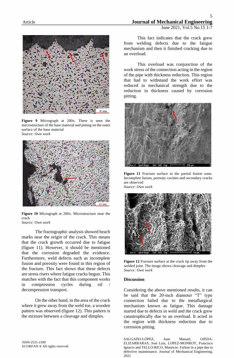
On the other hand, in the area of the crack
where it grew away from the weld toe, a wooden
pattern was observed (figure 12). This pattern is
the mixture between a cleavage and dimples.
This fact indicates that the crack grew
from welding defects due to the fatigue
mechanism and then it finished cracking due to
an overload.
This overload was conjunction of the
work stress of the connection acting in the region
of the pipe with thickness reduction. This region
that had to withstand the work effort was
reduced in mechanical strength due to the
reduction in thickness caused by corrosion
pitting.
Figure 11 Fracture surface in the partial fusion zone.
Incomplete fusion, porosity cavities and secondary cracks
are observed
Source: Own work
Figure 12 Fracture surface at the crack tip away from the
welded joint. The image shows cleavage and dimples
Source: Own work
Discussion
Considering the above mentioned results, it can
be said that the 20-inch diameter “T” type
connection failed due to the metallurgical
mechanism known as fatigue. This damage
started due to defects in weld and the crack grew
catastrophically due to an overload. It acted in
the region with thickness reduction due to
corrosion pitting.

6
Article Journal of Mechanical Engineering
June 2021, Vol.5 No.15 1-7
ISSN-2531-2189
ECORFAN ® All rights reserved.
SALGADO-LÓPEZ, Juan Manuel, OJEDA-
ELIZARRARAS, José Luis, LOPEZ-MONROY, Francisco
Ignacio and TELLO-RICO, Mauricio. Failure in a pipe due to
defective maintenance. Journal of Mechanical Engineering.
2021
One has to consider that the failure of this
component occurred despite preventive
maintenance, which consisted of visual
inspection and painting; then it can be deduced
that this was not a good maintenance practice.
Then, from the evidence previously
shown and discussed it is clear that at the
beginning the crack grew by fatigue due to
pressure/decompression cycles with origin in
weld defects such as incomplete penetration.
These types of welding defects are detected by
non-destructive tests, this is also valid for the
growth of the crack and the loss of thickness in
the HAZ. Besides, the results of non-destructive
testing can be used to feed a methodology of
mechanical integrity, with which it is possible to
give predictions of the growth of corrosion
damage and thus design strategies for the
replacement of said component.
Finally, combining the previously
discussed evidences with the defective practice
maintenance mentioned it can be deduced that
good preventive maintenance practices could
avoid the catastrophic failure of this component.
Acknowledgements
The authors wish to thank the CIDESI
Metallography and Failure Analysis Laboratory
for their support in carrying out this work.
Conclusions
The “T” type connection failed due to fatigue,
which started in defects in the HAZ and the
fracture grew catastrophically due to an overload
acting in the region with a decrease in thickness
due to corrosion pitting.
Weld defects act as crack initiators in
equipment that is subjected to loading /
unloading cycles and corrosion decreases the
thickness of the material, causing cracks to grow
in these places.
The evidence previously discussed
shows that good preventive maintenance
practices could prevent the catastrophic failure
of this type of components.
References
Babu, S. K., & Natarajan, S. (2008). Influence of
heat input on high temperature weldment
corrosion in submerged arc welded power plant
carbon steel. Materials & Design, 29(5), 1036-
1042.
Barsom, J. M., & Pellegrino Jr, J. V. (2002).
Failure analysis of welded steel moment-
resisting frame connections. Journal of materials
in civil engineering, 14(1), 24-34.
Bilmes, P. D., Llorente, C. L., Méndez, C. M., &
Gervasi, C. A. (2009). Microstructure, heat
treatment and pitting corrosion of 13CrNiMo
plate and weld metals. Corrosion Science, 51(4),
876-881.
Chaves, I. A., & Melchers, R. E. (2011). Pitting
corrosion in pipeline steel weld zones. Corrosion
Science, 53(12), 4026-4032.
Cheng, B., Ye, X., Cao, X., Mbako, D. D., &
Cao, Y. (2017). Experimental study on fatigue
failure of rib-to-deck welded connections in
orthotropic steel bridge decks. International
Journal of Fatigue, 103, 157-167.
Davis, J. R. (Ed.). (2006). Corrosion of
weldments. ASM international.
Lu, Y., Jing, H., Han, Y., & Xu, L. (2016). Effect
of welding heat input on the corrosion resistance
of carbon steel weld metal. Journal of Materials
Engineering and Performance, 25(2), 565-576.
Mashiri, F. R., Zhao, X. L., & Grundy, P. (2004).
Stress concentration factors and fatigue failure
of welded T-connections in circular hollow
sections under in-plane bending. International
Journal of Structural Stability and Dynamics,
4(03), 403-422.
Mellor, B. G., Rainey, R. C. T., & Kirk, N. E.
(1999). The static strength of end and T fillet
weld connections. Materials & design, 20(4),
193-205.
Mohammadi, F., Eliyan, F. F., & Alfantazi, A.
(2012). Corrosion of simulated weld HAZ of
API X-80 pipeline steel. Corrosion science, 63,
323-333.

7
Article Journal of Mechanical Engineering
June 2021, Vol.5 No.15 1-7
ISSN-2531-2189
ECORFAN ® All rights reserved.
SALGADO-LÓPEZ, Juan Manuel, OJEDA-
ELIZARRARAS, José Luis, LOPEZ-MONROY, Francisco
Ignacio and TELLO-RICO, Mauricio. Failure in a pipe due to
defective maintenance. Journal of Mechanical Engineering.
2021
Oosterhof, S. A., & Driver, R. G. (2011). Effects
of connection geometry on block shear failure of
welded lap plate connections. Journal of
Constructional Steel Research, 67(3), 525-532.
Peköz, T., & McGuire, W. (1979). Welding of
sheet steel.
Shirinzadeh-Dastgiri, M., Mohammadi, J.,
Behnamian, Y., Eghlimi, A., & Mostafaei, A.
(2015). Metallurgical investigations and
corrosion behavior of failed weld joint in AISI
1518 low carbon steel pipeline. Engineering
Failure Analysis, 53, 78-96.
Xing, S., Dong, P., & Threstha, A. (2016).
Analysis of fatigue failure mode transition in
load-carrying fillet-welded connections. Marine
Structures, 46, 102-126.

8
Article Journal of Mechanical Engineering
June 2021, Vol.5 No.15 8-15
Effect of induction heating on Vickers and Knoop hardness of 1045 steel heat treated
Efecto del calentamiento por inducción en la dureza Vickers y Knoop del acero 1045
tratado térmicamente
MARTÍNEZ-VÁZQUEZ, J. Merced†*, RODRÍGUEZ-ORTIZ, Gabriel, HORTELANO-CAPETILLO,
J. Gregorio and PÉREZ-PÉREZ, Arnulfo
Universidad Politécnica de Juventino Rosas, Metallurgical Engineering. Hidalgo 102, Community of Valencia, Santa Cruz
de Juventino Rosas, Gto. 38253. Mexico.
ID 1st Author: J. Merced, Martínez-Vázquez / ORC ID: 0000-0002-6230-3846, CVU CONACYT ID: 93450
ID 1st Co-author: Gabriel, Rodríguez-Ortiz / ORC ID: 0000-0002-3702-4853, CVU CONACYT ID: 48565
ID 2nd Co-author: J. Gregorio, Hortelano-Capetillo / ORC ID: 0000-0002-3702-4853, CVU CONACYT ID: 347496
ID 3rd Co-author: Arnulfo, Pérez-Pérez / ORC ID: 0000-0003-1267-2560, CVU CONACYT ID: 176434
DOI: 10.35429/JME.2021.15.5.8.15 Received January 15, 2021; Accepted June 30, 2021
Abstract
AISI 1045 steel is a steel of medium carbon, widely used
in machinery, the automotive industry, and the food
industry, among others. Therefore, to fulfill its purpose, it
is necessary to improve its mechanical resistance, wear
resistance and resistance to fatigue through different
surface heat treatments. Variables such as heating time and
hence speed affect the thickness of the hardened layer and
the microstructural characteristics of the area affected by
heat treatment. The inspection of the transformation of
phases during the treatment and the thickness of the
boundary layer is generated by determining the hardness
of the material, whose procedure is subject to the ASTM
E92-17 and E384-17standards, which establish the
methodology to be followed. Therefore, the objective of
this work is to quantify the effect of three heating times at
1123 K on the hardening of AISI 1045 steel and the
regularity of the hardened layer to ensure its functionality
as a component subjected to friction, in addition to
developing a table of equivalences between the Knoop
(HK), Vickers (HK) and Rockwell C (HRC) hardness
scales.
Induction, Microhardness, Quenching
Resumen
El acero AISI 1045, es un acero de medio carbono
ampliamente utilizado en maquinaria, industria
automotriz, industria alimenticia, entre otras. Por lo que
para cumplir con su propósito es necesario mejorar su
resistencia mecánica, resistencia al desgaste y la
resistencia a la fatiga mediante distintos tratamientos
térmicos superficiales. Las variables, como el tiempo de
calentamiento y, por ende, la velocidad afecta el espesor
de la capa endurecida y las características
microestructurales de la zona afectada por el tratamiento
térmico. La inspección de la transformación de fases
durante el tratamiento y el espesor de la capa limite se
genera mediante la determinación de la dureza del
material, cuyo procedimiento está supeditado al
seguimiento de las normas ASTM E92-17 y E384-17, las
cuales establecen la metodología a seguir. Por lo que el
objetivo del presente trabajo es cuantificar el efecto de tres
tiempos de calentamiento a 1123 K sobre el
endurecimiento del acero AISI 1045 y la regularidad de la
capa endurecida para asegurar su funcionalidad como
componente sometido a fricción además de elaborar una
Table de equivalencias entre las escalas de dureza Knoop
(HK), Vickers (HK) y Rockwell C (HRC).
Inducción, Microdureza, Temple
Citation: MARTÍNEZ-VÁZQUEZ, J. Merced, RODRÍGUEZ-ORTIZ, Gabriel, HORTELANO-CAPETILLO, J. Gregorio
and PÉREZ-PÉREZ, Arnulfo. Effect of induction heating on Vickers and Knoop hardness of 1045 steel heat treated. Journal
of Mechanical Engineering. 2021. 5-15:8-15.
* Correspondence to the Author (Email: [email protected])
† Researcher contributing as first author.
© ECORFAN-Spain www.ecorfan.org/spain

9
Article Journal of Mechanical Engineering
June 2021, Vol.5 No.15 8-15
ISSN-2531-2189
ECORFAN ® All rights reserved.
MARTÍNEZ-VÁZQUEZ, J. Merced, RODRÍGUEZ-ORTIZ,
Gabriel, HORTELANO-CAPETILLO, J. Gregorio and PÉREZ-
PÉREZ, Arnulfo. Effect of induction heating on Vickers and
Knoop hardness of 1045 steel heat treated. Journal of Mechanical
Engineering. 2021
Introduction
The mechanical strength, wear resistance and
fatigue resistance of medium carbon steels, such
as SAE1045, can be improved by different
surface heat treatments such as flame, laser and
induction heating. Compared with other surface
hardening methods, induction hardening shows
favorable characteristics such as controlled
heating depth, rapid heating, energy saving, and
good reproducibility. The typical procedure for
induction heating involves heating the
component to the austenitizing temperature
range and then rapidly cooling it until it is below
the martensitic temperature (Ms). Conventional
methods to determine the hardening of steels
involve heating the samples in an oven for
several minutes at an austenitizing temperature
that depends on the carbon content of the steel
[1]; according to ASTM A255, the process
involves Jominy heating and tempering for the
samples for 30 minutes. For steels with carbon
contents above 0.37% by weight, the standard
indicates an austenitizing temperature prior to
hardening. The standard assumes that the steels
will produce an ASTM 7 grain size. Some
studies have shown an inverse relationship
between austenitic grain size and hardening [2-
4], which consider austenitic grain sizes in the 4-
8 range.
With induction heating, the heating ratios
are higher and the austenitizing times are much
shorter leading to the possibility of incomplete
dissolution of carbides in the austenite. Clarke et
al. [5] studied the transformation kinetics of
austenite and carbide dissolution in 5150 grade
steels, finding that for the quenched and
tempered structure all carbides were dissolved at
heating rates of up to 900 ° C / s.
The time-temperature cycles that can be
achieved in induction surface heating vary from
one hardened part to another and depends on the
initial size of the cross section and the required
depth [6]. Austenitizing times can be less than 2
s and greater than 10 s depending on the part
treated and the parameters of the equipment.
The main objective of this work is to
examine the effects of three heating times at
austenitic temperatures of 1123 K on the
hardening of 1045 steel and the regularity of the
hardened layer to ensure their functionality as
components subjected to friction, for which they
will be carried out.
Vickers and Knoop hardness tests to
compare the degree of hardness at the beginning
and end of the treatment; Furthermore, it is
important to mention that there is controversy in
the margin of error between microhardness
scales such as the Vickers (HV) and the Knoop
(HK), which can generate errors when
converting to the Rockwell C (HRC) scale. For
this reason, the methodology will be
implemented to carry out the conversion
between scales correctly and avoiding said error
in the block & wing part manufactured by
forging, which carries an induction hardening
heat treatment, whose minimum hardness limit
is 59 HRC and a maximum of 63 HRC;
Likewise, the induction heating time on the
thickness of the hardened layer will be correlated
with the hardness.
Methodology to be developed
The research was carried out on SAE1045 steel
pieces shown in Figure 1, due to their
application, said samples must have a hardened
outer layer in order to increase their resistance to
wear, so they were subjected to a heat treatment
of induction hardening. in a GH Induction
equipment model 2X100MS150 / S. The process
consists of austenitizing the material at 1123 K;
For this, the equipment operating conditions
were 37 kW of power at a frequency of 15 KHz,
and later the pieces were cooled in a 5% polymer
solution at 28 ° C, the austenitizing times were
2.0, 2.2 and 2.4 s and a total cycle of 39 s / piece.
Once the pieces were tempered, they were cut
transversely (Figure 1b), the evaluation points
shown in the Figure. 1c correspond to the critical
areas of the piece, in which hardness values
greater than 50 HRC are required. The pieces
were cut in a Leco MX205M metallographic
cutter, with cooling during cutting to avoid
heating and possible microstructural
transformation of the surface.
Figure 1 Induction Hardened 1045 Steel Automotive Part
Source: Own, Solidworks
10
Article Journal of Mechanical Engineering
June 2021, Vol.5 No.15 8-15
ISSN-2531-2189
ECORFAN ® All rights reserved.
MARTÍNEZ-VÁZQUEZ, J. Merced, RODRÍGUEZ-ORTIZ,
Gabriel, HORTELANO-CAPETILLO, J. Gregorio and PÉREZ-
PÉREZ, Arnulfo. Effect of induction heating on Vickers and
Knoop hardness of 1045 steel heat treated. Journal of Mechanical
Engineering. 2021
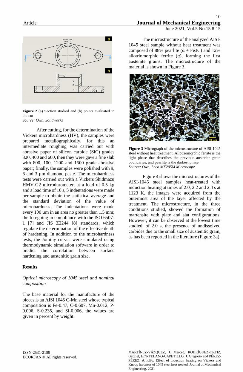
Figure 2 (a) Section studied and (b) points evaluated in
the cut
Source: Own, Solidworks
After cutting, for the determination of the
Vickers microhardness (HV), the samples were
prepared metallographically, for this an
intermediate roughing was carried out with
abrasive paper of silicon carbide (SiC) grades
320, 400 and 600, then they were gave a fine slab
with 800, 100, 1200 and 1500 grade abrasive
paper; finally, the samples were polished with 9,
6 and 3 µm diamond paste. The microhardness
tests were carried out with a Vickers Shidmazu
HMV-G2 microdurometer, at a load of 0.5 kg
and a load time of 10 s, 5 indentations were made
per sample to obtain the statistical average and
the standard deviation of the value of
microhardness. The indentations were made
every 100 µm in an area no greater than 1.5 mm;
the foregoing in compliance with the ISO 6507-
1 [7] and JIS Z2244 [8] standards, which
regulate the determination of the effective depth
of hardening. In addition to the microhardness
tests, the Jominy curves were simulated using
thermodynamic simulation software in order to
predict the correlation between surface
hardening and austenitic grain size.
Results
Optical microscopy of 1045 steel and nominal
composition
The base material for the manufacture of the
pieces is an AISI 1045 C-Mn steel whose typical
composition is Fe-0.47, C-0.607, Mn-0.012, P-
0.006, S-0.235, and Si-0.006, the values are
given in percent by weight.
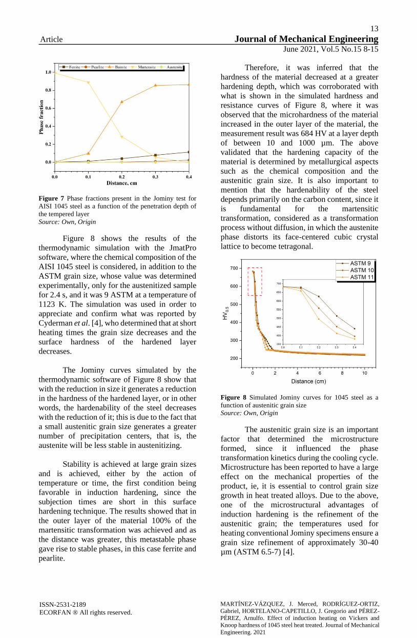
The microstructure of the analyzed AISI-
1045 steel sample without heat treatment was
composed of 88% pearlite (α + Fe3C) and 12%
allotriomorphic ferrite (α), forming the first
austenite grains. The microstructure of the
material is shown in Figure 3.
Figure 3 Micrograph of the microstructure of AISI 1045
steel without heat treatment. Allotriomorphic ferrite is the
light phase that describes the previous austenite grain
boundaries, and pearlite is the darkest phase
Source: Own, Leco MX205M Microscope
Figure 4 shows the microstructures of the
AISI-1045 steel samples heat-treated with
induction heating at times of 2.0, 2.2 and 2.4 s at
1123 K, the images were acquired from the
outermost area of the layer affected by the
treatment. The microstructure, in the three
conditions studied, showed the formation of
martensite with plate and slat configurations.
However, it can be observed at the lowest time
studied, of 2.0 s, the presence of undissolved
carbides due to the small size of austenitic grain,
as has been reported in the literature (Figure 3a).

11
Article Journal of Mechanical Engineering
June 2021, Vol.5 No.15 8-15
ISSN-2531-2189
ECORFAN ® All rights reserved.
MARTÍNEZ-VÁZQUEZ, J. Merced, RODRÍGUEZ-ORTIZ,
Gabriel, HORTELANO-CAPETILLO, J. Gregorio and PÉREZ-
PÉREZ, Arnulfo. Effect of induction heating on Vickers and
Knoop hardness of 1045 steel heat treated. Journal of Mechanical
Engineering. 2021
Figure 4 Optical micrographs of AISI-4045 steel samples
heated by induction at a temperature of 1123 K for (a) 2.0
s, (b) 2.2 s and (c) 2.4 s and tempered in polymeric solution
Source: Own, Leco MX205M Microscope
Microhardness of the surface of hardened 1045
steel
The Vickers microhardness of the surface layer
of 1045 steel subjected to induction hardening at
1123 K was found in a range of values between
709 to 744 (± 45) HV for points A, B, C and D
shown in Figure 5. In general, the average
microhardness values are within specification
for 1045 steel treated under these conditions.
However, it is observed that at longer
induction times there is an increase in hardness
values, which is related to the fact that at shorter
austenitic times the austenitic grain size tends to
decrease due to the inverse relationship
proportional to the hardness of the hardened
parts. It was confirmed that short austenitizing
periods generate a decrease in the hardness
values for this type of steel, AISI-1045; in
addition, as a function of the decrease in the
austenitic grain size and the time for the
dissolution of carbides during the transformation
from pearlitic phase (α + Fe3C) to austenitic (γ).
Figure 5 (a) Vickers microhardness measurements at the
critical points of the automotive part indicated in Figure 1,
and (b) depth of the thickness of the hardened layer in the
indication quenching of AISI 1045 steel
Source: Own, Origin
HK, HV and HRC hardness equivalences
It is important to note the difficulty of converting
between hardness scales, in this regard Callister
[9] emphasizes that due to the fact that hardness
is not a well-defined property of the material and
because of the experimental differences of each
technique, a general method of converting
hardnesses from one scale to another.

12
Article Journal of Mechanical Engineering
June 2021, Vol.5 No.15 8-15
ISSN-2531-2189
ECORFAN ® All rights reserved.
MARTÍNEZ-VÁZQUEZ, J. Merced, RODRÍGUEZ-ORTIZ,
Gabriel, HORTELANO-CAPETILLO, J. Gregorio and PÉREZ-
PÉREZ, Arnulfo. Effect of induction heating on Vickers and
Knoop hardness of 1045 steel heat treated. Journal of Mechanical
Engineering. 2021
The conversion data have been
determined experimentally and found to be
dependent on the type of material and the
characteristics. Likewise, for the conversion
between scales, data have been found for steels
whose data are illustrated in Figure 6. The
equivalence between one scale and another is
calculated roughly by drawing a horizontal line
that crosses both scales and, if necessary,
performs a correlation for a more exact value of
the conversion between scales.
Figure 6 Schematic representation of the different
hardness scales
Source: Internet
For this reason, it is necessary to
establish equivalent values between the HK, HV
and HRC hardness scales for AISI 1045 steel
heat treated with induction heating, which is
shown in Table 1. The results corroborate what
was mentioned by Ghorbal et al. [10] where they
mention that the HV / HK hardness ratio has a
variation between 1.05 and 1.15. Therefore, the
comparison between hardness scales should be
taken with reserve; Therefore, the conversion
between hardness scales is recommended only in
the event that it is not possible to measure this
property directly on the specified scale;
Similarly, both Callister and Ghorbal et al.
indicate that the Knoop hardness scale is more
appropriate for brittle materials, so testing
materials with greater ductility can generate a
deviation in the hardness values determined by
said scale.
Knoop
hardness
(HK)
Vickers
hardness
(HV)
Rockwell C
hardness
(HRC)
311 303 30
427 416 42
450 438 44
504 491 48
548 534 50
556 542 51
604 589 54
620 604 57
650 633 58
685 668 59
700 682 59
702 684 59
705 687 59
713 695 59
715 697 59
721 736 60
814 794 64
848 827 65
Table 1 Equivalences between the HK, HV and HRC
hardness scales for AISI 1045 steel
Source: Own, Word
Determination of the thickness of the hardened
layer
Figure 7 shows the thicknesses of the hardened
layer in the four areas considered critical in the
automotive part, since the surface at these points
will be subjected to friction, the microhardness
corresponds to large values. In the results
obtained, a slight variation was observed in the
measurements of the same points at the three
time conditions. But, in addition, a considerable
increase in the thickness of the layer was
measured at points C and D. This variation was
associated, not with heating by electromagnetic
induction; which depends on the intensity of the
magnetic field, the frequency of the working
current, the separation between the piece and the
inductor coil, as well as the magnetic
characteristics of the material to be treated; if not
to the geometric shape of the piece. In addition
to the above, the austenitizing time is also a
variable that influences the depth of penetration
of the temper and showed a clear trend
specifically at points C and D where it was
observed that at austenitizing times of 2.0 and
2.2 s the thickness the layer was less;
Cunningham et al. [11] indicate that the
variations in the depth of the layer are due, in the
case of induction by a single shot, to the
exposure time of the steel above the critical
temperature A3, for which it was concluded that
the geometry of the piece mainly influenced the
temperature reached in the different areas of the
piece, and that areas A and B were exposed to a
shorter time to induction heating compared to
points C and D.
13
Article Journal of Mechanical Engineering
June 2021, Vol.5 No.15 8-15
ISSN-2531-2189
ECORFAN ® All rights reserved.
MARTÍNEZ-VÁZQUEZ, J. Merced, RODRÍGUEZ-ORTIZ,
Gabriel, HORTELANO-CAPETILLO, J. Gregorio and PÉREZ-
PÉREZ, Arnulfo. Effect of induction heating on Vickers and
Knoop hardness of 1045 steel heat treated. Journal of Mechanical
Engineering. 2021
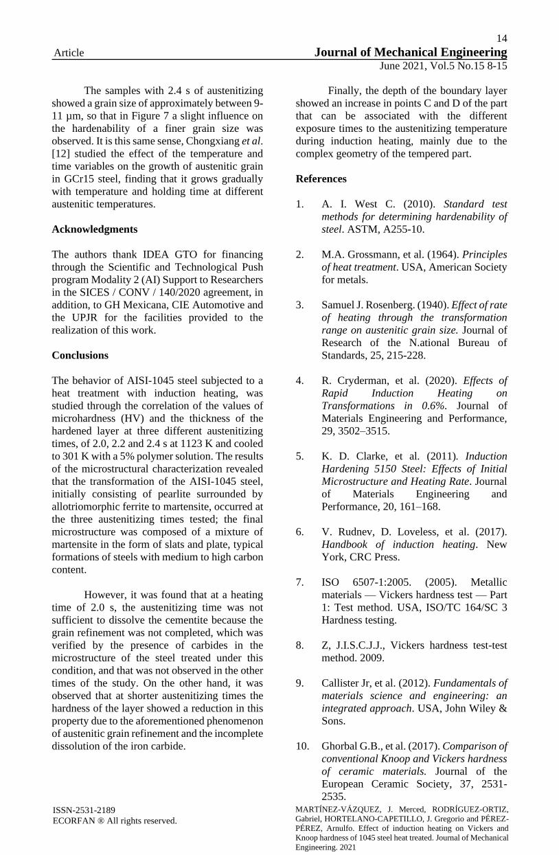
Figure 7 Phase fractions present in the Jominy test for
AISI 1045 steel as a function of the penetration depth of
the tempered layer
Source: Own, Origin
Figure 8 shows the results of the
thermodynamic simulation with the JmatPro
software, where the chemical composition of the
AISI 1045 steel is considered, in addition to the
ASTM grain size, whose value was determined
experimentally, only for the austenitized sample
for 2.4 s, and it was 9 ASTM at a temperature of
1123 K. The simulation was used in order to
appreciate and confirm what was reported by
Cyderman et al. [4], who determined that at short
heating times the grain size decreases and the
surface hardness of the hardened layer
decreases.
The Jominy curves simulated by the
thermodynamic software of Figure 8 show that
with the reduction in size it generates a reduction
in the hardness of the hardened layer, or in other
words, the hardenability of the steel decreases
with the reduction of it; this is due to the fact that
a small austenitic grain size generates a greater
number of precipitation centers, that is, the
austenite will be less stable in austenitizing.
Stability is achieved at large grain sizes
and is achieved, either by the action of
temperature or time, the first condition being
favorable in induction hardening, since the
subjection times are short in this surface
hardening technique. The results showed that in
the outer layer of the material 100% of the
martensitic transformation was achieved and as
the distance was greater, this metastable phase
gave rise to stable phases, in this case ferrite and
pearlite.
Therefore, it was inferred that the
hardness of the material decreased at a greater
hardening depth, which was corroborated with
what is shown in the simulated hardness and
resistance curves of Figure 8, where it was
observed that the microhardness of the material
increased in the outer layer of the material, the
measurement result was 684 HV at a layer depth
of between 10 and 1000 µm. The above
validated that the hardening capacity of the
material is determined by metallurgical aspects
such as the chemical composition and the
austenitic grain size. It is also important to
mention that the hardenability of the steel
depends primarily on the carbon content, since it
is fundamental for the martensitic
transformation, considered as a transformation
process without diffusion, in which the austenite
phase distorts its face-centered cubic crystal
lattice to become tetragonal.
Figure 8 Simulated Jominy curves for 1045 steel as a
function of austenitic grain size
Source: Own, Origin
The austenitic grain size is an important
factor that determined the microstructure
formed, since it influenced the phase
transformation kinetics during the cooling cycle.
Microstructure has been reported to have a large
effect on the mechanical properties of the
product, ie, it is essential to control grain size
growth in heat treated alloys. Due to the above,
one of the microstructural advantages of
induction hardening is the refinement of the
austenitic grain; the temperatures used for
heating conventional Jominy specimens ensure a
grain size refinement of approximately 30-40
µm (ASTM 6.5-7) [4].
14
Article Journal of Mechanical Engineering
June 2021, Vol.5 No.15 8-15
ISSN-2531-2189
ECORFAN ® All rights reserved.
MARTÍNEZ-VÁZQUEZ, J. Merced, RODRÍGUEZ-ORTIZ,
Gabriel, HORTELANO-CAPETILLO, J. Gregorio and PÉREZ-
PÉREZ, Arnulfo. Effect of induction heating on Vickers and
Knoop hardness of 1045 steel heat treated. Journal of Mechanical
Engineering. 2021
The samples with 2.4 s of austenitizing
showed a grain size of approximately between 9-
11 µm, so that in Figure 7 a slight influence on
the hardenability of a finer grain size was
observed. It is this same sense, Chongxiang et al.
[12] studied the effect of the temperature and
time variables on the growth of austenitic grain
in GCr15 steel, finding that it grows gradually
with temperature and holding time at different
austenitic temperatures.
Acknowledgments
The authors thank IDEA GTO for financing
through the Scientific and Technological Push
program Modality 2 (AI) Support to Researchers
in the SICES / CONV / 140/2020 agreement, in
addition, to GH Mexicana, CIE Automotive and
the UPJR for the facilities provided to the
realization of this work.
Conclusions
The behavior of AISI-1045 steel subjected to a
heat treatment with induction heating, was
studied through the correlation of the values of
microhardness (HV) and the thickness of the
hardened layer at three different austenitizing
times, of 2.0, 2.2 and 2.4 s at 1123 K and cooled
to 301 K with a 5% polymer solution. The results
of the microstructural characterization revealed
that the transformation of the AISI-1045 steel,
initially consisting of pearlite surrounded by
allotriomorphic ferrite to martensite, occurred at
the three austenitizing times tested; the final
microstructure was composed of a mixture of
martensite in the form of slats and plate, typical
formations of steels with medium to high carbon
content.
However, it was found that at a heating
time of 2.0 s, the austenitizing time was not
sufficient to dissolve the cementite because the
grain refinement was not completed, which was
verified by the presence of carbides in the
microstructure of the steel treated under this
condition, and that was not observed in the other
times of the study. On the other hand, it was
observed that at shorter austenitizing times the
hardness of the layer showed a reduction in this
property due to the aforementioned phenomenon
of austenitic grain refinement and the incomplete
dissolution of the iron carbide.
Finally, the depth of the boundary layer
showed an increase in points C and D of the part
that can be associated with the different
exposure times to the austenitizing temperature
during induction heating, mainly due to the
complex geometry of the tempered part.
References
1. A. I. West C. (2010). Standard test
methods for determining hardenability of
steel. ASTM, A255-10.
2. M.A. Grossmann, et al. (1964). Principles
of heat treatment. USA, American Society
for metals.
3. Samuel J. Rosenberg. (1940). Effect of rate
of heating through the transformation
range on austenitic grain size. Journal of
Research of the N.ational Bureau of
Standards, 25, 215-228.
4. R. Cryderman, et al. (2020). Effects of
Rapid Induction Heating on
Transformations in 0.6%. Journal of
Materials Engineering and Performance,
29, 3502–3515.
5. K. D. Clarke, et al. (2011). Induction
Hardening 5150 Steel: Effects of Initial
Microstructure and Heating Rate. Journal
of Materials Engineering and
Performance, 20, 161–168.
6. V. Rudnev, D. Loveless, et al. (2017).
Handbook of induction heating. New
York, CRC Press.
7. ISO 6507-1:2005. (2005). Metallic
materials — Vickers hardness test — Part
1: Test method. USA, ISO/TC 164/SC 3
Hardness testing.
8. Z, J.I.S.C.J.J., Vickers hardness test-test
method. 2009.
9. Callister Jr, et al. (2012). Fundamentals of
materials science and engineering: an
integrated approach. USA, John Wiley &
Sons.
10. Ghorbal G.B., et al. (2017). Comparison of
conventional Knoop and Vickers hardness
of ceramic materials. Journal of the
European Ceramic Society, 37, 2531-
2535.

15
Article Journal of Mechanical Engineering
June 2021, Vol.5 No.15 8-15
ISSN-2531-2189
ECORFAN ® All rights reserved.
MARTÍNEZ-VÁZQUEZ, J. Merced, RODRÍGUEZ-ORTIZ,
Gabriel, HORTELANO-CAPETILLO, J. Gregorio and PÉREZ-
PÉREZ, Arnulfo. Effect of induction heating on Vickers and
Knoop hardness of 1045 steel heat treated. Journal of Mechanical
Engineering. 2021
11. J. Cunningham, et al. (1999). Effects of
induction hardening and prior cold work
on a microalloyed medium carbon steel.
Journal of Materials Engineering and
Performance, 8, 401-408.
12. C. Yue, et al. (2010). Kinetic Analysis of
the Austenite Grain Growth in GCr15
Steel. Journal of Materials Engineering
and Performance, 19, 112-115.

16
Article Journal of Mechanical Engineering
June 2021 Vol.5 No.15 16-23
The numerical characterization of the gas turbine blade with static stress analysis
applying finite element method
La caracterización numérica del álabe de la turbina de gas con el análisis de
esfuerzos aplicando el método de los elementos finitos
VILLAGRÁN-VILLEGAS, Luz Yazmín†*´,´´, HERNÁNDEZ-GÓMEZ, Luis Héctor´, MARTÍNEZ-
CRUZ, Miguel Ángel´ and ROJAS-RAMÍREZ, Jorge Armando´
´Instituto Politécnico Nacional, School of Mechanical and Electrical Engineering, Graduate Studies and Research Section,
Unidad Profesional Adolfo López Mateos “Zacatenco”, Building 5 Floor, Lindavista, Zip. 07738, Mexico City.
´´Universidad de Veracruz, Faculty of Electrical Mechanical Engineering, Venustiano Carranza St. no number, Revolution,
Ave. Zip. 93390, Poza Rica; Veracruz, Mexico.
ID 1st Author: Luz Yazmín, Villagrán-Villegas / ORC ID: 0000-0003-3860-2923, CVU CONACYT ID: 96365
ID 1st Co-author: Luis Héctor, Hernández-Gómez / ORC ID: 0000-0003-2573-9672, CVU CONACYT ID: 5107
ID 2nd Co-author: Miguel Ángel, Martínez-Cruz / ORC ID: 0000-0002-4431-9262, CVU CONACYT ID: 208501
ID 3rd Co-author: Jorge Armando, Rojas-Ramírez / ORC ID: 0000-0002-0779-1242, CVU CONACYT ID: 120643
DOI: 10.35429/JME.2021.15.5.16.23 Received January 20, 2021; Accepted June 30, 2021
Abstract
The lifespan of a blade is reduced due to the operating
environment and high mechanical and thermal stresses, where
typically two or more factors act simultaneously. The most
common degradation mechanisms are: contamination, blade
pitting, opening of the gap between rotor and stator, and erosion
of the leading and trailing edge of the gas turbine blade.
Degradation is mainly caused by scale, corrosion, hot corrosion,
oxidation, erosion, abrasion, particle melting and mechanical
degradation. The research that has been carried out in turbine
blades are based on visual observations, optical microscopy,
scanning electron microscopy, fractography analysis,
metallography, structural analysis and hardness tests. This work
proposes a methodology to carry out numerical analysis of the
nozzle blade of a gas turbine. The investigation will perform a
scan to obtain a 3D model using reverse engineering. Reverse
engineering technology can be used to assist in the manufacture
of replacement parts when the original parts inventory is
depleted. The numerical analysis with the point mesh of the
nozzle blade and static stress modeling in ANSYS were made.
The main objective of this work is to know the maximum and
minimum values at which a turbine blade is operating and located
the area of the gas turbine blade is more prone to failure due to
different wear mechanisms and to the stresses that the blades are
subjected during the operation of the gas turbine.
Blades, Gas turbine, ANSYS, Static modeling
Resumen
La vida útil de un álabe se reduce debido al entorno de
funcionamiento y a las elevadas tensiones mecánicas y térmicas,
donde suelen actuar dos o más factores simultáneamente. Los
mecanismos de degradación más comunes son: la
contaminación, las picaduras en los álabes, la apertura del claro
entre el rotor y el estator, y la erosión del borde de ataque y de
salida del álabe de turbina de la turbina de gas. La degradación
se debe principalmente a las sales, la corrosión, la corrosión en
caliente, la oxidación, la erosión, la abrasión, la fusión de
partículas y la degradación mecánica. Las investigaciones que se
han llevado a cabo en los álabes de turbina se basan en
observaciones visuales, microscopía óptica, microscopía
electrónica de barrido, análisis de fractografía, metalografía,
análisis estructural y ensayos de dureza. Este trabajo propone una
metodología para realizar el análisis numérico del álabe de la
tobera de una turbina de gas. La investigación realizará un
escaneo para obtener un modelo 3D mediante ingeniería inversa.
La tecnología de ingeniería inversa puede utilizarse para ayudar
a la fabricación de piezas de repuesto cuando se agota el
inventario de piezas originales. Se realizó el análisis numérico
con la malla de puntos del álabe de la tobera y el modelado de la
tensión estática en ANSYS. El objetivo principal de este trabajo
es conocer los valores máximos y mínimos a los que opera un
álabe de turbina y localizar la zona del álabe de turbina de gas
más propensa a fallar debido a los diferentes mecanismos de
desgaste y a las tensiones a las que están sometidos los álabes
durante el funcionamiento de la turbina de gas.
Álabes, Turbina de gas, ANSYS, Modelado estático
Citation: VILLAGRÁN-VILLEGAS, Luz Yazmín, HERNÁNDEZ-GÓMEZ, Luis Héctor, MARTÍNEZ-CRUZ, Miguel
Ángel and ROJAS-RAMÍREZ, Jorge Armando. The numerical characterization of the gas turbine blade with static stress
analysis applying finite element method. Journal of Mechanical Engineering. 2021. 5-15:16-23.
* Correspondence to the Author (Email: [email protected])
† Researcher contributing as first author.
© ECORFAN-Spain www.ecorfan.org/spain

17
Article Journal of Mechanical Engineering
June 2021 Vol.5 No.15 16-23
VILLAGRÁN-VILLEGAS, Luz Yazmín, HERNÁNDEZ-GÓMEZ, Luis Héctor, MARTÍNEZ-CRUZ, Miguel Ángel and ROJAS-RAMÍREZ,
Jorge Armando. The numerical characterization of the gas turbine blade
with static stress analysis applying finite element method. Journal of Mechanical Engineering. 2021
ISSN-2531-2189
ECORFAN® All rights reserved.
Introduction
Gas turbines play an important role in fields such
as aviation and power generation. The main
function of blades in gas turbines is to use or
extract energy from a fluid stream to change the
speed and pressure of the fluid flow. In the
absence of design data, the reverse engineering
process can be considered an important tool for
modeling. The reverse engineering process
involves detecting the geometry of the blade,
creating a geometric model from the detected
data, and passing this model to an appropriate
CAD / CAM system for fabrication. (Gopinat,
2014)
Turbine blades are subject to complex
conditions of temperature, stress, oxidation and
hot corrosion (Giampaolo, 2016). The extreme
service environment often results in premature
failure of the turbine blades, when the turbine
inlet gas temperature exceeds the service
temperature limit, the turbine blades are
subjected to overheating; this could lead to rapid
microstructural degradation and even brittle
fracture. (Xiaotong, 2016) Gas turbine
efficiency in oil & gas applications has improved
more than 40%, currently, leading OEM
manufacturers and researchers are working on
gas turbine optimization design to constantly
improve efficiency and reduce cost of gas
turbines maintenance (Jun Su, 2019).
To further increase the thermodynamic
efficiency of advanced gas turbines, higher gas
inlet temperatures are required. An increase in
the gas inlet temperature causes an increase in
thermal stresses throughout the engine,
especially in the turbine blades and therefore
drastically reduces its useful life. Experimental
research of turbine blade materials under real
operating conditions are very demanding Figure
1 shows seventh stage compressor blade;
thermal and mechanical analysis must be
performed based on the finite element method
(O Kaussa, 2019).
Figure 1 Rotor blades of axial compressor.
Note. Adapted from Turbine Compressor Disc, Villagrán-
Villegas Luz Yazmin, 2017
Turbine blades are subject to stresses
because of high temperatures, high centrifugal
forces, and thermal cycling; these stresses
accelerate the growth of defects that may be
present in the material; this is the base of the
demand for materials that can withstand high
temperatures without losing their resistance to
centrifugal forces, vibrations, thermal cycles,
oxidation or corrosion.
The improvement in creep and rupture
strength properties was constant from the late
1940s to the early 1970s, since 1960, the reliance
on sophisticated cooling techniques for turbine
blades and nozzles has increased. The increase
in the turbine inlet temperature was possible
thanks to new air-cooling schemes and the
incorporation of complex ceramic core bodies
used in the production of hollow and cast parts,
Figure 2 shows two elaborated compressor
blades of a chromium superalloy and a power
turbine blade with red coloration due to the
exposure of the ceramic coating to high
temperatures in the first power stage.
Figure 2 Two rotor blades of an axial compressor and a
power turbine blade
Note. Adapted from Turbine Compressor Disc, Villagrán-
Villegas Luz Yazmin, 2017
Blade (sample 01) Blade (sample 02)
Blade and power disk C40
Identification of samples
18
Article Journal of Mechanical Engineering
June 2021 Vol.5 No.15 16-23
VILLAGRÁN-VILLEGAS, Luz Yazmín, HERNÁNDEZ-GÓMEZ, Luis Héctor, MARTÍNEZ-CRUZ, Miguel Ángel and ROJAS-RAMÍREZ,
Jorge Armando. The numerical characterization of the gas turbine blade
with static stress analysis applying finite element method. Journal of Mechanical Engineering. 2021
ISSN-2531-2189
ECORFAN® All rights reserved.
Protective coatings used on turbine
blades were developed to serve as physical
barriers between the aggressive environment and
the substrate. (Jaroslav,2010)
In addition, Thermal Barrier Coatings are
used as a cover material, delay creep degradation
and reduce the severity of thermal gradients; no
coating has been found that can fully survive the
aggressive turbine environment. The durability
of thermal barrier coatings is limited by
degradation of adhesion by environmental
interactions rather than mechanical stress.
(Miller, 2010)
The most serious degradation modes are
as follows: oxidation of high temperature, hot
corrosion, damage due to thermal and
thermomechanical fatigue, mechanical damage
from erosion and creep degradation during
overheating.
Solar Turbines' Centauro 40 gas turbine
operates in the active Bellota-Jujo complex
located in the city of Comalcalco, 30 km from
Villahermosa, Tabasco, the fields are in the
municipalities of Comalcalco, Paraíso, Jalpa de
Méndez, Nacajuca, Cunduacán, Cárdenas and
Huimanguillo.
The area represents the greatest oil
wealth in southeastern Mexico, due to the quality
of its hydrocarbon and because of the giant fields
that have been discovered there. (Córdova,
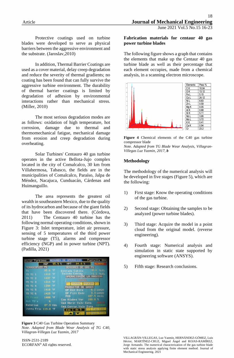
2011) The Centauro 40 turbine has the
following normal operating conditions, shown in
Figure 3: Inlet temperature, inlet air pressure,
sensing of 5 temperatures of the third power
turbine stage (T5), alarms and compressor
efficiency (NGP) and in power turbine (NPT).
(Padilla, 2021)
Figure 3 C40 Gas Turbine Operation Summary
Note. Adapted from Blade Wear Analysis of TG C40,
Villagran-Villegas Luz Yazmin, 2017
Fabrication materials for centaur 40 gas
power turbine blades
The following figure shows a graph that contains
the elements that make up the Centaur 40 gas
turbine blade as well as their percentage that
each element occupies, made from a chemical
analysis, in a scanning electron microscope.
Figure 4 Chemical elements of the C40 gas turbine
compressor blade
Note. Adapted from TG Blade Wear Analysis, Villagran-
Villegas Luz Yazmin, 2017, b
Methodology
The methodology of the numerical analysis will
be developed in five stages (Figure 5), which are
the following:
1) First stage: Know the operating conditions
of the gas turbine.
2) Second stage: Obtaining the samples to be
analyzed (power turbine blades).
3) Third stage: Acquire the model in a point
cloud from the original model. (reverse
engineering).
4) Fourth stage: Numerical analysis and
simulation in static state supported by
engineering software (ANSYS).
5) Fifth stage: Research conclusions.

19
Article Journal of Mechanical Engineering
June 2021 Vol.5 No.15 16-23
VILLAGRÁN-VILLEGAS, Luz Yazmín, HERNÁNDEZ-GÓMEZ, Luis Héctor, MARTÍNEZ-CRUZ, Miguel Ángel and ROJAS-RAMÍREZ,
Jorge Armando. The numerical characterization of the gas turbine blade
with static stress analysis applying finite element method. Journal of Mechanical Engineering. 2021
ISSN-2531-2189
ECORFAN® All rights reserved.
Figure 5 Methodology of numerical analysis.
Note. Adapted from Study on the damage caused by wear
in the blades of a gas turbine compressor (Villagrán-
Villegas Luz Yazmin, 2017)
A. Determination of operating conditions.
Figure 6 Blade sample after its operation in the Northeast
Region, in the Cantarell asset, Nohoch Alfa Oil Platform
The sample in Figure 6 was in operation
in the Northeast Region, in the Cantarell asset,
Nohoch Alfa Oil Platform. The air enters the gas
turbine at room temperature of 15 ° C (at the sea
level) and increases its temperature when
compressed, reaching 1,800 ° C, after passing
through the combustion chambers. The Centaur
40 turbine is made up of 11 stages. In the axial
type of compressor, the pressure ratio is 10.3: 1
and the air flow input is 18.7 kg / sec (41.3 lb /
sec). The variable vanes begin to open when the
Pcd (pressure compressor discharge) reaches
approximately 32 psi (gauge) and fully open
when the Pcd reaches approximately 76.5 psi
(gauge).
Table 1 shows the information provided
by the manufacturer and Table 2 the sample data.
Condition Value
Compressor discharge pressure
(PCD)
107.5 psi
(lb/in2)
Average temperature of
thermocouple T5
1400 ºF
Gas Producer Speed NGP. 95.9 %
Power Turbine Speed) NPT. 84.8 %
Table 1 Turbine C40 data
Sample Material Stage Weight
Blade Superalloy 1 42.37 g
Table 2 Power turbine blade data
B. Obtaining samples.
The ATOS ScanBox (Figure 7) is a 3D optical
measurement equipment that was developed by
GOM for efficient quality control in the
production and manufacturing process; it is an
optical 3D coordinate measuring system.
Figure 7 ATOS ScanBox
ATOS sensors provide full-field 3D
coordinates for each individual measurement of
up to 16 million independent measurement
points and are captured within 1 to 2 seconds.
The measurement data is characterized by a very
detailed reproduction and therefore also allows
the measurement of very small components
(38mm).
ATOS captures the entire surface
geometry of an object accurately in a dense point
cloud or polygon mesh; that enable detailed,
high-resolution scans, rapid data collection,
advanced inspection functionality, and
comprehensive dimensional analysis. GOM
Inspect is software for 3D measurement data
analysis. GOM software is used in product
development, quality control, and production.
The generated model is a polygonal mesh that
can be smoothed, thinned and refined, likewise,
from the initial model, the holes in the mesh can
be filled, allowing curvatures to be extracted.
The mesh is processed using algorithms based
on curvatures and tolerances. The software
provides the user with a view prior to each
processing step and generates the calculation of
an average mesh.
1 First stage Second stage Third stage
Fourth stage Fifth stage

20
Article Journal of Mechanical Engineering
June 2021 Vol.5 No.15 16-23
VILLAGRÁN-VILLEGAS, Luz Yazmín, HERNÁNDEZ-GÓMEZ, Luis Héctor, MARTÍNEZ-CRUZ, Miguel Ángel and ROJAS-RAMÍREZ,
Jorge Armando. The numerical characterization of the gas turbine blade
with static stress analysis applying finite element method. Journal of Mechanical Engineering. 2021
ISSN-2531-2189
ECORFAN® All rights reserved.
Once the scanner assembly and
calibration process has been carried out, it is time
for the digitization of the part that we want to
evaluate in this particular case it is the blade of a
gas turbine.
The scanner works in an optimal way
when the piece is white, since there is a
difference in tones, in addition to eliminating the
reflection in the metallic pieces, which makes
the sensor perfectly detect the details, thus
achieving a model. STL similar to the original
part.
If the piece to be scanned is not white,
there is a procedure, which consists of applying
a zinc oxide coating that manages to change the
original color and at the same time eliminates the
excess shine that a metallic piece can get. to be
reflected, thus guaranteeing optimal
performance by the scanner.
Our sample to be scanned (blade) will
require the application of a zinc oxide coating
due to its color tone (Figure 8).
Figure 8 Zinc oxide coated blade.
Note. Adapted from Study on the damage caused by wear
in the blades of a gas turbine compressor, Villagrán-
Villegas Luz Yazmin, 2017.
C. 3D model
The piece to be scanned must be completely dry
after applying the zinc oxide coating, to start the
digitization process; For this, sample holder
clips and stickers are used that will serve as
reference points when closing our piece after
scanning. (Figure 9)
Figure 9 Blade with reference points
Note. Adapted from Study on the damage caused by wear
in the blades of a gas turbine compressor, Villagrán-
Villegas Luz Yazmin, 2017.
The piece is placed on a rotating base full
of reference points that will help us to obtain
digitization. Once the light bombardment
process has started by the scanner, the part
cannot be moved from its original position. As
soon as the software detects that the part and all
the reference points are in the correct position,
the equipment will begin to scan and obtain the
first parts of the point cloud (Figure 10)
represented with the parts in red.
Figure 10 Power turbine blade point cloud
At the end of the necessary scans, the two
measurement series will be joined using the
reference points to obtain a single point cloud
that combines the two measurement series,
which shows us a form very similar to the real
one. The process of scanning a part is a very
exact process. Reverse engineering is used since
a design is obtained from a product. Without a
doubt, the point cloud obtained through the
ATOS & GOM scanner closely matches the
actual design of the piece. Once the entire
process has been carried out, the .STL file is
obtained, which offers us endless possibilities,
either by solidifying the model to be able to
simulate it in some engineering software or by
transforming it to another format readable by a
3D printer to finally print it.

21
Article Journal of Mechanical Engineering
June 2021 Vol.5 No.15 16-23
VILLAGRÁN-VILLEGAS, Luz Yazmín, HERNÁNDEZ-GÓMEZ, Luis Héctor, MARTÍNEZ-CRUZ, Miguel Ángel and ROJAS-RAMÍREZ,
Jorge Armando. The numerical characterization of the gas turbine blade
with static stress analysis applying finite element method. Journal of Mechanical Engineering. 2021
ISSN-2531-2189
ECORFAN® All rights reserved.
D. Numerical analysis.
To overcome the difficulty of solving real
continuous problems, engineers and
mathematicians have been proposing, over the
years, various methods of discretization. The
application of these methods makes it necessary
to carry out some approximation, in such a way
that it can be expected that it approaches, as
closely as desired, the true continuous solution
as the number of discrete variables increases.
(Cuevas,2017)
The unique way of approaching discrete
type problems leads us to the definition of the
finite element method as an approximation
procedure for continuous problems, in such a
way that:
a) The continuum is divided into a finite
number of parts (elements), whose
behavior is specified by a finite number of
parameters.
b) The solution of the complete system as an
assembly of the elements follows precisely
the same rules that apply to discrete type
problems.
The Finite Element Method uses the
discretization hypothesis, which is based on the
following:
- The continuum is divided by means of
imaginary lines or surfaces into a series of
contiguous and disjoint regions of simple
and normalized geometric shapes, called
finite elements.
- Finite elements are joined together at a
finite number of points, called nodes.
- The displacements of the nodes are the
basic unknowns of the blade structure and
this determine the deformed configuration
of the structure.
- The displacement of any point is uniquely
determined by the displacement of nodes
of the element to which the point belongs
and interpolation functions are defined for
each element that allow the calculation of
the value of any interior displacement by
interpolating the nodal displacements.
- The interpolation function and the nodal
displacement defined the state of strains
inside element.
- For each element, there is a system of
forces concentrated in the nodes, which
balance the tension in the element contour
and the external forces acting on it.
- The solution function of the problem is
approximated independently in each
element. The solution function is
approximate within each element, relying
on a finite (and small) number of
parameters, which are the values of said
function in the nodes that make up the
element and sometimes its derivatives.
(Celigüeta, 2019)
Due to the characteristics of the scanned
blade geometry, our .STL file has a total of
688,076 facets (Figure 11). If you zoom in on
any region, you can see a large number of facets
into which our point cloud is divided.
Figure 11 Power turbine blade mesh with 688,076 facets
Results
The values of the variables used in the stationary
stress analysis (type: Von Mises) in the blade
are: (Figure 12).

22
Article Journal of Mechanical Engineering
June 2021 Vol.5 No.15 16-23
VILLAGRÁN-VILLEGAS, Luz Yazmín, HERNÁNDEZ-GÓMEZ, Luis Héctor, MARTÍNEZ-CRUZ, Miguel Ángel and ROJAS-RAMÍREZ,
Jorge Armando. The numerical characterization of the gas turbine blade
with static stress analysis applying finite element method. Journal of Mechanical Engineering. 2021
ISSN-2531-2189
ECORFAN® All rights reserved.
Material: Base Superalloy Cr (Losertová, 2014)
Module of Young 0.211 Gpa (Losertová, 2014)
Density: 8.35 x 10 3 kg/m3 (Losertová, 2014)
Relation of Poisson: 0.325 (Losertová, 2014)
Fluid stress: 0°-15 ° (Solar, 2007)
Air pressure: 110 psi (Solar, 2007)
Maximum stress: 158.31 Mpa (Solar, 2007)
Figure 12 1st stage power turbine blade
Conclusions
The simulation of a gas turbine blade
from the power turbine area was achieved.
In the project, 3D models of the blade
were obtained, through the ATOS & GOM
optical scanner (tool provided by the National
Polytechnic Institute), of which a dotted mesh
with 688,076 facets was recorded.
With the SpaceClaim software, the
solidification of the model obtained was
obtained.
Finally, a static analysis was carried out
with the help of the ANSYS Workbench R18.0
software, where the characteristics of which the
blade material is made were added, as well as the
application of a mesh (Figure 13).
The work concluded with a Finite
Element Analysis, with a pressure of 107.5 psi
distributed in the intrados of the blade, obtaining
a maximum Von Mises effort of 1.873e5 (psi)
and a minimum of 1.321e-7 (psi) with a total of
367,381 nodes and 217,272 elements.
Figure 13 Finite element analysis in the power turbine
blade
Acknowledgements
The authors of this research gratefully
acknowledge the Instituto Politécnico Nacional
(IPN), Mexico, for their support for the
development of this work.
References
Hutchings, I. (2003). Tribology (Vol. 1). (B.
Heinemann, Ed.) London, UK: Elsevier Science.
Villagrán-Villegas, L.Y. (2017). Estudio sobre
el daño causado por desgaste en los álabes de
compresor de una turbina de gas, 4, 94.
Gopinath Chintala, P. G. (2014). Optimum
material evaluation for gas turbine blade using.
Giampaolo, A. (2006). Gas Turbine Handbook;
Principles and practices (3a. ed., Vol. 1). (CRC,
Ed.) BR, Florida, USA: The fairmont press.
Xiaotong Guoa, W. Z. (2019). Evaluation of
microstructural degradation in a failed gas
turbine blade due to overheating. ELSEVIER,
Engineering Failure Analysis.
Jun Su Parka, W. C. (2019). Heat and mass
transfer characteristics on the first-stage gas
turbine blade under unsteady wake flow.
ELSEVIER, International Journal of Thermal
Sciences.
O Kaussa, H. T. (2019). Structural analysis of
gas turbine blades made of Mo-Si-B under
transient T thermo-mechanical loads.
ELSEVIER, Computational Materials Science.
Jaroslav Pokluda, M. K. (September de 2010).
Damage and Performance Assessment of
Protective Coatings on Turbine Blades. Intech.

23
Article Journal of Mechanical Engineering
June 2021 Vol.5 No.15 16-23
VILLAGRÁN-VILLEGAS, Luz Yazmín, HERNÁNDEZ-GÓMEZ, Luis Héctor, MARTÍNEZ-CRUZ, Miguel Ángel and ROJAS-RAMÍREZ,
Jorge Armando. The numerical characterization of the gas turbine blade
with static stress analysis applying finite element method. Journal of Mechanical Engineering. 2021
ISSN-2531-2189
ECORFAN® All rights reserved.
Miller, R. A. (March de 2009). History of
Thermal Barrier Coatings for Gas Turbine
Engines. NASA STI Program .
Cordova Lopez Fernando, L. F. (2011).
Administracion de proyectos de explotación.
Universidad Veracruzana, Coatzacoalcos.
Padilla, N. N. D., & Silvera, A. J. B. (2021).
Diseño de sistemas termofluidos: una visión
integradora. Ediciones de la U.
Cuevas, E. (2017). Tratamiento de Imágenes con
Matlab.
Celigüeta, L. (2019) Método de los Elementos
Finitos para Análisis Estructural. Unicopia CB
Losertová, M. (2014). Advancved materials
(Vol. 1). (VSB, Ed.) Ostrava: VSB.
Solar Turbines A Caterpillar Company. (2007).
Curso de operación y mantenimiento rutinario
(Vol. 1). San Diego, C.A., USA: Solar Turbines
Incorporated.
24
Article Journal of Mechanical Engineering
June 2021 Vol.5 No.15 24-31
Vibration analysis in a rotodynamic system
Análisis de vibraciones en un sistema rotodinámico
GAMBOA-MARTÍN, Vianney Aurora†*, RODRIGUEZ-BLANCO, Marco Antonio, DURÁN-
MORALES, Iván and MARTÍNEZ-RODRÍGUEZ, Gilberto
Universidad Autónoma del Carmen, Faculty of Engineering and Technology, México.
ID 1er Author: Vianney Aurora, Gamboa-Martín / ORC ID:0000-0001-6257-5473, Researcher ID Thomson: AAN-2297-
2021, CVU CONACYT ID: 1015116
ID 1er Co-author: Marco Antonio, Rodríguez-Blanco / ORC ID:0000-0003-3641-6895, Researcher ID Thomson: U-6476-
2017, CVU CONACYT ID: 92331
ID 2do Co-author: Iván, Durán-Morales / ORC ID: 0000-0001-9568-4457, Researcher ID Thomson: AAQ-1775-2021,
CVU CONACYT ID: 169683
ID 3er Co-author: Gilberto, Martínez-Rodríguez / ORC ID:0000-0002-3529-7460, Researcher ID Thomson: AAN-3256-
2021, CVU CONACYT ID: 1015109
DOI: 10.35429/JME.2021.15.5.24. 31 Received January 25, 2021; Accepted June 30, 2021
Abstract
In this paper, a study of vibrations for a rotodynamic
system connected to a three-phase induction motor with
mass imbalance is analyzed. The study is carried out using
a test bench interacting with different scenarios of
mechanical speed and rotational mass imbalance and
translational mass imbalance. The critical rotational mass
imbalance causes maximum vibration, then vibration and
current signals are measurement in the rotodynamic and
motor system respectively, which are processed and
analyzed in the frequency domain. The operation
scenarios of the rotodynamic system focus on the
parametric variation as, separation of bearing, inertial
mass unbalance and speed of the induction motor. The
instrumentation for data acquisition is made up of
accelerometers, current meters, frequency inverter. Open
programming in LabVIEW is used to process the signals.
Finally, the measured vibration, the faults found, the
problems of the faults and the operation of the process are
explained.
Rotodynamic system, Out-of-phase, Unbalance
Resumen
En este trabajo se analizan las vibraciones en un sistema
rotodinámico conectado a un motor de inducción trifásico,
las cuales son causadas por desequilibrio o desbalance de
masa. El análisis se lleva a cabo interactuando con
distintos escenarios y se induce a una rotación al sistema
por medio de un banco de pruebas, donde un desbalance
de masa en el disco lleva aun estado de excitación máxima,
forzándolo a vibrar de manera desequilibrada, este entrará
en un estado desequilibrado, se adquieren las señales de
vibración y la corriente del motor. Las cuáles se procesan
y analizan en el dominio de frecuencia. Los escenarios de
operación del sistema rotodinámico se enfocan a la
variación paramétrica de: separación de chumacera, masa
de desbalance disco inercial y velocidad del motor de
inducción. La instrumentación para la adquisición de datos
está constituida por acelerómetros, medidores de
corriente, variador de frecuencia. Para procesar las señales
se utiliza una programación abierta en LabVIEW.
Finalmente, se explica la vibración desequilibrada, fallas
que esta misma ocasiona, se expone la importancia de la
problemática de este, se detalla el proceso y equipo
utilizado para su realización.
Sistema rotodinámico, Desfasamiento, Desbalance
Citation: GAMBOA-MARTÍN, Vianney Aurora, RODRIGUEZ-BLANCO, Marco Antonio, DURÁN-MORALES, Iván and
MARTÍNEZ-RODRÍGUEZ, Gilberto. Vibration analysis in a rotodynamic system. Journal of Mechanical Engineering. 2021.
5-15:24-31.
* Correspondence to the Author (Email: [email protected])
† Researcher contributing as first author.
© ECORFAN-Spain www.ecorfan.org/spain

25
Article Journal of Mechanical Engineering
June 2021 Vol.5 No.15 24-31
GAMBOA-MARTÍN, Vianney Aurora, RODRIGUEZ-
BLANCO, Marco Antonio, DURÁN-MORALES, Iván and
MARTÍNEZ-RODRÍGUEZ, Gilberto. Vibration analysis in a
rotodynamic system. Journal of Mechanical Engineering. 2021
ISSN-2531-2189
ECORFAN® All rights reserved.
Introduction
Most rotational machines contain drive systems
with motors, clutches, gears, shafts, belts or
chains, ball bearings, rollers, oil. Some normal
vibrations can be generated by inherent machine
oscillations as shaft oscillations, angular
velocity, or pulse excitation in the driver.
However, changes in these vibrations and
additional appearances can be caused by
failures. Therefore, vibration analysis is a well-
established field in the supervision and
monitoring of machines. In this sense, there is a
machine transfer behavior between the source of
the vibrations and the location of the
measurement. This transfer behavior, usually
expressed by a frequency response, 𝐺𝑚(𝑖𝜔)
may contain one or more resonance frequencies
𝜔𝑟𝑒𝑠,𝑖 de the structure of the machine, as result
of different mechanical systems type mass-
spring-damper. There are measuring instruments
in the machines such as lateral accelerometers in
one, two or three directions, this direction can be
orthogonal, horizontal, vertical, and axial or
rotational in the casing of the machines. The
measurement principle of accelerometers is
based on the measurement of forces, such as the
measurement of force in piezoelectric sensors, or
measurement of displacement in a seismic mass
using inductive sensors. Usually a high-pass
filter is placed after the accelerometer to dampen
low-frequency disturbances, with a cut-off
frequency 100-200 Hz. Instead of acceleration
𝑎(𝑡) you can also measure the vibration speed
𝜐(𝑡)or vibration displacement 𝑑(𝑡). (Isermann,
R., 2005).
Machine failures generate additional
stationary harmonic signals or pulse signals
(Isermann, R., 2005). The former arises due to
linearly overlapping effects such as imbalance,
inaccurate alignment of electrical flow in electric
motors, or changes in the periodic operation of
the machine. The resulting signals may appear as
additive vibrations, such as
𝑦(𝑡) = 𝑦1(𝑡) + 𝑦2(𝑡) + ⋯ + 𝑦𝑛(𝑡) = ∑ 𝑦𝑖(𝑡)
𝑛
𝑖=1
(1)
The Fourier transform is a tool that
allows decomposing a function into an infinite
series of functions that have different
frequencies, and all of them are multiples of the
frequency. (Marin, 2012).
The components of a system (bearings,
pillow blocks, bearings, etc.) with the overtime
suffer some wear or misalignment derived from
misalignment or mass imbalance or other cause,
causing the system to vibrate in an over-excited
manner, then the vibration analysis is important
because the failures derived from unbalanced
vibration are detected, so a constant vibration
wears out the components of the system.
In general, exist two types of
maintenance, predictive and corrective. The
predictive maintenance identifies the prevailing
amplitudes in the vibration signals taken from
the system, which are analyzed to determine the
causes of the vibration. In this way, a scheduled
stop can be established to perform preventive
maintenance and correct the imbalance or
replace the damaged element, subsystem or
system in a timely manner and avoid the
propagation of the failure. Corrective
maintenance is used based on intervention or
interruption in case of failure due to breakdown,
which is distinguished by two ways (Blanco-
Ortega, 2010) that consist of corrective
maintenance by intervention with the
elimination of the failure due to breakdown,
where in emergency repair, replaces the
damaged components of the machine, and
corrective maintenance by interruption with
elimination of causes, where the damaged
components are replaced and the cause that
originates the failure is eliminated.
The corrective maintenance it has its
advantages and disadvantages, which can
maximize the use of the machine or even lower
the level of useful life of the same.
Various phenomena can impair the
performance of induction motors and cause
potential safety risks, this can be detrimental to
the critical applications. Deficiencies such as
unbalanced voltages due to variations in the
electrical, mechanical unbalance system or
harmonic grid at the voltage source could lead to
problems such as excessive losses, overcurrents,
mechanical oscillations, and interference in the
electronic control.(Ioannides, M. G., 1995).
Starting a three-phase induction motor
with unbalance in both the mechanical and
electrical parts, causes vibrations in the system
and increases the heating in the mechanical
transmission, which propagates to the motor.

26
Article Journal of Mechanical Engineering
June 2021 Vol.5 No.15 24-31
GAMBOA-MARTÍN, Vianney Aurora, RODRIGUEZ-
BLANCO, Marco Antonio, DURÁN-MORALES, Iván and
MARTÍNEZ-RODRÍGUEZ, Gilberto. Vibration analysis in a
rotodynamic system. Journal of Mechanical Engineering. 2021
ISSN-2531-2189
ECORFAN® All rights reserved.
The traditional method for analyzing
motor operating conditions with unbalanced
supply voltages has been the theory of
symmetrical components. (W. H. Kersting,
March/April 1997).
Common sources that generate
mechanical vibrations in rotating machinery are
mainly imbalance, resonances, and
misalignment. The imbalance occurs when the
main axis of inertia does not coincide with the
geometric axis of the system, causing vibrations
that generate forces that are transmitted mainly
to the supports or bearings.
Vibration caused by imbalance is a
common problem that occurs in a large number
of rotating machineries. To balance the system,
various passive and active methods or devices
have been proposed with the aim of attenuating
the vibrations caused by the imbalance, (Blanco-
Ortega, 2010)prior to a vibration analysis.
Fault detection and diagnosis while the
system is in operation helps reduce all types of
losses. The mechanical failures, the uses, the
slack cause different noises and vibrations with
different amplitude and frequency compared to
the sound and normal movement of the
equipment. In this sense, the induction motors
are present in all processes and systems and for
this it is important to know the types of failures
that can occur during their operation(Ágoston,
2015).
The voltage source imbalance and
harmonic voltage distortion affect electrical
power, torque, and vibrations in induction
motors, for example in (Donolo, 2016) the
frequency of electrical power, torque, and
vibration oscillations due to voltage imbalance
and harmonics is calculated. It is also shown that
the typical values of harmonic distortion
combined with the maximum levels of voltage
imbalance allowed by the standards are
sufficient to introduce vibration levels under
which continuous operation of the three-phase
induction motor is not recommended. Nevertheless,
also the mechanical vibrations can be used to
identify defects arising from defective design,
faulty installation, and wear and the frequency of
the measured vibration is the same as that of the
force causing the vibration (Gopinath, 2010,
September).
Measurement and instrumentation
The rotodynamic system or process used in this
work is a mechatronic system, which consists of
a three-phase induction motor connected and
controlled by a frequency inverter (PowerFlex
525), in addition to and shaft or mechanical axis.
Figure 1 shows the rotodynamic system
and the frequency inverter used to control the
motor speed, it should be noted that the
connection of the induction motor is configured
in delta with the intention of ensuring the
appropriate measurement between phases and
dispensing with the neutral wire. In addition, the
harmonic 3ra, in a delta configuration, is not
magnified by the motor failure due to loss of
insulation or ground fault inherent in the failures
in the mechanical system.
Figure 1 Rotodynamic system and PowerFlex 525 driver
Source: UNACAR mechatronics laboratory facilities
Table 1 shows the operating parameters
of the three-phase induction motor with which it
operates, the data in the frequency driver
(PowerFlex 525) is configured through the
ethernet type connection.
Motor parameters
Volts 220 V
RPM 1725 RPM
Poles 4
Frequency 60 Hz
Current 0.9 A
HP 0.37 kW
Table 1 Three-phase induction motor parameters
Source: Own elaboration
The data acquisition (DAQ), is shown in
figure 2 and consists of the following equipment:
- Sound and vibration input module NI-
9234, 4 cannel, 51.2 KS/s channel ±5V.

27
Article Journal of Mechanical Engineering
June 2021 Vol.5 No.15 24-31
GAMBOA-MARTÍN, Vianney Aurora, RODRIGUEZ-
BLANCO, Marco Antonio, DURÁN-MORALES, Iván and
MARTÍNEZ-RODRÍGUEZ, Gilberto. Vibration analysis in a
rotodynamic system. Journal of Mechanical Engineering. 2021
ISSN-2531-2189
ECORFAN® All rights reserved.
- Device USB 6003 de I/O Multifuntion, 8
I (16Bits, 100 KS/s, 2AO (5 KS/s
channel), 13 DIO)
- Counter of 32 Bits, el chassis cDA-914
- Two accelerometer PCB of general
purpose, 10 mV/g, ICP (EPE) GPTC03
Figure 2 DAQ equipment, target NI 9234, National
Instruments Source: Own elaboration
Methodology
The data collection methodology begins, as
shown in figure 3, by programming the initial
scenario with the help of the PowerFlex
frequency inverter control software through an
ethernet connection, subsequently the frequency
variation interacts with the induction motor
variation and transfers the rotational movement
to the rotor, which is connected to the
mechanical shaft of the rotodynamic system, an
accelerometer or vibration sensor for each
bearing, is connected to DAQ which is
connected to the PC, where the processing and
analysis using LabVIEW software with open
source algorithms is developed in this work.
Once the test is obtained, subsequent scenarios
are carried out to obtain a more complete
analysis.
Figure 3 Diagram of data acquisition and control of
induction motor speed in open loop
Source: Own elaboration
Below, the used instrumentation
equipment for the development of this work is
shown.
Figure 4 shows the first part of the
instrumentation set equipment: the frequency
inverter PowerFlex 525, the induction motor,
mechanical transmission shaft, the current meter
and oscilloscope.
Figure 4 shows the first part of the
instrumentation set equipment: the frequency
inverter PowerFlex 525, the induction motor,
mechanical transmission shaft, the current meter
and oscilloscope.
Figure 4 First part of instrumental set
Source: UNACAR mechatronics laboratory facilities
Figure 5 shows the second part of the
instrumentation set equipment for data
acquisition and signal processing
(accelerometers, DAQ acquisition card, and data
interface HMI).
Figure 5 Second part of instrumental set
Source: UNACAR mechatronics laboratory facilities
PC Software
Driver Motor Rotor
Sensors
DAQ
Sensors
PC
Labview
Analysis
Scenarios
s

28
Article Journal of Mechanical Engineering
June 2021 Vol.5 No.15 24-31
GAMBOA-MARTÍN, Vianney Aurora, RODRIGUEZ-
BLANCO, Marco Antonio, DURÁN-MORALES, Iván and
MARTÍNEZ-RODRÍGUEZ, Gilberto. Vibration analysis in a
rotodynamic system. Journal of Mechanical Engineering. 2021
ISSN-2531-2189
ECORFAN® All rights reserved.
The vibrations are obtained by means of
a network of accelerometers, where the signals
are processed by a DAQ and through a
LabVIEW system engineering software, the
signals are analyzed and the data obtained in the
frequency domain are extracted, on the other
hand, the currents of the induction motor in the
oscilloscope are analyzed, where the data
obtained are processed by means of
mathematical software for engineering
calculations.
To analyze the vertical vibration in
detail, sensors A and B were placed on the
bearing as shown in the following figure 6.
Lateral vibrations were not considered in this
analysis because the vertical magnitudes give
more significant changes experimentally.
Figure 6 Location of accelerometers A and B on the
bearing of rotodynamic system
Source: UNACAR mechatronics laboratory facilities
Experimental test
The results of the tests carried out on the
rotodynamic system are acquired using two steel
transmission bars, one of 0.60 meters and the
other of 0.75 meters, which vibrate in a
particular way at different speeds. The
measurement of motor current disturbances due
to the length of the steel transmission bar are
post-processed using the Fourier Fast
Transformation FFT that the oscilloscope itself
has as mathematical tools, resulting in the same
frequency spectrum as the methodology that
uses accelerators, DAQ, software LabVIEW and
PC. The advantage of using accelerometer is the
more significant magnitudes relative to the FFT
using motor currents.
Test 1
In the first test, a 0.60 m long transmission bar
with balanced and unbalanced inertia disc is
used. The frequency spectrum of the motor
current processed with the mathematical tools of
the oscilloscope and the frequency spectrum of
the mechanical vibrations with accelerometers
are measured with the oscilloscope and the
LabVIEW software respectively. The results
obtained are shown in Graphs 1 and 2,
respectively.
Graphic 1 shows the Fourier spectra of
the motor current, where two signals are
observed; the first blue signal corresponds to the
free-of-load or balanced condition, and the
second orange signal, to the under-load or
unbalanced condition, both at the same operating
speed of 1725 rpm, which were measured by
means of a tachometer.
Graphic 1 Fourier spectra of motor currents first test
Source: Own elaboration
Graphic 2 shows the frequency spectra
obtained from the mechanical vibrations of the
system, where four signals are observed; the first
signal in blue and the second in orange
correspond to the accelerometers located on the
bearing near and far from induction motor,
respectively, in a free inertial or balanced load
condition with an operating speed of 2,243 rpm. The third signal in gray and the fourth signal in
yellow, correspond to the accelerometers located
in the bearing near and far from the engine
respectively, in condition under inertial load or
unbalanced with an operating speed of 2,158
rpm.
-100
-80
-60
-40
-20
0
20
40
0 25 50 75 100
Am
pli
tud
e (d
B)
Frequency (Hz)
Balanced
signal
Unbalanced
signal

29
Article Journal of Mechanical Engineering
June 2021 Vol.5 No.15 24-31
GAMBOA-MARTÍN, Vianney Aurora, RODRIGUEZ-
BLANCO, Marco Antonio, DURÁN-MORALES, Iván and
MARTÍNEZ-RODRÍGUEZ, Gilberto. Vibration analysis in a
rotodynamic system. Journal of Mechanical Engineering. 2021
ISSN-2531-2189
ECORFAN® All rights reserved.
Graphic 2 Fourier spectra of the mechanical vibrations of
the system first test
Source: Own elaboration
Test 2
In the second test, a 0.75 m long transmission bar
with balanced and unbalanced inertia disc is
used. like the first test. the frequency spectra are
obtained using the measurement of motor
current and mechanical vibrations. The results
obtained are shown in Graphs 3 and 4,
respectively. The results obtained are shown in
Graphics 3 and 4, respectively.
Graphic 3 shows the Fourier spectra of
the motor current, where two signals are
observed; the first blue signal corresponds to the
free-of-load or balanced condition, and the
second orange signal, to the under-load or
unbalanced condition, both at the same operating
speed of 1,905 rpm.
In this test, like the first test, the change
in magnitudes is almost negligible in balanced
and unbalanced conditions, so it is not possible
to adequately analyze different scenarios.
Graphic 3 Fourier spectrum of motor currents second test
Source: Own elaboration
Graphic 4 shows the frequency spectra
obtained from the mechanical vibrations of the
system, where four signals are observed; the first
signal in blue and the second in orange
correspond to the accelerometers located on the
bearing near and far from induction motor,
respectively, in a free inertial or balanced load
condition with an operating speed of 1,550 rpm.
The third gray signal and the fourth yellow
signal correspond to the accelerometers located
in the bearing near and far from induction motor,
respectively, in free condition under inertial load
or unbalanced with an operating speed of 1,905
rpm. In this test,
In this test, like the previous test in
Graphic 2, it can be observed that the amplitude
variation is much more significant than with the
current sensors, so it is more convenient to use
this type of instrumentation to determine the
severity of the fault.
Graphic 4 Fourier spectrum of system vibrations second
test
Source: Own elaboration
Discussion of results
In Graphics 1, 2, 3 and 4 it is observed that the
central harmonics correspond to the electrical
operating frequency of the motor, which is 50 Hz
for Test 1 and 2. Here it is interesting to mention
that system shaft speed is a function of operating
frequency
On the other hand, the frequency of 25
Hz and 75 Hz for Test 1 and 2, are characteristic
of the vibrations produced by the bearings of the
pillow blocks. To corroborate these frequencies,
it is necessary to know some internal parameters
of the bearings, such as the shaft speed and
dimensions of the diameters of the pellets, as
reported in (Blanco-Ortega, 2010).
-1
0
1
2
3
4
5
6
7
8
0 25 50 75 100
Mag
nit
ude
(V)
Frequency (Hz)
SA_1
Balanced
SB_1
Balanced
SA_2
Unbalanced
SB_2
Unbalanced
-70
-60
-50
-40
-30
-20
-10
0
10
20
30
40
0 25 50 75 100
Am
pli
tud
e (d
B)
Frequency (Hz)
Balanced
signal
Unbalanced
signal
-1
0
1
2
3
4
5
6
7
8
9
0 25 50 75 100
Mag
nit
ude
(V)
Frequency (Hz)
SA_1
Balanced
SB_1
Balanced
SA_2
Unbalanced
SB_2
Unbalanced
30
Article Journal of Mechanical Engineering
June 2021 Vol.5 No.15 24-31
GAMBOA-MARTÍN, Vianney Aurora, RODRIGUEZ-
BLANCO, Marco Antonio, DURÁN-MORALES, Iván and
MARTÍNEZ-RODRÍGUEZ, Gilberto. Vibration analysis in a
rotodynamic system. Journal of Mechanical Engineering. 2021
ISSN-2531-2189
ECORFAN® All rights reserved.
Now, why do we have symmetrical side
frequencies? if it is known that the two bearings
used are the same. The answer is because
vibrations always propagate within the same
metal bearing diameter, but transversely. That is,
the vibrations are doubled or tripled for each
bearing with a different dimension.
The reason why could not operate at full
speed of Test 1 and Test 2 could not be selected
is because in an unbalanced system with a larger
shaft, the vibrations increase to such a degree
that the shaft becomes deformed.
Acknowledgements
The author gratefully acknowledges the support
provided by both Consejo Nacional de Ciencia y
Tecnología (CONACYT) and Universidad
Autónoma del Carmen (UNACAR).
Conclusions
The results obtained from the motor currents and
the mechanical vibrations of the rotodynamic
system have very similar Fourier spectra.
The detection system can analyze the
vibrations of the rotodynamic equipment,
sensing a minimum load, but if the load is
exceeded, the fault can be immediately
propagated to induction motor.
The importance of the length of the shaft
is fundamental in obtaining the samples, the
greater the length of the shaft, the system
experiences greater magnitudes of mechanical
vibration and consequently a greater number of
samples to be analyzed, Now, the shorter the
shaft, the lower the vibration amplitude and the
smaller the samples to analyze. So, the shorter the
length of the transmission mechanical bar, the
less mechanical vibration, and the fewer samples
to analyze. This proposal can be improved by
adding more sensors, to analyze not only the
vertical vibrations but also the lateral vibrations
References
Ágoston, K. (2015). Fault detection of the
electrical motors based on vibration analysis.
Procedia technology, 19, 547-553.
Blanco-Ortega, A., Beltrán-Carbajal, F., Silva-
Navarro, G., & Méndez-Azúa, H. (2010).
Control de vibraciones en maquinaria rotatoria.
Revista Iberoamericana de Automática e
Informática Industrial RIAI, 7(4), 36-43.
de Abreu, J. P. G., & Emanuel, A. E. (October
2000). Induction motors loss of life due to
voltage imbalance and harmonics: a preliminary
study. In Ninth International Conference on
Harmonics and Quality of Power. Proceedings
(Cat. No. 00EX441), Vol. 1, (7-80) IEEE.
Donolo, P., Bossio, G., De Angelo, C., García,
G., & Donolo, M. (2016). Voltage unbalance and
harmonic distortion effects on induction motor
power, torque and vibrations. Electric power
systems research, 140, 866-873.
Gopinath, S. (2010, September). Study on
electric motor mass unbalance based on
vibration monitoring analysis technique. In 2010
International Conference on Mechanical and
Electrical Technology , 539-542.
Hu, J. B. (2009). Proportional integral plus
multi-frequency resonant current controller for
grid-connected voltage source converter under
imbalanced and distorted supply voltage
conditions. Journal of Zhejiang University-
Science A,, 10(10), 1532-1540.
Ioannides, M. G. (1995). A new approach for the
prediction and identification of generated
harmonics by induction generators in transient
state. IEEE transactions on energy conversion,
10(1), 118-125.
Isermann, R. (2005). Fault-diagnosis systems:
an introduction from fault detection to fault
tolerance. Springer Science & Business Media.
Kersting, W. H. . (May 2000). Causes and
effects of unbalanced voltages serving an
induction motor. In 2000 Rural Electric Power
Conference. Papers Presented at the 44th
Annual Conference (Cat. No. 00CH37071), (pp.
B3-1). IEEE.
Khoobroo, A., Fahimi, B., & Lee, W. J.
(November 2008). Effects of system harmonics
and unbalanced voltages on electromagnetic
performance of induction motors. 34th Annual
Conference of IEEE Industrial Electronics In
2008, 1173-1178.

31
Article Journal of Mechanical Engineering
June 2021 Vol.5 No.15 24-31
GAMBOA-MARTÍN, Vianney Aurora, RODRIGUEZ-
BLANCO, Marco Antonio, DURÁN-MORALES, Iván and
MARTÍNEZ-RODRÍGUEZ, Gilberto. Vibration analysis in a
rotodynamic system. Journal of Mechanical Engineering. 2021
ISSN-2531-2189
ECORFAN® All rights reserved.
Marín, E. P. (2012). Elementos de medición y
análisis de vibraciones en máquinas rotatorias.
Félix Varela.
Wang, Y. J. (January 2000). An analytical study
on steady-state performance of an induction
motor connected to unbalanced three-phase
voltage. In 2000 IEEE Power Engineering
Society Winter Meeting. Conference
Proceedings (Cat. No. 00CH37077), Vol.1,
(159-164) IEEE.

Article Journal of Mechanical Engineering
Month, Year Vol.1 No.1 1-15-[Using ECORFAN]
[[Title in Times New Roman and Bold No. 14 in English and Spanish]
Surname (IN UPPERCASE), Name 1st Author†*, Surname (IN UPPERCASE), Name 1st Coauthor,
Surname (IN UPPERCASE), Name 2nd Coauthor and Surname (IN UPPERCASE), Name 3rd Coauthor
Institutional Affiliation of Author including Dependency (No.10 Times New Roman and Italic)
International Identification of Science - Technology and Innovation
ID 1st Author: (ORC ID - Researcher ID Thomson, arXiv Author ID - PubMed Author ID - Open ID) and CVU 1st author:
(Scholar-PNPC or SNI-CONACYT) (No.10 Times New Roman)
ID 1st Coauthor: (ORC ID - Researcher ID Thomson, arXiv Author ID - PubMed Author ID - Open ID) and CVU 1st coauthor:
(Scholar or SNI) (No.10 Times New Roman)
ID 2nd Coauthor: (ORC ID - Researcher ID Thomson, arXiv Author ID - PubMed Author ID - Open ID) and CVU 2nd coauthor:
(Scholar or SNI) (No.10 Times New Roman)
ID 3rd Coauthor: (ORC ID - Researcher ID Thomson, arXiv Author ID - PubMed Author ID - Open ID) and CVU 3rd coauthor:
(Scholar or SNI) (No.10 Times New Roman)
(Report Submission Date: Month, Day, and Year); Accepted (Insert date of Acceptance: Use Only ECORFAN)
Abstract (In English, 150-200 words)
Objectives
Methodology
Contribution
Keywords (In English)
Indicate 3 keywords in Times New Roman and Bold No.
10
Abstract (In Spanish, 150-200 words)
Objectives
Methodology
Contribution
Keywords (In Spanish)
Indicate 3 keywords in Times New Roman and Bold No.
10
Citation: Surname (IN UPPERCASE), Name 1st Author, Surname (IN UPPERCASE), Name 1st Coauthor, Surname (IN
UPPERCASE), Name 2nd Coauthor and Surname (IN UPPERCASE), Name 3rd Coauthor. Paper Title. Journal of Mechanical
Engineering. Year 1-1: 1-11 [Times New Roman No.10]
* Correspondence to Author ([email protected])
† Researcher contributing as first author.
© ECORFAN Journal-Spain www.ecorfan.org/spain

Article Journal of Mechanical Engineering
Month, Year Vol.1 No.1 1-15-[Using ECORFAN]
ISSN 2531-2189
ECORFAN® All rights reserved
Surname (IN UPPERCASE), Name 1st Author, Surname (IN
UPPERCASE), Name 1st Coauthor, Surname (IN UPPERCASE), Name
2nd Coauthor and Surname (IN UPPERCASE), Name 3rd Coauthor. Paper Title Journal of Mechanical Engineering. Year [Times New Roman
No. 8]
Introduction
Text in Times New Roman No.12, single space.
General explanation of the subject and explain
why it is important.
What is your added value with respect to other
techniques?
Clearly focus each of its features
Clearly explain the problem to be solved and the
central hypothesis.
Explanation of sections Article.
Development of headings and subheadings of
the article with subsequent numbers
[Title No.12 in Times New Roman, single
spaced and bold]
Products in development No.12 Times New
Roman, single spaced.
Including graphs, figures and tables-Editable
In the article content any graphic, table and
figure should be editable formats that can change
size, type and number of letter, for the purposes
of edition, these must be high quality, not
pixelated and should be noticeable even
reducing image scale.
[Indicating the title at the bottom with No.10 and
Times New Roman Bold]
Graphic 1 Title and Source (in italics)
Should not be images-everything must be editable.
Figure 1 Title and Source (in italics)
Should not be images-everything must be editable.
Table 1 Title and Source (in italics)
Should not be images-everything must be editable.
Each article shall present separately in 3 folders:
a) Figures, b) Charts and c) Tables in .JPG
format, indicating the number and sequential
Bold Title.
For the use of equations, noted as follows:
Yij = α + ∑ βhXhijrh=1 + uj + eij (1)
Must be editable and number aligned on the right
side.
Methodology
Develop give the meaning of the variables in
linear writing and important is the comparison of
the used criteria.
Results
The results shall be by section of the article.
Annexes
Tables and adequate sources
Acknowledgment
Indicate if they were financed by any institution,
University or company.
Conclusions
Explain clearly the results and possibilities of
improvement.

Article Journal of Mechanical Engineering
Month, Year Vol.1 No.1 1-15-[Using ECORFAN]
ISSN 2531-2189
ECORFAN® All rights reserved
Surname (IN UPPERCASE), Name 1st Author, Surname (IN
UPPERCASE), Name 1st Coauthor, Surname (IN UPPERCASE), Name
2nd Coauthor and Surname (IN UPPERCASE), Name 3rd Coauthor. Paper Title Journal of Mechanical Engineering. Year [Times New Roman
No. 8]
References
Use APA system. Should not be numbered, nor
with bullets, however if necessary numbering
will be because reference or mention is made
somewhere in the Article.
Use Roman Alphabet, all references you
have used must be in the Roman Alphabet, even
if you have quoted an Article, book in any of the
official languages of the United Nations
(English, French, German, Chinese, Russian,
Portuguese, Italian, Spanish, Arabic), you must
write the reference in Roman script and not in
any of the official languages.
Technical Specifications
Each article must submit your dates into a Word
document (.docx):
Journal Name
Article title
Abstract
Keywords
Article sections, for example:
1. Introduction
2. Description of the method
3. Analysis from the regression demand curve
4. Results
5. Thanks
6. Conclusions
7. References
Author Name (s)
Email Correspondence to Author
References
Intellectual Property Requirements for
editing:
-Authentic Signature in Color of Originality
Format Author and Coauthors
-Authentic Signature in Color of the Acceptance
Format of Author and Coauthors

Reservation to Editorial Policy
Journal of Mechanical Engineering reserves the right to make editorial changes required to adapt the
Articles to the Editorial Policy of the Journal. Once the Article is accepted in its final version, the Journal
will send the author the proofs for review. ECORFAN® will only accept the correction of errata and
errors or omissions arising from the editing process of the Journal, reserving in full the copyrights and
content dissemination. No deletions, substitutions or additions that alter the formation of the Article will
be accepted.
Code of Ethics - Good Practices and Declaration of Solution to Editorial Conflicts
Declaration of Originality and unpublished character of the Article, of Authors, on the obtaining
of data and interpretation of results, Acknowledgments, Conflict of interests, Assignment of rights
and Distribution.
The ECORFAN-Mexico, S.C. Management claims to Authors of Articles that its content must be
original, unpublished and of Scientific, Technological and Innovation content to be submitted for
evaluation.
The Authors signing the Article must be the same that have contributed to its conception, realization and
development, as well as obtaining the data, interpreting the results, drafting and reviewing it. The
Corresponding Author of the proposed Article will request the form that follows.
Article title:
– The sending of an Article to Journal of Mechanical Engineering emanates the commitment of the
author not to submit it simultaneously to the consideration of other series publications for it must
complement the Format of Originality for its Article, unless it is rejected by the Arbitration
Committee, it may be withdrawn.
– None of the data presented in this article has been plagiarized or invented. The original data are
clearly distinguished from those already published. And it is known of the test in PLAGSCAN
if a level of plagiarism is detected Positive will not proceed to arbitrate.
– References are cited on which the information contained in the Article is based, as well as
theories and data from other previously published Articles.
– The authors sign the Format of Authorization for their Article to be disseminated by means that
ECORFAN-Mexico, S.C. In its Holding Spain considers pertinent for disclosure and diffusion
of its Article its Rights of Work.
– Consent has been obtained from those who have contributed unpublished data obtained through
verbal or written communication, and such communication and Authorship are adequately
identified.
– The Author and Co-Authors who sign this work have participated in its planning, design and
execution, as well as in the interpretation of the results. They also critically reviewed the paper,
approved its final version and agreed with its publication.
– No signature responsible for the work has been omitted and the criteria of Scientific
Authorization are satisfied.
–
The results of this Article have been interpreted objectively. Any results contrary to the point of
view of those who sign are exposed and discussed in the Article.

Copyright and Access
The publication of this Article supposes the transfer of the copyright to ECORFAN-Mexico, SC in its
Holding Spain for its Journal of Mechanical Engineering, which reserves the right to distribute on the
Web the published version of the Article and the making available of the Article in This format supposes
for its Authors the fulfilment of what is established in the Law of Science and Technology of the United
Mexican States, regarding the obligation to allow access to the results of Scientific Research.
Article Title:
Name and Surnames of the Contact Author and the Coauthors Signature
1.
2.
3.
4.
Principles of Ethics and Declaration of Solution to Editorial Conflicts
Editor Responsibilities
The Publisher undertakes to guarantee the confidentiality of the evaluation process, it may not disclose
to the Arbitrators the identity of the Authors, nor may it reveal the identity of the Arbitrators at any time.
The Editor assumes the responsibility to properly inform the Author of the stage of the editorial process
in which the text is sent, as well as the resolutions of Double-Blind Review.
The Editor should evaluate manuscripts and their intellectual content without distinction of race, gender,
sexual orientation, religious beliefs, ethnicity, nationality, or the political philosophy of the Authors.
The Editor and his editing team of ECORFAN® Holdings will not disclose any information about
Articles submitted to anyone other than the corresponding Author.
The Editor should make fair and impartial decisions and ensure a fair Double-Blind Review.
Responsibilities of the Editorial Board
The description of the peer review processes is made known by the Editorial Board in order that the
Authors know what the evaluation criteria are and will always be willing to justify any controversy in
the evaluation process. In case of Plagiarism Detection to the Article the Committee notifies the Authors
for Violation to the Right of Scientific, Technological and Innovation Authorization.
Responsibilities of the Arbitration Committee
The Arbitrators undertake to notify about any unethical conduct by the Authors and to indicate all the
information that may be reason to reject the publication of the Articles. In addition, they must undertake
to keep confidential information related to the Articles they evaluate.
Any manuscript received for your arbitration must be treated as confidential, should not be displayed or
discussed with other experts, except with the permission of the Editor.
The Arbitrators must be conducted objectively, any personal criticism of the Author is inappropriate.
The Arbitrators must express their points of view with clarity and with valid arguments that contribute
to the Scientific, Technological and Innovation of the Author.
The Arbitrators should not evaluate manuscripts in which they have conflicts of interest and have been
notified to the Editor before submitting the Article for Double-Blind Review.

Responsibilities of the Authors
Authors must guarantee that their articles are the product of their original work and that the data has been
obtained ethically.
Authors must ensure that they have not been previously published or that they are not considered in
another serial publication.
Authors must strictly follow the rules for the publication of Defined Articles by the Editorial Board.
The authors have requested that the text in all its forms be an unethical editorial behavior and is
unacceptable, consequently, any manuscript that incurs in plagiarism is eliminated and not considered
for publication.
Authors should cite publications that have been influential in the nature of the Article submitted to
arbitration.
Information services
Indexation - Bases and Repositories
LATINDEX (Scientific Journals of Latin America, Spain and Portugal)
RESEARCH GATE (Germany)
GOOGLE SCHOLAR (Citation indices-Google)
REDIB (Ibero-American Network of Innovation and Scientific Knowledge- CSIC)
MENDELEY (Bibliographic References Manager)
HISPANA (Information and Bibliographic Orientation-Spain)
UNIVERSIA (University Library-Madrid)
Publishing Services
Citation and Index Identification H
Management of Originality Format and Authorization
Testing Article with PLAGSCAN
Article Evaluation
Certificate of Double-Blind Review
Article Edition
Web layout
Indexing and Repository
ArticleTranslation
Article Publication
Certificate of Article
Service Billing
Editorial Policy and Management
38 Matacerquillas, CP-28411. Moralzarzal –Madrid-España. Phones: +52 1 55 6159 2296, +52 1 55 1260
0355, +52 1 55 6034 9181; Email: [email protected] www.ecorfan.org

ECORFAN®
Chief Editor
SERRUDO-GONZALES, Javier. BsC
Executive Director
RAMOS-ESCAMILLA, María. PhD
Editorial Director
PERALTA-CASTRO, Enrique. MsC
Web Designer
ESCAMILLA-BOUCHAN, Imelda. PhD
Web Diagrammer
LUNA-SOTO, Vladimir. PhD
Editorial Assistant
TREJO-RAMOS, Iván. BsC
Translator
DÍAZ-OCAMPO, Javier. BsC
Philologist
RAMOS-ARANCIBIA, Alejandra. BsC
Advertising & Sponsorship
(ECORFAN® Spain), [email protected]
Site Licences
03-2010-032610094200-01-For printed material, 03-2010-031613323600-01-For Electronic
material,03-2010-032610105200-01-For Photographic material, 03-2010-032610115700-14-For the
facts Compilation, 04-2010-031613323600-01-For its Web page, 19502-For the Iberoamerican and
Caribbean Indexation, 20-281HB9- For its indexation in Latin-American in Social Sciences and
Humanities,671-For its indexing in Electronic Scientific Journals Spanish and Latin-America,7045008-
For its divulgation and edition in the Ministry of Education and Culture-Spain,25409-For its repository
in the Biblioteca Universitaria-Madrid,16258-For its indexing in the Dialnet,20589-For its indexing in
the edited Journals in the countries of Iberian-America and the Caribbean, 15048-For the international
registration of Congress and Colloquiums. [email protected]
Management Offices
38 Matacerquillas, CP-28411. Moralzarzal –Madrid-España.

Journal of Mechanical Engineering
“Failure in a pipe due to defective maintenance”
SALGADO-LÓPEZ, Juan Manuel, OJEDA-ELIZARRARAS, José Luis, LOPEZ-
MONROY, Francisco Ignacio and TELLO-RICO, Mauricio
CIDESI
“Effect of induction heating on Vickers and Knoop hardness of 1045 steel heat treated”
MARTÍNEZ-VÁZQUEZ, J. Merced, RODRÍGUEZ-ORTIZ, Gabriel, HORTELANO-
CAPETILLO, J. Gregorio and PÉREZ-PÉREZ, Arnulfo
Universidad Politécnica de Juventino Rosas
“The numerical characterization of the gas turbine blade with static stress analysis applying finite
element method”
VILLAGRÁN-VILLEGAS, Luz Yazmín, HERNÁNDEZ-GÓMEZ, Luis Héctor,
MARTÍNEZ-CRUZ, Miguel Ángel and ROJAS-RAMÍREZ, Jorge Armando
Instituto Politécnico Nacional
Universidad de Veracruz
“Vibration analysis in a rotodynamic system”
GAMBOA-MARTÍN, Vianney Aurora, RODRIGUEZ-BLANCO, Marco Antonio,
DURÁN-MORALES, Iván and MARTÍNEZ-RODRÍGUEZ, Gilberto
Universidad Autónoma del Carmen
Copyright © 2022 FDOKUMEN