Viola project - DTU Informatics
182
Viola project Morten Silberbauer Sabinsky Kongens Lyngby 2006
-
Upload
khangminh22 -
Category
Documents
-
view
4 -
download
0
Transcript of Viola project - DTU Informatics

Viola project
Morten Silberbauer Sabinsky
Kongens Lyngby 2006

Technical University of Denmark
Informatics and Mathematical Modelling
Building 321, DK-2800 Kongens Lyngby, Denmark
Phone +45 45253351, Fax +45 45882673
www.imm.dtu.dk

Summary
This thesis describes how a ”State of the art” framework for embedded systemscan be designed. The target for this framework is a transcutane monitor alsoknown as a TCM device. A TCM is a device capable of measuring blood gasses,pulse rate and oxigen saturation through the skin of a patient, without piercingthe skin. The goal of the thesis is to create a framework consisting of a numberof self contained software modules each capable of carrying out one specifictask. Emphasis have been put on the usage of design patterns and usage of themost current theories regarding designing embedded frameworks. This meanstheories of software evolution, composite design patterns and slippage problemshas been used in the framework design. The thesis explores how some of thesetheories can be used to create new design patterns and use excisting patternsto combining several small patterns into a new larger pattern.
The software modules designed in this framework cannot communicate directlywith each other. For this reason a software module have been created to handlecommunication between software modules. Also modules controlling how ob-jects are shared, how user the user interfaces are controlled and how integrityis kept in XML based configuration files.
The thesis is separated into 4 main chapters.
Chapter 1 is designed to give the reader a description of the target TCMsystem, the overall goals for the thesis and a preliminary analysis of therequirements and concepts to be used. Lastly there is a small descriptionof the challenges solved before the design was created.
Chapter 2 describes each module designed during the thesis. The modules

ii
describes methods for sharing objects between the modules using a fac-tory sphere, methods for using a unified way of communication using acommunication manager, method for controlling user interfaces using aninput controller and configuration files using a configuration manager.
Chapter 3 shows how the designed modules can be used together to create aTCM device and how to solve some of the problems the given design gives.
Chapter 4 contains the conclusion of the thesis and a list of items where im-provement could be done and areas that should be included if furtherdevelopment should be done.
Resume
Dette speciale beskriver hvordan et ”State of the art” framework til et embed-ded system kan designes. Det beskrevne framework er designet til køre pa entranscutan monitor, i dette tilfælde et TCM apparat. Et TCM apparat brugestil at male blodgasser, puls og iltmætning igennem en patients hud, uden atprikke hul i huden. Malet for dette speciale, er at lave et framework, som bestaraf sma selvstændige software moduler, som kan løse en specifik opgave. Vægteni dette speciale er lagt i brugen af design patterns og det nyeste teorier for de-sign af embeddede frameworks. Det betyder at teorier om software evolution,sammensatte design patterns og udvidelsesproblemer er blevet brugt i designet.I specialet vil der ogsa blive set pa, hvordan nye typer design patterns kan lavesog hvordan sma design patterns kan kombineres til større og mere kompleksedesign patterns.
De software moduler der er designet i dette framework, kan ikke kommunikeredirekte med hinanden. Det betyder at de kræver hjælp fra andre moduler ogderfor er der lavet software moduler til at styre kommunikation, objektdeling,brugerinterface og integritet af XML baseret konfigurationsfiler.
Specialet er delt op i 4 hovedafsnit
Kapitel 1 giver læseren et overblik over TCM systemet, de overordnet krav tilog begrænsninger for specialet. En tidlig analyse af specialet er lavet forat fa et overblik over koncepter og krav. Sidst er der en kort beskrivelseaf en række udfordringer som er blevet løst for at give et bedre grundlagfor designet.
Kapitel 2 beskriver de software moduler som er blevet designet. Software mod-

iv
ulerne beskriver metoder for deling fabriksobjekter mellem software mod-uler, metode til kommunikation mellem software moduler ved brug af enkommunikations manager. Dertil metode til at styre views ved brug af eninput controller og metode til at styre konfigurationsfiler.
Kapitel 3 bruges til at vise en række eksempler pa TCM relateret brug af detimplementerede framework, samt hvordan nogle af modulerne i samspilkan løse nogle af de beskrevne problemer.
Kapitel 4 indeholder specialets konklusion og lister en række punkter, hvorforbedringer er nødvendige hvis frameworket skal bruges.
Preface
This thesis is a result of the Master of Science project done in collaborationbetween IMM/DTU1 and Radiometer Medical ApS2. The thesis has been madeby Morten S. Sabinsky student no. S973936 and have been supervised by BjarnePoulsen at IMM/DTU and Jørgen Belfalas at Radiometer Medical ApS, TCMdevelopment.
The purpose of this cooperation is to bring new knowledge and demonstrate newtechnology to Radiometer that could be used for the next generation of TCMdevices. None of the methods and theories in this thesis has been used for TCMdevices before, making this a new area of software design and development forRadiometer.
The thesis was original called ”Modular TCM Application” it was however inthe beginning of the thesis given the codename ”Viola” by Radiometer. Thisname has been used since then.
It is recommended the reader of this thesis have some experience with designpattern, understands UML diagrams and some basic knowledge regarding C#and the .NET 2.0 framework.
1Richard Petersens Plads. DTU - Bygning 321. 2800 Lyngby. [email protected]. Tlf.4525 3351
2Radiometer Danmark. Akandevej 21. 2700 Brønshøj. Tlf: 3827 2829. Fax: 3827 2712.

vi

Acknowledgements
First I want to thank Radiometer for allowing me to make this exciting thesis.I thank all who have supported me during the period of this thesis and to all ofyou who have been reviewing the thesis with me.
My thanks go toCounselingBjarne Poulsen IMM/DTUJørgen Belfalas RMED TCM development
ProofreadingMichael Ditzel RMED TCM DevelopmentOle Hansen REMD TCM DevelopmentOluf Dannevang RMED TCM DevelopmentThomas Gerken

viii

Contents
Summary i
Resume iii
Preface v
Acknowledgements vii
1 Introduction 1
1.1 Thesis vision . . . . . . . . . . . . . . . . . . . . . . . . . . . . . 2
1.2 About Radiometer . . . . . . . . . . . . . . . . . . . . . . . . . . 2
1.3 TCM devices . . . . . . . . . . . . . . . . . . . . . . . . . . . . . 2
1.4 Preliminary analysis . . . . . . . . . . . . . . . . . . . . . . . . . 5
1.5 Challenges . . . . . . . . . . . . . . . . . . . . . . . . . . . . . . . 13
1.6 Test strategy . . . . . . . . . . . . . . . . . . . . . . . . . . . . . 15
1.7 Overall requirements and limitations . . . . . . . . . . . . . . . . 17
x CONTENTS
1.8 Introduction summery . . . . . . . . . . . . . . . . . . . . . . . . 18
2 Analysis of core architecture for future TCM device 21
2.1 Preliminary architecture overview . . . . . . . . . . . . . . . . . . 23
2.2 Software modules . . . . . . . . . . . . . . . . . . . . . . . . . . . 24
2.3 Factory sphere system . . . . . . . . . . . . . . . . . . . . . . . . 31
2.4 Module communication . . . . . . . . . . . . . . . . . . . . . . . 47
2.5 Configuration manager . . . . . . . . . . . . . . . . . . . . . . . . 58
2.6 Controlling user interface . . . . . . . . . . . . . . . . . . . . . . 64
2.7 Design summery . . . . . . . . . . . . . . . . . . . . . . . . . . . 74
3 Case studys 79
3.1 Case A - High speed communication . . . . . . . . . . . . . . . . 80
3.2 Case B - Configuration security . . . . . . . . . . . . . . . . . . . 84
3.3 Case C - Distributed system . . . . . . . . . . . . . . . . . . . . . 87
3.4 Case D - Interaction between user interfaces . . . . . . . . . . . . 89
3.5 Case E - Evolution on communication channels . . . . . . . . . . 92
3.6 Case F - Controlling measurement location . . . . . . . . . . . . 95
3.7 Case G - Auto configuration . . . . . . . . . . . . . . . . . . . . . 96
4 Conclusion 101
4.1 Overall results . . . . . . . . . . . . . . . . . . . . . . . . . . . . 101
4.2 Design results . . . . . . . . . . . . . . . . . . . . . . . . . . . . . 102
4.3 Case study conclusion . . . . . . . . . . . . . . . . . . . . . . . . 104
CONTENTS xi
4.4 Future development . . . . . . . . . . . . . . . . . . . . . . . . . 107
A CD content and Glossary 111
A.1 CD content . . . . . . . . . . . . . . . . . . . . . . . . . . . . . . 111
A.2 Glossery . . . . . . . . . . . . . . . . . . . . . . . . . . . . . . . . 112
B Platform and Visual Studio 2005 113
B.1 Platform requirements . . . . . . . . . . . . . . . . . . . . . . . . 113
B.2 Visual Studio . . . . . . . . . . . . . . . . . . . . . . . . . . . . . 114
C Module GUID ID’s 117
D Thesis description 119
D.1 Projekt oplæg til modulær TCM applikation V 0.4 . . . . . . . . 119
E Protocols 123
E.1 Base document . . . . . . . . . . . . . . . . . . . . . . . . . . . . 123
E.2 Measurement . . . . . . . . . . . . . . . . . . . . . . . . . . . . . 124
E.3 Key fetch . . . . . . . . . . . . . . . . . . . . . . . . . . . . . . . 126
E.4 KeyData . . . . . . . . . . . . . . . . . . . . . . . . . . . . . . . . 126
E.5 Data storage fetch . . . . . . . . . . . . . . . . . . . . . . . . . . 127
E.6 Data . . . . . . . . . . . . . . . . . . . . . . . . . . . . . . . . . . 128
E.7 Return path . . . . . . . . . . . . . . . . . . . . . . . . . . . . . . 128
F Thread memory leak test 131
xii CONTENTS
G Test protocols 133
G.1 Template for test protocol . . . . . . . . . . . . . . . . . . . . . . 133
G.2 Test protocol for Communication Manager . . . . . . . . . . . . . 134
G.3 Test protocol for Factory sphere . . . . . . . . . . . . . . . . . . 135
H Time schedules 139
H.1 Thesis time schedule for introduction . . . . . . . . . . . . . . . . 140
H.2 Schedule for core architecture . . . . . . . . . . . . . . . . . . . . 143
H.3 Schedule for case study . . . . . . . . . . . . . . . . . . . . . . . 145
I Challenges 149
I.1 Platform image . . . . . . . . . . . . . . . . . . . . . . . . . . . . 149
I.2 Connectivity between Visual Studio and CE . . . . . . . . . . . . 151
I.3 Serial connection . . . . . . . . . . . . . . . . . . . . . . . . . . . 152
I.4 Event handling . . . . . . . . . . . . . . . . . . . . . . . . . . . . 152
I.5 Software module integrity . . . . . . . . . . . . . . . . . . . . . . 153
I.6 Third party software modules . . . . . . . . . . . . . . . . . . . . 154
I.7 Module hardware interface . . . . . . . . . . . . . . . . . . . . . . 155
I.8 Loading modules Runtime . . . . . . . . . . . . . . . . . . . . . . 155
I.9 String localization . . . . . . . . . . . . . . . . . . . . . . . . . . 156
I.10 Modules version control . . . . . . . . . . . . . . . . . . . . . . . 157
I.11 Integrity of configuration files . . . . . . . . . . . . . . . . . . . . 158
I.12 Serializing objects . . . . . . . . . . . . . . . . . . . . . . . . . . 158

CONTENTS xiii
I.13 FDA and CE approval . . . . . . . . . . . . . . . . . . . . . . . . 159
List of figures . . . . . . . . . . . . . . . . . . . . . . . . . . . . . . . . 163
Bibliography . . . . . . . . . . . . . . . . . . . . . . . . . . . . . . . . 165

xiv CONTENTS
Chapter 1
Introduction
Contents
1.1 Thesis vision . . . . . . . . . . . . . . . . . . . . . . . 2
1.2 About Radiometer . . . . . . . . . . . . . . . . . . . . 2
1.3 TCM devices . . . . . . . . . . . . . . . . . . . . . . . 2
1.4 Preliminary analysis . . . . . . . . . . . . . . . . . . . 5
1.5 Challenges . . . . . . . . . . . . . . . . . . . . . . . . . 13
1.6 Test strategy . . . . . . . . . . . . . . . . . . . . . . . 15
1.7 Overall requirements and limitations . . . . . . . . . 17
1.8 Introduction summery . . . . . . . . . . . . . . . . . 18
This chapter is used to give some background information’s about the TCMdevices, method and tools used. Books, papers and links are shown in the bib-liography and a small description of each is given this chapter. It also containsthe preliminary analysis done before the design. This analysis was done to plotareas that needed to be probed before the design could begin. This analysis wasalso an important part in establishing a time schedule for this thesis.
2 Introduction
1.1 Thesis vision
The purpose of this thesis is to explore a modular software design where 3 TCMvariants can be combined into one application. The design should be easy toevolve, maintain and allow reuse of components. In this thesis the main focuswill be the design of a framework to support a modular software system. Theframework should be as general as possible and to show how it can be used anumber of cases will be described.
1.2 About Radiometer
Radiometer Medical is a company that is specialized in devices that can measuredifferent parameters in blood. Currently they are one of world biggest companiesin this area with a global marked share around 50%. It was founded in 1935where they developed measuring devices for the radio industry. They startedproducing medical devices in 1954.
There are 2 main types of blood measuring devices developed by Radiometer.The main product type if called ABL. This is a device that measures directlyon blood samples and is capable of measuring a large number of parameter.Some of these are pO2, pCO2, cK+, cNa+, cGlu, cLac. More can be seen athttp://www.radiometer.com/
The second type of device is called TCM and these devices are the once thisthesis will concentrate on.
1.3 TCM devices
TCM stands for Transcutane Monitor. This type of device is used to measureblood gasses through a patient’s skin. This is a noninvasive way of measuringpatient vitals and is therefore used for long term measuring to determine trends.
The current TC-Monitor version is 4 and it comes in 3 variants. These areTCM4, TCM40 and TCM400.
The hardware platform for these variants is mostly the same. The Hardwareplatform consists of a base unit where up to 6 hardware-measuring modules

1.3 TCM devices 3
can be attached. Depending on the hardware configuration there are 2 differentsoftware packages. These are a TCM4/40 package and a TCM400 package.
The platform currently uses Windows CE 4.2 as a operating system.
1.3.1 Device overview
TCM4This device is capable of measuring O2 and CO2 using a single sensor thatcombines the parameters.This device is mainly used in neonatal care.This device consists of a TCM4/40 software package and a hardware mod-ule capable of measuring O2 and CO2.
TCM40This device is capable of measuring O2 and CO2 using a single sensor thatcombines the parameters. It can also measure pulse in beats/minutes andSpO2 using a second sensor.This device is mainly used in sleep labs when treating sleep disorders.This device consists of a TCM4/40 software package and 2 hardware mod-ules. The first module can measure O2 and CO2 and the second can mea-sure SpO2 and Pulse.
TCM400This device is capable of measuring O2 using up to 6 independent sensors.This device is mainly used in wound treatment.This device consists of a TCM400 software package and between 1 and 6hardware modules capable of measuring O2.This allows for measuring O2 in up to 6 different places on the body.
Common for all of the devices is that measurements for O2 and CO2 can bedisplayed using mmHg or kPa.
1.3.2 TCM4 History
The first TCM4 variant was the TCM400 and it was released around the year2000. Then came the TCM4 variant and a later extension allowed for a TCM40
4 Introduction
variant. The software for these variant has been continuously updated the last6 years to keep up the new demands for functionality.
This has evolved the application far beyond what the original was designed forand resulted in an application that is complex and difficult to maintain. It hasalso been through several hardware versions and Windows CE versions requiringsmall modifications to the application.
1.3.3 Problems with the currents design
The current applications are not only difficult to maintain but they are alsodifficult to extend. Extending the applications to support new parameters orsensors requires changes to large portions of the application. This requires a lotof retesting before the applications can be released.
The 2 software packages also come in up to 12 different versions depending onthe language selected.
1.3.4 Future TCM
How a future TCM device should be is currently not known. This makes itchallenging to design a framework that could support it. However it is knowa future system would support the current parameters and probably more. Tostart with the thesis should take the current technologies and use these as afoundation but also keeping in mind that this could change. Every thing dis-cussed in this thesis has never been done before for a TCM device and shouldbe considered as an evaluation model.

1.4 Preliminary analysis 5
1.4 Preliminary analysis
To get at overview of the Thesis a small analysis is required. This analysis isused to get an overview of the technology required, the methods and tools touse. It should also be used to generate some concept ideas to be used later inthe design process.
The section contains:
• Description of the technology used.
• Description of the tools used.
• Description of methods used.
• Description of some of the most current theories used.
• Description of some concepts to be used when designing a software module.
After reading this section an overview of the methods and theories used, shouldhave been gained. Also a preliminary system has been given and will be usedas a guideline for the final system.
1.4.1 Technology
The software development will use compact framework 2.0 and windows CE 5.0.The reason for selecting compact framework 2.0 is its support for communicationwith serial ports. This new addition to the framework makes it attractive forRadiometer to investigate possible usages of .NET. The size of the framework isalso a factor since the software has to run on a small-embedded platform withlimited space for storing applications and data.
An alternative to compact framework 2.0 is OpenNETCF1. This is an opensource version of the compact framework. The reason this framework has notbeen taken into consideration is concerns regarding license requirements. If thisframework is to be used then the legal department has to explore the licenserequirements first to give an overview of any license problems.
The reason for selecting Windows CE 5.0 is that it is the only platform currentlysupporting compact framework 2.0, for customized Windows CE images. If this
1See more at http://www.opennetcf.org

6 Introduction
project has to be used commercially later, the price per license is also an issue.Using Windows CE the price for a license is about $4 to $20 per device, werean alternative OS like Embedded XP is about $70 to $80 per device.
Embedded XP have been disused as an alternative usage to Windows CE thereason for this is it can support the full .NET 2.0 framework. The reason fornot selecting this product is primarily its size and resource usage. Windows CEhave an image footprint of about 16Mb where Embedded XP is about 300Mb.
Open source operating systems like BSD and Linux has not been considered asa viable solution. This is primarily because license concerns regarding sourcecode, application and time consumption trying to implement a system like this.Although this could be an interesting project later on since most can be freelydistributed saving the license cost to Microsoft.
1.4.2 Tools
Visual StudioVisual Studio 2005 can be used for developing the software. It can also beused to generate some of the simple class diagrams needed.
Platform builderPlatform builder 5.0 is used to create Windows CE images to test theapplication on.
CE EmulatorCE 5.0 Emulator is used to launch generated Windows CE images.
VisioVisio 2003 will be used to create drawing to support the documentation.These are sequence diagrams, class diagrams and all other drawings. Thereason for using Visio for class diagrams is because the class diagramsystem in Visual Studio cannot show all the necessary information’s toexplain relations.
LaTeXLaTeX will be used to generate the thesis documentation. This is a re-quirement from DTU. Delivery information’s can be found at:http://www2.imm.dtu.dk/teaching/thesis/
TeXnicCenterTeXnicCenter is an IDE for LaTeX. This will be used for writing the thesisin LaTeX. Information about TeXnicCenter can be found at:http://sourceforge.net/projects/texniccenter/

1.4 Preliminary analysis 7
1.4.3 Methods
IterationWhen developing the software an iterative method will be used. Themethod will follow the procedure
1. Analysis and requirement specification
2. Design
3. Implementation
4. Test
5. Summery
If the summery says the result is not satisfactory or some of the require-ments are not met, then the procedure starts again using the current resultas a basis. Iterations can skip 4 and 5 if a design flaw is discovered duringthe implementation. This should save time in the overall development pro-cess. When skipping steps is should be considered if the summery couldhave any value. Describing the design flaw might help avoiding the samepitfall at a later iteration.
To limit the time spent on a specific part of the application there shouldnot be performed more than 4 iterations in each part.
Design patternDesign patterns are predefined software structures describing commonfunctionally used in applications. This could be functionality describ-ing object creation and how object interacts. They should be used whenpossible. Not meaning to force the used of design patterns but using thewhere it makes sense.
UMLTo document the application UML diagrams will be used, to support thedescriptions. Class diagram and sequence diagram will mainly be used.Class diagrams will be used to give an overview of interface and classrelations. Sequence diagrams will be used to give an overview of complexfunctionality.
The reason for using UML to support the documentation is because Ra-diometer Medical uses UML in their development process.
1.4.3.1 Summery
Chapter 2 contains the design of the system. Each main section describes aspecific part if the system using the iterations described. This means eachsection self contained from the rest of the design.

8 Introduction
The methods and tools described are only a part of what is used. The nextsection describes the theories used.
1.4.4 Analysis of current theories
This is a part of the method analysis. The reason for this is because most ofwhat is found in the books and papers will be the basis for the method used inthis thesis. The purpose of this section is to shortly describe the papers usedcontaining some of the newest knowledge in the areas of interest.
1.4.4.1 Books
Design patterns [1]This book describes commonly used design patterns. I have chosen thisbook because the description of the patterns are good and it also describeswhen it is most beneficial to use the patterns. The patterns described inthis book are most commonly used to implement specific functionality. Ihave mostly used this book as a library to lookup descriptions of patternsI needed.
Patterns of Enterprise Application Architecture [2]This book is used to describe how to implement enterprise systems anddesign patterns used in enterprise applications. Although most of thedesigns are for large system and not embedded system, there are somepatterns that are interesting for this thesis. These are patterns describingdata storage, plug-in systems and user interface control.
1.4.4.2 Papers
How to tackle the Slippage Problem in object systems [3]This paper describes methods for handling slippage problems and methodsfor avoiding slippage problems. A slippage problem is a situation where apiece of software has to be extended beyond what the design is capable of.As an example this could be an added parameter to an interface function,this often requires changes to large part of the software. What will beused from this paper are the parts that describe the methods for avoidingslippage problems.
Adaptive Plug-and-Play Components for Evolutionary SWD [4] 2
2SWD : Software Development

1.4 Preliminary analysis 9
This paper discusses methods and techniques for creating modular soft-ware solutions and methods for evolving these. Mostly the techniques formodular systems will be used from this paper. However the descriptionof how to evolve the system could be interesting to look at, at a laterdate. Especially if evolution process could be combined with the slippageproblems.
Composite Design Patterns [5]This paper discusses how to combine design patters to create new largerdesign patterns. This is interesting since combining design patterns cansolve complex problems. The guideline described should to help avoid thepitfalls described when designing the software.
A Layered Architecture for Uniform Version Management [6]This paper discusses administrative methods for controlling software ver-sions for both small applications and large component based system. Italso gives some insight into the tools that could be used to keep track ofversions. What are interesting in this paper are the methods used. Someof these could be implemented into the software itself.
A Simple and Practical Approach to Unit Testing [7]This paper discusses methods for unit testing software. It is especiallydesign for Java and it also discusses some of the tools available. Themethods described can however be transferred to any system.
Patterns as Signs [8]This paper discusses methods for identifying patterns in software and triesto give a definition of what a design pattern is. This is interesting sinceit in combination with Composite Design Patterns paper can be used toverify the end result.
1.4.4.3 Links
Wiki [9]This site contains links to different sites containg informations about de-sign patterns of different types and methods to implement these.
1.4.4.4 Summery
There is not much documentation describing framework design for embeddedsystems. Most of what can be found is for large enterprise systems. This meansthat most of the methods described in the books and papers cannot be directly
10 Introduction
used in the form they have. However they can be used for inspiration, to makelighter version of the methods and patterns, and to help avoid some of thepitfalls described in the papers.
1.4.5 Concept ideas
These ideas came up during a brainstorm and sorted for usability. This meansthese concepts are the ones that were considered to give the best preview forthe components in the desired system.
1.4.5.1 Concept 1 HAL ������� ������� ������� �� �� �� ���� ������ ����� ���� ����������������������
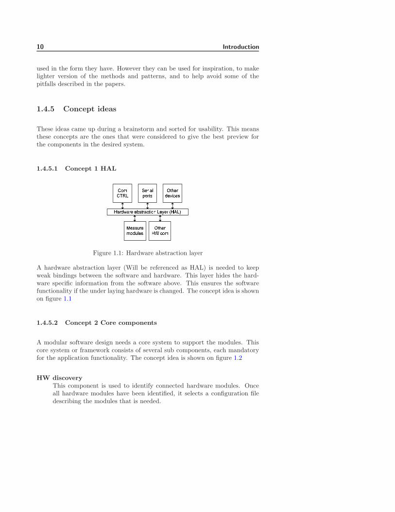
Figure 1.1: Hardware abstraction layer
A hardware abstraction layer (Will be referenced as HAL) is needed to keepweak bindings between the software and hardware. This layer hides the hard-ware specific information from the software above. This ensures the softwarefunctionality if the under laying hardware is changed. The concept idea is shownon figure 1.1
1.4.5.2 Concept 2 Core components
A modular software design needs a core system to support the modules. Thiscore system or framework consists of several sub components, each mandatoryfor the application functionality. The concept idea is shown on figure 1.2
HW discoveryThis component is used to identify connected hardware modules. Onceall hardware modules have been identified, it selects a configuration filedescribing the modules that is needed.

1.4 Preliminary analysis 11
� !"#$% &!$'()!*+, -$'. (/%0 12*34&1&3$' /554 !"#$+6.+7$4% 3
Figure 1.2: Core components
Config managerThis component is to handle global application configuration and localconfiguration for each module. Global configurations could be license re-striction and default data. Local configuration could be alarm limits orranges selected for displayed curves.
Module loaderThis component is responsible for loading application/software modules,verify integrity and initialize them.
System logThis component is responsible for storing log information for the entire sys-tem in a common format. Log information’s could contain information’sabout errors or other event important for the overall system operation.
App modulesThese components are software modules loaded to make up the functionalpart of the application. These software modules could be modules used tomeasure O2 or SpO2 values and modules to display O2 or SpO2 values.
1.4.5.3 Concept 3 Module layering
Layering of the modules is needed to give a functional overview. Modules areto be separated into 3 layers seen on figure. 1.3
Layer 3This layer is to contain user interface software modules.

12 Introduction
89:;< =>;9?@<;A;BC ADE@F;?89:;< GH9C9 A9B9I;A;BC89:;< JK?;< LBC;<M9N;Figure 1.3: Module layers
Layer 2This layer is to contain software modules responsible for data management.This is storing measurement, exporting/importing data.
Layer 1This layer is to contain measuring software modules.
1.4.5.4 Concept 4 Resources
Software components often need software resources like text strings or images,especially if the system needs to display text in different languages. To sim-plify resource management only software modules in layer 3 may have languagedependent resources. No software module should share a software resource.
1.4.5.5 Concept 5 Events
Since this application is build up of many small software modules it would bebeneficial to have a system to handle events. This event system should be ableto dynamically add and remove events. Software module requiring an eventshould be able to add a listener to an event.
1.4.5.6 Summery
The concepts given describe a modular system and this should be the goal ofthis thesis to create a system. The concept does not give solutions that can beused directly, but they give inspiration and a direction for the design process.

1.5 Challenges 13
1.5 Challenges
Before design of the modules can begin a number of challenges have to besolved. These challenges are done to highlight and eliminate certain problemareas, which exist due to lack of knowledge.
The challenges that have been looked at in this thesis are:
1. Platform image.
2. Connectivity between Visual Studio and CE.
3. Serial connection.
4. Event handling.
5. Software module integrity.
6. Third party software modules.
7. Module hardware interface.
8. Loading modules Runtime.
9. String localization.
10. Modules version control.
11. Integrity of configuration files.
12. Serializing objects.
13. FDA and CE approval.
Appendix I gives a detailed description of each challenge and the results.
1.5.1 Summery
Most of the challenges solved were relative easy once the problem was specified.However there were some problems that took a lot longer to solve than expected.
Creating a custom CE device to the current hardware platform proved impossi-ble with CE 5.0. The problems found might have been solved if more time hadbeen available. A bug in the CE 5.0 was discovered when creating images to

14 Introduction
at PC. COM1 was always locked to send out debug information’s, even thoughthe loader was told to shut down the debug system. A solution was found butnot tested due to time restrictions. The image used, uses the CE emulator. Thesolution is acceptable but performance cannot be tested in this environment.
Creating a connection between a Windows CE and Visual Studio 2005 (VS) wasa lot more difficult than expected. VS depend on the Active Sync application tohandle the communication. This makes it very easy to develop applications tohandheld devices. But VS has almost no support for developing applications tocustom CE device. A guide in appendix B describes what have to be includedin the custom CE device and all the manual steps that have to be carried outto establish a connection.
1.6 Test strategy 15
1.6 Test strategy
A test strategy is necessary to insure the quality of the application. This hasto be sketched out before the application design starts, in order to incorporatetestable requirements. Inspiration for the test strategy have been found usingref. [7].
Unit testing ensures a uniform test of objects but can also be quite difficult,especially if there are many similar objects in the system. This is becausenormally there is one unit test for each object. This causes repetition of teststeps. To reduce the complexity to the unit test, it will be split into 2 levels foreach object.
Level 1 testThe purpose of this test is to verify implemented interfaces. These testsare common for all objects using a specific interface.
Creating a standardized interface test reduces overall complexity for theunit testing system. Instead of repeating steps in several unit tests, it cannow reuse the same test for several objects. Creating a standardized testhowever does have some problems. Firstly it cannot test all functionalityin an object, secondly the interface have to have a strong specification,describing all input and output, and reactions to failure.
This type of test can be implemented into the application itself. Thiscould help development of object by letting the application test the objectbefore it is initialized the first time. Also it can help third party developersbecause they do not need to have a test environment for the objects.
Level 2 testThe purpose of this test is to test functionality not covered by level 1 test.This type of unit test uses an external test environment designed for thespecific object.
Non-unit testNot all functionality can be tested by automatic unit tests. Most of thesetests are tests requiring user input or visual inspections.
These are often objects used to display user interfaces. Testing these ob-jects can be done, by creating test stubs simulating the underlying system.Simulation is preferred since this can control all underlying functionalityand thereby allowing the test to get into all states of the user interface.
Integrations testIntegrations tests are used to verify the interaction between several ob-jects/software modules. This can be the final application or parts of it.
16 Introduction
These tests should be relative simple tests since the interfaces used forinteraction have been tested.
1.6.1 Test documentation
To document how a test is performed a step-by-step list has to be made. Thislist should describe requirement/functionality tested and expected result. Thetest description must include the test type, the interface or object tested and testresults for each step. A template for a test protocol can be found in appendixG.1. Once a test protocol have described for an object, a review of the protocolmust be performed. The purpose of this review is to validate the protocol againstthe objects requirements and design. This should revile any flaws in the testprotocol.
If an error is found in a objects that have passed its test protocol, a new reviewshould be made of the requirements, design and test protocol. This is to revilewhere the errors come from and where changes have to be made, so this errorcan be caught if it should occur again.

1.7 Overall requirements and limitations 17
1.7 Overall requirements and limitations
The overall requirements have been created from the information given in thethesis description in appendix D and the information gained during the chal-lenge analysis. The overall requirements and limitations are used to create apreliminary time schedule.
Specific requirements for each module are identified in the design for each mod-ule.
1.7.1 Overall requirements
OR1 The framework must be module based.OR2 The modules must be signed.OR3 The modules must be identifiable with a GUID value.OR4 Events handling must be done using delegates.OR5 Module must be loaded using reflections.OR6 Traceability must be implemented into the thesis documentation.OR7 The framework must be developed in Visual Studio 2005.OR8 The framework must be implements using Compact framework 2.0.OR9 The framework must be executable on a Windows CE 5.0 emulator
target.OR10 The framework must be implemented using the language C#.OR11 Test strategy must be described.OR12 Software modules must use a serial port for communication
with hardware modules.
OR4 events using delegatesChallenge 4 was used to test different ways to perform event handling.Primary focus should be put on using delegates to perform the event han-dling. The reason for this is delegates seems to offer the most flexiblefunctionality.
OR6 TraceabilityThis is a requirement given by FDA. Traceability is to give the reader achance to see where requirements are described, implemented and testedin the documentation done for a project. In this thesis all requirementshave been given an Id. Sections that describes requirements will have areference to the requirements.

18 Introduction
1.7.2 Limitation
The main focus of this thesis should be in the design of the framework softwaremodules. Software modules for user interfaces, data storage and measurementshould be secondary. They should only be implemented in a limited version toevaluate the framework functionality.
The main focus on the framework should be to develop the methods in thefollowing order:
1. Method for object sharing between all the modules.
2. Method for event handling between the modules.
3. Method for data transfer between modules.
4. Method for controlling user interfaces.
5. Method for controlling framework configuration.
6. Method for loading modules runtime.
7. Method for separating modules from communicating directly with hard-ware.
8. Method for discovery of hardware modules.
9. Method for controlling languages in the user interface.
All methods from 5 to 9 are only to be made once there is a satisfactory resultof the previous items is established. The items should therefore not be outlinedin the preliminary time schedule. If these items make it into the thesis theyshould be shown in the final time schedule in appendix H.2.
A test strategy must be described however there should not be implemented atest for every module created. Test should only be implemented to demonstrateand verify some of the main modules functionality.
1.8 Introduction summery
This chapter have been used to give some background information about TCMdevices and their usage. Information’s about tools and methods have been given.
1.8 Introduction summery 19
A number papers and books have been shortly described. These describe someof the most current theories available. Theories for making modular systemsfor embedded devices are almost non-existing. Most of the theories found havetheir main focus in large applications and enterprise system. This means mostof the theories cannot be used directly in this thesis. They can however beused for inspiration to make new theories and designs. The chapter containsdescriptions of a number of challenges. These challenges have been identifiedand solved to help establish a foundation for the design of the framework.
The next chapter will concentrate on designing modules for the framework.The chapter will mainly focus on modules to the framework. The moduleswill be designed using the iterative method described. This means each sectiondescribing a module contains analysis, design and implementation.

20 Introduction

Chapter 2
Analysis of core architecture
for future TCM device
Contents2.1 Preliminary architecture overview . . . . . . . . . . 23
2.2 Software modules . . . . . . . . . . . . . . . . . . . . 24
2.3 Factory sphere system . . . . . . . . . . . . . . . . . 31
2.4 Module communication . . . . . . . . . . . . . . . . . 47
2.5 Configuration manager . . . . . . . . . . . . . . . . . 58
2.6 Controlling user interface . . . . . . . . . . . . . . . 64
2.7 Design summery . . . . . . . . . . . . . . . . . . . . . 74
This chapter contains several sections each describing a software module in theframework architecture. The chapter has the following structure.
1. A short overview is given, to show all the components in the frameworkand a small description of where focus have been put in the framework
2. A section describing the basic architecture of the software modules usedin the framework.
3. A section describing a method for sharing factory objects between softwaremodules without the software modules know each other.

22 Analysis of core architecture for future TCM device
4. A section describing a method for software modules to communicate witheach other.
5. A section describing a method for controlling configuration files and en-suring the integrity of these
6. A section describing a method for controlling views in a user interface.
7. Lastly a small summery of what have been archived and a discussionof whether some of the solutions could be seen as a new type of designpatterns.

2.1 Preliminary architecture overview 23
2.1 Preliminary architecture overview
Module A
Configuration Manager Factory
Module CModule B
Communication Manager Factory
Framework
View Manager Factory Communication
Manager
Factory SphereManager
Configuration Manager
Register framework factories
R egi ster obj ect
factory
Get object instance
Get object instance
Communication Channels
Factory Sphere
View Manager
Module C Object Factory
Figure 2.1: Preliminary architecture of framework
Figure 2.1 shows the architecture for the system to be designed.
The system has 3 main components. To the right is the framework block. Thisis the block where the main focus will be put in the design. The purpose ofthe framework block is to contain a number of modules capable of controllingand support the external software modules. The software modules shown in theright block will be described in the coming sections.
The middle contains a sphere. The main purpose of this sphere is to containfactory objects capable of creating objects used and shared by the frameworkand external modules. The factory sphere is a virtual container used by theframework.
The bottom shows 3 external software modules. These modules could be mea-surements modules measuring O2 and CO2. They could also be module usedto store data and user interface components. External modules will loosely bedescribed but will not be designed.

24 Analysis of core architecture for future TCM device
2.2 Software modules
The purpose of this section is to describe an overall design for software mod-ules in the framework architecture. This means the design should be used forboth framework software modules and external software modules. The sectioncontains.
1. An analysis describing the overall module design and desired structure.
2. List of requirements for a basic software module.
3. Information about how versions should be handled.
4. Information about how integrity of software modules should be tested.
5. An interface design for software modules. This interface should be theonly part of the software modules, exposed of the outside.
6. Some guidelines for initialization and configuration of software modules.These are only overall guidelines. Specific information about configurationlocated in the design of each software module module.
2.2.1 Module analysis
Software modules are the basic components in the framework architecture.These components are used in the framework core and as plug in modules.
A software module can be seen as a UML package that contains on or more ob-jects. The defined software module interface is the entry point into the package.
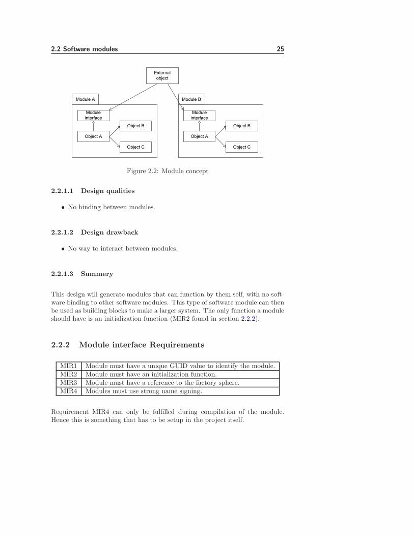
Figure 2.2 shows a concept idea on how software modules should be build.The software module interface should be as minimal as possible, removing alloperation-oriented functionality from the interface. By operation oriented func-tionality it is ment all access to specific functionality in a module should notbe allowed. Communication between the modules through the module interfaceshould not be allowed. The reason for these restrictions is to minimize bindingsbetween the modules. The module interface should however contain a functionto set a reference to a global factory system, allowing object to be shared in acontrolled manner between the modules. Also a function to initialize the moduleshould be present. Inspiration for this design comes from ref. [3] and [4]
2.2 Software modules 25
Module A
Object B
Object CObject A
Module interface
Module B
Object B
Object CObject A
Module interface
External object
Figure 2.2: Module concept
2.2.1.1 Design qualities
• No binding between modules.
2.2.1.2 Design drawback
• No way to interact between modules.
2.2.1.3 Summery
This design will generate modules that can function by them self, with no soft-ware binding to other software modules. This type of software module can thenbe used as building blocks to make a larger system. The only function a moduleshould have is an initialization function (MIR2 found in section 2.2.2).
2.2.2 Module interface Requirements
MIR1 Module must have a unique GUID value to identify the module.MIR2 Module must have an initialization function.MIR3 Module must have a reference to the factory sphere.MIR4 Modules must use strong name signing.
Requirement MIR4 can only be fulfilled during compilation of the module.Hence this is something that has to be setup in the project itself.

26 Analysis of core architecture for future TCM device
2.2.3 Module identification
Software modules should be uniquely identifiable to ensure the software modulesare of a valid type and not loaded more than once. Only allowing softwaremodules to be loaded once limits the overhead in integrity testing modules. AGUID value has been selected to identify software modules. A GUID value is a128bit value usually generated using a random generator. This gives with highprobability a unique value.
Using these unique values to identify a software module can not only be used toidentify software module type, but also a specific software module version. Thesevalues can be put into a database linking them to module type and version. Thisgives us the ability to control module types, versions and owners.
Instead of using random numbers in the GUID value a system could be used bysplitting up the 128bit value into sections, type, version and owner. Splittingup the values like this does however create some limit on the amount of modulesfor the system. But it can also give a better overview of the modules and to alimit remove the need for an external database of the software modules.
2.2.3.1 Design qualities
• Gives a unique Id of module and version.
• Gives a way to administrate modules and versions.
2.2.3.2 Design drawbacks
• Requires administration of modules and versions.
2.2.3.3 Summery
The use of GUID values should be added as a requirement (MIR1). The ad-ministration of GUID values is seen as a drawback and a quality of the design.The reason for this is administration can be time consuming and cost money,but it gives a way to control the modules. GUID’s must be implemented in thisthesis, but methods for version control will not be discussed.

2.2 Software modules 27
2.2.4 Module integrity
Compact Framework 2.0 supports strong named assemblies. Strong named as-semblies are assemblies there have been signed with a private RSA (ref. [10])key and with the public key embedded into the assembly. The RSA key pair canbe supplied through a simple key pair file or through a Personal InformationExchange certificate (similar to X.509 certificate ref. [11]). If an assembly issigned then the compact framework will automatically verify the signature. Ifthe verification fail then the loading of the module will be aborted. If softwaremodules are static linked then all software modules have to be signed. Softwaremodules however do not need to use the same key pair. This gives the possibilityto have different key pairs to different module suppliers. By creating a list ofvalid third party public RSA keys and compare these keys to the module key,then it is possible to control access to supplier’s modules. This will howeverrequire some form of updating of the key list. Another solution could be thatall modules have to se signed using the same key. This will require some typevalidation procedure from Radiometer. One problem to consider when select-ing method, is that the signing procedure for strong named assemblies, is doneduring build time.
2.2.4.1 Design qualities
• Gives a strong integrity verification.
• Gives the ability to verify module owner.
• Gives the ability to control allowed third party modules.
2.2.4.2 Design drawbacks
• Gives a longer load time for modules.
2.2.4.3 Summery
The only drawback when using strong name signing is the load time. This isincreased since modules must be verified before they are executed. This howeveronly affect the time it takes to start the application. Once the application isstarted it has no effect on performance.
Strong name signing must be added as a requirement (MIR4).
28 Analysis of core architecture for future TCM device
2.2.5 Module interface designOOPQRQSTQUVWXYZ[\]^Z_`abcdeOfghiTVWWXjYj]kjlZWXYZ[\]^Zmnco`nap e
Figure 2.3: Module interface design.
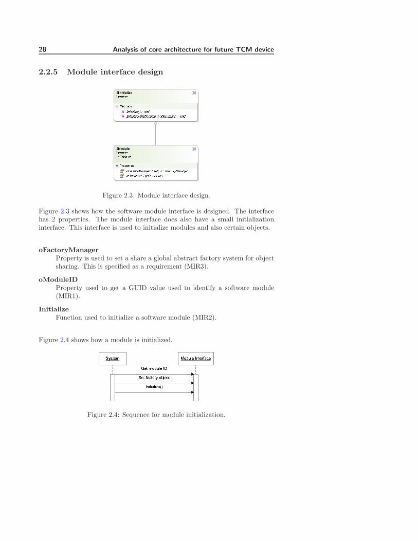
Figure 2.3 shows how the software module interface is designed. The interfacehas 2 properties. The module interface does also have a small initializationinterface. This interface is used to initialize modules and also certain objects.
oFactoryManagerProperty is used to set a share a global abstract factory system for objectsharing. This is specified as a requirement (MIR3).
oModuleIDProperty used to get a GUID value used to identify a software module(MIR1).
InitializeFunction used to initialize a software module (MIR2).
Figure 2.4 shows how a module is initialized.qrstuv wxyz{u |}tu~���u�ut vxyz{u |�qut ���tx~r x��u�t|}�t��{��u��Figure 2.4: Sequence for module initialization.

2.2 Software modules 29
2.2.6 Initialization and configuration guidelines
2.2.6.1 Initialization
This section describes some guidelines modules should follow when initializingsoftware modules. The initialization of software modules should be done in 3stages.
Stage 1First a module should get the configuration it needs to set itself up. Oncethe configuration have been retrieved it should be checked for missing dataand if data follow the setup requirements. As an example if a limit is sethigher than allowed.
If the configuration cannot be verified as valid a default configurationshould be used instead. A note in a log system should also be set, sayingthe retrieved configuration was not valid.
Stage 2Required objects located in the factory sphere, should be retrieved and ifnecessary initialized.
Stage 3Threads and listeners should be initialized.
2.2.6.2 Configuration
This section describes some guidelines modules should follow when it is con-figured. In section 2.4.2 a method for communication using channels betweensoftware modules is described. To make a software module as flexible as possi-ble, the identification for the input and output channels should be described in aconfiguration file. This would allow for redirection of data without recompilingthe software modules.
As an example a system can have two channel, channel A and channel B. Chan-nel A show data on the screen and in this system is used for debugging. ChannelB is used in the final system and stores data on a disk. When working on amodule or interaction between modules the system can be configured to senddata to channel A to see if data is correct. Once data is verified then the con-figuration can be changed to channel B storing data instead. If no softwarechanges have been performed on the software module then test of the modulesis not necessary. However if channels were hard coded into the modules. It

30 Analysis of core architecture for future TCM device
would then be necessary to test the module every time a change was done. Theability to redirect data in the configuration should also make it easier to reusea module.

2.3 Factory sphere system 31
2.3 Factory sphere system
The purpose this section is to give the description on how factory objects canbe shared between software modules in the framework and external softwaremodules. The design given tries to make a new type of factory system, which issimilar to an abstract factory.
1. The first thing given is a small description of where the factory system fitsinto the framework architecture.
2. The analysis starts with a small description of the abstract factory patternand lists some for the qualities and drawbacks of this design.
3. A prototype design of the factory sphere is created to see if the qualities ofthe abstract factory can be maintained in a system that can be configuredat runtime.
4. A front-end prototype for the factory sphere is created to se if this cansolve some of the problems that were discovered when Implementing theprototype factory sphere.
5. After the analysis and prototypes a list of requirements are given.
6. A final design is described, this design contains information about inter-faces used, how generic factory objects can be made, how objects createdshould be initialized and how creational patterns can be implemented asgeneric factory objects.
7. An overview of the objects and interfaces designed, and relations betweenthese are given.
8. A summery for the factory sphere system.
2.3.1 Architecture overview for Factory Sphere
The highlighted components in figure 2.5, shows where the factory sphere man-ager fits into the framework architecture. The factory sphere manager moduleis a part of the framework and it is responsible for controlling how softwaremodules can share access to factory objects.
As shown in the interface design for the module in section 2.2.5, each modulecontains a property to set a reference to the factory sphere. This means all

32 Analysis of core architecture for future TCM device
Module A
Configuration Manager Factory
Module CModule B
Communication Manager Factory
Framework
View Manager Factory Communication
Manager
Factory SphereManager
Configuration Manager
Register framework factories
R egi ster obj ect
factory
Get object instance
Get object instance
Communication Channels
Factory Sphere
View Manager
Module C Object Factory
Figure 2.5: Architecture overview for factory sphere system.
software modules have access to the sphere and they can register factories andaccess factory objects to get object instances.
Inspiration for this system comes from ref. [1], [5] and [8].
2.3.2 Abstract factory
It is not unusual to use abstract factory patterns when designing large softwaresystems since this decrease the bindings between the used objects. This designis especially used when object needs to be shared globally and in reconfigurablesystem where underlying layers can be substituted.
Figure 2.6 shows the normal design of an abstract factory and is based on thedesign in ref [1]. Here an interface is used to describe the basic functionalityand two subclasses implementing the interface. This design allows substitutionof ”ModuleA” with ”ModuleB”, giving the system the ability to use differentfunctionality depending of the situation. The design does however not offer aunified way to control availability of an object, as an example what to do if”ObjectA’ is missing in ”ModuleA”. It can also get very complex and difficultto maintain when there are a large number of objects in the system.

2.3 Factory sphere system 33�������� ���������������������� �¡¢£ ¤ ���� �¡���������� �¥¢£ ¤ ���� �¥¦§¨©ª«¬�����������®����������������������� �¡¢£ ¤ ���� �¡���������� �¥¢£ ¤ ���� �¥ ¦§¨©ª«°�����������®����������������������� �¡¢£ ¤ ���� �¡���������� �¥¢£ ¤ ���� �¥
Figure 2.6: Abstract factory design
2.3.2.1 Design qualities
• Binds between objects are weak, allowing easy substitution.
• Forces the developers to make objects that are easier to reuse.
• Simple design.
2.3.2.2 Design drawbacks
• Increased complexity for every object added to the factory system.
• It can be difficult to handle availability of objects.
2.3.2.3 Requirements for new factory system
1. The new factory system for the framework should keep the qualities fromthe abstract factory system.
2. The new factory system for the framework must be able to handle dynam-ically adding of factory objects.
3. The complexity of the factory system should not be increased when addingnew factory objects to the factory sphere.
34 Analysis of core architecture for future TCM device
2.3.3 Prototype design
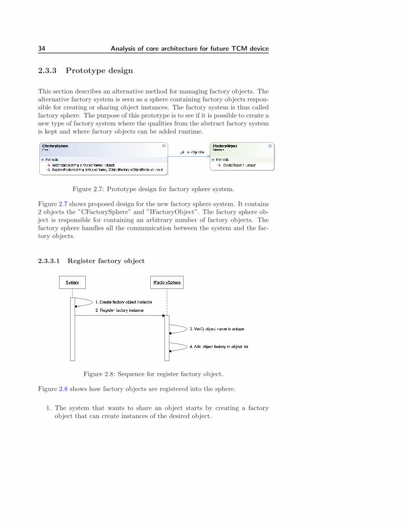
This section describes an alternative method for managing factory objects. Thealternative factory system is seen as a sphere containing factory objects respon-sible for creating or sharing object instances. The factory system is thus calledfactory sphere. The purpose of this prototype is to see if it is possible to create anew type of factory system where the qualities from the abstract factory systemis kept and where factory objects can be added runtime.±²³´µ¶·¸¹º»¼·¼½¾¿ÀÀÁÂÃÄÅÆÇÈÂÃÉÊÇÃËÊÌÂÍÇÃÎÏÊÐ ÇÃÎÑÒÓÂÌÃÔËÕÂÖ × ÅÒÓÂÌÃØÂÐÏÇÃÂÎÙËÌÃÅÎÚÍÇÃÎÏÊÐ ÇÃÎÑÒÓÂÌÃÔËÕÂÛ ÉÑÒÓÂÌÃÙËÌÃÅÎÚ ÅÑÒÓÂÌÃÙËÌÃÅÎÚÖ × ÜÅÏÆ Ý²³´µ¶·¸Þß༴µáâãäåæ¿çäÁÂÃÄÅÆÇÕèÑÒÓÂÌÃéÏÇÃ
Figure 2.7: Prototype design for factory sphere system.
Figure 2.7 shows proposed design for the new factory sphere system. It contains2 objects the ”CFactorySphere” and ”IFactoryObject”. The factory sphere ob-ject is responsible for containing an arbitrary number of factory objects. Thefactory sphere handles all the communication between the system and the fac-tory objects.
2.3.3.1 Register factory objectêëìíîï ðñòóíôõëêö÷îõîøù úîûüìíîõ ýòóíôõë üþìíòþóî ÿù�îõüýë ô��îóí þòïî üì �þü��î�ù �õîòíî ýòóíôõë ô��îóí üþìíòþóî� ù� ô��îóí ýòóíôõë íô ô��îóí üìí
Figure 2.8: Sequence for register factory object.
Figure 2.8 shows how factory objects are registered into the sphere.
1. The system that wants to share an object starts by creating a factoryobject that can create instances of the desired object.

2.3 Factory sphere system 35
2. The factory object can then be registered by calling the ”RegisterFactory”function using a string to identify the factory object and a reference tothe factory object.
3. Before a factory object is registered into the sphere, the factory systemverifies the identification for the factory object is unique.
4. If no other objects are registered under the desired name the factory objectis then stored in the sphere.
Factory objects are registered into the system while the application is running.This means factories can be registered at any time. However the registrationprocedure should be contained to the initialization process of the system. Thereason for this is to minimize the dependencies between modules at start up.If the factories have been registered during the initialization then all softwaremodule have access to the factory when they are started.
2.3.3.2 Get object instance�� ��� �������������� ���������������� ��� ������ � �� �� !� ������ "�� ������ � �����#� ��� ������ � �� �� $� %����� ������ � �� ��Figure 2.9: Sequence for getting object instance.
Figure 2.9 shows how objects instances should be created.
1. The sequence is started when the system request an object instance.
2. The factory sphere starts searching for the requested factory object using asupplied Id for the factory object. In the prototype design, factory objectsare identified using strings.
3. Once a factory object is located the factory sphere system calls the factoryobjects ”CreateObject” function to get an object instance.

36 Analysis of core architecture for future TCM device
4. The factory objects can then, depending of the rules implemented, createa new object instance and return it to the system.
The factory objects in this design are similar to the create functions in the ab-stract factory design. This object keeps the weak bindings between the objectsas required. The prototype design shows the factory object as an interface. Thisallows for different implementations of the factory objects. These implementa-tions could be different creational patterns like singleton or session patterns.
2.3.3.3 Design qualities
• Binds between objects are weak, allowing easy substitution.
• Forces the developers to make objects that are easier to reuse.
• Can reconfigure the factory system at runtime.
• No increase in complexity when adding a new factory objects.
2.3.3.4 Design drawbacks
• Factory object can be removed runtime.
• Non-specific object instances returned.
• Performance.
2.3.3.5 Prototype summery
The prototype design fulfills the requirements. The register function allowsfor dynamic adding of factory objects. The create function can create objectinstances without any increase in complexity. The qualities from the abstractfactory have been kept. The design is however not as simple as the abstractfactory.
The drawbacks from the abstract factory have been solved in this design. How-ever a new set of problems has been created.
Removal of factory objectsAs shortly mentioned factory objects are added runtime. Adding a remove

2.3 Factory sphere system 37
function to the system could allow for reconfiguration at runtime, removingone factory and replacing it with a new one. This is however not desirablebecause it would be difficult to keep consistency in the system.
An example could be the system creates 2 instances of specific objectsusing the Id ”TestObject”. The factory that is linked to ”TestObjects”is now exchanged with another factory object. Now if the system createsinstance using ”TestObjects” it would get a different object than the 2first ones. This could lead to unpredictable results because there is notconsistency between the objects. The system could also completely re-move a factory from the system. This would lead to the question, are theinstances still valid. For these reasons removal of factory objects shouldnot be allowed.
However if the consistency problem and validity problems could be con-trolled, then this could become a strong tool in a modular system.
PerformanceThe system stored the factory object and identification of these in sometype of list. The prototype uses a simple dictionary to store the factoryobjects in and strings to identify factory objects. Using strings to identifyfactory objects are not necessarily the best way to go. If the list usedcontains a large amount of strings it could become a problem.
Object typeThe biggest problem in the prototype design is the fact that objects createdby the factory objects, are returned without a type making them non-specific. This makes the returned objects useless and a solution must befound to solve this problem.
2.3.4 Prototype front-end design&'()*+),-./01123456789:3;43<=>3?4@AB C <=>3?4@&'()*+),D./01123456789:3;43<=>3?4EAB C <=>3?4EF&GH*('IJKL+'+./011MN3O78PQ<=>3?4RN84 C SM;?46:T<=>3?4UV2345678W34SX84;X?3AB C 6=>3?4Y3ZN843:M;?46:TAB C [6N7PQ6M;?46:T\]53:3PQ6M;?46:T\]53:3
Figure 2.10: Frontend design for factory sphere system.

38 Analysis of core architecture for future TCM device
One way to solve the problem of the non-specific object generated by the factoryobjects, described in the prototype design, could be by using some of the abstractfactory design. This could be creation of front-ends to the factory sphere asshown on figure 2.10. The front-ends contains like the abstract factory a createfunction. Only responsibility is to get an instance from the factory sphere andtype convert it.
This gives a global check from the factory sphere, on availability and the frontend gives a type specific object.
2.3.4.1 Design qualities
• Validation on object type.
• Returning type specific objects.
2.3.4.2 Design drawbacks
• Gives more complexity in design.
2.3.4.3 Front end summery
The design gets a little more complex since a create function for each factoryobject is needed. It is however easier to add and remove factory objects fromthe front end because of the underlying factory system. The front end do notneed the create functions for all the objects and it is possible to use more thanone front end on top of the factory sphere.
2.3.5 Requirements for factory sphere
The ideas and experience gained during implementation of the prototypes wasused to generate the following requirements, described in this section.

2.3 Factory sphere system 39
2.3.5.1 Factory sphere interface
FAC1 The interface must have a ”RegisterFactory” function.FAC2 The interface must have a ”GetInstance” function.FAC3 The interface must have a ”ReleaseInstance” function.FAC4 Factories are identified using strings.FAC5 The factory sphere system may not remove registered objects.
2.3.5.2 Factory object interface
FAC6 The interface must have a ”GetInstance” function.FAC7 The interface must have a ”ReleaseInstace” function.
2.3.5.3 Factory sphere object
FAC8 This object must implement ”IFacatorySphere” interface.
2.3.5.4 Factory objects
FAC9 These objects must implement ”IFactoryObject” interface.FAC10 A generic factory object must be implemented.FAC11 A generic singleton pattern factory must be implemented.FAC12 A generic session pattern factory must be implemented.FAC13 A generic pool pattern factory must be implemented.FAC14 A generic prototype pattern factory must be implemented.
2.3.5.5 Implementation priority
Implementation of the factory sphere system has been prioritized in order to getan overview of where focus should be put. There are 3 levels of priorities theseare:
HighItems that must be implemented before the system works.

40 Analysis of core architecture for future TCM device
MedItems that would be helpful to have, but not necessary for the overallfunctionality.
LowItems that is not necessary but nice to have.
Below is a table showing the implementation priority.
Factory sphere HighFactory object HighGeneric factory HighSingleton Pattern MedSession Pattern MedPool pattern LowPrototype pattern Low
2.3.6 Design
This chapter describes the final design of the factory sphere manager. Thisdesign is based on the requirements described and the experience gained duringthe implementations of the prototypes.^_`abcdefghidi ^_`abcdejkliabmnopqrnstuvwxsxy mnopqrnstz{|r}~~�
Figure 2.11: Relations between factory sphere objects.���������������������������������������� ��������� ¡�����������������������������Figure 2.12: Interfaces for factory sphere system.
Figure 2.11 show the relations between the objects and figure 2.12 shows thefinal interface design.
2.3 Factory sphere system 41
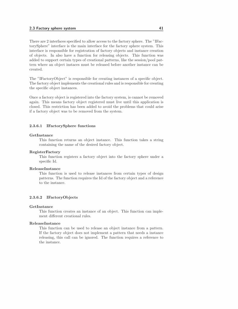
There are 2 interfaces specified to allow access to the factory sphere. The ”IFac-torySphere” interface is the main interface for the factory sphere system. Thisinterface is responsible for registration of factory objects and instance creationof objects. In also have a function for releasing objects. This function wasadded to support certain types of creational patterns, like the session/pool pat-tern where an object instaces must be released before another instance can becreated.
The ”IFactoryObject” is responsible for creating instances of a specific object.The factory object implements the creational rules and is responsible for creatingthe specific object instances.
Once a factory object is registered into the factory system, is cannot be removedagain. This means factory object registered must live until this application isclosed. This restriction has been added to avoid the problems that could ariseif a factory object was to be removed from the system.
2.3.6.1 IFactorySphere functions
GetInstanceThis function returns an object instance. This function takes a stringcontaining the name of the desired factory object.
RegisterFactoryThis function registers a factory object into the factory sphere under aspecific Id.
ReleaseInstanceThis function is used to release instances from certain types of designpatterns. The function requires the Id of the factory object and a referenceto the instance.
2.3.6.2 IFactoryObjects
GetInstanceThis function creates an instance of an object. This function can imple-ment different creational rules.
ReleaseInstanceThis function can be used to release an object instance from a pattern.If the factory object does not implement a pattern that needs a instancereleasing, this call can be ignored. The function requires a reference tothe instance.
42 Analysis of core architecture for future TCM device
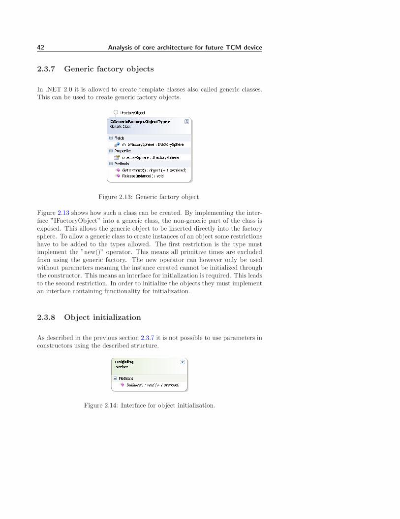
2.3.7 Generic factory objects
In .NET 2.0 it is allowed to create template classes also called generic classes.This can be used to create generic factory objects.¢£¤¥¤¦§¨©ª¨«¬¦®¯°±¤¨«²³¤´µ¶·¶¸¹º »¼½¾¾¿ÀÁÂÃÄÅÆÇ¿ÈÉÊÇËÌÍÎÏÁËÁ Ð Ñ¿ÈÉÊÇËÌÍÎÏÁËÁÒËÇÎÁËÊÀÁÄÇ¿ÈÉÊÇËÌÍÎÏÁËÁ Ð Ñ¿ÈÉÊÇËÌÍÎÏÁËÁÓÁÊÏÇÃÄÔÁÊÑÕÄÊÈÕÉÁÖ× Ð ÇØÙÁÉÊ ÖÚ Û ÇÜÁËÂÇÈÃ×ÝÁÂÁÈÄÁÑÕÄÊÈÕÉÁÖ× Ð ÜÇÀÃ
Ñ¿ÈÉÊÇËÌÞØÙÁÉÊ
Figure 2.13: Generic factory object.
Figure 2.13 shows how such a class can be created. By implementing the inter-face ”IFactoryObject” into a generic class, the non-generic part of the class isexposed. This allows the generic object to be inserted directly into the factorysphere. To allow a generic class to create instances of an object some restrictionshave to be added to the types allowed. The first restriction is the type mustimplement the ”new()” operator. This means all primitive times are excludedfrom using the generic factory. The new operator can however only be usedwithout parameters meaning the instance created cannot be initialized throughthe constructor. This means an interface for initialization is required. This leadsto the second restriction. In order to initialize the objects they must implementan interface containing functionality for initialization.
2.3.8 Object initialization
As described in the previous section 2.3.7 it is not possible to use parameters inconstructors using the described structure.ßßàáâáãäáåæçèéêëìíîêïðñòóôõ
Figure 2.14: Interface for object initialization.

2.3 Factory sphere system 43
Allowing the object to implement an interface containing functions to initializethe object can solve this. Figure 2.14 shows an interface that solves the problem.During the creational process a check on the object could be done to se if itcontains the interface. If the object has the interface, then the initializationfunctions could be called. These functions can have any parameters required.The function should be called right after the object has been created.
2.3.9 Creational patterns
The purpose of this chapter is to give a short description of the designed cre-ational patterns used. A complete description of the creational patterns can befound in ref [1].
2.3.9.1 Singleton patternö÷øùøúûüýûùþÿø��ù����øü����ø��� �� ������������������� !"#$� � % &����� !"#$� ����'()���&*���*�� % '()���+!#����+$ ���,��- % �()���. �#� ���������� !"#$� � % &����� !"#$� ��'()���&*���*�� % '()���+!#�/��$���0��&*���*��12 % �()��� 13 4 �5� ����26������&*���*��12 % 5���&����� !'()���
Figure 2.15: Generic singleton pattern implementation.
”CGenericSingleton” in figure 2.15 implements a generic version of the single-ton pattern, allowing only one instance of an object to be created. The classimplements the ”IAbstractFactory” interface to make it compatible to the fac-tory sphere system. The current implementation ignores release calls so once anobject instance is created the instance will live until the application is closed.

44 Analysis of core architecture for future TCM device789:9;<=>9??<@:ABCD9=EFGH9IJKLKMNO PQRSSTUVWXYZ[\T]^_\`abcdV`V e fT]^_\`abcdV`VZ[\bVYYU\ghUY_ e iV]jkVlV`Vg^VmnZ[\od`V]Xh\^j e \pqV^_Z[Y_`rZc_abW\_s\_T\tgX e Y_`UguZ[Y_`fgv]WUXbVYYU\ghUY_ e Y_`Uguw`\cV`_UVY\T]^_\`abcdV`V e fT]^_\`abcdV`VxV_d\XYyV_fgY_]g^Vz{ e \pqV^_ z| } \vV`W\]X{fgU_U]WU~Vz{ e v\UX z| } \vV`W\]X{kVWV]YVfgY_]g^Vz{ e v\UXkVZ\vV�V]X�pqV^_Yz{ e v\UX
fT]^_\`a�pqV^_ffgU_U]WU~V
Figure 2.16: Generic session pattern implementation.
2.3.9.2 Session pattern
”CGenericSession” in figure 2.16 implements a generic session pattern, allowinga limited number of instances to be created. The class implements the ”IAb-stractFactory” interface to make it compatible to the factory sphere system.The object uses ”WeakReference” object to create a weak reference to the re-turned objects. This ensures the garbage collector still releases objects thrownaway from the receiving party. This makes the release instance function op-tional. However since the system wont directly control the garbage collector itis however preferable to release instances in the pattern.
2.3.9.3 Generic front-end object
Like the factory objects it is possible to make a generic object that can functionas the front end for an object in the factory sphere.
Figure 2.17 shows how such an object could look like. When the generic front-end is created, it is given the Id of the object to create and reference the factorysphere it has to use. The generic object has also given the type it has toconvert to. The create function then gets the object instance through the factorysphere and converts it before returning it. The create function should verify thereturned object can be converted to the valid type.
2.3 Factory sphere system 45�������������������������������������� ������ ¡¢£¤¥¦§�¨©ª§«¬®¯¡«¡ ° §±²¡©ª³¡ª¯§£¤´µ¡¶¡« ©�«§¶ª·¶£¸¹´«¡¨ª¡º±²¡©ª¸¹ ° »¶ª¡«¼¨©¡½¬®¡¾¡¢¡¨¤¡º±²¡©ª¸¹ ° ¿§ £Figure 2.17: Generic implementaion implementation.
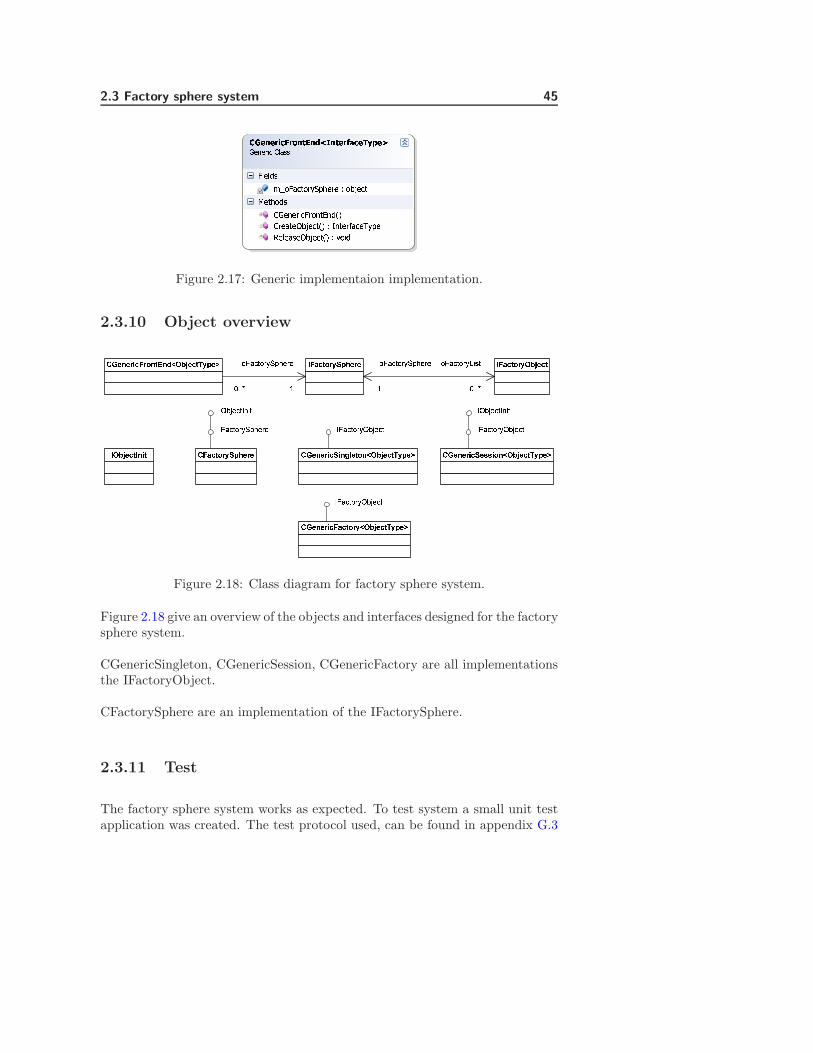
2.3.10 Object overview ÀÁÂÃÄÅÆÇÈÉÊËÆË ÀÁÂÃÄÅÆÇÌÍÎËÃÄÏÐÑÒÓÔÐÕÖ×ØÙÚÕÚÛ ÏÐÑÒÓÔÐÕÖÜÝÞÔßààáâãËäËÆåÃÁÆÅäÄæäçèÌÍÎËÃÄéÇÉËêÀÌÍÎËÃÄÀäåÄ âÁÂÃÄÅÆÇÈÉÊËÆËëÑÒÓÔÐÕÖ×ØÙÚÕÚëìíîÚÓÔëïÝÔßààáÏÐÑÒÓÔÐÕÖ×ØÙÚÕÚÛ âãËäËÆåÃÈåäðñËÄÅäèÌÍÎËÃÄéÇÉËê âãËäËÆåÃÈËòòåÅäèÌÍÎËÃÄéÇÉËêëÑÒÓÔÐÕÖìíîÚÓÔ ëÑÒÓÔÐÕÖìíîÚÓÔëìíîÚÓÔëïÝÔ
âãËäËÆåÃÁÂÃÄÅÆÇèÌÍÎËÃÄéÇÉËêëÑÒÓÔÐÕÖìíîÚÓÔFigure 2.18: Class diagram for factory sphere system.
Figure 2.18 give an overview of the objects and interfaces designed for the factorysphere system.
CGenericSingleton, CGenericSession, CGenericFactory are all implementationsthe IFactoryObject.
CFactorySphere are an implementation of the IFactorySphere.
2.3.11 Test
The factory sphere system works as expected. To test system a small unit testapplication was created. The test protocol used, can be found in appendix G.3

46 Analysis of core architecture for future TCM device
2.3.12 Summery
It is surprisingly easy to use the generic factory object, register and get objectinstances from the factory system.
The factory sphere system can be used on any type of objects since factoryobject that create the objects can be customized if needed. The generic factoryobjects designed can in most cases be used without any modifications.
The factory sphere has the same qualities as the abstract factory design butwith the addition that it can handle new object added at runtime.
The downside to the factory sphere could be performance depending on howfactory objects in the factory sphere are searched and identified. This is some-thing that must be looked at if this is to be used in the future. The factorysphere also contains more components than the original abstract factory makingit more complex to implement.
The qualities of the factory sphere system do however make it attractive to use.The system can be reconfigured without the need of recompilation of any partsof the system.
Only 3 of the required factory objects have been implemented, these are Genericfactory, Singleton factory and Session factory.

2.4 Module communication 47
2.4 Module communication
The purpose of this section is to give a description on how events/communicationcan be performed between modules.
The section starts with a small description of where the communication systemfits in to the framework architecture:
1. A small analysis was done to get an overview of the desired communicationarchitecture.
2. A description of the mediator pattern is given, listing qualities and draw-backs. A small description is given on how this mediator pattern helpedto inspire the design.
3. A list of requirements is given to specify the communication systems func-tionality.
4. Interfaces for the communication system are designed, describing how callthrough the communication system can be done both synchronously andasynchronously, qualities and drawbacks. The interface design ends witha small summery.
5. A small description of how to manage channels and protocol used aregiven.
6. A small test is described and used to test the implemented communicationsystem.
7. A summery with drawbacks and qualities of the design is given.
2.4.1 Architecture overview for Communication system
The highlighted components in figure 2.19 shows the items for the communi-cation system to be designed. The communication manager is a part of theframework and is registered as a generic singleton factory when it is initialized.This is done to give all other software module access to the same communicationchannel in the system. The communication manager is as the factory systemone of the main components in the framework. Its purposes are to give all soft-ware modules a unified way of communicating with each other. A unified wayof communication should minimize the bindings between all software modules.
Concept 5 in section 1.4.5.5 is the main inspiration for this design. But also ref.[1] and [3] have been used.
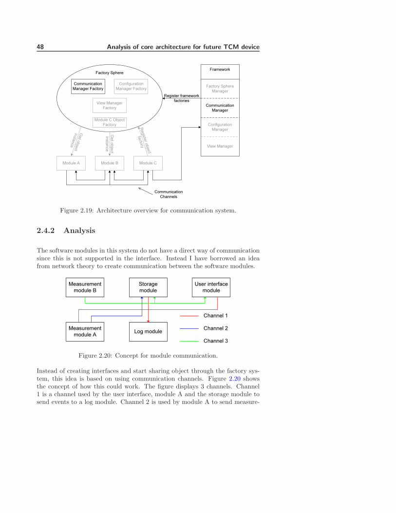
48 Analysis of core architecture for future TCM device
Module A
Configuration Manager Factory
Module CModule B
Communication Manager Factory
Framework
View Manager Factory Communication
Manager
Factory SphereManager
Configuration Manager
Register framework factories
R egi ster obj ect
factory
Get object instance
Get object instance
Communication Channels
Factory Sphere
View Manager
Module C Object Factory
Figure 2.19: Architecture overview for communication system.
2.4.2 Analysis
The software modules in this system do not have a direct way of communicationsince this is not supported in the interface. Instead I have borrowed an ideafrom network theory to create communication between the software modules.
User interface module
Log module
Measurement module B
Measurement module A
Storage module
Channel 1Channel 2Channel 3
Figure 2.20: Concept for module communication.
Instead of creating interfaces and start sharing object through the factory sys-tem, this idea is based on using communication channels. Figure 2.20 showsthe concept of how this could work. The figure displays 3 channels. Channel1 is a channel used by the user interface, module A and the storage module tosend events to a log module. Channel 2 is used by module A to send measure-

2.4 Module communication 49
ment data to the storage module. Channel 3 is used to send measurements frommodule B to the storage system and user interface.
A communication channel is a place where modules can register listeners toreceive data. If multiple listeners are registered on a channel (Channel 3) thendata is broadcasted to all listeners. A channel can also have multiple senders(Channel 1) allowing modules to share functionality in one module.
2.4.3 Mediator pattern
The communication manager that controls the communication channels can beseen as a kind of Mediator pattern. The object contains a list of functions to becalled. Each list contains an unique Id. When calling a list using the Id, thenall the functions in the list are executed.
The mediator pattern is designed to execute some type of interaction betweenobjects without the objects know anything about the other objects. The medi-ator pattern is described in ref. [1] page 273.
The mediator pattern can however not directly be used because the mediatorpattern have to know all the objects or at least an interface to these objects.
2.4.3.1 Design qualities
The mediator pattern have the following qualities that is attractive to keep:
• Gives weak bindings between objects.
• Give object the ability to interact without knowing each other.
2.4.3.2 Design drawbacks
The mediator does also have some drawbacks. These are:
• Mediator needs to know all the objects that requires interaction.
• Mediator requires a unique implementation for each interaction type.

50 Analysis of core architecture for future TCM device
2.4.3.3 Summery
The design should focus on solving the drawbacks of the mediator pattern andkeep the qualities.
2.4.4 Requirements
COM1 The interface must contain a function for adding channels.COM2 The interface must contain a function for registering a listener on a channel.COM3 The interface must contain a function for removing a listener on a channel.COM4 The interface must contain a function verifying the existents of a channel.COM5 The interface must contain a function for sending data to a channel.COM6 Channels must be identified using strings.COM7 Listeners can be registered as synchronized.COM8 Listeners can be registered as asynchronized.COM9 Channel may not be removed.
Channels must not be removed from system once the application is running.Removing a channel could lead to unpredictable results. As an example a defectsoftware module is loaded. When the software module is initialized, it removesall channels in the system. This scenario could be devastating for the entiresystem.
Listeners may however be removed. The reason for this is because in order toremove a listener from a delegate, a reference to the listener is required. Thismeans only the owner module can remove a listener from a channel. If a defectin the module would remove all its listeners it would not be devastating for theentire system. The problem would be contained in the specific software module.
2.4.5 Channel interface
First the focus have to be on how communication should be performed betweenthe modules. To solve the problem of the mediator needing to know all theobjects required for interaction, it could be turned around. This means allthe software modules that needs interaction should know the mediator. Thishowever requires some interfaces to be specified.
The channel interface should be used to give a unified way for communication

2.4 Module communication 51
between the modules. óôõö÷÷øùúûüýø÷øþÿ���������������� � � ������� �Figure 2.21: Channel listener interface.
The method chosen is shown on figure 2.21. It is a delegate that contains areference to a XML document.
A delegate can be used to contain a list of functions following the specifiedformat. This means that one delegate can function as one channel simply bysharing the delegate among the modules that needs to interact. The modulescan then register functions into this delegate. A module calling this delegatedoes not need to know any thing about the other modules.
Using delegates in Compact Framework 2.0 does however have one large draw-back. This only supports synchronous communication. This means if a modulecalls the channel it will have to wait until all the functions in the delegate havebeen executed. This is not always desirable and for this reason an asynchronousway of communication must be designed.
2.4.5.1 Asynchronous communication
In order to create asynchronous communication I have added the followingclasses.
Figure 2.22 show the objects used to create an asynchronous function call. The”CListener” is an object that is used to hold the references to a listener functionthat needs to be called. The ”CListener” object specifies whether the givenlistener is called synchronous or asynchronous. When the ”CListener” objectis registered onto a channel as an asynchronous listener. It is the ”CListener””AsyncListener” listener function that will be registered into the channel. Forsynchronous listeners it is the ”m oListener” attribute in the ”CListener” objectthat will be registered into the channel.
Figure 2.23 and 2.24 shows the sequences the done when registering and callingan asynchronous class.
The thread created in the ”CListener” object is thrown away and left to itself
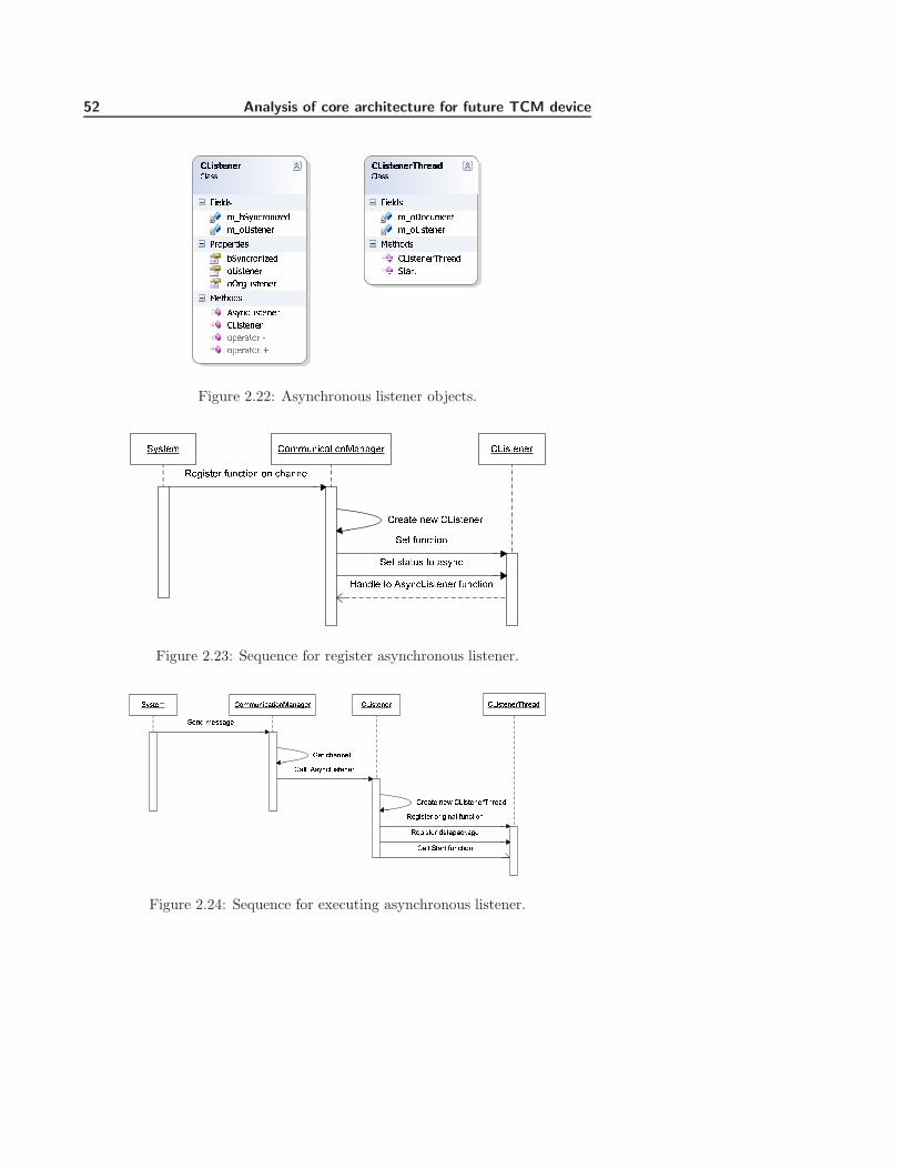
52 Analysis of core architecture for future TCM device������������������ !"#$%&'()*)+,'#-.'()/"&.#-#01#.2)%&3/"&.#-#0420#5%6.50.������������ !"#$%&'(768-+0)-"9#%'()/"&.#-#0:0);#0."#&768-+0)-"9#%)/"&.#-#0)<0=/"&.#-#01#.2)%&>&8-+/"&.#-#03/"&.#-#0);#05.)0 ?);#05.)0 @Figure 2.22: Asynchronous listener objects.ABCDEF GHFFIJKLMDKHJNMJMOEPQEOKCDEP RIJLDKHJ HJ LSMJJET GUKCDEJEPGPEMDE JEV GUKCDEJEPAED RIJLDKHJAED CDMDIC DH MCBJLWMJXTE DH YCBJLUKCDEJEP RIJLDKHJ
Figure 2.23: Sequence for register asynchronous listener.Z[\]^_ `a__bcdef]dacgfcfh^i `jd\]^c^i `jd\]^c^ikli^fmZ^cm _^\\fh^ n^] elfcc^o`foo p\[cejd\]^c^i `i^f]^ c^q `jd\]^c^ikli^fm`foo Z]fi] rbce]dacs^hd\]^i aidhdcfo rbce]dacs^hd\]^i mf]ftfeufh^Figure 2.24: Sequence for executing asynchronous listener.

2.4 Module communication 53
once it has been started. This means no one have a reference to the createthread at it will simply die once the function call is completed. Concerns wereraised whether this approached would lead to a memory leak. For this reasona small test application was created to test for a leak. The test can be seen inappendix F.
2.4.5.2 Design qualities
• Unified interface.
• Can add listener’s runtime.
• Can execute functions synchronous and asynchronous.
• Gives weak bindings between objects.
• Give object the ability to interact without knowing each other.
2.4.5.3 Design drawback
• Channel needs to be shared between all modules.
• Can only support one type of functionality.
• Cannot support complex interaction between modules.
2.4.5.4 Summery
The current system has kept the qualities from the mediator. It has also solvedthe drawbacks from the mediator. Giving the system a unified interface for com-munication and using delegates removes the need for a unique implementation.
However some new drawbacks have also created. Unifying the interaction in adelegate makes it difficult to implement complex interaction between modules.As an example the system cannot get data from one module and then send itto another in the same delegate. However since interaction between modulesshould be as limited as possible this is not considered a problem.
A way to share a channel between the modules have to be found, since all themodules that need this channel for interaction, needs to be able to either registera function or call the delegate. One way to solve the problem could be to usethe designed factory to handle the sharing.
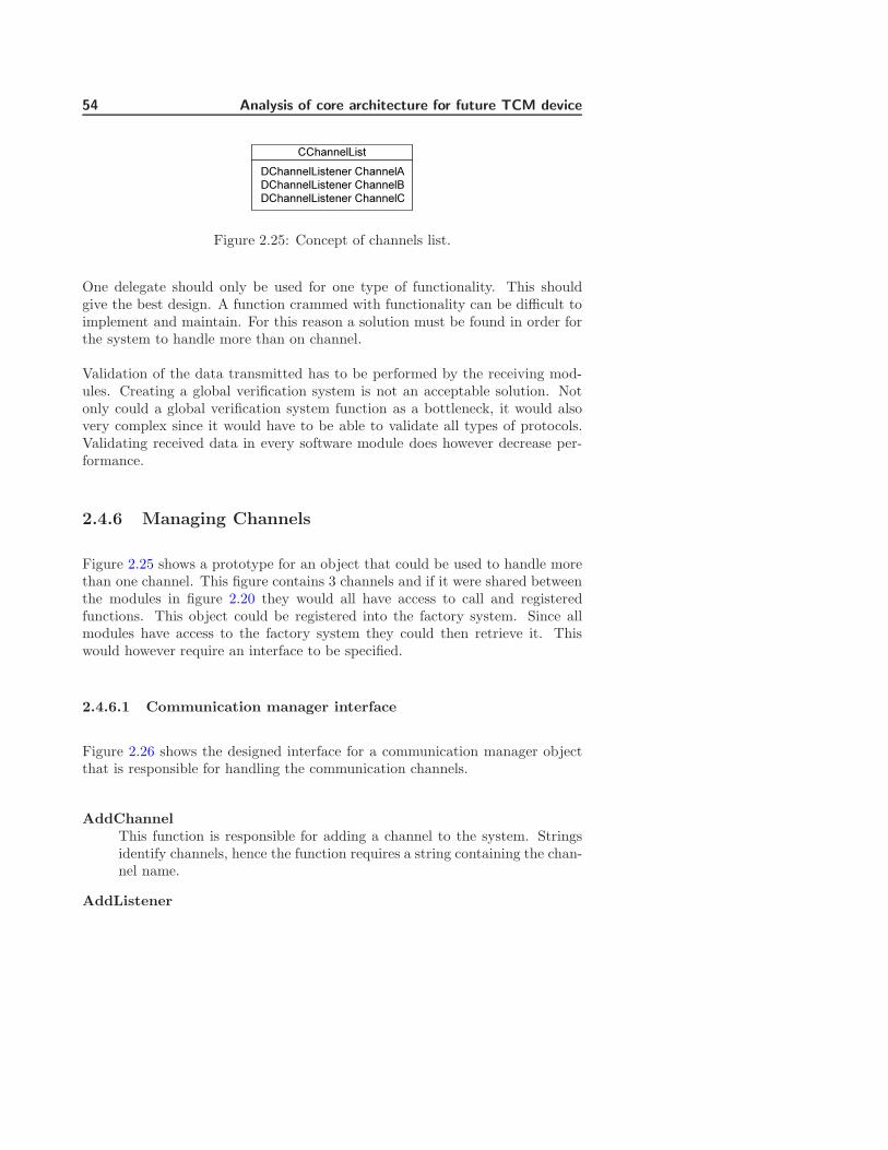
54 Analysis of core architecture for future TCM device
DChannelListener ChannelA
DChannelListener ChannelCDChannelListener ChannelB
CChannelList
Figure 2.25: Concept of channels list.
One delegate should only be used for one type of functionality. This shouldgive the best design. A function crammed with functionality can be difficult toimplement and maintain. For this reason a solution must be found in order forthe system to handle more than on channel.
Validation of the data transmitted has to be performed by the receiving mod-ules. Creating a global verification system is not an acceptable solution. Notonly could a global verification system function as a bottleneck, it would alsovery complex since it would have to be able to validate all types of protocols.Validating received data in every software module does however decrease per-formance.
2.4.6 Managing Channels
Figure 2.25 shows a prototype for an object that could be used to handle morethan one channel. This figure contains 3 channels and if it were shared betweenthe modules in figure 2.20 they would all have access to call and registeredfunctions. This object could be registered into the factory system. Since allmodules have access to the factory system they could then retrieve it. Thiswould however require an interface to be specified.
2.4.6.1 Communication manager interface
Figure 2.26 shows the designed interface for a communication manager objectthat is responsible for handling the communication channels.
AddChannelThis function is responsible for adding a channel to the system. Stringsidentify channels, hence the function requires a string containing the chan-nel name.
AddListener
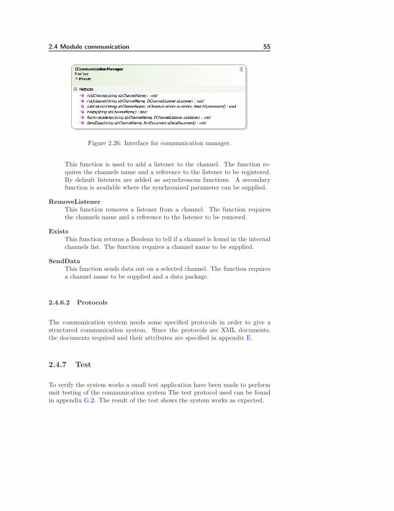
2.4 Module communication 55vwxyyz{|}~�|x{�~{~��������������������������Figure 2.26: Interface for communication manager.
This function is used to add a listener to the channel. The function re-quires the channels name and a reference to the listener to be registered.By default listeners are added as asynchronous functions. A secondaryfunction is available where the synchronized parameter can be supplied.
RemoveListenerThis function removes a listener from a channel. The function requiresthe channels name and a reference to the listener to be removed.
ExistsThis function returns a Boolean to tell if a channel is found in the internalchannels list. The function requires a channel name to be supplied.
SendDataThis function sends data out on a selected channel. The function requiresa channel name to be supplied and a data package.
2.4.6.2 Protocols
The communication system needs some specified protocols in order to give astructured communication system. Since the protocols are XML documents,the documents required and their attributes are specified in appendix E.
2.4.7 Test
To verify the system works a small test application have been made to performunit testing of the communication system The test protocol used can be foundin appendix G.2. The result of the test shows the system works as expected.

56 Analysis of core architecture for future TCM device
2.4.8 Summery
The design of the communication gives a system that is very flexible. An arbi-trary number communication channels can be created to support an arbitrarynumber of functionality. The system uses an XML document as a parameterallowing for an arbitrary number of attributes to be supplied to the functionality
This design has a few drawbacks that have already been discussed. Howeverperformance could also be a problem using this system. The XML documentitself is not parsed to all the listeners, but only the reference. However all theattributes in the XML document must be converted from string to the neededformat and when added to the document they must be converted from theformat to string.
Data integrity could also be an issue, since it is only a reference that is passedbetween the listeners. One listener could modify the data resulting in invaliddata for all the other listeners. For this reason listeners should be restricted toread received data only.
The few drawbacks this system has are outweighed by the qualities of the system.It gives us a way to runtime configures how modules should interact withoutthe module has to know any thing about each other, expect channel name andprotocol.
The given design contains 2 add functions for adding channels. The only differ-ence between the functions is the parameter ”bSyncronized”. This parameteris used to select whether the listener registered is synchronous or asynchronous.The add function without the parameter will always register listeners as asyn-chronous. This means the function containing the parameter most likely onlywill be used to register synchronous listeners. The next version should there-fore remove the this parameter and have add function for registering listenersdirectly to synchronous or asynchronous.
2.4.8.1 Design qualities
• Unified interface.
• Can add listener’s runtime.
• Can remove listeners runtime.
• Can execute functions synchronous and asynchronous.
• Gives weak bindings between objects.

2.4 Module communication 57
• Give object the ability to interact without knowing each other.
• Flexibility in communication.
2.4.8.2 Design drawbacks
• Channel needs to be shared between all modules.
• Cannot support complex interaction between modules.
• Performance.
• Data integrity.

58 Analysis of core architecture for future TCM device
2.5 Configuration manager
The purpose of this section is to describe how configuration files should behandled.
1. To start with a small description of where the configuration system fitsinto the framework architecture is given.
2. A small analysis was done to get an overview of how configuration filesshould look and be controlled.
3. Description of security issues regarding configuration files is given and alsoa method for integrity testing configuration files.
4. A design of the main configuration files is given, with a description of howexternal and custom designed configuration files could be added.
5. The section ends with a small summery and a list of qualities and draw-backs of the design configuration system
2.5.1 Architecture overview for Configuration Manager
Module A
Configuration Manager Factory
Module CModule B
Communication Manager Factory
Framework
View Manager Factory Communication
Manager
Factory SphereManager
Configuration Manager
Register framework factories
R egi ster obj ect
factory
Get object instance
Get object instance
Communication Channels
Factory Sphere
View Manager
Module C Object Factory
Figure 2.27: Architecture overview for configuration manager

2.5 Configuration manager 59
The highlighted components in figure 2.27, shows where the configuration sys-tem is located in the framework architecture. The configuration system is apart of the framework and is used to load and save configuration files. Theconfiguration manager registers a factory allowing all modules to access it. Itregisters the factory object using a generic singleton factory. This is done toincrease performance since loaded configuration files only have to be loaded andparsed once.
Inspiration for this module is mainly based of the module described in Concept2 section 1.4.5.2.
2.5.2 Analysis
The configuration system uses XML files. The reason XML files have beenchosen is because they are easy to edit and readers and writers are supportedin compact framework. The readers and writers make it easy to extract andmodify the configuration from the application.
2.5.3 Security
There are several problems involved when having external configuration files.These are:
Data corruptionThis could result in impassable configuration data or invalid configurationof system. An invalid configuration could harm the patient or result inwrong treatment. Data corruption could come from a damaged disk or byaccidentally overwriting the configuration file. External editing could alsobe a problem. Especially since the files are in clear text.
License restrictionDepending on the product purchased, it could be necessary to implementcertain license restrictions into the configuration files. These restrictionsshould be protected so the buyer can’t gain access to restricted servicesby editing the configuration files.
These problems can be solved by digitally signing the configuration files whencreated or modified.
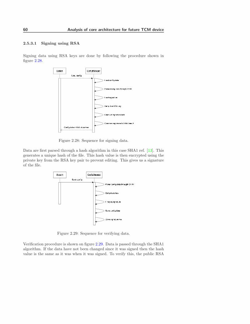
60 Analysis of core architecture for future TCM device
2.5.3.1 Signing using RSA
Signing data using RSA keys are done by following the procedure shown infigure 2.28. ������ �� ¡¢£¤¥ ¥£�¦
§�� ¨©ª«¢¬ �® ¯��°�¥± ¬� ¡¢£ ±¥�¥°�¥± �¢£ ¥�©¦�²¥¦�� ¬� ¡¢£ ±¥�¥ �³¦�©£³ �´®µ¶��¬¦� � �¢£ ¥�©¦� ±¥�¥���¨¥¦� �¢£ ¥�©¦� �� �´®µ ¦��©«��� ¡¢£ ±¥�¥ ¢ ·¤° ±�¬©�� �
°�¥± ¬� ¡¢£
Figure 2.28: Sequence for signing data.
Data are first parsed through a hash algorithm in this case SHA1 ref. [13]. Thisgenerates a unique hash of the file. This hash value is then encrypted using theprivate key from the RSA key pair to prevent editing. This gives us a signatureof the file. ¸¹º»¼½ ¾¿ÀÁÂÃÄÅÀÅüƸÅǼ È¿ÀÁÂà ÉÅƺ¼ È¿ÀÁÂà ÊŻŠ»ËÆ¿ÌÃ»Ë ¸ÍÎÏм» ÑÆÂÇÅ»¼ Ò¼¹ÓÀÈƹѻ ºÂÃÀÅ»ÌƼ¸ÅǼ È¿ÀÁÂà ÊŻŸÅǼ ºÂÃÀÅ»ÌƼ ÁÂÔ¼
Figure 2.29: Sequence for verifying data.
Verification procedure is shown on figure 2.29. Data is passed through the SHA1algorithm. If the data have not been changed since it was signed then the hashvalue is the same as it was when it was signed. To verify this, the public RSA

2.5 Configuration manager 61
key is used to decrypt the signature and then compare the two hash values. Ifthe hash values do not mach then the file is declared corrupt.
The strength of the signature depends on the hash algorithm used, the numberof hash algorithm used and the RSA key size used.
2.5.4 Requirements
In order to sign the configuration files some requirements must be met by theconfiguration system.
CFR1 The system must be able to handle static configuration.CFR2 The system must be able to handle dynamic configuration.CFR3 Only the public RSA key must be available for static configuration files.CFR4 Private RSA key must be available for dynamic configuration files.CFR5 A files signature must be verified when loaded.CFR6 A files signature must be updated when saving.
2.5.5 Design
The functions to load and save XML files are built into compact framework 2.0.So are RSA functions to sign and verify data. This means the only thing to bedesigned are the file buildup.
2.5.5.1 Main configuration file
The main configuration file is called ”FrameworkConfig.xml”. This file is staticconfiguration file containing the overall configuration of the system and links toexternal configuration files.
The configuration files consist of sections following the format
<ModuleConfig ID="">
<External></External>
<SaveAllowed></SaveAllowed>
<ConfigFile></ConfigFile>
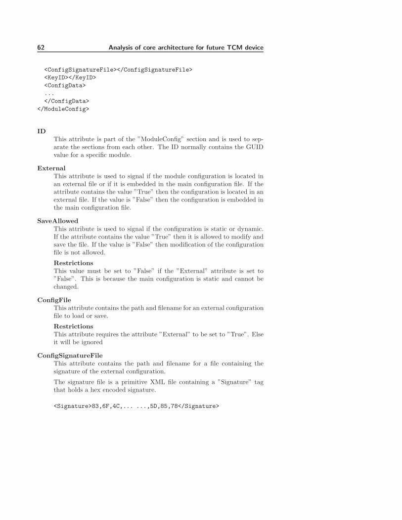
62 Analysis of core architecture for future TCM device
<ConfigSignatureFile></ConfigSignatureFile>
<KeyID></KeyID>
<ConfigData>
...
</ConfigData>
</ModuleConfig>
IDThis attribute is part of the ”ModuleConfig” section and is used to sep-arate the sections from each other. The ID normally contains the GUIDvalue for a specific module.
ExternalThis attribute is used to signal if the module configuration is located inan external file or if it is embedded in the main configuration file. If theattribute contains the value ”True” then the configuration is located in anexternal file. If the value is ”False” then the configuration is embedded inthe main configuration file.
SaveAllowedThis attribute is used to signal if the configuration is static or dynamic.If the attribute contains the value ”True” then it is allowed to modify andsave the file. If the value is ”False” then modification of the configurationfile is not allowed.
RestrictionsThis value must be set to ”False” if the ”External” attribute is set to”False”. This is because the main configuration is static and cannot bechanged.
ConfigFileThis attribute contains the path and filename for an external configurationfile to load or save.
RestrictionsThis attribute requires the attribute ”External” to be set to ”True”. Elseit will be ignored
ConfigSignatureFileThis attribute contains the path and filename for a file containing thesignature of the external configuration.
The signature file is a primitive XML file containing a ”Signature” tagthat holds a hex encoded signature.
<Signature>83,6F,4C,... ...,5D,85,78</Signature>

2.5 Configuration manager 63
KeyIDThis attribute is used to point to a RSA key in the key manager.
RestrictionsThis attribute requires the attribute ”External” to be set to ”True”. Elseit will be ignored
If the attribute ”SaveAllowed” contains the value ”True” the ”KeyID”attribute must point at a private RSA key
ConfigDataThis attribute is used to encapsulate configuration data for a module ifthe attribute ”External” is set to ”False”. Else this attribute is ignored.
2.5.6 Summery
There are performance issues that have to be considered in the final system.Every time a configuration file is loaded it has to be parsed through the signingalgorithm and then parsed by the XML system. Saving a configuration alsorequires a parse through the signing algorithm. This is time consuming couldgive problems if the selected processor have a low execution capacity.
The design is relative simple because of the XML usage. XML files are wellsupported by the compact framework giving a lot of tools to manipulate thesefiles. The compact framework also supports the signing system. This meansmost of the design for the configuration system is in how the files should bebuilt.
2.5.6.1 Design qualities
• The design gives the ability to control who is allowed to edit files.
• The design gives a good integrity test of configuration files.
• The design gives ”easy to edit” configuration files.
• The design uses a well supported system for modifying configurations.
2.5.6.2 Design drawbacks
• Performance.
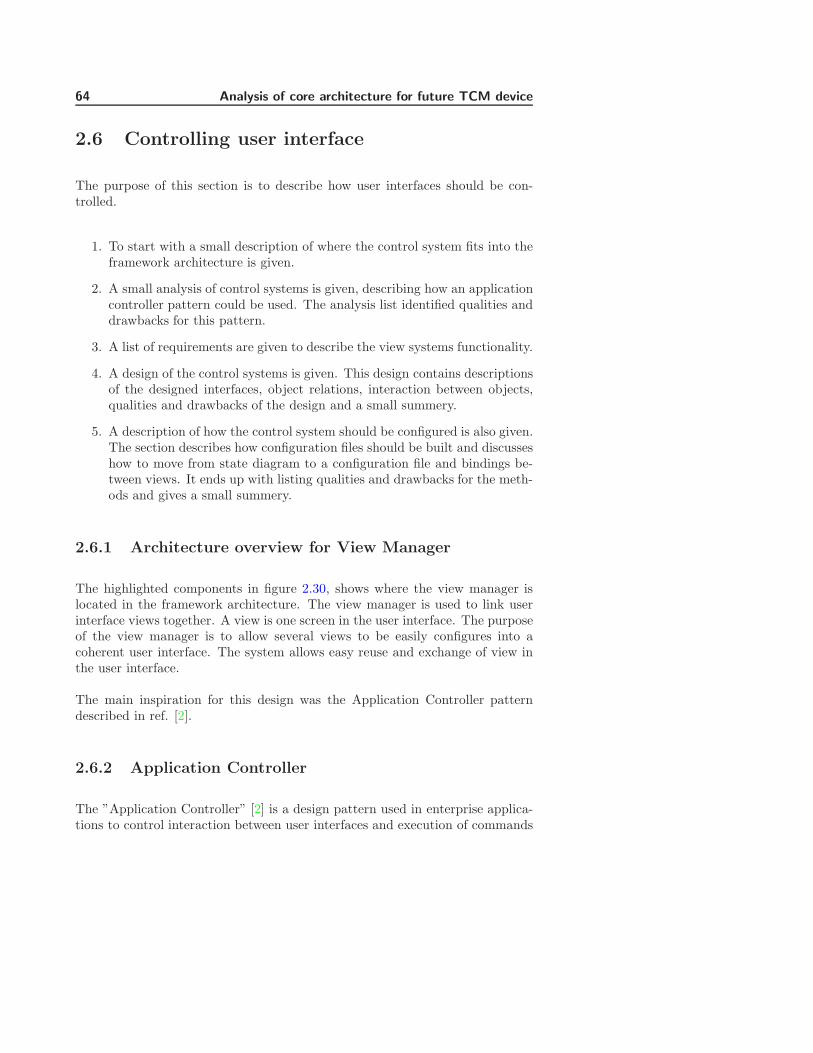
64 Analysis of core architecture for future TCM device
2.6 Controlling user interface
The purpose of this section is to describe how user interfaces should be con-trolled.
1. To start with a small description of where the control system fits into theframework architecture is given.
2. A small analysis of control systems is given, describing how an applicationcontroller pattern could be used. The analysis list identified qualities anddrawbacks for this pattern.
3. A list of requirements are given to describe the view systems functionality.
4. A design of the control systems is given. This design contains descriptionsof the designed interfaces, object relations, interaction between objects,qualities and drawbacks of the design and a small summery.
5. A description of how the control system should be configured is also given.The section describes how configuration files should be built and discusseshow to move from state diagram to a configuration file and bindings be-tween views. It ends up with listing qualities and drawbacks for the meth-ods and gives a small summery.
2.6.1 Architecture overview for View Manager
The highlighted components in figure 2.30, shows where the view manager islocated in the framework architecture. The view manager is used to link userinterface views together. A view is one screen in the user interface. The purposeof the view manager is to allow several views to be easily configures into acoherent user interface. The system allows easy reuse and exchange of view inthe user interface.
The main inspiration for this design was the Application Controller patterndescribed in ref. [2].
2.6.2 Application Controller
The ”Application Controller” [2] is a design pattern used in enterprise applica-tions to control interaction between user interfaces and execution of commands
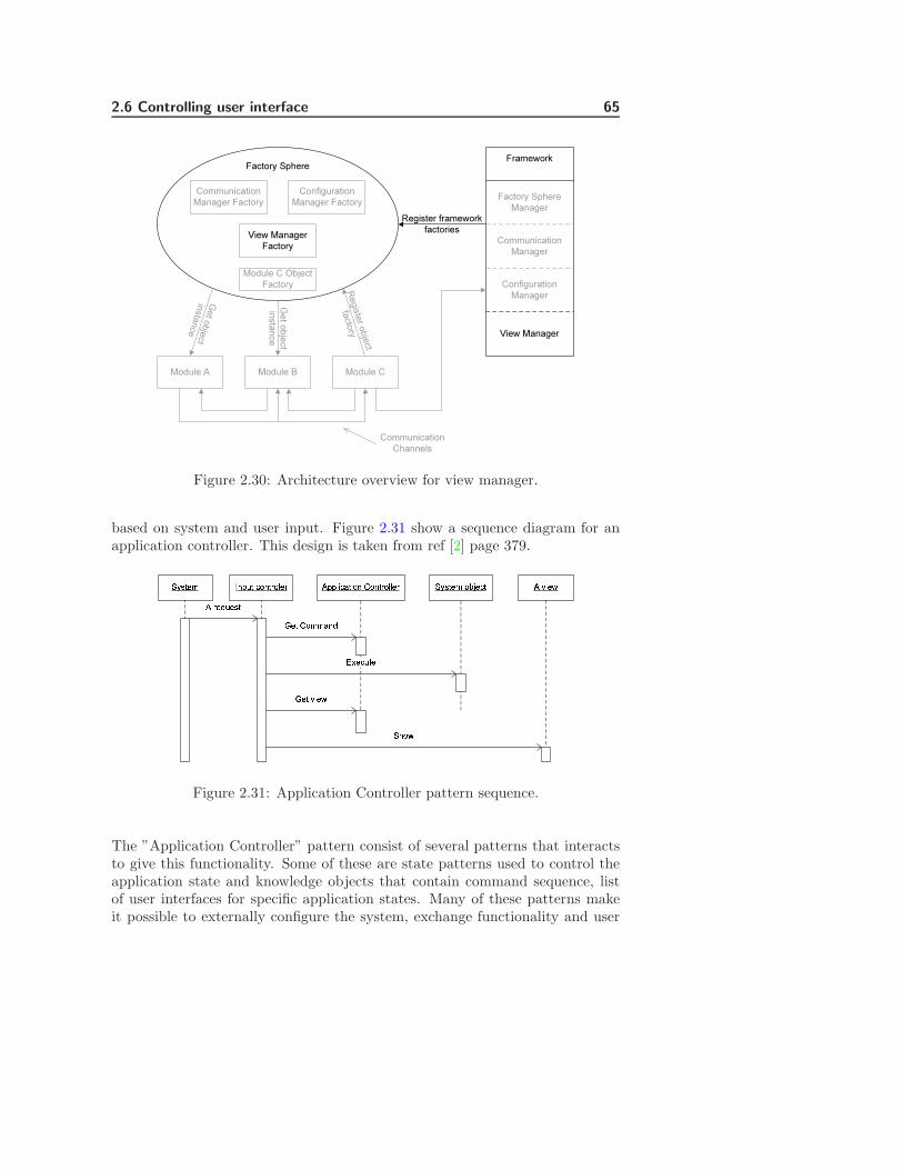
2.6 Controlling user interface 65
Module A
Configuration Manager Factory
Module CModule B
Communication Manager Factory
Framework
View Manager Factory Communication
Manager
Factory SphereManager
Configuration Manager
Register framework factories
R egi ster obj ect
factory
Get object instance
Get object instance
Communication Channels
Factory Sphere
View Manager
Module C Object Factory
Figure 2.30: Architecture overview for view manager.
based on system and user input. Figure 2.31 show a sequence diagram for anapplication controller. This design is taken from ref [2] page 379.ÕÖ×ØÙÚ ÛÜÝÞØ ßàÜØáàâÙá ãÝÝâäßåØäàÜ æàÜØáàââÙá ã çäÙèã áÙéÞÙ×Ø êÙØ æàÚÚåÜë ÕÖ×ØÙÚ àìíÙßØîïÙßÞØÙêÙØ çäÙè Õðàè
Figure 2.31: Application Controller pattern sequence.
The ”Application Controller” pattern consist of several patterns that interactsto give this functionality. Some of these are state patterns used to control theapplication state and knowledge objects that contain command sequence, listof user interfaces for specific application states. Many of these patterns makeit possible to externally configure the system, exchange functionality and user

66 Analysis of core architecture for future TCM device
interfaces as needed. This gives an abstraction between the user interface andunderlying business logic, allowing for substitution of modules in both layers.
2.6.2.1 Design qualities
• Easy substitution of user interface.
• Easy substitution of business logic.
• Easy reuse of user interfaces.
• Easy reuse of business functionality.
• Give an overview of user interaction at design time.
2.6.2.2 Design drawback
• Performance.
• Requires large amount of design documentation.
• Design is for large systems.
2.6.2.3 Summery
The ”Application Controller” pattern can be complex to use, and since thetarget application is an embedded system. One way to use this application isto reduce the pattern and only take a part of it. The part that is interesting totake is the part that controls the user interface. The part that controls functionexecution should be ignored. This can be ignored since interaction between themodules should be done through the communication channels. Also the mainpurpose of the user interface is to present data send from the underlying system,minimizing the amount interaction with the underlying system.
Performance could be an issue depending of how views are identified in theknowledge object. The design performance will not be considered because it isto demonstrate functionality only. For easy implementation the identificationwill de done using strings.
The easy reuse and substitution of user interfaces should be kept in the finaldesign

2.6 Controlling user interface 67
2.6.3 Requirements
VR1 View must be signaled when opened.VR2 View must be signaled when closed.VR3 View must be able to access input controller.VR4 Input controller must be configured externally.VR5 Views should know where the system comes from.VR6 Views should know where the system is going.
2.6.4 View system design
Using the ”Application Controller” pattern as inspiration. The following systemhave been designed.ñòóôõö ÷øùúûô÷üùôýüþþõýÿ� ÷��ù�õ��õ����õ� ø� ÷ûýýõùôñô�ôõ� �õôñô�ôõ���õ� ø� ÷��õ�÷üùôýüþþõý�� �õô��õ����õ� ø� � �õô��õ��÷ûýýõùô��õ� ø�
÷ûýýõùô��õ� �õ���õ��� �õ��õñô�ôõ���õ� ø��� �ùôõýñô�ôõ�÷ûýýõùô��õ� ø��� ñ��õ ùõ� óô�ôõ �ó �ûýýõùô óô�ôõ
Figure 2.32: Sequence for changing views.
Figure 2.32 shows the sequence used to change views in the ”View Controller”.
1. The system starts by sending a request to the input controller to show aspecific view.
2. The input controller asks the knowledge object ”CurrentState” to returnthe state containing the requested view.
3. When a valid state is returned, it is possible to ask the knowledge object”CViewController” for a reference to the physical view.
4. For bookkeeping a reference to the current view is also needed.
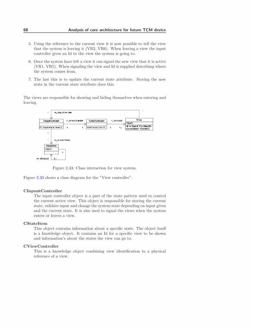
68 Analysis of core architecture for future TCM device
5. Using the reference to the current view it is now possible to tell the viewthat the system is leaving it (VR2, VR6). When leaving a view the inputcontroller gives an Id to the view the system is going to.
6. Once the system have left a view it can signal the new view that it is active(VR1, VR5). When signaling the view and Id is supplied describing wherethe system comes from.
7. The last this is to update the current state attribute. Storing the newstate in the current state attribute does this.
The views are responsible for showing and hiding themselves when entering andleaving.
����������� �� ����!"#$%&'()$*&)+*,,-+.����!"$/)0)-%)-12 .345�677��898�8�2 �:�8�798�8� �� ;75398�8�!"#�<��=�98�8� �� >598�8�!"#.���� !" %?@-A�B�8���� �� ����!"#$?@-A$*&)+*,,-+ 2.345����<�C82DDE2.345�����5�875FF�72 2.345!�G68�5�875FF�72
2.34598�8�<�C8 HDDEFigure 2.33: Class interaction for view system.
Figure 2.33 shows a class diagram for the ”View controller”.
CInpuntControllerThe input controller object is a part of the state pattern used to controlthe current active view. This object is responsible for storing the currentstate, validate input and change the system state depending on input givenand the current state. It is also used to signal the views when the systementers or leaves a view.
CStateItemThis object contains information about a specific state. The object itselfis a knowledge object. It contains an Id for a specific view to be shownand information’s about the states the view can go to.
CViewControllerThis is a knowledge object combining view identification to a physicalreference of a view.
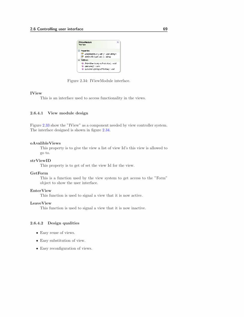
2.6 Controlling user interface 69IJKLMNOPQRLSTUVWXYZV[\]^_\`a_bc_`d]ebFigure 2.34: IViewModule interface.
IViewThis is an interface used to access functionality in the views.
2.6.4.1 View module design
Figure 2.33 show the ”IView” as a component needed by view controller system.The interface designed is shown in figure 2.34.
oAvalibleViewsThis property is to give the view a list of view Id’s this view is allowed togo to.
strViewIDThis property is to get of set the view Id for the view.
GetFormThis is a function used by the view system to get access to the ”Form”object to show the user interface.
EnterViewThis function is used to signal a view that it is now active.
LeaveViewThis function is used to signal a view that it is now inactive.
2.6.4.2 Design qualities
• Easy reuse of views.
• Easy substitution of view.
• Easy reconfiguration of views.

70 Analysis of core architecture for future TCM device
• Give an overview of user interaction at design time.
2.6.4.3 Design drawbacks
• Limited interaction between views.
• Performance.
2.6.4.4 Summery
The view system design is a reduced version of the ”Application controller”pattern. This design only controls the user interface part. This results in alighter and easier system that can be implemented into an embedded system. Itdoes however create a new drawback in the design. Since the control system onlycontrols the views and not function calls, this limits the interaction between theviews significantly. The views only get information’s about the views available,where the view comes from when entering and where it is going when leaving.However the few drawbacks there are in this system do not outweigh the qualitiesin the system. The ability to substitute a view with another just by changingthe ID makes the system easy to adapt and gives an easy way to reuse userinterface.
2.6.5 View configuration
As described the input controller shown on figure 2.33 is just a state machinethat based on some input is capable of changing state. To make the statemachine as dynamic as possible is should be build up around a configurationfile describing the states.
2.6.5.1 Configuration file
The configuration files have two main sections. The fist is a list of views to beloaded and the second it a list that describes each state.
Before generating a configuration files a state machine should be drawn to getan overview of the states in the system.
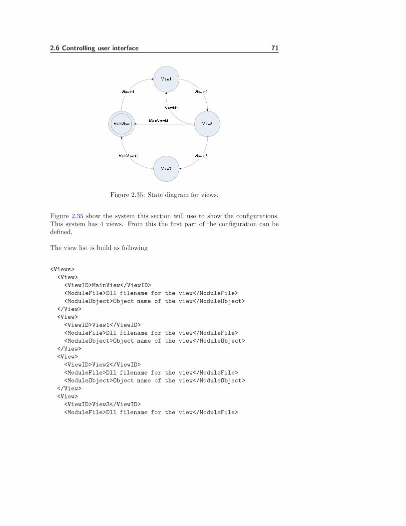
2.6 Controlling user interface 71
fghijhkljhklm
jhklnjhklo
jhklpqm fghijhklpqfghijhklpq jhklpqo
jhklpqnjhklpqm
Figure 2.35: State diagram for views.
Figure 2.35 show the system this section will use to show the configurations.This system has 4 views. From this the first part of the configuration can bedefined.
The view list is build as following
<Views>
<View>
<ViewID>MainView</ViewID>
<ModuleFile>Dll filename for the view</ModuleFile>
<ModuleObject>Object name of the view</ModuleObject>
</View>
<View>
<ViewID>View1</ViewID>
<ModuleFile>Dll filename for the view</ModuleFile>
<ModuleObject>Object name of the view</ModuleObject>
</View>
<View>
<ViewID>View2</ViewID>
<ModuleFile>Dll filename for the view</ModuleFile>
<ModuleObject>Object name of the view</ModuleObject>
</View>
<View>
<ViewID>View3</ViewID>
<ModuleFile>Dll filename for the view</ModuleFile>

72 Analysis of core architecture for future TCM device
<ModuleObject>Object name of the view</ModuleObject>
</View>
</Views>
The section ”View” is an entry that describes one single view.
ViewIDThis attribute is used to give a view a unique Id to identify it by.
ModuleFileThis attribute contains the filename and path for a DLL file containingthe view.
ModuleObjectThis attribute contains the name of an object in a DLL file that functionsas the entry point for a view module.
The combination of the filename and object name uniqly described the moduleto be loaded. This means more than one view can be located in the same DLLfile.
The second part of the configuration file describes the relations between theviews. From figure 2.35 the following can be described:
<States>
<InitialView>MainViewId</InitialView>
<view>
<ViewID>MainViewId</ViewID>
<State>ViewId1</State>
</View>
<View>
<ViewID>ViewId1</ViewID>
<State>ViewId2</State>
</View>
<View>
<ViewID>ViewId2</ViewID>
<State>MainViewId</State>
<State>ViewId1</State>
<State>ViewId3</State>
</View>
<View>
<ViewID>ViewId3</ViewID>
2.6 Controlling user interface 73
<State>MainViewId</State>
</View>
</States>
InitialViewThis attribute defined the view to be showed at startup. In figure 2.35this is showed as the initial state.
The configuration files contains a list of ”View” sections. These sections describethe state a specific view is allowed to go to by listing the Id’s for the allowedstates.
ViewIDThis attribute is used to define the view for the state list.
StateThis attribute contains the Id of a view where the defined ViewID isallowed to go to. The section can contain 1 to many of this attribute.
As an example of how a section to build up it can be seen ”View2” can go to”MainView”, ”View1” and ”View3”. The section that defined the states for”View2” contains the Id for these 3 views.
2.6.5.2 Dependencies between views and input controller
Defining the state machine is however not enough to make it work. The viewshave to give feedback to the input controller in order to change views.
The input controller required the viewId’s to be given as input when changingviews. This means button or actions in a view have to be linked to a ViewId.
This can be done using a simple configuration file like this.
<ButtonLinks>
<ButtonID>ButtonA</ButtonID>
<ViewID>ViewId1</ViewID>
</ButtonLinks>
This creates a dependency between the views and the input controller becausethe view needs to know what view it has to go to. This link is unavoidable,

74 Analysis of core architecture for future TCM device
however keeping it in configuration files give the possibility to reconfigure theviews without recompiling the views.
The dependency could be moved to the view controller by modifying it to re-spond to button Id’s instead of ViewId. This however would require the inputcontroller to know about the buttons in the views. Where this dependencyshould be considered before a final system is created.
2.6.5.3 Design qualities
• Easy to reconfigure view interaction without recompiling views.
2.6.5.4 Design drawbacks
• There are dependencies between the input controller and views.
2.6.5.5 Summery
The way the view system is build up generates some dependencies between theviews and the input controller. A larger analysis should be performed to seeif this dependency could be reduced and where it should be located. It willprobably not be possible to remove this dependency because views can have anarbitrary number of buttons and can go to any view. This means some one haveto know about the internals of the view and how the view should navigate toother views.
2.7 Design summery
This chapter describes how modules should be designed and describes 4 imple-mented software modules.
2.7.1 Module design
The design shows how a basic software module should look. Access to softwaremodules can only be done through a simple interface. This limits bindings be-
2.7 Design summery 75
tween software modules. All software modules rely on external help for all typesof communication between software modules. This has been done to remove anyslippage problems when it comes to communication between software modules.
Slippage problems often shows themselves when module that have not beendesigned to communication with each other suddenly have to. The interfacesbetween these are in most cases not compatible. Forcing modules to communi-cate through a common interface removed the problem.
2.7.2 Factory sphere
This module was developed to give a common way for all software modules toshare factory objects. The system works by letting software modules register afactory object into the factory sphere, which is responsible for creating objectinstances. The factory sphere consists of a number of general interfaces designedto allow almost all types of objects to be created. Modules should also be ableto register any type of factory objects into the sphere. This generality havebeen designed into the module to allow easy evolution of the entire framework.The only restrictions in the factory sphere are the factory objects have to im-plement a simple interface. If modules exclusively rely on the factory sphere forcommunication with other modules, slippage problems could become a problem.
The factory system used the Abstract Factory patterns as baseline of compar-isons to develop a system where factories can be added runtime. The final resulthas almost the same qualities as the original factory. The biggest drawback isthis system is more complex to implement.
The factory sphere implements a number of generic creational patterns that canbe used to create object with. These are session and singleton patterns. Thegenerality of the factory sphere could be seen as a sign, that the factory systemcould be a design pattern. However before this can be determined analysis ofthis must be done.
2.7.3 Communication Manager
This module controls communication channels between modules. The commu-nication manager have been developed to minimize the effect evolution can haveon communication between modules and thus reduce slippage problems. Thecommunication manager lets modules create channels to communicate over us-ing parsed XML documents as protocols. Not only gives this method a very

76 Analysis of core architecture for future TCM device
flexible method for communication, but also a unified interface for this.
The communication system is relative simple to implement and use. But it hassome problems. Data have to be packed into and out of a XML document. Thisrequires time and lower performance. This means this system has to be testedon the final hardware platform before any conclusion of usability can be done.There is also a problem regarding data integrity. To increase performance in thecommunication system, it is only the reference to the XML document that isparsed to each listener. This means if one listener modifies the protocol contentsit could affect other listeners.
2.7.4 Configuration Manager
This module can be used by other modules to load and save configuration filesand test integrity. The module is relative simple to implement because the con-figuration files are XML documents and the .NET framework has XML classescapable of this. Most of the work in this module was on the implementation ofthe integrity test.
2.7.5 Controlling user interfaces
To control the views in the user interface a reduced version of the applicationcontroller pattern was implemented. The implemented solution works, but theoverall result for this software module is not a complete success. Reducing pat-terns cannot be recommended. It is time consuming and the end result is notas usable as could be desired. The implemented view manager has some unre-solved issues regarding how dependencies between the views should be. There isalso a lot of work to be done regarding configuration of the system. Before thissoftware module should be used a cost/benefit analysis of the software moduleshould be done and compared to a normal implementation of a user interface.
If this module was to be redesigned it could be more beneficial to use ref [5] andcombine patterns into a useful solution.
2.7.6 Design patterns
During the design several patterns have been used and what could be considerednew patterns have been created. The factory sphere and communication system

2.7 Design summery 77
could be considered as new patterns because they work on generally any thing.But before this can be concluded a comprehensive analysis has to be performed.Ref [8] describes how design patterns could be identified. Before a code structurecan be considered a pattern, it has to general enough to be used by any objectwith only a small modification. It also has to be implementable in more thanone language and a usability study has to be performed. None of these thingshave been analysed in this thesis and the reasons for this is time. An analysisof the factory sphere and communication manager would take approximately 2to 3 month.
A faster way could be trying to implement these as templates instead (or genericin C#). When implementing the factory sphere it was discovered that manydesign patterns are easy to implement as templates. It could be interesting tosee which of these method best could describe a design pattern.

78 Analysis of core architecture for future TCM device

Chapter 3
Case studys
Contents3.1 Case A - High speed communication . . . . . . . . . 80
3.2 Case B - Configuration security . . . . . . . . . . . . 84
3.3 Case C - Distributed system . . . . . . . . . . . . . . 87
3.4 Case D - Interaction between user interfaces . . . . 89
3.5 Case E - Evolution on communication channels . . 92
3.6 Case F - Controlling measurement location . . . . . 95
3.7 Case G - Auto configuration . . . . . . . . . . . . . . 96
In this chapter cases will be discussed for framework usability regarding TCMrelated devices. The cases described have been kept small in order to keep focuson specific problems and solutions. Creating one large case study could obscuresome of the details involved. The case studies will describe different problemsidentified in the design of each software module. They will also describe someof the concepts and requirements.
The chapter contains information about:
• How high-speed communication between modules can be made.
• How restrictions can be implemented into configuration files.
80 Case studys
• How the communication system could be extended into a distributed sys-tem.
• How interaction between user interfaces could be performed.
• What happens when a protocol for a communication channel is evolved.
• How measurements could be controlled in a user interface.
• How the framework could be auto configured by detecting connected hard-ware.
3.1 Case A - High speed communication
This case describes the different options for communication supported in theframework. This case have been selected because section 2.4.8 describes per-formance problems in the communication system. SpO2 requires high-speedsynchronised communication, describing each available method should help fur-ther development in selecting the correct methods.
3.1.1 Problem description
Section 2.4 describes how communication between modules can be performedusing communication channels. A problem using this system for communicationcould be performance. In most TMC related measurements performance shouldnot be a problem since data is send with an interval of 2s. However there is onemodule where performance could be a problem.
The TCM40 device has a hardware module used to measure SpO2 and pulse.This module can also send out graph data. The graph data sent from theSpO2 hardware module is used to show the rhythm of the heartbeat. To depicthow this rhythm, there is sent data for the graph with an interval of a fewmilliseconds. The SpO2 can send wave information with the intervals 79Hz,38Hz, 25.3Hz or 19Hz depending on configuration. This gives the system min13ms and max 52ms to handle the graph value. As default the hardware modulesends data every 13ms this is also used by the current TCM40 devices.
It is also very importent that measurements are received in the correct order andwith an even interval. This is because the curve has to be drawn at a specificspeed of about 25mm/s. If graph data do not come with an even interval, it isimpossible to draw the graph correctly.

3.1 Case A - High speed communication 81
3.1.2 Scenario
The framework gives 3 methods for communication. These are synchronousand asynchronous communication through the communication system. The lastmethod bypasses the communication system and creates a bridge between themodules.
This case will use a SpO2 module configured to send data every 52ms. This hasbeen select because this is the system have to run on the emulator device.
Before a method can be used it must fulfil the following requirements:
• Graph data must come with an even interval of 52ms or less.
• Graph data come in the correct order.
3.1.3 Solutions
3.1.3.1 Method 1
As default the communication system used asynchronous communication be-tween software modules. This method cannot be used because asynchronouscommunication cannot guarantee either of the requirements. Measurementscan come in a different order than they are measured. The time interval forreceiving the measurements can also very, depending on the load of the system.
3.1.3.2 Method 2
Communication channels can be setup to transmit communication synchronously.This guaranties the measurements comes in the order they are measured andalso measurements come in an even interval. Using the communication systemcould however give problems on low-end systems. The problem is data have tobe packed and unpacked from an XML document and this takes time. Low-endsystem could have trouble creating these XML documents within 52ms and stillhave an acceptable safety margin on resource usage.
Creating a system where some modules require 99% of the resources are notacceptable because other parts of the system then easily could disrupt the dataflow, if they suddenly require a large amount of resources.

82 Case studys
Using this method is acceptable but is requires an analysis of the performanceon the desired platform.
3.1.3.3 Method 3
This method uses the factory sphere to create a bridge between the SpO2 soft-ware measurement module and the software module used to display the SpO2
values.
rstuvwxtywz{t|}~�������������������������������������������������Figure 3.1: Bridge interface and object.
Figure 3.1 shows the interface and object defined to the bridge between thetwo modules. The interface is shared between the modules and the object isregistered into the factory sphere. The interface have a function used to setSpO2 value, the object is responsible for implementing and handling the values.
SpO� receiver object
Factory sphere
SpO� measurement module
SpO� Display Module
1. Register CSpO2Receiver factory
2. Get instance of SSpO2Receiver
SpO2 Receiver interface
3. SetWaveValue
Figure 3.2: Connection modules through bridge.
Figure 3.2 shows an overview for how the bridge is created.
1. When the system is initialized the view responsible for displaying the wavevalues register the object ”CSpO2Receiver” object into the factory sphere.
2. This allows the SpO2 measurement module to get an instance of the object.
3.1 Case A - High speed communication 83
3. Using the shared interface on the instance received allows the measurementmodule to set SpO2 values into the object. The object can then functionas a bride between the measurement module and the display module.
This method is a little more complex to implement than using the communica-tion system. However because the SpO2 data do not have to be packed into anXML document, makes this method a lot more efficient.
3.1.4 Summery
Method 2 and 3 are both acceptable solutions for the problem and can both beused depending on performance requirements and capabilities of the system.
3.1.4.1 Method 2
This method should be used if possible because this method makes the systemmore flexible. The method allows transmission to more than one module withoutcreating any bindings between these.
Qualities
• No extra implementation required.
• No extra bindings or dependencies on other modules.
• Send data to multiple sources.
Drawbacks
• Worse performance compared to method 3.
3.1.4.2 Method 3
This method creates a weak binding between the modules because they need theinterface for the bridge object. There is also some dependency on the sequence ofinitialization. The measurement module cannot get the bridge object before thedisplay module register it. The shown example can also only send data to oneother module. The communication module allows for data to be transmitted to
84 Case studys
multiple listeners. To achieve this using the factory sphere as a way to bridge themodules would require a more complex implementation of the ”CSpO2Receiver”object. One way to solve the problem could be by letting the object implementan observer pattern [1]. This would require all the modules to share the interfacecreating a weak bound between them.
Qualities
• Better performance than method 2.
Drawbacks
• More complex implementation.
• Creates dependency and weak bindings between modules.
3.2 Case B - Configuration security
This case has been selected to show the different options available in the config-uration system described in section 2.5. Showing the available options shouldhelp in selecting the correct type of configuration file in the future.
3.2.1 Problem
Section 2.5 describes how the configuration uses a digital signature to verify theintegrity of configuration files. There are several types of data that could beinteresting to store an external configuration files. These could be default datafor modules, user configuration, and license information. License information’scould be the number of allowed modules of a specific type and other informationused to restrict module functionality.
This means some of the configuration files must not be changeable and othersshould be changeable.
3.2 Case B - Configuration security 85
3.2.2 Scenario
The case will describe 2 types of configuration files. The first type is called adynamic configuration file. This type of configuration file is a file where theframework is allowed to alter data. The second type of configuration is a staticconfiguration file where the framework cannot alter data.
3.2.3 Solutions
3.2.3.1 Dynamic configurations files
Dynamic configuration files are containing parameters the user is allowed toadjust. These parameters could be printer setup or alarm limits for O2 or CO2.
Dynamic configuration files require a private RSA key to be preset in frameworkin order to generate a new signature when the file is saved. For this reason thesignature in this type of configuration file, is for integrity test only. The privatekey could be extracted from the system and used for manually updating.
This makes dynamic configuration file unsuitable to store static data, but itallows for storage of user changed data.
Qualities
• Detection of corrupt disk.
• Attributes can be changed in the configuration files.
• Attributes can be added.
• Attributes can be removed.
Drawbacks
• Limited detection of external editing.
3.2.3.2 Static configuration files
Static configuration is designed to hold license information used to limit func-tionality in the framework. But they can also be used to hold factory default

86 Case studys
values and other parameters that are not allowed to be changed. License in-formation’s could be information’s about how many O2 hardware modules thatis supported by the framework. It is not desirable to let a costumer use moreO2 sensors the than they have bought licenses for. Another example could beto limit the number of sensors allowed in the system because of user interfacelimitations.
The main difference between the static and dynamic configuration files are, thestatic does not need a private RSA key to be present. This means the frameworkcannot change the configuration files. This means not only do the system offersdetection of corrupt disks it also offers detection of external editing. Since theprivate key is not necessary to have on the system, like it is for the dynamicconfiguration file, makes it difficult to edit the files because the signature cannotbe updates.
3.2.3.3 Qualities
• Detection of corrupt disk.
• Detection of external editing.
• Cannot be changed.
3.2.4 Drawbacks
• Only the files owner can change it.
3.2.5 Summery
The configuration system gives a way to control license information in the ap-plication. This is done in a way that makes it difficult for the costumer to alter.The configuration system also gives a way to let the user store a system setupon the disk in a secure way. Meaning the configuration system detects if thesetup have been damaged by a corrupt disk and for limited external editing.
The system does not give a way to store data encrypted on the disk. This meansif there is sensitive data in a configuration file, then this data can be read byanyone.
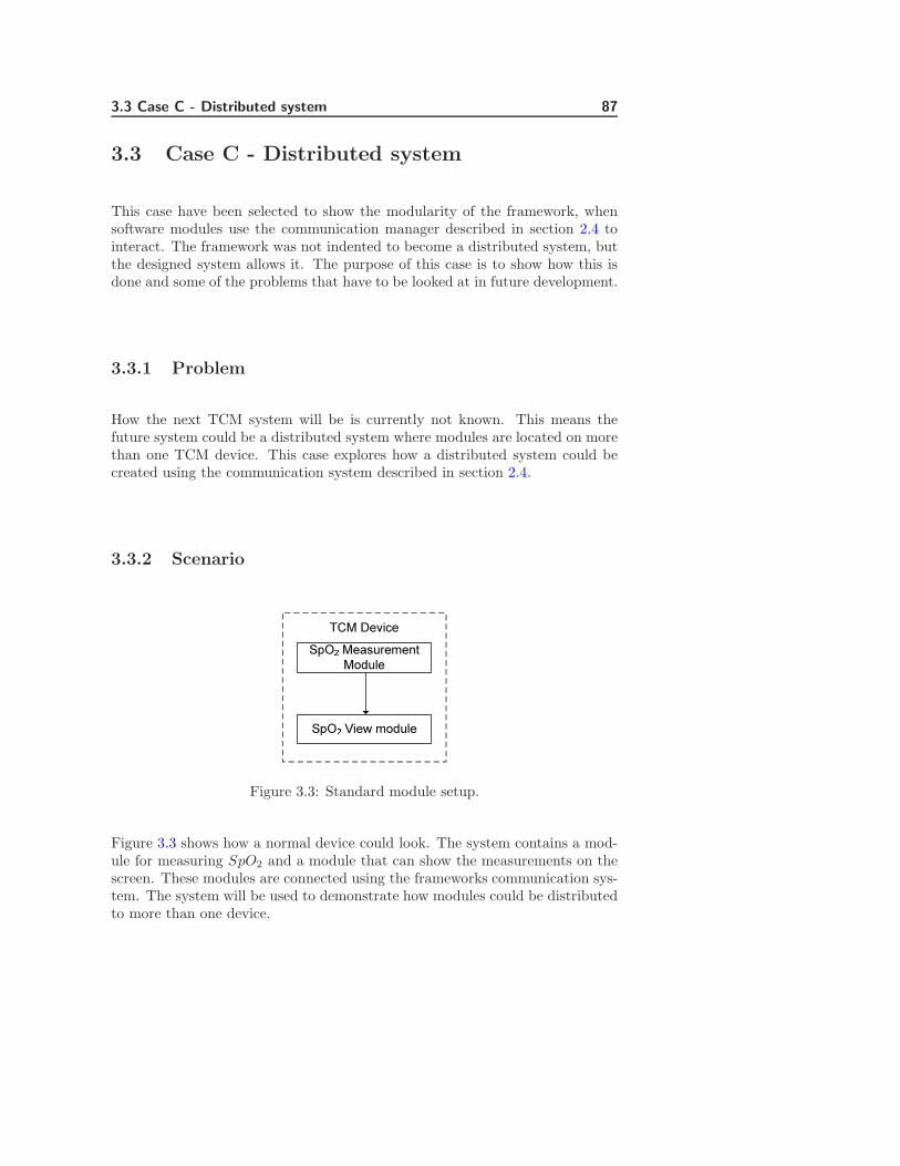
3.3 Case C - Distributed system 87
3.3 Case C - Distributed system
This case have been selected to show the modularity of the framework, whensoftware modules use the communication manager described in section 2.4 tointeract. The framework was not indented to become a distributed system, butthe designed system allows it. The purpose of this case is to show how this isdone and some of the problems that have to be looked at in future development.
3.3.1 Problem
How the next TCM system will be is currently not known. This means thefuture system could be a distributed system where modules are located on morethan one TCM device. This case explores how a distributed system could becreated using the communication system described in section 2.4.
3.3.2 Scenario
SpO� Measurement Module
TCM Device
SpO� View module
Figure 3.3: Standard module setup.
Figure 3.3 shows how a normal device could look. The system contains a mod-ule for measuring SpO2 and a module that can show the measurements on thescreen. These modules are connected using the frameworks communication sys-tem. The system will be used to demonstrate how modules could be distributedto more than one device.
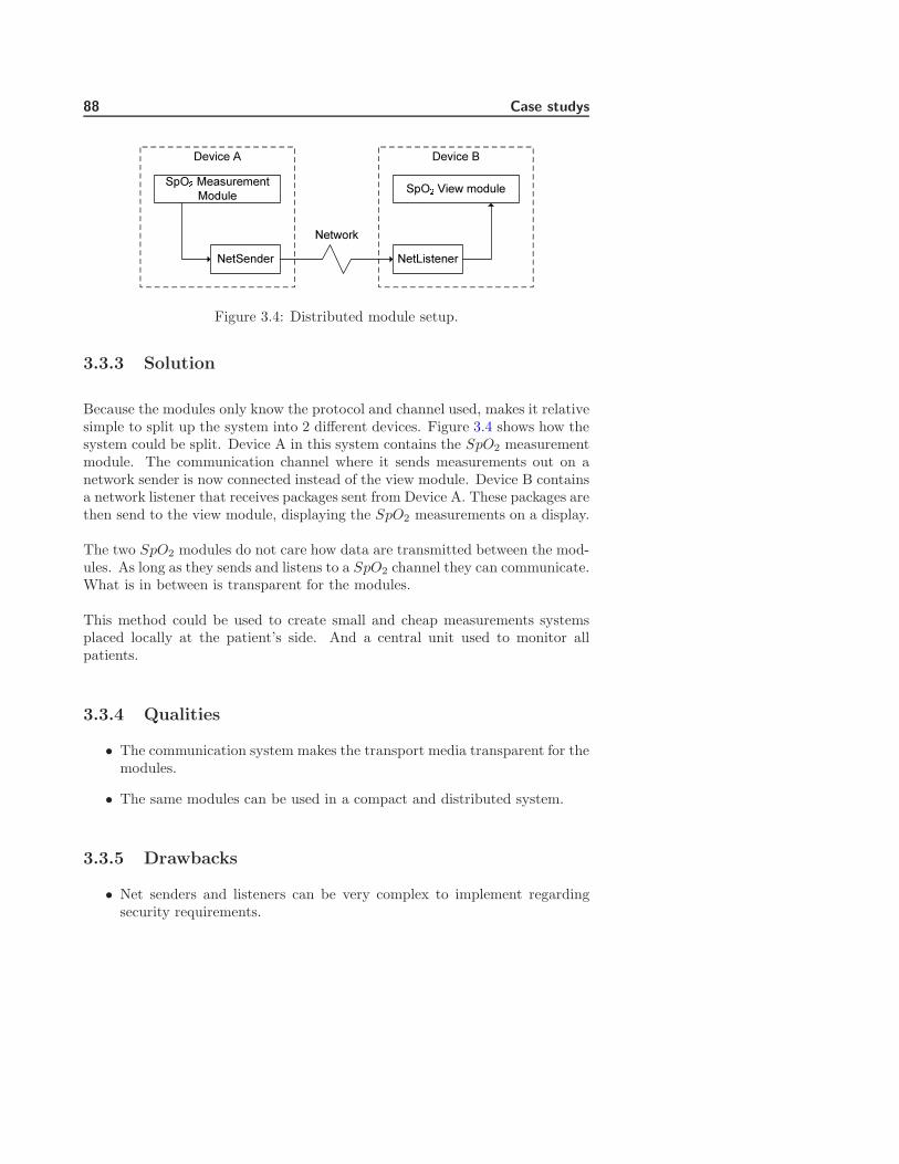
88 Case studys
NetSender NetListener
SpO� Measurement Module SpO� View module
Device A Device B
Network
Figure 3.4: Distributed module setup.
3.3.3 Solution
Because the modules only know the protocol and channel used, makes it relativesimple to split up the system into 2 different devices. Figure 3.4 shows how thesystem could be split. Device A in this system contains the SpO2 measurementmodule. The communication channel where it sends measurements out on anetwork sender is now connected instead of the view module. Device B containsa network listener that receives packages sent from Device A. These packages arethen send to the view module, displaying the SpO2 measurements on a display.
The two SpO2 modules do not care how data are transmitted between the mod-ules. As long as they sends and listens to a SpO2 channel they can communicate.What is in between is transparent for the modules.
This method could be used to create small and cheap measurements systemsplaced locally at the patient’s side. And a central unit used to monitor allpatients.
3.3.4 Qualities
• The communication system makes the transport media transparent for themodules.
• The same modules can be used in a compact and distributed system.
3.3.5 Drawbacks
• Net senders and listeners can be very complex to implement regardingsecurity requirements.
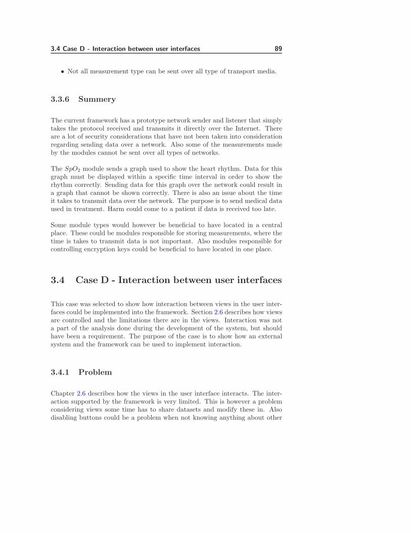
3.4 Case D - Interaction between user interfaces 89
• Not all measurement type can be sent over all type of transport media.
3.3.6 Summery
The current framework has a prototype network sender and listener that simplytakes the protocol received and transmits it directly over the Internet. Thereare a lot of security considerations that have not been taken into considerationregarding sending data over a network. Also some of the measurements madeby the modules cannot be sent over all types of networks.
The SpO2 module sends a graph used to show the heart rhythm. Data for thisgraph must be displayed within a specific time interval in order to show therhythm correctly. Sending data for this graph over the network could result ina graph that cannot be shown correctly. There is also an issue about the timeit takes to transmit data over the network. The purpose is to send medical dataused in treatment. Harm could come to a patient if data is received too late.
Some module types would however be beneficial to have located in a centralplace. These could be modules responsible for storing measurements, where thetime is takes to transmit data is not important. Also modules responsible forcontrolling encryption keys could be beneficial to have located in one place.
3.4 Case D - Interaction between user interfaces
This case was selected to show how interaction between views in the user inter-faces could be implemented into the framework. Section 2.6 describes how viewsare controlled and the limitations there are in the views. Interaction was nota part of the analysis done during the development of the system, but shouldhave been a requirement. The purpose of the case is to show how an externalsystem and the framework can be used to implement interaction.
3.4.1 Problem
Chapter 2.6 describes how the views in the user interface interacts. The inter-action supported by the framework is very limited. This is however a problemconsidering views some time has to share datasets and modify these in. Alsodisabling buttons could be a problem when not knowing anything about other

90 Case studys
views.
3.4.2 Scenario
A common problem in TCM could be the control of patient Id. In TCM4system it is possible to enter a patient Id. This Id is shown on all the viewsdisplaying measurement data. In the TCM400 system it is also used to controlmeasurement sessions.
3.4.3 Solutions
3.4.3.1 Using communication channels
One method for creating interaction between the views could be by using com-munication channels.
A view could create a channel and use this channel every time a change to adataset has been performed. Any one interested in the data could then listento this channel and get updates.
This is however not preferred since all views that have data to exchange needto create a channel and send data over. Changing the rules for notificationof changes is difficult because changes have to be made in all the views. Thiswould also give some undesired bindings between the modules since they haveto communicate directly if values have to be modified.
The preferred way would be to implement an Observer pattern to handle thistype of traffic.
3.4.3.2 Observer pattern
This section describes how an observer pattern can be implemented into theframework.
A Common way to create interaction between views is to create an observer thatcould hold the required data and then notify the views when data is changed.An example of an observer pattern can be seen in ref [1] page 293. The designto be used is very close the one described in ref [1].
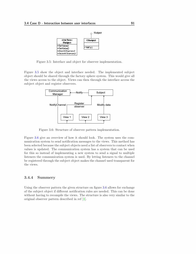
3.4 Case D - Interaction between user interfaces 91
�� ¡¢£¤¥ ¦§�¨ ¡¢£¤¥ ¦§�©¡¡£ª«¬® ¯° ¯¦§�± ¡£ª«¬® ¯° ¯¦§²³ µ¶·¸¹º¶»¼½¾¿ÀÁÂà ÄÅƵ³ ÇÈÉʽ¾¿ÀÁÂÃËÌÍÎ϶ºµFigure 3.5: Interface and object for observer implementation.
Figure 3.5 show the object and interface needed. The implemented subjectobject should be shared through the factory sphere system. This would give allthe views access to the object. Views can then through the interface access thesubject object and register observers.
Subject
View 1 View 2 View 3
Communication Manager Notify
NotifyChannel Register observer Modify data
Figure 3.6: Structure of observer pattern implementation.
Figure 3.6 give an overview of how it should look. The system uses the com-munication system to send notification messages to the views. This method hasbeen selected because the subject objects need a list of observers to contact whenvalues is updated. The communication system has a system that can be usedfor this so instead of implementing a new system to send a signal to multiplelisteners the communication system is used. By letting listeners to the channelbe registered through the subject object makes the channel used transparent forthe views.
3.4.4 Summery
Using the observer pattern the given structure on figure 3.6 allows for exchangeof the subject object if different notification rules are needed. This can be donewithout having to recompile the views. The structure is also very similar to theoriginal observer pattern described in ref [1].

92 Case studys
The bindings between the modules have not been increased since they have tocommunicate with the subject object. The system is also better than using thecommunication system directly because the values are stored in a central place.
The subject object has to be implemented for each type of interaction required.This could mean that there should be a subject object for disabling buttons,and subject objects for different datasets.
3.4.4.1 Qualities
• No bindings between the views.
• Transparent usage of the communication system.
• Allowed other objects to interact with multiple views.
3.4.4.2 Drawbacks
• Different implementations of subject object might be needed dependingon the systems configuration.
3.5 Case E - Evolution on communication chan-
nels
This case has been selected to show how the concept of evolution and slippageproblems described in ref. [3] affect the communication system described insection 2.4. The purpose of this case is to show the effect module evolution haveon the system. Since communication between modules should only be performedusing the communication system means this is where evolution problem couldshow them self.
Evolution is defined as system object changing the way they communicate withother systems.
Communication is done using XML based protocols. The following example willbe used to show how evolution can affect the communication in this system.
<Protocol>

3.5 Case E - Evolution on communication channels 93
<SpO2Value></SpO2Value>
</Protocol>
Measurement module SpOÐ
Data storage module
View displaying SpOÐ
Figure 3.7: Modules linked through a communication channel.
The system used is shown on figure 3.7. The system shows a SpO2 modulesending out measurements to a storage system and to a view displaying theresults.
Evolution can go two ways in the communication system. Attributes can beadded to the protocol due to new parameters. Attributes can be removed do toobsolete parameters.
3.5.1 Adding new parameter
An attribute called BPM could be added to the protocol allowing it to transmitthe SpO2 pulse parameter.
<Protocol>
<SpO2Value></SpO2Value>
<BPMValue></BPMValue>
</Protocol>
Considering the storage and view module currently do not know the attribute”BMPValue” means this attribute is simply ignored. For the modules to use itthey need to be upgraded. This means if an attribute is added to a protocol acombination of both old and new modules could be used at the same time.
As an example only the storage module is upgraded to support the new param-eter. Both modules would still be able to handle the new protocol. Retesting isonly required of the storage module.

94 Case studys
3.5.2 Removing a parameter
Both storage and view module are now upgraded to use both attributes in theprotocol. Now the SpO2 parameter will be removed from the system.
<Protocol>
<BPMValue></BPMValue>
</Protocol>
If the storage and view modules got this protocol they would both fail becausethey expect the SpO2 module. When designing modules they should be preparedto handle situations where one or more parameters are missing. This is to ensurethat one defect module cant crash the system because is sends defect packagesout on a channel.
3.5.3 Summery
Attributes can easily be added to the protocols without having to upgrade all themodules using the protocol. This makes it easy to extend the system. Removingattributes however can become a very complex affair since all the modules haveto be upgraded to use the new protocol.
Using normal interfaces between the modules instead of the communicationchannels would require recompilation of each module and retesting every time anattribute is added or removed. The same would apply if a static data structurewere used.
3.5.3.1 Qualities
• Easy to extend protocols.
• Extension requires minimal amount of testing.
3.5.3.2 Drawbacks
• Difficult to reduce protocols.
• Reduction requires complete retesting of all affected modules.
3.6 Case F - Controlling measurement location 95
3.6 Case F - Controlling measurement location
This have been selected to show how the configuration manager described insection 2.5 can be used to control where the measurements are shown in a viewand what have to be implemented in the future. The purpose of this case is toshow how to control measurements on the user interface.
The system can have more than one sensor of the same type located. Thecurrent TCM device can have up to 6 O2 measurement modules connected atthe same time. A method is needed to ensure the measurements from specificmodules always are shown in the same position on the screen.
In the current TCM system measurements are shown in the screen based onthe port it is connect to. The method is possible to use on the TCM devicebecause each module have a dedicated serial port. However this system cannotbe used if the TCM device uses another communication system. If the modulesare connected through USB or Ethernet then it could be a problem to ensurethe same module always has the same position on the screen. This is becausethe not necessarily can be identified on the port used, because these can bechanged every time the system starts up.
The measurement protocol contains a ”HardwareID” attribute than can be usedto uniquely identify each hardware module. The identification can be done usingthe hardware modules serial number.
By having a unique identification of each module it is now possible to create aconfiguration file describing where each module should be shown on the view.
3.6.1 Qualities
• Modules can be uniquely identified.
• Can control modules placement on the view.
3.6.2 Drawbacks
• Currently it is not all modules that contains a serial number.
• Require reconfiguration when modules are changed.

96 Case studys
3.6.3 Summery
The solution is relative simple using the module serial number. Currently thereis one problem using this method. That is the SpO2 module does not supportretrieval of the modules serial number. However normally it is not necessary touse more than one module when measuring SpO2 and pulse. O2 is the mostcommon modules used when it comes to using multiple sensors. The reason forthis, is this type of sensors are used in wound treatment where several sensorsare placed around the wound. The O2 modules do have a serial number thatcan be retrieved.
The biggest problem would be if modules are changed for a new one. A changelike that would require a reconfiguration of the view. For this reason it shouldbe considered if a tool for reconfiguring should be implemented into the system.
3.7 Case G - Auto configuration
This case have been selected to show how a future system could be if conceptsdescribed in section 1.4.5.2 were to be implemented and the overall requirementOR12 were to be removed. This case will discuss how the system could beautomatically configured if two of the concepts in the preliminary analysis wasimplemented. The concepts are ”Hardware Abstraction Layer” and ”HardwareDiscovery”.
3.7.1 Hardware Abstraction Layer
The preliminary analysis section 1.4.5.1 contains a concept called the HAL wasshown. This is not something that has been discussed during the design, but isa relative important part for a larger system.
Figure 1.1 in the preliminary analysis shows the concept of the HAL layer. Thisis a small abstraction layer between the software modules and the hardware. Thepurpose of the layer is to have an abstraction between the software and hardwareallowing the software to communicate with the hardware without knowing howthe communication is performed. This means there could be several differenthardware versions of O2 modules each using different hardware interfaces. Sincethe software module do not communicate directly with the hardware makes itpossible reuse of the same software modules. Changing hardware should resultin a reconfiguration or a new HAL layer only. The main purpose of the HAL
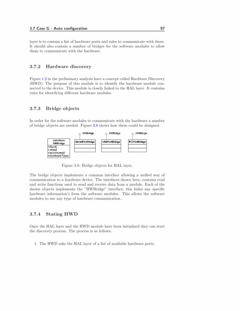
3.7 Case G - Auto configuration 97
layer is to contain a list of hardware ports and rules to communicate with these.It should also contain a number of bridges for the software modules to allowthem to communicate with the hardware.
3.7.2 Hardware discovery
Figure 1.2 in the preliminary analysis have a concept called Hardware Discovery(HWD). The purpose of this module is to identify the hardware module con-nected to the device. This module is closely linked to the HAL layer. It containsrules for identifying different hardware modules.
3.7.3 Bridge objects
In order for the software modules to communicate with the hardware a numberof bridge objects are needed. Figure 3.8 shows how these could be designed.ÑÒÓÔÕÖ×ÑØÙÚÛÓÖ×ÑÜÝÞßààÓáÛÓÕÖ×ÑâÓÛãßÕäåÓæçèÓÖ×éêëìíîïðñíòóôõö÷øùú ûúö÷üýþÿö�õö÷øùú �ûõþÿö�õö÷øùú þ��þÿö�õö÷øùú���îê��í ���îê��í ���îê��í
Figure 3.8: Bridge objects for HAL layer.
The bridge objects implements a common interface allowing a unified way ofcommunication to a hardware device. The interfaces shown here, contains readand write functions used to send and receive data from a module. Each of theshown objects implements the ”HWBridge” interface, this hides any specifichardware information’s from the software modules. This allows the softwaremodules to use any type of hardware communication.
3.7.4 Stating HWD
Once the HAL layer and the HWD module have been initialized they can startthe discovery process. The process is as follows:
1. The HWD asks the HAL layer of a list of available hardware ports.

98 Case studys
2. Create a bridge object for each port.
3. Try to discover the identity of modules connected to each port.
4. Bridge objects connected to a hardware module is registered in the HALlayer.
The end result for this procedure is a list of bridge objects in the HAL layer.These bridge objects allow the software modules to communicate with the hard-ware.
3.7.5 Using HAL and HWD to start the framework
Up till now it has been shortly described how hardware modules should be iden-tified and how software modules should connect to these. The software modulesimplemented for a TCM device would in most cases be distributed as one largesoftware package. This package not only contains all the modules implemented,but also a number of configuration files describing how the software modules canbe combined. There could be a configuration file describing a TCM400 deviceor a TCM4 device. The result from the HWD could be used at startup to selectone of these configurations. This would allow the application to automaticallystart the needed modules for a specific configuration.
Consider the HWD discovers 6 O2 modules connected to the device. Using thecurrent TCM devices as a reference this would then be identified as TCM400device. The HWD could then lookup in a rule list to se if there is a validconfiguration file for the found modules. A rule for a TCM400 device could beonly O2 module found and only between 1 and 6 modules allowed.
Given the HWD now have identified the device type it could give the TCM400configuration file to the framework. The framework would then start loadingthe appropriate modules.
A rule for TCM4 device could be only one combo module found. If this was thecase the HWD could give a TCM4 configuration file to the framework and itwould start as a TCM4.
The current TCM devices rely on a technician to manually configure the deviceto a specific type, depending on the modules connected. This means if themodules were changed to reflect a different TCM device, the system would haveto be manually reconfigured to reflect the changes.

3.7 Case G - Auto configuration 99
3.7.6 Qualities
• Automatic recognition of device type.
• Automatic loading of required modules.
• Easy to add new device types to the system.
• No hardware bindings between the hardware module and software mod-ules.
3.7.7 Drawbacks
• Complex to implement.
• Identification could be time consuming.
3.7.8 Summery
The system could be relative complex to implement depending on the numberof different type of communication options that have to be available. Also arelative large number of configuration files have to be available depending onhow many different combinations of hardware modules that are allowed. Thediscovery process could also be an issue if the HWD has to ask all availableports for all types of hardware modules. This could especially be a problem atstartup time. Consider a system containing 10 ports. There are 10 differenthardware modules. If it takes 6 seconds to search for one module it could in aworst case take up to 10 ∗ 10 ∗ 6/60 = 10 minutes for the search to complete.In most situations this would be an unacceptable startup time. This could besolved implementing rules describing the type of hardware a specific hardwaremodule can be connected to. Also implement an efficient identification systeminto each module could help. This is currently not available in the hardwaremodules, but should be considered for the next generation.
The biggest advantages using the system are the communication between thehardware and software modules have been separated. The bridge objects alloweddifferent connection type completely invisible from the software’s point of view.The HWD’s value however could be discussed. Its biggest advantage is thesystem automatically can configure itself depending on the connected hardwaremodules. However the current devices in existence are selfdom reconfiguredonce sold to a costumer. This means the time used to configure the devices is

100 Case studys
relative small. However if a future system is meant to become for fluent thanthe current system it could be considerer as a possible solution.

Chapter 4
Conclusion
Morten S. Sabinsky S973936
This chapter describes the overall results of the thesis. It contains
• Description of the overall results and what has been accompliced.
• A description of the results for each designed module.
• Description of items to be looked at in the future.
4.1 Overall results
This thesis have been used to design and implement a ”State of the art” frame-work for an embedded system. The framework currently consists of softwaremodules that handle object sharing, communication between software modules,configuration files and user interfaces.
The implemented modules shows that the theories and selected methods canbe used. The theories and methods have to be refined before they will be

102 Conclusion
usable in a medical grade application. Some of the refinements that should beperformed for the designed software modules are described in the next sections.During the refinement process an evaluation on each software module should beperformed. The evaluation should result in an overview of cost/benefit regardingthe software modules. If the software module should become over complex toimplement and offer only limited benefit for the overall solution they should beremoved. There are already concerns regarding the user interface system. This isa good example where the design may give more problems than is solves. In thesesituations a more traditional design could be used, where severe components arestatically linked together. As an example all the views are linked together anfunctions like one software module instead of each view is a software module.
As shown in the final time schedules for the thesis in appendix H, the overalltime consumption for thesis has been following the predicted schedule. Thereason why it have been possible to follow these schedules so precisely is mainlybecause of the challenges solved in the start of the process, also having theconcepts as guidelines during the module design have been helpful. Howeverthe concepts might also have limited the creativity process a little, because itwas difficult to move focus away from these.
Overall the thesis shows new ideas and interesting solutions for both objectsharing and communication between modules. The current state of the frame-work allows the framework modules to be exchanged without having any directeffect on any other modules. The way the system is designed allows for easyevolution of modules. The communication system allows modules requiring dif-ferent protocol versions to function together as long as backward compatibilityis maintained. The factory system allowed modules an easy way of sharingobjects without the framework have to be recompiled to support these. Thedesigned configuration system allows many of the dependencies in the systemto be located in configuration files and not in source code. This means most ofthe code dependencies have been removed.
4.2 Design results
4.2.1 Factory Sphere
The factory sphere descibed in section 2.3, is a software module that controlhow objects can be shared between modules. The system works by allowingmodules to register a factory object. Other modules can then use the factoryobjects to create an instance of a specific object.

4.2 Design results 103
In its current state, it is fully functional. There are some issues that needs tobe looked at:
PerformancePerformance is an item that should be looked at once a hardware platformhas been specified.
Factory removalThere are also some issues regarding removal of factories from the sphere.Currently this is not allowed because there are no methods to handle thissafely. However if this could be handled safely a hole new area of usabilityfor the factory system could be reveled.
4.2.2 Communication Manager
The communication manager described in section 2.4, is a software module thatis used to control how modules communicate with each other. The Communi-cation manager creates channels between the modules where protocols can betransmitted.
In its current form, it is fully functional, but there are some issues that mustme looked at:
PerformanceCurrently a reference to a parsed XML document is sent to each listener.This means data have to be parsed in to text format and from text formatto be used. An exploration for a better method for data transmissionshould be explored.
Data integrityListeners can currently modify data in the received XML documents. Sincethe listeners only receive a reference, a modification could influence otherlisteners. This is a problem because this could lead to unpredictable re-sults.
Distributed systemAs described in section 3.3 the communication system could be used todistribute modules over several devices. It could be extremely interestingto map and explore problems and usable cases for this. It is not some thathave had the direct focus in this thesis, but it is possible to implementwith only minor modifications.

104 Conclusion
4.2.3 Configuration manager
The confuguration manager descibed in section 2.5, is a software module thatcontains a simple implementation allowing load and save of XML files and signa-ture verification and generation. Its current form if fully functional, but there isone item that should be explored. This could be some type of basic encryptionof the data stored in the configuration files.
4.2.4 Controlling user interfaces
This system is descibed in section 2.6 and is a system that controls the userinterface is a reduced version of the application controller pattern described in[2].
The implemented module works, but there are some issues regarding dependen-cies between the modules that have to be solved.
This implementation requires a lot of documentation. Not only must everyimplemented user interface be described. But also the state machine controllingthe user interfaces must describe all interaction.
This might not be the best solution. A better solution could be to create acomplete software package where each view is statically linked. In most cases theuser interfaces would always be configured in one specific way. Once configuredit will seldom change. The reusability of that is gained using the applicationcontroller pattern, might not be more cost effective than implementing a normaluser interface, because of the documentation amount.
User interfaces that have been carefully designed can have views statically linkedto each other, without this gives any problems.
4.3 Case study conclusion
The cases study has been used to show how the software modules can be usedand what should be considered for future development. The purpose of thissection is to shortly describe and summaries the results for each of cases shownin the case study.

4.3 Case study conclusion 105
4.3.1 Case A - High speed communication
Case A described in section 3.1, is used to described how the factory sphere insection 2.3 and the communication manager in section 2.4, both can be used toestablish communication between software modules.
The use case describes 3 methods available in the framework and discusses theusability regarding transmission of data from a SpO2 software module. Method1 cannot be used since this is an asynchronous method and do not guarantymeasurements come in the correct order and at an even interval. Method 2 canbe used, but this method could have some performance issues that have to besolved. By method 2 is the preferred method because it uses the communicationsystem. Method 3 uses the factory sphere to create a bridge between the softwaremodules. This method offers the best performance, but creates a dependencybetween the modules that have to communicate. This dependency can give riseto slippage problems at a later time.
4.3.2 Case B - Configuration security
Case B described in section 3.2, is used to describe how configuration files canbe secured using a digital signature. The case describes the different types ofconfiguration files (static and dynamic) and what purposes the configurationfiles are bested suited for.
Static configuration files should be used to store default configuration data formodules. They are also suitable to store license restrictions in because theycannot be altered. Dynamic configuration files are however only suitable tostore user controlled data. They are less secure that static files because theprivate RSA key used to generate the configuration files signature, have to bestored on the TCM device.
4.3.3 Case C - Distributed system
Case C described in section 3.3, is used to describe how the framework can bedistributed if the software modules rely on the communication manager in sec-tion 2.4 for communication. The case described what is necessary to implementin the current framework and what considerations that have to be done for afuture system.

106 Conclusion
The framework can easily be distributed if modules only rely on the communi-cation manager. Section 4.4.4 describes some of the problems that have to beconsiderer before this is done.
4.3.4 Case D - Interaction between user interfaces
Case D described in section 3.4, used to describe how interaction between viewsin the user interface is possible. As described in section 2.6 this is not possiblein the current design of the views. But a combination of an external modulesharing a subject object using the factory sphere and using the communicationsystem to notify views, allows complex interactions. The system shown in thecase study allows views to interact without communication directly with eachother. This means there is almost no bindings between the views and theyshould be easy of exchange or exclude. A multiple number of these subjectobjects could be implemented allowing very complex interaction to occur.
4.3.5 Case E - Evolution on communication channels
Case E described in section 3.5, shows the effect evolution have on module usingthe communication manager to interact. This shows why it could be beneficialto use such a system, because adding parameters to the protocol do no effectmodules using an older version of the used protocol.
4.3.6 Case F - Controlling measurement location
Case F described in section 3.6, show how the communication could be used tocontrol the locations of measurements in a view. This could be a problem in adynamic where it not necessarily knows where measurements are coming from.The case also describes how a tool on the device to configure the measurementlocations in a view, could be helpful to have.
4.3.7 Case G - Auto configuration
Case G described in section 3.7, discuses how the framework could be autoconfigure it to load a specific set of software module, based on the connected

4.4 Future development 107
hardware module. The case is based on the concepts described in section 1.4.5.2,specifically the concepts about Hardware Abstraction and Hardware Detection.
The case main purpose was to map out how the framework will function afterthese modules are implemented.
4.4 Future development
As described in the earlier in chapter 1.3.4 the model implemented in this thesis,is only an evaluation model. This also means the list of future improvements arerelative long. This section however will only show some of the most importantimprovements needed if this framework is to be used.
4.4.1 Performance
Several times during the development of the core modules performance havebeen mentioned. The framework design has not taken into consideration thetype of hardware platform it should run on. This is because the profile for anew TCM device is not developed. Once this is known performance must betested.
Some of the initiative that could be taken to increase performance could be byselecting different methods for transmitting data. Also using different methodsfor storing and identifying channel and object factories.
4.4.2 User interface
The system that controls the user interfaces should be looked at again. Thereason for this is to streamline the dependencies between the user interfacemodule and the control system. The way the dependencies are between the userinterface modules and the control system are currently not the most optimal.
4.4.3 Is .NET the best framework?
The framework has been developed to run using .NET Compact Framework2.0. The framework gives access to a large number of tools that makes software

108 Conclusion
development easy. However there are a few problems when using the .NETframework. The first problem is access to external hardware. The support forthis in .NET is currently limited to serial ports. This means any other typeof access could be difficult to implement into the application. The frameworkitself does also take up space on the disk. Depending on the platform used forthe next generation TCM device this could be a problem. Moving the finalapplication from one OS to another can also be a problem. The problem ismostly when trying to move user interface components. If an OS like Linux orBSD is used, then the mono framework could be used. However this frameworkdo not support the user interface components. An alternative could be to useGTK#1 for user interface modules, but license requirements should be exploredbefore any usage.
4.4.4 Distributed system
As described in the case study in section 3.3, modules that used the communica-tion system to interact with other modules can be distributed to other devices.However when the communication system was designed this usage was not apart of the considerations done. There are a lot of security considerations thathave to be considerer before the framework is used in this matter. The followinglist contains descriptions of some of the considerations that are needed.
4.4.4.1 Online/Offline
Then devices are network connected there are a lot of external elements thatcan influence the channels used. This means that devices are not always capableof communication with each other. How modules or the framework should reactwhen communication to an external device must be considered before usage.Should data be stored in buffers and if so how much data should be stored.How should module react when they are starved of data. Can the modulefunction if not connected.
4.4.4.2 Security
Transmission security must be a required exploration before this is used. Howto ensure data received is valid, encryption of transmitted data. Recognitionof devices is just some of the things to be explored. Allowing devices to be
1A free open source user interface system.
4.4 Future development 109
connected to a network also brings up the question of how to make it resistanceto network worms and other types of attack. This is something that highly relieson the OS chosen.
4.4.4.3 High-speed synchronous communication
Hardware modules like the SpO2 module sends graph data continuously. Forthose graphs to be shown correctly requires synchronous communication andenough bandwidth for the data to be transferred. Distributing modules like thisover a network is almost impossible since there is no control of it. This meansrestrictions on how the system can be distributed must be specified.
4.4.5 Communication system
The designed communication system allows all modules to listen to any channelon the system. It should be considered if some type of restrictions should beimplemented on this. The reason for this is allowing confidential data to betransmitted between modules. This protects sensitive personal data, propertaryprotocols or restricts access to certain functionality.
4.4.6 Factory system
The factory sphere is used as a global factory system for modules in the frame-work. Like the communication system all modules have access to the factorysystem. Here could access restrictions to certain objects be used to protect thesystem from modules accessing certain functionality. Like the communicationsystem this protects sensitive data and restrict access to some functionality.
4.4.7 Using C#
The framework designed has been implemented using C#. Most of the currentsoftware written to the TCM devices is written in C/C++. This makes it dif-ficult to directly reuse code. This forces the developers to rethink and rewritethe code so if fits better into the framework, but it is also much more costlyto do this. Using C# should also depend on the usage of the .NET Compact

110 Conclusion
Framework. If this were not to be used, it would be better to choose an imple-mentation done in C/C++. Linking unmanaged code to the framework couldsolve some of these problems.
4.4.8 Hardware abstraction layer
The hardware abstraction layer (HAL) is one on the concepts in the preliminaryanalysis that did not make it into this thesis. Currently the modules have tocommunicate directly to an external port. The purpose of the HAL layer isto separate the software modules from the hardware. This is a part of theframework that must be designed and implemented if the framework is to beused. Shielding the software modules from the hardware would make it easierto reuse the software module in a future system.
Appendix A
CD content and Glossary
A.1 CD content
This appendix describes the content of the supplied CD.
/Viola-print.pdfThis is an eletronic version of the printed thesis.
/Viola-net.pdfThis is an electronic version of the thesis meant for network distribution.
/Source/PrototypesThis directory contains prototype solutions created during the challangeanalysis and the design.
/Source/ViolaThis directory contains unit test modules created for implemented mod-ules.
/Source/ViolaV2This directory containes the implemented software modules.
/PapersThis directory containes electronic versions of some of the papers used.
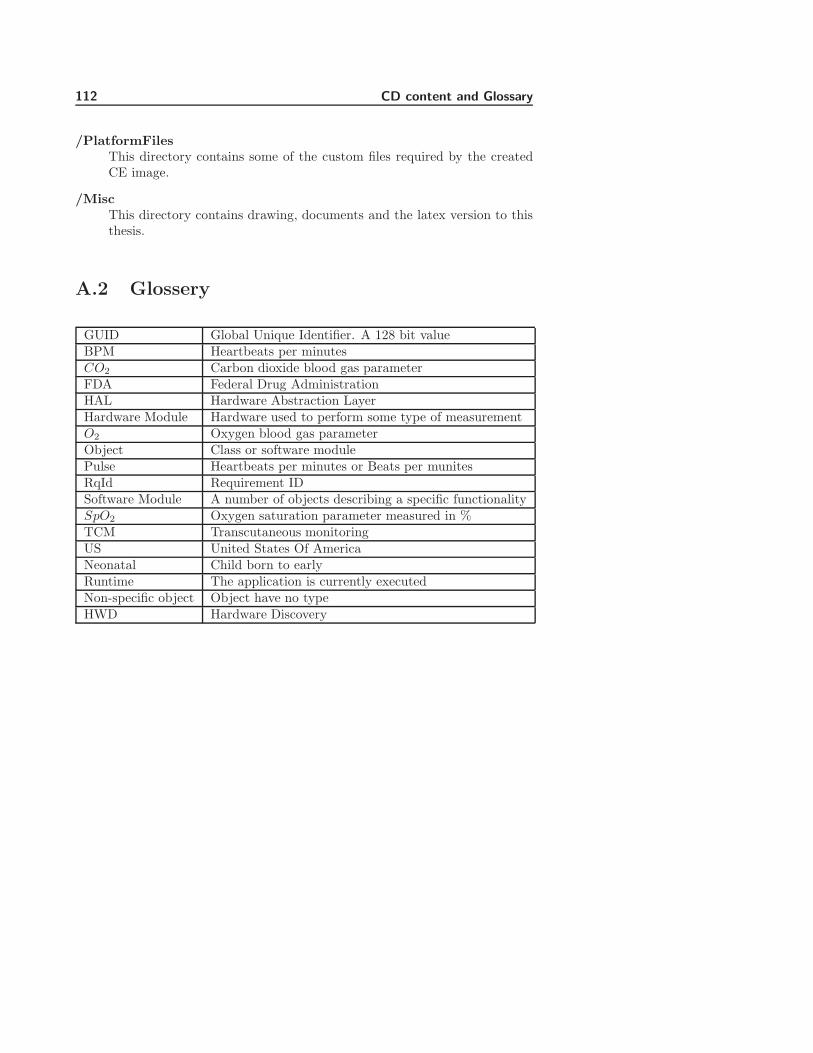
112 CD content and Glossary
/PlatformFilesThis directory contains some of the custom files required by the createdCE image.
/MiscThis directory contains drawing, documents and the latex version to thisthesis.
A.2 Glossery
GUID Global Unique Identifier. A 128 bit valueBPM Heartbeats per minutesCO2 Carbon dioxide blood gas parameterFDA Federal Drug AdministrationHAL Hardware Abstraction LayerHardware Module Hardware used to perform some type of measurementO2 Oxygen blood gas parameterObject Class or software modulePulse Heartbeats per minutes or Beats per munitesRqId Requirement IDSoftware Module A number of objects describing a specific functionalitySpO2 Oxygen saturation parameter measured in %TCM Transcutaneous monitoringUS United States Of AmericaNeonatal Child born to earlyRuntime The application is currently executedNon-specific object Object have no typeHWD Hardware Discovery

Appendix B
Platform and Visual Studio
2005
The purpose of this chapter is to describe how connectivity is established be-tween Visual Studio 2005 and a CE device over an Ethernet channel. The de-scription below is based on information found in the help files of Visual Studio2005 and the Platform Builder and the compressed into this small document.
As standard Visual Studio 2005 use Active Sync to communicate with CE de-vices. Active Sync is designed for CE client device, communicating over USBor a serial connection. The device this project uses does not have USB clientcompatibility and serial communication is not practical to use. The device doeshowever have an Ethernet port suitable for downloading and debugging appli-cation, but using this requires a workaround of the Active Sync connection.
B.1 Platform requirements
When designing the platform, one library component must be included intothe project. This is component is ”CAB File Installer/Uninstaller”. This com-ponent allows the installation of a CAB file generated by Visual Studio to beinstalled on the CE device.
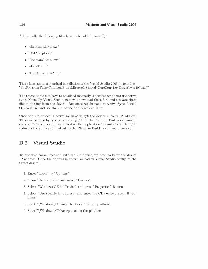
114 Platform and Visual Studio 2005
Additionally the following files have to be added manually:
• ”clientshutdown.exe”
• ”CMAccept.exe”
• ”ConmanClient2.exe”
• ”eDbgTL.dll”
• ”TcpConnectionA.dll”
These files can on a standard installation of the Visual Studio 2005 be found at:”C:\Program Files\Common Files\Microsoft Shared\CoreCon\1.0\Target\wce400\x86”
The reason these files have to be added manually is because we do not use activesync. Normally Visual Studio 2005 will download these files and activate thesefiles if missing from the device. But since we du not use Active Sync, VisualStudio 2005 can’t see the CE device and download them.
Once the CE device is active we have to get the device current IP address.This can be done by typing ”s ipconfig /d” in the Platform Builders commandconsole. ”s” specifies you want to start the application ”ipconfig” and the ”/d”redirects the application output to the Platform Builders command console.
B.2 Visual Studio
To establish communication with the CE device, we need to know the deviceIP address. Once the address is known we can in Visual Studio configure thetarget device.
1. Enter ”Tools” → ”Options”.
2. Open ”Device Tools” and select ”Devices”.
3. Select ”Windows CE 5.0 Device” and press ”Properties” button.
4. Select ”Use specific IP address” and enter the CE device current IP ad-dress.
5. Start ”\Windows\ConmanClient2.exe” on the platform.
6. Start ”\Windows\CMAccept.exe”on the platform.

B.2 Visual Studio 115
Know you have 3 minutes to deploy an application to the CE device. Once anapplication is deployed within 3 minutes, you can continue to deploy applicationindefinitely.

116 Platform and Visual Studio 2005

Appendix C
Module GUID ID’s
This chapter have a complete list of guid values used to identify modules.
Module class Guid IDCKeyManager {49BF16AD-8CC5-43b2-9E00-8F2F199AF27B}CModuleManager {ED4C44CA-0DD0-4854-83D4-B5C6CA26E925}CViewManager {E05E0A5E-6B0C-49b8-800F-C65C1E448E62}CConfigManager {9DC957E3-E027-44d0-9005-2EC00F12A0C7}CCommunicationCore {E691CA8A-5C4E-4b8b-BAA8-B80E617CF133}
Table C.1: Module GUID ID’s

118 Module GUID ID’s

Appendix D
Thesis description
This chapter containes the danish description of the thesis, used to getit ap-proved.
D.1 Projekt oplæg til modulær TCM applika-
tion V 0.4
Projekt locationRadiometer DanmarkAkandevej 21DK-2700 BrønshøjAfd. 422 TCM Udvikling
Radiometer vejlederJørgen BelfalasTlf. 38273340Email: [email protected]
Vejleder pa DTUBjarne Poulsen
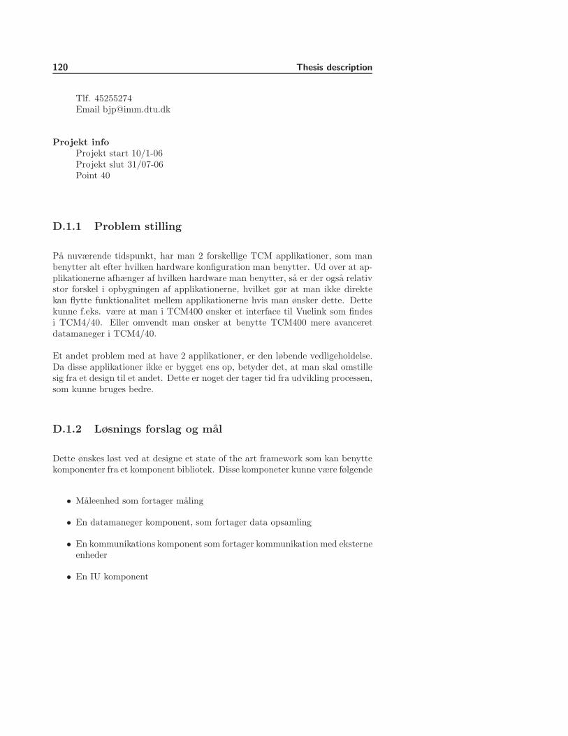
120 Thesis description
Tlf. 45255274Email [email protected]
Projekt infoProjekt start 10/1-06Projekt slut 31/07-06Point 40
D.1.1 Problem stilling
Pa nuværende tidspunkt, har man 2 forskellige TCM applikationer, som manbenytter alt efter hvilken hardware konfiguration man benytter. Ud over at ap-plikationerne afhænger af hvilken hardware man benytter, sa er der ogsa relativstor forskel i opbygningen af applikationerne, hvilket gør at man ikke direktekan flytte funktionalitet mellem applikationerne hvis man ønsker dette. Dettekunne f.eks. være at man i TCM400 ønsker et interface til Vuelink som findesi TCM4/40. Eller omvendt man ønsker at benytte TCM400 mere avanceretdatamaneger i TCM4/40.
Et andet problem med at have 2 applikationer, er den løbende vedligeholdelse.Da disse applikationer ikke er bygget ens op, betyder det, at man skal omstillesig fra et design til et andet. Dette er noget der tager tid fra udvikling processen,som kunne bruges bedre.
D.1.2 Løsnings forslag og mal
Dette ønskes løst ved at designe et state of the art framework som kan benyttekomponenter fra et komponent bibliotek. Disse komponeter kunne være følgende
• Maleenhed som fortager maling
• En datamaneger komponent, som fortager data opsamling
• En kommunikations komponent som fortager kommunikation med eksterneenheder
• En IU komponent

D.1 Projekt oplæg til modulær TCM applikation V 0.4 121
For at kunne lave et sadan bibliotek, sa ma det kræves, at disse komponenterskal have en meget skarp grænseflade. En sadan grænseflade, vil ogsa give denfordel, at man kan fortage unit test pa hver komponent.
Malet med at have dette et bibliotek med komponenter, er at man via det de-signet framework kan modulært stykke en applikation man ønsker at benytte,sammen. Dette kunne være en fuld applikation, som kan alt, en handholdt app-likation, som kun benytter en elektrode komponent og et simpelt IU komponent.Eller en malestation som ikke indeholder en IU, men man kan kommunikere viaen webserver i stedet.
Malet med frameworket, er at kunne loade moduler runtime, nar der er brugfor dem
D.1.3 Problem stillinger
Det er dog ikke uden problemer, at lave et bibliotek med komponenter. Følgendeproblemer skal der tages stilling til.
• Hvordan skal data flyde rundt i et komponent design
• Hvordan skal signalering af events fungerer
• Hvordan skal versions styring af moduler styres
• Hvordan skal moduler opdateres
• Hvordan sikres modulers integritet
• Skal tredje parts leverandører kunne levere komponenter (Hvis man ma,hvad skal der sa være af krav til et sadant modul)
• Hvordan sikres korrekt modul type (f.eks. hvis man har flere forskelligeIU komponenter, hvordan ved man sa, at det er den korrekte type)
• Hvad skal der være af krav til komponent konfigurering
• Hvordan en test strategi skal udformes
• Hvordan handteres sprogvarianter

122 Thesis description
D.1.4 Ønsker og krav
Projektet ønskes udført som en .NET v2.0 løsning, hvor der benyttes C# og.NET compact framework. Som krav stilles det, at design af komponenter i detomfang det er relevant, benytter design patterns.
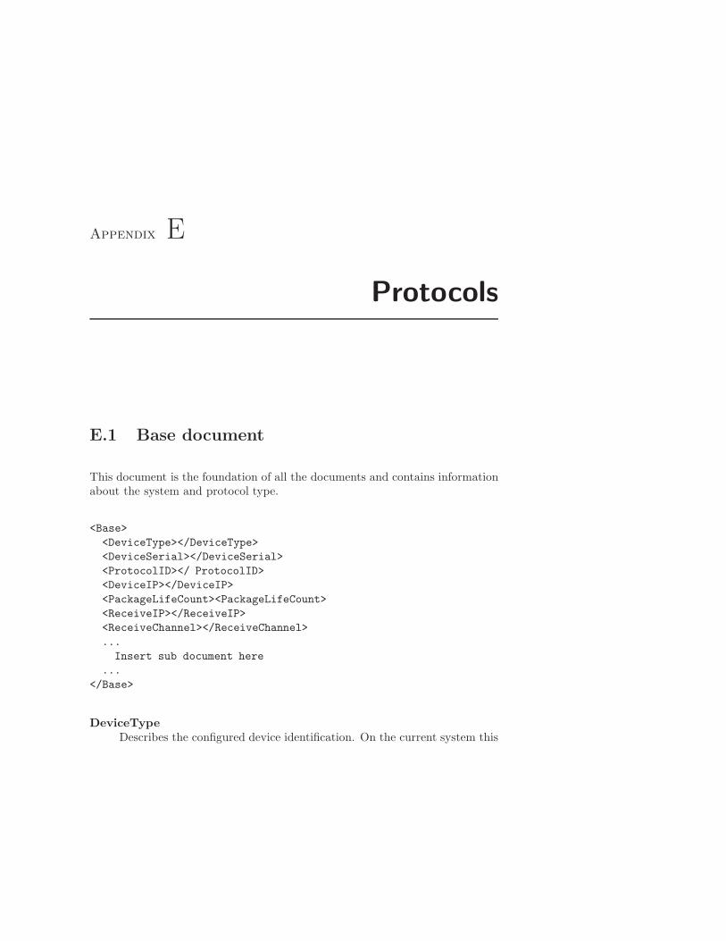
Appendix E
Protocols
E.1 Base document
This document is the foundation of all the documents and contains informationabout the system and protocol type.
<Base>
<DeviceType></DeviceType>
<DeviceSerial></DeviceSerial>
<ProtocolID></ ProtocolID>
<DeviceIP></DeviceIP>
<PackageLifeCount><PackageLifeCount>
<ReceiveIP></ReceiveIP>
<ReceiveChannel></ReceiveChannel>
...
Insert sub document here
...
</Base>
DeviceTypeDescribes the configured device identification. On the current system this
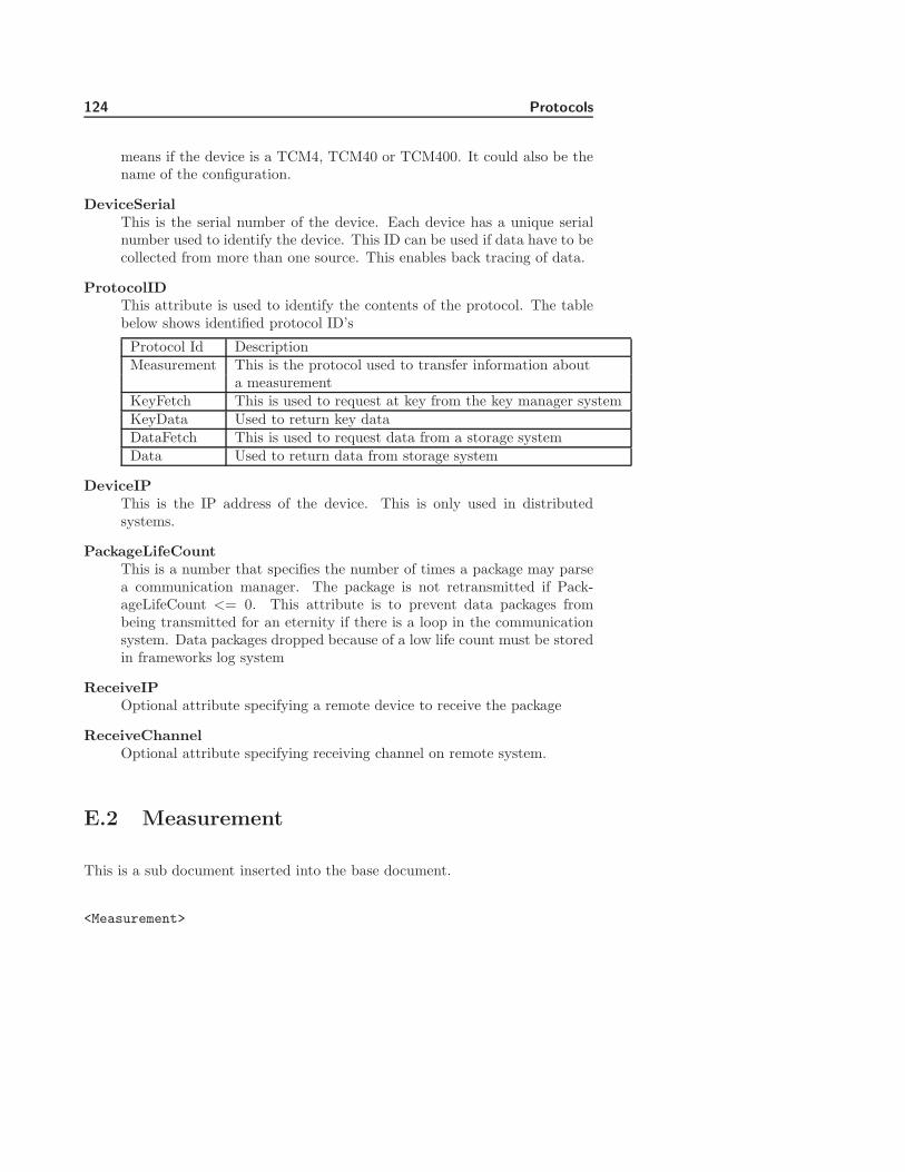
124 Protocols
means if the device is a TCM4, TCM40 or TCM400. It could also be thename of the configuration.
DeviceSerialThis is the serial number of the device. Each device has a unique serialnumber used to identify the device. This ID can be used if data have to becollected from more than one source. This enables back tracing of data.
ProtocolIDThis attribute is used to identify the contents of the protocol. The tablebelow shows identified protocol ID’s
Protocol Id DescriptionMeasurement This is the protocol used to transfer information about
a measurementKeyFetch This is used to request at key from the key manager systemKeyData Used to return key dataDataFetch This is used to request data from a storage systemData Used to return data from storage system
DeviceIPThis is the IP address of the device. This is only used in distributedsystems.
PackageLifeCountThis is a number that specifies the number of times a package may parsea communication manager. The package is not retransmitted if Pack-ageLifeCount <= 0. This attribute is to prevent data packages frombeing transmitted for an eternity if there is a loop in the communicationsystem. Data packages dropped because of a low life count must be storedin frameworks log system
ReceiveIPOptional attribute specifying a remote device to receive the package
ReceiveChannelOptional attribute specifying receiving channel on remote system.
E.2 Measurement
This is a sub document inserted into the base document.
<Measurement>

E.2 Measurement 125
<ParameterName></ParameterName>
<ParameterUnit><ParameterUnit>
<Value></Value>
<HardwareID></HardwareID>
<LowerAlarmLimit></LowerAlarmLimit>
<UpperAlarmLimit></UpperAlarmLimit>
<Alarm></Alarm>
<Timestamp></Timestamp>
<SampleID></SampleID>
</Measurement>
ParameterNameThis is used to name the measurements type. Current valid names are O2,CO2, SpO2 and Pulse.
ParameterUnitThis describes the unit measurements are represented in. Current validunits are mmHg for O2 and CO2. SpO2 are measured in % and pulse isin beats pre minutes.
ValueThis is the value of the measurements
HardwareIDThis is an identification field used to uniquely identify the hardware mod-ule. This could be the serial number of the measurements device. Cur-rently it is not possible to get the serial number of all measurement devices.For that reason this ID is currently optional. The reason for putting thisattribute into the protocol is the desire to be able to track a measurementto its source.
LowerAlarmLimitThis is a value describing the lowest value allowed before an alarm isactivated. Alarm is activated the value < LowerAlarmLimit
UpperAlarmLimitThis is a value describibg the higest allowed value before an alarm isactivated. Alarm is activated when the value > UpperAlarmLimit.
AlarmThis is an optional field used to signal if an alarm is active. Valid valuesfor this attribute are None, Low and High. This can also be derived usingthe given alarm limit.
TimestampThis field must contain the time when the measurements were taken. For-mat for the timestamp is YYYY-MM-DD hh:mm:ss.

126 Protocols
SampleIDThis attribute is to accommodate .NET compact frameworks ”Date” ob-ject. Depending on the underling system the .NET framework does notguaranty a time resolution of more than one second. If more than onemeasurement is to be made during one second then they will get the sametimestamp at we can use the sample ID to separate the measurements.The sample ID must be unique within one second. Every new sample IDmust be incremented by the value 1.
E.3 Key fetch
This protocol is used to request encryption key data from a key manager.
<KeyFetch>
<KeyID></KeyID>
<ReturnPath></ReturnPath>
</KeyFetch>
KeyIDThis is the ID of the key requested
ReturnPathThis is the GUID value of the module performing the request or channelname
E.4 KeyData
This protocol is used to distribute key data in the system
<KeyData>
<KeyType></KeyType>
<PrivateKey></PrivateKey>
<KeyDataFormat></KeyDataFormat>
<Key></Key>
<KeyOwner></KeyOwner>
</KeyData>

E.5 Data storage fetch 127
KeyTypeThis is used to specify what type of key is used. Currently only RSA issupported
PrivateKeySpecify if the key contains private key data. Current values are ”False”for public RSA keys and ”True” for private RSA keys
KeyDataFormatThis described the keys data format. Currently only SNK format is sup-ported.
KeyThis attribute contains the key data. Key data comes in the commaseparated hex numbers like this ”AA,BB,10,11,12,FF”
KeyOwnerThis is an optional attribute containing information about the key owner.
E.5 Data storage fetch
This protocol is used to request all measurement data for a specific time periodusing a specified time interval.
<DataFetch>
<Starttime></Starttime>
<Stoptime></Stoptime>
<TimeInteval></TimeInteval>
<SessionID></SessionID>
<ReturnPath></ReturnPath>
</DataFetch>
StarttimeThis attribute defines the start time for when data is to be retrieved.The time format is ”YYYY-MM-DD hh:mm:ss”. Data returned is whereStarttime = Timestamp
StoptimeThis attribute defines the stop time for when data is to be received. Thetime format is ”YYYY-MM-DD hh:mm:ss”. Data returned is where Stop-time = Timestamp
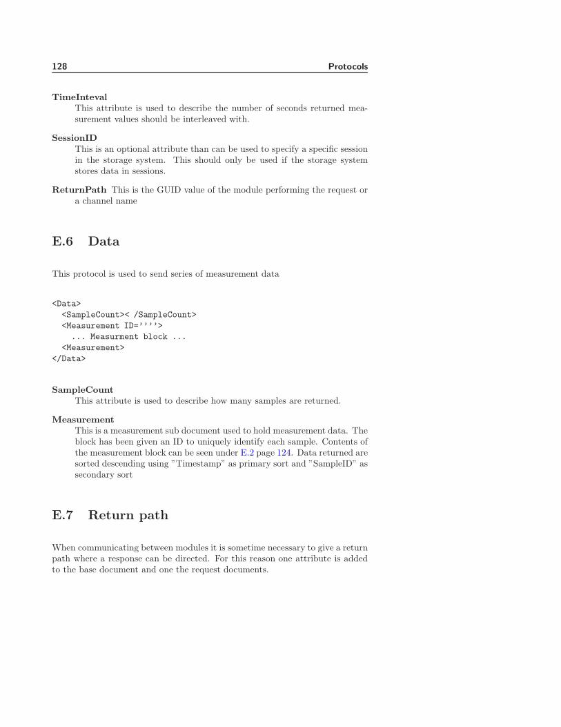
128 Protocols
TimeIntevalThis attribute is used to describe the number of seconds returned mea-surement values should be interleaved with.
SessionIDThis is an optional attribute than can be used to specify a specific sessionin the storage system. This should only be used if the storage systemstores data in sessions.
ReturnPath This is the GUID value of the module performing the request ora channel name
E.6 Data
This protocol is used to send series of measurement data
<Data>
<SampleCount>< /SampleCount>
<Measurement ID=’’’’>
... Measurment block ...
<Measurement>
</Data>
SampleCountThis attribute is used to describe how many samples are returned.
MeasurementThis is a measurement sub document used to hold measurement data. Theblock has been given an ID to uniquely identify each sample. Contents ofthe measurement block can be seen under E.2 page 124. Data returned aresorted descending using ”Timestamp” as primary sort and ”SampleID” assecondary sort
E.7 Return path
When communicating between modules it is sometime necessary to give a returnpath where a response can be directed. For this reason one attribute is addedto the base document and one the request documents.
E.7 Return path 129
In the base document there is an attribute called ”DeviceIP”. This attributecontains the devices IP address and is used if a request is directed to anotherdevice.
In the request documents there is an attribute called ”ReturnPath”. This at-tribute contains a channel where the requests should be directed.
The combination of IP and channel name makes is possible to send data toanother device. The base document contains two optional attributes used tospecify a remote receiver these are ”ReceiveIP” and ”ReceiveChannel”. Usingthe device IP and return path from the request document we can initialize thistwo attributes a send the requested data back.

130 Protocols

Appendix F
Thread memory leak test
The communication system creates a new thread every time an asynchronous callis made. Once a thread is created and started all references to it are thrown awayby the communication system and the thread is left to itself. This method raisedsome questions about the garbage collectors ability to cleanup dead threads. Forthis reason I have made a small test that creates and starts 1000 thread at throwsthem away once started. I then monitor the memory usage to see if it remainsstable over several runs. Figure F.1 shows a log created of the memory usageduring the test. The yellow lines split the log into 4 sections. Each yellow linerepresents a new run where I creates and starts 1000 threads. The first sectionleading up to the first yellow line represents the first execution of the run. Afterthis run I get a baseline of a 35% memory usage of the system. Each subsequentrun of the test returns to the same baseline at 35%. From this I can concludethe garbage collector can cleanup thread correctly.
The test follows the procedure below.
1. Start garbage collection to remove all unwanted object from memory
2. Print out memory usage
3. Create and start 1000 threads and throw away the handles
4. Sleep to allow the threads to be executed

132 Thread memory leak test
Memory thread leak test
0
5
10
15
20
25
30
35
40
45
50
1 20 39 58 77 96 115
134
153
172
191
210
229
248
267
286
305
324
343
362
Sample
Mem
ory
usa
ge
in %
Memory usageMemory usage at startNew loop
Figure F.1: Memory usage during leak test
5. Start garbage collection
6. Print out memory usage
7. Wait for restart or quit command
The functions called in the threads are just empty functions. This is to avoid toomuch cluttering of the memory that might obscure the results. During the testthe memory usage was sampled every second and assigned a sample number.All measurement are supplied the CD.

Appendix G
Test protocols
G.1 Template for test protocol
Test nameTest case 1 to x
Test typeLevel 1, level 2, Non-unit test or integration test.
Name of interface or object
Test steps
Step RqId Tested functionality Expected result Success/Failed1...X
Results of failed tests

134 Test protocols
Step Actual resultX
G.2 Test protocol for Communication Manager
Test nameTest of ”ICommunicationManager” interface
Test typeLevel 1
Name of interface or objectICommunicationManager
Test steps
Step RqId Tested functionality Expected result Success/Failed
1 COM1 Create ”ChannelA” -2 COM4 Verify ”ChannelA” exists Channel exist3 COM1 Create ”ChannelB” -4 COM4 Verify ”ChannelB” exists Channel exits5 COM2 Add ”Listener1” to -
”ChannelA”6 COM2 Add ”Listener2” to -
”ChannelB”7 COM5 Send data to ”ChannelA” -8 Verify ”Listener1” have Data was
received data received9 Verify ”Listener2” have No was data
not received data reveived10 COM5 Send data to ”ChannelB” -11 Verify ”Listener1” have No data
not received data received12 Verify ”Listener2” have Data Reveived
received data13 COM2 Add ”Listener3” to -
”ChannelA”14 COM5 Send data to ”ChannelA” -15 Verify ”Listener1” have Data was
received data received
Continued on next page

G.3 Test protocol for Factory sphere 135
Step RqId Tested functionality Expected result Success/Failed16 Verify ”Listener2” have No was data
not received data received17 Verify ”Listener3” have Data was
received data Received18 COM3 Remove ”Listener2” from Error received
”ChannelA”19 COM3 Remove ”Listener1” from -
”ChannelA”20 COM5 Send data to ”ChannelA” -21 Verify ”Listener1” have No was data
not received data received22 Verify ”Listener2” have No was data
not received data received23 Verify ”Listener3” have Data was
received data received24 COM8 Add ”SleepListener” to -
”ChannelA” as asynchronous25 COM7 Add ”SleepListener” to -
”ChannelB” as synchronous26 COM5 Send data to ”ChannelA” -27 Verify ”SleepListener” is Listener is
executed after send is executed aftercompleted send is completed
28 COM5 Send data to ”ChannelB” -29 Verify ”SleepListener” is Listener is
executed before send is executed beforecompleted send is completed
Results of failed testsNo errors
G.3 Test protocol for Factory sphere
Test nameTest of ”IFactorySphere” interface
Test typeLevel 1

136 Test protocols
Name of interface or objectIFactorySphere
Test steps
Step RqId Tested functionality Expected result Success/Failed
1 Create instance of -”CFactorySphere” object
2 FAC8 Verify instance have ”IFactorySphere””IFactorySphere” is implementedimplemented
3 FAC1 Register ”TestFactory” -using ”TestFactory” as Id
4 FAC2 Get instance using Instance returned”TestFactory” as Id
5 Verify returned instance is Instance is of”TestObject” correct type
6 FAC1 Register ”TestObject” -using the generic factoryobject ”GTest” as Id
7 FAC2 Get instance using ”GTest” Instance returnedas Id
8 Verify returned instance is Instance is of”TestObject” correct type
9 Save instance reference as -”Test1”
10 FAC2 Get instance using ”GTest” Instance returnedas Id
11 Verify returned instance is Instance is of”TestObject” correct type
12 FAC10 Verify returned instance The instances arereference is different from different”Test1” reference
13 FAC1 Register ”TestObject” -using the generic singletonobject ”STest” as Id
14 FAC2 Get instance using ”STest” Instance returnedas Id
15 Verify returned instance is Instance is of”TestObject” correct type
16 Save instance reference as -”Test1”
Continued on next page

G.3 Test protocol for Factory sphere 137
Step RqId Tested functionality Expected result Success/Failed17 FAC2 Get instance using ”STest” Instance returned
as Id18 Verify returned instance is Instance is of
”TestObject” correct type19 FAC11 Verify returned instance The instances have
reference is the same as the same reference”Test1” reference
20 Init generic session object -with the limit of 3 objects
21 FAC1 Register ”TestObject” -using the generic sessionobject ”SesTest” as Id
22 FAC2 Get 3 instances using 3 instances”SesTest” as Id returned
23 Verify each returned Instances is ofinstance is ”TestObject” correct type
24 FAC12 Try to get new instance Error thrownusing ”SesTest” as Id
25 FAC3 Release instance using the -first returned reference
26 FAC2 Get new instance using Instance returned”SesTest” as Id
27 Verify returned instance is Instance is of”TestObject” correct type
Results of failed testsNo errors

138 Test protocols

Appendix H
Time schedules
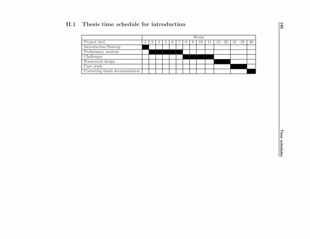
140
Tim
esc
hedule
sH.1 Thesis time schedule for introduction
WeeksProject titel 2 3 4 5 6 7 8 9 10 11 12 - 20 21 - 29 30Introduction/StartupPreliminary analysisChallengesFramework designCase studyCorrecting thesis documentation
H.1 Thesis time schedule for introduction 141
Introduction/StartupThis phase is used to get an overview of the thesis and to create a schedulefor the first part of thesis. Description of the thesis is generated.
Preliminary analysisThe preliminary analysis is used to get an overview of the methods touse, find relevant documentation, tools and brainstorm for ideas to finallygenerated concepts.
Risk AnalysisThis part is used to analyze and find solutions to risks identified duringthe preliminary analysis
Framework design8 weeks are set aside to for creating a framework design. A schedule forthe framework design will first be created during the startup process ofthe design.
Case study8 weeks have been set aside to make case studies of the framework. Aschedule for this will be made during the startup process of the case stud-ies.
Correcting thesis documentationThe last week of the thesis will be used to create and correct the finaldocumentation for this thesis. Documentation for the individual parts ofthe thesis should be made during each process.
H.1.1 Actual time used for introduction
Introduction/Startup started week 2 9/1 - ended week 2 14/1Completed introduction chapters and stated working on concept ideas
Preliminary analysis started week 3 16/1 - ended week 9 3/3Concept generationThis was already stated during the approval period of the thesis. In the analysisphase the main purpose of the concept generation is to select the most usefulideas.
Technology/Tools/MethodsMost of the methods and tools were given in the thesis descriptions. Most of thework done in these sections was to find alternative tools to use. The sectionswas completed 30/1
142 Time schedules
Analysis of current theoriesMost of the work done in the preliminary analysis is in this section. It wasmore time consuming to find relevant papers and books than expected. Thereason for this is the limited number of relevant papers for this area of softwaredevelopment. This section was concluded 3/3.
Challenges started week 10 6/3 - ended week 12 23/3This section describes the challenges that were solved before the main frameworkdesign started.
Test strategyBase on the papers describing unit testing a test strategy was formulated. Thiswas completed 24/3
Overall requirements and summeryThese sections was completed 25/3
H.1.2 Summery
The introduction chapter took 6 days more than expected. The main reasonswas the search for relevant papers and books took longer than expected. Some ofthe time lost when searching for papers was gained when solving the challenges.Most of these were easier than expected.
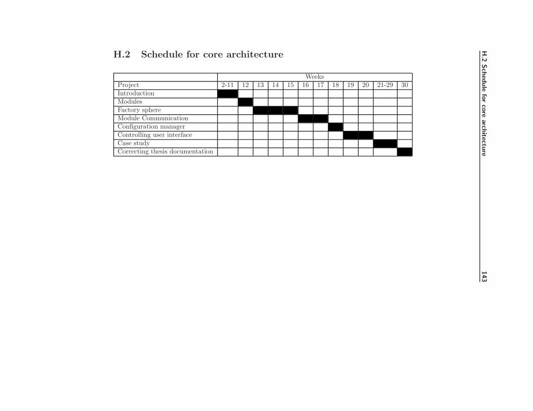
H.2
Schedule
for
core
arc
hite
ctu
re143
H.2 Schedule for core architecture
WeeksProject 2-11 12 13 14 15 16 17 18 19 20 21-29 30IntroductionModulesFactory sphereModule CommunicationConfiguration managerControlling user interfaceCase studyCorrecting thesis documentation

144 Time schedules
ModulesThis is used to describe how individual modules should be designed.
Factory sphereThis time is to be used to develop a method for sharing objects betweenframework modules and external modules.
Module CommunicationThis time is used to develop a method for communication between frame-work modules and external modules.
Configuration managerThis time is used to develop a method for controlling configuration files
Controlling user interfaceThis time is used to develop a method for controlling user interfaces
H.2.1 Actual time used for designing the core architecture
Modules started week 13 27/3 - ended week 13 30/3The time was used for designing a basic module to use in the framework. Oneday was gained
Factory sphere started week 13 31/3 - ended week 16 21/4This module was designed in the limited time allowed.
Module Communication started week 17 24/4- ended week 19 10/5This module has taken 3 days longer to implement than expected. The mainreason for this, it was more difficult to implement the solution than expected
Configuration Manager started week 19 11/5 - ended week 20 17/5The design and implementation of this module took 1 day less than expected.The reason for this is the implementation was easy.
Controlling user interfaces started week 20 18/5 - ended week 23 9/2Reducing the application controller pattern and implementing is was more dif-ficult than anticipated. For this reason this module took 5 days more to imple-ment than expected.

H.3 Schedule for case study 145
H.2.2 Summery
The phase of developing and implementing modules have taken 2 weeks longerthan expected. This is mainly because of difficulties regarding implementationof the designed modules.
H.3 Schedule for case study
Before a time schedule can be made, it is necessary to identify the cases thatare to be looked at. Each case should be given a case Id.
H.3.1 Defined cases
Case A High speed communicationPurpose of this case is to explore how performance effective communicationcan be done using the framework.
Case B Configuration securityPurpose of this case is to explore how license relevant information’s canbe stored in configuration files without being altered.
Case C Distributed systemPurpose of this case is to explore how the system can be split up intoseveral smaller devices.
Case D Interaction between user interfacesPurpose of this case is to explore how interaction between user interfacemodules can be performed.
Case E Evolution on communication channelsPurpose of this case is to explore what happens to the communicationbetween modules when the protocol used is evolved.
Case F Controlling measurement locationThe purpose of this case is to explore how to ensure measurement modulesare displayed at the correct location every time they are displayed.

146 Time schedules
H.3.2 What to be done during case study
During a case study a small implementation is created to verify the describedsolution.

H.3
Schedule
for
case
study
147
H.3.3 Schedule
WeeksProject 2-11 12-20 21 22 23 24 25 26 27 28 29 30IntroductionCore architectureCase ACase BCase CCase DCase ECase FCase GThesis documentationCorrecting thesis documentation
148 Time schedules
H.3.4 Actual time used for Case studies
Case A started week 24 12/6 - ended week 15 15/6This case have been reduced to 4 days to catch up the delays
Case B started week 24 16/6 - ended week 25 21/6Case C started week 25 22/6 - ended week 26 27/6Case D started week 26 28/6 - ended week 27 3/7Case E started week 27 4/7 - ended week 27 6/7Case F started week 27 7/7 - ended week 28 10/7Case G started week 28 11/7 - ended week 28 13/7
Thesis documentation and corrections started week 28 14/7 - endedweek 31 7/8This part have mainly been used to collect all the written material and proof-reading of the thesis. Proofreading started 24/7.
H.3.5 Summery
Due to the delays of the previously part of the thesis, the case studies had tobe reduced in order to complete them in time.
One week was added to the thesis period due to supervisor’s vacation plans.Delivery have been moved from 31/7 to 7/8
Appendix I
Challenges
Purpose of this chapter is to give an overview of problems that needs to beaddressed before the design of the application can commence. Each identifiedchallenge will be given an ID for later reference.
I.1 Platform image
Challenge 1
This project requires a Windows CE 5.0 image supporting Compact Framework2.0 running on the TCM platform. The platform builder contains a limitedamount of hardware drivers that can make it difficult to work on the TCMplatform. Alternative platforms could be a standard PC image or CE emulatorimage.

150 Challenges
I.1.1 Device image
Before starting configuration of a Windows CE 5.0 image a copy of the currentimage used on the TCM was analyzed. This was done to have a list of driversneeded for getting the image to work on the TCM device. Using the driver listas a reference several images was created and tested. None of the images testedworked. It was discovered that the driver used to control the graphic card onthe device was incompatible with the hardware. This was already known onthe old platform, but a small modification to the graphic driver made it work.This modification did however not work on the new graphic driver. It was thendecided to find another solution.
I.1.2 PC Image
After 2 configuration attempts a working CEPC image was ready.
Using a CEPC image generated a problem. When calibrating O2 and CO2 sen-sors the current barometer pressure is needed in order to get a precise calibra-tion. Since there is no barometer in a normal PC this value have to be hardcodeor typed into the system meaning a precise calibration cannot be made.
During analysis of challenge 3 it was discovered that on a CEPC image COM1is used to send out debugging information for the image. This was a problemsince the only available PC’s only had one COM port. Several attempts todisable this feature failed and it was decided to use an emulator image instead.Later it was discovered the reason why the attempts to disable the debuggingfeature failed. The reason for this is a bug in the boot loader used to initializethe image. The bug and a solution are described at:http://blogs.msdn.com/mikehall/archive/2005/03/14/395317.aspxThis solution has not been tested since I had a working image for the emulator.
I.1.3 Emulator image
The emulator image was up and running in the fist attempt. Using the emulatorgive the same problem as using an image on the PC. There is no access tobarometer pressure. It also adds the problem of performance testing. Runningperformance test in the emulator is almost impossible since the system is at themercy of the host PC and what it is doing at the moment. This means a piece ofcode can be executed in 1ms the first time executed. The second time it could

I.2 Connectivity between Visual Studio and CE 151
take 10 second because the PC is scanning for viruses.
I.1.4 Summery
The emulator image has been chosen as a usable solution. The problem of thebarometer pressure can be ignored since this software is not for medical usage.Imprecise value can still be used to demonstrate the basic functionality.
The performance issues using the emulator can largely be ignored since it isnot currently known what hardware platform that will be used in the future.However areas where performance could be an issue should be noted for laterinvestigation.
I.2 Connectivity between Visual Studio and CE
Challenge 2
To run and debug applications on the CE platform requires some form for con-nection between the CE platform and Visual studio.
This challenge could have a high impact on the implemetation schedule sinceit is an essential part for the success of this project. Searching the help files inVisual Studio 2005, Platform Builder and google search has solved this problem.A small guide for how to get connectivity can be found in Appendix B.
I.2.1 Summery
It seems Visual Studio is mainly designed to create applications for small hand-held devices when it comes to compact framework. Support for devices that donot support Active Sync1 is not directly available. The guide created explainsthe requirements needed in the CE image and setup procedure required to es-tablish communication. Support for this type of development is better whenusing platform builder 4.2 and embedded visual studio 4.0.
1Active Sync is tool used to establish a connection between a PC and a handheld CEdevice.

152 Challenges
I.3 Serial connection
Challenge 3
The current hardware modules require a serial connection. In Compact Frame-work 2.0 serial support has been included, but how to use and what limitationsthe implemented objects have, is currently not known.
The software connection to communicate with modules is an essential part ofthe project, but the project can be complete using simulated values instead ofreal measurements from a hardware module.
After several attempts to get serial communication on the CEPC platform, itwas discovered the CEPC image was unable to initialize the computers serialport.
The solution to this problem was to make an emulator image and through thiscommunication with serial ports is possible.
The emulators mapping is not entirely logical the emulators COM1 is reservedfor serial debugging and cannot be seen from the CE image running in theemulator. The emulators COM2 port is from the CE image seen as COM1.This port can in the emulator’s configuration be mapped to a hardware COMport.
Using the serial class in .NET is relative simple.
I.3.1 Summery
Once the image configuration problems were solved communication was imme-diately available. The serial support in Compact Framwork 2.0 works withoutany problems.
I.4 Event handling
Challenge 4

I.5 Software module integrity 153
.NET has several ways of event handling. These are message queues, delegatesand events (Extended version of delegate.). Before designing the application itis needed to know strength and weakness of each event type.
The application will require some type of event handling but how this is doneis currently not important and the method should be selected during design ofevent system.
The message queue system is a new addition to Compact Framework 2.0 andit allows global message queues. This enables cross application communicationon the same system and over a network if necessary. It can however be difficultto multicast an event over a message queue since the queue system is designedfor multiple senders and one receiver.
The event class is an extended version of a delegate. Both classes contains a listof listener functions that are executed when the event or delegate is invoked.The main difference between events and delegates are, events can be declared ininterfaces and there is a restriction on who is allowed to invoke the event. Onlythe object that owns the event is allowed to invoke it.
Currently the focus of the event system should be on event or delegates. Thefunctionality in the message queue system seems to be more complex thanneeded.
It should be noted that events and delegates in Compact Framework 2.0 do notsupport asynchronies calls.
I.4.1 Summery
After implementing prototypes to test the different events methods, they showedthe methods are easy to use. Event methods should therefore not be consideredas a problem area anymore.
I.5 Software module integrity
Challenge 5
The design is supposed to be modular, with interchangeable modules. Before
154 Challenges
initializing a module a check of the module must be performed to ensure it hasnot been corrupted.
The chances of the disk corrupts a module is low. The current system usesindustrial grade flash disks that can handle a large amount write operationsbefore damage occurs. Software modules will properly only be update once ortwice per year, meaning the probability for modules being damaged by a corruptdisk is relative small. If however a damaged module is initialized and used, itcould have serious impact on application performance. A damaged modulecould crash the application or give wrong results, causing wrong treatment of apatient.
Compact Framework 2.0 supports strong named assemblies. Strong named as-semblies are assemblies that have been signed with a private RSA ref. [10] keyand with the public key embedded into the assembly. The RSA key pair canbe supplied through a simple key pair file or through a Personal InformationExchange certificate (similar to X.509 certificate ref. [11]). If an assembly issigned then the compact framework will automatically verify the signature. Ifthe verification fails then the loading of the software module will be aborted. Ifsoftware modules are static linked then all modules have to be signed. Softwaremodules however do not need to use the same key pair. This gives the possibilityto have different key pairs to different module suppliers. By creating a list ofvalid third party public RSA keys and compare these keys to the module key,then it is possible to control supplier’s modules. This will however require someform of updating of the key list. Another solution could be that all softwaremodules have to be signed using the same key. This will require some typevalidation procedure from Radiometer. One problem to consider when selectinga method is that the signing procedure for strong named assemblies is doneduring build time.
I.5.1 Summery
It is relative simple to create keys and setup the projects to sign the buildsoftware. This is no longer considered a problem.
I.6 Third party software modules
Challenge 6

I.7 Module hardware interface 155
Software modules supplied by a third party must be verified and approved byRadiometer before it is used in a TCM device. This is to ensure these softwaremodules are not malicious or otherwise damaging to the system. The chancesof a third party supplier creates malicious software modules are very low but asoftware module with errors in it could course the application to crash or givebad values. To avoid this there must be a procedure to describe how softwaremodules are tested and a detailed description of software module interfaces.
A solution for module control is described in challenge 5. A test strategy isdescribed in section 1.6
I.6.1 Summery
This is not something that will be looked at further in this thesis. This shouldonly be taken into consideration if the design is to be used commercially.
I.7 Module hardware interface
Challenge 7
Most serial ports on PC use the voltage range -15v to +15v. The measurementmodules for the TCM platform use 0v to 5v. To avoid burning out the hardwarean interface is required.
I.7.1 Summery
This was discovered not to be a problem at all since such an interface is alreadyavailable.
I.8 Loading modules Runtime
Challenge 8
156 Challenges
In .NET it is possible to load modules runtime using the reflection package. InCompact Framework a reduced version the reflection package is implemented.Some test implementations is required to find out the limits of the CompactFramework reflection package.
A small test application was created (appendix A.1) to demonstrate reflectionfunctionality. This application also makes use of strong named DLL files. Acommon interface shared among the modules must be designed.
I.8.1 Summery
The test application demonstrated that it is easy to load and execute externalDLL files at runtime. If a DLL file is signed the reflection framework willautomatically check the integrity of the DLL file before loading it.
I.9 String localization
Challenge 9
If the application is to support multiple languages it is necessary to use multipleresource files containing the applications strings. Since I never have used multi-ple resource files in a project before, it was necessary to make a small prototypeapplication demonstrating the principle. This should help avoid any problemsusing resource file during the application design.
I.9.1 Naming resource files
The resource system in .NET has standardized the naming scheme for resourcefiles. Naming resource files in this project have to follow the naming scheme”Module name.LanguageID.resx”
According the resource documentation language ID has to follow ISO 639-1 orISO 639-2 if ISO 639-1 (ref. [12]) is not possible.

I.10 Modules version control 157
I.9.2 Summery
The test application created (appendix A.1) demonstrates it is possible to createan application containing multiple language files. This makes it possible toswitch languages at runtime. The test also showed it can be a little tricky toget it to work. If the language files are not named correctly or if one of theresource files is missing the application could fail unexpectedly. This meansgreat care have to taken to ensure that all the languages exits and they have allthe necessary strings. This will require a lot of manual testing.
I.10 Modules version control
Challenge 10
Assembly files can in its standard attributes contain information about thecompany that have created it and version information. In a standard projectthese information are located in the ”AssemblyInfo.cs” file.
One assembly could be seen as a software module2. If this method is used thenthe standard attributes could be used for version control. This is however notattractive to use since this could result in a very large number of files.
An alternative could be to se an assembly as a package instead. When seen asa package the assembly can contain more than one software module. Since eachof the software modules must have the version number it is no longer possible touse the assembly own attributes. These can only be used to version the package.One way to solve the problem could be, by giving each module a GUID value.
A GUID value is a 128bit value normally used to uniquely identify objects. Thiscould be used for version information and also depending on how the value issplit, be used to identify the module type. The reason for selecting a GUIDvalue is the possibility extending the information about a module by splittingthe value up into smaller parts.
2A software module can contain one or more objects

158 Challenges
I.10.1 Summery
GUID values should be used to identify modules. The way they should be usedmust be specified in the design. There is no problem in using GUID valuessince the amount of unique values should last the lifetime of the application.However if the value is split up into sections some limitations of its lifetimecould be introduces. This should be taken into consideration during the design.
Listing the allowed GUID values in a configuration file could be used to controlthe dependencies between modules and versions.
I.11 Integrity of configuration files
Challenge 11
This system can have multiple configuration files. This could be files contain-ing configuration for a specific module, or files containing descriptions of validsystem configurations. To avoid the files becomes corrupted by a bad disk orexternal editing these files should be signed. In Compact Framework 2.0 digitalsigning is possible by creating a SHA1 hash value and encrypts it with a privateRSA key.
I.11.1 Summery
Securing the integrity is important and if a configuration control system is im-plemented, the focus should be on the security part.
I.12 Serializing objects
Challenge 12
Serialization of objects can be necessary when saving objects to the disk. Thishas low priority in the projects since test stubs can be used in these situations.
I.13 FDA and CE approval 159
Compact Framework 2.0 supports serialization to xml files through the ”XmlSe-rializer” objects. This object serializes all public attributes in an object to astream, as long as these are primitive types. Other types of serialization are cur-rently not supported by the framework. Since it is not attractive to use publicattributes in objects and it only supports primitive type, it should be consideredto make a custom serialization system. The XML system does however have amethod for serializing a XML document to a text files and also to deserialize atext file to a XML document.
I.12.1 Summery
Since serialization is not directly available it should be considered to contain alldata that needs to be saved in XML a document. This should make it easier toload and save data.
I.13 FDA and CE approval
Challenge 13
As a medical device the TCM monitor must get approval from several differentorganisations. Some of these are FDA, UL and CE
To approval from these organisations there is a lot of requirement that have tobe fulfilled. To get an overview what these requirements are and if any shouldbe taken into consideration during the system design, a small meeting withRadiometer is needed.
After the meeting about approval, it was clear the requirements are mostlyfocused on controlling the development process and electrical security. Most ofthe requirements are therefore not relevant for this thesis, and can largely beignored. The few requirements that could influence this thesis are the following.
TraceabilityFDA has a requirement about traceability of product requirements in thedocumentation. The purpose of this traceability seen from a software per-spective is the ability to trace a software requirement from requirementdescription to design and to test. Adding a unique ID to a software re-quirement can do this.

160 Challenges
Test strategyFDA requires a test strategy, since this is something I need anyway thisrequirement will also be taken into consideration.
Language localizationCE approval requires a product to be translated into the native languagein the target marked. In challenge 9 there is a discussion on how stringlocalization could be done, so this requirements should be taken into con-sideration during the design process.
I.13.1 Summery
Since the purpose of this project is not to make an application ready for sale,these requirements will have a low priority.
List of Figures
1.1 Hardware abstraction layer . . . . . . . . . . . . . . . . . . . . . 10
1.2 Core components . . . . . . . . . . . . . . . . . . . . . . . . . . . 11
1.3 Module layers . . . . . . . . . . . . . . . . . . . . . . . . . . . . . 12
2.1 Preliminary architecture of framework . . . . . . . . . . . . . . . 23
2.2 Module concept . . . . . . . . . . . . . . . . . . . . . . . . . . . . 25
2.3 Module interface design. . . . . . . . . . . . . . . . . . . . . . . . 28
2.4 Sequence for module initialization. . . . . . . . . . . . . . . . . . 28
2.5 Architecture overview for factory sphere system. . . . . . . . . . 32
2.6 Abstract factory design . . . . . . . . . . . . . . . . . . . . . . . 33
2.7 Prototype design for factory sphere system. . . . . . . . . . . . . 34
2.8 Sequence for register factory object. . . . . . . . . . . . . . . . . 34
2.9 Sequence for getting object instance. . . . . . . . . . . . . . . . . 35
2.10 Frontend design for factory sphere system. . . . . . . . . . . . . . 37
162 LIST OF FIGURES
2.11 Relations between factory sphere objects. . . . . . . . . . . . . . 40
2.12 Interfaces for factory sphere system. . . . . . . . . . . . . . . . . 40
2.13 Generic factory object. . . . . . . . . . . . . . . . . . . . . . . . . 42
2.14 Interface for object initialization. . . . . . . . . . . . . . . . . . . 42
2.15 Generic singleton pattern implementation. . . . . . . . . . . . . . 43
2.16 Generic session pattern implementation. . . . . . . . . . . . . . . 44
2.17 Generic implementaion implementation. . . . . . . . . . . . . . . 45
2.18 Class diagram for factory sphere system. . . . . . . . . . . . . . . 45
2.19 Architecture overview for communication system. . . . . . . . . . 48
2.20 Concept for module communication. . . . . . . . . . . . . . . . . 48
2.21 Channel listener interface. . . . . . . . . . . . . . . . . . . . . . . 51
2.22 Asynchronous listener objects. . . . . . . . . . . . . . . . . . . . . 52
2.23 Sequence for register asynchronous listener. . . . . . . . . . . . . 52
2.24 Sequence for executing asynchronous listener. . . . . . . . . . . . 52
2.25 Concept of channels list. . . . . . . . . . . . . . . . . . . . . . . . 54
2.26 Interface for communication manager. . . . . . . . . . . . . . . . 55
2.27 Architecture overview for configuration manager . . . . . . . . . 58
2.28 Sequence for signing data. . . . . . . . . . . . . . . . . . . . . . . 60
2.29 Sequence for verifying data. . . . . . . . . . . . . . . . . . . . . . 60
2.30 Architecture overview for view manager. . . . . . . . . . . . . . . 65
2.31 Application Controller pattern sequence. . . . . . . . . . . . . . . 65
2.32 Sequence for changing views. . . . . . . . . . . . . . . . . . . . . 67

LIST OF FIGURES 163
2.33 Class interaction for view system. . . . . . . . . . . . . . . . . . . 68
2.34 IViewModule interface. . . . . . . . . . . . . . . . . . . . . . . . . 69
2.35 State diagram for views. . . . . . . . . . . . . . . . . . . . . . . . 71
3.1 Bridge interface and object. . . . . . . . . . . . . . . . . . . . . . 82
3.2 Connection modules through bridge. . . . . . . . . . . . . . . . . 82
3.3 Standard module setup. . . . . . . . . . . . . . . . . . . . . . . . 87
3.4 Distributed module setup. . . . . . . . . . . . . . . . . . . . . . . 88
3.5 Interface and object for observer implementation. . . . . . . . . . 91
3.6 Structure of observer pattern implementation. . . . . . . . . . . . 91
3.7 Modules linked through a communication channel. . . . . . . . . 93
3.8 Bridge objects for HAL layer. . . . . . . . . . . . . . . . . . . . . 97
F.1 Memory usage during leak test . . . . . . . . . . . . . . . . . . . 132

164 LIST OF FIGURES

Bibliography
[1] Design Patterns : Elements of Reuseable Object-Oriented SoftwareErich Gamma, Richard Helm, Ralph Johnson and John VlissidesISBN 0-201-633610-2
[2] Patterns Of Enterprice Application ArchiectureMartin FowlerISBN 0-321-12742-0
[3] Evolution of Object Systems or How to tackle the Slippage Problem inobject systemsKai-Uwe M.tzel, Walter BischofbergerUbilab, Union Bank of SwitzerlandBahnhofstr. 45, CH-8021 Zuriche-mail: Kai-Uwe.Maetzel, [email protected]
[4] Adaptive Plug-and-Play Components for Evolutionary Software Develop-mentMira Mezini and Karl LieberherrCollege of Computer Science, Northeastern University, Boston, MA 02115-9959E-mail: fmira,[email protected]
[5] Composite Design PatternsDirk RiehleUbilab, Union Bank of Switzerland, Bahnhofstrasse 45, CH-8021 ZurichPhone: +41-1-234-2702, fax: +41-1-236-4671E-mail: [email protected] or [email protected]
166 BIBLIOGRAPHY
[6] A Layered Architecture for Uniform Version ManagementBernhard Westfechtel, Bjurn P. Munch, and Reidar Conradi, Member,IEEE
[7] A Simple and Practical Approach to Unit Testing : The JML and JUnitWayYoonsik Cheon and Gary T. LeavensECOOP 202 - Object-Oriented ProgrammingISBN 3-540-43759-2
[8] Patterns as SignsJames Noble and Robert BiddleECOOP 202 - Object-Oriented ProgrammingISBN 3-540-43759-2
[9] http://en.wikipedia.org/wiki/Design pattern (computer science)Wiki containing links to different design pattern sites.
[10] http://en.wikipedia.org/wiki/RSAInformation regarding RSA encryption usage.
[11] http://en.wikipedia.org/wiki/X.509Description of the X.509 certificate.
[12] http://www.loc.gov/standards/iso639-2/englangn.htmlLink to ISO 639 1 and 2.
[13] http://en.wikipedia.org/wiki/SHALink to SHA algorithms.