vico office - r6.8 mr2 user guide
812
VICO OFFICE R6.8 MR2 USER GUIDE 6.8.83.956 July 2021
-
Upload
khangminh22 -
Category
Documents
-
view
0 -
download
0
Transcript of vico office - r6.8 mr2 user guide
VICO OFFICER6.8 MR2 USER GUIDE
6.8.83.956July 2021

Vico Office User Guide Page 2
Vico Office Introduction
Welcome to Vico Office, Vico's integrated Virtual Construction environment. The Vico Office Suiteconsists of a core module and a set of discipline-specific application modules. Each Vico Office applic-ation shares access to the same integrated project database, which ensures that a change in oneplace is reflected everywhere.
The user interface across all modules is consistent, predictable, and highly visual. As a result users canquickly learn and use the system; moreover, they retain their knowledge over extended periods ofnon-use.
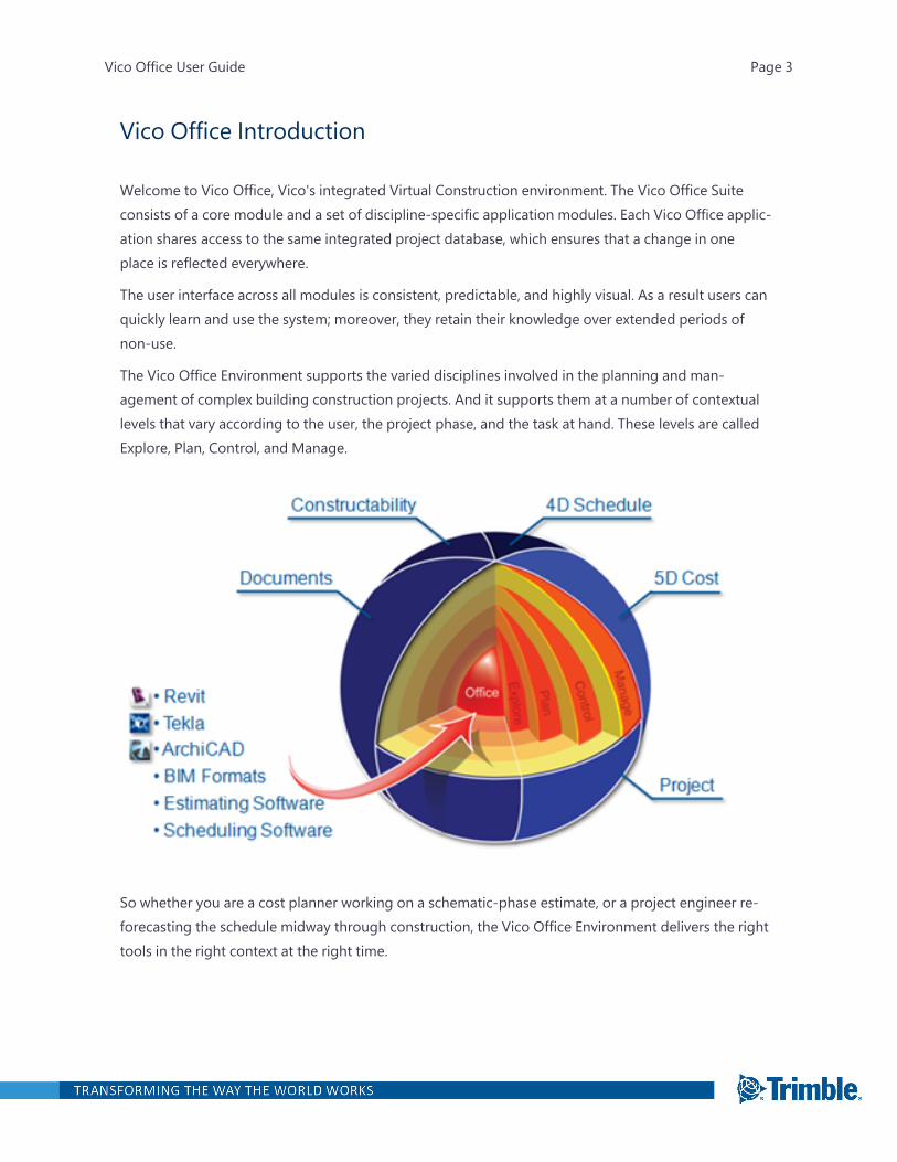
The Vico Office Environment supports the varied disciplines involved in the planning and man-agement of complex building construction projects. And it supports them at a number of contextuallevels that vary according to the user, the project phase, and the task at hand. These levels are calledExplore, Plan, Control, and Manage.
So whether you are a cost planner working on a schematic-phase estimate, or a project engineer re-forecasting the schedule midway through construction, the Vico Office Environment delivers the righttools in the right context at the right time.
Vico Office User Guide Page 3
Vico Office Suite
The Vico Office Suite is composed of applications, or modules, that address specific disciplines orareas of interest across the project team.
The Vico Office Client is the central access point for models and model information. From here theuser creates a project, manages the versions of published models coming into that project, performsreporting, and accomplishes viewing, navigation, and other filtering/selection. With the Vico OfficeClient as platform, Vico Office contains various workflow modules.
7/1/2021
Vico Office Workflow
The Vico Office workflow guides team members through the process of activating models, calculatingcosts, and analyzing schedule impacts.
After the BIM models are completed, publish and compare 3D models from multiple project stake-holders all within the Vico Office Client. For example:
l The architect can contribute an architectural model in Archicad.
l The structural engineer can contribute a structural model in Tekla.
l The mechanical subcontractor can submit a model in Revit MEP.
l The HVAC subcontractor can submit a model in CAD-Duct.
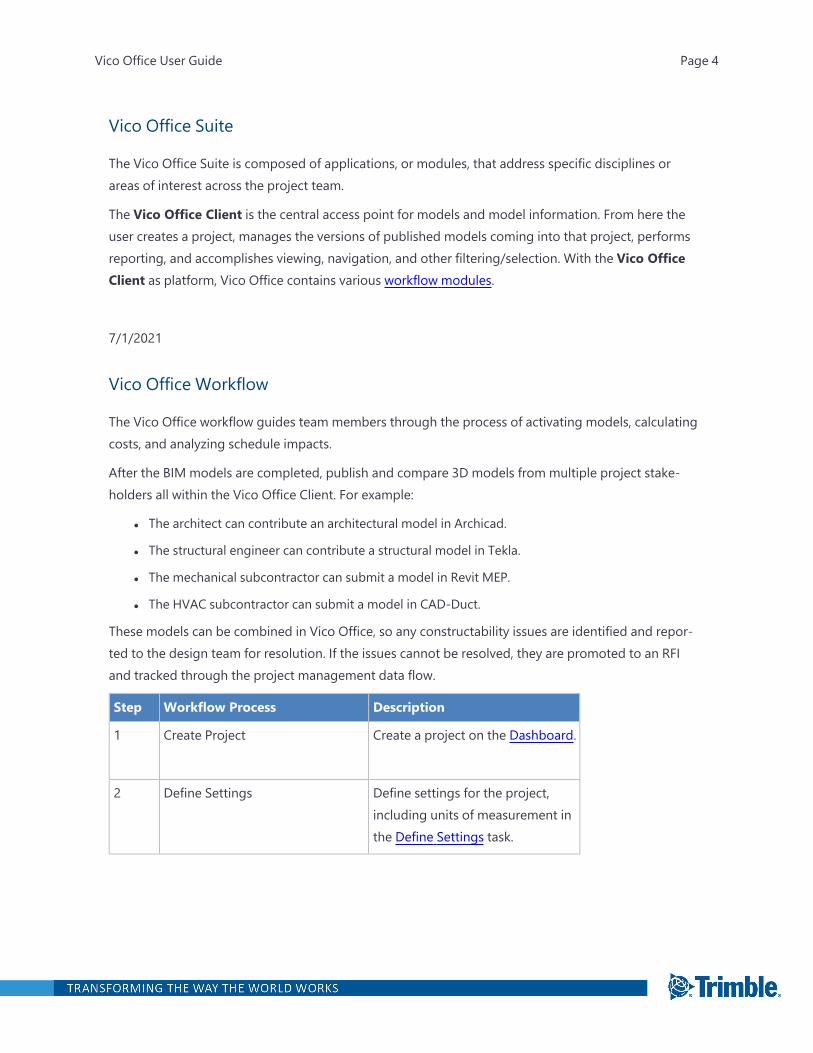
These models can be combined in Vico Office, so any constructability issues are identified and repor-ted to the design team for resolution. If the issues cannot be resolved, they are promoted to an RFIand tracked through the project management data flow.
Step Workflow Process Description
1 Create Project Create a project on the Dashboard.
2 Define Settings Define settings for the project,including units of measurement inthe Define Settings task.
Vico Office User Guide Page 4

Step Workflow Process Description
3 Publish to Vico or Import into Vico Open one or more models in Revit,Archicad or Tekla and publish tothe Vico Office project, or importfiles into Vico Office.
4 Activate Model Version Activate a version of publishedmodels, re-group the Takeoffitems using the TOI Builder, andquantify the elements to calculateyour Premium Quantities.
5 Analyze Constructability Detect and processconstructability issues in theManage Issues task.
6 Takeoff Manager Analyze quantity takeoff pertakeoff item, create new takeoffitems and (re)assign modelelements in the Takeoff Managertask.
Regroup Takeoff items using theTOI Builder and then thenselectively quantify.
7 Takeoff Pad Add new calculation rules for themanually created takeoffquantities per elements in theTakeoff Pad task.
8 Manage Takeoff Check and enter quantities permodel location in the ManageTakeoff task.
9 Document Controller Compare the 3D Model and thedrawings, or the versions of eachdrawings or 3D Models inDocument Controller.
Vico Office User Guide Page 5

Step Workflow Process Description
10 Review Cost Calculate project resourcequantities and cost with takeoffitems for quantity input andreferences for standard content inthe Review Cost task.
11 Edit Tags Define tags for cost estimatingcontent in the project for sortingand filtering purposes in the EditTags task.
12 Explore Cost Analyze cost status and compareagainst project targets in theExplore Cost task.
13 Define Locations Define floors, zones and optimizedlocation breakdown structures pertrade with Define Locations task.
14 Plan Schedule Define tasks and schedule logic,assign crews and optimize theschedule with Schedule Planner.
15 Compare & Update Compare versions of the project toprevious versions or other projectsin the Compare & Update task.
16 Import from Excel Import data from project datasources such as cost plans,quantity takeoffs and targets usingExcel spreadsheet files in the ExcelImporter view.
17 Create and View Reports Use the extracted quantities,created cost plan(s) and detectedconstructability issues to generatereports for project or project bylocation in the Reports view.
Vico Office User Guide Page 6
Step Workflow Process Description
18 Production Control Keep your schedule up-to-date inSchedule Planner during theconstruction.
Vico Office User Interface
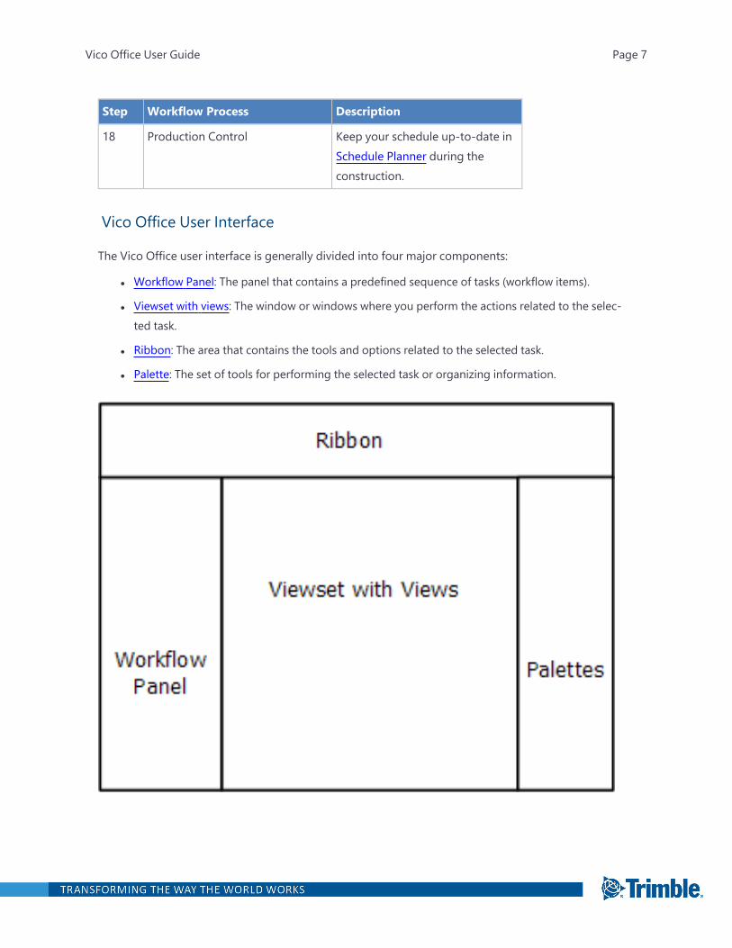
The Vico Office user interface is generally divided into four major components:
l Workflow Panel: The panel that contains a predefined sequence of tasks (workflow items).
l Viewset with views: The window or windows where you perform the actions related to the selec-ted task.
l Ribbon: The area that contains the tools and options related to the selected task.
l Palette: The set of tools for performing the selected task or organizing information.
Vico Office User Guide Page 7
After you select a task in the Workflow Panel, the related views appear with their own ribbon and/orpalettes.
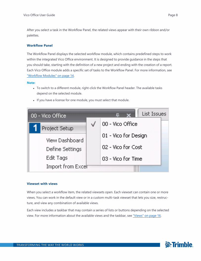
Workflow Panel
The Workflow Panel displays the selected workflow module, which contains predefined steps to workwithin the integrated Vico Office environment. It is designed to provide guidance in the steps thatyou should take, starting with the definition of a new project and ending with the creation of a report.Each Vico Office module adds a specific set of tasks to the Workflow Panel. For more information, see"Workflow Modules" on page 14.
Note:l To switch to a different module, right-click the Workflow Panel header. The available tasks
depend on the selected module.
l If you have a license for one module, you must select that module.
Viewset with views
When you select a workflow item, the related viewsets open. Each viewset can contain one or moreviews. You can work in the default view or in a custom multi-task viewset that lets you size, restruc-ture, and view any combination of available views.
Each view includes a taskbar that may contain a series of lists or buttons depending on the selectedview. For more information about the available views and the taskbar, see "Views" on page 16.
Vico Office User Guide Page 8
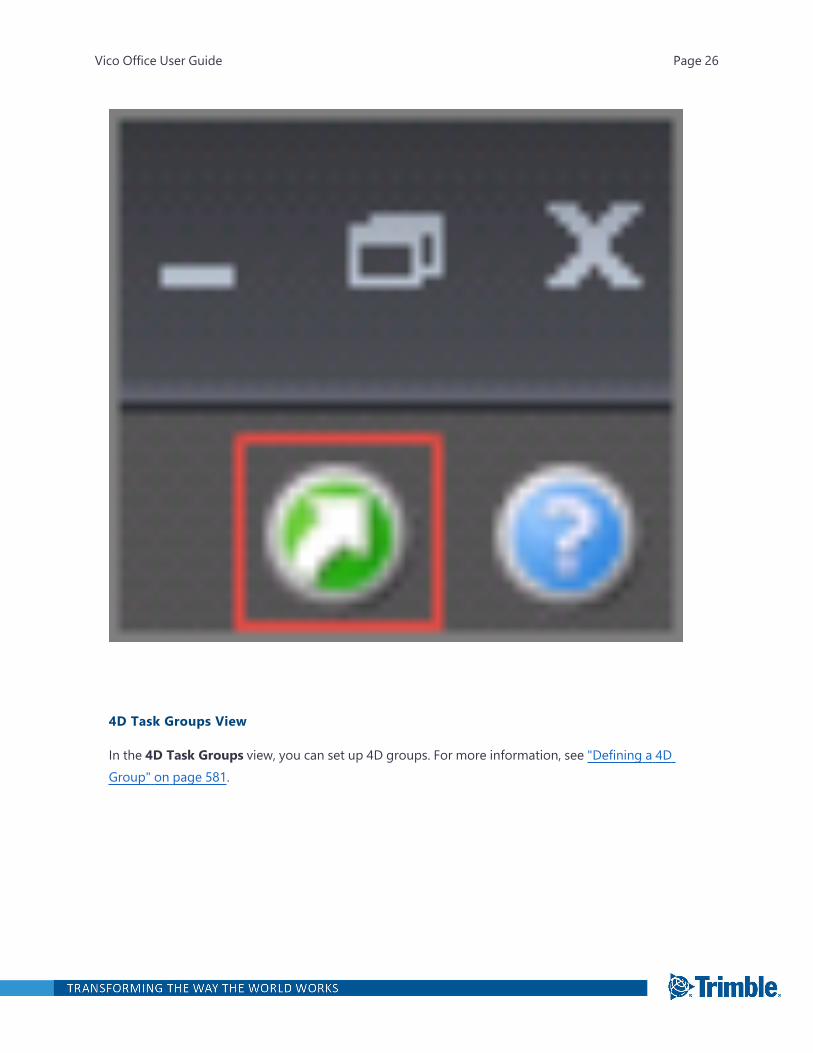
Tip:l From any view, click the green arrow on the top-right corner to see a list of available shortcuts
that apply to that module.
l Click the blue question mark in the top-right corner to access the Help.
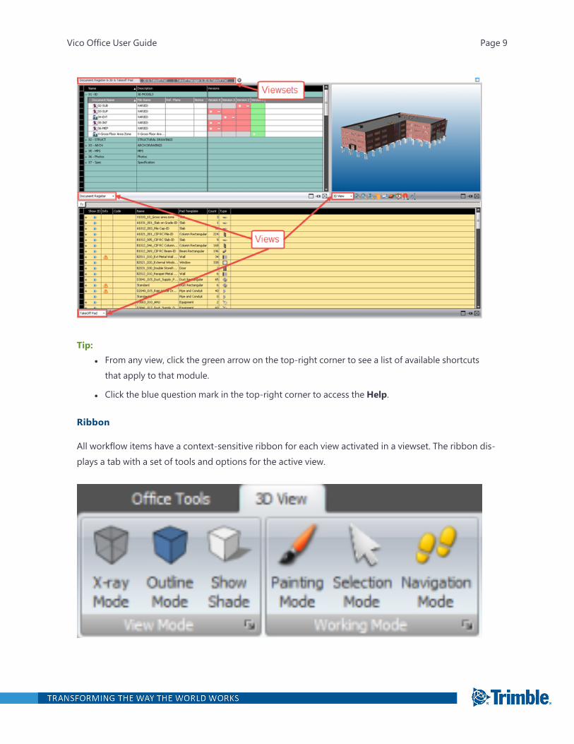
Ribbon
All workflow items have a context-sensitive ribbon for each view activated in a viewset. The ribbon dis-plays a tab with a set of tools and options for the active view.
Vico Office User Guide Page 9
Palettes
A view or viewset may have designated palettes available that help you to organize project inform-ation via filters and view properties of selected elements. The Filtering palette contains the tools to fil-ter the 3D View based on properties of the BIM elements. The Properties palette displays theproperties of the selected elements, so they can be analyzed and or edited.
The names of available palettes appear along the right side of the screen. To select which palettes arevisible, click the palettes icon in the upper-right corner.
Vico Office User Guide Page 10
Vico Office User Guide Page 11
Managing Users and Controlling Project Access
Vico Office requires a Trimble Identity (TID) account to sign it. Once you are signed in as an Admin-istrator, you can use project access controls to manage user accounts. If you are signed in as anEditor, you can access all project to which you have been given access.
Controlling project access using Trimble ID authentication
Every new session opens to a TID login screen. Once you log in, your credentials are saved within thesession. Close the current session to log out. You can sign in as a different user upon starting a newsession. If you do not already have a Trimble Identity (TID), you can create on the login screen.
Note: If you get an authentication error, you should confirm connectivity using another Trimbleonline product, such as Trimble Connect. If you are successful, then Vico Office has encountered aproblem; if you are unsuccessful, TID may be down.
Managing user accounts
There are two roles in Vico Office: Administrator and Editor.
Administrator - Whoever creates a project is assigned as the administrator by default. If you arean administrator for an open project, you can now also use the new Manage Users command to:
l Add users to give them access to a project. Project access is disabled for all other users bydefault (when a project is created, only a project's administrator/owner gets permissions bydefault).
l Change user roles for the project
l Remove users from the project
Editor - Everyone else with access to a project is an editor who can manage data, but cannot addusers, change their roles, remove users, or delete the project.
TO ACCESS THE ADD USERS DIALOG
l ClickManage Users on the ribbon.
TO ADD A NEW USER
1. In the Add Users dialog, enter the user's email address in the empty box under Users.
2. If the user needs full Administrator permissions to manage project access for other users, checkthe Is Admin box. Otherwise, leave this box unchecked to create a user account with Editor per-missions.
Vico Office User Guide Page 12
3. To add additional users, click + and repeat steps 1 and 2.
4. Click Apply.
Note: If the user has an active TID account, their name is displayed in the dialog and an edit iconappears in the Status column. Otherwise, when a user is entered without a valid TID account, onlytheir email address is shown, and a clock icon appears to indicate that the account is uneditable untilthe user has activated a TID account. Vico Office project Administrators should encourage the usersthey add to register with TID as soon as possible.
TO CHANGE A USER'S ROLE
1. In the Add Users dialog, click the Edit icon next to the user (not available for non-TID accounts).
2. Select a new role in the list next to the user name.
3. Click Apply.
TO REMOVE AN EXISTING USER
1. In the Add Users dialog, click the trash can icon.
2. Click Apply.
Note: Each project needs at least one administrator, so this option is not available to remove yourselfyou are the sole administrator. Assign another administrator first.
Migrating projects from earlier versions
Important!When you open your dashboard, any projects from R6.6 or earlier will appear with a yel-low icon in the Code column; this indicates that they are older and must be upgraded. When youopen one of these projects, you will be notified that upgrading and unpacking it will result in youbeing assigned as the default administrator. This means that you need to be careful and have only theappropriate person upgrade legacy projects. It is recommended that you pack and archive older pro-jects before proceeding. After migrating a project to the latest version, use the steps above to give allappropriate users access and set their roles.
Working offline
In case of a network error or unsuccessful login, you can choose to proceed by accessing your localDB only, in which case you will be in offline mode. After logging in using your Trimble Identity (TID)credentials, Vico Office behaves normally, but the ability to select a VPS server is disabled.
Note: Offline mode does support publishing functions.
Note: When entering offline mode, the last valid user is suggested to be the Administrator by default,but you can change this to another person by entering a different email address in the Offline Mode
Vico Office User Guide Page 13
dialog. The application will behave as usual with the permissions of the specific user (by accessingonly the local database).
LICENSING IN OFFLINE MODE
When offline, Vico Office will still work with local licenses.
Workflow Modules
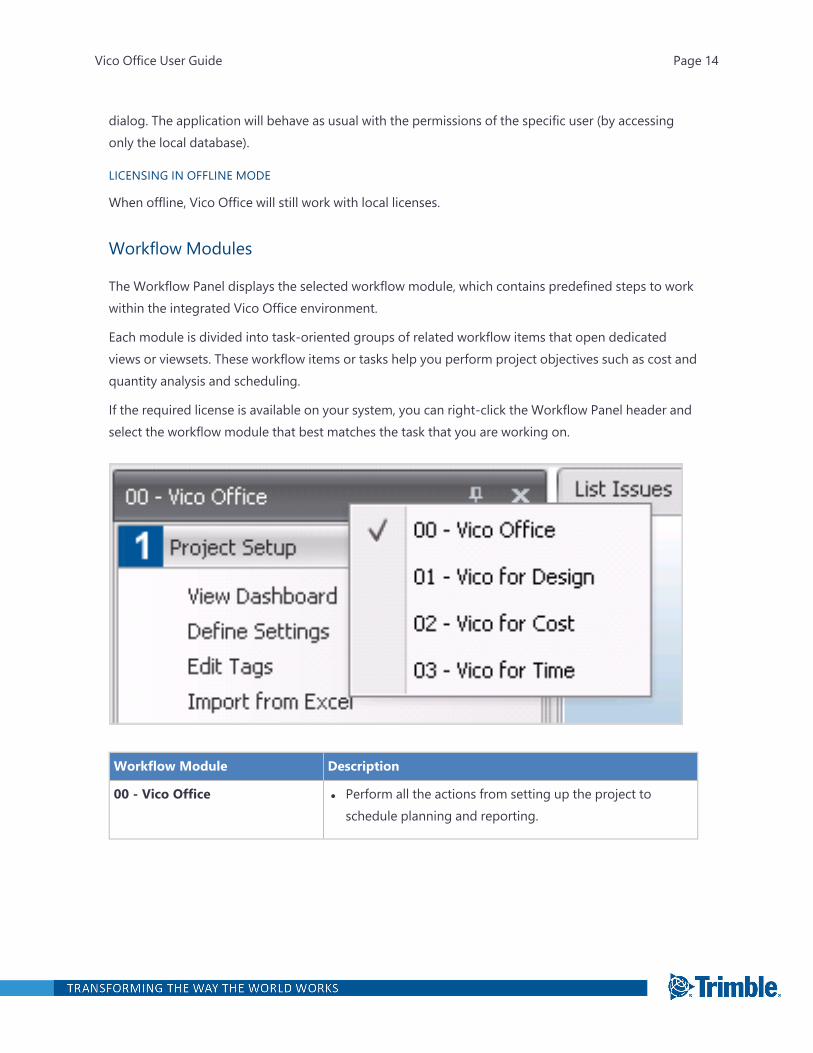
The Workflow Panel displays the selected workflow module, which contains predefined steps to workwithin the integrated Vico Office environment.
Each module is divided into task-oriented groups of related workflow items that open dedicatedviews or viewsets. These workflow items or tasks help you perform project objectives such as cost andquantity analysis and scheduling.
If the required license is available on your system, you can right-click the Workflow Panel header andselect the workflow module that best matches the task that you are working on.
Workflow Module Description
00 - Vico Office l Perform all the actions from setting up the project toschedule planning and reporting.
Vico Office User Guide Page 14
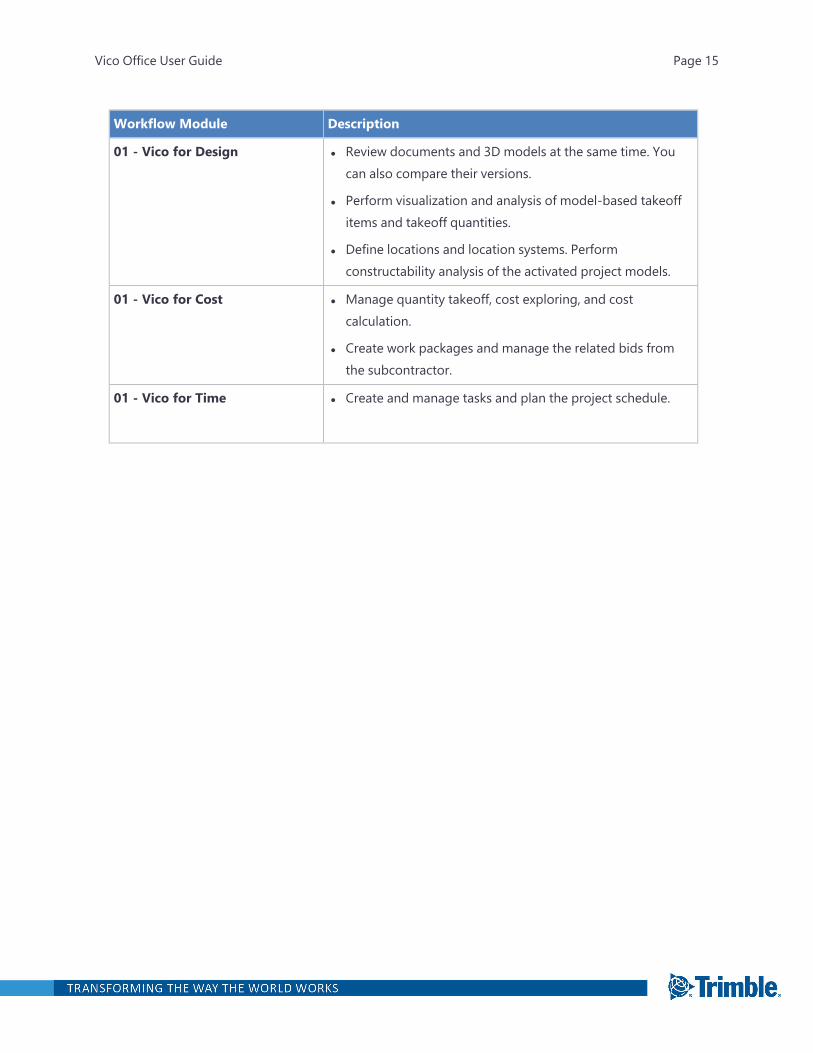
Workflow Module Description
01 - Vico for Design l Review documents and 3D models at the same time. Youcan also compare their versions.
l Perform visualization and analysis of model-based takeoffitems and takeoff quantities.
l Define locations and location systems. Performconstructability analysis of the activated project models.
01 - Vico for Cost l Manage quantity takeoff, cost exploring, and costcalculation.
l Create work packages and manage the related bids fromthe subcontractor.
01 - Vico for Time l Create and manage tasks and plan the project schedule.
Vico Office User Guide Page 15

Views
A view is a window where you can perform actions related to a task. When you click a task in theWorkflow Panel, the related views open in a viewset.
You can use the default viewset or do one of the following:
l From the View list on the taskbar, select a different view. On the viewset tab, the word 'Modified'is added to the original tab name.
l To create a custom viewset, click the Add Viewset button, and select the layout. Then you canselect the view for each window.
On the taskbar, you can also do the following:
l To maximize the view, click .
The other views in the viewset remain visible, but the maximized view takes up most of thescreen.
l To restore the view to its original size, click .
l To unpin the view, click .
The name of the unpinned view appears at the top of the viewset. To expand the view, point tothe name.
Vico Office User Guide Page 16
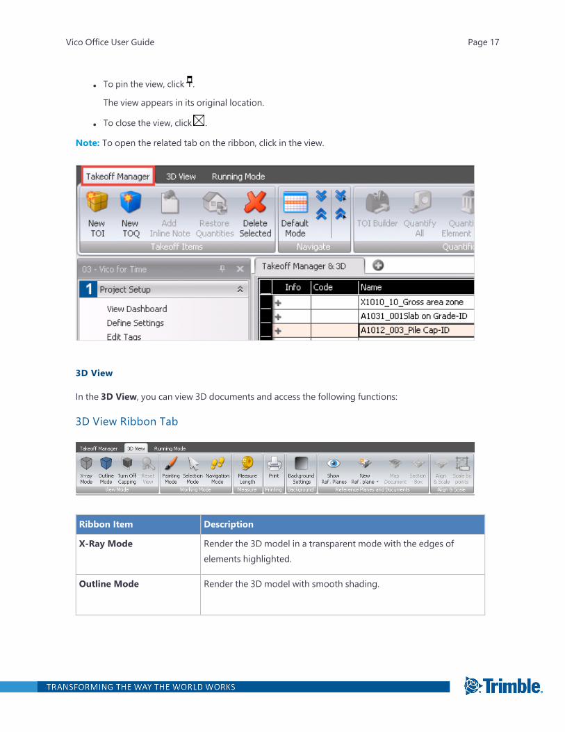
l To pin the view, click .
The view appears in its original location.
l To close the view, click .
Note: To open the related tab on the ribbon, click in the view.
3D View
In the 3D View, you can view 3D documents and access the following functions:
3D View Ribbon Tab
Ribbon Item Description
X-Ray Mode Render the 3D model in a transparent mode with the edges ofelements highlighted.
Outline Mode Render the 3D model with smooth shading.
Vico Office User Guide Page 17
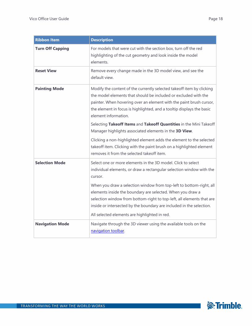
Ribbon Item Description
Turn Off Capping For models that were cut with the section box, turn off the redhighlighting of the cut geometry and look inside the modelelements.
Reset View Remove every change made in the 3D model view, and see thedefault view.
Painting Mode Modify the content of the currently selected takeoff item by clickingthe model elements that should be included or excluded with thepainter. When hovering over an element with the paint brush cursor,the element in focus is highlighted, and a tooltip displays the basicelement information.
Selecting Takeoff Items and Takeoff Quantities in the Mini TakeoffManager highlights associated elements in the 3D View.
Clicking a non-highlighted element adds the element to the selectedtakeoff item. Clicking with the paint brush on a highlighted elementremoves it from the selected takeoff item.
Selection Mode Select one or more elements in the 3D model. Click to selectindividual elements, or draw a rectangular selection window with thecursor.
When you draw a selection window from top-left to bottom-right, allelements inside the boundary are selected. When you draw aselection window from bottom-right to top-left, all elements that areinside or intersected by the boundary are included in the selection.
All selected elements are highlighted in red.
Navigation Mode Navigate through the 3D viewer using the available tools on thenavigation toolbar.
Vico Office User Guide Page 18

Ribbon Item Description
Measure Length Measure any distance within the 3D model. The recognized points ofthe model are indicated by colored squares.
Print Create an image of the activated model. In the Print Setup dialog,you are can set up the orientation, the printer, or you can add theoutput folder.
Background Settings Set up the solid or gradient background color as desired.
Show Reference Planes Make the mapped documents visible.
For information on importing documents into a project, see"Document Control " on page 215.
Vico Office User Guide Page 19
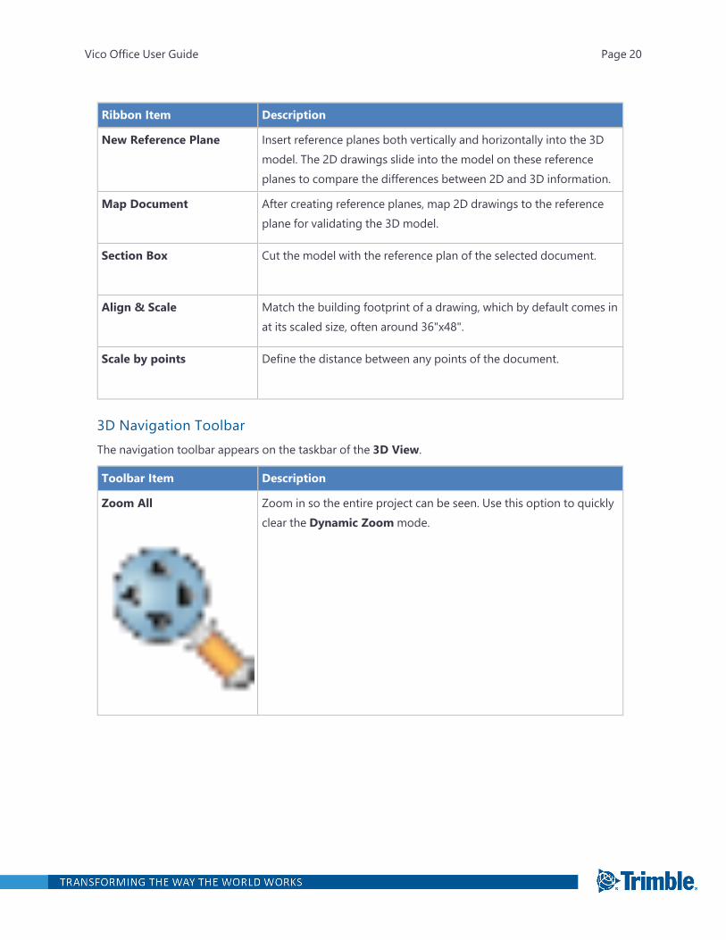
Ribbon Item Description
New Reference Plane Insert reference planes both vertically and horizontally into the 3Dmodel. The 2D drawings slide into the model on these referenceplanes to compare the differences between 2D and 3D information.
Map Document After creating reference planes, map 2D drawings to the referenceplane for validating the 3D model.
Section Box Cut the model with the reference plan of the selected document.
Align & Scale Match the building footprint of a drawing, which by default comes inat its scaled size, often around 36"x48".
Scale by points Define the distance between any points of the document.
3D Navigation ToolbarThe navigation toolbar appears on the taskbar of the 3D View.
Toolbar Item Description
Zoom All Zoom in so the entire project can be seen. Use this option to quicklyclear the Dynamic Zoommode.
Vico Office User Guide Page 20
Toolbar Item Description
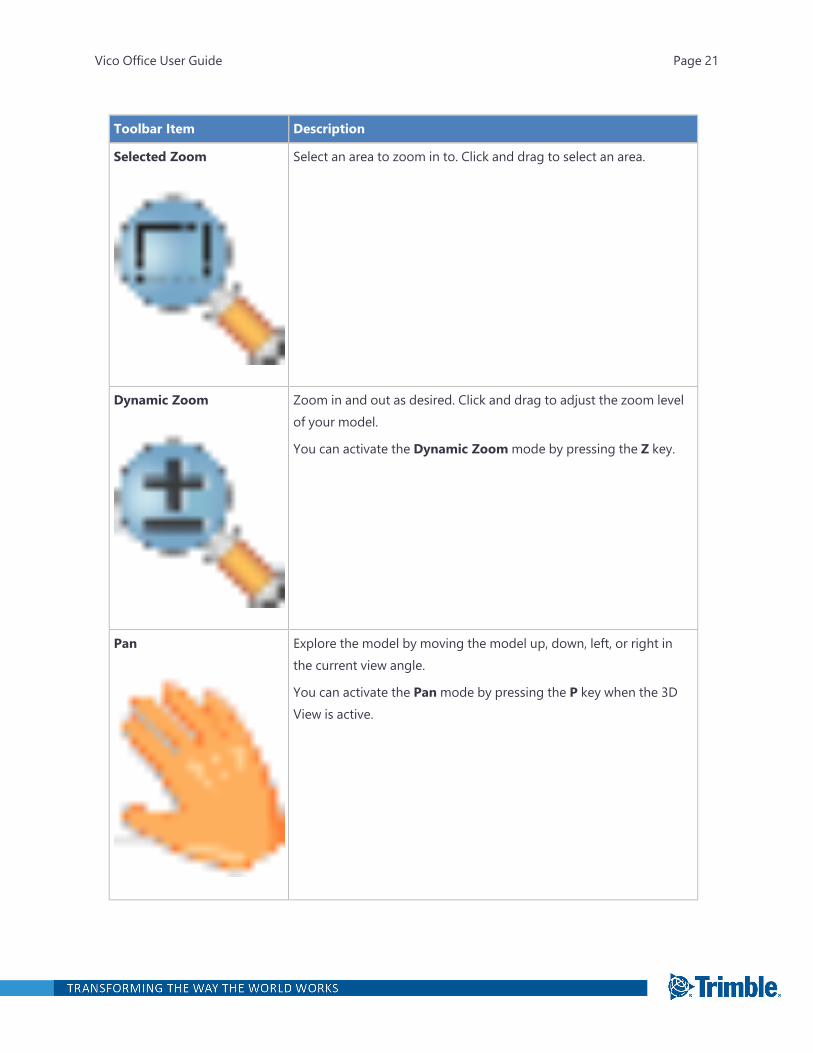
Selected Zoom Select an area to zoom in to. Click and drag to select an area.
Dynamic Zoom Zoom in and out as desired. Click and drag to adjust the zoom levelof your model.
You can activate the Dynamic Zoommode by pressing the Z key.
Pan Explore the model by moving the model up, down, left, or right inthe current view angle.
You can activate the Panmode by pressing the P key when the 3DView is active.
Vico Office User Guide Page 21
Toolbar Item Description
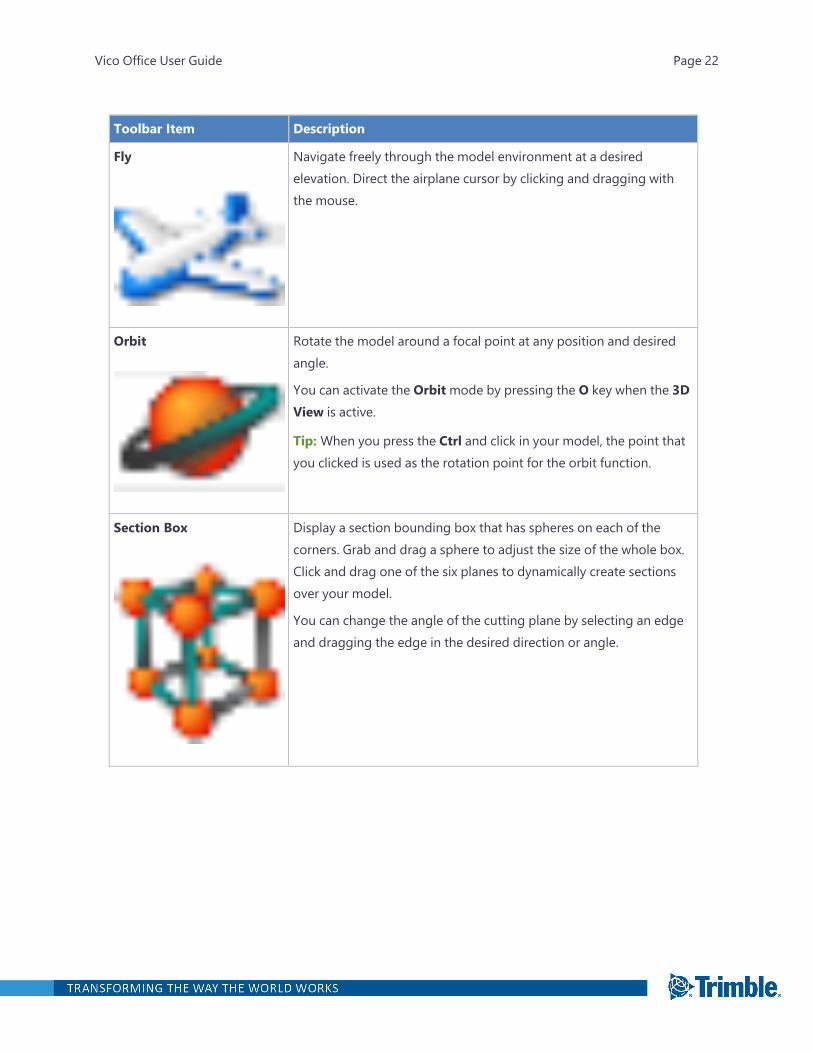
Fly Navigate freely through the model environment at a desiredelevation. Direct the airplane cursor by clicking and dragging withthe mouse.
Orbit Rotate the model around a focal point at any position and desiredangle.
You can activate the Orbitmode by pressing the O key when the 3DView is active.
Tip: When you press the Ctrl and click in your model, the point thatyou clicked is used as the rotation point for the orbit function.
Section Box Display a section bounding box that has spheres on each of thecorners. Grab and drag a sphere to adjust the size of the whole box.Click and drag one of the six planes to dynamically create sectionsover your model.
You can change the angle of the cutting plane by selecting an edgeand dragging the edge in the desired direction or angle.
Vico Office User Guide Page 22
Toolbar Item Description
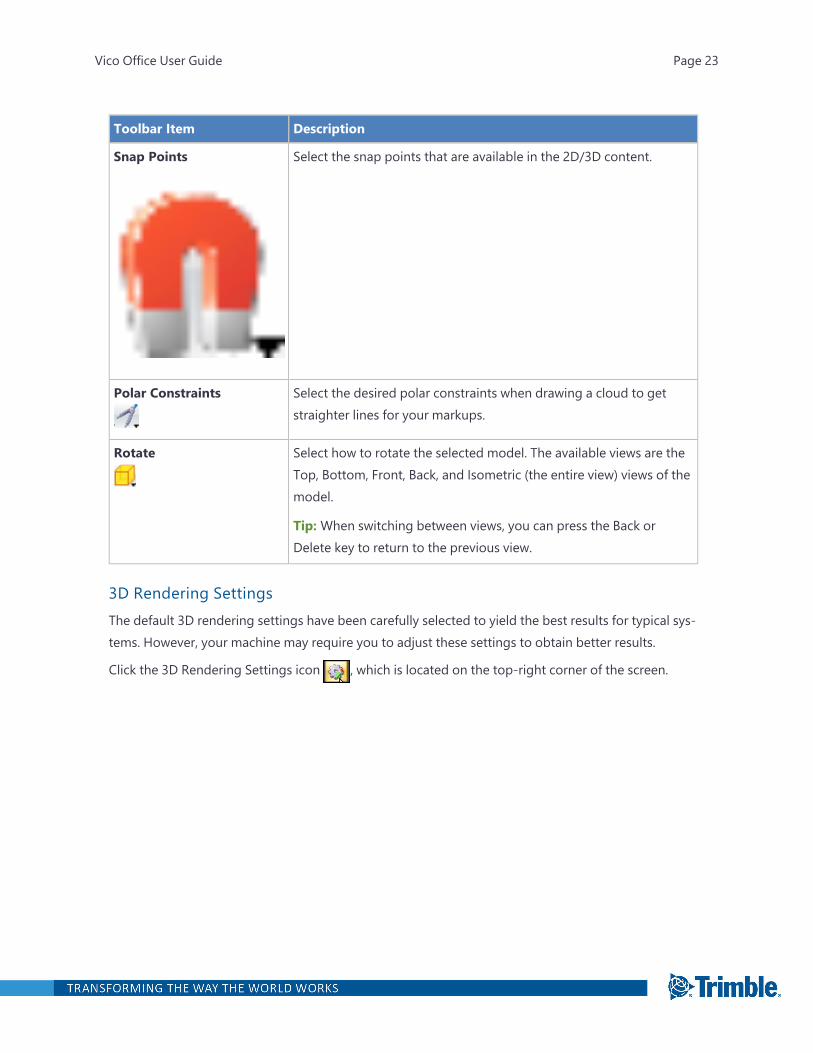
Snap Points Select the snap points that are available in the 2D/3D content.
Polar Constraints Select the desired polar constraints when drawing a cloud to getstraighter lines for your markups.
Rotate Select how to rotate the selected model. The available views are theTop, Bottom, Front, Back, and Isometric (the entire view) views of themodel.
Tip: When switching between views, you can press the Back orDelete key to return to the previous view.
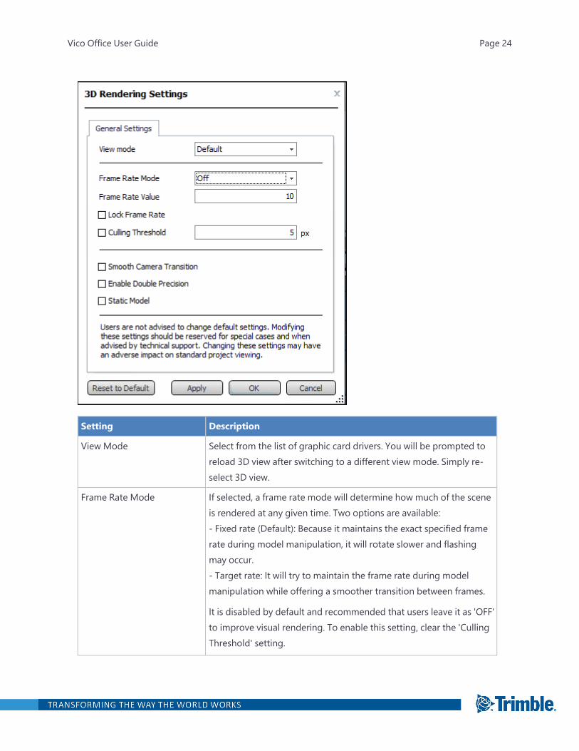
3D Rendering SettingsThe default 3D rendering settings have been carefully selected to yield the best results for typical sys-tems. However, your machine may require you to adjust these settings to obtain better results.
Click the 3D Rendering Settings icon , which is located on the top-right corner of the screen.
Vico Office User Guide Page 23
Setting Description
View Mode Select from the list of graphic card drivers. You will be prompted toreload 3D view after switching to a different view mode. Simply re-select 3D view.
Frame Rate Mode If selected, a frame rate mode will determine how much of the sceneis rendered at any given time. Two options are available:- Fixed rate (Default): Because it maintains the exact specified framerate during model manipulation, it will rotate slower and flashingmay occur.- Target rate: It will try to maintain the frame rate during modelmanipulation while offering a smoother transition between frames.
It is disabled by default and recommended that users leave it as 'OFF'to improve visual rendering. To enable this setting, clear the 'CullingThreshold' setting.
Vico Office User Guide Page 24
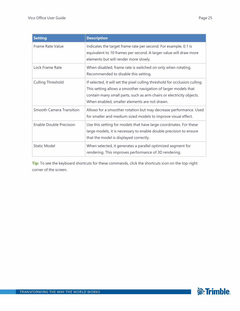
Setting Description
Frame Rate Value Indicates the target frame rate per second. For example, 0.1 isequivalent to 10 frames per second. A larger value will draw moreelements but will render more slowly.
Lock Frame Rate When disabled, frame rate is switched on only when rotating.Recommended to disable this setting.
Culling Threshold If selected, it will set the pixel culling threshold for occlusion culling.This setting allows a smoother navigation of larger models thatcontain many small parts, such as arm chairs or electricity objects.When enabled, smaller elements are not drawn.
Smooth Camera Transition Allows for a smoother rotation but may decrease performance. Usedfor smaller and medium sized models to improve visual effect.
Enable Double Precision Use this setting for models that have large coordinates. For theselarge models, it is necessary to enable double precision to ensurethat the model is displayed correctly.
Static Model When selected, it generates a parallel optimized segment forrendering. This improves performance of 3D rendering.
Tip: To see the keyboard shortcuts for these commands, click the shortcuts icon on the top-rightcorner of the screen.
Vico Office User Guide Page 25
4D Task Groups View
In the 4D Task Groups view, you can set up 4D groups. For more information, see "Defining a 4DGroup" on page 581.
Vico Office User Guide Page 26
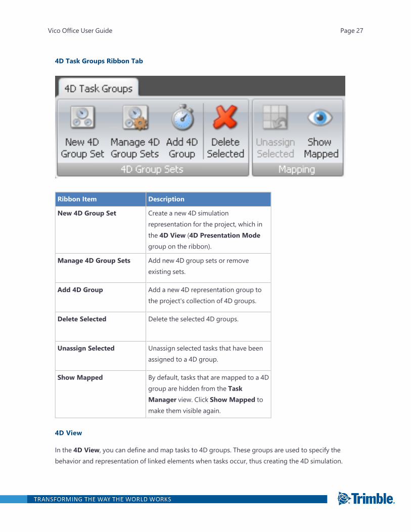
4D Task Groups Ribbon Tab
Ribbon Item Description
New 4D Group Set Create a new 4D simulationrepresentation for the project, which inthe 4D View (4D Presentation Modegroup on the ribbon).
Manage 4D Group Sets Add new 4D group sets or removeexisting sets.
Add 4D Group Add a new 4D representation group tothe project's collection of 4D groups.
Delete Selected Delete the selected 4D groups.
Unassign Selected Unassign selected tasks that have beenassigned to a 4D group.
Show Mapped By default, tasks that are mapped to a 4Dgroup are hidden from the TaskManager view. Click Show Mapped tomake them visible again.
4D View
In the 4D View, you can define and map tasks to 4D groups. These groups are used to specify thebehavior and representation of linked elements when tasks occur, thus creating the 4D simulation.
Vico Office User Guide Page 27
For more information, see "Manage 4D" on page 580.
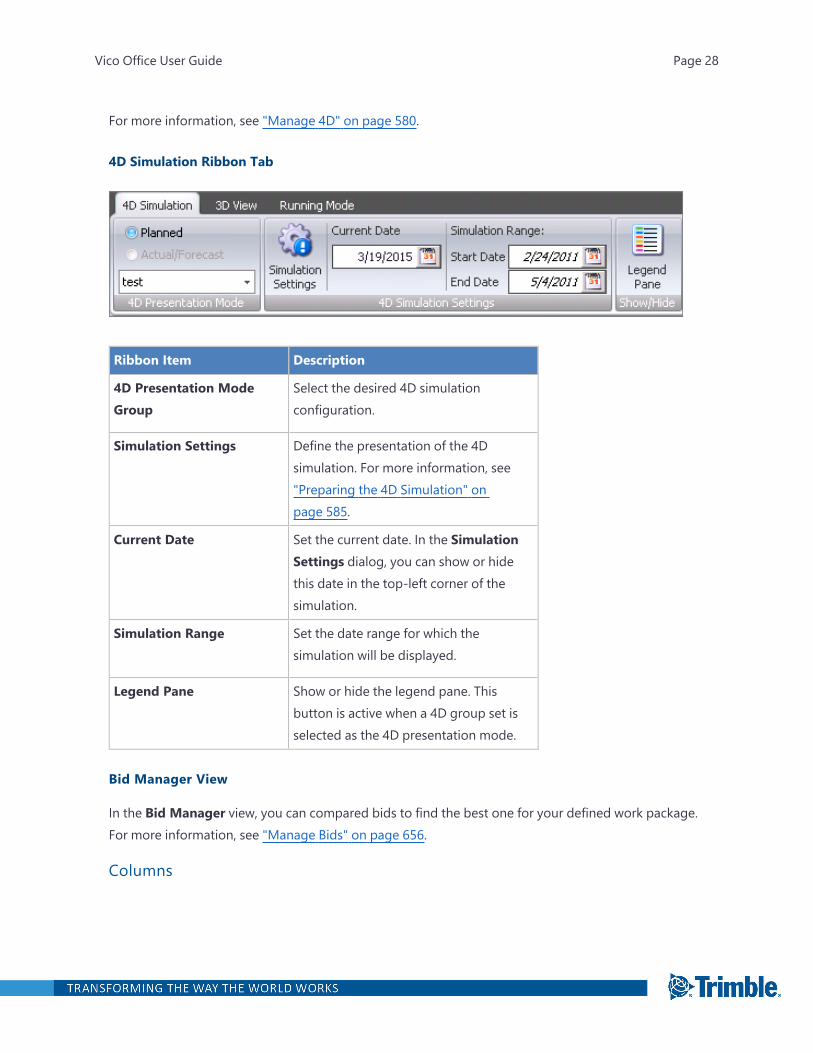
4D Simulation Ribbon Tab
Ribbon Item Description
4D Presentation ModeGroup
Select the desired 4D simulationconfiguration.
Simulation Settings Define the presentation of the 4Dsimulation. For more information, see"Preparing the 4D Simulation" onpage 585.
Current Date Set the current date. In the SimulationSettings dialog, you can show or hidethis date in the top-left corner of thesimulation.
Simulation Range Set the date range for which thesimulation will be displayed.
Legend Pane Show or hide the legend pane. Thisbutton is active when a 4D group set isselected as the 4D presentation mode.
Bid Manager View
In the Bid Manager view, you can compared bids to find the best one for your defined work package.For more information, see "Manage Bids" on page 656.
Columns
Vico Office User Guide Page 28
Column Description
Code The code that is added automatically after you create a workpackage. This code can be modified anytime in the future.
Description The description of the work package.
Monitoring Quantity The values that belong to the defined unit. This cell is filledautomatically after you select the monitoring unit.
Monitoring Unit The units that were used in the project. This is available for the workpackages but not for the whole project.
Total The estimated total package cost, which is the sum of the Committedand Plugged values.
Committed The total of values submitted by the chosen subcontractor.
Plugged The plug value applied to a cost assembly or component.
By Others The sum of items to be released from the chosen subcontractor ifthey will not be involved with a particular job. Item can be re-allocated to another package.
Approval State The level of selection. The states are Target, Estimate, Planned, Bid,and Contracted.
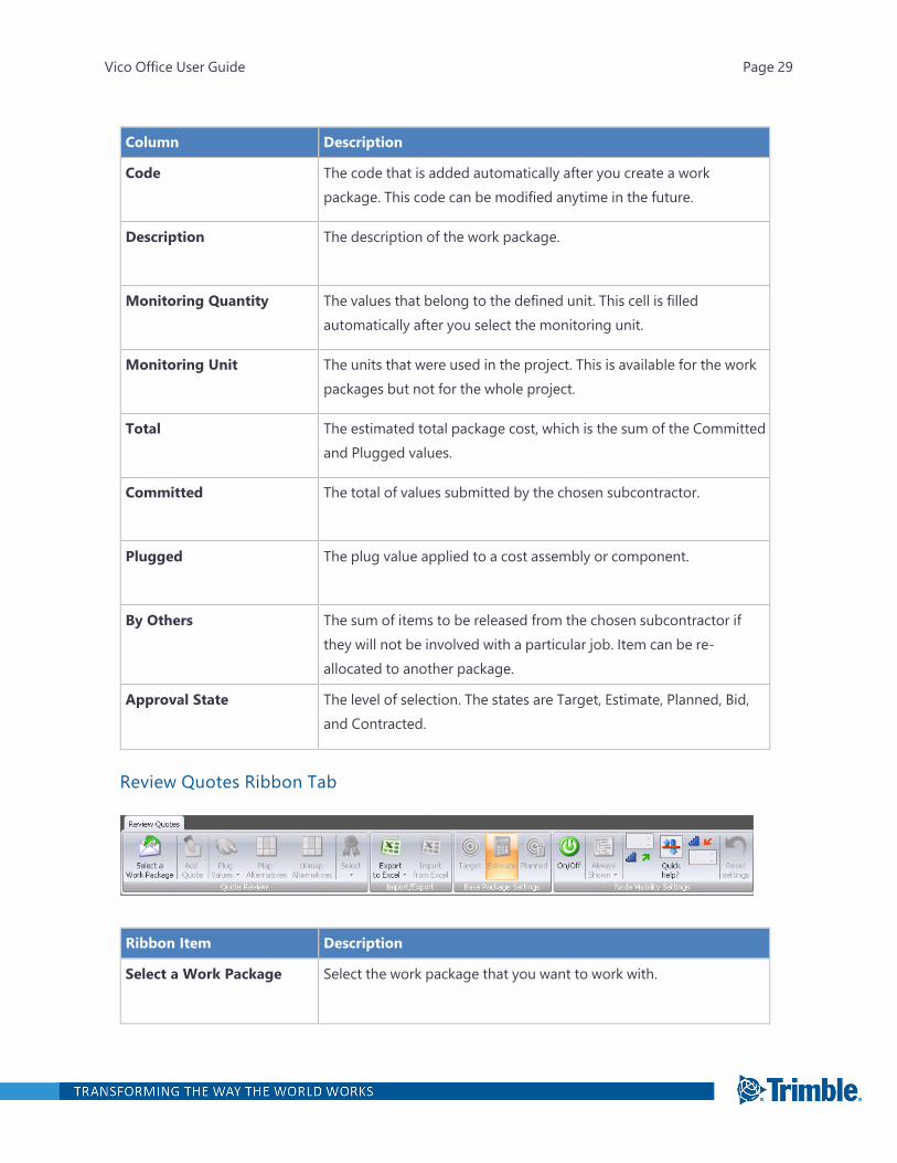
Review Quotes Ribbon Tab
Ribbon Item Description
Select a Work Package Select the work package that you want to work with.
Vico Office User Guide Page 29
Ribbon Item Description
Add Quote Add extra bidder columns on the right-side of the spreadsheet.
Plug Values Select the type of plug value. For more information, see "Using PlugValues" on page 666.
Map Alternatives After entering an alternative, map it to the buyout item that youwant to replace. For more information, see "Entering and Mappingan Alternative" on page 665.
Unmap Alternatives Unmap an alternative from a buyout item.
Select Assign an award level to a bidder. For more information, see"Awarding a Bid" on page 660.
Import/Export Group Import data from Excel, or export data to Excel.
Base Package SettingsGroup
Select a stage for comparing bids. For more information, see"Entering Bid Data Manually" on page 657.
Node Visibility SettingsGroup
Determine the cost plan hierarchy levels displayed in each package.Fore more information, see "Node Visibility Settings" on page 639.
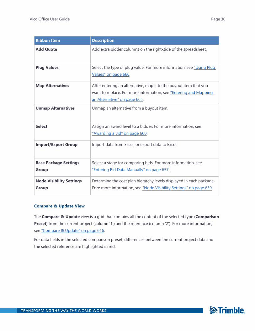
Compare & Update View
The Compare & Update view is a grid that contains all the content of the selected type (ComparisonPreset) from the current project (column '1') and the reference (column '2'). For more information,see "Compare & Update" on page 616.
For data fields in the selected comparison preset, differences between the current project data andthe selected reference are highlighted in red.
Vico Office User Guide Page 30
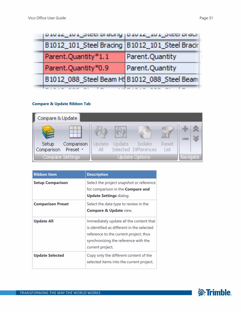
Compare & Update Ribbon Tab
Ribbon Item Description
Setup Comparison Select the project snapshot or referencefor comparison in the Compare andUpdate Settings dialog.
Comparison Preset Select the data type to review in theCompare & Update view.
Update All Immediately update all the content thatis identified as different in the selectedreference to the current project, thussynchronizing the reference with thecurrent project.
Update Selected Copy only the different content of theselected items into the current project.
Vico Office User Guide Page 31
Ribbon Item Description
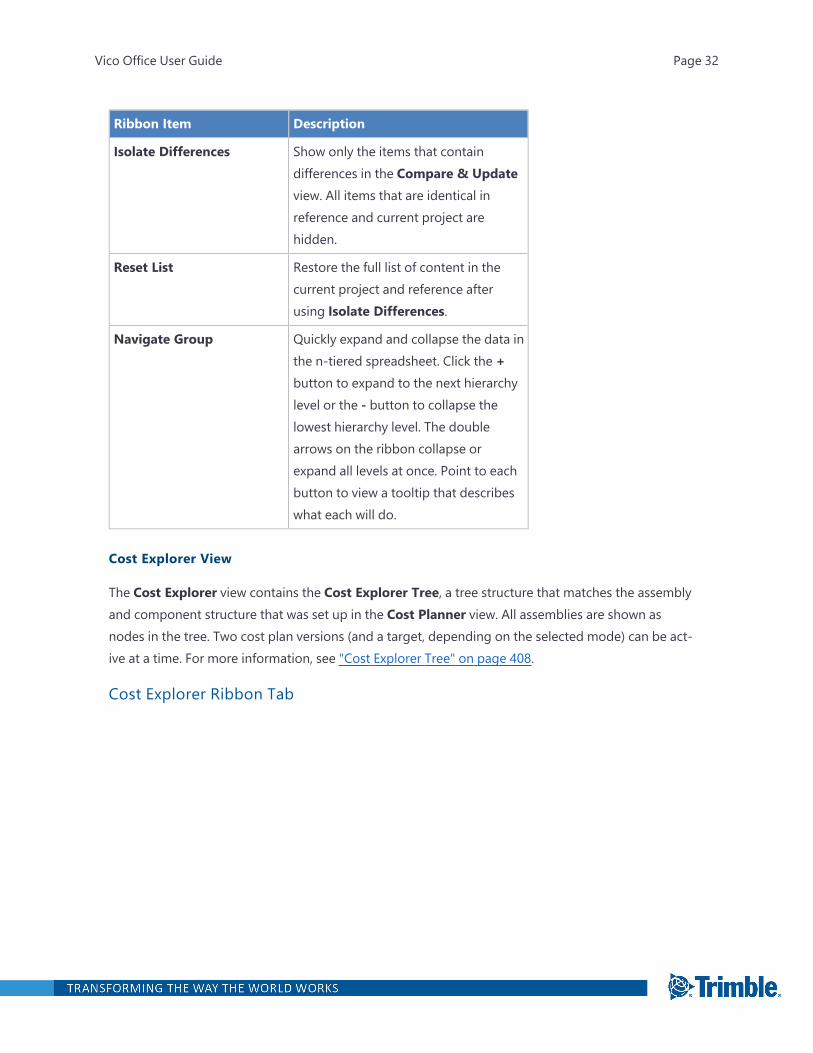
Isolate Differences Show only the items that containdifferences in the Compare & Updateview. All items that are identical inreference and current project arehidden.
Reset List Restore the full list of content in thecurrent project and reference afterusing Isolate Differences.
Navigate Group Quickly expand and collapse the data inthe n-tiered spreadsheet. Click the +button to expand to the next hierarchylevel or the - button to collapse thelowest hierarchy level. The doublearrows on the ribbon collapse orexpand all levels at once. Point to eachbutton to view a tooltip that describeswhat each will do.
Cost Explorer View
The Cost Explorer view contains the Cost Explorer Tree, a tree structure that matches the assemblyand component structure that was set up in the Cost Planner view. All assemblies are shown asnodes in the tree. Two cost plan versions (and a target, depending on the selected mode) can be act-ive at a time. For more information, see "Cost Explorer Tree" on page 408.
Cost Explorer Ribbon Tab
Vico Office User Guide Page 32
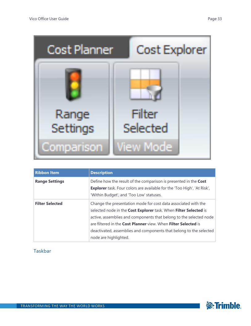
Ribbon Item Description
Range Settings Define how the result of the comparison is presented in the CostExplorer task. Four colors are available for the 'Too High', 'At Risk','Within Budget', and 'Too Low' statuses.
Filter Selected Change the presentation mode for cost data associated with theselected node in the Cost Explorer task. When Filter Selected isactive, assemblies and components that belong to the selected nodeare filtered in the Cost Planner view. When Filter Selected isdeactivated, assemblies and components that belong to the selectednode are highlighted.
Taskbar
Vico Office User Guide Page 33

Taskbar Item Description
Viewset List Available viewsets.
The Explore Cost task has two default viewsets: Cost Explorer &Cost Planner and Cost Explorer & 3D View. Click the tab at the topto activate the desired viewset.
Comparison Mode List Options for comparing cost plan versions.
The following options are available:
1. Assemblies to Components: Select up to two cost planversions.
2. Cost to Target: Select up to two cost plan versions and atarget against which the cost in the selected cost planversions can be compared.
For more information, see "Comparison Modes and Versions" onpage 406.
Version Lists Collections of cost plan versions that were saved from the ReviewCost view.
Cost Planner View
In the Cost Planner view, you can build a 'living cost estimate', which is a key to making information-driven decisions that keep the budget on track.
This view includes references, so you can use your own historical data and store a collection of stand-ards and reusable estimating content. For more information, see "Review Cost" on page 356.
Key Cost Plan DefinitionsTerm Definition
Source Qty A number entered manually in the cost plan or a formula that refersto a takeoff item.
Vico Office User Guide Page 34
Term Definition
Consumption The amount of a component required to install a certain element.This column is mainly used to calculate labor (per HR price) and todefine production rates for scheduling purposes.
Example: How many hours are needed to install a certain amount ofwork like pouring concrete.
Waste Unwanted material produced directly or incidentally by theconstruction project component.
Example: Building materials such as insulation, nails, electrical wiring,and rebar.
Qty Calculated field.
Qty = Source Qty x Consumption xWaste
Labor Summarizes the working hours of the subtree. Note that the unitmust be in hours (HR) in order for this column to add up all thehours.
Unit Cost Cost per unit.
Total Price Calculated field.
Total Price = Qty x Unit Cost
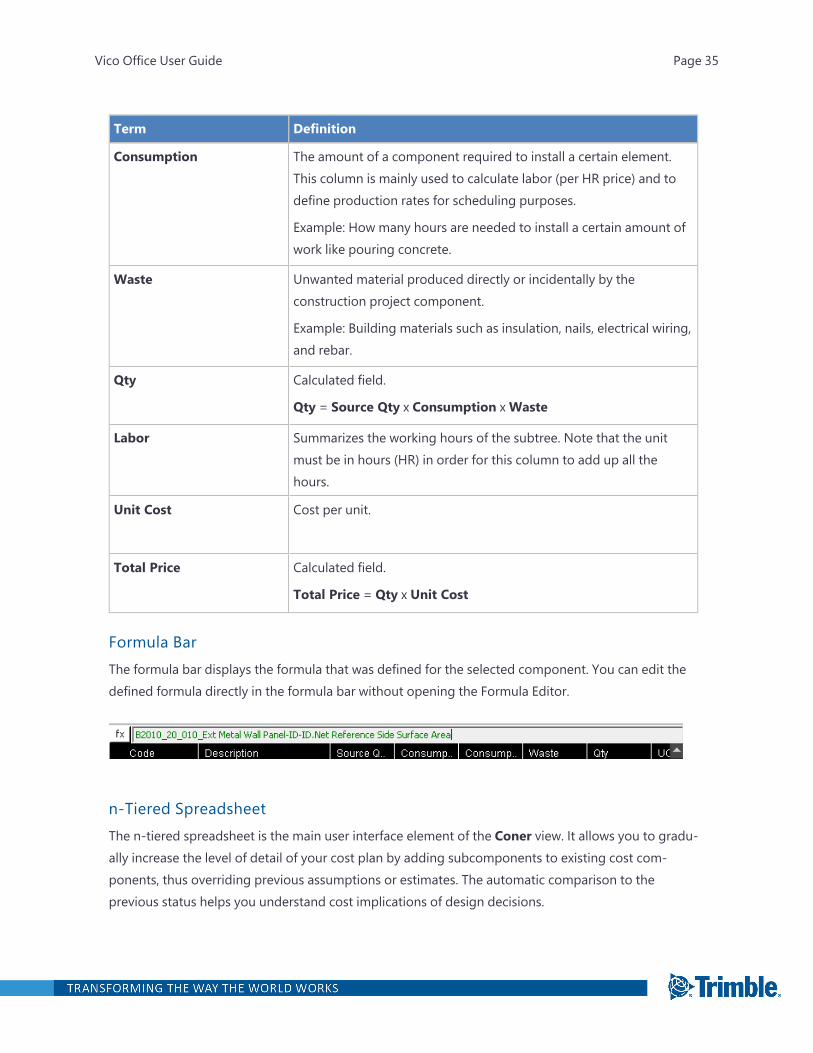
Formula BarThe formula bar displays the formula that was defined for the selected component. You can edit thedefined formula directly in the formula bar without opening the Formula Editor.
n-Tiered SpreadsheetThe n-tiered spreadsheet is the main user interface element of the Coner view. It allows you to gradu-ally increase the level of detail of your cost plan by adding subcomponents to existing cost com-ponents, thus overriding previous assumptions or estimates. The automatic comparison to theprevious status helps you understand cost implications of design decisions.
Vico Office User Guide Page 35
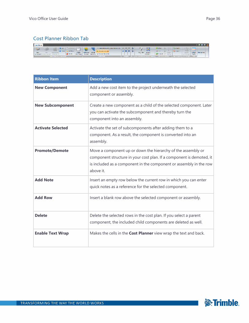
Cost Planner Ribbon Tab
Ribbon Item Description
New Component Add a new cost item to the project underneath the selectedcomponent or assembly.
New Subcomponent Create a new component as a child of the selected component. Lateryou can activate the subcomponent and thereby turn thecomponent into an assembly.
Activate Selected Activate the set of subcomponents after adding them to acomponent. As a result, the component is converted into anassembly.
Promote/Demote Move a component up or down the hierarchy of the assembly orcomponent structure in your cost plan. If a component is demoted, itis included as a component in the component or assembly in the rowabove it.
Add Note Insert an empty row below the current row in which you can enterquick notes as a reference for the selected component.
Add Row Insert a blank row above the selected component or assembly.
Delete Delete the selected rows in the cost plan. If you select a parentcomponent, the included child components are deleted as well.
Enable Text Wrap Makes the cells in the Cost Planner view wrap the text and back.
Vico Office User Guide Page 36
Ribbon Item Description
Reference Browser Open the Reference Browser dialog with the default referenceloaded.
The settings include:
l Server Name: Select a computer in the network that contains theassemblies and components that you want to copy into thecurrent project.
l Project Selection: Represents the project of which assembly andcomponent content is shown in the Reference Browser. Bydefault, the reference that is selected in the Define Settings viewis opened.
l Add in selected Component: Add the selected content insidethe selected component as subcomponents.
l Add below selected Component: Add the selected contentbelow the selected component, which adds the selection to thesame level in the assembly and component structure.
Include Hierarchy When dragging over a cost item from a reference project to thecurrent project's cost plan, it will also include the parent levels of themapped item. Note that if the same code is in the existing project,you will be prompted to resolve the conflict by either overwriting theexisting code, add a new one, or keep the existing code.
Quantity Copy Options For all copy operations in the Cost Planner view, determine howquantity information is included in the target location:
l Descriptions and Consumptions Only: Keep the default valuefor the target quantity.
l Include Formula: Copy the defined formula from the source and,if possible, reuse the takeoff items and takeoff quantities in thecurrent project. This is the default option.
l Include Quantities: Only copy the formula's results from thesource.
Vico Office User Guide Page 37
Ribbon Item Description
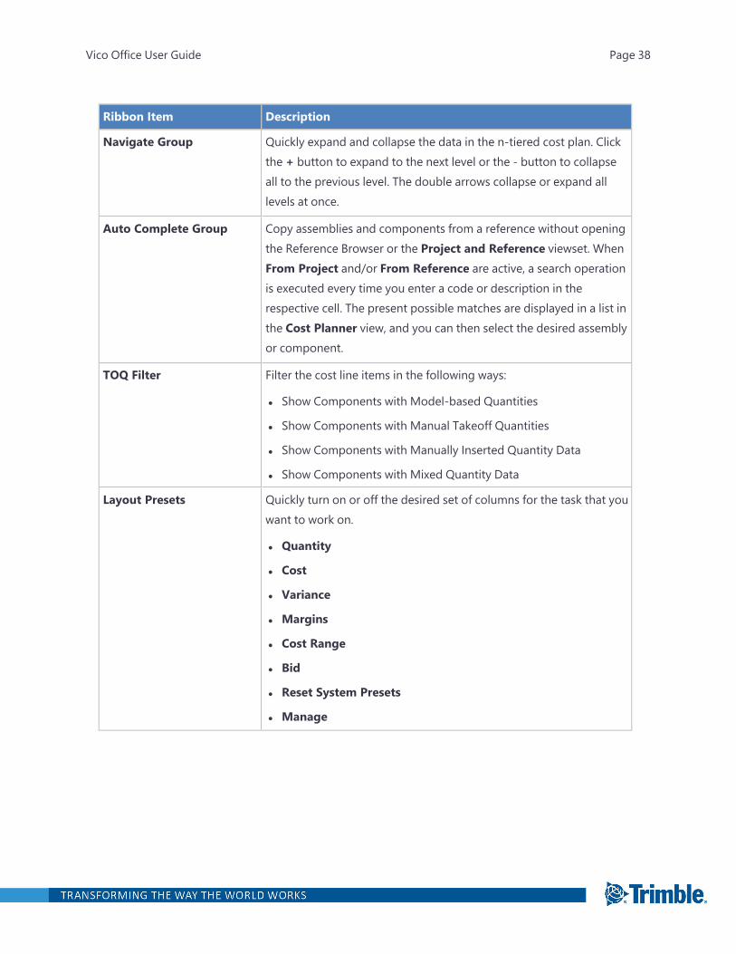
Navigate Group Quickly expand and collapse the data in the n-tiered cost plan. Clickthe + button to expand to the next level or the - button to collapseall to the previous level. The double arrows collapse or expand alllevels at once.
Auto Complete Group Copy assemblies and components from a reference without openingthe Reference Browser or the Project and Reference viewset. WhenFrom Project and/or From Reference are active, a search operationis executed every time you enter a code or description in therespective cell. The present possible matches are displayed in a list inthe Cost Planner view, and you can then select the desired assemblyor component.
TOQ Filter Filter the cost line items in the following ways:
l Show Components with Model-based Quantities
l Show Components with Manual Takeoff Quantities
l Show Components with Manually Inserted Quantity Data
l Show Components with Mixed Quantity Data
Layout Presets Quickly turn on or off the desired set of columns for the task that youwant to work on.
l Quantity
l Cost
l Variance
l Margins
l Cost Range
l Bid
l Reset System Presets
l Manage
Vico Office User Guide Page 38
Ribbon Item Description
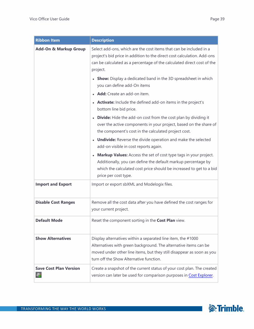
Add-On & Markup Group Select add-ons, which are the cost items that can be included in aproject's bid price in addition to the direct cost calculation. Add-onscan be calculated as a percentage of the calculated direct cost of theproject.
l Show: Display a dedicated band in the 3D spreadsheet in whichyou can define add-On items
l Add: Create an add-on item.
l Activate: Include the defined add-on items in the project'sbottom line bid price.
l Divide: Hide the add-on cost from the cost plan by dividing itover the active components in your project, based on the share ofthe component's cost in the calculated project cost.
l Undivide: Reverse the divide operation and make the selectedadd-on visible in cost reports again.
l Markup Values: Access the set of cost type tags in your project.Additionally, you can define the default markup percentage bywhich the calculated cost price should be increased to get to a bidprice per cost type.
Import and Export Import or export sbXML and Modelogix files.
Disable Cost Ranges Remove all the cost data after you have defined the cost ranges foryour current project.
Default Mode Reset the component sorting in the Cost Plan view.
Show Alternatives Display alternatives within a separated line item, the #1000Alternatives with green background. The alternative items can bemoved under other line items, but they still disappear as soon as youturn off the Show Alternative function.
Save Cost Plan Version Create a snapshot of the current status of your cost plan. The createdversion can later be used for comparison purposes in Cost Explorer.
Vico Office User Guide Page 39
Ribbon Item Description
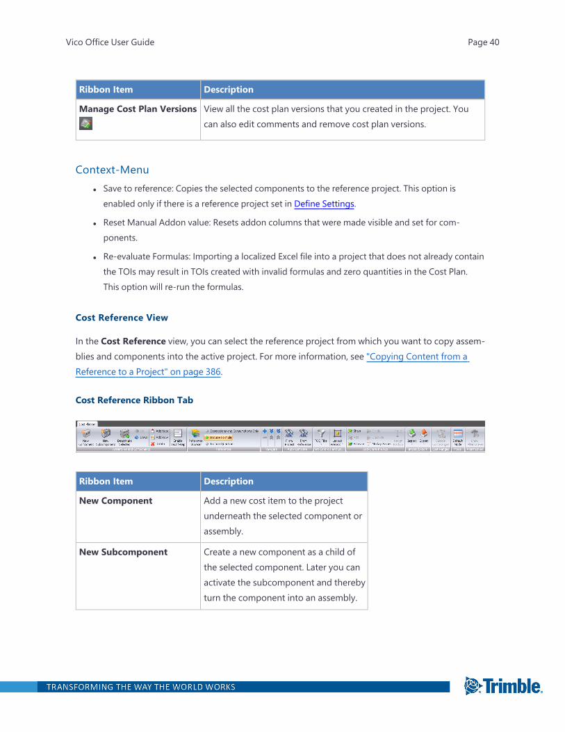
Manage Cost Plan Versions View all the cost plan versions that you created in the project. Youcan also edit comments and remove cost plan versions.
Context-Menul Save to reference: Copies the selected components to the reference project. This option is
enabled only if there is a reference project set in Define Settings.
l Reset Manual Addon value: Resets addon columns that were made visible and set for com-ponents.
l Re-evaluate Formulas: Importing a localized Excel file into a project that does not already containthe TOIs may result in TOIs created with invalid formulas and zero quantities in the Cost Plan.This option will re-run the formulas.
Cost Reference View
In the Cost Reference view, you can select the reference project from which you want to copy assem-blies and components into the active project. For more information, see "Copying Content from aReference to a Project" on page 386.
Cost Reference Ribbon Tab
Ribbon Item Description
New Component Add a new cost item to the projectunderneath the selected component orassembly.
New Subcomponent Create a new component as a child ofthe selected component. Later you canactivate the subcomponent and therebyturn the component into an assembly.
Vico Office User Guide Page 40
Ribbon Item Description
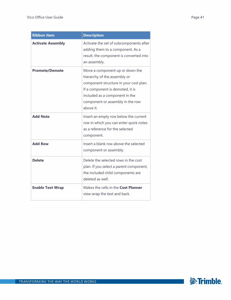
Activate Assembly Activate the set of subcomponents afteradding them to a component. As aresult, the component is converted intoan assembly.
Promote/Demote Move a component up or down thehierarchy of the assembly orcomponent structure in your cost plan.If a component is demoted, it isincluded as a component in thecomponent or assembly in the rowabove it.
Add Note Insert an empty row below the currentrow in which you can enter quick notesas a reference for the selectedcomponent.
Add Row Insert a blank row above the selectedcomponent or assembly.
Delete Delete the selected rows in the costplan. If you select a parent component,the included child components aredeleted as well.
Enable Text Wrap Makes the cells in the Cost Plannerview wrap the text and back.
Vico Office User Guide Page 41
Ribbon Item Description
Reference Browser Open the Reference Browser dialogwith the default reference loaded.
The settings include:
l Server Name: Select a computer inthe network that contains theassemblies and components thatyou want to copy into the currentproject.
l Project Selection: Represents theproject of which assembly andcomponent content is shown in theReference Browser. By default, thereference that is selected in theDefine Settings view is opened.
l Add in selected Component: Addthe selected content inside theselected component assubcomponents.
l Add below selected Component:Add the selected content below theselected component, which adds theselection to the same level in theassembly and component structure.
Vico Office User Guide Page 42
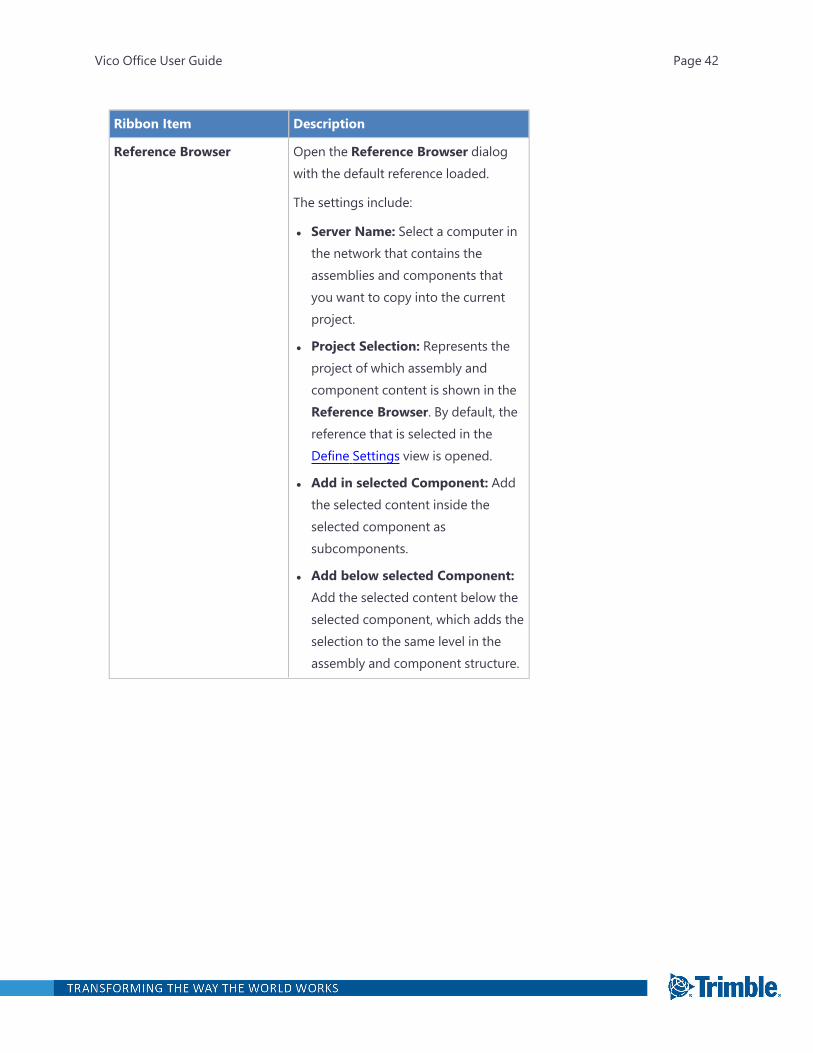
Ribbon Item Description
Quantity Copy Options For all copy operations in the CostPlanner view, determine how quantityinformation is included in the targetlocation:
l Descriptions and ConsumptionsOnly: Keep the default value for thetarget quantity.
l Include Formula: Copy the definedformula from the source and, ifpossible, reuse the takeoff items andtakeoff quantities in the currentproject. This is the default option.
l Include Quantities: Only copy theformula's results from the source.
Navigate Group Quickly expand and collapse the data inthe n-tiered spreadsheet. Click the +button to expand to the next hierarchylevel or the - button to collapse thelowest hierarchy level. The doublearrows on the ribbon collapse orexpand all levels at once. Point to eachbutton to view a tooltip that describeswhat each will do.
Vico Office User Guide Page 43
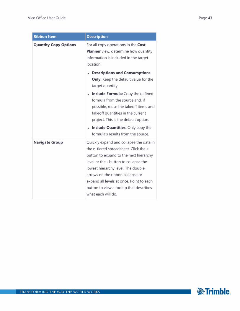
Ribbon Item Description
Auto Complete Group Copy assemblies and components froma reference without opening theReference Browser or the Project andReference viewset. When FromProject and/or From Reference areactive, a search operation is executedevery time you enter a code ordescription in the respective cell. Thepresent possible matches are displayedin a list in the Cost Planner view, andyou can then select the desiredassembly or component.
TOQ Filter Filter the cost line items in the followingways:
l Show Components with Model-based Quantities
l Show Components with ManualTakeoff Quantities
l Show Components with ManuallyInserted Quantity Data
l Show Components with MixedQuantity Data
Vico Office User Guide Page 44
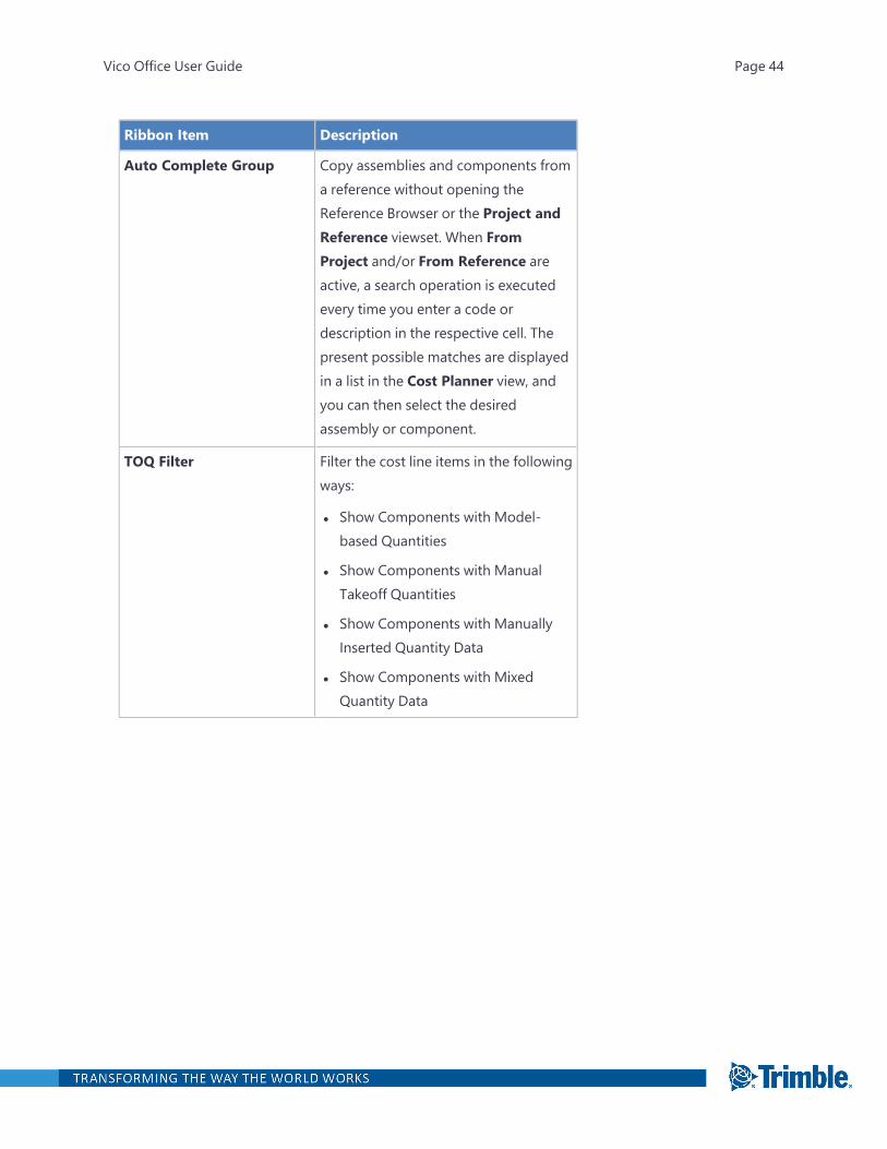
Ribbon Item Description
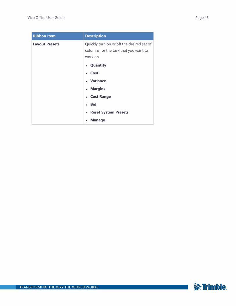
Layout Presets Quickly turn on or off the desired set ofcolumns for the task that you want towork on.
l Quantity
l Cost
l Variance
l Margins
l Cost Range
l Bid
l Reset System Presets
l Manage
Vico Office User Guide Page 45
Ribbon Item Description
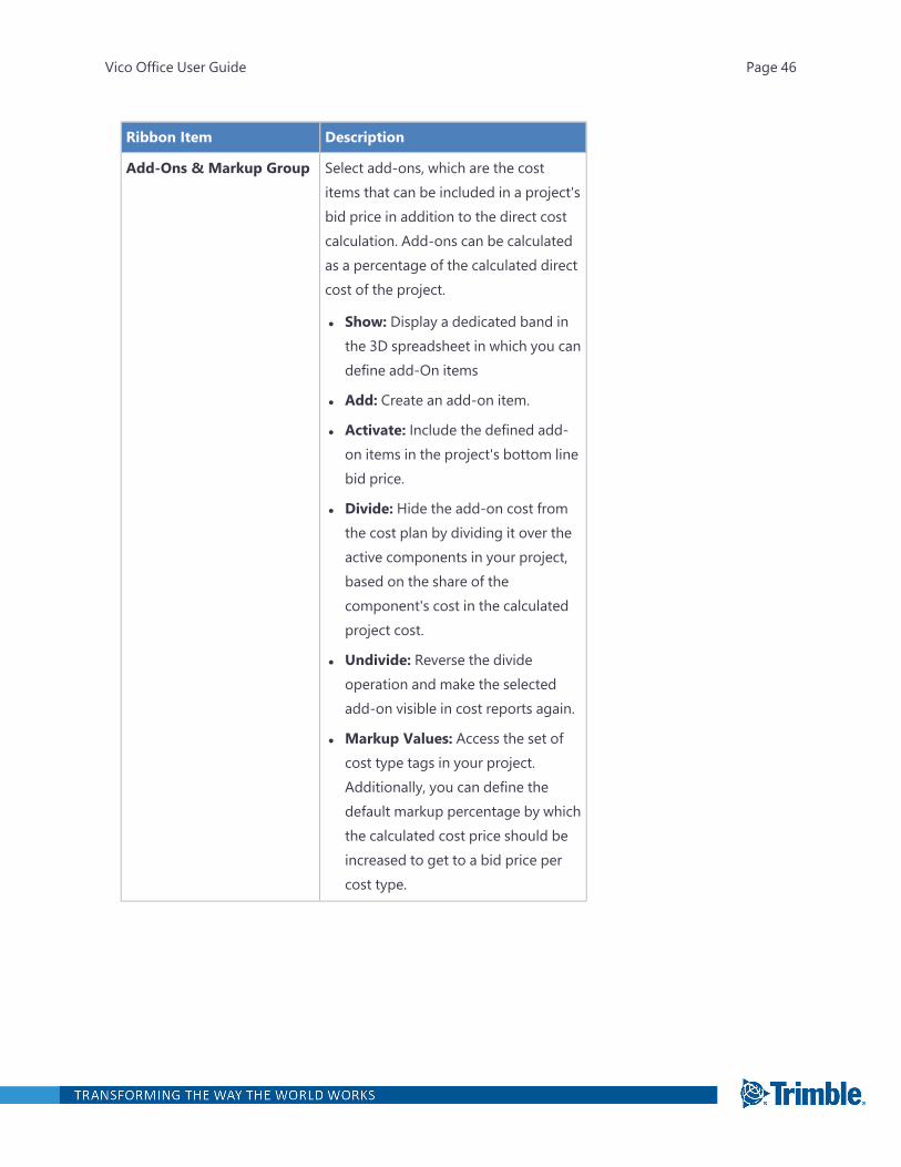
Add-Ons & Markup Group Select add-ons, which are the costitems that can be included in a project'sbid price in addition to the direct costcalculation. Add-ons can be calculatedas a percentage of the calculated directcost of the project.
l Show: Display a dedicated band inthe 3D spreadsheet in which you candefine add-On items
l Add: Create an add-on item.
l Activate: Include the defined add-on items in the project's bottom linebid price.
l Divide: Hide the add-on cost fromthe cost plan by dividing it over theactive components in your project,based on the share of thecomponent's cost in the calculatedproject cost.
l Undivide: Reverse the divideoperation and make the selectedadd-on visible in cost reports again.
l Markup Values: Access the set ofcost type tags in your project.Additionally, you can define thedefault markup percentage by whichthe calculated cost price should beincreased to get to a bid price percost type.
Vico Office User Guide Page 46

Ribbon Item Description
Save Cost Plan Version Create a snapsot of the current status ofyour cost plan. The created version canlater be used for comparison purposesin Cost Explorer.
Manage Cost Plan Versions View all the cost plan versions that youcreated in the project. You can also editcomments and remove cost planversions.
Document Register View
The Document Register view displays all of the documents that have been loaded into your VicoOffice file. A folder for 3D models is created by default whenever models are sent to Vico Office.
You can create folder structures that are as detailed as your project drawings by including place-holders for floor plans, elevations, sections, details, notes, and so on. Versions can be created for eachfolder to organize all your drawings by design release, allowing the user to know which documentshave been updated or changed with the latest release. The Document Register view displayschanges across multiple drawings or models, clouds that are placed onto drawings, and the activemodel (indicated by a circle on the model version). For more information, see "Document Control "on page 215.
Vico Office User Guide Page 47

Document Control Ribbon Tab
Ribbon Item Description
New Folder Add a folder.
New Subfolder Add a folder at a nested hierarchy level. Vico supports an n-tieredfolder structure, so you can create a folder structure that is as deepneeded.
New Document Add a placeholder for a document. Use placeholders to organize thedata structure according to your plans. If you want to add files first,you do not need to create placeholders by clicking New Document.
Add Version Create a design release version. You can add individual files orfolders and then provide a version name and a comment, such asinformation about the release date. You can also create an emptyversion if you want to set up your entire organizational structurebefore importing documents.
Add Files Populate the previously created versions with project documents.This button becomes active after a version is created. You canchoose the drawing folder and the version that you wish to populatewith the selected file or folder.
Vico Office User Guide Page 48

Ribbon Item Description
Delete Selected Remove the selected item such as a folder, subfolder, document, row(a series of documents), or column (a version of documents). Theselected items are permanently deleted from the Vico Office project,and this action cannot be undone.
l To select several documents for deletion, Ctrl-click each cell.
Note: Shift-Click does not remove several documents at oncebecause the Vico grid is more complex than traditionalspreadsheets.
l To select a folder and all its content for deletion, select the folderrow at the parent hierarchy level.
l To select an entire version and its documents within a folder fordeletion, select the version header in the folder.
l To select multiple versions of a single document for deletion,select the row.
View and Compare Group View and analyze your 2D documents.
Document Status Click each button to show/hide the following statuses for eachdocument in the latest version column.
Date/Time: The date and time when it was imported.
Path: The path where it was imported from.
Vectorize: indicates it has not been vectorized. Indicates it has been
vectorized.
Vectorize Document: Vectorizes the currently selected document.Recommended for large PDFs as they may not fit in your computer'sgraphic memory. If you encounter issues where your PDF cannot beviewed, or when your PDF cannot be aligned and scaled, you maywish to vectorize your document.
Vico Office User Guide Page 49
Ribbon Item Description
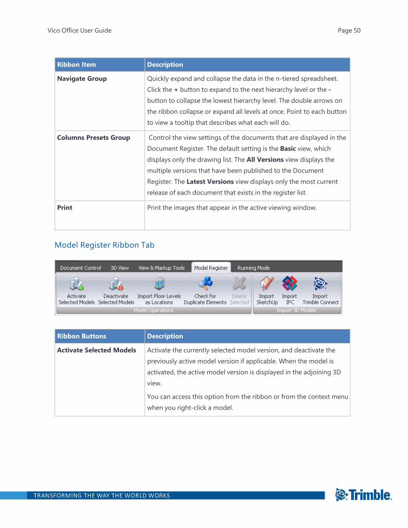
Navigate Group Quickly expand and collapse the data in the n-tiered spreadsheet.Click the + button to expand to the next hierarchy level or the -button to collapse the lowest hierarchy level. The double arrows onthe ribbon collapse or expand all levels at once. Point to each buttonto view a tooltip that describes what each will do.
Columns Presets Group Control the view settings of the documents that are displayed in theDocument Register. The default setting is the Basic view, whichdisplays only the drawing list. The All Versions view displays themultiple versions that have been published to the DocumentRegister. The Latest Versions view displays only the most currentrelease of each document that exists in the register list.
Print Print the images that appear in the active viewing window.
Model Register Ribbon Tab
Ribbon Buttons Description
Activate Selected Models Activate the currently selected model version, and deactivate thepreviously active model version if applicable. When the model isactivated, the active model version is displayed in the adjoining 3Dview.
You can access this option from the ribbon or from the context menuwhen you right-click a model.
Vico Office User Guide Page 50
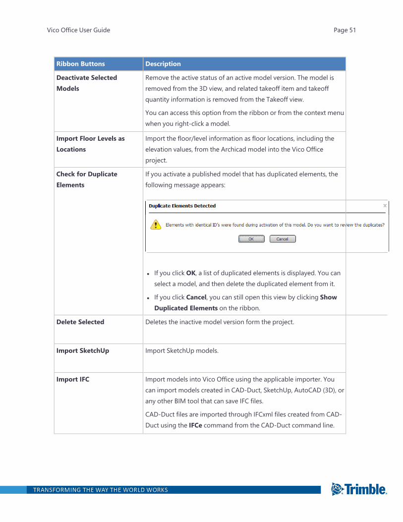
Ribbon Buttons Description
Deactivate SelectedModels
Remove the active status of an active model version. The model isremoved from the 3D view, and related takeoff item and takeoffquantity information is removed from the Takeoff view.
You can access this option from the ribbon or from the context menuwhen you right-click a model.
Import Floor Levels asLocations
Import the floor/level information as floor locations, including theelevation values, from the Archicad model into the Vico Officeproject.
Check for DuplicateElements
If you activate a published model that has duplicated elements, thefollowing message appears:
l If you click OK, a list of duplicated elements is displayed. You canselect a model, and then delete the duplicated element from it.
l If you click Cancel, you can still open this view by clicking ShowDuplicated Elements on the ribbon.
Delete Selected Deletes the inactive model version form the project.
Import SketchUp Import SketchUp models.
Import IFC Import models into Vico Office using the applicable importer. Youcan import models created in CAD-Duct, SketchUp, AutoCAD (3D), orany other BIM tool that can save IFC files.
CAD-Duct files are imported through IFCxml files created from CAD-Duct using the IFCe command from the CAD-Duct command line.
Vico Office User Guide Page 51
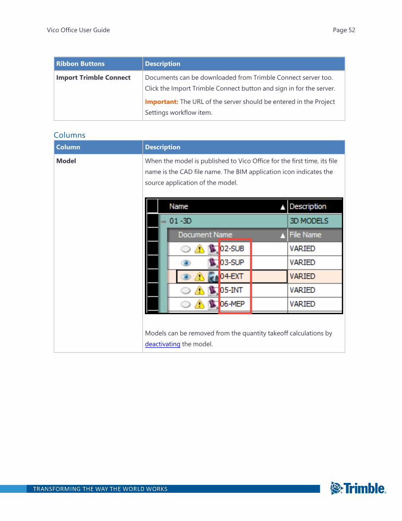
Ribbon Buttons Description
Import Trimble Connect Documents can be downloaded from Trimble Connect server too.Click the Import Trimble Connect button and sign in for the server.
Important: The URL of the server should be entered in the ProjectSettings workflow item.
ColumnsColumn Description
Model When the model is published to Vico Office for the first time, its filename is the CAD file name. The BIM application icon indicates thesource application of the model.
Models can be removed from the quantity takeoff calculations bydeactivating the model.
Vico Office User Guide Page 52

Column Description
Model Version Each time you publish an updated to the same model in Vico Office,a new model version is added to the row.
The name of the new model version has this structure: version [n] -[model name].
l [n] is the version number, which is based on the publishing order.
l [model name] is based on the CAD file name.
Note: For each model, only one version can be active at a given time.
Version Identifiers:
l Small Circle: The active model that supplies the projectquantities.
l Cloud: The models that include a view point that has beenclouded and marked with an issue.
l Gray cell: The document is not part of a version.
l Green cell: The document is new or unchanged as part of aversion.
l Red cell: The document has been changed as part of a version.
For more information on model versions, see "Adding Versions andFiles" on page 217.
Vico Office User Guide Page 53
Column Description
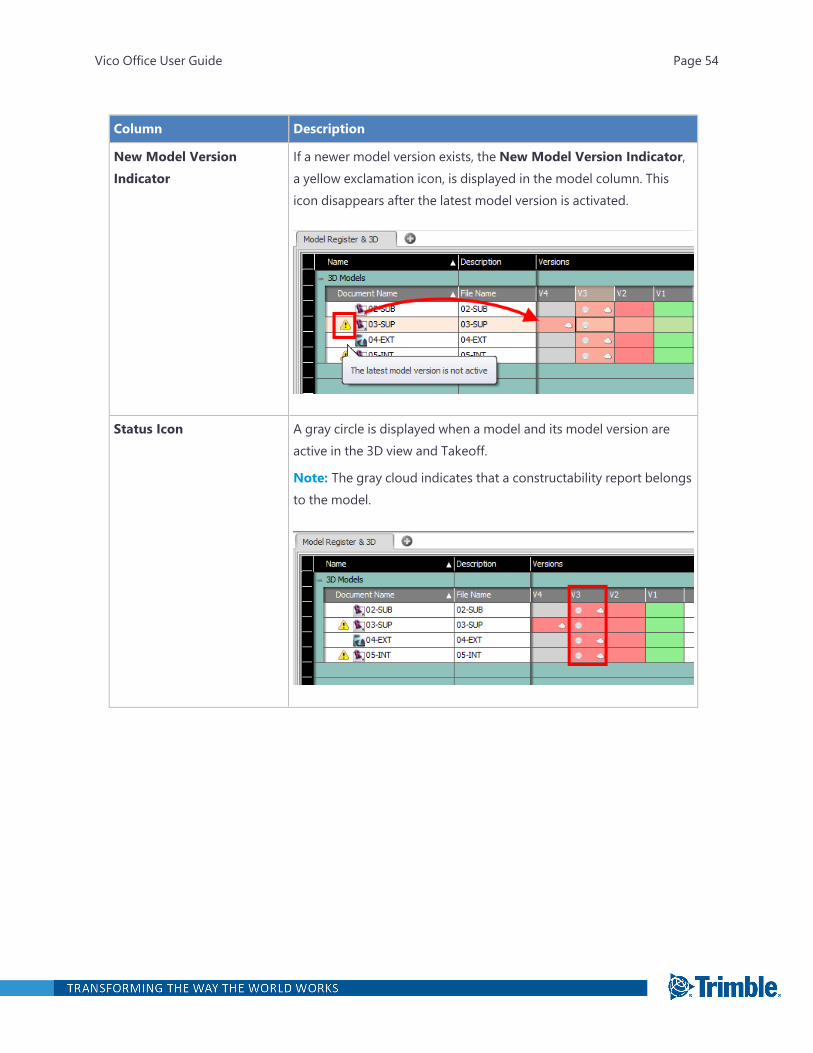
New Model VersionIndicator
If a newer model version exists, the New Model Version Indicator,a yellow exclamation icon, is displayed in the model column. Thisicon disappears after the latest model version is activated.
Status Icon A gray circle is displayed when a model and its model version areactive in the 3D view and Takeoff.
Note: The gray cloud indicates that a constructability report belongsto the model.
Vico Office User Guide Page 54
Column Description
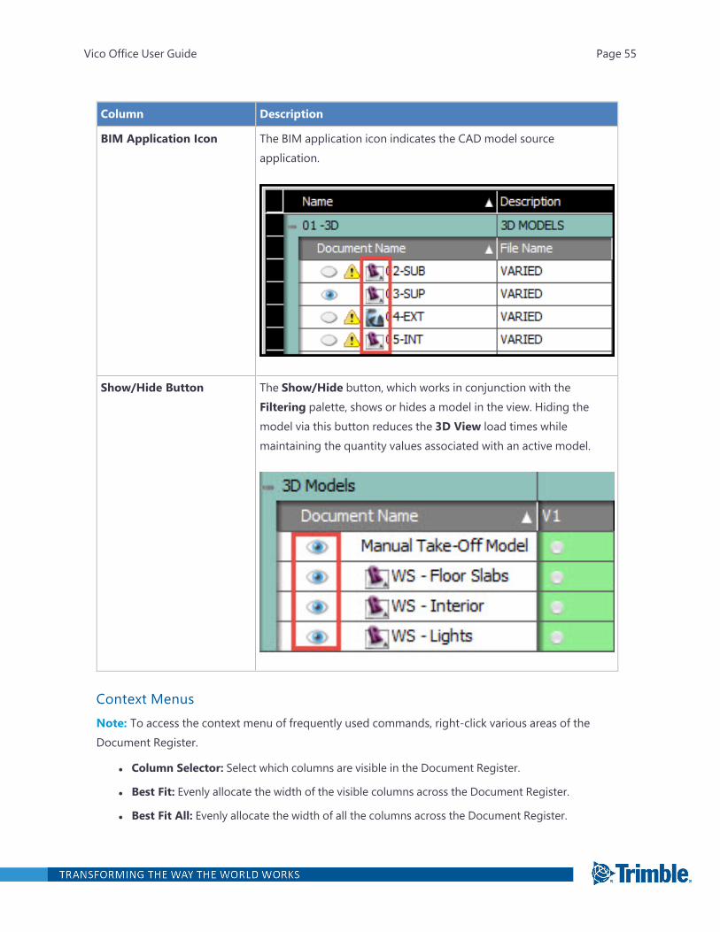
BIM Application Icon The BIM application icon indicates the CAD model sourceapplication.
Show/Hide Button The Show/Hide button, which works in conjunction with theFiltering palette, shows or hides a model in the view. Hiding themodel via this button reduces the 3D View load times whilemaintaining the quantity values associated with an active model.
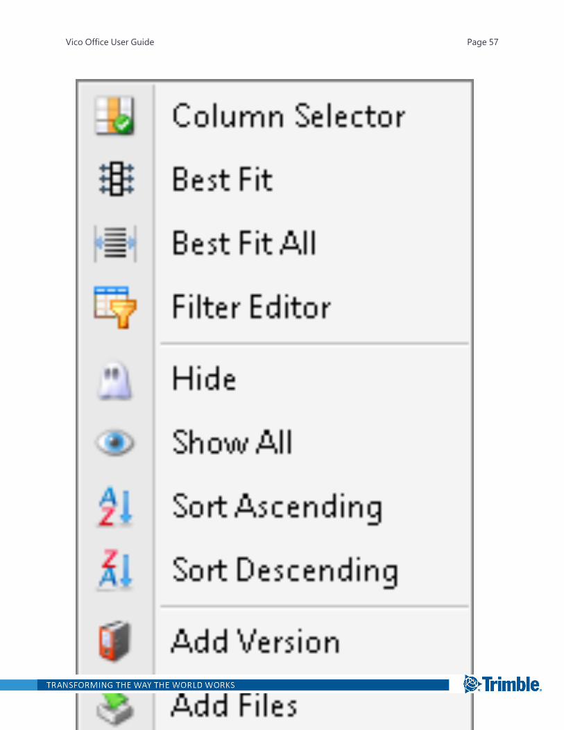
Context MenusNote: To access the context menu of frequently used commands, right-click various areas of theDocument Register.
l Column Selector: Select which columns are visible in the Document Register.
l Best Fit: Evenly allocate the width of the visible columns across the Document Register.
l Best Fit All: Evenly allocate the width of all the columns across the Document Register.
Vico Office User Guide Page 55
l Filter Editor: Filter what is displayed on the screen by applying a viewing criteria to the list of pos-sible items. This can be used to quickly identify a specific item within a lengthy list.
l Hide: Conceal a version that you do not wish to see in the Document Register. Choose ColumnSelector to re-display a version after it has been hidden.
l Show All: Display all the possible versions in the Document Register.
l Sort Ascending/Descending: Reorder the Document Register alphabetically by the selectedcolumn header.
l Show File Name: Display the actual file name in each of the green or red document cells.
l Show Path: Display the folder path for each document within the green or red document cells.
l Change Path: Change the folder path where the document is stored. The correct folder path isimportant if you want to display it on the cells or use the View in an External Application func-tion.
l Rename: Rename a document .
Vico Office User Guide Page 56
Vico Office User Guide Page 57

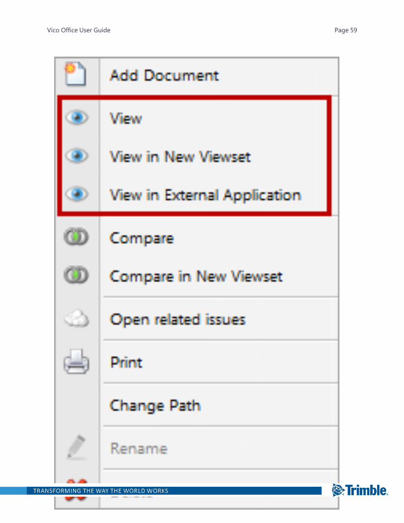
To open the document context menu, right-click the selected document. The following options areavailable:
l View: Display the document in the active viewset.
l View in New Viewset: Display the document in a different viewset. The current viewsetremains available, so you can return to it.
l View in External Application: Open the document in the native viewing tool that is set forthat document type on your computer.
Vico Office User Guide Page 58
Vico Office User Guide Page 59
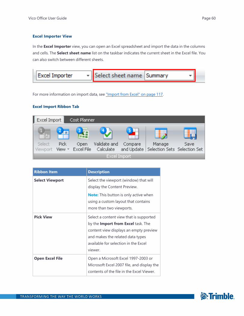
Excel Importer View
In the Excel Importer view, you can open an Excel spreadsheet and import the data in the columnsand cells. The Select sheet name list on the taskbar indicates the current sheet in the Excel file. Youcan also switch between different sheets.
For more information on import data, see "Import from Excel" on page 117.
Excel Import Ribbon Tab
Ribbon Item Description
Select Viewport Select the viewport (window) that willdisplay the Content Preview.
Note: This button is only active whenusing a custom layout that containsmore than two viewports.
Pick View Select a content view that is supportedby the Import from Excel task. Thecontent view displays an empty previewand makes the related data typesavailable for selection in the Excelviewer.
Open Excel File Open a Microsoft Excel 1997-2003 orMicrosoft Excel 2007 file, and display thecontents of the file in the Excel Viewer.
Vico Office User Guide Page 60
Ribbon Item Description
Validate and Calculate After selecting the data to be importedinto the current project, validate thedata. This function completes thedataset by adding default values forempty data fields.
Compare and Update Compare the data in the temporarypreview, where the data is placed afterthe first four steps, with the data in theproject. Then copy the data in thepreview to the project.
Manage Selection Set Open the list of saved selection sets. Ifyou choose one, it is applied to theactive Excel spreadsheet.
Save Selection Set After setting the data type for thecolumns in your Excel spreadsheet, savethem as a selection set that can be usedduring other imports.
Graph View
The Graph view displays the work package data in a pie chart or a bar chart. For more information,see "Viewing a Pie Chart" on page 646 and "Viewing a Bar Chart" on page 650.
Vico Office User Guide Page 61
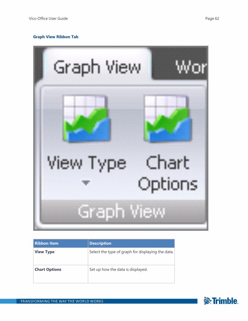
Graph View Ribbon Tab
Ribbon Item Description
View Type Select the type of graph for displaying the data.
Chart Options Set up how the data is displayed.
Vico Office User Guide Page 62

Issue List View
In the Issue List View, you can manage constructability issues. To see viewpoints and imagesattached to an issue, you can switch to the Issue Card View.
Note: Issues can be deleted only in the Issue List View.
Constructability Manager Ribbon Tab\
Ribbon Item Description
Add Issue Manually add a constructability issue.
Add Issue Add a constructability issue with a 3D marker placed in the modelthat helps you identify recognized problems during the reviewphase.
Add BCF Issue Add a BCF (BIM collaboration format) issue to the Issues tab on theIssue List View. A 'Is BCF' column distinguishes an issue from a BCFissue. A newly created BCF issue will have this check boxautomatically selected, which indicates it is BCF transferable.
Add RFI Manually add a request for information if parts of the model ordocument are unclear (for example, if there is a contradictionbetween the two plans). You can enter the detailed problem with asaved view point (if it is possible).
Add RFI with Symbol Add an RFI and place a blue diamond symbol in the 3D view toindicate the relevant area or element.
Column Presets The column presets displays the data fields that are only applicableto the selected preset.
Import BCF Imports a BCF file and all important issues are marked as BCF. Textcontent (Subject, Description, Creation Date, and Messages), imageand viewpoint are imported.
Vico Office User Guide Page 63
Ribbon Item Description
Export BCF When exporting a BCF file, only issues marked with the BCF flag areexported. Text content (Subject, Description, Creation Date, andMessages), image and viewpoint are exported.
IssuesThe Issues tab contains the constructability issues. In the list, you can add comments, viewpoints, andmarkup. Filters and sort criteria can be applied to define subsets of this content. See "Sorting and Fil-tering Constructability Issues" on page 592.
RFIsThe RFIs tab contains all Issues that have been classified as RFI. The RFI list allows you for adding com-ments, viewpoints, and markup.
LBS Manager View
In the LBS Manager view, you can define locations for location-based quantity takeoff, location-based cost, and schedule planning. For more information, see "Define Locations" on page 418.
Vico Office User Guide Page 64
LBS Tree
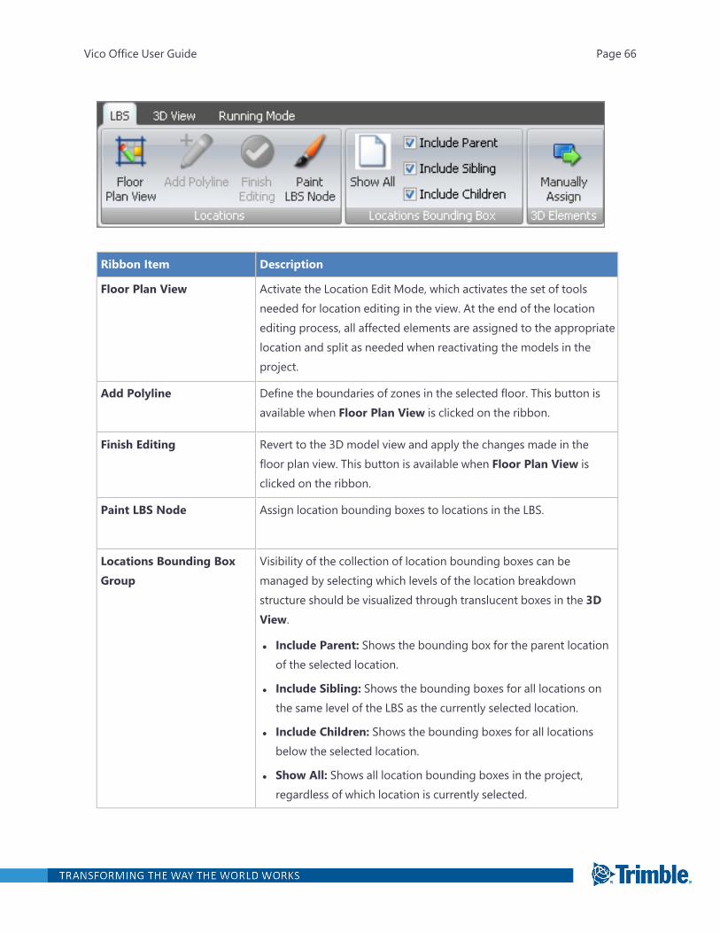
The LBS Tree view contains the following columns:
l Locations: Aligned based on the level of the locations in the location breakdown structure. LBSlevels are indicated with numbers in the column header.
l Elevation: Values show the elevation above the project "0" of a location. Zones are always on thesame elevation as their parent floor location. Changing the elevation results in moving the bot-tom of the selected location bounding box up, and moving the top of the location bounding boxbelow it up at the same time.
l Cut: Values indicate how far above the defined floor elevation the 2D section for the floor planview is generated. Default value is 4' or 1.2m.
l View Depth: The floor plan view's viewing distance from the cut height is defined. Default valueis 0' or 0m. above the defined floor elevation; increasing this value results in decreasing the reachof the view, decreasing the value results in increasing the reach of the floor plan view.
LBS Ribbon Tab
Vico Office User Guide Page 65
Ribbon Item Description
Floor Plan View Activate the Location Edit Mode, which activates the set of toolsneeded for location editing in the view. At the end of the locationediting process, all affected elements are assigned to the appropriatelocation and split as needed when reactivating the models in theproject.
Add Polyline Define the boundaries of zones in the selected floor. This button isavailable when Floor Plan View is clicked on the ribbon.
Finish Editing Revert to the 3D model view and apply the changes made in thefloor plan view. This button is available when Floor Plan View isclicked on the ribbon.
Paint LBS Node Assign location bounding boxes to locations in the LBS.
Locations Bounding BoxGroup
Visibility of the collection of location bounding boxes can bemanaged by selecting which levels of the location breakdownstructure should be visualized through translucent boxes in the 3DView.
l Include Parent: Shows the bounding box for the parent locationof the selected location.
l Include Sibling: Shows the bounding boxes for all locations onthe same level of the LBS as the currently selected location.
l Include Children: Shows the bounding boxes for all locationsbelow the selected location.
l Show All: Shows all location bounding boxes in the project,regardless of which location is currently selected.
Vico Office User Guide Page 66
Ribbon Item Description
Manually Assign Override the automatic assignment of 3D elements to the locationsthey are included in by selecting a location, then the 3D elementsthat should be included.
Location Systems View
In the Location Systems view, you can define alternative location breakdown structures, which canbe maintained within the same parent location. For more information, see "Define Location Systems"on page 447.
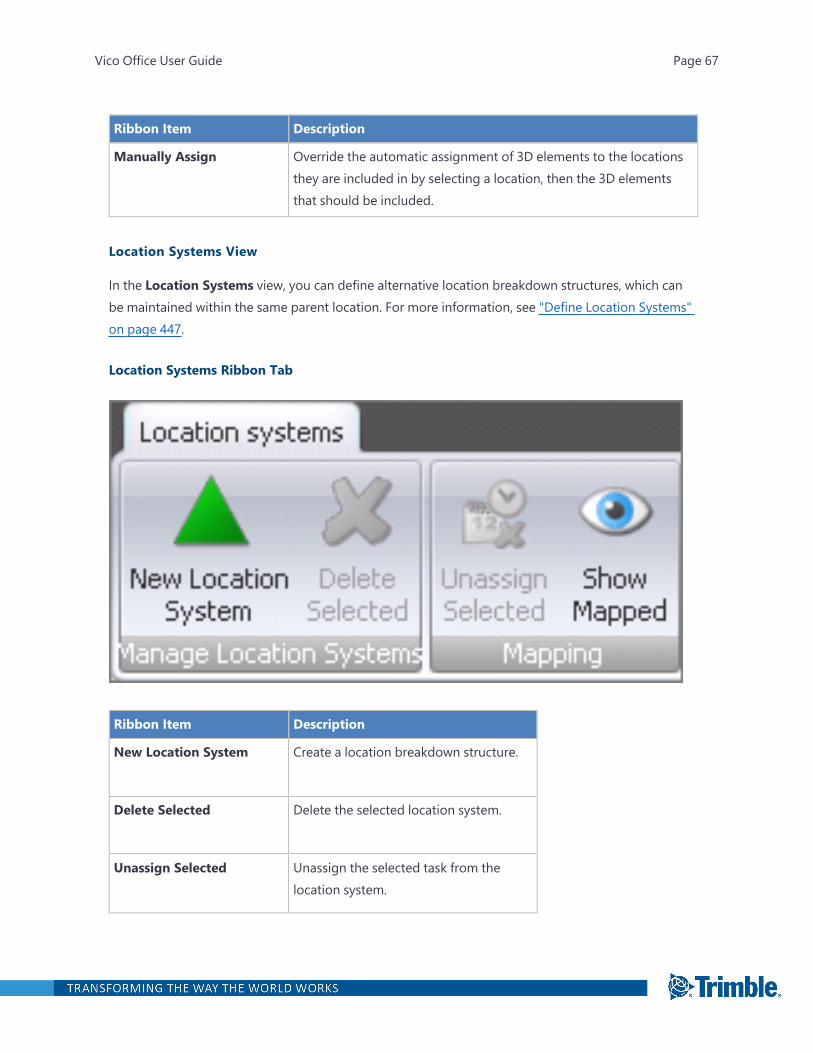
Location Systems Ribbon Tab
Ribbon Item Description
New Location System Create a location breakdown structure.
Delete Selected Delete the selected location system.
Unassign Selected Unassign the selected task from thelocation system.
Vico Office User Guide Page 67
Ribbon Item Description
Show Mapped If activated, shows the mapped tasks inthe Task Manager view.
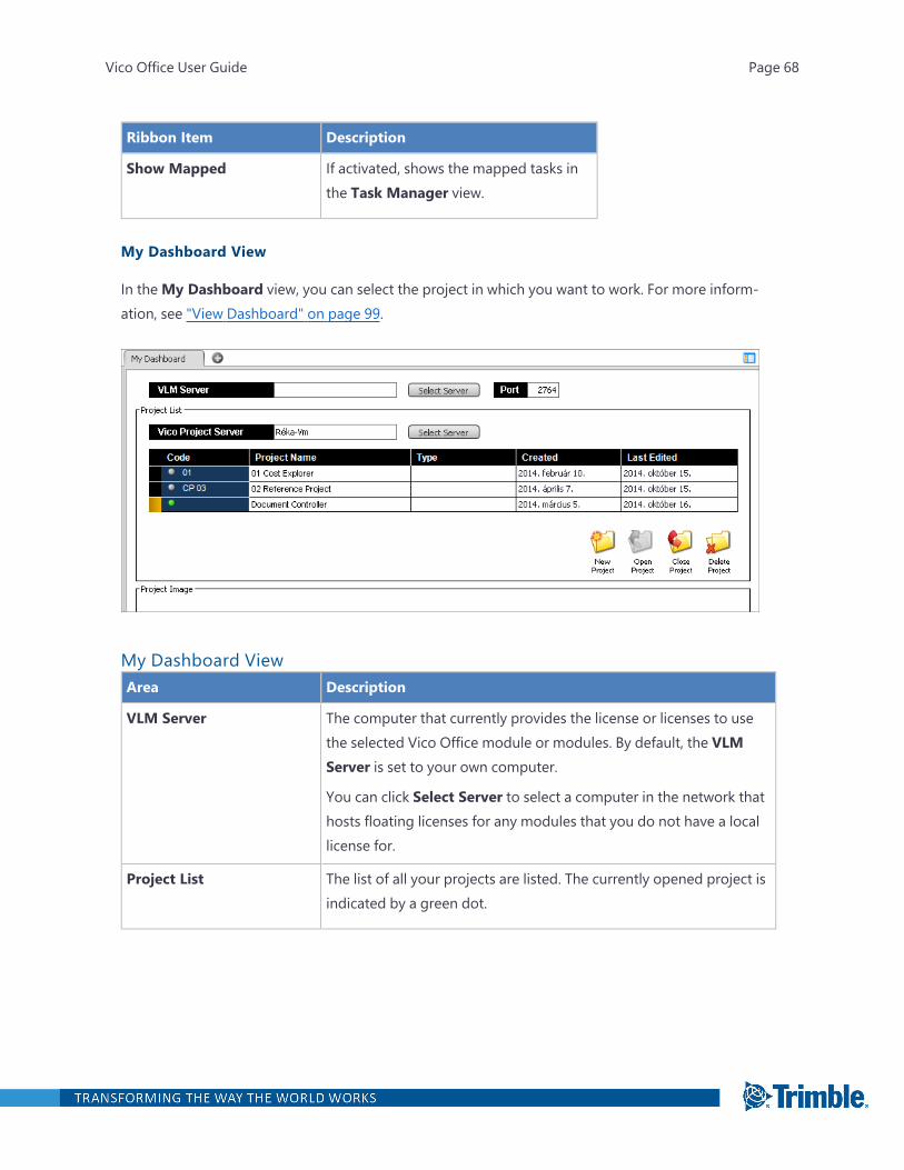
My Dashboard View
In theMy Dashboard view, you can select the project in which you want to work. For more inform-ation, see "View Dashboard" on page 99.
My Dashboard ViewArea Description
VLM Server The computer that currently provides the license or licenses to usethe selected Vico Office module or modules. By default, the VLMServer is set to your own computer.
You can click Select Server to select a computer in the network thathosts floating licenses for any modules that you do not have a locallicense for.
Project List The list of all your projects are listed. The currently opened project isindicated by a green dot.
Vico Office User Guide Page 68
Area Description
Vico Project Server Accept the default local server (your computer's name), or browse toselect a computer in the network on which your company's VicoOffice database will be stored. By default the server name is set tothe name of your computer because the database that Officeconnects to after installation is located here.
Code Assign a code to your project. Click the field header to sort theprojects based on values in this column.
Project Name Define a name for the selected project. Click the field header to sortyour projects alphabetically.
Type Assign a code to your project. Click the field header to sort theprojects based on values in this column.
Created The time and date of when the project was created. When you createa new project, a time and date stamp is automatically generated anddisplayed in this field as a historical record of your project. If desired,you can sort projects by this property by clicking the header on theDashboard.
Last Edited The time and date of when the project was last edited. Each time theproject is modified, a time and date stamp is automatically begenerated in this field.
Project Image The project image uploaded in the Project Settings view.
My Dashboard Ribbon Tab
Vico Office User Guide Page 69
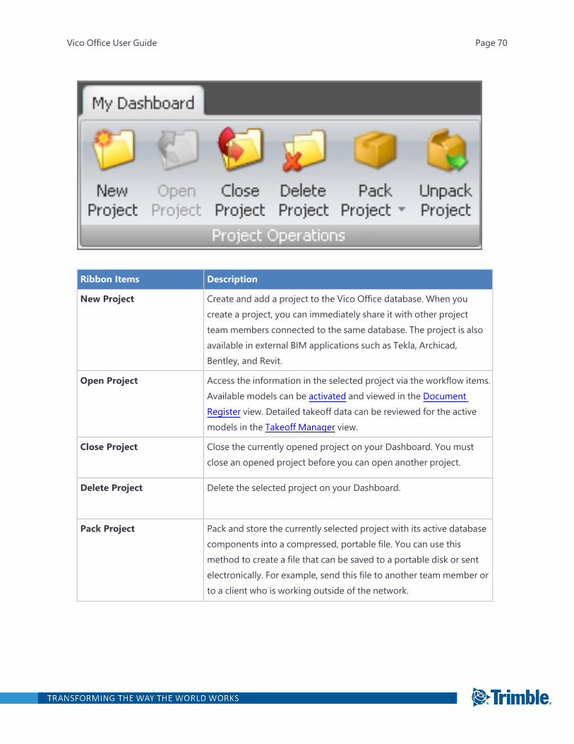
Ribbon Items Description
New Project Create and add a project to the Vico Office database. When youcreate a project, you can immediately share it with other projectteam members connected to the same database. The project is alsoavailable in external BIM applications such as Tekla, Archicad,Bentley, and Revit.
Open Project Access the information in the selected project via the workflow items.Available models can be activated and viewed in the DocumentRegister view. Detailed takeoff data can be reviewed for the activemodels in the Takeoff Manager view.
Close Project Close the currently opened project on your Dashboard. You mustclose an opened project before you can open another project.
Delete Project Delete the selected project on your Dashboard.
Pack Project Pack and store the currently selected project with its active databasecomponents into a compressed, portable file. You can use thismethod to create a file that can be saved to a portable disk or sentelectronically. For example, send this file to another team member orto a client who is working outside of the network.
Vico Office User Guide Page 70
Ribbon Items Description
Unpack Project Open a packed project file. The packed project is added to yourcollection of projects on the Dashboard. Then you can open and viewthe project information at the state that it had when it was backedup. By packing and unpacking projects, you can view stored projectdata in Vico Office for sharing, reference, or backup purposes.
Project Settings View
Customize project information in the Project Settings view. For more information, see "Define Set-tings" on page 106.
FILTERING
WinEst integration - will not filter the projects by permission for WinEst
VOWS - same as above, no filtering
SP - same as above, no filtering
filter the project list in the reference project dropdown
Vico Office User Guide Page 71

Project Settings ViewArea Description
Project Code Assign or edit a project code. The field data is the same as the Codefield in the My Dashboard view.
Project Name Assign or edit a project name. The field data is the same as theProject Name field in the My Dashboard view.
Project Type Assign or edit a project type with an unlimited number of characters.Use the assigned project type to quickly find similar projects bysorting them based on this property in the My Dashboard view
Project Address Enter address information that can be used for reporting purposeslater.
Company Logo Under the Logo field, click Browse to find and select a companyimage to be associated with the project. You can include the insertedlogo in your reports later.
Vico Office User Guide Page 72
Area Description
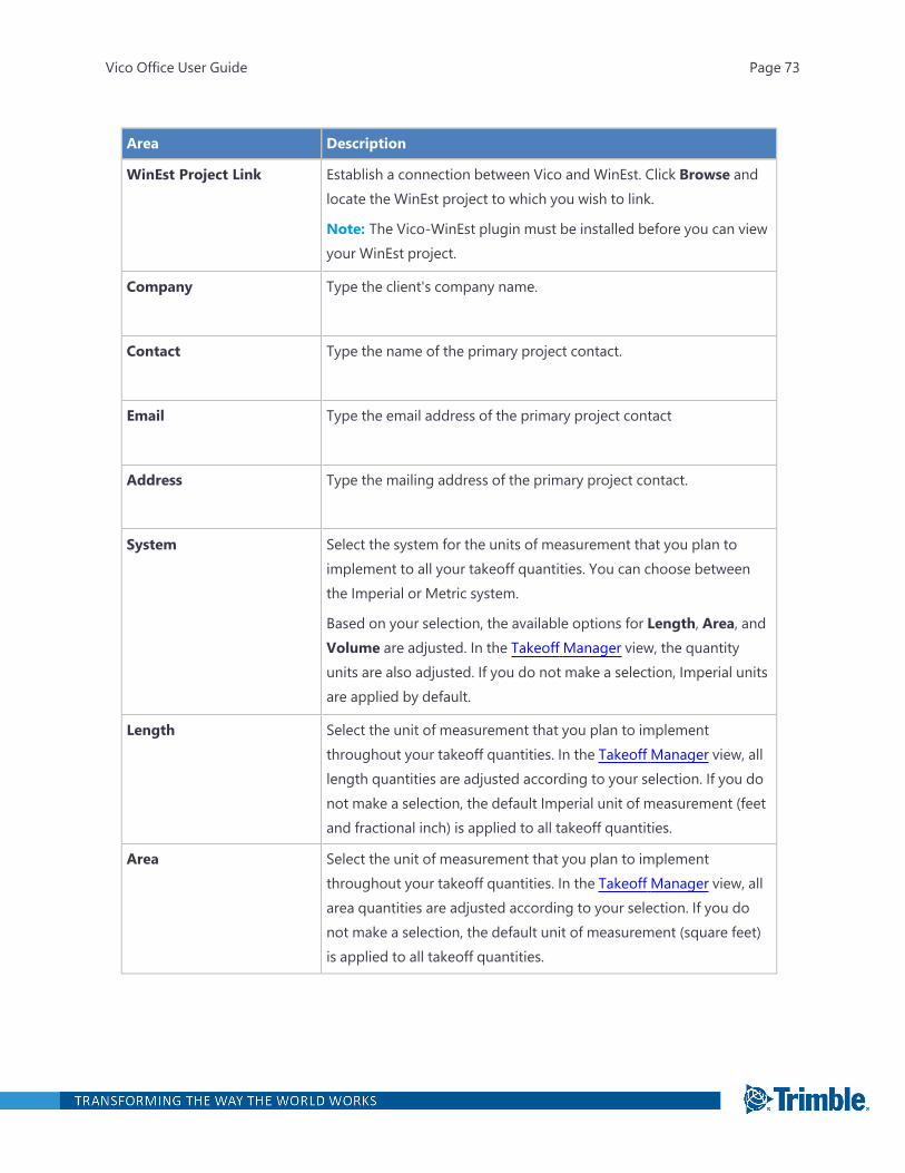
WinEst Project Link Establish a connection between Vico and WinEst. Click Browse andlocate the WinEst project to which you wish to link.
Note: The Vico-WinEst plugin must be installed before you can viewyour WinEst project.
Company Type the client's company name.
Contact Type the name of the primary project contact.
Email Type the email address of the primary project contact
Address Type the mailing address of the primary project contact.
System Select the system for the units of measurement that you plan toimplement to all your takeoff quantities. You can choose betweenthe Imperial or Metric system.
Based on your selection, the available options for Length, Area, andVolume are adjusted. In the Takeoff Manager view, the quantityunits are also adjusted. If you do not make a selection, Imperial unitsare applied by default.
Length Select the unit of measurement that you plan to implementthroughout your takeoff quantities. In the Takeoff Manager view, alllength quantities are adjusted according to your selection. If you donot make a selection, the default Imperial unit of measurement (feetand fractional inch) is applied to all takeoff quantities.
Area Select the unit of measurement that you plan to implementthroughout your takeoff quantities. In the Takeoff Manager view, allarea quantities are adjusted according to your selection. If you donot make a selection, the default unit of measurement (square feet)is applied to all takeoff quantities.
Vico Office User Guide Page 73
Area Description
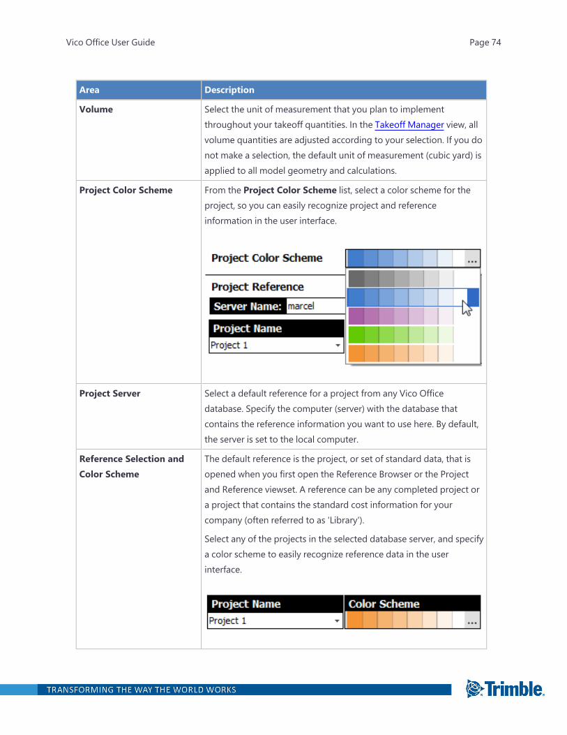
Volume Select the unit of measurement that you plan to implementthroughout your takeoff quantities. In the Takeoff Manager view, allvolume quantities are adjusted according to your selection. If you donot make a selection, the default unit of measurement (cubic yard) isapplied to all model geometry and calculations.
Project Color Scheme From the Project Color Scheme list, select a color scheme for theproject, so you can easily recognize project and referenceinformation in the user interface.
Project Server Select a default reference for a project from any Vico Officedatabase. Specify the computer (server) with the database thatcontains the reference information you want to use here. By default,the server is set to the local computer.
Reference Selection andColor Scheme
The default reference is the project, or set of standard data, that isopened when you first open the Reference Browser or the Projectand Reference viewset. A reference can be any completed project ora project that contains the standard cost information for yourcompany (often referred to as 'Library').
Select any of the projects in the selected database server, and specifya color scheme to easily recognize reference data in the userinterface.
Vico Office User Guide Page 74
Area Description
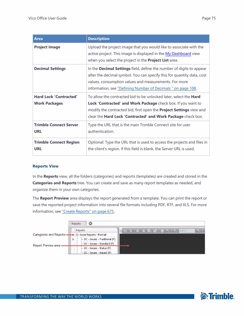
Project Image Upload the project image that you would like to associate with theactive project. This image is displayed in the My Dashboard viewwhen you select the project in the Project List area.
Decimal Settings In the Decimal Settings field, define the number of digits to appearafter the decimal symbol. You can specify this for quantity data, costvalues, consumption values and measurements. For moreinformation, see "Defining Number of Decimals " on page 108.
Hard Lock 'Contracted'Work Packages
To allow the contracted bid to be unlocked later, select the HardLock 'Contracted' and Work Package check box. If you want tomodify the contracted bid, first open the Project Settings view andclear the Hard Lock 'Contracted' and Work Package check box.
Trimble Connect ServerURL
Type the URL that is the main Trimble Connect site for userauthentication.
Trimble Connect RegionURL
Optional: Type the URL that is used to access the projects and files inthe client's region. If this field is blank, the Server URL is used.
Reports View
In the Reports view, all the folders (categories) and reports (templates) are created and stored in theCategories and Reports tree. You can create and save as many report templates as needed, andorganize them in your own categories.
The Report Preview area displays the report generated from a template. You can print the report orsave the reported project information into several file formats including PDF, RTF, and XLS. For moreinformation, see "Create Reports" on page 675.
Vico Office User Guide Page 75
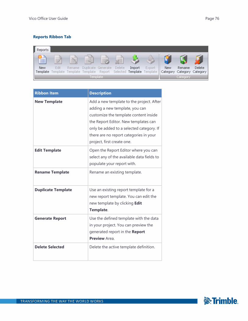
Reports Ribbon Tab
Ribbon Item Description
New Template Add a new template to the project. Afteradding a new template, you cancustomize the template content insidethe Report Editor. New templates canonly be added to a selected category. Ifthere are no report categories in yourproject, first create one.
Edit Template Open the Report Editor where you canselect any of the available data fields topopulate your report with.
Rename Template Rename an existing template.
Duplicate Template Use an existing report template for anew report template. You can edit thenew template by clicking EditTemplate.
Generate Report Use the defined template with the datain your project. You can preview thegenerated report in the ReportPreview Area.
Delete Selected Delete the active template definition.
Vico Office User Guide Page 76
Ribbon Item Description
New Category Create a new category for a reporttemplate. Report templates arecategorized, so you must create acategory if none exist yet.
Rename Category Rename an existing category.
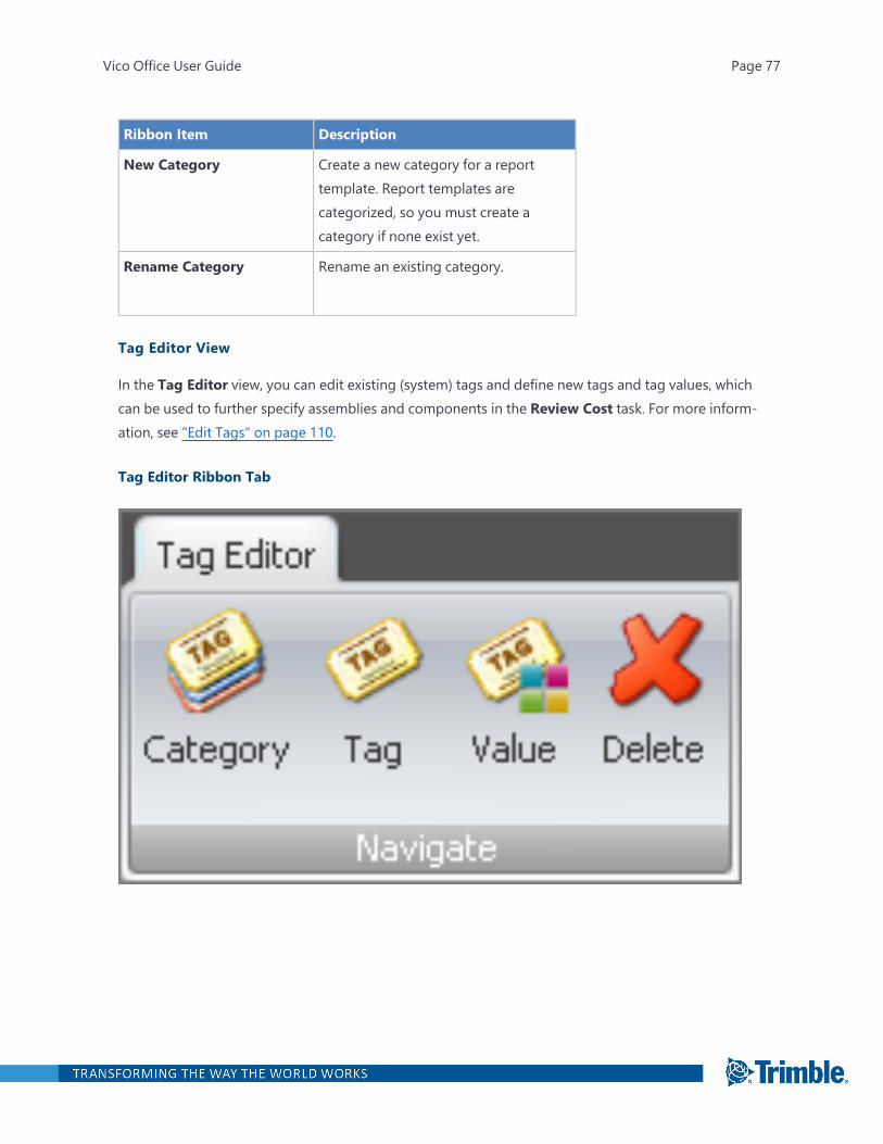
Tag Editor View
In the Tag Editor view, you can edit existing (system) tags and define new tags and tag values, whichcan be used to further specify assemblies and components in the Review Cost task. For more inform-ation, see "Edit Tags" on page 110.
Tag Editor Ribbon Tab
Vico Office User Guide Page 77
Ribbon Item Description
Category Add a new category of tags to theproject. By default, the Systemcategory is included in Vico Office. Thiscategory contains all the tags that areused by Vico Office functions andcannot be deleted.
Tag Add a new tag to the project. Tags canbe assigned to cost estimating content(assemblies and components) anddisplayed in the Review Cost view as acolumn.
Value Add new values to a tag system. Valuesare predefined entries that can beselected for components andassemblies.
Delete Delete a selected category, tag, or tagvalue.
Note: Tags in the System categorycannot be deleted.
Takeoff Manager View
In the Takeoff Manager view, you can manage takeoff quantities by location. For more information,see "Manage Takeoff" on page 324.
ColumnsColumn Description
TOI Info Column for information and warning icons that provide additional information on eachitem.
Click on the heading to filter the list by icon type .
(Custom) filter: Allows you to customize the list of takeoff items to be displayed.
(Clear all Filters): Removes any applied filter.
Vico Office User Guide Page 78
Column Description
TOI Code A blank field where you can assign unique classification codes to your takeoff items asneeded.
Vico Office User Guide Page 79
Column Description
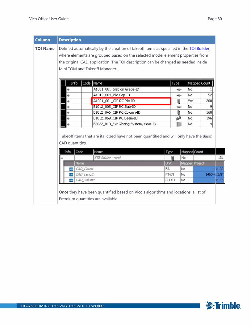
TOI Name Defined automatically by the creation of takeoff items as specified in the TOI Builder,where elements are grouped based on the selected model element properties fromthe original CAD application. The TOI description can be changed as needed insideMini TOM and Takeoff Manager.
Takeoff items that are italicized have not been quantified and will only have the BasicCAD quantities.
Once they have been quantified based on Vico's algorithms and locations, a list ofPremium quantities are available.
Vico Office User Guide Page 80

Column Description
TOQ Name Indicates the name of the quantity that is calculated in the value column. Each quantityhas a unit and value assigned. The group of selected quantities under a TOI is drivenby the selected TOI type.
Vico Office User Guide Page 81
Column Description
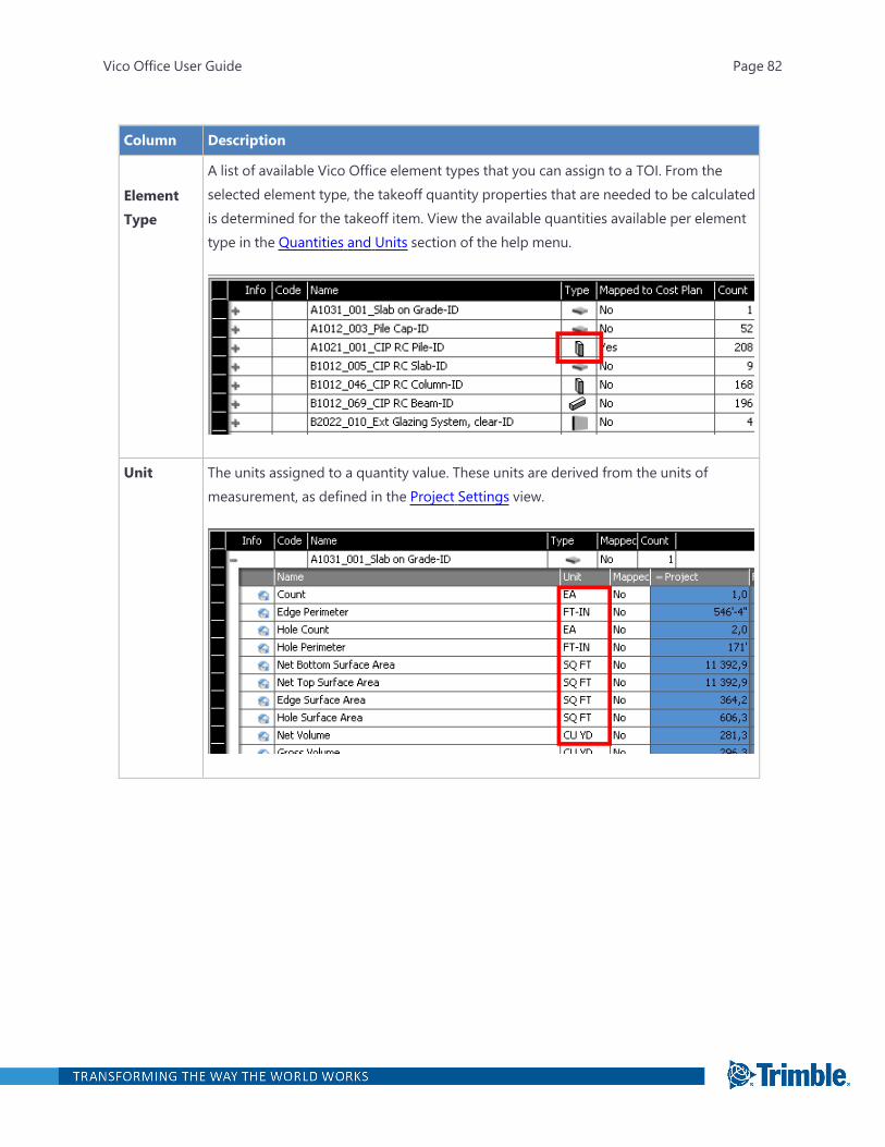
ElementType
A list of available Vico Office element types that you can assign to a TOI. From theselected element type, the takeoff quantity properties that are needed to be calculatedis determined for the takeoff item. View the available quantities available per elementtype in the Quantities and Units section of the help menu.
Unit The units assigned to a quantity value. These units are derived from the units ofmeasurement, as defined in the Project Settings view.
Vico Office User Guide Page 82
Column Description
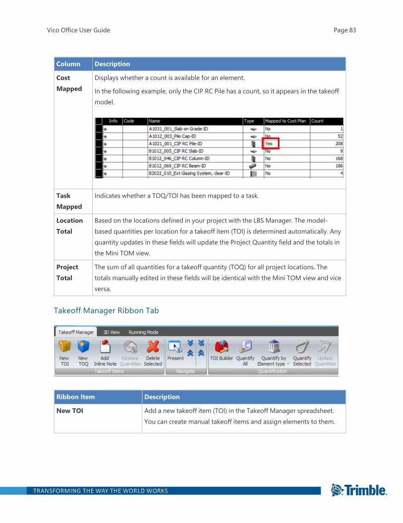
CostMapped
Displays whether a count is available for an element.
In the following example, only the CIP RC Pile has a count, so it appears in the takeoffmodel.
TaskMapped
Indicates whether a TOQ/TOI has been mapped to a task.
LocationTotal
Based on the locations defined in your project with the LBS Manager. The model-based quantities per location for a takeoff item (TOI) is determined automatically. Anyquantity updates in these fields will update the Project Quantity field and the totals inthe Mini TOM view.
ProjectTotal
The sum of all quantities for a takeoff quantity (TOQ) for all project locations. Thetotals manually edited in these fields will be identical with the Mini TOM view and viceversa.
Takeoff Manager Ribbon Tab
Ribbon Item Description
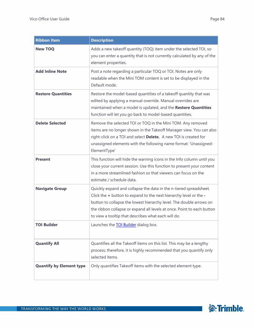
New TOI Add a new takeoff item (TOI) in the Takeoff Manager spreadsheet.You can create manual takeoff items and assign elements to them.
Vico Office User Guide Page 83
Ribbon Item Description
New TOQ Adds a new takeoff quantity (TOQ) item under the selected TOI, soyou can enter a quantity that is not currently calculated by any of theelement properties.
Add Inline Note Post a note regarding a particular TOQ or TOI. Notes are onlyreadable when the Mini TOM content is set to be displayed in theDefault mode.
Restore Quantities Restore the model-based quantities of a takeoff quantity that wasedited by applying a manual override. Manual overrides aremaintained when a model is updated, and the Restore Quantitiesfunction will let you go back to model-based quantities.
Delete Selected Remove the selected TOI or TOQ in the Mini TOM. Any removeditems are no longer shown in the Takeoff Manager view. You can alsoright-click on a TOI and select Delete. A new TOI is created forunassigned elements with the following name format: 'Unassigned-ElementType'
Present This function will hide the warning icons in the Info column until youclose your current session. Use this function to present your contentin a more streamlined fashion so that viewers can focus on theestimate / schedule data.
Navigate Group Quickly expand and collapse the data in the n-tiered spreadsheet.Click the + button to expand to the next hierarchy level or the -button to collapse the lowest hierarchy level. The double arrows onthe ribbon collapse or expand all levels at once. Point to each buttonto view a tooltip that describes what each will do.
TOI Builder Launches the TOI Builder dialog box.
Quantify All Quantifies all the Takeoff items on this list. This may be a lengthyprocess; therefore, it is highly recommended that you quantify onlyselected items.
Quantify by Element type Only quantifies Takeoff items with the selected element type.
Vico Office User Guide Page 84
Quantify Selected Quantifies only the selected Takeoff items.
Update Quantities Re-quantifies Takeoff items that are out-of-date.
IndicatorsIndicators Description
Model Quantity Indicator Displayed beside a takeoff quantity to show that a quantity is derivedfrom a currently active model.
Missing Quantity Indicator Displayed beside a takeoff item and takeoff quantity if one or moretakeoff quantities could not be calculated correctly or if a quantity ismissing.
Vico Office User Guide Page 85

Indicators Description
Manual Quantity Indicator Displayed beside a takeoff quantity to indicate that a quantity haseither been modified manually or that a newly inputted takeoffquantity has been created using non-model based quantity data.
CAD Indicator Displayed beside a takeoff quantity to indicate that this is aCAD quantity obtained from the CAD tool from which it waspublished.
Re-activate model Displayed beside a takeoff item to indicate that the model fromwhich this TOI was generated should be re-activated to ensure thatthe quantities are still up-to-date..
Re-quantify Takeoff item Displayed beside a takeoff item to indicate that the takeoff itemshould be re-quantified.
Information Displayed beside a takeoff item to indicate that it has elements withmanual quantities.
Takeoff Pad View
In the Takeoff Pad view, you can view and manage individual takeoff components. For more inform-ation, see "Takeoff Pad" on page 339.
ColumnsTable Items Description
Show 2D Show or hide takeoff items that were created by onscreen takeofffunctions.
Vico Office User Guide Page 86
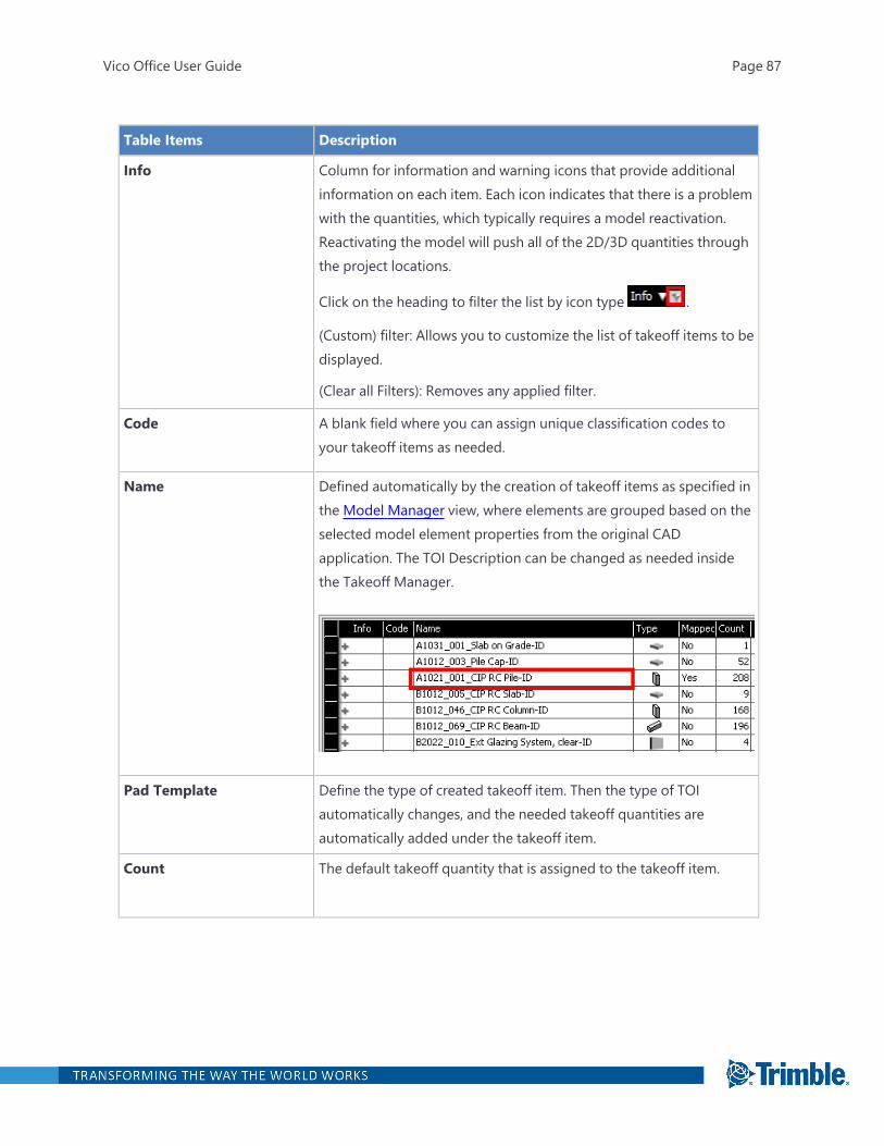
Table Items Description
Info Column for information and warning icons that provide additionalinformation on each item. Each icon indicates that there is a problemwith the quantities, which typically requires a model reactivation.Reactivating the model will push all of the 2D/3D quantities throughthe project locations.
Click on the heading to filter the list by icon type .
(Custom) filter: Allows you to customize the list of takeoff items to bedisplayed.
(Clear all Filters): Removes any applied filter.
Code A blank field where you can assign unique classification codes toyour takeoff items as needed.
Name Defined automatically by the creation of takeoff items as specified inthe Model Manager view, where elements are grouped based on theselected model element properties from the original CADapplication. The TOI Description can be changed as needed insidethe Takeoff Manager.
Pad Template Define the type of created takeoff item. Then the type of TOIautomatically changes, and the needed takeoff quantities areautomatically added under the takeoff item.
Count The default takeoff quantity that is assigned to the takeoff item.
Vico Office User Guide Page 87
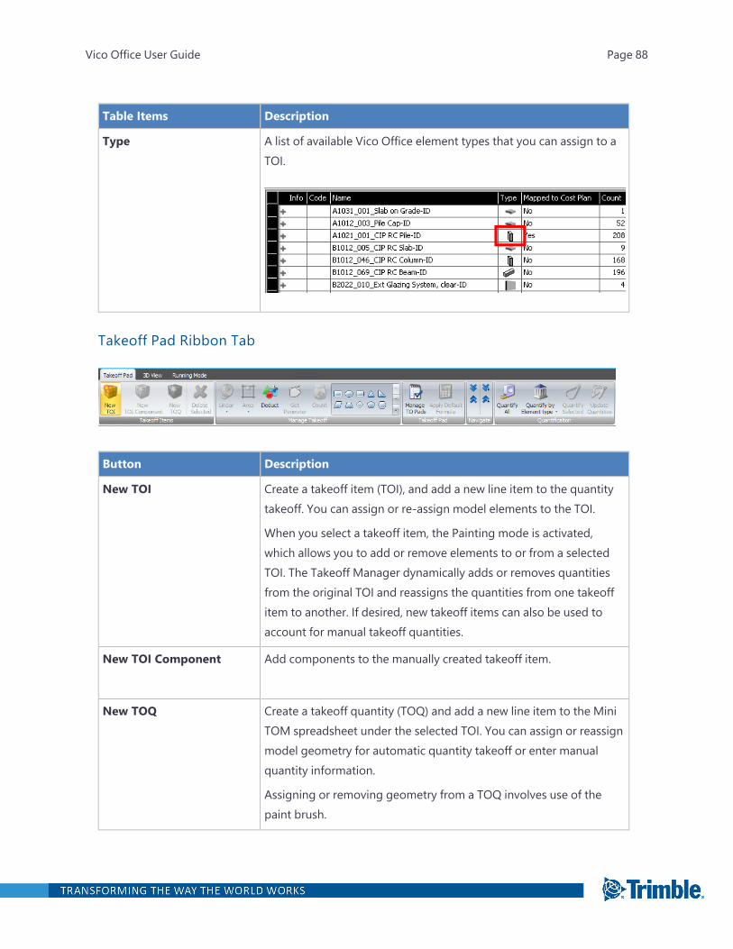
Table Items Description
Type A list of available Vico Office element types that you can assign to aTOI.
Takeoff Pad Ribbon Tab
Button Description
New TOI Create a takeoff item (TOI), and add a new line item to the quantitytakeoff. You can assign or re-assign model elements to the TOI.
When you select a takeoff item, the Painting mode is activated,which allows you to add or remove elements to or from a selectedTOI. The Takeoff Manager dynamically adds or removes quantitiesfrom the original TOI and reassigns the quantities from one takeoffitem to another. If desired, new takeoff items can also be used toaccount for manual takeoff quantities.
New TOI Component Add components to the manually created takeoff item.
New TOQ Create a takeoff quantity (TOQ) and add a new line item to the MiniTOM spreadsheet under the selected TOI. You can assign or reassignmodel geometry for automatic quantity takeoff or enter manualquantity information.
Assigning or removing geometry from a TOQ involves use of thepaint brush.
Vico Office User Guide Page 88
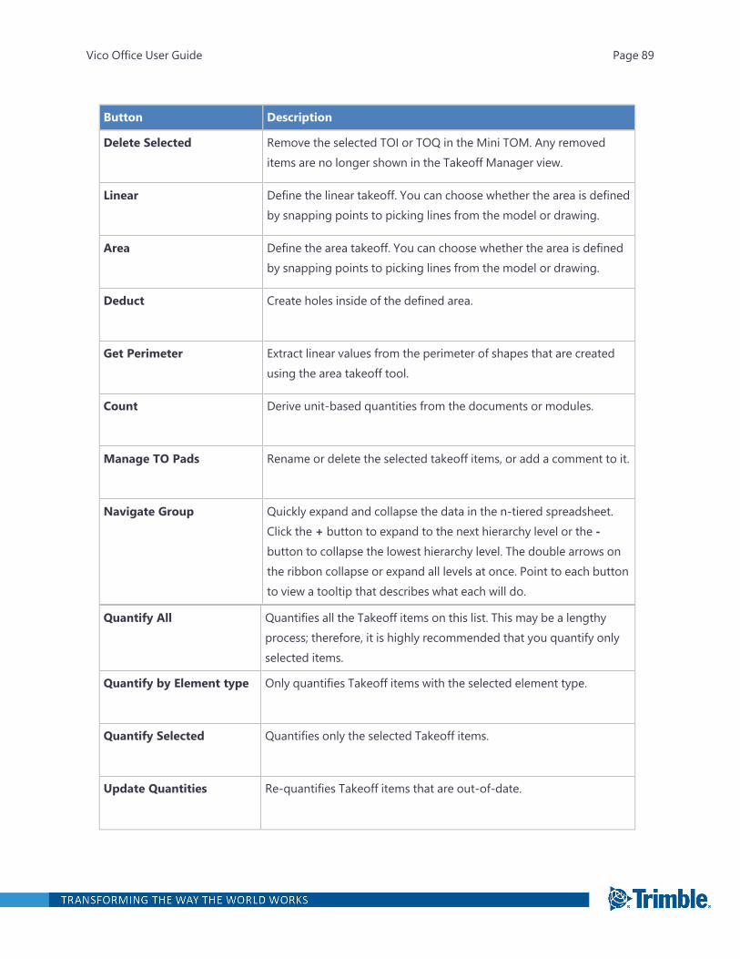
Button Description
Delete Selected Remove the selected TOI or TOQ in the Mini TOM. Any removeditems are no longer shown in the Takeoff Manager view.
Linear Define the linear takeoff. You can choose whether the area is definedby snapping points to picking lines from the model or drawing.
Area Define the area takeoff. You can choose whether the area is definedby snapping points to picking lines from the model or drawing.
Deduct Create holes inside of the defined area.
Get Perimeter Extract linear values from the perimeter of shapes that are createdusing the area takeoff tool.
Count Derive unit-based quantities from the documents or modules.
Manage TO Pads Rename or delete the selected takeoff items, or add a comment to it.
Navigate Group Quickly expand and collapse the data in the n-tiered spreadsheet.Click the + button to expand to the next hierarchy level or the -button to collapse the lowest hierarchy level. The double arrows onthe ribbon collapse or expand all levels at once. Point to each buttonto view a tooltip that describes what each will do.
Quantify All Quantifies all the Takeoff items on this list. This may be a lengthyprocess; therefore, it is highly recommended that you quantify onlyselected items.
Quantify by Element type Only quantifies Takeoff items with the selected element type.
Quantify Selected Quantifies only the selected Takeoff items.
Update Quantities Re-quantifies Takeoff items that are out-of-date.
Vico Office User Guide Page 89
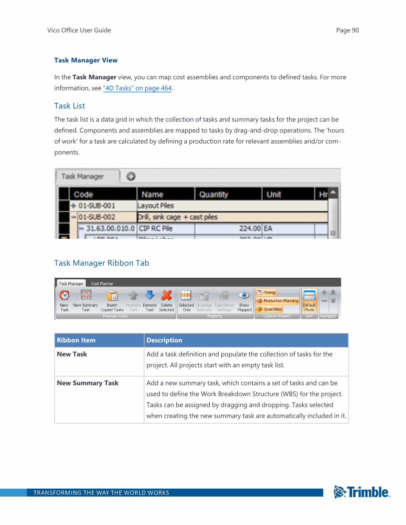
Task Manager View
In the Task Manager view, you can map cost assemblies and components to defined tasks. For moreinformation, see "4D Tasks" on page 464.
Task ListThe task list is a data grid in which the collection of tasks and summary tasks for the project can bedefined. Components and assemblies are mapped to tasks by drag-and-drop operations. The 'hoursof work' for a task are calculated by defining a production rate for relevant assemblies and/or com-ponents.
Task Manager Ribbon Tab
Ribbon Item Description
New Task Add a task definition and populate the collection of tasks for theproject. All projects start with an empty task list.
New Summary Task Add a new summary task, which contains a set of tasks and can beused to define the Work Breakdown Structure (WBS) for the project.Tasks can be assigned by dragging and dropping. Tasks selectedwhen creating the new summary task are automatically included in it.
Vico Office User Guide Page 90
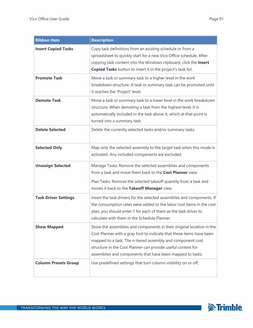
Ribbon Item Description
Insert Copied Tasks Copy task definitions from an existing schedule or from aspreadsheet to quickly start for a new Vico Office schedule. Aftercopying task content into the Windows clipboard, click the InsertCopied Tasks button to insert it in the project's task list.
Promote Task Move a task or summary task to a higher level in the workbreakdown structure. A task or summary task can be promoted untilit reaches the 'Project' level.
Demote Task Move a task or summary task to a lower level in the work breakdownstructure. When demoting a task from the highest level, it isautomatically included in the task above it, which at that point isturned into a summary task.
Delete Selected Delete the currently selected tasks and/or summary tasks.
Selected Only Map only the selected assembly to the target task when this mode isactivated. Any included components are excluded.
Unassign Selected Manage Tasks: Remove the selected assemblies and componentsfrom a task and move them back to the Cost Planner view.
Plan Tasks: Remove the selected takeoff quantity from a task andmoves it back to the Takeoff Manager view.
Task Driver Settings Insert the task drivers for the selected assemblies and components. Ifthe consumption rates were added to the labor cost items in the costplan, you should enter 1 for each of them as the task driver tocalculate with them in the Schedule Planner.
Show Mapped Show the assemblies and components in their original location in theCost Planner with a gray font to indicate that these items have beenmapped to a task. The n-tiered assembly and component coststructure in the Cost Planner can provide useful context forassemblies and components that have been mapped to tasks.
Column Presets Group Use predefined settings that turn column visibility on or off.
Vico Office User Guide Page 91
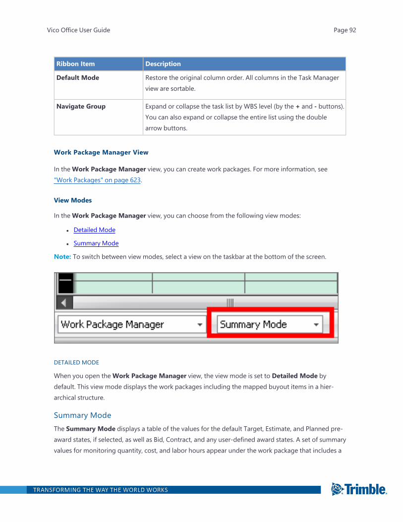
Ribbon Item Description
Default Mode Restore the original column order. All columns in the Task Managerview are sortable.
Navigate Group Expand or collapse the task list by WBS level (by the + and - buttons).You can also expand or collapse the entire list using the doublearrow buttons.
Work Package Manager View
In theWork Package Manager view, you can create work packages. For more information, see"Work Packages" on page 623.
View Modes
In theWork Package Manager view, you can choose from the following view modes:
l Detailed Mode
l Summary Mode
Note: To switch between view modes, select a view on the taskbar at the bottom of the screen.
DETAILED MODE
When you open theWork Package Manager view, the view mode is set to Detailed Mode bydefault. This view mode displays the work packages including the mapped buyout items in a hier-archical structure.
Summary ModeThe Summary Mode displays a table of the values for the default Target, Estimate, and Planned pre-award states, if selected, as well as Bid, Contract, and any user-defined award states. A set of summaryvalues for monitoring quantity, cost, and labor hours appear under the work package that includes a
Vico Office User Guide Page 92
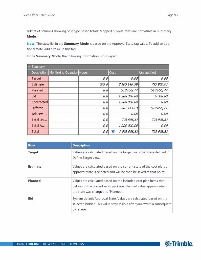
subset of columns showing cost type based totals. Mapped buyout items are not visible in SummaryMode.
Note: The state list in the Summary Mode is based on the Approval State tag value. To add an addi-tional state, add a value in this tag.
In the Summary Mode, the following information is displayed:
Row Description
Target Values are calculated based on the target costs that were defined inDefine Target view.
Estimate Values are calculated based on the current state of the cost plan; anapproval state is selected and will be then be saved at that point.
Planned Values are calculated based on the included cost plan items thatbelong to the current work package. Planned value appears whenthe state was changed to ’Planned’.
Bid System default Approval State. Values are calculated based on theselected bidder. This value stays visible after you award a subsequentbid stage.
Vico Office User Guide Page 93

Row Description
Contracted System default Approval State. Values are calculated based on theselected bidder. After you select a bidder as ’Contracted’, thecorresponding work package cannot be edited any longer withoutchanging the ‘Hard Lock ‘Contracted’ Work Packages in ProjectSettings.
Difference Calculates the difference between the Planned and the Contractedvalues.
Total Shows the total value of the packages.
ColumnsColumn Description
Code The code that is added automatically after you create a work package. This code can bemodified anytime in the future.
Description
The description of the work package.
Monitoring Quantity
The values that belong to the defined unit. This cell is filled automatically after youselect the monitoring unit.
Monitoring Unit
The units that were used in the project. This is available for the work packages but notfor the whole project.
Total The estimated total package cost, which is the sum of the Committed and Pluggedvalues.
Committed
The total of values submitted by the chosen subcontractor.
Plugged The plug value applied to a cost assembly or component.
# Quotes The number of contractors that submitted a bid for the current work package.
Vico Office User Guide Page 94
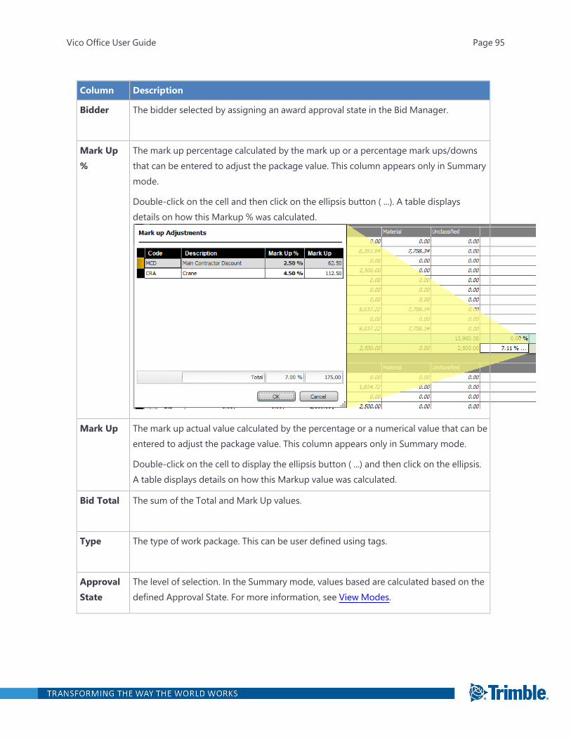
Column Description
Bidder The bidder selected by assigning an award approval state in the Bid Manager.
Mark Up%
The mark up percentage calculated by the mark up or a percentage mark ups/downsthat can be entered to adjust the package value. This column appears only in Summarymode.
Double-click on the cell and then click on the ellipsis button ( ...). A table displaysdetails on how this Markup % was calculated.
Mark Up The mark up actual value calculated by the percentage or a numerical value that can beentered to adjust the package value. This column appears only in Summary mode.
Double-click on the cell to display the ellipsis button ( ...) and then click on the ellipsis.A table displays details on how this Markup value was calculated.
Bid Total The sum of the Total and Mark Up values.
Type The type of work package. This can be user defined using tags.
ApprovalState
The level of selection. In the Summary mode, values based are calculated based on thedefined Approval State. For more information, see View Modes.
Vico Office User Guide Page 95
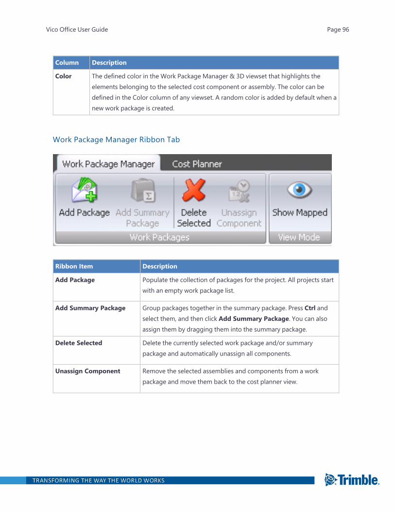
Column Description
Color The defined color in the Work Package Manager & 3D viewset that highlights theelements belonging to the selected cost component or assembly. The color can bedefined in the Color column of any viewset. A random color is added by default when anew work package is created.
Work Package Manager Ribbon Tab
Ribbon Item Description
Add Package Populate the collection of packages for the project. All projects startwith an empty work package list.
Add Summary Package Group packages together in the summary package. Press Ctrl andselect them, and then click Add Summary Package. You can alsoassign them by dragging them into the summary package.
Delete Selected Delete the currently selected work package and/or summarypackage and automatically unassign all components.
Unassign Component Remove the selected assemblies and components from a workpackage and move them back to the cost planner view.
Vico Office User Guide Page 96
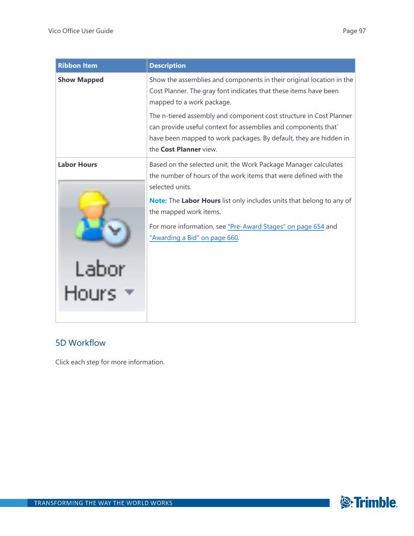
Ribbon Item Description
Show Mapped Show the assemblies and components in their original location in theCost Planner. The gray font indicates that these items have beenmapped to a work package.
The n-tiered assembly and component cost structure in Cost Plannercan provide useful context for assemblies and components that`have been mapped to work packages. By default, they are hidden inthe Cost Planner view.
Labor Hours Based on the selected unit, the Work Package Manager calculatesthe number of hours of the work items that were defined with theselected units.
Note: The Labor Hours list only includes units that belong to any ofthe mapped work items.
For more information, see "Pre-Award Stages" on page 654 and"Awarding a Bid" on page 660.
5D Workflow
Click each step for more information.
Vico Office User Guide Page 97

Vico Office User Guide Page 98
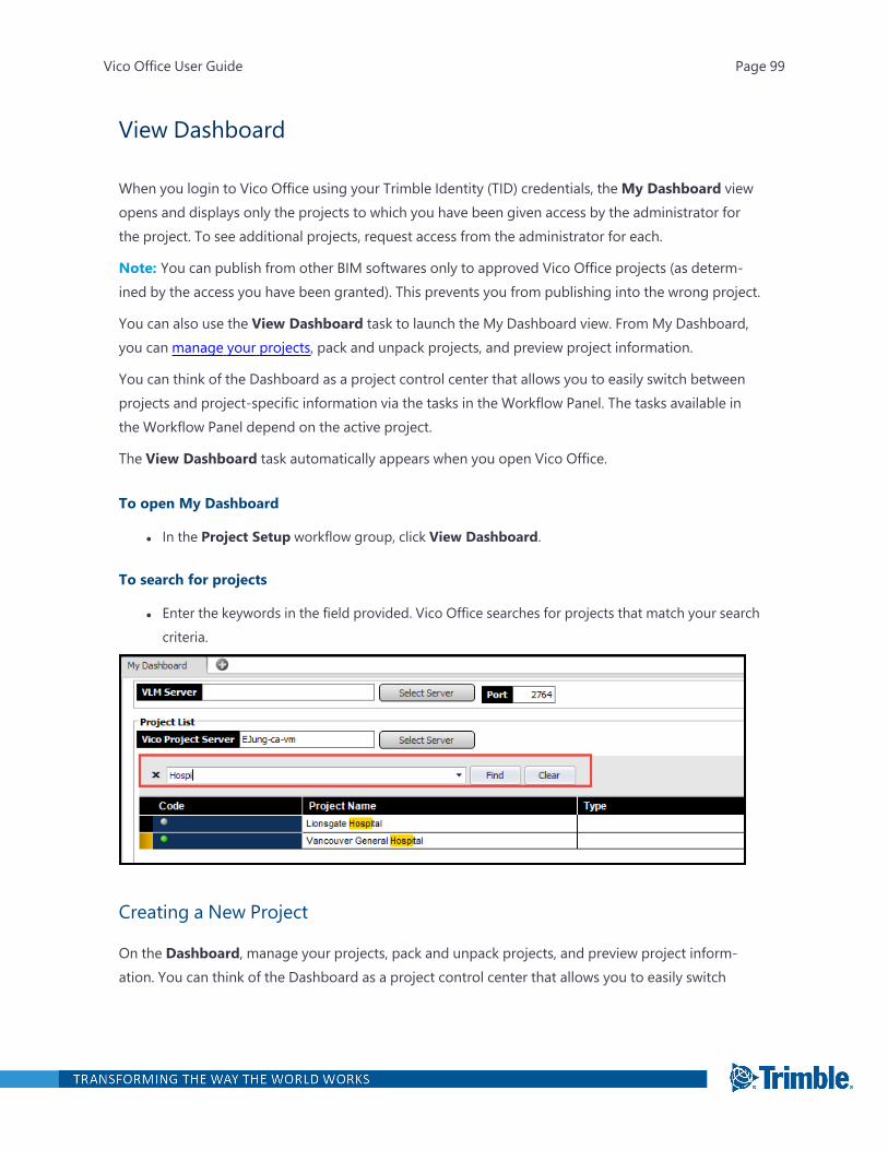
View Dashboard
When you login to Vico Office using your Trimble Identity (TID) credentials, theMy Dashboard viewopens and displays only the projects to which you have been given access by the administrator forthe project. To see additional projects, request access from the administrator for each.
Note: You can publish from other BIM softwares only to approved Vico Office projects (as determ-ined by the access you have been granted). This prevents you from publishing into the wrong project.
You can also use the View Dashboard task to launch the My Dashboard view. From My Dashboard,you can manage your projects, pack and unpack projects, and preview project information.
You can think of the Dashboard as a project control center that allows you to easily switch betweenprojects and project-specific information via the tasks in the Workflow Panel. The tasks available inthe Workflow Panel depend on the active project.
The View Dashboard task automatically appears when you open Vico Office.
To open My Dashboard
l In the Project Setup workflow group, click View Dashboard.
To search for projects
l Enter the keywords in the field provided. Vico Office searches for projects that match your searchcriteria.
Creating a New Project
On the Dashboard, manage your projects, pack and unpack projects, and preview project inform-ation. You can think of the Dashboard as a project control center that allows you to easily switch
Vico Office User Guide Page 99
between projects and project specific information available via the Workflow Panel. The informationavailable in views, via all the workflow items, is dependent on the currently opened project on yourDashboard.
Note: When you create a project, you are assigned the Administrator role by default. See"Managing Users and Controlling Project Access" on page 12 for more information.
TO CREATE A NEW PROJECT
1. Open the View Dashboard task.
2. On the ribbon, click New Project.
The new project is added as a new line in the Project List area.
3. In the Project Name field, type the project name.
A time stamp is generated in the Created and Last Edited fields.
4. Optional: In the Code field, type a code for the project.
Tip: Use the code to categorize your projects numerically.
5. Optional: In the Type field, enter the type.
Tip: Use the type to sort by similar projects.
6. Define your project settings in the Define Settings workflow item.
Closing a Project
Because only one project can be opened at a time, you must close a project before opening a newone.
After closing a project, the model is not visible anymore, and you cannot edit the project until youopen it again.
To close a project
1. Open the View Dashboard task.
2. On the Dashboard, click the currently opened project.
3. On the ribbon, click Close Project.
Note: To open another project, select the project on the Dashboard, and then click Open Project. Ifyou open another project, the previously opened one is automatically closed.
Vico Office User Guide Page 100
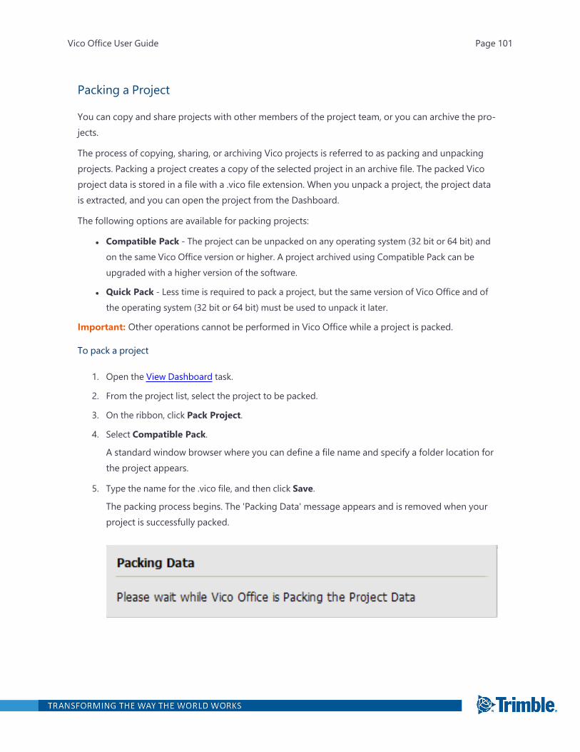
Packing a Project
You can copy and share projects with other members of the project team, or you can archive the pro-jects.
The process of copying, sharing, or archiving Vico projects is referred to as packing and unpackingprojects. Packing a project creates a copy of the selected project in an archive file. The packed Vicoproject data is stored in a file with a .vico file extension. When you unpack a project, the project datais extracted, and you can open the project from the Dashboard.
The following options are available for packing projects:
l Compatible Pack - The project can be unpacked on any operating system (32 bit or 64 bit) andon the same Vico Office version or higher. A project archived using Compatible Pack can beupgraded with a higher version of the software.
l Quick Pack - Less time is required to pack a project, but the same version of Vico Office and ofthe operating system (32 bit or 64 bit) must be used to unpack it later.
Important: Other operations cannot be performed in Vico Office while a project is packed.
To pack a project
1. Open the View Dashboard task.
2. From the project list, select the project to be packed.
3. On the ribbon, click Pack Project.
4. Select Compatible Pack.
A standard window browser where you can define a file name and specify a folder location forthe project appears.
5. Type the name for the .vico file, and then click Save.
The packing process begins. The 'Packing Data' message appears and is removed when yourproject is successfully packed.
Vico Office User Guide Page 101
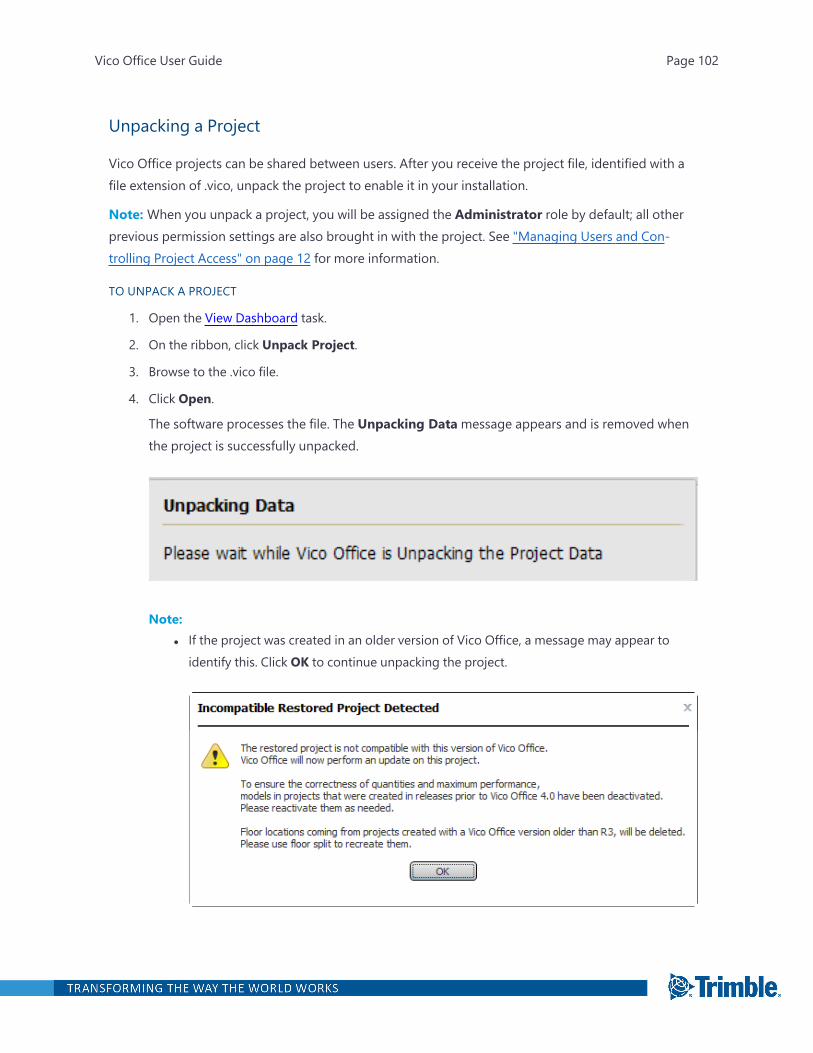
Unpacking a Project
Vico Office projects can be shared between users. After you receive the project file, identified with afile extension of .vico, unpack the project to enable it in your installation.
Note: When you unpack a project, you will be assigned the Administrator role by default; all otherprevious permission settings are also brought in with the project. See "Managing Users and Con-trolling Project Access" on page 12 for more information.
TO UNPACK A PROJECT
1. Open the View Dashboard task.
2. On the ribbon, click Unpack Project.
3. Browse to the .vico file.
4. Click Open.
The software processes the file. The Unpacking Datamessage appears and is removed whenthe project is successfully unpacked.
Note:l If the project was created in an older version of Vico Office, a message may appear to
identify this. Click OK to continue unpacking the project.
Vico Office User Guide Page 102
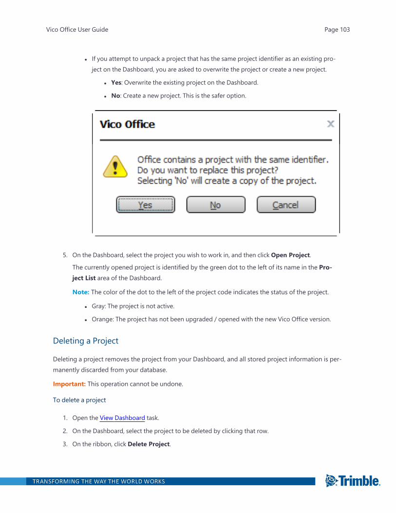
l If you attempt to unpack a project that has the same project identifier as an existing pro-ject on the Dashboard, you are asked to overwrite the project or create a new project.
l Yes: Overwrite the existing project on the Dashboard.
l No: Create a new project. This is the safer option.
5. On the Dashboard, select the project you wish to work in, and then click Open Project.
The currently opened project is identified by the green dot to the left of its name in the Pro-ject List area of the Dashboard.
Note: The color of the dot to the left of the project code indicates the status of the project.
l Gray: The project is not active.
l Orange: The project has not been upgraded / opened with the new Vico Office version.
Deleting a Project
Deleting a project removes the project from your Dashboard, and all stored project information is per-manently discarded from your database.
Important: This operation cannot be undone.
To delete a project
1. Open the View Dashboard task.
2. On the Dashboard, select the project to be deleted by clicking that row.
3. On the ribbon, click Delete Project.
Vico Office User Guide Page 103
4. In the Delete Project dialog box, click Delete Anyway.
The project is removed from the Dashboard.
Selecting a Vico Project Server
Switch project databases from the default database created on your computer to another machine inyour network.
To change to a network database
1. Open the View Dashboard task.
2. Click Select Server next to Vico Project Server.
3. In the Select Host dialog, select Network Host, and then select the computer that contains thedatabase that you want to connect to.
The database is switched from a local to a network host location.
You and your project team can now work off the same network location designated to storethe latest project database and information.
Selecting a VLM Server
To select a VLM server
1. Open the View Dashboard task.
2. Click Select Server next to VLM Server.
3. In the Select Host dialog, click Network Host.
4. From the list of available computers under Network Host, select the computer that hosts thelicense server, and then click OK.
Vico Office checks the VLM Server for available licenses for the module or modules that youactivate in the Module Selector.
Vico Office User Guide Page 104
Project Setup
In the Project Setup workflow group, you can:
l Define settings for your project
l Edit tags that are used for categorizing and filtering estimation information
You can also manage projects from your dashboard and import existing project information usingExcel.
Vico Office User Guide Page 105
Define Settings
In the Define Settings task, you can customize project information such as:
l Project Details
l WinEst Project Link (when integrating with WinEst. Note that the WinEst-Vico plugin is required. )
l Customer Information
l Units of Measurement
Note: This setting is applied to takeoff quantities when a model is activated and takeoff itemsare generated. The units selected in this view are then automatically assigned to new takeoffquantities.
l Decimal Places
l Color Scheme and Reference
l 3D View Background Color
l Project Image
l Work Packages
The information entered in the Define Settings task is available for reporting purposes. For example,you can include a company logo in your reports.
To open the Define Settings task
l In the Project Setup workflow group, click Define Settings.
The default viewset includes the Project Settings view.
Defining Units of Measurement
Important: Before activating your first project model in Vico Office, you must define your units ofmeasurement in the Project Settings view. Any changes made after the first model activation do notaffect any of the content in the project.
To define units of measurement
1. Open the Define Settings task.
2. From the System list in the Units of Measurement area, select the desired system, Imperial orMetric.
Your selection determines which units are displayed for the other lists in this area.
Vico Office User Guide Page 106

3. From the Length, Area, and Volume lists, select the units of measurement.
Note: The selected units of measurement are used in the Takeoff Manager view for takeoffquantities in takeoff items.
After defining your preferred Units of Measurement, you can begin the process of publishing andactivating models. Note that the available takeoff quantities (TOQs) are specified per element type.To see the available TOQs per element type, see "Quantities and Units " on page 2.
Selecting a Reference
A reference is a powerful way to reuse information from an earlier project or to copy cost assembliesand components from a standard set of data.
In the Project Reference area in the Project Settings view, you can specify the project or standarddataset in your database.
To select a default reference for your project
1. Open the Define Settings task.
2. In the Color Scheme and Reference area, click Browse to select the server that contains thedatabase with the cost data you want to use.
By default, this is set to your own computer.
3. From the list of projects that exist in the selected database, select the project from the ProjectName combo.
Vico Office User Guide Page 107
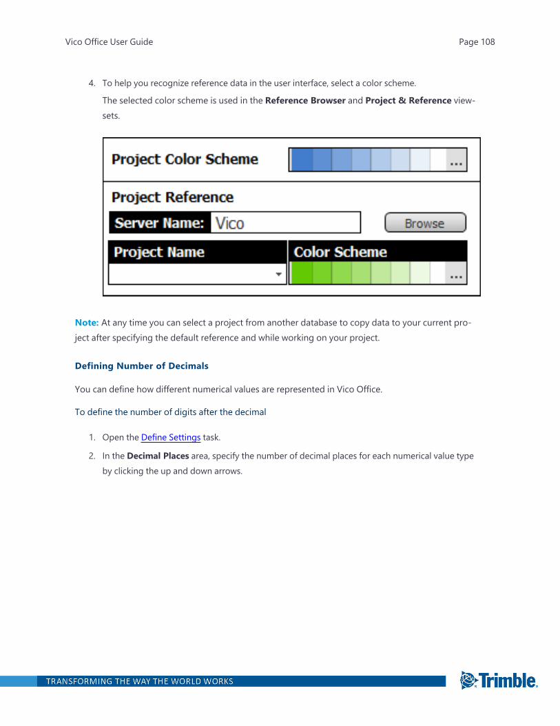
4. To help you recognize reference data in the user interface, select a color scheme.
The selected color scheme is used in the Reference Browser and Project & Reference view-sets.
Note: At any time you can select a project from another database to copy data to your current pro-ject after specifying the default reference and while working on your project.
Defining Number of Decimals
You can define how different numerical values are represented in Vico Office.
To define the number of digits after the decimal
1. Open the Define Settings task.
2. In the Decimal Places area, specify the number of decimal places for each numerical value typeby clicking the up and down arrows.
Vico Office User Guide Page 108
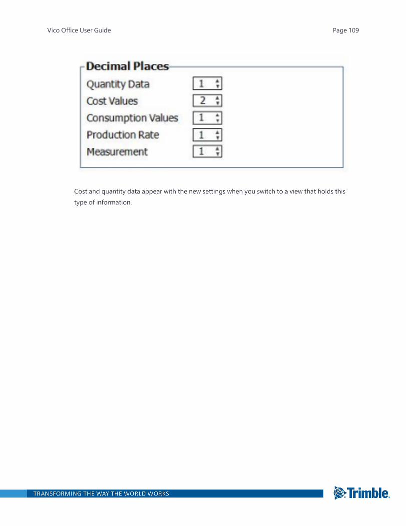
Cost and quantity data appear with the new settings when you switch to a view that holds thistype of information.
Vico Office User Guide Page 109

Edit Tags
Tags are attributes of cost items (components and assemblies) that can be used for categorizing andfiltering estimation information. They are not specific to any view but are typically used in spread-sheet views where they can be displayed as columns.
Tags store properties that are needed in addition to the standard data fields. Each tag has a list of pos-sible values and a default value.
Important: Some tags and tag values cannot be edited or removed because they are required forVico Office functionality. For example, the Cost Type tag is used for determining the default markuppercentage for components and is therefore part of the System tag category.
To open the Edit Tags task
l In the Project Setup workflow group, click Edit Tags.
The default viewset includes in the Tag Editor view.
Defining a New Tag with Tag Values
Tag values are the variables that can be predefined for tags. A tag can have an unlimited number ofpredefined tag values, which can also be extended 'on the fly' by entering custom values in the CostPlanner view.
To add a new tag and define its tag values
Vico Office User Guide Page 110

1. Open the Edit Tags task.
2. In the Tagging Categories section, select the category to which you would like to add the newtag.
3. On the ribbon, click Tag.
The new tag is added to the selected category, and a default name is assigned to it.
4. To change the name, click the new tag, and then type the name.
5. Add the default set of values that you would like to have available when you define the propertyof this tag.
6. On the ribbon, click Value.
—Or—
Right-click the tag value area, and then click Insert New Value.
Note: A tag or tag value must be selected before you insert the new value.
The new value is added to the list of predefined tag values for the selected tag.
7. To change the value name, click the Value cell.
If desired, you can also enter information in the Description cell.
8. Click the Color cell, and then select the color.
Vico Office User Guide Page 111
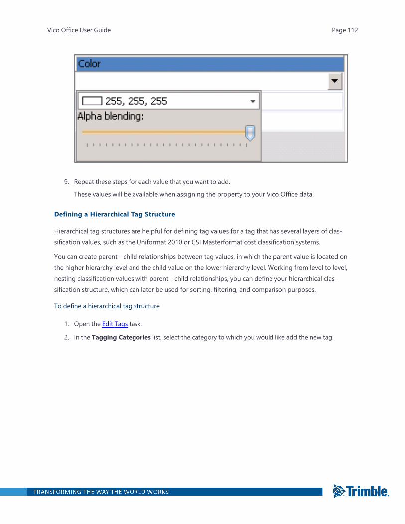
9. Repeat these steps for each value that you want to add.
These values will be available when assigning the property to your Vico Office data.
Defining a Hierarchical Tag Structure
Hierarchical tag structures are helpful for defining tag values for a tag that has several layers of clas-sification values, such as the Uniformat 2010 or CSI Masterformat cost classification systems.
You can create parent - child relationships between tag values, in which the parent value is located onthe higher hierarchy level and the child value on the lower hierarchy level. Working from level to level,nesting classification values with parent - child relationships, you can define your hierarchical clas-sification structure, which can later be used for sorting, filtering, and comparison purposes.
To define a hierarchical tag structure
1. Open the Edit Tags task.
2. In the Tagging Categories list, select the category to which you would like add the new tag.
Vico Office User Guide Page 112
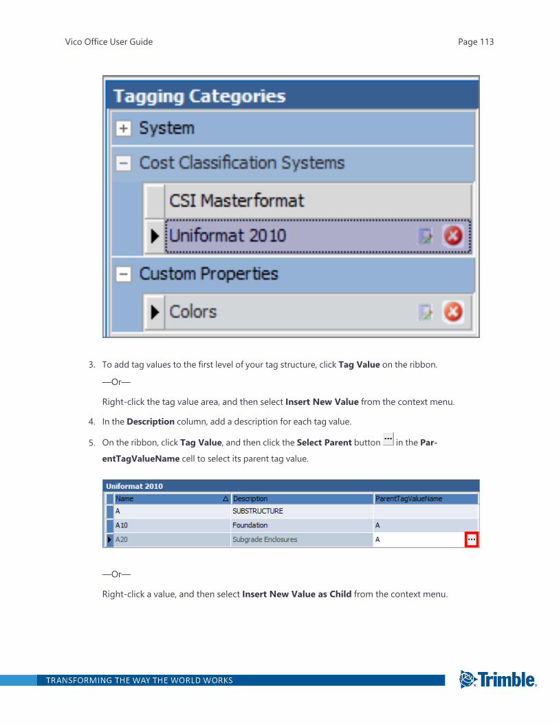
3. To add tag values to the first level of your tag structure, click Tag Value on the ribbon.
—Or—
Right-click the tag value area, and then select Insert New Value from the context menu.
4. In the Description column, add a description for each tag value.
5. On the ribbon, click Tag Value, and then click the Select Parent button in the Par-
entTagValueName cell to select its parent tag value.
—Or—
Right-click a value, and then select Insert New Value as Child from the context menu.
Vico Office User Guide Page 113

A new tag value is inserted inside the selected tag value.
6. To change the name of the new tag value, click it, and type the new name.
Specifying the Use of a Tag
Specify the data source for which a defined tag can be used, so you can limit the tags that are avail-able in all selection dialogs.
Note:l To ensure that a tag works correctly, it must be mapped to the correct data source.
l The data sources for default tags cannot be changed.
To specify the type of content
1. Open the Edit Tags task.
2. In the Tagging Categories list, select the tag.
3. Click the Edit button next to the tag.
Vico Office User Guide Page 114
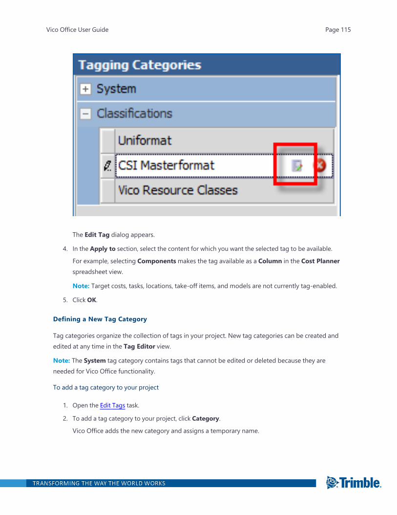
The Edit Tag dialog appears.
4. In the Apply to section, select the content for which you want the selected tag to be available.
For example, selecting Components makes the tag available as a Column in the Cost Plannerspreadsheet view.
Note: Target costs, tasks, locations, take-off items, and models are not currently tag-enabled.
5. Click OK.
Defining a New Tag Category
Tag categories organize the collection of tags in your project. New tag categories can be created andedited at any time in the Tag Editor view.
Note: The System tag category contains tags that cannot be edited or deleted because they areneeded for Vico Office functionality.
To add a tag category to your project
1. Open the Edit Tags task.
2. To add a tag category to your project, click Category.
Vico Office adds the new category and assigns a temporary name.
Vico Office User Guide Page 115
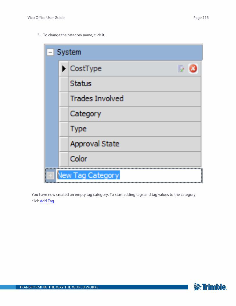
3. To change the category name, click it.
You have now created an empty tag category. To start adding tags and tag values to the category,click Add Tag.
Vico Office User Guide Page 116

Import from Excel
Take advantage of existing project information by importing it into Vico Office. You can open an Excelspreadsheet and then select the columns and cells that contain the data that you want to reuse.
Excel data can be imported into the following views:
l Cost Planner
l Takeoff Manager
l Tag Editor
l Issue Manager
l Work Packages
To import data from Excel:
1. Select the content view.
—Or—
If you are using a custom layout, select the viewport that will display the content view.
2. Open the Excel file.
3. Select the data to be imported. You can also import hierarchical data.
4. Validate the data.
5. Copy the data into the project.
To open the Import from Excel task
l In the Project Setup workflow group, click Import from Excel.
The default viewset includes the following views:
l Content view: Contains the data that you select from the cells and columns in the ExcelImporter view. The data types that can be imported depend on the selected view.
l Excel Importer view: Displays the content of the opened Excel file. For more information,see "Excel Importer View" on page 60.
Selecting the Content View
When you import data from Excel, the content view determines which data types can be importedinto your project. After you open the Excel spreadsheet, you can select the data types that represent
Vico Office User Guide Page 117

the content of each column.
To select the content view
1. Open the Import from Excel task.
The top window of the default Excel Import viewset is empty.
2. On the ribbon, click Pick View, and then click the desired view.
The empty view appears. You can open open an Excel file and select the data to import intothe project.
Selecting a Viewport for the Content View
If you use a custom layout (a layout created by adding a new custom viewset) that contains morethan two viewports, you must select the viewport (window) that displays the content view.Example:
In the following layout, Viewport 1 is the Excel Importer view. You can select Viewport 2 or Viewport3 for the content view.
Vico Office User Guide Page 118

To select the view for the content view
1. Open the Import from Excel task.
2. On the ribbon, click Select Viewport.
The Viewport Selection mode is activated.
3. Click the viewport that will display the content view.
4. To select a content view, click Pick View on the ribbon, and then click the desired view.
The empty view appears. You can open an Excel file and select the data to import into the pro-ject.
Opening the Excel File
Open the file with the data that you want to import into your Vico Office project. The selected fileopens in the Excel Importer view.
To open the Excel file
1. After you selected the content view in the Import from Excel task, click Open Excel File on the rib-bon.
2. In the Open dialog, select the Excel file.
You can open Microsoft Excel 1997-2003 or Microsoft Excel 2007 files.
The first sheet of the file is displayed in the Excel Importer view.
3. To switch to a different sheet in the file, select the sheet from the Select sheet name list on thetaskbar.
Vico Office User Guide Page 119

You can select the data to import into the project.
Selecting the Data to Import
In the Excel file, you can select the columns and cells that contain the data that you want to copy intothe Vico Office project.
Note: For best results when importing data from Excel, it is recommended that each column in thespreadsheet has one type of data.
To select the data to import into the Vico Office project
1. After you opened the excel file in the Import from Excel task, click the Data Type cell of thecolumn.
Vico Office User Guide Page 120
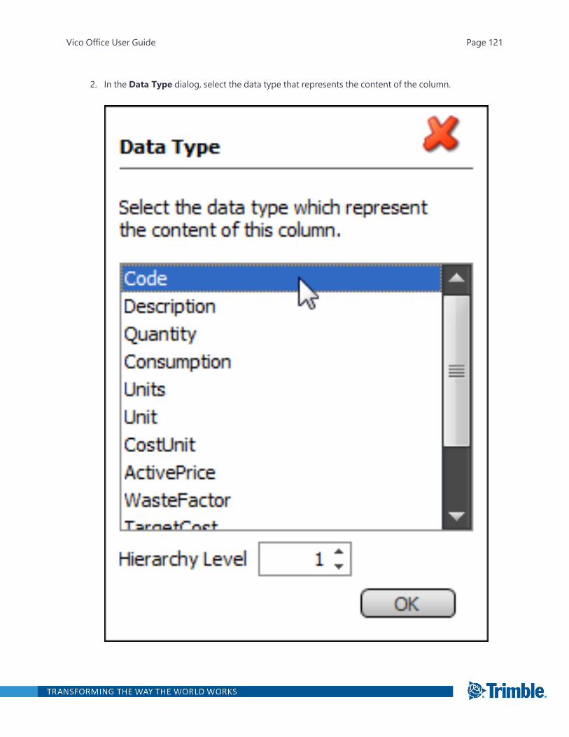
2. In the Data Type dialog, select the data type that represents the content of the column.
Vico Office User Guide Page 121
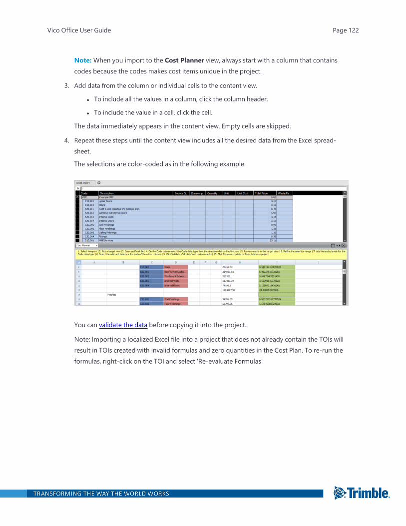
Note: When you import to the Cost Planner view, always start with a column that containscodes because the codes makes cost items unique in the project.
3. Add data from the column or individual cells to the content view.
l To include all the values in a column, click the column header.
l To include the value in a cell, click the cell.
The data immediately appears in the content view. Empty cells are skipped.
4. Repeat these steps until the content view includes all the desired data from the Excel spread-sheet.
The selections are color-coded as in the following example.
You can validate the data before copying it into the project.
Note: Importing a localized Excel file into a project that does not already contain the TOIs willresult in TOIs created with invalid formulas and zero quantities in the Cost Plan. To re-run theformulas, right-click on the TOI and select 'Re-evaluate Formulas'
Vico Office User Guide Page 122
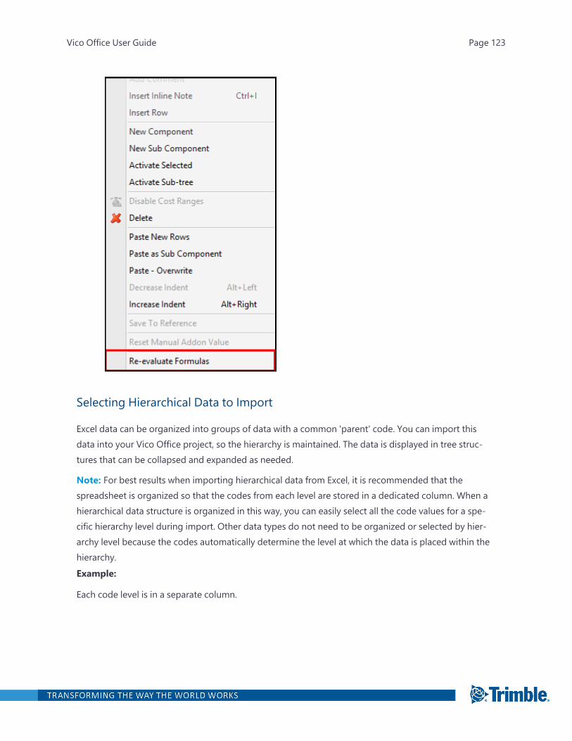
Selecting Hierarchical Data to Import
Excel data can be organized into groups of data with a common 'parent' code. You can import thisdata into your Vico Office project, so the hierarchy is maintained. The data is displayed in tree struc-tures that can be collapsed and expanded as needed.
Note: For best results when importing hierarchical data from Excel, it is recommended that thespreadsheet is organized so that the codes from each level are stored in a dedicated column. When ahierarchical data structure is organized in this way, you can easily select all the code values for a spe-cific hierarchy level during import. Other data types do not need to be organized or selected by hier-archy level because the codes automatically determine the level at which the data is placed within thehierarchy.Example:
Each code level is in a separate column.
Vico Office User Guide Page 123
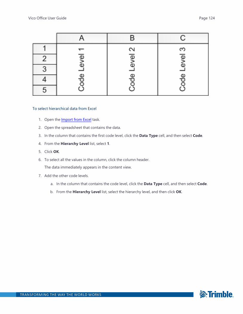
To select hierarchical data from Excel
1. Open the Import from Excel task.
2. Open the spreadsheet that contains the data.
3. In the column that contains the first code level, click the Data Type cell, and then select Code.
4. From the Hierarchy Level list, select 1.
5. Click OK.
6. To select all the values in the column, click the column header.
The data immediately appears in the content view.
7. Add the other code levels.
a. In the column that contains the code level, click the Data Type cell, and then select Code.
b. From the Hierarchy Level list, select the hierarchy level, and then click OK.
Vico Office User Guide Page 124
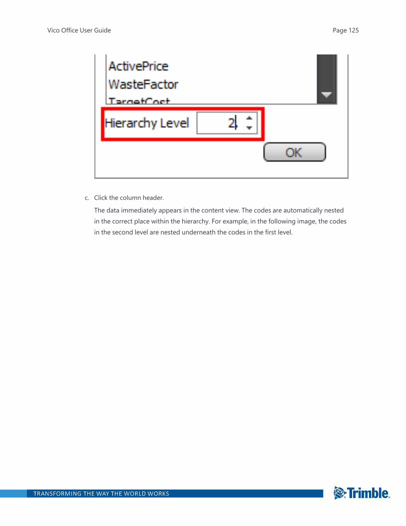
c. Click the column header.
The data immediately appears in the content view. The codes are automatically nestedin the correct place within the hierarchy. For example, in the following image, the codesin the second level are nested underneath the codes in the first level.
Vico Office User Guide Page 125
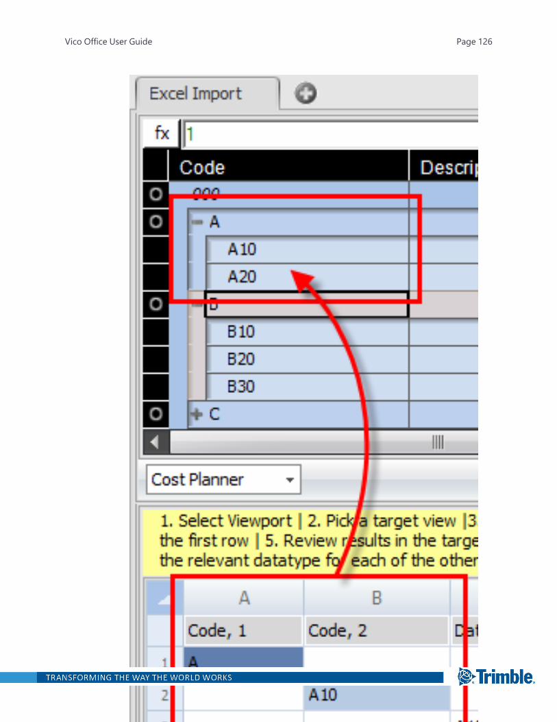
Vico Office User Guide Page 126

8. Select the other data types that you want to import.
You do not have to select the other data types by hierarchy level because the codes auto-matically determine their place within the hierarchy.
You can validate the data before copying it into the project.
Validating the Data
The Excel spreadsheet may not include all the data that can be associated with a component,assembly, takeoff item, or other type of Vico Office data. After you select the columns and cells thatyou want to import from the spreadsheet, the selections appear in the content view. Data fieldswithout corresponding selections are empty.
However, Vico Office does require a value in each available data field. To ensure that the data in thecontent view is ready to be copied into the project, the validation step completes the dataset byadding default values in the empty fields.
To complete the dataset to match requirements of selected content view
Vico Office User Guide Page 127
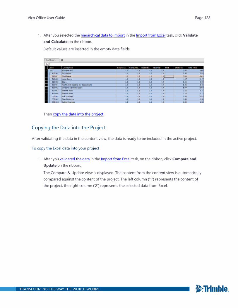
1. After you selected the hierarchical data to import in the Import from Excel task, click Validateand Calculate on the ribbon.
Default values are inserted in the empty data fields.
Then copy the data into the project.
Copying the Data into the Project
After validating the data in the content view, the data is ready to be included in the active project.
To copy the Excel data into your project
1. After you validated the data in the Import from Excel task, on the ribbon, click Compare andUpdate on the ribbon.
The Compare & Update view is displayed. The content from the content view is automaticallycompared against the content of the project. The left column ('1') represents the content ofthe project, the right column ('2') represents the selected data from Excel.
Vico Office User Guide Page 128
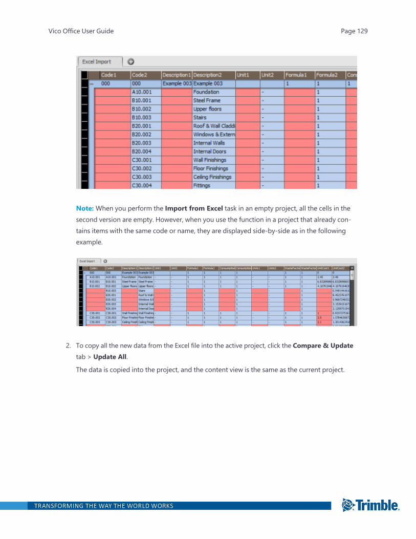
Note: When you perform the Import from Excel task in an empty project, all the cells in thesecond version are empty. However, when you use the function in a project that already con-tains items with the same code or name, they are displayed side-by-side as in the followingexample.
2. To copy all the new data from the Excel file into the active project, click the Compare & Updatetab > Update All.
The data is copied into the project, and the content view is the same as the current project.
Vico Office User Guide Page 129

Vico Office User Guide Page 130
Publishing a Model to Vico Office
The Publish to Vico process is a key part of the Vico Office workflow. The first step in publishing aBuilding Information Model (BIM) into Vico Office is to login using your Trimble Identity (TID) cre-dentials so that Vico Office can identify which projects you can publish into based on your TID. Thenopen a BIM file in a supported CAD application.When you launch a Publish command from an applic-ation like Tekla, Revit, or Archicad, you are prompted to login using your TID.
Important: The modeling applications must be installed before Vico Office. During the Vico Officeinstallation, you can then choose which publisher add-ons you wish to include.
The following publishers are currently supported:
l Autodesk Revit 2018, 2019, 2020, 2021, and 2022
l Tekla Structures 2018, 2018i, 2019, 2019i, 2020, and 2021
l Archicad 21, 22, 23, and 24
l Bentley is not supported in Vico R6.1 and later. (To continue to use this publisher, you must useVico R6 or earlier)
For each BIM application, Vico Office installs an add-on that introduces a Publish to Vico button tothe application's user interface.
When selected, the Publish Data dialog appears. You can then specify the project and model loc-ation, as well as select the elements and parameters to publish.
Note: Access to projects is controlled by each project's administrator using Trimble Identity (TID) cre-dentials. You can only publish a 3D model from BIM software like Revit or Archicad to approved Vicoprojects to which you have been given access. This prevents you from publishing into the wrong pro-ject.
The Vico Add-On application extracts the specified model element geometry data, including thequantities from each CAD, and stores it in the Vico Office database. When the publishing process iscompleted, you can activate the model in Document Controller. During the model activation process,an initial set of takeoff items and takeoff quantities are generated based on model element geometryand properties stored in the project during the publish operation.
Note: Only the active model feeds quantities to the Takeoff Pad and the Cost Plan tasks.
Vico Office Publishing Rules
Vico Office User Guide Page 131
Complex geometries increase the duration of the publishing process. Therefore, it is recommendedthat you use the Advanced section of the Publish Data dialog box to select only the elements that areabsolutely necessary for your project. For example, exclude items such as microscopes or curtains asthey don't provide any value to your project's cost estimate.
Other publishing rules that will decrease duration:
l Use the simplest geometry.
l Use solid elements.
l Use boxes to represent elements that are needed only for counting.
l Hide unnecessary objects to include in the estimates.
l Publish links separately if possible.
Exchange Data via IFC Files
Use the Industry Foundation Classes (IFC) file format to import BIM objects from Tekla and other BIMsystems. IFC is a universal XML format used for exchanging building object data. You can export toIFC and then import the IFC into Vico Office. This enables you to get BIM data in IFC format fromother publishers. See "Supported IFC Classes" below for the types of supported objects.
Warning: The IFC exchange format is open source and can be customized by any 3rd party BIMdeveloper, so you should always confirm that your Vico results match the source design. Trimble can-not guarantee specific results when importing IFC geometry.
Note: The unit of measurement in Vico must match that of the exporting software.
Supported IFC Classes
The following IFC classes are supported:
l IfcBeam
l IfcBuildingElement
l IfcBuildingElementComponent
l IfcBuildingElementProxy
l IfcColumn
l IfcCovering
l IfcCurtainwal
l IfcDistributionChamberElement
Vico Office User Guide Page 132
l IfcDistributionControlElement
l IfcDistributionFlowElement
l IfcDoor
l IfcElectricalElement
l IfcEnergyConversionDevice
l IfcEquipmentElement
l IfcEquipmentElement
l IfcFlowController
l IfcFlowFitting
l IfcFlowMovingDevice
l IfcFlowSegment
l IfcFlowStorageDevice
l IfcFlowTerminal
l IfcFlowTreatmentDevice
l IfcFooting
l IfcFurnishingElement
l IfcMember
l IfcPile
l IfcPlate
l IfcRailing
l IfcRamp
l IfcRampFlight
l IfcReinforcingBar
l IfcReinforcingMesh
l IfcRoof
l IfcSite
l IfcSlab
l IfcSpace
l IfcStair
l IfcStairFlight
Vico Office User Guide Page 133

l IfcTendon
l IfcTendonAnchor
l IfcTransportElement
l IfcWall
l IfcWallstandardcase
l IfcWindow
Publishing from Revit
Autodesk Revit is building information modeling software for architects, structural engineers, MEPengineers, designers and contractors. Users can design a building and structure and its componentsin 3D, annotate the model with 2D drafting elements, and access building information from the build-ing models database. Revit is 4D BIM capable with tools to plan and track various stages in the build-ing's lifecycle, from concept to construction and later demolition.
When you publish from Revit to Vico Office, you will need to login using your Trimble Identity (TID)credentials so that Vico Office can identify which projects you can publish into based on your TID.You will not have to login to Vico Office as well because your TID is cached.
After you create a building information model in Revit, you can easily publish it to Vico Office and useit in your Vico Office workflow.
Setting up Models
For easier and faster use later, break down the models by trades/systems or other smaller chunks.These trade models or ‘system files’ must originate from the ‘base model’.
ExampleA system breakdown has the following structure:
l Substructure model: Contains all the structural members that ‘touch the earth’ such as foundations,basement walls, slabs on grade, and pits.
l Superstructure model: Contains all the structural members excluding the ones that were modeledunder ‘Substructure’.
l Exterior model: Contains the shell of building such as exterior walls, roofing, and canopies. This is asingle model that contains all levels of the project.
l Interior model: Contains the rest of the architectural elements plus fixtures that are modeled in thearchitectural context such as interior walls, ceilings, flooring, and lighting and plumbing fixtures.
l MEP model: Contains all the systems such as pipes, ducts, fitting and equipment, and air terminals.
Vico Office User Guide Page 134
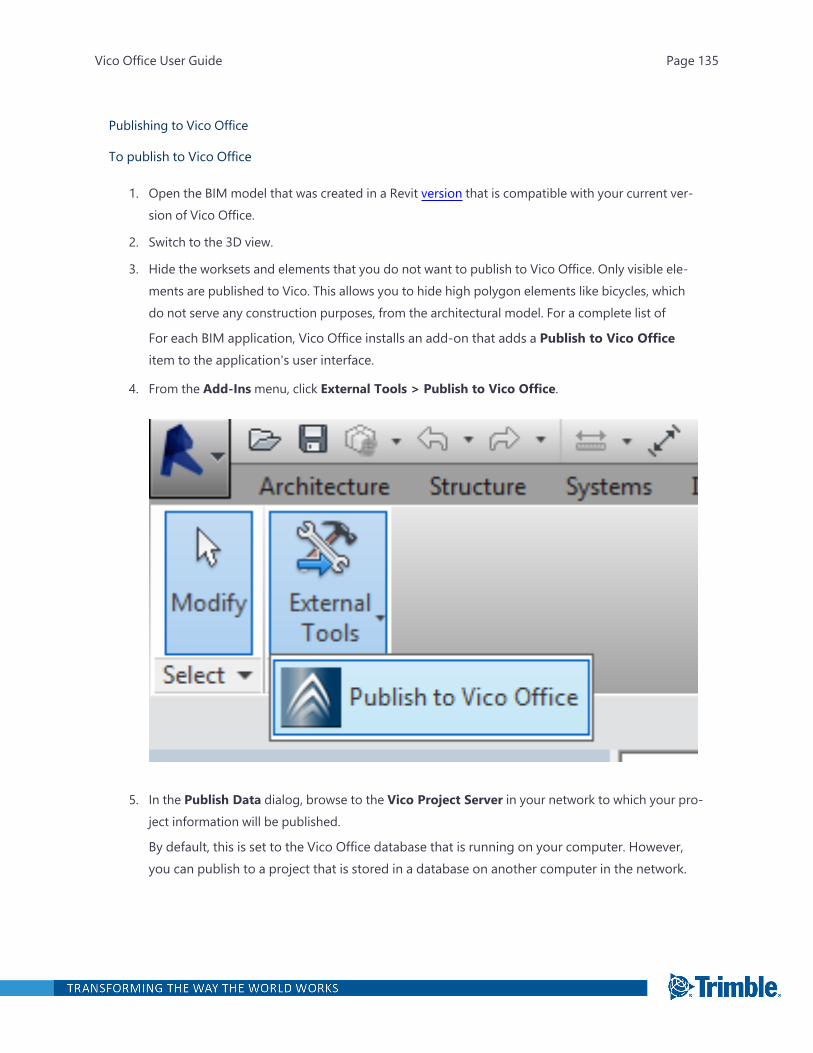
Publishing to Vico Office
To publish to Vico Office
1. Open the BIM model that was created in a Revit version that is compatible with your current ver-sion of Vico Office.
2. Switch to the 3D view.
3. Hide the worksets and elements that you do not want to publish to Vico Office. Only visible ele-ments are published to Vico. This allows you to hide high polygon elements like bicycles, whichdo not serve any construction purposes, from the architectural model. For a complete list of
For each BIM application, Vico Office installs an add-on that adds a Publish to Vico Officeitem to the application's user interface.
4. From the Add-Insmenu, click External Tools > Publish to Vico Office.
5. In the Publish Data dialog, browse to the Vico Project Server in your network to which your pro-ject information will be published.
By default, this is set to the Vico Office database that is running on your computer. However,you can publish to a project that is stored in a database on another computer in the network.
Vico Office User Guide Page 135
6. In the Select Project list, expand the node to find your project. The Project list is sorted by pro-ject and then by existing models within each project.
7. To publish a new version of a previously published model, select the model. After it's published,the previous version is not replaced and a new version will appear in Vico Office's Model Man-ager.
—Or—
Click Create New Model. If this is the first model that will be published to Vico Office, only theCreate New Model option is available.
Note: Models that were created in other supporting application are not displayed in the pro-ject list.
Vico Office User Guide Page 136
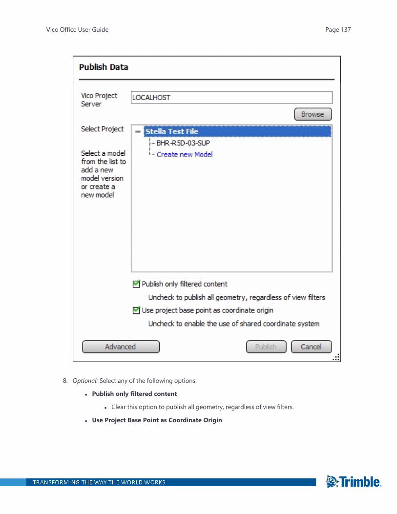
8. Optional: Select any of the following options:
l Publish only filtered content
l Clear this option to publish all geometry, regardless of view filters.
l Use Project Base Point as Coordinate Origin
Vico Office User Guide Page 137
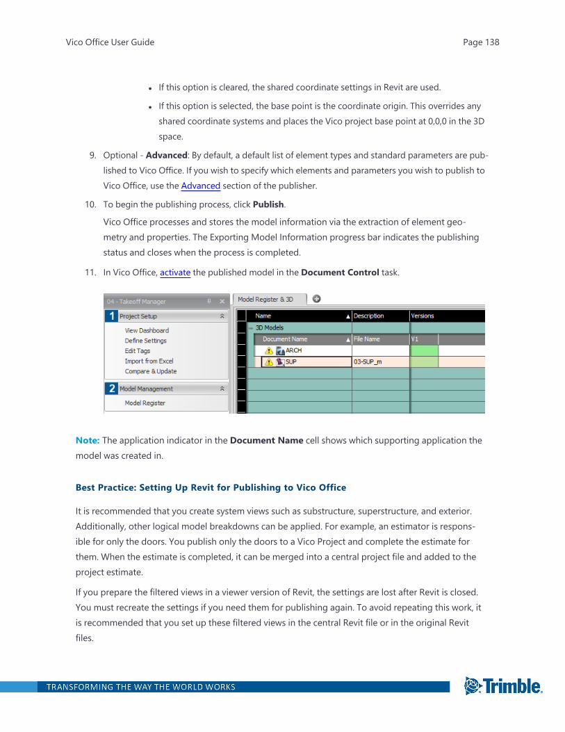
l If this option is cleared, the shared coordinate settings in Revit are used.
l If this option is selected, the base point is the coordinate origin. This overrides anyshared coordinate systems and places the Vico project base point at 0,0,0 in the 3Dspace.
9. Optional - Advanced: By default, a default list of element types and standard parameters are pub-lished to Vico Office. If you wish to specify which elements and parameters you wish to publish toVico Office, use the Advanced section of the publisher.
10. To begin the publishing process, click Publish.
Vico Office processes and stores the model information via the extraction of element geo-metry and properties. The Exporting Model Information progress bar indicates the publishingstatus and closes when the process is completed.
11. In Vico Office, activate the published model in the Document Control task.
Note: The application indicator in the Document Name cell shows which supporting application themodel was created in.
Best Practice: Setting Up Revit for Publishing to Vico Office
It is recommended that you create system views such as substructure, superstructure, and exterior.Additionally, other logical model breakdowns can be applied. For example, an estimator is respons-ible for only the doors. You publish only the doors to a Vico Project and complete the estimate forthem. When the estimate is completed, it can be merged into a central project file and added to theproject estimate.
If you prepare the filtered views in a viewer version of Revit, the settings are lost after Revit is closed.You must recreate the settings if you need them for publishing again. To avoid repeating this work, itis recommended that you set up these filtered views in the central Revit file or in the original Revitfiles.
Vico Office User Guide Page 138
Setting up Revit for publishing purposes can be time-consuming, and the same work is required foreach model release. To help ensure that the same filter settings are applied in the new model files, itis recommended that you document all the settings from the beginning.
For more information, refer to the PDF.
Troubleshooting:
With some Revit models, a dialog with an “Inconsistency detected” message appears during pub-lishing of new model versions. Click the “No” button to bypass this message and complete the activ-ation process. The new version will be published to Vico Office as intended.
Modeling Guidelines for Revit
The following document provides guidelines for creating 3D construction models, which allow usersto fully utilize the capabilities of Vico Office. The document is NOT a Revit user guide and it sharesbest practices for developing construction caliber quantities with a 3D model or with modifying datain Vico Office.
View as PDF
Supported Parameters and CAD Quantities - Revit
The following CAD quantities from your Revit model are published to Vico:
Note: Note: All custom numerical parameters will also be added as CAD quantities.
CAD Quantitiesl Actual Number of Risers
l Actual Number of Treads
l Actual Riser Height
l Actual Run Width
l Actual Tread Depth
l Area
l Count
l Cut
l Cut Length
l Cut Overall Length
l Depth
Vico Office User Guide Page 139
l Diameter
l Exterior Surface Area
l Fill
l Floor Area
l Floor Perimeter
l Floor Volume
l Gross Floor Area
l Gross Surface Area
l Gross Volume
l Head Height
l Heel Length
l Height
l Length
l Mass Interior Wall Area
l Net cut/fill
l Outside Diameter
l Overall Length
l Perimeter
l Projected Area
l Quantity
l Rough Height
l Rough Width
l Surface Area
l Thickness
l Toe Length
l Tread Thickness
l Volume
l Width
Using the Publish Data dialog when importing or publishing a model allows you to hide high polygonelements like bicycles, which do not serve any construction purposes, from the architectural model.
Vico Office User Guide Page 140
You can publish either filtered elements (visible in the current view) or all existing elements. Note thatall custom numerical parameters will be added to as CAD quantities.
Supported ElementsThe following table lists the supported categories of Revit elements.
l Areas
l Cable Tray
l Cable Tray Fitting
l Casework
l Ceilings
l Columns
l Communication Devices
l Conduit
l Conduit Fitting
l Cornices
l Curtain Systems
l Curtain Wall Mullions
l Curtain Wall Panels
l CurtaSystem
l Data Devices
l Doors
l Duct Accessory
l Duct Curves
l Duct Fitting
l Duct Terminal
l Electrical Equipment
l Electrical Fixtures
l Entourage
l Extrusions
l Fascia
l Fire Alarm Devices
Vico Office User Guide Page 141

l Fixtures
l Flex Duct Curves
l Flex Pipe Curves
l Floors
l Furniture
l Furniture Systems
l Generic Model
l Girder
l Gutter
l Horizontal Bracing
l Joist
l Lighting Devices
l Lighting Fixtures
l Lights
l Mass
l Massing
l Mechanical Equipment
l Nurse Call Devices
l Parking
l Pipe Accessory
l Pipe Curves
l Pipe Fitting
l Planting
l Plumbing Fixtures
l Purlin
l Railings
l Ramps
l Roads
l Roofs
l Roof Soffit
Vico Office User Guide Page 142
l Rooms
l SecurityDevices
l Sewer
l ShaftOpening
l Site
l Site Surface
l SpecialityEquipment
l Sprinklers
l Stairs
l StairsRailings
l StructConnections
l Structural Columns
l Structural Truss
l StructuralFoundations
l StructuralFraming
l StructuralFramingOther
l TelephoneDevices
l Topography
l Truss
l VerticalBracing
l Walls
l Windows
Standard Parametersl Assembly Code
l Assembly Description
l Catagory
l Comments
l Description
l Family
l Family and Type
Vico Office User Guide Page 143
l Keynote
l Mark
l Model
l Type
l Vico 01
l Vico 02
l Vico 03
Advanced ParametersThe list of advanced parameters are categorized into a Primary and Secondary group. Use the Displayfilters on the Publish Data (Advanced) dialog to view the parameters in each group. Note that theAdvanced Parameters section also includes user-defined (custom) parameters .
Primary
l Abbreviation
l Area Type
l Bar Diameter
l Bar Length
l Base Finish
l Base Level
l Base Offset
l Base Offset From Level
l Beam Type
l Bearing
l Bottom Elevation
l Building Story
l Ceiling Finish
l Circuit Number
l Condition Type
l Construction
l Construction Type
l Cost
Vico Office User Guide Page 144
l Diameter(Trade Size)
l Distance
l Electrical Data
l Elevation
l Elevation at Bottom
l Elevation Base
l Excluded
l Feed
l Finish
l Fire Rating
l Fixture Units
l Floor Finish
l Frame Material
l Frame Type
l Function
l Height Offset From Level
l IfcGUID
l Insulation Thickness
l Insulation Type
l Invert Elevation
l Landing Type
l Level
l Lining Thickness
l Lining Type
l Location
l Mains
l Mains Type
l Manufacturer
l Material
l Maximum Riser Height
Vico Office User Guide Page 145
l MEP System
l Minimum Tread Depth
l Modifications
l Name
l Naming Category
l Number
l Number of Elements
l Number of studs
l Occupancy
l Occupant
l Offset
l OmniClass Number
l OmniClass Title
l Operation
l Original Category
l Original Family
l Original Type
l Overall Width
l Panel
l Panel Name
l Phase Created
l Phase Demolished
l Pipe Size
l Pressure Class
l Profile
l Radius
l Railing Height
l Reference Level
l Reinforcement Volume
l Service Type
Vico Office User Guide Page 146
l Shape
l Shape is modified
l Slab
l Slope
l Space Type
l Spacing
l Standard
l Style
l Subcategory of Walls
l Summary
l System Abbreviation
l System Classification
l System Equipment
l System Name
l System Type
l Top Elevation
l Top Level
l Top Offset
l Type Comments
l Type IfcGUID
l Type Mark
l URL
l Usage
l Voltage
l Wall Finish
l Wattage
l Zone
Secondary
l A
l Absorptance
Vico Office User Guide Page 147
l Additional Flow
l Apparent Load
l Apparent Load Phase A
l Apparent Load Phase B
l Apparent Load Phase C
l Ballast Loss
l Beam Type (No Family Name)
l Bend Diameter
l Bend or Fitting
l Bend Radius
l Bend Radius Multiplier
l Bussing
l Camber Size
l Centerline Spacing
l Coefficient of Utilization
l Column Location Mark
l Connection Type
l Coverage
l Cross-Section Rotation
l CW Connection
l CWFU
l Default Thickness
l Deformation
l Department
l Drain
l E/W
l Efficacy
l Enclosure
l Engineering Type
l Equivalent Diameter
Vico Office User Guide Page 148
l Estimated Reinforcement Volume
l Fabric Sheet
l Flow State
l Fluid Density
l Fluid Temperature
l Fluid Type
l Fluid Viscosity
l Foundation Thickness
l Friction
l Friction Factor
l Graphical Appearance
l Ground Bus
l Hand Clearance
l Heat Transfer Coefficient (U)
l Hook At End
l Hook At Start
l HW Connection
l HWFU
l Hydraulic Diameter
l Illuminance
l Initial Color Temperature
l Inside Diameter
l K-Factor
l L/R
l Left Support Type
l Loss Coefficient
l Major Lap Splice Length
l Middle Support Type
l Minor Lap Splice Length
l Monolithic Thickness
Vico Office User Guide Page 149
l Multistory Top Level
l N/S
l Orifice
l Orifice Size
l Pressure Drop
l Relative Roughness
l Response
l Reynolds Number
l Right Support Type
l Roughness
l Run Height
l Run Type
l Schedule Mark
l Schedule/Type
l Scope Box
l Section
l Segment Description
l Shade Depth
l Sill Height
l Size Lock
l Solar Heat Gain Coefficient
l Static Pressure
l Story Above
l Structural
l Structural Depth
l Structural Depth On Landing
l Structural Depth On Run
l Structural Material
l Structural Usage
l Supply Fitting
Vico Office User Guide Page 150

l Supply Pipe
l Switch ID
l Target Percentage Glazing
l Target Sill Height
l Temperature Loss
l Temperature Rating
l Thermal mass
l Thermal Resistance (R)
l Total Bar Length
l Total Depth
l Total Light Loss Factor
l Total Sheet Mass
l Trap
l Tread/Stringer Offset
l Upper Limit
l Velocity
l Vent Connection
l Visual Light Transmittance
l Voltage Loss
l Waste Connection
l Wattage Comments
l WFU
Mapping Revit Categories to Vico Office ElementsFor a list of Vico Office elements that are mapped to Revit categories, see "Revit-VO element typemapping".
Publishing from Tekla
Tekla Structures, a Trimble product, is a building information modeling (BIM) software that is able tomodel structures that incorporate different kinds of building materials, including steel and concrete.When you publish from Tekla to Vico Office, you will need to login using your Trimble Identity (TID)
Vico Office User Guide Page 151

credentials so that Vico Office can identify which projects you can publish into based on your TID.You will not have to login to Vico Office as well because your TID is cached.
After you create a building information model in Tekla, you can easily publish it to Vico Office and useit in your Vico Office workflow.
EXPORTING TO IFC AND IMPORTING INTO VICO OFFICE
When you export from Tekla to the Industry Foundation Classes (IFC) file format , it is important thatyou set certain export options.
1. In Tekla, select Export > IFC.
2. In the Export to IFC dialog's Parameters tab, select these options:
l Export type: Coordination view 2.0. Tekla can export both polyline and beta geometry, butVico Office only supports polyline geometry. If you choose another export type, there will be nogeometry when you import the IFC into Vico Office.
l Export: All objects
1. In Vico Office, select Document Control > Import IFC.
TO PUBLISH TO VICO OFFICE
1. Open the BIM model that was created in a Tekla version that is compatible with your current ver-sion of Vico Office.
2. On the toolbar, click Publish to Vico.
3. In the Publish Data dialog, browse to the Vico Project Server in your network to which your pro-ject information will be published.
By default, this is set to the Vico Office database that is running on your computer. However,you can publish to a project that is stored in a database on another computer in the network.
4. In the Select Project list, expand the node to find your project. The Project list is sorted by pro-ject and then by existing models within each project.
5. To publish a new version of a previously published model, select the model. After it's published,the previous version is not replaced and a new version will appear in Vico Office's Model Man-ager.
—Or—
Vico Office User Guide Page 152

Click Create New Model. If this is the first model that will be published to Vico Office, only theCreate New Model option is available.
Note: Models that were created in other supporting application are not displayed in the pro-ject list.
6. Optionally clear the Publish selected objects only check box to publish all objects in the model.
7. Optional - Advanced: By default, a default list of element types and standard parameters are pub-lished to Vico Office. If you wish to specify which elements and parameters you wish to publish toVico Office, use the Advanced section of the publisher.
8. To begin the publishing process, click Publish.
Vico Office processes and stores the model information via the extraction of element geo-metry and properties. The Exporting Model Information progress bar indicates the publishingstatus and closes when the process is completed.
9. In Vico Office, activate the published model in the Document Control task.
Vico Office User Guide Page 153

Supported Parameters and CAD Quantities - Tekla
The following CAD quantities from your Tekla model are published to Vico:
CAD Quantitiesl AREA
l AREA_GROSS
l AREA_NET
l ASSEMBLY.AREA
l CAST_UNIT.AREA
l CAST_UNIT.AREA_FORM_BOTTOM
l CAST_UNIT.AREA_FORM_SIDE
l CAST_UNIT.AREA_FORM_TOP
l PROFILE.COVER_AREA
l PROFILE.CROSS_SECTION_AREA
l HEIGHT
l LENGTH
l LENGTH_GROSS
l LENGTH_NET
l CAST_UNIT.LENGTH
l CAST_UNIT.LENGTH_GROSS
l CAST_UNIT.LENGTH_NET
l PROFILE.DIAMETER
l PROFILE.DIAMETER_1
l PROFILE.DIAMETER_2
l PROFILE.HEIGHT
l PROFILE.WIDTH
l WIDTH
l INNER_DIAMETER
l PERIMETER
l PROFILE.PLATE_THICKNESS
l CAST_UNIT.VOLUME
Vico Office User Guide Page 154
l CAST_UNIT.VOLUME_ONLY_CONCRETE_PARTS
l VOLUME
l VOLUME_GROSS
l VOLUME_NET
l CAST_UNIT.WEIGHT
l CAST_UNIT.WEIGHT_GROSS
l CAST_UNIT.WEIGHT_NET
l CAST_UNIT.WEIGHT_ONLY_CONCRETE_PARTS
l PROFILE_WEIGHT
l PROFILE_WEIGHT_NET
l WEIGHT
l WEIGHT_GROSS
l WEIGHT_M
l WEIGHT_NET
l PROFILE.WEIGHT_PER_UNIT_LENGTH
Using the Publish Data dialog when publishing a model from Tekla, you can hide high polygon ele-ments like bicycles, which do not serve any construction purposes, from the architectural model. Thefollowing elements and their parameters can be published to Vico Office.
Supported Element TypesAll geometrical elements from Tekla are supported. Examples of these elements include:
l BEAM
l BOLT
l COLUMN
l PAD_FOOTING
l PANEL
l PLATE
l SLAB
l STRIP_FOOTING
Supported Standard Parameters
Vico Office User Guide Page 155
l ASSEMBLY.ASSEMBLY_NAME
l ASSEMBLY.ASSEMBLY_PREFIX
l ASSEMBLY_NAME
l CAST_UNIT_TYPE
l CLASS
l COMMENT
l FINISH
l MAINPART.NAME
l MATERIAL
l NAME
l PART_PREFIX
l PROFILE
Supported Advanced ParametersThe Advanced Parameters section consists of Primary, Secondary and UDA (User-Defined attributes).
Primary
l ACN
l ASSEMBLY_POS
l ASSEMBLY_POSITION_CODE
l ASSEMBLY.AREA
l ASSEMBLY.ASSEMBLY_POS
l ASSEMBLY.ASSEMBLY_POSITION_CODE
l ASSEMBLY.GUID
l ASSEMBLY.LOCATION_BREAKDOWN_STRUCTURE.LBS_FLOOR
l ASSEMBLY.LOCATION_BREAKDOWN_STRUCTURE.LBS_SECTION
l ASSEMBLY.LOT_NAME
l ASSEMBLY.MATERIAL_TYPE
l BOLT.MATERIAL
l BOLT.NAME
l BOTTOM_LEVEL
l BOTTOM_LEVEL_GLOBAL_UNFORMATTED (from Assembly)
Vico Office User Guide Page 156
l BOUNDING_BOX_MAX_Z
l CAST_UNIT_LENGTH_ONLY_CONCRETE_PARTS
l CAST_UNIT_NAME
l CAST_UNIT_POS
l CAST_UNIT_POSITION_CODE
l CAST_UNIT_PREFIX
l CAST_UNIT_REBAR_WEIGHT
l CAST_UNIT_WIDTH_ONLY_CONCRETE_PARTS
l CAST_UNIT.AREA
l CAST_UNIT.AREA_FORM_BOTTOM
l CAST_UNIT.AREA_FORM_SIDE
l CAST_UNIT.AREA_FORM_TOP
l CAST_UNIT.CAST_UNIT_NAME
l CAST_UNIT.CAST_UNIT_POS
l CAST_UNIT.CAST_UNIT_POSITION_CODE
l CAST_UNIT.CONTENTTYPE
l CAST_UNIT.GUID
l CAST_UNIT.LOCATION_BREAKDOWN_STRUCTURE.LBS_FLOOR
l CAST_UNIT.LOCATION_BREAKDOWN_STRUCTURE.LBS_SECTION
l COG_Y
l COG_Z
l CONCRETE_MIXTURE
l CONTENTTYPE
l FINISH
l GRADE
l GUID
l HEIGHT
l ID
l LOCATION_BREAKDOWN_STRUCTURE.LBS_FLOOR
l LOCATION_BREAKDOWN_STRUCTURE.LBS_SECTION
Vico Office User Guide Page 157

l LOT_NAME
l LOT_NUMBER
l MAINPART.NAME
l MAINPART.ACN
l MAINPART.MATERIAL
l MAINPART.MATERIAL_TYPE
l MAINPART.PROFILE
l MAINPART.TOP_LEVEL_UNFORMATTED
l MAINPART.WIDTH
l MATERIAL_TYPE
l MODEL_TOTAL
l NUMBER
l NUT.NAME
l OBJECT_TYPE
l PART_POS
l PART.CAST_UNIT.LOCATION_BREAKDOWN_STRUCTURE.LBS_FLOOR
l PART.CAST_UNIT.LOCATION_BREAKDOWN_STRUCTURE.LBS_SECTION
l PHASE
l PHASE.NAME
l PLANNED_END_D
l PLANNED_END_E
l PLANNED_END_F
l PLANNED_START_D
l PLANNED_START_E
l PLANNED_START_F
l POUR_NUMBER
l POUR_TYPE
l PREFIX
l PROFILE
l PROFILE_WEIGHT
Vico Office User Guide Page 158
l PROFILE_WEIGHT_NET
l PROFILE.PLATE_THICKNESS
l PROJECT.NAME
l START_X
l START_Y
l START_Z
l TOP_LEVEL
l TOP_LEVEL_GLOBAL
l TOP_LEVEL_GLOBAL_UNFORMATTED (from Assembly)
l TOP_LEVEL_UNFORMATTED
l TOP_LEVEL_UNFORMATTED
Secondary
l ACTUAL_END_D
l ACTUAL_END_E
l ACTUAL_END_F
l ACTUAL_START_D
l ACTUAL_START_E
l ACTUAL_START_F
l AREA
l AREA_FORM_BOTTOM
l AREA_FORM_SIDE
l AREA_FORM_TOP
l AREA_NGX
l AREA_NGY
l AREA_NGZ
l AREA_NX
l AREA_NY
l AREA_NZ
l AREA_PGX
l AREA_PGY
Vico Office User Guide Page 159

l AREA_PGZ
l AREA_PLAN
l AREA_PROJECTION_GXY_GROSS
l AREA_PROJECTION_GXY_NET
l AREA_PROJECTION_GXZ_GROSS
l AREA_PROJECTION_GXZ_NET
l AREA_PROJECTION_GYZ_GROSS
l AREA_PROJECTION_GYZ_NET
l AREA_PROJECTION_XY_GROSS
l AREA_PROJECTION_XY_NET
l AREA_PROJECTION_XZ_GROSS
l AREA_PROJECTION_XZ_NET
l AREA_PROJECTION_YZ_GROSS
l AREA_PROJECTION_YZ_NET
l AREA_PX
l AREA_PY
l AREA_PZ
l ASSEMBLY_BOTTOM_LEVEL
l ASSEMBLY_BOTTOM_LEVEL_GLOBAL
l ASSEMBLY_BOTTOM_LEVEL_UNFORMATTED
l ASSEMBLY_DEFAULT_PREFIX
l ASSEMBLY_PLWEIGHT
l ASSEMBLY_PREFIX
l ASSEMBLY_SERIAL_NUMBER
l ASSEMBLY_START_NUMBER
l ASSEMBLY_TOP_LEVEL
l ASSEMBLY_TOP_LEVEL_GLOBAL
l ASSEMBLY_TOP_LEVEL_GLOBAL_UNFORMATTED
l ASSEMBLY_TOP_LEVEL_UNFORMATTED
l ASSEMBLY.AREA_FORM_BOTTOM
Vico Office User Guide Page 160
l ASSEMBLY.AREA_FORM_SIDE
l ASSEMBLY.AREA_FORM_TOP
l ASSEMBLY.AREA_NGX
l ASSEMBLY.AREA_NGY
l ASSEMBLY.AREA_NGZ
l ASSEMBLY.AREA_NX
l ASSEMBLY.AREA_NY
l ASSEMBLY.AREA_NZ
l ASSEMBLY.AREA_PGX
l ASSEMBLY.AREA_PGY
l ASSEMBLY.AREA_PGZ
l ASSEMBLY.AREA_PLAN
l ASSEMBLY.AREA_PROJECTION_GXY_GROSS
l ASSEMBLY.AREA_PROJECTION_GXY_NET
l ASSEMBLY.AREA_PROJECTION_GXZ_GROSS
l ASSEMBLY.AREA_PROJECTION_GXZ_NET
l ASSEMBLY.AREA_PROJECTION_GYZ_GROSS
l ASSEMBLY.AREA_PROJECTION_GYZ_NET
l ASSEMBLY.AREA_PROJECTION_XY_GROSS
l ASSEMBLY.AREA_PROJECTION_XY_NET
l ASSEMBLY.AREA_PROJECTION_XZ_GROSS
l ASSEMBLY.AREA_PROJECTION_XZ_NET
l ASSEMBLY.AREA_PROJECTION_YZ_GROSS
l ASSEMBLY.AREA_PROJECTION_YZ_NET
l ASSEMBLY.AREA_PX
l ASSEMBLY.AREA_PY
l ASSEMBLY.AREA_PZ
l ASSEMBLY.ASSEMBLY_BOTTOM_LEVEL_GLOBAL
l ASSEMBLY.ASSEMBLY_BOTTOM_LEVEL_UNFORMATTED
l ASSEMBLY.ASSEMBLY_PLWEIGHT
Vico Office User Guide Page 161
l ASSEMBLY.ASSEMBLY_SERIAL_NUMBER
l ASSEMBLY.ASSEMBLY_START_NUMBER
l ASSEMBLY.ASSEMBLY_TOP_LEVEL
l ASSEMBLY.ASSEMBLY_TOP_LEVEL_GLOBAL
l ASSEMBLY.ASSEMBLY_TOP_LEVEL_GLOBAL_UNFORMATTED
l ASSEMBLY.ASSEMBLY_TOP_LEVEL_UNFORMATTED
l ASSEMBLY.BOTTOM_LEVEL_GLOBAL
l ASSEMBLY.BOTTOM_LEVEL_UNFORMATTED
l ASSEMBLY.COG_X
l ASSEMBLY.COG_Y
l ASSEMBLY.COG_Z
l ASSEMBLY.HEIGHT
l ASSEMBLY.HIERARCHY_LEVEL
l ASSEMBLY.ID
l ASSEMBLY.LENGTH
l ASSEMBLY.LENGTH_GROSS
l ASSEMBLY.LENGTH_NET
l ASSEMBLY.LOCATION_BREAKDOWN_STRUCTURE.GUID
l ASSEMBLY.LOCATION_BREAKDOWN_STRUCTURE.LBS_BUILDING
l ASSEMBLY.LOCATION_BREAKDOWN_STRUCTURE.LBS_FLOOR_ELEVATION
l ASSEMBLY.LOCATION_BREAKDOWN_STRUCTURE.LBS_HIERARCHY
l ASSEMBLY.LOCATION_BREAKDOWN_STRUCTURE.LBS_HIERARCHY_LEVEL_NUMBER
l ASSEMBLY.LOCATION_BREAKDOWN_STRUCTURE.LBS_PROJECT
l ASSEMBLY.LOCATION_BREAKDOWN_STRUCTURE.LBS_SITE
l ASSEMBLY.LOCATION_BREAKDOWN_STRUCTURE.NAME
l ASSEMBLY.LOT_NUMBER
l ASSEMBLY.MAINPART.AREA
l ASSEMBLY.MAINPART.AREA_GROSS
l ASSEMBLY.MAINPART.AREA_NET
l ASSEMBLY.MAINPART.AREA_NGX
Vico Office User Guide Page 162

l ASSEMBLY.MAINPART.AREA_NGY
l ASSEMBLY.MAINPART.AREA_NGZ
l ASSEMBLY.MAINPART.AREA_NX
l ASSEMBLY.MAINPART.AREA_NY
l ASSEMBLY.MAINPART.AREA_NZ
l ASSEMBLY.MAINPART.AREA_PER_TONS
l ASSEMBLY.MAINPART.AREA_PGX
l ASSEMBLY.MAINPART.AREA_PGY
l ASSEMBLY.MAINPART.AREA_PGZ
l ASSEMBLY.MAINPART.AREA_PLAN
l ASSEMBLY.MAINPART.AREA_PROJECTION_GXY_GROSS
l ASSEMBLY.MAINPART.AREA_PROJECTION_GXY_NET
l ASSEMBLY.MAINPART.AREA_PROJECTION_GXZ_GROSS
l ASSEMBLY.MAINPART.AREA_PROJECTION_GXZ_NET
l ASSEMBLY.MAINPART.AREA_PROJECTION_GYZ_GROSS
l ASSEMBLY.MAINPART.AREA_PROJECTION_GYZ_NET
l ASSEMBLY.MAINPART.AREA_PROJECTION_XY_GROSS
l ASSEMBLY.MAINPART.AREA_PROJECTION_XY_NET
l ASSEMBLY.MAINPART.AREA_PROJECTION_XZ_GROSS
l ASSEMBLY.MAINPART.AREA_PROJECTION_XZ_NET
l ASSEMBLY.MAINPART.AREA_PROJECTION_YZ_GROSS
l ASSEMBLY.MAINPART.AREA_PROJECTION_YZ_NET
l ASSEMBLY.MAINPART.AREA_PX
l ASSEMBLY.MAINPART.AREA_PY
l ASSEMBLY.MAINPART.AREA_PZ
l ASSEMBLY.MAINPART.ASSEMBLY_DEFAULT_PREFIX
l ASSEMBLY.MAINPART.ASSEMBLY_START_NUMBER
l ASSEMBLY.MAINPART.BOTTOM_LEVEL
l ASSEMBLY.MAINPART.BOTTOM_LEVEL_GLOBAL
l ASSEMBLY.MAINPART.BOTTOM_LEVEL_GLOBAL_UNFORMATTED
Vico Office User Guide Page 163
l ASSEMBLY.MAINPART.BOTTOM_LEVEL_UNFORMATTED
l ASSEMBLY.MAINPART.CLASS_ATTR
l ASSEMBLY.MAINPART.COG_X
l ASSEMBLY.MAINPART.COG_Y
l ASSEMBLY.MAINPART.COG_Z
l ASSEMBLY.MAINPART.CURVED_SEGMENTS
l ASSEMBLY.MAINPART.END_X
l ASSEMBLY.MAINPART.END_X_IN_WORK_PLANE
l ASSEMBLY.MAINPART.END_Y
l ASSEMBLY.MAINPART.END_Y_IN_WORK_PLANE
l ASSEMBLY.MAINPART.END_Z
l ASSEMBLY.MAINPART.END_Z_IN_WORK_PLANE
l ASSEMBLY.MAINPART.END1_ANGLE_Y
l ASSEMBLY.MAINPART.END1_ANGLE_Z
l ASSEMBLY.MAINPART.END1_CODE
l ASSEMBLY.MAINPART.END1_CUT_ANGLE_Y
l ASSEMBLY.MAINPART.END1_CUT_ANGLE_Z
l ASSEMBLY.MAINPART.END1_SKEW
l ASSEMBLY.MAINPART.END2_ANGLE_Y
l ASSEMBLY.MAINPART.END2_ANGLE_Z
l ASSEMBLY.MAINPART.END2_CODE
l ASSEMBLY.MAINPART.END2_CUT_ANGLE_Y
l ASSEMBLY.MAINPART.END2_CUT_ANGLE_Z
l ASSEMBLY.MAINPART.END2_SKEW
l ASSEMBLY.MAINPART.FINISH
l ASSEMBLY.MAINPART.FLANGE_LENGTH_B
l ASSEMBLY.MAINPART.FLANGE_LENGTH_U
l ASSEMBLY.MAINPART.HAS_CONNECTIONS
l ASSEMBLY.MAINPART.HAS_HOLES
l ASSEMBLY.MAINPART.HEIGHT
Vico Office User Guide Page 164
l ASSEMBLY.MAINPART.ID
l ASSEMBLY.MAINPART.IS_ITEM
l ASSEMBLY.MAINPART.IS_POLYBEAM
l ASSEMBLY.MAINPART.LENGTH
l ASSEMBLY.MAINPART.LENGTH_GROSS
l ASSEMBLY.MAINPART.LENGTH_NET
l ASSEMBLY.MAINPART.MATERIAL
l ASSEMBLY.MAINPART.MATERIAL.ACTIVE_DESIGN_CODE
l ASSEMBLY.MAINPART.MATERIAL.ALIAS_NAME1
l ASSEMBLY.MAINPART.MATERIAL.ALIAS_NAME2
l ASSEMBLY.MAINPART.MATERIAL.ALIAS_NAME3
l ASSEMBLY.MAINPART.MATERIAL.MODULUS_OF_ELASTICITY
l ASSEMBLY.MAINPART.MATERIAL.PLATE_DENSITY
l ASSEMBLY.MAINPART.MATERIAL.POISSONS_RATIO
l ASSEMBLY.MAINPART.MATERIAL.PROFILE_DENSITY
l ASSEMBLY.MAINPART.MATERIAL.THERMAL_DILATATION
l ASSEMBLY.MAINPART.MODEL_TOTAL
l ASSEMBLY.MAINPART.NAME
l ASSEMBLY.MAINPART.NUMBER_IN_PHASE(X)
l ASSEMBLY.MAINPART.NUMBER#1
l ASSEMBLY.MAINPART.OBJECT_DESCRIPTION
l ASSEMBLY.MAINPART.OBJECT_LOCKED
l ASSEMBLY.MAINPART.OBJECT_TYPE
l ASSEMBLY.MAINPART.OWNER
l ASSEMBLY.MAINPART.PART_POS
l ASSEMBLY.MAINPART.PART_PREFIX
l ASSEMBLY.MAINPART.PART_SERIAL_NUMBER
l ASSEMBLY.MAINPART.PART_START_NUMBER
l ASSEMBLY.MAINPART.PERIMETER
l ASSEMBLY.MAINPART.PHASE
Vico Office User Guide Page 165

l ASSEMBLY.MAINPART.PHASE.COMMENT
l ASSEMBLY.MAINPART.PHASE.NAME
l ASSEMBLY.MAINPART.PRELIM_MARK
l ASSEMBLY.MAINPART.PROFILE
l ASSEMBLY.MAINPART.PROFILE_TYPE
l ASSEMBLY.MAINPART.PROFILE_WEIGHT
l ASSEMBLY.MAINPART.PROFILE_WEIGHT_NET
l ASSEMBLY.MAINPART.PROFILE.ANGLE
l ASSEMBLY.MAINPART.PROFILE.CANTILEVER
l ASSEMBLY.MAINPART.PROFILE.COVER_AREA
l ASSEMBLY.MAINPART.PROFILE.CROSS_SECTION_AREA
l ASSEMBLY.MAINPART.PROFILE.DIAMETER
l ASSEMBLY.MAINPART.PROFILE.DIAMETER_1
l ASSEMBLY.MAINPART.PROFILE.DIAMETER_2
l ASSEMBLY.MAINPART.PROFILE.ECCENTRICITY_X
l ASSEMBLY.MAINPART.PROFILE.ECCENTRICITY_Y
l ASSEMBLY.MAINPART.PROFILE.EDGE_FOLD
l ASSEMBLY.MAINPART.PROFILE.EDGE_FOLD_1
l ASSEMBLY.MAINPART.PROFILE.EDGE_FOLD_2
l ASSEMBLY.MAINPART.PROFILE.FLANGE_SLOPE_RATIO
l ASSEMBLY.MAINPART.PROFILE.FLANGE_THICKNESS
l ASSEMBLY.MAINPART.PROFILE.FLANGE_THICKNESS_1
l ASSEMBLY.MAINPART.PROFILE.FLANGE_THICKNESS_2
l ASSEMBLY.MAINPART.PROFILE.FLANGE_THICKNESS_B
l ASSEMBLY.MAINPART.PROFILE.FLANGE_THICKNESS_U
l ASSEMBLY.MAINPART.PROFILE.FLANGE_WIDTH
l ASSEMBLY.MAINPART.PROFILE.FLANGE_WIDTH_1
l ASSEMBLY.MAINPART.PROFILE.FLANGE_WIDTH_2
l ASSEMBLY.MAINPART.PROFILE.FLANGE_WIDTH_B
l ASSEMBLY.MAINPART.PROFILE.FLANGE_WIDTH_U
Vico Office User Guide Page 166
l ASSEMBLY.MAINPART.PROFILE.HEIGHT
l ASSEMBLY.MAINPART.PROFILE.HEIGHT_1
l ASSEMBLY.MAINPART.PROFILE.HEIGHT_2
l ASSEMBLY.MAINPART.PROFILE.HEIGHT_3
l ASSEMBLY.MAINPART.PROFILE.HEIGHT_4
l ASSEMBLY.MAINPART.PROFILE.MAJOR_AXIS_LENGTH_1
l ASSEMBLY.MAINPART.PROFILE.MAJOR_AXIS_LENGTH_2
l ASSEMBLY.MAINPART.PROFILE.MINOR_AXIS_LENGTH_1
l ASSEMBLY.MAINPART.PROFILE.MINOR_AXIS_LENGTH_2
l ASSEMBLY.MAINPART.PROFILE.MOMENT_OF_INERTIA_X
l ASSEMBLY.MAINPART.PROFILE.MOMENT_OF_INERTIA_Y
l ASSEMBLY.MAINPART.PROFILE.NEUTRAL_AXIS_LOCATION_ELASTIC_X
l ASSEMBLY.MAINPART.PROFILE.NEUTRAL_AXIS_LOCATION_ELASTIC_Y
l ASSEMBLY.MAINPART.PROFILE.NEUTRAL_AXIS_LOCATION_PLASTIC_X
l ASSEMBLY.MAINPART.PROFILE.NEUTRAL_AXIS_LOCATION_PLASTIC_Y
l ASSEMBLY.MAINPART.PROFILE.NORMALIZED_WARPING_CONSTANT
l ASSEMBLY.MAINPART.PROFILE.PLASTIC_MODULUS_X
l ASSEMBLY.MAINPART.PROFILE.PLASTIC_MODULUS_Y
l ASSEMBLY.MAINPART.PROFILE.PLATE_THICKNESS
l ASSEMBLY.MAINPART.PROFILE.POLAR_RADIUS_OF_GYRATION
l ASSEMBLY.MAINPART.PROFILE.RADIUS_OF_GYRATION_X
l ASSEMBLY.MAINPART.PROFILE.RADIUS_OF_GYRATION_Y
l ASSEMBLY.MAINPART.PROFILE.ROUNDING_RADIUS
l ASSEMBLY.MAINPART.PROFILE.ROUNDING_RADIUS_1
l ASSEMBLY.MAINPART.PROFILE.ROUNDING_RADIUS_2
l ASSEMBLY.MAINPART.PROFILE.SECTION_MODULUS_X
l ASSEMBLY.MAINPART.PROFILE.SECTION_MODULUS_Y
l ASSEMBLY.MAINPART.PROFILE.SHEAR_CENTER_LOCATION
l ASSEMBLY.MAINPART.PROFILE.SORT_OF_E_x_Cw_PER_G_x_J
l ASSEMBLY.MAINPART.PROFILE.STATICAL_MOMENT_Qf
Vico Office User Guide Page 167
l ASSEMBLY.MAINPART.PROFILE.STATICAL_MOMENT_Qw
l ASSEMBLY.MAINPART.PROFILE.STIFFENER_DIMENSION
l ASSEMBLY.MAINPART.PROFILE.STIFFENER_DIMENSION_1
l ASSEMBLY.MAINPART.PROFILE.STIFFENER_DIMENSION_2
l ASSEMBLY.MAINPART.PROFILE.STIFFENER_DIMENSION_3
l ASSEMBLY.MAINPART.PROFILE.SUBTYPE
l ASSEMBLY.MAINPART.PROFILE.TANGENT_OF_PRINCIPAL_AXIS_ANGLE
l ASSEMBLY.MAINPART.PROFILE.TORSIONAL_CONSTANT
l ASSEMBLY.MAINPART.PROFILE.WARPING_CONSTANT
l ASSEMBLY.MAINPART.PROFILE.WARPING_STATICAL_MOMENT
l ASSEMBLY.MAINPART.PROFILE.WEB_THICKNESS
l ASSEMBLY.MAINPART.PROFILE.WEB_THICKNESS_1
l ASSEMBLY.MAINPART.PROFILE.WEB_THICKNESS_2
l ASSEMBLY.MAINPART.PROFILE.WEIGHT_PER_UNIT_LENGTH
l ASSEMBLY.MAINPART.PROFILE.WIDTH
l ASSEMBLY.MAINPART.PROFILE.WIDTH_1
l ASSEMBLY.MAINPART.PROFILE.WIDTH_2
l ASSEMBLY.MAINPART.RADIUS
l ASSEMBLY.MAINPART.SAWING_ITEM
l ASSEMBLY.MAINPART.START_X
l ASSEMBLY.MAINPART.START_X_IN_WORK_PLANE
l ASSEMBLY.MAINPART.START_Y
l ASSEMBLY.MAINPART.START_Y_IN_WORK_PLANE
l ASSEMBLY.MAINPART.START_Z
l ASSEMBLY.MAINPART.START_Z_IN_WORK_PLANE
l ASSEMBLY.MAINPART.SUPPLEMENT_PART_WEIGHT
l ASSEMBLY.MAINPART.TOP_LEVEL
l ASSEMBLY.MAINPART.TOP_LEVEL_GLOBAL
l ASSEMBLY.MAINPART.TOP_LEVEL_GLOBAL_UNFORMATTED
l ASSEMBLY.MAINPART.TOP_LEVEL_UNFORMATTED
Vico Office User Guide Page 168

l ASSEMBLY.MAINPART.VOLUME
l ASSEMBLY.MAINPART.VOLUME_GROSS
l ASSEMBLY.MAINPART.VOLUME_NET
l ASSEMBLY.MAINPART.WEB_LENGTH
l ASSEMBLY.MAINPART.WEIGHT
l ASSEMBLY.MAINPART.WEIGHT_GROSS
l ASSEMBLY.MAINPART.WEIGHT_M
l ASSEMBLY.MAINPART.WEIGHT_NET
l ASSEMBLY.MAINPART.WIDTH
l ASSEMBLY.MODEL_TOTAL
l ASSEMBLY.NUMBER_IN_PHASE(X)
l ASSEMBLY.NUMBER#1
l ASSEMBLY.PHASE
l ASSEMBLY.PHASE.COMMENT
l ASSEMBLY.PHASE.NAME
l ASSEMBLY.PRELIM_ASSEM_MARK
l ASSEMBLY.SUPPLEMENT_PART_WEIGHT
l ASSEMBLY.TOP_LEVEL
l ASSEMBLY.TOP_LEVEL_GLOBAL
l ASSEMBLY.TOP_LEVEL_GLOBAL_UNFORMATTED
l ASSEMBLY.TOP_LEVEL_UNFORMATTED
l ASSEMBLY.VOLUME
l ASSEMBLY.WEIGHT
l ASSEMBLY.WEIGHT_GROSS
l ASSEMBLY.WEIGHT_NET
l ASSEMBLY.WIDTH
l BOTTOM_LEVEL_GLOBAL
l BOTTOM_LEVEL_UNFORMATTED
l BOUNDING_BOX_MAX_X
l BOUNDING_BOX_MAX_Y
Vico Office User Guide Page 169

l BOUNDING_BOX_MIN_X
l BOUNDING_BOX_MIN_Y
l BOUNDING_BOX_MIN_Z
l CAST_UNIT.AREA_NGX
l CAST_UNIT.AREA_NGY
l CAST_UNIT.AREA_NGZ
l CAST_UNIT.AREA_NX
l CAST_UNIT.AREA_NY
l CAST_UNIT.AREA_NZ
l CAST_UNIT.AREA_PGX
l CAST_UNIT.AREA_PGY
l CAST_UNIT.AREA_PGZ
l CAST_UNIT.AREA_PLAN
l CAST_UNIT.AREA_PROJECTION_GXY_GROSS
l CAST_UNIT.AREA_PROJECTION_GXY_NET
l CAST_UNIT.AREA_PROJECTION_GXZ_GROSS
l CAST_UNIT.AREA_PROJECTION_GXZ_NET
l CAST_UNIT.AREA_PROJECTION_GYZ_GROSS
l CAST_UNIT.AREA_PROJECTION_GYZ_NET
l CAST_UNIT.AREA_PROJECTION_XY_GROSS
l CAST_UNIT.AREA_PROJECTION_XY_NET
l CAST_UNIT.AREA_PROJECTION_XZ_GROSS
l CAST_UNIT.AREA_PROJECTION_XZ_NET
l CAST_UNIT.AREA_PROJECTION_YZ_GROSS
l CAST_UNIT.AREA_PROJECTION_YZ_NET
l CAST_UNIT.AREA_PX
l CAST_UNIT.AREA_PY
l CAST_UNIT.AREA_PZ
l CAST_UNIT.BOTTOM_LEVEL_GLOBAL
l CAST_UNIT.BOTTOM_LEVEL_GLOBAL_UNFORMATTED
Vico Office User Guide Page 170
l CAST_UNIT.BOTTOM_LEVEL_UNFORMATTED
l CAST_UNIT.CAST_UNIT_HEIGHT_ONLY_CONCRETE_PARTS
l CAST_UNIT.CAST_UNIT_HEIGHT_ONLY_PARTS
l CAST_UNIT.CAST_UNIT_HEIGHT_TOTAL
l CAST_UNIT.CAST_UNIT_LENGTH_ONLY_PARTS
l CAST_UNIT.CAST_UNIT_LENGTH_TOTAL
l CAST_UNIT.CAST_UNIT_SERIAL_NUMBER
l CAST_UNIT.CAST_UNIT_VERTICAL_POSITION_CODE
l CAST_UNIT.CAST_UNIT_WIDTH_ONLY_PARTS
l CAST_UNIT.CAST_UNIT_WIDTH_TOTAL
l CAST_UNIT.COG_X
l CAST_UNIT.COG_Y
l CAST_UNIT.COG_Z
l CAST_UNIT.ID
l CAST_UNIT.LENGTH
l CAST_UNIT.LENGTH_GROSS
l CAST_UNIT.LENGTH_NET
l CAST_UNIT.LOCATION_BREAKDOWN_STRUCTURE.GUID
l CAST_UNIT.LOCATION_BREAKDOWN_STRUCTURE.LBS_BUILDING
l CAST_UNIT.LOCATION_BREAKDOWN_STRUCTURE.LBS_FLOOR_ELEVATION
l CAST_UNIT.LOCATION_BREAKDOWN_STRUCTURE.LBS_HIERARCHY
l CAST_UNIT.LOCATION_BREAKDOWN_STRUCTURE.LBS_HIERARCHY_LEVEL_NUMBER
l CAST_UNIT.LOCATION_BREAKDOWN_STRUCTURE.LBS_PROJECT
l CAST_UNIT.LOCATION_BREAKDOWN_STRUCTURE.LBS_SITE
l CAST_UNIT.LOCATION_BREAKDOWN_STRUCTURE.NAME
l CAST_UNIT.LOT_NUMBER
l CAST_UNIT.MAINPART.ACN
l CAST_UNIT.MAINPART.AREA
l CAST_UNIT.MAINPART.AREA_GROSS
l CAST_UNIT.MAINPART.AREA_NET
Vico Office User Guide Page 171
l CAST_UNIT.MAINPART.AREA_NGX
l CAST_UNIT.MAINPART.AREA_NGY
l CAST_UNIT.MAINPART.AREA_NGZ
l CAST_UNIT.MAINPART.AREA_NX
l CAST_UNIT.MAINPART.AREA_NY
l CAST_UNIT.MAINPART.AREA_NZ
l CAST_UNIT.MAINPART.AREA_PER_TONS
l CAST_UNIT.MAINPART.AREA_PGX
l CAST_UNIT.MAINPART.AREA_PGY
l CAST_UNIT.MAINPART.AREA_PGZ
l CAST_UNIT.MAINPART.AREA_PLAN
l CAST_UNIT.MAINPART.AREA_PROJECTION_GXY_GROSS
l CAST_UNIT.MAINPART.AREA_PROJECTION_GXY_NET
l CAST_UNIT.MAINPART.AREA_PROJECTION_GXZ_GROSS
l CAST_UNIT.MAINPART.AREA_PROJECTION_GXZ_NET
l CAST_UNIT.MAINPART.AREA_PROJECTION_GYZ_GROSS
l CAST_UNIT.MAINPART.AREA_PROJECTION_GYZ_NET
l CAST_UNIT.MAINPART.AREA_PROJECTION_XY_GROSS
l CAST_UNIT.MAINPART.AREA_PROJECTION_XY_NET
l CAST_UNIT.MAINPART.AREA_PROJECTION_XZ_GROSS
l CAST_UNIT.MAINPART.AREA_PROJECTION_XZ_NET
l CAST_UNIT.MAINPART.AREA_PROJECTION_YZ_GROSS
l CAST_UNIT.MAINPART.AREA_PROJECTION_YZ_NET
l CAST_UNIT.MAINPART.AREA_PX
l CAST_UNIT.MAINPART.AREA_PY
l CAST_UNIT.MAINPART.AREA_PZ
l CAST_UNIT.MAINPART.ASSEMBLY_DEFAULT_PREFIX
l CAST_UNIT.MAINPART.BOTTOM_LEVEL
l CAST_UNIT.MAINPART.BOTTOM_LEVEL_GLOBAL
l CAST_UNIT.MAINPART.BOTTOM_LEVEL_GLOBAL_UNFORMATTED
Vico Office User Guide Page 172
l CAST_UNIT.MAINPART.BOTTOM_LEVEL_UNFORMATTED
l CAST_UNIT.MAINPART.CLASS_ATTR
l CAST_UNIT.MAINPART.COG_X
l CAST_UNIT.MAINPART.COG_Y
l CAST_UNIT.MAINPART.COG_Z
l CAST_UNIT.MAINPART.END_X
l CAST_UNIT.MAINPART.END_X_IN_WORK_PLANE
l CAST_UNIT.MAINPART.END_Y
l CAST_UNIT.MAINPART.END_Y_IN_WORK_PLANE
l CAST_UNIT.MAINPART.END_Z
l CAST_UNIT.MAINPART.END_Z_IN_WORK_PLANE
l CAST_UNIT.MAINPART.END1_ANGLE_Y
l CAST_UNIT.MAINPART.END1_ANGLE_Z
l CAST_UNIT.MAINPART.END1_CODE
l CAST_UNIT.MAINPART.END1_CUT_ANGLE_Y
l CAST_UNIT.MAINPART.END1_CUT_ANGLE_Z
l CAST_UNIT.MAINPART.END1_SKEW
l CAST_UNIT.MAINPART.END2_ANGLE_Y
l CAST_UNIT.MAINPART.END2_ANGLE_Z
l CAST_UNIT.MAINPART.END2_CODE
l CAST_UNIT.MAINPART.END2_CUT_ANGLE_Y
l CAST_UNIT.MAINPART.END2_CUT_ANGLE_Z
l CAST_UNIT.MAINPART.END2_SKEW
l CAST_UNIT.MAINPART.FINISH
l CAST_UNIT.MAINPART.FLANGE_LENGTH_B
l CAST_UNIT.MAINPART.FLANGE_LENGTH_U
l CAST_UNIT.MAINPART.HAS_CONNECTIONS
l CAST_UNIT.MAINPART.HAS_HOLES
l CAST_UNIT.MAINPART.HEIGHT
l CAST_UNIT.MAINPART.ID
Vico Office User Guide Page 173

l CAST_UNIT.MAINPART.IS_ITEM
l CAST_UNIT.MAINPART.IS_POLYBEAM
l CAST_UNIT.MAINPART.LENGTH
l CAST_UNIT.MAINPART.LENGTH_GROSS
l CAST_UNIT.MAINPART.LENGTH_NET
l CAST_UNIT.MAINPART.MATERIAL
l CAST_UNIT.MAINPART.MATERIAL.ACTIVE_DESIGN_CODE
l CAST_UNIT.MAINPART.MODEL_TOTAL
l CAST_UNIT.MAINPART.NAME
l CAST_UNIT.MAINPART.OBJECT_DESCRIPTION
l CAST_UNIT.MAINPART.OBJECT_LOCKED
l CAST_UNIT.MAINPART.OBJECT_TYPE
l CAST_UNIT.MAINPART.OWNER
l CAST_UNIT.MAINPART.PART_POS
l CAST_UNIT.MAINPART.PART_PREFIX
l CAST_UNIT.MAINPART.PART_SERIAL_NUMBER
l CAST_UNIT.MAINPART.PART_START_NUMBER
l CAST_UNIT.MAINPART.PHASE
l CAST_UNIT.MAINPART.PRELIM_MARK
l CAST_UNIT.MAINPART.PROFILE
l CAST_UNIT.MAINPART.PROFILE_TYPE
l CAST_UNIT.MAINPART.PROFILE_WEIGHT
l CAST_UNIT.MAINPART.PROFILE_WEIGHT_NET
l CAST_UNIT.MAINPART.START_X
l CAST_UNIT.MAINPART.START_X_IN_WORK_PLANE
l CAST_UNIT.MAINPART.START_Y
l CAST_UNIT.MAINPART.START_Y_IN_WORK_PLANE
l CAST_UNIT.MAINPART.START_Z
l CAST_UNIT.MAINPART.START_Z_IN_WORK_PLANE
l CAST_UNIT.MAINPART.SUPPLEMENT_PART_WEIGHT
Vico Office User Guide Page 174
l CAST_UNIT.MAINPART.TOP_LEVEL
l CAST_UNIT.MAINPART.TOP_LEVEL_GLOBAL
l CAST_UNIT.MAINPART.TOP_LEVEL_GLOBAL_UNFORMATTED
l CAST_UNIT.MAINPART.TOP_LEVEL_UNFORMATTED
l CAST_UNIT.MAINPART.VOLUME
l CAST_UNIT.MAINPART.VOLUME_GROSS
l CAST_UNIT.MAINPART.VOLUME_NET
l CAST_UNIT.MAINPART.WEB_LENGTH
l CAST_UNIT.MAINPART.WEIGHT
l CAST_UNIT.MAINPART.WEIGHT_GROSS
l CAST_UNIT.MAINPART.WEIGHT_M
l CAST_UNIT.MAINPART.WEIGHT_NET
l CAST_UNIT.MAINPART.WIDTH
l CAST_UNIT.MATERIAL
l CAST_UNIT.MODEL_TOTAL
l CAST_UNIT.OBJECT_DESCRIPTION
l CAST_UNIT.OBJECT_LOCKED
l CAST_UNIT.OBJECT_TYPE
l CAST_UNIT.OWNER
l CAST_UNIT.PHASE
l CAST_UNIT.TOP_LEVEL
l CAST_UNIT.TOP_LEVEL_GLOBAL
l CAST_UNIT.TOP_LEVEL_GLOBAL_UNFORMATTED
l CAST_UNIT.TOP_LEVEL_UNFORMATTED
l CAST_UNIT.VOLUME
l CAST_UNIT.VOLUME_NET_ONLY_CONCRETE_PARTS
l CAST_UNIT.VOLUME_ONLY_CONCRETE_PARTS
l CAST_UNIT.WEIGHT
l CAST_UNIT.WEIGHT_GROSS
l CAST_UNIT.WEIGHT_NET
Vico Office User Guide Page 175
l CAST_UNIT.WEIGHT_NET_ONLY_CONCRETE_PARTS
l CAST_UNIT.WEIGHT_ONLY_CONCRETE_PARTS
l CASTUNIT.MAINPART.PROFILE.ANGLE
l CASTUNIT.MAINPART.PROFILE.CANTILEVER
l CASTUNIT.MAINPART.PROFILE.COVER_AREA
l CASTUNIT.MAINPART.PROFILE.CROSS_SECTION_AREA
l CASTUNIT.MAINPART.PROFILE.DIAMETER
l CASTUNIT.MAINPART.PROFILE.DIAMETER_1
l CASTUNIT.MAINPART.PROFILE.DIAMETER_2
l CASTUNIT.MAINPART.PROFILE.ECCENTRICITY_X
l CASTUNIT.MAINPART.PROFILE.ECCENTRICITY_Y
l CASTUNIT.MAINPART.PROFILE.EDGE_FOLD
l CASTUNIT.MAINPART.PROFILE.EDGE_FOLD_1
l CASTUNIT.MAINPART.PROFILE.EDGE_FOLD_2
l CASTUNIT.MAINPART.PROFILE.FLANGE_SLOPE_RATIO
l CASTUNIT.MAINPART.PROFILE.FLANGE_THICKNESS
l CASTUNIT.MAINPART.PROFILE.FLANGE_THICKNESS_1
l CASTUNIT.MAINPART.PROFILE.FLANGE_THICKNESS_2
l CASTUNIT.MAINPART.PROFILE.FLANGE_THICKNESS_B
l CASTUNIT.MAINPART.PROFILE.FLANGE_THICKNESS_U
l CASTUNIT.MAINPART.PROFILE.FLANGE_WIDTH
l CASTUNIT.MAINPART.PROFILE.FLANGE_WIDTH_1
l CASTUNIT.MAINPART.PROFILE.FLANGE_WIDTH_2
l CASTUNIT.MAINPART.PROFILE.FLANGE_WIDTH_B
l CASTUNIT.MAINPART.PROFILE.FLANGE_WIDTH_U
l CASTUNIT.MAINPART.PROFILE.HEIGHT
l CASTUNIT.MAINPART.PROFILE.HEIGHT_1
l CASTUNIT.MAINPART.PROFILE.HEIGHT_2
l CASTUNIT.MAINPART.PROFILE.HEIGHT_3
l CASTUNIT.MAINPART.PROFILE.HEIGHT_4
Vico Office User Guide Page 176
l CASTUNIT.MAINPART.PROFILE.MAJOR_AXIS_LENGTH_1
l CASTUNIT.MAINPART.PROFILE.MAJOR_AXIS_LENGTH_2
l CASTUNIT.MAINPART.PROFILE.MINOR_AXIS_LENGTH_1
l CASTUNIT.MAINPART.PROFILE.MINOR_AXIS_LENGTH_2
l CASTUNIT.MAINPART.PROFILE.MOMENT_OF_INERTIA_X
l CASTUNIT.MAINPART.PROFILE.MOMENT_OF_INERTIA_Y
l CASTUNIT.MAINPART.PROFILE.NEUTRAL_AXIS_LOCATION_ELASTIC_X
l CASTUNIT.MAINPART.PROFILE.NEUTRAL_AXIS_LOCATION_ELASTIC_Y
l CASTUNIT.MAINPART.PROFILE.NEUTRAL_AXIS_LOCATION_PLASTIC_X
l CASTUNIT.MAINPART.PROFILE.NEUTRAL_AXIS_LOCATION_PLASTIC_Y
l CASTUNIT.MAINPART.PROFILE.NORMALIZED_WARPING_CONSTANT
l CASTUNIT.MAINPART.PROFILE.PLASTIC_MODULUS_X
l CASTUNIT.MAINPART.PROFILE.PLASTIC_MODULUS_Y
l CASTUNIT.MAINPART.PROFILE.PLATE_THICKNESS
l CASTUNIT.MAINPART.PROFILE.POLAR_RADIUS_OF_GYRATION
l CASTUNIT.MAINPART.PROFILE.RADIUS_OF_GYRATION_X
l CASTUNIT.MAINPART.PROFILE.RADIUS_OF_GYRATION_Y
l CASTUNIT.MAINPART.PROFILE.ROUNDING_RADIUS
l CASTUNIT.MAINPART.PROFILE.ROUNDING_RADIUS_1
l CASTUNIT.MAINPART.PROFILE.ROUNDING_RADIUS_2
l CASTUNIT.MAINPART.PROFILE.SECTION_MODULUS_X
l CASTUNIT.MAINPART.PROFILE.SECTION_MODULUS_Y
l CASTUNIT.MAINPART.PROFILE.SHEAR_CENTER_LOCATION
l CASTUNIT.MAINPART.PROFILE.SORT_OF_E_x_Cw_PER_G_x_J
l CASTUNIT.MAINPART.PROFILE.STATICAL_MOMENT_Qf
l CASTUNIT.MAINPART.PROFILE.STATICAL_MOMENT_Qw
l CASTUNIT.MAINPART.PROFILE.STIFFENER_DIMENSION
l CASTUNIT.MAINPART.PROFILE.STIFFENER_DIMENSION_1
l CASTUNIT.MAINPART.PROFILE.STIFFENER_DIMENSION_2
l CASTUNIT.MAINPART.PROFILE.STIFFENER_DIMENSION_3
Vico Office User Guide Page 177

l CASTUNIT.MAINPART.PROFILE.SUBTYPE
l CASTUNIT.MAINPART.PROFILE.TANGENT_OF_PRINCIPAL_AXIS_ANGLE
l CASTUNIT.MAINPART.PROFILE.TORSIONAL_CONSTANT
l CASTUNIT.MAINPART.PROFILE.WARPING_CONSTANT
l CASTUNIT.MAINPART.PROFILE.WARPING_STATICAL_MOMENT
l CASTUNIT.MAINPART.PROFILE.WEB_THICKNESS
l CASTUNIT.MAINPART.PROFILE.WEB_THICKNESS_1
l CASTUNIT.MAINPART.PROFILE.WEB_THICKNESS_2
l CASTUNIT.MAINPART.PROFILE.WEIGHT_PER_UNIT_LENGTH
l CASTUNIT.MAINPART.PROFILE.WIDTH
l CASTUNIT.MAINPART.PROFILE.WIDTH_1
l CASTUNIT.MAINPART.PROFILE.WIDTH_2
l CASTUNIT.MAINPART.SAWING_ITEM
l CIP_STATUS
l COG_X
l COG_Y
l COG_Z
l COLOR
l CURRENT_PHASE
l CURVED_SEGMENTS
l DATE
l DELIVERY_NUMBER
l DESIGN_ASSIGNED_TO
l DESIGN_CHECK_DATE
l DESIGN_CHECKED_BY
l DESIGN_CODE
l DESIGN_COMMENT
l DIMENSION_A
l DIMENSION_B
l END_X
Vico Office User Guide Page 178
l END_X_IN_WORK_PLANE
l END_Y
l END_Y_IN_WORK_PLANE
l END_Z
l END_Z_IN_WORK_PLANE
l END1_ANGLE_Y
l END1_ANGLE_Z
l END1_CODE
l END1_CUT_ANGLE_Y
l END1_CUT_ANGLE_Z
l END1_SKEW
l END2_ANGLE_Y
l END2_ANGLE_Z
l END2_CODE
l END2_CUT_ANGLE_Y
l END2_CUT_ANGLE_Z
l END2_SKEW
l ERECTION_CODE
l ERECTION_COMMENT
l ERECTION_STATUS
l FABRICATION_CODE
l FABRICATION_STATUS
l HAS_CONNECTIONS
l HAS_HOLES
l HIERARCHY_LEVEL
l HISTORY.OWNER
l IS_ITEM
l IS_POLYBEAM
l LENGTH
l LENGTH_GROSS
Vico Office User Guide Page 179
l LENGTH_NET
l LOCATION_BREAKDOWN_STRUCTURE.GUID
l LOCATION_BREAKDOWN_STRUCTURE.LBS_BUILDING
l LOCATION_BREAKDOWN_STRUCTURE.LBS_FLOOR_ELEVATION
l LOCATION_BREAKDOWN_STRUCTURE.LBS_HIERARCHY
l LOCATION_BREAKDOWN_STRUCTURE.LBS_HIERARCHY_LEVEL_NUMBER
l LOCATION_BREAKDOWN_STRUCTURE.LBS_PROJECT
l LOCATION_BREAKDOWN_STRUCTURE.LBS_SITE
l LOCATION_BREAKDOWN_STRUCTURE.NAME
l LOT_NUMBER
l MAIN_PART
l MAINPART.ACN
l MAINPART.AREA
l MAINPART.AREA_GROSS
l MAINPART.AREA_NET
l MAINPART.AREA_NGX
l MAINPART.AREA_NGY
l MAINPART.AREA_NGZ
l MAINPART.AREA_NX
l MAINPART.AREA_NY
l MAINPART.AREA_NZ
l MAINPART.AREA_PER_TONS
l MAINPART.AREA_PGX
l MAINPART.AREA_PGY
l MAINPART.AREA_PGZ
l MAINPART.AREA_PLAN
l MAINPART.AREA_PROJECTION_GXY_GROSS
l MAINPART.AREA_PROJECTION_GXY_NET
l MAINPART.AREA_PROJECTION_GXZ_GROSS
l MAINPART.AREA_PROJECTION_GXZ_NET
Vico Office User Guide Page 180
l MAINPART.AREA_PROJECTION_GYZ_GROSS
l MAINPART.AREA_PROJECTION_GYZ_NET
l MAINPART.AREA_PROJECTION_XY_GROSS
l MAINPART.AREA_PROJECTION_XY_NET
l MAINPART.AREA_PROJECTION_XZ_GROSS
l MAINPART.AREA_PROJECTION_XZ_NET
l MAINPART.AREA_PROJECTION_YZ_GROSS
l MAINPART.AREA_PROJECTION_YZ_NET
l MAINPART.AREA_PX
l MAINPART.AREA_PY
l MAINPART.AREA_PZ
l MAINPART.ASSEMBLY_DEFAULT_PREFIX
l MAINPART.ASSEMBLY_START_NUMBER
l MAINPART.BOTTOM_LEVEL
l MAINPART.BOTTOM_LEVEL_GLOBAL
l MAINPART.BOTTOM_LEVEL_GLOBAL_UNFORMATTED
l MAINPART.BOTTOM_LEVEL_UNFORMATTED
l MAINPART.CLASS_ATTR
l MAINPART.COG_X
l MAINPART.COG_Y
l MAINPART.COG_Z
l MAINPART.CURVED_SEGMENTS
l MAINPART.END_X
l MAINPART.END_X_IN_WORK_PLANE
l MAINPART.END_Y
l MAINPART.END_Y_IN_WORK_PLANE
l MAINPART.END_Z
l MAINPART.END_Z_IN_WORK_PLANE
l MAINPART.END1_ANGLE_Y
l MAINPART.END1_ANGLE_Z
Vico Office User Guide Page 181
l MAINPART.END1_CODE
l MAINPART.END1_CUT_ANGLE_Y
l MAINPART.END1_CUT_ANGLE_Z
l MAINPART.END1_SKEW
l MAINPART.END2_ANGLE_Y
l MAINPART.END2_ANGLE_Z
l MAINPART.END2_CODE
l MAINPART.END2_CUT_ANGLE_Y
l MAINPART.END2_CUT_ANGLE_Z
l MAINPART.END2_SKEW
l MAINPART.FINISH
l MAINPART.FLANGE_LENGTH_B
l MAINPART.FLANGE_LENGTH_U
l MAINPART.HAS_CONNECTIONS
l MAINPART.HAS_HOLES
l MAINPART.HEIGHT
l MAINPART.ID
l MAINPART.IS_ITEM
l MAINPART.IS_POLYBEAM
l MAINPART.LENGTH
l MAINPART.LENGTH_GROSS
l MAINPART.LENGTH_NET
l MAINPART.MATERIAL.ACTIVE_DESIGN_CODE
l MAINPART.MATERIAL.ALIAS_NAME1
l MAINPART.MATERIAL.ALIAS_NAME2
l MAINPART.MATERIAL.ALIAS_NAME3
l MAINPART.MATERIAL.MODULUS_OF_ELASTICITY
l MAINPART.MATERIAL.PLATE_DENSITY
l MAINPART.MATERIAL.POISSONS_RATIO
l MAINPART.MATERIAL.PROFILE_DENSITY
Vico Office User Guide Page 182

l MAINPART.MATERIAL.THERMAL_DILATATION
l MAINPART.MODEL_TOTAL
l MAINPART.NUMBER_IN_PHASE(X)
l MAINPART.NUMBER#1
l MAINPART.OBJECT_DESCRIPTION
l MAINPART.OBJECT_LOCKED
l MAINPART.OWNER
l MAINPART.PART_PREFIX
l MAINPART.PART_SERIAL_NUMBER
l MAINPART.PART_START_NUMBER
l MAINPART.PERIMETER
l MAINPART.PHASE
l MAINPART.PHASE.COMMENT
l MAINPART.PHASE.NAME
l MAINPART.PRELIM_MARK
l MAINPART.PROFILE_TYPE
l MAINPART.PROFILE_WEIGHT
l MAINPART.PROFILE_WEIGHT_NET
l MAINPART.PROFILE.ANGLE
l MAINPART.PROFILE.CANTILEVER
l MAINPART.PROFILE.COVER_AREA
l MAINPART.PROFILE.CROSS_SECTION_AREA
l MAINPART.PROFILE.DIAMETER_1
l MAINPART.PROFILE.DIAMETER_2
l MAINPART.PROFILE.ECCENTRICITY_X
l MAINPART.PROFILE.ECCENTRICITY_Y
l MAINPART.PROFILE.EDGE_FOLD
l MAINPART.PROFILE.EDGE_FOLD_1
l MAINPART.PROFILE.EDGE_FOLD_2
l MAINPART.PROFILE.FLANGE_SLOPE_RATIO
Vico Office User Guide Page 183
l MAINPART.PROFILE.FLANGE_THICKNESS
l MAINPART.PROFILE.FLANGE_THICKNESS_1
l MAINPART.PROFILE.FLANGE_THICKNESS_2
l MAINPART.PROFILE.FLANGE_THICKNESS_B
l MAINPART.PROFILE.FLANGE_THICKNESS_U
l MAINPART.PROFILE.FLANGE_WIDTH
l MAINPART.PROFILE.FLANGE_WIDTH_1
l MAINPART.PROFILE.FLANGE_WIDTH_2
l MAINPART.PROFILE.FLANGE_WIDTH_B
l MAINPART.PROFILE.FLANGE_WIDTH_U
l MAINPART.PROFILE.HEIGHT
l MAINPART.PROFILE.HEIGHT_1
l MAINPART.PROFILE.HEIGHT_2
l MAINPART.PROFILE.HEIGHT_3
l MAINPART.PROFILE.HEIGHT_4
l MAINPART.PROFILE.MAJOR_AXIS_LENGTH_1
l MAINPART.PROFILE.MAJOR_AXIS_LENGTH_2
l MAINPART.PROFILE.MINOR_AXIS_LENGTH_1
l MAINPART.PROFILE.MINOR_AXIS_LENGTH_2
l MAINPART.PROFILE.MOMENT_OF_INERTIA_X
l MAINPART.PROFILE.MOMENT_OF_INERTIA_Y
l MAINPART.PROFILE.NEUTRAL_AXIS_LOCATION_ELASTIC_X
l MAINPART.PROFILE.NEUTRAL_AXIS_LOCATION_ELASTIC_Y
l MAINPART.PROFILE.NEUTRAL_AXIS_LOCATION_PLASTIC_X
l MAINPART.PROFILE.NEUTRAL_AXIS_LOCATION_PLASTIC_Y
l MAINPART.PROFILE.NORMALIZED_WARPING_CONSTANT
l MAINPART.PROFILE.PLASTIC_MODULUS_X
l MAINPART.PROFILE.PLASTIC_MODULUS_Y
l MAINPART.PROFILE.PLATE_THICKNESS
l MAINPART.PROFILE.POLAR_RADIUS_OF_GYRATION
Vico Office User Guide Page 184
l MAINPART.PROFILE.RADIUS_OF_GYRATION_X
l MAINPART.PROFILE.RADIUS_OF_GYRATION_Y
l MAINPART.PROFILE.ROUNDING_RADIUS
l MAINPART.PROFILE.ROUNDING_RADIUS_1
l MAINPART.PROFILE.ROUNDING_RADIUS_2
l MAINPART.PROFILE.SECTION_MODULUS_X
l MAINPART.PROFILE.SECTION_MODULUS_Y
l MAINPART.PROFILE.SHEAR_CENTER_LOCATION
l MAINPART.PROFILE.SORT_OF_E_x_Cw_PER_G_x_J
l MAINPART.PROFILE.STATICAL_MOMENT_Qf
l MAINPART.PROFILE.STATICAL_MOMENT_Qw
l MAINPART.PROFILE.STIFFENER_DIMENSION
l MAINPART.PROFILE.STIFFENER_DIMENSION_1
l MAINPART.PROFILE.STIFFENER_DIMENSION_2
l MAINPART.PROFILE.STIFFENER_DIMENSION_3
l MAINPART.PROFILE.SUBTYPE
l MAINPART.PROFILE.TANGENT_OF_PRINCIPAL_AXIS_ANGLE
l MAINPART.PROFILE.TORSIONAL_CONSTANT
l MAINPART.PROFILE.WARPING_CONSTANT
l MAINPART.PROFILE.WARPING_STATICAL_MOMENT
l MAINPART.PROFILE.WEB_THICKNESS
l MAINPART.PROFILE.WEB_THICKNESS_1
l MAINPART.PROFILE.WEB_THICKNESS_2
l MAINPART.PROFILE.WEIGHT_PER_UNIT_LENGTH
l MAINPART.PROFILE.WIDTH
l MAINPART.PROFILE.WIDTH_1
l MAINPART.PROFILE.WIDTH_2
l MAINPART.RADIUS
l MAINPART.SAWING_ITEM
l MAINPART.START_X
Vico Office User Guide Page 185

l MAINPART.START_X_IN_WORK_PLANE
l MAINPART.START_Y
l MAINPART.START_Y_IN_WORK_PLANE
l MAINPART.START_Z
l MAINPART.START_Z_IN_WORK_PLANE
l MAINPART.SUPPLEMENT_PART_WEIGHT
l MAINPART.TOP_LEVEL
l MAINPART.TOP_LEVEL_GLOBAL
l MAINPART.TOP_LEVEL_GLOBAL_UNFORMATTED
l MAINPART.VOLUME
l MAINPART.VOLUME_GROSS
l MAINPART.VOLUME_NET
l MAINPART.WEB_LENGTH
l MAINPART.WEIGHT
l MAINPART.WEIGHT_GROSS
l MAINPART.WEIGHT_M
l MAINPART.WEIGHT_NET
l MATERIAL.ACTIVE_DESIGN_CODE
l MATERIAL.ALIAS_NAME1
l MATERIAL.ALIAS_NAME2
l MATERIAL.ALIAS_NAME3
l MATERIAL.MODULUS_OF_ELASTICITY
l MATERIAL.PLATE_DENSITY
l MATERIAL.POISSONS_RATIO
l MATERIAL.PROFILE_DENSITY
l MATERIAL.THERMAL_DILATATION
l NUMBER_IN_PHASE(X)
l NUMBER#1
l OBJECT_DESCRIPTION
l OBJECT_LOCKED
Vico Office User Guide Page 186

l OWNER
l PACKAGE_NUMBER
l PAGE
l PART_SERIAL_NUMBER
l PART_START_NUMBER
l PERIMETER
l PHASE.COMMENT
l PLANNED_END_D
l PLANNED_END_E
l PLANNED_END_F
l PLANNED_START_D
l PLANNED_START_E
l PLANNED_START_F
l PLANS_STATUS
l PRELIM_ASSEM_MARK
l PRELIM_MARK
l PRODUCT_NAME
l PROFILE_TYPE
l PROFILE_WEIGHT
l PROFILE_WEIGHT_NET
l PROFILE.ANGLE
l PROFILE.CANTILEVER
l PROFILE.COVER_AREA
l PROFILE.CROSS_SECTION_AREA
l PROFILE.CROSS_SECTION_AREA_END
l PROFILE.CROSS_SECTION_AREA_START
l PROFILE.DIAMETER_1
l PROFILE.DIAMETER_2
l PROFILE.ECCENTRICITY_X
l PROFILE.ECCENTRICITY_Y
Vico Office User Guide Page 187
l PROFILE.EDGE_FOLD
l PROFILE.EDGE_FOLD_1
l PROFILE.EDGE_FOLD_2
l PROFILE.FLANGE_SLOPE_RATIO
l PROFILE.FLANGE_THICKNESS
l PROFILE.FLANGE_THICKNESS_1
l PROFILE.FLANGE_THICKNESS_2
l PROFILE.FLANGE_THICKNESS_B
l PROFILE.FLANGE_THICKNESS_U
l PROFILE.FLANGE_WIDTH
l PROFILE.FLANGE_WIDTH_1
l PROFILE.FLANGE_WIDTH_2
l PROFILE.FLANGE_WIDTH_B
l PROFILE.FLANGE_WIDTH_U
l PROFILE.HEIGHT_1
l PROFILE.HEIGHT_2
l PROFILE.HEIGHT_3
l PROFILE.HEIGHT_4
l PROFILE.MAJOR_AXIS_LENGTH_1
l PROFILE.MAJOR_AXIS_LENGTH_2
l PROFILE.MINOR_AXIS_LENGTH_1
l PROFILE.MINOR_AXIS_LENGTH_2
l PROFILE.MOMENT_OF_INERTIA_X
l PROFILE.MOMENT_OF_INERTIA_Y
l PROFILE.NEUTRAL_AXIS_LOCATION_ELASTIC_X
l PROFILE.NEUTRAL_AXIS_LOCATION_ELASTIC_Y
l PROFILE.NEUTRAL_AXIS_LOCATION_PLASTIC_X
l PROFILE.NEUTRAL_AXIS_LOCATION_PLASTIC_Y
l PROFILE.NORMALIZED_WARPING_CONSTANT
l PROFILE.PLASTIC_MODULUS_X
Vico Office User Guide Page 188

l PROFILE.PLASTIC_MODULUS_Y
l PROFILE.POLAR_RADIUS_OF_GYRATION
l PROFILE.RADIUS_OF_GYRATION_X
l PROFILE.RADIUS_OF_GYRATION_Y
l PROFILE.ROUNDING_RADIUS
l PROFILE.ROUNDING_RADIUS_1
l PROFILE.ROUNDING_RADIUS_2
l PROFILE.SECTION_MODULUS_X
l PROFILE.SECTION_MODULUS_Y
l PROFILE.SHEAR_CENTER_LOCATION
l PROFILE.SORT_OF_E_x_Cw_PER_G_x_J
l PROFILE.STATICAL_MOMENT_Qf
l PROFILE.STATICAL_MOMENT_Qw
l PROFILE.STIFFENER_DIMENSION
l PROFILE.STIFFENER_DIMENSION_1
l PROFILE.STIFFENER_DIMENSION_2
l PROFILE.STIFFENER_DIMENSION_3
l PROFILE.SUBTYPE
l PROFILE.TANGENT_OF_PRINCIPAL_AXIS_ANGLE
l PROFILE.TORSIONAL_CONSTANT
l PROFILE.WARPING_CONSTANT
l PROFILE.WARPING_STATICAL_MOMENT
l PROFILE.WEB_THICKNESS
l PROFILE.WEB_THICKNESS_1
l PROFILE.WEB_THICKNESS_2
l PROFILE.WEIGHT_PER_UNIT_LENGTH
l PROFILE.WIDTH
l PROFILE.WIDTH_1
l PROFILE.WIDTH_2
l PROJECT.ADDRESS
Vico Office User Guide Page 189
l PROJECT.BUILDER
l PROJECT.DATE_END
l PROJECT.DATE_START
l PROJECT.DESCRIPTION
l PROJECT.DESIGNER
l PROJECT.INFO1
l PROJECT.INFO2
l PROJECT.MODEL
l PROJECT.NUMBER#2
l PROJECT.OBJECT
l RADIUS
l RAIL_ANGLE
l RAIL_OFFSET
l RAIL_RADIUS
l REVISION_CODE
l ROW_IN_PAGE
l SERIAL_NUMBER
l SHIPMENT_NUMBER
l SUPPLEMENT_PART_WEIGHT
l TIME
l TITLE1
l TITLE2
l TITLE3
l VOLUME
l VOLUME_GROSS
l VOLUME_NET
l WEIGHT
l WEIGHT_GROSS
l WEIGHT_NET
l WIDTH
Vico Office User Guide Page 190
Tip: If you are adding Vico Properties (Vico_01, Vico_02, Vico_03, and Vico Object Types) to Tekla,please see "Specifying Vico Office Object Types in Tekla 2016i and 2017" on page 1.
Publishing from Archicad
Archicad is an architectural BIM CAD software for Macintosh and Windows developed by the Hun-garian company Graphisoft. Archicad offers computer aided solutions for handling all commonaspects of aesthetics and engineering during the whole design process of the built environment —buildings, interiors, urban areas, etc.
When you publish from Archicad to Vico Office, you will need to login using your Trimble Identity(TID) credentials so that Vico Office can identify which projects you can publish into based on yourTID. You will not have to login to Vico Office as well because your TID is cached.
Once you created a building information model in Archicad , you can easily publish it to Vico Officeand use it during your Vico Office workflow.
Setting up Models
For easier and faster use later, break down the models by trades/systems or other smaller chunks.These trade models or ‘system files’ must originate from the ‘base model’.
ExampleA system breakdown has the following structure:
l Substructure model: Contains all the structural members that ‘touch the earth’ such as foundations,basement walls, slabs on grade, and pits.
l Superstructure model: Contains all the structural members excluding the ones that were modeledunder ‘Substructure’.
l Exterior model: Contains the shell of building such as exterior walls, roofing, and canopies. This is asingle model that contains all levels of the project.
l Interior model: Contains the rest of the architectural elements plus fixtures that are modeled in thearchitectural context such as interior walls, ceilings, flooring, and lighting and plumbing fixtures.
l MEP model: Contains all the systems such as pipes, ducts, fitting and equipment, and air terminals.
Publishing to Vico Office
To publish to Vico Office
Vico Office User Guide Page 191
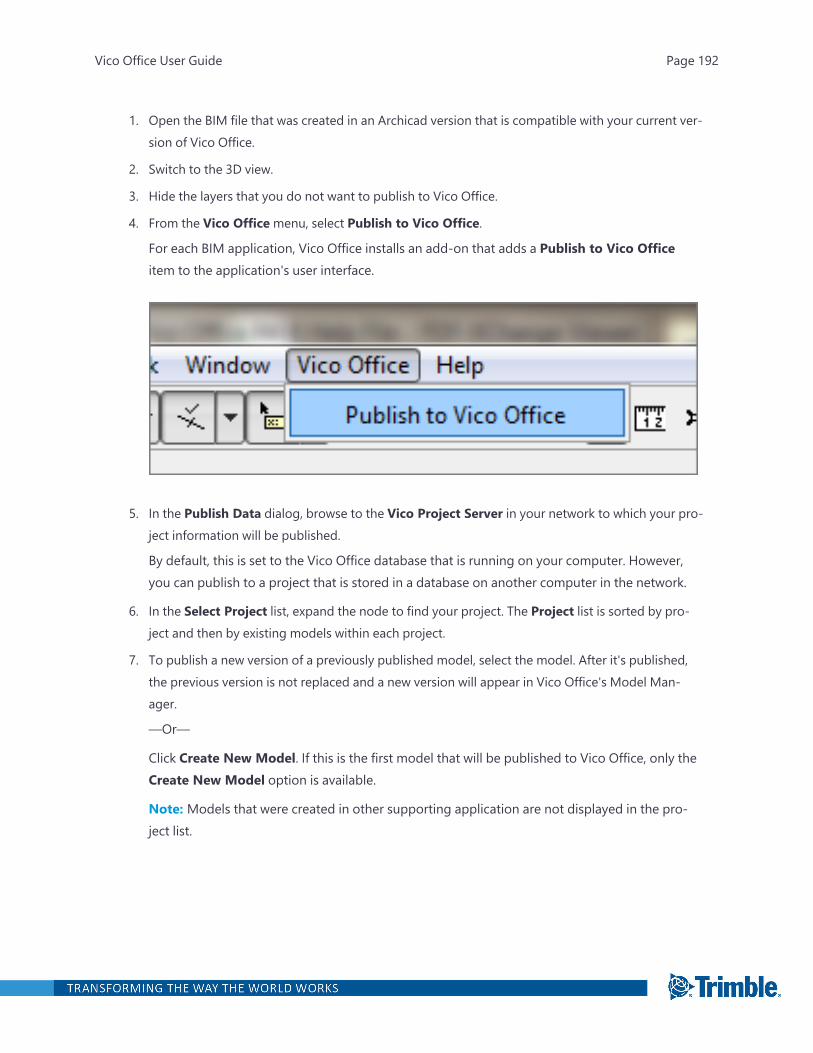
1. Open the BIM file that was created in an Archicad version that is compatible with your current ver-sion of Vico Office.
2. Switch to the 3D view.
3. Hide the layers that you do not want to publish to Vico Office.
4. From the Vico Officemenu, select Publish to Vico Office.
For each BIM application, Vico Office installs an add-on that adds a Publish to Vico Officeitem to the application's user interface.
5. In the Publish Data dialog, browse to the Vico Project Server in your network to which your pro-ject information will be published.
By default, this is set to the Vico Office database that is running on your computer. However,you can publish to a project that is stored in a database on another computer in the network.
6. In the Select Project list, expand the node to find your project. The Project list is sorted by pro-ject and then by existing models within each project.
7. To publish a new version of a previously published model, select the model. After it's published,the previous version is not replaced and a new version will appear in Vico Office's Model Man-ager.
—Or—
Click Create New Model. If this is the first model that will be published to Vico Office, only theCreate New Model option is available.
Note: Models that were created in other supporting application are not displayed in the pro-ject list.
Vico Office User Guide Page 192
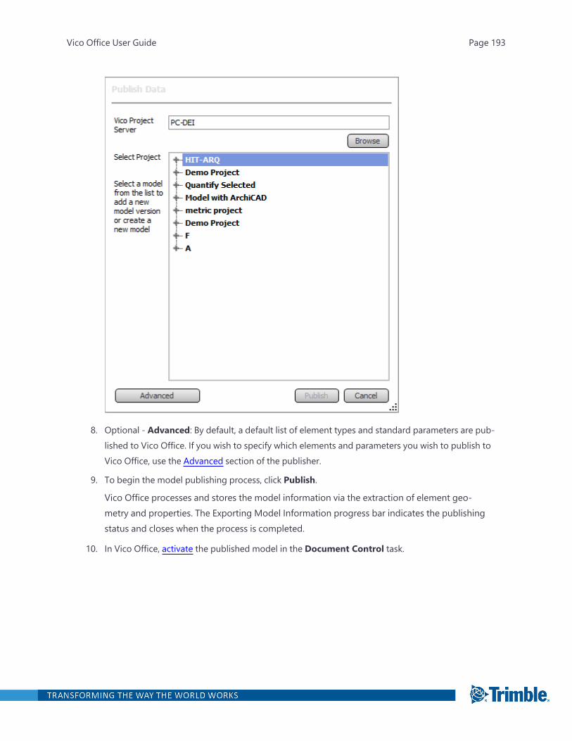
8. Optional - Advanced: By default, a default list of element types and standard parameters are pub-lished to Vico Office. If you wish to specify which elements and parameters you wish to publish toVico Office, use the Advanced section of the publisher.
9. To begin the model publishing process, click Publish.
Vico Office processes and stores the model information via the extraction of element geo-metry and properties. The Exporting Model Information progress bar indicates the publishingstatus and closes when the process is completed.
10. In Vico Office, activate the published model in the Document Control task.
Vico Office User Guide Page 193

Note: The application icon in the Document Name cell shows which supporting application themodel was created in.
Supported Parameters and CAD Quantities - Archicad
CAD QuantitiesThe following CAD quantities from your Archicad model are published to Vico:
Accessory
l Height
l Length
l Width
Beam
l Bottom surface area
l Conditional volume
l End surface area
l Height
l Hole Number
l Holes surface area
l Left side surface area
l Length left
l Length right
l Right side surface area
l Top surface area
l Total surface area of hole edges
Vico Office User Guide Page 194
l Total volume of holes
l Volume
Column
l Area
l Core Dimension 1
l Core Dimension 2
l Gross surface area of the core
l Gross Surface area of the core top and bottom
l Gross surface area of the veneer
l Gross Surface area of the veneer top and bottom
l Gross volume of the core
l Gross volume of the veneer
l Height
l Max height
l Min height
l Net surface area of the core bottom
l Net surface area of the core top
l Net surface area of the veneer bottom
l Net surface area of the veneer top
l Perimeter
l Surface area of the column core
l Surface area of the column veneer
l Volume of the column core
l Volume of the column veneer
Curtain Wall
l Height
l Length
l Slant angle
l Surface bordered by boundary frames
l Surface bordered by contour
Vico Office User Guide Page 195
l The number of panels belong to the Curtain Wall
l Thickness
l Total Length of Frames
l Total Panel Surface Area
Door
l Height
l Nominal W/D opening height on the reveal side
l Nominal W/D opening height on the side opposite to the reveal side
l Nominal W/D opening surface on the reveal side
l Nominal W/D opening surface on the side opposite to the reveal side
l Nominal W/D opening width on the reveal side
l Nominal W/D opening width on the side opposite to the reveal side
l Surface area
l Thickness
l W/D head height according to the vertical anchor
l W/D head height on the reveal side
l W/D head height on the side opposite to the reveal side
l W/D nominal head height
l W/D nominal sill height
l W/D Opening height on the reveal side
l W/D Opening height on the side opposite to the reveal side
l W/D Opening nominal surface area
l W/D Opening nominal volume
l W/D Opening surface on the reveal side
l W/D Opening surface on the side opposite to the reveal side
l W/D Opening volume
l W/D Opening width on the reveal side
l W/D Opening width on the side opposite to the reveal side
l W/D sill height according to the vertical anchor
l W/D sill height on the reveal side
Vico Office User Guide Page 196

l W/D sill height on the side opposite to the reveal side
l Width
Frame
l Category
l Depth
l Direction
l Length
l Material index
l Physical position
l Width
Junction
l Height
l Length
l Width
Lamp
l Surface Area
l Volume
Mesh
l Bottom surface area
l Edge Surface area
l Holes perimeter
l Holes Surface Area
l Perimeter
l Projected area
l Top surface area
l Volume
Morph
Vico Office User Guide Page 197
l Base height
l Elevation
l Height
l Net area
l Net area of the floor plan projection
l Number of the edges
l Number of the faces
l Number of the hidden edges
l Number of the nodes
l Number of the soft edges
l Number of the visible edges
l Perimeter of the floor plan projection
l Volume
Object
l Surface area
l Volume
Panel
l Gross perimeter of the frame
l Gross surface area
l Height
l Horizontal direction
l Material index of the edge
l Material index of the exterior surface area
l Material index of the interior surface area
l Net perimeter of the frame
l Net surface area
l Nominal panel height
l Nominal panel width
l Thickness
l Type of the panel
Vico Office User Guide Page 198
l Vertical direction
l Width
Roof
l Conditional bottom surface area
l Conditional top surface area
l Conditional volume
l Dome connection length
l Eaves lengths
l End Wall Connection Length
l Gross Surface area of the bottom
l Gross Surface area of the edges
l Gross Surface area of the top
l Gross volume
l Hips length
l Holes Perimeter
l Holes Surface Area
l Insulation skin thickness
l Length of Gable type edges
l Length of RTHollow type edges
l Net Surface Area of the Bottom
l Net Surface Area of the Edge
l Net Surface Area of the Top
l Number of holes in contour polygon
l Number of skylight
l Openings Surface Area
l Peaks length
l Perimeter
l Ridges Length
l Side Wall Connection Length
l Sum of the surfaces of the roof openings
Vico Office User Guide Page 199
l The area of the roof contour polygon
l Thickness
l Valleys length
l Volume
Shell
l Conditional area of the opposite surface area
l Conditional area of the reference surface area
l Conditional volume
l Gross Surface Area of the Edges
l Gross Surface Area of the Opposite to Reference Side (holes included)
l Gross Surface Area of the Reference Side (holes included)
l Gross volume of the shell (holes included)
l Insulation thickness of the shell
l Net area of the reference surface (without holes)
l Net area of the surface opposite to the reference (without holes)
l Perimeter of the contour polygon
l Projected floor plan area of the contour polygon
l Thickness
l Total area of the edges
l Total area of the holes
l Total area of the openings
l Total length of the connecting line with domes
l Total length of the connecting line with hollows
l Total length of the connecting line with side walls
l Total length of the connecting line with wall ends
l Total length of the eaves
l Total length of the gables
l Total length of the hips
l Total length of the peaks
l Total length of the ridges
Vico Office User Guide Page 200
l Total length of the valleys
l Total perimeter of the holes
l Total perimeter of the holes
l Volume of the shell
Skylight
l Header height
l Shell/Roof Opening height
l Shell/Roof Opening surface area
l Shell/Roof Opening volume
l Shell/Roof Opening width
l Sill height
Slab
l Bottom surface area
l Conditional Surface Area of the Bottom
l Conditional Surface Area of the Top
l Conditional volume
l Edge surface area
l Gross surface area of the slab bottom
l Gross surface area of the slab bottom with holes
l Gross surface area of the slab edges
l Gross surface area of the slab edges with holes
l Gross surface area of the slab top
l Gross surface area of the slab top with holes
l Gross volume of the slab
l Gross volume of the slab with holes
l Holes perimeter
l Holes surface area
l Perimeter
l Thickness
l Top surface area
Vico Office User Guide Page 201
l Volume
Wall
l Analytic surface of openings on the Inside Face
l Analytic surface of openings on the Outside Face
l Analytic volume of openings
l Area
l Combined width of doors
l Combined width of windows
l Conditional length on the Inside Face
l Conditional length on the Outside Face
l Conditional Surface Area on the Inside Face
l Conditional Surface Area on the Outside Face
l Conditional volume
l Conditional wall skin volume on the Inside Face
l Conditional wall skin volume on the Outside Face
l End Thickness of the Wall
l Gross surface on the Inside Face
l Gross surface on the Outside Face
l Gross volume
l Height
l Length
l Length at the center
l Length of the reference line
l Length on the Inside Face
l Length on the Outside Face
l Maximum height
l Maximum Height of the Wall Skin on the Inside Face
l Maximum height skin on the Outside Face
l Minimum height
l Minimum height skin on the Inside Face
Vico Office User Guide Page 202
l Minimum height skin on the Outside Face
l Number of columns
l Perimeter
l Surface area of the edge
l Surface of doors
l Surface of empty openings
l Surface of windows
l Surface on the Inside Face
l Surface on the Outside Face
l Thickness
l Volume
l Volume of columns
l Wall air skin thickness
l Wall insulation skin thickness
l Wall skin thickness on the Inside Face
l Wall skin thickness on the Outside Face
l Wall skin volume on the Inside Face
l Wall skin volume on the Outside Face
Window
l Height
l Nominal sill height
l Nominal W/D opening height on the reveal side
l Nominal W/D opening height on the side opposite to the reveal side
l Nominal W/D opening surface on the reveal side
l Nominal W/D opening surface on the side opposite to the reveal side
l Nominal W/D opening width on the reveal side
l Nominal W/D opening width on the side opposite to the reveal side
l Surface area
l Thickness
l W/D head height according to the vertical anchor
Vico Office User Guide Page 203

l W/D head height on the reveal side
l W/D head height on the side opposite to the reveal side
l W/D Nominal head height
l W/D Opening height on the reveal side
l W/D Opening height on the side opposite to the reveal side
l W/D Opening nominal surface area
l W/D Opening nominal volume
l W/D Opening surface on the reveal side
l W/D Opening surface on the side opposite to the reveal side
l W/D Opening volume
l W/D Opening width on the reveal side
l W/D Opening width on the side opposite to the reveal side
l W/D Sill height according to the vertical anchor
l W/D Sill height on the reveal side
l W/D Sill height on the side opposite to the reveal side
l Width
Zone
l Calculated area
l Calculated area
l Doors width
l Extracted column area
l Extracted fill area
l Extracted low area
l Extracted wall area
l Floor level
l Height
l Length of perimeter walls
l Net area
l Net perimeter
l Number of concave corners
Vico Office User Guide Page 204
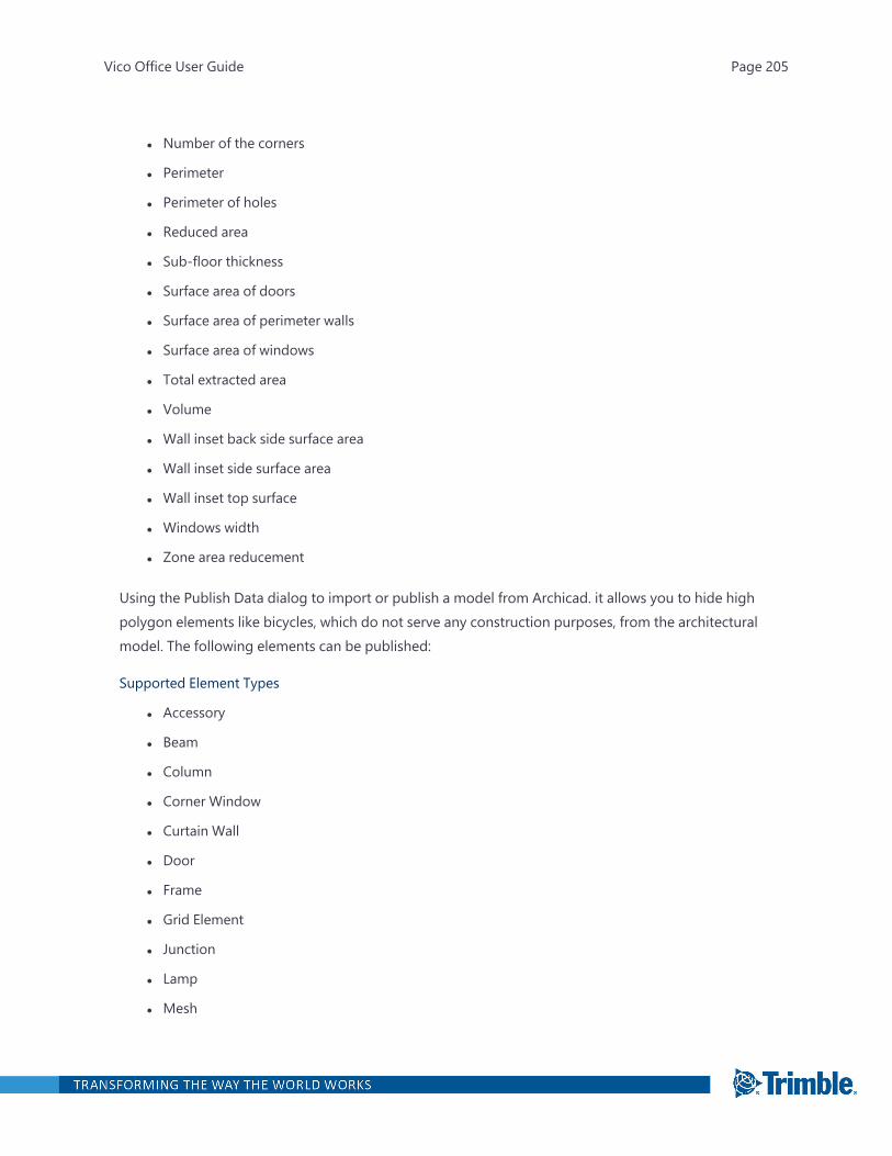
l Number of the corners
l Perimeter
l Perimeter of holes
l Reduced area
l Sub-floor thickness
l Surface area of doors
l Surface area of perimeter walls
l Surface area of windows
l Total extracted area
l Volume
l Wall inset back side surface area
l Wall inset side surface area
l Wall inset top surface
l Windows width
l Zone area reducement
Using the Publish Data dialog to import or publish a model from Archicad. it allows you to hide highpolygon elements like bicycles, which do not serve any construction purposes, from the architecturalmodel. The following elements can be published:
Supported Element Types
l Accessory
l Beam
l Column
l Corner Window
l Curtain Wall
l Door
l Frame
l Grid Element
l Junction
l Lamp
l Mesh
Vico Office User Guide Page 205

l Morph
l Object
l Panel
l Roof
l Shell
l Skylight
l Slab
l Stair
l Wall
l Wall End
l Window
l Zone
Note: All GDL parameters are listed under the Advanced section. All Parameters for Listing (GDL) arelisted under the Primary section. All other GLD parameters are listed under the Secondary section.The Archicad publisher also has an IFC section with IFC attributes and properties.
Publishing Data - Advanced Settings
On the Publish Data (Advanced) dialog box, choose which elements and parameters you wish to pub-lish to Vico Office. Keep in mind that if you choose more elements and parameters to publish, it mayhave an impact on the publish duration. Therefore, it is highly recommended that you exclude ele-ments that do not add any value to your project.
Vico Office User Guide Page 206

A - Element: All the elements are selected by default. Select which elements you wish to exclude byclearing their check box.
B - Standard Parameters: All standard parameters are selected by default. It is recommended thatyou include all the standard parameters.
C - Advanced Parameters: Parameters that are available in the current model, including user-defined parameters, are listed in this dialog box. They are grouped into four subgroups: All, Primary,Secondary, and Frequent. Unlike the Standard parameters, none of the advanced parameters areselected by default to be published.
D - Use the Search box to quickly find the advanced parameters that you wish to include/exclude.
E - Click on a subgroup filter to display only the parameters from that group or click All to display allthe parameters.
Vico Office User Guide Page 207

Note: When you select a subgroup filter and then enter a keyword in the Search field,
the Search field will only search for a keyword within that subgroup.
IFC Parameters (Available for Archicad only)
In Archicad, you can also publish IFC attributes, IFC properties and IFC Classifications into Vico Office.The available parameters are all listed under the IFC Parameters section of the Publish Data Advanceddialog.
Vico Office User Guide Page 208

Templates
Vico Office User Guide Page 209
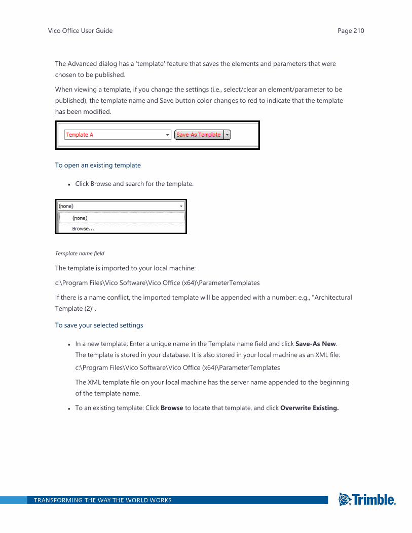
The Advanced dialog has a 'template' feature that saves the elements and parameters that werechosen to be published.
When viewing a template, if you change the settings (i.e., select/clear an element/parameter to bepublished), the template name and Save button color changes to red to indicate that the templatehas been modified.
To open an existing template
l Click Browse and search for the template.
Template name field
The template is imported to your local machine:
c:\Program Files\Vico Software\Vico Office (x64)\ParameterTemplates
If there is a name conflict, the imported template will be appended with a number: e.g., "ArchitecturalTemplate (2)".
To save your selected settings
l In a new template: Enter a unique name in the Template name field and click Save-As New.The template is stored in your database. It is also stored in your local machine as an XML file:
c:\Program Files\Vico Software\Vico Office (x64)\ParameterTemplates
The XML template file on your local machine has the server name appended to the beginningof the template name.
l To an existing template: Click Browse to locate that template, and click Overwrite Existing.
Vico Office User Guide Page 210
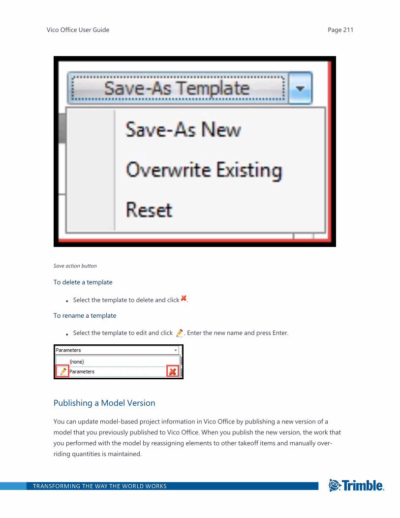
Save action button
To delete a template
l Select the template to delete and click .
To rename a template
l Select the template to edit and click . Enter the new name and press Enter.
Publishing a Model Version
You can update model-based project information in Vico Office by publishing a new version of amodel that you previously published to Vico Office. When you publish the new version, the work thatyou performed with the model by reassigning elements to other takeoff items and manually over-riding quantities is maintained.
Vico Office User Guide Page 211
To publish an updated model version
1. In your selected CAD application, select Publish to Vico from the Vico Office add-on menu.
2. In the Publish Data dialog, find and select the project to which you want to publish the updatedmodel version.
3. Expand the project node to see the existing models that were published under that project.
4. Select the model to which you plan to update the quantities and geometry.
When you publish a new model, unchanged model geometry is verified, and changes are pro-cessed and saved to the database.
5. After the publishing process is complete, you can then open the Document Register task to activ-ate and update the model version.
An notification icon indicates that a newer model version exists. By default the new modelversion indicator is shown as long as the newest version is not active. Note that the new modelversions are sorted based on the original publishing order, from the oldest to the newest.
Integrating with Trimble Connect
Trimble Connect (TC) is a cloud-based collaboration application that enables you to share files withother supported applications and your team members. This is an easier way to update your in-pro-gress models without the long procedure of publishing. Every time you use any of the supportedapplications to make changes in your model, you can upload it to the Trimble Connect server anddownload it directly to Vico Office. Trimble Connect uses Trimble Identity (TID) for the login cre-dentials. This will allow you to use a single account across all Trimble products.
Supported Applications
l Tekla (export to .ifc)
l SketchUp 2014 (.skp)
If you don't have a Trimble Connect Account:
Create a Trimble ID account
1. On the Trimble Connect site, sign up for a Trimble ID account.
2. Activate your account by clicking the link in the activation email.
If you do not see the activation email in your Inbox, check your spam or junk folder to ensurethat the email was not filtered.
3. Create a project, and invite other people to join it.
Vico Office User Guide Page 212

Configure your access to the Trimble Connect site
1. Open the Define Settings task.
2. Choose the Trimble Connect region that you wish your projects connected to.
You are now set up to download models from Trimble Connect. When downloading models for thefirst time, you will be prompted to enter your Trimble ID credentials. Vico Office will save these cre-dentials for future connections.
To reset your Trimble Connect password
1. On the Forgot your password page, enter the email address used to log in to Trimble Connect,and then follow the instructions in the "Reset your password" email.
2. Use that password as your new Trimble Connect password.
Download a Model from Trimble Connect
After configuring your Trimble Connect access, you can now easily download building models to VicoOffice. When connecting to Trimble Connect for the first time, you will be prompted to enter your cre-dentials.
To download a model from Trimble Connect
1. Open the Document Control task.
2. On theModel Register ribbon tab, click Import Trimble Connect.
If this is the first time connecting to Trimble Connect you will be prompted to enter your cre-dentials. On the Trimble Connect Login dialog box, enter your Trimble ID credentials.
Note: If you do not have your credentials at the moment, optionally click one of the followingto close the dialog box:
l Cancel Once: You will be able to re-open this dialog box to reconnect to Trimble Connect.
l Cancel for Session: You will be disabling the Import Trimble Connect button until youlog back on to Vico Office.
1. Navigate between your documents, select the version of the file that you wish to import, andclick Import Selected Version.
2. Select the model from the list to add the new model version. Only the models that were createdwith the same application are displayed. For example, if you are importing a SketchUp (.skp)model, only SketchUp models are displayed.
—Or—
Vico Office User Guide Page 213
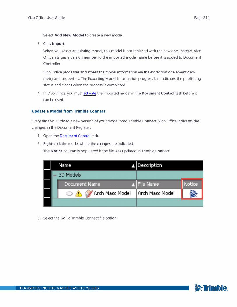
Select Add New Model to create a new model.
3. Click Import.
When you select an existing model, this model is not replaced with the new one. Instead, VicoOffice assigns a version number to the imported model name before it is added to DocumentController.
Vico Office processes and stores the model information via the extraction of element geo-metry and properties. The Exporting Model Information progress bar indicates the publishingstatus and closes when the process is completed.
4. In Vico Office, you must activate the imported model in the Document Control task before itcan be used.
Update a Model from Trimble Connect
Every time you upload a new version of your model onto Trimble Connect, Vico Office indicates thechanges in the Document Register.
1. Open the Document Control task.
2. Right-click the model where the changes are indicated.
The Notice column is populated if the file was updated in Trimble Connect.
3. Select the Go To Trimble Connect file option.
Vico Office User Guide Page 214
Document Control
Vico Office Document Controller helps project teams manage project documents and efficientlyidentify, interpret, and react to drawing changes in a collaborative environment.
The Document Register view provides one central place for all project models and drawing versionsand an easy, yet powerful way to review the project document status, and communicate changes indocument sets to the project team.
The Document Controller's powerful comparison tools help reduce project risk and improve pro-ductivity by quickly scanning and mapping changes in thousands of drawings, generating document-based RFIs and by providing easy-to-use visual comparison tools.
Document Controller provides a unified repository to store and track all your project inputs, including2D PDF drawings, 3D BIM models, photos, spreadsheets and other project reports. The program sup-ports a folder and versioning structure to group and classify your data according to the designreleases coming from the project. On the left of the default screen is your Document Register, whilethe active viewset can be found on the right side of the screen. Palettes for view filtering, referenceplanes and element properties can be found on the right side of the screen and are available for dock-ing when used regularly.
Key highlights:
l Files can be added and tracked within Document Controller, along with models from mostauthoring applications, including SketchUp.
l 2D drawings can be compared to other 2D drawings, including different versions of the samedrawing or the same version of drawings from different sets or disciplines.
l 2D drawings can be mapped as reference planes for model checking and detailed takeoff.
l Issues found on 2D drawings or across 3D models can be clouded and marked up for tracking.
l Issues can be elevated to RFI or Constructability Issue status.
To open the Document Control task
1. Right-click the Workflow Panel header, and then click the Vico Office or Vico for Design module.
2. In the Vico for Design or Design Management workflow group, click Document Control.
The default viewset includes the Document Register view and the 3D view.
Vico Office User Guide Page 215
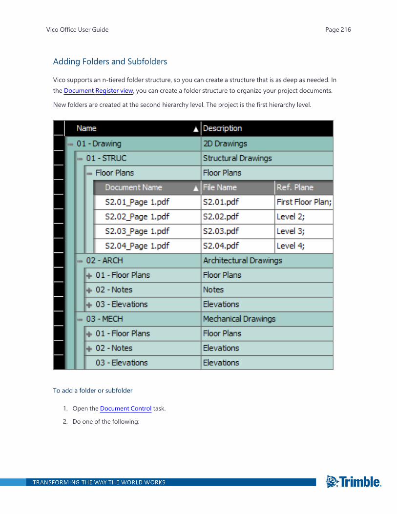
Adding Folders and Subfolders
Vico supports an n-tiered folder structure, so you can create a structure that is as deep as needed. Inthe Document Register view, you can create a folder structure to organize your project documents.
New folders are created at the second hierarchy level. The project is the first hierarchy level.
To add a folder or subfolder
1. Open the Document Control task.
2. Do one of the following:
Vico Office User Guide Page 216
l To create a folder, click New Folder on the ribbon.
l To create a subfolder, select the desired parent folder, and then click New Subfolder onthe ribbon.
Tip: You can also right-click a folder to open the context menu.
3. In the Folder Name field, type the folder name.
4. In the Folder Description field, type a description for the folder.
5. Click Create.
Adding Versions and Files
Versions can be added to Document Controller to group releases of drawings or other documents.
When you add a version, you can create an empty version or select the files or folder that you wish toadd. Create empty versions for the project all at once before populating them with drawings, or cre-ate the versions individually and populate them with drawings as you go.
Adding drawings into Document Controller fully imports their content into Vico Office. Changing orupdating content in the source drawing folder does not update the content in Vico. You must re-import drawings into Vico to update their contents in Vico.
To add new version of 2D Drawings
1. Open the Document Control task.
2. Click a previously created parent folder.
3. On the Document Control ribbon tab, click Add Version.
—Or—
Right-click in the view, and then click Add Version.
The Add Version dialog box is displayed.
4. In the Version Name field, type the name.
Note that the parent folder is auto-selected in the Folder list. To change where the version isstored, select a different folder from the list.
Vico Office User Guide Page 217
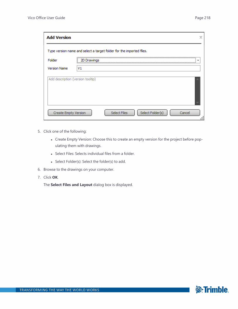
5. Click one of the following:
l Create Empty Version: Choose this to create an empty version for the project before pop-ulating them with drawings.
l Select Files: Selects individual files from a folder.
l Select Folder(s): Select the folder(s) to add.
6. Browse to the drawings on your computer.
7. Click OK.
The Select Files and Layout dialog box is displayed.
Vico Office User Guide Page 218
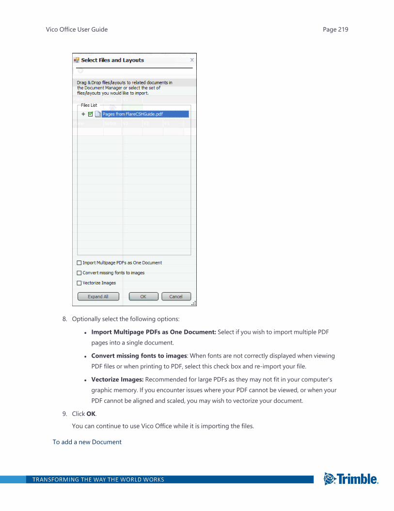
8. Optionally select the following options:
l Import Multipage PDFs as One Document: Select if you wish to import multiple PDFpages into a single document.
l Convert missing fonts to images: When fonts are not correctly displayed when viewingPDF files or when printing to PDF, select this check box and re-import your file.
l Vectorize Images: Recommended for large PDFs as they may not fit in your computer'sgraphic memory. If you encounter issues where your PDF cannot be viewed, or when yourPDF cannot be aligned and scaled, you may wish to vectorize your document.
9. Click OK.
You can continue to use Vico Office while it is importing the files.
To add a new Document
Vico Office User Guide Page 219
1. Open the Document Control task.
2. Click a previously created subfolder.
3. On the ribbon, click New Document.
4. In the Document Name cell, type the name.
Note that all version cells are gray indicating this document that is not part of a version.
To add Files
1. Open the Document Control task.
2. Navigate to the previously created parent.
3. On the ribbon, click Add Files.
4. In the Folder drop-down, select a subfolder.
5. In the Version Name field, type the name.
6. Click Select Files.
7. Browse to the drawing set on your computer.
8. Select the files, and then click Open.
The Select Files and Layout dialog box is displayed.
Note: If you are importing files with many images, it may take significant time to convert thoseimages to geometry. To improve performance, clear the 'Convert images to geometry' checkbox so that these images are not converted.
9. Click OK.
Editing and Deleting Content
You can rename documents or delete content such as folders, subfolders, and drawings in the Docu-ment Register view at any time.
Note: If you import a document with incorrect font, simply delete and re-import it.
Important: Deleting content from the Document Register view permanently deletes the data andcannot be undone.
Vico Office User Guide Page 220
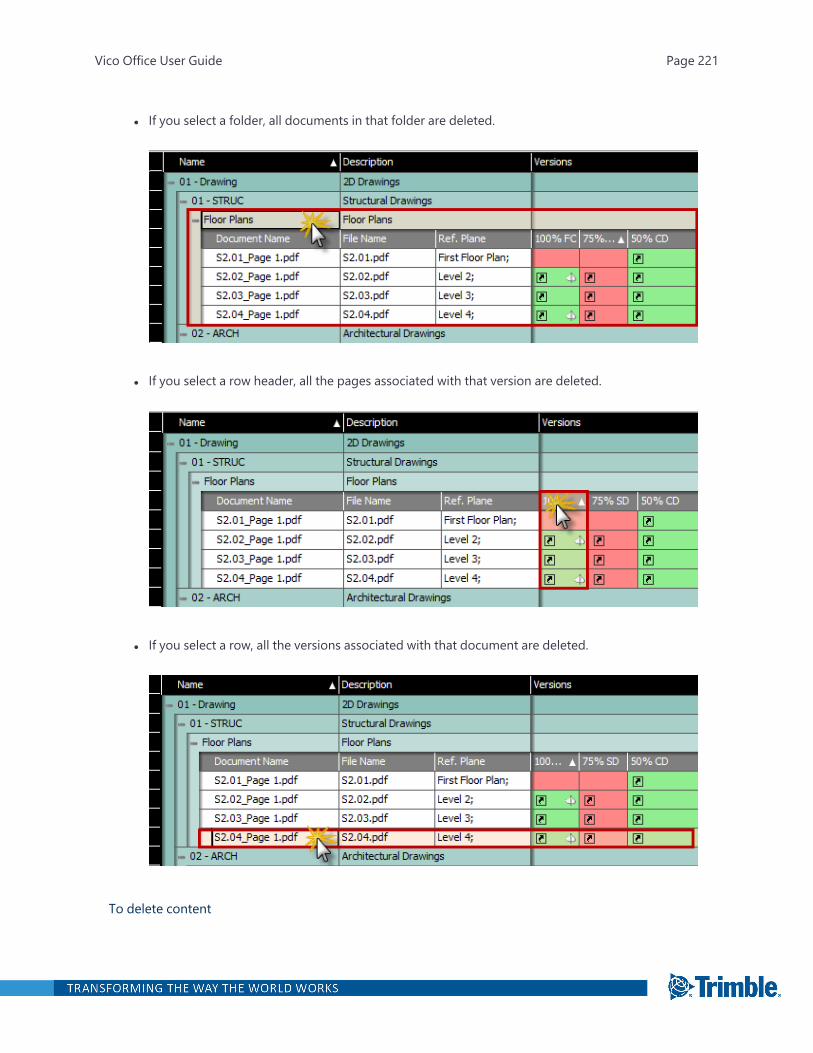
l If you select a folder, all documents in that folder are deleted.
l If you select a row header, all the pages associated with that version are deleted.
l If you select a row, all the versions associated with that document are deleted.
To delete content
Vico Office User Guide Page 221

1. Open the Document Control task.
2. Select one or more folders, subfolders, or documents to be deleted.
3. On the Document Control ribbon tab, click Delete Selected.
—Or—
Right-click the item, and then click Delete.
Viewing a Document
To view a document
1. Open the Document Control task.
2. In the Document Register view, click the document, and then click View Document on theDocument Control ribbon.
—Or—
Right-click the document, and then click View.
The document opens in a new viewset.
Note: You can also drag a document into the 3D View.
l To view the most current version, drag the row into the active viewset.
l To view an older version, drag a specific version cell into the active viewset.
Analyzing 2D Drawings
In Document Controller, you can store and review 2D PDF drawing releases by version. As new ver-sions are added, you can see which sheets have been added, changed, or removed and which onesremain the same.
Then compare versions on a sheet-by-sheet basis or in groups of sheets using the Slider, Highlight,and Overlaymodes.
Vico Office User Guide Page 222
To compare 2D drawings
1. Open the Document Control task.
2. On the Document Control ribbon tab, select the desired mode.
For more information on the modes, see:
l "2D Slider Mode " on the next page
l "2D Highlight Mode " on page 225
l "2D Overlay mode " on page 228
3. In the Document Register view, press the Ctrl key as you click the drawings that you want to com-pare.
4. On the ribbon, click Compare Documents.
—Or—
Right-click the drawings, and then click one of the following:
l Compare: The drawings appear in the active viewset.
l Compare in New Viewset: The drawings appear in a new viewset. The active viewsetremains available, so you can return to it.
Vico Office User Guide Page 223
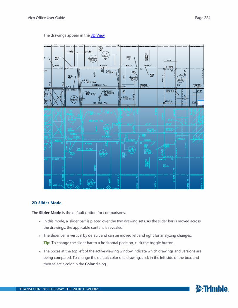
The drawings appear in the 3D View.
2D Slider Mode
The Slider Mode is the default option for comparisons.
l In this mode, a 'slider bar' is placed over the two drawing sets. As the slider bar is moved acrossthe drawings, the applicable content is revealed.
l The slider bar is vertical by default and can be moved left and right for analyzing changes.
Tip: To change the slider bar to a horizontal position, click the toggle button.
l The boxes at the top left of the active viewing window indicate which drawings and versions arebeing compared. To change the default color of a drawing, click in the left side of the box, andthen select a color in the Color dialog.
Vico Office User Guide Page 224
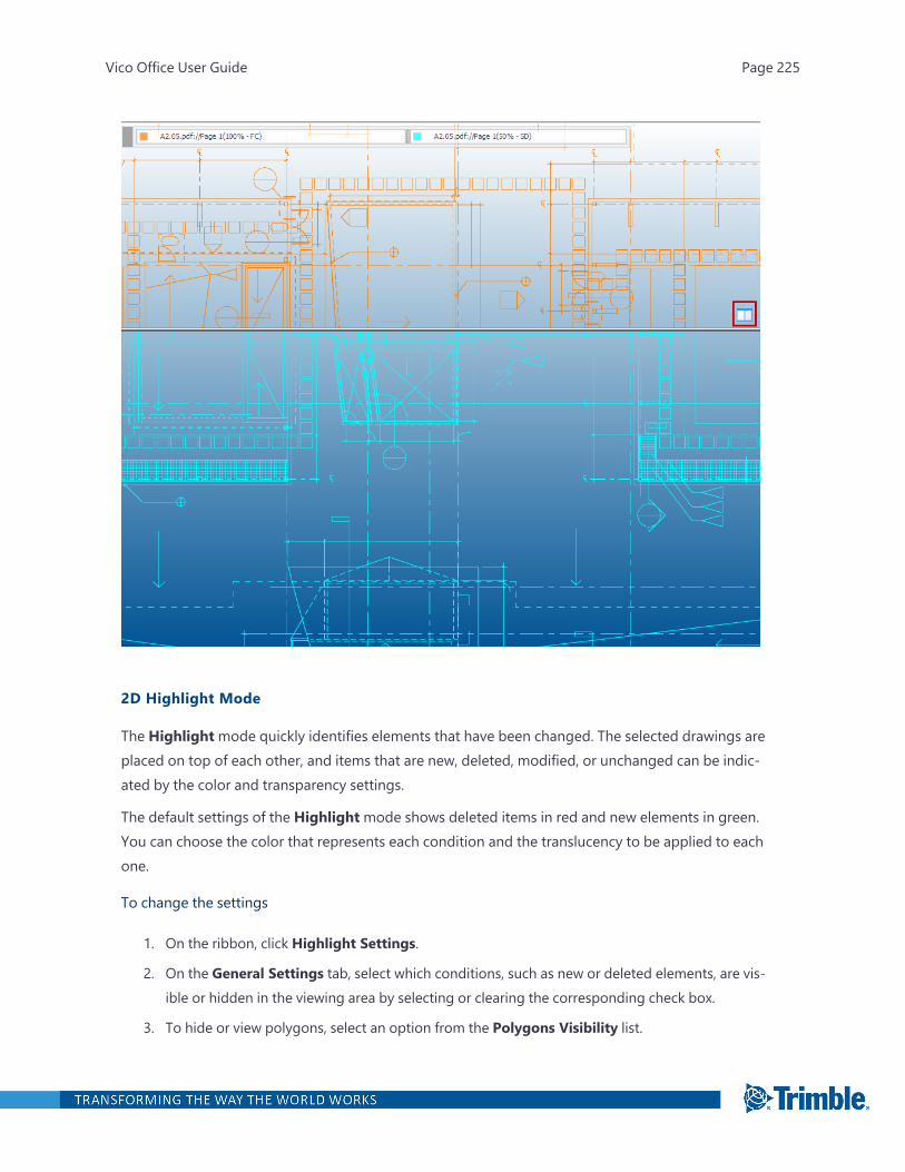
2D Highlight Mode
The Highlightmode quickly identifies elements that have been changed. The selected drawings areplaced on top of each other, and items that are new, deleted, modified, or unchanged can be indic-ated by the color and transparency settings.
The default settings of the Highlightmode shows deleted items in red and new elements in green.You can choose the color that represents each condition and the translucency to be applied to eachone.
To change the settings
1. On the ribbon, click Highlight Settings.
2. On the General Settings tab, select which conditions, such as new or deleted elements, are vis-ible or hidden in the viewing area by selecting or clearing the corresponding check box.
3. To hide or view polygons, select an option from the Polygons Visibility list.
Vico Office User Guide Page 225
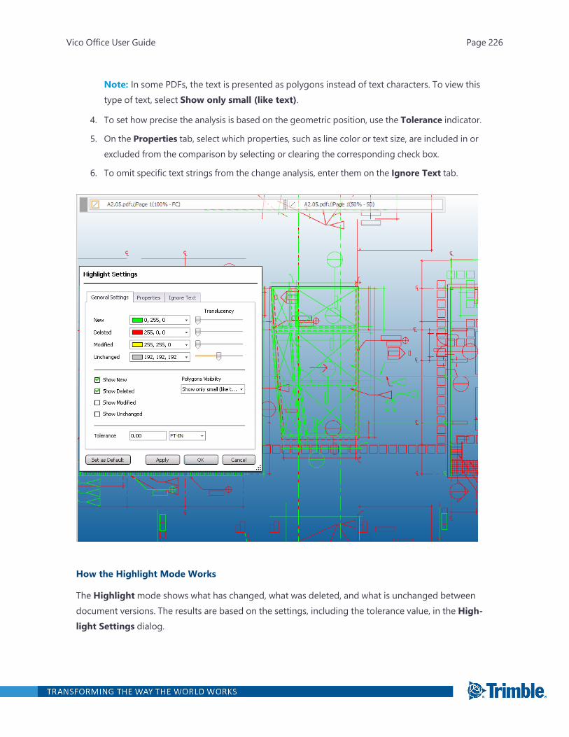
Note: In some PDFs, the text is presented as polygons instead of text characters. To view thistype of text, select Show only small (like text).
4. To set how precise the analysis is based on the geometric position, use the Tolerance indicator.
5. On the Properties tab, select which properties, such as line color or text size, are included in orexcluded from the comparison by selecting or clearing the corresponding check box.
6. To omit specific text strings from the change analysis, enter them on the Ignore Text tab.
How the Highlight Mode Works
The Highlightmode shows what has changed, what was deleted, and what is unchanged betweendocument versions. The results are based on the settings, including the tolerance value, in the High-light Settings dialog.
Vico Office User Guide Page 226

Example
The line colors indicate the results of the comparison:
1. Unchanged
2. Modified
3. Modified
Vico Office User Guide Page 227
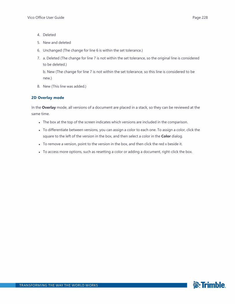
4. Deleted
5. New and deleted
6. Unchanged (The change for line 6 is within the set tolerance.)
7. a. Deleted (The change for line 7 is not within the set tolerance, so the original line is consideredto be deleted.)
b. New (The change for line 7 is not within the set tolerance, so this line is considered to benew.)
8. New (This line was added.)
2D Overlay mode
In the Overlaymode, all versions of a document are placed in a stack, so they can be reviewed at thesame time.
l The box at the top of the screen indicates which versions are included in the comparison.
l To differentiate between versions, you can assign a color to each one. To assign a color, click thesquare to the left of the version in the box, and then select a color in the Color dialog.
l To remove a version, point to the version in the box, and then click the red x beside it.
l To access more options, such as resetting a color or adding a document, right-click the box.
Vico Office User Guide Page 228
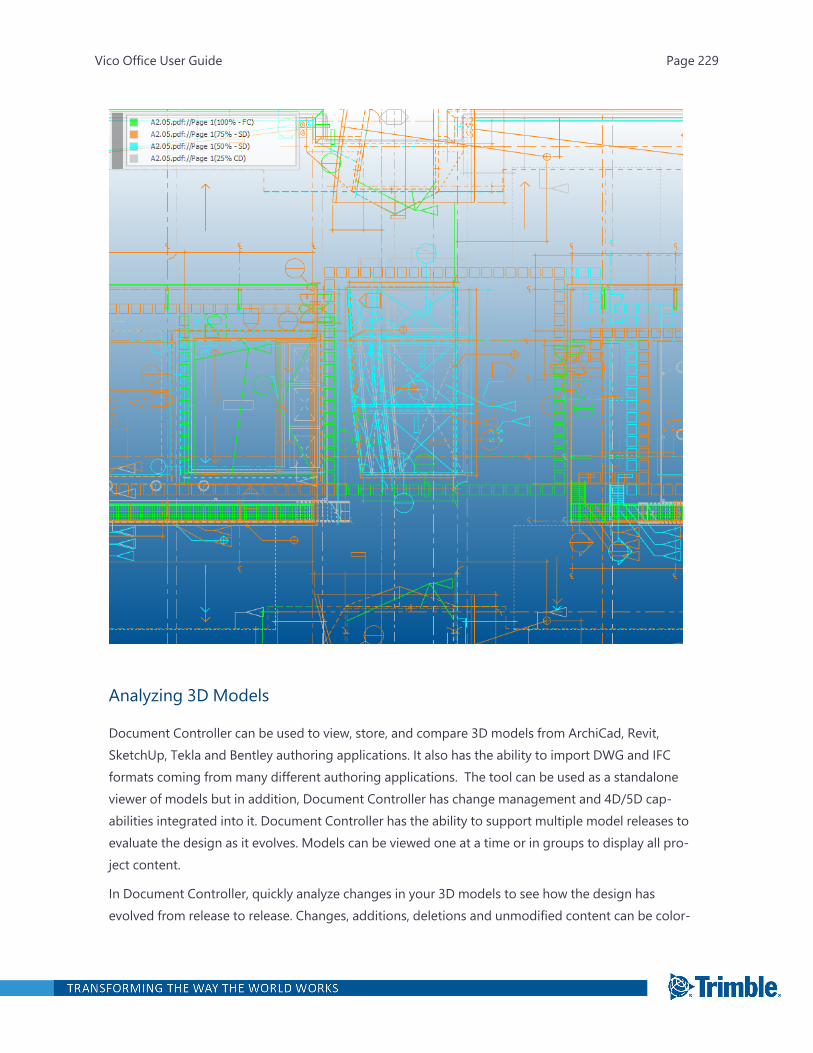
Analyzing 3D Models
Document Controller can be used to view, store, and compare 3D models from ArchiCad, Revit,SketchUp, Tekla and Bentley authoring applications. It also has the ability to import DWG and IFCformats coming from many different authoring applications. The tool can be used as a standaloneviewer of models but in addition, Document Controller has change management and 4D/5D cap-abilities integrated into it. Document Controller has the ability to support multiple model releases toevaluate the design as it evolves. Models can be viewed one at a time or in groups to display all pro-ject content.
In Document Controller, quickly analyze changes in your 3D models to see how the design hasevolved from release to release. Changes, additions, deletions and unmodified content can be color-
Vico Office User Guide Page 229

coded to quickly reveal updates in the model using the Highlightmode. You can also use the SliderMode to move geometric faces around while viewing old and new content on either side of theslider.
To compare 3D models
1. Open the Document Control task.
2. On the Document Control ribbon tab, select the desired mode.
For more information on the modes, see:
l "3D Slider Mode " on the next page
l "3D Highlight Mode " on page 232
3. In the Document Register view, press the Ctrl key as you click the models that you want to com-pare.
Tip: The sequence in which you select the versions is important when you want to highlightnew, deleted, changed, or unchanged elements. In most cases, you will want to select thelatest version first and then the earlier version before clicking Compare Documents.
4. On the ribbon, click Compare Documents.
—Or—
Right-click the models, and then click one of the following:
l Compare: The documents appear in the active viewset.
l Compare in New Viewset: The documents appear in a new viewset. The active viewsetremains available, so you can return to it.
Vico Office User Guide Page 230

The drawings appear in the 3D View.
3D Slider Mode
The Slider Mode is the default option for model comparisons. In this mode, a 'slider pane' transitionsacross the two model versions, revealing the applicable content as it is moved across the versions.
The slider pane can be moved in five different directions to reveal changes.
l Click and drag the center of the slider pane to move the entire pane across the models.
l Click any of the sides, indicated with a thick gray bar to move only that end of the slider pane.
Tip: To reveal more precise changes between the model versions, use a combination of full and sidemovements.
The box at the top of the active viewing window indicates which models and versions are being com-pared. To change the color of a version, click the square to its left, and then select a color from theColor dialog.
Vico Office User Guide Page 231

3D Highlight Mode
Use the Highlightmode to quickly identify elements that have been changed. This mode places theselected models together in the active view and can show which items are new, deleted, modified orunchanged using color and transparency settings.
The default settings show deleted elements in red and new elements in green. To change the defaultsettings, click Highlight Settings on the ribbon.
l Select the color and translucency setting for each condition on the General Settings tab.
l To show or hide a condition, select or clear the corresponding check box on the General Set-tings tab.
l To set how precise the analysis is based on the geometric position, adjust the Tolerance indic-ator on the General Settings tab.
Vico Office User Guide Page 232
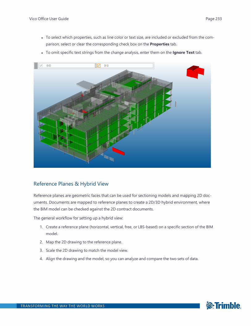
l To select which properties, such as line color or text size, are included or excluded from the com-parison, select or clear the corresponding check box on the Properties tab.
l To omit specific text strings from the change analysis, enter them on the Ignore Text tab.
Reference Planes & Hybrid View
Reference planes are geometric faces that can be used for sectioning models and mapping 2D doc-uments. Documents are mapped to reference planes to create a 2D/3D hybrid environment, wherethe BIM model can be checked against the 2D contract documents.
The general workflow for setting up a hybrid view:
1. Create a reference plane (horizontal, vertical, free, or LBS-based) on a specific section of the BIMmodel.
2. Map the 2D drawing to the reference plane.
3. Scale the 2D drawing to match the model view.
4. Align the drawing and the model, so you can analyze and compare the two sets of data.
Vico Office User Guide Page 233
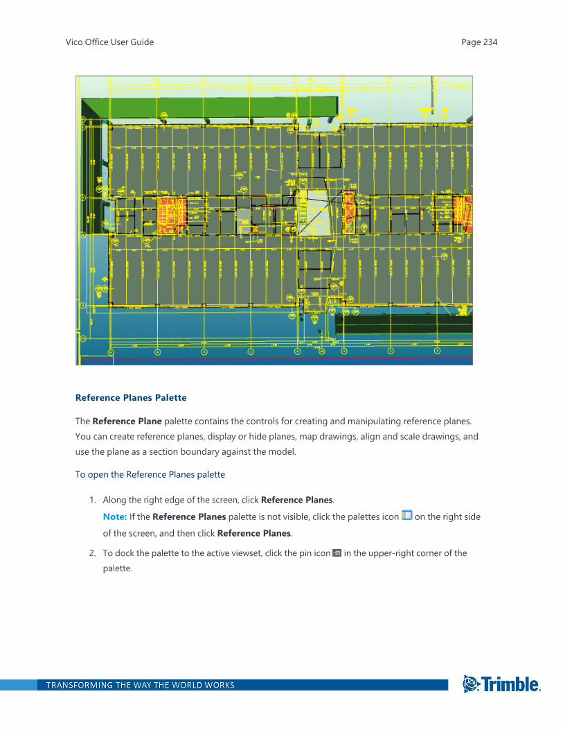
Reference Planes Palette
The Reference Plane palette contains the controls for creating and manipulating reference planes.You can create reference planes, display or hide planes, map drawings, align and scale drawings, anduse the plane as a section boundary against the model.
To open the Reference Planes palette
1. Along the right edge of the screen, click Reference Planes.
Note: If the Reference Planes palette is not visible, click the palettes icon on the right side
of the screen, and then click Reference Planes.
2. To dock the palette to the active viewset, click the pin icon in the upper-right corner of thepalette.
Vico Office User Guide Page 234
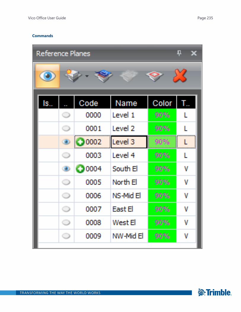
Commands
Vico Office User Guide Page 235

Command Description
Display Reference Planes Reveal or conceal the reference planes inyour project.
Create New ReferencePlane
Create a new reference plane in yourproject
l Horizontal plane: Lays flat along theX,Y axis.
l Vertical plane: Aligned up anddown, along the Z axis.
l Free plane: Aligned in any angle ordirection, based upon model pointsselected.
l LBS plane: Sets a reference plane ateach floor split from your LBSstructure.
Map Document Select any document or documentversion from the register list and map itonto the selected reference plane. Mapdocuments to a reference plane, afteraligning and scaling it, to validate the 3Dcontent against 2D drawings.
Align & Scale Move and resize 2D documents tomatch the 3D model after they aremapped onto a reference plane.
Vico Office User Guide Page 236

Command Description
Section Box Cut the 3D model where the referenceplane is located.
Delete Selected Delete the selected reference plane orremove a document that has beenmapped to a plane.
Columns
Column Description
IsLatestRevision A circle indicates the latest revision.
Visibility An eye icon indicates element is visible.
Code Used to sort the reference planes listedin the palette.
Name The name of the reference plane.
Color The color that identifies the referenceplane.
Vico Office User Guide Page 237
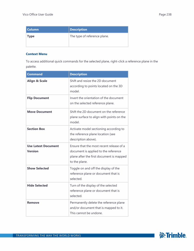
Column Description
Type The type of reference plane.
Context Menu
To access additional quick commands for the selected plane, right-click a reference plane in thepalette.
Command Description
Align & Scale Shift and resize the 2D documentaccording to points located on the 3Dmodel.
Flip Document Invert the orientation of the documenton the selected reference plane.
Move Document Shift the 2D document on the referenceplane surface to align with points on themodel.
Section Box Activate model sectioning according tothe reference plane location (seedescription above).
Use Latest DocumentVersion
Ensure that the most recent release of adocument is applied to the referenceplane after the first document is mappedto the plane.
Show Selected Toggle on and off the display of thereference plane or document that isselected.
Hide Selected Turn of the display of the selectedreference plane or document that isselected.
Remove Permanently delete the reference planeand/or document that is mapped to it.This cannot be undone.
Vico Office User Guide Page 238

Horizontal Reference Planes
Horizontal reference planes are flat surfaces that lay on the X, Y axis of the model. They often run par-allel to floor slabs.
To create a horizontal reference plane
1. Open the Document Control task.
2. Click the Document Controller, 3D and Issues viewset tab.
3. On the 3D View ribbon tab, click New Ref. plane > Horizontal Plane.
—Or—
On the Reference Planes palette, click the Create New Reference Plane button > Hori-
zontal.
4. In the New Reference Plane dialog, enter the following information:
l Code: Used for sorting the plane list.
l Name: Often correlates with something intuitive (for example, "First Floor Plan") aboutthe project.
l Elevation: Indicates where along the Z axis the reference plane should be positioned.Type the elevation, or click From Model to define the elevation value directly from themodel.
HINT: It is often easiest to define the elevation of new reference planes by filtering outthe 3D content that is not applicable or helpful to creating the reference plane. Use theFiltering palette to select the most pertinent elements, such as slabs, before clickingFrom Model, and it will be easier to create the plane. Also, turn on project O-snaps(from the 3D navigation toolbar) to precisely select end points from the model.
5. Click OK.
Vertical Reference Planes
Vertical reference planes are flat surfaces that run up and down along the Z axis of a model. Theyoften run parallel with walls.
Vertical Reference Plane ExamplesThis vertical reference plane is located on the north face of the building, spanning the east to west dir-ection. It was created by selecting two points along the north face of the building.
Vico Office User Guide Page 239
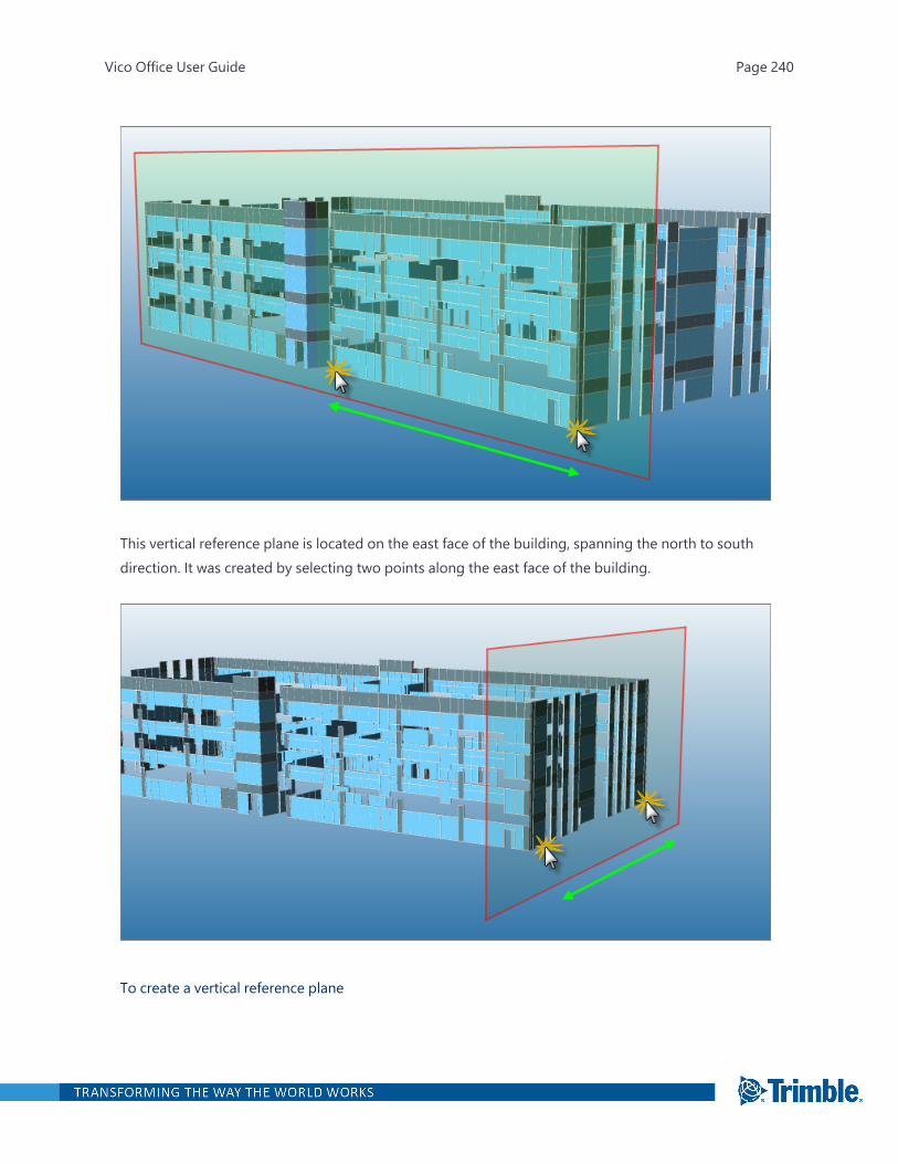
This vertical reference plane is located on the east face of the building, spanning the north to southdirection. It was created by selecting two points along the east face of the building.
To create a vertical reference plane
Vico Office User Guide Page 240

1. Open the Document Control task.
2. Click the Document Controller, 3D and Issues viewset tab.
3. On the 3D View ribbon tab, click New Ref. plane > Vertical Plane.
—Or—
On the Reference Planes palette, click the Create New Reference Plane button > Ver-
tical.
4. In the New Vertical Reference Plane dialog, enter the information for the two points to clarify ifthe plane should run in the X direction, the Y direction, or diagonally.
The selected points create a vertical reference plane that is actually in the horizontal plane ofthe model when clicking.
Tip: It is often easiest to define a vertical reference plane by filtering out the 3D content that isnot applicable or helpful to creating the reference plane. Use the Filtering palette to select themost pertinent elements, such as slabs or walls, to make vertical reference plane creationeasier. Also, turn on project O-snaps (from the 3D navigation toolbar) to precisely select endpoints from the model.
5. Click OK.
Free Reference Planes
Free reference planes are flat surfaces that can run in any direction. They can be aligned in any angleor direction based on the selected model points.
To create a free reference plane
1. Open the Document Control task.
2. Click the Document Controller, 3D and Issues tab.
3. On the 3D View ribbon tab, click New Ref. plane > Free Plane.
—Or—
On the Reference Planes palette, click the Create New Reference Plane button > Free.
4. In the New Reference Plane dialog, enter the information for the three points.
The first two points determine the major direction of the reference plane, and the third pointdefines the minor direction.
Vico Office User Guide Page 241

5. Click OK.
Vico Office User Guide Page 242
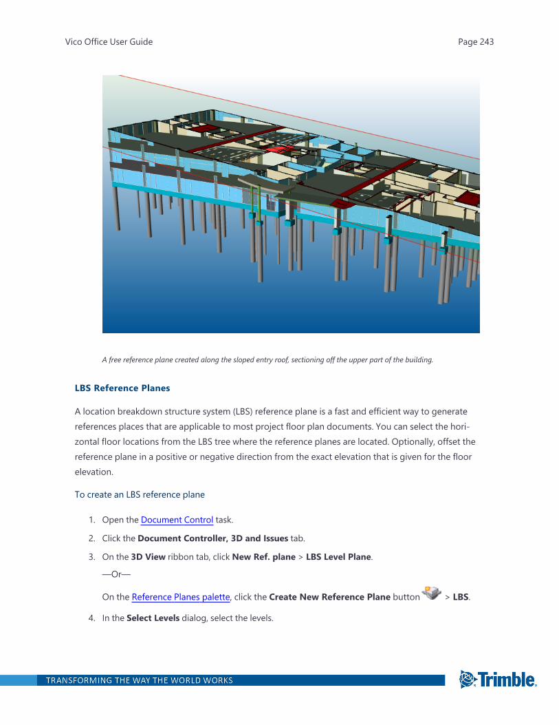
A free reference plane created along the sloped entry roof, sectioning off the upper part of the building.
LBS Reference Planes
A location breakdown structure system (LBS) reference plane is a fast and efficient way to generatereferences places that are applicable to most project floor plan documents. You can select the hori-zontal floor locations from the LBS tree where the reference planes are located. Optionally, offset thereference plane in a positive or negative direction from the exact elevation that is given for the floorelevation.
To create an LBS reference plane
1. Open the Document Control task.
2. Click the Document Controller, 3D and Issues tab.
3. On the 3D View ribbon tab, click New Ref. plane > LBS Level Plane.
—Or—
On the Reference Planes palette, click the Create New Reference Plane button > LBS.
4. In the Select Levels dialog, select the levels.
Vico Office User Guide Page 243
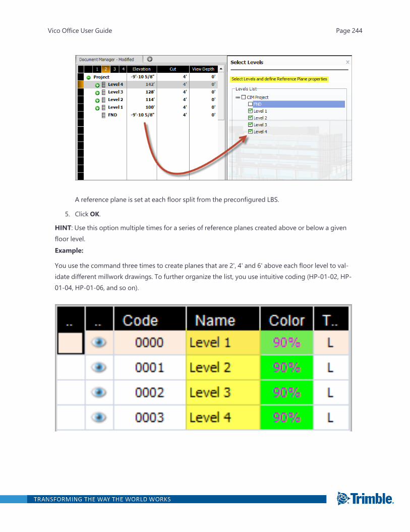
A reference plane is set at each floor split from the preconfigured LBS.
5. Click OK.
HINT: Use this option multiple times for a series of reference planes created above or below a givenfloor level.Example:
You use the command three times to create planes that are 2', 4' and 6' above each floor level to val-idate different millwork drawings. To further organize the list, you use intuitive coding (HP-01-02, HP-01-04, HP-01-06, and so on).
Vico Office User Guide Page 244
Mapping Documents
After reference planes are created, you can can map 2D drawings to the reference plane, so the 3Dmodel can be validated. This is an important step because 2D drawings are often the contract doc-uments, but the model is used for estimating and scheduling.
To map a document to a reference plane
1. Open the Document Control task.
2. Click the Document Controller, 3D and Issues tab.
3. In the 3D View, click the reference plane.
4. On the 3D View ribbon tab, clickMap Document.
—Or—
On the Reference Planes palette, click theMap Document button .
5. In the Select Document dialog, select the document.
Note: You can also select the document version from the Document Version list at the bot-tom of the dialog.
6. Click OK.
The drawing appears in one of the corners of the reference plane and is ready for aligning andscaling. The mapped drawing also appears in the Reference Plane palette under the selectedplane.
Vico Office User Guide Page 245
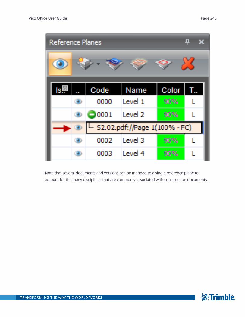
Note that several documents and versions can be mapped to a single reference plane toaccount for the many disciplines that are commonly associated with construction documents.
Vico Office User Guide Page 246

Aligning and Scaling
Most construction documents are created to scale and therefore it is necessary to align and scaletheir position according to the BIM model. By default drawings come in at their scaled size, oftenaround 36"x48" and must match the building footprint, which can be significantly larger.
Align and Scale Tips
l Select points in a unique area or shape, such as a notch in the slab edge, in the document. Select-ing unique places of the drawing will make it easier to validate the location on the BIM becauseof the rare geometry.
l To reduce misalignments, select a first and second point that are far from each other, preferablytwo corners of the building.
l To select very precise points on the drawing, use the Zoom Window tool .
l For increased selection accuracy, turn on O-snaps.
To align and scale a document
Vico Office User Guide Page 247
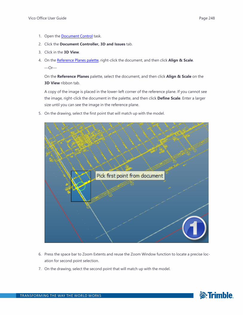
1. Open the Document Control task.
2. Click the Document Controller, 3D and Issues tab.
3. Click in the 3D View.
4. On the Reference Planes palette, right-click the document, and then click Align & Scale.
—Or—
On the Reference Planes palette, select the document, and then click Align & Scale on the3D View ribbon tab.
A copy of the image is placed in the lower-left corner of the reference plane. If you cannot seethe image, right-click the document in the palette, and then click Define Scale. Enter a largersize until you can see the image in the reference plane.
5. On the drawing, select the first point that will match up with the model.
6. Press the space bar to Zoom Extents and reuse the Zoom Window function to locate a precise loc-ation for second point selection.
7. On the drawing, select the second point that will match up with the model.
Vico Office User Guide Page 248

You are prompted to select points on the model that match the drawings. Make sure that thefirst model selection point matches the first point selected on the drawing and that the secondpoint selected on the model matches the second point selected on the drawing.
8. Select the points on the model that match the drawings.
Make sure that the first model selection point matches the first point selected on the drawingand that the second point selected on the model matches the second point selected on thedrawing.
Vico Office User Guide Page 249

After the two drawing points are mapped to the two model points, the selected document isaligned and scaled with the model.
Vico Office User Guide Page 250

Tip: To validate that the document was align and scale operation worked well by peeling away modelelements, use the model sectioning functionality. Again, identify areas of unique geometry to ensurea good match. If the drawing and model seem misaligned, repeat the align and scale operation oncemore until the results are exact.
Documenting Changes
After the dataset is organized in the Document Controller, you may want to perform change analysisand model validation. You can use a custom view to track design change issues. A common layoutincludes the Issue Card View on the left and the 3D View on the right with reference planes andmapped drawings turned on.
To create an issue from the Document Controller
Vico Office User Guide Page 251

1. Open the Document Control task.
2. To display the default model view, click Reset View on the 3D View ribbon tab.
3. In the Document Register view, right-click the document, and then click View.
4. In the Document Register view window, switch to the Issue Card View.
5. To add an issue, click the View & Markup Tools ribbon tab > Add Cloud, and then draw theshape in the 3D View.
Vico Office User Guide Page 252
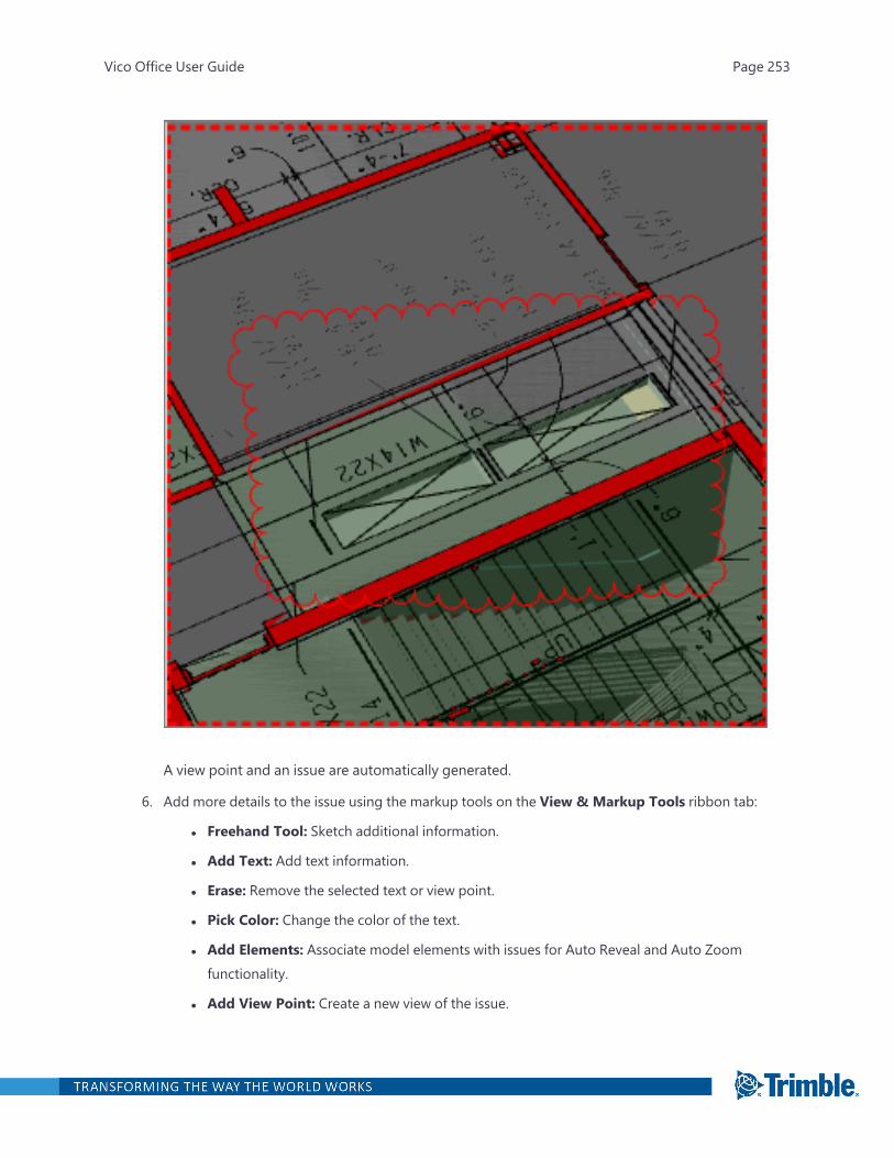
A view point and an issue are automatically generated.
6. Add more details to the issue using the markup tools on the View & Markup Tools ribbon tab:
l Freehand Tool: Sketch additional information.
l Add Text: Add text information.
l Erase: Remove the selected text or view point.
l Pick Color: Change the color of the text.
l Add Elements: Associate model elements with issues for Auto Reveal and Auto Zoomfunctionality.
l Add View Point: Create a new view of the issue.
Vico Office User Guide Page 253

l Add Image: Add images from the clipboard (screen shots) or from saved file locations.
l Auto Reveal: Peel away other 3D content that may be obstructing the view.
l Auto Zoom:Magnify the issue within the immediate range of the active viewset.
7. In the Issue Card View, add the meta data necessary for the issue to be understood andresolved.
Vico Office User Guide Page 254
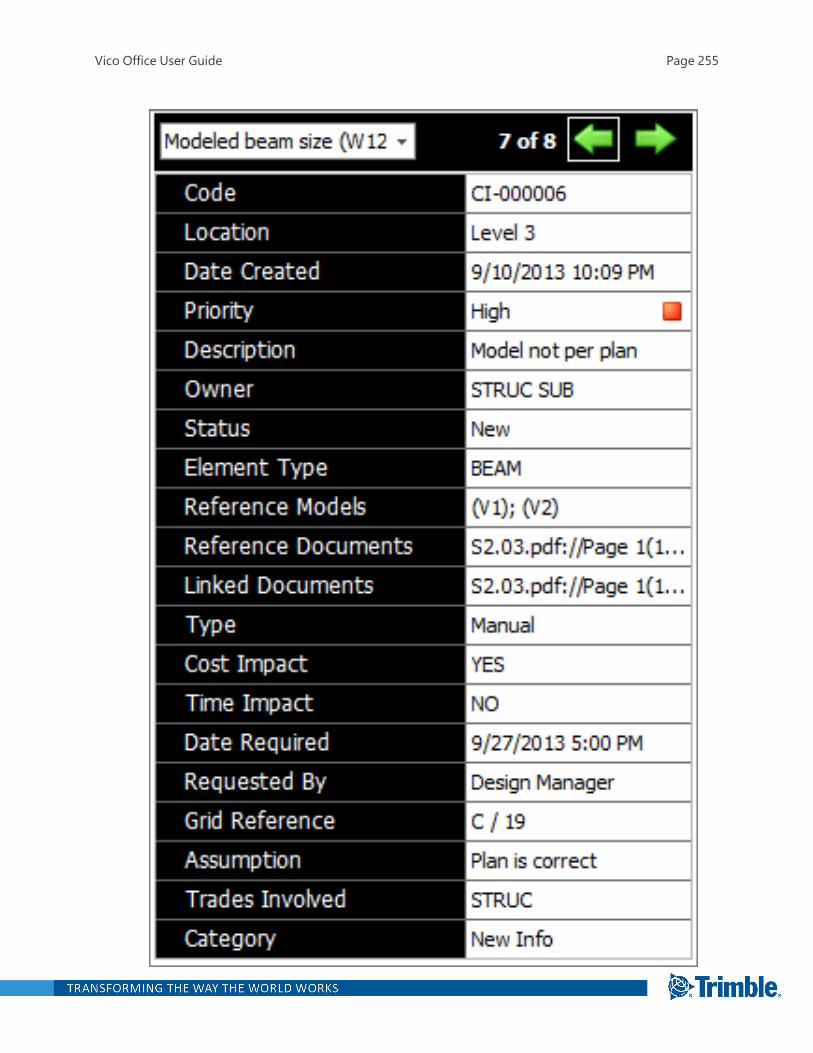
Vico Office User Guide Page 255
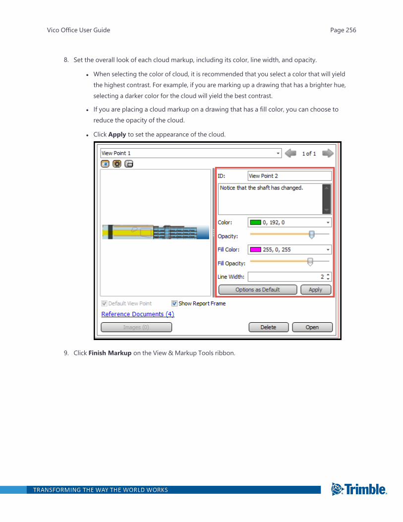
8. Set the overall look of each cloud markup, including its color, line width, and opacity.
l When selecting the color of cloud, it is recommended that you select a color that will yieldthe highest contrast. For example, if you are marking up a drawing that has a brighter hue,selecting a darker color for the cloud will yield the best contrast.
l If you are placing a cloud markup on a drawing that has a fill color, you can choose toreduce the opacity of the cloud.
l Click Apply to set the appearance of the cloud.
9. Click Finish Markup on the View & Markup Tools ribbon.
Vico Office User Guide Page 256
Models
After you publish your models from any of the supported BIM applications (Archicad, Revit, Tekla orBentley), the published models are available in the Document Control task.
In the model activation process, the takeoff items are created based on the activation options. Forevery takeoff item created, Vico's quantity extraction algorithms are executed to analyze the geo-metry and to extract the appropriate element quantities, which results in a set of takeoff quantitiesper takeoff item.
The available properties for takeoff item creation rules vary per application. For more information,see:
l "Archicad TOI Creation" on page 265
l "Revit TOI Creation" on page 267
l "Tekla TOI Creation" on page 272
Activating a Model
After publishing models from the selected BIM application and defining the units of measurement,you can activate them so that Vico Office can use them to quantify the Takeoff items. You can activatemodels in Document Controller.
Note:l If a new model version is published and activated, it will make the already quantified Takeoff
items out-of-date.
l All published models from the selected BIM application are visible in the 3D View.
To activate a model in the Document Register
1. Open the Document Control task.
2. To view all available versions of the model and their activation status, click All Versions in theColumn Presets group on the ribbon.
Vico Office User Guide Page 257
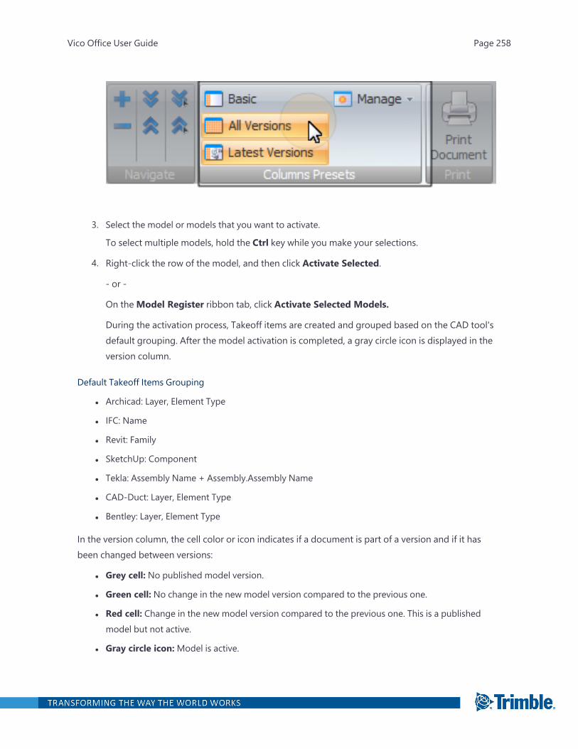
3. Select the model or models that you want to activate.
To select multiple models, hold the Ctrl key while you make your selections.
4. Right-click the row of the model, and then click Activate Selected.
- or -
On theModel Register ribbon tab, click Activate Selected Models.
During the activation process, Takeoff items are created and grouped based on the CAD tool'sdefault grouping. After the model activation is completed, a gray circle icon is displayed in theversion column.
Default Takeoff Items Grouping
l Archicad: Layer, Element Type
l IFC: Name
l Revit: Family
l SketchUp: Component
l Tekla: Assembly Name + Assembly.Assembly Name
l CAD-Duct: Layer, Element Type
l Bentley: Layer, Element Type
In the version column, the cell color or icon indicates if a document is part of a version and if it hasbeen changed between versions:
l Grey cell: No published model version.
l Green cell: No change in the new model version compared to the previous one.
l Red cell: Change in the new model version compared to the previous one. This is a publishedmodel but not active.
l Gray circle icon:Model is active.
Vico Office User Guide Page 258

l Cloud icon:Marked up screenshots have been created from the model for constructabilityreports.
Your data can be in three different states:
1. Published but not active - Models that have been published from a CAD tool are visible in 3Dview. However, if they are not activated, they are not used when quantifying Takeoff items.
2. Active but not 'quantified' - After activating a model, Takeoff items are created and visible onTakeoff Manager. They are initially grouped based on the CAD tool's default Takeoff itemgrouping. The quantities for these takeoff items consist of CAD information, CAD names andBasic quantities, and allow for a quick start and interrogation.
The Takeoff items on Takeoff Manager can be re-grouped using the Takeoff Items builder (TOIBuilder).
3. Quantified Takeoff items - After quantifying the Takeoff items, Vico generates Premium Quant-ities using a process that involves Vico algorithm and locations.
Quantified Takeoff item in the Takeoff Manager
Note: When a CAD model has been activated, some elements may not be assigned to a Takeoff item.In this case, they are labeled as 'Unassigned_<ElementType>'.
Vico Office User Guide Page 259

Deactivating a Model
Remove the active status from an active model version.
To deactivate a model
1. Open the Document Control task.
2. Select an active model or model version from the list.
The selected model or model version is indicated by an orange cell to the far left.
3. On theModel Register ribbon tab, click Deactivate Selected Models.
—Or—
Right-click the selected model or model version, and then click Deactivate Selected Models.
4. In the Deactivate Model Version dialog, click Deactivate to continue.
Note: When you deactivate a model or model version, the quantities are removed from thetakeoff items and the takeoff quantities. To restore them, you can reactivate the model versionlater.
The Deactivating Model progress dialog appears. When the deactivation process is com-pleted, the gray circle that indicates the active model version is removed. The elements in thismodel are no longer included in the current takeoff.
Importing a Model
With a license for an importer you can import BIM projects saved in the respective file formats intoyour Vico Office project. The supported importers are:
Vico Office User Guide Page 260
l IFC – Versions IFC2x3 and IFC4
l SketchUp: Versions 8, 2013, 2014, 2015, 2016, 2017
l Trimble Connect
Tip: You can import models created in CAD-Duct, SketchUp, AutoCAD (3D), or any other BIM toolthat can save IFC files. To make sure that Vico Office can correctly recognize the types of the elementsin a CAD-Duct model, your export to IFCxml from CAD-Duct should contain the following inform-ation:
1. Source (the element’s category)
2. Library (the element’s type)
3. Service (the MEP system)
If any of these properties are missing, elements will be imported as “Objects” in Vico Office and willonly return the “Count” quantity. Additionally, before running the IFCE command use the IFCATTRcommand and verify that the “Use Default Format” option is selected.
To import a SketchUp or IFC file into Vico Office
1. Open the Document Control task.
2. On theModel Register ribbon tab, click the applicable button.
Vico Office User Guide Page 261
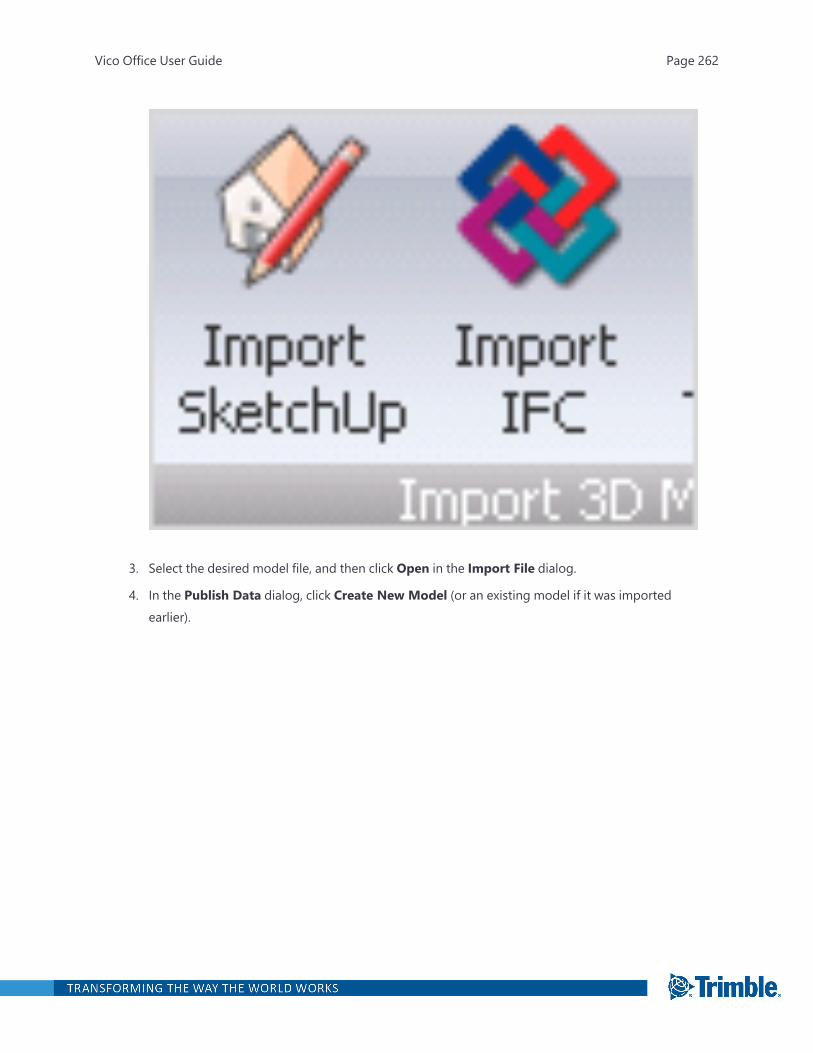
3. Select the desired model file, and then click Open in the Import File dialog.
4. In the Publish Data dialog, click Create New Model (or an existing model if it was importedearlier).
Vico Office User Guide Page 262
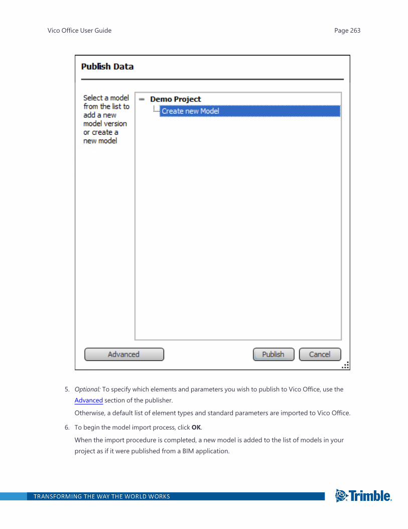
5. Optional: To specify which elements and parameters you wish to publish to Vico Office, use theAdvanced section of the publisher.
Otherwise, a default list of element types and standard parameters are imported to Vico Office.
6. To begin the model import process, click OK.
When the import procedure is completed, a new model is added to the list of models in yourproject as if it were published from a BIM application.
Vico Office User Guide Page 263
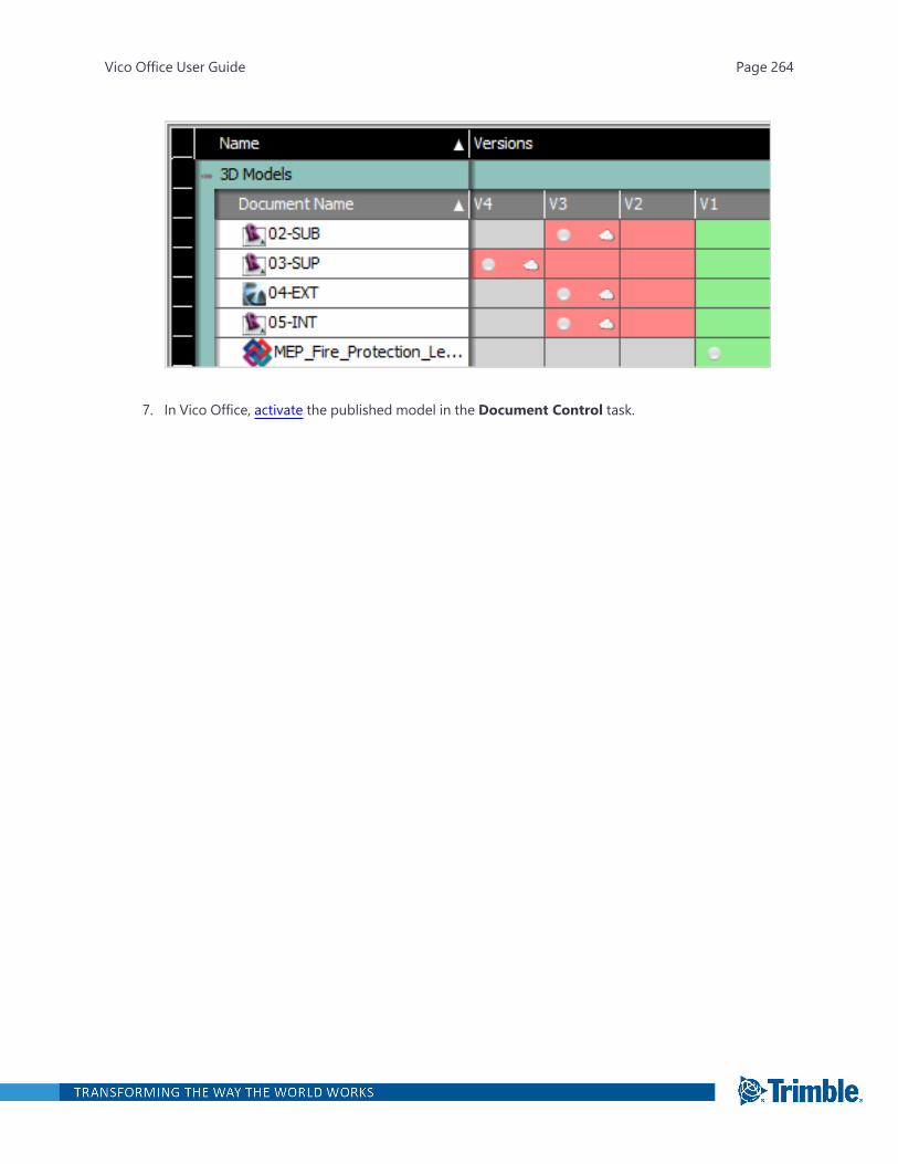
7. In Vico Office, activate the published model in the Document Control task.
Vico Office User Guide Page 264
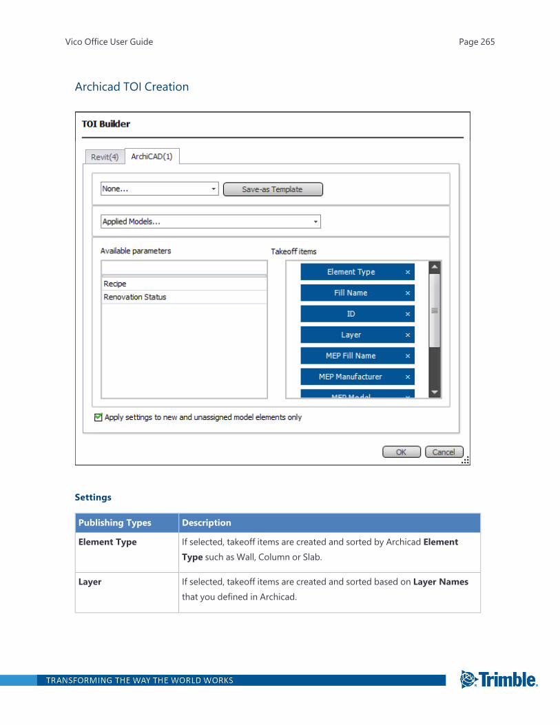
Archicad TOI Creation
Settings
Publishing Types Description
Element Type If selected, takeoff items are created and sorted by Archicad ElementType such as Wall, Column or Slab.
Layer If selected, takeoff items are created and sorted based on Layer Namesthat you defined in Archicad.
Vico Office User Guide Page 265
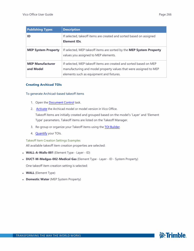
Publishing Types Description
ID If selected, takeoff items are created and sorted based on assignedElement IDs.
MEP System Property If selected, MEP takeoff items are sorted by theMEP System Propertyvalues you assigned to MEP elements.
MEP Manufacturerand Model
If selected, MEP takeoff items are created and sorted based on MEPmanufacturing and model property values that were assigned to MEPelements such as equipment and fixtures.
Creating Archicad TOIs
To generate Archicad-based takeoff items
1. Open the Document Control task.
2. Activate the Archicad model or model version in Vico Office.
Takeoff items are initially created and grouped based on the model's 'Layer' and 'ElementType' parameters. Takeoff items are listed on the Takeoff Manager.
3. Re-group or organize your Takeoff items using the TOI Builder.
4. Quantify your TOIs.
Takeoff Item Creation Settings ExamplesAll available takeoff item creation properties are selected:
l WALL-A-Walls-001 (Element Type - Layer - ID)
l DUCT-M-Medgas-002-Medical Gas (Element Type - Layer - ID - System Property)
One takeoff item creation setting is selected:
l WALL (Element Type)
l Domestic Water (MEP System Property)
Vico Office User Guide Page 266

Revit TOI Creation
Settings
Publishing Types Description
Family If selected, takeoff items are created and sorted based on unique Familydefinitions.
Family Type If selected, takeoff items are created and sorted by unique Family Types.
Vico Office User Guide Page 267
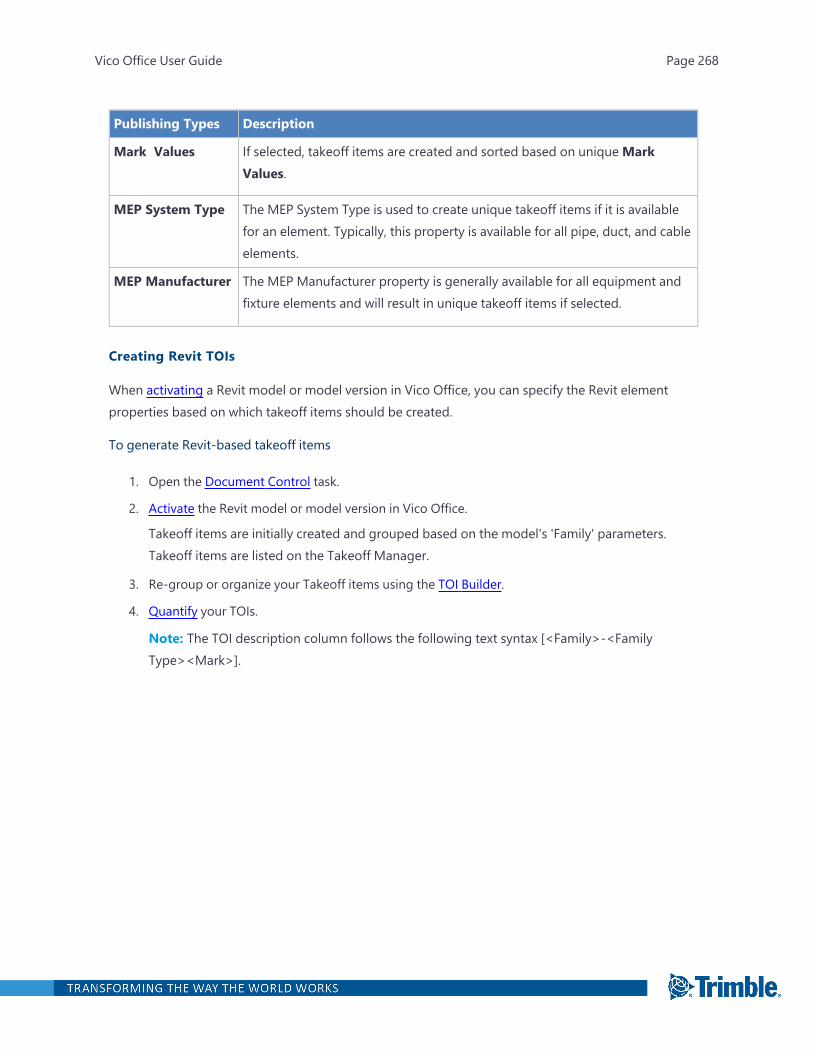
Publishing Types Description
Mark Values If selected, takeoff items are created and sorted based on uniqueMarkValues.
MEP System Type The MEP System Type is used to create unique takeoff items if it is availablefor an element. Typically, this property is available for all pipe, duct, and cableelements.
MEP Manufacturer The MEP Manufacturer property is generally available for all equipment andfixture elements and will result in unique takeoff items if selected.
Creating Revit TOIs
When activating a Revit model or model version in Vico Office, you can specify the Revit elementproperties based on which takeoff items should be created.
To generate Revit-based takeoff items
1. Open the Document Control task.
2. Activate the Revit model or model version in Vico Office.
Takeoff items are initially created and grouped based on the model's 'Family' parameters.Takeoff items are listed on the Takeoff Manager.
3. Re-group or organize your Takeoff items using the TOI Builder.
4. Quantify your TOIs.
Note: The TOI description column follows the following text syntax [<Family>-<FamilyType><Mark>].
Vico Office User Guide Page 268
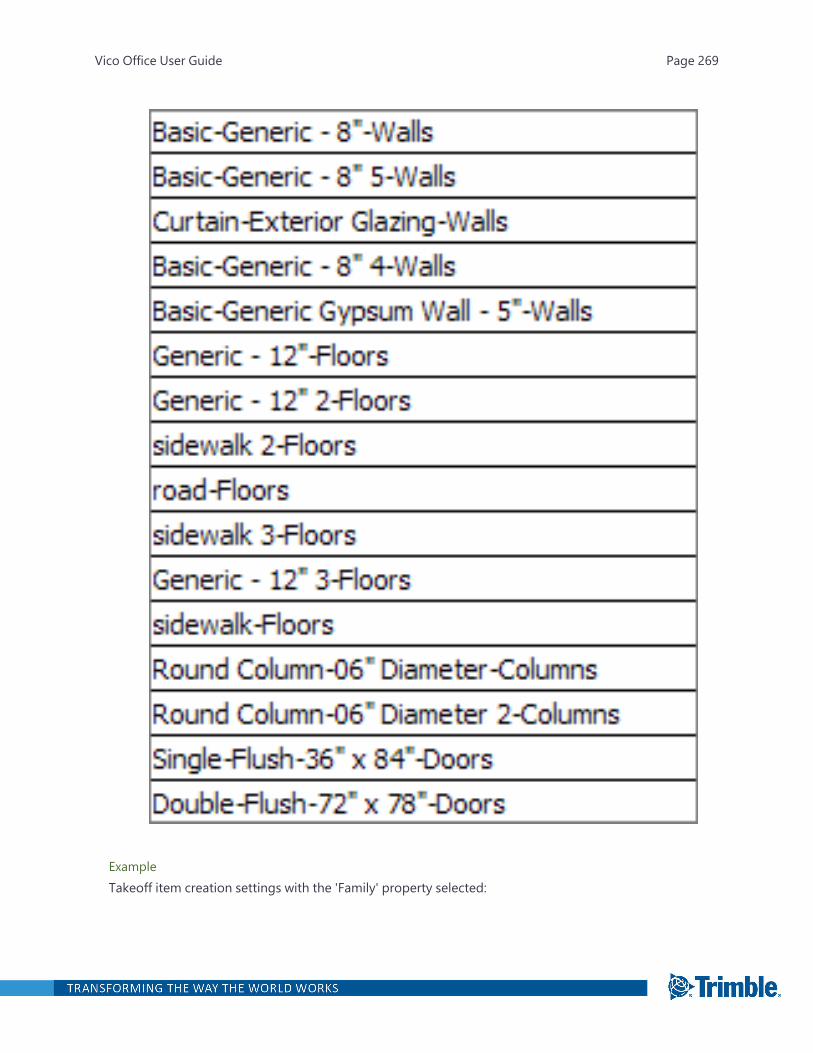
ExampleTakeoff item creation settings with the 'Family' property selected:
Vico Office User Guide Page 269

All the takeoff items are organized and listed in the description column based on the single takeoffitem creation property, which in this case would include all related Family Type elements assigned toone TOI [<Family>].
Vico Office User Guide Page 270
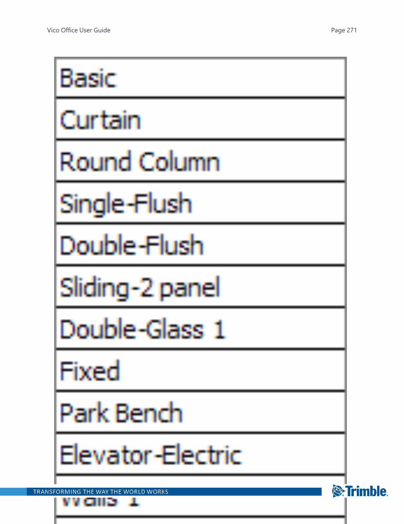
Vico Office User Guide Page 271
Tekla TOI Creation
Settings
PublishingTypes
Description
Class If selected, takeoff items from the Tekla Model are created and sorted based onunique Element Class property values.
Creating Tekla TOIs
To generate Tekla-based takeoff items
1. Open the Document Control task.
2. Activate the Tekla model or model version in Vico Office.
Takeoff items are initially created and grouped based on the model's 'Assembly Name' and'Assembly.Assembly Name' parameters. Takeoff items are listed on the Takeoff Manager.
3. Re-group or organize your Takeoff items using the TOI Builder. For example, if you select theClass property, it will be used to create and sort takeoff items. The Class name will be used in thedescription of the takeoff item.
4. Quantify your TOIs.
Publishing a Model to Trimble Connect
The Publish to Trimble Connect functionality enables sharing BIM data created in Vico Office withnon-Vico Office users through Trimble Connect.
1. The Publish Models to Trimble Connect function can be accessed from Document Control>Model Register.
2. Select one or more models to start the process.
3. Click Publish to Trimble Connect in the right-click context menu or select Publish Modelson the ribbon tab.
4. Choose the Trimble Connect project where the Vico BIM data should be stored.
Only activated models (model versions) can be published, and the model elements should also bequantified.
Vico Office User Guide Page 272
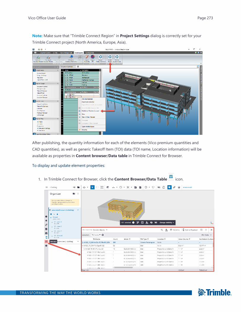
Note: Make sure that “Trimble Connect Region” in Project Settings dialog is correctly set for yourTrimble Connect project (North America, Europe, Asia).
After publishing, the quantity information for each of the elements (Vico premium quantities andCAD quantities), as well as generic Takeoff Item (TOI) data (TOI name, Location information) will beavailable as properties in Content browser/Data table in Trimble Connect for Browser.
To display and update element properties:
1. In Trimble Connect for Browser, click the Content Browser/Data Table icon.
Vico Office User Guide Page 273
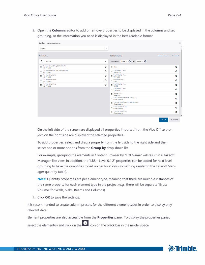
2. Open the Columns editor to add or remove properties to be displayed in the columns and setgrouping, so the information you need is displayed in the best readable format.
On the left side of the screen are displayed all properties imported from the Vico Office pro-ject; on the right side are displayed the selected properties.
To add properties, select and drag a property from the left side to the right side and thenselect one or more options from the Group by drop-down list.
For example, grouping the elements in Content Browser by “TOI Name” will result in a TakeoffManager-like view. In addition, the “LBS – Level 0,1,2” properties can be added for next levelgrouping to have the quantities rolled up per locations (something similar to the Takeoff Man-ager quantity table).
Note: Quantity properties are per element type, meaning that there are multiple instances ofthe same property for each element type in the project (e.g., there will be separate ‘GrossVolume’ for Walls, Slabs, Beams and Columns).
3. Click OK to save the settings.
It is recommended to create column presets for the different element types in order to display onlyrelevant data.
Element properties are also accessible from the Properties panel. To display the properties panel,
select the element(s) and click on the icon on the black bar in the model space.
Vico Office User Guide Page 274
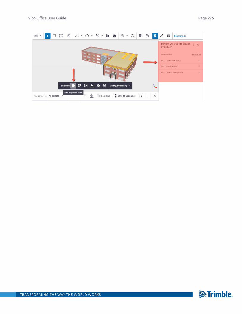
Vico Office User Guide Page 275
Takeoff Manager
In the Takeoff Manager task, you can quantify the elements, verify the generated takeoff item (TOI)element assignments and/or reassign them into new takeoff items as desired. You can also create anew takeoff quantity (TOQ) and assign model geometry for automatic quantity takeoff.
A takeoff item (TOI) is a group of takeoff information. This is created manually or based on propertiesof elements extracted from CAD models. Each TOI contains one or more takeoff quantities (TOQ),which are typical quantities of the TOIs that can be used for estimating or scheduling purposes. Theset of TOQs included in a TOI is based on the element type that is assigned to the TOI. For example,'Walls' have different TOQs than 'Slabs'. Each TOI from a CAD model also includes the CAD quantities.
The reassigning of assigned and unassigned elements into new or existing TOIs is an interactive pro-cess between the Takeoff Manager view and the 3D View. Takeoff items and takeoff quantity itemscan be created and selected in the Takeoff Manager view so that you can then use the Paint Mode inthe 3D View to assign or reassign the model elements and geometry. The process of verification,assigning, and reassigning model elements and quantities in the 3D View can be greatly enhancedby the use of the Filtering palette and Properties palette.
When you are satisfied with the collection of TOIs and their assigned TOQs, you can view a full break-down of all the TOIs and their quantities in the Takeoff Manager view. The quantity totals displayedby your projects location breakdown can subsequently be used to generate customizable quantityreports.
To open the Takeoff Manager task
1. Right-click the Workflow Panel header, and then click the Vico Office or Vico for Design module.
2. In the Vico for Design or Design Management workflow group, click Takeoff Manager.
The default viewset includes the Takeoff Manager view and the 3D View, so you can verifytakeoff items side-by-side with the 3D view. The model-based takeoff items are created in theDocument Control task.
Quantity Calculation Rules
When you quantify Takeoff items, Vico Office analyzes the geometry that was brought in from a BIMapplication and calculates the following for each element:
l Volume
l Surface Area
Vico Office User Guide Page 276

Quantities such as length and width are not calculated in Vico Office but are derived from meta datathat is saved with the geometry during the publish or import operation.
Volume
Volume is calculated by creating a solid element where the element's boundaries are defined by thefaces of the published element. After the volume is created, net volume quantities can be obtainedthrough solid element analysis.
When the published geometry contains faces that do not entirely close a 3D volume, Vico Officeattempts to fix this geometry with increasing levels of tolerance. If the volume correcting does notsucceed, the element is marked as ‘incomplete’ and returns to a ‘0’ volume value. In this case, thetakeoff item which the element belongs to is marked with a notification icon .
In calculating the surface area, the most important thing is to give the correct direction of the ele-ment faces. The calculation rules in Vico Office use the corkscrew rule to determine the direction of aface.
By following the drawing direction of the points of a face, this direction can be determined. The dir-ection of the face is then compared to the project’s normal vector, which is a vector that pointsexactly in the z-direction.
Based on this comparison, an angle variance with the normal vector can be determined, which thenlets Vico Office classify the face.
l If the direction of a face is in the 315° to 45° range, the face is classified as Top.
l If the direction of a face is in either 45° to 135° or 225° to 315° range, the face is classified asSide.
l If the direction of a face is in the 135° to 225° range, the face is classified as Bottom.
Vico Office User Guide Page 277

Element Types
The initial classification is then further processed based on the Vico element type. Each element typehas its own set of takeoff quantities, which are collections of faces that are classified based on the fol-lowing rules.
Vico Office User Guide Page 278
Walls
In addition to the element’s 3D geometry, published information of wall elements also contains theReference Line or Placement Line, which is saved as a start point and an end point.
For walls, the classified faces are processed as follows:
l ‘Top’ faces are assigned to Top Surface Area.
l ‘Bottom’ faces are assigned to Bottom Surface Area.
l ‘Side’ faces which are parallel to the Reference Line are assigned to Side Surface Area.
AND
l the ‘Side’ face that is nearest to the Reference Line is assigned to Net Reference
Side Surface Area.
Vico Office User Guide Page 279

l the ‘Side’ face that is farthest from the Reference Line is assigned to Net Opposite
Reference Side Surface Area.
l ‘Side’ faces that are not parallel to the Reference Line are assigned to Ends Surface Area.
l Window openings are found by looking for ‘loops within loops’. Any loop that matches this defin-ition is considered ‘Opening’ and is used to calculateOpening Surface Area.
Vico Office User Guide Page 280
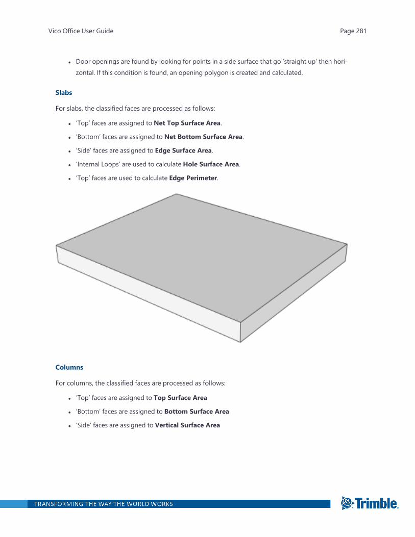
l Door openings are found by looking for points in a side surface that go ‘straight up’ then hori-zontal. If this condition is found, an opening polygon is created and calculated.
Slabs
For slabs, the classified faces are processed as follows:
l ‘Top’ faces are assigned to Net Top Surface Area.
l ‘Bottom’ faces are assigned to Net Bottom Surface Area.
l ‘Side’ faces are assigned to Edge Surface Area.
l ‘Internal Loops’ are used to calculate Hole Surface Area.
l ‘Top’ faces are used to calculate Edge Perimeter.
Columns
For columns, the classified faces are processed as follows:
l ‘Top’ faces are assigned to Top Surface Area
l ‘Bottom’ faces are assigned to Bottom Surface Area
l ‘Side’ faces are assigned to Vertical Surface Area
Vico Office User Guide Page 281
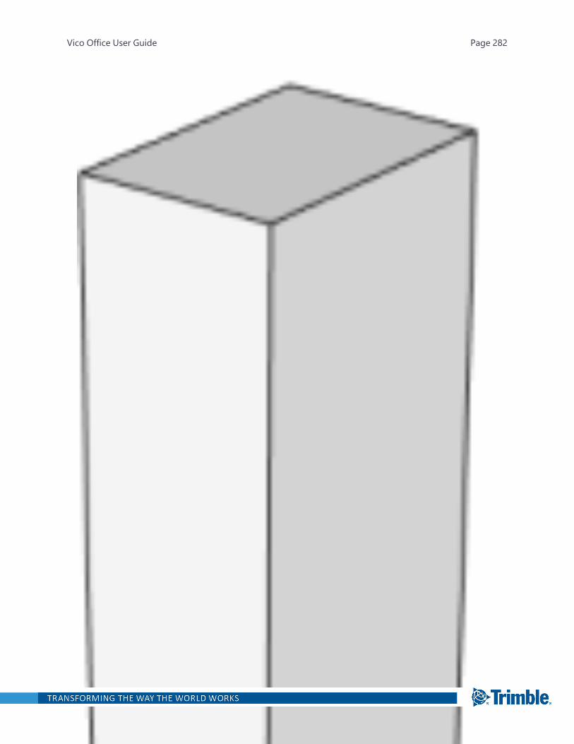
Vico Office User Guide Page 282
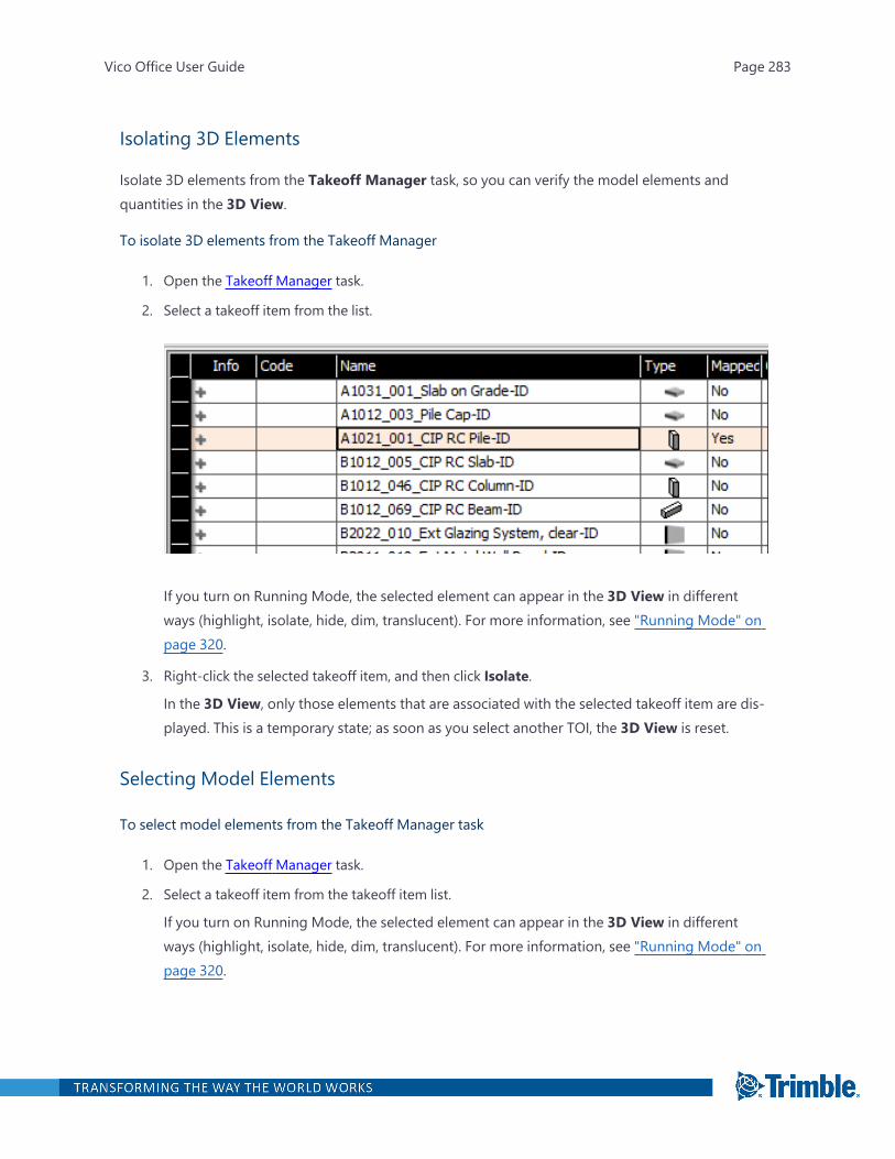
Isolating 3D Elements
Isolate 3D elements from the Takeoff Manager task, so you can verify the model elements andquantities in the 3D View.
To isolate 3D elements from the Takeoff Manager
1. Open the Takeoff Manager task.
2. Select a takeoff item from the list.
If you turn on Running Mode, the selected element can appear in the 3D View in differentways (highlight, isolate, hide, dim, translucent). For more information, see "Running Mode" onpage 320.
3. Right-click the selected takeoff item, and then click Isolate.
In the 3D View, only those elements that are associated with the selected takeoff item are dis-played. This is a temporary state; as soon as you select another TOI, the 3D View is reset.
Selecting Model Elements
To select model elements from the Takeoff Manager task
1. Open the Takeoff Manager task.
2. Select a takeoff item from the takeoff item list.
If you turn on Running Mode, the selected element can appear in the 3D View in differentways (highlight, isolate, hide, dim, translucent). For more information, see "Running Mode" onpage 320.
Vico Office User Guide Page 283
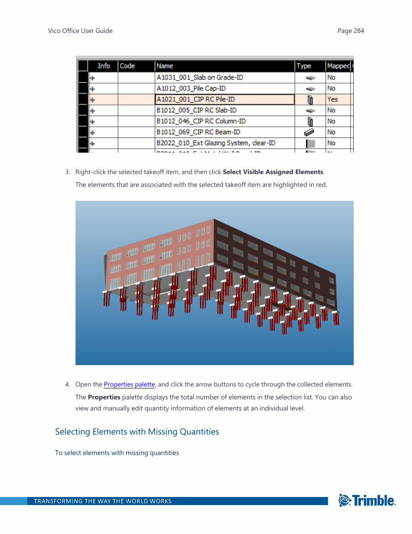
3. Right-click the selected takeoff item, and then click Select Visible Assigned Elements.
The elements that are associated with the selected takeoff item are highlighted in red.
4. Open the Properties palette, and click the arrow buttons to cycle through the collected elements.
The Properties palette displays the total number of elements in the selection list. You can alsoview and manually edit quantity information of elements at an individual level.
Selecting Elements with Missing Quantities
To select elements with missing quantities
Vico Office User Guide Page 284
1. Open the Takeoff Manager task.
2. In the takeoff item list, select a takeoff item that contains at least one missing quantity.
The missing quantities are indicated by the notification icon .
3. Right-click the selected takeoff item, and then click Select Visible Elements with MissingQuantities.
Vico Office selects all the visible elements with missing quantities.
4. Use the Properties palette to review individual element quantities in more detail.
If needed, you can also choose to edit or input the missing quantities manually.
Creating a Takeoff Item
Create a takeoff item (TOI), so you can assign elements to a custom group as needed for cost orschedule calculation purposes.
In the Takeoff Manager task, the activated models are displayed next to the takeoff items. When youselect a model, that element is highlighted in the model.
To create a TOI
1. Open the Takeoff Manager task.
2. On the Takeoff Manager ribbon tab, click New TOI.
—Or—
Right-click a TOI, and then click Add New Takeoff Item.
The new TOI is created in an empty cell.
3. In the Code and Description fields, name and classify the TOI as desired.
4. In the Type field, either predefine the model element type that you plan to add to the new TOI,or simply start painting the elements in the 3D View with the painter tool.
The painting method automatically configures the Type field to the first type of element youpaint. The selected TOI element type then define which TOQs should be applied and cal-culated to the newly grouped elements.
As you paint elements to assign them to the new TOI, the elements are either subtracted fromthe unassigned element group or re-assigned from another TOI group.
Vico Office User Guide Page 285
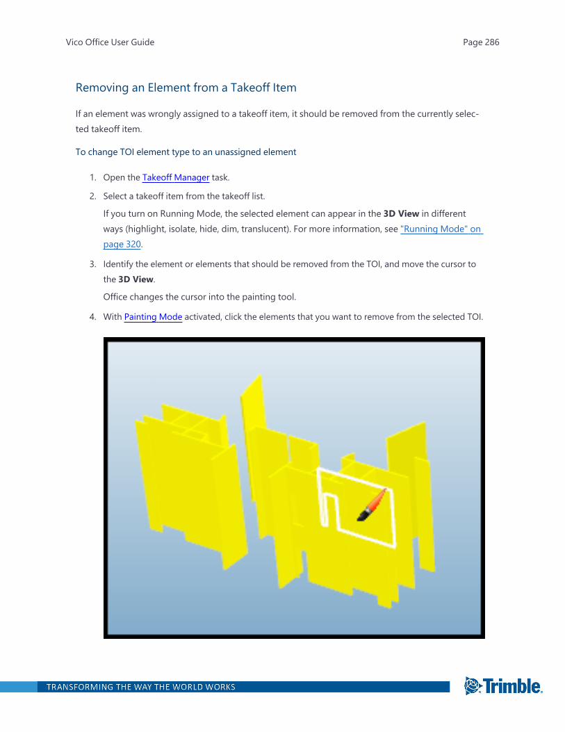
Removing an Element from a Takeoff Item
If an element was wrongly assigned to a takeoff item, it should be removed from the currently selec-ted takeoff item.
To change TOI element type to an unassigned element
1. Open the Takeoff Manager task.
2. Select a takeoff item from the takeoff list.
If you turn on Running Mode, the selected element can appear in the 3D View in differentways (highlight, isolate, hide, dim, translucent). For more information, see "Running Mode" onpage 320.
3. Identify the element or elements that should be removed from the TOI, and move the cursor tothe 3D View.
Office changes the cursor into the painting tool.
4. With Painting Mode activated, click the elements that you want to remove from the selected TOI.
Vico Office User Guide Page 286
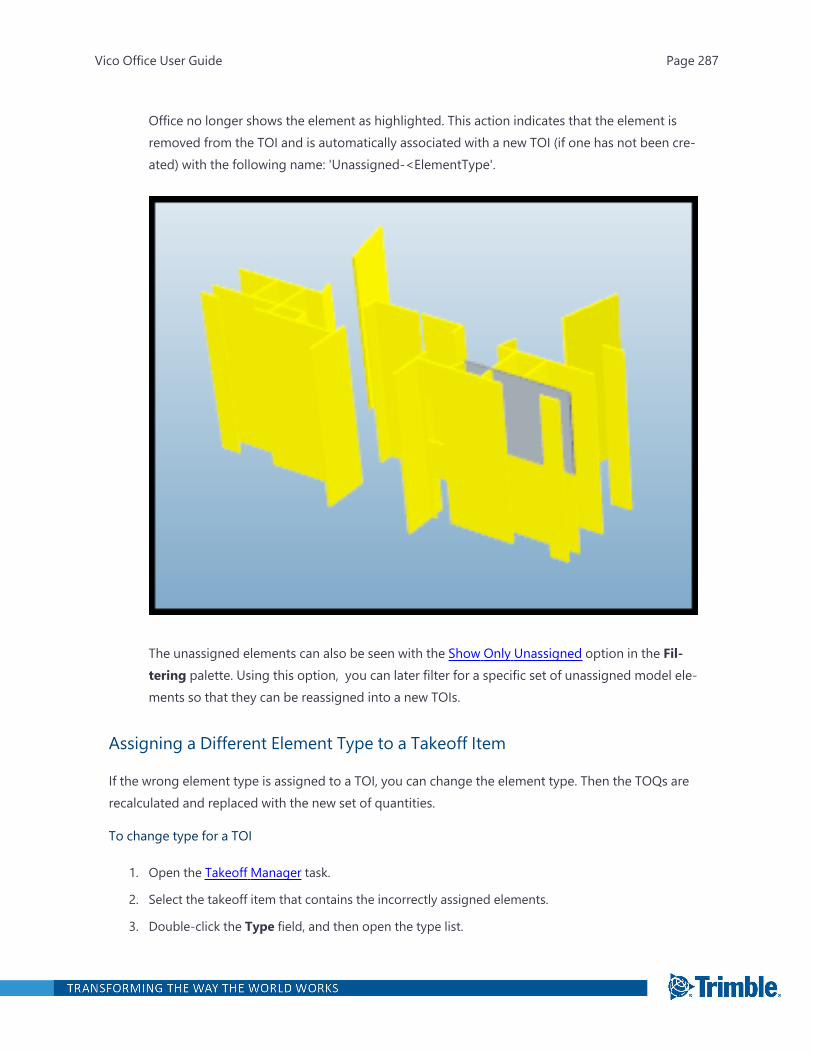
Office no longer shows the element as highlighted. This action indicates that the element isremoved from the TOI and is automatically associated with a new TOI (if one has not been cre-ated) with the following name: 'Unassigned-<ElementType'.
The unassigned elements can also be seen with the Show Only Unassigned option in the Fil-tering palette. Using this option, you can later filter for a specific set of unassigned model ele-ments so that they can be reassigned into a new TOIs.
Assigning a Different Element Type to a Takeoff Item
If the wrong element type is assigned to a TOI, you can change the element type. Then the TOQs arerecalculated and replaced with the new set of quantities.
To change type for a TOI
1. Open the Takeoff Manager task.
2. Select the takeoff item that contains the incorrectly assigned elements.
3. Double-click the Type field, and then open the type list.
Vico Office User Guide Page 287
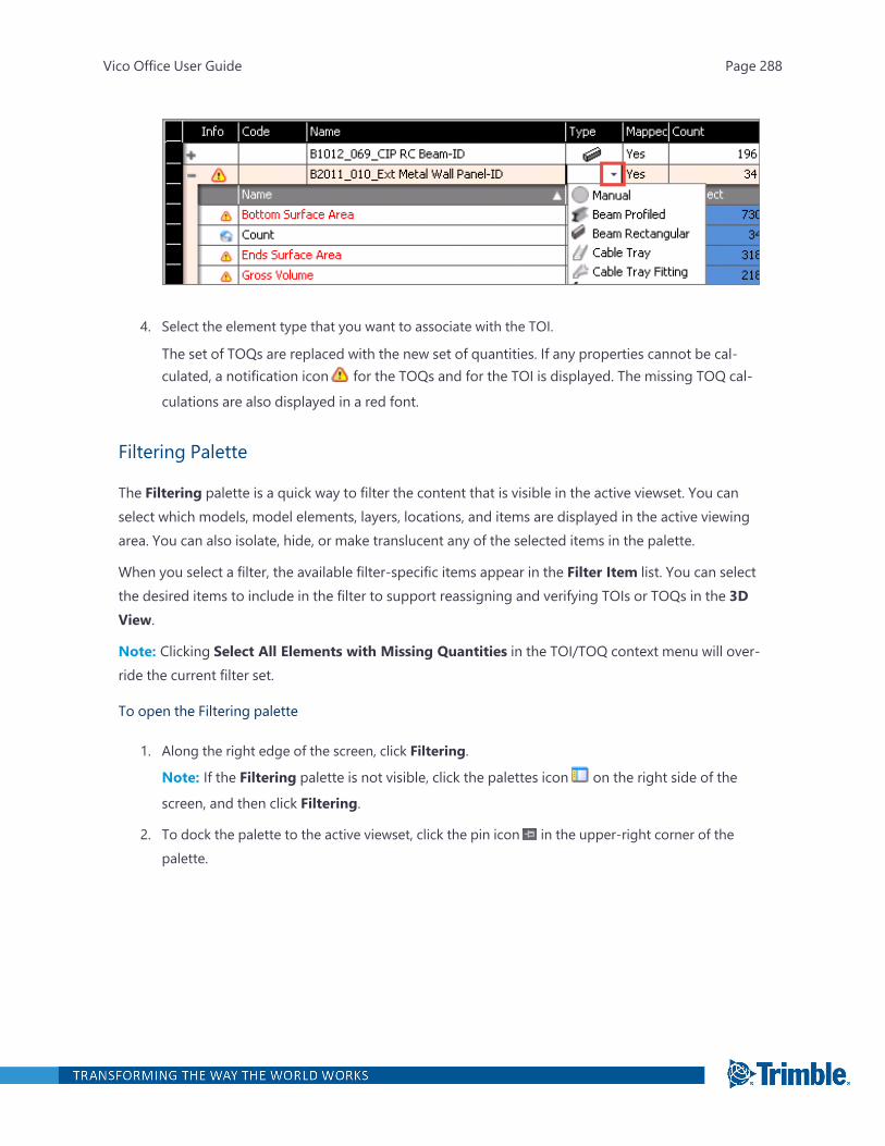
4. Select the element type that you want to associate with the TOI.
The set of TOQs are replaced with the new set of quantities. If any properties cannot be cal-culated, a notification icon for the TOQs and for the TOI is displayed. The missing TOQ cal-
culations are also displayed in a red font.
Filtering Palette
The Filtering palette is a quick way to filter the content that is visible in the active viewset. You canselect which models, model elements, layers, locations, and items are displayed in the active viewingarea. You can also isolate, hide, or make translucent any of the selected items in the palette.
When you select a filter, the available filter-specific items appear in the Filter Item list. You can selectthe desired items to include in the filter to support reassigning and verifying TOIs or TOQs in the 3DView.
Note: Clicking Select All Elements with Missing Quantities in the TOI/TOQ context menu will over-ride the current filter set.
To open the Filtering palette
1. Along the right edge of the screen, click Filtering.
Note: If the Filtering palette is not visible, click the palettes icon on the right side of the
screen, and then click Filtering.
2. To dock the palette to the active viewset, click the pin icon in the upper-right corner of thepalette.
Vico Office User Guide Page 288
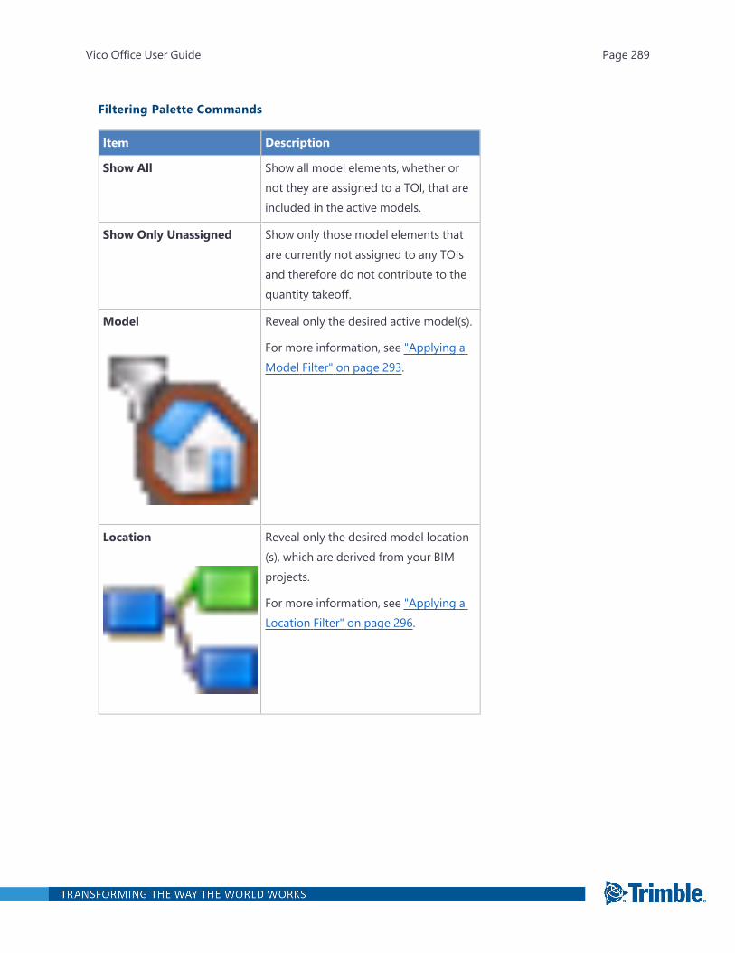
Filtering Palette Commands
Item Description
Show All Show all model elements, whether ornot they are assigned to a TOI, that areincluded in the active models.
Show Only Unassigned Show only those model elements thatare currently not assigned to any TOIsand therefore do not contribute to thequantity takeoff.
Model Reveal only the desired active model(s).
For more information, see "Applying aModel Filter" on page 293.
Location Reveal only the desired model location(s), which are derived from your BIMprojects.
For more information, see "Applying aLocation Filter" on page 296.
Vico Office User Guide Page 289
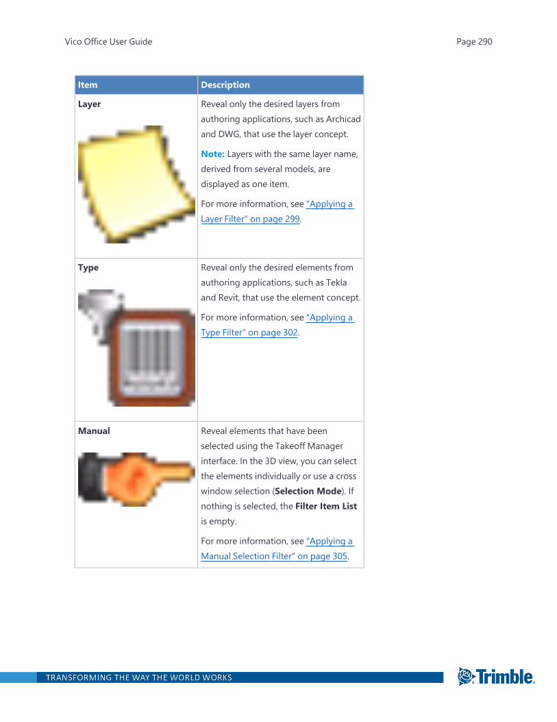
Item Description
Layer Reveal only the desired layers fromauthoring applications, such as Archicadand DWG, that use the layer concept.
Note: Layers with the same layer name,derived from several models, aredisplayed as one item.
For more information, see "Applying aLayer Filter" on page 299.
Type Reveal only the desired elements fromauthoring applications, such as Teklaand Revit, that use the element concept.
For more information, see "Applying aType Filter" on page 302.
Manual Reveal elements that have beenselected using the Takeoff Managerinterface. In the 3D view, you can selectthe elements individually or use a crosswindow selection (Selection Mode). Ifnothing is selected, the Filter Item Listis empty.
For more information, see "Applying aManual Selection Filter" on page 305.
Vico Office User Guide Page 290

Item Description
Filter Item List Displays the available filter-specificitems. Select the items that you want toinclude in the filter to supportreassigning and verifying TOIs or TOQsin the 3D View.
Select All Select all listed items currently shown inthe Filter Item list. Selected list itemsare indicated by a green check mark.
Deselect All Clear all listed items currently shown inthe Filter Item list. Deselected list itemsare indicated by the absence of a greencheck mark.
Reset All Filters Remove all selections and restore thefull 3D model view.
Isolate Selected Isolate all elements that meet thefiltering criteria in the 3D View.
Vico Office User Guide Page 291
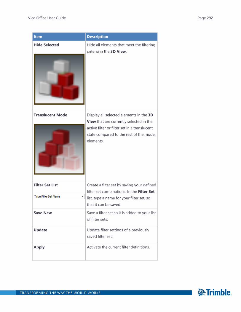
Item Description
Hide Selected Hide all elements that meet the filteringcriteria in the 3D View.
Translucent Mode Display all selected elements in the 3DView that are currently selected in theactive filter or filter set in a translucentstate compared to the rest of the modelelements.
Filter Set List Create a filter set by saving your definedfilter set combinations. In the Filter Setlist, type a name for your filter set, sothat it can be saved.
Save New Save a filter set so it is added to your listof filter sets.
Update Update filter settings of a previouslysaved filter set.
Apply Activate the current filter definitions.
Vico Office User Guide Page 292
Viewing All Unassigned Elements
If elements are removed from a takeoff item, they are automatically associated with a new TOI (if onehas not been created) with the following name: 'Unassigned-<ElementType'. You can use the Fil-tering palette to identify which elements are currently unassigned in the project.
To view all unassigned elements
1. Open and pin the Filtering palette.
2. At the top of the Filtering palette, select Show Only Unassigned.
3. To activate the filter, click Apply.
The elements in the project that are not currently associated with any takeoff items are dis-played in the 3D View.
Applying a Model Filter
To apply a model filter
1. Open and pin the Filtering palette.
2. In the Filtering palette, click the model filter icon .
The Filter Item list displays the activated models.
3. In the list, select the models that contain the model elements that you want to view.
A green check mark appears beside the selected models.
4. Select a filter mode.
Vico Office User Guide Page 293

l Isolate Selected: Isolate all elements that meet the filtering criteria in the 3D View.
l Hide Selected: Hide all elements that meet the filtering criteria in the 3D View.
Vico Office User Guide Page 294
l Translucent Mode: Display all selected elements in the 3D View that are currently selec-ted in the active filter or filter set in a translucent state compared to the rest of the modelelements.
Vico Office User Guide Page 295

5. To apply the filtering criteria, click Apply.
The selected models appear in the 3D View and are available for work in the DocumentRegister task.
6. Optional: Save the filter set.
7. Optional: To return the models to their original status, click Reset All Filters.
Applying a Location Filter
To apply a location filter
1. Open and pin the Filtering palette.
2. In the Filtering palette, click the location filter icon .
Vico Office User Guide Page 296

The Filter Item list displays the project stories or levels that were defined in and derived fromthe original modeling application.
3. In the list, select the locations that contain the model elements that you want to view.
A green check mark appears beside the selected locations.
4. Select a filter mode.
l Isolate Selected: Isolate all elements that meet the filtering criteria in the 3D View.
l Hide Selected: Hide all elements that meet the filtering criteria in the 3D View.
Vico Office User Guide Page 297

l Translucent Mode: Display all selected elements in the 3D View that are currently selec-ted in the active filter or filter set in a translucent state compared to the rest of the modelelements.
Vico Office User Guide Page 298

5. To apply the filtering criteria, click Apply.
The elements within the selected locations appear in the 3D View and are available for work inthe Document Register task.
6. Optional: Save the filter set.
7. Optional: To return the models to their original status, click Reset All Filters.
Applying a Layer Filter
Note: The layer filter is only available for certain CAD applications that allow you to sort elements inlayer groups.
To apply a layer filter
Vico Office User Guide Page 299
1. Open and pin the Filtering palette.
2. In the Filtering palette, click the layer filter icon .
The Filter Item list displays the layers that were defined in and derived from the original mod-eling application.
3. In the list, select the layers that contain the model elements that you want to view.
A green check mark appears beside the selected layers.
4. Select a filter mode.
l Isolate Selected: Isolate all elements that meet the filtering criteria in the 3D View.
l Hide Selected: Hide all elements that meet the filtering criteria in the 3D View.
Vico Office User Guide Page 300

l Translucent Mode: Display all selected elements in the 3D View that are currently selec-ted in the active filter or filter set in a translucent state compared to the rest of the modelelements.
Vico Office User Guide Page 301

5. To apply the filtering criteria, click Apply.
The elements within the selected layers appear in the 3D View and are available for work intheModel Register task.
6. Optional: Save the filter set.
7. Optional: To return the models to their original status, click Reset All Filters.
Applying a Type Filter
To apply a type filter
1. Open and pin the Filtering palette.
2. In the Filtering palette, click the type filter icon .
Vico Office User Guide Page 302
The Filter Item list displays the elements types that are supported in Vico Office.
3. In the list, select the element types that you want to view.
A green check mark appears beside the selected layers.
4. Select a filter mode.
l Isolate Selected: Isolate all elements that meet the filtering criteria in the 3D View.
l Hide Selected: Hide all elements that meet the filtering criteria in the 3D View.
Vico Office User Guide Page 303

l Translucent Mode: Display all selected elements in the 3D View that are currently selec-ted in the active filter or filter set in a translucent state compared to the rest of the modelelements.
Vico Office User Guide Page 304
5. To apply the filtering criteria, click Apply.
The selected element types appear in the 3D View and are available for work in the Docu-ment Register task.
6. Optional: Save the filter set.
7. Optional: To return the models to their original status, click Reset All Filters.
Applying a Manual Selection Filter
To apply a manual selection filter
1. Open and pin the Filtering palette.
2. At the top of the Filtering palette, click the manual filter icon .
The Filter Item list is empty until you manually select elements.
Vico Office User Guide Page 305
3. To select elements, do one of the following:
l Right-click the view, and then click Select All Assigned Elements.
l On the 3D View tab, click Selection Mode, and then click the desired elements in the 3DView.
The selected elements are shown in red.
4. To add the selected elements to the Filter Item list, click Add Selected in the Filtering palette.
The list displays the number of elements per type. To remove an element from the list, click thedelete icon to its right.
5. In the list, select the elements that you want to view.
A green check mark appears beside the selected elements.
6. Select a filter mode.
Vico Office User Guide Page 306

l Isolate Selected: Isolate all elements that meet the filtering criteria in the 3D View.
l Hide Selected: Hide all elements that meet the filtering criteria in the 3D View.
Vico Office User Guide Page 307

l Translucent Mode: Display all selected elements in the 3D View that are currently selec-ted in the active filter or filter set in a translucent state compared to the rest of the modelelements.
Vico Office User Guide Page 308
7. To apply the filtering criteria, click Apply.
The elements within the selected types appear in the 3D View and are available for work in theDocument Register task.
8. Optional: Save the filter set.
9. Optional: To return the models to their original status, click Reset All Filters.
Saving a Filter Set
After you define filtering criteria in one or more of the available filters, you can save it as a filter setthat can be used again later.
To save a filter set, you must first define filtering criteria in one or several of the filters that are avail-able. If you are satisfied with your selection, and you would like to use this filtering set multiple times,
Vico Office User Guide Page 309
you can save it as a filter set. With the filter defined, click the dropdown combo box where created fil-ter sets are stored.
To save a filter set
1. Open and pin the Filtering palette.
2. Define the filtering criteria.
For more information, see:
l "Applying a Model Filter" on page 293
l "Applying a Location Filter" on page 296
l "Applying a Layer Filter" on page 299
l "Applying a Type Filter" on page 302
l "Applying a Manual Selection Filter" on page 305
3. In the Filter Set list, replace the text with the name of the filter set.
4. Click Save New.
The new filter set is saved in the list.
Note:l If you change the settings (select or clear items in the filters), the list background changes to red
to indicate that the filter set has changed. If desired, save the changes in the active filter set byclicking Update; otherwise, the saved filter set retains its original settings. You can also save thechanges as a new filter set.
l To delete a filter set from the list, click the delete icon to its right.
Properties Palette
The Properties palette contains additional details on the selected element, Takeoff item, or doc-ument. To see the properties, select each element, document or TOI.
To open the Properties palette
1. Along the right edge of the screen, click Properties.
Note: If the Properties palette is not visible, click the palettes icon on the right side of the
screen, and then click Properties.
2. To dock the palette to the active viewset, click the pin icon in the upper-right corner of thepalette.
Vico Office User Guide Page 310
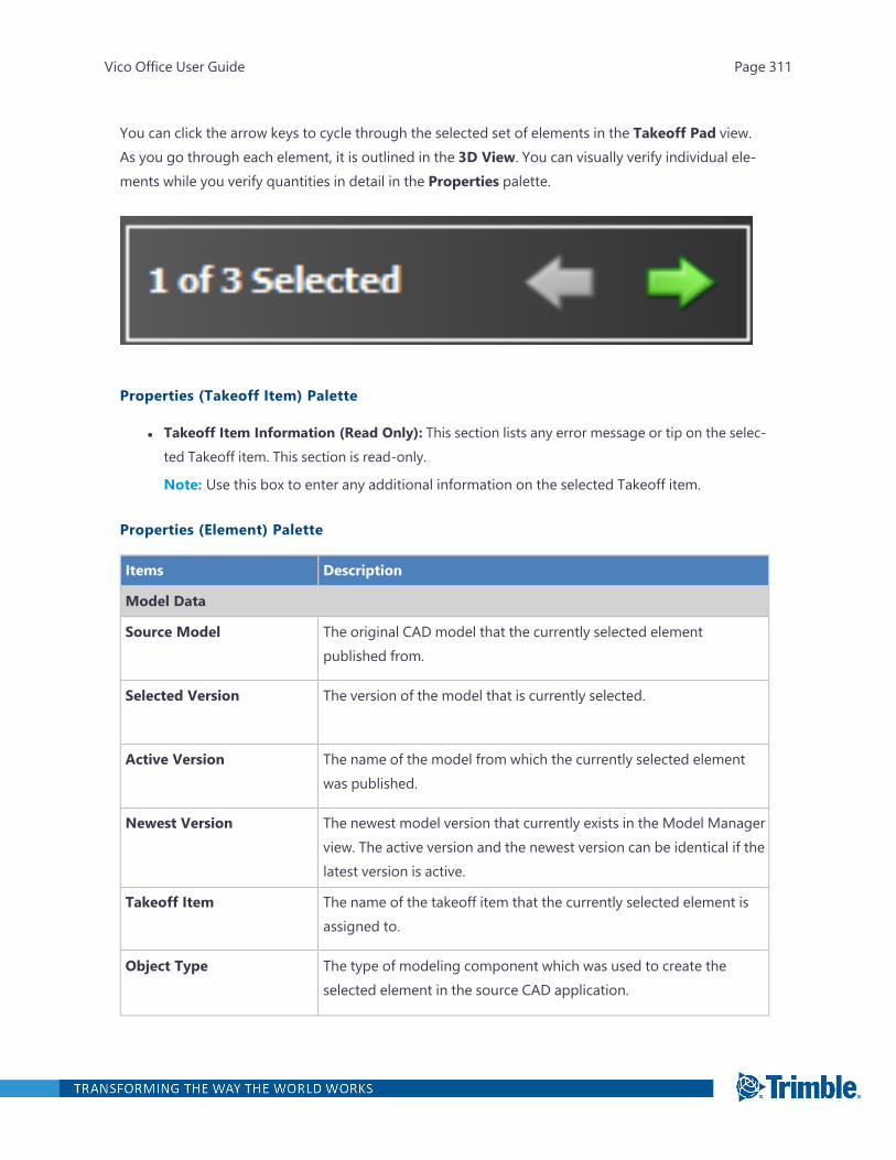
You can click the arrow keys to cycle through the selected set of elements in the Takeoff Pad view.As you go through each element, it is outlined in the 3D View. You can visually verify individual ele-ments while you verify quantities in detail in the Properties palette.
Properties (Takeoff Item) Palette
l Takeoff Item Information (Read Only): This section lists any error message or tip on the selec-ted Takeoff item. This section is read-only.
Note: Use this box to enter any additional information on the selected Takeoff item.
Properties (Element) Palette
Items Description
Model Data
Source Model The original CAD model that the currently selected elementpublished from.
Selected Version The version of the model that is currently selected.
Active Version The name of the model from which the currently selected elementwas published.
Newest Version The newest model version that currently exists in the Model Managerview. The active version and the newest version can be identical if thelatest version is active.
Takeoff Item The name of the takeoff item that the currently selected element isassigned to.
Object Type The type of modeling component which was used to create theselected element in the source CAD application.
Vico Office User Guide Page 311

Items Description
Location Data
Location System Indicates any alternative location breakdown structures for the samelocation in the project's location breakdown structure. This isdisplayed only if a Location System has been defined.
Location The project location to which the selected model element belongs.The defined model locations are defined in the CAD application andtransferred over to Vico Office.
Quantity Data: More info...1
Quantity Type The quantities that are associated with the current element type ofthe selected element.
Value The calculated totals of the quantities for the selected element. Inthis field, you can also choose to manually edit the current value ofany quantities if verified otherwise. The change will also be reflectedin the Mini TOM view as well as in the Takeoff Manager view.
Units The unit of measurement applied to the corresponding quantitytype. These units are derived from the Project Settings view wherethe units of measurement were defined.
CAD Quantity Data: More Info...2
Quantity Type The quantities that are associated with the current element type ofthe selected element.
Value The calculated totals of the quantities for the selected element.These values cannot be edited.
Units The unit type published from the CAD, if available.
If you map a CAD quantity to a Takeoff quantity that does not have aunit, then Vico office sets its default unit to the mapped CADquantity's unit type.
1Displays the quantities of the elements. This section includes both Vico Premium quantities (if the element has been
quantified) and the Basic (CAD) quantities (CAD_Count, CAD_Length, CAD_Volume - these are the default CAD quantities
and the ones that are mapped to the TOQ by the user).2Displays only the CAD quantities published from the CAD.
Vico Office User Guide Page 312
Manually Updating a Quantity of an Individual Element
When elements are selected in the 3D View, you can view the details for an individual element in theProperties palette.
To manually update the quantity of an element
1. Open and pin the Properties palette.
2. To select model elements, do one of the following:
l Use the selection options in the Takeoff Manager view context menu.
l On the ribbon, click the 3D View tab > Selection Mode, and then click the desired ele-ments.
The selected elements are highlighted in red, and the Properties palette is activated.
3. To cycle through the individual element properties, click the arrow keys at the top of the palette.
The selected elements are emphasized in the 3D View. Detailed information is also displayed
Vico Office User Guide Page 313

in the Properties palette for one element at a time.
Vico Office User Guide Page 314

Vico Office User Guide Page 315
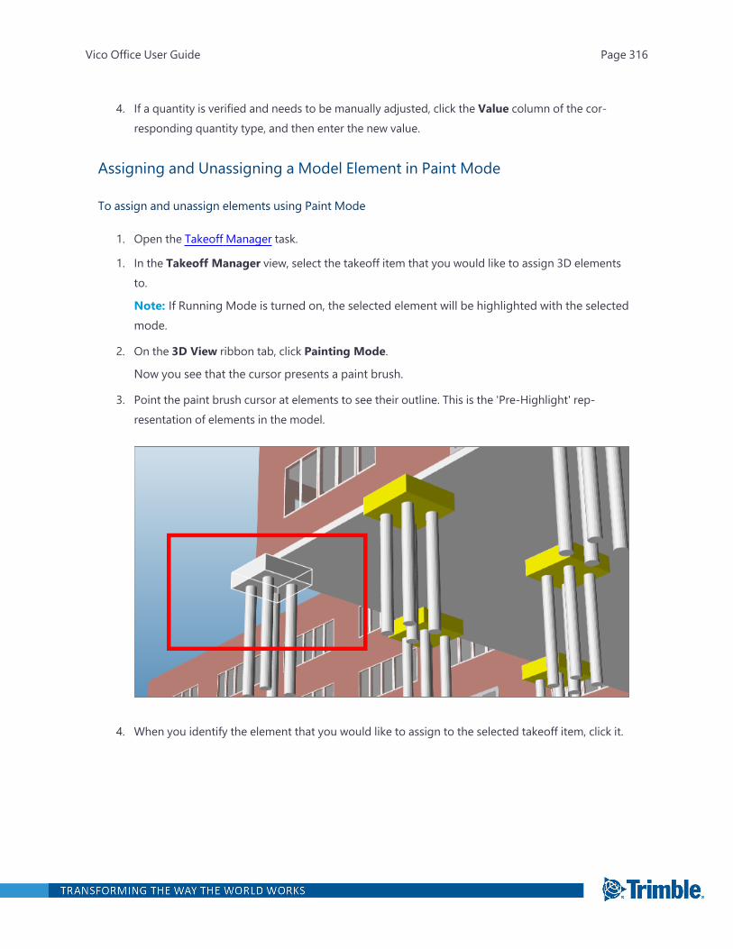
4. If a quantity is verified and needs to be manually adjusted, click the Value column of the cor-responding quantity type, and then enter the new value.
Assigning and Unassigning a Model Element in Paint Mode
To assign and unassign elements using Paint Mode
1. Open the Takeoff Manager task.
1. In the Takeoff Manager view, select the takeoff item that you would like to assign 3D elementsto.
Note: If Running Mode is turned on, the selected element will be highlighted with the selectedmode.
2. On the 3D View ribbon tab, click Painting Mode.
Now you see that the cursor presents a paint brush.
3. Point the paint brush cursor at elements to see their outline. This is the 'Pre-Highlight' rep-resentation of elements in the model.
4. When you identify the element that you would like to assign to the selected takeoff item, click it.
Vico Office User Guide Page 316
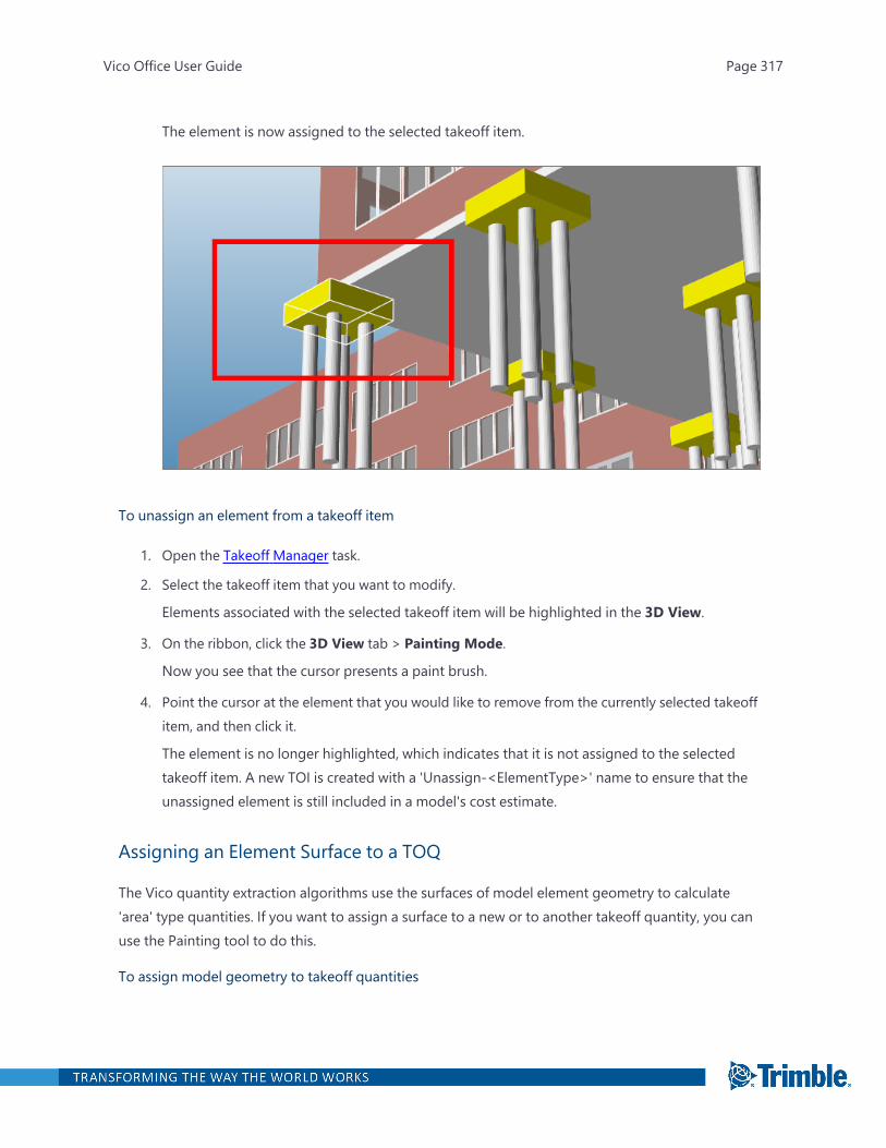
The element is now assigned to the selected takeoff item.
To unassign an element from a takeoff item
1. Open the Takeoff Manager task.
2. Select the takeoff item that you want to modify.
Elements associated with the selected takeoff item will be highlighted in the 3D View.
3. On the ribbon, click the 3D View tab > Painting Mode.
Now you see that the cursor presents a paint brush.
4. Point the cursor at the element that you would like to remove from the currently selected takeoffitem, and then click it.
The element is no longer highlighted, which indicates that it is not assigned to the selectedtakeoff item. A new TOI is created with a 'Unassign-<ElementType>' name to ensure that theunassigned element is still included in a model's cost estimate.
Assigning an Element Surface to a TOQ
The Vico quantity extraction algorithms use the surfaces of model element geometry to calculate'area' type quantities. If you want to assign a surface to a new or to another takeoff quantity, you canuse the Painting tool to do this.
To assign model geometry to takeoff quantities
Vico Office User Guide Page 317
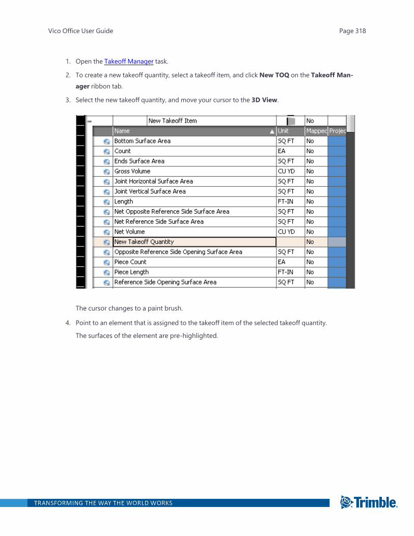
1. Open the Takeoff Manager task.
2. To create a new takeoff quantity, select a takeoff item, and click New TOQ on the Takeoff Man-ager ribbon tab.
3. Select the new takeoff quantity, and move your cursor to the 3D View.
The cursor changes to a paint brush.
4. Point to an element that is assigned to the takeoff item of the selected takeoff quantity.
The surfaces of the element are pre-highlighted.
Vico Office User Guide Page 318

5. Click the surface that you want to assign to the selected takeoff quantity.
The surface is highlighted in purple and is used for automatic calculation of the selected quant-ity.
Vico Office User Guide Page 319
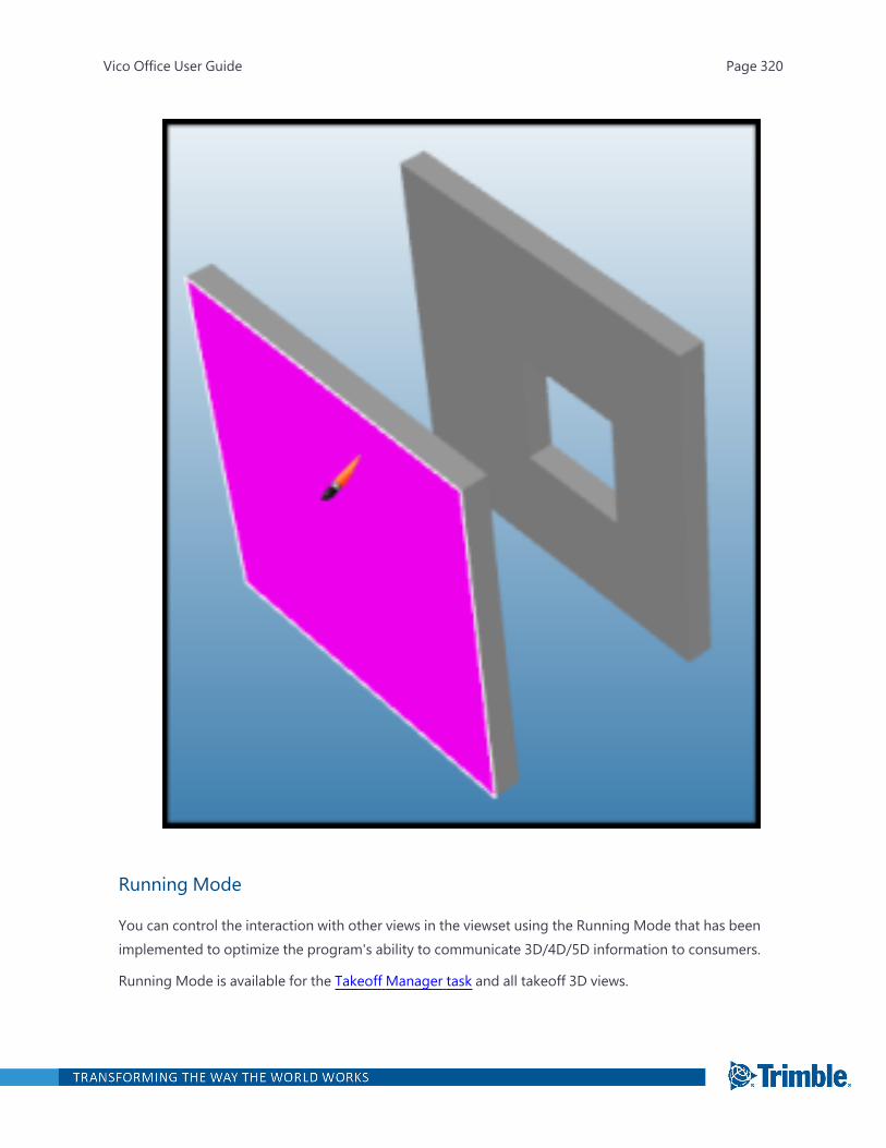
Running Mode
You can control the interaction with other views in the viewset using the Running Mode that has beenimplemented to optimize the program's ability to communicate 3D/4D/5D information to consumers.
Running Mode is available for the Takeoff Manager task and all takeoff 3D views.
Vico Office User Guide Page 320
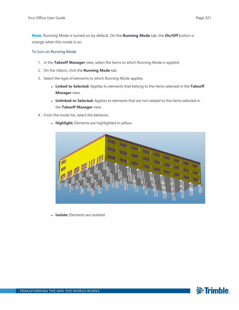
Note: Running Mode is turned on by default. On the Running Mode tab, the On/Off button isorange when this mode is on.
To turn on Running Mode
1. In the Takeoff Manager view, select the items to which Running Mode is applied.
2. On the ribbon, click the Running Mode tab.
3. Select the type of elements to which Running Mode applies.
l Linked to Selected: Applies to elements that belong to the items selected in the TakeoffManager view.
l Unlinked to Selected: Applies to elements that are not related to the items selected inthe Takeoff Manager view.
4. From the mode list, select the behavior.
l Highlight: Elements are highlighted in yellow.
l Isolate: Elements are isolated.
Vico Office User Guide Page 321
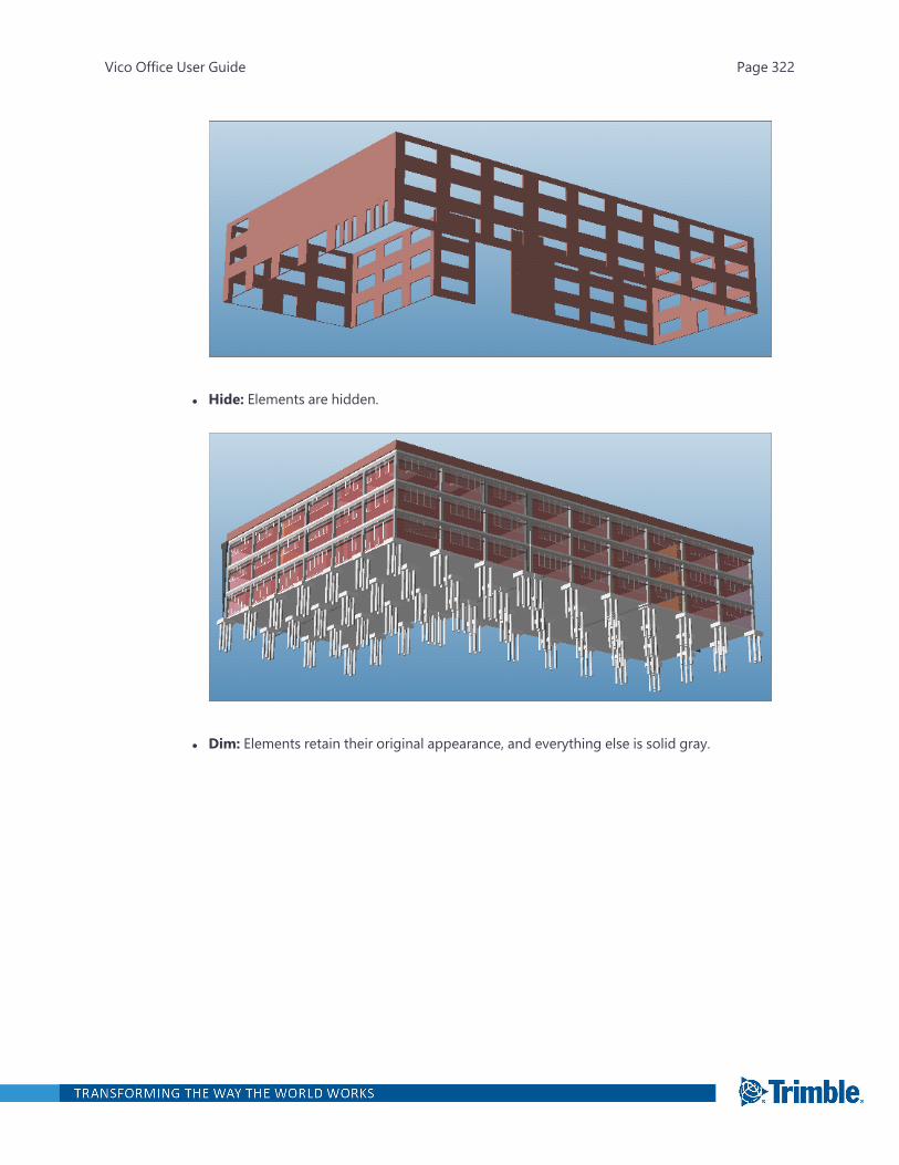
l Hide: Elements are hidden.
l Dim: Elements retain their original appearance, and everything else is solid gray.
Vico Office User Guide Page 322
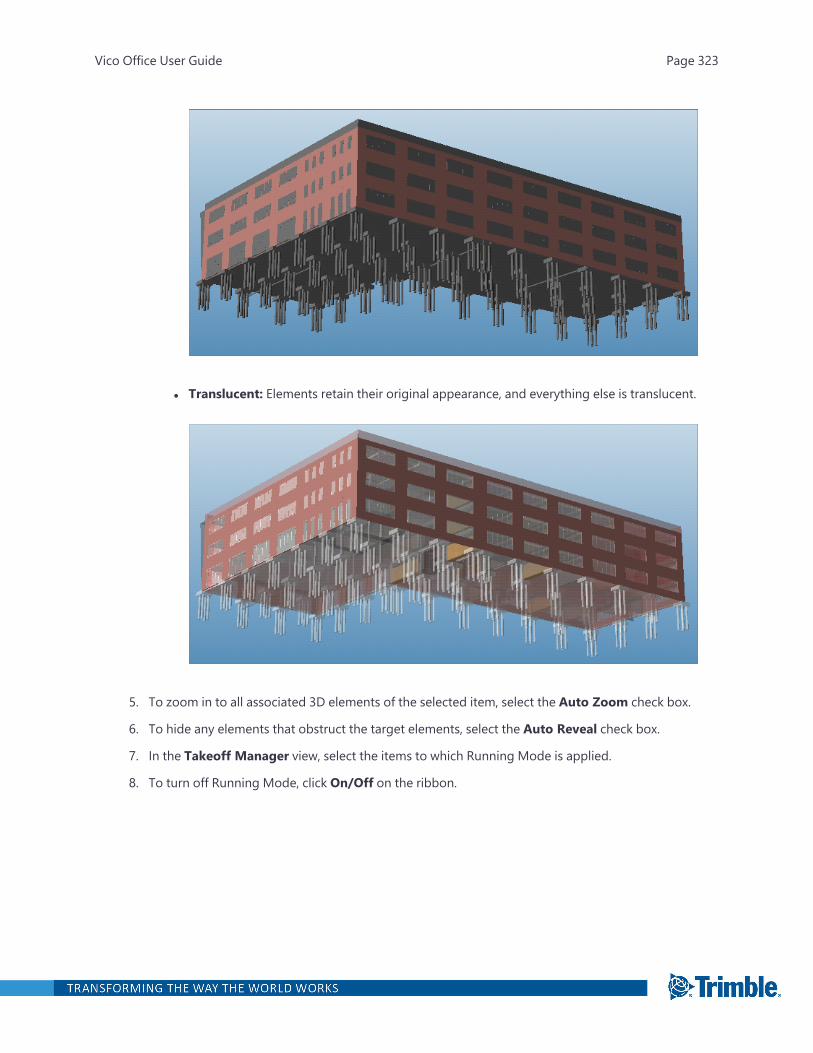
l Translucent: Elements retain their original appearance, and everything else is translucent.
5. To zoom in to all associated 3D elements of the selected item, select the Auto Zoom check box.
6. To hide any elements that obstruct the target elements, select the Auto Reveal check box.
7. In the Takeoff Manager view, select the items to which Running Mode is applied.
8. To turn off Running Mode, click On/Off on the ribbon.
Vico Office User Guide Page 323
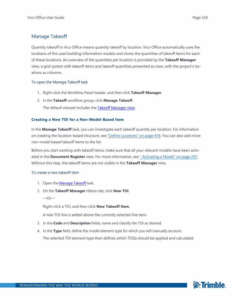
Manage Takeoff
Quantity takeoff in Vico Office means quantity takeoff by location. Vico Office automatically uses thelocations of the used building information models and stores the quantities of takeoff items for eachof these locations. An overview of the quantities per location is provided by the Takeoff Managerview, a grid system with takeoff items and takeoff quantities presented as rows, with the project's loc-ations as columns.
To open the Manage Takeoff task
1. Right-click the Workflow Panel header, and then click Takeoff Manager.
2. In the Takeoff workflow group, clickManage Takeoff.
The default viewset includes the Takeoff Manager view.
Creating a New TOI for a Non-Model-Based Item
In theManage Takeoff task, you can investigate each takeoff quantity per location. For informationon creating the location-based structure, see "Define Locations" on page 418. You can also add morenon-model based takeoff items to the list.
Before you start working with takeoff items, make sure that all your relevant models have been activ-ated in the Document Register view. For more information, see " Activating a Model" on page 257.Without this step, the takeoff items are not visible in the Takeoff Manager view.
To create a new takeoff item
1. Open the Manage Takeoff task.
2. On the Takeoff Manager ribbon tab, click New TOI.
—Or—
Right-click a TOI, and then click New Takeoff Item.
A new TOI line is added above the currently selected line item.
3. In the Code and Description fields, name and classify the TOI as desired.
4. In the Type field, define the model element type for which you will manually account.
The selected TOI element type then defines which TOQs should be applied and calculated.
Vico Office User Guide Page 324
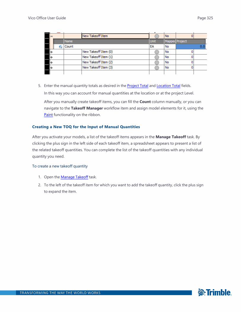
5. Enter the manual quantity totals as desired in the Project Total and Location Total fields.
In this way you can account for manual quantities at the location or at the project Level.
After you manually create takeoff items, you can fill the Count column manually, or you cannavigate to the Takeoff Manager workflow item and assign model elements for it, using thePaint functionality on the ribbon.
Creating a New TOQ for the Input of Manual Quantities
After you activate your models, a list of the takeoff items appears in theManage Takeoff task. Byclicking the plus sign in the left side of each takeoff item, a spreadsheet appears to present a list ofthe related takeoff quantities. You can complete the list of the takeoff quantities with any individualquantity you need.
To create a new takeoff quantity
1. Open the Manage Takeoff task.
2. To the left of the takeoff item for which you want to add the takeoff quantity, click the plus signto expand the item.
Vico Office User Guide Page 325
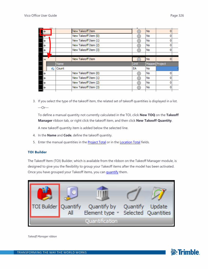
3. If you select the type of the takeoff item, the related set of takeoff quantities is displayed in a list.
—Or—
To define a manual quantity not currently calculated in the TOI, click New TOQ on the TakeoffManager ribbon tab, or right click the takeoff item, and then click New Takeoff Quantity.
A new takeoff quantity item is added below the selected line.
4. In the Name and Code, define the takeoff quantity.
5. Enter the manual quantities in the Project Total or in the Location Total fields.
TOI Builder
The Takeoff Item (TOI) Builder, which is available from the ribbon on the Takeoff Manager module, isdesigned to give you the flexibility to group your Takeoff items after the model has been activated.Once you have grouped your Takeoff items, you can quantify them.
Takeoff Manager ribbon
Vico Office User Guide Page 326
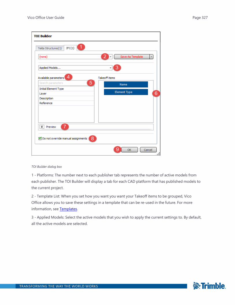
TOI Builder dialog box
1 - Platforms: The number next to each publisher tab represents the number of active models fromeach publisher. The TOI Builder will display a tab for each CAD platform that has published models tothe current project.
2 - Template List: When you set how you want you want your Takeoff items to be grouped, VicoOffice allows you to save these settings in a template that can be re-used in the future. For moreinformation, see Templates.
3 - Applied Models: Select the active models that you wish to apply the current settings to. By default,all the active models are selected.
Vico Office User Guide Page 327
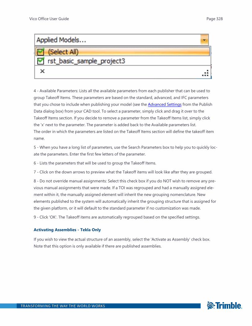
4 - Available Parameters: Lists all the available parameters from each publisher that can be used togroup Takeoff Items. These parameters are based on the standard, advanced, and IFC parametersthat you chose to include when publishing your model (see the Advanced Settings from the PublishData dialog box) from your CAD tool. To select a parameter, simply click and drag it over to theTakeoff Items section. If you decide to remove a parameter from the Takeoff Items list, simply clickthe 'x' next to the parameter. The parameter is added back to the Available parameters list.The order in which the parameters are listed on the Takeoff Items section will define the takeoff itemname.
5 - When you have a long list of parameters, use the Search Parameters box to help you to quickly loc-ate the parameters. Enter the first few letters of the parameter.
6 - Lists the parameters that will be used to group the Takeoff Items.
7 - Click on the down arrows to preview what the Takeoff items will look like after they are grouped.
8 - Do not override manual assignments: Select this check box if you do NOT wish to remove any pre-vious manual assignments that were made. If a TOI was regrouped and had a manually assigned ele-ment within it, the manually assigned element will inherit the new grouping nomenclature. Newelements published to the system will automatically inherit the grouping structure that is assigned forthe given platform, or it will default to the standard parameter if no customization was made.
9 - Click 'OK'. The Takeoff items are automatically regrouped based on the specified settings.
Activating Assemblies - Tekla Only
If you wish to view the actual structure of an assembly, select the 'Activate as Assembly' check box.Note that this option is only available if there are published assemblies.
Vico Office User Guide Page 328

TemplatesThe TOI Builder has a 'template' feature that saves the parameters that were chosen.
When viewing a template, if you change the settings (i.e., select/clear an element/parameter to bepublished), the template name and Save button color changes to red to indicate that the templatehas been modified.
Vico Office User Guide Page 329
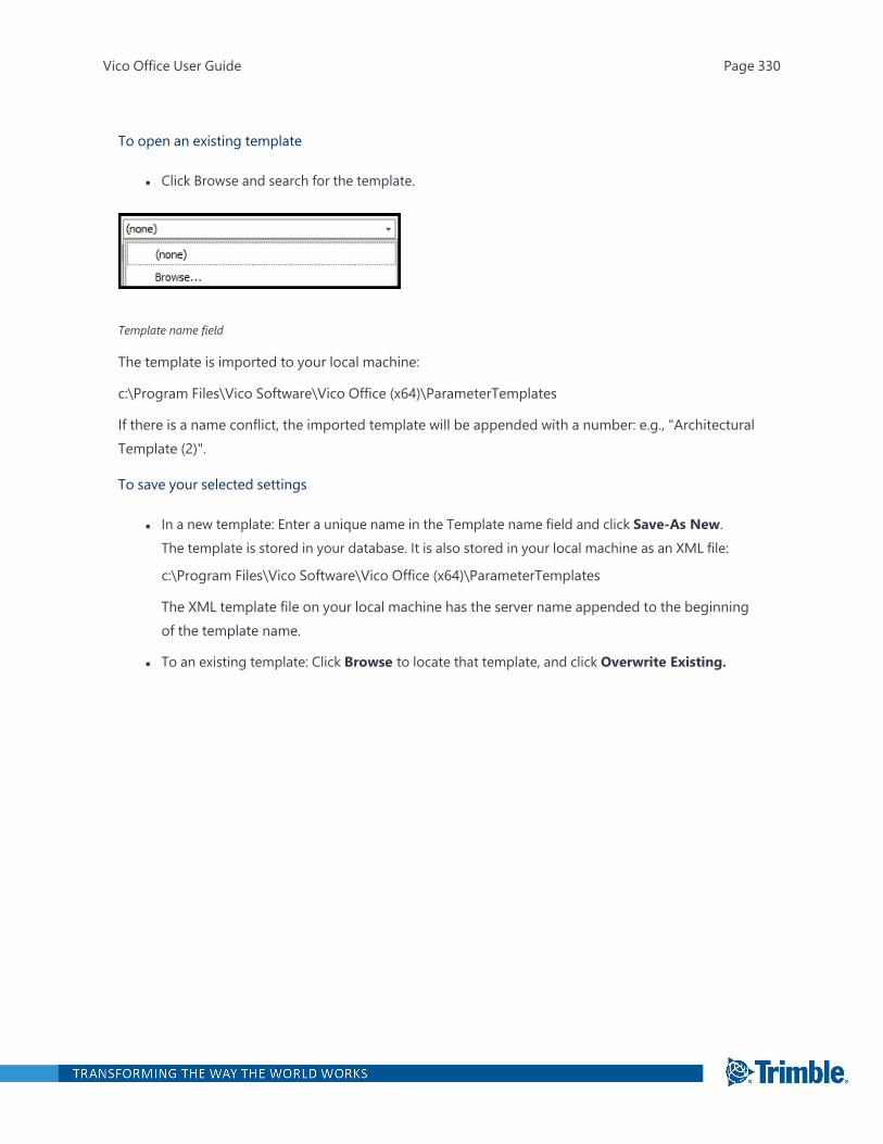
To open an existing template
l Click Browse and search for the template.
Template name field
The template is imported to your local machine:
c:\Program Files\Vico Software\Vico Office (x64)\ParameterTemplates
If there is a name conflict, the imported template will be appended with a number: e.g., "ArchitecturalTemplate (2)".
To save your selected settings
l In a new template: Enter a unique name in the Template name field and click Save-As New.The template is stored in your database. It is also stored in your local machine as an XML file:
c:\Program Files\Vico Software\Vico Office (x64)\ParameterTemplates
The XML template file on your local machine has the server name appended to the beginningof the template name.
l To an existing template: Click Browse to locate that template, and click Overwrite Existing.
Vico Office User Guide Page 330
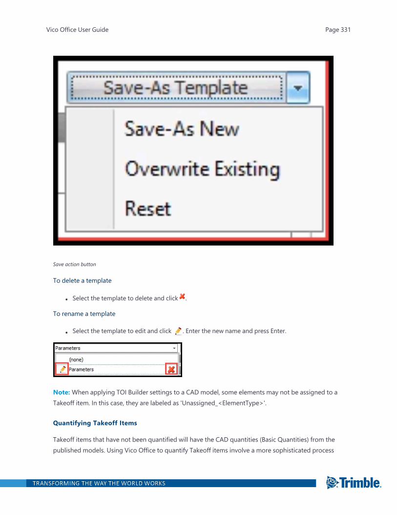
Save action button
To delete a template
l Select the template to delete and click .
To rename a template
l Select the template to edit and click . Enter the new name and press Enter.
Note: When applying TOI Builder settings to a CAD model, some elements may not be assigned to aTakeoff item. In this case, they are labeled as 'Unassigned_<ElementType>'.
Quantifying Takeoff Items
Takeoff items that have not been quantified will have the CAD quantities (Basic Quantities) from thepublished models. Using Vico Office to quantify Takeoff items involve a more sophisticated process
Vico Office User Guide Page 331

that includes Vico algorithm and locations.
Takeoff items that have not been quantified by Vico Office appear italicized in Takeoff Manager.
Once they have been quantified, the Premium Quantities include additional TOI components.
Vico Office offers various options in which to quantify your Takeoff items:
Ribbon Item Description
Quantifies all the Takeoff items in your list. Thisprocess may take some time depending on thenumber of Takeoff items.
Quantifies only the Takeoff items with the selectedelement type, such as Beams, Curtain Walls, Columns,Ducts and more.
Vico Office User Guide Page 332

Ribbon Item Description
Quantifies only the Takeoff items that are selected.Use CTRL+click to multi-select.
Quantifies out-of-date takeoff items.
If you decide not to use Vico's premium quantities, you can 'switch back' to CAD quantities by 'Dequantifying' a Takeoff
item.
Tip: Takeoff items may need to be re-quantified if you switch to a another model version.
Merging Takeoff Items
Vico provides you with the ability to manage the level of granularity for your Takeoff items. DetailedTakeoff items can be merged into a selected Takeoff item, into a new item, or into an existing item.
To merge Takeoff items
Vico Office User Guide Page 333
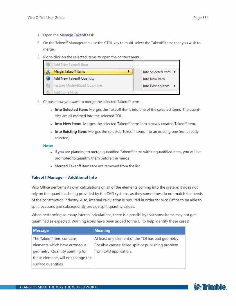
1. Open the Manage Takeoff task.
2. On the Takeoff Manager tab, use the CTRL key to multi-select the Takeoff items that you wish tomerge.
3. Right-click on the selected items to open the context menu.
4. Choose how you want to merge the selected Takeoff items:
l Into Selected Item: Merges the Takeoff items into one of the selected items. The quant-ities are all merged into the selected TOI.
l Into New Item: Merges the selected Takeoff items into a newly created Takeoff item.
l Into Existing Item: Merges the selected Takeoff items into an existing one (not alreadyselected).
Note:l If you are planning to merge quantified Takeoff items with unquantified ones, you will be
prompted to quantify them before the merge.
l Merged Takeoff items are not removed from the list.
Takeoff Manager - Additional Info
Vico Office performs its own calculations on all of the elements coming into the system; it does notrely on the quantities being provided by the CAD systems, as they sometimes do not match the needsof the construction industry. Also, internal calculation is required in order for Vico Office to be able tosplit locations and subsequently provide split quantity values.
When performing so many internal calculations, there is a possibility that some items may not getquantified as expected. Warning icons have been added to the UI to help identify these cases:
Message Meaning
The Takeoff item containselements which have erroneousgeometry. Quantity painting forthese elements will not change thesurface quantities
At least one element of the TOI has bad geometry.Possible causes: failed split or publishing problemfrom CAD application.
Vico Office User Guide Page 334
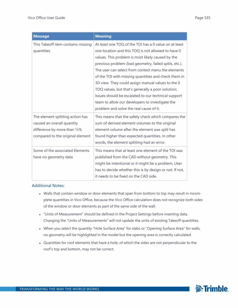
Message Meaning
This Takeoff item contains missingquantities
At least one TOQ of the TOI has a 0 value on at leastone location and this TOQ is not allowed to have 0values. This problem is most likely caused by theprevious problem (bad geometry, failed splits, etc.).The user can select from context menu the elementsof the TOI with missing quantities and check them in3D view. They could assign manual values to the 0TOQ values, but that’s generally a poor solution;Issues should be escalated to our technical supportteam to allow our developers to investigate theproblem and solve the real cause of it.
The element splitting action hascaused an overall quantitydifference by more than ½%compared to the original element
This means that the safety check which compares thesum of derived element volumes to the originalelement volume after the element was split hasfound higher than expected quantities. In otherwords, the element splitting had an error.
Some of the associated Elementshave no geometry data
This means that at least one element of the TOI waspublished from the CAD without geometry. Thismight be intentional or it might be a problem. Userhas to decide whether this is by design or not. If not,it needs to be fixed on the CAD side.
Additional Notes:
l Walls that contain window or door elements that span from bottom to top may result in incom-plete quantities in Vico Office, because the Vico Office calculation does not recognize both sidesof the window or door elements as part of the same side of the wall.
l “Units of Measurement” should be defined in the Project Settings before inserting data.Changing the “Units of Measurements” will not update the units of existing Takeoff quantities.
l When you select the quantity “Hole Surface Area” for slabs or “Opening Surface Area” for walls,no geometry will be highlighted in the model but the opening area is correctly calculated.
l Quantities for roof elements that have a hole, of which the sides are not perpendicular to theroof’s top and bottom, may not be correct.
Vico Office User Guide Page 335
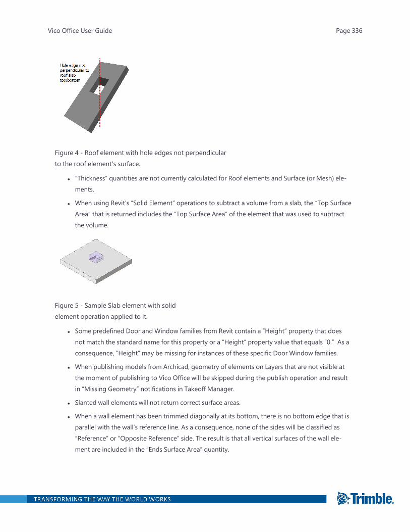
Figure 4 - Roof element with hole edges not perpendicularto the roof element's surface.
l “Thickness” quantities are not currently calculated for Roof elements and Surface (or Mesh) ele-ments.
l When using Revit’s “Solid Element” operations to subtract a volume from a slab, the “Top SurfaceArea” that is returned includes the “Top Surface Area” of the element that was used to subtractthe volume.
Figure 5 - Sample Slab element with solidelement operation applied to it.
l Some predefined Door and Window families from Revit contain a “Height” property that doesnot match the standard name for this property or a “Height” property value that equals “0.” As aconsequence, “Height” may be missing for instances of these specific Door Window families.
l When publishing models from Archicad, geometry of elements on Layers that are not visible atthe moment of publishing to Vico Office will be skipped during the publish operation and resultin “Missing Geometry” notifications in Takeoff Manager.
l Slanted wall elements will not return correct surface areas.
l When a wall element has been trimmed diagonally at its bottom, there is no bottom edge that isparallel with the wall’s reference line. As a consequence, none of the sides will be classified as“Reference” or “Opposite Reference” side. The result is that all vertical surfaces of the wall ele-ment are included in the “Ends Surface Area” quantity.
Vico Office User Guide Page 336
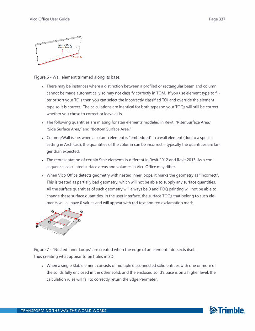
Figure 6 - Wall element trimmed along its base.
l There may be instances where a distinction between a profiled or rectangular beam and columncannot be made automatically so may not classify correctly in TOM. If you use element type to fil-ter or sort your TOIs then you can select the incorrectly classified TOI and override the elementtype so it is correct. The calculations are identical for both types so your TOQs will still be correctwhether you chose to correct or leave as is.
l The following quantities are missing for stair elements modeled in Revit: “Riser Surface Area,”“Side Surface Area,” and “Bottom Surface Area.”
l Column/Wall issue: when a column element is “embedded” in a wall element (due to a specificsetting in Archicad), the quantities of the column can be incorrect – typically the quantities are lar-ger than expected.
l The representation of certain Stair elements is different in Revit 2012 and Revit 2013. As a con-sequence, calculated surface areas and volumes in Vico Office may differ.
l When Vico Office detects geometry with nested inner loops, it marks the geometry as “incorrect”.This is treated as partially bad geometry, which will not be able to supply any surface quantities.All the surface quantities of such geometry will always be 0 and TOQ painting will not be able tochange these surface quantities. In the user interface, the surface TOQs that belong to such ele-ments will all have 0 values and will appear with red text and red exclamation mark.
Figure 7 - "Nested Inner Loops" are created when the edge of an element intersects itself,thus creating what appear to be holes in 3D.
l When a single Slab element consists of multiple disconnected solid entities with one or more ofthe solids fully enclosed in the other solid, and the enclosed solid’s base is on a higher level, thecalculation rules will fail to correctly return the Edge Perimeter.
Vico Office User Guide Page 337
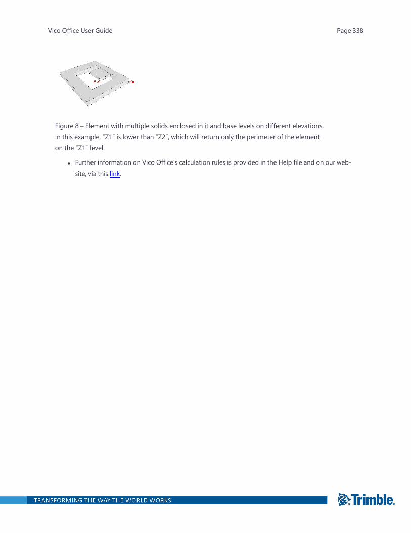
Figure 8 – Element with multiple solids enclosed in it and base levels on different elevations.In this example, “Z1” is lower than “Z2”, which will return only the perimeter of the elementon the “Z1” level.
l Further information on Vico Office’s calculation rules is provided in the Help file and on our web-site, via this link.
Vico Office User Guide Page 338
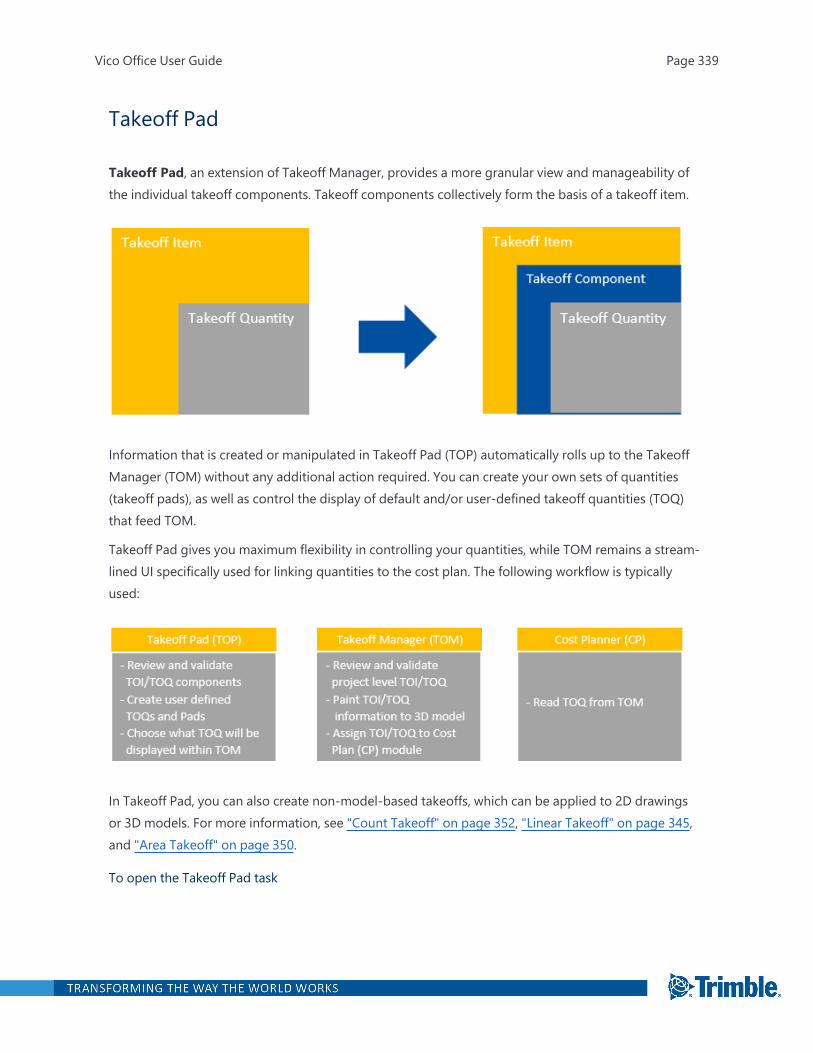
Takeoff Pad
Takeoff Pad, an extension of Takeoff Manager, provides a more granular view and manageability ofthe individual takeoff components. Takeoff components collectively form the basis of a takeoff item.
Information that is created or manipulated in Takeoff Pad (TOP) automatically rolls up to the TakeoffManager (TOM) without any additional action required. You can create your own sets of quantities(takeoff pads), as well as control the display of default and/or user-defined takeoff quantities (TOQ)that feed TOM.
Takeoff Pad gives you maximum flexibility in controlling your quantities, while TOM remains a stream-lined UI specifically used for linking quantities to the cost plan. The following workflow is typicallyused:
In Takeoff Pad, you can also create non-model-based takeoffs, which can be applied to 2D drawingsor 3D models. For more information, see "Count Takeoff" on page 352, "Linear Takeoff" on page 345,and "Area Takeoff" on page 350.
To open the Takeoff Pad task
Vico Office User Guide Page 339
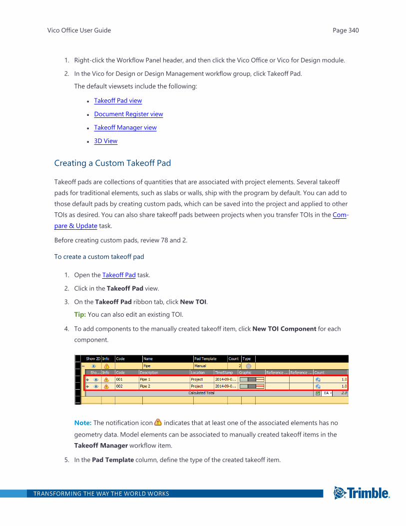
1. Right-click the Workflow Panel header, and then click the Vico Office or Vico for Design module.
2. In the Vico for Design or Design Management workflow group, click Takeoff Pad.
The default viewsets include the following:
l Takeoff Pad view
l Document Register view
l Takeoff Manager view
l 3D View
Creating a Custom Takeoff Pad
Takeoff pads are collections of quantities that are associated with project elements. Several takeoffpads for traditional elements, such as slabs or walls, ship with the program by default. You can add tothose default pads by creating custom pads, which can be saved into the project and applied to otherTOIs as desired. You can also share takeoff pads between projects when you transfer TOIs in the Com-pare & Update task.
Before creating custom pads, review 78 and 2.
To create a custom takeoff pad
1. Open the Takeoff Pad task.
2. Click in the Takeoff Pad view.
3. On the Takeoff Pad ribbon tab, click New TOI.
Tip: You can also edit an existing TOI.
4. To add components to the manually created takeoff item, click New TOI Component for eachcomponent.
Note: The notification icon indicates that at least one of the associated elements has no
geometry data. Model elements can be associated to manually created takeoff items in theTakeoff Manager workflow item.
5. In the Pad Template column, define the type of the created takeoff item.
Vico Office User Guide Page 340
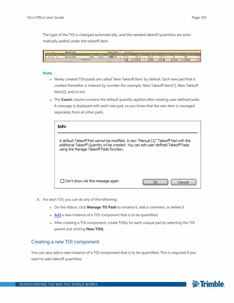
The type of the TOI is changed automatically, and the needed takeoff quantities are auto-matically added under the takeoff item.
Note:l Newly created TOIs/pads are called ‘New Takeoff Item’ by default. Each new pad that is
created thereafter is indexed by number (for example, New Takeoff Item[1], New TakeoffItem[2], and so on).
l The Count column contains the default quantity applied after creating user-defined pads.A message is displayed with each new pad, so you know that the new item is managedseparately from all other pads.
6. For each TOI, you can do any of the following:
l On the ribbon, clickManage TO Pads to rename it, add a comment, or delete it.
l Add a new instance of a TOI component that is to be quantified.
l After creating a TOI component, create TOQs for each unique pad by selecting the TOIparent and clicking New TOQ.
Creating a new TOI component
You can also add a new instance of a TOI component that is to be quantified. This is required if youwant to add takeoff quantities.
Vico Office User Guide Page 341

To create a new TOI component
1. Open the Takeoff Pad task.
2. Select the takeoff item that you want to quantify.
3. On the Takeoff Pad ribbon tab, click New TOI Component.
A TOI component is added directly below the selected TOI.
The following information is created for each TOI component:
l Show: A show/hide option for the display of TOQs created using onscreen takeoff func-tions.
l Info: Indicates that there is a problem with the quantities, which typically requires a modelreactivation. Reactivating the model will push all of the 2D/3D quantities through the pro-ject locations.
l Code: A user-defined value that can be used for sorting and grouping.
l Description: Detailed information about the individual TOI component.
l Location: Project locations where the quantities will appear when they roll up to TOM.
Optionally click the ellipsis button to change the location in the Select Location dia-
log.
l TimeStamp: The date and time when the new element was created (populated bydefault).
l Graphic: Display preferences applied to onscreen takeoff elements. Click the ellipsis but-
ton to display the Graphic Settings dialog and select the preferred display.
Note: Select the 'Set as Default' check box ONLY if you wish to apply these settings toall the takeoff geometry (includes all previously calculated and future ones).
l Reference Documents: The name of 2D drawings onto which onscreen takeoffs areapplied (populated by default).
l Reference Models: The name of 3D models onto which onscreen takeoffs are applied(populated by default).
l Count: The default takeoff quantity (TOQ) that is assigned to a takeoff component.
Vico Office User Guide Page 342
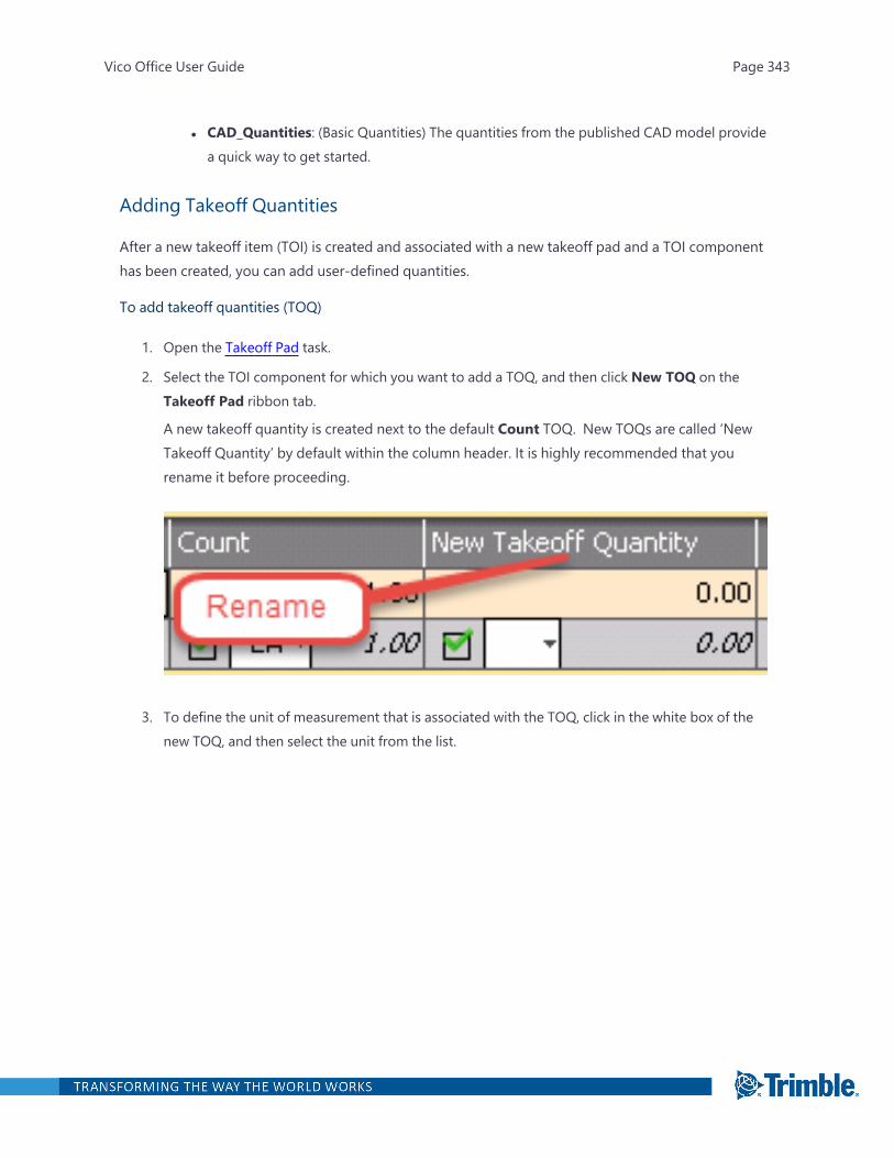
l CAD_Quantities: (Basic Quantities) The quantities from the published CAD model providea quick way to get started.
Adding Takeoff Quantities
After a new takeoff item (TOI) is created and associated with a new takeoff pad and a TOI componenthas been created, you can add user-defined quantities.
To add takeoff quantities (TOQ)
1. Open the Takeoff Pad task.
2. Select the TOI component for which you want to add a TOQ, and then click New TOQ on theTakeoff Pad ribbon tab.
A new takeoff quantity is created next to the default Count TOQ. New TOQs are called ‘NewTakeoff Quantity’ by default within the column header. It is highly recommended that yourename it before proceeding.
3. To define the unit of measurement that is associated with the TOQ, click in the white box of thenew TOQ, and then select the unit from the list.
Vico Office User Guide Page 343

Note: Selecting the unit of measurement enables each onscreen takeoff buttons when movinginto the takeoff portion of the workflow.
l If the component is intended to be an area-based takeoff, select SQ FT or SQ YD.
l If the component is intended to be a length-based takeoff, select FT orM.
l If the component is intended to be a count-based takeoff, select EA.
Each newly created pad can contain any subset of user-defined quantities. All the quantities that arecreated within a new pad are automatically applied anytime the pad template is applied to anotherTOI.
After TOIs, components, and pads are properly set up, you can use the onscreen takeoff commandsfor generating new quantities. For more information, see 344.
Switching to New Model Versions
When adding a new manual element, Vico automatically applies the default formula to the new ele-ments because thy receive all the settings of the TOI (e.g., element type, default formula, etc.). Thesame behavior occurs with TOI painting: the new element receives the settings of the TOI. However,when you switch to a new model version, the default formula is not automatically applied to manuallyadded TOQs. To apply the default formula to the TOQ, right-click on it and select 'Apply Default For-mula'.
Onscreen Takeoff
3D models do not always include all the elements needed to quantify and complete the estimate, soyou can add onscreen takeoffs to the project to supply the missing information.
Onscreen takeoffs can be applied in different ways:
Vico Office User Guide Page 344

l 2D Takeoff: Linear, area, and count quantities can be extracted from 2D drawings that areincluded in the project via Document Controller.
Note: 2D PDF drawings can only be imported in the Document Controller module, so a licenseis required if you wish to extract quantities from 2D drawings.
l 3D Takeoff: Linear, area, and count quantities can be extracted from 3D models that come intothe program via Document Controller.
l Hybrid Takeoff: Document Controller allows for a hybrid environment, whereby 2D PDF draw-ings can be scaled and mapped onto 3D models. Linear, area, and count quantities can be extrac-ted from this hybrid environment.
Note: The availability of the onscreen takeoff commands on the Takeoff Pad tab depends on thequantity type that is assigned to a TOQ column. For more information, see 343.
Scaling Drawings
Before starting any onscreen takeoff, scale up the construction drawings, which are typically printedout at a scaled representation, so you can get proper quantities from them.
To scale a drawing
1. In the Document Register view, right-click the document, and then click Define Scale.
2. In the Scale Document dialog, type the values for the drawing's printed scale.
This information is typically found in the drawing title block or in the annotations just below adrawing detail section.
Linear Takeoff
You can extract distance information between two or more points by selecting snap points, selectingpolylines, or calculating the perimeter.
Note: The Linear button on the Takeoff Pad tab is available only after you select FT orM as the unitof measurement.
To enable linear takeoff
1. Open the Takeoff Pad task.
2. After adding a takeoff quantity and selecting FT orM, click the cell directly above the white box.
Vico Office User Guide Page 345
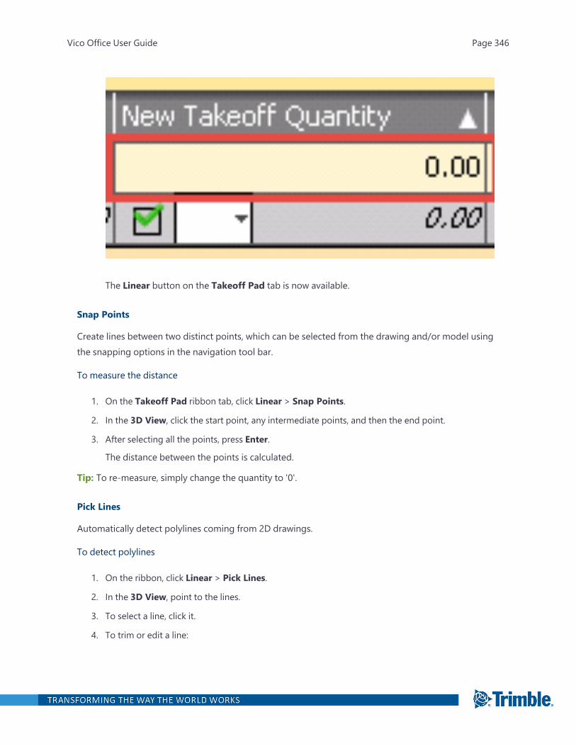
The Linear button on the Takeoff Pad tab is now available.
Snap Points
Create lines between two distinct points, which can be selected from the drawing and/or model usingthe snapping options in the navigation tool bar.
To measure the distance
1. On the Takeoff Pad ribbon tab, click Linear > Snap Points.
2. In the 3D View, click the start point, any intermediate points, and then the end point.
3. After selecting all the points, press Enter.
The distance between the points is calculated.
Tip: To re-measure, simply change the quantity to '0'.
Pick Lines
Automatically detect polylines coming from 2D drawings.
To detect polylines
1. On the ribbon, click Linear > Pick Lines.
2. In the 3D View, point to the lines.
3. To select a line, click it.
4. To trim or edit a line:
Vico Office User Guide Page 346

l Ctrl – Continuously select multiple lines.
l Shift – Divide the lines into smaller parts, When you press Shift and click the line, thesmall parts are selected.
l Combo – Select multiple small parts to extend the line in increments.
5. After selecting the lines, press Enter.
Get Perimeter
Linear values can also be extracted from the perimeter of shapes that are created using the areatakeoff tool.
To calculate the linear value from the perimeter
1. Click in the linear quantity cell that you want to populate with perimeter values.
2. On the ribbon, click Get Perimeter.
3. Select the shape for which you wish to calculate its perimeter.
When the cursor hovers over the shape, the lines of the shape are bold.
4. After selecting the shape, press Enter.
Using the shape perimeter will increase the linear quantity.
After choosing to extend a pad with this information, you should enter a number for the ‘rise/fall’information, as well as the ‘run’ over which rise/fall will take place. This will then provide the ‘Meas-ured Length’ TOQ, as well as quantifying the ‘Actual Length’ according to the modified third dimen-sion of information.
Moving and Adding a Grip
After a linear takeoff has been added to the system, you can modify it by moving or adding a grip.
MOVING A GRIP
When creating the polyline for a linear takeoff, each mouse click that occurs creates a grip. Grips canbe seen by first selecting inside the TOQ cell of the Takeoff Pad and then selecting the polyline in 3D.The grips appear as blue squares.
Vico Office User Guide Page 347

To move a grip
l Click and drag a grip to another location to move the polyline position and change the linearquantity accordingly.
l Select an endpoint grip and move it to pivot the polyline. The other end point in the original loc-ation will not move.
l Select the mid-point grip to reposition the entire polyline, including both end point grips.
ADDING A GRIP
If the existing grips of a polyline are insufficient for the desired edits, additional grips can be added tothe polyline.
To add a grip
1. Open the Takeoff Pad task.
2. Click the takeoff quantity cell.
3. Right-click inside the polyline 3D view.
A context menu appears.
Vico Office User Guide Page 348

4. Click Add Grip.
Another grip is added in the middle of the selected polyline for advanced editing.
Extending Pad with Sloping Data
Construction drawings use two dimensional (2D) lines to represent things that will be built in a threedimensional (3D) space. Because of this, a line that appears to be a certain length or distance in 2Dmay actually represent a different length or distance in the built environment. Support for this typeof representation is available using the ‘Extend Pad with Sloping Data’ option, which augments the ini-tial distance extracted from a line to account for rise and run distances.
To use this functionality, right-click an existing TOI and choose ‘Extend Pad with Sloping Data’ fromthe context menu. Doing so will introduce a subset of quantities associated with sloped content:
Vico Office User Guide Page 349
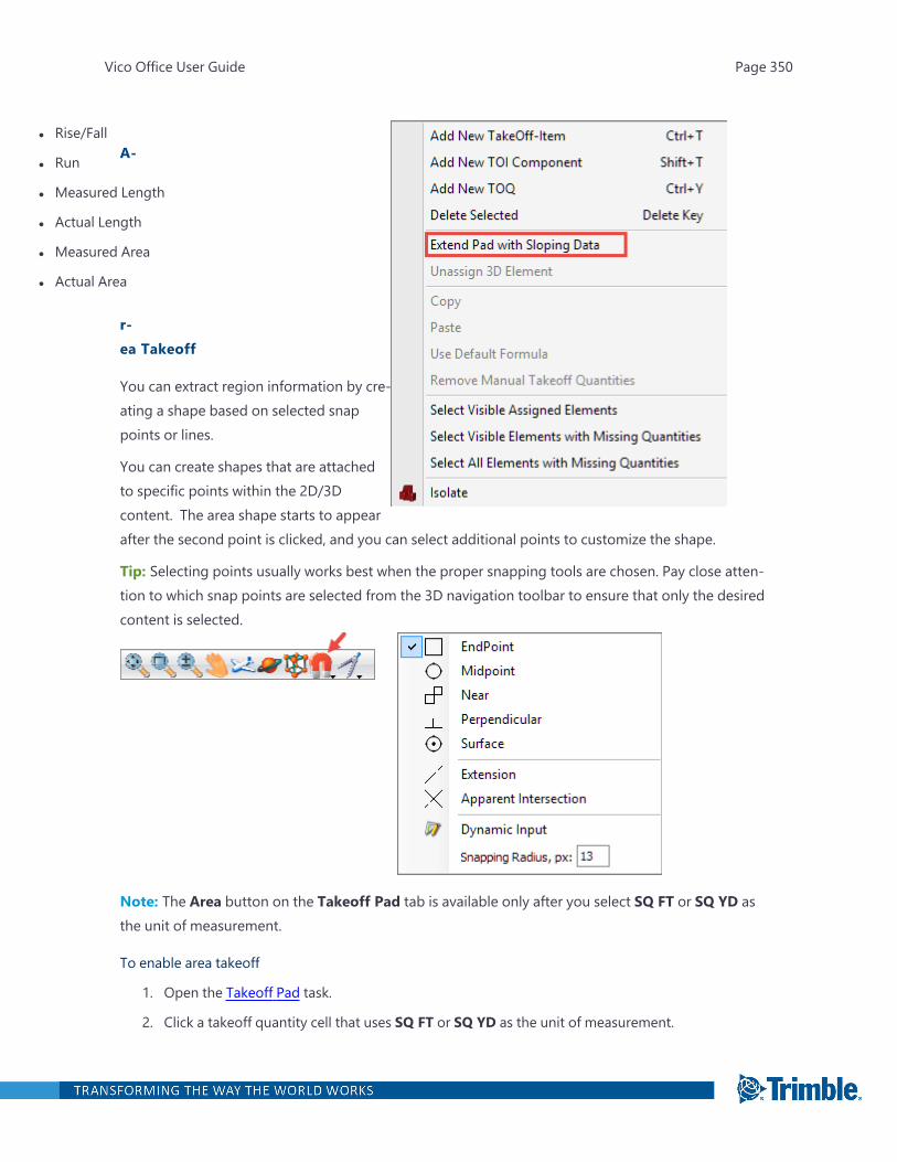
l Rise/Fall
l Run
l Measured Length
l Actual Length
l Measured Area
l Actual Area
A-
r-ea Takeoff
You can extract region information by cre-ating a shape based on selected snappoints or lines.
You can create shapes that are attachedto specific points within the 2D/3Dcontent. The area shape starts to appearafter the second point is clicked, and you can select additional points to customize the shape.
Tip: Selecting points usually works best when the proper snapping tools are chosen. Pay close atten-tion to which snap points are selected from the 3D navigation toolbar to ensure that only the desiredcontent is selected.
Note: The Area button on the Takeoff Pad tab is available only after you select SQ FT or SQ YD asthe unit of measurement.
To enable area takeoff
1. Open the Takeoff Pad task.
2. Click a takeoff quantity cell that uses SQ FT or SQ YD as the unit of measurement.
Vico Office User Guide Page 350
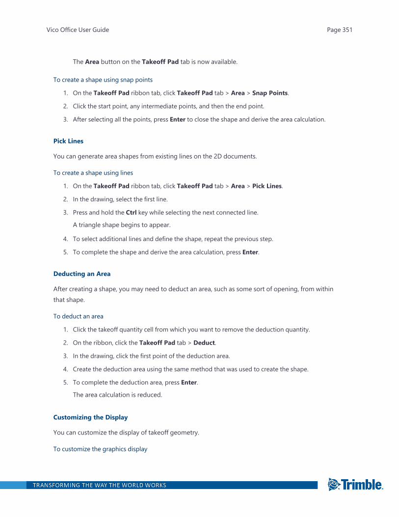
The Area button on the Takeoff Pad tab is now available.
To create a shape using snap points
1. On the Takeoff Pad ribbon tab, click Takeoff Pad tab > Area > Snap Points.
2. Click the start point, any intermediate points, and then the end point.
3. After selecting all the points, press Enter to close the shape and derive the area calculation.
Pick Lines
You can generate area shapes from existing lines on the 2D documents.
To create a shape using lines
1. On the Takeoff Pad ribbon tab, click Takeoff Pad tab > Area > Pick Lines.
2. In the drawing, select the first line.
3. Press and hold the Ctrl key while selecting the next connected line.
A triangle shape begins to appear.
4. To select additional lines and define the shape, repeat the previous step.
5. To complete the shape and derive the area calculation, press Enter.
Deducting an Area
After creating a shape, you may need to deduct an area, such as some sort of opening, from withinthat shape.
To deduct an area
1. Click the takeoff quantity cell from which you want to remove the deduction quantity.
2. On the ribbon, click the Takeoff Pad tab > Deduct.
3. In the drawing, click the first point of the deduction area.
4. Create the deduction area using the same method that was used to create the shape.
5. To complete the deduction area, press Enter.
The area calculation is reduced.
Customizing the Display
You can customize the display of takeoff geometry.
To customize the graphics display
Vico Office User Guide Page 351

1. In the Takeoff Pad view, double-click the Graphic cell, and then click the ellipsis button.
The Graphics Settings dialog appears.
2. Select the desired options for the line and area, and then click OK.
3. To see the changes, click away from the active TOI.
Note: Select the 'Set as Default' check box ONLY if you wish to apply these settings to all thetakeoff geometry (includes all previously calculated and future ones).
Count Takeoff
Count takeoff allows for unit-based quantities to be derived from the documents or models.
Note: The Count button on the Takeoff Pad tab is available only after you select EA as the unit ofmeasurement.
To use the Count option
1. Open the Takeoff Pad task.
2. After adding a takeoff quantity and selecting EA, click the cell directly above it.
Vico Office User Guide Page 352

The Count button on the Takeoff Pad tab is now available.
3. On the Takeoff Pad ribbon tab, choose a symbol from the options available to the right ofCount.
The selected symbol appears each time a click is made for count takeoff. When different itemtypes are counted on the same sheet, you can use different symbols to represent each type.
4. On the Takeoff Pad ribbon tab, click Count.
5. In the 3D View, click to indicate where the count should occur.
The selected symbol is placed in the drawing.
6. Continue clicking until the count operation is complete.
Vico Office User Guide Page 353

7. To finalize the count operation, press Esc.
Note: The TOQ increases by one each time a new selection is made, and the chosen icon appears inthe active view to represent where the count was made. If the count icons appear very large, scale thedrawing to a more suitable size. For information on scaling a document, see 344.
Location-based Quantities
Significant value can be found within Vico Office’s ability to provide quantities by location, and thesame holds true for onscreen takeoffs. You can derive quantities by onscreen takeoff on 2D doc-uments only or in 3D environments.
2D Only Takeoff
Onscreen takeoff that is performed only on 2D documents default to the project level. In addition tothe default location, you can assign quantities to one other location.
To perform 2D only takeoff
1. Open the Takeoff Pad task.
2. Double-click the location cell, and then click the ellipsis button.
The Select Location dialog appears with locations derived from the LBS Manager.
3. Select the location that the quantities are associated with, and then click OK.
Vico Office User Guide Page 354

After associating quantities with a different location, the ‘Manual Takeoff Model’ that appearsin Document Controller must be reactivated to associate the quantities with the new locationassignment.
Note: If you want to assign similar quantities to multiple locations in the project, create a new TOIcomponent.
3D Takeoff
Takeoffs that are done in a 3D environment, be it on a 3D model or in the hybrid mode, also defaultto the project location. However, they inherit the model locations immediately after the ‘ManualTakeoff Model’ is reactivated.
Location assignments assigned to or derived from TOIs within Takeoff Pad roll into TOM without anyadditional work. TOM displays location-based quantities coming from onscreen takeoff in the exactsame way that model-based quantities are displayed by location. 3D model quantities and onscreentakeoff quantities can be mixed and matched within the TOM and the Cost Planner without regard fortheir creation origin. That is, the Cost Planner does not behave any differently if the assigned quant-ities coming from TOM were created using a 3D model elements or onscreen takeoff.
Best Practice: Defining Quantities for Scheduling Purposes
Quantities do not have to be defined for every task in the schedule. However, for high priority taskssuch as those that are expensive, resource-intensive, or known to be risky, it is recommended thatyou work with intelligent tasks, which are quantity-driven and resource-driven tasks. These are “livinglinks” in Vico Office from takeoff quantities through the cost plan and the Location Breakdown Struc-ture Manager to the Schedule Planner.
Quantities can be defined in the following ways:
l Based on 3D models in Vico Office
l Based on 2D documents in Vico Office
l Manually in Schedule Planner / Vico Office
For more information, refer to the PDF.
Vico Office User Guide Page 355
Review Cost
Cost planning is typically an evolutionary process. Throughout the design and pre-constructionphases, more specific and accurate cost information is added to replace assumptions that were madein the initiation and early design phases.
The Review Cost task supports this process and provides continuous cost feedback throughout allproject phases. You can start with a costing scheme at the business development phase and graduallyincrease granularity as more specific data and accurate quantities become available from the 3D BIMmodel or manually entered quantities.
The Review Cost task contains an n-tiered 3D spreadsheet, a graphic scheme that emphasizes thehierarchical structure of the cost estimate. Every line item (assembly) can be further refined with addi-tional components, providing flexibility and enabling you to gradually develop your cost plan from abasic abstract level to a highly-detailed cost estimate.
You can use the Review Cost viewset in the following ways:
l As a spreadsheet, by manually entering quantity and cost information in place.
l With separated quantity takeoff, using a formula in your cost line items.
l With model-based quantity takeoff, using quantities extracted from your BIM files as input foryour cost line items.
These supported cost planning techniques can be combined as desired.
To open the Review Cost task
1. Right-click the Workflow Panel header, and then click the Vico for Cost module.
2. In the Cost Management workflow group, click Review Cost.
The default viewset includes the Cost Planner view and 3D View.
To open the Define Targets task
1. Right-click the Workflow Panel header, and then click the Vico Office or Vico for Cost module.
2. In the Vico for Cost or Cost Planning workflow group, click Define Targets.
Basic Cost Planning
The easiest way to start using the Cost Planner view is by using it as a regular spreadsheet with pre-defined columns.
To perform basic cost planning
Vico Office User Guide Page 356
1. Open the Review Cost task.
2. On the Cost Planner ribbon tab, click Layout Presets > Cost.
The columns needed for cost estimating are displayed.
3. Select a Code cell in the spreadsheet, and then enter the cost code of the line item you wouldlike to calculate for the new component.
Tip: You can create a new component anywhere in the spreadsheet by clicking a Code cell.Use the sorting function later to organize your cost plan.
4. To move to the next cell, press the Tab key, the Arrow key, or click the next cell.
The new component is added with the default description to your project. You can change thedescription as desired.
5. In the Source Qty, Qty, Consumption, Consumption Inv, andWaste cells, enter the inform-ation and include matching units as required.
The Qty is automatically calculated as Source Qty x Consumption xWaste.
6. To calculate the total cost (the price of the component), enter a value in the Unit Cost cell.
After you move to another cell, the price of the component is automatically calculated as Qty xUnit Cost
Cost Planning with Assemblies and Components
The Cost Planner view supports the concept of the evolving estimate: the idea that the cost planbecomes more detailed and accurate throughout the design and pre-construction phases. This is aresult of design and construction planning decisions that allow the cost planner to add more specificcost information to the project.
In the Cost Planner view, you can add subcomponents to components and activate them when thecollection of subcomponents matches the scope of the component. At this point, the subcomponentscan be activated. Then the component becomes an assembly, and the subcomponents become com-ponents.
The pace at which design and construction planning decisions are made will vary per system in thebuilding; detailed information will be available earlier for the foundation than for interior finishes.
You can add more detailed information (subcomponents) to select components in the project, and tokeep other components, for which design and planning decisions have yet to be made, at the lowerlevel of detail.Example:
In Step 1, a component 'Shell' was defined to include the cost for the project's shell. When moreinformation about the shell became available, subcomponents for 'Floors', 'Roof Construction' , 'Exter-ior Walls' and 'Windows and Doors' were added.
Vico Office User Guide Page 357
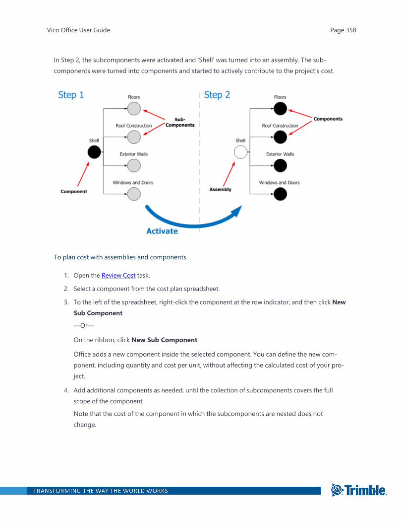
In Step 2, the subcomponents were activated and 'Shell' was turned into an assembly. The sub-components were turned into components and started to actively contribute to the project's cost.
To plan cost with assemblies and components
1. Open the Review Cost task.
2. Select a component from the cost plan spreadsheet.
3. To the left of the spreadsheet, right-click the component at the row indicator, and then click NewSub Component
—Or—
On the ribbon, click New Sub Component.
Office adds a new component inside the selected component. You can define the new com-ponent, including quantity and cost per unit, without affecting the calculated cost of your pro-ject.
4. Add additional components as needed, until the collection of subcomponents covers the fullscope of the component.
Note that the cost of the component in which the subcomponents are nested does notchange.
Vico Office User Guide Page 358

5. When all required subcomponents are included in the component, activate the parent com-ponent by right-clicking it and, and then clicking Activate Selected.
—Or—
On the ribbon, click Activate Selected.
Note: If you also want to activate every subcomponent under the parent component, clickActivate Sub-tree in the context menu.
Vico Office now starts using the cost calculations defined in the subcomponents, which at thismoment are turned into components. The component is turned into an assembly and reflectsthe sum of the cost calculated in the included components.
The row indicator changes into an assembly row indicator (a filled circle), and the data of theassembly is presented in bold letters and numbers. Calculated numbers are in bold italic.
In addition to the activated assembly row indicators, the following row indicator icons are avail-able:
l All subcomponents/assemblies are active.
l One or more components in the included subassemblies is inactive.
l All components in the included subassemblies are inactive.
Vico Office User Guide Page 359
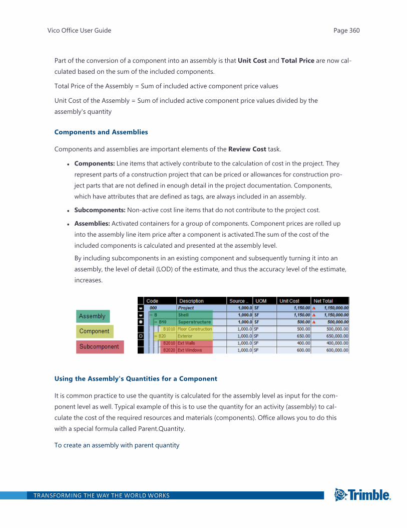
Part of the conversion of a component into an assembly is that Unit Cost and Total Price are now cal-culated based on the sum of the included components.
Total Price of the Assembly = Sum of included active component price values
Unit Cost of the Assembly = Sum of included active component price values divided by theassembly's quantity
Components and Assemblies
Components and assemblies are important elements of the Review Cost task.
l Components: Line items that actively contribute to the calculation of cost in the project. Theyrepresent parts of a construction project that can be priced or allowances for construction pro-ject parts that are not defined in enough detail in the project documentation. Components,which have attributes that are defined as tags, are always included in an assembly.
l Subcomponents: Non-active cost line items that do not contribute to the project cost.
l Assemblies: Activated containers for a group of components. Component prices are rolled upinto the assembly line item price after a component is activated.The sum of the cost of theincluded components is calculated and presented at the assembly level.
By including subcomponents in an existing component and subsequently turning it into anassembly, the level of detail (LOD) of the estimate, and thus the accuracy level of the estimate,increases.
Using the Assembly's Quantities for a Component
It is common practice to use the quantity is calculated for the assembly level as input for the com-ponent level as well. Typical example of this is to use the quantity for an activity (assembly) to cal-culate the cost of the required resources and materials (components). Office allows you to do thiswith a special formula called Parent.Quantity.
To create an assembly with parent quantity
Vico Office User Guide Page 360
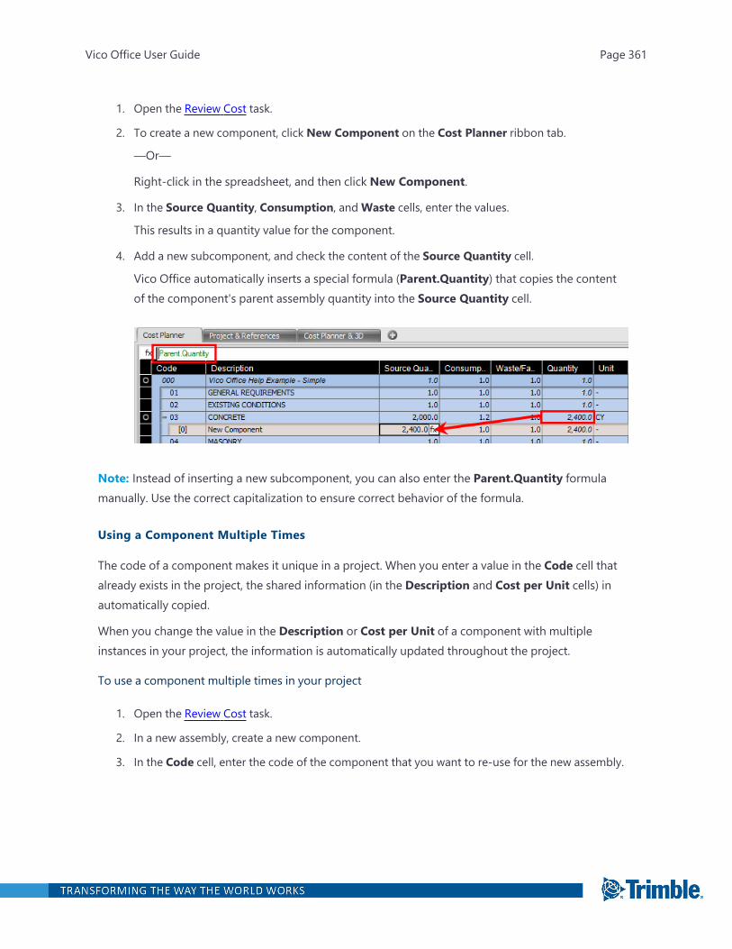
1. Open the Review Cost task.
2. To create a new component, click New Component on the Cost Planner ribbon tab.
—Or—
Right-click in the spreadsheet, and then click New Component.
3. In the Source Quantity, Consumption, andWaste cells, enter the values.
This results in a quantity value for the component.
4. Add a new subcomponent, and check the content of the Source Quantity cell.
Vico Office automatically inserts a special formula (Parent.Quantity) that copies the contentof the component's parent assembly quantity into the Source Quantity cell.
Note: Instead of inserting a new subcomponent, you can also enter the Parent.Quantity formulamanually. Use the correct capitalization to ensure correct behavior of the formula.
Using a Component Multiple Times
The code of a component makes it unique in a project. When you enter a value in the Code cell thatalready exists in the project, the shared information (in the Description and Cost per Unit cells) inautomatically copied.
When you change the value in the Description or Cost per Unit of a component with multipleinstances in your project, the information is automatically updated throughout the project.
To use a component multiple times in your project
1. Open the Review Cost task.
2. In a new assembly, create a new component.
3. In the Code cell, enter the code of the component that you want to re-use for the new assembly.
Vico Office User Guide Page 361
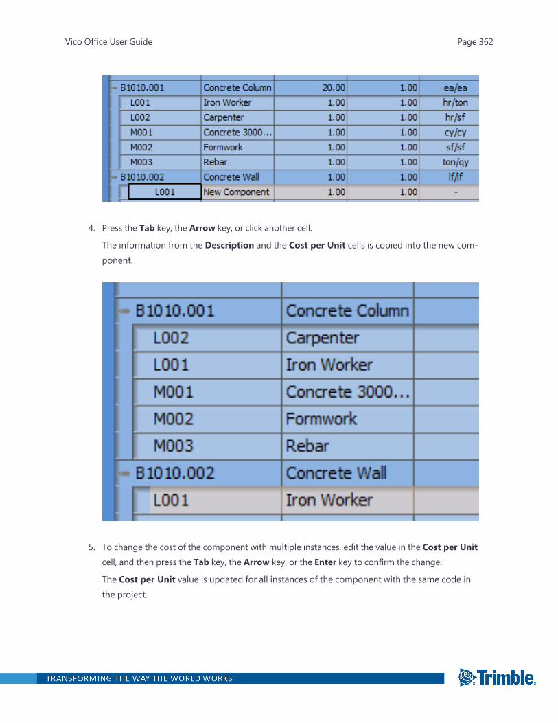
4. Press the Tab key, the Arrow key, or click another cell.
The information from the Description and the Cost per Unit cells is copied into the new com-ponent.
5. To change the cost of the component with multiple instances, edit the value in the Cost per Unitcell, and then press the Tab key, the Arrow key, or the Enter key to confirm the change.
The Cost per Unit value is updated for all instances of the component with the same code inthe project.
Vico Office User Guide Page 362
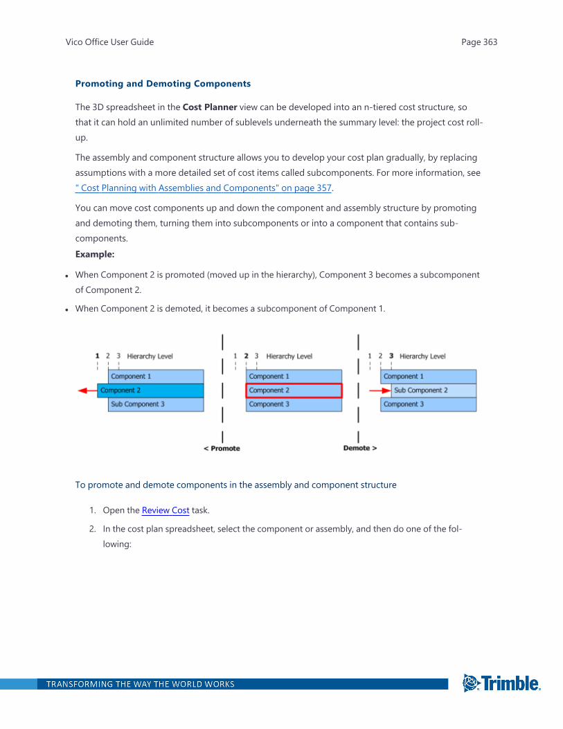
Promoting and Demoting Components
The 3D spreadsheet in the Cost Planner view can be developed into an n-tiered cost structure, sothat it can hold an unlimited number of sublevels underneath the summary level: the project cost roll-up.
The assembly and component structure allows you to develop your cost plan gradually, by replacingassumptions with a more detailed set of cost items called subcomponents. For more information, see" Cost Planning with Assemblies and Components" on page 357.
You can move cost components up and down the component and assembly structure by promotingand demoting them, turning them into subcomponents or into a component that contains sub-components.Example:
l When Component 2 is promoted (moved up in the hierarchy), Component 3 becomes a subcomponentof Component 2.
l When Component 2 is demoted, it becomes a subcomponent of Component 1.
To promote and demote components in the assembly and component structure
1. Open the Review Cost task.
2. In the cost plan spreadsheet, select the component or assembly, and then do one of the fol-lowing:
Vico Office User Guide Page 363

l To promote the component or assembly, click Up on the Cost Planner ribbon tab.
l To demote the component or assembly, click Down on the Cost Planner ribbon tab.
Using Auto-Complete
The auto-complete function is useful for quickly adding component and assembly cost calculationcontent to your project without opening a different view or dialog.
Vico Office User Guide Page 364
When the auto-complete function is turned on, a search is performed in the current project and/orselected reference for content that matches (part of) the code or description while you enter it. Match-ing options are presented in a dialog from which you can select the assembly or component that youwould like to add.
To add assemblies and components with the auto-complete function
1. Open the Review Cost task.
2. To activate the auto-complete function, click From Project and/or From Reference on the CostPlanner ribbon tab.
The button turns orange to indicate that auto-complete is now active and will search in the ref-erence, project or both.
3. In the Code cell of the spreadsheet, enter at least three characters.
A list of matching components and assemblies from the reference and/or project is displayed.If you select From Project and From Reference, matches are presented separately.
Vico Office User Guide Page 365
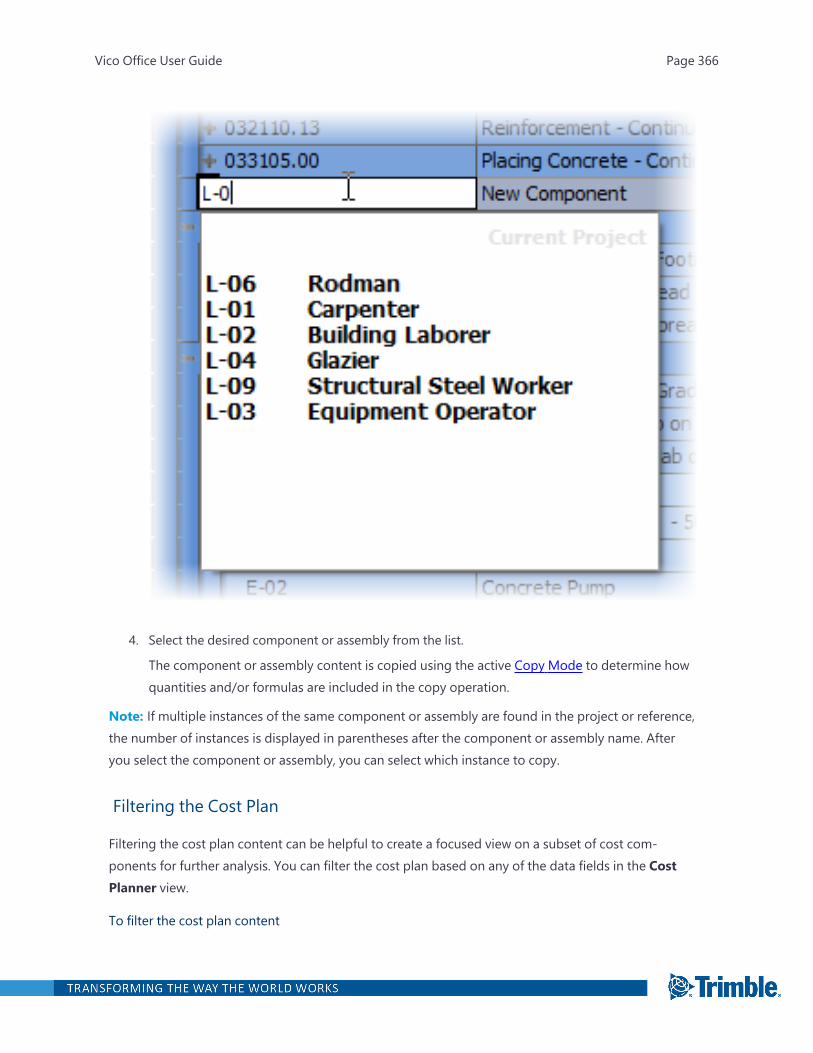
4. Select the desired component or assembly from the list.
The component or assembly content is copied using the active Copy Mode to determine howquantities and/or formulas are included in the copy operation.
Note: If multiple instances of the same component or assembly are found in the project or reference,the number of instances is displayed in parentheses after the component or assembly name. Afteryou select the component or assembly, you can select which instance to copy.
Filtering the Cost Plan
Filtering the cost plan content can be helpful to create a focused view on a subset of cost com-ponents for further analysis. You can filter the cost plan based on any of the data fields in the CostPlanner view.
To filter the cost plan content
Vico Office User Guide Page 366
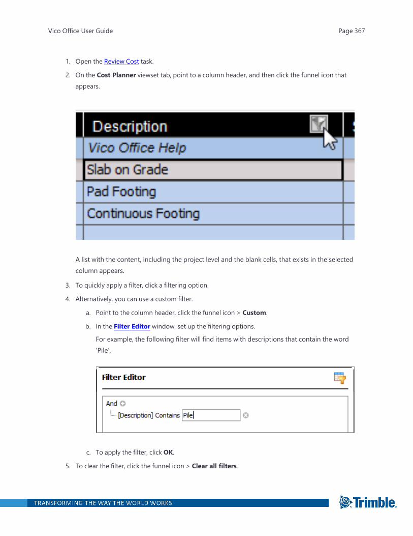
1. Open the Review Cost task.
2. On the Cost Planner viewset tab, point to a column header, and then click the funnel icon thatappears.
A list with the content, including the project level and the blank cells, that exists in the selectedcolumn appears.
3. To quickly apply a filter, click a filtering option.
4. Alternatively, you can use a custom filter.
a. Point to the column header, click the funnel icon > Custom.
b. In the Filter Editor window, set up the filtering options.
For example, the following filter will find items with descriptions that contain the word'Pile'.
c. To apply the filter, click OK.
5. To clear the filter, click the funnel icon > Clear all filters.
Vico Office User Guide Page 367
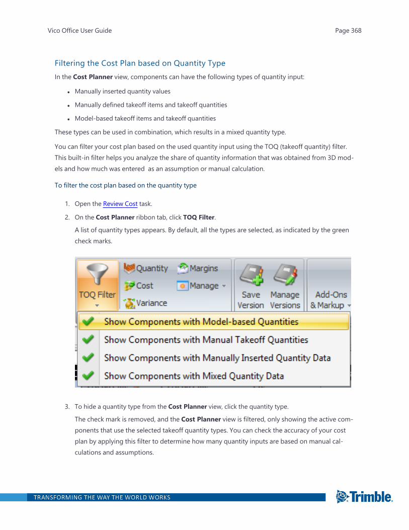
Filtering the Cost Plan based on Quantity TypeIn the Cost Planner view, components can have the following types of quantity input:
l Manually inserted quantity values
l Manually defined takeoff items and takeoff quantities
l Model-based takeoff items and takeoff quantities
These types can be used in combination, which results in a mixed quantity type.
You can filter your cost plan based on the used quantity input using the TOQ (takeoff quantity) filter.This built-in filter helps you analyze the share of quantity information that was obtained from 3D mod-els and how much was entered as an assumption or manual calculation.
To filter the cost plan based on the quantity type
1. Open the Review Cost task.
2. On the Cost Planner ribbon tab, click TOQ Filter.
A list of quantity types appears. By default, all the types are selected, as indicated by the greencheck marks.
3. To hide a quantity type from the Cost Planner view, click the quantity type.
The check mark is removed, and the Cost Planner view is filtered, only showing the active com-ponents that use the selected takeoff quantity types. You can check the accuracy of your costplan by applying this filter to determine how many quantity inputs are based on manual cal-culations and assumptions.
Vico Office User Guide Page 368
Note: For more information, see Status Tag.
Cost Planning with Ranges
Cost ranges can be used to calculate the cost of elements when insufficient design decisions havebeen made to define an exact number. In the Cost Planner view, set a minimum and a maximum costper unit, which then results in a minimum price and a maximum price.
To work with cost ranges
1. Open the Review Cost task.
2. Right-click a column header, and then click Column Selector.
3. In the list of available columns, activate a set of minimum and maximum columns such as:
l Min Base Cost
l Max Base Cost
l Min Unit Cost
l Max Base Cost
You can also activate other minimum and maximum columns such as variance and bidprice.
4. Click OK.
5. In a set of available minimum and maximum columns, enter values to define the cost range.
The values are automatically calculated after your input. A cost range icon appears in the left
Vico Office User Guide Page 369
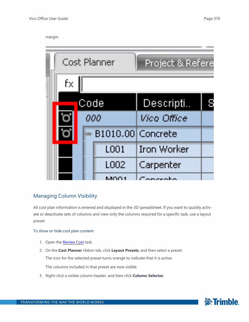
margin.
Managing Column Visibility
All cost plan information is entered and displayed in the 3D spreadsheet. If you want to quickly activ-ate or deactivate sets of columns and view only the columns required for a specific task, use a layoutpreset.
To show or hide cost plan content
1. Open the Review Cost task.
2. On the Cost Planner ribbon tab, click Layout Presets, and then select a preset.
The icon for the selected preset turns orange to indicate that it is active.
The columns included in that preset are now visible.
3. Right-click a visible column header, and then click Column Selector.
Vico Office User Guide Page 370

The Column Selector dialog opens.
4. Select the columns that you want to be visible in the Cost Planner view, and then click OK.
The selected columns appear in the spreadsheet.
Analyzing Variance
In the Cost Planner view, the calculated cost of active components is always displayed by default.You may, however, have entered an assumption in a line item that was later converted into anassembly. To compare it to the current active cost, use the Variance preset.
To analyze variance
1. Open the Review Cost task.
2. On the Cost Planner ribbon tab, click Layout Preset > Variance.
All columns related to analyzing variance are displayed in the spreadsheet.
l Component Unit Cost: The unit cost that was entered for the component BEFORE it wasturned into an assembly (after adding more detailed information to it).
l Unit Cost: The current CALCULATED cost (sum of the included component cost dividedby the assembly's quantity).
l Component Price: The price that was calculated for the component BEFORE it was turnedinto an assembly.
l Total Price: The current CALCULATED cost (sum of included component prices). Thearrows indicate whether the cost went up or down.
l Var Base Cost and Var Unit Cost: The difference between the component value and cur-rent assembly value.
Creating a Custom Layout Preset
In addition to the built-in Cost Planner presets, you can define your own presets with preferredcolumn visibility settings.
To create a custom layout preset
1. Open the Review Cost task.
2. On the Cost Planner ribbon tab, click Layout Presets >Manage.
TheManage Presets dialog appears.
Vico Office User Guide Page 371
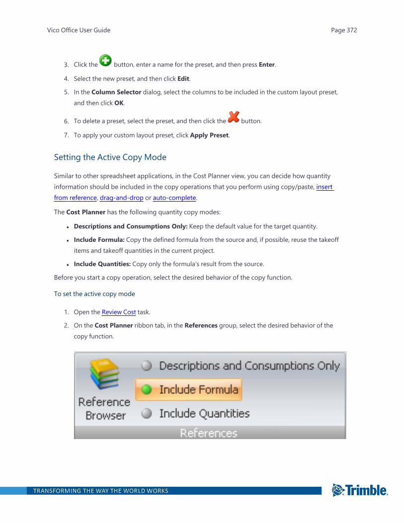
3. Click the button, enter a name for the preset, and then press Enter.
4. Select the new preset, and then click Edit.
5. In the Column Selector dialog, select the columns to be included in the custom layout preset,and then click OK.
6. To delete a preset, select the preset, and then click the button.
7. To apply your custom layout preset, click Apply Preset.
Setting the Active Copy Mode
Similar to other spreadsheet applications, in the Cost Planner view, you can decide how quantityinformation should be included in the copy operations that you perform using copy/paste, insertfrom reference, drag-and-drop or auto-complete.
The Cost Planner has the following quantity copy modes:
l Descriptions and Consumptions Only: Keep the default value for the target quantity.
l Include Formula: Copy the defined formula from the source and, if possible, reuse the takeoffitems and takeoff quantities in the current project.
l Include Quantities: Copy only the formula's result from the source.
Before you start a copy operation, select the desired behavior of the copy function.
To set the active copy mode
1. Open the Review Cost task.
2. On the Cost Planner ribbon tab, in the References group, select the desired behavior of thecopy function.
Vico Office User Guide Page 372

The active copy mode displays a green indicator and an orange background.
3. Start one of the available copy operations.
Using Tags
Use tags to further specify cost plan content by assigning codes, classifications, and properties tocomponents and assemblies. Values can be assigned easily, by activating the Tag column in the CostPlanner view.
To use tags in the cost plan
1. Open the Review Cost task.
2. Right-click a column header, and then click select Column Selector.
The Column Selector dialog appears.
3. To make a tag visible in the spreadsheet, so you can assign values for it to components andassemblies, click the tag in the list.
A green check mark appears to the left of the tag name.
4. To apply the changes, click OK.
5. To assign tag values to components in your cost plan, select them in the column of the tag.
Note: If you cannot find the tag that you would activate as a column in the spreadsheet, makesure that the tag has been set to apply to components in the tag properties.
Status Tag
Vico Office User Guide Page 373
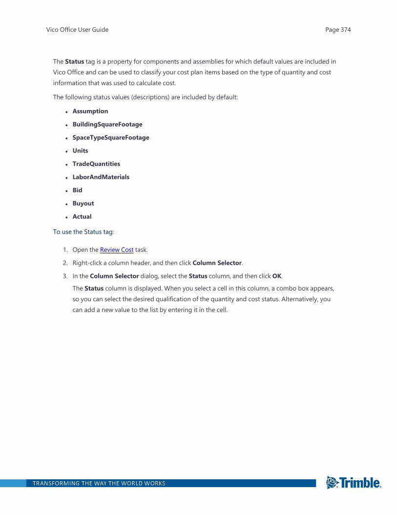
The Status tag is a property for components and assemblies for which default values are included inVico Office and can be used to classify your cost plan items based on the type of quantity and costinformation that was used to calculate cost.
The following status values (descriptions) are included by default:
l Assumption
l BuildingSquareFootage
l SpaceTypeSquareFootage
l Units
l TradeQuantities
l LaborAndMaterials
l Bid
l Buyout
l Actual
To use the Status tag:
1. Open the Review Cost task.
2. Right-click a column header, and then click Column Selector.
3. In the Column Selector dialog, select the Status column, and then click OK.
The Status column is displayed. When you select a cell in this column, a combo box appears,so you can select the desired qualification of the quantity and cost status. Alternatively, youcan add a new value to the list by entering it in the cell.
Vico Office User Guide Page 374
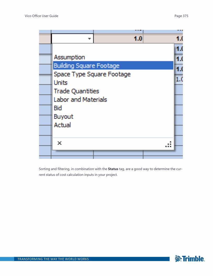
Sorting and filtering, in combination with the Status tag, are a good way to determine the cur-rent status of cost calculation inputs in your project.
Vico Office User Guide Page 375
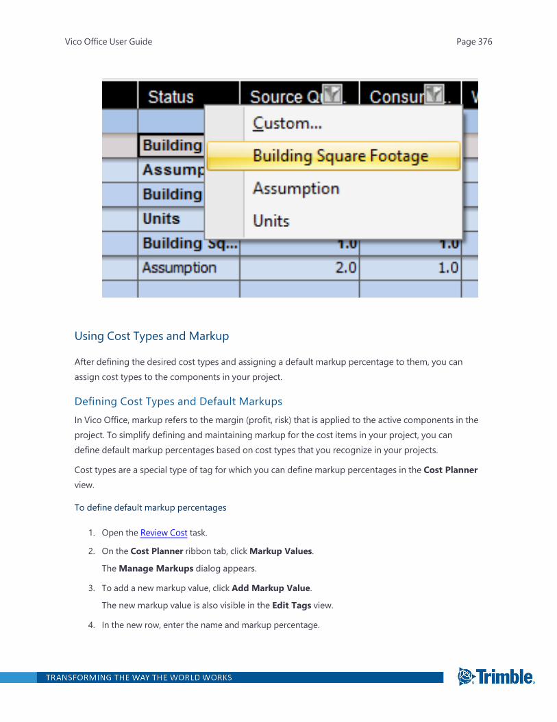
Using Cost Types and Markup
After defining the desired cost types and assigning a default markup percentage to them, you canassign cost types to the components in your project.
Defining Cost Types and Default MarkupsIn Vico Office, markup refers to the margin (profit, risk) that is applied to the active components in theproject. To simplify defining and maintaining markup for the cost items in your project, you candefine default markup percentages based on cost types that you recognize in your projects.
Cost types are a special type of tag for which you can define markup percentages in the Cost Plannerview.
To define default markup percentages
1. Open the Review Cost task.
2. On the Cost Planner ribbon tab, clickMarkup Values.
TheManage Markups dialog appears.
3. To add a new markup value, click Add Markup Value.
The new markup value is also visible in the Edit Tags view.
4. In the new row, enter the name and markup percentage.
Vico Office User Guide Page 376
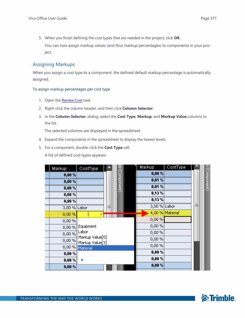
5. When you finish defining the cost types that are needed in the project, click OK.
You can now assign markup values (and thus markup percentages) to components in your pro-ject.
Assigning MarkupsWhen you assign a cost type to a component, the defined default markup percentage is automaticallyassigned.
To assign markup percentages per cost type
1. Open the Review Cost task.
2. Right-click the column header, and then click Column Selector.
3. In the Column Selector, dialog, select the Cost Type,Markup, andMarkup Value columns tothe list.
The selected columns are displayed in the spreadsheet.
4. Expand the components in the spreadsheet to display the lowest levels.
5. For a component, double-click the Cost Type cell.
A list of defined cost types appears.
Vico Office User Guide Page 377
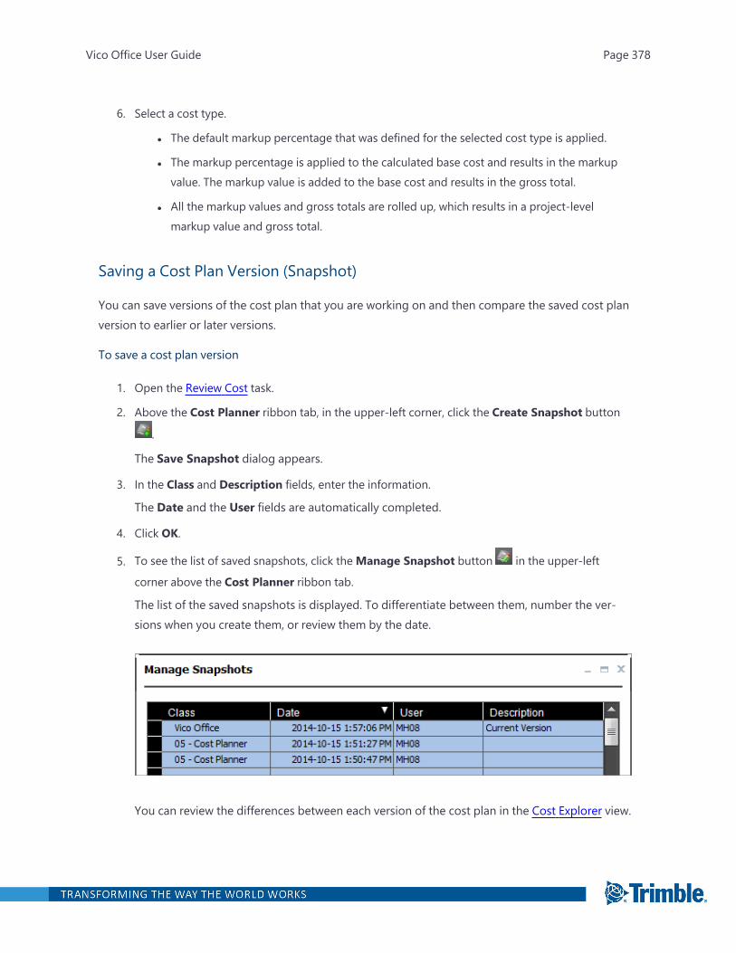
6. Select a cost type.
l The default markup percentage that was defined for the selected cost type is applied.
l The markup percentage is applied to the calculated base cost and results in the markupvalue. The markup value is added to the base cost and results in the gross total.
l All the markup values and gross totals are rolled up, which results in a project-levelmarkup value and gross total.
Saving a Cost Plan Version (Snapshot)
You can save versions of the cost plan that you are working on and then compare the saved cost planversion to earlier or later versions.
To save a cost plan version
1. Open the Review Cost task.
2. Above the Cost Planner ribbon tab, in the upper-left corner, click the Create Snapshot button
.
The Save Snapshot dialog appears.
3. In the Class and Description fields, enter the information.
The Date and the User fields are automatically completed.
4. Click OK.
5. To see the list of saved snapshots, click theManage Snapshot button in the upper-left
corner above the Cost Planner ribbon tab.
The list of the saved snapshots is displayed. To differentiate between them, number the ver-sions when you create them, or review them by the date.
You can review the differences between each version of the cost plan in the Cost Explorer view.
Vico Office User Guide Page 378

Using Add-Ons
In the Cost Planner view, you can create add-on items to include non-direct costs, margins, and con-tingencies in your cost plan. Add-on values are a percentage of the total direct cost, calculated for theproject using the component and assembly structure. You can add an unlimited number of add-onitems, all rolling up to the bid price at the project level.
The cost price of a project is calculated by adding up all the price values of active components fromthe assembly and component structure in the project. The bid price is calculated as the sum of allprice values, plus the sum of all markups plus the sum of all add-on margins.
Defining Add-OnsYou can include defined add-on values in the components of your project. Then the defined marginsand compensations are part of the assembly and component cost structure and are no longer calledout separately.
To define an add-on
1. Open the Review Cost task.
2. On the Cost Planner ribbon tab, click Layout Presets >Margins.
The required columns are displayed.
3. On the ribbon, in the Add-Ons & Markup group, click Show.
The Add-Ons area is opened underneath the Project Summary to indicate that the marginsare added on top of the calculated price.
4. To add a new add-on to the project, click Add in the Add-Ons & Markup group on the ribbon.
A new add-on line is added to the project.
Vico Office User Guide Page 379
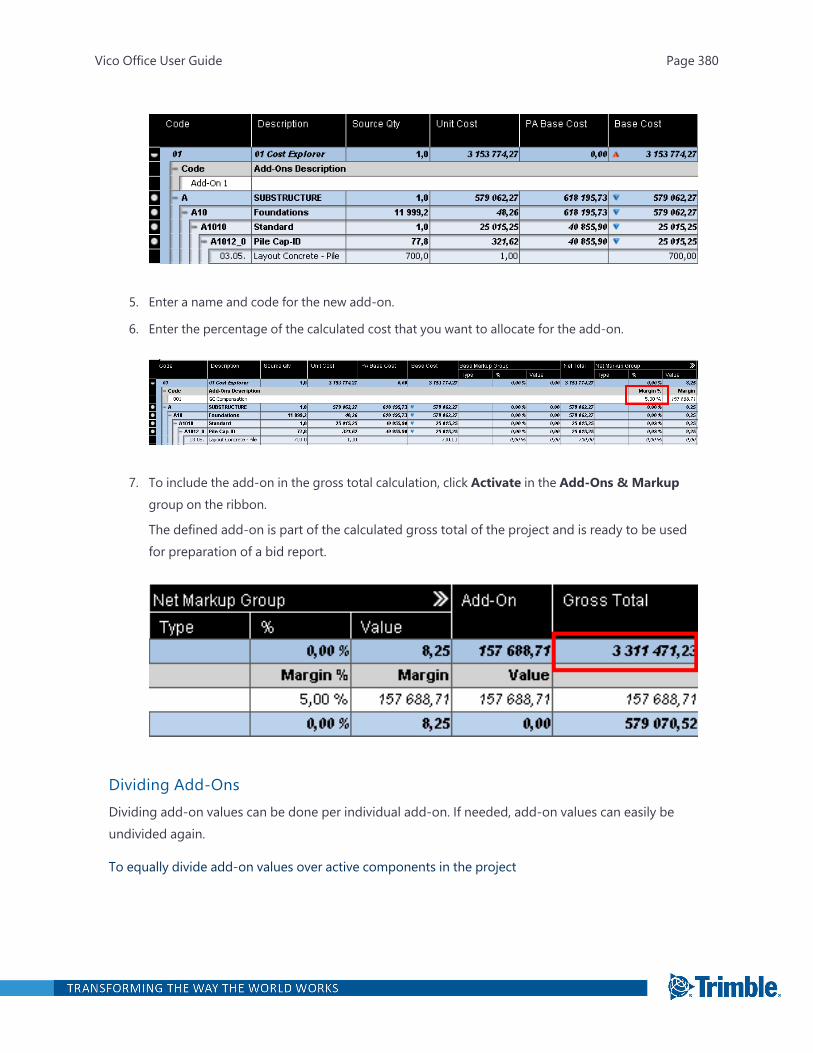
5. Enter a name and code for the new add-on.
6. Enter the percentage of the calculated cost that you want to allocate for the add-on.
7. To include the add-on in the gross total calculation, click Activate in the Add-Ons & Markupgroup on the ribbon.
The defined add-on is part of the calculated gross total of the project and is ready to be usedfor preparation of a bid report.
Dividing Add-OnsDividing add-on values can be done per individual add-on. If needed, add-on values can easily beundivided again.
To equally divide add-on values over active components in the project
Vico Office User Guide Page 380

1. Open the Review Cost task.
2. On the Cost Planner ribbon tab, in the Add-Ons & Markup group, click Show.
3. Select the add-on that you want to divide over the active components in the project.
4. On the Cost Planner ribbon tab, in the Add-Ons & Markup group, click Divide.
The defined add-on value is divided by ration over all active components, based on the shareof the component's price in the total project price.
5. To view the add-on value or sum of divided add-on values added to the component, right-click acolumn header, click Column Selector > Add-On column > OK.
Importing from and Exporting to Modelogix
Importing from Modelogix
In the absence of 2D drawings or a 3D model from which to perform takeoffs, you can import a costmodel from Modelogix, a stand-alone application for modeling preliminary project cost projects. Asyou receive more information regarding the scope, such as a 3D model for various parts of the build-ing, you can then override the initial quantity values from Modelogix.
Tip: Before importing a model from Modelogix, ensure that you already have a 3D model in VicoOffice from which to derive quantities. Also, this 3D model has components within it that match thecost items in the cost model.
To import from Modelogix
1. Create a new blank project.
2. Open the Review Cost task.
3. On the Cost Planner ribbon tab, click Import, and select Import from Modelogix.
Vico Office User Guide Page 381

4. On the Import from Modelogix dialog box, enter the following details:
l Username / Password: Enter a valid username and password. These are the credentialsthat were set in Modelogix (Setup > Options > Vico Import Mappings)
l Web Service URL: Enter the Web Service URL where the Modelogix server component isinstalled.
5. Click Connect.
Vico Office User Guide Page 382
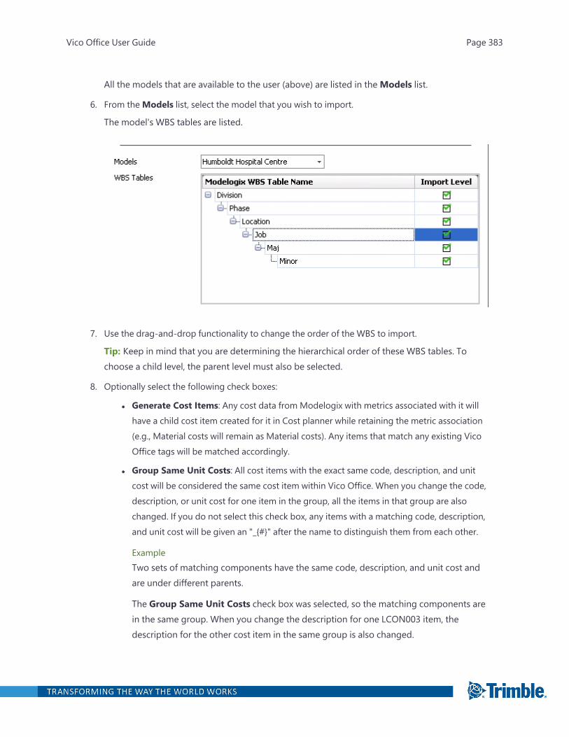
All the models that are available to the user (above) are listed in theModels list.
6. From theModels list, select the model that you wish to import.
The model's WBS tables are listed.
7. Use the drag-and-drop functionality to change the order of the WBS to import.
Tip: Keep in mind that you are determining the hierarchical order of these WBS tables. Tochoose a child level, the parent level must also be selected.
8. Optionally select the following check boxes:
l Generate Cost Items: Any cost data from Modelogix with metrics associated with it willhave a child cost item created for it in Cost planner while retaining the metric association(e.g., Material costs will remain as Material costs). Any items that match any existing VicoOffice tags will be matched accordingly.
l Group Same Unit Costs: All cost items with the exact same code, description, and unitcost will be considered the same cost item within Vico Office. When you change the code,description, or unit cost for one item in the group, all the items in that group are alsochanged. If you do not select this check box, any items with a matching code, description,and unit cost will be given an "_{#}" after the name to distinguish them from each other.
ExampleTwo sets of matching components have the same code, description, and unit cost andare under different parents.
The Group Same Unit Costs check box was selected, so the matching components arein the same group. When you change the description for one LCON003 item, thedescription for the other cost item in the same group is also changed.
Vico Office User Guide Page 383

9. Click Import.
Tip: After importing the model, you will need to activate it.
Exporting to Modelogix
After creating cost plans in Vico, you can export your projects into Modelogix, a stand-alone applic-ation for modeling preliminary project cost projects. Modelogix enables companies, large and small,to capture and store historical cost projects and as-built project costs efficiently in a standardMicrosoft SQL database.
Tip: Before you can export your projects, ensure that Modelogix metrics are mapped to Vico tags.This setup is done from Modelogix (Setup > Options).
To export to Modelogix
1. Open the project that you wish to export to Modelogix.
2. Open the Review Cost task.
3. On the Cost Planner ribbon tab, click Export, and select Export from Modelogix.
Vico Office User Guide Page 384
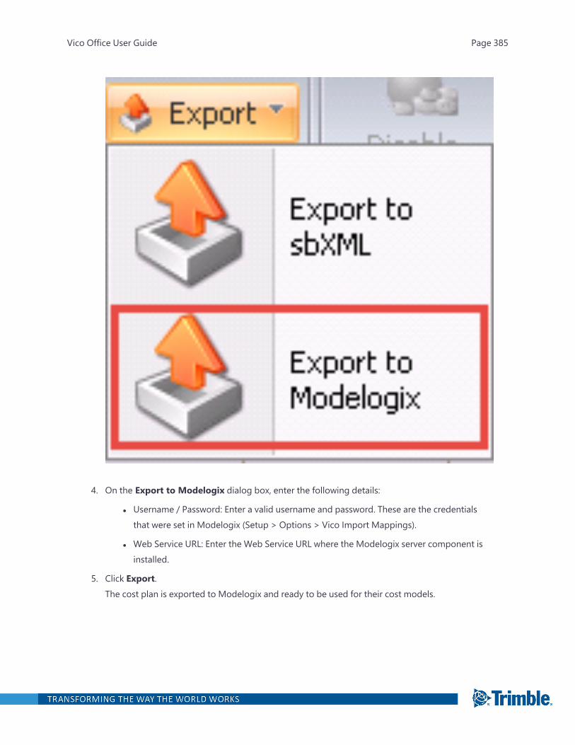
4. On the Export to Modelogix dialog box, enter the following details:
l Username / Password: Enter a valid username and password. These are the credentialsthat were set in Modelogix (Setup > Options > Vico Import Mappings).
l Web Service URL: Enter the Web Service URL where the Modelogix server component isinstalled.
5. Click Export.The cost plan is exported to Modelogix and ready to be used for their cost models.
Vico Office User Guide Page 385
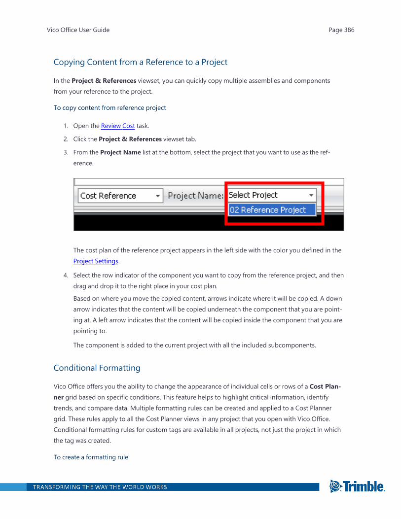
Copying Content from a Reference to a Project
In the Project & References viewset, you can quickly copy multiple assemblies and componentsfrom your reference to the project.
To copy content from reference project
1. Open the Review Cost task.
2. Click the Project & References viewset tab.
3. From the Project Name list at the bottom, select the project that you want to use as the ref-erence.
The cost plan of the reference project appears in the left side with the color you defined in theProject Settings.
4. Select the row indicator of the component you want to copy from the reference project, and thendrag and drop it to the right place in your cost plan.
Based on where you move the copied content, arrows indicate where it will be copied. A downarrow indicates that the content will be copied underneath the component that you are point-ing at. A left arrow indicates that the content will be copied inside the component that you arepointing to.
The component is added to the current project with all the included subcomponents.
Conditional Formatting
Vico Office offers you the ability to change the appearance of individual cells or rows of a Cost Plan-ner grid based on specific conditions. This feature helps to highlight critical information, identifytrends, and compare data. Multiple formatting rules can be created and applied to a Cost Plannergrid. These rules apply to all the Cost Planner views in any project that you open with Vico Office.Conditional formatting rules for custom tags are available in all projects, not just the project in whichthe tag was created.
To create a formatting rule
Vico Office User Guide Page 386
1. Right-click on a Cost Planner column header and select Conditional Formatting >ManageRules.
2. On the Conditional Formatting Rules Manager dialog box, click New Rule.
3. In the New Formatting Rule dialog box, choose one of the following rule types:
l Format only cells that contain:
l Cell value: Applies a format if a cell's value meets a specified condition (E.g., EqualTo, Less Than, Between).
l Dates Occurring: Applies a format if a column's date has a specific date and/ordate interval relative to today. These days and intervals include Today, Yesterday,This week, Earlier this month, and Prior to this year.
l Use a formula to determine which cells to format: Use this option to apply multiple formatrules to a cell.
Example: To highlight in red text all the items related to 'Floor' construction that exceeda 'Base Cost' of '$2 million', you would enter two conditions, Keep in mine that yourformatting rules need to honor Vico's default formatting rule. For more information, see'"Important Formatting Rules" on page 389
4. Click Format, specify how you want to format the cells and click OK.
5. On the Conditional Formatting Rules Manager dialog box, you can click on any of the fol-lowing:
l Edit Rule: Edit the currently selected rule.
l Delete Rule: Delete the currently selected rule.
l Up / Down: Use these buttons to determine the order of your rules. The lowest rule in thelist has the lowest priority.
l Apply to the row: Select it to apply the formatting to the entire row.
l Column: Select the column to which you want to apply the formatting rule.
Vico Office User Guide Page 387

Applying a Predefined Style Format
For ease of use, Vico Office contains a list of predefined style formats.
To apply a predefined style format
1. Right-click on a Cost Planner column header and select Conditional Formatting > HighlightCell Rules.
2. Select one of the predefined formatting rules.
3. Enter the value and the formatting style to be applied to this rule.
4. Optionally select the check box to apply the formatting rule to the entire row.
5. Click OK.
Deleting Conditional Formatting Rules
If you have already applied one or more rules to columns, the Clear Rules submenu becomes avail-able. It allows you to delete rules from one or all columns.
To delete the conditional formatting rules
1. Right-click on a Cost Planner column header and select Conditional Formatting > Clear Rules.
2. Choose to either clear the formatting rules applied to the selected column or to all the columnsin the grid.
Sharing Formatting Rules
The formatting rules are saved in the CP_FormatingRules XML file, which is located in the followingfolder path:
Vico Office User Guide Page 388
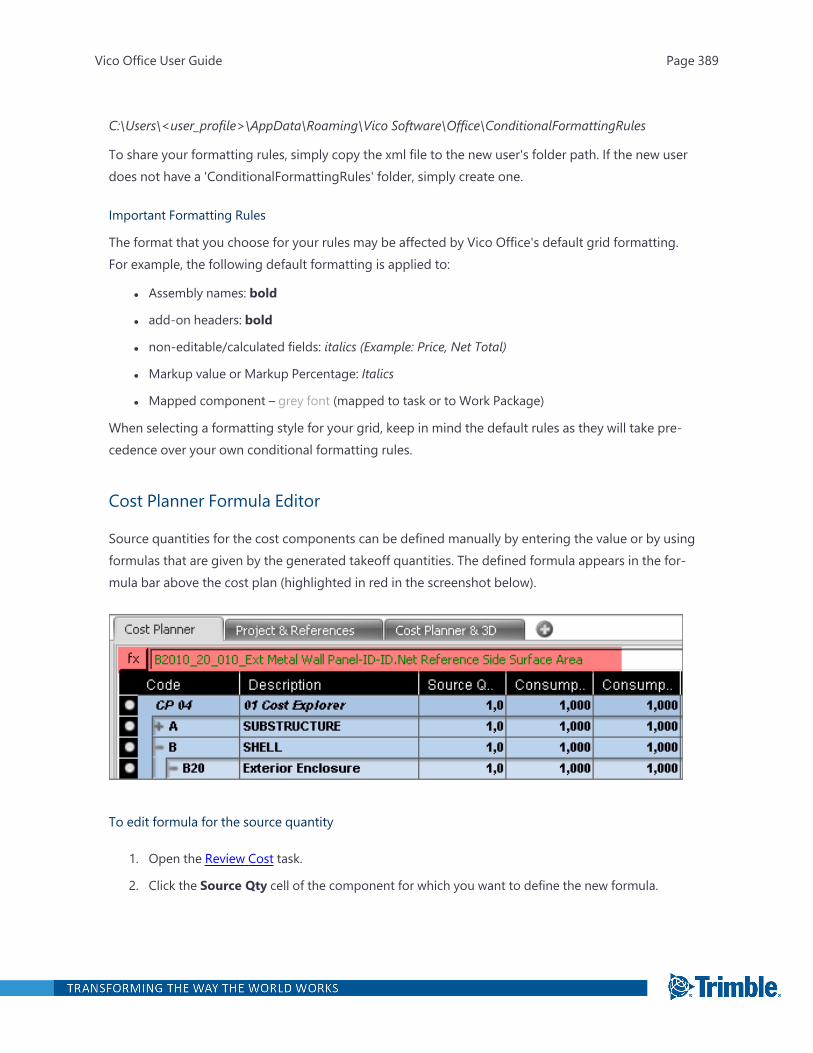
C:\Users\<user_profile>\AppData\Roaming\Vico Software\Office\ConditionalFormattingRules
To share your formatting rules, simply copy the xml file to the new user's folder path. If the new userdoes not have a 'ConditionalFormattingRules' folder, simply create one.
Important Formatting Rules
The format that you choose for your rules may be affected by Vico Office's default grid formatting.For example, the following default formatting is applied to:
l Assembly names: bold
l add-on headers: bold
l non-editable/calculated fields: italics (Example: Price, Net Total)
l Markup value or Markup Percentage: Italics
l Mapped component – grey font (mapped to task or to Work Package)
When selecting a formatting style for your grid, keep in mind the default rules as they will take pre-cedence over your own conditional formatting rules.
Cost Planner Formula Editor
Source quantities for the cost components can be defined manually by entering the value or by usingformulas that are given by the generated takeoff quantities. The defined formula appears in the for-mula bar above the cost plan (highlighted in red in the screenshot below).
To edit formula for the source quantity
1. Open the Review Cost task.
2. Click the Source Qty cell of the component for which you want to define the new formula.
Vico Office User Guide Page 389

The button appears in the cell.
3. To open the Formula Editor, click the button.
Areas in the Formula Editor:
Takeoff Manager
The Takeoff Manager displays the list of takeoff items and takeoff quantities that were defined in theproject using the Takeoff Manager module.
Enter Formula
The Enter Formula section shows selected takeoff items and takeoff quantities. You can modify theformula using mathematical functions and symbols.
For more information on entering formulas, see "Cost Planning with Takeoff Items" on the next page.
Vico Office User Guide Page 390
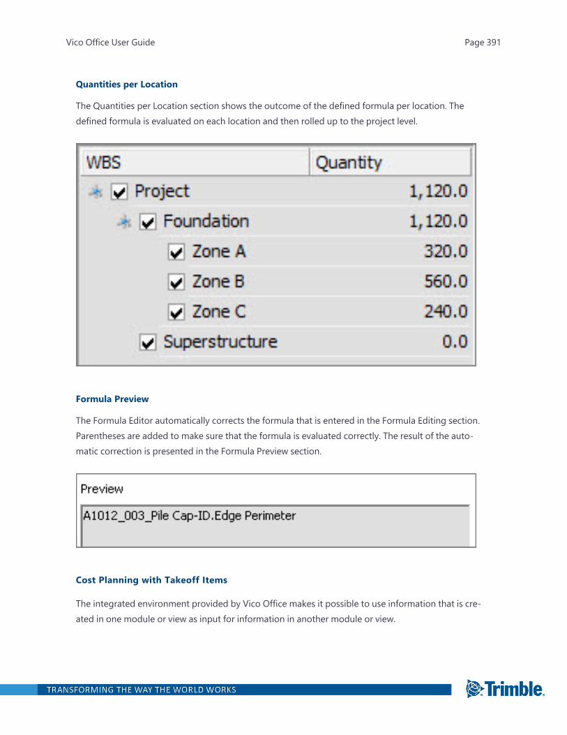
Quantities per Location
The Quantities per Location section shows the outcome of the defined formula per location. Thedefined formula is evaluated on each location and then rolled up to the project level.
Formula Preview
The Formula Editor automatically corrects the formula that is entered in the Formula Editing section.Parentheses are added to make sure that the formula is evaluated correctly. The result of the auto-matic correction is presented in the Formula Preview section.
Cost Planning with Takeoff Items
The integrated environment provided by Vico Office makes it possible to use information that is cre-ated in one module or view as input for information in another module or view.
Vico Office User Guide Page 391
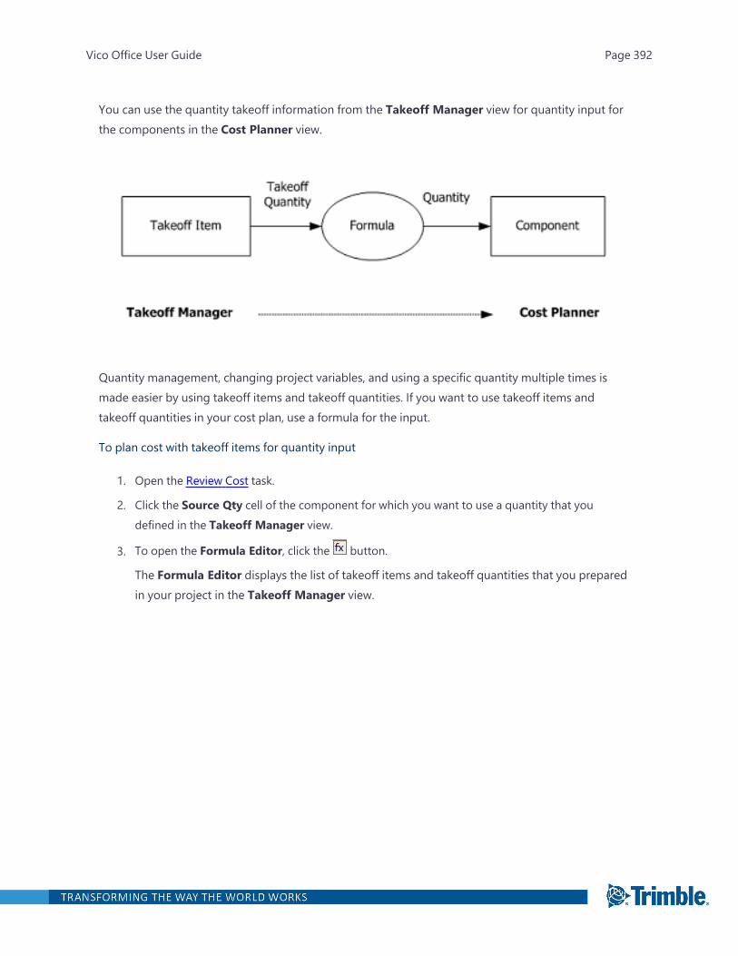
You can use the quantity takeoff information from the Takeoff Manager view for quantity input forthe components in the Cost Planner view.
Quantity management, changing project variables, and using a specific quantity multiple times ismade easier by using takeoff items and takeoff quantities. If you want to use takeoff items andtakeoff quantities in your cost plan, use a formula for the input.
To plan cost with takeoff items for quantity input
1. Open the Review Cost task.
2. Click the Source Qty cell of the component for which you want to use a quantity that youdefined in the Takeoff Manager view.
3. To open the Formula Editor, click the button.
The Formula Editor displays the list of takeoff items and takeoff quantities that you preparedin your project in the Takeoff Manager view.
Vico Office User Guide Page 392
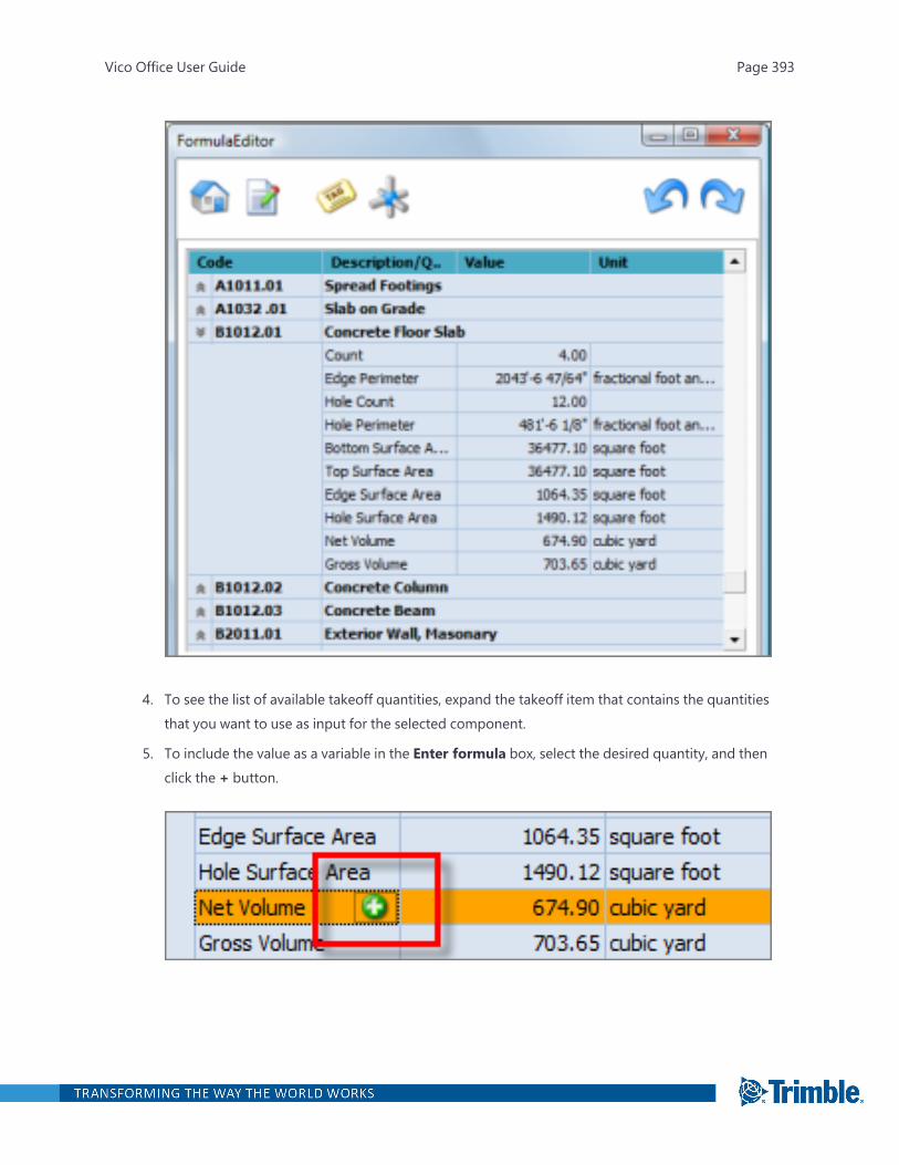
4. To see the list of available takeoff quantities, expand the takeoff item that contains the quantitiesthat you want to use as input for the selected component.
5. To include the value as a variable in the Enter formula box, select the desired quantity, and thenclick the + button.
Vico Office User Guide Page 393
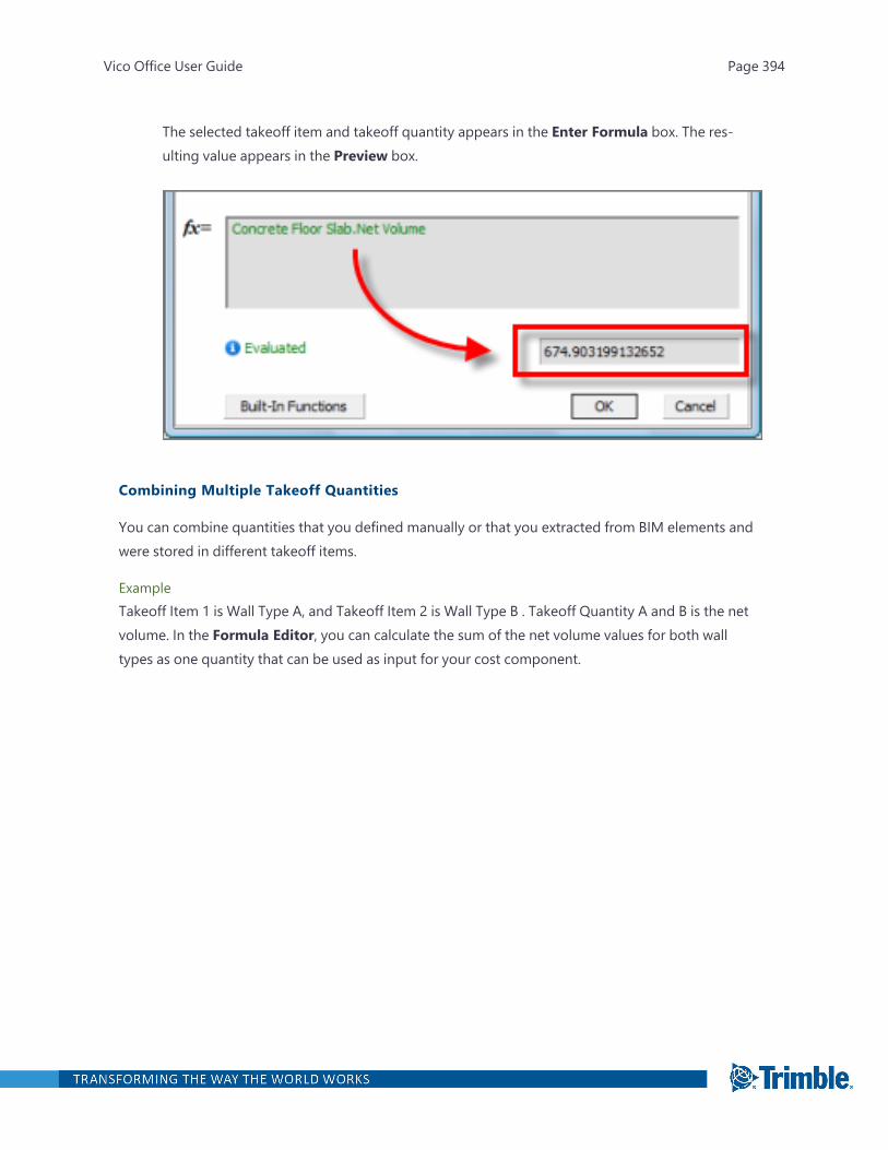
The selected takeoff item and takeoff quantity appears in the Enter Formula box. The res-ulting value appears in the Preview box.
Combining Multiple Takeoff Quantities
You can combine quantities that you defined manually or that you extracted from BIM elements andwere stored in different takeoff items.
ExampleTakeoff Item 1 is Wall Type A, and Takeoff Item 2 is Wall Type B . Takeoff Quantity A and B is the netvolume. In the Formula Editor, you can calculate the sum of the net volume values for both walltypes as one quantity that can be used as input for your cost component.
Vico Office User Guide Page 394
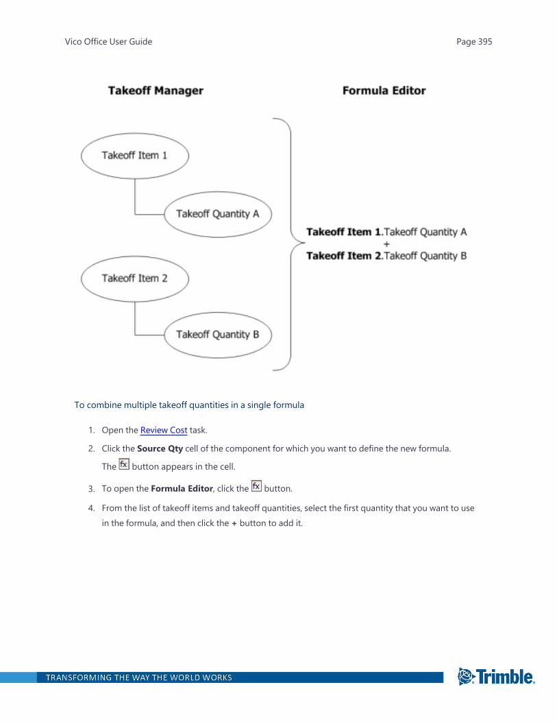
To combine multiple takeoff quantities in a single formula
1. Open the Review Cost task.
2. Click the Source Qty cell of the component for which you want to define the new formula.
The button appears in the cell.
3. To open the Formula Editor, click the button.
4. From the list of takeoff items and takeoff quantities, select the first quantity that you want to usein the formula, and then click the + button to add it.
Vico Office User Guide Page 395

The takeoff item and takeoff quantity are displayed in the Enter Formula box.
5. Click the Enter Formula box to activate the cursor, and then move the cursor to the end of theformula.
6. Type the + symbol.
The font color of the formula changes to red because the formula is no longer complete; a vari-able is missing after the + symbol.
7. Leave the cursor after the + symbol, and then include the next takeoff quantity by selecting thetakeoff quantity and clicking the + button.
Vico Office User Guide Page 396
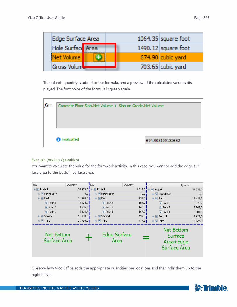
The takeoff quantity is added to the formula, and a preview of the calculated value is dis-played. The font color of the formula is green again.
Example (Adding Quantities)You want to calculate the value for the formwork activity. In this case, you want to add the edge sur-face area to the bottom surface area.
Observe how Vico Office adds the appropriate quantities per locations and then rolls them up to thehigher level.
Vico Office User Guide Page 397

If you multiply the appropriate takeoff quantities, Vico Office starts the calculation on the lowest level,and then rolls the results up to the higher (parent) level. In this case, the quantity on the project levelwill not be equivalent with the one that comes from multiplying the quantities on the project levels.
Example (Dividing Quantities)You want to calculate the height of the wall by dividing the side surface area by the length.
Observe how Vico Office divides the quantities on the lowest level and then rolls them up to thehigher level.
Floor 1 - Loc A: 2 030.4/660.7=3.1Floor 1 - Loc B: 888.9/274.0=3.2Floor 1 - Loc C: 1 066.5/166.0=6.4
Floor 1 - Total Height: 3.1+3.2+6.4=12.7;Project - Total Height: 12.7+34.8+0.0=47.6;
Defining Advanced Formulas
You can embed advanced functions in formulas to combine takeoff quantities for cost calculation in acomponent.
The functions are available in the following categories:
l Standard: Includes basic mathematical functions such as +, -, and /.
l Math: Includes geometrical functions such as SIN, COS, and TAN.
l Logical: Includes IF, NOT, TRUE, and FALSE statements for defining conditional calculations.
To use the advanced functions in the Formula Editor
Vico Office User Guide Page 398
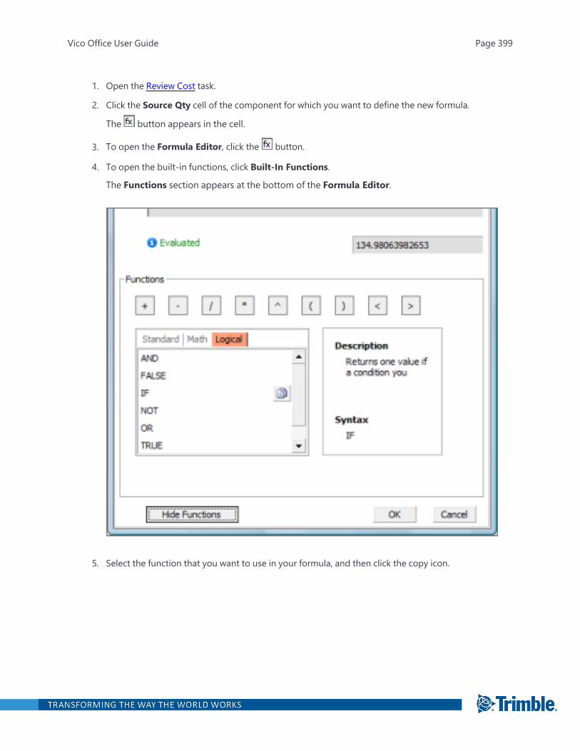
1. Open the Review Cost task.
2. Click the Source Qty cell of the component for which you want to define the new formula.
The button appears in the cell.
3. To open the Formula Editor, click the button.
4. To open the built-in functions, click Built-In Functions.
The Functions section appears at the bottom of the Formula Editor.
5. Select the function that you want to use in your formula, and then click the copy icon.
Vico Office User Guide Page 399
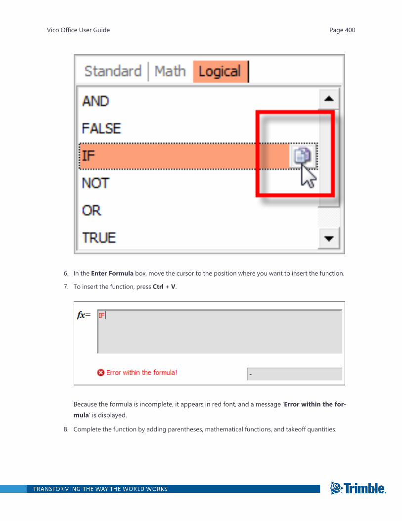
6. In the Enter Formula box, move the cursor to the position where you want to insert the function.
7. To insert the function, press Ctrl + V.
Because the formula is incomplete, it appears in red font, and a message 'Error within the for-mula' is displayed.
8. Complete the function by adding parentheses, mathematical functions, and takeoff quantities.
Vico Office User Guide Page 400

When the formula is complete, a preview value is presented, and the message Evaluatedappears.
Adding Constant Values
By default, constant values that are added to a formula are divided over all locations that have an eval-uated formula result that is larger than 0.Example:
In the project, the Wall.Count takeoff item and takeoff quantity are:
If the formula is defined asWall.Count, the evaluated result per location will be equal to these values.However, if you add a constant value, that value will be subdivided over all locations with a formulaoutcome larger than 0.
Vico Office User Guide Page 401
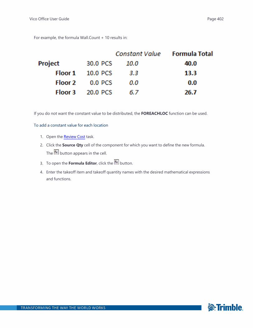
For example, the formula Wall.Count + 10 results in:
If you do not want the constant value to be distributed, the FOREACHLOC function can be used.
To add a constant value for each location
1. Open the Review Cost task.
2. Click the Source Qty cell of the component for which you want to define the new formula.
The button appears in the cell.
3. To open the Formula Editor, click the button.
4. Enter the takeoff item and takeoff quantity names with the desired mathematical expressionsand functions.
Vico Office User Guide Page 402
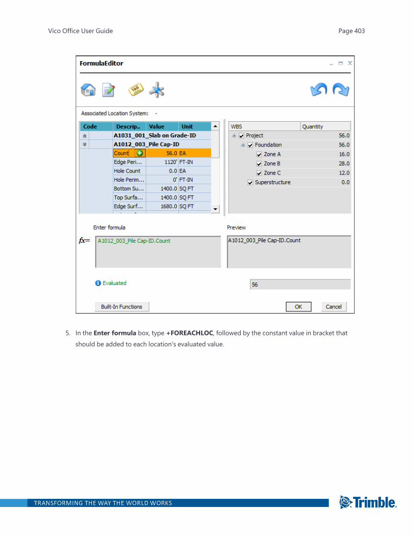
5. In the Enter formula box, type +FOREACHLOC, followed by the constant value in bracket thatshould be added to each location's evaluated value.
Vico Office User Guide Page 403
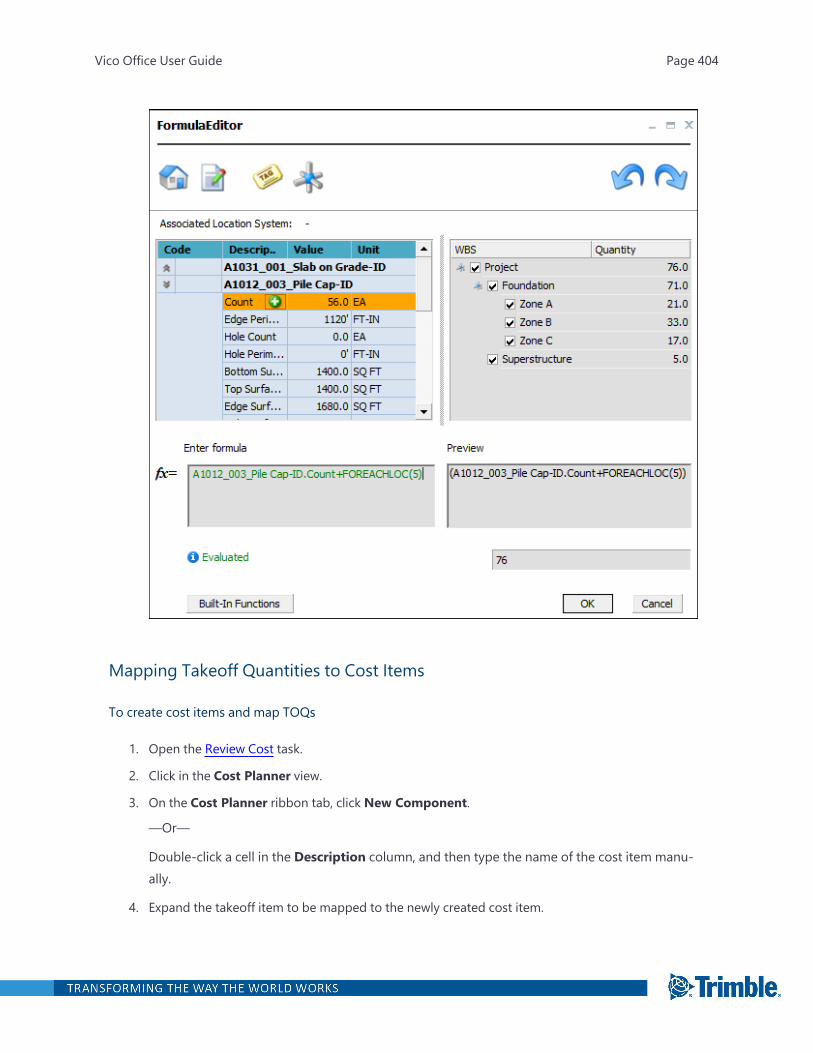
Mapping Takeoff Quantities to Cost Items
To create cost items and map TOQs
1. Open the Review Cost task.
2. Click in the Cost Planner view.
3. On the Cost Planner ribbon tab, click New Component.
—Or—
Double-click a cell in the Description column, and then type the name of the cost item manu-ally.
4. Expand the takeoff item to be mapped to the newly created cost item.
Vico Office User Guide Page 404
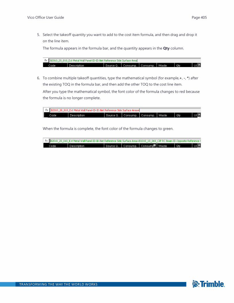
5. Select the takeoff quantity you want to add to the cost item formula, and then drag and drop iton the line item.
The formula appears in the formula bar, and the quantity appears in the Qty column.
6. To combine multiple takeoff quantities, type the mathematical symbol (for example,+, -, *) afterthe existing TOQ in the formula bar, and then add the other TOQ to the cost line item.
After you type the mathematical symbol, the font color of the formula changes to red becausethe formula is no longer complete.
When the formula is complete, the font color of the formula changes to green.
Vico Office User Guide Page 405

Explore Cost
Project teams often struggle with communicating cost and cost variance in a project. Traditional com-munication means are printouts of both cost estimate (versions) and design plans, both of which aredisconnected and voluminous. It is difficult to explain an occurring cost variance between two ver-sions in meetings. As a result, much time is spent on creating a common understanding of the projectinformation, which leaves insufficient time for analysis and decision making.
Most cost comparisons are done at the project level, so there is a misunderstanding of where budgetoverruns occur in the project. This often results in an inability to define accurate and targeted projectchanges to bring the project back on track.
The Explore Cost task in Vico Office helps project teams visualize and analyze project cost and costvariances. The color-coded Cost Explorer and 3D model integration is a powerful way to com-municate the cost of a specific group, where it exists in the project, and how it compares to thebudget and previous versions.
The default viewset includes the following:
l Cost Explorer view
l Cost Planner view
l 3D View
The Cost Explorer view contains the Cost Explorer Tree, and all assemblies are shown as nodes.When you click a circle or square in the tree, the corresponding cost data appears in the Cost Plan-ner view. You can see the collection of assemblies and components that were used to calculate thecost of the project.
To open the Explore Cost task
1. Right-click the Workflow Panel header, and then click the Vico Office or Vico for Cost module.
2. In the Vico for Cost or Cost Management workflow group, click Explore Cost.
Comparison Modes and Versions
The Cost Explorer view has the following comparison modes:
l Assemblies to Components: Compare each assembly's calculated cost to the sum of the includedcomponents and/or assemblies.
l Cost to Target: Compare the costs of two selected versions to the defined targets.
Vico Office User Guide Page 406
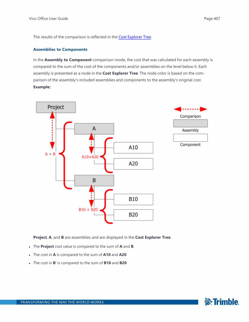
The results of the comparison is reflected in the Cost Explorer Tree.
Assemblies to Components
In the Assembly to Component comparison mode, the cost that was calculated for each assembly iscompared to the sum of the cost of the components and/or assemblies on the level below it. Eachassembly is presented as a node in the Cost Explorer Tree. The node color is based on the com-parison of the assembly's included assemblies and components to the assembly's original cost.Example:
Project, A, and B are assemblies and are displayed in the Cost Explorer Tree.
l The Project cost value is compared to the sum of A and B.
l The cost in A is compared to the sum of A10 and A20
l The cost in B' is compared to the sum of B10 and B20
Vico Office User Guide Page 407
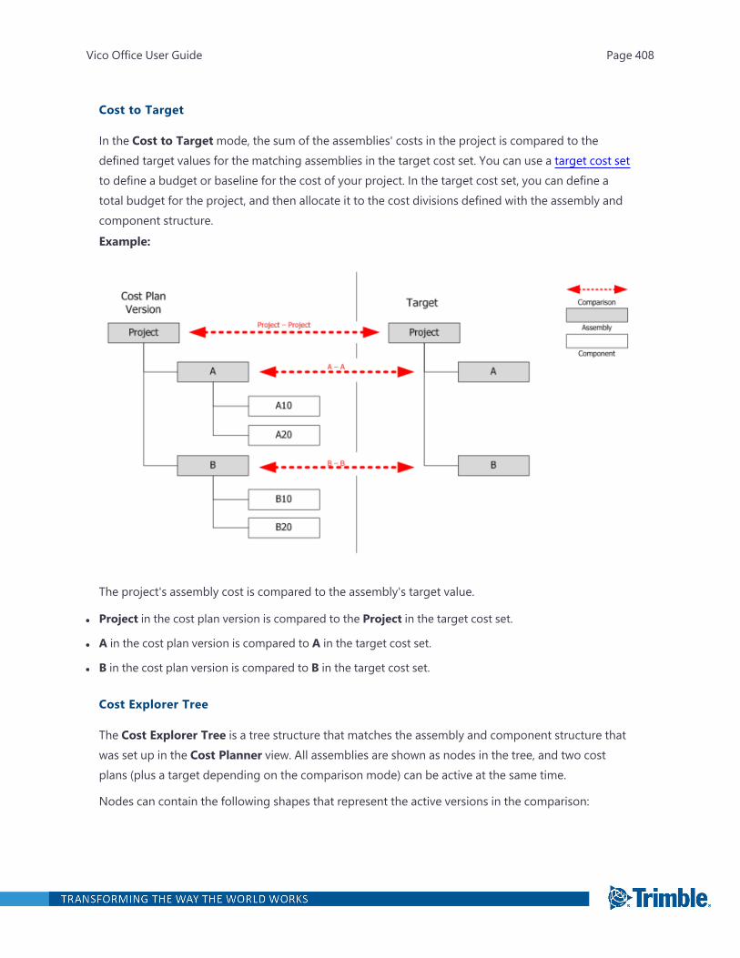
Cost to Target
In the Cost to Targetmode, the sum of the assemblies' costs in the project is compared to thedefined target values for the matching assemblies in the target cost set. You can use a target cost setto define a budget or baseline for the cost of your project. In the target cost set, you can define atotal budget for the project, and then allocate it to the cost divisions defined with the assembly andcomponent structure.Example:
The project's assembly cost is compared to the assembly's target value.
l Project in the cost plan version is compared to the Project in the target cost set.
l A in the cost plan version is compared to A in the target cost set.
l B in the cost plan version is compared to B in the target cost set.
Cost Explorer Tree
The Cost Explorer Tree is a tree structure that matches the assembly and component structure thatwas set up in the Cost Planner view. All assemblies are shown as nodes in the tree, and two costplans (plus a target depending on the comparison mode) can be active at the same time.
Nodes can contain the following shapes that represent the active versions in the comparison:
Vico Office User Guide Page 408

l Square: Represents the older version in the pair.
l Circle: Represents the newer version in the pair.
The color of the node indicates its cost status:
l Red: Higher than the target.
l Yellow: At risk.
l Green:Within the set target range.
l Blue: Too low compared to the target.
For information on setting up the cost comparison ranges, see "Defining Comparison Ranges" onpage 416.Example:
Vico Office User Guide Page 409

Vico Office User Guide Page 410
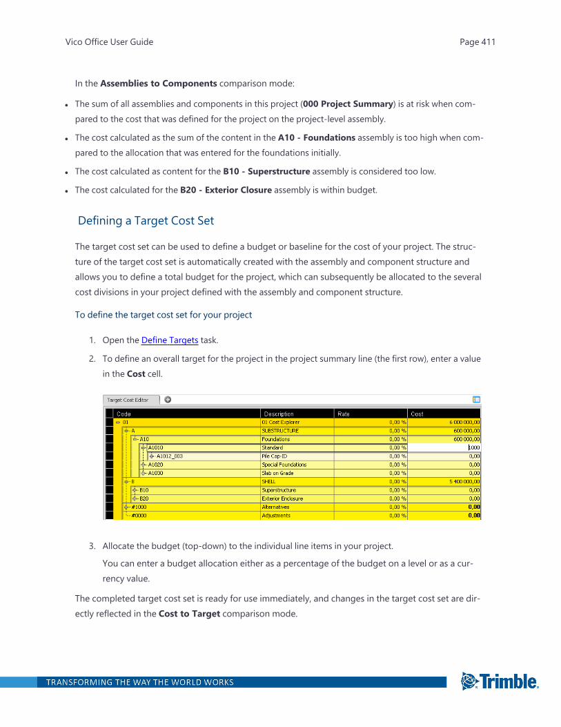
In the Assemblies to Components comparison mode:
l The sum of all assemblies and components in this project (000 Project Summary) is at risk when com-pared to the cost that was defined for the project on the project-level assembly.
l The cost calculated as the sum of the content in the A10 - Foundations assembly is too high when com-pared to the allocation that was entered for the foundations initially.
l The cost calculated as content for the B10 - Superstructure assembly is considered too low.
l The cost calculated for the B20 - Exterior Closure assembly is within budget.
Defining a Target Cost Set
The target cost set can be used to define a budget or baseline for the cost of your project. The struc-ture of the target cost set is automatically created with the assembly and component structure andallows you to define a total budget for the project, which can subsequently be allocated to the severalcost divisions in your project defined with the assembly and component structure.
To define the target cost set for your project
1. Open the Define Targets task.
2. To define an overall target for the project in the project summary line (the first row), enter a valuein the Cost cell.
3. Allocate the budget (top-down) to the individual line items in your project.
You can enter a budget allocation either as a percentage of the budget on a level or as a cur-rency value.
The completed target cost set is ready for use immediately, and changes in the target cost set are dir-ectly reflected in the Cost to Target comparison mode.
Vico Office User Guide Page 411
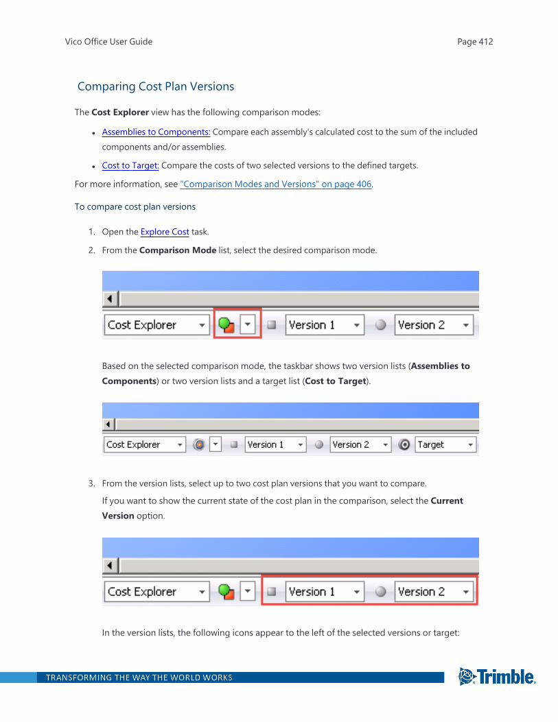
Comparing Cost Plan Versions
The Cost Explorer view has the following comparison modes:
l Assemblies to Components: Compare each assembly's calculated cost to the sum of the includedcomponents and/or assemblies.
l Cost to Target: Compare the costs of two selected versions to the defined targets.
For more information, see "Comparison Modes and Versions" on page 406.
To compare cost plan versions
1. Open the Explore Cost task.
2. From the Comparison Mode list, select the desired comparison mode.
Based on the selected comparison mode, the taskbar shows two version lists (Assemblies toComponents) or two version lists and a target list (Cost to Target).
3. From the version lists, select up to two cost plan versions that you want to compare.
If you want to show the current state of the cost plan in the comparison, select the CurrentVersion option.
In the version lists, the following icons appear to the left of the selected versions or target:
Vico Office User Guide Page 412
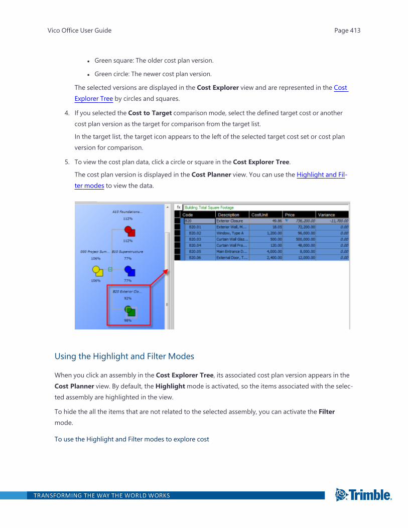
l Green square: The older cost plan version.
l Green circle: The newer cost plan version.
The selected versions are displayed in the Cost Explorer view and are represented in the CostExplorer Tree by circles and squares.
4. If you selected the Cost to Target comparison mode, select the defined target cost or anothercost plan version as the target for comparison from the target list.
In the target list, the target icon appears to the left of the selected target cost set or cost planversion for comparison.
5. To view the cost plan data, click a circle or square in the Cost Explorer Tree.
The cost plan version is displayed in the Cost Planner view. You can use the Highlight and Fil-ter modes to view the data.
Using the Highlight and Filter Modes
When you click an assembly in the Cost Explorer Tree, its associated cost plan version appears in theCost Planner view. By default, the Highlightmode is activated, so the items associated with the selec-ted assembly are highlighted in the view.
To hide the all the items that are not related to the selected assembly, you can activate the Filtermode.
To use the Highlight and Filter modes to explore cost
Vico Office User Guide Page 413
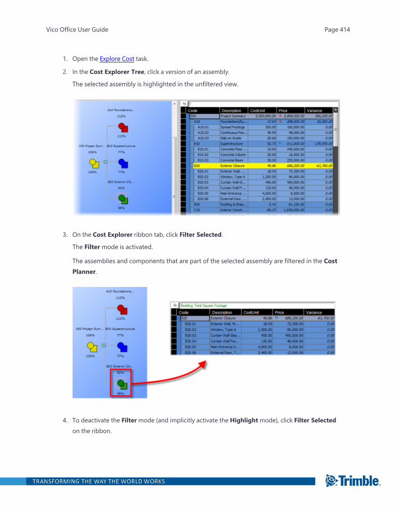
1. Open the Explore Cost task.
2. In the Cost Explorer Tree, click a version of an assembly.
The selected assembly is highlighted in the unfiltered view.
3. On the Cost Explorer ribbon tab, click Filter Selected.
The Filtermode is activated.
The assemblies and components that are part of the selected assembly are filtered in the CostPlanner.
4. To deactivate the Filtermode (and implicitly activate the Highlightmode), click Filter Selectedon the ribbon.
Vico Office User Guide Page 414
Vico Office User Guide Page 415
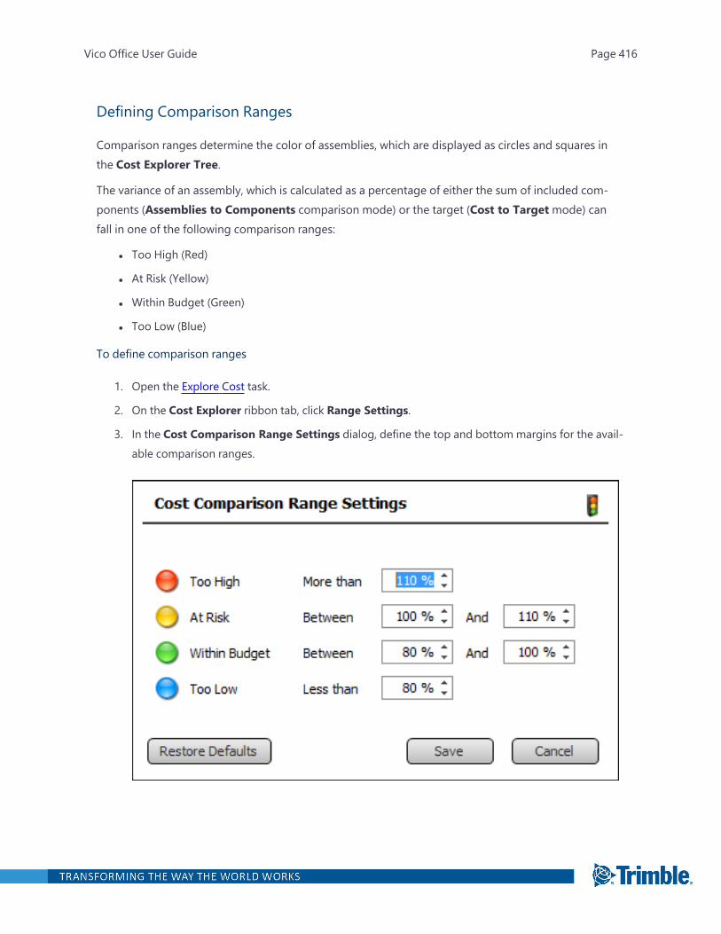
Defining Comparison Ranges
Comparison ranges determine the color of assemblies, which are displayed as circles and squares inthe Cost Explorer Tree.
The variance of an assembly, which is calculated as a percentage of either the sum of included com-ponents (Assemblies to Components comparison mode) or the target (Cost to Targetmode) canfall in one of the following comparison ranges:
l Too High (Red)
l At Risk (Yellow)
l Within Budget (Green)
l Too Low (Blue)
To define comparison ranges
1. Open the Explore Cost task.
2. On the Cost Explorer ribbon tab, click Range Settings.
3. In the Cost Comparison Range Settings dialog, define the top and bottom margins for the avail-able comparison ranges.
Vico Office User Guide Page 416

4. Click Save.
The changes are applied immediately to the Cost Explorer Tree.
Vico Office User Guide Page 417
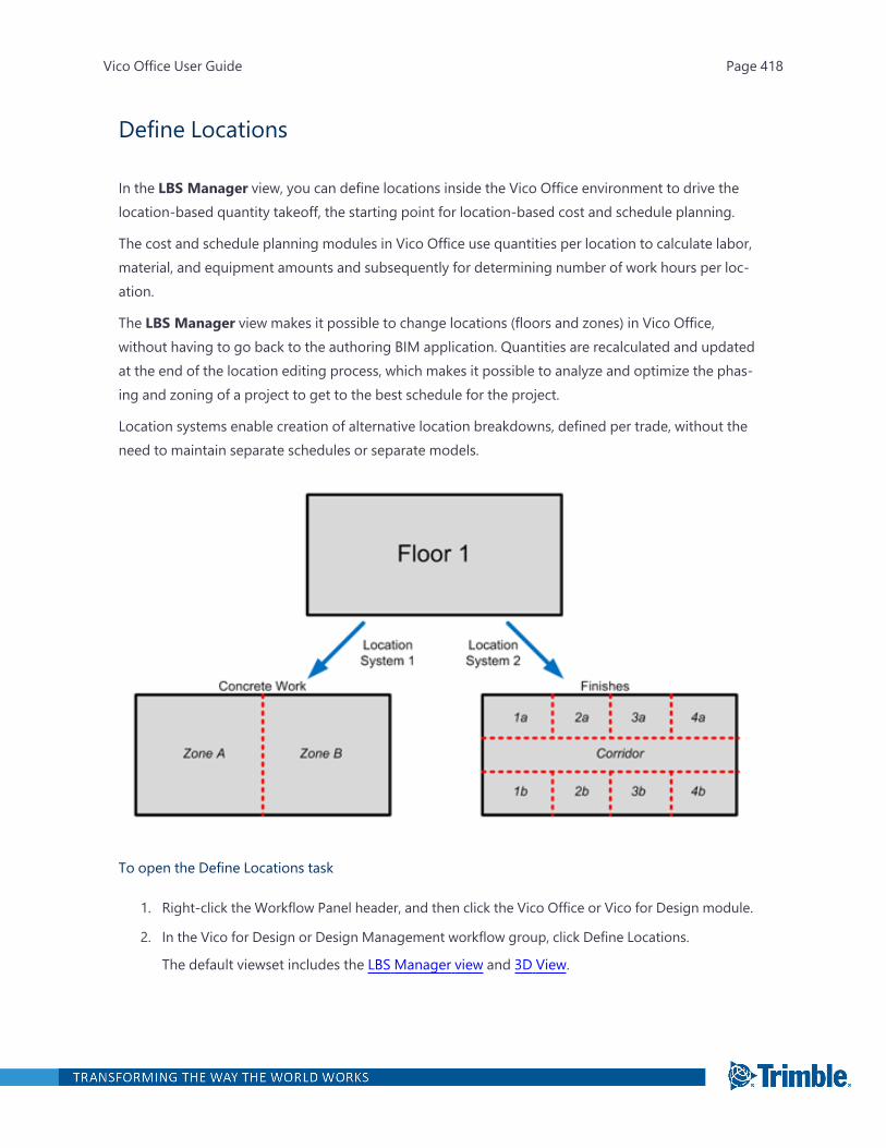
Define Locations
In the LBS Manager view, you can define locations inside the Vico Office environment to drive thelocation-based quantity takeoff, the starting point for location-based cost and schedule planning.
The cost and schedule planning modules in Vico Office use quantities per location to calculate labor,material, and equipment amounts and subsequently for determining number of work hours per loc-ation.
The LBS Manager view makes it possible to change locations (floors and zones) in Vico Office,without having to go back to the authoring BIM application. Quantities are recalculated and updatedat the end of the location editing process, which makes it possible to analyze and optimize the phas-ing and zoning of a project to get to the best schedule for the project.
Location systems enable creation of alternative location breakdowns, defined per trade, without theneed to maintain separate schedules or separate models.
To open the Define Locations task
1. Right-click the Workflow Panel header, and then click the Vico Office or Vico for Design module.
2. In the Vico for Design or Design Management workflow group, click Define Locations.
The default viewset includes the LBS Manager view and 3D View.
Vico Office User Guide Page 418
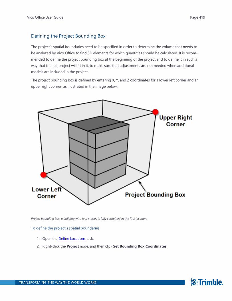
Defining the Project Bounding Box
The project's spatial boundaries need to be specified in order to determine the volume that needs tobe analyzed by Vico Office to find 3D elements for which quantities should be calculated. It is recom-mended to define the project bounding box at the beginning of the project and to define it in such away that the full project will fit in it, to make sure that adjustments are not needed when additionalmodels are included in the project.
The project bounding box is defined by entering X, Y, and Z coordinates for a lower left corner and anupper right corner, as illustrated in the image below.
Project bounding box: a building with four stories is fully contained in the first location.
To define the project's spatial boundaries
1. Open the Define Locations task.
2. Right-click the Project node, and then click Set Bounding Box Coordinates.
Vico Office User Guide Page 419
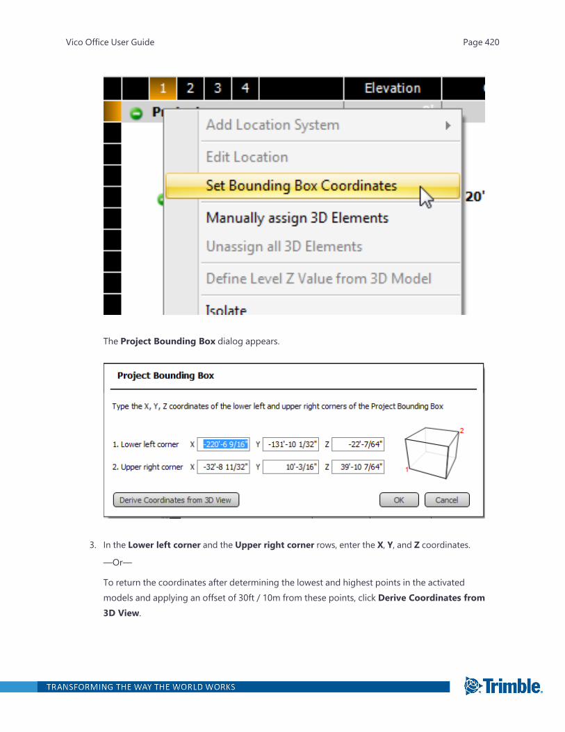
The Project Bounding Box dialog appears.
3. In the Lower left corner and the Upper right corner rows, enter the X, Y, and Z coordinates.
—Or—
To return the coordinates after determining the lowest and highest points in the activatedmodels and applying an offset of 30ft / 10m from these points, click Derive Coordinates from3D View.
Vico Office User Guide Page 420
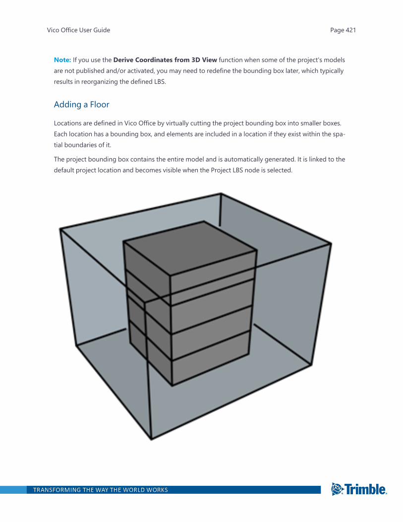
Note: If you use the Derive Coordinates from 3D View function when some of the project's modelsare not published and/or activated, you may need to redefine the bounding box later, which typicallyresults in reorganizing the defined LBS.
Adding a Floor
Locations are defined in Vico Office by virtually cutting the project bounding box into smaller boxes.Each location has a bounding box, and elements are included in a location if they exist within the spa-tial boundaries of it.
The project bounding box contains the entire model and is automatically generated. It is linked to thedefault project location and becomes visible when the Project LBS node is selected.
Vico Office User Guide Page 421
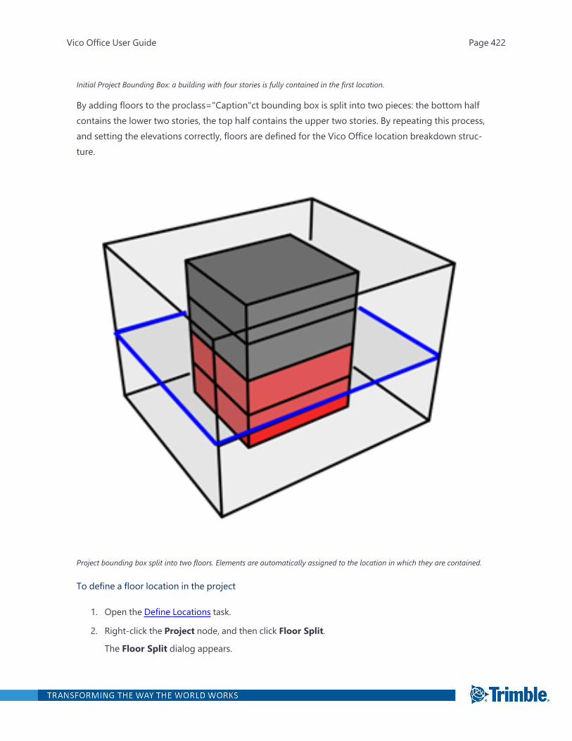
Initial Project Bounding Box: a building with four stories is fully contained in the first location.
By adding floors to the proclass="Caption"ct bounding box is split into two pieces: the bottom halfcontains the lower two stories, the top half contains the upper two stories. By repeating this process,and setting the elevations correctly, floors are defined for the Vico Office location breakdown struc-ture.
Project bounding box split into two floors. Elements are automatically assigned to the location in which they are contained.
To define a floor location in the project
1. Open the Define Locations task.
2. Right-click the Project node, and then click Floor Split.
The Floor Split dialog appears.
Vico Office User Guide Page 422
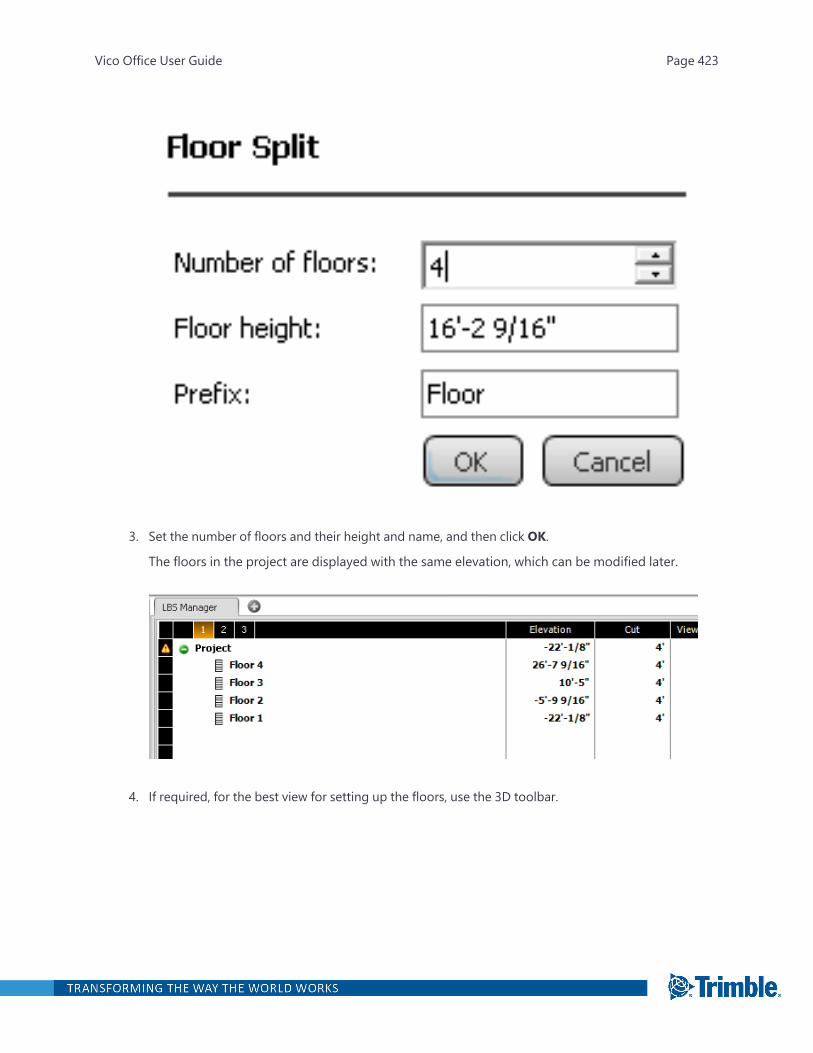
3. Set the number of floors and their height and name, and then click OK.
The floors in the project are displayed with the same elevation, which can be modified later.
4. If required, for the best view for setting up the floors, use the 3D toolbar.
Vico Office User Guide Page 423
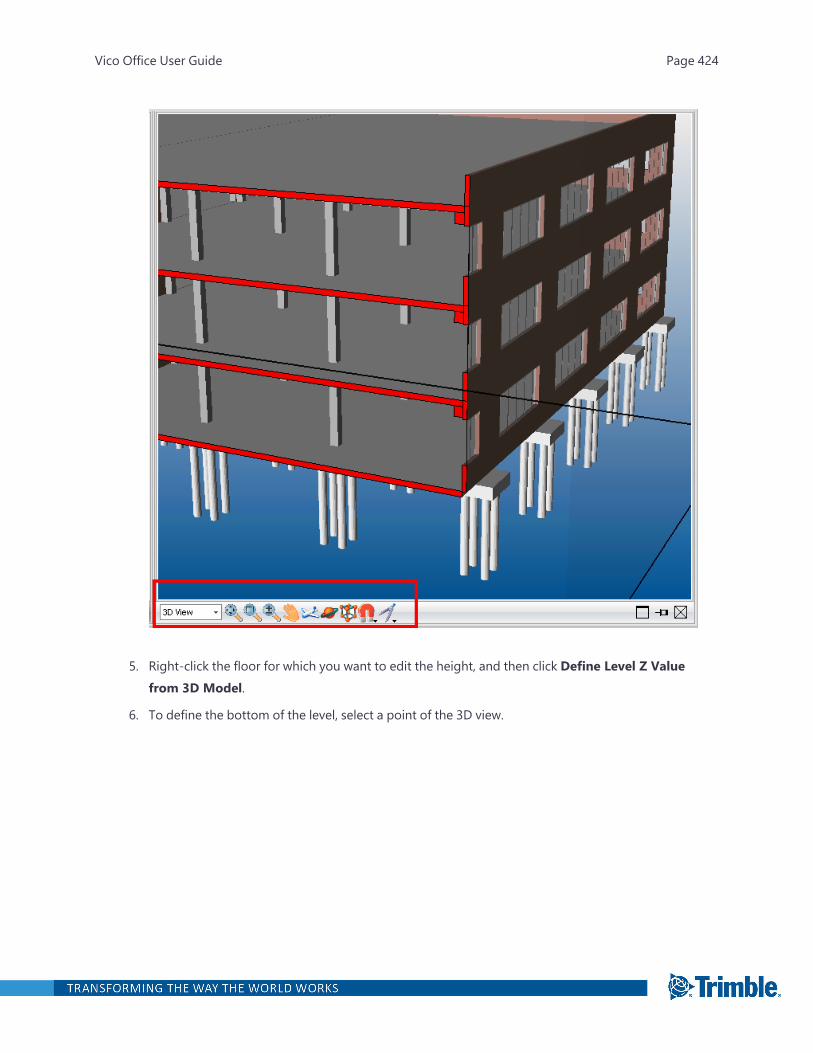
5. Right-click the floor for which you want to edit the height, and then click Define Level Z Valuefrom 3D Model.
6. To define the bottom of the level, select a point of the 3D view.
Vico Office User Guide Page 424
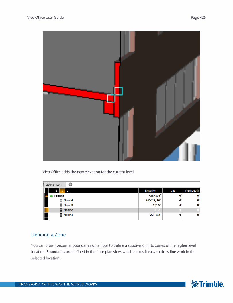
Vico Office adds the new elevation for the current level.
Defining a Zone
You can draw horizontal boundaries on a floor to define a subdivision into zones of the higher levellocation. Boundaries are defined in the floor plan view, which makes it easy to draw line work in theselected location.
Vico Office User Guide Page 425
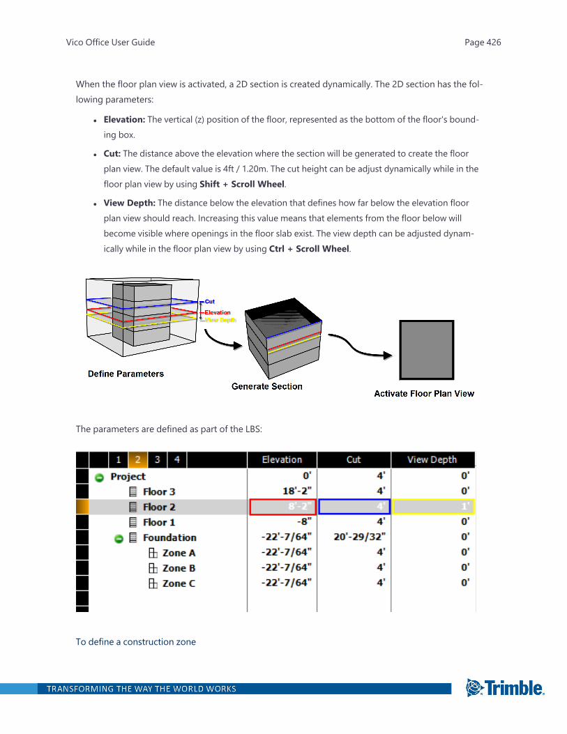
When the floor plan view is activated, a 2D section is created dynamically. The 2D section has the fol-lowing parameters:
l Elevation: The vertical (z) position of the floor, represented as the bottom of the floor's bound-ing box.
l Cut: The distance above the elevation where the section will be generated to create the floorplan view. The default value is 4ft / 1.20m. The cut height can be adjust dynamically while in thefloor plan view by using Shift + Scroll Wheel.
l View Depth: The distance below the elevation that defines how far below the elevation floorplan view should reach. Increasing this value means that elements from the floor below willbecome visible where openings in the floor slab exist. The view depth can be adjusted dynam-ically while in the floor plan view by using Ctrl + Scroll Wheel.
The parameters are defined as part of the LBS:
To define a construction zone
Vico Office User Guide Page 426

1. Open the Define Locations task.
2. Select the location (either floor or zone) in which the zone should be created.
Make sure to check the elevation, cut, and view depth parameters for correct representation ofthe floor plan view.
3. On the LBS ribbon tab, click Floor Plan View button.
—Or—
Right-click, and then click Floor Plan View.
The 3D view changes to a floor plan view based on the selected location and defined elevation,cut and view depth parameters.
4. On the LBS ribbon tab, click Add Polyline.
The cursor in the 3D View changes into a pencil.
5. From the Snap Settings in the 3D View, select the desired snapping tools.
Vico Office User Guide Page 427
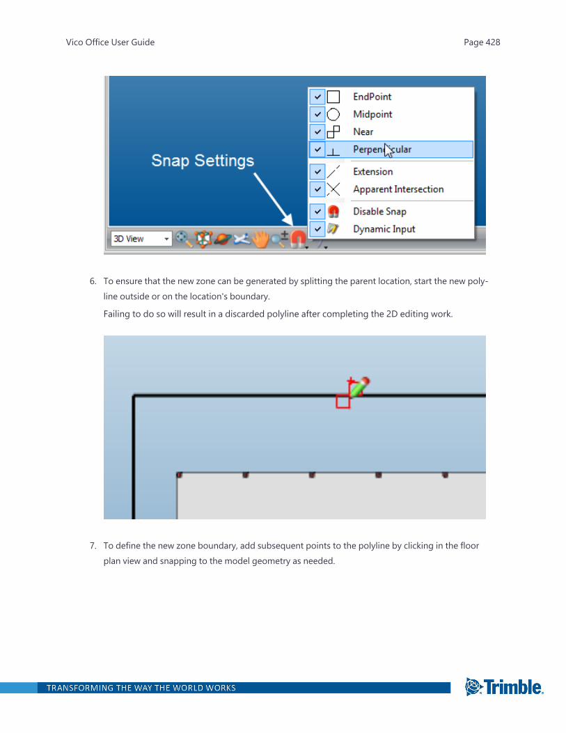
6. To ensure that the new zone can be generated by splitting the parent location, start the new poly-line outside or on the location's boundary.
Failing to do so will result in a discarded polyline after completing the 2D editing work.
7. To define the new zone boundary, add subsequent points to the polyline by clicking in the floorplan view and snapping to the model geometry as needed.
Vico Office User Guide Page 428
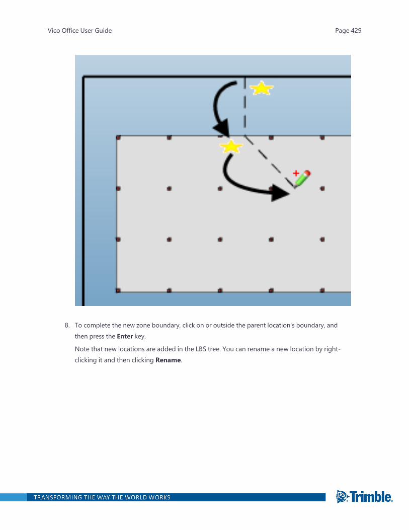
8. To complete the new zone boundary, click on or outside the parent location's boundary, andthen press the Enter key.
Note that new locations are added in the LBS tree. You can rename a new location by right-clicking it and then clicking Rename.
Vico Office User Guide Page 429
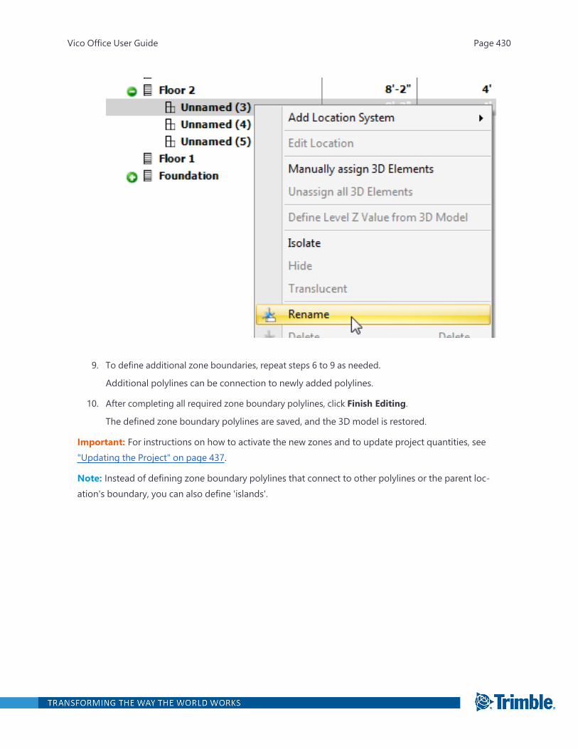
9. To define additional zone boundaries, repeat steps 6 to 9 as needed.
Additional polylines can be connection to newly added polylines.
10. After completing all required zone boundary polylines, click Finish Editing.
The defined zone boundary polylines are saved, and the 3D model is restored.
Important: For instructions on how to activate the new zones and to update project quantities, see"Updating the Project" on page 437.
Note: Instead of defining zone boundary polylines that connect to other polylines or the parent loc-ation's boundary, you can also define 'islands'.
Vico Office User Guide Page 430
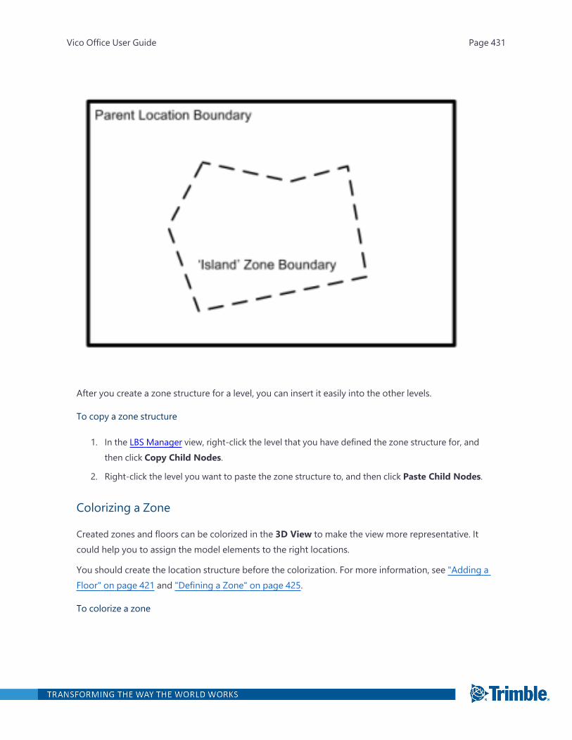
After you create a zone structure for a level, you can insert it easily into the other levels.
To copy a zone structure
1. In the LBS Manager view, right-click the level that you have defined the zone structure for, andthen click Copy Child Nodes.
2. Right-click the level you want to paste the zone structure to, and then click Paste Child Nodes.
Colorizing a Zone
Created zones and floors can be colorized in the 3D View to make the view more representative. Itcould help you to assign the model elements to the right locations.
You should create the location structure before the colorization. For more information, see "Adding aFloor" on page 421 and "Defining a Zone" on page 425.
To colorize a zone
Vico Office User Guide Page 431
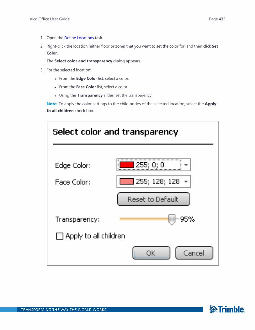
1. Open the Define Locations task.
2. Right-click the location (either floor or zone) that you want to set the color for, and then click SetColor.
The Select color and transparency dialog appears.
3. For the selected location:
l From the Edge Color list, select a color.
l From the Face Color list, select a color.
l Using the Transparency slides, set the transparency.
Note: To apply the color settings to the child nodes of the selected location, select the Applyto all children check box.
Vico Office User Guide Page 432

Editing a Zone
Part of the location-based schedule optimization process is to optimize the size of work locations insuch a way that a continuous flow of work can be achieved. Location optimization can be performedin the LBS Manager view by adding or removing floors and zones or by changing the boundaries ofexisting zones.
To modify the boundaries of a previously defined zone
1. Open the Define Locations task.
2. Select the location that contains the zone boundaries that should be edited, and then activatethe floor plan view.
Vico Office User Guide Page 433

3. In the floor plan view, point to an earlier defined zone boundary polyline.
The polyline is highlighted.
Vico Office User Guide Page 434

4. Click the highlighted polyline.
Three grip points appear.
Vico Office User Guide Page 435
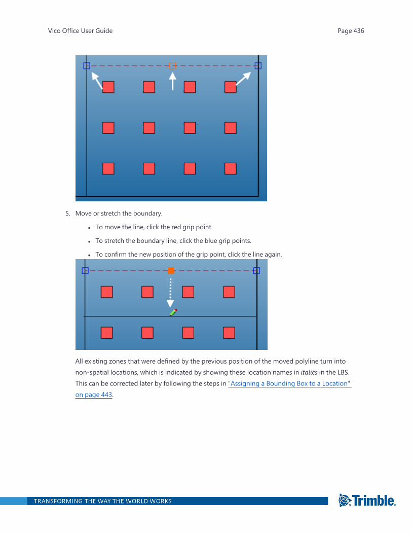
5. Move or stretch the boundary.
l To move the line, click the red grip point.
l To stretch the boundary line, click the blue grip points.
l To confirm the new position of the grip point, click the line again.
All existing zones that were defined by the previous position of the moved polyline turn intonon-spatial locations, which is indicated by showing these location names in italics in the LBS.This can be corrected later by following the steps in "Assigning a Bounding Box to a Location"on page 443.
Vico Office User Guide Page 436
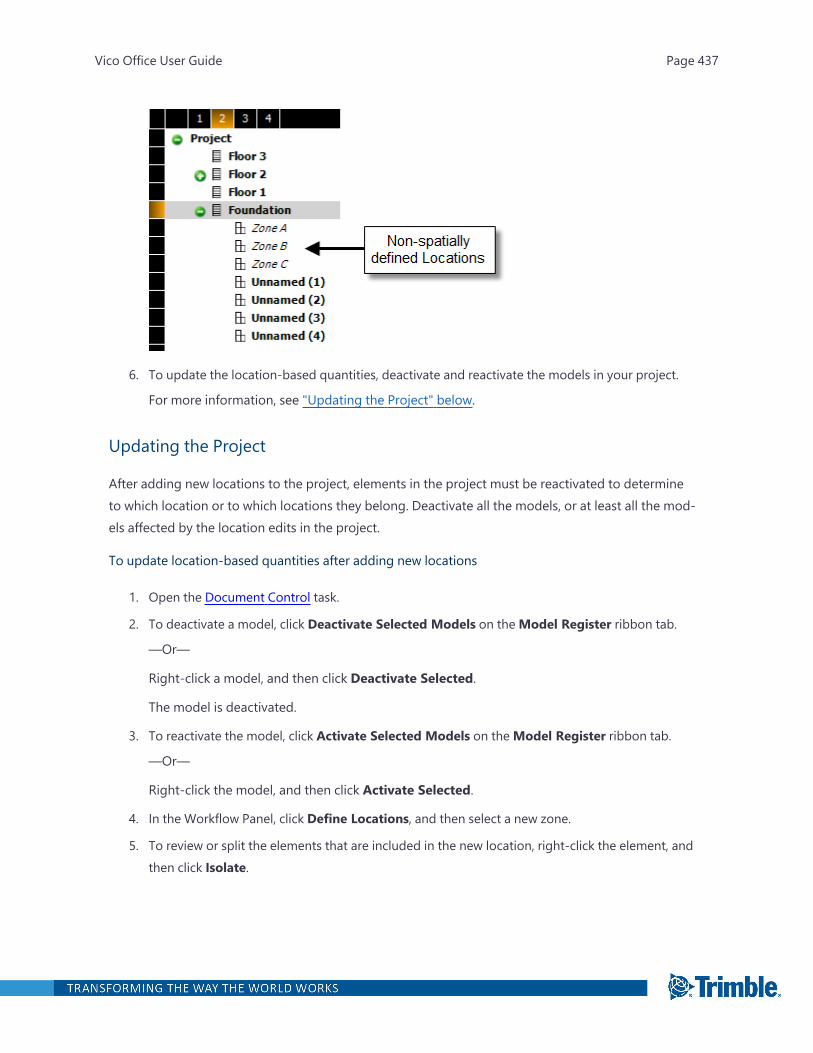
6. To update the location-based quantities, deactivate and reactivate the models in your project.
For more information, see "Updating the Project" below.
Updating the Project
After adding new locations to the project, elements in the project must be reactivated to determineto which location or to which locations they belong. Deactivate all the models, or at least all the mod-els affected by the location edits in the project.
To update location-based quantities after adding new locations
1. Open the Document Control task.
2. To deactivate a model, click Deactivate Selected Models on theModel Register ribbon tab.
—Or—
Right-click a model, and then click Deactivate Selected.
The model is deactivated.
3. To reactivate the model, click Activate Selected Models on theModel Register ribbon tab.
—Or—
Right-click the model, and then click Activate Selected.
4. In the Workflow Panel, click Define Locations, and then select a new zone.
5. To review or split the elements that are included in the new location, right-click the element, andthen click Isolate.
Vico Office User Guide Page 437
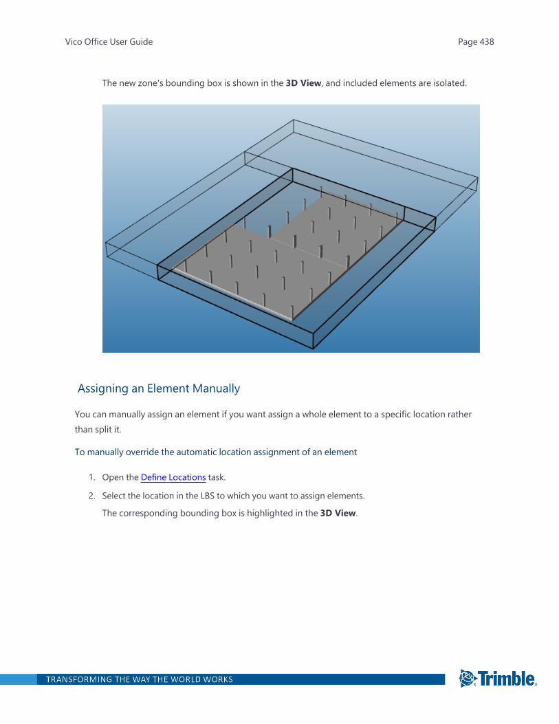
The new zone's bounding box is shown in the 3D View, and included elements are isolated.
Assigning an Element Manually
You can manually assign an element if you want assign a whole element to a specific location ratherthan split it.
To manually override the automatic location assignment of an element
1. Open the Define Locations task.
2. Select the location in the LBS to which you want to assign elements.
The corresponding bounding box is highlighted in the 3D View.
Vico Office User Guide Page 438

3. On the LBS ribbon tab, clickManually Assign.
—Or—
Right-click the model, and then clickManually assign 3D elements.
4. Click the element or elements that are to be assigned to the selected location in the 3D model.
To assist with the selection of the correct element, elements are highlighted wwhen you pointto them.
Vico Office User Guide Page 439

Selected elements are shown in red.
Vico Office User Guide Page 440
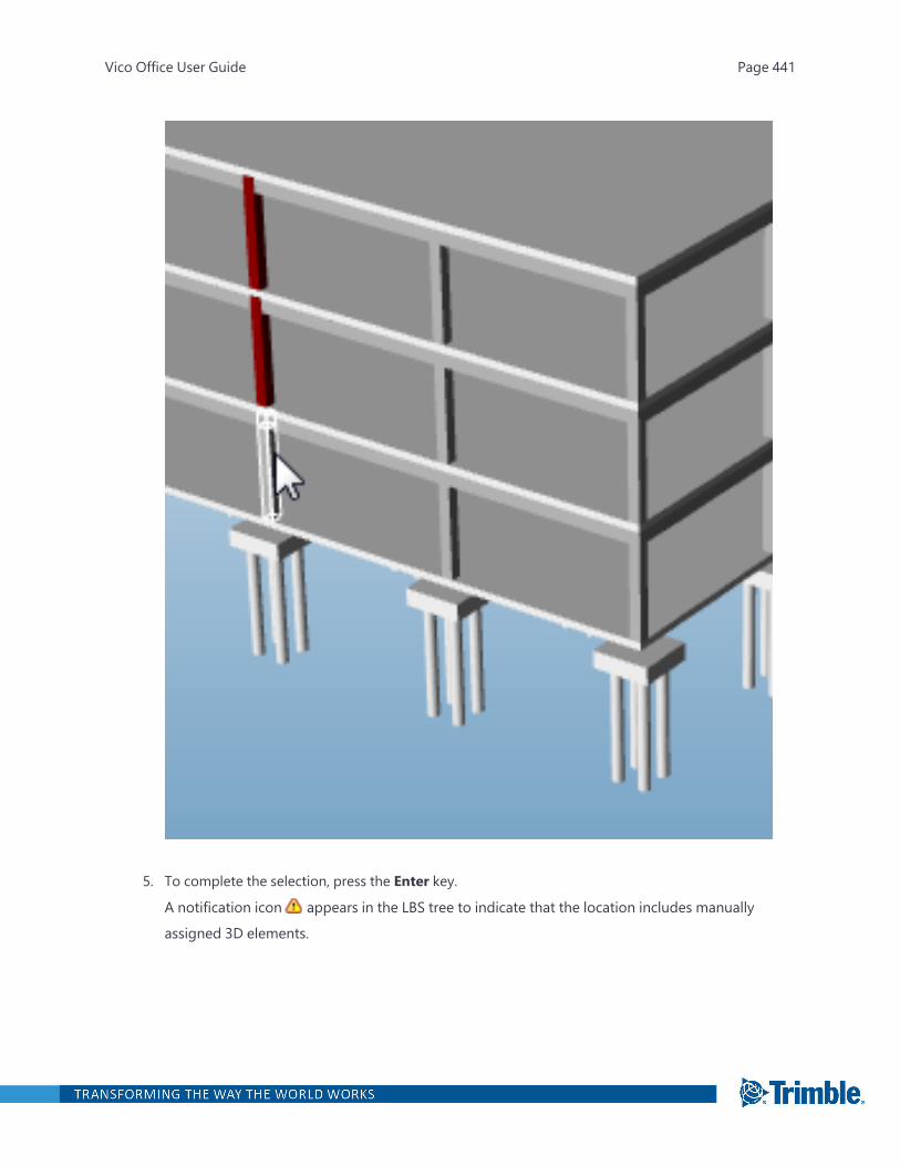
5. To complete the selection, press the Enter key.
A notification icon appears in the LBS tree to indicate that the location includes manually
assigned 3D elements.
Vico Office User Guide Page 441
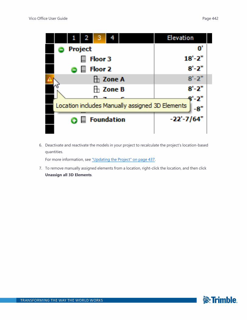
6. Deactivate and reactivate the models in your project to recalculate the project's location-basedquantities.
For more information, see "Updating the Project" on page 437.
7. To remove manually assigned elements from a location, right-click the location, and then clickUnassign all 3D Elements.
Vico Office User Guide Page 442

Assigning a Bounding Box to a Location
Locations can be added to the Vico Office project as non-spatially defined locations, which meansthat the location name is included in the LBS, but no floor or zone definition is associated with it.Non-spatially defined locations can be added from theManage Takeoff view or from the PlanSchedule view, or can result from changes in existing zone locations by moving boundaries. For moreinformation, see "Editing a Zone" on page 433.
Note: It is strongly recommended that you complete this step before opening the Plan Scheduleview because activities (tasks in LBS locations) are removed from the schedule if the quantities areequal to zero.
To assign a location bounding box to a non-spatially defined location
1. Open the Define Locations task.
2. Expand the floors in the LBS that contains non-spatially defined locations.
The name of these locations are italicized.
Vico Office User Guide Page 443
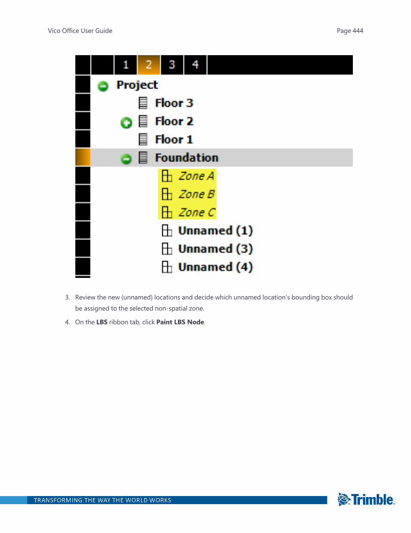
3. Review the new (unnamed) locations and decide which unnamed location's bounding box shouldbe assigned to the selected non-spatial zone.
4. On the LBS ribbon tab, click Paint LBS Node.
Vico Office User Guide Page 444
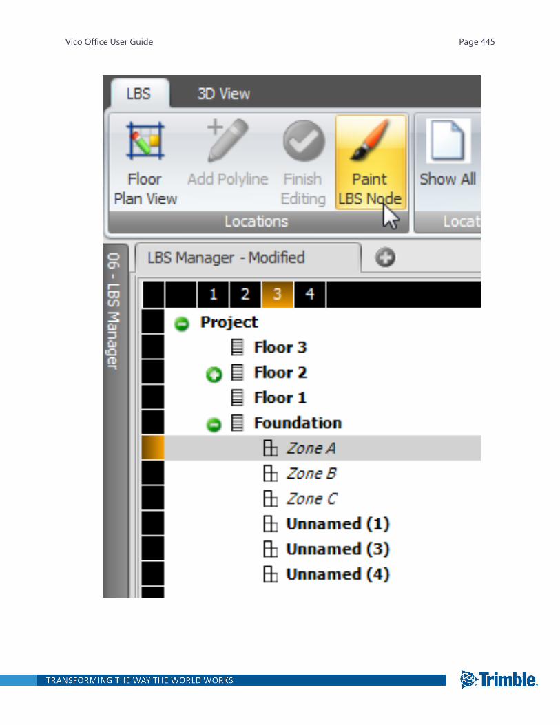
Vico Office User Guide Page 445

The cursor changes to a paint brush. As you point to the available bounding boxes, the boxesare highlighted. The names are displayed in tooltips.
5. To select the bounding box that should be assigned to the selected non-spatially defined loc-ation, click it.
The previously non-spatially defined location is now shown in bold, and the location fromwhich the bounding box was obtained is shown in italics.
Vico Office User Guide Page 446

Define Location Systems
Location systems are alternative location breakdown structures for the same location in the project'slocation breakdown structure. The ability to maintain parallel alternative location breakdown struc-tures within the same parent location makes it possible to use the optimal location size for eachtrade.Example:
Floor 1 will be broken down into Zone A and Zone B for all Concrete Work, whereas a subdivision intothe individual rooms on the floor is more appropriate for the trades involved with Finishes.
Two location systems will be created in this case: one that is broken down in the optimal way for Con-crete Work, and another one that is broken down optimized for Finishes.
Vico Office User Guide Page 447
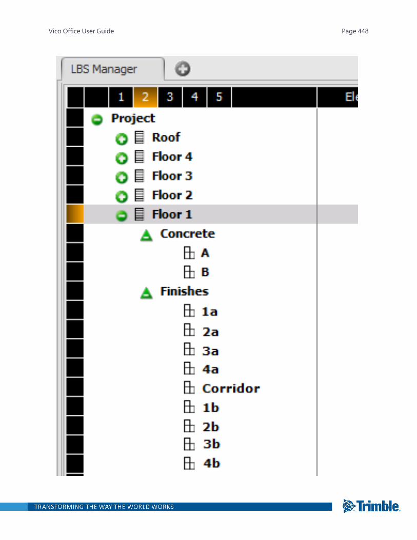
Vico Office User Guide Page 448
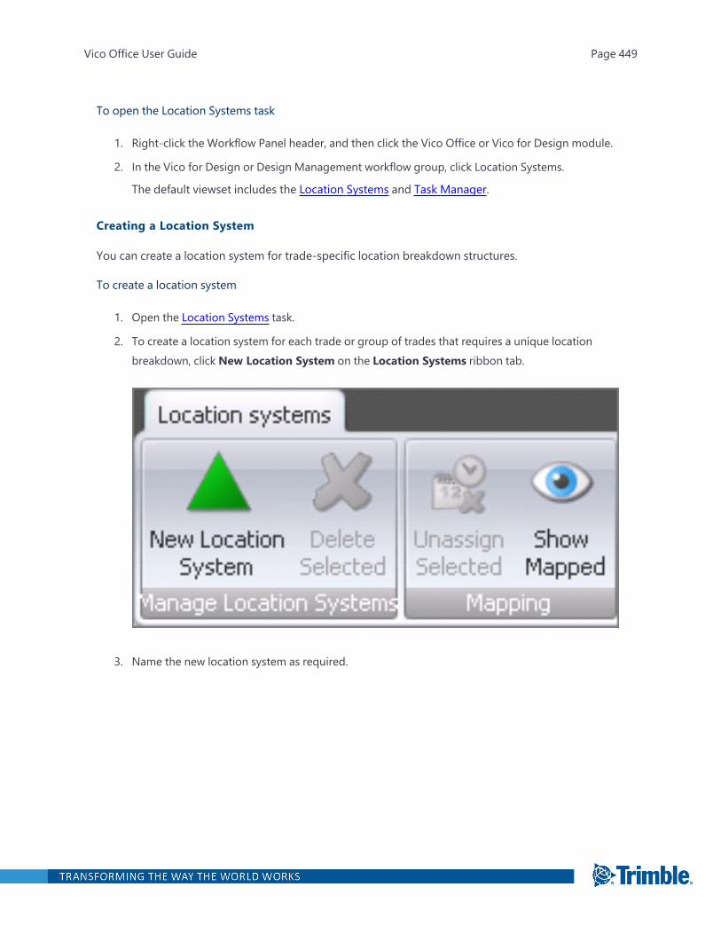
To open the Location Systems task
1. Right-click the Workflow Panel header, and then click the Vico Office or Vico for Design module.
2. In the Vico for Design or Design Management workflow group, click Location Systems.
The default viewset includes the Location Systems and Task Manager.
Creating a Location System
You can create a location system for trade-specific location breakdown structures.
To create a location system
1. Open the Location Systems task.
2. To create a location system for each trade or group of trades that requires a unique locationbreakdown, click New Location System on the Location Systems ribbon tab.
3. Name the new location system as required.
Vico Office User Guide Page 449

4. To set up how the locations are defined for mapped tasks, associate tasks with the new locationsystem by dragging and droppng tasks to the appropriate location system.
After mapping tasks to location systems, the formula of the components that are mapped tothe tasks are updated so that they are evaluated only in the assigned location system's loc-ations. You can check this by opening the Formula Editor for the components that are mappedto tasks that are mapped to a location system.
Including a Location System in the LBS
When one location should be broken down in more than one way to accommodate for optimal loc-ation sizes for all trades, location system nodes should be included in the LBS to allow for that.
Vico Office User Guide Page 450
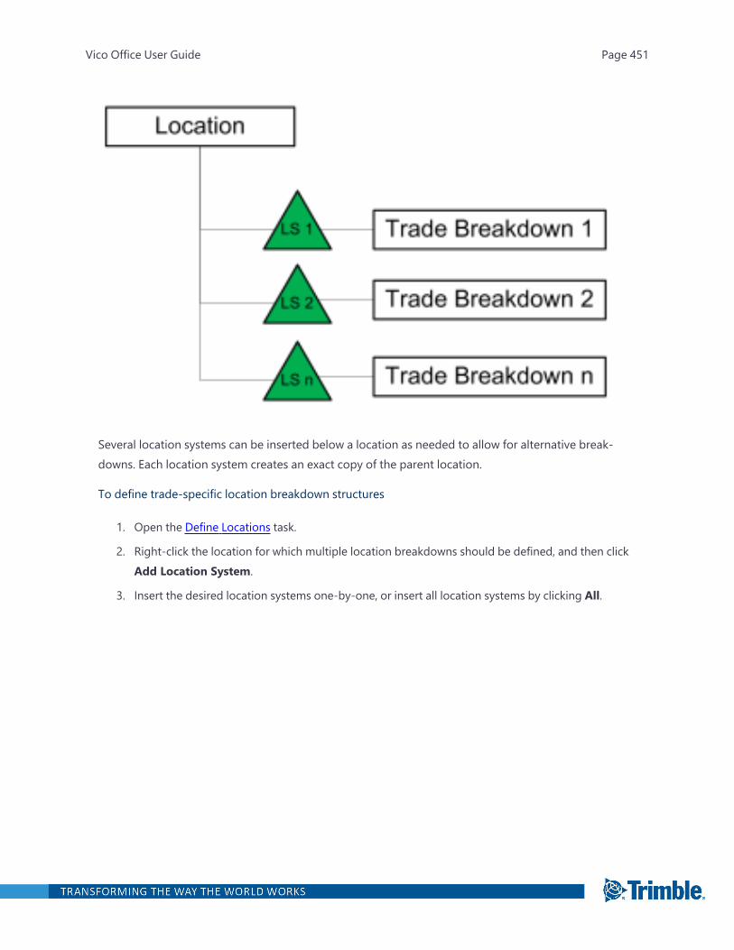
Several location systems can be inserted below a location as needed to allow for alternative break-downs. Each location system creates an exact copy of the parent location.
To define trade-specific location breakdown structures
1. Open the Define Locations task.
2. Right-click the location for which multiple location breakdowns should be defined, and then clickAdd Location System.
3. Insert the desired location systems one-by-one, or insert all location systems by clicking All.
Vico Office User Guide Page 451
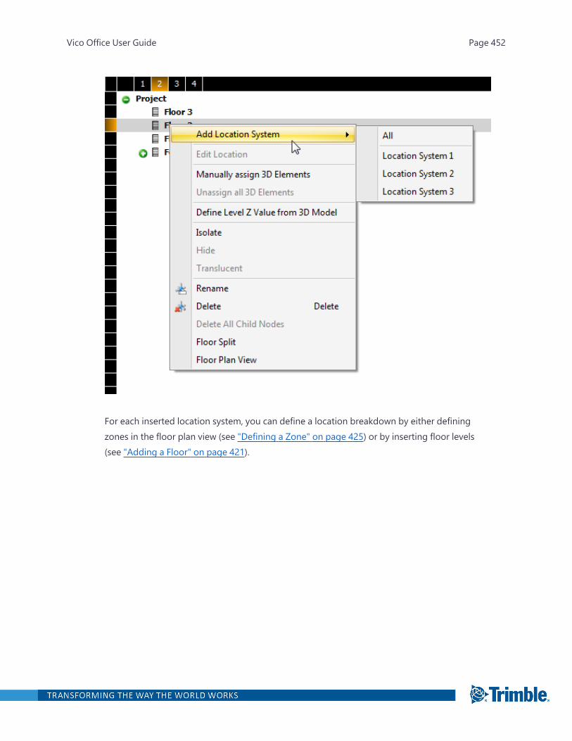
For each inserted location system, you can define a location breakdown by either definingzones in the floor plan view (see "Defining a Zone" on page 425) or by inserting floor levels(see "Adding a Floor" on page 421).
Vico Office User Guide Page 452
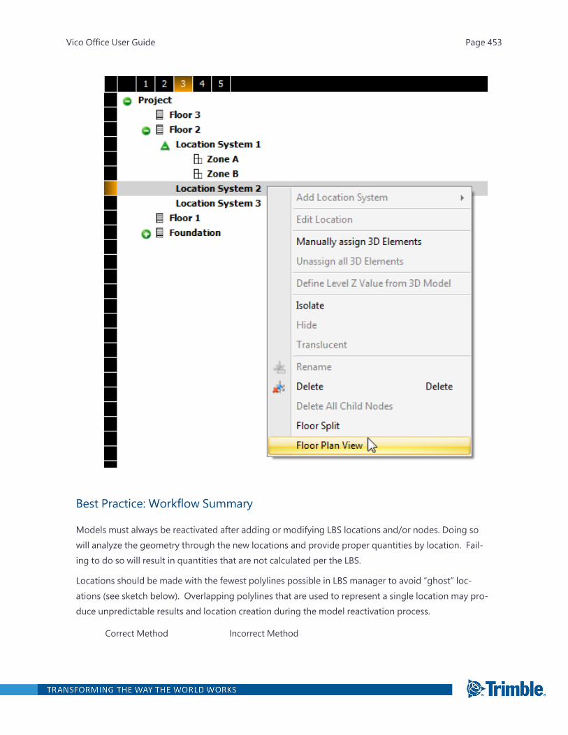
Best Practice: Workflow Summary
Models must always be reactivated after adding or modifying LBS locations and/or nodes. Doing sowill analyze the geometry through the new locations and provide proper quantities by location. Fail-ing to do so will result in quantities that are not calculated per the LBS.
Locations should be made with the fewest polylines possible in LBS manager to avoid “ghost” loc-ations (see sketch below). Overlapping polylines that are used to represent a single location may pro-duce unpredictable results and location creation during the model reactivation process.
Correct Method Incorrect Method
Vico Office User Guide Page 453
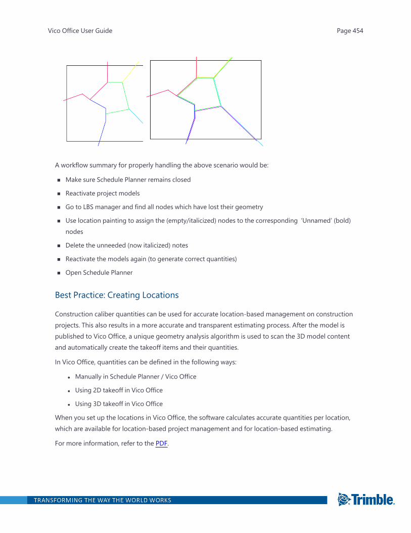
A workflow summary for properly handling the above scenario would be:
n Make sure Schedule Planner remains closed
n Reactivate project models
n Go to LBS manager and find all nodes which have lost their geometry
n Use location painting to assign the (empty/italicized) nodes to the corresponding ‘Unnamed’ (bold)nodes
n Delete the unneeded (now italicized) notes
n Reactivate the models again (to generate correct quantities)
n Open Schedule Planner
Best Practice: Creating Locations
Construction caliber quantities can be used for accurate location-based management on constructionprojects. This also results in a more accurate and transparent estimating process. After the model ispublished to Vico Office, a unique geometry analysis algorithm is used to scan the 3D model contentand automatically create the takeoff items and their quantities.
In Vico Office, quantities can be defined in the following ways:
l Manually in Schedule Planner / Vico Office
l Using 2D takeoff in Vico Office
l Using 3D takeoff in Vico Office
When you set up the locations in Vico Office, the software calculates accurate quantities per location,which are available for location-based project management and for location-based estimating.
For more information, refer to the PDF.
Vico Office User Guide Page 454

Best Practice: Copying Locations
Before copying locations, a specific set of circumstances is required for it to work properly:
l The source node (copy from) has to be a floor or location system node.
l The source node cannot be a zone node.
l The source node (copy from) and destination (copy to) must be under the same parent node,which refers to a floor split or a location system.
For example: A zone breakdown from location system 1 cannot be copied across to the cor-responding floor split of location system 2 because each location system is considered to be adifferent parent node.
l The source node (copy from) may only contain zones under it – it cannot include any additionalfloor splits under it.
l The destination node (copy to) can only be a floor or location system node – it cannot be a zonenode.
l The destination node (copy to) cannot already have existing zone nodes below it.
Publishing Location Data to Trimble Connect
The Publish Location Data to Trimble Connect functionality enables sharing the Vico Office loc-ation breakdown structure and location level model data (element geometries and quantities) withnon-Vico Office users through Trimble Connect.
The Vico Office location breakdown structure with bounding boxes is published to Trimble ConnectOrganizer and all published model elements (both original and derived) are linked to location Organ-izer nodes.
The Publish Location Data function can be accessed from Location Manager or from DocumentControl >Model Register. To start the process, click Publish Location Data on the ribbon.
Important: Publishing location data and models is a two-step procedure – first, the location data hasto be published, and then the model(s). Every time the LBS is edited in Vico Office, it has to be repub-lished, followed by publishing the model(s).
Note: Make sure that Trimble Connect Region in Project Settings is correctly set for your TrimbleConnect project (North America, Europe, Asia).
Vico Office User Guide Page 455
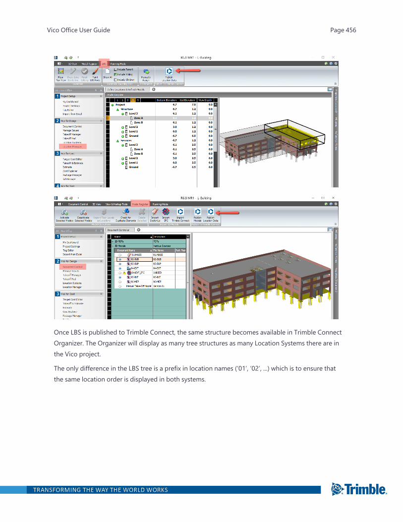
Once LBS is published to Trimble Connect, the same structure becomes available in Trimble ConnectOrganizer. The Organizer will display as many tree structures as many Location Systems there are inthe Vico project.
The only difference in the LBS tree is a prefix in location names (‘01’, ‘02’, ...) which is to ensure thatthe same location order is displayed in both systems.
Vico Office User Guide Page 456
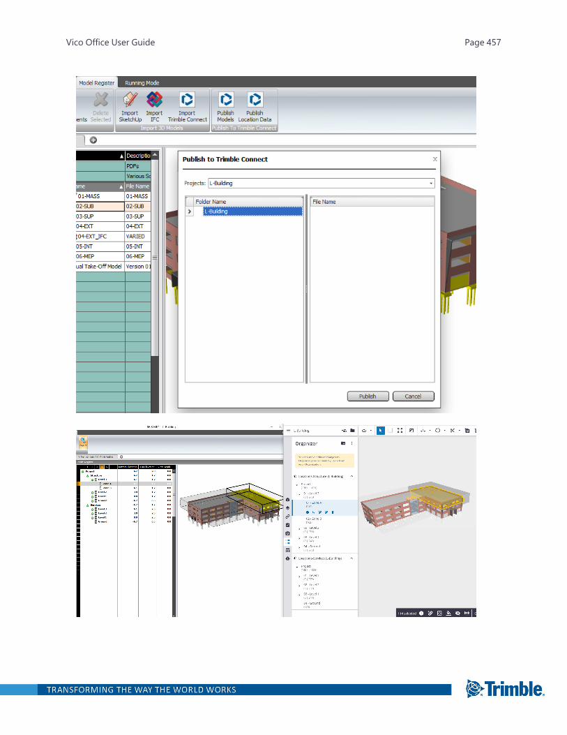
Vico Office User Guide Page 457

The location geometries (bounding boxes, including the color set in Vico Office) are also displayed inTrimble Connect. These geometries can be turned on and off in the Organizer by clicking on the iconon the left side of the Location tree.
Note: Location bounding box visibility status is not stored in saved views.
There are two types of element geometries that are present in Trimble Connect Vico projects:
l ‘original’ elements, which can be further divided into the following categories:
l split by location boundaries
l not split by location boundaries
l ‘derived’ elements, which are the element pieces that result from LBS splitting
To manage and correctly display both types, we introduced special layers in Trimble Connect, whichunfortunately overwrite the layer information coming from the CAD models. However, CAD layers arestill available from Content Browser/Data table as a property:
l (VICO)DerivedElements
l (VICO)NonSplitOriginalElements
l (VICO)SplitOriginalElements
These layers are per model; if there are multiple models in the Vico project, there will be multipleinstances of these layers depending on how LBS splitting affects the model.
Vico Office User Guide Page 458
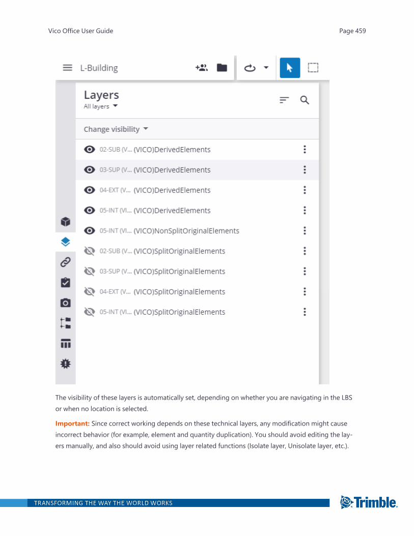
The visibility of these layers is automatically set, depending on whether you are navigating in the LBSor when no location is selected.
Important: Since correct working depends on these technical layers, any modification might causeincorrect behavior (for example, element and quantity duplication). You should avoid editing the lay-ers manually, and also should avoid using layer related functions (Isolate layer, Unisolate layer, etc.).
Vico Office User Guide Page 459
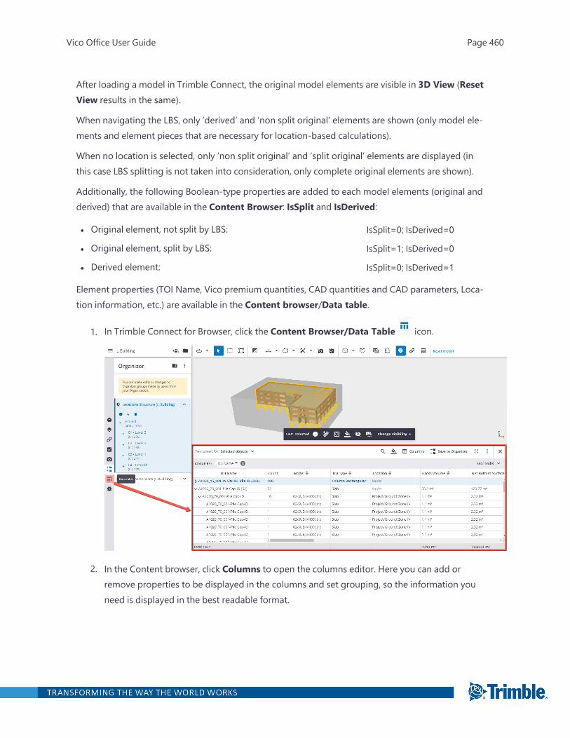
After loading a model in Trimble Connect, the original model elements are visible in 3D View (ResetView results in the same).
When navigating the LBS, only ‘derived’ and ‘non split original’ elements are shown (only model ele-ments and element pieces that are necessary for location-based calculations).
When no location is selected, only ‘non split original’ and ‘split original’ elements are displayed (inthis case LBS splitting is not taken into consideration, only complete original elements are shown).
Additionally, the following Boolean-type properties are added to each model elements (original andderived) that are available in the Content Browser: IsSplit and IsDerived:
l Original element, not split by LBS: IsSplit=0; IsDerived=0
l Original element, split by LBS: IsSplit=1; IsDerived=0
l Derived element: IsSplit=0; IsDerived=1
Element properties (TOI Name, Vico premium quantities, CAD quantities and CAD parameters, Loca-tion information, etc.) are available in the Content browser/Data table.
1. In Trimble Connect for Browser, click the Content Browser/Data Table icon.
2. In the Content browser, click Columns to open the columns editor. Here you can add orremove properties to be displayed in the columns and set grouping, so the information youneed is displayed in the best readable format.
Vico Office User Guide Page 460

On the left side of the screen are displayed all properties imported from the Vico Office pro-ject; on the right side are displayed selected properties.
To add properties, select and drag a property from the left side to the right side and thenselect one or more options from the Group by drop-down list.
For example, grouping the elements in Content Browser by “TOI Name” will result in a TakeoffManager-like view.
In addition, the “LBS – Level 0,1,2” properties can be added for next level grouping to have thequantities rolled up per locations (similar to the Takeoff Manager quantity table).
Note: Quantity properties are per element type, meaning that there are multiple instances ofthe same property for each element type in the project (e.g., there will be separate ‘GrossVolume’ for Walls, Slabs, Beams and Columns).
3. Click OK to save the settings.
It is recommended to create column presets for the different element types in order to display onlyrelevant data.
The Content Browser shows the properties of the elements selected in the 3D space. Model ele-ments can be selected manually, or by clicking on an LBS node, which automatically selects all ele-ments that are mapped to that location. Using Ctrl+click, additional items (model elements, LBSnodes) can be added to the selection set, or can be removed from the selection set.
Vico Office User Guide Page 461

Note that in case of LBS nodes, the lowest levels have to be added with Ctrl+click, parent levels willnot add propagate elements on child nodes.
Important: When working with Locations and location based quantities, make sure that View con-tent for field setting in the Content Browser is set to Selected objects. All objects setting wouldresult in element/quantity duplication, as both ‘original’ and ‘derived’ elements (element pieces) areincluded at the same time. When Selected objects option is set and an LBS node is selected, onlyderived elements (result of an LBS split) and non-split original elements are listed in the Contentbrowser. As a consequence, all count values in the view (in Organizer, Properties palette, 3D view andthe default Count column in Content browser) show the number of derived + non-split original ele-ments, which equals to Vico’s Piece count value.
Element properties are also accessible from the Properties panel. To display the Properties panel,
select the element(s) and click on the icon on the black bar in the model space.
Vico Office User Guide Page 462

The location data should not be edited/updated in Trimble Connect. All changes should be applied inVico Office, followed by republishing the LBS, and then the models.
Vico Office User Guide Page 463
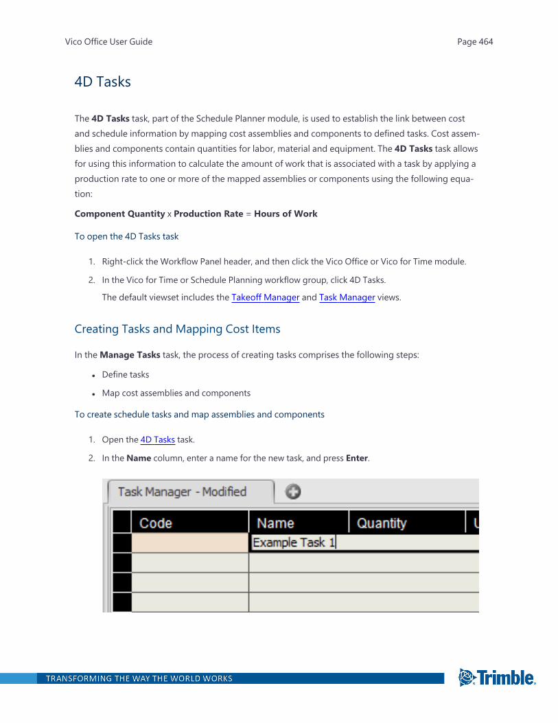
4D Tasks
The 4D Tasks task, part of the Schedule Planner module, is used to establish the link between costand schedule information by mapping cost assemblies and components to defined tasks. Cost assem-blies and components contain quantities for labor, material and equipment. The 4D Tasks task allowsfor using this information to calculate the amount of work that is associated with a task by applying aproduction rate to one or more of the mapped assemblies or components using the following equa-tion:
Component Quantity x Production Rate = Hours of Work
To open the 4D Tasks task
1. Right-click the Workflow Panel header, and then click the Vico Office or Vico for Time module.
2. In the Vico for Time or Schedule Planning workflow group, click 4D Tasks.
The default viewset includes the Takeoff Manager and Task Manager views.
Creating Tasks and Mapping Cost Items
In theManage Tasks task, the process of creating tasks comprises the following steps:
l Define tasks
l Map cost assemblies and components
To create schedule tasks and map assemblies and components
1. Open the 4D Tasks task.
2. In the Name column, enter a name for the new task, and press Enter.
Vico Office User Guide Page 464
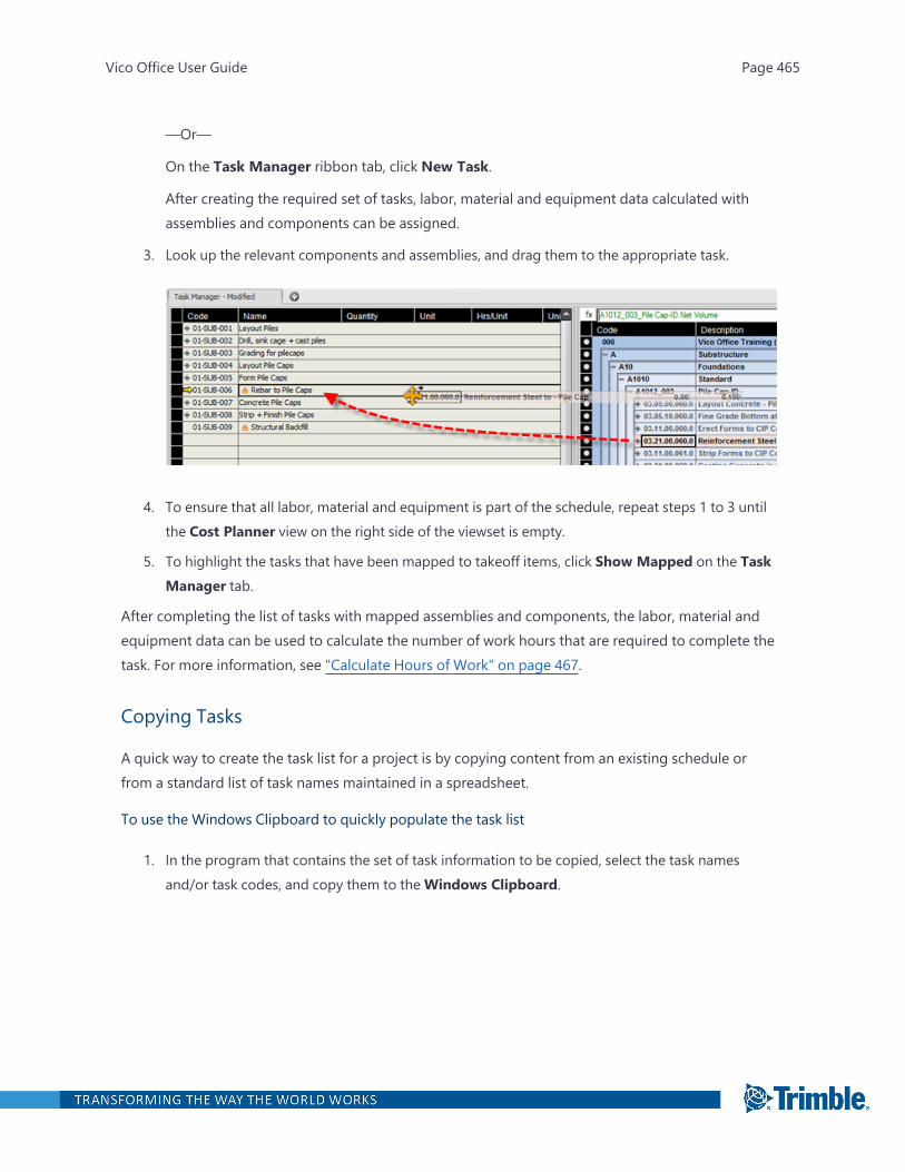
—Or—
On the Task Manager ribbon tab, click New Task.
After creating the required set of tasks, labor, material and equipment data calculated withassemblies and components can be assigned.
3. Look up the relevant components and assemblies, and drag them to the appropriate task.
4. To ensure that all labor, material and equipment is part of the schedule, repeat steps 1 to 3 untilthe Cost Planner view on the right side of the viewset is empty.
5. To highlight the tasks that have been mapped to takeoff items, click Show Mapped on the TaskManager tab.
After completing the list of tasks with mapped assemblies and components, the labor, material andequipment data can be used to calculate the number of work hours that are required to complete thetask. For more information, see "Calculate Hours of Work" on page 467.
Copying Tasks
A quick way to create the task list for a project is by copying content from an existing schedule orfrom a standard list of task names maintained in a spreadsheet.
To use the Windows Clipboard to quickly populate the task list
1. In the program that contains the set of task information to be copied, select the task namesand/or task codes, and copy them to theWindows Clipboard.
Vico Office User Guide Page 465
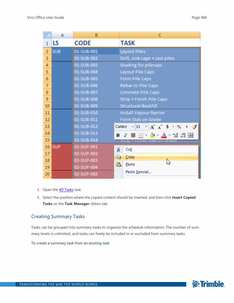
2. Open the 4D Tasks task.
3. Select the position where the copied content should be inserted, and then click Insert CopiedTasks on the Task Manager ribbon tab.
Creating Summary Tasks
Tasks can be grouped into summary tasks to organize the schedule information. The number of sum-mary levels is unlimited, and tasks can freely be included in or excluded from summary tasks.
To create a summary task from an existing task
Vico Office User Guide Page 466
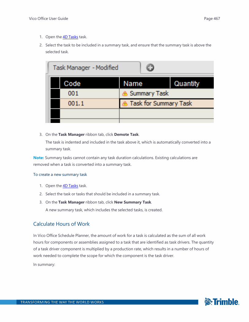
1. Open the 4D Tasks task.
2. Select the task to be included in a summary task, and ensure that the summary task is above theselected task.
3. On the Task Manager ribbon tab, click Demote Task.
The task is indented and included in the task above it, which is automatically converted into asummary task.
Note: Summary tasks cannot contain any task duration calculations. Existing calculations areremoved when a task is converted into a summary task.
To create a new summary task
1. Open the 4D Tasks task.
2. Select the task or tasks that should be included in a summary task.
3. On the Task Manager ribbon tab, click New Summary Task.
A new summary task, which includes the selected tasks, is created.
Calculate Hours of Work
In Vico Office Schedule Planner, the amount of work for a task is calculated as the sum of all workhours for components or assemblies assigned to a task that are identified as task drivers. The quantityof a task driver component is multiplied by a production rate, which results in a number of hours ofwork needed to complete the scope for which the component is the task driver.
In summary:
Vico Office User Guide Page 467
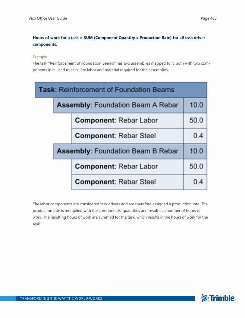
Hours of work for a task = SUM (Component Quantity x Production Rate) for all task drivercomponents.
ExampleThe task "Reinforcement of Foundation Beams" has two assemblies mapped to it, both with two com-ponents in it, used to calculate labor and material required for the assemblies.
The labor components are considered task drivers and are therefore assigned a production rate. Theproduction rate is multiplied with the components' quantities and result in a number of hours ofwork. The resulting hours of work are summed for the task, which results in the hours of work for thetask.
Vico Office User Guide Page 468
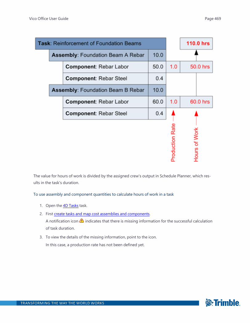
The value for hours of work is divided by the assigned crew's output in Schedule Planner, which res-ults in the task's duration.
To use assembly and component quantities to calculate hours of work in a task
1. Open the 4D Tasks task.
2. First create tasks and map cost assemblies and components.
A notification icon indicates that there is missing information for the successful calculation
of task duration.
3. To view the details of the missing information, point to the icon.
In this case, a production rate has not been defined yet.
Vico Office User Guide Page 469

4. To define the production rate for the component identified as the task driver, click the Hrs/Unitor Units/Hr column, and enter the experience-based number.
For a calculation of labor in hours, the production rate can be left as 1, because the number ofman hours was already calculated in the cost plan.
The amount of work hours for the component is calculated and rolled up to the task level. Anicon in the row indicator shows which component is used as the task driver.
After completing the previous steps, the tasks have a number of hours of work. You can thenadd the schedule logic, crew assignments, and schedule optimization in the Schedule Plannerview.
Vico Office User Guide Page 470
Best Practice: Creating Tasks
Tasks should be defined during the pull planning session, but in the pre-construction phase, a stand-ard company task list can be applied. Tasks should NOT be location-based because Vico generatesthe locations in the LBS module.
When defining tasks, consider the following points:
l Are you using the same unit for the quantities included in this task?
l Will you have the same crew (type) working on this task?
l What level of detail would you like to have in your schedule?
l What are your summary tasks?
l Is there any coding structure that you would like to follow?
For more information, refer to the PDF.
Vico Office User Guide Page 471
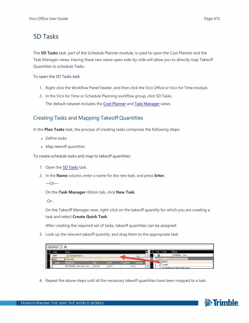
5D Tasks
The 5D Tasks task, part of the Schedule Planner module, is used to open the Cost Planner and theTask Manager views. Having these two views open side-by-side will allow you to directly map TakeoffQuantities to schedule Tasks.
To open the 5D Tasks task
1. Right-click the Workflow Panel header, and then click the Vico Office or Vico for Time module.
2. In the Vico for Time or Schedule Planning workflow group, click 5D Tasks.
The default viewset includes the Cost Planner and Task Manager views.
Creating Tasks and Mapping Takeoff Quantities
In the Plan Tasks task, the process of creating tasks comprises the following steps:
l Define tasks
l Map takeoff quantities
To create schedule tasks and map to takeoff quantities
1. Open the 5D Tasks task.
2. In the Name column, enter a name for the new task, and press Enter.
—Or—
On the Task Manager ribbon tab, click New Task.
-Or-
On the Takeoff Manager view, right-click on the takeoff quantity for which you are creating atask and select Create Quick Task.
After creating the required set of tasks, takeoff quantities can be assigned.
3. Look up the relevant takeoff quantity, and drag them to the appropriate task.
4. Repeat the above steps until all the necessary takeoff quantities have been mapped to a task.
Vico Office User Guide Page 472
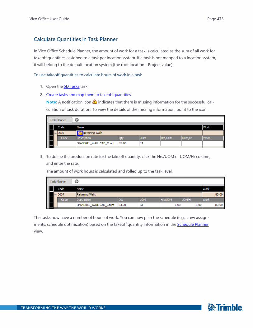
Calculate Quantities in Task Planner
In Vico Office Schedule Planner, the amount of work for a task is calculated as the sum of all work fortakeoff quantities assigned to a task per location system. If a task is not mapped to a location system,it will belong to the default location system (the root location - Project value)
To use takeoff quantities to calculate hours of work in a task
1. Open the 5D Tasks task.
2. Create tasks and map them to takeoff quantities.
Note: A notification icon indicates that there is missing information for the successful cal-
culation of task duration. To view the details of the missing information, point to the icon.
3. To define the production rate for the takeoff quantity, click the Hrs/UOM or UOM/Hr column,and enter the rate.
The amount of work hours is calculated and rolled up to the task level.
The tasks now have a number of hours of work. You can now plan the schedule (e.g., crew assign-ments, schedule optimization) based on the takeoff quantity information in the Schedule Plannerview.
Vico Office User Guide Page 473
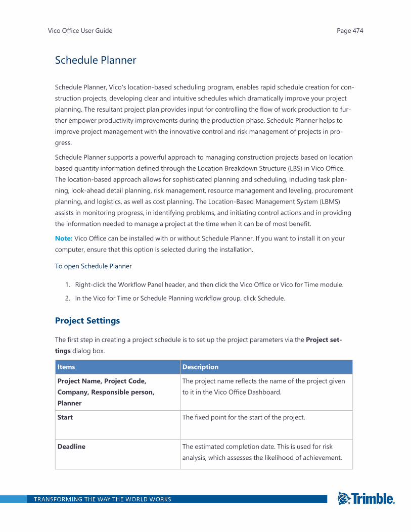
Schedule Planner
Schedule Planner, Vico's location-based scheduling program, enables rapid schedule creation for con-struction projects, developing clear and intuitive schedules which dramatically improve your projectplanning. The resultant project plan provides input for controlling the flow of work production to fur-ther empower productivity improvements during the production phase. Schedule Planner helps toimprove project management with the innovative control and risk management of projects in pro-gress.
Schedule Planner supports a powerful approach to managing construction projects based on locationbased quantity information defined through the Location Breakdown Structure (LBS) in Vico Office.The location-based approach allows for sophisticated planning and scheduling, including task plan-ning, look-ahead detail planning, risk management, resource management and leveling, procurementplanning, and logistics, as well as cost planning. The Location-Based Management System (LBMS)assists in monitoring progress, in identifying problems, and initiating control actions and in providingthe information needed to manage a project at the time when it can be of most benefit.
Note: Vico Office can be installed with or without Schedule Planner. If you want to install it on yourcomputer, ensure that this option is selected during the installation.
To open Schedule Planner
1. Right-click the Workflow Panel header, and then click the Vico Office or Vico for Time module.
2. In the Vico for Time or Schedule Planning workflow group, click Schedule.
Project Settings
The first step in creating a project schedule is to set up the project parameters via the Project set-tings dialog box.
Items Description
Project Name, Project Code,Company, Responsible person,Planner
The project name reflects the name of the project givento it in the Vico Office Dashboard.
Start The fixed point for the start of the project.
Deadline The estimated completion date. This is used for riskanalysis, which assesses the likelihood of achievement.
Vico Office User Guide Page 474

Items Description
Shift Length Used to define the length of the default work day for theproject. The total number of hours for the assigned crewis divided by this number to determine number of shiftsfor the crew.
Currency Unit Define the unit for all calculated cost values in theproject.
LBS Hierarchy Show the location breakdown structure that was definedwith the LBS Manager.
Approve Schedule Create a baseline for the project.
Defining Project Settings
The Project Settings dialog box defines all the basic project specifications that are used everywhere inthe project such as the start date and deadline as well as the shift length or currency for payments.You can also set the project name, code, responsible person, planner, and company.
To define the project settings
1. Open Schedule Planner.
2. In the Projectmenu, click Project settings.
Vico Office User Guide Page 475

—Or—
On the left toolbar, click the gear icon .
The Project settings dialog appears.
3. In the Project settings dialog, change Start Date, Deadline and Shift Length as required.
Project Name and Project Code are defined in the Vico Office Dashboard view.
Schedule Planner UI
Most features of Schedule Planner are grouped into toolbars. The toolbars can be enabled or dis-abled from the Viewmenu > Toolbars.
Note: To reset the toolbars to their original positions, click the Filemenu > Program settings >Reset toolbars.
Toolbars
Toolbars are used to edit tasks and enable scheduling features.
Vico Office User Guide Page 476
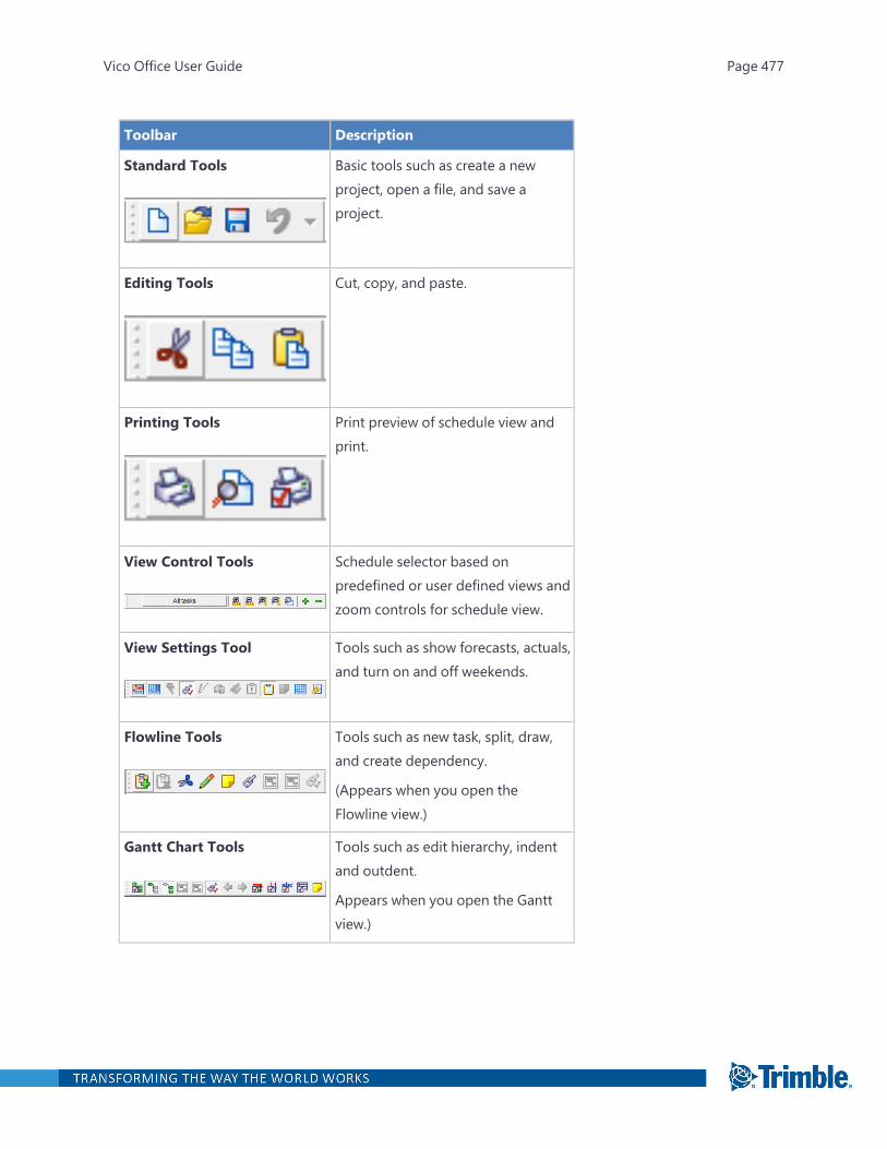
Toolbar Description
Standard Tools Basic tools such as create a newproject, open a file, and save aproject.
Editing Tools Cut, copy, and paste.
Printing Tools Print preview of schedule view andprint.
View Control Tools Schedule selector based onpredefined or user defined views andzoom controls for schedule view.
View Settings Tool Tools such as show forecasts, actuals,and turn on and off weekends.
Flowline Tools Tools such as new task, split, draw,and create dependency.
(Appears when you open theFlowline view.)
Gantt Chart Tools Tools such as edit hierarchy, indentand outdent.
Appears when you open the Ganttview.)
Vico Office User Guide Page 477
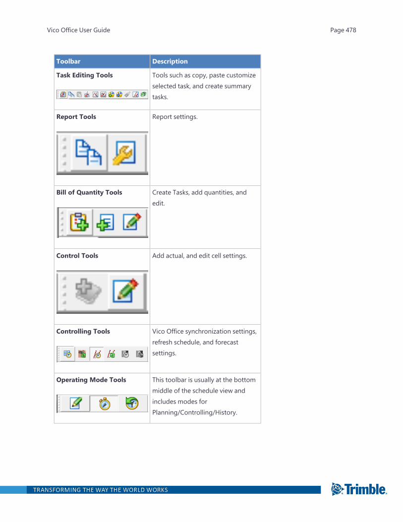
Toolbar Description
Task Editing Tools Tools such as copy, paste customizeselected task, and create summarytasks.
Report Tools Report settings.
Bill of Quantity Tools Create Tasks, add quantities, andedit.
Control Tools Add actual, and edit cell settings.
Controlling Tools Vico Office synchronization settings,refresh schedule, and forecastsettings.
Operating Mode Tools This toolbar is usually at the bottommiddle of the schedule view andincludes modes forPlanning/Controlling/History.
Vico Office User Guide Page 478
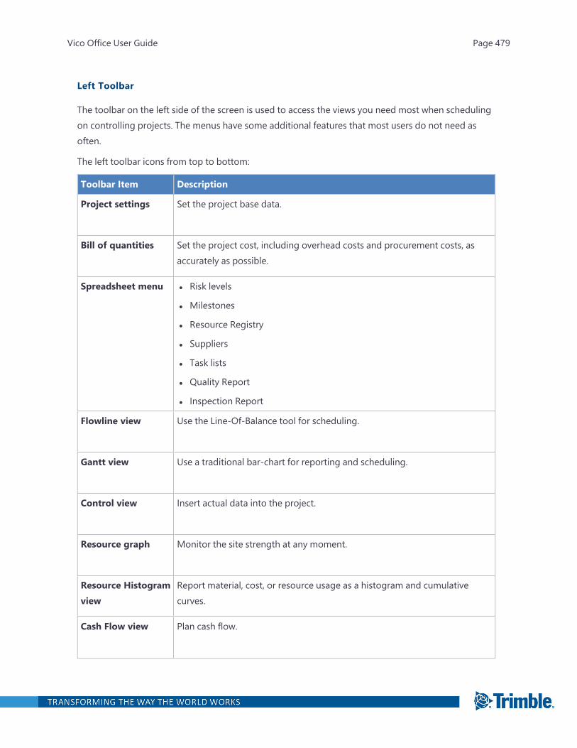
Left Toolbar
The toolbar on the left side of the screen is used to access the views you need most when schedulingon controlling projects. The menus have some additional features that most users do not need asoften.
The left toolbar icons from top to bottom:
Toolbar Item Description
Project settings Set the project base data.
Bill of quantities Set the project cost, including overhead costs and procurement costs, asaccurately as possible.
Spreadsheet menu l Risk levels
l Milestones
l Resource Registry
l Suppliers
l Task lists
l Quality Report
l Inspection Report
Flowline view Use the Line-Of-Balance tool for scheduling.
Gantt view Use a traditional bar-chart for reporting and scheduling.
Control view Insert actual data into the project.
Resource graph Monitor the site strength at any moment.
Resource Histogramview
Report material, cost, or resource usage as a histogram and cumulativecurves.
Cash Flow view Plan cash flow.
Vico Office User Guide Page 479

Toolbar Item Description
Network view For examining the project logic
Open reportswindow
Access the reports of Schedule Planner.
Payment tables Access the supplier and cost type specific payment tables of SchedulePlanner.
Risk simulationmenu
Use the schedule risk analysis tools.
Schedule menu Select the simulated or planned schedule mode.
Log menu View logged project information – project feasibility and disturbances.
LBS in Schedule Planner
Schedule Planner is a location-based construction management system where specific 'Place hier-archy levels' or location hierarchies and appropriate lower level 'Places' or locations are created todetermine the appropriate level of precision for assigning project data, such as quantities andresources. These collectively from the Location Breakdown Structure (LBS) for the project.
In fact, Schedule Planner creates a more streamlined and sophisticated schedule resulting from theallocation of quantities, resources and production rates to specific tasks across multiple locations.
Once created, the LBS will appear in the Flowline view, the Bill of Quantities and the Schedule task con-trol chart windows. For more information about how to create LBS for a model-based project, see the"Define Locations" on page 418 section.
Once you open the Schedule Planner the location breakdown structure is visible on the left side ofthe working area.
Location-Based Schedule
l Task durations calculated with explicit assumptions recorded
l Highlight planned work locations and wasted opportunities
l Identify bottle necks, inefficiencies, stops and starts
Vico Office User Guide Page 480
l Optimized for continuous labor flow
l Optimal resources + starts ensure continuous workflow
l Buffers protect against uncertainty in the field
Location-based planning
Definition:
l Provides a container for project data at a scale which is easy to monitor and analyze
l Plan for productivity
Examples:
l Building > Floors > Work Zones(e.g. Building 1 > Floor 2 > Offices/Apartments)
l Phases > Sections > Chain(e.g. Phase 2 > Section B > Pipeline A/Tunnel B)
Location Breakdown Structure
Definition:
l Physical roject locations for trade groups
l Hierarchical structure
l Independent locations (could be build simultaneously or in any sequence)
General guidelines to define locations:
l Highest level should be: independent locations (buildings)
l Middle level should require flow (floors)
l Lowest level should be the smallest location where only one trade can work effectively (zones)
l Same LBS should apply to most trades
l Plan groups of similar spaces for finishes
Vico Office User Guide Page 481

Add new location
Since the non model-based schedules do not have any location based structure taken from VicoOffice, we should create it inside of the application.
To define location based structure
1. Open Schedule Planner.
The Project level appears by default.
2. Right click on the Project level and select Insert Location.
3. Type the hierarchy level name for the new location. (E.g.: Floor, Location, Level, etc.)
4. Enter the number of locations and the type you want them to be appeared.
Vico Office User Guide Page 482
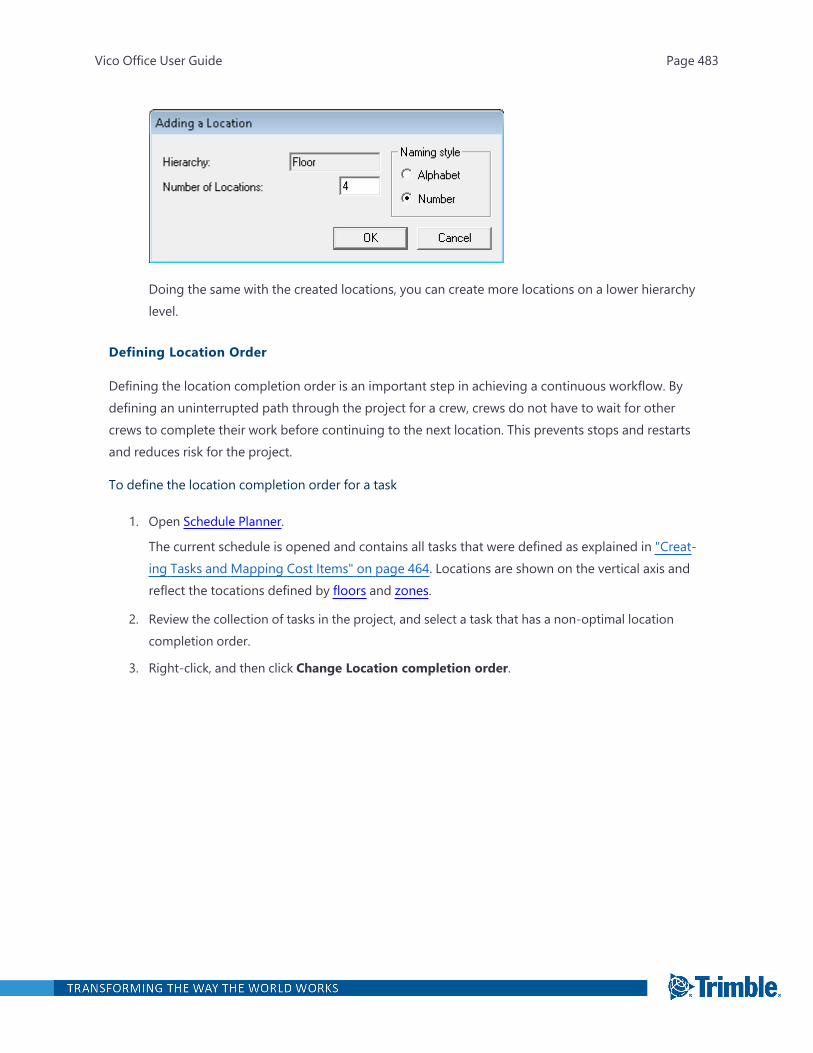
Doing the same with the created locations, you can create more locations on a lower hierarchylevel.
Defining Location Order
Defining the location completion order is an important step in achieving a continuous workflow. Bydefining an uninterrupted path through the project for a crew, crews do not have to wait for othercrews to complete their work before continuing to the next location. This prevents stops and restartsand reduces risk for the project.
To define the location completion order for a task
1. Open Schedule Planner.
The current schedule is opened and contains all tasks that were defined as explained in "Creat-ing Tasks and Mapping Cost Items" on page 464. Locations are shown on the vertical axis andreflect the tocations defined by floors and zones.
2. Review the collection of tasks in the project, and select a task that has a non-optimal locationcompletion order.
3. Right-click, and then click Change Location completion order.
Vico Office User Guide Page 483
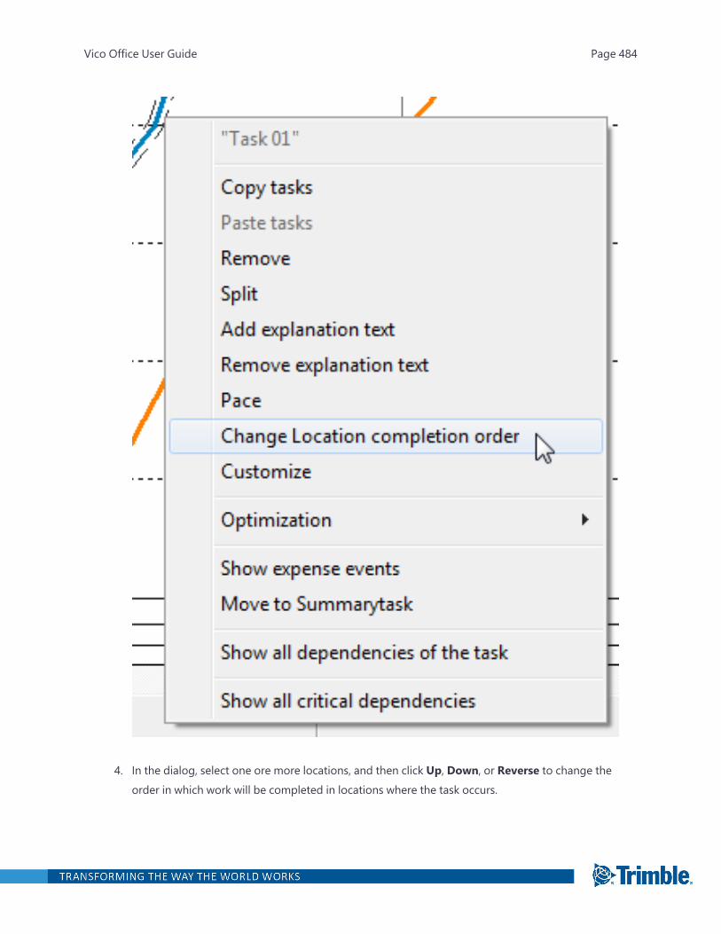
4. In the dialog, select one ore more locations, and then click Up, Down, or Reverse to change theorder in which work will be completed in locations where the task occurs.
Vico Office User Guide Page 484
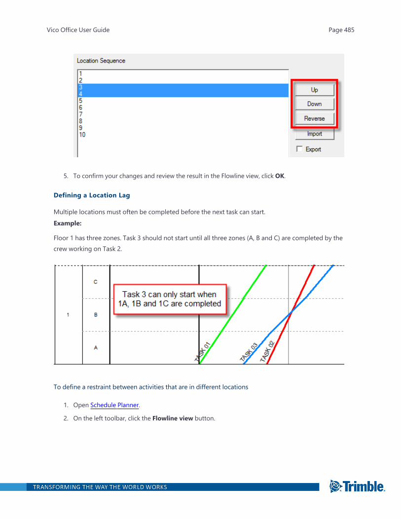
5. To confirm your changes and review the result in the Flowline view, click OK.
Defining a Location Lag
Multiple locations must often be completed before the next task can start.Example:
Floor 1 has three zones. Task 3 should not start until all three zones (A, B and C) are completed by thecrew working on Task 2.
To define a restraint between activities that are in different locations
1. Open Schedule Planner.
2. On the left toolbar, click the Flowline view button.
Vico Office User Guide Page 485
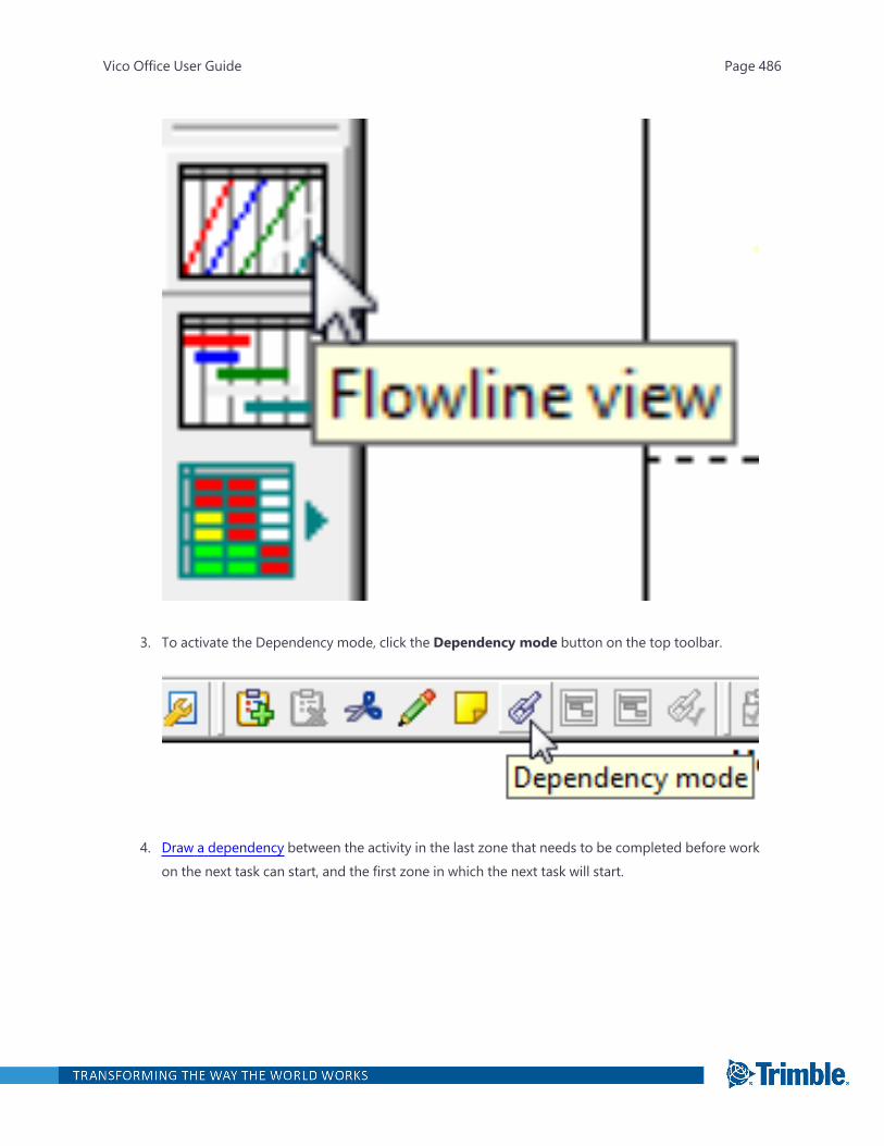
3. To activate the Dependency mode, click the Dependency mode button on the top toolbar.
4. Draw a dependency between the activity in the last zone that needs to be completed before workon the next task can start, and the first zone in which the next task will start.
Vico Office User Guide Page 486
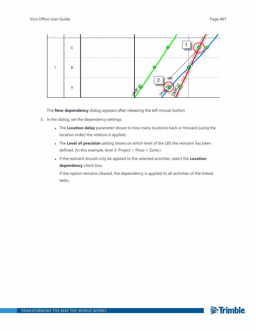
The New dependency dialog appears after releasing the left mouse button.
5. In the dialog, set the dependency settings.
l The Location delay parameter shows to how many locations back or forward (using thelocation order) the relation is applied.
l The Level of precision setting shows on which level of the LBS the restraint has beendefined. (In this example, level 3: Project > Floor > Zone.)
l If the restraint should only be applied to the selected activities, select the Locationdependency check box.
If the option remains cleared, the dependency is applied to all activities of the linkedtasks.
Vico Office User Guide Page 487
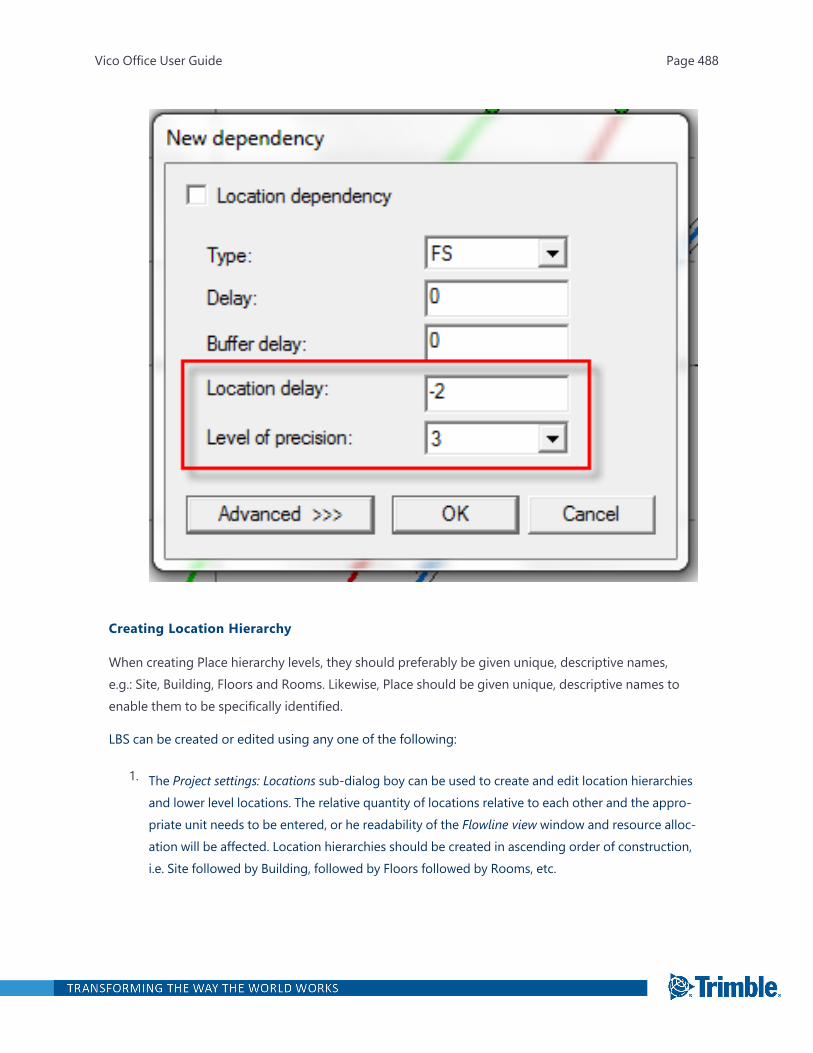
Creating Location Hierarchy
When creating Place hierarchy levels, they should preferably be given unique, descriptive names,e.g.: Site, Building, Floors and Rooms. Likewise, Place should be given unique, descriptive names toenable them to be specifically identified.
LBS can be created or edited using any one of the following:
1. The Project settings: Locations sub-dialog boy can be used to create and edit location hierarchiesand lower level locations. The relative quantity of locations relative to each other and the appro-priate unit needs to be entered, or he readability of the Flowline view window and resource alloc-ation will be affected. Location hierarchies should be created in ascending order of construction,i.e. Site followed by Building, followed by Floors followed by Rooms, etc.
Vico Office User Guide Page 488
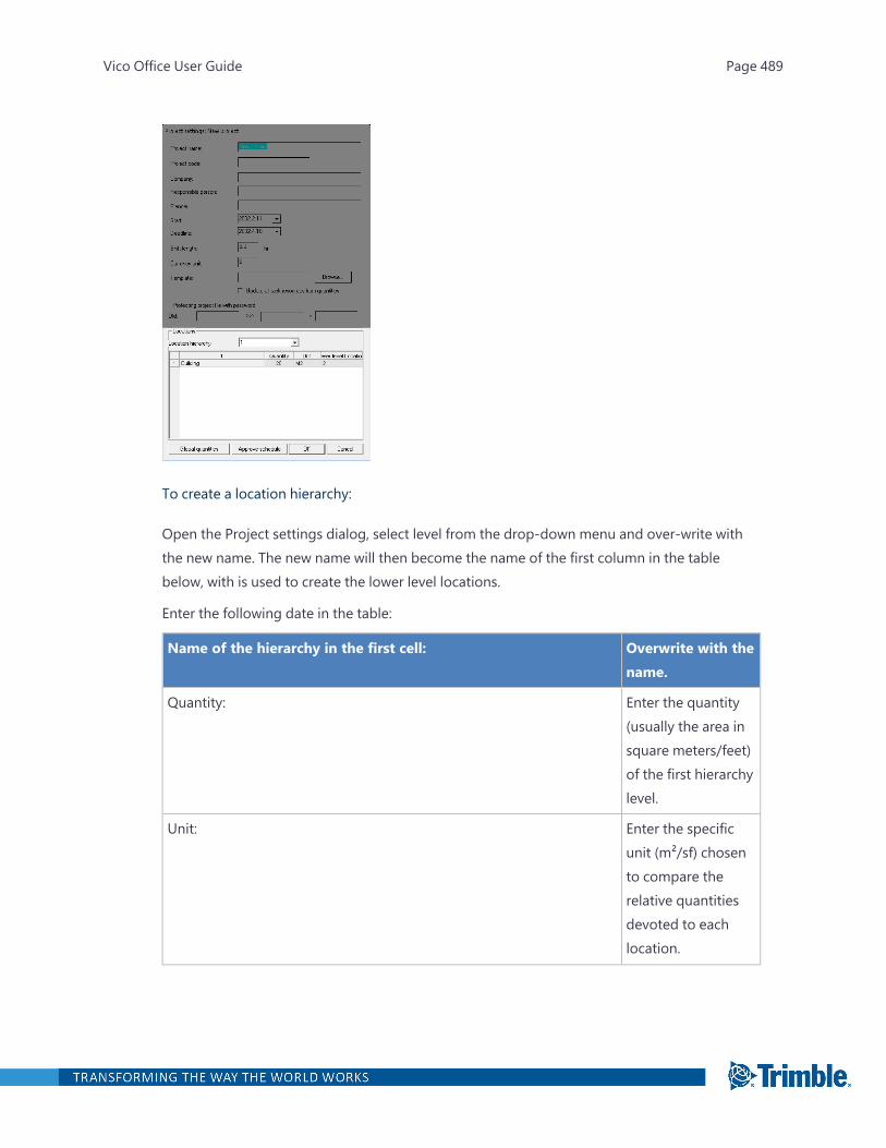
To create a location hierarchy:
Open the Project settings dialog, select level from the drop-down menu and over-write withthe new name. The new name will then become the name of the first column in the tablebelow, with is used to create the lower level locations.
Enter the following date in the table:
Name of the hierarchy in the first cell: Overwrite with thename.
Quantity: Enter the quantity(usually the area insquare meters/feet)of the first hierarchylevel.
Unit: Enter the specificunit (m²/sf) chosento compare therelative quantitiesdevoted to eachlocation.
Vico Office User Guide Page 489
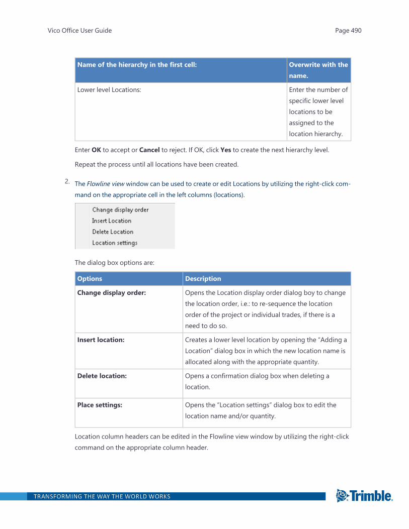
Name of the hierarchy in the first cell: Overwrite with thename.
Lower level Locations: Enter the number ofspecific lower levellocations to beassigned to thelocation hierarchy.
Enter OK to accept or Cancel to reject. If OK, click Yes to create the next hierarchy level.
Repeat the process until all locations have been created.
2. The Flowline view window can be used to create or edit Locations by utilizing the right-click com-mand on the appropriate cell in the left columns (locations).
The dialog box options are:
Options Description
Change display order: Opens the Location display order dialog boy to changethe location order, i.e.: to re-sequence the locationorder of the project or individual trades, if there is aneed to do so.
Insert location: Creates a lower level location by opening the “Adding aLocation” dialog box in which the new location name isallocated along with the appropriate quantity.
Delete location: Opens a confirmation dialog box when deleting alocation.
Place settings: Opens the “Location settings” dialog box to edit thelocation name and/or quantity.
Location column headers can be edited in the Flowline view window by utilizing the right-clickcommand on the appropriate column header.
Vico Office User Guide Page 490
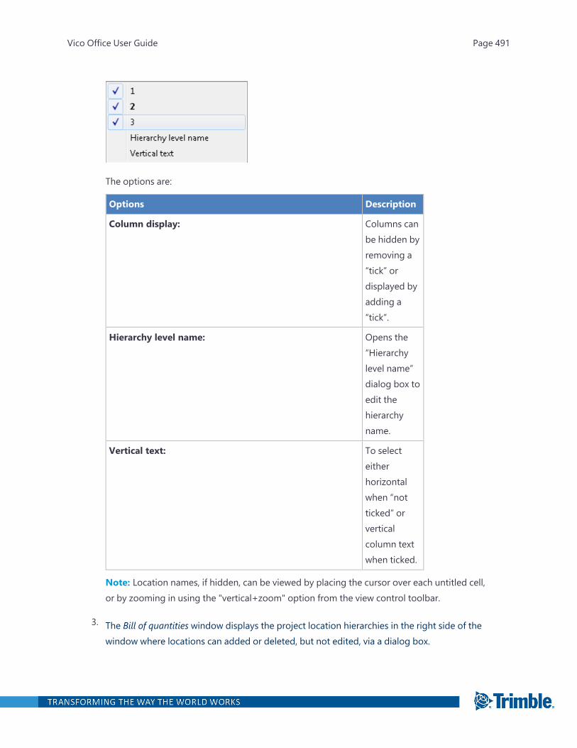
The options are:
Options Description
Column display: Columns canbe hidden byremoving a“tick” ordisplayed byadding a“tick”.
Hierarchy level name: Opens the“Hierarchylevel name”dialog box toedit thehierarchyname.
Vertical text: To selecteitherhorizontalwhen “notticked” orverticalcolumn textwhen ticked.
Note: Location names, if hidden, can be viewed by placing the cursor over each untitled cell,or by zooming in using the "vertical+zoom" option from the view control toolbar.
3. The Bill of quantities window displays the project location hierarchies in the right side of thewindow where locations can added or deleted, but not edited, via a dialog box.
Vico Office User Guide Page 491
To add a lower level location:
Right-click on the higher level location to open the Add hierarchy level dialog box, insert thename of new hierarchy and the number of new locations, select OK to accept or Cancel toreject.
To delete a location:
Right-click on the location to be removed, select Remove, select No to cancel or Yes toremove, then choose whether or not to distribute quantities.
4. The Project settings: Locations sub-dialog box can be used in conjunction with a spreadsheetapplication to rapidly populate project LBS data. The procedure is similar to (1) above, butinstead of entering the text (which can get confusing in long lists), it is sufficient to enter thenumber of location places, drop down to the lower level and copy all the columns and rowsand paste into your spreadsheet, where they may be edited. Once completed, they may becopied and pasted back into the project settings dialog box by placing the cursor into the firstcell and pasting with Ctrl-V. This process may then be repeated at a lower level.
Note: A powerful use of method (4) is to copy the structure from a past project for use in anew project. This method can construct a new LBS in a matter of minutes, even when it is com-plex.
Location-based Layer logic
The underlying engine of Schedule Planner is a CPM engine, as such, many of the concepts will befamiliar to many who have used other software packages for scheduling construction. However basicCPM is unaware of location information, and is not able to control resources for continuous use. Thefollowing discussion briefly introduces the more powerful Layered logic which is part of the location-based management system and which is fully developed in Schedule Planner.
The new theory of Location-based scheduling involves far more that like activities in chain to deriveresource optimization, as sometimes suggested. Rather, it involves several layers of interactive CPMlogic, which combine to form a powerful location-based logic, Layered Logic, which involves the fol-lowing:
1. External logical relationship between activities within locations.
2. External higher-level logical relationships between activities driven by different levels of accuracy.
3. Internal logic between activities within tasks.
Vico Office User Guide Page 492

4. Phased hybrid logic between tasks in related locations.
5. Standard CPM links between any tasks and different locations.
In this chapter, only the basic elements of location-based scheduling will be demonstrated. Theseinvolve Layer 1, Layer 2, and Layer 3logic. Essentially, this is the internal logic for a task that involvessequential work through locations (Layer 3) and the connection between tasks as they pass the loc-ation from task to task using Layer 1 (same level) and Layer 2 (higher level) logic.
Adjust crews
To align production by changing the number of crews:
1. Open the Flowline view by clicking on the icon in the left toolbar.
2. Move the mouse over the upper right end of the task until the cursor changes to an arrow to theright. Click and drag to the left until the slope of the line is similar to the preceding task.
3. The “Crew” is proposed automatically in the “Setting method” sub-dialog box. In the example,the original duration was 127 shifts, it was dragged to 60 shifts, and adding 4 crews (to result in atotal of 10) results in a duration of 50.8 shifts. You can manually change the Number if it differs –the duration is then recalculated.
Vico Office User Guide Page 493
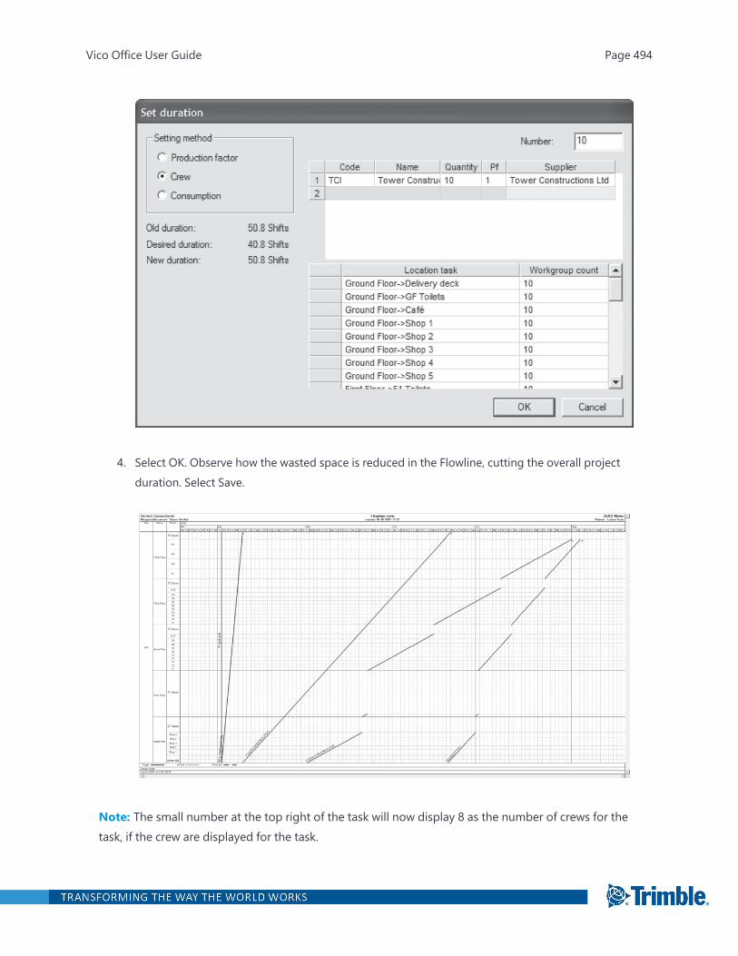
4. Select OK. Observe how the wasted space is reduced in the Flowline, cutting the overall projectduration. Select Save.
Note: The small number at the top right of the task will now display 8 as the number of crews for thetask, if the crew are displayed for the task.
Vico Office User Guide Page 494

Assigning Crews from Cost Components
The duration of a task is defined by the production rate of the crew that works on it, using the fol-lowing formula:
Duration = (Units of Work) / (Crew Output per Hour * Number of Crews)
The formula is evaluated in each location where units of work (thus an activity) exist.
When the assembly that contains labor components was mapped to the task (see also "CreatingTasks and Mapping Cost Items" on page 464). crews can be generated automatically.
To assign crews from calculated labor components to scheduled tasks
1. Define tasks and assign assemblies and components with labor components, as explained in"Creating Tasks and Mapping Cost Items" on page 464.
Ensure that the labor components are used as task drivers, as explained in "Calculate Hours ofWork" on page 467.
2. Open Schedule Planner.
3. In the Projectmenu, click Resource registry.
4. To generate labor resources and crews, click the Update resources from quantities.
Vico Office User Guide Page 495
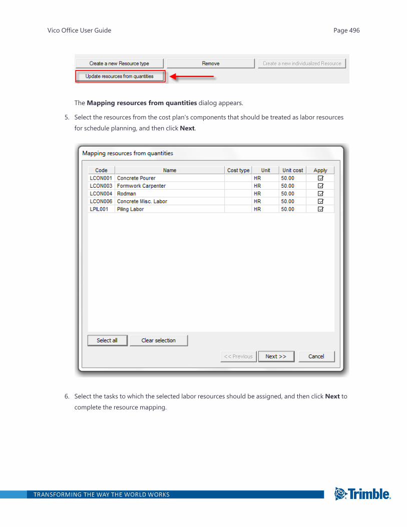
TheMapping resources from quantities dialog appears.
5. Select the resources from the cost plan's components that should be treated as labor resourcesfor schedule planning, and then click Next.
6. Select the tasks to which the selected labor resources should be assigned, and then click Next tocomplete the resource mapping.
Vico Office User Guide Page 496

The labor resources, including unit rate, are now listed in the Resource Registry.
The labor resources from your cost plan are now also assigned as crews to the tasks in yourschedule. The crew composition is calculated by setting the component with the largest num-ber of labor hours to "1". All other labor resource numbers are calculated by ratio of this num-ber.
ExampleA task has been assigned the following resources from cost components:
Vico Office User Guide Page 497
Concrete Laborer 220 hours
General Labor 100 hours
The Crew becomes:
Concrete Laborer 1.00
General Labor 0.45
The optimal crew for this task will be 2 Concrete Laborers and 1 General Labor resource. Optim-ization of the schedule will involve including the number of "Standard Crews", which is stand-ard calculated.
Assigning Crews Manually
The duration of a task is defined by the production rate of the crew that works on it, using the fol-lowing formula:
Duration = (Units of Work) / (Crew Output per Hour * Number of Crews)
The formula is evaluated in each location where units of work (thus an activity) exist.
When cost for the project is not calculated to the level of labor resources, crews for tasks can bedefined manually.
To assign crews to tasks manually:
1. Open Schedule Planner.
2. On the left toolbar, click either the Flowline view buttton or the Gantt view button.
3. To open the schedule task, double-click it.
4. Click Advanced, and then click the Resources tab.
Vico Office User Guide Page 498
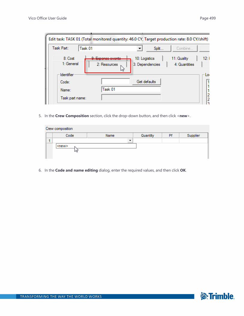
5. In the Crew Composition section, click the drop-down button, and then click <new>.
6. In the Code and name editing dialog, enter the required values, and then click OK.
Vico Office User Guide Page 499
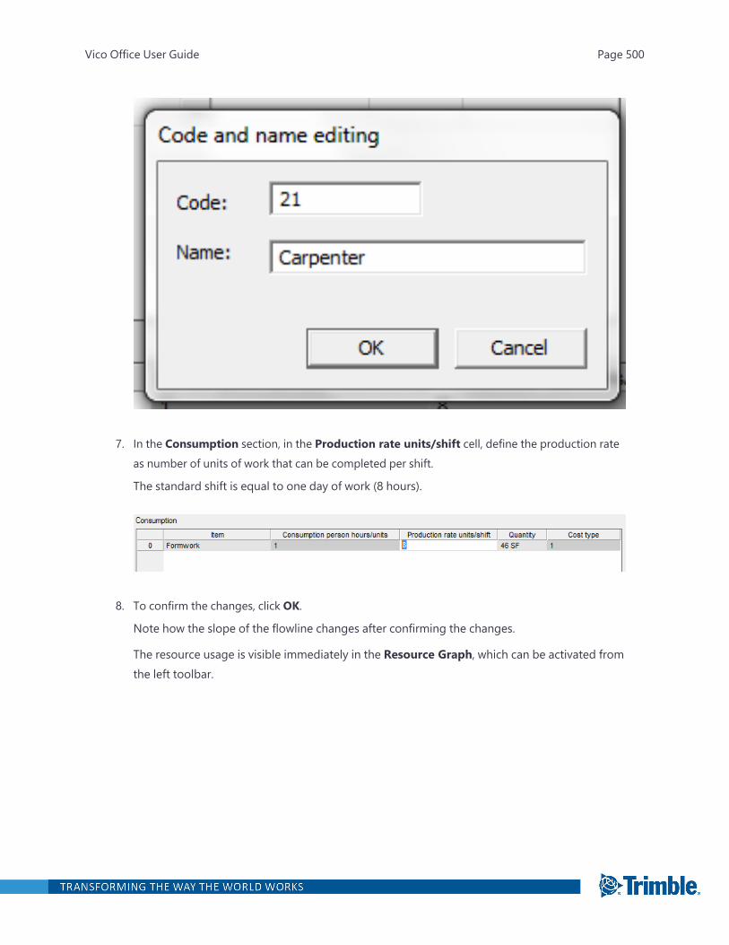
7. In the Consumption section, in the Production rate units/shift cell, define the production rateas number of units of work that can be completed per shift.
The standard shift is equal to one day of work (8 hours).
8. To confirm the changes, click OK.
Note how the slope of the flowline changes after confirming the changes.
The resource usage is visible immediately in the Resource Graph, which can be activated fromthe left toolbar.
Vico Office User Guide Page 500
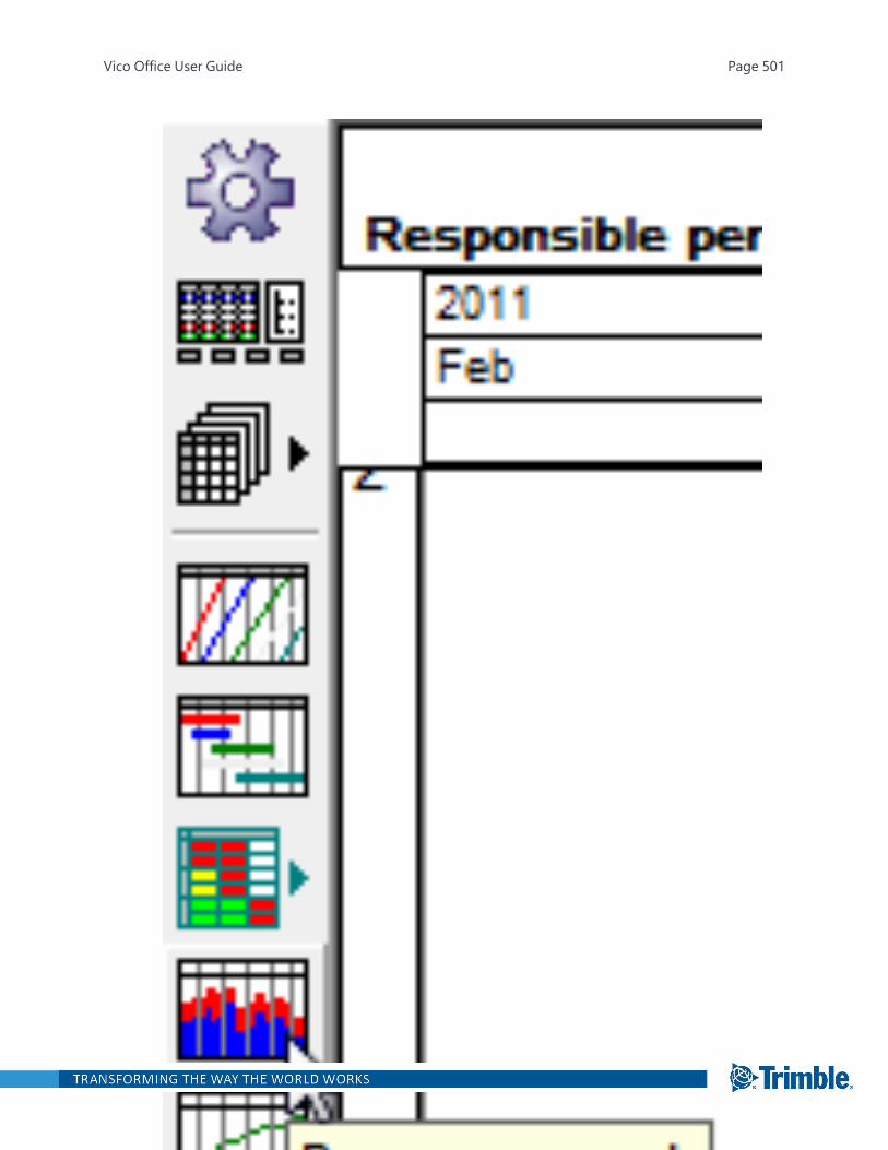
Vico Office User Guide Page 501
Optimizing Crew Allocations
You can optimize production by adjusting crews, by adjusting crew configuration, or by splitting thework to enable parallel activities.
To adjust crews
1. Double-click the task, and then click Advanced.
2. On the Resources tab of the Edit Task dialog, change the number of crews to the numberrequired to achieve the required faster or slower production rate.
To adjust crew configuration
1. In the Flowline view, point to the top of the task.
The cursor changes to an arrow pointing to the right.
2. Click the top of the task, and then drag the line until its slope matches the task that is beingmatched.
The Set duration dialog appears. You can change either the Production Factor (the same asthe Production factor on the duration tab of the Edit task dialog box), the crew (either Num-ber or the crew makeup (Resource Quantity), or Consumption.
To enable parallel activities by splitting the work
1. Double-click the task, and then click Advanced.
2. On the Duration tab of the Edit Task dialog, change the count of crews per location in theWork-group count cell.
The composition of crews is the same for all locations, but the count may differ. Thus, you canspeed up the locations with more work, and slow down locations with less work or space forworking.
Creating Tasks
Location-based methods of scheduling shift the focus from the activity alone, to the flow of the seriesof activities that make up common tasks through many locations.
The Flowline schedule produced by Schedule Planner recognizes three board categories of tasks.They are:
l Schedule tasks: The combination of quantity of work and resource consumption required for atask over all locations, i.e. they can be said to be construction tasks. Schedule tasks will be further
Vico Office User Guide Page 502
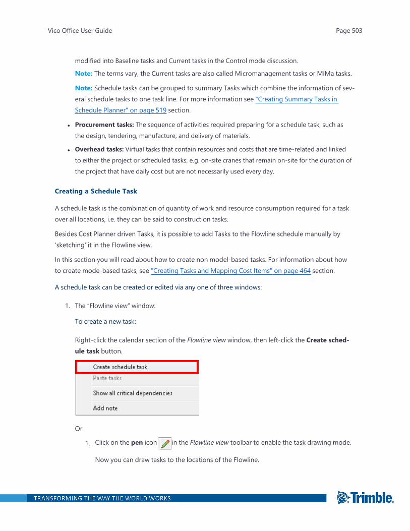
modified into Baseline tasks and Current tasks in the Control mode discussion.
Note: The terms vary, the Current tasks are also called Micromanagement tasks or MiMa tasks.
Note: Schedule tasks can be grouped to summary Tasks which combine the information of sev-eral schedule tasks to one task line. For more information see "Creating Summary Tasks inSchedule Planner" on page 519 section.
l Procurement tasks: The sequence of activities required preparing for a schedule task, such asthe design, tendering, manufacture, and delivery of materials.
l Overhead tasks: Virtual tasks that contain resources and costs that are time-related and linkedto either the project or scheduled tasks, e.g. on-site cranes that remain on-site for the duration ofthe project that have daily cost but are not necessarily used every day.
Creating a Schedule Task
A schedule task is the combination of quantity of work and resource consumption required for a taskover all locations, i.e. they can be said to construction tasks.
Besides Cost Planner driven Tasks, it is possible to add Tasks to the Flowline schedule manually by'sketching' it in the Flowline view.
In this section you will read about how to create non model-based tasks. For information about howto create mode-based tasks, see "Creating Tasks and Mapping Cost Items" on page 464 section.
A schedule task can be created or edited via any one of three windows:
1. The “Flowline view” window:
To create a new task:
Right-click the calendar section of the Flowline view window, then left-click the Create sched-ule task button.
Or
1. Click on the pen icon in the Flowline view toolbar to enable the task drawing mode.
Now you can draw tasks to the locations of the Flowline.
Vico Office User Guide Page 503
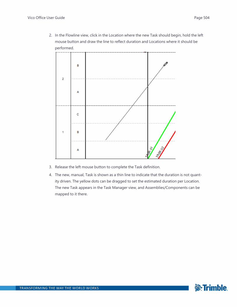
2. In the Flowline view, click in the Location where the new Task should begin, hold the leftmouse button and draw the line to reflect duration and Locations where it should beperformed.
3. Release the left mouse button to complete the Task definition.
4. The new, manual, Task is shown as a thin line to indicate that the duration is not quant-ity driven. The yellow dots can be dragged to set the estimated duration per Location.The new Task appears in the Task Manager view, and Assemblies/Components can bemapped to it there.
Vico Office User Guide Page 504
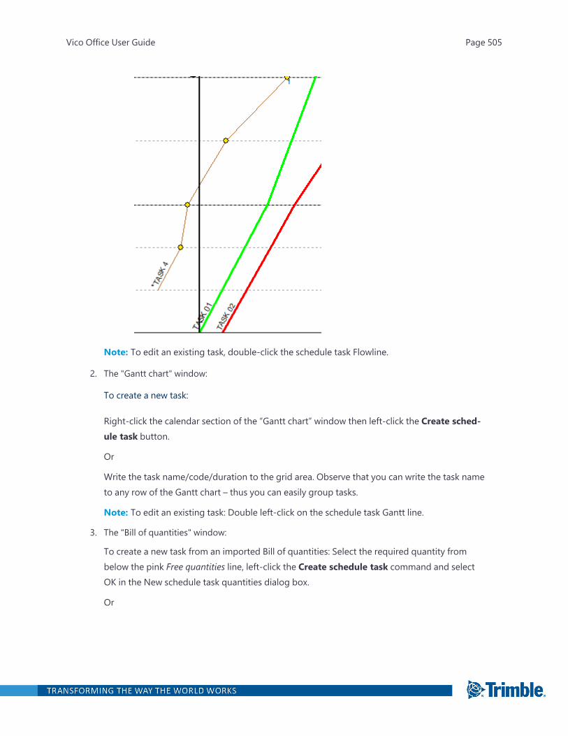
Note: To edit an existing task, double-click the schedule task Flowline.
2. The "Gantt chart" window:
To create a new task:
Right-click the calendar section of the “Gantt chart” window then left-click the Create sched-ule task button.
Or
Write the task name/code/duration to the grid area. Observe that you can write the task nameto any row of the Gantt chart – thus you can easily group tasks.
Note: To edit an existing task: Double left-click on the schedule task Gantt line.
3. The "Bill of quantities" window:
To create a new task from an imported Bill of quantities: Select the required quantity frombelow the pink Free quantities line, left-click the Create schedule task command and selectOK in the New schedule task quantities dialog box.
Or
Vico Office User Guide Page 505
Left-click on the pink Free quantities line, left-click on the Add/Edit quantities to open theAdd method dialog box enter data and select OK. Select the new task then left-click the Createschedule task button and select OK in the New schedule task quantities dialog box.
Note: To save time, schedule tasks and quantities can be prepared, stored and managed forimport from a spreadsheet prior to importation into the Bill of quantities.
Note: To edit an existing task: Double left-click on the schedule task name.
The above procedures all result in opening the Edit task dialog box which is used to create or edit aschedule task via 15 schedule task sub-dialog boxes. If the task does not have quantities, then a smal-ler Edit Task dialog is shown - the normal one is then accessed from the Advanced button.
For more information see "Edit Task" on page 545 section.
Creating Overhead Task
Overhead costs are usually incurred by the general contractor, and arise from the costs of supportingthe construction activities. They are a function of the project, particularly a construction phase dur-ation or the duration of use of important resources, such as a tower crane and supervision.
To create Overhead Task via the Bill of Quantities window:
1. Open the Bill of Quantities window.
2. Select Overhead from the Task type.
3. Select the "Free quantities" line and select the Add/edit quantities button. Enter the quantityitems, including a description, quantities and units.
4. Click OK.
5. Select the relevant method from below the "Free quantities" line.
6. Left click the Create an overhead task button, then click OK in the "The quantities of a new over-head" task dialog box to open the Overhead task editing dialog box.
The Overhead task editing dialog box appears.
The Overhead task editing dialog box allows access to four sub-dialog boxes:
Sub-dialog box Description
General Used to enter general information about the task.
Vico Office User Guide Page 506
Sub-dialog box Description
Durations Used to calculate the duration of the overhead task.
Costs Used to display cost information on the overhead task.
Expense events Used to define expense events for the overhead task.
1. The "General" sub-dialog box displays board parameter information for each overhead task:
Identifier: Enables the procurement task to be identified by Code and Name.
Timing: Start delay: The lead period for costs to commence prior toproduction starting. For example, the erection of a crane, or settingout site sheds.
Enter the duration (in hours).
End delay: The following period for costs to continue afterproduction is complete. For example, dismantling cranes, orremoving site sheds.
Enter the duration (in hours).
Calendar: The overhead task may have its own calendar. Forexample, a seven-day hiring calendar might be used.
Vico Office User Guide Page 507
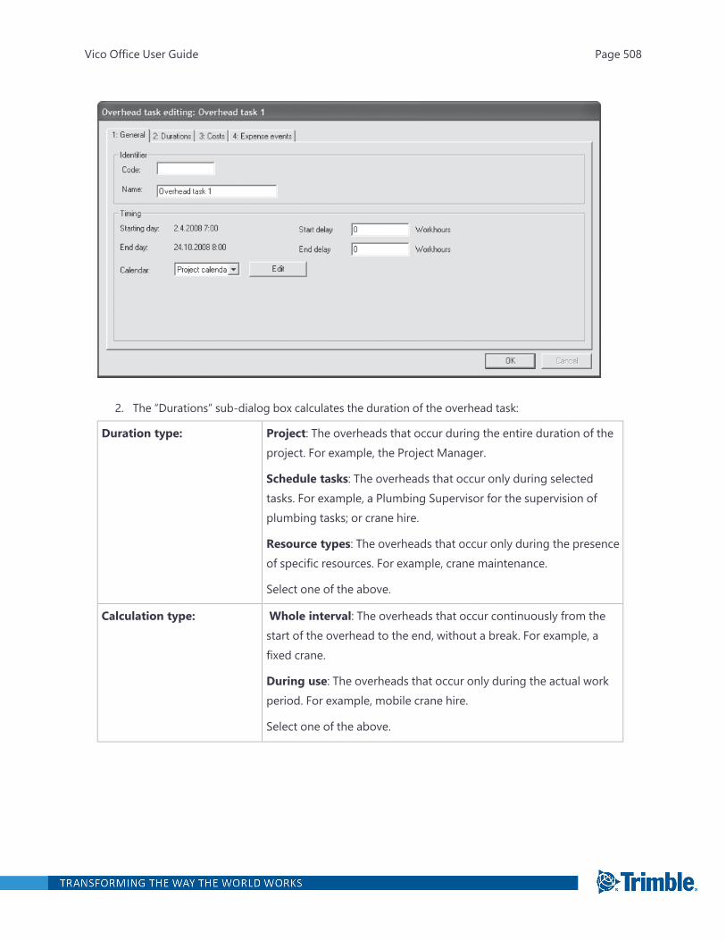
2. The “Durations” sub-dialog box calculates the duration of the overhead task:
Duration type: Project: The overheads that occur during the entire duration of theproject. For example, the Project Manager.
Schedule tasks: The overheads that occur only during selectedtasks. For example, a Plumbing Supervisor for the supervision ofplumbing tasks; or crane hire.
Resource types: The overheads that occur only during the presenceof specific resources. For example, crane maintenance.
Select one of the above.
Calculation type: Whole interval: The overheads that occur continuously from thestart of the overhead to the end, without a break. For example, afixed crane.
During use: The overheads that occur only during the actual workperiod. For example, mobile crane hire.
Select one of the above.
Vico Office User Guide Page 508
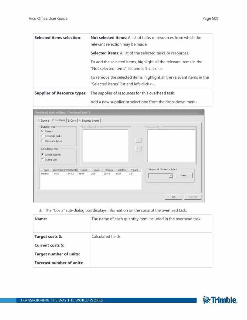
Selected items selection: Not selected items: A list of tasks or resources from which therelevant selection may be made.
Selected items: A list of the selected tasks or resources.
To add the selected items, highlight all the relevant items in the“Not selected items” list and left-click –>.
To remove the selected items, highlight all the relevant items in the“Selected items” list and left-click<–.
Supplier of Resource types: The supplier of resources for this overhead task.
Add a new supplier or select one from the drop-down menu.
3. The “Costs” sub-dialog box displays information on the costs of the overhead task:
Name: The name of each quantity item included in the overhead task.
Target costs $:
Current costs $:
Target number of units:
Forecast number of units:
Calculated fields.
Vico Office User Guide Page 509

4. The “Expense events” sub-dialog box defines expense events for the overhead task:
This section is for determining the timing of payments (expense events). Selection options are: Selec-ted days, Weekly, Bi-weekly and Monthly. These selections determine the options for the cash flowsystem, discussed elsewhere.
Vico Office User Guide Page 510
Creating Procurement Task
In current scheduling practice, the common way for linking procurement and design activities to theconstruction schedule is to add the relevant events as predecessor tasks to the schedule. This methodeffectively pushes the start dates of production tasks - thus the procurement activities are treated asbeing of equal importance to production.
Procurement Tasks are used to group the labor, material and equipment, needed for the execution ofschedule Tasks, and to plan the purchasing process for these resources. Planned Procurement Eventshelp to keep track of the procurement process during the production phase.
To create Procurement Task via the Bill of Quantities window
Vico Office User Guide Page 511
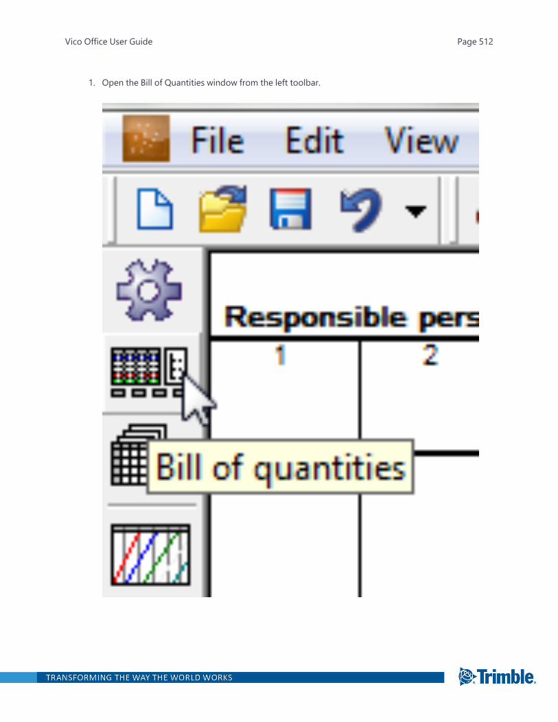
1. Open the Bill of Quantities window from the left toolbar.
Vico Office User Guide Page 512
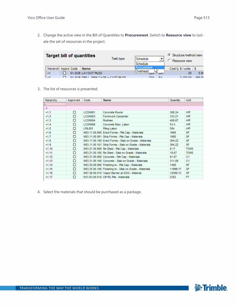
2. Change the active view in the Bill of Quantities to Procurement. Switch to Resource view to isol-ate the set of resources in the project.
3. The list of resources is presented.
4. Select the materials that should be purchased as a package.
Vico Office User Guide Page 513
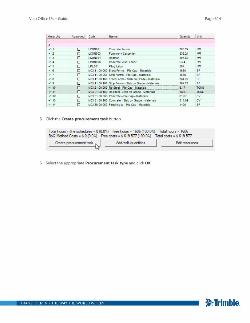
5. Click the Create procurement task button.
6. Select the appropriate Procurement task type and click OK.
Vico Office User Guide Page 514
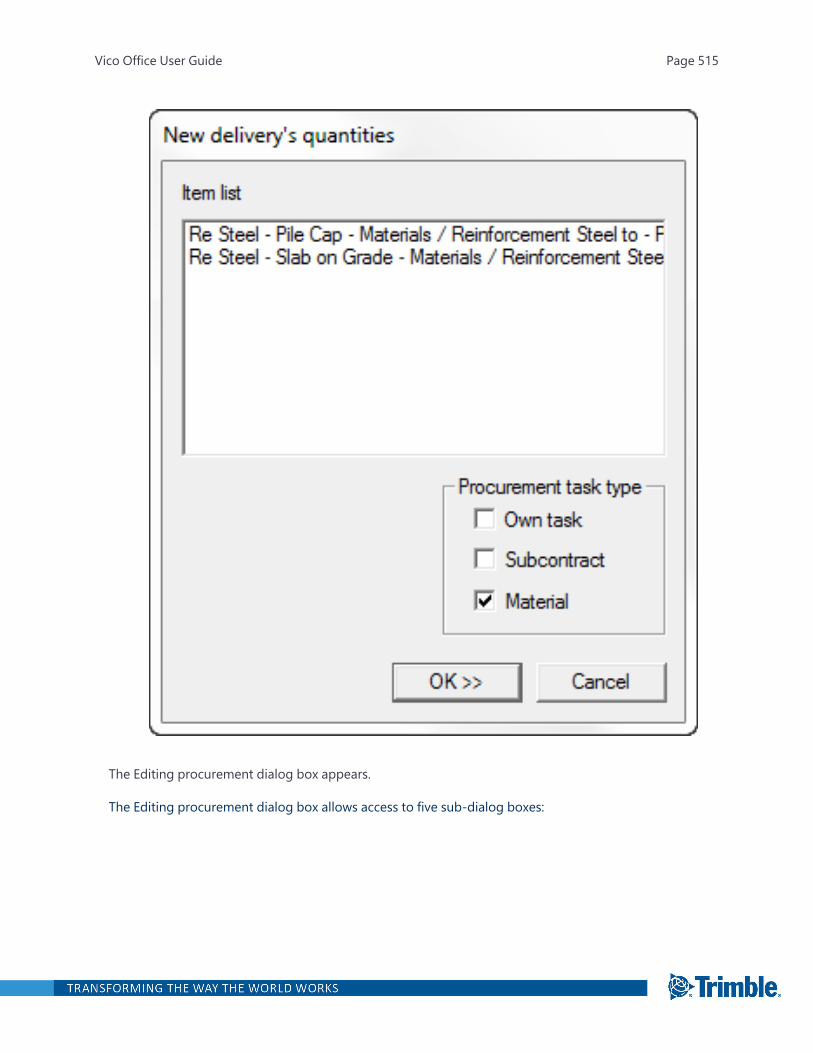
The Editing procurement dialog box appears.
The Editing procurement dialog box allows access to five sub-dialog boxes:
Vico Office User Guide Page 515
Sub-dialogbox
Description
General Used to enter general information about the task.
Quantity data Used to enter quantity data.
Events Used to enter information on the scheduling of events, such as planning,tendering, contracting, ordering, and delivery.
Dependencies Used to define dependencies.
Diary Used to record special dates.
Deal In the project controlling mode there is an additional tab for making deals ofprocured quantities.
For more information, see the "Editing Procurement task" section.
Adding a Task Manually
To 'sketch' a new schedule Task
1. Open Schedule Planner.
2. On the left toolbar, click the Flowline view button.
Vico Office User Guide Page 516

3. Click the Task drawing mode button.
The cursor changes to a pencil.
4. In the Flowline view, click the location where the new task should begin, and hold the left mousebutton while drawing the line to reflect the duration and locations where it should be performed.
5. To complete the task definition, release the left mouse button.
The new task is shown as a thin line to indicate that the duration is not quantity-driven. The yel-low dots can be dragged to set the estimated duration per location. The new task appears inthe Task Manager view, and assemblies and components can be mapped to it there.
Vico Office User Guide Page 517

Vico Office User Guide Page 518
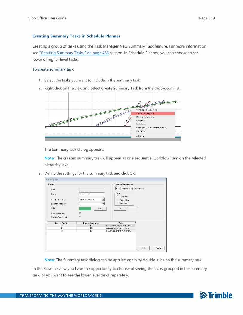
Creating Summary Tasks in Schedule Planner
Creating a group of tasks using the Task Manager New Summary Task feature. For more informationsee "Creating Summary Tasks " on page 466 section. In Schedule Planner, you can choose to seelower or higher level tasks.
To create summary task
1. Select the tasks you want to include in the summary task.
2. Right click on the view and select Create Summary Task from the drop-down list.
The Summary task dialog appears.
Note: The created summary task will appear as one sequential workflow item on the selectedhierarchy level.
3. Define the settings for the summary task and click OK.
Note: The Summary task dialog can be applied again by double-click on the summary task.
In the Flowline view you have the opportunity to choose of seeing the tasks grouped in the summarytask, or you want to see the lower level tasks separately.
Vico Office User Guide Page 519
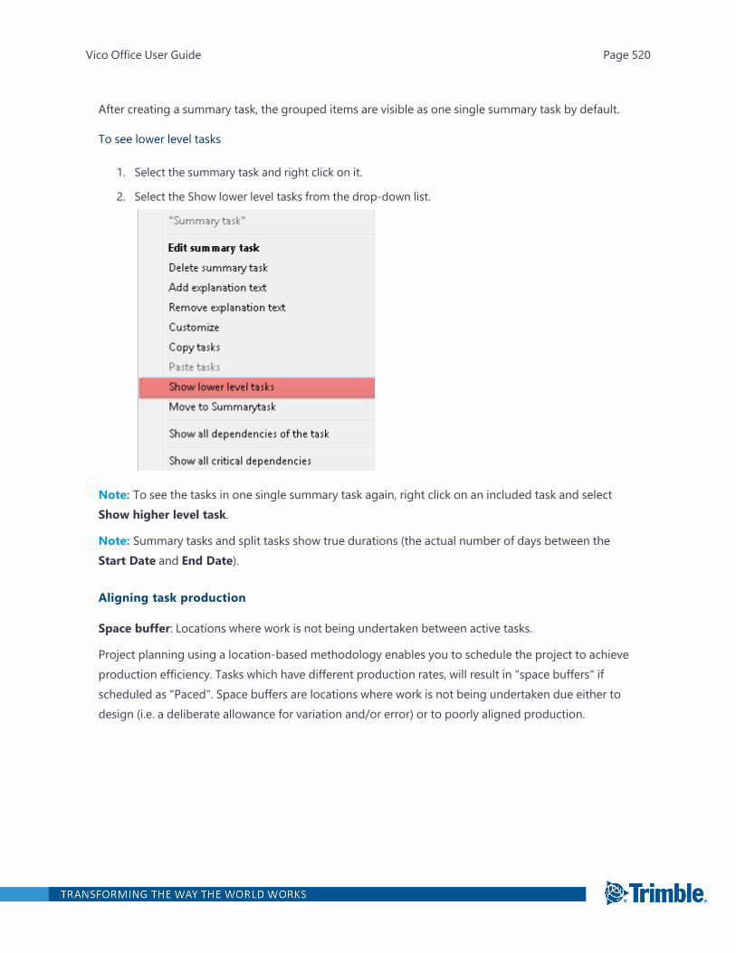
After creating a summary task, the grouped items are visible as one single summary task by default.
To see lower level tasks
1. Select the summary task and right click on it.
2. Select the Show lower level tasks from the drop-down list.
Note: To see the tasks in one single summary task again, right click on an included task and selectShow higher level task.
Note: Summary tasks and split tasks show true durations (the actual number of days between theStart Date and End Date).
Aligning task production
Space buffer: Locations where work is not being undertaken between active tasks.
Project planning using a location-based methodology enables you to schedule the project to achieveproduction efficiency. Tasks which have different production rates, will result in "space buffers" ifscheduled as "Paced". Space buffers are locations where work is not being undertaken due either todesign (i.e. a deliberate allowance for variation and/or error) or to poorly aligned production.
Vico Office User Guide Page 520
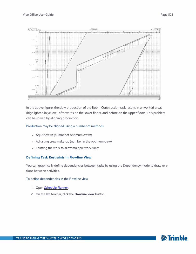
In the above figure, the slow production of the Room Construction task results in unworked areas(highlighted in yellow), afterwards on the lower floors, and before on the upper floors. This problemcan be solved by aligning production.
Production may be aligned using a number of methods:
l Adjust crews (number of optimum crews)
l Adjusting crew make-up (number in the optimum crew)
l Splitting the work to allow multiple work-faces
Defining Task Restraints in Flowline View
You can graphically define dependencies between tasks by using the Dependency mode to draw rela-tions between activities.
To define dependencies in the Flowline view
1. Open Schedule Planner.
2. On the left toolbar, click the Flowline view button.
Vico Office User Guide Page 521
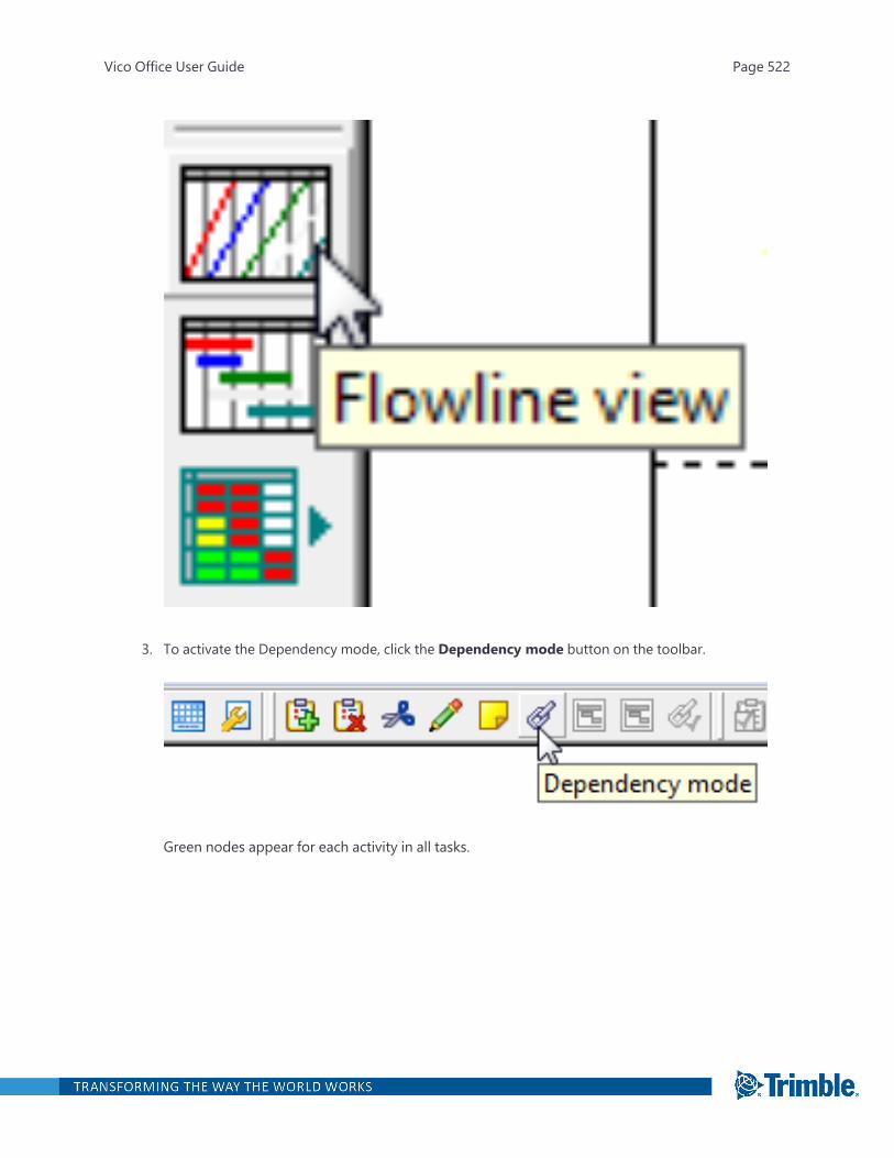
3. To activate the Dependency mode, click the Dependency mode button on the toolbar.
Green nodes appear for each activity in all tasks.
Vico Office User Guide Page 522
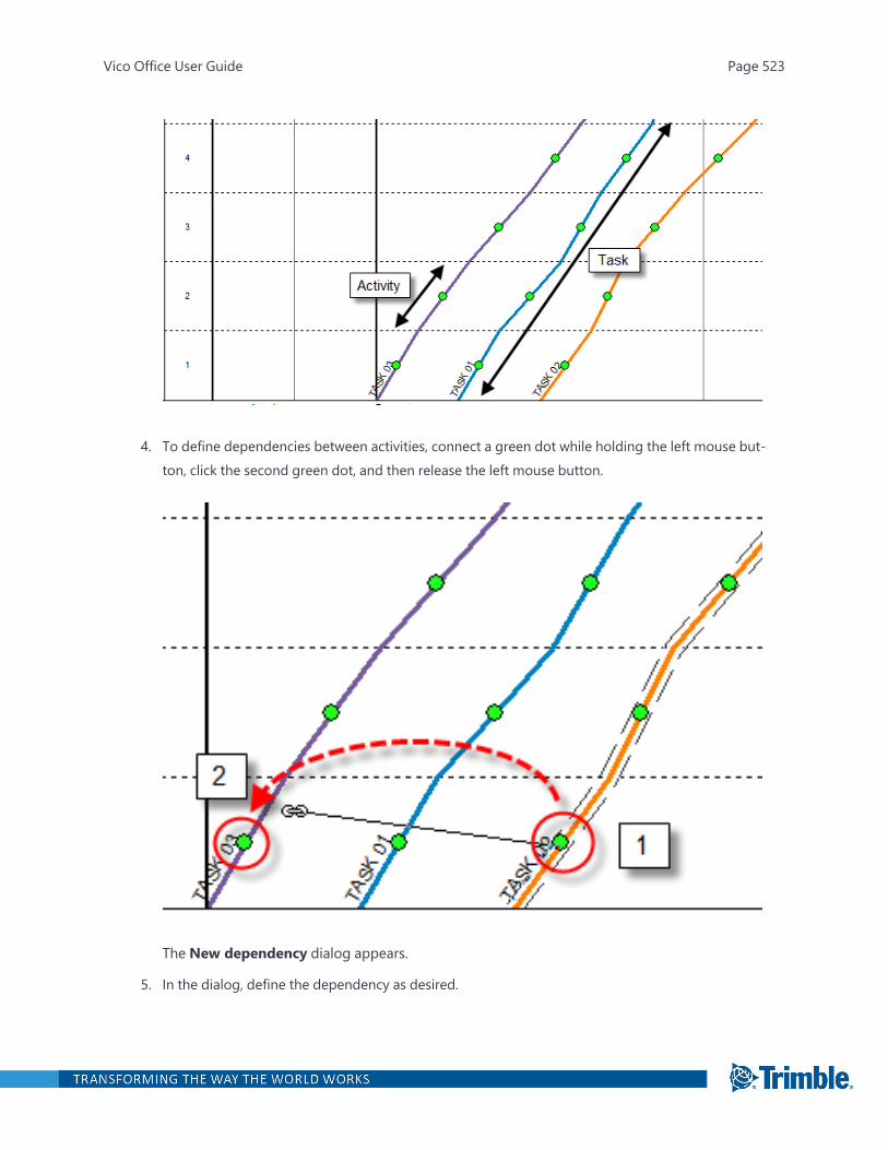
4. To define dependencies between activities, connect a green dot while holding the left mouse but-ton, click the second green dot, and then release the left mouse button.
The New dependency dialog appears.
5. In the dialog, define the dependency as desired.
Vico Office User Guide Page 523
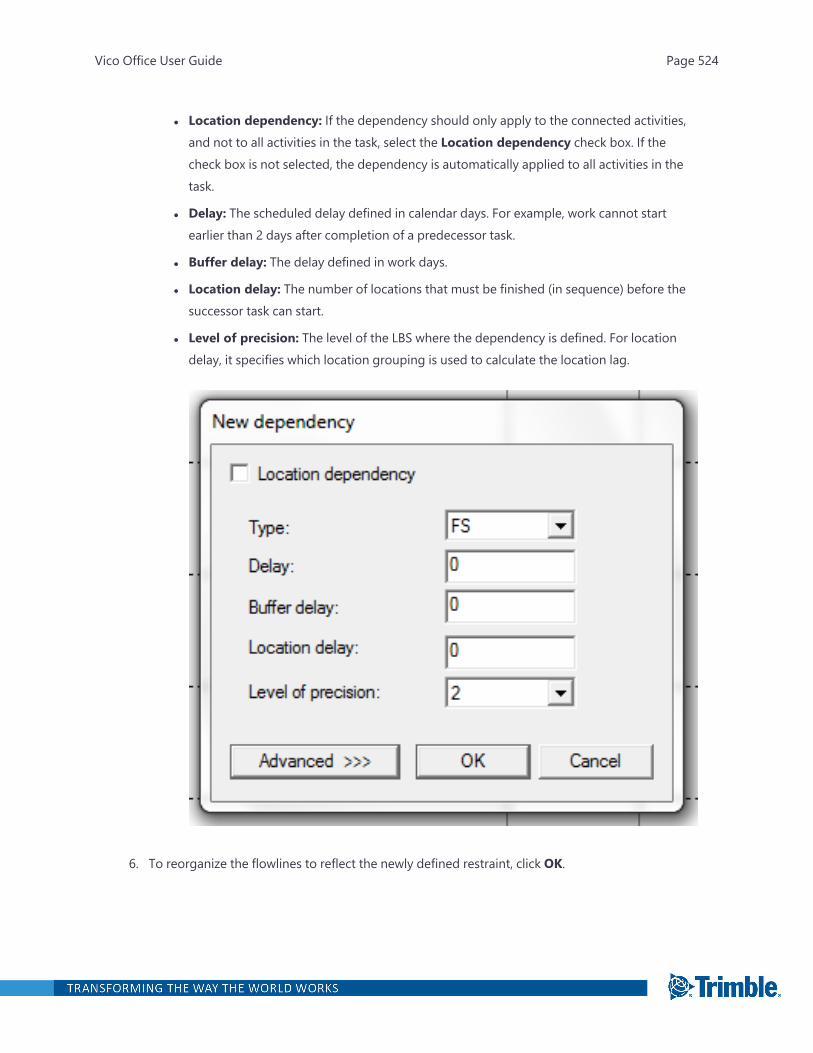
l Location dependency: If the dependency should only apply to the connected activities,and not to all activities in the task, select the Location dependency check box. If thecheck box is not selected, the dependency is automatically applied to all activities in thetask.
l Delay: The scheduled delay defined in calendar days. For example, work cannot startearlier than 2 days after completion of a predecessor task.
l Buffer delay: The delay defined in work days.
l Location delay: The number of locations that must be finished (in sequence) before thesuccessor task can start.
l Level of precision: The level of the LBS where the dependency is defined. For locationdelay, it specifies which location grouping is used to calculate the location lag.
6. To reorganize the flowlines to reflect the newly defined restraint, click OK.
Vico Office User Guide Page 524
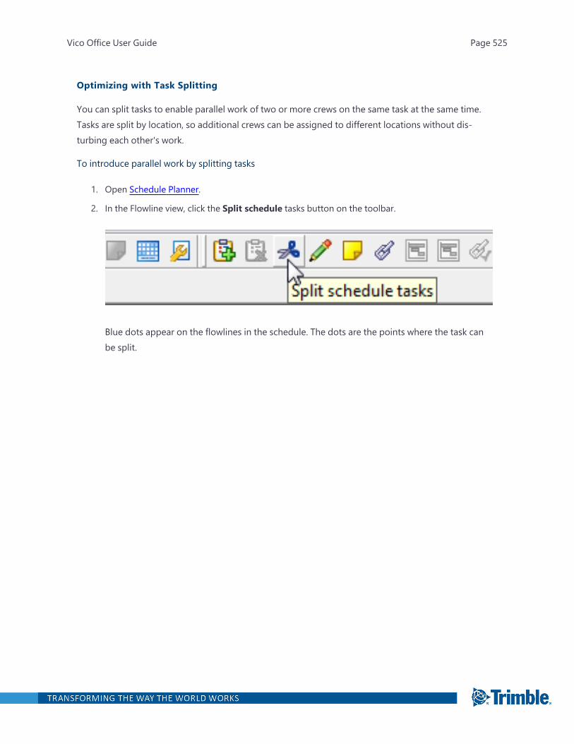
Optimizing with Task Splitting
You can split tasks to enable parallel work of two or more crews on the same task at the same time.Tasks are split by location, so additional crews can be assigned to different locations without dis-turbing each other's work.
To introduce parallel work by splitting tasks
1. Open Schedule Planner.
2. In the Flowline view, click the Split schedule tasks button on the toolbar.
Blue dots appear on the flowlines in the schedule. The dots are the points where the task canbe split.
Vico Office User Guide Page 525
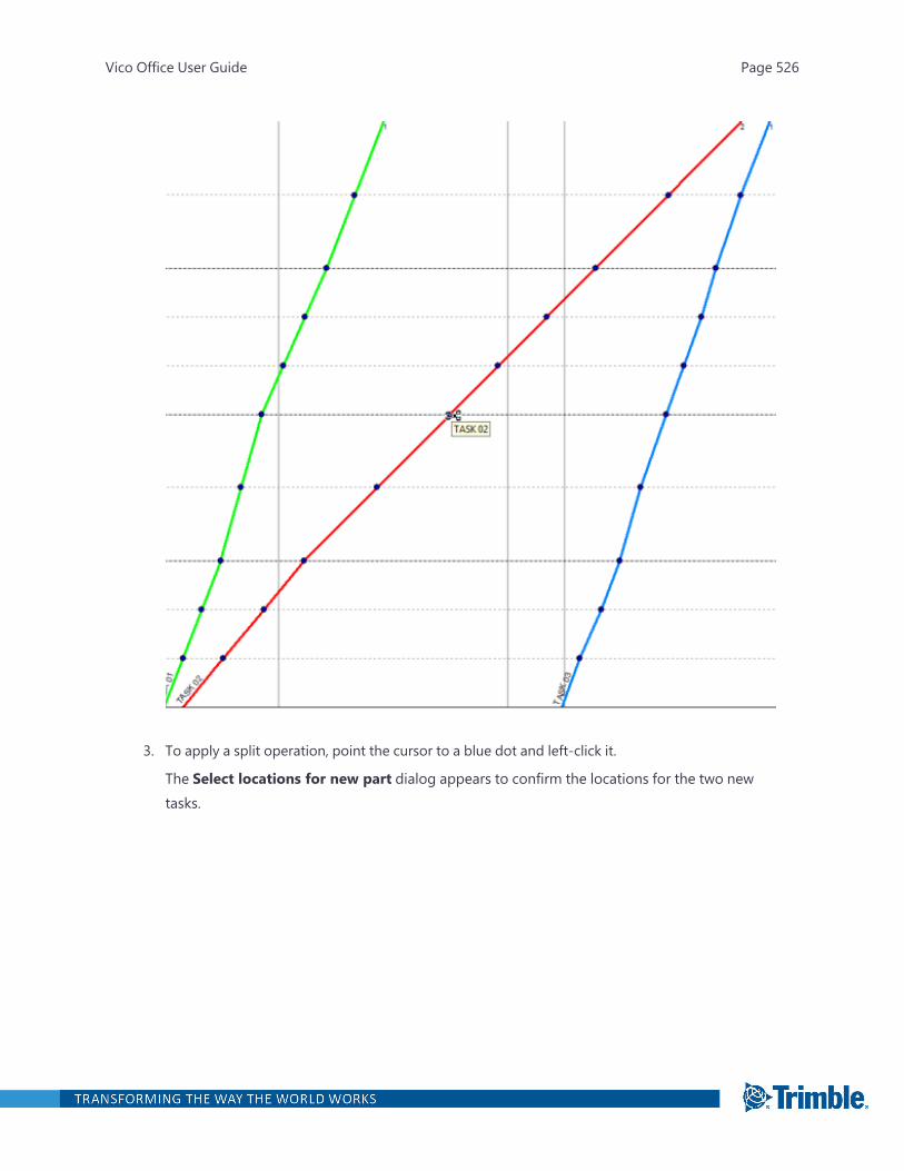
3. To apply a split operation, point the cursor to a blue dot and left-click it.
The Select locations for new part dialog appears to confirm the locations for the two newtasks.
Vico Office User Guide Page 526

4. Click OK to confirm.
The original task is split into two split tasks. You can define parallel work and assign differentlabor resources for optimization of the schedule.
Vico Office User Guide Page 527
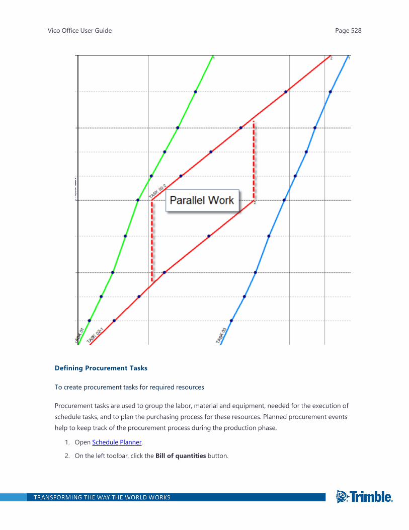
Defining Procurement Tasks
To create procurement tasks for required resources
Procurement tasks are used to group the labor, material and equipment, needed for the execution ofschedule tasks, and to plan the purchasing process for these resources. Planned procurement eventshelp to keep track of the procurement process during the production phase.
1. Open Schedule Planner.
2. On the left toolbar, click the Bill of quantities button.
Vico Office User Guide Page 528
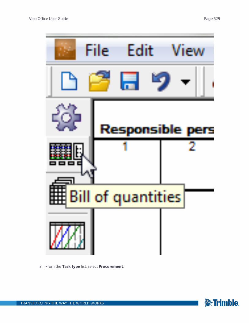
3. From the Task type list, select Procurement.
Vico Office User Guide Page 529

4. To isolate the set of resources in the project, select Resource view.
The list of resources is displayed.
5. Select the materials that should be purchased as a package.
Vico Office User Guide Page 530
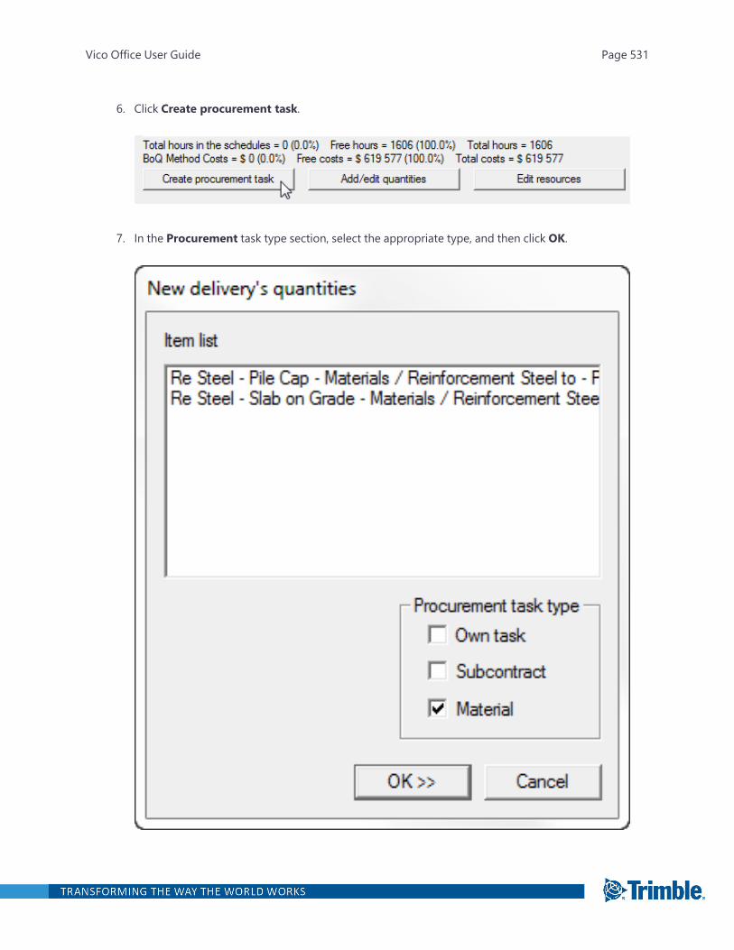
6. Click Create procurement task.
7. In the Procurement task type section, select the appropriate type, and then click OK.
Vico Office User Guide Page 531
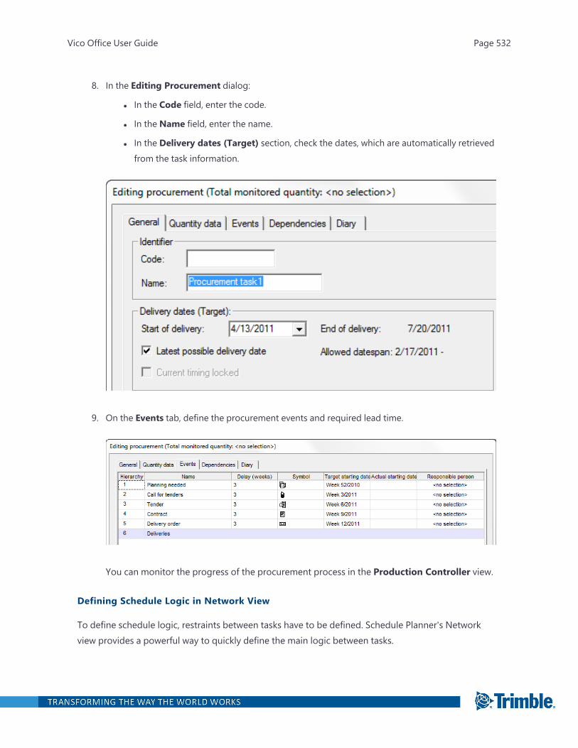
8. In the Editing Procurement dialog:
l In the Code field, enter the code.
l In the Name field, enter the name.
l In the Delivery dates (Target) section, check the dates, which are automatically retrievedfrom the task information.
9. On the Events tab, define the procurement events and required lead time.
You can monitor the progress of the procurement process in the Production Controller view.
Defining Schedule Logic in Network View
To define schedule logic, restraints between tasks have to be defined. Schedule Planner's Networkview provides a powerful way to quickly define the main logic between tasks.
Vico Office User Guide Page 532

Note: An activity is a task that occurs in a location. Task restraints (dependencies) are automaticallydefined for all activities of a task.Example:
Task A occurs in 10 locations and is restrained by a dependency to Task B that also occurs in 10 loc-ations. The 10 activities from both tasks are linked with the same dependency when it is definedbetween Task A and Task B.
To define the logical connections between tasks in the schedule
1. Open Schedule Planner.
2. On the left toolbar, click the Network view button.
Vico Office User Guide Page 533
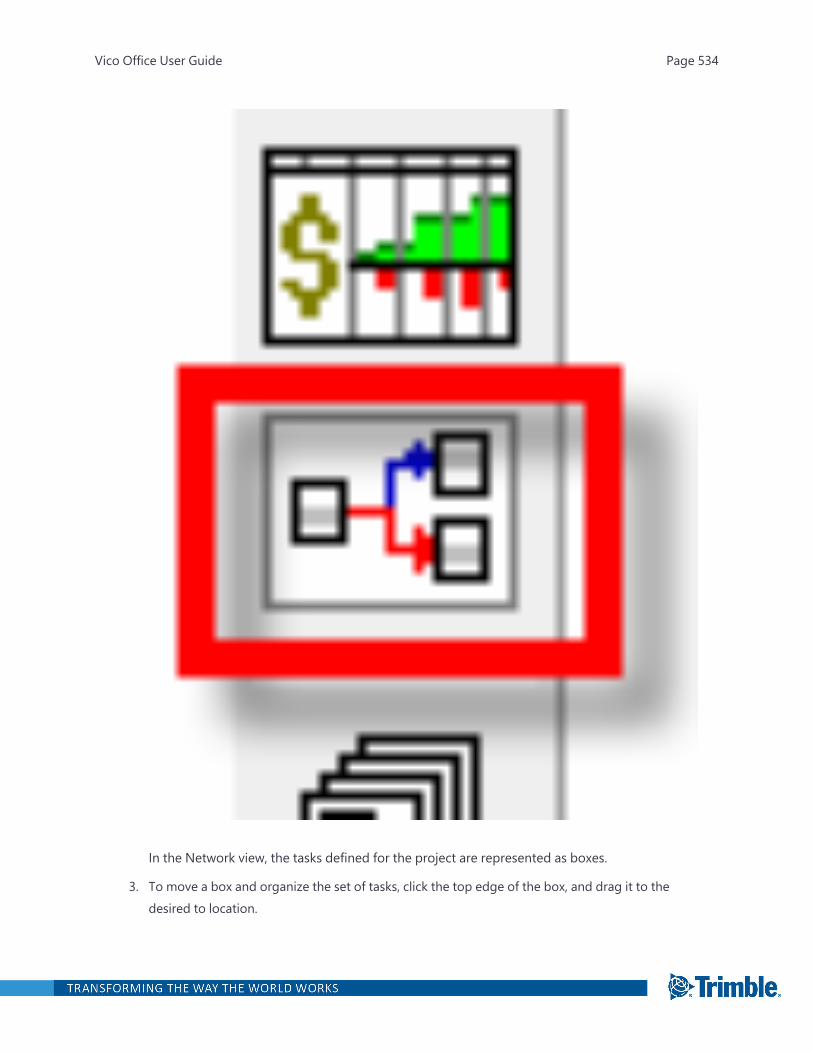
In the Network view, the tasks defined for the project are represented as boxes.
3. To move a box and organize the set of tasks, click the top edge of the box, and drag it to thedesired to location.
Vico Office User Guide Page 534
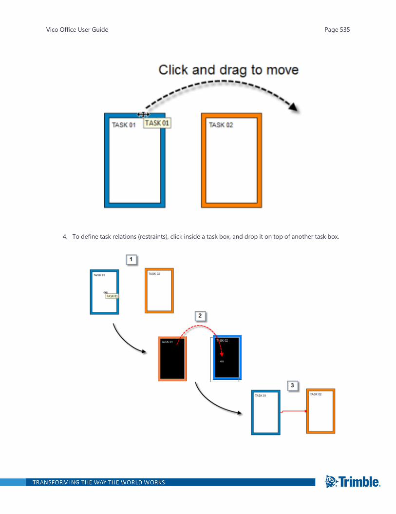
4. To define task relations (restraints), click inside a task box, and drop it on top of another task box.
Vico Office User Guide Page 535
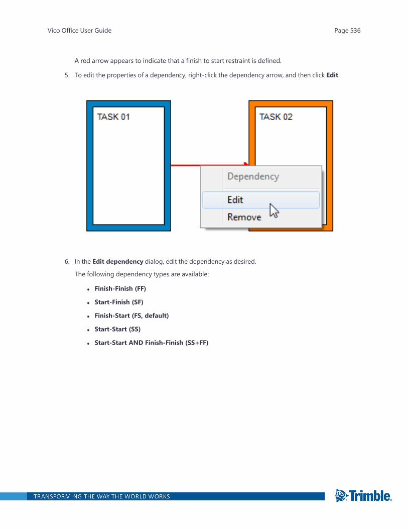
A red arrow appears to indicate that a finish to start restraint is defined.
5. To edit the properties of a dependency, right-click the dependency arrow, and then click Edit.
6. In the Edit dependency dialog, edit the dependency as desired.
The following dependency types are available:
l Finish-Finish (FF)
l Start-Finish (SF)
l Finish-Start (FS, default)
l Start-Start (SS)
l Start-Start AND Finish-Finish (SS+FF)
Vico Office User Guide Page 536
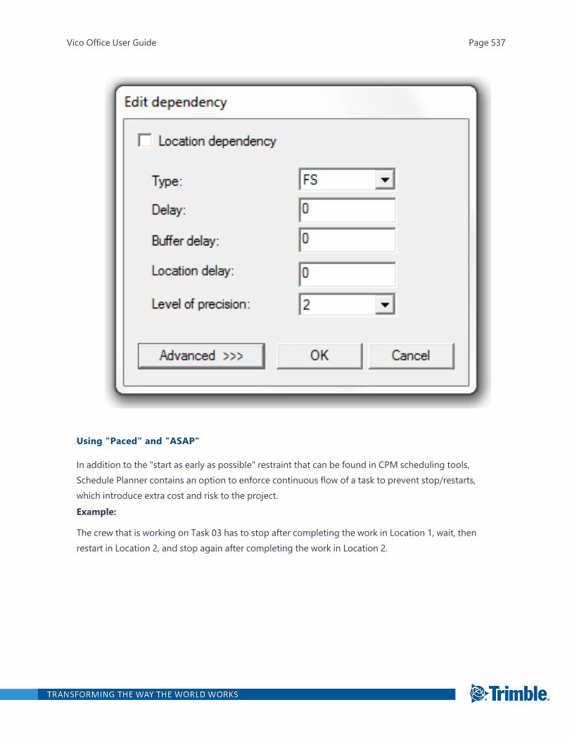
Using "Paced" and "ASAP"
In addition to the "start as early as possible" restraint that can be found in CPM scheduling tools,Schedule Planner contains an option to enforce continuous flow of a task to prevent stop/restarts,which introduce extra cost and risk to the project.Example:
The crew that is working on Task 03 has to stop after completing the work in Location 1, wait, thenrestart in Location 2, and stop again after completing the work in Location 2.
Vico Office User Guide Page 537

Schedule Planner uses two internal restraints that prevents this from happening in the plan: "Pace"and "ASAP".
To force the early start and continuous flow of tasks
1. Open Schedule Planner.
2. On the left toolbar, click the Flowline view button.
Vico Office User Guide Page 538
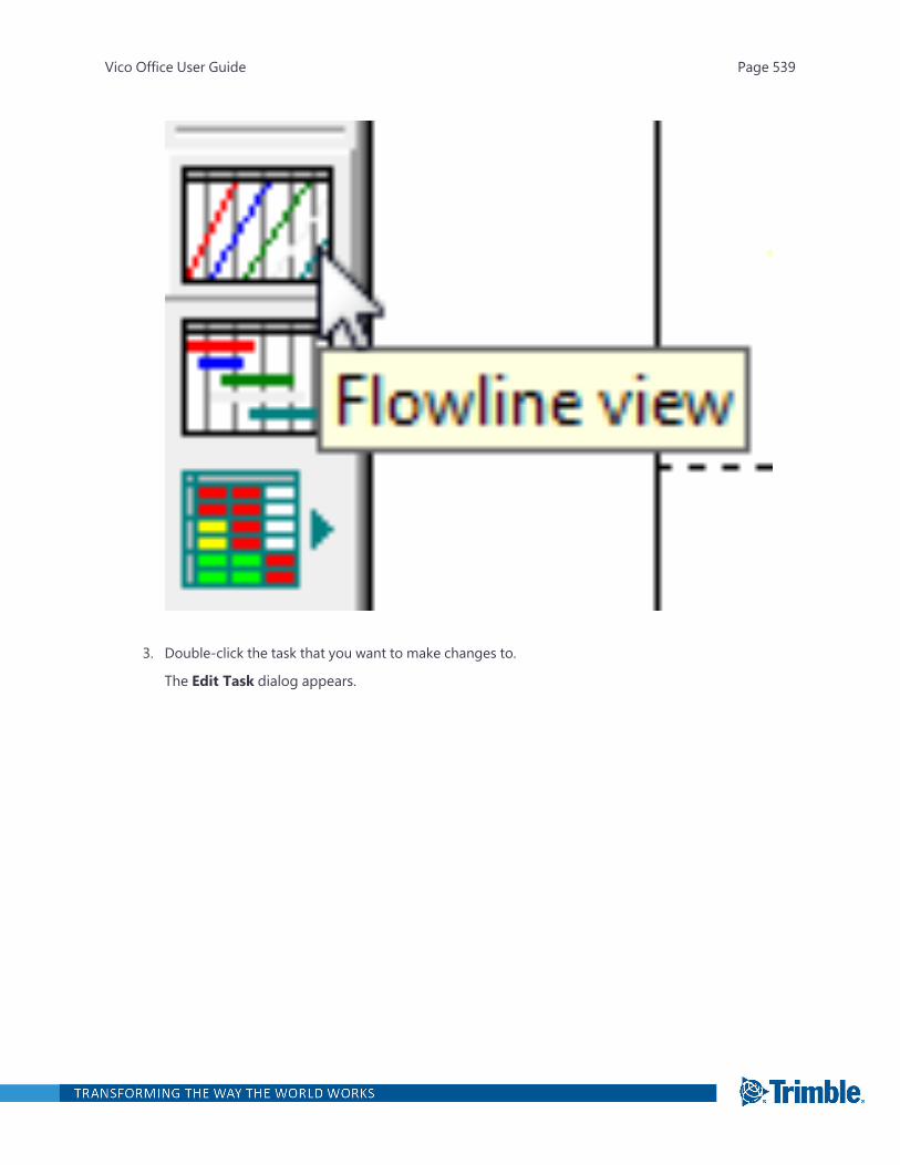
3. Double-click the task that you want to make changes to.
The Edit Task dialog appears.
Vico Office User Guide Page 539
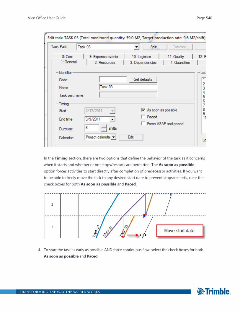
In the Timing section, there are two options that define the behavior of the task as it concernswhen it starts and whether or not stops/restarts are permitted. The As soon as possibleoption forces activities to start directly after completion of predecessor activities. If you wantto be able to freely move the task to any desired start date to prevent stops/restarts, clear thecheck boxes for both As soon as possible and Paced.
4. To start the task as early as possible AND force continuous flow, select the check boxes for bothAs soon as possible and Paced.
Vico Office User Guide Page 540
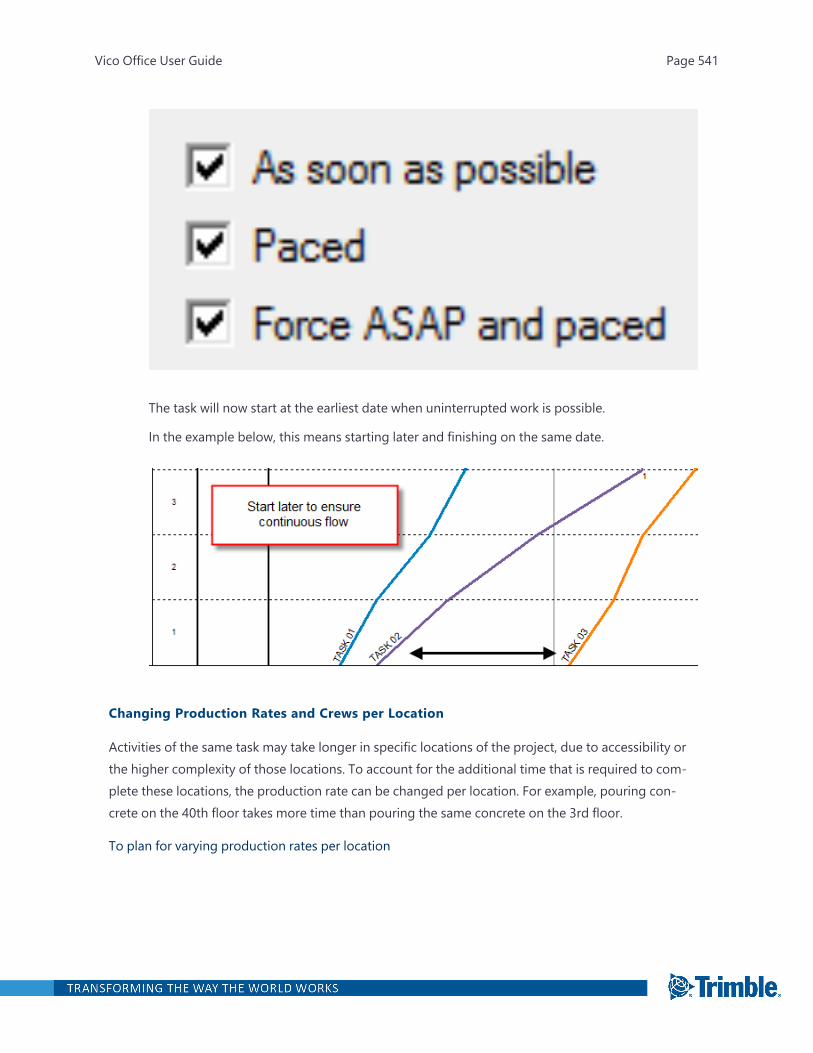
The task will now start at the earliest date when uninterrupted work is possible.
In the example below, this means starting later and finishing on the same date.
Changing Production Rates and Crews per Location
Activities of the same task may take longer in specific locations of the project, due to accessibility orthe higher complexity of those locations. To account for the additional time that is required to com-plete these locations, the production rate can be changed per location. For example, pouring con-crete on the 40th floor takes more time than pouring the same concrete on the 3rd floor.
To plan for varying production rates per location
Vico Office User Guide Page 541

1. Open Schedule Planner.
2. To open the task for which you want to change the production rates for specific locations,double-click it.
3. Click the Duration tab.
4. Edit the default value as required.
The default production factor is <1>.
If needed due to complexity or amount of work, additional crews can be added per location foroptimal flow of work.
Adding Buffers
To accommodate the risk that a predecessor task will disturb a successor task or to schedule time forpost-activity curing, a buffer can be added as part of a defined dependency. For more informationdefining dependencies, see "Defining Schedule Logic in Network View" on page 532 and "DefiningTask Restraints in Flowline View" on page 521.
To add buffers between Tasks in your schedule
1. Open Schedule Planner.
2. In Flowline view, select the task for which a buffer should be defined.
Vico Office User Guide Page 542

All dependencies of the task are shown. Blue dependency lines are activity (location-specific) dependencies; red dependency lines illustrate the dependency.
If the dependencies are not shown, see "Using the View Filter Settings" on page 562 for inform-ation on how to make dependencies visible.)
3. Right-click a dependency, and then click Edit.
4. Enter a value in one or both of the following fields:
l Delay: Number of calendar fields.
l Buffer delay: Number of work days.
Vico Office User Guide Page 543
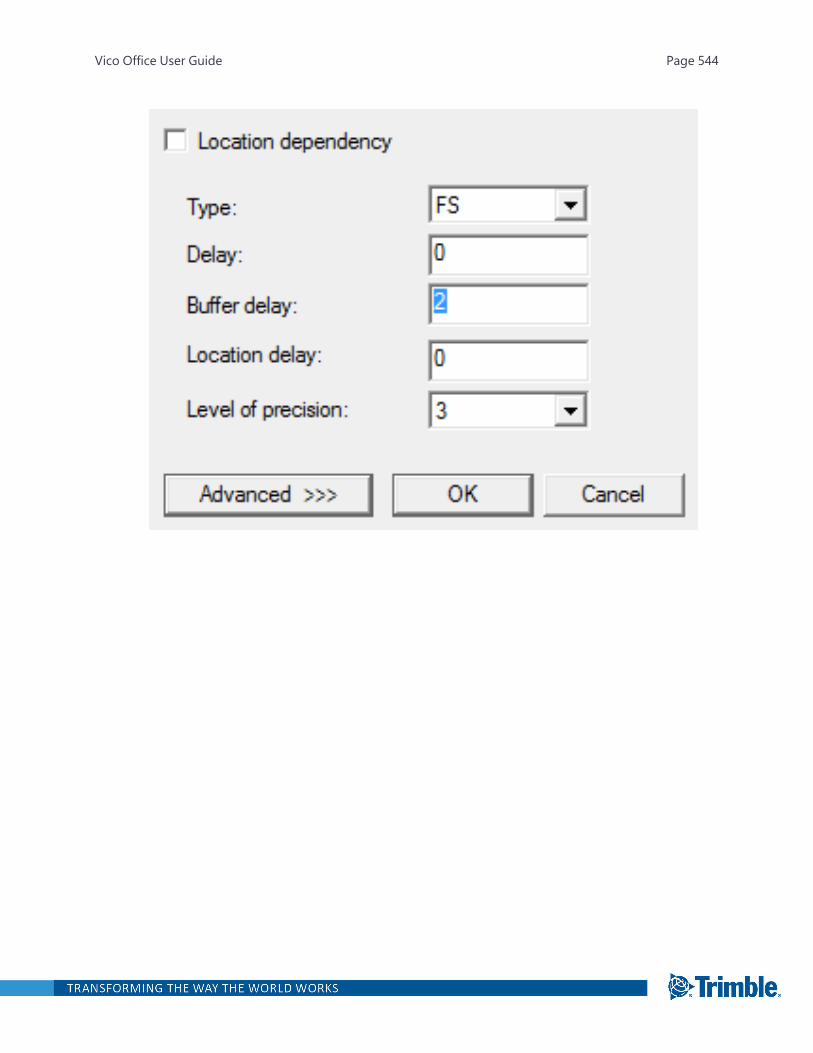
Vico Office User Guide Page 544

Edit Task
“Edit task” dialog box is used to create or edit a schedule task via 15 schedule task sub-dialog boxes.If the task does not have quantities, then a smaller Edit Task dialog is shown – the normal one is thenaccessed from the “Advanced” button.
There are a variety of operations that can be performed using the "Edit task..." dialog box:
l To access the 15 schedule task sub-dialog boxes: Select the relevant tab.
Note: The number and content of the tabs varies, depending on the selected softwareoptions. The numbering will vary because non-activated features will be hidden.
l To split schedule task: Use the split button.
l To combine a previously split schedule task: Use the Combine button.
l To select of parts of a split schedule task: Use the Task bat drop list.
l To confirm new schedule tasks or changes to schedule task:
Left-click either:
<<OK and previous, to open the previous schedule task,
OK and next>>, to open the next schedule task,
Or
OK, to return to he original window from which the edit schedule task was accessed.
Vico Office User Guide Page 545
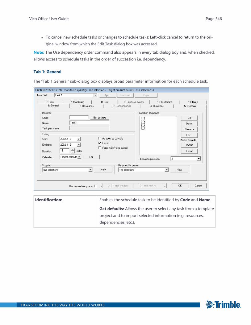
l To cancel new schedule tasks or changes to schedule tasks: Left-click cancel to return to the ori-ginal window from which the Edit Task dialog box was accessed.
Note: The Use dependency order command also appears in every tab dialog boy and, when checked,allows access to schedule tasks in the order of succession i.e. dependency.
Tab 1: General
The “Tab 1 General” sub-dialog box displays broad parameter information for each schedule task.
Identification: Enables the schedule task to be identified by Code and Name.
Get defaults: Allows the user to select any task from a templateproject and to import selected information (e.g. resources,dependencies, etc.).
Vico Office User Guide Page 546
Timing Start: The expected schedule task commencement date. Thestart date does not affect the duration of the schedule task.
End time: The expected schedule task finish date. Changing thiswill affect the duration of the schedule task.
Duration: The expected duration, in number of shifts, tocomplete the schedule task.
Calendar: The default project calendar will be automaticallyselected unless another task calendar is selected from the drop-down menu, or a new task calendar is created by using the“Edit” button.
Work continuity settings checkboxes:
As early as possible: Checking this box will schedule theschedule task to be started as early as possible in each location,based on its dependencies.
Paced: Checking this box will schedule the schedule task to becarried out in a continuous manner, from location to location,without any interruption to resources.
Forced ASAP and paced: Checking this box forces theschedule task to be completed in a continuous manner, with theearliest start date based on its dependencies.
Location sequence: The “location sequence” or “Location completion order” affectslocation dependencies where the uppermost listed location isperformed first and the bottom last. The locations can bereordered by utilizing the Up, Down and Reverse buttons.
Location precision: The drop-down menu contains the location hierarchies createdfor the project. The selected precision affects the locationprecision used in dependencies and how the task is displayed incontrol charts.
Project defaults: Enables a sequence of locations for a schedule task to beexported or imported to other schedule tasks.
Import: Select to import.
Export: Select to export.
Vico Office User Guide Page 547
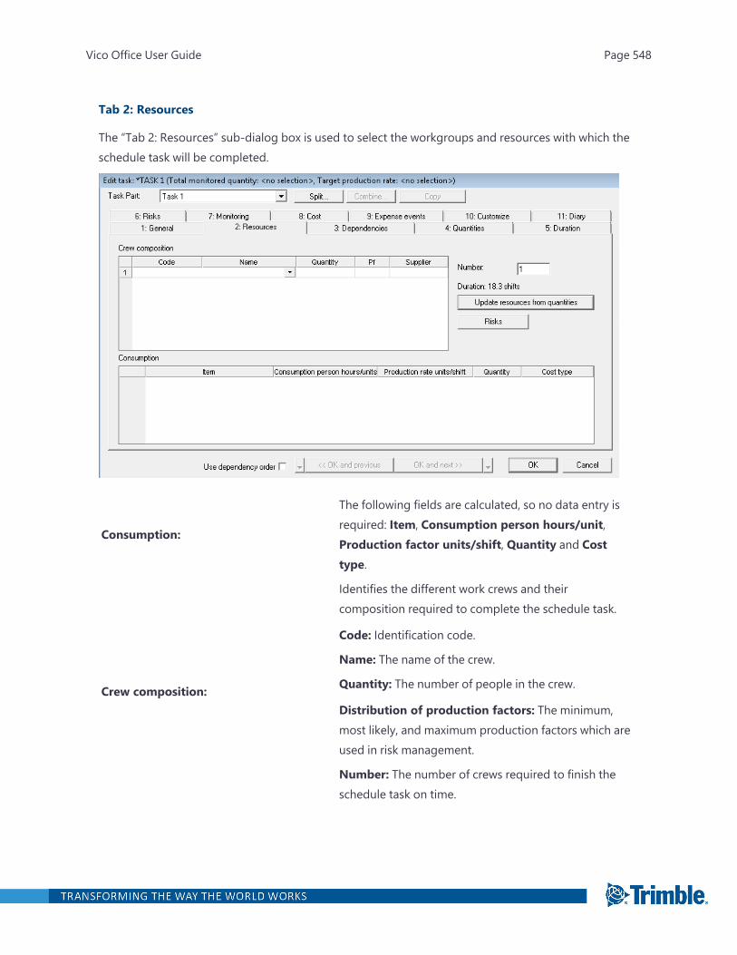
Tab 2: Resources
The “Tab 2: Resources” sub-dialog box is used to select the workgroups and resources with which theschedule task will be completed.
Consumption:
The following fields are calculated, so no data entry isrequired: Item, Consumption person hours/unit,Production factor units/shift, Quantity and Costtype.
Crew composition:
Identifies the different work crews and theircomposition required to complete the schedule task.
Code: Identification code.
Name: The name of the crew.
Quantity: The number of people in the crew.
Distribution of production factors: The minimum,most likely, and maximum production factors which areused in risk management.
Number: The number of crews required to finish theschedule task on time.
Vico Office User Guide Page 548
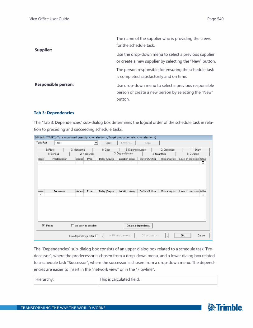
Supplier:
The name of the supplier who is providing the crewsfor the schedule task.
Use the drop-down menu to select a previous supplieror create a new supplier by selecting the “New” button.
Responsible person:
The person responsible for ensuring the schedule taskis completed satisfactorily and on time.
Use drop-down menu to select a previous responsibleperson or create a new person by selecting the “New”button.
Tab 3: Dependencies
The “Tab 3: Dependencies” sub-dialog box determines the logical order of the schedule task in rela-tion to preceding and succeeding schedule tasks.
The “Dependencies” sub-dialog box consists of an upper dialog box related to a schedule task “Pre-decessor”, where the predecessor is chosen from a drop-down menu, and a lower dialog box relatedto a schedule task “Successor”, where the successor is chosen from a drop-down menu. The depend-encies are easier to insert in the “network view” or in the “Flowline”.
Hierarchy: This is calculated field.
Vico Office User Guide Page 549

Predecessor: The schedule task that logically precedes the current scheduletask.
Select from the drop-down menu.
Successor: The schedule task that logically follows the current scheduletask.
Select from the drop-down menu.
Type: Select from the drop-down menu where:
FS: The predecessor must finish before the successor can start.
FF: The successor cannot finish until the predecessor hasfinished.
SS: The successor can start when the predecessor has started.
SF: The successor can finish when the predecessor has started.
Delay (Shifts): The duration of the link between the two schedule tasks.
Location delay: A special Layer 4 logic relationship.
Buffer (shift): A special delay designed to absorb production variability, whichis used like a Delay, when planning a schedule, but in contrast,may be absorbed by actual delays in the control phase. Refer toRisk Management
Risk analysis: Refer to Risk Management.
Level of precision: Used to set the accuracy to the same r a lower level as theschedule task accuracy e.g.: to set Layer 2 logic.
Must be selected.
Active: Used to select specific locations where the link betweenschedule tasks is active, e.g. to set Layer 5 logic.
Work continuity settings checkboxes:
Use as required as per Tab 1, General.
The dependency should preferably be created or edited using the Dependency dialog box.
To open the Dependency dialog box:
Left-click the Create a dependency button
Or
Vico Office User Guide Page 550
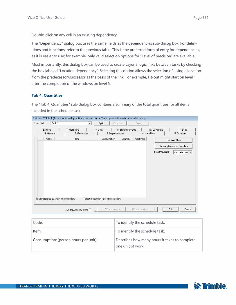
Double-click on any cell in an existing dependency.
The “Dependency” dialog box uses the same fields as the dependencies sub-dialog box. For defin-itions and functions, refer to the previous table. This is the preferred form of entry for dependencies,as it is easier to use; for example, only valid selection options for “Level of precision” are available.
Most importantly, this dialog box can be used to create Layer 5 logic links between tasks by checkingthe box labeled “Location dependency”. Selecting this option allows the selection of a single locationfrom the predecessor/successor as the basis of the link. For example, Fit-out might start on level 1after the completion of the windows on level 5.
Tab 4: Quantities
The “Tab 4: Quantities” sub-dialog box contains a summary of the total quantities for all itemsincluded in the schedule task.
Code: To identify the schedule task.
Item: To identify the schedule task.
Consumption: (person hours per unit) Describes how many hours it takes to completeone unit of work.
Vico Office User Guide Page 551
Quantity: For example, piling might take 0.07 hours permeter, cutting off piles might take 0.09 hours each,and placing reinforcement might take 0.01 hoursper kilogram or 10 hours per tonne.
Note: When the quantity is not known, and thenumber of days of work is estimated, it is possibleto schedule in days by setting the consumption toshift length and the unit to days.
The total quantity required to complete theschedule task.
Cost Type: Refer to Cost.
The “Quantities” dialog box also provides the following:
Total controlled quantity: A calculated field giving the total quantity required to complete theschedule task.
Target production rate: A calculated field giving the number of consumption units required pershift to complete schedule task.
Monitoring unit: A drop-down menu that enables different units to be selected to monitor theschedule task production rates used to determine if the calculated production rate is reasonable. Theselected unit then becomes the unit that is monitored in the control phase. By choosing that unitSchedule Planner will automatically select all items with that unit as control items, and these will behighlighted in blue. If a unit is not selected, the program will select a unit automatically.
To remove or add to item to control:
Right-click the item.
Consumptions from template: Imports consumptions, by Code and Name, from a similar previousproject which can be applied to this schedule task.
The “Bill of quantities” window “Add method:” dialog box requires the following data to be inputted:
Quantities are allocated via the “Bill of quantities” window, where data is entered via the “Addmethod:” dialog box.
To open the “Add method” dialog box:
Left -click the “Bill of Quantities” button.
Vico Office User Guide Page 552
Code: To identify the schedule task.
Item: To identify the schedule task.
Consumption: person hours per unit: Describes how many hours it takes to completeone unit of work.
Currency per units: The cost per quantity unit (for example, the costper M 2 of plasterboard walls or the cost per shiftfor items measured in shifts).
Currency: This is the total cost for the schedule task, and iscalculated automatically.
Cost type: Refer to the section on Cost.
Quantity Location columns: The consumption units required to complete eachlocation.
Unit: The base unit being used, as selected from a drop-down menu.
Precision: The precise location for a schedule task and thedistribution of quantities should be chosen tomatch the precision selected in Tab 1; General. Alower level of precision can be selected here andthe quantities will be stored as entered. However,Control 2008 will roll them up and apply them tothe level selected in Tab 1; General.
Note: When this happens and a lower level ofprecision for the schedule task is required, selectthe lower level of precision in Tab 1. This will thenopen a dialog boy asking how the quantities willbe distributed.
Copy all and Paste function: Refer to Managing Quantities with a spreadsheet.
Tab 5: Duration
The “Tab 5: Duration” sub-dialog box summarizes the factors that affect the duration of a selectedschedule task in each location.
Vico Office User Guide Page 553
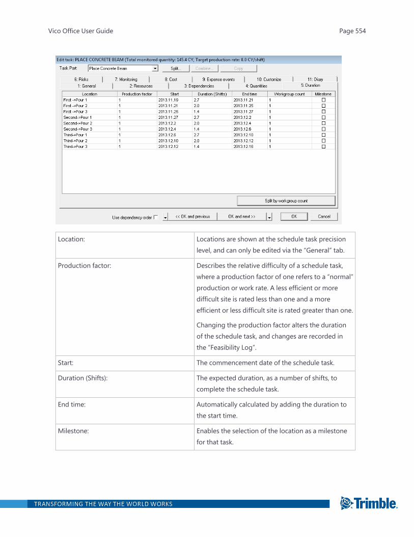
Location: Locations are shown at the schedule task precisionlevel, and can only be edited via the “General” tab.
Production factor: Describes the relative difficulty of a schedule task,where a production factor of one refers to a “normal”production or work rate. A less efficient or moredifficult site is rated less than one and a moreefficient or less difficult site is rated greater than one.
Changing the production factor alters the durationof the schedule task, and changes are recorded inthe “Feasibility Log”.
Start: The commencement date of the schedule task.
Duration (Shifts): The expected duration, as a number of shifts, tocomplete the schedule task.
End time: Automatically calculated by adding the duration tothe start time.
Milestone: Enables the selection of the location as a milestonefor that task.
Vico Office User Guide Page 554
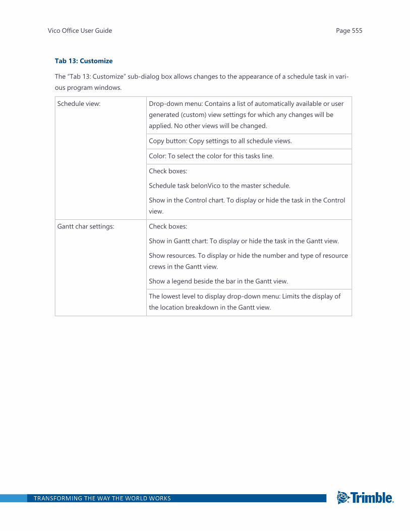
Tab 13: Customize
The “Tab 13: Customize” sub-dialog box allows changes to the appearance of a schedule task in vari-ous program windows.
Schedule view: Drop-down menu: Contains a list of automatically available or usergenerated (custom) view settings for which any changes will beapplied. No other views will be changed.
Copy button: Copy settings to all schedule views.
Color: To select the color for this tasks line.
Check boxes:
Schedule task belonVico to the master schedule.
Show in the Control chart. To display or hide the task in the Controlview.
Gantt char settings: Check boxes:
Show in Gantt chart: To display or hide the task in the Gantt view.
Show resources. To display or hide the number and type of resourcecrews in the Gantt view.
Show a legend beside the bar in the Gantt view.
The lowest level to display drop-down menu: Limits the display ofthe location breakdown in the Gantt view.
Vico Office User Guide Page 555
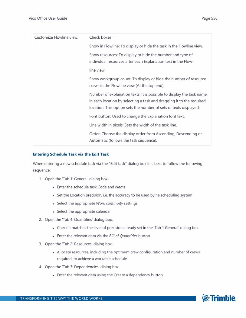
Customize Flowline view: Check boxes:
Show in Flowline: To display or hide the task in the Flowline view.
Show resources: To display or hide the number and type ofindividual resources after each Explanation text in the Flow-
line view.
Show workgroup count: To display or hide the number of resourcecrews in the Flowline view (At the top end).
Number of explanation texts: It is possible to display the task namein each location by selecting a task and dragging it to the requiredlocation. This option sets the number of sets of texts displayed.
Font button: Used to change the Explanation font text.
Line width in pixels: Sets the width of the task line.
Order: Choose the display order from Ascending, Descending orAutomatic (follows the task sequence).
Entering Schedule Task via the Edit Task
When entering a new schedule task via the “Edit task” dialog box it is best to follow the followingsequence:
1. Open the 'Tab 1: General' dialog box
l Enter the schedule task Code and Name
l Set the Location precision, i.e. the accuracy to be used by he scheduling system
l Select the appropriate Work continuity settings
l Select the appropriate calendar
2. Open the 'Tab 4: Quantities' dialog box:
l Check it matches the level of precision already set in the 'Tab 1 General' dialog box.
l Enter the relevant data via the Bill of Quantities button
3. Open the 'Tab 2: Resources' dialog box:
l Allocate resources, including the optimum crew configuration and number of crewsrequired, to achieve a workable schedule.
4. Open the 'Tab 3: Dependencies' dialog box:
l Enter the relevant data using the Create a dependency button
Vico Office User Guide Page 556
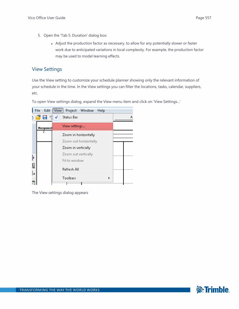
5. Open the 'Tab 5: Duration' dialog box:
l Adjust the production factor as necessary, to allow for any potentially slower or fasterwork due to anticipated variations in local complexity. For example, the production factormay be used to model learning effects.
View Settings
Use the View setting to customize your schedule planner showing only the relevant information ofyour schedule in the time. In the View settings you can filter the locations, tasks, calendar, suppliers,etc.
To open View settings dialog, expand the View menu item and click on 'View Settings...'
The View settings dialog appears
Vico Office User Guide Page 557
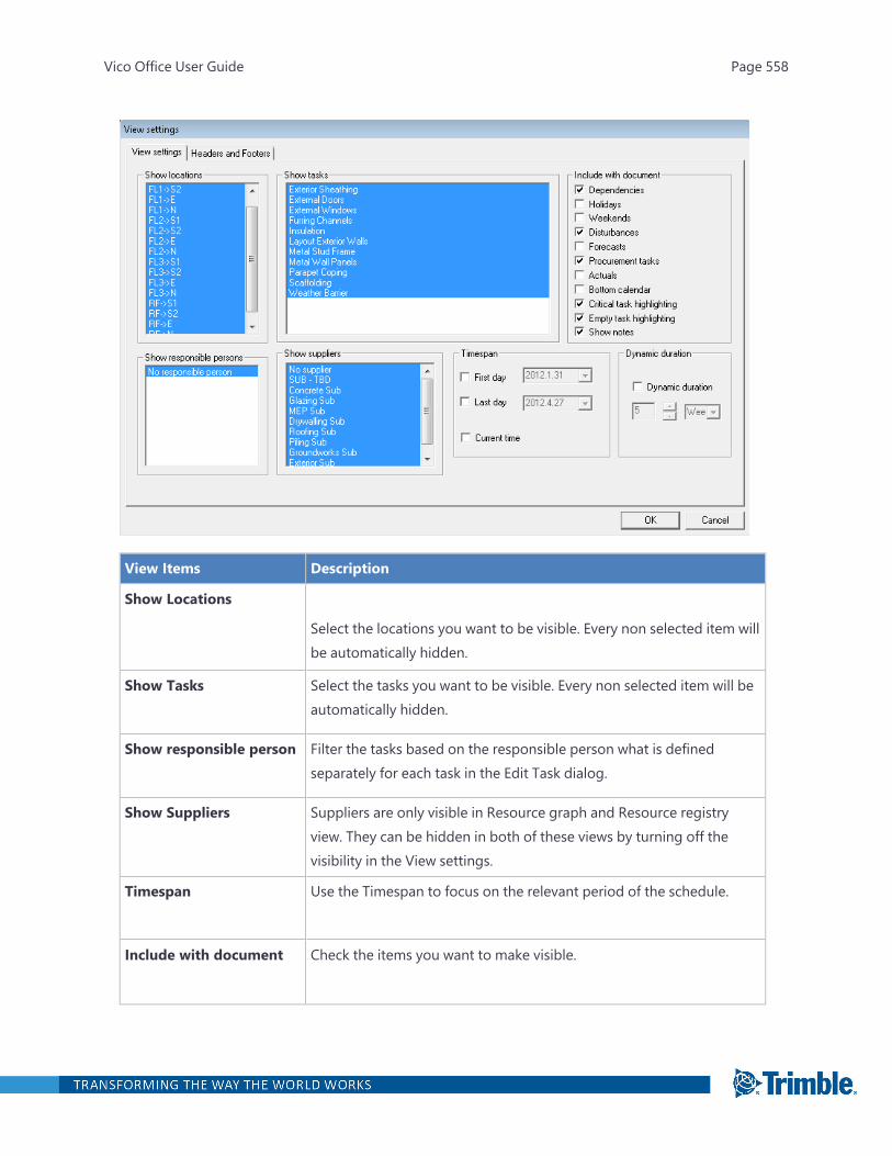
View Items Description
Show Locations
Select the locations you want to be visible. Every non selected item willbe automatically hidden.
Show Tasks Select the tasks you want to be visible. Every non selected item will beautomatically hidden.
Show responsible person Filter the tasks based on the responsible person what is definedseparately for each task in the Edit Task dialog.
Show Suppliers Suppliers are only visible in Resource graph and Resource registryview. They can be hidden in both of these views by turning off thevisibility in the View settings.
Timespan Use the Timespan to focus on the relevant period of the schedule.
Include with document Check the items you want to make visible.
Vico Office User Guide Page 558

View Items Description
Dynamic duration Use it to set up the visible period of the schedule.
Creating Custom Schedule Views
Custom schedule views are named filters that can be opened from the toolbar.
To define and use custom schedule views
1. Open Schedule Planner.
2. In the Projectmenu, click Custom schedule views.
3. In the Custom schedules dialog, click Add.
Vico Office User Guide Page 559
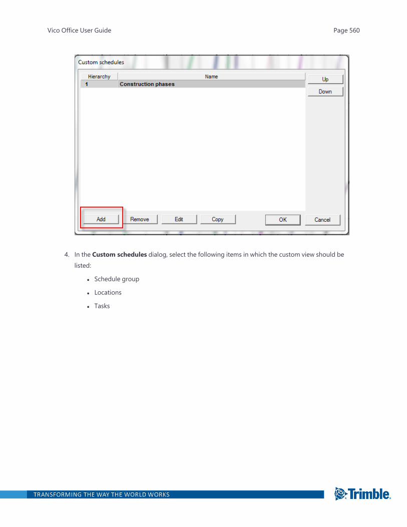
4. In the Custom schedules dialog, select the following items in which the custom view should belisted:
l Schedule group
l Locations
l Tasks
Vico Office User Guide Page 560

5. To save the custom view, click OK.
6. On the toolbar, activate the new custom view from the view selector.
Vico Office User Guide Page 561
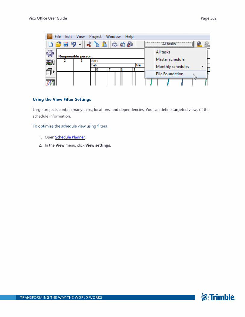
Using the View Filter Settings
Large projects contain many tasks, locations, and dependencies. You can define targeted views of theschedule information.
To optimize the schedule view using filters
1. Open Schedule Planner.
2. In the Viewmenu, click View settings.
Vico Office User Guide Page 562
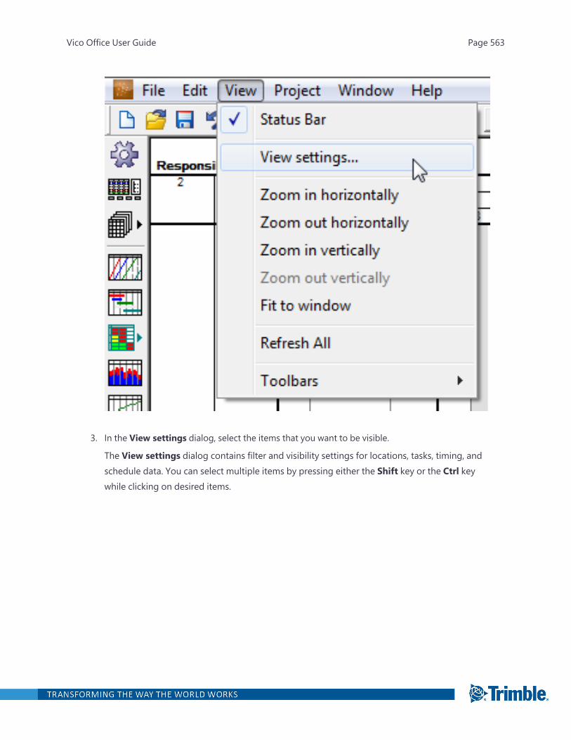
3. In the View settings dialog, select the items that you want to be visible.
The View settings dialog contains filter and visibility settings for locations, tasks, timing, andschedule data. You can select multiple items by pressing either the Shift key or the Ctrl keywhile clicking on desired items.
Vico Office User Guide Page 563

4. Click OK.
Viewing and Sorting the Gantt Chart
In addition to the Flowline view, Schedule Planner provides a Gantt view that can be used to view theschedule in a traditional bar chart format.
To use the Gantt chart view in Schedule Planner
1. Open Schedule Planner.
2. On the left toolbar, click the Gantt view button.
Vico Office User Guide Page 564

Vico Office User Guide Page 565
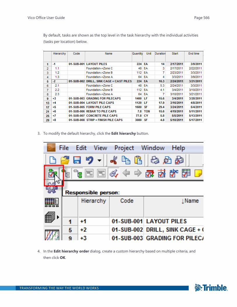
By default, tasks are shown as the top level in the task hierarchy with the individual activities(tasks per location) below.
3. To modify the default hierarchy, click the Edit hierarchy button.
4. In the Edit hierarchy order dialog, create a custom hierarchy based on multiple criteria, andthen click OK.
Vico Office User Guide Page 566
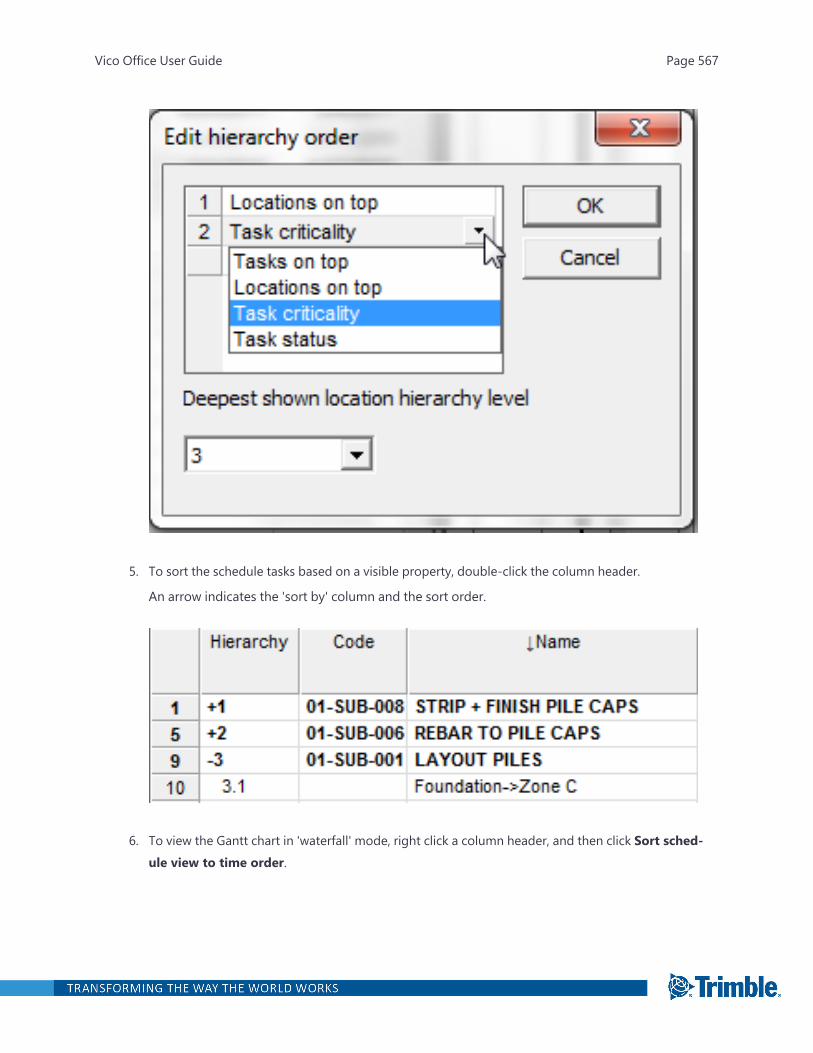
5. To sort the schedule tasks based on a visible property, double-click the column header.
An arrow indicates the 'sort by' column and the sort order.
6. To view the Gantt chart in 'waterfall' mode, right click a column header, and then click Sort sched-ule view to time order.
Vico Office User Guide Page 567
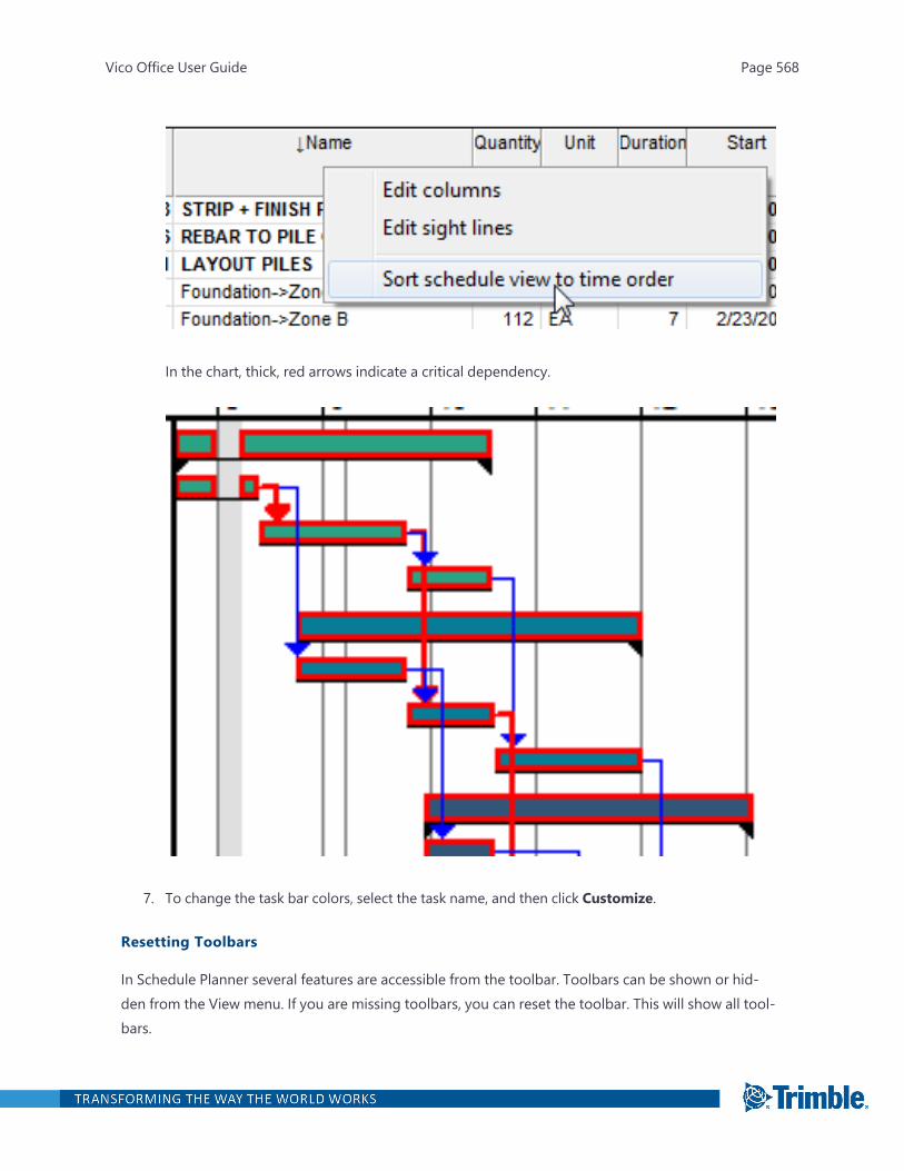
In the chart, thick, red arrows indicate a critical dependency.
7. To change the task bar colors, select the task name, and then click Customize.
Resetting Toolbars
In Schedule Planner several features are accessible from the toolbar. Toolbars can be shown or hid-den from the View menu. If you are missing toolbars, you can reset the toolbar. This will show all tool-bars.
Vico Office User Guide Page 568
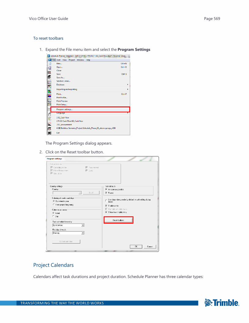
To reset toolbars
1. Expand the File menu item and select the Program Settings
The Program Settings dialog appears.
2. Click on the Reset toolbar button.
Project Calendars
Calendars affect task durations and project duration. Schedule Planner has three calendar types:
Vico Office User Guide Page 569

CalendarTypes
Description
GlobalCalendar
Default calendar available in schedule Planner
ProjectCalendar
Specific to the project (including rain days, union holidays or restored days off forexample). Effective on every task unless a Task Calendar has been applied to the task.
TaskCalendar
Certain tasks required custom calendars. For example, a crew would like to work six daysa week or six hours a day. Some holidays may apply to some tasks but not to others. Inthis case you can create unique calendars and apply them to a task.
Vico Office User Guide Page 570
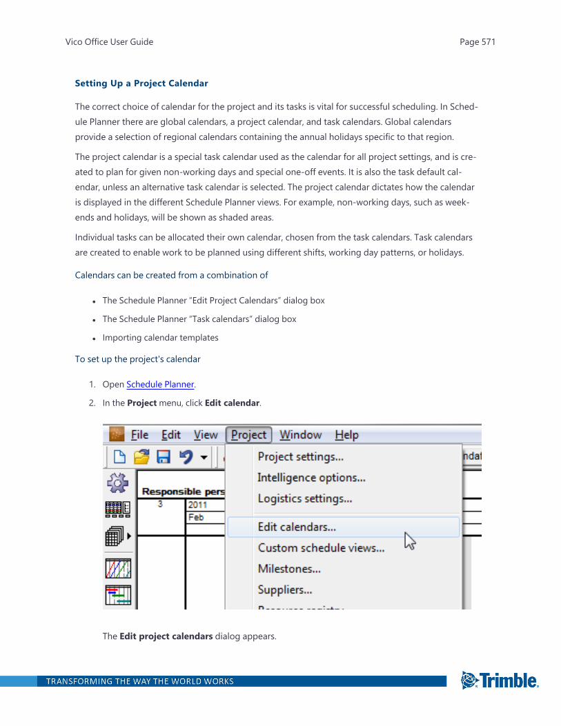
Setting Up a Project Calendar
The correct choice of calendar for the project and its tasks is vital for successful scheduling. In Sched-ule Planner there are global calendars, a project calendar, and task calendars. Global calendarsprovide a selection of regional calendars containing the annual holidays specific to that region.
The project calendar is a special task calendar used as the calendar for all project settings, and is cre-ated to plan for given non-working days and special one-off events. It is also the task default cal-endar, unless an alternative task calendar is selected. The project calendar dictates how the calendaris displayed in the different Schedule Planner views. For example, non-working days, such as week-ends and holidays, will be shown as shaded areas.
Individual tasks can be allocated their own calendar, chosen from the task calendars. Task calendarsare created to enable work to be planned using different shifts, working day patterns, or holidays.
Calendars can be created from a combination of
l The Schedule Planner “Edit Project Calendars” dialog box
l The Schedule Planner “Task calendars” dialog box
l Importing calendar templates
To set up the project's calendar
1. Open Schedule Planner.
2. In the Projectmenu, click Edit calendar.
The Edit project calendars dialog appears.
Vico Office User Guide Page 571
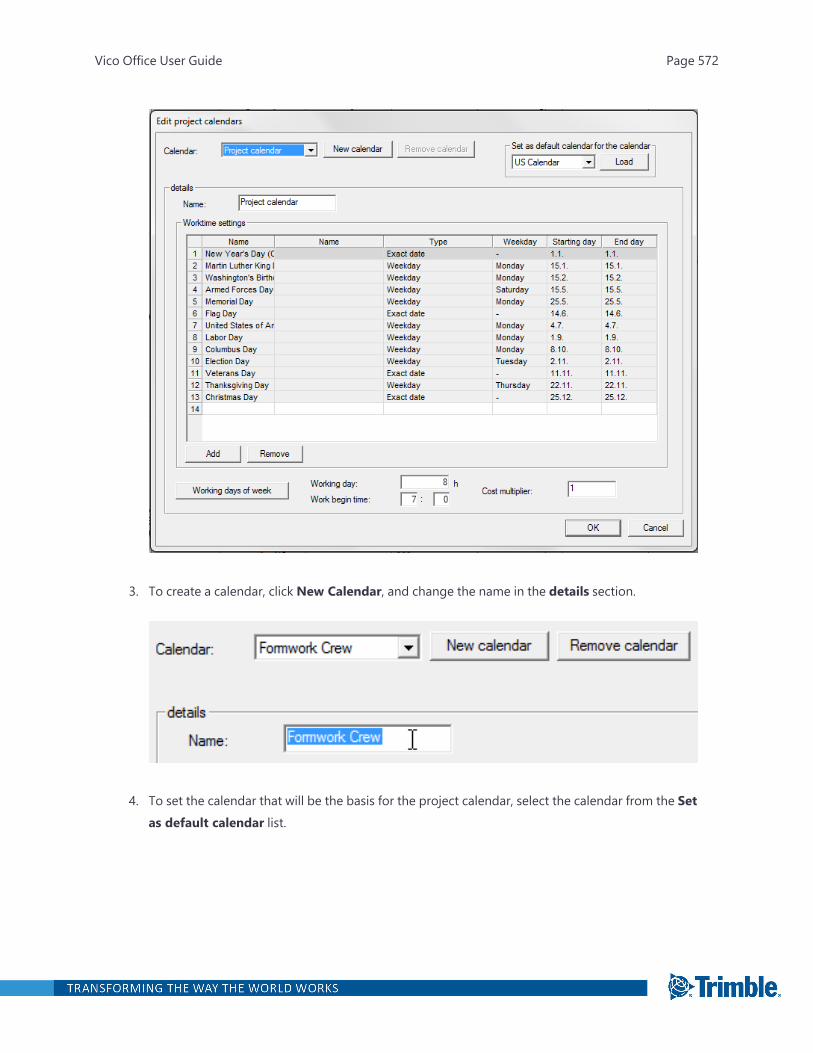
3. To create a calendar, click New Calendar, and change the name in the details section.
4. To set the calendar that will be the basis for the project calendar, select the calendar from the Setas default calendar list.
Vico Office User Guide Page 572

5. In theWorktime settings section, modify the list of holidays.
Vico Office User Guide Page 573
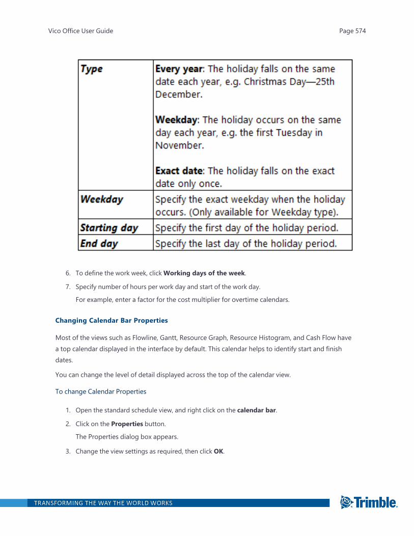
6. To define the work week, clickWorking days of the week.
7. Specify number of hours per work day and start of the work day.
For example, enter a factor for the cost multiplier for overtime calendars.
Changing Calendar Bar Properties
Most of the views such as Flowline, Gantt, Resource Graph, Resource Histogram, and Cash Flow havea top calendar displayed in the interface by default. This calendar helps to identify start and finishdates.
You can change the level of detail displayed across the top of the calendar view.
To change Calendar Properties
1. Open the standard schedule view, and right click on the calendar bar.
2. Click on the Properties button.
The Properties dialog box appears.
3. Change the view settings as required, then click OK.
Vico Office User Guide Page 574
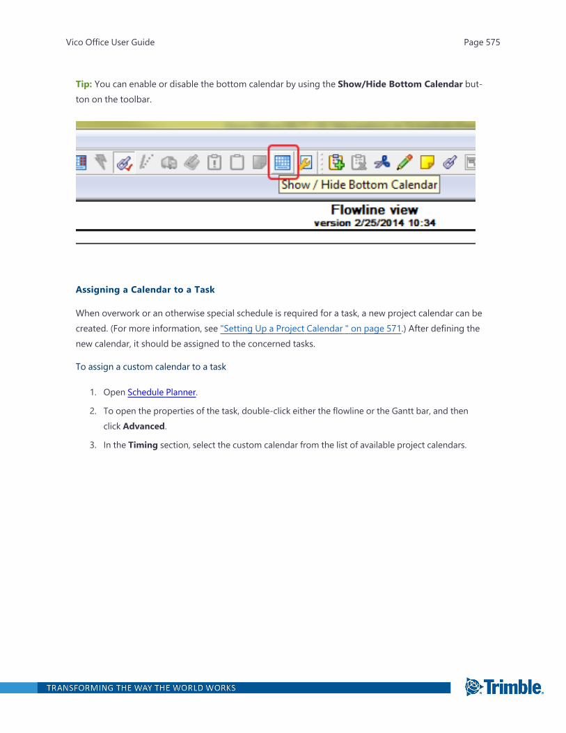
Tip: You can enable or disable the bottom calendar by using the Show/Hide Bottom Calendar but-ton on the toolbar.
Assigning a Calendar to a Task
When overwork or an otherwise special schedule is required for a task, a new project calendar can becreated. (For more information, see "Setting Up a Project Calendar " on page 571.) After defining thenew calendar, it should be assigned to the concerned tasks.
To assign a custom calendar to a task
1. Open Schedule Planner.
2. To open the properties of the task, double-click either the flowline or the Gantt bar, and thenclick Advanced.
3. In the Timing section, select the custom calendar from the list of available project calendars.
Vico Office User Guide Page 575

4. To apply the new calendar, click OK.
Using Schedule Reports
To use Schedule Planner to generate reports
1. Open Schedule Planner.
2. On the left toolbar, click the Open reports window button.
Vico Office User Guide Page 576
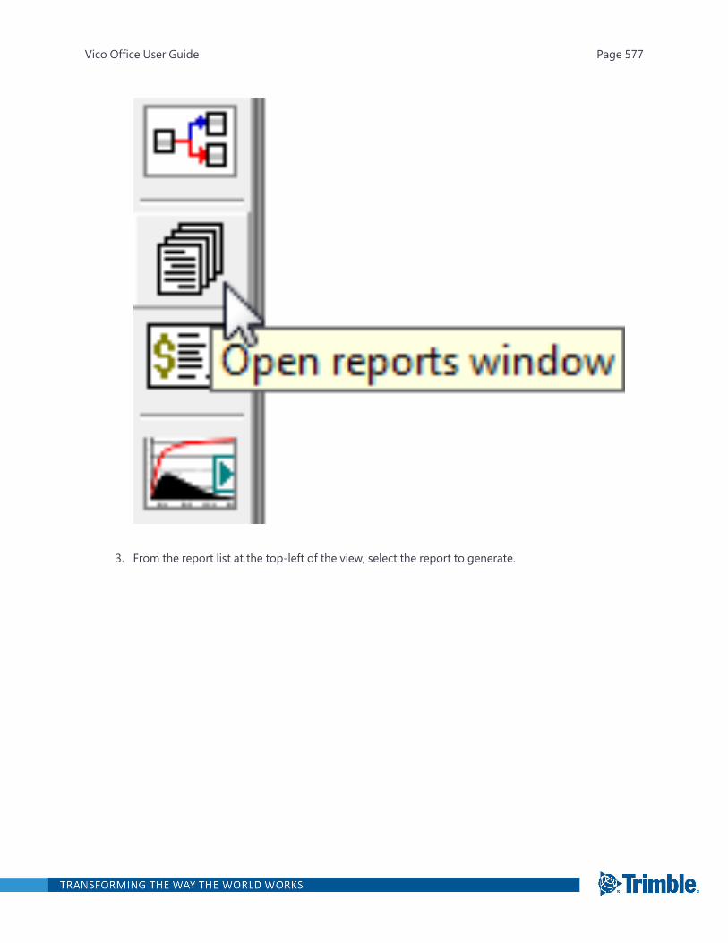
3. From the report list at the top-left of the view, select the report to generate.
Vico Office User Guide Page 577
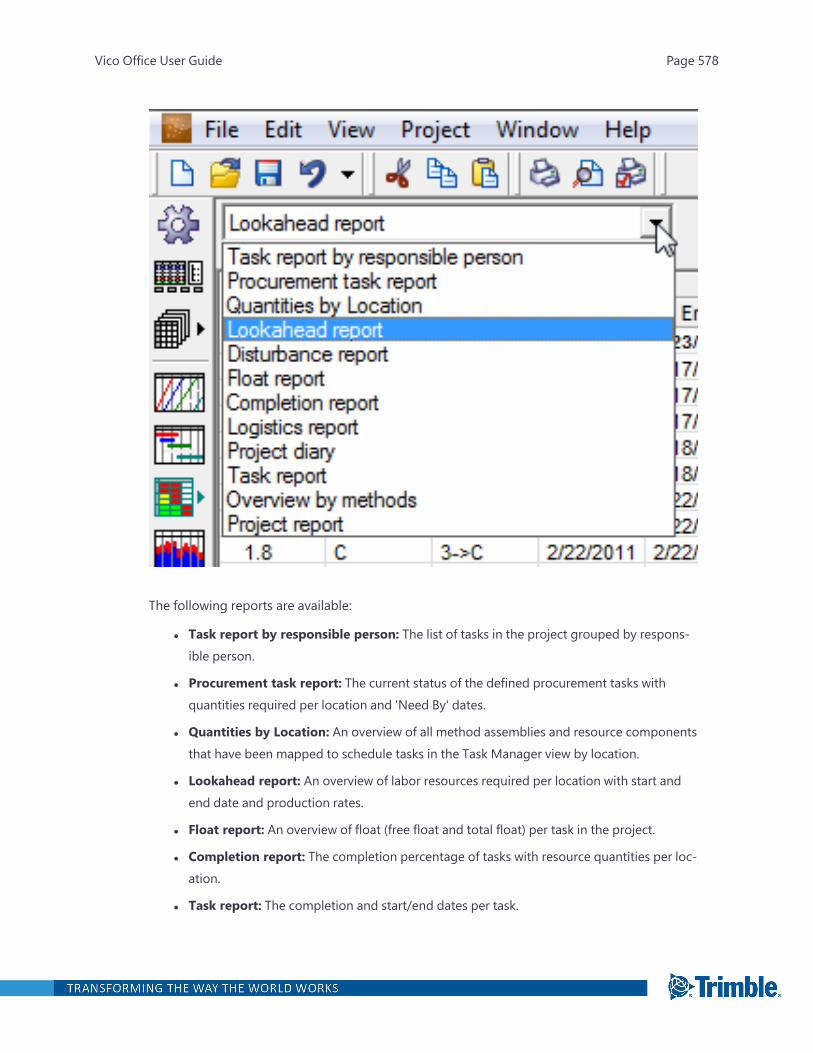
The following reports are available:
l Task report by responsible person: The list of tasks in the project grouped by respons-ible person.
l Procurement task report: The current status of the defined procurement tasks withquantities required per location and 'Need By' dates.
l Quantities by Location: An overview of all method assemblies and resource componentsthat have been mapped to schedule tasks in the Task Manager view by location.
l Lookahead report: An overview of labor resources required per location with start andend date and production rates.
l Float report: An overview of float (free float and total float) per task in the project.
l Completion report: The completion percentage of tasks with resource quantities per loc-ation.
l Task report: The completion and start/end dates per task.
Vico Office User Guide Page 578

l Overview by methods: An overview of tasks with method assemblies and resource com-ponents.
l Project report: An overall project overview.
4. To specify the columns that will be visible in the report view, click Settings.
Vico Office User Guide Page 579
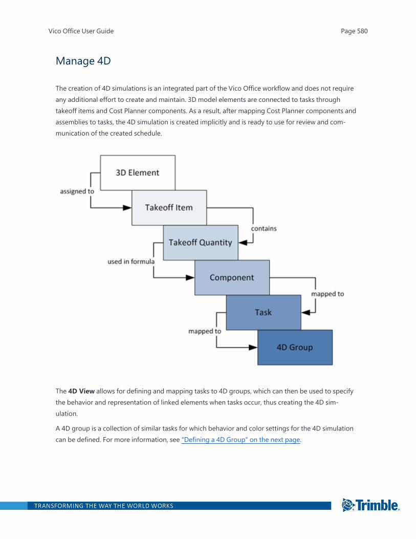
Manage 4D
The creation of 4D simulations is an integrated part of the Vico Office workflow and does not requireany additional effort to create and maintain. 3D model elements are connected to tasks throughtakeoff items and Cost Planner components. As a result, after mapping Cost Planner components andassemblies to tasks, the 4D simulation is created implicitly and is ready to use for review and com-munication of the created schedule.
The 4D View allows for defining and mapping tasks to 4D groups, which can then be used to specifythe behavior and representation of linked elements when tasks occur, thus creating the 4D sim-ulation.
A 4D group is a collection of similar tasks for which behavior and color settings for the 4D simulationcan be defined. For more information, see "Defining a 4D Group" on the next page.
Vico Office User Guide Page 580
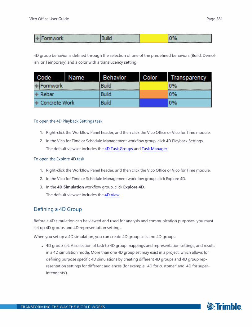
4D group behavior is defined through the selection of one of the predefined behaviors (Build, Demol-ish, or Temporary) and a color with a translucency setting.
To open the 4D Playback Settings task
1. Right-click the Workflow Panel header, and then click the Vico Office or Vico for Time module.
2. In the Vico for Time or Schedule Management workflow group, click 4D Playback Settings.
The default viewset includes the 4D Task Groups and Task Manager.
To open the Explore 4D task
1. Right-click the Workflow Panel header, and then click the Vico Office or Vico for Time module.
2. In the Vico for Time or Schedule Management workflow group, click Explore 4D.
3. In the 4D Simulation workflow group, click Explore 4D.
The default viewset includes the 4D View.
Defining a 4D Group
Before a 4D simulation can be viewed and used for analysis and communication purposes, you mustset up 4D groups and 4D representation settings.
When you set up a 4D simulation, you can create 4D group sets and 4D groups:
l 4D group set: A collection of task to 4D group mappings and representation settings, and resultsin a 4D simulation mode. More than one 4D group set may exist in a project, which allows fordefining purpose specific 4D simulations by creating different 4D groups and 4D group rep-resentation settings for different audiences (for example, '4D for customer' and '4D for super-intendents').
Vico Office User Guide Page 581
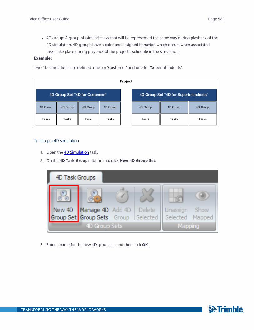
l 4D group: A group of (similar) tasks that will be represented the same way during playback of the4D simulation. 4D groups have a color and assigned behavior, which occurs when associatedtasks take place during playback of the project's schedule in the simulation.
Example:
Two 4D simulations are defined: one for 'Customer' and one for 'Superintendents'.
To setup a 4D simulation
1. Open the 4D Simulation task.
2. On the 4D Task Groups ribbon tab, click New 4D Group Set.
3. Enter a name for the new 4D group set, and then click OK.
Vico Office User Guide Page 582
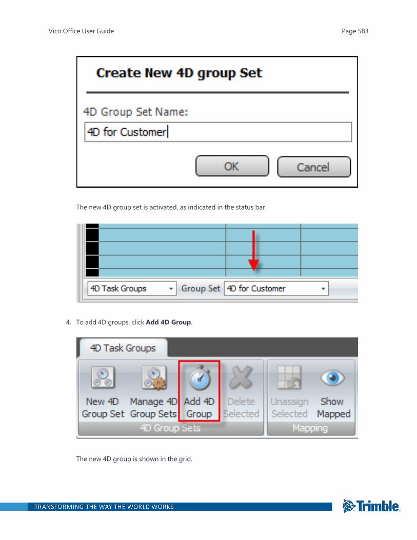
The new 4D group set is activated, as indicated in the status bar.
4. To add 4D groups, click Add 4D Group.
The new 4D group is shown in the grid.
Vico Office User Guide Page 583
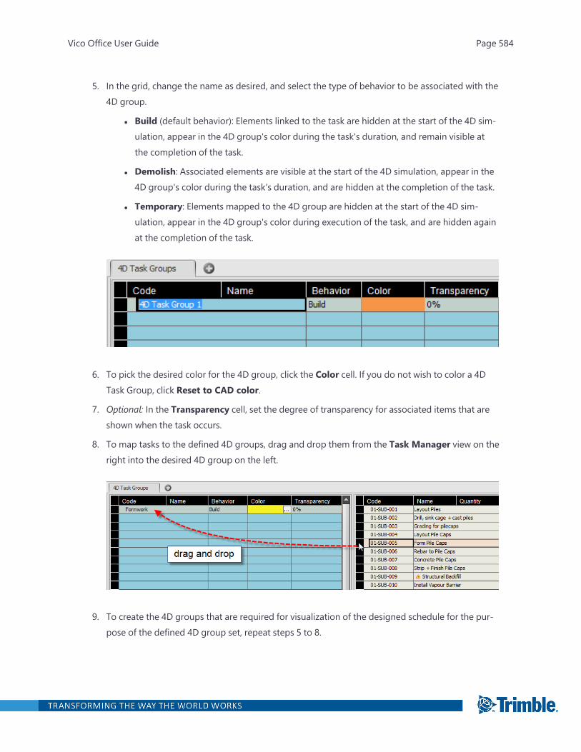
5. In the grid, change the name as desired, and select the type of behavior to be associated with the4D group.
l Build (default behavior): Elements linked to the task are hidden at the start of the 4D sim-ulation, appear in the 4D group's color during the task's duration, and remain visible atthe completion of the task.
l Demolish: Associated elements are visible at the start of the 4D simulation, appear in the4D group's color during the task's duration, and are hidden at the completion of the task.
l Temporary: Elements mapped to the 4D group are hidden at the start of the 4D sim-ulation, appear in the 4D group's color during execution of the task, and are hidden againat the completion of the task.
6. To pick the desired color for the 4D group, click the Color cell. If you do not wish to color a 4DTask Group, click Reset to CAD color.
7. Optional: In the Transparency cell, set the degree of transparency for associated items that areshown when the task occurs.
8. To map tasks to the defined 4D groups, drag and drop them from the Task Manager view on theright into the desired 4D group on the left.
9. To create the 4D groups that are required for visualization of the designed schedule for the pur-pose of the defined 4D group set, repeat steps 5 to 8.
Vico Office User Guide Page 584
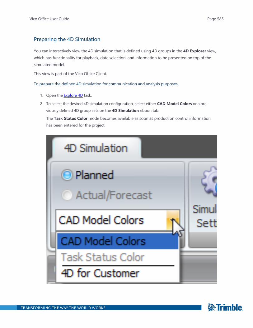
Preparing the 4D Simulation
You can interactively view the 4D simulation that is defined using 4D groups in the 4D Explorer view,which has functionality for playback, date selection, and information to be presented on top of thesimulated model.
This view is part of the Vico Office Client.
To prepare the defined 4D simulation for communication and analysis purposes
1. Open the Explore 4D task.
2. To select the desired 4D simulation configuration, select either CAD Model Colors or a pre-viously defined 4D group sets on the 4D Simulation ribbon tab.
The Task Status Colormode becomes available as soon as production control informationhas been entered for the project.
Vico Office User Guide Page 585
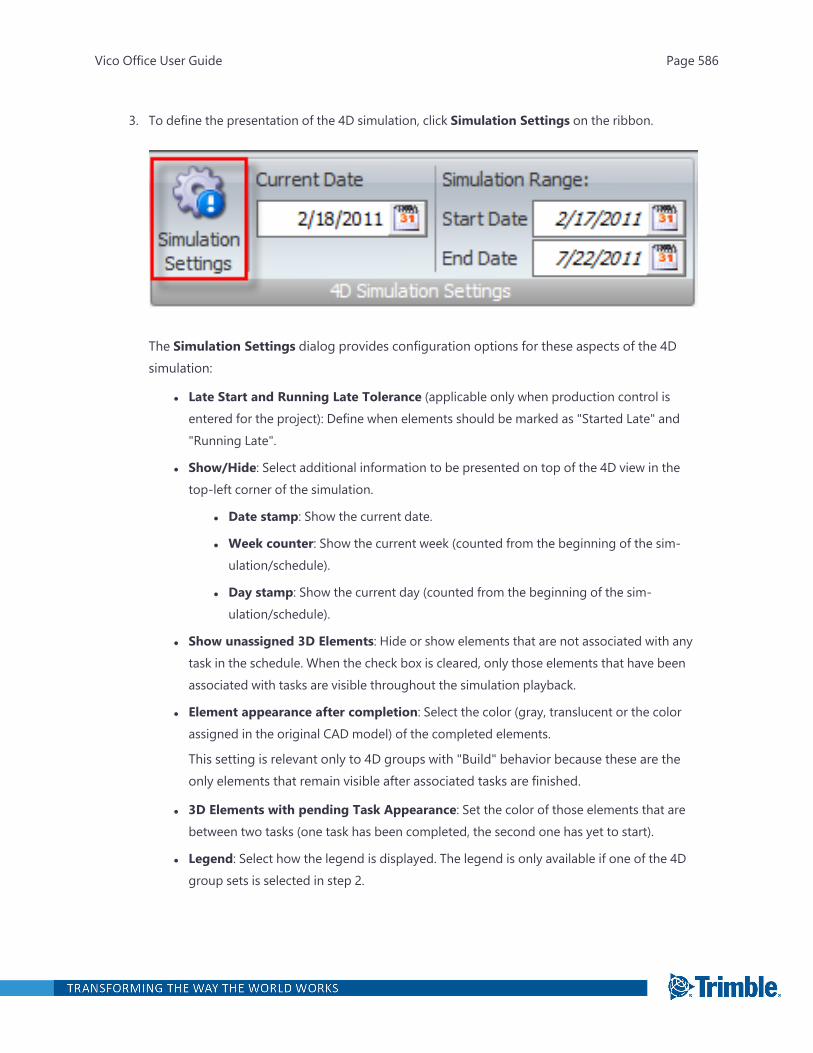
3. To define the presentation of the 4D simulation, click Simulation Settings on the ribbon.
The Simulation Settings dialog provides configuration options for these aspects of the 4Dsimulation:
l Late Start and Running Late Tolerance (applicable only when production control isentered for the project): Define when elements should be marked as "Started Late" and"Running Late".
l Show/Hide: Select additional information to be presented on top of the 4D view in thetop-left corner of the simulation.
l Date stamp: Show the current date.
l Week counter: Show the current week (counted from the beginning of the sim-ulation/schedule).
l Day stamp: Show the current day (counted from the beginning of the sim-ulation/schedule).
l Show unassigned 3D Elements: Hide or show elements that are not associated with anytask in the schedule. When the check box is cleared, only those elements that have beenassociated with tasks are visible throughout the simulation playback.
l Element appearance after completion: Select the color (gray, translucent or the colorassigned in the original CAD model) of the completed elements.
This setting is relevant only to 4D groups with "Build" behavior because these are theonly elements that remain visible after associated tasks are finished.
l 3D Elements with pending Task Appearance: Set the color of those elements that arebetween two tasks (one task has been completed, the second one has yet to start).
l Legend: Select how the legend is displayed. The legend is only available if one of the 4Dgroup sets is selected in step 2.
Vico Office User Guide Page 586

l Static legend: Shows an overview of all defined 4D groups and colors.
l Dynamic legend Updates when tasks in a 4D group occur.
Vico Office User Guide Page 587
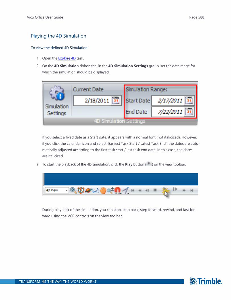
Playing the 4D Simulation
To view the defined 4D Simulation
1. Open the Explore 4D task.
2. On the 4D Simulation ribbon tab, in the 4D Simulation Settings group, set the date range forwhich the simulation should be displayed.
If you select a fixed date as a Start date, it appears with a normal font (not italicized). However,if you click the calendar icon and select 'Earliest Task Start / Latest Task End', the dates are auto-matically adjusted according to the first task start / last task end date. In this case, the datesare italicized.
3. To start the playback of the 4D simulation, click the Play button ( ) on the view toolbar.
During playback of the simulation, you can stop, step back, step forward, rewind, and fast for-ward using the VCR controls on the view toolbar.
Vico Office User Guide Page 588
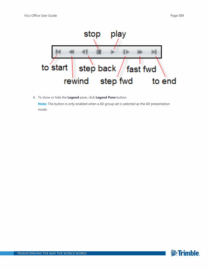
4. To show or hide the Legend pane, click Legend Pane button.
Note: The button is only enabled when a 4D group set is selected as the 4D presentationmode.
Vico Office User Guide Page 589

Vico Office User Guide Page 590
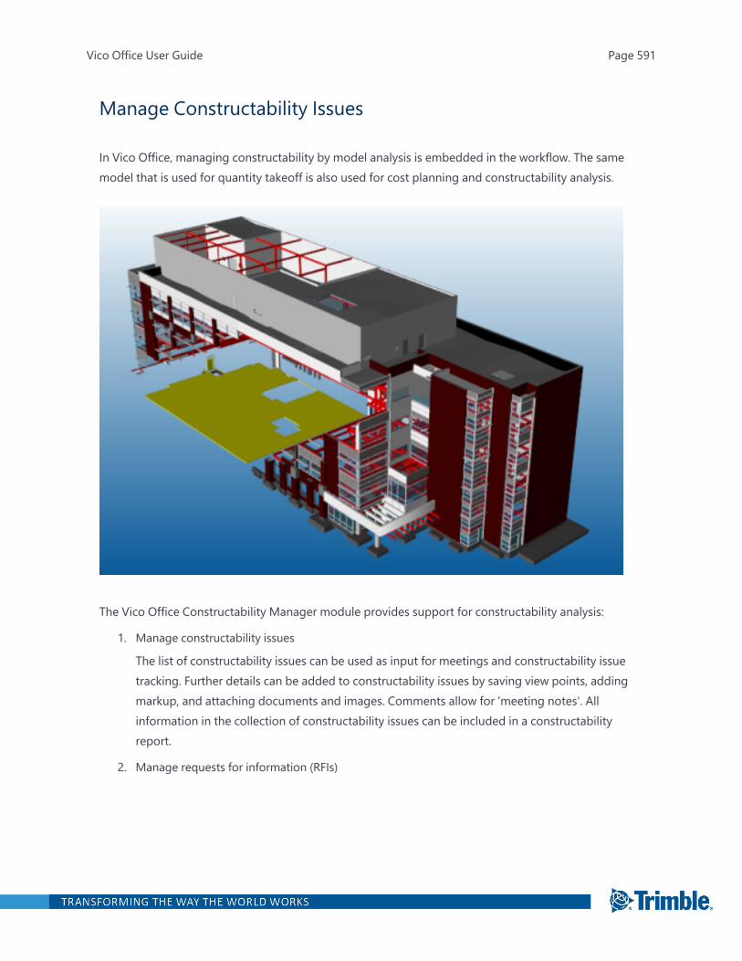
Manage Constructability Issues
In Vico Office, managing constructability by model analysis is embedded in the workflow. The samemodel that is used for quantity takeoff is also used for cost planning and constructability analysis.
The Vico Office Constructability Manager module provides support for constructability analysis:
1. Manage constructability issues
The list of constructability issues can be used as input for meetings and constructability issuetracking. Further details can be added to constructability issues by saving view points, addingmarkup, and attaching documents and images. Comments allow for 'meeting notes'. Allinformation in the collection of constructability issues can be included in a constructabilityreport.
2. Manage requests for information (RFIs)
Vico Office User Guide Page 591

When a constructability issue requires further information from project partners, it can beescalated to an RFI. In this case, the constructability issue is copied, with its saved view pointsand markup, to the Manage RFIs viewset.
To open the Manage Issues task
1. Right-click the Workflow Panel header, and then click the Vico Office or Vico for Design module.
2. In the Vico for Design or Design Management workflow group, click Manage Issues.
The default viewset includes the Issue List View and 3D View.
Sorting and Filtering Constructability Issues
The list of constructability issues to manage can get quite long. Therefore, it is sometimes beneficialto filter the list based on specific properties, such as 'Element Type' or 'Date Found'.
To filter the list of constructability issues
1. On the Issues tab of the Issue List View, ensure that the column that you want to use for sortingand/or filtering is active.
a. Open the Manage Issues task.
b. Right-click any column header, and then click Column Selector to add any missingcolumns.
c. In the Column Selector dialog, select the columns that you want to appear in the spread-
Vico Office User Guide Page 592

sheet.
Vico Office User Guide Page 593
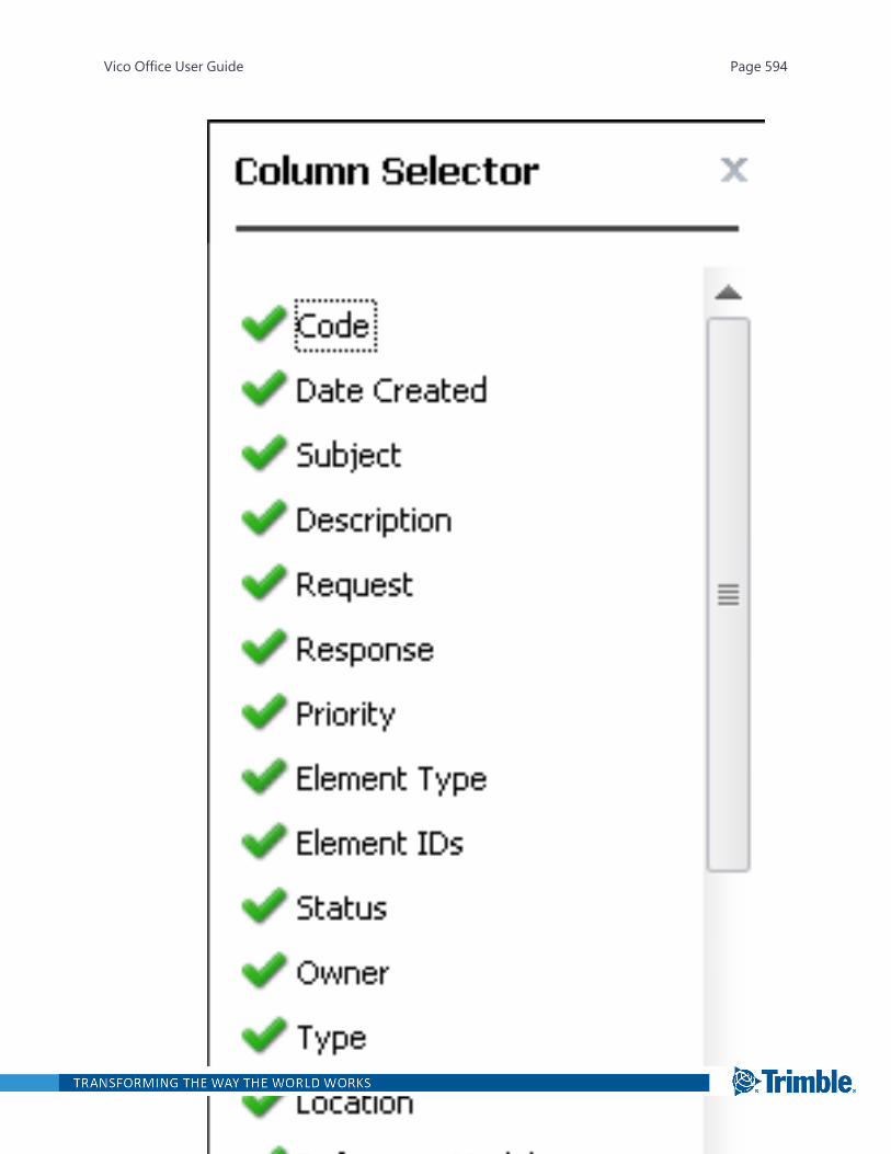
Vico Office User Guide Page 594

2. To sort a column in ascending order, click the column header.
Tip: To sort by descending order, click the column header again.
3. Filter the list for a specific value.
a. Click the small funnel icon.
A list of values in the selected column appears.
Vico Office User Guide Page 595

b. Click the desired value to filter out all items that match this criteria.
4. Define a custom filter that combines multiple search criteria.
Vico Office User Guide Page 596
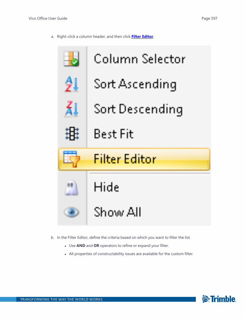
a. Right-click a column header, and then click Filter Editor.
b. In the Filter Editor, define the criteria based on which you want to filter the list.
l Use AND and OR operators to refine or expand your filter.
l All properties of constructability issues are available for the custom filter.
Vico Office User Guide Page 597
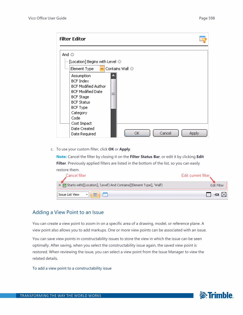
c. To use your custom filter, click OK or Apply.
Note: Cancel the filter by closing it on the Filter Status Bar, or edit it by clicking EditFilter. Previously applied filters are listed in the bottom of the list, so you can easilyrestore them.
Adding a View Point to an Issue
You can create a view point to zoom in on a specific area of a drawing, model, or reference plane. Aview point also allows you to add markups. One or more view points can be associated with an issue.
You can save view points in constructability issues to store the view in which the issue can be seenoptimally. After saving, when you select the constructability issue again, the saved view point isrestored. When reviewing the issue, you can select a view point from the Issue Manager to view therelated details.
To add a view point to a constructability issue
Vico Office User Guide Page 598
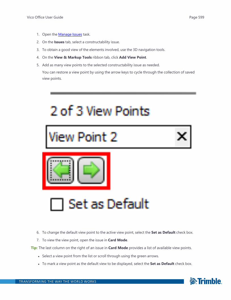
1. Open the Manage Issues task.
2. On the Issues tab, select a constructability issue.
3. To obtain a good view of the elements involved, use the 3D navigation tools.
4. On the View & Markup Tools ribbon tab, click Add View Point.
5. Add as many view points to the selected constructability issue as needed.
You can restore a view point by using the arrow keys to cycle through the collection of savedview points.
6. To change the default view point to the active view point, select the Set as Default check box.
7. To view the view point, open the issue in Card Mode.
Tip: The last column on the right of an issue in Card Mode provides a list of available view points.
l Select a view point from the list or scroll through using the green arrows.
l To mark a view point as the default view to be displayed, select the Set as Default check box.
Vico Office User Guide Page 599

l To see the view point details in the 3D View, click the Open button.
Adding Markup to a View Point
View points that you have saved with a constructability issue allow for adding multiple markups, tofurther clarify the problem that is captured by means of the issue.
To add markups to a saved view point
1. Open the Manage Issues task.
2. Select a constructability issue and a view point in that issue.
3. Click the View & Markup Tools ribbon tab.
The tab contains theMarkup Tools group, which you can use to annotate the active savedview point.
Vico Office User Guide Page 600

4. On the ribbon, click Pick Color, and then select the color to be used for the markups.
Vico Office User Guide Page 601
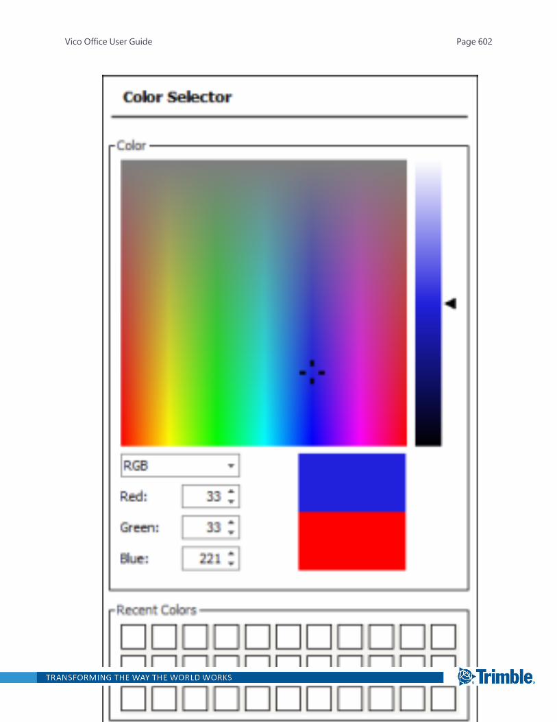
Vico Office User Guide Page 602

5. On the ribbon, click one of the available tools, and add your markups.
l Freehand Tool: Add line work to the view point as if you were using a pen. This allowsyou to add information in 'sketch mode'.
l Add Cloud: Pick points around the areas of interest. The Constructability Manager auto-matically translates these points into a cloud shape. Multiple clouds can be created.Optionally set the appearance of your cloud. Switch to the Issue Card View and set yourcloud appearance.
l When selecting the color of cloud, it is recommended that you select a color thatwill yield the highest contrast. For example, if you are marking up a drawing thathas a brighter hue, selecting a darker color for the cloud will yield the best con-trast.
l If you are placing a cloud markup on a drawing that has a fill color, you canchoose to reduce the opacity of the cloud.
l Click Apply to set the appearance of the cloud.
l Add Text: Type text in the selected color in the model space.
Vico Office User Guide Page 603
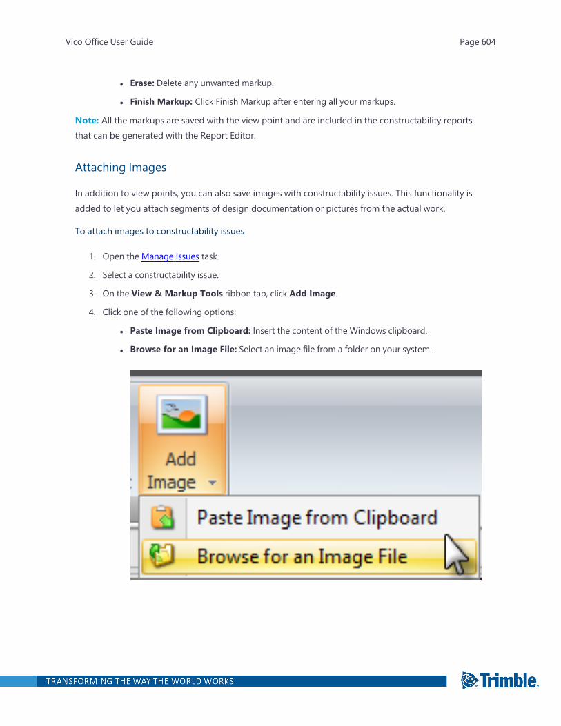
l Erase: Delete any unwanted markup.
l Finish Markup: Click Finish Markup after entering all your markups.
Note: All the markups are saved with the view point and are included in the constructability reportsthat can be generated with the Report Editor.
Attaching Images
In addition to view points, you can also save images with constructability issues. This functionality isadded to let you attach segments of design documentation or pictures from the actual work.
To attach images to constructability issues
1. Open the Manage Issues task.
2. Select a constructability issue.
3. On the View & Markup Tools ribbon tab, click Add Image.
4. Click one of the following options:
l Paste Image from Clipboard: Insert the content of the Windows clipboard.
l Browse for an Image File: Select an image file from a folder on your system.
Vico Office User Guide Page 604
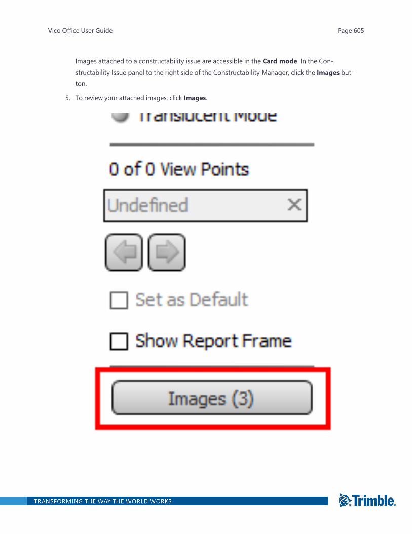
Images attached to a constructability issue are accessible in the Card mode. In the Con-structability Issue panel to the right side of the Constructability Manager, click the Images but-ton.
5. To review your attached images, click Images.
Vico Office User Guide Page 605

6. Review the images.
l To cycle through the collection of attached images, use the arrow keys.
l To zoom in and out, click the + and - buttons.
l To set the image as the default, select the Set as Default check box.
Vico Office User Guide Page 606
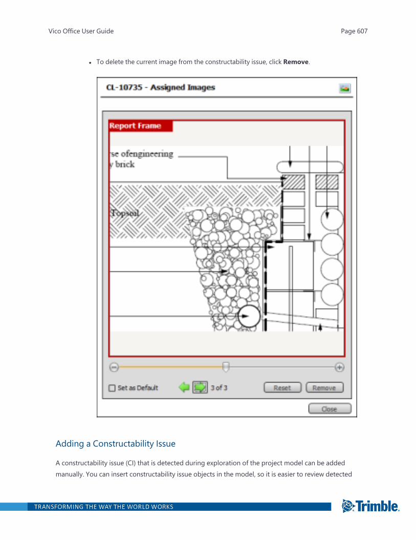
l To delete the current image from the constructability issue, click Remove.
Adding a Constructability Issue
A constructability issue (CI) that is detected during exploration of the project model can be addedmanually. You can insert constructability issue objects in the model, so it is easier to review detected
Vico Office User Guide Page 607
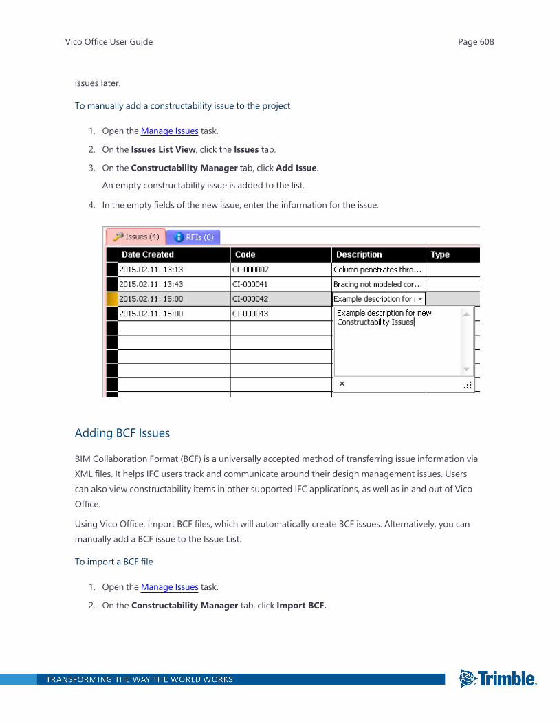
issues later.
To manually add a constructability issue to the project
1. Open the Manage Issues task.
2. On the Issues List View, click the Issues tab.
3. On the Constructability Manager tab, click Add Issue.
An empty constructability issue is added to the list.
4. In the empty fields of the new issue, enter the information for the issue.
Adding BCF Issues
BIM Collaboration Format (BCF) is a universally accepted method of transferring issue information viaXML files. It helps IFC users track and communicate around their design management issues. Userscan also view constructability items in other supported IFC applications, as well as in and out of VicoOffice.
Using Vico Office, import BCF files, which will automatically create BCF issues. Alternatively, you canmanually add a BCF issue to the Issue List.
To import a BCF file
1. Open the Manage Issues task.
2. On the Constructability Manager tab, click Import BCF.
Vico Office User Guide Page 608
3. Select the BCF file to import and click Open.
When importing a BCF file, all imported issues are marked as BCF.
To manually add a BCF issue
1. Open the Manage Issues task.
2. On the Issue List View, click the Issues tab.
3. On the Constructability Manager tab, click Add BCF Issue.
- or -
Right-click on the Issues tab and select 'Create BCF Issue' from the context menu.
A new row is added for the BCF issue. The 'Is BCF' check box is automatically selected toidentify it as a BCF issue.
4. In the empty fields of the new BCF issue, enter any necessary information for the issue.
Changing the Location of CI Symbols
To modify the insertion point of a constructability issue symbol
1. Open the Manage Issues task.
2. On the 3D View ribbon tab, click Selection Mode.
3. Zoom to the constructability issue symbol that you would like to edit.
4. Right-click the symbol, and then click Edit Symbol.
Vico Office User Guide Page 609
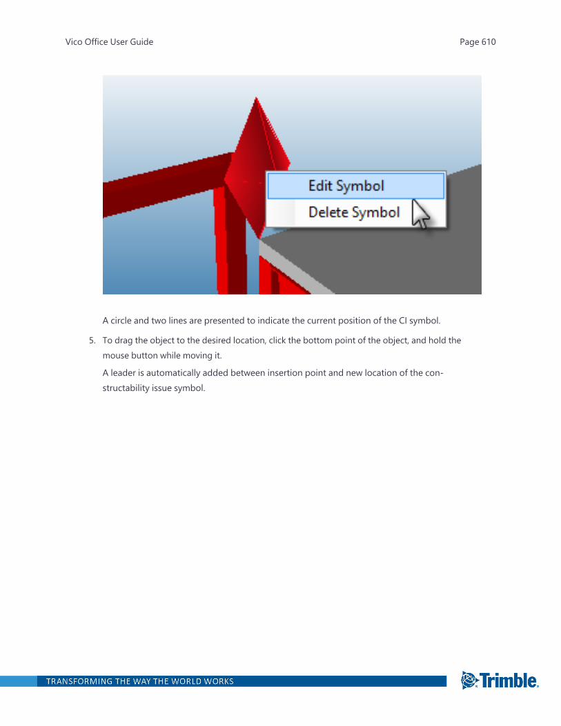
A circle and two lines are presented to indicate the current position of the CI symbol.
5. To drag the object to the desired location, click the bottom point of the object, and hold themouse button while moving it.
A leader is automatically added between insertion point and new location of the con-structability issue symbol.
Vico Office User Guide Page 610
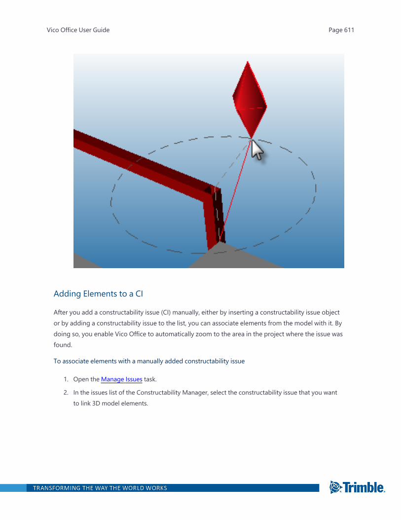
Adding Elements to a CI
After you add a constructability issue (CI) manually, either by inserting a constructability issue objector by adding a constructability issue to the list, you can associate elements from the model with it. Bydoing so, you enable Vico Office to automatically zoom to the area in the project where the issue wasfound.
To associate elements with a manually added constructability issue
1. Open the Manage Issues task.
2. In the issues list of the Constructability Manager, select the constructability issue that you wantto link 3D model elements.
Vico Office User Guide Page 611
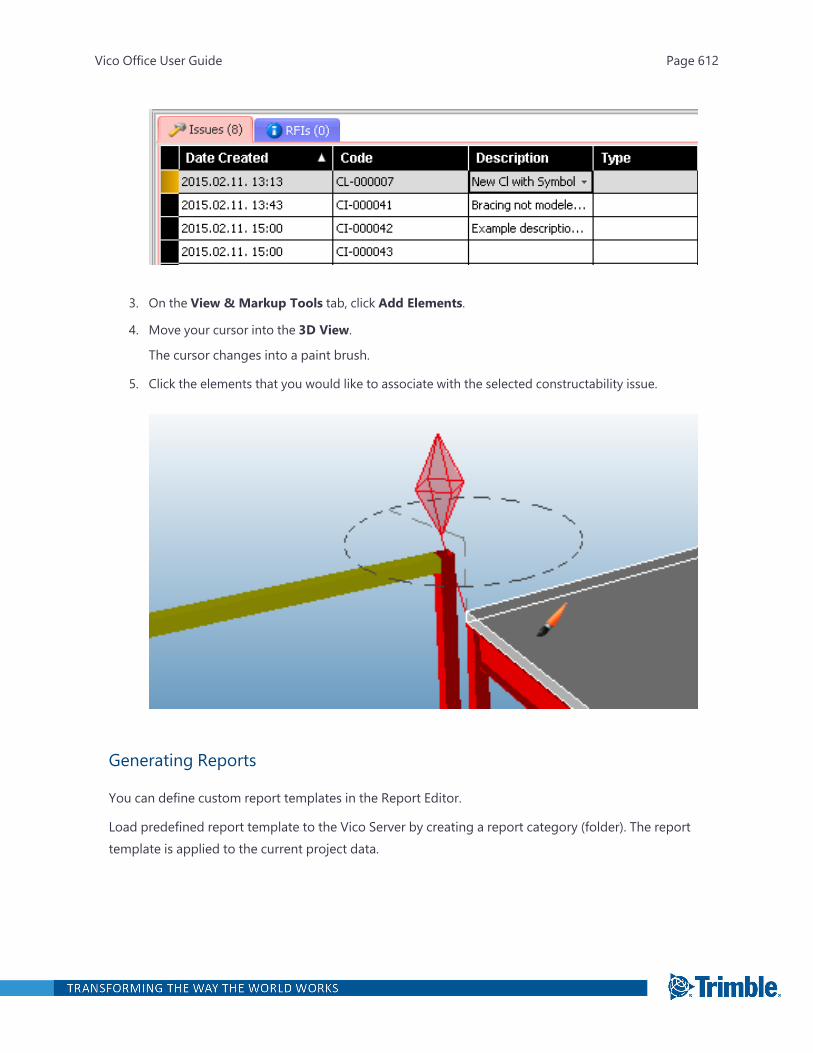
3. On the View & Markup Tools tab, click Add Elements.
4. Move your cursor into the 3D View.
The cursor changes into a paint brush.
5. Click the elements that you would like to associate with the selected constructability issue.
Generating Reports
You can define custom report templates in the Report Editor.
Load predefined report template to the Vico Server by creating a report category (folder). The reporttemplate is applied to the current project data.
Vico Office User Guide Page 612
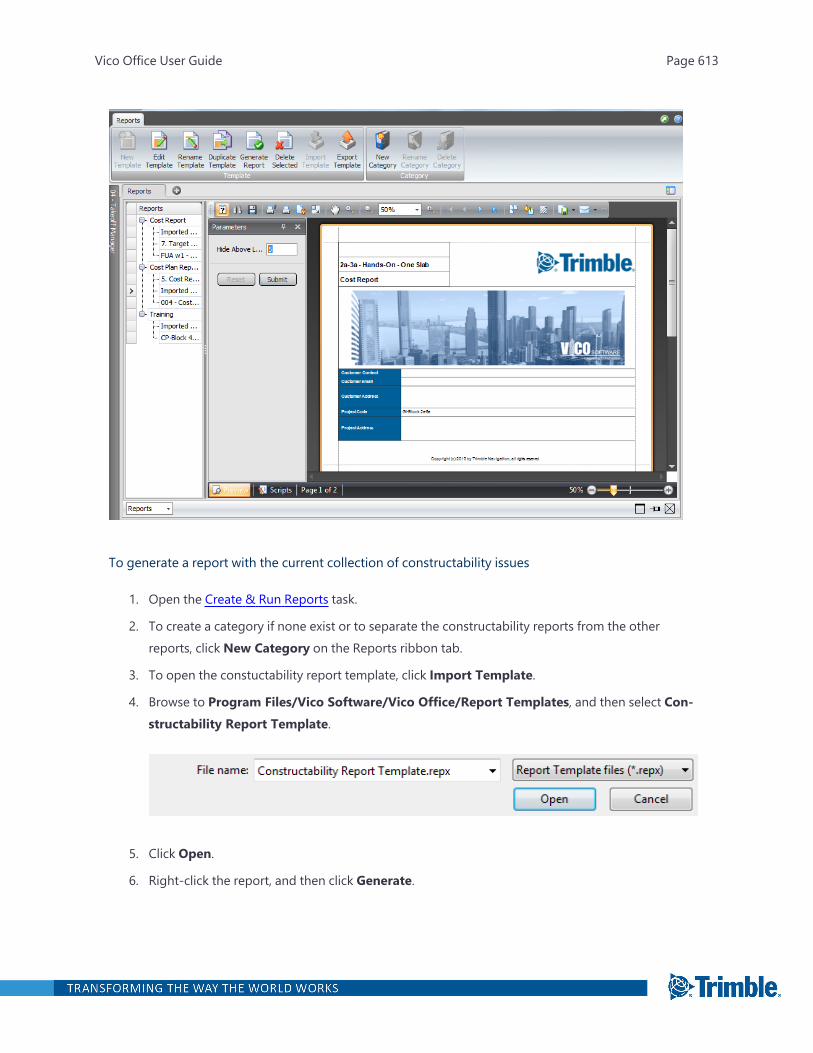
To generate a report with the current collection of constructability issues
1. Open the Create & Run Reports task.
2. To create a category if none exist or to separate the constructability reports from the otherreports, click New Category on the Reports ribbon tab.
3. To open the constuctability report template, click Import Template.
4. Browse to Program Files/Vico Software/Vico Office/Report Templates, and then select Con-structability Report Template.
5. Click Open.
6. Right-click the report, and then click Generate.
Vico Office User Guide Page 613
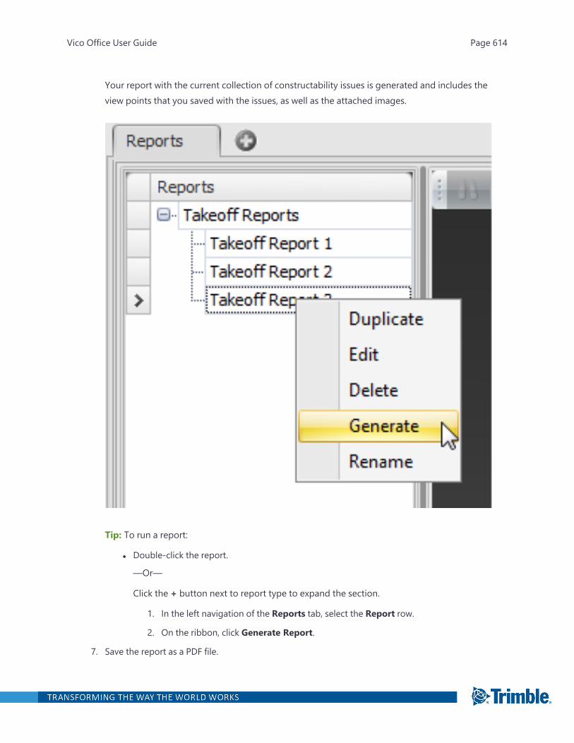
Your report with the current collection of constructability issues is generated and includes theview points that you saved with the issues, as well as the attached images.
Tip: To run a report:
l Double-click the report.
—Or—
Click the + button next to report type to expand the section.
1. In the left navigation of the Reports tab, select the Report row.
2. On the ribbon, click Generate Report.
7. Save the report as a PDF file.
Vico Office User Guide Page 614

Vico Office User Guide Page 615
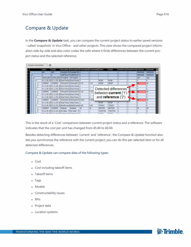
Compare & Update
In the Compare & Update task, you can compare the current project status to earlier saved versions- called 'snapshots' in Vico Office - and other projects. This view shows the compared project inform-ation side-by-side and also color codes the cells where it finds differences between the current pro-ject status and the selected reference.
This is the result of a 'Cost' comparison between current project status and a reference. The softwareindicates that the cost per unit has changed from 45.00 to 60.00.
Besides detecting differences between 'current' and 'reference', the Compare & Update function alsolets you synchronize the reference with the current project; you can do this per selected item or for alldetected differences.
Compare & Update can compare data of the following types:
l Cost
l Cost including takeoff items
l Takeoff items
l Tags
l Models
l Constructability issues
l RFIs
l Project data
l Location systems
Vico Office User Guide Page 616

l LBS structure
l Task groups
l Tasks
l Target Costs
l Cost types
l Schedule Planner file
l Layout points
l Documents
l Work packages
l Takeoff Pads
To open the Compare & Update task
l In the Reporting & Data Mining workflow group, click Compare & Update.
The default viewset includes the Compare & Update view.
Starting a Comparison
You can look for changes between current project data and data from an earlier saved snapshot orfrom a reference. The reference can be another project or data set that contains company standardinformation such as unit cost.
To start a comparison between the current project data and a reference
1. Open the Compare & Update task.
2. On the Compare & Update ribbon tab, click Setup Comparison.
3. In the Compare and Update Settings dialog, select the project snapshot or other project tocompare the current project status with, and then click OK.
You can compare one snapshot or other project to the current project status at a time.
By default, the Cost Comparison Preset is loaded, and the cost assemblies and componentsof current project ('1' columns) and selected reference ('2' columns) are presented side-by-side.
4. To compare a different type of content, click Comparison Preset, and then select one of theavailable options:
Vico Office User Guide Page 617
l Cost: The default option and compares assemblies and components as defined in CostPlanner.
l Cost Takeoff: Compares assemblies and components, as well as the takeoff items andtakeoff quantities that were used in the component formulas.
l Takeoff: compares takeoff items and takeoff quantities and allows for analysis of quantityvariance.
l Tags: Compares the collection of tags and tag values.
l Models: Compares models and model versions and allows for quickly copying model con-tent from one project to another.
l Constructability Issues: Compares the collection of managed constructability issues withID, Name, Comment and Date Found.
l RFIs: Provides a comparison between the set of requests for information between currentstatus and selected reference.
l Project data: Compares the project settings between the current project to the ref-erenced one.
l Location systems: Compares the location systems names and any linked tasks betweenthe current project and the referenced one.
l LBS structure: Compares the LBS structure
l Task groups: Compares the task groups
l Tasks: Compares the tasks and allows for analysis of the linked location systems, thegroups to which they belong, and any linked components and TOQs.
l Target Costs: Compares the target rate and cost
l Cost types: Compares the cost types that were defined for the projects
l Schedule Planner file:
l Layout points: Compares the layout points, which includes various attributes, such ascolor, size, and reference points.
l Documents
l Work packages: Compares the projects' work packages, including the mapped com-ponents, markup adjustments and linked tag values.
l Takeoff Pads
After selecting the comparison preset, the result is presented in the Compare & Update grid.
Differences between the two datasets (current and reference) are displayed in red cells.
Vico Office User Guide Page 618
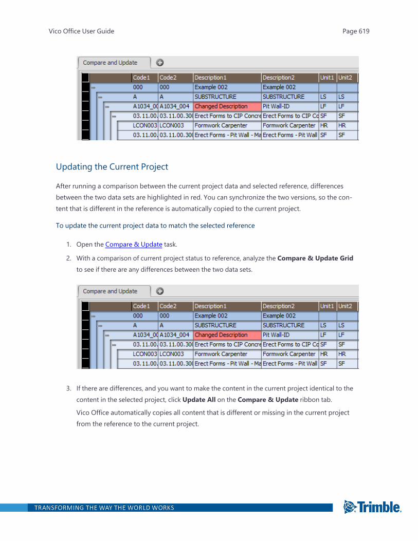
Updating the Current Project
After running a comparison between the current project data and selected reference, differencesbetween the two data sets are highlighted in red. You can synchronize the two versions, so the con-tent that is different in the reference is automatically copied to the current project.
To update the current project data to match the selected reference
1. Open the Compare & Update task.
2. With a comparison of current project status to reference, analyze the Compare & Update Gridto see if there are any differences between the two data sets.
3. If there are differences, and you want to make the content in the current project identical to thecontent in the selected project, click Update All on the Compare & Update ribbon tab.
Vico Office automatically copies all content that is different or missing in the current projectfrom the reference to the current project.
Vico Office User Guide Page 619
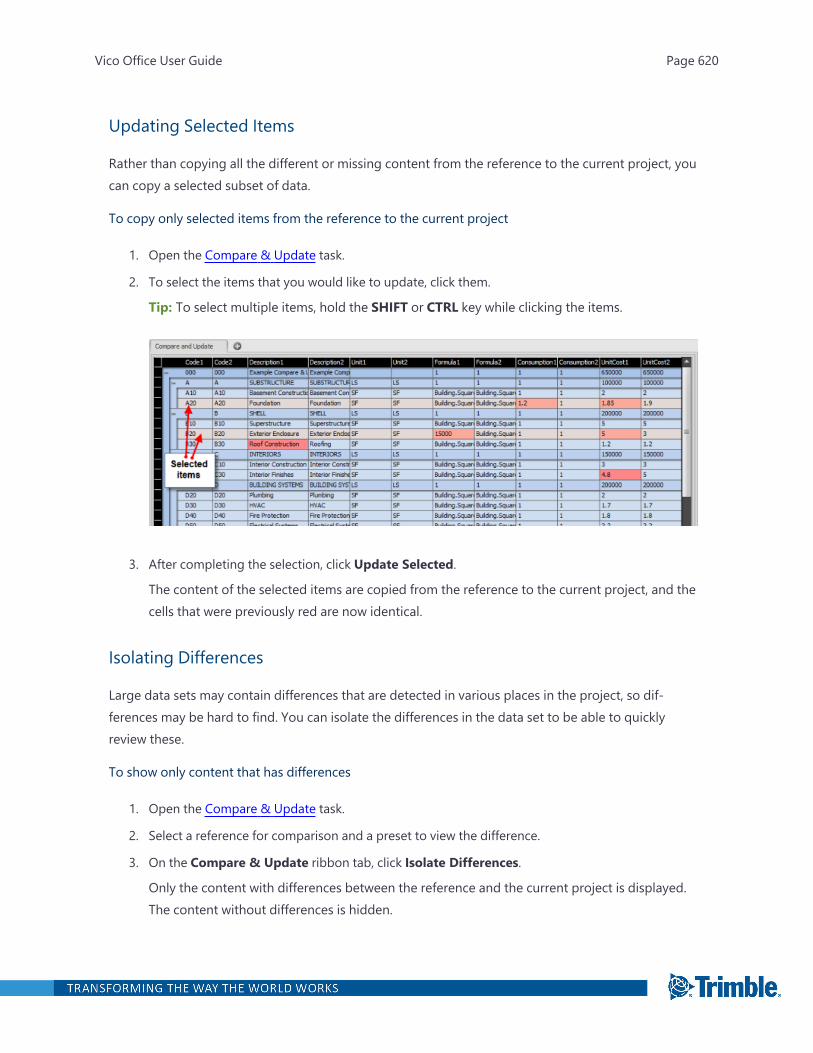
Updating Selected Items
Rather than copying all the different or missing content from the reference to the current project, youcan copy a selected subset of data.
To copy only selected items from the reference to the current project
1. Open the Compare & Update task.
2. To select the items that you would like to update, click them.
Tip: To select multiple items, hold the SHIFT or CTRL key while clicking the items.
3. After completing the selection, click Update Selected.
The content of the selected items are copied from the reference to the current project, and thecells that were previously red are now identical.
Isolating Differences
Large data sets may contain differences that are detected in various places in the project, so dif-ferences may be hard to find. You can isolate the differences in the data set to be able to quicklyreview these.
To show only content that has differences
1. Open the Compare & Update task.
2. Select a reference for comparison and a preset to view the difference.
3. On the Compare & Update ribbon tab, click Isolate Differences.
Only the content with differences between the reference and the current project is displayed.The content without differences is hidden.
Vico Office User Guide Page 620
Copying Models
The Compare & Update view is a great tool for synchronizing cost and other project data, but canalso be used to copy models from one project to another. Using the 'Models' preset, model data caneasily be transferred.
To copy models from one project to another in the Compare & Update view
1. Open the Compare & Update task.
2. Select the project that contains the model or models that you want to copy.
3. On the Compare & Update ribbon tab, click Comparison Preset, and then clickModels.
Vico Office presents the list of models and model versions. Models and versions that exist inthe selected project but not in the current project are marked red.
4. Select the models that you would like to copy to the current project, and then click Update Selec-ted on the Compare & Update ribbon tab.
All the model data of the selected models is now copied to the current project.
5. To make them visible in the current project, activate the copied models in the Document Registertask.
Working Offline
For information on working offline, see Manage Users and Project Access. Offline work is also sup-ported through the Compare & Update function in Vico Office.
TO WORK OFFLINE ON A PROJECT THAT EXISTS ON A PROJECT SERVER
1. Create a project on the system that will be taken offline.
2. Run the Compare & Update function, and copy all project content from the project server to thenew project.
3. Connect to the project server and open the project from the server.
4. Run the Compare & Update function, and copy the changes to the server.
Vico Office User Guide Page 621

Vico Office User Guide Page 622

Work Packages
In work packages, you can group estimate work items in the way you intend to procure them. Thework package module is used to establish the link between work items and subcontractor pricing bymapping cost assemblies and components to defined work packages.
Bids can be evaluated, compared, and allocated to the estimate, thus, providing more opportunitiesto find the optimum bid for your wallet.
TheWork Package Managermodule includes two dedicated tasks:
l Define Work Packages: Create work packages that can be investigated from different points ofview.
l Manage Bids: Add, normalize, and compare quotes.
To open the Define Work Packages task
1. Right-click the Workflow Panel header, and then click the Vico Office or Vico for Cost module.
2. In the Vico for Cost or Cost Management workflow group, click Define Work Packages.
To open the Manage Bids task
1. Right-click the Workflow Panel header, and then click the Vico Office or Vico for Cost module.
2. In the Vico for Cost or Cost Management workflow group, click Manage Bids.
The default viewset includes the Bid Manager view.
Define Work Packages
The Define Work Package task includes the following default viewsets that are used for creating andinvestigating work packages:
l Work Package Manager: Create work packages and summary work packages.
l Work Package Manager & Cost Plan:Map the cost components and assemblies (work items)to each work package while comparing the estimated costs with the bidder's given values. Afteryou map the components and assemblies to each work package, they contain the model-basedquantities that bidders can use later.
l Work Package Manager & 3D: Review the scope of the work packages and verify that therewere no mistakes during the mapping process by checking the assigned elements. You can reas-
Vico Office User Guide Page 623
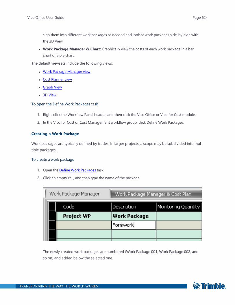
sign them into different work packages as needed and look at work packages side-by-side withthe 3D View.
l Work Package Manager & Chart: Graphically view the costs of each work package in a barchart or a pie chart.
The default viewsets include the following views:
l Work Package Manager view
l Cost Planner view
l Graph View
l 3D View
To open the Define Work Packages task
1. Right-click the Workflow Panel header, and then click the Vico Office or Vico for Cost module.
2. In the Vico for Cost or Cost Management workflow group, click Define Work Packages.
Creating a Work Package
Work packages are typically defined by trades. In larger projects, a scope may be subdivided into mul-tiple packages.
To create a work package
1. Open the Define Work Packages task.
2. Click an empty cell, and then type the name of the package.
The newly created work packages are numbered (Work Package 001, Work Package 002, andso on) and added below the selected one.
Vico Office User Guide Page 624
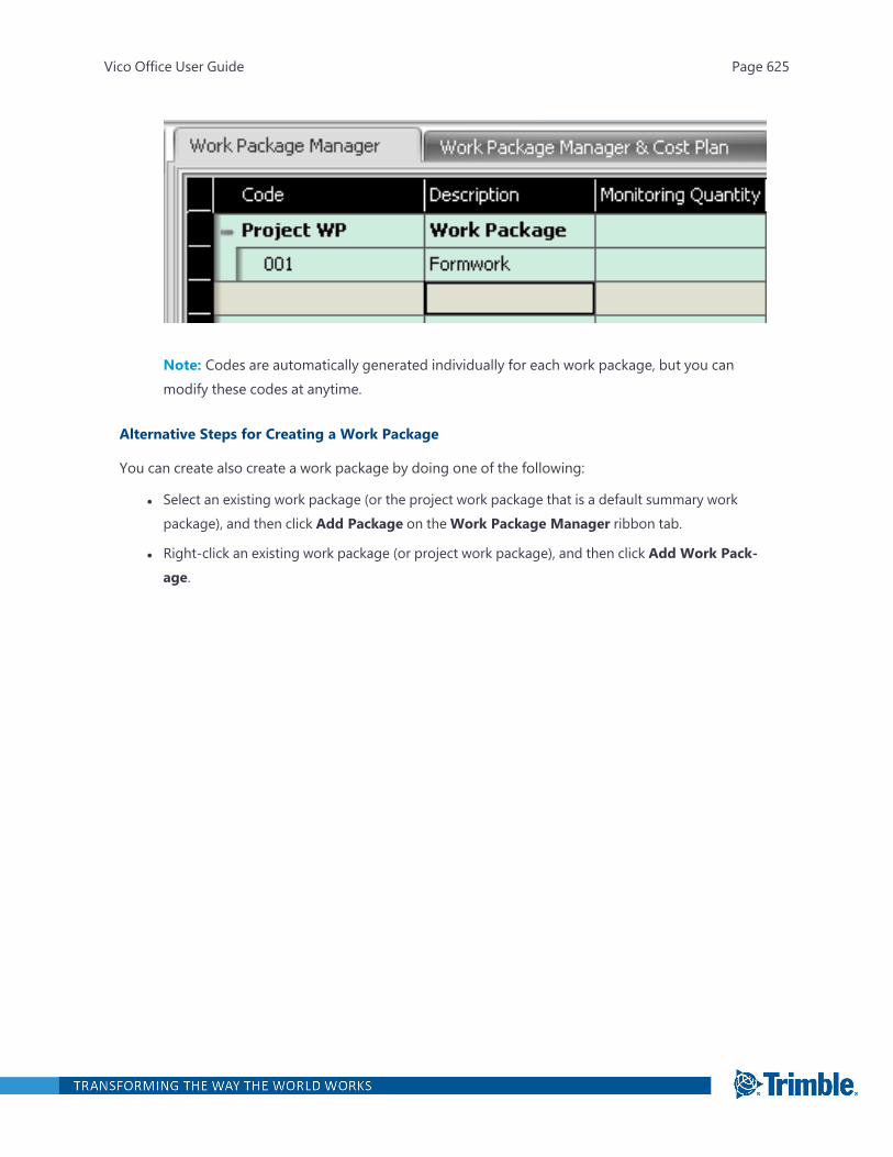
Note: Codes are automatically generated individually for each work package, but you canmodify these codes at anytime.
Alternative Steps for Creating a Work Package
You can create also create a work package by doing one of the following:
l Select an existing work package (or the project work package that is a default summary workpackage), and then click Add Package on theWork Package Manager ribbon tab.
l Right-click an existing work package (or project work package), and then click Add Work Pack-age.
Vico Office User Guide Page 625

l Click an existing work package, and then press Ctrl +W.
The hierarchy of work packages can be changed by adding them to a summary work package.For more information, see "Adding a Summary Work Package" on page 628.
Vico Office User Guide Page 626
Work packages can also be imported from Excel. For more information, see "Exporting to/Importingfrom Microsoft Excel" on page 659.
Deleting a Work Package
You can delete work packages that do or do not have content. You can also delete awarded workpackages; however, you must change its status before deleting it.
To delete a work package without content
1. Open the Define Work Packages task.
2. Select the work package that you want to delete.
You can select multiple work packages.
3. On theWork Package Manager ribbon tab, click Delete Selected.
—Or—
Right-click the selected work package, and then click Delete.
The selected work packages are deleted.
To delete a work package with content
1. Open the Define Work Packages task.
2. Select the work package that you want to delete.
3. On theWork Package Manager ribbon tab, click Delete Selected.
—Or—
Right-click the work package, and then click Delete.
4. In the confirmation dialog, click OK.
The components are unassigned, and the work package is deleted.
Deleting an Awarded Work Package
The status of an awarded work package must be changed before you can delete it.
To delete an awarded work package
1. Open the Define Work Packages task.
2. Select the work package that you want to delete.
3. Right-click the work package, and then click Unlock Selected.
Note: If the bidder was selected as Contracted, click Define Settings in the Workflow Panel,and then clear the Hard Lock 'Contracted' Work Packages check box.
Vico Office User Guide Page 627

To indicate that the work package is not awarded but was before, the box icon/lock icon
changes to an opened lock .
4. On theWork Package Manager ribbon tab, click Delete Selected.
—Or—
Right-click the work package, and then click Delete.
The work package is deleted. The mapped components are also unassigned, making themavailable in the Cost Planner view again.
Adding a Summary Work Package
After creating work packages, you can group them in summary work packages. Summary work pack-ages allow for subdividing a scope of work into multiple sub work packages.
Note: The Add Summary Package button is enabled only after selecting at least two work packages.
To create a summary work package
1. Open the Define Work Packages task.
2. Select a set of work packages.
3. On theWork Package Manager ribbon tab, click Add Summary Package.
—Or—
Vico Office User Guide Page 628

Right-click the selected set, and then click Add Summary Work Package from the drop-down menu.
A summary work package is created with all the selected work packages and added to the bot-tom of the list.
Note: The summary information in the summary work package is read-only and is based on the cal-culated data from the work packages.
To edit a summary work package
1. Open the Define Work Packages task.
2. To expand the summary work package, click the plus (+) icon.
3. To add existing work packages to the summary work package, drag them inside of the summarywork package.
4. To remove work packages from the summary work package, drag them outside of the summarywork package.
After changing the content of the summary work package, values are automatically updated.
Note: The Project line item is a summary work package, and work packages cannot removed from it.
Deleting a Summary Work Package
Important: When you delete a summary work package, each included work package is deleted aswell.
To delete an empty summary work package
Vico Office User Guide Page 629
1. Open the Define Work Packages task.
2. Select the summary work package that you want to delete.
3. On theWork Package Manager ribbon tab, click Delete Selected.
—Or—
Right-click the summary work package, and then click Delete.
The selected summary work package is deleted.
To delete summary work packages with work packages
1. Open the Define Work Packages task.
2. Select the summary work package that you want to delete.
3. On theWork Package Manager ribbon tab, click Delete Selected.
—Or—
Right-click the summary work package, and then click Delete.
A confirmation dialog asks you to confirm whether you want to delete the work packagesincluded in the summary work package.
4. To keep the work packages, click Cancel, and then remove the work packages from the summarywork package before deleting it.
—Or—
To delete the summary work package and its included work packages, click OK.
Deleting a Summary Work Package with Awarded Content
Change the status of the awarded work packages that are contained in the summary work packagebefore deleting it. If the summary work package contains individual work packages, you must firstremove them.
To delete a committed summary work package
1. Open the Define Work Packages task.
2. To expand the summary work package and see the committed work package, click the plus (+)sign.
3. Right-click the committed items, and then click Unlock Selected.
To indicate that the work package is not awarded, the lock icon changes to an opened lock
.
Vico Office User Guide Page 630
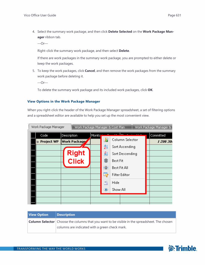
4. Select the summary work package, and then click Delete Selected on theWork Package Man-ager ribbon tab.
—Or—
Right-click the summary work package, and then select Delete.
If there are work packages in the summary work package, you are prompted to either delete orkeep the work packages.
5. To keep the work packages, click Cancel, and then remove the work packages from the summarywork package before deleting it.
—Or—
To delete the summary work package and its included work packages, click OK.
View Options in the Work Package Manager
When you right-click the header of the Work Package Manager spreadsheet, a set of filtering optionsand a spreadsheet editor are available to help you set up the most convenient view.
View Option Description
Column Selector Choose the columns that you want to be visible in the spreadsheet. The chosencolumns are indicated with a green check mark.
Vico Office User Guide Page 631
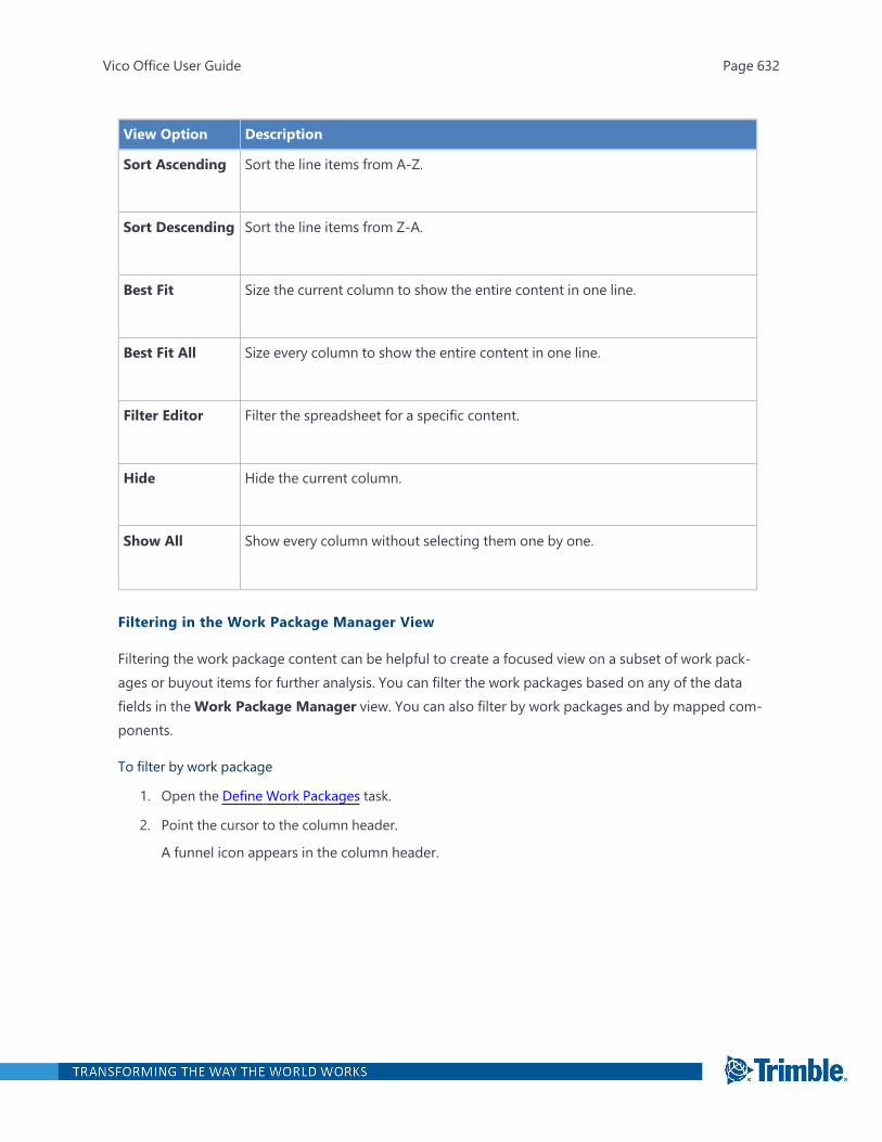
View Option Description
Sort Ascending Sort the line items from A-Z.
Sort Descending Sort the line items from Z-A.
Best Fit Size the current column to show the entire content in one line.
Best Fit All Size every column to show the entire content in one line.
Filter Editor Filter the spreadsheet for a specific content.
Hide Hide the current column.
Show All Show every column without selecting them one by one.
Filtering in the Work Package Manager View
Filtering the work package content can be helpful to create a focused view on a subset of work pack-ages or buyout items for further analysis. You can filter the work packages based on any of the datafields in theWork Package Manager view. You can also filter by work packages and by mapped com-ponents.
To filter by work package
1. Open the Define Work Packages task.
2. Point the cursor to the column header.
A funnel icon appears in the column header.
Vico Office User Guide Page 632
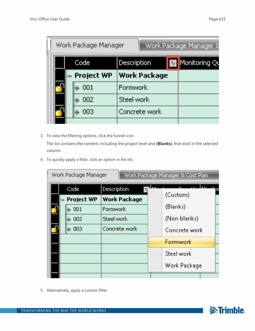
3. To view the filtering options, click the funnel icon.
The list contains the content, including the project level and (Blanks), that exist in the selectedcolumn.
4. To quickly apply a filter, click an option in the list.
5. Alternatively, apply a custom filter.
Vico Office User Guide Page 633
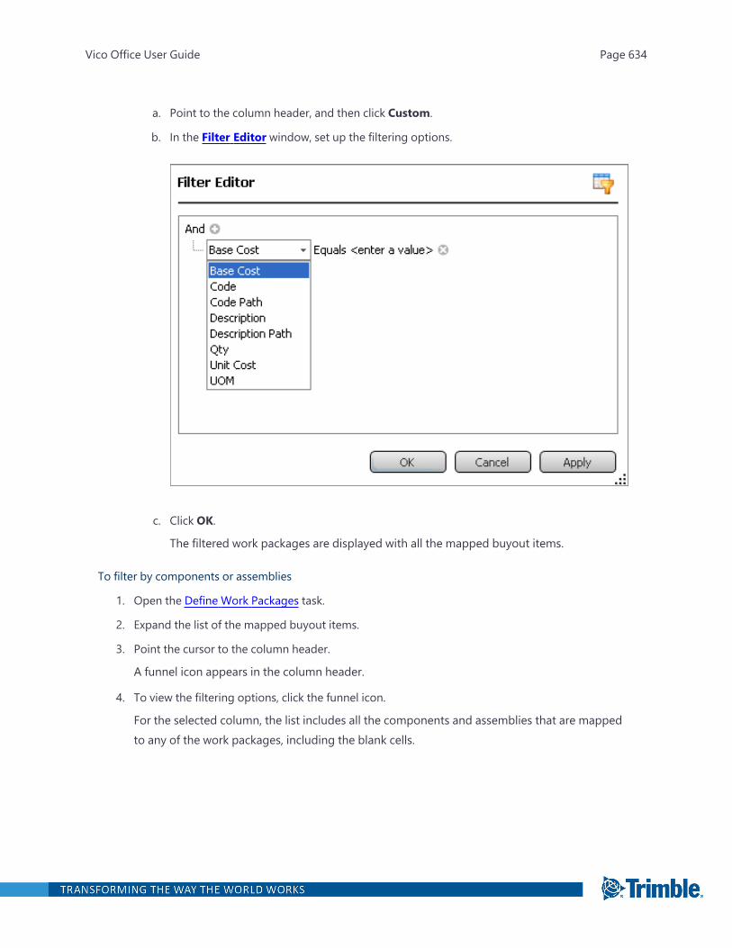
a. Point to the column header, and then click Custom.
b. In the Filter Editor window, set up the filtering options.
c. Click OK.
The filtered work packages are displayed with all the mapped buyout items.
To filter by components or assemblies
1. Open the Define Work Packages task.
2. Expand the list of the mapped buyout items.
3. Point the cursor to the column header.
A funnel icon appears in the column header.
4. To view the filtering options, click the funnel icon.
For the selected column, the list includes all the components and assemblies that are mappedto any of the work packages, including the blank cells.
Vico Office User Guide Page 634
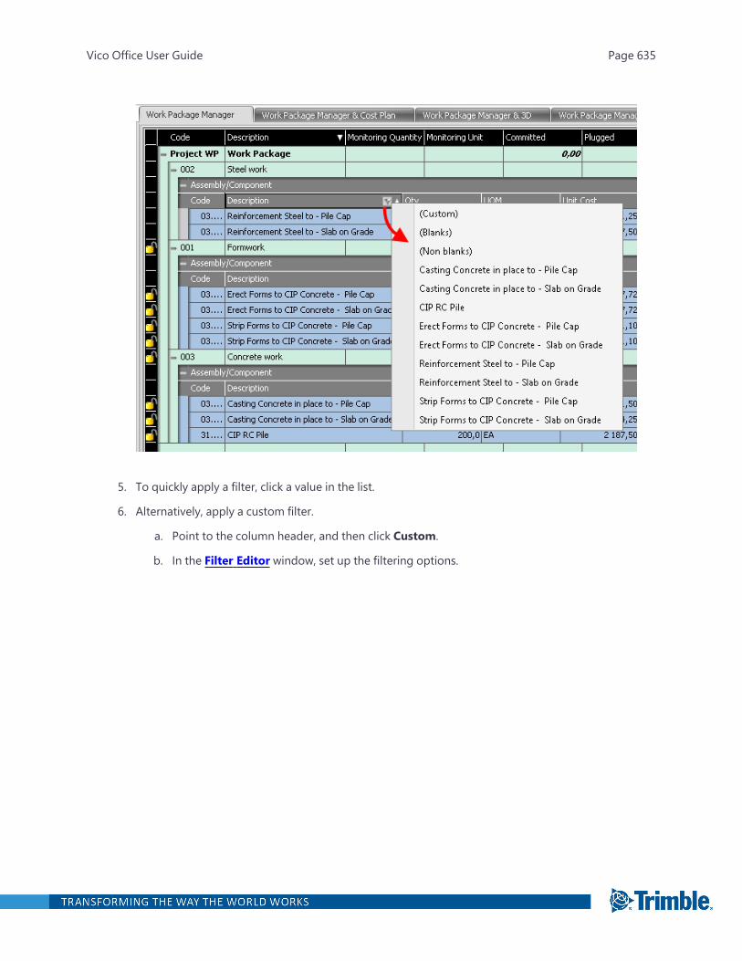
5. To quickly apply a filter, click a value in the list.
6. Alternatively, apply a custom filter.
a. Point to the column header, and then click Custom.
b. In the Filter Editor window, set up the filtering options.
Vico Office User Guide Page 635
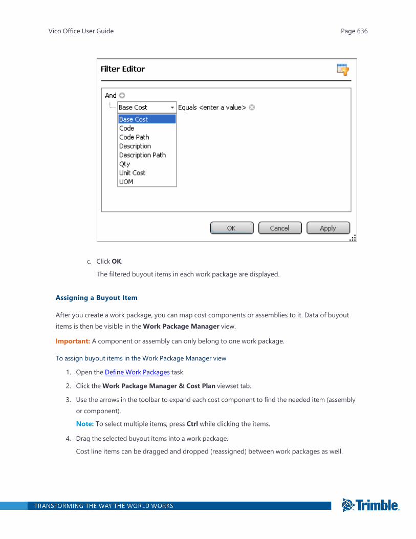
c. Click OK.
The filtered buyout items in each work package are displayed.
Assigning a Buyout Item
After you create a work package, you can map cost components or assemblies to it. Data of buyoutitems is then be visible in theWork Package Manager view.
Important: A component or assembly can only belong to one work package.
To assign buyout items in the Work Package Manager view
1. Open the Define Work Packages task.
2. Click theWork Package Manager & Cost Plan viewset tab.
3. Use the arrows in the toolbar to expand each cost component to find the needed item (assemblyor component).
Note: To select multiple items, press Ctrl while clicking the items.
4. Drag the selected buyout items into a work package.
Cost line items can be dragged and dropped (reassigned) between work packages as well.
Vico Office User Guide Page 636

TheWork Package column in the Cost Planner view is populated with the name of the workpackage that it belongs to.
When a higher level assembly is assigned to another work package, then all of its componentsare assigned to the same work package as the higher level assembly.
To assign a buyout item in the Cost Planner view
1. Open the Define Work Packages task.
2. Click theWork Package Manager & Cost Plan viewset tab.
3. Double-click theWork Package cell.
Vico Office User Guide Page 637

A list of the work package names appears in the list.
4. Select the target work package.
The line item is automatically mapped to the related work package.
Any line item that includes calculated unit costs has the calculator icon shown on that line when
entered in the cost plan from the bid award.
Note: Components can only belong to one work package. Therefore, the value of a work packagedecreases if its components are moved to another work package.
When you select a component in the cost plan, Vico Office highlights the work package that the cur-rent work item, or any work items from the levels below the selected one, was assigned to.
When you select a work package, Vico Office highlights every assigned work items in the Cost Plan-ner view.
ExampleIn the images below, A4010_10_001 Slab on Grade was assigned to the Slab on Grade Work Package,and the A1020_70_001 Pile Cap-ID was assigned to the Pile Cap Work Package.
Vico Office User Guide Page 638
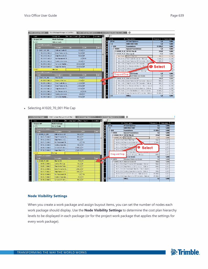
l Selecting A1020_70_001 Pile Cap
Node Visibility Settings
When you create a work package and assign buyout items, you can set the number of nodes eachwork package should display. Use the Node Visibility Settings to determine the cost plan hierarchylevels to be displayed in each package (or for the project work package that applies the settings forevery work package).
Vico Office User Guide Page 639

To set the nodes to display for each work package
1. Open the Define Work Packages task.
2. Click theWork Package Manager & Cost Plan viewset tab.
3. In theWork Package Manager view, click the work package whose node you wish to set.
4. On theWork Package Manager ribbon tab, ensure that Show Mapped is enabled.
This allows you to view the full parent/child nodes of the mapped component in the Cost Plan-ner view.
Vico Office User Guide Page 640
5. To enable the settings, click On/Off on theWork Package Manager ribbon tab.
When the setting is off, all the mapped component’s child node levels are displayed.
Vico Office User Guide Page 641

Vico Office User Guide Page 642
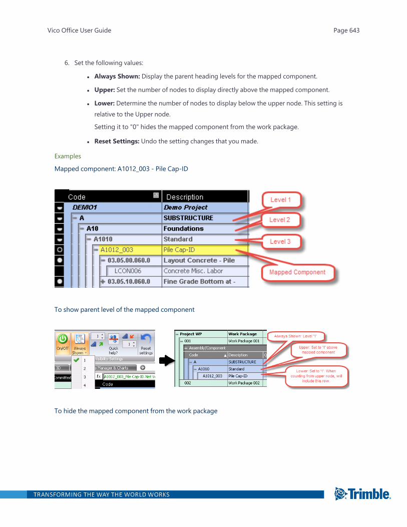
6. Set the following values:
l Always Shown: Display the parent heading levels for the mapped component.
l Upper: Set the number of nodes to display directly above the mapped component.
l Lower: Determine the number of nodes to display below the upper node. This setting isrelative to the Upper node.
Setting it to "0" hides the mapped component from the work package.
l Reset Settings: Undo the setting changes that you made.
Examples
Mapped component: A1012_003 - Pile Cap-ID
To show parent level of the mapped component
To hide the mapped component from the work package
Vico Office User Guide Page 643
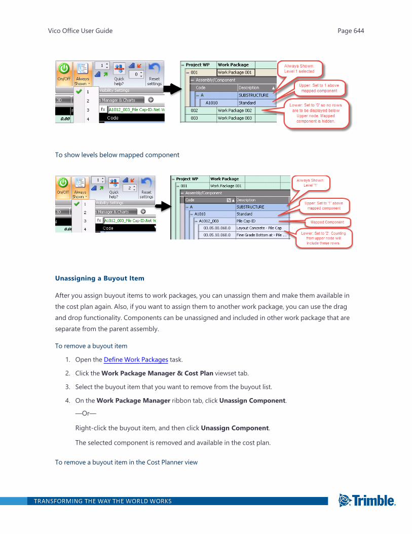
To show levels below mapped component
Unassigning a Buyout Item
After you assign buyout items to work packages, you can unassign them and make them available inthe cost plan again. Also, if you want to assign them to another work package, you can use the dragand drop functionality. Components can be unassigned and included in other work package that areseparate from the parent assembly.
To remove a buyout item
1. Open the Define Work Packages task.
2. Click theWork Package Manager & Cost Plan viewset tab.
3. Select the buyout item that you want to remove from the buyout list.
4. On theWork Package Manager ribbon tab, click Unassign Component.
—Or—
Right-click the buyout item, and then click Unassign Component.
The selected component is removed and available in the cost plan.
To remove a buyout item in the Cost Planner view
Vico Office User Guide Page 644
1. Open the Define Work Packages task.
2. Click theWork Package Manager & Cost Plan viewset tab.
3. On theWork Package Manager ribbon tab, click Show Mapped.
Mapped components in the Cost Planner view are gray.
4. Select the work package that you want to unassign the component from.
The components that belong to the selected work package are highlighted in the Cost Plan-ner view.
5. In the highlighted fields, scroll to the right to find theWork Package column.
6. Double-click theWork Package cell, and then click Unassigned.
Because unassigned components no longer contribute to the work package values, the valueof the work package is automatically updated.
Reviewing the Bid Scope
Elements that are already assigned to work packages are displayed in the 3D View when selecting awork package.
To customize how your elements are displayed in the 3D View, you can use Running Mode. If Run-ning Mode is enabled, elements are highlighted as per the pre-defined Running Mode settings. IfRunning Mode is disabled, you can set the color for the current work package.
Note: If an element is part of multiple work packages (that are defined with different colors), whenyou select these work packages, the element is highlighted in white in the 3D View.
Setting the Work Package Color
You can select the work package color in the work package spreadsheet, or you can create a list of col-ors that are applied automatically when you create a new work package.
To select the color in the work package spreadsheet
1. Open the Define Work Packages task.
2. Click theWork Package Manager & 3D viewset tab.
3. On the Running Mode ribbon tab, ensure that the On/Off button is set to off.
4. In the work package spreadsheet, click the Color cell for the work package, and then select acolor.
Tip: If the list does not contain any colors, click New to add a color.
Vico Office User Guide Page 645
Elements that are associated to the current work package are highlighted with the selectedcolor.
To create a list of colors for the Work Package Manager
1. Open the Edit Tags task.
2. Expand the System category, and then select Color.
3. Create a new tag value and define the color for it.
a. On the ribbon, click Value.
b. In the Name cell, type the value name.
c. Click the Color cell, and then select a color.
The defined color is added to the color list in theWork Package Manager view. When you cre-ate a new work package, Vico Office automatically applies a color for it from the defined list.
Note: If an element is associated with a different workflow item and both of them are selected, theelement is highlighted in white.
Viewing a Pie Chart
The pie chart displays the work packages and its subdivisions. Each slice of the pie consists of a sub-division, and the total project cost includes all the subdivisions.
To view your work packages in a pie chart
1. Open the Define Work Packages task.
2. Click theWork Package Manager & Charts viewset tab.
3. On the Graph View ribbon tab, click View Type > Pie View.
Vico Office User Guide Page 646

4. Press the Ctrl key as you click each work package that you wish to include in the graph.
Vico Office User Guide Page 647
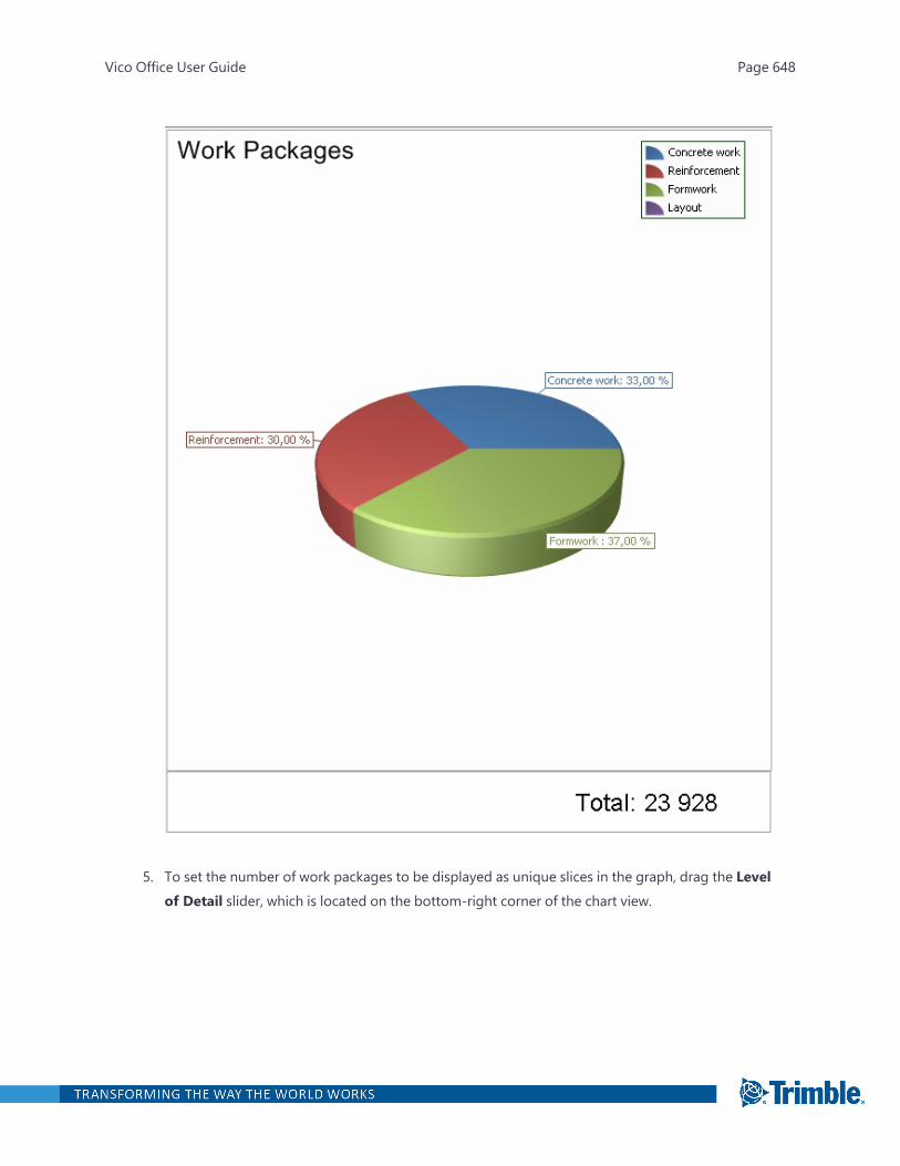
5. To set the number of work packages to be displayed as unique slices in the graph, drag the Levelof Detail slider, which is located on the bottom-right corner of the chart view.
Vico Office User Guide Page 648
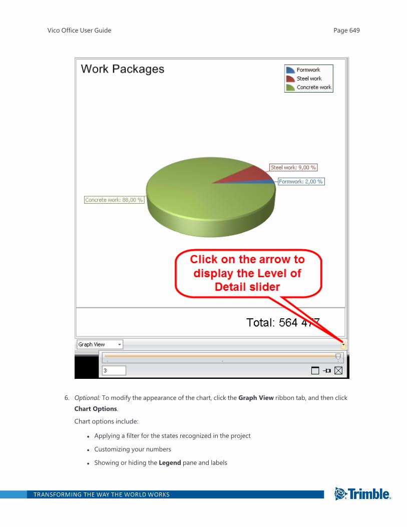
6. Optional: To modify the appearance of the chart, click the Graph View ribbon tab, and then clickChart Options.
Chart options include:
l Applying a filter for the states recognized in the project
l Customizing your numbers
l Showing or hiding the Legend pane and labels
Vico Office User Guide Page 649

l Applying a color scheme to override the default colors
By default, the chart view uses the colors that are defined in theWork Package Man-ager view.
Viewing a Bar Chart
The bar chart helps you visualize how the value of a work package may have developed throughoutthe various project phases and work package states. In this view, the Y-axis represents the cost data,
Vico Office User Guide Page 650
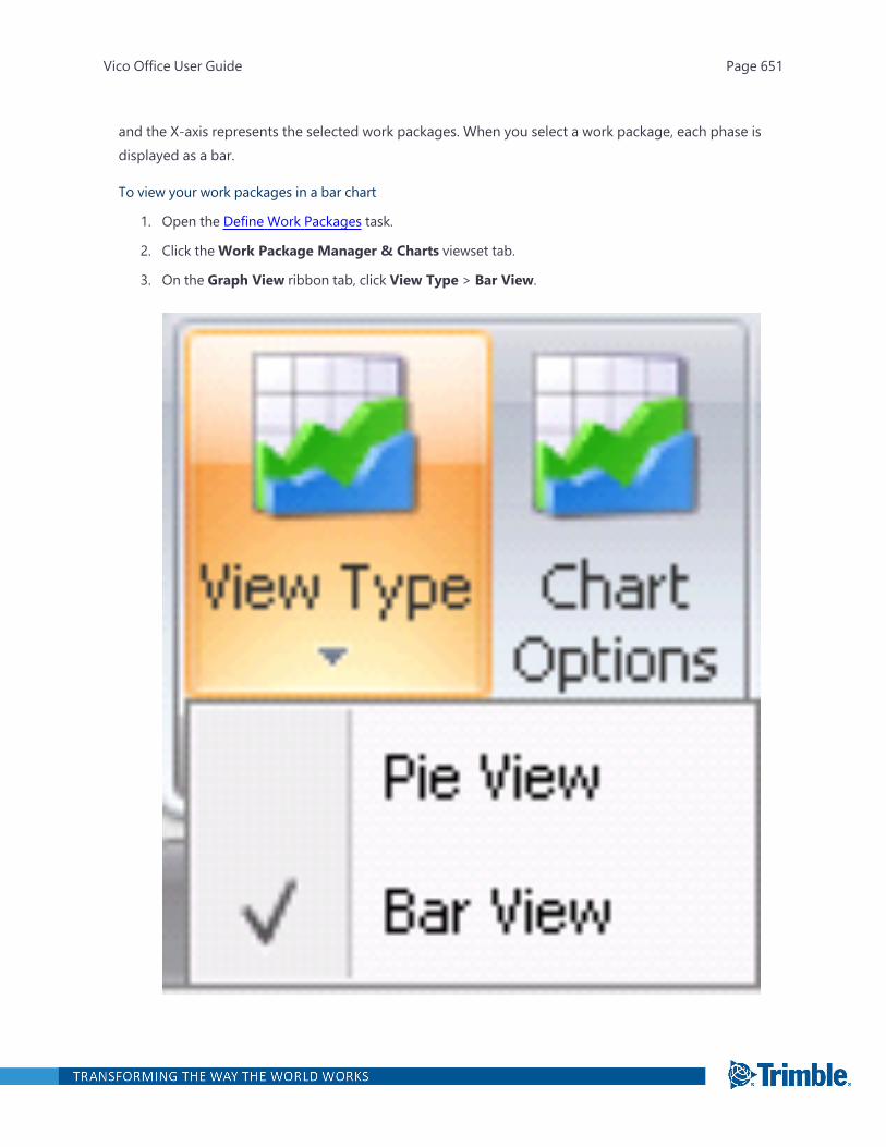
and the X-axis represents the selected work packages. When you select a work package, each phase isdisplayed as a bar.
To view your work packages in a bar chart
1. Open the Define Work Packages task.
2. Click theWork Package Manager & Charts viewset tab.
3. On the Graph View ribbon tab, click View Type > Bar View.
Vico Office User Guide Page 651

4. Press the Ctrl key as you click each work package that you wish to include in the graph.
The total project cost consists of all the subdivisions of the selected work packages. The activestatuses and the project total are displayed in the graph area.
5. Optional: To modify the appearance of the chart, click the Graph View ribbon tab, and then clickChart Options.
Vico Office User Guide Page 652
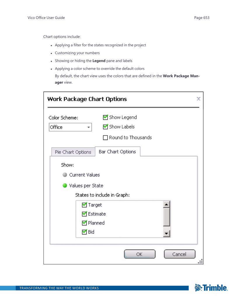
Chart options include:
l Applying a filter for the states recognized in the project
l Customizing your numbers
l Showing or hiding the Legend pane and labels
l Applying a color scheme to override the default colors
By default, the chart view uses the colors that are defined in theWork Package Man-ager view.
Vico Office User Guide Page 653

Adding Requirements
After creating a work package, you can enter any extra information and requirements for it in theProperties palette.
To add requirements
1. Open the Manage Bids task.
2. Select the work package.
3. Open and pin the Properties palette.
4. Enter your notes and requirements in the corresponding sections.
The information that you enter is visible when you open the Properties palette in the workpackage.
Pre-Award Stages
When you create a work package, you can define the pre-awarded stage for it. The bids that youenter in theManage Bids task are compared with the selected stage of the work package. TheWorkPackage Manager view displays the values based on the selected awarded stage. You can also com-pare these stages to each other in the Summary Mode.
Defined pre-awarded stages are useful during the bid examination, where you can compare your biddata with the defined stages. For more information, see "Awarding a Bid" on page 660.
To define pre-award stages
1. Open the Define Work Packages task.
2. Select theWork Package for which you want to set the pre-award stage.
3. Double-click the cell in the Approval State column, and then select the state from the list.
Vico Office User Guide Page 654
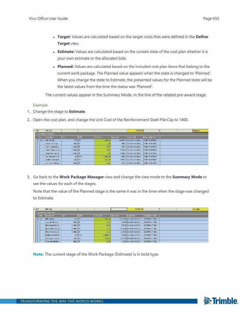
l Target: Values are calculated based on the target costs that were defined in the DefineTarget view.
l Estimate: Values are calculated based on the current state of the cost plan whether it isyour own estimate or the allocated bids.
l Planned: Values are calculated based on the included cost plan items that belong to thecurrent work package. The Planned value appears when the state is changed to ’Planned’.When you change the state to Estimate, the presented values for the Planned state will bethe latest values from the time the status was 'Planned'.
The current values appear in the Summary Mode, in the line of the related pre-award stage.
Example1. Change the stage to Estimate.
2. Open the cost plan, and change the Unit Cost of the Reinforcement Steel Pile Cap to 1400.
3. Go back to theWork Package Manager view and change the view mode to the Summary Mode tosee the values for each of the stages.
Note that the value of the Planned stage is the same it was in the time when the stage was changedto Estimate.
Note: The current stage of the Work Package (Estimate) is in bold type.
Vico Office User Guide Page 655
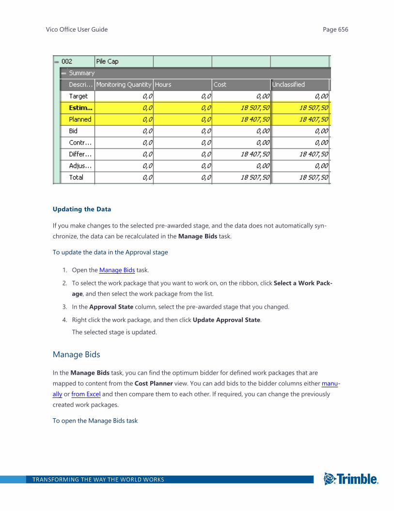
Updating the Data
If you make changes to the selected pre-awarded stage, and the data does not automatically syn-chronize, the data can be recalculated in theManage Bids task.
To update the data in the Approval stage
1. Open the Manage Bids task.
2. To select the work package that you want to work on, on the ribbon, click Select a Work Pack-age, and then select the work package from the list.
3. In the Approval State column, select the pre-awarded stage that you changed.
4. Right click the work package, and then click Update Approval State.
The selected stage is updated.
Manage Bids
In theManage Bids task, you can find the optimum bidder for defined work packages that aremapped to content from the Cost Planner view. You can add bids to the bidder columns either manu-ally or from Excel and then compare them to each other. If required, you can change the previouslycreated work packages.
To open the Manage Bids task
Vico Office User Guide Page 656
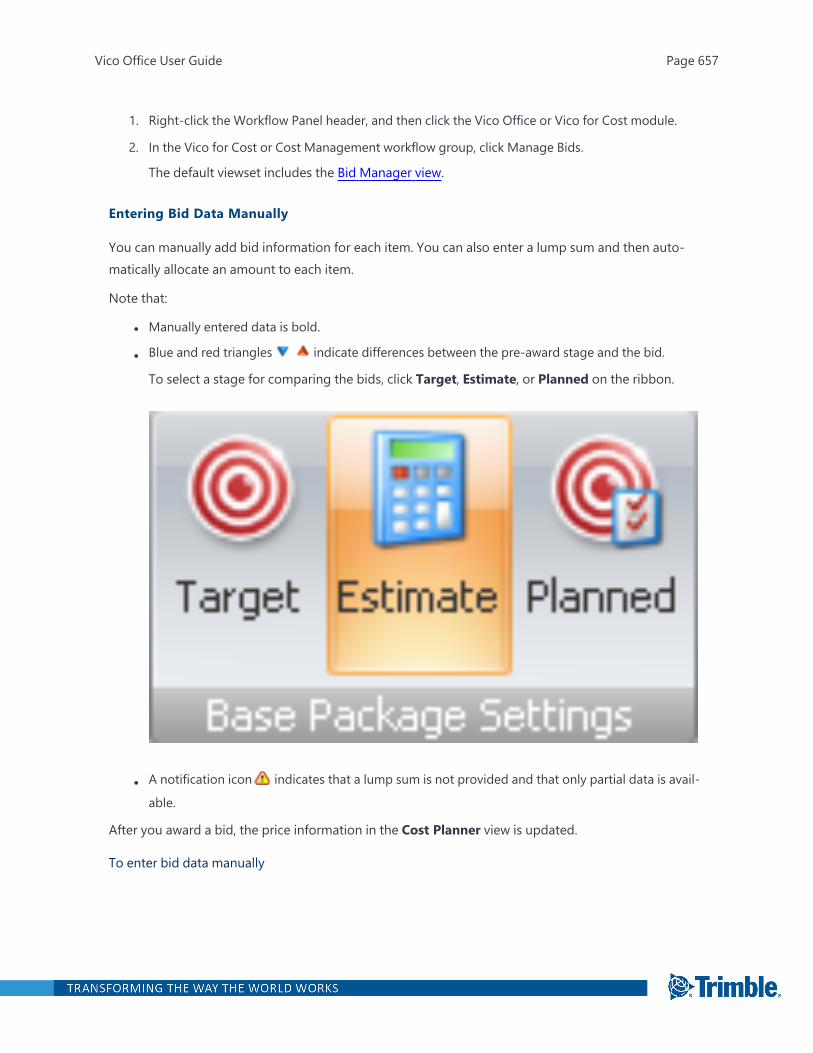
1. Right-click the Workflow Panel header, and then click the Vico Office or Vico for Cost module.
2. In the Vico for Cost or Cost Management workflow group, click Manage Bids.
The default viewset includes the Bid Manager view.
Entering Bid Data Manually
You can manually add bid information for each item. You can also enter a lump sum and then auto-matically allocate an amount to each item.
Note that:
l Manually entered data is bold.
l Blue and red triangles indicate differences between the pre-award stage and the bid.
To select a stage for comparing the bids, click Target, Estimate, or Planned on the ribbon.
l A notification icon indicates that a lump sum is not provided and that only partial data is avail-
able.
After you award a bid, the price information in the Cost Planner view is updated.
To enter bid data manually
Vico Office User Guide Page 657
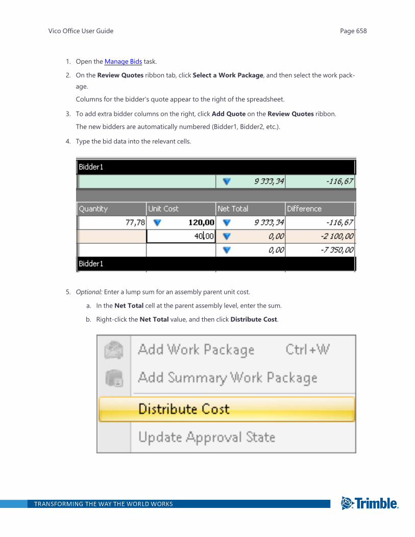
1. Open the Manage Bids task.
2. On the Review Quotes ribbon tab, click Select a Work Package, and then select the work pack-age.
Columns for the bidder's quote appear to the right of the spreadsheet.
3. To add extra bidder columns on the right, click Add Quote on the Review Quotes ribbon.
The new bidders are automatically numbered (Bidder1, Bidder2, etc.).
4. Type the bid data into the relevant cells.
5. Optional: Enter a lump sum for an assembly parent unit cost.
a. In the Net Total cell at the parent assembly level, enter the sum.
b. Right-click the Net Total value, and then click Distribute Cost.
Vico Office User Guide Page 658
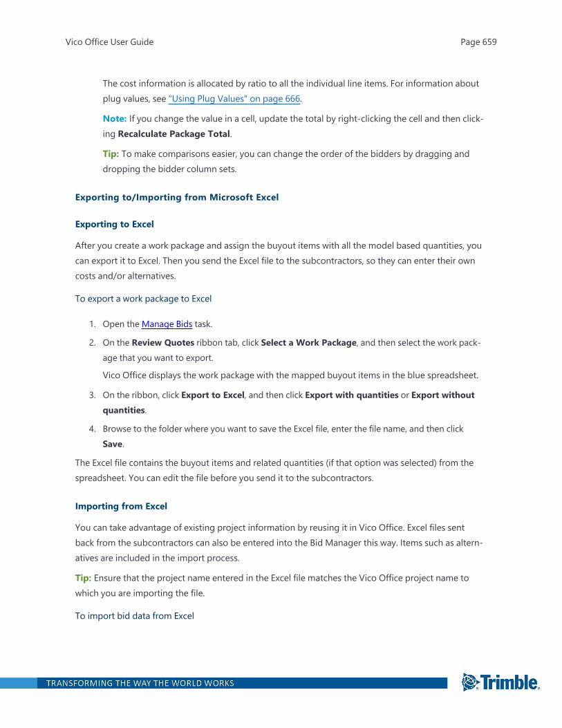
The cost information is allocated by ratio to all the individual line items. For information aboutplug values, see "Using Plug Values" on page 666.
Note: If you change the value in a cell, update the total by right-clicking the cell and then click-ing Recalculate Package Total.
Tip: To make comparisons easier, you can change the order of the bidders by dragging anddropping the bidder column sets.
Exporting to/Importing from Microsoft Excel
Exporting to Excel
After you create a work package and assign the buyout items with all the model based quantities, youcan export it to Excel. Then you send the Excel file to the subcontractors, so they can enter their owncosts and/or alternatives.
To export a work package to Excel
1. Open the Manage Bids task.
2. On the Review Quotes ribbon tab, click Select a Work Package, and then select the work pack-age that you want to export.
Vico Office displays the work package with the mapped buyout items in the blue spreadsheet.
3. On the ribbon, click Export to Excel, and then click Export with quantities or Export withoutquantities.
4. Browse to the folder where you want to save the Excel file, enter the file name, and then clickSave.
The Excel file contains the buyout items and related quantities (if that option was selected) from thespreadsheet. You can edit the file before you send it to the subcontractors.
Importing from Excel
You can take advantage of existing project information by reusing it in Vico Office. Excel files sentback from the subcontractors can also be entered into the Bid Manager this way. Items such as altern-atives are included in the import process.
Tip: Ensure that the project name entered in the Excel file matches the Vico Office project name towhich you are importing the file.
To import bid data from Excel
Vico Office User Guide Page 659
1. Open the Manage Bids task.
2. On the Review Quotes ribbon tab, click Select a Work Package, and then select the work pack-age for which you want to add a bid.
3. On the ribbon, click Import from Excel, and then select the file that you want to import.
The bid data with the related unit costs, net total, and/or alternatives is added to the spread-sheet. It also automatically calculates the Net Total from the imported values and presents thecalculated values in italics.
Deleting a Bid
Unused bidders can be deleted from the Bid Manager view at anytime during the workflow.
To delete a locked item, you must first unlock it.
To unlock a work package
1. Open the Manage Bids task.
2. Select the work package you want to unlock.
3. Right-click the work package, and then click Unlock Selected.
To indicate that the item was previously locked, the locked icon changes to an open lock .
Now that the bidder is no longer locked, you can delete or modify it.
To delete a bid
1. Open the Manage Bids task.
2. Right-click the bidder that you wish to delete, and then click Delete.
The bidder is deleted from the spreadsheet. This action cannot be undone.
Awarding a Bid
If you add a quote and provide values to all included components, you can assign an award level.
The following award levels are available:
l Bid: The bidder who is identified as the best candidate for the contract. When this level isassigned, the values are calculated based on the selected bidder. An icon indicates that this
level is assigned to the bidder, but you can still select a different bidder later.
l Contracted: The bidder who is awarded the contract. When this level is assigned, the values arecalculated based on the included cost plan items. The lock icon indicates that the work pack-
Vico Office User Guide Page 660
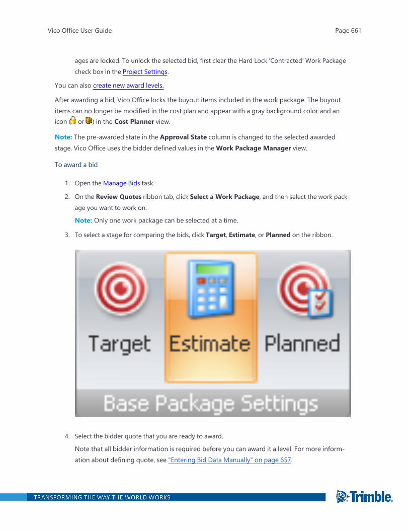
ages are locked. To unlock the selected bid, first clear the Hard Lock 'Contracted' Work Packagecheck box in the Project Settings.
You can also create new award levels.
After awarding a bid, Vico Office locks the buyout items included in the work package. The buyoutitems can no longer be modified in the cost plan and appear with a gray background color and anicon ( or ) in the Cost Planner view.
Note: The pre-awarded state in the Approval State column is changed to the selected awardedstage. Vico Office uses the bidder defined values in theWork Package Manager view.
To award a bid
1. Open the Manage Bids task.
2. On the Review Quotes ribbon tab, click Select a Work Package, and then select the work pack-age you want to work on.
Note: Only one work package can be selected at a time.
3. To select a stage for comparing the bids, click Target, Estimate, or Planned on the ribbon.
4. Select the bidder quote that you are ready to award.
Note that all bidder information is required before you can award it a level. For more inform-ation about defining quote, see "Entering Bid Data Manually" on page 657.
Vico Office User Guide Page 661
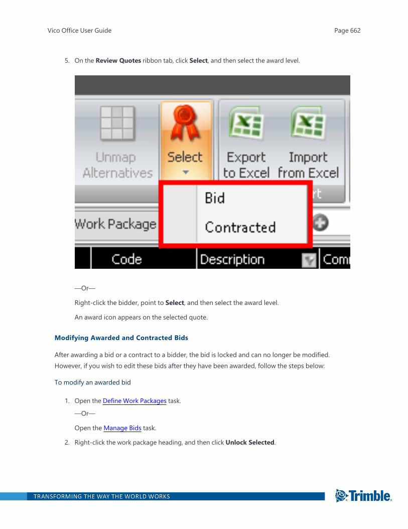
5. On the Review Quotes ribbon tab, click Select, and then select the award level.
—Or—
Right-click the bidder, point to Select, and then select the award level.
An award icon appears on the selected quote.
Modifying Awarded and Contracted Bids
After awarding a bid or a contract to a bidder, the bid is locked and can no longer be modified.However, if you wish to edit these bids after they have been awarded, follow the steps below:
To modify an awarded bid
1. Open the Define Work Packages task.
—Or—
Open the Manage Bids task.
2. Right-click the work package heading, and then click Unlock Selected.
Vico Office User Guide Page 662

An unlocked icon indicates that the bid is no longer awarded. The work package is no
longer locked, so it can now be modified.
To modify a contracted bid
1. Open the Define Settings task.
2. At the bottom-left corner, clear the Hard Lock 'Contracted' Work Packages check box.
Now you can unlock the work package.
3. Open the Manage Bids task.
4. On the Review Quotes ribbon tab, click Select a Work Package, and then select the work pack-age that you want to modify.
5. Right-click the work package, and then click Unlock Selected.
The work package is unlocked and editable.
Creating an Awarded Stage
You can create additional awarded states in the Tag Editor view. The new tags can then be selectedin the Bid Manager view.
To create an awarded stage
1. Open the Edit Tags task.
2. Expand the System category, and then select Approval State.
Vico Office User Guide Page 663
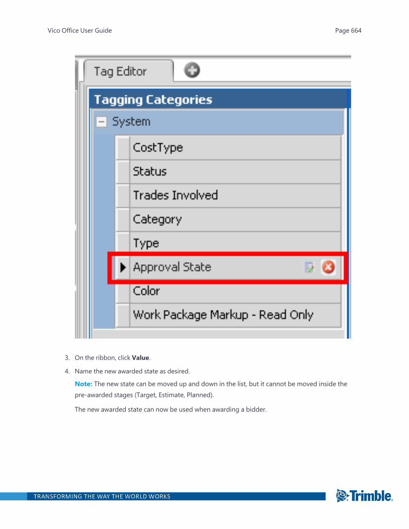
3. On the ribbon, click Value.
4. Name the new awarded state as desired.
Note: The new state can be moved up and down in the list, but it cannot be moved inside thepre-awarded stages (Target, Estimate, Planned).
The new awarded state can now be used when awarding a bidder.
Vico Office User Guide Page 664

Entering and Mapping an Alternative
If a bidder enters a different offer for a bid item, you can add a cost item as an alternative and make itas a replacement for the original cost item. Alternatives can be either manually entered into the bid orimported from Excel. For more information on importing from Excel, see "Exporting to/Importingfrom Microsoft Excel" on page 659.
After entering the alternatives, you can map them to the buyout item that you wish to replace.
To map an alternative
1. Open the Manage Bids task.
2. On the Review Quotes ribbon tab, click Select a Work Package, and then select the work pack-age for which you are entering an alternative.
Vico Office User Guide Page 665

3. Optional: On the ribbon, click Add Quote to add additional bidders.
4. In the Alternatives section of the spreadsheet, enter the alternatives and the related unit costs.
5. Select the alternative, and clickMap Alternatives on the ribbon.
6. Select the buyout item that you want to replace with the alternative, and then clickMap Altern-atives again.
The name of the alternative is entered in the Net Total column.
After you enter an alternative, the related cost line item appears in the Cost Planner view.
To see an alternative in the Cost Planner view
1. Open the Review Cost task.
—Or—
Open the Define Work Packages task.
2. In the Cost Planner view, click Show Alternatives on the Cost Planner ribbon tab.
—Or—
On theWork Package Manager & Cost Plan tab, click in the Cost Planner view to enablethe Alternatives group on the ribbon, and then click Show Alternatives.
Vico Office displays each alternative as a separate line item with a green background.
Alternatives can be moved under other line items, but they are not part of the cost plan basecost.
Using Plug Values
In the Bid Manager view, plug values are used to either determine the cost of line items in a workpackage or to exclude them from the work package's scope upon award. If a bidder does not providerequired unit costs for all the line items included in the work package, you can 'plug' the costs with
Vico Office User Guide Page 666
values from other sources to enable comparison based on the Target Cost, the Cost Plan, the PlannedValues, the Lowest Bid Prices, the Average Bid Prices, or the Highest Bid Prices.
Plugged numbers use the cost type from their original estimate to contribute to the totals. Plug val-ues also contribute to the Plug Values Summary.
Tip: Plug values shown in italics are calculated numbers.
Types of plug values:
l Based on Target Cost
l Based on Cost Plan
l Based on Planned Value
l Based on Lowest Bid Prices
l Based on Average Bid Price
l Based on Highest Bid Price
l Manually: Indicates that this plugged value was entered manually and is not based on any of theexisting values or prices.
l Included: Indicates that the price of the selected line item is already included in all the othercosts, so that the unit cost of the included line item shows a zero value.
l By Others: Indicates that the selected line item is definitely not included in the scope of workdefined by the work package and awarded bidder; thus, allowing it to be reallocated to anotherpackage.
Important: When you want to reset a unit cost from the plug value, you should select the cell in theNet Total column and delete it. Then manually enter the values to include in the calculation.
To reset plug values
1. Open the Manage Bids task.
2. Right-click the work item that you applied the plug value to, and then click Reset.
Vico Office User Guide Page 667
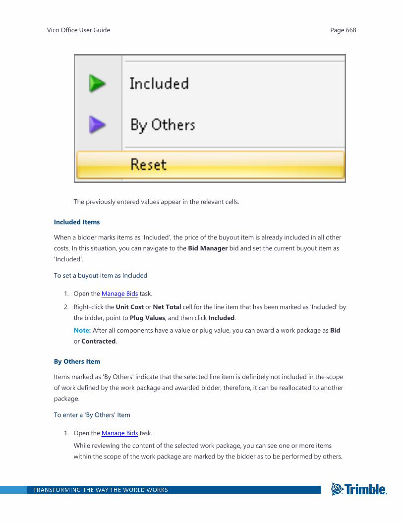
The previously entered values appear in the relevant cells.
Included Items
When a bidder marks items as 'Included', the price of the buyout item is already included in all othercosts. In this situation, you can navigate to the Bid Manager bid and set the current buyout item as'Included'.
To set a buyout item as Included
1. Open the Manage Bids task.
2. Right-click the Unit Cost or Net Total cell for the line item that has been marked as 'Included' bythe bidder, point to Plug Values, and then click Included.
Note: After all components have a value or plug value, you can award a work package as Bidor Contracted.
By Others Item
Items marked as 'By Others' indicate that the selected line item is definitely not included in the scopeof work defined by the work package and awarded bidder; therefore, it can be reallocated to anotherpackage.
To enter a 'By Others' Item
1. Open the Manage Bids task.
While reviewing the content of the selected work package, you can see one or more itemswithin the scope of the work package are marked by the bidder as to be performed by others.
Vico Office User Guide Page 668
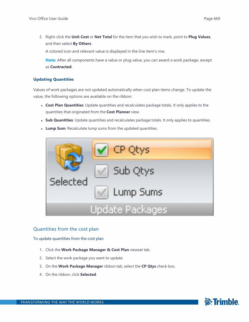
2. Right-click the Unit Cost or Net Total for the item that you wish to mark, point to Plug Values,and then select By Others.
A colored icon and relevant value is displayed in the line item's row.
Note: After all components have a value or plug value, you can award a work package, exceptas Contracted.
Updating Quantities
Values of work packages are not updated automatically when cost plan items change. To update thevalue, the following options are available on the ribbon:
l Cost Plan Quantities: Update quantities and recalculates package totals. It only applies to thequantities that originated from the Cost Planner view.
l Sub Quantities: Update quantities and recalculates package totals. It only applies to quantities.
l Lump Sum: Recalculate lump sums from the updated quantities.
Quantities from the cost plan
To update quantities from the cost plan
1. Click theWork Package Manager & Cost Plan viewset tab.
2. Select the work package you want to update.
3. On theWork Package Manager ribbon tab, select the CP Qtys check box.
4. On the ribbon, click Selected.
Vico Office User Guide Page 669
5. When prompted to confirm, click Yes.
Vico Office updates the quantities in the selected work package for every cost item that is usedfor Cost Planner quantities. This excludes items whose quantities were provided by the sub.After updating quantities, Vico Office automatically recalculates the package total using thenew quantities.
Quantities from the subsAfter you create a work package with the allocated buyout items and enter the bid that is priced bythe sub's own quantities, the actual quantities should be updated from the cost plan.
To replace subcontractor quantities with cost plan quantities
1. Click theWork Package Manager & Cost Plan viewset tab.
2. Select the work package you want to update.
3. On theWork Package Manager ribbon tab, select the Sub Qtys check box.
4. On the ribbon, click Selected.
5. When prompted to confirm, click Yes.
Vico Office updates all the quantities in the selected work package. After updating the quant-ities, Vico Office automatically recalculates the package totals using the new quantities by mul-tiplying the unit costs with the value entered by the sub. The lump sums that were defined bythe subcontractor are not affected.
Lump sums from changed quantitiesAfter updating the quantities in the work packages and the bids, you can update the lump sum to cal-culate the final total price for the bids.
If a subcontractor has provided a lump sum and the package quantities subsequently change thisfunctionality is to allow you to recalculate the lump sum based on distributed values to provide an‘educated guess’ as to what the revised lump sum may be as a temporary measure until the sub-contractor can confirm updated pricing.
To update lump sums
1. Click theWork Package Manager & Cost Plan viewset tab.
2. Select the work package you want to update.
3. On theWork Package Manager ribbon tab, select the Lump Sums check box.
4. On the ribbon, click Selected.
Vico Office User Guide Page 670

Vico Office updates the lump sums for every bid by using the cost plan quantities and mul-tiplying them to the calculated unit cost created when the subs' bids were originally entered.
Managing Markup Adjustments
Quite often, you may need to make adjustments to a work package while comparing bids. Forexample, you may wish to award a 2.5% discount to main contractors for payments made within 30days, or perhaps you wish to add the cost of an additional crane. Using the Markup Adjustments fea-ture available in Work Package Manager, you can create positive or negative markups depending onyour changes. Markup adjustments will enable you to create an audit trail of your adjustments.
To add a markup adjustment
1. Open the Define Work Packages task.
2. Click theWork Package Manager & Cost Plan viewset tab.
3. On the ribbon of theWork Package Manager tab, clickManage Markup Adjustments
Note: By default, the 'UNC - Unclassified' markup adjustment is created. Please see "Unclas-sified Markup Adjustments" on page 673 on the recommended use of this markup adjustmenttype.
4. Click . A new row is added to the table.
5. Enter a Code and Description for the new markup.
6. Repeat steps 5 - 6 to create additional markup adjustments.
7. Click OK to save your changes.
8. You can now assign these markup adjustments to work packages. For more information, see"Assigning Markup Adjustments" on the next page
To delete a markup adjustment
1. On the Manage Markup Adjustments dialog box, select the markup to delete.
2. Click . The selected markup is deleted.
Vico Office User Guide Page 671
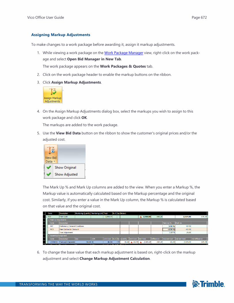
Assigning Markup Adjustments
To make changes to a work package before awarding it, assign it markup adjustments.
1. While viewing a work package on the Work Package Manager view, right-click on the work pack-age and select Open Bid Manager in New Tab.
The work package appears on theWork Packages & Quotes tab.
2. Click on the work package header to enable the markup buttons on the ribbon.
3. Click Assign Markup Adjustments.
.
4. On the Assign Markup Adjustments dialog box, select the markups you wish to assign to thiswork package and click OK.
The markups are added to the work package.
5. Use the View Bid Data button on the ribbon to show the customer's original prices and/or theadjusted cost.
The Mark Up % and Mark Up columns are added to the view. When you enter a Markup %, theMarkup value is automatically calculated based on the Markup percentage and the originalcost. Similarly, if you enter a value in the Mark Up column, the Markup % is calculated basedon that value and the original cost.
6. To change the base value that each markup adjustment is based on, right-click on the markupadjustment and select Change Markup Adjustment Calculation.
Vico Office User Guide Page 672
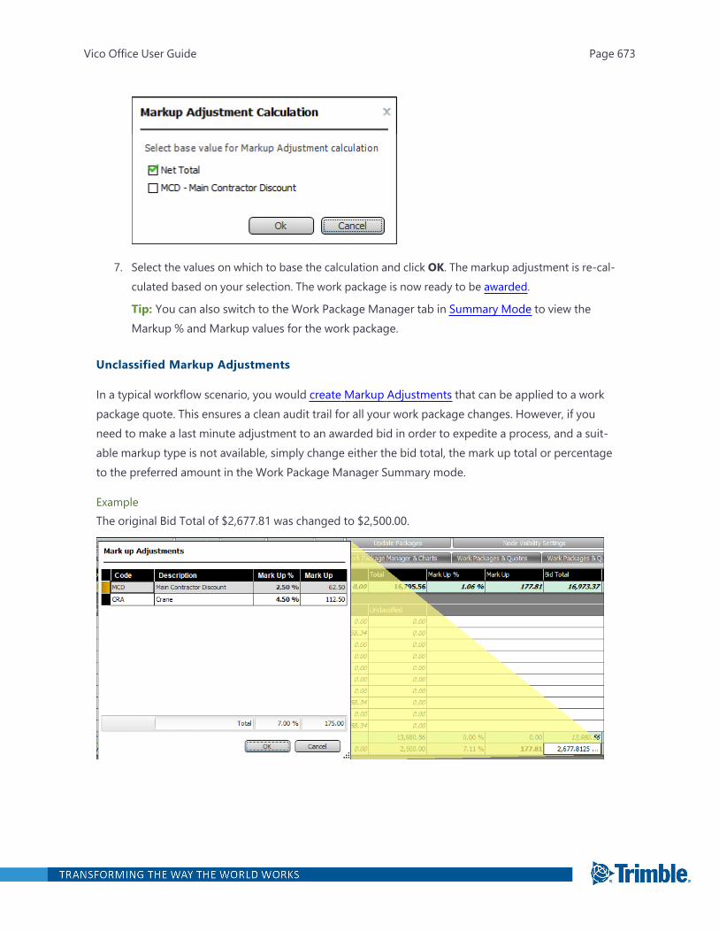
7. Select the values on which to base the calculation and click OK. The markup adjustment is re-cal-culated based on your selection. The work package is now ready to be awarded.
Tip: You can also switch to the Work Package Manager tab in Summary Mode to view theMarkup % and Markup values for the work package.
Unclassified Markup Adjustments
In a typical workflow scenario, you would create Markup Adjustments that can be applied to a workpackage quote. This ensures a clean audit trail for all your work package changes. However, if youneed to make a last minute adjustment to an awarded bid in order to expedite a process, and a suit-able markup type is not available, simply change either the bid total, the mark up total or percentageto the preferred amount in the Work Package Manager Summary mode.
ExampleThe original Bid Total of $2,677.81 was changed to $2,500.00.
Vico Office User Guide Page 673
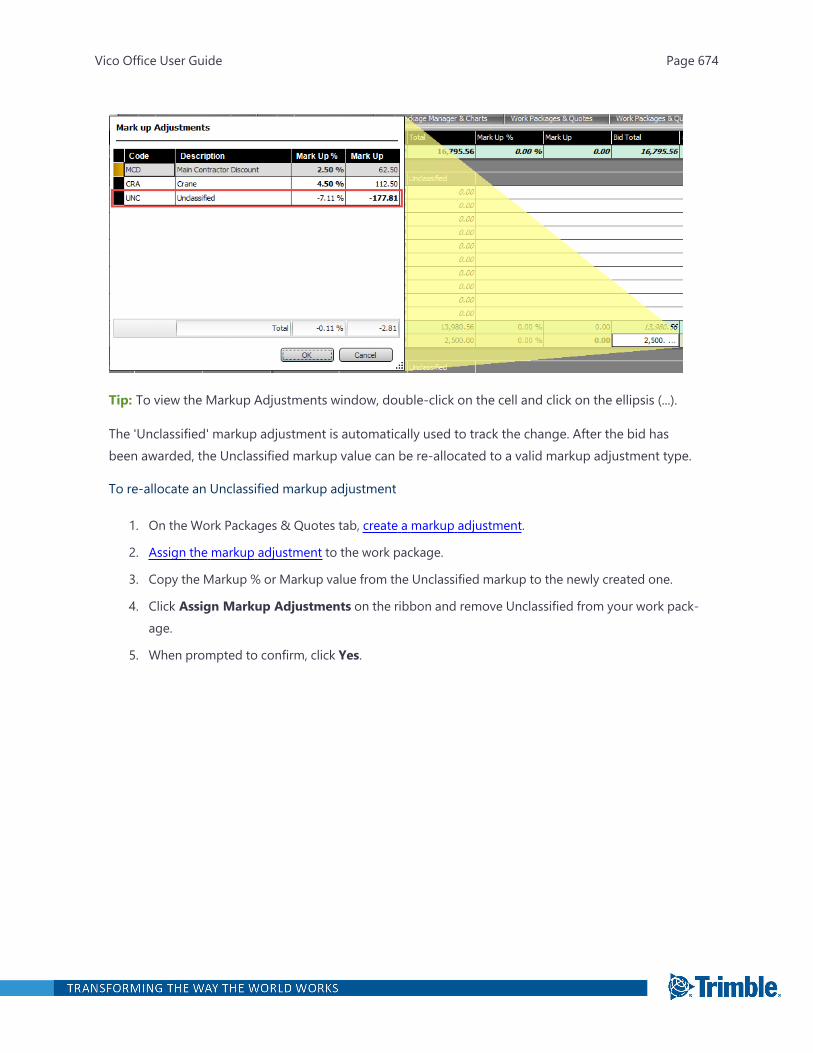
Tip: To view the Markup Adjustments window, double-click on the cell and click on the ellipsis (...).
The 'Unclassified' markup adjustment is automatically used to track the change. After the bid hasbeen awarded, the Unclassified markup value can be re-allocated to a valid markup adjustment type.
To re-allocate an Unclassified markup adjustment
1. On the Work Packages & Quotes tab, create a markup adjustment.
2. Assign the markup adjustment to the work package.
3. Copy the Markup % or Markup value from the Unclassified markup to the newly created one.
4. Click Assign Markup Adjustments on the ribbon and remove Unclassified from your work pack-age.
5. When prompted to confirm, click Yes.
Vico Office User Guide Page 674

Create Reports
Vico Office contains the built-in Report Designer that you can use to generate location-based quant-ity reports for your project. All information, including project properties, that you defined for your pro-ject can be used in your report. The templates that you create can be used with all projects in thecurrent database.
To open the Create & Run Reports task
l In the Reporting & Data Mining workflow group, click Create & Run Reports.
The default viewset includes the Reports view.
Viewing a report
Built-in report templates are available in the Reports view. You can use any of these templates to gen-erate a quantity report for the active project.
To view a report
1. Open the Create & Run Reports task.
2. In the Categories and Reports tree, right-click a template, and then click Generate Report.
Vico Office User Guide Page 675
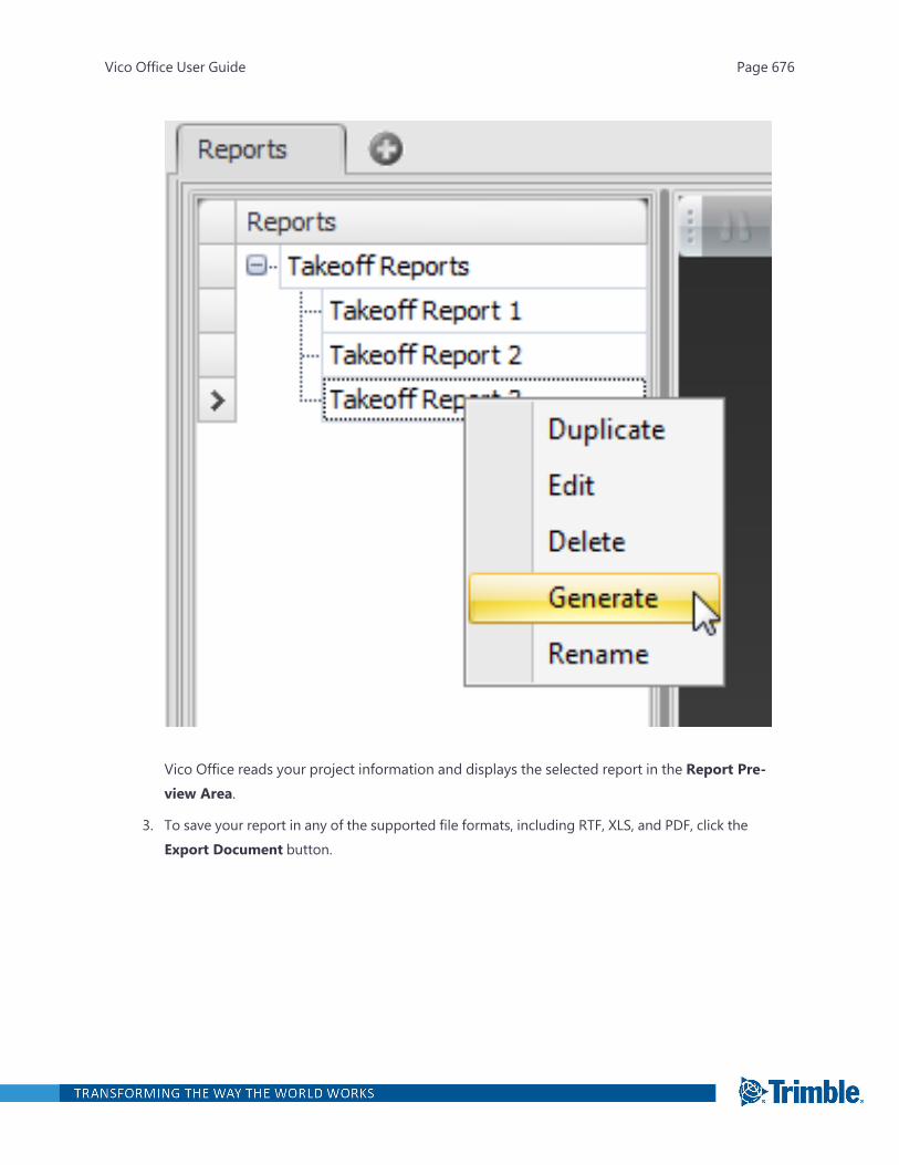
Vico Office reads your project information and displays the selected report in the Report Pre-view Area.
3. To save your report in any of the supported file formats, including RTF, XLS, and PDF, click theExport Document button.
Vico Office User Guide Page 676

Working with Report Templates
With the Report Designer included in Vico Office, you can create your own reports, or modify existingtemplates by adding your company's logo or contact information.
Report templates are defined using bands, which are report sections that contain the informationsources that are available for your project. You can add bands for the report header, footer, and title.
The main content of the report is included through detail bands. Takeoff Manager has two standarddetail bands, Project Properties and Takeoff Items, that contain the functionality to combine your pro-ject information correctly.
Note: A template must always be included in a category. If your project does not contain any cat-egories yet, click New Category, and create a category.
To create a report template
1. Open the Create & Run Reports task.
2. Click on the template category where you want your template to be added.
Tip: A template category groups your templates.
3. On the Reports ribbon tab, click New Template and enter a descriptive name for the template.
Vico Office User Guide Page 677
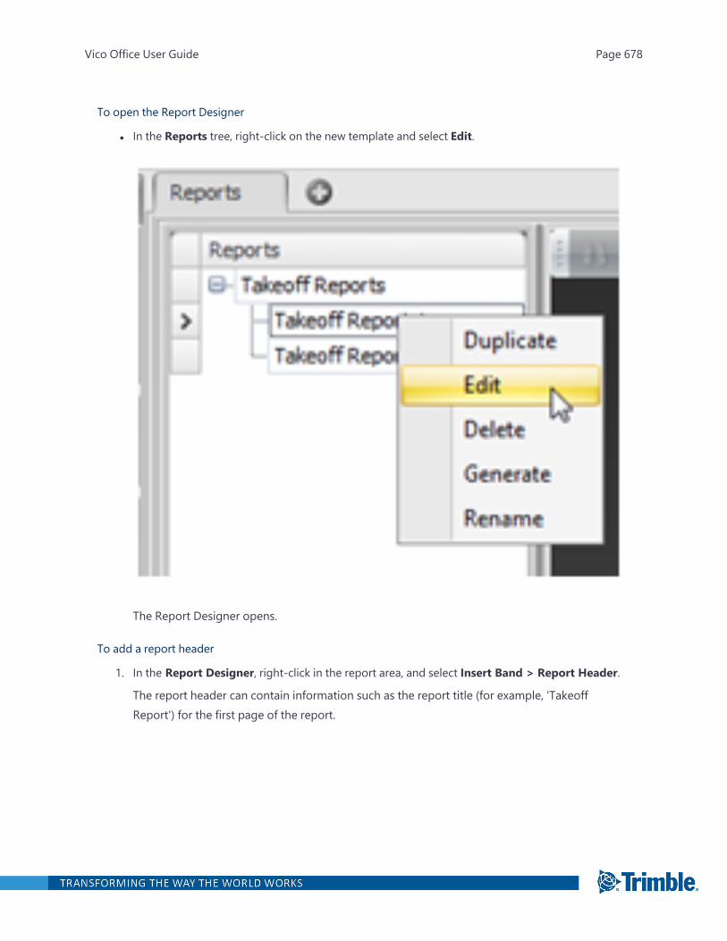
To open the Report Designer
l In the Reports tree, right-click on the new template and select Edit.
The Report Designer opens.
To add a report header
1. In the Report Designer, right-click in the report area, and select Insert Band > Report Header.
The report header can contain information such as the report title (for example, 'TakeoffReport') for the first page of the report.
Vico Office User Guide Page 678
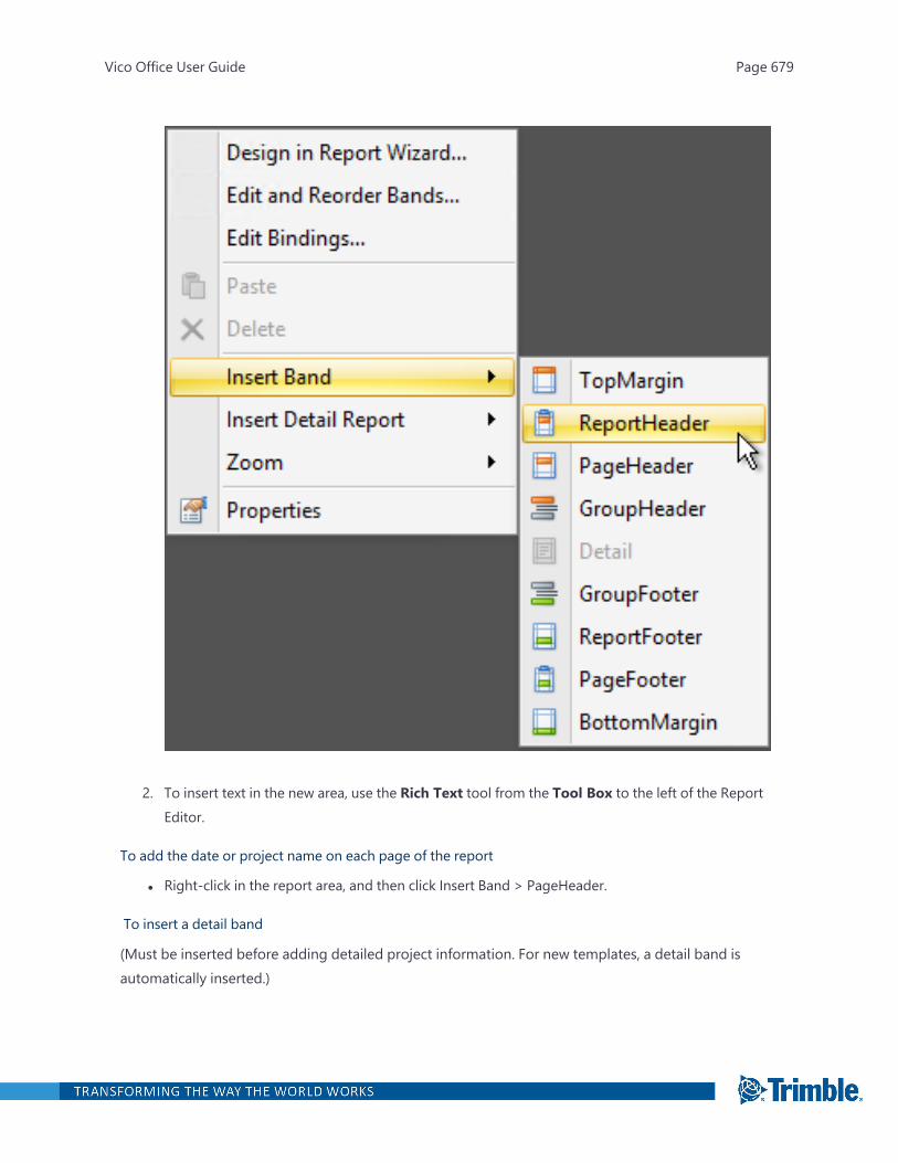
2. To insert text in the new area, use the Rich Text tool from the Tool Box to the left of the ReportEditor.
To add the date or project name on each page of the report
l Right-click in the report area, and then click Insert Band > PageHeader.
To insert a detail band
(Must be inserted before adding detailed project information. For new templates, a detail band isautomatically inserted.)
Vico Office User Guide Page 679
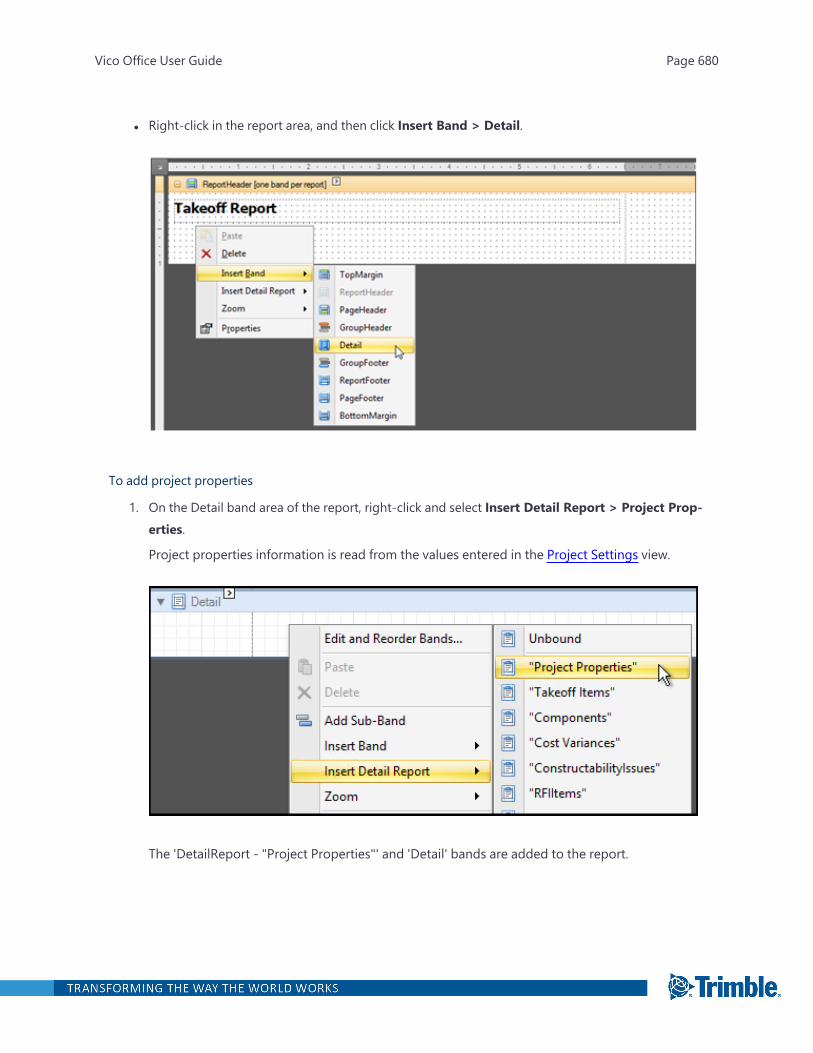
l Right-click in the report area, and then click Insert Band > Detail.
To add project properties
1. On the Detail band area of the report, right-click and select Insert Detail Report > Project Prop-erties.
Project properties information is read from the values entered in the Project Settings view.
The 'DetailReport - "Project Properties"' and 'Detail' bands are added to the report.
Vico Office User Guide Page 680

2. In the Report Explorer window to the right, click the Field List tab.
Vico Office User Guide Page 681
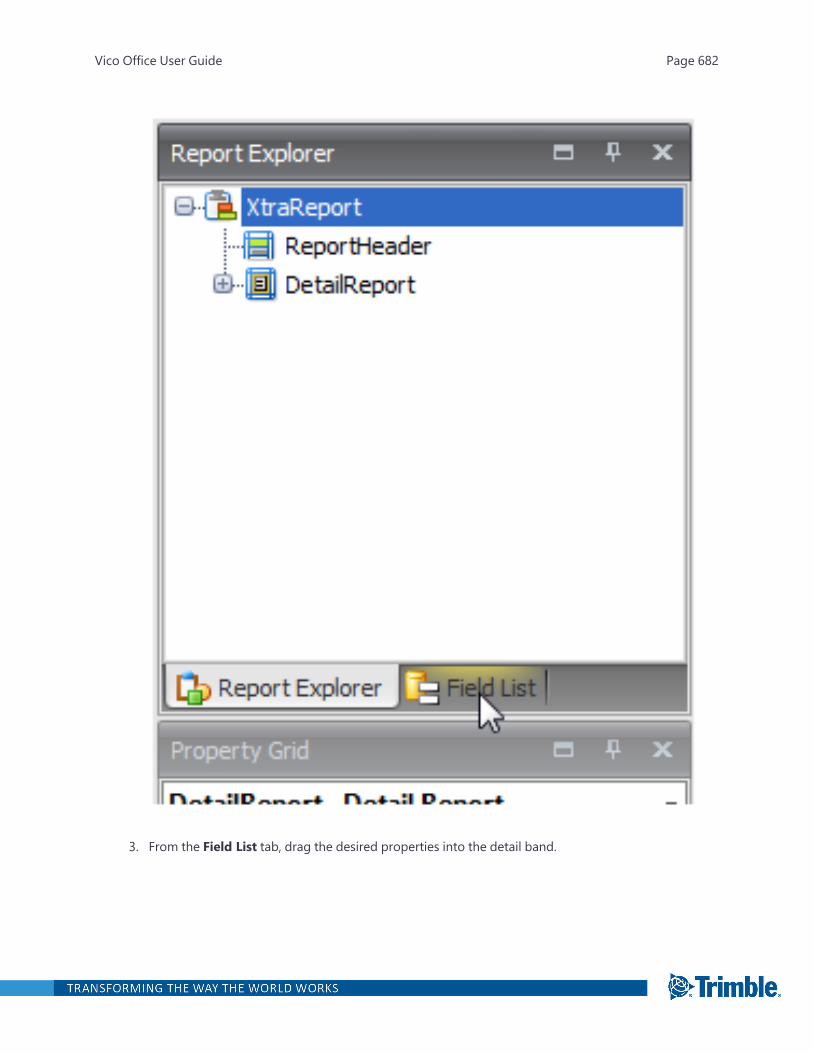
3. From the Field List tab, drag the desired properties into the detail band.
Vico Office User Guide Page 682
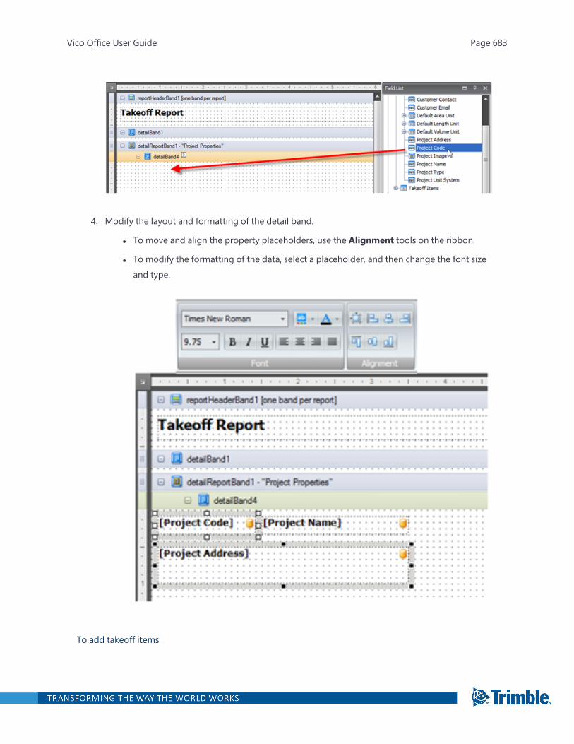
4. Modify the layout and formatting of the detail band.
l To move and align the property placeholders, use the Alignment tools on the ribbon.
l To modify the formatting of the data, select a placeholder, and then change the font sizeand type.
To add takeoff items
Vico Office User Guide Page 683
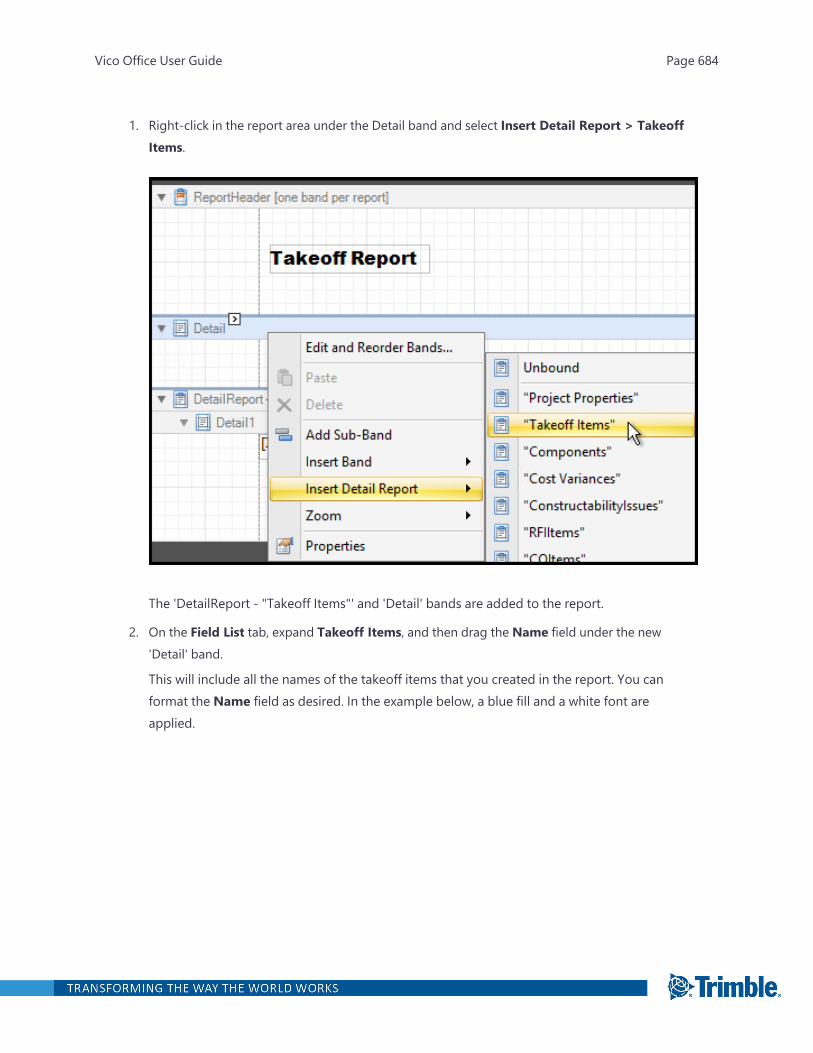
1. Right-click in the report area under the Detail band and select Insert Detail Report > TakeoffItems.
The 'DetailReport - "Takeoff Items"' and 'Detail' bands are added to the report.
2. On the Field List tab, expand Takeoff Items, and then drag the Name field under the new'Detail' band.
This will include all the names of the takeoff items that you created in the report. You canformat the Name field as desired. In the example below, a blue fill and a white font areapplied.
Vico Office User Guide Page 684
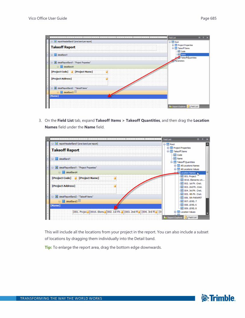
3. On the Field List tab, expand Takeoff Items > Takeoff Quantities, and then drag the LocationNames field under the Name field.
This will include all the locations from your project in the report. You can also include a subsetof locations by dragging them individually into the Detail band.
Tip: To enlarge the report area, drag the bottom edge downwards.
Vico Office User Guide Page 685
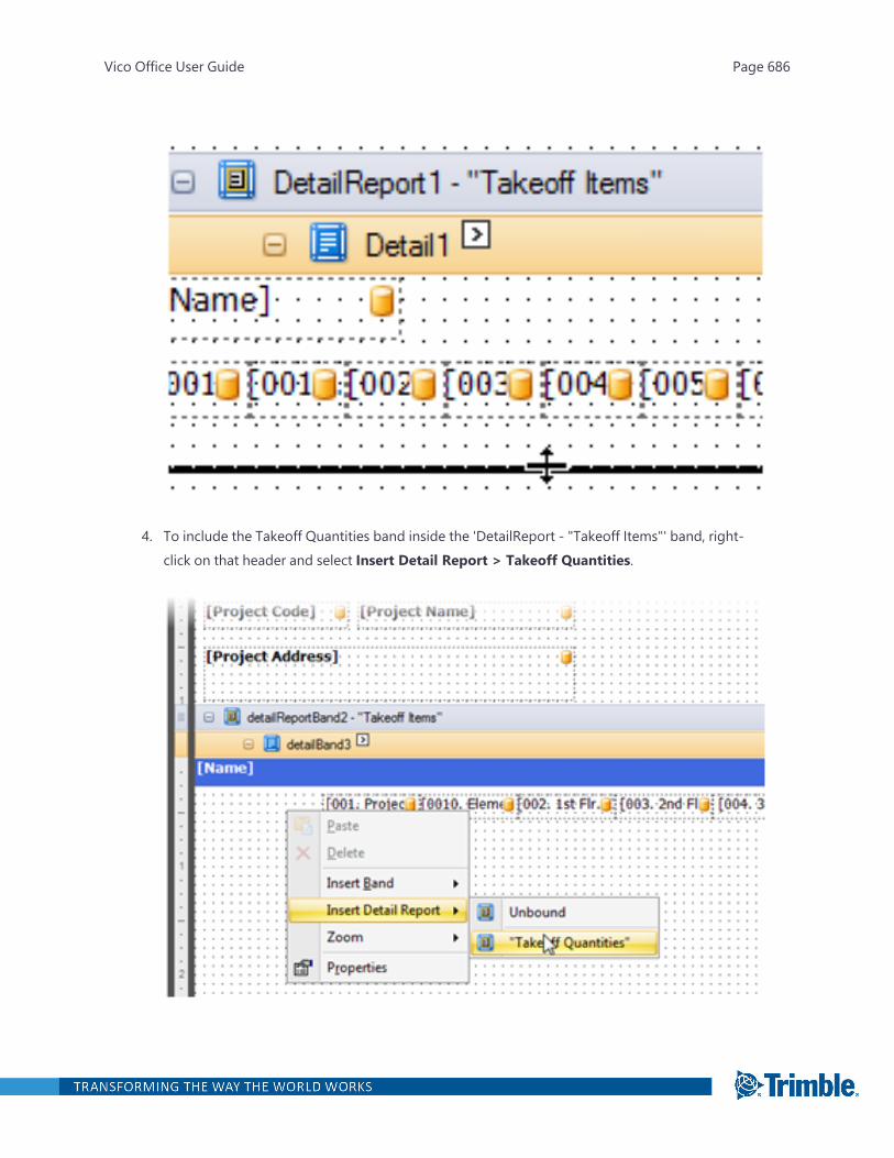
4. To include the Takeoff Quantities band inside the 'DetailReport - "Takeoff Items"' band, right-click on that header and select Insert Detail Report > Takeoff Quantities.
Vico Office User Guide Page 686

The 'DetailReport - "Takeoff Items.Takeoff Quantities" and "Detail" bands are added to thereport.
5. On the Field List tab, expand Takeoff Items > Takeoff Quantities, and then drag the Namefield into the detailReport Band - "Takeoff Quantities".
All takeoff quantities are automatically included.
6. From the Field List tab, drag Location Values, the quantity values for all locations and takeoffquantities, to underneath the Locations field in the detailBand.
Tip: Ensure that the locations and location values are properly aligned to guarantee that theyare presented correctly in the report.
Vico Office User Guide Page 687
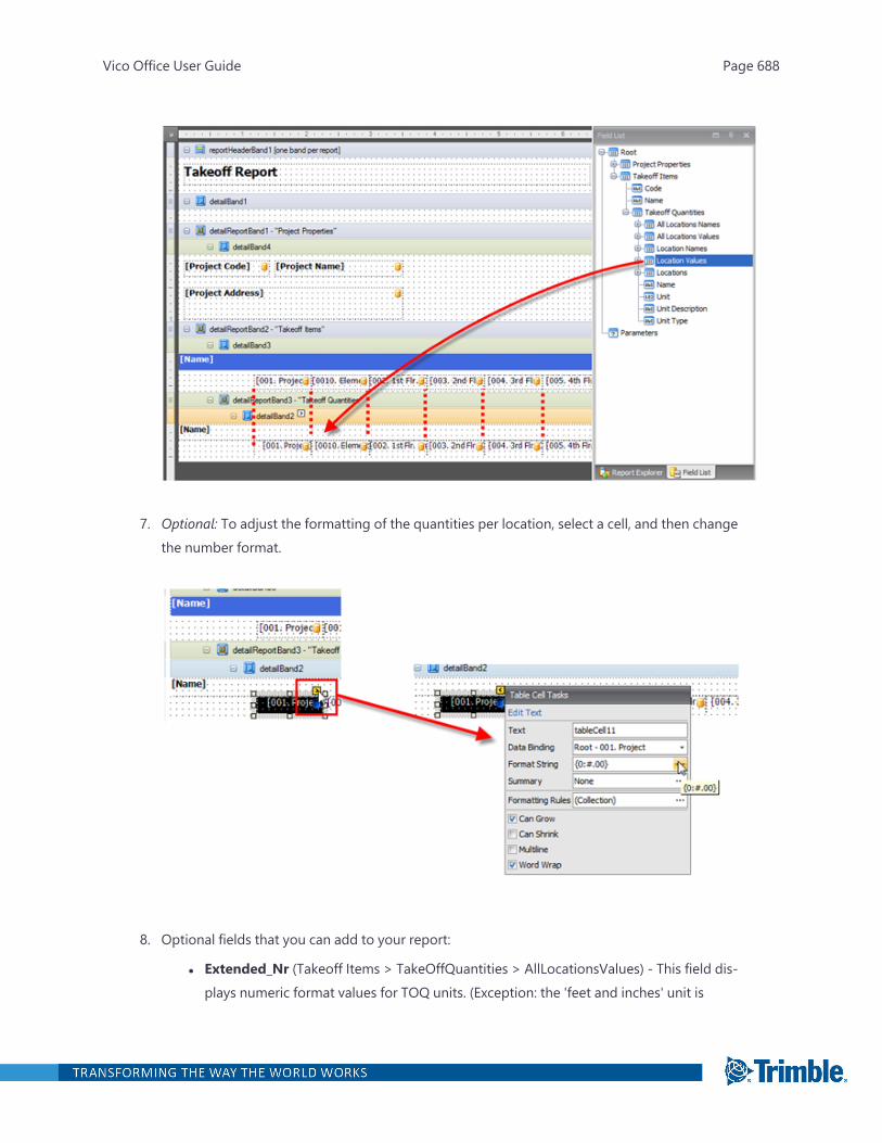
7. Optional: To adjust the formatting of the quantities per location, select a cell, and then changethe number format.
8. Optional fields that you can add to your report:
l Extended_Nr (Takeoff Items > TakeOffQuantities > AllLocationsValues) - This field dis-plays numeric format values for TOQ units. (Exception: the 'feet and inches' unit is
Vico Office User Guide Page 688
displayed in inches.) You can also apply the standard report field formatting to thisnumeric field. If you do not need this to appear as a numeric field, use the 'Extended'field.
l WarningType (Takeoff Items > WarningType) - Displays a value that represents the warn-ing message that appears next to each Takeoff Item on the Takeoff Manager view (Infocolumn).
Value Definition:
l 0 - no warning is displayed next to this Takeoff item in Takeoff Manager.
l 1 - Information - Indicates that the Takeoff item has elements with manual quant-ities. Corresponds to the blue circle icon 'Information' in Takeoff Manager.
l 2 - Other - Indicates that the Takeoff item has takeoff quantities that could not becalculated correctly or if a quantity is missing. Corresponds to the yellow triangleicon 'Missing Quantity' in Takeoff Manager.
l 3 - Reactivate model - Indicates that the model needs to be reactivated. Cor-responds to the blue triangle icon in Takeoff Manager.
l 4 - Re-quantification of the Takeoff item is required. Corresponds to the orange tri-angle icon 'Requantify Takeoff item' in Takeoff Manager.
To edit and reorder report bands
Vico Office User Guide Page 689
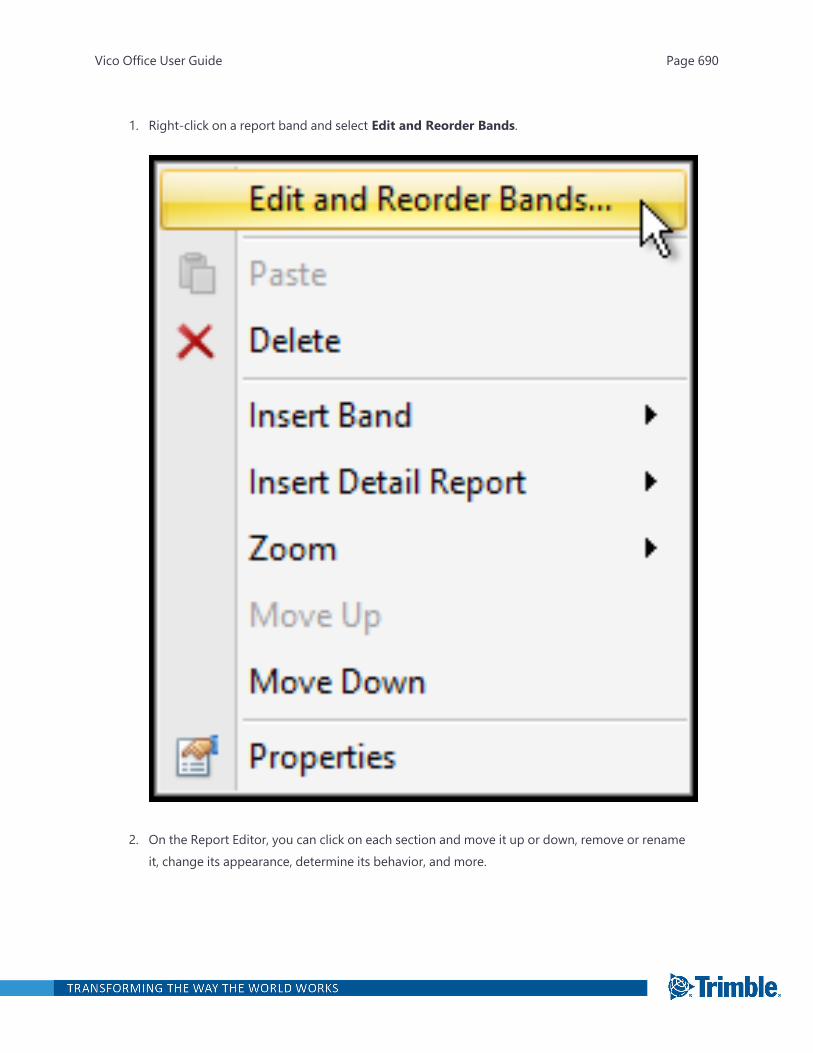
1. Right-click on a report band and select Edit and Reorder Bands.
2. On the Report Editor, you can click on each section and move it up or down, remove or renameit, change its appearance, determine its behavior, and more.
Vico Office User Guide Page 690
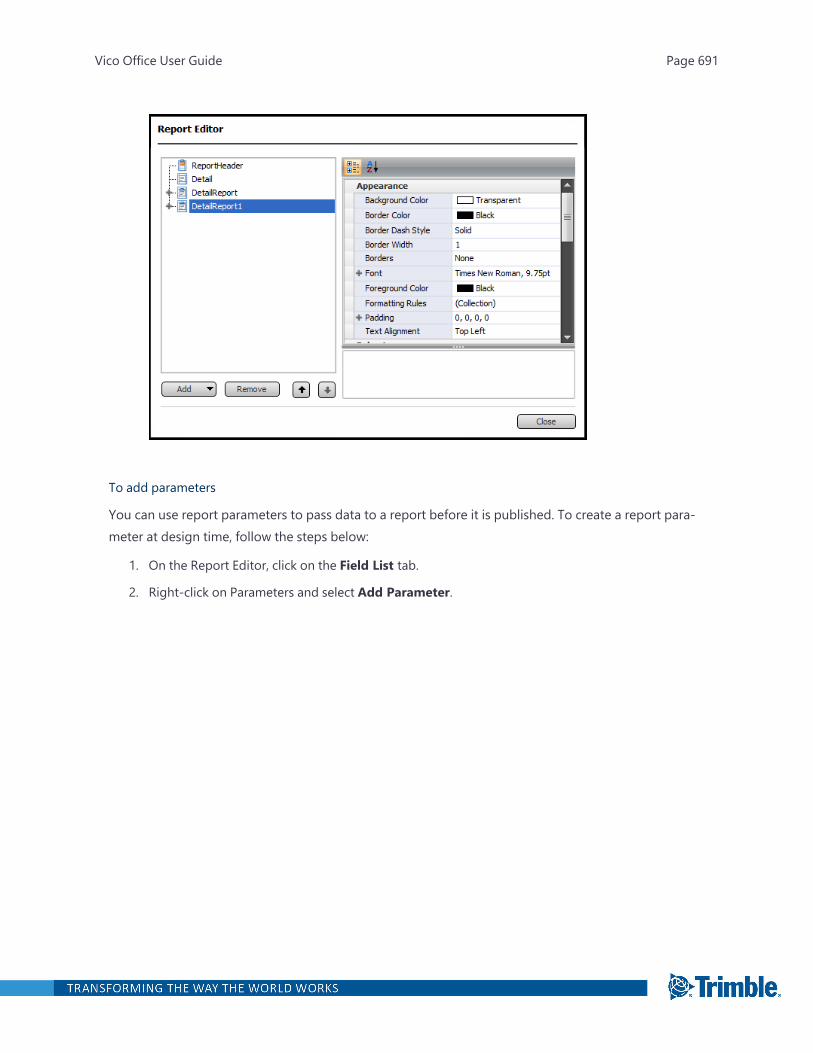
To add parameters
You can use report parameters to pass data to a report before it is published. To create a report para-meter at design time, follow the steps below:
1. On the Report Editor, click on the Field List tab.
2. Right-click on Parameters and select Add Parameter.
Vico Office User Guide Page 691

3. On the Add New Parameter dialog box, choose the following options:
l Name: Enter a unique name for the parameter.
l Description: Enter the text that will be displayed in a Print Preview along with the cor-responding value.
l Type: Specify the parameter's value type. This property can be set to any standard datatype matching the expected data type of the parameter value.
l Default value: Specify the default parameter value.
l Show in the parameters panel: Enable this option to show the parameter value ina Print Preview.
l Supports the collection of standard values: Enable this option if the parameter isvisible (i.e., its value will be shown during Print Preview). The user will be promp-ted to choose a value from a predefined list. You can manually populate this listwith possible values.
l Allow multiple values: Enable this option if a parameter can be assigned a col-lection of values.
Vico Office User Guide Page 692

l Dynamic values: Although it is on the Report Designer, the Dynamic values tab is cur-rently not supported.
l Static values: Click on this tab to specify a static list of possible values. Each value shouldhave a description that is displayed in the Print Preview.
Changing the Report Page Settings
To change the page settings of a report template
1. Open the Create & Run Reports task.
2. Create a report template in the Report Designer.
3. In the Report Explorer panel to the right of the Report Designer, click the name of the reporttemplate.
Vico Office User Guide Page 693

4. In the Property Grid, scroll to the Page Settings section.
Vico Office User Guide Page 694
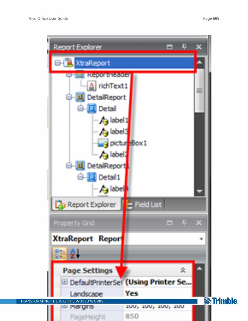
Vico Office User Guide Page 695
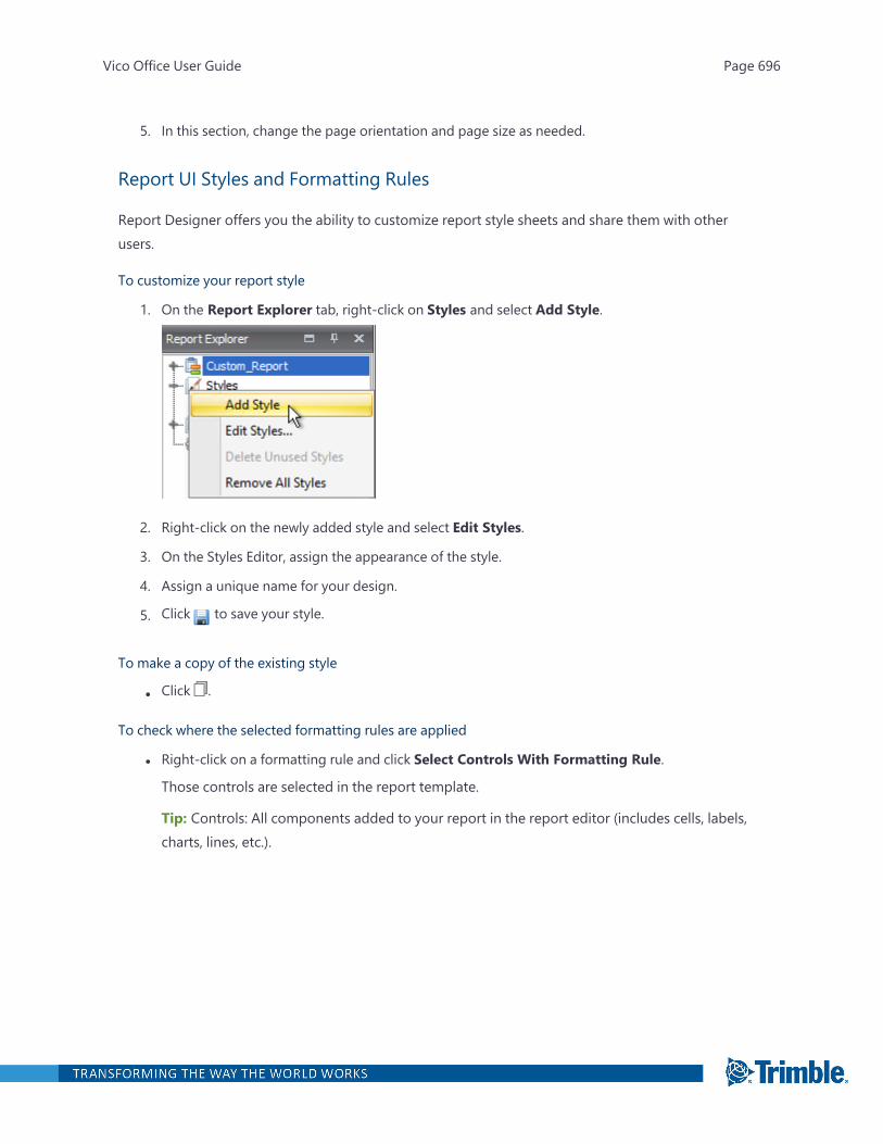
5. In this section, change the page orientation and page size as needed.
Report UI Styles and Formatting Rules
Report Designer offers you the ability to customize report style sheets and share them with otherusers.
To customize your report style
1. On the Report Explorer tab, right-click on Styles and select Add Style.
2. Right-click on the newly added style and select Edit Styles.
3. On the Styles Editor, assign the appearance of the style.
4. Assign a unique name for your design.
5. Click to save your style.
To make a copy of the existing style
l Click .
To check where the selected formatting rules are applied
l Right-click on a formatting rule and click Select Controls With Formatting Rule.
Those controls are selected in the report template.
Tip: Controls: All components added to your report in the report editor (includes cells, labels,charts, lines, etc.).
Vico Office User Guide Page 696

VICO OFFICER6.8 MR2 USER GUIDE
6.8.83.956July 2021

Quantities and Units
The following units and abbreviations are available in Vico Office:
Dimension Units(Imperial)
Units Abbr(Imperial)
Units (Metric) Units Abbr(Metric)
Length Inch IN Millimeter MM
Feet and Inches FT-IN Centimeter CM
Foot FT Decimeter DM
Yard YD Meter M
Mile MI Kilometer KM
Area Square Inch SQ IN Square Millimeter MM2
Square Foot SQ FT SquareCentimeter
CM2
Square Yard SQ YD Square Decimeter DM2
Square Meter M2
Volume &Capacity
Cubic Inch CU IN Cubic Centimeter CM3
Cubic Foot CU FT Cubic Decimeter DM3
Cubic Yard CU YD Cubic Meter M3
Pint PT Centiliter CL
Quart QT Deciliter DL
Gallon GAL Litre L
Weight Ounce OZ Gram G
Pound LB Kilogram KG
TON (Short) T (S) TON (Metric) T (M)
TON (Long) T (L)
Count / General Each EA Each EA
Vico Office User Guide Page 2
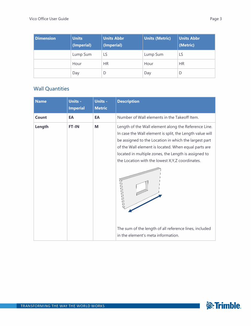
Dimension Units(Imperial)
Units Abbr(Imperial)
Units (Metric) Units Abbr(Metric)
Lump Sum LS Lump Sum LS
Hour HR Hour HR
Day D Day D
Wall Quantities
Name Units -Imperial
Units -Metric
Description
Count EA EA Number of Wall elements in the Takeoff Item.
Length FT-IN M Length of the Wall element along the Reference Line.In case the Wall element is split, the Length value willbe assigned to the Location in which the largest partof the Wall element is located. When equal parts arelocated in multiple zones, the Length is assigned tothe Location with the lowest X,Y,Z coordinates.
The sum of the length of all reference lines, includedin the element's meta information.
Vico Office User Guide Page 3
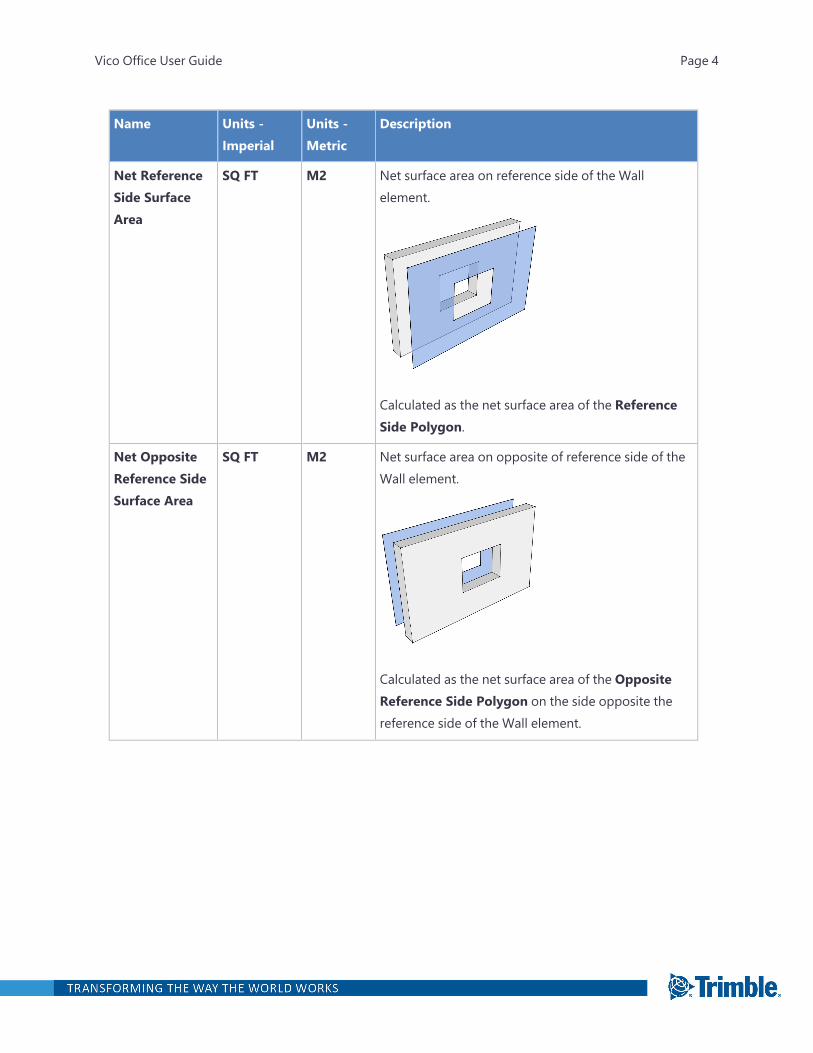
Name Units -Imperial
Units -Metric
Description
Net ReferenceSide SurfaceArea
SQ FT M2 Net surface area on reference side of the Wallelement.
Calculated as the net surface area of the ReferenceSide Polygon.
Net OppositeReference SideSurface Area
SQ FT M2 Net surface area on opposite of reference side of theWall element.
Calculated as the net surface area of the OppositeReference Side Polygon on the side opposite thereference side of the Wall element.
Vico Office User Guide Page 4
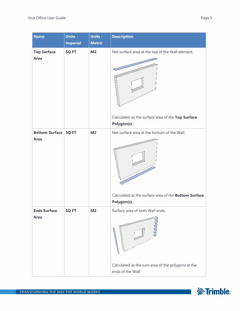
Name Units -Imperial
Units -Metric
Description
Top SurfaceArea
SQ FT M2 Net surface area at the top of the Wall element.
Calculated as the surface area of the Top SurfacePolygon(s).
Bottom SurfaceArea
SQ FT M2 Net surface area at the bottom of the Wall.
Calculated as the surface area of the Bottom SurfacePolygon(s).
Ends SurfaceArea
SQ FT M2 Surface area of both Wall ends.
Calculated as the sum area of the polygons at theends of the Wall.
Vico Office User Guide Page 5
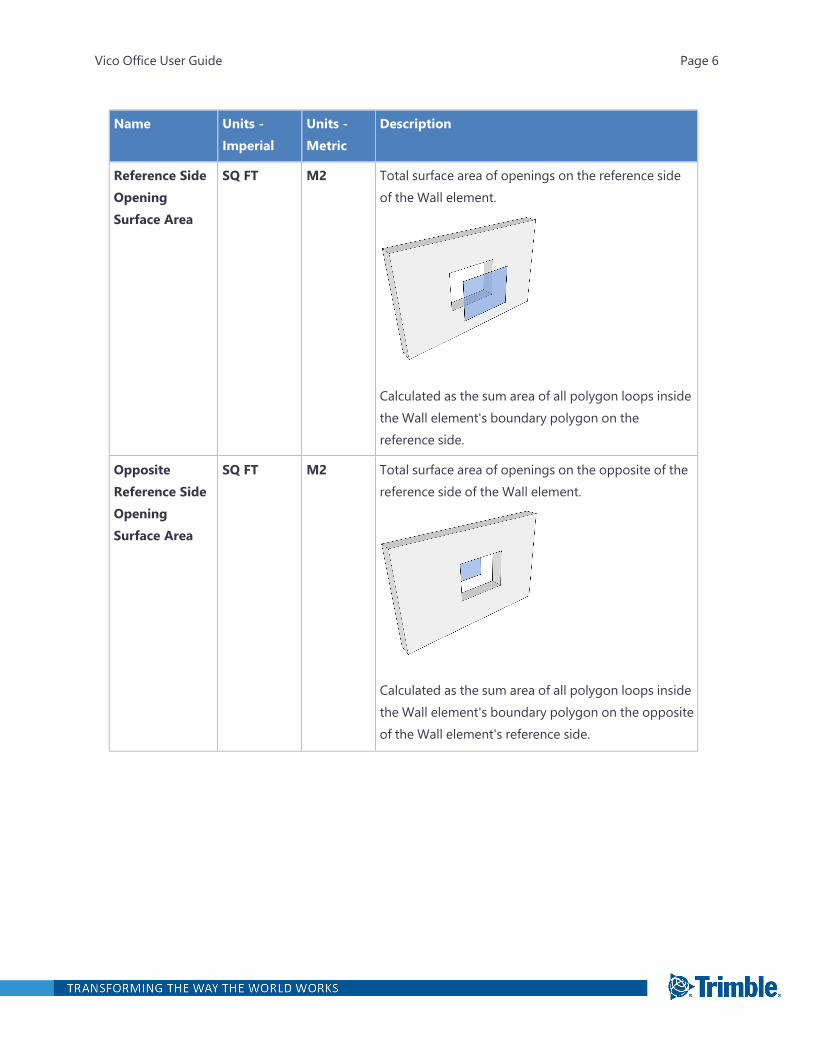
Name Units -Imperial
Units -Metric
Description
Reference SideOpeningSurface Area
SQ FT M2 Total surface area of openings on the reference sideof the Wall element.
Calculated as the sum area of all polygon loops insidethe Wall element's boundary polygon on thereference side.
OppositeReference SideOpeningSurface Area
SQ FT M2 Total surface area of openings on the opposite of thereference side of the Wall element.
Calculated as the sum area of all polygon loops insidethe Wall element's boundary polygon on the oppositeof the Wall element's reference side.
Vico Office User Guide Page 6
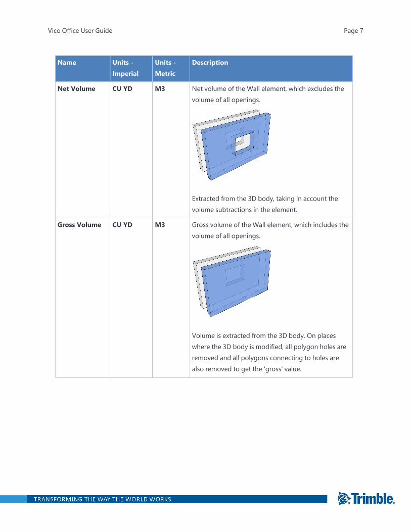
Name Units -Imperial
Units -Metric
Description
Net Volume CU YD M3 Net volume of the Wall element, which excludes thevolume of all openings.
Extracted from the 3D body, taking in account thevolume subtractions in the element.
Gross Volume CU YD M3 Gross volume of the Wall element, which includes thevolume of all openings.
Volume is extracted from the 3D body. On placeswhere the 3D body is modified, all polygon holes areremoved and all polygons connecting to holes arealso removed to get the 'gross' value.
Vico Office User Guide Page 7
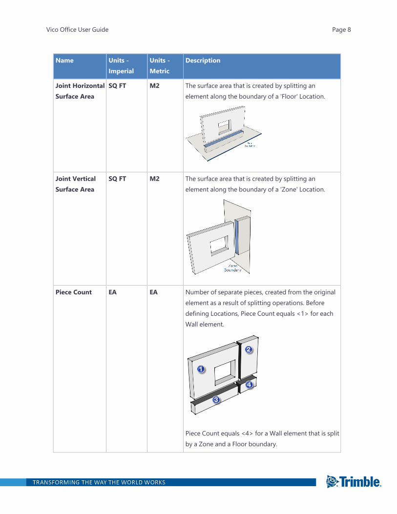
Name Units -Imperial
Units -Metric
Description
Joint HorizontalSurface Area
SQ FT M2 The surface area that is created by splitting anelement along the boundary of a 'Floor' Location.
Joint VerticalSurface Area
SQ FT M2 The surface area that is created by splitting anelement along the boundary of a 'Zone' Location.
Piece Count EA EA Number of separate pieces, created from the originalelement as a result of splitting operations. Beforedefining Locations, Piece Count equals <1> for eachWall element.
Piece Count equals <4> for a Wall element that is splitby a Zone and a Floor boundary.
Vico Office User Guide Page 8
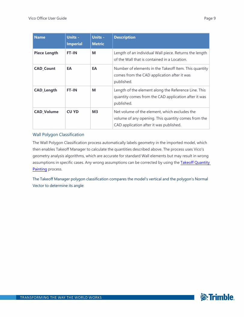
Name Units -Imperial
Units -Metric
Description
Piece Length FT-IN M Length of an individual Wall piece. Returns the lengthof the Wall that is contained in a Location.
CAD_Count EA EA Number of elements in the Takeoff Item. This quantitycomes from the CAD application after it waspublished.
CAD_Length FT-IN M Length of the element along the Reference Line. Thisquantity comes from the CAD application after it waspublished.
CAD_Volume CU YD M3 Net volume of the element, which excludes thevolume of any opening. This quantity comes from theCAD application after it was published.
Wall Polygon Classification
The Wall Polygon Classification process automatically labels geometry in the imported model, whichthen enables Takeoff Manager to calculate the quantities described above. The process uses Vico'sgeometry analysis algorithms, which are accurate for standard Wall elements but may result in wrongassumptions in specific cases. Any wrong assumptions can be corrected by using the Takeoff QuantityPainting process.
The Takeoff Manager polygon classification compares the model's vertical and the polygon's NormalVector to determine its angle:
Vico Office User Guide Page 9
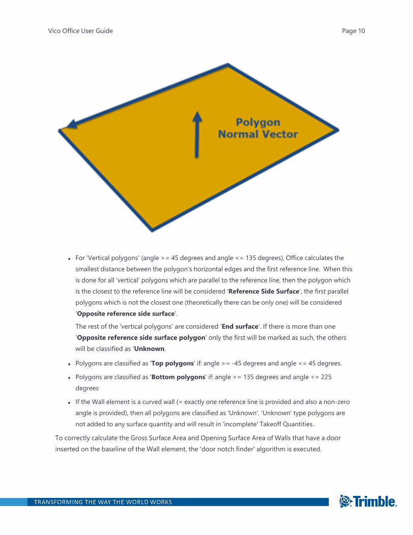
l For 'Vertical polygons' (angle >= 45 degrees and angle <= 135 degrees), Office calculates thesmallest distance between the polygon's horizontal edges and the first reference line. When thisis done for all 'vertical' polygons which are parallel to the reference line, then the polygon whichis the closest to the reference line will be considered 'Reference Side Surface', the first parallelpolygons which is not the closest one (theoretically there can be only one) will be considered'Opposite reference side surface'.
The rest of the 'vertical polygons' are considered 'End surface'. If there is more than one'Opposite reference side surface polygon' only the first will be marked as such, the otherswill be classified as 'Unknown.
l Polygons are classified as 'Top polygons' if: angle >= -45 degrees and angle <= 45 degrees.
l Polygons are classified as 'Bottom polygons' if: angle >= 135 degrees and angle <= 225degrees
l If the Wall element is a curved wall (= exactly one reference line is provided and also a non-zeroangle is provided), then all polygons are classified as 'Unknown'. 'Unknown' type polygons arenot added to any surface quantity and will result in 'incomplete' Takeoff Quantities.
To correctly calculate the Gross Surface Area and Opening Surface Area of Walls that have a doorinserted on the baseline of the Wall element, the 'door notch finder' algorithm is executed.
Vico Office User Guide Page 10
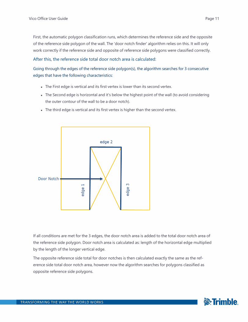
First, the automatic polygon classification runs, which determines the reference side and the oppositeof the reference side polygon of the wall. The 'door notch finder' algorithm relies on this. It will onlywork correctly if the reference side and opposite of reference side polygons were classified correctly.
After this, the reference side total door notch area is calculated:
Going through the edges of the reference side polygon(s), the algorithm searches for 3 consecutiveedges that have the following characteristics:
l The First edge is vertical and its first vertex is lower than its second vertex.
l The Second edge is horizontal and it's below the highest point of the wall (to avoid consideringthe outer contour of the wall to be a door notch).
l The third edge is vertical and its first vertex is higher than the second vertex.
If all conditions are met for the 3 edges, the door notch area is added to the total door notch area ofthe reference side polygon. Door notch area is calculated as: length of the horizontal edge multipliedby the length of the longer vertical edge.
The opposite reference side total for door notches is then calculated exactly the same as the ref-erence side total door notch area, however now the algorithm searches for polygons classified asopposite reference side polygons.
Vico Office User Guide Page 11
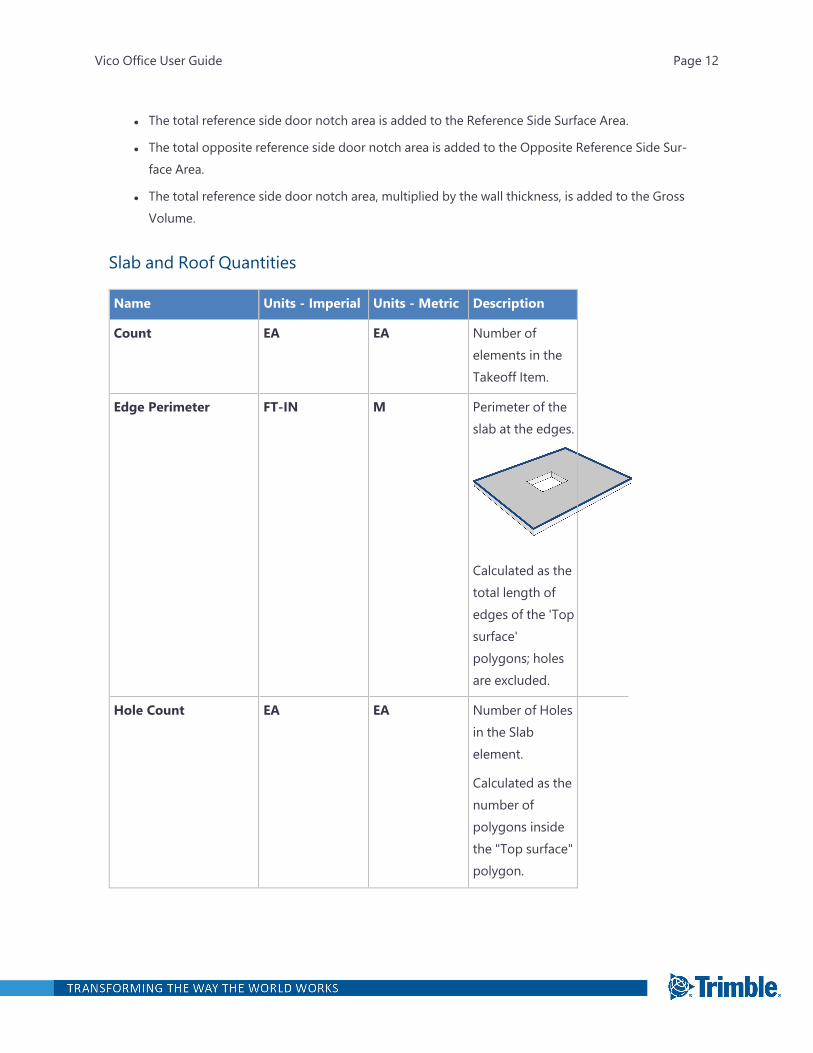
l The total reference side door notch area is added to the Reference Side Surface Area.
l The total opposite reference side door notch area is added to the Opposite Reference Side Sur-face Area.
l The total reference side door notch area, multiplied by the wall thickness, is added to the GrossVolume.
Slab and Roof Quantities
Name Units - Imperial Units - Metric Description
Count EA EA Number ofelements in theTakeoff Item.
Edge Perimeter FT-IN M Perimeter of theslab at the edges.
Calculated as thetotal length ofedges of the 'Topsurface'polygons; holesare excluded.
Hole Count EA EA Number of Holesin the Slabelement.
Calculated as thenumber ofpolygons insidethe "Top surface"polygon.
Vico Office User Guide Page 12
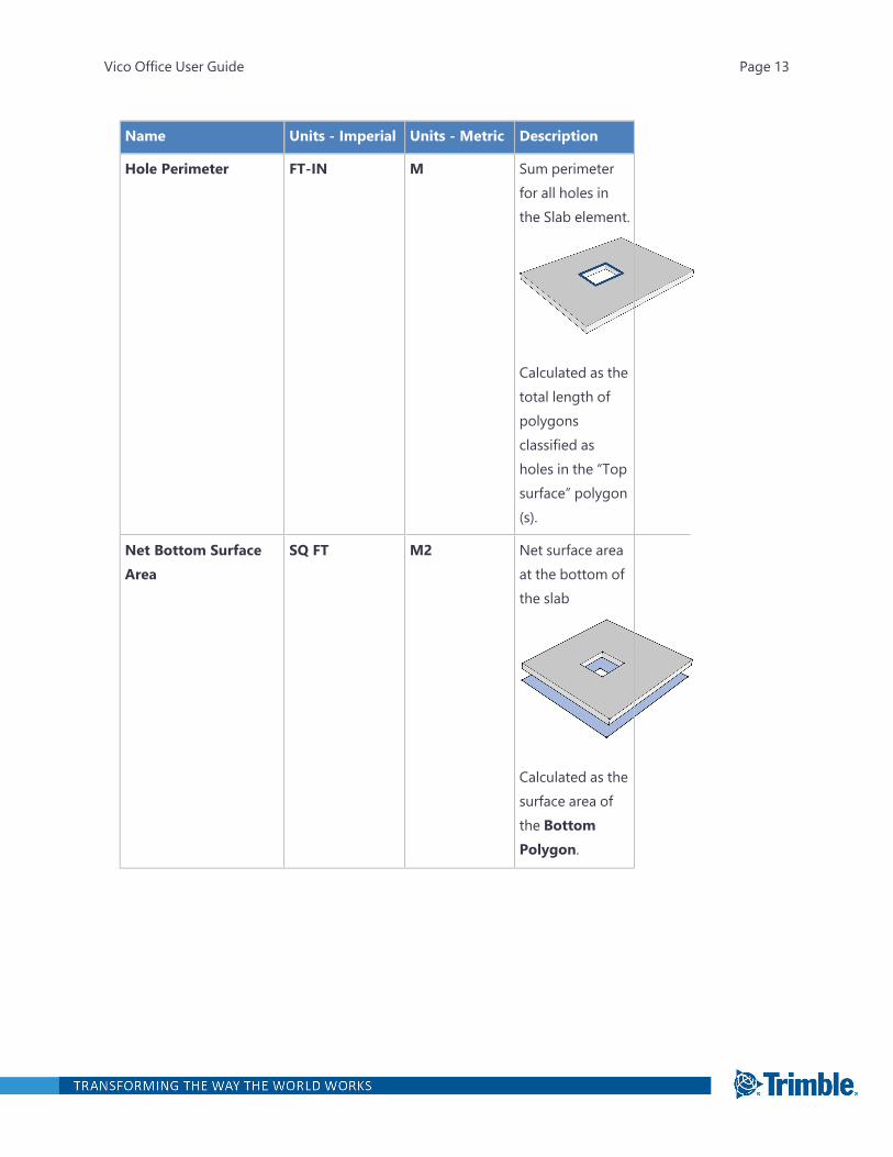
Name Units - Imperial Units - Metric Description
Hole Perimeter FT-IN M Sum perimeterfor all holes inthe Slab element.
Calculated as thetotal length ofpolygonsclassified asholes in the “Topsurface” polygon(s).
Net Bottom SurfaceArea
SQ FT M2 Net surface areaat the bottom ofthe slab
Calculated as thesurface area ofthe BottomPolygon.
Vico Office User Guide Page 13
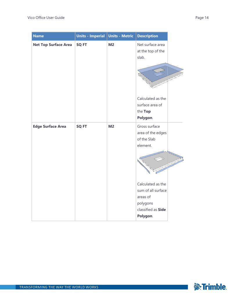
Name Units - Imperial Units - Metric Description
Net Top Surface Area SQ FT M2 Net surface areaat the top of theslab.
Calculated as thesurface area ofthe TopPolygon.
Edge Surface Area SQ FT M2 Gross surfacearea of the edgesof the Slabelement.
Calculated as thesum of all surfaceareas ofpolygonsclassified as SidePolygon.
Vico Office User Guide Page 14
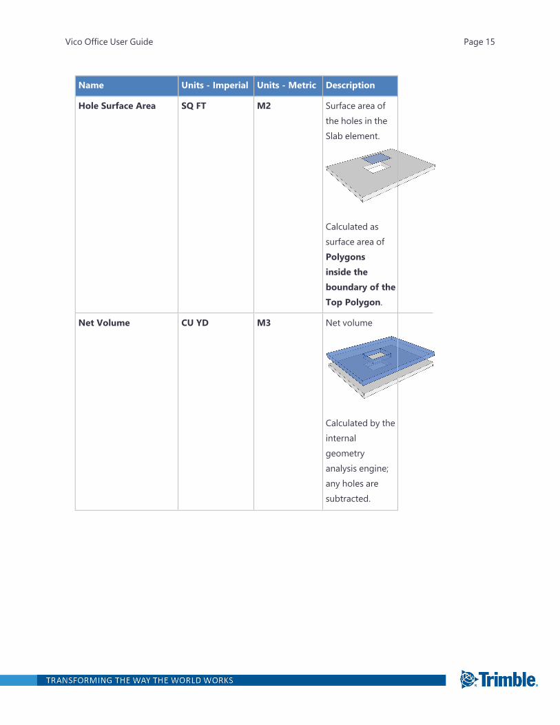
Name Units - Imperial Units - Metric Description
Hole Surface Area SQ FT M2 Surface area ofthe holes in theSlab element.
Calculated assurface area ofPolygonsinside theboundary of theTop Polygon.
Net Volume CU YD M3 Net volume
Calculated by theinternalgeometryanalysis engine;any holes aresubtracted.
Vico Office User Guide Page 15
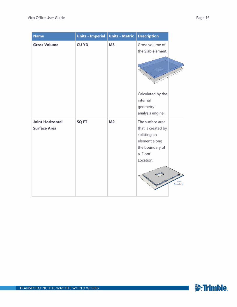
Name Units - Imperial Units - Metric Description
Gross Volume CU YD M3 Gross volume ofthe Slab element.
Calculated by theinternalgeometryanalysis engine.
Joint HorizontalSurface Area
SQ FT M2 The surface areathat is created bysplitting anelement alongthe boundary ofa 'Floor'Location.
Vico Office User Guide Page 16
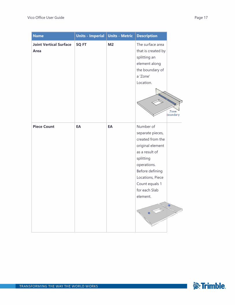
Name Units - Imperial Units - Metric Description
Joint Vertical SurfaceArea
SQ FT M2 The surface areathat is created bysplitting anelement alongthe boundary ofa 'Zone'Location.
Piece Count EA EA Number ofseparate pieces,created from theoriginal elementas a result ofsplittingoperations.Before definingLocations, PieceCount equals 1for each Slabelement.
Vico Office User Guide Page 17
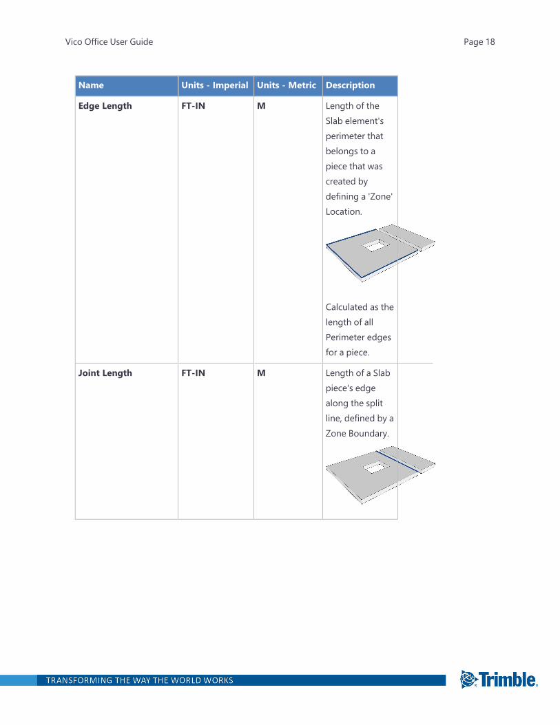
Name Units - Imperial Units - Metric Description
Edge Length FT-IN M Length of theSlab element'sperimeter thatbelongs to apiece that wascreated bydefining a 'Zone'Location.
Calculated as thelength of allPerimeter edgesfor a piece.
Joint Length FT-IN M Length of a Slabpiece's edgealong the splitline, defined by aZone Boundary.
Vico Office User Guide Page 18

Name Units - Imperial Units - Metric Description
Hole Edge Length FT-IN M The length of theslab hole's edgein a Location. Thesum of all HoleEdge Lengthsequals the HolePerimeter.
Hole Joint Length FT-IN M The length of thesplit line over ahole in the slab.
CAD_Count EA EA Number ofelements in theTakeoff Item.This quantitycomes from theCAD applicationafter it waspublished.
Vico Office User Guide Page 19
Name Units - Imperial Units - Metric Description
CAD_Volume CU YD M3 Net volume ofthe element,which excludesthe volume ofany opening.This quantitycomes from theCAD applicationafter it waspublished.
Slab and Roof Polygon Classification
The Slab and Roof Polygon Classification process automatically labels geometry in the importedmodel, which then enables Takeoff Manager to calculate the quantities described above. The processuses Vico's geometry analysis algorithms, which are accurate for standard Slab elements but some-times may result in wrong assumptions. Any wrong assumptions can be corrected by using theTakeoff Quantity Painting process.
The Takeoff Manager polygon classification compares the model's vertical and the polygon's NormalVector to determine its angle:
Vico Office User Guide Page 20

The angle of a polygon is calculated by the internal geometry analysis engine, the normal vector is cal-culated by Takeoff Manager.
Beam Rectangular Quantities
Name Units - Imperial Units - Metric Description
Count EA EA Number ofelements in theTakeoff Item.
Vico Office User Guide Page 21
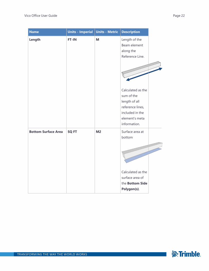
Name Units - Imperial Units - Metric Description
Length FT-IN M Length of theBeam elementalong theReference Line.
Calculated as thesum of thelength of allreference lines,included in theelement's metainformation.
Bottom Surface Area SQ FT M2 Surface area atbottom
Calculated as thesurface area ofthe Bottom SidePolygon(s).
Vico Office User Guide Page 22
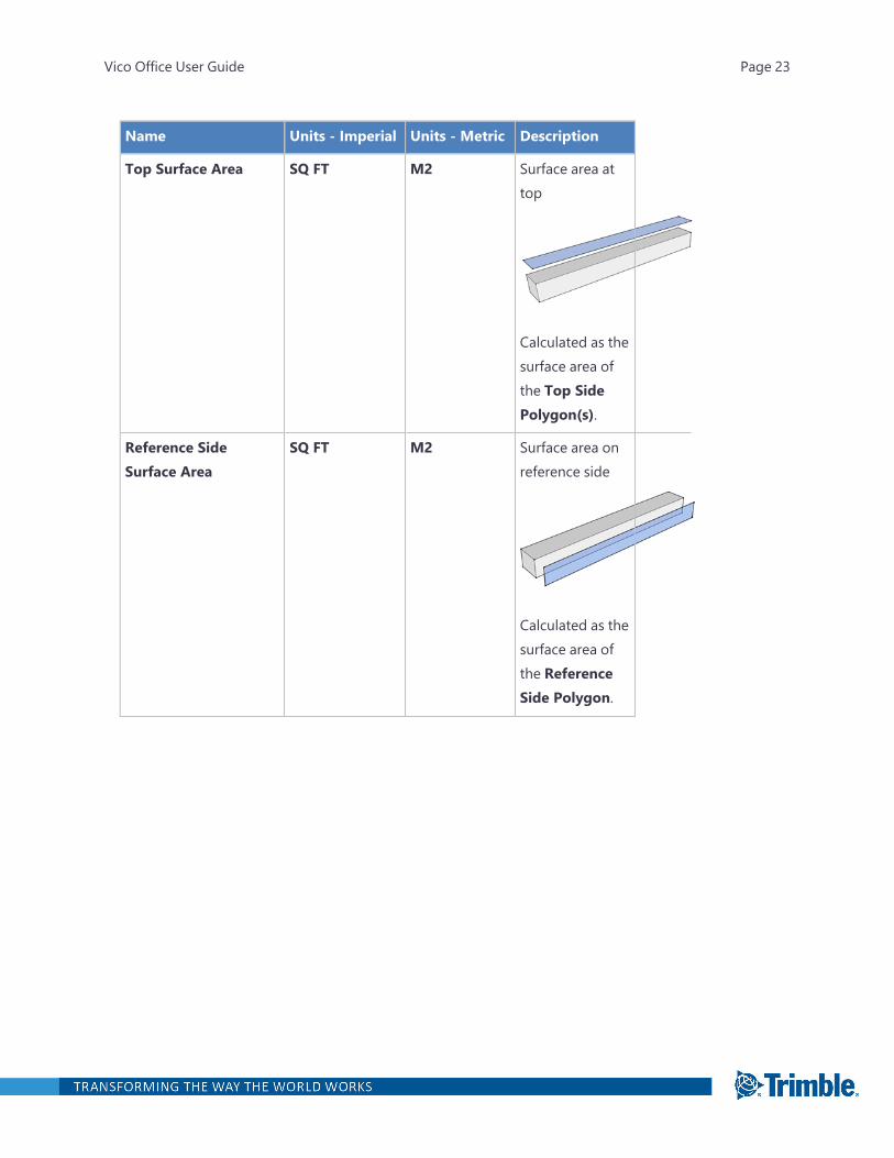
Name Units - Imperial Units - Metric Description
Top Surface Area SQ FT M2 Surface area attop
Calculated as thesurface area ofthe Top SidePolygon(s).
Reference SideSurface Area
SQ FT M2 Surface area onreference side
Calculated as thesurface area ofthe ReferenceSide Polygon.
Vico Office User Guide Page 23
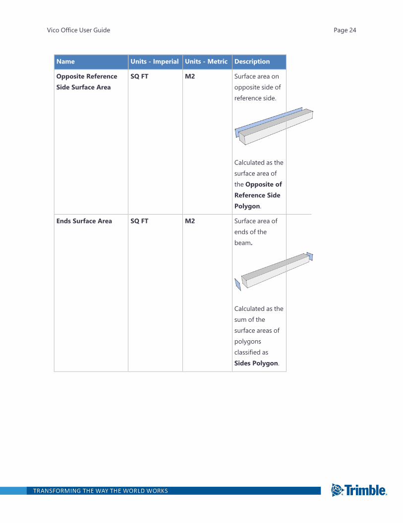
Name Units - Imperial Units - Metric Description
Opposite ReferenceSide Surface Area
SQ FT M2 Surface area onopposite side ofreference side.
Calculated as thesurface area ofthe Opposite ofReference SidePolygon.
Ends Surface Area SQ FT M2 Surface area ofends of thebeam.
Calculated as thesum of thesurface areas ofpolygonsclassified asSides Polygon.
Vico Office User Guide Page 24
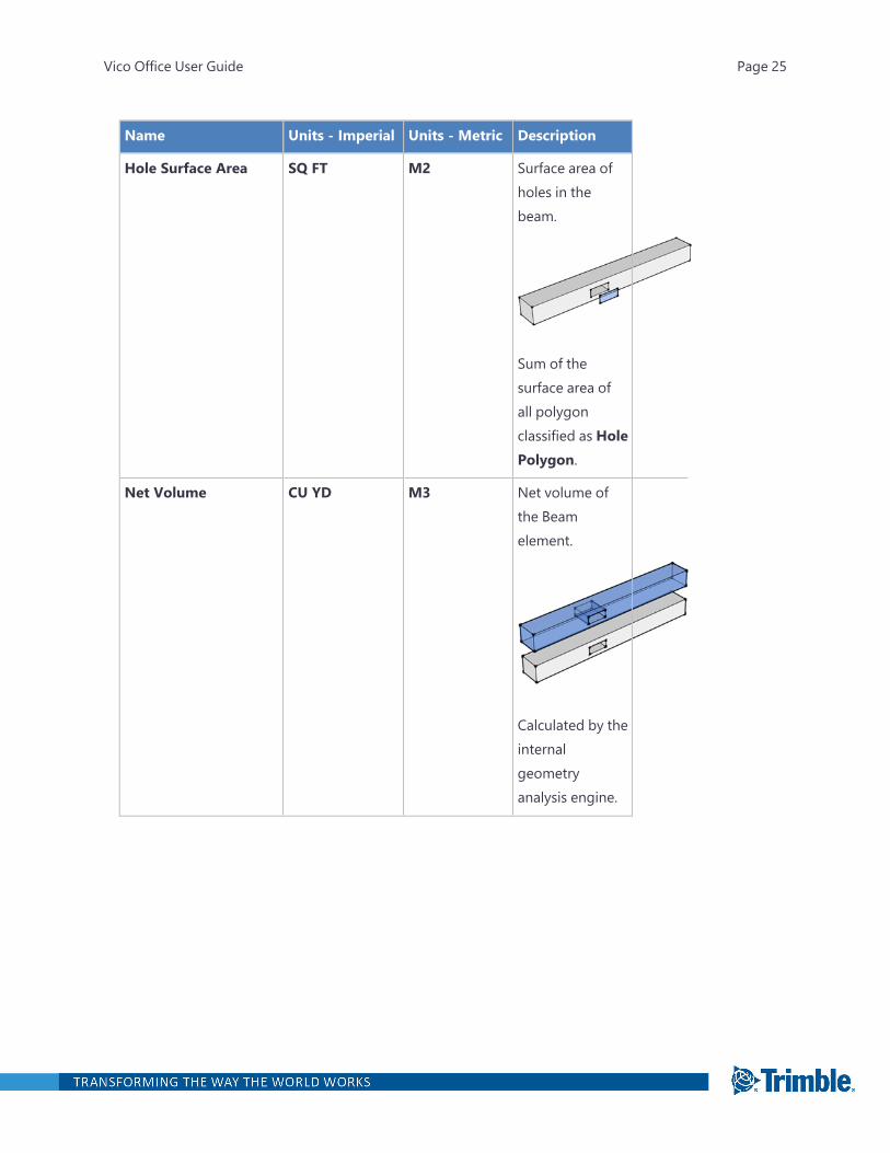
Name Units - Imperial Units - Metric Description
Hole Surface Area SQ FT M2 Surface area ofholes in thebeam.
Sum of thesurface area ofall polygonclassified as HolePolygon.
Net Volume CU YD M3 Net volume ofthe Beamelement.
Calculated by theinternalgeometryanalysis engine.
Vico Office User Guide Page 25
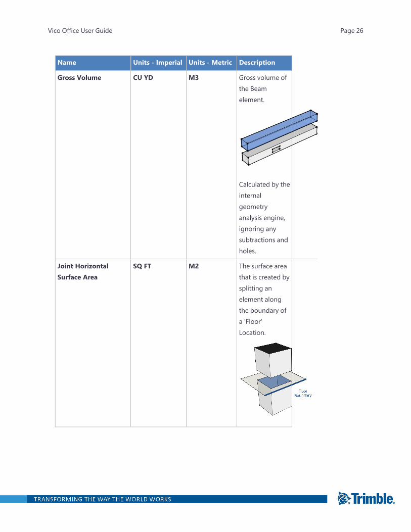
Name Units - Imperial Units - Metric Description
Gross Volume CU YD M3 Gross volume ofthe Beamelement.
Calculated by theinternalgeometryanalysis engine,ignoring anysubtractions andholes.
Joint HorizontalSurface Area
SQ FT M2 The surface areathat is created bysplitting anelement alongthe boundary ofa 'Floor'Location.
Vico Office User Guide Page 26

Name Units - Imperial Units - Metric Description
Joint Vertical SurfaceArea
SQ FT M2 The surface areathat is created bysplitting anelement alongthe boundary ofa 'Zone'Location.
Piece Count EA EA Number ofseparate pieces,created from theoriginal elementas a result ofsplittingoperations.Before definingLocations, PieceCount equals 1for each Beamelement.
Piece Length FT-IN M Length of anindividual Wallpiece. Returnsthe length of theWall that iscontained in aLocation.
Vico Office User Guide Page 27
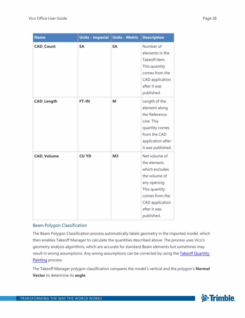
Name Units - Imperial Units - Metric Description
CAD_Count EA EA Number ofelements in theTakeoff Item.This quantitycomes from theCAD applicationafter it waspublished.
CAD_Length FT-IN M Length of theelement alongthe ReferenceLine. Thisquantity comesfrom the CADapplication afterit was published.
CAD_Volume CU YD M3 Net volume ofthe element,which excludesthe volume ofany opening.This quantitycomes from theCAD applicationafter it waspublished.
Beam Polygon Classification
The Beam Polygon Classification process automatically labels geometry in the imported model, whichthen enables Takeoff Manager to calculate the quantities described above. The process uses Vico'sgeometry analysis algorithms, which are accurate for standard Beam elements but sometimes mayresult in wrong assumptions. Any wrong assumptions can be corrected by using the Takeoff QuantityPainting process.
The Takeoff Manager polygon classification compares the model's vertical and the polygon's NormalVector to determine its angle:
Vico Office User Guide Page 28

l For 'Vertical polygons' (angle >= 45 degrees and angle <= 135 degrees), Office calculates thesmallest distance between the polygon's horizontal edges and the first reference line. When thisis done for all 'vertical' polygons which are parallel to the reference line, then the polygon whichis the closest to the reference line will be considered 'Reference Side Surface', the first parallelpolygons which is not the closest one (theoretically there can be only one) will be considered'Opposite reference side surface'.
The rest of the 'vertical polygons' are considered 'Side Polygon'. If there is more than one'Opposite reference side surface polygon' only the first will be marked as such, and the oth-ers will be classified as 'Unknown'. If there is no reference line, all polygons will be classified as'Side Polygon'
l Polygons are classified as 'Top polygons' if: angle >= -45 degrees and angle <= 45 degrees.
l Polygons are classified as 'Bottom polygons' if: angle >= 135 degrees and angle <= 225degrees.
Vico Office User Guide Page 29

Beam Profiled Quantities
Name Units - Imperial Units - Metric Description
Count EA EA Number ofelements in theTakeoff Item.
Length FT-IN M Length of theBeam elementalong theReference Line.
Calculated as thesum of thelength of allreference lines,included in theelement's metainformation.
Bottom Surface Area SQ FT M2 Surface area atbottom
Calculated as thesurface area ofthe Bottom SidePolygon(s).
Top Surface Area SQ FT M2 Surface area attop
Calculated as thesurface area ofthe Top SidePolygon(s).
Vico Office User Guide Page 30
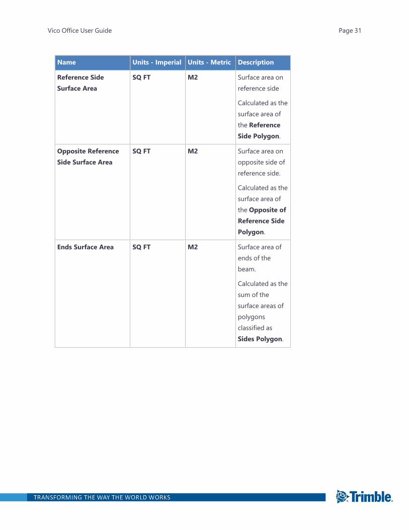
Name Units - Imperial Units - Metric Description
Reference SideSurface Area
SQ FT M2 Surface area onreference side
Calculated as thesurface area ofthe ReferenceSide Polygon.
Opposite ReferenceSide Surface Area
SQ FT M2 Surface area onopposite side ofreference side.
Calculated as thesurface area ofthe Opposite ofReference SidePolygon.
Ends Surface Area SQ FT M2 Surface area ofends of thebeam.
Calculated as thesum of thesurface areas ofpolygonsclassified asSides Polygon.
Vico Office User Guide Page 31
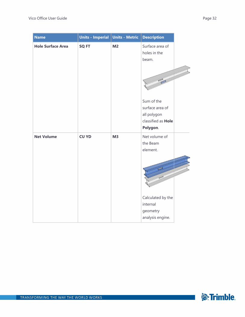
Name Units - Imperial Units - Metric Description
Hole Surface Area SQ FT M2 Surface area ofholes in thebeam.
Sum of thesurface area ofall polygonclassified as HolePolygon.
Net Volume CU YD M3 Net volume ofthe Beamelement.
Calculated by theinternalgeometryanalysis engine.
Vico Office User Guide Page 32
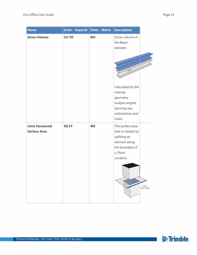
Name Units - Imperial Units - Metric Description
Gross Volume CU YD M3 Gross volume ofthe Beamelement.
Calculated by theinternalgeometryanalysis engine,ignoring anysubtractions andholes.
Joint HorizontalSurface Area
SQ FT M2 The surface areathat is created bysplitting anelement alongthe boundary ofa 'Floor'Location.
Vico Office User Guide Page 33
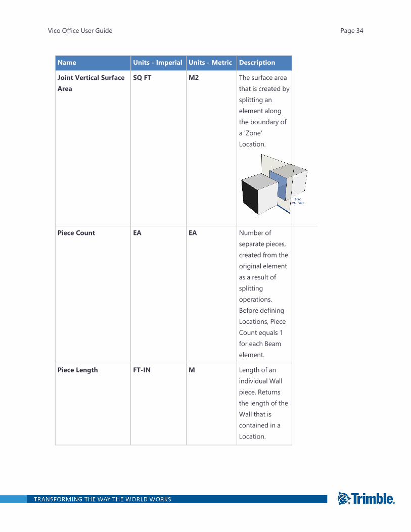
Name Units - Imperial Units - Metric Description
Joint Vertical SurfaceArea
SQ FT M2 The surface areathat is created bysplitting anelement alongthe boundary ofa 'Zone'Location.
Piece Count EA EA Number ofseparate pieces,created from theoriginal elementas a result ofsplittingoperations.Before definingLocations, PieceCount equals 1for each Beamelement.
Piece Length FT-IN M Length of anindividual Wallpiece. Returnsthe length of theWall that iscontained in aLocation.
Vico Office User Guide Page 34
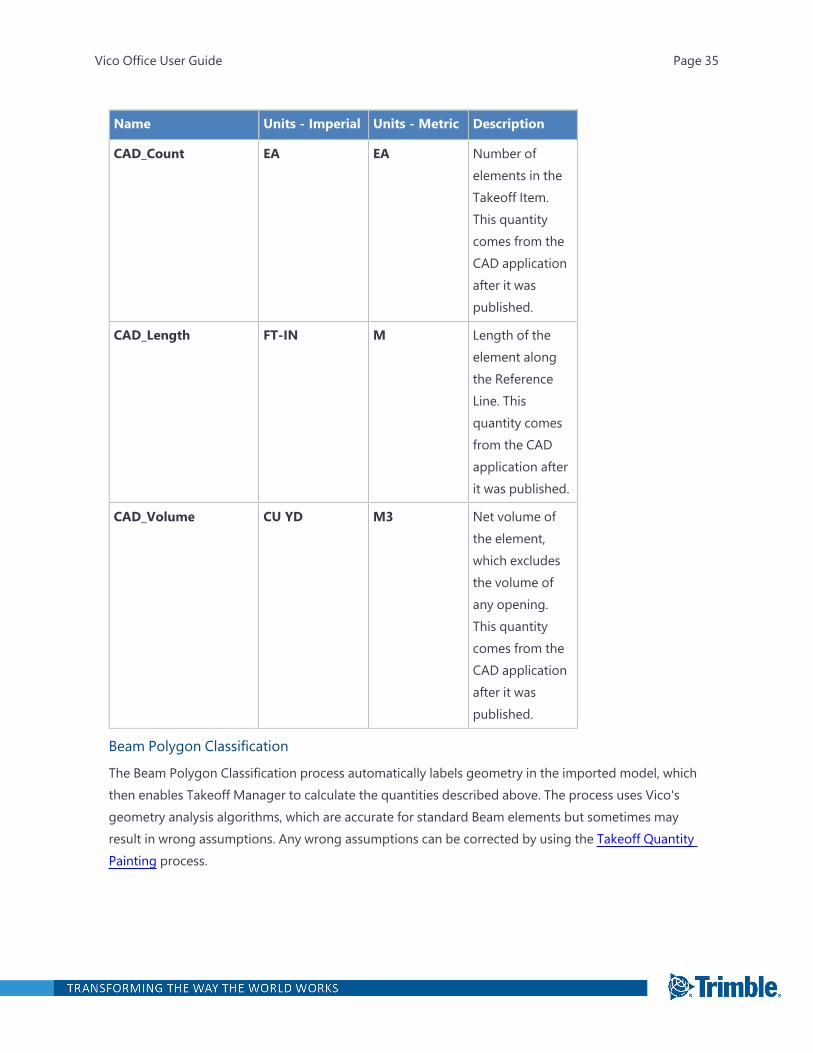
Name Units - Imperial Units - Metric Description
CAD_Count EA EA Number ofelements in theTakeoff Item.This quantitycomes from theCAD applicationafter it waspublished.
CAD_Length FT-IN M Length of theelement alongthe ReferenceLine. Thisquantity comesfrom the CADapplication afterit was published.
CAD_Volume CU YD M3 Net volume ofthe element,which excludesthe volume ofany opening.This quantitycomes from theCAD applicationafter it waspublished.
Beam Polygon Classification
The Beam Polygon Classification process automatically labels geometry in the imported model, whichthen enables Takeoff Manager to calculate the quantities described above. The process uses Vico'sgeometry analysis algorithms, which are accurate for standard Beam elements but sometimes mayresult in wrong assumptions. Any wrong assumptions can be corrected by using the Takeoff QuantityPainting process.
Vico Office User Guide Page 35
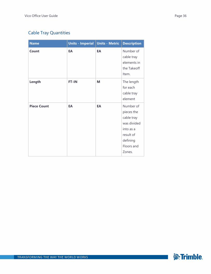
Cable Tray Quantities
Name Units - Imperial Units - Metric Description
Count EA EA Number ofcable trayelements inthe TakeoffItem.
Length FT-IN M The lengthfor eachcable trayelement
Piece Count EA EA Number ofpieces thecable traywas dividedinto as aresult ofdefiningFloors andZones.
Vico Office User Guide Page 36
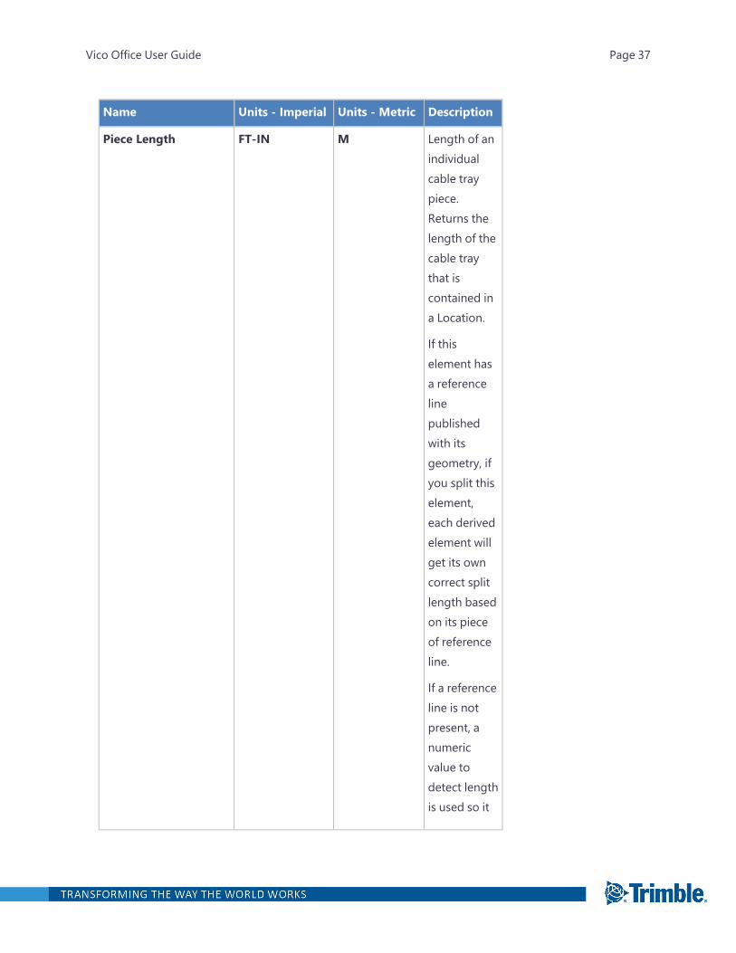
Name Units - Imperial Units - Metric Description
Piece Length FT-IN M Length of anindividualcable traypiece.Returns thelength of thecable traythat iscontained ina Location.
If thiselement hasa referencelinepublishedwith itsgeometry, ifyou split thiselement,each derivedelement willget its owncorrect splitlength basedon its pieceof referenceline.
If a referenceline is notpresent, anumericvalue todetect lengthis used so it
Vico Office User Guide Page 37
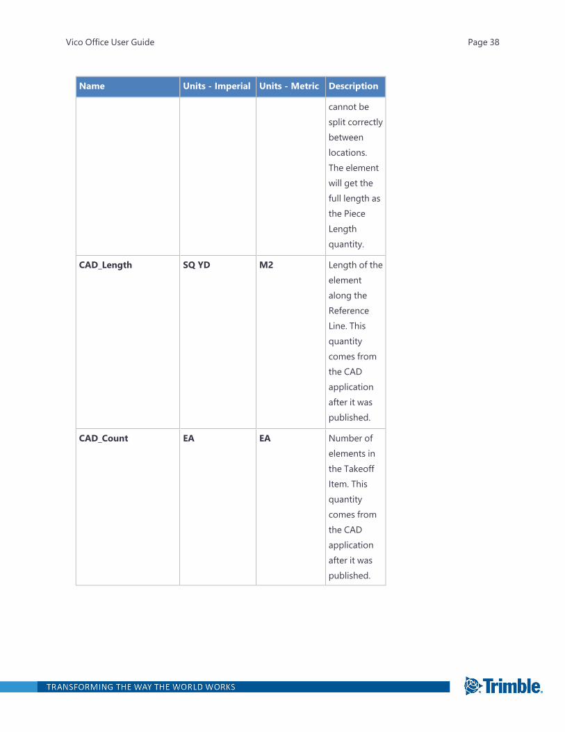
Name Units - Imperial Units - Metric Description
cannot besplit correctlybetweenlocations.The elementwill get thefull length asthe PieceLengthquantity.
CAD_Length SQ YD M2 Length of theelementalong theReferenceLine. Thisquantitycomes fromthe CADapplicationafter it waspublished.
CAD_Count EA EA Number ofelements inthe TakeoffItem. Thisquantitycomes fromthe CADapplicationafter it waspublished.
Vico Office User Guide Page 38

Cable Tray Fitting Quantities
Name Units - Imperial Units - Metric Description
Count EA EA Number ofcable trayfittingelements inthe TakeoffItem.
CAD_Count EA EA Number ofelements inthe TakeoffItem. Thisquantitycomes fromthe CADapplicationafter it waspublished.
Curtain Wall Quantities
Name Units - Imperial Units - Metric Description
Count EA EA Number ofCurtain Wallelements inthe TakeoffItem.
Vico Office User Guide Page 39

Name Units - Imperial Units - Metric Description
Piece Count EA EA Number ofpieces theCurtain Wallwas dividedinto as aresult ofdefiningFloors andZones.
CAD Net Surface Area SQ YD M2 Quantity thatcomes fromthe CADsystem and isnotcalculated byVico Office.
CAD_Count EA EA Number ofelements inthe TakeoffItem. Thisquantitycomes fromthe CADapplicationafter it waspublished.
Vico Office User Guide Page 40
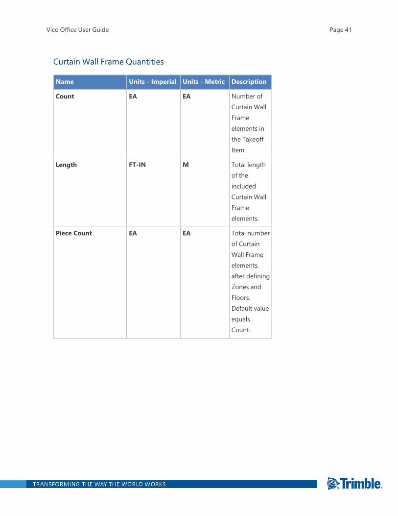
Curtain Wall Frame Quantities
Name Units - Imperial Units - Metric Description
Count EA EA Number ofCurtain WallFrameelements inthe TakeoffItem.
Length FT-IN M Total lengthof theincludedCurtain WallFrameelements.
Piece Count EA EA Total numberof CurtainWall Frameelements,after definingZones andFloors.Default valueequalsCount.
Vico Office User Guide Page 41
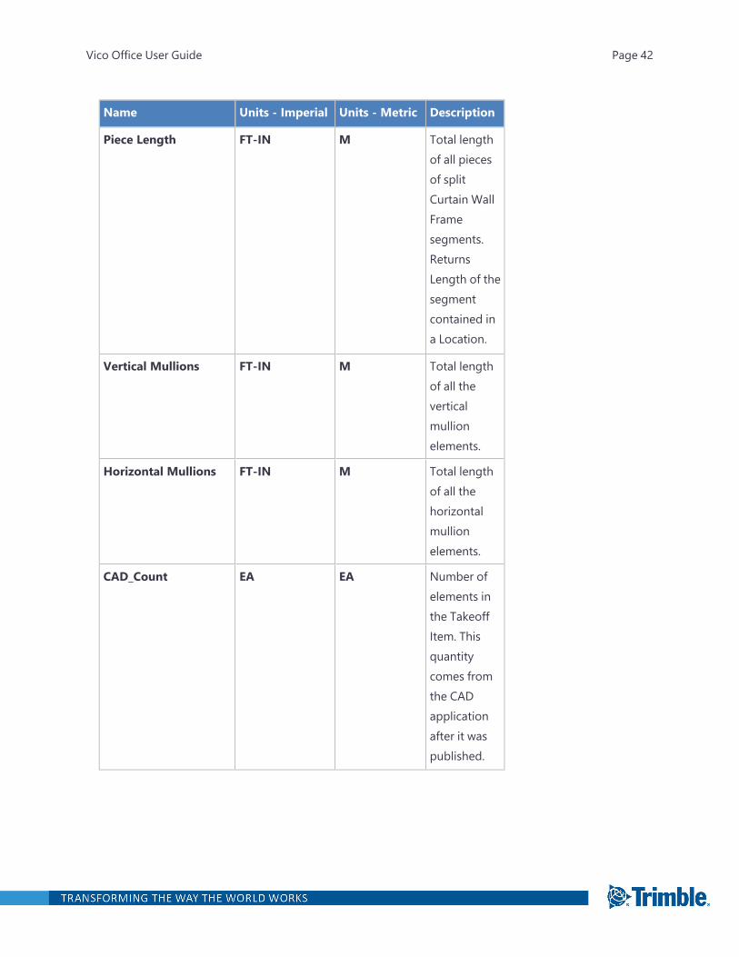
Name Units - Imperial Units - Metric Description
Piece Length FT-IN M Total lengthof all piecesof splitCurtain WallFramesegments.ReturnsLength of thesegmentcontained ina Location.
Vertical Mullions FT-IN M Total lengthof all theverticalmullionelements.
Horizontal Mullions FT-IN M Total lengthof all thehorizontalmullionelements.
CAD_Count EA EA Number ofelements inthe TakeoffItem. Thisquantitycomes fromthe CADapplicationafter it waspublished.
Vico Office User Guide Page 42
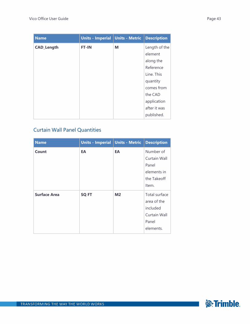
Name Units - Imperial Units - Metric Description
CAD_Length FT-IN M Length of theelementalong theReferenceLine. Thisquantitycomes fromthe CADapplicationafter it waspublished.
Curtain Wall Panel Quantities
Name Units - Imperial Units - Metric Description
Count EA EA Number ofCurtain WallPanelelements inthe TakeoffItem.
Surface Area SQ FT M2 Total surfacearea of theincludedCurtain WallPanelelements.
Vico Office User Guide Page 43
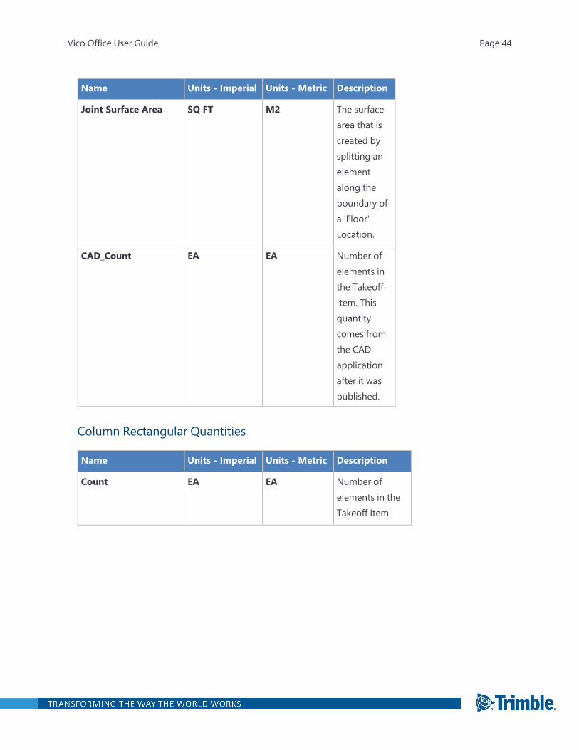
Name Units - Imperial Units - Metric Description
Joint Surface Area SQ FT M2 The surfacearea that iscreated bysplitting anelementalong theboundary ofa 'Floor'Location.
CAD_Count EA EA Number ofelements inthe TakeoffItem. Thisquantitycomes fromthe CADapplicationafter it waspublished.
Column Rectangular Quantities
Name Units - Imperial Units - Metric Description
Count EA EA Number ofelements in theTakeoff Item.
Vico Office User Guide Page 44

Name Units - Imperial Units - Metric Description
Height FT-IN M Height of theColumn element.
Whole Height isalways assignedto lowestLocation of theColumn.
Calculated as thedifferencebetween thehighest point inthe TopPolygon and thelowest point inthe Bottom
Vico Office User Guide Page 45
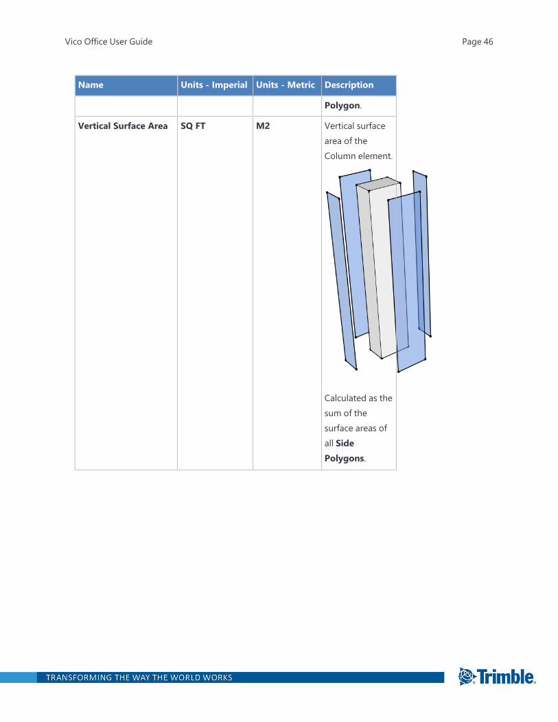
Name Units - Imperial Units - Metric Description
Polygon.
Vertical Surface Area SQ FT M2 Vertical surfacearea of theColumn element.
Calculated as thesum of thesurface areas ofall SidePolygons.
Vico Office User Guide Page 46
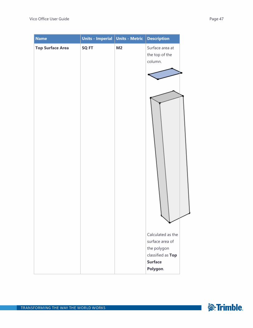
Name Units - Imperial Units - Metric Description
Top Surface Area SQ FT M2 Surface area atthe top of thecolumn.
Calculated as thesurface area ofthe polygonclassified as TopSurfacePolygon.
Vico Office User Guide Page 47
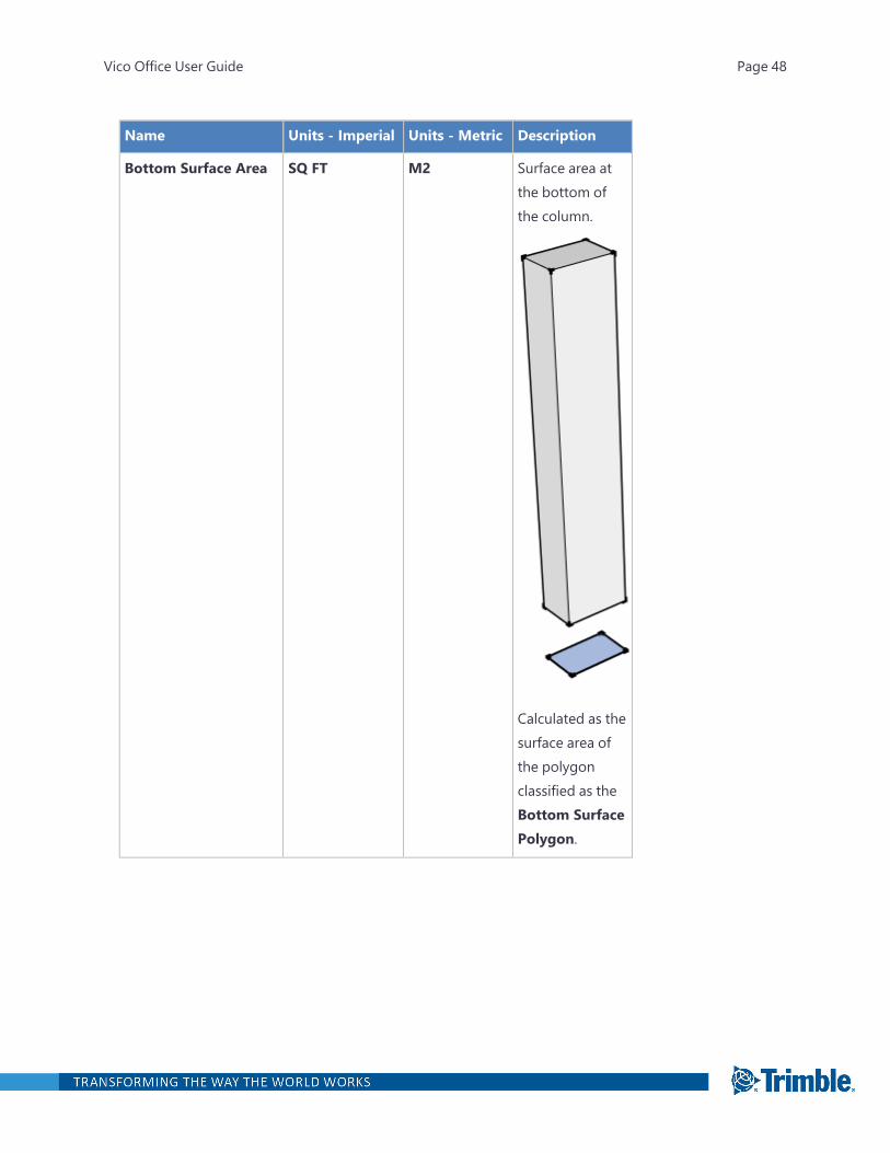
Name Units - Imperial Units - Metric Description
Bottom Surface Area SQ FT M2 Surface area atthe bottom ofthe column.
Calculated as thesurface area ofthe polygonclassified as theBottom SurfacePolygon.
Vico Office User Guide Page 48
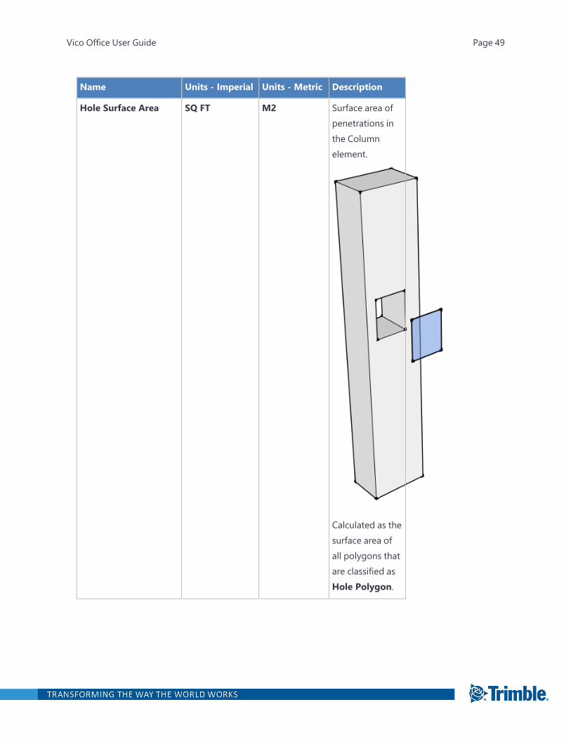
Name Units - Imperial Units - Metric Description
Hole Surface Area SQ FT M2 Surface area ofpenetrations inthe Columnelement.
Calculated as thesurface area ofall polygons thatare classified asHole Polygon.
Vico Office User Guide Page 49
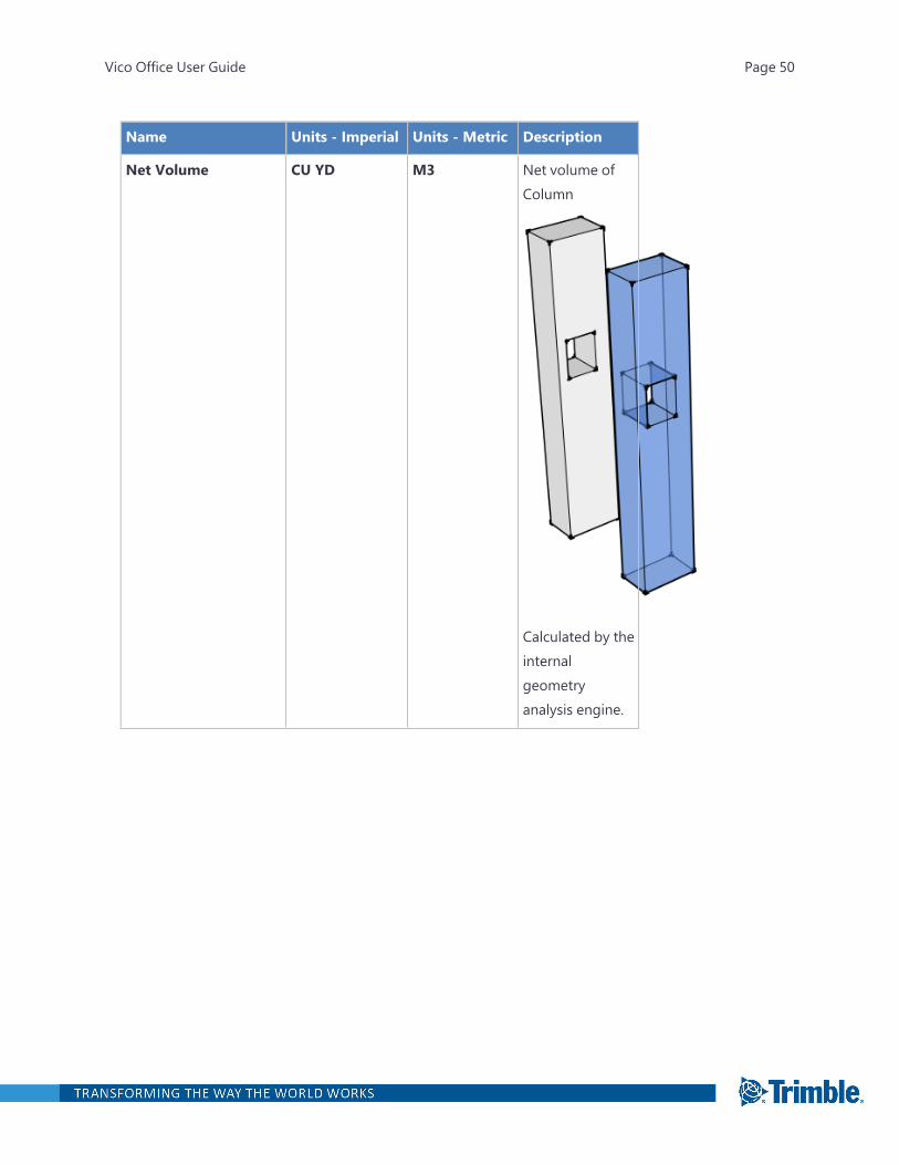
Name Units - Imperial Units - Metric Description
Net Volume CU YD M3 Net volume ofColumn
Calculated by theinternalgeometryanalysis engine.
Vico Office User Guide Page 50

Name Units - Imperial Units - Metric Description
Gross Volume CU YD M3 Gross volume ofColumn
Calculated by theinternalgeometryanalysis engine,ignoring anypenetrations andsubtractions.
Vico Office User Guide Page 51
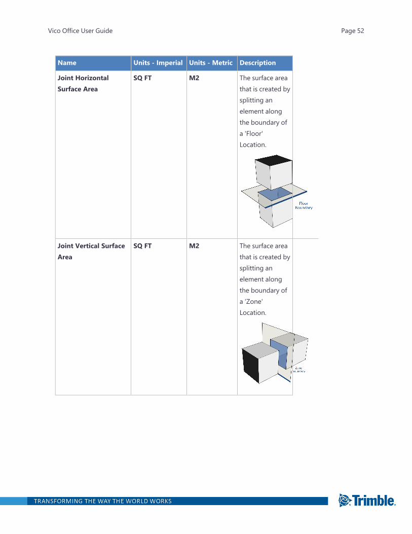
Name Units - Imperial Units - Metric Description
Joint HorizontalSurface Area
SQ FT M2 The surface areathat is created bysplitting anelement alongthe boundary ofa 'Floor'Location.
Joint Vertical SurfaceArea
SQ FT M2 The surface areathat is created bysplitting anelement alongthe boundary ofa 'Zone'Location.
Vico Office User Guide Page 52
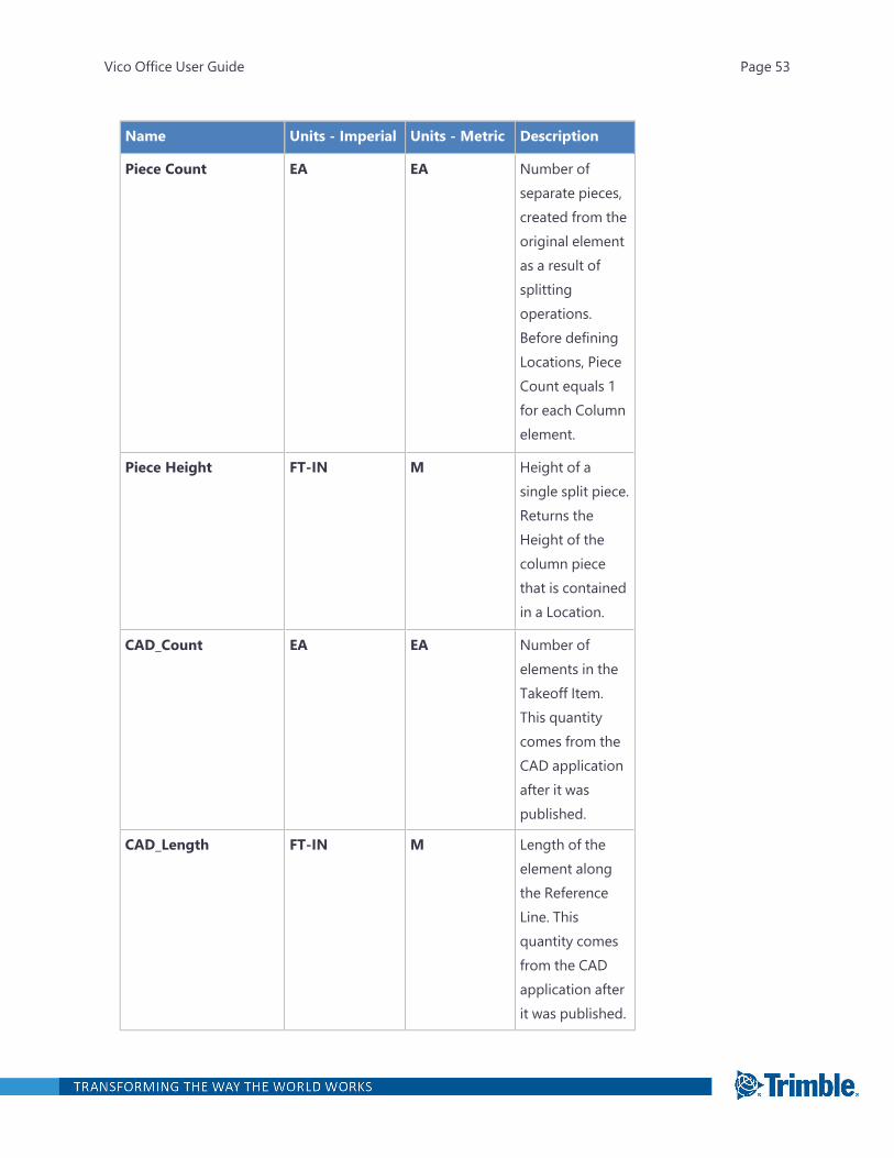
Name Units - Imperial Units - Metric Description
Piece Count EA EA Number ofseparate pieces,created from theoriginal elementas a result ofsplittingoperations.Before definingLocations, PieceCount equals 1for each Columnelement.
Piece Height FT-IN M Height of asingle split piece.Returns theHeight of thecolumn piecethat is containedin a Location.
CAD_Count EA EA Number ofelements in theTakeoff Item.This quantitycomes from theCAD applicationafter it waspublished.
CAD_Length FT-IN M Length of theelement alongthe ReferenceLine. Thisquantity comesfrom the CADapplication afterit was published.
Vico Office User Guide Page 53
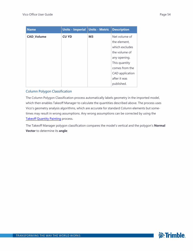
Name Units - Imperial Units - Metric Description
CAD_Volume CU YD M3 Net volume ofthe element,which excludesthe volume ofany opening.This quantitycomes from theCAD applicationafter it waspublished.
Column Polygon Classification
The Column Polygon Classification process automatically labels geometry in the imported model,which then enables Takeoff Manager to calculate the quantities described above. The process usesVico's geometry analysis algorithms, which are accurate for standard Column elements but some-times may result in wrong assumptions. Any wrong assumptions can be corrected by using theTakeoff Quantity Painting process.
The Takeoff Manager polygon classification compares the model's vertical and the polygon's NormalVector to determine its angle:
Vico Office User Guide Page 54
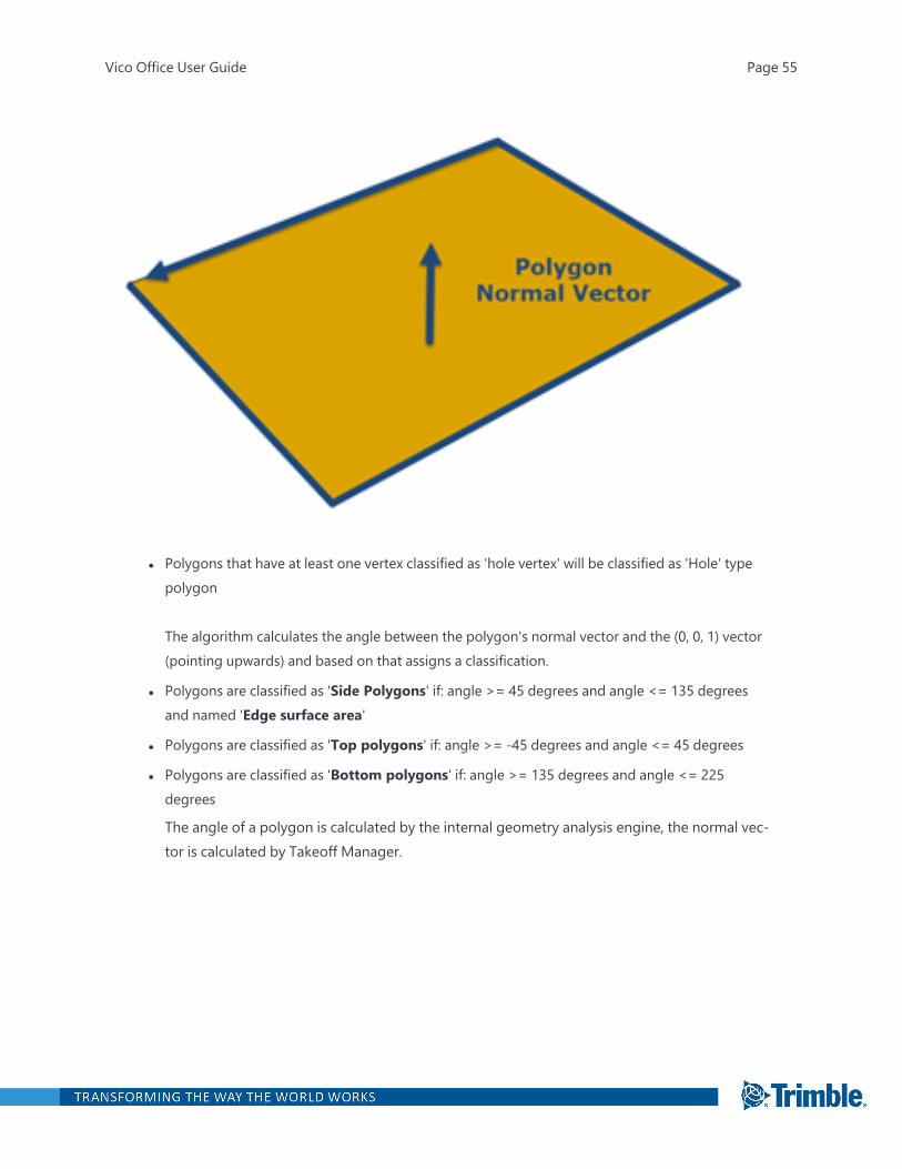
l Polygons that have at least one vertex classified as 'hole vertex' will be classified as 'Hole' typepolygon
The algorithm calculates the angle between the polygon's normal vector and the (0, 0, 1) vector(pointing upwards) and based on that assigns a classification.
l Polygons are classified as 'Side Polygons' if: angle >= 45 degrees and angle <= 135 degreesand named 'Edge surface area'
l Polygons are classified as 'Top polygons' if: angle >= -45 degrees and angle <= 45 degrees
l Polygons are classified as 'Bottom polygons' if: angle >= 135 degrees and angle <= 225degrees
The angle of a polygon is calculated by the internal geometry analysis engine, the normal vec-tor is calculated by Takeoff Manager.
Vico Office User Guide Page 55
Column Profiled Quantities
Name Units - Imperial Units - Metric Description
Count EA EA Number ofelements in theTakeoff Item.
Vico Office User Guide Page 56
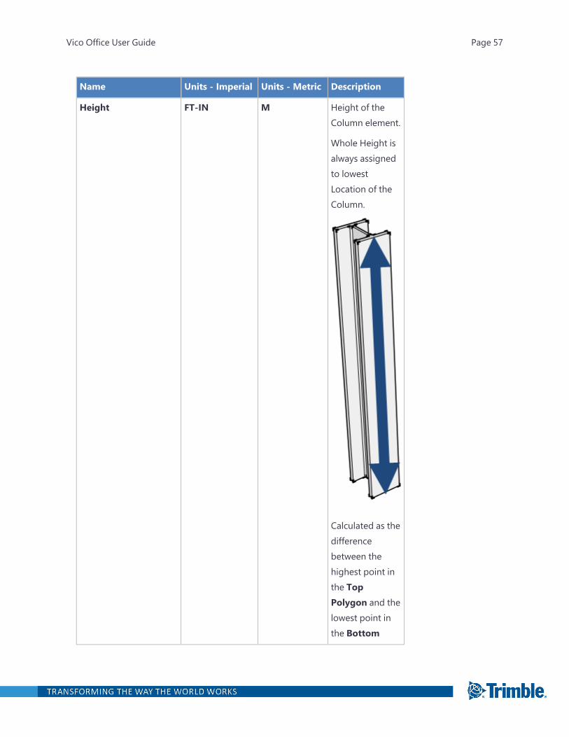
Name Units - Imperial Units - Metric Description
Height FT-IN M Height of theColumn element.
Whole Height isalways assignedto lowestLocation of theColumn.
Calculated as thedifferencebetween thehighest point inthe TopPolygon and thelowest point inthe Bottom
Vico Office User Guide Page 57

Name Units - Imperial Units - Metric Description
Polygon.
Vertical Surface Area SQ FT M2 Vertical surfacearea of theColumn element.
Calculated as thesum of thesurface areas ofall SidePolygons.
Top Surface Area SQ FT M2 Surface area atthe top of thecolumn.
Calculated as thesurface area ofthe polygonclassified as TopSurfacePolygon.
Vico Office User Guide Page 58
Name Units - Imperial Units - Metric Description
Bottom Surface Area SQ FT M2 Surface area atthe bottom ofthe column.
Calculated as thesurface area ofthe polygonclassified as theBottom SurfacePolygon.
Vico Office User Guide Page 59
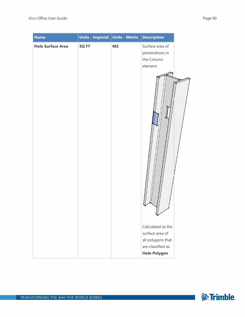
Name Units - Imperial Units - Metric Description
Hole Surface Area SQ FT M2 Surface area ofpenetrations inthe Columnelement.
Calculated as thesurface area ofall polygons thatare classified asHole Polygon.
Vico Office User Guide Page 60
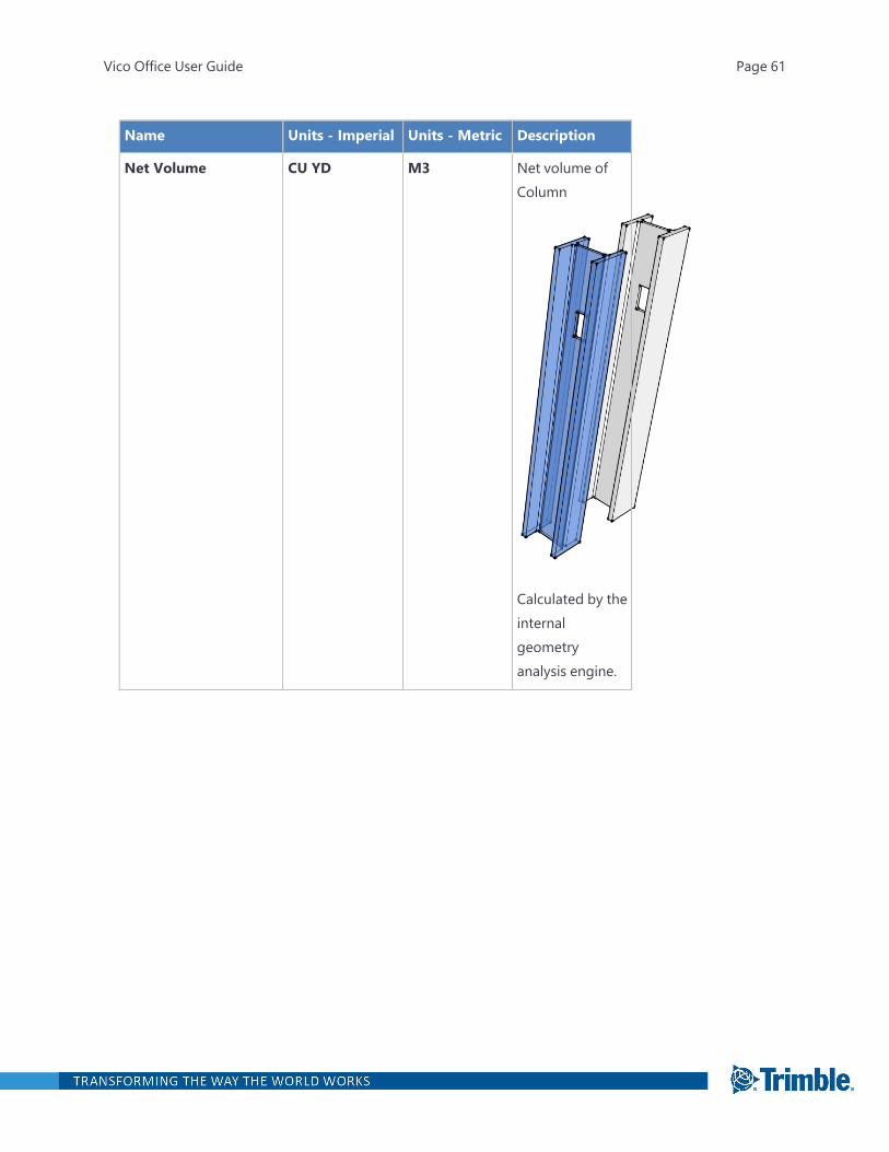
Name Units - Imperial Units - Metric Description
Net Volume CU YD M3 Net volume ofColumn
Calculated by theinternalgeometryanalysis engine.
Vico Office User Guide Page 61

Name Units - Imperial Units - Metric Description
Gross Volume CU YD M3 Gross volume ofColumn
Calculated by theinternalgeometryanalysis engine,ignoring anypenetrations andsubtractions.
Vico Office User Guide Page 62

Name Units - Imperial Units - Metric Description
Joint HorizontalSurface Area
SQ FT M2 The surface areathat is created bysplitting anelement alongthe boundary ofa 'Floor'Location.
Joint Vertical SurfaceArea
SQ FT M2 The surface areathat is created bysplitting anelement alongthe boundary ofa 'Zone'Location.
Vico Office User Guide Page 63

Name Units - Imperial Units - Metric Description
Piece Count EA EA Number ofseparate pieces,created from theoriginal elementas a result ofsplittingoperations.Before definingLocations, PieceCount equals 1for each Columnelement.
Piece Height FT-IN M Height of asingle split piece.Returns theHeight of thecolumn piecethat is containedin a Location.
CAD_Count EA EA Number ofelements in theTakeoff Item.This quantitycomes from theCAD applicationafter it waspublished.
CAD_Length FT-IN M Length of theelement alongthe ReferenceLine. Thisquantity comesfrom the CADapplication afterit was published.
Vico Office User Guide Page 64
Name Units - Imperial Units - Metric Description
CAD_Volume CU YD M3 Net volume ofthe element,which excludesthe volume ofany opening.This quantitycomes from theCAD applicationafter it waspublished.
Column Polygon Classification
The Column Polygon Classification process automatically labels geometry in the imported model,which then enables Takeoff Manager to calculate the quantities described above. The process usesVico's geometry analysis algorithms, which are accurate for standard Column elements but some-times may result in wrong assumptions. Any wrong assumptions can be corrected by using theTakeoff Quantity Painting process.
Duct Quantities
Name Units - Imperial Units - Metric Description
Count EA EA Number ofDuctelements inthe TakeoffItem.
Length FT-IN M Length of therun
Vico Office User Guide Page 65
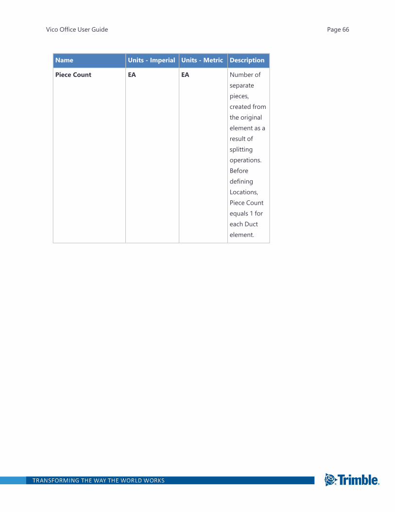
Name Units - Imperial Units - Metric Description
Piece Count EA EA Number ofseparatepieces,created fromthe originalelement as aresult ofsplittingoperations.BeforedefiningLocations,Piece Countequals 1 foreach Ductelement.
Vico Office User Guide Page 66

Name Units - Imperial Units - Metric Description
Piece Length FT-IN M Length of anindividualDuct piece.Returns thelength of theDuct that iscontained ina Location.
If thiselement hasa referencelinepublishedwith itsgeometry, ifyou split thiselement,each derivedelement willget its owncorrect splitlength basedon its pieceof referenceline.
If a referenceline is notpresent, anumericvalue todetect lengthis used so itcannot besplit correctly
Vico Office User Guide Page 67

Name Units - Imperial Units - Metric Description
betweenlocations.The elementwill get thefull length asthe PieceLengthquantity.
CAD_Count EA EA Number ofelements inthe TakeoffItem. Thisquantitycomes fromthe CADapplicationafter it waspublished.
CAD_Length FT-IN M Length of theelementalong theReferenceLine. Thisquantitycomes fromthe CADapplicationafter it waspublished.
Length of Revit Duct Fittings is calculated using these elements' custom properties. See "Revit DuctFitting Length Calculation" below for an overview of calculation rules.
Revit Duct Fitting Length Calculation
Calculation of 'Length' property of duct fittings in Autodesk Revit MEP library.
Vico Office User Guide Page 68

Autodesk\RME 2009\ImperialLibrary\Duct\Fittings\Multi-Shape\Taps
ElementProfile
Length Calculation
Rectangular to Round Duct Takeoff.rfa Takeoff Length + Takeoff LengthProjection
Autodesk\RME 2009\ImperialLibrary\Duct\Fittings\Multi-Shape\Tees
Element Profile Length Calculation
Rectangular to Round Duct Tee -Conical Tap.rfa
Duct Length 1 + Duct Length 2
Rectangular to Round Duct Tee -Transition.rfa
Duct Length 1 + Duct Width/2 + Length 3
Rectangular to Round Duct Tee withTransition - Conical Tap.rfa
Duct Length 1 + Duct Length 2 + DuctLength 3
Round to Rectangular Duct Tee -Transition.rfa
Duct Length 1
Autodesk\RME 2009\ImperialLibrary\Duct\Fittings\Multi-Shape\Transitions
Element Profile Length Calculation
Rectangular to Round Duct Transition -Angle.rfa
Length 1
Round to Rectangular Duct Transition -Angle.rfa
Duct Length 1
Vico Office User Guide Page 69

Autodesk\RME 2009\ImperialLibrary\Duct\Fittings\Multi-Shape\Taps
ElementProfile
Length Calculation
Round to Rectangular Duct Transition -Length.rfa
Duct Length 1
Autodesk\RME 2009\ImperialLibrary\Duct\Fittings\Profiles
Element Profile Length Calculation
Duct - Rectangular.rfa N/A (2D)
Duct - Round.rfa N/A (2D)
Autodesk\RME 2009\ImperialLibrary\Duct\Fittings\Rectangular\Caps
Element Profile Length Calculation
Rectangular Duct Endcap.rfa Length
Autodesk\RME 2009\ImperialLibrary\Duct\Fittings\Rectangular\Crosses
Element Profile Length Calculation
Rectangular Duct Cross.rfa Length 3 *2 + Length 1 * 2
Autodesk\RME 2009\ImperialLibrary\Duct\Fittings\Rectangular\Elbows
Element Profile Length Calculation
Rectangular Duct Elbow - BeveledThroat - Sharp Heel.rfa
W*2
Rectangular Duct Elbow - Mitered -Transition.rfa
W1 + W2 + Shoulder Length * 2
Vico Office User Guide Page 70

Autodesk\RME 2009\ImperialLibrary\Duct\Fittings\Multi-Shape\Taps
ElementProfile
Length Calculation
Rectangular Duct Elbow - Mitered.rfa Length 1 *2
Rectangular Duct Elbow - Radius.rfa Centre Radius * Angle(this quantity isneeded in radial)
Rectangular Duct Elbow - Round Throat- Sharp Heel.rfa
W550 + Sholder Length*2 + ThroatRadius*2
Rectangular Duct Elbow - Sharp Throat- Radius Heel.rfa
Radius * Angle(in radial) + ConnectorExtension*2
Autodesk\RME 2009\ImperialLibrary\Duct\Fittings\Rectangular\Offsets
Element Profile Length Calculation
Rectangular Duct Offset - Plain -Flanged.rfa
Rectangular Duct Offset.rfa
Autodesk\RME 2009\ImperialLibrary\Duct\Fittings\Rectangular\Pants and Vees
Element Profile Length Calculation
Rectangular Duct Pants - Reducing.rfa Duct Length 1
Vico Office User Guide Page 71
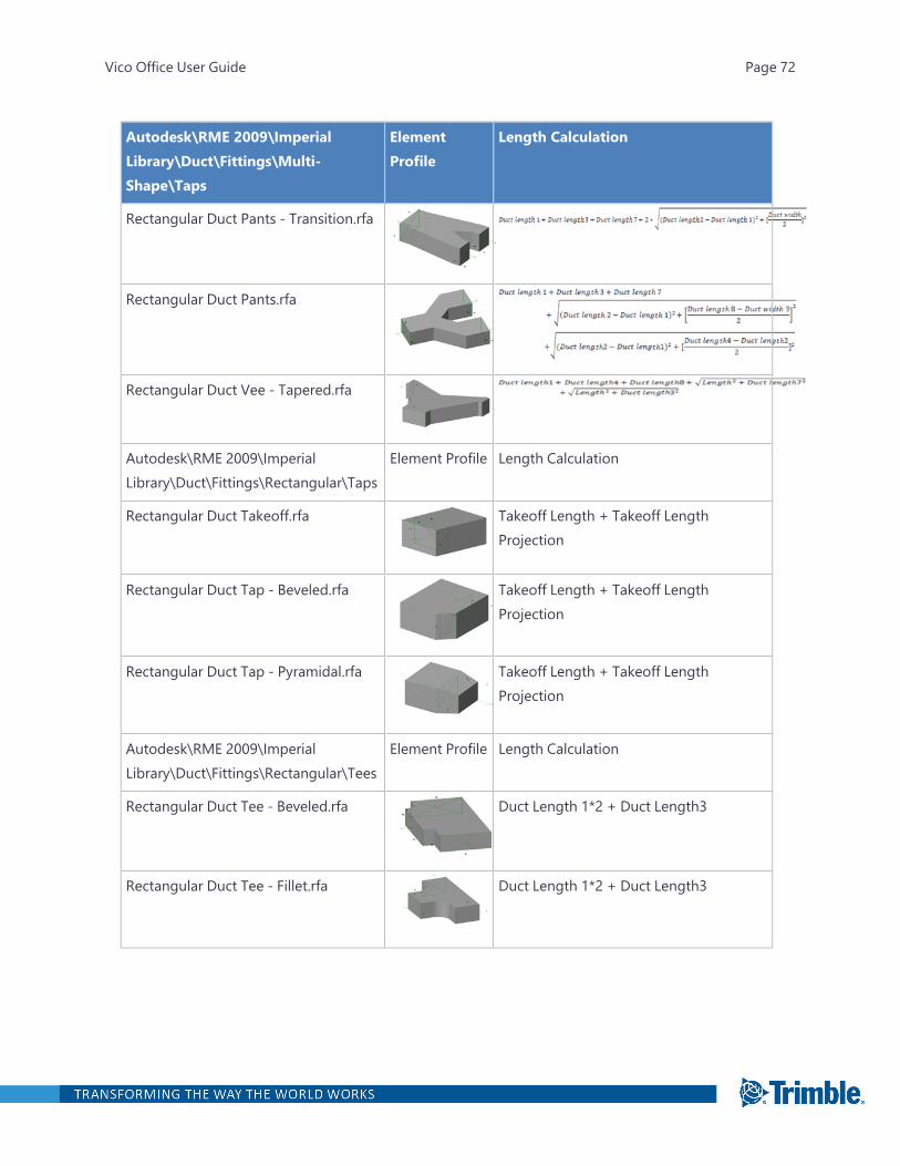
Autodesk\RME 2009\ImperialLibrary\Duct\Fittings\Multi-Shape\Taps
ElementProfile
Length Calculation
Rectangular Duct Pants - Transition.rfa
Rectangular Duct Pants.rfa
Rectangular Duct Vee - Tapered.rfa
Autodesk\RME 2009\ImperialLibrary\Duct\Fittings\Rectangular\Taps
Element Profile Length Calculation
Rectangular Duct Takeoff.rfa Takeoff Length + Takeoff LengthProjection
Rectangular Duct Tap - Beveled.rfa Takeoff Length + Takeoff LengthProjection
Rectangular Duct Tap - Pyramidal.rfa Takeoff Length + Takeoff LengthProjection
Autodesk\RME 2009\ImperialLibrary\Duct\Fittings\Rectangular\Tees
Element Profile Length Calculation
Rectangular Duct Tee - Beveled.rfa Duct Length 1*2 + Duct Length3
Rectangular Duct Tee - Fillet.rfa Duct Length 1*2 + Duct Length3
Vico Office User Guide Page 72
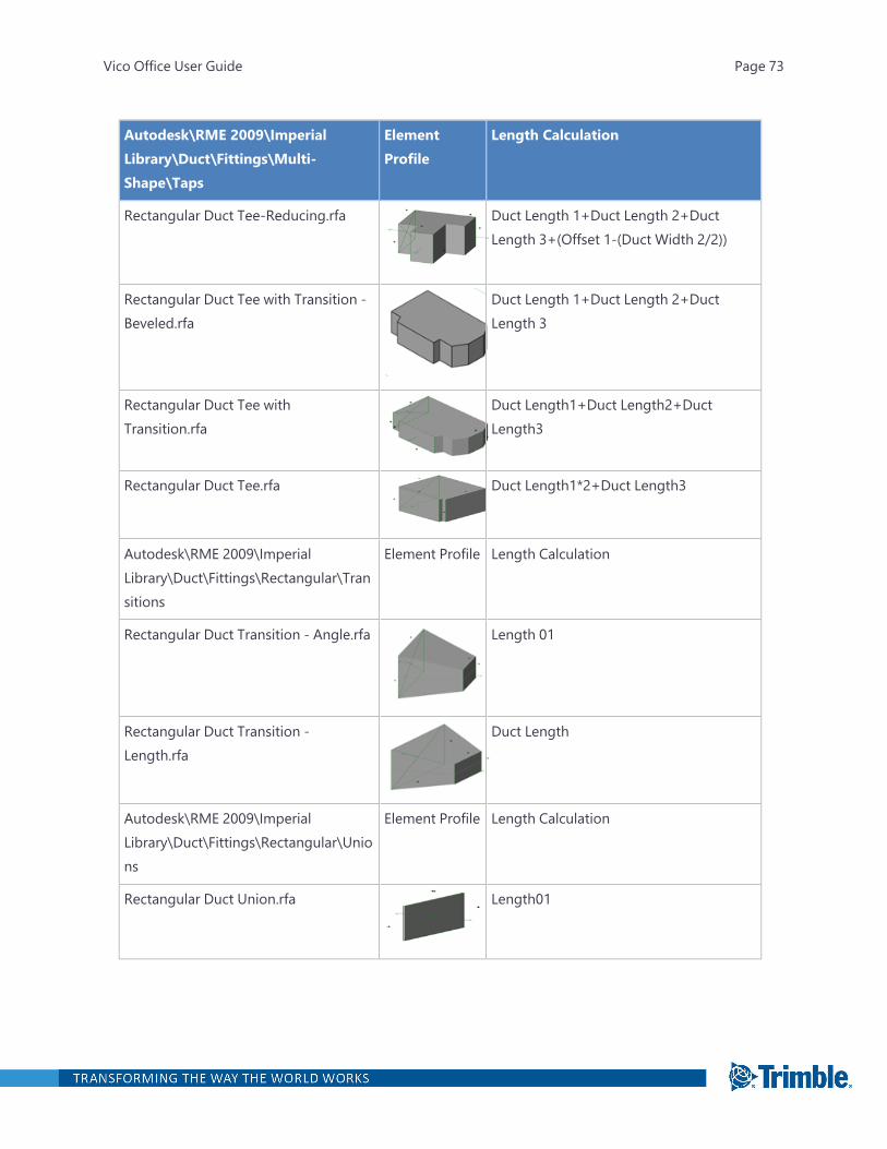
Autodesk\RME 2009\ImperialLibrary\Duct\Fittings\Multi-Shape\Taps
ElementProfile
Length Calculation
Rectangular Duct Tee-Reducing.rfa Duct Length 1+Duct Length 2+DuctLength 3+(Offset 1-(Duct Width 2/2))
Rectangular Duct Tee with Transition -Beveled.rfa
Duct Length 1+Duct Length 2+DuctLength 3
Rectangular Duct Tee withTransition.rfa
Duct Length1+Duct Length2+DuctLength3
Rectangular Duct Tee.rfa Duct Length1*2+Duct Length3
Autodesk\RME 2009\ImperialLibrary\Duct\Fittings\Rectangular\Transitions
Element Profile Length Calculation
Rectangular Duct Transition - Angle.rfa Length 01
Rectangular Duct Transition -Length.rfa
Duct Length
Autodesk\RME 2009\ImperialLibrary\Duct\Fittings\Rectangular\Unions
Element Profile Length Calculation
Rectangular Duct Union.rfa Length01
Vico Office User Guide Page 73
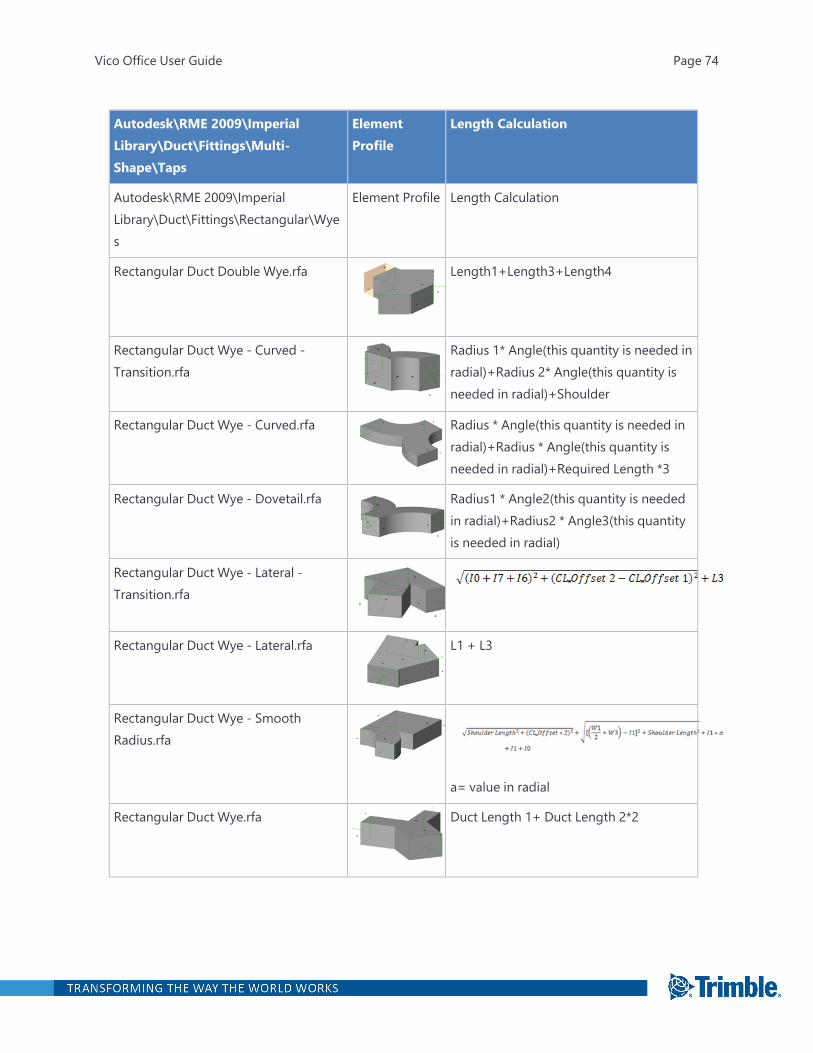
Autodesk\RME 2009\ImperialLibrary\Duct\Fittings\Multi-Shape\Taps
ElementProfile
Length Calculation
Autodesk\RME 2009\ImperialLibrary\Duct\Fittings\Rectangular\Wyes
Element Profile Length Calculation
Rectangular Duct Double Wye.rfa Length1+Length3+Length4
Rectangular Duct Wye - Curved -Transition.rfa
Radius 1* Angle(this quantity is needed inradial)+Radius 2* Angle(this quantity isneeded in radial)+Shoulder
Rectangular Duct Wye - Curved.rfa Radius * Angle(this quantity is needed inradial)+Radius * Angle(this quantity isneeded in radial)+Required Length *3
Rectangular Duct Wye - Dovetail.rfa Radius1 * Angle2(this quantity is neededin radial)+Radius2 * Angle3(this quantityis needed in radial)
Rectangular Duct Wye - Lateral -Transition.rfa
Rectangular Duct Wye - Lateral.rfa L1 + L3
Rectangular Duct Wye - SmoothRadius.rfa
a= value in radial
Rectangular Duct Wye.rfa Duct Length 1+ Duct Length 2*2
Vico Office User Guide Page 74
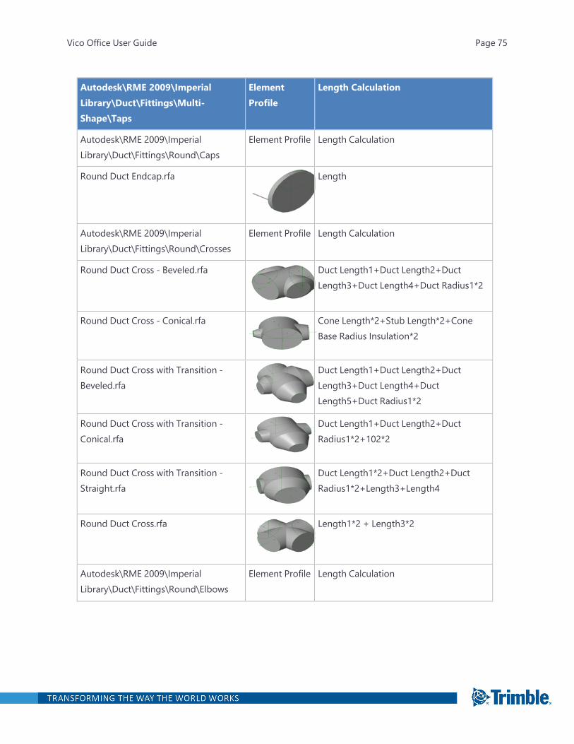
Autodesk\RME 2009\ImperialLibrary\Duct\Fittings\Multi-Shape\Taps
ElementProfile
Length Calculation
Autodesk\RME 2009\ImperialLibrary\Duct\Fittings\Round\Caps
Element Profile Length Calculation
Round Duct Endcap.rfa Length
Autodesk\RME 2009\ImperialLibrary\Duct\Fittings\Round\Crosses
Element Profile Length Calculation
Round Duct Cross - Beveled.rfa Duct Length1+Duct Length2+DuctLength3+Duct Length4+Duct Radius1*2
Round Duct Cross - Conical.rfa Cone Length*2+Stub Length*2+ConeBase Radius Insulation*2
Round Duct Cross with Transition -Beveled.rfa
Duct Length1+Duct Length2+DuctLength3+Duct Length4+DuctLength5+Duct Radius1*2
Round Duct Cross with Transition -Conical.rfa
Duct Length1+Duct Length2+DuctRadius1*2+102*2
Round Duct Cross with Transition -Straight.rfa
Duct Length1*2+Duct Length2+DuctRadius1*2+Length3+Length4
Round Duct Cross.rfa Length1*2 + Length3*2
Autodesk\RME 2009\ImperialLibrary\Duct\Fittings\Round\Elbows
Element Profile Length Calculation
Vico Office User Guide Page 75
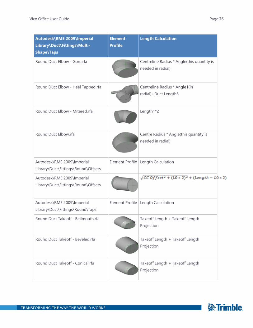
Autodesk\RME 2009\ImperialLibrary\Duct\Fittings\Multi-Shape\Taps
ElementProfile
Length Calculation
Round Duct Elbow - Gore.rfa Centreline Radius * Angle(this quantity isneeded in radial)
Round Duct Elbow - Heel Tapped.rfa Centreline Radius * Angle1(inradial)+Duct Length3
Round Duct Elbow - Mitered.rfa Length1*2
Round Duct Elbow.rfa Centre Radius * Angle(this quantity isneeded in radial)
Autodesk\RME 2009\ImperialLibrary\Duct\Fittings\Round\Offsets
Element Profile Length Calculation
Autodesk\RME 2009\ImperialLibrary\Duct\Fittings\Round\Offsets
Autodesk\RME 2009\ImperialLibrary\Duct\Fittings\Round\Taps
Element Profile Length Calculation
Round Duct Takeoff - Bellmouth.rfa Takeoff Length + Takeoff LengthProjection
Round Duct Takeoff - Beveled.rfa Takeoff Length + Takeoff LengthProjection
Round Duct Takeoff - Conical.rfa Takeoff Length + Takeoff LengthProjection
Vico Office User Guide Page 76
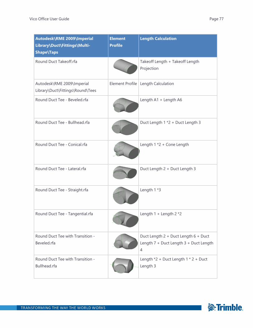
Autodesk\RME 2009\ImperialLibrary\Duct\Fittings\Multi-Shape\Taps
ElementProfile
Length Calculation
Round Duct Takeoff.rfa Takeoff Length + Takeoff LengthProjection
Autodesk\RME 2009\ImperialLibrary\Duct\Fittings\Round\Tees
Element Profile Length Calculation
Round Duct Tee - Beveled.rfa Length A1 + Length A6
Round Duct Tee - Bullhead.rfa Duct Length 1 *2 + Duct Length 3
Round Duct Tee - Conical.rfa Length 1 *2 + Cone Length
Round Duct Tee - Lateral.rfa Duct Length 2 + Duct Length 3
Round Duct Tee - Straight.rfa Length 1 *3
Round Duct Tee - Tangential.rfa Length 1 + Length 2 *2
Round Duct Tee with Transition -Beveled.rfa
Duct Length 2 + Duct Length 6 + DuctLength 7 + Duct Length 3 + Duct Length4
Round Duct Tee with Transition -Bullhead.rfa
Length *2 + Duct Length 1 * 2 + DuctLength 3
Vico Office User Guide Page 77
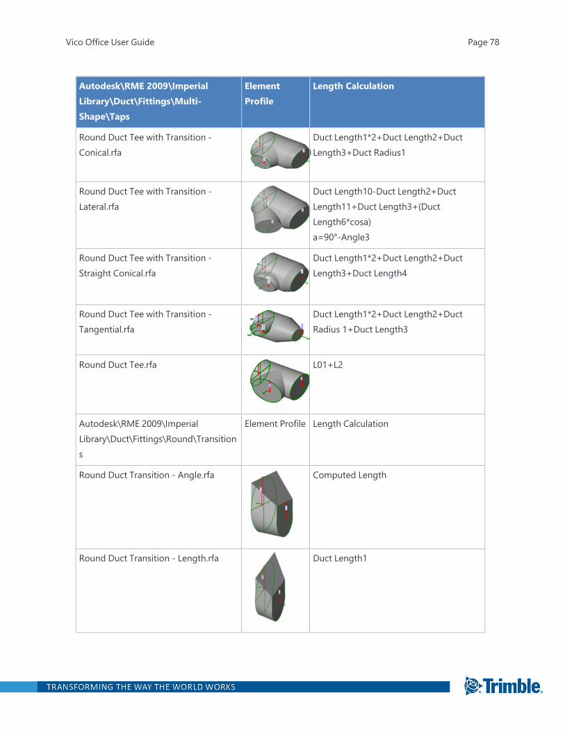
Autodesk\RME 2009\ImperialLibrary\Duct\Fittings\Multi-Shape\Taps
ElementProfile
Length Calculation
Round Duct Tee with Transition -Conical.rfa
Duct Length1*2+Duct Length2+DuctLength3+Duct Radius1
Round Duct Tee with Transition -Lateral.rfa
Duct Length10-Duct Length2+DuctLength11+Duct Length3+(DuctLength6*cosa)a=90°-Angle3
Round Duct Tee with Transition -Straight Conical.rfa
Duct Length1*2+Duct Length2+DuctLength3+Duct Length4
Round Duct Tee with Transition -Tangential.rfa
Duct Length1*2+Duct Length2+DuctRadius 1+Duct Length3
Round Duct Tee.rfa L01+L2
Autodesk\RME 2009\ImperialLibrary\Duct\Fittings\Round\Transitions
Element Profile Length Calculation
Round Duct Transition - Angle.rfa Computed Length
Round Duct Transition - Length.rfa Duct Length1
Vico Office User Guide Page 78
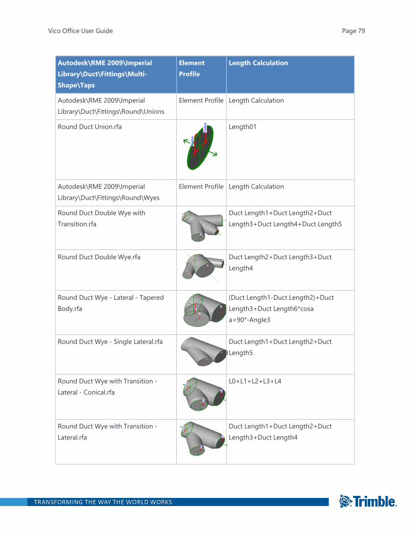
Autodesk\RME 2009\ImperialLibrary\Duct\Fittings\Multi-Shape\Taps
ElementProfile
Length Calculation
Autodesk\RME 2009\ImperialLibrary\Duct\Fittings\Round\Unions
Element Profile Length Calculation
Round Duct Union.rfa Length01
Autodesk\RME 2009\ImperialLibrary\Duct\Fittings\Round\Wyes
Element Profile Length Calculation
Round Duct Double Wye withTransition.rfa
Duct Length1+Duct Length2+DuctLength3+Duct Length4+Duct Length5
Round Duct Double Wye.rfa Duct Length2+Duct Length3+DuctLength4
Round Duct Wye - Lateral - TaperedBody.rfa
(Duct Length1-Duct Length2)+DuctLength3+Duct Length6*cosaa=90°-Angle3
Round Duct Wye - Single Lateral.rfa Duct Length1+Duct Length2+DuctLength5
Round Duct Wye with Transition -Lateral - Conical.rfa
L0+L1+L2+L3+L4
Round Duct Wye with Transition -Lateral.rfa
Duct Length1+Duct Length2+DuctLength3+Duct Length4
Vico Office User Guide Page 79
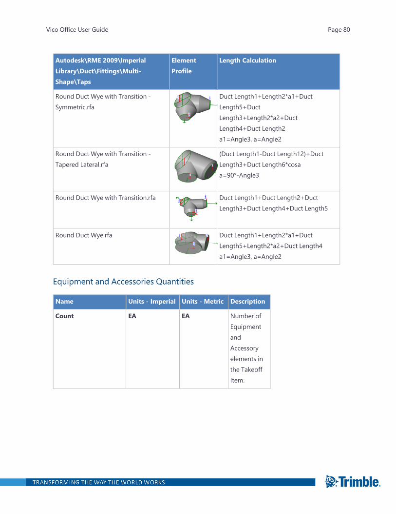
Autodesk\RME 2009\ImperialLibrary\Duct\Fittings\Multi-Shape\Taps
ElementProfile
Length Calculation
Round Duct Wye with Transition -Symmetric.rfa
Duct Length1+Length2*a1+DuctLength5+DuctLength3+Length2*a2+DuctLength4+Duct Length2a1=Angle3, a=Angle2
Round Duct Wye with Transition -Tapered Lateral.rfa
(Duct Length1-Duct Length12)+DuctLength3+Duct Length6*cosaa=90°-Angle3
Round Duct Wye with Transition.rfa Duct Length1+Duct Length2+DuctLength3+Duct Length4+Duct Length5
Round Duct Wye.rfa Duct Length1+Length2*a1+DuctLength5+Length2*a2+Duct Length4a1=Angle3, a=Angle2
Equipment and Accessories Quantities
Name Units - Imperial Units - Metric Description
Count EA EA Number ofEquipmentandAccessoryelements inthe TakeoffItem.
Vico Office User Guide Page 80

Name Units - Imperial Units - Metric Description
Piece Count EA EA Number ofseparatepieces,created fromthe originalelement as aresult ofsplittingoperations.
CAD_Count EA EA Number ofelements inthe TakeoffItem. Thisquantitycomes fromthe CADapplicationafter it waspublished.
Light Fixture Quantities
Name Units - Imperial Units - Metric Description
Count EA EA Number oflight fixtureelements inthe TakeoffItem.
Vico Office User Guide Page 81
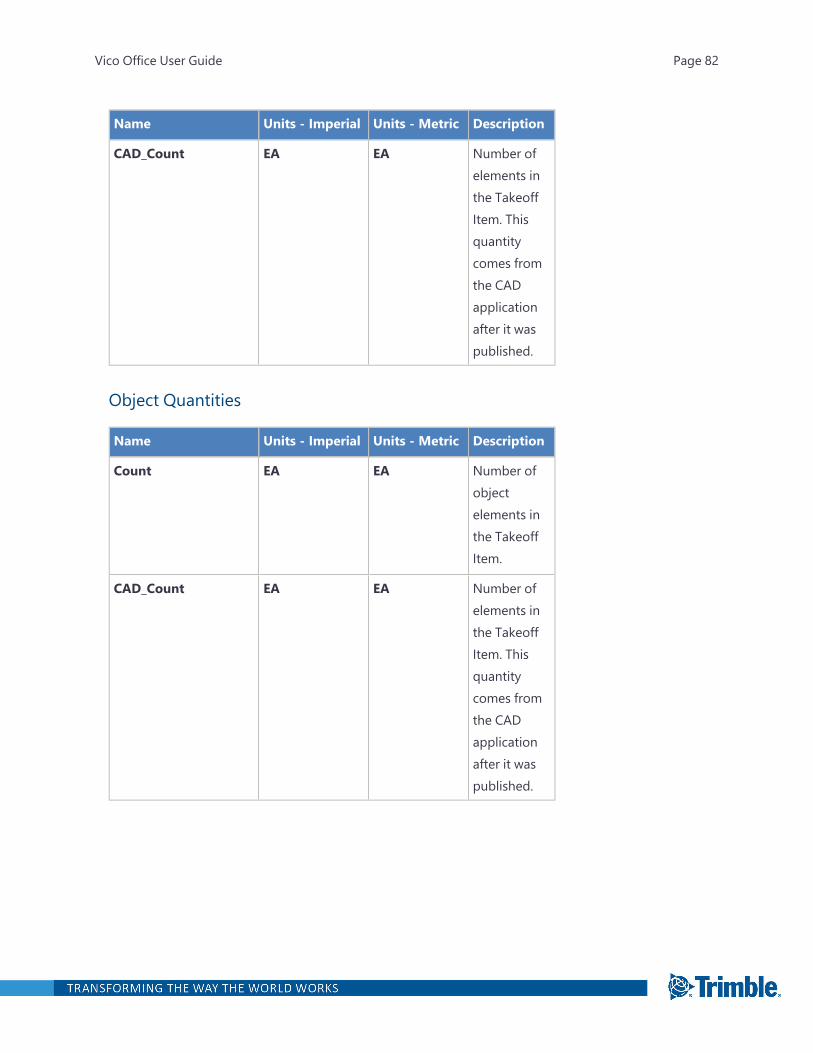
Name Units - Imperial Units - Metric Description
CAD_Count EA EA Number ofelements inthe TakeoffItem. Thisquantitycomes fromthe CADapplicationafter it waspublished.
Object Quantities
Name Units - Imperial Units - Metric Description
Count EA EA Number ofobjectelements inthe TakeoffItem.
CAD_Count EA EA Number ofelements inthe TakeoffItem. Thisquantitycomes fromthe CADapplicationafter it waspublished.
Vico Office User Guide Page 82
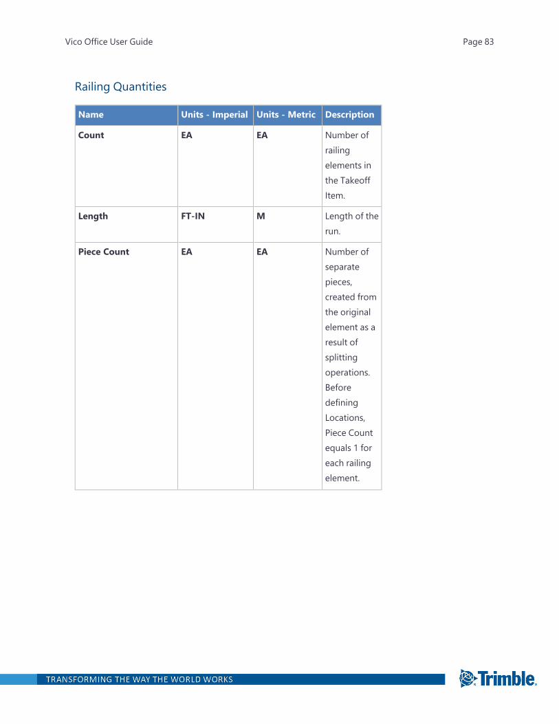
Railing Quantities
Name Units - Imperial Units - Metric Description
Count EA EA Number ofrailingelements inthe TakeoffItem.
Length FT-IN M Length of therun.
Piece Count EA EA Number ofseparatepieces,created fromthe originalelement as aresult ofsplittingoperations.BeforedefiningLocations,Piece Countequals 1 foreach railingelement.
Vico Office User Guide Page 83

Name Units - Imperial Units - Metric Description
Piece Length FT-IN M Length of anindividualrailing piece.Returns thelength of therailing that iscontained ina Location.
If thiselement hasa referencelinepublishedwith itsgeometry, ifyou split thiselement,each derivedelement willget its owncorrect splitlength basedon its pieceof referenceline.
If a referenceline is notpresent, anumericvalue todetect lengthis used so itcannot besplit correctly
Vico Office User Guide Page 84
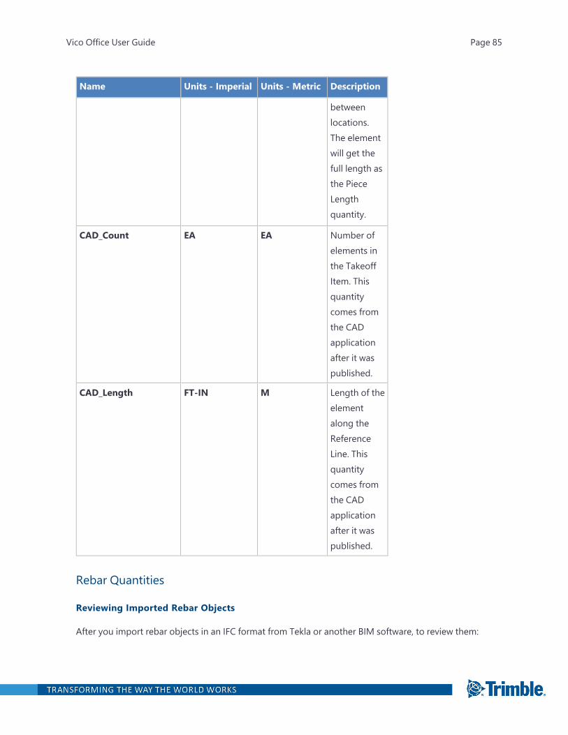
Name Units - Imperial Units - Metric Description
betweenlocations.The elementwill get thefull length asthe PieceLengthquantity.
CAD_Count EA EA Number ofelements inthe TakeoffItem. Thisquantitycomes fromthe CADapplicationafter it waspublished.
CAD_Length FT-IN M Length of theelementalong theReferenceLine. Thisquantitycomes fromthe CADapplicationafter it waspublished.
Rebar Quantities
Reviewing Imported Rebar Objects
After you import rebar objects in an IFC format from Tekla or another BIM software, to review them:
Vico Office User Guide Page 85
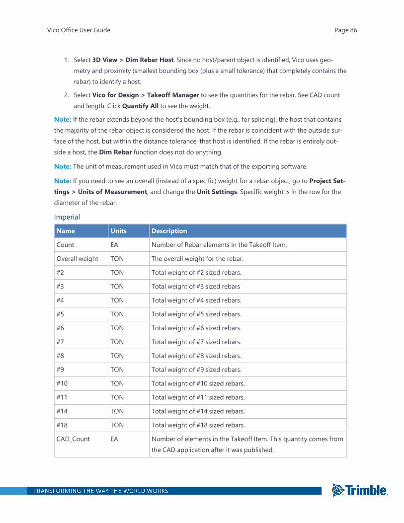
1. Select 3D View > Dim Rebar Host. Since no host/parent object is identified, Vico uses geo-metry and proximity (smallest bounding box (plus a small tolerance) that completely contains therebar) to identify a host.
2. Select Vico for Design > Takeoff Manager to see the quantities for the rebar. See CAD countand length. Click Quantify All to see the weight.
Note: If the rebar extends beyond the host's bounding box (e.g., for splicing), the host that containsthe majority of the rebar object is considered the host. If the rebar is coincident with the outside sur-face of the host, but within the distance tolerance, that host is identified. If the rebar is entirely out-side a host, the Dim Rebar function does not do anything.
Note: The unit of measurement used in Vico must match that of the exporting software.
Note: If you need to see an overall (instead of a specific) weight for a rebar object, go to Project Set-tings > Units of Measurement, and change the Unit Settings. Specific weight is in the row for thediameter of the rebar.
Imperial
Name Units Description
Count EA Number of Rebar elements in the Takeoff Item.
Overall weight TON The overall weight for the rebar.
#2 TON Total weight of #2 sized rebars.
#3 TON Total weight of #3 sized rebars
#4 TON Total weight of #4 sized rebars.
#5 TON Total weight of #5 sized rebars.
#6 TON Total weight of #6 sized rebars.
#7 TON Total weight of #7 sized rebars.
#8 TON Total weight of #8 sized rebars.
#9 TON Total weight of #9 sized rebars.
#10 TON Total weight of #10 sized rebars.
#11 TON Total weight of #11 sized rebars.
#14 TON Total weight of #14 sized rebars.
#18 TON Total weight of #18 sized rebars.
CAD_Count EA Number of elements in the Takeoff Item. This quantity comes fromthe CAD application after it was published.
Vico Office User Guide Page 86

Name Units Description
CAD_Length FT-IN Length of the element along the Reference Line. This quantitycomes from the CAD application after it was published.
Metric
Name Units Description
Count EA Number of Rebar elements in the Takeoff Item.
Piece Count EA Number of separate pieces, created from the original element as aresult of splitting operations.
Overallweight
TON The overall weight for the rebar.
M5 TON Total weight of M5 sized rebars.
M6 TON Total weight of M6 sized rebars.
M8 TON Total weight of M8 sized rebars.
M10 TON Total weight of M10 sized rebars.
M12 TON Total weight of M10 sized rebars.
M14 TON Total weight of M14 sized rebars.
M16 TON Total weight of M16 sized rebars.
M18 TON Total weight of M18 sized rebars.
M20 TON Total weight of M20 sized rebars.
M22 TON Total weight of M22 sized rebars.
M24 TON Total weight of M24 sized rebars.
M25 TON Total weight of M25 sized rebars.
M26 TON Total weight of M26 sized rebars.
M28 TON Total weight of M28 sized rebars.
M30 TON Total weight of M30 sized rebars.
M32 TON Total weight of M32 sized rebars.
M34 TON Total weight of M34 sized rebars.
M35 TON Total weight of M35 sized rebars.
M36 TON Total weight of M36 sized rebars.
Vico Office User Guide Page 87
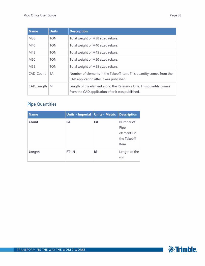
Name Units Description
M38 TON Total weight of M38 sized rebars.
M40 TON Total weight of M40 sized rebars.
M45 TON Total weight of M45 sized rebars.
M50 TON Total weight of M50 sized rebars.
M55 TON Total weight of M55 sized rebars.
CAD_Count EA Number of elements in the Takeoff Item. This quantity comes from theCAD application after it was published.
CAD_Length M Length of the element along the Reference Line. This quantity comesfrom the CAD application after it was published.
Pipe Quantities
Name Units - Imperial Units - Metric Description
Count EA EA Number ofPipeelements inthe TakeoffItem.
Length FT-IN M Length of therun
Vico Office User Guide Page 88

Name Units - Imperial Units - Metric Description
Piece Count EA EA Number ofseparatepieces,created fromthe originalelement as aresult ofsplittingoperations.BeforedefiningLocations,Piece Countequals 1 foreach Pipeelement.
Vico Office User Guide Page 89
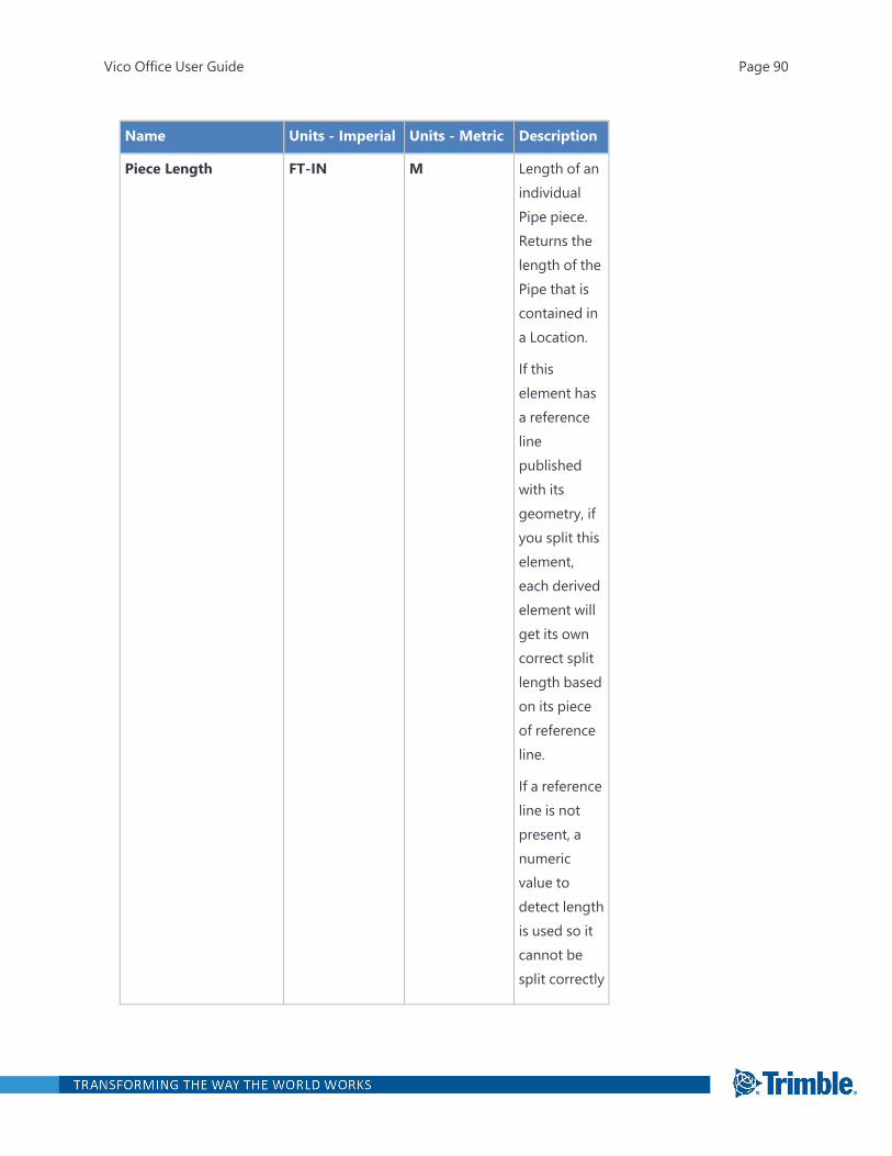
Name Units - Imperial Units - Metric Description
Piece Length FT-IN M Length of anindividualPipe piece.Returns thelength of thePipe that iscontained ina Location.
If thiselement hasa referencelinepublishedwith itsgeometry, ifyou split thiselement,each derivedelement willget its owncorrect splitlength basedon its pieceof referenceline.
If a referenceline is notpresent, anumericvalue todetect lengthis used so itcannot besplit correctly
Vico Office User Guide Page 90

Name Units - Imperial Units - Metric Description
betweenlocations.The elementwill get thefull length asthe PieceLengthquantity.
CAD_Count EA EA Number ofelements inthe TakeoffItem. Thisquantitycomes fromthe CADapplicationafter it waspublished.
CAD_Length FT-IN M Length of theelementalong theReferenceLine. Thisquantitycomes fromthe CADapplicationafter it waspublished.
Length of Revit Pipe Fittings and Valves is calculated using these elements' custom properties. See"Revit Pipe Fitting and Valve Length Calculation" on the next page for an overview of calculationrules.
Vico Office User Guide Page 91
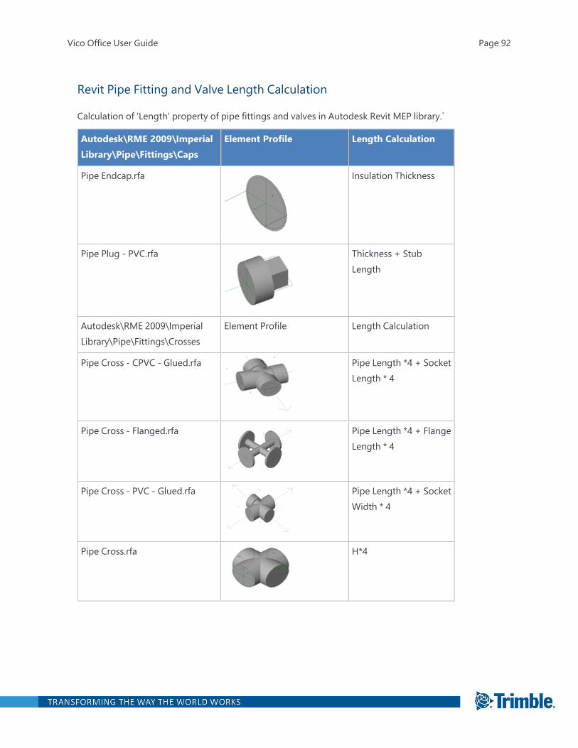
Revit Pipe Fitting and Valve Length Calculation
Calculation of 'Length' property of pipe fittings and valves in Autodesk Revit MEP library.`
Autodesk\RME 2009\ImperialLibrary\Pipe\Fittings\Caps
Element Profile Length Calculation
Pipe Endcap.rfa Insulation Thickness
Pipe Plug - PVC.rfa Thickness + StubLength
Autodesk\RME 2009\ImperialLibrary\Pipe\Fittings\Crosses
Element Profile Length Calculation
Pipe Cross - CPVC - Glued.rfa Pipe Length *4 + SocketLength * 4
Pipe Cross - Flanged.rfa Pipe Length *4 + FlangeLength * 4
Pipe Cross - PVC - Glued.rfa Pipe Length *4 + SocketWidth * 4
Pipe Cross.rfa H*4
Vico Office User Guide Page 92
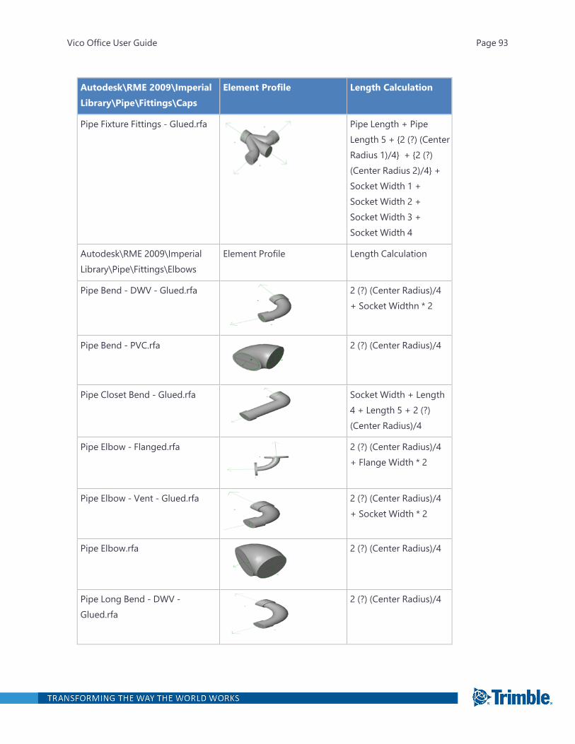
Autodesk\RME 2009\ImperialLibrary\Pipe\Fittings\Caps
Element Profile Length Calculation
Pipe Fixture Fittings - Glued.rfa Pipe Length + PipeLength 5 + {2 (?) (CenterRadius 1)/4} + {2 (?)(Center Radius 2)/4} +Socket Width 1 +Socket Width 2 +Socket Width 3 +Socket Width 4
Autodesk\RME 2009\ImperialLibrary\Pipe\Fittings\Elbows
Element Profile Length Calculation
Pipe Bend - DWV - Glued.rfa 2 (?) (Center Radius)/4+ Socket Widthn * 2
Pipe Bend - PVC.rfa 2 (?) (Center Radius)/4
Pipe Closet Bend - Glued.rfa Socket Width + Length4 + Length 5 + 2 (?)(Center Radius)/4
Pipe Elbow - Flanged.rfa 2 (?) (Center Radius)/4+ Flange Width * 2
Pipe Elbow - Vent - Glued.rfa 2 (?) (Center Radius)/4 + Socket Width * 2
Pipe Elbow.rfa 2 (?) (Center Radius)/4
Pipe Long Bend - DWV -Glued.rfa
2 (?) (Center Radius)/4
Vico Office User Guide Page 93

Autodesk\RME 2009\ImperialLibrary\Pipe\Fittings\Caps
Element Profile Length Calculation
Pipe Long Radius Elbow -Flanged.rfa
2 (?) (Center Radius)/4 + Flange Width * 2
Pipe Round Base Elbow -Flanged.rfa
2 (?) (Center Radius)/4+ Flange Width * 3
Pipe Square Base Elbow -Flanged.rfa
2 (?) (Center Radius)/4 + Flange Width * 3
Pipe Three Way Ell - Glued.rfa 2 (?) (Center Radius)/4 + Socket Width * 3
Autodesk\RME 2009\ImperialLibrary\Pipe\Fittings\Lateral Tees
Element Profile Length Calculation
Pipe 45 Deg Lateral - Flanged.rfa Pipe Length 1 + PipeLength 2+ Pipe Length3 + 3*Flange Width
Autodesk\RME 2009\ImperialLibrary\Pipe\Fittings\Profiles
Element Profile Length Calculation
Pipe - Round.rfa N/A
Autodesk\RME 2009\ImperialLibrary\Pipe\Fittings\Spuds
Element Profile Length Calculation
Pipe Closet Flange - DWV -Glued.rfa
Socket Width +Transition Width +Flange Width
Autodesk\RME 2009\ImperialLibrary\Pipe\Fittings\Tees
Element Profile Length Calculation
Pipe Double Long Tee - Glued.rfa Pipe Length 2 + {2 (?)(Center Radius)/4}*2 +Socket Width * 3
Vico Office User Guide Page 94
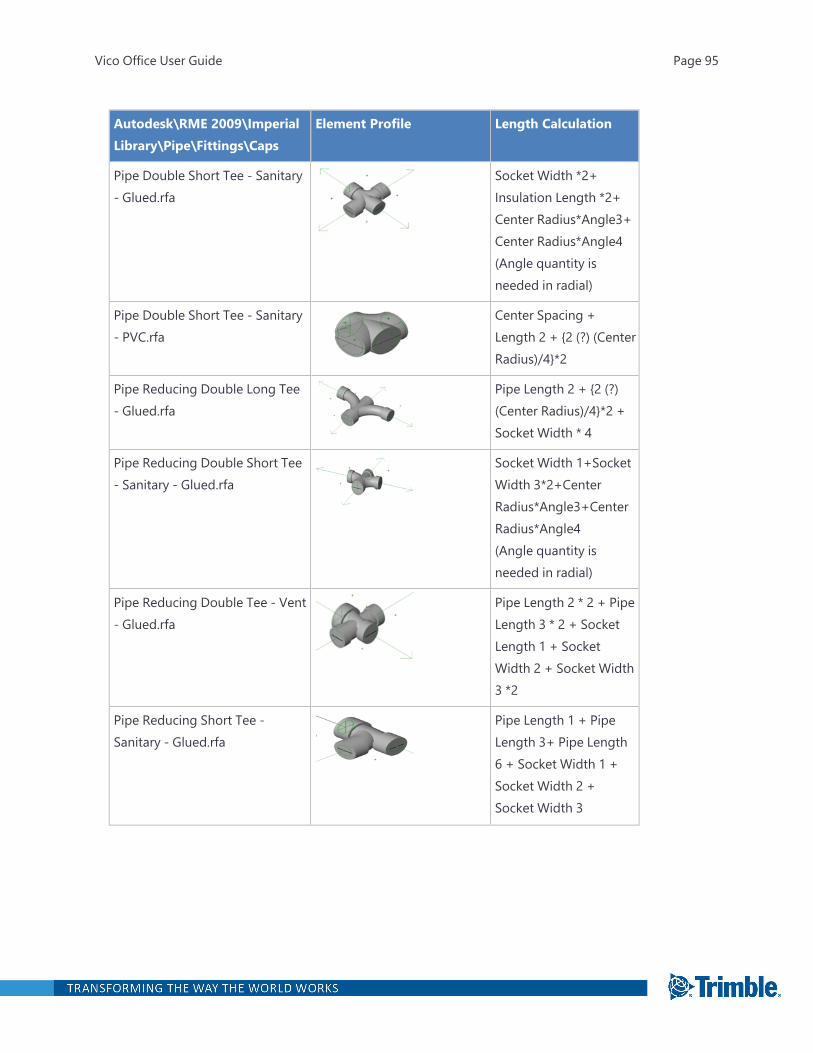
Autodesk\RME 2009\ImperialLibrary\Pipe\Fittings\Caps
Element Profile Length Calculation
Pipe Double Short Tee - Sanitary- Glued.rfa
Socket Width *2+Insulation Length *2+Center Radius*Angle3+Center Radius*Angle4(Angle quantity isneeded in radial)
Pipe Double Short Tee - Sanitary- PVC.rfa
Center Spacing +Length 2 + {2 (?) (CenterRadius)/4}*2
Pipe Reducing Double Long Tee- Glued.rfa
Pipe Length 2 + {2 (?)(Center Radius)/4}*2 +Socket Width * 4
Pipe Reducing Double Short Tee- Sanitary - Glued.rfa
Socket Width 1+SocketWidth 3*2+CenterRadius*Angle3+CenterRadius*Angle4(Angle quantity isneeded in radial)
Pipe Reducing Double Tee - Vent- Glued.rfa
Pipe Length 2 * 2 + PipeLength 3 * 2 + SocketLength 1 + SocketWidth 2 + Socket Width3 *2
Pipe Reducing Short Tee -Sanitary - Glued.rfa
Pipe Length 1 + PipeLength 3+ Pipe Length6 + Socket Width 1 +Socket Width 2 +Socket Width 3
Vico Office User Guide Page 95
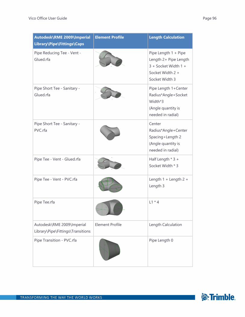
Autodesk\RME 2009\ImperialLibrary\Pipe\Fittings\Caps
Element Profile Length Calculation
Pipe Reducing Tee - Vent -Glued.rfa
Pipe Length 1 + PipeLength 2+ Pipe Length3 + Socket Width 1 +Socket Width 2 +Socket Width 3
Pipe Short Tee - Sanitary -Glued.rfa
Pipe Length 1+CenterRadius*Angle+SocketWidth*3(Angle quantity isneeded in radial)
Pipe Short Tee - Sanitary -PVC.rfa
CenterRadius*Angle+CenterSpacing+Length 2(Angle quantity isneeded in radial)
Pipe Tee - Vent - Glued.rfa Half Length * 3 +Socket Width * 3
Pipe Tee - Vent - PVC.rfa Length 1 + Length 2 +Length 3
Pipe Tee.rfa L1 * 4
Autodesk\RME 2009\ImperialLibrary\Pipe\Fittings\Transitions
Element Profile Length Calculation
Pipe Transition - PVC.rfa Pipe Length 0
Vico Office User Guide Page 96
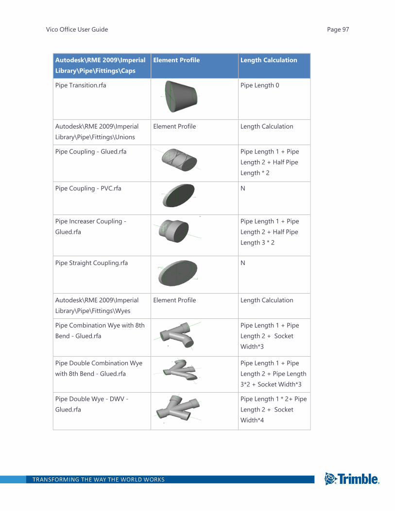
Autodesk\RME 2009\ImperialLibrary\Pipe\Fittings\Caps
Element Profile Length Calculation
Pipe Transition.rfa Pipe Length 0
Autodesk\RME 2009\ImperialLibrary\Pipe\Fittings\Unions
Element Profile Length Calculation
Pipe Coupling - Glued.rfa Pipe Length 1 + PipeLength 2 + Half PipeLength * 2
Pipe Coupling - PVC.rfa N
Pipe Increaser Coupling -Glued.rfa
Pipe Length 1 + PipeLength 2 + Half PipeLength 3 * 2
Pipe Straight Coupling.rfa N
Autodesk\RME 2009\ImperialLibrary\Pipe\Fittings\Wyes
Element Profile Length Calculation
Pipe Combination Wye with 8thBend - Glued.rfa
Pipe Length 1 + PipeLength 2 + SocketWidth*3
Pipe Double Combination Wyewith 8th Bend - Glued.rfa
Pipe Length 1 + PipeLength 2 + Pipe Length3*2 + Socket Width*3
Pipe Double Wye - DWV -Glued.rfa
Pipe Length 1 * 2+ PipeLength 2 + SocketWidth*4
Vico Office User Guide Page 97

Autodesk\RME 2009\ImperialLibrary\Pipe\Fittings\Caps
Element Profile Length Calculation
Pipe Double Wye - DWV -PVC.rfa
Pipe Length 1 + PipeLength 2 + Pipe Length3 + Pipe Length 4
Pipe Plain Wye - DWV - Glued.rfa Pipe Length 1 + PipeLength 2 + Pipe Length3 + Socket Width*3
Pipe Reducing Double Wye -Glued.rfa
Pipe Length 1 + PipeLength 2 + Pipe Length3*2 + Socket Width 1+Socket Width 2 +SocketWidth 3*2
Pipe Reducing Wye - DWV -Glued.rfa
Pipe Length 1 + PipeLength 2 + Pipe Length3 + Socket Width 1+Socket Width 2 +SocketWidth 3
Pipe True Wye - Flanged.rfa Pipe Length 1+PipeLength 2+Pipe Length3+Flange Width*3
Pipe Upright Wye - DWV -Glued.rfa
Pipe Length 1 + PipeLength 2 + Pipe Length3 + Socket Width 1 *3
Pipe Wye - DWV - PVC.rfa Pipe Length 1 + PipeLength 2 + Pipe Length3
Pipe Wye and 8th Bend - PVC.rfa CenterRadius*Angle+L0+L1
Autodesk\RME 2009\ImperialLibrary\Pipe\Valves\3 Way Valves
Element Profile Length Calculation
Vico Office User Guide Page 98

Autodesk\RME 2009\ImperialLibrary\Pipe\Fittings\Caps
Element Profile Length Calculation
3 Way Valve - 0.75-4 Inch.rfa Body Length
Autodesk\RME 2009\ImperialLibrary\Pipe\Valves\BackflowPreventers
Element Profile Length Calculation
Backflow Preventer - 0.5-2Inch.rfa
Valve Length
Double Check Valve - 2.5-10Inch.rfa
Valve Length
Double Check Valve - N Pattern -2.5-10 Inch.rfa
Valve Length
Vacuum Breaker Backflow Valve -0.5-2 Inch.rfa
C2 Offset
Autodesk\RME 2009\ImperialLibrary\Pipe\Valves\BalancingValves
Element Profile Length Calculation
Balancing Valve - Angle - 2.5-12Inch - Flanged.rfa
Open Length+C2Offset1
Balancing Valve - Angle - 2.5-12Inch - Grooved.rfa
Open Length+C2Offset1
Vico Office User Guide Page 99
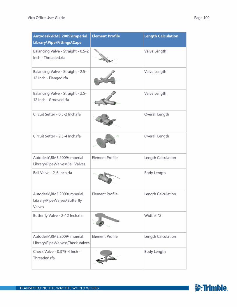
Autodesk\RME 2009\ImperialLibrary\Pipe\Fittings\Caps
Element Profile Length Calculation
Balancing Valve - Straight - 0.5-2Inch - Threaded.rfa
Valve Length
Balancing Valve - Straight - 2.5-12 Inch - Flanged.rfa
Valve Length
Balancing Valve - Straight - 2.5-12 Inch - Grooved.rfa
Valve Length
Circuit Setter - 0.5-2 Inch.rfa Overall Length
Circuit Setter - 2.5-4 Inch.rfa Overall Length
Autodesk\RME 2009\ImperialLibrary\Pipe\Valves\Ball Valves
Element Profile Length Calculation
Ball Valve - 2-6 Inch.rfa Body Length
Autodesk\RME 2009\ImperialLibrary\Pipe\Valves\ButterflyValves
Element Profile Length Calculation
Butterfly Valve - 2-12 Inch.rfa Width3 *2
Autodesk\RME 2009\ImperialLibrary\Pipe\Valves\Check Valves
Element Profile Length Calculation
Check Valve - 0.375-4 Inch -Threaded.rfa
Body Length
Vico Office User Guide Page 100

Autodesk\RME 2009\ImperialLibrary\Pipe\Fittings\Caps
Element Profile Length Calculation
Check Valve - 2-12 Inch -Flanged.rfa
Body Length
Check Valve - Wafer - 2-24Inch.rfa
Body Length
Autodesk\RME 2009\ImperialLibrary\Pipe\Valves\ControlValves
Element Profile Length Calculation
Motor Control Valve - 0.5-2Inch.rfa
Valve Length
Motor Control Valve - 2.5-6Inch.rfa
Half Valve Length * 2
Motor Control Valve - 3 Way - 2-16 Inch.rfa
Width2* 4
Motor Control Valve - 8-12Inch.rfa
Valve Thickness
Solenoid Valve - 0.5-3 Inch.rfa Length2
Solenoid Valve - 0.25-0.375Inch.rfa
N/A
Autodesk\RME 2009\ImperialLibrary\Pipe\Valves\DiaphragmValves
Element Profile Length Calculation
Vico Office User Guide Page 101
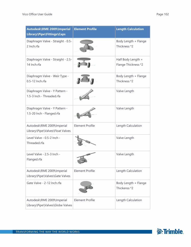
Autodesk\RME 2009\ImperialLibrary\Pipe\Fittings\Caps
Element Profile Length Calculation
Diaphragm Valve - Straight - 0.5-2 Inch.rfa
Body Length + FlangeThickness *2
Diaphragm Valve - Straight - 2.5-14 Inch.rfa
Half Body Length +Flange Thickness *2
Diaphragm Valve - Weir Type -0.5-12 Inch.rfa
Body Length + FlangeThickness *2
Diaphragm Valve - Y Pattern -1.5-3 Inch - Threaded.rfa
Valve Length
Diaphragm Valve - Y Pattern -1.5-20 Inch - Flanged.rfa
Valve Length
Autodesk\RME 2009\ImperialLibrary\Pipe\Valves\Float Valves
Element Profile Length Calculation
Level Valve - 0.5-2 Inch -Threaded.rfa
Valve Length
Level Valve - 2.5-3 Inch -Flanged.rfa
Valve Length
Autodesk\RME 2009\ImperialLibrary\Pipe\Valves\Gate Valves
Element Profile Length Calculation
Gate Valve - 2-12 Inch.rfa Body Length + FlangeThickenss *2
Autodesk\RME 2009\ImperialLibrary\Pipe\Valves\Globe Valves
Element Profile Length Calculation
Vico Office User Guide Page 102

Autodesk\RME 2009\ImperialLibrary\Pipe\Fittings\Caps
Element Profile Length Calculation
Globe Valve - 0.375-2 Inch -Threaded.rfa
Half Pipe Length *2
Globe Valve - 2-18 Inch -Flanged.rfa
Half Pipe Length *2 +Flange thickness *2
Autodesk\RME 2009\ImperialLibrary\Pipe\Valves\Multi-Purpose Valves
Element Profile Length Calculation
Multi-Purpose Valve - Angle -1.5-2.5 Inch - Threaded.rfa
C2 Offset 1+OpenLength
Multi-Purpose Valve - Angle - 3-12 Inch - Flanged.rfa
C2 Offset 1+OpenLength
Multi-Purpose Valve - Straight -1.5-2.5 Inch - Threaded.rfa
Valve Length
Multi-Purpose Valve - Straight -3-12 Inch - Flanged.rfa
Valve Length
Autodesk\RME 2009\ImperialLibrary\Pipe\Valves\Plug Valves
Element Profile Length Calculation
Plug Valve - 0.5-2 Inch.rfa Half Valve Length * 2
Plug Valve - 3 Way - 0.5-2Inch.rfa
Valve Length
Plug Valve - 3 Way - GearOperated - 4-16 Inch.rfa
Valve Length
Vico Office User Guide Page 103
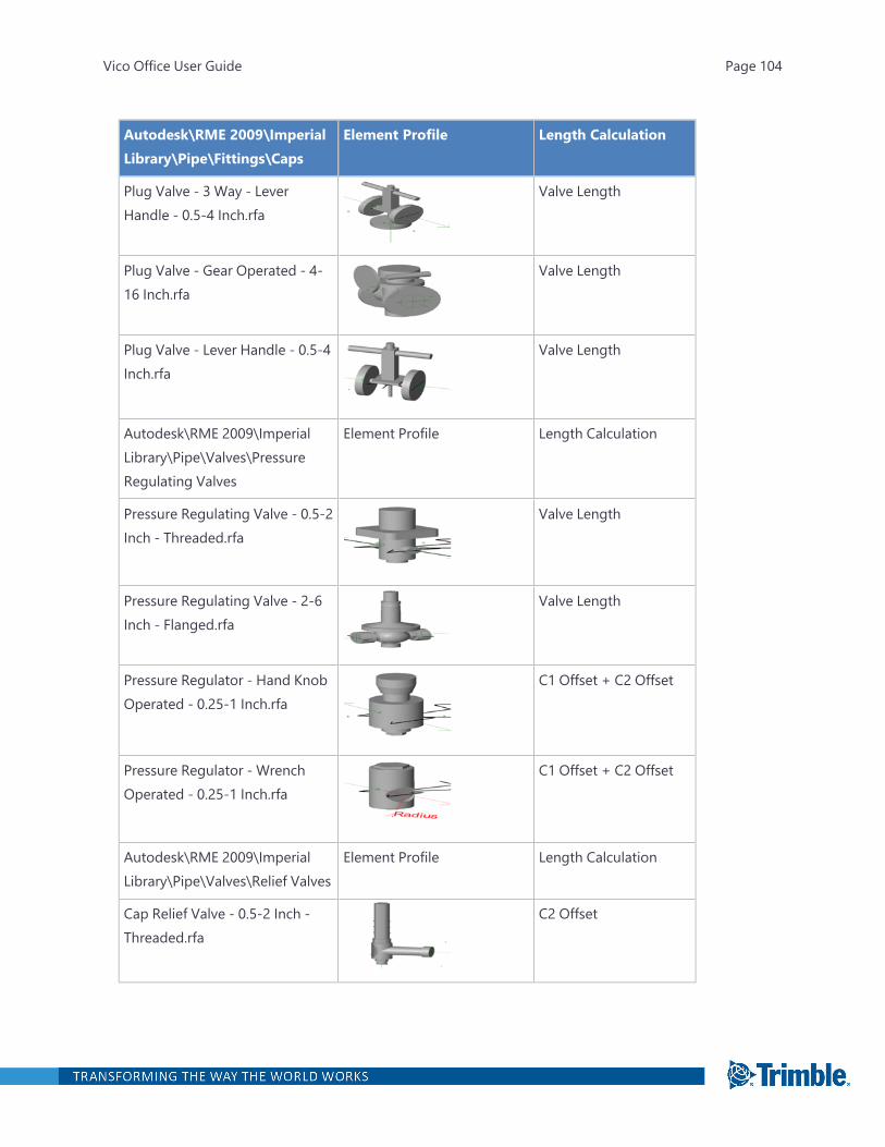
Autodesk\RME 2009\ImperialLibrary\Pipe\Fittings\Caps
Element Profile Length Calculation
Plug Valve - 3 Way - LeverHandle - 0.5-4 Inch.rfa
Valve Length
Plug Valve - Gear Operated - 4-16 Inch.rfa
Valve Length
Plug Valve - Lever Handle - 0.5-4Inch.rfa
Valve Length
Autodesk\RME 2009\ImperialLibrary\Pipe\Valves\PressureRegulating Valves
Element Profile Length Calculation
Pressure Regulating Valve - 0.5-2Inch - Threaded.rfa
Valve Length
Pressure Regulating Valve - 2-6Inch - Flanged.rfa
Valve Length
Pressure Regulator - Hand KnobOperated - 0.25-1 Inch.rfa
C1 Offset + C2 Offset
Pressure Regulator - WrenchOperated - 0.25-1 Inch.rfa
C1 Offset + C2 Offset
Autodesk\RME 2009\ImperialLibrary\Pipe\Valves\Relief Valves
Element Profile Length Calculation
Cap Relief Valve - 0.5-2 Inch -Threaded.rfa
C2 Offset
Vico Office User Guide Page 104

Autodesk\RME 2009\ImperialLibrary\Pipe\Fittings\Caps
Element Profile Length Calculation
Pressure Relief Valve - 1-10Inch.rfa
C2 Offset
Autodesk\RME 2009\ImperialLibrary\Pipe\Valves\Steam Traps
Element Profile Length Calculation
Steam Trap - Inverted Bucket.rfa Overall Length
Room Quantities
Name Units - Imperial Units - Metric Description
Count EA EA Number ofRoomelements inthe TakeoffItem.
Height FT-IN M Height of theRoom
Vico Office User Guide Page 105
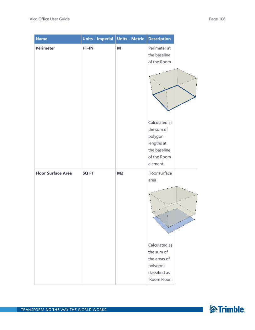
Name Units - Imperial Units - Metric Description
Perimeter FT-IN M Perimeter atthe baselineof the Room
Calculated asthe sum ofpolygonlengths atthe baselineof the Roomelement.
Floor Surface Area SQ FT M2 Floor surfacearea
Calculated asthe sum ofthe areas ofpolygonsclassified as'Room Floor'.
Vico Office User Guide Page 106

Name Units - Imperial Units - Metric Description
Net Volume CU YD M3 Net volume
Gross Volume CU YD M3 Grossvolume ofthe Room.
Piece Count EA EA Number ofpiecescreated fromthe originalRoomelement as aresult ofdefiningLocations(Floors andZones).
Piece Height FT-IN M Height of anindividualpiece of theRoomelement,created as aresult ofdefiningLocations.
Vico Office User Guide Page 107
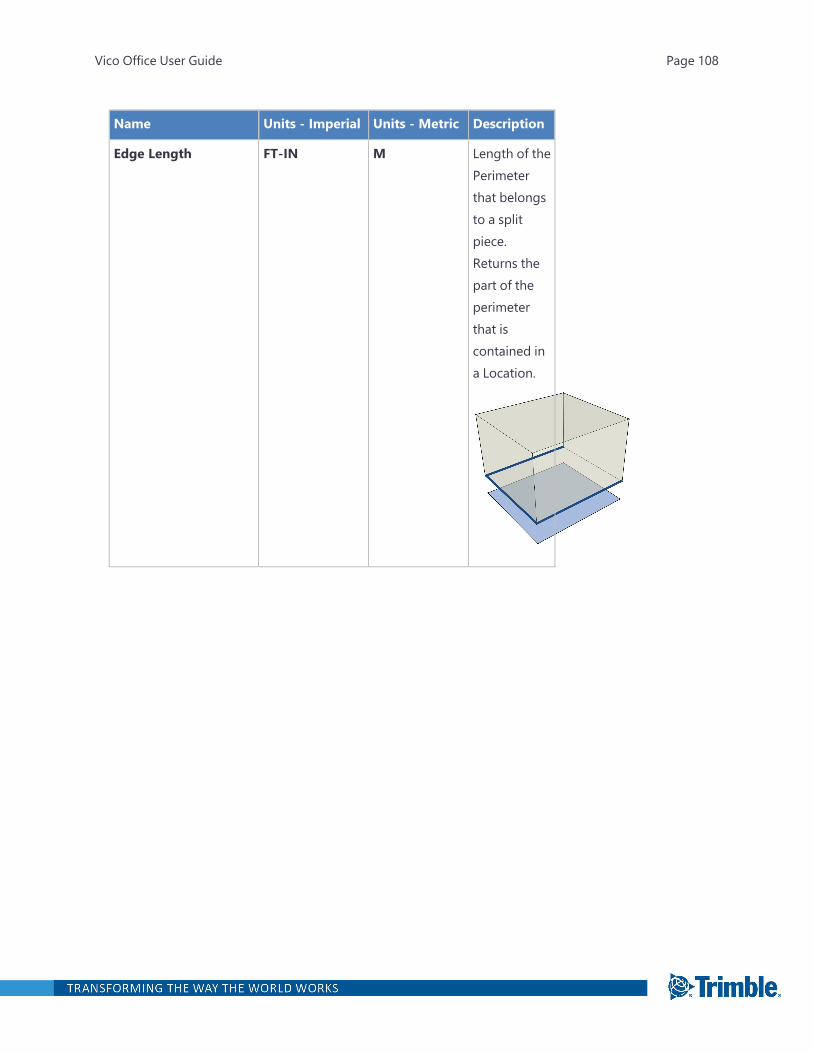
Name Units - Imperial Units - Metric Description
Edge Length FT-IN M Length of thePerimeterthat belongsto a splitpiece.Returns thepart of theperimeterthat iscontained ina Location.
Vico Office User Guide Page 108
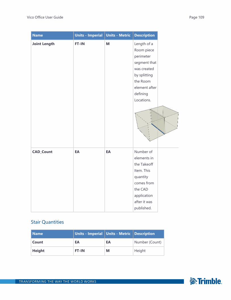
Name Units - Imperial Units - Metric Description
Joint Length FT-IN M Length of aRoom pieceperimetersegment thatwas createdby splittingthe Roomelement afterdefiningLocations.
CAD_Count EA EA Number ofelements inthe TakeoffItem. Thisquantitycomes fromthe CADapplicationafter it waspublished.
Stair Quantities
Name Units - Imperial Units - Metric Description
Count EA EA Number (Count)
Height FT-IN M Height
Vico Office User Guide Page 109
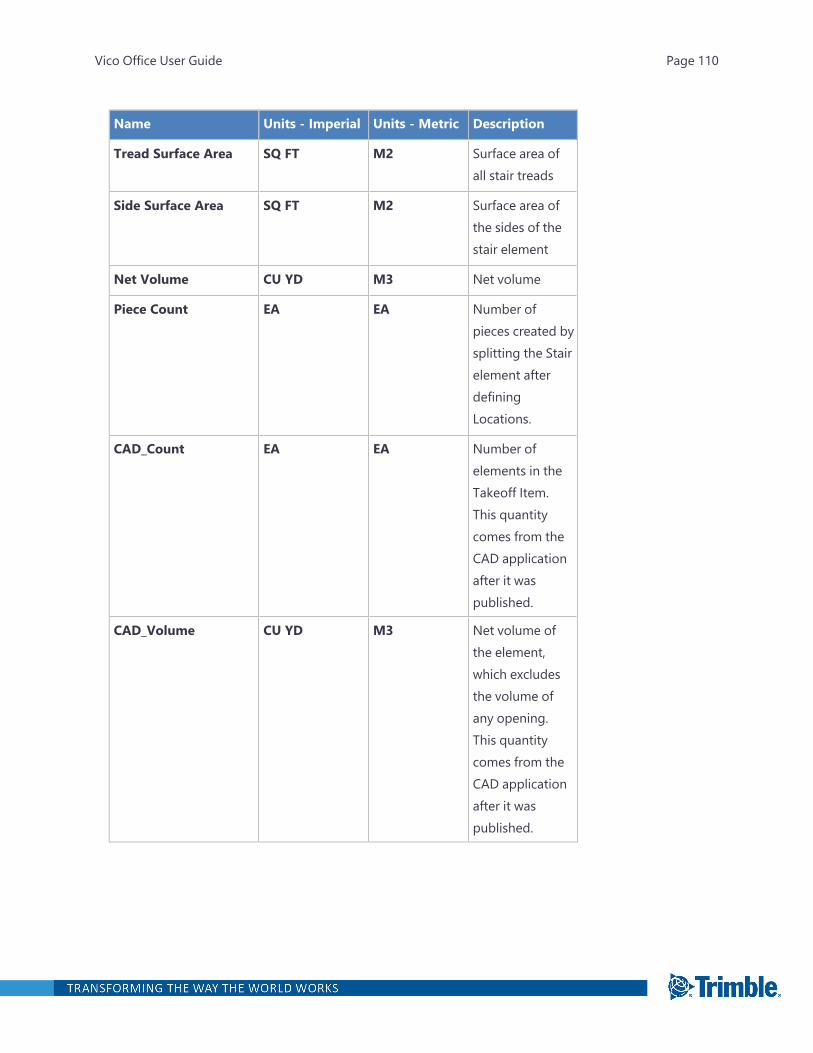
Name Units - Imperial Units - Metric Description
Tread Surface Area SQ FT M2 Surface area ofall stair treads
Side Surface Area SQ FT M2 Surface area ofthe sides of thestair element
Net Volume CU YD M3 Net volume
Piece Count EA EA Number ofpieces created bysplitting the Stairelement afterdefiningLocations.
CAD_Count EA EA Number ofelements in theTakeoff Item.This quantitycomes from theCAD applicationafter it waspublished.
CAD_Volume CU YD M3 Net volume ofthe element,which excludesthe volume ofany opening.This quantitycomes from theCAD applicationafter it waspublished.
Vico Office User Guide Page 110
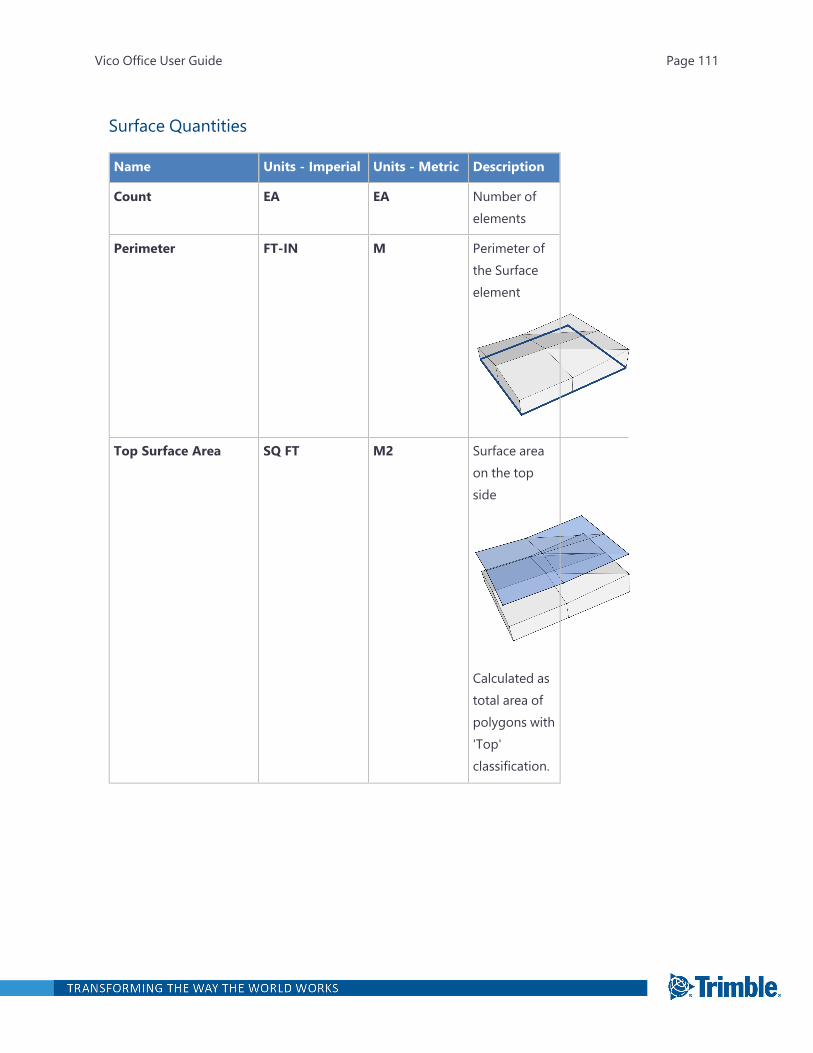
Surface Quantities
Name Units - Imperial Units - Metric Description
Count EA EA Number ofelements
Perimeter FT-IN M Perimeter ofthe Surfaceelement
Top Surface Area SQ FT M2 Surface areaon the topside
Calculated astotal area ofpolygons with'Top'classification.
Vico Office User Guide Page 111

Name Units - Imperial Units - Metric Description
Edge Surface Area SQ FT M2 Surface areaat the edges
Calculated astotal area ofpolygons with'Edge'classification.
Hole Surface Area SQ FT M2 Surface areaof holes
Calculated astotal area ofpolygons with'Hole'classification.
Net Volume CU YD M3 Net volume
Bottom Surface Area SQ FT M2 Surface areaat the bottomof the Surfaceelement.
Vico Office User Guide Page 112
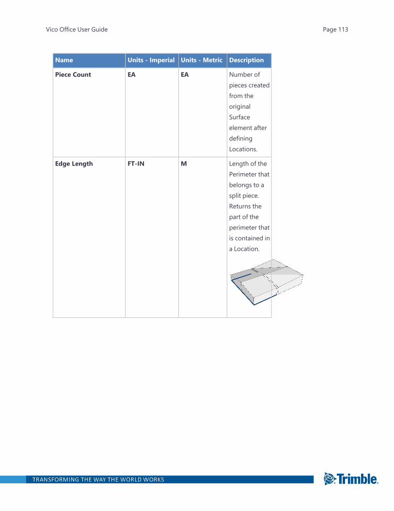
Name Units - Imperial Units - Metric Description
Piece Count EA EA Number ofpieces createdfrom theoriginalSurfaceelement afterdefiningLocations.
Edge Length FT-IN M Length of thePerimeter thatbelongs to asplit piece.Returns thepart of theperimeter thatis contained ina Location.
Vico Office User Guide Page 113

Name Units - Imperial Units - Metric Description
Joint Length FT-IN M Length of aRoom pieceperimetersegment thatwas createdby splittingthe Roomelement afterdefiningLocations.
CAD_Count EA EA Number ofelements inthe TakeoffItem. Thisquantitycomes fromthe CADapplicationafter it waspublished.
Surface Polygon Classification
The Surface Polygon Classification process automatically labels geometry in the imported model,which then enables Takeoff Manager to calculate the quantities described above. The process usesVico's geometry analysis algorithms, which are accurate for standard elements but may result inwrong assumptions in specific cases. Any wrong assumptions can be corrected by using the TakeoffQuantity Painting process.
The Takeoff Manager polygon classification compares the model's vertical and the polygon's NormalVector to determine its angle:
Vico Office User Guide Page 114

Based on orientation and direction of normal vector, Surface polygons are classified as follows:
l If a polygon is horizontal and its normal vector points downwards, it is classified as 'unknown',because 'Bottom Surface Area' is not a standard quantity type for the Surface element type.
l If a polygon's orientation is vertical, then it is classified as 'Edge'
l All other polygons are classified as 'Top'
Window, Door, and Opening Quantities
Name Units - Imperial Units - Metric Description
Count EA EA Number ofelements
Width FT-IN M Width
Height FT-IN M Height
Perimeter FT-IN M Perimeter
Element Surface Area* SQ FT M2 Area*
Vico Office User Guide Page 115
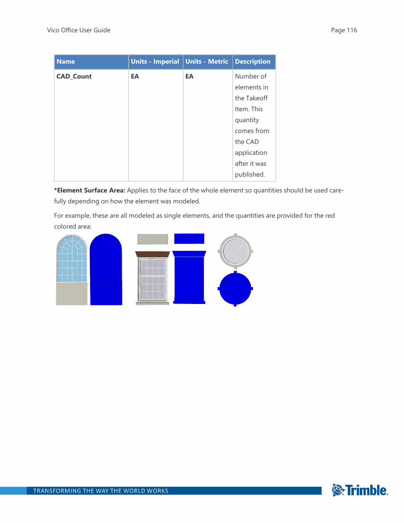
Name Units - Imperial Units - Metric Description
CAD_Count EA EA Number ofelements inthe TakeoffItem. Thisquantitycomes fromthe CADapplicationafter it waspublished.
*Element Surface Area: Applies to the face of the whole element so quantities should be used care-fully depending on how the element was modeled.
For example, these are all modeled as single elements, and the quantities are provided for the redcolored area:
Vico Office User Guide Page 116