Versalent - Mikrocontroller.net
12
Versalent Apr 2008 PS2ADPT PS2 Keyboard Serial Converter Manual Version 1.09 Revised Jul 3, 2008
-
Upload
khangminh22 -
Category
Documents
-
view
3 -
download
0
Transcript of Versalent - Mikrocontroller.net

Versalent Apr 2008
PS2ADPT PS2 Keyboard Serial Converter Manual
Version 1.09
Revised Jul 3, 2008

2
General Description
PS2ADPT is a small module (2.6” x 1.7” x 0.8”) that translates PS2 PC keyboard output
to the standard RS-232 characters printed on the keys so non-PC based hosts can easily use
these low cost keyboards. The PS2 keyboard protocol has real-time requirements which
can interfere with normal operation if not off-loaded to an auxiliary processor. And the
keycodes can be complex sequences of multiple codes. PS2ADPT simplifies all that and
provides a simple, standard RS-232 output which can interface to almost any computer
system – even small micros which do not have the resources to manage the real-time PS2
protocol and still do other work.
PS2ADPT connects to a keyboard through the standard 6-pin PS2 keyboard connector, and
to your host system through a standard DB9 (F) connector. It analyzes the keyboards scan
set 2 keycodes (the keyboard’s default scan code set) and outputs the ASCII character
printed on the key. It also translates all the non-ASCII keys and generates characters for
those as well so that your host can recognize and act on all keys including function keys,
arrow keys, keypad keys with Numlock both on and off etc.
Keyboard power is provided through the PS2 connector, and therefore through PS2ADPT.
Various power options allow you to supply power for both the keyboard and PS2ADPT via
the DB9 connector, or with the optional ‘power brick’ wall supply. And there are several
models which provide DTE or DCE connection options so you won’t need a null-modem
adapter to adjust connector signal/pin positions.
Keyboard LEDs are handled transparently so if the user presses CAPS LOCK, the LED is
turned on automatically and characters arriving from PS2ADPT are uppercased so no host
action is required. When the PS2ADPT is powered and operating a small red LED flashes
every ½ second as a visual indication that power is applied and it is operating.
Reliability Features:
PS2ADPT implements an internal watchdog timer, and an internal brown-out detector.
Should its microcontroller get disrupted through static discharge or other temporary
interference, the watchdog will automatically reset the unit so that normal operation
resumes with no user intervention. Or should power droop below an operational threshold
the brown-out detector will suspend operation until power is restored to a normal level. At
that point it will resume operation from a reset state again with no user intervention.
3
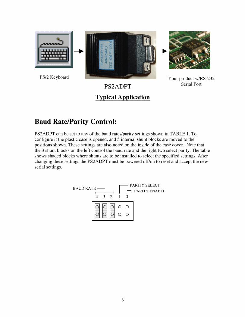
Typical Application
Baud Rate/Parity Control:
PS2ADPT can be set to any of the baud rates/parity settings shown in TABLE 1. To
configure it the plastic case is opened, and 5 internal shunt blocks are moved to the
positions shown. These settings are also noted on the inside of the case cover. Note that
the 3 shunt blocks on the left control the baud rate and the right two select parity. The table
shows shaded blocks where shunts are to be installed to select the specified settings. After
changing these settings the PS2ADPT must be powered off/on to reset and accept the new
serial settings.
PS/2 Keyboard
PS2ADPT
Your product w/RS-232
Serial Port
BAUD RATE
4 3 2 1 0
PARITY ENABLE
PARITY SELECT

4
DIAGRAM BAUD RATE PARITY
2400 bps
See below
2400 bps
See below
4800 bps
See below
9600 bps
See below
19.2k bps
See below
38.4k bps
See below
57.6k bps
See below
115k bps
See below
See above
Parity Enabled, ODD Parity
See above
Parity Enabled, EVEN Parity
See above
Parity Disabled
TABLE 1 .

5
Note that any shunt blocks in a horizontal orientation have no effect on serial settings and
are typically used for storing the shunts. PS2ADPT devices are shipped in the following
default configuration .. 9600 baud, no parity. (All the horizontal blocks have no effect, the
only effective one is the vertical one to the far left. )
RS-232 Signal Compatibility:
The PS2ADPT is compatible with standard RS-232 signals levels which go both positive
and negative (above and below 0 volts) and is also compatible with the non-standard 0-5
volt signal levels used in some systems. This is because the internal Texas Instruments
MAX202 RS-232 driver has a receiver threshold that is approximately +1.2 volts above the
RS-232 ground. So these ‘single-ended’ signals which do not go below ground provide a
sufficient RS-232 signal level for the PS2ADPT to operate reliably. Please refer to:
http://www.ti.com/lit/gpn/max202 for more technical details of the drivers capabilities.
Power Control:
The standard PS2 keyboard requires +5VDC to operate and so does the PS2ADPT.
Keyboard power is applied through the PS2ADPT’s PS2 connector so external power
need only be applied to the PS2ADPT. There are two ways to do this:
1) Apply power to a pin of the DB9 connector
2) Plug a ‘power brick’ into the PS2ADPT
4 3 2 1 0

6
Applying Power Through the DB9 Connector:
Power can be applied to either PIN 4, or PIN6 of the DB9 depending on the model.
See table below. During assembly different options are installed which provide this
flexibility. In addition the voltage applied can also be selected again, based on the model
selected. If your system has +5VDC @ 250mA available**, and the cable to the
PS2ADPT will be fairly short, you can select one of the 5VDC input models (voltage drop
through the cable will be minimal). However if the cable will be long and significant
voltage could be dropped in the cable, a better option is the 6-12VDC model. The low
drop-out regulator in the PS2ADPT will supply the keyboard with +5VDC.
In addition to power options there are various models which configure the DB9
connector as DTE or DCE. Choose the model appropriate to mate to your DB9 with no
null-modem adapter.
**Note that although PC keyboards are often rated at 250mA maximum, typical keyboards
require considerably less current. Many require in the range of 30-60mA. Selection of
which voltage option is appropriate is left to the system designer.
PS2ADPT-xxx MODELS AVAILABLE
Model# Features PS2ADPT-014 DB9 = DCE, +5VDC power applied to DB9 Pin 4
PS2ADPT-016 DB9 = DCE, +5VDC power applied to DB9 Pin 6 PS2ADPT-024 DB9 = DCE, 6-12VDC power applied to DB9 Pin 4 or use
optional 6V wall supply PS2ADPT-026 DB9 = DCE, 6-12VDC power applied to DB9 Pin 6 or use
optional 6V wall supply PS2ADPT-034 DB9 = DTE, +5VDC power applied to DB9 Pin 4 PS2ADPT-036 DB9 = DTE, +5VDC power applied to DB9 Pin 6 PS2ADPT-044 DB9 = DTE, 6-12VDC power applied to DB9 Pin 4 or use
optional 6V wall supply PS2ADPT-046 DB9 = DTE, 6-12VDC power applied to DB9 Pin 6 or use
optional 6V wall supply
TABLE 2
Note that the COMx ports on a standard PC are configured as DTE and therefore its RS-
232 signals mate directly to the first four (DCE) models in the table above. That is, the
PCs Tx signal connects to the PS2ADPT Rx signal, and the PCs Rx signal connects to
the PS2ADPT Tx signal with a standard straight-thru M/F DB9 cable.

7
When applying DC power to the PS2ADPT via the DB9 connector, use the
FIGURE 1 power dissipation graph to ensure that the PS2ADPT is operating in a safe
power range for your keyboard current. Note that this is a room temperature graph. See
Environmental Specifications section to derate input voltage for other temperatures.
Room Temperature Safe Operating Area
FIGURE 1
Applying Power Using the ‘Power Brick’:
Power can also be applied using the optional ‘6VDC power brick’ which is the
optional wall supply. This option is useful when it is not convenient to route power
through the DB9 connector, or additional power is not available from the system. Choose
an appropriate model that allows operation with the wall supply (Model PS2_PWR) which
plugs into any standard 110VAC power outlet.
25
225
250
175
200
150
125
100
75
50
KE
YB
OA
RD
CU
RR
EN
T (
mA
)
SUPPLIED VOLTAGE (Volts)
5 6 7 8 9 10 11 12 13 14
Safe
Area
Do Not Operate
In This Area

8
PS2ADPT Physical, Electrical, Environmental Specifications
Physical:
Size: 2.6” X 1.7” X 0.8”
Weight: 2.6 oz
Keyboard Connector: Standard PS2 6-pin mini DIN (female)
Host Connector: Standard DB9 (female)
Case Color: Black (Ivory available special order)
Power Connector: 5mm X 2.1 mm (male, outer ring positive)
PS2ADPT DB9 (Female) Pin Assignments Diagram
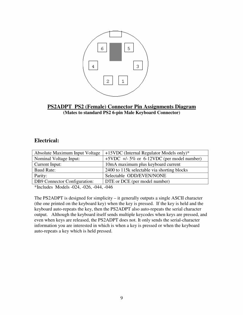
9
PS2ADPT PS2 (Female) Connector Pin Assignments Diagram (Mates to standard PS2 6-pin Male Keyboard Connector)
Electrical:
Absolute Maximum Input Voltage +15VDC (Internal Regulator Models only)*
Nominal Voltage Input: +5VDC +/- 5% or 6-12VDC (per model number)
Current Input: 10mA maximum plus keyboard current
Baud Rate: 2400 to 115k selectable via shorting blocks
Parity: Selectable ODD/EVEN/NONE
DB9 Connector Configuration: DTE or DCE (per model number)
*Includes Models -024, -026, -044, -046
The PS2ADPT is designed for simplicity – it generally outputs a single ASCII character
(the one printed on the keyboard key) when the key is pressed. If the key is held and the
keyboard auto-repeats the key, then the PS2ADPT also auto-repeats the serial character
output. Although the keyboard itself sends multiple keycodes when keys are pressed, and
even when keys are released, the PS2ADPT does not. It only sends the serial-character
information you are interested in which is when a key is pressed or when the keyboard
auto-repeats a key which is held pressed.
10
Since the standard 7-bit ASCII character set contains only 128 characters (0x00 thru 0x7f),
in order to support the keyboard’s function keys , keypad keys and CTRL keys, the
PS2ADPT sends 8-bit characters to identify these ‘non-printable’ keys. And to support the
use of the ALT key as a character-modifier the PS2ADPT sends two characters to identify
ALT-x keys. Please refer to http://www.versalent.biz/manuals/STAManKeyMap.pdf
which is a diagram of a 102-key PS2 keyboard showing all key positions, and the
associated character(s) which the PS2ADPT generates when the key is pressed. You will
notice that there are 5 characters (hex values) on each key to identify what 8-bit characters
are output when each key is pressed:
1) Normal keypress .. with no other keys pressed
2) Key pressed with SHIFT pressed (or CAPSLOCK active)
3) Key pressed with ALT pressed
4) Key pressed with CRTL pressed
5) Key pressed with NUMLOCK active
You will notice that the NUMLOCK, SHIFT, ALT and CTRL keys do not cause any
characters to be sent when pressed by themselves. These are ‘modifier’ keys only – which
affect the values that other keys send when pressed. CAPSLOCK does send a code and
then continues to act as a modified when active.

11
Environmental:
Max Operating Temperature: +85
oC Derate by 12
oC per 100mW Power dissipation
Min Operating Temperature: -30oC
Max Storage Temperature: +100oC
Min Storage Temperature: -40oC
Humidity: Non-condensing at all temperatures
Power Dissipation = (Input Voltage – 5) * (keyboard current + 0.010A)
Derating Example:
Keyboard Current = 65mA, Input Voltage = 10VDC
Power Dissipation = (10 –5) * (.065 + .01) = 375mw
Required derating = 12oC * (375mw/100mw) = 45
oC
Max Ambient Operating Temp = +85oC – 45
oC = 40
oC
12
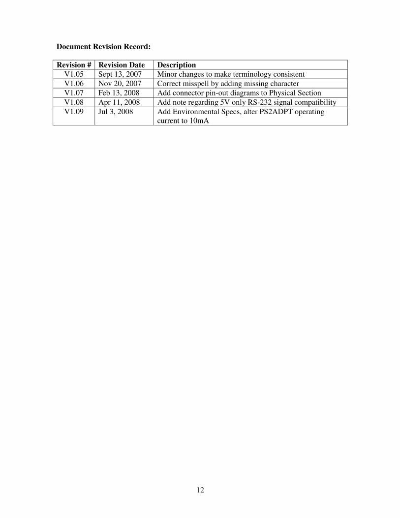
Document Revision Record:
Revision # Revision Date Description
V1.05 Sept 13, 2007 Minor changes to make terminology consistent
V1.06 Nov 20, 2007 Correct misspell by adding missing character
V1.07 Feb 13, 2008 Add connector pin-out diagrams to Physical Section
V1.08 Apr 11, 2008 Add note regarding 5V only RS-232 signal compatibility
V1.09 Jul 3, 2008 Add Environmental Specs, alter PS2ADPT operating
current to 10mA