
Vehicle Battery Pack Design and Considerations for ...
116
Vehicle Battery Pack Design and Considerations for Repurposing by Benjamin John Gaffney A thesis presented to the University of Waterloo in fulfillment of the thesis requirement for the degree of Master of Applied Science in Mechanical Engineering Waterloo, Ontario, Canada, 2015 ©Benjamin John Gaffney 2015
-
Upload
khangminh22 -
Category
Documents
-
view
1 -
download
0
Transcript of Vehicle Battery Pack Design and Considerations for ...

Vehicle Battery Pack Design and
Considerations for Repurposing
by
Benjamin John Gaffney
A thesis
presented to the University of Waterloo
in fulfillment of the
thesis requirement for the degree of
Master of Applied Science
in
Mechanical Engineering
Waterloo, Ontario, Canada, 2015
©Benjamin John Gaffney 2015

ii
AUTHOR'S DECLARATION
I hereby declare that I am the sole author of this thesis. This is a true copy of the thesis, including any
required final revisions, as accepted by my examiners.
I understand that my thesis may be made electronically available to the public.

iii
Abstract
The market for hybrid and electric vehicles is expanding with the rise of gas prices and desires to
curb climate change. With the creation of these complex systems comes the development of
advanced battery systems which store and provide energy in the vehicle life stage. These batteries
however have a limited lifetime in the vehicle, after which they can be used to provide energy in
repurposed stationary energy storage applications. The objective of this thesis is to examine how
electric vehicle batteries can be repurposed. The design of a hybrid vehicle battery pack, which
uses mechanical topology optimization techniques to assist the designer in developing a weight-
efficient design, is detailed. The battery pack under consideration is composed of Lithium-ion
cells and the design techniques proposed can assist with the design of a lightweight repurposed
energy storage system for a residential application. A design process for a repurposed battery pack
is also proposed, which takes into account design steps from initial business/market predictions to
installation of the assembly at a residence. This design process details a capacity fade model to
predict battery state of health after the vehicle life stage, as well as a risk analysis which focuses
on a design failure modes and affects analysis, fault tree analysis, and a code analysis. Finally, the
design of two iterations of a repurposed battery pack bench test is documented with lessons learned
for the design of future test benches and the full size repurposed pack. Lithium-ion battery packs
are still relatively new to the vehicle market, and the ability for significant numbers of them to
enter the repurposed market is a few years away. However, there are commercially available
stationary battery packs that use this technology. As a result, there are a number of risks still
evident in the design of a repurposed system as the relevant codes and legislation have not been
written. Additionally, the nature of the collection, testing, and supply chain for the repurposed
packs after vehicle use is currently unknown. It is recommended that more research be completed
in the areas of battery state of health models as well as the business models for repurposed
applications. Full-scale degradation research of packs is required in real-world vehicle settings, in
order to understand exactly how the batteries degrade over a vehicle’s lifetime. As well, re-
manufacturing firms need to understand how they can feasibly take used packs of uncertain quality
to build the newly proposed assemblies while minimizing risk to the consumer and their own
liability.

iv
Acknowledgements
I would like to thank all of my family members, friends, team mates, peers, professors, and mentors
who have helped me through the past seven years of university. Thank you to Dr. Roydon Fraser,
and Dr. Michael Fowler especially for your continued support and guidance over the past three
years as a member and leader of the University of Waterloo Alternative Fuels Team (UWAFT).
UWAFT is the single reason why I am where I am right now, and the continued, persistent support
of Dr. Fraser and Dr. Fowler are what has kept the team moving forward over the past 19 years.
The team has taught me a great deal, much more than any text book ever could, and has shaped
me through the development of not only technical skills, but soft skills as well. I am forever
grateful for what has been established and look forward to seeing how the team does in the rest of
EcoCAR 3!
I would like to thank the entire technical steering committee and the sponsoring partners of
EcoCAR. The experience through the Advanced Vehicle Technology Competition Series is
unparalleled in academia, and not only trains the next generation of engineers, but also forms a
basis to create friendships that will last for years. Thank you especially to the two headline
sponsors, the U.S. Department of Energy and General Motors. GM has been instrumental in my
schooling over the past three years and I am very excited to join the team in the coming months.
A special thanks goes to Dan Mepham and Benjamin Beacock for helping to mentor the team
while I was a member. Without your support, we would not be able to do what we do, and you
are an inspiration for every team member moving through the program.
To my team mates, friends and peers: thank you. We have accomplished a great deal over my past
three years on the team, especially through Year One of EcoCAR 3. There are too many of you to
list, but to Patrick, Dan, Suzie, Ramin, Brandon, John, Alec, Paul, Peter, Angelo, Kieran, Megan,
and Salman thank you for the great experience in competition that was the culmination of my time
with UWAFT. We have created a great workplace and culture together over the past year, and the
team is firing on all cylinders. I cannot wait to see what you are all capable of doing over the next
three years!
Thank you as well to the members of my master’s research group into battery repurposing, and my
sponsors Mitsui and NSERC. Dr. Steven Young, Sean Walker, and Leila Ahmadi were very

v
helpful in the development/editing of my content for my thesis and helping me to complete my
master’s degree. I look forward to seeing the progress of the group and installing a repurposed
energy storage system in my future home!
Finally, I would like to thank my family for their support during my master’s program. Long days
and nights were tough sometimes. Thank you Mom, Dad, and Heather for supporting me no matter
what and to push me to be better every day.

vi
Dedication
To my family, friends, mentors, and teammates.

vii
Table of Contents
AUTHOR'S DECLARATION ...................................................................................................................... ii
Abstract ........................................................................................................................................................ iii
Acknowledgements ...................................................................................................................................... iv
Dedication .................................................................................................................................................... vi
Table of Contents ........................................................................................................................................ vii
List of Figures ............................................................................................................................................... x
List of Tables .............................................................................................................................................. xii
List of Acronyms ....................................................................................................................................... xiii
Chapter 1 Introduction .................................................................................................................................. 1
1.1 Objective and Contributions ............................................................................................................... 3
1.2 Thesis Outline ..................................................................................................................................... 3
Chapter 2 Background and Literature Review .............................................................................................. 6
2.1 Conventional and Hybrid Vehicles ..................................................................................................... 6
2.2 Hybrid Vehicle Configurations ........................................................................................................... 7
2.2.1 Series Hybrid Architecture ........................................................................................................... 7
2.2.2 Parallel Hybrid Architecture ........................................................................................................ 8
2.2.3 Split-Parallel Hybrid Architecture ............................................................................................... 9
2.2.4 Benefits/Drawbacks of each Architecture .................................................................................... 9
2.3 Vehicle Drive Cycles ........................................................................................................................ 10
2.4 Component Sizing ............................................................................................................................. 12
2.5 Battery Fundamentals and Definitions .............................................................................................. 13
2.6 Capacity Fade, Power Fade, Charge Efficiency Fade ....................................................................... 13
2.6.1 Capacity Fade ............................................................................................................................. 13
2.6.2 Power Fade ................................................................................................................................. 15
2.6.3 Charge Efficiency Fade .............................................................................................................. 16
2.7 Fade Mechanism Contributors .......................................................................................................... 18
2.8 Stationary Energy Storage ................................................................................................................ 19
2.9 Repurposed Battery Pack .................................................................................................................. 20
Chapter 3 Battery Pack Design ................................................................................................................... 21
3.1 Background ....................................................................................................................................... 21

viii
3.2 Vehicle Background .......................................................................................................................... 21
3.3 Structural Considerations .................................................................................................................. 24
3.3.1 Geometry Optimization.............................................................................................................. 27
3.3.2 Finite Element Analysis ............................................................................................................. 37
3.3.3 Structural Recommendations ..................................................................................................... 39
3.3.4 Electrical Design ........................................................................................................................ 39
3.4 Thermal Management ....................................................................................................................... 42
3.5 Chapter Summary ............................................................................................................................. 45
Chapter 4 Repurposed Battery Pack Design Considerations ...................................................................... 46
4.1 Introduction: Repurposed Battery Pack Design Process ................................................................... 46
4.2 Repurposed Pack Business Development ......................................................................................... 47
4.2.1 Repurposed Packs for Application ............................................................................................. 47
4.2.2 Market Analysis of In-Vehicle Battery Supply .......................................................................... 48
4.3 Repurposed Pack Condition Assessment .......................................................................................... 49
4.3.1 Collection/Salvage of Repurposed Packs................................................................................... 49
4.3.2 Assessment of Degradation/Quality of Pack .............................................................................. 50
4.3.3 Repair/Maintenance of Pack ...................................................................................................... 51
4.4 Repurposed Energy Storage System Application Specifications ...................................................... 52
4.5 Battery Pack State of Health ............................................................................................................. 52
4.5.1 Background ................................................................................................................................ 52
4.5.2 Capacity Fade Model ................................................................................................................. 52
4.6 Energy Storage System Conceptual Design ...................................................................................... 56
4.6.1 Energy Storage System Sizing and Pack Configuration ............................................................ 56
4.6.2 Infrastructure Design.................................................................................................................. 57
4.7 Battery Pack Risk/Code Analysis ..................................................................................................... 58
4.7.1 Design Failure Modes and Effects Analysis .............................................................................. 58
4.7.2 Fault Tree Analysis .................................................................................................................... 60
4.7.3 Repurposed Battery Pack Code Analysis ................................................................................... 62
4.8 Assembly Conceptual Design ........................................................................................................... 65
4.8.1 Plant/Grid Balance Interface Design .......................................................................................... 65
4.8.2 Control System Development .................................................................................................... 65
4.8.3 Mechanical and Casement Design ............................................................................................. 66

ix
4.9 Energy Storage System Grid Integration .......................................................................................... 67
4.9.1 Permitting ................................................................................................................................... 67
4.9.2 ESS Construction ....................................................................................................................... 67
4.9.3 ESS Installation .......................................................................................................................... 68
4.10 Pack Design with a 16.2 kWh Battery ............................................................................................ 68
4.11 Chapter Summary ........................................................................................................................... 69
Chapter 5 Repurposed Battery Pack Testing .............................................................................................. 71
5.1 Introduction ....................................................................................................................................... 71
5.2 Design Criteria and Constraints ........................................................................................................ 72
5.3 Proposed Designs .............................................................................................................................. 73
5.4 Repurposed Battery Pack Operation ................................................................................................. 75
5.5 Operation and Results ....................................................................................................................... 80
5.6 Lessons Learned ................................................................................................................................ 81
5.7 Revision Two Background ............................................................................................................... 81
5.8 Design ............................................................................................................................................... 82
5.9 Operation and Results ....................................................................................................................... 83
5.10 Chapter Summary ........................................................................................................................... 83
Chapter 6 Conclusions and Recommendations ........................................................................................... 85
6.1 Conclusions ....................................................................................................................................... 85
6.2 Recommendations ............................................................................................................................. 87
References ................................................................................................................................................... 89
Appendix A Design Failure Modes and Effects Analysis .......................................................................... 96
Appendix B Fault Tree Analysis ............................................................................................................... 101

x
List of Figures
Figure 1: Original Battery Lifecycle ............................................................................................................. 2
Figure 2: Modified Battery Lifecycle ........................................................................................................... 3
Figure 3: Series Power Flow ......................................................................................................................... 8
Figure 4: Parallel Power Flow ...................................................................................................................... 8
Figure 5: Split-Parallel Power Flow.............................................................................................................. 9
Figure 6: fleetcarma Data Logger ............................................................................................................... 11
Figure 7: Sample Vehicle Architecture in Autonomie ................................................................................ 12
Figure 8: Capacity Fade Trend.................................................................................................................... 14
Figure 9: Internal Impedance Acceleration ................................................................................................. 15
Figure 10: Energy Capacity available at Differing Charge Rates ............................................................... 17
Figure 11: Sample Utility Demand in Ontario ............................................................................................ 19
Figure 12: UWAFT EcoCAR 3 Powertrain Architecture ........................................................................... 22
Figure 13: EcoCAR 2 Battery CAD Image ................................................................................................ 25
Figure 14: EcoCAR 2 Assembled Battery Pack ......................................................................................... 25
Figure 15: Module Configuration One ........................................................................................................ 26
Figure 16: Module Configuration Two ....................................................................................................... 26
Figure 17: Optimization Setup with Design and Non-Design Space for Battery Frame ............................ 28
Figure 18: Optimization Setup for Module Mounting Plate with Design Space ........................................ 29
Figure 19: Final Optimization Setup with Loading Conditions .................................................................. 30
Figure 20: Frame Optimization First Iteration ............................................................................................ 31
Figure 21: Frame Optimization First Iteration (From Bottom View) ......................................................... 32
Figure 22: Frame Optimization Final Iteration ........................................................................................... 33
Figure 23: Plate Optimization First Iteration .............................................................................................. 34
Figure 24: Plate Optimization Final Iteration ............................................................................................. 34
Figure 25: Final Battery Frame Design ....................................................................................................... 35
Figure 26: Final Module Mount Plate Design ............................................................................................ 36
Figure 27: Battery Assembly Material Makeup .......................................................................................... 37
Figure 28: Battery Assembly FEA Setup .................................................................................................... 37
Figure 29: Final Battery Frame FEA Results .............................................................................................. 38
Figure 30: Battery Pack Electrical Setup .................................................................................................... 40
xi
Figure 31: EXRAD Sizing Table ................................................................................................................ 41
Figure 32: Module-to-Module Jumper ........................................................................................................ 41
Figure 33: US06 City Battery Current ........................................................................................................ 42
Figure 34: Rint Battery Model ..................................................................................................................... 43
Figure 35: Cooling Plate Conceptual Design (Left Hand Side Modules Hidden) ...................................... 44
Figure 36: Repurposed Energy Storage System Design Process ................................................................ 47
Figure 37: Example Residential Demand Profile ....................................................................................... 48
Figure 38: U.S. Electric and Hybrid Vehicle Sales ..................................................................................... 49
Figure 39: Battery Pack Level Classification ............................................................................................. 51
Figure 40: Capacity Fade Model (Assumes no cell failure) ....................................................................... 54
Figure 41: Initial Study Capacity Fade Loss ............................................................................................... 55
Figure 42: Burn/Explosion Fault Tree Analysis ......................................................................................... 61
Figure 43: Control System Overview ......................................................................................................... 66
Figure 44: Test Bench Battery Pack ........................................................................................................... 71
Figure 45: Time-of-use pricing in Ontario .................................................................................................. 73
Figure 46: Bench Setup Isometric View ..................................................................................................... 75
Figure 47: Bench Setup Top View .............................................................................................................. 76
Figure 48: Revision One Setup ................................................................................................................... 76
Figure 49: Pack without Case ..................................................................................................................... 77
Figure 50: Pack Bus Bars Uninstalled ........................................................................................................ 78
Figure 51: Retaining Bars Uninstalled ........................................................................................................ 78
Figure 52: Disassembled Battery modules .................................................................................................. 79
Figure 53: Revision Two Setup .................................................................................................................. 83

xii
List of Tables
Table 1: Advantages and Disadvantages of Hybrid Architectures ............................................................. 10
Table 2: EcoCAR 3 Battery Pack Options .................................................................................................. 23
Table 3: Available Vehicle Battery Packs .................................................................................................. 57
Table 4: Top DFMEA Risks ....................................................................................................................... 59
Table 5: Applicable Codes for Repurposed Li-ion Battery Packs in a Stationary Application .................. 63
Table 6: Applicable Codes for the Repurposed Battery Pack Assembly .................................................... 64
Table 7: 16.2 kWh Battery Pack Energy Ratings ....................................................................................... 69
Table 8: Revision One Proposed Design Summary .................................................................................... 74
Table 9: Inverter/Charger Design Specifications ........................................................................................ 79

xiii
List of Acronyms
Ah-Processed Amp-hours Processed
AVTC Advanced Vehicle Technology Competition
BEV Battery Electric Vehicle
BMS Battery Management System
C-Rates Charge Rates
CAN Controller Area Network
CO2 Carbon Dioxide
COG Centre of Gravity
CSM Current Sense Module
DOD Depth of Discharge
DET Detection
DFMEA Design Failure Modes and Effects Analysis
E&EC Emissions and Energy Consumption
EMI Electromagnetic Inteference
EOL End of Life
EPA U.S. Environmental Protection Agency
FEA Finite Element Analysis
FDR Final Design Review
FTA Fault Tree Analysis
HC Hydrocarbons
HEV Hybrid-Electric Vehicle
HV High Voltage
HWFET Highway Fuel Economy Driving Schedule
ICE Internal Combustion Engine
L-PEM Linear Prediction Error Method
Li-ion Lithium-ion
LiFePO4 Lithium-Iron-Phosphate
LiMnO Lithium-Manganese-Oxide
LV Low Voltage
MIL Model-in-the-Loop
NiMH Nickel-Metal-Hydride
NOx Nitrogen Oxide
NVH Noise, Vibration, and Harshness
OBD On-board Diagnostics
OCC Occurrence
OEMs Original Equipment Manufacturers
O3 Ozone
PDR Preliminary Design Review
PHEV Plug-in Hybrid-Electric Vehicle
PM10 Particulate Matter
RPN Risk Priority Number

xiv
RUL Remaining Useful Life
SEI Solid Electrolyte Interface
SEV Severity
SOC State of Charge
SOH State of Health
SOx Sulfur Oxides
SSR Solid State Relay
UDDS Urban Dynamometer Driving Schedule
UPS Uninterruptable Power Supply
UWAFT University of Waterloo Alternative Fuels Team
VTS Vehicle Technical Specifications

1
Chapter 1
Introduction
With the rise of gas prices and the desire to curb climate change, there is a push to utilize alternative
energy sources to provide for the needs of the future. Currently, non-renewable energy sources
make up 29 percent of the energy used to meet the grid needs within the province of Ontario [1].
Within the automotive sector, the incorporation of new technologies and fuels is allowing
consumers to offset emissions and decrease energy consumption in the vehicles they drive.
Automakers are looking to capitalize on methods which decrease the use of fossil fuels to provide
power to a vehicle; one of the biggest being the use of electrification [2].
Electrification allows automakers to use electric motors either in conjunction with, or in
replacement of the conventional combustion engine to propel the vehicle’s wheels. Electric motors
have many advantages over combustion engines, including the availability of their full torque at a
standstill, and the ability to contain vehicle tailpipe emissions to upstream sources exclusively.
The pinnacle of electrification in a vehicle is the Battery Electric Vehicle (BEV) that uses full
electric power without any burning of fossil fuels onboard. However, this type of vehicle is
hampered by its low vehicle range compared to a conventional vehicle. An alternative is a hybrid-
electric vehicle, which combines both a combustion engine and one or more electric motors to
achieve the highest efficiency of both powertrains and increase the vehicle’s usable range.
Both hybrid and full-electric vehicles use large batteries to provide storage of onboard electrical
energy. These batteries are predominantly made up of Lithium-ion cells which can be heavy, and
expensive. With the increased use of these batteries, there is an increased demand of minor metals,
including lithium. Experts believe that this industry can be carried forward for future generations,
with future growth being governed by the amount of recycling which occurs in the manufacturing
process [3]. The current life cycle of these batteries is shown in Figure 1.

2
Figure 1: Original Battery Lifecycle [4]
Within automotive use, batteries see large current draws and state of charge swings in acceleration,
deceleration, and prolonged driving periods. This environment degrades the battery, and can
render it useless over a period of approximately eight years for this application, based on
automotive manufacturer’s warranties [4].
One way of modifying the life cycle of these batteries to increase sustainability is to add a second
‘repurposing’ phase to the battery’s use. In this repurposing phase, the battery is reused in a second
application, such as stationary energy storage, where it is gently cycled and able to be used again
before going through the recycling process. The addition of the repurposing stage of the battery’s
life allows it to be fully utilized before being disassembled for recycling. The addition of the
repurposing stage in the battery life cycle is shown in Figure 2.

3
Figure 2: Modified Battery Lifecycle [4]
1.1 Objective and Contributions
The objective of this thesis is to outline the background, design considerations, and bench test
setups of using a repurposed battery pack in a stationary energy storage application. Specific
information is drawn from the design and fabrication of automotive batteries, used in a hybrid
configuration in the context of the Advanced Vehicle Technology Competition (AVTC) series for
the University of Waterloo Alternative Fuels Team (UWAFT) entry. Following this discussion,
considerations for the design of a repurposed energy storage system will be outlined and a design
process will be proposed. Finally, two revisions of a repurposed energy storage system test bench
setup using a 1.3 kWh battery pack will be outlined. The design will be documented, along with
the lessons learned from the setup for the next phase of testing. Both designs are in initial
conceptual phases, and the use of the test bench setup allows for simulation of the pack with
integration with the utility grid.
1.2 Thesis Outline
This thesis includes six chapters, including this introduction. The topics of each of the sections
are as follows:

4
Chapter 1 outlines an introduction to the thesis, including a background on the push for
electrification in vehicle design to offset vehicle tailpipe emissions and reduce operating costs.
The introduction also discusses batteries, their life cycle process, and the addition of a second use
stage known as ‘repurposing’ which is the focus of this thesis.
Chapter 2 discusses background and literature focusing on hybrid vehicles, batteries, vehicle
design, and repurposing. Concepts discussed include the modifications required to implement a
hybrid vehicle design, including aspects in terms of mechanical, electrical, and controls. The
discussion also incorporates information about vehicle configurations, and overall design
choices/considerations including drive cycles, and component sizing. Finally, batteries and
literature focusing on fade mechanisms and degradation are discussed and how these factors
correlate to battery use in initial use stages (vehicle) and repurposed stages (secondary storage).
Chapter 3 discusses battery pack design in a vehicle. This chapter focuses on the design of a
battery pack for the University of Waterloo Alternative Fuels Team, which competes in Advanced
Vehicle Technology Competitions. Design considerations and aspects of battery pack
manufacturing are discussed to give a background on the areas of consideration when building a
battery pack from the module level. The mechanical optimization techniques discussed are useful
for the repurposed pack discussion as they can be employed in the design of the casement for the
repurposed assembly.
Chapter 4 discusses considerations for design of a repurposed battery pack. A design process is
outlined, which follows the repurposed pack from initial market research to installation at an
application. Steps outlined include insight into battery state of health predictions following vehicle
use, including a capacity fade model developed based on cycling results from studies on Lithium-
ion half cells. A risk analysis is also performed for the pack assembly, including a design failure
modes and effects analysis, fault tree analysis, and code analysis.
Chapter 5 discusses the repurposed battery pack bench test setup constructed at the University of
Waterloo. Sections of discussion include the design, operation, and lessons learned in the
construction of the setup. The documentation of its design is outlined as a starting point for further
analysis into repurposed battery packs in the future, with the use of a newly available bi-directional
inverter/charger system sourced from the solar energy industry.

5
Chapter 6 is a conclusion section, which will outline the main points covered in this thesis and
outline recommendations for future work which builds upon this knowledge base in the areas of
vehicle, battery, and repurposed energy storage system design.

6
Chapter 2
Background and Literature Review
2.1 Conventional and Hybrid Vehicles
There are three basic vehicle configurations used on the road presently: conventional vehicles,
electric vehicles, and hybrid vehicles. Conventional vehicles utilize an Internal Combustion
Engine (ICE) which performs a conversion between chemical and mechanical forms of energy to
propel the vehicle in the form of combustion. These cars feature a driving range of around 500 –
600 km on a regular tank, and can be filled in only a few minutes at a convenient re-fueling station.
The combustion process uses a source of ignition, air, and fuel which often produces harmful
emissions into the environment. These emissions are in the form of Nitrogen Oxides (NOx),
Carbon Dioxide (CO2), Hydrocarbons (HC), Sulphur Oxides (SOx), Particulate Matter (PM10), or
Ozone (O3) [5].
Electric vehicles replace the combustion engine in the conventional vehicle with a battery pack
and an electric motor. The battery pack provides an onboard storage area for electrical energy
which can be used later by the motor. The biggest advantages of the use of an electric motor are
the offsetting of vehicle tailpipe emissions and the ability to employ regenerative braking.
Through the use of the motor, the vehicle will not create any emissions and leave all sources to
upstream generation. For Ontario, this use of upstream energy is beneficial to the environment as
70.1 percent of the energy mix is made up of nuclear, hydro, wind, and solar energy; all forms of
generation which do not pollute the air [1]. The biggest disadvantage to the use of electric vehicles
is the limited range, lack of re-fueling infrastructure, and increased cost of the powertrain. The
increased cost is mainly due to the incorporation of large Lithium-ion battery packs to store
onboard energy [6]. Additionally, it can take up to twenty hours to charge an onboard pack; an
aspect of an electric vehicle’s design which inhibits consumer acceptance [7].
Hybrid vehicles attempt to combine the advantages of both the combustion and electric vehicles
into one package. They traditionally feature a downsized combustion engine to burn less fuel to
meet the consumer’s desired vehicle range, in conjunction with one or more electric motors. There
are two main variants of hybrids: Hybrid Electric Vehicles (HEVs), and Plug-In Hybrid Electric
Vehicles (PHEVs). HEVs are designed with smaller battery packs, benefitting from the use of

7
regenerative braking in city driving to charge the onboard battery. For a PHEV, the battery is often
much larger and is a dominant source of propulsion power. In the PHEV, the electric powertrain
of the vehicle is often designed to meet the average commuting requirements of the consumer of
40.55 km [8]. By meeting this target, consumers can achieve the daily benefits of driving an
electric vehicle, using only electric energy, creating zero emissions, and saving up to $13,000 over
the lifetime of the vehicle compared to driving a conventional vehicle [9].
2.2 Hybrid Vehicle Configurations
There are multiple types of hybrid vehicle architectures, depending on how each of the powertrain
sources in the vehicle are connected to the wheels. By changing how the engine and motors
connect, engineers are able to change the power delivery to the wheels and many performance and
environmental characteristics as a result. There are three main types of hybrid architectures in the
marketplace: series, parallel, and split-parallel.
2.2.1 Series Hybrid Architecture
In a series hybrid, the engine is not directly connected to the vehicle’s wheels. Electric motors are
used to fully provide torque and propulsion for the vehicle. Instead of driving the wheels, the
engine is directly coupled to a generator. This coupling allows engineers to tailor the operation of
the engine-generator connection, independent of the speed at which the driver wishes to drive.
Additionally the use of a full-electric drivetrain mitigates any Noise, Vibration, and Harshness
(NVH) concerns made by using a loud, vibrating engine which requires the use of a multi-speed
transmission to keep power operation in efficient ranges. The power flow of a series vehicle is
seen in Figure 3.

8
Figure 3: Series Power Flow
An example of a series vehicle put in to production in the automotive market is the Fisker Karma
[10].
2.2.2 Parallel Hybrid Architecture
In a parallel hybrid, both the engine and the motors are connected to the vehicle’s wheels to provide
tractive force. Either powertrain, or both together, can provide torque, with the vehicle often
relying on the electric motors to supplement the power-torque curve of the combustion engine at
low speeds where they can provide their full amount of available torque. Parallel vehicles have
decreased cost/weight compared to a series vehicle, but are unable to generate at optimal
efficiencies at all times as all powertrain components are limited by the driver’s desired vehicle
speed. The power flow for a parallel vehicle is shown in Figure 4.
Figure 4: Parallel Power Flow

9
An example of a parallel vehicle put in to production is the Honda Civic hybrid [11].
2.2.3 Split-Parallel Hybrid Architecture
In a split-parallel vehicle, the vehicle can operate in either series or parallel modes depending on
which is most efficient at the time. Vehicle characteristics such as battery State of Charge (SOC)
and vehicle speed dictate which mode of operation would be best. Split-parallel vehicles combine
the advantages of both series and parallel powertrains, but can often be complicated and difficult
to build as they usually require complex planetary gear sets. The power flow for a split-parallel
vehicle can be seen in Figure 5.
Figure 5: Split-Parallel Power Flow
Production examples of split-parallel vehicles include the Toyota Prius and the Chevrolet Volt [12]
[13].
2.2.4 Benefits/Drawbacks of each Architecture
As alluded to earlier, there are some benefits/drawbacks of each of the series, parallel, and split-
parallel vehicles mentioned. Table 1 shows these as they pertain to each architecture discussed.

10
Table 1: Advantages and Disadvantages of Hybrid Architectures
Series Parallel Split-Parallel
Advantages
Generate at optimal
efficiency at all times
Electric-only drive
(NVH concerns)
All components can
provide torque to
wheels
Generate in
series or provide
torque in parallel
operation
Disadvantages
Engine unable to
provide torque to road
(heavy)
Space constraints
(multiple components
to do same job)
Unable to generate at
optimal efficiency
Complex
mechanical
connections and
control in
powertrain
2.3 Vehicle Drive Cycles
In designing a vehicle, it is important to know how the driver may interact with the constructed
product. As a guideline, the U.S. Environmental Protection Agency (EPA) has developed drive
cycles which attempt to characterize a typical drive under differing conditions. These drive cycles
are used to test new vehicles to determine fuel economy ratings, and are used as design targets by
Original Equipment Manufacturers (OEMs). The typical drive cycles utilized include the US06
drive cycle which features high acceleration events that are typical of a more aggressive driver, a
city cycle known as the Urban Dynamometer Driving Schedule (UDDS), and a high way cycle
known as the Highway Fuel Economy Driving Schedule (HWFET). [14]
Although these drive schedules are made to describe a daily driver’s cycle, many factors affect a
person’s unique driving profile. As a result, there can be differences between a vehicle’s test
performance under the EPA drive cycles and those found by a consumer. Differences can occur
due to vehicle conditions, ambient environment, and variations in fuel. As a result, there is an
importance in understanding each person’s driving habits in order to best optimize a vehicle
powertrain to a consumer. [15]

11
This push to categorize a consumer has created a number of technologies which can be deployed
on vehicles to describe a driver’s habits. One that has been used by the author is the use of the
data loggers developed by fleetcarma, a division of CrossChasm Technologies [16]. fleetcarma’s
data loggers allow consumers to track On-board Diagnostic (OBD) signals to track their vehicle’s
performance, including vehicle speed and length of trips. fleetcarma’s C5 logger can be seen in
Figure 6.
Figure 6: fleetcarma Data Logger
With the use of the logger, consumers are able to enter their data into fleetcarma’s database to
generate reports on their driving profile. With the information provided, consumers can make
better choices on their driving habits, and have new vehicles marketed to them which are best
optimized to their profile. Not all HEVs or PHEVs are built for every user’s drive cycle patterns,
and the data from the logger can help vehicle designers. As a result, vehicle designers can best
understand consumer driving habits and design vehicles to perform optimally in each environment.
As OEMs use the results from modeling and simulation of vehicle designs on EPA or real-world
drive cycles, they are able to establish targets known as Vehicle Technical Specifications (VTS)
to benchmark their design. These specifications are goals which new designs of vehicles try to
achieve. For HEV or PHEV design, the architecture, including the specifications/number of
motors used to propel the vehicle in conjunction with the engine, can have wide variance on the
VTS.

12
2.4 Component Sizing
Based on the understanding of consumer driving profiles and preferences, designers can make
decisions on component requirements to meet these VTS. For a hybrid vehicle, this method of
component sizing can be much more complex than that of a conventional vehicle. This added
complexity is due to the fact that there are multiple variants of hybrids and many combinations of
engines, motors, and batteries that can meet the vehicle requirements.
The University of Waterloo Alternative Fuels Team (UWAFT), a vehicle design team the author
is a part of, uses a combination of mechanical, controls, and simulation techniques in the early
stages of vehicle design to develop vehicle architectures. These tools allow students to simulate
vehicle performance, without the need of actual components. One of the tools used to simulate
vehicles through drive cycles is Autonomie, which is a software ‘wrapper’ which works over top
of MATLAB/Simulink. Autonomie allows the simulation of multiple hybrid powertrains with
different components, in a Model-in-the-Loop (MIL) context that allows for fast iterations between
vehicles. The modeling environment in Autonomie is shown in Figure 7.
Figure 7: Sample Vehicle Architecture in Autonomie
In the entries into AVTCs by UWAFT, there has been a large emphasis of battery performance in
previous competitions. As discussed previously, batteries allow consumers to offset emissions
and drive on all-electric energy alone in many driving situations with the use of large batteries in
a PHEV. However, battery technology is the reason why many hybrids have a large initial cost,

13
and are heavy. It is research into this area that can allow hybrids to develop to take more of a
market presence, and progress the automotive sector for generations to come.
2.5 Battery Fundamentals and Definitions
A battery is fundamentally defined as ‘a container consisting of one or more cells, in which
chemical energy is converted into electricity and used as a source of power’ [17]. Batteries are
used in many applications, to power systems which are disconnected from the utility grid during
use. As technology progresses, battery technology has changed in order to maximize power and
energy density. Currently, Lithium-ion (Li-Ion) technology is at the forefront and is utilized in
applications ranging from computers to hybrid vehicles [18].
Through both their use and their calendar aging, batteries exhibit degradation mechanisms which
affect their performance over time and operational use. The two main performance degradation
mechanisms are referred to as ‘Capacity Fade’ and ‘Power Fade’ [19]. Capacity fade is a known
degradation mechanism where the available capacity of the battery decreases during its life.
Capacity fade can be attributed to both calendar aging and regular cyclic fade. Power fade is the
loss of available power during a battery’s life time. As a battery ages, its ability to provide power
to connected loads such as a motor decreases. A third degradation mechanism has been defined
by the battery research group at the University of Waterloo [20]. This degradation mechanism has
been referred to as ‘Charge Efficiency Fade’. During the charging/discharging process for a
battery, internal resistances inherent in the battery cells lead to a loss converted to heat. This loss
affects the efficiency of the charging/discharging process, and is predicted to increase during the
lifetime of the battery as the internal resistance of the cells increases with use. The following
section will discuss capacity, power, and charge efficiency fade further with references to the fade
mechanisms in current literature.
2.6 Capacity Fade, Power Fade, Charge Efficiency Fade
2.6.1 Capacity Fade
During cycling of a battery pack, the usable amount of capacity may diminish as a result of
degradation mechanisms. These mechanisms include increased impedance, Solid Electrolyte

14
Interface (SEI) build up, and degradation of the positive electrode [21] [22]. Spotnitz added a loss
of active lithium at the negative electrode of the battery as another major fade mechanism [22].
Higher temperatures increase the rate of capacity loss according to the Arrhenius law, as well as
high SOC. At high SOC, reactions within the battery’s electrolyte are more prone to occur,
degrading the material used for ionic transport [23]. These side reactions can occur during storage
of the battery, with oxidation occurring on the positive cathode and reduction on the negative
anode. This capacity loss can actually be reversed in the event that both reactions occur at the
same time, and the lithium ions are able to be released by the negative terminal [23]. For Li-ion
batteries incorporating a graphite anode, the degradation rate is increased at the start of a cell’s life
as build up occurs but is reduced once a layer is formed. Of note is that the Depth of Discharge
(DOD), the amount of charge utilized in one battery cycle, does not affect capacity fade [24].
Capacity fade rate follows a trend of brief acceleration followed by an approximately constant
slope. Figure 8 below shows data from the study completed by Lohmann et al for different types
of Li-Ion cells.
Figure 8: Capacity Fade Trend [25]
Lohmann concluded that the fade rates were similar for each of the cells tested based on their
chemistry, with LiFePO4 cells exhibiting the least acceleration at the beginning of life and the
highest overall [25].

15
Spotnitz came up with the following conclusions regarding capacity fade in Li-ion batteries:
1. Capacity loss on storage has reversible and irreversible components;
2. Capacity loss on storage or cycling increases with increasing temperature;
3. Capacity loss on storage increases with increasing cell voltage; and,
4. Cycling causes capacity loss at a greater rate than storage. [22]
2.6.2 Power Fade
Power fade has been said to be due to the construction of a resistive layer on the cathode to the
active material [26]. Lohmann et Al. used values of internal impedance throughout the life of a
battery as an indicator of power fade. Lohmann found that internal impedance decreases during
the early life of a cell, and then follows a period with approximately no change. The LiMnO cells
in the study exhibited the highest acceleration of impedance at the start of life and highest over the
entire life of the cell. However, the cells made up of LiFePO4 showed the lowest change in
impedance, attributed to stability with the FePO4 cathode material. Figure 9 shows the internal
impedance trend followed.
Figure 9: Internal Impedance Acceleration [25]

16
2.6.3 Charge Efficiency Fade
Charge efficiency is defined as the ratio between the energy used to charge the battery and what
can be utilized for work after storage. Parasitic reactions cause inefficiencies between the charging
and discharging periods, where some energy is lost in the battery as heat. Smith et Al. explain the
concept of charge efficiency using Equation 1 [27].
Equation 1: Charge Efficiency
𝐶ℎ𝑎𝑟𝑔𝑒 𝐸𝑓𝑓𝑖𝑐𝑖𝑒𝑛𝑐𝑦 = 𝑄𝑑
𝑄𝑐=
𝐶ℎ𝑎𝑟𝑔𝑒 𝑂𝑢𝑡
𝐶ℎ𝑎𝑟𝑔𝑒 𝐼𝑛
Charge efficiency is an important battery aspect in a repurposing application, as it should be
ensured that the majority of the energy utilized off of the electrical grid can be harnessed at a later
time instead of being lost in inefficiencies such as heat generation. More heat is generated in a
battery system as more power is required for propulsion [28]. Miyamoto et Al. suggest that heat
generation, Gbatt, can be calculated using Equation 2 and is a result of three factors: internal
resistance, entropy changes and secondary reactions [29].
Equation 2: Battery Heat Generation
𝐺𝑏𝑎𝑡𝑡 =∫ 𝑃𝑖𝑛𝑑𝑡−∫ 𝑃𝑜𝑢𝑡𝑑𝑡
𝑇0
𝑇0
𝑇=
𝑄𝑐−𝑄𝑑
𝑇
Studies on Li-ion cells show that this chemistry can reach near 100% charge efficiency [30].
However if this finding were true in all Li-ion applications, full size battery packs would not
require large cooling systems. All batteries have a form of internal resistance which contributes
to a loss in charge efficiency. One reason Li-ion batteries are preferred over NiMH batteries as
they have lower internal resistance [31]. Entropy changes do not make up a significant amount of
charge efficiency loss in HEV batteries as the power going in/out of the cell during charging is
regulated by the battery’s Battery Management System (BMS). The BMS monitors battery
parameters, estimates battery SOC, and controls battery operation throughout the drive cycles of a
vehicle [32]. In addition, in the case of Li-ion batteries, secondary reactions are absent during the
charging/discharging times, leaving only internal resistance as a factor in charge efficiency loss
[29]. These secondary reactions are used in conventional batteries as a form of load leveling. The

17
water-solvent electrolyte induces secondary reactions where water will become dissolved and
recombined [33]. During charging of Li-ion batteries, the BMS is responsible for leveling the
amount of charge throughout the battery. This load leveling procedure is usually completed
through electrical connections between the battery’s cells. As one cell charges more than another,
a resistor is placed between it and a neighbouring cell to discharge the excess power accumulated.
Miyatake et Al. attempted to correlate how individual battery factors and their combinations,
including the physical electrode material properties, ion concentration, and external control
variables, affect internal resistance values of a pack [34]. It was found that for a small portion of
charge rates, near 100% charge efficiency can be achieved; similar to those results found on Li-
ion cells in a laboratory environment. However, as high discharge currents are used, as typical in
an automotive environment, charge efficiency may decrease. Specifically, it was found that at a
10C rate some batteries will only be able to provide around 20% of their capacity [34]. This result
is echoed in the experiments completed by Tanjo et Al., where a prototype Li-ion cell was cycled
at rates between 1C and 40C. At a 20C discharge rate only 88% of the original capacity could be
utilized, while at a 40C discharge rate approximately 80% could be used [33]. Results of the tests
performed are included in Figure 10.
Figure 10: Energy Capacity available at Differing Charge Rates [34]
It has also been found that rates of heat generation in batteries may rise by approximately 35% by
the end of their service life, indicating greater cooling practices may need to be implemented [35].
As a battery ages, its internal impedance may become higher and more losses will occur. This

18
resistance may be the main contributor to any changes seen in the charge efficiency of a battery
over its lifetime.
Charge efficiency fade and its effects on stationary repurposing applications was studied by
Ahmadi et Al. [20]. The proposed capacity fade model is used to correlate to charge efficiency
fade, as both fade mechanisms are predicted to degrade at the same rate; being primarily driven by
SEI growth. The battery is predicted to have 80% of its original capacity remaining after its use
in the vehicle, with a further 15% drop in capacity during its repurposing stage (resulting in 65%
remaining at the end of its stationary use compared to new). A failure rate model was also
introduced to study the effects of cell failures on battery health, but showed no significant effects
in the expected life of the battery.
2.7 Fade Mechanism Contributors
There are a number of indicators which can be monitored throughout the life of a battery to indicate
the amount of degradation which has resulted. In the degradation study completed by Lohmann
et Al., available cell impedance and cell capacity were monitored. The statement regarding these
two indicators is included below:
“Available cell capacity refers to cruising range while internal impedance affects the
maximum available power. Cruising range is also affected by internal impedance,
because higher voltage drop at increased internal impedance results in a decreased
available energy before cell is discharged to minimal voltage defined by the cell
chemistry” [25]
Therefore, in the context of this review, available cell capacity and internal resistance would both
contribute to capacity fade, while internal resistance would also be applicable to charge efficiency
fade and power fade. With an increased internal resistance, more heat may be generated during
the charging/discharging processes which may lead to a decrease in charge efficiency.
There are a number of techniques being discussed to be implemented in future ‘smart’ batteries.
These batteries may have two forms of communication to communicate their State of Health

19
(SOH) during their use. Neural networks feeding back data from the battery including terminal
voltage, battery temperature, and discharge current have been utilized in control systems to assess
SOH and predict Remaining Useful Life (RUL) [36].
2.8 Stationary Energy Storage
In new ‘smart grid’ solutions for the utility grid, new technologies and energy storage solutions
are being proposed to be integrated to help assist with varying loads and demands. Stationary
energy storage technologies which have been researched include hydrogen, pumped hydro, and
the use of batteries [37]. These technologies allow utilities to store energy for later use, in
reference to the demand on the grid. A sample of a grid projected and actual demand for the
province of Ontario can be seen in Figure 11.
Figure 11: Sample Utility Demand in Ontario [1]
Stationary storage is critical in Ontario due to the nature of the grid mix, and its widespread use
within the grid network would assist the utility due to the power generation sources which are
predominant within the infrastructure. The energy sources making up Ontario’s generation in
order of largest to smallest percentage of generation are: nuclear, hydro, gas, wind, biofuel, and
solar [1]. The use of stationary energy storage can shift generation from sources that cannot be
easily turned on/off with demand, nuclear energy for example, and generation from sources which
vary with nature, such as wind or solar energy.

20
2.9 Repurposed Battery Pack
Batteries show great promise in being able to meet the generation shifting within the grid, however
they can be hampered by fade/degeneration mechanisms as well as high cost [38]. This application
can be referred to as load shifting, demand management, or energy arbitrage (where the energy
storage system is charged during periods of low cost electricity and discharged when grid
electricity is at a high cost). One way of reducing the cost of this application is by using previously
used batteries in repurposed stationary storage applications. Lithium-ion, being the lead energy
storage technology at the moment, shows high costs for initial investment but low costs in a used
context. Some predictions are on the order of 38 – 132 $/kWh of capacity (in 2020 USD) [39].
Currently, battery packs are designed, assembled, and installed with the idea that they are only to
be used for one stage of their life cycle – in a vehicle. As a result, many of the components of a
battery pack are designed to be assembled once, with any disassembly requiring heavy
modifications to the pack. Some manufacturing methods used in battery packs have welded tabs
and compression systems which connect the cells together; a one-time construction method which
would require a high amount of labor to disassemble and re-assemble into the repurposed pack.
In a repurposed idea, the battery pack would initially have to be designed to incorporate the
disassembly of the pack from the vehicle stage before being integrated into the stationary
assembly. From previous findings within the author’s research group, it is believed that
repurposed packs should be integrated into a stationary application as a full assembly without any
modification to individual cells or modules. If repurposing were to reuse batteries at the cell level,
it would not be cost effective to dismantle the packs [20]. Some automotive manufacturers have
demonstrated the repurposed application using battery packs at the pack level, including General
Motors who used one at a demonstration setup at the Toronto 2015 Pan American games and as
backup power at their proving grounds in Milford, Michigan [40].

21
Chapter 3
Battery Pack Design
3.1 Background
The design considerations for a hybrid battery pack are included here from the author’s experience
with designing a High Voltage (HV) Energy Storage System (ESS) for use in the University of
Waterloo Alternative Fuels Team (UWAFT) entry to EcoCAR 3. At the time of writing, the
battery pack’s design has gone through the initial Preliminary Design Review (PDR) section of
feedback from the competition, and is being progressed before the Final Design Review (FDR) is
completed and pack construction takes place. An overview of the vehicle, the pack design, and
considerations are included in the following chapter. The mechanical design optimization
discussed is important to the repurposed battery pack discussion as the techniques can be used in
the design and assembly of the repurposed pack assembly’s casing. Additionally, it provides an
overview of one battery pack setup which could be used in a repurposed application following its
installation into a vehicle.
3.2 Vehicle Background
EcoCAR 3 is the current AVTC occurring from 2014 – 2018, which challenges 16 universities
across North America to re-design a 2016 Chevrolet Camaro. The competition is open to
undergraduate and graduate students, and challenges them to design a vehicle which reduces the
environmental footprint of the stock vehicle while maintaining design aspects including safety and
consumer acceptability. The competition is UWAFT’s sixth participation since its inception in
1996, and the team is looking to build on its extensive history with an award-winning design.
In Year One of the competition (2014 – 2015), teams use software and model-based design to
generate hybrid vehicle concepts/architectures that they would be willing to design and construct
in the following three years of the competition. After an extensive process using tools such as
MATLAB/Simulink, Autonomie, and Unigraphics NX, UWAFT selected a split-parallel
architecture for construction. The powertrain architecture for the vehicle is included in Figure 12.

22
Figure 12: UWAFT EcoCAR 3 Powertrain Architecture
The selected vehicle features an 850cc turbocharged Weber engine which has been converted to
run on E85, and two GKN axial flux motors. The vehicle can run in series, parallel, or split
operation depending on a number of factors including driver torque demand, and battery SOC.
The development of the EcoCAR 3 battery pack began with the selection of the appropriate battery
pack for use in the vehicle. UWAFT focused on the battery packs made available through the
competition, as finding outside sponsors for this specific component has proven to be difficult.
Two battery pack suppliers are sponsoring the EcoCAR 3 competition, with their specific packs
included in Table 2 below.

23
Table 2: EcoCAR 3 Battery Pack Options
Manufacturer Model Capacity
(kWh)
Peak
Current (A)
Continuous
Current (A)
Nominal
Voltage (V)
A123 6x15S2P 10.8 350 115 292
A123 7x15S2P 12.6 350 115 340
A123 6x15S3P 16.2 520 175 292
A123 7x15S3P 18.9 520 175 340
Enerdel PE 350-394 12.1 105 70 317
Enerdel PP 320-394 11.2 320 125 317
The selection of the battery is based on a combination of both EcoCAR 3, and UWAFT-specific
goals. The design and development of the vehicle is done with a ‘model-based design’
methodology without a real vehicle in accordance with the given drive cycle profiles that the
vehicle should perform to in the latter years of the competition [41]. Specifically, the first step in
the design process of ‘simulation’ of the vehicle is completed. The two biggest factors for battery
sizing are the acceleration events, and the Emissions and Energy Consumption (E&EC) event.
The battery should be able to provide sufficient energy to the vehicle’s motors to meet acceleration
targets, but also be able to provide energy during hybrid operation.
The chosen battery for the vehicle is a 16.2 kWh A123 pack, which uses six 15S3P modules that
are connected in series. The pack runs at a nominal voltage of 292 V, and can provide a peak
current of 400 A to the two electric motors. These 15S3P modules were used in the team’s
EcoCAR 2 Chevrolet Malibu, which had an 18.9 kWh pack installed. The modules are chosen
due to the team’s familiarity with the system and accompanying research into the A123 cells which
is performed by graduate students working with the team. For construction of the pack, as part of
the competition agreement, A123 will provide UWAFT with the battery modules, the Current
Sense Module (CSM), the BMS, the battery contactors, and limited technical support to help the
team integrate the unit in to their vehicle.

24
Particularly, the 16.2 kWh pack is chosen as it is the largest battery that the team feels it can
manageably fit into the vehicle’s trunk, without adding large amounts of weight to the structure
and inhibiting passenger or cargo capacity. The 16.2 kWh pack, in conjunction with UWAFT’s
own battery control scheme, is able to provide the user with up to 69 km of all-electric range,
meeting the daily driving range of North Americans of 40.55 km [42]. This fact allows regular
consumers driving the UWAFT-designed Camaro to be able to make their daily commutes on all-
electric power alone, generating zero vehicle tailpipe emissions and using grid energy which is
much cheaper than burning gasoline.
The design of the vehicle’s battery pack is a joint effort made by the multiple sub-teams which
make up the technical team for UWAFT. Mechanical, electrical, and controls considerations are
all required to design a complete pack which works well in the vehicle. The design of the pack is
based on the experience of the team in previous competitions as well as background documentation
from A123, and is outlined in the following sections.
3.3 Structural Considerations
The structural design of the battery pack is key in order to ensure that the assembly, servicing, and
installation of the components work well within the vehicle’s structure. As mentioned previously,
A123 will be providing UWAFT with the battery modules, and auxiliary control modules for
construction of the pack. UWAFT will be required to design, build, and integrate the structure for
holding the modules in place, as well as the battery enclosure around the pack.
The design of a battery pack in the trunk of the Camaro is regulated by the rules enforced by the
EcoCAR competition [43]. The first consideration is placement of the pack within the vehicle’s
structure. The modules and accompanying components should be placed within the vehicle such
that they are not within the vehicle’s crash structure. Much of the areas in the engine bay and
trunk are eliminated from ESS placement as they are designed to crush in the event of a collision.
Placement of the ESS in these selected areas would therefore cause a significant safety hazard to
the driver and passengers in the event of an accident. In order to optimize both passenger, and
cargo capacity as well as allow for the installation of other powertrain components, the vehicle’s
battery pack will be situated in the front of the vehicle’s trunk.

25
Once placement is set, the team must design the frame to support the modules during vehicle
operation as well as a finger-proof enclosure which can protect users from the battery’s lethal
electrical potential. The battery frame is to be designed to withstand the following loading
conditions from the competition [43]:
20g Loading in the Front – Rear Longitudinal Direction;
20g Loading in the Left – Right Lateral Direction; and,
8g Loading in the Up – Down Vertical Direction.
These loading conditions are understood to be the ‘worst case’ basis for loading that the pack could
experience in vehicle motion, or under large impacts in a collision. It is this loading which will
verify whether the UWAFT-designed battery frame will be strong enough to be installed in the
vehicle.
UWAFT’s EcoCAR 3 battery pack is built on the knowledge gained primarily through the design
of the battery pack in the team’s EcoCAR 2 Chevrolet Malibu and the re-design of the team’s
custom rear subframe in Year Three of the EcoCAR 2 competition. The EcoCAR 2 pack was
known through the competition to be a well thought out design, which was relatively easy to
assemble, install, and service. An image of the battery pack in the rear of the Malibu in CAD and
the pack installed in the vehicle can be seen in Figure 13 and Figure 14.
Figure 13: EcoCAR 2 Battery CAD Image
Figure 14: EcoCAR 2 Assembled Battery Pack
Through the design of the structural aspects of the pack, it became evident that the Camaro’s trunk
would prove significant hardship in fitting a full-sized hybrid battery. The trunk is large enough

26
to fit the modules, however the trunk opening is small and inhibits entry and access. The team
used multiple space claims within the trunk space, fitting modules in different arrays to find the
best fit. The following images, Figure 15 and Figure 16, show two of the preliminary module
configurations in the vehicle trunk. The overall vehicle CAD is scrubbed due to confidentiality
reasons.
Figure 15: Module Configuration One
Figure 16: Module Configuration Two
After the space claim analysis, Figure 15 is chosen for construction due to its small volume and
weight considerations required in its design. The structure is designed such that it can be easily
manufactured, add minimal amount of the weight to the vehicle, and be assembled/serviced during
use. Previous iterations of UWAFT battery packs have used steel in their construction, and
aluminum or carbon fibre enclosures to isolate the high voltage energy source from the vehicle.
Through development of UWAFT’s custom rear subframe in Year Three of EcoCAR 2, new
geometry optimization techniques were acquired by UWAFT engineers which are used in the
design of the battery pack. These techniques allow the designer to understand where the load paths
are in the structure in the final iteration, and where to best put material to meet the structural
demands. This technique results in designs which can optimize overall assembly structures, based
on lightweight materials. The following sections detail the geometry optimization and Finite
Element Analysis (FEA) techniques used to come up with the first iteration of UWAFT’s EcoCAR
3 battery pack. All design is completed using Siemens Unigraphics NX 9 software, and all
optimization/FEA is completed using Altair Hyperworks 13.

27
The initial battery concept is to mount the batteries to the vehicle’s frame rails in the trunk, using
the rails as a mounting point to the chassis. The pack will be made in two halves allowing UWAFT
to bolt the two in place once assembled in the vehicle, and accommodate the small trunk opening.
In order to help assembly further, the modules will be assembled outside of the vehicle on ‘module
mounting plates’ which will be bolted to the main assembly in the vehicle.
3.3.1 Geometry Optimization
The geometry optimization techniques used by UWAFT in the construction of the battery pack are
based on topology optimization in the Hyperworks software suite. There are a multitude of
optimization methods available, and the topology optimization is used as a starting point to
understand where material should be assembled to take the loads of the pack once constructed.
The battery pack is initially set up in NX, understanding the space claim where the team wishes to
mount the battery modules and how. The geometry from NX is imported to Hypermesh, where
two-dimensional shell elements and three-dimensional solid elements are made to represent the
geometry for analysis. The designer initially sets up the design and non-design spaces where the
optimization solver can and cannot place material to meet the loading conditions. The design and
non-design spaces for the battery frame specifically are shown in Figure 17 below.

28
Figure 17: Optimization Setup with Design and Non-Design Space for Battery Frame
As can be seen, the optimization is set up by first defining the space, known as the ‘design space’,
where the battery frame can exist. Building upon the design that was used by UWAFT in EcoCAR
2, the team proposes that the frame be secured to the frame rails by bolting to steel rails which will
be welded to the vehicle chassis through the front/rear brackets/rails. The rails allow threaded
bolts to go through the frame to attach to the vehicle, with the frame being made potentially of a
different material than the base chassis as it will not require welding directly to a steel vehicle.
These rails and the points which attach to them are non-design space, as they are required for
attachment in the end design and cannot be modified. Within the design space, the optimization
solver will understand where load paths form and where the most efficient use of material is in the
structure.
An optimization will also be performed on the module mounting plate to minimize the overall
mass of the entire structure. The module mount plate will not need to support the majority of the
load in the structure, rather, it will act as a sub-assembly which transfers loading from the areas
where the modules are bolted to the plate to the base battery frame. The design space setup for the
module mounting plate is shown in Figure 18.

29
Figure 18: Optimization Setup for Module Mounting Plate with Design Space
Once the design spaces are set up, the loading conditions are applied that the frame will need to
withstand. Based on the 20g, and 8g loading conditions outlined in Section 3.3, the loads are
calculated and placed at the Centre of Gravity (COG) of each battery module. These COGs are
then connected to the base module mounting plate at bolt hole locations where they would be
connected during pack construction. These connections are made up of RIGID connectors in
Hypermesh, which distribute the load within the frame and are denoted in red in the images.
Similar RIGID connectors are used in the setup to simulate the bolts which hold the module
mounting plate to the base battery frame, and the battery frame to the steel rails which will be
welded to the vehicle chassis. The final setup for the optimization is shown in Figure 19.

30
Figure 19: Final Optimization Setup with Loading Conditions
Through the use of optimization, there may be a trade-off in properties of the end result. If a
material is desired to be the stiffest that it can possibly be, it may also be the heaviest.
Alternatively, the lightest material will be nothing at all; which has zero stiffness. Therefore, when
performing optimization processes, a ‘Design Objective’, a ‘Design Constraint’, and
‘Optimization Responses’ need to be defined for the solver.
The optimization is set up and ran in multiple iterations to achieve the best result. As the frame is
required to withstand multiple loading conditions at once, including longitudinal, lateral, and
vertical loading, the optimization is set up to take into account compliance with all three load cases
at the same time. Compliance, within the context of structural physics, is defined as ‘the ability
of an object to yield elastically when a force is applied’ [44]. During the time of optimization, the
solver does not know which material the end assembly may be made of, or exactly how thick
members of the assembly should be. Thus compliance is used, instead of a geometry specific term
such as stress. The specific details of material and geometry will be found out later during the
FEA stage.
To begin the optimization, the design objective is set to a ‘Weighted Compliance’ objective, which
measures how much compliance is within the design space. The weighted category allows the
designer to bias the optimization solver based on a specific loading condition. For the longitudinal,

31
lateral, and vertical loads, a weighting of ‘1’ is given to each to ensure that the conditions are
evaluated equally. In order to constrain the objective, a volume fraction design constraint is
applied to the frame design space. This constraint allows the solver to find the maximum stiffness
of the design space, while only using a fraction of the material within it, reducing the resulting
frame’s overall weight. The volume fraction set up for the analysis is 30%, ensuring the solver
eliminates 70% of the initial material based on input from Altair engineering support. This volume
fraction, combined with the weighted compliance will be the two responses output by the
optimization solver. The first run of the optimization process can be seen below in Figure 20.
Figure 20: Frame Optimization First Iteration
The result of the topology optimization is a map which shows the elements of the design space
which are holding load during the loading conditions. The elements have varying densities, as
shown by the differing colours, with a density of ‘1’ being a full element which carries load. The
non-design spaces result in a density of ‘1’ as they are not optimized through the process.
Iteration one of the optimization shows a viable result, but there are areas which can be improved
upon. The optimization is showing load paths, but they are not mirrored across the design space
and there are also holes in between the connection points as seen in the front of Figure 20 and
highlighted by the red circle. It is predicted that the result should be symmetrical, as the loads and
the design space are mirrored. Additionally, the manufacturing of a battery frame which is based
on this optimization would prove hard as the material in the optimization has been removed from

32
both the top and the bottom of the assembly requiring multiple setups during construction. Refer
to Figure 21 below showing material removed from the same iteration.
Figure 21: Frame Optimization First Iteration (From Bottom View)
This iteration is the most unconstrained, and it allows the designer to see the routes at which the
solver would like to place material. Based on the results, the designer applies more constraints to
come closer to a finished product which can be iterated through FEA at a later stage. The two
largest changes made between this iteration and the final iteration include the integration of a
‘Symmetry’ constraint, ensuring both sides of the frame are symmetrical to one another, and a
‘Draw Direction’ constraint, ensuring that the solver only removes material from the top of the
assembly. The ‘Draw Direction’ constraint is important, as the team uses basic, standard
machining processes to make the majority of the structures in the vehicle. If there is material
removed from both the top and bottom of the assembly, this construction would require multiple
setups and increase the cost of manufacturing. If material is only removed from the top,
manufacturing may be much simpler. The final iteration of the optimization process is seen in
Figure 22.

33
Figure 22: Frame Optimization Final Iteration
Figure 22 shows a symmetrical design which can now be imported into a CAD software program
in order to start the mechanical design process. The optimization software shows load paths which
connect the bolt areas from the modules to the welded frame rails, in an efficient manner. More
material is shown to be required to be at the front and rear of the structure, with the majority of the
frame being used to connect the front and rear mounting points. Of note is that no material is
shown to be needed in the centre of the structure, below the four vertical modules.
The same optimization process is performed for the module mounting plate, in order to minimize
the amount of material used overall. The mounting plate is a much simpler optimization, and it is
predicted that the solver will show the majority of the material being required between the areas
where the modules mount to the plate, and to the bolt holes which connect it to the main battery
frame. Loading conditions are not used at this time to simulate the team assembling the battery
and installing it in a vehicle, and the designer understands that more material may be required in
the final iteration of the plate design to accommodate these tasks. The first iteration of the
optimization process on the module mounting plate is shown in Figure 23.

34
Figure 23: Plate Optimization First Iteration
The first iteration of the optimization of the plate shows similar areas to improvement as the first
iteration of the battery frame optimization. The solver did not come up with a symmetric design,
which would be the easier design to construct and assemble. There are also some constraint
locations which show large amount of material around them, which is not repeated in other
locations, showing a biased zone of material especially on the right hand side of the assembly. A
symmetric constraint is imposed on the solution and the final iteration is included in Figure 24.
Figure 24: Plate Optimization Final Iteration

35
In the final iteration, the optimization has shown that the best use of material is between the module
mounting bolt locations and the locations that mount the plate to the frame. There is no material
in the centre of the assembly, given that the load paths would be directed towards areas of
constraint. This iteration along with the final iteration are imported into CAD software in order to
begin iteration in the design phase of the battery pack. Through iterations on the design,
manufacturing, assembly, and joining methods can be taken into account. The final design of the
battery frame is seen in Figure 25.
Figure 25: Final Battery Frame Design
The structure is based upon the optimization that took into account the load paths, however there
are changes made to it to accommodate manufacturing, and assembly. The optimization also does
not tell the designer the size, material, or shape of the members which make up the structure, and
these design decisions are evaluated through FEA. The structural frame is made up of two primary
pieces, which are bolted together at the centre by six bolts. This division of the structure into two
halves allows easier assembly into the vehicle, given the small trunk opening. The frame is held
to the vehicle frame rails via aluminum brackets, which are bolted in place to the frame rail. The
final design for the module mount plate is shown in Figure 26.

36
Figure 26: Final Module Mount Plate Design
The module mount plate is also primarily made up of material from which the optimization
showed, but there are changes up front from the analysis. As the loading conditions in the
optimization solver did not take into account any loads due to assembly or installation, the designer
added the ‘X’ webbing to the front of the structure to support the modules during construction.
The material is minimized in this area however, as the solver showed that this area of the structure
will be subjected to minimal load in the conditions required by the competition.
In order to minimize the weight of the overall frame, 6061 Aluminum is proposed as the material
to make up the structure. 6061 aluminum is approximately three times lighter compared to the
4130 steel used to make up the EcoCAR 2 battery pack, and can be welded by one of UWAFT’s
suppliers. This aluminum was also used in the team’s EcoCAR 2 subframe, which displayed the
ability to decrease weight of the entire assembly by almost 60 %. The use of 2” x 1” x 0.125”
6061 aluminum tubing is considered, as the tubing is easier to weld based on discussions with
welders during the assembly of the subframe compared to solid material. Additionally, the tubing
has optimal bending properties compared to a solid material. Figure 27 shows the FEA setup of
the battery assembly and the materials which make up the structure.

37
Figure 27: Battery Assembly Material Makeup
3.3.2 Finite Element Analysis
Structural FEA is completed on the final design of the structure to ensure that it can withstand the
loading conditions. These loading conditions are the same as those used during the optimization,
and are placed at the COG of each battery module. The FEA setup on the assembly is shown in
Figure 28.
Figure 28: Battery Assembly FEA Setup

38
The setup is made in accordance with the GM CAE Statement of Requirements [45]. The statement
of requirements details how the part should be meshed in order to obtain correct FEA results.
Details are included on mesh quality, as well as element types which make up the model. The
battery assembly is primarily made up of shell elements, simulating the aluminum tubing and plate
which the structure is made up of. Shell elements are used as they best represent the bending that
may occur in the frame members, which are thin.
Iterations are made on the exact design of the frame based on FEA results. The results show weak
areas of the frame which need to be further supported to withstand the load. The final FEA results
made by the author before the battery frame underwent the Preliminary Design Review for the
EcoCAR 3 competition are shown in Figure 29.
Figure 29: Final Battery Frame FEA Results
These results show the frame being minimally loaded in most areas, with the blue colour showing
minimal stresses being applied to the material. There are two areas of weakness and failure in the
structure in particular, near the front of the assembly that are outlined with red circles. During
load, these two stress concentration areas are supporting the front of the first four battery modules,
and the aluminum breaks in this loading condition.

39
3.3.3 Structural Recommendations
Based on the FEA results outlined in the PDR for UWAFT in EcoCAR 3, it is recommended that
the team continue to iterate on the battery frame design to create a structure which can withstand
the provided loading conditions. Currently the frame and mounting plate have been designed
around the optimization results, which show the load paths within the structure. It is recommended
that the team look at different geometries and material thicknesses which may increase the strength
of the structure prior to the FDR.
3.3.4 Electrical Design
The battery pack has a complex electrical design which is made up of both Low Voltage (LV) and
High Voltage (HV) components. The low voltage components in the assembly are primarily for
the control of the pack, and include the control boards on each battery module as well as the battery
pack’s BMS. The high voltage components include the wiring from each module to the vehicle’s
HV bus, the battery pack contactors, the battery pack current sense module, and the battery pack
manual service disconnect.
In EcoCAR 3, UWAFT will base the majority of its battery pack electrical design on documents
provided by the battery manufacturer, A123. The manufacturer outlines the wiring schematic of
the pack, and provides the base materials required for the team to make its LV control harness.
UWAFT is tasked with the job of wiring the pack, routing cables, and sizing the wiring/fuses. The
electrical work performed by the author in the design of the pack is based on recommendations
from A123 as well as knowledge gained through working with previous UWAFT pack designs.
The LV harness will not be discussed in this document as the harness details have not been released
to the author at the time of writing. It is recommended that during the design of the harness that
the team takes great care in the construction, as many control issues have been experienced in the
past from errors in the harnesses of key vehicle components. As well, all LV wires should be kept
away from HV wires as much as possible to reduce impacts of Electromagnetic Interference (EMI).
In the case that a LV wire must cross a HV wire, the crossing point should be done at a 90° angle
to reduce EMI issues. The overall view of the electrical setup in the assembly is shown in Figure
30.

40
Figure 30: Battery Pack Electrical Setup
The numbers in the figure represent how the battery modules are set up in the circuit. The HV
harness begins with the current sense module, which is connected to module ‘1’. All six battery
modules are then connected in series to add to the overall pack voltage of 292 volts. The manual
service disconnect is placed in between modules ‘3’ and ‘4’, which divides the battery potential
when it is removed. This division reduces the safety risks involved with working on the pack,
reducing the nominal voltage of each side to 146 volts. The battery pack contactors are the final
part of the HV circuit, and the contactors will close in order to energize the vehicle’s full HV bus.
The cable routing within the pack structure is shown by the orange cabling seen in Figure 30.
EXRAD XLE 2/0 cable is suggested for construction of the pack based on the wire size table
shown in Figure 31.

41
Figure 31: EXRAD Sizing Table [46]
The 2/0 sized cable is selected based on the 390 ampacity rating for the cable. Through simulations
of drive cycles of the UWAFT Camaro, it is estimated that the average current draw on the pack
will be approximately 350 amps and can be accommodate by the selected wire.
For the smaller gaps between the modules, the 2/0 cable’s bend radius will not allow the poles of
the modules to be attached. In these circumstances, it is recommended that UWAFT connect the
modules with the module-to-module jumper connectors suggested by A123. The connectors are
included in the battery assembly as shown in Figure 32, with one connecting module ‘2’ to ‘3’ and
one connecting module ‘4’ to ‘5’.
Figure 32: Module-to-Module Jumper
The jumpers are ideal in the battery pack as they allow some movement between the modules in
case of a large loading on the pack that could be seen in the event of a collision. In the third year
of EcoCAR 2, A123 engineers recommended that UWAFT re-design the solid busbars used in the
Malibu’s pack to flexible ones which can allow the movement and decrease risk of catastrophic

42
failure of the modules. The use of the jumpers early in the EcoCAR 3 design will mitigate these
potential re-design issues in the future.
3.4 Thermal Management
Through the cycling of the battery in the charge and discharge portions of a drive cycle, or during
stationary charging, inefficiencies in the battery cells will cause temperature fluctuations. The
most aggressive drive cycle that the UWAFT vehicle will experience is the US06 city cycle, which
makes up the E&EC event. The US06 city cycle is defined as a ‘high acceleration aggressive
driving schedule’ that will demand a large amount of power from the battery [14]. Developed
through MATLAB/Simulink models of the vehicle, the current draw on the UWAFT Camaro during
the US06 city cycle is shown in Figure 33
Figure 33: US06 City Battery Current
From the simulated data, UWAFT believes the total power to be discharged from the battery to be
215.5 W, based on a basic Rint model of a battery. The Rint model assumes the battery behaves as
a simple resistor within a circuit, as seen in Figure 34.
-200
-100
0
100
200
300
400
500
600
700
0 50 100 150 200 250
Cu
rren
t (A
)
Time (s)
US06 City Cycle

43
Figure 34: Rint Battery Model
The power calculation is made based on the root mean square current being drawn, as both the
charge and discharge swings in the drive cycle will produce heat. The charge swings in the drive
cycle are a result from regenerative braking which can cause higher current input than the motor
draw. In order to dissipate the heat in the battery, a liquid cooling system is proposed. A liquid
system was utilized in both the UWAFT EcoCAR and EcoCAR 2 packs, with varying success, but
the liquid system shows the best promise to dissipate generated heat over an air cooled system.
The liquid cooling system will use cold plates manufactured by Dana Holding Corporation in
Oakville, Ontario, who have been long time sponsors of the team. The team plans on placing the
cold plates on the bottom of the modules, where they have a large contact area and do not inhibit
module placement. The layout of the pack with the cooling plates can be seen in Figure 35, with
the cooling plates shown in green being placed between the module mount plate and the module.

44
Figure 35: Cooling Plate Conceptual Design (Left Hand Side Modules Hidden)
Optimal placement of the cooling plates would be on the sides of the module, however routing of
the liquid lines and the thickness of the modules did not allow for it. However, there is a major
advantage given to UWAFT for the placement of the plates at the bottom of the modules. One of
the innovation topics being focused on for the team over the course of EcoCAR 3 is the design and
construction of a PHEV which can perform optimally in colder climates. It is a known issue that
electric and hybrid vehicles perform poorly in colder weather, as the battery is not working at its
optimal temperature [47]. Heat rises, and the placement of the bottom plates will allow UWAFT
to best heat the batteries in the winter. By tying the engine and an electric heater in to the cooling
loop, the control systems on board the vehicle can limit motor torque at colder ambient
temperatures; relying on the engine to propel the vehicle primarily. At the same time, the heater
and engine cooling loops can add heat to the battery loop to warm it. Once the battery is at its
operating temperature, it can provide its full amount of energy to the system.

45
3.5 Chapter Summary
In this chapter, the design of a hybrid battery pack is outlined based on the author’s experience
with the design of a pack for the UWAFT Camaro in the EcoCAR 3 competition. Mechanical
optimization techniques are used to create a starting point for mechanical design, and show great
advantages in being able to make efficient designs which minimize vehicle weight and can be
employed to design the assembly for a repurposed energy storage system. The pack is made in
two halves, and features a base battery frame and module mounting plates which assist in
assembly. This pack is developed for a split-parallel vehicle, with a 16.2 kWh A123 pack which
supplies power to two GKN AF 130-4 motors that power the wheels in conjunction with an 850cc
turbocharged Weber engine. The pack’s electrical design is made in accordance with guidelines
from the battery manufacturer, and the cooling system is designed to accommodate both the
heating and cooling of the battery. The cooling system is designed to provide cooling based on
the worst case conditions the vehicle could face in competition: the US06 aggressive drive cycle.

46
Chapter 4
Repurposed Battery Pack Design Considerations
4.1 Introduction: Repurposed Battery Pack Design Process
Stationary energy storage can be used in multiple scenarios to provide energy, including for peak
shifting in residential/industrial applications, intermittent power delivery for renewable energy
sources, energy arbitrage, demand management, provision of ancillary services, or as power
backup for grid interruptions. Once a repurposed battery pack is selected for use as stationary
energy storage, the following design process is suggested for design of the overall pack assembly.
The algorithm is based on a thesis published by Shahab Shkrzadeh, and is modified based on the
business, risk analysis and degradation work completed by the author and the research group at
the University of Waterloo [48] . The design process is included in Figure 36.

47
Figure 36: Repurposed Energy Storage System Design Process
4.2 Repurposed Pack Business Development
4.2.1 Repurposed Packs for Application
Initial market analysis may be required to be completed to determine the applicability of
repurposed battery packs to an application. Currently, there are a number of energy storage
systems which are used in the market, including pumped hydro, compressed air, and power-to-gas
storage. For this work, the application is the provision of electrical services in a residential facility
where the ESS is placed at the user’s site, with the provision of services to this facility. Note that
such a facility may also include the onsite generation of electricity by renewable means, including
wind and solar energy. One example of the demand profile for a residential application that uses
a repurposed energy storage system to peak shift energy is shown below in Figure 37 from

48
Heymans et Al, illustrating the differences between the demand for a house with or without a
repurposed ESS installed.
Figure 37: Example Residential Demand Profile [49]
Repurposed battery packs show advantages in low initial cost estimates of $2475 for the pack and
its installation, with payback periods as low as two years based on the battery pack used in the
system [39]. The packs have lower initial costs compared to a new Li-ion battery pack, and can
be used in smaller applications such as a residential home.
4.2.2 Market Analysis of In-Vehicle Battery Supply
Once a repurposed pack energy storage system is selected for installation, the current in-vehicle
battery supply should be analyzed to determine the number of batteries available for repurposing.
Hybrid and electric vehicles sales have increased over the past years, due to the market penetration
of new models and the use of incentives by the government. Figure 38 shows the increase in sales
in the United States market.

49
Figure 38: U.S. Electric and Hybrid Vehicle Sales [39]
It is predicted that after a period of eight years in the vehicle that these batteries will no longer be
useful and can be released to the market for repurposing [20]. This estimate is consistent with the
OEM’s warranty of such battery packs [50]. The timeline for the majority of Li-ion battery
systems which would be useful in the repurposed packs discussed in this thesis is around 2018, at
which point multiple packs would be available from vehicles being removed from service.
4.3 Repurposed Pack Condition Assessment
4.3.1 Collection/Salvage of Repurposed Packs
One of the biggest uncertainties with the use of repurposed battery packs in stationary, second-use
applications is the collection and salvaging of the packs after they are integrated into the vehicle.
As the number of electric and hybrid vehicles with valuable Li-ion batteries increase on the roads,
the batteries that power them are beginning to be collected by automotive recyclers as vehicles are
damaged in an accident or ownership is transferred. A report from the author’s research group
attempted to predict how manufacturers of repurposed packs could obtain the batteries after vehicle
life through interviews with OEM dealers and surveys with automotive recyclers [51]. Although

50
there was a small response rate of 10%, the surveys gained information on the hazards and policies
the recyclers have on the batteries. Of note is that the majority of recyclers are currently obtaining
batteries from insurance companies and auctions, and not necessarily from the overall vehicle.
This finding indicates that automotive recyclers see the value in the packs, but the survey also
finds that many do not know what to do after obtaining the batteries. As well, it emphasizes the
trend that large numbers of hybrid batteries will not be ready for repurposing from vehicles nearing
the end of life period for a few years.
Many recyclers also noted that they re-sell the batteries in an approximate two month timeframe,
but some hold on to them for prolonged periods [51]. For collecting of the batteries by a re-
manufacturer, they would need to implement a supply chain which encompasses all of the available
salvaging network. This network includes insurance companies, automotive recyclers, garages,
dealers, auctions, and consumers themselves [51].
4.3.2 Assessment of Degradation/Quality of Pack
From the responses of the automotive recycler survey, many recyclers are concerned about the
hazards associated with the battery pack and the author’s experience believes that many do not
have the specialized knowledge that the OEM and its dealer network have with safe servicing
practices of the system. Additionally, it is found that many recyclers do not understand how to
properly test the battery and understand its SOH after coming out of the vehicle [51]. Re-
manufacturing firms may need to take batteries once acquired and test for degradation and quality
to establish baselines for each pack. Currently, only vehicle manufacturers and dealers are able to
check the diagnostic codes displayed by the packs to check their quality. Each pack can vary
widely based on its vehicle use, how aggressive it was cycled, and the environment in which it
was operated. This assessment may take into account fade mechanisms associated with capacity,
and power as well as the testing for cells which have catastrophically failed. Any cell failures in
the author’s opinion may render an entire pack useless for repurposing, due to the labor-intensive
operation that would be required to replace the broken cell.
The author proposes a five level system to categorize battery packs based on their SOH after the
vehicle use phase. Batteries could be sorted based on a diagnostic process completed by the

51
vehicle manufacturer or dealer and decisions on the battery’s future can be made with the level
categories as shown below in Figure 39.
Figure 39: Battery Pack Level Classification
After the vehicle life stage, batteries can be placed in one of the five categories based on their state
of health. Level One and Level Two batteries have experienced a minimal amount of degradation
during their vehicle use, and have more than 80% capacity remaining. These batteries could
continue to be used in the vehicle before being taken out for use in a repurposed application. Level
Three batteries have degraded to below the 80% threshold for capacity remaining, but still have
enough life to be used in a repurposed application. In this scenario, a second battery could be
installed in the vehicle to extend its life and the original battery can be taken out for stationary
storage. Level Four and Five categories are for batteries which have been significantly degraded
or suffered catastrophic damage. In this state, the batteries are unable to provide energy for either
the vehicle or stationary use, and should be recycled.
4.3.3 Repair/Maintenance of Pack
Extensive repair or maintenance of the pack would make the pack unsuitable for use in
repurposing, due to the labor-intensive process that would be required for servicing. However,
some packs may be able to enter a repurposed application with limited repairs or maintenance
being required. For example, the author with the help of undergraduate students was able to
construct a repurposed pack with limited damage from a collision (results included in Chapter 5).
This pack only had minor damage to the case, leaving the battery cells fully functioning.
Leve
l 1 Little or no degradation
Leve
l 2 Some degradation, vehicle re-use
Leve
l 3 Some degradation, stationary repurposing Le
vel 4 Significant
degradation, material recycling Le
vel 5 Catastrophic
failure/damage, material recycling

52
4.4 Repurposed Energy Storage System Application Specifications
After an application is deemed as a fit for a repurposed energy storage system, specifications for
the system may need to be collected prior to design. A repurposed pack in the context of this thesis
is to be designed to primarily offset peak electricity usage and/or energy arbitrage, but the packs
are also able to help store energy from renewable, intermittent sources, or provide energy during
grid blackouts in a back-up power function. Each application may have specific properties which
affect the repurposed ESS design including:
Time-of-use and/or grid electricity pricing;
Variability in grid dependence;
Congestion in the distribution and transmission systems;
Integration of renewable energy sources; and,
Charge/discharge profiles of the facility.
The combination of these factors may help designers to understand how much capacity is required
to meet demands of the application, and the charge/discharge capabilities required.
4.5 Battery Pack State of Health
4.5.1 Background
In order to understand how a vehicle battery can be repurposed into a secondary, stationary
application, one should understand how they are affected during the initial vehicle stage. Through
aggressive drive cycles and various use profiles, batteries can be damaged and degraded during
vehicle life. The initial vehicle life puts a large strain on batteries, which can lead to capacity fade,
power fade, charge efficiency fade, and catastrophic failure of individual cells within the pack. In
order to understand the available capacity for repurposing, a capacity fade model is developed
which builds upon lab experiments on Li-ion half cells to understand how their degradation is
affected in the two stages of the battery’s life.
4.5.2 Capacity Fade Model
As discussed, the capacity fade model is based on the cycling of Li-ion half cells. The model is
developed to understand fade over two life stages of the battery: vehicle, and repurposed stationary

53
use. The first assumption in the model is that the battery has a useful in-vehicle life span of eight
years, based on manufacturers’ warranties [20]. Currently, manufacturers do not claim a specific
lifetime of the battery as many factors including drive cycle aggression and ambient temperature
can affect the overall life. The author states that End of Life (EOL) of the battery in the vehicle is
defined as 20% capacity fade, at which point the battery would be repurposed for a stationary
application. At this stage, the battery can no longer meet the daily drive demands of the driver,
and it still retains enough residual value to be able to provide energy in a secondary use. This
capacity fade over the vehicle lifetime occurs as a result of both calendar aging, a decomposition
of the electrolyte over the battery’s lifetime, and cycling which contributes a larger portion of the
overall capacity fade in the battery. LiFePO4 cells are focused on, due to their environmental
effectiveness, cost, and availability [20]. These cells have been researched extensively to
understand their capacity fade based on charge rates (C-rates), temperatures, and DOD. A large
issue found by the author in developing a capacity fade model for the entire lifetime of the battery
is that many studies only cycle the cell for a small amount of time. This fact makes it hard to
establish predictions for fade rates over the entire lifetime. The chosen studies which are used for
the correlation are those completed by Song et Al., Lam et Al., Dubarry et Al., Safari et Al., and
Peterson et Al. [52] [53] [54] [55] [56]. All of these studies cycle LiFePO4 cells to different
amounts of time, to establish capacity fade trends as a result of different environments. The model
developed normalizes the results of the previous studies, and extrapolates them from their
relatively low number of cycles processed to achieve results in a practical application. At the start
of the trend, all five study results are averaged to find a capacity fade trend, and they are gradually
phased out as they are extrapolated. [20]
The capacity fade of the battery is correlated to the number of Amp hours-processed (Ah-
processed). This correlation allows for the normalization of many experiments, where cycles range
in the amount they utilize the energy in the battery based on differing DOD. The battery’s capacity
fade is found for its 18 year life, which includes the initial eight years of vehicle use and an
additional ten years of repurposed stationary life. The ten years are estimated for full repurposed
life, at which point the battery can be re-assessed for further cycling or replaced.

54
Through the normalizing of the cycling occurring in the aforementioned five studies, the following
capacity fade trend developed as part of this work is found in Figure 40.
Figure 40: Capacity Fade Model (Assumes no cell failure) [20]
The model is broken up into three distinct capacity fade stages. The first stage, which has an
exponential capacity fade, occurs over the first 300-350 cycles of the battery; resulting in an 8%
capacity loss. The exponential loss is seen in the five independent studies, as the battery is ‘broken
in’, and begins its cycling life. This exponential loss would correlate to approximately 20,000 km
of driving in the average vehicle. The five study results are shown in Figure 41.

55
Figure 41: Initial Study Capacity Fade Loss
For the remaining vehicle life in the second and third stages of the capacity fade model, the battery
will degrade in a linear fashion. The trend in the second stage is based on the initial assumption
of 20% loss of capacity over the first eight years of service in the vehicle. After the 8% initial
loss, the trend is normalized to achieve the 20% at its conclusion of the battery’s lifetime in the
vehicle.
In the repurposed application, the third life stage, capacity fade loss is also assumed to be linear.
However, the rate at which the capacity degrades is assumed to be less than the linear fade as seen
in the second stage of vehicle life. This decreased capacity fade rate in the repurposed stage is due
to the fact that the stationary pack can be gently cycled, thus reducing fade during this application.
Through the many potential applications of the repurposed pack, designers of the battery control
system can limit current draws on the battery and regulate its performance as its design is no longer
constrained by the volume/space limitations of the vehicle and its aggressive drive patterns. The
reduced capacity fade rate in the stationary application results in a 15% decrease in capacity overall
in the repurposed stage of life, resulting in approximately 35% capacity fade loss over the entire
18 year life.
0
5
10
15
20
25
30
35
40
0 200 400 600 800 1000
Cap
acit
y Fa
de
(%)
Ah-processed (Ah)
Song et al. Lam et al. Dubarry et al.
Safari et al. Peterson et al.

56
Capacity fade is important in the context of a repurposed application, as the available amount of
capacity diminishes over the vehicle life. However, of particular importance is also the charge
efficiency fade over the battery’s lifetime. Specific studies for charge efficiency fade over long
cycling life has not been completed at this time, most likely due to the fact that it is an unimportant
characteristic to many OEMs. Due to the cost difference between running a vehicle on
conventional gasoline or grid electricity, inefficiencies in charging can be overcome during vehicle
operation. In a repurposed application this charge efficiency loss represents a significant decrease
in overall efficiency (and thus effectiveness, especially for economics) of the system, as the packs
need to be charged and discharged again in order to provide energy at a later point in time [49]. It
is currently estimated that the rate at which charge efficiency decreases over a battery’s lifetime is
approximately the same at which capacity fades, marking the importance of being able to predict
this battery characteristic through its life cycle. This assumption is likely generally correct since
the predominate material degradation mode is likely to be the growth in the SEI layer, which may
lead to an increase in resistance of the cell, which in turn may result in capacity and charge
efficiency fade.
4.6 Energy Storage System Conceptual Design
4.6.1 Energy Storage System Sizing and Pack Configuration
ESS sizing and configurations of packs within the assembly may be dictated based on each
application and the packs chosen for construction. As indicated in Section 4.4, each application
may have specific needs which will be addressed by the repurposed ESS. The specific design may
depend heavily on the selected vehicle pack for assembly, as each have differing capacities which
may degrade over time in the vehicle. Table 3, included in a report from the author’s research
group, shows currently available vehicle battery packs and their capacities assuming 20%
degradation over the vehicle’s lifetime.

57
Table 3: Available Vehicle Battery Packs [39]
Vehicle New Capacity (kWh) Repurposed Capacity (kWh)
Toyota Prius PHEV 4.4 3.5
Ford C-Max Energi 7.6 6.1
Ford Fusion Energi 7.6 6.1
Chevrolet Volt 16 12.8
Mitsubishi i-MiEV 16 12.8
Ford Focus 23 18.4
Nissan Leaf 24 19.2
Toyota RAV4 41.8 33.4
Tesla Roadster 56 44.8
Tesla Model S 60 48
These packs can be connected in parallel to add capacity, or in series to increase the potential of
the repurposed system. Higher rates of return are seen with the larger Tesla packs in a repurposed
setting, as they are able to offset more power on each charge cycle [39].
4.6.2 Infrastructure Design
Infrastructure of the repurposed pack assembly may depend heavily on the size and pack
configuration of the unit. Some sizing of components in the repurposed bench test setup is outlined
in Chapter 5. Nominal voltage of the pack, as well as the desired charge/discharge rates will
determine specifications required of the charger/inverter that is used, with costs increasing quickly
with increasing performance. Larger capacities of packs may be able to offset longer periods of
peak power, but may require high capacity charge circuits to be able to charge the battery during
daily cycling. Additionally, control systems may need to be developed which integrate with the
smart grid network and can control the charge/discharge of the ESS.

58
4.7 Battery Pack Risk/Code Analysis
One of the biggest inhibitors to widespread integration of repurposed battery packs into the market
is the risks involved in installing, servicing, and insuring this high potential device. As the
repurposed packs are new, there is little literature and codes that are in place to regulate their
incorporation on to the grid and into residential homes or businesses. In order to understand the
risks that the battery packs create, the author performed a Design Failure Modes and Effects
Analysis (DFMEA), a Fault Tree Analysis (FTA), and a code analysis. The details from each of
these analysis techniques are included in the following sections [57].
4.7.1 Design Failure Modes and Effects Analysis
The DFMEA risk technique approaches a problem from the user function down to a potential cause
of an issue [58]. The DFMEA for the repurposed pack looks at each component in the bench test
setup outlined in Chapter 5, and the functions that the component should achieve. Each function
and the associated risk is assigned a number from 1-10 for the following three categories:
Severity (SEV): Defined as the severity of an incident that is caused by the risk
Risk of Occurrence (OCC): Defined as the chances of an incident being caused by the risk
Probability of Detection (DET): Defined as the chances that once an incident occurs that it is
detected before risk to people
The SEV, OCC, and DET are then multiplied together to find the Risk Priority Number (RPN)
using the following formula, Equation 3:
Equation 3: Risk Priority Number
𝑅𝑃𝑁 = 𝑆𝐸𝑉 ∗ 𝑂𝐶𝐶 ∗ 𝐷𝐸𝑇
The higher the RPN, the greater risk that each risk poses on the entire assembly. The greatest risks
are targeted as those need the most attention during the design phase to be mitigated prior to
installation and assembly. The DFMEA discussed is based on the revision one bench setup of the
repurposed battery pack, focusing on the charger, battery pack, controller, inverter, and protective
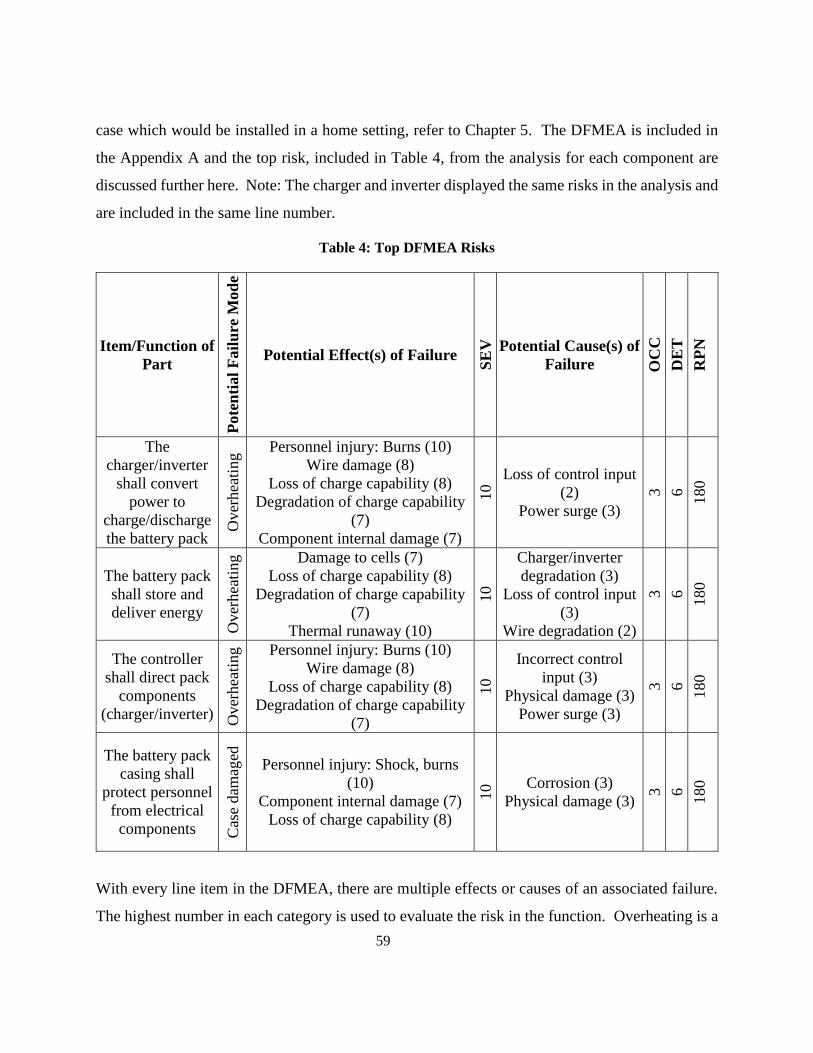
59
case which would be installed in a home setting, refer to Chapter 5. The DFMEA is included in
the Appendix A and the top risk, included in Table 4, from the analysis for each component are
discussed further here. Note: The charger and inverter displayed the same risks in the analysis and
are included in the same line number.
Table 4: Top DFMEA Risks
Item/Function of
Part
Pote
nti
al
Fail
ure
Mod
e
Potential Effect(s) of Failure
SE
V
Potential Cause(s) of
Failure OC
C
DE
T
RP
N
The
charger/inverter
shall convert
power to
charge/discharge
the battery pack
Over
hea
ting
Personnel injury: Burns (10)
Wire damage (8)
Loss of charge capability (8)
Degradation of charge capability
(7)
Component internal damage (7)
10 Loss of control input
(2)
Power surge (3)
3
6
180
The battery pack
shall store and
deliver energy
Over
hea
ting
Damage to cells (7)
Loss of charge capability (8)
Degradation of charge capability
(7)
Thermal runaway (10)
10
Charger/inverter
degradation (3)
Loss of control input
(3)
Wire degradation (2)
3
6
180
The controller
shall direct pack
components
(charger/inverter) Over
hea
ting
Personnel injury: Burns (10)
Wire damage (8)
Loss of charge capability (8)
Degradation of charge capability
(7)
10
Incorrect control
input (3)
Physical damage (3)
Power surge (3)
3
6
180
The battery pack
casing shall
protect personnel
from electrical
components Cas
e dam
aged
Personnel injury: Shock, burns
(10)
Component internal damage (7)
Loss of charge capability (8)
10 Corrosion (3)
Physical damage (3)
3
6
180
With every line item in the DFMEA, there are multiple effects or causes of an associated failure.
The highest number in each category is used to evaluate the risk in the function. Overheating is a

60
common high risk to each component in the assembly, as it is anticipated that the assembly may
heat up during operation which could cause damage to the components. Overheating is understood
to be one of the biggest risks associated with Li-ion packs due to the risk of thermal runaway in a
potential breakdown situation. As a result, the design team recommends the installation of
multiple fans in the case which protects the assembly, with a perforated enclosure which can allow
for sufficient air flow to cool the pack. The battery used in the bench test setup is an air cooled
pack, and may require additional cooling under heavy loading scenarios.
4.7.2 Fault Tree Analysis
The Fault Tree Analysis (FTA) risk technique looks at a risk which is posed to personnel, and
attempts to break it down to the root causes which can lead to it. The technique approaches the
risk analysis for the repurposed battery pack from the opposite side of the DFMEA, to find if there
are different risks which can be posed to the user. The FTA for the repurposed battery pack focuses
on the following five major safety risks: electrocution, slips/falls, inhalation, cuts/scrapes, and
burns/explosions. Faults are connected through ‘And’ or ‘Or’ gates to suggest the combination of
faults which can arise with the risk in question. The full FTA for the five risks is included in
Appendix B. The ‘Burns/Explosions’ FTA is included in Figure 42 for discussion.

61
Figure 42: Burn/Explosion Fault Tree Analysis
Through the use of the FTA, designers can understand where an end risk to the user began. The
biggest root causes leading to burns/explosions in the repurposed pack arise from installation
issues, improper preventative maintenance, and catastrophic failure of the battery pack. The
installation issues can be mitigated in the implementation of the pack through the use of qualified
technicians who are specially trained in HV apparatus. These same technicians should also be
employed to do routine maintenance on the assemblies, especially early in their use in the market
as issues are sorted through the cycling of the packs. Finally, catastrophic failure is always a risk
in an assembly, but the integration of a well-designed assembly/enclosure which has a thorough
control system in place that can monitor the pack as it is cycled should mitigate any issues of
overheating or thermal runaway.

62
4.7.3 Repurposed Battery Pack Code Analysis
To understand the safety measures that need to be included in the design of a repurposed pack in
a grid storage context, all applicable safety codes for construction may need to be adhered to.
Stationary energy storage, especially with Li-ion cells, is a relatively new concept and codes are
currently being developed which address the safe design, installation, and operation of these
projects. In the United States, it is anticipated that new codes may take approximately six years
before they are ready for enforcement in the market [59].
A report by the Pacific Northwest National Laboratory outlines the codes and standards in the
United States for energy storage systems [60]. Table 5 and Table 6 display the codes outlined
which are applicable to the repurposed packs outlined in this report. Table 5 focuses on codes
which are specific to the battery pack used in the stationary assembly, while Table 6 focuses on
codes which outline design considerations for the repurposed pack assembly.

63
Table 5: Applicable Codes for Repurposed Li-ion Battery Packs in a Stationary Application [60]
Cod
e
Cate
gory
Code Title Connection to Repurposed Packs
Batt
ery P
ack
IEC 61960 Ed 3: Secondary lithium cells and
batteries for portable applications
Covers criteria for the selection of
secondary lithium cells for
remanufacturing
IEC 62485-2: Safety requirements for secondary
batteries and battery installations – Part 2:
Stationary batteries
Covers protections from hazards with
stationary battery packs with nominal
voltages less than 1500 V
IEC CD 62619: Secondary cells and batteries
containing alkaline or other non-acid
electrolytes. Safety requirements for secondary
lithium cells and batteries, for use in industrial
applications.
Under development, covers
requirements on all aspects of
stationary application use of Li-ion
batteries including erection, use,
inspection, maintenance, and disposal
of cells
IEC CDV 62620: Secondary cells and batteries
containing alkaline or other non-acid electrolytes
– Secondary lithium cells and batteries for use in
industrial applications
Covers tests and requirements for Li-
ion cells to be used in a stationary
application
IEC 62620 Ed 1: Large format secondary lithium
cells and batteries for use in industrial
applications
Covers specifications for cells in
secondary industrial applications
IEEE 1660: Guide for Application and
Management of Stationary Batteries Used in
Cycling Service
Covers battery management strategies,
with changes relative to cycling for
stationary applications
UL 1642: Lithium Batteries
Covers requirements for lithium
batteries in stationary applications for
safety of technicians, users, and other
design features

64
Table 6: Applicable Codes for the Repurposed Battery Pack Assembly [60] C
od
e
Cate
gory
Code Title Connection to Repurposed Packs
En
tire
Ass
emb
ly
ANSI C84.1: Electric Power Systems and
Equipment – Voltage Ratings (60 Hertz)
Standard covers nominal voltage
ratings and operating conditions for
60-hertz systems above 100 volts
IEC 62257-9-2: Recommendations for small
renewable energy and hybrid systems for rural
electrification – Microgrids
Standard covers requirements for how
microgrids can be maintained and
safety upheld
IEC 62897: Stationary energy storage systems
with lithium batteries – Safety requirements
(under development)
Covers hazards that need to be
mitigated for the use of a stationary
pack with Li-ion cells
IEEE 1375: Guide for the protection of
stationary battery systems
Covers guidelines for options of
protecting stationary battery systems
NFPA 111-2013: Standard on stored electrical
energy emergency and standby power systems
Covers safe operation of stationary
energy storage systems with the grid
in the event of service disruptions
UL 9540: Outline for investigation for safety for
energy storage systems and equipment
Covers safety for all energy storage
systems, being charged and
discharged at a later point in time to
shift demand
As many Li-ion codes are still in development, the author analyzed codes that have been developed
for lead-acid battery stationary storage setups to determine the direction that would be followed
for the Li-ion legislation. Two codes that are applicable for the installation of a lead-acid system
in Canada are the CSA Electrical Code 2012 and IEEE 484 [61] [62]; key findings from both codes
for the casing and assembly of the ESS are included below [61]:
The assembly should be installed on a level plane, with sufficient storage strength to
protect against electrolyte corrosion;

65
Batteries with nominal voltage >150 V should be sectionalized into groups;
Storage of the batteries should be only accessible by authorized personnel;
Storage of the batteries should be kept at an ambient temperature of approximately 25°C;
and,
Installation should be performed in a protected area, isolated from vibration.
4.8 Assembly Conceptual Design
4.8.1 Plant/Grid Balance Interface Design
The interface between the ESS (plant) and the grid may need to be designed for each application.
For maximum utility of the ESS, control may need to be established with the utility, to understand
changes in price, supply, demand, and grid mix to integrate intermittent renewables. This interface
may require HV access for the ESS to be integrated, as well as the communication infrastructure
for the unit to communicate.
4.8.2 Control System Development
The development of the control system in the repurposed ESS may require the careful monitoring
of changes in the usage profile of the application, the grid mix, and the SOC/SOH of the pack.
Each battery pack used in the assembly should be integrated with its own BMS, which can monitor
and control the differences in voltage and charge between the individual cells in the pack. There
may be a supervisory controller in place which can control the whole system, and interact with the
auxiliary components in the assembly. Figure 43 shows the overview of the proposed control
system that could be implemented in a repurposed ESS.

66
Figure 43: Control System Overview
The supervisory controller monitors the assembly, controlling the charger/inverter in accordance
with grid and application needs. The controller should be monitoring communication with each
individual BMS, to understand if there are degradation or failure issues with each pack. This
communication may be a challenge to set up, given the differences in controllers between each
individual vehicle. As a result, it is recommended that only similar packs are used in each
application. All communication is anticipated to be completed via a Controller Area Network
(CAN), similar to those that are implemented in a vehicle.
4.8.3 Mechanical and Casement Design
The design of the mechanical aspects of the ESS and the casing may need to achieve two main
purposes. The first is to protect the internals of the case from the ambient environment. To protect
the internals, the case may need to be designed to allow for cooling, while protecting against
moisture which can degrade and corrode the batteries and electrical connections. A system which
is mounted to a wall may be optimal, keeping the assembly out of the potential path of any floods
which could occur in the area of the installation. In this case, mechanical optimization techniques
such as those discussed in Chapter 3 may help to decrease the associated weight with the
construction. The second purpose is to protect users and technicians who are interacting with the

67
pack. The pack may be working at high voltages (likely 48 – 300 V), which may need to be
protected in a secure case to protect against shock hazards. The lower end of this voltage range is
anticipated for use in an industrial application, as many commercially available chargers and
inverters could be used in the repurposed setup from the solar energy industry. To achieve this
low working voltage using the 50 V modules discussed in the battery pack design in Chapter 3,
each module would need to be connected in parallel to form the repurposed pack. Another example
of achieving this low working voltage is outlined in Chapter 5, which uses four smaller modules
from a Prius battery pack to reach a nominal voltage of 28 V.
4.9 Energy Storage System Grid Integration
4.9.1 Permitting
Permitting is currently a large unknown for repurposed energy storage systems. As in the code
analysis outlined previously, Li-ion repurposed energy storage is a new concept. As a result, the
legislation that regulates the installation of these systems is not currently written. Permits may
need to first be issued to the designers/installers of the system to implement it in the market. Some
studies have found that the introduction of renewable technologies into the market can be more
difficult than introducing fossil-fueled technologies, and call for reforms to the system [63] [64].
4.9.2 ESS Construction
Once designed, construction of the ESS is anticipated to be simple, requiring the construction of
Low Voltage (LV) harnesses and High Voltage (HV) cabling. Any remanufacturing facilities and
their employees may need to be sufficiently trained in HV procedures however, and many training
procedures differ based on each manufacturer. Safe practices will need to be employed, to ensure
that the packs can be assembled and delivered to the customer in a safe manner. Incoming battery
packs may first need to be sorted based on their degradation and SOH status into one of the five
levels discussed in Section 4.3.2, and repaired if small amounts of damage are evident. There is
the potential for one or more of the cells within the pack to be beyond useful application, requiring
this cell to be physically removed from the pack or, more likely, the pack being reconfigured to
bypass the nonfunctioning cells. Once the design has been completed for a specific application,

68
viable packs can be assembled with a custom harness to a supervisory controller that has been
programmed to work with the chosen charger/inverter and BMS specific to the packs in use. The
control networks such as CAN can then be wired, and the battery modules connected together to
form the system’s HV bus. It is anticipated that the entire assembly may have its own service
disconnect that can be installed/uninstalled to allow service procedures and shipping to occur in a
safe manner.
4.9.3 ESS Installation
The installation of the ESS may require changes to the application’s electrical network to allow
for the integration of the unit. Installation is predicted to be simple, with the assembly acting as
an independent unit with only HV and control connections required to integrate it. Installation
may require certified technicians, to complete the task in accordance with the codes specific to the
area of installation to ensure that the risks outlined in the FTA and DFMEA in this report are
mitigated.
4.10 Pack Design with a 16.2 kWh Battery
Chapter 3 of this thesis discusses a 16.2 kWh battery pack, made up of six 15S3P battery modules
from A123. These modules each operate at a nominal voltage of approximately 49 V, which are
connected in the vehicle in series to achieve an operating voltage of 292 V. Assuming a 20%
capacity fade through the vehicle, the full battery pack could be uninstalled from the Chevrolet
Camaro with 12.96 kWh remaining.
To implement this pack in a repurposed setting, the modules could be disconnected in their series
configuration within the vehicle, and connected in a parallel setting to achieve a nominal operating
voltage of 49 V. At this range, chargers/inverters from the solar energy industry including the
Conext XW+ discussed in the design of the bench test setup in Chapter 5 could be implemented
off-the-shelf to integrate the pack into the grid network.
Based on assumptions regarding charging from Heymans et Al., the following chart is created
using this pack to understand the maximum amount of energy that can be offset during a single
day for a residential application in a repurposed setting, Table 7. The numbers included are based

69
on an assumption that the repurposed pack is charged/discharged at a charge efficiency of 80% for
each charge, resulting in a 64% efficiency ‘round-trip’.
Table 7: 16.2 kWh Battery Pack Energy Ratings
Energy (kWh)
Rated Pack Capacity - New 16.2
Rated Pack Capacity – After Vehicle Use 12.96
Total Discharge Available – After Charge Efficiency 10.37
Maximum Energy Available for Discharge 8.3
Thus, only 8.3 kWh of energy is available for discharge in the repurposed pack, down from the
newly rated capacity of 16.2 kWh. However, a given North American home will use on average
3 - 4 kWh of energy during a day [65]. Therefore, this pack has the potential to offset a full day
worth of energy for a home, and can offset peak power use for the end consumer.
4.11 Chapter Summary
In this chapter, a design process is proposed which should be followed in the application of a
repurposed battery pack in a stationary energy storage situation. Repurposed packs offer an
alternative to more expensive energy storage solutions, which require new packs or specific
infrastructure such as pumped hydro. There are many areas of research which still need to be
sorted, in order to develop supply chains which can distribute used batteries to a re-manufacturer.
The exact supply of vehicle batteries nearing end of life is still uncertain, as Li-ion technology is
new to the market.
Once collected, assessments of the degradation and quality of the pack are needed to determine if
they are viable for repurposing or require minor amounts of repair or maintenance. Packs with a
large amount of degradation or large numbers of cell failures would deem packs as useless for
repurposing, due to the large investment required in capital to fix packs at the cell level. This
quality assessment can only be completed currently by dealers and OEMs; a fact which may inhibit
the third party repurposing market.

70
Applications may benefit most from custom solutions made to the charge/discharge profiles of the
user, with packs that have been designed and configured based on their state of health following
vehicle use. Infrastructure of the specific pack can then be designed, in accordance with the codes
applicable to the application and grid. Once constructed, the ESS can be integrated into the
application to provide a relatively inexpensive option for storage.

71
Chapter 5
Repurposed Battery Pack Testing
5.1 Introduction
Two revisions of a repurposed battery pack are designed as part of this work. Both test setups are
based on a 1.3 kWh battery pack from a donated Toyota Prius. This battery pack is made up of a
NiMH chemistry, and runs at a nominal voltage of 201.6 V. The overall nominal voltage is attained
by connecting 28 battery modules in series, each running at a nominal voltage of 7.2 V and made
up of six NiMH cells. The battery pack used in the test bench setup is shown in Figure 44.
Figure 44: Test Bench Battery Pack
Revision one and two will be discussed in this chapter, which use a 28.8 V battery pack in
conjunction with an AC/DC battery charger, a DC/AC inverter, and a Uninterruptable Power
Supply (UPS) to simulate a load from the grid on the system. The setup is made to simulate one
which would power an individual home, instead of a larger pack which may be used in a
commercial application. The use of commercially available components are emphasised in the
design to reduce overall costs, with much of the chosen equipment originating from the solar
industry which works at nominal voltages similar to the repurposed battery setup. The revision
one setup is designed and constructed with the author’s guidance by four fourth year Chemical
Engineering students at the University of Waterloo for their fourth year design project: Mark

72
Merocchi, Alex Rak, Eric Wierdsma, and Corey Lavigne. Results of the project and the report are
summarized in the following sections [66].
5.2 Design Criteria and Constraints
There are four major design criteria to be considered in the design of the test bench setup:
functionality (size), safety, energy, and economics [66].
Functionality: As the repurposed pack would be used in a home, the equipment used should be
of a size that is modular and could be installed in a basement or in a backyard. The equipment
should show the ability to be scaled, such that components could be developed for use in the home.
Additionally, they should be able to work with standard household nominal voltage (110V AC),
and be reliable so that a user can depend on the pack on a daily basis to provide cost savings.
Safety: The safety of the end user should be considered in the development of the pack. As regular
consumers will have the pack installed in their home, care should be taken to ensure that voltages
of the pack are low to reduce any safety risk. Additionally, the pack’s encasement should be
designed to eliminate any potential sharp points and barricade against entry by unauthorized users
to ‘always energized’ components.
Energy: For a residential application, the average full amount of energy used in a given day for a
home in North America is 3-4 kWh [65]. A design constraint on the test setup is that the pack
should be designed so that it can be charged the full 3-4 kWh capacity during off-peak times, and
deliver this energy during on-peak hours. This use of the pack may allow consumers to shift the
entirety of their on-peak energy use.
Economics: Costs should be minimized as much as possible to enable a shorter payback period
for the end consumer. The residential pack’s primary purpose is intended to be to load shift energy
between off-peak periods to on-peak periods, thus reducing load on the grid. In Ontario, electricity
prices are regulated based on time-of-use measures. For example, off-peak hours during the
summer occur for a 12 hour period between 7 P.M. and 7 A.M. The prices and peak times for the
province of Ontario is shown in Figure 45.

73
Figure 45: Time-of-use pricing in Ontario [67]
These cost savings will need to make up for the initial cost of design, construction, and installation
of the setup. The battery pack will be charged over the 12 hour off-peak period, and the chosen
charger should meet this requirement. Commercial components should be used as much as
possible to reduce the potentially large costs of using custom components in the design.
5.3 Proposed Designs
There are three proposed designs in revision one for the test bench setup which are evaluated using
the aforementioned design criteria. The first uses the entire 201.6 V, 1.3 kWh pack. In this design,
three full battery packs would be connected in parallel to maintain the standard nominal voltage
and increase the capacity to 3 kWh. In order to charge the full pack, the charger would need to
provide 1.2 A over a period of 12 hours. Due to the high operating voltage of this design, a
specialized inverter is required to convert the DC energy in the pack to AC energy for use in the
grid. The Schneider Conext RL 3000E is selected, which can withstand input voltages ranging
between 90 and 550 V DC [68]. However, this inverter will only output to 230V AC, and an
additional transformer would be needed to reduce the voltage to 110 V. These two components
cost $4,387. [66]

74
The second proposed design is based on a 64 V system. By breaking the battery modules within
the pack into sections of nine, the 7.2 V (6.5 Ah) modules can be connected in series to reach a
nominal operating voltage of 64.8 V. The connection of ten of these smaller packs will yield a
total capacity of 3.2 kWh, enough to cover the entirety of energy used by a typical residential
application. Due to the lower operating voltage, the capacity of this system is now 49.2 Ah and
would require a charge current of 4 A to fully charge in 12 hours. The chosen inverter for this
setup is bidirectional, allowing the charging and discharging of the energy storage system. The
chosen inverter is the Schneider Conext XW 4548 120, and the entire setup would cost $2,350. [66]
The third proposed design is based on a 28V system, made up of four battery modules connected
in series. With the small capacity of this system, 22 full battery assemblies would be required to
be connected in parallel to achieve the operating energy of 3.13 kWh (with a capacity of 108.68
Ah). The connected charger in the setup would need to provide a current of 9 A to charge the pack
in a 12 hour period. At the operating voltage of 28 V, the setup will be charged with an Iota DLS-
27-15 charger and discharged with a Cotek S300-124 inverter. The total cost for the system is
$925. [66]
A summary of each of the three proposed designs is shown below in Table 8.
Table 8: Revision One Proposed Design Summary
Design One Design Two Design Three
Operating Voltage (V) 201.6 64.8 28.8
Parallel Units 3 10 22
Overall Capacity (Ah) 14.8 49.4 108.7
Overall Energy (kWh) 3 3.2 3.13
Charge Current (A) 1.2 4.1 9.1
Cost ($) 4,387 2,350 925
For safety, complexity, and cost purposes, design three is chosen for construction. The test bench
is designed to work at low voltages of approximately 30 volts, thus limiting many electrically-

75
associated safety concerns. As well, the setup may not require the purchase and integration of
additional transformers or the control of a bi-directional charger.
5.4 Repurposed Battery Pack Operation
The revision one setup relies on five major components for operation: the battery pack, a controller,
a charger, an inverter, and a UPS. Figure 46 and Figure 47 show the test bench setup, with the
proposed casing which would be integrated if the setup were to be installed in a home.
Figure 46: Bench Setup Isometric View

76
Figure 47: Bench Setup Top View
The diagram below shows the components and their electrical connections, Figure 48.
Figure 48: Revision One Setup [66]
In order to accommodate the choice of four battery modules to make up the ESS in the design, the
battery needed to be dismantled in order to separate each component from the stock design. This
process is documented step-by-step in order to allow future groups to use the additional stock
batteries provided to the project from the sponsoring company. As stated earlier, the battery is

77
made up of 28 battery modules which are ‘sandwiched’ together and use four lateral bars to hold
them in operation. The modules each have terminals on opposing sides of the structure, and are
connected using a copper bus bar which is protected from accidental short circuit through the use
of a piece of custom orange conduit. Of note is that the stock battery uses passive cooling during
operation, and there are small vent ports on the top of each module to allow ventilation of built up
gases in the event of an emergency. The dismantling of the battery is shown below in Figure 49,
Figure 50, Figure 51, and Figure 52.
Figure 49: Pack without Case

78
Figure 50: Pack Bus Bars Uninstalled
Figure 51: Retaining Bars Uninstalled

79
Figure 52: Disassembled Battery modules
Table 9 shows the selected inverter and charger in the setup and their design specifications. Both
the inverter and charger are purchased from the solar energy market, and are designed to work at
the operating voltage of 28.8 V.
Table 9: Inverter/Charger Design Specifications
Inverter Charger
Make/Model Cotek S-Series 28 Iota DLS-27-15
Power (W) 300 400
Cost ($) 311 164
Efficiency (%) 85 85
One drawback of the selected charger is its inability to be directly controlled during operation.
The inverter has a controller input which can turn it on/off during operation remotely by the chosen
controller. The charger lacks a controller input pin, and other measures are required in order to
control its operation. In order to control the charger, a PowerSwitch Tail is purchased which
interfaces between the charger and the wall. The tail is able to be activated on/off using a 5V
output on the controller, eliminating the need for manual charging of the setup.

80
A controller is needed in order for the test bench to charge and discharge given the time of day to
offset peak power use. In order to safely control the pack, three measured variables are needed:
voltage, current, and temperature. The controller will need to monitor the battery’s SOC in order
to determine how much current should be discharged/charged at a time. The SOC may need to be
kept in a nominal operating range, to ensure that the battery will not be degraded from over
charging/discharging which could affect its lifetime and its SOH. Additionally, large amounts of
overcharging could result in a fire or catastrophic failure of the pack.
The controller will monitor the SOC and stop charging once the pack has reached its full SOC,
with the opposite operation occurring when discharging. Three controller options are identified
for use in the system: a Mototron 24 pin General Control Module, a National Instruments USB-
6008 controller, and a National Instruments PCIe-6321 controller. The controller should have
three analog inputs, one analog output, and two digital outputs to be compatible with the setup.
All three controllers are compared based on their functionality, cost, and compatibility with the
system. The National Instruments USB-6008 controller is selected due to its intuitive controls
software which the project group is familiar with using. [66]
In order to interface the controller with the pack to monitor operation, the Phidget 1135 voltage
sensor, Allegro ACS-712-10B current sensor, and a thermistor are selected. The voltage and current
sensors are able to be connected to one of the 12 analog inputs on the controller, and the controller
is able to provide enough power to drive them. The thermistors are attached to the tops of the
modules in order to monitor any heat generated during cycling. [66]
For the cycling of the battery, two Solid State Relays (SSRs) are used to allow current to flow to
either the charger or the inverter. The controller is not able to provide enough power to drive the
relays alone, and interfaces with a ULN2003A relay driver and an external 12 V power supply in
order to drive the selected Phidget 3951 DC SSRs. [66]
5.5 Operation and Results
The team was able to charge the constructed 28.8 V pack using the charger and a wall plug
independently of using the controller. Once the pack was charged, the charger was manually
disconnected, and the system was connected to the inverter and UPS as a load. Once connected,
81
the small pack was able to charge the UPS and deliver energy. This manual process was repeated
to prove the ability of the setup to function correctly.
During cycling, control code was written in order to be able to integrate the National Instruments
controller into the setup. Unfortunately, the accidental reversal of polarity on one installation of
the inverter in the test bench setup damaged the Cota inverter to the point that it could not properly
function. This damage caused the setup to be nonoperational for the remainder of the project,
inhibiting the testing of the bench with the controller and all components fully functioning. It is
anticipated that if the inverter were to still be functioning, that the setup would have proven fully
functional with the documented control code written during the project.
5.6 Lessons Learned
Some positive lessons learned from the first test bench setup included the fact that charging and
discharging was implemented manually using the chosen charger and inverter. The use of the four
battery modules to create a small ESS allowed the team to reduce any safety considerations with
using a high voltage pack, and commercial off-the-shelf components were integrated reducing cost
of the setup. The pack was safely disassembled through the use of basic HV tools and the Toyota
maintenance manual for the car.
For future installations, diodes should be installed on expensive components to ensure that damage
does not occur. As well, proper fusing should be integrated into the circuits to protect against a
short circuit or current spike which could damage sensitive components.
5.7 Revision Two Background
In order to build on the knowledge gained through revision one of the repurposed battery pack
design, a second test bench is designed in order to understand how to design around the lessons
learned from the previous setup. Revision two focuses on the use of a new bi-directional
charger/inverter, the Conext XW+, which is made available through the University of Waterloo’s
new partnership with Schneider Electric. This charger/inverter is capable of working with the
grid, and tying in additional energy sources/storage devices including photovoltaic panels and
Lead-acid or Li-ion batteries. It can additionally be tied in with other Conext XW+ systems, in
82
order to scale the operation from one model, capable of providing from 5.5 kW - 102 kW with
multiple systems attached [69].
This revision two setup is designed and constructed with the author’s guidance by four fourth year
Mechatronics Engineering students at the University of Waterloo for their ME 599: Hybrid Vehicle
Design independent project: Jaesik Kim, Jae Seung Kweon, and Mingu Kwon. Results of the
project and the report are summarized in the following sections [70].
5.8 Design
Revision two built off of the components and design from revision one. The setup is a 28.8 V test
bench, using the four module configuration. Changes to the revision two setup include the use of
an Ardiuno Uno board to control the system instead of the NI controller due to familiarity of the
group members with the product, a real-time clock to sync the system with the charge profile, a
bi-directional charger/inverter from Schneider Electric (replacing the Cotek inverter and Iota
charger), and a new voltage sensor which interfaces with the newly chosen controller. [70]
The Arduino Uno controller is selected for revision two as the controller allows for development
of code using C/C++, a language more familiar to the group than the LabVIEW software required
for the NI USB-6008 used in revision one. Both controllers are deemed sufficient to power the
setup given the number of inputs/outputs available on each controller, but development time was
short thus making the selection of the familiar controller. The real-time clock is used with the
controller, as the Arduino does not have a stock method of keeping track of time as it progresses.
The real-time clock is chosen over the use of an Ethernet or WIFI shield due to cost constraints
and, once set, will track the time in order to switch the battery pack on/off in accordance with time-
of-use electricity prices. The overall setup of revision two of the test bench is seen in Figure 53.
[70]

83
Figure 53: Revision Two Setup [70]
5.9 Operation and Results
Revision two was never fully tested before the writing of this report. Due to the complexity of the
bi-directional charger/inverter, the team was not able to integrate it fully during the time constraints
of the project. However, simulations of the newly written control code show that the new setup
with the Arduino controller would be able to integrate with the fully completed setup. It is
anticipated that with the results of developments with the battery pack in revision one and the
controller selection in revision two that a fully functioning test bench could be made easily over
the coming terms.
5.10 Chapter Summary
Through this chapter, two setups of a repurposed battery pack test bench are designed. Revision
one focuses on the use of off-the-shelf commercial components, which are relatively inexpensive
to incorporate into the setup. The Toyota Prius battery pack is dismantled into its 28 battery
modules, of which four are connected to create a small pack which operates at 28.8 V. This low
voltage decreases safety concerns with the setup, and allows the team to use components from the
solar energy industry to connect the pack to the grid. The manual charging/discharging process
using the chosen Cotek inverter and Iota charger is able to charge the pack, and provide energy to

84
the UPS load. Unfortunately, the accidental reversal of polarity on the inverter irreversibly
damaged it.
Revision two focuses on the use of the small 28.8 V pack as well, only with the addition of a
donated Schneider-Electric bi-directional charger/inverter. The setup uses an Arduino Uno as a
controller, due to the team’s familiarity with the controller in the time constrained project.
Unfortunately, the team did not manage to have the system fully functioning, as the bi-directional
charger/inverter’s control mechanism is complex.

85
Chapter 6
Conclusions and Recommendations
6.1 Conclusions
The objective of this thesis is to outline battery pack design for a vehicle application while taking
into account considerations for repurposing in a stationary application, and to suggest setups and
lessons learned from the construction of a repurposed pack bench test setup. The conclusions
illustrate the advances made in each section of the work, with recommendations following on how
the work can be further advanced in the future.
Mechanical design optimization techniques show advantages in designing complex systems
and can be implemented in the design of the repurposed energy storage system casement.
The battery pack designed by UWAFT for the EcoCAR 3 competition is based on a topology
optimization performed in Altair Hyperworks which shows load paths in the assembly prior to
mechanical design. These load paths allow the designer to have a starting point to create members
in the final assembly prior to finite element analysis. This process, in turn, allows for a weight-
efficient design which reduces the assembly’s final mass. With this complex design integrating
the battery into a vehicle being completed, the task of creating an assembly for the simpler
repurposed pack for a residential application is within reach.
A design process for a repurposed battery pack is proposed, displaying the current research
in design methods and steps. The design process takes into account business aspects including
market analysis of in-vehicle batteries which are suitable for repurposing, state of health models
which take into account degradation, and applicable risks/codes which may affect the end
assembly design.
Repurposed battery packs are currently prohibited from mass market penetration, due to
associated risks, an uncertain supply chain, and a lack of regulation. The incorporation of this
new technology into the grid is currently not regulated, with applicable codes coming in the next

86
six years. There are additionally many concerns on the state and number of batteries which may
be uninstalled from the vehicles and used for repurposing.
Repurposed battery pack codes are still in development, with Li-ion technology being newly
introduced in the market. Lead-acid stationary storage legislature shows some proxies which
can be used for Li-ion technology, however Li-ion technology has its own issues which may need
to be addressed in new codes. One of the biggest risks of the use of Li-ion batteries is due to
thermal runaway. In addition, the use of repurposed batteries for stationary applications may
present a technical and regulatory hurdle.
A repurposed battery pack test bench setup has been created. This test bench setup is
completed in two revisions, using different setups and charger/inverter combinations. The first
setup displays the ability for the small pack, made out of a repurposed vehicle battery, to allow for
manual charging/discharging to take place. The second setup works to build on this setup with the
incorporation of a bi-directional charger/inverter from the solar energy industry.

87
6.2 Recommendations
As mentioned in Subsection 6.1, the objective of this thesis is to present the design of a vehicle
battery pack with considerations for repurposing, as well as the design and lessons learned from
the design/construction of a repurposed pack bench test setup. The following recommendations
outline areas of focus for future work in the development of UWAFT’s Chevrolet Camaro battery
pack and a repurposed pack assembly which could be installed in industry.
New designs of the battery pack’s structural frame and mounting plate should be tested, to
verify strength of the geometry based on the given loading conditions. The completed
optimization does not suggest exact geometry, material, or structure details, and these may need
to be decided through iterations in finite element analysis and re-design. However, the structure
is close to passing the given loading conditions while minimizing the overall assembly weight.
More research into the market of repurposed packs is needed. Currently, there is a large
uncertainty as to the timeline for the packs coming out of service, the supply chain in order to
purchase the batteries, and how vehicles may continue once the pack reaches its loss of 20% of its
original capacity. Market research as the vehicles mature may provide new insight into how
designers can incorporate this technology into new repurposed assemblies. With the development
of a market for stationary energy storage by major automakers, proxies to the potential repurposed
market may be made.
As Li-ion powered electric and hybrid vehicles begin to end service, degradation studies
should be completed to verify estimates in state of health at the end of vehicle life. Current
degradation estimates are largely based on the cycling of half cells in a laboratory setting, to low
cycling numbers to quantify the effects of temperature, depth of discharge, or cycling rate. Studies
on full pack-scale degradation on highly cycled packs should provide insight into how these packs
are degrading in a vehicle and help with the assessment of packs as they are introduced in
repurposed applications. The acquisition of fleet data with respect to battery performance may be
needed to further this objective.

88
A new repurposed pack setup should be created, using the bi-directional charger/inverter
and the lessons learned from revision one and revision two. The bi-directional charger/inverter
is optimized for the bench test setup, and its incorporation was inhibited due to time constraints.
The charger can also be scaled to larger setups, such as in a residential setting which could be used
in a full scale application.

89
References
[1] Independent Electricity System Operator, "Supply Overview," 2015. [Online]. Available:
http://www.ieso.ca/Pages/Power-Data/Supply.aspx. [Accessed 12 June 2015].
[2] A. Boulanger, A. Chu, S. Maxx and D. Waltz, "Vehicle Electrification: Status and Issues," World
Team Now, Malibu, 2011.
[3] S. H. Mohr, G. M. Mudd and D. Giurco, "Lithium Resources and Production: Critical Assessment
and Global Projections," minerals, vol. 2, pp. 65 - 84, 2012.
[4] L. Ahmadi, A. Yip, M. Fowler, S. B. Young and R. A. Fraser, "Environmental feasibility of re-use
of electric vehicle batteries," Sustainable Energy Technologies and Assessments, pp. 64 - 74, 8
January 2014.
[5] Manitoba Eco Network, "Climate Change Connection," Modern Earth, 4 December 2009.
[Online]. Available: http://www.climatechangeconnection.org/emissions/Tailpipeemissions.htm.
[Accessed 18 February 2014].
[6] Natural Resources Canada, "Electricity for Transportation," 17 November 2014. [Online].
Available: http://www.nrcan.gc.ca/energy/alternative-fuels/fuel-facts/electric/3551. [Accessed 12
June 2015].
[7] Plug In America, "How long does it take to charge a plug-in car?," 2015. [Online]. Available:
http://www.pluginamerica.org/faq/how-long-does-it-take-charge-plug-car. [Accessed 12 June
2015].
[8] S. C. Davis, "Transportation Energy Data Book: Edition 20," Office of Transporation
Technologies U.S. Department of Energy, Washington, 2000.
[9] Union of Concerned Scientists, "State of Charge," September 2014. [Online]. Available:
http://www.ucsusa.org/clean_vehicles/smart-transportation-solutions/advanced-vehicle-
technologies/electric-cars/emissions-and-charging-costs-electric-cars.html#.VXstHflVhBc.
[Accessed 12 June 2015].
[10] The New Fisker, "Karma Owners," 2015. [Online]. Available: http://www.thenewfisker.com/.
[Accessed 12 June 2015].

90
[11] Honda, "2015 Civic Hybrid," 2015. [Online]. Available: http://www.honda.ca/civic_hybrid.
[Accessed 12 June 2015].
[12] Toyota, "2015 Prius," 2015. [Online]. Available:
http://www.toyota.ca/toyota/en/vehicles/prius/overview?gclid=CIfT5rHyisYCFVM1aQoddW4A_
w. [Accessed 12 June 2015].
[13] Chevrolet, "2015 Volt," 2015. [Online]. Available:
http://www.gm.ca/gm/english/vehicles/chevrolet/volt/overview/?adv=78245&mkwid=goo_|_%5B
account_name%5D_|_Chevrolet+-+Volt+-+EXA+-+GG+-
+EN_|_Chevrolet+Volt_|_chevrolet%20volt. [Accessed 12 June 2015].
[14] United States Environmental Protection Agency, "Dynamometer Drive Schedules," 2 June 2013.
[Online]. Available: http://www.epa.gov/nvfel/testing/dynamometer.htm. [Accessed 15 June
2015].
[15] U.S. Department of Energy: Energy Efficiency & Renewable Energy, "Your Mileage Will Vary,"
2015. [Online]. Available: http://www.fueleconomy.gov/feg/why_differ.shtml. [Accessed 15 June
2015].
[16] FleetCarma, "FleetCarma: Make Fuel Efficient Vehicles Green & Green," 2014. [Online].
Available: http://www.fleetcarma.com/. [Accessed 15 June 2015].
[17] Oxford Dictionaries, "Oxford Dictionaries," Oxford University Press, 2015. [Online]. Available:
http://www.oxforddictionaries.com/definition/english/battery. [Accessed 10 June 2015].
[18] G. P. Hammond and T. Hazeldine, "Indicative energy technology assessment of advanced
rechargeable batteries," Applied Energy, vol. 138, pp. 559 - 571, 2015.
[19] J. Vetter, P. Novak, M. Wagner, C. Veit, K. -C. Moeller, J. Besenhard, M. Winter, M. Wohlfahrt-
Mehrens, C. Vogler and A. Hammouche, "Ageing mechanisms in lithium-ion batteries," Journal of
Power Sources, vol. 147, pp. 269 - 281, 2005.
[20] L. Ahmadi, M. Fowler, S. B. Young, R. A. Fraser, B. Gaffney and S. Walker, "Energy efficiency
of Li-ion battery packs re-used in stationary power applications," Sustainable Energy Technologies
and Assessments, vol. 8, pp. 9 - 17, 2014.
[21] A. G. Ritchie, "Recent Developments and Likely Advances in Lithium Rechargeable Batteries,"
Journal of Power Sources, vol. 136, pp. 285 - 289, 2004.

91
[22] R. Spotnitz, "Simulation of capacity fade in lithium-ion batteries," Journal of Power Sources, vol.
113, pp. 72 - 80, 2003.
[23] M. Broussely, S. Herreyre, P. Biensan, P. Kasztejna, K. Nechev and R. J. Staniewicz, "Aging
mechanism in Li ion cells and calendar life predictions," Journal of Power Sources, pp. 13 - 21,
2001.
[24] K. Takei, K. Kumai, Y. Kobayashi, H. Miyashiro, N. Terada, T. Iwahori and T. Tanaka, "Cycle
life estimation of lithium secondary battery by extrapolation method and accelerated aging test,"
Journal of Power Sources, pp. 697 - 701, 2001.
[25] N. Lohmann, M. Fischnaller, J. Melbert, T. Musch, P. Lamp, S. Scharner and V. Liebau, "Cycle
Life Investigations on Different Li-ion Cell Chemistries for PHEV Applications Based on Real
Life Conditions," SAE International, 2012.
[26] S. S. Choi and H. S. Lim, "Factors that affect cycle-life and possible degradation mechanisms of a
Li-ion cell based on LiCoO2," Journal of Power Sources, vol. 111, pp. 130 - 136, 2002.
[27] A. J. Smith, J. C. Burns and J. R. Dahn, "A High Precision Study of the Coulombic Efficiency of
Li-Ion Batteries," Electrochemical and Solid-State Letters, vol. 13, no. 12, pp. A177 - A179, 2010.
[28] Y. Hisamitsu, T. Abe, T. Kinoshita, H. Miyakubo and H. Horie, "Research and Development
Work on High-performance Lithium-Ion Batteries for EV Application," in 2008 World Congress,
Detroit, 2008.
[29] T. Miyamoto, E. Oogami, M. Origuchi, T. Tsuji, N. Hirata and T. Horiba, "Development of a
Lithium-Ion Battery System for HEVs," in SAE 2000 World Congress, Detroit, 2000.
[30] K. Smith and C.-Y. Wang, "Pulse Discharge Power Availability of a Lithium-Ion Hybrid Vehicle
Battery Pack," SAE International, 2005.
[31] K. Oguri and N. Maruno, "Development of Lithium-Ion-Battery System for Hybrid System," SAE
International, 2011.
[32] Z. Zhu, "Modeling of Lithium-Ion Battery Management System and Regeneration Control
Strategy for Hybrid Electric Vehicles," SAE International, 2013.
[33] Y. Tanjo, T. Abe, H. Horie, T. Nakagawa, T. Miyamoto and K. Katayama, "Study of a High-
Power Lithium-Ion Battery for Parallel HEV Application," in International Congress and
Exposition, 1999, 1999.

92
[34] K. Miyatake, T. Abe, Y. Hisamitsu, T. Kinoshita, Y. Shimoida and H. Horie, "Research on Large
Capacity, High Power Lithium-Ion Batteries," SAE International, 2009.
[35] P. Nelson, I. Bloom, K. Amine and G. Henriksen, "Simulation of Lithium-Ion Battery Performance
in Hybrid Electric Vehicles," in 2002 Future Car Congress, Arlington, 2002.
[36] M. Landi and G. Gross, "Measurement Techniques for Online Battery State of Health Estimation
in Vehicle-to-Grid Applications," IEEE Transactions on Instrumentation and Measurement, vol.
63, no. 5, pp. 1224 - 1234, 2014.
[37] C. Schaber, P. Mazza and R. Hammerschlag, "Utility-Scale Storage of Renewable Energy,"
Elsevier Inc., Toronto, 2004.
[38] K. Divya and J. Oestergaard, "Battery energy storage technology for power systems - An
overview," Electric Power Systems Research, pp. 511 - 520, 16 September 2008.
[39] J. Cocking and D. van Lanen, "Design of an Energy Hub with Energy Storage for a Commercial
Building," Waterloo Engineering, Waterloo, 2014.
[40] A. Mackenzie, "Secondary-Use Chevrolet Volt Batteries Power Their Way Into The Record
Books," General Motors Canada, 24 July 2015. [Online]. Available:
http://media.gm.ca/product/public/ca/en/gm/home.detail.html/content/Pages/news/ca/en/2015/Jul/0
724_Volt.html. [Accessed 13 September 2015].
[41] C. Hua, C. Haliburton, E. J. Wilhelm, C. J. Mendez, M. B. Stevens, M. Fowler and R. A. Fraser,
"University of Waterloo's Hydrogen Fuel Cell Choice Meets the Reality of Canada's Winter by
Using Model-Based Design," SAE International, vol. 1, no. 1, pp. 346 - 351, 2008.
[42] S. C. Davis, S. W. Diegel and R. G. Boundy, "Transportation Energy Data Book Edition 33," U.S.
Department of Energy, Washington, 2014.
[43] Argonne National Laboratory, "Non-Year-Specific Rules - Revision: D," Argonne National
Laboratory, Argonne, 2015.
[44] Merriam-Webster, "Merriam-Webster," 2015. [Online]. Available: http://www.merriam-
webster.com/dictionary/compliance. [Accessed 21 July 2015].
[45] F. Burger and E. Argalas, "General Modeling Guidelines for Stamped Steel Welded Fabrications
Used in Chassis Structures & Suspensions," General Motors, Warren, 2014.

93
[46] Champlain Cable, "EXRAD XLE 1000 Volt Shielded Cable," 2015. [Online]. Available:
http://www.champcable.com/product/exrad-xle-1000-volt-shielded-cable. [Accessed 24 July
2015].
[47] S. A. H. Zahabi, L. Miranda-Moreno and P. V. B. Barla, "Fuel economy of hybrid-electric versus
conventional gasoline vehicles in real-world conditions: A case study of cold cities in Quebec,
Canada," Transportation Research Part D, pp. 184 - 192, 2014.
[48] S. Shokrzadeh, "Battery Repurposing of Plug-in Electric Vehicles: A Framework for the
Integration of Renewable Energy and Electrified Transportation," The University of Manitoba,
Winnipeg, 2015.
[49] C. Heymans, S. Walker, S. Young and M. Fowler, "Economic analysis of second use electric
vehicle batteries for residential energy storage and load-levelling," Energy Policy, vol. 71, pp. 22 -
30, 2014.
[50] Toyota, "2013 Prius Product Information," Toyota, Aichi Prefecture, 2013.
[51] A. Cimprich, D. Skinner, B. Oh, K. Booth and A. Leutenegger, "Responsible Stewardship of
Electrified Vehicles," University of Waterloo, Waterloo, 2015.
[52] H. Song, Z. Cao, X. Chen, H. Lu, M. Jia, Z. Zhang, Y. Lai, J. Li and Y. Liu, "Capacity fade of
LiFePO4/graphite cell at elevated temperature," Journal of Solid State Electrochem, vol. 17, no. 3,
pp. 599 - 605, 2012.
[53] L. Lam and P. Bauer, "Practical capacity fading model for Li-ion battery cells in electric vehicles,"
IEEE, vol. 28, no. 12, pp. 5910 - 8, 2013.
[54] M. Dubarry and B. Liaw, "Identify capacity fading mechanism in a commercial LiFePO4 cell,"
Journal of Power Sources, vol. 194, no. 1, pp. 541 - 9, 2009.
[55] M. Safari and C. Delacourt, "Simulation-based analysis of aging phenomena in a commercial
graphite/LiFePO4 cell," Journal of Electrochemical Sources, vol. 158, no. 12, p. A1436, 2011.
[56] S. Peterson, J. Apt and J. Whitacre, "Lithium-ion battery cell degradation rsulting from realistic
vehicle and vehicle-to-grid utilization," Journal of Power Sources, vol. 195, no. 8, pp. 2385 - 92,
2009.
[57] B. Gaffney, S. Walker, M. Fowler, S. Young and R. Fraser, "FMEA and Fault Tree Analysis for
Second Use EV Battery in a Residence," in 64th Canadian Society of Chemical Engineers
Conference (CSCHe-14), Niagara Falls, 2014.

94
[58] United States of America Department of Defense, "Military Handbook - Electronic Reliability
Design Handbook," United States of America Department of Defense, Washington, 1998.
[59] D. Conover, "Overview of Development and Deployment of Codes, Standards and Regulations
Affecting Energy Storage System Safety in the United States," U.S. Department of Energy,
Richland, 2014.
[60] D. Conover, "Inventory of Safety-related Codes and Standards for Energy Storage Systems," U.S.
Department of Energy, Richland, 2014.
[61] Canadian Standards Association, "Canadian Electrical Code, Part 1," Canadian Standards
Association, Mississauga, 2012.
[62] IEEE Power Engineering Society, "484: IEEE Recommended Practice for Installation Design and
Installation of Vented Lead-Acid Batteries for Stationary Applications," The Institute of Electrical
and Electronics Engineers, Inc., New York, 2003.
[63] R. D. Kahn, "Siting Struggles: The Unique Challenge of Permitting Renewable Energy Power
Plants," The Electricity Journal, pp. 21 - 33, March 2000.
[64] J. Thaler, "Fiddling as the World Burns: How Climate Change Urgently Requires a Paradigm Shift
in the Permitting of Renewable Energy Projects," University of Maine - School of Law, Portland,
2012.
[65] E. Cready, J. Lippert, J. Pihl, I. Weinstock, P. Symons and R. Jungst, "Final Report: Technical and
Economic Feasibility of Applying Used EV Batteries in Stationary Applications," Sandia National
Laboratories, Albuquerque, 2003.
[66] M. Merocchi, A. Rak, E. Wierdsma and C. Lavigne, "Design of NiMH-EV Battery Pack For
Stationary Power Storage," Waterloo Engineering, Waterloo, 2014.
[67] Hydro One, "Time-of-Use (TOU)," 1 May 2015. [Online]. Available:
http://www.hydroone.com/TOU/Pages/Default.aspx. [Accessed 28 July 2015].
[68] Schneider Electric, "Conext RL Single-Phase Inverters," 2015. [Online]. Available:
http://solar.schneider-electric.com/product/conext-rl/. [Accessed 17 June 2015].
[69] Schneider Electric, "Conext XW+ Hybrid Inverter for Solar Power," 2015. [Online]. Available:
http://solar.schneider-electric.com/product/conext-xw-hybrid-inverter/. [Accessed 19 June 2015].
[70] J. Kim, J. S. Kweon and M. Kwon, "ME 599 Report: Repurposed Battery Pack," Waterloo
Engineering, Waterloo, 2014.

95
[71] Toyota Canada, "Prius for Everyone," 2013. [Online]. Available:
http://www.priusforeveryone.ca/?gclid=COXww8mr2LoCFYRDMgod63QA1A. [Accessed 9
November 2013].
[72] General Motors of Canada, "2014 Chevrolet Volt," 2013. [Online]. Available:
http://www.gm.ca/gm/english/vehicles/chevrolet/volt/overview?adv=110208. [Accessed 9
November 2013].
[73] B. Lutz, "The Real Story on GM's Volt Costs," Forbes.com LLC, 10 September 2012. [Online].
Available: http://www.forbes.com/sites/boblutz/2012/09/10/the-real-story-on-gms-volt-costs/.
[Accessed 9 November 2013].
[74] S. Samadani, R. Fraser and M. Fowler, "A Review Study of Methods for Lithium-ion Battery
Health Monitoring and Remaining Life Estimation in Hybrid Electric Vehicles," SAE
International, 2012.
[75] R. Matthe, L. Turner and H. Mettlach, "VOLTEC Battery System for Electric Vehicle with
Extended Range," SAE International, 2011.
[76] M. Rezvani, M. AbuAli, S. Lee, J. Lee and J. Ni, "A Comparative Analysis of Techniques for
Electric Vehicle Battery Prognostics and Health Management (PHM)," SAE International, 2011.
[77] ieso, "Supply Overview," Independent Electricity System Operator, 2012. [Online]. Available:
http://www.ieso.ca/imoweb/media/md_supply.asp. [Accessed 13 November 2012].

96
Appendix A
Design Failure Modes and Effects Analysis
Item/Function of
Part
Pote
nti
al
Fail
ure
Mod
e
Potential Effect(s) of Failure
SE
V
Potential Cause(s) of
Failure OC
C
DE
T
RP
N
The
charger/inverter
shall convert power
to charge the
battery pack Over
hea
ting
Personnel injury - Burns (10)
Damage to electrical wire
connections to/from charger (8)
Loss of charge capability (8)
Degradation of charge capability (7)
Damage to charger internal electrical
connections (7)
10
Loss of control input
(2)
Power surge (3)
3
6
180
The
charger/inverter
shall convert power
to charge the
battery pack
Short
Cir
cuit
Blown fuse (8)
Damage to charger internals (7)
8 Power surge (3) 3
3
72
The
charger/inverter
shall convert power
to charge the
battery pack
Dis
connec
t
Loss of charge capability (8)
Degradation of charge capability (7)
Damage to charger internals (7)
Personnel injury - Shock, burns (10)
10
Wire degradation (2)
Physical disconnection
(2)
2
1
20
The
charger/inverter
shall convert power
to charge the
battery pack
Dis
con
nec
t Personnel Injury - Shock, burns (10)
Loss of charge capability (8)
Damage to charger internals (7)
10
Wire degradation (2)
Physical disconnection
(2)
2
1
20

97
Item/Function of
Part P
ote
nti
al
Fail
ure
Mod
e
Potential Effect(s) of Failure
SE
V
Potential Cause(s) of
Failure OC
C
DE
T
RP
N
The charger shall
convert power to
charge the battery
pack Deg
radat
ion
Loss of charge capability (8)
Degradation of charge capability (7)
8
Incorrect control input
(3)
Physical damage (3)
3
4
96
The charger shall
convert power to
charge the battery
pack Gro
und F
ault
Personnel Injury - Shock, burns (10)
Loss of charge capability (8)
Damage to charger internals (7) 10
Wire degradation (2)
Physical disconnection
(2)
Power surge (3)
3
3
90
The charger shall
convert power to
charge the battery
pack
Fau
lty Loss of charge capability (8)
Degradation of charge capability (7)
Damage to charger internals (7)
8
Loss of control input
(2)
Power surge (3)
Wire degradation (2)
Physical disconnection
(2)
Incorrect control input
(3)
Physical damage (3)
3
2
48
The battery pack
shall store and
deliver energy
Ov
erh
eati
ng Damage to module cells (7)
Loss of charge capability (8)
Degradation of charge capability (7)
Thermal Runaway (10)
10
Charger/inverter not a
peak operation (3)
Loss of control input
(3)
Wire degradation (2)
3
6
18
0

98
Item/Function of
Part
Pote
nti
al
Fail
ure
Mod
e
Potential Effect(s) of Failure
SE
V
Potential Cause(s) of
Failure OC
C
DE
T
RP
N
The battery pack
shall store and
deliver energy
Sh
ort
Cir
cuit
Damage to module cells (7)
Loss of charge capability (8)
Degradation of charge capability (7)
Personnel injury - Shock, burns (10)
10
Physical damage (3) 3
3
90
The battery pack
shall store and
deliver energy Corr
osi
on
Loss of charge capability (8)
Degradation of charge capability (7)
Electric arc on terminal (4)
Personnel injury - Shock, burns (10) 10
Physical damage to case
(3)
3
3
90
The battery pack
shall store and
deliver energy
Over
char
ge/
dis
cha
rge
Loss of cycling ability (8)
Degradation of cycling ability (7)
Module overheating (7)
8
Incorrect control input
(3)
Physical damage (3)
3
6
144
The battery pack
shall store and
deliver energy
Deg
radat
ion
Loss of charge capability (8)
Degradation of charge capability (7)
8 Age (3) 3
3
72
The battery pack
shall store and
deliver energy Dam
age
Thermal runaway (10)
Damage to module cells (7)
Personnel injury - Shock, burns (10)
10
Physical damage (3) 3
1
30
The controller shall
direct pack
components
Po
wer
Lo
ss Module overcharge/discharge (7)
Loss of charge capability (8)
Component overheating (7)
Component short circuit (8)
8
Wire degradation (2)
Physical disconnection
(2)
Power surge (3)
3
1
24
The controller shall
direct pack
components
Pro
gra
mm
ing Module overcharge/discharge (7)
Loss of charge capability (8)
Component overheating (7)
Component short circuit (8)
8 Human error (3) 3
6
14
4

99
Item/Function of
Part P
ote
nti
al
Fail
ure
Mod
e
Potential Effect(s) of Failure
SE
V
Potential Cause(s) of
Failure OC
C
DE
T
RP
N
The controller shall
direct pack
components Inp
ut
Lo
ss Module overcharge/discharge (7)
Loss of charge capability (8)
Component overheating (7)
Component short circuit (8)
8
Wire degradation (2)
Physical disconnection
(2)
Power surge (3)
3
6
14
4
The controller shall
direct pack
components
Outp
ut
Loss
Module overcharge/discharge (7)
Loss of charge capability (8)
Component overheating (7)
Component short circuit (8) 8
Wire degradation (2)
Physical disconnection
(2)
Power surge (3)
3
6
144
The controller shall
direct pack
components
Over
hea
ting
Personnel injury - Burns (10)
Damage to electrical electrical
connections to/from controller (8)
Loss of charge capability (8)
Degradation of charge capability (7)
10
Incorrect control input
(3)
Physical damage (3)
Power surge (3)
3
6
180
The controller shall
direct pack
components
Short
Cir
cuit
Blown fuse (8)
Damage to controller internals (7)
8 Power surge (3) 3
3
72
The controller shall
direct pack
components Dam
age Thermal runaway (10)
Personnel injury - Shock, burns (10) 10
Physical damage (3) 3
1
30
The battery pack
casing shall protect
personnel from
electrical
components
Dam
age Personnel injury - Shock, burns (10)
Damage to component internals (7)
Loss of charge capability (8)
10 Corrosion (3)
Physical damage (3)
3
6
18
0

100
Item/Function of
Part
Pote
nti
al
Fail
ure
Mod
e
Potential Effect(s) of Failure
SE
V
Potential Cause(s) of
Failure OC
C
DE
T
RP
N
The battery pack
casing shall protect
personnel from
electrical
components
Deg
radat
ion
Personnel injury - Shock, burns (10)
Damage to component internals (7)
Degradation of charge capability (7)
10
Corrosion (3)
Physical damage (3)
3
2
60

101
Appendix B
Fault Tree Analysis
Electrocution Fault Tree Analysis
Cut/Scrape Fault Tree Analysis

102
Slip/Fall Fault Tree Analysis
Inhalation Fault Tree Analysis