usq v rn - Free
570
MV AGUSTA MOTOR S.P.A. Servizio Assistenza Tecnica Via Nino Bixio, 8 21024 Cassinetta di Biandronno (Varese) - Italy www.husqvarna.it TE 250-450-510/2008-I.E., TC 250-450-510/2008, TXC 250-450-510/2008 (USA), SMR 450-510/2008-I.E. Libretto uso e manutenzione Owner’s manual Livret d’utilisation et d’entretien Betriebsanleitung Manual de uso y mantenimiento usq v rn Part. n. 8000 B0147 TE 250-450-510/2008-I.E., TC 250-450-510/2008, TXC 250-450-510/2008 (USA), SMR 450-510/2007-I.E.
-
Upload
khangminh22 -
Category
Documents
-
view
0 -
download
0
Transcript of usq v rn - Free

MV AGUSTA MOTOR S.P.A.
Servizio Assistenza Tecnica
Via Nino Bixio, 8
21024 Cassinetta di Biandronno
(Varese) - Italy
www.husqvarna.it
TE 250-450-510/2008-I.E.,
TC 250-450-510/2008,
TXC 250-450-510/2008 (USA),
SMR 450-510/2008-I.E.
Libretto uso
e manutenzione
Owner’s manual
Livret d’utilisation
et d’entretien
Betriebsanleitung
Manual de usoy mantenimiento usq v rn
Par
t. n
. 8000 B
0147
TE 2
50-4
50-5
10/2
008-I
.E.,
TC
250-4
50-5
10/2
008,
TX
C 2
50-4
50-5
10/2
008 (
USA
),SM
R 4
50-5
10/2
007-I
.E.

La MV Agusta Motor S.P.A. - Varese declina qualsiasi responsabilità per eventuali errori in cuipuò essere incorsa nella compilazione del presente manuale e si riserva il diritto di apportarequalsiasi modifica richiesta dallo sviluppo evolutivo dei propri prodotti. Le illustrazioni riportatesono indicative e potrebbero non corrispondere esattamente al particolare trattato. É vietata lariproduzione anche parziale della presente pubblicazione senza autorizzazione scritta.
1a Edizione (07-07)
To the best knowledge of MV Agusta Motor S.p.A. - Varese, Inc. the material contained hereinis accurate as of the date this pubblication was approved for printing. Cagiva Motor S.p.a. -Varese, Inc. reserves the right to change specifications, equipment, or designs at any timewithout notice and without incurring obligation. Illustrations in this manual are merely for demon-stration purposes and could not exactly match the detail described.No part of this manual cande reproduced without permission in writing of the copyright holder.
1st Edition (07-07)
MV Agusta Motor S.p.A. - Varese décline toute résponsabilité pour erreurs évuntuelles com-mises pendant la rédaction du manuel et question et se réserve le droit d’apporter tous les per-fectionnements nécessaires sans avis préalable. Les illustrations gravées dans ce manuel nesont qu’à titre idicatif et pourraient ne pas correspondre au détail traité. Le copiage partiel outotale de ce manuel sans autorisation écrite est strictement interdit.
1ère édition (07-07)
Die MV Agusta Motor S.p.A. - Varese lehnt jegliche Verantwortung für eventuelle Fehler ab,welche bei der Zusammenstellung dieses Handbuches entstanden sein können und behält sichferner das Recht vor, alles, was sich an Änderungen durch die Weiterentwicklung ihrer Produkteergeben sollte, in diesem Hendbuch anzuführen. Die wiedergegebenen Darstellungen sind indi-kativ und Könnten nicht genau dem betreffenden Teil entsprechen. Die Reproduktion, auch teil-weise, der vorliegenden Harausgabe ohne vorheriger schriftlicher Genehmigung ist untersagt.Die an den Wettrennen jeder Art teilnehmenden Motorräder sind in allen deren Teilen von jegli-cher Garantie ausgeschlossen.
1. Auflage (07-07)
MV Agusta Motor S.p.A. - Varese no se responsabiliza por los errores debidos a la compila-ción del presente manual y se reserva el derecho de aportar toda modificación necesaria parael desarrollo evolutivo de sus productos. Las ilustraciones presentadas son indicativas y pue-den no corresponderse exactamente con la pieza tratada. Se prohibe la reproducción, tambiénparciel, de la presente publicación sin autorización por escrito.
1° Ediciòn (07-07)

1
TE 250-450-510/2008-I.E.,TC 250-450-510/2008,
TXC 250-450-510/2008 (solo/only USA),SMR 450-510/2008-I.E.
CARATTERISTICHE - USO - MANUTENZIONESPECIFICATIONS - OPERATION - MAINTENANCE
CARACTERISTIQUES - UTILISATION - ENTRETIENMERKMALE - GEBRAUCH - WARTUNG
CARACTERISTICAS - USO - MANTENIMIENTODove non diversamente specificato, i dati e le prescizioni si riferiscono a tutti i modelli. Unless specified, data and presciption are referred to all t he models. Lorsque non différemment indiqué, les donneé et les instructions se réfèrent à tous les modèles. Wo nicht anders ausdrücklich angegeben, beziehen sich die Daten und die Vorschriften auf alle Modelle. Donde no especificado, los datos y resenas se refieren a todos los modelos.
TC
R: A RICHIESTA (VEDERE PAGINA 95)R: UPON REQUEST (SEE PAGE 95)R: SUR DEMANDE (VOIR PAGE 95)R: AUF ANFRAGE (SEHEN SEITE 95)R: BAJO PEDIDO (VER PÁGINA 95)
TE
SMR
1-250-450-510-2008-OK 19-07-2007 10:37 Pagina 1
2
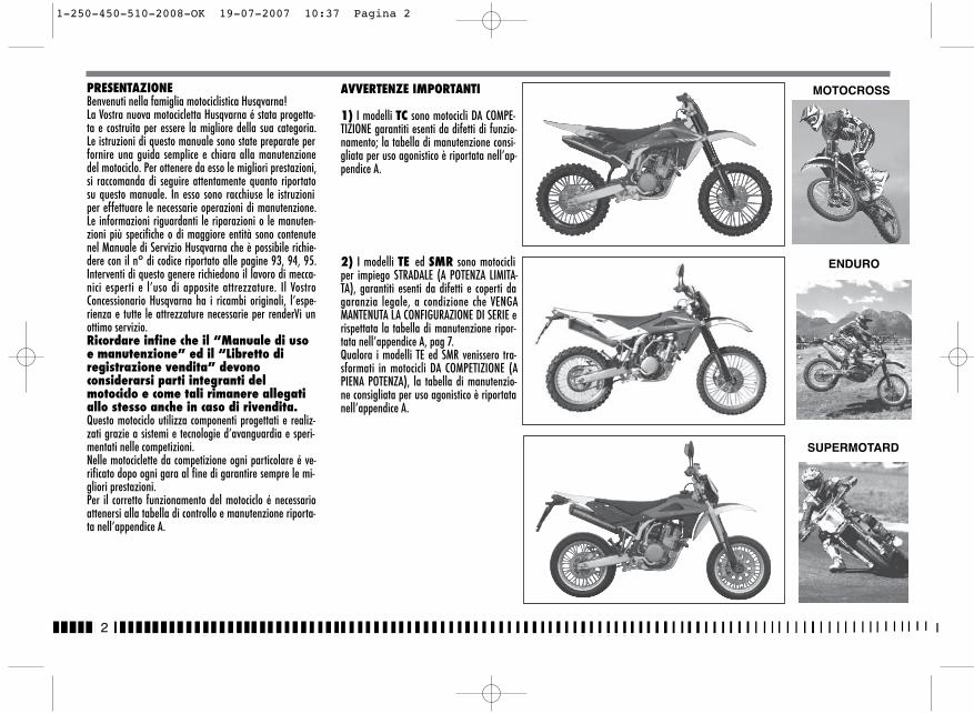
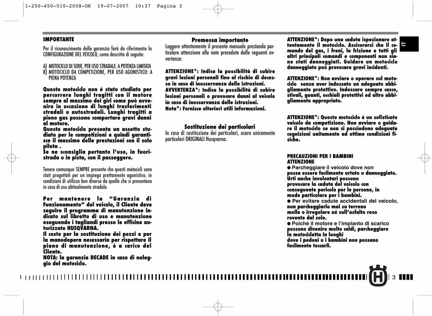
PRESENTAZIONEBenvenuti nella famiglia motociclistica Husqvarna! La Vostra nuova motocicletta Husqvarna é stata progetta-ta e costruita per essere la migliore della sua categoria.Le istruzioni di questo manuale sono state preparate perfornire una guida semplice e chiara alla manutenzionedel motociclo. Per ottenere da esso le migliori prestazioni,si raccomanda di seguire attentamente quanto riportatosu questo manuale. In esso sono racchiuse le istruzioniper effettuare le necessarie operazioni di manutenzione.Le informazioni riguardanti le riparazioni o le manuten-zioni più specifiche o di maggiore entità sono contenutenel Manuale di Servizio Husqvarna che è possibile richie-dere con il n° di codice riportato alle pagine 93, 94, 95.Interventi di questo genere richiedono il lavoro di mecca-nici esperti e l’uso di apposite attrezzature. Il VostroConcessionario Husqvarna ha i ricambi originali, l’espe-rienza e tutte le attrezzature necessarie per renderVi unottimo servizio.Ricordare infine che il “Manuale di usoe manutenzione” ed il “Libretto diregistrazione vendita” devonoconsiderarsi parti integranti delmotociclo e come tali rimanere allegatiallo stesso anche in caso di rivendita. Questo motociclo utilizza componenti progettati e realiz-zati grazie a sistemi e tecnologie d’avanguardia e speri-mentati nelle competizioni.Nelle motociclette da competizione ogni particolare é ve-rificato dopo ogni gara al fine di garantire sempre le mi-gliori prestazioni.Per il corretto funzionamento del motociclo é necessarioattenersi alla tabella di controllo e manutenzione riporta-ta nell’appendice A.
MOTOCROSS
SUPERMOTARD
ENDURO
AVVERTENZE IMPORTANTI
1) I modelli TC sono motocicli DA COMPE-TIZIONE garantiti esenti da difetti di funzio-namento; la tabella di manutenzione consi-gliata per uso agonistico è riportata nell’ap-pendice A.
2) I modelli TE ed SMR sono motocicliper impiego STRADALE (A POTENZA LIMITA-TA), garantiti esenti da difetti e coperti dagaranzia legale, a condizione che VENGAMANTENUTA LA CONFIGURAZIONE DI SERIE erispettata la tabella di manutenzione ripor-tata nell’appendice A, pag 7.Qualora i modelli TE ed SMR venissero tra-sformati in motocicli DA COMPETIZIONE (APIENA POTENZA), la tabella di manutenzio-ne consigliata per uso agonistico è riportatanell’appendice A.
1-250-450-510-2008-OK 19-07-2007 10:37 Pagina 2
3
IT
IMPORTANTE
Per il riconoscimento della garanzia farà da riferimento laCONFIGURAZIONE DEL VEICOLO, come descritto di seguito:
A) MOTOCICLO DI SERIE, PER USO STRADALE: A POTENZA LIMITATAB) MOTOCICLO DA COMPETIZIONE, PER USO AGONISTICO: A
PIENA POTENZA
Questo motociclo non é stato studiato perpercorrere lunghi tragitti con il motoresempre al massimo dei giri come può avve-nire in occasione di lunghi trasferimentistradali o autostradali. Lunghi tragitti apieno gas possono comportare gravi dannial motore.Questo motociclo presenta un assetto stu-diato per le competizioni e quindi garanti-sce il massimo delle prestazioni con il solopilota .Se ne sconsiglia pertanto l’uso, in fuori-strada o in pista, con il passeggero.
Tenere comunque SEMPRE presente che questi motocicli sonostati progettati per un impiego prettamente agonistico, incondizioni di utilizzo ben diverse da quelle che si presentanoin caso di uso abitualmente stradale.
Per mantenere la “Garanzia diFunzionamento” del veicolo, il Cliente deveseguire il programma di manutenzione in-dicato sul libretto di uso e manutenzioneeseguendo i tagliandi presso le officine au-torizzate HUSQVARNA.Il costo per la sostituzione dei pezzi e perla manodopera necessaria per rispettare ilpiano di manutenzione, è a carico delCliente.NOTA: la garanzia DECADE in caso di noleg-gio del motociclo.
Premessa importanteLeggere attentamente il presente manuale prestando par-ticolare attenzione alle note precedute dalle seguenti av-vertenze:
ATTENZIONE*: Indica la possibilità di subiregravi lesioni personali fino al rischio di deces-so in caso di inosservanza delle istruzioni.AVVERTENZA*: Indica la possibilità di subirelesioni personali o provocare danni al veicoloin caso di inosservanza delle istruzioni.Nota*: Fornisce ulteriori utili informazioni.
Sostituzione dei particolariIn caso di sostituzione dei particolari, usare unicamenteparticolari ORIGINALI Husqvarna.
ATTENZIONE*: Dopo una caduta ispezionare at-tentamente il motociclo. Assicurarsi che il co-mando del gas, i freni, la frizione e tutti glialtri principali comandi e componenti non sia-no stati danneggiati. Guidare un motociclodanneggiato può provocare gravi incidenti.
ATTENZIONE*: Non avviare o operare sul moto-ciclo senza aver indossato un adeguato abbi-gliamento protettivo. Indossare sempre casco,stivali, guanti, occhiali protettivi ed altro abbi-gliamento appropriato.
ATTENZIONE*: Questo motociclo è un sofisticatoveicolo da competizione. Non avviare o guida-re il motociclo se non si possiedono adeguatecognizioni unitamente ad ottime condizioni fi-siche.
PRECAUZIONI PER I BAMBINIATTENZIONE� Parcheggiare il veicolo dove nonpossa essere facilmente urtato o danneggiato.Urti anche involontari possonoprovocare la caduta del veicolo conconseguente pericolo per le persone, inmodo particolare per i bambini.� Per evitare cadute accidentali del veicolo,non parcheggiarlo mai su terrenomolle o irregolare né sull’asfalto resorovente dal sole.� Poiché il motore e l’impianto di scaricopossono divenire molto caldi, parcheggiarela motocicletta in luoghidove i pedoni o i bambini non possanofacilmente toccarli.
1-250-450-510-2008-OK 19-07-2007 10:37 Pagina 3
4
SOMMARIO Pag.
PRESENTAZIONE.....................................................................2AVVERTENZE IMPORTANTI .......................................................2DATI PER L’IDENTIFICAZIONE..................................................5DATI TECNICI ..........................................................................8TABELLA DI LUBRIFICAZIONE, RIFORNIMENTI .........................10COMANDI .............................................................................11ISTRUZIONI PER L’USO DEL MOTOCICLO......................................21LIMITI DI USURA ..................................................................68IMPIANTO ACCENSIONE/IMPIANTO ELETTRICO.................77-88ATTREZZI SPECIALI................................................................89COPPIE DI SERRAGGIO..........................................................90KIT ......................................................................................92PARTI OPTIONAL .............................................................93-95APPENDICE ......................................................................…96OPERAZIONI DI PRECONSEGNA .............................................98 INDICE ALFABETICO ..............................................................99MANUTENZIONE PERIODICA/REGOLAZIONI ...........APPENDICE A
Note� Le indicazioni di destra e sinistra si riferiscono ai due lati
del motociclo rispetto al senso di marcia.
� Z: n° denti� A: Austria
AUS: AustraliaB: BelgioBR: BrasileCDN: CanadaCH: SvizzeraD: GermaniaE: SpagnaF: FranciaFIN: FinlandiaGB: Gran BretagnaI: ItaliaJ: GiapponeUSA: Stati Uniti d’America
� Dove non diversamente specificato, i dati e le prescrizionisi riferiscono a tutte le Nazioni.
1-250-450-510-2008-OK 19-07-2007 10:37 Pagina 4
5
IT
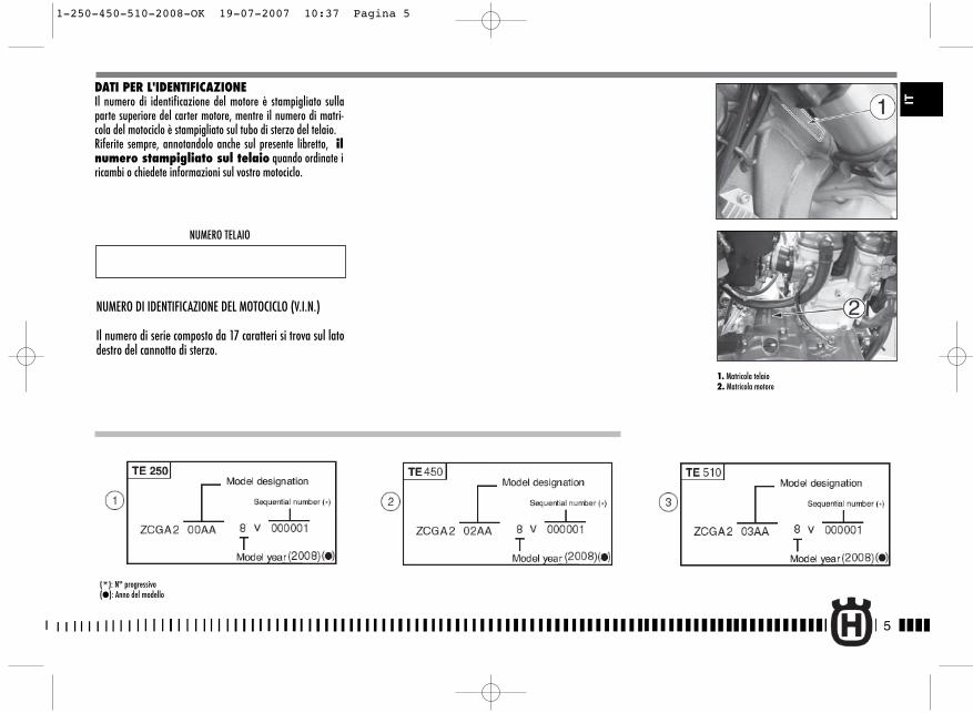
DATI PER L'IDENTIFICAZIONEIl numero di identificazione del motore è stampigliato sullaparte superiore del carter motore, mentre il numero di matri-cola del motociclo è stampigliato sul tubo di sterzo del telaio.Riferite sempre, annotandolo anche sul presente libretto, ilnumero stampigliato sul telaio quando ordinate iricambi o chiedete informazioni sul vostro motociclo.
NUMERO TELAIO
NUMERO DI IDENTIFICAZIONE DEL MOTOCICLO (V.I.N.)
Il numero di serie composto da 17 caratteri si trova sul latodestro del cannotto di sterzo.
(*): N° progressivo(�): Anno del modello
1. Matricola telaio2. Matricola motore
1-250-450-510-2008-OK 19-07-2007 10:37 Pagina 5
6
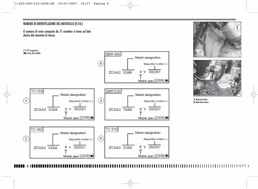
NUMERO DI IDENTIFICAZIONE DEL MOTOCICLO (V.I.N.)
Il numero di serie composto da 17 caratteri si trova sul latodestro del cannotto di sterzo.
(*): N° progressivo(�): Anno del modello
1. Matricola telaio2. Matricola motore
1-250-450-510-2008-OK 19-07-2007 10:37 Pagina 6
7
IT
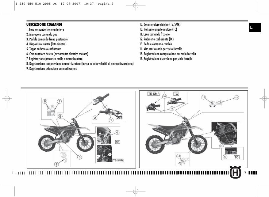
UBICAZIONE COMANDI1. Leva comando freno anteriore2. Manopola comando gas3. Pedale comando freno posteriore4. Dispositivo starter (lato sinistro)5. Tappo serbatoio carburante6. Commutatore destro (avviamento elettrico motore)7. Registrazione precarico molla ammortizzatore8. Registrazione compressione ammortizzatore (bassa ed alta velocità di ammortizzazaione)9. Registrazione estensione ammortizzatore
10. Commutatore sinistro (TE, SMR)10. Pulsante arresto motore (TC)11. Leva comando frizione12. Rubinetto carburante (TC)13. Pedale comando cambio14. Vite scarico aria per stelo forcella15. Registrazione compressione per stelo forcella16. Registrazione estensione per stelo forcella
1-250-450-510-2008-OK 19-07-2007 10:37 Pagina 7
8
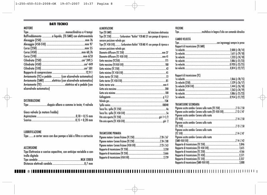
DATI TECNICIMOTORETipo....................................................monocilindrico a 4 tempiRaffreddamento ..............a liquido, (TE-SMR) con elettroventolaAlesaggio (250) .............................................................mm 76 Alesaggio (450-510) ......................................................mm 97Corsa (250) ...................................................................mm 55Corsa (450) ..............................................................mm 60,76Corsa (510) .................................................................mm 67,8 Cilindrata (250) ........................................................cm3 249,5 Cilindrata (450) ...........................................................cm3 449Cilindrata (510) ............................................................cm3 501 Rapporto di compressione ...............................................12,9:1 Avviamento (TC) a pedale ............ (con alzavalvole automatico)Avviamento (SMR) ...........elettrico (con alzavalvole automatico)Avviamento (TE) .................................elettrico ed a pedale (conalzavalvole automatico)
DISTRIBUZIONETipo ..........................doppio albero a camme in testa; 4 valvole
Gioco valvole (a motore freddo)Aspirazione .......................................................0,10 ÷ 0,15 mmScarico..............................................................0,15 ÷ 0,20 mm
LUBRIFICAZIONETipo .......a carter secco con due pompe a lobi e filtro a cartuccia
ACCENSIONETipo Elettronica a scarica capacitiva, con anticipo variabile a con-trollo digitaleTipo candela ............................................................NGK CR8EBDistanza elettrodi candela .............................................0,7 mm
ALIMENTAZIONETipo (TE-SMR)................................................................Ad iniezione elettronicaTipo (TC 250) .............. Carburatore ”Keihin” FCR-MX 37 con pompa di ripresa esensore posizione valvola gasTipo (TC 450-510).......... Carburatore Keihin” FCR-MX 41 con pompa di ripresa esensore posizione valvola gasDiametro diffusore (TC 250) ..................................................................mm 37Diametro diffusore (TC 450-510) ............................................................mm 41Getto massimo (TC250)...............................................................................175Getto massimo (TC450-510).........................................................................180Getto minimo (TC 250)..................................................................................42Getto minimo (TC 450-510) ...........................................................................45Getto starter (TC 250) ...................................................................................72Getto starter (TC 450-510).............................................................................85Getto starter aria .....................................................................................mm 4Getto aria massimo .....................................................................................200Getto aria minimo .......................................................................................100Galleggiante ............................................................................................g 11,2Valvola gas.................................................................................................15MSpillo conico............................................................................................OBDVRTacca fiss. spillo (TC 250) ..............................................................................4aTacca fiss. spillo (TC 450-510) . ......................................................................5aVite aria aperta (TC 250) ..................................................................giri 1+1/2Vite aria aperta (TC 450-510) ...................................................................giri 2
TRASMISSIONE PRIMARIAPignone motore- Corona frizione (TC 250) ...............................................Z 20- Z 67Pignone motore- Corona frizione (TE 250) ...............................................Z 24- Z 88Pignone motore- Corona frizione (450-510) .............................................Z 23- Z 63Rapporto di trasmissione (TC 250)..................................................................3,350Rapporto di trasmissione (TE 250)..................................................................3,666Rapporto di trasmissione (450-510)................................................................2,739
FRIZIONETipo........................................multidisco in bagno d’olio con comando idraulico
CAMBIO VELOCITÁTipo ..................................................................con ingranaggi sempre in presaRapporti di trasmissione (TE-SMR)1a velocità ...............................................................................2,000 (z 28/14)2a velocità ................................................................................1,611 (z 29/18)3a velocità ...............................................................................1,333 (z 24/18)4a velocità ...............................................................................1,086 (z 25/23)5a velocità...............................................................................0,920 (z 23/25)6a velocità ...............................................................................0,814 (z 22/27)
Rapporti di trasmissione (TC)1a velocità ...............................................................................1,866 (z 28/15)2a velocità (250)......................................................................1,529 (z 26/17)2a velocità (450-510) ...............................................................1,444 (z 26/18)3a velocità ...............................................................................1,263 (z 24/19)4a velocità ...............................................................................1,086 (z 25/23)5a velocità ...............................................................................0,954 (z 21/22)
TRASMISSIONE SECONDARIAPignone uscita cambio- Corona sulla ruota (TE 250) ...........................Z 13- Z 50Pignone uscita cambio- Corona sulla ruota (TE 450-510).....................Z 13- Z 47Pignone uscita cambio- Corona sulla ruota (TC 450) ............................................................................................Z 14- Z 50Pignone uscita cambio- Corona sulla ruota (TC 250) ............................................................................................Z 12- Z 50Pignone uscita cambio- Corona sulla ruota (TC 510) ............................................................................................Z 14- Z 47Pignone uscita cambio- Corona sulla ruota (SMR 450-510) ..................................................................................Z 14- Z 42Rapporto di trasmissione (TE 250)........................................................... 3,846Rapporto di trasmissione (TE 450-510)..................................................... 3,615Rapporto di trasmissione (TC 250) ............................................................4,166Rapporto di trasmissione (TC 450)............................................................3,571Rapporto di trasmissione (TC 510)............................................................3,357Rapporto di trasmissione (SMR 450-510)........................................................3,000
1-250-450-510-2008-OK 19-07-2007 10:37 Pagina 8
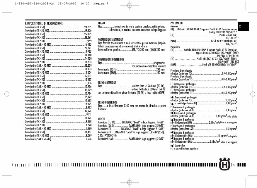
RAPPORTI TOTALI DI TRASMISSIONE1a velocità (TE 250).............................................................28,2051a velocità (TE 450-510) .......................................................19,8061a velocità (TC 250) ............................................................26,0551a velocità (TC 450) .............................................................18,2611a velocità (TC 510)...............................................................17,1591a velocità (SMR 450-510) ...................................................16,4352a velocità (TE 250).............................................................22,7212a velocità (TE 450-510) .....................................................15,9552a velocità (TC 250) ............................................................21,3482a velocità (TC 450) .............................................................14,1302a velocità (TC 510) ............................................................13,2832a velocità (SMR 450-510) ...................................................13,2393a velocità (TE 250) ............................................................18,8033a velocità (TE 450-510) .....................................................13,2043a velocità (TC 250) .............................................................17,6313a velocità (TC 450) ............................................................12,3573a velocità (TC 510) .............................................................11,6163a velocità (SMR 450-510) ..................................................10,9564a velocità (TE 250) .............................................................15,3294a velocità (TE 450-510) ......................................................10,7644a velocità (TC 250) .............................................................15,1724a velocità (TC 450) ............................................................10,6334a velocità (TC 510) ..............................................................9,9954a velocità (SMR 450-510) ....................................................8,9325a velocità (TE 250) ............................................................12,9745a velocità (TE 450-510) ........................................................9,1115a velocità (TC 250) ............................................................13,3245a velocità (TC 450) ..............................................................9,3385a velocità (TC 510) ..............................................................8,7785a velocità (SMR 450-510) .....................................................7,5606a velocità (TE 250) .............................................................11,4916a velocità (TE 450-510) .......................................................8,0696a velocità (SMR 450-510) ....................................................6,696
TELAIOTipo...................monotrave, in tubi a sezione circolare, rettangolare,
ellissoidale, in acciaio; telaietto posteriore in lega leggera.
SOSPENSIONE ANTERIORETipo forcella teleidraulica a steli rovesciati e perno avanzato (regola-bile in compressione ed estensione); steli ø 50 mm Corsa sull’asse gambe ...................(TE, TC) 300 mm; (SMR) 250 mm
SOSPENSIONE POSTERIORETipo ................................................................................progressiva
con monoammortizzatore idraulicoCorsa ruota (TC-TE) ..............................................................296 mmCorsa ruota (SMR) ...............................................................290 mm
FRENO ANTERIORETipo . . . . . . . . . . . . . . . . . . . . . . .a disco fisso ∅ 260 mm (TE, TC),
a disco flottante Ø 320 mm (SMR) con comando idraulico e pinza flottante (TE, TC) o fissa radiale (SMR)
FRENO POSTERIORETipo..... a disco flottante Ø240 mm con comando idraulico e pinzaflottante
CERCHIAnteriore (TE, TC)...........TAKASAGO “Excel” in lega leggera: 1,6x21”Anteriore (SMR)........................SANREMO in lega leggera: 3,50x17”Posteriore (TE) .............TAKASAGO “Excel” in lega leggera: 2,15x18”Posteriore (TC) ...TAKASAGO “Excel” in lega leggera: 1,85x19”(250);2,15x19”(450-510)Posteriore (SMR) ......................SANREMO in lega leggera: 4,25x17”
PNEUMATICIAnteriore (TE)......Michelin ENDURO COMP. 3 oppure Pirelli MT 83 Scorpion oppure
Dunlop 54R-D907; 90/90x21"(TC) .........................................................................Pirelli 51R-MT 32A;
80/100 x 21”(SMR)..........................................................Pirelli MTR 21 DRAGON-EVO;
120/70-17”Posteriore(TE) . . . . . . . Michelin ENDURO COMP. 3 oppure Pirelli MT 83 Scorpion ;
oppure Dunlop 70R-D907; 120/90x18” (250);140/80x18” (450-510).
(TC) . . . . . . . . . . . . . . . . . . Pirelli NHS (62) MT 32; 100/90x19” (250);110/90x19” (450-510)
(SMR) . . . . . . . . . . . . . . . . . . . . . . . Pirelli MTR 22 DRAGON-EVO; 150/60x17”
Pressione di gonfiaggioa freddo (anteriore TC) .................................................0,9÷1,0 Kg/cm2Pressione di gonfiaggioa freddo (posteriore TC) ...............................................0,8÷0,9 Kg/cm2
(*) Pressione di gonfiaggioa freddo (anteriore TE) .................................................0,9..1,0 Kg/cm2(*) Pressione di gonfiaggioa freddo (posteriore TE)................................................0,8..0,9 Kg/cm2
(�) Pressione di gonfiaggioa freddo (anteriore TE) ........................................................1,1 Kg/cm2(�) a freddo (posteriore TE)................................................1,0 Kg/cm2(*)Pressione di gonfiaggioa freddo (anteriore SMR) .................................................... 1,4 kg/cm
2(�)Pressione di gonfiaggioa freddo (anteriore SMR) ................................... 1,8 kg/cm2 solo pilota(�)Pressione di gonfiaggioa freddo (anteriore SMR) .............................2,0 kg/cm2pilota e passeggero(*)Pressione di gonfiaggioa freddo (posteriore SMR)................................................... 1,6 kg/cm2
(�)Pressione di gonfiaggioa freddo (posteriore SMR) ...........................................2,0 kg/cm2 solo pilota(�)Pressione di gonfiaggioa freddo (posteriore SMR) ..............................2,2 kg/cm2 pilota e passeggero(�) Uso stradale(*) In caso di impiego agonistico
9
IT
1-250-450-510-2008-OK 19-07-2007 10:37 Pagina 9
10
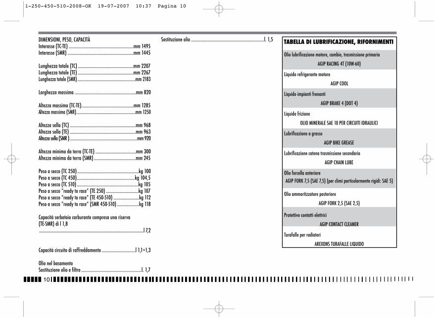
DIMENSIONI, PESO, CAPACITÀInterasse (TC-TE) ........................................................mm 1495 Interasse (SMR) .........................................................mm 1445
Lunghezza totale (TC) ................................................mm 2207 Lunghezza totale (TE) ................................................mm 2267Lunghezza totale (SMR) ..................................................mm 2183
Larghezza massima .....................................................mm 820
Altezza massima (TC-TE).............................................mm 1285Altezza massima (SMR)...................................................mm 1250
Altezza sella (TC) .........................................................mm 968Altezza sella (TE) .........................................................mm 963Altezza sella (SMR ) ..........................................................mm 920
Altezza minima da terra (TC-TE) ...................................mm 300Altezza minima da terra (SMR) ....................................mm 245
Peso a secco (TC 250) .....................................................kg 100Peso a secco (TC 450)..................................................kg 104,5Peso a secco (TC 510) .....................................................kg 105 Peso a secco “ready to race” (TE 250) ............................kg 107Peso a secco “ready to race” (TE 450-510) ......................kg 112Peso a secco “ready to race” (SMR 450-510) ...................kg 118
Capacità serbatoio carburante compresa una riserva(TE-SMR) di l 1,8..................................................................................................l 7,2
Capacità circuito di raffreddamento .............................l 1,1÷1,3
Olio nel basamentoSostituzione olio e filtro ....................................................l. 1,7
Sostituzione olio ...............................................................l. 1,5 TABELLA DI LUBRIFICAZIONE, RIFORNIMENTI
Olio lubrificazione motore, cambio, trasmissione primaria
AGIP RACING 4T (10W-60)
Liquido refrigerante motore
AGIP COOL
Liquido impianti frenanti
AGIP BRAKE 4 (DOT 4)
Liquido frizione
OLIO MINERALE SAE 10 PER CIRCUITI IDRAULICI
Lubrificazione a grasso
AGIP BIKE GREASE
Lubrificazione catena trasmissione secondaria
AGIP CHAIN LUBE
Olio forcella anterioreAGIP FORK 7,5 (SAE 7,5) (per climi particolarmente rigidi: SAE 5)
Olio ammortizzatore posteriore
AGIP FORK 2,5 (SAE 2,5)
Protettivo contatti elettrici
AGIP CONTACT CLEANER
Turafalle per radiatori
AREXONS TURAFALLE LIQUIDO
1-250-450-510-2008-OK 19-07-2007 10:37 Pagina 10
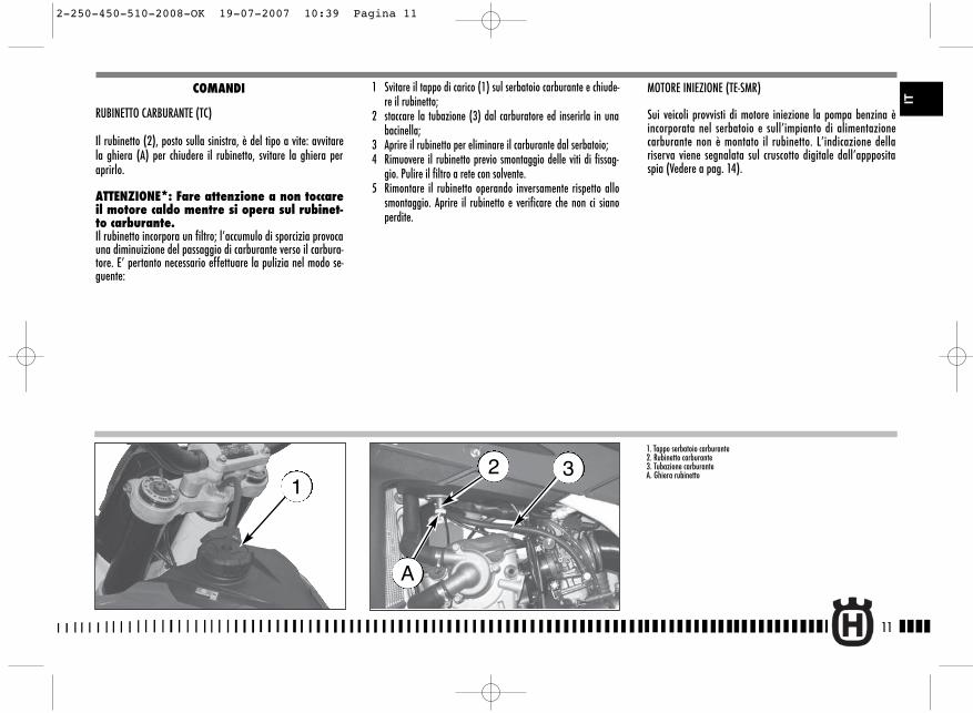
MOTORE INIEZIONE (TE-SMR)
Sui veicoli provvisti di motore iniezione la pompa benzina èincorporata nel serbatoio e sull’impianto di alimentazionecarburante non è montato il rubinetto. L’indicazione dellariserva viene segnalata sul cruscotto digitale dall’apppositaspia (Vedere a pag. 14).
11
IT
1 Svitare il tappo di carico (1) sul serbatoio carburante e chiude-re il rubinetto;
2 staccare la tubazione (3) dal carburatore ed inserirla in unabacinella;
3 Aprire il rubinetto per eliminare il carburante dal serbatoio;4 Rimuovere il rubinetto previo smontaggio delle viti di fissag-
gio. Pulire il filtro a rete con solvente.5 Rimontare il rubinetto operando inversamente rispetto allo
smontaggio. Aprire il rubinetto e verificare che non ci sianoperdite.
COMANDI
RUBINETTO CARBURANTE (TC)
Il rubinetto (2), posto sulla sinistra, è del tipo a vite: avvitarela ghiera (A) per chiudere il rubinetto, svitare la ghiera peraprirlo.
ATTENZIONE*: Fare attenzione a non toccareil motore caldo mentre si opera sul rubinet-to carburante. Il rubinetto incorpora un filtro; l’accumulo di sporcizia provocauna diminuizione del passaggio di carburante verso il carbura-tore. E’ pertanto necessario effettuare la pulizia nel modo se-guente:
1. Tappo serbatoio carburante2. Rubinetto carburante3. Tubazione carburanteA. Ghiera rubinetto
132
A
2-250-450-510-2008-OK 19-07-2007 10:39 Pagina 11
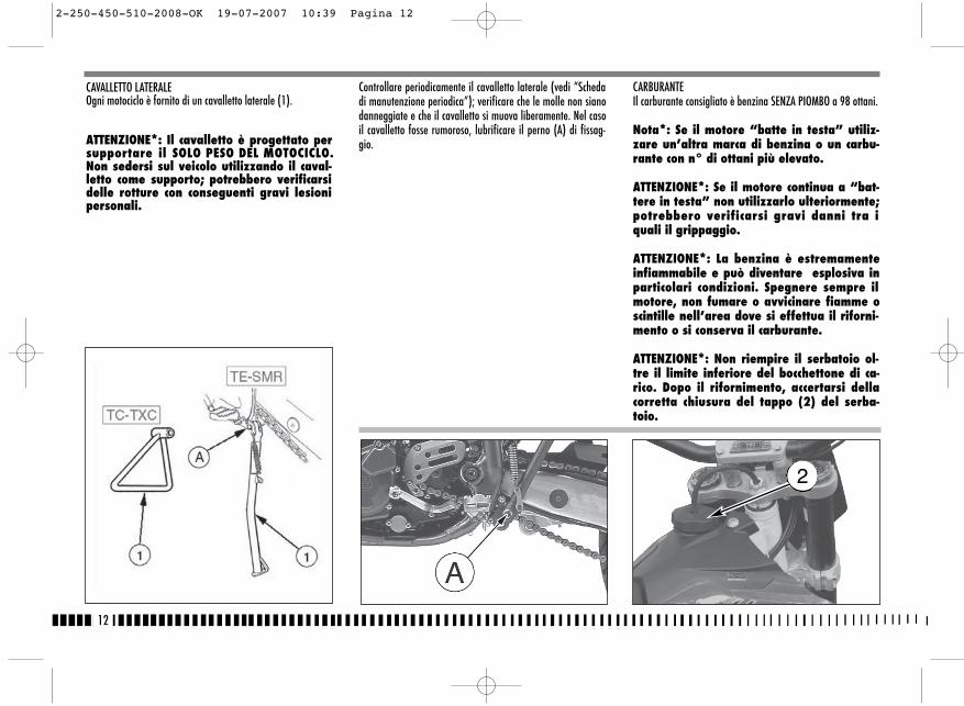
CARBURANTEIl carburante consigliato è benzina SENZA PIOMBO a 98 ottani.
Nota*: Se il motore “batte in testa” utiliz-zare un’altra marca di benzina o un carbu-rante con n° di ottani più elevato.
ATTENZIONE*: Se il motore continua a “bat-tere in testa” non utilizzarlo ulteriormente;potrebbero verificarsi gravi danni tra iquali il grippaggio.
ATTENZIONE*: La benzina è estremamenteinfiammabile e può diventare esplosiva inparticolari condizioni. Spegnere sempre ilmotore, non fumare o avvicinare fiamme oscintille nell’area dove si effettua il riforni-mento o si conserva il carburante.
ATTENZIONE*: Non riempire il serbatoio ol-tre il limite inferiore del bocchettone di ca-rico. Dopo il rifornimento, accertarsi dellacorretta chiusura del tappo (2) del serba-toio.
Controllare periodicamente il cavalletto laterale (vedi “Schedadi manutenzione periodica”); verificare che le molle non sianodanneggiate e che il cavalletto si muova liberamente. Nel casoil cavalletto fosse rumoroso, lubrificare il perno (A) di fissag-gio.
12
CAVALLETTO LATERALEOgni motociclo è fornito di un cavalletto laterale (1).
ATTENZIONE*: Il cavalletto è progettato persupportare il SOLO PESO DEL MOTOCICLO.Non sedersi sul veicolo utilizzando il caval-letto come supporto; potrebbero verificarsidelle rotture con conseguenti gravi lesionipersonali.
2
2-250-450-510-2008-OK 19-07-2007 10:39 Pagina 12
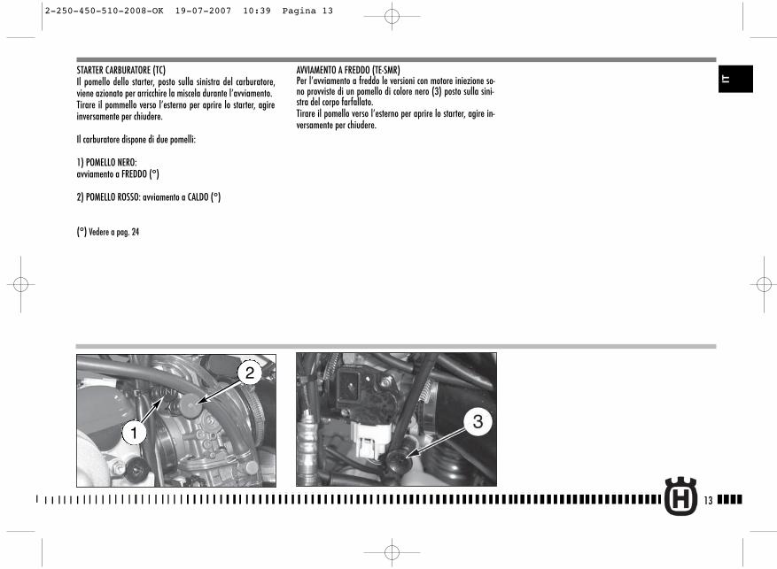
STARTER CARBURATORE (TC)Il pomello dello starter, posto sulla sinistra del carburatore,viene azionato per arricchire la miscela durante l’avviamento.Tirare il pommello verso l’esterno per aprire lo starter, agireinversamente per chiudere.
Il carburatore dispone di due pomelli:
1) POMELLO NERO: avviamento a FREDDO (°)
2) POMELLO ROSSO: avviamento a CALDO (°)
(°) Vedere a pag. 24
AVVIAMENTO A FREDDO (TE-SMR)Per l’avviamento a freddo le versioni con motore iniezione so-no provviste di un pomello di colore nero (3) posto sulla sini-stra del corpo farfallato.Tirare il pomello verso l’esterno per aprire lo starter, agire in-versamente per chiudere.
13
IT
2
1
2-250-450-510-2008-OK 19-07-2007 10:39 Pagina 13
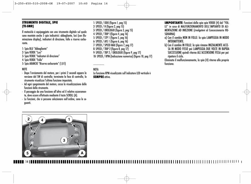
1- SPEED / ODO (figura 1, pag 15)2- SPEED / H (figura 2, pag 15)3- SPEED / OROLOGIO (figura 3, pag 15)4- SPEED / TRIP 1(figura 4, pag 16)5- SPEED / STP 1 (figura 5, pag 16)6- SPEED / AVS 1 (figura 6, pag 16)7- SPEED / SPEED MAX (figura 7, pag 17)8- SPEED / TRIP 2 (figura 8, pag 17)9- SPEED / TRP 2 / OROLOGIO (figura 9, pag 17)10- SPEED / RPM (Indicazione numerica) (figura 10, pag 17)
.................
NOTALa funzione RPM visualizzata sull’indicatore LED verticale èSEMPRE attiva.
IMPORTANTE: Funzioni della spia spia VERDE (4) del “FOL-LE” in caso di MALFUNZIONAMENTO DELL’IMPIANTO DI ALI-MENTAZIONE AD INIEZIONE (rivolgetevi al Concessionario HU-SQVARNA)a) Con il cambio NON IN FOLLE: la spia LAMPEGGIA IN MODO
INTERMITTENTE.b) Con il cambio IN FOLLE: la spia rimane INIZIALMENTE ACCE-
SA IN MODO FISSO poi LAMPEGGIA DUE VOLTE IN RAPIDASUCCESSIONE quindi ritorna ALL’ACCENSIONE FISSA per poiripetere il ciclo.
Eliminato il malfunzionamento, la spia (4) ritorna alla propriafunzione.
14
STRUMENTO DIGITALE, SPIE(TE-SMR)
Il motociclo è equipaggiato con uno strumento digitale sul qualesono montate anche 5 spie indicatrici: abbagliante, luci (con illu-minazione display), indicatori di direzione, folle e riserva carbu-rante.
1- Spia BLU “Abbagliante”2- Spia VERDE ”Luci”3- Spia VERDE “Indicatori di direzione”4- Spia VERDE “Folle”5- Spia ARANCIO “Riserva carburante” (1,8 l)
NOTE- Dopo l’avviamento del motore, per i primi 2 secondi appare la
versione del SW di controllo; terminata la fase di controllo, lostrumento visualizza l’ultima funzione impostata.
- Ad ogni spegnimento del motore, cessa la visualizzazione dellefunzioni dello strumento.
- Il passaggio da una funzione all’altra ed il relativo azzeramen-to, deve essere effettuato mediante il tasto SCROLL (A).
- Le funzioni, che si possono selezionare nell’ordine, sono le se-guenti.
2
5
4 1
3
A
3-250-450-510-2008-OK 19-07-2007 10:40 Pagina 14

15
2- SPEED / H / RPM (figura 2)
- SPEED: velocità- Indicazione max: 299 kmh o 299 mph;- H: Indica le ore di funzionamento del motore (il dato è salvato
in memoria permanente ogni 10 minuti)- Indicazione max: 9999:59;- RPM: regime motore visualizzato sull’indicatore LED verticale.
1- SPEED (kmh o mph) / ODO / RPM(figura 1)
- SPEED: velocità del veicolo- Indicazione max: 299 kmh o 299 mph;- ODO: odometro- Indicazione max: 99999 km;- RPM: regime motore visualizzato sull’indicatore LED verticale
Per passare da km a miles o da miles a km procedere nel modoseguente:1) visualizzare la figura 1, spegnere il motore e premere il pul-
sante SCROLL (A).2) avviare il motore tenendo premuto per 3 secondi il pulsante
SCROLL (A).Per conferma dell’avvenuta conversione si attiveranno, per 3 se-condi, “SET” ed i segmenti Miles e mph oppure km e kmh; succes-sivamente si tornerà alla funzionalità standard della figura 1.
NOTAAl termine dell’operazione descritta, il datoODO verrà convertito e tutti gli altri dati azze-rati ( il CONTA H rimane invariato).
IT
3- SPEED / CLOCK / RPM (figura 3)
- SPEED: velocità- Indicazione max: 299 kmh o 299 mph;- CLOCK: orologio- Indicazione da 0:00 a 23:59:59 ( il dato verrà
perso al distacco della batteria).Per regolare l’orologio, premere il pulsante SCROLL (A) per piùdi 3 secondi per incrementare le ore; rilasciato il pulsante, dopo3 secondi è possibile incrementare i minuti;- RPM: regime motore visualizzato sull’indicatore LED verticale.
3-250-450-510-2008-OK 19-07-2007 10:40 Pagina 15
16
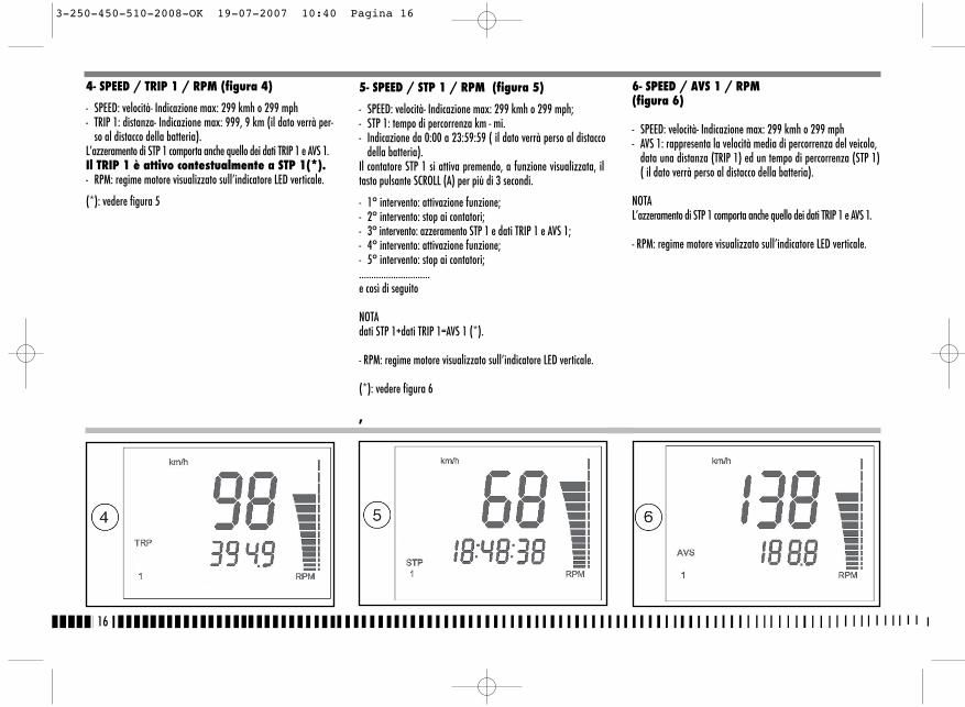
6- SPEED / AVS 1 / RPM (figura 6)
- SPEED: velocità- Indicazione max: 299 kmh o 299 mph- AVS 1: rappresenta la velocità media di percorrenza del veicolo,
data una distanza (TRIP 1) ed un tempo di percorrenza (STP 1)( il dato verrà perso al distacco della batteria).
NOTAL’azzeramento di STP 1 comporta anche quello dei dati TRIP 1 e AVS 1.
- RPM: regime motore visualizzato sull’indicatore LED verticale.
4- SPEED / TRIP 1 / RPM (figura 4)
- SPEED: velocità- Indicazione max: 299 kmh o 299 mph- TRIP 1: distanza- Indicazione max: 999, 9 km (il dato verrà per-
so al distacco della batteria).L’azzeramento di STP 1 comporta anche quello dei dati TRIP 1 e AVS 1.Il TRIP 1 è attivo contestualmente a STP 1(*).- RPM: regime motore visualizzato sull’indicatore LED verticale.
(*): vedere figura 5
5- SPEED / STP 1 / RPM (figura 5)
- SPEED: velocità- Indicazione max: 299 kmh o 299 mph;- STP 1: tempo di percorrenza km - mi.- Indicazione da 0:00 a 23:59:59 ( il dato verrà perso al distacco
della batteria).Il contatore STP 1 si attiva premendo, a funzione visualizzata, iltasto pulsante SCROLL (A) per più di 3 secondi.
- 1° intervento: attivazione funzione;- 2° intervento: stop ai contatori;- 3° intervento: azzeramento STP 1 e dati TRIP 1 e AVS 1;- 4° intervento: attivazione funzione;- 5° intervento: stop ai contatori;.............................e così di seguito
NOTAdati STP 1+dati TRIP 1=AVS 1 (*).
- RPM: regime motore visualizzato sull’indicatore LED verticale.
(*): vedere figura 6
,
3-250-450-510-2008-OK 19-07-2007 10:40 Pagina 16
17
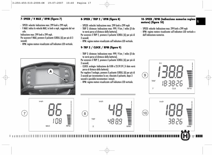
8- SPEED / TRIP 2 / RPM (figura 8)
- SPEED: velocità- Indicazione max: 299 kmh o 299 mph- TRIP 2: distanza- Indicazione max: 999, 9 km / miles (il da-
to verrà perso al distacco della batteria).Per azzerare il TRIP 2, premere il pulsante SCROLL (A) per più di3 secondi;- RPM: regime motore visualizzato sull’indicatore LED verticale.
9- TRP 2 / CLOCK / RPM (figura 9)
- TRIP 2: distanza- Indicazione max: 999, 9 km / miles (il da-to verrà perso al distacco della batteria).
Per azzerare il TRIP 2, premere il pulsante SCROLL (A) per più di3 secondi;- CLOCK: orologio- Indicazione da 0:00 a 23:59:59 ( il dato verrà
perso al distacco della batteria).Per regolare l’orologio, premere il pulsante SCROLL (A) per più di3 secondi per incrementare le ore; rilasciato il pulsante, dopo 3secondi è possibile incrementare i minuti;- RPM: regime motore visualizzato sull’indicatore LED verticale.
10- SPEED /RPM (Indicazione numerica regimemotore) (figura 10)
- SPEED: velocità- Indicazione max: 299 kmh o 299 mph- RPM: regime motore visualizzato sull’indicatore LED verticale e
dall’indicazione numerica.
7- SPEED / V MAX / RPM (figura 7)
- SPEED: velocità- Indicazione max: 299 kmh o 299 mph;- V MAX: indica la velocità MAX, in kmh o mph, raggiunta dal vei-
colo.Indicazione max: 299 kmh o 299 mph.Per azzerare V MAX, premere il pulsante SCROLL (A) per più di 3secondi;- RPM: regime motore visualizzato sull’indicatore LED verticale.
A
IT
3-250-450-510-2008-OK 19-07-2007 10:40 Pagina 17
18
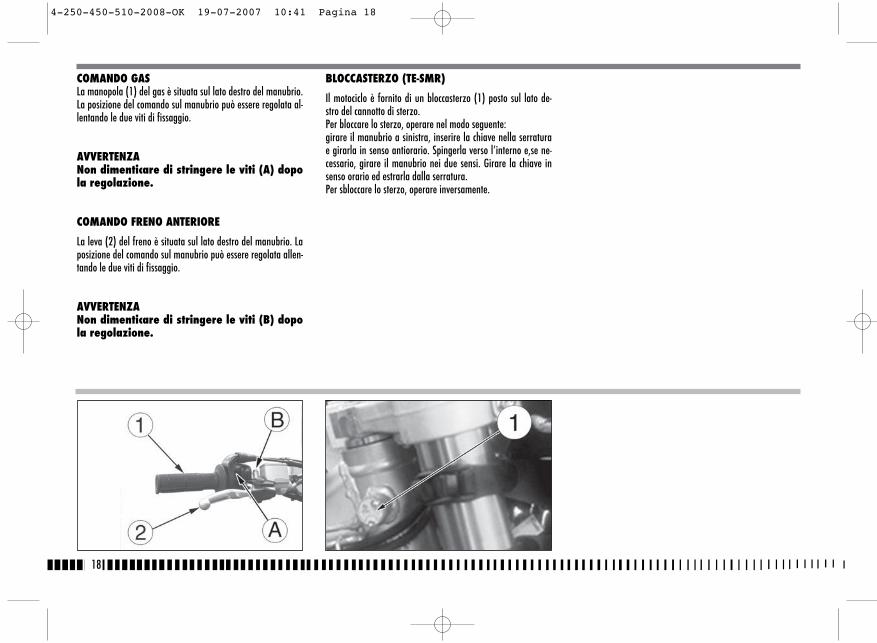
COMANDO GASLa manopola (1) del gas è situata sul lato destro del manubrio.La posizione del comando sul manubrio può essere regolata al-lentando le due viti di fissaggio.
AVVERTENZANon dimenticare di stringere le viti (A) dopola regolazione.
COMANDO FRENO ANTERIORE
La leva (2) del freno è situata sul lato destro del manubrio. Laposizione del comando sul manubrio può essere regolata allen-tando le due viti di fissaggio.
AVVERTENZANon dimenticare di stringere le viti (B) dopola regolazione.
BLOCCASTERZO (TE-SMR)
Il motociclo è fornito di un bloccasterzo (1) posto sul lato de-stro del cannotto di sterzo.Per bloccare lo sterzo, operare nel modo seguente:girare il manubrio a sinistra, inserire la chiave nella serraturae girarla in senso antiorario. Spingerla verso l’interno e,se ne-cessario, girare il manubrio nei due sensi. Girare la chiave insenso orario ed estrarla dalla serratura. Per sbloccare lo sterzo, operare inversamente.
4-250-450-510-2008-OK 19-07-2007 10:41 Pagina 18
19
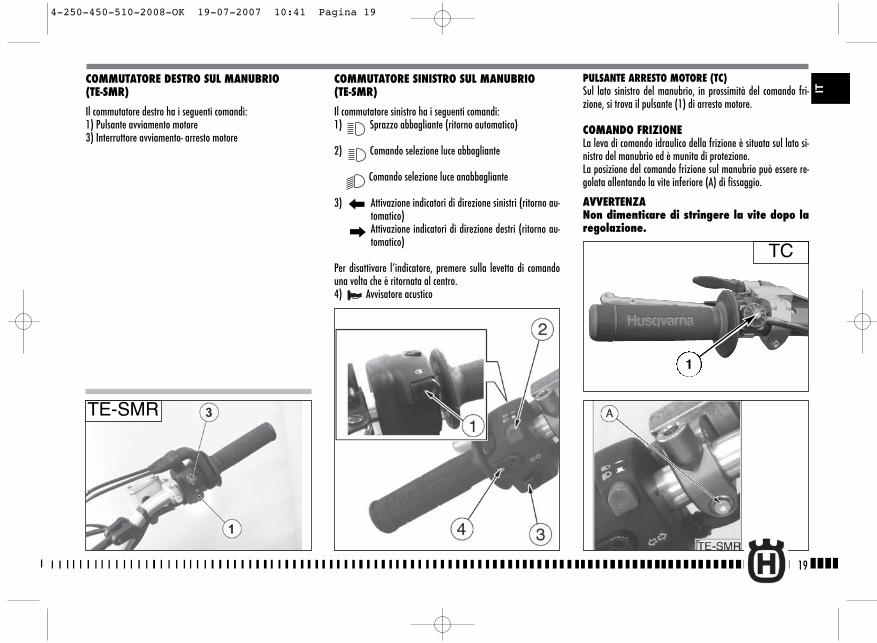
PULSANTE ARRESTO MOTORE (TC)Sul lato sinistro del manubrio, in prossimità del comando fri-zione, si trova il pulsante (1) di arresto motore.
COMANDO FRIZIONELa leva di comando idraulico della frizione è situata sul lato si-nistro del manubrio ed è munita di protezione.La posizione del comando frizione sul manubrio può essere re-golata allentando la vite inferiore (A) di fissaggio.
AVVERTENZANon dimenticare di stringere la vite dopo laregolazione.
COMMUTATORE DESTRO SUL MANUBRIO (TE-SMR)
Il commutatore destro ha i seguenti comandi:1) Pulsante avviamento motore3) Interruttore avviamento- arresto motore
COMMUTATORE SINISTRO SUL MANUBRIO (TE-SMR)
Il commutatore sinistro ha i seguenti comandi:1) Sprazzo abbagliante (ritorno automatico)
2) Comando selezione luce abbagliante
Comando selezione luce anabbagliante
3) Attivazione indicatori di direzione sinistri (ritorno au-tomatico)Attivazione indicatori di direzione destri (ritorno au-tomatico)
Per disattivare l’indicatore, premere sulla levetta di comandouna volta che è ritornata al centro.4) Avvisatore acustico
IT
TC
TE-SMR
1
4-250-450-510-2008-OK 19-07-2007 10:41 Pagina 19
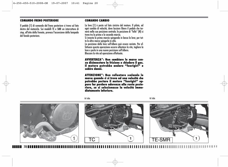
COMANDO CAMBIO
La leva (1) è posta sul lato sinistro del motore. Il pilota, adogni cambio di velocità, deve lasciare libero il pedale che tor-nerà nella sua posizione centrale; la posizione di “folle” (N) sitrova tra la prima e la seconda marcia.Si innesta la prima marcia spingendo in basso la leva; per tut-te le altre marce spingerla in alto.La posizione della leva sull'albero può essere variata. Per ef-fettuare questa operazione occorre allentare la vite, togliere laleva e porla in una nuova posizione sull'albero.Bloccare la vite ad operazione effettuata.
AVVERTENZA*: Non cambiare le marce sen-za disinnestare la frizione e chiudere il gas.Il motore potrebbe andare “fuorigiri” esubire danni.
ATTENZIONE*: Non rallentare scalando lemarce quando ci si trova ad una velocità chepotrebbe portare il motore “fuorigiri” op-pure far perdere aderenza alla ruota poste-riore, se si selezionasse la velocità imme-diatamente inferiore.
20
COMANDO FRENO POSTERIORE
Il pedale (1) di comando del freno posteriore si trova sul latodestro del motociclo. Sui modelli TE e SMR un interruttore distop, all'atto della frenata, provoca l'accensione della lampadadel fanale posteriore.
N: FolleN: Folle
TC 1 1TE-SMR
4-250-450-510-2008-OK 19-07-2007 10:41 Pagina 20
Controllare che il filtro sia pulito.Controllare i raccordi in gomma e le fascette.
8. Controllare il sistema di scaricoControllare i montaggi e verificare eventuali rotture.Controllare il silenziatore.
9. Controllare le coppie di serraggioA. Candela.B. Dadi della testa cilindro.C. Verifica generale dei serraggi.
10. Controllare lo sterzoControllare il gioco dei cuscinetti dello sterzo.
11. Controllare l’impianto elettrico (TE- SMR)Avviare il motore e controllare che i fanali, la luce stop, gli in-dicatori di direzione, le spie sul cruscotto e l’avvisatore acu-stico funzionino regolarmente.
ATTENZIONE*: L’inosservanza di questi controlliquotidiani prima della guida può causare seridanni al veicolo o gravi incidenti.
21
RODAGGIO
La durata e le prestazioni del motore risulteranno maggiori emigliori, una volta effettuato un rodaggio di un paio d’ore pri-ma di impiegareil mezzo a livello agonistico.Duarnte la prima mezz’ora di guida si consiglia di mantenerebassa la velocità, evitando accelerazioni improvvise per nonforzare il motore. Provvedere al cambio dell’olio e a tutte leoperazioni di manutenzione. Dopo la prima mezz’ora di guidaaumentare leggermente il numero di giri, sempre senza forza-re.Non mantenere una velocità eccessivamente bassa una voltainserire le marce alte. Dopo un paio d’ore potete iniziare adusare il mezzo normalmente, a livello agonistico.
CONTROLLI DURANTE IL RODAGGIO
- CONTROLLO TENSIONE RAGGI RUOTE (vedi pag. 76);- CONTROLLO SERRAGGIO RUOTE
(vedi pag. 90-91);- CONTROLLO SERRAGGIO PERNO FORCELLONE (vedi pag. 90);- CONTROLLO REGOLAZIONE CATENA (vedi pag. 49);- CONTROLLO GIOCO CUSCINETTI DI STERZO (vedi pag. 38);- CONTROLLO SERRAGGIO MANUBRIO (vedi pag. 90);- CONTROLLO SERRAGGIO MOTORE AL TELAIO (vedi pag. 90);- CONTROLLO SERRAGGIO RACCORDO ASPIRAZIONE (vedi pag.
90);- CONTROLLO SERRAGGIO DADI TESTA E CILINDRO (vedi pag.
90);
VERIFICARE FREQUENTEMENTE LO STATO DI CARICA DELLA BAT-TERIA (vedi pag. 84.)
ISTRUZIONI PER L'USO DEL MOTOCICLO
CONTROLLI PRELIMINARIATTENZIONE!Esaminate attentamente questa lista prima di guidare per evi-tare incidenti o guasti durante la marcia.
1. Controllate tutti i liquidiA. Livello olio motore-trasmissione.B. Livello carburante.C. Livello liquido di raffreddamento.
Accertarsi che tutti i tappi siano stati correttamente installati.ATTENZIONE*: Non rimuovere il tappo delradiatore a motore caldo!
2. Controllare tutti i comandiA. Manopola del gas.B. Leva della frizione.Assicuratevi che le trasmissioni flessibili non siano dan-neggiate e scorrano liberamente.
3. Controllare i freniAccertarsi che non vi siano perdite di olio e che le tuba-zioni non siano usurate.Controllare il funzionamento.
4. Controllare le sospensioniComprimere la forcella e la sospensione posteriore.Controllare che non vi siano perdite di olio ed accertarsidel corretto funzionamento.
5. Controllare le ruoteControllare i raggi e che i cuscinetti non presentino usura.Controllare i cerchi ed i pneumatici.Controllare la pressione dei pneumatici.
6. Controllare i rulli tendicatena, il pignone ela coronaControllare l'usura dei rulli, del pignone e della corona.Accertarsi che la catena sia correttamente regolata e lubrifica-ta.
7. Controllare il filtro aria e il sistema di aspi-razione
IT
5-250-450-510-2008-OK 19-07-2007 10:42 Pagina 21
22
NOTASul supporto della leva frizione è montato un interruttore di si-curezza che consente di effettuare l’avviamento SOLO con ilcambio in folle o la marcia inserita e la leva frizione tirata.
IMPORTANTENON ESEGUIRE MAI L’AVVIAMENTO SE NELCIRCUITO NON É INSERITA LA BATTERIA.
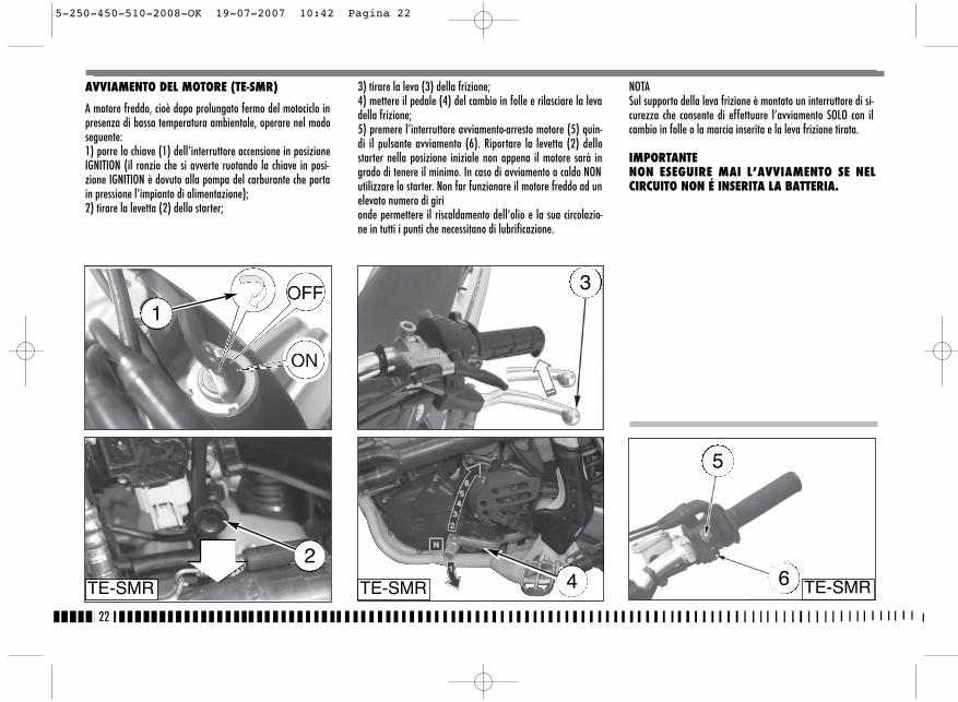
AVVIAMENTO DEL MOTORE (TE-SMR)
A motore freddo, cioè dopo prolungato fermo del motociclo inpresenza di bassa temperatura ambientale, operare nel modoseguente:1) porre la chiave (1) dell’interruttore accensione in posizioneIGNITION (il ronzio che si avverte ruotando la chiave in posi-zione IGNITION è dovuto alla pompa del carburante che portain pressione l’impianto di alimentazione);2) tirare la levetta (2) dello starter;
3) tirare la leva (3) della frizione;4) mettere il pedale (4) del cambio in folle e rilasciare la levadella frizione;5) premere l’interruttore avviamento-arresto motore (5) quin-di il pulsante avviamento (6). Riportare la levetta (2) dellostarter nella posizione iniziale non appena il motore sarà ingrado di tenere il minimo. In caso di avviamento a caldo NONutilizzare lo starter. Non far funzionare il motore freddo ad unelevato numero di girionde permettere il riscaldamento dell’olio e la sua circolazio-ne in tutti i punti che necessitano di lubrificazione.
TE-SMR TE-SMR TE-SMR42
3
5
6
1
5-250-450-510-2008-OK 19-07-2007 10:42 Pagina 22
23
IT
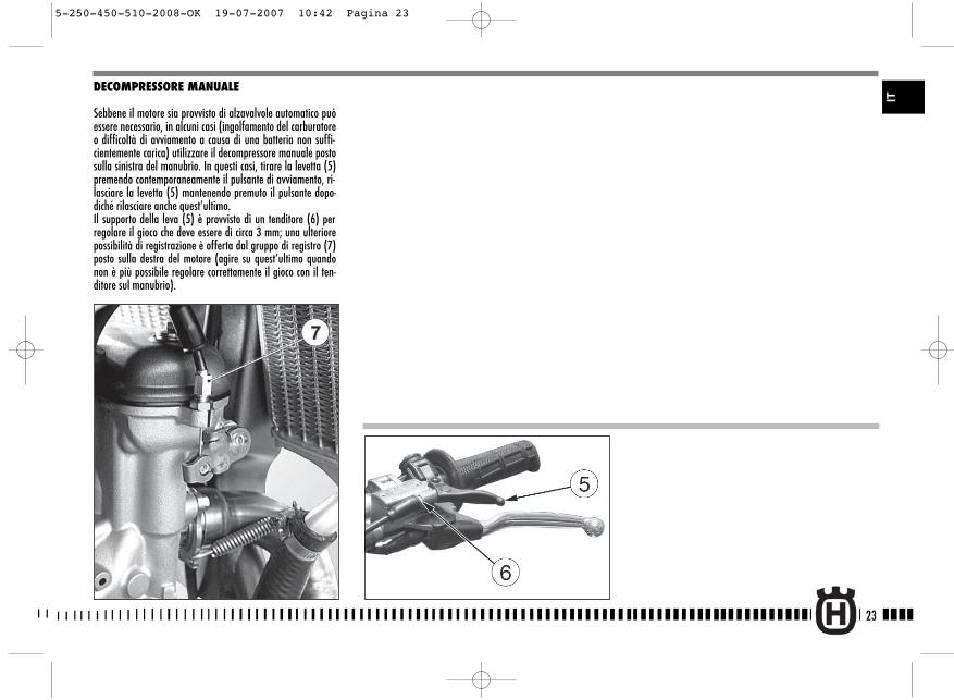
DECOMPRESSORE MANUALE
Sebbene il motore sia provvisto di alzavalvole automatico puòessere necessario, in alcuni casi (ingolfamento del carburatoreo difficoltà di avviamento a causa di una batteria non suffi-cientemente carica) utilizzare il decompressore manuale postosulla sinistra del manubrio. In questi casi, tirare la levetta (5)premendo contemporaneamente il pulsante di avviamento, ri-lasciare la levetta (5) mantenendo premuto il pulsante dopo-diché rilasciare anche quest’ultimo. Il supporto della leva (5) è provvisto di un tenditore (6) perregolare il gioco che deve essere di circa 3 mm; una ulteriorepossibilità di registrazione è offerta dal gruppo di registro (7)posto sulla destra del motore (agire su quest’ultimo quandonon è più possibile regolare correttamente il gioco con il ten-ditore sul manubrio).
5-250-450-510-2008-OK 19-07-2007 10:42 Pagina 23
24
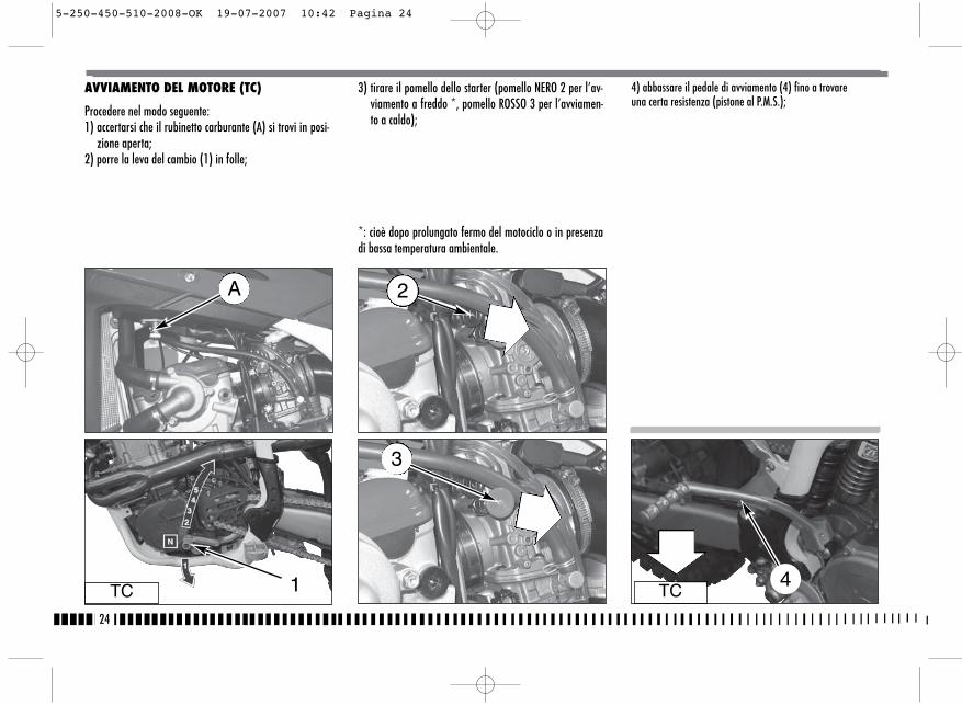
AVVIAMENTO DEL MOTORE (TC)
Procedere nel modo seguente:1) accertarsi che il rubinetto carburante (A) si trovi in posi-
zione aperta;2) porre la leva del cambio (1) in folle;
3) tirare il pomello dello starter (pomello NERO 2 per l’av-viamento a freddo *, pomello ROSSO 3 per l’avviamen-to a caldo);
*: cioè dopo prolungato fermo del motociclo o in presenzadi bassa temperatura ambientale.
TC TC1 4
4) abbassare il pedale di avviamento (4) fino a trovareuna certa resistenza (pistone al P.M.S.);
A 2
3
5-250-450-510-2008-OK 19-07-2007 10:42 Pagina 24

25
5) tirare la levetta (5) ed abbassare ulteriormente, di una cor-sa limitata, il pedale fino a vincere la suddetta resistenza(superamento del P.M.S.);
6) a questo punto, rilasciare la levetta (5) ed il pedale (4); 7) in caso di AVVIAMENTO A FREDDO, ruotare completamenteper 2 volte la manopola (6) del comando gas (in caso di av-viamento a caldo NON effettuare questa operazione);
TC
TC
TC4
IT
5-250-450-510-2008-OK 19-07-2007 10:42 Pagina 25
26
IMPORTANTENon accelerare mai il motore dopo un avviamento a freddo.
ATTENZIONE*: Il sistema di scarico contiene gasdi monossido di carbonio. Non far mai girareil motore in luoghi chiusi.In caso di uso dell’avviamento a pedale, se-guire attentamente le istruzioni riportate apag. 84 e tenere presente la nota sottoripor-tata.
Avviamento a pedaleATTENZIONE*: In fase di avviamento di questotipo di motociclo ad alte prestazioni si può ve-rificare, talvolta, un forte “contraccolpo” . Nonavviare il motore senza aver prima indossatostivali di guida appropriati, particolarmenteprotettivi. Si corre il rischio di ferirsi seriamen-te alla gamba nel caso il pedale di a il “con-traccolpo” ed il piede scivoli.
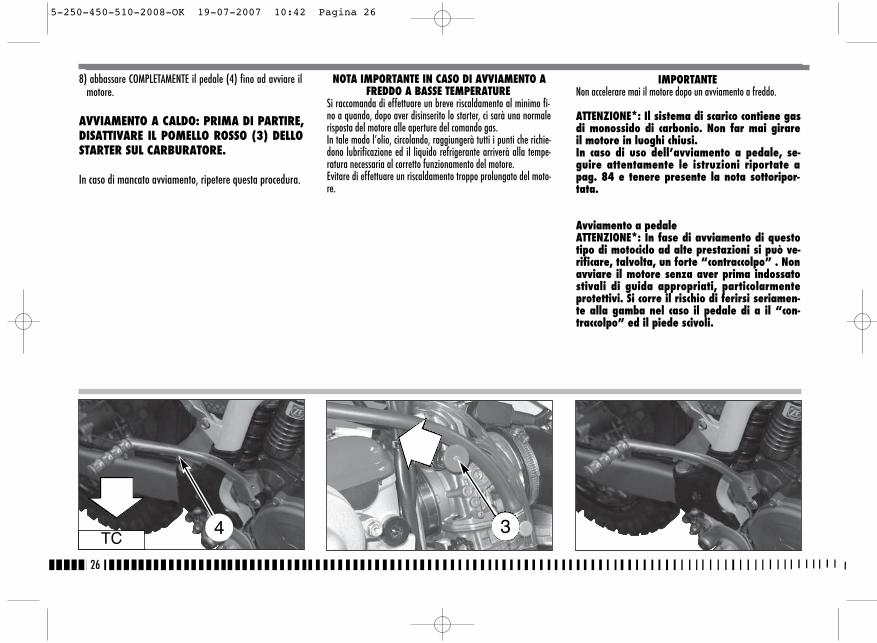
8) abbassare COMPLETAMENTE il pedale (4) fino ad avviare ilmotore.
AVVIAMENTO A CALDO: PRIMA DI PARTIRE,DISATTIVARE IL POMELLO ROSSO (3) DELLOSTARTER SUL CARBURATORE.
In caso di mancato avviamento, ripetere questa procedura.
NOTA IMPORTANTE IN CASO DI AVVIAMENTO AFREDDO A BASSE TEMPERATURE
Si raccomanda di effettuare un breve riscaldamento al minimo fi-no a quando, dopo aver disinserito lo starter, ci sarà una normalerisposta del motore alle aperture del comando gas. In tale modo l’olio, circolando, raggiungerà tutti i punti che richie-dono lubrificazione ed il liquido refrigerante arriverà alla tempe-ratura necessaria al corretto funzionamento del motore.Evitare di effettuare un riscaldamento troppo prolungato del moto-re.
TC4 3
5-250-450-510-2008-OK 19-07-2007 10:42 Pagina 26
27
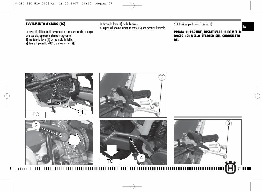
3) tirare la leva (3) della frizione;4) agire sul pedale messa in moto (5) per avviare il veicolo.
5) Rilasciare poi la leva frizione (3).
PRIMA DI PARTIRE, DISATTIVARE IL POMELLOROSSO (2) DELLO STARTER SUL CARBURATO-RE.
AVVIAMENTO A CALDO (TC)
In caso di difficoltà di avviamento a motore caldo, o dopouna caduta, operare nel modo seguente:1) mettere la leva (1) del cambio in folle;2) tirare il pomello ROSSO dello starter (2);
TC 1
TC4
IT
2
5-250-450-510-2008-OK 19-07-2007 10:42 Pagina 27

28
ARRESTO DEL MOTOCICLO E DEL MOTORE
- Chiudere completamente la manopola (1) del gas in mododa far decelerare il motociclo.
- Frenare sia anteriormente che posteriormente mentre si sca-lano le marce (per una forte decelerazione, agire in mododeciso sul leva e pedale dei freni).
- Una volta arrestato il motociclo, tirare la leva frizione e por-re la leva (2) del cambio in posizione di folle.
- Premere il pulsante ROSSO (3) arresto motore.- TC: Chiudere il rubinetto (4) del carburante.
- TE, SMR: ruotare a sinistra la chiave dell’interruttore di ac-censione.
ATTENZIONE*: In alcune condizioni può esse-re utile l’uso indipendente del freno ante-riore o di quello posteriore. Usare il frenoanteriore con prudenza, specialmente suterreni sdrucciolevoli. L’uso scorretto deifreni può causare gravi incidenti.
TE-SMRTE-SMR
TC
TC
ATTENZIONE*: In caso di bloccaggio delgas in posizione aperta o di altro malfun-zionamento che facesse girare il motorein modo incontrollabile, premere IMME-DIATAMENTE il pulsante arresto motore.Mantenere il controllo del motociclo con ilnormale uso dei freni e dello sterzo men-tre si preme il pulsante di arresto.
4
5-250-450-510-2008-OK 19-07-2007 10:42 Pagina 28

SOSTITUZIONE OLIO MOTORE E PULIZIA- SO-STITUZIONE FILTRI METALLICI ED A CARTUCCIA
ATTENZIONE*: Fare attenzione a non tocca-re l’olio caldo.L’operazione dovrà essere effettuata, A MOTORE CALDO, nelmodo seguente:� Togliere il tappo di carico olio (2);� anche se non indispensabile, è consigliabile rimuovere la
protezione inferiore (A) del motore;� porre una bacinella sotto il motore;� togliere il tappo di scarico olio (3);� evacuare l’olio esausto e pulire la calamita sul tappo;
29
� rimuovere i tre filtri metallici (5), (6) e (7) sulla sinistra delmotore, controllare le condizioni degli anelli OR ed effet-tuare la pulizia dei filtri con benzina; procedere inversa-mente per il rimontaggio;
� per sostituire la cartuccia filtro (4) è necessario svitare letre viti di fissaggio e rimuovere il coperchietto;
� una volta sostituiti i filtri, rimontare il tappo di scarico (3),la protezione del motore (A) e versare la prevista quantitàdi olio.
CONTROLLO LIVELLO OLIO
Tenendo il motociclo in piano ed in posizione verticale, controlla-re il livello dell’olio per mezzo dell’oblò di ispezione (1) inseritosul carter destro del motore. Verificare che il livello si trovi com-preso tra le due tacche MIN e MAX.Per effettuare il rabbocco, rimuovere il tappo di carico (2).
Nota*: Eseguire questa operazione a motorecaldo.
ATTENZIONE*: Fare attenzione a non toccarel’olio caldo.
MAX
MIN
1
2
2
3 4
IT
A
5-250-450-510-2008-OK 19-07-2007 10:42 Pagina 29

30
SOSTITUZIONE LIQUIDO DI RAFFREDDAMENTO
Porre un contenitore sul lato destro del cilindro, sotto la vite(1) di scarico refrigerante.Togliere PER PRIMA la vite (1), aprire LENTAMENTE il tappo (2)del radiatore destro e lasciar defluire il refrigerante nel conte-nitore inclinando sulla destra il motociclo. Rimontare la vite(1).Versare nel radiatore la quantità di liquido prescritta e portareil motore in temperatura per eliminare eventuali bolle d’aria.
1
AVVERTENZANon togliere il tappo del radiatore a moto-re caldo. Si corre il rischio che il liquido fuo-riesca e provochi ustioni.
AVVERTENZATE-SMR: Ricordare che la ventola di raffred-damento (A) può entrare in funzione anchecon l’interruttore di accensione in posizioneOFF; operare pertanto a debita distanzadalle palette della ventola.
NOTAPotrebbero sorgere difficoltà nell'eliminareil liquido da superfici verniciate. Se così fos-se, lavare con acqua.
CONTROLLO LIVELLO LIQUIDO DI RAFFREDDA-MENTO
Controllare il livello (1) nel radiatore destro a motore freddo econ il motociclo in posizione verticale. Il refrigerante deve tro-varsi 10 mm sopra gli elementi ed inoltre, sui modelli TE edSMR, non deve superare la metà del serbatoio di recupero (2)posto davanti all'ammortizzatore posteriore.
Il tappo del radiatore presenta due posizioni di bloccaggio: laprima serve allo scarico preventivo della pressione esistentenel circuito di raffreddamento.
1
2
6-250-450-510-2008 19-07-2007 10:43 Pagina 30
NOTA
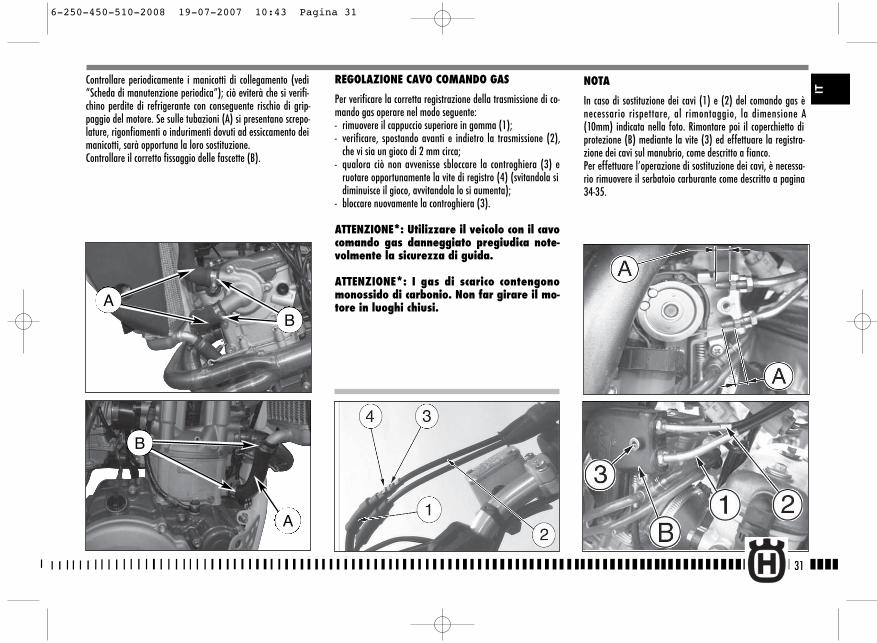
In caso di sostituzione dei cavi (1) e (2) del comando gas ènecessario rispettare, al rimontaggio, la dimensione A(10mm) indicata nella foto. Rimontare poi il coperchietto diprotezione (B) mediante la vite (3) ed effettuare la registra-zione dei cavi sul manubrio, come descritto a fianco.Per effettuare l’operazione di sostituzione dei cavi, è necessa-rio rimuovere il serbatoio carburante come descritto a pagina34-35.
31
Controllare periodicamente i manicotti di collegamento (vedi“Scheda di manutenzione periodica”); ciò eviterà che si verifi-chino perdite di refrigerante con conseguente rischio di grip-paggio del motore. Se sulle tubazioni (A) si presentano screpo-lature, rigonfiamenti o indurimenti dovuti ad essiccamento deimanicotti, sarà opportuna la loro sostituzione.Controllare il corretto fissaggio delle fascette (B).
B
A
REGOLAZIONE CAVO COMANDO GAS
Per verificare la corretta registrazione della trasmissione di co-mando gas operare nel modo seguente:- rimuovere il cappuccio superiore in gomma (1);- verificare, spostando avanti e indietro la trasmissione (2),
che vi sia un gioco di 2 mm circa;- qualora ciò non avvenisse sbloccare la controghiera (3) e
ruotare opportunamente la vite di registro (4) (svitandola sidiminuisce il gioco, avvitandola lo si aumenta);
- bloccare nuovamente la controghiera (3).
ATTENZIONE*: Utilizzare il veicolo con il cavocomando gas danneggiato pregiudica note-volmente la sicurezza di guida.
ATTENZIONE*: I gas di scarico contengonomonossido di carbonio. Non far girare il mo-tore in luoghi chiusi.
IT
AB
6-250-450-510-2008 19-07-2007 10:43 Pagina 31
32
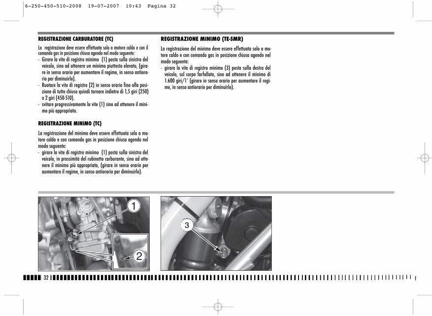
REGISTRAZIONE CARBURATORE (TC)
La registrazione deve essere effettuata solo a motore caldo e con ilcomando gas in posizione chiusa agendo nel modo seguente:- Girare la vite di registro minimo (1) posta sulla sinistra del
veicolo, sino ad ottenere un minimo piuttosto elevato, (gira-re in senso orario per aumentare il regime, in senso antiora-rio per diminuirlo).
- Ruotare la vite di registro (2) in senso orario fino alla posi-zione di tutto chiuso quindi tornare indietro di 1,5 giri (250)o 2 giri (450-510).
- svitare progressivamente la vite (1) sino ad ottenere il mini-mo più appropriato.
REGISTRAZIONE MINIMO (TC)
La registrazione del minimo deve essere effettuata solo a mo-tore caldo e con comando gas in posizione chiusa agendo nelmodo seguente:- girare la vite di registro minimo (1) posta sulla sinistra del
veicolo, in prossimità del rubinetto carburante, sino ad otte-nere il minimo più appropriato, (girare in senso orario peraumentare il regime, in senso antiorario per diminuirlo).
REGISTRAZIONE MINIMO (TE-SMR)
La registrazione del minimo deve essere effettuata solo a mo-tore caldo e con comando gas in posizione chiusa agendo nelmodo seguente:- girare la vite di registro minimo (3) posta sulla destra del
veicolo, sul corpo farfallato, sino ad ottenere il minimo di1.600 giri/1’ (girare in senso orario per aumentare il regi-me, in senso antiorario per diminuirlo).
3
6-250-450-510-2008 19-07-2007 10:43 Pagina 32
33
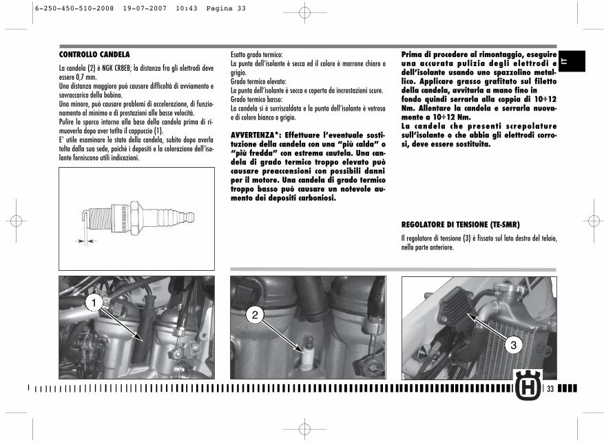
CONTROLLO CANDELA
La candela (2) è NGK CR8EB; la distanza fra gli elettrodi deveessere 0,7 mm.Una distanza maggiore può causare difficoltà di avviamento esovraccarico della bobina.Una minore, può causare problemi di accelerazione, di funzio-namento al minimo e di prestazioni alle basse velocità.Pulire lo sporco intorno alla base della candela prima di ri-muoverla dopo aver totlto il cappuccio (1).E’ utile esaminare lo stato della candela, subito dopo averlatolta dalla sua sede, poichè i depositi e la colorazione dell’iso-lante forniscono utili indicazioni.
Esatto grado termico:La punta dell’isolante è secca ed il colore è marrone chiaro ogrigio.Grado termico elevato:La punta dell’isolante è secca e coperta da incrostazioni scure.Grado termico basso:La candela si è surriscaldata e la punta dell’isolante è vetrosae di colore bianco o grigio.
AVVERTENZA*: Effettuare l’eventuale sosti-tuzione della candela con una “più calda” o“più fredda” con estrema cautela. Una can-dela di grado termico troppo elevato puòcausare preaccensioni con possibili danniper il motore. Una candela di grado termicotroppo basso può causare un notevole au-mento dei depositi carboniosi.
Prima di procedere al rimontaggio, eseguireuna accurata pulizia degli elettrodi edell’isolante usando uno spazzolino metal-lico. Applicare grasso grafitato sul filettodella candela, avvitarla a mano fino infondo quindi serrarla alla coppia di 10÷12Nm. Allentare la candela e serrarla nuova-mente a 10÷12 Nm. La candela che presenti screpolaturesull’isolante o che abbia gli elettrodi corro-si, deve essere sostituita.
REGOLATORE DI TENSIONE (TE-SMR)
Il regolatore di tensione (3) è fissato sul lato destro del telaio,nella parte anteriore.
2
3
1
IT
6-250-450-510-2008 19-07-2007 10:43 Pagina 33
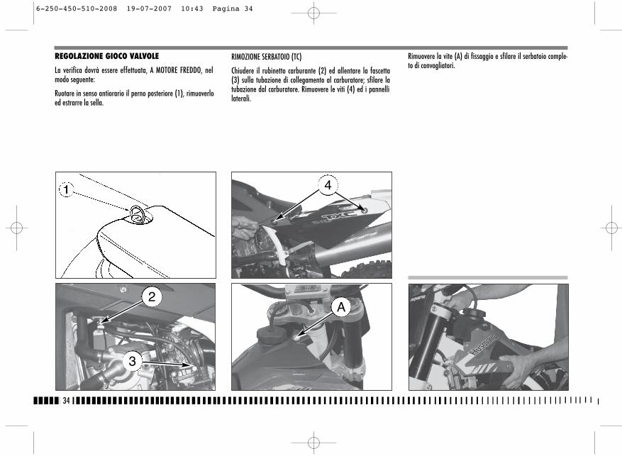
RIMOZIONE SERBATOIO (TC)
Chiudere il rubinetto carburante (2) ed allentare la fascetta(3) sulla tubazione di collegamento al carburatore; sfilare latubazione dal carburatore. Rimuovere le viti (4) ed i pannellilaterali.
Rimuovere la vite (A) di fissaggio e sfilare il serbatoio comple-to di convogliatori.
34
REGOLAZIONE GIOCO VALVOLE
La verifica dovrà essere effettuata, A MOTORE FREDDO, nelmodo seguente:
Ruotare in senso antiorario il perno posteriore (1), rimuoverloed estrarre la sella.
2
3
4
A
6-250-450-510-2008 19-07-2007 10:43 Pagina 34

Sollevare il serbatoio quindi staccare il connettore della pom-pa carburante dal cablaggio principale.Scollegare il tubo di alimentazione (B) dal raccordo di uscita(C) sulla pompa carburante nella parte inferiore posterioredel serbatoio.
RIMOZIONE SERBATOIO (TE-SMR)Rimuovere le viti (1) ed i pannelli laterali. Rimuovere la vite(A) di fissaggio serbatoio.
Sfilare il serbatoio completo di convogliatori.
35
TE-SMR
B
TE-SMR
C
A
TE-SMR
TE-SMR
1
TE-SMR
IT
6-250-450-510-2008 19-07-2007 10:43 Pagina 35

In caso contrario, sollevare la molletta (7) di ritegno con l’ausi-lio di un attrezzo tiramolla, far scivolare il bilanciere da un lato,estrarre con una pinzetta la pastiglia e verificarne lo spessore;In base al valore rilevato, montare la nuova pastiglia (a ricam-bio, sono fornite pastiglie con spessore da 1,60 mm a 2,60mm con maggiorazioni di 0,05 mm) e riportare in sede lamolletta ed il bilanciere; Verificare di nuovo il gioco valvole e, se corretto, rimontare iparticolari precedentemente rimossi procedendo inversamenterispetto allo smontaggio.
36
Verificare, usando uno spessimetro, che il gioco sia 0,10÷0,15 mmper il lato ASPIRAZIONE e 0,15÷0,20 mm per il lato SCARICO;
Togliere la candela (5), le quattro viti (6) del coperchio testaed il coperchio testa;Inserire la 2a marcia e, spingendo avanti e indietro il motoci-clo, portare il pistone al Punto Morto Superiore (in questa con-dizione la tacca riportata sulla testa coincide con i due riferi-menti posti sull’ingranaggio di rinvio degli alberi a camme,come indicato sulla figura);
6-250-450-510-2008 19-07-2007 10:43 Pagina 36
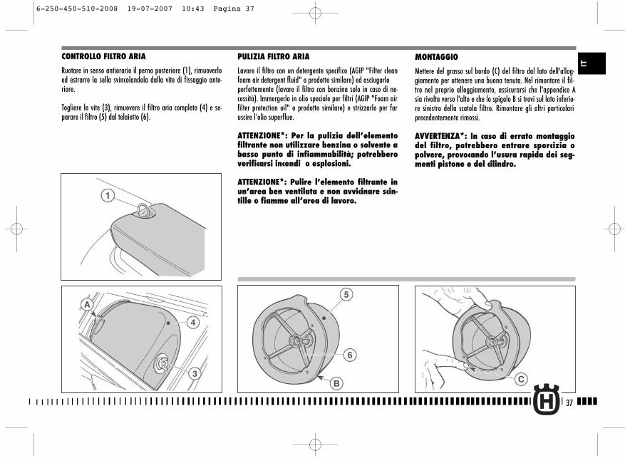
PULIZIA FILTRO ARIA
Lavare il filtro con un detergente specifico (AGIP "Filter cleanfoam air detergent fluid" o prodotto similare) ed asciugarloperfettamente (lavare il filtro con benzina solo in caso di ne-cessità). Immergerlo in olio speciale per filtri (AGIP "Foam airfilter protection oil" o prodotto similare) e strizzarlo per faruscire l’olio superfluo.
ATTENZIONE*: Per la pulizia dell’elementofiltrante non utilizzare benzina o solvente abasso punto di infiammabilità; potrebberoverificarsi incendi o esplosioni.
ATTENZIONE*: Pulire l’elemento filtrante inun’area ben ventilata e non avvicinare scin-tille o fiamme all’area di lavoro.
MONTAGGIO
Mettere del grasso sul bordo (C) del filtro dal lato dell'allog-giamento per ottenere una buona tenuta. Nel rimontare il fil-tro nel proprio alloggiamento, assicurarsi che l'appendice Asia rivolta verso l'alto e che lo spigolo B si trovi sul lato inferio-re sinistro della scatola filtro. Rimontare gli altri particolariprecedentemente rimossi.
AVVERTENZA*: In caso di errato montaggiodel filtro, potrebbero entrare sporcizia opolvere, provocando l’usura rapida dei seg-menti pistone e del cilindro.
37
CONTROLLO FILTRO ARIA
Ruotare in senso antiorario il perno posteriore (1), rimuoverloed estrarre la sella svincolandola dalla vite di fissaggio ante-riore.
Togliere la vite (3), rimuovere il filtro aria completo (4) e se-parare il filtro (5) dal telaietto (6).
IT
6-250-450-510-2008 19-07-2007 10:43 Pagina 37
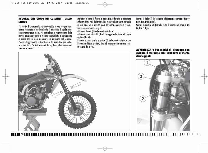
Serrare il dado (1) del cannotto alla coppia di serraggio di 8÷9Kgm. (78,4÷88,3 Nm).Serrare le quattro viti (3) sulla testa di sterzo a 22,5÷26,5 Nm(2,3÷2,7 Kgm).
AVVERTENZA*: Per motivi di sicurezza nonguidare il motociclo con i cuscinetti di sterzodanneggiati.
38
REGOLAZIONE GIOCO DEI CUSCINETTI DELLOSTERZO
Per motivi di sicurezza lo sterzo dovrebbe essere sempre man-tenuto registrato in modo tale che il manubrio di guida ruotiliberamente senza gioco. Per controllare la registrazione dellosterzo, posizionare sotto al motore un cavalletto o un supportoin modo che la ruota anteriore sia sollevata dal terreno.Premere leggermente sulle estremità del manubrio per mette-re in rotazione l'articolazione di sterzo; il manubrio dovrà ruo-tare senza sforzo.
Mettetevi a terra di fronte al motociclo, afferrate le estremitàinferiori degli steli della forcella e muovetele in senso normaleal loro asse. Se si avverte gioco occorrerà eseguire la regola-zione operando come segue:allentare il dado (1) del cannotto di sterzo.Allentare le quattro viti (3) di fissaggio della testa di sterzoagli steli forcella.Ruotare in senso orario la ghiera (2) del cannotto di sterzo conl'apposita chiave speciale, fino ad ottenere una corretta regi-strazione del gioco.
7-250-450-510-2008-OK 19-07-2007 10:45 Pagina 38
A
B
+
-
2TE-TC
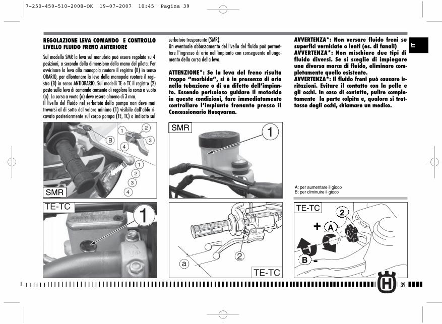
serbatoio trasparente (SMR).Un eventuale abbassamento del livello del fluido può permet-tere l'ingresso di aria nell'impianto con conseguente allunga-mento della corsa della leva.
ATTENZIONE*: Se la leva del freno risultatroppo “morbida”, si è in presenza di arianella tubazione o di un difetto dell’impian-to. Essendo pericoloso guidare il motocicloin queste condizioni, fare immediatamentecontrollare l’impianto frenante presso ilConcessionario Husqvarna.
AVVERTENZA*: Non versare fluido freni susuperfici verniciate o lenti (es. di fanali) AVVERTENZA*: Non mischiare due tipi difluido diversi. Se si sceglie di impiegareuna diversa marca di fluido, eliminare com-pletamente quello esistente.AVVERTENZA*: Il fluido freni può causare ir-ritazioni. Evitare il contatto con la pelle egli occhi. In caso di contatto, pulire comple-tamente la parte colpita e, qualora si trat-tasse degli occhi, chiamare un medico.
39
IT
REGOLAZIONE LEVA COMANDO E CONTROLLOLIVELLO FLUIDO FRENO ANTERIORE
Sul modello SMR la leva sul manubrio può essere regolata su 4posizioni, a seconda della dimensione della mano del pilota. Peravvicinare la leva alla manopola ruotare il registro (B) in sensoORARIO, per allontanare la leva dalla manopola ruotare il regi-stro (B) in senso ANTIORARIO. Sui modelli TE e TC il registro (2)posto sulla leva di comando consente di regolare la corsa a vuoto(a). La corsa a vuoto (a) deve essere almeno di 3 mm.Il livello del fluido nel serbatoio della pompa non deve maitrovarsi al di sotto del valore minimo (1) visibile dall’oblò ri-cavato posteriormente sul corpo pompa (TE, TC) o indicato sul
SMR
A: per aumentare il giocoB: per diminuire il giocoSMR
7-250-450-510-2008-OK 19-07-2007 10:45 Pagina 39
40
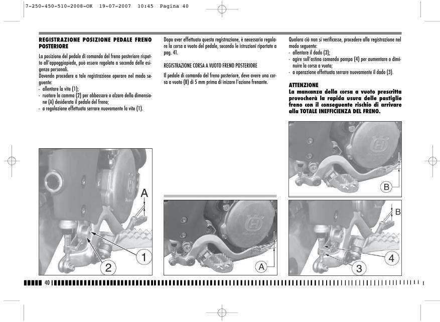
Dopo aver effettuato questa registrazione, è necessario regola-re la corsa a vuoto del pedale, secondo le istruzioni riportate apag. 41.
REGISTRAZIONE CORSA A VUOTO FRENO POSTERIORE
Il pedale di comando del freno posteriore, deve avere una cor-sa a vuoto (B) di 5 mm prima di inizare l’azione frenante.
Qualora ciò non si verificasse, procedere alla registrazione nelmodo seguente:- allentare il dado (3);- agire sull’astina comando pompa (4) per aumentare o dimi-
nuire la corsa a vuoto;- a operazione effettuata serrare nuovamente il dado (3).
ATTENZIONELa mancanza della corsa a vuoto prescrittaprovocherà la rapida usura delle pastigliefreno con il conseguente rischio di arrivarealla TOTALE INEFFICIENZA DEL FRENO.
REGISTRAZIONE POSIZIONE PEDALE FRENOPOSTERIORE
La posizione del pedale di comando del freno posteriore rispet-to all’appoggiapiede, può essere regolata a seconda delle esi-genze personali.Dovendo procedere a tale registrazione operare nel modo se-guente:- allentare la vite (1);- ruotare la camma (2) per abbassare o alzare della dimensio-
ne (A) desiderata il pedale del freno;- a regolazione effettuata serrare nuovamente la vite (1).
7-250-450-510-2008-OK 19-07-2007 10:45 Pagina 40
41
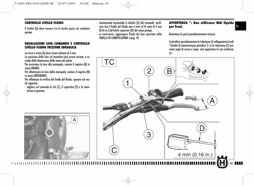
CONTROLLO LIVELLO FLUIDO
Il livello (A) deve trovarsi tra le tacche poste sul serbatoiopompa.
REGOLAZIONE LEVA COMANDO E CONTROLLOLIVELLO FLUIDO FRIZIONE IDRAULICA
La corsa a vuoto (A) deve essere almeno di 3 mm.La posizione della leva sul manubrio può essere variata, a se-conda della dimensione della mano del pilota.Per avvicinare la leva alla manopola, ruotare il registro (B) insenso ORARIO.Per allontanare la leva dalla manopola, ruotare il registro (B)in senso ANTIORARIO. Per effettuare la verifica del livello del fluido, operare nel mo-do seguente:- togliere sul comando le viti (1), il coperchio (2) e la mem-
brana in gomma;
- mantenendo orizzontale il cilindro (3) del comando, verifi-care che il livello del fluido non si trovi al di sotto di 4 mm(0.16 in.) dal limite superiore (D) del corpo pompa;
- se necessario, aggiungere fluido del tipo riportato nellaTABELLA DI LUBRIFICAZIONE a pag. 10.
AVVERTENZA *: Non utilizzare MAI liquidoper freni.
Rimontare le parti precedentemente rimosse.
Controllare periodicamente la tubazione di collegamento (vedi“Scheda di manutenzione periodica”); se la tubazione (C) pre-senta segni di usura o crepe, sarà opportuna la sua sostituzio-ne.
IT
7-250-450-510-2008-OK 19-07-2007 10:45 Pagina 41
42
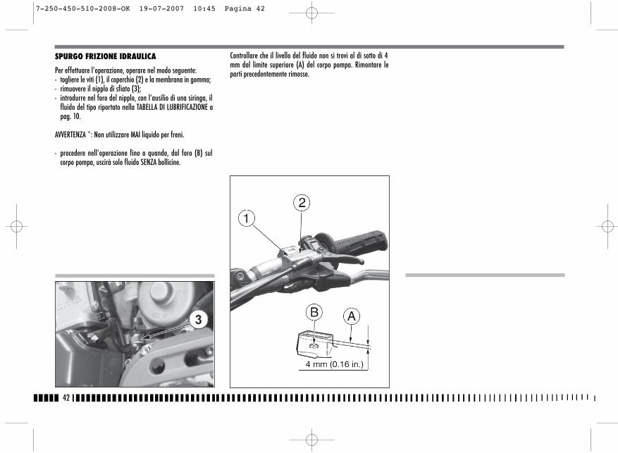
SPURGO FRIZIONE IDRAULICA
Per effettuare l’operazione, operare nel modo seguente:- togliere le viti (1), il coperchio (2) e la membrana in gomma;- rimuovere il nipplo di sfiato (3);- introdurre nel foro del nipplo, con l’ausilio di una siringa, il
fluido del tipo riportato nella TABELLA DI LUBRIFICAZIONE apag. 10.
AVVERTENZA *: Non utilizzare MAI liquido per freni.
- procedere nell’operazione fino a quando, dal foro (B) sulcorpo pompa, uscirà solo fluido SENZA bollicine.
Controllare che il livello del fluido non si trovi al di sotto di 4mm dal limite superiore (A) del corpo pompa. Rimontare leparti precedentemente rimosse.
7-250-450-510-2008-OK 19-07-2007 10:45 Pagina 42
43
REGOLAZIONE DELLE SOSPENSIONI IN BASE APARTICOLARI CONDIZIONI DELLA PISTA
Le indicazioni che seguono costituiscono una guida indicativaper la messa a punto delle sospensioni in funzione del tipo diterreno di impiego del motociclo.Prima di effettuare qualunque modifica ed anche in seguito,se la nuova registrazione fosse insoddisfacente, è necessariopartire sempre dalla taratura standard aumentando o dimi-nuendo gli scatti di registrazione di uno alla volta.
TERRENO DUROForcella: regolazione più morbida in compressioneAmmortizzatore: regolazione più morbida in compressioneIn caso di percorso veloce, regolazione più morbida sia in com-pressione che in estensione per entrambe le sospensioni, que-st’ultima modifica favorisce l’aderenza delle ruote sul terreno.
TERRENO SABBIOSOForcella: regolazione più dura in compressione, oppure sostitu-zione della molla standard con una più dura con contempora-nea regolazione più morbida della compressione e più duradell’estensione.Ammortizzatore: regolazione più dura in compressione e prin-cipalmente in estensione; agire inoltre sul precarico della mol-la per abbassare la parte posteriore della moto.
TERRENO FANGOSOForcella: regolazione più dura in compressione, oppure sostitu-zione della molla standard con una più dura; Ammortizzatore: regolazione più dura sia in compressione chein estensione oppure sostituzione della molla standard conuna più dura; agire inoltre sul precarico della molla per alzarela parte posteriore della moto. La sostituzione delle molle suentrambe le sospensioni è consigliata per compensare l’au-mento di peso della moto dovuto al fango accumulato.NOTE
Se la forcella fosse troppo morbida o troppo dura in ogni con-dizione di registrazione, verificare il livello dell’olio nello steloperchè potrebbe essere troppo basso o troppo alto ; ricordareche una quantità maggiore di olio nella forcella comporta uno
spurgo aria più frequente. Se le sospensioni non reagisconoalle variazioni di taratura, verificare i gruppi di registro perchèpotrebbero essere bloccati.Le tarature standard e le procedure di registrazione sono ri-
IT
7-250-450-510-2008-OK 19-07-2007 10:45 Pagina 43
44
portate sulle pagine che seguono; le molle disponibili a richie-sta, unitamente ai rispettivi distanziali di precarica, sono ripor-tate alle pagine 93, 94, 95.
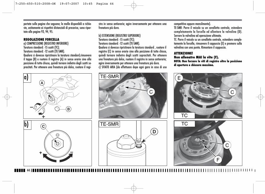
REGOLAZIONE FORCELLAa) COMPRESSIONE (REGISTRO INFERIORE)Taratura standard: -15 scatti (TC);Taratura standard: -12 scatti (TE-SMR).Qualora si dovesse ripristinare la taratura standard,rimuovereil tappo (B) e ruotare il registro (A) in senso orario sino allaposizione di tutto chiuso, quindi tornare indietro degli scatti so-pracitati. Per ottenere una frenatura più dolce, ruotare il regi-
stro in senso antiorario; agire inversamente per ottenere unafrenatura più dura.
b) ESTENSIONE (REGISTRO SUPERIORE) Taratura standard: -15 scatti (TC);Taratura standard: -12 scatti (TE-SMR).Qualora si dovesse ripristinare la taratura standard , ruotare ilregistro (C) in senso orario sino alla posizione di tutto chiuso,quindi tornare indietro degli scatti sopracitati. Per ottenereuna frenatura più dolce, ruotare il registro in senso antiorario;agire inversamente per ottenere una frenatura più dura.c) SFIATO ARIA (da effettuare dopo ogni gara in caso di uso
competitivo oppure mensilmente).TE-SMR: Porre il veicolo su un cavalletto centrale, estenderecompletamente la forcella ed allentare la valvolina (D).Serrare la valvolina ad operazione ultimata.TC: Porre il veicolo su un cavalletto centrale, estendere comple-tamente la forcella, rimuovere il cappuccio (E) e premere sullavalvolina con una punta. Rimontare il cappuccio.
ATTENZIONE!Non allenatre MAI la vite (F).NOTA: Non forzare le viti di registro oltre la posizionedi apertura e chiusura massima.
A
B
CD
a)
b)TC
TC
TE-SMR
TE-SMR
E
C
C
C
F
7-250-450-510-2008-OK 19-07-2007 10:45 Pagina 44
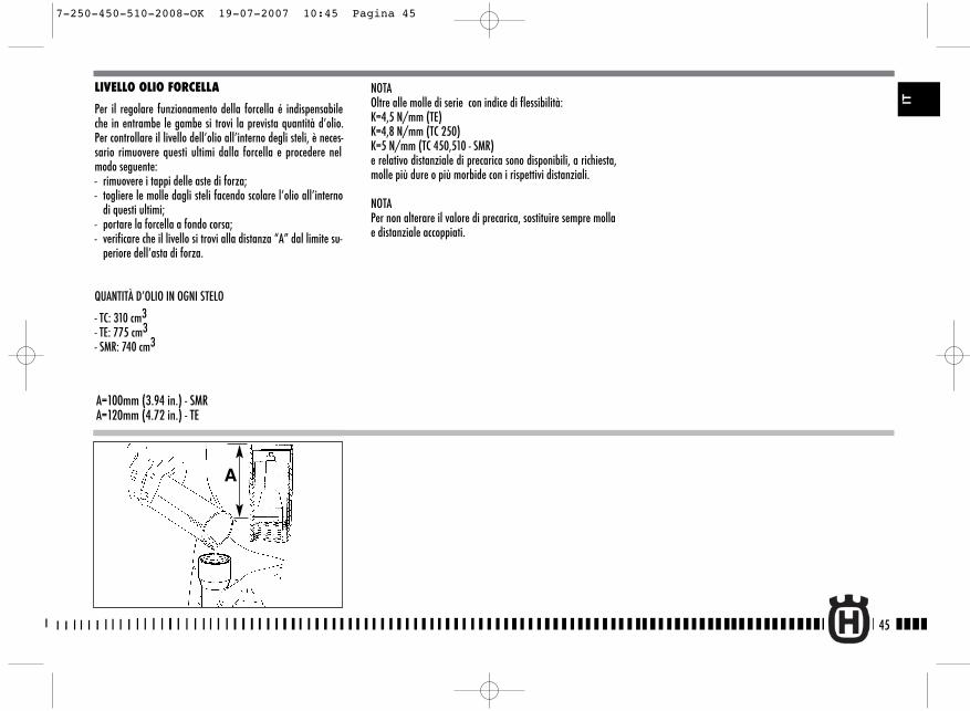
LIVELLO OLIO FORCELLA
Per il regolare funzionamento della forcella é indispensabileche in entrambe le gambe si trovi la prevista quantità d’olio.Per controllare il livello dell’olio all’interno degli steli, è neces-sario rimuovere questi ultimi dalla forcella e procedere nelmodo seguente:- rimuovere i tappi delle aste di forza;- togliere le molle dagli steli facendo scolare l’olio all’interno
di questi ultimi;- portare la forcella a fondo corsa;- verificare che il livello si trovi alla distanza “A” dal limite su-
periore dell’asta di forza.
QUANTITÀ D’OLIO IN OGNI STELO
- TC: 310 cm3- TE: 775 cm3- SMR: 740 cm3
A=100mm (3.94 in.) - SMRA=120mm (4.72 in.) - TE
A
NOTAOltre alle molle di serie con indice di flessibilità:K=4,5 N/mm (TE) K=4,8 N/mm (TC 250) K=5 N/mm (TC 450,510 - SMR)e relativo distanziale di precarica sono disponibili, a richiesta,molle più dure o più morbide con i rispettivi distanziali.
NOTAPer non alterare il valore di precarica, sostituire sempre mollae distanziale accoppiati.
45
IT
7-250-450-510-2008-OK 19-07-2007 10:45 Pagina 45
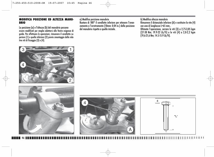
46
b) Modifica altezza manubrioRimuovere il distanziale inferiore (A) e sostituire la vite (4)con una di lunghezza L=65 mm..Ultimata l’operazione, serrare le viti (3) a 2,75-3,05 kgm(27-30 Nm; 19.9-22 Lb/ft) e le viti (4) a 2,0-2,2 kgm(19,6-21,6 Nm; 14.5-15.9 Lb/ft).
MODIFICA POSIZIONE ED ALTEZZA MANU-BRIO
La posizione (a) e l'altezza (b) del manubrio possonoessere modificati per meglio adattarsi alle Vostre esigenze diguida. Per effettuare le operazioni, rimuovere il cavallotto su-periore (1) e quello inferiore (2) previo smontaggio delle rela-tive viti di fissaggio (3) e (4).
a) Modifica posizione manubrioRuotare di 180° il cavallotto inferiore per ottenere l’avan-zamento o l’arretramento (10mm- 0.04 in.) della posizionedel manubrio rispetto a quella iniziale.
7-250-450-510-2008-OK 19-07-2007 10:45 Pagina 46
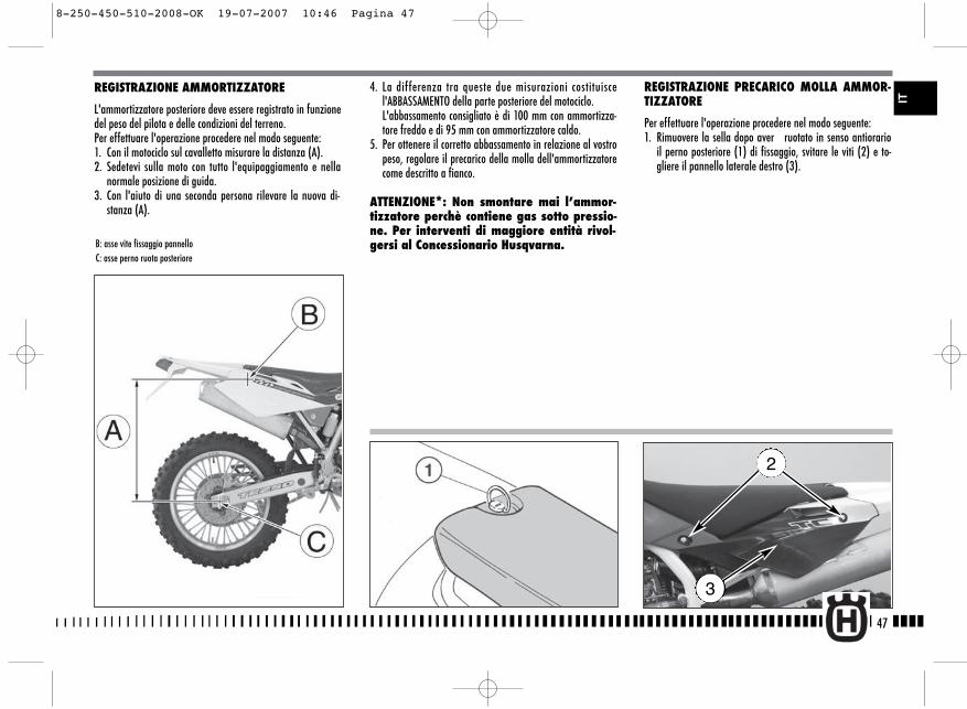
4. La differenza tra queste due misurazioni costituiscel'ABBASSAMENTO della parte posteriore del motociclo.L'abbassamento consigliato è di 100 mm con ammortizza-tore freddo e di 95 mm con ammortizzatore caldo.
5. Per ottenere il corretto abbassamento in relazione al vostropeso, regolare il precarico della molla dell'ammortizzatorecome descritto a fianco.
ATTENZIONE*: Non smontare mai l’ammor-tizzatore perchè contiene gas sotto pressio-ne. Per interventi di maggiore entità rivol-gersi al Concessionario Husqvarna.
REGISTRAZIONE PRECARICO MOLLA AMMOR-TIZZATORE
Per effettuare l'operazione procedere nel modo seguente:1. Rimuovere la sella dopo aver ruotato in senso antiorario
il perno posteriore (1) di fissaggio, svitare le viti (2) e to-gliere il pannello laterale destro (3).
47
REGISTRAZIONE AMMORTIZZATORE
L'ammortizzatore posteriore deve essere registrato in funzionedel peso del pilota e delle condizioni del terreno.Per effettuare l'operazione procedere nel modo seguente:1. Con il motociclo sul cavalletto misurare la distanza (A).2. Sedetevi sulla moto con tutto l'equipaggiamento e nella
normale posizione di guida.3. Con l'aiuto di una seconda persona rilevare la nuova di-
stanza (A).
B: asse vite fissaggio pannelloC: asse perno ruota posteriore
2
3
IT
8-250-450-510-2008-OK 19-07-2007 10:46 Pagina 47
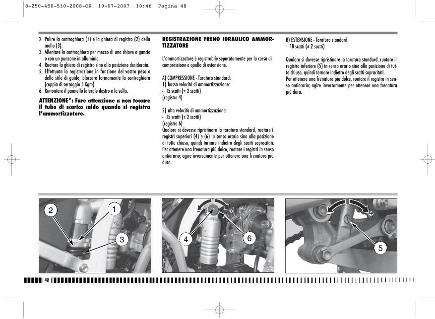
B) ESTENSIONE - Taratura standard:- 18 scatti (± 2 scatti)
Qualora si dovesse ripristinare la taratura standard, ruotare ilregistro inferiore (5) in senso orario sino alla posizione di tut-to chiuso, quindi tornare indietro degli scatti sopracitati.Per ottenere una frenatura più dolce, ruotare il registro in sen-so antiorario; agire inversamente per ottenere una frenaturapiù dura.
2. Pulire la controghiera (1) e la ghiera di registro (2) dellamolla (3).
3. Allentare la controghiera per mezzo di una chiave a gancioo con un punzone in alluminio.
4. Ruotare la ghiera di registro sino alla posizione desiderata.5. Effettuata la registrazione in funzione del vostro peso o
dello stile di guida, bloccare fermamente la controghiera(coppia di serraggio 5 Kgm).
6. Rimontare il pannello laterale destro e la sella.
ATTENZIONE*: Fare attenzione a non toccareil tubo di scarico caldo quando si registral’ammortizzatore.
REGISTRAZIONE FRENO IDRAULICO AMMOR-TIZZATORE
L'ammortizzatore è registrabile separatamente per la corsa dicompressione e quella di estensione.
A) COMPRESSIONE - Taratura standard:1) bassa velocità di ammortizzazione: - 15 scatti (± 2 scatti)(registro 4)
2) alta velocità di ammortizzazione:- 15 scatti (± 2 scatti)(registro 6)Qualora si dovesse ripristinare la taratura standard, ruotare iregistri superiori (4) e (6) in senso orario sino alla posizionedi tutto chiuso, quindi tornare indietro degli scatti sopracitati.Per ottenere una frenatura più dolce, ruotare i registri in sensoantiorario; agire inversamente per ottenere una frenatura piùdura.
48
12
3 645
8-250-450-510-2008-OK 19-07-2007 10:46 Pagina 48
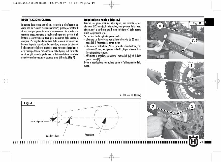
REGISTRAZIONE CATENA
La catena deve essere controllata, registrata e lubrificata in ac-cordo con la "Tabella di manutenzione"; questo per motivi disicurezza e per prevenire una usura eccessiva. Se la catena siconsuma eccessivamente o risulta malregistrata, cioè se è al-lentata o eccessivamente tesa, può fuoriuscire dalla corona orompersi. Per regolare la tensione della catena è necessario ab-bassare la parte posteriore del motociclo, in modo da ottenerel'allineamento dell'asse pignone, asse rotazione forcellone easse ruota posteriore come indicato nella figura, indi far ruota-re di tre giri la ruota posteriore. In tale condizione la catenanon deve risultare tesa pur essendo priva di freccia. (Fig. A).
Regolazione rapida (Fig. B.)Inserire, nel punto indicato sulla figura, una bussola (a) deldiametro di 35 mm (o, in alternativa, uno spessore della stessadimensione) e verificare che il ramo inferiore (C) della catenarisulti leggermente teso.Se così non risulta agire in questo modo:- allentare sul lato destro, con chiave a bussola da 27 mm, il
dado (1) di fissaggio del perno ruota;- allentare i controdadi (2) su entrambi i tendicatena, con
chiave da 12 mm, ed operare sulle viti (3) per ottenere il va-lore di tensione corretto;
- effettuata la regolazione serrare i controdadi (2) ed il dadoperno ruota (1).
Dopo la regolazione, controllare sempre l’allineamento dellaruota.
49
Fig. A
IT
Asse pignone
Asse forcellone Asse ruota
A = 0÷2 mm (0÷0.08 in.)
a
C
1
32
Fig. B
9-250-450-510-2008-OK 19-07-2007 10:48 Pagina 49
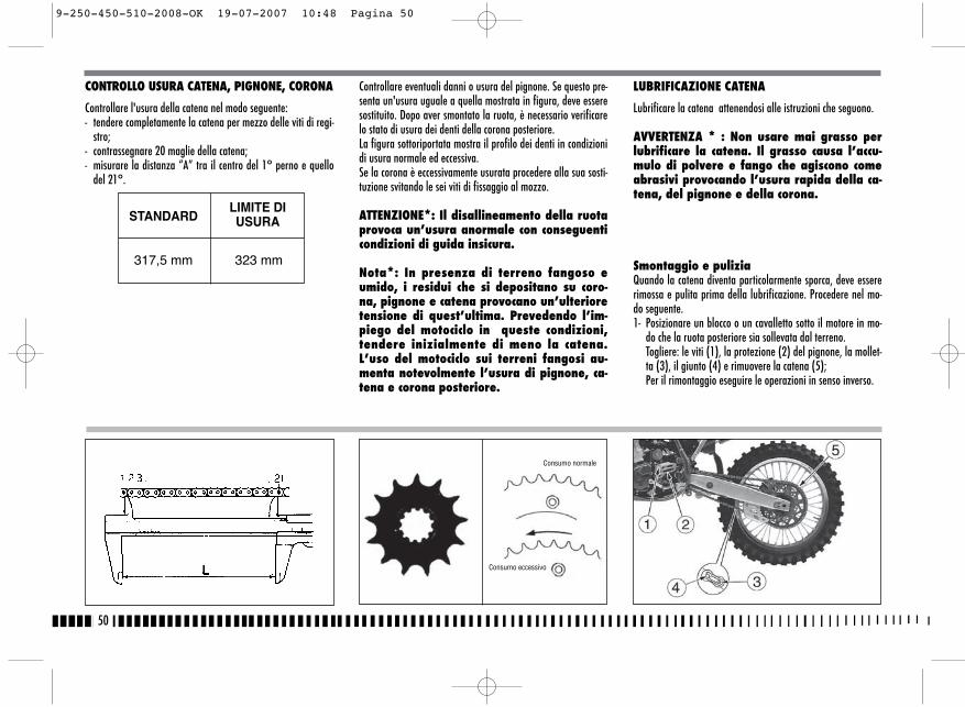
Controllare eventuali danni o usura del pignone. Se questo pre-senta un'usura uguale a quella mostrata in figura, deve esseresostituito. Dopo aver smontato la ruota, è necessario verificarelo stato di usura dei denti della corona posteriore.La figura sottoriportata mostra il profilo dei denti in condizionidi usura normale ed eccessiva.Se la corona è eccessivamente usurata procedere alla sua sosti-tuzione svitando le sei viti di fissaggio al mozzo.
ATTENZIONE*: Il disallineamento della ruotaprovoca un’usura anormale con conseguenticondizioni di guida insicura.
Nota*: In presenza di terreno fangoso eumido, i residui che si depositano su coro-na, pignone e catena provocano un’ulterioretensione di quest’ultima. Prevedendo l’im-piego del motociclo in queste condizioni,tendere inizialmente di meno la catena.L’uso del motociclo sui terreni fangosi au-menta notevolmente l’usura di pignone, ca-tena e corona posteriore.
LUBRIFICAZIONE CATENA
Lubrificare la catena attenendosi alle istruzioni che seguono.
AVVERTENZA * : Non usare mai grasso perlubrificare la catena. Il grasso causa l’accu-mulo di polvere e fango che agiscono comeabrasivi provocando l’usura rapida della ca-tena, del pignone e della corona.
Smontaggio e puliziaQuando la catena diventa particolarmente sporca, deve essererimossa e pulita prima della lubrificazione. Procedere nel mo-do seguente.1- Posizionare un blocco o un cavalletto sotto il motore in mo-
do che la ruota posteriore sia sollevata dal terreno.Togliere: le viti (1), la protezione (2) del pignone, la mollet-ta (3), il giunto (4) e rimuovere la catena (5);Per il rimontaggio eseguire le operazioni in senso inverso.
50
CONTROLLO USURA CATENA, PIGNONE, CORONA
Controllare l'usura della catena nel modo seguente:- tendere completamente la catena per mezzo delle viti di regi-
stro;- contrassegnare 20 maglie della catena;- misurare la distanza “A” tra il centro del 1° perno e quello
del 21°.
STANDARDLIMITE DIUSURA
317,5 mm 323 mm
Consumo normale
Consumo eccessivo
9-250-450-510-2008-OK 19-07-2007 10:48 Pagina 50
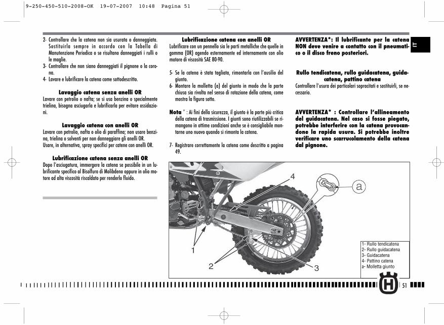
Lubrificazione catena con anelli ORLubrificare con un pennello sia le parti metalliche che quelle ingomma (OR) agendo esternamente ed internamente con oliomotore di viscosità SAE 80-90.
5- Se la catena è stata tagliata, rimontarla con l’ausilio delgiunto.
6- Montare la molletta (a) del giunto in modo che la partechiusa sia rivolta nel senso di rotazione della catena, comemostra la figura sotto.
Nota * : Ai fini della sicurezza, il giunto è la parte più criticadella catena di trasmissione. I giunti sono riutilizzabili se ri-mangono in ottime condizioni anche se è consigliabile mon-tarne uno nuovo quando si rimonta la catena.
7- Registrare correttamente la catena come descritto a pagina49.
2- Controllare che la catena non sia usurata o danneggiata.Sostituirla sempre in accordo con la Tabella diManutenzione Periodica o se risultano danneggiati i rulli ole maglie.
3- Controllare che non siano danneggiati il pignone o la coro-na.
4- Lavare e lubrificare la catena come sottodescritto.
Lavaggio catena senza anelli ORLavare con petrolio o nafta; se si usa benzina o specialmentetrielina, bisogna asciugarla e lubrificarla per evitare ossidazio-ni.
Lavaggio catena con anelli ORLavare con petrolio, nafta o olio di paraffina; non usare benzi-na, trielina o solventi per non danneggiare gli anelli OR. Usare, in alternativa, spray specifici per catene con anelli OR.
Lubrificazione catena senza anelli ORDopo l’asciugatura, immergere la catena se possibile in un lu-brificante specifico al Bisolfuro di Molibdeno oppure in olio mo-tore ad alta viscosità riscaldato per renderlo fluido.
AVVERTENZA*: Il lubrificante per la catenaNON deve venire a contatto con il pneumati-co o il disco freno posteriori.
Rullo tendicatena, rullo guidacatena, guida-catena, pattino catena
Controllare l’usura dei particolari sopracitati e sostituirli, se ne-cessario.
AVVERTENZA* : Controllare l’allineamentodel guidacatena. Nel caso si fosse piegato,potrebbe interferire con la catena provocan-done la rapida usura. Si potrebbe inoltreverificare uno scarrucolamento della catenadal pignone.
51
1- Rullo tendicatena2- Rullo guidacatena3- Guidacatena4- Pattino catenaa- Molletta giunto
IT
9-250-450-510-2008-OK 19-07-2007 10:48 Pagina 51

NOTECon la ruota smontata, non tirare la leva del freno per non pro-vocare l’avanzamento dei pistoncini della pinza. Dopo la rimo-zione, appoggiare la ruota con il disco rivolto verso l’alto.
52
SMONTAGGIO RUOTA ANTERIORE
Posizionare un blocco o un cavalletto sotto il motore in modoche la ruota anteriore sia sollevata dal terreno.SMR: rimuovere le due viti (A) e la pinza freno.Allentare le viti (1) che bloccano il perno ruota (2) sui suppor-ti degli steli forcella. Bloccare la testa del perno ruota e con-temporaneamente svitare la vite (3) sul lato opposto; sfilare ilperno ruota.
SMR
9-250-450-510-2008-OK 19-07-2007 10:48 Pagina 52

sullo stelo destro (10,4 Nm/ 1,05 Kgm/ 7.7 ft-lb), la vite (3)sul lato sinistro (51,45 Nm/ 5,25 Kgm/ 38 ft-lb) e le viti (1)sullo stelo sinistro (10,4 Nm/ 1,05 Kgm/ 7.7 ft-lb).SMR: inserire la pinza freno nel disco, montarla sul relativosupporto serrando le due viti (A) a 25,5 Nm/ 2,6 Kgm/ 18.8ft-lb. Verificare che il disco freno scorra fra le pastiglie dellapinza senza resistenza.
NOTADopo aver rimontato la ruota, agire sulla leva di comando finoa portare le pastiglie a contatto del disco.
53
RIMONTAGGIO RUOTA ANTERIORE
Montare il distanziale sinistro sul mozzo ruota.TE-TC: inserire la ruota tra gli steli della forcella facendo inmodo che il disco freno si inserisca nella pinza.SMR: inserire la ruota tra gli steli della forcella.Inserire dal lato destro il perno ruota (2) precedentemente in-grassato e batterlo fino a battuta sullo stelo sinistro; mentre siesegue questa operazione, è bene far girare la ruota. Avvitarela vite (3) sul lato sinistro della forcella SENZA bloccarla.A questo punto eseguire qualche pompaggio, spingendo versoil basso il manubrio fino al punto in cui si può essere certi delperfetto allineamento degli steli forcella. Bloccare: le viti (1)
TE-TC SMR
IT
9-250-450-510-2008-OK 19-07-2007 10:48 Pagina 53
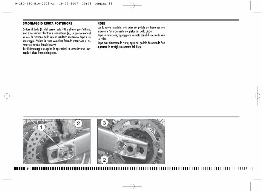
SMONTAGGIO RUOTA POSTERIORE
Svitare il dado (1) del perno ruota (3) e sfilare quest’ultimo;non è necessario allentare i tendicatena (2), in questo modo ilvalore di tensione della catena risulterà inalterato dopo il ri-montaggio. Sfilare la ruota completa facendo attenzione ai di-stanziali posti ai lati del mozzo. Per il rimontaggio eseguire le operazioni in senso inverso inse-rendo il disco freno nella pinza.
NOTECon la ruota smontata, non agire sul pedale del freno per nonprovocare l’avanzamento dei pistoncini della pinza.Dopo la rimozione, appoggiare la ruota con il disco rivolto ver-so l’alto.Dopo aver rimontato la ruota, agire sul pedale di comando finoa portare le pastiglie a contatto del disco.
54
9-250-450-510-2008-OK 19-07-2007 10:48 Pagina 54
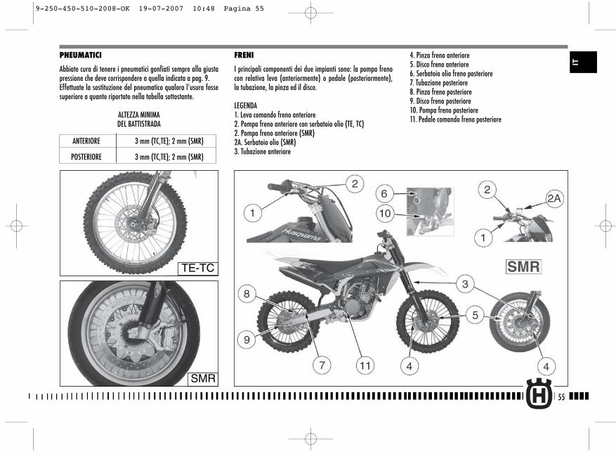
4. Pinza freno anteriore 5. Disco freno anteriore 6. Serbatoio olio freno posteriore7. Tubazione posteriore8. Pinza freno posteriore9. Disco freno posteriore10. Pompa freno posteriore11. Pedale comando freno posteriore
FRENI
I principali componenti dei due impianti sono: la pompa frenocon relativa leva (anteriormente) o pedale (posteriormente),la tubazione, la pinza ed il disco.
LEGENDA1. Leva comando freno anteriore2. Pompa freno anteriore con serbatoio olio (TE, TC)2. Pompa freno anteriore (SMR)2A. Serbatoio olio (SMR)3. Tubazione anteriore
55
IT
PNEUMATICI
Abbiate cura di tenere i pneumatici gonfiati sempre alla giustapressione che deve corrispondere a quella indicata a pag. 9. Effettuate la sostituzione del pneumatico qualora l’usura fossesuperiore a quanto riportato nella tabella sottostante.
ALTEZZA MINIMA DEL BATTISTRADA
ANTERIORE 3 mm (TC,TE); 2 mm (SMR)
POSTERIORE 3 mm (TC,TE); 2 mm (SMR)
TE-TC
SMR
9-250-450-510-2008-OK 19-07-2007 10:48 Pagina 55
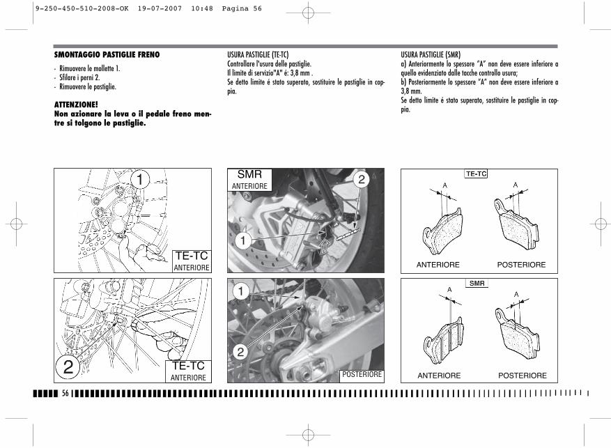
SMONTAGGIO PASTIGLIE FRENO
- Rimuovere le mollette 1.- Sfilare i perni 2.- Rimuovere le pastiglie.
ATTENZIONE!Non azionare la leva o il pedale freno men-tre si tolgono le pastiglie.
USURA PASTIGLIE (TE-TC)Controllare l'usura delle pastiglie.Il limite di servizio"A" é: 3,8 mm .Se detto limite é stato superato, sostituire le pastiglie in cop-pia.
USURA PASTIGLIE (SMR)a) Anteriormente lo spessore “A” non deve essere inferiore aquello evidenziato dalle tacche controllo usura;b) Posteriormente lo spessore “A” non deve essere inferiore a3,8 mm. Se detto limite é stato superato, sostituire le pastiglie in cop-pia.
56
TE-TCANTERIORE
TE-TCANTERIORE
SMRANTERIORE
POSTERIORE
ANTERIORE POSTERIORE
ANTERIORE POSTERIORE
9-250-450-510-2008-OK 19-07-2007 10:48 Pagina 56
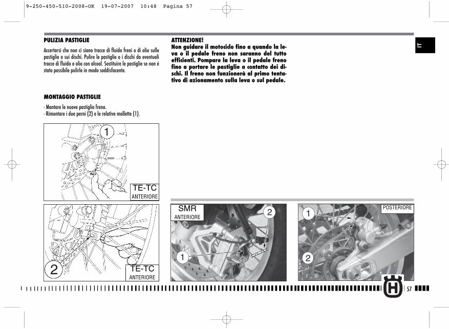
PULIZIA PASTIGLIE
Accertarsi che non ci siano tracce di fluido freni o di olio sullepastiglie o sui dischi. Pulire le pastiglie o i dischi da eventualitracce di fluido o olio con alcool. Sostituire le pastiglie se non éstato possibile pulirle in modo soddisfacente.
MONTAGGIO PASTIGLIE
- Montare le nuove pastiglie freno.- Rimontare i due perni (2) e le relative mollette (1).
ATTENZIONE!Non guidare il motociclo fino a quando la le-va o il pedale freno non saranno del tuttoefficienti. Pompare la leva o il pedale frenofino a portare le pastiglie a contatto dei di-schi. Il freno non funzionerà al primo tenta-tivo di azionamento sulla leva o sul pedale.
57
TE-TCANTERIORE
TE-TCANTERIORE
SMRANTERIORE
POSTERIORE
IT
9-250-450-510-2008-OK 19-07-2007 10:48 Pagina 57

USURA DISCO FRENO
Rilevare lo spessore di ogni disco nel punto di maggiore usura.Sostituire il disco se l'usura ha superato il limite previsto.
Spessore Disco
SFARFALLAMENTO DISCOMisurare lo sfarfallamento del disco. Il limite di servizio perentrambi i dischi é di 0,15 mm.Sostituire il disco se lo sfarfallamento é superiore al limite diusura.
58
Anteriore(SMR)
5 mm 4,5 mm
Anteriore 3 mm 2,5 mm(TE-TC)
DISCO STANDARDLIMITE DISERVIZIO
Posteriore 4 mm 3,5 mm
TE-TC
TE-TC
9-250-450-510-2008-OK 19-07-2007 10:48 Pagina 58
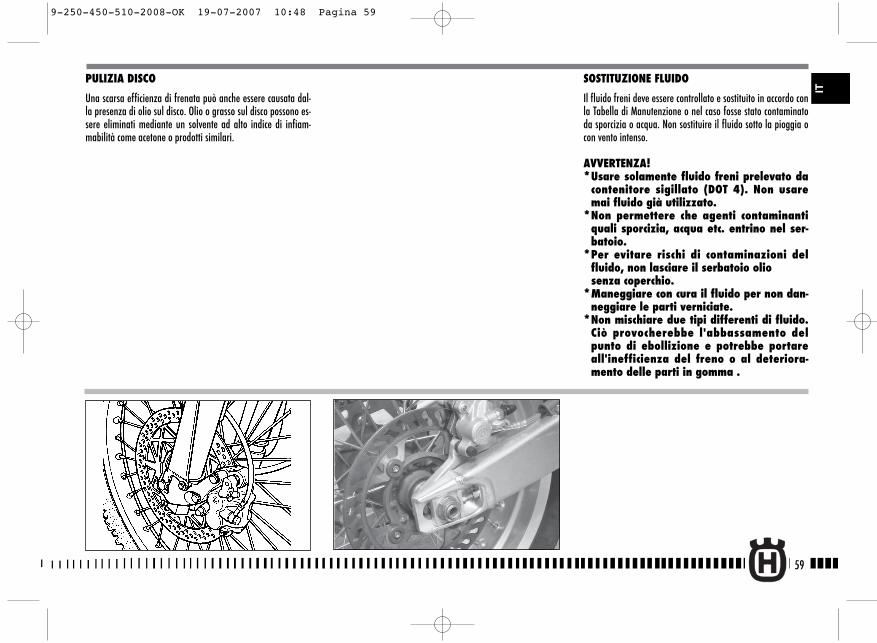
PULIZIA DISCO
Una scarsa efficienza di frenata può anche essere causata dal-la presenza di olio sul disco. Olio o grasso sul disco possono es-sere eliminati mediante un solvente ad alto indice di infiam-mabilità come acetone o prodotti similari.
SOSTITUZIONE FLUIDO
Il fluido freni deve essere controllato e sostituito in accordo conla Tabella di Manutenzione o nel caso fosse stato contaminatoda sporcizia o acqua. Non sostituire il fluido sotto la pioggia ocon vento intenso.
AVVERTENZA! *Usare solamente fluido freni prelevato da
contenitore sigillato (DOT 4). Non usaremai fluido già utilizzato.
*Non permettere che agenti contaminantiquali sporcizia, acqua etc. entrino nel ser-batoio.
*Per evitare rischi di contaminazioni delfluido, non lasciare il serbatoio olio senza coperchio.
*Maneggiare con cura il fluido per non dan-neggiare le parti verniciate.
*Non mischiare due tipi differenti di fluido.Ciò provocherebbe l'abbassamento delpunto di ebollizione e potrebbe portareall'inefficienza del freno o al deteriora-mento delle parti in gomma .
59
IT
9-250-450-510-2008-OK 19-07-2007 10:48 Pagina 59
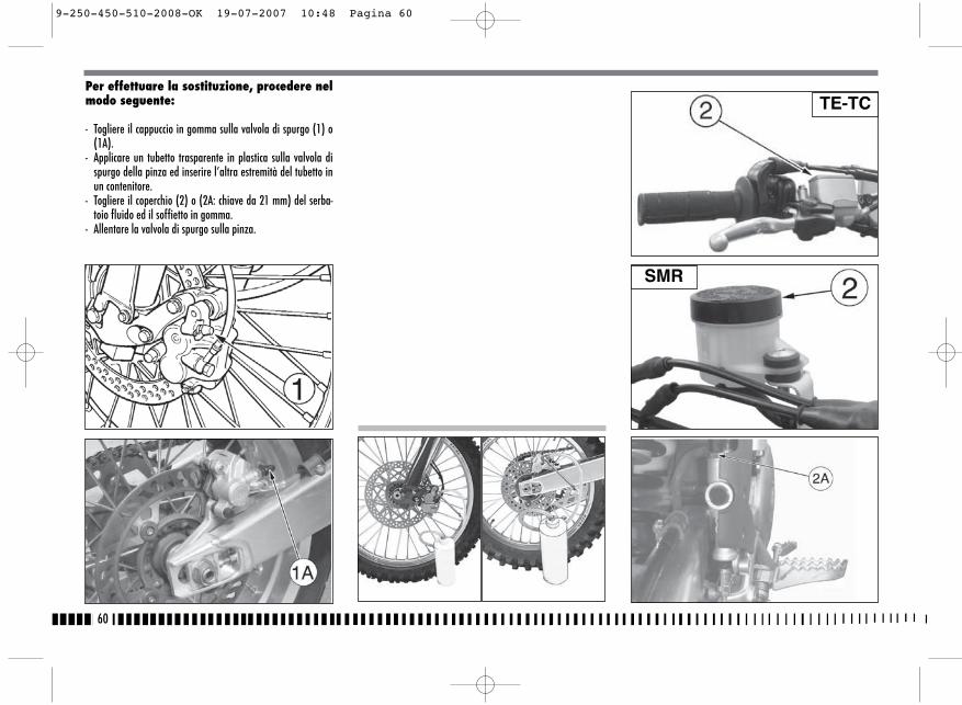
Per effettuare la sostituzione, procedere nelmodo seguente:
- Togliere il cappuccio in gomma sulla valvola di spurgo (1) o(1A).
- Applicare un tubetto trasparente in plastica sulla valvola dispurgo della pinza ed inserire l’altra estremità del tubetto inun contenitore.
- Togliere il coperchio (2) o (2A: chiave da 21 mm) del serba-toio fluido ed il soffietto in gomma.
- Allentare la valvola di spurgo sulla pinza.
60
TE-TC
SMR
9-250-450-510-2008-OK 19-07-2007 10:48 Pagina 60
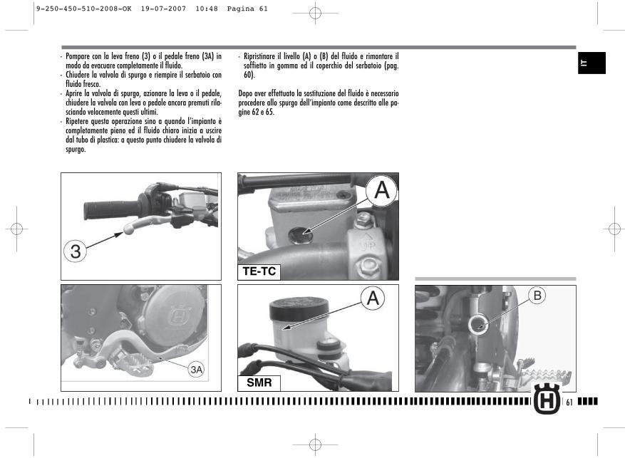
- Ripristinare il livello (A) o (B) del fluido e rimontare ilsoffietto in gomma ed il coperchio del serbatoio (pag.60).
Dopo aver effettuato la sostituzione del fluido è necessarioprocedere allo spurgo dell’impianto come descritto alle pa-gine 62 e 65.
61
- Pompare con la leva freno (3) o il pedale freno (3A) inmodo da evacuare completamente il fluido.
- Chiudere la valvola di spurgo e riempire il serbatoio confluido fresco.
- Aprire la valvola di spurgo, azionare la leva o il pedale,chiudere la valvola con leva o pedale ancora premuti rila-sciando velocemente questi ultimi.
- Ripetere questa operazione sino a quando l’impianto ècompletamente pieno ed il fluido chiaro inizia a usciredal tubo di plastica: a questo punto chiudere la valvola dispurgo.
TE-TC
SMR
IT
9-250-450-510-2008-OK 19-07-2007 10:48 Pagina 61
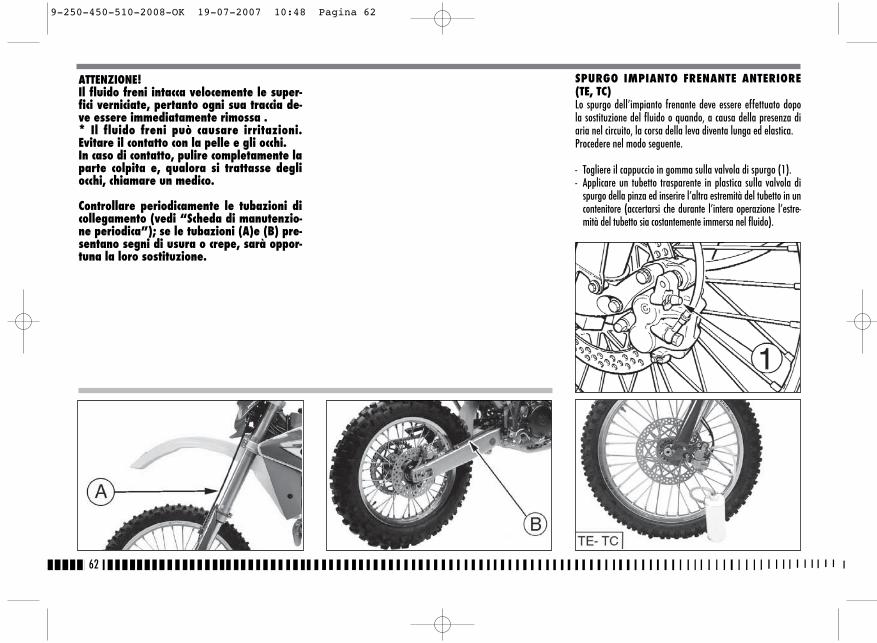
62
SPURGO IMPIANTO FRENANTE ANTERIORE (TE, TC)Lo spurgo dell’impianto frenante deve essere effettuato dopola sostituzione del fluido o quando, a causa della presenza diaria nel circuito, la corsa della leva diventa lunga ed elastica.Procedere nel modo seguente.
- Togliere il cappuccio in gomma sulla valvola di spurgo (1).- Applicare un tubetto trasparente in plastica sulla valvola di
spurgo della pinza ed inserire l’altra estremità del tubetto in uncontenitore (accertarsi che durante l’intera operazione l’estre-mità del tubetto sia costantemente immersa nel fluido).
ATTENZIONE!Il fluido freni intacca velocemente le super-fici verniciate, pertanto ogni sua traccia de-ve essere immediatamente rimossa .* Il fluido freni può causare irritazioni.Evitare il contatto con la pelle e gli occhi.In caso di contatto, pulire completamente laparte colpita e, qualora si trattasse degliocchi, chiamare un medico.
Controllare periodicamente le tubazioni dicollegamento (vedi “Scheda di manutenzio-ne periodica”); se le tubazioni (A)e (B) pre-sentano segni di usura o crepe, sarà oppor-tuna la loro sostituzione.
9-250-450-510-2008-OK 19-07-2007 10:48 Pagina 62
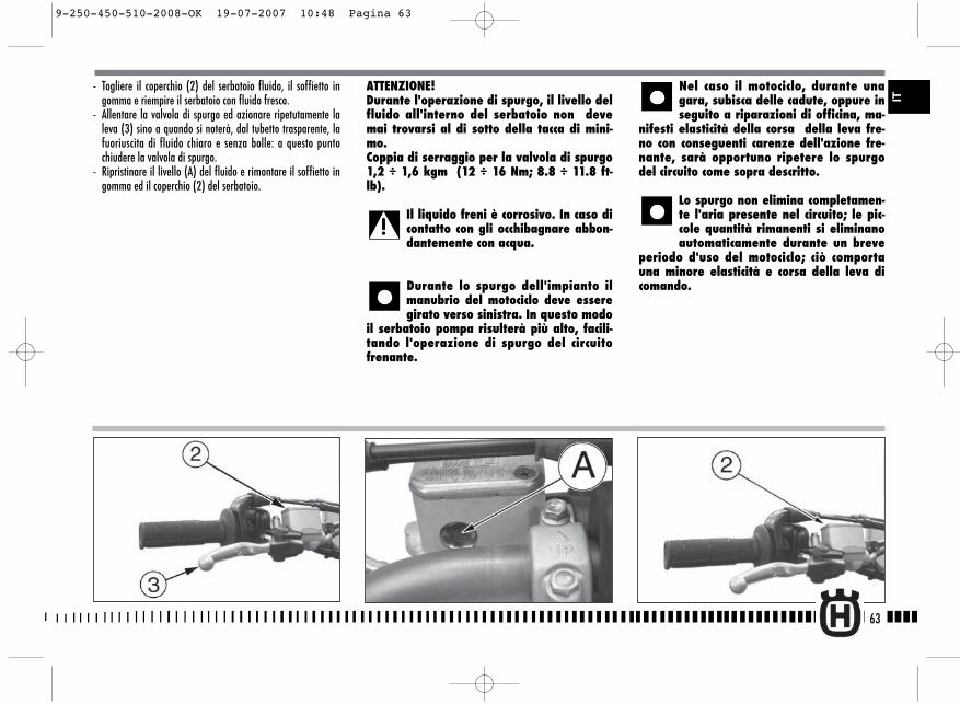
- Togliere il coperchio (2) del serbatoio fluido, il soffietto ingomma e riempire il serbatoio con fluido fresco.
- Allentare la valvola di spurgo ed azionare ripetutamente laleva (3) sino a quando si noterà, dal tubetto trasparente, lafuoriuscita di fluido chiaro e senza bolle: a questo puntochiudere la valvola di spurgo.
- Ripristinare il livello (A) del fluido e rimontare il soffietto ingomma ed il coperchio (2) del serbatoio.
ATTENZIONE!Durante l'operazione di spurgo, il livello delfluido all'interno del serbatoio non devemai trovarsi al di sotto della tacca di mini-mo.Coppia di serraggio per la valvola di spurgo1,2 ÷ 1,6 kgm (12 ÷ 16 Nm; 8.8 ÷ 11.8 ft-lb).
Il liquido freni è corrosivo. In caso dicontatto con gli occhibagnare abbon-dantemente con acqua.
Durante lo spurgo dell'impianto ilmanubrio del motociclo deve esseregirato verso sinistra. In questo modo
il serbatoio pompa risulterà più alto, facili-tando l'operazione di spurgo del circuitofrenante.
Nel caso il motociclo, durante unagara, subisca delle cadute, oppure inseguito a riparazioni di officina, ma-
nifesti elasticità della corsa della leva fre-no con conseguenti carenze dell'azione fre-nante, sarà opportuno ripetere lo spurgodel circuito come sopra descritto.
Lo spurgo non elimina completamen-te l'aria presente nel circuito; le pic-cole quantità rimanenti si eliminanoautomaticamente durante un breve
periodo d'uso del motociclo; ciò comportauna minore elasticità e corsa della leva dicomando.
63
IT
9-250-450-510-2008-OK 19-07-2007 10:48 Pagina 63

SPURGO IMPIANTO FRENANTE ANTERIORE(SMR)
Lo spurgo dell’impianto frenante deve essere effettuato dopola sostituzione del fluido o quando, a causa della presenza diaria nel circuito, la corsa della leva diventa lunga ed elastica.Nell’impianto frenante anteriore lo spurgo deve avvenire pri-ma sul comando sul manubrio poi sulla pinza: le operazioni daeffettuare sono le stesse.Procedere nel modo seguente.- Togliere il cappuccio in gomma sulla valvola di spurgo (1) o
(1A).
- Applicare un tubetto trasparente in plastica sulla valvola dispurgo della pinza ed inserire l’altra estremità del tubetto in uncontenitore (accertarsi che durante l’intera operazione l’estre-mità del tubetto sia costantemente immersa nel fluido).
- Togliere il coperchio (2) del serbatoio fluido, il soffietto ingomma e riempire il serbatoio con fluido fresco.
- Allentare la valvola di spurgo ed azionare ripetutamente laleva sino a quando si noterà, dal tubetto trasparente, la fuo-riuscita di fluido chiaro e senza bolle: a questo punto chiude-re la valvola di spurgo.
64
SMR
SMR
9-250-450-510-2008-OK 19-07-2007 10:48 Pagina 64
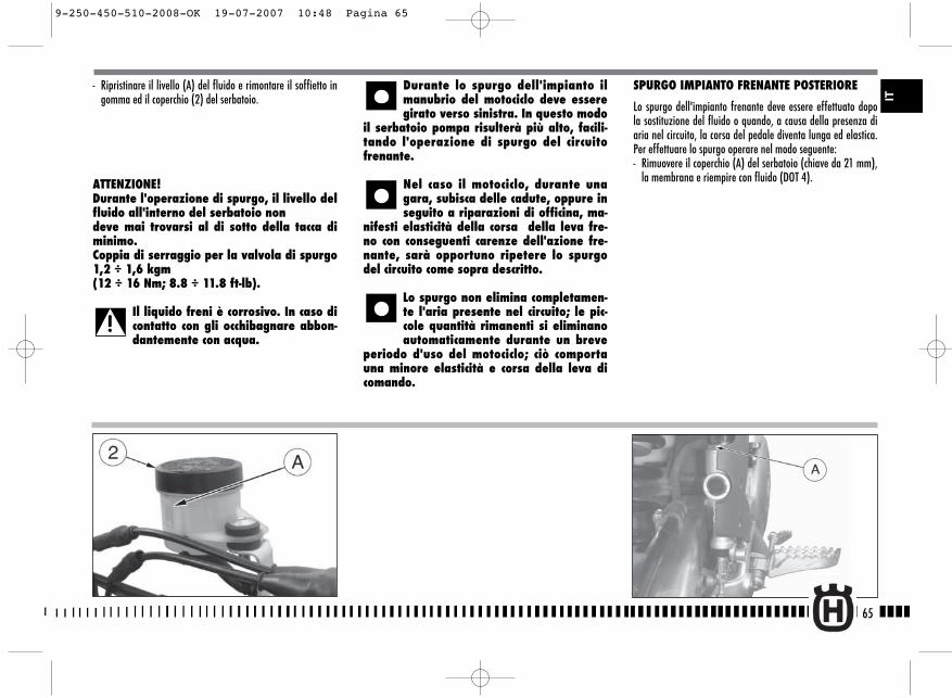
SPURGO IMPIANTO FRENANTE POSTERIORE
Lo spurgo dell'impianto frenante deve essere effettuato dopola sostituzione del fluido o quando, a causa della presenza diaria nel circuito, la corsa del pedale diventa lunga ed elastica.Per effettuare lo spurgo operare nel modo seguente:- Rimuovere il coperchio (A) del serbatoio (chiave da 21 mm),
la membrana e riempire con fluido (DOT 4).
- Ripristinare il livello (A) del fluido e rimontare il soffietto ingomma ed il coperchio (2) del serbatoio.
ATTENZIONE!Durante l'operazione di spurgo, il livello delfluido all'interno del serbatoio nondeve mai trovarsi al di sotto della tacca diminimo.Coppia di serraggio per la valvola di spurgo1,2 ÷ 1,6 kgm(12 ÷ 16 Nm; 8.8 ÷ 11.8 ft-lb).
Il liquido freni è corrosivo. In caso dicontatto con gli occhibagnare abbon-dantemente con acqua.
Durante lo spurgo dell'impianto ilmanubrio del motociclo deve esseregirato verso sinistra. In questo modo
il serbatoio pompa risulterà più alto, facili-tando l'operazione di spurgo del circuitofrenante.
Nel caso il motociclo, durante unagara, subisca delle cadute, oppure inseguito a riparazioni di officina, ma-
nifesti elasticità della corsa della leva fre-no con conseguenti carenze dell'azione fre-nante, sarà opportuno ripetere lo spurgodel circuito come sopra descritto.
Lo spurgo non elimina completamen-te l'aria presente nel circuito; le pic-cole quantità rimanenti si eliminanoautomaticamente durante un breve
periodo d'uso del motociclo; ciò comportauna minore elasticità e corsa della leva dicomando.
65
IT
9-250-450-510-2008-OK 19-07-2007 10:48 Pagina 65
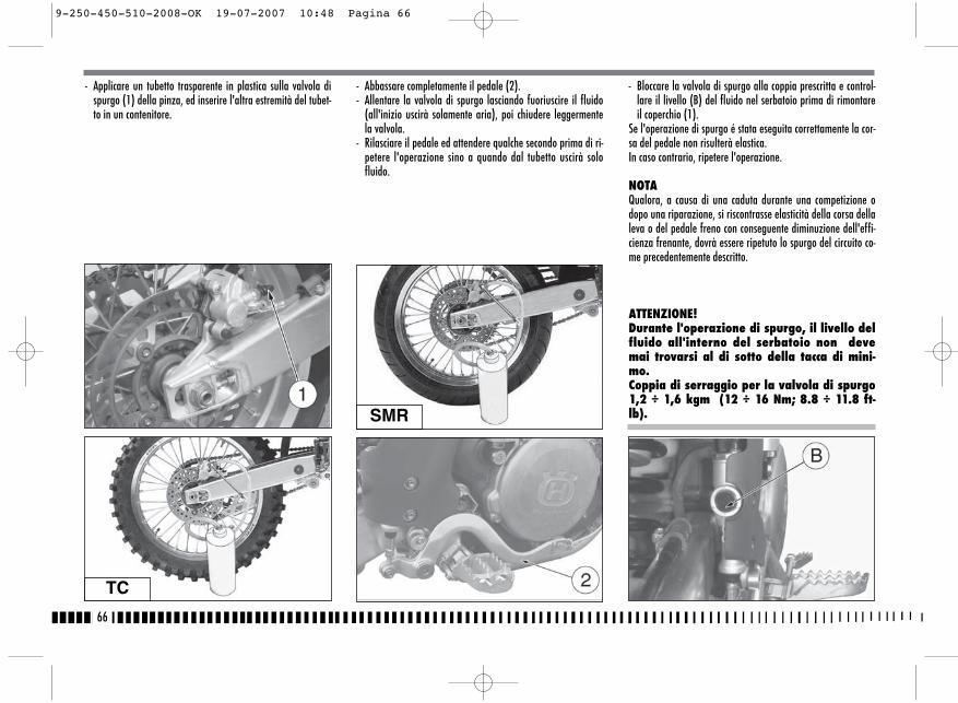
- Applicare un tubetto trasparente in plastica sulla valvola dispurgo (1) della pinza, ed inserire l'altra estremità del tubet-to in un contenitore.
- Abbassare completamente il pedale (2).- Allentare la valvola di spurgo lasciando fuoriuscire il fluido
(all'inizio uscirà solamente aria), poi chiudere leggermentela valvola.
- Rilasciare il pedale ed attendere qualche secondo prima di ri-petere l'operazione sino a quando dal tubetto uscirà solofluido.
- Bloccare la valvola di spurgo alla coppia prescritta e control-lare il livello (B) del fluido nel serbatoio prima di rimontareil coperchio (1).
Se l'operazione di spurgo é stata eseguita correttamente la cor-sa del pedale non risulterà elastica. In caso contrario, ripetere l'operazione.
NOTAQualora, a causa di una caduta durante una competizione odopo una riparazione, si riscontrasse elasticità della corsa dellaleva o del pedale freno con conseguente diminuzione dell'effi-cienza frenante, dovrà essere ripetuto lo spurgo del circuito co-me precedentemente descritto.
ATTENZIONE!Durante l'operazione di spurgo, il livello delfluido all'interno del serbatoio non devemai trovarsi al di sotto della tacca di mini-mo.Coppia di serraggio per la valvola di spurgo1,2 ÷ 1,6 kgm (12 ÷ 16 Nm; 8.8 ÷ 11.8 ft-lb).
66
TC
SMR
9-250-450-510-2008-OK 19-07-2007 10:48 Pagina 66
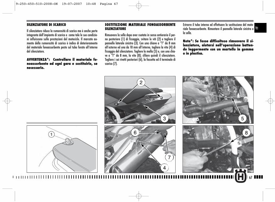
SILENZIATORE DI SCARICO
Il silenziatore riduce la rumorosità di scarico ma è anche parteintegrante dell’impianto di scarico e come tale le sue condizio-ni influiscono sulle prestazioni del motociclo. Il marcato au-mento della rumorosità di scarico è indice di deterioramentodel materiale fonoassorbente posto sul tubo forato all’internodel silenziatore.
AVVERTENZA*: Controllare il materiale fo-noassorbente ad ogni gara e sostituirlo, senecessario.
SOSTITUZIONE MATERIALE FONOASSORBENTESILENZIATORE
Rimuovere la sella dopo aver ruotato in senso antiorario il per-no posteriore (1) di fissaggio, svitare le viti (2) e togliere ilpannello laterale sinistro (3). Con una chiave a “T” da 8 mmall’esterno ed una da 10 mm all’interno, togliere la vite (4) difissaggio del silenziatore. Togliere la molla (5) e, con una chia-ve a “T” da 8 mm, la vite (8); sfilare quindi il silenziatore.Togliere i sei rivetti posteriori (6), la fascetta ed il terminale discarico (7).
Estrarre il tubo interno ed effettuare la sostituzione del mate-riale fonoassorbente. Rimontare il pannello laterale sinistro ela sella.
Nota*: Se fosse difficoltoso rimuovere il si-lenziatore, aiutarsi nell’operazione batten-do leggermente con un martello in gommao in plastica.
67
2
3
4
5
86
7
IT
9-250-450-510-2008-OK 19-07-2007 10:48 Pagina 67
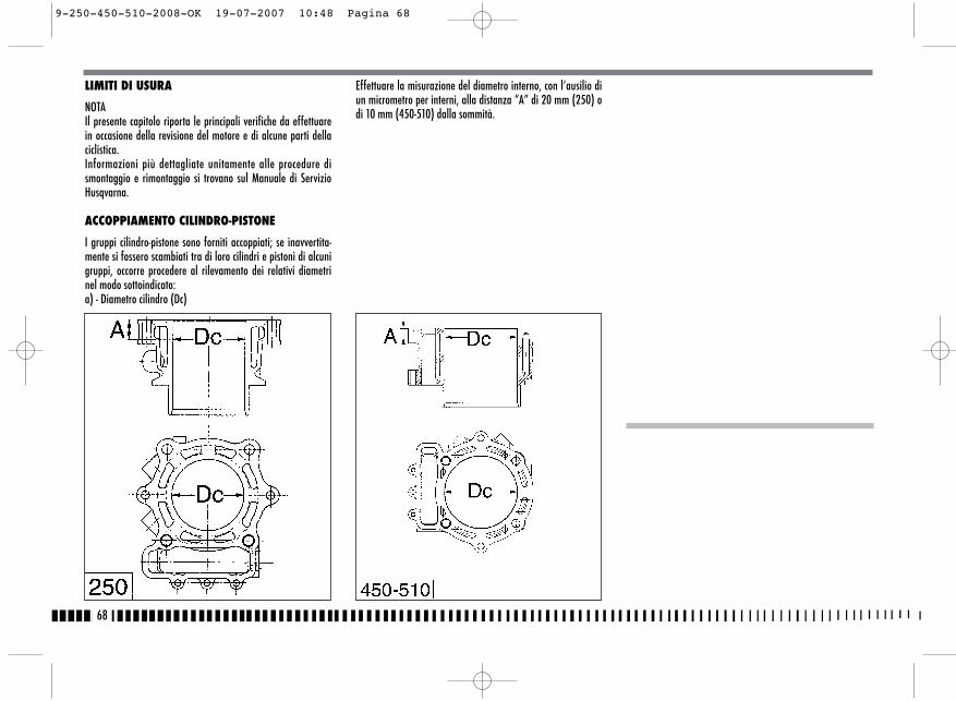
LIMITI DI USURA
NOTAIl presente capitolo riporta le principali verifiche da effettuarein occasione della revisione del motore e di alcune parti dellaciclistica.Informazioni più dettagliate unitamente alle procedure dismontaggio e rimontaggio si trovano sul Manuale di ServizioHusqvarna.
ACCOPPIAMENTO CILINDRO-PISTONE
I gruppi cilindro-pistone sono forniti accoppiati; se inavvertita-mente si fossero scambiati tra di loro cilindri e pistoni di alcunigruppi, occorre procedere al rilevamento dei relativi diametrinel modo sottoindicato:a) - Diametro cilindro (Dc)
Effettuare la misurazione del diametro interno, con l’ausilio diun micrometro per interni, alla distanza “A” di 20 mm (250) odi 10 mm (450-510) dalla sommità.
68
9-250-450-510-2008-OK 19-07-2007 10:48 Pagina 68
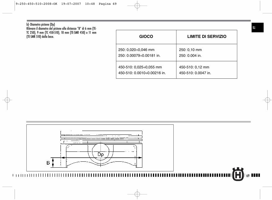
b)- Diametro pistone (Dp)Rilevare il diametro del pistone alla distanza “B” di 6 mm (TE-TC 250), 9 mm (TC 450-510), 10 mm (TE-SMR 450) o 11 mm(TE-SMR 510) dalla base.
69
IT
250: 0,020÷0,046 mm
250: 0.00079÷0.00181 in.
450-510: 0,025÷0,055 mm
450-510: 0.0010÷0.00216 in.
LIMITE DI SERVIZIOGIOCO
250: 0,10 mm
250: 0.004 in.
450-510: 0,12 mm
450-510: 0.0047 in.
9-250-450-510-2008-OK 19-07-2007 10:48 Pagina 69
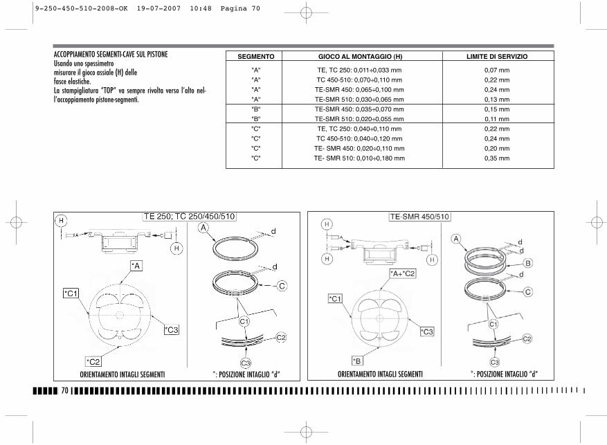
ACCOPPIAMENTO SEGMENTI-CAVE SUL PISTONEUsando uno spessimetromisurare il gioco assiale (H) dellefasce elastiche.La stampigliatura “TOP” va sempre rivolta verso l’alto nel-l’accoppiamento pistone-segmenti.
70
ORIENTAMENTO INTAGLI SEGMENTI *: POSIZIONE INTAGLIO “d” ORIENTAMENTO INTAGLI SEGMENTI *: POSIZIONE INTAGLIO “d”
SEGMENTO GIOCO AL MONTAGGIO (H) LIMITE DI SERVIZIO
"A" TE, TC 250: 0,011÷0,033 mm 0,07 mm
"A" TC 450-510: 0,070÷0,110 mm 0,22 mm
"A" TE-SMR 450: 0,065÷0,100 mm 0,24 mm
"A" TE-SMR 510: 0,030÷0,065 mm 0,13 mm
"B" TE-SMR 450: 0,035÷0,070 mm 0,15 mm
"B" TE-SMR 510: 0,020÷0,055 mm 0,11 mm
"C" TE, TC 250: 0,040÷0,110 mm 0,22 mm
"C" TC 450-510: 0,040÷0,120 mm 0,24 mm
"C" TE- SMR 450: 0,020÷0,110 mm 0,20 mm
"C" TE- SMR 510: 0,010÷0,180 mm 0,35 mm
9-250-450-510-2008-OK 19-07-2007 10:48 Pagina 70
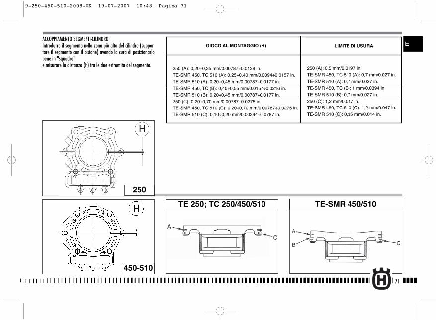
ACCOPPIAMENTO SEGMENTI-CILINDROIntrodurre il segmento nella zona più alta del cilindro (suppor-tare il segmento con il pistone) avendo la cura di posizionarlobene in "squadro"e misurare la distanza (H) tra le due estremità del segmento.
71
250
TE 250; TC 250/450/510 TE-SMR 450/510
450-510
LIMITE DI USURAGIOCO AL MONTAGGIO (H)
250 (A): 0,20÷0,35 mm/0.00787÷0.0138 in.TE-SMR 450, TC 510 (A): 0,25÷0,40 mm/0.0094÷0.0157 in.TE-SMR 510 (A): 0,20÷0,45 mm/0.00787÷0.0177 in.TE-SMR 450, TC (B): 0,40÷0,55 mm/0.0157÷0.0216 in.TE-SMR 510 (B): 0,20÷0,45 mm/0.00787÷0.0177 in.250 (C): 0,20÷0,70 mm/0.00787÷0.0275 in.TE-SMR 450, TC 510 (C): 0,20÷0,70 mm/0.00787÷0.0275 in.TE-SMR 510 (C): 0,10÷0,20 mm/0.00394÷0.0787 in.
250 (A): 0,5 mm/0.0197 in.TE-SMR 450, TC 510 (A): 0,7 mm/0.027 in.TE-SMR 510 (A): 0,7 mm/0.027 in.TE-SMR 450, TC (B): 1 mm/0.0394 in.TE-SMR 510 (B): 0,7 mm/0.027 in.250 (C): 1,2 mm/0.047 in.TE-SMR 450, TC 510 (C): 1,2 mm/0.047 in.TE-SMR 510 (C): 0,35 mm/0.014 in.
IT
9-250-450-510-2008-OK 19-07-2007 10:48 Pagina 71
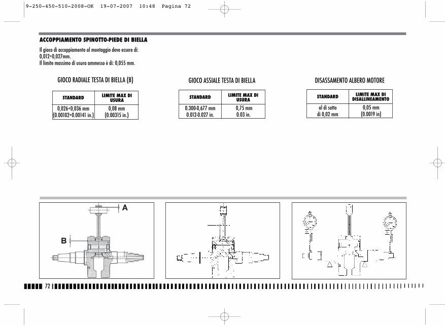
ACCOPPIAMENTO SPINOTTO-PIEDE DI BIELLA
Il gioco di accoppiamento al montaggio deve essere di:0,012÷0,027mm.Il limite massimo di usura ammesso è di: 0,055 mm.
72
STANDARD LIMITE MAX DIUSURA
0,026÷0,036 mm(0.00102÷0.00141 in.)
0,08 mm(0.00315 in.)
GIOCO RADIALE TESTA DI BIELLA (B) GIOCO ASSIALE TESTA DI BIELLA
STANDARD LIMITE MAX DIUSURA
0.300-0,677 mm0.012-0.027 in.
0,75 mm0.03 in.
DISASSAMENTO ALBERO MOTORE
STANDARD LIMITE MAX DIDISALLINEAMENTO
al di sotto di 0,02 mm
0,05 mm(0.0019 in)
9-250-450-510-2008-OK 19-07-2007 10:48 Pagina 72
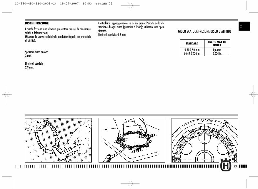
73
IT
DISCHI FRIZIONE
I dischi frizione non devono presentare tracce di bruciature,solchi o deformazioni.Misurare lo spessore dei dischi conduttori (quelli con materialedi attrito).
Spessore disco nuovo:3 mm.
Limite di servizio2,9 mm.
Controllare, appoggiandolo su di un piano, l'entità della di-storsione di ogni disco (guarnito e liscio); utilizzare uno spes-simetro.Limite di servizio: 0,2 mm.
STANDARD LIMITE MAX DIUSURA
0.30-0,50 mm0.012-0.020 in.
0,6 mm0.024 in.
GIOCO SCATOLA FRIZIONE-DISCO D'ATTRITO
10-250-450-510-2008-OK 19-07-2007 10:53 Pagina 73
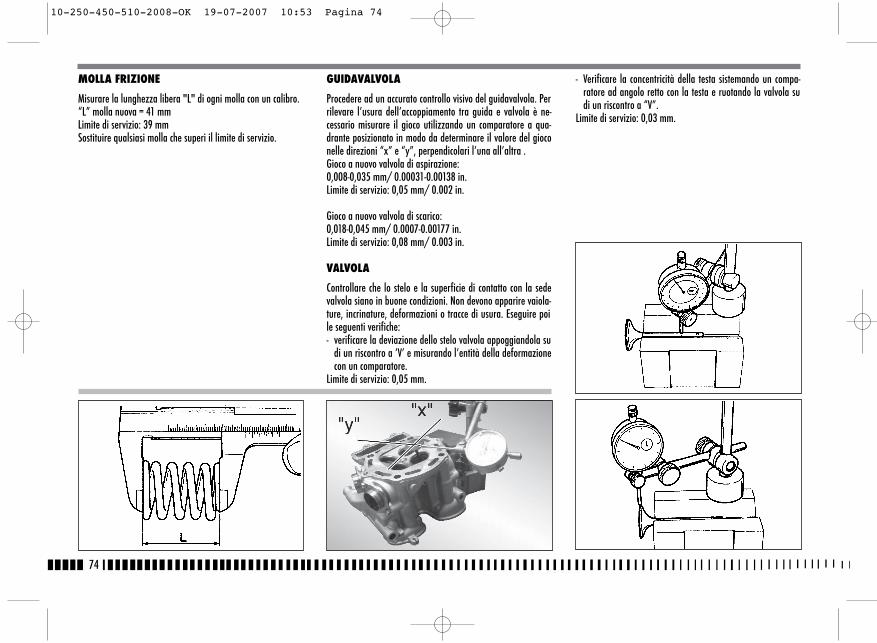
MOLLA FRIZIONE
Misurare la lunghezza libera "L" di ogni molla con un calibro.“L” molla nuova = 41 mmLimite di servizio: 39 mmSostituire qualsiasi molla che superi il limite di servizio.
GUIDAVALVOLA
Procedere ad un accurato controllo visivo del guidavalvola. Perrilevare l’usura dell’accoppiamento tra guida e valvola è ne-cessario misurare il gioco utilizzando un comparatore a qua-drante posizionato in modo da determinare il valore del gioconelle direzioni “x” e “y”, perpendicolari l’una all’altra .Gioco a nuovo valvola di aspirazione:0,008-0,035 mm/ 0.00031-0.00138 in.Limite di servizio: 0,05 mm/ 0.002 in.
Gioco a nuovo valvola di scarico:0,018-0,045 mm/ 0.0007-0.00177 in.Limite di servizio: 0,08 mm/ 0.003 in.
VALVOLA
Controllare che lo stelo e la superficie di contatto con la sedevalvola siano in buone condizioni. Non devono apparire vaiola-ture, incrinature, deformazioni o tracce di usura. Eseguire poile seguenti verifiche:- verificare la deviazione dello stelo valvola appoggiandola su
di un riscontro a ‘V’ e misurando l’entità della deformazionecon un comparatore.
Limite di servizio: 0,05 mm.
- Verificare la concentricità della testa sistemando un compa-ratore ad angolo retto con la testa e ruotando la valvola sudi un riscontro a “V”.
Limite di servizio: 0,03 mm.
74
10-250-450-510-2008-OK 19-07-2007 10:53 Pagina 74
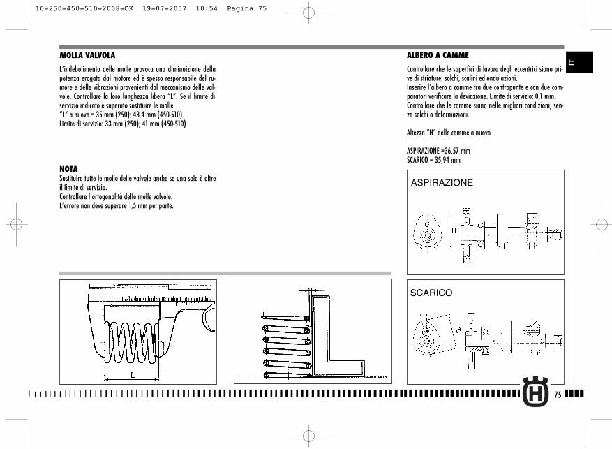
ALBERO A CAMME
Controllare che le superfici di lavoro degli eccentrici siano pri-ve di striature, solchi, scalini ed ondulazioni.Inserire l’albero a camme tra due contropunte e con due com-paratori verificare la deviazione. Limite di servizio: 0,1 mm.Controllare che le camme siano nelle migliori condizioni, sen-za solchi o deformazioni.
Altezza “H” delle camme a nuovo
ASPIRAZIONE =36,57 mmSCARICO = 35,94 mm
MOLLA VALVOLA
L’indebolimento delle molle provoca una diminuizione dellapotenza erogata dal motore ed è spesso responsabile del ru-more e delle vibrazioni provenienti dal meccanismo delle val-vole. Controllare la loro lunghezza libera “L”. Se il limite diservizio indicato è superato sostituire le molle.“L” a nuovo = 35 mm (250); 43,4 mm (450-510) Limite di servizio: 33 mm (250); 41 mm (450-510)
NOTASostituire tutte le molle delle valvole anche se una sola è oltreil limite di servizio.Controllare l’ortogonalità delle molle valvole.L’errore non deve superare 1,5 mm per parte.
75
ASPIRAZIONE
SCARICO
IT
10-250-450-510-2008-OK 19-07-2007 10:54 Pagina 75

76
REVISIONE RUOTE
Le tabelle sono riportate mostrando i tipi di controllo a cui de-vono essere sottoposti cerchio e perno ruota.
Nota*: se il cerchio è eccessivamente piegato, deve esseresostituito.
DEFORMAZION E CERCHIO
PIEGATURA PERNO RUOTA
Se il valore della piegatura supera il limite max. consentito,raddrizzare il perno o sostituirlo.Se il perno non può essere raddrizzato entro il valore di limitemax. prescritto (0,2mm), sostituirlo.
RAGGI RUOTA
Accertarsi che tutti i nippli siano ben stretti e, se necessario,serrarli nuovamente. Una tensione insufficiente pregiudica lastabilità del motociclo; per effettuare un controllo immediato,è sufficiente battere i raggi con una punta metallica (ad esem-pio quella di un cacciavite): un suono vivo è indice di serraggiocorretto, un suono sordo indica che è necessario un nuovo ser-raggio.
STANDARD LIMITE MAX.
Sbandamento laterale meno di 0,5 mm2 mm
(0,078 in)Eccentricità meno di 0,8 mm
10-250-450-510-2008-OK 19-07-2007 10:54 Pagina 76
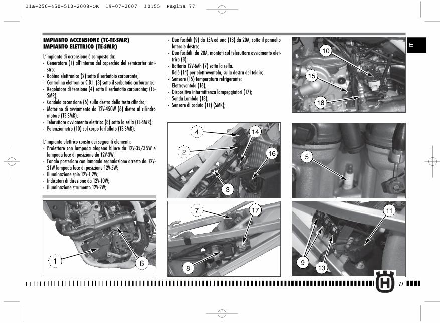
9
11
- Due fusibili (9) da 15A ed uno (13) da 20A, sotto il pannellolaterale destro;
- Due fusibili da 20A, montati sul teleruttore avviamento elet-trico (8);
- Batteria 12V-6Ah (7) sotto la sella.- Relè (14) per elettroventola, sulla destra del telaio;- Sensore (15) temperatura refrigerante;- Elettroventola (16);- Dispositivo intermittenza lampeggiatori (17);- Sonda Lambda (18);- Sensore di caduta (11) (SMR);
77
IT
IMPIANTO ACCENSIONE (TC-TE-SMR)IMPIANTO ELETTRICO (TE-SMR)
L’impianto di accensione è composto da:- Generatore (1) all’interno del coperchio del semicarter sini-
stro;- Bobina elettronica (2) sotto il serbatoio carburante;- Centralina elettronica C.D.I. (3) sotto il serbatotio carburante;- Regolatore di tensione (4) sotto il serbatotio carburante; (TE-
SMR);- Candela accensione (5) sulla destra della testa cilindro;- Motorino di avviamento da 12V-450W (6) dietro al cilindro
motore (TE-SMR);- Teleruttore avviamento elettrico (8) sotto la sella (TE-SMR);- Potenziometro (10) sul corpo farfallato (TE-SMR);
L’impianto elettrico consta dei seguenti elementi:- Proiettore con lampada alogena biluce da 12V-35/35W e
lampada luce di posizione da 12V-3W;- Fanale posteriore con lampada segnalazione arresto da 12V-
21W lampada luce di posizione 12V-5W;- Illuminazione spie 12V-1,2W;- Indicatori di direzione da 12V-10W;- Illuminazione strumento 12V-2W;
1 6
4
2 16
14
3
7 17
8
5
15
18
10
13
11a-250-450-510-2008-OK 19-07-2007 10:55 Pagina 77
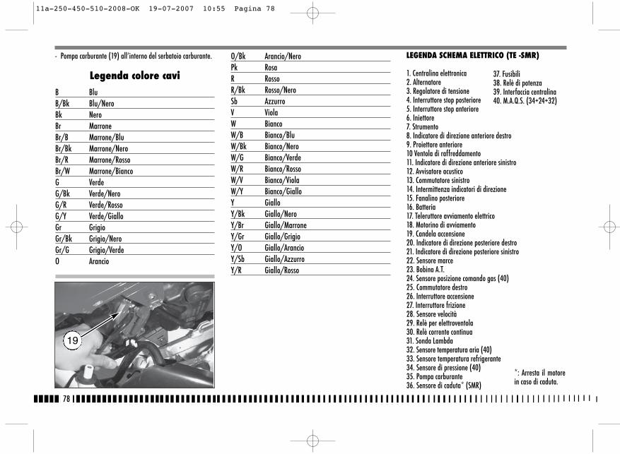
- Pompa carburante (19) all’interno del serbatoio carburante.
Legenda colore caviB BluB/Bk Blu/NeroBk NeroBr MarroneBr/B Marrone/BluBr/Bk Marrone/NeroBr/R Marrone/RossoBr/W Marrone/BiancoG VerdeG/Bk Verde/NeroG/R Verde/RossoG/Y Verde/GialloGr GrigioGr/Bk Grigio/NeroGr/G Grigio/VerdeO Arancio
O/Bk Arancio/NeroPk RosaR RossoR/Bk Rosso/NeroSb AzzurroV ViolaW BiancoW/B Bianco/BluW/Bk Bianco/NeroW/G Bianco/VerdeW/R Bianco/RossoW/V Bianco/ViolaW/Y Bianco/GialloY GialloY/Bk Giallo/NeroY/Br Giallo/MarroneY/Gr Giallo/GrigioY/O Giallo/ArancioY/Sb Giallo/AzzurroY/R Giallo/Rosso
78
19
LEGENDA SCHEMA ELETTRICO (TE -SMR)
1. Centralina elettronica2. Alternatore3. Regolatore di tensione4. Interruttore stop posteriore5. Interruttore stop anteriore6. Iniettore7. Strumento8. Indicatore di direzione anteriore destro9. Proiettore anteriore 10 Ventola di raffreddamento 11. Indicatore di direzione anteriore sinistro12. Avvisatore acustico13. Commutatore sinistro14. Intermittenza indicatori di direzione15. Fanalino posteriore16. Batteria17. Teleruttore avviamento elettrico18. Motorino di avviamento19. Candela accensione20. Indicatore di direzione posteriore destro21. Indicatore di direzione posteriore sinistro22. Sensore marce23. Bobina A.T.24. Sensore posizione comando gas (40)25. Commutatore destro26. Interruttore accensione27. Interruttore frizione28. Sensore velocità29. Relè per elettroventola30. Relè corrente continua31. Sonda Lambda 32. Sensore temperatura aria (40)33. Sensore temperatura refrigerante34. Sensore di pressione (40)35. Pompa carburante36. Sensore di caduta* (SMR)
37. Fusibili38. Relè di potenza39. Interfaccia centralina40. M.A.Q.S. (34+24+32)
*: Arresta il motorein caso di caduta.
11a-250-450-510-2008-OK 19-07-2007 10:55 Pagina 78
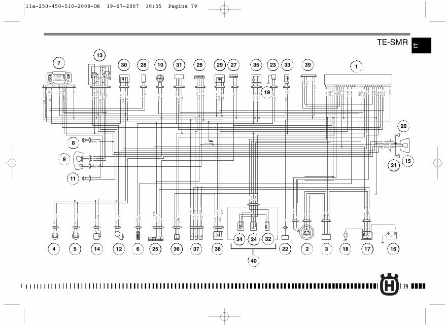
1
2
PASSING
HI
Lo
Pos
TURNHORN
R= 110 Ohm
+-
f
+-
+ -
B
W/G
W/V
Bk
B
B
Y-R
YY
Y
YY
Y
V
Bk
G/R
G/B
k
O
O
B
B
B
Bk
B
B
Pk
R
R
Y-R
Y-R
Y-B
k
Y-B
k
Y-B
k
Y-S
b
Br
G/R
G/R
G/R
V
Pk
Pk
Br/
Bk
Br/
W
Br/
W W/R
W/R
W/B
k
W/B
k
G/B
k
Bk
Bk
Bk
O
Gr/
Bk
Gr/
Bk
Y/B
r Y/S
b
Y/B
r
Y/S
b
Br/
R
Br/
R
O/B
k
O/B
k
W/B
k
W/B
k
Gr/
G
W/B
W/V
W/G
W/B
G-Y B
B
B
B
B
B
Y-R
Y-G
r
Y-S
b
Br
BBr
Y-B
k
Y-G
r
Br-
W
Br-
W
Br-
W
Br-
W
Br-
W
Br-
W
Br-
Bk
Br-
Bk
Br W
Gr/
G
Br/
B
Br/
B
W/R
W/YBk
G/Y
G/Y
G/Y
G/Y
Gr
Gr
B/B
kB
/Bk
Sb
Sb
Sb
R/B
k
R/Bk R/Bk
Bk
Bk
W
W
Y/O
Y/O
Y/O
G/R
G-Y Y RY
W
Br
G
G
B
Y/B
k
W/R
W/Y
W
Bk
Bk
Br
B
RR
/Bk
Sb
Br/
W
1 2 3 4 5 6 7 9 10 11 13 14 15 16 18 19 20 22 25 26 27 29 30 31 32 33 34
M
M 15 12V
R
9Ah
21 3 4
21
ONOFF
1 2
31 2 31 2
OFF
ON
8 12 17 21 23 24 2821
OFF
21 1 2 3 4 1 2 3 4 1 2 3 4 21
1 2 3 421 21 3 1 2 3 4 5 6
1 2 3 4 5
1
21 21 3 1 2 3 4 5 21 3 4
1 2 3 4
1 2 3 4 5 6
21 21
21
34
56
21
21
21
21
3
21212121
1 2 3 41 2 3 4 5 6 7 8 9
1 2 3 4
RUN
START
M P
DF
12
34
56
78
910 12
1114 16
13 15 2526
1718
1920
2122
2324
79
IT
1
2 34 5
7
6
8
9
10
11
12
13
14
15
161718
19
20
21
22
23
24
40
25
26 2728 29
3234
36
35 3330 31
37 38
39
TE-SMR
11a-250-450-510-2008-OK 19-07-2007 10:55 Pagina 79
80
Legenda colore cavi
B BluBr MarroneBk NeroG VerdeGr GrigioGr/R Grigio/RossoO ArancioP RosaR RossoSb AzzurroV ViolaW BiancoY Giallo
LEGENDA SCHEMA ELETTRICO (TC 250)
1. Centralina elettronica2. Alternatore3. Regolatore di tensione4. Condensatore5. Batteria6. Teleruttore avviamento elettrico7. Motorino di avviamento8. Candela accensione9. Sensore marce10. Bobina elettronica11. Sensore farfalla carburatore12. Arresto motore13. Avviamento motore14. Interruttore frizione
11a-250-450-510-2008-OK 19-07-2007 10:55 Pagina 80
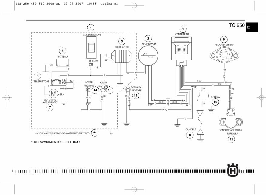
81
R-WGBK-R
R-W
W-Br
GRBK-R
R
CANDELA
BOBINA
GENERATORE
W-O
SENSORE MARCE
SENSORE APERTURAFARFALLA
REGOLATORE
CONDENSATORE
- +
15A
ARRESTO
MOTORE
BATTERIA
TELERUTTORE
MOTORINOAVVIAMENTO
Y-G BBk
Y
B
R Bk
B-W
W
BB
kY
CENTRALINA
Bk - +
R
G-O
R
R
O
R
Bk-W
B
YYR
R
Bk
AVVIOMOTORE
B-W
Bk
R
INTERR.FRIZIONE
SCHEMA PER INSERIMENTO AVVIAMENTO ELETTRICO
TC 250 IT
*: KIT AVVIAMENTO ELETTRICO
1
23
4
5
7
6
8
9
10
11
12
14 13
*
11a-250-450-510-2008-OK 19-07-2007 10:55 Pagina 81

82
Legenda colore cavi
B BluBr MarroneBk NeroG VerdeGr GrigioGr/R Grigio/RossoO ArancioP RosaR RossoSb AzzurroV ViolaW BiancoY Giallo
LEGENDA SCHEMA ELETTRICO (TC 450-510)
1. Centralina elettronica2. Alternatore3. Regolatore di tensione4. Condensatore5. Batteria6. Teleruttore avviamento elettrico7. Motorino di avviamento8. Candela accensione9. Sensore marce10. Bobina elettronica11. Sensore farfalla carburatore12. Arresto motore13. Avviamento motore14. Interruttore frizione
11a-250-450-510-2008-OK 19-07-2007 10:55 Pagina 82

83
R-WGBK-R
R-W
W-Br
GRBK-R
R
CANDELA
BOBINA
GENERATORE
W-O
SENSORE MARCE
SENSORE APERTURAFARFALLA
REGOLATORE
- +
15A
ARRESTO
MOTORE
AVVIO
MOTORE
BATTERIA
TELERUTTORE
MOTORINOAVVIAMENTO
Y-G BBk
Y
B
B-W
Bk
Bk
B-W
W
BB
kY
CENTRALINA
Bk - +
R
G-O
R
R
O
R
Bk-W
B
WYR
R
BkRR
INT.
FRIZIONE
CONDENSATORE
SCHEMA PER INSERIMENTO AVVIAMENTO ELETTRICO
TC 450-510
*: KIT AVVIAMENTO ELETTRICO
1
23
4
5
7
6
8
9
10
11
12
14
13
*
IT
11a-250-450-510-2008-OK 19-07-2007 10:55 Pagina 83
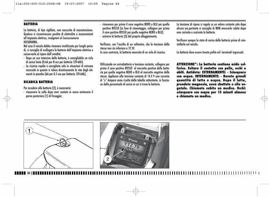
- rimuovere per primo il cavo negativo NERO o BLU poi quellopositivo ROSSO (in fase di rimontaggio, collegare per primoil cavo positivo ROSSO poi quello negativo NERO o BLU);
- estrarre la batteria (3) dal proprio alloggiamento.
Verificare, con l’ausilio di un voltmetro, che la tensione dellastessa non sia inferiore a 12.5V.In caso contrario, la batteria necessita di un ciclo di ricarica.
Utilizzando un caricabatteria a tensione costante, collegare perprimo il cavo positivo ROSSO al morsetto positivo della batte-ria poi quello negativo NERO o BLU al morsetto negativo dellastessa. Applicare alla tensione costante di 14,4 V una correntedi “x” Ampere come risulta dalla tabella sottostante, in funzio-ne della percentuale di carica in cui si trova la batteria.
BATTERIA
La batteria, di tipo sigillato, non necessita di manutenzione.Qualora si riscontrassero perdite di elettrolita o inconvenientiall’impianto elettrico, rivolgetevi al Concessionario HUSQVARNA.Nel caso il veicolo debba rimanere inutilizzato per lunghi perio-di, si consiglia di scollegare la batteria dall’impianto elettrico econservarla al riparo dall’umidità.- Dopo un uso intensivo della batteria, è consigliabile un ciclo
di carica lenta (0.6A per 8 ore per batteria 12V-6Ah).- La ricarica rapida è consigliata solo in situazioni di estrema
necessità in quanto si riduce drasticamente la vita degli ele-menti in piombo (6A per 0.5 ore per batteria 12V-6Ah).
RICARICA BATTERIA
Per accedere alla batteria (2), è necessario:- rimuovere la sella dopo aver ruotato in senso antiorario il
perno posteriore (1) di fissaggio;
La tensione di riposo si regola su un valore costante solo dopoalcune ore,pertanto si consiglia di NON misurarla subito dopoaver caricato o scaricato la batteria.
Verificare sempre lo stato di carica della batteria prima di rein-stallarla sul veicolo.
La batteria deve essere tenuta pulita ed i terminali ingrassati.
ATTENZIONE*: La batteria contiene acido sol-forico. Evitare il contatto con pelle, occhi eabiti. Antidoto: ESTERNAMENTE: - Sciacquarecon acqua. INTERNAMENTE: - Bevete grandiquantità di latte o acqua. Dopo il latte,prendete magnesia, uova sbattute o olio ve-getale. Chiamate subito un medico. Occhi:sciacquare con acqua per 15 minuti almenoe chiamate un medico.
84
2
11a-250-450-510-2008-OK 19-07-2007 10:55 Pagina 84

85
IT
VALORI INDICATIVI RELATIVI ALLA DURATA DELLA CARICA A SECONDA DELLO STATO DELLA BATTERIA
TENSIONE DI RIPOSO * (V) % CARICA DURATA DELLA CARICA (LA CORRENTE NOMINALE IN AMPERE DA APPLICARE É: 0,1x CAPACITÁ NOMINALE DELLA BATTERIA)
> 12,7 100 _~12,5 75 4h~12,2 50 7h~12,0 25 11h~11,8 0 14h
ATTENZIONE*: Le batterie producono gasesplosivi, date aria quindi quando caricateo usate la batteria in ambienti chiusi.Quando usate un carica-batteria, collegatela batteria al caricatore prima di accender-lo. Questa pratica evita la formazione discintille in corrispondenza dei terminali del-la batteria che, potrebbero incendiare i gascontenuti nella batteria.
11a-250-450-510-2008-OK 19-07-2007 10:55 Pagina 85
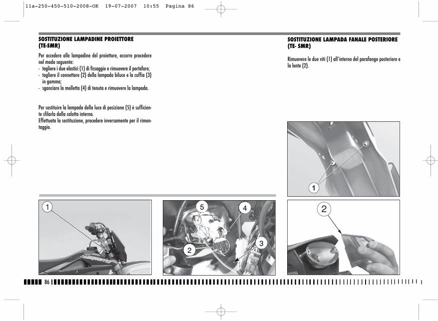
SOSTITUZIONE LAMPADA FANALE POSTERIORE (TE- SMR)
Rimuovere le due viti (1) all’interno del parafango posteriore ela lente (2).
86
SOSTITUZIONE LAMPADINE PROIETTORE(TE-SMR)
Per accedere alle lampadine del proiettore, occorre procederenel modo seguente:- togliere i due elastici (1) di fissaggio e rimuovere il portafaro;- togliere il connettore (2) della lampada biluce e la cuffia (3)
in gomma;- sganciare la molletta (4) di tenuta e rimuovere la lampada.
Per sostituire la lampada della luce di posizione (5) è sufficien-te sfilarla dalla calotta interna.Effettuata la sostituzione, procedere inversamente per il rimon-taggio.
5 4
23
11a-250-450-510-2008-OK 19-07-2007 10:55 Pagina 86

5
Spingere la lampadina (3) verso l’interno, ruotarla in sensoantiorario e rimuoverla dal portalampada.
Effettuata la sostituzione, procedere inversamente per il rimon-taggio.
NOTA: fare attenzione a non serrare eccessi-vamente le viti.
SOSTITUZIONE LAMPADA LUCE TARGA (TE- SMR)
Rimuovere il supporto della luce targa (4) sfilandolo dalla co-da del veicolo. Estrarre il portalampada con la lampadina dalsupporto. Ruotare la lampadina (5) per sfilarla dal portalam-pada.
Effettuata la sostituzione, procedere inversamente per il ri-montaggio.
87
IT
4
11a-250-450-510-2008-OK 19-07-2007 10:55 Pagina 87
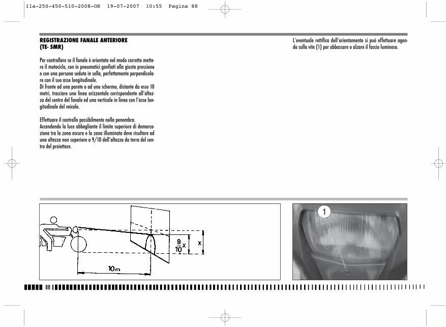
REGISTRAZIONE FANALE ANTERIORE(TE- SMR)
Per controllare se il fanale è orientato nel modo corretto mette-re il motociclo, con in pneumatici gonfiati alla giusta pressionee con una persona seduta in sella, perfettamente perpendicola-re con il suo asse longitudinale.Di fronte ad una parete o ad uno schermo, distante da esso 10metri, tracciare una linea orizzontale corrispondente all’altez-za del centro del fanale ed una verticale in linea con l’asse lon-gitudinale del veicolo.
Effettuare il controllo possibilmente nella penombra.Accendendo la luce abbagliante il limite superiore di demarca-zione tra la zona oscura e la zona illuminata deve risultare aduna altezza non superiore a 9/10 dell’altezza da terra del cen-tro del proiettore.
L’eventuale rettifica dell’orientamento si può effettuare agen-do sulla vite (1) per abbassare o alzare il fascio luminoso.
88
11a-250-450-510-2008-OK 19-07-2007 10:55 Pagina 88
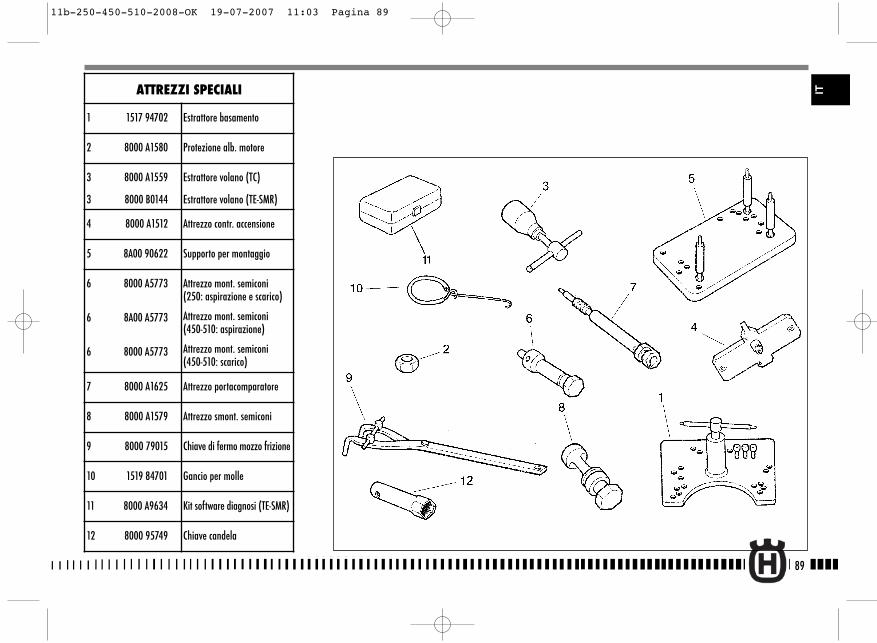
89
ITATTREZZI SPECIALI
1 1517 94702 Estrattore basamento
2 8000 A1580 Protezione alb. motore
3 8000 A1559
3 8000 B0144
Estrattore volano (TC)
Estrattore volano (TE-SMR)
4 8000 A1512 Attrezzo contr. accensione
5 8A00 90622 Supporto per montaggio
6 8000 A5773
6 8A00 A5773
6 8000 A5773
Attrezzo mont. semiconi(250: aspirazione e scarico)
Attrezzo mont. semiconi(450-510: aspirazione)
Attrezzo mont. semiconi(450-510: scarico)
7 8000 A1625 Attrezzo portacomparatore
8 8000 A1579 Attrezzo smont. semiconi
9 8000 79015 Chiave di fermo mozzo frizione
10 1519 84701 Gancio per molle
11 8000 A9634 Kit software diagnosi (TE-SMR)
12 8000 95749 Chiave candela
11b-250-450-510-2008-OK 19-07-2007 11:03 Pagina 89
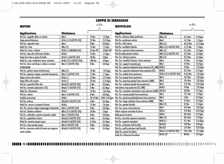
90
MOTORE
ApplicazioneVite fiss. cappello albero a cammeTappo perno bilanciereVite fiss. coperchio testaDado fiss. testaDado fiss. testa e cilindroVite fiss. tubo olio sulla testa cilindroTappo foro olio su perno di biellaDado fiss. ingr. conduttore trasm. primariaVite fiss. disco centrifugo su albero a cammeASPIRAZIONEVite fiss. pattino catena distribuzioneVite fiss. piastrine ritegno cuscinetti basamentoTappo scarico olio motoreTappo filtro olio motoreVite fiss. coperchio filtro olioVite fiss. cornetto carburatore (TC)Dado fiss. alternatoreVite fiss. statoreCandela accensioneVite fiss. pick-upDado fiss. mozzo e campana frizioneVite fiss. piastra ritegno ingranaggi avviamentoVite fiss. tamburo selettoreVite fiss. saltarello e piastra comando cambioVite fiss. segnalatore marceDado fiss. girante pompa acquaVite fiss. corpo pompa acquaVite fiss. piastrina anello di tenuta per pignoneuscita cambio
MOTEUR
FilettaturaM6x1 12 Nm 1,2 KgmM14x1,5 (+LOCTITE 243) 25 Nm 2,55 KgmM6x1 8 Nm 0,8 KgmM8x1,25 15 Nm 1,5 KgmM10x1,5 (+MOLIKOTE HSC) 37 Nm+90° 3.8 Nm+90°M10x1 15 Nm 1,5 KgmM14x1 (+LOCTITE 243) 20 Nm 2 KgmM18x1,25 (+LOCTITE 243) 180 Nm 18 KgmM6x1 (+LOCTITE 243) 8 Nm 0,8 Kgm
M8x1,25 12 Nm 1,23 KgmM6x1 (+LOCTITE 272) 11 Nm 1,1 KgmM16x1,5 25 Nm 2,55 KgmM14x1,5 25 Nm 2,55 KgmM5x0,8 (+LOCTITE 243) 6 Nm 0,6 KgmM4x0,7 (+LOCTITE 272) 3 Nm 0,3 KgmM12x1 75 Nm 7,65 KgmM6x1 (+LOCTITE 272) 8 Nm 0,8 KgmM10x1 10÷12 Nm 0,98÷1,23 KgmM5x0,8 (+LOCTITE 272) 6 Nm 0,6 KgmM18x1 75 Nm 7,6 KgmM6x1 (+LOCTITE 243) 8 Nm 0,8 KgmM8x1,25 (+LOCTITE 243) 20 Nm 2 KgmM6x1 (+LOCTITE 243) 8 Nm 0,8 KgmM5x0,8 (+LOCTITE 243) 6 Nm 0,6 KgmM5x0,8 (+LOCTITE 243) 3,9 Nm 0,4 KgmM6x1(+LOCTITE 542) 8 Nm 0,8 KgmM5x0,8 (+LOCTITE 243) 6 Nm 0,6 Kgm
COPPIE DI SERRAGGIO± 5%
MOTOTELAIO
ApplicazioneVite fiss. inferiore telaio posterioreVite fiss. protezione motoreVite fiss. rullo catenaVite fiss. cavalletto lateraleVite fiss. superiore telaio posterioreVite fiss.telaio-piastra motoreVite fiss. inferiore motoreVite fiss. cavallotti frizione e freno anterioreVite fiss. supporti comando gasVite fiss. superiore tubazione freno anteriore (TE, SMR)Vite fiss. superiore tubazione freno anteriore (TC)Vite fiss. pedale freno posterioreVite fiss. pompa freno posterioreVite fiss. piastrina pompa freno anteriore (SMR)Vite fiss. serbatoio liquido freno posterioreInterruttore stop posteriore (TE, SMR)Vite fiss. connettore interruttore stop anteriore (SMR)Vite fiss. camma pedale freno posterioreVite fiss. piastrina guidatubazione freno anterioreVite fiss. tappo serbatoio freno anteriore (SMR)Vite fiss. gambe forcellaVite fiss. perno ruota anterioreGhiera registro cuscinetti di sterzoDado perno di sterzoVite fiss. morsetto superiore manubrioVite fiss. supporto manubrioVite fiss. protezioni steli forcellaVite fiss. anelli protezioni steli forcellaDado fiss. perno forcelloneDado fiss. bilanciere-forcellone
FilettaturaM8x1,25 25,5 Nm 2,6 KgmM6x1 14,7 Nm 1,5 KgmM8x1,25 26,95 Nm 2,75 KgmM8x1,25 (+LOCTITE 243) 11,75 Nm 1,2 KgmM8x1,25 25,5 Nm 2,6 KgmM8x1,25 (+LOCTITE 270 35,3 Nm 3,6 KgmM8x1,25 35,3 Nm 3,6 KgmM6x1 4,9 Nm 0,5 KgmM6x1 4,9 Nm 0,5 KgmM10x1 19 Nm 1,95 KgmM10x1 24,7 Nm 2,5 KgmM10x1,25 (+LOCTITE 243) 41,65 Nm 4,25 KgmM6x1 10,4 Nm 1,05 KgmM6x1 10,4 Nm 1,05 KgmM6x1 2,45 Nm 0,25 KgmM10x1 19 Nm 1,95 KgmM2x0,4 0,8 Nm 0,1 KgmM6x1 14,7 Nm 1,4 KgmM6x1 6 Nm 0,6 KgmM6x1 4,9 Nm 0,5 KgmM8x1,25 25 Nm 2,5 KgmM6x1 10,4 Nm 1,05 KgmM25x1 3,45 Nm 0,35 KgmM24x1 83,3 Nm 8,5 KgmM8x1,25 28,4 Nm 2,9 KgmM10x1,5 21,1 Nm 2,15 KgmM5x0,8 7,85 Nm 0,8 KgmM5x0,8 2,45 Nm 0,25 KgmM16x1,5 (+LOCTITE 243) 122,5 Nm 12,5 KgmM12x1,25 80 Nm 8,2 Kgm
± 5%
11b-250-450-510-2008-OK 19-07-2007 11:03 Pagina 90
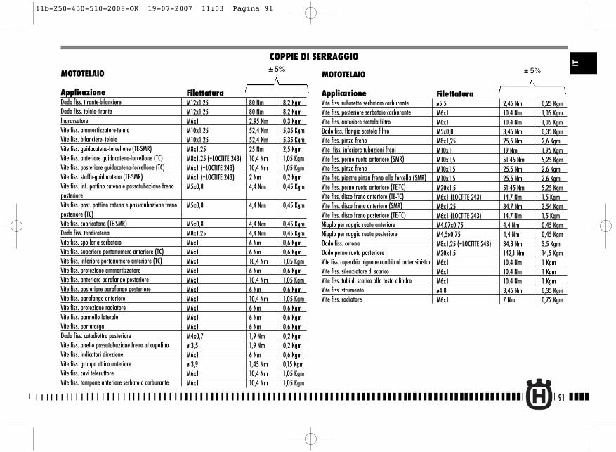
91
IT
MOTOTELAIO
ApplicazioneDado fiss. tirante-bilanciere Dado fiss. telaio-tiranteIngrassatoreVite fiss. ammortizzatore-telaioVite fiss. bilanciere- telaioVite fiss. guidacatena-forcellone (TE-SMR)Vite fiss. anteriore guidacatena-forcellone (TC)Vite fiss. posteriore guidacatena-forcellone (TC)Vite fiss. staffa-guidacatena (TE-SMR)Vite fiss. inf. pattino catena e passatubazione frenoposterioreVite fiss. post. pattino catena e passatubazione frenoposteriore (TC)Vite fiss. copricatena (TE-SMR)Dado fiss. tendicatenaVite fiss. spoiler a serbatoioVite fiss. superiore portanumero anteriore (TC)Vite fiss. inferiore portanumero anteriore (TC)Vite fiss. protezione ammortizzatoreVite fiss. anteriore parafango posterioreVite fiss. posteriore parafango posterioreVite fiss. parafango anterioreVite fiss. protezione radiatoreVite fiss. pannello lateraleVite fiss. portatargaDado fiss. catadiottro posterioreVite fiss. anello passatubazione freno al cupolinoVite fiss. indicatori direzioneVite fiss. gruppo ottico anterioreVite fiss. cavi teleruttoreVite fiss. tampone anteriore serbatoio carburante
COPPIE DI SERRAGGIO
FilettaturaM12x1,25 80 Nm 8,2 KgmM12x1,25 80 Nm 8,2 KgmM6x1 2,95 Nm 0,3 KgmM10x1,25 52,4 Nm 5,35 KgmM10x1,25 52,4 Nm 5,35 KgmM8x1,25 25 Nm 2,5 KgmM8x1,25 (+LOCTITE 243) 10,4 Nm 1,05 KgmM6x1 (+LOCTITE 243) 10,4 Nm 1,05 KgmM6x1 (+LOCTITE 243) 2 Nm 0,2 KgmM5x0,8 4,4 Nm 0,45 Kgm
M5x0,8 4,4 Nm 0,45 Kgm
M5x0,8 4,4 Nm 0,45 KgmM8x1,25 4,4 Nm 0,45 KgmM6x1 6 Nm 0,6 KgmM6x1 6 Nm 0,6 KgmM6x1 10,4 Nm 1,05 KgmM6x1 6 Nm 0,6 KgmM6x1 10,4 Nm 1,05 KgmM6x1 6 Nm 0,6 KgmM6x1 10,4 Nm 1,05 KgmM6x1 6 Nm 0,6 KgmM6x1 6 Nm 0,6 KgmM6x1 6 Nm 0,6 KgmM4x0,7 1,9 Nm 0,2 Kgmø 3,5 1,9 Nm 0,2 KgmM6x1 6 Nm 0,6 Kgmø 3,9 1,45 Nm 0,15 KgmM6x1 10,4 Nm 1,05 KgmM6x1 10,4 Nm 1,05 Kgm
± 5%MOTOTELAIO
ApplicazioneVite fiss. rubinetto serbatoio carburanteVite fiss. posteriore serbatoio carburanteVite fiss. anteriore scatola filtroDado fiss. flangia scatola filtroVite fiss. pinza freno Vite fiss. inferiore tubazioni freniVite fiss. perno ruota anteriore (SMR)Vite fiss. pinza freno Vite fiss. piastra pinza freno alla forcella (SMR)Vite fiss. perno ruota anteriore (TE-TC)Vite fiss. disco freno anteriore (TE-TC) Vite fiss. disco freno anteriore (SMR) Vite fiss. disco freno posteriore (TE-TC) Nipplo per raggio ruota anterioreNipplo per raggio ruota posterioreDado fiss. coronaDado perno ruota posterioreVite fiss. coperchio pignone cambio al carter sinistroVite fiss. silenziatore di scarico Vite fiss. tubi di scarico alla testa cilindroVite fiss. strumentoVite fiss. radiatore
± 5%
Filettaturaø5,5 2,45 Nm 0,25 KgmM6x1 10,4 Nm 1,05 KgmM6x1 10,4 Nm 1,05 KgmM5x0,8 3,45 Nm 0,35 KgmM8x1,25 25,5 Nm 2,6 KgmM10x1 19 Nm 1,95 KgmM10x1,5 51,45 Nm 5,25 KgmM10x1,5 25,5 Nm 2,6 KgmM10x1,5 25,5 Nm 2,6 KgmM20x1,5 51,45 Nm 5,25 KgmM6x1 (LOCTITE 243) 14,7 Nm 1,5 KgmM8x1,25 34,7 Nm 3,54 KgmM6x1 (LOCTITE 243) 14,7 Nm 1,5 KgmM4,07x0,75 4,4 Nm 0,45 KgmM4,5x0,75 4,4 Nm 0,45 KgmM8x1,25 (+LOCTITE 243) 34,3 Nm 3,5 KgmM20x1,5 142,1 Nm 14,5 KgmM6x1 10,4 Nm 1 KgmM6x1 10,4 Nm 1 KgmM6x1 10,4 Nm 1 Kgmø4,8 3,45 Nm 0,35 KgmM6x1 7 Nm 0,72 Kgm
11b-250-450-510-2008-OK 19-07-2007 11:03 Pagina 91

92
N. Codice DENOMINAZIONE
1 8000 A1320 Kit protezione carter destro(TE-TC)
2 8000 A4295 Kit carburatore KEIHIN 37(TC 250)
2 8000 A4296 Kit carburatore KEIHIN 41(TC 450/510)
2A 80A0 A6211 Kit paramani (TE)
3 8000 B0157 Paramotore (TE-TC)
4 8000 B0152 Kit compl. poggiapiedi(TE-SMR)
5 8000 B0150 Kit indicatori di direzione
6 8000 A6441 Kit gancio per la fase di partenzadella gara (TC)
*: Non per USA/CDN
KIT
TC
11b-250-450-510-2008-OK 19-07-2007 11:03 Pagina 92
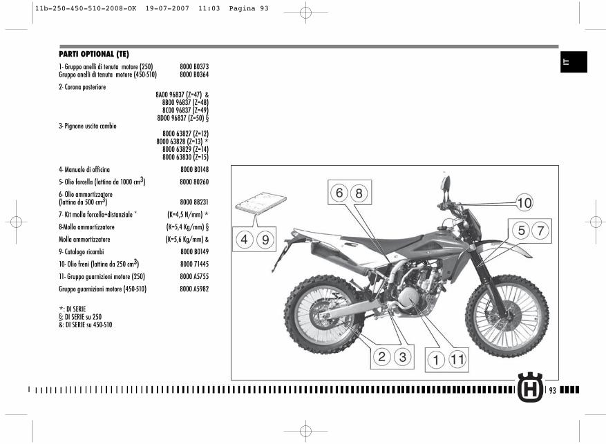
93
IT
PARTI OPTIONAL (TE)
1- Gruppo anelli di tenuta motore (250) 8000 B0373Gruppo anelli di tenuta motore (450-510) 8000 B0364
2- Corona posteriore8A00 96837 (Z=47) &
8B00 96837 (Z=48) 8C00 96837 (Z=49)
8D00 96837 (Z=50) §3- Pignone uscita cambio
8000 63827 (Z=12) 8000 63828 (Z=13) *8000 63829 (Z=14)
8000 63830 (Z=15)
4- Manuale di officina 8000 B0148
5- Olio forcella (lattina da 1000 cm3) 8000 80260
6- Olio ammortizzatore (lattina da 500 cm3) 8000 88231
7- Kit molla forcella+distanziale * (K=4,5 N/mm) *8-Molla ammortizzatore (K=5,4 Kg/mm) §
Molla ammortizzatore (K=5,6 Kg/mm) &
9- Catalogo ricambi 8000 B0149
10- Olio freni (lattina da 250 cm3) 8000 71445
11- Gruppo guarnizioni motore (250) 8000 A5755
Gruppo guarnizioni motore (450-510) 8000 A5982
*: DI SERIE§: DI SERIE su 250&: DI SERIE su 450-510
11b-250-450-510-2008-OK 19-07-2007 11:03 Pagina 93
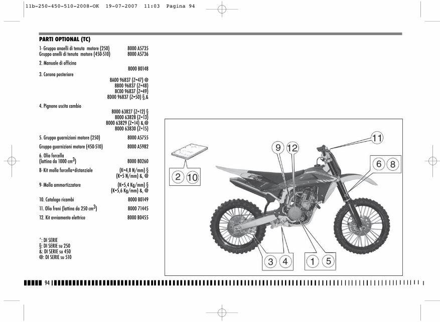
94
PARTI OPTIONAL (TC)
1- Gruppo anaelli di tenuta motore (250) 8000 A5735Gruppo anelli di tenuta motore (450-510) 8000 A5736
2. Manuale di officina8000 B0148
3. Corona posteriore8A00 96837 (Z=47) @
8B00 96837 (Z=48) 8C00 96837 (Z=49)
8D00 96837 (Z=50) §,&
4. Pignone uscita cambio8000 63827 (Z=12) §
8000 63828 (Z=13) 8000 63829 (Z=14) &,@
8000 63830 (Z=15)
5. Gruppo guarnizioni motore (250) 8000 A5755
Gruppo guarnizioni motore (450-510) 8000 A5982
6. Olio forcella (lattina da 1000 cm3) 8000 80260
8- Kit molla forcella+distanziale (K=4,8 N/mm) §(K=5 N/mm) &, @
9- Molla ammortizzatore (K=5,4 Kg/mm) §(K=5,6 Kg/mm) &, @
10. Catalogo ricambi 8000 B0149
11. Olio freni (lattina da 250 cm3) 8000 71445
12. Kit avviamento elettrico 8000 B0455
*: DI SERIE§: DI SERIE su 250&: DI SERIE su 450@: DI SERIE su 510
11b-250-450-510-2008-OK 19-07-2007 11:03 Pagina 94
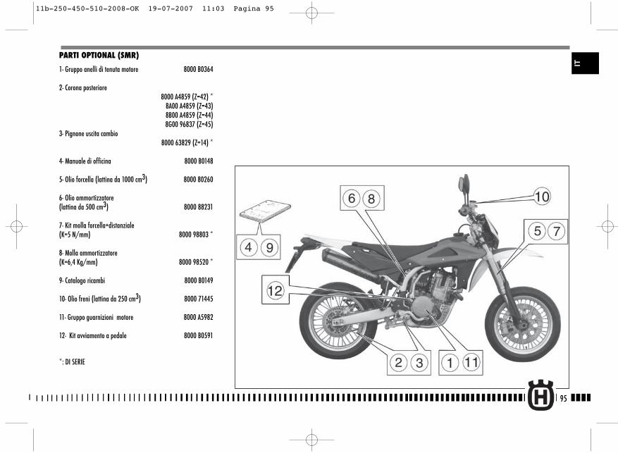
PARTI OPTIONAL (SMR)
1- Gruppo anelli di tenuta motore 8000 B0364
2- Corona posteriore8000 A4859 (Z=42) *
8A00 A4859 (Z=43)8B00 A4859 (Z=44)8G00 96837 (Z=45)
3- Pignone uscita cambio8000 63829 (Z=14) *
4- Manuale di officina 8000 B0148
5- Olio forcella (lattina da 1000 cm3) 8000 80260
6- Olio ammortizzatore (lattina da 500 cm3) 8000 88231
7- Kit molla forcella+distanziale(K=5 N/mm) 8000 98803 *
8- Molla ammortizzatore(K=6,4 Kg/mm) 8000 98520 *
9- Catalogo ricambi 8000 B0149
10- Olio freni (lattina da 250 cm3) 8000 71445
11- Gruppo guarnizioni motore 8000 A5982
12- Kit avviamento a pedale 8000 B0591
*: DI SERIE
95
IT
11b-250-450-510-2008-OK 19-07-2007 11:03 Pagina 95
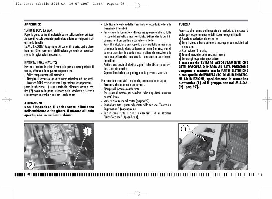
96
- Lubrificare la catena della trasmissione secondaria e tutte letrasmissioni flessibili.
- Per evitare la formazione di ruggine spruzzare olio su tuttele superfici metalliche non verniciate. Evitare che le parti ingomma o i freni entrino a contatto con l’olio.
- Porre il motociclo su un supporto o un cavalletto in modo cheentrambe le ruote siano sollevate da terra (nel caso non sipotesse procedere in questo modo, mettere delle assi sotto leruote per evitare che i pneumatici rimangano a contatto conl’umidità).
- Mettere una busta di plastica sopra il tubo di scarico per evi-tare che entri umidità.
- Coprire il motociclo per proteggerlo da polvere e sporcizia.
Per rimettere in attività il motociclo, procedere come segue:- Accertarsi che la candela sia serrata .- Riempire il serbatoio carburante.- Far girare il motore per scaldare l’olio dopodichè scaricare
queest’ultimo.- Versare olio fresco nel carter (pagina 29).- Controllare tutti i punti richiamati nella sezione “Controlli e
Registrazioni” (Appendice A).- Lubrificare tutti i punti richiamati nella sezione
“Lubrificazione” (Appendice A).
APPENDICE
VERIFICHE DOPO LA GARADopo la gara, pulire il motociclo come sottoriportato poi ispe-zionare il veicolo ponendo particolare attenzione ai punti indi-cati nella Tabella “MANUTENZIONE” (Appendice A) come filtro aria, carburatore,freni etc. Effettuare una lubrificazione generale ed eventual-mente le registrazioni necessarie.
INATTIVITA’ PROLUNGATA (TC)Dovendo lasciare inattivo il motociclo per un certo periodo ditempo, effettuare la seguente preparazione:- Pulire completamente il motociclo.- Riempire il serbatoio con carburante miscelato ad uno stabi-
lizzatore DOPO aver effettuato l’operazione sottoriportata:porre la tubazione (1) in una bacinella, allentare la vite di sca-rico (2) posta nella parte inferiore della vaschetta e serrarlanuovamente una volta eliminato il carburante.
ATTENZIONENon disperdere il carburante eliminatonell’ambiente e far girare il motore all’ariaaperta, non in ambienti chiusi.
PULIZIA
Premesso che, prima del lavaggio del motociclo, è necessarioproteggere opportunamente dall’acqua le seguenti parti:a) Apertura posteriore dello scarico;b) Leve frizione e freno anteriore, manopole, commutatori sul
manubrio;c) Aspirazione filtro aria;d) Testa di sterzo forcella, cuscinetti ruote;e) Leveraggi sospensione posteriore,è necessario EVITARE ASSOLUTAMENTE CHEGETTI D’ACQUA O D’ARIA AD ALTA PRESSIONEvengano a contatto con le PARTI ELETTRICHEe con quelle dell’IMPIANTO DI ALIMENTAZIO-NE AD INIEZIONE, specialmente la centralinaelettronica (1) ed il gruppo sensori M.A.Q.S.(2) (pag 97).
1
12a-senza tabelle-2008-OK 19-07-2007 11:04 Pagina 96
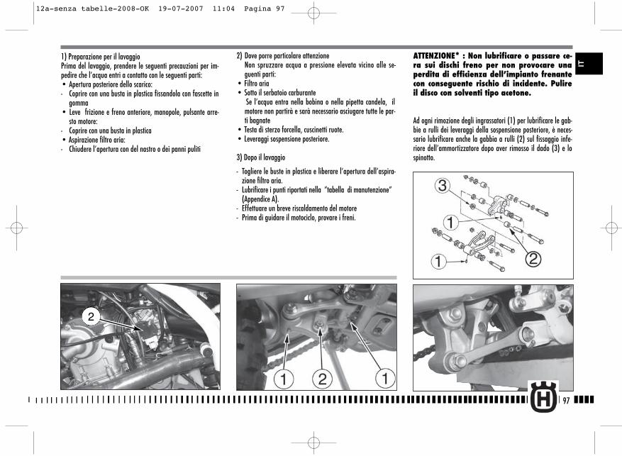
2) Dove porre particolare attenzioneNon spruzzare acqua a pressione elevata vicino alle se-guenti parti:
• Filtro aria• Sotto il serbatoio carburante
Se l’acqua entra nella bobina o nella pipetta candela, ilmotore non partirà e sarà necessario asciugare tutte le par-ti bagnate
• Testa di sterzo forcella, cuscinetti ruote.• Leveraggi sospensione posteriore.
3) Dopo il lavaggio
- Togliere le buste in plastica e liberare l’apertura dell’aspira-zione filtro aria.
- Lubrificare i punti riportati nella “tabella di manutenzione” (Appendice A).
- Effettuare un breve riscaldamento del motore- Prima di guidare il motociclo, provare i freni.
ATTENZIONE* : Non lubrificare o passare ce-ra sui dischi freno per non provocare unaperdita di efficienza dell’impianto frenantecon conseguente rischio di incidente. Pulireil disco con solventi tipo acetone.
Ad ogni rimozione degli ingrassatori (1) per lubrificare le gab-bie a rulli dei leveraggi della sospensione posteriore, è neces-sario lubrificare anche la gabbia a rulli (2) sul fissaggio infe-riore dell’ammortizzatore dopo aver rimosso il dado (3) e lospinotto.
97
IT
1) Preparazione per il lavaggioPrima del lavaggio, prendere le seguenti precauzioni per im-pedire che l’acqua entri a contatto con le seguenti parti:• Apertura posteriore dello scarico:- Coprire con una busta in plastica fissandola con fascette in
gomma• Leve frizione e freno anteriore, manopole, pulsante arre-
sto motore:- Coprire con una busta in plastica • Aspirazione filtro aria:- Chiudere l’apertura con del nastro o dei panni puliti
2
12a-senza tabelle-2008-OK 19-07-2007 11:04 Pagina 97
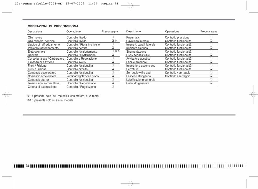
98
�� ���� � ������ �����
��������������
Olio motore Controllo livelloOlio miscela benzina Controllo livelloLiquido di raffreddamento Controllo / Ripristino livello Impianto raffreddamento Controllo perditeElettroventole Controllo funzionamentoCandele Controllo / SostituzioneCorpo farfallato / Carburatore Controllo e Regolazione Fluido freni e frizione Controllo livelloFreni / Frizione Controllo funzionalitàFreni / Frizione Controllo circuitoComando acceleratore Controllo funzionalitàComando acceleratore Verifica/regolazione giocoComando starter Controllo funzionalitàTrasmissioni e com. fless. Controllo / RegolazioneCatena di trasmissione Controllo / Regolazione
Pneumatici Controllo pressioneCavalletto laterale Controllo funzionalitàInterrutt. cavall. laterale Controllo funzionalitàImpianto elettrico Controllo funzionalitàStrumentazione Controllo funzionalitàLuci / segnali visivi Controllo funzionalitàAvvisatore acustico Controllo funzionalitàFanale anteriore Controllo funzionalitàInterruttore accensione Controllo funzionalitàSerrature Controllo funzionalitàSerraggio viti e dadi Controllo / serraggioFascette stringitubo Controllo / serraggioLubrificazione generaleCollaudo generale
OPERAZIONI DI PRECONSEGNA
Descrizione Operazione Preconsegna Descrizione Operazione Preconsegna
� : presenti solo sui motocicli con motore a 2 tempi �� : presente solo su alcuni modelli
12a-senza tabelle-2008-OK 19-07-2007 11:04 Pagina 98
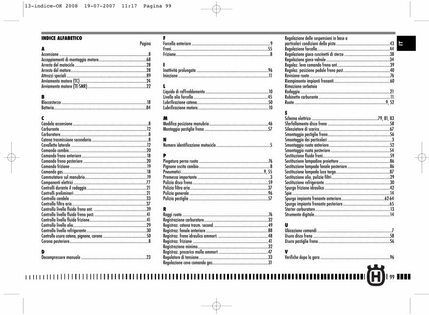
99
IT
Regolazione delle sospensioni in base aparticolari condizioni della pista ....................................................43Regolazione forcella......................................................................44Regolazione gioco cuscinetti di sterzo ............................................38Regolazione gioco valvole .............................................................34Regolaz. leva comando freno ant...................................................39Regolaz. posizione pedale freno post. ............................................40Revisione ruote..............................................................................76Riempimento impianti frenanti ......................................................60Rimozione serbatoioRodaggio.......................................................................................21Rubinetto carburante .....................................................................11Ruote ........................................................................................9, 52
SSchema elettrico ................................................................79, 81, 83Sfarfallamento disco freno ............................................................58Silenziatore di scarico....................................................................67Smontaggio pastiglie freno............................................................56Smontaggio dei particolari ..............................................................3Smontaggio ruota anteriore...........................................................52Smontaggio ruota posteriore .........................................................54Sostituzione fluido freni.................................................................59Sostituzione lampadine proiettore .................................................86Sostituzione lampada fanale posteriore .........................................86Sostituzione lampada luce targa....................................................87Sostituzione olio, pulizia filtri ........................................................29Sostituzione refrigerante ...............................................................30Spurgo frizione idraulica ...............................................................42Spie ..............................................................................................14Spurgo impianto frenante anteriore..........................................62-64Spurgo impianto frenante posteriore .............................................65Starter carburatore ........................................................................13Strumento digitale.........................................................................14
UUbicazione comandi ........................................................................7Usura disco freno ..........................................................................58Usura pastiglie freno .....................................................................56
VVerifiche dopo la gara ...................................................................96
INDICE ALFABETICOPagina
AAccensione ......................................................................................8Accoppiamenti di montaggio motore..............................................68Arresto del motociclo .....................................................................28Arresto del motore.........................................................................28Attrezzi speciali .............................................................................89Avviamento motore (TC) ................................................................24Avviamento motore (TE-SMR).........................................................22
BBloccasterzo ..................................................................................18Batteria.........................................................................................84
CCandela accensione .........................................................................8Carburante ....................................................................................12Carburatore.....................................................................................8Catena trasmissione secondaria .......................................................8Cavalletto laterale .........................................................................12Comando cambio...........................................................................20Comando freno anteriore...............................................................18Comando freno posteriore .............................................................20Comando frizione ..........................................................................19Comando gas.................................................................................18Commutatore sul manubrio............................................................19Componenti elettrici ......................................................................77Controlli durante il rodaggio..........................................................21Controlli preliminari ......................................................................21Controllo candela ..........................................................................33Controllo filtro aria........................................................................37Controllo livello fluido freno ant. ...................................................39Controllo livello fluido freno post. ..................................................41Controllo livello fluido frizione.......................................................41Controllo livello olio.......................................................................29Controllo livello refrigerante..........................................................30Controllo usura catena, pignone, corona ..........................................50Corona posteriore............................................................................8
DDecompressore manuale ...............................................................23
FForcella anteriore ............................................................................9Freni. ............................................................................................55Frizione...........................................................................................8
IInattività prolungata .....................................................................96Iniezione .......................................................................................11
LLiquido di raffreddamento .............................................................10Livello olio forcella........................................................................45Lubrificazione catena.....................................................................50Lubrificazione motore. ...................................................................10
MModifica posizione manubrio.........................................................46Montaggio pastiglie freno .............................................................57
NNumero identificazione motociclo ....................................................5
PPiegatura perno ruota ...................................................................76Pignone uscita cambio.....................................................................8Pneumatici................................................................................9, 55Premessa importante ......................................................................3Pulizia disco freno .........................................................................59Pulizia filtro aria ...........................................................................37Pulizia generale ............................................................................96Pulizia pastiglie ............................................................................57
RRaggi ruota ...................................................................................76Registrazione carburatore..............................................................32Registraz. catena trasm. second. ....................................................49Registraz. fanale anteriore ............................................................88Registraz. freno idraulico ammort. ................................................48Registraz. frizione .........................................................................41Registrazione minimo....................................................................32Registraz. precarico molla ammort. ...............................................47Regolatore di tensione...................................................................33Regolazione cavo comando gas......................................................31
13-indice-OK 2008 19-07-2007 11:17 Pagina 99
100
13-indice-OK 2008 19-07-2007 11:17 Pagina 100
ENGLISH
1
Cap1_GB 19-07-2007 10:35 Pagina 1
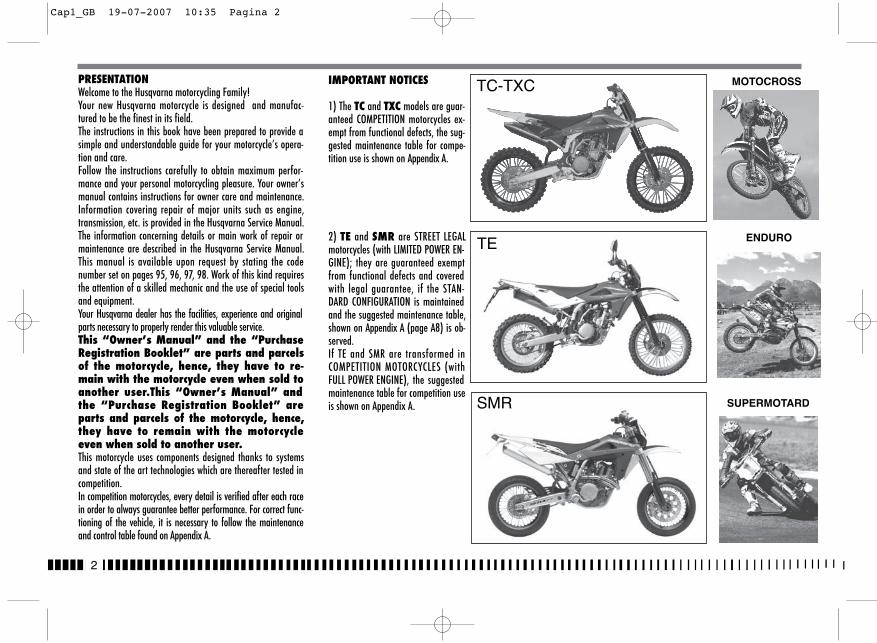
2
PRESENTATIONWelcome to the Husqvarna motorcycling Family!Your new Husqvarna motorcycle is designed and manufac-tured to be the finest in its field.The instructions in this book have been prepared to provide asimple and understandable guide for your motorcycle’s opera-tion and care.Follow the instructions carefully to obtain maximum perfor-mance and your personal motorcycling pleasure. Your owner’smanual contains instructions for owner care and maintenance.Information covering repair of major units such as engine,transmission, etc. is provided in the Husqvarna Service Manual.The information concerning details or main work of repair ormaintenance are described in the Husqvarna Service Manual.This manual is available upon request by stating the codenumber set on pages 95, 96, 97, 98. Work of this kind requiresthe attention of a skilled mechanic and the use of special toolsand equipment.Your Husqvarna dealer has the facilities, experience and originalparts necessary to properly render this valuable service.This “Owner’s Manual” and the “PurchaseRegistration Booklet” are parts and parcelsof the motorcycle, hence, they have to re-main with the motorcycle even when sold toanother user.This “Owner’s Manual” andthe “Purchase Registration Booklet” areparts and parcels of the motorcycle, hence,they have to remain with the motorcycleeven when sold to another user. This motorcycle uses components designed thanks to systemsand state of the art technologies which are thereafter tested incompetition.In competition motorcycles, every detail is verified after each racein order to always guarantee better performance. For correct func-tioning of the vehicle, it is necessary to follow the maintenanceand control table found on Appendix A.
MOTOCROSS
SUPERMOTARD
ENDURO
IMPORTANT NOTICES
1) The TC and TXC models are guar-anteed COMPETITION motorcycles ex-empt from functional defects, the sug-gested maintenance table for compe-tition use is shown on Appendix A.
2) TE and SMR are STREET LEGALmotorcycles (with LIMITED POWER EN-GINE); they are guaranteed exemptfrom functional defects and coveredwith legal guarantee, if the STAN-DARD CONFIGURATION is maintainedand the suggested maintenance table,shown on Appendix A (page A8) is ob-served.If TE and SMR are transformed inCOMPETITION MOTORCYCLES (withFULL POWER ENGINE), the suggestedmaintenance table for competition useis shown on Appendix A.
TE
SMR
TC-TXC
Cap1_GB 19-07-2007 10:35 Pagina 2
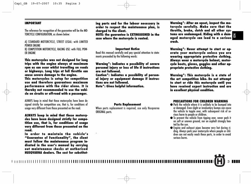
3
IMPORTANT
The reference for recognition of the guarantee will be the MO-TORCYCLE CONFIGURATION, as shown below:
A) STANDARD MOTORCYCLE, STREET LEGAL: with LIMITEDPOWER ENGINEB) COMPETITION MOTORCYCLE, RACING USE: with FULL POW-ER ENGINE
This motorcycles was not designed for longtrips with the engine always at maximumrpm as can occur whilst travelling on roadsor highways. Long trips at full throttle cancause severe damage to the engine.This motorcycles is setup for competitionuse and therefore guarantees maximumperformance with the rider alone. It isthereby not recommended to use the vehi-cle on circuits or off-road with a passenger.
ALWAYS keep in mind that these motorcycles have been de-signed strictly for competition use, that is, for conditions ofusage very different from those presented on the road.
ALWAYS keep in mind that these motorcy-cles have been designed strictly for compe-tition use, that is, for conditions of usagevery different from those presented on theroad.In order to maintain the vehicle’s“Guarantee of Functionality”, the clientmust follow the maintenance program in-dicated in the user’s manual by carryingout maintenance checks at authorizedHUSQVARNA dealers. The cost for substitut-
ing parts and for the labour necessary inorder to respect the maintenance plan, ischarged to the client.NOTE: the guarantee is EXTINGUISHED in thecase where the motorcycle is rented.
Important NoticeRead this manual carefully and pay special attention to state-ments preceeded by the following words:
Warning*: Indicates a possibility of severepersonal injury or loss of life if instructionsare not followed.Caution*: Indicates a possibility of person-al injury or equipment damage if instruc-tions are not followed.Note*: Gives helpful information.
Parts Replacement When parts replacement is required, use only HusqvarnaORIGINAL parts.
.
Warning*: After an upset, inspect the mo-torcycle carefully. Make sure that thethrottle, brake, clutch and all other sys-tems are undamaged. Riding with a dam-aged motorcycle can lead to a seriouscrash.
Warning*: Never attempt to start or op-erate your motorcycle unless you arewearing appropriate protective clothing.Always wear a motorcycle helmet, motor-cycle boots, gloves, goggles and other ap-propriate protective clothing.
Warning*: This motorcycle is a state ofthe art competition bike. Do not attemptto start or ride this motorcycle until youhave received expert instruction and arein excellent physical condition.
PRECAUTIONS FOR CHILDREN WARNING� Park the vehicle where it is unlikely to be bumped into
or damaged. Even slight or involuntary bumps can causethe vehicle to topple over, with subsequent risk of se-rious harm to people or children.
� To prevent the vehicle from tipping over, never park iton soft or uneven ground, nor on asphalt strongly hea-ted by the sun.
� Engine and exhaust pipes become very hot during ri-ding. Always park your motorcycle where people or chil-dren can not easily reach these parts, in order to avoidserious burns.
EN
Cap1_GB 19-07-2007 10:35 Pagina 3
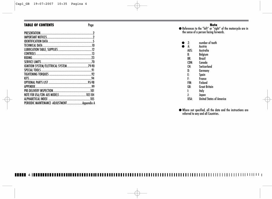
4
TABLE OF CONTENTS Page
PRESENTATION........................................................................2IMPORTANT NOTICES...............................................................2IDENTIFICATION DATA .............................................................5TECHNICAL DATA ...................................................................10LUBRICATION TABLE, SUPPLIES ..............................................12CONTROLS ............................................................................13RIDING.................................................................................23SERVICE LIMITS.....................................................................70IGNITION SYSTEM/ELETTRICAL SYSTEM.............................79-90SPECIAL TOOLS .....................................................................91TIGHTENING TORQUES ..........................................................92KITS .....................................................................................94OPTIONAL PARTS LIST ......................................................95-98APPENDIX.............................................................................99PRE-DELIVERY INSPECTION...................................................101NOTE FOR USA/CDN- AUS MODELS ........................................102-104ALPHABETICAL INDEX .........................................................105PERIODIC MAINTENANCE -ADJUSTMENT.....................Appendix A
Note� References to the “left” or “right” of the motorcycle are in
the sense of a person facing forwards.
� Z: number of teeth� A: Austria
AUS: AustraliaB: BelgiumBR: BrazilCDN: CanadaCH: SwitzerlandD: GermanyE: SpainF: FranceFIN: FinlandGB: Great BritainI: ItalyJ: JapanUSA: United States of America
� Where not specified, all the data and the instructions arereferred to any and all Countries.
Cap1_GB 19-07-2007 10:35 Pagina 4
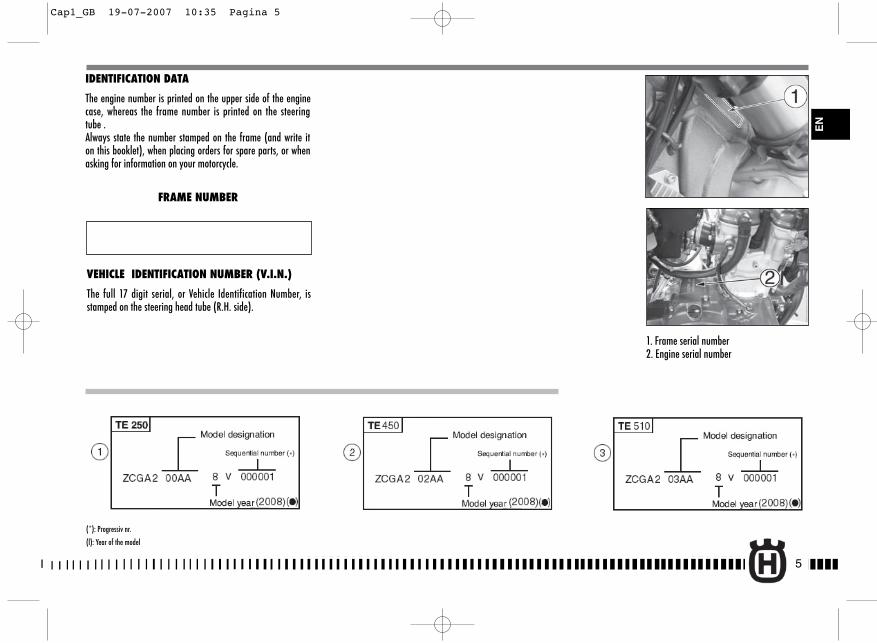
5
IDENTIFICATION DATA
The engine number is printed on the upper side of the enginecase, whereas the frame number is printed on the steeringtube .Always state the number stamped on the frame (and write iton this booklet), when placing orders for spare parts, or whenasking for information on your motorcycle.
FRAME NUMBER
VEHICLE IDENTIFICATION NUMBER (V.I.N.)
The full 17 digit serial, or Vehicle Identification Number, isstamped on the steering head tube (R.H. side).
1. Frame serial number2. Engine serial number
EN
(*): Progressiv nr.
(l): Year of the model
Cap1_GB 19-07-2007 10:35 Pagina 5
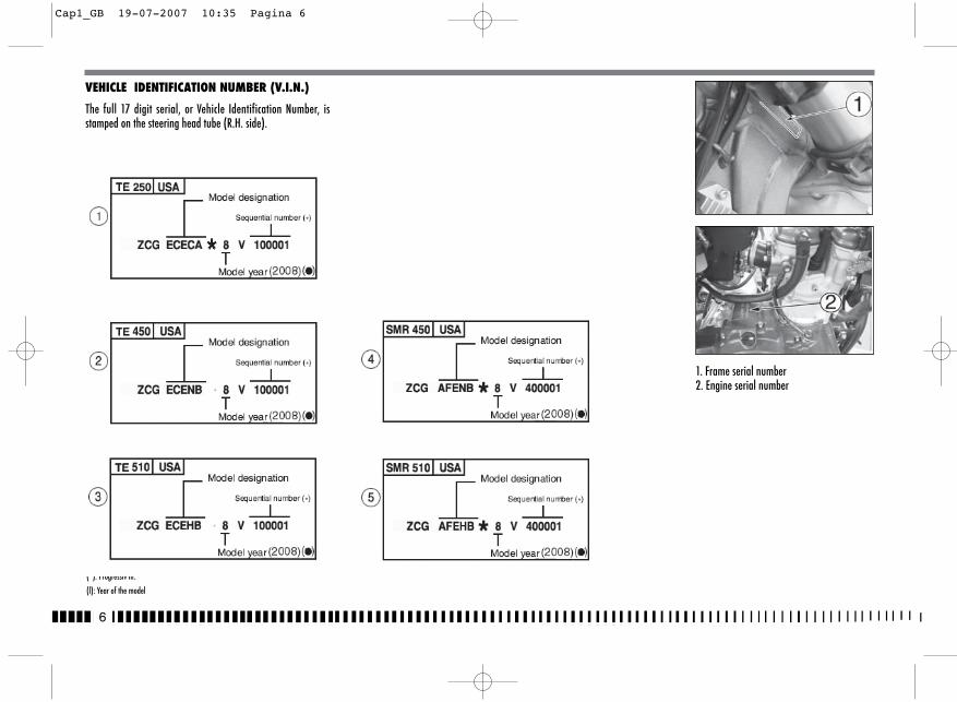
6
VEHICLE IDENTIFICATION NUMBER (V.I.N.)
The full 17 digit serial, or Vehicle Identification Number, isstamped on the steering head tube (R.H. side).
(*): Progressiv nr.
(l): Year of the model
1. Frame serial number2. Engine serial number
Cap1_GB 19-07-2007 10:35 Pagina 6
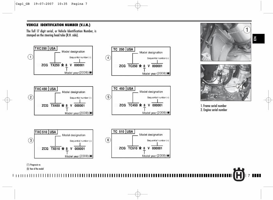
VEHICLE IDENTIFICATION NUMBER (V.I.N.)
The full 17 digit serial, or Vehicle Identification Number, isstamped on the steering head tube (R.H. side).
7
EN
1. Frame serial number2. Engine serial number
(*): Progressiv nr.
(l): Year of the model
Cap1_GB 19-07-2007 10:35 Pagina 7
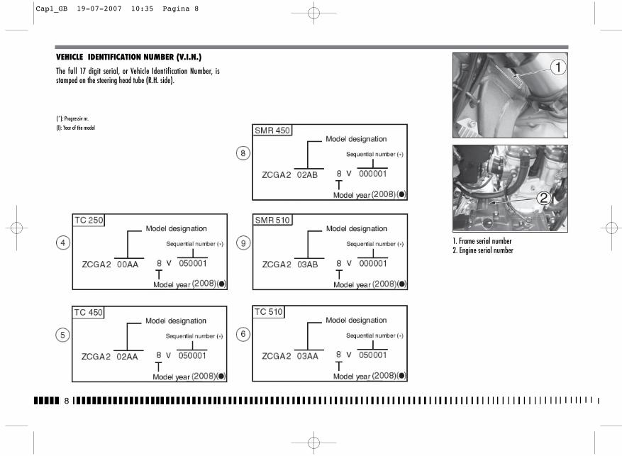
8
VEHICLE IDENTIFICATION NUMBER (V.I.N.)
The full 17 digit serial, or Vehicle Identification Number, isstamped on the steering head tube (R.H. side).
(*): Progressiv nr.
(l): Year of the model
1. Frame serial number2. Engine serial number
Cap1_GB 19-07-2007 10:35 Pagina 8
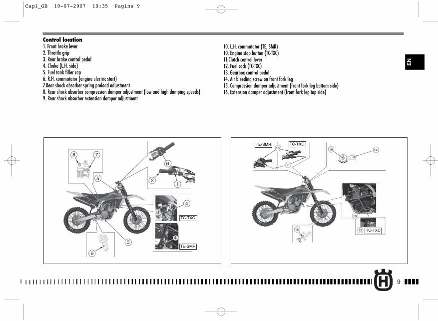
9
EN
Control location1. Front brake lever2. Throttle grip3. Rear brake control pedal4. Choke (L.H. side)5. Fuel tank filler cap6. R.H. commutator (engine electric start)7.Rear shock absorber spring preload adjustment8. Rear shock absorber compression damper adjustment (low and high damping speeds)9. Rear shock absorber extension damper adjustment
10. L.H. commutator (TE, SMR)10. Engine stop button (TC-TXC)11.Clutch control lever12. Fuel cock (TC-TXC)13. Gearbox control pedal14. Air bleeding screw on front fork leg15. Compression damper adjustment (front fork leg bottom side)16. Extension damper adjustment (front fork leg top side)
TC-TXC
TE-SMR
TE-SMR TC-TXC
TC-TXC
Cap1_GB 19-07-2007 10:35 Pagina 9
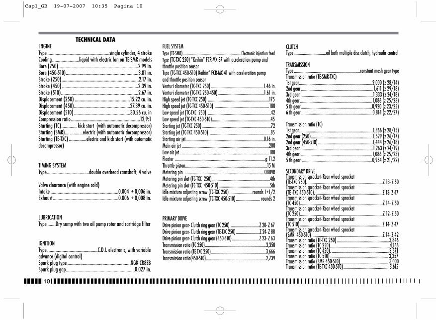
10
CLUTCHType...............................oil bath multiple disc clutch, hydraulic control
TRANSMISSIONType ...............................................................constant mesh gear typeTransmission ratio (TE-SMR-TXC)1st gear......................................................................2,000 (z 28/14)2nd gear .....................................................................1,611 (z 29/18)3rd gear .....................................................................1,333 (z 24/18)4th gear .....................................................................1,086 (z 25/23)5 th gear....................................................................0,920 (z 23/25)6 th gear ....................................................................0,814 (z 22/27)
Transmission ratio (TC)1st gear. .....................................................................1,866 (z 28/15)2nd gear (250)...........................................................1,529 (z 26/17)2nd gear (450-510) ....................................................1,444 (z 26/18)3rd gear ....................................................................1,263 (z 24/19)4th gear. ....................................................................1,086 (z 25/23)5 th gear. ...................................................................0,954 (z 21/22)
SECONDARY DRIVETransmission sprocket- Rear wheel sprocket (TE-TXC 250).........................................................................Z 13- Z 50Transmission sprocket- Rear wheel sprocket (TE -TXC 450-510). ................................................................Z 13- Z 47Transmission sprocket- Rear wheel sprocket (TC 450)...............................................................................Z 14- Z 50Transmission sprocket- Rear wheel sprocket (TC 250)...............................................................................Z 12- Z 50Transmission sprocket- Rear wheel sprocket (TC 510)...............................................................................Z 14- Z 47Transmission sprocket- Rear wheel sprocket (SMR 450-510) ....................................................................Z 14- Z 42Transmission ratio (TE-TXC 250) ..................................................3,846Transmission ratio (TC 250).........................................................4,166Transmission ratio (TC 450). .......................................................3,571Transmission ratio (TC 510) ....................................................... 3,357Transmission ratio (SMR 450-510).............................................. 3,000Transmission ratio (TE-TXC 450-510) ........................................... 3,615
TECHNICAL DATAENGINEType .....................................................single cylinder, 4 strokeCooling.......................liquid with electric fan on TE-SMR modelsBore (250)....................................................................2.99 in.Bore (450-510)..............................................................3.81 in.Stroke (250)..................................................................2.17 in.Stroke (450) .................................................................2.39 in.Stroke (510)..................................................................2.67 in. Displacement (250) ...............................................15.22 cu. in.Displacement (450)................................................27.39 cu. in.Displacement (510) ................................................30.56 cu. inCompression ratio...........................................................12,9:1Starting (TC)............. kick start (with automatic decompressor)Starting (SMR).... ...........electric (with automatic decompressor)Starting (TE-TXC) ...............electric and kick start (with automaticdecompressor)
TIMING SYSTEMType....................................double overhead camshaft; 4 valve
Valve clearance (with engine cold)Intake ..........................................................0.004 ÷ 0,006 in.Exhaust........................................................0.006 ÷ 0,008 in.
LUBRICATIONType .......Dry sump with two oil pump rotor and cartridge filter
IGNITIONType ...........................................C.D.I. electronic, with variableadvance (digital control)Spark plug type ......................................................NGK CR8EBSpark plug gap...........................................................0.027 in.
FUEL SYSTEMType (TE-SMR)...............................................................Electronic injection feedType (TC-TXC 250) ”Keihin” FCR-MX 37 with acceleration pump andthrottle position sensorTipo (TC-TXC 450-510) Keihin” FCR-MX 41 with acceleration pumpand throttle position sensorVenturi diameter (TC-TXC 250) ..................................................1.46 in.Venturi diameter (TC-TXC 250-450)............................................1.61 in.High speed jet (TC-TXC 250) ..........................................................175High speed jet (TC-TXC 450-510) ....................................................180Low speed jet (TC-TXC 250) ............................................................42Low speed jet (TC-TXC 450-510)........................................................45Starting jet (TC-TXC 250)..................................................................72Starting jet (TC-TXC 450-510) ..........................................................85Starting air jet. .........................................................................0.16 in.Main air jet ...................................................................................200Low air jet .....................................................................................100Floater ......................................................................................g 11.2Throttle piston..............................................................................15 MMetering pin ............................................................................OBDVRMetering pin slot (TC-TXC 250). ......................................................4thMetering pin slot (TC-TXC 450-510).................................................5thIdle mixture adjusting screw (TC-TXC 250) ......................rounds 1+1/2Idle mixture adjusting screw (TC-TXC 450-510) ....................... rounds 2
PRIMARY DRIVEDrive pinion gear- Clutch ring gear (TC 250) .............................Z 20- Z 67Drive pinion gear- Clutch ring gear (TE-TXC 250)........................Z 24- Z 88Drive pinion gear- Clutch ring gear (450-510)............................Z 23- Z 63Transmission ratio (TC 250)..............................................................3,350Transmission ratio (TE-TXC 250)........................................................3,666Transmission ratio(450-510).............................................................2,739
Cap1_GB 19-07-2007 10:35 Pagina 10
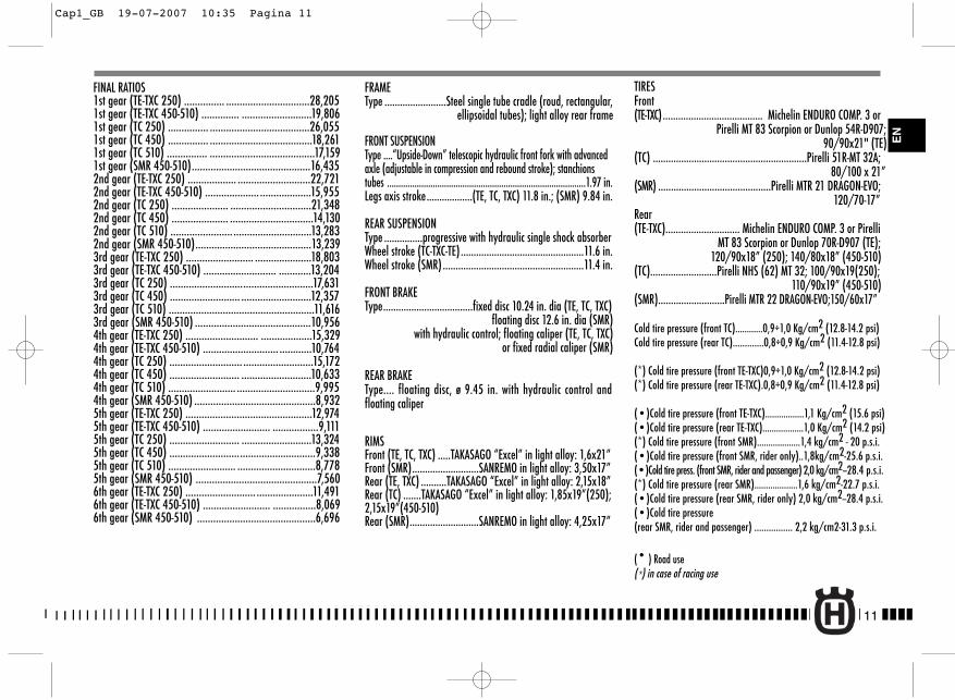
11
EN
FINAL RATIOS1st gear (TE-TXC 250) ............... ...............................28,2051st gear (TE-TXC 450-510) .............. ..........................19,8061st gear (TC 250) ............... .....................................26,0551st gear (TC 450) ............... ......................................18,2611st gear (TC 510) ............... .......................................17,1591st gear (SMR 450-510)............................................16,4352nd gear (TE-TXC 250) .................. ...........................22,7212nd gear (TE-TXC 450-510) .................... ...................15,9552nd gear (TC 250) ..................... ..............................21,3482nd gear (TC 450) ..................... ...............................14,1302nd gear (TC 510) ....................... .............................13,2832nd gear (SMR 450-510)...........................................13,2393rd gear (TE-TXC 250) ......................... .....................18,8033rd gear (TE-TXC 450-510) ........................... ............13,2043rd gear (TC 250) .....................................................17,6313rd gear (TC 450) .......................... ..........................12,3573rd gear (TC 510) ......................................................11,6163rd gear (SMR 450-510) ...........................................10,9564th gear (TE-TXC 250) ........................... ...................15,3294th gear (TE-TXC 450-510) ............................ ............10,7644th gear (TC 250) ........................... ..........................15,1724th gear (TC 450) .......................... ..........................10,6334th gear (TC 510) ......................... .............................9,9954th gear (SMR 450-510) .............................................8,9325th gear (TE-TXC 250) ...............................................12,9745th gear (TE-TXC 450-510) ......................... .................9,1115th gear (TC 250) .......................... ..........................13,3245th gear (TC 450) ......................................................9,3385th gear (TC 510) ......................... .............................8,7785th gear (SMR 450-510) .............................................7,5606th gear (TE-TXC 250) .......................... .....................11,4916th gear (TE-TXC 450-510) ......................... ................8,0696th gear (SMR 450-510) ............................................6,696
FRAMEType ........................Steel single tube cradle (roud, rectangular,
ellipsoidal tubes); light alloy rear frame
FRONT SUSPENSIONType ....“Upside-Down” telescopic hydraulic front fork with advancedaxle (adjustable in compression and rebound stroke); stanchionstubes .......................................................................................1.97 in.Legs axis stroke..................(TE, TC, TXC) 11.8 in.; (SMR) 9.84 in.
REAR SUSPENSIONType ...............progressive with hydraulic single shock absorberWheel stroke (TC-TXC-TE)................................................11.6 in.Wheel stroke (SMR) .......................................................11.4 in.
FRONT BRAKEType...................................fixed disc 10.24 in. dia (TE, TC, TXC)
floating disc 12.6 in. dia (SMR) with hydraulic control; floating caliper (TE, TC, TXC)
or fixed radial caliper (SMR)
REAR BRAKEType.... floating disc, ø 9.45 in. with hydraulic control andfloating caliper
RIMSFront (TE, TC, TXC) .....TAKASAGO “Excel” in light alloy: 1,6x21”Front (SMR)..........................SANREMO in light alloy: 3,50x17”Rear (TE, TXC) ..........TAKASAGO “Excel” in light alloy: 2,15x18”Rear (TC) .......TAKASAGO “Excel” in light alloy: 1,85x19”(250);2,15x19”(450-510)Rear (SMR)...........................SANREMO in light alloy: 4,25x17”
TIRESFront(TE-TXC)....................................... Michelin ENDURO COMP. 3 or
Pirelli MT 83 Scorpion or Dunlop 54R-D907;90/90x21" (TE)
(TC) ............................................................Pirelli 51R-MT 32A;80/100 x 21”
(SMR) ............................................Pirelli MTR 21 DRAGON-EVO;120/70-17”
Rear(TE-TXC)............................. Michelin ENDURO COMP. 3 or Pirelli
MT 83 Scorpion or Dunlop 70R-D907 (TE); 120/90x18” (250); 140/80x18” (450-510)
(TC)..........................Pirelli NHS (62) MT 32; 100/90x19(250); 110/90x19” (450-510)
(SMR)..........................Pirelli MTR 22 DRAGON-EVO;150/60x17”
Cold tire pressure (front TC)............0,9÷1,0 Kg/cm2 (12.8-14.2 psi)Cold tire pressure (rear TC).............0,8÷0,9 Kg/cm2 (11.4-12.8 psi)
(*) Cold tire pressure (front TE-TXC)0,9÷1,0 Kg/cm2 (12.8-14.2 psi)(*) Cold tire pressure (rear TE-TXC).0,8÷0,9 Kg/cm2 (11.4-12.8 psi)
(•)Cold tire pressure (front TE-TXC).................1,1 Kg/cm2 (15.6 psi)(•)Cold tire pressure (rear TE-TXC)..................1,0 Kg/cm2 (14.2 psi)(*) Cold tire pressure (front SMR)...................1,4 kg/cm2 - 20 p.s.i.(•)Cold tire pressure (front SMR, rider only)..1,8kg/cm2-25.6 p.s.i.(•)Cold tire press. (front SMR, rider and passenger) 2,0 kg/cm2--28.4 p.s.i.(*) Cold tire pressure (rear SMR)...................1,6 kg/cm2-22.7 p.s.i.(•)Cold tire pressure (rear SMR, rider only) 2,0 kg/cm2--28.4 p.s.i.(•)Cold tire pressure(rear SMR, rider and passenger) ................ 2,2 kg/cm2-31.3 p.s.i.
(• ) Road use(*) in case of racing use
Cap1_GB 19-07-2007 10:35 Pagina 11
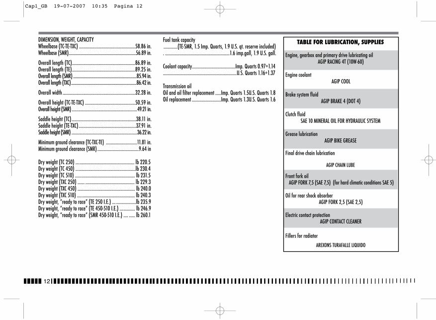
Fuel tank capacity............(TE-SMR, 1.5 Imp. Quarts, 1.9 U.S. qt. reserve included). .......................................................1.6 imp.gall, 1.9 U.S. gall.
Coolant capacity.....................................Imp. Quarts 0.97÷1.14...............................................................U.S. Quarts 1.16÷1.37
Transmission oilOil and oil filter replacement .....Imp. Quarts 1.5U.S. Quarts 1.8Oil replacement .........................Imp. Quarts 1.3U.S. Quarts 1.6
TABLE FOR LUBRICATION, SUPPLIES
Engine, gearbox and primary drive lubricating oilAGIP RACING 4T (10W-60)
Engine coolantAGIP COOL
Brake system fluidAGIP BRAKE 4 (DOT 4)
Clutch fluidSAE 10 MINERAL OIL FOR HYDRAULIC SYSTEM
Grease lubricationAGIP BIKE GREASE
Final drive chain lubrication
AGIP CHAIN LUBE
Front fork oilAGIP FORK 7,5 (SAE 7,5) (for hard climatic conditions SAE 5)
Oil for rear shock absorber AGIP FORK 2,5 (SAE 2,5)
Electric contact protectionAGIP CONTACT CLEANER
Fillers for radiator
AREXONS TURAFALLE LIQUIDO
DIMENSION, WEIGHT, CAPACITYWheelbase (TC-TE-TXC) ................................................58.86 in.Wheelbase (SMR).............................................................56.89 in.
Overall length (TC)......................................................86.89 in.Overall length (TE)......................................................89.25 in.Overall length (SMR) ...............................................................85.94 in.Overall length (TXC).................................................................86.42 in.
Overall width ..............................................................32.28 in.
Overall height (TC-TE-TXC) ...........................................50.59 in.Overall height (SMR) ........................................................49.21 in.
Saddle height (TC).......................................................38.11 in.Saddle height (TE-TXC) .................................................37.91 in.Saddle height (SMR) ........................................................36.22 in.
Minimum ground clearance (TC-TXC-TE) ............................11.81 in.Minimum ground clearance (SMR) .....................................9.64 in
Dry weight (TC 250) .................................................. lb 220.5Dry weight (TC 450) ...................................................lb 230.4Dry weight (TC 510) ................................................... lb 231.5Dry weight (TXC 250) ...... .......................................... lb 229.3Dry weight (TXC 450) ................................................. lb 240.0 Dry weight (TXC 510) ................................................. lb 240.3Dry weight, “ready to race” (TE 250 I.E.) ... .................lb 235.9Dry weight, “ready to race” (TE 450-510 I.E.) ............. lb 246.9Dry weight, “ready to race” (SMR 450-510 I.E.) .... ..... lb 260.1
12
Cap1_GB 19-07-2007 10:35 Pagina 12
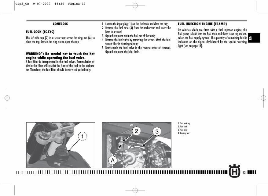
FUEL INJECTION ENGINE (TE-SMR)
On vehicles which are fitted with a fuel injection engine, thefuel pump is built into the fuel tank and there is no tap mount-ed on the fuel supply system. The quantity of remaining fuel isindicated on the digital dash-board by the special warninglight (see on page 16).
13
CONTROLS
FUEL COCK (TC-TXC)
The left-side tap (2) is a screw tap: screw the ring nut (A) toclose the tap, loosen the ring nut to open the tap.
WARNING*: Be careful not to touch the hotengine while operating the fuel valve.A fuel filter is incorporated in the fuel valves. Accumulation ofdirt in the filter will restrict the flow of the fuel to the carbure-tor. Therefore, the fuel filter should be serviced periodically.
1. Fuel tank cap2. Fuel cock3. Fuel hoseA. Tap ring nut
1
EN
32
A
1 Loosen the input plug (1) on the fuel tank and close the tap;2 Remove the fuel hose (3) from the carburetor and insert the
hose in a vessel;3 Open the tap and drain the fuel out of the tank;4 Remove the fuel valve by removing the screws. Wash the fuel
screen filter in cleaning solvent;5 Reassemble the fuel valve in the reverse order of removal.
Open the tap and check for leaks.
Cap2_GB 9-07-2007 16:20 Pagina 13
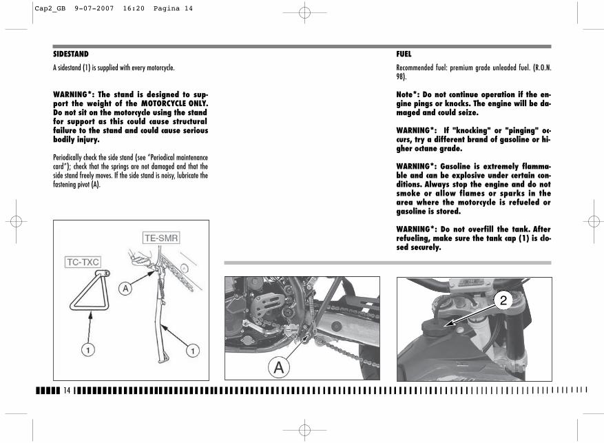
FUEL
Recommended fuel: premium grade unleaded fuel. (R.O.N.98).
Note*: Do not continue operation if the en-gine pings or knocks. The engine will be da-maged and could seize.
WARNING*: If "knocking" or "pinging" oc-curs, try a different brand of gasoline or hi-gher octane grade.
WARNING*: Gasoline is extremely flamma-ble and can be explosive under certain con-ditions. Always stop the engine and do notsmoke or allow flames or sparks in thearea where the motorcycle is refueled orgasoline is stored.
WARNING*: Do not overfill the tank. Afterrefueling, make sure the tank cap (1) is clo-sed securely.
14
SIDESTAND
A sidestand (1) is supplied with every motorcycle.
WARNING*: The stand is designed to sup-port the weight of the MOTORCYCLE ONLY.Do not sit on the motorcycle using the standfor support as this could cause structuralfailure to the stand and could cause seriousbodily injury.
Periodically check the side stand (see “Periodical maintenancecard”); check that the springs are not damaged and that theside stand freely moves. If the side stand is noisy, lubricate thefastening pivot (A).
2
Cap2_GB 9-07-2007 16:20 Pagina 14
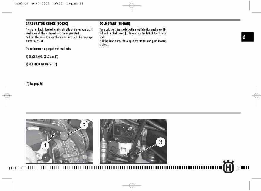
CARBURETOR CHOKE (TC-TXC)
The starter knob, located on the left side of the carburetor, isused to enrich the mixture during the engine start.Pull out the knob to open the starter, and pull the lever up-wards to close it.
The carburetor is equipped with two knobs:
1) BLACK KNOB: COLD start (°)
2) RED KNOB: WARM start (°)
(°) See page 26
COLD START (TE-SMR)
For a cold start, the models with a fuel injection engine are fit-ted with a black knob (3) located on the left of the throttlebody. Pull the knob outwards to open the starter and push inwardsto close.
15
EN
2
1
Cap2_GB 9-07-2007 16:20 Pagina 15
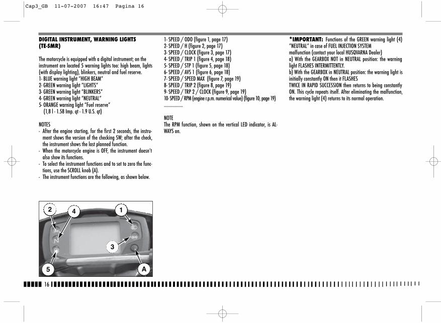
*IMPORTANT: Functions of the GREEN warning light (4)“NEUTRAL” in case of FUEL INJECTION SYSTEMmalfunction (contact your local HUSQVARNA Dealer)a) With the GEARBOX NOT in NEUTRAL position: the warninglight FLASHES INTERMITTENTLY.b) With the GEARBOX in NEUTRAL position: the warning light isinitially constantly ON then it FLASHESTWICE IN RAPID SUCCESSION then returns to being constantlyON. This cycle repeats itself. After eliminating the malfunction,the warning light (4) returns to its normal operation.
1- SPEED / ODO (figure 1, page 17)2- SPEED / H (figure 2, page 17)3- SPEED / CLOCK (figure 3, page 17)4- SPEED / TRIP 1 (figure 4, page 18)5- SPEED / STP 1 (figure 5, page 18)6- SPEED / AVS 1 (figure 6, page 18)7- SPEED / SPEED MAX (figure 7, page 19)8- SPEED / TRIP 2 (figure 8, page 19)9- SPEED / TRP 2 / CLOCK (figure 9, page 19)10- SPEED / RPM (engine r.p.m. numerical value) (figure 10, page 19).................
NOTEThe RPM function, shown on the vertical LED indicator, is AL-WAYS on.
DIGITAL INSTRUMENT, WARNING LIGHTS (TE-SMR)
The motorcycle is equipped with a digital instrument; on theinstrument are located 5 warning lights too: high beam, lights(with display lighting), blinkers, neutral and fuel reserve.1- BLUE warning light “HIGH BEAM”2- GREEN warning light ”LIGHTS”3- GREEN warning light “BLINKERS”4- GREEN warning light “NEUTRAL”5- ORANGE warning light “Fuel reserve”
(1,8 l - 1.58 Imp. qt - 1.9 U.S. qt)
NOTES- After the engine starting, for the first 2 seconds, the instru-
ment shows the version of the checking SW; after the check,the instrument shows the last planned function.
- When the motorcycle engine is OFF, the instrument doesn’talso show its functions.
- To select the instrument functions and to set to zero the func-tions, use the SCROLL knob (A).
- The instrument functions are the following, as shown below.
16
2
5
4 1
3
A
Cap3_GB 11-07-2007 16:47 Pagina 16
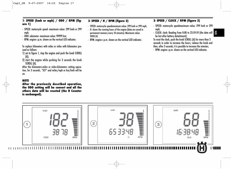
3- SPEED / CLOCK / RPM (figure 3)
- SPEED: motorcycle speedmaximum value: 299 kmh or 299mph;
- CLOCK: clock- Reading from 0:00 to 23:59:59 (the data willbe lost after battery detachment);
To reset the clock, push the knob SCROLL (A) for more than 3seconds in order to increase the hours; release the knob andthen, after 3 seconds, it is possible to increase the minutes;- RPM: engine r.p.m. shown on the vertical LED indicator.
1- SPEED (kmh or mph) / ODO / RPM (fig-ure 1)
- SPEED: motorcycle speed- maximum value: 299 kmh or 299mph;
- ODO: odometer- maximum value: 99999 km;- RPM: engine r.p.m. shown on the vertical LED indicator.
To replace kilometers with miles or miles with kilometers pro-ceed as follows:1) set to figure 1, stop the engine and push the knob SCROLL
(A);2) start the engine while pushing for 3 seconds the knob
SCROLL (A).After the kilometers-miles or miles-kilometers setting opera-tion, for 3 seconds, “SET” and miles/mph or km/kmh will beon.
NOTEAfter the previously described operation,the ODO setting will be convert and all theothers data will be reseted (the H Counteris unchanged).
2- SPEED / H / RPM (figure 2)
- SPEED: motorcycle speedmaximum value: 299 kmh or 299 mph;- H: shows the running hours of the engine (data are saved in
permanent memory every 10 minutes)- Maximum value:9999:59;
- RPM: engine r.p.m. shown on the vertical LED indicator.
17
EN
Cap3_GB 9-07-2007 16:22 Pagina 17
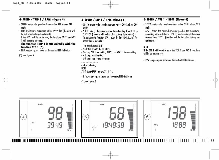
5- SPEED / STP 1 / RPM (figure 5)
- SPEED: motorcycle speedmaximum value: 299 kmh or 299mph;
- STP 1: miles/kilometers covered time- Reading from 0:00 to23:59:59 (the data will be lost after battery detachment).To activate the function STP 1, push the knob SCROLL (A) formore than 3 seconds.
- 1st step: function ON;- 2nd step: stop to the counters;- 3rd step: STP 1 zero-setting; TRIP 1 and AVS 1 data zero-setting;- 4th step: function ON;- 5th step: stop to the counters;.............................and so followingNOTESTP 1 data+TRIP 1 data=AVS 1 (*).
- RPM: engine r.p.m. shown on the vertical LED indicator.
(*): see figure 6
6- SPEED / AVS 1 / RPM (figure 6)
- SPEED: motorcycle speedmaximum value: 299 kmh or 299mph;
- AVS 1: shows the covered average speed of the motorcycle,according with a distance (TRIP 1) and a miles/kilometerscovered time (STP 1) (the data will be lost after battery de-tachment).
NOTEIf the STP 1 will be set to zero, the TRIP 1 and AVS 1 functionswill be set to zero too.
- RPM: engine r.p.m. shown on the vertical LED indicator.
18
4- SPEED / TRIP 1 / RPM (figure 4)
- SPEED: motorcycle speedmaximum value: 299 kmh or 299mph;
- TRIP 1: distance- maximum value: 999.9 km (the data willbe lost after battery detachment).If the STP 1 will be set to zero, the functions TRIP 1 and AVS1 will be set to zero too.The function TRIP 1 is ON unitedly with thefunction STP 1 (*).
- RPM: engine r.p.m. shown on the vertical LED indicator.
(*): see figure 5
Cap3_GB 9-07-2007 16:22 Pagina 18
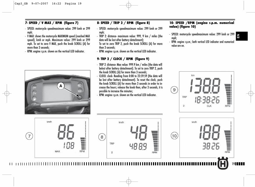
7- SPEED / V MAX / RPM (figure 7)
- SPEED: motorcycle speedmaximum value: 299 kmh or 299mph;
- V MAX: shows the motorcycle MAXIMUM speed (reached MAXspeed), kmh or mph. Maximum value: 299 kmh or 299mph. To set to zero V MAX, push the knob SCROLL (A) formore than 3 seconds;
- RPM: engine r.p.m. shown on the vertical LED indicator.
8- SPEED / TRIP 2 / RPM (figure 8)
- SPEED: motorcycle speedmaximum value: 299 kmh or 299mph;
- TRIP 2: distance- maximum value: 999, 9 km / miles (thedata will be lost after battery detachment);To set to zero TRIP 2, push the knob SCROLL (A) for morethan 3 seconds;
- RPM: engine r.p.m. shown on the vertical LED indicator.
9- TRP 2 / CLOCK / RPM (figure 9)
- TRIP 2: distance- Max value: 999.9 km / miles (the data willbelost after battery detachment). To set to zero TRIP 2, pushthe knob SCROLL (A) for more than 3 seconds;
- CLOCK: clock- Reading from 0:00 to 23:59:59 (the data willbe lost after battery detachment). To reset the clock, pushthe knob SCROLL (A) for more than 3 seconds in order to in-crease the hours; release the knob then, after 3 seconds, it ispossible to increase the minutes;
- RPM: engine r.p.m. shown on the vertical LED indicator.
10- SPEED /RPM (engine r.p.m. numericalvalue) (figure 10)
- SPEED: motorcycle speedmaximum value: 299 kmh or 299mph;
- RPM: engine r.p.m.; both vertical LED indicator and numericalvalue are on.
A
19
EN
Cap3_GB 9-07-2007 16:22 Pagina 19

20
THROTTLE CONTROL
The throttle knob (1), is located on the right hand side of thehandlebar. The position of the throttle control can be adjustedby loosening the two fastenig screws .
CAUTIONDo not forget to tighten the screws (A) afterthe adjustment.
FRONT BRAKE CONTROL
The brake control lever (2) is located on the right hand side ofthe handlebar. The position of the throttle control can be ad-justed by loosening the two fastenig screws .
CAUTIONDo not forget to tighten the screws (B) afterthe adjustment.
STEERING LOCK (TE-SMR)
The motorcycle is equipped with a steering lock (1) on the R.H.side of the steering head tube.To lock it, procede as follows:turn the handlebar leftwards, place the key in lock and turncounterclockwise. Push the key inwards (if necessary, turn toand from). Turn the key clockwise and remove it from the lock. To unlock the steering lock, reverse the above procedure.
Cap4_GB 9-07-2007 16:23 Pagina 20
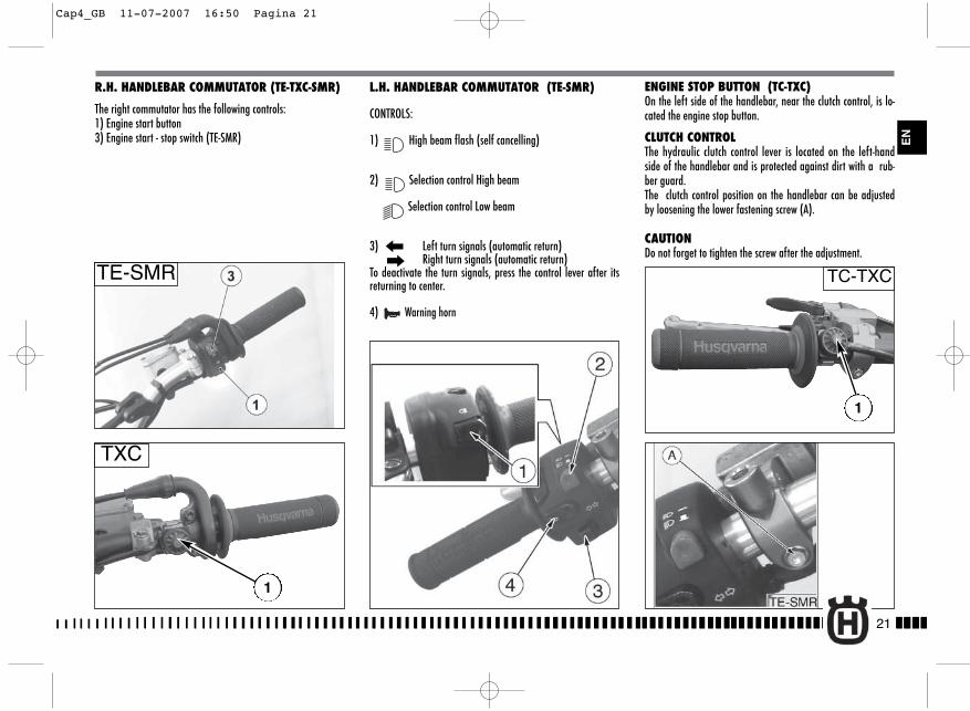
21
ENGINE STOP BUTTON (TC-TXC)On the left side of the handlebar, near the clutch control, is lo-cated the engine stop button.
CLUTCH CONTROLThe hydraulic clutch control lever is located on the left-handside of the handlebar and is protected against dirt with a rub-ber guard.The clutch control position on the handlebar can be adjustedby loosening the lower fastening screw (A).
CAUTIONDo not forget to tighten the screw after the adjustment.
R.H. HANDLEBAR COMMUTATOR (TE-TXC-SMR)
The right commutator has the following controls:1) Engine start button3) Engine start - stop switch (TE-SMR)
L.H. HANDLEBAR COMMUTATOR (TE-SMR)
CONTROLS:
1) High beam flash (self cancelling)
2) Selection control High beam
Selection control Low beam
3) Left turn signals (automatic return)Right turn signals (automatic return)
To deactivate the turn signals, press the control lever after itsreturning to center.
4) Warning horn
TC-TXC
TXC
TE-SMR
1
EN
1
Cap4_GB 11-07-2007 16:50 Pagina 21
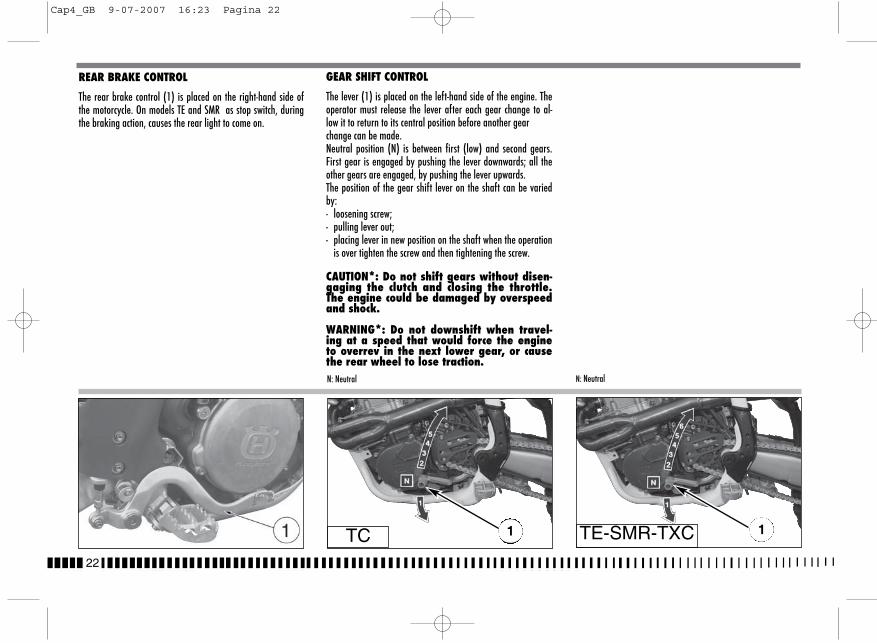
22
REAR BRAKE CONTROL
The rear brake control (1) is placed on the right-hand side ofthe motorcycle. On models TE and SMR as stop switch, duringthe braking action, causes the rear light to come on.
GEAR SHIFT CONTROL
The lever (1) is placed on the left-hand side of the engine. Theoperator must release the lever after each gear change to al-low it to return to its central position before another gearchange can be made.Neutral position (N) is between first (low) and second gears.First gear is engaged by pushing the lever downwards; all theother gears are engaged, by pushing the lever upwards. The position of the gear shift lever on the shaft can be variedby:- loosening screw;- pulling lever out;- placing lever in new position on the shaft when the operation
is over tighten the screw and then tightening the screw.
CAUTION*: Do not shift gears without disen-gaging the clutch and closing the throttle.The engine could be damaged by overspeedand shock.
WARNING*: Do not downshift when travel-ing at a speed that would force the engineto overrev in the next lower gear, or causethe rear wheel to lose traction.N: Neutral
TC 1
N: Neutral
1TE-SMR-TXC
Cap4_GB 9-07-2007 16:23 Pagina 22
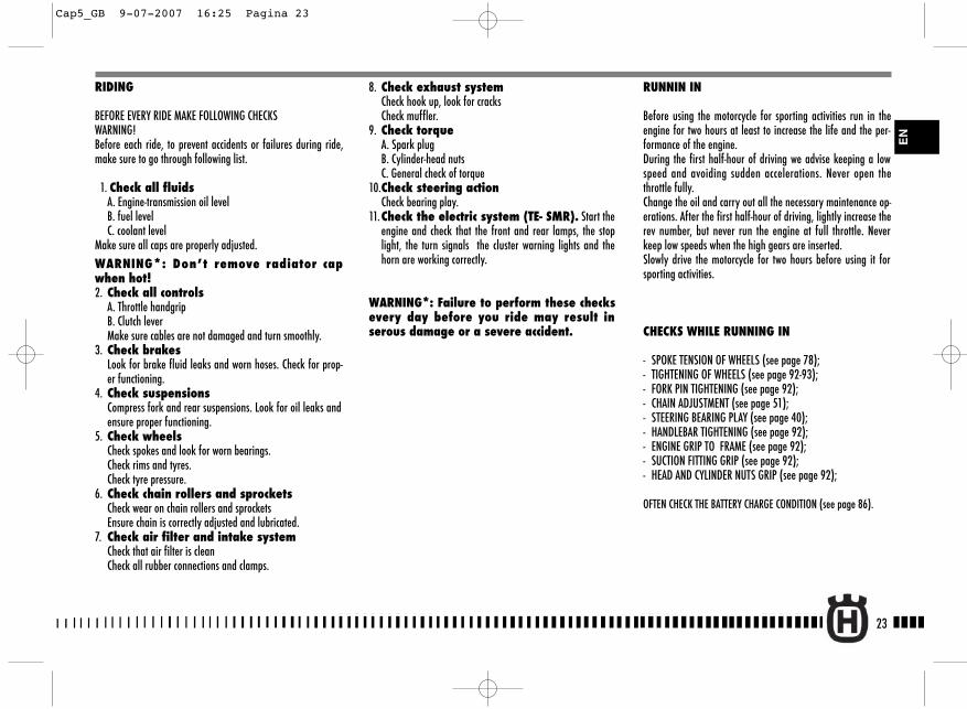
23
8. Check exhaust systemCheck hook up, look for cracksCheck muffler.
9. Check torqueA. Spark plugB. Cylinder-head nutsC. General check of torque
10.Check steering actionCheck bearing play.
11.Check the electric system (TE- SMR). Start theengine and check that the front and rear lamps, the stoplight, the turn signals the cluster warning lights and thehorn are working correctly.
WARNING*: Failure to perform these checksevery day before you ride may result inserous damage or a severe accident.
RUNNIN IN
Before using the motorcycle for sporting activities run in theengine for two hours at least to increase the life and the per-formance of the engine.During the first half-hour of driving we advise keeping a lowspeed and avoiding sudden accelerations. Never open thethrottle fully.Change the oil and carry out all the necessary maintenance op-erations. After the first half-hour of driving, lightly increase therev number, but never run the engine at full throttle. Neverkeep low speeds when the high gears are inserted. Slowly drive the motorcycle for two hours before using it forsporting activities.
CHECKS WHILE RUNNING IN
- SPOKE TENSION OF WHEELS (see page 78);- TIGHTENING OF WHEELS (see page 92-93);- FORK PIN TIGHTENING (see page 92);- CHAIN ADJUSTMENT (see page 51);- STEERING BEARING PLAY (see page 40);- HANDLEBAR TIGHTENING (see page 92);- ENGINE GRIP TO FRAME (see page 92);- SUCTION FITTING GRIP (see page 92);- HEAD AND CYLINDER NUTS GRIP (see page 92);
OFTEN CHECK THE BATTERY CHARGE CONDITION (see page 86).
RIDING
BEFORE EVERY RIDE MAKE FOLLOWING CHECKSWARNING!Before each ride, to prevent accidents or failures during ride,make sure to go through following list.
1. Check all fluidsA. Engine-transmission oil levelB. fuel levelC. coolant level
Make sure all caps are properly adjusted.WARNING*: Don’t remove radiator capwhen hot!2. Check all controls
A. Throttle handgripB. Clutch lever Make sure cables are not damaged and turn smoothly.
3. Check brakesLook for brake fluid leaks and worn hoses. Check for prop-er functioning.
4. Check suspensionsCompress fork and rear suspensions. Look for oil leaks andensure proper functioning.
5. Check wheelsCheck spokes and look for worn bearings.Check rims and tyres.Check tyre pressure.
6. Check chain rollers and sprocketsCheck wear on chain rollers and sprocketsEnsure chain is correctly adjusted and lubricated.
7. Check air filter and intake systemCheck that air filter is cleanCheck all rubber connections and clamps.
EN
Cap5_GB 9-07-2007 16:25 Pagina 23
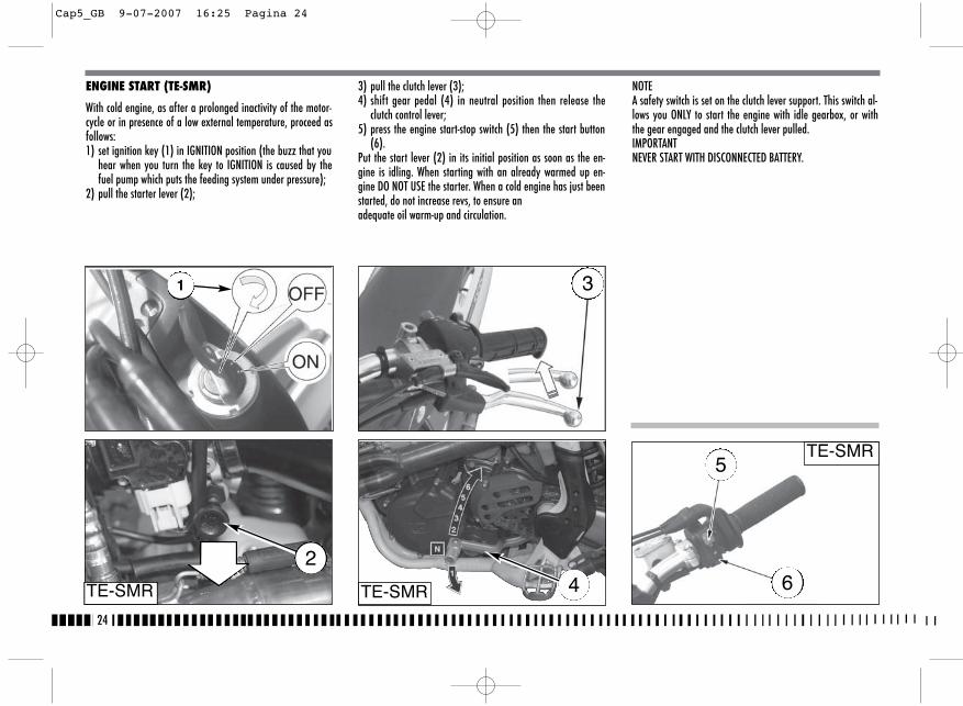
24
ENGINE START (TE-SMR)
With cold engine, as after a prolonged inactivity of the motor-cycle or in presence of a low external temperature, proceed asfollows:1) set ignition key (1) in IGNITION position (the buzz that you
hear when you turn the key to IGNITION is caused by thefuel pump which puts the feeding system under pressure);
2) pull the starter lever (2);
3) pull the clutch lever (3);4) shift gear pedal (4) in neutral position then release the
clutch control lever;5) press the engine start-stop switch (5) then the start button
(6).Put the start lever (2) in its initial position as soon as the en-gine is idling. When starting with an already warmed up en-gine DO NOT USE the starter. When a cold engine has just beenstarted, do not increase revs, to ensure anadequate oil warm-up and circulation.
NOTEA safety switch is set on the clutch lever support. This switch al-lows you ONLY to start the engine with idle gearbox, or withthe gear engaged and the clutch lever pulled.IMPORTANTNEVER START WITH DISCONNECTED BATTERY.
TE-SMR TE-SMR
TE-SMR
42
3
5
6
1
Cap5_GB 9-07-2007 16:25 Pagina 24

25
EN
ENGINE START (TXC)
Make sure the fuel tap is in the OPEN position, then shift gearpedal in neutral position.Pull the starter knob (BLACK knob (2) for cold starting*, REDknob (3) for warm starting), pull the clutch control lever,then press the engine start button (1).Release the clutch control lever.
*: after a prolonged inactivity of the motorcycle or in presenceof a low external temperature.
STARTING DECOMPRESSORThough the engine is provided with an automatic decompressor,can be necessary, in some cases (carburetor flooding or startingdifficulties due to a battery inadequate charge), to use the man-ual starting decompressor on the L.H. side of the handlebar. Inthese cases, pull the lever (5) whilst simultaneously pressingthe starter button, release the lever (5) keeping the buttonpressed and afterwards release the latter as well. In order to adjust the lever decompressor free play (approximately3 mm- 0.12 in.), the lever holder is provided with the adjuster (6);the adjustment can be also effected with the tightener (7) on theR.H. side of the engine (use this tightener if it is not possible to ob-tain the correct free play with the adjuster on the handlebar).
2
3 TXC
1
Cap5_GB 12-07-2007 10:03 Pagina 25
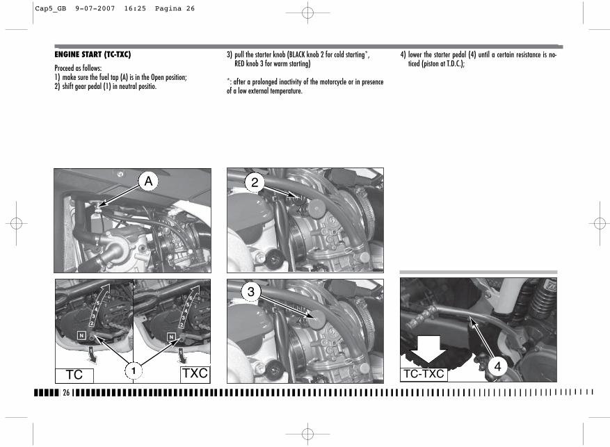
26
ENGINE START (TC-TXC)
Proceed as follows:1) make sure the fuel tap (A) is in the Open position;2) shift gear pedal (1) in neutral positio.
3) pull the starter knob (BLACK knob 2 for cold starting*, RED knob 3 for warm starting)
*: after a prolonged inactivity of the motorcycle or in presenceof a low external temperature.
4) lower the starter pedal (4) until a certain resistance is no-ticed (piston at T.D.C.);
A
TC TXC1
2
3
TC-TXC4
Cap5_GB 9-07-2007 16:25 Pagina 26
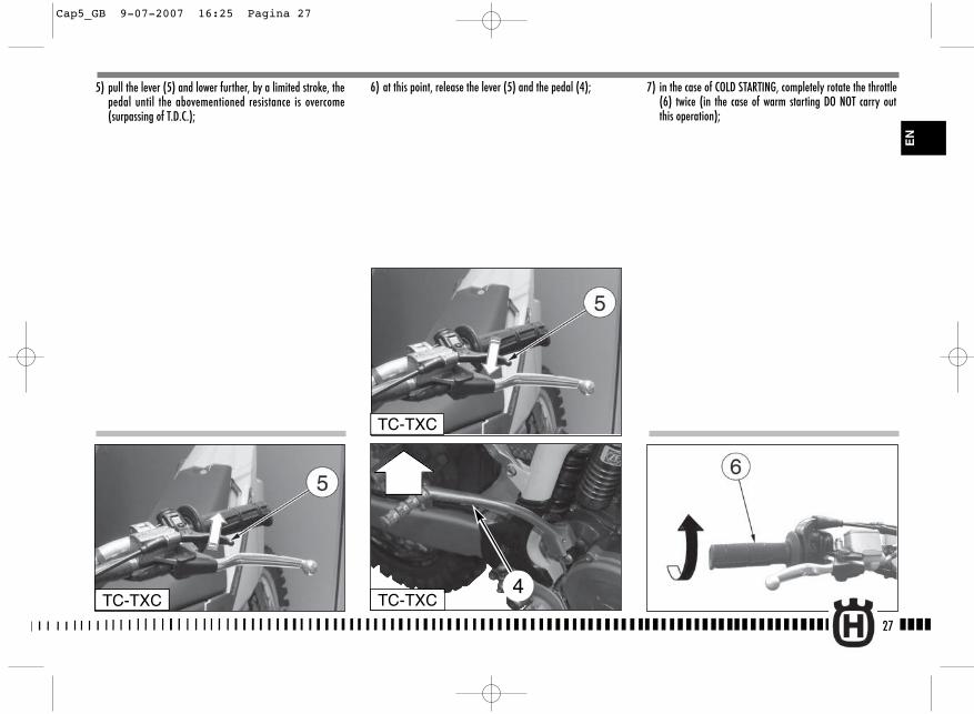
27
5) pull the lever (5) and lower further, by a limited stroke, thepedal until the abovementioned resistance is overcome(surpassing of T.D.C.);
7) in the case of COLD STARTING, completely rotate the throttle(6) twice (in the case of warm starting DO NOT carry outthis operation);
6) at this point, release the lever (5) and the pedal (4);
TC-TXC
TC-TXC
TC-TXC4
EN
Cap5_GB 9-07-2007 16:25 Pagina 27
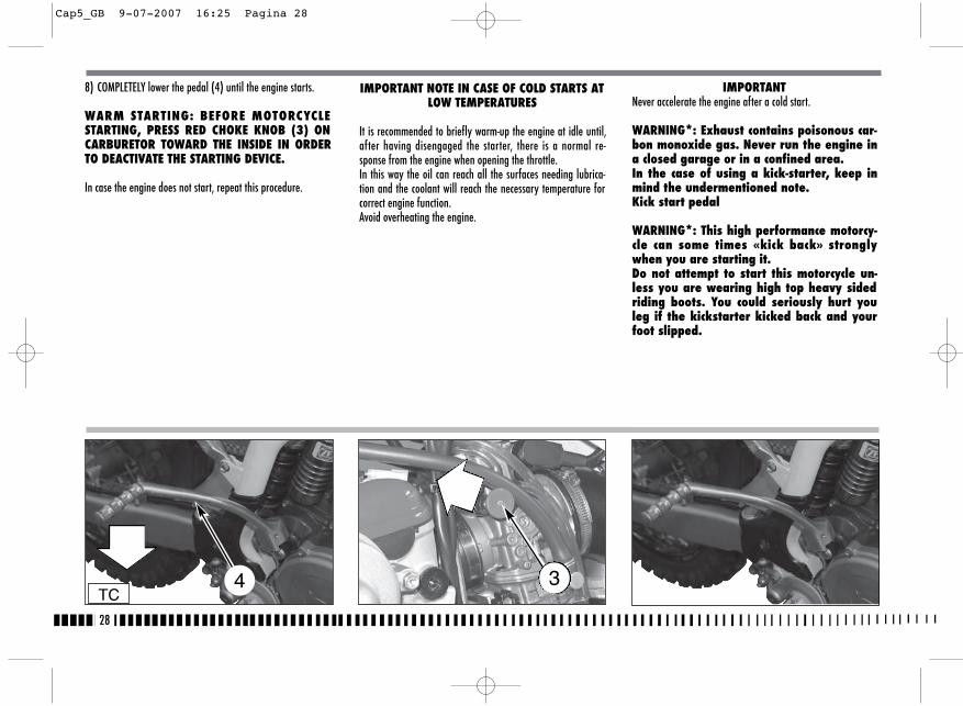
28
8) COMPLETELY lower the pedal (4) until the engine starts.
WARM STARTING: BEFORE MOTORCYCLESTARTING, PRESS RED CHOKE KNOB (3) ONCARBURETOR TOWARD THE INSIDE IN ORDERTO DEACTIVATE THE STARTING DEVICE.
In case the engine does not start, repeat this procedure.
IMPORTANT NOTE IN CASE OF COLD STARTS ATLOW TEMPERATURES
It is recommended to briefly warm-up the engine at idle until,after having disengaged the starter, there is a normal re-sponse from the engine when opening the throttle. In this way the oil can reach all the surfaces needing lubrica-tion and the coolant will reach the necessary temperature forcorrect engine function.Avoid overheating the engine.
IMPORTANTNever accelerate the engine after a cold start.
WARNING*: Exhaust contains poisonous car-bon monoxide gas. Never run the engine ina closed garage or in a confined area.In the case of using a kick-starter, keep inmind the undermentioned note.Kick start pedal
WARNING*: This high performance motorcy-cle can some times «kick back» stronglywhen you are starting it.Do not attempt to start this motorcycle un-less you are wearing high top heavy sidedriding boots. You could seriously hurt youleg if the kickstarter kicked back and yourfoot slipped.
4 3TC
Cap5_GB 9-07-2007 16:25 Pagina 28

29
3) pull the clutch lever (3);4) push the kick-starter pedal (5) to start the vehicle.
5) Then release the clutch lever (3).
BEFORE MOVING OFF, DEACTIVATE THE REDKNOB (2) OF THE STARTER ON THE CARBURET-TOR.
HOT START (TC-TXC)
If it is a problem to start the engine when hot, or following afall, proceed as follows:1) the transmission (1) should be placed in neutral;2) pull the RED knob of the starter (2);
TC TXC1
2
EN
TC 4
Cap5_GB 9-07-2007 16:25 Pagina 29
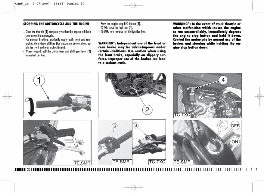
30
STOPPING THE MOTORCYCLE AND THE ENGINE
- Close the throttle (1) completely so that the engine will helpslow down the motorcycle.
- For normal braking, gradually apply both front and rearbrakes while down shifting (for maximum deceleration, ap-ply the front and rear brakes firmly).
- When stopped, pull the clutch lever and shift gear lever (2)in neutral position.
- Press the engine stop RED button (3).- TC-TXC: close the fuel cock (4).- TE-SMR: turn towards left the ignition key.
WARNING*: Independent use of the front orrear brake may be advantageous undercertain conditions. Use caution when usingthe front brake, especially on slippery sur-faces. Improper use of the brakes can leadto a serious crash.
TE-SMRTE-SMR
TC-TXC
TC-TXC
WARNING*: In the event of stuck throttle orother malfunction which causes the engineto run uncontrollably, immediately depressthe engine stop button and hold it down.Control the motorcycle by normal use of thebrakes and steering while holding the en-gine stop button down.
4
Cap5_GB 9-07-2007 16:25 Pagina 30
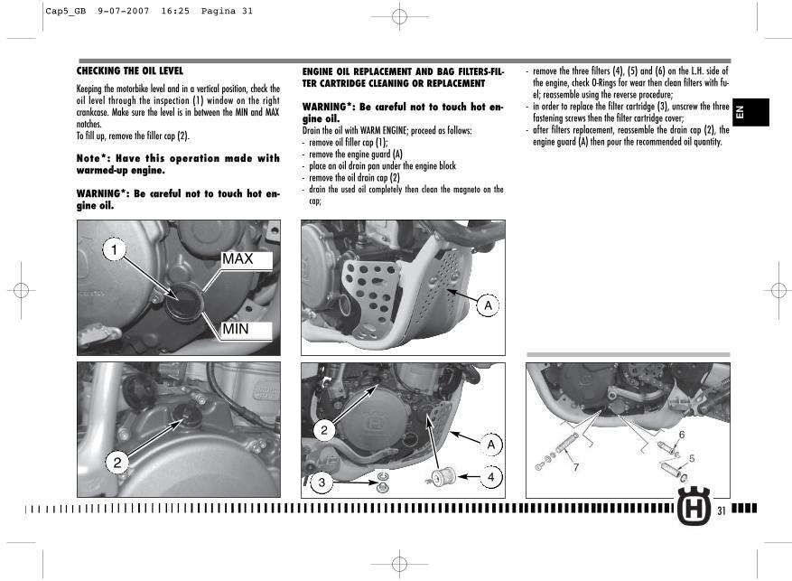
31
- remove the three filters (4), (5) and (6) on the L.H. side ofthe engine, check O-Rings for wear then clean filters with fu-el; reassemble using the reverse procedure;
- in order to replace the filter cartridge (3), unscrew the threefastening screws then the filter cartridge cover;
- after filters replacement, reassemble the drain cap (2), theengine guard (A) then pour the recommended oil quantity.
CHECKING THE OIL LEVEL
Keeping the motorbike level and in a vertical position, check theoil level through the inspection (1) window on the rightcrankcase. Make sure the level is in between the MIN and MAXnotches.To fill up, remove the filler cap (2).
Note*: Have this operation made withwarmed-up engine.
WARNING*: Be careful not to touch hot en-gine oil.
MAX
MIN
1
2
ENGINE OIL REPLACEMENT AND BAG FILTERS-FIL-TER CARTRIDGE CLEANING OR REPLACEMENT
WARNING*: Be careful not to touch hot en-gine oil.Drain the oil with WARM ENGINE; proceed as follows:- remove oil filler cap (1);- remove the engine guard (A)- place an oil drain pan under the engine block- remove the oil drain cap (2)- drain the used oil completely then clean the magneto on the
cap;
2
3
A
4
A
EN
Cap5_GB 9-07-2007 16:25 Pagina 31
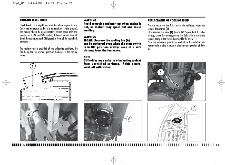
32
REPLACEMENT OF COOLING FLUID
Place a vessel on the R.H. side of the cylinder, under thecoolant drain screw (1).FIRST remove the screw (1) then SLOWLY open the R.H. radia-tor cap; slope the motorcycle on the right side to drain thecoolant easily in the vessel. Reassemble the screw (1).Pour the necessary quantity of coolant in the radiator thenwarm up the engine in order to eliminate any possible air bub-ble.
1
WARNINGAvoid removing radiator cap when engine ishot, as coolant may spout out and causescalding.
WARNINGTE-SMR: Because the cooling fan (A)can be activated even when the start switchis in OFF position, always keep at a safedistance from the fan vanes.
NOTEDifficulties may arise in eliminating coolantfrom varnished surfaces. If this occurs,wash off with water.
COOLANT LEVEL CHECK
Check level (1) in right-hand radiator when engine is cold(place the motorcycle so that it is perpendicular to the ground).The coolant should be approximately 10 mm above cells andbesides, on TE-TXC and SMR models, it doesn't exceed the mid-dle of the expansion tank (2) located in front of the rear shockabsorber.
The radiator cap is provided of two unlocking positions, thefirst being for the previous pressure discharge in the coolingsystem.
1
Cap6_GB 9-07-2007 16:09 Pagina 32
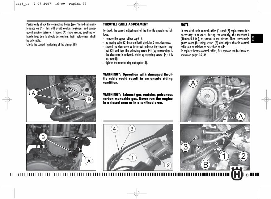
33
NOTE
In case of throttle control cables (1) and (2) replacement it isnecessary to respect, during reassembly, the measure Á(10mm/0.4 in.), as shown in the picture. Then reassembleguard cover (B) using screw (3) and adjust throttle controlcables on handlebar as described at side.To replace throttle control cables, first remove tha fuel tank asshown on pages 35, 36.
Periodically check the connecting hoses (see “Periodical main-tenance card”): this will avoid coolant leakages and conse-quent engine seizure: If hoses (A) show cracks, swelling orhardenings due to sheats desiccation, their replacement shallbe advisable.Check the correct tightening of the clamps (B).
B
A
THROTTLE CABLE ADJUSTMENT
To check the correct adjustment of the throttle operate as fol-lows:- remove the upper rubber cap (1);- by moving cable (2) back and forth check for 2 mm. clearance;- should the clearance be incorrect, unblock the counter ring-
nut (3) and turn the adjusting screw (4) (by unscrewing it,the clearance is reduced, while by screwing screw (4) it isincreased);
- tighten the counter ring-nut again (3).
WARNING*: Operation with damaged throt-tle cable could result in an unsafe ridingcondition.
WARNING*: Exhaust gas contains poisonouscarbon monoxide gas. Never run the enginein a closed area or in a confined area.
EN
AB
Cap6_GB 9-07-2007 16:09 Pagina 33
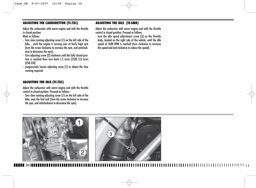
34
ADJUSTING THE CARBURETTOR (TC-TXC)
Adjust the carburettor with warm engine and with the throttlein closed position. Work as follows:- Turn slow running adjusting screw (1) on the left side of the
bike, , until the engine is turning over at fairly high rpm(turn the screw clockwise to increase the rpm, and anticlock-wise to descrease the rpm).
- Turn adjusting screw (2) clockwise until the fully closed posi-tion is reached then turn back 1,5 turns (250) 2,0 turns(450-510)
- progressively loosen adjusting screw (1) to obtain the slowrunning required.
ADJUSTING THE IDLE (TC-TXC)
Adjust the carburetor with warm engine and with the throttlecontrol in closed position. Proceed as follows:- Turn slow running adjusting screw (1) on the left side of the
bike, near the fuel cock (turn the screw clockwise to increasethe rpm, and anticlockwise to descrease the rpm).
ADJUSTING THE IDLE (TE-SMR)
Adjust the carburetor with warm engine and with the throttlecontrol in closed position. Proceed as follows:- turn the idle speed adjustment screw (3) on the throttle
body, located on the right side of the vehicle, until the idlespeed of 1600 RPM is reached (turn clockwise to increasethe speed and anti-clockwise to reduce the speed).
3
Cap6_GB 9-07-2007 16:09 Pagina 34
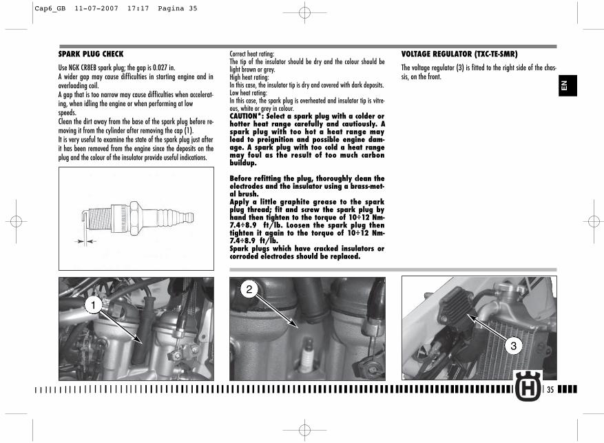
35
SPARK PLUG CHECK
Use NGK CR8EB spark plug; the gap is 0.027 in.A wider gap may cause difficulties in starting engine and inoverloading coil.A gap that is too narrow may cause difficulties when accelerat-ing, when idling the engine or when performing at lowspeeds.Clean the dirt away from the base of the spark plug before re-moving it from the cylinder after removing the cap (1).It is very useful to examine the state of the spark plug just afterit has been removed from the engine since the deposits on theplug and the colour of the insulator provide useful indications.
Correct heat rating:The tip of the insulator should be dry and the colour should belight brown or grey.High heat rating:In this case, the insulator tip is dry and covered with dark deposits.Low heat rating:In this case, the spark plug is overheated and insulator tip is vitre-ous, white or grey in colour.CAUTION*: Select a spark plug with a colder orhotter heat range carefully and cautiously. Aspark plug with too hot a heat range maylead to preignition and possible engine dam-age. A spark plug with too cold a heat rangemay foul as the result of too much carbonbuildup.
Before refitting the plug, thoroughly clean theelectrodes and the insulator using a brass-met-al brush.Apply a little graphite grease to the sparkplug thread; fit and screw the spark plug byhand then tighten to the torque of 10÷12 Nm-7.4÷8.9 ft/lb. Loosen the spark plug thentighten it again to the torque of 10÷12 Nm-7.4÷8.9 ft/lb.Spark plugs which have cracked insulators orcorroded electrodes should be replaced.
VOLTAGE REGULATOR (TXC-TE-SMR)
The voltage regulator (3) is fitted to the right side of the chas-sis, on the front.
2
3
1
EN
Cap6_GB 11-07-2007 17:17 Pagina 35
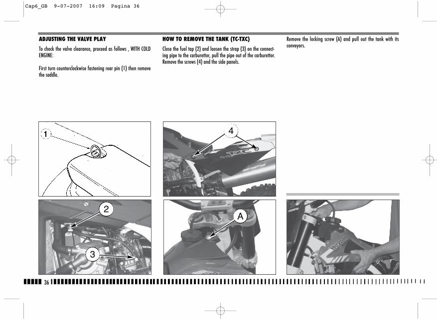
HOW TO REMOVE THE TANK (TC-TXC)
Close the fuel tap (2) and loosen the strap (3) on the connect-ing pipe to the carburettor, pull the pipe out of the carburettor.Remove the screws (4) and the side panels.
ADJUSTING THE VALVE PLAY
To check the valve clearance, proceed as follows , WITH COLDENGINE:
First turn counterclockwise fastening rear pin (1) then removethe saddle.
Remove the locking screw (A) and pull out the tank with itsconveyors.
4
2
3
A
36
Cap6_GB 9-07-2007 16:09 Pagina 36
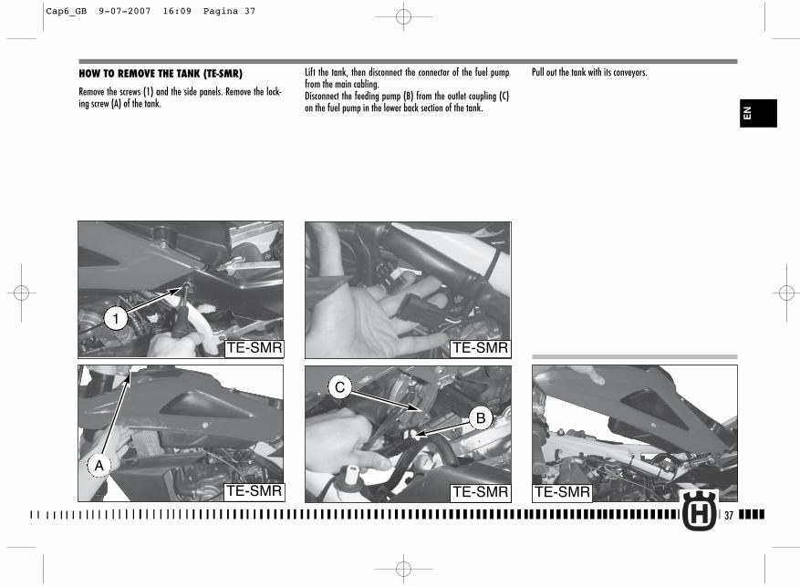
Lift the tank, then disconnect the connector of the fuel pumpfrom the main cabling.Disconnect the feeding pump (B) from the outlet coupling (C)on the fuel pump in the lower back section of the tank.
HOW TO REMOVE THE TANK (TE-SMR)
Remove the screws (1) and the side panels. Remove the lock-ing screw (A) of the tank.
Pull out the tank with its conveyors.
TE-SMR
B
TE-SMR
C
A
TE-SMR
TE-SMR
1
TE-SMR
37
EN
Cap6_GB 9-07-2007 16:09 Pagina 37
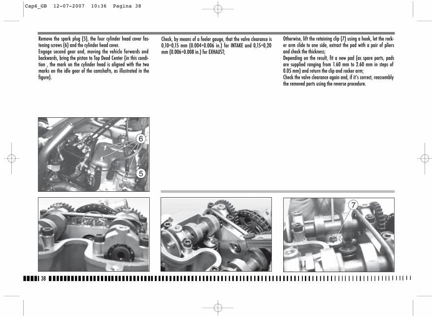
38
Check, by means of a feeler gauge, that the valve clearance is0,10÷0,15 mm (0.004÷0.006 in.) for INTAKE and 0,15÷0,20mm (0.006÷0.008 in.) for EXHAUST;
Otherwise, lift the retaining clip (7) using a hook, let the rock-er arm slide to one side, extract the pad with a pair of pliersand check the thickness;Depending on the result, fit a new pad (as spare parts, padsare supplied ranging from 1.60 mm to 2.60 mm in steps of0.05 mm) and return the clip and rocker arm;Check the valve clearance again and, if it’s correct, reassemblythe removed parts using the reverse procedure.
Remove the spark plug (5), the four cylinder head cover fas-tening screws (6) and the cylinder head cover.Engage second gear and, moving the vehicle forwards andbackwards, bring the piston to Top Dead Center (in this condi-tion , the mark on the cylinder head is aligned with the twomarks on the idle gear of the camshafts, as illustrated in thefigure).
Cap6_GB 12-07-2007 10:36 Pagina 38
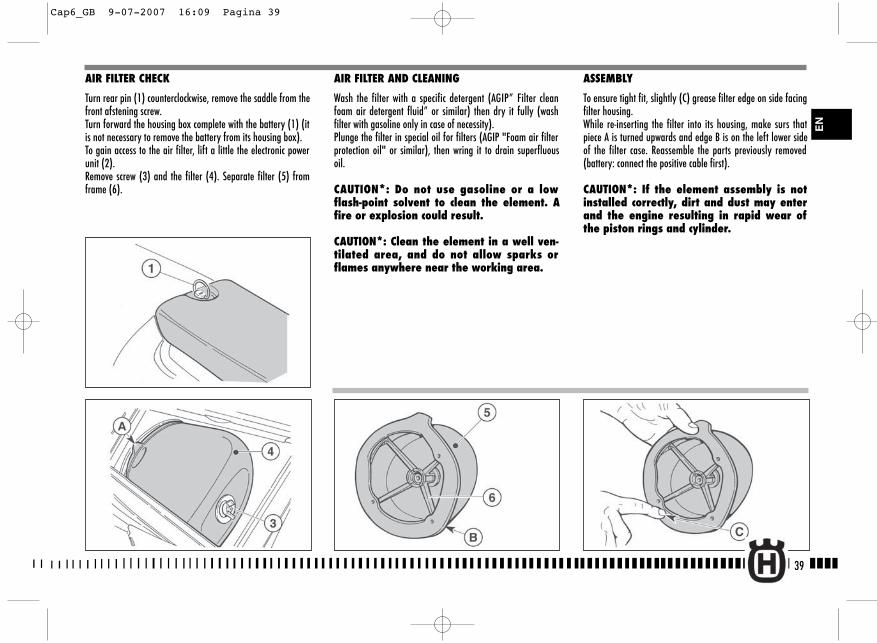
AIR FILTER AND CLEANING
Wash the filter with a specific detergent (AGIP” Filter cleanfoam air detergent fluid” or similar) then dry it fully (washfilter with gasoline only in case of necessity).Plunge the filter in special oil for filters (AGIP "Foam air filterprotection oil" or similar), then wring it to drain superfluousoil.
CAUTION*: Do not use gasoline or a lowflash-point solvent to clean the element. Afire or explosion could result.
CAUTION*: Clean the element in a well ven-tilated area, and do not allow sparks orflames anywhere near the working area.
ASSEMBLY
To ensure tight fit, slightly (C) grease filter edge on side facingfilter housing.While re-inserting the filter into its housing, make surs thatpiece A is turned upwards and edge B is on the left lower sideof the filter case. Reassemble the parts previously removed(battery: connect the positive cable first).
CAUTION*: If the element assembly is notinstalled correctly, dirt and dust may enterand the engine resulting in rapid wear ofthe piston rings and cylinder.
AIR FILTER CHECK
Turn rear pin (1) counterclockwise, remove the saddle from thefront afstening screw.Turn forward the housing box complete with the battery (1) (itis not necessary to remove the battery from its housing box).To gain access to the air filter, lift a little the electronic powerunit (2).Remove screw (3) and the filter (4). Separate filter (5) fromframe (6).
39
EN
Cap6_GB 9-07-2007 16:09 Pagina 39
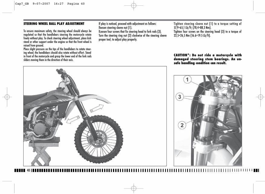
40
STEERING WHEEL BALL PLAY ADJUSTMENT
To ensure maximum safety, the steering wheel should always beregulated so that the handlebars steering the motorcycle rotatefreely without play. To check steering wheel adjustment, place kickstand or other support under the engine so that the front wheel israised from ground.Place slight pressure on the tips of the handlebars to rotate steer-ing wheel; the handlebars should also rotate without effort. Standin front of the motorcycle and grasp the lower end of the fork rodssliders moving them in the direction of their axis.
If play is noticed, proceed with adjustment as follows:lloosen steering sleeve nut (1).lLoosen four screws that fix steering head to fork rods (3).Turn the steering ring nut (2) clockwise of the steering sleeveproper tool, to adjust play properly.
T ighten steering sleeve nut (1) to a torque setting of57,9÷65,1 Lb/ft; (78,4÷88,3 Nm).Tighten four screws on the steering head (3) to a torque of22,5÷26,5 Nm (16.6÷19.5 Lb/ft).
CAUTION*: Do not ride a motorcycle withdamaged steering stem bearings. An un-safe handling condition can result.
Cap7_GB 9-07-2007 16:27 Pagina 40
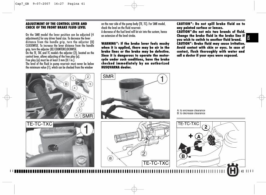
A
B
+
-
2
SMR
A: to encrease clearanceB: to decrease clearance
ADJUSTMENT OF THE CONTROL LEVER ANDCHECK OF THE FRONT BRAKE FLUID LEVEL
On the SMR model the lever position can be adjusted (4adjustments) for any driver hand size. To decrease the leverdistance from the handle grip, turn the adjuster (B)CLOCKWISE. To increase the lever distance from the handlegrip, turn the adjuster (B) COUNTERCLOCKWISE.On the TE, TXC and TC models the adjuster (2), located on thecontrol lever, allows adjusting of the free play (a). Free play (a) must be at least 3 mm (0.1 in.).The level of the fluid in pump reservoir must never be belowthe minimum value (1), which can be checked from the window
on the rear side of the pump body (TE, TC). For SMR model,check the level on the fluid reservoir.A decrease of the fuel level will let air into the sustem, hencean extension of the level stroke.
WARNING*: If the brake lever feels mushywhen it is applied, there may be air in thebrake lines or the brake may be defective.Since it is dangerous to operate the motor-cycle under such conditions, have the brakechecked immediately by an authorizedHUSQVARNA dealer.
CAUTION*: Do not spill brake fluid on toany painted surface or lenses.CAUTION*:Do not mix two brands of fluid.Change the brake fluid in the brake line ifyou wish to switch to another fluid brand.CAUTION*: Brake fluid may cause irritation.Avoid contact with skin or eyes. In case ofcontact, flush thoroughly with water andcall a doctor if your eyes were exposed.
TE-TC-TXC
TE-TC-TXC TE-TC-TXC
41
EN
SMR
Cap7_GB 9-07-2007 16:27 Pagina 41
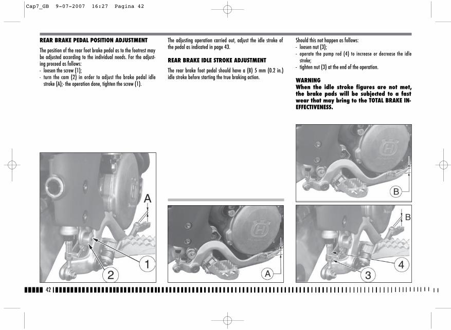
42
The adjusting operation carried out, adjust the idle stroke ofthe pedal as indicated in page 43.
REAR BRAKE IDLE STROKE ADJUSTMENT
The rear brake foot pedal should have a (B) 5 mm (0.2 in.)idle stroke before starting the true braking action.
Should this not happen as follows:- loosen nut (3);- operate the pump rod (4) to increase or decrease the idle
stroke;- tighten nut (3) at the end of the operation.
WARNINGWhen the idle stroke figures are not met,the brake pads will be subjected to a fastwear that may bring to the TOTAL BRAKE IN-EFFECTIVENESS.
REAR BRAKE PEDAL POSITION ADJUSTMENT
The position of the rear foot brake pedal as to the footrest maybe adjusted according to the individual needs. For the adjust-ing proceed as follows:- loosen the screw (1);- turn the cam (2) in order to adjust the brake pedal idle
stroke (A);- the operation done, tighten the screw (1).
Cap7_GB 9-07-2007 16:27 Pagina 42

43
CHECKING THE FLUID LEVEL
The level (A) must be set between the pump tank notches.
ADJUSTMENT OF THE CONTROL LEVER ANDCHECK OF THE HYDRAULIC CLUTCH FLUID LEVEL
Free play (A) must be at least 3 mm (0.1 in.).The lever position can be adjusted for any driver hand size. To decrease the lever distance from the handle grip, rotate theadjuster (B) CLOCKWISE.To increase the lever distance from the handle grip, rotate theadjuster (B) COUNTERCLOCKWISE.
To check the fluid level, proceed as follows:- remove screws (1), cover (2) and rubber pump diaphragm
on the handlebar clutch control;
- by keeping the master cylinder (3) in horizontal position,check the fluid level is NOT BELOW 4 mm (0.16 in.) from theupper surface (D) of the pump body;
- if necessary, add fluid until the correct level is reached seeTABLE FOR LUBRICATION-SUPPLIES for the fluid type page 12.
CAUTION*: NEVER use brake fluid.
Reassembly the removed parts using the reverse procedure.
Periodically check the connecting hose (see “Periodical main-tenance card”): if the hose (C) show is bent or cracked, its re-placement is advised.
EN
TC-TXC
Cap7_GB 9-07-2007 16:27 Pagina 43
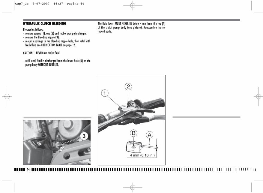
44
HYDRAULIC CLUTCH BLEEDING
Proceed as follows:- remove screws (1), cap (2) and rubber pump diaphragm;- remove the bleeding nipple (3);- mount a syringe in the bleeding nipple hole, then refill with
fresh fluid see LUBRICATION TABLE on page 12.
CAUTION *: NEVER use brake fluid.
- refill until fluid is discharged from the lower hole (B) on thepump body WITHOUT BUBBLES.
The fluid level MUST NEVER BE below 4 mm from the top (A)of the clutch pump body (see picture). Reassemble the re-moved parts.
Cap7_GB 9-07-2007 16:27 Pagina 44
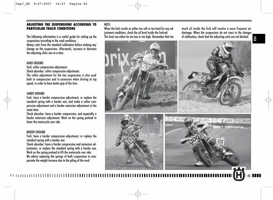
45
ADJUSTING THE SUSPENSIONS ACCORDING TOPARTICULAR TRACK CONDITIONS
The following information is a useful guide for setting up thesuspensions according to the road conditions. Always start from the standard calibration before making anychange on the suspensions. Afterwards, increase or decreasethe adjusting clicks one at a time.
HARD GROUNDFork: softer compression adjustment.Shock absorber: softer compression adjustment.The softer adjustment for the two suspensions is also usedboth in compression and in extension when driving at topspeed, in order to have better grip of the tires.
SANDY GROUNDFork: have a harder compression adjustment, or replace thestandard spring with a harder one, and make a softer com-pression adjustment and a harder extension adjustment at thesame time. Shock absorber: have a harder compression, and expecially aharder extension adjustment. Work on the spring preload tolower the motorcycle rear side.
MUDDY GROUNDFork: have a harder compression adjustment, or replace thestandard spring with a harder one.Shock absorber: have a harder compression and extension ad-justments, or replace the standard spring with a harder one.Work on the spring preload to lift the motorcycle rear side. We advise replacing the springs of both suspensions to com-pensate the weight increase due to the piling of the mud.
NOTE: When the fork results as either too soft or too hard for any ad-justment conditions, check the oil level inside the forkrod. The level can either be too low or too high. Remember that too
much oil inside the fork will involve a more frequent airdrainage. When the suspensions do not react to the changesof calibration, check that the adjusting units are not blocked.
EN
Cap7_GB 9-07-2007 16:27 Pagina 45
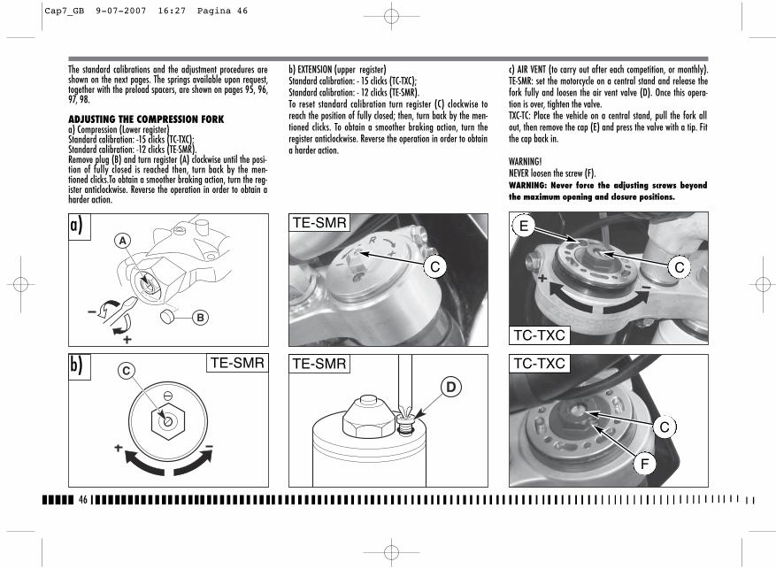
46
The standard calibrations and the adjustment procedures areshown on the next pages. The springs available upon request,together with the preload spacers, are shown on pages 95, 96,97, 98.
ADJUSTING THE COMPRESSION FORKa) Compression (Lower register)Standard calibration: -15 clicks (TC-TXC);Standard calibration: -12 clicks (TE-SMR).Remove plug (B) and turn register (A) clockwise until the posi-tion of fully closed is reached then, turn back by the men-tioned clicks.To obtain a smoother braking action, turn the reg-ister anticlockwise. Reverse the operation in order to obtain aharder action.
b) EXTENSION (upper register)Standard calibration: - 15 clicks (TC-TXC);Standard calibration: - 12 clicks (TE-SMR).To reset standard calibration turn register (C) clockwise toreach the position of fully closed; then, turn back by the men-tioned clicks. To obtain a smoother braking action, turn theregister anticlockwise. Reverse the operation in order to obtaina harder action.
c) AIR VENT (to carry out after each competition, or monthly).TE-SMR: set the motorcycle on a central stand and release thefork fully and loosen the air vent valve (D). Once this opera-tion is over, tighten the valve.TXC-TC: Place the vehicle on a central stand, pull the fork allout, then remove the cap (E) and press the valve with a tip. Fitthe cap back in.
WARNING!NEVER loosen the screw (F).WARNING: Never force the adjusting screws beyondthe maximum opening and closure positions.
A
B
C
a)
b)D
TC-TXC
TC-TXC
TE-SMR
TE-SMR
E
C
C
TE-SMR
C
F
Cap7_GB 9-07-2007 16:27 Pagina 46
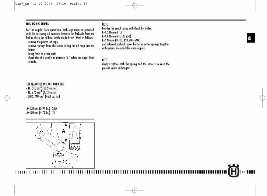
OIL FORK LEVEL
For the regular fork operation, both legs must be providedwith the necessary oil quantity. Remove the forkrods form thefork to check the oil level inside the forkrods. Work as follows: - remove the power rod caps;- remove springs from the stems letting the oil drop into the
latter;- bring forks to stroke end;- check that the level is at distance “A” below the upper limit
of rods.
OIL QUANTITY IN EACH FORK LEG- TC: 310 cm3 (18.9 cu. in.)- TE: 775 cm3 (47.3 cu. in.)- SMR: 740 cm3 (45.1 cu. in.)
A=100mm (3.94 in.) - SMRA=120mm (4.72 in.) - TE
A
NOTEBesides the serial spring with flexibility index:K=4,5 N/mm (TE) K=4,8 N/mm (TC-TXC 250) K=5 N/mm (TC-TXC 450,510 - SMR)and relevant preload spacer harder or softer springs, togetherwith spacers are abailable upon request.
NOTEAlways replace both the spring and the spacers to keep thepreload value unchanged.
47
EN
Cap7_GB 11-07-2007 17:19 Pagina 47
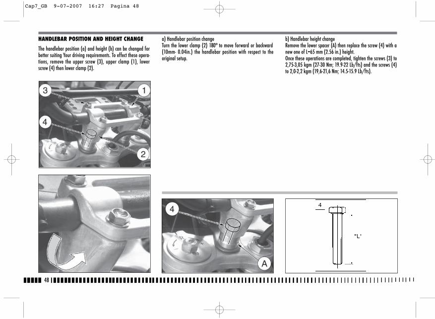
48
b) Handlebar height changeRemove the lower spacer (A) then replace the screw (4) with anew one of L=65 mm (2.56 in.) height.Once these operations are completed, tighten the screws (3) to2,75-3,05 kgm (27-30 Nm; 19.9-22 Lb/fts) and the screws (4)to 2,0-2,2 kgm (19,6-21,6 Nm; 14.5-15.9 Lb/fts).
HANDLEBAR POSITION AND HEIGHT CHANGE
The handlebar position (a) and height (b) can be changed forbetter suiting Your driving requirements. To effect these opera-tions, remove the upper screw (3), upper clamp (1), lowerscrew (4) then lower clamp (2).
a) Handlebar position changeTurn the lower clamp (2) 180° to move forward or backward(10mm- 0.04in.) the handlebar position with respect to theoriginal setup.
Cap7_GB 9-07-2007 16:27 Pagina 48
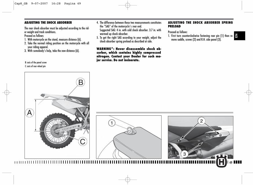
4. The difference between these two measurements constitutesthe “SAG” of the motorcycle’s rear end. Suggested SAG: 4 in. with cold shock absorber. 3.7 in. withwarmed up shock absorber.
5. To get the right SAG according to your weight, adjust theshock absorber spring preload as described at side.
WARNING*: Never disassemble shock ab-sorber, which contains highly compressednitrogen. Contact your Dealer for such ma-jor service. Do not incinerate.
ADJUSTING THE SHOCK ABSORBER SPRINGPRELOAD
Proceed as follows:1. First turn counterclockwise fastening rear pin (1) then re-
move saddle, screws (2) and R.H. side panel (3).
49
ADJUSTING THE SHOCK ABSORBER
The rear shock absorber must be adjusted according to the rid-er weight and track conditions.Proceed as follows:1. With motorcycle on the stand, measure distance (A).2. Take the normal riding position on the motorcycle with all
your riding apparel.3. With somebody’s help, take the new distance (A).
B: axis of the panel screwC: axis of rear wheel pin
2
EN
3
Cap8_GB 9-07-2007 16:28 Pagina 49
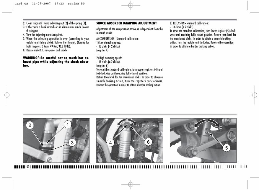
B) EXTENSION - Standard calibration: - 18 clicks (± 2 clicks)To reset the standard calibration, turn lower register (5) clock-wise until reaching fully closed position. Return then back forthe mentioned clicks. In order to obtain a smooth brakingaction, turn the register anticlockwise. Reverse the operationin order to obtain a harder braking action.
2. Clean ringnut (1) and adjusting nut (2) of the spring (3).3. Either with a hook wrench or an aluminium punch, loosen
the ringnut .4. Turn the adjusting nut as required.5. When the adjusting operation is over (according to your
weight and riding style), tighten the ringnut. (Torque forboth ringnuts: 5 Kgm; 49 Nm; 36.2 ft/lb).
6. Reassemble R.H. side panel and saddle.
WARNING*:Be careful not to touch hot ex-haust pipe while adjusting the shock abosr-ber.
SHOCK ABSORBER DAMPING ADJUSTMENT
Adjustment of the compression stroke is independent from therebound stroke.
A) COMPRESSION - Standard calibration:1) Low damping speed: - 15 clicks (± 2 clicks) (register 4)
2) High damping speed: - 15 clicks (± 2 clicks) (register 6)To reset the standard calibration, turn upper registers (4) and(6) clockwise until reaching fully closed position.Return then back for the mentioned clicks. In order to obtain asmooth braking action, turn the registers anticlockwise.Reverse the operation in order to obtain a harder braking action.
50
12
3 645
Cap8_GB 11-07-2007 17:23 Pagina 50
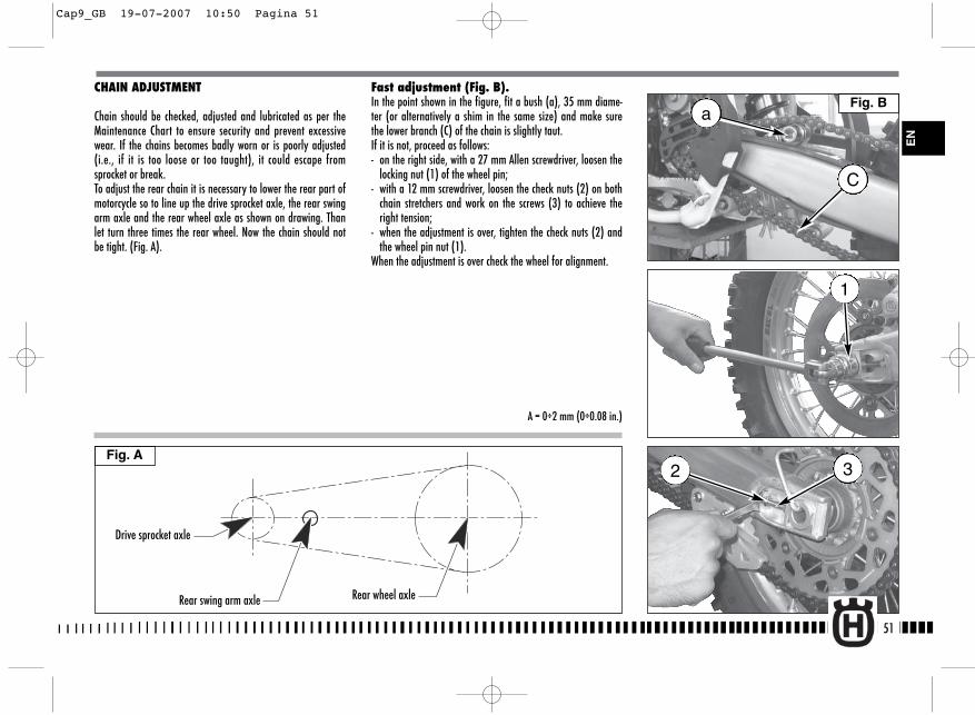
CHAIN ADJUSTMENT
Chain should be checked, adjusted and lubricated as per theMaintenance Chart to ensure security and prevent excessivewear. If the chains becomes badly worn or is poorly adjusted(i.e., if it is too loose or too taught), it could escape fromsprocket or break.To adjust the rear chain it is necessary to lower the rear part ofmotorcycle so to line up the drive sprocket axle, the rear swingarm axle and the rear wheel axle as shown on drawing. Thanlet turn three times the rear wheel. Now the chain should notbe tight. (Fig. A).
Fast adjustment (Fig. B). In the point shown in the figure, fit a bush (a), 35 mm diame-ter (or alternatively a shim in the same size) and make surethe lower branch (C) of the chain is slightly taut.If it is not, proceed as follows:- on the right side, with a 27 mm Allen screwdriver, loosen the
locking nut (1) of the wheel pin;- with a 12 mm screwdriver, loosen the check nuts (2) on both
chain stretchers and work on the screws (3) to achieve theright tension;
- when the adjustment is over, tighten the check nuts (2) andthe wheel pin nut (1).
When the adjustment is over check the wheel for alignment.
51
Fig. A
EN
Drive sprocket axle
Rear swing arm axle Rear wheel axle
A = 0÷2 mm (0÷0.08 in.)
a
C
1
32
Fig. B
Cap9_GB 19-07-2007 10:50 Pagina 51

Check the pinion damages or wear and replace it should thewear degree be as the one shown in figure.Remove the wheel and check the wear of the rear sproketteeth. The below figure shows the outline of teeth in normaland excessive wear. Should the sprocket be badly worn out, re-place it by loosening the six fastening screws to the hub.
WARNING*: Misalignment of the wheel willresult in abnormal wear and may result inan unsafe riding condition.
Note*: In muddy and wet conditions, mudsticks to the chain and sprockets resulting inan overtight chain. The pinion, the chain,and the rear sprocket wheel wear increaseswhen running on muddy ground.
LUBRICATING THE CHAIN
Lubricate the chain following these instructions.
WARNING * : Never use grease to lubricatethe chain. Grease helps to accumulate dustand mud, which act as abrasive and hepl torapidly wear out the chain, the sprocket,and the crown.
Disassembling and cleaningWhen particularly dirty, remove and clean the chain before lu-brication. Work as follows: 1 - Set a stand or a block under the engine and see that the
rear wheel is lifted from the ground.Remove: screws (1), transmission sprocket guard (2), clip(3), master link (4) and transmission chain (5);To reassemble, reverse the above procedure.
52
CHECKING THE WEAR OF CHAIN, PINION ANDSPROCKET
Proceed as follows:- fully stretch the chain with the adjusting screws.- mark 20 chain links.- measure the distance “A” between 1st pin center and 21 st pin center.
STANDARDWEARLIMIT
317,5 mm 323 mm
Normal consumption
Excessive consumption
Cap9_GB 19-07-2007 10:50 Pagina 52
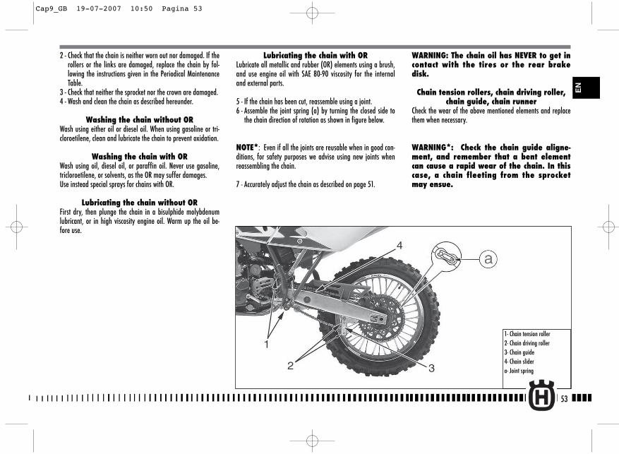
Lubricating the chain with ORLubricate all metallic and rubber (OR) elements using a brush,and use engine oil with SAE 80-90 viscosity for the internaland external parts.
5 - If the chain has been cut, reassemble using a joint.6 - Assemble the joint spring (a) by turning the closed side to
the chain direction of rotation as shown in figure below.
NOTE*: Even if all the joints are reusable when in good con-ditions, for safety purposes we advise using new joints whenreassembling the chain.
7 - Accurately adjust the chain as described on page 51.
2 - Check that the chain is neither worn out nor damaged. If therollers or the links are damaged, replace the chain by fol-lowing the instructions given in the Periodical MaintenanceTable.
3 - Check that neither the sprocket nor the crown are damaged.4 - Wash and clean the chain as described hereunder.
Washing the chain without ORWash using either oil or diesel oil. When using gasoline or tri-cloroetilene, clean and lubricate the chain to prevent oxidation.
Washing the chain with ORWash using oil, diesel oil, or paraffin oil. Never use gasoline,tricloroetilene, or solvents, as the OR may suffer damages. Use instead special sprays for chains with OR.
Lubricating the chain without ORFirst dry, then plunge the chain in a bisulphide molybdenumlubricant, or in high viscosity engine oil. Warm up the oil be-fore use.
WARNING: The chain oil has NEVER to get incontact with the tires or the rear brakedisk.
Chain tension rollers, chain driving roller,chain guide, chain runner
Check the wear of the above mentioned elements and replacethem when necessary.
WARNING*: Check the chain guide aligne-ment, and remember that a bent elementcan cause a rapid wear of the chain. In thiscase, a chain fleeting from the sprocketmay ensue.
53
1- Chain tension roller2- Chain driving roller3- Chain guide4- Chain slidera- Joint spring
EN
Cap9_GB 19-07-2007 10:50 Pagina 53

NOTESDo not operate the front brake lever when the wheel has beenremoved; this causes the caliper piston to move outwards. Afterremoval, lay down the wheel with brake disc on top.
54
REMOVING THE FRONT WHEEL
Set a stand or a block under the engine and see that the frontwheel is lifted from the ground. Loosen the bolts (1) holdingthe wheel axle (2) to the frontfork stanchions.SMR: remove the two screws (A) and the brake caliper.Hold the head of the wheel axle (2) in place, unscrew the bolt(3) on the opposite side; draw the wheel axle out.
SMR
TE-TC-TXC
TE-TC-TXCSMR
Cap9_GB 19-07-2007 10:51 Pagina 54
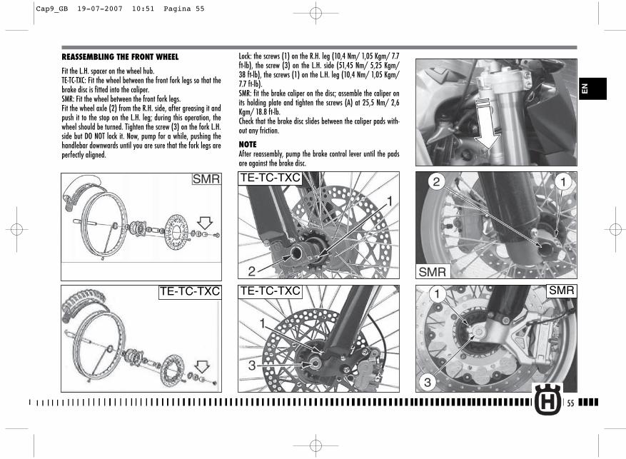
Lock: the screws (1) on the R.H. leg (10,4 Nm/ 1,05 Kgm/ 7.7ft-lb), the screw (3) on the L.H. side (51,45 Nm/ 5,25 Kgm/38 ft-lb), the screws (1) on the L.H. leg (10,4 Nm/ 1,05 Kgm/7.7 ft-lb).SMR: fit the brake caliper on the disc; assemble the caliper onits holding plate and tighten the screws (A) at 25,5 Nm/ 2,6Kgm/ 18.8 ft-lb.Check that the brake disc slides between the caliper pads with-out any friction.
NOTEAfter reassembly, pump the brake control lever until the padsare against the brake disc.
55
REASSEMBLING THE FRONT WHEEL
Fit the L.H. spacer on the wheel hub.TE-TC-TXC: Fit the wheel between the front fork legs so that thebrake disc is fitted into the caliper.SMR: Fit the wheel between the front fork legs.Fit the wheel axle (2) from the R.H. side, after greasing it andpush it to the stop on the L.H. leg; during this operation, thewheel should be turned. Tighten the screw (3) on the fork L.H.side but DO NOT lock it. Now, pump for a while, pushing thehandlebar downwards until you are sure that the fork legs areperfectly aligned.
TE-TC-TXC SMR
EN
TE-TC-TXC
TE-TC-TXC
Cap9_GB 19-07-2007 10:51 Pagina 55

REMOVING THE REAR WHEEL
Unscrew the nut (1) of the wheel pin (3) and extract it. It is notnecessary to unloose the chain adjusters (2); in this way, thechain tension will remain unchanged after the reassembly.Extract the complete rear wheel, by taking care of the spacerslocated at the hub sides.To reassemble, reverse the above procedure remembering toinsert the disc into the caliper.
NOTESDo not operate the rear brake pedal when the wheel has beenremoved; this causes the caliper piston to move outwards.After removal, lay down the wheel with brake disc on top.After reassembly, pump the brake control pedal until the padsare against the brake disc.
56
Cap9_GB 19-07-2007 10:51 Pagina 56
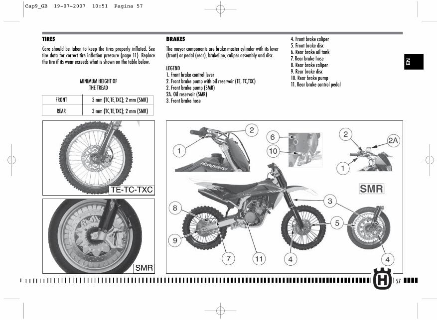
4. Front brake caliper5. Front brake disc6. Rear brake oil tank7. Rear brake hose8. Rear brake caliper9. Rear brake disc10. Rear brake pump11. Rear brake control pedal
BRAKES
The mayor components are brake master cylinder with its lever(front) or pedal (rear), brakeline, caliper assembly and disc.
LEGEND1. Front brake control lever2. Front brake pump with oil reservoir (TE, TC,TXC)2. Front brake pump (SMR)2A. Oil reservoir (SMR)3. Front brake hose
57
EN
TIRES
Care should be taken to keep the tires properly inflated. Seetire data for correct tire inflation pressure (page 11). Replacethe tire if its wear exceeds what is shown on the table below.
MINIMUM HEIGHT OF THE TREAD
FRONT 3 mm (TC,TE,TXC); 2 mm (SMR)
REAR 3 mm (TC,TE,TXC); 2 mm (SMR)
TE-TC-TXC
SMR
Cap9_GB 19-07-2007 10:51 Pagina 57
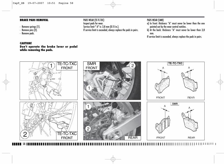
BRAKE PADS REMOVAL
- Remove springs (1).- Remove pins (2).- Remove pads.
CAUTION! Don't operate the brake lever or pedalwhile removing the pads.
PADS WEAR (TE-TC-TXC)Inspect pads for wear.Service limit " A" is: 3,8 mm (0.15 in.).If service limit is exceeded, always replace the pads in pairs.
PADS WEAR (SMR)a) In front: thickness “A” must never be lower than the one
pointed out by the wear control notches.b) At the back: thickness “A” must never be lower than 3,8
mm.If service limit is exceeded, always replace the pads in pairs.
58
TE-TC-TXCFRONT
SMRFRONT
REAR
TE-TC-TXC
TE-TC-TXCFRONT
Cap9_GB 19-07-2007 10:51 Pagina 58
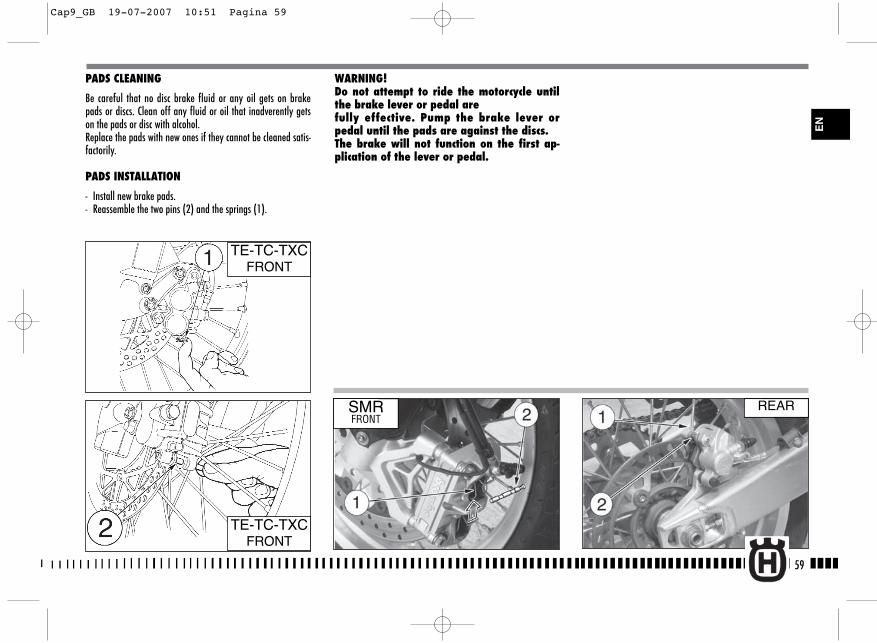
PADS CLEANING
Be careful that no disc brake fluid or any oil gets on brakepads or discs. Clean off any fluid or oil that inadverently getson the pads or disc with alcohol. Replace the pads with new ones if they cannot be cleaned satis-factorily.
PADS INSTALLATION
- Install new brake pads.- Reassemble the two pins (2) and the springs (1).
WARNING! Do not attempt to ride the motorcycle untilthe brake lever or pedal are fully effective. Pump the brake lever orpedal until the pads are against the discs.The brake will not function on the first ap-plication of the lever or pedal.
59
TE-TC-TXCFRONT
SMRFRONT
REAR
EN
TE-TC-TXCFRONT
Cap9_GB 19-07-2007 10:51 Pagina 59

BRAKE DISC WEAR
Measure the thickness of each disc at the point where it hasworn the most. Replace the disc if it has worn past the servicelimit.
Disc Thickness
DISC WARPAGEMeasure disc warpage. Service limit for both discs is 0,15 mm(0.006 in.)Replace the disc if warpage is more than service limit.
60
Front(SMR)
5 mm 4,5 mm
Front 3 mm 2,5 mm(TE-TC-TXC)
DISC STANDARD SERVICE LIMIT
Rear 4 mm 3,5 mm
TE-TC-TXC
TE-TC-TXC
Cap9_GB 19-07-2007 10:51 Pagina 60
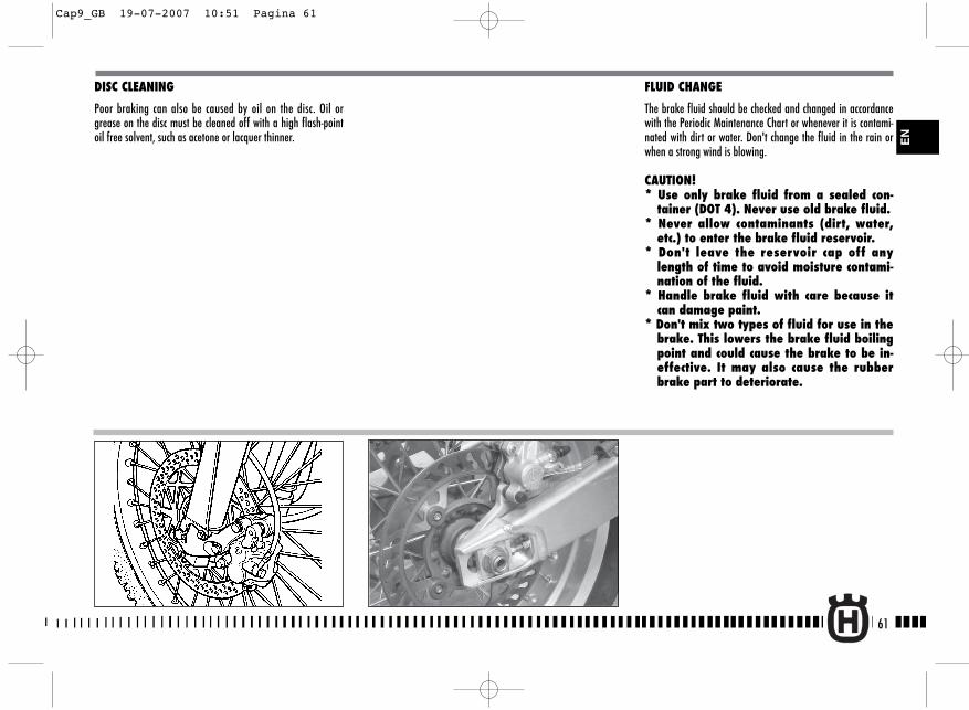
DISC CLEANING
Poor braking can also be caused by oil on the disc. Oil orgrease on the disc must be cleaned off with a high flash-pointoil free solvent, such as acetone or lacquer thinner.
FLUID CHANGE
The brake fluid should be checked and changed in accordancewith the Periodic Maintenance Chart or whenever it is contami-nated with dirt or water. Don't change the fluid in the rain orwhen a strong wind is blowing.
CAUTION! * Use only brake fluid from a sealed con-
tainer (DOT 4). Never use old brake fluid.* Never allow contaminants (dirt, water,
etc.) to enter the brake fluid reservoir.* Don't leave the reservoir cap off any
length of time to avoid moisture contami-nation of the fluid.
* Handle brake fluid with care because itcan damage paint.
* Don't mix two types of fluid for use in thebrake. This lowers the brake fluid boilingpoint and could cause the brake to be in-effective. It may also cause the rubberbrake part to deteriorate.
61
EN
Cap9_GB 19-07-2007 10:51 Pagina 61
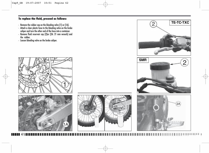
To replace the fluid, proceed as follows:
- Remove the rubber cap on the bleeding valve (1) or (1A).- Attach a clear plastic hose to the bleeding valve on the brake
caliper and turn the other end of the hose into a container.- Remove fluid reservoir cap (2)or (2A: 21 mm wrench) and
the rubber.- Loosen bleeding valve on the brake caliper.
62
TE-TC-TXC
SMR
Cap9_GB 19-07-2007 10:51 Pagina 62
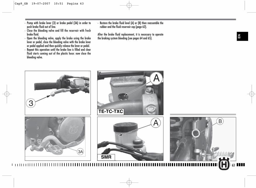
- Restore the brake fluid level (A) or (B) then reassemble therubber and the fluid reservoir cap (page 62).
After the brake fluid replacement, it is necessary to operatethe braking system bleeding (see pages 64 and 65).
63
- Pump with brake lever (3) or brake pedal (3A) in order topush brake fluid out of line.
- Close the bleeding valve and fill the reservoir with freshbrake fluid.
- Open the bleeding valve, apply the brake using the brakelever or pedal, close the bleeding valve with the brake leveror pedal applied and then quickly release the lever or pedal.
- Repeat this operation until the brake line is filled and clearfluid starts coming out of the plastic hose: now close thebleeding valve.
TE-TC-TXC
SMR
EN
Cap9_GB 19-07-2007 10:51 Pagina 63
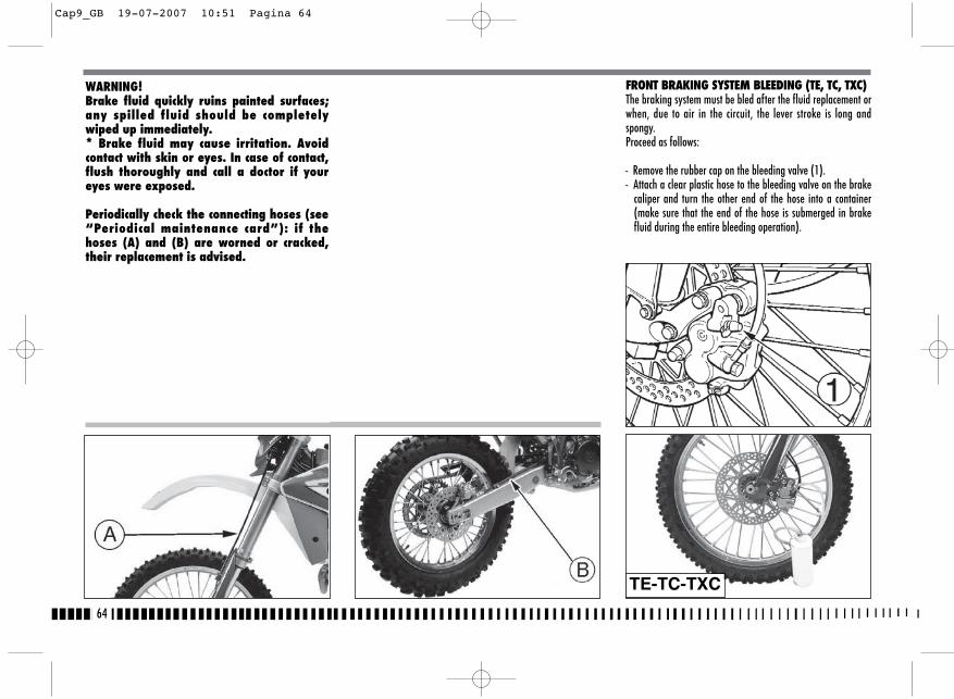
64
FRONT BRAKING SYSTEM BLEEDING (TE, TC, TXC)The braking system must be bled after the fluid replacement orwhen, due to air in the circuit, the lever stroke is long andspongy.Proceed as follows:
- Remove the rubber cap on the bleeding valve (1).- Attach a clear plastic hose to the bleeding valve on the brake
caliper and turn the other end of the hose into a container(make sure that the end of the hose is submerged in brakefluid during the entire bleeding operation).
WARNING! Brake fluid quickly ruins painted surfaces;any spilled fluid should be completelywiped up immediately.* Brake fluid may cause irritation. Avoidcontact with skin or eyes. In case of contact,flush thoroughly and call a doctor if youreyes were exposed.
Periodically check the connecting hoses (see“Periodical maintenance card”): if thehoses (A) and (B) are worned or cracked,their replacement is advised.
TE-TC-TXC
Cap9_GB 19-07-2007 10:51 Pagina 64
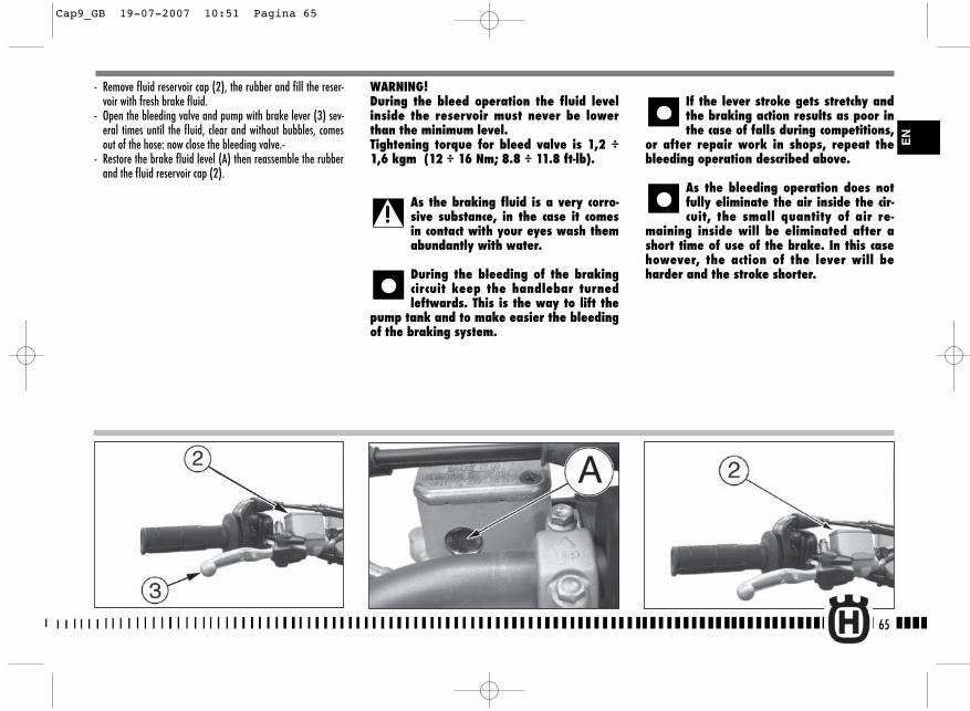
- Remove fluid reservoir cap (2), the rubber and fill the reser-voir with fresh brake fluid.
- Open the bleeding valve and pump with brake lever (3) sev-eral times until the fluid, clear and without bubbles, comesout of the hose: now close the bleeding valve.-
- Restore the brake fluid level (A) then reassemble the rubberand the fluid reservoir cap (2).
WARNING!During the bleed operation the fluid levelinside the reservoir must never be lowerthan the minimum level.Tightening torque for bleed valve is 1,2 ÷1,6 kgm (12 ÷ 16 Nm; 8.8 ÷ 11.8 ft-lb).
As the braking fluid is a very corro-sive substance, in the case it comesin contact with your eyes wash themabundantly with water.
During the bleeding of the brakingcircuit keep the handlebar turnedleftwards. This is the way to lift the
pump tank and to make easier the bleedingof the braking system.
If the lever stroke gets stretchy andthe braking action results as poor inthe case of falls during competitions,
or after repair work in shops, repeat thebleeding operation described above.
As the bleeding operation does notfully eliminate the air inside the cir-cuit, the small quantity of air re-
maining inside will be eliminated after ashort time of use of the brake. In this casehowever, the action of the lever will beharder and the stroke shorter.
65
EN
Cap9_GB 19-07-2007 10:51 Pagina 65

FRONT BRAKING SYSTEM BLEEDING (SMR)
The braking system must be bled after the fluid replacementor when, due to air in the circuit, the lever stroke is longand spongy.Regarding the front braking system, first proceed to bleed theupper braking system control (bleeding valve 1), thenthe brake caliper (bleeding valve 1A).In both cases, proceed as follows:
- Remove the rubber cap on the bleeding valve (1) or (1A).
- Attach a clear plastic hose to the bleeding valve on the brakecaliper and turn the other end of the hose into a container(make sure that the end of the hose is submerged in brakefluid during the entire bleeding operation).
- Remove fluid reservoir cap (2), the rubber and fill the reser-voir with fresh brake fluid.
- Open the bleeding valve and pump with brake lever severaltimes until the fluid, clear and without bubbles, comes out ofthe hose: now close the bleeding valve.
66
SMR
SMRSMR
Cap9_GB 19-07-2007 10:51 Pagina 66
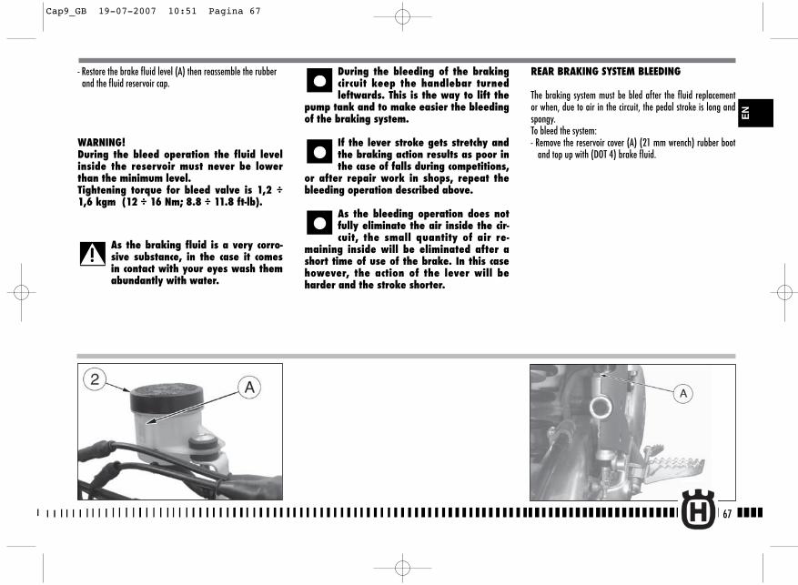
REAR BRAKING SYSTEM BLEEDING
The braking system must be bled after the fluid replacementor when, due to air in the circuit, the pedal stroke is long andspongy.To bleed the system:- Remove the reservoir cover (A) (21 mm wrench) rubber boot
and top up with (DOT 4) brake fluid.
- Restore the brake fluid level (A) then reassemble the rubberand the fluid reservoir cap.
WARNING!During the bleed operation the fluid levelinside the reservoir must never be lowerthan the minimum level.Tightening torque for bleed valve is 1,2 ÷1,6 kgm (12 ÷ 16 Nm; 8.8 ÷ 11.8 ft-lb).
As the braking fluid is a very corro-sive substance, in the case it comesin contact with your eyes wash themabundantly with water.
During the bleeding of the brakingcircuit keep the handlebar turnedleftwards. This is the way to lift the
pump tank and to make easier the bleedingof the braking system.
If the lever stroke gets stretchy andthe braking action results as poor inthe case of falls during competitions,
or after repair work in shops, repeat thebleeding operation described above.
As the bleeding operation does notfully eliminate the air inside the cir-cuit, the small quantity of air re-
maining inside will be eliminated after ashort time of use of the brake. In this casehowever, the action of the lever will beharder and the stroke shorter.
67
EN
Cap9_GB 19-07-2007 10:51 Pagina 67
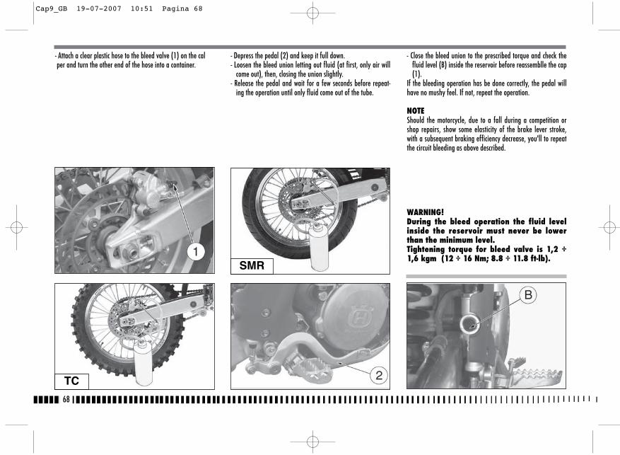
- Attach a clear plastic hose to the bleed valve (1) on the calper and turn the other end of the hose into a container.
- Depress the pedal (2) and keep it full down.- Loosen the bleed union letting out fluid (at first, only air will
come out), then, closing the union slightly.- Release the pedal and wait for a few seconds before repeat-
ing the operation until only fluid come out of the tube.
- Close the bleed union to the prescribed torque and check thefluid level (B) inside the reservoir before reassemblle the cap(1).
If the bleeding operation has be done correctly, the pedal willhave no mushy feel. If not, repeat the operation.
NOTEShould the motorcycle, due to a fall during a competition orshop repairs, show some elasticity of the brake lever stroke,with a subsequent braking efficiency decrease, you'll to repeatthe circuit bleeding as above described.
WARNING!During the bleed operation the fluid levelinside the reservoir must never be lowerthan the minimum level.Tightening torque for bleed valve is 1,2 ÷1,6 kgm (12 ÷ 16 Nm; 8.8 ÷ 11.8 ft-lb).
68
TC
SMR
Cap9_GB 19-07-2007 10:51 Pagina 68
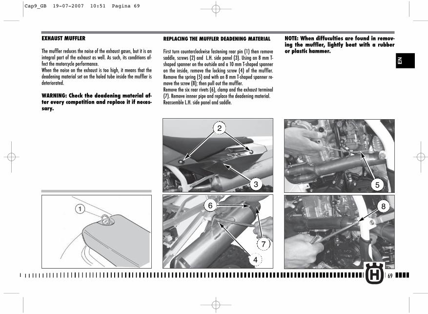
NOTE: When diffuculties are found in remov-ing the muffler, lightly beat with a rubberor plastic hammer.
EXHAUST MUFFLER
The muffler reduces the noise of the exhaust gases, but it is anintegral part of the exhaust as well. As such, its conditions af-fect the motorcycle performance.When the noise on the exhaust is too high, it means that thedeadening material set on the holed tube inside the muffler isdeteriorated.
WARNING: Check the deadening material af-ter every competition and replace it if neces-sary.
REPLACING THE MUFFLER DEADENING MATERIAL
First turn counterclockwise fastening rear pin (1) then removesaddle, screws (2) and L.H. side panel (3). Using an 8 mm T-shaped spanner on the outside and a 10 mm T-shaped spanneron the inside, remove the locking screw (4) of the muffler.Remove the spring (5) and with an 8 mm T-shaped spanner re-move the screw (8); then pull out the muffler.Remove the six rear rivets (6), clamp and the exhaust terminal(7). Remove innner pipe and replace the deadening material.Reassemble L.H. side panel and saddle.
69
2
3
EN
6
7
4
5
8
Cap9_GB 19-07-2007 10:51 Pagina 69
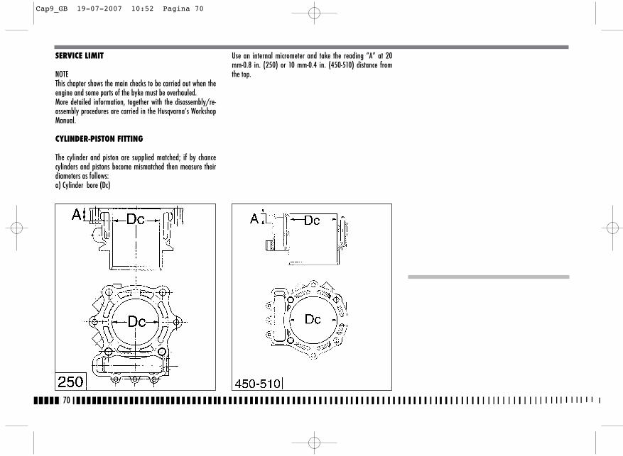
SERVICE LIMIT
NOTEThis chapter shows the main checks to be carried out when theengine and some parts of the byke must be overhauled.More detailed information, together with the disassembly/re-assembly procedures are carried in the Husqvarna’s WorkshopManual.
CYLINDER-PISTON FITTING
The cylinder and piston are supplied matched; if by chancecylinders and pistons become mismatched then measure theirdiameters as follows:a) Cylinder bore (Dc)
Use an internal micrometer and take the reading “A” at 20mm-0.8 in. (250) or 10 mm-0.4 in. (450-510) distance fromthe top.
70
Cap9_GB 19-07-2007 10:52 Pagina 70
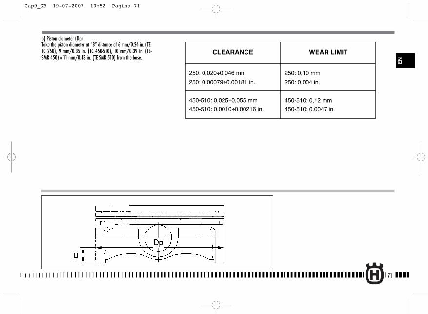
b) Piston diameter (Dp)Take the piston diameter at “B” distance of 6 mm/0.24 in. (TE-TC 250), 9 mm/0.35 in. (TC 450-510), 10 mm/0.39 in. (TE-SMR 450) o 11 mm/0.43 in. (TE-SMR 510) from the base.
71
EN
250: 0,020÷0,046 mm
250: 0.00079÷0.00181 in.
450-510: 0,025÷0,055 mm
450-510: 0.0010÷0.00216 in.
WEAR LIMITCLEARANCE
250: 0,10 mm
250: 0.004 in.
450-510: 0,12 mm
450-510: 0.0047 in.
Cap9_GB 19-07-2007 10:52 Pagina 71
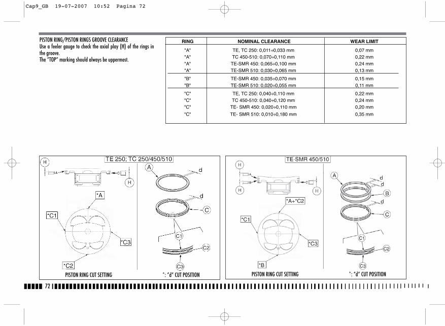
PISTON RING/PISTON RINGS GROOVE CLEARANCEUse a feeler gauge to check the axial play (H) of the rings inthe groove.The “TOP” marking should always be uppermost.
72
RING NOMINAL CLEARANCE WEAR LIMIT
"A" TE, TC 250: 0,011÷0,033 mm 0,07 mm "A" TC 450-510: 0,070÷0,110 mm 0,22 mm "A" TE-SMR 450: 0,065÷0,100 mm 0,24 mm "A" TE-SMR 510: 0,030÷0,065 mm 0,13 mm
"B" TE-SMR 450: 0,035÷0,070 mm 0,15 mm "B" TE-SMR 510: 0,020÷0,055 mm 0,11 mm
"C" TE, TC 250: 0,040÷0,110 mm 0,22 mm "C" TC 450-510: 0,040÷0,120 mm 0,24 mm "C" TE- SMR 450: 0,020÷0,110 mm 0,20 mm
"C" TE- SMR 510: 0,010÷0,180 mm 0,35 mm
PISTON RING CUT SETTING *: “d” CUT POSITION PISTON RING CUT SETTING *: “d” CUT POSITION
Cap9_GB 19-07-2007 10:52 Pagina 72
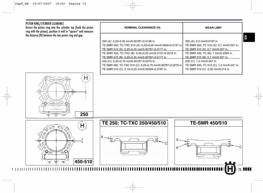
PISTON RING/CYLINDER CLEARANCEIInsert the piston ring into the cylinder top (hold the pistonring with the piston), position it well in "square" and measurethe distance (H) between the two piston ring end gap.
73
250
TE 250; TC-TXC 250/450/510 TE-SMR 450/510
450-510
WEAR LIMITNOMINAL CLEARANCE (H)
250 (A): 0,20÷0,35 mm/0.00787÷0.0138 in.TE-SMR 450, TC-TXC 510 (A): 0,25÷0,40 mm/0.0094÷0.0157 in.TE-SMR 510 (A): 0,20÷0,45 mm/0.00787÷0.0177 in.TE-SMR 450, TC-TXC (B): 0,40÷0,55 mm/0.0157÷0.0216 in.TE-SMR 510 (B): 0,20÷0,45 mm/0.00787÷0.0177 in.250 (C): 0,20÷0,70 mm/0.00787÷0.0275 in.TE-SMR 450, TC-TXC 510 (C): 0,20÷0,70 mm/0.00787÷0.0275 in.TE-SMR 510 (C): 0,10÷0,20 mm/0.00394÷0.0787 in.
250 (A): 0,5 mm/0.0197 in.TE-SMR 450, TC 510 (A): 0,7 mm/0.027 in.TE-SMR 510 (A): 0,7 mm/0.027 in.TE-SMR 450, TC (B): 1 mm/0.0394 in.TE-SMR 510 (B): 0,7 mm/0.027 in.250 (C): 1,2 mm/0.047 in.TE-SMR 450, TC 510 (C): 1,2 mm/0.047 in.TE-SMR 510 (C): 0,35 mm/0.014 in.
EN
Cap9_GB 19-07-2007 10:52 Pagina 73
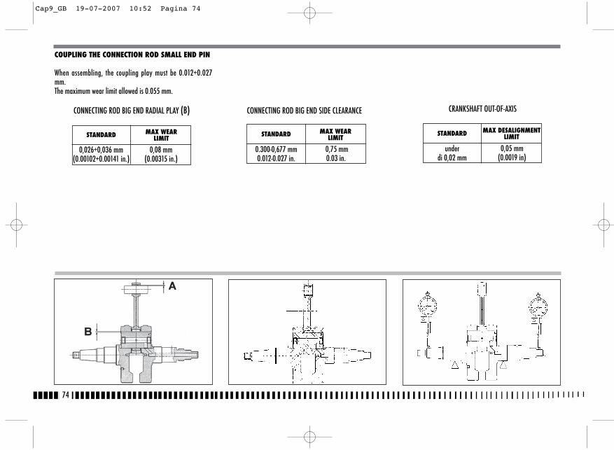
COUPLING THE CONNECTION ROD SMALL END PIN
When assembling, the coupling play must be 0.012÷0.027mm.The maximum wear limit allowed is 0.055 mm.
74
STANDARD MAX WEARLIMIT
0,026÷0,036 mm(0.00102÷0.00141 in.)
0,08 mm(0.00315 in.)
CONNECTING ROD BIG END RADIAL PLAY (B) CONNECTING ROD BIG END SIDE CLEARANCE
STANDARD MAX WEARLIMIT
0.300-0,677 mm0.012-0.027 in.
0,75 mm0.03 in.
CRANKSHAFT OUT-OF-AXIS
STANDARD MAX DESALIGNMENTLIMIT
under di 0,02 mm
0,05 mm(0.0019 in)
Cap9_GB 19-07-2007 10:52 Pagina 74
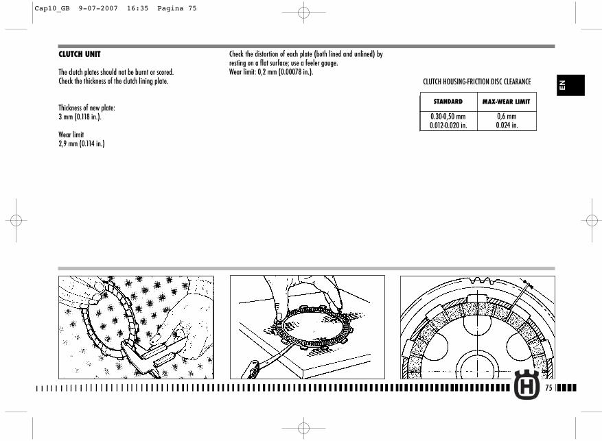
75
EN
CLUTCH UNIT
The clutch plates should not be burnt or scored.Check the thickness of the clutch lining plate.
Thickness of new plate: 3 mm (0.118 in.).
Wear limit2,9 mm (0.114 in.)
Check the distortion of each plate (both lined and unlined) byresting on a flat surface; use a feeler gauge.Wear limit: 0,2 mm (0.00078 in.).
STANDARD MAX-WEAR LIMIT
0.30-0,50 mm0.012-0.020 in.
0,6 mm0.024 in.
CLUTCH HOUSING-FRICTION DISC CLEARANCE
Cap10_GB 9-07-2007 16:35 Pagina 75
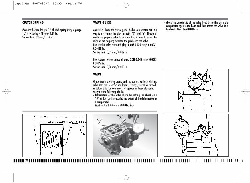
CLUTCH SPRING
Measure the free length “L” of each spring using a gauge.“L” new spring = 41 mm/ 1.61 in.Service limit: 39 mm/ 1.53 in.
VALVE GUIDE
Accurately check the valve guide. A dial comparator set in away to determine the play in both “X” and “Y” directions,which are perpendicular to one another, is used to detect thewear on the coupling between the guide and the valve.New intake valve standard play: 0,008-0,035 mm/ 0.00031-0.00138 in.Service limit: 0,05 mm/ 0.002 in.
New exhaust valve standard play: 0,018-0,045 mm/ 0.0007-0.00177 in.Service limit: 0,08 mm/ 0.003 in.
VALVE
Check that the valve shank and the contact surface with thevalve seat are in perfect conditions. Pittings, cracks, or any oth-er deformation or wear must not appear on these elements.Carry out the following checks:- deformation of the valve shank by setting the shank on a
“ V” striker, and measuring the extent of the deformation bya comparator. Working limit: 0.05 mm (0.00197 in.).
- check the concetricity of the valve head by resting an anglecomparator against the head and then rotate the valve in aVee block. Wear limit:0.0012 in.
76
Cap10_GB 9-07-2007 16:35 Pagina 76
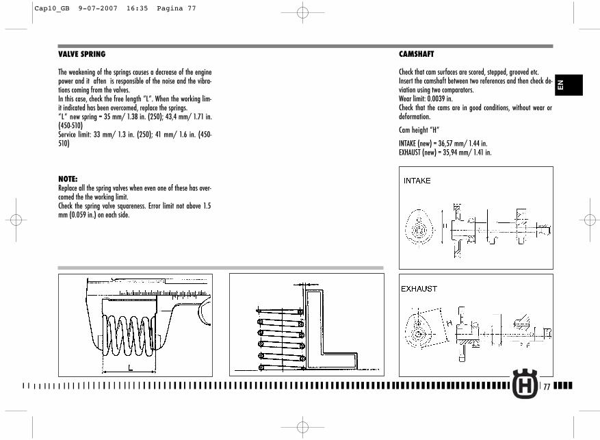
CAMSHAFT
Check that cam surfaces are scored, stepped, grooved etc.Insert the camshaft between two references and then check de-viation using two comparators.Wear limit: 0.0039 in.Check that the cams are in good conditions, without wear ordeformation.
Cam height “H”
INTAKE (new) = 36,57 mm/ 1.44 in.EXHAUST (new) = 35,94 mm/ 1.41 in.
VALVE SPRING
The weakening of the springs causes a decrease of the enginepower and it aften is responsible of the noise and the vibra-tions coming from the valves.In this case, check the free length “L”. When the working lim-it indicated has been overcomed, replace the springs.“L” new spring = 35 mm/ 1.38 in. (250); 43,4 mm/ 1.71 in.(450-510) Service limit: 33 mm/ 1.3 in. (250); 41 mm/ 1.6 in. (450-510)
NOTE: Replace all the spring valves when even one of these has over-comed the the working limit. Check the spring valve squareness. Error limit not above 1.5mm (0.059 in.) on each side.
77
EN
Cap10_GB 9-07-2007 16:35 Pagina 77
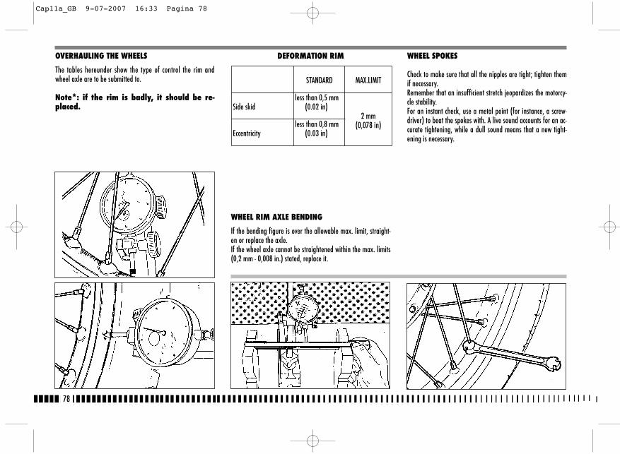
OVERHAULING THE WHEELS
The tables hereunder show the type of control the rim andwheel axle are to be submitted to.
Note*: if the rim is badly, it should be re-placed.
DEFORMATION RIM
WHEEL RIM AXLE BENDING
If the bending figure is over the allowable max. limit, straight-en or replace the axle.If the wheel axle cannot be straightened within the max. limits(0,2 mm - 0,008 in.) stated, replace it.
WHEEL SPOKES
Check to make sure that all the nipples are tight; tighten themif necessary.Remember that an insufficient stretch jeopardizes the motorcy-cle stability.For an instant check, use a metal point (for instance, a screw-driver) to beat the spokes with. A live sound accounts for an ac-curate tightening, while a dull sound means that a new tight-ening is necessary.
78
STANDARD MAX.LIMIT
Side skidless than 0,5 mm
(0.02 in)2 mm
(0,078 in)Eccentricity
less than 0,8 mm(0.03 in)
Cap11a_GB 9-07-2007 16:33 Pagina 78
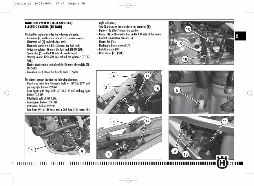
right side panel;- Two 20A fuses on the electric starter contactor (8);- Battery 12V-6Ah (7) under the saddle.- Relay (14) for the electric fan, on the R.H. side of the frame;- Coolant temperature sensor (15);- Electric fan (16).- Flashing indicator device (17)- LAMBDA probe (18)- Drop sensor (11) (SMR);
79
EN
IGNITION SYSTEM (TC-TE-SMR-TXC)ELECTRIC SYSTEM (TE-SMR)
The ignition system includes the following elements:- Generator (1) on the inner side of L.H. crankcase cover;- Electronic coil (2) under the fuel tank;- Electronic power unit C.D.I. (3) under the fuel tank;- Voltage regulator (4) under the fuel tank (TE-TXC-SMR)- Spark plug (5) on the R.H. side of cylinder head;- Starting motor 12V-450W (6) behind the cylinder (TE-TXC-
SMR);- Electric start remote control switch (8) under the saddle (TE-
TXC-SMR)- Potentiometer (10) on the throttle body (TE-SMR);
The electric system includes the following elements:- Headlamp with two filaments bulb of 12V-35/35W and
parking light bulb of 12V-3W;- Rear lights with stop bulbs of 12V-21W and parking light
bulb of 12V-5W;- Pilot lights bulb of 12V-1,2W;- Turn signals bulb of 12V-10W;- Instrument bulb of 12V-2W;- Two fuses (9), a 15A fuse and a 20A fuse (13), under the
1 6
4
2 16
14
3
7 17
89
11
5
15
18
10
13
Cap11a_GB 9-07-2007 17:47 Pagina 79
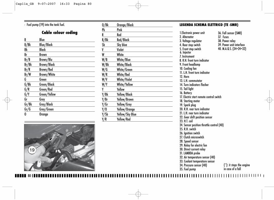
80
19
- Fuel pump (19) into the tank fuel.
Cable colour coding
B BlueB/Bk Blue/BlackBk BlackBr BrownBr/B Brown/BluBr/Bk Brown/BlackBr/R Brown/RedBr/W Brown/WhiteG GreenG/Bk Green/BlackG/R Green/RedG/Y Green/YellowGr GreyGr/Bk Grey/BlackGr/G Grey/GreenO Orange
O/Bk Orange/BlackPk PinkR RedR/Bk Red/BlackSb Sky blueV VioletW WhiteW/B White/BlueW/Bk White/BlackW/G White/GreenW/R White/RedW/V White/VioletW/Y White/YellowY YellowY/Bk Yellow/BlackY/Br Yellow/BrownY/Gr Yellow/GreyY/O Yellow/OrangeY/Sb Yellow/Sky BlueY/R Yellow/Red
LEGENDA SCHEMA ELETTRICO (TE -SMR)
1.Electronic power unit2. Alternator3. Voltage regulator4. Rear stop switch5. Front stop switch6. Injector7. Instrument8. R.H. front turn indicator9. Front headlamp10. Cooling fan11. L.H. front turn indicator12. Horn13. L.H. commutator 14. Turn indicators flasher 15. Tail light16. Battery17. Electric start remote control switch18. Starting motor19. Spark plug20. R.H. rear turn indicator21. L.H. rear turn indicator22. Gear shift position sensor23. H.T. coil24. Sensor position throttle control (40)25. R.H. switch26. Ignition switch27. Clutch microswitch28. Speed sensor29. Relay for electric fan30. Direct current relay31. LAMBDA probe32. Air temperature sensor (40)33. Coolant temperature sensor34. Pressure sensor (40)35. Fuel pump
36. Fall sensor (SMR)37. Fuses38. Power relay39. Power unit interface40. M.A.Q.S. (34+24+32)
(*): it stops the enginein case of a fall
Cap11a_GB 9-07-2007 16:33 Pagina 80
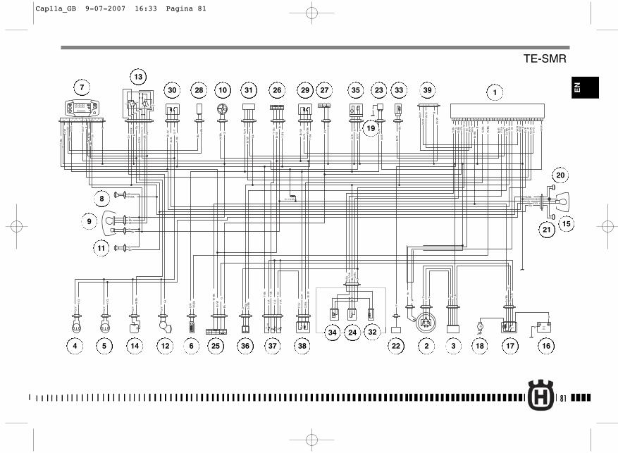
1
2
PASSING
HI
Lo
Pos
TURNHORN
R= 110 Ohm
+-
f
+-
+ -
B
W/G
W/V
Bk
B
B
Y-R
YY
Y
YY
Y
V
Bk
G/R
G/B
k
O
O
B
B
B
Bk
B
B
Pk
R
R
Y-R
Y-R
Y-B
k
Y-B
k
Y-B
k
Y-S
b
Br
G/R
G/R
G/R
V
Pk
Pk
Br/
Bk
Br/
W
Br/
W W/R
W/R
W/B
k
W/B
k
G/B
k
Bk
Bk
Bk
O
Gr/
Bk
Gr/
Bk
Y/B
r Y/S
b
Y/B
r
Y/S
b
Br/
R
Br/
R
O/B
k
O/B
k
W/B
k
W/B
k
Gr/
G
W/B
W/V
W/G
W/B
G-Y B
B
B
B
B
B
Y-R
Y-G
r
Y-S
b
Br
BBr
Y-B
k
Y-G
r
Br-
W
Br-
W
Br-
W
Br-
W
Br-
W
Br-
W
Br-
Bk
Br-
Bk
Br W
Gr/
G
Br/
B
Br/
B
W/R
W/YBk
G/Y
G/Y
G/Y
G/Y
Gr
Gr
B/B
kB
/Bk
Sb
Sb
Sb
R/B
k
R/Bk R/Bk
Bk
Bk
W
W
Y/O
Y/O
Y/O
G/R
G-Y Y RY
W
Br
G
G
B
Y/B
k
W/R
W/Y
W
Bk
Bk
Br
B
RR
/Bk
Sb
Br/
W
1 2 3 4 5 6 7 9 10 11 13 14 15 16 18 19 20 22 25 26 27 29 30 31 32 33 34
M
M 15 12V
R
9Ah
21 3 4
21
ONOFF
1 2
31 2 31 2
OFF
ON
8 12 17 21 23 24 2821
OFF
21 1 2 3 4 1 2 3 4 1 2 3 4 21
1 2 3 421 21 3 1 2 3 4 5 6
1 2 3 4 5
1
21 21 3 1 2 3 4 5 21 3 4
1 2 3 4
1 2 3 4 5 6
21 21
21
34
56
21
21
21
21
3
21212121
1 2 3 41 2 3 4 5 6 7 8 9
1 2 3 4
RUN
START
M P
DF
12
34
56
78
910 12
1114 16
13 15 2526
1718
1920
2122
2324
81
EN
1
2 34 5
7
6
8
9
10
11
12
13
14
15
161718
19
20
21
22
23
24
25
26 2728 29
3234
36
35 3330 31
37 38
39
TE-SMR
Cap11a_GB 9-07-2007 16:33 Pagina 81
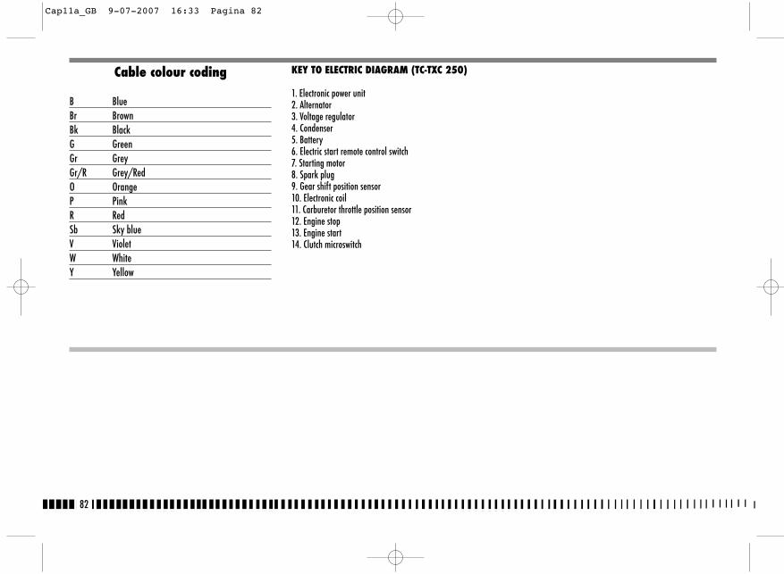
82
Cable colour coding
B BlueBr BrownBk BlackG GreenGr GreyGr/R Grey/RedO OrangeP PinkR RedSb Sky blueV VioletW WhiteY Yellow
KEY TO ELECTRIC DIAGRAM (TC-TXC 250)
1. Electronic power unit2. Alternator3. Voltage regulator4. Condenser5. Battery6. Electric start remote control switch7. Starting motor8. Spark plug9. Gear shift position sensor10. Electronic coil11. Carburetor throttle position sensor12. Engine stop13. Engine start14. Clutch microswitch
Cap11a_GB 9-07-2007 16:33 Pagina 82

83
R-WGBK-R
R-W
W-Br
GRBK-R
R
CANDELA
BOBINA
GENERATORE
W-O
SENSORE MARCE
SENSORE APERTURAFARFALLA
REGOLATORE
CONDENSATORE
- +
15A
ARRESTO
MOTORE
BATTERIA
TELERUTTORE
MOTORINOAVVIAMENTO
Y-G BBk
Y
B
R Bk
B-W
W
BB
kY
CENTRALINA
Bk - +
R
G-O
R
R
O
R
Bk-W
B
YYR
R
Bk
AVVIOMOTORE
B-W
Bk
R
INTERR.FRIZIONE
SCHEMA PER INSERIMENTO AVVIAMENTO ELETTRICO
TC-TXC 250
EN
*: ELECTRIC STARTER KIT
1
23
4
5
7
6
8
9
10
11
12
14 13
*
Cap11a_GB 9-07-2007 16:33 Pagina 83
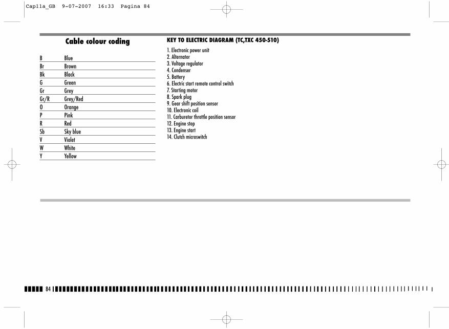
84
Cable colour coding
B BlueBr BrownBk BlackG GreenGr GreyGr/R Grey/RedO OrangeP PinkR RedSb Sky blueV VioletW WhiteY Yellow
KEY TO ELECTRIC DIAGRAM (TC,TXC 450-510)
1. Electronic power unit2. Alternator3. Voltage regulator4. Condenser5. Battery6. Electric start remote control switch7. Starting motor8. Spark plug9. Gear shift position sensor10. Electronic coil11. Carburetor throttle position sensor12. Engine stop13. Engine start14. Clutch microswitch
Cap11a_GB 9-07-2007 16:33 Pagina 84
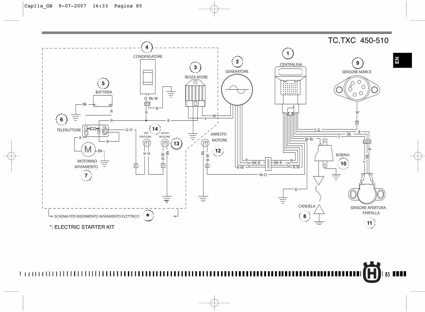
85
R-WGBK-R
R-W
W-Br
GRBK-R
R
CANDELA
BOBINA
GENERATORE
W-O
SENSORE MARCE
SENSORE APERTURAFARFALLA
REGOLATORE
- +
15A
ARRESTO
MOTORE
AVVIO
MOTORE
BATTERIA
TELERUTTORE
MOTORINOAVVIAMENTO
Y-G BBk
Y
B
B-W
Bk
Bk
B-W
W
BB
kY
CENTRALINA
Bk - +
R
G-O
R
R
O
R
Bk-W
B
WYR
R
BkRR
INT.
FRIZIONE
CONDENSATORE
SCHEMA PER INSERIMENTO AVVIAMENTO ELETTRICO
TC,TXC 450-510
*: ELECTRIC STARTER KIT
1
23
4
5
7
6
8
9
10
11
12
14
13
*
EN
Cap11a_GB 9-07-2007 16:33 Pagina 85
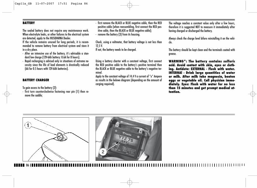
BATTERY
The sealed battery does not require any maintenance work.When electrolyte leaks, or other failures to the electrical systemare detected, apply to the HUSQVARNA Dealer.If the vehicle remains unused for long periods, it is recom-mended to remove battery from electrical system and store itin a dry place.- After an intensive use of the battery, it’s advisable a stan-
dard low charge (12V-6Ah battery: 0.6A for 8 hours).- Rapid recharging is advised only in situations of extreme ne-
cessity since the life of lead elements is drastically reduced(6A for 0.5 hours with 12V-6Ah batteries).
BATTERY CHARGER
To gain access to the battery (2):- first turn counterclockwise fastening rear pin (1) then re-
move the saddle;
- first remove the BLACK or BLUE negative cable, then the REDpositive cable (when reassembling, first connect the RED pos-itive cable, then the BLACK or BLUE negative cable);
- remove the battery (3) from its housing.
Check, using a voltmeter, that battery voltage is not less than12,5 V. If not, the battery needs to be charged.
Using a battery charter with a constant voltage, first connectthe RED positive cable to the battery’s positive terminal thenthe BLACK or BLUE negative cable to the battery’s negative ter-minal. Apply to the constant voltage of 14,4 V a current of “x” Ampereas results in the belowe diagram (depending on the amount ofcarging required).
The voltage reaches a constant value only after a few hours,therefore it is suggested NOT to measure it immediately afterhaving charged or discharged the battery.
Always check the charge level bifore reinstalling it on the vehi-cle.
The battery should be kept clean and the terminals coated withgrease.
WARNING*: The battery contains sulfuricacid. Avoid contact with skin, eyes or cloth-ing. Antidote: EXTERNAL - Flush with water.INTERNAl - Drink large quantities of wateror milk. After milk take magnesia, beateneggs or vegetable oil. Call physician imme-diately. Eyes: Flush with water for no lessthan 15 minutes and get prompt medical at-tention.
86
2
Cap11a_GB 11-07-2007 17:51 Pagina 86
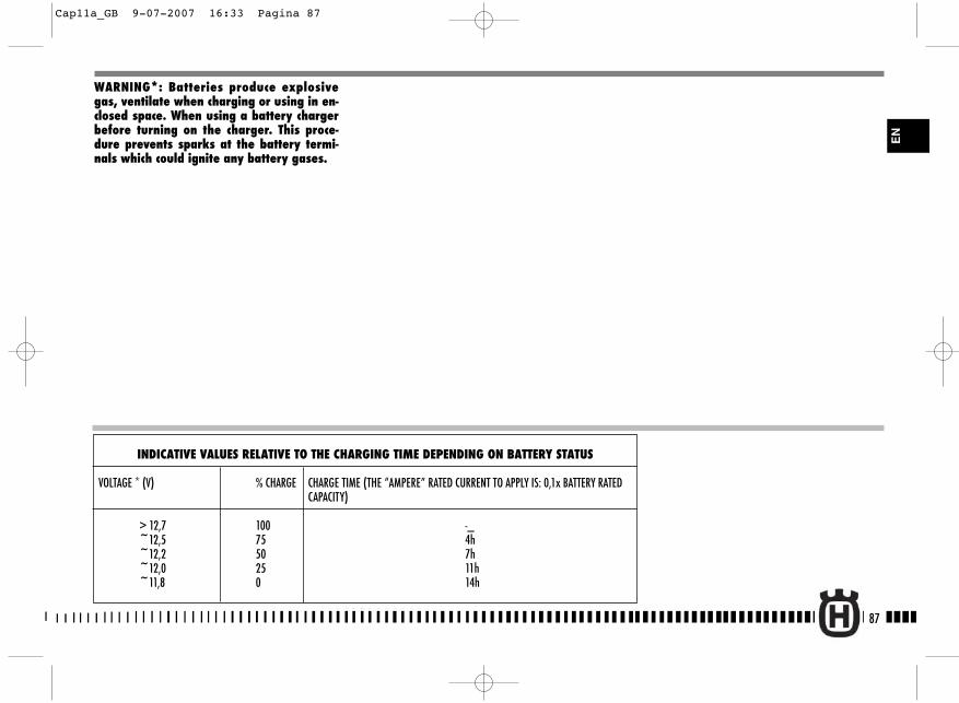
87
EN
INDICATIVE VALUES RELATIVE TO THE CHARGING TIME DEPENDING ON BATTERY STATUS
VOLTAGE * (V) % CHARGE CHARGE TIME (THE “AMPERE” RATED CURRENT TO APPLY IS: 0,1x BATTERY RATED CAPACITY)
> 12,7 100 -_~12,5 75 4h~12,2 50 7h~12,0 25 11h~11,8 0 14h
WARNING*: Batteries produce explosivegas, ventilate when charging or using in en-closed space. When using a battery chargerbefore turning on the charger. This proce-dure prevents sparks at the battery termi-nals which could ignite any battery gases.
Cap11a_GB 9-07-2007 16:33 Pagina 87
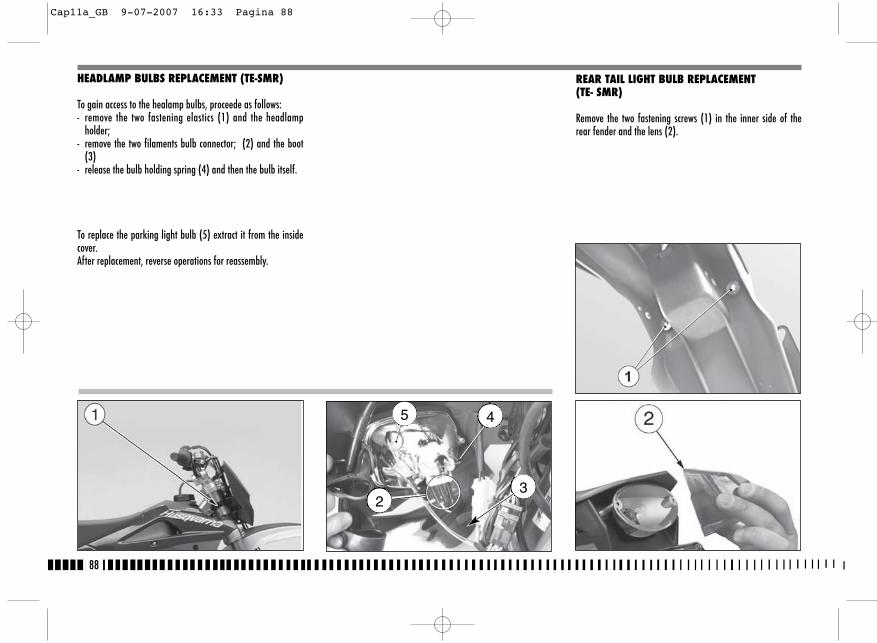
REAR TAIL LIGHT BULB REPLACEMENT (TE- SMR)
Remove the two fastening screws (1) in the inner side of therear fender and the lens (2).
88
HEADLAMP BULBS REPLACEMENT (TE-SMR)
To gain access to the healamp bulbs, proceede as follows:- remove the two fastening elastics (1) and the headlamp
holder;- remove the two filaments bulb connector; (2) and the boot
(3) - release the bulb holding spring (4) and then the bulb itself.
To replace the parking light bulb (5) extract it from the insidecover.After replacement, reverse operations for reassembly.
5 4
23
Cap11a_GB 9-07-2007 16:33 Pagina 88

5
Pull the lamp (3) inside, turn it counterclockwise then removeit from the lamp holder.
After replacement, reverse operations for reassembly.
NOTES: make sure not to tighten the screwsexcessively.
REPLACING THE NUMBER PLATE LAMP (TE- SMR)
Pull out the number plate lampholder (4) from the back of thevehicle. Pull out the lampholder and the bulb. Rotate the bulb(5) to remove from the lampholder.
Once the bulb has been replaced, reverse the above procedure.
89
EN
4
Cap11a_GB 9-07-2007 16:33 Pagina 89
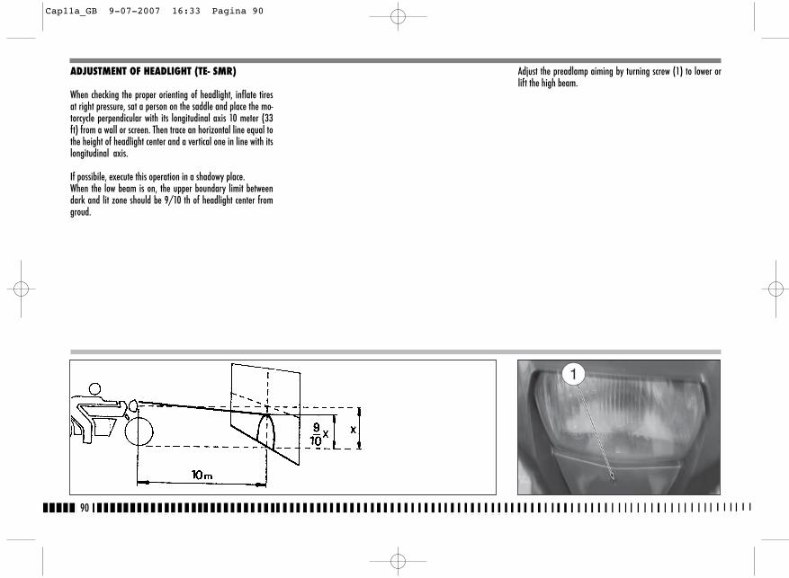
ADJUSTMENT OF HEADLIGHT (TE- SMR)
When checking the proper orienting of headlight, inflate tiresat right pressure, sat a person on the saddle and place the mo-torcycle perpendicular with its longitudinal axis 10 meter (33ft) from a wall or screen. Then trace an horizontal line equal tothe height of headlight center and a vertical one in line with itslongitudinal axis.
If possibile, execute this operation in a shadowy place.When the low beam is on, the upper boundary limit betweendark and lit zone should be 9/10 th of headlight center fromgroud.
Adjust the preadlamp aiming by turning screw (1) to lower orlift the high beam.
90
Cap11a_GB 9-07-2007 16:33 Pagina 90
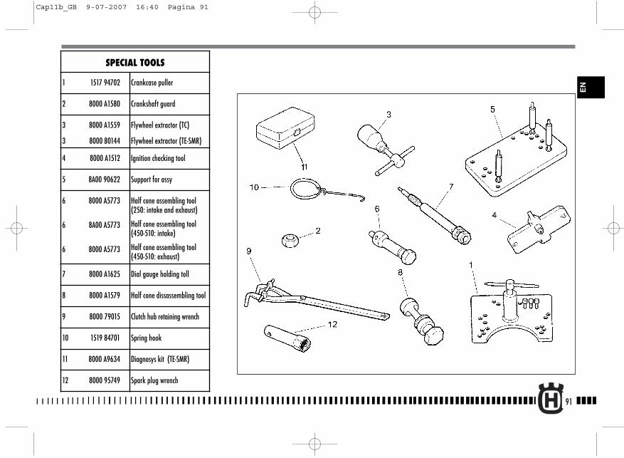
91
EN
SPECIAL TOOLS
1 1517 94702 Crankcase puller
2 8000 A1580 Crankshaft guard
3 8000 A1559
3 8000 B0144
Flywheel extractor (TC)
Flywheel extractor (TE-SMR)
4 8000 A1512 Ignition checking tool
5 8A00 90622 Support for assy
6 8000 A5773
6 8A00 A5773
6 8000 A5773
Half cone assembling tool(250: intake and exhaust)
Half cone assembling tool(450-510: intake)
Half cone assembling tool(450-510: exhaust)
7 8000 A1625 Dial gauge holding toll
8 8000 A1579 Half cone dissassembling tool
9 8000 79015 Clutch hub retaining wrench
10 1519 84701 Spring hook
11 8000 A9634 Diagnosys kit (TE-SMR)
12 8000 95749 Spark plug wrench
Cap11b_GB 9-07-2007 16:40 Pagina 91

92
ENGINE
ApplicationCamshaft cap fastening screwRocker arm axle plugCylinder head cover fastening screwCylinder head fastening nutCylinder head and cylinder fastening nutOil hose to cylinder head fastening screwOil hole plug on conrod pinPrimary drive driving gear fastening nutCentrifugal disc on INTAKE CAMSHAFT fastening screwTiming chain slider fastening screwCrankcase bearings plates fastening screwEngine oil drain plugEngine oil filter plugEngine oil filter cartridge cover fastening screwCarburetor union fastening screw (TC-TXC)Alternator fastening nutStator plate fastening screwSpark plugPick-up fastening screwClutch hub and disc housing fastening nutStarting gears stop plate fastening screwGearbox forks driving shaft fastening screwGear control click and plate fastening screwGear shift position sensor fastening screwWater pump rotor fastening nutWater pump body fastening screwDrive sprocket seal ring plate fastening screw
MOTEUR
ThreadingM6x1 12 Nm 8.7 ft/lbM14x1,5 (+LOCTITE 243) 25 Nm 18.4 ft/lbM6x1 8 Nm 5.8 ft/lbM8x1,25 15 Nm 10.8 ft/lbM10x1,5 (+MOLIKOTE HSC) 37 Nm+90° 27.5 ft/lb+90°M10x1 15 Nm 10.8 ft/lbM14x1 (+LOCTITE 243) 20 Nm 14.5 ft/lbM18x1,25 (+LOCTITE 243) 180 Nm 130 ft/lbM6x1 (+LOCTITE 243) 8 Nm 5,8 ft/lb
M8x1,25 12 Nm 8.9 ft/lbM6x1 (+LOCTITE 272) 11 Nm 7.9 ft/lbM16x1,5 25 Nm 18.4 ft/lbM14x1,5 25 Nm 18.4 ft/lbM5x0,8 (+LOCTITE 243) 6 Nm 4.3 ft/lbM4x0,7 (+LOCTITE 272) 3 Nm 2.2 ft/lbM12x1 75 Nm 55.3 ft/lbM6x1 (+LOCTITE 272) 8 Nm 5.8 ft/lbM10x1 10÷12 Nm 7.4÷8.9 ft/lbM5x0,8 (+LOCTITE 272) 6 Nm 4.3 ft/lbM18x1 75 Nm 55 ft/lbM6x1 (+LOCTITE 243) 8 Nm 5.8 ft/lbM8x1,25 (+LOCTITE 243) 20 Nm 14.5 ft/lbM6x1 (+LOCTITE 243) 8 Nm 5.8 ft/lbM5x0,8 (+LOCTITE 243) 6 Nm 4.3 ft/lbM5x0,8 (+LOCTITE 243) 3,9 Nm 2.9 ft/lbM6x1(+LOCTITE 542) 8 Nm 5.8 ft/lbM5x0,8 (+LOCTITE 243) 6 Nm 4.3 ft/lb
TIGHTENING TORQUES± 5%
CHASSIS
ApplicationRear frame lower fastening screwEngine guard fastening screwRear chain roller fastening screwSide stand fastening screwRear frame upper fastening screwFrame to engine plate fastening screwEngine lower fastening screwClutch and front brake controls clamp fastening screwThrottle control holders fastening screwFront brake hose upper fastening screw (TE, SMR)Front brake hose upper fastening screw (TC-TXC)Rear brake control pedal fastening screwRear brake pump fastening screwFront brake pump plate fastening screw (SMR)Rear brake fluid tank fastening screwRear stop control switch (TE, SMR)Front control switch connector fastening screw (SMR)Rear brake pedal adjusting cam fastening screwFront brake hose guide plate fastening screwFront brake tank cap fastening screw (SMR)Front fork legs fastening screwFront wheel axle fastening screwSteering bearings adjusting ring nutSteering pivot fastening nutHandlebar upper clamp Handlebar holder fastening screw Front fork legs guard fastening screwFront fork legs ring guard fastening screwRear swing arm axle fastening nutRear swing arm to rocker arm fastening nut
ThreadingM8x1,25 25,5 Nm 18.8 ft/lbM6x1 14,7 Nm 10.8 ft/lbM8x1,25 26,95 Nm 19.9 ft/lbM8x1,25 (+LOCTITE 243) 11,75 Nm 8.7 ft/lbM8x1,25 25,5 Nm 18.8 ft/lbM8x1,25 (+LOCTITE 270 35,3 Nm 26 ft/lbM8x1,25 35,3 Nm 26 ft/lbM6x1 4,9 Nm 3.6 ft/lbM6x1 4,9 Nm 3.6 ft/lbM10x1 19 Nm 14 ft/lbM10x1 24,7 Nm 18.2 ft/lbM10x1,25 (+LOCTITE 243) 41,65 Nm 30.7 ft/lbM6x1 10,4 Nm 7.7 ft/lbM6x1 10,4 Nm 7.7 ft/lbM6x1 2,45 Nm 1.8 ft/lbM10x1 19 Nm 14 ft/lbM2x0,4 0,8 Nm 0.6 ft/lbM6x1 14,7 Nm 10.8 ft/lbM6x1 6 Nm 4.4 ft/lbM6x1 4,9 Nm 3.6 ft/lbM8x1,25 25 Nm 18.4 ft/lbM6x1 10,4 Nm 7.7 ft/lbM25x1 3,45 Nm 2.5 ft/lbM24x1 83,3 Nm 61.4 ft/lbM8x1,25 28,4 Nm 20.9 ft/lbM10x1,5 21,1 Nm 15.6 ft/lbM5x0,8 7,85 Nm 5.8 ft/lbM5x0,8 2,45 Nm 1.8 ft/lbM16x1,5 (+LOCTITE 243) 122,5 Nm 90.3 ft/lbM12x1,25 80 Nm 59 ft/lb
± 5%
Cap11b_GB 9-07-2007 16:40 Pagina 92
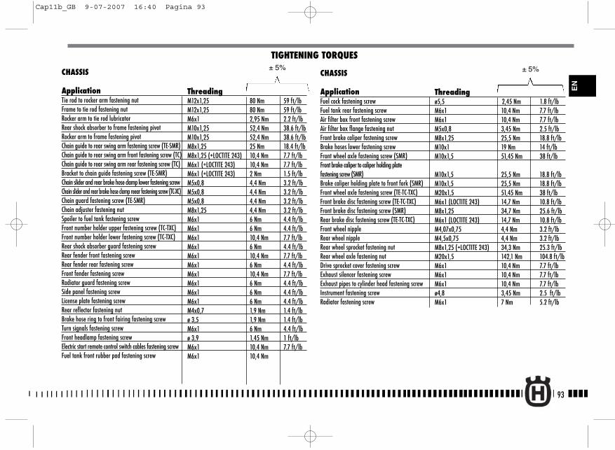
93
EN
CHASSIS
ApplicationTie rod to rocker arm fastening nut Frame to tie rod fastening nutRocker arm to tie rod lubricatorRear shock absorber to frame fastening pivotRocker arm to frame fastening pivotChain guide to rear swing arm fastening screw (TE-SMR)Chain guide to rear swing arm front fastening screw (TC)Chain guide to rear swing arm rear fastening screw (TC)Bracket to chain guide fastening screw (TE-SMR)Chain slider and rear brake hose clamp lower fastening screwChain slider and rear brake hose clamp reear fastening screw (TC-XC) Chain guard fastening screw (TE-SMR)Chain adjuster fastening nutSpoiler to fuel tank fastening screwFront number holder upper fastening screw (TC-TXC)Front number holder lower fastening screw (TC-TXC)Rear shock absorber guard fastening screwRear fender front fastening screwRear fender rear fastening screwFront fender fastening screwRadiator guard fastening screwSide panel fastening screwLicense plate fastening screwRear reflector fastening nutBrake hose ring to front fairing fastening screwTurn signals fastening screwFront headlamp fastening screwElectric start remote control switch cables fastening screwFuel tank front rubber pad fastening screw
TIGHTENING TORQUES
ThreadingM12x1,25 80 Nm 59 ft/lbM12x1,25 80 Nm 59 ft/lbM6x1 2,95 Nm 2.2 ft/lbM10x1,25 52,4 Nm 38.6 ft/lbM10x1,25 52,4 Nm 38.6 ft/lbM8x1,25 25 Nm 18.4 ft/lbM8x1,25 (+LOCTITE 243) 10,4 Nm 7.7 ft/lbM6x1 (+LOCTITE 243) 10,4 Nm 7.7 ft/lbM6x1 (+LOCTITE 243) 2 Nm 1.5 ft/lbM5x0,8 4,4 Nm 3.2 ft/lbM5x0,8 4,4 Nm 3.2 ft/lbM5x0,8 4,4 Nm 3.2 ft/lbM8x1,25 4,4 Nm 3.2 ft/lbM6x1 6 Nm 4.4 ft/lbM6x1 6 Nm 4.4 ft/lbM6x1 10,4 Nm 7.7 ft/lbM6x1 6 Nm 4.4 ft/lbM6x1 10,4 Nm 7.7 ft/lbM6x1 6 Nm 4.4 ft/lbM6x1 10,4 Nm 7.7 ft/lbM6x1 6 Nm 4.4 ft/lbM6x1 6 Nm 4.4 ft/lbM6x1 6 Nm 4.4 ft/lbM4x0,7 1,9 Nm 1.4 ft/lbø 3,5 1,9 Nm 1.4 ft/lbM6x1 6 Nm 4.4 ft/lbø 3,9 1,45 Nm 1 ft/lbM6x1 10,4 Nm 7.7 ft/lbM6x1 10,4 Nm
± 5%CHASSIS
ApplicationFuel cock fastening screwFuel tank rear fastening screwAir filter box front fastening screwAir filter box flange fastening nutFront brake caliper fastening screwBrake hoses lower fastening screwFront wheel axle fastening screw (SMR) Front brake caliper to caliper holding plate fastening screw (SMR)Brake caliper holding plate to front fork (SMR) Front wheel axle fastening screw (TE-TC-TXC) Front brake disc fastening screw (TE-TC-TXC) Front brake disc fastening screw (SMR) Rear brake disc fastening screw (TE-TC-TXC) Front wheel nippleRear wheel nippleRear wheel sprocket fastening nutRear wheel axle fastening nutDrive sprocket cover fastening screw Exhaust silencer fastening screwExhaust pipes to cylinder head fastening screwInstrument fastening screwRadiator fastening screw
Threadingø5,5 2,45 Nm 1.8 ft/lbM6x1 10,4 Nm 7.7 ft/lbM6x1 10,4 Nm 7.7 ft/lbM5x0,8 3,45 Nm 2.5 ft/lbM8x1,25 25,5 Nm 18.8 ft/lbM10x1 19 Nm 14 ft/lbM10x1,5 51,45 Nm 38 ft/lb
M10x1,5 25,5 Nm 18.8 ft/lbM10x1,5 25,5 Nm 18.8 ft/lbM20x1,5 51,45 Nm 38 ft/lbM6x1 (LOCTITE 243) 14,7 Nm 10.8 ft/lbM8x1,25 34,7 Nm 25.6 ft/lbM6x1 (LOCTITE 243) 14,7 Nm 10.8 ft/lbM4,07x0,75 4,4 Nm 3.2 ft/lbM4,5x0,75 4,4 Nm 3.2 ft/lbM8x1,25 (+LOCTITE 243) 34,3 Nm 25.3 ft/lbM20x1,5 142,1 Nm 104.8 ft/lbM6x1 10,4 Nm 7.7 ft/lbM6x1 10,4 Nm 7.7 ft/lbM6x1 10,4 Nm 7.7 ft/lbø4,8 3,45 Nm 2.5 ft/lbM6x1 7 Nm 5.2 ft/lb
± 5%
Cap11b_GB 9-07-2007 16:40 Pagina 93
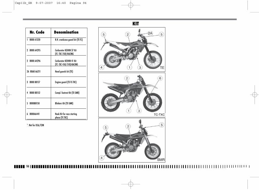
94
Nr. Code Denomination
1 8000 A1320 R.H. crankcase guard kit (TE-TC)
2 8000 A4295 Carburetor KEIHIN 37 Kit(TC -TXC 250) RACING
2 8000 A4296 Carburetor KEIHIN 41 Kit(TC -TXC 450/510)-RACING
2A 80A0 A6211 Hand guards kit (TE)
3 8000 B0157 Engine guard (TE-TC-TXC)
4 8000 B0152 Compl. footrest Kit (TE-SMR)
5 8000B0150 Blinkers Kit (TE-SMR)
6 8000A6441 Hook Kit for race starting phase (TC-TXC)
*: Not for USA/CDN
KIT
TC-TXC
Cap11b_GB 9-07-2007 16:40 Pagina 94
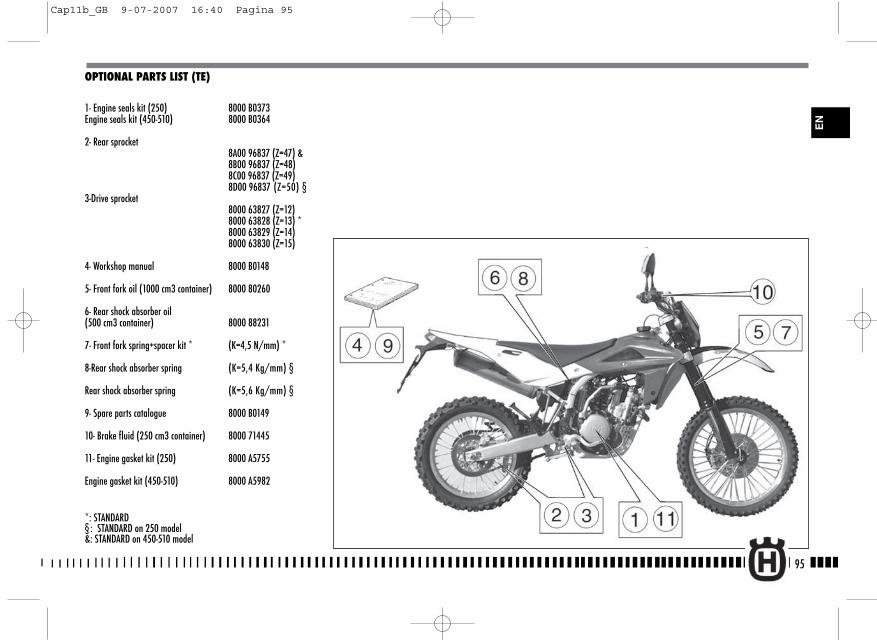
95
OPTIONAL PARTS LIST (TE)
1- Engine seals kit (250) 8000 B0373Engine seals kit (450-510) 8000 B0364
2- Rear sprocket8A00 96837 (Z=47) &8B00 96837 (Z=48) 8C00 96837 (Z=49) 8D00 96837 (Z=50) §
3-Drive sprocket8000 63827 (Z=12) 8000 63828 (Z=13) *8000 63829 (Z=14) 8000 63830 (Z=15)
4- Workshop manual 8000 B0148
5- Front fork oil (1000 cm3 container) 8000 80260
6- Rear shock absorber oil (500 cm3 container) 8000 88231
7- Front fork spring+spacer kit * (K=4,5 N/mm) *
8-Rear shock absorber spring (K=5,4 Kg/mm) §
Rear shock absorber spring (K=5,6 Kg/mm) §
9- Spare parts catalogue 8000 B0149
10- Brake fluid (250 cm3 container) 8000 71445
11- Engine gasket kit (250) 8000 A5755
Engine gasket kit (450-510) 8000 A5982
*: STANDARD§ : STANDARD on 250 model&: STANDARD on 450-510 model
EN
Cap11b_GB 9-07-2007 16:40 Pagina 95
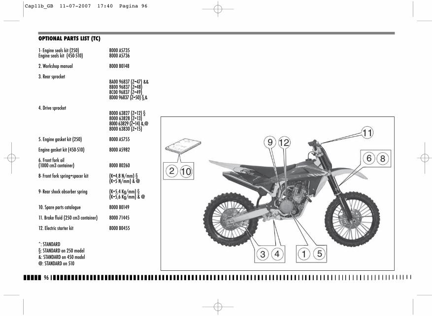
96
OPTIONAL PARTS LIST (TC)
1- Engine seals kit (250) 8000 A5735Engine seals kit (450-510) 8000 A5736
2. Workshop manual 8000 B0148
3. Rear sprocket8A00 96837 (Z=47) && 8B00 96837 (Z=48) 8C00 96837 (Z=49) 8D00 96837 (Z=50) §,&
4. Drive sprocket8000 63827 (Z=12) §8000 63828 (Z=13) 8000 63829 (Z=14) &,@8000 63830 (Z=15)
5. Engine gasket kit (250) 8000 A5755
Engine gasket kit (450-510) 8000 A5982
6. Front fork oil (1000 cm3 container) 8000 80260
8- Front fork spring+spacer kit (K=4,8 N/mm) §(K=5 N/mm) & @
9- Rear shock absorber spring (K=5,4 Kg/mm) §(K=5,6 Kg/mm) & @
10. Spare parts catalogue 8000 B0149
11. Brake fluid (250 cm3 container) 8000 71445
12. Electric starter kit 8000 B0455
*: STANDARD§: STANDARD on 250 model&: STANDARD on 450 model @: STANDARD on 510
Cap11b_GB 11-07-2007 17:40 Pagina 96
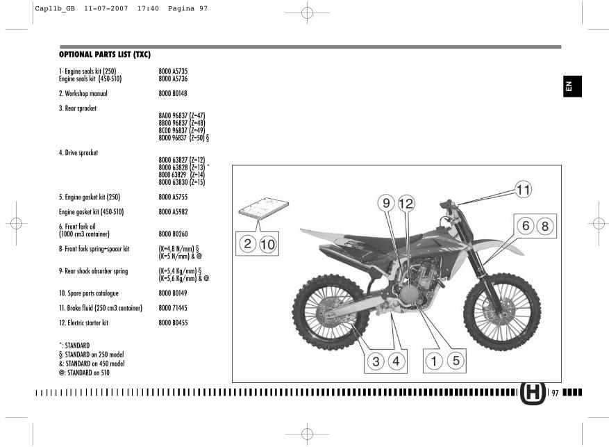
97
EN
OPTIONAL PARTS LIST (TXC)
1- Engine seals kit (250) 8000 A5735Engine seals kit (450-510) 8000 A5736
2. Workshop manual 8000 B0148
3. Rear sprocket8A00 96837 (Z=47) 8B00 96837 (Z=48) 8C00 96837 (Z=49) 8D00 96837 (Z=50) §
4. Drive sprocket8000 63827 (Z=12) 8000 63828 (Z=13) *8000 63829 (Z=14) 8000 63830 (Z=15)
5. Engine gasket kit (250) 8000 A5755
Engine gasket kit (450-510) 8000 A5982
6. Front fork oil (1000 cm3 container) 8000 80260
8- Front fork spring+spacer kit (K=4,8 N/mm) §(K=5 N/mm) & @
9- Rear shock absorber spring (K=5,4 Kg/mm) §(K=5,6 Kg/mm) & @
10. Spare parts catalogue 8000 B0149
11. Brake fluid (250 cm3 container) 8000 71445
12. Electric starter kit 8000 B0455
*: STANDARD§: STANDARD on 250 model&: STANDARD on 450 model @: STANDARD on 510
Cap11b_GB 11-07-2007 17:40 Pagina 97
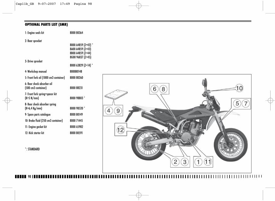
98
OPTIONAL PARTS LIST (SMR)
1- Engine seals kit 8000 B0364
2- Rear sprocket8000 A4859 (Z=42) *8A00 A4859 (Z=43)8B00 A4859 (Z=44)8G00 96837 (Z=45)
3- Drive sprocket8000 63829 (Z=14) *
4- Workshop manual 8000B0148
5- Front fork oil (1000 cm3 container) 8000 80260
6- Rear shock absorber oil (500 cm3 container) 8000 88231
7- Front fork spring+spacer kit(K=5 N/mm) 8000 98803 *
8- Rear shock absorber spring(K=6,4 Kg/mm) 8000 98520 *
9- Spare parts catalogue 8000 B0149
10- Brake fluid (250 cm3 container) 8000 71445
11- Engine gasket kit 8000 A5982
12- Kick starter kit 8000 B0591
*: STANDARD
Cap11b_GB 9-07-2007 17:49 Pagina 98
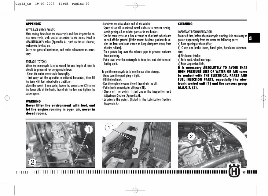
CLEANING
IMPORTANT RECOMMENDATION Premised that, before the motorcycle washing, it is necessary toprotect opportunely from the water the following parts:a) Rear opening of the muffler;b) Clutch and brake levers, hand grips, handlebar commuta-tors;c) Air cleaner intake;d) Fork head, wheel bearings;e) Rear suspension links,it is necessary ABSOLUTELY TO AVOID THATHIGH PRESSURE JETS OF WATER OR AIR cometo contact with THE ELECTRICAL PARTS ANDFUEL INJECTION PARTS, especially the elec-tronic control unit (1) and the sensors groupM.A.Q.S. (2).
2
- Lubricate the drive chain and all the cables.- Spray oil on all unpainted metal surfaces to prevent rusting.
Avoid getting oil on rubber parts or in the brakes.- Set the motorcycle on a box or stand so that both wheels are
raised off the ground. (If this cannot be done, put boards un-der the front and rear wheels to keep dampness away fromthe tire rubber).
- Tie a plastic bag over the exhaust pipe to prevent moisturefrom entering.
- Put a cover over the motorcycle to keep dust and dirt from col-lecting on it.
To put the motorcycle back into the use after storage.- Make sure the spark plug is tight.- Fill the fuel tank.- Run the engine to warm the oil then drain the oil.- Put in fresh transmission oil (page 31).- Check all the points listed under the inspection and
Adjustment Section (Appendix A).- Lubricate the points (listed in the Lubrication Section
(Appendix A).
APPENDIX
AFTER-RACE CHECK POINTSAfter racing, first clean the motorcycle and then inspect the en-tire motorcycle, with special attention to the items listed in«MAINTENANCE» table (Appendix A), such as the air cleaner,carburetor, brakes, etc.Carry out general lubrication, and make adjustment as neces-sary.
STORAGE (TC-TCXC)When the motorcycle is to be stored for any length of time, isshould be prepared for storage as follows:- Clean the entire motorcycle thoroughly.- first carry out the operation mentioned hereunder, then fillthe tank with fuel mixed with a stabilizer:place the hose (1) in a basin, loosen the drain screw (2) set onthe lower side of the basin, then drain the fuel and tighten thescrew again.
WARNINGNever litter the environment with fuel, andlet the engine running in open air, never inclosed rooms.
99
EN
1
Cap12_GB 19-07-2007 11:05 Pagina 99
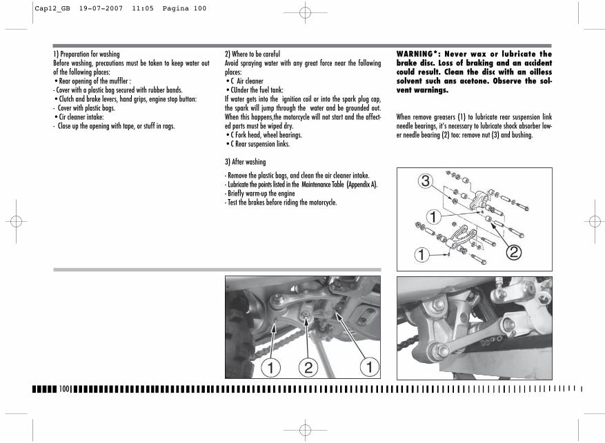
100
WARNING*: Never wax or lubricate thebrake disc. Loss of braking and an accidentcould result. Clean the disc with an oillesssolvent such ans acetone. Observe the sol-vent warnings.
When remove greasers (1) to lubricate rear suspension linkneedle bearings, it’s necessary to lubricate shock absorber low-er needle bearing (2) too: remove nut (3) and bushing.
1) Preparation for washingBefore washing, precautions must be taken to keep water outof the following places:•Rear opening of the muffler :- Cover with a plastic bag secured with rubber bands.•Clutch and brake levers, hand grips, engine stop button:- Cover with plastic bags.•Cir cleaner intake:- Close up the opening with tape, or stuff in rags.
2) Where to be carefulAvoid spraying water with any great force near the followingplaces:•C Air cleaner•CUnder the fuel tank:If water gets into the ignition coil or into the spark plug cap,the spark will jump through the water and be grounded out.When this happens,the motorcycle will not start and the affect-ed parts must be wiped dry. •C Fork head, wheel bearings.•C Rear suspension links.
3) After washing
- Remove the plastic bags, and clean the air cleaner intake.- Lubricate the points listed in the Maintenance Table (Appendix A).- Briefly warm-up the engine- Test the brakes before riding the motorcycle.
Cap12_GB 19-07-2007 11:05 Pagina 100

101
EN
�� ���� � ������ �����
��������������
Engine oil Check levelTwo-stroke mix oil level Check levelCoolant Check / Restore levelCooling system Check for leakageElectric fans Check operationSpark plugs Check / ReplaceThrottle body / Carburettor Check and adjustBrakes / Clutch fluid Check levelBrakes / Clutch Check operationBrakes / Clutch Check lines for leakageThrottle control Check operationThrottle control Check / Adjust playChoke control Check operationFlexible controls and transm. Check / AdjustDrive chain Check / Adjust
Tyres Check pressureSide stand Check operationSide stand switch Check operationElectrical equipment Check operationInstrument panel Check operationLights / Visual signals Check operationHorn Check operationHeadlight Check operationIgnition switch Check operationLocks Check operationScrews and nuts Check / TightenHose clamps Check / TightenGeneral lubrication General test
� : presenti solo sui motocicli con motore a 2 tempi �� : presente solo su alcuni modelli
� : only for motorcycles with 2 stroke engine �� : only for some models
PRE -DELIVERY INSPECTION
Description Operation Pre-delivery Description Operation Pre-delivery
Cap12_GB 19-07-2007 11:05 Pagina 101
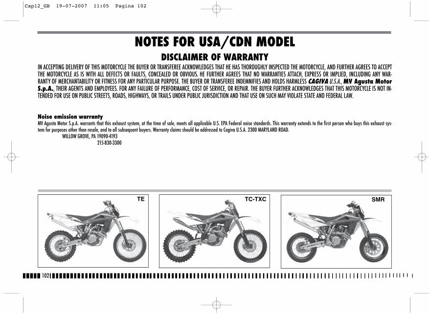
DISCLAIMER OF WARRANTYIN ACCEPTING DELIVERY OF THIS MOTORCYCLE THE BUYER OR TRANSFEREE ACKNOWLEDGES THAT HE HAS THOROUGHLY INSPECTED THE MOTORCYCLE, AND FURTHER AGREES TO ACCEPTTHE MOTORCYCLE AS IS WITH ALL DEFECTS OR FAULTS, CONCEALED OR OBVIOUS. HE FURTHER AGREES THAT NO WARRANTIES ATTACH, EXPRESS OR IMPLIED, INCLUDING ANY WAR-RANTY OF MERCHANTABILITY OR FITNESS FOR ANY PARTICULAR PURPOSE. THE BUYER OR TRANSFEREE INDEMNIFIES AND HOLDS HARMLESS CAGIVA U.S.A., MV Agusta MotorS.p.A., THEIR AGENTS AND EMPLOYEES. FOR ANY FAILURE OF PERFORMANCE, COST OF SERVICE, OR REPAIR. THE BUYER FURTHER ACKNOWLEDGES THAT THIS MOTORCYCLE IS NOT IN-TENDED FOR USE ON PUBLIC STREETS, ROADS, HIGHWAYS, OR TRAILS UNDER PUBLIC JURISDICTION AND THAT USE ON SUCH MAY VIOLATE STATE AND FEDERAL LAW.
Noise emission warrantyMV Agusta Motor S.p.A. warrants that this exhaust system, at the time of sale, meets all applicable U.S. EPA Federal noise standards. This warranty extends to the first person who buys this exhaust sys-tem for purposes other than resale, and to all subsequent buyers. Warranty claims should be addressed to Cagiva U.S.A. 2300 MARYLAND ROAD.
WILLOW GROVE, PA 19090-4193 215-830-3300
102
NOTES FOR USA/CDN MODEL
TC-TXCTE SMR
Cap12_GB 19-07-2007 11:05 Pagina 102
Warning statementThis product should be checked for repair or replacement if themotorcycle noise has increased significantly through use.Otherwise, the owner may become subject to penalties understate and local ordinances.
Tampering warningTampering with Noise Control System Prohibited.Federal law prohibits the following acts or causing thereof:(1) The removal or rendering inoperative by any person other
than for purposes of maintenance, repair, or replacement,of any device or element of design incorporated into anynew vehicle for the purpose of noise control prior to itssale or delivery to the ultimate purchaser or while it is inuse, and
(2) the use of the vehicle after such device or element of de-sign has been removed or rendered inoperative by anyperson.
Among those acts presumed to constitute tampering are theacts listed below.1) Removal of, or puncturing the muffler, baffles, header pipes
or any other component which conducts exhaust gases.2) Removal or puncturing of any part of the intake system.3) Lack of proper maintenance.4) Replacing any moving part of the vehicle, or parts of the
exhaust or intake system, with parts other than those speci-fied by the manufacturer.
103
EN
Cap12_GB 19-07-2007 11:06 Pagina 103
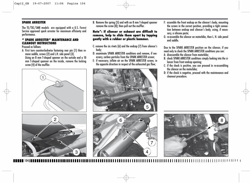
SPARK ARRESTER
The TE/TXC/SMR models are equipped with a U.S. ForestService approved spark arrester for maximum efficienty andperformance.
“ SPARK ARRESTER” MAINTENANCE ANDCLEANOUT INSTRUCTIONSProceed as follows:A: First turn counterclockwise fastening rear pin (1) then re-
move saddle, screws (2) and L.H. side panel (3). Using an 8 mm T-shaped spanner on the outside and a 10mm T-shaped spanner on the inside, remove the lockingscrew (4) of the muffler.
B: Remove the spring (5) and with an 8 mm T-shaped spannerremove the screw (8); then pull out the muffler.
Note*: If silencer or exhaust are difficult toremove, help to slide them apart by tappinggently with a rubber or plastic hammer.
C: remove the six rivets (6) and the endcap (7) from silencer’sbody;
D: examinate SPARK ARRESTER conditions and remove, if nec-essary, carbon particles from the SPARK ARRESTER screen;
E: if necessary, inflate air on the SPARK ARRESTER screen, inthe opposite direction in respect of the exhausted gas flow;
F: assemble the front endcap on the silencer’s body, mountingthe screws in the correct position, providing a tight connec-tion between endcap and silencer’s body, using, if neces-sary, a silicone paste;
G: re-assemble the silencer on motorbike, then L. H. side paneland saddle.
Due to the SPARK ARRESTER position on the silencer, if youneed only to check the SPARK ARRESTER conditions you can:A: disassemble the silencer from motorbike;B: check SPARK ARRESTER conditions simply looking into the si-
lencer from front endcap opening;C: if the check is positive, you can proceed in re-assembling
the silencer on the motorbike;D: if the check is negative, proceed with the maintenance and
cleanout procedure.
104
2
3
6
7
4
5
8
Cap12_GB 19-07-2007 11:06 Pagina 104
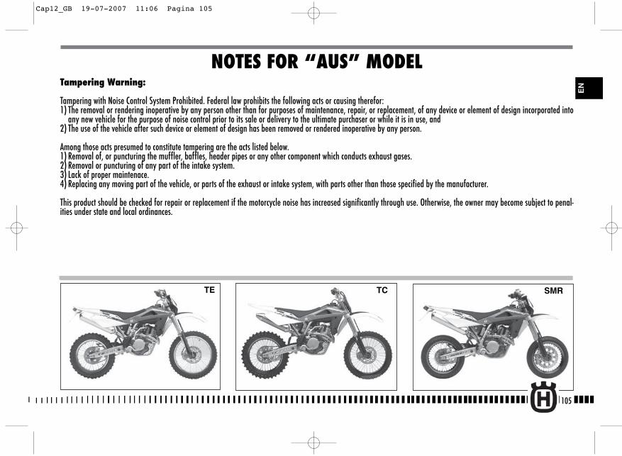
Tampering Warning:
Tampering with Noise Control System Prohibited. Federal law prohibits the following acts or causing therefor:1) The removal or rendering inoperative by any person other than for purposes of maintenance, repair, or replacement, of any device or element of design incorporated into
any new vehicle for the purpose of noise control prior to its sale or delivery to the ultimate purchaser or while it is in use, and2) The use of the vehicle after such device or element of design has been removed or rendered inoperative by any person.
Among those acts presumed to constitute tampering are the acts listed below.1) Removal of, or puncturing the muffler, baffles, header pipes or any other component which conducts exhaust gases.2) Removal or puncturing of any part of the intake system.3) Lack of proper maintenace.4) Replacing any moving part of the vehicle, or parts of the exhaust or intake system, with parts other than those specified by the manufacturer.
This product should be checked for repair or replacement if the motorcycle noise has increased significantly through use. Otherwise, the owner may become subject to penal-ities under state and local ordinances.
NOTES FOR “AUS” MODEL
TCTE SMR
105
EN
Cap12_GB 19-07-2007 11:06 Pagina 105
106
Cap12_GB 19-07-2007 11:06 Pagina 106
107
MMotorcycle stop............................................................................30Muffler on the exhaust ................................................................69
OOil filters replacement..................................................................31Overhauling the wheels ..............................................................78
PPad cleaning................................................................................59Parts replacement..........................................................................3Pilot lights ..................................................................................16Preliminary checks ......................................................................23
RRear brake control ......................................................................22Rear braking system bleeding......................................................67Rear crown ..................................................................................10Rear fork ....................................................................................11Rear taillight bulb replacement....................................................88Removal tank ........................................................................36, 37Removing the front wheel............................................................54Removing the rear wheel ............................................................56Running in ..................................................................................23
SSteering lock ..............................................................................20Side stand ..................................................................................14Spark arrester ..........................................................................104Spark plug ..................................................................................10Spark plug check ........................................................................35Special tools ................................................................................91Starting decompressor ................................................................25
TThrottle control ............................................................................20Tires ......................................................................................11, 57
VVehicle identification number ........................................................5Voltage regulator ........................................................................35
WWheel pin bending ......................................................................78Wheel spokes ..............................................................................78Wheels ........................................................................................11
ALPHABETIC INDEXPage
AAdjusting the carburetor ..............................................................34Adjusting the clutch ....................................................................43Adjusting the driven transmission ................................................51Adjusting the fork ........................................................................46Adjusting the front brake control lever ..................................................41Adjusting the headlamp ..............................................................90Adjusting the idle ........................................................................34Adjusting the rear brake idle stroke ............................................43Adjusting shock absorber hydraulic brake ..........................................................................................50Adjusting shock absorber preload spring ................................................49Adjusting the rear brake pedal position............................................42Adjusting the steering bearing play..............................................40Adjusting the suspensions according to the track special conditions ......................................................45Adjusting the throttle cable ..........................................................33Adjusting the valve play ..............................................................36
BBattery ........................................................................................86Brakes ........................................................................................57Brake disc cleaning ......................................................................61Brake disc warpage......................................................................60Brake disc wear ..........................................................................60Brake pad assembly ....................................................................59Brake pad wear ..........................................................................58Brake pad disassembly ................................................................58
CCarburettor ..................................................................................10Carburettor starter ......................................................................15Chain lubrication ........................................................................52Checks after every competition ....................................................98Checks during running in ............................................................23Check of air filter ........................................................................39Check of chain, pinion, crown wear ..............................................52Check of clutch fluid level ............................................................43Check of cooling fluid ..................................................................32Check of front brake fluid level ....................................................41Check of engine oil ....................................................................31Check of rear brake fluid level ....................................................43Cleaning the air filter ..................................................................39Clutch ........................................................................................10Clutch control ..............................................................................21
Coolant replacement ....................................................................32Cooling fluid ................................................................................12Control position ............................................................................9
DDigital instrument ........................................................................16Driven transmission chain ............................................................10
EEngine assembling fits ................................................................70Electric diagram ..............................................................81, 83, 85Electric elements ..........................................................................79Engine lubrication........................................................................12Engine oil replacement ................................................................31Engine start (TC)..........................................................................24Engine start (TE-SMR) ..................................................................26Engine stop..................................................................................30
FFilling the braking system............................................................62Fluid change ................................................................................61Fork oil level ..............................................................................47Fuel ............................................................................................14Fuel cock......................................................................................13Front brake control ......................................................................20Front braking system bleeding................................................62-64Front fork ....................................................................................11
GGearbox control ..........................................................................22Gearbox outlet pinion ..................................................................10General cleaning ........................................................................99
HHandlebar commutators ..............................................................21Handlebar position change ..........................................................48Headlamp bulbs replacement ......................................................88Hydraulic clutch bluding ..............................................................44
IIgnition ......................................................................................10Important notice ............................................................................3Injection ......................................................................................13
LLamp light plate replacement ......................................................89Long inactivity ............................................................................99
EN
Cap13_GB 19-07-2007 11:17 Pagina 107

108
Cap13_GB 19-07-2007 11:18 Pagina 108
FRANÇAIS
1
Cap1_FR 19-07-2007 10:34 Pagina 1
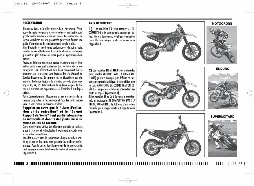
2
PRESENTATION
Bienvenus dans la famille motocycliste Husqvarna! Votrenouvelle moto Husqvarna a été projetée et construite pourqu’elle soit la meilleure dans son genre. Les instructions deservice ci-incluses ont été préparées pour vous fournir uneguide d’entretien et de fonctionnement simple et clair.Afin d’obtenir les meilleures performances de votre moto,veuillez suivre attentivement les instructions ici contenues,qui sont les plus simples à suivre pour les opérations d’en-tretien.Toutes les informations concernantes les réparations et l’en-tretien particuliers sont contenues dans ce livret de serviceHusqvarna. Les informations détaillées concernant les ré-parations ou l’entretien sont décrites dans le Manuel deService Husqvarna. Ce manuel est à disposition sur de-mande. Indiquer toujours le numéro de code placé auxpages 93, 94, 95. Interventions de ce feure exigent le tra-vail de mécaniciens expérimentés et l’emploi d’outillagesspécial.Votre Concessionnaire Husqvarna en sus des pièces de re-change originales, a l’expérience et tous les outils néces-saires à vous rendre un service excellent.Rappeler en outre que le “Livret d'utilisa-tion et de entretien” et le “CarnetRapport de Vente” font partie intégrantesdu motocycle et donc rester joints aussi aumême en cas de revente.Cette motocyclette utilise des éléments projetés et realizésgrace à systèmes et technologies d’avanguard et expérimen-tés dans les competitions.Dans les motocyclette de competition, chaque détail est véri-fié après toutes les races pour garantir les meilleur perfor-mances. Pour le correct fonctionnement de la motocyclette,c’est nécessaire suivre le tableau de control et maintien dansl’Appendice A.
MOTOCROSS
SUPERMOTARD
ENDURO
AVIS IMPORTANT
1) Les modèles TC êtes motocycles DECOMPÉTITION et ils sont garantis exempté par dé-fauts de fonctionnement; le tableau d'entretienconseillé pour usage sportif se trouve dansl’Appendice A.
2) Les modèles TE et SMR êtes motocyclespour emploi ROUTIER (AVEC LA PUISSANCELIMITÉ) garantis exempté par défauts et cou-vert par garantie juridique, à la condition queje sois MAINTENUE LA CONFIGURATION DESÉRIE et respectée le tableau d’entretien re-porté au page 7 (Appendice A).Si les modèles TE et SMR ils vinssent transfor-més en motocycles DE COMPÉTITION (AVEC LAPLEINE PUISSANCE), le tableau d’entretienconseillé pour usage sportif est reporté dansl’Appendice A.
Cap1_FR 19-07-2007 10:34 Pagina 2
3
IMPORTANT
Pour la reconnaissance de la garantie il fera à la référence laCONFIGURATION DU VÉHICULE, comme de suite décrit:
A) MOTOCYCLE DE SÉRIE, POUR USAGE ROUTIER: AVEC LA PUIS-SANCE LIMITÉ
B) MOTOCYCLE DE COMPÉTITION, POUR USAGE SPORTIF: AVEC LAPLEINE PUISSANCE
Cette motocyclette n’était pas projeté pourparcourir longs trajets avec le moteur tou-jours au maximum des tours comme peut sepasser en occasion des longs trajets surroutes ou autoroutes. Longs trajets au pleingaz peuvent causer des dégats au moteur.Cette motocyclette présent un setup pour lescompetitions et donc le maximum des perfor-mances sont garantis avec seulement un pilo-te. L’utilisation dans les circuits ou tout ter-rain avec un passager n’est pas conseillé.
Rappeler TOUJOURS que ces motocyclettes ont été projetées pourusage sportif où les conditions sont très différentes de cellesd'un usage routier normal.
Pour maintenir la "Garantie deFonctionnement" du véhicule, le Client doitsuivre le programme d'entretien indiqué surle livret d'usage et entretien en exécutant lescoupons près des ateliers autorisés HUSQVAR-NA. Le coût pour la substitution des bouts etpour la main-d'oeuvre nécessaire pour res-pecter l'étage d'entretien est à la charge duClient. NOTE: la garantie DÉCHOIT en cas de locationdu motocycle.
PréliminairesSuivre scrupuleusement les instructions données dans ce ma-nuel en prêtant attention aux remarques indiquées par lesmots suivants:
ATTENTION*: Indique la possibilité de bles-sures graves ou mortelles si ces instruc-tions ne seraient pas suivies.ATTENTION*: Indique la possibilité que deblessures graves soient provoquées à lapersonne, ou des dommages sérieux au vé-hicule, si ces instructions ne seraient passuivies.Note*: Fournit d’ultérieures informations.
Remplacement de détailsPour assurer un usage sans aléa, remplacer les plusieurs élé-ments avec des éléments ORIGINAUX Husqvarna.
ATTENTION*: Après une chute, inspectersoigneusement le motocycle. Assurez-vous que la poignée des gaz, les freins,l’embrayage, et tous les autres com-mandes et composants, ne soient pas en-dommagés, car la conduite d’un moto-cycle endommagé peut provoquer des ac-cidents.
ATTENTION*: Ne jamais démarrer le moto-cycle, ou effectuer des opérations d’en-tretien, sans s’habiller convenablement.Porter le casque, les bottes, les gants,les lunettes pour cyclomotoristes et toutautre mise appropriée.
ATTENTION*: Ce motocycle est un véhiculesophistiqué à utiliser dans les compéti-tions. Ne jamais démarrer ou conduire lemotocycle sans avoir la nécessaire expé-rience. Assurez-vous d’être toujours dansde bonnes conditions physiques.
PRECAUTIONS POUR LES ENFANTS ATTEN-TION� Garer le véhicule à l'abri dans un en-
droit où il ne pourra pas être heurtéou endommagé. Les coups, même invo-lontaires, pourraient provoquer la chu-te du véhicule avec le danger consé-quent pour les personnes, en particu-lier pour les enfants.
� Pour éviter toute chute accidentelle duvéhicule, ne jamais le garer sur un ter-rain mouillé ou irrégulier, ni sur legoudron rendu ardent par l'effet du so-leil.
� Etant donné que le moteur ou le systè-me d'échappement peuvent atteindredes températures très élevées, garerla moto dans un endroit où les piétonsou les enfants ne pourront pas la tou-cher facilement.
FR
Cap1_FR 19-07-2007 10:34 Pagina 3
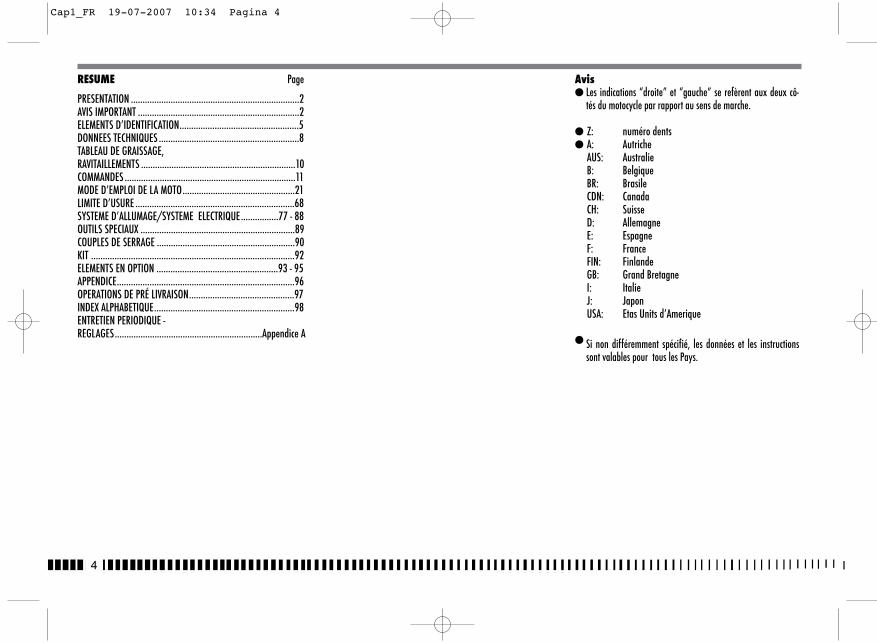
4
RESUME Page
PRESENTATION ........................................................................2AVIS IMPORTANT .....................................................................2ELEMENTS D’IDENTIFICATION...................................................5DONNEES TECHNIQUES ............................................................8TABLEAU DE GRAISSAGE, RAVITAILLEMENTS ..................................................................10COMMANDES .........................................................................11MODE D’EMPLOI DE LA MOTO................................................21LIMITE D’USURE ....................................................................68SYSTEME D’ALLUMAGE/SYSTEME ELECTRIQUE.............…77 - 88OUTILS SPECIAUX ..................................................................89COUPLES DE SERRAGE ...........................................................90KIT .......................................................................................92ELEMENTS EN OPTION ....................................................93 - 95APPENDICE............................................................................96OPERATIONS DE PRÉ LIVRAISON.............................................97INDEX ALPHABETIQUE............................................................98ENTRETIEN PERIODIQUE -REGLAGES...............................................................Appendice A
Avis� Les indications “droite” et “gauche” se refèrent aux deux cô-
tés du motocycle par rapport au sens de marche.
� Z: numéro dents� A: Autriche
AUS: AustralieB: BelgiqueBR: BrasileCDN: CanadaCH: SuisseD: AllemagneE: EspagneF: FranceFIN: FinlandeGB: Grand BretagneI: ItalieJ: JaponUSA: Etas Units d’Amerique
� Si non différemment spécifié, les données et les instructionssont valables pour tous les Pays.
Cap1_FR 19-07-2007 10:34 Pagina 4
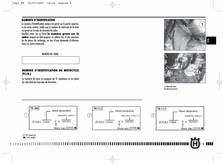
5
FR
ELEMENTS D’IDENTIFICATIONLe numéro d'identification moteur est gravé sur la partie supérieu-re du carter moteur, tandis que le numéro de matricule de la motoest gravé sur le tube de direction du cadre.Veuillez noter sur ce livret le numéro gravé sur lecadre, auquel on doit toujours se référer lors d’une comman-de de pièces de rechange, ou lors d’une demande d’informa-tions sur votre motocycle.
NUMÉRO DE CADRE
NUMERO D’IDENTIFICATION DU MOTOCYCLE(V.I.N.)
Le numéro de série se compose de 17 caractères et est placédu côté droit du fourreau de direction.
(*): N° progressive(�): An du modèle
1. Matricule cadre2. Matricule moteur
Cap1_FR 19-07-2007 10:34 Pagina 5

6
NUMERO D’IDENTIFICATION DU MOTOCYCLE(V.I.N.)
Le numéro de série se compose de 17 caractères et est placé ducôté droit du fourreau de direction.
(*): N° progressive(�): An du modèle
1. Matricule cadre2. Matricule moteur
Cap1_FR 19-07-2007 10:34 Pagina 6
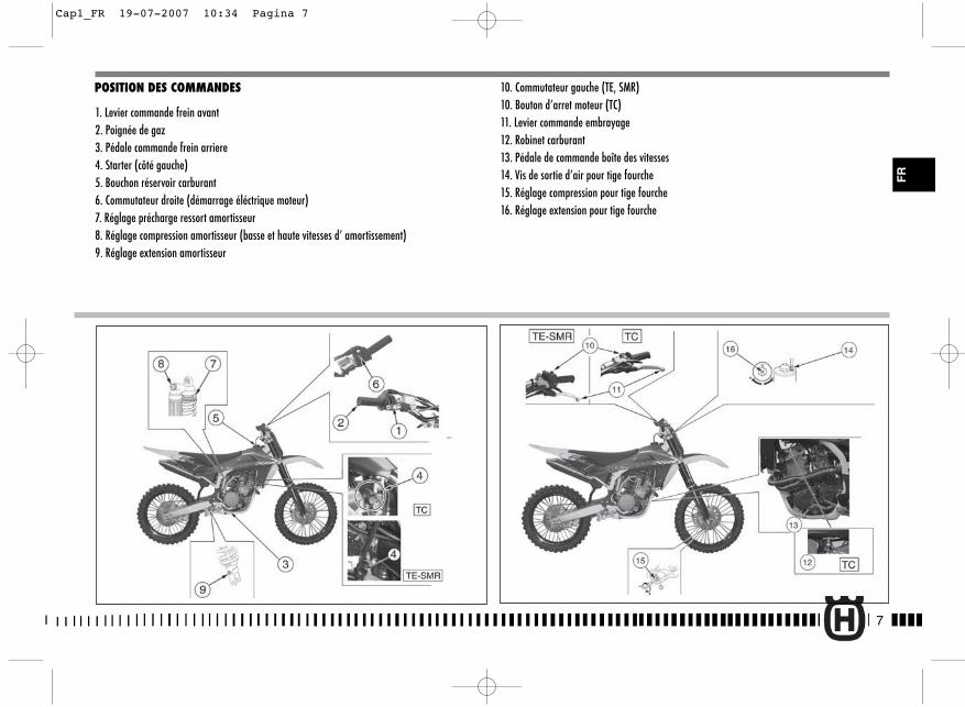
7
FR
POSITION DES COMMANDES
1. Levier commande frein avant2. Poignée de gaz3. Pédale commande frein arriere4. Starter (côté gauche)5. Bouchon réservoir carburant6. Commutateur droite (démarrage éléctrique moteur)7. Réglage précharge ressort amortisseur8. Réglage compression amortisseur (basse et haute vitesses d’ amortissement)9. Réglage extension amortisseur
10. Commutateur gauche (TE, SMR)10. Bouton d’arret moteur (TC)11. Levier commande embrayage12. Robinet carburant13. Pédale de commande boîte des vitesses14. Vis de sortie d’air pour tige fourche15. Réglage compression pour tige fourche16. Réglage extension pour tige fourche
Cap1_FR 19-07-2007 10:34 Pagina 7
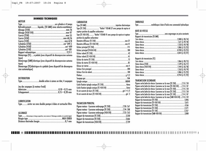
8
DONNEES TECHNIQUESMOTEURType............................................................un cylindre à 4 tempsRefroidissement ............liquide, (TE-SMR) avec electro-ventilateurAlésage (250)..................................................................mm 76 Alésage (450-510)...........................................................mm 97Course (250) ..................................................................mm 55Course (450) ..............................................................mm 60,76Course (510).................................................................mm 67,8 Cylindrée (250) ..........................................................cm3 249,5 Cylindrée (450) .............................................................cm3 449Cylindrée (510) ..............................................................cm3 501 Rapport volumetrique........................................................12,9:1 Démarrage (TC).....a pédale (avec dispositif de décompression automa-tique)Démarrage (SMR) éléctrique (avec dispositif de décompression automa-tique)Démarrage (TE)éléctrique et a pèdale (avec dispositif de décompres-sion automatique)
DISTRIBUTIONType...............................double arbre à cames en tête; 4 soupapes
Jeu des soupapes (à moteur froid) Admission ..........................................................0,10 ÷ 0,15 mmEchappement.....................................................0,15 ÷ 0,20 mm
LUBRIFICATIONType..........carter sec avec double pompe à lobes et cartouche filtre
ALLUMAGEType........Electronique à charge capacitive, avec avance à l’allumage variable et à contrôle digital
Bougie type ..............................................................NGK CR8EBDistance électrodes bougie ..............................................0,7 mm
CARBURATEURType (TE-SMR)...................................................................injection électroniqueType (TC 250) ............................. ”Keihin” FCR-MX 37 avec pompe de reprise etcapteur position du papillon carburateurType (TC 450-510)........... ”Keihin” FCR-MX 41 avec pompe de reprise et capteurposition du papillon carburateurDiamètre diffuseur (TC 250) ..................................................................mm 37Diamètre diffuseur (TC 450-510) ............................................................mm 41Gicleur principal (TC 250)............................................................................175Gicleur principal (TC450-510) ......................................................................180Gicleur ralenti (TC 250).................................................................................42Gicleur ralenti (TC 450-510) ..........................................................................45Gicleur de starter (TC 250) ............................................................................72Gicleur de starter (TC 450-510) .....................................................................85Gliceur air starter.....................................................................................mm 4Gicleur d’air principal..................................................................................200Gicleur d’air de ralenti.................................................................................100Flotteur....................................................................................................g 11,2Soupape gaz ..............................................................................................15MEpingle conique ......................................................................................OBDVRCoche fixation épingle conique (TC 250)....................................................4émeCoche fixation épingle conique (TC 450-510) . ...........................................5émeVis air ouverte de tours (TC 250).......................................................giri 1+1/2Vis air ouverte de tours (TC 450-510)........................................................giri 2
TRASMISSION PRINCIPALPignon moteur - Couronne embrayage (TC 250) ............................Z 20- Z 67Pignon moteur - Couronne embrayage (TE 250).............................Z 24- Z 88Pignon moteur - Couronne embrayage (450-510) ..........................Z 23- Z 63Rapport de transmission (TC 250)..........................................................3,350Rapport de transmission (TE 250)..........................................................3,666Rapport de transmission (450-510)........................................................2,739
EMBRAYAGEType .............................multidisque à bain d’huile avec commande hydraulique
BOITE DE VITESSEType ............................................................avec engrenages en prise constanteRapports de transmission (TE-SMR)1ère vitesse..............................................................................2,000 (z 28/14)2éme vitesse.............................................................................1,611 (z 29/18)3éme vitesse ............................................................................1,333 (z 24/18)4éme vitesse............................................................................1,086 (z 25/23)5éme vitesse............................................................................0,920 (z 23/25)6éme vitesse ............................................................................0,814 (z 22/27)
Rapports de transmission (TC)1ère vitesse..............................................................................1,866 (z 28/15)2éme vitesse (250) ..................................................................1,529 (z 26/17)2éme vitesse (450-510)............................................................1,444 (z 26/18)3éme vitesse ...........................................................................1,263 (z 24/19)4éme vitesse............................................................................1,086 (z 25/23)5éme vitesse............................................................................0,954 (z 21/22)
TRANSMISSION SECONDAIREPignon sortie boîte de vitesse- Couronne sur la roue (TE 250) .............Z 13- Z 50Pignon sortie boîte de vitesse- Couronne sur la roue (TE 450-510) ......Z 13- Z 47Pignon sortie boîte de vitesse- Couronne sur la roue (TC 450) .............Z 14- Z 50Pignon sortie boîte de vitesse- Couronne sur la roue (TC 250) .............Z 12- Z 50Pignon sortie boîte de vitesse- Couronne sur la roue (TC 510) .............Z 14- Z 47Pignon sortie boîte de vitesse- Couronne sur la roue (SMR 450-510) ...Z 14- Z 42Rapport de transmission (TE 250) ........................................................... 3,846Rapport de transmission (TE 450-510) ..................................................... 3,615Rapport de transmission (TC 250) .............................................................4,166Rapport de transmission (TC 450).............................................................3,571Rapport de transmission (TC 510).............................................................3,357Rapport de transmission (SMR 450-510) .......................................................3,000
Cap1_FR 19-07-2007 10:34 Pagina 8
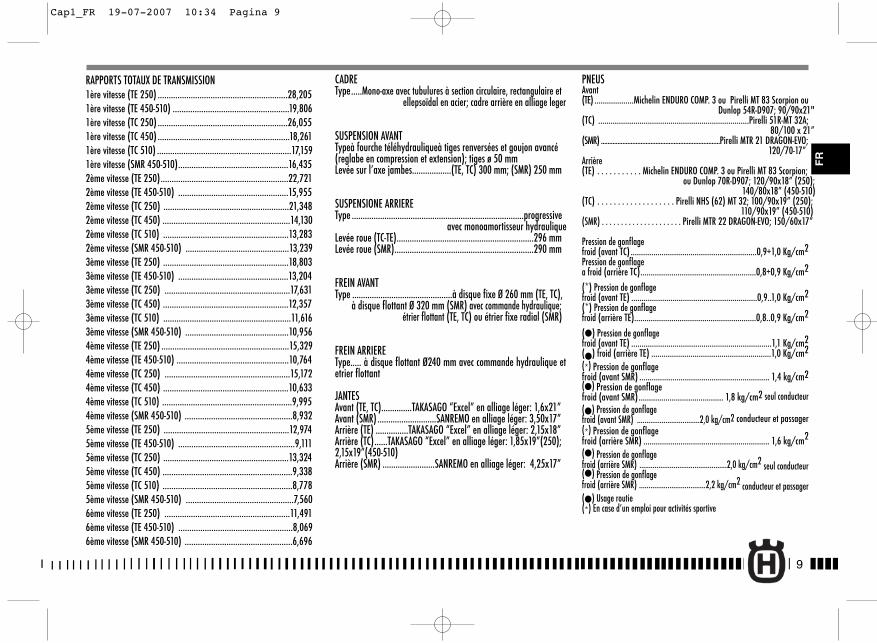
RAPPORTS TOTAUX DE TRANSMISSION1ère vitesse (TE 250) ...........................................................28,2051ère vitesse (TE 450-510) .....................................................19,8061ère vitesse (TC 250) ...........................................................26,0551ère vitesse (TC 450) ............................................................18,2611ère vitesse (TC 510) .............................................................17,1591ère vitesse (SMR 450-510)..................................................16,4352ème vitesse (TE 250)..........................................................22,7212ème vitesse (TE 450-510) ..................................................15,9552ème vitesse (TC 250) .........................................................21,3482ème vitesse (TC 450) ..........................................................14,1302ème vitesse (TC 510) .........................................................13,2832ème vitesse (SMR 450-510) ...............................................13,2393ème vitesse (TE 250) .........................................................18,8033ème vitesse (TE 450-510) ..................................................13,2043ème vitesse (TC 250) .........................................................17,6313ème vitesse (TC 450) .........................................................12,3573ème vitesse (TC 510) ..........................................................11,6163ème vitesse (SMR 450-510) ...............................................10,9564ème vitesse (TE 250) ..........................................................15,3294ème vitesse (TE 450-510) ...................................................10,7644ème vitesse (TC 250) .........................................................15,1724ème vitesse (TC 450) .........................................................10,6334ème vitesse (TC 510) ...........................................................9,9954ème vitesse (SMR 450-510) .................................................8,9325ème vitesse (TE 250) .........................................................12,9745ème vitesse (TE 450-510) .....................................................9,1115ème vitesse (TC 250) .........................................................13,3245ème vitesse (TC 450) ...........................................................9,3385ème vitesse (TC 510) ...........................................................8,7785ème vitesse (SMR 450-510) .................................................7,5606ème vitesse (TE 250) .........................................................11,4916ème vitesse (TE 450-510) ....................................................8,0696ème vitesse (SMR 450-510) .................................................6,696
CADREType.....Mono-axe avec tubulures à section circulaire, rectangulaire et
ellepsoïdal en acier; cadre arrière en alliage leger
SUSPENSION AVANTTypeà fourche téléhydrauliqueà tiges renversées et goujon avancé(reglabe en compression et extension); tiges ø 50 mmLevée sur l’axe jambes..................(TE, TC) 300 mm; (SMR) 250 mm
SUSPENSIONE ARRIEREType ...............................................................................progressive
avec monoamortisseur hydrauliqueLevée roue (TC-TE)...............................................................296 mmLevée roue (SMR)................................................................290 mm
FREIN AVANTType ..............................................à disque fixe Ø 260 mm (TE, TC),
à disque flottant Ø 320 mm (SMR) avec commande hydraulique;étrier flottant (TE, TC) ou étrier fixe radial (SMR)
FREIN ARRIEREType..... à disque flottant Ø240 mm avec commande hydraulique etetrier flottant
JANTESAvant (TE, TC)..............TAKASAGO “Excel” en alliage léger: 1,6x21”Avant (SMR) ...........................SANREMO en alliage léger: 3,50x17”Arrière (TE) ...............TAKASAGO “Excel” en alliage léger: 2,15x18”Arrière (TC)......TAKASAGO “Excel” en alliage léger: 1,85x19”(250); 2,15x19”(450-510)Arrière (SMR) ........................SANREMO en alliage léger: 4,25x17”
PNEUSAvant(TE) ...................Michelin ENDURO COMP. 3 ou Pirelli MT 83 Scorpion ou
Dunlop 54R-D907; 90/90x21"(TC) .........................................................................Pirelli 51R-MT 32A;
80/100 x 21”(SMR) ........................................................................Pirelli MTR 21 DRAGON-EVO;
120/70-17”Arrière(TE) . . . . . . . . . . . Michelin ENDURO COMP. 3 ou Pirelli MT 83 Scorpion;
ou Dunlop 70R-D907; 120/90x18” (250);140/80x18” (450-510)
(TC) . . . . . . . . . . . . . . . . . . . Pirelli NHS (62) MT 32; 100/90x19” (250); 110/90x19” (450-510)
(SMR) . . . . . . . . . . . . . . . . . . . . . Pirelli MTR 22 DRAGON-EVO; 150/60x17”
Pression de gonflagefroid (avant TC) .............................................................0,9÷1,0 Kg/cm2Pression de gonflagea froid (arrière TC)........................................................0,8÷0,9 Kg/cm2
(*) Pression de gonflagefroid (avant TE) .............................................................0,9..1,0 Kg/cm2(*) Pression de gonflagefroid (arrière TE)...........................................................0,8..0,9 Kg/cm2
(�) Pression de gonflagefroid (avant TE) ....................................................................1,1 Kg/cm2(�) froid (arrière TE) ..........................................................1,0 Kg/cm2(*) Pression de gonflagefroid (avant SMR) ............................................................... 1,4 kg/cm2(�) Pression de gonflagefroid (avant SMR)......................................... 1,8 kg/cm2 seul conducteur(�) Pression de gonflagefroid (avant SMR) .................................2,0 kg/cm2 conducteur et passager(*) Pression de gonflagefroid (arrière SMR) ............................................................. 1,6 kg/cm2
(�) Pression de gonflagefroid (arrière SMR) ..............................................2,0 kg/cm2 seul conducteur(�) Pression de gonflagefroid (arrière SMR) ...................................2,2 kg/cm2 conducteur et passager(�) Usage routie(*) En case d’un emploi pour activités sportive
9
FR
Cap1_FR 19-07-2007 10:34 Pagina 9
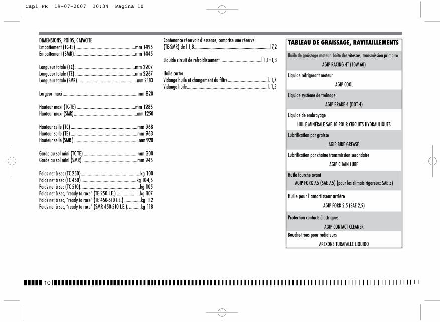
10
DIMENSIONS, POIDS, CAPACITEEmpattement (TC-TE)...................................................mm 1495 Empattement (SMR)....................................................mm 1445
Longueur totale (TC) ...................................................mm 2207 Longueur totale (TE) ...................................................mm 2267Longueur totale (SMR)...................................................mm 2183
Largeur maxi ................................................................mm 820
Hauteur maxi (TC-TE) ..................................................mm 1285Hauteur maxi (SMR)......................................................mm 1250
Hauteur selle (TC) .........................................................mm 968Hauteur selle (TE) .........................................................mm 963Hauteur selle (SMR ) .......................................................mm 920
Garde au sol mini (TC-TE) ..............................................mm 300Garde au sol mini (SMR) ...............................................mm 245
Poids net à sec (TC 250)...................................................kg 100 Poids net à sec (TC 450) ...............................................kg 104,5Poids net à sec (TC 510)...................................................kg 105 Poids net à sec, “ready to race” (TE 250 I.E.) ....................kg 107Poids net à sec, “ready to race” (TE 450-510 I.E.) ..............kg 112Poids net à sec, “ready to race” (SMR 450-510 I.E.). ..........kg 118
Contenance réservoir d’essence, comprise une réserve(TE-SMR) de l 1,8......................................................................l 7,2
Liquide circuit de refroidissement ...................................l 1,1÷1,3
Huile carterVidange huile et changement du filtre..................................l. 1,7Vidange huile.....................................................................l. 1,5
TABLEAU DE GRAISSAGE, RAVITAILLEMENTS
Huile de graissage moteur, boîte des vitesses, transmission primaire
AGIP RACING 4T (10W-60)
Liquide réfrigérant moteur
AGIP COOL
Liquide système de freinage
AGIP BRAKE 4 (DOT 4)
Liquide de embrayage
HUILE MINÉRALE SAE 10 POUR CIRCUITS HYDRAULIQUES
Lubrification par graisse
AGIP BIKE GREASE
Lubrification par chaine transmission secondaire
AGIP CHAIN LUBE
Huile fourche avantAGIP FORK 7,5 (SAE 7,5) (pour les climats rigoreux: SAE 5)
Huile pour l’amortisseur arrière
AGIP FORK 2,5 (SAE 2,5)
Protection contacts électriques
AGIP CONTACT CLEANERBouche-trous pour radiateurs
AREXONS TURAFALLE LIQUIDO
Cap1_FR 19-07-2007 10:34 Pagina 10

MOTEUR A INJECTION (TE-SMR)
Sur les véhicules équipés d’un moteur à injection, la pompe àessence est incorporée au réservoir et le circuit d’alimentationen carburant est dépourvu de robinet. L’indication de la réser-ve est signalée sur le tableau de bord numérique par levoyant correspondant (voir page 14).
11
FR
1 Dévisser le bouchon de vidange (1) sur le réservoir du carbu-rant et fermer le robinet;
2 ôter la tuyauterie (3) du carburateur et placer la misme dansune cuvette;
3 Ouvrir le robinet pour éliminer le carburant du réservoir;4 Desserrer les vis et ôter le robinet. Nettoyer le tamis avec du
solvent.5 Remonter le robinet en renversant les opération de démonta-
ge. Ouvrir le robinet et vérifier qu'il n'y a pas de fuites.
COMMANDES
ROBINETS CARBURANT (TC)
Le robinet (2), situé sur la gauche est de type à vis: visser labague (A) pour fermer le robinet, dévisser la bague pour l'ou-vrir.
ATTENTION*: Durant les opérations sur le ro-binet carburant, veillez à ne jamais toucherle moteur chaud.Le robinet a un filtre; la crasse s’accumulant dans ce filtre causeune diminution de carburant vers le carburateur. Il faudra doncnettoyer le filtre comme suit:
1. Bouchon reservoir carburant2. Robinet carburant3. Tuyanterie carburantA. Bague robinet
132
A
Cap2_FR 12-07-2007 15:15 Pagina 11

CARBURANTCarburant recommandé: essence SANS PLOMB à 98 octanes.
Nota*: Si le moteur “cogne”, utiliser uneautre marque d’essence, ou un carburantavec indice d’octane plus élevé.
ATTENTION*: Si le moteur “cogne”, l’arrê-ter immédiatement, car il pourrait gripper.
ATTENTION*: L’essence est une matièretrès inflammable que, dans des conditionsparticulières, peut devenir explosive.Arrêter toujours le moteur, ne pas fumer,ou approcher la flamme ou étincelles à lazone de ravitaillement, ou dans les lieux oùon garde le carburant.
ATTENTION*: Ne jamais remplir le réservoirau délà de la limite inférieure de la goulot-te de remplissage. Assurez-vous que le bou-chon (1) du réservoir soit bien fermé.
Contrôler la bequille latéral périodiquement (tu vois "Fiched'entretien périodique"); vérifier que les ressorts ne soientpas endommagés et que la bequille latéral se remue libre-ment. Dans le cas la bequille latéral devînt bruyant, lubrifierle pivot (A) de fixation.
12
BEQUILLE LATERALEChaque motocycle est doté d’une béquille latérale (1).
ATTENTION*: La béquille a été projetée poursupporter SEULEMENT LE POIDS DU MOTO-CYCLE. Ne jamais s’asseoir sur le motocycleen utilisant la béquille comme support, cardans ce cas, on court le risque d’endomma-ger la béquille et de se blesser.
2
Cap2_FR 9-07-2007 12:42 Pagina 12
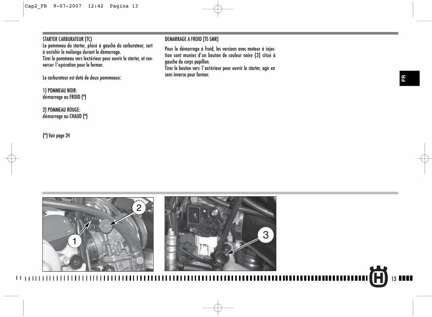
STARTER CARBURATEUR (TC)Le pommeau du starter, placé à gauche du carburateur, sertà enrichir le mélange durant le démarrage.Tirer le pommeau vers lextérieur pour ouvrir le starter, et ren-verser l’opération pour le fermer.
Le carburateur est doté de deux pommeaux:
1) POMMEAU NOIR:démarrage au FROID (°)
2) POMMEAU ROUGE:démarrage au CHAUD (°)
(°) Voir page 24
DEMARRAGE A FROID (TE-SMR)
Pour le démarrage à froid, les versions avec moteur à injec-tion sont munies d’un bouton de couleur noire (3) situé àgauche du corps papillon.Tirer le bouton vers l’extérieur pour ouvrir le starter, agir ensens inverse pour fermer.
13
FR
2
1
Cap2_FR 9-07-2007 12:42 Pagina 13
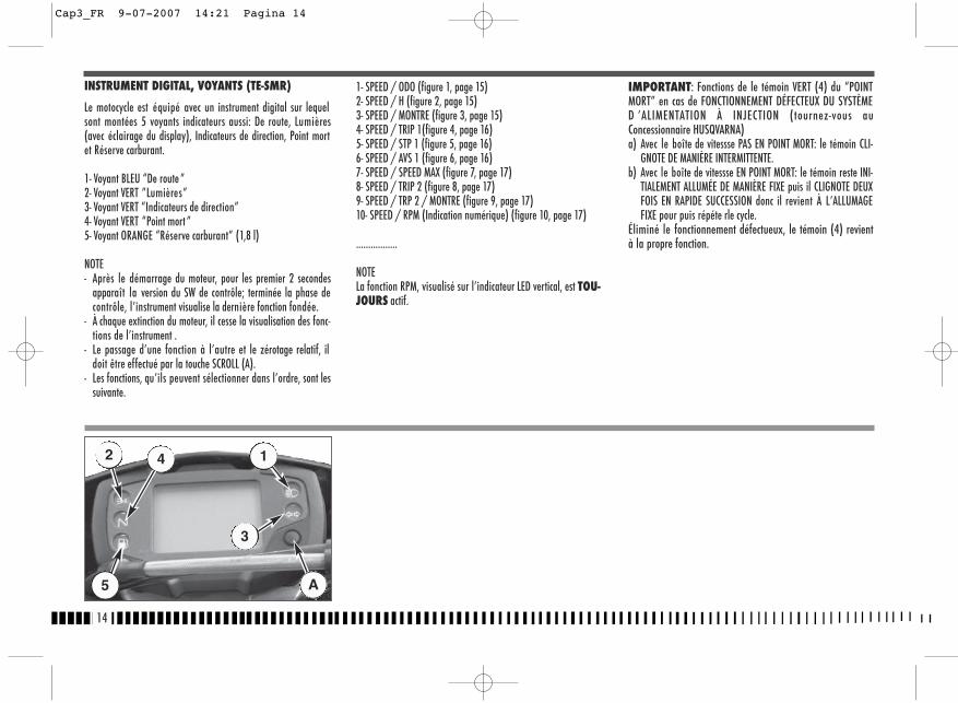
1- SPEED / ODO (figure 1, page 15)2- SPEED / H (figure 2, page 15)3- SPEED / MONTRE (figure 3, page 15)4- SPEED / TRIP 1(figure 4, page 16)5- SPEED / STP 1 (figure 5, page 16)6- SPEED / AVS 1 (figure 6, page 16)7- SPEED / SPEED MAX (figure 7, page 17)8- SPEED / TRIP 2 (figure 8, page 17)9- SPEED / TRP 2 / MONTRE (figure 9, page 17)10- SPEED / RPM (Indication numérique) (figure 10, page 17)
.................
NOTELa fonction RPM, visualisé sur l’indicateur LED vertical, est TOU-JOURS actif.
IMPORTANT: Fonctions de le témoin VERT (4) du “POINTMORT” en cas de FONCTIONNEMENT DÉFECTEUX DU SYSTÈMED ’ALIMENTATION À INJECTION (tournez-vous auConcessionnaire HUSQVARNA)a) Avec le boîte de vitessse PAS EN POINT MORT: le témoin CLI-
GNOTE DE MANIÈRE INTERMITTENTE.b) Avec le boîte de vitessse EN POINT MORT: le témoin reste INI-
TIALEMENT ALLUMÉE DE MANIÈRE FIXE puis il CLIGNOTE DEUXFOIS EN RAPIDE SUCCESSION donc il revient À L’ALLUMAGEFIXE pour puis répéte rle cycle.
Éliminé le fonctionnement défectueux, le témoin (4) revientà la propre fonction.
14
INSTRUMENT DIGITAL, VOYANTS (TE-SMR)
Le motocycle est équipé avec un instrument digital sur lequelsont montées 5 voyants indicateurs aussi: De route, Lumières(avec éclairage du display), Indicateurs de direction, Point mortet Réserve carburant.
1- Voyant BLEU “De route ”2- Voyant VERT ”Lumières”3- Voyant VERT “Indicateurs de direction”4- Voyant VERT “Point mort ”5- Voyant ORANGE “Réserve carburant” (1,8 l)
NOTE- Après le démarrage du moteur, pour les premier 2 secondes
apparaît la version du SW de contrôle; terminée la phase decontrôle, l’instrument visualise la dernière fonction fondée.
- À chaque extinction du moteur, il cesse la visualisation des fonc-tions de l’instrument .
- Le passage d’une fonction à l’autre et le zérotage relatif, ildoit être effectué par la touche SCROLL (A).
- Les fonctions, qu’ils peuvent sélectionner dans l’ordre, sont lessuivante.
2
5
4 1
3
A
Cap3_FR 9-07-2007 14:21 Pagina 14
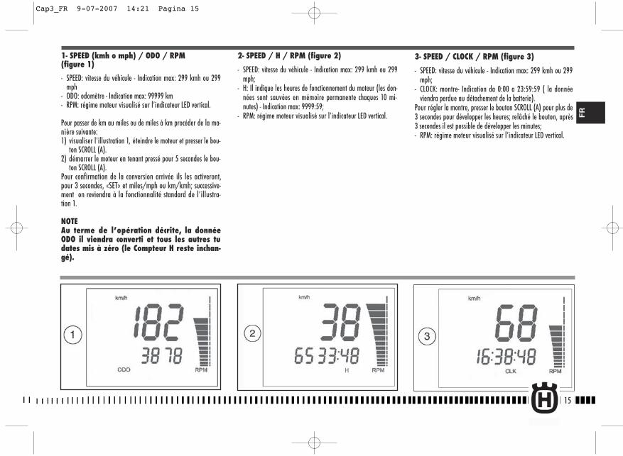
15
2- SPEED / H / RPM (figure 2)
- SPEED: vitesse du véhicule - Indication max: 299 kmh ou 299mph;
- H: Il indique les heures de fonctionnement du moteur (les don-nées sont sauvées en mémoire permanente chaques 10 mi-nutes) - Indication max: 9999:59;
- RPM: régime moteur visualisé sur l’indicateur LED vertical.
1- SPEED (kmh o mph) / ODO / RPM (figure 1)
- SPEED: vitesse du véhicule - Indication max: 299 kmh ou 299mph
- ODO: odomètre - Indication max: 99999 km- RPM: régime moteur visualisé sur l’indicateur LED vertical.
Pour passer de km au miles ou de miles à km procéder de la ma-nière suivante:1) visualiser l’illustration 1, éteindre le moteur et presser le bou-
ton SCROLL (A). 2) démarrer le moteur en tenant pressé pour 5 secondes le bou-
ton SCROLL (A).Pour confirmation de la conversion arrivée ils les activeront,pour 3 secondes, «SET» et miles/mph ou km/kmh; successive-ment on reviendra à la fonctionnalité standard de l’illustra-tion 1.
NOTEAu terme de l’opération décrite, la donnéeODO il viendra converti et tous les autres tudates mis à zéro (le Compteur H reste inchan-gé).
FR
3- SPEED / CLOCK / RPM (figure 3)
- SPEED: vitesse du véhicule - Indication max: 299 kmh ou 299mph;
- CLOCK: montre- Indication da 0:00 a 23:59:59 ( la donnéeviendra perdue au détachement de la batterie).
Pour régler la montre, presser le bouton SCROLL (A) pour plus de3 secondes pour développer les heures; relâché le bouton, après3 secondes il est possible de développer les minutes;- RPM: régime moteur visualisé sur l’indicateur LED vertical.
Cap3_FR 9-07-2007 14:21 Pagina 15
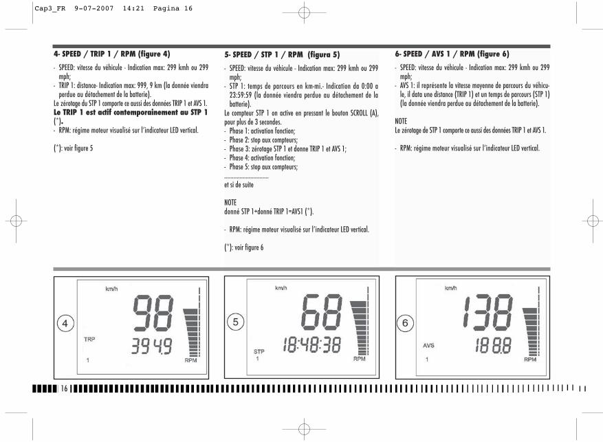
16
6- SPEED / AVS 1 / RPM (figure 6)
- SPEED: vitesse du véhicule - Indication max: 299 kmh ou 299mph;
- AVS 1: il représente la vitesse moyenne de parcours du véhicu-le, il data une distance (TRIP 1) et un temps de parcours (STP 1)(la donnée viendra perdue au détachement de la batterie).
NOTELe zérotage de STP 1 comporte ce aussi des données TRIP 1 et AVS 1.
- RPM: régime moteur visualisé sur l’indicateur LED vertical.
4- SPEED / TRIP 1 / RPM (figure 4)
- SPEED: vitesse du véhicule - Indication max: 299 kmh ou 299mph;
- TRIP 1: distance- Indication max: 999, 9 km (la donnée viendraperdue au détachement de la batterie).
Le zérotage du STP 1 comporte ce aussi des données TRIP 1 et AVS 1.Le TRIP 1 est actif contemporainement au STP 1(*).- RPM: régime moteur visualisé sur l’indicateur LED vertical.
(*): voir figure 5
5- SPEED / STP 1 / RPM (figura 5)
- SPEED: vitesse du véhicule - Indication max: 299 kmh ou 299mph;
- STP 1: temps de parcours en km-mi.- Indication da 0:00 a23:59:59 (la donnée viendra perdue au détachement de labatterie).
Le compteur STP 1 on active en pressant le bouton SCROLL (A),pour plus de 3 secondes.- Phase 1: activation fonction;- Phase 2: stop aux compteurs;- Phase 3: zérotage STP 1 et donne TRIP 1 et AVS 1;- Phase 4: activation fonction;- Phase 5: stop aux compteurs;.............................et si de suite
NOTEdonné STP 1+donné TRIP 1=AVS1 (*).
- RPM: régime moteur visualisé sur l’indicateur LED vertical.
(*): voir figure 6
Cap3_FR 9-07-2007 14:21 Pagina 16
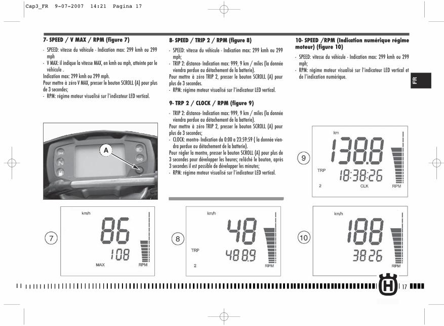
17
8- SPEED / TRIP 2 / RPM (figure 8)
- SPEED: vitesse du véhicule - Indication max: 299 kmh ou 299mph;
- TRIP 2: distance- Indication max: 999, 9 km / miles (la donnéeviendra perdue au détachement de la batterie).
Pour mettre à zéro TRIP 2, presser le bouton SCROLL (A) pourplus de 3 secondes.- RPM: régime moteur visualisé sur l’indicateur LED vertical.
9- TRP 2 / CLOCK / RPM (figure 9)
- TRIP 2: distance- Indication max: 999, 9 km / miles (la donnéeviendra perdue au détachement de la batterie).
Pour mettre à zéro TRIP 2, presser le bouton SCROLL (A) pourplus de 3 secondes;- CLOCK: montre- Indication da 0:00 a 23:59:59 ( la donnée vien-
dra perdue au détachement de la batterie).Pour régler la montre, presser le bouton SCROLL (A) pour plus de3 secondes pour développer les heures; relâché le bouton, après3 secondes il est possible de développer les minutes;- RPM: régime moteur visualisé sur l’indicateur LED vertical.
10- SPEED /RPM (Indication numérique régimemoteur) (figure 10)
- SPEED: vitesse du véhicule - Indication max: 299 kmh ou 299mph;
- RPM: régime moteur visualisé sur l’indicateur LED vertical etde l’indication numérique.
7- SPEED / V MAX / RPM (figure 7)
- SPEED: vitesse du véhicule - Indication max: 299 kmh ou 299mph
- V MAX: il indique la vitesse MAX, en kmh ou mph, atteinte par levéhicule .
Indication max: 299 kmh ou 299 mph.Pour mettre à zéro V MAX, presser le bouton SCROLL (A) pour plusde 3 secondes;- RPM: régime moteur visualisé sur l’indicateur LED vertical.
A
FR
Cap3_FR 9-07-2007 14:21 Pagina 17
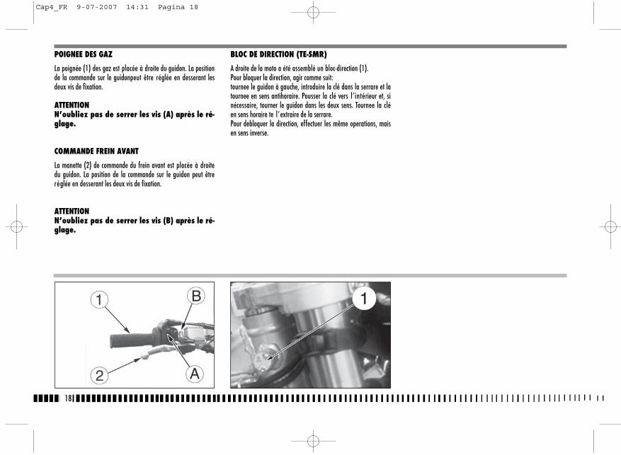
18
POIGNEE DES GAZ
La poignée (1) des gaz est placée à droite du guidon. La positionde la commande sur le guidonpeut être réglée en desserant lesdeux vis de fixation.
ATTENTIONN’oubliez pas de serrer les vis (A) après le ré-glage.
COMMANDE FREIN AVANT
La manette (2) de commande du frein avant est placée à droitedu guidon. La position de la commande sur le guidon peut êtreréglée en desserant les deux vis de fixation.
ATTENTIONN’oubliez pas de serrer les vis (B) après le ré-glage.
BLOC DE DIRECTION (TE-SMR)
A droite de la moto a été assemblé un bloc-direction (1).Pour bloquer la direction, agir comme suit:tournee le guidon à gauche, introduire la clé dans la serrare et latournee en sens antihoraire. Pousser la clé vers l’intérieur et, sinécessaire, tourner le guidon dans les deux sens. Tournee la cléen sens horaire te l’extraire de la serrare. Pour debloquer la direction, effectuer les même operations, maisen sens inverse.
Cap4_FR 9-07-2007 14:31 Pagina 18

19
BOUTON D'ARRET MOTEUR (TC)Ce bouton (1) est place sur le côté gauche du guidon, auprès lacommande de l’embrayage.
COMMANDE DE L’EMBRAYAGELe levier de commande hydraulique de l’embrayage est situé àgauche sur le guidon et il est muni d’une protection.La position de la commande de l’embrayage sur le guidon peutetre régléé en desserrant la vis inferieur (A) de fixation.
ATTENTIONN’oubliez pas de serrer la vis après le régla-ge.
COMMUTATEUR DROIT SUR LE GUIDON(TE-SMR)
Le commutateur droit a les fonctions suivantes:1) Bouton de démarrage moteur3) Interrupteur démarrage - arrêt moteur
COMMUTATEUR GAUCHE SUR LE GUIDON(TE-SMR)
Le commutateur gauche a les fonctions suivantes:1) Flash d’avertissement (retour automatique)
2) Commande sélection feu de route
Commande sélection feu de croisement
3) Indicateurs de direction gauche (retour automatique)
Indicateurs de direction droite (retour automatique)
Pour désactivier l’indicateur, presser le levier de commande unefois retourné au centre.4) Avertisseur acoustique
FR
1
Cap4_FR 9-07-2007 14:31 Pagina 19
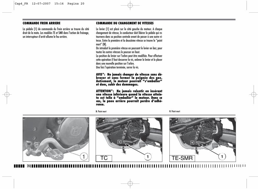
COMMANDE DU CHANGEMENT DE VITESSES
Le levier (1) est placé sur le côté gauche du moteur. A chaquechangement de vitesse, le conducteur doit libérer la pédale qui re-tournera dans sa position centrale avant de passer à une autre vi-tesse. Entre la première et la deuxième vitesse se trouve le “pointmort” (N).On introduit la première vitesse en poussant le levier en bas; pourtoutes les autres vitesses le pousser en haut.La position du levier sur l’arbre peut être modifiée. Pour effectuercette opération il faut desserrer la vis, enlever le levier et le placerdans une nouvelle position sur l’arbre.Une fois l’opération terminée, serrer la vis.
AVIS*: Ne jamais changer de vitesse sans dé-brayer et sans fermer la poignée des gaz.Autrement, le moteur pourrait “s’emballer”et donc, subir des dommages.
ATTENTION*: Ne jamais ralentir en insérantune vitesse inférieure quand la vitesse attein-te est telle à “emballer” le moteur. Dans cecas, le pneu arrière pourrait perdre d’adhé-rence.
20
COMMANDE FREIN ARRIERE
La pédale (1) de commande du frein arrière se trouve du côtédroit de la moto. Les modèles TE et SMR dans l’action de freinage,un interrupteur d’arrêt allume le feu arrière.
N: Point mortN: Point mort
TC 1 1TE-SMR
Cap4_FR 12-07-2007 15:16 Pagina 20
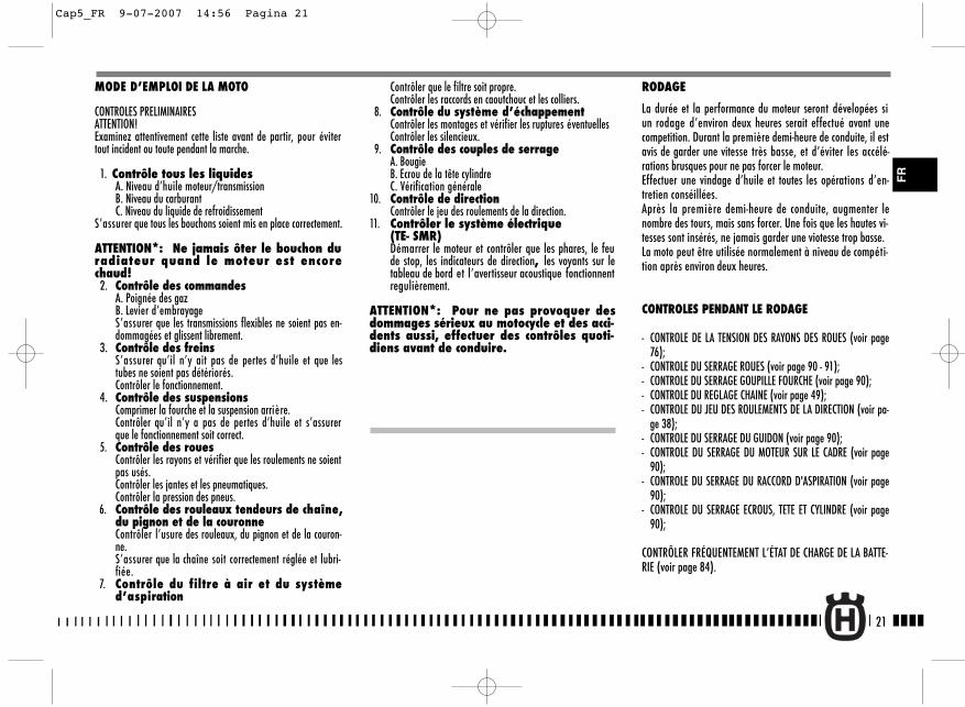
Contrôler que le filtre soit propre.Contrôler les raccords en caoutchouc et les colliers.
8. Contrôle du système d’échappementContrôler les montages et vérifier les ruptures éventuellesContrôler les silencieux.
9. Contrôle des couples de serrageA. BougieB. Ecrou de la tête cylindreC. Vérification générale
10. Contrôle de directionContrôler le jeu des roulements de la direction.
11. Contrôler le système électrique (TE- SMR)Démarrer le moteur et contrôler que les phares, le feude stop, les indicateurs de direction, les voyants sur letableau de bord et l’avertisseur acoustique fonctionnentregulièrement.
ATTENTION*: Pour ne pas provoquer desdommages sérieux au motocycle et des acci-dents aussi, effectuer des contrôles quoti-diens avant de conduire.
21
RODAGE
La durée et la performance du moteur seront dévelopées siun rodage d’environ deux heures serait effectué avant unecompetition. Durant la première demi-heure de conduite, il estavis de garder une vitesse très basse, et d’éviter les accélé-rations brusques pour ne pas forcer le moteur.Effectuer une vindage d’huile et toutes les opérations d’en-tretien conséillées. Après la première demi-heure de conduite, augmenter lenombre des tours, mais sans forcer. Une fois que les hautes vi-tesses sont insérés, ne jamais garder une viotesse trop basse.La moto peut être utilisée normalement à niveau de compéti-tion après environ deux heures.
CONTROLES PENDANT LE RODAGE
- CONTROLE DE LA TENSION DES RAYONS DES ROUES (voir page76);
- CONTROLE DU SERRAGE ROUES (voir page 90 - 91);- CONTROLE DU SERRAGE GOUPILLE FOURCHE (voir page 90);- CONTROLE DU REGLAGE CHAINE (voir page 49);- CONTROLE DU JEU DES ROULEMENTS DE LA DIRECTION (voir pa-
ge 38);- CONTROLE DU SERRAGE DU GUIDON (voir page 90);- CONTROLE DU SERRAGE DU MOTEUR SUR LE CADRE (voir page
90);- CONTROLE DU SERRAGE DU RACCORD D'ASPIRATION (voir page
90);- CONTROLE DU SERRAGE ECROUS, TETE ET CYLINDRE (voir page
90);
CONTRÔLER FRÉQUENTEMENT L’ÉTAT DE CHARGE DE LA BATTE-RIE (voir page 84).
MODE D’EMPLOI DE LA MOTO
CONTROLES PRELIMINAIRESATTENTION!Examinez attentivement cette liste avant de partir, pour évitertout incident ou toute pendant la marche.
1. Contrôle tous les liquidesA. Niveau d’huile moteur/transmissionB. Niveau du carburantC. Niveau du liquide de refroidissement
S’assurer que tous les bouchons soient mis en place correctement.
ATTENTION*: Ne jamais ôter le bouchon duradiateur quand le moteur est encorechaud!
2. Contrôle des commandesA. Poignée des gazB. Levier d’embrayageS’assurer que les transmissions flexibles ne soient pas en-dommagées et glissent librement.
3. Contrôle des freinsS’assurer qu’il n’y ait pas de pertes d’huile et que lestubes ne soient pas détériorés.Contrôler le fonctionnement.
4. Contrôle des suspensionsComprimer la fourche et la suspension arrière.Contrôler qu’il n’y a pas de pertes d’huile et s’assurerque le fonctionnement soit correct.
5. Contrôle des rouesContrôler les rayons et vérifier que les roulements ne soientpas usés.Contrôler les jantes et les pneumatiques.Contrôler la pression des pneus.
6. Contrôle des rouleaux tendeurs de chaîne,du pignon et de la couronneContrôler l’usure des rouleaux, du pignon et de la couron-ne. S’assurer que la chaîne soit correctement réglée et lubri-fiée.
7. Contrôle du filtre à air et du systèmed’aspiration
FR
Cap5_FR 9-07-2007 14:56 Pagina 21

22
NOTESur le support du levier d’embrayage est monté un interrup-teur de sûreté qu’il permet d’effectuer le démarrage SEULavec boîte de vitesse au point mort ou avec une vitesse enga-gée et levier d’embrayage tirée.
IMPORTANTNE JAMAIS EFFECTUER LE DEMARRAGE SI LA BATTERIE N’A PASETE CONNECTEE DANS LE CIRCUIT.
DÉMARRAGE DU MOTEUR (TE-SMR)
Au moteur froid, c’est-à-dire après arrêt prolongé du moto-cycle ou en présence de basse température ambiante, opérerde la manière suivante:1) placer la clé (1) de l’interrupteur d’allumage dans la po-
sition IGNITION (le ronflement qui se produit en tournant laclé sur IGNITION est dû à la pompe à carburant qui met lecircuit d’alimentation sous pression);
2) tirer le levier (2) du starter;
3) tirer le levier (3) de l’embrayage;4) placer le pédale (4) de la boîte de vitesses dans la posi-
tion de point mort et relâcher le levier de commande em-brayage;
5) presser le commutateur démarrage-arrêt moteur (5) en-suite le bouton (6).Ramener le levier (2) de starter dans sa position initialedès que le moteur tient le ralenti. Pour le démarrage àchaud, NE PAS mettre le starter. Ne pas faire fonctionner àmoteur froid à haut régime pour permettre le réchauffe-ment de l’huile et sa circulation à tous les endroits qui ontbesoin de graissage.
TE-SMR TE-SMR TE-SMR42
3
5
6
1
Cap5_FR 9-07-2007 14:56 Pagina 22
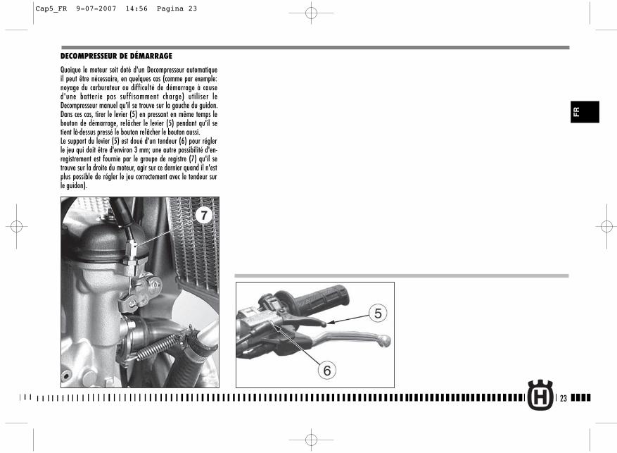
23
FR
DECOMPRESSEUR DE DÉMARRAGE
Quoique le moteur soit doté d'un Decompresseur automatiqueil peut être nécessaire, en quelques cas (comme par exemple:noyage du carburateur ou difficulté de démarrage à caused'une batterie pas suf fisamment charge) utiliser leDecompresseur manuel qu'il se trouve sur la gauche du guidon.Dans ces cas, tirer le levier (5) en pressant en même temps lebouton de démarrage, relâcher le levier (5) pendant qu'il setient là-dessus pressé le bouton relâcher le bouton aussi.Le support du levier (5) est doué d'un tendeur (6) pour réglerle jeu qui doit être d'environ 3 mm; une autre possibilité d'en-registrement est fournie par le groupe de registre (7) qu'il setrouve sur la droite du moteur, agir sur ce dernier quand il n'estplus possible de régler le jeu correctement avec le tendeur surle guidon).
Cap5_FR 9-07-2007 14:56 Pagina 23

24
DÉMARRAGE DU MOTEUR (TC)
Procéder de la manière suivante:1) s'assurer que le robinet du carburant (A) se trouve en posi-
tion ouverte;2) placer le levier (1) de la boîte de vitesses dans la position
de point mort;
3) tirer le pommeau du starter (pommeau NOIR 2 pour le dé-marrage au froid *, pommeau ROUGE 3 pour le démarra-ge à chaud);
*: c'est-à-dire aprèsarrêt prolongé du motocycle ou en pré-sence de basse température ambiante.
TC TC1 4
4) baisser la pédale de démarrage (4) jusqu’à trouver ré-sistance (piston au P.M.H.);
A 2
3
Cap5_FR 9-07-2007 14:56 Pagina 24
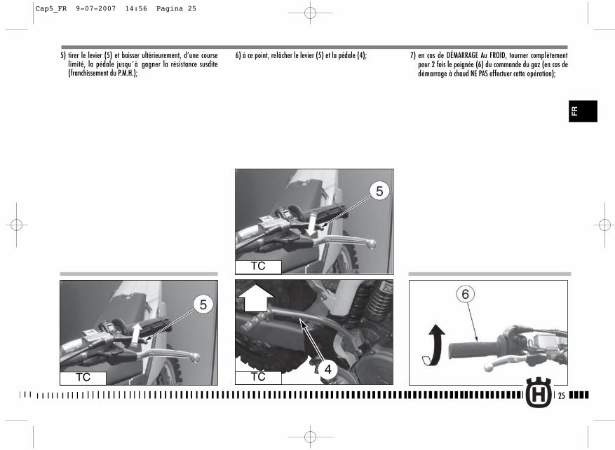
25
5) tirer le levier (5) et baisser ultérieurement, d’une courselimité, la pédale jusqu ’ à gagner la résistance susdite(franchissement du P.M.H.);
6) à ce point, relâcher le levier (5) et la pédale (4); 7) en cas de DÉMARRAGE Au FROID, tourner complètementpour 2 fois le poignée (6) du commande du gaz (en cas dedémarrage à chaud NE PAS effectuer cette opération);
TC
TC
TC4
FR
Cap5_FR 9-07-2007 14:56 Pagina 25
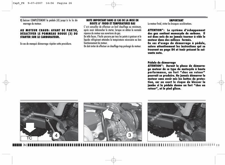
26
IMPORTANTLe moteur froid, éviter les brusques accélérations.
ATTENTION*: Le système d’échappementdes gaz contient monoxyde de carbone. Ilest donc avis de ne jamais tourner à vide lemoteur dans des milieux fermés. En cas d'usage du démarrage à pédale,suivre attentivement les instructions qui setrouvent au page 84 et tenir présent la sui-vante note.
Pédale de démarrageATTENTION*: Durant la phase de démarra-ge moteur de ce type de motocycle à hauteperformance, un fort “choc en retour”pourrait se produire. Ne jamais démarrer lemoteur sans avoir mis les bottes de protec-tion, car on court le risque de blesser lajambe si la pédale donne un fort “choc enretour”, et le pied glisse.
8) baisser COMPLÈTEMENT la pédale (4) jusqu’à le le dé-marrage du moteur.
AU MOTEUR CHAUD: AVANT DE PARTIR,DÉSACTIVER LE POMMEAU ROUGE (3) DUSTARTER SUR LE CARBURATEUR.
En cas de manqué démarrage répéter cette procédure.
NOTE IMPORTANT DANS LE CAS DE LA MISE ENROUTE A’ FROID ET TEMPERATURES BAS
C ’ e st conseiller de effectuer un bref chauffage au minimum,après avoir débrancher le starter, lorsque on obtien la normaleréponse du moteur aux ouvertures du gaz.De telle façon, l’huile passera par tous les points à graisser et leliquide réfrigérant atteindra la température nécessaire au bonfonctionnement du moteur.On doit éviter de effectuer un chauffage trop prolongé du moteur.
TC4 3
Cap5_FR 9-07-2007 14:56 Pagina 26

27
3) tirer le levier (3) d’embrayage;4) agir sur la pédale de mise en marche (5) pour démarrer le
véhicule;
5) Relâcher ensuite le levier d’embrayage (3).
AVANT DE DEMARRER, DESACTIVER LE BOU-TON ROUGE (2) DU STARTER SUR LE CARBU-RATEUR.
DEMARRAGE A CHAUD (TC)
En cas de difficulté de démarrage lorsque le moteur estchaud, ou après une chute, procéder comme suit:
1) mettre le levier (1) de vitesse au point mort;2) tirer le bouton ROUGE du starter (2);
TC 1
TC4
FR
2
Cap5_FR 9-07-2007 14:56 Pagina 27

28
ARRET DU MOTOCYCLE ET DU MOTEUR
- Fermer la poignée (1) des gaz tout, de façon à réduire lavitesse du motocycle.
- Tandis que les vitesses sont réduites, freiner soit la roueavant, soit l’arrière (pour une forte décélération, ap-puyer avec décision sur le levier et sur la pédale desfreins).
- Une fois que le motocycle est arrêté, débrayer et placer lelevier (2) de la boîte des vitesses au point mort.
- Presser le bouton ROUGE (3) d’arrêt moteur.- TC: Fermer le robinet d’essence (4).
- TE, SMR: tourner vers la gauche la clé de l’interrupteurd’allumage.
ATTENTION*: Dans des conditions particu-lières, il est avis d’utiliser indépendam-ment le frein avant ou l’arrière. En roulantsur des terrains glissants, utilise prudem-ment le frein avant. L’usage incorrect desfreins peut causer des accidents sérieux.
TE-SMRTE-SMR
TC
TC
ATTENTION*: Au cas d’un blocage de la poi-gnée des gaz dans la position ouverte, oude tout autre mauvais fonctionnement où lemoteur tourne d’une façon incontrôlable,appuyer IMMEDIATEMENT sur le boutond’arrêt moteur. Tandis que ce bouton est pressé, garder lecontrôle du motocycle, et utiliser doucementles freins et le guidon.
4
Cap5_FR 9-07-2007 14:56 Pagina 28
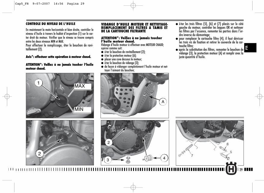
VIDANGE D’HUILE MOTEUR ET NETTOYAGE-REMPLACEMENT DES FILTRES A TAMIS ETDE LA CARTOUCHE FILTRANTE
ATTENTION*: Veillez à ne jamais toucherl’huile moteur chaud.Vidange d’huile moteur à effectuer avec MOTEUR CHAUD;opérer comme suit:● ô ter le bouchon de ravitaillement (2);● ô ter la protection moteur (A);● placer une cuve dessous le moteur;● ô ter le bouchon de vidange (3);● de façon à vidanger completèment l’huile moteur et net-
toyer l’aimant du bouchon;
29
● ô ter les trois filtres (5), (6) et (7) placés sur le côtégauche du moteur, contrôler les bagues OR et nettoyerles filtres par l’essence, remonter les parties dans l’or-dre inverse du démontage;
● pour remplacer la cartouche filtre (4), il faut dévisserles trois vis de fixation et retirer le couvercle de la car-touche filtre;
● après la substitution des filtres, remonter le bouchon devidange (3), la protection moteur (A) et remplir avec lajuste quantité d’huile.
CONTROLE DU NIVEAU DE L’HUILE
En maintenant la moto horizontale et bien droite, contrôler leniveau d’huile à travers le hublot d’inspection (1) sur le car-ter droit du moteur. Vérifier que le niveau se trouve comprisentre les deux niveaux MIN et MAX.Pour effectuer le remplissage, ôter le bouchon de ravi-taillement (2).
Avis*: effectuer cette opération à moteur chaud.
ATTENTION*: Veillez à ne jamais toucher l’huilemoteur chaud.
MAX
MIN
1
2
2
3 4
FR
A
Cap5_FR 9-07-2007 14:56 Pagina 29
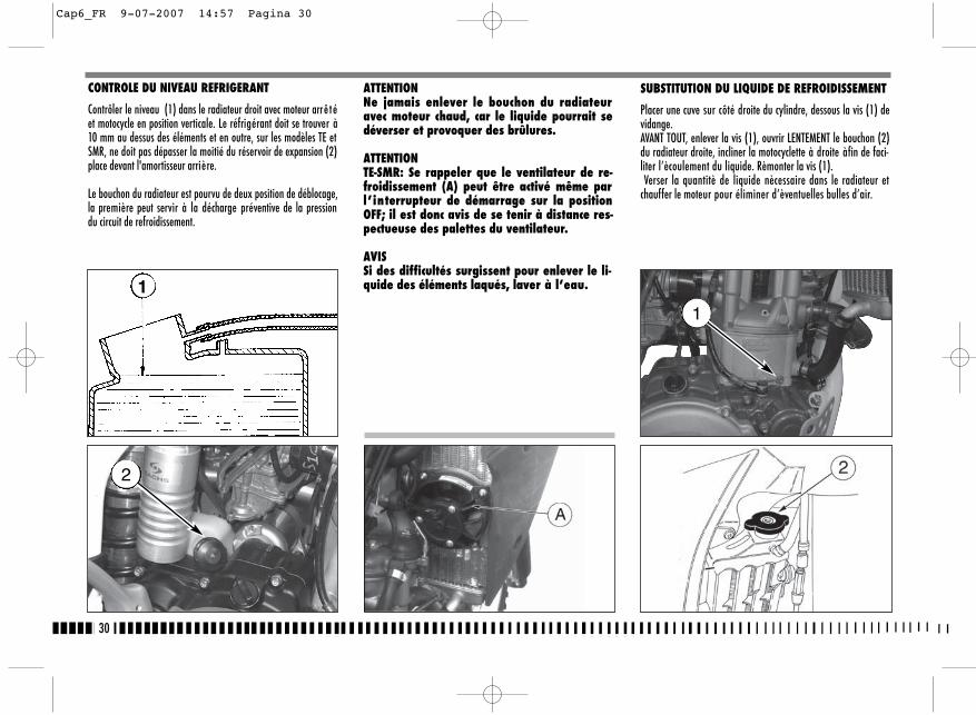
30
SUBSTITUTION DU LIQUIDE DE REFROIDISSEMENT
Placer une cuve sur côté droite du cylindre, dessous la vis (1) devidange.AVANT TOUT, enlever la vis (1), ouvrir LENTEMENT le bouchon (2)du radiateur droite, incliner la motocyclette à droite àfin de faci-liter l’ècoulement du liquide. Rèmonter la vis (1).Verser la quantitè de liquide nècessaire dans le radiateur et
chauffer le moteur pour éliminer d’èventuelles bulles d’air.
1
ATTENTIONNe jamais enlever le bouchon du radiateuravec moteur chaud, car le liquide pourrait sedéverser et provoquer des brûlures.
ATTENTIONTE-SMR: Se rappeler que le ventilateur de re-froidissement (A) peut être activé même parl’interrupteur de démarrage sur la positionOFF; il est donc avis de se tenir à distance res-pectueuse des palettes du ventilateur.
AVISSi des difficultés surgissent pour enlever le li-quide des éléments laqués, laver à l’eau.
CONTROLE DU NIVEAU REFRIGERANT
Contrôler le niveau (1) dans le radiateur droit avec moteur arrê téet motocycle en position verticale. Le réfrigérant doit se trouver à10 mm au dessus des éléments et en outre, sur les modèles TE etSMR, ne doit pas dépasser la moitié du réservoir de expansion (2)place devant l'amortisseur arrière.
Le bouchon du radiateur est pourvu de deux position de déblocage,la première peut servir à la décharge préventive de la pressiondu circuit de refroidissement.
1
2
Cap6_FR 9-07-2007 14:57 Pagina 30
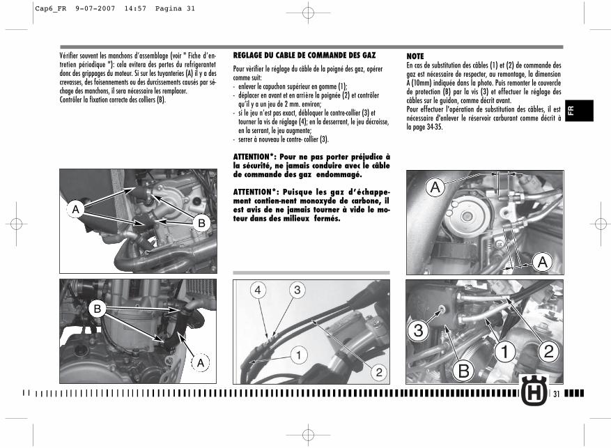
NOTEEn cas de substitution des câbles (1) et (2) de commande desgaz est nécessaire de respecter, au remontage, la dimensionÀ (10mm) indiquée dans la photo. Puis remonter le couverclede protection (B) par la vis (3) et effectuer le réglage descâbles sur le guidon, comme décrit avant.Pour effectuer l'opération de substitution des câbles, il estnécessaire d'enlever le réservoir carburant comme décrit àla page 34-35.
31
Vérifier souvent les manchons d’assemblage (voir " Fiche d’en-tretien périodique "): cela evitera des pertes du refrigerantetdonc des grippages du moteur. Si sur les tuyanteries (A) il y a descrevasses, des foisennements ou des durcissements causés par sé-chage des manchons, il sera nécessaire les remplacer.Contrôler la fixation correcte des colliers (B).
B
A
REGLAGE DU CABLE DE COMMANDE DES GAZ
Pour vèrifier le réglage du câble de la poigné des gaz, opérercomme suit:- enlever le capuchon supérieur en gomme (1);- déplacer en avant et en arrière la poignée (2) et contrôler
qu’il y a un jeu de 2 mm. environ;- si le jeu n’est pas exact, débloquer le contre-collier (3) et
tourner la vis de réglage (4); en la desserrant, le jeu décroisse,en la serrant, le jeu augmente;
- serrer à nouveau le contre- collier (3).
ATTENTION*: Pour ne pas porter préjudice àla sécurité, ne jamais conduire avec le câblede commande des gaz endommagé.
ATTENTION*: Puisque les gaz d’échappe-ment contien-nent monoxyde de carbone, ilest avis de ne jamais tourner à vide le mo-teur dans des milieux fermés.
FR
AB
Cap6_FR 9-07-2007 14:57 Pagina 31
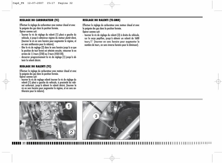
32
REGLAGE DU CARBURATEUR (TC)
Effectuer le réglage du carburateur avec moteur chaud et avecla poignée des gaz dans la position fermée. Opérer comme suit:- Tourner la vis de réglage du ralenti (1) placé a gauche du
vehicule, à jusqu’à obtenirun régime du moteur plutôt élevé,(tourner la vis en sens horaire pour augmenter le régime, eten sens antihoraire pour le réduire).
- Oter le vis de reglage (2) dans le sens horaire jusqu’à ce quela position de tout fermé est atteinte ensuite, retourner le enarrière de 1,5 tours (250) ou 2 tours (450-510).
- desserrer progressivement la vis de réglage (1) jusqu’à ob-tenir le relenti désiré.
REGLAGE DU RALENTI (TC)
Effectuer le réglage du carburateur avec moteur chaud et avecla poignée des gaz dans la position fermée. Opérer comme suit:- tourner la vis de reglage ralenti tourner la vis de réglage du
ralenti (1) placé a gauche du vehicule, à proximité du robi-net carburant, jusqu’à obtenir le ralenti désiré, (tourner lavis en sens horaire pour augmenter le régime, et en sens an-tihoraire pour le réduire).
REGLAGE DU RALENTI (TE-SMR)
Effectuer le réglage du carburateur avec moteur chaud et avecla poignée des gaz dans la position fermée. Opérer comme suit:- tourner la vis de réglage du ralenti (3) à droite du véhicule,
sur le corps papillon, jusqu’à obtenir un ralenti de 1600tours/1’ (tourner en sens horaire pour augmenter lenombre de tours, en sens inverse horaire pour le diminuer).
3
Cap6_FR 12-07-2007 15:17 Pagina 32
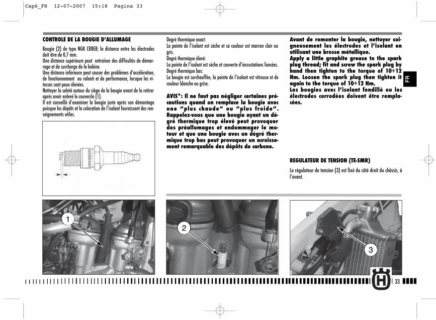
33
CONTROLE DE LA BOUGIE D’ALLUMAGE
Bougie (2) de type NGK CR8EB; la distance entre les électrodesdoit être de 0,7 mm.Une distance supérieure peut entraîner des difficultés de démar-rage et de surcharge de la bobine.Une distance inférieure peut causer des problèmes d’accélération,de fonctionnement au ralenti et de performance, lorsque les vi-tesses sont peux élevées.Nettoyer la saleté autour du siège de la bougie avant de la retireraprès avoir enlevé le couvercle (1).Il est conseillé d’examiner la bougie juste après son démontagepuisque les dépôts et la coloration de l’isolant fournissent des ren-seignements utiles.
Degré thermique exact:La pointe de l’isolant est sèche et sa couleur est marron clair ougris.Degré thermique élevé:La pointe de l’isolant est sèche et couverte d’incrustations foncées.Degré thermique bas:La bougie est surchauffée, la pointe de l’isolant est vitreuse et decouleur blanche ou grise.
AVIS*: Il ne faut pas négliger certaines pré-cautions quand on remplace la bougie avecune “plus chaude” ou “plus froide”.Rappelez-vous que une bougie ayant un dé-gré thermique trop élevé peut provoquerdes préallumages et endommager le mo-teur et que une bougie avec un dégré ther-mique trop bas peut provoquer un acroisse-ment remarquable des dépôts de carbone.
Avant de remonter la bougie, nettoyer soi-gneusement les électrodes et l’isolant enutilisant une brosse métallique.Apply a little graphite grease to the sparkplug thread; fit and screw the spark plug byhand then tighten to the torque of 10÷12Nm. Loosen the spark plug then tighten itagain to the torque of 10÷12 Nm.Les bougies avec l’isolant fendillé ou lesélectrodes corrodées doivent être rempla-cées.
REGULATEUR DE TENSION (TE-SMR)
Le régulateur de tension (3) est fixé du côté droit du châssis, àl’avant.
2
3
1
FR
Cap6_FR 12-07-2007 15:18 Pagina 33

DEMONTAGE DU RESERVOIR (TC)
Fermer le robinet du carburant (2) et desserrer le collier (3)sur le tuyau de raccordement au carburateur ; extraire la letuyau du carburateur. Enlever les vis (4) et les panneaux laté-raux.
Enlever la vis (A) de fixation et extraire le réservoir et lesconvoyeurs.
34
REGLAGE DU JEU DES SOUPAPES
Effectuer ce côntrole AVEC MOTEUR FROID, en opérant comme suit :
Enlever la selle après avoir tourné dans le sens inverse des aiguillesd’une montre le pivot arrière (1) de fixage;
2
3
4
A
Cap6_FR 9-07-2007 14:58 Pagina 34
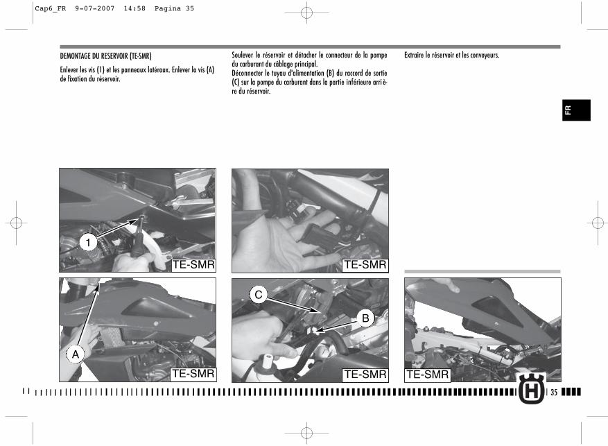
Soulever le réservoir et détacher le connecteur de la pompedu carburant du câblage principal.Déconnecter le tuyau d'alimentation (B) du raccord de sortie(C) sur la pompe du carburant dans la partie inférieure arri è-re du réservoir.
DEMONTAGE DU RESERVOIR (TE-SMR)
Enlever les vis (1) et les panneaux latéraux. Enlever la vis (A)de fixation du réservoir.
Extraire le réservoir et les convoyeurs.
35
TE-SMR
B
TE-SMR
C
A
TE-SMR
TE-SMR
1
TE-SMR
FR
Cap6_FR 9-07-2007 14:58 Pagina 35
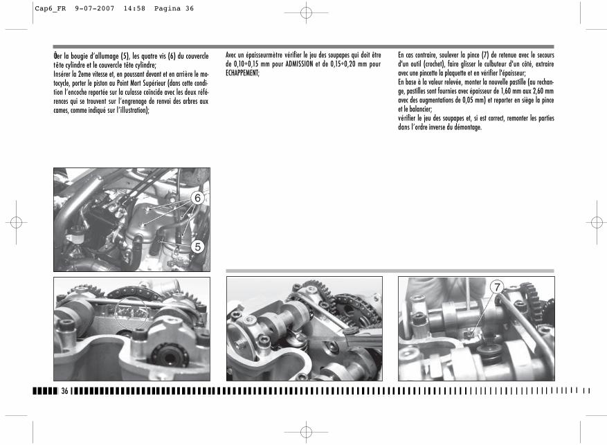
En cas contraire, soulever la pince (7) de retenue avec le secoursd'un outil (crochet), faire glisser le culbuteur d'un côté, extraireavec une pincette la plaquette et en vérifier l'épaisseur; En base à la valeur relevée, monter la nouvelle pastille (au rechan-ge, pastilles sont fournies avec épaisseur de 1,60 mm aux 2,60 mmavec des augmentations de 0,05 mm) et reporter en siège la pinceet le balancier; vérifier le jeu des soupapes et, si est correct, remonter les partiesdans l’ordre inverse du démontage.
36
Avec un épaisseurmètre vérifier le jeu des soupapes qui doit êtrede 0,10÷0,15 mm pour ADMISSION et de 0,15÷0,20 mm pourECHAPPEMENT;
Ôter la bougie d’allumage (5), les quatre vis (6) du couvercletête cylindre et le couvercle tête cylindre;Insérer la 2eme vitesse et, en poussant devant et en arrière le mo-tocycle, porter le piston au Point Mort Supérieur (dans cette condi-tion l’encoche reportée sur la culasse coïncide avec les deux réfé-rences qui se trouvent sur l’engrenage de renvoi des arbres auxcames, comme indiqué sur l’illustration);
Cap6_FR 9-07-2007 14:58 Pagina 36
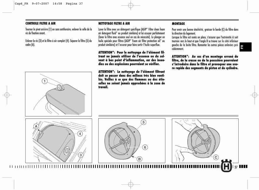
NETTOYAGE FILTRE A AIR
Laver le filtre avec un détergent spécifique (AGIP” Filter clean foamair detergent fluid” ou produit similaire) et lui essuyer parfaitement(laver le filtre avec essence seul en cas de nécessité). Le plonger enhuile spéciale pour filtres (AGIP” Foam air filter protection oil” ouproduit similaire) et l’essorer pour faire sortir l’huile superflue.
ATTENTION*: Pour le nettoyage de l’élément fil-trant ne jamais utiliser de l’essence ou du sol-vant à bas point d’inflammation, car des incen-dies ou des explosions pourraient se vérifier.
ATTENTION*: Le nettoyage de l’élément filtrantdoit se passer dans des milieux très bien venti-lés. Veillez à ce que des flammes ou des étin-celles ne soient jamais approchées à la zone detravail.
MONTAGE
Pour avoir une bonne étachéité, graisser le borde (C) du filtre dansla direction du logement.Lorsque le filtre est remis en place, s'assurer que l'extrémité A soittournée vers le haut et que l'angle B se trouve sur le côté inférieurgauche de la boîte filtre. Remonter les autres pièces enlevées pré-cédemment.
ATTENTION*: Au cas d’un montage erroné dufiltre, de la crasse ou de la poussière pourraients’introduire dans le filtre et provoquer une usu-re rapide des segments du piston et du cyclindre.
37
CONTROLE FILTRE A AIR
Tourner le pivot arrière (1) en sans antihoraire, enlever la selle de lavis de fixation avant.
Enlever la vis (3) et le filtre à air complet (4). Séparer le filtre (5) ducadre (6).
FR
Cap6_FR 9-07-2007 14:58 Pagina 37
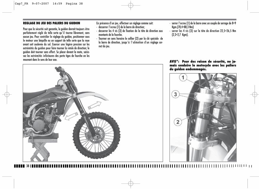
38
REGLAGE DU JEU DES PALIERS DU GUIDON
Pour que la sécurité soit garantie, le guidon devrait toujours êtreparfaitement réglé de telle sorte qu’il tourne librement, sansaucun jeu. Pour contrôler le réglage du guidon, positionner sousle moteur une béquille ou un support de telle sorte que la roueavant soit soulevée du sol. Exercer une légère pression sur lesextrémités du guidon pour faire tourner la rotule de direction; leguidon doit tourner sans effort. Se placer devant la moto, saisis-sez les extrémités inférieures des porte tiges de fourche en lesmouvant dans le sens de leur axe.
En présence d’un jeu, effectuer un réglage comme suit:- desserrer l’ecrou (1) de la barre de direction;- desserrer les 4 vis (3) de fixation de la tête de direction aux
montants de la fourche.- Tourner en sens horaire le collier (2) par la clé spéciale de
la barre de direction, jusqu’à l ’obtention d’un réglage cor-rect du jeu.
- serrer l’ecrou (1) de la barre avec un couple de serrage de 8÷9Kgm.(78,4÷88,3 Nm)
- serrer les 4 vis (3) sur la tête de direction 22,5÷26,5 Nm(2,3÷2,7 Kgm).
AVIS*: Pour des raison de sécurité, ne ja-mais conduire le motocycle avec les paliersdu guidon endommagés.
Cap7_FR 9-07-2007 14:59 Pagina 38
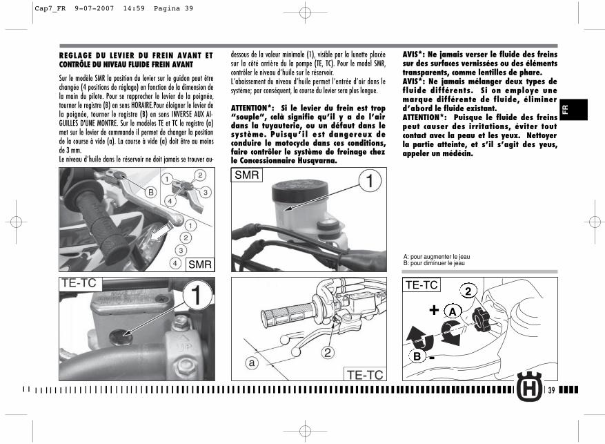
A
B
+
-
2TE-TC
dessous de la valeur minimale (1), visible par la lunette placéesur la côté arrière du la pompe (TE, TC). Pour le model SMR,contrôler le niveau d’huile sur le réservoir.L’abaissement du niveau d’huile permet l’entrée d’air dans lesystème; par conséquent, la course du levier sera plus longue.
ATTENTION*: Si le levier du frein est trop“souple”, celà signifie qu’il y a de l’airdans la tuyauterie, ou un défaut dans lesystème. Puisqu’ i l e st dangereux deconduire le motocycle dans ces conditions,faire contrôler le système de freinage chezle Concessionnaire Husqvarna.
AVIS*: Ne jamais verser le fluide des freinssur des surfaces vernissées ou des élémentstransparents, comme lentilles de phare.AVIS*: Ne jamais mélanger deux types defluide dif férents. Si on employe unemarque différente de fluide, éliminerd’abord le fluide existant.ATTENTION*: Puisque le fluide des freinspeut causer des irritations, éviter toutcontact avec la peau et les yeux. Nettoyerla partie atteinte, et s’il s’agit des yeus,appeler un médécin.
39
FR
REGLAGE DU LEVIER DU FREIN AVANT ETCONTRÔLE DU NIVEAU FLUIDE FREIN AVANT
Sur le modèle SMR la position du levier sur le guidon peut êtrechangée (4 positions de réglage) en fonction de la dimension dela main du pilote. Pour se rapprocher le levier de la poignée,tourner le registre (B) en sens HORAIRE.Pour éloigner le levier dela poignée, tourner le registre (B) en sens INVERSE AUX AI-GUILLES D'UNE MONTRE. Sur le modèles TE et TC le registre (a)met sur le levier de commande il permet de changer la positionde la course à vide (a). La course à vide (a) doit être au moinsde 3 mm.Le niveau d’huile dans le réservoir ne doit jamais se trouver au-
SMR
A: pour augmenter le jeauB: pour dimínuer le jeauSMR
Cap7_FR 9-07-2007 14:59 Pagina 39
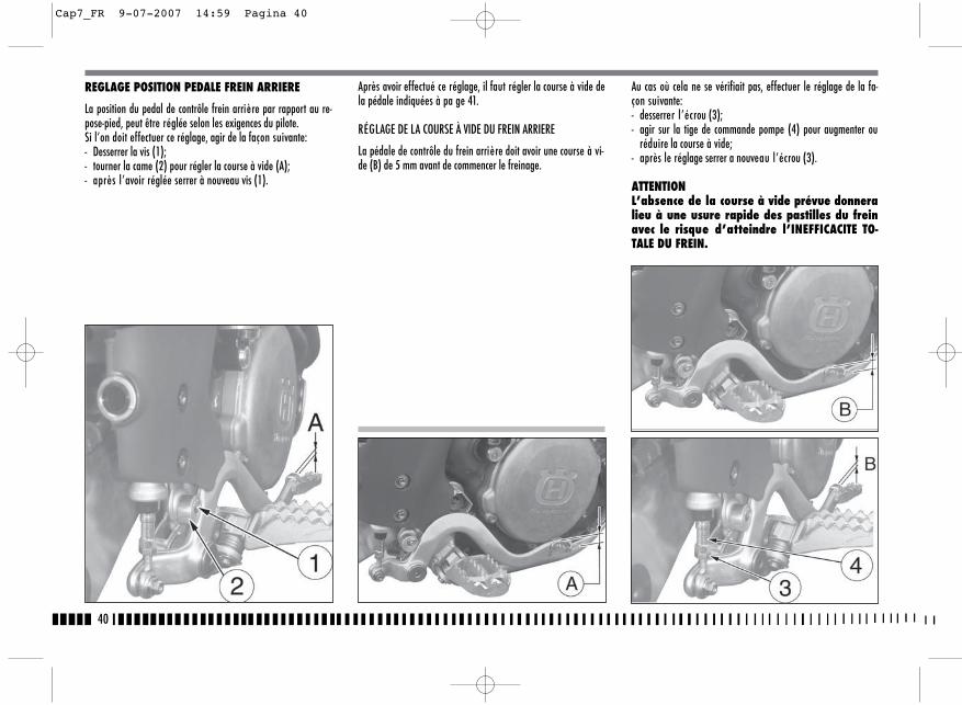
40
Après avoir effectué ce réglage, il faut régler la course à vide dela pédale indiquées à pa ge 41.
RÉGLAGE DE LA COURSE À VIDE DU FREIN ARRIERE
La pédale de contrôle du frein arrière doit avoir une course à vi-de (B) de 5 mm avant de commencer le freinage.
Au cas où cela ne se vérifiait pas, effectuer le réglage de la fa-çon suivante:- desserrer l’écrou (3);- agir sur la tige de commande pompe (4) pour augmenter ou
réduire la course à vide;- après le réglage serrer a nouveau l’écrou (3).
ATTENTIONL’absence de la course à vide prévue donneralieu à une usure rapide des pastilles du freinavec le risque d’atteindre l’INEFFICACITE TO-TALE DU FREIN.
REGLAGE POSITION PEDALE FREIN ARRIERE
La position du pedal de contrôle frein arrière par rapport au re-pose-pied, peut être réglée selon les exigences du pilote. Si l’on doit effectuer ce réglage, agir de la façon suivante:- Desserrer la vis (1);- tourner la came (2) pour régler la course à vide (A);- après l’avoir réglée serrer à nouveau vis (1).
Cap7_FR 9-07-2007 14:59 Pagina 40

41
CONTROLE DU NIVEAU FLUIDE
Le niveau (A) doit être situé entre les encoches sur le réservoirpompe.
REGLAGE DU LEVIER DE COMMANDE ETCONTRÔLE DU NIVEAU FLUIDE DE L’EMBRAYAGEHYDRAULIQUE
La course à vide (A) doit être au moins de 3 mm.La position du levier sur le guidon peut être changée en fonctionde la dimension de la main du pilote.Pour se rapprocher le levier de la poignée, tourner le registre (B)en sens HORAIRE.Pour éloigner le levier de la poignée, tourner le registre (B) ensens INVERSE AUX AIGUILLES D'UNE MONTRE. Pour effectuer le contrôle du niveau du fluide, en opérant commesuit:- oter les vis (1), le couvercle (2) et le diaphragme pompe sur le
commande pompe d’embrayage;
- mettre le maître-cylindre (3) du commande embrayage dansla position horizontale et contrôler le niveau du fluide: le ni-veau ne doit se trouver au-dessous de 4 mm (0.16 in.) du bordsupérieur (D) de la pompe;
- si nécessaire, insérer fluide (pour le type, voir TABLEAU DEGRAISSAGE-RAVITAILLEMENTS page 10).
AVIS*: Ne JAMAIS utiliser liquide de frein.
Remonter les parties dans l’ordre inverse du démontage.
Vérifier souvent les manchons d’assemblage (voir " Fiche d’en-tretien périodique "); si sur la tuyanterie (C) il y a des signesd'usure ou ruptures, il sera nécessaire le remplacer. F
R
Cap7_FR 9-07-2007 14:59 Pagina 41
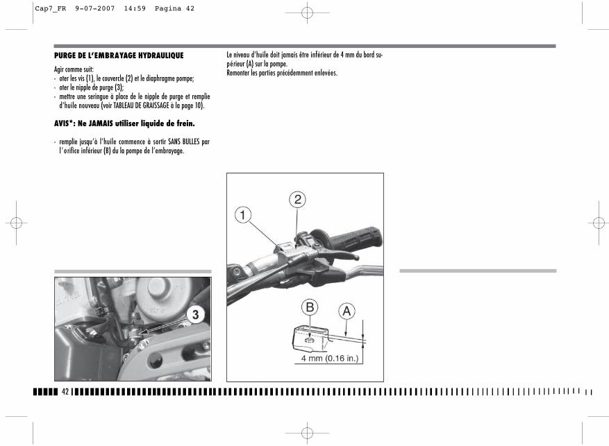
42
PURGE DE L’EMBRAYAGE HYDRAULIQUE
Agir comme suit:- oter les vis (1), le couvercle (2) et le diaphragme pompe;- oter le nipple de purge (3);- mettre une seringue à place de le nipple de purge et remplie
d’huile nouveau (voir TABLEAU DE GRAISSAGE à la page 10).
AVIS*: Ne JAMAIS utiliser liquide de frein.
- remplie jusqu’à l’huile commence à sortir SANS BULLES parl ’orifice inférieur (B) du la pompe de l’embrayage.
Le niveau d’huile doit jamais être inférieur de 4 mm du bord su-périeur (A) sur la pompe.Remonter les parties précédemment enlevées.
Cap7_FR 9-07-2007 14:59 Pagina 42
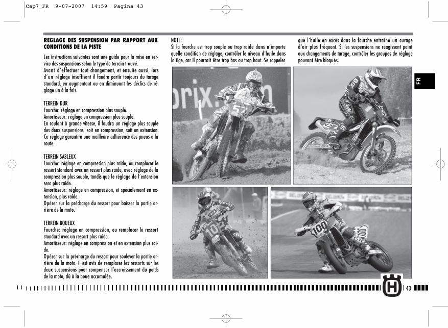
43
REGLAGE DES SUSPENSION PAR RAPPORT AUXCONDITIONS DE LA PISTE
Les instructions suivantes sont une guide pour la mise en ser-vice des suspensions selon le type de terrein trouvé. Avant d’effectuer tout changement, et ensuite aussi, lorsd’un réglage insuffisant il faudra partir toujours du taragestandard, en augmentant ou en diminuant les déclics de ré-glage un à la fois.
TERREIN DURFourche: réglage en compression plus souple.Amortisseur: réglage en compression plus souple.En roulant à grande vitesse, il faudra un réglage plus soupledes deux suspensions soit en compression, soit en extension.Ce réglage garantira une meilleure adhérence des pneus à laroute.
TERREIN SABLEUXFourche: réglage en compression plus raide, ou remplacer leressort standard avec un ressort plus raide, avec réglage de lacompression plus souple, tandis que le réglage de l’extensionsera plus raide.Amortisseur: réglage en compression, et spécialement en ex-tension, plus raide.Opérer sur la précharge du ressort pour baisser la partie ar-rière de la moto.
TERREIN BOUEUXFourche: réglage en compression, ou remplacer le ressortstandard avec un ressort plus raide.Amortisseur: réglage en compression et en extension plus rai-de.Opérer sur la précharge du ressort pour soulever la partie ar-rière de la moto. Il est avis de remplacer les ressorts sur lesdeux suspensions pour compenser l’accroissement du poidsde la moto, dû à la boue accumulée.
NOTE: Si la fourche est trop souple ou trop raide dans n’importequelle condition de réglage, contrôler le niveau d’huile dansla tige, car il pourrait être trop bas ou trop haut. Se rappeler
que l’huile en excès dans la fourche entraîne un curaged’air plus fréquent. Si les suspensions ne réagissent pointaux changements de tarage, contrôler les groupes de réglagepouvant être bloqués.
FR
Cap7_FR 9-07-2007 14:59 Pagina 43
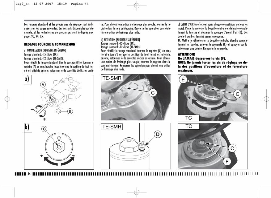
44
Les tarages standard et les procédures de règlage sont indi-quées sur les pages suivantes. Les ressorts disponibles sur de-mande, et les entretoises de précharge, sont indiqués auxpages 93, 94, 95.
REGLAGE FOURCHE A COMPRESSION
a) COMPRESSION (REGISTRE INFÉRIEUR)Tarage standard: -15 clicks (TC);Tarage standard: -12 clicks (TE-SMR).Pour rétablir le tarage standard, ôter le bouchon (B) et tourner leregistre (A) en sens horaire jusqu’à ce que la position de tout fer-mé est atteinte ensuite, retourner le de souscités déclics en arriè-
re. Pour obtenir une action de freinage plus souple, tourner le re-gistre dans le sens anti-horaire. Renverser les opération pour obte-nir une action de freinage plus raide.
b) EXTENSION (REGISTRE SUPÉRIEUR)Tarage standard: -15 clicks (TC);Tarage standard: -12 clicks (TE-SMR).Pour rétablir le tarage standard, tourner le registre (C) en senshoraire jusqu’à ce que la position de tout fermé est atteinte.Ensuite, retourner le de souscités déclics en arrière. Pour obtenirune action de freinage plus souple, tourner le registre dans lesens anti-horaire. Renverser les opération pour obtenir une actionde freinage plus raide.
c) EVENT D’AIR (à effectuer après chaque compétition, ou tous lesmois). Placer la moto sur la béquille centrale et détendre complè-tement la fourche et desserer la soupape d’évent d’air (D). Dèsque le travail est terminé serrer la soupape.TC: Mettre le véhicule sur sa béquille centrale, étendre complè-tement la fourche, enlever le couvercle (E) et appuyer sur lavalve avec une pointe. Remonter le couvercle.
ATTENTION!Ne JAMAIS desserrer la vis (F).NOTE: Ne jamais forcer les vis de réglage au de-la des positions d’ouverture et de fermeturemaximum.
A
B
CD
a)
b)TC
TC
TE-SMR
TE-SMR
E
C
C
C
F
Cap7_FR 12-07-2007 15:19 Pagina 44
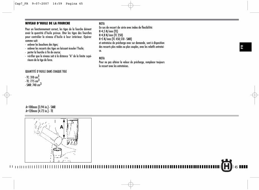
NIVEAU D’HUILE DE LA FOURCHE
Pour un fonctionnement correct, les tiges de la fourche doiventavoir la quantité d’huile prévue. Oter les tiges des fourchespour contrôler le niveau d’huile à leur intérieur. Opérercomme suit:- enlever les bouchons des tiges;- enlever les ressorts des tiges en laissant écouler l’huile;- porter la fourche à fin de course;- vérifier que le niveau soit à la distance “A” de la limite supé-
rieure de la tige de force.
QUANTITÉ D’HUILE DANS CHAQUE TIGE
- TC: 310 cm3- TE: 775 cm3- SMR: 740 cm3
A=100mm (3.94 in.) - SMRA=120mm (4.72 in.) - TE
A
NOTAEn sus de ressort de série avec index de flexibilité:K=4,5 N/mm (TE) K=4,8 N/mm (TC 250) K=5 N/mm (TC 450,510 - SMR)et entretoise de précharge avec sur demande, sont à dispositiondes ressorts plus raides ou plus souples, avec les relatifs entretoi-se.
NOTAPour ne pas altérer la valeur de précharge, remplacer toujoursle ressort avec les entretoises.
45
FR
Cap7_FR 9-07-2007 14:59 Pagina 45

46
b) Modification de l'hauteur du guidonEnlever l'entertoise inférieur (A) et remplacer la vis (4) avecune de longueur L=65 mm.Exécuter le remontage en opérant inversement et en serrantles vis (3) aux 2,75-3,05 kgm (27-30 Nm; 19.9-22 Lb/ft) et lesvis (4) aux 2,0-2,2 kgm (19,6-21,6 Nm; 14.5-15.9 Lb/ft).
MODIFICATION DE LA POSITION ET DE L'HAU-TEUR DU GUIDON
La position (a) et l'hauteur (b) du guidon ils peuvent êtrechangée pour mieux s'adapter à Vos exigences de guide. Poureffectuer cette opération, il est nécessaire de démonter les vis(3), le etau supérieur (1), les vis (4) et le etau inférieur (2).
a) Modification de la position du guidonTourner le etau inférieur (2) de 180° pour avancer ou reculer(10mm - 0.04in.) la position du guidon en relation à cette ini-tiale.
Cap7_FR 9-07-2007 14:59 Pagina 46

4. La diff é rence entre ces deux mesurages représente l ’“ ABAISSEMENT” de la partie arrière de la moto.L’abaissement conseillé est de 100 mm. avec amortisseurfroid. De 95 mm. avec amortisseur chaud.
5. Pour obtenir l’abaissement correct en fonction de votre poids,régler la précharge du ressort de l’amortisseur (comme dé-crit à flanc).
ATTENTION*: Ne jamais démonter l’amor-tisseur car il contien du gaz sous pression.Pour des interventions plus importantes,contacter le Concessionnaire Husqvarna.
REGLAGE DE LA PRECHARGE DU RESSORT AMOR-TISSEUR
Agir comme suit:1. Enlever la selle après avoir tourné dans le sens inverse des
aiguilles d’une montre le pivot arrière (1) de fixage, oter lesvis (2) et le panneau latéral droite (3).
47
REGLAGE DE L’ AMORTISSEUR
Régler l’amortisseur arrière selon le poids du conducteur et sui-vant les condition du sol.Agir comme suit:1. Placer la moto sur la béquille et mesurer la distance (A).2. S’asseoir sur la moto dans la position normale de conduite et
avec tout l’équipement.3. A l’aide d’une autre personne, relever la nouvelle distance
(A).
B: axe de la vis de fixation panneauC: axe du pivot roue arrière
2
3
FR
Cap8_FR 9-07-2007 15:01 Pagina 47
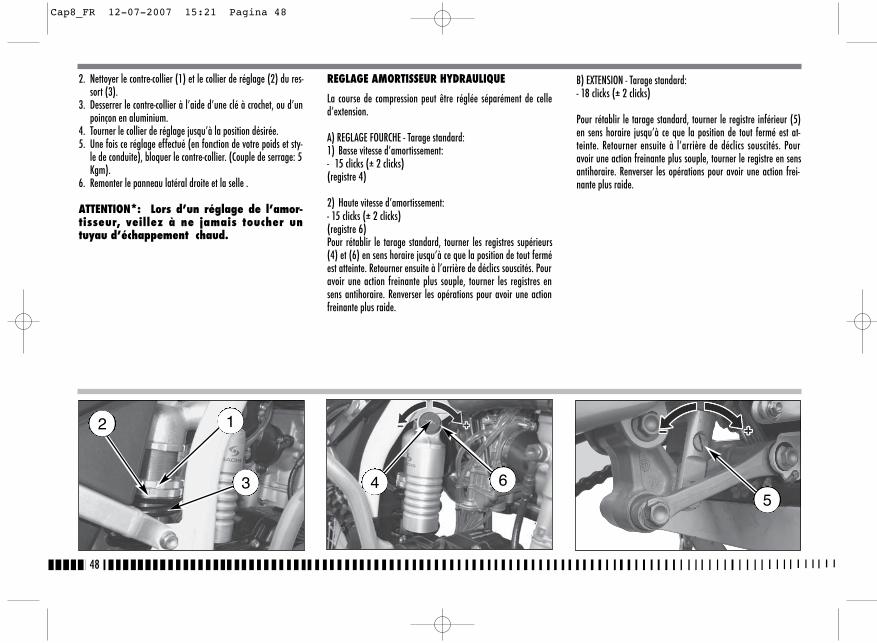
B) EXTENSION - Tarage standard:- 18 clicks (± 2 clicks)
Pour rétablir le tarage standard, tourner le registre inférieur (5)en sens horaire jusqu’à ce que la position de tout fermé est at-teinte. Retourner ensuite à l’arrière de déclics souscités. Pouravoir une action freinante plus souple, tourner le registre en sensantihoraire. Renverser les opérations pour avoir une action frei-nante plus raide.
2. Nettoyer le contre-collier (1) et le collier de réglage (2) du res-sort (3).
3. Desserrer le contre-collier à l’aide d’une clé à crochet, ou d’unpoinçon en aluminium.
4. Tourner le collier de réglage jusqu’à la position désirée.5. Une fois ce réglage effectué (en fonction de votre poids et sty-
le de conduite), bloquer le contre-collier. (Couple de serrage: 5Kgm).
6. Remonter le panneau latéral droite et la selle .
ATTENTION*: Lors d’un réglage de l’amor-tisseur, veillez à ne jamais toucher untuyau d’échappement chaud.
REGLAGE AMORTISSEUR HYDRAULIQUE
La course de compression peut être réglée séparément de celled’extension.
A) REGLAGE FOURCHE - Tarage standard:1) Basse vitesse d’amortissement:- 15 clicks (± 2 clicks)(registre 4)
2) Haute vitesse d’amortissement:- 15 clicks (± 2 clicks)(registre 6)Pour rétablir le tarage standard, tourner les registres supérieurs(4) et (6) en sens horaire jusqu’à ce que la position de tout ferméest atteinte. Retourner ensuite à l’arrière de déclics souscités. Pouravoir une action freinante plus souple, tourner les registres ensens antihoraire. Renverser les opérations pour avoir une actionfreinante plus raide.
48
12
3 645
Cap8_FR 12-07-2007 15:21 Pagina 48
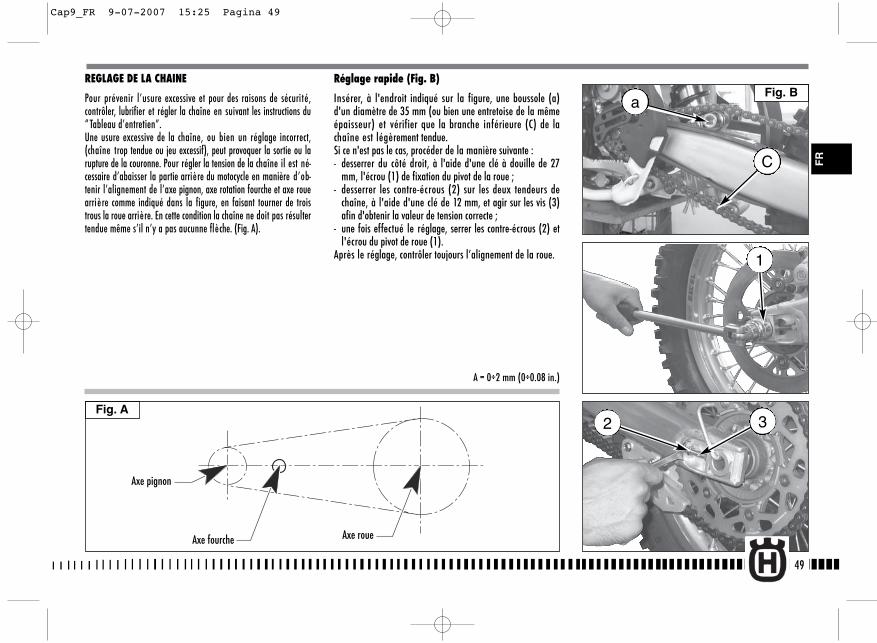
REGLAGE DE LA CHAINE
Pour prévenir l’usure excessive et pour des raisons de sécurité,contrôler, lubrifier et régler la chaîne en suivant les instructions du“ Tableau d’entretien”.Une usure excessive de la chaîne, ou bien un réglage incorrect,(chaîne trop tendue ou jeu excessif), peut provoquer la sortie ou larupture de la couronne. Pour régler la tension de la chaîne il est né-cessaire d’abaisser la partie arrière du motocycle en manière d’ob-tenir l’alignement de l’axe pignon, axe rotation fourche et axe rouearrière comme indiqué dans la figure, en faisant tourner de troistrous la roue arrière. En cette condition la chaîne ne doit pas résultertendue même s’il n’y a pas aucunne flèche. (Fig. A).
Réglage rapide (Fig. B)
Insérer, à l'endroit indiqué sur la figure, une boussole (a)d'un diamètre de 35 mm (ou bien une entretoise de la mêmeépaisseur) et vérifier que la branche inférieure (C) de lachaîne est légèrement tendue.Si ce n'est pas le cas, procéder de la manière suivante :- desserrer du côté droit, à l'aide d'une clé à douille de 27
mm, l'écrou (1) de fixation du pivot de la roue ;- desserrer les contre-écrous (2) sur les deux tendeurs de
chaîne, à l'aide d'une clé de 12 mm, et agir sur les vis (3)afin d'obtenir la valeur de tension correcte ;
- une fois effectué le réglage, serrer les contre-écrous (2) etl'écrou du pivot de roue (1).
Après le réglage, contrôler toujours l’alignement de la roue.
49
Fig. A
FR
Axe pignon
Axe fourche Axe roue
A = 0÷2 mm (0÷0.08 in.)
a
C
1
32
Fig. B
Cap9_FR 9-07-2007 15:25 Pagina 49
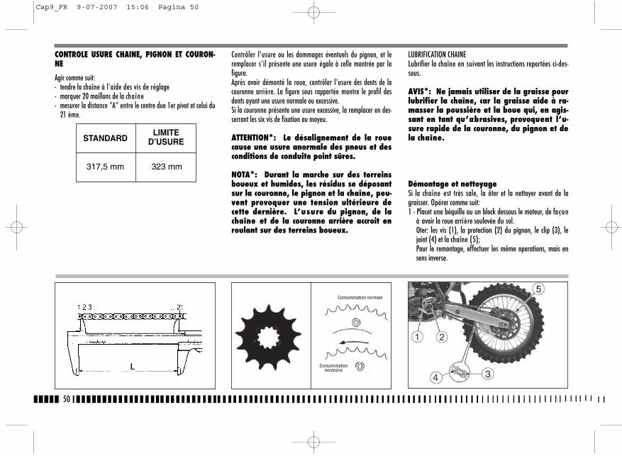
Contrôler l’usure ou les dommages éventuels du pignon, et leremplacer s’il présente une usure égale à celle montrée par lafigure.Après avoir démonté la roue, contrôler l’usure des dents de lacouronne arrière. La figure sous rapportée montre le profil desdents ayant une usure normale ou excessive.Si la couronne présente une usure excessive, la remplacer en des-serrant les six vis de fixation au moyeu.
ATTENTION*: Le désalignement de la rouecause une usure anormale des pneus et desconditions de conduite point sûres.
NOTA*: Durant la marche sur des terreinsboueux et humides, les résidus se déposantsur la couronne, le pignon et la chaîne, peu-vent provoquer une tension ultérieure decette dernière. L’usure du pignon, de lachaîne et de la couronne arrière accroit enroulant sur des terreins boueux.
LUBRIFICATION CHAINELubrifier la chaîne en suivant les instructions reportées ci-des-sous.
AVIS*: Ne jamais utiliser de la graisse pourlubrifier la chaîne, car la graisse aide à ra-masser la poussière et la boue qui, en agis-sant en tant qu’abrasives, provoquent l’u-sure rapide de la couronne, du pignon et dela chaîne.
Démontage et nettoyageSi la chaîne est très sale, la ôter et la nettoyer avant de lagraisser. Opérer comme suit:1 - Placet une béquille ou un block dessous le moteur, de façon
à avoir la roue arrière soulevée du sol.Oter: les vis (1), la protection (2) du pignon, le clip (3), lejoint (4) et la chaîne (5);Pour le remontage, effectuer les même operations, mais ensens inverse.
50
CONTROLE USURE CHAINE, PIGNON ET COURON-NE
Agir comme suit:- tendre la chaîne à l’aide des vis de réglage- marquer 20 maillons de la chaîne- mesurer la distance “A” entre le centre due 1er pivot et celui du
21 ème.
STANDARDLIMITE
D’USURE
317,5 mm 323 mm
Consommation normale
Consommationexcessive
Cap9_FR 9-07-2007 15:06 Pagina 50
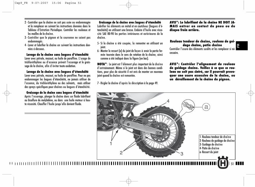
Graissage de la chaîne avec bagues d’étanchéitéLubrifier les éléments en métal et en cautchouc (bagues d’é-tanchéité) en utilisant une brosse. Enduire d’huile avec visco-sité SAE 80-90 les parties intérieures et extérieures de lachaîne.
5 - Si la chaîne a été coupée, la remonter en utilisant unjoint.
6 - Monter le ressort (a) du joint de façon à avoir la partie fer-mée tournée dans le sens de rotation de la chaîne, ainsicomme a été indiqué dans la figure (en bas).
NOTA*: Le joint est l’élément plus important de la chaîned’entrainement. Même si le joint est dans des bonnes condi-tions, pour plus de sécurité il est avis de monter un nouveaujoint quand la chaîne est remontée.
7 - Régler la chaîne d’après la déscription à la page 49.
2 - Contrôler que la chaîne ne soit pas usée ou endommagéeet la remplacer en suivant les instructions données dans leTableau d’Entretien Périodique. Contrôler les rouleaux etles mailles de la chaîne.
3 - Contrôler que le pignon et la couronne ne soient pasendommagés.
4 - Laver et lubrifier la chaîne en suivant les instructions don-nées ci-dessous.
Lavage de la chaîne sans bagues d’étanchéitéLaver avec pétrole, mazout, ou huile de paraffine. L’usage detrichloréthylène ou d’essence prévoit l’essorage et le grais-sage de la chaîne, afin d’éviter toute oxidation.
Lavage de la chaîne avec bagues d’étanchéitéLaver avec pétrole, mazout, ou huile de paraffine. Pour ne pasendommager les bagues d’étanchéité, ne jamais utiliser del’essence, du trichloréthylène ou des solvants, mais utiliserdes sprays spécifiques pour chaînes ou bagues d’étanchéité.
Graissage de la chaîne sans bagues d’étanchéitéAprès l’essorage, plonger la chaîne dans un fluide lubrifiantau bisolfure de molybdène, ou dans une huile moteur à hau-te viscosité. Chauffer l’huile jusqu’elle devient fluide.
AVIS*: Le lubrifiant de la chaîne NE DOIT JA-MAIS entrer en contact du pneu ou dudisque frein arrière.
Rouleau tendeur de chaîne, rouleau de gui-dage chaîne, patin chaîne
Contrôler l’usure des éléments susdits et les remplacer si né-cessaire.
AVIS*: Contrôler l’alignement du rouleaude guidage chaîne. Veillez à ce que ce rou-leau ne soit pas cintré, car il pourrait provo-quer une usure excessive de la chaîne, ouun déraillement de la chaîne du pignon.
51
1- Rouleau tendeur de chaîne2- Rouleau de guidage de chaîne3- Guidage de chaîne4- Patin de chaînea- Ressort du joint
FR
Cap9_FR 9-07-2007 15:06 Pagina 51

AVISLorsque la roue est démontée, ne pas tirer la poignée du frein,pour ne pas faire avancer les pistons de l’ etrier. Après le démon-tage de la roue avant, poser la roue avec le disque sur le dessus.
52
Démontage de la roue avant
Placet une béquille ou un block dessous le moteur, de façon àavoir la roue avant soulevée du sol.SMR: desserrer les deux vis (A) et enlever l'etrier du frein.Desserrer les vis (1) qui bloquent l’axe (2) de la roue sur les sup-ports des montants de la fourche.Bloquer l’extrémité de l’axe (2) de la roue et dévisser, en mê-me temps, la vis (3) sur le côté opposé; enlever l’axe de la roue.
SMR
Cap9_FR 9-07-2007 15:06 Pagina 52

Bloquer: les vis (1) sur la tige droite (10,4 Nm/ 1,05 Kgm/ 7.7 ft-lb), la vis (3) sur le côté gauche (51,45 Nm/ 5,25 Kgm/ 38 ft-lb)et les vis (1) sur la tige gauche (10,4 Nm/ 1,05 Kgm/ 7.7 ft-lb).SMR: insérer l'etrier du frein, la monter sur le support relatif enserrant les deux vis (À) aux 25,5 Nm / 2,6 Kgm / 18.8 ft-lbs.Vérifier que le frein courre librement entre les pastilles de l'etrier.
AVISAprès le rémontage de la roue avant, actionner le levier du freinjusqu’à ce que les pastilles ne seront à contact de disque.
53
RÉMONTAGE DE LA ROUE AVANT
Insérer l'entertoise gauche sur le moyeau de la roue.TE-TC: Insérer la roue entre les deux tiges de la fourche de maniè-re à introduire le disque de frein dans l'etrier.SMR: Insérer la roue entre les deux tiges de la fourche.Insérer par le côté droit le pivot de la roue (2) préalablementgraissé et le battre jusq'à la butée sur la tige gauche; pendantcette opération il est conseillé de faire tourner la roue. Visser lavis (3) sur le côté gauche de la fourche SANS la bloquer. A cepoint, pomper plusieurs fois en poussant vers le bas le guidon jus-q'à être certain de l'alignement parfait des tiges de fourche.
TE-TC SMR
FR
Cap9_FR 9-07-2007 15:07 Pagina 53
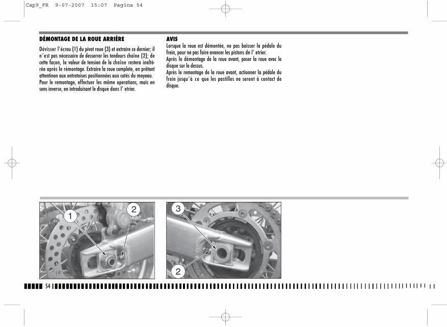
DÉMONTAGE DE LA ROUE ARRIÈRE
Dévisser l’écrou (1) du pivot roue (3) et extraire ce dernier; iln ’est pas nécessaire de desserrer les tendeurs chaîne (2); decette façon, la valeur de tension de la chaîne restera inalté-rée après le rémontage. Extraire la roue complete, en prêtantattentinon aux entretoises positionnées aux cotés du moyeau. Pour le remontage, effectuer les même operations, mais ensens inverse, en introduisant le disque dans l’ etrier.
AVISLorsque la roue est démontée, ne pas baisser la pédale dufrein, pour ne pas faire avancer les pistons de l’ etrier.Après le démontage de la roue avant, poser la roue avec ledisque sur le dessus.Après le remontage de la roue avant, actionner la pédale dufrein jusqu’à ce que les pastilles ne seront à contact dedisque.
54
Cap9_FR 9-07-2007 15:07 Pagina 54

6. Réservoir à huile du frein arrière7. Tuyau arrière8. Etrier arrière9. Disque arrière10. Pompe du frein arrière11. Pédale de controle du frein arrière
FREIN
Eléments principaux des deux systèmes: pompe frein avec levier(avant) ou pédale (arrière), tubulure, étrier et disque.
LEGENDE1. Levier de contrôle frein avant2. Pompe du frein avant avec réservoir à huile (TE, TC)2. Pompe du frein avant (SMR)2A. Réservoir à huile (SMR)3. Tuyau avant
4. Etrier avant5. Disque avant
55
FR
PNEUS
Garder les pneus gonflés à la pression exacte, comme indiqué àpage 9.Remplacer le pneu lorsque l’usure est supérieure aux indicationsdu tableau qui suit.
HAUTEUR MINIMALEDE LA BANDE
AVANT 3 mm (TC,TE); 2 mm (SMR)
ARRIÈRE 3 mm (TC,TE); 2 mm (SMR)
TE-TC
SMR
Cap9_FR 12-07-2007 15:22 Pagina 55
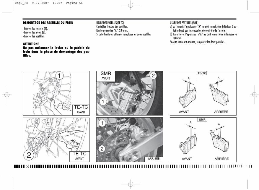
DEMONTAGE DES PASTILLES DU FREIN
- Enlever les ressorts (1).- Enlever les pivots (2).- Enlever les pastilles.
ATTENTION!Ne pas actionner le levier ou la pédale dufrein dans la phase de démontage des pas-tilles.
USURE DES PASTILLES (TE-TC)Contrôler l’usure des pastilles.Limite de service “A”: 3,8 mm.Si cette limite est atteinte, remplacer les deux pastilles.
USURE DES PASTILLES (SMR)a) A l’avant: l’épaisseur “A” ne doit jamais être inférieur à ce-
lui indiqué par les encoches de contrôle de l’usure;b) En arrière: l’épaisseu r“A” ne doit jamais être inférieure à
3,8 mm.Si cette limite est atteinte, remplacer les deux pastilles.
56
TE-TCAVANT
TE-TCAVANT
SMRAVANT
ARRIÈRE
AVANT ARRIÈRE
AVANT ARRIÈRE
Cap9_FR 9-07-2007 15:07 Pagina 56
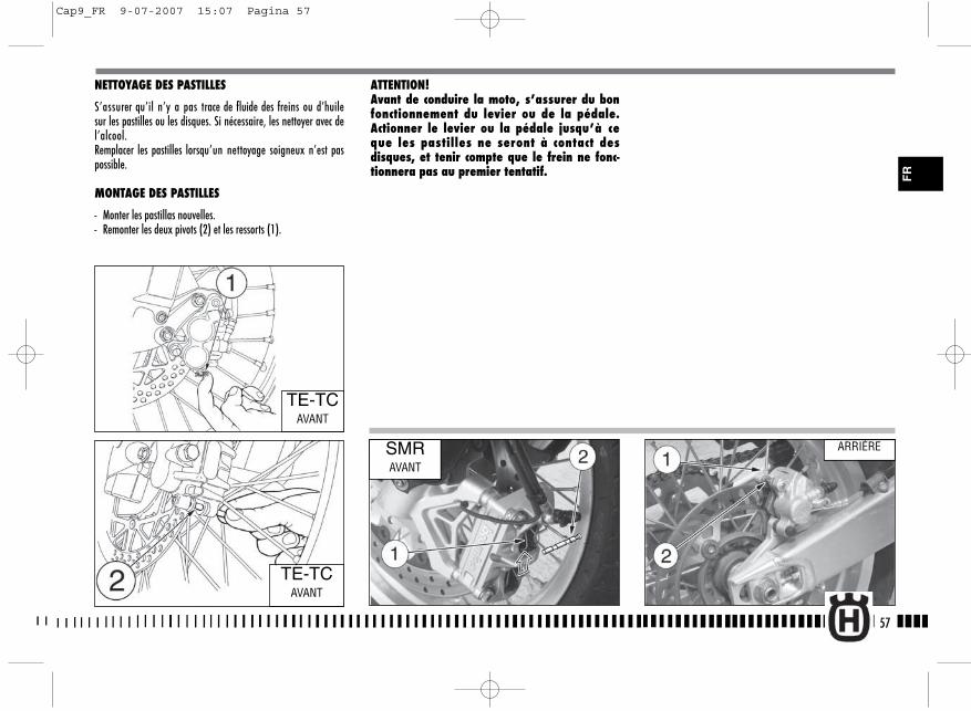
NETTOYAGE DES PASTILLES
S’assurer qu’il n’y a pas trace de fluide des freins ou d’huilesur les pastilles ou les disques. Si nécessaire, les nettoyer avec del’alcool.Remplacer les pastilles lorsqu’un nettoyage soigneux n’est paspossible.
MONTAGE DES PASTILLES
- Monter les pastillas nouvelles.- Remonter les deux pivots (2) et les ressorts (1).
ATTENTION!Avant de conduire la moto, s’assurer du bonfonctionnement du levier ou de la pédale.Actionner le levier ou la pédale jusqu’à ceque les pastilles ne seront à contact desdisques, et tenir compte que le frein ne fonc-tionnera pas au premier tentatif.
57
TE-TCAVANT
TE-TCAVANT
SMRAVANT
ARRIÈRE
FR
Cap9_FR 9-07-2007 15:07 Pagina 57
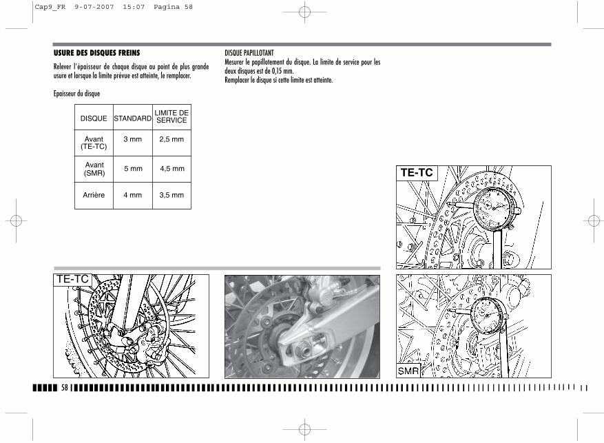
USURE DES DISQUES FREINS
Relever l’épaisseur de chaque disque au point de plus grandeusure et lorsque la limite prévue est atteinte, le remplacer.
Epaisseur du disque
DISQUE PAPILLOTANTMesurer le papillotement du disque. La limite de service pour lesdeux disques est de 0,15 mm. Remplacer le disque si cette limite est atteinte.
58
Avant(SMR)
5 mm 4,5 mm
Avant 3 mm 2,5 mm(TE-TC)
DISQUE STANDARDLIMITE DESERVICE
Arrière 4 mm 3,5 mm
TE-TC
TE-TC
Cap9_FR 9-07-2007 15:07 Pagina 58
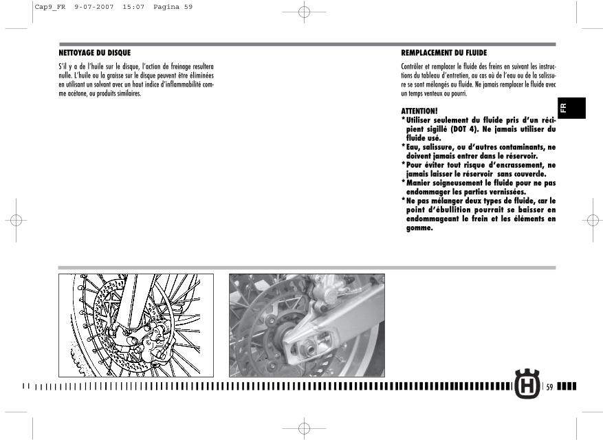
NETTOYAGE DU DISQUE
S’il y a de l’huile sur le disque, l’action de freinage resulteranulle. L’huile ou la graisse sur le disque peuvent être éliminéesen utilisant un solvant avec un haut indice d’inflammabilité com-me acétone, ou produits similaires.
REMPLACEMENT DU FLUIDE
Contrôler et remplacer le fluide des freins en suivant les instruc-tions du tableau d’entretien, au cas où de l’eau ou de la salissu-re se sont mélangés au fluide. Ne jamais remplacer le fluide avecun temps venteux ou pourri.
ATTENTION!*Utiliser seulement du fluide pris d’un réci-
pient sigillé (DOT 4). Ne jamais utiliser dufluide usé.
*Eau, salissure, ou d’autres contaminants, nedoivent jamais entrer dans le réservoir.
*Pour éviter tout risque d’encrassement, nejamais laisser le réservoir sans couvercle.
*Manier soigneusement le fluide pour ne pasendommager les parties vernissées.
*Ne pas mélanger deux types de fluide, car lepoint d’ébullition pourrait se baisser enendommageant le frein et les éléments engomme.
59
FR
Cap9_FR 9-07-2007 15:07 Pagina 59
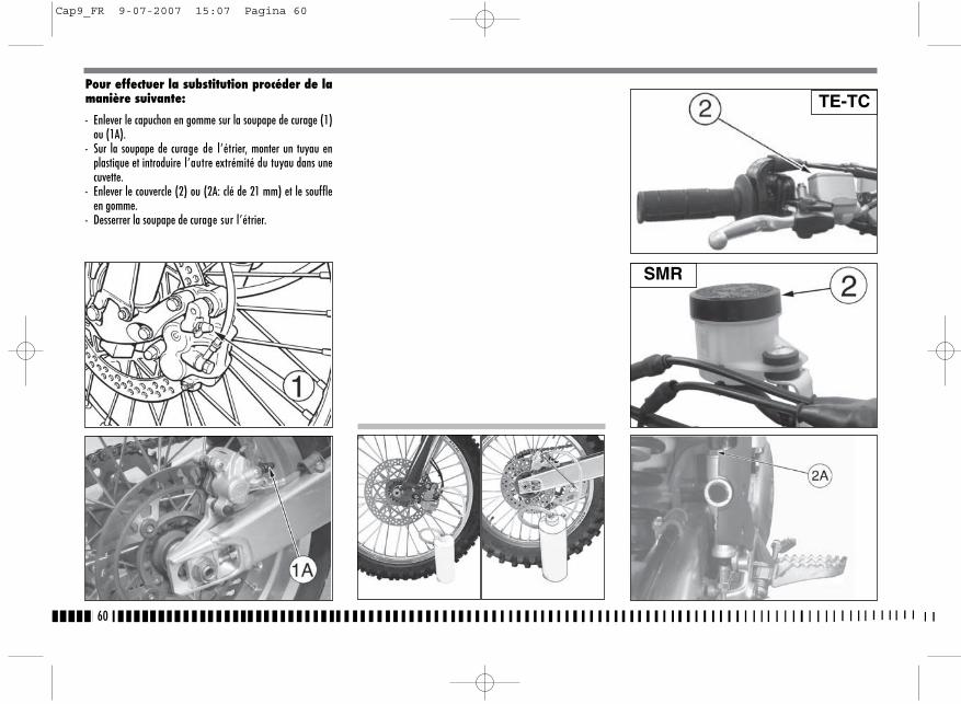
Pour effectuer la substitution procéder de lamanière suivante:
- Enlever le capuchon en gomme sur la soupape de curage (1)ou (1A).
- Sur la soupape de curage de l’étrier, monter un tuyau enplastique et introduire l’autre extrémité du tuyau dans unecuvette.
- Enlever le couvercle (2) ou (2A: clé de 21 mm) et le souffleen gomme.
- Desserrer la soupape de curage sur l’étrier.
60
TE-TC
SMR
Cap9_FR 9-07-2007 15:07 Pagina 60

- Rétablir le niveau (A) o (B) du fluide et remonter le souffleten gomme et le couvercle du réservoir (page 60).
Après avoir effectué la substitution du fluide, il est nécessaireprocéder à la vidange du systeme comme décrit aux pages 62et 65.
61
- Actionner le levier (3) ou la pédale (3A) pour vidanger.- Fermer la soupape de curage et remplir le réservoir avec du
fluide nouveau.- Ouvrir la soupape de curage, actionner le levier ou la péda-
le, fermer la soupape en gardant pressér le levier ou la pé-dale et ensuite, les relâcher rapidement.
- Répéter l’opération jusqu’à ce que le système est totale-ment rempli et le fluide clair commende à sortir du tuyau enplastique: maintenant fermer la soupape de curage.
TE-TC
SMR
FR
Cap9_FR 9-07-2007 15:07 Pagina 61
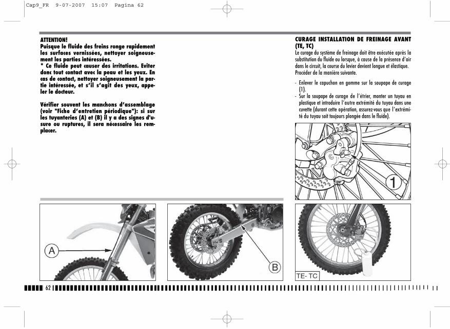
62
CURAGE INSTALLATION DE FREINAGE AVANT(TE, TC)Le curage du système de freinage doit être exécutée après lasubstitution du fluide ou lorsque, à cause de la présence d’airdans le circuit, la course du levier devient longue et élastique.Procéder de la manière suivante.
- Enlever le capuchon en gomme sur la soupape de curage(1).
- Sur la soupape de curage de l’étrier, monter un tuyau enplastique et introduire l’autre extrémité du tuyau dans unecuvette (durant cette opération, assurez-vous que l’extrémi-té du tuyau soit toujours plongée dans le fluide).
ATTENTION!Puisque le fluide des freins ronge rapidementles surfaces vernissées, nettoyer soigneuse-ment les parties intéressées.* Ce fluide peut causer des irritations. Eviterdonc tout contact avec la peau et les yeux. Encas de contact, nettoyer soigneusement la par-tie intéressée, et s’il s’agit des yeux, appe-ler le docteur.
Vérifier souvent les manchons d’assemblage(voir "Fiche d’entretien périodique"): si surles tuyanteries (A) et (B) il y a des signes d'u-sure ou ruptures, il sera nécessaire les rem-placer.
Cap9_FR 9-07-2007 15:07 Pagina 62
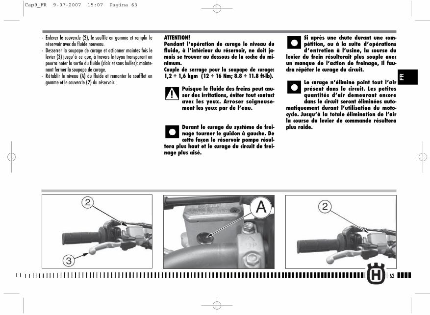
- Enlever le couvercle (2), le souffle en gomme et remplir leréservoir avec du fluide nouveau.
- Desserrer la soupape de curage et actionner maintes fois lelevier (3) jusqu’à ce que, à travers le tuyau transparent onpourra noter la sortie du fluide (clair et sans bulles): mainte-nant fermer la soupape de curage.
- Rétablir le niveau (A) du fluide et remonter le soufflet engomme et le couvercle (2) du réservoir.
ATTENTION!Pendant l’opération de curage le niveau dufluide, à l’intérieur du réservoir, ne doit ja-mais se trouver au dessous de la coche du mi-nimum.Couple de serrage pour la soupape de curage:1,2 ÷ 1,6 kgm (12 ÷ 16 Nm; 8.8 ÷ 11.8 ft-lb).
Puisque le fluide des freins peut cau-ser des irritations, éviter tout contactavec les yeux. Arroser soigneuse-ment les yeux par de l’eau.
Durant le curage du système de frei-nage tourner le guidon à gauche. Decette façon le réservoir pompe résul-
tera plus haut et le curage du circuit de frei-nage plus aisé.
Si après une chute durant une com-pétition, ou à la suite d’opérationsd’entretien à l’usine, la course du
levier du frein résulterait plus souple avecun manque de l’action de freinage, il fau-dra répéter le curage du circuit.
Le curage n’élimine point tout l’airprésent dans le circuit. Les petitesquantités d’air demeurant encoredans le circuit seront éliminées auto-
matiquement durant l’utilisation du moto-cycle. Jusqu’à la totale élimination de l’airla course du levier de commande résulteraplus raide.
63
FR
Cap9_FR 9-07-2007 15:07 Pagina 63
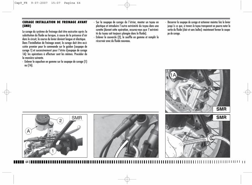
CURAGE INSTALLATION DE FREINAGE AVANT(SMR)
Le curage du système de freinage doit être exécutée après lasubstitution du fluide ou lorsque, à cause de la présence d’airdans le circuit, la course du levier devient longue et élastique.Dans l'installation de freinage avant, le curage doit être ex é-cutée premier pour le commande sur le guidon (soupape decurage 1) et successivement pour l’étrie r(soupape de curage1A): les opérations à effectuer sont les mêmes. Procéder dela manière suivante.- Enlever le capuchon en gomme sur la soupape de curage (1)
ou (1A).
- Sur la soupape de curage de l’étrier, monter un tuyau enplastique et introduire l’autre extrémité du tuyau dans unecuvette (durant cette opération, assurez-vous que l’extrémi-té du tuyau soit toujours plongée dans le fluide).
- Enlever le couvercle (2), le souffle en gomme et remplir leréservoir avec du fluide nouveau.
- Desserrer la soupape de curage et actionner maintes fois le levierjusqu’à ce que, à travers le tuyau transparent on pourra noter lasortie du fluide (clair et sans bulles): maintenant fermer la soupa-pe de curage.
64
SMR
SMR
Cap9_FR 9-07-2007 15:07 Pagina 64
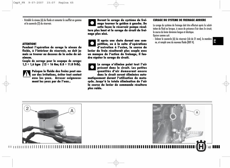
CURAGE DU SYSTEME DE FREINAGE ARRIERE
Le curage du système de freinage doit être effectué après la substi-tution du fluid ou lorsque, à cause de présence d’air dans le circuit,la course du levier devienne longue et élastique.Opérer comme suit:- Enlever le couvercle (A) du réservoir (clé de 21 mm), la membra-
ne, et remplir avec du nouveau fluide (DOT 4).
- Rétablir le niveau (A) du fluide et remonter le soufflet en gommeet le couvercle (2) du réservoir.
ATTENTION!Pendant l’opération de curage le niveau dufluide, à l’intérieur du réservoir, ne doit ja-mais se trouver au dessous de la coche du mi-nimum.Couple de serrage pour la soupape de curage:1,2 ÷ 1,6 kgm (12 ÷ 16 Nm; 8.8 ÷ 11.8 ft-lb).
Puisque le fluide des freins peut cau-ser des irritations, éviter tout contactavec les yeux. Arroser soigneuse-ment les yeux par de l’eau..
Durant le curage du système de frei-nage tourner le guidon à gauche. Decette façon le réservoir pompe résul-
tera plus haut et le curage du circuit de frei-nage plus aisé.
Si après une chute durant une com-pétition, ou à la suite d’opérationsd’entretien à l’usine, la course du
levier du frein résulterait plus souple avecun manque de l’action de freinage, il fau-dra répéter le curage du circuit.
Le curage n’élimine point tout l’airprésent dans le circuit. Les petitesquantités d’air demeurant encoredans le circuit seront éliminées auto-
matiquement durant l’utilisation du moto-cycle. Jusqu’à la totale élimination de l’airla course du levier de commande résulteraplus raide.
65
FR
Cap9_FR 9-07-2007 15:07 Pagina 65
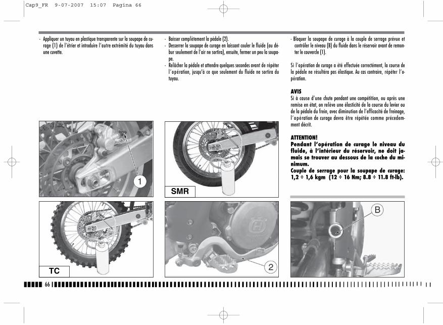
- Appliquer un tuyau en plastique transparente sur la soupape de cu-rage (1) de l’étrier et introduire l’autre extrémité du tuyau dansune cuvette.
- Baisser complètement la pédale (2).- Desserrer la soupape de curage en laissant couler le fluide (au dé-
bur seulement de l’air ne sortira), ensuite, fermer un peu la soupa-pe.
- Relâcher la pédale et attendre quelques secondes avant de répéterl ’opération, jusqu'à ce que seulement du fluide ne sortira dutuyau.
- Bloquer la soupape de curage à la couple de serrage prévue etcontrôler le niveau (B) du fluide dans le réservoir avant de remon-ter le couvercle (1).
Si l’opération de curage a été effectuée correctément, la course dela pédale ne résultéra pas élastique. Au cas contraire, répéter l’o-pération.
AVISSi à cause d’une chute pendant une compétition, ou après uneremise en état, on relève une élasticité de la course du levier oude la pédale du frein, avec diminution de l’efficacité de freinage,l ’opération de curage devra être répétée comme précedem-ment décrit.
ATTENTION!Pendant l’opération de curage le niveau dufluide, à l’intérieur du réservoir, ne doit ja-mais se trouver au dessous de la coche du mi-nimum.Couple de serrage pour la soupape de curage:1,2 ÷ 1,6 kgm (12 ÷ 16 Nm; 8.8 ÷ 11.8 ft-lb).
66
TC
SMR
Cap9_FR 9-07-2007 15:07 Pagina 66
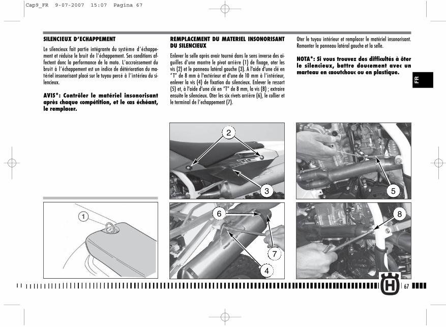
SILENCIEUX D’ECHAPPEMENT
Le silencieux fait partie intégrante du système d’échappe-ment et réduise le bruit de l’échappement. Ses conditions af-fectent donc la performance de la moto. L’accroissement dubruit à l’échappement est un indice de détérioration du ma-tériel insonorisant placé sur le tuyau percé à l’intérieu du si-lencieux.
AVIS*: Contrôler le matériel insonorisantaprès chaque compétition, et le cas échéant,le remplacer.
REMPLACEMENT DU MATERIEL INSONORISANTDU SILENCIEUX
Enlever la selle après avoir tourné dans le sens inverse des ai-guilles d’une montre le pivot arrière (1) de fixage, oter lesvis (2) et le panneau latéral gauche (3). À l'aide d'une clé en“ T” de 8 mm à l'extérieur et d'une de 10 mm à l’intérieur,enlever la vis (4) de fixation du silencieux. Enlever le ressort(5) et, à l'aide d'une clé en “T” de 8 mm, la vis (8) ; extraireensuite le silencieux. Oter les six rivets arrière (6), le collier etle terminal de l’echappement (7).
Oter le tuyau intérieur et remplacer le matériel insonorisant.Remonter le panneau latéral gauche et la selle.
NOTA*: Si vous trouvez des difficultés à ôterle silencieux, battre doucement avec unmarteau en caoutchouc ou en plastique.
67
2
3
4
5
86
7
FR
Cap9_FR 9-07-2007 15:07 Pagina 67
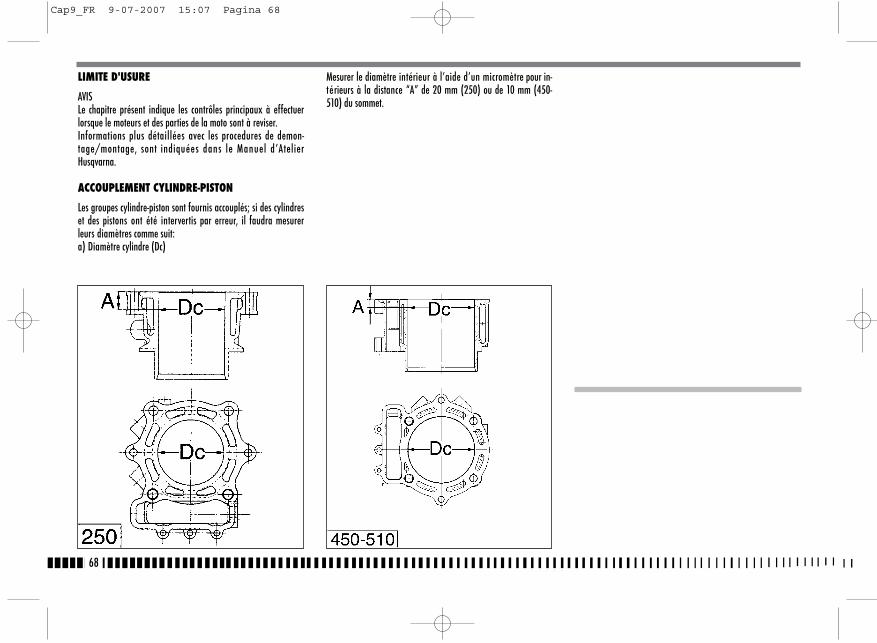
LIMITE D'USURE
AVISLe chapitre présent indique les contrôles principaux à effectuerlorsque le moteurs et des parties de la moto sont à reviser.Informations plus détaillées avec les procedures de demon-tage/montage, sont indiquées dans le Manuel d’AtelierHusqvarna.
ACCOUPLEMENT CYLINDRE-PISTON
Les groupes cylindre-piston sont fournis accouplés; si des cylindreset des pistons ont été intervertis par erreur, il faudra mesurerleurs diamètres comme suit:a) Diamètre cylindre (Dc)
Mesurer le diamètre intérieur à l’aide d’un micromètre pour in-térieurs à la distance “A” de 20 mm (250) ou de 10 mm (450-510) du sommet.
68
Cap9_FR 9-07-2007 15:07 Pagina 68
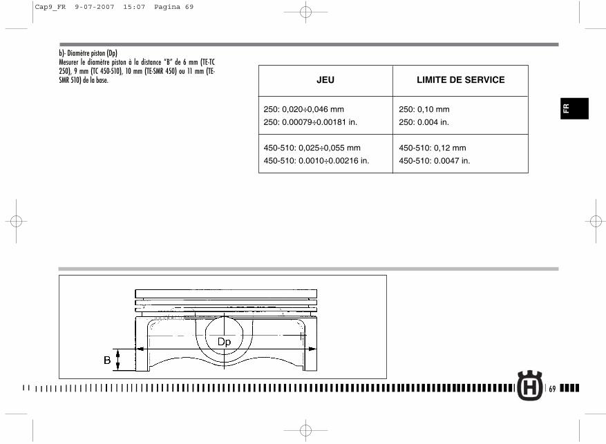
b)- Diamètre piston (Dp)Mesurer le diamètre piston à la distance “B” de 6 mm (TE-TC250), 9 mm (TC 450-510), 10 mm (TE-SMR 450) ou 11 mm (TE-SMR 510) de la base.
69
FR250: 0,020÷0,046 mm
250: 0.00079÷0.00181 in.
450-510: 0,025÷0,055 mm
450-510: 0.0010÷0.00216 in.
LIMITE DE SERVICEJEU
250: 0,10 mm
250: 0.004 in.
450-510: 0,12 mm
450-510: 0.0047 in.
Cap9_FR 9-07-2007 15:07 Pagina 69
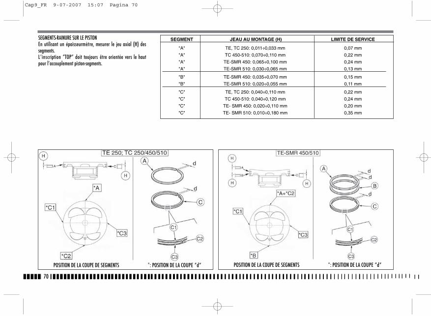
SEGMENTS-RAINURE SUR LE PISTONEn utilisant un épaisseurmètre, mesurer le jeu axial (H) dessegments.L’inscription “TOP” doit toujours être orientée vers le hautpour l’accouplement piston-segments.
70
POSITION DE LA COUPE DE SEGMENTS *: POSITION DE LA COUPE “d” POSITION DE LA COUPE DE SEGMENTS *: POSITION DE LA COUPE “d”
SEGMENT JEAU AU MONTAGE (H) LIMITE DE SERVICE
"A" TE, TC 250: 0,011÷0,033 mm 0,07 mm
"A" TC 450-510: 0,070÷0,110 mm 0,22 mm
"A" TE-SMR 450: 0,065÷0,100 mm 0,24 mm
"A" TE-SMR 510: 0,030÷0,065 mm 0,13 mm
"B" TE-SMR 450: 0,035÷0,070 mm 0,15 mm
"B" TE-SMR 510: 0,020÷0,055 mm 0,11 mm
"C" TE, TC 250: 0,040÷0,110 mm 0,22 mm
"C" TC 450-510: 0,040÷0,120 mm 0,24 mm
"C" TE- SMR 450: 0,020÷0,110 mm 0,20 mm
"C" TE- SMR 510: 0,010÷0,180 mm 0,35 mm
Cap9_FR 9-07-2007 15:07 Pagina 70

COUPLAGE SEGMENTS-CYLINDREMettre la bagues élastique dans la zon plus haute du cylindre(soutenir le segment avec le piston) en ayant le soin de le bienplacer en "cadre" en mésurer la distance (H) entre les deux extre-mité du segment.
71
250
TE 250; TC 250/450/510 TE-SMR 450/510
450-510
LIMITE D’USUREJEAU AU MONTAGE (H)
250 (A): 0,20÷0,35 mm/0.00787÷0.0138 in.TE-SMR 450, TC 510 (A): 0,25÷0,40 mm/0.0094÷0.0157 in.TE-SMR 510 (A): 0,20÷0,45 mm/0.00787÷0.0177 in.TE-SMR 450, TC (B): 0,40÷0,55 mm/0.0157÷0.0216 in.TE-SMR 510 (B): 0,20÷0,45 mm/0.00787÷0.0177 in.250 (C): 0,20÷0,70 mm/0.00787÷0.0275 in.TE-SMR 450, TC 510 (C): 0,20÷0,70 mm/0.00787÷0.0275 in.TE-SMR 510 (C): 0,10÷0,20 mm/0.00394÷0.0787 in.
250 (A): 0,5 mm/0.0197 in.TE-SMR 450, TC 510 (A): 0,7 mm/0.027 in.TE-SMR 510 (A): 0,7 mm/0.027 in.TE-SMR 450, TC (B): 1 mm/0.0394 in.TE-SMR 510 (B): 0,7 mm/0.027 in.250 (C): 1,2 mm/0.047 in.TE-SMR 450, TC 510 (C): 1,2 mm/0.047 in.TE-SMR 510 (C): 0,35 mm/0.014 in.
FR
Cap9_FR 9-07-2007 15:07 Pagina 71
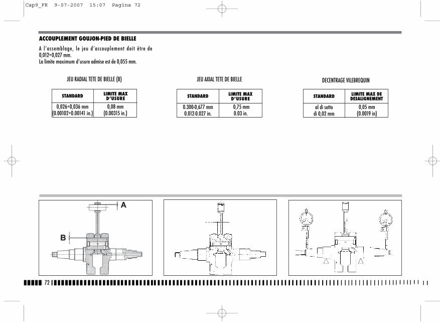
ACCOUPLEMENT GOUJON-PIED DE BIELLE
A l ’assemblage, le jeu d’accouplement doi t être de0,012÷0,027 mm.La limite maximum d’usure admise est de 0,055 mm.
72
STANDARD LIMITE MAX D’USURE
0,026÷0,036 mm(0.00102÷0.00141 in.)
0,08 mm(0.00315 in.)
JEU RADIAL TETE DE BIELLE (B) JEU AXIAL TETE DE BIELLE
STANDARD LIMITE MAX D’USURE
0.300-0,677 mm0.012-0.027 in.
0,75 mm0.03 in.
DECENTRAGE VILEBREQUIN
STANDARD LIMITE MAX DEDESALIGNEMENT
al di sotto di 0,02 mm
0,05 mm(0.0019 in)
Cap9_FR 9-07-2007 15:07 Pagina 72
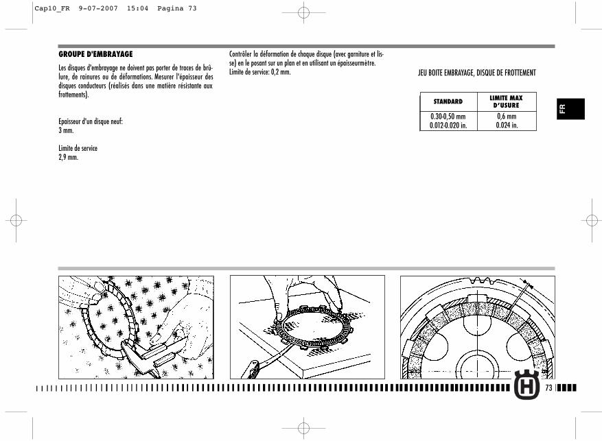
73
FR
GROUPE D'EMBRAYAGE
Les disques d'embrayage ne doivent pas porter de traces de brû-lure, de rainures ou de déformations. Mesurer l'épaisseur desdisques conducteurs (réalisés dans une matière résistante auxfrottements).
Epaisseur d'un disque neuf: 3 mm.
Limite de service2,9 mm.
Contrôler la déformation de chaque disque (avec garniture et lis-se) en le posant sur un plan et en utilisant un épaisseurmètre.Limite de service: 0,2 mm.
STANDARD LIMITE MAXD’USURE
0.30-0,50 mm0.012-0.020 in.
0,6 mm0.024 in.
JEU BOITE EMBRAYAGE, DISQUE DE FROTTEMENT
Cap10_FR 9-07-2007 15:04 Pagina 73
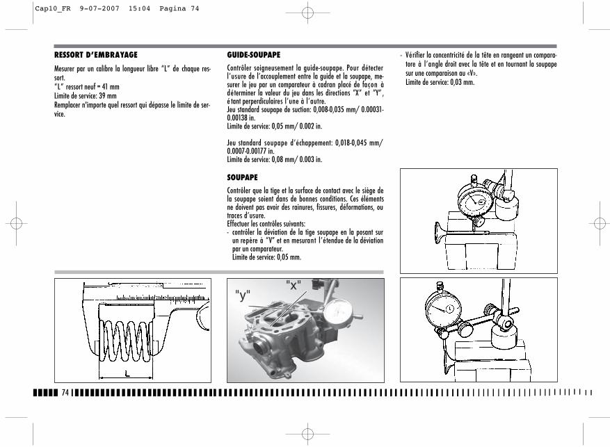
RESSORT D’EMBRAYAGE
Mesurer par un calibre la longueur libre “L” de chaque res-sort. “L” ressort neuf = 41 mmLimite de service: 39 mmRemplacer n'importe quel ressort qui dépasse le limite de ser-vice.
GUIDE-SOUPAPE
Contrôler soigneusement la guide-soupape. Pour détecterl’usure de l’accouplement entre la guide et la soupape, me-surer le jeu par un comparateur à cadran placé de façon àdéterminer la valeur du jeu dans les directions “X” et “Y” ,é tant perperdiculaires l’une à l’autre.Jeu standard soupape de suction: 0,008-0,035 mm/ 0.00031-0.00138 in.Limite de service: 0,05 mm/ 0.002 in.
Jeu standard soupape d’échappement: 0,018-0,045 mm/0.0007-0.00177 in.Limite de service: 0,08 mm/ 0.003 in.
SOUPAPE
Contrôler que la tige et la surface de contact avec le siège dela soupape soient dans de bonnes conditions. Ces élémentsne doivent pas avoir des rainures, fissures, déformations, outraces d’usure.Effectuer les contrôles suivants:- contrôler la déviation de la tige soupape en la posant sur
un repère à “V” et en mesurant l’étendue de la déviationpar un comparateur.Limite de service: 0,05 mm.
- Vérifier la concentricité de la tête en rangeant un compara-tore à l’angle droit avec la tête et en tournant la soupapesur une comparaison au «V». Limite de service: 0,03 mm.
74
Cap10_FR 9-07-2007 15:04 Pagina 74
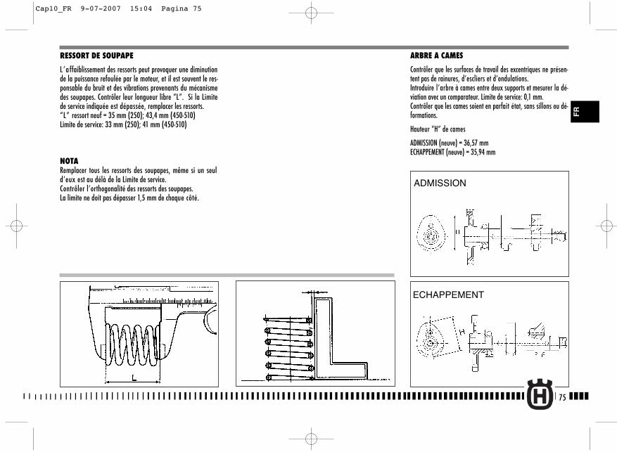
ARBRE A CAMES
Contrôler que les surfaces de travail des excentriques ne présen-tent pas de rainures, d’escliers et d’ondulations.Introduire l’arbre à cames entre deux supports et mesurer la dé-viation avec un comparateur. Limite de service: 0,1 mm.Contrôler que les cames soient en parfait état, sans sillons ou dé-formations.
Hauteur “H” de cames
ADMISSION (neuve) = 36,57 mmECHAPPEMENT (neuve) = 35,94 mm
RESSORT DE SOUPAPE
L’affaiblissement des ressorts peut provoquer une diminutionde la puissance refoulée par le moteur, et il est souvent le res-ponsable du bruit et des vibrations provenants du mécanismedes soupapes. Contrôler leur longueur libre “L”. Si la Limitede service indiquée est dépassée, remplacer les ressorts.“L” ressort neuf = 35 mm (250); 43,4 mm (450-510) Limite de service: 33 mm (250); 41 mm (450-510)
NOTARemplacer tous les ressorts des soupapes, même si un seuld’eux est au délà de la Limite de service.Contrôler l’orthogonalité des ressorts des soupapes.La limite ne doit pas dépasser 1,5 mm de chaque côté.
75
ADMISSION
ECHAPPEMENT
FR
Cap10_FR 9-07-2007 15:04 Pagina 75
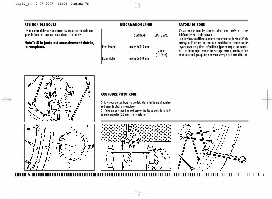
76
REVISION DES ROUES
Les tableaux ci-dessous montrent les types de contrô le aux-quels la jante et l’axe de roue doivent être soumis.
Nota*: Si la jante est excessivement cintrée,la remplacer.
DEFORMATION JANTE
COURBURE PIVOT ROUE
Si la valeur de courbure va au dela de la limite maxi admise,redresser le pivot ou remplacer.Si l’axe ne peut pas être redressé entre les valeurs de la limi-te max prescrite (0,2 mm), le remplacer.
RAYONS DE ROUE
S’assurer que tous les nipples soient bien serrés et, le casé chéant, les serrer de nouveau.Une tensions insuffisante pourra compromettre la stabilité dumotocycle. Effectuez un contrôle immédiat en tapant sur lesrayons avec un pointe métallique (par example: un tourne-vis): un bruit aigu indique un serrage correct, tandis qu’unbruit sourd indique qu’un nouveau serrage doit être effectué.
STANDARD LIMITE MAX.
Effet latéral moins de 0,5 mm2 mm
(0.078 in)Excentricitè moins de 0,8 mm
Cap10_FR 9-07-2007 15:04 Pagina 76
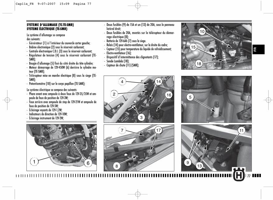
9
11
- Deux fusibles (9) de 15A et un (13) de 20A, sous le panneaulatéral droit;
- Deux fusibles de 20A, montés sur le télérupteur du démar-rage électrique (8);
- Batterie de 12V-6Ah (7) sous la siege.- Relais (14) pour electro-ventilateur, sur la droite du cadre;- Capteur (15) pour temperature du liquide de refroidissement;- Electro-ventilateur (16);- Dispositif d’intermittence des clignotants (17);- Sonde Lambda (18);- Capteur de chute (11) (SMR);
77
FR
SYSTEME D’ALLUMAGE (TC-TE-SMR)SYSTEME ÉLECTRIQUE (TE-SMR)
Le système d’allumage se composedes suivants:- Générateur (1) à l’intérieur du couvercle carter gauche;- Bobine électronique (2) sous le réservoir carburant;- Centrale électronique C.D.I. (3) sous le réservoir carburant;- Régulateur de tension (4) sous le réservoir carburant (TE-
SMR);- Bougie d’allumage (5) fixé du côté droite du tête cylindre;- Moteur démarrage de 12V-450W (6) derrière le cylindre mo-
teur (TE-SMR);- Télérupteur mise en marche électrique (8) sous la siege (TE-
SMR);- Potentiomètre (10) sur le corps papillon (TE-SMR);
Le système électrique se compose des suivants:- Phare avant avec ampoule à deux feux de 12V-35/35W et am-
poule de feux de position de 12V-3W;- Feux arrière avec ampoule de stop de 12V-21W et ampoule de
feux de position de 12V-5W;- Éclairage voyants de 12V-1,2W;- Indicateurs de direction de 12V-10W;- Éclairage instrument de 12V-2W;
1 6
4
2 16
14
3
7 17
8
5
15
18
10
13
Cap11a_FR 9-07-2007 15:09 Pagina 77
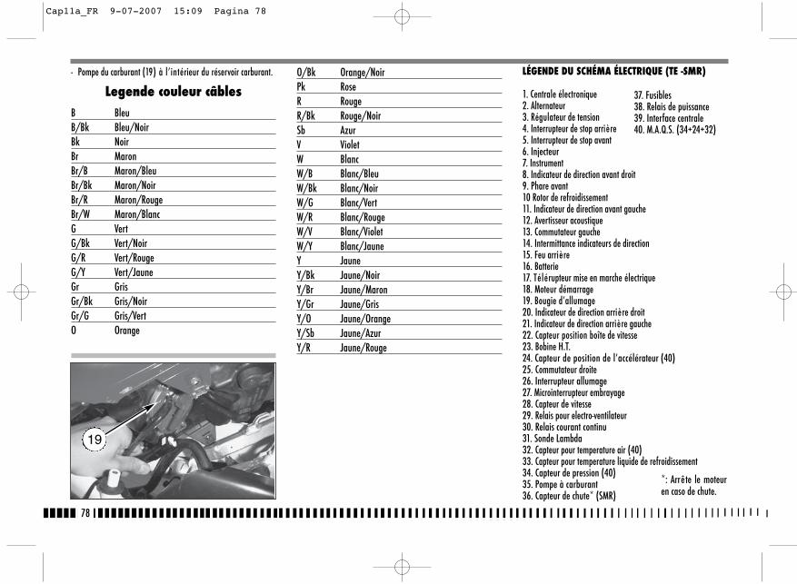
- Pompe du carburant (19) à l’intérieur du réservoir carburant.
Legende couleur câblesB BleuB/Bk Bleu/NoirBk NoirBr MaronBr/B Maron/BleuBr/Bk Maron/NoirBr/R Maron/RougeBr/W Maron/BlancG VertG/Bk Vert/NoirG/R Vert/RougeG/Y Vert/JauneGr GrisGr/Bk Gris/NoirGr/G Gris/VertO Orange
O/Bk Orange/NoirPk RoseR RougeR/Bk Rouge/NoirSb AzurV VioletW BlancW/B Blanc/BleuW/Bk Blanc/NoirW/G Blanc/VertW/R Blanc/RougeW/V Blanc/VioletW/Y Blanc/JauneY JauneY/Bk Jaune/NoirY/Br Jaune/MaronY/Gr Jaune/GrisY/O Jaune/OrangeY/Sb Jaune/AzurY/R Jaune/Rouge
78
19
LÉGENDE DU SCHÉMA ÉLECTRIQUE (TE -SMR)
1. Centrale électronique2. Alternateur3. Régulateur de tension4. Interrupteur de stop arrière5. Interrupteur de stop avant6. Injecteur7. Instrument8. Indicateur de direction avant droit9. Phare avant10 Rotor de refroidissement11. Indicateur de direction avant gauche12. Avertisseur acoustique13. Commutateur gauche14. Intermittance indicateurs de direction15. Feu arrière16. Batterie17. Télérupteur mise en marche électrique18. Moteur démarrage19. Bougie d’allumage20. Indicateur de direction arrière droit21. Indicateur de direction arrière gauche22. Capteur position boîte de vitesse23. Bobine H.T.24. Capteur de position de l’accélérateur (40)25. Commutateur droite26. Interrupteur allumage27. Microinterrupteur embrayage28. Capteur de vitesse29. Relais pour electro-ventilateur30. Relais courant continu31. Sonde Lambda32. Capteur pour temperature air (40)33. Capteur pour temperature liquide de refroidissement34. Capteur de pression (40)35. Pompe à carburant36. Capteur de chute* (SMR)
37. Fusibles38. Relais de puissance39. Interface centrale40. M.A.Q.S. (34+24+32)
*: Arrête le moteuren caso de chute.
Cap11a_FR 9-07-2007 15:09 Pagina 78
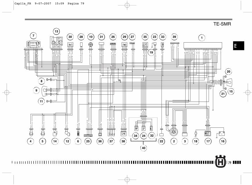
1
2
PASSING
HI
Lo
Pos
TURNHORN
R= 110 Ohm
+-
f
+-
+ -
B
W/G
W/V
Bk
B
B
Y-R
YY
Y
YY
Y
V
Bk
G/R
G/B
k
O
O
B
B
B
Bk
B
B
Pk
R
R
Y-R
Y-R
Y-B
k
Y-B
k
Y-B
k
Y-S
b
Br
G/R
G/R
G/R
V
Pk
Pk
Br/
Bk
Br/
W
Br/
W W/R
W/R
W/B
k
W/B
k
G/B
k
Bk
Bk
Bk
O
Gr/
Bk
Gr/
Bk
Y/B
r Y/S
b
Y/B
r
Y/S
b
Br/
R
Br/
R
O/B
k
O/B
k
W/B
k
W/B
k
Gr/
G
W/B
W/V
W/G
W/B
G-Y B
B
B
B
B
B
Y-R
Y-G
r
Y-S
b
Br
BBr
Y-B
k
Y-G
r
Br-
W
Br-
W
Br-
W
Br-
W
Br-
W
Br-
W
Br-
Bk
Br-
Bk
Br W
Gr/
G
Br/
B
Br/
B
W/R
W/YBk
G/Y
G/Y
G/Y
G/Y
Gr
Gr
B/B
kB
/Bk
Sb
Sb
Sb
R/B
k
R/Bk R/Bk
Bk
Bk
W
W
Y/O
Y/O
Y/O
G/R
G-Y Y RY
W
Br
G
G
B
Y/B
k
W/R
W/Y
W
Bk
Bk
Br
B
RR
/Bk
Sb
Br/
W
1 2 3 4 5 6 7 9 10 11 13 14 15 16 18 19 20 22 25 26 27 29 30 31 32 33 34
M
M 15 12V
R
9Ah
21 3 4
21
ONOFF
1 2
31 2 31 2
OFF
ON
8 12 17 21 23 24 2821
OFF
21 1 2 3 4 1 2 3 4 1 2 3 4 21
1 2 3 421 21 3 1 2 3 4 5 6
1 2 3 4 5
1
21 21 3 1 2 3 4 5 21 3 4
1 2 3 4
1 2 3 4 5 6
21 21
21
34
56
21
21
21
21
3
21212121
1 2 3 41 2 3 4 5 6 7 8 9
1 2 3 4
RUN
START
M P
DF
12
34
56
78
910 12
1114 16
13 15 2526
1718
1920
2122
2324
79
FR
1
2 34 5
7
6
8
9
10
11
12
13
14
15
161718
19
20
21
22
23
24
40
25
26 2728 29
3234
36
35 3330 31
37 38
39
TE-SMR
Cap11a_FR 9-07-2007 15:09 Pagina 79
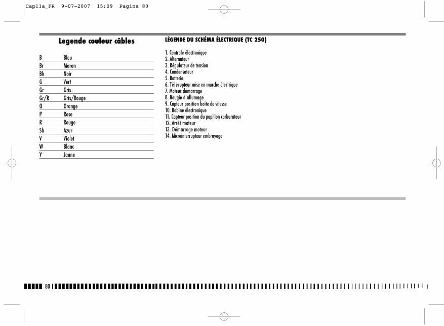
80
Legende couleur câbles
B BleuBr MaronBk NoirG VertGr GrisGr/R Gris/RougeO OrangeP RoseR RougeSb AzurV VioletW BlancY Jaune
LÉGENDE DU SCHÉMA ÉLECTRIQUE (TC 250)
1. Centrale électronique2. Alternateur3. Régulateur de tension4. Condensateur5. Batterie6. Télérupteur mise en marche électrique7. Moteur démarrage8. Bougie d’allumage9. Capteur position boîte de vitesse10. Bobine électronique11. Capteur position du papillon carburateur12. Arrêt moteur13. Démarrage moteur14. Microinterrupteur embrayage
Cap11a_FR 9-07-2007 15:09 Pagina 80
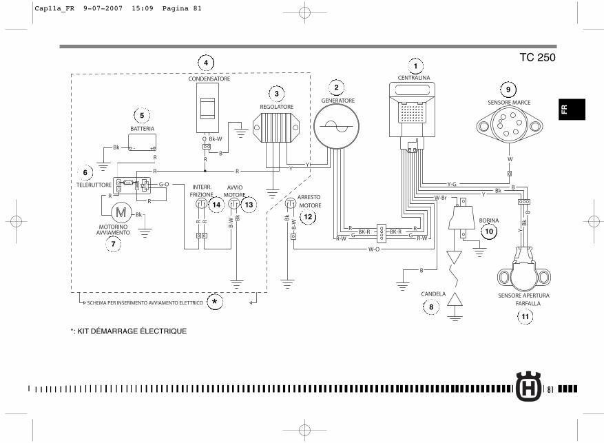
81
R-WGBK-R
R-W
W-Br
GRBK-R
R
CANDELA
BOBINA
GENERATORE
W-O
SENSORE MARCE
SENSORE APERTURAFARFALLA
REGOLATORE
CONDENSATORE
- +
15A
ARRESTO
MOTORE
BATTERIA
TELERUTTORE
MOTORINOAVVIAMENTO
Y-G BBk
Y
B
R Bk
B-W
W
BB
kY
CENTRALINA
Bk - +
R
G-O
R
R
O
R
Bk-W
B
YYR
R
Bk
AVVIOMOTORE
B-W
Bk
R
INTERR.FRIZIONE
SCHEMA PER INSERIMENTO AVVIAMENTO ELETTRICO
TC 250
FR
*: KIT DÉMARRAGE ÉLECTRIQUE
1
23
4
5
7
6
8
9
10
11
12
14 13
*
Cap11a_FR 9-07-2007 15:09 Pagina 81
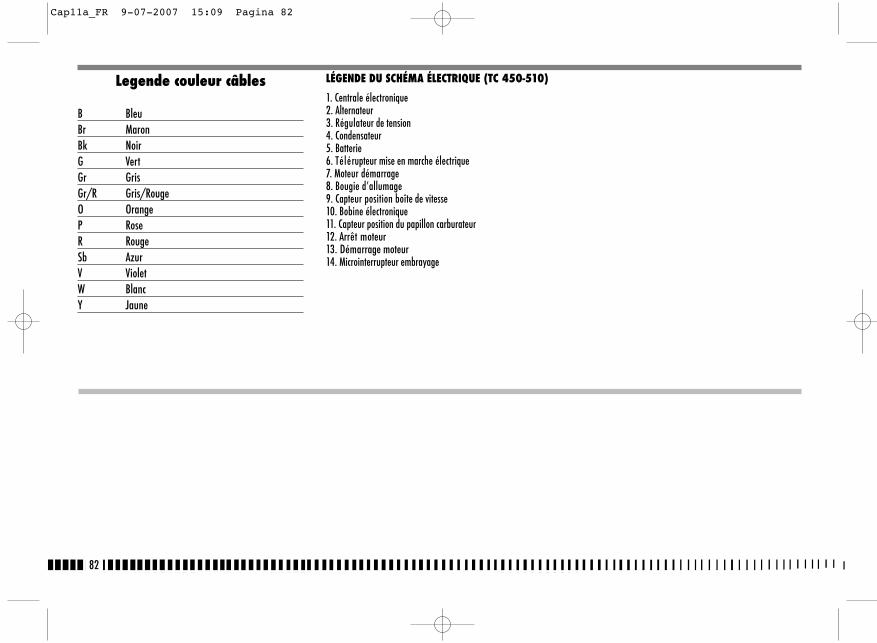
82
Legende couleur câbles
B BleuBr MaronBk NoirG VertGr GrisGr/R Gris/RougeO OrangeP RoseR RougeSb AzurV VioletW BlancY Jaune
LÉGENDE DU SCHÉMA ÉLECTRIQUE (TC 450-510)
1. Centrale électronique2. Alternateur3. Régulateur de tension4. Condensateur5. Batterie6. Télérupteur mise en marche électrique7. Moteur démarrage8. Bougie d’allumage9. Capteur position boîte de vitesse10. Bobine électronique11. Capteur position du papillon carburateur12. Arrêt moteur13. Démarrage moteur14. Microinterrupteur embrayage
Cap11a_FR 9-07-2007 15:09 Pagina 82
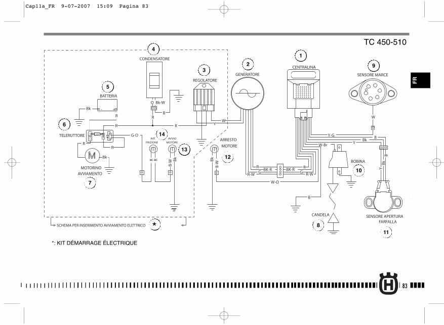
83
R-WGBK-R
R-W
W-Br
GRBK-R
R
CANDELA
BOBINA
GENERATORE
W-O
SENSORE MARCE
SENSORE APERTURAFARFALLA
REGOLATORE
- +
15A
ARRESTO
MOTORE
AVVIO
MOTORE
BATTERIA
TELERUTTORE
MOTORINOAVVIAMENTO
Y-G BBk
Y
B
B-W
Bk
Bk
B-W
W
BB
kY
CENTRALINA
Bk - +
R
G-O
R
R
O
R
Bk-W
B
WYR
R
BkRR
INT.
FRIZIONE
CONDENSATORE
SCHEMA PER INSERIMENTO AVVIAMENTO ELETTRICO
TC 450-510
*: KIT DÉMARRAGE ÉLECTRIQUE
1
23
4
5
7
6
8
9
10
11
12
14
13
*
FR
Cap11a_FR 9-07-2007 15:09 Pagina 83
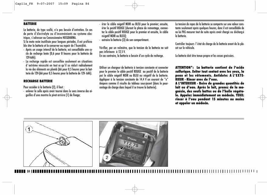
- ô ter le câble négatif NOIR ou BLEU pour le premier; ensuite,ô ter le positif ROUGE (durant la phase de remontage, connec-ter le câble positif ROUGE pour le premier et ensuite, le câblenégatif NOIR ou BLEU);
- extraire la batterie (3) de son compartiment.
Vérifier, par un volmètre, que la tension de la batterie ne soitpas inférieure à 12,5 V.En cas contraire, la batterie a besoin d’un cycle de recharge.
Utiliser un chargeur de batterie à tension constante et connecterpour le premier le câble positif ROUGE au positif de la batteriepoi le câble négatif NOIR ou BLEU au négatif de la batterie.Appliquer à la tension constante de 14,4 V un courant de “x”Ampere comme il résulte du tableau sous-jacent (dans le pour-centage de charge dans lequel il se trouve la batterie).
BATTERIE
La batterie, de type scellé, n’a pas besoin d’entretien. En casde perte d’électrolyte ou d’inconvénients au systeme elec-trique, s’adresser au Concessionaire HUSQVARNA.Si la moto reste inutilisée pour longues périodes, il est préféra-ble ôter la batterie et la conserver au repair de l’humidité.- Après un usage intensif de la batterie, est conseillable une cy-
cle de recharge lente (0,6 pour 8 heures pour la batterie de12V-6Ah).
- La recharge rapide est conseillée seulement en situationsd ’ extrême nécessité en tout ce qu’il se réduit radicalementla vie des éléments en plomb (6A pour 0,5 heures pour la bat-terie de 12V-(6A pour 0,5 heures pour la batterie de 12V- 6Ah).
RECHARGE BATTERIE
Pour accéder à la batterie (2), il faut :- enlever la selle après avoir tourné dans le sens inverse des ai-
guilles d’une montre le pivot arrière (1) de fixage;
La tension de repos de la batterie se comporte sur une valeur cons-tante seulement après quelques heures, donc il est conseillable dene lui PAS mesurer tout de suite après avoir chargé ou décharg éla batterie.
Contrôler toujours l ’état de charge de la batterie avant de la pla-cet sur le véhicule.
La batterie doit être tenue propre et les cosses graissées.
ATTENTION*: La batterie contient de l’acidesulfurique. Eviter tout contact avec les yeux, lapeau et les vêtements. Antidote: A L’EXTE-RIEUR - Rincer avec de l’eau. A L’INTERIEUR - Boire de grandes quantités delait ou d’eau. Après le lait, prenez de la ma-gnésie, des oeufs battus ou de l’huile végéta-le. Appelez immédiatement un médecin. YEUX:rincer à l’eau pendant 15 minutes au moinset appeler un médecin.
84
2
Cap11a_FR 9-07-2007 15:09 Pagina 84
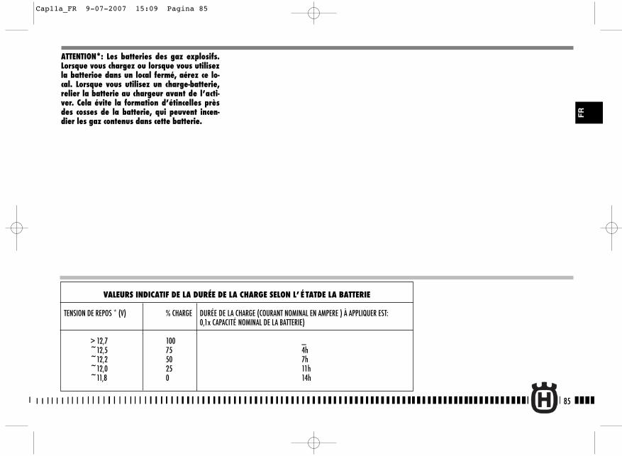
85
FR
VALEURS INDICATIF DE LA DURÉE DE LA CHARGE SELON L’ É TATDE LA BATTERIE
TENSION DE REPOS * (V) % CHARGE DURÉE DE LA CHARGE (COURANT NOMINAL EN AMPERE ) À APPLIQUER EST: 0,1x CAPACITÉ NOMINAL DE LA BATTERIE)
> 12,7 100 _~12,5 75 4h~12,2 50 7h~12,0 25 11h~11,8 0 14h
ATTENTION*: Les batteries des gaz explosifs.Lorsque vous chargez ou lorsque vous utilisezla batterioe dans un local fermé, aérez ce lo-cal. Lorsque vous utilisez un charge-batterie,relier la batterie au chargeur avant de l’acti-ver. Cela évite la formation d’étincelles prèsdes cosses de la batterie, qui peuvent incen-dier les gaz contenus dans cette batterie.
Cap11a_FR 9-07-2007 15:09 Pagina 85
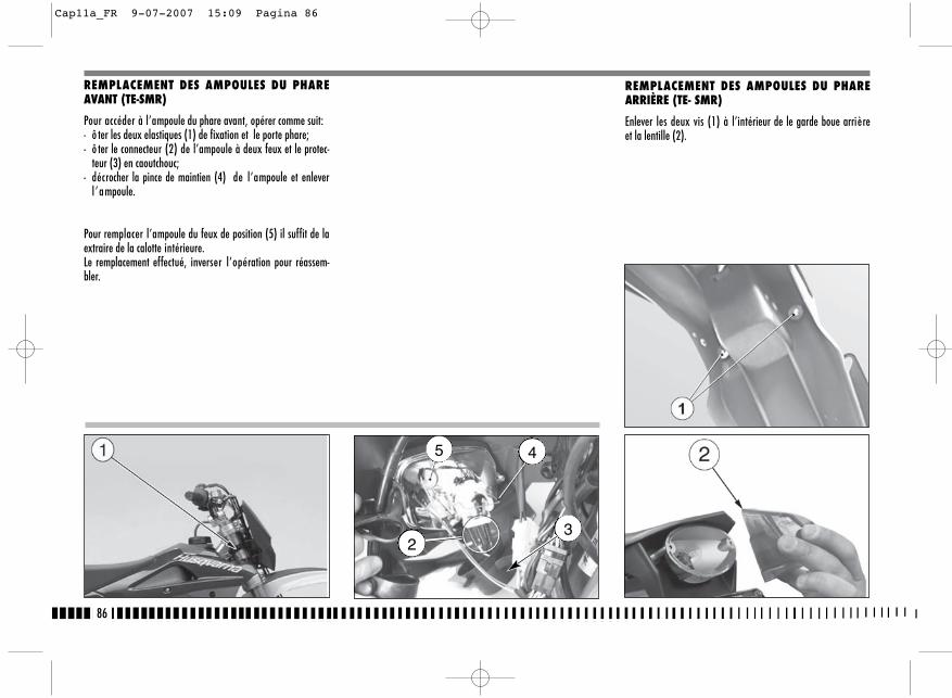
REMPLACEMENT DES AMPOULES DU PHAREARRIÈRE (TE- SMR)
Enlever les deux vis (1) à l’intérieur de le garde boue arrièreet la lentille (2).
86
REMPLACEMENT DES AMPOULES DU PHAREAVANT (TE-SMR)
Pour accéder à l’ampoule du phare avant, opérer comme suit:- ô ter les deux elastiques (1) de fixation et le porte phare;- ô ter le connecteur (2) de l’ampoule à deux feux et le protec-
teur (3) en caoutchouc;- décrocher la pince de maintien (4) de l’ampoule et enlever
l ’ampoule.
Pour remplacer l’ampoule du feux de position (5) il suffit de laextraire de la calotte intérieure.Le remplacement effectué, inverser l’opération pour réassem-bler.
5 4
23
Cap11a_FR 9-07-2007 15:09 Pagina 86
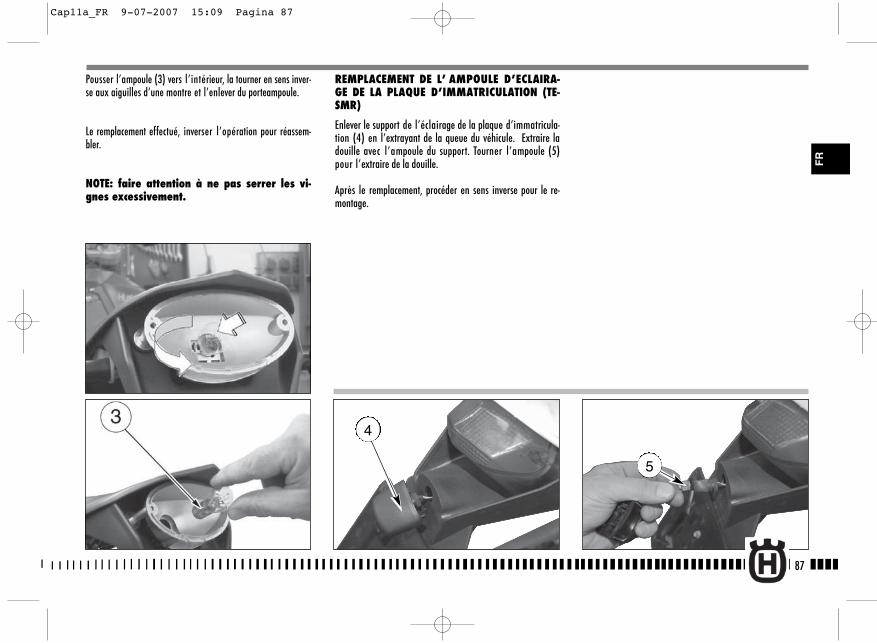
5
Pousser l’ampoule (3) vers l’intérieur, la tourner en sens inver-se aux aiguilles d’une montre et l’enlever du porteampoule.
Le remplacement effectué, inverser l’opération pour réassem-bler.
NOTE: faire attention à ne pas serrer les vi-gnes excessivement.
REMPLACEMENT DE L’ AMPOULE D’ECLAIRA-GE DE LA PLAQUE D’IMMATRICULATION (TE-SMR)
Enlever le support de l’éclairage de la plaque d’immatricula-tion (4) en l’extrayant de la queue du véhicule. Extraire ladouille avec l’ampoule du support. Tourner l’ampoule (5)pour l’extraire de la douille.
Après le remplacement, procéder en sens inverse pour le re-montage.
87
FR
4
Cap11a_FR 9-07-2007 15:09 Pagina 87
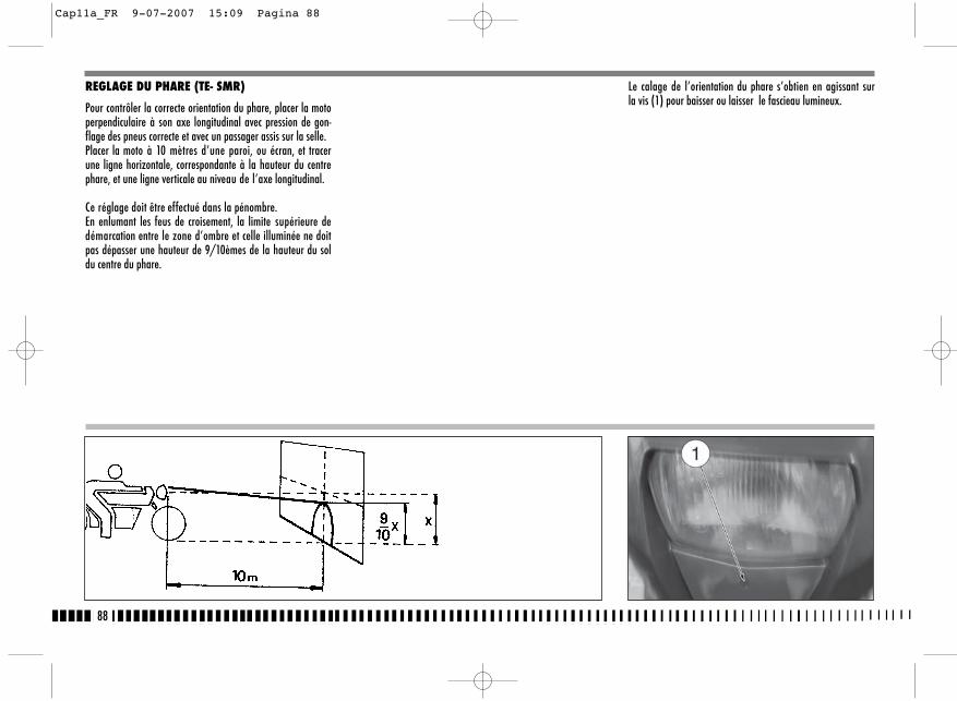
REGLAGE DU PHARE (TE- SMR)
Pour contrôler la correcte orientation du phare, placer la motoperpendiculaire à son axe longitudinal avec pression de gon-flage des pneus correcte et avec un passager assis sur la selle.Placer la moto à 10 mètres d’une paroi, ou écran, et tracerune ligne horizontale, correspondante à la hauteur du centrephare, et une ligne verticale au niveau de l’axe longitudinal.
Ce réglage doit être effectué dans la pénombre.En enlumant les feus de croisement, la limite supérieure dedémarcation entre le zone d’ombre et celle illuminée ne doitpas dépasser une hauteur de 9/10èmes de la hauteur du soldu centre du phare.
Le calage de l’orientation du phare s’obtien en agissant surla vis (1) pour baisser ou laisser le fascieau lumineux.
88
Cap11a_FR 9-07-2007 15:09 Pagina 88
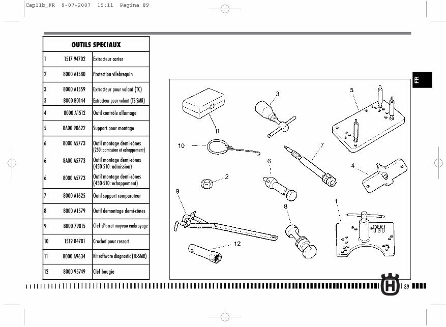
89
FR
OUTILS SPECIAUX
1 1517 94702 Extracteur carter
2 8000 A1580 Protection vilebrequin
3 8000 A1559
3 8000 B0144
Extracteur pour volant (TC)
Extracteur pour volant (TE-SMR)
4 8000 A1512 Outil contrôle allumage
5 8A00 90622 Support pour montage
6 8000 A5773
6 8A00 A5773
6 8000 A5773
Outil montage demi-cônes(250: admission et echappement)
Outil montage demi-cônes(450-510: admission)
Outil montage demi-cônes(450-510: echappement)
7 8000 A1625 Outil support comparateur
8 8000 A1579 Outil demontage demi-cônes
9 8000 79015 Cléf d’arret moyeau embrayage
10 1519 84701 Crochet pour ressort
11 8000 A9634 Kit software diagnostic (TE-SMR)
12 8000 95749 Cléf bougie
Cap11b_FR 9-07-2007 15:11 Pagina 89
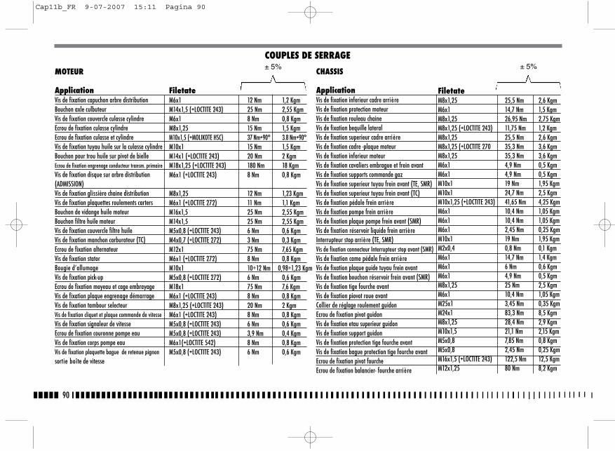
90
MOTEUR
ApplicationVis de fixation capuchon arbre distributionBouchon axle culbuteurVis de fixation couvercle culasse cylindreEcrou de fixation culasse cylindreEcrou de fixation culasse et cylindreVis de fixation tuyau huile sur la culasse cylindreBouchon pour trou huile sur pivot de bielleEcrou de fixation engrenage conducteur transm. primaireVis de fixation disque sur arbre distribution(ADMISSION)Vis de fixation glissière chaine distributionVis de fixation plaquettes roulements cartersBouchon de vidange huile moteurBouchon filtre huile moteurVis de fixation couvercle filtre huileVis de fixation manchon carburateur (TC)Ecrou de fixation alternateurVis de fixation statorBougie d’allumageVis de fixation pick-upEcrou de fixation moyeau et cage embrayageVis de fixation plaque engrenage démarrageVis de fixation tambour selecteurVis de fixation cliquet et plaque commande de vitesseVis de fixation signaleur de vitesseEcrou de fixation couronne pompe eauVis de fixation corps pompe eauVis de fixation plaquette bague de retenue pignonsortie boîte de vitesse
MOTEUR
FiletateM6x1 12 Nm 1,2 KgmM14x1,5 (+LOCTITE 243) 25 Nm 2,55 KgmM6x1 8 Nm 0,8 KgmM8x1,25 15 Nm 1,5 KgmM10x1,5 (+MOLIKOTE HSC) 37 Nm+90° 3.8 Nm+90°M10x1 15 Nm 1,5 KgmM14x1 (+LOCTITE 243) 20 Nm 2 KgmM18x1,25 (+LOCTITE 243) 180 Nm 18 KgmM6x1 (+LOCTITE 243) 8 Nm 0,8 Kgm
M8x1,25 12 Nm 1,23 KgmM6x1 (+LOCTITE 272) 11 Nm 1,1 KgmM16x1,5 25 Nm 2,55 KgmM14x1,5 25 Nm 2,55 KgmM5x0,8 (+LOCTITE 243) 6 Nm 0,6 KgmM4x0,7 (+LOCTITE 272) 3 Nm 0,3 KgmM12x1 75 Nm 7,65 KgmM6x1 (+LOCTITE 272) 8 Nm 0,8 KgmM10x1 10÷12 Nm 0,98÷1,23 KgmM5x0,8 (+LOCTITE 272) 6 Nm 0,6 KgmM18x1 75 Nm 7,6 KgmM6x1 (+LOCTITE 243) 8 Nm 0,8 KgmM8x1,25 (+LOCTITE 243) 20 Nm 2 KgmM6x1 (+LOCTITE 243) 8 Nm 0,8 KgmM5x0,8 (+LOCTITE 243) 6 Nm 0,6 KgmM5x0,8 (+LOCTITE 243) 3,9 Nm 0,4 KgmM6x1(+LOCTITE 542) 8 Nm 0,8 KgmM5x0,8 (+LOCTITE 243) 6 Nm 0,6 Kgm
COUPLES DE SERRAGE± 5%
CHASSIS
ApplicationVis de fixation inferieur cadre arrièreVis de fixation protection moteurVis de fixation rouleau chaineVis de fixation bequille lateralVis de fixation superieur cadre arrièreVis de fixation cadre -plaque moteurVis de fixation inferieur moteurVis de fixation cavaliers embrague et frein avantVis de fixation supports commande gazVis de fixation superieur tuyau frein avant (TE, SMR)Vis de fixation superieur tuyau frein avant (TC)Vis de fixation pédale frein arrièreVis de fixation pompe frein arrièreVis de fixation plaque pompe frein avant (SMR)Vis de fixation réservoir liquide frein arrièreInterrupteur stop arrière (TE, SMR)Vis de fixation connecteur Interrupteur stop avant (SMR)Vis de fixation came pédale frein arrièreVis de fixation plaque guide tuyau frein avantVis de fixation bouchon réservoir frein avant (SMR)Vis de fixation tige fourche avantVis de fixation piovot roue avantCollier de réglage roulement guidonEcrou de fixation pivot guidonVis de fixation etau superieur guidonVis de fixation support guidonVis de fixation protection tige fourche avantVis de fixation bague protection tige fourche avantEcrou de fixation pivot fourcheEcrou de fixation balancier- fourche arrière
FiletateM8x1,25 25,5 Nm 2,6 KgmM6x1 14,7 Nm 1,5 KgmM8x1,25 26,95 Nm 2,75 KgmM8x1,25 (+LOCTITE 243) 11,75 Nm 1,2 KgmM8x1,25 25,5 Nm 2,6 KgmM8x1,25 (+LOCTITE 270 35,3 Nm 3,6 KgmM8x1,25 35,3 Nm 3,6 KgmM6x1 4,9 Nm 0,5 KgmM6x1 4,9 Nm 0,5 KgmM10x1 19 Nm 1,95 KgmM10x1 24,7 Nm 2,5 KgmM10x1,25 (+LOCTITE 243) 41,65 Nm 4,25 KgmM6x1 10,4 Nm 1,05 KgmM6x1 10,4 Nm 1,05 KgmM6x1 2,45 Nm 0,25 KgmM10x1 19 Nm 1,95 KgmM2x0,4 0,8 Nm 0,1 KgmM6x1 14,7 Nm 1,4 KgmM6x1 6 Nm 0,6 KgmM6x1 4,9 Nm 0,5 KgmM8x1,25 25 Nm 2,5 KgmM6x1 10,4 Nm 1,05 KgmM25x1 3,45 Nm 0,35 KgmM24x1 83,3 Nm 8,5 KgmM8x1,25 28,4 Nm 2,9 KgmM10x1,5 21,1 Nm 2,15 KgmM5x0,8 7,85 Nm 0,8 KgmM5x0,8 2,45 Nm 0,25 KgmM16x1,5 (+LOCTITE 243) 122,5 Nm 12,5 KgmM12x1,25 80 Nm 8,2 Kgm
± 5%
Cap11b_FR 9-07-2007 15:11 Pagina 90

91
FR
CHASSIS
ApplicationEcrou de fixation tirant- balancier Ecrou de fixation cadre- tirantGraisseurVis de fixation amortisseur- cadreVis de fixation balancier - cadreVis de fixation guide-chaine/fourche arrière (TE-SMR)Vis de fixation avant guide-chaine/fourche arrière (TC)Vis de fixation arrière guide-chaine/fourche arrière (TC)Vis de fixation etrier/guide-chaine (TE-SMR)Vis de fixation inf. glissière chaine et passe-tuyaufrein arrièreVis de fixation arrière glissière chaine et passe-tuyaufrein arrière (TC)Vis de fixation carter de chaine (TE-SMR)Ecrou de fixation tendeur de chaineVis de fixation spoiler-réservoirVis de fixation superieur porte-numero avant (TC)Vis de fixation inferieur porte-numero avant (TC)Vis de fixation protection amortisseur arrièreVis de fixation avant garde-bouie arrièreVis de fixation arrière garde-bouie arrièreVis de fixation garde-bouie avantVis de fixation protection radiateurVis de fixation panneau lateralVis de fixation porte-balaiEcrou de fixation catadioptrique arrièreVis de fixation bague passe-tuyau frein au carenage avantVis de fixation clignotantVis de fixation gruppo phare avantVis de fixation cable telerupteurVis de fixation tampon avant réservoir essence
COUPLES DE SERRAGE
FiletateM12x1,25 80 Nm 8,2 KgmM12x1,25 80 Nm 8,2 KgmM6x1 2,95 Nm 0,3 KgmM10x1,25 52,4 Nm 5,35 KgmM10x1,25 52,4 Nm 5,35 KgmM8x1,25 25 Nm 2,5 KgmM8x1,25 (+LOCTITE 243) 10,4 Nm 1,05 KgmM6x1 (+LOCTITE 243) 10,4 Nm 1,05 KgmM6x1 (+LOCTITE 243) 2 Nm 0,2 KgmM5x0,8 4,4 Nm 0,45 Kgm
M5x0,8 4,4 Nm 0,45 Kgm
M5x0,8 4,4 Nm 0,45 KgmM8x1,25 4,4 Nm 0,45 KgmM6x1 6 Nm 0,6 KgmM6x1 6 Nm 0,6 KgmM6x1 10,4 Nm 1,05 KgmM6x1 6 Nm 0,6 KgmM6x1 10,4 Nm 1,05 KgmM6x1 6 Nm 0,6 KgmM6x1 10,4 Nm 1,05 KgmM6x1 6 Nm 0,6 KgmM6x1 6 Nm 0,6 KgmM6x1 6 Nm 0,6 KgmM4x0,7 1,9 Nm 0,2 Kgmø 3,5 1,9 Nm 0,2 KgmM6x1 6 Nm 0,6 Kgmø 3,9 1,45 Nm 0,15 KgmM6x1 10,4 Nm 1,05 KgmM6x1 10,4 Nm 1,05 Kgm
± 5%CHASSIS
ApplicationVis de fixation robinet réservoir essenceVis de fixation arrière réservoir essenceVis de fixation avant scatola filtroEcrou de fixation flangia bôite filtre à airVis de fixation etrier frein Vis de fixation inferieur tuyau freinsVis de fixation pivot roue Vis de fixation etrier frein Vis de fixation plaque etrier frein –fourche avant (SMR)Vis de fixation pivot roue Vis de fixation disque frein Vis de fixation disque frein Vis de fixation disque frein Nipplo per raggio roue Nipplo per raggio roue Ecrou de fixation couronne arrièreEcrou de fixation pivot roue Vis de fixation couvercle pignon-carter gauche Vis de fixation silencieux d’echappementVis de fixation tuyau d’echappement au culasse cylindreVis de fixation instrumentVis de fixation radiateur
± 5%
Filetateø5,5 2,45 Nm 0,25 KgmM6x1 10,4 Nm 1,05 KgmM6x1 10,4 Nm 1,05 KgmM5x0,8 3,45 Nm 0,35 KgmM8x1,25 25,5 Nm 2,6 KgmM10x1 19 Nm 1,95 KgmM10x1,5 51,45 Nm 5,25 KgmM10x1,5 25,5 Nm 2,6 KgmM10x1,5 25,5 Nm 2,6 KgmM20x1,5 51,45 Nm 5,25 KgmM6x1 (LOCTITE 243) 14,7 Nm 1,5 KgmM8x1,25 34,7 Nm 3,54 KgmM6x1 (LOCTITE 243) 14,7 Nm 1,5 KgmM4,07x0,75 4,4 Nm 0,45 KgmM4,5x0,75 4,4 Nm 0,45 KgmM8x1,25 (+LOCTITE 243) 34,3 Nm 3,5 KgmM20x1,5 142,1 Nm 14,5 KgmM6x1 10,4 Nm 1 KgmM6x1 10,4 Nm 1 KgmM6x1 10,4 Nm 1 Kgmø4,8 3,45 Nm 0,35 KgmM6x1 7 Nm 0,72 Kgm
Cap11b_FR 9-07-2007 15:11 Pagina 91
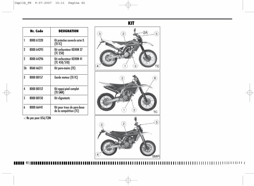
92
Nr. Code DESIGNATION
1 8000 A1320 Kit protection couvercle carter D.(TE-TC)
2 8000 A4295 Kit carburateur KEIHIN 37(TC 250)
2 8000 A4296 Kit carburateur KEIHIN 41(TC 450/510)
2A 80A0 A6211 Kit pare-mains (TE)
3 8000 B0157 Garde moteur (TE-TC)
4 8000 B0152 Kit appui-pied complet(TE-SMR)
5 8000 B0150 Kit clignotants
6 8000 A6441 Kit pour trous de pare-boue de la compétition (TC)
*: Ne pas pour USA/CDN
KIT
TC
Cap11b_FR 9-07-2007 15:11 Pagina 92
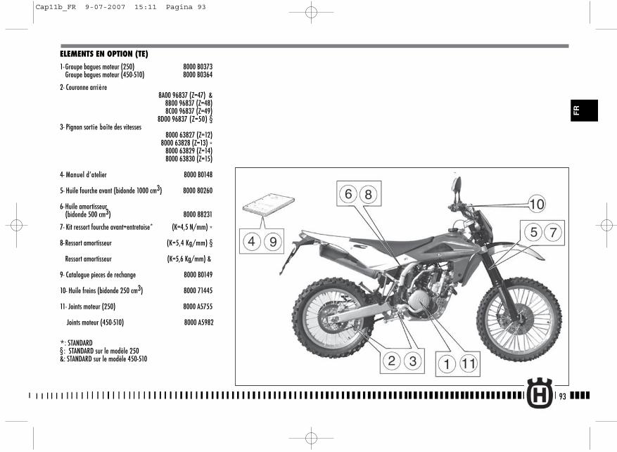
93
FR
ELEMENTS EN OPTION (TE)
1- Groupe bagues moteur (250) 8000 B0373Groupe bagues moteur (450-510) 8000 B0364
2- Couronne arrière8A00 96837 (Z=47) &
8B00 96837 (Z=48) 8C00 96837 (Z=49)
8D00 96837 (Z=50) §3- Pignon sortie boîte des vitesses
8000 63827 (Z=12) 8000 63828 (Z=13) *
8000 63829 (Z=14) 8000 63830 (Z=15)
4- Manuel d’atelier 8000 B0148
5- Huile fourche avant (bidonde 1000 cm3) 8000 80260
6- Huile amortisseur(bidonde 500 cm3) 8000 88231
7- Kit ressort fourche avant+entretoise* (K=4,5 N/mm) *
8- Ressort amortisseur (K=5,4 Kg/mm) §
Ressort amortisseur (K=5,6 Kg/mm) &
9- Catalogue pieces de rechange 8000 B0149
10- Huile freins (bidonde 250 cm3) 8000 71445
11- Joints moteur (250) 8000 A5755
Joints moteur (450-510) 8000 A5982
*: STANDARD§ : STANDARD sur le modèle 250&: STANDARD sur le modèle 450-510
Cap11b_FR 9-07-2007 15:11 Pagina 93

94
ELEMENTS EN OPTION (TC)
1- Groupe bagues moteur (250) 8000 A5735Groupe bagues moteur (450-510) 8000 A5736
2- Manuel d’atelier8000 B0148
3- Couronne arrière8A00 96837 (Z=47) @
8B00 96837 (Z=48) 8C00 96837 (Z=49)
8D00 96837 (Z=50) §,&
4- Pignon sortie boîte des vitesses8000 63827 (Z=12 ) §
8000 63828 (Z=13) 8000 63829 (Z=14) &,@
8000 63830 (Z=15)
5- Joints moteur (250) 8000 A5755
Joints moteur (450-510) 8000 A5982
6- Huile fourche avant (bidonde 1000 cm3) 8000 80260
8- Kit ressort fourche avant+entretoise* (K=4,8 N/mm) §(K=5 N/mm) &, @
9- Ressort amortisseur (K=5,4 Kg/mm) §(K=5,6 Kg/mm) &, @
10- Catalogue pieces de rechange 8000 B0149
11- Huile freins (bidonde 250 cm3) 8000 71445
12- Kit démarrage electrique 8000 B0455
*: STANDARD§ : STANDARD sur le modèle 250&: STANDARD sur le modèle 450@: STANDARD sur le modèle 510
Cap11b_FR 9-07-2007 15:11 Pagina 94
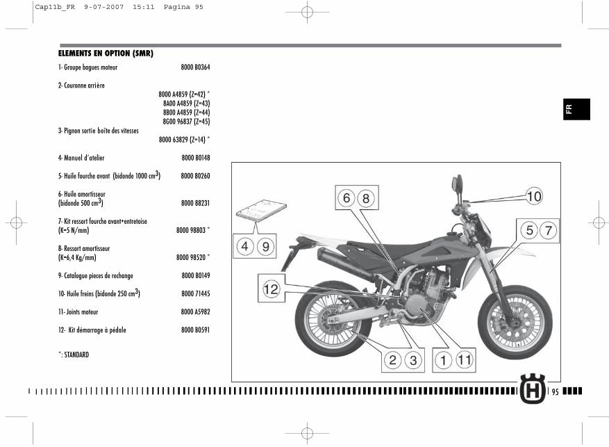
ELEMENTS EN OPTION (SMR)
1- Groupe bagues moteur 8000 B0364
2- Couronne arrière8000 A4859 (Z=42) *
8A00 A4859 (Z=43)8B00 A4859 (Z=44)8G00 96837 (Z=45)
3- Pignon sortie boîte des vitesses8000 63829 (Z=14) *
4- Manuel d’atelier 8000 B0148
5- Huile fourche avant (bidonde 1000 cm3) 8000 80260
6- Huile amortisseur(bidonde 500 cm3) 8000 88231
7- Kit ressort fourche avant+entretoise(K=5 N/mm) 8000 98803 *
8- Ressort amortisseur(K=6,4 Kg/mm) 8000 98520 *
9- Catalogue pieces de rechange 8000 B0149
10- Huile freins (bidonde 250 cm3) 8000 71445
11- Joints moteur 8000 A5982
12- Kit démarrage à pédale 8000 B0591
*: STANDARD
95
FR
Cap11b_FR 9-07-2007 15:11 Pagina 95
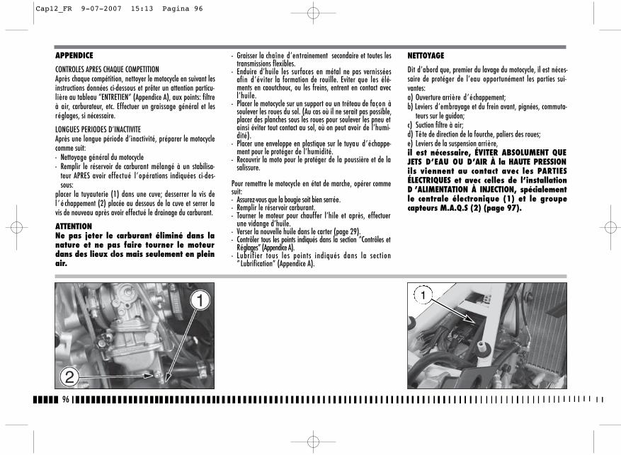
96
- Graisser la chaîne d’entrainement secondaire et toutes lestransmissions flexibles.
- Enduire d’huile les surfaces en métal ne pas vernisséesafin d’éviter la formation de rouille. Eviter que les élé-ments en caoutchouc, ou les freins, entrent en contact avecl’huile.
- Placer le motocycle sur un support ou un tréteau de façon àsoulever les roues du sol. (Au cas où il ne serait pas possible,placer des planches sous les roues pour soulever les pneu etainsi éviter tout contact au sol, où on peut avoir de l’humi-dité).
- Placer une enveloppe en plastique sur le tuyau d’échappe-ment pour le protéger de l’humidité.
- Recouvrir la moto pour le protéger de la poussière et de lasalissure.
Pour remettre le motocycle en état de marche, opérer commesuit:- Assurez-vous que la bougie soit bien serrée.- Remplir le réservoir carburant.- Tourner le moteur pour chauffer l’hile et après, effectuer
une vidange d’huile.- Verser la nouvelle huile dans le carter (page 29).- Contrôler tous les points indiqués dans la section “Contrôles et
Réglages” (Appendice A).- Lubrifier tous les points indiqués dans la sect ion
“ Lubrification” (Appendice A).
APPENDICE
CONTROLES APRES CHAQUE COMPETITIONAprès chaque compétition, nettoyer le motocycle en suivant lesinstructions données ci-dessous et prêter un attention particu-lière au tableau “ENTRETIEN” (Appendice A), aux points: filtreà air, carburateur, etc. Effectuer un graissage général et lesréglages, si nécessaire.
LONGUES PERIODES D’INACTIVITEAprès une longue période d’inactivité, préparer le motocyclecomme suit:- Nettoyage général du motocycle- Remplir le réservoir de carburant mélangé à un stabilisa-
teur APRES avoir effectué l’opérations indiquées ci-des-sous:
placer la tuyauterie (1) dans une cuve; desserrer la vis del ’ é chappement (2) placée au dessous de la cuve et serrer lavis de nouveau après avoir effectué le drainage du carburant.
ATTENTIONNe pas jeter le carburant éliminé dans lanature et ne pas faire tourner le moteurdans des lieux clos mais seulement en pleinair.
NETTOYAGE
Dit d’abord que, premier du lavage du motocycle, il est néces-saire de protéger de l’eau opportunément les parties sui-vantes:a) Ouverture arrière d’échappement;b) Leviers d’embrayage et du frein avant, pignées, commuta-
teurs sur le guidon;c) Suction filtre à air;d) Tête de direction de la fourche, paliers des roues;e) Leviers de la suspension arrière,il est nécessaire, ÉVITER ABSOLUMENT QUEJETS D’EAU OU D’AIR À la HAUTE PRESSIONils viennent au contact avec les PARTIESÉLECTRIQUES et avec celles de l’installationD ’ALIMENTATION À INJECTION, spécialementle centrale électronique (1) et le groupecapteurs M.A.Q.S (2) (page 97).
1
Cap12_FR 9-07-2007 15:13 Pagina 96
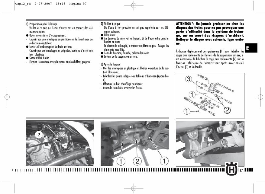
2) Veillez à ce queDe l’eau à fort pression ne soit pas vaporisée sur les élé-ments suivants:
● Filtre à air● Au dessous du réservoir carburant. Si de l’eau entre dans la
bobine ou dans la pipette de la bougie, le moteur ne démarre pas. Essuyer leséléments mouillés.
● Tête de direction, fourche, paliers des roues.● Leviers de la suspension arrière.
3) Après le lavage- Oter les enveloppes en plastique et libérer louverture de la suc-
tion filtre à air.- Lubrifier les points indiqués au Tableau d’Entretien (Appendice
A).- Effectuer un bref chauffage du moteur- Avant de counduire, essayer les freins.
ATTENTION*: Ne jamais graisser ou cirer lesdisques des freins pour ne pas provoquer uneperte d’efficacité dans le système de freina-ge, car on court des risques d’accident.Nettoyer le disque avec solvants, type acéto-ne.
À chaque déplacement des graisseurs (1) pour lubrifier lescages aux roulements des leviers de la suspension arrière, ilest nécessaire de lubrifier la cage aux roulements (2) sur lafixation inférieure de l'amortisseur après avoir enlev él’ecrou (3) et la douille.
97
FR
1) Préparation pour le lavageVeillez à ce que de l’eau n’entre pas en contact des élé-ments suivants:
● Ouverture arrière d’échappement:- Couvrir par une enveloppe en plastique en la fixant avec des
colliers en caoutchouc● Leviers d’embrayage et du frein arrière:- Couvrir par une enveloppe en poignées, boutons d’arrêt mo-
teur plastique● Suction filtre à air:- Fermer l’ouverture avec du ruban, ou des chiffons propres
2
Cap12_FR 9-07-2007 15:13 Pagina 97

98
� : presenti solo sui motocicli con motore a 2 tempi �� : presente solo su alcuni modelli
�� ���� � ������ �����
��������������
Huile moteur Contrôle niveauHuile mélange essence Contrôle niveauLiquide de refroidissement Contrôle/appoint Circuit de refroidissement Contrôle des fuitesElectroventilateurs Contrôle fonctionnalitéBougies Contrôle/remplacementPapillon/Carburateur Contrôle et réglageLiquide des freins et d’embrayage Contrôle niveauFreins/embrayage Contrôle fonctionnalitéFreins/embrayage Contrôle circuitCommande d’accélérateur Contrôle fonctionnalitéCommande d’accélérateur Vérification/réglage du jeuCommande starter Contrôle fonctionnalitéTransmissions/commandes souples Contrôle / réglageChaîne de transmission Contrôle / réglage
Pneumatiques Contrôle pressionBéquille latérale Contrôle fonctionnalitéContacteur béquille Contrôle fonctionnalitéInstallation électrique Contrôle fonctionnalitéAppareillage de bord Contrôle fonctionnalitéEclairage/signaux visuels Contrôle fonctionnalitéAvertisseur acoustique Contrôle fonctionnalitéPhare avant Contrôle fonctionnalitéInterrupteur d’allumage Contrôle fonctionnalitéSerrures Contrôle fonctionnalitéSerrage des vis et écrous Contrôle / serrageColliers serre-tube Contrôle / serrageLubrification généraleEssai sur route
OPERATIONS DE PRÉ - LIVRAISON
Description Operation Prep. a la route Description Operation Prep. a la route
seulement pour le motorisation a 2 tempsseulement sur modèles spécifiques
Cap12_FR 9-07-2007 16:45 Pagina 98
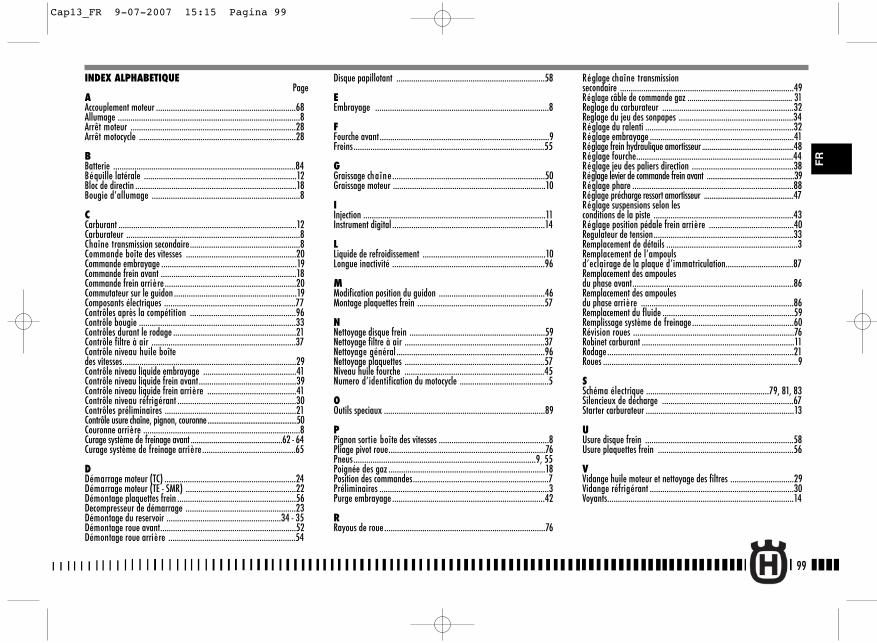
99
Réglage chaîne transmissionsecondaire ..................................................................................49Réglage câble de commande gaz .................................................... 31Reglage du carburateur ..............................................................32Reglage du jeu des sonpapes ......................................................34Réglage du ralenti ......................................................................32Réglage embrayage ....................................................................41Réglage frein hydraulique amortisseur ................................................48Réglage fourche..........................................................................44Réglage jeu des paliers direction ................................................38Réglage levier de commande frein avant ................................................39Réglage phare ............................................................................88Réglage précharge ressort amortisseur ................................................47Réglage suspensions selon les conditions de la piste ..................................................................43Réglage position pédale frein arrière ........................................40Regulateur de tension..................................................................33Remplacement de détails ..............................................................3Remplacement de l’ampouls d’eclairage de la plaque d’immatriculation................................87Remplacement des ampoules du phase avant............................................................................86Remplacement des ampoules du phase arrière ........................................................................86Remplacement du fluide ..............................................................59Remplissage système de freinage................................................60Révision roues ............................................................................76Robinet carburant ........................................................................11Rodage........................................................................................21Roues ............................................................................................9
SSchéma électrique ..........................................................79, 81, 83Silencieux de décharge ..............................................................67Starter carburateur ......................................................................13
UUsure disque frein ......................................................................58Usure plaquettes frein ................................................................56
VVidange huile moteur et nettoyage des filtres ..............................29Vidange réfrigérant ....................................................................30Voyants........................................................................................14
INDEX ALPHABETIQUEPage
AAccouplement moteur ..................................................................68Allumage ......................................................................................8Arrêt moteur ..............................................................................28Arrêt motocycle ..........................................................................28
BBatterie ......................................................................................84Béquille latérale ........................................................................12Bloc de directin ............................................................................18Bougie d’allumage ......................................................................8
CCarburant ....................................................................................12Carburateur ..................................................................................8Chaîne transmission secondaire....................................................8Commande boîte des vitesses ....................................................20Commande embrayage ................................................................19Commande frein avant ................................................................18Commande frein arrière ..............................................................20Commutateur sur le guidon ..........................................................19Composants électriques ..............................................................77Contrôles après la compétition ..................................................96Contrôle bougie ..........................................................................33Contrôles durant le rodage ..........................................................21Contrôle filtre à air ....................................................................37Contrôle niveau huile boîte des vitesses..................................................................................29Contrôle niveau liquide embrayage ............................................41 Contrôle niveau liquide frein avant..............................................39Contrôle niveau liquide frein arrière ..........................................41Contrôle niveau réfrigérant ........................................................30Contrôles préliminaires ..............................................................21Contrôle usure chaîne, pignon, couronne..................................................50Couronne arrière ..........................................................................8Curage système de freinage avant ................................................62 - 64Curage système de freinage arrière............................................65
DDémarrage moteur (TC) ..............................................................24Démarrage moteur (TE - SMR) ....................................................22Démontage plaquettes frein ........................................................56Decompresseur de démarrage ....................................................23Démontage du reservoir ......................................................34 - 35Démontage roue avant................................................................52Démontage roue arrière ............................................................54
Disque papillotant ......................................................................58
EEmbrayage ..................................................................................8
FFourche avant................................................................................9Freins..........................................................................................55
GGraissage chaîne ........................................................................50Graissage moteur ........................................................................10
IInjection ......................................................................................11Instrument digital ........................................................................14
LLiquide de refroidissement ..........................................................10Longue inactivité ........................................................................96
MModification position du guidon ..................................................46Montage plaquettes frein ............................................................57
NNettoyage disque frein ................................................................59Nettoyage filtre à air ..................................................................37Nettoyage général ......................................................................96Nettoyage plaquettes ..................................................................57Niveau huile fourche ..................................................................45Numero d’identification du motocycle ..........................................5
OOutils speciaux ............................................................................89
PPignon sortie boîte des vitesses ....................................................8Pliage pivot roue..........................................................................76Pneus......................................................................................9, 55Poignée des gaz ..........................................................................18Position des commandes................................................................7Préliminaires ................................................................................3Purge embrayage ........................................................................42
RRayous de roue............................................................................76
FR
Cap13_FR 9-07-2007 15:15 Pagina 99

100
Cap13_FR 9-07-2007 15:15 Pagina 100

1
DEUTSCH
Cap1_DE 19-07-2007 10:17 Pagina 1
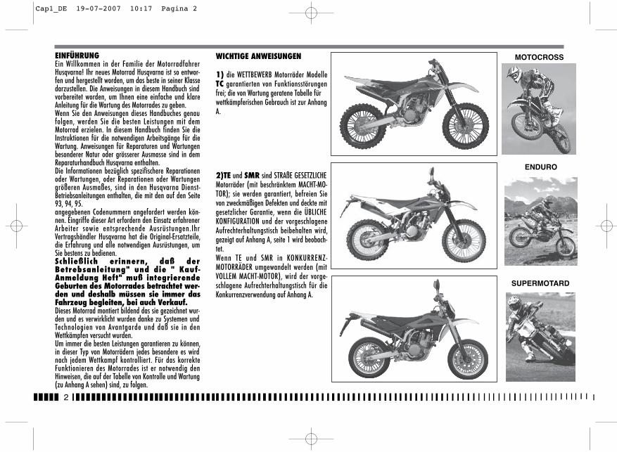
2
EINFÜHRUNGEin Willkommen in der Familie der MotorradfahrerHusqvarna! Ihr neues Motorrad Husqvarna ist so entwor-fen und hergestellt worden, um das beste in seiner Klassedarzustellen. Die Anweisungen in diesem Handbuch sindvorbereitet worden, um Ihnen eine einfache und klareAnleitung für die Wartung des Motorrades zu geben.Wenn Sie den Anweisungen dieses Handbuches genaufolgen, werden Sie die besten Leistungen mit demMotorrad erzielen. In diesem Handbuch finden Sie dieInstruktionen für die notwendigen Arbeitsgänge für dieWartung. Anweisungen für Reparaturen und Wartungenbesonderer Natur oder grösserer Ausmasse sind in demReparaturhandbuch Husqvarna enthalten. Die Informationen bezüglich spezifischere Reparationenoder Wartungen, oder Reparationen oder Wartungengrößeren Ausmaßes, sind in den Husqvarna Dienst-Betriebsanleitungen enthalten, die mit den auf den Seite93, 94, 95. angegebenen Codenummern angefordert werden kön-nen. Eingriffe dieser Art erfordern den Einsatz erfahrenerArbeiter sowie entsprechende Ausrüstungen.IhrVertragshändler Husqvarna hat die Original-Ersatzteile,die Erfahrung und alle notwendigen Ausrüstungen, umSie bestens zu bedienen. Schließlich erinnern, daß derBetrebsanleitung" und die " Kauf-Anmeldung Heft" muß integrierendeGeburten des Motorrades betrachtet wer-den und deshalb müssen sie immer dasFahrzeug begleiten, bei auch Verkauf.Dieses Motorrad montiert bildend das sie gezeichnet wur-den und es verwirklicht wurden danke zu Systemen undTechnologien von Avantgarde und daß sie in denWettkämpfen versucht wurden. Um immer die besten Leistungen garantieren zu können,in dieser Typ von Motorrädern jedes besondere es wirdnach jedem Wettkampf kontrolliert. Für das korrekteFunktionieren des Motorrades ist er notwendig denHinweisen, die auf der Tabelle von Kontrolle und Wartung(zu Anhang A sehen) sind, zu folgen.
MOTOCROSS
SUPERMOTARD
ENDURO
WICHTIGE ANWEISUNGEN
1) die WETTBEWERB Motorräder ModelleTC garantierten von Funktionsstörungenfrei; die von Wartung geratene Tabelle fürwettkämpferischen Gebrauch ist zur AnhangA.
2)TE und SMR sind STRAßE GESETZLICHEMotorräder (mit beschränktem MACHT-MO-TOR); sie werden garantiert, befreien Sievon zweckmäßigen Defekten und deckte mitgesetzlicher Garantie, wenn die ÜBLICHEKONFIGURATION und der vorgeschlageneAufrechterhaltungstisch beibehalten wird,gezeigt auf Anhang A, seite 1 wird beobach-tet. Wenn TE und SMR in KONKURRENZ-MOTORRÄDER umgewandelt werden (mitVOLLEM MACHT-MOTOR), wird der vorge-schlagene Aufrechterhaltungstisch für dieKonkurrenzverwendung auf Anhang A.
Cap1_DE 19-07-2007 10:17 Pagina 2
3
DE
WICHTIG
Der Hinweis für Anerkennung der Garantie wird die MOTOR-RAD-KONFIGURATION sein, wie unten gezeigt,:
A) ÜBLICHES MOTORRAD, STRAßE GESETZLICH: mit beschränk-tem MACHT-MOTOR
B) KONKURRENZ-MOTORRAD, das Machen EINEN WETTKAMPFMIT von der VERWENDUNG: mit VOLLEM MACHT-MOTOR.
Dieses Motorrad wurde nicht ausgedacht,um immer höchstens einige Drehungen lan-ge Reisen mit dem Motor vorzunehmen,wie es anläßlich langer Verschiebungenauf Straßen oder Autobahnen geschehenkann. Die langen Reisen in dieseBedingungen können zum ernste Schädenverursachen Motor. Dieses Motorrad wurde für dieWettkämpfe und den Abschluß gelernt esgarantiert die besten Leistungen mit demeinzigen Fahrer. Sie rät ab deshalb sie mitdem Passagier benutzen, sowohl aufStraße, daß ins geländegängige.
IMMER erinnern, daß diese Motorräder für die Wettkämpfegeplant wurden, das heißt für einen sehr verschiedenenGebrauch von jenes Straßen.Um die "Garantie von Funktionieren" desFahrzeuges zu erhalten, muß der Kundedem Programm von Wartung folgen dasauf ihn auf dem Libretto von Gebrauch undWartung gezeigt wird, da führt es die beiden Werkstätten genehmigt HUSQVARNAvorgesehenen Abschnitte aus. Der Preis fürden Ersatz der Stücke und um den Plan vonWartung zu beachten, ist er zu Lasten der
Kunde für die notwendige Arbeitskräfte. ZUR BEACHTUNG: die Garantie verfällt beiVermietung des Kraftrades.
Wichtige EinleitungDie vorliegenden Betriebsanleitungen aufmerksam durchlesenund den Anmerkungen, denen die folgenden Hinweise voraus-gehen, besondere Beachtung schenken :
ACHTUNG *: Zeigt die Möglichkeit an, beiNichtbeachtung der Anweisungen schwerepersönliche Schäden bis zum Todesfall zuerleiden.WARNHINWEIS* : Zeigt die Möglichkeit an,bei Nichtbeachtung der Anweisungen per-sönliche Schäden zu erleiden oder Schädenam Fahrzeug zu verursachen. Anmerkung * : Liefert weitere nützlicheInformationen.
Austausch der TeileIm Falle des Austausches von Teilen, nur Original-Husqvarna-Teile mit entsprechenden Merkmalen einschließlich Typ,Widerstand und Material benutzen. Andernfalls könntenFehlfunktionen mit möglicher Verletzungsgefahr auftreten..
ACHTUNG * : Nach einem Fall dasMotorrad sorgfältig überprüfen. Sich ver-gewissern, daß die Gasschaltung, dieBremsen, die Kupplung und andereHauptschaltungen und Komponentennicht beschädigt wurden. Ein beschädig-tes Motorrad zu fahren kann schwereUnfälle verursachen.
ACHTUNG * : Das Motorrad nicht anlassenoder an ihm arbeiten, ohne vorher geeig-nete Schutzkleidung angezogen zu ha-ben. Immer Schutzhelm, Stiefel,Handschuhe, Schutzbrille und andere ge-eignete Kleidung tragen.
ACHTUNG * : Dieses Motorrad ist ein sofi-stiziertes Wettrennfahrzeug. DasMotorrad nicht anlassen und führen,wenn nicht über geeignete Anweisungenund ausgezeichneten körperlichenZustand verfügt wird.
SICHERHEITSMASSNAHMEN FÜR KINDERACHTUNGl Motorrad sicher parkieren, d.h. wo kei-ne Stoss- oder Schadengefahren leichtvorkommen können. Unabsichtliche Stößekonnten auch den Absturz des Motorradsverursachen, mit Verletzungsgefahr vonPersonen und vor allem Kindern.l Um einen unabsichtlichen Absturz zuvermeiden, den Motorrad nie auf unebe-nen oder weichen Boden oder heißeAsphalt parkieren.l Da Motor und Auspuffanlage sehr heißwerden können, den Motorrad sicherparkieren, uzw. wo Kinder oderFußgänger nicht leicht mit solchen Teilenin Berührung kommen können.
Cap1_DE 19-07-2007 10:17 Pagina 3
4
INHALTSANGABE Seite
EINFÜHRUNG ..........................................................................2WICHTIGE ANWEISUNGEN ........................................................2DATEN ZUR IDENTIFIZIERUNG ..................................................5TECHNISCHE DATEN .................................................................8SCHMIERUNGSTABELLE, TANKEN.............................................10STEUERUNGEN.......................................................................11GEBRAUCHSANLEITUNG .........................................................21VERSCHLEISSGRENZE.............................................................68ZÜNDUNGSANLAGE/ELEKTRISCHEANLAGE ........................77-88SONDERWERKZEUGE..............................................................89VERSCHRAUBUNGSMOMENTE .................................................90KIT........................................................................................92EXTRA-TEILE .....................................................................93-95AHNHAG ...............................................................................96VORäNGE ZUR AUSLIEFERUNG ...............................................97ALPHABETISCHES VERZEICHNIS ..............................................98WARTUNGSPALAN EINSTELLUNGEN .............................Anhang A
Note� Die Angaben, rechts und links, beziehen sich auf die beiden
Motorradseiten in Bezug auf die Fahrtrichtung
� Z: Zähne nummer� A: Österreich
AUS: AustralienB: BelgienBR: BrasilienCDN: KanadaCH: SchweizeD: DeutschlandE: SpanienF: FrankreichFIN: FinnlandGB: Groos BritanI: ItalienJ: JapanUSA: Vereinigte Staten von Amerika
� Wenn nicht anders angegeben, beziehen sich die Daten undVorschriften auf alle Länder. 0
Cap1_DE 19-07-2007 10:17 Pagina 4
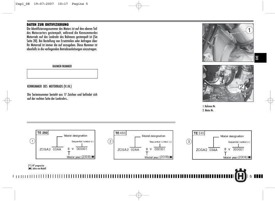
5
DE
DATEN ZUR IDETIFIZIERUNGDie Identifizierungsnummer des Motors ist auf den oberen Teildes Motorcarters gestempelt, während die KennummerdesMotorrads auf das Lenkrohr des Rahmens gestempelt ist (SieSeite 20). Bei Bestellung von Ersatzteilen oder Anfragen überIhr Motorrad ist immer die auf anzugeben. Diese Nummer istebenfalls in die vorliegenden Betriebsanleitungen einzutragen.
RAHMEN NUMMER
KENNUMMER DES MOTORRADS (V.I.N.)
Die Seriennummer besteht aus 17 Zeichen und befindet sichauf der rechten Seite der Lenkrohrs..
1. Rahmen Nr.2. Motor Nr.
(*): N° progressive(�): Jahre von Modell
Cap1_DE 19-07-2007 10:17 Pagina 5
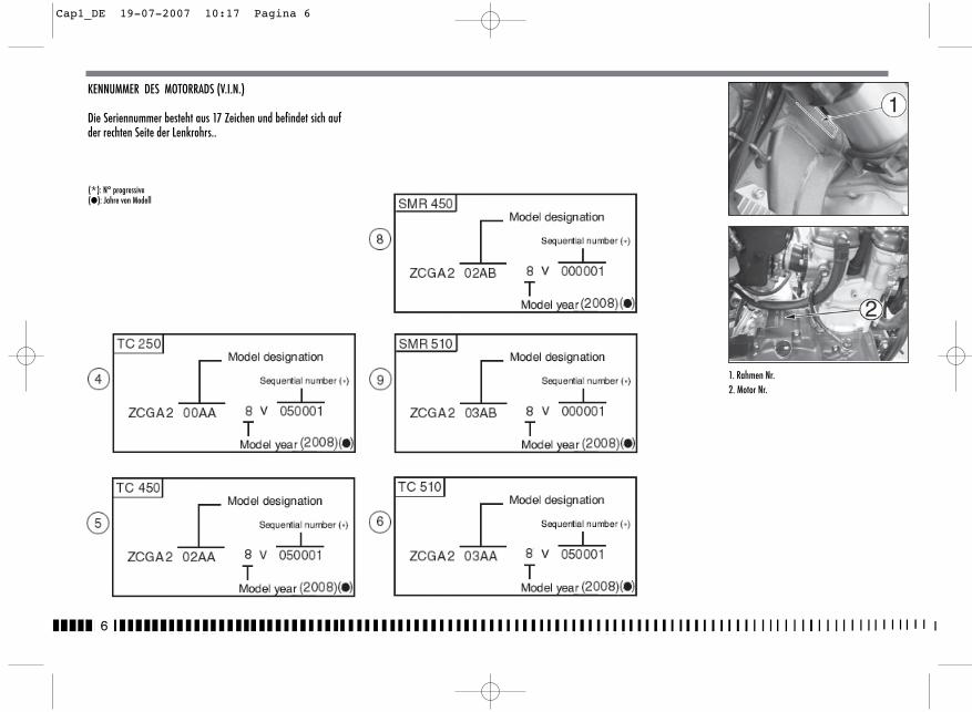
6
KENNUMMER DES MOTORRADS (V.I.N.)
Die Seriennummer besteht aus 17 Zeichen und befindet sich aufder rechten Seite der Lenkrohrs..
(*): N° progressive(�): Jahre von Modell
1. Rahmen Nr.2. Motor Nr.
Cap1_DE 19-07-2007 10:17 Pagina 6
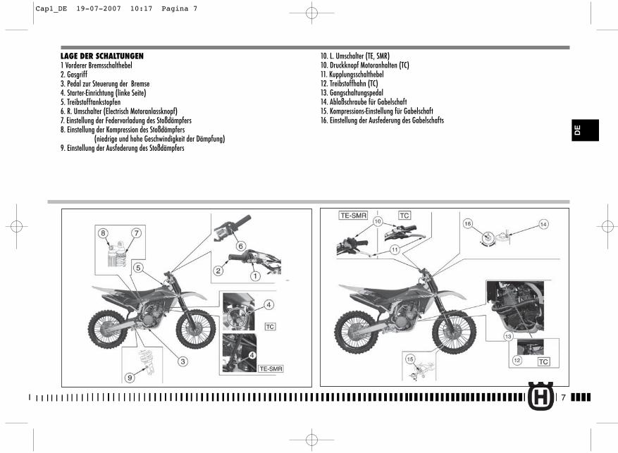
7
DE
LAGE DER SCHALTUNGEN1 Vorderer Bremsschalthebel2. Gasgriff3. Pedal zur Steuerung der Bremse4. Starter-Einrichtung (linke Seite)5. Treibstofftankstopfen6. R. Umschalter (Electrisch Motoranlassknopf)7. Einstellung der Federvorladung des Stoßdämpfers8. Einstellung der Kompression des Stoßdämpfers
(niedrige und hohe Geschwindigkeit der Dämpfung)9. Einstellung der Ausfederung des Stoßdämpfers
10. L. Umschalter (TE, SMR)10. Druckknopf Motoranhalten (TC)11. Kupplungsschalthebel12. Treibstoffhahn (TC)13. Gangschaltungspedal14. Ablaßschraube für Gabelschaft15. Kompressions-Einstellung für Gabelschaft16. Einstellung der Ausfederung des Gabelschafts
Cap1_DE 19-07-2007 10:17 Pagina 7
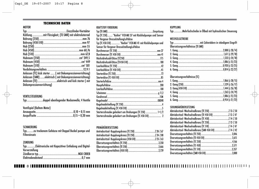
8
TECHNISCHE DATENMOTORTyp .........................................................Einzzilinder-ViertakterKühlung ................mit Flüssigkeit, (TE-SMR) mit elektroluterradBohrung (250) ...............................................................mm 76 Bohrung (450-510) ........................................................mm 97Hub (250) .....................................................................mm 55Hub (450).................................................................mm 60,76Hub (510) ...................................................................mm 67,8 Hubraum (250).........................................................cm3 249,5 Hubraum (450) ............................................................cm3 449Hubraum (510) ............................................................cm3 501 Verdichtungsverhältnis ....................................................12,9:1 Anlassen (TC) kick starter ...... ( mit Dekompressionvorrichtung)Anlassen (SMR) .......elektrisch ( mit Dekompressionvorrichtung)Anlassen (TE) ............................elektrisch und kick starter ( mitDekompressionvorrichtung)
VENTILSTEUERUNGTyp .......................doppel obenliegender Nockenwelle; 4 Ventile
Ventilspiel (Kaltem Motor)Ansaugseite.......................................................0,10 ÷ 0,15 mmAuspuffseite .....................................................0,15 ÷ 0,20 mm
SCHMIERUNGTyp..........zu trockenem Gehäuse mit Doppel Buckel pumpe und Filtereinsatz
ZUNDUNGTyp ............Elektronische mit Kapazitiver Entladung und Digital-VorverstellungZündkerze typ..........................................................NGK CR8EBElektrodenabstand ........................................................0,7 mm
KRAFTSTOFF FORDERUNGTyp (TE-SMR) ..................................................................................EinspritzungTyp (TC 250) ......... “Keihin“ FCR-MX 37 mit Rückholpumpe und Sensorfür Vergaser DresselstellungLuftdüseTyp (TC 450-510) ............... “Keihin“ FCR-MX 41 mit Rückholpumpe undSensor für Vergaser DresselstellungLuftdüseDurchmesser (TC 250) ........................................................................mm 37Durchmesser (TC 450-510) ..................................................................mm 41Hóchstdrehzahl-Düse (TC250) ................................................................175Hóchstdrehzahl-Düse (TC450-510) ..........................................................180Leerlaufdüse (TC 250) ...............................................................................42Leerlaufdüse (TC 450-510).........................................................................45Starterdüse (TC 250)..................................................................................72Starterdüse (TC 450-510) ...........................................................................85Starterluftdüse.....................................................................................mm 4Hauptluftdüse .........................................................................................200Leerlaufluftdüse......................................................................................100Schwimmer..............................................................................................g 11,2Gasdrossel...............................................................................................15MKegelnadel ..........................................................................................OBDVRKegelnadelstellung (TC 250) ......................................................................4Kegelnadelstellung (TC 450-510) ...............................................................5Starterschraube gelockert um Drehungen (TC 250) ..................... 1+1/2Starterschraube gelockert um Drehungen (TC 450-510) ...................... 2
PRIMÄRÜBERSETZUNGAntriebsritzel- Kupplungskranz (TC 250) .......................................Z 20- Z 67Antriebsritzel- Kupplungskranz (TE 250)........................................Z 24- Z 88Antriebsritzel- Kupplungskranz (450-510) .....................................Z 23- Z 63Übersetzungsverhältnis (TC 250) ............................................................3,350Übersetzungsverhältnis (TE 250) ............................................................3,666Übersetzungsverhältnis (450-510) ..........................................................2,739
KUPPLUNGTyp .............Mehrfachscheibe in Ölbad mit hydraulischen Steuerung
WECHSELGETREIBETyp ........................................mit Zahnrädern in ständigem EingriftÜbersetzungsverhältnisse (TE-SMR)1. Gang..................................................................................2,000 (z 28/14)2. Gang ..................................................................................1,611 (z 29/18)3. Gang..................................................................................1,333 (z 24/18)4. Gang .................................................................................1,086 (z 25/23)5. Gang .................................................................................0,920 (z 23/25)6. Gang..................................................................................0,814 (z 22/27)
Übersetzungsverhältnisse (TC)1. Gang..................................................................................1,866 (z 28/15)2. Gang (250)........................................................................1,529 (z 26/17)3. Gang (450-510) .................................................................1,444 (z 26/18)4. Gang .................................................................................1,263 (z 24/19)5. Gang .................................................................................1,086 (z 25/23)6. Gang .................................................................................0,954 (z 21/22)
SEKUNDÀRÜBERSETZUNGAbtriebsritzel- Wechselradkranz (TE 250) ...................................Z 13- Z 50Abtriebsritzel- Wechselradkranz (TE 450-510) ............................Z 13- Z 47Abtriebsritzel- Wechselradkranz (TC 450) ...................................Z 14- Z 50Abtriebsritzel- Wechselradkranz (TC 250) ...................................Z 12- Z 50Abtriebsritzel- Wechselradkranz (TC 510) ...................................Z 14- Z 47Abtriebsritzel- Wechselradkranz (SMR 450-510) .........................Z 14- Z 42Üversetzungsverhältnis (TE 250) ....................................................... 3,846Üversetzungsverhältnis (TE 450-510) ................................................. 3,615Üversetzungsverhältnis (TC 250) ........................................................4,166Üversetzungsverhältnis (TC 450) ........................................................3,571Üversetzungsverhältnis (TC 510) ........................................................3,357Üversetzungsverhältnis (SMR 450-510)...................................................3,000
Cap1_DE 19-07-2007 10:17 Pagina 8
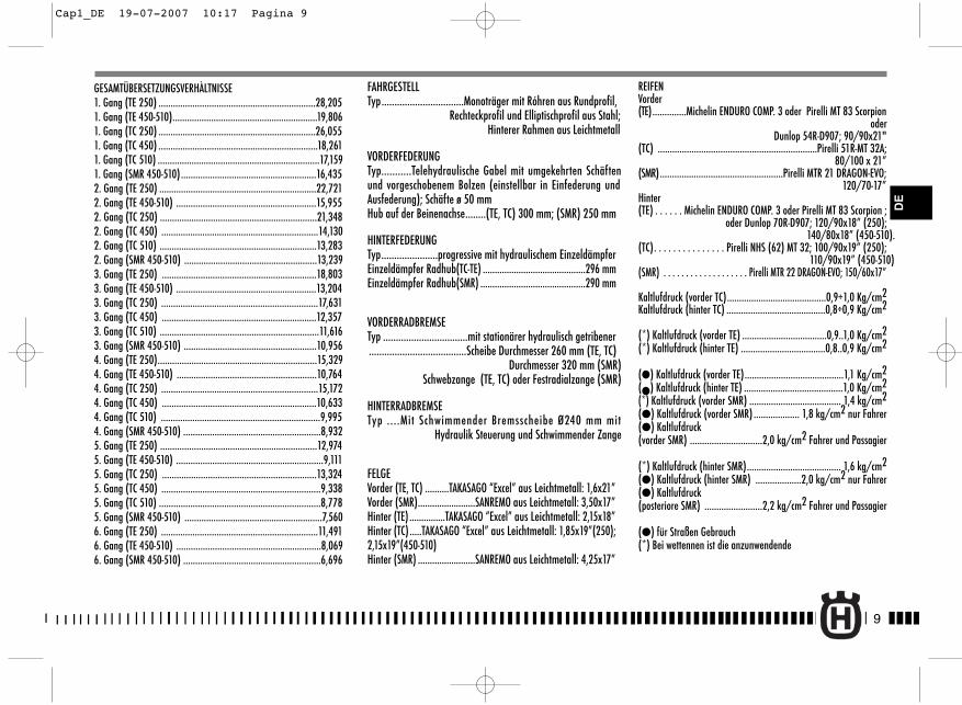
GESAMTÜBERSETZUNGSVERHÀLTNISSE1. Gang (TE 250) .................................................................28,2051. Gang (TE 450-510)............................................................19,8061. Gang (TC 250) .................................................................26,0551. Gang (TC 450) ..................................................................18,2611. Gang (TC 510) ...................................................................17,1591. Gang (SMR 450-510)........................................................16,4352. Gang (TE 250) .................................................................22,7212. Gang (TE 450-510) ..........................................................15,9552. Gang (TC 250) .................................................................21,3482. Gang (TC 450) .................................................................14,1302. Gang (TC 510) .................................................................13,2832. Gang (SMR 450-510) .......................................................13,2393. Gang (TE 250) ................................................................18,8033. Gang (TE 450-510) ..........................................................13,2043. Gang (TC 250) .................................................................17,6313. Gang (TC 450) ................................................................12,3573. Gang (TC 510) ..................................................................11,6163. Gang (SMR 450-510) .......................................................10,9564. Gang (TE 250)..................................................................15,3294. Gang (TE 450-510) ..........................................................10,7644. Gang (TC 250) .................................................................15,1724. Gang (TC 450) ................................................................10,6334. Gang (TC 510) ..................................................................9,9954. Gang (SMR 450-510) .........................................................8,9325. Gang (TE 250) .................................................................12,9745. Gang (TE 450-510) .............................................................9,1115. Gang (TC 250) ................................................................13,3245. Gang (TC 450) ..................................................................9,3385. Gang (TC 510) ...................................................................8,7785. Gang (SMR 450-510) .........................................................7,5606. Gang (TE 250) .................................................................11,4916. Gang (TE 450-510) ............................................................8,0696. Gang (SMR 450-510) .........................................................6,696
FAHRGESTELLTyp................................Monoträger mit Róhren aus Rundprofil,
Rechteckprofil und Elliptischprofil aus Stahl;Hinterer Rahmen aus Leichtmetall
VORDERFEDERUNGTyp...........Telehydraulische Gabel mit umgekehrten Schäftenund vorgeschobenem Bolzen (einstellbar in Einfederung undAusfederung); Schäfte ø 50 mmHub auf der Beinenachse........(TE, TC) 300 mm; (SMR) 250 mm
HINTERFEDERUNGTyp......................progressive mit hydraulischem EinzeldämpferEinzeldämpfer Radhub(TC-TE) ...........................................296 mmEinzeldämpfer Radhub(SMR) ............................................290 mm
VORDERRADBREMSETyp .................................mit stationärer hydraulisch getribener ......................................Scheibe Durchmesser 260 mm (TE, TC)
Durchmesser 320 mm (SMR)Schwebzange (TE, TC) oder Festradialzange (SMR)
HINTERRADBREMSETyp ....Mit Schwimmender Bremsscheibe Ø240 mm mit
Hydraulik Steuerung und Schwimmender Zange
FELGEVorder (TE, TC) ..........TAKASAGO “Excel” aus Leichtmetall: 1,6x21”Vorder (SMR)........................SANREMO aus Leichtmetall: 3,50x17”Hinter (TE) ...............TAKASAGO “Excel” aus Leichtmetall: 2,15x18”Hinter (TC) .....TAKASAGO “Excel” aus Leichtmetall: 1,85x19”(250);2,15x19”(450-510)Hinter (SMR) ........................SANREMO aus Leichtmetall: 4,25x17”
REIFENVorder(TE)..............Michelin ENDURO COMP. 3 oder Pirelli MT 83 Scorpion
oderDunlop 54R-D907; 90/90x21"
(TC) ..................................................................Pirelli 51R-MT 32A;80/100 x 21”
(SMR)...................................................Pirelli MTR 21 DRAGON-EVO;120/70-17”
Hinter(TE) . . . . . . Michelin ENDURO COMP. 3 oder Pirelli MT 83 Scorpion ;
oder Dunlop 70R-D907; 120/90x18” (250);140/80x18” (450-510).
(TC). . . . . . . . . . . . . . . Pirelli NHS (62) MT 32; 100/90x19” (250);110/90x19” (450-510)
(SMR) . . . . . . . . . . . . . . . . . . . Pirelli MTR 22 DRAGON-EVO; 150/60x17”
Kaltlufdruck (vorder TC).........................................0,9÷1,0 Kg/cm2Kaltlufdruck (hinter TC) .........................................0,8÷0,9 Kg/cm2
(*) Kaltlufdruck (vorder TE) ...................................0,9..1,0 Kg/cm2(*) Kaltlufdruck (hinter TE) ...................................0,8..0,9 Kg/cm2
(�) Kaltlufdruck (vorder TE).........................................1,1 Kg/cm2(�) Kaltlufdruck (hinter TE) .........................................1,0 Kg/cm2(*) Kaltlufdruck (vorder SMR) ...................................... 1,4 kg/cm2(�) Kaltlufdruck (vorder SMR) ................... 1,8 kg/cm2 nur Fahrer(�) Kaltlufdruck(vorder SMR) ..............................2,0 kg/cm2 Fahrer und Passagier
(*) Kaltlufdruck (hinter SMR)....................................... 1,6 kg/cm2(�) Kaltlufdruck (hinter SMR) ...................2,0 kg/cm2 nur Fahrer(�) Kaltlufdruck(posteriore SMR) ........................2,2 kg/cm2 Fahrer und Passagier
(�) für Straßen Gebrauch (*) Bei wettennen ist die anzunwendende
9
DE
Cap1_DE 19-07-2007 10:17 Pagina 9
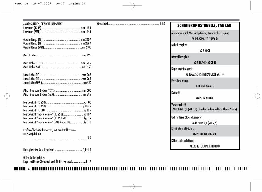
10
AMBESSUNGEN, GEWICHT, KAPAZITÀTRadstand (TC-TE) ........................................................mm 1495 Radstand (SMR) .........................................................mm 1445
Gesamtlänge (TC) ......................................................mm 2207 Gesamtlänge (TE) ......................................................mm 2267Gesamtlänge (SMR)......................................................mm 2183
Max. Breite ..................................................................mm 820
Max. Höhe (TC-TE)......................................................mm 1285Max. Höhe (SMR) .........................................................mm 1250
Sattelhöhe (TC) ............................................................mm 968Sattelhöhe (TE) ............................................................mm 963Sattelhöhe (SMR ) ..........................................................mm 920
Min. Höhe vom Boden (TC-TE).......................................mm 300Min. Höhe vom Boden (SMR)........................................mm 245
Leergewicht (TC 250)......................................................kg 100Leergewicht (TC 450) ..................................................kg 104,5Leergewicht (TC 510)......................................................kg 105 Leergewicht “ready to race” (TE 250) .............................kg 107Leergewicht “ready to race” (TE 450-510) .......................kg 112Leergewicht “ready to race” (SMR 450-510)....................kg 118
Kraftstoffbehälterkapazität, mit Kraftstoffreserve(TE-SMR) di l 1,8..................................................................................................l 7,2
Flüssigkeit im Kühl Kreislauf........................................l 1,1÷1,3
Öl im KurbelgehäuseRegel mäßiger Ölwechsel und Öllfilterwechsel ....................l 1,7
Ölwechsel ..........................................................................l 1,5 SCHMIERUNGSTABELLE, TANKEN
Motorschmieröl, Wechselgetriebe, Primär-Übertragung
AGIP RACING 4T (10W-60)
Kühlflüssigkeit
AGIP COOL
Bremsflüssigkeit
AGIP BRAKE 4 (DOT 4)
Kupplungflüssigkeit
MINERALISCHES HYDRAULIKÖL SAE 10
Fettschmierung
AGIP BIKE GREASE
Kettenöl
AGIP CHAIN LUBE
VordergabelölAGIP FORK 7,5 (SAE 7,5) ( bei besonders kaltem Klima: SAE 5)
Oel hinterer Stoessdaempfer
AGIP FORK 2,5 (SAE 2,5)
Elektrokontakt-Schutz
AGIP CONTACT CLEANER
Küler-Leckabdichtung
AREXONS TURAFALLE LIQUIDO
Cap1_DE 19-07-2007 10:17 Pagina 10
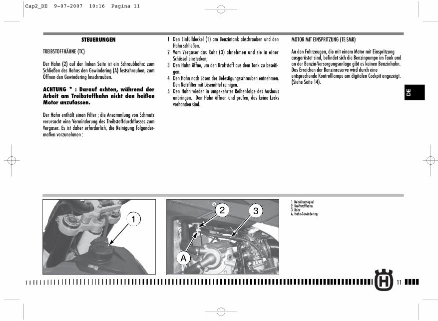
MOTOR MIT EINSPRITZUNG (TE-SMR)
An den Fahrzeugen, die mit einem Motor mit Einspritzungausgerüstet sind, befindet sich die Benzinpumpe im Tank undan der Benzin-Versorgungsanlage gibt es keinen Benzinhahn.Das Erreichen der Benzinreserve wird durch eineentsprechende Kontrolllampe am digitalen Cockpit angezeigt.(Siehe Seite 14).
11
DE
1 Den Einfülldeckel (1) am Benzintank abschrauben und denHahn schließen.
2 Vom Vergaser das Rohr (3) abnehmen und sie in einerSchüssel einstecken;
3 Den Hahn öffne, um den Kraftstoff aus dem Tank zu beseiti-gen.
4 Den Hahn nach Lösen der Befestigungsschrauben entnehmen.Den Netzfilter mit Lösemittel reinigen.
5 Den Hahn wieder in umgekehrter Reihenfolge des Ausbausanbringen. Den Hahn öffnen und prüfen, das keine Lecksvorhanden sind.
STEUERUNGEN
TREIBSTOFFHÄHNE (TC)
Der Hahn (2) auf der linken Seite ist ein Schraubhahn: zumSchließen des Hahns den Gewindering (A) festschrauben, zumÖffnen den Gewindering losschrauben.
ACHTUNG * : Darauf achten, während derArbeit am Treibstoffhahn nicht den heißenMotor anzufassen.
Der Hahn enthält einen Filter ; die Ansammlung von Schmutzverursacht eine Verminderung des Treibstoffdurchflusses zumVergaser. Es ist daher erforderlich, die Reinigung folgender-maßen vorzunehmen :
1. Behälterstöpsel2. Kraftstoffhahn3. RohrA. Hahn-Gewindering
132
A
Cap2_DE 9-07-2007 10:16 Pagina 11
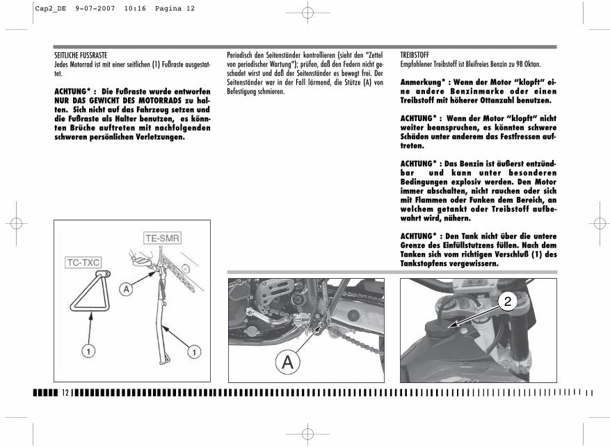
TREIBSTOFF Empfohlener Treibstoff ist Bleifreies Benzin zu 98 Oktan.
Anmerkung* : Wenn der Motor “klopft” ei-ne andere Benzinmarke oder einenTreibstoff mit höherer Ottanzahl benutzen.
ACHTUNG* : Wenn der Motor “klopft” nichtweiter beanspruchen, es könnten schwereSchäden unter anderem das Festfressen auf-treten.
ACHTUNG* : Das Benzin ist äußerst entzünd-bar und kann unter besonderenBedingungen explosiv werden. Den Motorimmer abschalten, nicht rauchen oder sichmit Flammen oder Funken dem Bereich, anwelchem getankt oder Treibstoff aufbe-wahrt wird, nähern.
ACHTUNG* : Den Tank nicht über die untereGrenze des Einfüllstutzens füllen. Nach demTanken sich vom richtigen Verschluß (1) desTankstopfens vergewissern.
Periodisch den Seitenständer kontrollieren (sieht den "Zettelvon periodischer Wartung"); prüfen, daß den Federn nicht ge-schadet wirst und daß der Seitenständer es bewegt frei. DerSeitenständer war in der Fall lärmend, die Stütze (A) vonBefestigung schmieren.
12
SEITLICHE FUSSRASTE Jedes Motorrad ist mit einer seitlichen (1) Fußraste ausgestat-tet.
ACHTUNG* : Die Fußraste wurde entworfenNUR DAS GEWICHT DES MOTORRADS zu hal-ten. Sich nicht auf das Fahrzeug setzen unddie Fußraste als Halter benutzen, es könn-ten Brüche auftreten mit nachfolgendenschweren persönlichen Verletzungen.
2
Cap2_DE 9-07-2007 10:16 Pagina 12
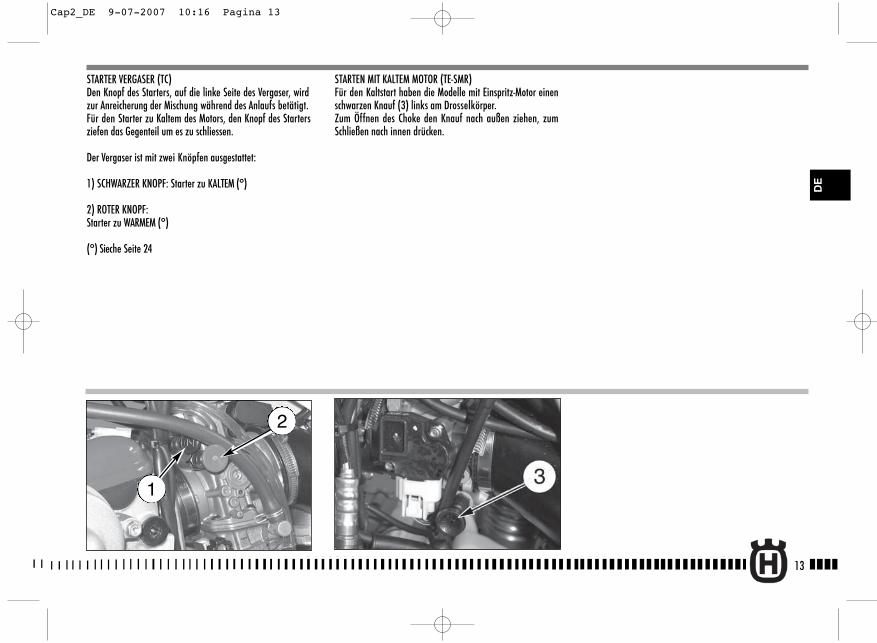
STARTER VERGASER (TC)Den Knopf des Starters, auf die linke Seite des Vergaser, wirdzur Anreicherung der Mischung während des Anlaufs betätigt.Für den Starter zu Kaltem des Motors, den Knopf des Startersziefen das Gegenteil um es zu schliessen.
Der Vergaser ist mit zwei Knöpfen ausgestattet:
1) SCHWARZER KNOPF: Starter zu KALTEM (°)
2) ROTER KNOPF: Starter zu WARMEM (°)
(°) Sieche Seite 24
STARTEN MIT KALTEM MOTOR (TE-SMR)Für den Kaltstart haben die Modelle mit Einspritz-Motor einenschwarzen Knauf (3) links am Drosselkörper.Zum Öffnen des Choke den Knauf nach außen ziehen, zumSchließen nach innen drücken.
13
DE
2
1
Cap2_DE 9-07-2007 10:16 Pagina 13
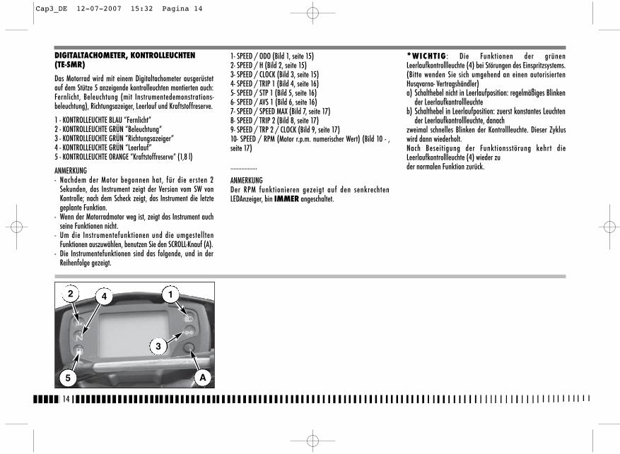
1- SPEED / ODO (Bild 1, seite 15)2- SPEED / H (Bild 2, seite 15)3- SPEED / CLOCK (Bild 3, seite 15)4- SPEED / TRIP 1 (Bild 4, seite 16)5- SPEED / STP 1 (Bild 5, seite 16)6- SPEED / AVS 1 (Bild 6, seite 16)7- SPEED / SPEED MAX (Bild 7, seite 17)8- SPEED / TRIP 2 (Bild 8, seite 17)9- SPEED / TRP 2 / CLOCK (Bild 9, seite 17)10- SPEED / RPM (Motor r.p.m. numerischer Wert) (Bild 10 - ,seite 17)
.................
ANMERKUNGDer RPM funktionieren gezeigt auf den senkrechtenLEDAnzeiger, bin IMMER angeschaltet.
*WICHTIG : Die Funktionen der grünenLeerlaufkontrollleuchte (4) bei Störungen des Einspritzsystems.(Bitte wenden Sie sich umgehend an einen autorisiertenHusqvarna- Vertragshändler)a) Schalthebel nicht in Leerlaufposition: regelmäßiges Blinken
der Leerlaufkontrollleuchteb) Schalthebel in Leerlaufposition: zuerst konstantes Leuchten
der Leerlaufkontrollleuchte, danachzweimal schnelles Blinken der Kontrollleuchte. Dieser Zykluswird dann wiederholt.Nach Beseitigung der Funktionsstörung kehr t dieLeerlaufkontrollleuchte (4) wieder zuder normalen Funktion zurück.
14
DIGITALTACHOMETER, KONTROLLEUCHTEN(TE-SMR)
Das Motorrad wird mit einem Digitaltachometer ausgerüstetauf dem Stütze 5 anzeigende kontrolleuchten montierten auch:Fernlicht, Beleuchtung (mit Instrumentedemonstrations-beleuchtung), Richtungsazeiger, Leerlauf und Kraftstoffreserve.
1 - KONTROLLEUCHTE BLAU “Fernlicht”2 - KONTROLLEUCHTE GRÜN “Beleuchtung”3 - KONTROLLEUCHTE GRÜN “Richtungsazeiger”4 - KONTROLLEUCHTE GRÜN “Leerlauf”5 - KONTROLLEUCHTE ORANGE “Kraftstoffreserve” (1,8 l)
ANMERKUNG- Nachdem der Motor begonnen hat, für die ersten 2
Sekunden, das Instrument zeigt der Version vom SW vonKontrolle; nach dem Scheck zeigt, das Instrument die letztegeplante Funktion.
- Wenn der Motorradmotor weg ist, zeigt das Instrument auchseine Funktionen nicht.
- Um die Instrumentefunktionen und die umgestelltenFunktionen auszuwählen, benutzen Sie den SCROLL-Knauf (A).
- Die Instrumentefunktionen sind das folgende, und in derReihenfolge gezeigt.
2
5
4 1
3
A
Cap3_DE 12-07-2007 15:32 Pagina 14
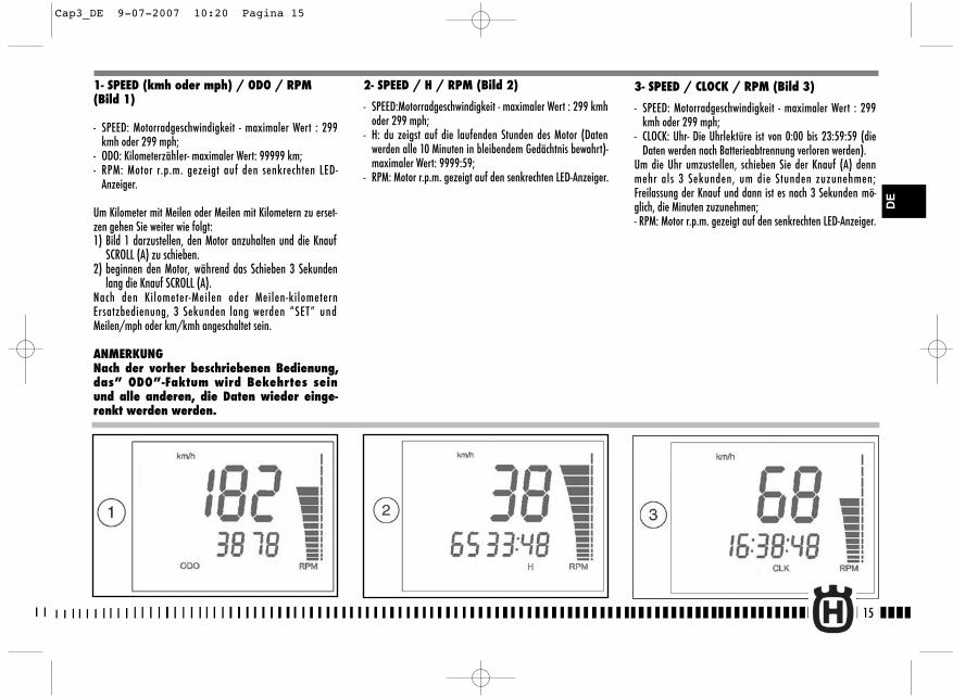
15
2- SPEED / H / RPM (Bild 2)
- SPEED:Motorradgeschwindigkeit - maximaler Wert : 299 kmhoder 299 mph;
- H: du zeigst auf die laufenden Stunden des Motor (Datenwerden alle 10 Minuten in bleibendem Gedächtnis bewahrt)-maximaler Wert: 9999:59;
- RPM: Motor r.p.m. gezeigt auf den senkrechten LED-Anzeiger.
1- SPEED (kmh oder mph) / ODO / RPM(Bild 1)
- SPEED: Motorradgeschwindigkeit - maximaler Wert : 299kmh oder 299 mph;
- ODO: Kilometerzähler- maximaler Wert: 99999 km;- RPM: Motor r.p.m. gezeigt auf den senkrechten LED-
Anzeiger.
Um Kilometer mit Meilen oder Meilen mit Kilometern zu erset-zen gehen Sie weiter wie folgt:1) Bild 1 darzustellen, den Motor anzuhalten und die Knauf
SCROLL (A) zu schieben. 2) beginnen den Motor, während das Schieben 3 Sekunden
lang die Knauf SCROLL (A). Nach den Kilometer-Meilen oder Meilen-kilometernErsatzbedienung, 3 Sekunden lang werden “SET” undMeilen/mph oder km/kmh angeschaltet sein.
ANMERKUNGNach der vorher beschriebenen Bedienung,das” ODO”-Faktum wird Bekehrtes seinund alle anderen, die Daten wieder einge-renkt werden werden.
DE
3- SPEED / CLOCK / RPM (Bild 3)
- SPEED: Motorradgeschwindigkeit - maximaler Wert : 299kmh oder 299 mph;
- CLOCK: Uhr- Die Uhrlektüre ist von 0:00 bis 23:59:59 (dieDaten werden nach Batterieabtrennung verloren werden).
Um die Uhr umzustellen, schieben Sie der Knauf (A) dennmehr als 3 Sekunden, um die Stunden zuzunehmen;Freilassung der Knauf und dann ist es nach 3 Sekunden mö-glich, die Minuten zuzunehmen;- RPM: Motor r.p.m. gezeigt auf den senkrechten LED-Anzeiger.
Cap3_DE 9-07-2007 10:20 Pagina 15
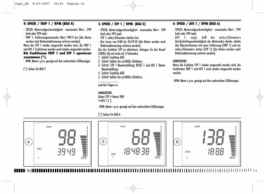
16
6- SPEED / AVS 1 / RPM (Bild 6)
- SPEED: Motorradgeschwindigkeit - maximaler Wert : 299kmh oder 299 mph;
- AVS 1: zeigt, daß der miles/kilometersDurchschnittsgeschwindigkeit des Motorrades deckte, decktedas Übereinstimmen mit einer Entfernung (TRIP 1) und einmiles/kilometers Zeiten (STP 1) (die Daten werden nachBatterieabtrennung verloren werden).
ANMERKUNGWenn die Funktion STP 1 wieder eingerenkt werden wird, dieFunktionen TRIP 1 und AVS 1 auch wieder eingerenkt werdenwerden.
- RPM: Motor r.p.m. gezeigt auf den senkrechten LEDAnzeiger.
4- SPEED / TRIP 1 / RPM (Bild 4)
- SPEED: Motorradgeschwindigkeit - maximaler Wert : 299kmh oder 299 mph;
- TRIP 1: Entfernungmaximaler Wert: 999.9 km (die Datenwerden nach Batterieabtrennung verloren werden).
Wenn die STP 1 wieder eingerenkt werden wird, die TRIP 1und AVS 1 Funktionen werden auch wieder eingerenkt werden.Die Funktionen TRIP 1 und STP 1 operierenzusammen (*).- RPM: Motor r.p.m. gezeigt auf den senkrechten LEDAnzeiger.
(*): Sehen Sie Bild 5
5- SPEED / STP 1 / RPM (Bild 5)
- SPEED: Motorradgeschwindigkeit - maximaler Wert : 299kmh oder 299 mph;
- STP 1: miles/kilometers deckte Zeit- Das Lesen von 0:00 bis 23:59:59 (die Daten werden nach
Batterieabtrennung verloren werden).Um der Funktion STP zu aktivieren, drängen Sie der KnaufSCROLL (A) auf mehr als 3 Sekunden.1. Schritt: Funktion AUF;2. Schritt: halten Sie zu-Höhle Schaltern;3. Schritt: STP 1 Neueinstellung; REISE 1 und AVS 1 Daten-
Neueinstellung;4. Schritt: Funktion AUF;5. Schritt: halten Sie zu-Höhle Schaltern;.............................und das Folgen so
ANMERKUNGDaten STP 1+Daten TRIP1=AVS 1 (*).
- RPM: Motor r.p.m. gezeigt auf den senkrechten LEDAnzeiger.
(*): Sehen Sie Bild 6
Cap3_DE 9-07-2007 10:20 Pagina 16
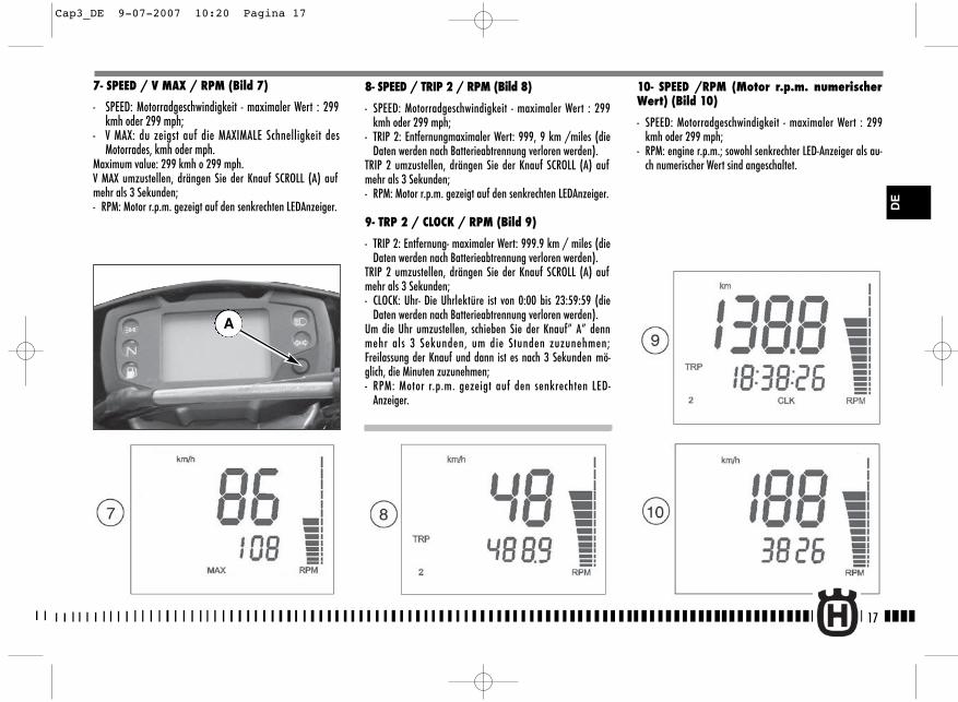
17
8- SPEED / TRIP 2 / RPM (Bild 8)
- SPEED: Motorradgeschwindigkeit - maximaler Wert : 299kmh oder 299 mph;
- TRIP 2: Entfernungmaximaler Wert: 999, 9 km /miles (dieDaten werden nach Batterieabtrennung verloren werden).
TRIP 2 umzustellen, drängen Sie der Knauf SCROLL (A) aufmehr als 3 Sekunden;- RPM: Motor r.p.m. gezeigt auf den senkrechten LEDAnzeiger.
9- TRP 2 / CLOCK / RPM (Bild 9)
- TRIP 2: Entfernung- maximaler Wert: 999.9 km / miles (dieDaten werden nach Batterieabtrennung verloren werden).
TRIP 2 umzustellen, drängen Sie der Knauf SCROLL (A) aufmehr als 3 Sekunden;- CLOCK: Uhr- Die Uhrlektüre ist von 0:00 bis 23:59:59 (die
Daten werden nach Batterieabtrennung verloren werden).Um die Uhr umzustellen, schieben Sie der Knauf” A” dennmehr als 3 Sekunden, um die Stunden zuzunehmen;Freilassung der Knauf und dann ist es nach 3 Sekunden mö-glich, die Minuten zuzunehmen;- RPM: Motor r.p.m. gezeigt auf den senkrechten LED-
Anzeiger.
10- SPEED /RPM (Motor r.p.m. numerischerWert) (Bild 10)
- SPEED: Motorradgeschwindigkeit - maximaler Wert : 299kmh oder 299 mph;
- RPM: engine r.p.m.; sowohl senkrechter LED-Anzeiger als au-ch numerischer Wert sind angeschaltet.
7- SPEED / V MAX / RPM (Bild 7)
- SPEED: Motorradgeschwindigkeit - maximaler Wert : 299kmh oder 299 mph;
- V MAX: du zeigst auf die MAXIMALE Schnelligkeit desMotorrades, kmh oder mph.
Maximum value: 299 kmh o 299 mph.V MAX umzustellen, drängen Sie der Knauf SCROLL (A) aufmehr als 3 Sekunden;- RPM: Motor r.p.m. gezeigt auf den senkrechten LEDAnzeiger.
A
DE
Cap3_DE 9-07-2007 10:20 Pagina 17

18
GASANLASSERDer Griff (1) für das Gas, der sich auf der rechten Seite desLenkers befindet. Die Schaltungs-Position auf dem Lenker kanndurch Lockern der beiden Befestigungsschrauben eingestelltwerden.
MAN BEACHTENach der Einstellung nicht vergessen, dieSchrauben (A) anzuziehen.
STEUERUNG VORDERBREMSEDer Bremshebel (2) befindet sich auf der rechten Seite desLenkers und steuert die Vorderbremse. Die Schaltungs-Positionauf dem Lenker kann durch Lockern der beidenBefestigungsschrauben eingestellt werden.
MAN BEACHTENach der Einstellung nicht vergessen, dieSchrauben (B) anzuziehen.
LENKERBLOCKUNG (TE-SMR)
Das Motorrad ist mit einer Lenkerblockung ausgerüstet (1), diesich auf der rechten Seite des Lenkers befindet.Um den Lenker zu blockieren, folgendermassen vorgehen:den Lenker in beide Richtungen drehen. Den Schlüssel in dasSchloss stecken und dem Uhrzeigersinn entgegen drehen. Ihnnach innen drücken, und, wenn nötig, den Lenker in beideRichtungen drehen. Den Sclüssel in Uhrzeigersinn drehen undihn aus dem Schloss herausziehen. Um die Lenkung freizugeben, umgekehrt operieren.
Cap4_DE 9-07-2007 10:23 Pagina 18
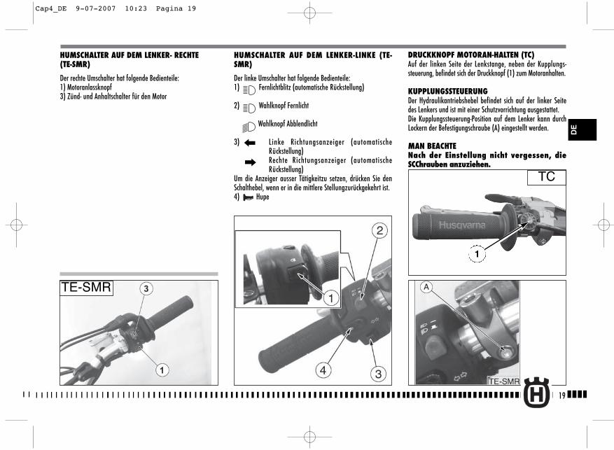
19
DRUCKKNOPF MOTORAN-HALTEN (TC)Auf der linken Seite der Lenkstange, neben der Kupplungs-steuerung, befindet sich der Druckknopf (1) zum Motoranhalten.
KUPPLUNGSSTEUERUNGDer Hydraulikantriebshebel befindet sich auf der linker Seitedes Lenkers und ist mit einer Schutzvorrichtung ausgestattet.Die Kupplungssteuerung-Position auf dem Lenker kann durchLockern der Befestigungschraube (A) eingestellt werden.
MAN BEACHTENach der Einstellung nicht vergessen, dieSCChrauben anzuziehen.
HUMSCHALTER AUF DEM LENKER- RECHTE (TE-SMR)
Der rechte Umschalter hat folgende Bedienteile:1) Motoranlassknopf3) Zünd- und Anhaltschalter für den Motor
HUMSCHALTER AUF DEM LENKER-LINKE (TE-SMR)
Der linke Umschalter hat folgende Bedienteile:1) Fernlichtblitz (automatische Rückstellung)
2) Wahlknopf Fernlicht
Wahlknopf Abblendlicht
3) Linke Richtungsanzeiger (automatischeRückstellung)Rechte Richtungsanzeiger (automatischeRückstellung)
Um die Anzeiger ausser Tätigkeitzu setzen, drücken Sie denSchalthebel, wenn er in die mittlere Stellungzurückgekehrt ist.4) Hupe
DE
TC
TE-SMR
1
Cap4_DE 9-07-2007 10:23 Pagina 19
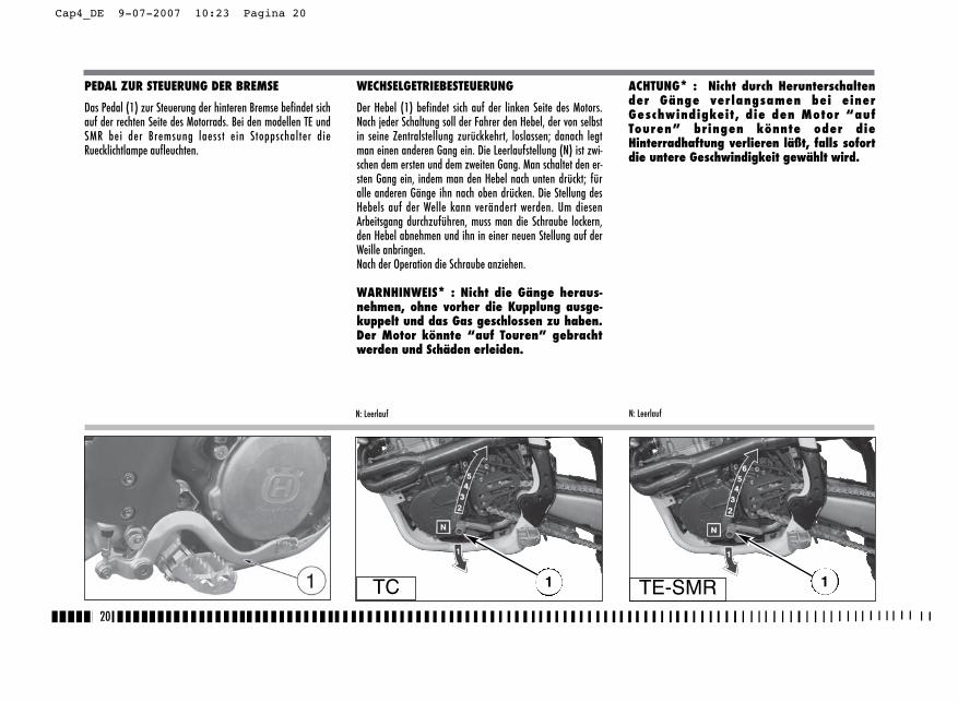
WECHSELGETRIEBESTEUERUNG
Der Hebel (1) befindet sich auf der linken Seite des Motors.Nach jeder Schaltung soll der Fahrer den Hebel, der von selbstin seine Zentralstellung zurückkehrt, loslassen; danach legtman einen anderen Gang ein. Die Leerlaufstellung (N) ist zwi-schen dem ersten und dem zweiten Gang. Man schaltet den er-sten Gang ein, indem man den Hebel nach unten drückt; füralle anderen Gänge ihn nach oben drücken. Die Stellung desHebels auf der Welle kann verändert werden. Um diesenArbeitsgang durchzuführen, muss man die Schraube lockern,den Hebel abnehmen und ihn in einer neuen Stellung auf derWeille anbringen.Nach der Operation die Schraube anziehen.
WARNHINWEIS* : Nicht die Gänge heraus-nehmen, ohne vorher die Kupplung ausge-kuppelt und das Gas geschlossen zu haben.Der Motor könnte “auf Touren” gebrachtwerden und Schäden erleiden.
ACHTUNG* : Nicht durch Herunterschaltender Gänge verlangsamen bei einerGeschwindigkeit, die den Motor “aufTouren” bringen könnte oder dieHinterradhaftung verlieren läßt, falls sofortdie untere Geschwindigkeit gewählt wird.
20
PEDAL ZUR STEUERUNG DER BREMSE
Das Pedal (1) zur Steuerung der hinteren Bremse befindet sichauf der rechten Seite des Motorrads. Bei den modellen TE undSMR bei der Bremsung laesst ein Stoppschalter dieRuecklichtlampe aufleuchten.
N: LeerlaufN: Leerlauf
TC 1 1TE-SMR
Cap4_DE 9-07-2007 10:23 Pagina 20

Die Abnutzung der Rollen, des Ritzels und des Kranzeskontrollieren. Sich vergewissern, dass die Kette korrekteingestellt und geschmiert ist.
7. Den Luftfilter und das Ansaugesystemkontrollieren.Sich vergewissern, dass der Filter sauber ist.Die Anschlusstücke aus Gummi und die Schlauchbinderkontrollieren.
8. Das Auspuffsystem kontrollieren Die Montagen kontrollieren und eventuelle schadhafteStellen feststellen.Die Schalldämpfer kontrollieren.
9. Die Verschraubungsmomente kontrollie-renA. Kerze.B. Muttern des Zylinderkopfs.C. Allgemeine Überprüfung der Verschraubungen.
10.Den Lenker kontrollierenDas Spiel der Lenkerlager kontrollieren.
11.Die elektrische Anlage überprüfen (TE-SMR).Den Motor anlassen und überprü fen, daß dieScheinwerfer, das Stoplicht und die Richtungsanzeiger,die Instrumentenbrett-Kontrolleuchten und die Hupe ein-wandfrei funktionieren.
ACHTUNG* : Die Nichtbeachtung dieser täg-lichen Überprüfungen vor der Fahrt kannernsthafte Schäden am Fahrzeug undschwere Unfälle verursachen.
21
EINFAHRZEIT
Die Dauer und die Leistungen des Motors ergeben sich nach er-folgter Einfahrt von einigen Stunden vor der Benutzung desFahrzeugs bei Wettrennen als höher und besser. Während derersten halben Stunde Fahrzeit wird empfohlen, dieGeschwindigkeit niedrig zu halten und unvorhergeseheneBeschleunigungen zu vermeiden, um den Motor nicht zu bean-spruchen.Den Ölwechsel und alle Wartungsvorgänge vorsehen. Nach derersten halben Stunde Fahrzeit, die Drehzahl, immer ohneBeanspruchung, leicht erhöhen. Nicht eine äu?erst niedrigeGeschwindigkeit einhalten, nachdem die höheren Gänge ein-geschaltet wurden.Nach ein paar Stunden können Sie beginnen, das Fahrzeugnormalerweise auf Wettrenn-Niveau zu benutzen.
KONTROLLEN WÄHRENDDES EINFAHRENS
- KONTROLLE SPANNUNG RADSPEICHEN (76);- KONTROLLE RADVERSCHRAUBUNG (siehe Seite 90-91);- KONTROLLE VERSCHRAUBUNG DER GROSSEN GABEL (siehe
Seite 90);- KONTROLLE KETTENEINSTELLUNG (siehe Seite 49);- KONTROLLE SPIEL LENKERLAGER (siehe Seite 38);- KONTROLLE LENKERVERSCHRAUBUNG (siehe Seite 90);- KONTROLLE VERSCHRAUBUNG MOTOR AM RAHMEN (siehe
Seite 90);- KONTROLLE VERSCHRAUBUNG ANSAUGEVERBINDUNGSSTÜCK
(siehe Seite 90);- KONTROLLE VERSCHRAUBUNG MUTTERN KOPF UND ZYLINDER
(siehe Seite 90);
HÄUFIG DEN STAAT VON AMT DER BATTERIE prüfen (SieheSeite84).
DASS MOTORRAD
VORKONTROLLENACHTUNG!Prüfen Sie aufmerksam diese Liste vor dem Fahren, umUnfälle oder Defekte zu vermeiden.
1. Kontrollieren Sie alle FlüssigkeitenA. Pegel Motoröl-Antrieb.B. Treibstoffpegel.C. Kühlflüssigkeitspegel.
Sich vergewissern, dass alle Stöpsel korrekt angebracht wor-den sind.ACHTUNG* : Nicht den Kühlerstopfen beiwarmem Motor abnehmen !2. Alle Steuerungen kontrollieren
A. Griff für das Gas.B. Kupplungshebel.Vergewissern Sie sich, dass die flexiblen Übersetzungennicht beschädigt worden sind und dass sie frei beweglichsind.
3. Die Bremsen kontrollierenSich vergewissern, dass keine Ölverluste bestehen unddass die Leitungen nicht abgenutzt sind.Die Funktion kontrollieren.
4. Die Aufhängungen kontrollierenDie Gabel und die hintere Aufhängung zusammen-drücken.Kontrollieren, ob keine Ölverluste bestehen und sich derkorrekten Funktion vergewissern.
5. Die Räder kontrollierenDie Speichen kontrollieren und kontrollieren, ob die Lagerkeine Abnutzungen aufweisen.Die Felgen- und die Gummireifen kontrollieren.Den Druck der Gummireifen kontrollieren.
6. Die Kettenspannrollen, das Ritzel undden Kranz kontrollieren
DE
Cap5_DE 9-07-2007 10:24 Pagina 21

22
ANMERKUNGKupplung ist auf der Stütze des Hebels montiert einenSicherheits Schalter daß es erlaubt vorzunehmen derStarter NUR mit dem Wechsel in wahnsinniges oder der stecktMarsch und sie es hebt gezogene Kupplung.
WICHTIGNIEMALS STARTEN; WENN DIE BATTERIE NICHTIM KREIS EINGESETZT IST.
AVVIAMENTO DEL MOTORE (TE-SMR)
A motore freddo, cioè dpo prolungato fermo del motocicloo inpreseza di bassa temperatura ambientale, operare nle modoseguente:1) den Zündschalterschlüssel (1) auf die Position IGNITION(Das Brummen, das beim Drehen des Schlüssels auf diePosition IGNITION zu hören ist, ist auf die Treibstoffpumpezurückzuführen, die die Versorgungsanlage unter Drucksetzt);2) den Starterhebel (2) ziehen;
3) den Kupplunghebel (3) ziehen;4) den Schalthebel (4) in Leerlaufstellung bringen und denKupplungsshalthebel freilassen;5) auf dem Zünd- und Anhaltschalter für den Motor (5) unddann auf der Anlassenknopf (6) zu drücken.Sobald der Motor im Leerlauf drehen kann, ist derStarterhebel (2) in Ausgangstellung zu drehen. Ist der Motorbeim Anlassen noch betriebswarm, dann ist der StarterhebelNICHT zu betätigen. Den Motor nicht kalt laufen lassen, damitdas Schmieröl alle Schmierstellen erreichen kann.
TE-SMR TE-SMR TE-SMR42
3
5
6
2
Cap5_DE 9-07-2007 10:24 Pagina 22

23
DE
INGANGSETZUNGSDEKOMPRESSOR
Obwohl der Motor einen automatischdekompressor benutzt, eskann notwendig sein, in einige Fälle (zum Beispiel: Sollte derVergaser oder Schwierigkeit Einschalt wegen einer Batterienicht ausreichend Amt) den dekompressor von manuellemTyp, daß es auf der Linke des Lenkers ist. In diese Fälle ist ernotwendig und dann den Hebel (5) des Dekompressor vonmanuellem Typ freizulassen zu ziehen, bevor drückt es aufdem Anlassenknopf. In diese Fälle ist er notwendig den hebel (5) zu ziehen,gleichzeitig den Anlassenknopf drücken, den hebel freilassen(5) den Anlassenknopf gedrückt erhaltend, dann auch denAnlassenknopf, freilassen.
Der Hebelhalterung (5) ist mit einem Einstellschraube 6 aus-gestattet um den Lauf zu leerem zu regeln (etwa 3 mm); eineweitere Möglichkeit von Eintragung wird vom Einstellschraube(7) angeboten, der rechterseit der Motor ist (die Eintragungauf dieses letzte ausführen, wenn es nicht möglicher ist, kor-rekt das Spiel mit der Spannvorrichtung auf der Lenker zu re-geln).
Cap5_DE 9-07-2007 10:24 Pagina 23
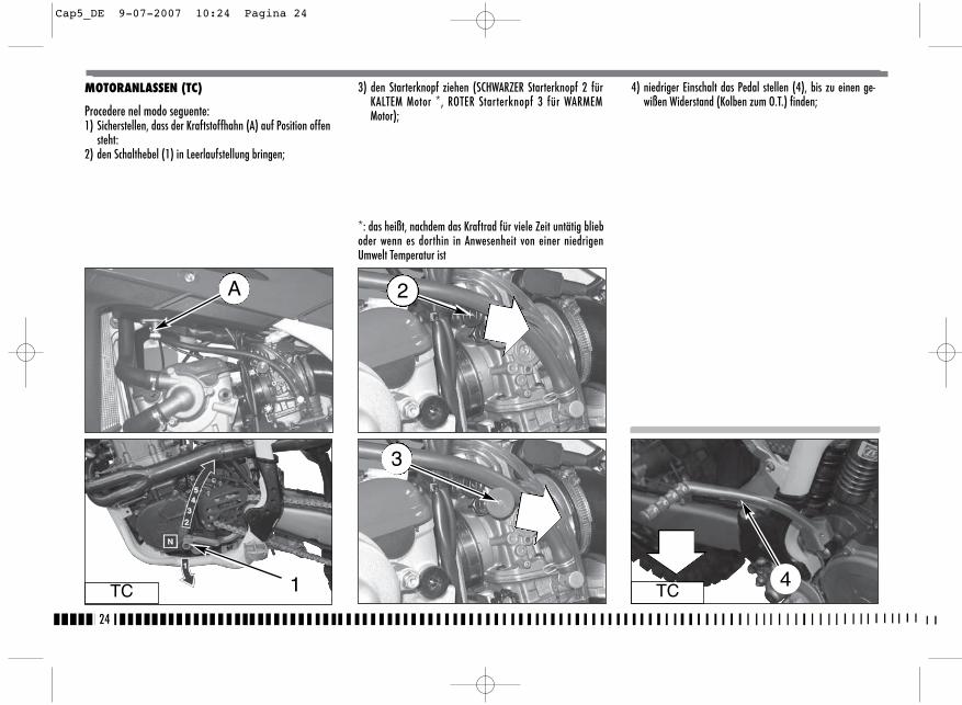
24
MOTORANLASSEN (TC)
Procedere nel modo seguente:1) Sicherstellen, dass der Kraftstoffhahn (A) auf Position offen
steht:2) den Schalthebel (1) in Leerlaufstellung bringen;
3) den Starterknopf ziehen (SCHWARZER Starterknopf 2 fürKALTEM Motor *, ROTER Starterknopf 3 für WARMEMMotor);
*: das heißt, nachdem das Kraftrad für viele Zeit untätig blieboder wenn es dorthin in Anwesenheit von einer niedrigenUmwelt Temperatur ist
TC TC1 4
4) niedriger Einschalt das Pedal stellen (4), bis zu einen ge-wißen Widerstand (Kolben zum O.T.) finden;
A 2
3
Cap5_DE 9-07-2007 10:24 Pagina 24
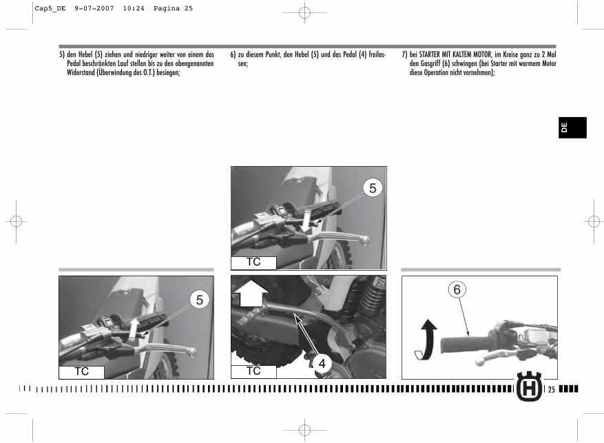
25
5) den Hebel (5) ziehen und niedriger weiter von einem dasPedal beschränkten Lauf stellen bis zu den obengenanntenWiderstand (Überwindung des O.T.) besiegen;
6) zu diesem Punkt, den Hebel (5) und das Pedal (4) freilas-sen;
7) bei STARTER MIT KALTEM MOTOR, im Kreise ganz zu 2 Malden Gasgriff (6) schwingen (bei Starter mit warmem Motordiese Operation nicht vornehmen);
TC
TC
TC4
DE
Cap5_DE 9-07-2007 10:24 Pagina 25
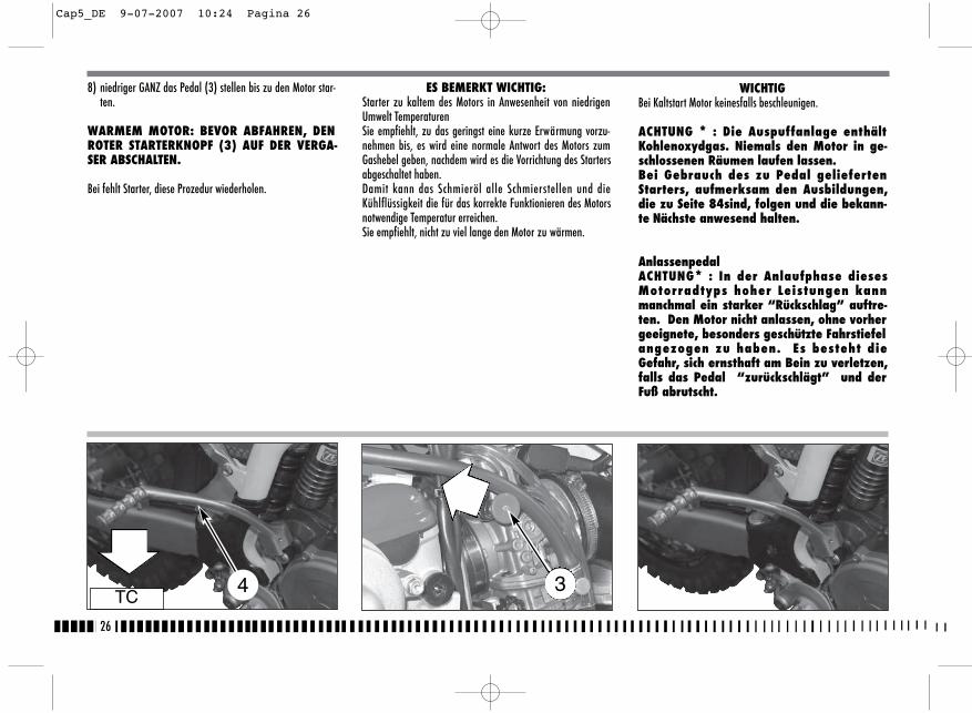
26
WICHTIGBei Kaltstart Motor keinesfalls beschleunigen.
ACHTUNG * : Die Auspuffanlage enthältKohlenoxydgas. Niemals den Motor in ge-schlossenen Räumen laufen lassen.Bei Gebrauch des zu Pedal geliefertenStarters, aufmerksam den Ausbildungen,die zu Seite 84sind, folgen und die bekann-te Nächste anwesend halten.
AnlassenpedalACHTUNG* : In der Anlaufphase diesesMotorradtyps hoher Leistungen kannmanchmal ein starker “Rückschlag” auftre-ten. Den Motor nicht anlassen, ohne vorhergeeignete, besonders geschützte Fahrstiefelangezogen zu haben. Es besteht dieGefahr, sich ernsthaft am Bein zu verletzen,falls das Pedal “zurückschlägt” und derFuß abrutscht.
8) niedriger GANZ das Pedal (3) stellen bis zu den Motor star-ten.
WARMEM MOTOR: BEVOR ABFAHREN, DENROTER STARTERKNOPF (3) AUF DER VERGA-SER ABSCHALTEN.
Bei fehlt Starter, diese Prozedur wiederholen.
ES BEMERKT WICHTIG:Starter zu kaltem des Motors in Anwesenheit von niedrigenUmwelt Temperaturen Sie empfiehlt, zu das geringst eine kurze Erwärmung vorzu-nehmen bis, es wird eine normale Antwort des Motors zumGashebel geben, nachdem wird es die Vorrichtung des Startersabgeschaltet haben. Damit kann das Schmieröl alle Schmierstellen und dieKühlflüssigkeit die für das korrekte Funktionieren des Motorsnotwendige Temperatur erreichen.Sie empfiehlt, nicht zu viel lange den Motor zu wärmen.
TC4 3
Cap5_DE 9-07-2007 10:24 Pagina 26
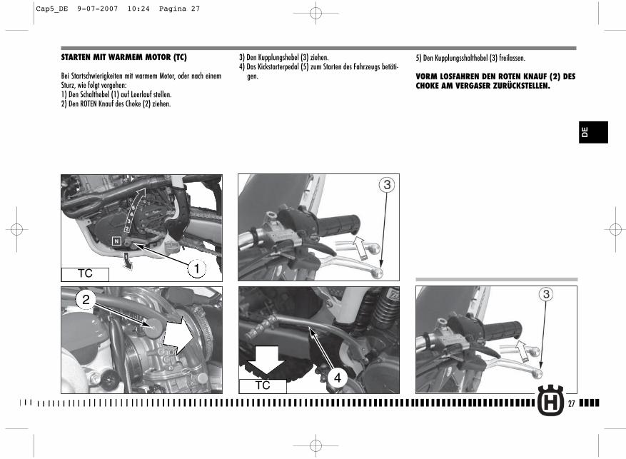
27
3) Den Kupplungshebel (3) ziehen.4) Das Kickstarterpedal (5) zum Starten des Fahrzeugs betäti-
gen.
5) Den Kupplungsshalthebel (3) freilassen.
VORM LOSFAHREN DEN ROTEN KNAUF (2) DESCHOKE AM VERGASER ZURÜCKSTELLEN.
STARTEN MIT WARMEM MOTOR (TC)
Bei Startschwierigkeiten mit warmem Motor, oder nach einemSturz, wie folgt vorgehen:1) Den Schalthebel (1) auf Leerlauf stellen.2) Den ROTEN Knauf des Choke (2) ziehen.
TC 1
TC4
DE
2
Cap5_DE 9-07-2007 10:24 Pagina 27

28
MOTORANHALT UND MOTORSTILLSTAND
- Das Gazgriff (1) vollständig schlie?en , da? das Motorradverlangsamt.
- Sowohl vorn als auch hinten beim Herunterschalten derGänge bremsen (zur starken Verlangsamung, entschiedenHebel und Bremspedale betätigen).
- Nach dem Anhalten des Motorrads, die Kupplung vollstän-dig auskuppeln und den Schalthebel (2) in Leerlaufstellungbringen.
- ROT Druckknopf (3) drüchen. - Den Treibstoffhane (4) schliessen.
- TE, SMR: im Kreise nach Linke den Schlüssel des Anla?schal-ter schwingen.
ACHTUNG*: Unter einigen Umständen kannes nützlich sein, die vordere Bremse oderdie hintere Bremse unabhängig zu benut-zen. Die vordere Bremse mit Vorsicht benut-zen, besonders auf rutschigen Geländen.Die unrichtige Anwendung der Bremsenkann schwere Unfälle verursachen.
TE-SMRTE-SMR
TC
TC
ACHTUNG * : Im Falle der Gassperrung in of-fener Position oder anderer Störung, dieden Motor unkontrollierbar drehen läßt,SOFORT den Motoranhalt-Druckknopfdrücken. Die Kontrolle des Motorrades un-ter normaler Benutzung der Bremsen undder Lenkung beim Drücken des Anhalt-Druckknopfes behalten.
4
Cap5_DE 9-07-2007 10:24 Pagina 28
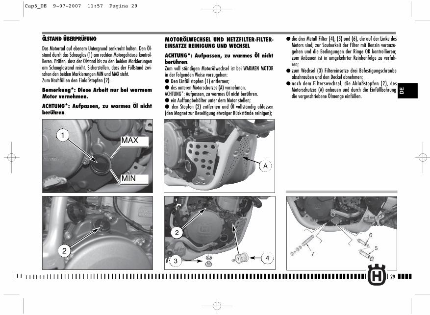
MOTORÖLWECHSEL UND NETZFILTER-FILTER-EINSATZE REINIGUNG UND WECHSEL
ACHTUNG*: Aufpassen, zu warmes Öl nichtberühren. Zum voll ständigen Motorölwechsel ist bei WARMEN MOTORin der folgenden Weise vorzugehen:● Den Einfüllstopfen (1) entfernen;● des unteren Motorschutzes (A) vornehmen.ACHTUNG*: Aufpassen, zu warmes Öl nicht berühren.● ein Auffangbehälter unter dem Motor stellen;● den Stopfen (2) entfernen und Öl vollständig ablassen(den Magnet zur Beseitigung etwaiger Rückstände reinigen);
29
● die drei Metall Filter (4), (5) und (6), die auf der Linke desMotors sind, zur Sauberkeit der Filter mit Benzin voranzu-gehen und die Bedingungen der Ringe OR kontrollieren;zum Anbauen ist in umgekehrter Reinhenfolge zu verfah-ren;
● zum Wechsel (3) Filtereinsatze drei Befestigungschraubeabschrauben und den Deckel abnehmen;
● nach dem Filterswechsel, die Ablaßstopfen (2), desMotorschutzes (A) anbauen und durch die Einfüllbohrungdie vorgeschriebene Ölmenge einfüllen.
ÖLSTAND ÜBERPRÜFUNG
Das Motorrad auf ebenem Untergrund senkrecht halten. Den Öl-stand durch das Schauglas (1) am rechten Motorgehäuse kontrol-lieren. Prüfen, dass der Ölstand bis zu den beiden Markierungenam Schauglasrand reicht. Sicherstellen, dass der Füllstand zwi-schen den beiden Markierungen MIN und MAX steht.Zum Nachfüllen den Einlaßstopfen (2).
Bemerkung*: Diese Arbeit nur bei warmemMotor vernehmen.
ACHTUNG*: Aufpassen, zu warmes Öl nichtberühren.
MAX
MIN
1
2
2
3 4
DE
A
Cap5_DE 9-07-2007 11:57 Pagina 29
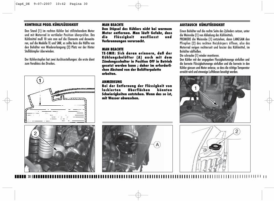
30
AUSTAUSCH KÜHLFTÜSSIGKEIT
Einen Behälter auf die rechte Seite des Zylinders setzen, unterdie Weinrebe (1) von Abladung des Kühlmittels. PREMIERE die Weinrebe (1) entziehen, dann LANGSAM denPfropfen (2) des rechten Heizkörpers öffnen, also dasMotorrad neigen rechterseit und lasciar das Kühlmittel, imBehälter abfließen. Die schraube (1) wieder montieren.Den Kühler mit der angegeben Flussigkeitsmenge einfullen unddie korrecte Flüssigkeitsmenge einfullen und die korrecte in denKühler giessen und Motor anlasse, so dass die richtige Temperaturerreicht wird und etwwaige Luftblasen beseitigt werden.
1
MAN BEACHTEDen Stöpsel des Kühlers nicht bei warmemMotor entfernen. Man läuft Gefahr, dassdie Flüssigkeit ausf liesst undVerbrennungen verursacht.
MAN BEACHTETE-SMR: Sich daran erinnern, daß derKühlungsbelüfter (A) auch mit demZündungsschalter in Position OFF in Betriebgesetzt werden kann ; daher im erforderli-chen Abstand von der Belüfterpalettearbeiten.
ANMERKUNGBei der Entfernung der Flüssigkeit vonlackierten Oberf lächen könntenSchwierigkeiten entstehen. Wenn das so ist,mit Wasser abwaschen.
KONTROLLE PEGEL KÜHLFLÜSSIGKEIT
Den Stand (1) im rechten Kühler bei stillstehendem Motorund mit Motorrad in vertikaler Position überprüfen. DasKühlmittel muß 10 sein mm auf die Elemente und desweite-ren, auf die Modelle TE und SMR, es sollte kein die Hälfte vonden Behälter von Wiedererlangung (2) Platz vor der HinterStoßdämpfer überwinden.
Der Kühlerstopfen hat zwei Auslösestellungen: die erste dientzum Vorablass des Druckes.
1
2
Cap6_DE 9-07-2007 10:42 Pagina 30

ANMERKUNG
Bei Ersatz der Kabel (1) und (2) Gas ist zur Remontage dieDimension Á. 10mm im Foto geeignet zu beachten desBefehles notwendig. Wieder dann den Deckel von Schutz (B)durch die Schraube (3) zusammensetzen und die Eintragungder Kabel auf der Lenker vornehmen, wie zuvor beschreiben. Um die Operation von Ersatz der Kabel vorzunehmen, ist ernotwendig den Behälter Treibstoff zu entfernen wie be-schreibt zu Seite 34-35.
31
Die Verbindungsmuffen von Zeit zu Zeit nachprüfen (siehe„Karte der periodischen Wartung“): um Wasserleck undMotorfressen zu vermeiden. Falls Rissigkeiten, Verhärtung,Schwellung wegen Muffenaustrocknung an den Schläuchen(A) vorhanden sind, dann sind, die Letzten auszuwechseln.Die Korrekte Befestigung der Schellen (B) kontrollieren.
B
A
EINSTELLUNG DES GASSEILZUGS
Um den Drehgasgriff auf korrekte Einstellung zu prüfen, istfolgenderweise vorzugehen:- Obere Gummikappe (1) entfernen;- Beim Vorwärts- und Rückwärtsziehen der Welle (2) ist dar-
auf zu achten, dass es ein Spiel von etwa 2 mm gibt;- Ist das nicht der Fall, Nutmutter (3) lösen und
Einstellschraube (4) drehen (zieht man die Schraube an,dann nimmt das Spiel zu; im umgekehrten Fall wird es ge-ringer);
- Nutmutter (3) neu festklemmen.
ACHTUNG * : Die Auspuffgase enthaltenKohlenoxyd. Den Motor nicht in geschlosse-nen Räumen laufen lassen.
ACHTUNG * : Das Fahrzeug mit beschädig-tem Gasschaltungskabel zu benutzen beein-trächtigt die Fahrsicherheit bemerken-swert.
DE
AB
Cap6_DE 9-07-2007 10:42 Pagina 31
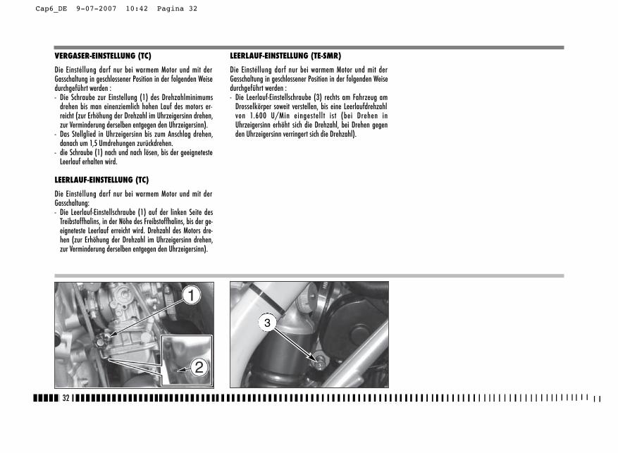
32
VERGASER-EINSTELLUNG (TC)
Die Einstéllung darf nur bei warmem Motor und mit derGasschaltung in geschlossener Position in der folgenden Weisedurchgeführt werden :- Die Schraube zur Einstellung (1) des Drehzahlminimums
drehen bis man einenziemlich hohen Lauf des motors er-reicht (zur Erhöhung der Drehzahl im Uhrzeigersinn drehen,zur Verminderung derselben entgegen den Uhrzeigersinn).
- Das Stellglied in Uhrzeigersinn bis zum Anschlag drehen,danach um 1,5 Umdrehungen zurückdrehen.
- die Schraube (1) nach und nach lösen, bis der geeignetesteLeerlauf erhalten wird.
LEERLAUF-EINSTELLUNG (TC)
Die Einstéllung darf nur bei warmem Motor und mit derGasschaltung:- Die Leerlauf-Einstellschraube (1) auf der linken Seite des
Treibstoffhalins, in der Nöhe des Freibstoffhalins, bis der ge-eigneteste Leerlauf erreicht wird. Drehzahl des Motors dre-hen (zur Erhöhung der Drehzahl im Uhrzeigersinn drehen,zur Verminderung derselben entgegen den Uhrzeigersinn).
LEERLAUF-EINSTELLUNG (TE-SMR)
Die Einstéllung darf nur bei warmem Motor und mit derGasschaltung in geschlossener Position in der folgenden Weisedurchgeführt werden :- Die Leerlauf-Einstellschraube (3) rechts am Fahrzeug am
Drosselkörper soweit verstellen, bis eine Leerlaufdrehzahlvon 1.600 U/Min eingestellt ist (bei Drehen inUhrzeigersinn erhöht sich die Drehzahl, bei Drehen gegenden Uhrzeigersinn verringert sich die Drehzahl).
3
Cap6_DE 9-07-2007 10:42 Pagina 32
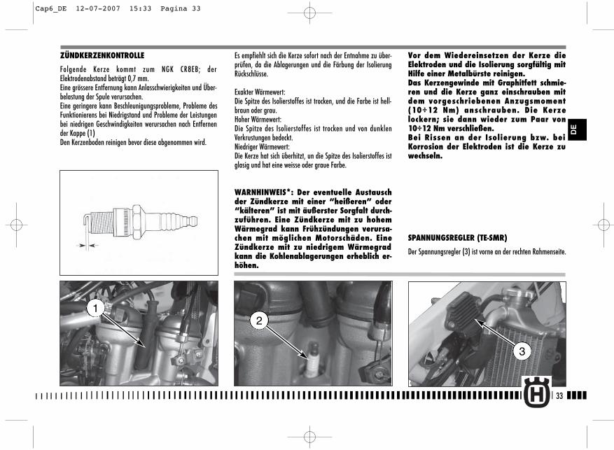
33
ZÜNDKERZENKONTROLLE
Folgende Kerze kommt zum NGK CR8EB; derElektrodenabstand beträgt 0,7 mm.Eine grössere Entfernung kann Anlasschwierigkeiten und Über-belastung der Spule verursachen.Eine geringere kann Beschleunigungsprobleme, Probleme desFunktionierens bei Niedrigstand und Probleme der Leistungenbei niedrigen Geschwindigkeiten werursachen nach Entfernender Kappe (1)Den Kerzenboden reinigen bevor diese abgenommen wird.
Es empfiehlt sich die Kerze sofort nach der Entnahme zu über-prüfen, da die Ablagerungen und die Färbung der IsolierungRückschlüsse.
Exakter Wärmewert:Die Spitze des Isolierstoffes ist trocken, und die Farbe ist hell-braun oder grau.Hoher Wärmewert:Die Spitze des Isolierstoffes ist trocken und von dunklenVerkrustungen bedeckt.Niedriger Wärmewert:Die Kerze hat sich überhitzt, un die Spitze des Isolierstoffes istglasig und hat eine weisse oder graue Farbe.
WARNHINWEIS*: Der eventuelle Austauschder Zündkerze mit einer “heißeren” oder“kälteren” ist mit äußerster Sorgfalt durch-zuführen. Eine Zündkerze mit zu hohemWärmegrad kann Frühzündungen verursa-chen mit möglichen Motorschäden. EineZündkerze mit zu niedrigem Wärmegradkann die Kohlenablagerungen erheblich er-höhen.
Vor dem Wiedereinsetzen der Kerze dieElektroden und die Isolierung sorgfältig mitHilfe einer Metalbürste reinigen.Das Kerzengewinde mit Graphitfett schmie-ren und die Kerze ganz einschrauben mitdem vorgeschriebenen Anzugsmoment(10÷12 Nm) anschrauben. Die Kerzelockern; sie dann wieder zum Paar von10÷12 Nm verschließen. Bei Rissen an der Isolierung bzw. beiKorrosion der Elektroden ist die Kerze zuwechseln.
SPANNUNGSREGLER (TE-SMR)
Der Spannungsregler (3) ist vorne an der rechten Rahmenseite.
2
3
1
DE
Cap6_DE 12-07-2007 15:33 Pagina 33
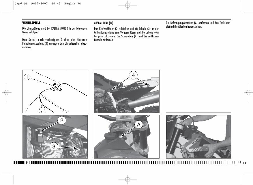
AUSBAU TANK (TC)
Den Kraftstoffhahn (2) schließen und die Schelle (3) an derVerbindungsleitung zum Vergaser lösen und die Leitung vomVergaser abziehen. Die Schrauben (4) und die seitlichenPaneele entfernen.
Die Befestigungsschraube (A) entfernen und den Tank kom-plett mit Leitblechen herausziehen.
34
VENTILSPIELS
Die Uberprüfung muß bei KALTEM MOTOR in der folgendenWeise erfolgen:
Den Sattel, nach vorherigem Drehen des hinterenBefestigungszapfens (1) entgegen den Uhrzeigersinn, abzu-nehmen;
2
3
4
A
Cap6_DE 9-07-2007 10:42 Pagina 34
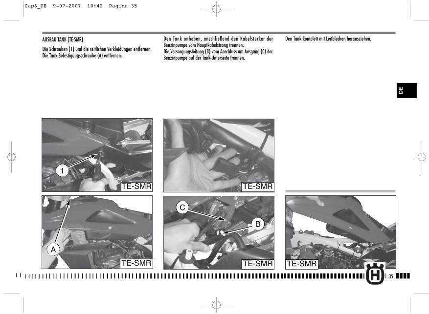
Den Tank anheben, anschließend den Kabelstecker derBenzinpumpe vom Hauptkabelstrang trennen.Die Versorgungsleitung (B) vom Anschluss am Ausgang (C) derBenzinpumpe auf der Tank-Unterseite trennen.
AUSBAU TANK (TE-SMR)
Die Schrauben (1) und die seitlichen Verkleidungen entfernen.Die Tank-Befestigungsschraube (A) entfernen.
Den Tank komplett mit Leitblechen herausziehen.
35
TE-SMR
B
TE-SMR
C
A
TE-SMR
TE-SMR
1
TE-SMR
DE
Cap6_DE 9-07-2007 10:42 Pagina 35

Andernfalls, die Klammer heben (7) ihm einen Haken benut-zend, den Schwinghebel gleiten machen einerseits, mit einerPinzette die Einstellscheibe herausziehen und die Dicke davonprüfen; Aufgrund der vorspringenden Dicke wird die neueEinstellscheibe (zu Austausch Einstellscheiben montieren mitDicke von 1,60 geliefert mm zu 2,60 mm mit Erhöhungen von0,05 mm) und wieder im Sitz die Klammer und denSchwinghebel bringen; Nochmal das Spiel der Ventile prüfen und, wenn korrekt, wie-der die Details, die umgekehrt bezüglich der Zerlegung voran-gehend, zerlegt wurden, zusammensetzen
36
Das Ventilspiel, das 0,10÷0,15 mm für den ANSAUGSEITE und0,15÷0,20 mm für den AUSPUFFSEITE muß, mit einemDickenmesser überprüfen;
Die Zündkerze (5), den vier Schrauben (6) und ZylinderkopfDeckel abnehmen;Den Wechsel des Motors in 2. Gang stellen und vorn schiebend,und rückwärts das Motorrad, dem Höheren Totpunkt denKolben bringen (in diese Bedingung, die Kerbe auf derZylinderkopf überschneidet sic h mit den zwei Bezügen aufder Zahnradvorgelege der Nockenwellen , wie auf der Figurgezeit wird);
Cap6_DE 9-07-2007 10:42 Pagina 36
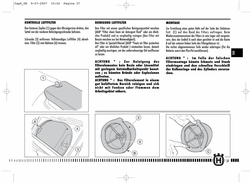
REINIGUNG LUFTFILTER
Den Filter mit einem spezifischen Reinigungsmittel waschen(AGIP "Filter clean foam air detergent fluid" oder ein ähnli-ches Produkt) und es sorgfaeltig reinigen (den Filter mitBenzin waschen nur bei Notwendigkeit).Den Filter in Spezial-Filteroel (AGIP "Foam air filter protectionoil" oder ein ähnliches Produkt ) eintauchen lassen, danachsorgfaeltig ausringen, um das uebersohuessige Oel ausfliessenzu lassen.
ACHTUNG * : Zur Reinigung desFilterelementes kein Bezin oder Lösemittelmit geringem Entzündbarkeitspunkt benut-zen ; es könnten Brände oder Explosionenauftreten.ACHTUNG * : Das Filterelement in einemgut belüftetem Bereich reinigen und sichnicht mit Funken oder Flammen demArbeitsgebiet nähern.
MONTAGE
Zur Erreichung eines guten Halts auf der Seite des GehäusesFett (C) auf den Rand des Filters auf tragen. BeimWiederzusammensetzen des Filters in sein Lager sich vergewis-sern, dass der Endteil A nach oben gerichtet ist und die KanteB auf der unteren linken Seite des Filtergehäuses ist.Die vorher abgenommenen Teile wieder anbringen (für dieBatterie zuerst den Plus-Pol anschliessen).
ACHTUNG * : Im Falle der falschenFiltermontage könnte Schmutz und Staubeindringen und den schnellen Verschleißder Kolbenringe und des Zylinders verursa-chen.
37
KONTROLLE LUFTFILTER
Den hinteren Zapfen (1) gegen den Uhrzeigersinn drehen, denSattel von der vorderen Befestigungsschraube befreien.
Schraube (3) entfernen. Vollstaendiges Luftfilter (4) abneh-men. Filter (5) vom Rahmen (6) trennen.
DE
Cap6_DE 9-07-2007 10:42 Pagina 37
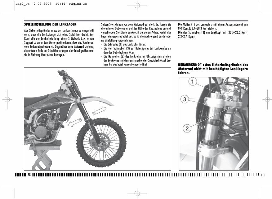
38
SPIELEINSTELLUNG DER LENKLAGER
Aus Sicherheitsgründen muss der Lenker immer so eingestelltsein, dass die Lenkstange sich ohne Spiel frei dreht. ZurKontrolle der Lenkeinstellung einen Stützbock bzw. einenSupport so unter dem Motor positionieren, dass das Vorderradvom Boden abgehoben ist. Gegenüber dem Motorrad stehend,die unteren Ende der Schafthalterungen der Gabel greifen undsie in Richtung ihrer Achse bewegen.
Setzen Sie sich nun vor dem Motorrad auf die Erde, fassen Siedie unteren Gabelenden auf der Höhe des Radzapfens an undverschieben Sie diese senkrecht zu deren Achse; weist dasLager ein gewisses Spiel auf, so ist die nachfolgend beschriebe-ne Einstellung vorzunehmen:- Die Schraube (1) des Lenkrohrs lösen.- Die vier Schrauben (3) zur Befestigung des Lenkkopfes an
den der Gabelholmen lösen- Die Nutmutter (2) des Lenkrohrs im Uhrzeigersinn drehen
des Lenkrohrs mit dem entsprechenden Spezialschlüssel dre-hen, bis das Spiel korrekt eingestellt ist
Die Mutter (1) des Lenkrohrs mit einem Anzugsmoment von8÷9 Kgm.(78,4÷88,3 Nm) sichern. Die vier Schrauben (3) am Lenkkopf mit 22,5÷26,5 Nm (2,3÷2,7 Kgm).
BENMERKUNG* : Aus Sicherheitsgründen dasMotorrad nicht mit beschädigten Lenklagernfahren.
Cap7_DE 9-07-2007 10:44 Pagina 38
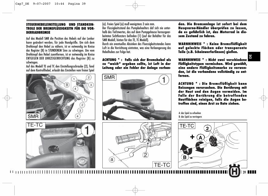
A
B
+
-
2TE-TC
(a). Freies Spiel (a) muß wenigstens 3 sein mm. Der Flussigkeitsstand des Pumpbehaelters daf sich nie unter-halb des Tiefstwertes, des auf dem Pumpgehause herausgear-beiteten Sichtfensters befinden (1) (auf der Behälter für dasSMR Modell, hinten für das TE, TC Modell).Durch ein eventuelles Absinken des Fluessigkeitsstandes kannLuft in die Vorrichtung eintreten, was eine Verlaengerung desHebelhubes zur Folge hat.
ACHTUNG * : Falls sich der Bremshebel alszu “weich” ergeben sollte, ist Luft in derLeitung oder ein Fehler der Anlage vorhan-
den. Die Bremsanlage ist sofort bei demHusqvarna-Händler überprüfen zu lassen,da es gefährlich ist, das Motorrad in die-sem Zustand zu fahren.
WARNHINWEIS * : Keine Bremsflüßigkeitauf gelackte Flächen oder transparenteTeile (z.B. Scheinwerferlinsen) gießen.
WARNHINWEIS * : Nicht zwei verschiedeneFlüßigkeitstypen vermischen. Wird gewählt,eine andere Flüßigkeitsmarke zu verwen-den, ist die vorhandene vollständig zu ent-fernen.
ACHTUNG * : Die Bremsflüßigkeit kannReizungen verursachen. Die Berührung mitder Haut und den Augen vermeiden. ImFalle der Berührung die betreffendenHautflächen reinigen, falls die Augen be-troffen sind, einen Arzt zu Rate ziehen.
39
DE
STEUERHEBELEINSTELLUNG UND STANDKON-TROLE DER BREMSFLÜSSIGKEITN FÜR DIE VOR-DERRADBREMSE
Auf das Modell SMR die Position des Hebels auf der Lenkerkann geändert werden, für jede Handgröße. Um sich demDrehknopf den Hebel zu nähern, ist er notwendig im Kreisedas Register (B) in STUNDENEM Sinn zu schwingen. Um vomDrehknopf den Hebel zuentfernen, ist er notwendig im KreiseENTGEGEN DER UHRZEIGERRICHTUNG das Register (B) zuschwingen.Auf das Modell TE und TC den Einstellungsschraube (2), fandauf dem Kontrollhebel, erlaubt das Einstellen vom freien Spiel
SMR
A: das Spiel zu erhoehenB: das Spiel zu verringernSMR
Cap7_DE 9-07-2007 10:44 Pagina 39
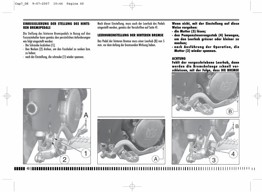
40
Nach dieser Einstellung, muss auch der Leerhub des Pedalseingestellt werden, gemäss der Vorschriften auf Seite 41.
LEERHUBEINSTELLUNG DER HINTEREN BREMSE
Das Pedal der hinteren Bremse muss einer Leerhub (B) von 5mm. vor dem Anfang der bremsenden Wirkung haben.
Wenn nicht, mit der Einstellung auf dieseWeise vorgehen:- die Mutter (3) lösen;- den Pumpensteuerungsstab (4) bewegen,
um den Leerhub grösser oder kleiner zumachen;
- nach Ausführung der Operation, dieMutter (3) wieder spannen.
ACHTUNGFehlt der vorgeschriebene Leerhub, dannwerden die Bremsbelaege schnell ver-schleissen, mit der Folge, dass DIE BREMSEVOELLIG UNWIRKSAM WIRD.
EINREGULIERUNG DER STELLUNG DES HINTE-REN BREMSPEDALS
Die Stellung des hinteren Bremspedals in Bezug auf denFussrastehalter kann gemäss den persönlichen Anforderungenwie folgt eingestellt werden:- Die Schraube losdrehen (1);- Den Nocken (2) drehen, um den Fusshebel zu senken bzw.
zu heben;- nach der Einstellung, die schraube (1) wieder spannen.
Cap7_DE 9-07-2007 10:44 Pagina 40
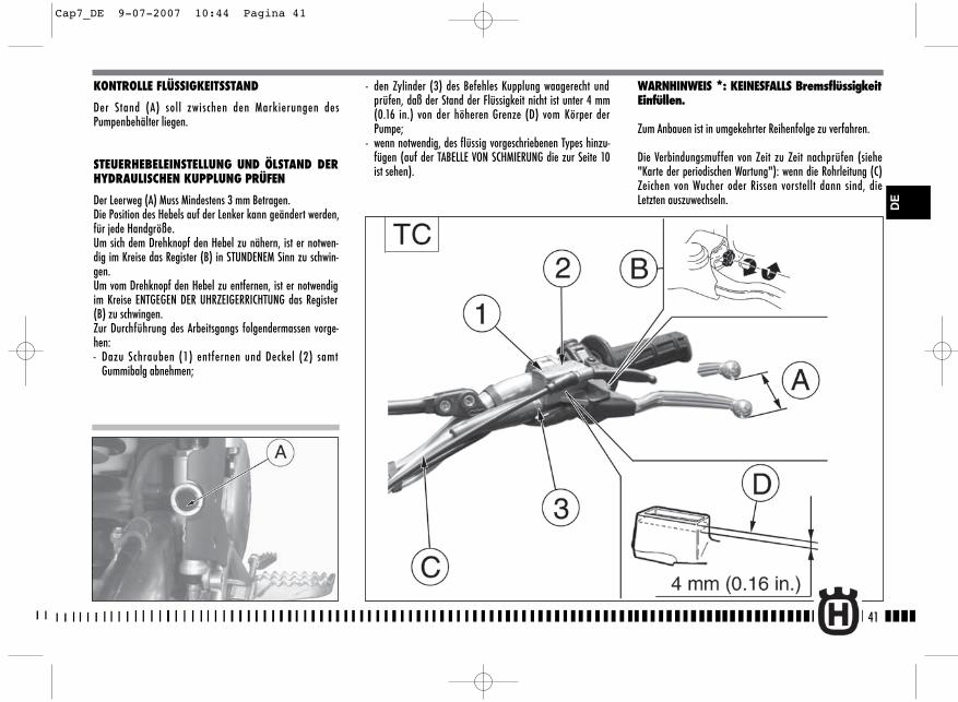
41
KONTROLLE FLÜSSIGKEITSSTAND
Der Stand (A) soll zwischen den Markierungen desPumpenbehälter liegen.
STEUERHEBELEINSTELLUNG UND ÖLSTAND DERHYDRAULISCHEN KUPPLUNG PRÜFEN
Der Leerweg (A) Muss Mindestens 3 mm Betragen.Die Position des Hebels auf der Lenker kann geändert werden,für jede Handgröße.Um sich dem Drehknopf den Hebel zu nähern, ist er notwen-dig im Kreise das Register (B) in STUNDENEM Sinn zu schwin-gen.Um vom Drehknopf den Hebel zu entfernen, ist er notwendigim Kreise ENTGEGEN DER UHRZEIGERRICHTUNG das Register(B) zu schwingen.Zur Durchführung des Arbeitsgangs folgendermassen vorge-hen:- Dazu Schrauben (1) entfernen und Deckel (2) samt
Gummibalg abnehmen;
- den Zylinder (3) des Befehles Kupplung waagerecht undprüfen, daß der Stand der Flüssigkeit nicht ist unter 4 mm(0.16 in.) von der höheren Grenze (D) vom Körper derPumpe;
- wenn notwendig, des flüssig vorgeschriebenen Types hinzu-fügen (auf der TABELLE VON SCHMIERUNG die zur Seite 10ist sehen).
WARNHINWEIS *: KEINESFALLS BremsflüssigkeitEinfüllen.
Zum Anbauen ist in umgekehrter Reihenfolge zu verfahren.
Die Verbindungsmuffen von Zeit zu Zeit nachprüfen (siehe"Karte der periodischen Wartung"): wenn die Rohrleitung (C)Zeichen von Wucher oder Rissen vorstellt dann sind, dieLetzten auszuwechseln. D
E
Cap7_DE 9-07-2007 10:44 Pagina 41
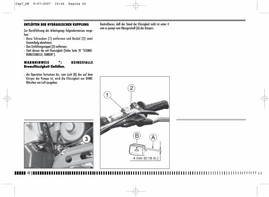
42
ENTLÜFTEN DER HYDRAULISCHEN KUPPLUNG
Zur Durchführung des Arbeitsgangs folgendermassen vorge-hen:- Dazu Schrauben (1) entfernen und Deckel (2) samt
Gummibalg abnehmen;- Den Entlüftungsnippel (3) entfernen;- Statt dessen die mit Fluessigkeit (Siehe Seite 10 “SCHMIE-
RUNGSTABELLE, TANKEN”).
WARNHINWEIS *: KEINESFALLSBremsflüssigkeit Einfüllen.
- die Operation fortsetzen bis, vom Loch (B) das auf demKörper der Pumpe ist, wird die Flüssigkeit nur OHNEBläschen von Luft ausgehen.
Kontrollieren, daß der Stand der Flüssigkeit nicht ist unter 4mm es pumpt vom Obergeschoß (A) des Körpers.
Cap7_DE 9-07-2007 10:44 Pagina 42
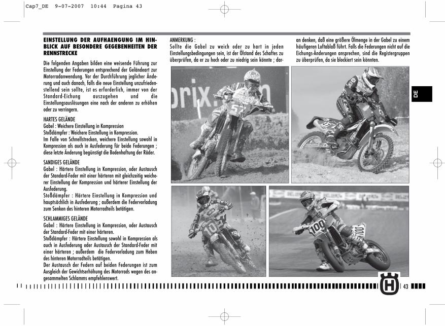
43
EINSTELLUNG DER AUFHAENGUNG IM HIN-BLICK AUF BESONDERE GEGEBENHEITEN DERRENNSTRECKE
Die folgenden Angaben bilden eine weisende Führung zurEinstellung der Federungen entsprechend der Geländeart zurMotorradanwendung. Vor der Durchführung jeglicher Ände-rung und auch danach, falls die neue Einstellung unzufrieden-stellend sein sollte, ist es erforderlich, immer von derStandard-Eichung auszugehen und dieEinstellungsauslösungen eine nach der anderen zu erhöhenoder zu verringern.
HARTES GELÄNDEGabel : Weichere Einstellung in KompressionStoßdämpfer : Weichere Einstellung in Kompression.Im Falle von Schnellstrecken, weichere Einstellung sowohl inKompression als auch in Ausfederung für beide Federungen ;diese letzte Änderung begünstigt die Bodenhaftung der Räder.
SANDIGES GELÄNDEGabel : Härtere Einstellung in Kompression, oder Austauschder Standard-Feder mit einer härteren mit gleichzeitig weiche-rer Einstellung der Kompression und härterer Einstellung derAusfederung. Stoßdämpfer : Härtere Einstellung in Kompression undhauptsächlich in Ausfederung ; außerdem die Federvorladungzum Senken des hinteren Motorradteils betätigen.
SCHLAMMIGES GELÄNDEGabel : Härtere Einstellung in Kompression, oder Austauschder Standard-Feder mit einer härteren.Stoßdämpfer : Härtere Einstellung sowohl in Kompression alsauch in Ausfederung oder Austausch der Standard-Feder miteiner härteren ; außerdem die Federvorladung zum Hebendes hinteren Motorradteils betätigen.Der Austausch der Federn auf beiden Federungen ist zumAusgleich der Gewichtserhöhung des Motorrads wegen des an-gesammelten Schlamms empfehlenswert.
ANMERKUNG :Sollte die Gabel zu weich oder zu har t in jedenEinstellungsbedingungen sein, ist der Ölstand des Schaftes zuüberprüfen, da er zu hoch oder zu niedrig sein könnte ; dar-
an denken, daß eine größere Ölmenge in der Gabel zu einemhäufigeren Luftablaß führt. Falls die Federungen nicht auf dieEichungs-Änderungen ansprechen, sind die Registergruppenzu überprüfen, da sie blockiert sein könnten.
DE
Cap7_DE 9-07-2007 10:44 Pagina 43

44
Die Standard-Eichungen und die Einstellverfahren sind auf denfolgenden Seiten angegeben ; die auf Anfrage zur Verfügungstehenden Federn, zusammen mit den entsprechendenVorladungs-Abstandsstücken, sind auf den Seiten 93, 94, 95aufgeführt.
EINSTELLUNG GABEL
a) EINFEDERUNG (unteres Stellglied)Standardjustierung: -15 Klicks (TC)Standardjustierung: -12 Klicks (TE-SMR)Will man die Standardjustierung wiederherstellen, den Stopfen(B) entfernen und das Stellglied (A) in Uhrzeigersinn bis zum
Anschlag drehen, danach um Klicks zurückdrehen. Für eineweichere Bremsung, das Stellglied gegen den Uhrzeigersinndrehen; für eine härtere Bremsung in umgekehrter Weise vor-gehen.
b) AUSFEDERUNG (oberes Stellglied) Standardjustierung: - Standardjustierung: -15 Klicks (TC)Standardjustierung: -12 Klicks (TE-SMR) Falls es notwendig ist, die Standardjustierung wieder herzustel-len, das Stellglied (C) in den Uhrzeigersinn bis zum Anschlagdrehen, danach um Klicks zurückdrehen. Für eine weichereBremsung, das Stellglied gegen den Uhrzeigersinn drehen; füreine härtere Bremsung in umgekehrter Weise vorgehen.
c) LUFTABLASSTE-SMR: Das Ventil (D) öffnen, das Motorrad auf einen mitti-gen Bock stellen und die Gabel vollständig ausstrecken (nachjedem Rennen oder monatlich). Das Ventil nach ausgeführtemVorgang schliessen.TC: Das Fahrzeug auf den Hauptständer stellen, die Gabel voll-ständig ausfahren, die Kappe (E) abnehmen und mit einer Spitzeauf das kleine Ventil drücken. Die Kappe wieder anbringen.ACHTUNG!NIEMALS die Schraube (F) lockern.
HINWEIS Stellschraube nicht jenseits der maxima-len Öffnug bzw. Schliessung drehen.
A
B
CD
a)
b)TC
TC
TE-SMR
TE-SMR
E
C
C
F
C
Cap7_DE 12-07-2007 15:34 Pagina 44
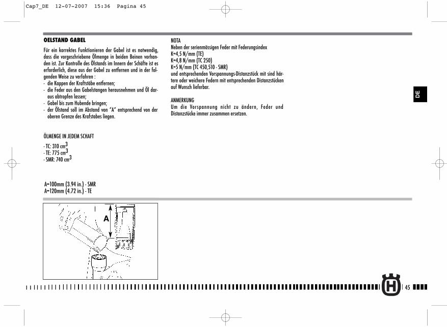
OELSTAND GABEL
Für ein korrektes Funktionieren der Gabel ist es notwendig,dass die vorgeschriebene Ölmenge in beiden Beinen vorhan-den ist. Zur Kontrolle des Ölstands im Innern der Schäfte ist eserforderlich, diese aus der Gabel zu entfernen und in der fol-genden Weise zu verfahren :- die Kappen der Kraftstäbe entfernen;- die Feder aus den Gabelstangen herausnehmen und Öl dar-
aus abtropfen lassen;- Gabel bis zum Hubende bringen;- der Ölstand soll im Abstand von “A” entsprechend von der
oberen Grenze des Krafstabes liegen.
ÖLMENGE IN JEDEM SCHAFT
- TC: 310 cm3- TE: 775 cm3- SMR: 740 cm3
A=100mm (3.94 in.) - SMRA=120mm (4.72 in.) - TE
A
NOTANeben der serienmässigen Feder mit FederungsindexK=4,5 N/mm (TE) K=4,8 N/mm (TC 250) K=5 N/mm (TC 450,510 - SMR)und entsprechenden Vorspannungs-Distanzstück mit sind här-tere oder weichere Federn mit entsprechenden Distanzstückenauf Wunsch lieferbar.
ANMERKUNGUm die Vorspannung nicht zu ändern, Feder undDistanzstücke immer zusammen ersetzen.
45
DE
Cap7_DE 12-07-2007 15:36 Pagina 45
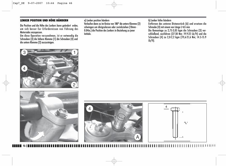
46
b) Lenker höhe händernEntfernen das unteren Distanzstück (A) und ersetzen dieSchraube (4) mit einem von Länge L=65 mm Die Remontage zu 2,75-3,05 kgm die Schrauben (3) ver-schließend, ausführen (27-30 Nm; 19.9-22 Lb/ft) und dieSchrauben (4) zu 2,0-2,2 kgm (19,6-21,6 Nm; 14.5-15.9Lb/ft).
LENKER POSITION UND HÖHE HÄNDERN
Die Position und die Höhe des Lenkers kann geändert erden,um sich besser Eur Er fordernissen von Führung desMotorrades anzupassen.Um diese Operation vorzunehmen, ist er notwendig dieSchrauben (3) die höhere Klemme (1) die Schrauben (4) unddie untere Klemme (2) auszusteigen.
a) Lenker position händernVerlaufen dann zu im Kreise von 180° die untere Klemme (2)schwingen um übrigzulassen oder zurückziehen (10mm -0.04in.) die Position des Lenkers in Beziehung zu jenerInitiale.
Cap7_DE 9-07-2007 10:44 Pagina 46
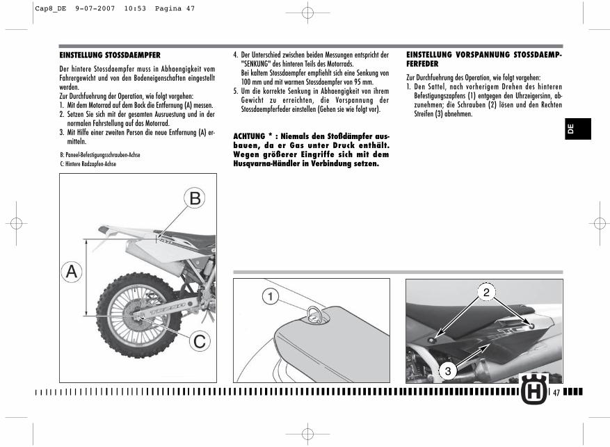
4. Der Unterschied zwischen beiden Messungen entspricht der"SENKUNG" des hinteren Teils des Motorrads.Bei kaltem Stossdaempfer empfiehlt sich eine Senkung von100 mm und mit warmen Stossdaempfer von 95 mm.
5. Um die korrekte Senkung in Abhaengigkeit von ihremGewicht zu erreichten, die Vorspannung derStossdaempferfeder einstellen (Gehen sie wie folgt vor).
ACHTUNG * : Niemals den Stoßdämpfer aus-bauen, da er Gas unter Druck enthält.Wegen größerer Eingriffe sich mit demHusqvarna-Händler in Verbindung setzen.
EINSTELLUNG VORSPANNUNG STOSSDAEMP-FERFEDER
Zur Durchfuehrung des Operation, wie folgt vorgehen:1. Den Sattel, nach vorherigem Drehen des hinteren
Befestigungszapfens (1) entgegen den Uhrzeigersinn, ab-zunehmen; die Schrauben (2) lösen und den RechtenStreifen (3) abnehmen.
47
EINSTELLUNG STOSSDAEMPFER
Der hintere Stossdaempfer muss in Abhaengigkeit vomFahrergewicht und von den Bodeneigenschaften eingestelltwerden.Zur Durchfuehrung der Operation, wie folgt vorgehen:1. Mit dem Motorrad auf dem Bock die Entfernung (A) messen.2. Setzen Sie sich mit der gesamten Ausruestung und in der
normalen Fahrstellung auf das Motorrad.3. Mit Hilfe einer zweiten Person die neue Entfernung (A) er-
mitteln.
B: Paneel-Befestigungsschrauben-AchseC: Hintere Radzapfen-Achse
2
3
DE
Cap8_DE 9-07-2007 10:53 Pagina 47
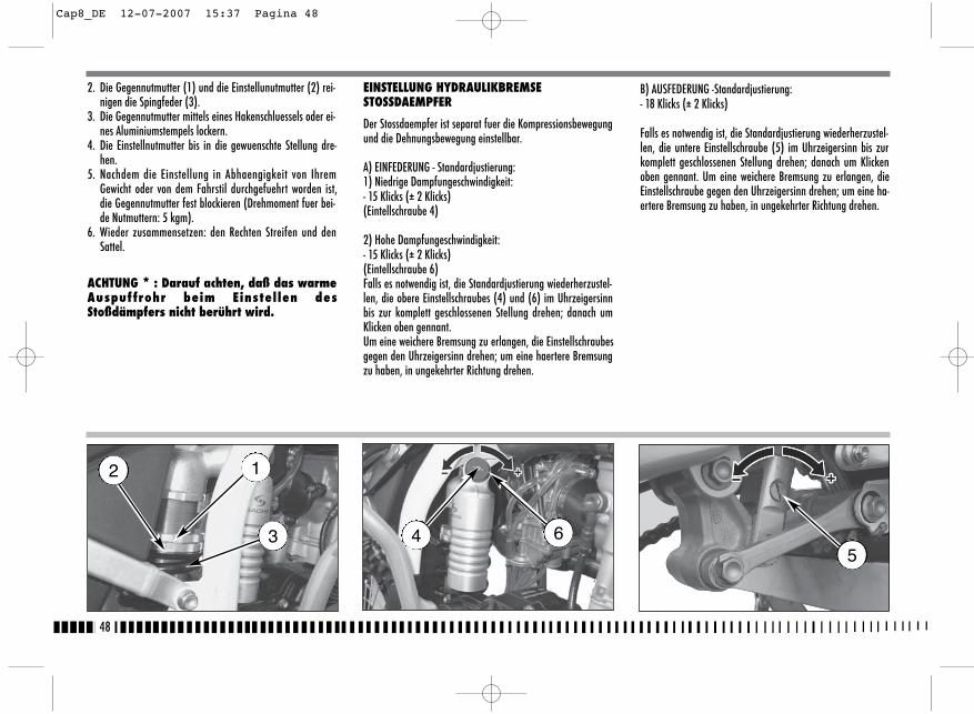
B) AUSFEDERUNG -Standardjustierung:- 18 Klicks (± 2 Klicks)
Falls es notwendig ist, die Standardjustierung wiederherzustel-len, die untere Einstellschraube (5) im Uhrzeigersinn bis zurkomplett geschlossenen Stellung drehen; danach um Klickenoben gennant. Um eine weichere Bremsung zu erlangen, dieEinstellschraube gegen den Uhrzeigersinn drehen; um eine ha-ertere Bremsung zu haben, in ungekehrter Richtung drehen.
2. Die Gegennutmutter (1) und die Einstellunutmutter (2) rei-nigen die Spingfeder (3).
3. Die Gegennutmutter mittels eines Hakenschluessels oder ei-nes Aluminiumstempels lockern.
4. Die Einstellnutmutter bis in die gewuenschte Stellung dre-hen.
5. Nachdem die Einstellung in Abhaengigkeit von IhremGewicht oder von dem Fahrstil durchgefuehrt worden ist,die Gegennutmutter fest blockieren (Drehmoment fuer bei-de Nutmuttern: 5 kgm).
6. Wieder zusammensetzen: den Rechten Streifen und denSattel.
ACHTUNG * : Darauf achten, daß das warmeAuspuffrohr beim Einstellen desStoßdämpfers nicht berührt wird.
EINSTELLUNG HYDRAULIKBREMSESTOSSDAEMPFER
Der Stossdaempfer ist separat fuer die Kompressionsbewegungund die Dehnungsbewegung einstellbar.
A) EINFEDERUNG - Standardjustierung:1) Niedrige Dampfungeschwindigkeit: - 15 Klicks (± 2 Klicks)(Eintellschraube 4)
2) Hohe Dampfungeschwindigkeit:- 15 Klicks (± 2 Klicks)(Eintellschraube 6)Falls es notwendig ist, die Standardjustierung wiederherzustel-len, die obere Einstellschraubes (4) und (6) im Uhrzeigersinnbis zur komplett geschlossenen Stellung drehen; danach umKlicken oben gennant.Um eine weichere Bremsung zu erlangen, die Einstellschraubesgegen den Uhrzeigersinn drehen; um eine haertere Bremsungzu haben, in ungekehrter Richtung drehen.
48
12
3 645
Cap8_DE 12-07-2007 15:37 Pagina 48
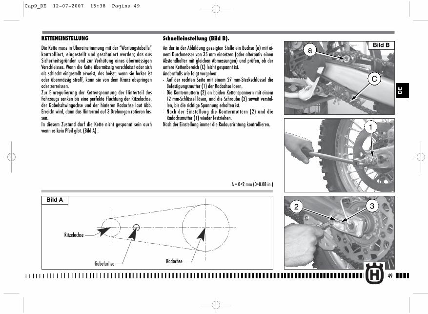
KETTENEINSTELLUNG
Die Kette muss in Übereinstimmung mit der “Wartungstabelle”kontrolliert, eingestellt und geschmiert werden; das ausSicherheitsgründen und zur Verhütung eines übermässigenVerschleisses. Wenn die Kette übermässig verschleisst oder sichals schlecht eingestellt erweist, das heisst, wenn sie locker istoder übermässig straff, kann sie von dem Kranz abspringenoder zerreissen.Zur Einregulierung der Kettenspannung der Hinterteil desFahrzeugs senken bis eine perfekte Fluchtung der Ritzelachse,der Gabelschwingachse und der hinteren Radachse laut Abb.Erreicht wird, dann das Hinterrad auf 3 Drehungen rotieren las-sen.In diesem Zustand darf die Kette nicht gespannt sein auchwenn es kein Pfeil gibt. (Bild A) .
Schnelleinstellung (Bild B).
An der in der Abbildung gezeigten Stelle ein Buchse (a) mit ei-nem Durchmesser von 35 mm einsetzen (oder alternativ einenAbstandhalter mit gleichen Abmessungen) und prüfen, ob deruntere Kettenbereich (C) leicht gespannt ist.Andernfalls wie folgt vorgehen:- Auf der rechten Seite mit einem 27 mm-Steckschlüssel die
Befestigungsmutter (1) der Radachse lösen.- Die Kontermuttern (2) an beiden Kettenspannern mit einem
12 mm-Schlüssel lösen, und die Schraube (3) soweit verstel-len, bis die richtige Spannung erhalten ist.
- Nach der Einstellung die Kontermuttern (2) und dieRadachsmutter (1) wieder festziehen.
Nach der Einstellung immer die Radausrichtung kontrollieren.
49
Bild A
DE
Ritzelachse
Gabelachse Radachse
A = 0÷2 mm (0÷0.08 in.)
a
C
1
32
Bild B
Cap9_DE 12-07-2007 15:38 Pagina 49
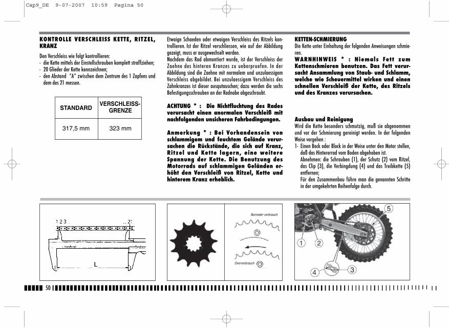
Etwaige Schaeden oder etwaigen Verschleiss des Ritzels kon-trollieren. Ist der Ritzel verschliessen, wie auf der Abbildunggezeigt, muss er ausgewechselt werden.Nachdem das Rad abmontiert wurde, ist der Verschleiss derZaehne des hinteren Kranzes zu ueberpruefen. In derAbbildung sind die Zaehne mit normalem und unzulaessigemVerschleiss abgebildet. Bei unzulaessigem Verschleiss desZahnkranzes ist dieser ausqutauschen; dazu werden die sechsBefestigungsschrauben an der Radnabe abgeschraubt.
ACHTUNG * : Die Nichtfluchtung des Radesverursacht einen anormalen Verschleiß mitnachfolgenden unsicheren Fahrbedingungen.
Anmerkung * : Bei Vorhandensein vonschlammigem und feuchtem Gelände verur-sachen die Rückstände, die sich auf Kranz,Ritzel und Kette lagern, eine weitereSpannung der Kette. Die Benutzung desMotorrads auf schlammigen Geländen er-höht den Verschleiß von Ritzel, Kette undhinterem Kranz erheblich.
KETTEN-SCHMIERUNGDie Kette unter Einhaltung der folgenden Anweisungen schmie-ren.WARNHINWEIS * : Niemals Fett zumKettenschmieren benutzen. Das Fett verur-sacht Ansammlung von Staub- und Schlamm,welche wie Scheuermittel wirken und einenschnellen Verschleiß der Kette, des Ritzelsund des Kranzes verursachen.
Ausbau und ReinigungWird die Kette besonders schmutzig, muß sie abgenommenund vor der Schmierung gereinigt werden. In der folgendenWeise vorgehen :1- Einen Bock oder Block in der Weise unter den Motor stellen,
daß das Hintererrad vom Boden abgehoben ist.Abnehmen: die Schrauben (1), der Schutz (2) vom Ritzel,das Clip (3), die Verbingdung (4) und das Treibkette (5)entfernen;Für den Zusammenbau führe man die genannten Schrittein der umgekehrten Reihenfolge durch.
50
KONTROLLE VERSCHLEISS KETTE, RITZEL,KRANZ
Den Verschleiss wie folgt kontrollieren:- die Kette mittels der Einstellschrauben komplett straffziehen;- 20 Glieder der Kette kennzeichnen;- den Abstand “A” zwischen dem Zentrum des 1 Zapfens und
dem des 21 messen.
STANDARDVERSCHLEISS-
GRENZE
317,5 mm 323 mm
Normaler verbrauch
Oververbrauch
Cap9_DE 9-07-2007 10:59 Pagina 50
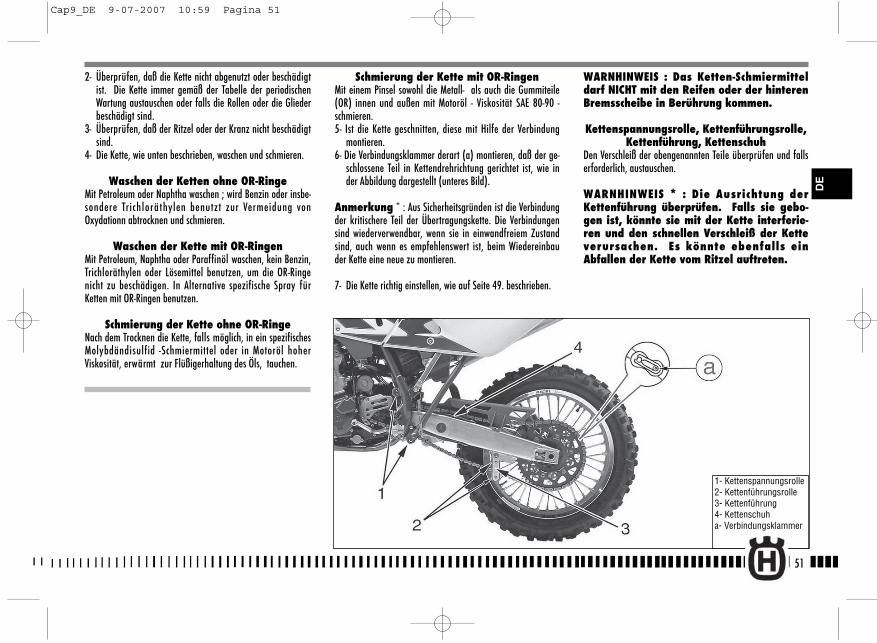
Schmierung der Kette mit OR-RingenMit einem Pinsel sowohl die Metall- als auch die Gummiteile(OR) innen und außen mit Motoröl - Viskosität SAE 80-90 -schmieren.5- Ist die Kette geschnitten, diese mit Hilfe der Verbindung
montieren.6- Die Verbindungsklammer derart (a) montieren, daß der ge-
schlossene Teil in Kettendrehrichtung gerichtet ist, wie inder Abbildung dargestellt (unteres Bild).
Anmerkung * : Aus Sicherheitsgründen ist die Verbindungder kritischere Teil der Übertragungskette. Die Verbindungensind wiederverwendbar, wenn sie in einwandfreiem Zustandsind, auch wenn es empfehlenswert ist, beim Wiedereinbauder Kette eine neue zu montieren.
7- Die Kette richtig einstellen, wie auf Seite 49. beschrieben.
2- Überprüfen, daß die Kette nicht abgenutzt oder beschädigtist. Die Kette immer gemäß der Tabelle der periodischenWartung austauschen oder falls die Rollen oder die Gliederbeschädigt sind.
3- Überprüfen, daß der Ritzel oder der Kranz nicht beschädigtsind.
4- Die Kette, wie unten beschrieben, waschen und schmieren.
Waschen der Ketten ohne OR-RingeMit Petroleum oder Naphtha waschen ; wird Benzin oder insbe-sondere Trichloräthylen benutzt zur Vermeidung vonOxydationn abtrocknen und schmieren.
Waschen der Kette mit OR-RingenMit Petroleum, Naphtha oder Paraffinöl waschen, kein Benzin,Trichloräthylen oder Lösemittel benutzen, um die OR-Ringenicht zu beschädigen. In Alternative spezifische Spray fürKetten mit OR-Ringen benutzen.
Schmierung der Kette ohne OR-RingeNach dem Trocknen die Kette, falls möglich, in ein spezifischesMolybdändisulfid -Schmiermittel oder in Motoröl hoherViskosität, erwärmt zur Flüßigerhaltung des Öls, tauchen.
WARNHINWEIS : Das Ketten-Schmiermitteldarf NICHT mit den Reifen oder der hinterenBremsscheibe in Berührung kommen.
Kettenspannungsrolle, Kettenführungsrolle,Kettenführung, Kettenschuh
Den Verschleiß der obengenannten Teile überprüfen und fallserforderlich, austauschen.
WARNHINWEIS * : Die Ausrichtung derKettenführung überprüfen. Falls sie gebo-gen ist, könnte sie mit der Kette interferie-ren und den schnellen Verschleiß der Ketteverursachen. Es könnte ebenfalls einAbfallen der Kette vom Ritzel auftreten.
51
1- Kettenspannungsrolle2- Kettenführungsrolle3- Kettenführung4- Kettenschuha- Verbindungsklammer
DE
Cap9_DE 9-07-2007 10:59 Pagina 51
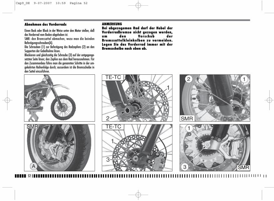
ANMERKUNGBei abgezogemen Rad darf der Hebel derVorderradbremse nicht gezogen werden,um den Vorschub derBremssattelkleinkolben zu vermeiden.Legen Sie das Vorderrad immer mit derBremsscheibe nach oben ab.
52
Abnehmen des Vorderrads
Einen Bock oder Block in der Weise unter den Motor stellen, daßdas Vorderrad vom Boden abgehoben ist.SMR: den Bremssattel abmachen, wozu man die beindenBefestigungsschrauben(A).Die Schrauben (1) zur Befestigung des Radzapfens (2) an denSupporten der Gabelholme lösen.Blockieren und gleichzeitig die Schraube (3) auf der entgegenge-setzten Seite lösen; den Zapfen aus dem Rad herausnehmen. Fürden Zusammenbau führe man die genannten Schritte in der um-gekehrten Reihenfolge durch; ausserdem ist die Bremsscheibe inden Sattel einzuführen.
SMR
Cap9_DE 9-07-2007 10:59 Pagina 52
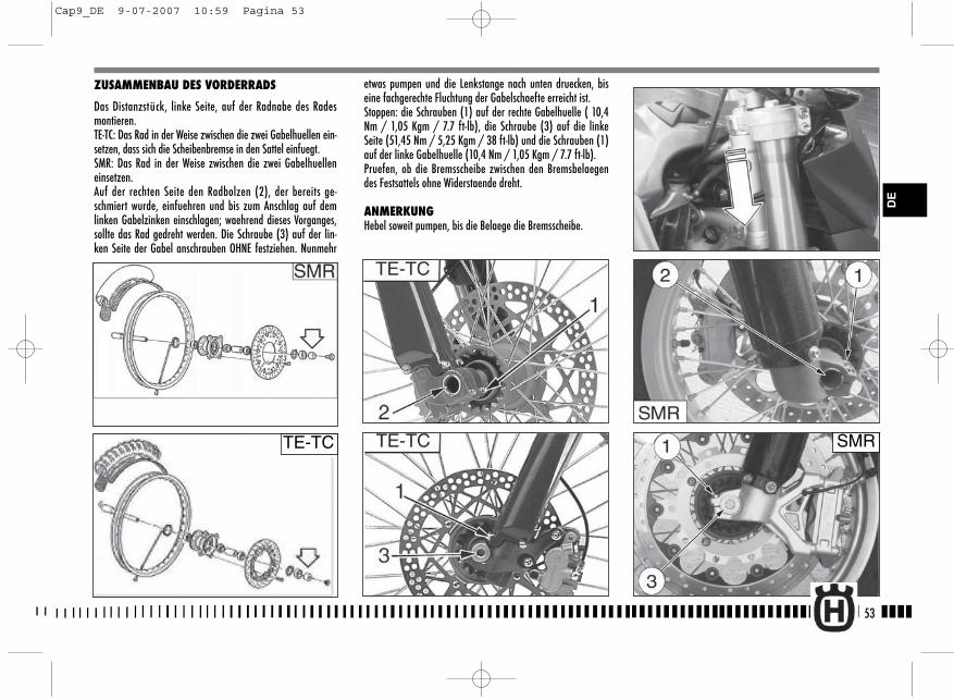
etwas pumpen und die Lenkstange nach unten druecken, biseine fachgerechte Fluchtung der Gabelschaefte erreicht ist.Stoppen: die Schrauben (1) auf der rechte Gabelhuelle ( 10,4Nm / 1,05 Kgm / 7.7 ft-lb), die Schraube (3) auf die linkeSeite (51,45 Nm / 5,25 Kgm / 38 ft-lb) und die Schrauben (1)auf der linke Gabelhuelle (10,4 Nm / 1,05 Kgm / 7.7 ft-lb).Pruefen, ob die Bremsscheibe zwischen den Bremsbelaegendes Festsattels ohne Widerstaende dreht.
ANMERKUNGHebel soweit pumpen, bis die Belaege die Bremsscheibe.
53
ZUSAMMENBAU DES VORDERRADS
Das Distanzstück, linke Seite, auf der Radnabe des Radesmontieren.TE-TC: Das Rad in der Weise zwischen die zwei Gabelhuellen ein-setzen, dass sich die Scheibenbremse in den Sattel einfuegt.SMR: Das Rad in der Weise zwischen die zwei Gabelhuelleneinsetzen.Auf der rechten Seite den Radbolzen (2), der bereits ge-schmiert wurde, einfuehren und bis zum Anschlag auf demlinken Gabelzinken einschlagen; waehrend dieses Vorganges,sollte das Rad gedreht werden. Die Schraube (3) auf der lin-ken Seite der Gabel anschrauben OHNE festziehen. Nunmehr
TE-TC SMR
DE
Cap9_DE 9-07-2007 10:59 Pagina 53
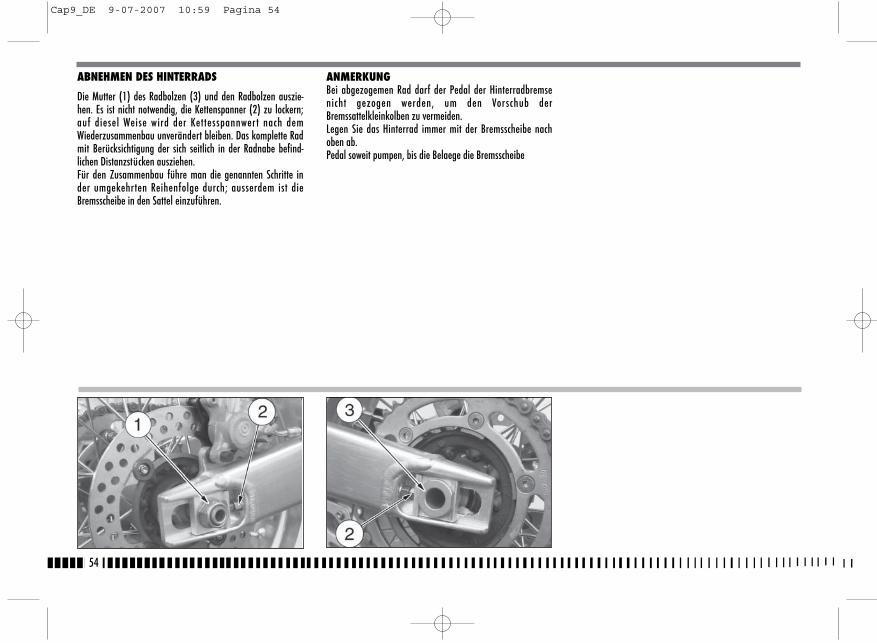
ABNEHMEN DES HINTERRADS
Die Mutter (1) des Radbolzen (3) und den Radbolzen auszie-hen. Es ist nicht notwendig, die Kettenspanner (2) zu lockern;auf diesel Weise wird der Kettesspannwert nach demWiederzusammenbau unverändert bleiben. Das komplette Radmit Berücksichtigung der sich seitlich in der Radnabe befind-lichen Distanzstücken ausziehen. Für den Zusammenbau führe man die genannten Schritte inder umgekehrten Reihenfolge durch; ausserdem ist dieBremsscheibe in den Sattel einzuführen.
ANMERKUNGBei abgezogemen Rad darf der Pedal der Hinterradbremsenicht gezogen werden, um den Vorschub derBremssattelkleinkolben zu vermeiden.Legen Sie das Hinterrad immer mit der Bremsscheibe nachoben ab.Pedal soweit pumpen, bis die Belaege die Bremsscheibe
54
Cap9_DE 9-07-2007 10:59 Pagina 54
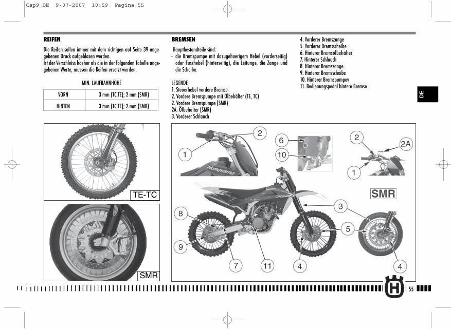
4. Vorderer Bremszange5. Vorderer Bremsscheibe6. Hinterer Bremsölbehälter7. Hinterer Schlauch8. Hinterer Bremszange9. Hinterer Bremsscheibe10. Hinterer Bremspumpev11. Bedienungspedal hintere Bremse
BREMSEN
Hauptbestandteile sind:- die Bremspumpe mit dazugehoerigem Hebel (vorderseitig)
oder Fusshebel (hinterseitig), die Leitunge, die Zange unddie Scheibe.
LEGENDE1. Steuerhebel vordere Bremse2. Vordere Bremspumpe mit Ölbehälter (TE, TC)2. Vordere Bremspumpe (SMR)2A. Ölbehälter (SMR)3. Vorderer Schlauch
55
DE
REIFEN
Die Reifen sollen immer mit dem richtigen auf Seite 39 ange-gebenen Druck aufgeblasen werden. Ist der Verschleiss hoeher als die in der folgenden Tabelle ange-gebenen Werte, müssen die Reifen ersetzt werden.
MIN. LAUFBAHNHÖHE
VORN 3 mm (TC,TE); 2 mm (SMR)
HINTEN 3 mm (TC,TE); 2 mm (SMR)
TE-TC
SMR
Cap9_DE 9-07-2007 10:59 Pagina 55
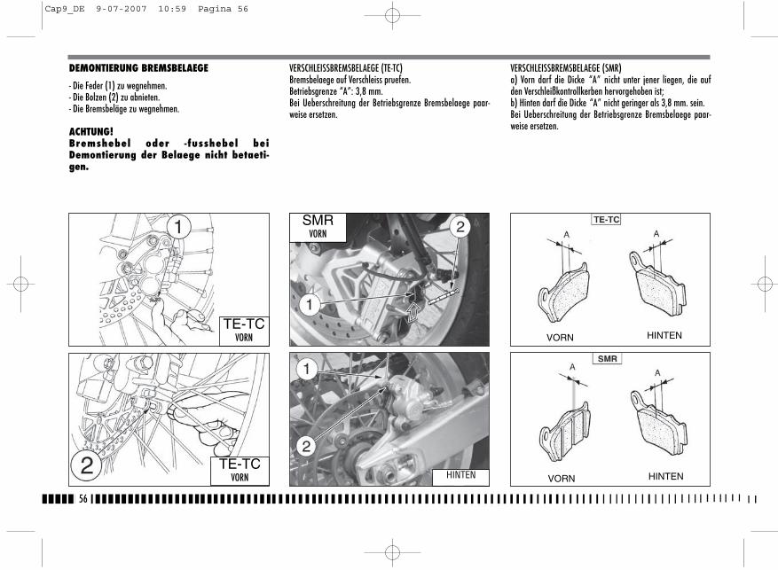
DEMONTIERUNG BREMSBELAEGE
- Die Feder (1) zu wegnehmen.- Die Bolzen (2) zu abnieten.- Die Bremsbeläge zu wegnehmen.
ACHTUNG!Bremshebel oder -fusshebel beiDemontierung der Belaege nicht betaeti-gen.
VERSCHLEISSBREMSBELAEGE (TE-TC)Bremsbelaege auf Verschleiss pruefen.Betriebsgrenze “A”: 3,8 mm.Bei Ueberschreitung der Betriebsgrenze Bremsbelaege paar-weise ersetzen.
VERSCHLEISSBREMSBELAEGE (SMR)a) Vorn darf die Dicke “A” nicht unter jener liegen, die aufden Verschleißkontrollkerben hervorgehoben ist;b) Hinten darf die Dicke “A” nicht geringer als 3,8 mm. sein.Bei Ueberschreitung der Betriebsgrenze Bremsbelaege paar-weise ersetzen.
56
TE-TCVORN
TE-TCVORN
SMRVORN
HINTEN
VORN HINTEN
VORN HINTEN
Cap9_DE 9-07-2007 10:59 Pagina 56
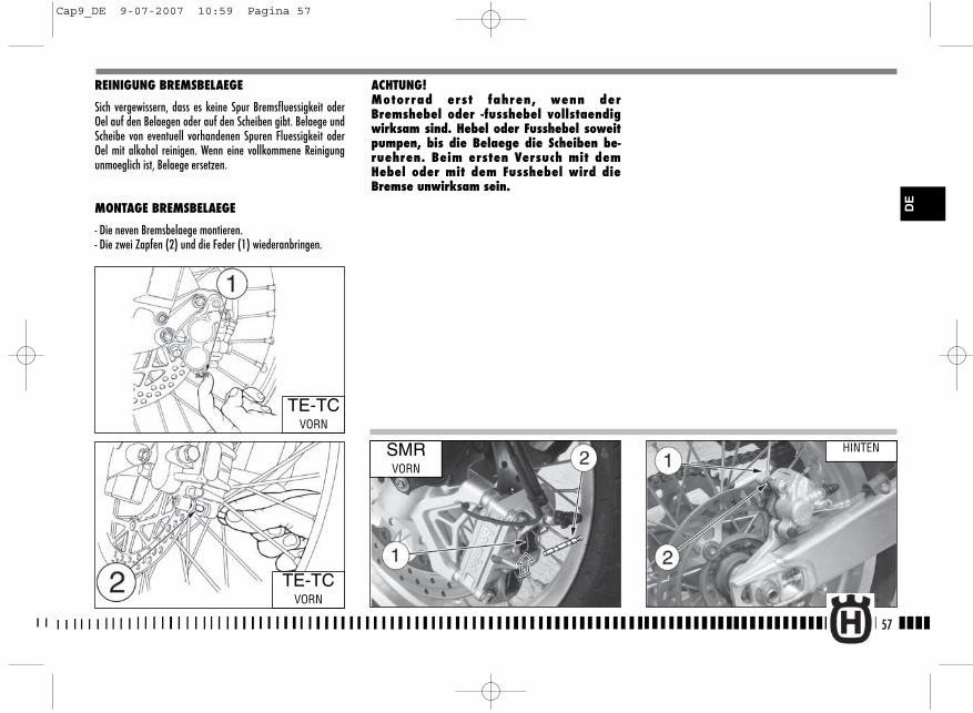
REINIGUNG BREMSBELAEGE
Sich vergewissern, dass es keine Spur Bremsfluessigkeit oderOel auf den Belaegen oder auf den Scheiben gibt. Belaege undScheibe von eventuell vorhandenen Spuren Fluessigkeit oderOel mit alkohol reinigen. Wenn eine vollkommene Reinigungunmoeglich ist, Belaege ersetzen.
MONTAGE BREMSBELAEGE
- Die neven Bremsbelaege montieren.- Die zwei Zapfen (2) und die Feder (1) wiederanbringen.
ACHTUNG!Motorrad erst fahren, wenn derBremshebel oder -fusshebel vollstaendigwirksam sind. Hebel oder Fusshebel soweitpumpen, bis die Belaege die Scheiben be-ruehren. Beim ersten Versuch mit demHebel oder mit dem Fusshebel wird dieBremse unwirksam sein.
57
TE-TCVORN
TE-TCVORN
SMRVORN
HINTEN
DE
Cap9_DE 9-07-2007 10:59 Pagina 57
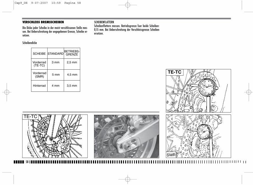
VERSCHLEISS BREMSSCHEIBEN
Die Dicke jeder Scheibe in der meist verschlissenen Stelle mes-sen. Bei Ueberschreitung der angegebenen Grenze, Scheibe er-setzen.
Scheibendicke
SCHEIBENFLATTERNScheibenflattern messen. Betriebsgrenze fuer beide Scheiben:0,15 mm. Bei Ueberschreitung der Verschleissgrenze Scheibenersetzen.
58
Vorderrad(SMR)
5 mm 4,5 mm
Vorderrad 3 mm 2,5 mm(TE-TC)
SCHEIBE STANDARDBETRIEBS-GRENZE
Hinterrad 4 mm 3,5 mm
TE-TC
TE-TC
Cap9_DE 9-07-2007 10:59 Pagina 58
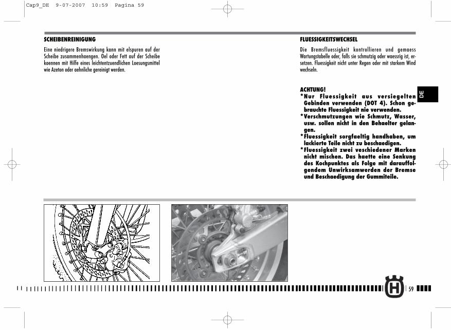
SCHEIBENREINIGUNG
Eine niedrigere Bremswirkung kann mit elspuren auf derScheibe zusammenhaengen. Oel oder Fett auf der Scheibekoennen mit Hilfe eines leichtentzuendlichen Loesungsmittelwie Azeton oder aehnliche gereinigt werden.
FLUESSIGKEITSWECHSEL
Die Bremsfluessigkeit kontrollieren und gemaessWartungstabelle oder, falls sie schmutzig oder waessrig ist, er-setzen. Fluessigkeit nicht unter Regen oder mit starkem Windwechseln.
ACHTUNG!*Nur Fluessigkeit aus versiegelten
Gebinden verwenden (DOT 4). Schon ge-brauchte Fluessigkeit nie verwenden.
*Verschmutzungen wie Schmutz, Wasser,usw. sollen nicht in den Behaelter gelan-gen.
*Fluessigkeit sorgfaeltig handhaben, umlackierte Teile nicht zu beschaedigen.
*Fluessigkeit zwei veschiedener Markennicht mischen. Das haette eine Senkungdes Kochpunktes als Folge mit darauffol-gendem Unwirksamwerden der Bremseund Beschaedigung der Gummiteile.
59
DE
Cap9_DE 9-07-2007 10:59 Pagina 59
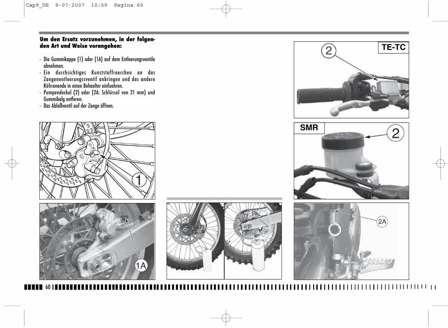
Um den Ersatz vorzunehmen, in der folgen-den Art und Weise vorangehen:
- Die Gummikappe (1) oder (1A) auf dem Entleerungsventileabnehmen.
- Ein durchsichtiges Kunststof froerchen an dasZangenentleerungssventil anbringen und das andereRöhrenende in einen Behaelter einfuehren.
- Pumpendeckel (2) oder (2A: Schlüssel von 21 mm) undGummibalg entferen.
- Das Ablaßventil auf der Zange öffnen.
60
TE-TC
SMR
Cap9_DE 9-07-2007 10:59 Pagina 60
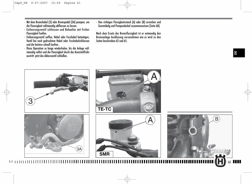
- Den richtigen Flussigkeitsstand (A) oder (B) erreichen undGummibalg und Pumpendeckel zusammensetzen (Seite 60).
Nach dem Ersatz des Bremsflussigkeit ist er notwendig denBremsanlage Ausblasung vorzunehmen wie es wird zu denSeiten beschrieben 62 und 65.
61
- Mit dem Bremshebel (3) oder Bremspedal (3A) pumpen, umdie Fluessigkeit vollstaendig abfliessen zu lassen.
- Entleerungsventil schliessen und Behaelter mit frisherFluessigkeit fuellen.
- Entleerungsventil oeffen, Hebel oder Fusshebel betaetigen,Ventil bei noch gedrucktem Hebel oder Fusshebelschliessenund die letztere schnell lueften .
- Diese Operation so lange wiederholen, bis die Anlage voll-staendig vollist und die Fluessigkeit durch das Kunststoffrohraustritt: jetzt das Ablassventil schließen.
TE-TC
SMR
DE
Cap9_DE 9-07-2007 10:59 Pagina 61
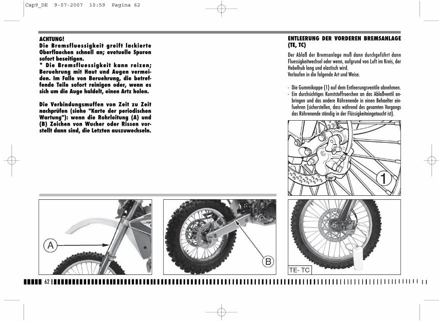
62
ENTLEERUNG DER VORDEREN BREMSANLAGE(TE, TC)
Der Ablaß der Bremsanlage muß dann durchgeführt dannFluessigkeitwechsel oder wenn, aufgrund von Luft im Kreis, derHebelhub lang und elastisch wird.Verlaufen in die folgende Art und Weise.
- Die Gummikappe (1) auf dem Entleerungsventile abnehmen.- Ein durchsichtiges Kunststoffroerchen an das Ablaßventil an-
bringen und das andere Röhrenende in einen Behaelter ein-fuehren (sicherstellen, dass während des gesamten Vorgangsdas Röhrenende ständig in der Flüssigkeiteingetaucht ist).
ACHTUNG!Die Bremsfluessigkeit greift lackierteOberflaechen schnell an; evetuelle Spurensofort beseitigen.* Die Bremsfluessigkeit kann reizen;Beruehrung mit Haut und Augen vermei-den. Im Falle von Beruehrung, die betref-fende Teile sofort reinigen oder, wenn essich um die Auge haldelt, einen Artz holen.
Die Verbindungsmuffen von Zeit zu Zeitnachprüfen (siehe "Karte der periodischenWartung"): wenn die Rohrleitung (A) und(B) Zeichen von Wucher oder Rissen vor-stellt dann sind, die Letzten auszuwechseln.
Cap9_DE 9-07-2007 10:59 Pagina 62
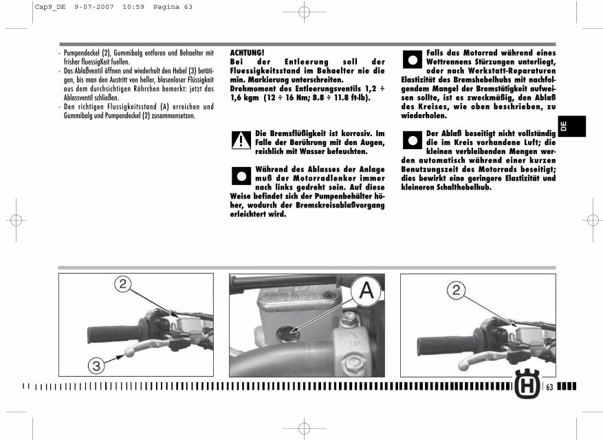
- Pumpendeckel (2), Gummibalg entferen und Behaelter mitfrisher fluessigKeit fuellen.
- Das Ablaßventil öffnen und wiederholt den Hebel (3) betäti-gen, bis man den Austritt von heller, blasenloser Flüssigkeitaus dem durchsichtigen Röhrchen bemerkt: jetzt dasAblassventil schließen.
- Den richtigen Flussigkeitsstand (A) erreichen undGummibalg und Pumpendeckel (2) zusammensetzen.
ACHTUNG!Bei der Entleerung soll derFluessigkeitsstand im Behaelter nie diemin. Markierung unterschreiten.Drehmoment des Entleerungsventils 1,2 ÷1,6 kgm (12 ÷ 16 Nm; 8.8 ÷ 11.8 ft-lb).
Die Bremsflüßigkeit ist korrosiv. ImFalle der Berührung mit den Augen,reichlich mit Wasser befeuchten.
Während des Ablasses der Anlagemuß der Motorradlenker immernach links gedreht sein. Auf diese
Weise befindet sich der Pumpenbehälter hö-her, wodurch der Bremskreisablaßvorgangerleichtert wird.
Falls das Motorrad während einesWettrennens Stürzungen unterliegt,oder nach Werkstatt-Reparaturen
Elastizität des Bremshebelhubs mit nachfol-gendem Mangel der Bremstätigkeit aufwei-sen sollte, ist es zweckmäßig, den Ablaßdes Kreises, wie oben beschrieben, zuwiederholen.
Der Ablaß beseitigt nicht vollständigdie im Kreis vorhandene Luft; diekleinen verbleibenden Mengen wer-
den automatisch während einer kurzenBenutzungszeit des Motorrads beseitigt;dies bewirkt eine geringere Elastizität undkleineren Schalthebelhub.
63
DE
Cap9_DE 9-07-2007 10:59 Pagina 63

ENTLEERUNG DER VORDEREN BREMSANLAGE(SMR)
Der Ablaß der Bremsanlage muß dann durchgeführt dannFluessigkeitwechsel oder wenn, aufgrund von Luft im Kreis, derHebelhub lang und elastisch wird.In der vorderen Bremsanlage, der Ablaß muß dann Premiereauf die Steuerung auf der Lenker auf die Zange geschehen: dieOperationen, von vornehmen, sind die derselbe. Verlaufen indie folgende Art und Weise.- Die Gummikappe (1) oder (1A) auf dem Entleerungsventile
abnehmen.
- Ein durchsichtiges Kunststoffroerchen an das Ablaßventil an-bringen und das andere Röhrenende in einen Behaelter ein-fuehren (sicherstellen, dass während des gesamtenVorgangs das Röhrenende ständig in derFlüssigkeiteingetaucht ist).
- Pumpendeckel (2), Gummibalg entferen und Behaelter mitfrisher fluessigKeit fuellen.
- Das Ablaßventil öffnen und wiederholt den Hebel betätigen,bis man den Austritt von heller, blasenloser Flüssigkeit ausdem durchsichtigen Röhrchen bemerkt: jetzt das Ablassventilschließen.
64
SMR
SMR
Cap9_DE 9-07-2007 10:59 Pagina 64
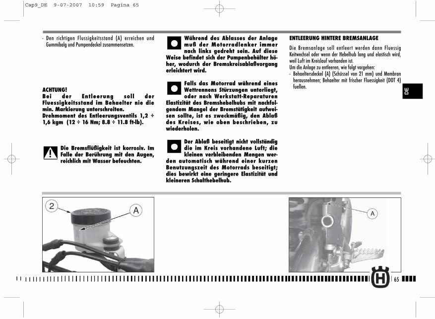
ENTLEERUNG HINTERE BREMSANLAGE
Die Bremsanlage soll entleer t werden dann FluessigKeitwechsel oder wenn der Hebelhub lang und elastisch wird,weil Luft im Kreislauf vorhanden ist.Um die Anlage zu entleeren, wie folgt vorgehen:- Behaeltersdeckel (A) (Schüssel von 21 mm) und Membran
herausnehmen; Behaelter mit frischer Fluessigkeit (DOT 4)fuellen.
- Den richtigen Flussigkeitsstand (A) erreichen undGummibalg und Pumpendeckel zusammensetzen.
ACHTUNG!Bei der Entleerung soll derFluessigkeitsstand im Behaelter nie diemin. Markierung unterschreiten.Drehmoment des Entleerungsventils 1,2 ÷1,6 kgm (12 ÷ 16 Nm; 8.8 ÷ 11.8 ft-lb).
Die Bremsflüßigkeit ist korrosiv. ImFalle der Berührung mit den Augen,reichlich mit Wasser befeuchten.
Während des Ablasses der Anlagemuß der Motorradlenker immernach links gedreht sein. Auf diese
Weise befindet sich der Pumpenbehälter hö-her, wodurch der Bremskreisablaßvorgangerleichtert wird.
Falls das Motorrad während einesWettrennens Stürzungen unterliegt,oder nach Werkstatt-Reparaturen
Elastizität des Bremshebelhubs mit nachfol-gendem Mangel der Bremstätigkeit aufwei-sen sollte, ist es zweckmäßig, den Ablaßdes Kreises, wie oben beschrieben, zuwiederholen.
Der Ablaß beseitigt nicht vollständigdie im Kreis vorhandene Luft; diekleinen verbleibenden Mengen wer-
den automatisch während einer kurzenBenutzungszeit des Motorrads beseitigt;dies bewirkt eine geringere Elastizität undkleineren Schalthebelhub.
65
DE
Cap9_DE 9-07-2007 10:59 Pagina 65
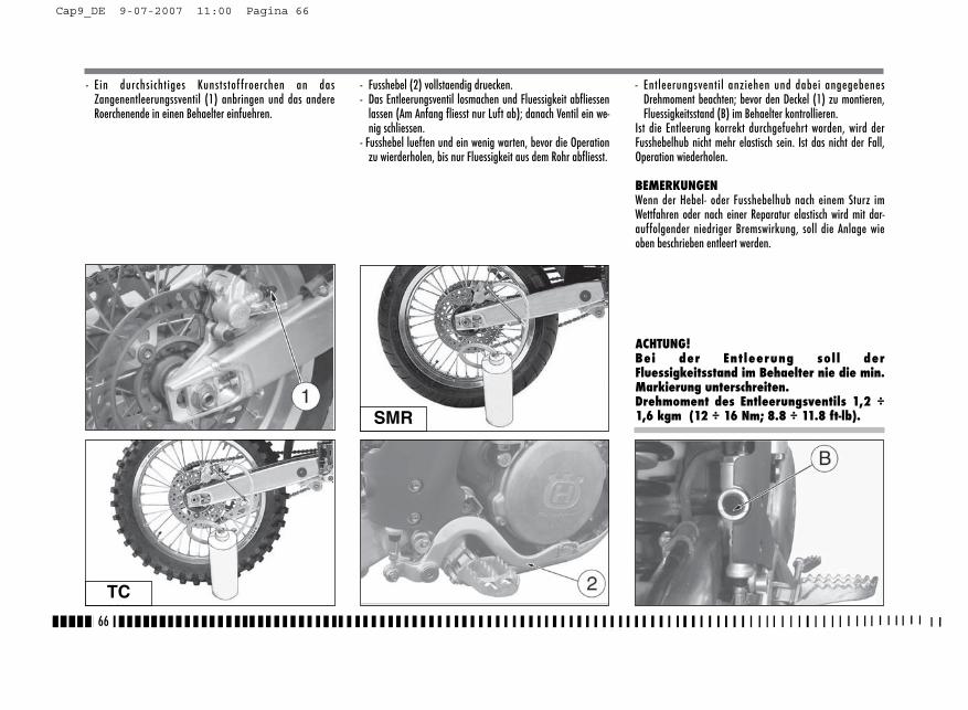
- Ein durchsichtiges Kunststof froerchen an dasZangenentleerungssventil (1) anbringen und das andereRoerchenende in einen Behaelter einfuehren.
- Fusshebel (2) vollstaendig druecken.- Das Entleerungsventil losmachen und Fluessigkeit abfliessen
lassen (Am Anfang fliesst nur Luft ab); danach Ventil ein we-nig schliessen.
- Fusshebel lueften und ein wenig warten, bevor die Operationzu wierderholen, bis nur Fluessigkeit aus dem Rohr abfliesst.
- Entleerungsventil anziehen und dabei angegebenesDrehmoment beachten; bevor den Deckel (1) zu montieren,Fluessigkeitsstand (B) im Behaelter kontrollieren.
Ist die Entleerung korrekt durchgefuehrt worden, wird derFusshebelhub nicht mehr elastisch sein. Ist das nicht der Fall,Operation wiederholen.
BEMERKUNGENWenn der Hebel- oder Fusshebelhub nach einem Sturz imWettfahren oder nach einer Reparatur elastisch wird mit dar-auffolgender niedriger Bremswirkung, soll die Anlage wieoben beschrieben entleert werden.
ACHTUNG!Bei der Entleerung soll derFluessigkeitsstand im Behaelter nie die min.Markierung unterschreiten.Drehmoment des Entleerungsventils 1,2 ÷1,6 kgm (12 ÷ 16 Nm; 8.8 ÷ 11.8 ft-lb).
66
TC
SMR
Cap9_DE 9-07-2007 11:00 Pagina 66
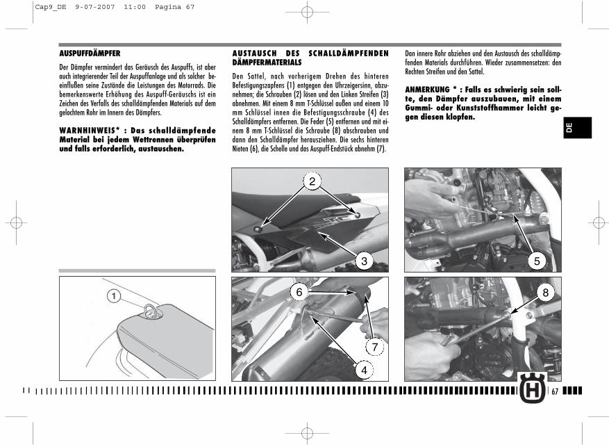
AUSPUFFDÄMPFER
Der Dämpfer vermindert das Geräusch des Auspuffs, ist aberauch integrierender Teil der Auspuffanlage und als solcher be-einflußen seine Zustände die Leistungen des Motorrads. Diebemerkenswerte Erhöhung des Auspuff-Geräuschs ist einZeichen des Verfalls des schalldämpfenden Materials auf demgelochtem Rohr im Innern des Dämpfers.
WARNHINWEIS* : Das schalldämpfendeMaterial bei jedem Wettrennen überprüfenund falls erforderlich, austauschen.
AUSTAUSCH DES SCHALLDÄMPFENDENDÄMPFERMATERIALS
Den Sattel, nach vorherigem Drehen des hinterenBefestigungszapfens (1) entgegen den Uhrzeigersinn, abzu-nehmen; die Schrauben (2) lösen und den Linken Streifen (3)abnehmen. Mit einem 8 mm T-Schlüssel außen und einem 10mm Schlüssel innen die Befestigungsschraube (4) desSchalldämpfers entfernen. Die Feder (5) entfernen und mit ei-nem 8 mm T-Schlüssel die Schraube (8) abschrauben unddann den Schalldämpfer herausziehen. Die sechs hinterenNieten (6), die Schelle und das Auspuff-Endstück abnehm (7).
Dan innere Rohr abziehen und den Austausch des schalldämp-fenden Materials durchführen. Wieder zusammensetzen: denRechten Streifen und den Sattel.
ANMERKUNG * : Falls es schwierig sein soll-te, den Dämpfer auszubauen, mit einemGummi- oder Kunststoffhammer leicht ge-gen diesen klopfen.
67
2
3
4
5
86
7
DE
Cap9_DE 9-07-2007 11:00 Pagina 67
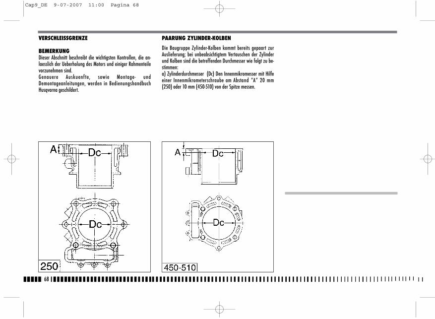
VERSCHLEISSGRENZE
BEMERKUNGDieser Abschnitt beschreibt die wichtigsten Kontrollen, die an-laesslich der Ueberholung des Motors und einiger Rahmenteilevorzunehmen sind.Genauere Auskuenf te, sowie Montage- undDemontageanleitungen, werden in BedienungshandbuchHusqvarna geschildert.
PAARUNG ZYLINDER-KOLBEN
Die Baugruppe Zylinder-Kolben kommt bereits gepaart zurAuslieferung; bei unbeabsichtigtem Vertauschen der Zylinderund Kolben sind die betreffenden Durchmesser wie folgt zu be-stimmen:a) Zylinderdurchmesser (Dc) Den Innenmikromesser mit Hilfeeiner Innenmikrometerschraube am Abstand “A“ 20 mm(250) oder 10 mm (450-510) von der Spitze messen.
68
Cap9_DE 9-07-2007 11:00 Pagina 68
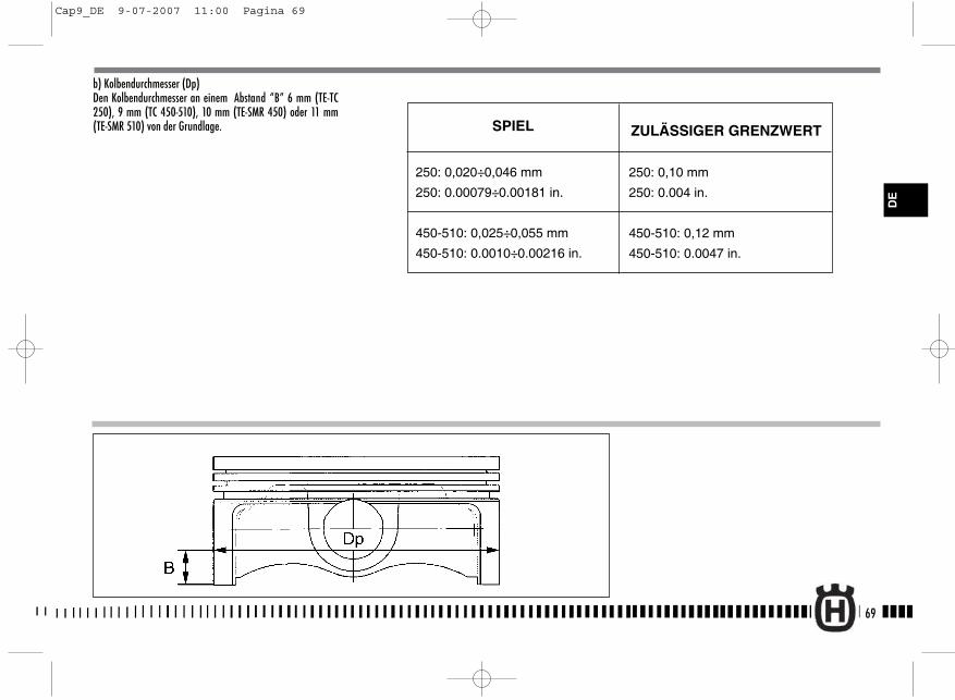
b) Kolbendurchmesser (Dp)Den Kolbendurchmesser an einem Abstand “B” 6 mm (TE-TC250), 9 mm (TC 450-510), 10 mm (TE-SMR 450) oder 11 mm(TE-SMR 510) von der Grundlage.
69
DE
250: 0,020÷0,046 mm
250: 0.00079÷0.00181 in.
450-510: 0,025÷0,055 mm
450-510: 0.0010÷0.00216 in.
ZULÄSSIGER GRENZWERTSPIEL
250: 0,10 mm
250: 0.004 in.
450-510: 0,12 mm
450-510: 0.0047 in.
Cap9_DE 9-07-2007 11:00 Pagina 69
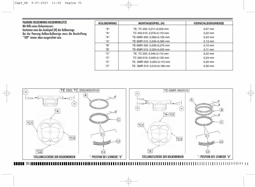
PAARUNG KOLBENRINGE-KOLBENRINGZITZEMit Hilfe eines Dickenmessersbestimme man das Axialspiel (H) der Kolbenringe.Bei der Paarung Kolben-Kolbenrige muss die Beschriftung“ TOP” immer oben ausgerichtet sein.
70
STELLUNGSSCHEIDE DER KOLBENRINGEN *: POSITION DES SCHNEIDE “d” STELLUNGSSCHEIDE DER KOLBENRINGEN *: POSITION DES SCHNEIDE “d”
KOLBENRING MONTAGESPIEL (H) VERSCHLEISSGRENZE
"A" TE, TC 250: 0,011÷0,033 mm 0,07 mm
"A" TC 450-510: 0,070÷0,110 mm 0,22 mm
"A" TE-SMR 450: 0,065÷0,100 mm 0,24 mm
"A" TE-SMR 510: 0,030÷0,065 mm 0,13 mm
"B" TE-SMR 450: 0,035÷0,070 mm 0,15 mm
"B" TE-SMR 510: 0,020÷0,055 mm 0,11 mm
"C" TE, TC 250: 0,040÷0,110 mm 0,22 mm
"C" TC 450-510: 0,040÷0,120 mm 0,24 mm
"C" TE- SMR 450: 0,020÷0,110 mm 0,20 mm
"C" TE- SMR 510: 0,010÷0,180 mm 0,35 mm
Cap9_DE 9-07-2007 11:00 Pagina 70
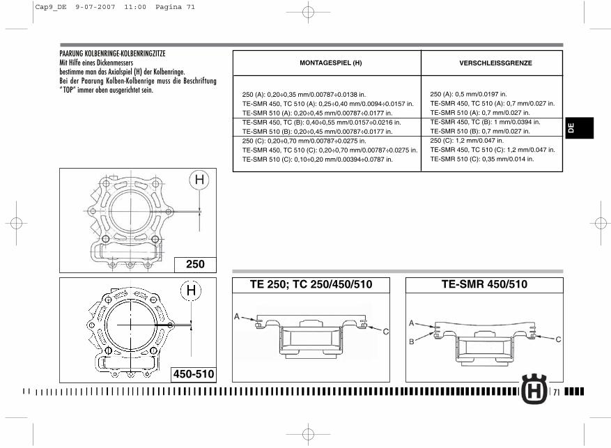
PAARUNG KOLBENRINGE-KOLBENRINGZITZEMit Hilfe eines Dickenmessersbestimme man das Axialspiel (H) der Kolbenringe.Bei der Paarung Kolben-Kolbenrige muss die Beschriftung“ TOP” immer oben ausgerichtet sein.
71
250
TE 250; TC 250/450/510 TE-SMR 450/510
450-510
VERSCHLEISSGRENZEMONTAGESPIEL (H)
250 (A): 0,20÷0,35 mm/0.00787÷0.0138 in.TE-SMR 450, TC 510 (A): 0,25÷0,40 mm/0.0094÷0.0157 in.TE-SMR 510 (A): 0,20÷0,45 mm/0.00787÷0.0177 in.TE-SMR 450, TC (B): 0,40÷0,55 mm/0.0157÷0.0216 in.TE-SMR 510 (B): 0,20÷0,45 mm/0.00787÷0.0177 in.250 (C): 0,20÷0,70 mm/0.00787÷0.0275 in.TE-SMR 450, TC 510 (C): 0,20÷0,70 mm/0.00787÷0.0275 in.TE-SMR 510 (C): 0,10÷0,20 mm/0.00394÷0.0787 in.
250 (A): 0,5 mm/0.0197 in.TE-SMR 450, TC 510 (A): 0,7 mm/0.027 in.TE-SMR 510 (A): 0,7 mm/0.027 in.TE-SMR 450, TC (B): 1 mm/0.0394 in.TE-SMR 510 (B): 0,7 mm/0.027 in.250 (C): 1,2 mm/0.047 in.TE-SMR 450, TC 510 (C): 1,2 mm/0.047 in.TE-SMR 510 (C): 0,35 mm/0.014 in.
DE
Cap9_DE 9-07-2007 11:00 Pagina 71
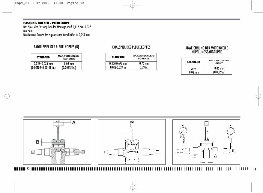
PASSUNG BOLZEN - PLEUELKOPFDas Spiel der Passung bei der Montage muß 0,012 bis 0,027mm sein.Die Maximal-Grenze des zugelassenen Verschleißes ist 0,055 mm.
72
STANDARD MAX.VERSCHLEIS-SGRENZE
0,026÷0,036 mm(0.00102÷0.00141 in.)
0,08 mm(0.00315 in.)
RADIALSPIEL DES PLEUELKOPFES (B) AXIALSPIEL DES PLEUELKOPFES
STANDARD MAX.VERSCHLEIS-SGRENZE
0.300-0,677 mm0.012-0.027 in.
0,75 mm0.03 in.
ABWEICHNUNG DER MOTORWELLEKUPPLUNGSBAUGRUPPE
STANDARD MAX.MISSFLUCHTUNG-GRENZE
unter 0,02 mm
0,05 mm(0.0019 in)
Cap9_DE 9-07-2007 11:00 Pagina 72

73
DE
KUPPLUNGSBAUGRUPPE
Die Kupplungsscheiben dürfen keine Brandstellen, Rillen oderVerformungen aufweisen. Die Dicke der angetriebenenScheiben messen (jene mit Reibungsmaterial).
Dicke der neuen Scheibe:3 mm.
Zulässiger Grenzwert 2,9 mm.
Jede Scheibe auf einer ebenen Fläche positionieren und aufeventuelle Verformungen untersuchen (mit Belag und ohneBelag) dazu verwende man einen Dickenmesser.Zulässiger Grenzwert: 0,2 mm.
STANDARDMAX. VERSCHLEISS-
GRENZE
0.30-0,50 mm0.012-0.020 in.
0,6 mm0.024 in.
STÄRKE DER REIBSSCHEIBE
Cap10_DE 9-07-2007 11:01 Pagina 73

KUPPLUNGSFEDER
Die freie Länge “L” jeder Feder mit einer Lehre messen.“L” Neue Feder = 41 mmDienstgrenze: 39 mmJede Feder, die die Dienstgrenze übersteigt, austauschen.
VENTILFÜHRUNG
Eine sorgfältige sichtliche Überprüfung der Ventilführungdurchführen. Zur Erhebung des Verschleißes der Passung zwi-schen Führung und Ventil ist es erforderlich, das Spiel mit ei-nem Zifferblatt-Komparator zu messen, der derart zu positio-nieren ist, daß der Wert des Spiels in den Richtungen “x”und “y” senkrecht zu einander bestimmt werden kann.Neue Ansaugventil normale Spiel: 0,008-0,035 mm/ 0.00031-0.00138 in.Dienstgrenze: 0,05 mm/ 0.002 in.
Neue Auspuffventil normale Spiel: 0,018-0,045 mm/ 0.0007-0.00177 in.Dienstgrenze: 0,08 mm/ 0.003 in.
VENTIL
Überprüfen, daß der Schaft und die Berührungsfläche mitdem Ventilsitz in gutem Zustand sind. Es dürfen keine Risse,Verformungen oder Verschleißspuren vorhanden sein. Danachdie folgenden Überprüfungen durchführen :- Die Abweichung des Ventilschaftes durch Aufsetzen auf eine“ V”-Prüflehre überprüfen und das Ausmaß der Verformungmit einem Komparator messen.
Dienstgrenze : 0,05 mm.- Die Konzentrizität des Zylinderkopfes überprüfen, indem
man eine Messuhr rechtzinklig auf dem Zylinderkopf positio-niert und das Ventil auf dem „V“-Bezug dreht.
Zülassiger Grenzwert: 0,03 mm.
74
Cap10_DE 9-07-2007 11:01 Pagina 74
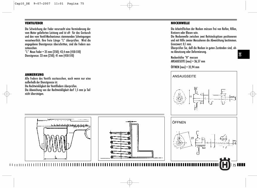
NOCKNWELLE
Die Arbeitsflächen der Nocken müssen frei von Reifen, Rillen,Kratzern oder Blasen sein. Die Nockenwelle zwischen zwei Reitstockspitzen positionerenund mit Hilfe zweier Messuheren die Abweichtung bestimmen.Grenzwert: 0,1 mm.Überprüfen Sie, daß die Nocken in guten Zuständen sind, oh-ne Abnutzung oder Deformierung.
Nockenhöhe “H” messenANSAUGSEITE (neu) = 36,57 mm
ÖFFNEN (neu) = 35,94 mm
VENTILFEDER
Die Schwächung der Feder verursacht eine Verminderung dervom Motor gelieferten Leistung und ist oft für das Geräuschund den vom Ventil-Mechanismus stammenden Schwingungenverantwortlich. Ihre freie Länge “L” überprüfen. Wird dieangegebene Dienstgrenze überschritten, sind die Federn aus-zutauschen.“L” Neue Feder = 35 mm (250); 43,4 mm (450-510) Dienstgrenze: 33 mm (250); 41 mm (450-510)
ANMERKUNGAlle Federn des Ventils austauschen, auch wenn nur eineaußerhalb der Dienstgrenze ist.Die Rechtwinkligkeit der Ventilfedern überprüfen.Die Abweichung von der Rechtwinkligkeit darf 1,5 mm je Teilnicht übersteigen.
75
ANSAUGSEITE
ÖFFNEN
DE
Cap10_DE 9-07-2007 11:01 Pagina 75
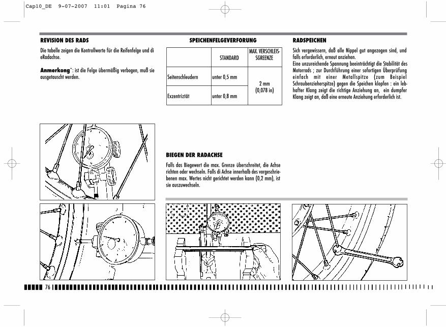
76
REVISION DES RADS
Die tabelle zeigen die Kontrollwerte für die Reifenfelge und dieRadachse.
Anmerkong*: ist die Felge übermäßig verbogen, muß sieausgetauscht werden.
SPEICHENFELGEVERFORUNG
BIEGEN DER RADACHSE
Falls das Biegewert die max. Grenze überschreitet, die Achserichten oder wechseln. Falls di Achse innerhalb des vorgeschrie-benen max. Wertes nicht gerichtet werden kann (0,2 mm), istsie auszuwechseln.
RADSPEICHEN
Sich vergewissern, daß alle Nippel gut angezogen sind, undfalls erforderlich, erneut anziehen.Eine unzureichende Spannung beeinträchtigt die Stabilität desMotorrads ; zur Durchführung einer sofortigen Überprüfungeinfach mit einer Metallspitze (zum BeispielSchraubenzieherspitze) gegen die Speichen klopfen : ein leb-hafter Klang zeigt die richtige Anziehung an, ein dumpferKlang zeigt an, daß eine erneute Anziehung erforderlich ist.
STANDARDMAX. VERSCHLEIS-
SGREENZE
Seitenschleudern unter 0,5 mm2 mm
(0,078 in)Exzentriztät unter 0,8 mm
Cap10_DE 9-07-2007 11:01 Pagina 76
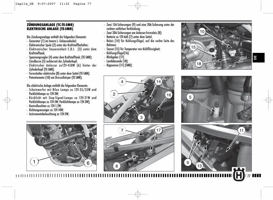
9
11
- Zwei 15A-Sicherungen (9) und eine 20A-Sicherung unter derrechten seitlichen Verkleidung;
- Zwei 20A-Sicherungen am Anlasser-Fernrelais (8);- Batterie zu 12V-6Ah (7) unter dem Sattel.- Relais (14) für Kühlungsflügel, auf die rechte Seite des
Rahmen;- Sensor (15) für Temperatur von Kühlflüssigkeit;- Kühlungsflügel(16).- Blinkgeber (17).- Lambdasonde (18);- Kippsensor (11) (SMR);
77
DE
ZÜNDUNGSANLAGE (TC-TE-SMR)ELEKTRISCHE ANLAGE (TE-SMR)
Die Zündungsanlage enthält die folgenden Elemente:- Generator (1) im Innern L. Gehausedeckel;- Elektronischer Spule (2) unter des Kraftstoffbehälter;- Elektronischer Steuereinheit C.D.I. (3) unter dem
Kraftstofftank;- Spannungsregler (4) unter dem Kraftstofftank; (TE-SMR);- Zündkerze (5) rechterseit der Zylinderkopf;- Elektrischer Anlasser zu12V-450W (6) hinter der
Zylinderkopf (TE-SMR);- Fernschalter elektrische (8) unter dem Sattel (TE-SMR);- Potentiometer (10) am Drosselkörper (TE-SMR);
Die elektrische Anlage enthält die folgenden Elemente:- Scheinwerfer mit Bilux Lampe zu 12V-35/35W und
Parklichtlampe zu 12V-3W;- R ü cklicht mit Stop-Signal-Lampe zu 12V-21W und
Parklichtlampe zu 12V-5W; Parklichtlampe zu 12V-3W);- Kontrolleuchten zu 12V-1,2W;- Richtungsanzeiger zu 12V-10W;- Instrumentebeleuchtung zu 12V-2W;
1 6
4
2 16
14
3
7 17
8
5
15
18
10
13
Cap11a_DE 9-07-2007 11:32 Pagina 77
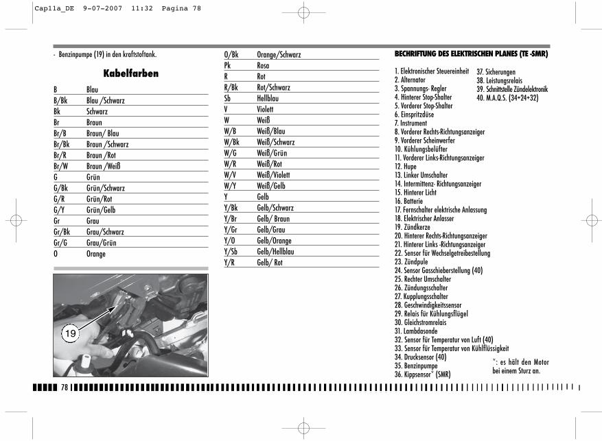
- Benzinpumpe (19) in den kraftstoftank.
KabelfarbenB BlauB/Bk Blau /SchwarzBk SchwarzBr BraunBr/B Braun/ BlauBr/Bk Braun /SchwarzBr/R Braun /RotBr/W Braun /WeißG GrünG/Bk Grün/SchwarzG/R Grün/RotG/Y Grün/GelbGr GrauGr/Bk Grau/SchwarzGr/G Grau/GrünO Orange
O/Bk Orange/SchwarzPk RosaR RotR/Bk Rot/SchwarzSb HellblauV ViolettW WeißW/B Weiß/BlauW/Bk Weiß/SchwarzW/G Weiß/GrünW/R Weiß/RotW/V Weiß/ViolettW/Y Weiß/GelbY GelbY/Bk Gelb/SchwarzY/Br Gelb/ BraunY/Gr Gelb/GrauY/O Gelb/OrangeY/Sb Gelb/HellblauY/R Gelb/ Rot
78
19
BECHRIFTUNG DES ELEKTRISCHEN PLANES (TE -SMR)
1. Elektronischer Steuereinheit2. Alternator3. Spannungs- Regler4. Hinterer Stop-Shalter5. Vorderer Stop-Shalter6. Einspritzdüse7. Instrument8. Vorderer Rechts-Richtungsanzeiger9. Vorderer Scheinwerfer10. Kühlungsbelüfter11. Vorderer Links-Richtungsanzeiger12. Hupe13. Linker Umschalter14. Intermittenz- Richtungsanzeiger15. Hinterer Licht16. Batterie17. Fernschalter elektrische Anlassung18. Elektrischer Anlasser19. Zündkerze20. Hinterer Rechts-Richtungsanzeiger21. Hinterer Links -Richtungsanzeiger22. Sensor für Wechselgetreibestellung23. Zündpule24. Sensor Gasschieberstellung (40)25. Rechter Umschalter26. Zündungsschalter27. Kupplungsschalter28. Geschwindigkeitssensor29. Relais für Kühlungsflügel30. Gleichstromrelais31. Lambdasonde 32. Sensor für Temperatur von Luft (40)33. Sensor für Temperatur von Kühlflüssigkeit34. Drucksensor (40)35. Benzinpumpe36. Kippsensor* (SMR)
37. Sicherungen38. Leistungsrelais39. Schnittstelle Zündelektronik40. M.A.Q.S. (34+24+32)
*: es hält den Motorbei einem Sturz an.
Cap11a_DE 9-07-2007 11:32 Pagina 78

1
2
PASSING
HI
Lo
Pos
TURNHORN
R= 110 Ohm
+-
f
+-
+ -
B
W/G
W/V
Bk
B
B
Y-R
YY
Y
YY
Y
V
Bk
G/R
G/B
k
O
O
B
B
B
Bk
B
B
Pk
R
R
Y-R
Y-R
Y-B
k
Y-B
k
Y-B
k
Y-S
b
Br
G/R
G/R
G/R
V
Pk
Pk
Br/
Bk
Br/
W
Br/
W W/R
W/R
W/B
k
W/B
k
G/B
k
Bk
Bk
Bk
O
Gr/
Bk
Gr/
Bk
Y/B
r Y/S
b
Y/B
r
Y/S
b
Br/
R
Br/
R
O/B
k
O/B
k
W/B
k
W/B
k
Gr/
G
W/B
W/V
W/G
W/B
G-Y B
B
B
B
B
B
Y-R
Y-G
r
Y-S
b
Br
BBr
Y-B
k
Y-G
r
Br-
W
Br-
W
Br-
W
Br-
W
Br-
W
Br-
W
Br-
Bk
Br-
Bk
Br W
Gr/
G
Br/
B
Br/
B
W/R
W/YBk
G/Y
G/Y
G/Y
G/Y
Gr
Gr
B/B
kB
/Bk
Sb
Sb
Sb
R/B
k
R/Bk R/Bk
Bk
Bk
W
W
Y/O
Y/O
Y/O
G/R
G-Y Y RY
W
Br
G
G
B
Y/B
k
W/R
W/Y
W
Bk
Bk
Br
B
RR
/Bk
Sb
Br/
W
1 2 3 4 5 6 7 9 10 11 13 14 15 16 18 19 20 22 25 26 27 29 30 31 32 33 34
M
M 15 12V
R
9Ah
21 3 4
21
ONOFF
1 2
31 2 31 2
OFF
ON
8 12 17 21 23 24 2821
OFF
21 1 2 3 4 1 2 3 4 1 2 3 4 21
1 2 3 421 21 3 1 2 3 4 5 6
1 2 3 4 5
1
21 21 3 1 2 3 4 5 21 3 4
1 2 3 4
1 2 3 4 5 6
21 21
21
34
56
21
21
21
21
3
21212121
1 2 3 41 2 3 4 5 6 7 8 9
1 2 3 4
RUN
START
M P
DF
12
34
56
78
910 12
1114 16
13 15 2526
1718
1920
2122
2324
79
DE
1
2 34 5
7
6
8
9
10
11
12
13
14
15
161718
19
20
21
22
23
24
40
25
26 2728 29
3234
36
35 3330 31
37 38
39
TE-SMR
Cap11a_DE 9-07-2007 11:32 Pagina 79

80
Kabelfarben
B BlauBr BraunBk SchwarzG GrünGr GrauGr/R Grau/RotO OrangeP RosaR RotSb HellblauV ViolettW WeißY Gelb
BECHRIFTUNG DES ELEKTRISCHEN PLANES(TC 250)
1. Elektronischer Steuereinheit2. Alternator3. Spannungs- Regler4. Kondensator5. Batterie6. Fernschalter elektrische Anlassung7. Elektrischer Anlasser8. Zündkerze9. Sensor für Wechselgetreibestellung10. Elektronischer Spule11. Sensor für Vergaser Drosselstellung12. Motorabschaltung13. Zündungsschalter14. Kupplungsschalter
Cap11a_DE 9-07-2007 11:32 Pagina 80
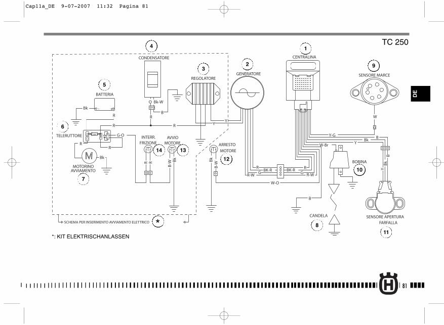
81
R-WGBK-R
R-W
W-Br
GRBK-R
R
CANDELA
BOBINA
GENERATORE
W-O
SENSORE MARCE
SENSORE APERTURAFARFALLA
REGOLATORE
CONDENSATORE
- +
15A
ARRESTO
MOTORE
BATTERIA
TELERUTTORE
MOTORINOAVVIAMENTO
Y-G BBk
Y
B
R Bk
B-W
W
BB
kY
CENTRALINA
Bk - +
R
G-O
R
R
O
R
Bk-W
B
YYR
R
Bk
AVVIOMOTORE
B-W
Bk
R
INTERR.FRIZIONE
SCHEMA PER INSERIMENTO AVVIAMENTO ELETTRICO
TC 250
DE
*: KIT ELEKTRISCHANLASSEN
1
23
4
5
7
6
8
9
10
11
12
14 13
*
Cap11a_DE 9-07-2007 11:32 Pagina 81
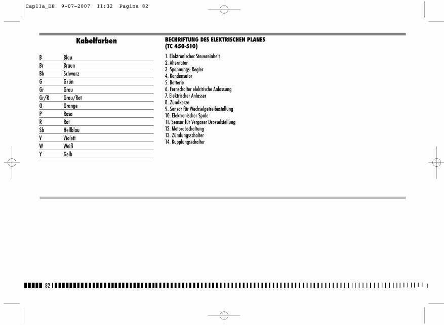
82
Kabelfarben
B BlauBr BraunBk SchwarzG GrünGr GrauGr/R Grau/RotO OrangeP RosaR RotSb HellblauV ViolettW WeißY Gelb
BECHRIFTUNG DES ELEKTRISCHEN PLANES(TC 450-510)
1. Elektronischer Steuereinheit2. Alternator3. Spannungs- Regler4. Kondensator5. Batterie6. Fernschalter elektrische Anlassung7. Elektrischer Anlasser8. Zündkerze9. Sensor für Wechselgetreibestellung10. Elektronischer Spule11. Sensor für Vergaser Drosselstellung12. Motorabschaltung13. Zündungsschalter14. Kupplungsschalter
Cap11a_DE 9-07-2007 11:32 Pagina 82
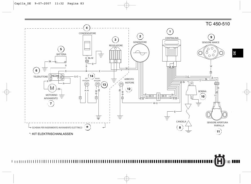
83
R-WGBK-R
R-W
W-Br
GRBK-R
R
CANDELA
BOBINA
GENERATORE
W-O
SENSORE MARCE
SENSORE APERTURAFARFALLA
REGOLATORE
- +
15A
ARRESTO
MOTORE
AVVIO
MOTORE
BATTERIA
TELERUTTORE
MOTORINOAVVIAMENTO
Y-G BBk
Y
B
B-W
Bk
Bk
B-W
W
BB
kY
CENTRALINA
Bk - +
R
G-O
R
R
O
R
Bk-W
B
WYR
R
BkRR
INT.
FRIZIONE
CONDENSATORE
SCHEMA PER INSERIMENTO AVVIAMENTO ELETTRICO
TC 450-510
*: KIT ELEKTRISCHANLASSEN
1
23
4
5
7
6
8
9
10
11
12
14
13
*
DE
Cap11a_DE 9-07-2007 11:32 Pagina 83
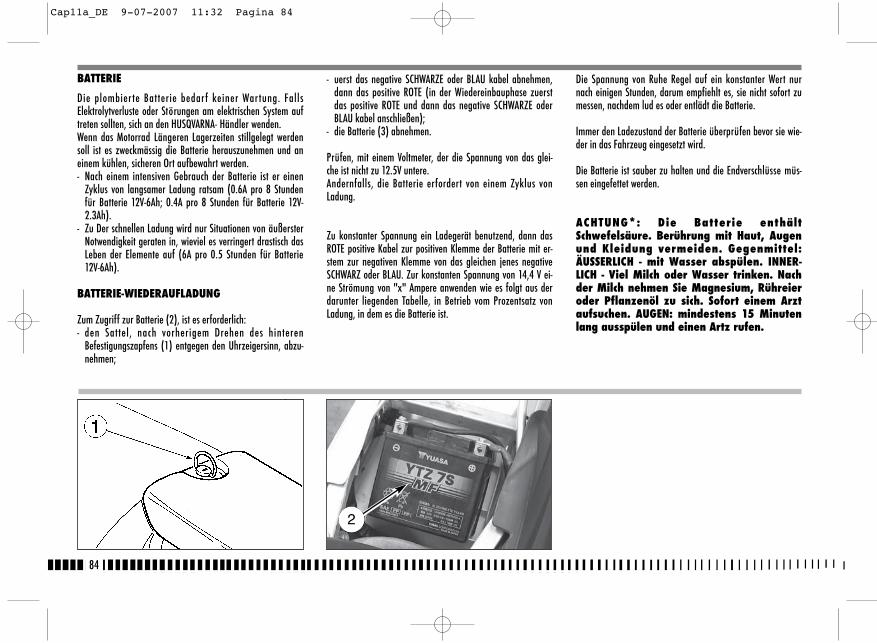
- uerst das negative SCHWARZE oder BLAU kabel abnehmen,dann das positive ROTE (in der Wiedereinbauphase zuerstdas positive ROTE und dann das negative SCHWARZE oderBLAU kabel anschließen);
- die Batterie (3) abnehmen.
Prüfen, mit einem Voltmeter, der die Spannung von das glei-che ist nicht zu 12.5V untere. Andernfalls, die Batterie erfordert von einem Zyklus vonLadung.
Zu konstanter Spannung ein Ladegerät benutzend, dann dasROTE positive Kabel zur positiven Klemme der Batterie mit er-stem zur negativen Klemme von das gleichen jenes negativeSCHWARZ oder BLAU. Zur konstanten Spannung von 14,4 V ei-ne Strömung von "x" Ampere anwenden wie es folgt aus derdarunter liegenden Tabelle, in Betrieb vom Prozentsatz vonLadung, in dem es die Batterie ist.
BATTERIE
Die plombier te Batterie bedarf keiner Wartung. FallsElektrolytverluste oder Störungen am elektrischen System auftreten sollten, sich an den HUSQVARNA- Händler wenden.Wenn das Motorrad Längeren Lagerzeiten stillgelegt werdensoll ist es zweckmässig die Batterie herauszunehmen und aneinem kühlen, sicheren Ort aufbewahrt werden.- Nach einem intensiven Gebrauch der Batterie ist er einen
Zyklus von langsamer Ladung ratsam (0.6A pro 8 Stundenfür Batterie 12V-6Ah; 0.4A pro 8 Stunden für Batterie 12V-2.3Ah).
- Zu Der schnellen Ladung wird nur Situationen von äußersterNotwendigkeit geraten in, wieviel es verringert drastisch dasLeben der Elemente auf (6A pro 0.5 Stunden für Batterie12V-6Ah).
BATTERIE-WIEDERAUFLADUNG
Zum Zugriff zur Batterie (2), ist es erforderlich:- den Sattel, nach vorherigem Drehen des hinteren
Befestigungszapfens (1) entgegen den Uhrzeigersinn, abzu-nehmen;
Die Spannung von Ruhe Regel auf ein konstanter Wert nurnach einigen Stunden, darum empfiehlt es, sie nicht sofort zumessen, nachdem lud es oder entlädt die Batterie.
Immer den Ladezustand der Batterie überprüfen bevor sie wie-der in das Fahrzeug eingesetzt wird.
Die Batterie ist sauber zu halten und die Endverschlüsse müs-sen eingefettet werden.
ACHTUNG*: Die Batterie enthältSchwefelsäure. Berührung mit Haut, Augenund Kleidung vermeiden. Gegenmittel:ÄUSSERLICH - mit Wasser abspülen. INNER-LICH - Viel Milch oder Wasser trinken. Nachder Milch nehmen Sie Magnesium, Rühreieroder Pflanzenöl zu sich. Sofort einem Arztaufsuchen. AUGEN: mindestens 15 Minutenlang ausspülen und einen Artz rufen.
84
2
Cap11a_DE 9-07-2007 11:32 Pagina 84
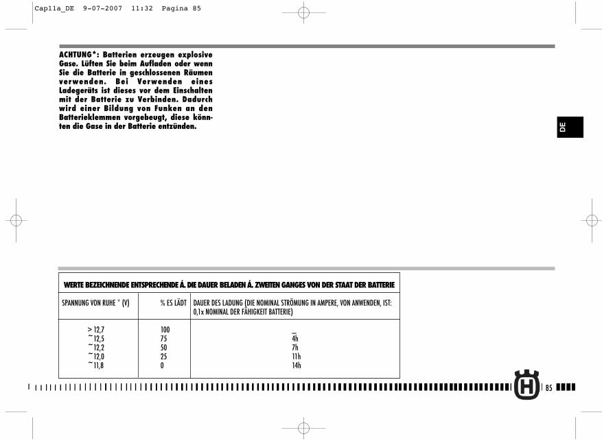
85
DE
WERTE BEZEICHNENDE ENTSPRECHENDE Á. DIE DAUER BELADEN Á. ZWEITEN GANGES VON DER STAAT DER BATTERIE
SPANNUNG VON RUHE * (V) % ES LÄDT DAUER DES LADUNG (DIE NOMINAL STRÖMUNG IN AMPERE, VON ANWENDEN, IST: 0,1x NOMINAL DER FÄHIGKEIT BATTERIE)
> 12,7 100 _~12,5 75 4h~12,2 50 7h~12,0 25 11h~11,8 0 14h
ACHTUNG*: Batterien erzeugen explosiveGase. Lüften Sie beim Aufladen oder wennSie die Batterie in geschlossenen Räumenverwenden. Bei Verwenden einesLadegeräts ist dieses vor dem Einschaltenmit der Batterie zu Verbinden. Dadurchwird einer Bildung von Funken an denBatterieklemmen vorgebeugt, diese könn-ten die Gase in der Batterie entzünden.
Cap11a_DE 9-07-2007 11:32 Pagina 85
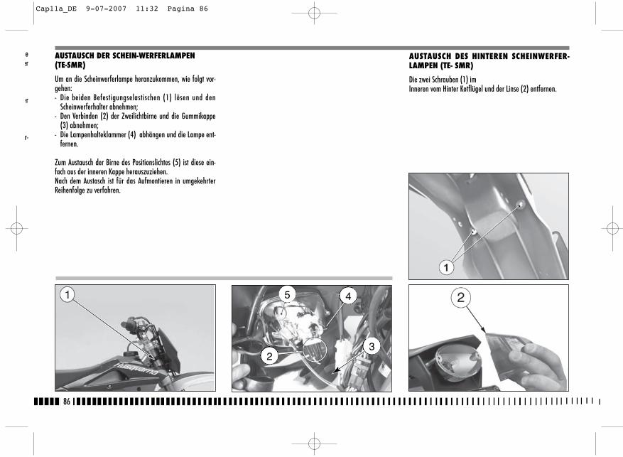
AUSTAUSCH DES HINTEREN SCHEINWERFER-LAMPEN (TE- SMR)
Die zwei Schrauben (1) imInneren vom Hinter Kotflügel und der Linse (2) entfernen.
86
AUSTAUSCH DER SCHEIN-WERFERLAMPEN(TE-SMR)
Um an die Scheinwerferlampe heranzukommen, wie folgt vor-gehen:- Die beiden Befestigungselastischen (1) lösen und den
Scheinwerferhalter abnehmen;- Den Verbinden (2) der Zweilichtbirne und die Gummikappe
(3) abnehmen;- Die Lampenhalteklammer (4) abhängen und die Lampe ent-
fernen.
Zum Austausch der Birne des Positionslichtes (5) ist diese ein-fach aus der inneren Kappe herauszuziehen.Nach dem Austasch ist für das Aufmontieren in umgekehrterReihenfolge zu verfahren.
5 4
23
eer
er
r-
Cap11a_DE 9-07-2007 11:32 Pagina 86
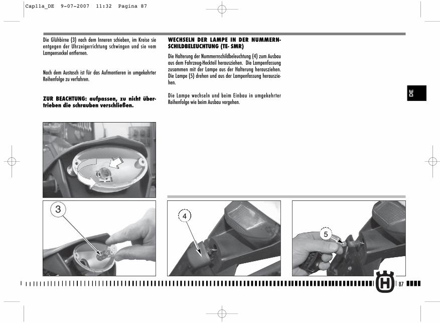
5
Die Glühbirne (3) nach dem Inneren schieben, im Kreise sieentgegen der Uhrzeigerrichtung schwingen und sie vomLampensockel entfernen.
Nach dem Austasch ist für das Aufmontieren in umgekehrterReihenfolge zu verfahren.
ZUR BEACHTUNG: aufpassen, zu nicht über-trieben die schrauben verschließen.
WECHSELN DER LAMPE IN DER NUMMERN-SCHILDBELEUCHTUNG (TE- SMR)
Die Halterung der Nummernschildbeleuchtung (4) zum Ausbauaus dem Fahrzeug-Heckteil herausziehen. Die Lampenfassungzusammen mit der Lampe aus der Halterung herausziehen.Die Lampe (5) drehen und aus der Lampenfassung herauszie-hen.
Die Lampe wechseln und beim Einbau in umgekehrterReihenfolge wie beim Ausbau vorgehen.
87
DE
4
Cap11a_DE 9-07-2007 11:32 Pagina 87
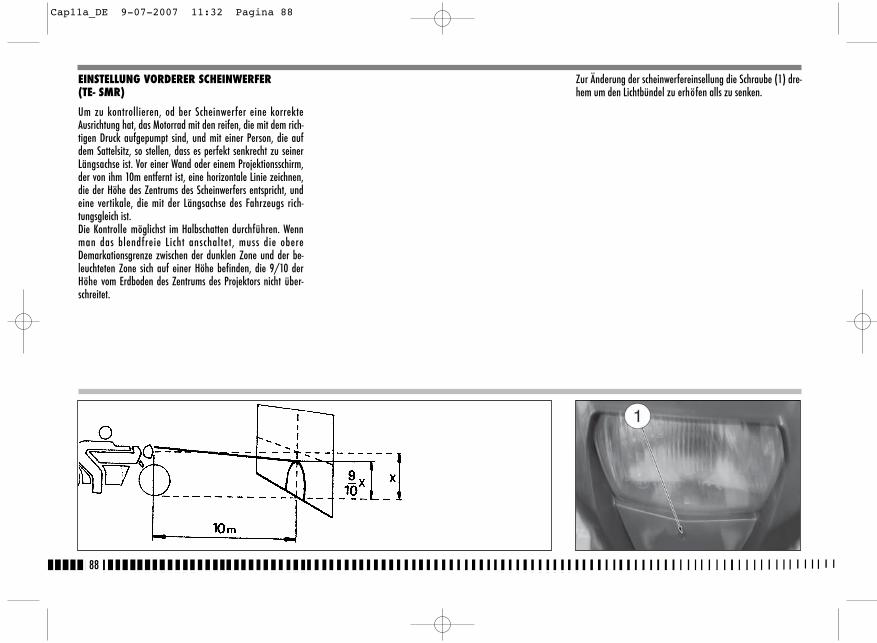
EINSTELLUNG VORDERER SCHEINWERFER(TE- SMR)
Um zu kontrollieren, od ber Scheinwerfer eine korrekteAusrichtung hat, das Motorrad mit den reifen, die mit dem rich-tigen Druck aufgepumpt sind, und mit einer Person, die aufdem Sattelsitz, so stellen, dass es perfekt senkrecht zu seinerLängsachse ist. Vor einer Wand oder einem Projektionsschirm,der von ihm 10m entfernt ist, eine horizontale Linie zeichnen,die der Höhe des Zentrums des Scheinwerfers entspricht, undeine vertikale, die mit der Längsachse des Fahrzeugs rich-tungsgleich ist.Die Kontrolle möglichst im Halbschatten durchführen. Wennman das blendfreie Licht anschaltet, muss die obereDemarkationsgrenze zwischen der dunklen Zone und der be-leuchteten Zone sich auf einer Höhe befinden, die 9/10 derHöhe vom Erdboden des Zentrums des Projektors nicht über-schreitet.
Zur Änderung der scheinwerfereinsellung die Schraube (1) dre-hem um den Lichtbündel zu erhöfen alls zu senken.
88
Cap11a_DE 9-07-2007 11:32 Pagina 88
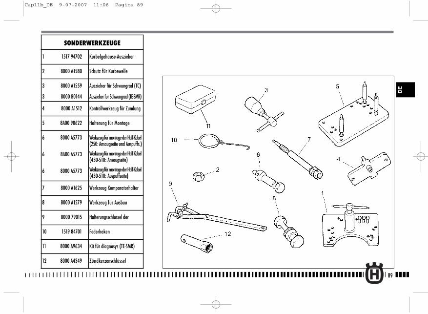
89
DE
SONDERWERKZEUGE
1 1517 94702 Kurbelgehäuse-Auszieher
2 8000 A1580 Schutz für Kurbewelle
3 8000 A1559
3 8000 B0144
Auszieher für Schwungrad (TC)
Auszieher für Schwungrad (TE-SMR)
4 8000 A1512 Kontrollwerkzeug für Zundung
5 8A00 90622 Halterung für Montage
6 8000 A5773
6 8A00 A5773
6 8000 A5773
Werkzeug für montage der Half-Kebel(250: Ansaugseite und Auspuffs.)
Werkzeug für montage der Half-Kebel(450-510: Ansaugseite)
Werkzeug für montage der Half-Kebel(450-510: Auspuffseite)
7 8000 A1625 Werkzeug Komparatorhalter
8 8000 A1579 Werkzeug für Ausbau
9 8000 79015 Halterungsschlussel der
10 1519 84701 Federhaken
11 8000 A9634 Kit für diagnosys (TE-SMR)
12 8000 A4349 Zündkerzenschlüssel
Cap11b_DE 9-07-2007 11:06 Pagina 89
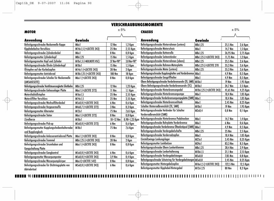
90
MOTOR
AnvendungBefestigungsschraube Nockenwelle KappeKipphebelachse VerschlussBefestigungsschraube ZylinderdeckelBefestigungsmutter ZylinderkopfBefestigungsmutter Kopf und ZylinderBefestigungsschraube Ölrohr-Zylinderkopf Ölstopfen auf der KurbelzapfenBefestigungsmutter AntriebsradBefestigungsschraube Scheibe für Nockenwelle(ANSAUGSEITE)Befestigungsschraube Ventilsteuerungkette GleitbahnBefestigungsschraube Gehauselager PlatteMotorölablaßstopfenMotorölfilter VerschlussBefestigungsschraube WechselfilterdeckelBefestigungsschraube VergasermuffeBefestigungsmutter AlternatorBefestigungsschraube StatorZündkerzeBefestigungsschraube Pick-upBefestigungsmutter Kupplungscheibenhalternabeund KupplungkorbBefestigungsschraube Anlasserantriebsrad PlatteBefestigungsschraube TrommelBefestigungsschraube Strumhaken und Gangschaltung PlatteBefestigungsschraube GangkontrolBefestigungsmutter WasserpumprotorBefestigungsschraube WasserpumpkörperBefestigungsschraube für Dichtringsplatte vonAbtriebritzel
MOTEUR
GewindeM6x1 12 Nm 1,2 KgmM14x1,5 (+LOCTITE 243) 25 Nm 2,55 KgmM6x1 8 Nm 0,8 KgmM8x1,25 15 Nm 1,5 KgmM10x1,5 (+MOLIKOTE HSC) 37 Nm+90° 3.8 Nm+90°M10x1 15 Nm 1,5 KgmM14x1 (+LOCTITE 243) 20 Nm 2 KgmM18x1,25 (+LOCTITE 243) 180 Nm 18 KgmM6x1 (+LOCTITE 243) 8 Nm 0,8 Kgm
M8x1,25 12 Nm 1,23 KgmM6x1 (+LOCTITE 272) 11 Nm 1,1 KgmM16x1,5 25 Nm 2,55 KgmM14x1,5 25 Nm 2,55 KgmM5x0,8 (+LOCTITE 243) 6 Nm 0,6 KgmM4x0,7 (+LOCTITE 272) 3 Nm 0,3 KgmM12x1 75 Nm 7,65 KgmM6x1 (+LOCTITE 272) 8 Nm 0,8 KgmM10x1 10÷12 Nm 0,98÷1,23 KgmM5x0,8 (+LOCTITE 272) 6 Nm 0,6 KgmM18x1 75 Nm 7,6 Kgm
M6x1 (+LOCTITE 243) 8 Nm 0,8 KgmM8x1,25 (+LOCTITE 243) 20 Nm 2 KgmM6x1 (+LOCTITE 243) 8 Nm 0,8 Kgm
M5x0,8 (+LOCTITE 243) 6 Nm 0,6 KgmM5x0,8 (+LOCTITE 243) 3,9 Nm 0,4 KgmM6x1(+LOCTITE 542) 8 Nm 0,8 KgmM5x0,8 (+LOCTITE 243) 6 Nm 0,6 Kgm
VERSCHRAUBUNGSMOMENTE± 5%
CHASSIS
AnvendungBefestigungsschraube Hinterrahmen (untere)Befestigungsschraube MotorschutzBefestigungsschraube KettenrolleBefestigungsschraube SeitenständerBefestigungsschraube Hinterrahmen (obere)Befestigungsschraube Rahmen-MotorplatteBefestigungsschraube Motor (untere)Befestigungsschraube Kupplunghalter und VorderbremseBefestigungsschraube GasgriffhalterObere Befestigungsschraube Vorderbremserohr (TE, SMR)Obere Befestigungsschraube Vorderbremserohr (TC)Befestigungsschraube HinterbremsenpedalBefestigungsschraube HinterbremsenpumpeBefestigungsschraube Vorderbremsenpumpeplatte (SMR)Befestigungsschraube HinterbremseöltankSchalter Hinterradbremslicht (TE, SMR)Befestigungsschraube Verbinder für SchalterVorderradbremslicht (SMR)Befestigungsschraube Hinterbremse PedalnockenBefestigungsschraube Rohrplatte VorderbremseBefestigungsschraube Vorderbremse Öltankstöpsel (SMR)Befestigungsschraube VordergabelschafteBefestigungsschraube VorderradzapfenEinstellzwinge LenkungslagerBefestigungsmutter LenkbolzenBefestigungsschraube Obere LenkerklemmeBefestigungsschraube LenkerhalterungBefestigungsschraube VordergabelstangenBefestigungsschraube Schutzring für VordergabelstangenBefestigungsmutter HintergabelzapfenBefestigungsmutter Kipphebel-Hintergabel
GewindeM8x1,25 25,5 Nm 2,6 KgmM6x1 14,7 Nm 1,5 KgmM8x1,25 26,95 Nm 2,75 KgmM8x1,25 (+LOCTITE 243) 11,75 Nm 1,2 KgmM8x1,25 25,5 Nm 2,6 KgmM8x1,25 (+LOCTITE 270 35,3 Nm 3,6 KgmM8x1,25 35,3 Nm 3,6 KgmM6x1 4,9 Nm 0,5 KgmM6x1 4,9 Nm 0,5 KgmM10x1 19 Nm 1,95 KgmM10x1 24,7 Nm 2,5 KgmM10x1,25 (+LOCTITE 243) 41,65 Nm 4,25 KgmM6x1 10,4 Nm 1,05 KgmM6x1 10,4 Nm 1,05 KgmM6x1 2,45 Nm 0,25 KgmM10x1 19 Nm 1,95 KgmM2x0,4 0,8 Nm 0,1 Kgm
M6x1 14,7 Nm 1,4 KgmM6x1 6 Nm 0,6 KgmM6x1 4,9 Nm 0,5 KgmM8x1,25 25 Nm 2,5 KgmM6x1 10,4 Nm 1,05 KgmM25x1 3,45 Nm 0,35 KgmM24x1 83,3 Nm 8,5 KgmM8x1,25 28,4 Nm 2,9 KgmM10x1,5 21,1 Nm 2,15 KgmM5x0,8 7,85 Nm 0,8 KgmM5x0,8 2,45 Nm 0,25 KgmM16x1,5 (+LOCTITE 243) 122,5 Nm 12,5 KgmM12x1,25 80 Nm 8,2 Kgm
± 5%
Cap11b_DE 9-07-2007 11:06 Pagina 90
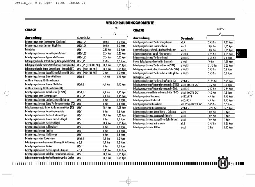
Gewindeø5,5 2,45 Nm 0,25 KgmM6x1 10,4 Nm 1,05 KgmM6x1 10,4 Nm 1,05 KgmM5x0,8 3,45 Nm 0,35 KgmM8x1,25 25,5 Nm 2,6 KgmM10x1 19 Nm 1,95 KgmM10x1,5 51,45 Nm 5,25 KgmM10x1,5 25,5 Nm 2,6 KgmM10x1,5 25,5 Nm 2,6 Kgm
M20x1,5 51,45 Nm 5,25 KgmM6x1 (LOCTITE 243) 14,7 Nm 1,5 KgmM8x1,25 34,7 Nm 3,54 KgmM6x1 (LOCTITE 243) 14,7 Nm 1,5 KgmM4,07x0,75 4,4 Nm 0,45 KgmM4,5x0,75 4,4 Nm 0,45 KgmM8x1,25 (+LOCTITE 243) 34,3 Nm 3,5 KgmM20x1,5 142,1 Nm 14,5 KgmM6x1 10,4 Nm 1 KgmM6x1 10,4 Nm 1 KgmM6x1 10,4 Nm 1 Kgmø4,8 3,45 Nm 0,35 KgmM6x1 7 Nm 0,72 Kgm
91
DE
CHASSIS
AnvendungBefestigungsmutter Spannstange- Kipphebel Befestigungsmutter Rahmen- KipphebelFettbüchseBefestigungsschraube Stossdämpfer-RahmenBefestigungsschraube Kipphebel - RahmenBefestigungsschraube Kettenführung- Hintergabel (TE-SMR)Befestigungsschraube Vordere Kettenführung - Hintergabel (TC)Befestigungsschraube Hintere Kettenführung - Hintergabel (TC)Befestigungsschraube Buegel-Kettenführung (TE-SMR)Befestigungsschraube Untere Gleitbahnund Rohrfühurung für HinterbremseBefestigungsschraube Hintere Gleitbahnund Rohrfühurung für Hinterbremse (TC)Befestigungsschraube Kettenkasten (TE-SMR)Befestigungsmutter KettenspannerBefestigungsschraube Spoiler-KraftstoffbehälterBefestigungsschraube Obere Vordernummerträge (TC)Befestigungsschraube Untere Vordernummerträger (TC)Befestigungsschraube StossdämpferschutzBefestigungsschraube Vordere HinterkotflügelBefestigungsschraube Hintere HinterkotflügelBefestigungsschraube VorderkotflügelBefestigungsschraube KühlerschutzBefestigungsschraube StreifenBefestigungsschraube SchildtraegerBefestigungsmutter RückstrahlerBefestigungsschraube Bremsenrohrfühurung für VerkleidungBefestigungsschraube BlinkerBefestigungsschraube Vordere optische GruppeBefestigungsschraube Kabel für Fernschalter AnlasserBefestigungsschraube für Kraftstoffbehälter Vordere Stopfen
VERSCHRAUBUNGSMOMENTE
GewindeM12x1,25 80 Nm 8,2 KgmM12x1,25 80 Nm 8,2 KgmM6x1 2,95 Nm 0,3 KgmM10x1,25 52,4 Nm 5,35 KgmM10x1,25 52,4 Nm 5,35 KgmM8x1,25 25 Nm 2,5 KgmM8x1,25 (+LOCTITE 243) 10,4 Nm 1,05 KgmM6x1 (+LOCTITE 243) 10,4 Nm 1,05 KgmM6x1 (+LOCTITE 243) 2 Nm 0,2 KgmM5x0,8 4,4 Nm 0,45 Kgm
M5x0,8 4,4 Nm 0,45 Kgm
M5x0,8 4,4 Nm 0,45 KgmM8x1,25 4,4 Nm 0,45 KgmM6x1 6 Nm 0,6 KgmM6x1 6 Nm 0,6 KgmM6x1 10,4 Nm 1,05 KgmM6x1 6 Nm 0,6 KgmM6x1 10,4 Nm 1,05 KgmM6x1 6 Nm 0,6 KgmM6x1 10,4 Nm 1,05 KgmM6x1 6 Nm 0,6 KgmM6x1 6 Nm 0,6 KgmM6x1 6 Nm 0,6 KgmM4x0,7 1,9 Nm 0,2 Kgmø 3,5 1,9 Nm 0,2 KgmM6x1 6 Nm 0,6 Kgmø 3,9 1,45 Nm 0,15 KgmM6x1 10,4 Nm 1,05 KgmM6x1 10,4 Nm 1,05 Kgm
± 5%CHASSIS
AnvendungBefestigungsschraube VorderfiltergehäuseBefestigungsschraube TreibstoffhahnHinterbefestigungsschraube KraftstoffbehälterBefestigungsmutter Flansch FiltergehäuseBefestigungsschraube VorderradsattelUntere Befestigungsschraube für BremsrohrBefestigungsschraube Vorderradzapfen (SMR) Befestigungsschraube Vorderradbremssattel-Platte (SMR)Befestigungsschraube Vorderradbremssattelplatte-Vordergabel (SMR) Befestigungsschraube Vorderradzapfen (TE-TC) Befestigungsschraube Vorderradbremsscheibe (TE-TC) Befestigungsschraube Vorderradbremsscheibe (SMR) Befestigungsschraube Hinterradbremsscheibe (TE-TC)Befestigungsnippel VorderradBefestigungsnippel HinterradBefestigungsmutter HinterkranzBefestigungsmutter HinterradzapfenBefestigungsschraube Deckel Ritzel-L. GehauseBefestigungsschraube Abgasschalldämpfer Befestigungsschraube Ausapuffrohr-ZylinderkopfBefestigungsschraube InstrumenteBefestigungsschraube Kühler
± 5%
Cap11b_DE 9-07-2007 11:06 Pagina 91
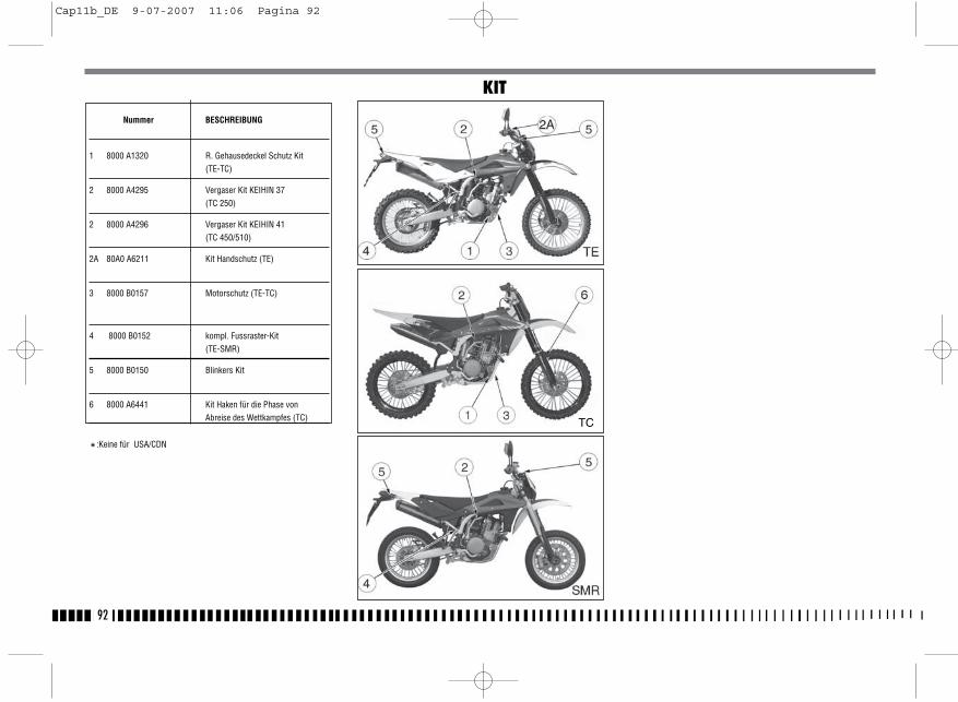
92
Nummer BESCHREIBUNG
1 8000 A1320 R. Gehausedeckel Schutz Kit(TE-TC)
2 8000 A4295 Vergaser Kit KEIHIN 37(TC 250)
2 8000 A4296 Vergaser Kit KEIHIN 41(TC 450/510)
2A 80A0 A6211 Kit Handschutz (TE)
3 8000 B0157 Motorschutz (TE-TC)
4 8000 B0152 kompl. Fussraster-Kit(TE-SMR)
5 8000 B0150 Blinkers Kit
6 8000 A6441 Kit Haken für die Phase vonAbreise des Wettkampfes (TC)
*:Keine für USA/CDN
KIT
TC
Cap11b_DE 9-07-2007 11:06 Pagina 92
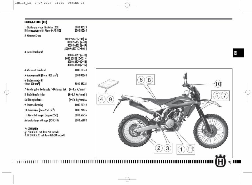
93
DE
EXTRA-TEILE (TE)
1- Dichtungsgruppe für Motor (250) 8000 B0373Dichtungsgruppe für Motor (450-510) 8000 B0364
2- Hinterer Kranz8A00 96837 (Z=47) &
8B00 96837 (Z=48) 8C00 96837 (Z=49)
8D00 96837 (Z=50) §3- Getriebezahnrad
8000 63827 (Z=12) 8000 63828 (Z=13) *8000 63829 (Z=14)
8000 63830 (Z=15)
4- Werkstatt Handbuch 8000 B0148
5- Vordergabelöl (Dose 1000 cm3) 8000 80260
6- Stoßdaempferöl (Dose 500 cm3) 8000 88231
7- Vordergabel Federsatz *+Distanzstück (K=4,5 N/mm) *8- Stoßdämpferfeder (K=5,4 Kg/mm) §
Stoßdämpferfeder (K=5,6 Kg/mm) &
9- Ersatzteilkatalog 8000 B0149
10- Bremsenöl (Dose 250 cm3) 8000 71445
11- Motordichtungen Gruppe (250) 8000 A5755
Motordichtungen Gruppe (450-510) 8000 A5982
*: STANDARD§ : STANDARD auf dem 250 modell&: DI STANDARD auf dem 450-510 modell
Cap11b_DE 9-07-2007 11:06 Pagina 93

94
EXTRA-TEILE (TC)
1- Dichtungsgruppe für Motor (250) 8000 A5735Dichtungsgruppe für Motor (450-510) 8000 A5736
2. Werkstatt Handbuch 8000 B0148
3. Hinterer Kranz 8A00 96837 (Z=47) @
8B00 96837 (Z=48) 8C00 96837 (Z=49)
8D00 96837 (Z=50) §,&
4. Getriebezahnrad 8000 63827 (Z=12 ) §
8000 63828 (Z=13) 8000 63829 (Z=14) &,@
8000 63830 (Z=15)
5. Motordichtungen Gruppe (250) 8000 A5755
Motordichtungen Gruppe (450-510) 8000 A5982
6. Vordergabelöl (Dose 1000 cm3) 8000 80260
8- Vordergabel Federsatz *+Distanzstück (K=4,8 N/mm) §(K=5 N/mm) &, @
9- Stoßdämpferfeder (K=5,4 Kg/mm) §(K=5,6 Kg/mm) &, @
10. Ersatzteilkatalog 8000 B0149
11. Bremsenöl (Dose 250 cm3) 8000 71445
12. Kit Elektrischanlassen 8000 B0455
*: STANDARD§ : STANDARD auf dem 250 modell&: STANDARD auf dem 450 modell@: STANDARD auf dem 510 modell
Cap11b_DE 9-07-2007 11:06 Pagina 94
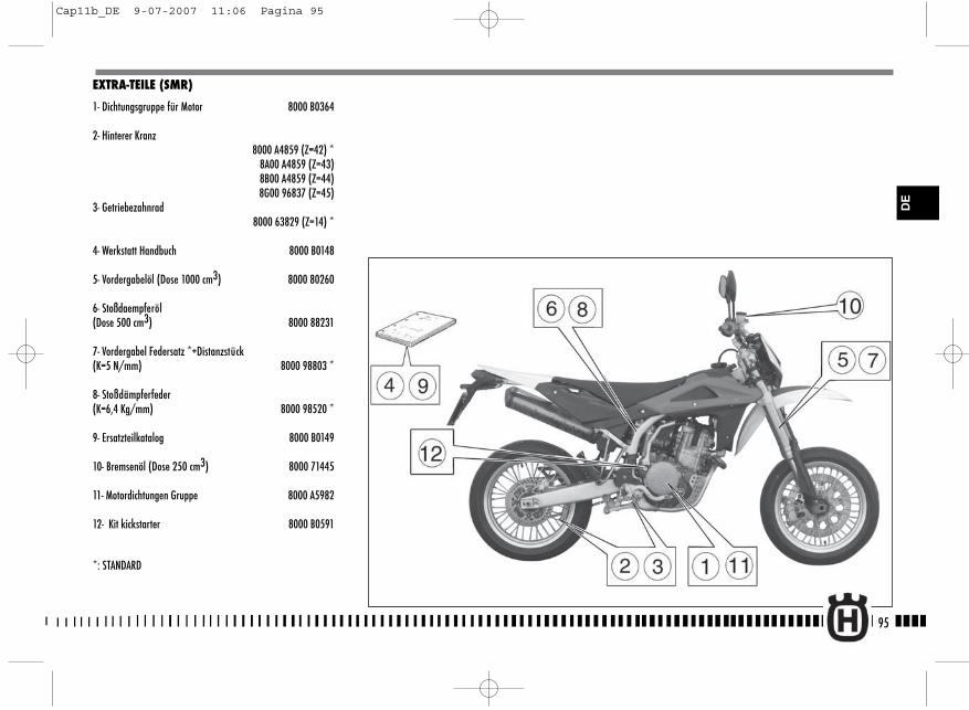
EXTRA-TEILE (SMR)
1- Dichtungsgruppe für Motor 8000 B0364
2- Hinterer Kranz8000 A4859 (Z=42) *
8A00 A4859 (Z=43)8B00 A4859 (Z=44)8G00 96837 (Z=45)
3- Getriebezahnrad 8000 63829 (Z=14) *
4- Werkstatt Handbuch 8000 B0148
5- Vordergabelöl (Dose 1000 cm3) 8000 80260
6- Stoßdaempferöl (Dose 500 cm3) 8000 88231
7- Vordergabel Federsatz *+Distanzstück(K=5 N/mm) 8000 98803 *
8- Stoßdämpferfeder(K=6,4 Kg/mm) 8000 98520 *
9- Ersatzteilkatalog 8000 B0149
10- Bremsenöl (Dose 250 cm3) 8000 71445
11- Motordichtungen Gruppe 8000 A5982
12- Kit kickstarter 8000 B0591
*: STANDARD
95
DE
Cap11b_DE 9-07-2007 11:06 Pagina 95
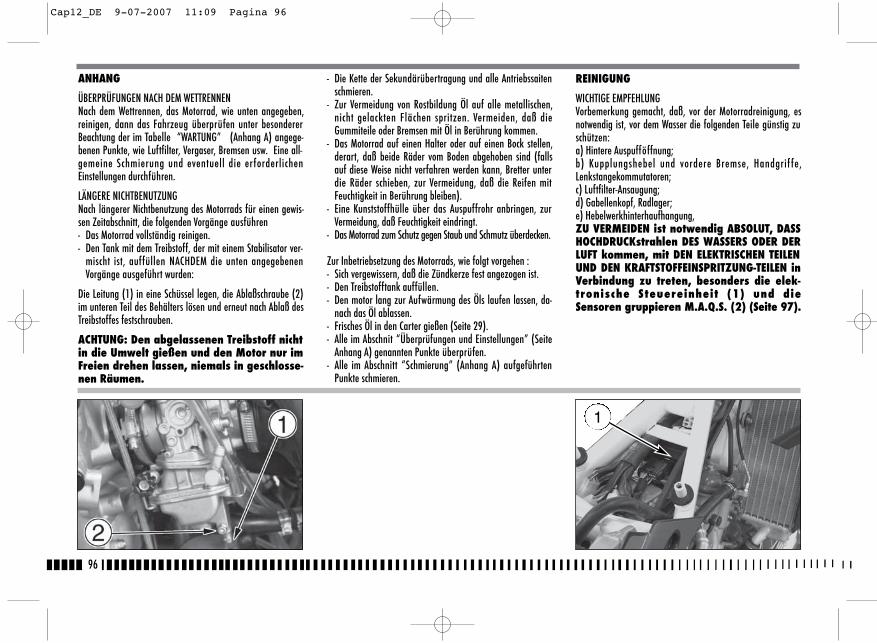
96
- Die Kette der Sekundärübertragung und alle Antriebssaitenschmieren.
- Zur Vermeidung von Rostbildung Öl auf alle metallischen,nicht gelackten Flächen spritzen. Vermeiden, daß dieGummiteile oder Bremsen mit Öl in Berührung kommen.
- Das Motorrad auf einen Halter oder auf einen Bock stellen,derart, daß beide Räder vom Boden abgehoben sind (fallsauf diese Weise nicht verfahren werden kann, Bretter unterdie Räder schieben, zur Vermeidung, daß die Reifen mitFeuchtigkeit in Berührung bleiben).
- Eine Kunststoffhülle über das Auspuffrohr anbringen, zurVermeidung, daß Feuchtigkeit eindringt.
- Das Motorrad zum Schutz gegen Staub und Schmutz überdecken.
Zur Inbetriebsetzung des Motorrads, wie folgt vorgehen :- Sich vergewissern, daß die Zündkerze fest angezogen ist.- Den Treibstofftank auffüllen.- Den motor lang zur Aufwärmung des Öls laufen lassen, da-
nach das Öl ablassen.- Frisches Öl in den Carter gießen (Seite 29).- Alle im Abschnit “Überprüfungen und Einstellungen” (Seite
Anhang A) genannten Punkte überprüfen.- Alle im Abschnitt “Schmierung” (Anhang A) aufgeführten
Punkte schmieren.
ANHANG
ÜBERPRÜFUNGEN NACH DEM WETTRENNENNach dem Wettrennen, das Motorrad, wie unten angegeben,reinigen, dann das Fahrzeug überprüfen unter besondererBeachtung der im Tabelle “WARTUNG” (Anhang A) angege-benen Punkte, wie Luftfilter, Vergaser, Bremsen usw. Eine all-gemeine Schmierung und eventuell die erforderlichenEinstellungen durchführen.
LÄNGERE NICHTBENUTZUNGNach längerer Nichtbenutzung des Motorrads für einen gewis-sen Zeitabschnitt, die folgenden Vorgänge ausführen - Das Motorrad vollständig reinigen.- Den Tank mit dem Treibstoff, der mit einem Stabilisator ver-
mischt ist, auffüllen NACHDEM die unten angegebenenVorgänge ausgeführt wurden:
Die Leitung (1) in eine Schüssel legen, die Ablaßschraube (2)im unteren Teil des Behälters lösen und erneut nach Ablaß desTreibstoffes festschrauben.
ACHTUNG: Den abgelassenen Treibstoff nichtin die Umwelt gießen und den Motor nur imFreien drehen lassen, niemals in geschlosse-nen Räumen.
REINIGUNG
WICHTIGE EMPFEHLUNG Vorbemerkung gemacht, daß, vor der Motorradreinigung, esnotwendig ist, vor dem Wasser die folgenden Teile günstig zuschützen:a) Hintere Auspufföffnung;b) Kupplungshebel und vordere Bremse, Handgrif fe,Lenkstangekommutatoren;c) Luftfilter-Ansaugung;d) Gabellenkopf, Radlager;e) Hebelwerkhinterhaufhangung,ZU VERMEIDEN ist notwendig ABSOLUT, DASSHOCHDRUCKstrahlen DES WASSERS ODER DERLUFT kommen, mit DEN ELEKTRISCHEN TEILENUND DEN KRAFTSTOFFEINSPRITZUNG-TEILEN inVerbindung zu treten, besonders die elek-tronische Steuereinheit (1) und dieSensoren gruppieren M.A.Q.S. (2) (Seite 97).
1
Cap12_DE 9-07-2007 11:09 Pagina 96
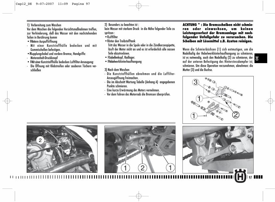
2) Besonders zu beachten ist : kein Wasser mit starkem Druck in die Nähe folgender Teile zuspritzen :• FLuftfilter• FUnter den Treibstofftank
Tritt das Wasser in die Spule oder in die Zündkerzenpipette,läuft der Motor nicht an und es ist erforderlich alle nassenTeile abzutrocknen.
• FGabellenkopf, Radlager.• FHebelwerkhinterhaufhangung
3) Nach dem Waschen- Die Kunststof fhüllen abnehmen und die Luf filter-
Ansaugöffnung freimachen.- Die im Abschnitt Wartung Tabelle (Anhang A) angegebenen
Punkte schmieren.- Eine kurze Erwärmung des Motors vornehmen.- Vor dem Fahren des Motorrads die Bremsen überprüfen.
ACHTUNG * : Die Bremsscheiben nicht schmie-ren oder einwachsen, um keinenLeistungsverlust der Bremsanlage mit nach-folgender Unfallgefahr zu verursachen. DieScheiben mit Lösemittel z.B. Azeton reinigen.
Wenn die Schmierbüchsen (1) sich entmutigen, um dieNadelkafig der Hebelwerkhinterhaufhangung zu schmieren,ist es notwendig, auch den Nadelkafig (2) zu schmieren, derauf der unteren Befestigung des Hinterstossdampfer ist,schmieren. Um diese Operation vorzunehmen, abnehmen: dieMutter (3) und die Buchse.
97
DE
1) Vorbereitung zum WaschenVor dem Waschen die folgenden Vorsichtsmaßnahmen treffen,zur Verhinderung, daß das Wasser mit den nachstehendenTeilen in Berührung komm• FHintere Auspufföffnung- Mit einer Kunststof fhülle bedecken und mit
Gummischellen befestigen.• FKupplungshebel und vordere Bremse, Handgriffe:- Motoranhalt-Druckknopf• FMit einer Kunststoffhülle bedecken Luftfilter-Ansaugung:- Die Öffnung mit Klebstreifen oder sauberen Tüchern ver-
schließen
2
Cap12_DE 9-07-2007 11:09 Pagina 97
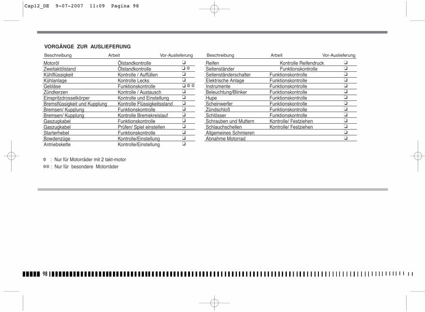
98
�� ���� � ������ �����
��������������
Motoröl ÖlstandkontrolleZweitaktölstand ÖlstandkontrolleKühlflüssigkeit Kontrolle / Auffüllen Kühlanlage Kontrolle LecksGebläse FunktionskontrolleZündkerzen Kontrolle / AustauschEinspritzdrosselkörper Kontrolle und Einstellung Bremsflüssigkeit und Kupplung Kontrolle FlüssigkeitsstandBremsen/ Kupplung FunktionskontrolleBremsen/ Kupplung Kontrolle BremskreislaufGaszugkabel FunktionskontrolleGaszugkabel Prüfen/ Spiel einstellenStarterhebel FunktionskontrolleBowdenzüge Kontrolle/EinstellungAntriebskette Kontrolle/Einstellung
Reifen Kontrolle ReifendruckSeitenständer FunktionskontrolleSeitenständerschalter FunktionskontrolleElektrische Anlage FunktionskontrolleInstrumente FunktionskontrolleBeleuchtung/Blinker FunktionskontrolleHupe FunktionskontrolleScheinwerfer FunktionskontrolleZündschloß FunktionskontrolleSchlösser FunktionskontrolleSchrauben und Muttern Kontrolle/ FestziehenSchlauchschellen Kontrolle/ FestziehenAllgemeines SchmierenAbnahme Motorrad
N f M d i k
VORGÄNGE ZUR AUSLIEFERUNG
Beschreibung Arbeit Vor-Auslieferung Beschreibung Arbeit Vor-Auslieferung
� : Nur für Motorräder mit 2 takt-motor�� : Nur für besondere Motorräder
Cap12_DE 9-07-2007 11:09 Pagina 98
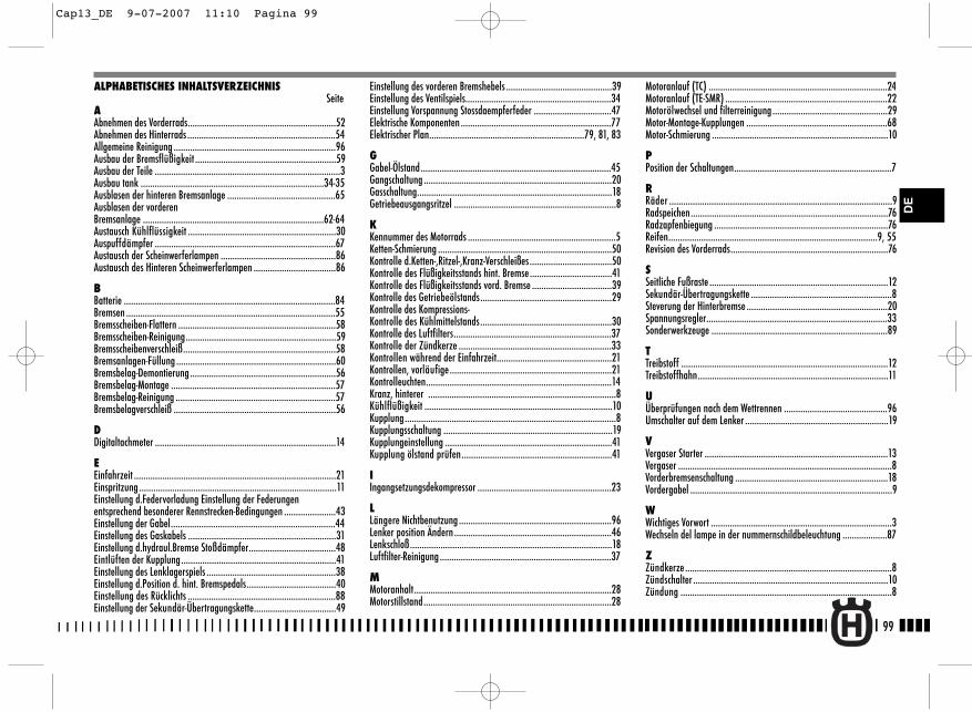
99
Motoranlauf (TC) ............................................................................24Motoranlauf (TE-SMR) .....................................................................22Motorölwechsel und filterreinigung.................................................29Motor-Montage-Kupplungen ............................................................68Motor-Schmierung ...........................................................................10
PPosition der Schaltungen...................................................................7
RRäder ...............................................................................................9Radspeichen....................................................................................76Radzapfenbiegung ..........................................................................76Reifen.........................................................................................9, 55Revision des Vorderrads...................................................................76
SSeitliche Fußraste ............................................................................12Sekundär-Übertragungskette ............................................................8Steverung der Hinterbremse ............................................................20Spannungsregler.............................................................................33Sonderwerkzeuge ...........................................................................89
TTreibstoff ........................................................................................12Treibstoffhahn.................................................................................11
UÜberprüfungen nach dem Wettrennen ............................................96Umschalter auf dem Lenker .............................................................19
VVergaser Starter ..............................................................................13Vergaser ...........................................................................................8Vorderbremsenschaltung .................................................................18Vordergabel ......................................................................................9
WWichtiges Vorwort .............................................................................3Wechseln del lampe in der nummernschildbeleuchtung ...................87
ZZündkerze ........................................................................................8Zündschalter ...................................................................................10Zündung ..........................................................................................8
ALPHABETISCHES INHALTSVERZEICHNISSeite
AAbnehmen des Vorderrads...............................................................52Abnehmen des Hinterrads ...............................................................54Allgemeine Reinigung .....................................................................96Ausbau der Bremsflüßigkeit ............................................................59Ausbau der Teile ...............................................................................3Ausbau tank ..............................................................................34-35Ausblasen der hinteren Bremsanlage ..............................................65Ausblasen der vorderenBremsanlage .............................................................................62-64Austausch Kühlflüssigkeit ...............................................................30Auspuffdämpfer .............................................................................67Austausch der Scheinwerferlampen .................................................86Austausch des Hinteren Scheinwerferlampen ...................................86
BBatterie ..........................................................................................84Bremsen .........................................................................................55Bremsscheiben-Flattern ...................................................................58Bremsscheiben-Reinigung................................................................59Bremsscheibenverschleiß.................................................................58Bremsanlagen-Füllung ....................................................................60Bremsbelag-Demontierung..............................................................56Bremsbelag-Montage ......................................................................57Bremsbelag-Reinigung ....................................................................57Bremsbelagverschleiß .....................................................................56
DDigitaltachmeter .............................................................................14
EEinfahrzeit ......................................................................................21Einspritzung ....................................................................................11Einstellung d.Federvorladung Einstellung der Federungen entsprechend besonderer Rennstrecken-Bedingungen ......................43 Einstellung der Gabel......................................................................44Einstellung des Gaskabels ...............................................................31Einstellung d.hydraul.Bremse Stoßdämpfer.....................................48Eintlüften der Kupplung..................................................................41Einstellung des Lenklagerspiels .......................................................38Einstellung d.Position d. hint. Bremspedals......................................40Einstellung des Rücklichts ...............................................................88Einstellung der Sekundär-Übertragungskette...................................49
Einstellung des vorderen Bremshebels .............................................39Einstellung des Ventilspiels..............................................................34Einstellung Vorspannung Stossdaempferfeder .................................47Elektrische Komponenten ................................................................77Elektrischer Plan..................................................................79, 81, 83
GGabel-Ölstand.................................................................................45Gangschaltung ................................................................................20Gasschaltung...................................................................................18Getriebeausgangsritzel .....................................................................8
KKennummer des Motorrads ...............................................................5Ketten-Schmierung ..........................................................................50Kontrolle d.Ketten-,Ritzel-,Kranz-Verschleißes...................................50Kontrolle des Flüßigkeitsstands hint. Bremse...................................41Kontrolle des Flüßigkeitsstands vord. Bremse ..................................39Kontrolle des Getriebeölstands........................................................29Kontrolle des Kompressions-Kontrolle des Kühlmittelstands........................................................30Kontrolle des Luftfilters...................................................................37Kontrolle der Zündkerze .................................................................33Kontrollen während der Einfahrzeit.................................................21Kontrollen, vorläufige.....................................................................21Kontrolleuchten...............................................................................14Kranz, hinterer ................................................................................8Kühlflüßigkeit ................................................................................10Kupplung..........................................................................................8Kupplungsschaltung ........................................................................19Kupplungeinstellung .......................................................................41Kupplung ölstand prüfen................................................................41
IIngangsetzungsdekompressor .........................................................23
LLängere Nichtbenutzung .................................................................96Lenker position Ändern...................................................................46Lenkschloß......................................................................................18Luftfilter-Reinigung.........................................................................37
MMotoranhalt....................................................................................28Motorstillstand................................................................................28
DE
Cap13_DE 9-07-2007 11:10 Pagina 99

100
Cap13_DE 9-07-2007 11:10 Pagina 100
1
ESPAÑOL
Cap1_ES 19-07-2007 10:33 Pagina 1
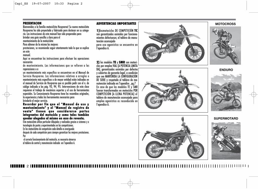
PRESENTACIONBienvenidos a la familia motociclista Husqvarna! Su nueva motocicletaHusqvarna ha sido proyectada y fabricada para destacar en su catego-ría. Las instrucciones de este manual han sido preparadas para brindar una guía sencilla y clara para el mantenimiento de la motocicletaPara obtener de la misma las mejores prestaciones, se recomienda seguir atentamente todo lo que se explicaen este manual.Aquí se encuentran las instrucciones para efectuar las operacionesnecesarias de mantenimiento. Las informaciones que se refieren a lasreparaciones o a un mantenimiento más específico se encuentran en el Manual deServicio Husqvarna. Las informaciones relativas a arreglos omantenimiento más especificos o de mayor entidad están indicadas enel manual de Servicio de Husqvarna que es posible pedir con el n. decódigo indicado a las pág. 93, 94, 95. Intervenciones de esta claserequieren el trabajo de mecánicos expertos y el uso de herramientasespeciales. Su Concesionario Husqvarna tiene los recambios originales,la experiencia y todas las herramientas necesarias para brindarle el mejor servicio. Recordar por f in que el "Manual de uso ymantenimiento" y el "Manual de registro deventa" tienen que considerarse partosintegrantes del motociclo y como tales tambiénquedar alegados al mismo en caso de reventa. Esta motocicleta utiliza particular dibujados y realizados gracias a sistemas y atecnologías de punta y experimentados en las competiciones. En las motocicletas de competición cada detalle es averiguado después de cada competición para siempre garantizar las mejores prestaciones.Por el correcto funcionamiento del motociclo, es necesario atenerse
al tablero de control y manutención indicado en l’apendice A.
2
MOTOCROSS
SUPERMOTARD
ENDURO
ADVERTENCIAS IMPORTANTES
1)losmotociclos DE COMPETICIÓN TCson garantizados eximidos por funciona-mientos defectuosos; el tablero de manu-tención aconsejadopara uso agonístico se encuentra enl’apendice A.
2) los modelos TE y SMR son motoci-clos por empleo VIAL (A POTENCIA LIMITA-DA), garantizados eximidos por defectosy cubiertos de garantía legal, a condiciónque sea MANTENIDA LA CONFIGURACIÓNDE SERIE y respetada el tablero de ma-nutención indicada en l’apendice , pg.7En caso de que los modelos TE y SMRfueran transformados en motociclos PORCOMPETICIÓN (A LLENA POTENCIA) eltablero de manutención aconsejado paraempleo agonístico es reconducido enl’apendice A.
Cap1_ES 19-07-2007 10:33 Pagina 2
3
ES
IMPORTANTE
Por el reconocimiento de la garantía hará de referencia laCONFIGURACIÓN DEL VEHÍCULO, como descrito en seguida:
A) MOTOCICLO DE SERIE, PARA USO VIAL: A POTENCIA LIMITADA B) MOTOCICLO DE COMPETICIÓN, PARA USO AGONÍSTICO: A
LLENA POTENCIA
Este motociclo no ha sido estudiado pararecorrer largos trayectos con el motor a losumo de las vueltas como puede ocurrircon ocasión de largos traslados viales o deautopista. Largos trayectos a lleno gaspueden comportar graves daños al motor. Este motociclo ha sido estudiado por lascompeticiones y por lo tanto sólo garantizalo máximo de las prestaciones con el pilo-to. Desaconseja por tanto el empleo, en to-doterreno o en pista, con el pasajero.
SIEMPRE recordar que estos motociclos han sido planeados porun empleo agonístico, es decir por condiciones de empleo biendiferente de las que se presentan en caso de empleo vial.
Para mantener la "Garantía de Funcionamiento"del vehículo, el Cliente tiene que seguir el pro-grama de manutención indicado sobre el manualde uso y mantenimiento ejecutando los cuponescerca de los talleres lícitos HUSQVARNA.El coste por la sustitución de los particularesy por la mano de obra necesaria para respe-tar el plan de manutención, está a cargo delCliente. NOTA: la garantía DECAE en caso de alquilerdel motociclo.
Premisa importanteLeer atentamente el presente manual prestando atención par-ticular a las notas precedidas por las siguientes advertencias:
ATENCIÓN *: Indica la posibilidad de sufrirgraves lesiones personales, hasta el riesgode muerte en caso de inobservancia de lasinstrucciones. ADVERTENCIA*: Indica la posibilidad de su-frir lesiones personales o provocar dañosal vehículo en caso de inobservancia de lasinstrucciones.Nota*: Proporciona más informaciones úti-les.
Substitución de los particularesEn caso de substitución de los particulares, utilizar sólo partesoriginales Husqvarna de características equivalentes, incluidoel tipo, la resistencia y el material. En caso contrario, podríanproducirse funcionamientos incorrectos, con posible riesgo delesiones.
ATENCIÓN *: Tras una caída, inspeccionarcon atención el motociclo. Asegurarse deque el mando del gas, los frenos, el embra-gue y todos los otros mandos y componen-tes principales no hayan sufrido daños.Conducir un motociclo dañado puede provo-car graves accidentes.
ATENCIÓN *: No poner en marcha y no tra-bajar sobre el motociclo cuando no se lle-ven indumentos protectores adecuados.Llevar siempre casco, botas, gafas protecto-ras y otra indumentaria adecuada.
ATENCIÓN *: Este motociclo es un vehículode competición sofisticado. No poner enmarcha o conducir el motociclo si no se tie-nen las adecuadas instrucciones junto abuenas condiciones físicas.
PRECAUCIONES PARA LOS NIÑOSATENCION• Aparcar el vehículo donde no pueda ser
golpeado o dañado con facilidad.Golpes, aunque sean involuntarios pue-den provocar la caída del vehículo conconsiguiente peligro para las personas,especialmente niños.
• Para evitar caídas accidentales del vehí-culo, no aparcar nunca en un terreno flojoo irregular ni tampoco sobre asfalto ca-liente.
• Puesto que el motor y el escape se pue-den poner muy caliente, aparcar la moto-cicleta en lugares donde sea peatones oniños no puedan tocarlos con facilidad.
Cap1_ES 19-07-2007 10:33 Pagina 3
4
SUMARIO Pág.
PRESENTACION.............................................................................2ADVERTENCIAS IMPORTANTES .......................................................2DATOS PARA LA IDENTIFICACION...................................................5FICHA TECNICA .............................................................................8TABLA DE LUBRICACION, RELLONES .............................................10CONTROLES ................................................................................11ISTRUCCIONES PARA EL USO DE LA MOTOCICLETA .......................21LIMITE DE DESGASTE ..................................................................68INSTALACION DE ENCENDIDO/INSTALACION ELECTRICA ..........77-88HERRAMIENTAS ESPECIALES ........................................................89PATAS DE TORSION .....................................................................90KIT.............................................................................................92PARTES OPCIONALES .............................................................93-95APENDICE...................................................................................96OPERACIONES DE PRE-ENTREGA.......................................................97INDICE ALFABETICO ....................................................................98MANTENIMIENTO PERIODICO/REGULACIONES ................apendice A
Nota•Las indicaciones de la derecha y la izquierda hacen referencia
a los dos lados de la moto con respecto al sentido de marcha.
• Z: nùmero dientes• A: Austria
AUS: AustraliaB: BélgicaBR: BrasilCDN: CanadàCH: SuizaD: AlemaniaE: EspañaF: FranciaFIN: FinlandiaGB: Gran BretañaI: ItaliaJ: JapònUSA: Estados Unidos
• A falta de indicaciones específicas, los datos y las instruccionesse refieren a todos los Países.
Cap1_ES 19-07-2007 10:33 Pagina 4

5
ES
DATOS PARA LA IDENTIFICACIONEl número de identificación del motor se encuentra marcadoen la parte superior del carter del motor, mientras que el nú-mero de matrícula de la motocicleta se encuentra marcado enel tubo de dirección del bastidor (véaser pag.21). Cuando pi-den piezas de recambio o informaciones acerca de su motoci-clo, indicar siempre, apuntándolo incluso en la presente docu-mentación, el número estampillado en el basti-dor.
NUMERO DEL BASTIDOR
NÚMERO DE IDENTIFICACIÓN DEL MOTOCICLO (V.I.N.)
El número de serie compuesto de 17 caracteres se halla en ellado derecho del eje de dirección.
(*): Nr. progresivo(•): Año del modelo
1. Matrícula bastidor2. Matrícula motor
Cap1_ES 19-07-2007 10:33 Pagina 5

6
NÚMERO DE IDENTIFICACIÓN DEL MOTOCICLO (V.I.N.)
El número de serie compuesto de 17 caracteres se halla en el la-do derecho del eje de dirección.
(*): Nr. progresivo(•): Año del modelo
1. Matrícula bastidor2. Matrícula motor
Cap1_ES 19-07-2007 10:33 Pagina 6
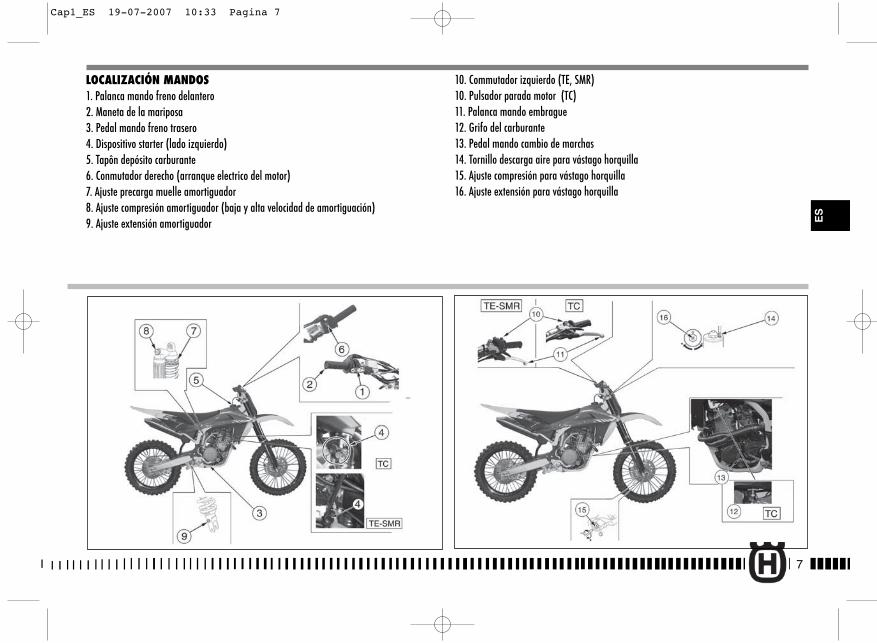
7
ES
LOCALIZACIÓN MANDOS1. Palanca mando freno delantero2. Maneta de la mariposa3. Pedal mando freno trasero4. Dispositivo starter (lado izquierdo)5. Tapôn depósito carburante6. Conmutador derecho (arranque electrico del motor)7. Ajuste precarga muelle amortiguador8. Ajuste compresión amortiguador (baja y alta velocidad de amortiguación)9. Ajuste extensión amortiguador
10. Commutador izquierdo (TE, SMR)10. Pulsador parada motor (TC)11. Palanca mando embrague12. Grifo del carburante13. Pedal mando cambio de marchas14. Tornillo descarga aire para vástago horquilla15. Ajuste compresión para vástago horquilla16. Ajuste extensión para vástago horquilla
Cap1_ES 19-07-2007 10:33 Pagina 7
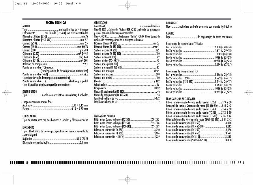
8
EMBRAGUETipo ............multidisco en baño de aceite con mando hydráulico
CAMBIO Tipo........................................de engranajes de toma constante
Relaciónes de transmisión (TE-SMR)En 1a velocidad ...............................................2,000 (z 28/14)En 2a velocidad ................................................1,611 (z 29/18)En 3a velocidad ..................................................1,333 (24/18)En 4a velocidad ...............................................1,086 (z 25/23)En 5a velocidad ...............................................0,920 (z 23/25)En 6a velocidad................................................0,814 (z 22/27)
Relaciónes de transmisión (TC)En 1a velocidad................................................1,866 (z 28/15)En 2a velocidad (250).....................................1,529 (z 26/17)En 2a velocidad (450-510) ...............................1,444 (z 26/17)En 3a velocidad................................................1,263 (z 24/19)En 4a velocidad ...............................................1,086 (z 25/23)En 5a velocidad ...............................................0,954 (z 21/22)
TRANSMISSION SECUNDARIAPiñón salida cambio- Corona en la rueda (TE 250) .....Z 13- Z 50Piñón salida cambio- Corona en la rueda (TE 450-510).....Z 13- Z 47Piñón salida cambio- Corona en la rueda (TC 450) .....Z 14- Z 50Piñón salida cambio- Corona en la rueda (TC 250) .....Z 12- Z 50Piñón salida cambio- Corona en la rueda (TC 510) .....Z 14- Z 47Piñón salida cambio- Corona en la rueda (SMR 450-510) ....Z 14- Z 42Relación de transmisión (TE 250) .................................... 3,846Relación de transmisión (TE 450-510).............................. 3,615Relación de transmisión (TC 250) .....................................4,166Relación de transmisión (TC 450) .....................................3,571Relación de transmisión (TC 510) .................................... 3,357Relación de transmisión (SMR 450-510) .......................... 3,000
FICHA TECNICAMOTORTipo ...............................................monocilindrico de 4 tiemposEnfriamento..............por liquido (TE-SMR) con electroventiladorDíametro cilindro (250) .................................................mm 76Díametro cilindro (450-510).......................................... mm 97 Carrera (250) ................................................................mm 55Carrera (450)............................................................mm 60,76Carrera (510) ..............................................................mm 67,8 Cilindrata (250) .......................................................cm3 249,5Cilindrata (450) ..........................................................cm3 449Cilindrata (510) ...........................................................cm3 501 Relación de compresión...................................................12,9:1Puesta en marcha (TC) a pedal..........................(condispositivo de descompresión automático)
Puesta en marcha (SMR) ..............................................electrico (condispositivo de descompresión automático)Puesta en marcha (TE) ..................................electrico y a pedal(con dispositivo de descompresión automático)
DISTRIBUCIONTipo .....................doble eje a excéntricos en cabeza; 4 valvulas
Juego valvulas (a motor frio)Aspiración .........................................................0,10 ÷ 0,15 mmEscape ..............................................................0,15 ÷ 0,20 mm
LUBRICACIÓNTipo de cárter seco con dos bombas a lóbulos y filtro a cartucho
ENCENDIDOTipo...Electrónico de descarga capacitiva con avance variable decontrol digitalBujía tipo.................................................................NGK CR8EBDistancia electrodos bujía..............................................0,7 mm
ALIMENTACIONTipo (TE-SMR) ..........................................................a inyección elettrónicaTipo (TC 250) .. .Carburador ”Keihin” FCR-MX 37 con bomba de aceleracióny sensor posición de la mariposa carburadorTipo (450-510). .................. Carburador ”Keihin” FCR-MX 41 con bomba deaceleración y sensor posición de la mariposa carburadorDiámetro difusor (TC 250) ..............................................................mm 37Diámetro difusor (TC 450-510) ........................................................mm 41Surtidor máximo (TC 250)....................................................................175Surtidor máximo (TC 450-510) ............................................................180Surtidor mínimo(TC 250) ......................................................................42Surtidor mínimo (TC 450-510)................................................................45Surtidor arranque (TC 250)....................................................................72Surtidor arranque (TC 450-510) .............................................................85Surtidor aire arranque ......................................................................mm 4Surtidor aire máximo...........................................................................200Surtidor aire mínimo............................................................................100Flotador............................................................................................g 11,2Válvula del gas....................................................................................15MEspiga cónica .................................................................................OBDVRMuesca fij. espiga cónica (TC 250)..........................................................4aMuesca fij. espiga cónica (TC 450-510) ..................................................5aTornillo aire abierto de rev. .............................................................1+1/2Tornillo aire abierto de rev. .....................................................................2
TRANSMISION PRIMARIAPiñón motor- Corona embrague (TC 250)....................................Z 20- Z 67Piñón motor- Corona embrague (TE 250) ....................................Z 24- Z 88Piñón motor- Corona embrague (450-510)..................................Z 23- Z 63Relación de transmisión (TC 250) ......................................................3,350Relación de transmisión (TE 250) ......................................................3,666Relación de transmisión (450-510) ....................................................2,739
Cap1_ES 19-07-2007 10:33 Pagina 8
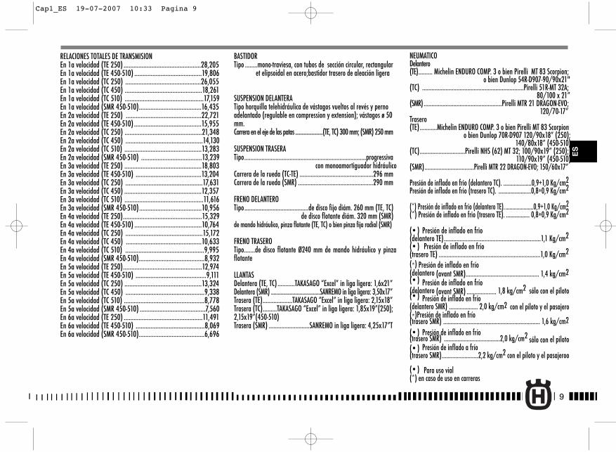
RELACIONES TOTALES DE TRANSMISIONEn 1a velocidad (TE 250) ...............................................28,205En 1a velocidad (TE 450-510) .........................................19,806En 1a velocidad (TC 250) ..............................................26,055En 1a velocidad (TC 450) ...............................................18,261En 1a velocidad (TC 510) ................................................17,159En 1a velocidad (SMR 450-510)......................................16,435En 2a velocidad (TE 250) ..............................................22,721En 2a velocidad (TE 450-510) .........................................15,955En 2a velocidad (TC 250) ...............................................21,348En 2a velocidad (TC 450) ...............................................14,130En 2a velocidad (TC 510) ...............................................13,283En 2a velocidad (SMR 450-510) .....................................13,239En 3a velocidad (TE 250) ...............................................18,803En 3a velocidad (TE 450-510) ........................................13,204En 3a velocidad (TC 250) ...............................................17,631En 3a velocidad (TC 450) ...............................................12,357En 3a velocidad (TC 510) ................................................11,616En 3a velocidad (SMR 450-510)......................................10,956En 4a velocidad (TE 250)................................................15,329En 4a velocidad (TE 450-510) .........................................10,764En 4a velocidad (TC 250) ...............................................15,172En 4a velocidad (TC 450) ..............................................10,633En 4a velocidad (TC 510) ................................................9,995En 4a velocidad (SMR 450-510)........................................8,932En 5a velocidad (TE 250)................................................12,974En 5a velocidad (TE 450-510) ...........................................9,111En 5a velocidad (TC 250) ...............................................13,324En 5a velocidad (TC 450) ................................................9,338En 5a velocidad (TC 510) .................................................8,778En 5a velocidad (SMR 450-510) ........................................7,560En 6a velocidad (TE 250) ................................................11,491En 6a velocidad (TE 450-510) ..........................................8,069En 6a velocidad (SMR 450-510)........................................6,696
BASTIDORTipo ........mono-traviesa, con tubos de sección circular, rectangular
et elipsoidal en acero;bastidor trasero de aleación ligera
SUSPENSION DELANTERATipo horquilla telehidráulica de vástagos vueltos al revés y pernoadelantado (regulable en compression y extension); vástagos ø 50mm.Carrera en el eje de las patas ......................(TE, TC) 300 mm; (SMR) 250 mm
SUSPENSION TRASERATipo..............................................................................progressiva
con monoamortiguador hidráulicoCarrera de la rueda (TC-TE) ...............................................296 mmCarrera de la rueda (SMR) ................................................290 mm
FRENO DELANTEROTipo.........................................de disco fijo diám. 260 mm (TE, TC)
de disco flotante diám. 320 mm (SMR)de mando hidráulico, pinza flotante (TE, TC) o bien pinza fija radial (SMR)
FRENO TRASEROTipo.......de disco flotante Ø240 mm de mando hidráulico y pinzaflotante
LLANTASDelantera (TE, TC) ...........TAKASAGO “Excel” in liga ligera: 1,6x21”Delantera (SMR) ....................................SANREMO in liga ligera: 3,50x17”Trasera (TE)...................TAKASAGO “Excel” in liga ligera: 2,15x18”Trasera (TC).........TAKASAGO “Excel” in liga ligera: 1,85x19”(250);2,15x19”(450-510)Trasera (SMR) ..........................SANREMO in liga ligera: 4,25x17”T
NEUMATICODelantero (TE)......... Michelin ENDURO COMP. 3 o bien Pirelli MT 83 Scorpion;
o bien Dunlop 54R-D907-90/90x21"(TC) .................................................................Pirelli 51R-MT 32A;
80/100 x 21”(SMR) ..................................................Pirelli MTR 21 DRAGON-EVO;
120/70-17”Trasero(TE)...........Michelin ENDURO COMP. 3 o bien Pirelli MT 83 Scorpion
o bien Dunlop 70R-D907 120/90x18” (250); 140/80x18” (450-510)
(TC).............................Pirelli NHS (62) MT 32; 100/90x19” (250); 110/90x19” (450-510)
(SMR)................................Pirelli MTR 22 DRAGON-EVO; 150/60x17”
Presión de inflado en frio (delantero TC). ...................0,9÷1,0 Kg/cm2Presión de inflado en frio (trasero TC). ......................0,8÷0,9 Kg/cm2
(*) Presión de inflado en frio (delantero TE). ....................0,9÷1,0 Kg/cm2(*) Presión de inflado en frio (trasero TE). ................ 0,8÷0,9 Kg/cm2
(• ) Presión de inflado en frio (delantero TE)..............................................................1,1 Kg/cm2(• ) Presión de inflado en frio (trasero TE) .................................................................1,0 Kg/cm2(*) Presión de inflado en frío (delantero (avant SMR)............................................... 1,4 kg/cm2(• ) Presión de inflado en frío(delantero (avant SMR) ................... 1,8 kg/cm2 sólo con el piloto(• ) Presión de inflado en frío(delantero SMR) ................... 2,0 kg/cm2 con el piloto y el pasajero(*)Presión de inflado en frío(trasero SMR) ................................................................ 1,6 kg/cm2(• ) Presión de inflado en frío(trasero SMR) .....................................2,0 kg/cm2 sólo con el piloto(• ) Presión de inflado a frío(trasero SMR)........................2,2 kg/cm2 con el piloto y el pasajeroo
(• ) Para uso vial (*) en caso de uso en carreras
9
ES
Cap1_ES 19-07-2007 10:33 Pagina 9
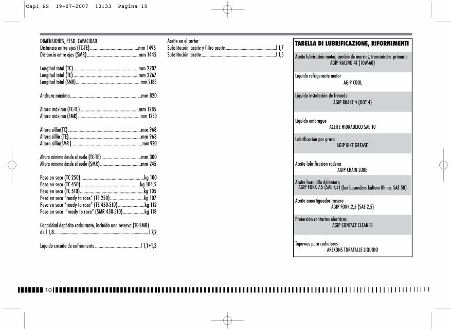
10
DIMENSIONES, PESO, CAPACIDADDistancia entre ejes (TC-TE) ........................................mm 1495 Distancia entre ejes (SMR)...........................................mm 1445
Longitud total (TC) ......................................................mm 2207 Longitud total (TE) ......................................................mm 2267Longitud total (SMR)......................................................mm 2183
Anchura màxima...........................................................mm 820
Altura màxima (TC-TE) ................................................mm 1285Altura màxima (SMR) ....................................................mm 1250
Altura sillín(TC).............................................................mm 968Altura sillín (TE)............................................................mm 963Altura sillín(SMR )...........................................................mm 920
Altura mínima desde el suelo (TC-TE) .................................mm 300Altura mínima desde el suelo (SMR)..................................mm 245
Peso en seco (TC 250).....................................................kg 100Peso en seco (TC 450) .................................................kg 104,5Peso en seco (TC 510).....................................................kg 105 Peso en seco “ready to race” (TE 250)............................kg 107Peso en seco “ready to race” (TE 450-510) ......................kg 112Peso en seco “ready to race” (SMR 450-510)..................kg 118
Capacidad depósito carburante, incluída una reserva (TE-SMR) de l 1,8......................................................................................l 7,2
Liquido circuito de enfriamento ......................................l 1,1÷1,3
Aceite en el carterSubstitución aceite y filtro aceite ............................................l 1,7Substitución aceite .................................................................l 1,5
TABELLA DI LUBRIFICAZIONE, RIFORNIMENTI
Aceite lubricación motor, cambio de marcias, transmisión primariaAGIP RACING 4T (10W-60)
Líquido refrigerante motorAGIP COOL
Líquido instalación de frenado AGIP BRAKE 4 (DOT 4)
Lìquìdo embragueACEITE HIDRÁULICO SAE 10
Lubrificación por grasaAGIP BIKE GREASE
Aceite lubrificación cadenaAGIP CHAIN LUBE
Aceite horquilla delanteraAGIP FORK 7,5 (SAE 7,5) (bei besonders kaltem Klima: SAE 50)
Aceite amortiguador traseroAGIP FORK 2,5 (SAE 2,5)
Protección contactos eléctricosAGIP CONTACT CLEANER
Tapavias para radiatoresAREXONS TURAFALLE LIQUIDO
Cap1_ES 19-07-2007 10:33 Pagina 10
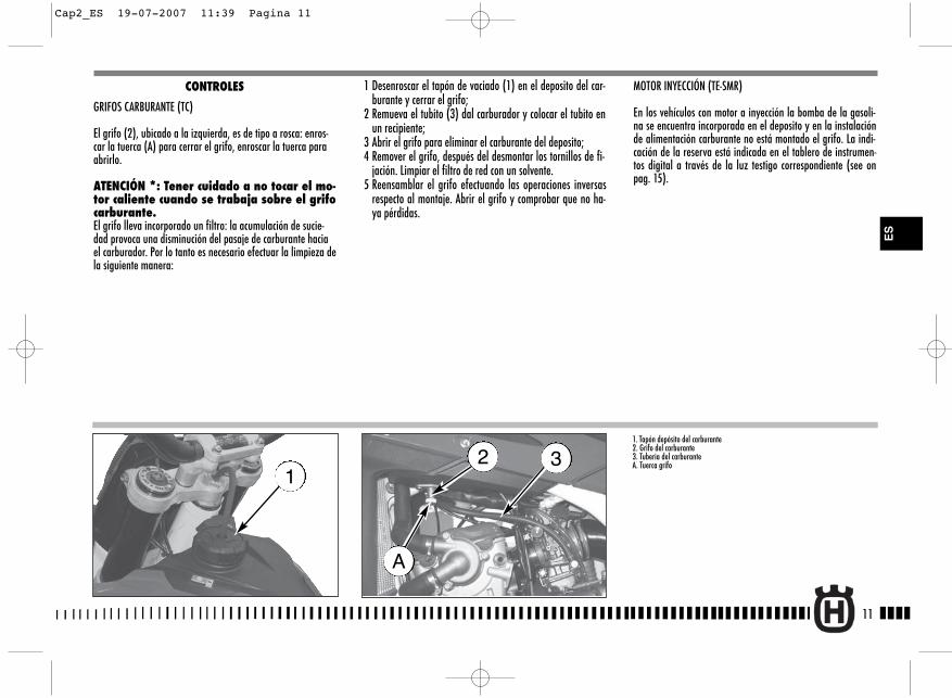
MOTOR INYECCIÓN (TE-SMR)
En los vehículos con motor a inyección la bomba de la gasoli-na se encuentra incorporada en el deposito y en la instalaciónde alimentación carburante no está montado el grifo. La indi-cación de la reserva está indicada en el tablero de instrumen-tos digital a través de la luz testigo correspondiente (see onpag. 15).
11
ES
1 Desenroscar el tapón de vaciado (1) en el deposito del car-burante y cerrar el grifo;
2 Remueva el tubito (3) dal carburador y colocar el tubito enun recipiente;
3 Abrir el grifo para eliminar el carburante del deposito;4 Remover el grifo, después del desmontar los tornillos de fi-
jación. Limpiar el filtro de red con un solvente.5 Reensamblar el grifo efectuando las operaciones inversas
respecto al montaje. Abrir el grifo y comprobar que no ha-ya pérdidas.
CONTROLES
GRIFOS CARBURANTE (TC)
El grifo (2), ubicado a la izquierda, es de tipo a rosca: enros-car la tuerca (A) para cerrar el grifo, enroscar la tuerca paraabrirlo.
ATENCIÓN *: Tener cuidado a no tocar el mo-tor caliente cuando se trabaja sobre el grifocarburante. El grifo lleva incorporado un filtro: la acumulación de sucie-dad provoca una disminución del pasaje de carburante haciael carburador. Por lo tanto es necesario efectuar la limpieza dela siguiente manera:
1. Tapón depósito del carburante2. Grifo del carburante3. Tuberia del carburanteA. Tuerca grifo
132
A
Cap2_ES 19-07-2007 11:39 Pagina 11
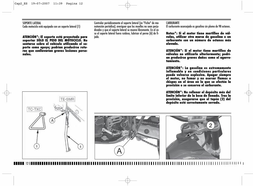
CARBURANTEEl carburante aconsejado es gasolina sin plomo de 98 octanos.
Notas*: Si el motor tiene martilleo de vál-vulas, utilizar otra marca de gasolina o uncarburante con un número de octanos máselevado.
ATENCIÓN*: Si el motor tiene martilleo deválvulas no utilizarlo ulteriormente; podrí-an producirse graves daños como el agarro-tamiento.
ATENCIÓN*: La gasolina es extremamenteinflamable y en condiciones particularespuede volverse explosiva. Apagar siempreel motor, no fumar y no acercar flamas ochispas en el área en la que se efectúa laprovisión o se conserva el carburante.
ATENCIÓN*: No rellenar el depósito más dellímite inferior de la boca de llenado. Tras laprovisión, asegurarse que el tapón (2) deldepósito esté correctamente cerrado.
Controlar periódicamente el soporte lateral (ve "Ficha" de ma-nutención periódica); averiguar que los muelles no sean perju-dicados y que el soporte lateral se mueva libremente. En el ca-so el soporte lateral fuera ruidoso, lubricar el perno (A) de fi-jado.
12
SOPORTE LATERALCada motociclo está equipado con un soporte lateral (1)
ATENCIÓN*: El soporte está proyectado parasoportar SÓLO EL PESO DEL MOTOCICLO. Nosentarse sobre el vehículo utilizando el so-porte como apoyo; podrían producirse rotu-ras que conllevarían graves lesiones perso-nales.
2
Cap2_ES 19-07-2007 11:39 Pagina 12
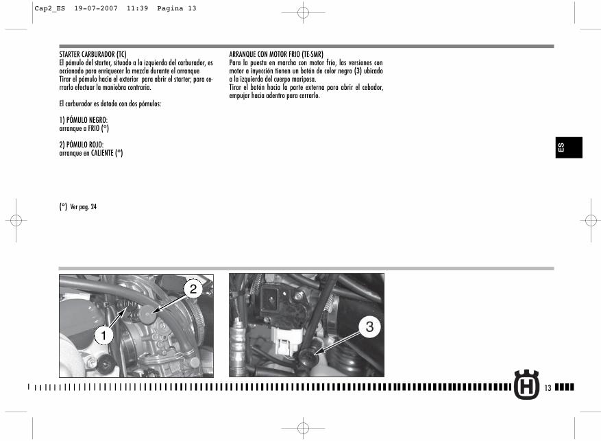
STARTER CARBURADOR (TC)El pómulo del starter, situado a la izquierda del carburador, esaccionado para enriquecer la mezcla durante el arranqueTirar el pómulo hacia el exterior para abrir el starter; para ce-rrarlo efectuar la maniobra contraria.
El carburador es dotado con dos pómulos:
1) PÓMULO NEGRO: arranque a FRIO (°)
2) PÓMULO ROJO: arranque en CALIENTE (°)
(°) Ver pag. 24
ARRANQUE CON MOTOR FRIO (TE-SMR)Para la puesta en marcha con motor frío, las versiones conmotor a inyección tienen un botón de color negro (3) ubicadoa la izquierda del cuerpo mariposa.Tirar el botón hacia la parte externa para abrir el cebador,empujar hacia adentro para cerrarlo.
13
ES
2
1
Cap2_ES 19-07-2007 11:39 Pagina 13
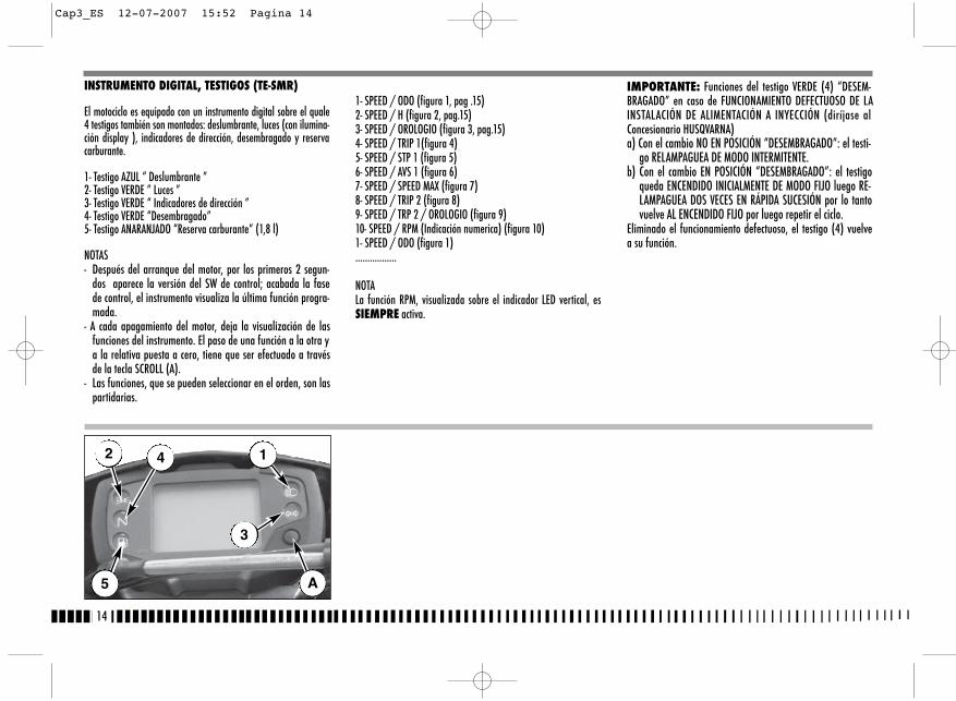
1- SPEED / ODO (figura 1, pag .15)2- SPEED / H (figura 2, pag.15)3- SPEED / OROLOGIO (figura 3, pag.15)4- SPEED / TRIP 1(figura 4)5- SPEED / STP 1 (figura 5)6- SPEED / AVS 1 (figura 6)7- SPEED / SPEED MAX (figura 7)8- SPEED / TRIP 2 (figura 8)9- SPEED / TRP 2 / OROLOGIO (figura 9)10- SPEED / RPM (Indicación numerica) (figura 10)1- SPEED / ODO (figura 1).................
NOTALa función RPM, visualizada sobre el indicador LED vertical, esSIEMPRE activa.
IMPORTANTE: Funciones del testigo VERDE (4) “DESEM-BRAGADO” en caso de FUNCIONAMIENTO DEFECTUOSO DE LAINSTALACIÓN DE ALIMENTACIÓN A INYECCIÓN (diríjase alConcesionario HUSQVARNA)a) Con el cambio NO EN POSICIÓN “DESEMBRAGADO”: el testi-
go RELAMPAGUEA DE MODO INTERMITENTE.b) Con el cambio EN POSICIÓN “DESEMBRAGADO”: el testigo
queda ENCENDIDO INICIALMENTE DE MODO FIJO luego RE-LAMPAGUEA DOS VECES EN RÁPIDA SUCESIÓN por lo tantovuelve AL ENCENDIDO FIJO por luego repetir el ciclo.
Eliminado el funcionamiento defectuoso, el testigo (4) vuelvea su función.
14
INSTRUMENTO DIGITAL, TESTIGOS (TE-SMR)
El motociclo es equipado con un instrumento digital sobre el quale4 testigos también son montados: deslumbrante, luces (con ilumina-ción display ), indicadores de dirección, desembragado y reservacarburante.
1- Testigo AZUL “ Deslumbrante ”2- Testigo VERDE ” Luces ”3- Testigo VERDE “ Indicadores de dirección ”4- Testigo VERDE “Desembragado”5- Testigo ANARANJADO “Reserva carburante” (1,8 l)
NOTAS- Después del arranque del motor, por los primeros 2 segun-
dos aparece la versión del SW de control; acabada la fasede control, el instrumento visualiza la última función progra-mada.
- A cada apagamiento del motor, deja la visualización de lasfunciones del instrumento. El paso de una función a la otra ya la relativa puesta a cero, tiene que ser efectuado a travésde la tecla SCROLL (A).
- Las funciones, que se pueden seleccionar en el orden, son laspartidarias.
2
5
4 1
3
A
Cap3_ES 12-07-2007 15:52 Pagina 14
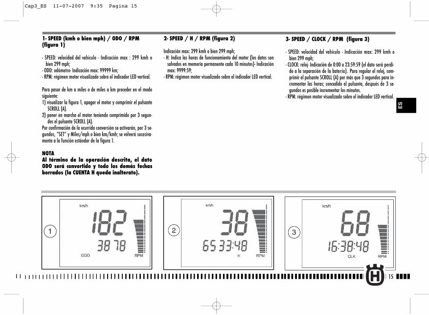
15
2- SPEED / H / RPM (figura 2)
Indicación max: 299 kmh o bien 299 mph;- H: Indica las horas de funcionamiento del motor (los datos son
salvados en memoria permanente cada 10 minutos)- Indicaciónmax: 9999:59;
- RPM: régimen motor visualizado sobre el indicador LED vertical.
1- SPEED (kmh o bien mph) / ODO / RPM (figura 1)
- SPEED: velocidad del vehículo - Indicación max : 299 kmh obien 299 mph;
- ODO: odómetro- Indicación max: 99999 km;- RPM: régimen motor visualizado sobre el indicador LED vertical.
Para pasar de km a miles o de miles a km proceder en el modosiguiente:1) visualizar la figura 1, apagar el motor y comprimir el pulsante
SCROLL (A). 2) poner en marcha el motor teniendo comprimido por 3 segun-
dos el pulsante SCROLL (A). Por confirmación de la ocurrida conversión se activarán, por 3 se-gundos, “SET” y Miles/mph o bien km/kmh; se volverá sucesiva-mente a la función estándar de la figura 1.
NOTA Al término de la operación descrita, el datoODO será convertido y todo los demás fechasborrados (la CUENTA H queda inalterato).
ES
3- SPEED / CLOCK / RPM (figura 3)
- SPEED: velocidad del vehículo - Indicación max: 299 kmh obien 299 mph;
- CLOCK: reloj- Indicación de 0:00 a 23:59:59 (el dato será perdi-do a la separación de la batería). Para regular el reloj, com-primir el pulsante SCROLL (A) por más que 3 segundos para in-crementar las horas; concedido el pulsante, después de 3 se-gundos es posible incrementar los minutos.
- RPM: régimen motor visualizado sobre el indicador LED vertical.
Cap3_ES 11-07-2007 9:35 Pagina 15
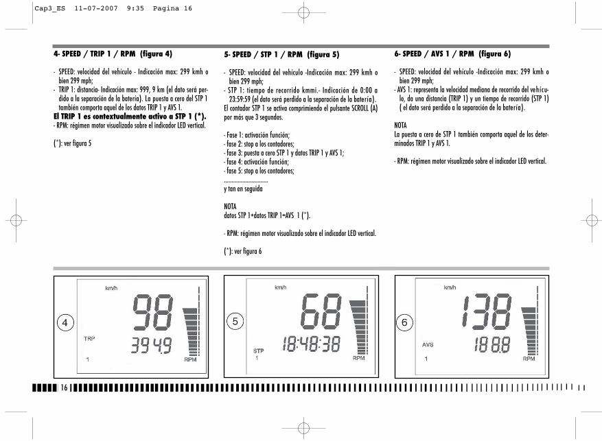
16
6- SPEED / AVS 1 / RPM (figura 6)
- SPEED: velocidad del vehículo -Indicación max: 299 kmh obien 299 mph;
- AVS 1: representa la velocidad mediana de recorrido del vehícu-lo, da una distancia (TRIP 1) y un tiempo de recorrido (STP 1)( el dato será perdido a la separación de la batería).
NOTALa puesta a cero de STP 1 también comporta aquel de los deter-minados TRIP 1 y AVS 1.
- RPM: régimen motor visualizado sobre el indicador LED vertical.
4- SPEED / TRIP 1 / RPM (figura 4)
- SPEED: velocidad del vehículo - Indicación max: 299 kmh obien 299 mph;
- TRIP 1: distancia- Indicación max: 999, 9 km (el dato será per-dido a la separación de la batería). La puesta a cero del STP 1también comporta aquel de los datos TRIP 1 y AVS 1.
El TRIP 1 es contextualmente activo a STP 1 (*).- RPM: régimen motor visualizado sobre el indicador LED vertical.
(*): ver figura 5
5- SPEED / STP 1 / RPM (figura 5)
- SPEED: velocidad del vehículo -Indicación max: 299 kmh obien 299 mph;
- STP 1: tiempo de recorrido kmmi.- Indicación de 0:00 a23:59:59 (el dato será perdido a la separación de la batería).
El contador STP 1 se activa comprimiendo el pulsante SCROLL (A)por más que 3 segundos.
- Fase 1: activación función;- fase 2: stop a los contadores;- fase 3: puesta a cero STP 1 y datos TRIP 1 y AVS 1;- fase 4: activación función;- fase 5: stop a los contadores;.............................y tan en seguida
NOTAdatos STP 1+datos TRIP 1=AVS 1 (*).
- RPM: régimen motor visualizado sobre el indicador LED vertical.
(*): ver figura 6
Cap3_ES 11-07-2007 9:35 Pagina 16
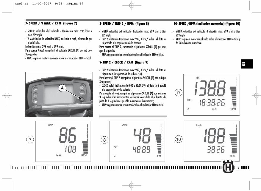
17
8- SPEED / TRIP 2 / RPM (figura 8)
- SPEED: velocidad del vehículo - Indicación max: 299 kmh o bien299 mph;
- TRIP 2: distancia- Indicación max: 999, 9 km / miles ( el dato se-rá perdido a la separación de la batería).
Para borrar el TRIP 2, comprimir el pulsante SCROLL (A) por másque 3 segundos.- RPM: régimen motor visualizado sobre el indicador LED vertical.
9- TRP 2 / CLOCK / RPM (figura 9)
- TRIP 2: distancia- Indicación max: 999, 9 km / miles ( el dato se-ráperdido a la separación de la batería).
Para borrar el TRIP 2, comprimir el pulsante SCROLL (A) por másque3 segundos;- CLOCK: reloj- Indicación de 0:00 a 23:59:59 ( el dato será perdid
a la separación de la batería).Para regular el reloj, comprimir el pulsante SCROLL (A) por más que3 segundos para incrementar las horas; concedido el pulsante, de-pués de 3 segundos es posible incrementar los minutos;- RPM: régimen motor visualizado sobre el indicador LED vertical.
10- SPEED /RPM (Indicación numerica) (figura 10)
- SPEED: velocidad del vehículo - Indicación max: 299 kmh o bien299 mph;
- RPM: régimen motor visualizado sobre el indicador LED vertical yde la indicación numérica.
7- SPEED / V MAX / RPM (figura 7)
- SPEED: velocidad del vehículo - Indicación max: 299 kmh obien 299 mph;
- V MAX: indica la velocidad MAX, en kmh o mph, alcanzada porel vehículo.
Indicación max: 299 kmh o 299 mph.Para borrar V MAX, comprimir el pulsante SCROLL (A) por má que3 segundos;- RPM: régimen motor visualizado sobre el indicador LED vertical.
A
ES
Cap3_ES 11-07-2007 9:35 Pagina 17
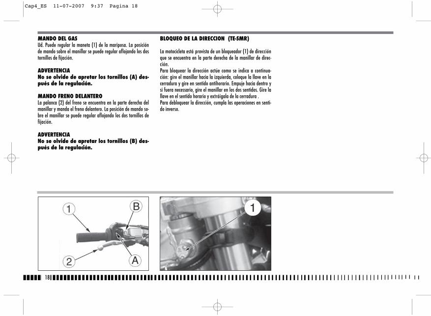
18
MANDO DEL GASUd. Puede regular la maneta (1) de la mariposa. La posiciónde mando sobre el manillar se puede regular aflojando los dostornillos de fijación.
ADVERTENCIANo se olvide de apretar los tornillos (A) des-pués de la regulación.
MANDO FRENO DELANTEROLa palanca (2) del freno se encuentra en la parte derecha delmanillar y manda el freno delantero. La posición de mando so-bre el manillar se puede regular aflojando los dos tornillos defijación.
ADVERTENCIANo se olvide de apretar los tornillos (B) des-pués de la regulación.
BLOQUEO DE LA DIRECCION (TE-SMR)
La motocicleta está provista de un bloqueador (1) de direcciónque se encuentra en la parte derecha de la manillar de direc-ción.Para bloquear la dirección actúe como se indica a continua-ción: gire el manillar hacia la izquierda, coloque la llave en lacerradura y gire en sentido antihorario. Empuje hacia dentro ysi fuera necessario, gire el manillar en los dos sentidos. Gire lallave en el sentido horario y extráigala de la cerradura . Para debloquear la dirección, cumpla las operaciones en senti-do inverso.
Cap4_ES 11-07-2007 9:37 Pagina 18

19
PULSADOR PARADA MOTOR (TC)
En la parte izquierda del manillar, cerca del mando del embraguese encuentra el pulsador (1) de parada del motor.MANDO EMBRAGUE
La palanca del mando hydraulico del embrague está situada a laizquierda del manillar y está dotada de protecciòn.La posición demando embrague sobre el manillar se puede regular affojando eltornillo inferior (A) de fijaciòn.ADVERTENCIA
No se olvide de apretar el tornillo después dela regulación.
CONMUTADOR DERECHO EN EL MANILLAR (TE-SMR)
El conmutador derecho tiene los siguientes mandos:1) botón de arranque3) interruptor de encendido-stop motor
CONMUTADOR IZQUIERDO EN EL MANILLAR (TE-SMR)
El conmutador izquierdo tiene los siguientes mandos:1) Rayo deslumbrante (retorno automático)
2) Mando selecciónluz luz deslumbrante
Mando selecciónluz luz de cruce
3) Activación indicadores de dirección izquierdos (re-torno automático)Activación indicadores de dirección derchos (retornoautomático)
Para desactivar el indicador pulse la palanca de mando cuandoha vuelto al centro.4) Avisador acústico
ES
TC
TE-SMR
1
Cap4_ES 11-07-2007 9:37 Pagina 19
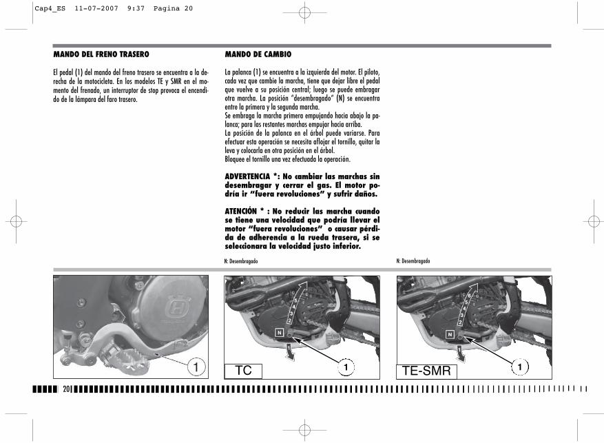
MANDO DE CAMBIO
La palanca (1) se encuentra a la izquierda del motor. El piloto,cada vez que cambie la marcha, tiene que dejar libre el pedalque vuelve a su posición central; luego se puede embragarotra marcha. La posición “desembragado” (N) se encuentraentre la primera y la segunda marcha.Se embraga la marcha primera empujando hacia abajo la pa-lanca; para las restantes marchas empujar hacia arriba.La posición de la palanca en el árbol puede variarse. Paraefectuar esta operación se necesita aflojar el tornillo, quitar laleva y colocarla en otra posición en el árbol.Bloquee el tornillo una vez efectuada la operación.
ADVERTENCIA *: No cambiar las marchas sindesembragar y cerrar el gas. El motor po-dría ir “fuera revoluciones” y sufrir daños.
ATENCIÓN * : No reducir las marcha cuandose tiene una velocidad que podría llevar elmotor “fuera revoluciones” o causar pérdi-da de adherencia a la rueda trasera, si seseleccionara la velocidad justo inferior.
20
MANDO DEL FRENO TRASERO
El pedal (1) del mando del freno trasero se encuentra a la de-recha de la motocicleta. En los modelos TE y SMR en el mo-mento del frenado, un interruptor de stop provoca el encendi-do de la lámpara del faro trasero.
N: DesembragadoN: Desembragado
TC 1 1TE-SMR
Cap4_ES 11-07-2007 9:37 Pagina 20
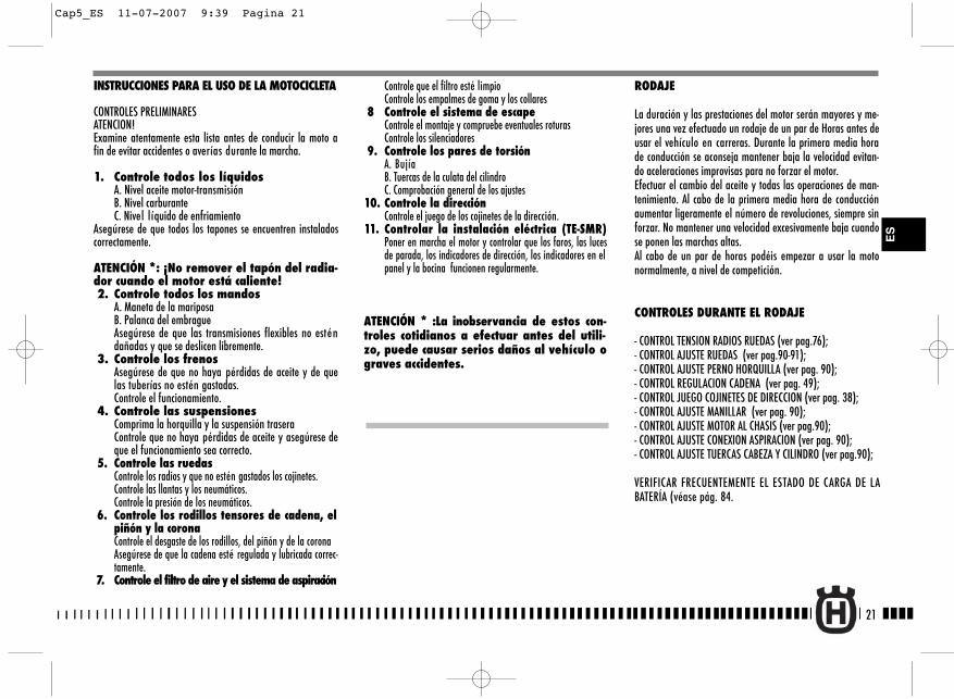
Controle que el filtro esté limpioControle los empalmes de goma y los collares
8 Controle el sistema de escapeControle el montaje y compruebe eventuales roturasControle los silenciadores
9. Controle los pares de torsiónA. BujíaB. Tuercas de la culata del cilindroC. Comprobación general de los ajustes
10. Controle la direcciónControle el juego de los cojinetes de la dirección.
11. Controlar la instalación eléctrica (TE-SMR)Poner en marcha el motor y controlar que los faros, las lucesde parada, los indicadores de dirección, los indicadores en elpanel y la bocina funcionen regularmente.
ATENCIÓN * :La inobservancia de estos con-troles cotidianos a efectuar antes del utili-zo, puede causar serios daños al vehículo ograves accidentes.
21
RODAJE
La duración y las prestaciones del motor serán mayores y me-jores una vez efectuado un rodaje de un par de Horas antes deusar el vehículo en carreras. Durante la primera media horade conducción se aconseja mantener baja la velocidad evitan-do aceleraciones improvisas para no forzar el motor. Efectuar el cambio del aceite y todas las operaciones de man-tenimiento. Al cabo de la primera media hora de conducciónaumentar ligeramente el número de revoluciones, siempre sinforzar. No mantener una velocidad excesivamente baja cuandose ponen las marchas altas.Al cabo de un par de horas podéis empezar a usar la motonormalmente, a nivel de competición.
CONTROLES DURANTE EL RODAJE
- CONTROL TENSION RADIOS RUEDAS (ver pag.76);- CONTROL AJUSTE RUEDAS (ver pag.90-91);- CONTROL AJUSTE PERNO HORQUILLA (ver pag. 90);- CONTROL REGULACION CADENA (ver pag. 49);- CONTROL JUEGO COJINETES DE DIRECCION (ver pag. 38);- CONTROL AJUSTE MANILLAR (ver pag. 90);- CONTROL AJUSTE MOTOR AL CHASIS (ver pag.90);- CONTROL AJUSTE CONEXION ASPIRACION (ver pag. 90);- CONTROL AJUSTE TUERCAS CABEZA Y CILINDRO (ver pag.90);
VERIFICAR FRECUENTEMENTE EL ESTADO DE CARGA DE LABATERÍA (véase pág. 84.
INSTRUCCIONES PARA EL USO DE LA MOTOCICLETA
CONTROLES PRELIMINARES ATENCION!Examine atentamente esta lista antes de conducir la moto afin de evitar accidentes o averías durante la marcha.
1. Controle todos los líquidosA. Nivel aceite motor-transmisiónB. Nivel carburanteC. Nivel líquido de enfriamiento
Asegúrese de que todos los tapones se encuentren instaladoscorrectamente.
ATENCIÓN *: ¡No remover el tapón del radia-dor cuando el motor está caliente!2. Controle todos los mandos
A. Maneta de la mariposaB. Palanca del embragueAsegúrese de que las transmisiones flexibles no esténdañadas y que se deslicen libremente.
3. Controle los frenosAsegúrese de que no haya pérdidas de aceite y de quelas tuberías no estén gastadas.Controle el funcionamiento.
4. Controle las suspensionesComprima la horquilla y la suspensión traseraControle que no haya pérdidas de aceite y asegúrese deque el funcionamiento sea correcto.
5. Controle las ruedasControle los radios y que no estén gastados los cojinetes.Controle las llantas y los neumáticos.Controle la presión de los neumáticos.
6. Controle los rodillos tensores de cadena, elpiñón y la coronaControle el desgaste de los rodillos, del piñón y de la coronaAsegúrese de que la cadena esté regulada y lubricada correc-tamente.
7. Controle el filtro de aire y el sistema de aspiración
ES
Cap5_ES 11-07-2007 9:39 Pagina 21
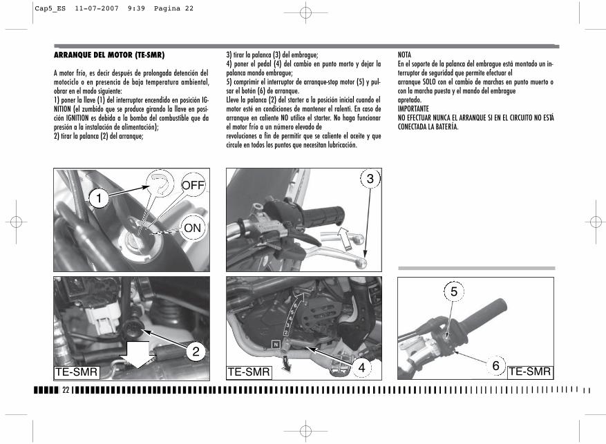
22
NOTAEn el soporte de la palanca del embrague está montado un in-terruptor de seguridad que permite efectuar elarranque SOLO con el cambio de marchas en punto muerto ocon la marcha puesta y el mando del embragueapretado.IMPORTANTENO EFECTUAR NUNCA EL ARRANQUE SI EN EL CIRCUITO NO ESTÁCONECTADA LA BATERÍA.
ARRANQUE DEL MOTOR (TE-SMR)
A motor frío, es decir después de prolongada detención delmotociclo o en presencia de baja temperatura ambiental,obrar en el modo siguiente:1) poner la llave (1) del interruptor encendido en posición IG-NITION (el zumbido que se produce girando la llave en posi-ción IGNITION es debida a la bomba del combustible que dapresión a la instalación de alimentación);2) tirar la palanca (2) del arranque;
3) tirar la palanca (3) del embrague;4) poner el pedal (4) del cambio en punto morto y dejar lapalanca mando embrague;5) comprimir el interruptor de arranque-stop motor (5) y pul-sar el botón (6) de arranque.Lleve la palanca (2) del starter a la posición inicial cuando elmotor esté en condiciones de mantener el ralenti. En caso dearranque en caliente NO utilice el starter. No haga funcionarel motor frío a un número elevado derevoluciones a fin de permitir que se caliente el aceite y quecircule en todos los puntos que necesitan lubricación.
TE-SMR TE-SMR TE-SMR42
3
5
6
1
Cap5_ES 11-07-2007 9:39 Pagina 22
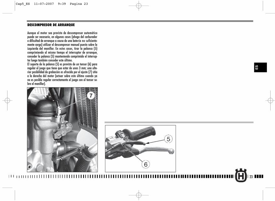
23
ES
DESCOMPRESOR DE ARRANQUE
Aunque el motor sea provisto de descompresor automáticopuede ser necesario, en algunos casos (ahogo del carburadoro dificultad de arranque a causa de una batería no suficiente-mente cargo) utilizar el descompresor manual puesto sobre laizquierda del manillar. En estos casos, tirar la palanca (5)comprimiendo al mismo tiempo el interruptor de arranque,conceder la palanca (5) manteniendo comprimido el interrup-tor luego también conceder este último.El soporte de la palanca (5) es provisto de un tensor (6) pararegular el juego que tiene que estar de unos 3 mm; una ulte-rior posibilidad de grabación es ofrecida por el ajuste (7) sitioa la derecha del motor (actuar sobre este último cuando yano es posible regular correctamente el juego con el tensor so-bre el manillar).
Cap5_ES 11-07-2007 9:39 Pagina 23

24
ARRANQUE DEL MOTOR (TC)
Obrar en el modo siguiente:1) cerciorarse que el grifo del carburante (A) se encuentre en
posición abierta;2) poner la palanca (1) del cambio en punto morto;
3) tirar el pómulo del arranque (pómulo NEGRO 2 por elarranque a frío *, pómulo ROJO 3 por el arranque en ca-liente);
*: es decir después de prolongada detención del motociclo oen presencia de baja temperatura ambiental.
TC TC1 4
4) bajar el pedal de arranque (4) hasta encontrar resistencia(pistón al P.M.S);
A 2
3
Cap5_ES 11-07-2007 9:39 Pagina 24
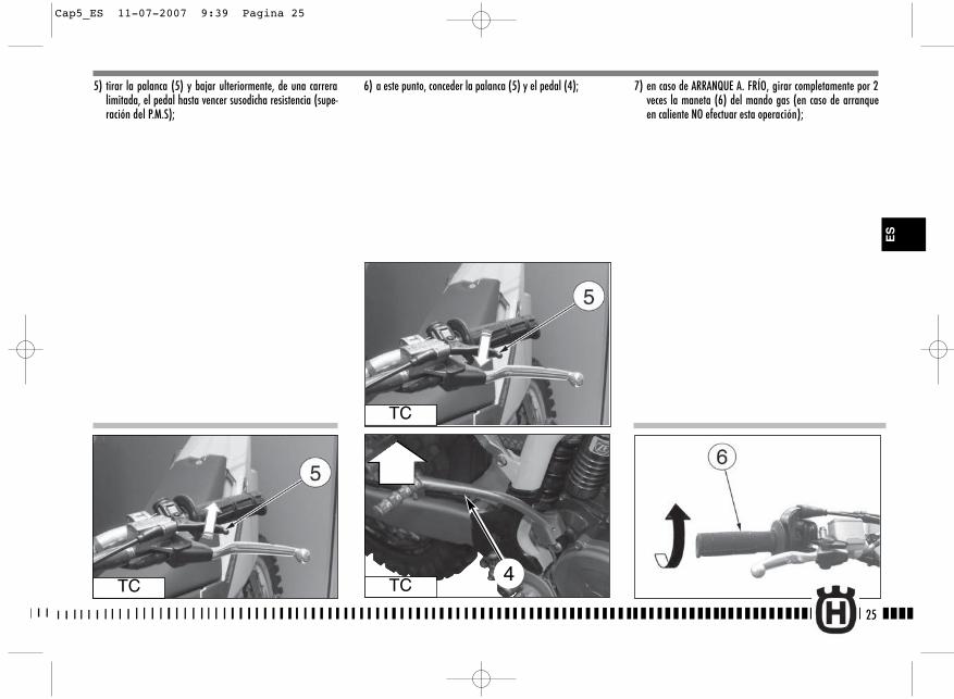
25
5) tirar la palanca (5) y bajar ulteriormente, de una carreralimitada, el pedal hasta vencer susodicha resistencia (supe-ración del P.M.S);
6) a este punto, conceder la palanca (5) y el pedal (4); 7) en caso de ARRANQUE A. FRÍO, girar completamente por 2veces la maneta (6) del mando gas (en caso de arranqueen caliente NO efectuar esta operación);
TC
TC
TC4
ES
Cap5_ES 11-07-2007 9:39 Pagina 25
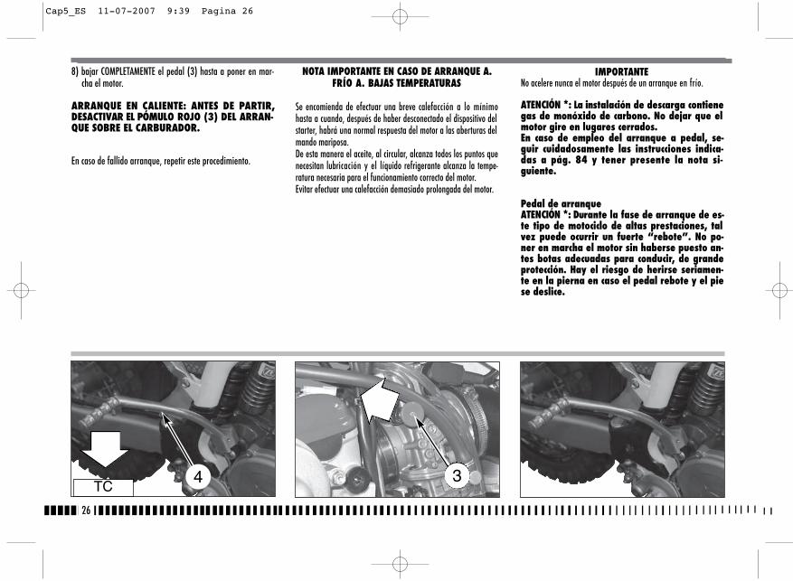
26
IMPORTANTENo acelere nunca el motor después de un arranque en frío.
ATENCIÓN *: La instalación de descarga contienegas de monóxido de carbono. No dejar que elmotor gire en lugares cerrados.En caso de empleo del arranque a pedal, se-guir cuidadosamente las instrucciones indica-das a pág. 84 y tener presente la nota si-guiente.
Pedal de arranqueATENCIÓN *: Durante la fase de arranque de es-te tipo de motociclo de altas prestaciones, talvez puede ocurrir un fuerte “rebote”. No po-ner en marcha el motor sin haberse puesto an-tes botas adecuadas para conducir, de grandeprotección. Hay el riesgo de herirse seriamen-te en la pierna en caso el pedal rebote y el piese deslice.
8) bajar COMPLETAMENTE el pedal (3) hasta a poner en mar-cha el motor.
ARRANQUE EN CALIENTE: ANTES DE PARTIR,DESACTIVAR EL PÓMULO ROJO (3) DEL ARRAN-QUE SOBRE EL CARBURADOR.
En caso de fallido arranque, repetir este procedimiento.
NOTA IMPORTANTE EN CASO DE ARRANQUE A.FRÍO A. BAJAS TEMPERATURAS
Se encomienda de efectuar una breve calefacción a lo mínimohasta a cuando, después de haber desconectado el dispositivo delstarter, habrá una normal respuesta del motor a las aberturas delmando mariposa. De esta manera el aceite, al circular, alcanza todos los puntos quenecesitan lubricación y el líquido refrigerante alcanza la tempe-ratura necesaria para el funcionamiento correcto del motor.Evitar efectuar una calefacción demasiado prolongada del motor.
TC4 3
Cap5_ES 11-07-2007 9:39 Pagina 26
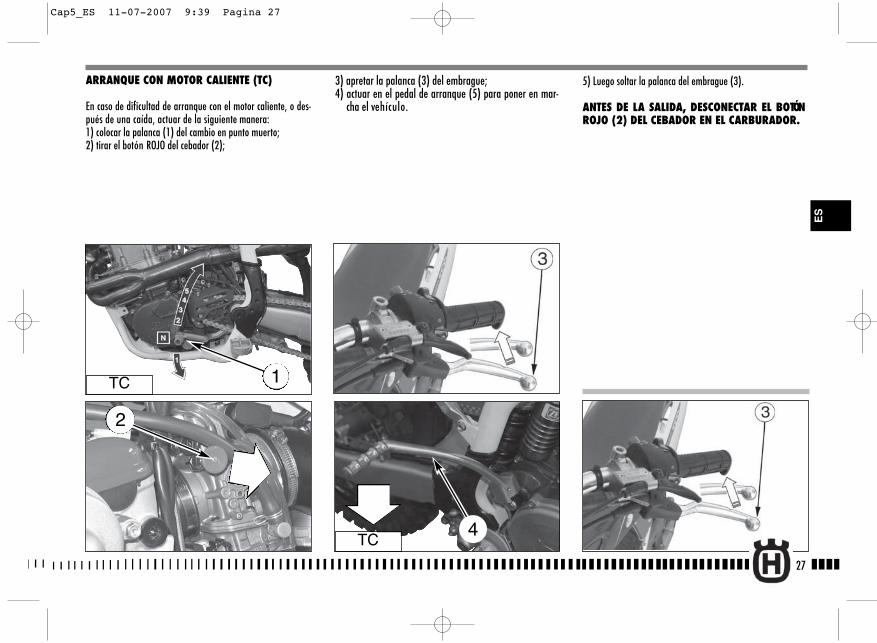
27
3) apretar la palanca (3) del embrague;4) actuar en el pedal de arranque (5) para poner en mar-
cha el vehículo.
5) Luego soltar la palanca del embrague (3).
ANTES DE LA SALIDA, DESCONECTAR EL BOTÓNROJO (2) DEL CEBADOR EN EL CARBURADOR.
ARRANQUE CON MOTOR CALIENTE (TC)
En caso de dificultad de arranque con el motor caliente, o des-pués de una caída, actuar de la siguiente manera:1) colocar la palanca (1) del cambio en punto muerto;2) tirar el botón ROJO del cebador (2);
TC 1
TC4
ES
2
Cap5_ES 11-07-2007 9:39 Pagina 27
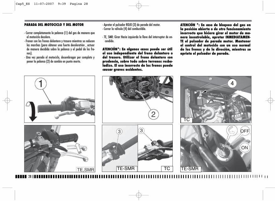
28
PARADA DEL MOTOCICLO Y DEL MOTOR
- Cerrar completamente la palanca (1) del gas de manera queel motociclo decelere.
- Frenar con los frenos delantero y trasero mientras se reducenlas marchas (para obtener una fuerte deceleratión , actuarde manera decidida sobre la palanca y el pedal de los fre-nos).
- Una vez parado el motociclo, desembragar por completo yponer la palanca (2) de cambio en punto morto.
- Apretar el pulsador ROJO (3) de parada del motor.- Cerrar la válvula (4) del combustible.
- TE, SMR: Girar Hacia izquierda la llave del interruptor de en-cendido.
ATENCIÓN*: En algunos casos puede ser útilel uso independiente del freno delantero odel trasero. Utilizar el freno delantero conprudencia, sobre todo sobre terrenos resba-ladizo. El uso incorrecto de los frenos puedecausar graves accidentes.
TE-SMRTE-SMR
TC
TC
ATENCIÓN *: En caso de bloqueo del gas enla posición abierta o de otro funcionamientoincorrecto que hiciera girar el motor de ma-nera incontrolable, apretar INMEDIATAMEN-TE el pulsador de parada motor. Mantenerel control del motociclo con un uso normalde los frenos y de la dirección, mientras seaprieta el pulsador de parada.
4
Cap5_ES 11-07-2007 9:39 Pagina 28
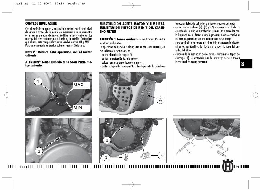
SUBSTITUCION ACEITE MOTOR Y LIMPIEZA-SUBSTITUCION FILTROS DE RED Y DEL CARTU-CHO FILTRO
ATENCIÓN*: Tener cuidado a no tocar l'aceitemotor caliente.La operación se deberá realizar, CON EL MOTOR CALIENTE, co-mo indicado a continuación:- quitar el tapón de carga (2);- quitar la protección (A) del motor;- colocar un recipiente debajo del motor;- quitar el tapón de descarga (3), a fin de permitir la completae-
29
vacuación del aceite del motor y limpie el magneto del tapón;- quitar los tres filtros (5), (6) y (7) situados en el lado iz-
quierdo del motor, comprobar las juntas OR y proceder conla limpieza de los filtros usando gasolina, despues vuelva amontar las partes en sentido contrario al desmontaje ;
- para sustituir el cartucho del filtro (4), es necesario destor-nillar los tres tornillos de fijación y remover la tapa del car-tucho del filtro;
- despues de la sustiución de los filtros, remontar el tapon dedescarga (3), la protección (A) del motor y vierta a travésla cantidad de aceite prescrita.
CONTROL NIVEL ACEITE
Con el vehículo en plano y en posición vertical, verificar el niveldel aceite a través de la mirilla de inspección que se encuentraen el cárter derecho del motor. Verificar el nivel entre las dosmarcas del nivel ubicadas en el borde de la mirilla. Comprobarque el nivel esté comprendido entre las dos marcas MIN y MAX. Para agregar aceite es preciso quitar el tapón (2) de carga
Notas*: Realice esta operación con el motorcaliente.
ATENCIÓN*: Tener cuidado a no tocar l'acte mo-tor caliente.
MAX
MIN
1
2
2
3 4
ES
A
Cap5_ES 11-07-2007 10:53 Pagina 29
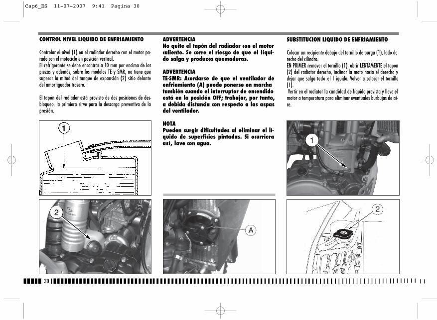
30
SUBSTITUCION LIQUIDO DE ENFRIAMIENTO
Colocar un recipiente debajo del tornillo de purga (1), lado de-recho del cilindro.EN PRIMER remover el tornillo (1), abrir LENTAMENTE el tapon(2) del radiator derecho, inclinar la moto hacia el derecho ydejar que salga todo el l íquido. Volver a colocar el tornillo(1).Vertir en el radiator la candidad de líquido prevista y lleve el
motor a temperatura para eliminar eventuales burbujas de ai-re.
1
ADVERTENCIANo quite el tapón del radiador con el motorcaliente. Se corre el riesgo de que el líqui-do salga y produzca quemaduras.
ADVERTENCIATE-SMR: Acordarse de que el ventilador deenfriamiento (A) puede ponerse en marchatambién cuando el interruptor de encendidoestá en la posición OFF; trabajar, por tanto,a debida distancia con respecto a las aspasdel ventilador.
NOTAPueden surgir dificultades al eliminar el lí-quido de superficies pintadas. Si ocurrieraasí, lave con agua.
CONTROL NIVEL LIQUIDO DE ENFRIAMIENTO
Controlar el nivel (1) en el radiador derecho con el motor pa-rado con el motociclo en posición vertical.El refrigerante se debe encontrar a 10 mm por encima de laspiezas y además, sobre los modelos TE y SMR, no tiene quesuperar la mitad del tanque de expansión (2) sitio delantedel amortiguador trasero.
El tapón del radiador está provisto de dos posiciones de des-bloqueo, la primiera sirve para la descarga preventiva de lapresión.
1
2
Cap6_ES 11-07-2007 9:41 Pagina 30
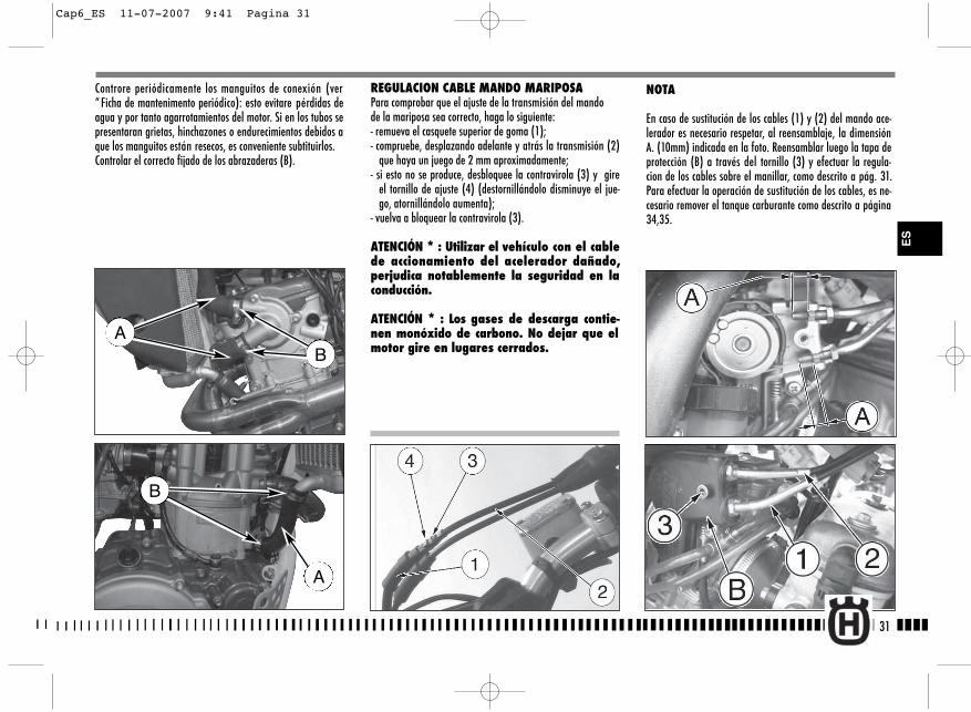
NOTA
En caso de sustitución de los cables (1) y (2) del mando ace-lerador es necesario respetar, al reensamblaje, la dimensiónA. (10mm) indicada en la foto. Reensamblar luego la tapa deprotección (B) a través del tornillo (3) y efectuar la regula-cion de los cables sobre el manillar, como descrito a pág. 31.Para efectuar la operación de sustitución de los cables, es ne-cesario remover el tanque carburante como descrito a página34,35.
31
Controre periódicamente los manguitos de conexión (ver“ Ficha de mantenimento periódico): esto evitare pérdidas deagua y por tanto agarrotamientos del motor. Si en los tubos sepresentaran grietas, hinchazones o endurecimientos debidos aque los manguitos están resecos, es conveniente subtituirlos.Controlar el correcto fijado de los abrazaderas (B).
B
A
REGULACION CABLE MANDO MARIPOSAPara comprobar que el ajuste de la transmisión del mando de la mariposa sea correcto, haga lo siguiente:- remueva el casquete superior de goma (1);- compruebe, desplazando adelante y atrás la transmisión (2)
que haya un juego de 2 mm aproximadamente;- si esto no se produce, desbloquee la contravirola (3) y gire
el tornillo de ajuste (4) (destornillándolo disminuye el jue-go, atornillándolo aumenta);
- vuelva a bloquear la contravirola (3).
ATENCIÓN * : Utilizar el vehículo con el cablede accionamiento del acelerador dañado,perjudica notablemente la seguridad en laconducción.
ATENCIÓN * : Los gases de descarga contie-nen monóxido de carbono. No dejar que elmotor gire en lugares cerrados.
ES
AB
Cap6_ES 11-07-2007 9:41 Pagina 31
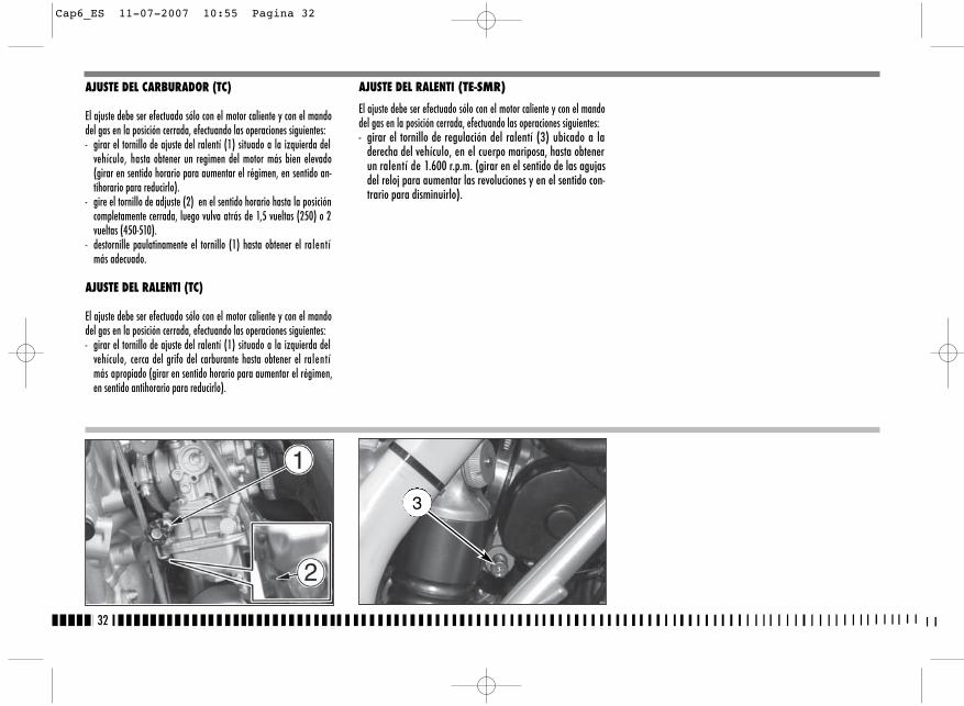
32
AJUSTE DEL CARBURADOR (TC)
El ajuste debe ser efectuado sólo con el motor caliente y con el mandodel gas en la posición cerrada, efectuando las operaciones siguientes:- girar el tornillo de ajuste del ralentí (1) situado a la izquierda del
vehículo, hasta obtener un regimen del motor más bien elevado(girar en sentido horario para aumentar el régimen, en sentido an-tihorario para reducirlo).
- gire el tornillo de adjuste (2) en el sentido horario hasta la posicióncompletamente cerrada, luego vulva atrás de 1,5 vueltas (250) o 2vueltas (450-510).
- destornille paulatinamente el tornillo (1) hasta obtener el ralentímás adecuado.
AJUSTE DEL RALENTI (TC)
El ajuste debe ser efectuado sólo con el motor caliente y con el mandodel gas en la posición cerrada, efectuando las operaciones siguientes:- girar el tornillo de ajuste del ralentí (1) situado a la izquierda del
vehículo, cerca del grifo del carburante hasta obtener el ralentímás apropiado (girar en sentido horario para aumentar el régimen,en sentido antihorario para reducirlo).
AJUSTE DEL RALENTI (TE-SMR)
El ajuste debe ser efectuado sólo con el motor caliente y con el mandodel gas en la posición cerrada, efectuando las operaciones siguientes:- girar el tornillo de regulación del ralentí (3) ubicado a la
derecha del vehículo, en el cuerpo mariposa, hasta obtenerun ralentí de 1.600 r.p.m. (girar en el sentido de las agujasdel reloj para aumentar las revoluciones y en el sentido con-trario para disminuirlo).
3
Cap6_ES 11-07-2007 10:55 Pagina 32
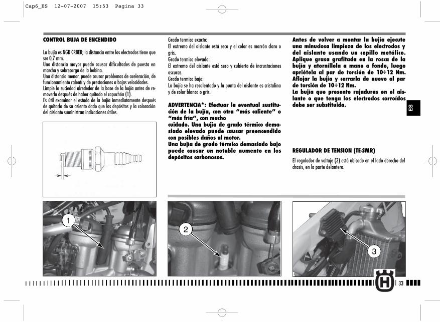
33
CONTROL BUJA DE ENCENDIDO
La bujía es NGK CR8EB; la distancia entre los electrodos tiene queser 0,7 mm.Una distancia mayor puede causar dificultades de puesta enmarcha y sobrecarga de la bobina.Una distancia menor, puede causar problemas de aceleración, defuncionamiento ralentí y de prestaciones a bajas velocidades.Limpie la suciedad alrededor de la base de la bujía antes de re-moverla después de haber quitado el capuchón (1).Es útil examinar el estado de la bujía inmediatamente despuésde quitarla de su asiento dado que los depósitos y la coloracióndel aislante suministran indicaciones útiles.
Grado termico exacto:El extremo del aislante está seco y el color es marrón claro ogris.Grado termico elevado:El extremo del aislante está seco y cubierto de incrustacionesoscuras.Grado termico bajo:La bujía se ha recalentado y la punta del aislante es cristalinay de color blanco o gris.
ADVERTENCIA*: Efectuar la eventual sustitu-ción de la bujía, con otra “más caliente” o“más fría”, con muchocuidado. Una bujía de grado térmico dema-siado elevado puede causar preencendidocon posibles daños al motor.Una bujía de grado térmico demasiado bajopuede causar un notable aumento en losdepósitos carbonosos.
Antes de volver a montar la bujía ejecuteuna minuciosa limpieza de los electrodos ydel aislante usando un cepillo metálico.Aplique grasa grafitada en la rosca de labujía y atorníllela a mano a fondo, luegoapriétela al par de torsión de 10÷12 Nm.Aflojar la bujía y cerrarla de nuevo al parde torsión de 10÷12 Nm. La bujía que presente rajaduras en el ais-lante o que tenga los electrodos corroídosdebe ser substituida.
REGULADOR DE TENSION (TE-SMR)
El regulador de voltaje (3) está ubicado en el lado derecho delchasis, en la parte delantera.
2
3
1
ES
Cap6_ES 12-07-2007 15:53 Pagina 33
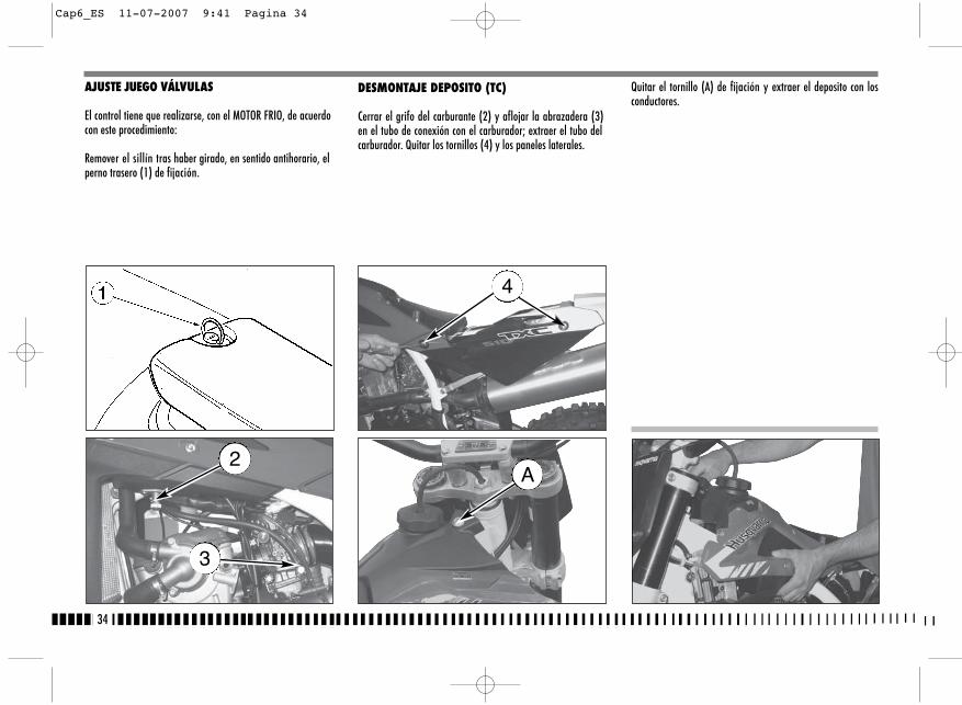
DESMONTAJE DEPOSITO (TC)
Cerrar el grifo del carburante (2) y aflojar la abrazadera (3)en el tubo de conexión con el carburador; extraer el tubo delcarburador. Quitar los tornillos (4) y los paneles laterales.
Quitar el tornillo (A) de fijación y extraer el deposito con losconductores.
34
AJUSTE JUEGO VÁLVULAS
El control tiene que realizarse, con el MOTOR FRIO, de acuerdocon este procedimiento:
Remover el sillín tras haber girado, en sentido antihorario, elperno trasero (1) de fijación.
2
3
4
A
Cap6_ES 11-07-2007 9:41 Pagina 34
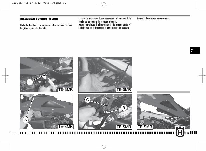
Levantar el deposito y luego desconectar el conector de labomba del carburante del cableado principal.Desconectar el tubo de alimentación (B) del tubo de salida (C)en la bomba del carburante en la parte inferior del deposito.
DESMONTAJE DEPOSITO (TE-SMR)
Quitar los tornillos (1) y los paneles laterales. Quitar el torni-llo (A) de fijación del deposito.
Extraer el deposito con los conductores.
35
TE-SMR
B
TE-SMR
C
A
TE-SMR
TE-SMR
1
TE-SMR
ES
Cap6_ES 11-07-2007 9:41 Pagina 35

36
Retirar la bujía (5), los cuatro tornillos (6) de la tapa culata yla tapa culata;Insertar la 2a marcha y, empujando adelante y atrás el moto-ciclo, llevar el pistón al Punto Muerto Superior (en esta condi-ción la muesca indicada sobre la culata coincide con las dosreferencias sobre el engranaje de renvio de los ejes distribu-ción coño indicado sobre la figura);
Con un medidor de espesores verificar el juego de las válvulasque debe ser de 0,10÷0,15 mm para la ASPIRACIÓN y de0,15÷0,20 mm para el ESCAPE;
En caso contrario, levantar la pinza (7) con el auxilio de ungancho, hacer resbalar el balancín de un lado, extraer con unalicate la pastilla y averiguar de ello el espesor; Con base en el valor realzado, montar la nueva pastilla (a re-puesto, son provistas pastillas con espesor de 1,60 mm a 2,60mm con aumentos de 0,05 mm) y reconducir en sede la pinzay el balancín; Verificar nuevamente el juego de las válvulas y, si correcto,volver a montar los componentes quitados en precedencia.
Cap6_ES 11-07-2007 9:41 Pagina 36
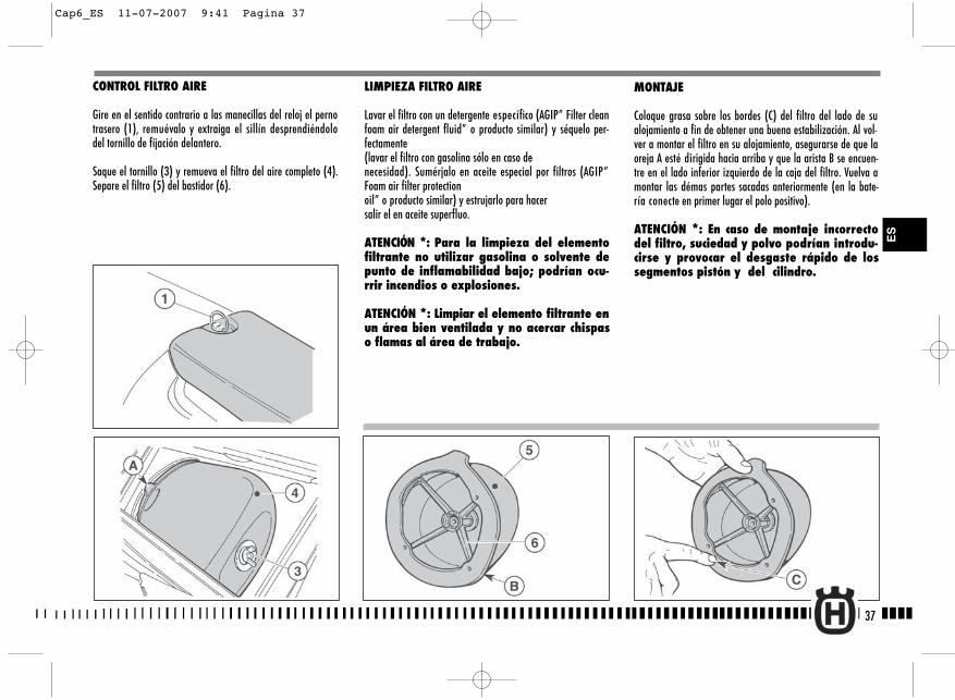
LIMPIEZA FILTRO AIRE
Lavar el filtro con un detergente específico (AGIP” Filter cleanfoam air detergent fluid” o producto similar) y séquelo per-fectamente(lavar el filtro con gasolina sólo en caso denecesidad). Sumérjalo en aceite especial por filtros (AGIP”Foam air filter protectionoil” o producto similar) y estrujarlo para hacersalir el en aceite superfluo.
ATENCIÓN *: Para la limpieza del elementofiltrante no utilizar gasolina o solvente depunto de inflamabilidad bajo; podrían ocu-rrir incendios o explosiones.
ATENCIÓN *: Limpiar el elemento filtrante enun área bien ventilada y no acercar chispaso flamas al área de trabajo.
MONTAJE
Coloque grasa sobre los bordes (C) del filtro del lado de sualojamiento a fin de obtener una buena estabilización. Al vol-ver a montar el filtro en su alojamiento, asegurarse de que laoreja A esté dirigida hacia arriba y que la arista B se encuen-tre en el lado inferior izquierdo de la caja del filtro. Vuelva amontar las démas partes sacadas anteriormente (en la bate-ría conecte en primer lugar el polo positivo).
ATENCIÓN *: En caso de montaje incorrectodel filtro, suciedad y polvo podrían introdu-cirse y provocar el desgaste rápido de lossegmentos pistón y del cilindro.
37
CONTROL FILTRO AIRE
Gire en el sentido contrario a las manecillas del reloj el pernotrasero (1), remuévalo y extraiga el sillín desprendiéndolodel tornillo de fijación delantero.
Saque el tornillo (3) y remueva el filtro del aire completo (4).Separe el filtro (5) del bastidor (6).
ES
Cap6_ES 11-07-2007 9:41 Pagina 37
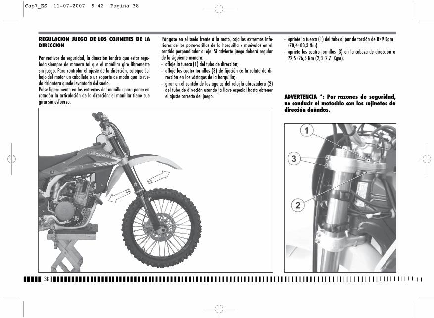
- apriete la tuerca (1) del tubo al par de torsión de 8÷9 Kgm(78,4÷88,3 Nm)
- apriete los cuatro tornillos (3) en la cabeza de dirección a22,5÷26,5 Nm (2,3÷2,7 Kgm).
ADVERTENCIA *: Por razones de seguridad,no conducir el motociclo con los cojinetes dedirección dañados.
38
REGULACION JUEGO DE LOS COJINETES DE LADIRECCION
Por motivos de seguridad, la dirección tendrá que estar regu-lada siempre de manera tal que el manillar gire librementesin juego. Para controlar el ajuste de la dirección, coloque de-bajo del motor un caballete o un soporte de modo que la rue-da delantera quede levantada del suelo.Pulse ligeramente en los extremos del manillar para poner enrotación la articulación de la dirección; el manillar tiene quegirar sin esfuerzo.
Póngase en el suelo frente a la moto, coja los extremos infe-riores de los porta-varillas de la horquilla y muévalos en elsentido perpendicular al eje. Si advierte juego deberá regularde la siguiente manera:- afloje la tuerca (1) del tubo de dirección;- afloje los cuatro tornillos (3) de fijación de la culata de di-
rección en los vástagos de la horquilla;- girar en el sentido de las agujas del reloj la abrazadera (2)
del tubo de dirección usando la llave especial hasta obtenerel ajuste correcto del juego.
Cap7_ES 11-07-2007 9:42 Pagina 38
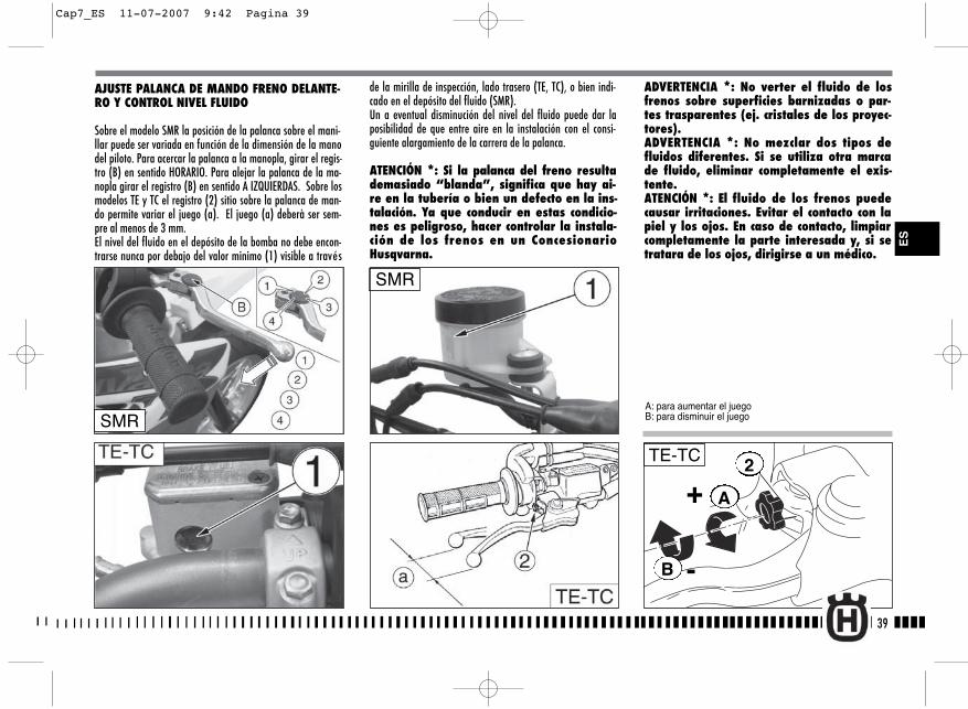
A
B
+
-
2TE-TC
de la mirilla de inspección, lado trasero (TE, TC), o bien indi-cado en el depósito del fluido (SMR).Un a eventual disminución del nivel del fluido puede dar laposibilidad de que entre aire en la instalación con el consi-guiente alargamiento de la carrera de la palanca.
ATENCIÓN *: Si la palanca del freno resultademasiado “blanda”, significa que hay ai-re en la tubería o bien un defecto en la ins-talación. Ya que conducir en estas condicio-nes es peligroso, hacer controlar la instala-ción de los frenos en un ConcesionarioHusqvarna.
ADVERTENCIA *: No verter el fluido de losfrenos sobre superficies barnizadas o par-tes trasparentes (ej. cristales de los proyec-tores). ADVERTENCIA *: No mezclar dos tipos defluidos diferentes. Si se utiliza otra marcade fluido, eliminar completamente el exis-tente.ATENCIÓN *: El fluido de los frenos puedecausar irritaciones. Evitar el contacto con lapiel y los ojos. En caso de contacto, limpiarcompletamente la parte interesada y, si setratara de los ojos, dirigirse a un médico.
39
ES
AJUSTE PALANCA DE MANDO FRENO DELANTE-RO Y CONTROL NIVEL FLUIDO
Sobre el modelo SMR la posición de la palanca sobre el mani-llar puede ser variada en función de la dimensión de la manodel piloto. Para acercar la palanca a la manopla, girar el regis-tro (B) en sentido HORARIO. Para alejar la palanca de la ma-nopla girar el registro (B) en sentido A IZQUIERDAS. Sobre losmodelos TE y TC el registro (2) sitio sobre la palanca de man-do permite variar el juego (a). El juego (a) deberà ser sem-pre al menos de 3 mm.El nivel del fluido en el depósito de la bomba no debe encon-trarse nunca por debajo del valor minimo (1) visible a través
SMR
A: para aumentar el juegoB: para disminuir el juegoSMR
Cap7_ES 11-07-2007 9:42 Pagina 39

40
Después de efectuar este ajuste es necesario regular la carreraen vacío del pedal de pág. 41.
AJUSTE FUNCIONAMIENTO EN VACIO FRENO POSTEIOR
El pedal de mando del freno trasero, tiene que tener una ca-rrera en vacío (B) de 5 mm antes de comenzar la acción fre-nante.
En el caso de que esto no se produjera ajústelo del modo si-guiente:- afloje la tuerca (3);- actúe en la varilla de mando de la bomba (4) para aumentar
o bien desminuir la carrera en vacío;- una vez acabada la operación vuelva a apretar la tuerca (3).
ATENCIONSi no se realiza la carrera en vacío prescrip-ta se provoca el desgaste rápido de las pas-tillas del freno con el consiguiente peligrode llegar a la TOTAL INEFICIENCIA DEL FRENO.
AJUSTE POSICION PEDAL DEL FRENO TRASERO
La posición del pedal de mando del freno trasero respecto delreposapiés, se puede ajustar según las exigencias personales.Teniendo que realizar dicho ajuste actúe del modo siguiente:- afloje el tornillo (1);- para regular la carrera en vacio (A), gire la leva (2);- una vez acabado el ajuste, vuelva a apretar il tornillo (1).
Cap7_ES 11-07-2007 9:42 Pagina 40

41
CONTROL NIVEL DEL FLUIDOEl nivel (A) tiene que encontrarse entre las muescas del depó-sito de la bomba.
AJUSTE PALANCA DE MANDO Y CONTROL NI-VEL FLUIDO EMBRAGUE HIDRÁULICO
El juego (A) deberà ser sempre al menos de 3 mm.La posición de la palanca sobre el manillar puede ser variadaen función de la dimensión de la mano del piloto. Para acercar la palanca a la manopla, girar el registro (B) ensentido HORARIO.Para alejar la palanca de la manopla, girar el registro (B) ensentido A IZQUIERDAS.Para controlar el nivel del fluido, actúe del modo siguiente:- retirar los tornillos (1), la tapa (2) y la membrana bomba;
- con el cilindro maestro (3) en posición horizontal, el niveldel fluido deberà ser a 4 mm (0.16 in.) del tope superior(D) del corpo bomba
- si necesario, rellenar (usar fluido indicado en la TABLA DELUBRICACION, RELLONES pàg. 10)
ADVERTENCIA *: En NINGUN caso utilizar li-quido de frenos.
Volver a montar los componentes quitados en precedencia.
Controre periódicamente el manguito de conexión (ver “Fichade mantenimento periódico): si en el tubo (C) se presentaranseñales de usura o grietas, es conveniente subtituirlo.
ES
Cap7_ES 11-07-2007 9:42 Pagina 41
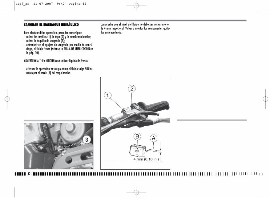
42
SANGRAR EL EMBRAGUE HIDRÁULICO
Para efectuar dicha operación, proceder como sigue:- retirar los tornillos (1), la tapa (2) y la membrana bomba;- retirar la boquilla de sangrado (3);- entroducir en el agujero de sangrado, por medio de una si-
ringa, el fluido fresco (véanse la TABLA DE LUBRICACIÓ N enla pág. 10).
ADVERTENCIA *: En NINGUN caso utilizar liquido de frenos.
- efectuar la operación hasta que tanto el fluido salga SIN bu-rrujas por el borde (B) del corpo bomba.
Compruebe que el nivel del fluido no debe ser nunca inferiorde 4 mm respecto al. Volver a montar los componentes quita-dos en precedencia.
Cap7_ES 11-07-2007 9:42 Pagina 42
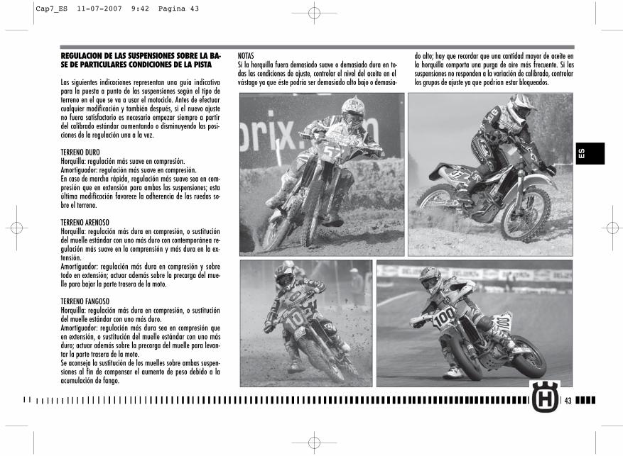
43
REGULACION DE LAS SUSPENSIONES SOBRE LA BA-SE DE PARTICULARES CONDICIONES DE LA PISTA
Las siguientes indicaciones representan una guía indicativapara la puesta a punto de las suspensiones según el tipo deterreno en el que se va a usar el motociclo. Antes de efectuarcualquier modificación y también después, si el nuevo ajusteno fuera satisfactorio es necesario empezar siempre a partirdel calibrado estándar aumentando o disminuyendo las posi-ciones de la regulación una a la vez.
TERRENO DUROHorquilla: regulación más suave en compresión. Amortiguador: regulación más suave en compresión. En caso de marcha rápida, regulación más suave sea en com-presión que en extensión para ambas las suspensiones; estaúltima modificación favorece la adherencia de las ruedas so-bre el terreno.
TERRENO ARENOSOHorquilla: regulación más dura en compresión, o sustitucióndel muelle estándar con uno más duro con contemporánea re-gulación más suave en la comprensión y más dura en la ex-tensión. Amortiguador: regulación más dura en compresión y sobretodo en extensión; actuar además sobre la precarga del mue-lle para bajar la parte trasera de la moto.
TERRENO FANGOSOHorquilla: regulación más dura en compresión, o sustitucióndel muelle estándar con uno más duro.Amortiguador: regulación más dura sea en compresión queen extensión, o sustitución del muelle estándar con uno másduro; actuar además sobre la precarga del muelle para levan-tar la parte trasera de la moto. Se aconseja la sustitución de los muelles sobre ambas suspen-siones al fin de compensar el aumento de peso debido a laacumulación de fango.
NOTASSi la horquilla fuera demasiado suave o demasiado dura en to-das las condiciones de ajuste, controlar el nivel del aceite en elvástago ya que éste podría ser demasiado alto bajo o demasia-
do alto; hay que recordar que una cantidad mayor de aceite enla horquilla comporta una purga de aire más frecuente. Si lassuspensiones no responden a la variación de calibrado, controlarlos grupos de ajuste ya que podrían estar bloqueados.
ES
Cap7_ES 11-07-2007 9:42 Pagina 43

44
Los calibrados estándar y los procedimientos de regulación estánindicadas en las páginas siguientes; los muelles disponibles bajopedido, junto a los relativos distanciadores de precarga, están indi-cados a las páginas 93, 94, 95.
REGULACION HORQUILLA (a) COMPRESION (AJUSTE INFERIOR). Calibrado estándar: -15 déclics (TC);Calibrado estándar: -12 déclics (TE-SMR).En el caso que se tuviese que restablecer el calibrado estándar, re-mueva el tapón (B) y gire el ajuste (A) en el sentido horario hastala posición completamente cerrada, luego vuelva atrás de sovraci-tatos clicks. Para obtener un frenado más blando, gire el ajuste en
el sentido contrario a las agujas del reloj; actúe inversamente paraobtener un frenado más duro.
b) EXTENSION (AJUSTE SUPERIOR). Calibrado estándar: -15 déclics (TC);Calibrado estándar: -12 déclics (TE-SMR).En el caso que se tuviese que restablecer el calibrado estándar, gireel ajuste (C) en el sentido de las agujas del reloj hasta la posicióncompletamente cerrada, luego vuelva atrás de sovracitatos clicks.Para obtener un frenado más blando, gire el ajuste en el sentidocontrario a las agujas del reloj; actúe inversamente para obtenerun frenado más duro.
(c) PURGA DEL AIRE (a efectuar después de cada carrera en caso deuso competitivo o mensualmente). TE-SMR: Ponga el vehículo en un caballete central y extienda com-pletamente la horquilla y afloje la válvula (D), Cerrar la válvulauna vea terminada la operación.TC: Colocar el vehículo sobre un caballete central, extender comple-tamente la horquilla, quitar el capuchón (E) y hacer presión sobrela válvula con un punzón. Montar nuevamente el capuchón.ATENCIÓN!No afloje NUNCA el tornillo (F).NOTA: No forzar los tornillos de ajuste más allá delas posiciones máxima de apertura y cierre.
A
B
CD
a)
b)TC
TC
TE-SMR
TE-SMR
E
C
C
C
F
Cap7_ES 12-07-2007 15:54 Pagina 44
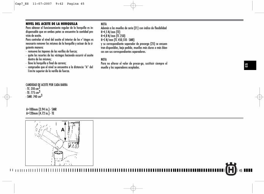
NIVEL DEL ACEITE DE LA HORQUILLAPara obtener el funcionamiento regular de la horquilla es in-dispensable que en ambas patas se encuentre la cantidad pre-vista de aceite.Para controlar el nivel del aceite al interior de los v*stagos esnecesario remover los mismos de la horquilla y actuar de la si-guiente manera:- remueva los tapones de las varillas de fuerza;- quite los resortes de las vástagos haciendo escurrir el aceite
dentro de los mismos;- lleve la horquilla a final de carrera;- compruebe que el nivel se encuentre a la distancia “A” del
l ímite superior de la varilla de fuerza.
CANDIDAD DE ACEITE POR CADA BARRA- TC: 310 cm3- TE: 775 cm3- SMR: 740 cm3
A=100mm (3.94 in.) - SMRA=120mm (4.72 in.) - TE
A
NOTAAdemás a les muelles de serie (21) con índice de flexibilidadK=4,5 N/mm (TE) K=4,8 N/mm (TC 250) K=5 N/mm (TC 450,510 - SMR)y su correspondiente separador de precarga (25) se encuen-tran disponibles, bajo pedido, muelles más duros o más blan-cos con sus correspondientes separadores.
NOTAPara no alterar el valor de precar-ga, sustituir siempre elmuelle y los separadores acoplados.
45
ES
Cap7_ES 11-07-2007 9:42 Pagina 45

46
b) Modificación altura manillar Remover el separador inferior (A) y reemplazar el tornillo(4) con uno de largo L=65 mm Ejecutar el reensamblaje obrando contrariamente y apre-tando los tornillos (3) a 2,75-3,05 kgm (27-30 Nm; 19.9-22 Lb/ft) y los tornillos (4) a 2,0-2,2 kgm (19,6-21,6 Nm;14.5-15.9 Lb/ft).
MODIFICACIÓN POSICIÓN Y ALTURA DEL MANILLAR
La posición (a) y la altura (b) del manillar pueden ser mo-dificados por mejor conformarse con Su exigencias deguía.Para efectuar esta operación, es necesario bajar los torni-llos (3) la abrazadera superior (1), los tornillos (4) y laabrazadera inferior (2).
a) Modificación posición del manillarGirar la abrazadera inferior (2) de 180° para avanzar o re-troceder (10mm - 0.04in.) la posición del manillar en rela-ción a esta inicial.
Cap7_ES 11-07-2007 9:42 Pagina 46
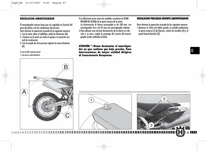
4.La diferencia entre estas dos medidas constituye la DISMINUCION DE ALTURA de la parte trasera de la moto. La disminución di altura aconsejada es de 100 mm. conamortiguador frío y de 95 mm con amortiguador caliente.
5.Para obtener una correcta disminución de la altura en relación a su peso, regule la precarga del resorte del amorti-guador (como indicado al lado).
ATENCIÓN *: Nunca desmontar el amortigua-dor ya que contiene gas bajo presión. Paraintervenciones de mayor entidad dirigirseal Concesionario Husqvarna.
REGULACION PRECARGA RESORTE AMORTIGUADOR
Para efectuar la operación proceda de las siguiente manera:1.Remover el sillín tras haber girado, en sentido antihorario,
el perno trasero (1) de fijación, retirar los tornillos (2) y el panel lateral derecho (3).
47
REGULACION AMORTIGUADOR
El amortiguador trasero tiene que ser regulado en función delpeso del piloto y de las condiciones del terreno.Para efectuar la operación proceda de la siguiente manera:1. Con la moto sobre el caballete, mida las distancias (A);2. Siéntese en la moto con todo el equipo y la posición nor
mal de conducción;3. Con la ayuda de otra persona registre la nueva distancia
(A).
B: eje tornillo sujection panelC: eje perno rueda delantera
2
3
ES
Cap8_ES 11-07-2007 9:43 Pagina 47
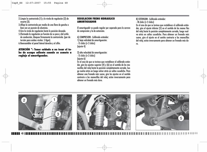
B) EXTENSION - Calibrado estándar:- 18 clicks (± 2 clicks)En el caso de que se tuviese que restablecer el calibrado están-dar, gire el ajuste inferior (5) en el sentido de las manec llasdel reloj hasta la posición completamente cerrada, luego vuel-va atrás en saltos susodicho. Para obtener un frenado mássuave, gire el ajuste en el sentito contrario a las manecillasdel reloj; actúe inversamente para obtener un frenado más du-ro.
2.Limpie la contravirola (1) y la virola de regulación (2) de resorte (3).
3.Afloje la contravirola por medio de una llave de gancho o bien con un punzón de aluminio.
4.Gire la virola de regulación hasta la posición deseada.5.Efectuada la regulación en función de su peso y del estilo
de conducción, bloquee firmemente la contravirola. (par de torsión para ambas virolas: 5 Kgm).
6.Reensamblar el panel lateral derecho y el sillín.
ATENCIÓN *: Tener cuidado a no tocar el tu-bo de escape caliente cuando se somete areglaje el amortiguador.
REGULACION FRENO HIDRAULICOAMORTIGUADOR
El amortiguadir se puede regular por separado para la carrerade compresión y la de extensión.
A) COMPRESION - Calibrado estándar:1) baja velicidad de amortiguación:- 15 clicks (± 2 clicks)(ajuste 4)
2) alta velocidad de amortiguación:- 15 clicks (± 2 clicks)(ajuste 6)En el caso de que se tuviese que restablecer el calibrado están-dar, gire los ajustos superior (4) y (6) en el sentido de las ma-necillas del reloj hasta la posición completamente cerrada, lue-go vuelva atrás en luego volver atrás en saltos susodicho. Paraobtener una frenado más suave, gire los ajustos en el sentidocontrario a las manecillas del reloj; actúe inversamente paraobtener un frenado más duro.
48
12
3 645
Cap8_ES 12-07-2007 15:55 Pagina 48

REGULACION CADENA
La cadena debe ser controlada, regulada y lubrificada según la“ Tabla de manutención”, por razones de seguridad y paraprevenir un desgaste excesivo. Si la cadena se desgasta excesi-vamente o resulta mal regulada, es decir se ha aflojado o sehalla excesivamente tensada, puede salir de la corona o rom-perse. Para regular la tensión de la cadena hay que bajar laparte trasera de la moto a fin de obtener la alineación del ejepiñón, eje de rotación horquilla y eje rueda trasera como seindica en la figura, luego hay que girar tres vueltas la ruedatrasera. En dicha condición la cadena no tiene que quedar ten-sa aún sin flexión.(Fig. A)
AJUSTE RÁPIDO (Fig. B.)
Introducir, en el punto indicado en la figura, un buje (a) de 35mm de diámetro (ó, como alternativa un espesor de las mis-mas dimensiones) y comprobar que el tramo inferior (C) de lacadena esté apenas tenso.Si así no resultara, actuar de la siguiente manera:- aflojar en el lado derecho, con una llave de tubo de 27 mm,
el lado (1) de fijación del perno rueda;- aflojar las contratuercas (2) en ambos tensores de la cade-
na, con una llave de 12 mm, y actuar sobre los tornillos (3)para obtener el valor de tensión correcto;
- una vez realizada la regulación apretar las contratuercas (2)y la tuerca del perno de la rueda (1).
Después de la regulación, verificar siempre la alineación de larueda.
49
Fig. A
ES
Eje piñón
Eje horquilla Eje rueda
A = 0÷2 mm (0÷0.08 in.)
a
C
1
32
Fig. B
Cap9_ES 11-07-2007 9:49 Pagina 49
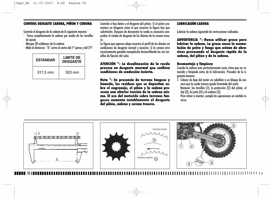
Controle si hay daños y el desgaste del piñón. Si el piñón pre-sentara un desgaste como el que muestra la figura hay quesubstituirlo. Después de desmontar la rueda es necesario com-probar el estado de desgaste de los dientes de la corona trase-ra.La figura que aparece abajo muestra el perfil de los dientes encondiciones de desgaste normal y excesivo. Si la corona est áexcesivamente gastada reemplácela destornillando los seis tor-nillos de fijación del cubo.
ATENCIÓN *: La desalineación de la ruedaprovoca un desgaste anormal que conllevacondiciones de conducción incierta.
Nota *: En presencia de terreno fangoso yhúmedo, los residuos que se depositan so-bre el engranaje, el piñón y la cadena pro-vocan una ulterior tensión de la cadena mis-ma. El uso del motociclo sobre terrenos fan-gosos aumenta notablemente el desgastedel piñón, cadena y corona trasera.
LUBRICACIÓN CADENA
Lubricar la cadena siguiendo las instrucciones indicadas.
ADVERTENCIA *: Nunca utilizar grasa paralubricar la cadena. La grasa causa la acumu-lación de polvo y fango que actúan de abra-sivos provocando el desgaste rápido de lacadena, del piñón y de la cadena.
Desmontaje y limpiezaCuando la cadena está particularmente sucia, tiene que ser re-movida y limpiada antes de la lubricación. Proceder de la si-guiente manera.1- Colocar de bajo del motor un caballete o un bloque de ma-
nera que la rueda trasera quede levantada del suelo.Remover: los tornillos (1), la protección (2) del piñón, elclip (3), la junta (4) y la cadena (5);Para volver a montar, cumpla las operaciones en sentido in-verso.
50
CONTROL DESGASTE CADENA, PIÑON Y CORONA
Controle el desgaste de la cadena de la siguiente manera:- Tense completamente la cadena por medio de los tornillos
de ajuste.- Marque 20 eslabones de la cadena.- Mida la distancia “A” entre el centro del 1° perno y del 21°.
ESTANDARLIMITE DE
DESGASTE
317,5 mm 323 mm
Consumo normal
Consumo excesivo
Cap9_ES 11-07-2007 9:49 Pagina 50

Lubricación cadena con empaque taduras de anilloLubricar con un pincel tanto las partes metálicas como las degoma (empaquetadura de anillo) actuando externa e interna-mente con aceite motor de viscosidad SAE 80-90.
5- Si la cadena ha sido cortada, volver a montarla con el auxi-lio de la junta.
6- Montar el clip de la junta de manera que la parte cerradaesté orientada hacia el sentido de rotación de la cadena,como indicado en la figura abajo.
Nota *: A fin de la seguridad, la junta es la parte más crí-tica de la cadena de transmisión. Las juntas se puede utili-zar otra vez con tanto que permanezcan en óptimas condi-ciones, aunque se aconseja montar una nueva cuando seensambla la cadena.
6- Ajustar correctamente la cadena como descrito a pagina 49.
2- Controlar que la cadena no esté desgastada o dañada.Sustituirla siempre de acuerdo con la Tabla deMantenimiento Periódico o en caso los rodillos o las mallasresultaran dañados.
3- Controlar que el piñón o la corona no estén dañados.4- Limpiar y lubricar la cadena come indicado abajo.
Limpieza cadena sin empaquetaduras de anillo Lavar con petróleo o nafta; si se utiliza gasolina o especial-mente bencina quitamanchas, hay que secarla y lubricarla alfin de evitar oxidaciones.
Limpieza cadena con empaquetaduras de anillo Lavar con petróleo, nafta o aceite de parafina; no utilizar ga-solina, bencina quitamanchas o solventes para no dañar lasempaquetaduras de anillo. En alternativa utilizar un espray es-pecifico para cadenas con empaquetaduras de anillo.
Lubricación cadena sin empaque taduras de anilloTras el secado, sumergir la cadena si es posible en un lubrican-te especifico al Bisolfuro de Molibdeno o en aceite motor de al-ta viscosidad calentado para que sea más fluido.
ADVERTENCIA: El lubricante para la cadenaNo tiene que entrar en contacto con el neu-mático o el disco del freno traseros.
Rodillo tensor de cadena, rodillo guíacana, guíacadena, patín cadena
Controlar el desgaste de los particulares indicados arriba y sifuera necesario sustituirlos.
ADVERTENCIA *: Controlar la alineación delguíacadena. En caso se hubiera plegado,podría interferir con la cadena provocandoun desgaste rápido. Además podría produ-cirse un deslizamiento de la cadena del pi-ñón.
51
1- Rodillo tensor de cadena2- Rodillo guíacadena3- Guíacadena4- Patín cadenaa- Clip de enganche
ES
Cap9_ES 11-07-2007 9:49 Pagina 51
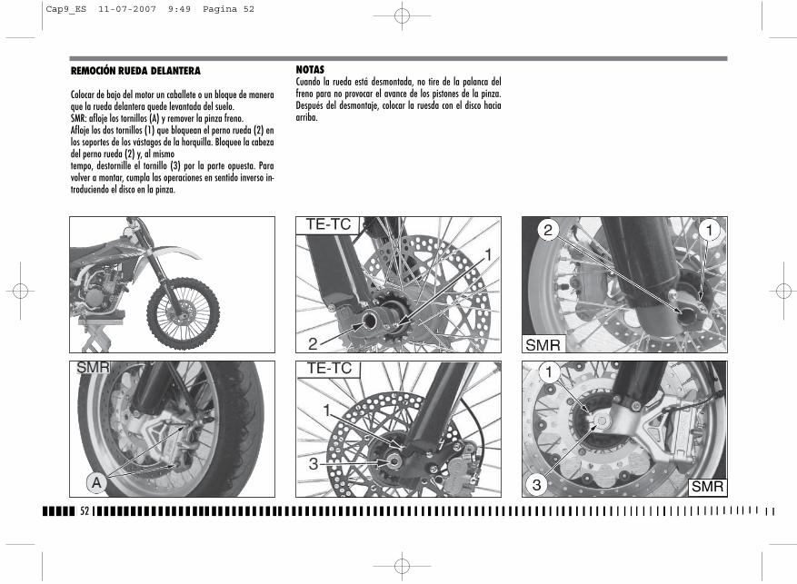
NOTASCuando la rueda está desmontada, no tire de la palanca delfreno para no provocar el avance de los pistones de la pinza.Después del desmontaje, colocar la ruesda con el disco haciaarriba.
52
REMOCIÓN RUEDA DELANTERA
Colocar de bajo del motor un caballete o un bloque de maneraque la rueda delantera quede levantada del suelo.SMR: afloje los tornillos (A) y remover la pinza freno.Afloje los dos tornillos (1) que bloquean el perno rueda (2) enlos soportes de los vástagos de la horquilla. Bloquee la cabezadel perno rueda (2) y, al mismotempo, destornille el tornillo (3) por la parte opuesta. Paravolver a montar, cumpla las operaciones en sentido inverso in-troduciendo el disco en la pinza.
SMR
Cap9_ES 11-07-2007 9:49 Pagina 52
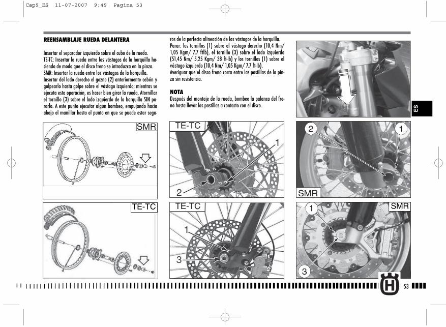
ros de la perfecta alineación de los vástagos de la horquilla.Parar: los tornillos (1) sobre el vástago derecho (10,4 Nm/1,05 Kgm/ 7.7 ftlb), el tornillo (3) sobre el lado izquierdo(51,45 Nm/ 5,25 Kgm/ 38 ft-lb) y los tornillos (1) sobre elvástago izquierdo (10,4 Nm/ 1,05 Kgm/ 7.7 ft-lb).Averiguar que el disco freno corra entre las pastillas de la pin-za sin resistencia.
NOTADespués del montaje de la rueda, bombee la palanca del fre-no hasta llevar las pastillas a contacto con el disco.
53
REENSAMBLAJE RUEDA DELANTERA
Insertar el separador izquierdo sobre el cubo de la rueda.TE-TC: Insertar la rueda entre los vástagos de la horquilla ha-ciendo de modo que el disco freno se introduzca en la pinza.SMR: Insertar la rueda entre los vástagos de la horquilla.Insertar del lado derecho el gozne (2) anteriormente cebón ygolpearlo hasta golpe sobre el vástago izquierdo; mientras seejecuta esta operación, es hacer bien girar la rueda. Atornillarel tornillo (3) sobre el lado izquierdo de la horquilla SIN pa-rarlo. A este punto ejecutar algún bombeo, empujando haciaabajo el manillar hasta el punto en que se puede estar segu-
TE-TC SMR
ES
Cap9_ES 11-07-2007 9:49 Pagina 53
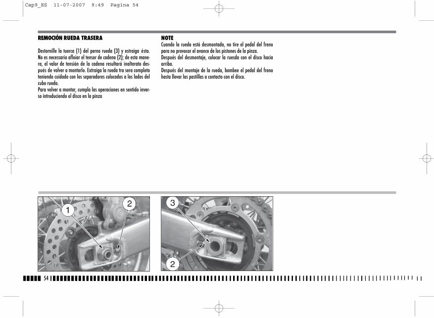
REMOCIÓN RUEDA TRASERA
Destornille la tuerca (1) del perno rueda (3) y estraiga ésto.No es necessario afloiar el tensor de cadena (2); de esta mane-ra, el valor de tensión de la cadena resultará inalterato des-pués de volver a montarlo. Extraiga la rueda tra sera completateniendo cuidado con los separadores colocados a los lados delcubo rueda. Para volver a montar, cumpla las operaciones en sentido inver-so introduciendo el disco en la pinza
NOTECuando la rueda está desmontada, no tire el pedal del frenopara no provocar el avance de los pistones de la pinza.Después del desmontaje, colocar la ruesda con el disco haciaarriba.Después del montaje de la rueda, bombee el pedal del frenohasta llevar las pastillas a contacto con el disco.
54
Cap9_ES 11-07-2007 9:49 Pagina 54

4. Pinza delantera5. Disco delantero6. Tanque aceite freno trasero7. Tubería trasera8. Pinza trasera9. Disco trasero10. Bomba del freno trasero11. Pedal de mando del freno trasero
FRENOS
Los principale componentes de las dos instalaciones son: la bomba del freno con su relativa palanca (delante) o pedal(detrás), la tubería, la pinza y el disco.
LEYENDA1. Palanca de mando del freno delantero2. Bomba del freno delantero con tanque aceite (TE, TC)2. Bomba del freno delantero (SMR)2A. Tanque aceite (SMR)3. Tubería delantera
55
ES
NEUMÁTICOS
Presten siempre atención a la presión de los neumáticos, lamisma debe ser la indicada en la página 9. Cambiar el neumático en el caso que el desgaste supere lo indi-cado en la tabla de abajo.
ALTURA MíNIMADE LA BANDA DE RODAMIENTO
DELANTERO 3 mm (TC,TE); 2 mm (SMR)
TRASERO 3 mm (TC,TE); 2 mm (SMR)
TE-TC
SMR
Cap9_ES 12-07-2007 15:56 Pagina 55
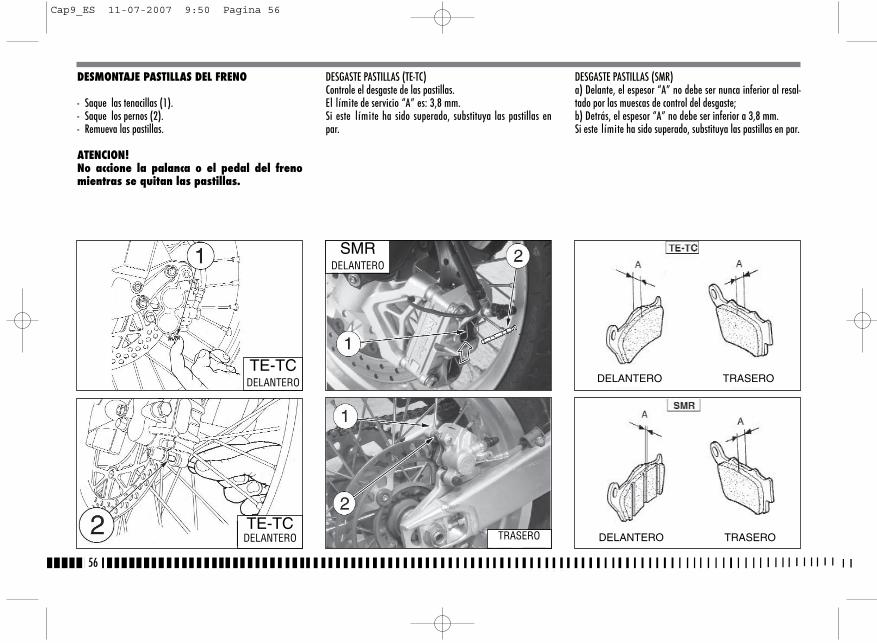
DESMONTAJE PASTILLAS DEL FRENO
- Saque las tenacillas (1).- Saque los pernos (2).- Remueva las pastillas.
ATENCION!No accione la palanca o el pedal del frenomientras se quitan las pastillas.
DESGASTE PASTILLAS (TE-TC)Controle el desgaste de las pastillas.El límite de servicio “A” es: 3,8 mm.Si este límite ha sido superado, substituya las pastillas enpar.
DESGASTE PASTILLAS (SMR)a) Delante, el espesor “A” no debe ser nunca inferior al resal-tado por las muescas de control del desgaste;b) Detrás, el espesor “A” no debe ser inferior a 3,8 mm.Si este límite ha sido superado, substituya las pastillas en par.
56
TE-TCDELANTERO
SMRDELANTERO
TRASERO
DELANTERO TRASERO
DELANTERO TRASEROTE-TC
DELANTERO
Cap9_ES 11-07-2007 9:50 Pagina 56
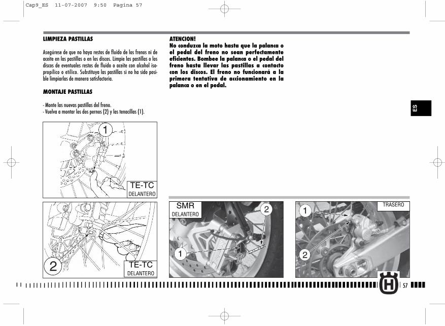
LIMPIEZA PASTILLAS
Asegúrese de que no haya restos de fluido de los frenos ni deaceite en las pastillas o en los discos. Limpie las pastillas o losdiscos de eventuales restos de fluido o aceite con alcohol iso-propílico o etílico. Substituya las pastillas si no ha sido posi-ble limpiarlas de manera satisfactoria.
MONTAJE PASTILLAS
- Monte las nuevas pastillas del freno.- Vuelva a montar los dos pernos (2) y las tenacillas (1).
ATENCION!No conduzca la moto hasta que la palanca oel pedal del freno no sean perfectamenteeficientes. Bombee la palanca o el pedal delfreno hasta llevar las pastillas a contactocon los discos. El freno no funcionará a laprimera tentativa de accionamiento en lapalanca o en el pedal.
57
TE-TCDELANTERO
SMRDELANTERO
TRASERO
ES
TE-TCDELANTERO
Cap9_ES 11-07-2007 9:50 Pagina 57
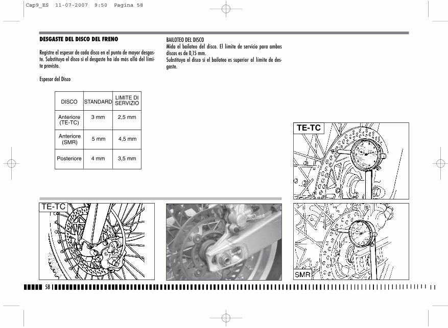
DESGASTE DEL DISCO DEL FRENO
Registre el espesor de cada disco en el punto de mayor desgas-te. Substituya el disco si el desgaste ha ido más allá del lími-te previsto.
Espesor del Disco
BAILOTEO DEL DISCOMida el bailoteo del disco. El límite de servicio para ambosdiscos es de 0,15 mm.Substituya el disco si el bailoteo es superior al límite de des-gaste.
58
Anteriore(SMR)
5 mm 4,5 mm
Anteriore 3 mm 2,5 mm(TE-TC)
DISCO STANDARDLIMITE DISERVIZIO
Posteriore 4 mm 3,5 mm
TE-TC
TE-TC
Cap9_ES 11-07-2007 9:50 Pagina 58
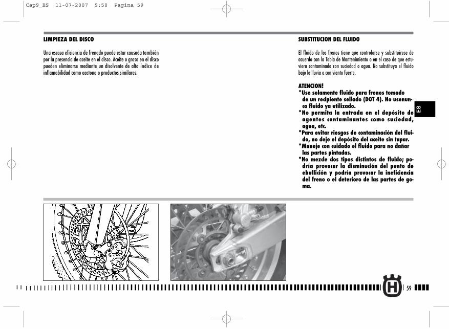
LIMPIEZA DEL DISCO
Una escasa eficiencia de frenado puede estar causada tambiénpor la presencia de aceite en el disco. Aceite o grasa en el discopueden eliminarse mediante un disolvente de alto índice deinflamabilidad como acetona o productos similares.
SUBSTITUCION DEL FLUIDO
El fluido de los frenos tiene que controlarse y substituirese deacuerdo con la Tabla de Mantenimiento o en el caso de que estu-viera contaminado con suciedad o agua. No substituya el fluidobajo la lluvia o con viento fuerte.
ATENCION!*Use solamente fluido para frenos tomado
de un recipiente sellado (DOT 4). No usenun-ca fluido ya utilizado.
*No permita la entrada en el depósito deagentes contaminantes como suciedad,agua, etc.
*Para evitar riesgos de contaminación del flui-do, no deje el depósito del aceite sin tapar.
*Maneje con cuidado el fluido para no dañar las partes pintadas.
*No mezcle dos tipos distintos de fluido; po-dría provocar la disminución del punto deebullición y podría provocar la ineficienciadel freno o el deterioro de las partes de go-ma.
59
ES
Cap9_ES 11-07-2007 9:50 Pagina 59
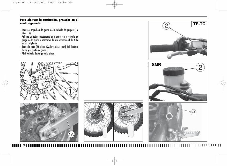
Para efectuar la sustitución, proceder en elmodo siguiente:
- Saque el capuchón de goma de la válvula de purga (1) obien (1A).
- Aplique un tubito trasparente de plástico en la válvula depurga de la pinza y introduzca la otra extremidad del tuboen un recipiente.
- Saque la tapa (2) o bien (2A:llave de 21 mm) del depósitofluido y el quelle de goma.
- Abrir válvula de purga en la pinza.
60
TE-TC
SMR
Cap9_ES 11-07-2007 9:50 Pagina 60
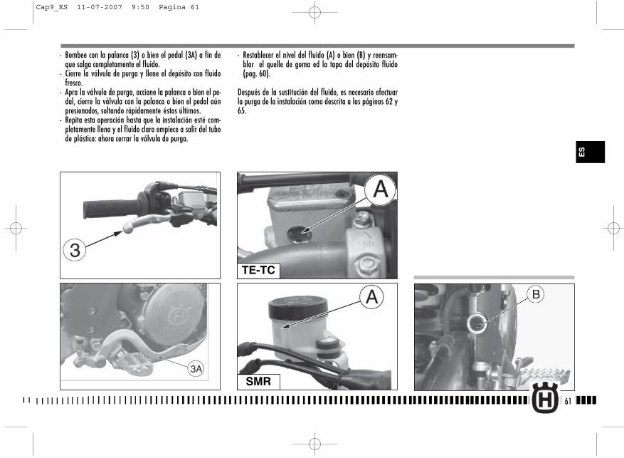
- Restablecer el nivel del fluido (A) o bien (B) y reensam-blar el quelle de goma ed la tapa del depósito fluido(pag. 60).
Después de la sustitución del fluido, es necesario efectuarla purga de la instalación como descrita a las páginas 62 y65.
61
- Bombee con la palanca (3) o bien el pedal (3A) a fin deque salga completamente el fluido.
- Cierre la válvula de purga y llene el depósito con fluidofresco.
- Apra la válvula de purga, accione la palanca o bien el pe-dal, cierre la válvula con la palanca o bien el pedal aúnpresionados, soltando rápidamente éstos últimos.
- Repita esta operación hasta que la instalación esté com-pletamente llena y el fluido claro empiece a salir del tubode plástico: ahora cerrar la válvula de purga.
TE-TC
SMR
ES
Cap9_ES 11-07-2007 9:50 Pagina 61

62
PURGA INSTALACIÓN FRENANTE DELANTERA (TE, TC)La purga de la instalación frenante tiene que efectuarse des-pues la sustitución del fluido o bvien cuando, a causa de lapresenzia de aire en el circuito, la carrera de la palanca se vul-ve larga y elástica.Proceder en el modo siguiente.
- Saque el capuchón de goma de la válvula de purga (1).- Aplique un tubito trasparente de plástico en la válvula de
purga y introduzca la otra extremidad del tubo en un reci-piente (asegurarse de que durante la operción la extremi-dad del tubito estéconstantemente inmergida en el fluido).
ATENCION!El fluido de los frenos ataca rápidamente lassuperficies pintadas, por tanto todo resto demismo tiene que ser quitado inmediatamente.* El fluido de los frenos puede causar irritacio-nes. Evite el contacto con la piel y los ojos. Encaso de contacto, limpie completamente la par-te afectada y, en el caso de que se tratara delos ojos, llame a un médico.
Controle periódicamente los manguitos de co-nexión (ver “Ficha de mantenimento periódi-co): si en los tubos (A) y (B) se presentaran se-ñales de usura o grietas, es conveniente subti-tuirlos.
Cap9_ES 11-07-2007 9:50 Pagina 62
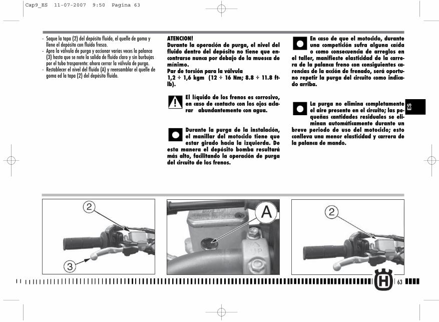
- Saque la tapa (2) del depósito fluido, el quelle de goma y llene el depósito con fluido fresco.
- Apra la válvula de purga y accionar varias veces la palanca (3) hasta que se note la salida de fluido claro y sin burbujas por el tubo trasparente: ahora cerrar la válvula de purga.
- Restablecer el nivel del fluido (A) y reensamblar el quelle degoma ed la tapa (2) del depósito fluido.
ATENCION!Durante la operación de purga, el nivel delfluido dentro del depósito no tiene que en-contrarse nunca por debajo de la muesca demínimo.Par de torsión para la válvula1,2 ÷ 1,6 kgm (12 ÷ 16 Nm; 8.8 ÷ 11.8 ft-lb).
El líquido de los frenos es corrosivo,en caso de contacto con los ojos acla-rar abundantemente con agua.
Durante la purga de la instalación,el manillar del motociclo tiene queestar girado hacia la izquierda. De
esta manera el depósito bomba resultarámás alto, facilitando la operación de purgadel circuito de los frenos.
En caso de que el motociclo, duranteuna competición sufra alguna caídao como consecuencia de arreglos en
el taller, manifieste elasticidad de la carre-ra de la palanca freno con consiguientes ca-rencias de la acción de frenado, será oportu-no repetir la purga del circuito como indica-do arriba.
La purga no elimina completamenteel aire presente en el circuito; las pe-queñas cantidades residuales se eli-minan automáticamente durante un
breve periodo de uso del motociclo; estoconlleva una menor elasticidad y carrera dela palanca de mando.
63
ES
Cap9_ES 11-07-2007 9:50 Pagina 63
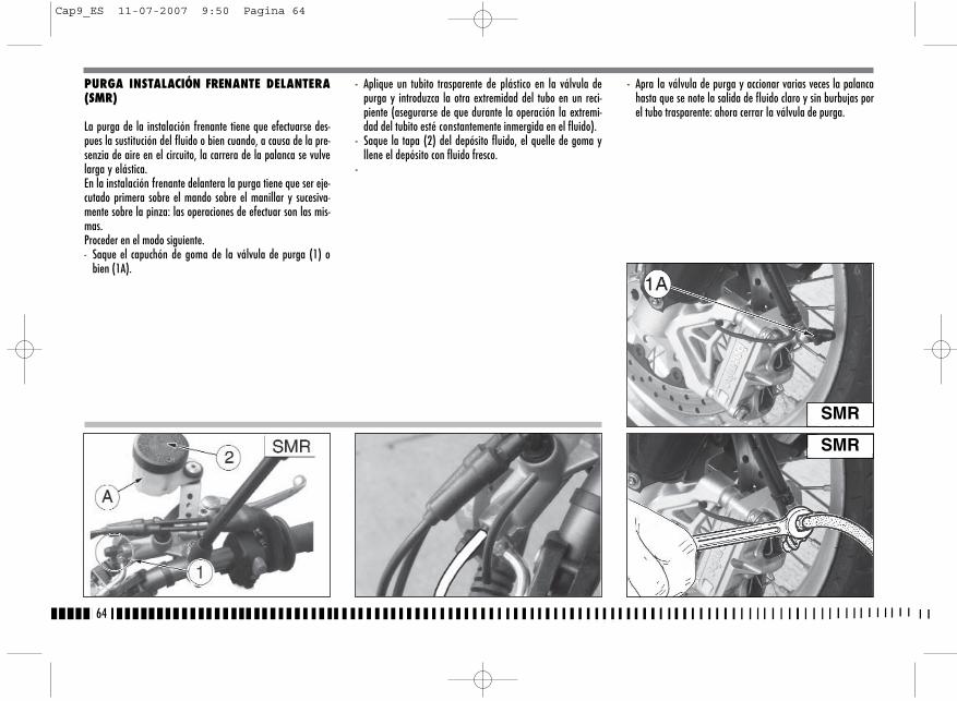
PURGA INSTALACIÓN FRENANTE DELANTERA(SMR)
La purga de la instalación frenante tiene que efectuarse des-pues la sustitución del fluido o bien cuando, a causa de la pre-senzia de aire en el circuito, la carrera de la palanca se vulvelarga y elástica.En la instalación frenante delantera la purga tiene que ser eje-cutado primera sobre el mando sobre el manillar y sucesiva-mente sobre la pinza: las operaciones de efectuar son las mis-mas. Proceder en el modo siguiente.- Saque el capuchón de goma de la válvula de purga (1) o
bien (1A).
- Aplique un tubito trasparente de plástico en la válvula depurga y introduzca la otra extremidad del tubo en un reci-piente (asegurarse de que durante la operación la extremi-dad del tubito esté constantemente inmergida en el fluido).
- Saque la tapa (2) del depósito fluido, el quelle de goma yllene el depósito con fluido fresco.
-
- Apra la válvula de purga y accionar varias veces la palancahasta que se note la salida de fluido claro y sin burbujas porel tubo trasparente: ahora cerrar la válvula de purga.
64
SMR
SMR
Cap9_ES 11-07-2007 9:50 Pagina 64
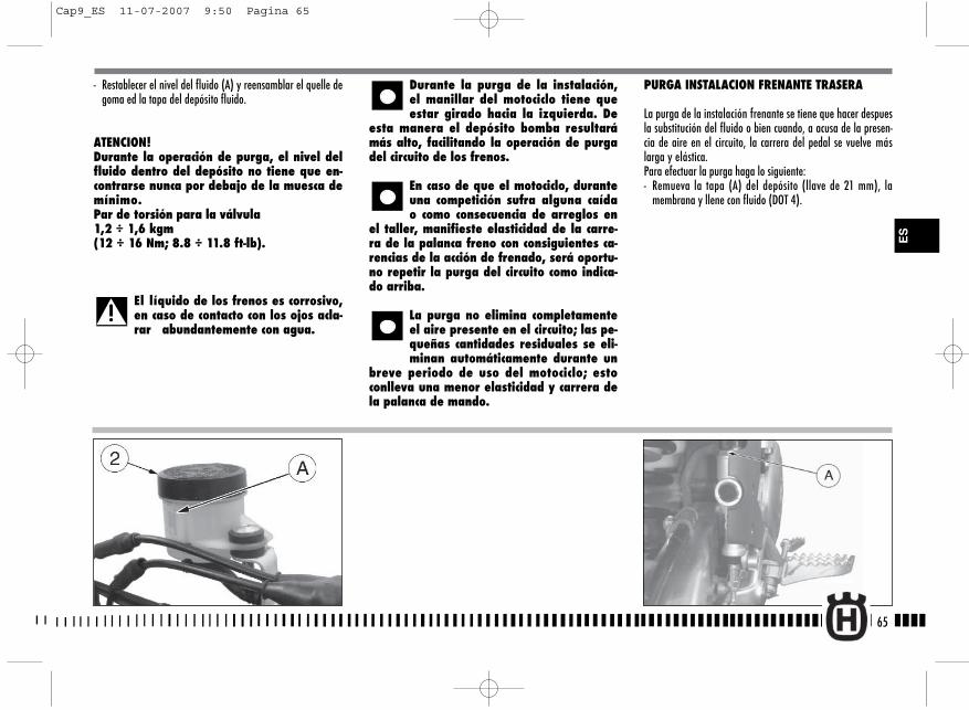
PURGA INSTALACION FRENANTE TRASERA
La purga de la instalación frenante se tiene que hacer despuesla substitución del fluido o bien cuando, a acusa de la presen-cia de aire en el circuito, la carrera del pedal se vuelve máslarga y elástica.Para efectuar la purga haga lo siguiente:- Remueva la tapa (A) del depósito (llave de 21 mm), la
membrana y llene con fluido (DOT 4).
- Restablecer el nivel del fluido (A) y reensamblar el quelle degoma ed la tapa del depósito fluido.
ATENCION!Durante la operación de purga, el nivel delfluido dentro del depósito no tiene que en-contrarse nunca por debajo de la muesca demínimo.Par de torsión para la válvula1,2 ÷ 1,6 kgm (12 ÷ 16 Nm; 8.8 ÷ 11.8 ft-lb).
El líquido de los frenos es corrosivo,en caso de contacto con los ojos acla-rar abundantemente con agua.
Durante la purga de la instalación,el manillar del motociclo tiene queestar girado hacia la izquierda. De
esta manera el depósito bomba resultarámás alto, facilitando la operación de purgadel circuito de los frenos.
En caso de que el motociclo, duranteuna competición sufra alguna caídao como consecuencia de arreglos en
el taller, manifieste elasticidad de la carre-ra de la palanca freno con consiguientes ca-rencias de la acción de frenado, será oportu-no repetir la purga del circuito como indica-do arriba.
La purga no elimina completamenteel aire presente en el circuito; las pe-queñas cantidades residuales se eli-minan automáticamente durante un
breve periodo de uso del motociclo; estoconlleva una menor elasticidad y carrera dela palanca de mando.
65
ES
Cap9_ES 11-07-2007 9:50 Pagina 65
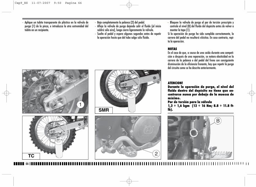
- Aplique un tubito transparente de plástico en la válvula depurga (1) de la pinza, e introduzca la otra extremidad deltubito en un recipiente.
- Baje completamente la palanca (2) del pedal.- Afloje la válvula de purga dejando salir el fluido (al inicio
saldrá sólo aire), luego cierre ligeramente la válvula.- Suelte el pedal y espere algunos segundos antes de repetir
la operación hasta que del tubo salga sólo fluido.
- Bloquee la válvula de purga al par de torsión prescripto ycontrole el nivel (B) del fluido del depósito antes de volver amontar la tapa (1).
Si la operación de purga ha sido cumplida correctamente, lacarrera del pedal no resultará elástica. En caso contrario, repi-ta la operación.
NOTASEn el caso de que, a causa de una caída durante una competi-ción o después de una reparación, se notara elasticidad en lacarrera de la palanca o del pedal del freno con consiguientedisminución de la eficiencia frenante, hay que repetir la purgadel circuito como se ha descrito anteriormente.
ATENCION!Durante la operación de purga, el nivel delfluido dentro del depósito no tiene que en-contrarse nunca por debajo de la muesca demínimo.Par de torsión para la válvula1,2 ÷ 1,6 kgm (12 ÷ 16 Nm; 8.8 ÷ 11.8 ft-lb).
66
TC
SMR
Cap9_ES 11-07-2007 9:50 Pagina 66
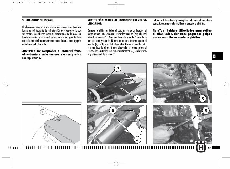
SILENCIADOR DE ESCAPE
El silenciador reduce la ruidosidad de escape pero tambiénforma parte integrante de la instalación de escape por lo quesus condiciones influyen sobre las prestaciones de la moto. Unfuerte aumento de la ruidosidad del escape es signo de dete-rioro del material fonoabsorbente colocado en el tubo agujere-ado dentro del silenciador.
ADVERTENCIA: comprobar el material fono-absorbente a cada carrera y a ser precisoreemplazarlo.
SUSTITUCIÓN MATERIAL FONOABSORBENTE SI-LENCIADOR
Remover el sillín tras haber girado, en sentido antihorario, elperno trasero (1) de fijación, retirar los tornillos (2) y el panellateral izquierdo (3). Con una llave de tubo de 8 mm de laparte externa y una de 10 mm en la parte interna, quitar eltornillo (4) de fijación del silenciador. Quitar el muelle (5) ycon una llave de tubo de 8 mm, el tornillo (8); luego extraer elsilenciador. Quitar los seis remaches traseros (6), la abrazade-ra y el terminal de escape (7).
Extraer el tubo interior y reemplazar el material fonoabsor-bente. Reensamblar el panel lateral derecho y el sillín.
Nota*: si hubiera dificultades para retirarel silenciador, dar unos pequeños golpescon un martillo en caucho o plástico.
67
2
3
4
5
86
7
ES
Cap9_ES 11-07-2007 9:50 Pagina 67
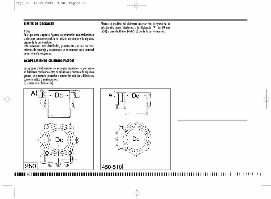
LIMITE DE DESGASTE
NOTAEn el presente capítulo figuran las principales comprobacionesa efectuar cuando se realiza la revisión del motor y de algunaspiezas de la parte ciclista.Informaciones más detalladas, juntamente con los procedi-mientos de montaje y desmontaje se encuentran en el manualde servicio de Husqvarna.
ACOPLAMIENTO CILINDRO-PISTON
Los grupos cilindro-pistón se entregan acoplados; si por acasose hubieran cambiado entre sí cilindros y pistones de algunosgrupos, es necesario proceder a anotar los relativos diámetroscomo se indica a continuación:a) - Diámetro cilindro (Dc)
Efectúe la medida del diámetro interior con la ayuda de unmicrómetro para interiores, a la distancia “A“ de 20 mm(250) o bien de 10 mm (450-510) desde la parte superior.
68
Cap9_ES 11-07-2007 9:50 Pagina 68
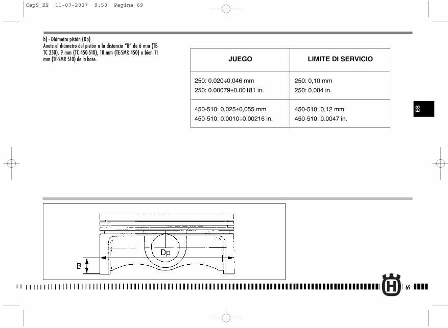
b) - Diámetro pistón (Dp)Anote el diámetro del pistón a la distancia “B” de 6 mm (TE-TC 250), 9 mm (TC 450-510), 10 mm (TE-SMR 450) o bien 11mm (TE-SMR 510) de la base.
69
ES
250: 0,020÷0,046 mm
250: 0.00079÷0.00181 in.
450-510: 0,025÷0,055 mm
450-510: 0.0010÷0.00216 in.
LIMITE DI SERVICIOJUEGO
250: 0,10 mm
250: 0.004 in.
450-510: 0,12 mm
450-510: 0.0047 in.
Cap9_ES 11-07-2007 9:50 Pagina 69
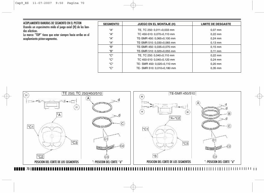
ACOPLAMIENTO RANURAS DE SEGMENTO EN EL PISTONUsando un espesímetro mida el juego axial (H) de las ban-das elásticas.La marca “TOP” tiene que estar siempre hacia arriba en elacoplamiento piston-segmentos.
70
POSICION DEL CORTE DE LOS SEGMENTOS *: POSICION DEL CORTE “d” POSICION DEL CORTE DE LOS SEGMENTOS *: POSICION DEL CORTE “d”
SEGMENTO JUEGO EN EL MONTAJE (H) LIMITE DE DESGASTE
"A" TE, TC 250: 0,011÷0,033 mm 0,07 mm
"A" TC 450-510: 0,070÷0,110 mm 0,22 mm
"A" TE-SMR 450: 0,065÷0,100 mm 0,24 mm
"A" TE-SMR 510: 0,030÷0,065 mm 0,13 mm
"B" TE-SMR 450: 0,035÷0,070 mm 0,15 mm
"B" TE-SMR 510: 0,020÷0,055 mm 0,11 mm
"C" TE, TC 250: 0,040÷0,110 mm 0,22 mm
"C" TC 450-510: 0,040÷0,120 mm 0,24 mm
"C" TE- SMR 450: 0,020÷0,110 mm 0,20 mm
"C" TE- SMR 510: 0,010÷0,180 mm 0,35 mm
Cap9_ES 11-07-2007 9:50 Pagina 70
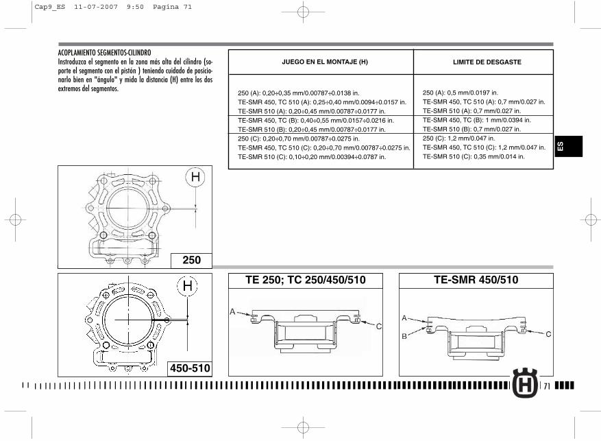
ACOPLAMIENTO SEGMENTOS-CILINDROInstroduzca el segmento en la zona más alta del cilindro (so-porte el segmento con el pistón ) teniendo cuidado de posicio-narlo bien en "ángulo" y mida la distancia (H) entre los dosextremos del segmentos.
71
250
TE 250; TC 250/450/510 TE-SMR 450/510
450-510
LIMITE DE DESGASTEJUEGO EN EL MONTAJE (H)
250 (A): 0,20÷0,35 mm/0.00787÷0.0138 in.TE-SMR 450, TC 510 (A): 0,25÷0,40 mm/0.0094÷0.0157 in.TE-SMR 510 (A): 0,20÷0,45 mm/0.00787÷0.0177 in.TE-SMR 450, TC (B): 0,40÷0,55 mm/0.0157÷0.0216 in.TE-SMR 510 (B): 0,20÷0,45 mm/0.00787÷0.0177 in.250 (C): 0,20÷0,70 mm/0.00787÷0.0275 in.TE-SMR 450, TC 510 (C): 0,20÷0,70 mm/0.00787÷0.0275 in.TE-SMR 510 (C): 0,10÷0,20 mm/0.00394÷0.0787 in.
250 (A): 0,5 mm/0.0197 in.TE-SMR 450, TC 510 (A): 0,7 mm/0.027 in.TE-SMR 510 (A): 0,7 mm/0.027 in.TE-SMR 450, TC (B): 1 mm/0.0394 in.TE-SMR 510 (B): 0,7 mm/0.027 in.250 (C): 1,2 mm/0.047 in.TE-SMR 450, TC 510 (C): 1,2 mm/0.047 in.TE-SMR 510 (C): 0,35 mm/0.014 in.
ES
Cap9_ES 11-07-2007 9:50 Pagina 71
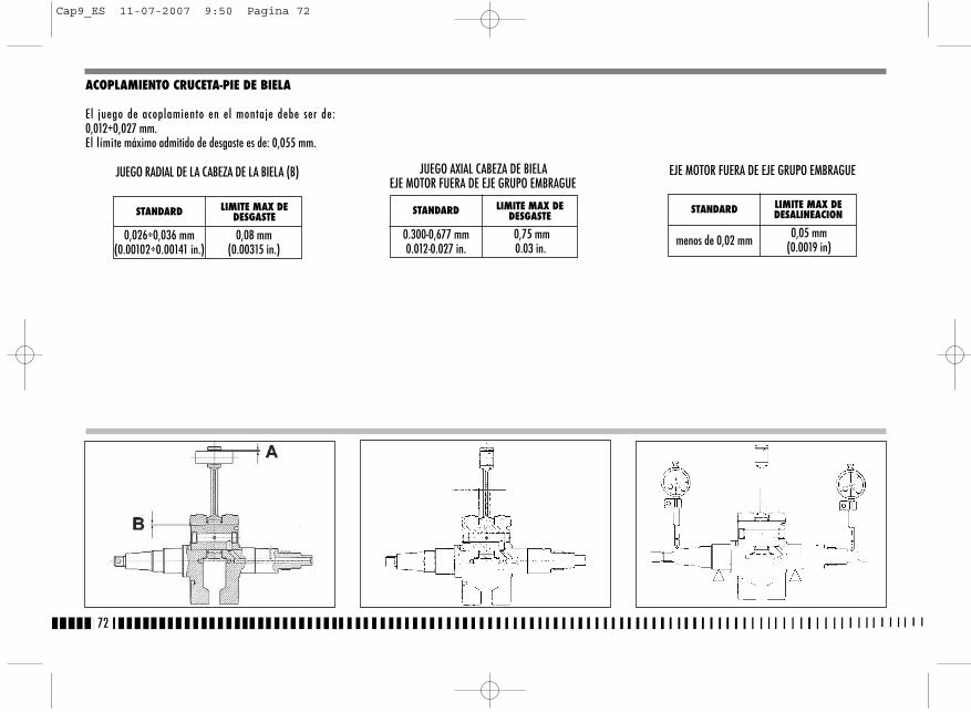
ACOPLAMIENTO CRUCETA-PIE DE BIELA
El juego de acoplamiento en el montaje debe ser de:0,012÷0,027 mm.El límite máximo admitido de desgaste es de: 0,055 mm.
72
STANDARD LIMITE MAX DEDESGASTE
0,026÷0,036 mm(0.00102÷0.00141 in.)
0,08 mm(0.00315 in.)
JUEGO RADIAL DE LA CABEZA DE LA BIELA (B) JUEGO AXIAL CABEZA DE BIELAEJE MOTOR FUERA DE EJE GRUPO EMBRAGUE
STANDARD LIMITE MAX DEDESGASTE
0.300-0,677 mm0.012-0.027 in.
0,75 mm0.03 in.
EJE MOTOR FUERA DE EJE GRUPO EMBRAGUE
STANDARD LIMITE MAX DEDESALINEACION
menos de 0,02 mm 0,05 mm(0.0019 in)
Cap9_ES 11-07-2007 9:50 Pagina 72
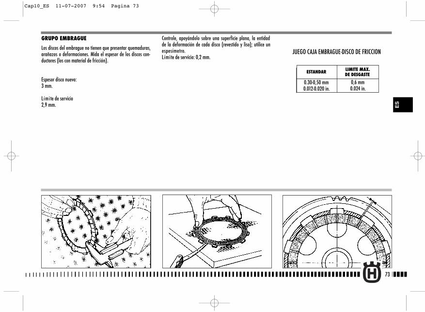
73
ES
GRUPO EMBRAGUE
Los discos del embrague no tienen que presentar quemaduras,arañazos o deformaciones. Mida el espesor de los discos con-ductores (los con material de fricción).
Espesor disco nuevo:3 mm.
Límite de servicio2,9 mm.
Controle, apoyándolo sobre una superficie plana, la entidadde la deformación de cada disco (revestido y liso); utilice unespesímetro.L ímite de servicio: 0,2 mm.
ESTANDAR LIMITE MAX.DE DESGASTE
0.30-0,50 mm0.012-0.020 in.
0,6 mm0.024 in.
JUEGO CAJA EMBRAGUE-DISCO DE FRICCION
Cap10_ES 11-07-2007 9:54 Pagina 73
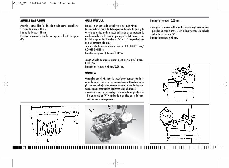
MUELLE EMBRAGUE
Medir la longitud libre “L” de cada muelle usando un calibre.“L” muelle nueva = 41 mmLímite de desgaste: 39 mmReemplazar cualquier muelle que supere el límite de opera-ción.
GUÍA-VÁLVULA
Proceder a un esmerado control visual del guía-válvula.Para detectar el desgaste del acoplamiento entre la guía y laválvula es preciso medir el juego utilizando un comparador decuadrante colocado de manera que se pueda determinar el va-lor del juego en las direcciones “x” e “y” perpendicularesuna con respecto a la otra.Juego válvula de aspiración nueva: 0,008-0,035 mm/0.00031-0.00138 in.L ímite de desgaste: 0,05 mm/ 0.002 in.
Juego válvula de escape nueva: 0,018-0,045 mm/ 0.0007-0.00177 in.L ímite de desgaste: 0,08 mm/ 0.003 in.
VÁLVULA
Comprobar que el vástago y la superficie de contacto con la se-de de la válvula estén en buenas condiciones. No deben haberpicados, resquebrajaduras, deformaciones o rastros de desgaste.Seguidamente efectuar las siguientes comprobaciones:- verificar el desvío del vástago de la válvula apoyándola so-
bre un encaje en “V” y midiendo la entidad de la deforma-ción usando un comparador.
L ímite de operación: 0,05 mm.
- Averiguar la concentricidad de la culata arreglando un com-parador en ángulo recto con la culata y girando la válvulasobre de un cotejo a “V”.
L ímite de servicio: 0,03 mm.
74
Cap10_ES 11-07-2007 9:54 Pagina 74
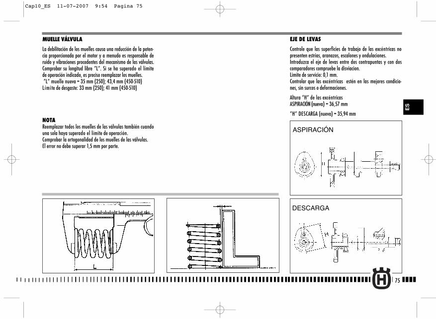
EJE DE LEVAS
Controle que las superficies de trabajo de las excéntricas nopresenten estrias, aranazos, escalones y ondulaciones.Introduzca el eje de levas entre dos contrapuntas y con doscomparadores compruebe la disviacion.Limite de servicio: 0,1 mm.Controlar que las excéntricas estén en las mejores condicio-nes, sin surcos o deformaciones.
Altura “H” de las excéntricasASPIRACIÓN (nueva) = 36,57 mm
“H” DESCARGA (nueva) = 35,94 mm
MUELLE VÁLVULA
La debilitación de los muelles causa una reducción de la poten-cia proporcionada por el motor y a menudo es responsable deruido y vibraciones procedentes del mecanismo de las válvulas.Comprobar su longitud libre “L”. Si se ha superado el límitede operación indicado, es preciso reemplazar los muelles.“L” muelle nueva = 35 mm (250); 43,4 mm (450-510) Límite de desgaste: 33 mm (250); 41 mm (450-510)
NOTAReemplazar todos los muelles de las válvulas también cuandouna sola haya superado el límite de operación.Comprobar la ortogonalidad de los muelles de las válvulas.El error no debe superar 1,5 mm por parte.
75
ASPIRACIÓN
DESCARGA
ES
Cap10_ES 11-07-2007 9:54 Pagina 75
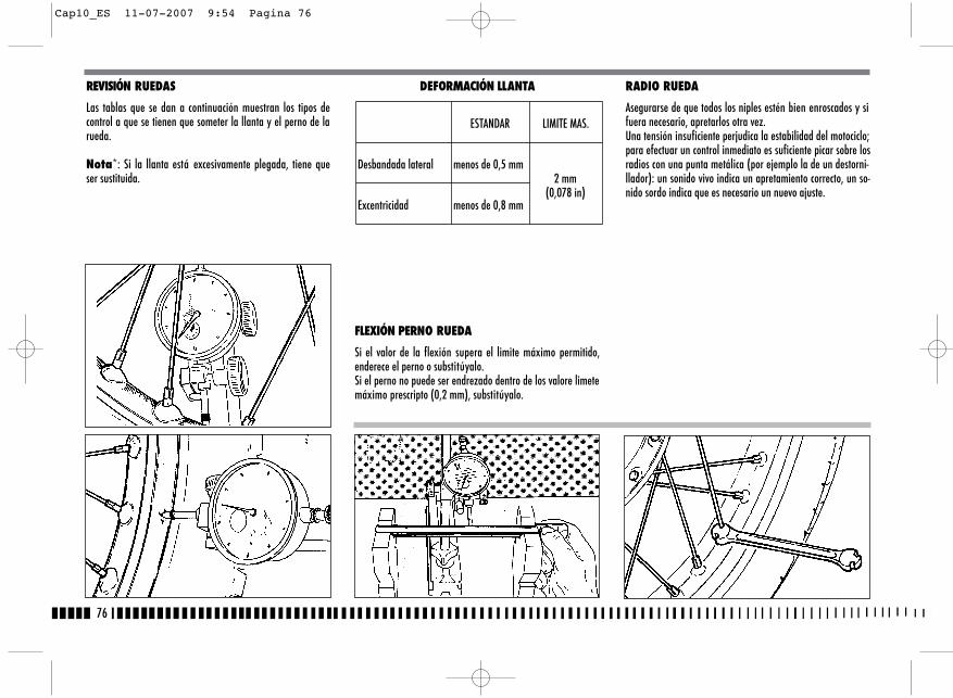
76
REVISIÓN RUEDAS
Las tablas que se dan a continuación muestran los tipos decontrol a que se tienen que someter la llanta y el perno de larueda.
Nota*: Si la llanta está excesivamente plegada, tiene queser sustituida.
DEFORMACIÓN LLANTA
FLEXIÓN PERNO RUEDA
Si el valor de la flexión supera el limite máximo permitido,enderece el perno o substitúyalo.Si el perno no puede ser endrezado dentro de los valore limetemáximo prescripto (0,2 mm), substitúyalo.
RADIO RUEDA
Asegurarse de que todos los niples estén bien enroscados y sifuera necesario, apretarlos otra vez. Una tensión insuficiente perjudica la estabilidad del motociclo;para efectuar un control inmediato es suficiente picar sobre losradios con una punta metálica (por ejemplo la de un destorni-llador): un sonido vivo indica un apretamiento correcto, un so-nido sordo indica que es necesario un nuevo ajuste.
ESTANDAR LIMITE MAS.
Desbandada lateral menos de 0,5 mm2 mm
(0,078 in)Excentricidad menos de 0,8 mm
Cap10_ES 11-07-2007 9:54 Pagina 76
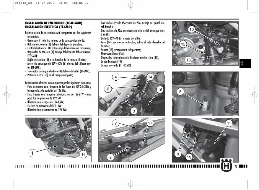
9
11
- Dos fusibles (9) de 15A y uno de 20A, debajo del panel late-ral derecho;
- Dos fusibles de 20A, montados en el relé del arranque eléc-trico (8);
- Batteria 12V-6Ah (7) debajo del sillin.- Relè (14) por electroventilador, sobre el lado derecho del
bastidor;- Sensor (15) temperatura refrigerante;- Electroventilador (16);- Dispositivo intermitencia indicadores de dirección (17);- Sonda Lambda (18);- Sensor de caída (11) (SMR);
77
ES
INSTALACIÓN DE ENCENDIDO (TC-TE-SMR)INSTALACIÓN ELÉCTRICA (TE-SMR)
La instalación de encendido está compuesta por los siguienteselementos:
- Generador (1) dentro la tapa de la bancada izquierda;- Bobina electrónica (2) debajo del deposito gasolina;- Central electrónica C.D.I. (3) debajo del deposito del carburante;- Regulador de tensión (4) debajo del deposito del carburante;
(TE-SMR);- Bujía encendido (5) a la derecha de la cabeza cilindro;- Motor de arranque de 12V-450W (6) detrás del cilindro mo-
tor (TE-SMR);- Teleruptor arranque electrico (8) debajo del sillin (TE-SMR);- Potenciómetro (10) en el cuerpo mariposa;
La instalación electrica está compuesta por los siguientes elementos:- Faro delantero con lámpara de los luces de 12V-35/35W y
lámpara luz de posición de 12V-3W;- Faro trasero con lámpara señalizacción de 12V-21W y lám-
para luz de posición de 12V-5W;- Illuminación testigos de 12V-1,2W;- Flechas de dirección de12V-10W;- Illuminación instrumento de 12V-2W;
1 6
4
2 16
14
3
7 17
8
5
15
18
10
13
Cap11a_ES 11-07-2007 10:09 Pagina 77
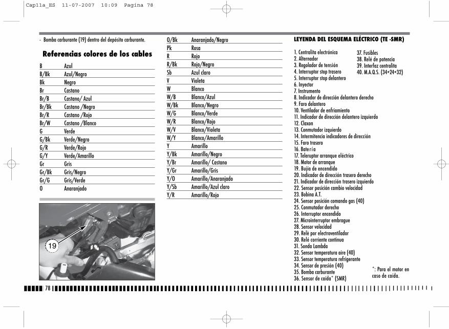
- Bomba carburante (19) dentro del depósito carburante.
Referencias colores de los cablesB AzulB/Bk Azul/NegroBk NegroBr CastanoBr/B Castano/ AzulBr/Bk Castano /NegroBr/R Castano /RojoBr/W Castano /BlancoG VerdeG/Bk Verde/NegroG/R Verde/RojoG/Y Verde/AmarilloGr GrisGr/Bk Gris/NegroGr/G Gris/VerdeO Anaranjado
O/Bk Anaranjado/NegroPk RosaR RojoR/Bk Rojo/NegroSb Azul claroV VioletaW BlancoW/B Blanco/AzulW/Bk Blanco/NegroW/G Blanco/VerdeW/R Blanco/RojoW/V Blanco/VioletaW/Y Blanco/AmarilloY AmarilloY/Bk Amarillo/NegroY/Br Amarillo/ CastanoY/Gr Amarillo/GrisY/O Amarillo/AnaranjadoY/Sb Amarillo/Azul claroY/R Amarillo/Rojo
78
19
LEYENDA DEL ESQUEMA ELÉCTRICO (TE -SMR)
1. Centralita electrónica2. Alternador3. Regolador de tensión4. Interruptor stop trasero5. Interruptor stop delantero6. Inyector7. Instrumento8. Indicador de dirección delantero derecho9. Faro delantero 10. Ventilador de enfriamiento 11. Indicador de dirección delantero izquierdo12. Claxon13. Conmutador izquierdo14. Intermitencia indicadores de dirección15. Faro trasero16. Bate r í a17. Teleruptor arranque eléctrico18. Motor de arranque19. Bujía de encendido20. Indicador de dirección trasero derecho21. Indicador de dirección trasero izquierdo22. Sensor posición cambio velocidad23. Bobina A.T.24. Sensor posición comando gas (40)25. Conmutador derecho26. Interruptor encendido27. Microinterruptor embrague28. Sensor velocidad29. Relè por electroventilador30. Relé corriente continua31. Sonda Lambda 32. Sensor temperatura aire (40)33. Sensor temperatura refrigerante34. Sensor de presión (40)35. Bomba carburante36. Sensor de caída* (SMR)
37. Fusibles38. Relé de potencia39. Interfaz centralita40. M.A.Q.S. (34+24+32)
*: Para el motor encaso de caída.
Cap11a_ES 11-07-2007 10:09 Pagina 78
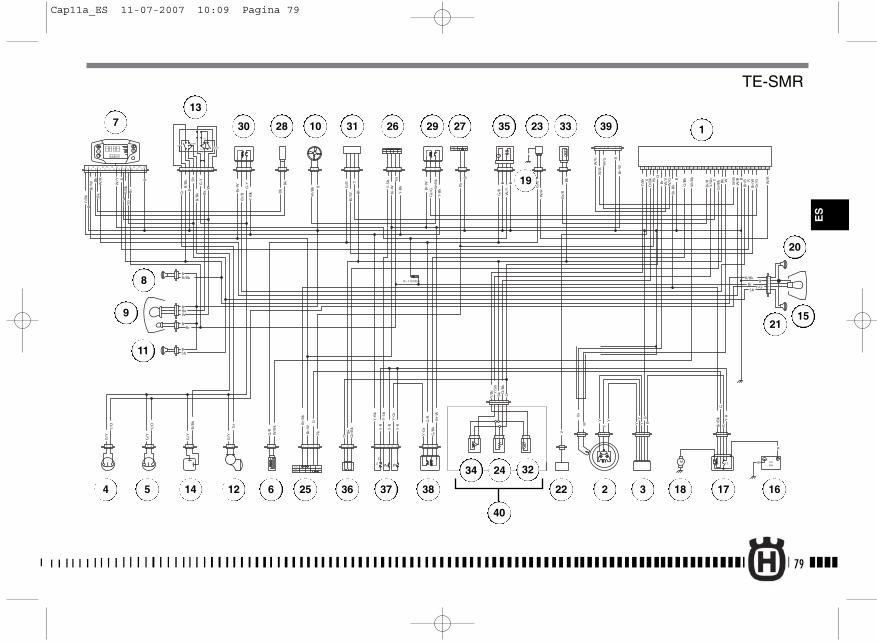
1
2
PASSING
HI
Lo
Pos
TURNHORN
R= 110 Ohm
+-
f
+-
+ -
B
W/G
W/V
Bk
B
B
Y-R
YY
Y
YY
Y
V
Bk
G/R
G/B
k
O
O
B
B
B
Bk
B
B
Pk
R
R
Y-R
Y-R
Y-B
k
Y-B
k
Y-B
k
Y-S
b
Br
G/R
G/R
G/R
V
Pk
Pk
Br/
Bk
Br/
W
Br/
W W/R
W/R
W/B
k
W/B
k
G/B
k
Bk
Bk
Bk
O
Gr/
Bk
Gr/
Bk
Y/B
r Y/S
b
Y/B
r
Y/S
b
Br/
R
Br/
R
O/B
k
O/B
k
W/B
k
W/B
k
Gr/
G
W/B
W/V
W/G
W/B
G-Y B
B
B
B
B
B
Y-R
Y-G
r
Y-S
b
Br
BBr
Y-B
k
Y-G
r
Br-
W
Br-
W
Br-
W
Br-
W
Br-
W
Br-
W
Br-
Bk
Br-
Bk
Br W
Gr/
G
Br/
B
Br/
B
W/R
W/YBk
G/Y
G/Y
G/Y
G/Y
Gr
Gr
B/B
kB
/Bk
Sb
Sb
Sb
R/B
k
R/Bk R/Bk
Bk
Bk
W
W
Y/O
Y/O
Y/O
G/R
G-Y Y RY
W
Br
G
G
B
Y/B
k
W/R
W/Y
W
Bk
Bk
Br
B
RR
/Bk
Sb
Br/
W
1 2 3 4 5 6 7 9 10 11 13 14 15 16 18 19 20 22 25 26 27 29 30 31 32 33 34
M
M 15 12V
R
9Ah
21 3 4
21
ONOFF
1 2
31 2 31 2
OFF
ON
8 12 17 21 23 24 2821
OFF
21 1 2 3 4 1 2 3 4 1 2 3 4 21
1 2 3 421 21 3 1 2 3 4 5 6
1 2 3 4 5
1
21 21 3 1 2 3 4 5 21 3 4
1 2 3 4
1 2 3 4 5 6
21 21
21
34
56
21
21
21
21
3
21212121
1 2 3 41 2 3 4 5 6 7 8 9
1 2 3 4
RUN
START
M P
DF
12
34
56
78
910 12
1114 16
13 15 2526
1718
1920
2122
2324
79
ES
1
2 34 5
7
6
8
9
10
11
12
13
14
15
161718
19
20
21
22
23
24
40
25
26 2728 29
3234
36
35 3330 31
37 38
39
TE-SMR
Cap11a_ES 11-07-2007 10:09 Pagina 79
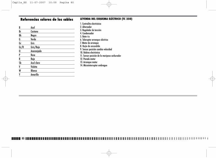
80
Referencias colores de los cables
B AzulBr CastanoBk NegroG VerdeGr GrisGr/R Gris/RojoO AnaranjadoP RosaR RojoSb Azul claroV VioletaW BlancoY Amarillo
LEYENDA DEL ESQUEMA ELÉCTRICO (TC 250)
1. Centralita electrónica2. Alternador3. Regolador de tensión4. Condensador5. Bate r í a6. Teleruptor arranque eléctrico7. Motor de arranque8. Bujía de encendido9. Sensor posición cambio velocidad10. Bobina electrónica11. Sensor posición de la mariposa carburador12. Parada motor13. Arranque motor14. Microinterruptor embrague
Cap11a_ES 11-07-2007 10:09 Pagina 80
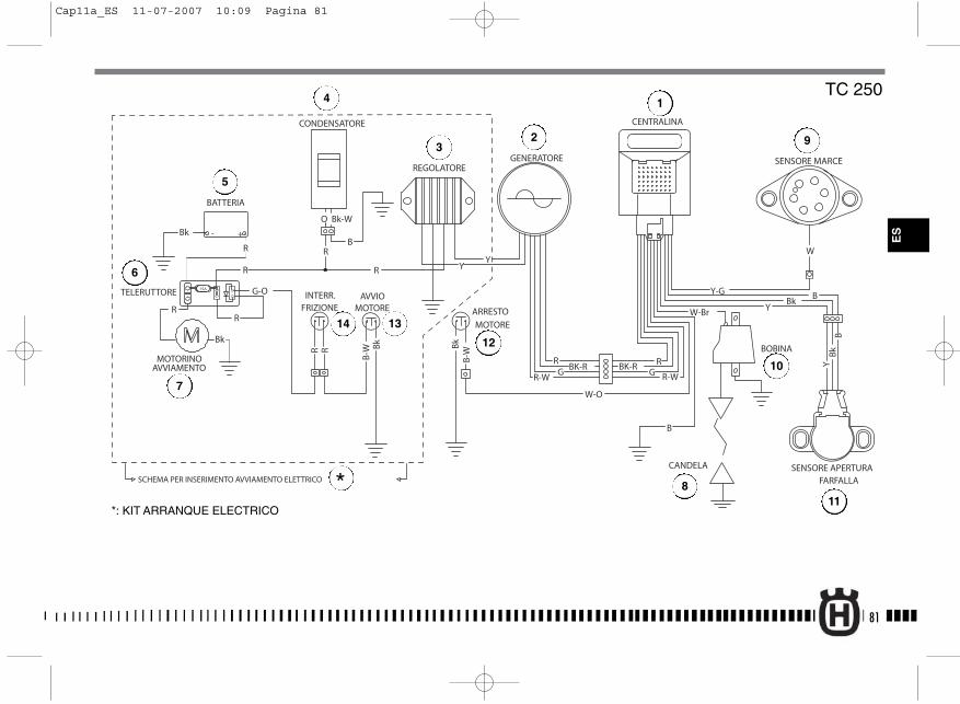
81
R-WGBK-R
R-W
W-Br
GRBK-R
R
CANDELA
BOBINA
GENERATORE
W-O
SENSORE MARCE
SENSORE APERTURAFARFALLA
REGOLATORE
CONDENSATORE
- +
15A
ARRESTO
MOTORE
BATTERIA
TELERUTTORE
MOTORINOAVVIAMENTO
Y-G BBk
Y
B
R Bk
B-W
W
BB
kY
CENTRALINA
Bk - +
R
G-O
R
R
O
R
Bk-W
B
YYR
R
Bk
AVVIOMOTORE
B-W
Bk
R
INTERR.FRIZIONE
SCHEMA PER INSERIMENTO AVVIAMENTO ELETTRICO
TC 250
ES
*: KIT ARRANQUE ELECTRICO
1
23
4
5
7
6
8
9
10
11
12
14 13
*
Cap11a_ES 11-07-2007 10:09 Pagina 81

82
Legenda colore cavi
B AzulBr CastanoBk NegroG VerdeGr GrisGr/R Gris/RojoO AnaranjadoP RosaR RojoSb Azul claroV VioletaW BlancoY Amarillo
LEYENDA DEL ESQUEMA ELÉCTRICO (TC 450-510)
1. Centralita electrónica2. Alternador3. Regolador de tensión4. Condensador5. Bate r í a6. Teleruptor arranque eléctrico7. Motor de arranque8. Bujía de encendido9. Sensor posición cambio velocidad10. Bobina electrónica11. Sensor posición de la mariposa carburador12. Parada motor13. Arranque motor14. Microinterruptor embrague
Cap11a_ES 11-07-2007 10:09 Pagina 82
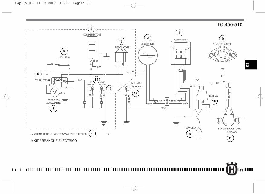
83
R-WGBK-R
R-W
W-Br
GRBK-R
R
CANDELA
BOBINA
GENERATORE
W-O
SENSORE MARCE
SENSORE APERTURAFARFALLA
REGOLATORE
- +
15A
ARRESTO
MOTORE
AVVIO
MOTORE
BATTERIA
TELERUTTORE
MOTORINOAVVIAMENTO
Y-G BBk
Y
B
B-W
Bk
Bk
B-W
W
BB
kY
CENTRALINA
Bk - +
R
G-O
R
R
O
R
Bk-W
B
WYR
R
BkRR
INT.
FRIZIONE
CONDENSATORE
SCHEMA PER INSERIMENTO AVVIAMENTO ELETTRICO
TC 450-510
*: KIT ARRANQUE ELECTRICO
1
23
4
5
7
6
8
9
10
11
12
14
13
*
ES
Cap11a_ES 11-07-2007 10:09 Pagina 83
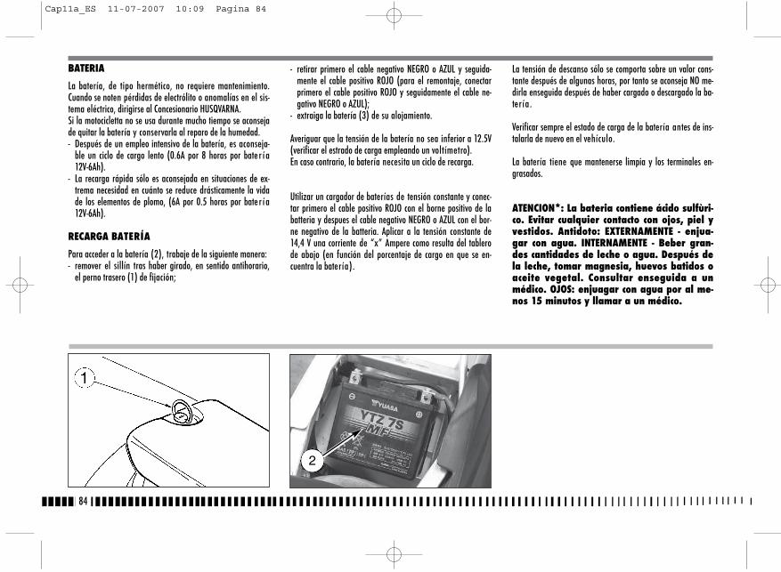
- retirar primero el cable negativo NEGRO o AZUL y seguida-mente el cable positivo ROJO (para el remontaje, conectarprimero el cable positivo ROJO y seguidamente el cable ne-gativo NEGRO o AZUL);
- extraiga la batería (3) de su alojamiento.
Averiguar que la tensión de la batería no sea inferior a 12.5V(verificar el estrado de carga empleando un voltímetro). En caso contrario, la batería necesita un ciclo de recarga.
Utilizar un cargador de baterías de tensión constante y conec-tar primero el cable positivo ROJO con el borne positivo de labatteria y despues el cable negativo NEGRO o AZUL con el bor-ne negativo de la batteria. Aplicar a la tensión constante de14,4 V una corriente de “x” Ampere como resulta del tablerode abajo (en función del porcentaje de cargo en que se en-cuentra la batería).
BATERIA
La batería, de tipo hermético, no requiere mantenimiento.Cuando se noten pérdidas de electrólito o anomalías en el sis-tema eléctrico, dirigirse al Concesionario HUSQVARNA.Si la motocicletta no se usa durante mucho tiempo se aconsejade quitar la batería y conservarla al reparo de la humedad.- Después de un empleo intensivo de la batería, es aconseja-
ble un ciclo de cargo lento (0.6A por 8 horas por bate r í a12V-6Ah).
- La recarga rápida sólo es aconsejada en situaciones de ex-trema necesidad en cuánto se reduce drásticamente la vidade los elementos de plomo, (6A por 0.5 horas por bate r í a12V-6Ah).
RECARGA BATERÍA
Para acceder a la batería (2), trabaje de la siguiente manera:- remover el sillín tras haber girado, en sentido antihorario,
el perno trasero (1) de fijación;
La tensión de descanso sólo se comporta sobre un valor cons-tante después de algunas horas, por tanto se aconseja NO me-dirla enseguida después de haber cargado o descargado la ba-ter ía.
Verificar sempre el estado de carga de la batería antes de ins-talarla de nuevo en el vehículo.
La batería tiene que mantenerse limpia y los terminales en-grasados.
ATENCION*: La bateria contiene ácido sulfùri-co. Evitar cualquier contacto con ojos, piel yvestidos. Antidoto: EXTERNAMENTE - enjua-gar con agua. INTERNAMENTE - Beber gran-des cantidades de leche o agua. Después dela leche, tomar magnesia, huevos batidos oaceite vegetal. Consultar enseguida a unmédico. OJOS: enjuagar con agua por al me-nos 15 minutos y llamar a un médico.
84
2
Cap11a_ES 11-07-2007 10:09 Pagina 84
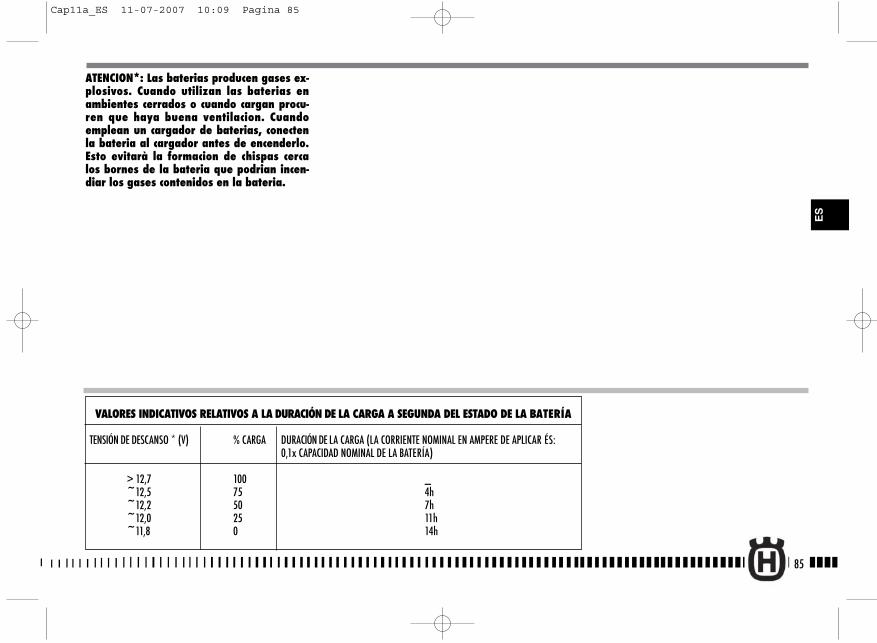
85
ES
VALORES INDICATIVOS RELATIVOS A LA DURACIÓN DE LA CARGA A SEGUNDA DEL ESTADO DE LA BATERÍA
TENSIÓN DE DESCANSO * (V) % CARGA DURACIÓN DE LA CARGA (LA CORRIENTE NOMINAL EN AMPERE DE APLICAR ÉS: 0,1x CAPACIDAD NOMINAL DE LA BATERÍA)
> 12,7 100 _~12,5 75 4h~12,2 50 7h~12,0 25 11h~11,8 0 14h
ATENCION*: Las baterias producen gases ex-plosivos. Cuando utilizan las baterias enambientes cerrados o cuando cargan procu-ren que haya buena ventilacion. Cuandoemplean un cargador de baterias, conectenla bateria al cargador antes de encenderlo.Esto evitarà la formacion de chispas cercalos bornes de la bateria que podrian incen-diar los gases contenidos en la bateria.
Cap11a_ES 11-07-2007 10:09 Pagina 85
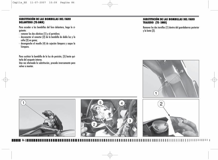
SUBSTITUCIÓN DE LAS BOMBILLAS DEL FAROTRASERO (TE- SMR)
Remover los dos tornillos (1) dentro del guardabarros posteriory la lente (2).
86
SUBSTITUCIÓN DE LAS BOMBILLAS DEL FARODELANTERO (TE-SMR)
Para acceder a las bombillas del faro delantero, haga lo si-guiente:- remover los dos elásticos (1) y el portafaro;- desconectar el conector (2) de la bombilla de doble luz y la
cofia (3) en goma;- desenganche el muelle (4) de sujeción lámpara y saque la
lámpara.
Para sustituir la bombilla de la luz de posición, (5) basta qui-tarla del casquete interno.Una vez efectuada la substitución, proceda inversamente paravolver a montar.
5 4
23
Cap11a_ES 11-07-2007 10:09 Pagina 86
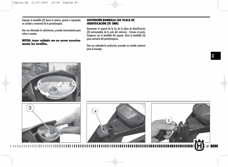
5
Empujar la bombilla (3) hacia el interior, girarla a izquierdasen sentido y removerla de la portalámpara.
Una vez efectuada la substitución, proceda inversamente paravolver a montar.
NOTAS: tener cuidado con no cerrar excesiva-mente los tornillos.
SUSTITUCIÓN BOMBILLA LUZ PLACA DEIDENTIFICACIÓN (TE- SMR)
Desmontar el soporte de la luz de la placa de identificación(4) extrayéndola de la cola del vehículo. Extraer el porta-lámparas con la bombilla del soporte. Girar la bombilla (5)para extraerla del portalámparas.
Una vez realizada la sustitución, proceder en sentido contrariopara el montaje.
87
ES
4
Cap11a_ES 11-07-2007 10:09 Pagina 87
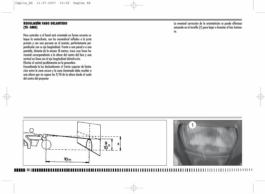
REGULACIÓN FARO DELANTERO(TE- SMR)
Para controlar si el fanal está orientado en forma correcta co-loque la motocilceta, con los neumáticol inflados a la justapresión y con una persona en el asiento, perfectamente per-pendicular son su eje longitudinal. Frente a una pared o a unapantalla, distante de la misma 10 metros, trace una línea ho-rizontal correspondiente a la altura del centro del faro y unavertical en línea con el eje longitudinal delvehículo.Efectúe el control posiblemente en la penumbra.Encendiendo la luz deslumbrante el límite superior de limita-ción entre la zona oscura y la zona iluminada debe resultar auna altura que no supere los 9/10 de la altura desde el suelodel centro del proyector
La eventual corrección de la orientatición se puede effectuaractuando en el tornillo (1) para bajar o levantar el haz lumino-so.
88
Cap11a_ES 11-07-2007 10:09 Pagina 88
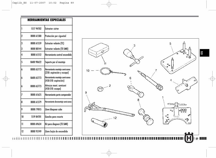
89
ES
HERRAMIENTAS ESPECIALES
1 1517 94702 Extractor cárter
2 8000 A1580 Protección por cigueñal
3 8000 A1559
3 8000 B0144
Extractor volante (TC)
Extractor volante (TE-SMR)
4 8000 A1512 Herramienta control encendido
5 8A00 90622 Soporte por el montaje
6 8000 A5773
6 8A00 A5773
6 8000 A5773
Herramienta montaje semi-conos(250: aspiración y escape)
Herramienta montaje semi-conos(450-510: aspiración)
Attrezzo mont. semiconi(450-510: escape)
7 8000 A1625 Herramienta porta comparador
8 8000 A1579 Herramienta desmontaje semi-conos
9 8000 79015 Llave bloquear cubo
10 1519 84701 Gancho para resorte
11 8000 A9634 Kit para diagnosi (TE-SMR)
12 8000 95749 Llave bujía de encendido
Cap11b_ES 11-07-2007 10:02 Pagina 89
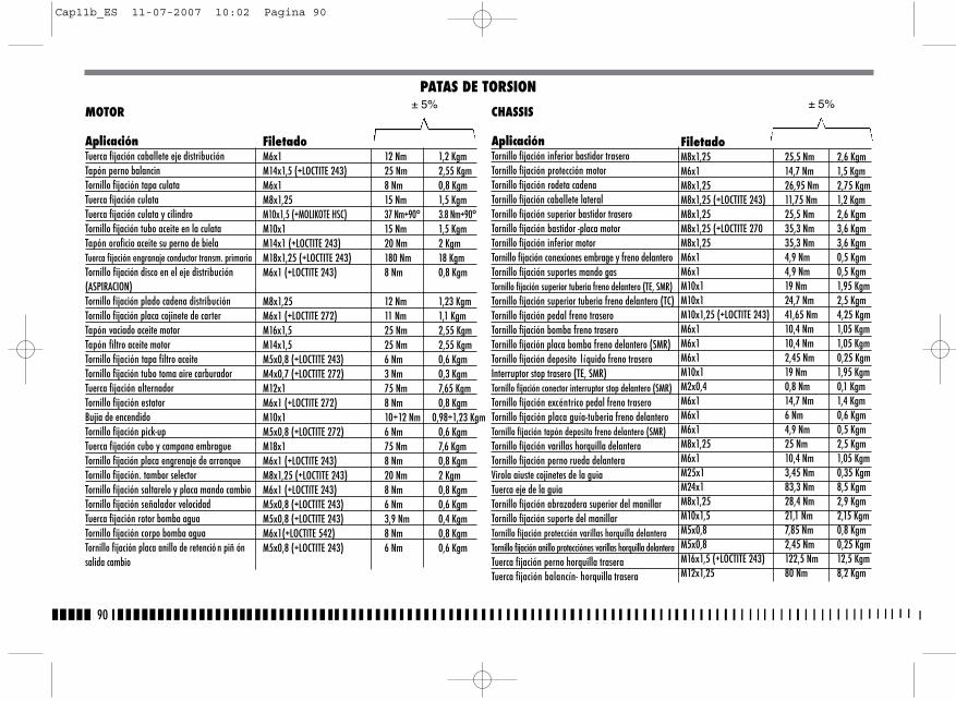
90
MOTOR
AplicaciónTuerca fijación caballete eje distribuciónTapón perno balancinTornillo fijación tapa culataTuerca fijación culataTuerca fijación culata y cilindroTornillo fijación tubo aceite en la culataTapón oroficio aceite su perno de bielaTuerca fijación engranaje conductor transm. primariaTornillo fijación disco en el eje distribución(ASPIRACION)Tornillo fijación plado cadena distribuciónTornillo fijación placa cojinete de carterTapón vaciado aceite motorTapón filtro aceite motorTornillo fijación tapa filtro aceiteTornillo fijación tubo toma aire carburadorTuerca fijación alternadorTornillo fijación estatorBujia de encendidoTornillo fijación pick-upTuerca fijación cubo y campana embragueTornillo fijación placa engrenaje de arranqueTornillo fijación. tambor selectorTornillo fijación saltarelo y placa mando cambioTornillo fijación señalador velocidadTuerca fijación rotor bomba aguaTornillo fijación corpo bomba aguaTornillo fijación placa anillo de retenció n piñ ónsalida cambio
MOTEUR
FiletadoM6x1 12 Nm 1,2 KgmM14x1,5 (+LOCTITE 243) 25 Nm 2,55 KgmM6x1 8 Nm 0,8 KgmM8x1,25 15 Nm 1,5 KgmM10x1,5 (+MOLIKOTE HSC) 37 Nm+90° 3.8 Nm+90°M10x1 15 Nm 1,5 KgmM14x1 (+LOCTITE 243) 20 Nm 2 KgmM18x1,25 (+LOCTITE 243) 180 Nm 18 KgmM6x1 (+LOCTITE 243) 8 Nm 0,8 Kgm
M8x1,25 12 Nm 1,23 KgmM6x1 (+LOCTITE 272) 11 Nm 1,1 KgmM16x1,5 25 Nm 2,55 KgmM14x1,5 25 Nm 2,55 KgmM5x0,8 (+LOCTITE 243) 6 Nm 0,6 KgmM4x0,7 (+LOCTITE 272) 3 Nm 0,3 KgmM12x1 75 Nm 7,65 KgmM6x1 (+LOCTITE 272) 8 Nm 0,8 KgmM10x1 10÷12 Nm 0,98÷1,23 KgmM5x0,8 (+LOCTITE 272) 6 Nm 0,6 KgmM18x1 75 Nm 7,6 KgmM6x1 (+LOCTITE 243) 8 Nm 0,8 KgmM8x1,25 (+LOCTITE 243) 20 Nm 2 KgmM6x1 (+LOCTITE 243) 8 Nm 0,8 KgmM5x0,8 (+LOCTITE 243) 6 Nm 0,6 KgmM5x0,8 (+LOCTITE 243) 3,9 Nm 0,4 KgmM6x1(+LOCTITE 542) 8 Nm 0,8 KgmM5x0,8 (+LOCTITE 243) 6 Nm 0,6 Kgm
PATAS DE TORSION± 5%
CHASSIS
AplicaciónTornillo fijación inferior bastidor traseroTornillo fijación protección motorTornillo fijación rodeta cadenaTornillo fijación caballete lateralTornillo fijación superior bastidor traseroTornillo fijación bastidor -placa motorTornillo fijación inferior motorTornillo fijación conexiones embrage y freno delanteroTornillo fijación suportes mando gasTornillo fijación superior tuberia freno delantero (TE, SMR)Tornillo fijación superior tuberia freno delantero (TC)Tornillo fijación pedal freno traseroTornillo fijación bomba freno traseroTornillo fijación placa bomba freno delantero (SMR)Tornillo fijación deposito l íquido freno traseroInterruptor stop trasero (TE, SMR)Tornillo fijación conector interruptor stop delantero (SMR)Tornillo fijación excéntrico pedal freno traseroTornillo fijación placa guía-tuberia freno delanteroTornillo fijación tapón deposito freno delantero (SMR)Tornillo fijación varillas horquilla delanteraTornillo fijación perno rueda delanteraVirola aiuste cojinetes de la guiaTuerca eje de la guiaTornillo fijación abrazadera superior del manillarTornillo fijación suporte del manillarTornillo fijación protección varillas horquilla delanteraTornillo fijación anillo protecciónes varillas horquilla delanteraTuerca fijación perno horquilla traseraTuerca fijación balancín- horquilla trasera
FiletadoM8x1,25 25,5 Nm 2,6 KgmM6x1 14,7 Nm 1,5 KgmM8x1,25 26,95 Nm 2,75 KgmM8x1,25 (+LOCTITE 243) 11,75 Nm 1,2 KgmM8x1,25 25,5 Nm 2,6 KgmM8x1,25 (+LOCTITE 270 35,3 Nm 3,6 KgmM8x1,25 35,3 Nm 3,6 KgmM6x1 4,9 Nm 0,5 KgmM6x1 4,9 Nm 0,5 KgmM10x1 19 Nm 1,95 KgmM10x1 24,7 Nm 2,5 KgmM10x1,25 (+LOCTITE 243) 41,65 Nm 4,25 KgmM6x1 10,4 Nm 1,05 KgmM6x1 10,4 Nm 1,05 KgmM6x1 2,45 Nm 0,25 KgmM10x1 19 Nm 1,95 KgmM2x0,4 0,8 Nm 0,1 KgmM6x1 14,7 Nm 1,4 KgmM6x1 6 Nm 0,6 KgmM6x1 4,9 Nm 0,5 KgmM8x1,25 25 Nm 2,5 KgmM6x1 10,4 Nm 1,05 KgmM25x1 3,45 Nm 0,35 KgmM24x1 83,3 Nm 8,5 KgmM8x1,25 28,4 Nm 2,9 KgmM10x1,5 21,1 Nm 2,15 KgmM5x0,8 7,85 Nm 0,8 KgmM5x0,8 2,45 Nm 0,25 KgmM16x1,5 (+LOCTITE 243) 122,5 Nm 12,5 KgmM12x1,25 80 Nm 8,2 Kgm
± 5%
Cap11b_ES 11-07-2007 10:02 Pagina 90
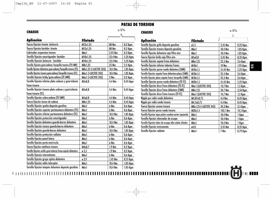
91
ES
CHASSIS
AplicaciónTuerca fijación tirante- balancín Tuerca fijación bastidor -tiranteLubricador suspension traseraTornillo fijación amortiguador- bastidorTornillo fijación balancín - bastidorTornillo fijación guia-cadena- horquilla trasera (TE-SMR)Tornillo fijación delantera guia-cadena/horquilla trasera (TC)Tornillo fijación trasero guia-cadena/horquilla trasera (TC)Tornillo fijación brida/guia-cadena (TE-SMR)Tornillo fijación inferior plato cadena y guía-tuberia freno traseroTornillo fijación trasero plato cadena y guía-tuberia freno trasero (TC)Tornillo fijación cubre-cadena (TE-SMR)Tuerca fijación tensor de cadenaTornillo fijación spoiler-deposito gasolinaTornillo fijación superior portanumero delantero (TC)Tornillo fijación inferior portanumero delantero (TC)Tornillo fijación protección amortiguadorTornillo fijación delantero guarda-barros delanteroTornillo fijación trasero guarda-barros delanteroTornillo fijación guarda-barros delanteroTornillo fijación protección radiatorTornillo fijación panel lateraTornillo fijación porta-matrículaTuerca fijación catafaros traseroTornillo fijación anillo guía-tuberia freno-cúpula delanteraTornillo fijación intermitentesTornillo fijación grupo óptico delanteroTornillo fijación cable teleruptorTornillo fijación tampón delantero deposito gasolina
PATAS DE TORSION
FiletadoM12x1,25 80 Nm 8,2 KgmM12x1,25 80 Nm 8,2 KgmM6x1 2,95 Nm 0,3 KgmM10x1,25 52,4 Nm 5,35 KgmM10x1,25 52,4 Nm 5,35 KgmM8x1,25 25 Nm 2,5 KgmM8x1,25 (+LOCTITE 243) 10,4 Nm 1,05 KgmM6x1 (+LOCTITE 243) 10,4 Nm 1,05 KgmM6x1 (+LOCTITE 243) 2 Nm 0,2 KgmM5x0,8 4,4 Nm 0,45 Kgm
M5x0,8 4,4 Nm 0,45 Kgm
M5x0,8 4,4 Nm 0,45 KgmM8x1,25 4,4 Nm 0,45 KgmM6x1 6 Nm 0,6 KgmM6x1 6 Nm 0,6 KgmM6x1 10,4 Nm 1,05 KgmM6x1 6 Nm 0,6 KgmM6x1 10,4 Nm 1,05 KgmM6x1 6 Nm 0,6 KgmM6x1 10,4 Nm 1,05 KgmM6x1 6 Nm 0,6 KgmM6x1 6 Nm 0,6 KgmM6x1 6 Nm 0,6 KgmM4x0,7 1,9 Nm 0,2 Kgmø 3,5 1,9 Nm 0,2 KgmM6x1 6 Nm 0,6 Kgmø 3,9 1,45 Nm 0,15 KgmM6x1 10,4 Nm 1,05 KgmM6x1 10,4 Nm 1,05 Kgm
± 5%CHASSIS
AplicaciónTornillo fijación grifo deposito gasolinaTornillo fijación trasero deposito gasolinaTornillo fijación delantera caja filtro aireTuerca fijación brida caja filtro aireTornillo fijación zapata freno delanteroTornillo fijación inferior tuberias frenosTornillo fijación perno rueda delantera (SMR) Tornillo fijación zapata freno delantero-placa (SMR)Tornillo fijación placa zapata freno- horquilla (SMR)Tornillo fijación perno rueda delantera (TE-TC) Tornillo fijación disco freno delantero (TE-TC) Tornillo fijación disco freno delantero (SMR) Tornillo fijación disco freno trasero (TE-TC) Nipple por radio rueda delanteraNipple per radio rueda traseraTuerca fijación corona traseraTuerca fijación perno rueda trasera Tornillo fijación tapa piñón cambio-carter izquierdo Tornillo fijación silenciador de escape Tornillo fijación tubos de escape alla culata cilindroTornillo fijación instrumentoTornillo fijación radiator
± 5%
Filetadoø5,5 2,45 Nm 0,25 KgmM6x1 10,4 Nm 1,05 KgmM6x1 10,4 Nm 1,05 KgmM5x0,8 3,45 Nm 0,35 KgmM8x1,25 25,5 Nm 2,6 KgmM10x1 19 Nm 1,95 KgmM10x1,5 51,45 Nm 5,25 KgmM10x1,5 25,5 Nm 2,6 KgmM10x1,5 25,5 Nm 2,6 KgmM20x1,5 51,45 Nm 5,25 KgmM6x1 (LOCTITE 243) 14,7 Nm 1,5 KgmM8x1,25 34,7 Nm 3,54 KgmM6x1 (LOCTITE 243) 14,7 Nm 1,5 KgmM4,07x0,75 4,4 Nm 0,45 KgmM4,5x0,75 4,4 Nm 0,45 KgmM8x1,25 (+LOCTITE 243) 34,3 Nm 3,5 KgmM20x1,5 142,1 Nm 14,5 KgmM6x1 10,4 Nm 1 KgmM6x1 10,4 Nm 1 KgmM6x1 10,4 Nm 1 Kgmø4,8 3,45 Nm 0,35 KgmM6x1 7 Nm 0,72 Kgm
Cap11b_ES 11-07-2007 10:02 Pagina 91
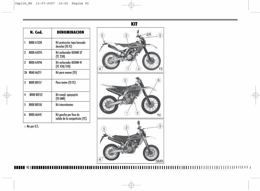
92
N. Cod. DENOMINACION
1 8000 A1320 Kit protección tapa bancadaderecha (TE-TC)
2 8000 A4295 Kit carburador KEIHIN 37(TC 250)
2 8000 A4296 Kit carburador KEIHIN 41(TC 450/510)
2A 80A0 A6211 Kit para manos (TE)
3 8000 B0157 Para motor (TE-TC)
4 8000 B0152 Kit compl. apoyapiés(TE-SMR)
5 8000 B0150 Kit intermitentes
6 8000 A6441 Kit gancho por fase de salida de la competición (TC)
*: No por U.S.
KIT
TC
Cap11b_ES 11-07-2007 10:02 Pagina 92
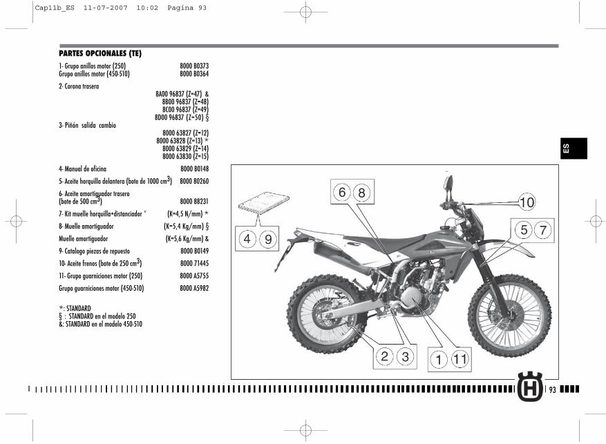
93
ES
PARTES OPCIONALES (TE)
1- Grupo anillos motor (250) 8000 B0373Grupo anillos motor (450-510) 8000 B0364
2- Corona trasera8A00 96837 (Z=47) &
8B00 96837 (Z=48) 8C00 96837 (Z=49)
8D00 96837 (Z=50) §3- Piñón salida cambio
8000 63827 (Z=12) 8000 63828 (Z=13) *8000 63829 (Z=14)
8000 63830 (Z=15)
4- Manual de oficina 8000 B0148
5- Aceite horquilla delantera (bote de 1000 cm3) 8000 80260
6- Aceite amortiguador trasero(bote de 500 cm3) 8000 88231
7- Kit muelle horquilla+distanciador * (K=4,5 N/mm) *8- Muelle amortiguador (K=5,4 Kg/mm) §
Muelle amortiguador (K=5,6 Kg/mm) &
9- Catalogo piezas de repuesto 8000 B0149
10- Aceite frenos (bote de 250 cm3) 8000 71445
11- Grupo guarniciones motor (250) 8000 A5755
Grupo guarniciones motor (450-510) 8000 A5982
*: STANDARD§ : STANDARD en el modelo 250&: STANDARD en el modelo 450-510
Cap11b_ES 11-07-2007 10:02 Pagina 93

94
PARTES OPCIONALES (TC)
1- Grupo anillos motor (250) 8000 A5735Grupo anillos motor (450-510) 8000 A5736
2. Manual de oficina8000 B0148
3. Corona trasera8A00 96837 (Z=47) @
8B00 96837 (Z=48) 8C00 96837 (Z=49)
8D00 96837 (Z=50) §,&
4. Piñón salida cambio8000 63827 (Z=12 ) §
8000 63828 (Z=13) 8000 63829 (Z=14) &,@
8000 63830 (Z=15)
5. Grupo guarniciones motor (250) 8000 A5755
Grupo guarniciones motor (450-510) 8000 A5982
6. Aceite horquilla delantera (bote de 1000 cm3) 8000 80260
8- Kit muelle horquilla+distanciador (K=4,8 N/mm) §(K=5 N/mm) &, @
9- Muelle amortiguador (K=5,4 Kg/mm) §(K=5,6 Kg/mm) &, @
10. Catalogo piezas de repuesto 8000 B0149
11. Aceite frenos (bote de 250 cm3) 8000 71445
12. Kit arranque electrico 8000 B0455
*: STANDARD§ : STANDARD en el modelo 250&: STANDARD en el modelo 450@: STANDARD en el modelo 510
Cap11b_ES 11-07-2007 10:02 Pagina 94

PARTES OPCIONALES (SMR)
1- Grupo anillos motor 8000 B0364
2- Corona trasera8000 A4859 (Z=42) *
8A00 A4859 (Z=43)8B00 A4859 (Z=44)8G00 96837 (Z=45)
3- Piñón salida cambio8000 63829 (Z=14) *
4- Manual de oficina 8000 B0148
5- Aceite horquilla delantera (bote de 1000 cm3) 8000 80260
6- Aceite amortiguador trasero (bote de 500 cm3) 8000 88231
7- Kit muelle horquilla+distanciador(K=5 N/mm) 8000 98803 *
8- Muelle amortiguador(K=6,4 Kg/mm) 8000 98520 *
9- Catalogo piezas de repuesto 8000 B0149
10- Aceite frenos (bote de 250 cm3) 8000 71445
11- Grupo guarniciones motor 8000 A5982
12- Kit arranque a pedal 8000 B0591
*: STANDARD
95
ES
Cap11b_ES 11-07-2007 10:02 Pagina 95
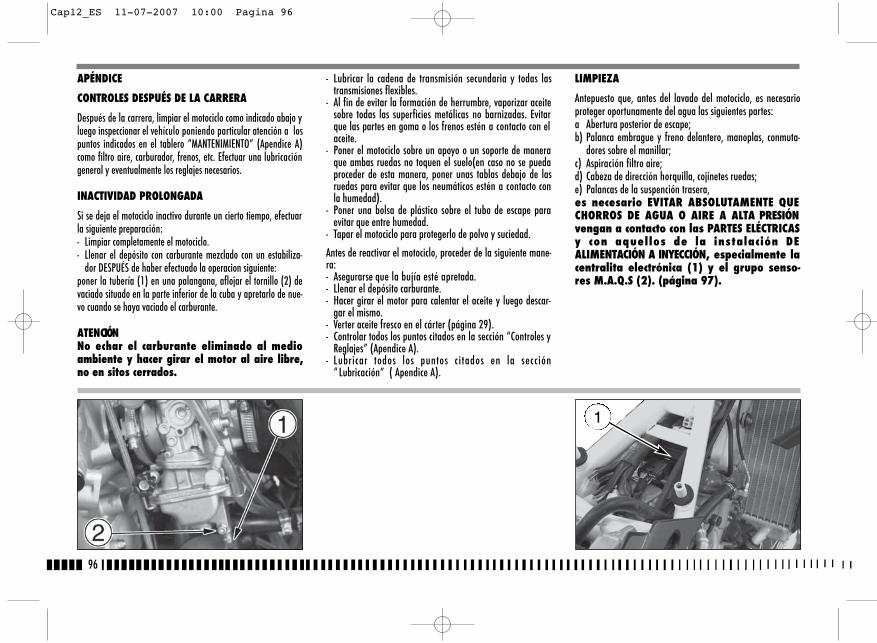
96
- Lubricar la cadena de transmisión secundaria y todas lastransmisiones flexibles.
- Al fin de evitar la formación de herrumbre, vaporizar aceitesobre todas las superficies metálicas no barnizadas. Evitarque las partes en goma o los frenos estén a contacto con elaceite.
- Poner el motociclo sobre un apoyo o un soporte de maneraque ambas ruedas no toquen el suelo(en caso no se puedaproceder de esta manera, poner unas tablas debajo de lasruedas para evitar que los neumáticos estén a contacto conla humedad).
- Poner una bolsa de plástico sobre el tubo de escape paraevitar que entre humedad.
- Tapar el motociclo para protegerlo de polvo y suciedad.
Antes de reactivar el motociclo, proceder de la siguiente mane-ra:- Asegurarse que la bujía esté apretada.- Llenar el depósito carburante.- Hacer girar el motor para calentar el aceite y luego descar-
gar el mismo.- Verter aceite fresco en el cárter (página 29).- Controlar todos los puntos citados en la sección “Controles y
Reglajes” (Apendice A).- Lubricar todos los puntos citados en la sección
“ Lubricación” ( Apendice A).
APÉNDICE
CONTROLES DESPUÉS DE LA CARRERA
Después de la carrera, limpiar el motociclo como indicado abajo yluego inspeccionar el vehículo poniendo particular atención a lospuntos indicados en el tablero “MANTENIMIENTO” (Apendice A)como filtro aire, carburador, frenos, etc. Efectuar una lubricacióngeneral y eventualmente los reglajes necesarios.
INACTIVIDAD PROLONGADA
Si se deja el motociclo inactivo durante un cierto tiempo, efectuarla siguiente preparación:- Limpiar completamente el motociclo.- Llenar el depósito con carburante mezclado con un estabiliza-
dor DESPUÉS de haber efectuado la operacion siguiente:poner la tubería (1) en una palangana, aflojar el tornillo (2) devaciado situado en la parte inferior de la cuba y apretarlo de nue-vo cuando se haya vaciado el carburante.
ATENCIÓNNo echar el carburante eliminado al medioambiente y hacer girar el motor al aire libre,no en sitos cerrados.
LIMPIEZA
Antepuesto que, antes del lavado del motociclo, es necesarioproteger oportunamente del agua las siguientes partes:a Abertura posterior de escape;b) Palanca embrague y freno delantero, manoplas, conmuta-
dores sobre el manillar;c) Aspiración filtro aire;d) Cabeza de dirección horquilla, cojinetes ruedas;e) Palancas de la suspención trasera,es necesario EVITAR ABSOLUTAMENTE QUECHORROS DE AGUA O AIRE A ALTA PRESIÓNvengan a contacto con las PARTES ELÉCTRICASy con aquellos de la instalación DEALIMENTACIÓN A INYECCIÓN, especialmente lacentralita electrónica (1) y el grupo senso-res M.A.Q.S (2). (página 97).
1
Cap12_ES 11-07-2007 10:00 Pagina 96

2)En qué poner atención particularNo vaporizar agua a presión elevada cerca de las siguientes partes:
•Filtro aire•Debajo del depósito carburante. Si el agua entra en la bobina o en
la pipeta bujía, el motor no arrancará y será necesario secar todaslas partes mojadas
•Cabeza de dirección horquilla, cojinetes ruedas.•Palancas de la suspención trasera.
3)Tras el lavado- Remover las bolsas de plástico y librar la abertura de la aspiración
filtro aire.- Lubricar los puntos citados en el Tablero de Manutención (Apendice
A).- Efectuar una breve calefacción del motor- Antes de conducir el motociclo, probar los frenos.
ATENCIÓN *: No lubricar o pasar cera sobre losdiscos del freno para no provocar una pérdidade eficiencia de la instalación de los frenoscon consiguiente riesgo de accidentes. Limpiarel disco con solventes tipo acetona.
A cada desmontaje de los lubrificadores (1) para lubricar loscojínetes de rodillos de las palancas de la suspensión trasera,es necesario también lubricar el cojínete de rodillos (2) delfijado inferior del amortiguador después de haber removidola tuerca (3) y el manguito.
97
ES
1)Preparación para el lavadoAntes de efectuar el lavado, tomar las siguientes precauciones al finde impedir que el agua llegue a contacto con las siguientes partes:•Abertura posterior de la descarga:- Tapar con una bolsa de plástico fijándola con bandas de goma •Palanca fricción y freno anterior, empuñaduras, pulsador parada
motor: - Tapar con una bolsa de plástico•Aspiración filtro aire:- Cerrar la abertura con un cinta o paños limpios
2
Cap12_ES 11-07-2007 10:00 Pagina 97
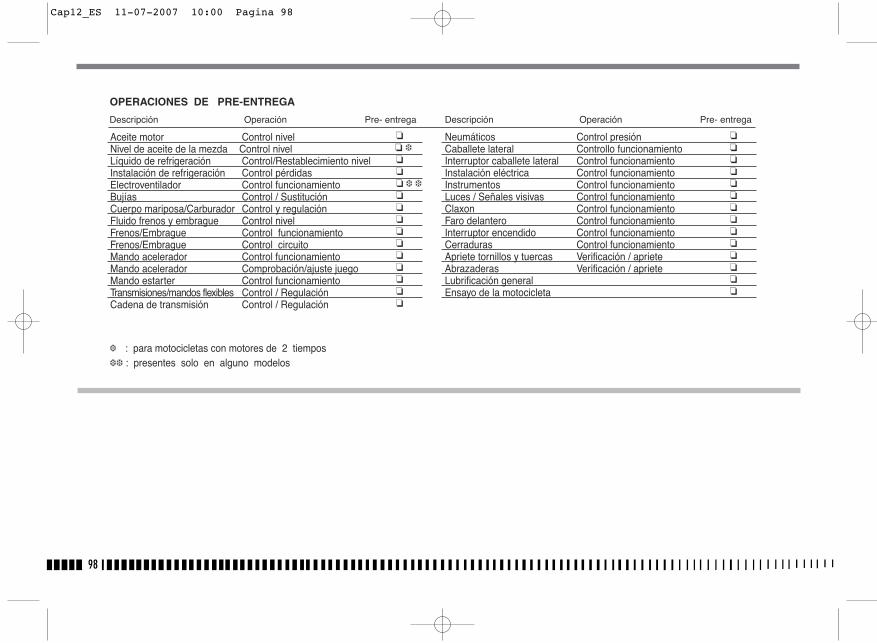
98
�� ���� � ������ �����
��������������
Aceite motor Control nivelNivel de aceite de la mezda Control nivelLíquido de refrigeración Control/Restablecimiento nivel Instalación de refrigeración Control pérdidasElectroventilador Control funcionamientoBujías Control / SustituciónCuerpo mariposa/Carburador Control y regulaciónFluido frenos y embrague Control nivelFrenos/Embrague Control funcionamiento Frenos/Embrague Control circuitoMando acelerador Control funcionamientoMando acelerador Comprobación/ajuste juegoMando estarter Control funcionamientoTransmisiones/mandos flexibles Control / RegulaciónCadena de transmisión Control / Regulación
Neumáticos Control presiónCaballete lateral Controllo funcionamientoInterruptor caballete lateral Control funcionamientoInstalación eléctrica Control funcionamientoInstrumentos Control funcionamientoLuces / Señales visivas Control funcionamientoClaxon Control funcionamientoFaro delantero Control funcionamientoInterruptor encendido Control funcionamientoCerraduras Control funcionamientoApriete tornillos y tuercas Verificación / aprieteAbrazaderas Verificación / aprieteLubrificación generalEnsayo de la motocicleta
� : para motocicletas con motores de 2 tiempos �� : presentes solo en alguno modelos
OPERACIONES DE PRE-ENTREGA
Descripción Operación Pre- entrega Descripción Operación Pre- entrega
Cap12_ES 11-07-2007 10:00 Pagina 98
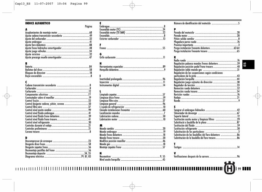
99
Número de identificación del motociclo ..........................................5
PParada del motociclo ..................................................................28Parada motor ..............................................................................28Piñón salida cambio ....................................................................8Plegadura perno rueda ................................................................76Premisa importante. ......................................................................3Purga instalación frenante delantero......................................62-64Purga instalación frenante trasero ..............................................65
RRadio rueda ................................................................................76Regulación palanca mandos frenos delantero ..............................39Regulación posición pedal freno trasero ......................................40Regulación cable mando gas ......................................................31Regulación de las suspensiones según condicionesparticulares de la pista ................................................................43Regulación horquilla ..................................................................44Regulación juego cojinetes de dirección ......................................38Regulador de tensión ..................................................................33Remoción rueda delantera ..........................................................52Remoción rueda trasera ..............................................................54Revisión ruedas ..........................................................................76Rodaje. ........................................................................................21Rueda............................................................................................9
SSangrar el embrague hidraulico ..................................................42Silenciador de descarga ..............................................................67Soporte lateral ............................................................................12Sustitución aceite motor y limpieza filtros ..................................29Substitució n boubilla de la placa ................................................87Sostitución del fluido ..................................................................59Sustitución refrigerante ..............................................................30Substitución de los particulares ....................................................3Substitución de las boubillas del faro delantero ..........................86Substitución de la boubilla del faro trasero..................................86
TTestigos ......................................................................................14
VVerificaciones después de la carrera ............................................96
INDICE ALFABETICOPágina
AAcoplamientos de montaje motor ..................................................68Ajuste cadena transmisión secundaria ..........................................49Ajuste del carburador ....................................................................32 Ajuste embrague ..........................................................................41Ajuste faro delantero ....................................................................88Ajuste freno hidràulico amortiguador............................................48Ajuste juego válvulas ....................................................................34Ajuste mínimo ............................................................................32Ajuste precarga muelle amortiguador............................................47
BBateria..........................................................................................84Bailoteo del disco ..........................................................................58Bloqueo de direccion ....................................................................18Bujía encendido ............................................................................8
CCadena transmisión secundaria ....................................................8Carburador ....................................................................................8Carburante ..................................................................................12Componentes eléctricos ..............................................................77Conmutador sobre el manillar ......................................................19Control bujía ..............................................................................33Control desgaste cadena, piñón, corona ......................................50Control filtro aire ........................................................................37Control nivel aceite cambio ..........................................................99Control nivel fluido embrague......................................................41Control nivel fluido freno delantero..............................................39Control nivel fluido freno trasero..................................................41Control nivel refrigerante ............................................................30Controles durante el rodaje..........................................................21Controles preliminares ................................................................21Corona trasera ..............................................................................8
DDescompressor de arranque ........................................................23Desgaste disco freno....................................................................58Desgaste zapatas freno................................................................56Desmontaje pastillas del freno ....................................................56Desmontaje deposito ............................................................34, 35Diagrama eléctrico ..........................................................79, 81, 83
EEmbrague......................................................................................8Encendido motor (TC) ..................................................................24Encendido motor (TE-SMR) ..........................................................22Encendido......................................................................................8Estàrter carburador ....................................................................13
FFrenos ........................................................................................55
GGrifo carburante ..........................................................................11
HHerramientas especiales ..............................................................89Horquilla delantera........................................................................9
IInactividad prolongada ................................................................96Inyección ....................................................................................11Instrumentos digital ....................................................................14
LLimpiado zapatas ........................................................................57Limpieza disco freno ....................................................................59Limpieza filtro aire ......................................................................37Limpieza general ........................................................................96L í quido de refrigeración ............................................................10Llenado instalaciones frenantes ..................................................60Localización mandos ....................................................................7Lubricación cadena......................................................................50Lubricación motor ......................................................................10
MMando cambio ............................................................................20Mando embrague ........................................................................19Mando freno delantero ................................................................18Mando freno trasero ....................................................................20Modifica posición manillar ..........................................................46Mando gas ..................................................................................18Montaje zapatas freno ................................................................57
NNeumaticos ............................................................................9, 55Nivel aceite horquilla ..................................................................45
ES
Cap13_ES 11-07-2007 10:04 Pagina 99

100
Cap13_ES 11-07-2007 10:04 Pagina 100
A1
APPENDICE AAPPENDIX AAPPENDICE AANHANG AAPÉNDICE A
AppendiceA 12-07-2007 16:07 Pagina 1
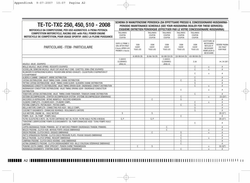
A2
TE-TC-TXC 250, 450, 510 - 2008MOTOCICLO DA COMPETIZIONE, PER USO AGONISTICO: A PIENA POTENZA
COMPETITION MOTORCYCLE, RACING USE: with FULL POWER ENGINEMOTOCYCLE DE COMPÉTITION, POUR USAGE SPORTIF: AVEC LA PLEINE PUISSANCE
SCHEMA DI MANUTENZIONE PERIODICA (DA EFFETTUARE PRESSO IL CONCESSIONARIO HUSQVARNA- PERIODIC MAINTENANCE SCHEDULE (SEE YOUR HUSQVARNA DEALER FOR THESE SERVICES)- ESQUEME ENTRETIEN PERIODIQUE (EFFECTUER PAR LE VOTRE CONCESSIONAIRE HUSQVARNA)
TAGLIANDOCOUPONCOUPON
TAGLIANDOCOUPONCOUPON
TAGLIANDOCOUPONCOUPON
TAGLIANDOCOUPONCOUPON
TAGLIANDOCOUPONCOUPON
PARTICOLARE- ITEM- PARTICULAIREDOPO LE PRIME 3 ORE-AFTER FIRST
3 hours-APRÈS LES PREMIER 3 heures
OGNEVERY
TOUS LES
OGNIEVERY
TOUS LES
OGNIEVERY
TOUS LES
OGNIEVERY
TOUS LES
OGNIEVERY
TOUS LES
SOSTITUIRE SE NECESSARIOREPLACE IF NECESSARY
REMPLACER SI NÉCESSAIRE
VEDERE PAGINASEE PAGE*VOIR PAGE
4h MX/8h EN 8h Mx/16h EN 16h MX/32h EN 32h MX/64h EN 40h MX/80h EN
VALVOLE- VALVE- SOUPAPES
C (GIOCOCLEARANCE-
JEAU) (•)
C (GIOCO-CLEARANCE-
JEAU) (•)S (#) (•): 34 (36*)
MOLLE VALVOLE- VALVE SPRING- RESSORTS SOUPAPES C x #SCODELLINI, SEMICONI VALVOLE- VALVE CUP, VALVE HALF CONE- CUVETTES, DEMI-CÔNE SOUPAPES C x #BILANCIERI DI ASPIRAZIONE/SCARICO- ROCKER ARM (INTAKE-EXHAUST)- CULBUTEURS D’ASPIRATION ET D’ÉCHAPPEMENT
C x #
ALBERO A CAMME- CAMSHAFT- ARBRE DISTRIBUTION C #CATENA DISTRIBUZIONE- VALVE TIMING CHAIN- CHAINE DISTRIBUTION C S #PATTINO CATENA DISTRIBUZIONE- VALVE TIMING CHAIN SLIDER- GLISSIÈRE CHAINE DISTRIBUTION S #INGRANAGGIO CONDOTTO DISTRIBUZIONE- VALVE TIMING DRIVEN GEAR- ENGRENAGE CONDIUT DISTRIBUTION C x #INGRANAGGIO CONDUTTORE DISTRIBUZIONE- VALVE TIMING DRIVING GEAR- ENGRENAGE CONDUCTEUR DISTRIBUTION
C x #
TENDITORE CATENA DISTRIBUZIONE- VALVE TIMING CHAIN TENSIONER- TENDEUR CHAINE DISTRIBUTION C #SISTEMA DECOMPRESSORE- STARTER DECOMPRESSOR SYSTEM- SYSTÈME DECOMPRESSEUR DÉMARRAGE C x 23 (25*)RACCORDO DI ASPIRAZIONE- INTAKE MANIFOLD- RACCORD ADMISSION C S #CILINDRO COMPLETO- CYLINDER ASSY.- CYLINDRE COMPL. C x #PISTONE COMPLETO- PISTON ASSY.- PISTON COMPL. C S #BIELLA MOTORE COMPLETA- CONNECTING ROD ASSY.- BIELLE COMPL. S #CUSCINETTI BASAMENTO- CRANKCASE BEARINGS- ROULEMENTS CARTERS S #OLIO MOTORE- ENGINE OIL - HUILE MOTEUR S S 29 (31*)POMPA OLIO - OIL PUMP - POMPE HUILE C #FILTRO OLIO/FILTRO A RETE- OIL FILTER CARTRIDGE/ NET OIL FILTER- FILTRE HUILE/ FILTRE A RESEAU S, P S, P 29 (31*)TUBAZIONE LUBRIFICAZIONE POMPA OLIO/BASAMENTO- OIL PUMP/CRANKCASE HOSE- TUYAU POMPE HUILE/CARTERS
C #
COPPIA INGRANAGGI TRASM. PRIMARIA- SET OF MATCHED PRIMARY ENGRENAGES TRANSM. PRIMARIE- C #MOZZO FRIZIONE- CLUTCH HUB- MOYEAU PORTE-DISQUE EMBRAYAGE C x #DISCHI FRIZIONE- CLUTCH DISCS- DISQUES EMBRAYAGE C S x #PIATTO SPINGIDISCHI FRIZIONE- CLUTCH DISCS PRESSURE PLATE- POUSSE DISQUES EMBRAYAGE C #MOLLE FRIZIONE- CLUTCH SPRING- RESSORT EMBRAYAGE C x #CAMPANA FRIZIONE- CLUTCH DISCS HOUSING- CAGE EMBRAYAGE C #ASTINA DISINNESTO FRIZIONE- CLUTCH DISENGAGEMENT ROD- BILLE COILESSAU DÉBRAYAGE EMBRAYAGE C #PIGNONE USCITA CAMBIO- DRIVE SPROCKET- PIGNON CHAÎNE TRANSMISSION C S x 50 (52*)INGRANAGGI AVVIAMENTO- STARTING GEARS - ENGRENAGE DÉMARRAGE C x #
AppendiceA 9-07-2007 10:07 Pagina A2
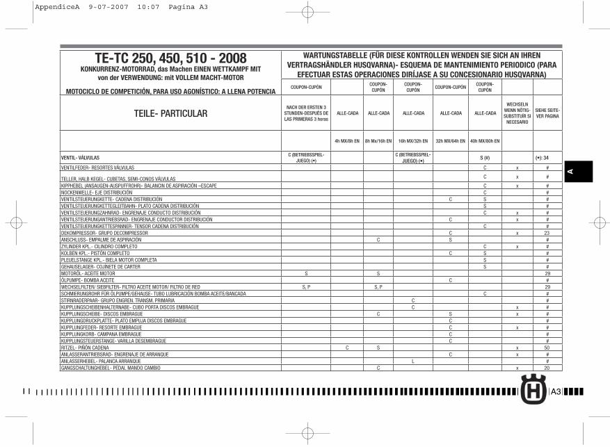
TE-TC 250, 450, 510 - 2008KONKURRENZ-MOTORRAD, das Machen EINEN WETTKAMPF MIT
von der VERWENDUNG: mit VOLLEM MACHT-MOTOR
MOTOCICLO DE COMPETICIÓN, PARA USO AGONÍSTICO: A LLENA POTENCIA
WARTUNGSTABELLE (FÜR DIESE KONTROLLEN WENDEN SIE SICH AN IHREN VERTRAGSHÄNDLER HUSQVARNA)- ESQUEMA DE MANTENIMIENTO PERIODICO (PARA
EFECTUAR ESTAS OPERACIONES DIRÍJASE A SU CONCESIONARIO HUSQVARNA)COUPON-CUPÓN
COUPON-CUPÓN
COUPON-CUPÓN
COUPON-CUPÓNCOUPON-CUPÓN
TEILE- PARTICULARNACH DER ERSTEN 3
STUNDEN-DESPUÉS DE LAS PRIMERAS 3 horas
ALLE-CADA ALLE-CADA ALLE-CADA ALLE-CADA ALLE-CADA
WECHSELNWENN NÖTIG-SUBSTITUÍR SI
NECESARIO
SIEHE SEITE- VER PAGINA
4h MX/8h EN 8h Mx/16h EN 16h MX/32h EN 32h MX/64h EN 40h MX/80h EN
VENTIL- VÁLVULAS C (BETRIEBSSPIEL-JUEGO) (•)
C (BETRIEBSSPIEL-JUEGO) (•)
S (#) (•): 34
VENTILFEDER- RESORTES VÁLVULAS C x #
TELLER, HALB KEGEL- CUBETAS, SEMI-CONOS VÁLVULAS C x #
KIPPHEBEL (ANSAUGEN-AUSPUFFROHR)- BALANCIN DE ASPIRACIÓN –ESCAPE C x #NOCKENWELLE- EJE DISTRIBUCIÓN C #VENTILSTEUERUNGKETTE- CADENA DISTRIBUCIÓN C S #VENTILSTEUERUNGKETTEGLEITBAHN- PLATO CADENA DISTRIBUCIÓN S #VENTILSTEUERUNGZAHNRAD- ENGRENAJE CONDUCTO DISTRIBUCIÓN C x #VENTILSTEUERUNGANTRIEBSRAD- ENGRENAJE CONDUCTOR DISTRIBUCIÓN C x #VENTILSTEUERUNGKETTESPANNER- TENSOR CADENA DISTRIBUCIÓN C #DEKOMPRESSOR- GRUPO DECOMPRESSOR C x 23ANSCHLUSS- EMPALME DE ASPIRACIÓN C S #ZYLINDER KPL.- CILINDRO COMPLETO C x #KOLBEN KPL.- PISTÓN COMPLETO C S #PLEUELSTANGE KPL.- BIELA MOTOR COMPLETA S #GEHAUSELAGER- COJÍNETE DE CARTER S #MOTORÖL- ACEITE MOTOR S S 29ÖLPUMPE- BOMBA ACEITE C #WECHSELFILTER/ SIEBFILTER- FILTRO ACEITE MOTOR/ FILTRO DE RED S, P S, P 29SCHMIERUNGROHR FÜR ÖLPUMPE/GEHAUSE- TUBO LUBRICACIÓN BOMBA ACEITE/BANCADA C #STIRNRADERPAAR- GRUPO ENGREN. TRANSM. PRIMARIA C #KUPPLUNGSCHEIBENHALTERNABE- CUBO PORTA DISCOS EMBRAGUE C x #KUPPLUNGSCHEIBE- DISCOS EMBRAGUE C S x #KUPPLUNGDRUCKPLATTE- PLATO EMPUJA DISCOS EMBRAGUE C #KUPPLUNGFEDER- RESORTE EMBRAGUE C x #KUPPLUNGKORB- CAMPANA EMBRAGUE C #KUPPLUNGSTEUERSTANGE- VARILLA DESEMBRAGUE C #RITZEL- PIÑÓN CADENA C S x 50ANLASSERANTRIEBSRAD- ENGRENAJE DE ARRANQUE C x #ANLASSERHEBEL- PALANCA ARRANQUE L #GANGSCHALTUNGHEBEL- PEDAL MANDO CAMBIO C x 20
A3
A
AppendiceA 9-07-2007 10:07 Pagina A3
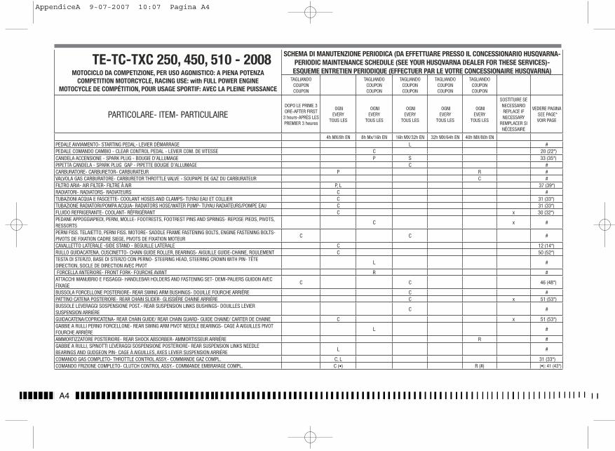
A4
TE-TC-TXC 250, 450, 510 - 2008MOTOCICLO DA COMPETIZIONE, PER USO AGONISTICO: A PIENA POTENZA
COMPETITION MOTORCYCLE, RACING USE: with FULL POWER ENGINEMOTOCYCLE DE COMPÉTITION, POUR USAGE SPORTIF: AVEC LA PLEINE PUISSANCE
SCHEMA DI MANUTENZIONE PERIODICA (DA EFFETTUARE PRESSO IL CONCESSIONARIO HUSQVARNA- PERIODIC MAINTENANCE SCHEDULE (SEE YOUR HUSQVARNA DEALER FOR THESE SERVICES)- ESQUEME ENTRETIEN PERIODIQUE (EFFECTUER PAR LE VOTRE CONCESSIONAIRE HUSQVARNA)
TAGLIANDOCOUPONCOUPON
TAGLIANDOCOUPONCOUPON
TAGLIANDOCOUPONCOUPON
TAGLIANDOCOUPONCOUPON
TAGLIANDOCOUPONCOUPON
PARTICOLARE- ITEM- PARTICULAIREDOPO LE PRIME 3 ORE-AFTER FIRST
3 hours-APRÈS LES PREMIER 3 heures
OGNEVERY
TOUS LES
OGNIEVERY
TOUS LES
OGNIEVERY
TOUS LES
OGNIEVERY
TOUS LES
OGNIEVERY
TOUS LES
SOSTITUIRE SE NECESSARIOREPLACE IF NECESSARY
REMPLACER SI NÉCESSAIRE
VEDERE PAGINASEE PAGE*VOIR PAGE
4h MX/8h EN 8h Mx/16h EN 16h MX/32h EN 32h MX/64h EN 40h MX/80h EN
PEDALE AVVIAMENTO- STARTING PEDAL- LEVIER DÉMARRAGE L #PEDALE COMANDO CAMBIO - CLEAR CONTROL PEDAL - LEVIER COM. DE VITESSE C 20 (22*)CANDELA ACCENSIONE - SPARK PLUG - BOUGIE D’ALLUMAGE P S 33 (35*)PIPETTA CANDELA - SPARK PLUG GAP - PIPETTE BOUGIE D’ALLUMAGE C #CARBURATORE- CARBURETOR- CARBURATEUR P R #VALVOLA GAS CARBURATORE- CARBURETOR THROTTLE VALVE - SOUPAPE DE GAZ DU CARBURATEUR C #FILTRO ARIA- AIR FILTER- FILTRE À AIR P, L 37 (39*)RADIATORI- RADIATORS- RADIATEURS C #TUBAZIONI ACQUA E FASCETTE- COOLANT HOSES AND CLAMPS- TUYAU EAU ET COLLIER C 31 (33*)TUBAZIONE RADIATORI/POMPA ACQUA- RADIATORS HOSE/WATER PUMP- TUYAU RADIATEURS/POMPE EAU C 31 (33*)FLUIDO REFRIGERANTE- COOLANT- RÉFRIGÉRANT C x 30 (32*)PEDANE APPOGGIAPIEDI, PERNI, MOLLE- FOOTRESTS, FOOTREST PINS AND SPRINGS- REPOSE PIEDS, PIVOTS, RESSORTS
C x #
PERNI FISS. TELAIETTO, PERNI FISS. MOTORE- SADDLE FRAME FASTENING BOLTS, ENGINE FASTENING BOLTS- PIVOTS DE FIXATION CADRE SIEGE, PIVOTS DE FIXATION MOTEUR
C C #
CAVALLETTO LATERALE -SIDE STAND - BEGUILLE LATERALE C 12 (14*)RULLO GUIDACATENA, CUSCINETTO- CHAIN GUIDE ROLLER, BEARINGS- AIGUILLE GUIDE-CHAINE, ROULEMENT C 50 (52*)TESTA DI STERZO, BASE DI STERZO CON PERNO- STEERING HEAD, STEERING CROWN WITH PIN- TÊTE DIRECTION, SOCLE DE DIRECTION AVEC PIVOT
L #
FORCELLA ANTERIORE- FRONT FORK- FOURCHE AVANT R #ATTACCHI MANUBRIO E FISSAGGI- HANDLEBAR HOLDERS AND FASTENING SET- DEMI-PALIERS GUIDON AVEC FIXAGE
C C 46 (48*)
BUSSOLA FORCELLONE POSTERIORE- REAR SWING ARM BUSHINGS- DOUILLE FOURCHE ARRIÉRE C #PATTINO CATENA POSTERIORE- REAR CHAIN SLIDER- GLISSIÉRE CHAINE ARRIÉRE C x 51 (53*)BUSSOLE LEVERAGGI SOSPENSIONE POST.- REAR SUSPENSION LINKS BUSHINGS- DOUILLES LEVIER SUSPENSION ARRIÉRE
C #
GUIDACATENA/COPRICATENA- REAR CHAIN GUIDE/ REAR CHAIN GUARD- GUIDE CHAINE/ CARTER DE CHAINE C x 51 (53*)GABBIE A RULLI PERNO FORCELLONE- REAR SWING ARM PIVOT NEEDLE BEARINGS- CAGE À AIGUILLES PIVOT FOURCHE ARRIÉRE
L #
AMMORTIZZATORE POSTERIORE- REAR SHOCK ABSORBER- AMMORTISSEUR ARRIÉRE R #GABBIE A RULLI, SPINOTTI LEVERAGGI SOSPENSIONE POSTERIORE- REAR SUSPENSION LINKS NEEDLE BEARINGS AND GUDGEON PIN- CAGE À AIGUILLES, AXES LEVIER SUSPENSION ARRIÉRE
L #
COMANDO GAS COMPLETO- THROTTLE CONTROL ASSY.- COMMANDE GAZ COMPL. C, L 31 (33*)COMANDO FRIZIONE COMPLETO- CLUTCH CONTROL ASSY.- COMMANDE EMBRAYAGE COMPL. C (•) R (#) (•): 41 (43*)
AppendiceA 9-07-2007 10:07 Pagina A4
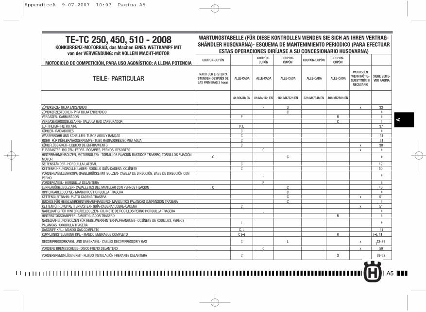
TE-TC 250, 450, 510 - 2008KONKURRENZ-MOTORRAD, das Machen EINEN WETTKAMPF MIT
von der VERWENDUNG: mit VOLLEM MACHT-MOTOR
MOTOCICLO DE COMPETICIÓN, PARA USO AGONÍSTICO: A LLENA POTENCIA
WARTUNGSTABELLE (FÜR DIESE KONTROLLEN WENDEN SIE SICH AN IHREN VERTRAG-SHÄNDLER HUSQVARNA)- ESQUEMA DE MANTENIMIENTO PERIODICO (PARA EFECTUAR
ESTAS OPERACIONES DIRÍJASE A SU CONCESIONARIO HUSQVARNA)COUPON-CUPÓN
COUPON-CUPÓN
COUPON-CUPÓN
COUPON-CUPÓNCOUPON-CUPÓN
TEILE- PARTICULARNACH DER ERSTEN 3
STUNDEN-DESPUÉS DE LAS PRIMERAS 3 horas
ALLE-CADA ALLE-CADA ALLE-CADA ALLE-CADA ALLE-CADA
WECHSELNWENN NÖTIG-SUBSTITUÍR SI
NECESARIO
SIEHE SEITE- VER PAGINA
4h MX/8h EN 8h Mx/16h EN 16h MX/32h EN 32h MX/64h EN 40h MX/80h EN
ZÜNDKERZE- BUJIA ENCENDIDO P S x 33ZÜNDKERZESTECKER- PIPA BUJIA ENCENDIDO C #VERGASER- CARBURADOR P R #VERGASERDROSSELKLAPPE- VALVULA GAS CARBURADOR C #LUFTFILTER- FILTRO AIRE P, L 37KÜHLER- RADIADORES C #WASSERROHR UND SCHELLEN- TUBOS AGUA Y BANDAS C 31ROHR FÜR KÜHLER/WASSERPUMPE- TUBO RADIADORES/BOMBA AGUA C 31KÜHLFLÜSSIGKEIT- LIQUIDO DE ENFRIAMIENTO C x 30FUSSRASTER, BOLZEN, FEDER- POSAPIES, PERNOS, RESORTES C x #HINTERRAHMENBOLZEN, MOTORBOLZEN- TORNILLOS FIJACIÓN BASTIDOR TRASERO, TORNILLOS FIJACIÓN MOTOR
C C #
SEITENSTÄNDER- HORQUILLA LATERAL C 12KETTENFÜHRUNGROLLE, LAGER- RODILLO GUÍA-CADENA, COJÍNETE C 50VORDERGABELLENKKOPF, GABELBRÜCKE MIT BOLZEN- CABEZA DE DIRECCIÓN, BASE DE DIRECCIÓN CON PERNO
L #
VORDERGABEL- HORQUILLA DELANTERA R #LENKERBÜGELBOLZEN- CABALLETES DEL MANILLAR CON PERNOS FIJACIÓN C C 46HINTERGABELBUCHSE- MANGUITOS HORQUILLA TRASERA C #KETTENGLEITBAHN- PLATO CADENA TRASERA C x 51BUCHSE FÜR HEBELWERKHINTERHAUFHANGUNG- MANGUITOS PALANCAS SUSPENSION TRASERA C #KETTENFÜHRUNG/ KETTENKASTEN- GUÍA-CADENA/ CUBRE-CADENA C x 51NADELKAFIG FÜR HINTERGABELBOLZEN- COJÍNETE DE RODILLOS PERNO HORQUILLA TRASERA L #HINTERSTOSSDAMPFER- AMORTIGUADOR TRASERO R #NADELKAFIG UND BOLZEN FÜR HEBELWERKHINTERHAUFHANGUNG- COJÍNETE DE RODILLOS, PERNOS PALANCAS HORQUILLA TRASERA
L #
GASGRIFF KPL.- MANDO GAS COMPLETO C, L 31KUPPLUNGSTEUERUNG KPL.- MANDO EMBRAGUE COMPLETO C (•) R (•): 41
DECOMPRESSORKABEL UND GASGKABEL- CABLES DECOMPRESSOR Y GAS C L x 23-31,
1VORDERE BREMSSCHEIBE- DISCO FRENO DELANTERO C x 59
VORDERBREMSFLÜSSIGKEIT- FLUIDO INSTALACIÓN FRENANTE DELANTERA C S 39-62
A5
A
AppendiceA 9-07-2007 10:07 Pagina A5
Marco
Rectangle
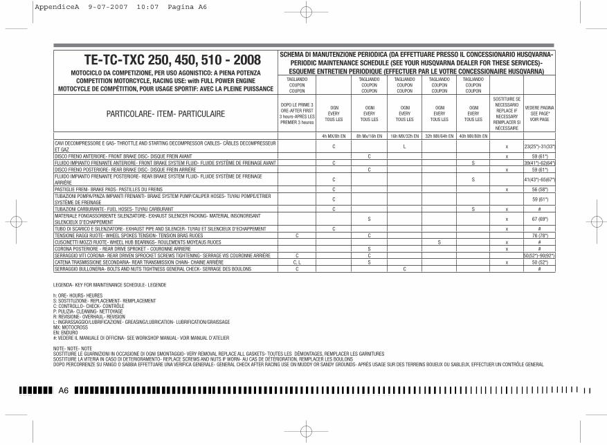
A6
TE-TC-TXC 250, 450, 510 - 2008MOTOCICLO DA COMPETIZIONE, PER USO AGONISTICO: A PIENA POTENZA
COMPETITION MOTORCYCLE, RACING USE: with FULL POWER ENGINEMOTOCYCLE DE COMPÉTITION, POUR USAGE SPORTIF: AVEC LA PLEINE PUISSANCE
SCHEMA DI MANUTENZIONE PERIODICA (DA EFFETTUARE PRESSO IL CONCESSIONARIO HUSQVARNA- PERIODIC MAINTENANCE SCHEDULE (SEE YOUR HUSQVARNA DEALER FOR THESE SERVICES)- ESQUEME ENTRETIEN PERIODIQUE (EFFECTUER PAR LE VOTRE CONCESSIONAIRE HUSQVARNA)
TAGLIANDOCOUPONCOUPON
TAGLIANDOCOUPONCOUPON
TAGLIANDOCOUPONCOUPON
TAGLIANDOCOUPONCOUPON
TAGLIANDOCOUPONCOUPON
PARTICOLARE- ITEM- PARTICULAIREDOPO LE PRIME 3 ORE-AFTER FIRST
3 hours-APRÈS LES PREMIER 3 heures
OGNEVERY
TOUS LES
OGNIEVERY
TOUS LES
OGNIEVERY
TOUS LES
OGNIEVERY
TOUS LES
OGNIEVERY
TOUS LES
SOSTITUIRE SE NECESSARIOREPLACE IF NECESSARY
REMPLACER SI NÉCESSAIRE
VEDERE PAGINASEE PAGE*VOIR PAGE
4h MX/8h EN 8h Mx/16h EN 16h MX/32h EN 32h MX/64h EN 40h MX/80h EN
CAVI DECOMPRESSORE E GAS- THROTTLE AND STARTING DECOMPRESSOR CABLES- CÂBLES DECOMPRESSEUR ET GAZ
C L x 23(25*)-31(33*)
DISCO FRENO ANTERIORE- FRONT BRAKE DISC- DISQUE FREIN AVANT C x 59 (61*)FLUIDO IMPIANTO FRENANTE ANTERIORE- FRONT BRAKE SYSTEM FLUID- FLUIDE SYSTÈME DE FREINAGE AVANT C S 39(41*)-62(64*)DISCO FRENO POSTERIORE- REAR BRAKE DISC- DISQUE FREIN ARRIÉRE C x 59 (61*)FLUIDO IMPIANTO FRENANTE POSTERIORE- REAR BRAKE SYSTEM FLUID- FLUIDE SYSTÈME DE FREINAGE ARRIÉRE
C S 41(43*)-65(67*)
PASTIGLIE FRENI- BRAKE PADS- PASTILLES DU FREINS C x 56 (58*)TUBAZIONI POMPA/PINZA IMPIANTI FRENANTI- BRAKE SYSTEM PUMP/CALIPER HOSES- TUYAU POMPE/ETRIER SYSTÈME DE FREINAGE
C 59 (61*)
TUBAZIONI CARBURANTE- FUEL HOSES- TUYAU CARBURANT C S x #MATERIALE FONOASSORBENTE SILENZIATORE- EXHAUST SILENCER PACKING- MATERIAL INSONORISANT SILENCIEUX D’ECHAPPEMENT
S x 67 (69*)
TUBO DI SCARICO E SILENZIATORE- EXHAUST PIPE AND SILENCER- TUYAU ET SILENCIEUX D’ECHAPPEMENT C x #TENSIONE RAGGI RUOTE- WHEEL SPOKES TENSION- TENSION BRAS RUOES C C 76 (78*)CUSCINETTI MOZZI RUOTE- WHEEL HUB BEARINGS- ROULEMENTS MOYEAUS RUOES S x #CORONA POSTERIORE - REAR DRIVE SPROKET - COURONNE ARRIERE S x #SERRAGGIO VITI CORONA- REAR DRIVEN SPROCKET SCREWS TIGHTENING- SERRAGE VIS COURONNE ARRIÉRE C C 50(52*)-90(92*)CATENA TRASMISSIONE SECONDARIA- REAR TRANSMISSION CHAIN- CHAINE ARRIÉRE C, L S x 50 (52*)SERRAGGIO BULLONERIA- BOLTS AND NUTS TIGHTNESS GENERAL CHECK- SERRAGE DES BOULONS C C #
LEGENDA- KEY FOR MAINTENANCE SCHEDULE- LEGENDE
h: ORE- HOURS- HEURESS: SOSTITUZIONE- REPLACEMENT- REMPLACEMENTC: CONTROLLO- CHECK- CONTRÔLEP: PULIZIA- CLEANING- NETTOYAGER: REVISIONE- OVERHAUL- REVISIONL: INGRASSAGGIO/LUBRIFICAZIONE- GREASING/LUBRICATION- LUBRIFICATION/GRAISSAGEMX: MOTOCROSSEN: ENDURO#: VEDERE IL MANUALE DI OFFICINA- SEE WORKSHOP MANUAL- VOIR MANUAL D’ATELIER
NOTE- NOTE- NOTESOSTITUIRE LE GUARNIZIONI IN OCCASIONE DI OGNI SMONTAGGIO- VERY REMOVAL REPLACE ALL GASKETS- TOUTES LES DÉMONTAGES, REMPLACER LES GARNITURES SOSTITUIRE LA VITERIA IN CASO DI DETERIORAMENTO- REPLACE SCREWS AND NUTS IF WORN- AU CAS DE DÉTÉRIORATION, REMPLACER LES BOULONS DOPO PERCORRENZE SU FANGO O SABBIA EFFETTUARE UNA VERIFICA GENERALE- GENERAL CHECK AFTER RACING USE ON MUDDY OR SANDY GROUNDS- APRÈS USAGE SUR DES TERREINS BOUEUX OU SABLEUX, EFFECTUER UN CONTRÔLE GENERAL
AppendiceA 9-07-2007 10:07 Pagina A6
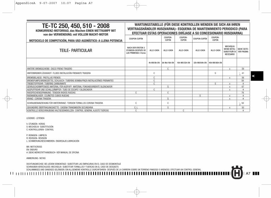
TE-TC 250, 450, 510 - 2008KONKURRENZ-MOTORRAD, das Machen EINEN WETTKAMPF MIT
von der VERWENDUNG: mit VOLLEM MACHT-MOTOR
MOTOCICLO DE COMPETICIÓN, PARA USO AGONÍSTICO: A LLENA POTENCIA
WARTUNGSTABELLE (FÜR DIESE KONTROLLEN WENDEN SIE SICH AN IHREN VERTRAGSHÄNDLER HUSQVARNA)- ESQUEMA DE MANTENIMIENTO PERIODICO (PARA
EFECTUAR ESTAS OPERACIONES DIRÍJASE A SU CONCESIONARIO HUSQVARNA)COUPON-CUPÓN
COUPON-CUPÓN
COUPON-CUPÓN
COUPON-CUPÓNCOUPON-CUPÓN
TEILE- PARTICULARNACH DER ERSTEN 3
STUNDEN-DESPUÉS DE LAS PRIMERAS 3 horas
ALLE-CADA ALLE-CADA ALLE-CADA ALLE-CADA ALLE-CADA
WECHSELNWENN NÖTIG-SUBSTITUÍR SI
NECESARIO
SIEHE SEITE- VER PAGINA
4h MX/8h EN 8h Mx/16h EN 16h MX/32h EN 32h MX/64h EN 40h MX/80h EN
HINTERE BREMSSCHEIBE- DISCO FRENO TRASERO C x 59
HINTERBREMSFLÜSSIGKEIT- FLUIDO INSTALACIÓN FRENANTE TRASERA C S 41,1
BREMSBELAEGE- PASTILLAS FRENOS C x 56 BREMSPUMPE/BREMSSÄTTEL SCHLAUCH- TUBERÍAS BOMBA/PINZA INSTALACIÓNES FRENANTES C 59TREIBSTOFFROHR- TUBERÍAS CARBURANTE C S x #GERÄUSCHDÄMPFENDES MATERIAL FÜR AUSPUFF- MATERIAL FONOABSORBENTE SILENCIADOR S x 67AUSPUFFROHR UND SCHALLDÄMPFER- TUBO DE ESCAPE Y SILENCIADOR C x #RADSPEICHENSSPANNUNG- TENSION RADIOS RUEDAS C C 76RADNABENLAGER- COJÍNETES CUBOS RUEDAS S x #KRANZ- CORONA TRASERA S x #
SCHRAUBENANZIEHUNG FÜR HINTERKRANZ- TORSION TORNILLOS CORONA TRASERA C C 50,2
SEKUNDÄRE ÜBERTRAGUNGSKETTE- CADENA TRANSMISIÓN SECUNDARIA C, L S x 50 KONTROLLE VERSCHRAUBUNG KALTGESENKBOLZEN- CONTROL GENERAL AJUSTE TUERCAS C C #
LEGENDE- LEYENDA
h: STUNDEN- HORASS: WECHSELN- SUBSTITUCIÓNC: KONTROLLIEREN- CONTROL
P: REINIGEN- LIMPIEZAR: REVISION- REVISIONL: SCHMIERUNG/BESCHMEIREN- ENGRESAJE/LUBRICACIÓN
MX: MOTOCROSSEN: ENDURO#: SIEHE WERKSTATTHANDBUCH- VER MANUAL DE OFICINA
ANMERKUNG- NOTAS
DICHTUNGWECHSE: BEI JEDEM DEMONTAGE- SUBSTITUIR LAS EMPACURAS EN EL CASO DE DESMONTAJESCHRAUBEN VERSCHLEISS: WECHSELN- SUBSTITUIR TORNILLOS Y TUERCAS EN EL CASO DE DESGASTESCHLAMMIGES UND SANDIGES GELÄNDEN: EIN ALLGEMEINE KONTROLLE DURCHFÜHREN- DESPUÉS DE LA CARRERA SOBRE UN TERRENO FANGOSO O ARENOSO, EFECTUAR UN CONTROL GENERAL
A7
A
AppendiceA 9-07-2007 10:07 Pagina A7
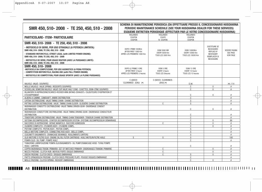
A8
SMR 450, 510- 2008 - TE 250, 450, 510 - 2008SCHEMA DI MANUTENZIONE PERIODICA (DA EFFETTUARE PRESSO IL CONCESSIONARIO HUSQVARNA
PERIODIC MAINTENANCE SCHEDULE (SEE YOUR HUSQVARNA DEALER FOR THESE SERVICES) ESQUEME ENTRETIEN PERIODIQUE (EFFECTUER PAR LE VOTRE CONCESSIONAIRE HUSQVARNA)
PARTICOLARE- ITEM- PARTICULAIRETAGLIANDO COUPON COUPON
TAGLIANDO COUPO
N- COUPON
TAGLIANDOCOUPONCOUPON
SMR 450, 510- 2008 - TE 250, 450, 510 - 2008- MOTOCICLO DI SERIE, PER USO STRADALE (A POTENZA LIMITATA): SMR 450, 510- 2008; TE 250, 450, 510 - 2008
- STANDARD MOTORCYCLE, STREET LEGAL (with LIMITED POWER ENGINE):SMR 450, 510- 2008; TE 250, 450, 510 - 2008
- MOTOCYCLE DE SÉRIE, POUR USAGE ROUTIER (AVEC LA PUISSANCE LIMITÉ): SMR 450, 510- 2008; TE 250, 450, 510 - 2008
DOPO I PRIMI 1000Km AFTER FIRST 1000 Km
APRÈS LES PREMIERS 1000 Km
OGNI 5000 KMEVERY 5000 Km
TOUS LES 5000 Km
OGNI 10000KmEVERY 10000 Km
TOUS LES 10000 Km
SOSTITUIRE SE NECESSARIOREPLACE IF NECESSARY
REMPLACER SI NÉCESSAIRE
VEDERE PAGINASEE PAGEVOIR PAGE
SMR 450, 510- 2008-MOTOCICLO DA COMPETIZIONE, PER USO AGONISTICO (A PIENA POTENZA) - COMPETITION MOTORCYCLE, RACING USE (with FULL POWER ENGINE)- MOTOCYCLE DE COMPÉTITION, POUR USAGE SPORTIF (AVEC LA PLEINE PUISSANCE)
DOPO LE PRIME 3 OREAFTER FIRST 3 hours
APRÈS LES PREMIERS 3 heures
OGNI 5 OREEVERY 5 hours
TOUS LES 5heures
OGNI 15 OREEVERY 15 hours
TOUS LES 15 heures
VALVOLE- VALVE- SOUPAPES
C (GIOCOCLEARANCE- JEAU) (•)
C (GIOCO- CLEARANCE- JEAU) (•) S (#) (•): 114
MOLLE VALVOLE- VALVE SPRING- RESSORTS SOUPAPES C X #SCODELLINI, SEMICONI VALVOLE- VALVE CUP, VALVE HALF CONE- CUVETTES, DEMI-CÔNE SOUPAPES C X #BILANCIERI DI ASPIRAZIONE/SCARICO-ROCKER ARM (INTAKE-EXHAUST)- CULBUTEURS D’ASPIRATION ET D’ÉCHAPPEMENT C X #ALBERO A CAMME- CAMSHAFT- ARBRE DISTRIBUTION C #CATENA DISTRIBUZIONE- VALVE TIMING CHAIN- CHAINE DISTRIBUTION S #PATTINO CATENA DISTRIBUZIONE- VALVE TIMING CHAIN SLIDER- GLISSIÈRE CHAINE DISTRIBUTION C S #INGRANAGGIO CONDOTTO DISTRIBUZIONE- VALVE TIMING DRIVEN GEAR- ENGRENAGE CONDIUT DISTRIBUTION C X #INGRANAGGIO CONDUTTORE DISTRIBUZIONE- VALVE TIMING DRIVING GEAR- ENGRENAGE CONDUCTEUR DISTRIBUTION C #TENDITORE CATENA DISTRIBUZIONE- VALVE TIMING CHAIN TENSIONER- TENDEUR CHAINE DISTRIBUTION C #SISTEMA DECOMPRESSORE- STARTER DECOMPRESSOR SYSTEM- SYSTÈME DECOMPRESSEUR DÉMARRAGE C X 86RACCORDO DI ASPIRAZIONE- INTAKE MANIFOLD- RACCORD ADMISSION C S X #CILINDRO COMPLETO- CYLINDER ASSY.- CYLINDRE COMPL. C X #PISTONE COMPLETO- PISTON ASSY.- PISTON COMPL. S #BIELLA MOTORE COMPLETA- CONNECTING ROD ASSY.- BIELLE COMPL. S #CUSCINETTI BASAMENTO- CRANKCASE BEARINGS- ROULEMENTS CARTERS S #OLIO MOTORE E FILTRO OLIO- ENGINE OIL/OIL FILTER CARTRIDGE- HUILE MOTEUR/FILTRE HUILE S S S 100POMPA OLIO- OIL PUMP- POMPE HUILE C #TUBAZIONE LUBRIFICAZIONE POMPA OLIO/BASAMENTO- OIL PUMP/CRANKCASE HOSE- TUYAU POMPE HUILE- CARTERS C #COPPIA INGRANAGGI TRASM. PRIMARIA- SET OF MATCHED PRIMARY- ENGRENAGES TRANSM. PRIMARIE C X #MOZZO FRIZIONE- CLUTCH HUB- MOYEAU PORTE-DISQUE EMBRAYAGE C X #DISCHI FRIZIONE- CLUTCH DISCS- DISQUES EMBRAYAGE C S X #PIATTO SPINGIDISCHI FRIZIONE- CLUTCH DISCS PRESSURE PLATE- POUSSE DISQUES EMBRAYAGE C #MOLLE FRIZIONE- CLUTCH SPRING- RESSORT EMBRAYAGE C X #
SRM 450 ita PAG 1.indd 1 28-07-2006 9:54:15
AppendiceA 9-07-2007 10:07 Pagina A8
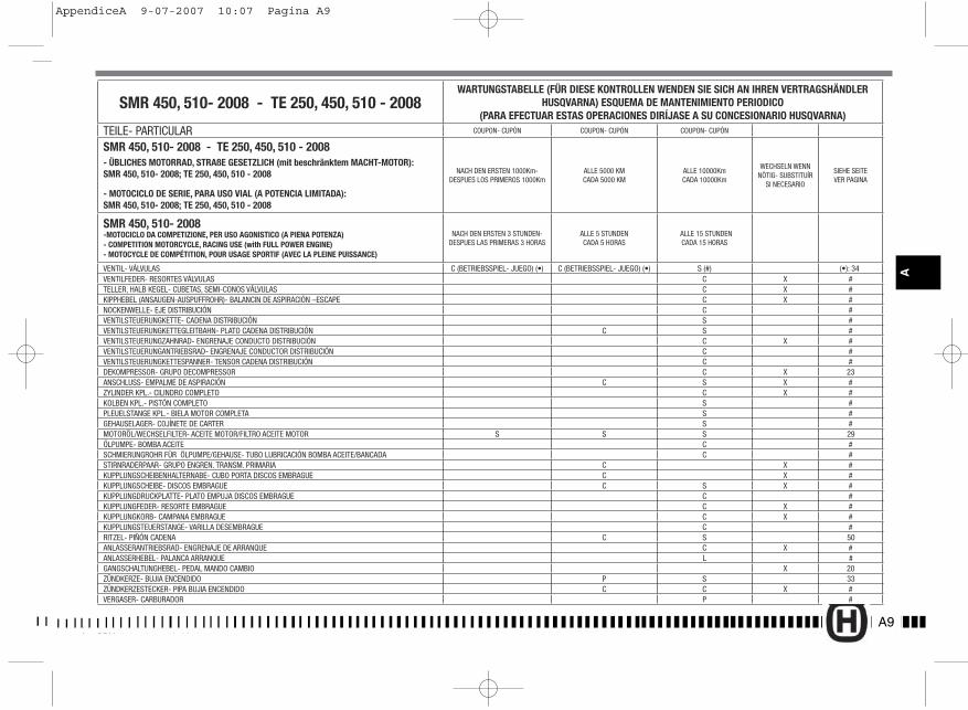
SMR 450, 510- 2008 - TE 250, 450, 510 - 2008WARTUNGSTABELLE (FÜR DIESE KONTROLLEN WENDEN SIE SICH AN IHREN VERTRAGSHÄNDLER
HUSQVARNA) ESQUEMA DE MANTENIMIENTO PERIODICO (PARA EFECTUAR ESTAS OPERACIONES DIRÍJASE A SU CONCESIONARIO HUSQVARNA)
TEILE- PARTICULAR COUPON- CUPÓN COUPON- CUPÓN COUPON- CUPÓN
SMR 450, 510- 2008 - TE 250, 450, 510 - 2008- ÜBLICHES MOTORRAD, STRAßE GESETZLICH (mit beschränktem MACHT-MOTOR): SMR 450, 510- 2008; TE 250, 450, 510 - 2008
- MOTOCICLO DE SERIE, PARA USO VIAL (A POTENCIA LIMITADA):SMR 450, 510- 2008; TE 250, 450, 510 - 2008
NACH DEN ERSTEN 1000Km-DESPUES LOS PRIMEROS 1000Km
ALLE 5000 KMCADA 5000 KM
ALLE 10000KmCADA 10000Km
WECHSELN WENN NÖTIG- SUBSTITUÍR
SI NECESARIO
SIEHE SEITEVER PAGINA
SMR 450, 510- 2008-MOTOCICLO DA COMPETIZIONE, PER USO AGONISTICO (A PIENA POTENZA) - COMPETITION MOTORCYCLE, RACING USE (with FULL POWER ENGINE)- MOTOCYCLE DE COMPÉTITION, POUR USAGE SPORTIF (AVEC LA PLEINE PUISSANCE)
NACH DEN ERSTEN 3 STUNDEN- DESPUES LAS PRIMERAS 3 HORAS
ALLE 5 STUNDENCADA 5 HORAS
ALLE 15 STUNDENCADA 15 HORAS
VENTIL- VÁLVULAS C (BETRIEBSSPIEL- JUEGO) (•) C (BETRIEBSSPIEL- JUEGO) (•) S (#) (•): 34VENTILFEDER- RESORTES VÁLVULAS C X #TELLER, HALB KEGEL- CUBETAS, SEMI-CONOS VÁLVULAS C X #KIPPHEBEL (ANSAUGEN-AUSPUFFROHR)- BALANCIN DE ASPIRACIÓN –ESCAPE C X #NOCKENWELLE- EJE DISTRIBUCIÓN C #VENTILSTEUERUNGKETTE- CADENA DISTRIBUCIÓN S #VENTILSTEUERUNGKETTEGLEITBAHN- PLATO CADENA DISTRIBUCIÓN C S #VENTILSTEUERUNGZAHNRAD- ENGRENAJE CONDUCTO DISTRIBUCIÓN C X #VENTILSTEUERUNGANTRIEBSRAD- ENGRENAJE CONDUCTOR DISTRIBUCIÓN C #VENTILSTEUERUNGKETTESPANNER- TENSOR CADENA DISTRIBUCIÓN C #DEKOMPRESSOR- GRUPO DECOMPRESSOR C X 23ANSCHLUSS- EMPALME DE ASPIRACIÓN C S X #ZYLINDER KPL.- CILINDRO COMPLETO C X #KOLBEN KPL.- PISTÓN COMPLETO S #PLEUELSTANGE KPL.- BIELA MOTOR COMPLETA S #GEHAUSELAGER- COJÍNETE DE CARTER S #MOTORÖL/WECHSELFILTER- ACEITE MOTOR/FILTRO ACEITE MOTOR S S S 29ÖLPUMPE- BOMBA ACEITE C #SCHMIERUNGROHR FÜR ÖLPUMPE/GEHAUSE- TUBO LUBRICACIÓN BOMBA ACEITE/BANCADA C #STIRNRADERPAAR- GRUPO ENGREN. TRANSM. PRIMARIA C X #KUPPLUNGSCHEIBENHALTERNABE- CUBO PORTA DISCOS EMBRAGUE C X #KUPPLUNGSCHEIBE- DISCOS EMBRAGUE C S X #KUPPLUNGDRUCKPLATTE- PLATO EMPUJA DISCOS EMBRAGUE C #KUPPLUNGFEDER- RESORTE EMBRAGUE C X #KUPPLUNGKORB- CAMPANA EMBRAGUE C X #KUPPLUNGSTEUERSTANGE- VARILLA DESEMBRAGUE C #RITZEL- PIÑÓN CADENA C S 50ANLASSERANTRIEBSRAD- ENGRENAJE DE ARRANQUE C X #ANLASSERHEBEL- PALANCA ARRANQUE L #GANGSCHALTUNGHEBEL- PEDAL MANDO CAMBIO X 20ZÜNDKERZE- BUJIA ENCENDIDO P S 33ZÜNDKERZESTECKER- PIPA BUJIA ENCENDIDO C C X #VERGASER- CARBURADOR P #
SRM 450 ted pag 1.indd 1SRM 450 t d 1 i dd 1 28-07-2006 9:58:2928 07 2006 9 58 29
A9
A
SRM 450 ita PAG 1.indd 1 28-07-2006 9:54:15
AppendiceA 9-07-2007 10:07 Pagina A9

A10
SMR 450, 510- 2008 - TE 250, 450, 510 - 2008SCHEMA DI MANUTENZIONE PERIODICA (DA EFFETTUARE PRESSO IL CONCESSIONARIO HUSQVARNA
PERIODIC MAINTENANCE SCHEDULE (SEE YOUR HUSQVARNA DEALER FOR THESE SERVICES) ESQUEME ENTRETIEN PERIODIQUE (EFFECTUER PAR LE VOTRE CONCESSIONAIRE HUSQVARNA)
PARTICOLARE- ITEM- PARTICULAIRETAGLIANDO COUPON COUPON
TAGLIANDO COUPO
N- COUPON
TAGLIANDOCOUPONCOUPON
SMR 450, 510- 2008 - TE 250, 450, 510 - 2008- MOTOCICLO DI SERIE, PER USO STRADALE (A POTENZA LIMITATA): SMR 450, 510- 2008; TE 250, 450, 510 - 2008
- STANDARD MOTORCYCLE, STREET LEGAL (with LIMITED POWER ENGINE):SMR 450, 510- 2008; TE 250, 450, 510 - 2008
- MOTOCYCLE DE SÉRIE, POUR USAGE ROUTIER (AVEC LA PUISSANCE LIMITÉ): SMR 450, 510- 2008; TE 250, 450, 510 - 2008
DOPO I PRIMI 1000Km AFTER FIRST 1000 Km
APRÈS LES PREMIERS 1000 Km
OGNI 5000 KMEVERY 5000 Km
TOUS LES 5000 Km
OGNI 10000KmEVERY 10000 Km
TOUS LES 10000 Km
SOSTITUIRE SE NECESSARIOREPLACE IF NECESSARY
REMPLACER SI NÉCESSAIRE
VEDERE PAGINASEE PAGE*VOIR PAGE
SMR 450, 510- 2008-MOTOCICLO DA COMPETIZIONE, PER USO AGONISTICO (A PIENA POTENZA) - COMPETITION MOTORCYCLE, RACING USE (with FULL POWER ENGINE)- MOTOCYCLE DE COMPÉTITION, POUR USAGE SPORTIF (AVEC LA PLEINE PUISSANCE)
DOPO LE PRIME 3 ORE AFTER FIRST 3 hours
APRÈS LES PREMIERS 3 heures
OGNI 5 OREEVERY 5 hours
TOUS LES 5heures
OGNI 15 OREEVERY 15 hours
TOUS LES 15 heures
ASTINA DISINNESTO FRIZIONE- CLUTCH DISENGAGEMENT ROD- BILLE COILESSAU DÉBRAYAGE EMBRAYAGE C #PIGNONE USCITA CAMBIO- DRIVE SPROCKET- PIGNON CHAÎNE TRANSMISSION C S 50 (52*)INGRANAGGI AVVIAMENTO- STARTING GEARS- ENGRENAGE DÉMARRAGE C X #PEDALE AVVIAMENTO- STARTING PEDAL- LEVIER DÉMARRAGE L #PEDALE COMANDO CAMBIO- GEAR CONTROL PEDAL- LEVIER COMM. DE VITESSE X 20 (22*)CANDELA ACCENSIONE- SPARK PLUG- BOUGIE D’ALLUMAGE P S 33 (35*)PIPETTA CANDELA- SPARK PLUG CAP- PIPETTE BOUGIE D’ALLUMAGE C C X #CARBURATORE- CARBURETOR- CARBURATEUR P #VALVOLA GAS CARBURATORE- CARBURETOR THROTTLE VALVE- SOUPAPE DE GAZ DU CARBURATEUR C X #FILTRO ARIA- AIR FILTER- FILTRE À AIR PL PL X 37 (39*)RADIATORI- RADIATORS- RADIATEURS C #TUBAZIONI ACQUA E FASCETTE- COOLANT HOSES AND CLAMPS- TUYAU EAU ET COLLIER C C 31 (33*)TUBAZIONE RADIATORI/POMPA ACQUA- RADIATORS HOSE/WATER PUMP- TUYAU RADIATEURS/POMPE EAU C CPEDANE APPOGGIAPIEDI, PERNI, MOLLE- FOOTRESTS, FOOTREST PINS AND SPRINGS- REPOSE PIEDS, PIVOTS, RESSORTS X #PERNI FISS. TELAIETTO, PERNI FISS. MOTORE- SADDLE FRAME FASTENING BOLTS, ENGINE FASTENING BOLTS- PIVOTS DE FIXATION CADRE SIEGE, PIVOTS DE FIXATION MOTEUR C C #CAVALLETTO LATERALE- SIDE STAND- BEQUILLE LATÉRALE C 12 (14*)RULLO GUIDACATENA, CUSCINETTO- CHAIN GUIDE ROLLER, BEARINGS- AIGUILLE GUIDE-CHAINE, ROULEMENT C C X 51 (53*)TESTA DI STERZO, BASE DI STERZO CON PERNO- STEERING HEAD, STEERING CROWN WITH PIN- TÊTE DIRECTION, SOCLE DE DIRECTION AVEC PIVOT L # FORCELLA ANTERIORE- FRONT FORK- FOURCHE AVANT R #ATTACCHI MANUBRIO CON FISSAGGI- HANDLEBAR HOLDERS AND FASTENING SET- DEMI-PALIERS GUIDON AVEC FIXAGE C C 46 (48*)BUSSOLA FORCELLONE POSTERIORE- REAR SWING ARM BUSHINGS- DOUILLE FOURCHE ARRIÉRE C #PATTINO CATENA POSTERIORE- REAR CHAIN SLIDER- GLISSIÉRE CHAINE ARRIÉRE C XBUSSOLE LEVERAGGI SOSPENSIONE POST.- REAR SUSPENSION LINKS BUSHINGS- DOUILLES LEVIER SUSPENSION ARRIÉRE C X #GUIDACATENA/COPRICATENA- REAR CHAIN GUIDE/ REAR CHAIN GUARD- GUIDE CHAINE/ CARTER DE CHAINE C C X
SRM 450 ita PAG 1.indd 2 28-07-2006 9:54:19
31 (33*)
51 (53*)
51 (53*)
AppendiceA 9-07-2007 10:07 Pagina A10
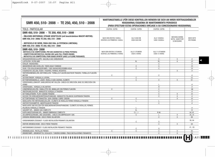
A11
A
SMR 450, 510- 2008 - TE 250, 450, 510 - 2008WARTUNGSTABELLE (FÜR DIESE KONTROLLEN WENDEN SIE SICH AN IHREN VERTRAGSHÄNDLER
HUSQVARNA) ESQUEMA DE MANTENIMIENTO PERIODICO (PARA EFECTUAR ESTAS OPERACIONES DIRÍJASE A SU CONCESIONARIO HUSQVARNA)
TEILE- PARTICULAR COUPON- CUPÓN COUPON- CUPÓN COUPON- CUPÓN
SMR 450, 510- 2008 - TE 250, 450, 510 - 2008- ÜBLICHES MOTORRAD, STRAßE GESETZLICH (mit beschränktem MACHT-MOTOR): SMR 450, 510- 2008; TE 250, 450, 510 - 2008
- MOTOCICLO DE SERIE, PARA USO VIAL (A POTENCIA LIMITADA):SMR 450, 510- 2008; TE 250, 450, 510 - 2008
NACH DEN ERSTEN 1000Km-DESPUES LOS PRIMEROS 1000Km
ALLE 5000 KMCADA 5000 KM
ALLE 10000KmCADA 10000Km
WECHSELN WENN NÖTIG- SUBSTITUÍR
SI NECESARIO
SIEHE SEITEVER PAGINA
SMR 450, 510- 2008-MOTOCICLO DA COMPETIZIONE, PER USO AGONISTICO (A PIENA POTENZA) - COMPETITION MOTORCYCLE, RACING USE (with FULL POWER ENGINE)- MOTOCYCLE DE COMPÉTITION, POUR USAGE SPORTIF (AVEC LA PLEINE PUISSANCE)
NACH DEN ERSTEN 3 STUNDEN- DESPUES LAS PRIMERAS 3 HORAS
ALLE 5 STUNDENCADA 5 HORAS
ALLE 15 STUNDENCADA 15 HORAS
VERGASERDROSSELKLAPPE- VALVUÁLA GAS CARBURADOR C X #LUFTFILTER- FILTRO AIRE PL PL X 37KÜHLER- RADIADORES C #WASSERROHR UND SCHELLEN- TUBOS AGUA Y BANDAS C C 31ROHR FÜR KÜHLER/WASSERPUMPE- TUBO RADIADORES/BOMBA AGUA C C 31FUSSRASTER, BOLZEN, FEDER- POSAPIES, PERNOS, RESORTES X #HINTERRAHMENBOLZEN, MOTORBOLZEN- TORNILLOS FIJACIÓN BASTIDOR TRASERO, TORNILLOS FIJACIÓN MOTOR C C #SEITENSTÄNDER- HORQUILLA LATERAL C 12KETTENFÜHRUNGROLLE, LAGER- RODILLO GUÍA-CADENA, COJÍNETE C C X 51VORDERGABELLENKKOPF, GABELBRÜCKE MIT BOLZEN- CABEZA DE DIRECCIÓN, BASE DE DIRECCIÓN CON PERNO L #VORDERGABEL- HORQUILLA DELANTERA R #LENKERBÜGELBOLZEN- CABALLETES DEL MANILLAR CON PERNOS FIJACIÓN C C 46HINTERGABELBUCHSE- MANGUITOS HORQUILLA TRASERA C #KETTENGLEITBAHN- PLATO CADENA TRASERA C X 51BUCHSE FÜR HEBELWERKHINTERHAUFHANGUNG- MANGUITOS PALANCAS SUSPENSION TRASERA C X #KETTENFÜHRUNG/ KETTENKASTEN- GUÍA-CADENA/ CUBRE-CADENA C C X 51NADELKAFIG FÜR HINTERGABELBOLZEN- COJÍNETE DE RODILLOS PERNO HORQUILLA TRASERA L L #HINTERSTOSSDAMPFER- AMORTIGUADOR TRASERO C #NADELKAFIG UND BOLZEN FÜR HEBELWERKHINTERHAUFHANGUNG- COJÍNETE DE RODILLOS, PERNOS PALANCAS HORQUILLA TRASERA L #GASGRIFF KPL.- MANDO GAS COMPLETO CL 31KUPPLUNGSTEUERUNG KPL.- MANDO EMBRAGUE COMPLETO C (…) R (#) (•): 41DECOMPRESSORKABEL UND GASGKABEL- CABLES DECOMPRESSOR Y GAS C L X 25, 31VORDERE BREMSSCHEIBE- DISCO FRENO DELANTERO C X 59
VORDERBREMSFLÜSSIGKEIT- FLUIDO INSTALACIÓN FRENANTE DELANTERAC S
39, 64
HINTERE BREMSSCHEIBE- DISCO FRENO TRASERO C X 59
HINTERBREMSFLÜSSIGKEIT- FLUIDO INSTALACIÓN FRENANTE TRASERAC S
41, 65
BREMSBELAEGE- PASTILLAS FRENOS C C C X 56BREMSPUMPE –BREMSSÄTTEL SCHLAUCH- TUBERÍAS BOMBA -PINZA INSTALACIÓNES FRENANTES C X 59
SRM 450 ted pag 1.indd 2 28-07-2006 9:58:30SRM 450 ita PAG 1.indd 2 28-07-2006 9:54:19
AppendiceA 9-07-2007 10:07 Pagina A11
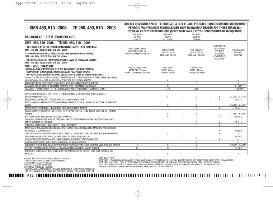
A12
SMR 450, 510- 2008 - TE 250, 450, 510 - 2008SCHEMA DI MANUTENZIONE PERIODICA (DA EFFETTUARE PRESSO IL CONCESSIONARIO HUSQVARNA
PERIODIC MAINTENANCE SCHEDULE (SEE YOUR HUSQVARNA DEALER FOR THESE SERVICES) ESQUEME ENTRETIEN PERIODIQUE (EFFECTUER PAR LE VOTRE CONCESSIONAIRE HUSQVARNA)
PARTICOLARE- ITEM- PARTICULAIRETAGLIANDO COUPON COUPON
TAGLIANDO COUPO
N- COUPON
TAGLIANDOCOUPONCOUPON
SMR 450, 510- 2008 - TE 250, 450, 510 - 2008- MOTOCICLO DI SERIE, PER USO STRADALE (A POTENZA LIMITATA): SMR 450, 510- 2008; TE 250, 450, 510 - 2008
- STANDARD MOTORCYCLE, STREET LEGAL (with LIMITED POWER ENGINE):SMR 450, 510- 2008; TE 250, 450, 510 - 2008
- MOTOCYCLE DE SÉRIE, POUR USAGE ROUTIER (AVEC LA PUISSANCE LIMITÉ): SMR 450, 510- 2008; TE 250, 450, 510 - 2008
DOPO I PRIMI 1000Km AFTER FIRST 1000 Km
APRÈS LES PREMIERS 1000 Km
OGNI 5000 KMEVERY 5000 Km
TOUS LES 5000 Km
OGNI 10000KmEVERY 10000 Km
TOUS LES 10000 Km
SOSTITUIRE SE NECESSARIOREPLACE IF NECESSARY
REMPLACER SI NÉCESSAIRE
VEDERE PAGINASEE PAGE*VOIR PAGE
SMR 450, 510-2008-MOTOCICLO DA COMPETIZIONE, PER USO AGONISTICO (A PIENA POTENZA) - COMPETITION MOTORCYCLE, RACING USE (with FULL POWER ENGINE)- MOTOCYCLE DE COMPÉTITION, POUR USAGE SPORTIF (AVEC LA PLEINE PUISSANCE)
DOPO LE PRIME 3 ORE AFTER FIRST 3 hours
APRÈS LES PREMIERS 3 heures
OGNI 5 OREEVERY 5 hours
TOUS LES 5heures
OGNI 15 OREEVERY 15 hours
TOUS LES 15 heures
GABBIE A RULLI, SPINOTTI LEVERAGGI SOSPENSIONE POST.- REAR SUSPENSION LINKS NEEDLE BEARINGS AND GUDGEON PIN - CAGE À AIGUILLES, AXES LEVIER SUSPENSION ARRIÉRE L #AMMORTIZZATORE POSTERIORE-REAR SHOCK ABSORBER-AMMORTISSEUR ARRIÈRE C #COMANDO GAS COMPLETO- THROTTLE CONTROL ASSY.- COMMANDE GAZ COMPL. CL 31 (33*)COMANDO FRIZIONE COMPLETO- CLUTCH CONTROL ASSY.- COMMANDE EMBRAYAGE COMPL. C (•) R (#) (•):41 (43*)
CAVI DECOMPRESSORE E GAS- THROTTLE AND STARTING DECOMPRESSOR CABLES- CÂBLES DECOMPRESSEUR ET GAZ C L X 23 (25*) - 31 (33*)DISCO FRENO ANTERIORE- FRONT BRAKE DISC- DISQUE FREIN AVANT C X 59 (61*)FLUIDO IMPIANTO FRENANTE ANTERIORE- FRONT BRAKE SYSTEM FLUID- FLUIDE SYSTÈME DE FREINAGE AVANT C S 39 (41*) - 64 (66*)DISCO FRENO POSTERIORE- REAR BRAKE DISC- DISQUE FREIN ARRIÉRE C XFLUIDO IMPIANTO FRENANTE POSTERIORE- REAR BRAKE SYSTEM FLUID- FLUIDE SYSTÈME DE FREINAGE ARRIÉRE C S 41 (43*) - 65 (67*)PASTIGLIE FRENI- BRAKE PADS- PASTILLES DU FREINS C C C X 56 (58*)TUBAZIONI POMPA/PINZA IMPIANTI FRENANTI- BRAKE SYSTEM PUMP-CALIPER HOSES- TUYAU POMPE/ETRIER SYSTÈME DE FREINAGE C XTUBAZIONI CARBURANTE- FUEL HOSES- TUYAU CARBURANT C X #MATERIALE FONOASSORBENTE SILENZIATORE- EXHAUST SILENCER PACKING- MATERIAL INSONORISANT SILENCIEUX D’ECHAPPEMENT X 67 (69*)TUBO DI SCARICO E SILENZIATORE- EXHAUST PIPE AND SILENCER- TUYAU ET SILENCIEUX D’ECHAPPEMENT C X #TENSIONE RAGGI RUOTE- WHEEL SPOKES TENSION- TENSION BRAS RUOES C C 76 (78*)CUSCINETTI MOZZI RUOTE- WHEEL HUB BEARINGS- ROULEMENTS MOYEAUS RUOES C X #CORONA POSTERIORE- REAR DRIVEN SPROCKET- COURONNE ARRIÉRE S #SERRAGGIO VITI CORONA- REAR DRIVEN SPROCKET SCREWS TIGHTENING- SERRAGE VIS COURONNE ARRIÉRE C C C 50 (52*) - 90 (92*)CATENA TRASMISSIONE SECONDARIA- REAR TRANSMISSION CHAIN- CHAINE ARRIÉRE CL CL S 50 (52*)SERRAGGIO BULLONERIA- BOLTS AND NUTS TIGHTNESS GENERAL CHECK - CONTRÔLE SERRAGE DES BOULONS C C #
LEGENDA- KEY FOR MAINTENANCE SCHEDULE- LEGENDES: SOSTITUZIONE- REPLACEMENT- REMPLACEMENTC: CONTROLLO- CHECK- CONTRÔLEP: PULIZIA- CLEANING- NETTOYAGER: REVISIONE- OVERHAUL- REVISIONL: INGRASSAGGIO/LUBRIFICAZIONE- GREASING/LUBRICATION- LUBRIFICATION/GRAISSAGE#: VEDERE IL MANUALE DI OFFICINA- SEE WORKSHOP MANUAL- VOIR MANUAL D’ATELIER
NOTE- NOTE- NOTESOSTITUIRE LE GUARNIZIONI IN OCCASIONE DI OGNI SMONTAGGIO- EVERY REMOVAL REPLACE ALL GASKETS- TOUTES LES DÉMONTAGES, REMPLACER LES GARNITURESSOSTITUIRE LA VITERIA IN CASO DI DETERIORAMENTO- REPLACE SCREWS AND NUTS IF WORN- AU CAS DE DÉTÉRIORATION, REMPLACER LES BOULONSDOPO PERCORRENZE SU FANGO O SABBIA EFFETTUARE UNA VERIFICA GENERALE- GENERAL CHECK AFTER RACING USE ON MUDDY OR SANDY GROUNDS- APRÈS USAGE SUR DES TERREINS BOUEUX OU SABLEUX, EFFECTUER UN CONTRÔLE GENERAL
SRM 450 ita PAG 1.indd 3 28-07-2006 9:54:20
59 (61*)
59 (61*)
AppendiceA 9-07-2007 10:07 Pagina A12
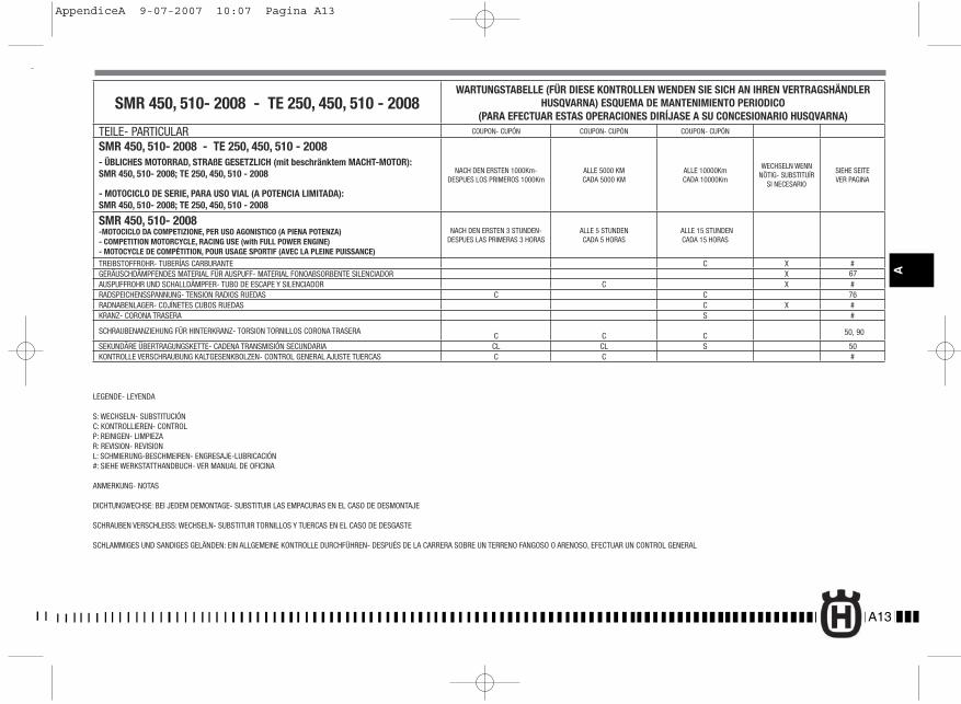
A13
A
SMR 450, 510- 2008 - TE 250, 450, 510 - 2008WARTUNGSTABELLE (FÜR DIESE KONTROLLEN WENDEN SIE SICH AN IHREN VERTRAGSHÄNDLER
HUSQVARNA) ESQUEMA DE MANTENIMIENTO PERIODICO (PARA EFECTUAR ESTAS OPERACIONES DIRÍJASE A SU CONCESIONARIO HUSQVARNA)
TEILE- PARTICULAR COUPON- CUPÓN COUPON- CUPÓN COUPON- CUPÓN
SMR 450, 510- 2008 - TE 250, 450, 510 - 2008- ÜBLICHES MOTORRAD, STRAßE GESETZLICH (mit beschränktem MACHT-MOTOR): SMR 450, 510- 2008; TE 250, 450, 510 - 2008
- MOTOCICLO DE SERIE, PARA USO VIAL (A POTENCIA LIMITADA):SMR 450, 510- 2008; TE 250, 450, 510 - 2008
NACH DEN ERSTEN 1000Km-DESPUES LOS PRIMEROS 1000Km
ALLE 5000 KMCADA 5000 KM
ALLE 10000KmCADA 10000Km
WECHSELN WENN NÖTIG- SUBSTITUÍR
SI NECESARIO
SIEHE SEITEVER PAGINA
SMR 450, 510- 2008-MOTOCICLO DA COMPETIZIONE, PER USO AGONISTICO (A PIENA POTENZA) - COMPETITION MOTORCYCLE, RACING USE (with FULL POWER ENGINE)- MOTOCYCLE DE COMPÉTITION, POUR USAGE SPORTIF (AVEC LA PLEINE PUISSANCE)
NACH DEN ERSTEN 3 STUNDEN- DESPUES LAS PRIMERAS 3 HORAS
ALLE 5 STUNDENCADA 5 HORAS
ALLE 15 STUNDENCADA 15 HORAS
TREIBSTOFFROHR- TUBERÍAS CARBURANTE C X #GERÄUSCHDÄMPFENDES MATERIAL FÜR AUSPUFF- MATERIAL FONOABSORBENTE SILENCIADOR X 67AUSPUFFROHR UND SCHALLDÄMPFER- TUBO DE ESCAPE Y SILENCIADOR C X #RADSPEICHENSSPANNUNG- TENSION RADIOS RUEDAS C C 76RADNABENLAGER- COJÍNETES CUBOS RUEDAS C X #KRANZ- CORONA TRASERA S #
SCHRAUBENANZIEHUNG FÜR HINTERKRANZ- TORSION TORNILLOS CORONA TRASERA C C C 50, 90
SEKUNDÄRE ÜBERTRAGUNGSKETTE- CADENA TRANSMISIÓN SECUNDARIA CL CL S 50KONTROLLE VERSCHRAUBUNG KALTGESENKBOLZEN- CONTROL GENERAL AJUSTE TUERCAS C C #
LEGENDE- LEYENDA
S: WECHSELN- SUBSTITUCIÓNC: KONTROLLIEREN- CONTROLP: REINIGEN- LIMPIEZAR: REVISION- REVISIONL: SCHMIERUNG-BESCHMEIREN- ENGRESAJE-LUBRICACIÓN#: SIEHE WERKSTATTHANDBUCH- VER MANUAL DE OFICINA
ANMERKUNG- NOTAS
DICHTUNGWECHSE: BEI JEDEM DEMONTAGE- SUBSTITUIR LAS EMPACURAS EN EL CASO DE DESMONTAJE
SCHRAUBEN VERSCHLEISS: WECHSELN- SUBSTITUIR TORNILLOS Y TUERCAS EN EL CASO DE DESGASTE
SCHLAMMIGES UND SANDIGES GELÄNDEN: EIN ALLGEMEINE KONTROLLE DURCHFÜHREN- DESPUÉS DE LA CARRERA SOBRE UN TERRENO FANGOSO O ARENOSO, EFECTUAR UN CONTROL GENERAL
SRM 450 ted pag 1.indd 3 28-07-2006 9:58:31
SRM 450 ita PAG 1.indd 3 28-07-2006 9:54:20
AppendiceA 9-07-2007 10:07 Pagina A13

A14
MEMORANDUM
AppendiceA 9-07-2007 10:07 Pagina A14
A15
A
MEMORANDUM
AppendiceA 9-07-2007 10:07 Pagina A15

A16
MEMORANDUM
AppendiceA 9-07-2007 10:07 Pagina A16

A17
A
MEMORANDUM
AppendiceA 9-07-2007 10:07 Pagina A17
A18
MEMORANDUM
AppendiceA 9-07-2007 10:07 Pagina A18
A19
A
MEMORANDUM
AppendiceA 9-07-2007 10:07 Pagina A19
A20
MEMORANDUM
AppendiceA 9-07-2007 10:07 Pagina A20