User Manual | HikCentral Professional Control Client - Hikvision
209
HikCentral Professional Control Client User Manual
-
Upload
khangminh22 -
Category
Documents
-
view
0 -
download
0
Transcript of User Manual | HikCentral Professional Control Client - Hikvision

HikCentral Professional Control ClientUser Manual

Legal Information
©2019 Hangzhou Hikvision Digital Technology Co., Ltd. All rights reserved.
About this ManualThe Manual includes instructions for using and managing the Product. Pictures, charts, images andall other information hereinafter are for description and explanation only. The informationcontained in the Manual is subject to change, without notice, due to firmware updates or otherreasons. Please find the latest version of this Manual at the Hikvision website ( https://www.hikvision.com/en/ ).Please use this Manual with the guidance and assistance of professionals trained in supporting theProduct.
Trademarks
and other Hikvision's trademarks and logos are the properties ofHikvision in various jurisdictions.Other trademarks and logos mentioned are the properties of their respective owners.
DisclaimerTO THE MAXIMUM EXTENT PERMITTED BY APPLICABLE LAW, THIS MANUAL AND THE PRODUCTDESCRIBED, WITH ITS HARDWARE, SOFTWARE AND FIRMWARE, ARE PROVIDED “AS IS” AND “WITHALL FAULTS AND ERRORS”. HIKVISION MAKES NO WARRANTIES, EXPRESS OR IMPLIED, INCLUDINGWITHOUT LIMITATION, MERCHANTABILITY, SATISFACTORY QUALITY, OR FITNESS FOR A PARTICULARPURPOSE. THE USE OF THE PRODUCT BY YOU IS AT YOUR OWN RISK. IN NO EVENT WILL HIKVISIONBE LIABLE TO YOU FOR ANY SPECIAL, CONSEQUENTIAL, INCIDENTAL, OR INDIRECT DAMAGES,INCLUDING, AMONG OTHERS, DAMAGES FOR LOSS OF BUSINESS PROFITS, BUSINESSINTERRUPTION, OR LOSS OF DATA, CORRUPTION OF SYSTEMS, OR LOSS OF DOCUMENTATION,WHETHER BASED ON BREACH OF CONTRACT, TORT (INCLUDING NEGLIGENCE), PRODUCT LIABILITY,OR OTHERWISE, IN CONNECTION WITH THE USE OF THE PRODUCT, EVEN IF HIKVISION HAS BEENADVISED OF THE POSSIBILITY OF SUCH DAMAGES OR LOSS.YOU ACKNOWLEDGE THAT THE NATURE OF INTERNET PROVIDES FOR INHERENT SECURITY RISKS,AND HIKVISION SHALL NOT TAKE ANY RESPONSIBILITIES FOR ABNORMAL OPERATION, PRIVACYLEAKAGE OR OTHER DAMAGES RESULTING FROM CYBER-ATTACK, HACKER ATTACK, VIRUSINSPECTION, OR OTHER INTERNET SECURITY RISKS; HOWEVER, HIKVISION WILL PROVIDE TIMELYTECHNICAL SUPPORT IF REQUIRED.YOU AGREE TO USE THIS PRODUCT IN COMPLIANCE WITH ALL APPLICABLE LAWS, AND YOU ARESOLELY RESPONSIBLE FOR ENSURING THAT YOUR USE CONFORMS TO THE APPLICABLE LAW.ESPECIALLY, YOU ARE RESPONSIBLE, FOR USING THIS PRODUCT IN A MANNER THAT DOES NOTINFRINGE ON THE RIGHTS OF THIRD PARTIES, INCLUDING WITHOUT LIMITATION, RIGHTS OFPUBLICITY, INTELLECTUAL PROPERTY RIGHTS, OR DATA PROTECTION AND OTHER PRIVACY RIGHTS.YOU SHALL NOT USE THIS PRODUCT FOR ANY PROHIBITED END-USES, INCLUDING THEDEVELOPMENT OR PRODUCTION OF WEAPONS OF MASS DESTRUCTION, THE DEVELOPMENT OR
HikCentral Professional Control Client User Manual
i

PRODUCTION OF CHEMICAL OR BIOLOGICAL WEAPONS, ANY ACTIVITIES IN THE CONTEXT RELATEDTO ANY NUCLEAR EXPLOSIVE OR UNSAFE NUCLEAR FUEL-CYCLE, OR IN SUPPORT OF HUMANRIGHTS ABUSES.IN THE EVENT OF ANY CONFLICTS BETWEEN THIS MANUAL AND THE APPLICABLE LAW, THE LATERPREVAILS.
HikCentral Professional Control Client User Manual
ii

Symbol Conventions
The symbols that may be found in this document are defined as follows.
Symbol Description
DangerIndicates a hazardous situation which, if not avoided, will or couldresult in death or serious injury.
CautionIndicates a potentially hazardous situation which, if not avoided, couldresult in equipment damage, data loss, performance degradation, orunexpected results.
NoteProvides additional information to emphasize or supplementimportant points of the main text.
HikCentral Professional Control Client User Manual
iii

ContentsChapter 1 About Control Client ................................................................................................... 1
1.1 Overview ................................................................................................................................ 1
1.2 Control Panel Overview ......................................................................................................... 1
1.3 Customize Module Arrangement on Control Panel ............................................................... 4
Chapter 2 Login .......................................................................................................................... 6
2.1 First Time Login ...................................................................................................................... 6
2.2 Normal Login (Not First Time) ................................................................................................ 7
2.3 Change Password for Reset User and Login ........................................................................... 9
Chapter 3 Manage View ........................................................................................................... 12
Chapter 4 Live View .................................................................................................................. 14
4.1 Start Live View in Area Mode ............................................................................................... 14
4.2 Start Live View in View Mode .............................................................................................. 16
4.3 Auto-Switch Camera in Area Mode ...................................................................................... 17
4.4 Auto-Switch View Group's Views ......................................................................................... 17
4.5 Auto-Switch One View's Cameras ........................................................................................ 18
4.6 PTZ Control .......................................................................................................................... 19
4.6.1 Configure Preset ......................................................................................................... 21
4.6.2 Configure Patrol .......................................................................................................... 22
4.6.3 Configure Pattern ........................................................................................................ 23
4.7 Manual Recording and Capture ........................................................................................... 24
4.7.1 Manual Recording ....................................................................................................... 24
4.7.2 View Manually Recorded Videos ................................................................................ 25
4.7.3 Capture Pictures .......................................................................................................... 26
4.7.4 Edit Captured Picture .................................................................................................. 26
4.7.5 View Captured Pictures ............................................................................................... 27
4.8 View Dewarped Live View of Fisheye Camera ..................................................................... 28
HikCentral Professional Control Client User Manual
iv

4.9 View Detected Event in Live View ........................................................................................ 29
4.10 Stop Live View .................................................................................................................... 30
4.11 More Functions .................................................................................................................. 31
4.12 Customize Icons on Live View Window .............................................................................. 32
Chapter 5 Playback ................................................................................................................... 35
5.1 Normal Playback .................................................................................................................. 35
5.1.1 Search Video File ......................................................................................................... 35
5.1.2 Play Video File ............................................................................................................. 36
5.2 Start Playback in View Mode ............................................................................................... 37
5.3 Synchronous Playback .......................................................................................................... 37
5.4 Fisheye Playback .................................................................................................................. 38
5.5 Customize Icons on Playback Window ................................................................................. 38
Chapter 6 Visual Tracking .......................................................................................................... 41
6.1 Perform Visual Tracking in Live View ................................................................................... 41
6.2 View Visual Tracking Video .................................................................................................. 42
Chapter 7 Video Search ............................................................................................................ 44
7.1 Search Video by Time Range ................................................................................................ 44
7.2 Search Tagged Video Footage .............................................................................................. 46
7.3 Search Locked Video Footage .............................................................................................. 49
7.4 Search Video/Picture/Audio Stored on Dock Station ........................................................... 51
7.5 Search Transaction Event Triggered Video Footage ............................................................. 52
7.6 Search ATM Event Triggered Video Footage ........................................................................ 54
7.7 Search VCA Event Related Video .......................................................................................... 56
Chapter 8 Manage Downloading Tasks ...................................................................................... 60
Chapter 9 Check Alarm and Event ............................................................................................. 62
9.1 Perform Arming Control ....................................................................................................... 62
9.2 View Resource's Real-Time Alarm ........................................................................................ 63
9.3 Search Event/Alarm Logs ..................................................................................................... 66
HikCentral Professional Control Client User Manual
v

9.4 Manually Trigger User-Defined Event .................................................................................. 67
9.5 View Pop-up Window Triggered by Alarm ........................................................................... 68
Chapter 10 Map Management .................................................................................................. 70
10.1 Operate Hot Spot ............................................................................................................... 70
10.1.1 Preview Hot Spot ...................................................................................................... 70
10.1.2 Perform Arming Control ............................................................................................ 72
10.1.3 View History Alarm ................................................................................................... 73
10.2 Preview Hot Region ............................................................................................................ 74
10.3 Preview Resource Group .................................................................................................... 74
10.4 Operate Map ...................................................................................................................... 75
Chapter 11 Manage Evidence .................................................................................................... 77
11.1 Save Manually Recorded Video as Evidence in Live View .................................................. 77
11.2 Save Clipped Video as Evidence in Playback ...................................................................... 78
11.3 Save Found Video Footage as Evidence ............................................................................. 79
11.4 Save Downloaded Video Footage as Evidence ................................................................... 80
11.5 Search Evidence ................................................................................................................. 81
Chapter 12 Access Control and Elevator Control ....................................................................... 84
12.1 Control Door Status in Live View ........................................................................................ 84
12.2 Control Floor Status in Live View ....................................................................................... 86
12.3 Open Door for Multi-Factor Authentication ...................................................................... 88
12.4 Handle Opening Door Request from Video Access Control Terminal ................................ 89
12.5 Search Access Records ....................................................................................................... 90
12.6 Perform Entry & Exit Counting ........................................................................................... 92
Chapter 13 Facial Comparison ................................................................................................... 94
13.1 View Detected and Matched Face in Live View ................................................................. 94
13.2 Add Mismatched Person to Person List ............................................................................. 96
13.3 Person Search .................................................................................................................... 98
13.3.1 Search Captured Face Picture and Related Video ..................................................... 98
HikCentral Professional Control Client User Manual
vi

13.3.2 Search Matched Face Picture and Related Video .................................................... 101
13.3.3 Search Frequently Appeared Person' Pictures ........................................................ 104
13.4 Archive Search ................................................................................................................. 105
13.5 Identity Verification ......................................................................................................... 107
13.5.1 Compare with Face Comparison Group .................................................................. 107
13.5.2 Compare with Specific Picture ................................................................................ 108
Chapter 14 Vehicle .................................................................................................................. 111
14.1 View ANPR Camera's Live Video ...................................................................................... 111
14.2 View UVSS's Live Video .................................................................................................... 112
14.3 Add Recognized Vehicle to Vehicle List ............................................................................ 114
14.4 Search Recognized Vehicles ............................................................................................. 116
Chapter 15 Security Control .................................................................................................... 120
15.1 Start Live View of Radar's Calibrated Camera .................................................................. 120
15.2 Perform Arming Control ................................................................................................... 121
15.3 Handle Panic Alarm from Panic Alarm Station ................................................................. 123
Chapter 16 Smart Wall ............................................................................................................ 124
16.1 Manage Smart Wall (Decoding Device) ............................................................................ 124
16.1.1 Decode and Display Directly ................................................................................... 126
16.1.2 View Settings ........................................................................................................... 128
16.1.3 Perform View Auto-Switch ...................................................................................... 130
16.1.4 Perform Auto-Switch of an Area's Cameras ............................................................ 130
16.1.5 Create a Roaming Window ..................................................................................... 131
16.1.6 View Alarm's Related Video on Smart Wall ............................................................ 132
16.1.7 View and Export Window No. and Camera ID ........................................................ 133
16.2 Manage Smart Wall (Graphic Card) ................................................................................. 133
16.2.1 Display Contents on Smart Wall in Smart Wall Mode ............................................. 134
16.2.2 Display Contents on Smart Wall in Live View Mode ............................................... 136
16.2.3 Display Alarm's Related Video on Smart Wall ......................................................... 140
HikCentral Professional Control Client User Manual
vii

16.2.4 Display Health Monitoring Page on Smart Wall ...................................................... 143
Chapter 17 Intelligent Analysis Report .................................................................................... 145
17.1 Customize Report Dashboard .......................................................................................... 145
17.2 Generate People Counting Report ................................................................................... 146
17.3 Generate Queue Analysis Report ..................................................................................... 151
17.4 Generate Heat Analysis Report ........................................................................................ 156
17.5 Generate Pathway Analysis Report .................................................................................. 160
17.6 Generate Person Feature Analysis Report ....................................................................... 164
17.7 Generate Temperature Report ......................................................................................... 166
17.8 Generate Vehicle Analysis Report .................................................................................... 170
Chapter 18 Maintenance ........................................................................................................ 174
18.1 Health Monitoring ........................................................................................................... 174
18.1.1 Real-Time Overview ................................................................................................ 174
18.1.2 History Overview ..................................................................................................... 175
18.2 Resource Status ................................................................................................................ 177
18.3 Log Search ........................................................................................................................ 181
18.3.1 Search Server Logs for Current Site ......................................................................... 181
18.3.2 Search Server Logs for Remote Site ........................................................................ 182
18.3.3 Search Online/Offline Logs of Device ...................................................................... 183
18.3.4 Search Device Logs .................................................................................................. 184
18.3.5 Search Online/Offline Logs of Resource .................................................................. 185
18.3.6 Search Recording Status of Resource ...................................................................... 186
18.3.7 Back Up Logs ........................................................................................................... 189
Chapter 19 Tools ..................................................................................................................... 190
19.1 Play Video via VSPlayer .................................................................................................... 190
19.2 Broadcast to Connected Devices ..................................................................................... 190
19.3 Perform Two-Way Audio .................................................................................................. 191
19.4 Control Alarm Output ...................................................................................................... 191
HikCentral Professional Control Client User Manual
viii

Chapter 20 System Settings ..................................................................................................... 193
20.1 Set General Parameters ................................................................................................... 193
20.2 Set Image Parameters ...................................................................................................... 195
20.3 Set File Saving Path .......................................................................................................... 196
20.4 Set Keyboard and Joystick Parameters ............................................................................. 197
20.5 Set Screen Position .......................................................................................................... 197
20.6 Set Alarm Sound .............................................................................................................. 197
20.7 Set Health Monitoring Parameters .................................................................................. 198
HikCentral Professional Control Client User Manual
ix
Chapter 1 About Control Client
1.1 OverviewAs one of the key components of the system, Control Client provides multiple operatingfunctionalities, including real-time live view, PTZ control, video playback and download, alarmreceiving, log query, and so on.
This user manual describes the function, configuration, and operation steps of the Control Client.To ensure the proper usage and stability of the client, refer to the contents below and read themanual carefully before operation.
NoteThe functions on the Control Client vary with the License you purchased. For detailed information,contact our technical support.
1.2 Control Panel OverviewThe control panel provides an overview of navigation and menu about the function modules. Itcontains multiple sections for the modules, such as Surveillance, Investigation, Intelligent Analysis,Maintenance, Tool, and Management. You can access to the function modules you want quicklyand conveniently via control panel.
The HikCentral Professional Control Client is composed of the following function modules bydefault.
NoteYou can custom and adjust the module arrangement as you desired. For details, refer to CustomizeModule Arrangement on Control Panel .
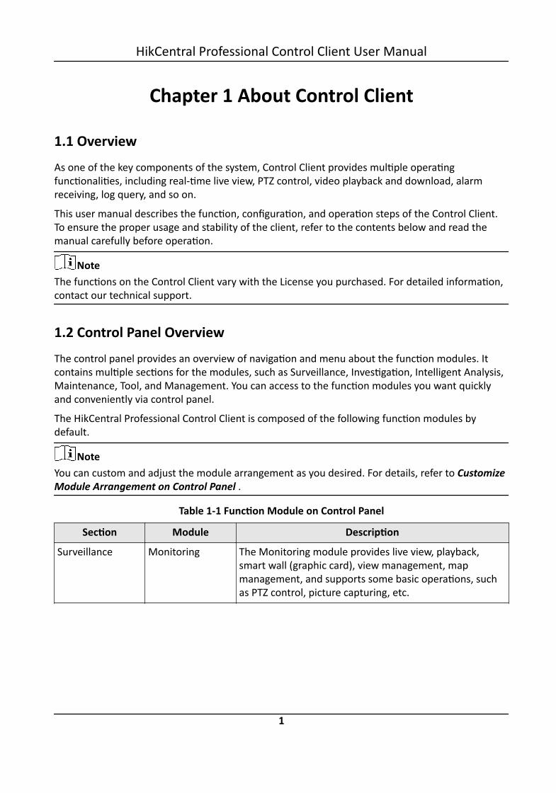
Table 1-1 Function Module on Control Panel
Section Module Description
Surveillance Monitoring The Monitoring module provides live view, playback,smart wall (graphic card), view management, mapmanagement, and supports some basic operations, suchas PTZ control, picture capturing, etc.
HikCentral Professional Control Client User Manual
1

Section Module Description
For more details, refer to Live View , Playback , MapManagement , and Manage Smart Wall (Graphic Card) .
Alarm Center The Alarm Center module provides the display andmanagement of alarm/event information received byControl Client.For more details, refer to Check Alarm and Event .
Investigation Video Search The Video Search module provides searching videofootage, video on device, or VCA event related video.For more details, refer to Video Search .
Person Search The Person Search module provides searching captured/matched/frequently appeared person's face picture andrelated video, archive information, and identityverification records.For more details, refer to Search Captured Face Pictureand Related Video , Search Matched Face Picture andRelated Video . Search Frequently Appeared Person'Pictures , Archive Search , and Compare with FaceComparison Group .
Alarm/EventSearch
The Alarm/Event Search module provides searchingalarm/event logs.For more details, refer to Search Event/Alarm Logs .
Vehicle Search The Vehicle Search module provides searching relatedvehicle passing information.For more details, refer to Search Recognized Vehicles .
Identity AccessSearch
The Identify Access module provides searching accessrecords and entry&exit counting.For more details, refer to Search Access Records andSearch Access Records .
Evidence Search The Evidence Search module provides searching videofootage which evidence information.For more details, refer to Search Evidence .
IntelligentAnalysis
Dashboard The Dashboard module provides customizing and viewingreports.For more details, refer to Customize Report Dashboard .
HikCentral Professional Control Client User Manual
2

Section Module Description
People Analysis The People Analysis module provides reports for peoplecounting, queue analysis, heat analysis, pathway analysis,and person feature analysis.For more details, refer to Generate People CountingReport , Generate Queue Analysis Report , GenerateHeat Analysis Report , Generate Pathway AnalysisReport , and Generate Person Feature Analysis Report .
TemperatureAnalysis
The Temperature Analysis module provides report fortemperature analysis.For more details, refer to Generate Temperature Report .
Vehicle Analysis The Vehicle Analysis provides report for the number ofpassing vehicles.For more details, refer to Generate Vehicle AnalysisReport .
Maintenance Health Monitoring The Health Monitoring module provides real-timeoverview and history overview of the resources andservice status.For more details, refer to Real-Time Overview andHistory Overview .
Real-Time Statusof Resource
The Real-Time Status of Resource module provides thestatus for the resources.For more details, refer to Resource Status .
Audit Trail The Audit Trail module provides searching, viewing, andbacking up the log files.For more details, refer to Log Search .
Tool Smart Wall The Smart Wall module provides the function ofdisplaying the decoded video on smart wall.For more details, refer to Manage Smart Wall (DecodingDevice)
VSPlayer Via VSPlayer module, you can run the software and playvideo files stored in the local PC.For more details, refer to Play Video via VSPlayer .
Broadcast The broadcast function supports distributing audiocontent to the added device if the device has an audiooutput.For more details, refer to Broadcast to Connected Devices
HikCentral Professional Control Client User Manual
3

Section Module Description
Alarm Output The alarm output function provides controlling alarmoutput remotely by Control Client.For more details, refer to Control Alarm Output .
Two-Way Audio The Two-Way Audio module provides the networkcommunication between the Control Client and theadded resources.
Management Download Center The Download Center module supports viewing andmanaging the downloading tasks.For more details, refer to Manage Downloading Tasks .
Local Picture The Local Picture module provides the search andmanagement of local pictures.
Local Recording The Local Recording module provides the search andmanagement of local video files.
System The System module provides basic settings andapplication settings.For more details, refer to System Settings .
Help The Help module provides help information, such as usermanual, license details and software version of ControlClient.
1.3 Customize Module Arrangement on Control PanelYou can customize the modules arrangement displayed on the control panel. The control panel isdivided into two areas: common area on the left and uncommon area on the right. For thefrequently-used modules, you can arrange them on the common area, which contains fivesections: Surveillance, Investigation, Intelligent Analysis, Maintenance, and Others. The othermodules which are not used so frequently, can be arranged on the uncommon area. The module'ssection and order is fixed. You can only drag the module from the common area to uncommonarea, or from uncommon area to common area, but you cannot adjust the fixed section andarrangement order in one section.
Drag the module to the desired area to customize the module arrangement.
HikCentral Professional Control Client User Manual
4

Figure 1-1 Module Arrangement on Control Panel
Note• If there are no modules in one section, the section will not be displayed in the area.• If you drag the modules in Tool section and Management section of uncommon area into
common area, they will be grouped into Others section in common area.
HikCentral Professional Control Client User Manual
5

Chapter 2 Login
Log in to the system via the Control Client for operations.
2.1 First Time LoginWhen normal user (except admin user) logs in to the system for the first time, he/she shouldchange the initial password and set a new password for login.
Before You StartWhen you log in to the system for the first time, you are required to create a password for thesystem pre-defined administrator user (named admin) on the Web Client before you can properlyconfigure and operate the system.Perform the following steps when you access the system via the Control Client for the first time asa normal user (except admin).
Steps1. Double-click on the desktop to run the Control Client.
Figure 2-1 Login Page2. Enter the server parameters.
NoteYou can click Hide Server Address or Show Server Address to hide or show the server networkinformation.
Transfer ProtocolSelect the transfer protocol. You can select HTTP or HTTPS as configured on the Web Client.
Server Address
HikCentral Professional Control Client User Manual
6

Enter the address (IP address or domain name) of the server that running the SYS service youwant to connect to.
PortEnter the port number of the server that running the SYS service. By default, it's 80 for HTTPand 443 for HTTPS.
3. Enter the user name and password of the HikCentral Professional.
Note• Contact the administrator for the user name and initial password.• For domain user account, you can check Auto-Launch so that you will not need to manually
start the Control Client next time you start your computer.
4. Click Login.5. Click Close in the pop-up dialog to continue.6. Set a new password and confirm the password.
CautionThe password strength of the device can be checked by the system. We highly recommend youchange the password of your own choosing (using a minimum of 8 characters, including at leastthree kinds of following categories: upper case letters, lower case letters, numbers, and specialcharacters) in order to increase the security of your product. And we recommend you reset yourpassword regularly, especially in the high security system, resetting the password monthly orweekly can better protect your product.Proper configuration of all passwords and other security settings is the responsibility of theinstaller and/or end-user.
7. Click Login to change the password.You enter the Control Client home page after you change the password.
2.2 Normal Login (Not First Time)Normally, you can log in to the system with the user name and password of HikCentral Professionalas a normal user.
Steps1. Double-click on the desktop to run the Control Client.
HikCentral Professional Control Client User Manual
7

Figure 2-2 Login Page2. Enter the server parameters.
NoteYou can click Hide Server Address or Show Server Address to hide or show the server networkinformation.
Transfer ProtocolSelect the transfer protocol. You can select HTTP or HTTPS as configured on the Web Client.
Server AddressEnter the address (IP address or domain name) of the server that running the SYS servicethat you want to connect to.
PortEnter the port number of the server that running the SYS service. By default, it's 80 for HTTPand 443 for HTTPS.
3. Enter the user name and password of the HikCentral Professional.4. Optional: Check Remember Password checkbox to keep the password.5. Optional: Check Enable Auto-login checkbox to log in to the software automatically for the next
login.
NoteFor domain user account, you can check Auto-Launch so that you will not need to manuallystart the Control Client next time you start your computer.
6. Click Login.
HikCentral Professional Control Client User Manual
8
Note• If failed password attempt of current user is detected, you are required to input theverification code before you can log in. The failed password attempt from current client, otherclient and other address will all require the verification code.
• The failed password attempt from current client, other client (e.g., Control Client) and otheraddress will all be accumulated. Your IP address will be locked for a specified period of timeafter specific number of failed password or verification code attempts. For detailed settings offailed login attempts and locking duration, refer to the User Manual of HikCentral ProfessionalWeb Client.
• The account will be frozen for 30 minutes after 5 failed password attempts. The failedpassword attempt from current client, other client (e.g., Control Client) and other address willall be accumulated.
• The password strength can be checked by the system and should meet the systemrequirements. If password strength is lower than the required minimum strength, you will beasked to change your password. For detailed settings of minimum password strength, refer tothe User Manual of HikCentral Professional Web Client.
• If your password has expired, you will be asked to change your password when login. Fordetailed settings of maximum password age, refer to the User Manual of HikCentralProfessional Web Client.
Enter the Control Client home page.
2.3 Change Password for Reset User and LoginIf the normal user's password is reset to the initial password by the administrator, he/she shouldchange the initial password and set a new password when logging in again.
Perform this task when you need to access the system via Control Client by normal user whosepassword has been reset to the initial one.
Steps1. Double-click on the desktop to run the Control Client.
HikCentral Professional Control Client User Manual
9

Figure 2-3 Login Page2. Enter the server parameters.
NoteYou can click Hide Server Address or Show Server Address to hide or show the server networkinformation.
Transfer ProtocolSelect the transfer protocol. You can select HTTP or HTTPS as configured on the Web Client.
Server AddressEnter the address (IP address or domain name) of the server that running the SYS service youwant to connect to.
PortEnter the port number of the server that running the SYS service. By default, it's 80 for HTTPand 443 for HTTPS.
3. Enter the user name and password of the HikCentral Professional.
Note• Contact the administrator for the user name and initial password.• For domain user account, you can check Auto-Launch so that you will not need to manually
start the Control Client next time you start your computer.
4. Click Login.5. Click Close in the pop-up dialog to continue.6. Set a new password and confirm the password.
CautionThe password strength of the device can be checked by the system. We highly recommend youchange the password of your own choosing (using a minimum of 8 characters, including at least
HikCentral Professional Control Client User Manual
10

three kinds of following categories: upper case letters, lower case letters, numbers, and specialcharacters) in order to increase the security of your product. And we recommend you reset yourpassword regularly, especially in the high security system, resetting the password monthly orweekly can better protect your product.Proper configuration of all passwords and other security settings is the responsibility of theinstaller and/or end-user.
7. Click Login to change the password.You enter the Control Client home page after you change the password.
HikCentral Professional Control Client User Manual
11

Chapter 3 Manage View
A view is a window division with resource channels (e.g., cameras and access points) linked to eachwindow. View mode enables you to save the window division and the correspondence betweencameras and windows (or correspondence between map and window) as favorite so that you canquickly access these channels and (or) map later. For example, you can link camera 1, camera 2,and camera 3 located in your office to the certain display windows and save them as a view calledoffice. Next time, you can access the view office and these cameras will display in the linkedwindow quickly.
Perform this task when you need to get quick access to a certain set of channels for live view orplayback.
Note• For live view, the view mode can save resource type, resource ID, stream type, position and scaleafter digital zoom, preset No., and fisheye dewarping status.
• For playback, the view mode can save resource type, resource ID, position and scale after digitalzoom, and fisheye dewarping status.
Steps1. Click Monitoring on control panel to enter Monitoring page.2. Click to enter the View page.3. Optional: Add a custom view group.
1) Select Public View or Private View to add the view group.
NoteThe view groups and views belonging to the private view group are hidden from the otheruser.
2) Click .3) Create a name for the group or use the default name.4) Click OK to add this view group.
4. Optional: Select a view group.5. Add a view.
1) Click .2) Create a name for the view or use the default name.3) Click OK to add this view.
6. Select a view name for setting window division mode and linked resource channels.7. Click (Logical Resource) tab.8. Drag the channels to the window or double-click the channels to start live view or playback.
NoteFor detailed operations about live view and playback, refer to Live View and Normal Playback .
HikCentral Professional Control Client User Manual
12

9. Save the view with the displayed view division and channels.- Click → Save to save the current window division mode and displayed channels and (or)
map as the selected view.- Click → Save as to save the current window division mode and displayed channels and (or)
map as a new view by creating view name (optional) and selecting the view saving path.
NoteIf the added view is not selected before, you can also save the current window division anddisplayed channels as a new view.
10. Optional: Perform the following operations after adding the view.
Edit View Edit the view settings (such as window division, correspondencebetween channels and display windows, etc.), click and edit theview name.
Add Camera and(or) Map to theExisting View
a. Go to Logical Resource.b. Select camera(s) or map.
NoteYou can click Ctrl on the keyboard to select multiple cameras.
c. Click → Save to View to save the camera(s) or map to anexisting view.
Delete Camera(s)and (or) Map fromView
a. Select camera(s) and (or) map under a view.b. Click → to delete the selected camera(s) and (or) map.
Delete View or ViewGroup
Click to delete the custom view or view group.
Reset If you did other operations on this view, click reset to restore tothe initial view settings.
Result
After adding a view, you can start live view or playback in view mode. See Start Live View in ViewMode and Start Playback in View Mode for details.
HikCentral Professional Control Client User Manual
13

Chapter 4 Live View
You can view live video of the connected cameras. During live view, you can also control PTZcameras, manually record video footage, capture images, and view instant playback. For the ANPRcamera, you can view the recognized license plate number. For the face identification device, youcan view the face comparison information of the detected face. For the access points that relatedto cameras, you can control the access point status in real-time and check the card swipingrecords. You can enter smart wall (graphic card) mode and display the resources on the smart wall.
Navigation Panel
Logic ResourceMode
View a list of available cameras and areas created by the systemadministrator.
Face ComparisonMode
View the face comparison information between the detected faces andthe face pictures in the selected face comparison group.
View Mode Create custom view groups and views of available channels.Edit existing view groups and views.
Smart Wall Mode Enter or exit Smart Wall (Graphic Card) Mode.Set window division and adjust display window on smart wall.
NoteFor more details, refer to Display Contents on Smart Wall in SmartWall Mode .
PTZ Control Mode Control a PTZ camera.Create presets for PTZ cameras.Create patrols for PTZ cameras.Create patterns for PTZ cameras.
4.1 Start Live View in Area ModeLive view shows you the live video getting from cameras.
Before You StartGroup cameras in areas via the Web Client. For details, refer to the User Manual of HikCentralProfessional Web Client.
Steps1. Click Monitoring → Live View to enter the live view page.2. Click (Logical Resource) tab.
HikCentral Professional Control Client User Manual
14

The areas which the current user has permission to access are displayed in the list and thelogical resources which the user has permission to access are displayed in the correspondingareas.
NoteFor setting the user permission, refer to User Manual of HikCentral Professional Web Client.
3. Optional: Click above the display window to layout the live video.
NoteThe types of window division are shown as the followings:Average
All the divided windows are distributed averagely on the full window.Highlighted
The highlighted window is used to display the live video of the critical camera.Horizontal
The divided windows are distributed horizontally on the window.Vertical
The divided windows are distributed vertically on the window.Others
Other types of window division besides the types above.
4. Start live view.
For one camera Drag the selected camera to the display window. Or double-click thecamera name to start the live view in a free display window.
For all cameras inthe same area
Drag the area to a display window, and click Play in Batch, or double-click an area name to start live view.
NoteThe display windows adapt to the number of cameras in the area.
5. Optional: Perform the following operations after starting live view.
Customize Icons Move the mouse to the lower edge of the live view window to accessthe icons for further operations.
NoteFor details, refer to Customize Icons on Live View Window .
HikCentral Professional Control Client User Manual
15

View AlarmInformation andAcknowledge Alarm
When an alarm is triggered on a resource, the title bar of theresource's live view window will turn red. Click the red title bar toview the alarm information and acknowledge alarm.
4.2 Start Live View in View ModeYou can quickly access the live view of the cameras managed in a view.
Steps1. Click Monitoring on control panel to enter Monitoring page.2. Click to enter the view mode.
NoteIf the playback page is shown, switch to live view page.
3. Optional: Add a view if no view is available.
NoteRefer to Manage View for details.
4. Click a view to quickly start the live view of all the cameras related to the view.
NoteYou can also quickly switch the added view from the drop-down view list above the displayingwindows.
5. Optional: Perform the following operations after starting live view.
Customize Icons Move the mouse to the lower edge of the live view window to accessthe icons for further operations.
NoteFor details, refer to Customize Icons on Live View Window .
View AlarmInformation
When an alarm is triggered on a resource, the title bar of the resource'slive view window will turn red. Click the red title bar to view the alarminformation and acknowledge alarm.
Adjust Windows'Sequence
Drag the windows to adjust their sequence.
NoteThe changed sequence will be restored after restarting live view in viewmode.
HikCentral Professional Control Client User Manual
16

4.3 Auto-Switch Camera in Area ModeYou can display the live view of the cameras in one area in turn in one window.
Steps1. Click Monitoring → Live View to enter the live view page.2. Click (Logical Resource) tab.
The areas which the current user has permission to access are displayed in the list and thelogical resources which the user has permission to access are displayed in the correspondingareas.
NoteFor setting the user permission, refer to User Manual of HikCentral Professional Web Client.
3. Start auto-switch in area mode.- Drag an area to the display window and select Single-Screen Auto-Switch to switch the
cameras of the area in the selected display window.- Click after area name and click Area Auto-Switch to switch the cameras of the area in the
display window.4. Optional: Move the cursor to the display window and perform the following operations after
auto-switch starts.
Adjust Switching Interval Click or to adjust the interval of the auto-switch.
View Previous or Next Camera Click or to go to the previous or next camera.
Pause Click to pause the auto-switch.5. Optional: Move the cursor to the display window to access the icons for further operations.
NoteFor details about icons, refer to Customize Icons on Live View Window .
4.4 Auto-Switch View Group's ViewsA custom view enables you to save the window division and the correspondence between camerasand windows as favorite so that you can quickly access these cameras later. You can display thecustom views in one view group in turn.
Before You StartCustomize the views and manage the views in different groups before proceeding. Refer toManage View for details.
Steps1. Click Monitoring → Live View to enter the live view page.2. Click to enter the view mode.
HikCentral Professional Control Client User Manual
17

3. Start auto-switch views in view group.- Drag a custom view group to the live view window to switch the views in the view group
according to the interval.- Click after custom view group and click View Group Auto-Switch to switch the views in
the view group according to the interval.
NoteThe two pre-defined view groups (Public View and Private View) do not support auto-switch.
The views belong to the view group will start switching automatically.4. Optional: Move the mouse to the lower edge of the live view window to access the icons for
further operations.
Note• Click or to adjust the interval of the auto-switch.• For details, refer to Customize Icons on Live View Window .
4.5 Auto-Switch One View's CamerasA custom view enables you to save the window division and the correspondence between camerasand windows as favorite so that you can quickly access these cameras later. After setting a view,you can perform auto-switch for the cameras in the view in one window so that you can view thelive video of the cameras in this view one by one.
Before You StartCustomize the views before proceeding. Refer to Manage View for details.
Steps1. Click Monitoring → Live View to enter the live view page.2. Click to enter the view mode.3. Start auto-switch for the cameras in one view.
- Drag a view to the display window and select Single-Screen Auto-Switch to switch itscameras in the selected display window.
HikCentral Professional Control Client User Manual
18

Figure 4-1 Drag View to Display Window- Click after view name and click View Auto-Switch to switch its cameras in the display
window.
Figure 4-2 Start View Auto-Switch
The cameras in the view will start playing one by one automatically.4. Optional: Move the cursor to the display window and perform the following operations after
auto-switch starts.
Adjust Switching Interval Click or to adjust the interval of the auto-switch.
View Previous or Next Camera Click or to go to the previous or next camera.
Pause Click to pause the auto-switch.5. Optional: Move the cursor to the display window to access the icons for further operations.
NoteFor details about icons, refer to Customize Icons on Live View Window .
4.6 PTZ ControlThe Control Client provides PTZ control for cameras with pan/tilt/zoom functionality. You can setthe preset, patrol and pattern for the cameras on the PTZ control panel.
HikCentral Professional Control Client User Manual
19

NoteThe PTZ control function should be supported by the camera.
Figure 4-3 PTZ Control Panel
The following buttons are available on the PTZ control panel:
Lock the PTZ for a designated time period. When the PTZ is locked, users withlower PTZ control permission levels cannot change the PTZ controls.
HikCentral Professional Control Client User Manual
20

NoteFor details about setting the PTZ control permission level, refer to the UserManual of HikCentral Professional Web Client.
Cancel the PTZ lock.
Direction Button, Auto-scan and PTZ speed.
In the live video display window, you can also click the icon to enable window PTZ control. Movethe cursor to the direction you desired and click on the image to pan or tilt. You can also click and drag the cursor with a white arrows to the direction you desired for a quick direction control.
4.6.1 Configure Preset
A preset is a predefined image position which contains configuration parameters for pan, tilt,zoom, focus and other parameters. You can also set a virtual preset after enabling digital zoom.
Steps1. Click Monitoring → Live View to enter the live view page2. Start live view.3. Click to enter the PTZ Control mode.4. Click to enter the PTZ preset configuration panel.5. Use the direction buttons and other buttons to control the PTZ movement.6. Select a PTZ preset number from the preset list and click .7. Create a name for the preset in the pop-up window.8. Click OK to save the settings.
Note• Up to 256 presets can be added.• The unconfigured preset is gray.
The configured preset is highlighted.
9. Optional: After adding the preset, you can do one or more of the followings:
Call Preset Double-click the preset, or select the preset and click .
Edit Preset Select the preset from the list and click .
Delete Preset Select the preset from the list and click .
HikCentral Professional Control Client User Manual
21

4.6.2 Configure Patrol
A patrol is a scanning track specified by a group of user-defined presets (including virtual presets),with the scanning speed between two presets and the dwell time of the preset separatelyprogrammable.
Before You StartTwo or more presets for one PTZ camera need to be added. Refer to Configure Preset for detailsabout adding a preset.
Steps1. Click Monitoring → Live View to enter the live view page2. Click to enter the PTZ Control mode.3. Click to enter the PTZ patrol configuration panel.4. Add presets to the patrol.
1) Select a patrol number from the drop-down list and click .2) Select Device Preset or Virtual Preset as the preset type.3) Click to add a configured preset, and set the dwell time and patrol speed.
Note• The preset dwell time ranges from 15 to 30s.• The patrol speed ranges from 1 to 40.• The unconfigured patrol is gray.
The configured patrol is highlighted.4) Repeat the above step to add other presets to the patrol.
NoteBy default, the first preset is added to the patrol list. Double-click the preset, speed, anddwell time to access a drop-down configuration list.
5. Optional: Perform the following operations after you add the preset.
Edit Added Preset Double-click the corresponding field of the preset to edit thesettings.
Remove Preset fromPatrol
Click to remove the preset from the patrol.
Adjust Preset Sequence Click to adjust the presets sequence.6. Click OK to save the patrol settings.
NoteUp to eight patrols can be configured.
7. Optional: After setting the patrol, you can do one or more of the followings:
Call Patrol Click to start the patrol.
HikCentral Professional Control Client User Manual
22

NoteWhen the patrol is working, it will stop if you start performing PTZ controlincluding direction button control, zoom in/out, focus +/-, iris +/-, etc. Thepatrol will continue working after you have stopped PTZ control for 15seconds.
Stop CallingPatrol
Click to stop the patrol.
4.6.3 Configure Pattern
Patterns can be set to record the movement of the PTZ.
Steps1. Click Monitoring → Live View to enter the live view page.2. Start live view.3. Click to enter the PTZ Control mode.4. Click to enter the PTZ pattern configuration panel.5. Click to start recording the movement path of the pattern.6. Use the direction buttons and other buttons to control the PTZ movement.7. Click to stop and save the pattern recording.
NoteOnly one pattern can be configured, and the newly-defined pattern will overwrite the previousone.
8. Optional: After setting the pattern, you can do one or more of the followings:
Call Pattern Click to call the pattern.
NoteWhen the pattern is working, it will stop if you perform PTZ controlincluding direction button control, zoom in/out, focus +/-, iris +/-, etc. Thepattern will continue working after you have stopped PTZ control for 15seconds.
Stop CallingPattern
Click to stop calling the pattern.
Delete Pattern Click to clear the recorded pattern.
HikCentral Professional Control Client User Manual
23

4.7 Manual Recording and CaptureYou can record video files and capture pictures manually during live view.
Manual RecordingRecord the live video during live view if needed and store the video files in the local PC.
CaptureCapture pictures during live view if needed and store the pictures in the local PC.
4.7.1 Manual Recording
While watching live video, you can record the video manually if you see something of interest andyou can export the video as video evidence.
Steps1. Click Monitoring → Live View to enter the live view page.2. Move the mouse to the live view display window to show the toolbar.3. Click in the toolbar of the display window to start the manual recording. The icon turns to .
NoteDuring the manual recording, Recording will display in the upper-right corner of the displaywindow.
4. Click to stop the manual recording.The recorded video file will be saved automatically and a dialog with the saving path of the filewill open.
Note• The saving path of video files can be set on the Local Configuration interface. For details, see
Set File Saving Path .• The video cannot be stored if the free space is less than 2 GB.
5. Optional: Perform the following operations after manual recording.
Open Folder Click Open Folder on the dialog to verify the video file.
Save asEvidence
Click Save as and check Save as Evidence, and then set the requiredinformation to save the video footage as evidence.
NoteSee Save Found Video Footage as Evidence for details.
a. Click Save as on the dialog to open the Save as panel.b. Check Save as Evidence and
HikCentral Professional Control Client User Manual
24

Set SavingPath
Set saving path for the recorded video files.a. Click Save as on the dialog to open the Save as panel.b. Click Browse to select a directory as the saving path.
4.7.2 View Manually Recorded Videos
The manually recorded files in live view are stored on the PC on which the Control Client isrunning. You can view the video files.
Steps1. On the Control Panel, click Local Recording to enter the Local Recording page.2. Click to select the camera(s) to be searched from the camera list and click Close to close the
camera selection window.3. Set the time period for search in the Time field.4. Click Search.
The video files recorded between the start time and end time will display.
Figure 4-4 Local Recording5. To play a video file using the VSPlayer, click on the video file.
NoteFor detailed instructions about VSPlayer, click and select User Manual to view the VSPlayeruser manual.
6. Select the files or check All to select all the found video file(s). You can:
Save Video File toLocal PC
Click Save as and then specify a local path to save the selected videofile(s).
Delete Video File Click Delete to delete the selected video file(s).
HikCentral Professional Control Client User Manual
25

Save Video File asEvidence
a. Click Save as to open the Export panel.b. Check Save as Evidence and then set the required information to
save the video file as evidence.
NoteFor details, see Save Found Video Footage as Evidence for details.
4.7.3 Capture Pictures
During live view, you can take a quick snapshot of an image for the live video manually via theControl Client if you want to save or share a still image.
Perform the following steps to capture picture during live view.
Steps1. Click Monitoring on control panel and then enter the live view page.2. Move the cursor to the live view display window to show the toolbar.3. Click in the toolbar of the display window to capture a picture.
The captured picture will be saved automatically and a dialog with the saving path will open.
Note• The saving path of the captured picture can be set on the Local Configuration interface. For
details, see Set File Saving Path .• The picture cannot be saved if the free space is less than 512 MB.
4. Optional: Click Open Folder on the dialog to verify the picture or click Edit to edit the picture.
NoteFor details about editing the captured picture, refer to Edit Captured Picture .
5. Optional: Click Search by Picture to open video search window. Refer to Search Captured FacePicture and Related Video for more details.
4.7.4 Edit Captured Picture
After capturing a picture during live view, you can edit the picture according to actual needs andsave the edited picture.
Before You StartCapture a picture during live view, and a dialog with the saving path of the captured picture willpop up.Perform the following steps to edit the captured picture.
HikCentral Professional Control Client User Manual
26

Steps1. Click Monitoring on control panel and then enter the live view page.2. Click Edit on the dialog with the saving path of the captured picture to pop up the following
window.
Figure 4-5 Edit Captured Picture3. Drag on the captured picture to draw as desired, such as marking the suspicious person.4. Optional: Click Browse to select the saving path and click Save.
NoteThe picture cannot be saved if the free space is less than 512 MB.
4.7.5 View Captured Pictures
The captured pictures in live view are stored on the PC on which the Control Client is running.
Perform the following steps to view the captured pictures.
Steps1. On the Control Panel, click Local Pictureto enter the Local Picture page.2. Click to select the camera(s) to be searched from the camera list, and click Close to close the
camera selection window.3. Set the time period for the search in the Time field.4. Click Search.
The pictures captured between the start time and end time will display.
HikCentral Professional Control Client User Manual
27

Figure 4-7 Local Picture5. Optional: Double-click the captured picture to enlarge it for a better view.6. Optional: Select the picture(s) or click All to select all the found picture(s). You can:
Print Pictures Click Print to print the selected pictures to a printer connected viathe network.
Save Picture to LocalPC
Click Save As and then specify a local path to save the selectedpicture(s).
Delete Picture Click Delete to delete the selected picture(s).
4.8 View Dewarped Live View of Fisheye CameraDewarping refers to the process of perspective correction of an image, to reverse the effects ofgeometric distortions caused by the fisheye camera lens. Dewarping allows the user to cover awide area with a single device, but also to have a "normal" view of an otherwise distorted orreversed image. A dewarped fisheye device will function as regular PTZ device, and can becontrolled by clicking and dragging the mouse inside the dewarped image.
Steps1. Start the live view for a fisheye camera (refer to Start Live View in Area Mode and Start Live
View in View Mode ).2. Move the mouse to the live view display window and click to enter the fisheye dewarping
mode.3. Drag on the live video to adjust the view angle.4. Scroll the mouse wheel to zoom in or out the view.5. Use the PTZ panel to perform PTZ control of the camera.
HikCentral Professional Control Client User Manual
28

Note• For details about PTZ control, refer to PTZ Control .• Fisheye camera doesn't support pattern.
4.9 View Detected Event in Live ViewThe detected events, including ANPR events, face comparison events, and access events, candisplay in real-time during live view. You can view the event details, filter the events, and clear theevents.
Before You StartMake sure you have added the required devices and events.
Steps1. Click Monitoring → Live View to enter the live view page.2. Start the live view.3. Click on the bottom of the client to show the event list.4. Select All Events/Face Comparison/Access Control to view the corresponding event
information.
Figure 4-9 Event List
Face ComparisonA face comparison event refers to any event involving a camera with face recognitionfunction. When a face comparison event occurs, event information can be displayed in theevent list at the bottom of Monitoring page.
Access ControlAn access control event refers to any event involving an access point. When an access eventoccurs, event information can be displayed in the event list at the bottomof Monitoring page.
5. Perform the following operation(s).
View EventDetails
Click to view the event details.
HikCentral Professional Control Client User Manual
29

Add to List • If the client recognizes a person that is not added to the person list,you can add her/him to the face comparison group by clicking .Refer to View Detected and Matched Face in Live View for details.
• If the client recognizes a vehicle license plate that is not added to thevehicle list, you can add it to the vehicle list by clicking . Refer toAdd Recognized Vehicle to Vehicle List for details.
Forgive Anti-PassbackViolation
When a person attempts to use a card out of anti-passback rule'ssequence, the access will be denied. This is called "Anti-PassbackViolation". When anti-passback violation occurs, no entry is allowedunless the anti-passback violation event is forgiven.In the Access Control event list, you can forgive an anti-passback eventby clicking in the Operation column.
Identity AccessSearch
For visitor access events, click to go to Identity Access Search page tosearch access records of the visitor by customizing searching conditions.
Event Search For door events, click to go to Event Search page to search event bycustomizing searching conditions.
Subscribe AllFace ComparisonEvents
In the Face Comparison event list, check Subscribe All so that thecurrent Control Client can receive events from all the face comparisongroups and display the events in the event list.
Subscribe AccessControl Events
In the Access Control event list, click Subscribed Event, and then checkthe event types you want to subscribe, so that the current ControlClient can receive events from all the access points and display theevents in the event list.
Filter Event Click to select the resource to filter the related event.
Clear Event Click to clear all the detected events.
4.10 Stop Live ViewStop the live view if needed.
You can perform the following steps to stop the live view.
Steps1. Select the display window.2. Click that appears in the upper-right corner when the mouse pointer is over the display
window. You can also click above the display window to stop the live view of all the displaywindows.
HikCentral Professional Control Client User Manual
30

4.11 More FunctionsThere are some other functions supported in the live view, including auxiliary screen preview,digital zoom, two-way audio, camera status, and arming control.
Auxiliary Screen PreviewLive video can be displayed on different auxiliary screens to monitor multiple scenes. Click above the display window area to open an auxiliary screen. Up to four auxiliary screens for liveview are supported.
Digital ZoomDigital zoom is a useful feature for cameras that do not have their own optical zoom capabilities. Itlets you zoom a portion of a given image to have a closer look at it.Move the mouse to the live view display window and click on the tool bar. Click a place or scrollup the mouse wheel to zoom in. Drag the mouse to the upper-left direction or scroll down themouse wheel to zoom out. Click to switch to dragging mode, which means you can drag theimage to another direction after zooming in. Click to resume the zoomed-in image to theoriginal one.
Two-way AudioMove the mouse to the live view display window and click . Two-way audio function enablesaudio on supported cameras. You can get not only the live video but also the real-time audio fromthe camera. For other operations, refer to Tools .
NoteThis function is not supported by the cameras added in Remote Site.
Camera StatusMove the mouse to the live view display window and click . The camera status, such asrecording status, signal status, connection number, bitrate (including camera's real-time bitrate andthe constant bitrate configured on the connected NVR), etc., can be detected and displayed. Thedefault inspection interval for the camera status is 3 minutes.
Arming ControlMove the mouse to the live view display window and click . The status of the enabled eventdetection (e.g., motion detection, video loss) of the camera displays, such as arming status, alarmname and alarm level. You can click Disarm or Disarm All to disable the event detection and setthe disarming duration. You can also click Arm or Arm All to enable the event detection.
Save Tagged Video FootageMove the mouse to the live view display window and click to display the Add Tag panel. Andthen set the information such as the time range of the to be saved video footage to save thetagged video footage.
HikCentral Professional Control Client User Manual
31

Start Camera Wipers in a BatchClick and select cameras to start wipers of the selected cameras in a batch. Click the buttonagain to stop their wipers in a batch.
4.12 Customize Icons on Live View WindowYou can customize the icons shown on the toolbar of the display window and other display settingsfor live view control.
Steps1. Click System on the control panel to enter the System page.2. Click Application Settings → Live View to enter the Live View Settings page.3. Customize the live view toolbar.
- Click an icon in the list to add it to the gray frame below to hide the icon. Icons in the grayframe will be hidden in the toolbar of the live view window.
- Click the icon in the gray frame to add it back to the live view toolbar to show an icon on thetoolbar.
4. Drag the icons in the icon list to adjust icon positions.Table 4-1 Icons on Live View Toolbar
Audio Control Turn off/on the sound and adjust the volume.
Capture Take a snapshot of the current video and save in thecurrent PC.
NoteAfter capturing a picture, a thumbnail will pop up on theupper-right corner. You can click Search by Picture tosearch the captured picture, archive, and identityverification related with the captured picture.
Print Take a snapshot of the current video and print it.You can enter some descriptive information.
Record Record the video files for current live view and save in thecurrent PC.
Playback Switch to instant playback to view the recorded videofiles.
Two-Way Audio Start two-way audio with the camera to get the real-timeaudio from the device to realize voice talk with theperson at the device.
HikCentral Professional Control Client User Manual
32

Digital Zoom Zoom in or out the video for cameras that do not havetheir own optical zoom capabilities. Click again to disablethe function.
PTZ Control Activate the PTZ icons on the image to pan, tilt, or zoomthe image.
Fisheye Dewarping Available for fisheye camera. In the fisheye dewarpingmode, the Control Client will correct the video image andreverse the effects of geometric distortions caused by thefisheye camera lens. See View Dewarped Live View ofFisheye Camera .
Camera Status Show the camera's recording status, signal status,connection number, etc.
Arming Control Open the arming control window of the camera to arm ordisarm the camera's event. The Control Client can receivethe armed events or alarms.
Edited Transcoded Stream Switch the live view stream to main stream, sub-stream(if supported), or smooth stream (if supported).
NoteThe smooth stream will show if the device supportssmoothing function. You can switch to smooth stream ifin low bandwidth situation to make live view morefluent.
Live View on Smart Wall Display the live video on the smart wall. See ManageSmart Wall (Decoding Device) for details.
VCA Playback Display the VCA Search window. You can set VCA rule tosearch video files and filter the videos by VCA eventtypes. Refer to Search VCA Event Related Video for moredetails.
Alarm Output Display the Alarm Output Control page and turn on/offthe alarm outputs of the connected camera. See ControlAlarm Output for details.
Add Tag Add tag for a video footage of a selected time periodduring live view. See Save Tagged Video Footage in MoreFunctions for details.
Visual Tracking Track an individual (such as a suspect) across differentareas without losing sight of the individual. See UserManual of HikCentral Professional Web Client and Visual
HikCentral Professional Control Client User Manual
33

Tracking for details about setting and performing visualtracking.
NoteThe icons shown on the toolbar in the display window will vary with the device's capabilities.
5. Optional: Set the Always Display Toolbar to ON to always display the toolbar on the live viewwindow.
6. Click Save.
HikCentral Professional Control Client User Manual
34

Chapter 5 Playback
You can view the recorded video files on the Monitoring module of the Control Client.
5.1 Normal PlaybackYou can search video files by area or camera for the Normal Playback and download found videofiles to local PC. You can also add a tag to mark important video footage, and so on.
Note• You can search video files by the time of the time zone where the device locates in, or by thetime of the time zone where the PC running the Control Client locates in.
• Automatically converting daylight saving time to standard time is supported, or vice versa.• Synchronous playback or asynchronous playback of devices in different time zones are
supported.
5.1.1 Search Video File
You can search video files by camera, by area, or by time for normal playback. And you can alsofilter the searched video files by video type or by storage location.
Steps1. Click Monitoring → Playback to enter the playback page.2. Drag the camera or area to the display window, or double-click the camera or area to play the
recording of the specified camera(s) in selected window.
NoteThe playback window supports up to 16 channels. If exceeding the limit in live video displaywindow, select the channels within 16 before switching to playback.
Today's recorded video files of the selected camera will be played.3. Click on the toolbar to set the date and time to search video files by time.
NoteIn the calendar, the date with video files will be marked with a triangle.
After selecting the date and time, the matched video files will start playing in the displaywindow.
4. Optional: Click on the toolbar to select video type and storage location for playback.
HikCentral Professional Control Client User Manual
35

NoteTo set the storage location for recording, refer to User Manual of HikCentral Professional WebClient.
5.1.2 Play Video File
After searching the video files for the normal playback, you can play the video via timeline orthumbnails.
Steps1. Click Monitoring → Playback to enter the playback page.2. Select a date with videos to start playing video and show the timeline after searching the video
files.
NoteThe video files of different types are color coded.
Figure 5-1 Play Video Files3. Play video in specified time period by timeline or thumbnails.
- Drag the timeline forward or backward to position the desired video segment.- Move the cursor over the timeline to take a quick view of video thumbnails (if supported by
the device) and click the appearing thumbnail to play the specific video segment.
Note• Click the icon / on the right of the timeline bar, or use the mouse wheel to zoom in or
zoom out on the timeline• Click / to show or hide the thumbnail bar.• Move the cursor to the top border of the thumbnail bar and drag to adjust the height of the
thumbnails when the cursor changes into . You can also click to lock the thumbnail barabove the playback timeline, and click to hide the thumbnail bar automatically.
HikCentral Professional Control Client User Manual
36
4. Optional: Move the mouse to the lower edge of the playback window to access the icons forfurther operations.
NoteFor details, refer to Customize Icons on Playback Window .
5.2 Start Playback in View ModeYou can quickly access the playback of the cameras managed in a view.
Steps1. Click Monitoring on the control panel to enter Monitoring page.2. Click to enter the view mode.3. Click the Playback tab to enter the playback page.4. Optional: Add a view if no view is available. Refer to Manage View for details.5. Click a view to quickly start the playback of all the cameras related to the view.
NoteYou can also quickly switch the added view from the drop-down view list above the displayingwindows.
5.3 Synchronous PlaybackYou can play the video files of different cameras synchronously.
Steps
NoteVideo files from up to 16 cameras can be played simultaneously.
1. Click Monitoring → Playback to enter the playback page.2. Start normal playback of at least two cameras.
NoteFor detailed configuration about normal playback and playback control, refer to NormalPlayback . Some icons may not be available for synchronous playback.
3. Click on the playback toolbar to enable the synchronous playback.The cameras displayed in Playback will start synchronous playback.
4. Optional: Click on the playback toolbar to disable synchronous playback.5. Optional: Move the mouse to the lower edge of the playback window to access the icons for
further operations.
HikCentral Professional Control Client User Manual
37

NoteFor details, refer to Customize Icons on Playback Window .
5.4 Fisheye PlaybackFisheye playback function allows you to play the fisheye camera's video in fisheye dewarpingmode. Fisheye dewarping mode refers to the process of perspective correction of an image, toreverse the effects of geometric distortions caused by the fisheye camera lens. Dewarping allowsyou to cover a wide area with a single device, but also to have a "normal" view of an otherwisedistorted or reversed image.
Steps1. Click Monitoring → Playback to enter the playback page.2. Select a fisheye camera to start playback.
NoteFor detailed configuration about playback and playback control, refer to Normal Playback .
3. Move the cursor to the display window and click on the appearing toolbar to enter thefisheye dewarping mode.
4. Drag on the video to adjust the view angle.5. Scroll the mouse wheel to zoom in or out the view.
5.5 Customize Icons on Playback WindowYou can customize the icons shown on the toolbar of the display window for playback control.
Steps1. Click System on the control panel to enter the System page.2. Click Playback to enter the Playback Settings page.3. Customize playback toolbar.
- Click an icon in the list to add it to the gray frame below to hide the icon. Icons in the grayframe will be hidden in the toolbar of the playback window.
- Click the icon in the gray frame to add it back to the playback toolbar to show an icon on thetoolbar.
4. Drag the icons in the icon list to adjust icon positions.Table 5-1 Icons on Playback Toolbar
Audio Control Turn off/on the sound and adjust the volume.
Capture Take a snapshot of the current video and save in thecurrent PC.
HikCentral Professional Control Client User Manual
38

NoteAfter capturing a picture, a thumbnail will pop up on theupper-right corner. You can click Search by Picture tosearch the captured picture, archive, and identityverification related with the captured picture.
Print Take a snapshot of the current video and print it.You can enter some descriptive information.
Clip Clip the video files for current playback and save in thecurrent PC. You can save the clipped video as evidence,and set the saving path for the clipped video files. Fordetails about saving video files as evidence and settingsaving path, see Manual Recording .
Tag Control Add custom tag for the video file to mark the importantvideo point. You can also edit the tag or go to the tagposition conveniently.
Lock Video Lock the video file and set the locking duration to avoiddeleting the video file and protect the video file frombeing overwritten when the HDD is full.
NoteFor the camera imported from Remote Site, if the videofiles are stored on the encoding device locally, youcannot lock the video files.
Digital Zoom Zoom in or out the video for cameras that do not havetheir own optical zoom capabilities. Click again to disablethe function.
NoteWhen in software decoding mode, you can also capturethe zoomed in picture after enabling digital zoomfunction.
Export Video File Export the video files of the camera and save them toyour PC or connected USB device. You can also save thevideo file as evidence, and set saving path for the videofiles. For details about saving video files as evidence andsetting saving path, see Manual Recording .
Fisheye Dewarping Available for fisheye camera for entering the fisheyedewarping mode. See Fisheye Playback .
HikCentral Professional Control Client User Manual
39

VCA Playback Display the VCA Search window. You can set VCA rule tosearch video files and filter the videos by VCA eventtypes, including VCA Search, Intrusion Detection, and LineCrossing Detection. Refer to Search VCA Event RelatedVideo for more details.
Camera Status Show the camera's recording status, signal status,connection number, etc.
Stream Switch Switch the stream to main stream, sub-stream (ifsupported), or smooth stream (if supported).If the device supports transcoding playback, starttranscoding and you need to set the resolution, framerate and bitrate for transcoding.
Note• The smooth stream will show if the device supports
smoothing function. You can switch to smooth streamif in low bandwidth situation to make live view morefluent.
• Only video files stored in DVR and I-series NVR supporttranscoding playback.
Playback on Smart Wall Click to view the playback on smart wall. See ManageSmart Wall (Decoding Device) for details.
Frame-Extracting Playback Extract frames from the video and play the extractedimages (frames) one by one.
Visual Tracking Track an individual (such as a suspect) across differentareas without losing sight of the individual. See UserManual of HikCentral Professional Web Client and VisualTracking for details about setting and performing visualtracking.
NoteThe icons shown on the toolbar in the display window will vary with the device's capabilities.
5. Optional: Set theAlways Display Toolbar switch to ON to always display the toolbar on theplayback window.
6. Click Save.
HikCentral Professional Control Client User Manual
40
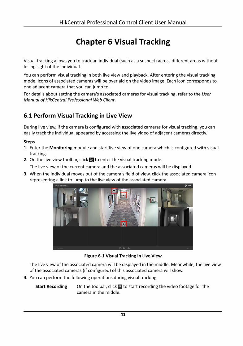
Chapter 6 Visual Tracking
Visual tracking allows you to track an individual (such as a suspect) across different areas withoutlosing sight of the individual.
You can perform visual tracking in both live view and playback. After entering the visual trackingmode, icons of associated cameras will be overlaid on the video image. Each icon corresponds toone adjacent camera that you can jump to.For details about setting the camera's associated cameras for visual tracking, refer to the UserManual of HikCentral Professional Web Client.
6.1 Perform Visual Tracking in Live ViewDuring live view, if the camera is configured with associated cameras for visual tracking, you caneasily track the individual appeared by accessing the live video of adjacent cameras directly.
Steps1. Enter the Monitoring module and start live view of one camera which is configured with visual
tracking.2. On the live view toolbar, click to enter the visual tracking mode.
The live view of the current camera and the associated cameras will be displayed.3. When the individual moves out of the camera's field of view, click the associated camera icon
representing a link to jump to the live view of the associated camera.
Figure 6-1 Visual Tracking in Live View
The live view of the associated camera will be displayed in the middle. Meanwhile, the live viewof the associated cameras (if configured) of this associated camera will show.
4. You can perform the following operations during visual tracking.
Start Recording On the toolbar, click to start recording the video footage for thecamera in the middle.
HikCentral Professional Control Client User Manual
41

Capture aPicture
On the toolbar, click to capture a picture for the camera in themiddle.After capture, you can click Search by Picture to perform further search.For searching captured picture, refer to Search Captured Face Pictureand Related Video .For searching archive, refer to Archive Search .For identity verification, refer to Identity Verification .
Show/HideCamera Icon
On the toolbar, click / to show or hide the icons of the associatedcameras.
Jump toPrevious/NextCamera
Click ← Previous or Next → to jump to the live view of previous or nextcamera.
5. Click Exit in the upper-right corner to exit the visual tracking mode.
6.2 View Visual Tracking VideoDuring playback, if the camera is configured with associated cameras for visual tracking, you caneasily track the individual appeared by accessing the recorded video of adjacent cameras directly.
Steps1. Start playback of the camera. Currently, you can access visual tracking during playback in the
following modules:- In the Playback module, start playback of the camera which is configured with visual tracking
and recording schedule. For details about starting playback, refer to Playback .- During live view, start instant playback of the camera which is configured with visual tracking
and recording schedule. For details about starting instant playback, refer to Live View .- In the Video Search module, after searching the video footage of the camera which is
configured with visual tracking and recording schedule, start playing the videos. For details,refer to Video Search .
- In the Alarm Center module, when checking the related video of the alarm source, startplayback of the camera which is configured with visual tracking and recording schedule. Fordetails, refer to Check Alarm and Event .
- In the Identity Access Search module, when checking the related video of the access point,start playback of the camera which is configured with visual tracking and recording schedule.For details, refer to Search Access Records .
2. On the playback toolbar, click to enter the visual tracking mode.The recorded video of the current camera and the associated cameras will be displayed.
3. When the individual moves out of the camera's field of view, click the associated camera iconrepresenting a link to the next camera.
HikCentral Professional Control Client User Manual
42
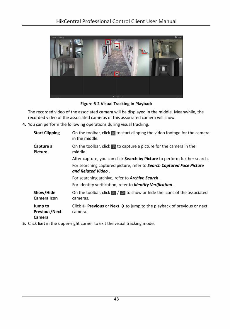
Figure 6-2 Visual Tracking in Playback
The recorded video of the associated camera will be displayed in the middle. Meanwhile, therecorded video of the associated cameras of this associated camera will show.
4. You can perform the following operations during visual tracking.
Start Clipping On the toolbar, click to start clipping the video footage for the camerain the middle.
Capture aPicture
On the toolbar, click to capture a picture for the camera in themiddle.After capture, you can click Search by Picture to perform further search.For searching captured picture, refer to Search Captured Face Pictureand Related Video .For searching archive, refer to Archive Search .For identity verification, refer to Identity Verification .
Show/HideCamera Icon
On the toolbar, click / to show or hide the icons of the associatedcameras.
Jump toPrevious/NextCamera
Click ← Previous or Next → to jump to the playback of previous or nextcamera.
5. Click Exit in the upper-right corner to exit the visual tracking mode.
HikCentral Professional Control Client User Manual
43

Chapter 7 Video Search
The video files stored on local devices or Recording Server can be searched.
7.1 Search Video by Time RangeYou can search video footage by time range. And optionally, you can configure the videosegmentation settings before search to segment the matched video footage if the original videofootage lasts too long. The segmented video files are shorter in terms of duration, which makes iteasier for locating specific video information such as a recorded criminal incident. After search, youcan export the matched video files to the local PC, and save them as evidence to the SFTP server.
Steps1. Click Video Search to enter the Video Search page.2. Click Video Clip tab to search for video footage.3. Select Time Range as the search type.4. Select cameras.
1) Click in this camera panel.2) Select a current site or Remote Site from the drop-down site list to show its cameras.3) Check the cameras you want to search.4) Click Close.
Note• Up to 16 resources can be selected for search at the same time.• The icon and represent the current site and remote site, respectively.
5. Optional: Move the mouse to the selected camera and click to switch the storage locationamong Main Stream/Main Storage, Sub Stream/Main Storage, Main Stream/Auxiliary Storage,or Sub Stream/Auxiliary Storage.
6. Set the time period for search in Time field.- Select the predefined time period in the drop-down list.- Select Custom Time Interval to specify the start time and end time for the search.
7. Optional: Check Video Segmentation to segment the matched video footage of each selectedcamera.Segment
Set the number of video clips for equally segmenting the video footage of each selectedcamera. For example, if you set the segment value to "5", the matched video footage of eachselected camera will be divided into 5 segments, each of which equals in terms of timeduration.
Interval (s)
HikCentral Professional Control Client User Manual
44

The matched video footage of each selected camera will be segmented into video clips bythe duration (unit: second) you set. For example, if you set 60 seconds as the duration forvideo segmentation, the matched video footage of each camera will be segmented into clipswhich last 60 seconds each.
Interval (min)The matched video footage of each selected camera will be segmented into video clips bythe duration (unit: minute) you set. For example, if you set 2 minutes as the duration forvideo segmentation, the matched video footage of each camera will be segmented into clipswhich last 2 minutes.
NoteA few clip(s) may last less than the duration you set.
8. Click Search to find the related video footage.The search results will be displayed and grouped by different cameras. You can switch betweenthumbnail and list mode to view.
9. Optional: Start remote playback of the searched video footage.- For list mode, click the item t in Time Range column- For thumbnail mode, click the image of the found result.
Play the previous video footage among the searched results.
Play the next video footage among the searched results.Play in Order
After playing the current video footage, continue to play the next one automatically.
Note• Refer to Normal Playback for more details of playback.• On the playback toolbar, click to enter the visual tracking mode. For details, refer to View
Visual Tracking Video .
10. Optional: Export the matched video footage to local storage.- During playback, click on the toolbar to export the current video footage.- Select the video footage and click Export to export all the selected video footage.1)(Optional) For downloading single video footage, set the time range of the video footage to
download.2)Set the file format of the exported file.
MP4MP4 format supports encryption. You can set a password to encrypt the video footage forsecurity purpose.
HikCentral Professional Control Client User Manual
45

Only VSPlayer supports playing video footage in MP4 format. You can check DownloadVSPlayer to download the player when exporting video footage.
AVIBesides VSPlayer, other players also support playing the video footage in AVI format.You can check Download VSPlayer to download the player when exporting the videofootage.
EXEPackage the video footage with the VSPlayer into one EXE file. The selected video footageof one camera will be merged to one MP4 file.After downloading, double-click the EXE file and the VSPlayer will launch. The mergedvideo footage of different cameras will be displayed in the playlist.
NoteUp to 16 cameras can be selected to export their video footage in EXE format for onetime.
3)(Optional) If you select the format as MP4 or AVI, you can check Merge Video Files to mergethe selected video footage of the same camera to one video file.
NoteUp to 2 GB video footage can be merged.
4)Optional: Check Save as Evidence and set the required information for the evidence.
Note• You should have enabled evidence collection on the Web Client. For details, see the User
Manual of HikCentral Professional Web Client.• For details about setting the required information for evidence, see Save Found Video
Footage as Evidence .5)Set the saving path to store the exported video footage.6)Click Export to add the exporting task to the download center.
NoteFor details about managing the exporting tasks, refer to Manage Downloading Tasks .
7.2 Search Tagged Video FootageYou can search for the camera's tagged video footage. After search, you can export the matchedvideo footage to the local PC and save the video footage as evidence to the SFTP server.
HikCentral Professional Control Client User Manual
46

Steps
NoteFor adding tag to the video file, refer to Play Video File .
1. Click Video Search to enter the Video Search page.2. Click Video Clip tab to search for video footage.3. Select Tag as the search type.4. Optional: Enter the keyword of tag name to search.5. Select cameras.
1) Click in this camera panel.2) Select a current site or Remote Site from the drop-down site list to show its cameras.3) Check the cameras you want to search.4) Click Close.
Note• Up to 16 resources can be selected for search at the same time.• The icon and represent the current site and remote site, respectively.
6. Optional: Move the mouse to the selected camera and click to switch the storage locationamong Main Stream/Main Storage, Sub Stream/Main Storage, Main Stream/Auxiliary Storage,or Sub Stream/Auxiliary Storage.
7. Set the time period for search in Time field.- Select the predefined time period in the drop-down list.- Select Custom Time Interval to specify the start time and end time for the search.
8. Click Search to find the related video footage.The search results will be displayed and grouped by different cameras. You can switch betweenthumbnail and list mode to view.
9. Optional: Start remote playback of the searched video footage.- For list mode, click the item t in Time Range column- For thumbnail mode, click the image of the found result.
Play the previous video footage among the searched results.
Play the next video footage among the searched results.Play in Order
After playing the current video footage, continue to play the next one automatically.
HikCentral Professional Control Client User Manual
47

Note• Refer to Normal Playback for more details of playback.• On the playback toolbar, click to enter the visual tracking mode. For details, refer to View
Visual Tracking Video .
10. Optional: Export the found video footage to local storage.- During playback, click to export the current video footage.- Select the video footage and click Export to export all the selected video footage.1)(Optional) For exporting single video footage, set the time range of the video footage for
export.2)Set the file format of the exported file.
MP4MP4 format supports encryption. You can set a password to encrypt the video footage forsecurity purpose.Only VSPlayer supports playing video footage in MP4 format. You can check DownloadVSPlayer to download the player when exporting video footage.
AVIBesides VSPlayer, other players also support playing the video footage in AVI format.You can check Download VSPlayer to download the player when exporting the videofootage.
EXEPackage the video footage with the VSPlayer into one EXE file. The selected video footageof one camera will be merged to one MP4 file.After downloading, double-click the EXE file and the VSPlayer will launch. The mergedvideo footage of different cameras will be displayed in the playlist.
NoteUp to 16 cameras can be selected to export their video footage in EXE format for onetime.
3)(Optional) If you select the format as MP4 or AVI, you can check Merge Video Files to mergethe selected video footage of the same camera to one video file.
NoteUp to 2 GB video footage can be merged.
4)Optional: Check Save as Evidence and set the required information for the evidence.
HikCentral Professional Control Client User Manual
48

Note• You should have enabled evidence collection on the Web Client. For details, see the User
Manual of HikCentral Professional Web Client.• For details about setting the required information for evidence, see Save Found Video
Footage as Evidence .5)Set the saving path to store the exported video footage.6)Click Export to add the exporting task to the download center.
NoteFor details about managing the exporting tasks, refer to Manage Downloading Tasks .
7.3 Search Locked Video FootageYou can search for the camera's locked video footage. After search, you can export the matchedvideo footage to the local PC and save the video footage as evidence to the SFTP server.
Steps
NoteFor locking the video file, refer to Normal Playback .
1. Click Video Search to enter the Video Search page.2. Click Video Clip tab to search for video footage.3. Select Locked File as the search type.4. Select cameras.
1) Click in this camera panel.2) Select a current site or Remote Site from the drop-down site list to show its cameras.3) Check the cameras you want to search.4) Click Close.
Note• Up to 16 resources can be selected for search at the same time.• The icon and represent the current site and remote site, respectively.
5. Optional: Move the mouse to the selected camera and click to switch the storage locationamong Main Stream/Main Storage, Sub Stream/Main Storage, Main Stream/Auxiliary Storage,or Sub Stream/Auxiliary Storage.
6. Set the time period for search in Time field.- Select the predefined time period in the drop-down list.- Select Custom Time Interval to specify the start time and end time for search.
7. Click Search to find the related video footage.
HikCentral Professional Control Client User Manual
49

The search results will be displayed and grouped by different cameras. You can switch betweenthumbnail and list mode to view.
8. Optional: Start remote playback of the searched video footage.- For list mode, click the object in Time Range column- For thumbnail mode, click the image of the searched result.
Play the previous video footage among the searched results.
Play the next video footage among the searched results.Play in Order
After playing the current video footage, continue to play the next one automatically.
Note• Refer to Normal Playback for more details of playback.• On the playback toolbar, click to enter the visual tracking mode. For details, refer to View
Visual Tracking Video .
9. Optional: Export the found video footage to local storage.- During playback, click to export the current video footage.- Select the video footage and click Export at the upper-right side to export all the selected
video footage.1) (Optional) For exporting single video footage, set the time range of the video footage for
export.2) Set the file format of the exported file.
MP4MP4 format supports encryption. You can set a password to encrypt the video footage forsecurity purpose.Only VSPlayer supports playing video footage in MP4 format. You can check DownloadVSPlayer to download the player when exporting the video footage.
AVIBesides VSPlayer, other players also support playing the video footage in AVI format.You can check Download VSPlayer to download the player when exporting the videofootage.
EXEPackage the video footage with the VSPlayer into one EXE file. The selected video footageof one camera will be merged to one MP4 file.After exporting, double-click the EXE file, and then the VSPlayer will launch. The mergedvideo footage of different cameras will be displayed in the playlist.
HikCentral Professional Control Client User Manual
50

NoteUp to 16 cameras can be selected to export their video footage in EXE format for onetime.
3) (Optional) If you select the format as MP4 or AVI, you can check Merge Video Files to mergethe selected video footage of the same camera to one video file.
NoteUp to 2 GB video footage can be merged.
4) Optional: Check Save as Evidence and set the required information for the evidence.
Note• You should have enabled evidence collection on the Web Client. For details, see the User
Manual of HikCentral Professional Web Client.• For details about setting the required information for evidence, see Save Found Video
Footage as Evidence .5) Set the saving path to store the exported video footage.6) Click Export to add the exporting task to the download center.
NoteFor details about managing the exporting tasks, refer to Manage Downloading Tasks .
7.4 Search Video/Picture/Audio Stored on Dock StationThe dock station is a data collector which can automatically detect and back up law-enforcementdata and evidence data (including video footage, pictures, and audio files) from body camera(s)connected to it. You can search these data via the Control Client. After search, you can lock andunlock the matched data.
Before You StartYou should have added dock station(s) to the system. For details, see the User Manual ofHikCentral Professional Web Client.
Steps1. Click Video Search on the Control Panel.2. Click Video Clip tab.3. Select Dock Station as the search type.4. Select dock station group(s).
NoteDock station group is a group of persons (usually policemen or policewomen). Only when thepersons are added to the dock station, can the data in their body cameras be backed up to thedock station. For selecting dock station group(s) in this step, when a dock station group is
HikCentral Professional Control Client User Manual
51

selected, the data backed up from the body camera(s) of the persons in the selected dockstation group will be searched.
5. Select a file type from the File drop-down list.6. Select a per-defined time period from the Time drop-down list or customize a time period.7. Click Search.
The matched video files, audio files, and pictures will be displayed by person. You can displaythe result in thumbnail mode or list mode.
8. Click the matched file to play the video/audio file or view the picture.9. Optional: Perform the following operations.
Export SingleFile to Local PC
After opening the matched file, click and then set the requiredinformation to export it to the local PC.
NoteFor details about the required information for exporting, see Search Videoby Time Range
Batch ExportFiles to LocalPC
Select the matched files, click Export and then set the requiredinformation for exporting to export the files to local PC.
NoteFor details about the required information for exporting, see Search Videoby Time Range
Lock File After opening the matched file, click to lock it in order to prevent itfrom being overwritten, modified or deleted.
7.5 Search Transaction Event Triggered Video FootageYou can search for the video footage triggered by transaction event which contains POSinformation. After search, you can export the matched video footage to the local PC or save it asevidence to the SFTP server.
Steps1. Click Video Search to enter the Video Search page.2. Click Video Clip tab to search for video footage.3. Select the search type as Transaction Event.4. Enter the keywords that are contained in the POS information.
HikCentral Professional Control Client User Manual
52

Note• You can enter up to three keywords, and you should separate each one with a space.• If you enter more than one keyword for search, you can select "|" to search the POSinformation containing any of the keywords, or select "&" to search the POS informationcontaining all keywords.
5. Optional: Select Case Sensitive to search the POS information with case-sensitivity.6. Select the device and camera in the Camera field to search the transaction information.7. Optional: Move the mouse to to switch the storage location among Main Stream/Main
Storage, Sub Stream/Main Storage, Main Stream/Auxiliary Storage, or Sub Stream/AuxiliaryStorage.
8. Set the time period for search in Time field.- Select the predefined time period in the drop-down list.- Select Custom Time Interval to specify the start time and end time for the search.
9. Click Search to find the related video footage.The search results will be displayed and grouped by different cameras. You can switch betweenthumbnail and list mode to view.
10. Optional: Start remote playback of the searched video footage.- For list mode, click the object in Time Range column- For thumbnail mode, click the image of the searched result.
Play the previous video footage among the searched results.
Play the next video footage among the searched results.Play in Order
After playing the current video footage, continue to play the next one automatically.
Note• Refer to Normal Playback for more details of playback.• On the playback toolbar, click to enter the visual tracking mode. For details, refer to View
Visual Tracking Video .
11. Optional: Export the searched video footage to local storage.- During playback, click to export the current video footage.- Select the video footage and click Export to export all the selected video footage.1)(Optional) For exporting single video footage, set the time range of the video footage to
export.2)Set the file format of the exported file.
MP4
HikCentral Professional Control Client User Manual
53

MP4 format supports encryption. You can set a password to encrypt the video file forsecurity purpose.Only VSPlayer supports playing video files in MP4 format. You can check DownloadVSPlayer to download the player with the video files.
AVIBesides VSPlayer, other player also supports playing the video files in AVI format.You can check Download VSPlayer to download the player with the video files.
EXEPackage the video files with the VSPlayer into one EXE file. The selected video footage ofone camera will be merged to one MP4 file.After downloading, double click the EXE file and the VSPlayer will launch. The mergedvideo files of different cameras will be displayed in the playlist.
NoteUp to 16 cameras can be selected to download in EXE format for one time.
3)(Optional) If you select the format as MP4 or AVI, you can check Merge Video Files to mergethe selected video footage of the same camera to one video file.
NoteUp to 2 GB files can be merged.
4)Optional: Check Save as Evidence and set the required information for the evidence.
Note• You should have enabled evidence collection on the Web Client. For details, see the User
Manual of HikCentral Professional Web Client.• For details about setting the required information for evidence, see Save Found Video
Footage as Evidence .5)Set the saving path to store the exported video files.6)Click Export to add the downloading task to the download center.
NoteFor details about managing the downloading tasks, refer to Manage Downloading Tasks .
7.6 Search ATM Event Triggered Video FootageYou can search for the video footage triggered by ATM event, such as transactions and otheroperations on the ATM. After search, you can save the matched video footage to the local PC andsave it as evidence to the SFTP server.
Steps1. Click Video Search to enter the Video Search page.
HikCentral Professional Control Client User Manual
54

2. Click Video Clip tab to search for video footage.3. Select the search type as ATM Event.4. Enter the card number that is contained in the ATM information.5. Select the device and camera to search the ATM information in the Camera field.6. Optional: Move the mouse to to switch the storage location among Main Stream/Main
Storage, Sub Stream/Main Storage, Main Stream/Auxiliary Storage, or Sub Stream/AuxiliaryStorage.
7. Set the time period for search in Time field.- Select the predefined time period in the drop-down list.- Select Custom Time Interval to specify the start time and end time for the search.
8. Click Search.The search results will be displayed and grouped by different cameras. You can switch betweenthumbnail mode and list mode to view.
9. Optional: Start remote playback of the searched video footage.- For list mode, click the object in Time Range column- For thumbnail mode, click the image of the searched result.
Play the previous video footage among the searched results.
Play the next video footage among the searched results.Play in Order
After playing the current video footage, continue to play the next one automatically.
Note• Refer to Normal Playback for more details of playback.• On the playback toolbar, click to enter the visual tracking mode. For details, refer to View
Visual Tracking Video .
10. Optional: Download the matched video footage to local storage.- During playback, click to download the current video footage.- Select the video footage and click Export to export all the selected video footage.1)(Optional) For downloading single video footage, set the time range of the video footage to
download.2)Set the file format of the downloaded file.
MP4MP4 format supports encryption. You can set a password to encrypt the video file forsecurity purpose.Only VSPlayer supports playing video files in MP4 format. You can check DownloadVSPlayer to download the player with the video files.
AVI
HikCentral Professional Control Client User Manual
55

Besides VSPlayer, other player also supports playing the video files in AVI format.You can check Download VSPlayer to download the player with the video files.
EXEPackage the video files with the VSPlayer into one EXE file. The selected video footage ofone camera will be merged to one MP4 file.After downloading, double click the EXE file and the VSPlayer will launch. The mergedvideo files of different cameras will be displayed in the playlist.
NoteUp to 16 cameras can be selected to download in EXE format for one time.
3)(Optional) If you select the format as MP4 or AVI, you can check Merge Video Files to mergethe selected video footage of the same camera to one video file.
NoteUp to 2 GB files can be merged.
4)Optional: Check Save as Evidence and set the required information for the evidence.
Note• You should have enabled evidence collection on the Web Client. For details, see the User
Manual of HikCentral Professional Web Client.• For details about setting the required information for evidence, see Save Found Video
Footage as Evidence .5)Set the saving path to store the downloaded video files.6)Click Export to add the downloading task to the download center.
NoteFor details about managing the downloading tasks, refer to Manage Downloading Tasks .
7.7 Search VCA Event Related VideoYou can search video files where VCA events occur. And you can play or download the found videofiles. The VCA events include motion detection, intrusion, and line crossing.
Steps
Note• This function should be supported by the device.• Video files stored on a Hybrid Storage Area Network do not support VCA event search.
1. Access the VCA Event search page and three ways are selectable.
HikCentral Professional Control Client User Manual
56

Access from LiveView Page
a. Enter the Live View page, and start the live view of the camera (referto Start Live View in Area Mode .
b. Move the cursor to the display window and click to pop up theVCA Event search page.
Access fromPlayback Page
a. Enter the Playback page, and start playback of the camera (refer toNormal Playback ).
b. Move the cursor to the display window and click to pop up theVCA Event search page.
Access fromVideo SearchPage
Click Video Search → VCA Search enter the VCA Search page.
2. Select the site (current site or Remote Site) and select the camera to search the video where theVCA event occurs.
NotePerform this step when you access the VCA Event search page from the Video Search module.
3. In the Time field, set the time period for search.
NoteYou can select Custom Time Interval to specify the start time and end time for search.
4. In the Draw VCA Rule field, click to open the rule settings window.
NotePerform this step when you accessing the VCA Event search page from the Video Searchmodule.
5. Select the VCA type, and draw the detection region.- Motion Detection: Click and drag on the display window to set the grid rectangle as the
detection region.- Line Crossing: Click and drag on the display window to set the detection line.- Intrusion: Click on the display window to set the vertex(es) for the detection region and
right-click to finish drawing.6. Optional: Click Clear to delete the drawn region.7. Click OK to save the settings.
NotePerform this step when you accessing the VCA Event search page from the Video Searchmodule.
8. Adjust the sensitivity for detecting the event. The larger the sensitivity is, the more sensitive thedetection is.
HikCentral Professional Control Client User Manual
57

9. Click Search to search the videos during which the VCA events occurring in the defined regionwill be displayed.The search results will be displayed and grouped by different cameras. You can switch betweenthumbnail and list mode to view.
10. Optional: Start remote playback of the searched video footage.- For list mode, click the object in Time Range column.- For thumbnail mode, click the image of the searched result.
Play the previous video footage among the searched results.
Play the next video footage among the searched results.Play in Order
After playing the current video footage, continue to play the next one automatically.
Note• Refer to Normal Playback for more details of playback.• On the playback toolbar, click to enter the visual tracking mode. For details, refer to View
Visual Tracking Video .
11. Optional: Download the searched video footage to local storage.- During playback, click to export the current video footage.- Select the video footage and click Export to export all the selected video footage.1)(Optional) For exporting single video footage, set the time range of the video footage to
export.2)Set the file format of the exported file.
MP4MP4 format supports encryption. You can set a password to encrypt the video file forsecurity purpose.Only VSPlayer supports playing video files in MP4 format. You can check DownloadVSPlayer to download the player with the video files.
AVIBesides VSPlayer, other player also supports playing the video files in AVI format.You can check Download VSPlayer to download the player with the video files.
EXEPackage the video files with the VSPlayer into one EXE file. The selected video footage ofone camera will be merged to one MP4 file.After downloading, double click the EXE file and the VSPlayer will launch. The mergedvideo files of different cameras will be displayed in the playlist.
HikCentral Professional Control Client User Manual
58

NoteUp to 16 cameras can be selected to download in EXE format for one time.
3)(Optional) If you select the format as MP4 or AVI, you can check Merge Video Files to mergethe selected video footage of the same camera to one video file.
NoteUp to 2 GB files can be merged.
4)Optional: Check Save as Evidence and set the required information for the evidence.
Note• You should have enabled evidence collection on the Web Client. For details, see the User
Manual of HikCentral Professional Web Client.• For details about setting the required information for evidence, see Save Found Video
Footage as Evidence .5)Set the saving path to store the exported video files.6)Click Export to add the downloading task to the download center.
NoteFor details about managing the downloading tasks, refer to Manage Downloading Tasks .
HikCentral Professional Control Client User Manual
59

Chapter 8 Manage Downloading Tasks
You can view the ongoing or completed downloading task information and manage all the tasks(e.g., video downloading, vehicle information downloading), such as starting, stopping, deletingand so on, in the Download Center.
Steps1. Click Download Center on the Control Panel to enter Download Center page.
Figure 8-1 Download Center2. Check the download tasks.
Check DownloadingTask
Click the Downloading tab to check the downloading tasks.
Check Uploading Task Click the Uploading tab to check the evidence which is beinguploaded to the SFTP (Secure File Transfer Protocol).
NoteFor details about saving video footage as evidence, see ManageEvidence .
Check CompletedTask
Click the Done tab to check the completed tasks.
3. Optional: Perform the following operation(s) for the tasks.
Pause Downloading Select an ongoing downloading task and click Pause.
ResumeDownloading
Click Start to resume the downloading, or click Start All to resume allthe paused tasks.
HikCentral Professional Control Client User Manual
60

Arrange Time forAuto-download
You can arrange an off-peak time period to automatically downloadfiles to avoid network congestion under low network bandwidth.a. Click the Downloading tab.b. Check Download Time and then select a time period or customize
a time period for automatically downloading.
DeleteDownloading Task
Select a task and then click to remove the downloading task, orclick Delete All to delete all the downloading records.For completed downloading task, you can also select to delete thedownloaded video files.
View DownloadedVideo
For completed downloading task, click Open File in Operation columnto view the downloaded video files.
4. Optional: Click Download Player to download the player to your PC for playing the downloadedvideo files.
HikCentral Professional Control Client User Manual
61

Chapter 9 Check Alarm and Event
The alarm information (for example, motion detection alarm information) received by the ControlClient displays. You can check the detailed information of the event or alarm, view the alarm linkedvideo, manage the related information, and so on.
NoteYou should configure the event or alarm settings via the Web Client before you can check therelated information and linkage actions via the Control Client. For detailed configuration of eventand alarm settings, refer to User Manual of HikCentral Professional Web Client.
9.1 Perform Arming ControlYou can arm or disarm the selected resource(s). After arming the resource, the current ControlClient can receive the triggered alarm information from the resource.
Steps
NoteYou can also perform arming control for the security control devices (such as arming/disarmingpartitions, bypassing zones, etc.). For details, refer to Security Control .
1. Click Alarm Center → Arming Control to open the Arming Control window.
Figure 9-1 Arming Control2. Set the filter condition on the left.3. Select the resource for arming control.
All the configured alarms of the selected resource will display.4. Perform arming control.
DisarmClick icon or Disarm All to disable the alarm and set the disarming start time and duration.
HikCentral Professional Control Client User Manual
62

For example, if you set the disarming duration as 1 hour, the alarm cannot be received byControl Client, but will be recorded as the log within 1 hour. The event detection will beenabled again in 1 hour after the disarming start time.
ArmClick icon or Arm All to enable the alarm detection.
Note• For alarm input source, an icon will display if there is an exception. You can view theexception details by moving the cursor on the icon.
• The disarming and arming control in Alarm Center only controls the alarm detection on thecurrent Control Client.
9.2 View Resource's Real-Time AlarmThe real-time alarm information received by the Control Client, such as motion detection, videoloss, and video tampering alarm, of the connected cameras and alarm inputs are displayed in theAlarm Center. You can check the alarm details and view alarm related video and picture ifconfigured.
Before You StartArm the device first before the Control Client can receive the alarm information from the device.For details, refer to Perform Arming Control .
Steps1. Enter the Alarm Center page and you can view the real-time alarms received by the Control
Client.Alarm Time (Control Client)
The Control Client time when the alarm starts.Alarm Source
The resource that occurred the alarm.Triggering Event/Alarm
Display the type of the event that triggered alarm.Operation
Go to Alarm SearchClick in the Operation column to go to the Alarm Search page to search the currentcamera's events by setting searching conditions.
Linkage ActionClick to start live view of the related cameras.
Two-Way Audio
HikCentral Professional Control Client User Manual
63

Start two-way audio with the camera.Export
Download the alarm details, including alarm information, alarm picture, linked video,linked map, etc.
Display on Smart WallDisplay the alarm video on smart wall.
NoteThe available operation changes according to the alarm linkage of the camera. For detailedconfiguration, refer to User Manual of HikCentral Professional Web Client.
Figure 9-2 Alarm Center
2. Set the filter conditions to display the required alarms only.Mark Status
Mark the alarm information and the marked items can be filtered.Alarm Priority
The priority including low, medium, high and custom level which indicates the urgent degreeof the alarm.
Alarm StatusThe status of the alarm includes Start, Stop and Abnormally Stopped. Start indicates thealarm has not stopped yet; Stop indicates the alarm has stopped; and Abnormally Stoppedindicates the alarm has stopped abnormally.
Alarm Displayed on Smart WallFilter the alarms which are set to be displayed on the smart wall.
The alarms will be automatically filtered by the configured conditions and display in the list.
HikCentral Professional Control Client User Manual
64

3. Select an alarm to view.The alarm linked video (if any) shows on display window and the alarm source linked map (ifany) appears as well.
4. Optional: Perform one or more of the following operations.
Acknowledge Alarm • Click an alarm's name to open its alarm information window, andthen click Acknowledge to acknowledge the alarm.
• Check alarms in the alarm list, or check multiple alarms, and thenclick Batch Acknowledge to acknowledge the selected alarms.
NoteUp to 100 alarms can be checked at a time.
Play Video fromAlarm Time
Click Go to Alarm Time to play the video from the alarm time.
Get Live View ofRelated Camera
Click Live View to view the live video of the related cameras.
Display Linked Videoon Smart Wall
Click Display on Smart Wall to play the videos on smart wall.
NoteFor setting the related camera of the alarm, refer to User Manual ofHikCentral Professional Web Client.
Display AlarmRelated Video andRelated Map
Click Display Related Video & Map to show the Related Video orRelated Map window.
Turn On/Off AlarmSound
When the Control Client receives an alarm, the PC running theControl Client will play the alarm sound. You can turn on/off thealarm sound by clicking Operation and checking or uncheckingAudio On.
NoteThis configuration won't be changed after restarting the ControlClient.
Disable Pop-upAlarm Window
For the alarm configured with pop-up window, a window will popup, showing the alarm details, when the Control Client receives thealarm. You can disable or enable the pop-up window by clickingOperation and checking or unchecking Pop-up Window Disabled.
HikCentral Professional Control Client User Manual
65

NoteThis configuration won't be changed after restarting the ControlClient.
Sort Alarms Click on the column name of the alarm list and select a property tosort the alarms by the selected property.
View History Alarm Click History Alarm to enter the Alarm & Event Search module tosearch the history alarms.
Enter Visual TrackingMode
Click to start live view of the camera triggering alarm in thelower-left corner. Click to enter the camera's visual trackingmode. See User Manual of HikCentral Professional Web Client fordetails about configuring visual tracking.
9.3 Search Event/Alarm LogsYou can search the event and alarm log files of the added resource for checking.
Before You StartYou should configure the event and alarm settings via Web Client. See User Manual of HikCentralProfessional Web Client for details.
Steps1. Enter the Alarm & Event Search module and click the Alarm Search or Event Search tab.2. Select the types of event source.
NoteThe Remote Site is only available for the Central System with Remote Site Management module(based on the license you purchased).
3. Set the time range for search.- Select a predefined time period for search.- Select Custom Time Interval and specify the start time and end time for search.
4. Set search conditions for different event source types.
NoteWhen searching certain event or alarm for thermal imaging devices, you can click icon in theadded source list for more accurate search, such as selecting VCA rule for VCA event, selectingthermometry point for temperature alarm or temperature difference alarm.
5. Click to select the triggering event(s)/alarm(s) and source(s).6. Click Search.
The matched event or alarm logs display on the list.
HikCentral Professional Control Client User Manual
66
7. Optional: Perform the following operation(s) after searching alarms or events.
View AlarmDetails
Click the Name field of the searched event or alarm to view the detailsand the linked picture, video, and map.
View EventDetails
Click the Name field of the searched event to view the details and linkedvideo.
Export Alarmsor Events
Click Export and select the format and saving path to save the foundevents or alarms to your PC.Click on the Operation column to export the specified event or alarmto your PC.
NoteYou can view the exporting process in the Download Center by clicking in the top of the interface.
Switch toAlarm/EventSearch Page
On the Event Search page, click on the Operation column to switch tothe Alarm Search page.On the Alarm Search page, click on the Operation column to switch tothe Event Search page.
Switch toAuxiliary Screen
Click to open the Alarm Search or Event Search page as a auxiliaryscreen. You can view the alarms or events on the auxiliary screen, as wellas operating the other pages of the Control Client.
9.4 Manually Trigger User-Defined EventThe system provides user-defined event which is used if the event you need is not in the providedsystem-monitored event list, or the generic event cannot properly define the event received fromthird-party system. On the Control Client, you can trigger a user-defined event manually and it willactivate a series of actions according to the settings on Web Client.
Before You StartAdd the user-defined event to the system and determine what happens when you manually triggerit, such as setting it as the alarm source, as start/end of the alarm's arming schedule, or as thealarm linkage actions. For details, refer to User Manual of HikCentral Professional Web Client.Perform this task if you need to trigger a user-defined event manually on the Control Client.
Steps1. In the Monitoring or Alarm Center module, click Trigger Event.
The user-defined events added to the system will display.2. Select the event you want to trigger and click OK.
HikCentral Professional Control Client User Manual
67

9.5 View Pop-up Window Triggered by AlarmAfter configuring the required settings on the Web Client and Control Client, the alarm window willopen when the corresponding event/alarm is triggered. You can view the alarm time, the sourcedevice which trigger the alarm, the triggered event, and alarm status, etc.
Before You StartMake sure you have enabled the alarm linkage of Trigger Pop-up Window on the Web Client, andenabled the pop-up window function in the Alarm Center on the Control Client. For setting thisalarm linkage, refer to the User Manual of HikCentral Professional Web Client.
Steps1. View the alarm details including alarm source, alarm time, triggered event type, alarm status,
etc., in the pop-up window when alarm is triggered.
Figure 9-3 Alarm Triggered Pop-Up Window2. Optional: Set the alarm priority, the alarm category, and input the note for the alarm according
to actual needs.3. Click Picture/Video/Map tab to view the alarm related cameras' captured pictures, the playback
or live view when alarm occurs, and view the camera/alarm input location on the map (ifconfigured).
NoteWhen viewing the recorded video files of the related camera, you can click Go to Alarm Time toplay the video from the alarm time. You can also click Live View to view the live video of therelated cameras, or click Display on Smart Wall to play the playback on smart wall.
4. Click the Acknowledge to acknowledge the alarm.The alarm status becomes Acknowledged.
HikCentral Professional Control Client User Manual
68

5. Optional: Click to view the previous or next alarm information.6. Optional: Uncheck Enable Pop-up Window to disable pop-up window when new alarm triggers.
NoteWhen the pop-up window remains open, the later alarm, if alarm priority is higher, will bedisplayed in the pop-up window, replacing the earlier one.
7. Optional: Check Full Screen to display the pop-up window in full screen mode by default.
HikCentral Professional Control Client User Manual
69

Chapter 10 Map Management
After properly configuring the map settings via the Web Client and enabling the map function onMonitoring module, you can view and manage the map, such as zooming in or zooming out themap, locating the resources on the map. You can view and operate the added resources on themap, such as getting the live view and playback of the cameras, UVSSs, and doors, setting thearming control for cameras, alarm inputs, UVSSs, and doors, and so on.
Note• If the GIS map doesn't show properly, all the current site's and Remote Site's E-map thumbnails
are displayed. Click one E-map to view details.• If you enable the GIS map function of the Central System via Web Client, you enter theconfigured GIS map. All the current site's and Remote Site's E-map thumbnails are displayedunder the GIS map. Click one E-map to view details.
10.1 Operate Hot SpotThe resources (including cameras, alarm inputs, alarm outputs, access points, elevators, radars,and UVSSs) added on the map are called the hot spots. The hot spots show the locations of theresources. You can operate the hot spot, such as starting live view of the camera, UVSS, and door,arming or disarming the resources.
10.1.1 Preview Hot Spot
You can view locations of the cameras, alarm inputs, alarm outputs, access points, elevators,radars, sites, and Under Vehicle Surveillance Systems (UVSSs). You can also set the arming controland view the history alarms of the surveillance scenarios through the hot spots.
Before You StartConfigure the map settings via the Web Client. For details, see User Manual of HikCentralProfessional Web Client.
Steps1. Click Monitoring on the Control Panel to enter the Monitoring module.2. Drag the map to the display window or double-click the map to display the map.3. Perform the following operations on the map.
HikCentral Professional Control Client User Manual
70

Switch Map • Switch from GIS map to e-map: Click at the bottom of the GISmap to display the e-map(s) and then select a e-map.
• Switch from e-map back to GIS map: Move the cursor to theupper side of the e-map and then click the appearing , or clickthe first map in the thumbnail map list.
• Switch between e-maps: Click at the bottom of the e-map todisplay other e-map(s) and then select a e-map.
Filter Resource onMap
Click Filter and select resource type(s).
Select MultipleResources
Click Select and draw a rectangle on the map to select multipleresources.
Drag Resource(s) onMap to Display
Select one or multiple resources on map and drag it/them to thedisplay window in Live View or Playback.
Real-Time Display ofFace Comparison/Access Control/Vehicle List
Click Live View and select the item(s) to display real-time relatedcaptured face picture, access event, and vehicle list on the map.
More Tools Click and select Add Label, Capture or Print to add a label onmap, capture or print the current map.
Display Map onSmart Wall
Click to display the map on smart wall. For details, see DisplayMap on Smart Wall .
4. Click the hot spot to open the dialog which displays the related functions.
NoteIf there is an alarm triggered on the hot spot, the hot spot icon will turn into red alarm mode
. Click the red icon, you can view the detailed alarm information.
5. Operate in the dialog.- For camera and UVSS hot spot: Check the live view and playback of the camera, view its
status, area, and remark, set the arming control, and view the history alarms.
Note• To view the live view and playback of the camera, the user should be assigned with
permissions of live view and playback of the camera. For details, please refer to the UserManual of HikCentral Professional Web Client.
• For details about arming control, see Perform Arming Control .• For details about viewing history alarms, see View History Alarm .
- For alarm input hot spot: View its status, area, and remark, set the arming control, and viewthe history alarms.
- For alarm output hot spot: Turn on or off the linked alarm output.
HikCentral Professional Control Client User Manual
71

- For access point hot spot: View the access point status, check the live view and playback ofthe access point's related camera(s), view the access point's basic information, control thedoor status, set the arming control, and view the history alarms and access records.
- For elevator hot spot: View the elevator status, area and remark, check the live view andplayback of the elevator's related camera(s), control the floor status, set the arming control,and view the history alarms and access records.
- For radar hot spot: View the radar status, area and remark, check the live view and playbackof the radar's related camera(s), set the arming control, and view the history alarms.
- For site hot spot: View the site's resources and alarms which are not handled.
10.1.2 Perform Arming Control
You can arm or disarm the hot spots via the arming control function. After arming the device, thecurrent Control Client can receive the triggered alarm information from the hot spot.
Before You StartConfigure the map settings via the Web Client. For details, see User Manual of HikCentralProfessional Web Client.
Steps1. Enter the Monitoring module.2. Drag the map to the display window or double-click the map to display the map.3. Click the hot spot.
A window on which the related functions of the hot spot display is opened.4. Click Arming Control to activate the Arming Control window.
Figure 10-1 Arming Control Page
HikCentral Professional Control Client User Manual
72

The information of the enabled alarms (e.g., motion detection, video loss) displays, such asalarm name, alarm priority and source IP address.
5. Perform arming control of the selected hot spot.- Click Disarm or Disarm All to disable the alarm(s) and set the disarming start time and
duration.
NoteFor example, if you set the disarming duration as 1 hour and the start time as 2018-03-2618:05, then the event detection will be enabled again after 2018-03-26 19:05.
- Click Arm or Arm All to enable the alarm(s).
10.1.3 View History Alarm
When an alarm is triggered, it will be recorded in the system. You can check the history log relatedto an alarm, including the alarm source details, alarm category, alarm triggered time, etc.
Steps1. Enter the Monitoring module.2. Drag the map to the display window or double-click the map to display the map.3. Click the hot spot.
A dialog pops up on which the related functions of the hot spot display.4. Click History Alarm to activate the History Alarm window.
Figure 10-2 History Alarm5. Select Camera or ANPR as alarm source.6. Set the time for searching the alarms.7. Select the triggering event from the drop-down list.8. Click Search to start searching the logs of the alarm.
The search results will display in the list and you can check the history alarm's detailedinformation.
HikCentral Professional Control Client User Manual
73

10.2 Preview Hot RegionThe hot region function links a map to another map. When you add a map to another map as a hotregion, an icon of the link to the added map is shown on the main map. The added map is calledchild map while the map to which you add the hot region is the parent map.
Before You StartConfigure the map settings via the Web Client. For details, see User Manual of HikCentralProfessional Web Client
Steps1. Enter the Monitoring module.2. Drag the map to the display window or double-click the map to display the map.3. Click the hot region and a window opens displaying the related functions.
NoteIf there is an alarm triggered in the hot region, the alarm icon will appear on the top left cornerof the hot region icon .
4. Click the E-map thumbnail to jump to the child map and view the elements added on the E-map.
10.3 Preview Resource GroupDuring displaying map in Monitoring module. you can view locations and regions of the resourcegroups, including alarm group, people analysis group, multi-door interlocking group, and anti-passback group. You can also perform further operations on the resources in the group.
NoteMake sure you have configured the required resource groupa and map settings via the Web Client.For details, see User Manual of HikCentral Professional Web Client.
Enter the Monitoring module and display the map. You can locate the resource group and viewrelated alarms on the map.• For alarm group: When an alarm is triggered by the resources in the group, the region of the
group will be highlighted on the map and you can view the real-time alarms triggered in theregion.
• For people analysis group: You can view the real-time number of people entered, exited theregion, or stayed in the region. Meanwhile, when an alarm is triggered in the region (such aspeople amount more/less than threshold), the region of the group.
HikCentral Professional Control Client User Manual
74
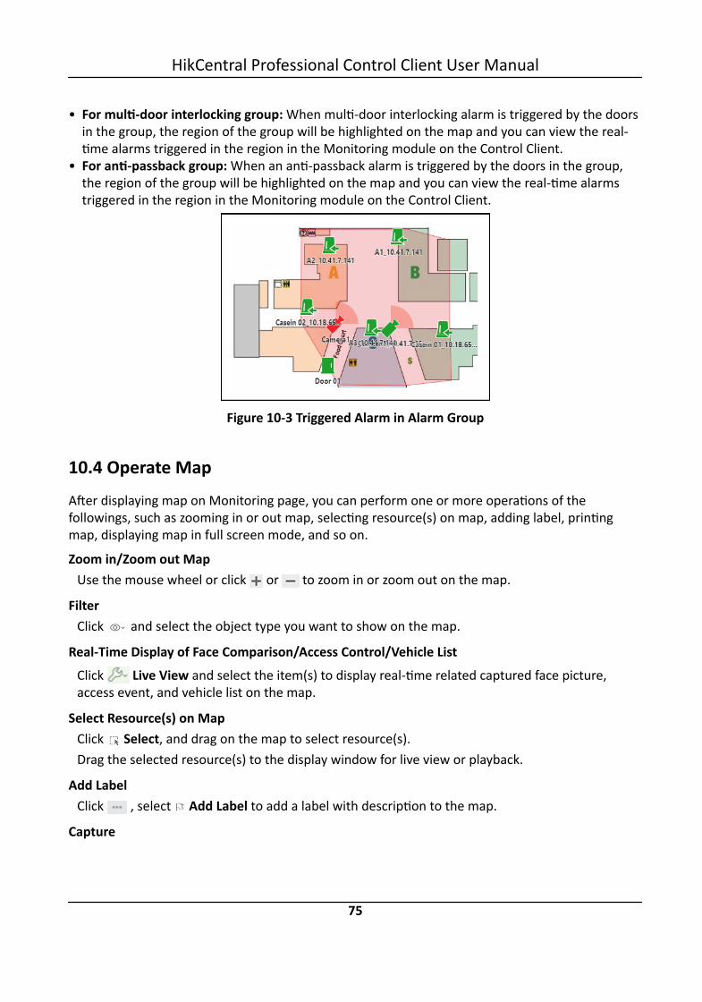
• For multi-door interlocking group: When multi-door interlocking alarm is triggered by the doorsin the group, the region of the group will be highlighted on the map and you can view the real-time alarms triggered in the region in the Monitoring module on the Control Client.
• For anti-passback group: When an anti-passback alarm is triggered by the doors in the group,the region of the group will be highlighted on the map and you can view the real-time alarmstriggered in the region in the Monitoring module on the Control Client.
Figure 10-3 Triggered Alarm in Alarm Group
10.4 Operate MapAfter displaying map on Monitoring page, you can perform one or more operations of thefollowings, such as zooming in or out map, selecting resource(s) on map, adding label, printingmap, displaying map in full screen mode, and so on.
Zoom in/Zoom out MapUse the mouse wheel or click or to zoom in or zoom out on the map.
FilterClick and select the object type you want to show on the map.
Real-Time Display of Face Comparison/Access Control/Vehicle ListClick Live View and select the item(s) to display real-time related captured face picture,access event, and vehicle list on the map.
Select Resource(s) on MapClick Select, and drag on the map to select resource(s).Drag the selected resource(s) to the display window for live view or playback.
Add LabelClick , select Add Label to add a label with description to the map.
Capture
HikCentral Professional Control Client User Manual
75

Click , select Capture, and drag on the map to select an area. You can save this area as apicture to local PC.
Print MapClick and select Print to print the map.
Locate Resource on MapMove the cursor to the resource in the device list, click and select Locate on Map to locatethe resource on the map. The located resources can be displayed in the center of the map.Or start live view or playback of a camera, move the mouse to the lower edge of the displaywindow and click on the left to locate the resource on the map.
NoteOnly when the resource is added to the map, you can locate the resource on map.
HikCentral Professional Control Client User Manual
76

Chapter 11 Manage Evidence
The Control Client allows you to save the recorded video footage as evidence if it containsimportant information about incidents such as traffic accidents and violent crimes in case of theneed for settling disputes or legal cases.
This functionality is available when you search video footage, manually record video footage duringlive view, manually clip video footage during playback, or download video footage in the DownloadCenter.
11.1 Save Manually Recorded Video as Evidence in Live ViewDuring live view, you can manually record video footage which contains important informationabout incidents such as traffic accident and violent crimes, and save it as evidence to the SFTP(Secure File Transfer Protocol).
Before You StartYou should have enabled evidence collection on the Web Client. For details, see the User Manuelof HikCentral Professional Web Client.
Steps
NoteYou can set the SFTP when enabling evidence collection on the Web Client. For details, see theUser Manuel of HikCentral Professional Web Client.
1. Start live view.
NoteSee Live View for details.
2. Click in the toolbar of the display window to start the manual recording.The icon turns to
3. Click to stop recording.A dialog will pop up.
4. Click Save as on the dialog to open the Save as panel.5. Check Save as Evidence and then set the required information for the evidence.
NoteFor details about the required information for the evidence, see Save Found Video Footage asEvidence .
6. Click Save on the Save as panel.
HikCentral Professional Control Client User Manual
77

NoteYou can search the saved evidence. For details, see Search Evidence .
11.2 Save Clipped Video as Evidence in PlaybackDuring playback, you can manually clip video footage which contains important information aboutincidents such as traffic accident and violent crimes, and save it as evidence to the SFTP (SecureFile Transfer Protocol).
Before You StartYou should have enabled evidence collection on the Web Client. For details, see the User Manualof HikCentral Professional Web Client.
Steps
NoteYou can set the SFTP address when enabling evidence collection on the Web Client. For details, seethe User Manual of HikCentral Professional Web Client.
1. Start playback.
NoteFor details, see Playback .
2. Click to start clipping.The icon turns to .
3. Click to stop clipping.A dialog will pop up.
4. Click Save as on the dialog to open the Save as panel.5. Check Save as Evidence and then set the required information for the evidence.
NoteFor details of the required information for the evidence, see Save Found Video Footage asEvidence .
6. Click Save on the Save as panel.
NoteYou can search the saved the evidence. For details, see Search Evidence .
HikCentral Professional Control Client User Manual
78

11.3 Save Found Video Footage as EvidenceAfter searching for video footage under specific conditions, you can export the matched videofootage as evidence if the video footage contains information of the incidents such as trafficaccidents and violent crimes.
Before You StartYou should have enabled evidence management on the Web Client. For details, see the ManageEvidence chapter in the User Manual of HikCentral Professional Web Client.
Steps
NoteYou can set the SFTP address when enabling evidence collection on the Web Client. For details, seethe Manage Evidence chapter in the User Manual of HikCentral Professional Web Client.
1. Search video footage.
NoteFor details, see Video Search .
2. Enter the Export panel.- On the video file list, click the time range to play back the video file, and then click .- Select video file(s) from the video file list, and then click Export at the upper-right side.
Figure 11-1 The Export Panel3. Check Save as Evidence and then select Create Evidence or Add to Existing Evidence.
Create EvidenceSet the parameters such as evidence ID, evidence type, and evidence status to create a newevidence.
NoteYou can add and delete the evidence type, organization on site, and conclusion/result on theWeb Client, see the Manage Evidence chapter in the User Manual of HikCentral ProfessionalWeb Client for details.
HikCentral Professional Control Client User Manual
79

Evidence TypeSelect the type of accident or criminal incident recorded in the video file(s).
Organization on SiteThe organization or personnel (e.g., police, fire department) on the site of the accident orcriminal incident.
Evidence StatusSelect Closed if the related case is settled, and select Open if the related-case is pending.
Add to Existing EvidenceAdd the video file(s) to existing evidence. After saving the video file(s) as evidence, you cansee the video file in the Content of Evidence section on the evidence details panel. Fordetails, see Search Evidence .
4. Click Save to save the video file(s) as evidence.The video file(s) will be downloaded in the Download Center, and then be uploaded as evidenceto the SFTP (Secure File Transfer Protocol).
Note• For details about the Download Center, see Manage Downloading Tasks .• You can configure the SFTP. See the Manage Evidence chapter in the User Manual of
HikCentral Professional Web Client for details.• You can search the saved evidence. For details, see Search Evidence .
11.4 Save Downloaded Video Footage as EvidenceWhen the downloading task is completed in the Download Center, you can save the downloadedvideo footage as evidence if it contains important information about incidents such as trafficaccidents and violent crimes.
Before You StartYou should have enabled evidence collection on the Web Client. For details, see the User Manualof HikCentral Professional Web Client.
Steps
NoteFor details about managing downloading tasks, see Manage Downloading Tasks .
1. Click Download Center on the Control Panel to enter the Download Center.2. Click Done to view the completed task.3. Select the downloaded video footage and then click Save as to open the Save As panel.4. Check Save as Evidence and then set the required information for the evidence.
HikCentral Professional Control Client User Manual
80

NoteFor details about the required information for the evidence, see Save Found Video Footage asEvidence .
5. Click Save on the Save As Panel.The saved video footage will be uploaded to the SFTP (Secure File Transfer Protocol).
Note• You can set the SFTP address when enabling evidence collection on the Web Client. For
details, see the User Manual of HikCentral Professional Web Client.• You can search the saved evidence. For details, see Search Evidence .
11.5 Search EvidenceEvidence in HikCentral Professional refers to the video footage which contains information forsettling disputes or criminal cases. You can search the evidence by setting search conditions.
Before You Start• You should have enabled evidence collection on the Web Client. For details, see the User Manual
of HikCentral Professional Web Client.• You should have saved video footage as evidence. For details, see Manage Evidence .
Steps1. Click Evidence Search to enter the Evidence Search page.2. Set the search conditions such as evidence ID, keywords, and evidence status, etc.
HikCentral Professional Control Client User Manual
81
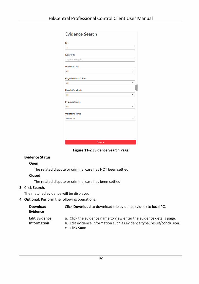
Figure 11-2 Evidence Search Page
Evidence StatusOpen
The related dispute or criminal case has NOT been settled.Closed
The related dispute or criminal case has been settled.3. Click Search.
The matched evidence will be displayed.4. Optional: Perform the following operations.
DownloadEvidence
Click Download to download the evidence (video) to local PC.
Edit EvidenceInformation
a. Click the evidence name to view enter the evidence details page.b. Edit evidence information such as evidence type, result/conclusion.c. Click Save.
HikCentral Professional Control Client User Manual
82

Export EvidenceInformation
Select evidence and then click Export and then select CSV or Excel toexport the evidence information to local PC as CSV file or Excel filerespectively.
NoteYou can check the exporting task in the Download Center.
Close Evidence Select evidence and then click Close Evidence to set the evidencestatus to Closed if the related case is settled.
Delete Evidence Select evidence and then click Delete.
HikCentral Professional Control Client User Manual
83

Chapter 12 Access Control and Elevator Control
The system supports access control and elevator control functions. Access control is a securitytechnique that can be used to regulate who can get access to the specified doors and elevatorcontrol can be used to regulate who can get access to the specified floors by taking the elevator.
After setting the persons' permissions of accessing specified doors and floors by assigning accesslevels to access groups, the authorized persons can access specified doors and floors withcredentials.On the Control Client, the operator can check the real-time access events (access granted or accessdenied, and so on), view the live video of the access point's related cameras (such as cameramounted inside the elevator), control the door or floor's status (such as remaining the door lockedor switching the floor to access forbidden status).You can also search the access records and perform entry & exit counting on the Control Client tosee who presents her/his credential on the card reader of the access point, whether he/sheaccesses successfully, who enters or exits this room, and how many people still stays in the room.
12.1 Control Door Status in Live ViewYou can view the live video of the door's related camera(s). During live view, you can control thedoor status if needed, and view the card swiping record in real time.
Steps1. Click Monitoring → Live View to enter the live view page.2. Drag the door to the display window, or double-click the door name after selecting the display
window.If the door is related with camera(s), the live view of these cameras will show. If two camerasare related, the live video will display in Picture-in-Picture mode, which means one is at thebottom left of the other one.If the door hasn't linked with any camera, the door status will show in the display window.The access record will overlap the display window in real time, if access event happens.
NoteFor relating cameras with door, refer to the User Manual of HikCentral Professional Web Client.
3. Optional: In Picture-in-Picture mode, click the smaller video view to switch the view position ofthe two cameras.
4. Click the icons in the middle of the window or on the upper right corner of the window toswitch the door status among Unlock, Lock, Remain Unlocked, Remain Locked.
: Unlock
HikCentral Professional Control Client User Manual
84

When the door is locked, unlock the door and it will be open. After the door open duration,the door will be closed and locked again automatically.
NoteFor setting the door's open duration, refer to User Manual of HikCentral Professional WebClient.
: LockWhen the door is unlocked, lock the door and it will be closed. The person who has theaccess permission can access the door with credentials. : Remain UnlockedThe door will be unlocked (no matter closed or open). All the persons can access the doorwith no credentials required (free access). : Remain LockedThe door will be closed and locked. No person can access the door even if he/she has theauthorized credentials, except the super users.
NoteFor setting person's super user privilege, refer to User Manual of HikCentral Professional WebClient.
Figure 12-1 Control Door Status in Live View5. Optional: Perform the follow operations after starting the live video of the door.
Control Statusof All Doors
Click in the upper-right corner of the displaying area to access thefollowing functions:
HikCentral Professional Control Client User Manual
85

• Allow All Access: Remain all doors unlocked. This function is used whenemergency happens and the persons need to leave as quickly aspossible, such as in a fire escape.
• Forbid All Access: Remain all doors locked. This function is applicable forsituations such as preventing a theft in the building from running away.
• Recover All Access:: Recover all the doors to normal status after theemergency.
Locate Dooron Map
Click on the lower-left corner of the display window to show the mapand the door's location on the map.
TriggeringEvent
Click Triggering Event to select the user-defined event. Refer to ManuallyTrigger User-Defined Event for details.
12.2 Control Floor Status in Live ViewDuring live view, you can view the live video of the elevator's related camera(s) (such as camerasmounted inside the elevator). You can also control the status of the floors linked to the elevator ifneeded.
Steps1. Click Monitoring → Live View to enter the live view page.2. Drag the elevator to the display window, or double-click the elevator name after selecting the
display window.If the elevator is related with camera(s), the live view of these cameras will show. If twocameras are related, the live video will display in Picture-in-Picture mode, which means one is atthe bottom left of the other one.
NoteFor relating cameras with elevator, refer to the User Manual of HikCentral Professional WebClient.
3. Optional: In Picture-in-Picture mode, click the smaller video view to switch the view position ofthe two cameras.
4. Move the cursor to the display window and click the floor icons to switch the floor status amongTemporary Access, Access with Credential, Free Access, Access Forbidden.
: Temporary AccessDuring the temporary access time period, the persons can access this floor with nocredentials required. After this time period, the floor will recover to Access with Credentialstatus.For details about setting the temporary access time period, refer to the User Manual ofHikCentral Professional Web Client. : Access with Credential
HikCentral Professional Control Client User Manual
86
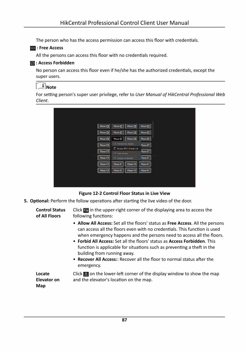
The person who has the access permission can access this floor with credentials. : Free AccessAll the persons can access this floor with no credentials required.
: Access ForbiddenNo person can access this floor even if he/she has the authorized credentials, except thesuper users.
NoteFor setting person's super user privilege, refer to User Manual of HikCentral Professional WebClient.
Figure 12-2 Control Floor Status in Live View5. Optional: Perform the follow operations after starting the live video of the door.
Control Statusof All Floors
Click in the upper-right corner of the displaying area to access thefollowing functions:• Allow All Access: Set all the floors' status as Free Access. All the persons
can access all the floors even with no credentials. This function is usedwhen emergency happens and the persons need to access all the floors.
• Forbid All Access: Set all the floors' status as Access Forbidden. Thisfunction is applicable for situations such as preventing a theft in thebuilding from running away.
• Recover All Access:: Recover all the floor to normal status after theemergency.
LocateElevator onMap
Click on the lower-left corner of the display window to show the mapand the elevator's location on the map.
HikCentral Professional Control Client User Manual
87

TriggeringEvent
Click Triggering Event to select the user-defined event. Refer to ManuallyTrigger User-Defined Event for details.
12.3 Open Door for Multi-Factor AuthenticationIn access control, multi-factor authentication is an authentication method in which the door willunlock only after multiple persons authenticating multiple credentials in turn. This method ismainly used for locations with high security requirements, such as bank vault. With the mutualsupervision of the persons, multi-factor authentication provides higher security for the assets inthese locations.
You can set multi-factor authentication rule on the Web Client. For details, refer to the UserManual of HikCentral Professional Web Client.If you set the access mode as Remotely Unlock After Granted, when the persons in the accessgroup authenticate at the door, a window will pop up on the Control Client as follows.
Figure 12-3 Pop-Up Window of Remote Request
Click Answer to answer the request. If the door is related with a camera, you can view the livevideo of the related camera. You need to verify the identity of the persons before opening thedoor.
HikCentral Professional Control Client User Manual
88

Figure 12-4 Remotely Open Door
Click Open Door and then the door will be unlocked successfully.
12.4 Handle Opening Door Request from Video Access Control TerminalVideo access control terminal supports voice talk with the connected client. Person can press button on the device front panel to send an opening door request to the security personnel andthe security personnel can talk with the person via Control Client, view the live video of the videoaccess control terminal's camera, and unlock the door if the person's identity is confirmed. Thisfunction is mainly used when the person forgets to take her/his credentials or for visitors.
NoteBefore the Control Client receiving the remote request from video access control terminal, youshould first add a Calling Surveillance Center alarm for this video access control terminal's accesspoint in the Web Client. For details about adding alarms, refer to User Manual of HikCentralProfessional Web Client.
After pressing the button on the device front panel, a window will pop up on the Control Clientas follows:
HikCentral Professional Control Client User Manual
89

Figure 12-5 Remote Request from Video Access Control Terminal
You can click Answer to view the live view of the video access control terminal's camera and startvoice talk with the person starts this request. You can also click Ignore to ignore this request andclose this window.During voice talk, click Open Door to allow the person to get in.Click End Call to end voice talk and close this window.
12.5 Search Access RecordsYou can search the persons' access records triggered on the specified doors or elevators) via theControl Client by setting the search conditions. For example, if you select specified access pointsand set the event type as access denied by card, all the access denied events (accessing by swipinga card) triggered on these access points will show.
Before You StartConfigure the access event on the Web Client. For details, refer to User Manual of HikCentralProfessional Web Client.
Steps1. Click Identity Access Search on the control panel.2. Set the search conditions.
NoteAmong source (door or elevator), person, and access mode, you need to set at least twoconditions.
1) Set the time during which the access events are occurred.
HikCentral Professional Control Client User Manual
90

NoteThe time here can be device time or client time, based on the time zone settings in System →General .
2) Select Door or Elevator as source and click to select the door(s) or elevator(s) to searchthe triggered events.
3) Click to select the person(s). You can filter the persons by person name, visitor name oradditional information.
4) Click to select the access mode, which refers to the type of the triggered access event.5) Select the access result including access granted and access failed.
3. Click Search.The matched access records will display.
4. Optional: Perform the following operations after search.
View EventDetails
Click the person name in the Name column to view the event details, suchas the recorded video or captured picture of the related camera (ifconfigured), person information, and access information. If the person is avisitor, here you can view the detailed visitor information and visiteeinformation, including name, person profile, visit reason, etc.
Filter SearchResults byPerson Type
Click near Type and select Employee, Visitor or All to filter the searchresults.
Forgive Anti-PassbackViolation
When a person attempts to use a card out of anti-passback rule'ssequence, the access will be denied. This is called "Anti-PassbackViolation". When anti-passback violation occurs, no entry is allowedunless the anti-passback violation event is forgiven.You can forgive an anti-passback event by clicking in the Operationcolumn. Or click Forgive All Anti-Passback to forgive all the anti-passbackviolation events in the search result.
DownloadSingle Record
Click in the Operation field to download the event information,including the event details, the person information, person profile,recorded video file (if configured), etc.
NoteYou can view the task progress in Download Center.
Export AllSearchedRecords
Click Export to export the searched access control events details(including person name, person ID, event time, access result, etc) and youcan save it in your PC.
HikCentral Professional Control Client User Manual
91

NoteThe exported file is in CSV format. You can view the task progress inDownload Center.
12.6 Perform Entry & Exit CountingBy grouping the doors (adding entry & exit counting group), the system provides countingfunctions based on the entry and exit records on these doors. With this function, you can knowwho enters/exits this region and how many persons still stay in this region. This is available forcertain emergency scene. For example, during a fire escape, the number of the stayed persons andname list are required.
Before You StartAdd an entry & exit counting group first to group the doors in the Web Client. For details, refer toUser Manual of HikCentral Professional Web Client.
Steps
NoteCurrently, the system only supports to search persons with access records in the last 24 hours.
1. Enter Identity Access Search → Entry & Exit Counting on the control panel.2. Select one entry & exit counting group in the Source list.3. Select what type of persons you want to search.
AllAll the entering and exiting access records in the last 24 hours will be displayed.
People StayedThe persons who are still stayed in the region will be displayed. The system will filter thepersons whose entering record is found but exiting record is not found.
People ExitedThe persons who entered and later exited the region will be displayed.
4. Click Search.The access records matched the search conditions will be listed, showing information such asperson details, location of last access, etc.
5. Optional: Perform the following operations after search.
View EventDetails
Click the person name in the Name column to view the record details,including the recorded video of the access point's related camera (ifconfigured), person information, and access information.
HikCentral Professional Control Client User Manual
92

DownloadSingle Record
Click in the Operation column to download the record, including theperson information, person profile, phone number, location of lastaccess, etc. You can check the downloading progress in the DownloadCenter.
Export AllSearchedRecords
Click Export in the upper-right corner to export the searched accesscontrol events details (including the person information, person profile,phone number, location of last access, etc.) and you can save it in yourPC. You can check the downloading progress in the Download Center.
Note• Up to 100,000 records can be exported for one time.• The exported file is an Excel file.
Print SingleRecord
Click in the Operation column to print the record.
Print AllSearchedRecords
Click Print in the upper-right corner to print all the searched records.
HikCentral Professional Control Client User Manual
93
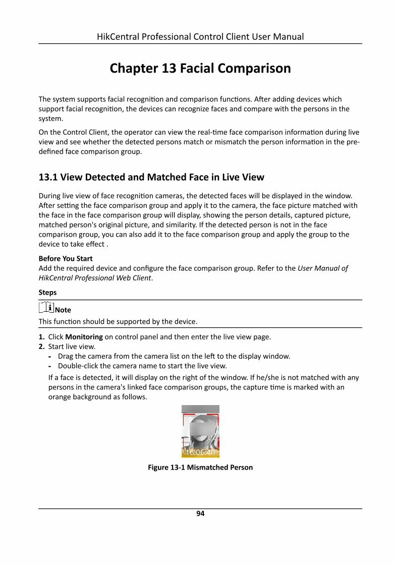
Chapter 13 Facial Comparison
The system supports facial recognition and comparison functions. After adding devices whichsupport facial recognition, the devices can recognize faces and compare with the persons in thesystem.
On the Control Client, the operator can view the real-time face comparison information during liveview and see whether the detected persons match or mismatch the person information in the pre-defined face comparison group.
13.1 View Detected and Matched Face in Live ViewDuring live view of face recognition cameras, the detected faces will be displayed in the window.After setting the face comparison group and apply it to the camera, the face picture matched withthe face in the face comparison group will display, showing the person details, captured picture,matched person's original picture, and similarity. If the detected person is not in the facecomparison group, you can also add it to the face comparison group and apply the group to thedevice to take effect .
Before You StartAdd the required device and configure the face comparison group. Refer to the User Manual ofHikCentral Professional Web Client.
Steps
NoteThis function should be supported by the device.
1. Click Monitoring on control panel and then enter the live view page.2. Start live view.
- Drag the camera from the camera list on the left to the display window.- Double-click the camera name to start the live view.If a face is detected, it will display on the right of the window. If he/she is not matched with anypersons in the camera's linked face comparison groups, the capture time is marked with anorange background as follows.
Figure 13-1 Mismatched Person
HikCentral Professional Control Client User Manual
94

3. View matched persons in different face comparison groups.
ExampleFor example, you can view the matched persons in blacklist and VIP list at the same time.1) Click tab to open the face comparison group list.
All the face comparison groups added to the system display.2) Double click the face comparison group name in the list or drag it to the display window.
A blank panel of the face comparison group will display on the right of the display windows.If there are persons matched with the person in the face comparison group, the captured andoriginal face pictures will display in this panel in pairs with similarity as follows.
Figure 13-2 Matched Persons
You can view the captured face picture, person's profile (configured in the Web Client) and thesimilarity. The person's name is shown on the profile.
4. Optional: View all the real-time face comparison events.1) Click Event List Hidden on the upper right corner to show the event list panel.2) Click Face Comparison tab to view all the detected faces (including matched and mismatched
persons.
NoteFor mismatched persons, the picture's capture time is marked with an orange background asfollows.
HikCentral Professional Control Client User Manual
95

Figure 13-3 Mismatched Person5. Optional: For the matched persons, view the person details.
- In the matched face picture panel, click to view the matched person details.- Click the face picture of matched person in the face comparison event list to view the person
details.- In the all events list panel, select the person matched event and click in the Operation
column to view the person information.6. Optional: If there are multiple cameras in live view, you can quickly find the camera which
captures certain picture and view its live view.- In the matched face picture panel, click .- In the Face Comparison event list, click the captured picture and click Live View.The camera which captures this picture will be highlighted with a red frame.
7. Optional: For the captured pictures (mismatched or matched person), click the picture and clickSearch by Picture to search other pictures of this person. Refer to Search Captured Face Pictureand Related Video for more details.
13.2 Add Mismatched Person to Person ListDuring live view, if a person is detected, but not matched with any persons in the face comparisongroup, and if you want the person to be recognized for the next time, you can add the person tothe face comparison group. For example, if the detected person is a new arrived VIP, you can addthe person to the VIP face comparison group and apply this group to the camera. For the nexttime, the camera will recognize the person's face and match her/him with the person informationin the face comparison group.
Steps1. Click Monitoring to enter the Monitoring module and perform face comparison in live view.
NoteFor details, refer to View Detected and Matched Face in Live View .
2. Open the Add to Person List panel.- In the All Events panel, click in the Operation column to open the Add to Person List page.- Click the mismatched face pictures in Face Comparison event panel and click Add to Person
List.
HikCentral Professional Control Client User Manual
96
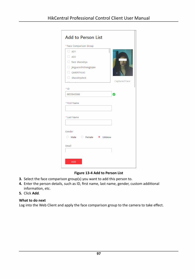
Figure 13-4 Add to Person List3. Select the face comparison group(s) you want to add this person to.4. Enter the person details, such as ID, first name, last name, gender, custom additional
information, etc.5. Click Add.
What to do nextLog into the Web Client and apply the face comparison group to the camera to take effect.
HikCentral Professional Control Client User Manual
97

13.3 Person SearchYou can search persons on pictures by the Control Client, including captured face pictures,captured face pictures matched with the pictures of face comparison group, and frequentlyappeared person.
Captured Face PicturesThe captured face pictures can be stored in HikCentral Professional server or on the RecordingServer. You can search for the target person in the captured pictures by person face credentialor by uploading a face picture. You can also view the search results' related video files and savethe related video files as evidence.
Matched PicturesYou can search for the captured face pictures which are matched with the faces in specified facecomparison groups. You can also export the related video footage to the local PC and save it asevidence to the SFTP server.
Frequently Appeared PersonYou can search for the pictures of the frequently appeared persons of specific locations in aspecific time period. The function is helpful for screening out the potential VIP customers inretail industry such as luxury stores. It can also be used to find out suspects who may commitcrimes and thereafter notify the security personnel to be on guard in locations such as banksand jewelry stores.
13.3.1 Search Captured Face Picture and Related Video
The captured face pictures can be stored in SYS server or on the Recording Server. You can searchfor the target person in the captured pictures by person face credential or by uploading a facepicture. You can also view the search results' related video files and save the related video files asevidence.
Steps
NoteMake sure your license supports facial recognition function, or turn to Home page of the WebClient, click License Details → Configuration → Add and then select the added cameras as facialrecognition cameras. Otherwise, facial recognition function cannot perform normally in thesystem.
1. Click Person Search → Face Search to enter the Face Search page.2. Select Captured Pictures as the searching type.3. In the Time field, set the time period.
You can select Custom Time Interval to specify the start time and end time for search.
HikCentral Professional Control Client User Manual
98

Figure 13-5 Face Search Page4. Select the camera(s) to search the face picture.
1) Click in this camera panel.2) Select a current site or Remote Site from the drop-down site list to show its cameras.3) Check the cameras you want to search.4) Click Close.
NoteUp to 200 resources can be selected for searching at the same time.
5. Optional: Set a picture for face picture searching, and you can use the added person's facecredential or upload one as desired.- Enter a keyword of person name or person ID in the Person Name/ID field to search in the
added persons and select a face credential.- Click Upload Picture to upload a face picture from local PC.
NoteThe uploaded picture should be in JPG format and picture size should be no larger than 1 GB.
The recognized face area will be marked on the face picture.
HikCentral Professional Control Client User Manual
99

6. Optional: Drag the slider to set the similarity.7. Click Search.
The search results will be displayed and grouped by different cameras. If you do not upload apicture, the similarity will not be displayed on the searching result. You can switch betweenthumbnail and list mode to view.
8. Optional: Perform the following operations for the searched pictures.
View Pictureand Video
Click the picture to view the large picture and the related video (ifavailable).
NoteFor playback control instructions, refer to Normal Playback . Some iconsmay not be available for face picture playback.
Add toPerson List
Click and set the required parameters to add the person to the personlist. For details about how to set the parameters, refer to the ManagePerson of HikCentral Professional Web Client User Manual.
9. Optional: Hover the cursor on a matched picture and click to perform secondary search.
SearchCapturedPicture
Click Search Captured Picture to go to the Face Search page to search thecaptured pictures related with the searched face picture by settingsearching conditions.
Search Archive Click Search Archive to go to the Archive Search page to search thesearched person's archive.
Verify Identity Click Identity Verification → To be Verified to verify the person's identity,or click Identity Verification → Target to set the person as a comparingtarget.
10. Optional: Export the matched video footage to local storage.- During playback, click to export the current video footage.- Select the video footage and click Export to export all the selected video footage.1)(Optional) For exporting single video footage, set the time range of the video footage to
export.2)Set the file format of the exported file.
MP4MP4 format supports encryption. You can set a password to encrypt the video file forsecurity purpose.Only VSPlayer supports playing video files in MP4 format. You can check DownloadVSPlayer to download the player with the video files.
AVIBesides VSPlayer, other player also supports playing the video files in AVI format.You can check Download VSPlayer to download the player with the video files.
HikCentral Professional Control Client User Manual
100

EXEPackage the video files with the VSPlayer into one EXE file. The selected video footage ofone camera will be merged to one MP4 file.After downloading, double click the EXE file and the VSPlayer will launch. The mergedvideo files of different cameras will be displayed in the playlist.
NoteUp to 16 cameras can be selected to download in EXE format for one time.
3)(Optional) If you select the format as MP4 or AVI, you can check Merge Video Files to mergethe selected video footage of the same camera to one video file.
NoteUp to 2 GB files can be merged.
4)Optional: Check Save as Evidence and set the required information for the evidence.
Note• You should have enabled evidence collection on the Web Client. For details, see the User
Manual of HikCentral Professional Web Client.• For details about setting the required information for evidence, see Save Found Video
Footage as Evidence .5)Set the saving path to store the exported video files.6)Click Export to add the downloading task to the download center.
NoteFor details about managing the downloading tasks, refer to Manage Downloading Tasks .
13.3.2 Search Matched Face Picture and Related Video
You can search for the captured face pictures which are matched with the faces in specified facecomparison groups. You can also export the related video footage to the local PC and save it asevidence to the SFTP server.
Steps1. Click Person Search → Face Search to enter the Face Search page.2. Select Matched Pictures as the searching type.3. In the Time field, set the time period for searching.
NoteYou can select Custom Time Interval to specify the start time and end time for search.
HikCentral Professional Control Client User Manual
101

Figure 13-6 Search Matched Pictures4. Select the face comparison group to search for the matched pictures.
NoteHover the cursor on a face comparison group and click to select cameras linked with thegroup.
5. Click Search.The matched persons will be displayed and grouped by different face comparison groups, andyou can view the person details. The face pictures of the matched persons (similarity larger thanthe threshold of the face comparison group) are displayed on the right of the person detailswith similarity.
6. Optional: Enter a similarity on the upper right corner and press Enter key to filter the pictures.The pictures the similarity of which is higher than this similarity will show.
7. Click beside the original picture to perform secondary search.
SearchCapturedPicture
Click Search Captured Picture to go to the Face Search page to search thecaptured pictures related with the searched face picture by settingsearching conditions.
HikCentral Professional Control Client User Manual
102

Search Archive Click Search Archive to go to the Archive Search page to search thesearched person's archive.
Verify Identity Click Identity Verification → To be Verified to verify the person's identity,or click Identity Verification → Target to set the person as a comparingtarget.
8. Optional: Click a matched picture to view the large picture and the related video (if available).
NoteFor playback control instructions, refer to Normal Playback . Some icons may not be availablefor face picture playback.
9. Optional: Export the matched video footage to local storage.- During playback, click to export the current video footage.- Select the video footage and click Export to export all the selected video footage.1) (Optional) For exporting single video footage, set the time range of the video footage to
export.2) Set the file format of the exported file.
MP4MP4 format supports encryption. You can set a password to encrypt the video file forsecurity purpose.Only VSPlayer supports playing video files in MP4 format. You can check DownloadVSPlayer to download the player with the video files.
AVIBesides VSPlayer, other player also supports playing the video files in AVI format.You can check Download VSPlayer to download the player with the video files.
EXEPackage the video files with the VSPlayer into one EXE file. The selected video footage ofone camera will be merged to one MP4 file.After downloading, double click the EXE file and the VSPlayer will launch. The mergedvideo files of different cameras will be displayed in the playlist.
NoteUp to 16 cameras can be selected to download in EXE format for one time.
3) (Optional) If you select the format as MP4 or AVI, you can check Merge Video Files to mergethe selected video footage of the same camera to one video file.
NoteUp to 2 GB files can be merged.
4) Optional: Check Save as Evidence and set the required information for the evidence.
HikCentral Professional Control Client User Manual
103

Note• You should have enabled evidence collection on the Web Client. For details, see the User
Manual of HikCentral Professional Web Client.• For details about setting the required information for evidence, see Save Found Video
Footage as Evidence .5) Set the saving path to store the exported video files.6) Click Export to add the downloading task to the download center.
NoteFor details about managing the downloading tasks, refer to Manage Downloading Tasks .
13.3.3 Search Frequently Appeared Person' Pictures
You can search for the pictures of the frequently appeared persons of specific locations in a specifictime period. The function is helpful for screening out the potential VIP customers in retail industrysuch as luxury stores. It can also be used to find out suspects who may commit crimes andthereafter notify the security personnel to be on guard in locations such as banks and jewelrystores.
Before You StartYou should have configured frequently appeared person alarm on the device. For details, see theuser manual of the device.
Steps1. Click Person Search → Face Search to enter the Face Search page.2. Select Frequently Appeared Person as the search type3. In the time field, select a time period or select Custom Time Interval to customize a time period
for search.4. Select the camera(s) to search pictures of the frequently appeared persons.
Figure 13-7 Face Search Page1) Click in this camera panel.2) Select a current site or Remote Site from the drop-down site list to show its cameras.
HikCentral Professional Control Client User Manual
104

3) Check the cameras you want to search.4) Click Close.
NoteUp to 200 resources can be selected for search at the same time.
5. Click Search.The search results will be displayed in list mode. You can view the appeared times of eachmatched person. Click a recorded time (Client) to view more captured pictures and relatedvideos.
6. Optional: Click to add the person to person list.7. Optional: Perform secondary search after clicking in the Operation column.
SearchCapturedPicture
Click Search Captured Picture to go to the Face Search page to search thecaptured pictures related with the searched face picture by settingsearching conditions.
Search Archive Click Search Archive to go to the Archive Search page to search thesearched person's archive.
Verify Identity Click Identity Verification → To be Verified to verify the person's identity,or click Identity Verification → Target to set the person as a comparingtarget.
13.4 Archive SearchThe system will save the features and information (including captured picture and video) of thecaptured person as archive. You can search the related archives of a face picture to check thecaptured pictures or videos of similar persons in the library. You can also check whether a person isa stranger.
Before You StartMake sure you have added a DeepinMind server to the system and have configured capturingcamera and face comparison group for it.
Steps
NoteBy default, the archive will be kept for 3 months.
1. Click Person Search → to enter the Archive Search page.2. Select a face comparison group in the Face Picture Library field, you can also check stranger
group.3. Upload a face picture in the Person Information field.4. Drag the slider of the similarity to set a similarity.5. Click Search.
HikCentral Professional Control Client User Manual
105
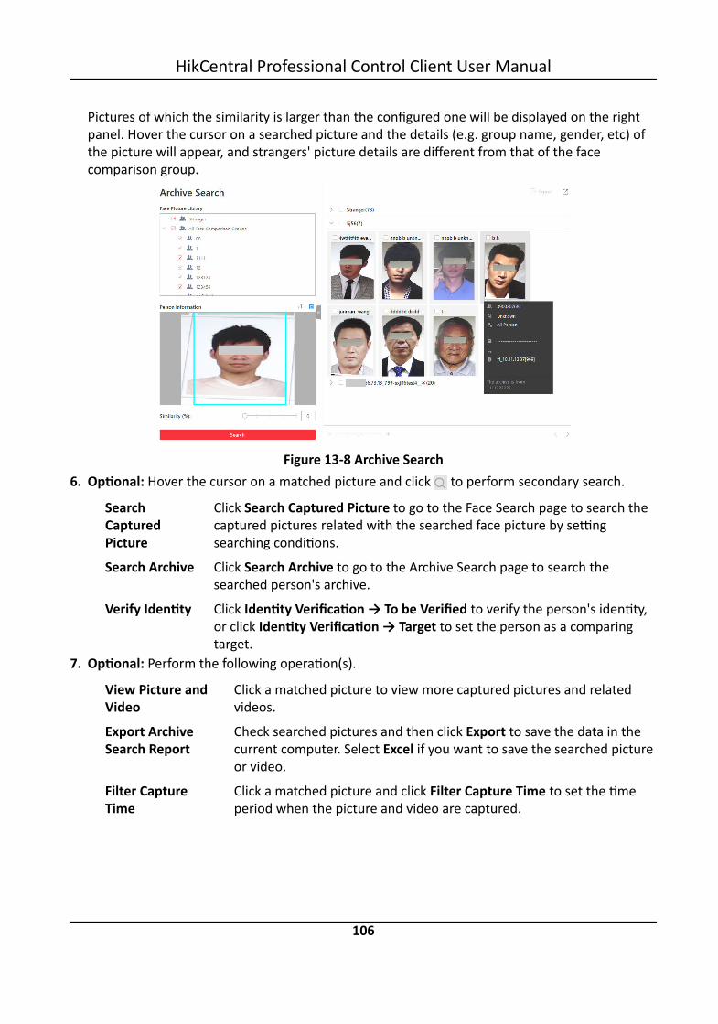
Pictures of which the similarity is larger than the configured one will be displayed on the rightpanel. Hover the cursor on a searched picture and the details (e.g. group name, gender, etc) ofthe picture will appear, and strangers' picture details are different from that of the facecomparison group.
Figure 13-8 Archive Search6. Optional: Hover the cursor on a matched picture and click to perform secondary search.
SearchCapturedPicture
Click Search Captured Picture to go to the Face Search page to search thecaptured pictures related with the searched face picture by settingsearching conditions.
Search Archive Click Search Archive to go to the Archive Search page to search thesearched person's archive.
Verify Identity Click Identity Verification → To be Verified to verify the person's identity,or click Identity Verification → Target to set the person as a comparingtarget.
7. Optional: Perform the following operation(s).
View Picture andVideo
Click a matched picture to view more captured pictures and relatedvideos.
Export ArchiveSearch Report
Check searched pictures and then click Export to save the data in thecurrent computer. Select Excel if you want to save the searched pictureor video.
Filter CaptureTime
Click a matched picture and click Filter Capture Time to set the timeperiod when the picture and video are captured.
HikCentral Professional Control Client User Manual
106

13.5 Identity VerificationThe control client provides picture-to-picture comparison and picture-to-group comparison, whichmeans you can know the similarity between two faces on two different pictures, or whether aperson is a member of an existing face comparison group,.
13.5.1 Compare with Face Comparison Group
When you are not sure about a person's identity, you can compare the his/her face picture withthose of the face comparison group to identify him/her.
Before You StartMake sure you have added a DeepinMind server to the system and have configured capturingcamera and face comparison group for it.
Steps1. Click Person Search → to enter the Identity Verification page.2. Upload the face picture you want to identify.3. Select Face Comparison Group in the Compare with field.4. Select a face comparison group in the list.5. Drag the slider of the similarity to set a similarity.
Figure 13-9 Compare with Face Recognition Group6. Click Search.
Pictures of which the similarity is larger than the configured one will be displayed on the rightpanel.
7. Optional: Click Add Person to add the person to person list.8. Optional: Hover the cursor on a matched picture and click to perform secondary search.
HikCentral Professional Control Client User Manual
107

SearchCapturedPicture
Click Search Captured Picture to go to the Face Search page to search thecaptured pictures related with the searched face picture by settingsearching conditions.
Search Archive Click Search Archive to go to the Archive Search page to search thesearched person's archive.
Verify Identity Click Identity Verification → To be Verified to verify the person's identity,or click Identity Verification → Target to set the person as a comparingtarget.
13.5.2 Compare with Specific Picture
You can also compare two face pictures to see whether they are the same person according to thesimilarity.
Before You StartMake sure you have added a DeepinMind server to the system and have configured capturingcamera and face comparison group for it.
Steps1. Click Person Search → to enter the Identity Verification page.2. Upload the face picture you want to identify in the Person Information field on the top of the
panel.3. Select Picture in the Compare with field.4. Upload a picture in the Person Information field on the bottom of the panel..
HikCentral Professional Control Client User Manual
108

Figure 13-10 Compare with Specified Picture
NoteYou can upload a picture with more than one face, and the client will tell the similarity betweenthe first picture and all faces in this picture.
5. Drag the slider of the similarity to set a similarity.6. Click Search.
The face picture(s) on the second uploaded picture will be displayed on the right panel, and thesimilarity between persons on the first-uploaded picture and second-uploaded is displayed.
7. Optional: Click Add Person to add the person to person list.8. Optional: Hover the cursor on a matched picture and click to perform secondary search.
SearchCapturedPicture
Click Search Captured Picture to go to the Face Search page to search thecaptured pictures related with the searched face picture by settingsearching conditions.
Search Archive Click Search Archive to go to the Archive Search page to search thesearched person's archive.
HikCentral Professional Control Client User Manual
109

Verify Identity Click Identity Verification → To be Verified to verify the person's identity,or click Identity Verification → Target to set the person as a comparingtarget.
HikCentral Professional Control Client User Manual
110
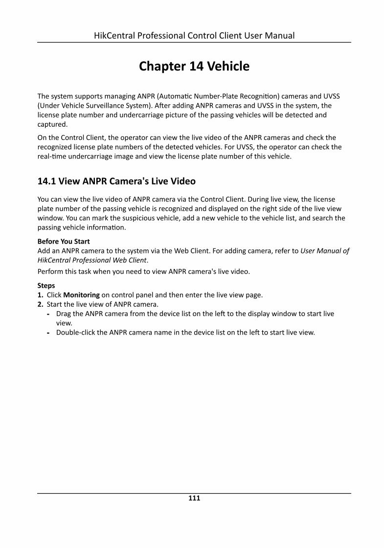
Chapter 14 Vehicle
The system supports managing ANPR (Automatic Number-Plate Recognition) cameras and UVSS(Under Vehicle Surveillance System). After adding ANPR cameras and UVSS in the system, thelicense plate number and undercarriage picture of the passing vehicles will be detected andcaptured.
On the Control Client, the operator can view the live video of the ANPR cameras and check therecognized license plate numbers of the detected vehicles. For UVSS, the operator can check thereal-time undercarriage image and view the license plate number of this vehicle.
14.1 View ANPR Camera's Live VideoYou can view the live video of ANPR camera via the Control Client. During live view, the licenseplate number of the passing vehicle is recognized and displayed on the right side of the live viewwindow. You can mark the suspicious vehicle, add a new vehicle to the vehicle list, and search thepassing vehicle information.
Before You StartAdd an ANPR camera to the system via the Web Client. For adding camera, refer to User Manual ofHikCentral Professional Web Client.Perform this task when you need to view ANPR camera's live video.
Steps1. Click Monitoring on control panel and then enter the live view page.2. Start the live view of ANPR camera.
- Drag the ANPR camera from the device list on the left to the display window to start liveview.
- Double-click the ANPR camera name in the device list on the left to start live view.
HikCentral Professional Control Client User Manual
111

Figure 14-1 Live View of ANPR Camera3. Perform the following operation(s) after starting the live view of ANPR camera.
MarkVehicle
If you think the vehicle is suspicious, move the cursor to the recognizedlicense plate number and click to mark the vehicle. The marked vehiclescan be filtered out later when searching the related vehicle passinginformation in Vehicle Search module.
Add Vehicleto VehicleList
If client recognizes a vehicle that is not added to the vehicle list, you can addit to the vehicle list manually. Move the cursor to the recognized license platenumber and click to add the vehicle. See Add Recognized Vehicle to VehicleList for details.
SearchVehicle
Move the cursor to the recognized license plate and click to enter theVehicle Search page to search the related vehicle passing informationrecorded by the camera. For details, refer to Search Recognized Vehicles .
14.2 View UVSS's Live VideoAn under-vehicle surveillance system (UVSS) generally consists of imaging systems mounted on aroadway and used at facility access points, particularly at secure facilities. It is used to detectthreats—such as bombs—that are hidden underneath vehicles. Cameras capture images of theundercarriage of the vehicle for manual or automated visual inspection by security personnel orsystems. As the vehicle arrives at the checkpoint and drives over the imaging unit, the camerascapture images of the undercarriage and transmit them to Control Client. The undercarriagepicture of the passing vehicle is captured and displayed on the live view window. The license platenumber of the passing vehicle is recognized and displayed on the right side of the live viewwindow.
HikCentral Professional Control Client User Manual
112
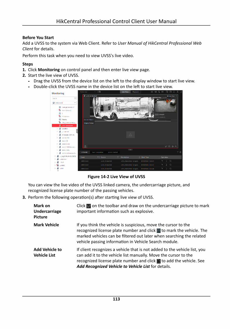
Before You StartAdd a UVSS to the system via Web Client. Refer to User Manual of HikCentral Professional WebClient for details.Perform this task when you need to view UVSS's live video.
Steps1. Click Monitoring on control panel and then enter live view page.2. Start the live view of UVSS.
- Drag the UVSS from the device list on the left to the display window to start live view.- Double-click the UVSS name in the device list on the left to start live view.
Figure 14-2 Live View of UVSS
You can view the live video of the UVSS linked camera, the undercarriage picture, andrecognized license plate number of the passing vehicles.
3. Perform the following operation(s) after starting live view of UVSS.
Mark onUndercarriagePicture
Click on the toolbar and draw on the undercarriage picture to markimportant information such as explosive.
Mark Vehicle If you think the vehicle is suspicious, move the cursor to therecognized license plate number and click to mark the vehicle. Themarked vehicles can be filtered out later when searching the relatedvehicle passing information in Vehicle Search module.
Add Vehicle toVehicle List
If client recognizes a vehicle that is not added to the vehicle list, youcan add it to the vehicle list manually. Move the cursor to therecognized license plate number and click to add the vehicle. SeeAdd Recognized Vehicle to Vehicle List for details.
HikCentral Professional Control Client User Manual
113

Search Vehicle Move the cursor to the recognized license plate and click to enterthe Vehicle Search page to search the related vehicle passinginformation. For details, refer to Search Recognized Vehicles .
14.3 Add Recognized Vehicle to Vehicle ListDuring the live view of ANPR camera or Under Vehicle Surveillance System (UVSS), the license platenumber of the passing vehicle can be recognized. If the recognized vehicle is not added to thevehicle list, you can add it to the vehicle list manually For example, if the vehicle belongs to an VIPvisitor, you can add it to the VIP vehicle list. If the vehicle belongs to a habitual thief, you can add itto the blacklist if needed.
Before You StartYou should add a vehicle list via the Web Client. Refer to User Manual of HikCentral ProfessionalWeb Client for details.
Steps
NoteYou can not add recognized vehicles to the list again that have been already added.
1. Click Monitoring on control panel and then enter live view page.2. Start live view of ANPR camera or UVSS.
- Drag the ANPR camera or UVSS from the device list on the left to the display window to startlive view.
- Double-click the ANPR camera name or UVSS name in the device list on the left to start liveview.
The detected license plate number is recognized and displayed on the right side of the live viewwindow.
HikCentral Professional Control Client User Manual
114

Figure 14-3 Live View of UVSS Camera
3. Move the cursor to the recognized license plate number, click → to display the Add toVehicle List window.
NoteYou can also click after searching for the passing vehicle information on Vehicle Search pageto display the Add to Vehicle List window.
HikCentral Professional Control Client User Manual
115
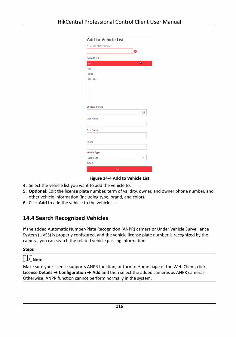
Figure 14-4 Add to Vehicle List4. Select the vehicle list you want to add the vehicle to.5. Optional: Edit the license plate number, term of validity, owner, and owner phone number, and
other vehicle information (including type, brand, and color).6. Click Add to add the vehicle to the vehicle list.
14.4 Search Recognized VehiclesIf the added Automatic Number-Plate Recognition (ANPR) camera or Under Vehicle SurveillanceSystem (UVSS) is properly configured, and the vehicle license plate number is recognized by thecamera, you can search the related vehicle passing information.
Steps
NoteMake sure your license supports ANPR function, or turn to Home page of the Web Client, clickLicense Details → Configuration → Add and then select the added cameras as ANPR cameras.Otherwise, ANPR function cannot perform normally in the system.
HikCentral Professional Control Client User Manual
116

1. Enter the Vehicle Search page.- Click Vehicle Search on control panel to enter the Vehicle Search page.- Start live view of the ANPR camera or UVSS, move the cursor to the recognized license plate
number, and click to enter the Vehicle Search page.
Figure 14-5 Vehicle Search Page2. Set the search conditions.
1) Select Camera or UVSS from the drop-down list.2) Select the resources to search the vehicle passing records.
NoteFor camera, you can click , select the current site or a Remote Site from the drop-down listand select the ANPR camera(s).
3) Optional: Set the mark information, country or region, plate number, and vehicle owner forsearching.
NoteYou can enter the keywords of plate number and vehicle owner name to fuzzy search thevehicles.
4) Optional: Check No License Plate to search passing records of vehicles with no plate.The Plate Number field will be unavailable.
5) Select vehicle type, brand, color, direction in the drop-down list.6) Set the time for searching.- Select to search the vehicles today, yesterday, current week, last 7 days, and last 30 days.- Click Custom Time Interval to set the search time range.
3. Click Search.The vehicle passing records that match the search conditions will display in the list.
HikCentral Professional Control Client User Manual
117
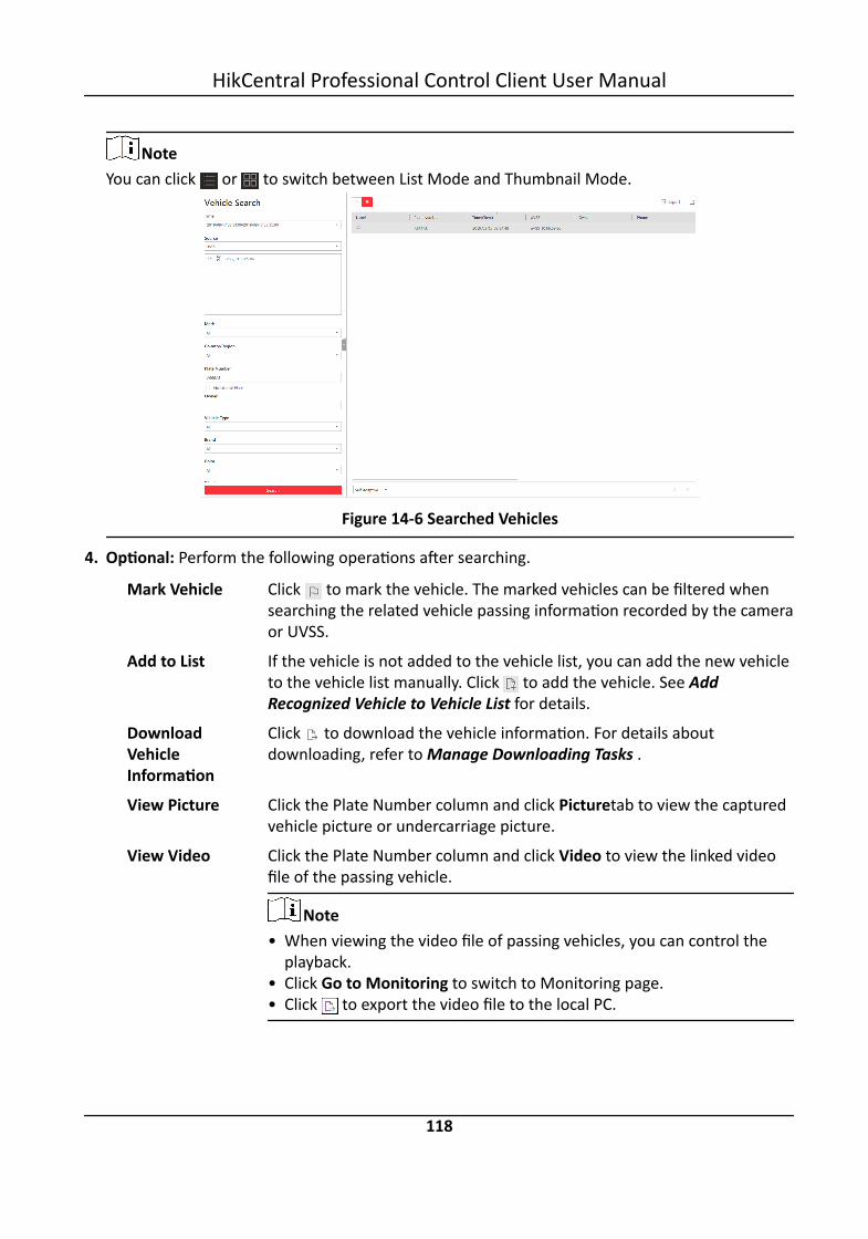
NoteYou can click or to switch between List Mode and Thumbnail Mode.
Figure 14-6 Searched Vehicles
4. Optional: Perform the following operations after searching.
Mark Vehicle Click to mark the vehicle. The marked vehicles can be filtered whensearching the related vehicle passing information recorded by the cameraor UVSS.
Add to List If the vehicle is not added to the vehicle list, you can add the new vehicleto the vehicle list manually. Click to add the vehicle. See AddRecognized Vehicle to Vehicle List for details.
DownloadVehicleInformation
Click to download the vehicle information. For details aboutdownloading, refer to Manage Downloading Tasks .
View Picture Click the Plate Number column and click Picturetab to view the capturedvehicle picture or undercarriage picture.
View Video Click the Plate Number column and click Video to view the linked videofile of the passing vehicle.
Note• When viewing the video file of passing vehicles, you can control the
playback.• Click Go to Monitoring to switch to Monitoring page.• Click to export the video file to the local PC.
HikCentral Professional Control Client User Manual
118

Export VehicleInformation
Click Export in the upper-right corner to export the searched vehiclerecords to a PDF file.
NoteUp to 500 vehicle records with captured pictures can be exported at onetime. Up to 100,000 vehicle records without pictures can be exported atone time.
Edit Click Edit to modify the recognized license plate number as needed.
HikCentral Professional Control Client User Manual
119

Chapter 15 Security Control
A security control device detects people, vehicles, etc., entering a pre-defined region, triggersevents and alarms, and reports events/alarms information (such as location) to security personnel.
On the Control Client, the operator can view the video of the radar's related cameras, arm &disarm partitions, bypass zones, etc. If a panic alarm is triggered, the operator can handle therequest on the Control Client.
15.1 Start Live View of Radar's Calibrated CameraYou can start live view of a radar's calibrated camera to view the image of the radar's detectionarea.
Before You StartMake sure you have configured at least one calibrated camera for the radar. See User Manual ofHikCentral Professional Web Client for details about configuring calibrated camera.
Steps1. Click Monitoring → Live View to enter the live view page.2. Click (Logical Resource) tab.
The areas which the current user has permission to access are displayed in the list and thelogical resources which the user has permission to access are displayed in the correspondingareas.
NoteFor setting the user permission, refer to User Manual of HikCentral Professional Web Client.
3. Double-click a radar's name or drag a radar to the display area to start the live view of itscalibrated cameras.The image of one calibrated camera will be displayed in the display window with a thumbnail ofanother calibrated camera's image on the lower-left corner.
HikCentral Professional Control Client User Manual
120

Figure 15-1 Live View of Radar's Calibrated Cameras4. Optional: Perform the following operation(s).
Arming Control Click to arm the radar; click to disarm a radar.
Switch CalibratedCamera
Hover the cursor on the thumbnail to display other calibrated cameras'thumbnails, and then click one of the thumbnail to display it in thedisplay window.
Locate on Map Click to show the map where the radar is added, so that you will seethe moving pattern of the one who intruded the detection area.
15.2 Perform Arming ControlYou can arm or disarm the partitions of the security control devices via the Control Client. Afterarming the partitions, the current Control Client can receive the triggered alarms in the partitions.You can also bypass or recover bypass for the zones if necessary.
Click Alarm Center → Arming Control to open the Arming Control window.Select the resource type as Alarm Input. You can also set the resource type as Radar to arm ordisarm the radar.
Arm & Disarm PartitionHover over the security control partition or radar and click to arm or disarm the partition orradar. You can select the arming mode according to actual needs.
HikCentral Professional Control Client User Manual
121

NoteThe disarming and arming control in Alarm Center only controls the alarm detection on the currentControl Client.
Figure 15-2 Arm & Disarm Partition
Instant ArmingIt is used when people leave the detection area. The zone will be immediately triggered when itdetects event or alarm with no delay and notify the security personnel.
Stay ArmingIt is used when people stay inside the detection area. During stay arming, all the perimeterburglary detections (such as perimeter detector, magnetic contacts, curtain detector in thebalcony) will be turned on. Meanwhile, the detectors inside the detection area are bypassed(such as PIR detectors). People can move inside the area and not trigger an event or alarm.
Away ArmingIt is used when people leave the detection area. Event or alarms will be activated when the zoneis triggered or tampered. For delayed zone, the alarm will not be activated when the zonedetects triggering event during entry/exit delay.
Bypass ZoneWhen some exception occurs for the zone, and other zones can work normally, you need to bypassthe abnormal zone to turn off the protection of it. Otherwise, you cannot arm the security controlpartition which the zone belongs to.Hover over the alarm input and click to bypass the zone.
Figure 15-3 Bypass Zone
Bypass RecoveryWhen you want to recover the zone that is bypassed to make it work normally, select alarm inputas triggered source and find the alarm input (zone) of the security control partition.Hover over the zone and click to recover zone to normal status.
HikCentral Professional Control Client User Manual
122

Clear AlarmsHover over the security control partition to click to clear the generated alarms in the securitycontrol partition.
15.3 Handle Panic Alarm from Panic Alarm StationA panic alarm station is mainly installed in the areas with the crowd or high incidence of cases,such as school, square, tourist attraction, hospital, supermarket gate, market, station, parking lot,etc. When the emergency happens or someone asks for help, the person can press panic button tosend alarm to the monitoring center, and the operator in the center will take the appropriateactions. The panic alarm station helps to realize alarm aid in emergency.
NoteYou should first set an alarm for the alarm input of the panic alarm station via the Web Client. Fordetails, refer to User Manual of HikCentral Professional Web Client.
If someone presses the panic button on the panic alarm station, a window will pop up on theControl Client as follows:
Figure 15-4 Panic Alarm
Perform Voice TalkClick Answer to answer this panic alarm and talk with the person who triggers this panic alarm.
Ignore AlarmClick Ignore to ignore this alarm if you don't want to handle it on the current Control Client. Ifignored, the user on other Control Client still can handle this alarm.
HikCentral Professional Control Client User Manual
123

Chapter 16 Smart Wall
Smart wall provides security personnel with a larger overview of the regions they want to watchfor any small or big unusual movement or activity. Large number of surveillance resources (such ascameras, maps) can be displayed on the smart wall for continuous monitoring. With the help of theSmart Wall, the security personnel can respond to the incidents effectively.
HikCentral Professional provides two modes of smart walls: Smart Wall (Decoding Device) andSmart Wall (Graphic Card).In Smart Wall (Decoding Device) mode, the decoding devices can decode the streams and displaythe cameras' images on the display units connected to the decoding devices.In Smart Wall (Graphic Card) mode, the graphic card of the PC running the Control Client willdecode the images and other contents (such as pages of the Control Client) and display on thescreens connected to the PC.
16.1 Manage Smart Wall (Decoding Device)A Smart Wall (Decoding Device) is a special multi-monitor setup that consists of multiple monitors,screens or display units tiled together contiguously or overlapped in order to form one largescreen, so that you can get a complete overview of large surveillance centers. With the smart wall,you can easily create views defining window division and content for the managed smart wall.What's more, the video triggered by event can also be displayed on smart wall to help operatorquickly focus on the most critical matters. For example, if a door is opened, the smart wall can beconfigured to display the video of the camera nearest to the door.
This type of smart wall is mainly used in medium and large surveillance scenarios, such assurveillance center. In these scenarios, more than four display units are required to display theimages.
Figure 16-1 Application Scenario: Smart Wall (Decoding Device)
HikCentral Professional Control Client User Manual
124

Before decoding and display, you need to add decoding devices (such as video wall controllers anddecoders) to the system, and create virtual smart walls via the Web Client. Then you need to linkthe decoding devices' decoding output to the windows of the virtual smart wall.After the above configuration, the Control Client supports displaying camera's video on the smartwall to get a complete and clear overview of the videos.Click Smart Wall in the Tool list to open the Smart Wall (Decoding Device) module.The following icons are available on the Smart Wall window.
Icon Description
Enter the Alarm Center to view the detected alarms and perform further operations,such as searching related video files of the alarm, displaying on smart wall, anddownloading the alarm details. Refer to Check Alarm and Event for details.
When the smart wall settings on the SYS server are changed (e.g., more smart wallsare added, linked decoding outputs are changed, decoding devices deleted), a red dotwill appear on this icon. Click it to synchronize the smart wall information.
Set to switch the stream type automatically according to current network situation,display the window No. on the smart wall, or view the details of the smart wall.
/ Unlock or lock the window. When you lock the window, you cannot display the videoon this window or stop decoding and displaying on the window.
Set the window division for the selected display window of smart wall. Double-click onthe split window to enlarge the window.
Create a roaming window to open a virtual window on the screen(s).
/ Display or hide the VCA rules on the display window of smart wall, such as configuredtarget detection frames for VCA event.
Stop all the windows' playing.
Save the current settings to the view or to other view. In this way, you can easily viewthe required live videos on the smart wall by calling this view.
NoteFor details, refer to View Settings .
Click to view the view schedule of the current smart wall.
NoteFor details about how to define the schedule, refer to Set Schedule for DisplayingViews on Smart Wall .
/ Display three/two smart walls in line.
Display the smart wall in the center of the window.
HikCentral Professional Control Client User Manual
125

16.1.1 Decode and Display Directly
After setting the smart wall via Web Client, the video streams from the camera can be decoded bythe configured decoding outputs, and then you can display the decoded videos on the smart wall.
Before You StartAdd the smart wall via Web Client. For details, refer to User Manual of HikCentral Professional WebClient.
Steps1. Click Smart Wall on the control panel to enter the Smart Wall page.2. Click in the upper-right corner of the smart wall window to select a window division mode.3. Display resources on smart wall.
- Display Camera on Smart Wall: Select Camera and site from the drop-down list, and double-click a camera name or drag the camera to the layout area of smart wall area to display thecamera on the smart wall.
NoteIt is only available for the central system with Remote Site Management module (based onthe license you purchased).
- Display Signal Source on Smart Wall: Select Signal Source from the drop-down list, and dragthe signal source to display window of the smart wall.
- Display Area on Smart Wall: Select Camera and site from the drop-down list, and double-clickthe area or drag the area to the layout area of smart wall to display the resources in the areaon the smart wall.
NoteIf there are multiple resources in the area, when you drag it to the layout area of smart wall,you need to select Play in Batch or Single-Screen Auto-Switch to display each resource inone display window or display area auto-switch in one display window on the smart wall. Formore details about area auto-switch, refer to Perform Auto-Switch of an Area's Cameras .
- Display View on Smart Wall: Click on the left , and double-click the view name to displayon smart wall.
HikCentral Professional Control Client User Manual
126

Figure 16-2 Display Live Video on Smart Wall
The decoded video stream is displayed on the smart wall.4. Optional: Select a display window which is linked with the camera to display the live video on
the large window at the bottom of the page, and then perform the following operation(s).
View CameraStatus
Click to show the camera's frame rate, resolution, and streamformat.
Switch Stream Click or to switch the live view stream to main stream, sub-stream,or smooth stream.
NoteSmooth stream needs to be supported by device.
Enable PTZControl
Click to enable PTZ (pan, tilt, zoom) control function on the displaywindow. And then you can control PTZ and set preset, patrol, andpattern. See PTZ Control for details.
Switch toPlayback
Click to switch to playback mode. For details, refer to Play Video File .
Stop Decodingand Displaying
Click or to stop the decoding and displaying for the specifiedwindow or all windows.
NoteFor the locked windows and alarm linked windows, you cannot stop thedecoding and displaying.
HikCentral Professional Control Client User Manual
127

16.1.2 View Settings
You can set the view and organize the views into a group for displaying the video on smart wallconveniently. You can also perform the view auto-switch for the view group on the smart wall.
Add View Group
A view group of a smart wall is to manage multiple views in a group for performing view auto-switch.
Steps1. Click Smart Wall on control panel to open the Smart Wall window.2. Click to open the View window.3. Select Public View or Private View to add this view group.
Note• The view groups and views belonging to the public view can be seen by all the system users.• The view groups and views belonging to the private view can only be seen by the user who
add it.
4. Click to open Add View Group window.5. Edit the group name or use the default one.6. Click Save to add the group.7. Optional: Perform the following operation(s) after adding the view group.
Edit View Group Select the view group and click to edit the view group name.
Delete View Group Select the view group and click to delete the group.
Add View
View defines which cameras are displayed on the monitors of the smart wall. In this way, you canquickly access the frequently used cameras on smart wall for an excellent overview.
Steps1. Click Smart Wall on control panel to open the Smart Wall window.2. Display the videos of cameras on the smart wall.
NoteFor more details, refer to Decode and Display Directly .
3. Click to open the View window.4. Select a view group.5. Click to open Add View window.6. Enter the view name or use the default one.
HikCentral Professional Control Client User Manual
128

7. Optional: Set Schedule Play switch to on and set when to automatically display the view onsmart wall.
NoteFor more details about how to set view schedule, refer to Set Schedule for Displaying Views onSmart Wall .
8. Click OK to save the view.9. Optional: Perform the following operation(s) after adding the view.
Start Decoding andDisplaying
Double-click the view to start decoding and displaying on smartwall conveniently.
Edit View Click to edit the name of the view.
Delete View Click to delete the view.
Set Schedule for Displaying Views on Smart Wall
The view schedule is used to define when to automatically display the view on smart wall.According to the schedule, the view will play on the smart wall at the time point(s) or the fixedtime point(s) on regular date(s) in one week repeatedly.
When adding a view, enable Scheduled Play and do one of the followings:• Check Repeated Play, select the days in one week, and set time for displaying the view on smart
wall at the regular time.• Uncheck Repeated Play, and set the date and time for displaying the view on smart wall at the
irregular time.
HikCentral Professional Control Client User Manual
129
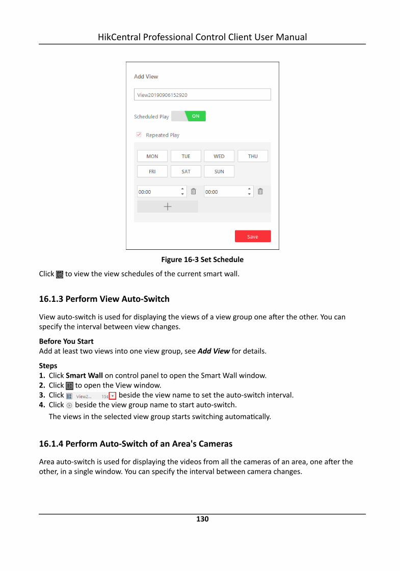
Figure 16-3 Set Schedule
Click to view the view schedules of the current smart wall.
16.1.3 Perform View Auto-Switch
View auto-switch is used for displaying the views of a view group one after the other. You canspecify the interval between view changes.
Before You StartAdd at least two views into one view group, see Add View for details.
Steps1. Click Smart Wall on control panel to open the Smart Wall window.2. Click to open the View window.3. Click beside the view name to set the auto-switch interval.4. Click beside the view group name to start auto-switch.
The views in the selected view group starts switching automatically.
16.1.4 Perform Auto-Switch of an Area's Cameras
Area auto-switch is used for displaying the videos from all the cameras of an area, one after theother, in a single window. You can specify the interval between camera changes.
HikCentral Professional Control Client User Manual
130

Before You StartThe cameras are added to one area. See User Manual of HikCentral Professional Web Client.
Steps1. Click Smart Wall on control panel to open the Smart Wall window.2. Click on the left to enter the Camera page.3. Select Camera and site from the drop-down list.4. Double-click an area name or drag an area on the left panel to the window linked with the
decoding output.5. Click Single-Screen Auto-Switch in the pop-up menu to display the videos of all cameras of the
area in one display window of the smart wall.The cameras in the selected area starts switching automatically on the smart wall.
6. Optional: Click << or >> in the toolbar of the video view to set the auto-switch interval: 20 s, 40s, 1min, 3min, 5min.
16.1.5 Create a Roaming Window
Windowing is to open a virtual window on the screen(s). The window can be within a screen orspan multiple screens. You can move the window on the valid screens as desired and this functionis called roaming. With windowing and roaming function, you can create custom window and thewindow size and position will not be limited by the actual screen(s).
Steps1. Click Smart Wall on control panel to open Smart Wall window.2. Click and drag on the screens which are linked to decoding outputs to open a window.
NoteScreens linked to BNC outputs are not available for opening a window.
Figure 16-4 Open a Window
HikCentral Professional Control Client User Manual
131

3. Optional: Perform the following operation(s) after opening a window.
Roam Click on the window and hold the mouse to move the window on thevalid screens.
Adjust WindowSize
Move your cursor to the window edges and adjust the window sizewhen the cursor becomes directional arrow.
Enlarge Window Double-click the window and it will be enlarged to fill the spannedscreens and display on the top layer. Double-click again to restore.
Display Windowon Top Layer
Select one window when there're overlapped windows and right-clickthe window to display it on the top layer.
16.1.6 View Alarm's Related Video on Smart Wall
If you have enabled the smart wall linkage for an alarm, the live view of cameras or public viewsrelated to the alarm will pop up on the chosen smart wall when the alarm is triggered. Therefore,you will know alarm details in a timely manner for further operations.
• When an alarm linked with multiple cameras in one display window is triggered, the window willbe divided into an adaptive division mode and show the videos of all cameras.
• When multiple alarms linked with one display window are triggered, the window will be dividedinto an adaptive division mode and show the alarms' related videos.
• When each alarm linked with multiple display windows is triggered, every window will show onealarm's related video. If the alarms exceed the window limit, the window will be divided into anadaptive division mode and show the more alarms' related videos.For example, there are alarm A, alarm B, alarm C and alarm D are linked with window 1, window2 and window 3 of smart wall. When alarm A, alarm B, and alarm C are triggered, the displaywindow of smart wall will show as the left figure below. When alarm D is also triggered, thedisplay window will show as the right figure below.
Figure 16-5 Multiple Alarms Displayed on Smart Wall
HikCentral Professional Control Client User Manual
132

16.1.7 View and Export Window No. and Camera ID
When displaying live view on smart wall, you can use a keyboard for convenient operations such asstarting live view on smart wall, PTZ control, etc. If you want to display certain camera's live view incertain window on the smart wall, you should press the camera's identifier number and targetwindow number on the keyboard, which are called Camera ID and Window No.
In the Web Client, you can set a unique ID for each camera added in the system. For details, referto User Manual of HikCentral Professional Web Client.In the Control Client, click Smart Wall on the control panel, and click → Window No. & CameraID → Display Window No. to show the number of each window.If you want to export a document which contains the IDs of all the cameras and smart wallinformation (such as smart wall name, row and column, etc.) as a reference, click → WindowNo. & Camera ID → View Window No. and Camera ID to generate a document.Click Download to download this document and save it in local PC. You can print it if necessary.
Note• The exported file is in PDF format.• The exported document also contains smart wall No., which are used for selecting smart wall via
network keyboard.
16.2 Manage Smart Wall (Graphic Card)Smart Wall (Graphic Card) is hardware independent. It doesn't require any decoding resourcessuch as video wall controllers or decoders. The PC running the client can decode the streams by itsgraphic card and then display the content on the screens connected to the PC. As a result, it is costefficient solution and easy deployment.
This type of smart wall is mainly used in small surveillance scenarios, such as supermarket, withless than four display units required.
HikCentral Professional Control Client User Manual
133

Figure 16-6 Application Scenario: Smart Wall (Graphic Card)
In this smart wall mode, you can display not only the camera's videos on the smart wall, but alsoother display contents such as maps, health status, Monitoring page, etc.
NoteUp to four screens are supported as smart walls for one Control Client in this mode.
16.2.1 Display Contents on Smart Wall in Smart Wall Mode
A variety of contents (e.g., video, map, face comparison) can be shared on the smart wall to helpyou respond quickly and effectively. The smart wall (graphic card) mode provides a convenient wayto set up initial smart wall, check complete overview of the smart wall layout, or adjust the layoutof the smart wall. You can select the desired smart screen and enter this mode to set windowdivision, adjust layout, display contents on smart wall or perform other operations.
Before You StartMake sure you have enabled GPU Hardware Decoding function in System → Image .
Steps1. Click Monitoring → Smart Wall to enter smart wall page.2. Enter Smart Wall Modce.
- Double-click a smart wall in the smart wall list.- Drag a smart wall from the smart wall list to the layout area of smart wall.The smart wall's icon will turn to .
Figure 16-7 Enter Smart Wall Mode
HikCentral Professional Control Client User Manual
134

3. Optional: Click at the bottom to choose the predefined window division to layout the displaywindow of the smart wall.
4. In smart wall mode, display contents on the smart wall.- Display Camera on Smart Wall: Double-click a camera name or drag the camera to the layout
area of smart wall area to display the camera on the smart wall.- Display Map on Smart Wall: Double-click the map or drag the map to the layout area of
smart wall to display the map on the smart wall.- Display Area on Smart Wall: Double-click the area or drag the area to the layout area of
smart wall to display the resources in the area on the smart wall.
NoteIf there are multiple resources in the area, when you drag it to the layout area of smart wall,you need to select Play in Batch or Single-Screen Auto-Switch to display each resource inone display window or display area auto-switch in one display window on the smart wall.
- Display View on Smart Wall: Drag the view to the layout area of smart wall and select Single-Screen Auto-Switch or Replace Current View to display the auto-switch view in one displaywindow or replace current display content on smart wall.
- Display View Group on Smart Wall: Drag the view group to the layout area of smart wall todisplay auto-switch of each view in one display window on smart wall.
- Display Face Comparison on Smart Wall: Double-click the face comparison group or drag it tothe layout area of smart wall to display the face comparison result on the smart wall.
5. Optional: In smart wall (graphic card) mode, perform one of the following operations.
View ResourceChannel
You can view all resource channels displayed on smart wall.
Adjust DisplayWindow
Drag one display window to another to adjust the layout order onsmart wall.
Edit Name Click and select Edit Name to edit the name of the smart wall.
Show Screen Click and select Show Screen to show the name on the smartwall.
Back to Monitoring Click Back to Monitoring to enter the live view page and the layoutarea of the smart wall is converted into one display window of liveview. You can view the video of other resources or perform otheroperations at the same time. Click Enter Smart Wall Mode to go backto the smart mall page.
Display or Do NotDisplay Alarm onScreen
Click to disable alarm display on the corresponding screen whenan alarm is triggered. Click to restore alarm display on the screen.
Exit Smart WallMode
Click Exit Smart Wall Mode to exit the mode.
HikCentral Professional Control Client User Manual
135

16.2.2 Display Contents on Smart Wall in Live View Mode
During live view, if you see something important in the live view window, for example, a suspectcaught by one camera or a VIP matched in the face comparison panel, you can display thesecontents on the smart wall to get a complete and larger overview.
After displaying the live contents on the smart wall (on another display) in this mode, you cancontinue view other live content, or perform other operations on the Control Client on the currentdisplay, without changing the content that smart wall displays. This function lets you keep an eyeon your smart wall while working in Control Client. For example, the smart wall continues to showthe current video while you start playback of this camera on the Control Client.
Display All Contents in Live View on Smart Wall
In the Monitoring module, you can display all contents you are viewing in the displaying windowsonto the smart wall (graphic card) to get a larger overview by a one-touch operation.
NoteMake sure you have enabled GPU Hardware Decoding function in System → Image .
After starting live view, click in the upper-right corner on the client and select a smart wall todisplay all the displaying windows on the smart wall.
Figure 16-8 Display All Contents in Live View on Smart Wall
NoteThe contents include all the resources displayed in the display area, such as video of the cameras,maps, face comparison groups, access points, etc.
HikCentral Professional Control Client User Manual
136

Hover the cursor on the top the displaying smart wall screen and click Exit Smart Wall Mode tostop displaying the contents on smart wall.
Display Camera on Smart Wall
You can display the live view of a camera on the smart wall without decoding, so as to show detailsof the monitored area of the camera in a timely manner.
Before You Start• Connect your PC to at least one smart wall.• Make sure you have enabled GPU Hardware Decoding function in System → Image .
Steps1. Click Monitoring to enter the Monitoring module.2. Click to open the Logical Resource panel.3. Optional: Click to select a window division mode.4. Display the live view of a camera on smart wall.
- Hover the cursor on a live view window, click in the window's toolbar, and then select asmart wall.
NoteYou can also click Smart Wall (Decoding Device) to decode and display this camera on smartwall.
- Hover the cursor on a camera's name, click , and then hover the cursor on Display onSmart Wall to select a smart wall.
The camera's icon will turn to , and the icons of different camera types vary.
Figure 16-9 Display Camera on Smart Wall
HikCentral Professional Control Client User Manual
137

5. Optional: Use a USB keyboard (such as DS-1005KI) to start live view of certain camera on smartwall by pressing the camera's identifier number.
NoteIn the Web Client, you can set a unique ID for each camera added in the system. For details,refer to User Manual of HikCentral Professional Web Client.
Display Area on Smart Wall
You can display all the cameras' live view in an area on the smart wall to view the details in an areain a timely manner for an overview of the area.
Before You Start• Connect your PC to at least one smart wall.• Make sure you have enabled GPU Hardware Decoding function in System → Image .
Steps1. Click Monitoring to enter the Monitoring module.2. Hover the cursor on an area's name, click , and then hover the cursor on Display on Smart
Wall to select a smart wall to display an area on the smart wall.
Display Map on Smart Wall
You can display e-map and GIS map on smart wall to show the overall layout and locations of theadded devices, or devices of a certain type. The alarm information will be displayed on the smartwall as well when an alarm is triggered.
Before You Start• Configure a GIS map or e-map via the Web Client beforehand. For details, see User Manual of
HikCentral Professional Web Client.• Make sure you have enabled GPU Hardware Decoding function in System → Image .
Steps1. Click Monitoring to enter the Monitoring module.2. Optional: Enter Smart Wall Mode. For details, see Display Contents on Smart Wall in Smart
Wall Mode .3. Click to open the Logical Resource panel.4. Optional: Click to select a window division mode.5. Display a map on smart wall.
- Hover the cursor on Map in the Logical Resource panel, click , and then move the cursoron Display on Smart Wall to select a smart wall.
- Double-click Map in the Logical Resource panel to display it on the right panel. Click in theupper-right corner of the map-displaying window and select a smart wall.
HikCentral Professional Control Client User Manual
138

NoteThe devices added to the map will be displayed with the map.
Figure 16-10 Display Map on Smart Wall
Display View and View Group on Smart Wall
If you have saved a view or view group, you can display it on smart wall in a timely manner withthe saved window division and the correspondence between cameras and windows.
Before You StartSave at least a view or create at least one view group beforehand. For details, see Manage View.
Steps1. Click Monitoring to enter the Monitoring module.2. Click to open the View panel.3. Display a view or view group on smart wall.
- Hover the cursor on a view name, click , and then hover the cursor on Display on SmartWall to select a smart wall.
- Hover the cursor on a view group name, click , and then click View Group Auto-Switch.• The view will be displayed on the selected smart wall in the saved window division mode.• Views in a group will be displayed on the selected smart wall in auto-switching mode.
HikCentral Professional Control Client User Manual
139

16.2.3 Display Alarm's Related Video on Smart Wall
If you have enabled the smart wall linkage for an alarm, the live view of cameras or public viewsrelated to the alarm will pop up on the chosen smart wall when the alarm is triggered. Therefore,you will know alarm details in a timely manner for further operations. You can also manuallydisplay live view of one of the alarm-related cameras on the smart wall.
Before You Start• Configure an alarm (and enable smart wall linkage for it) via the Web Client beforehand. For
details, see User Manual of HikCentral Professional Web Client.• Make sure you have enabled GPU Hardware Decoding function in System → Image .
Steps1. Enter the Alarm Center module.
The information of triggered alarms will be displayed.2. Optional: Click an alarm to display the live view of the alarm in the Related Video & Picture
window in the lower-left corner of the client for a preview.3. Display live view of a camera related to an alarm on smart wall.
Figure 16-11 Display Alarm's Related Video on Smart Wall- If you are viewing video of the camera's video in the Related Video & Picture window, click
Display on Smart Wall under the window to select a smart wall.- Click in the alarm's Operation column to display the alarm-related camera's live view on
smart wall directly.4. Optional: Hover the cursor on the top of the displaying smart wall to show the Exit Smart Wall
Mode bar, and then click to enable automatic alarm-video display on the current wall.• The icon turns to . The related cameras or views of the alarms configured with smart
wall linkage can be displayed on the smart wall automatically when triggered.
HikCentral Professional Control Client User Manual
140
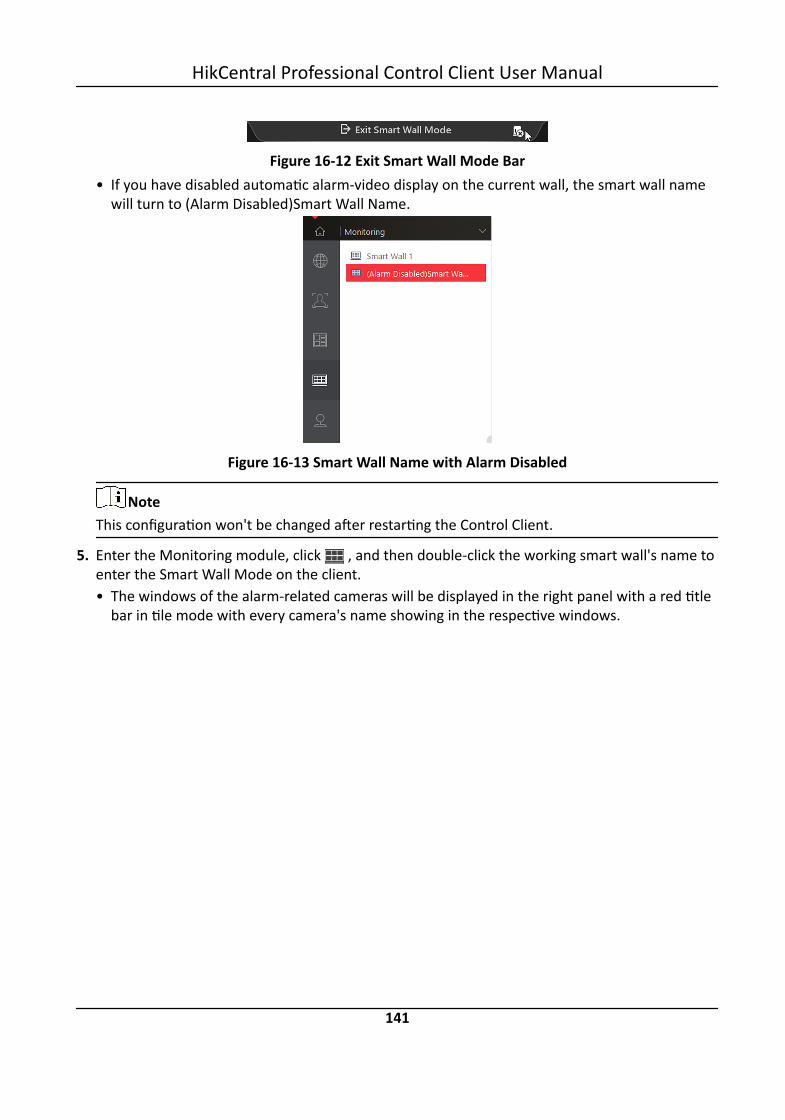
Figure 16-12 Exit Smart Wall Mode Bar• If you have disabled automatic alarm-video display on the current wall, the smart wall name
will turn to (Alarm Disabled)Smart Wall Name.
Figure 16-13 Smart Wall Name with Alarm Disabled
NoteThis configuration won't be changed after restarting the Control Client.
5. Enter the Monitoring module, click , and then double-click the working smart wall's name toenter the Smart Wall Mode on the client.• The windows of the alarm-related cameras will be displayed in the right panel with a red title
bar in tile mode with every camera's name showing in the respective windows.
HikCentral Professional Control Client User Manual
141

Figure 16-14 Display Alarm on Smart Wall• For alarm-related view, the view will be displayed in the right panel covering the images you
are currently viewing in the saved window division mode.6. Optional: Perform the following operations if you need.
View Alarm Details Click a red title bar on the client to open the alarm informationwindow for details.
Switch to Auto-Switching Mode
Click to switch between tile mode and auto-switching modefor the alarm-related cameras.
Note• In auto-switching mode, you can hover the cursor on the displaying window to performoperations including stream switching, switching between instant playback and live view,recording, camera switching, fast forward and slow forward.
• Up to 64 windows can be displayed on the smart wall. You can perform the above-mentionedtasks to control the live view displaying of the cameras and views.
• If you have enabled alarm on the smart wall, live view of alarms with higher priority will coverthat of alarms with lower priority before the due time of smart wall displaying.
• You can configure the due time of smart wall displaying via the Web Client. For details, seeUser Manual of HikCentral Professional Web Client.
• When multiple alarms with the same camera/view linkage are triggered, the alarms will bedisplayed on smart wall showing alarm number. When new alarm with the camera/viewlinkage is triggered, the number will change. The alarm window title shows the alarm's namewith the highest priority. Hover your cursor on alarm name, you can view all alarms in timeand priority order and handle them in a batch.
HikCentral Professional Control Client User Manual
142
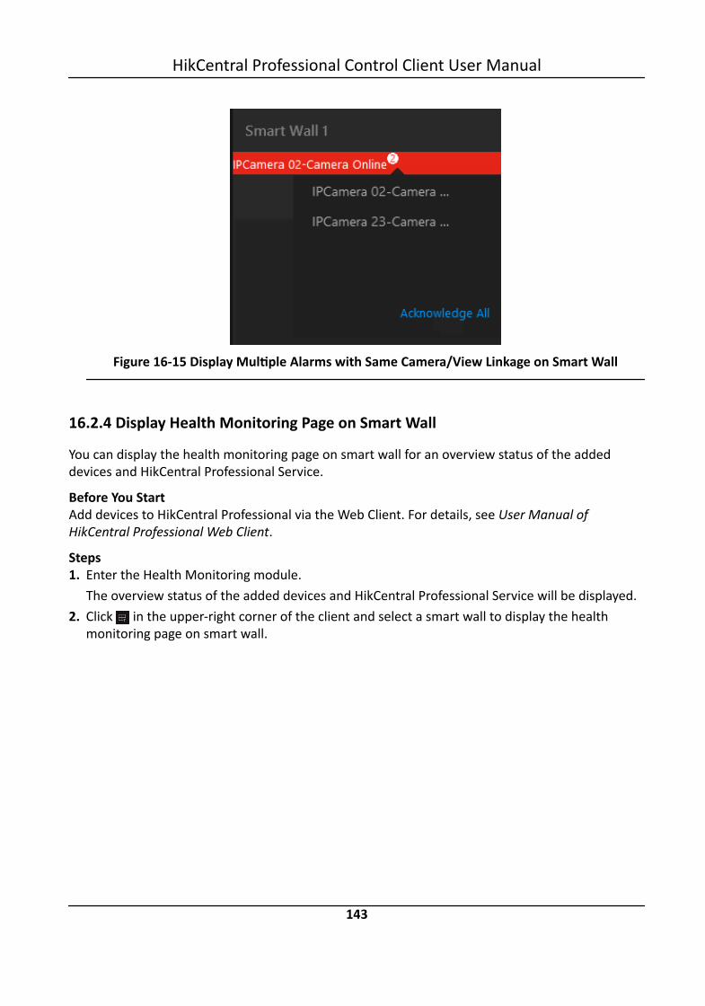
Figure 16-15 Display Multiple Alarms with Same Camera/View Linkage on Smart Wall
16.2.4 Display Health Monitoring Page on Smart Wall
You can display the health monitoring page on smart wall for an overview status of the addeddevices and HikCentral Professional Service.
Before You StartAdd devices to HikCentral Professional via the Web Client. For details, see User Manual ofHikCentral Professional Web Client.
Steps1. Enter the Health Monitoring module.
The overview status of the added devices and HikCentral Professional Service will be displayed.2. Click in the upper-right corner of the client and select a smart wall to display the health
monitoring page on smart wall.
HikCentral Professional Control Client User Manual
143

Figure 16-16 Display Health Monitoring Page on Smart Wall3. Enter the Monitoring module and click to open the smart wall panel.4. Double-click the name of the smart wall displaying the health monitoring page to enter the
Smart Wall (Graphic Card) mode in the Control Client.The word Health Monitoring will be displayed in the right window.
5. Optional: Click in the upper-right corner of the display window to stop displaying the healthmonitoring page on smart wall.
HikCentral Professional Control Client User Manual
144
Chapter 17 Intelligent Analysis Report
Reports, created for a specified period, are essential documents, which are used to check whethera business runs smoothly and effectively. In HikCentral Professional, reports can be generated daily,weekly, monthly, annually, and by custom time period. The reports can also be added to thedashboard for browsing at a glance. You can use reports as basis in creating decisions, addressingproblems, checking tendency and comparison, etc.
17.1 Customize Report DashboardThe report dashboard provides an at-a-glance view for the reports supported by the system, suchas people counting report, vehicle analysis report, and queue analysis report. You can customizethe report dashboard as required.
Steps1. Click Dashboard to enter the report dashboard page.2. Optional: Add dashboard(s).
- Click on the report dashboard page to add a new dashboard.- Click → to add a new dashboard.
NoteYou can add up to 200 dashboards.
The new dashboard appears and it is named as "Dashboard + The Time When It was Added" bydefault. For example, in "Dashboard20190916102436", "2019" represents year, "09" month,"16" date, "10" hour, "24" minute, and "26" second.
3. Optional: Edit dashboard(s).1) Click to enter the dashboard management page.2) Move the cursor to the name of a dashboard, and then click to edit the dashboard name,
or click to delete the dashboard.3) Click Back to go back to the report dashboard page.
4. Add report(s) to a dashboard and edit the report(s).1) Select a report type and generate the report.2) Click Add to Dashboard on the report page to add the report to dashboard.
The report appears on the selected dashboard.And appears on the lower-right of the report dashboard page. You can click the icon toadd more reports.
3) Perform the following operations.• Add More Reports: Click to add more reports to the dashboard.• View Report in Larger Window: Click to view the report in larger window.
HikCentral Professional Control Client User Manual
145

• Edit Report Name: Click and then click Edit Name.• Delete Report from Dashboard: Click and then click Delete.
Figure 17-1 Report Dashboard5. Switch time to view report data.
1) Select a dashboard and then click Switch Time to View to set the report type and time.Report Type
Select the time basis for the reports. For example, daily report shows data on a daily basis.Time
Set the specific time for generating the reports. For example, if you select Custom TimeInterval as the report type, you can click to specify a time interval for generating reportdata.
2) Perform one of the following operations.• Click Save to change the default time basis of all the reports in the dashboard to the time
you set in the previous sub step.• Click View to view the reports in the dashboard on the basis of the time you set in the
previous sub step.6. Optional: Export report(s) on the dashboard to the local PC.
1) Click Export to display the Export panel.2) Select report(s) from the report list.3) Click Browse to select a saving path for the selected report(s).4) Select Excel or CSV as the format of the exported report(s).5) Click Export.
17.2 Generate People Counting ReportYou can manually generate a people counting report to view the people counting statistics in a linechart or histogram, and generate reports for exporting the detailed data to local storage.
HikCentral Professional Control Client User Manual
146

Before You StartProperly configure the camera with a people counting rule for the required area. To configure thepeople counting rule, please refer to user manual of people counting camera.
Steps1. Click People Analysis → People Counting to enter the People Counting page.2. Set the analysis type.
People Counting for One CameraA people counting report based on the data from the cameras you select will be generated.You can compare the data of different cameras.
People Counting in One RegionA people counting report based on the data from the people counting groups you select willbe generated. You can compare the data of different groups.
NoteYou should have added people counting groups. See for details.
3. Select people counting camera(s) or people counting group(s) based on the analysis type youset in the previous step.1) Click .2) Select a current site or Remote Site from the drop-down site list to show its people counting
cameras or people counting groups.
NoteOnly people counting cameras and people counting groups will be displayed here.
3) Check the people counting camera(s) or people counting group(s) for statistics.The selected item(s) will appear in the camera list or people counting group list.
4. Select item(s) for the report in the camera list or people counting group list.
NoteUp to 20 people counting cameras can be selected for statistics at the same time.
5. Set the report type to daily report, weekly report, monthly report, annual report, or customizethe time interval for a report.Daily Report
Daily report shows data on a daily basis. The system will calculate the number of people ineach hour of one day.
Weekly Report, Monthly Report, Annual ReportAs compared to daily report, weekly report, monthly report, and annual report can be lesstime-consuming, since they are not to be submitted every day. The system will calculate thenumber of people in each day of one week, in each day of one month, and in each month ofone year.
HikCentral Professional Control Client User Manual
147

Custom Time IntervalUsers can customize the days in the report to analyze the number of people in each day ormonth of the custom time interval.
6. Set the time or time period in the Time field for statistics.
NoteFor custom time interval report, you need to set the start time and end time to specify the timeperiod.
7. Click Generate Report.The statistics of all the selected item(s) are displayed in the right panel.
Figure 17-2 People Counting Report8. Optional: Perform the following operation(s) after generating the people counting report.
Show/Hide CertainData
Click the legend to show or hide the data of certain element, suchas certain camera.
View Entered/Exited/Both Enteredand Exited Statistics
Select Enter, Exit, or Enter and Exit from the drop-down list. Thetotal statistics and all the selected cameras' statistics are displayedand marked with different colors.
View Both Enteredand Exited Statisticsof Single Camera
Click the camera name on the page below to view the chart ofsingle camera.
Switch Between LineChart and Histogram
Select Time or Item for Comparison on the upper-right corner toswitch the between line chart (displaying the trend for the numberof people on different time points) or histogram (for comparison).
Play Linked Video For line chart, if the selected report type is daily report, weeklyreport, or monthly report, click the line on the line chart to play thelinked video.
HikCentral Professional Control Client User Manual
148

For histogram, if the selected report type is daily report, click therectangle on the histogram to play the linked video.
9. Optional: Export the report and save it in local PC.1) Click Export.
The following panel will display with camera selected and time configured according to therange you defined in step 2 to 5.
HikCentral Professional Control Client User Manual
149

Figure 17-3 Export People Counting Report2) (Optional) Select the camera and set the report type and report time if needed.3) Select shorter time period to view more detailed data of each camera.
HikCentral Professional Control Client User Manual
150

ExampleFor example, if you select Daily Report, you can select Day or Hour, and it will export 1, 24records respectively for each camera.
NoteIf you select Minute, the records amount depends on the configuration on the device. Forexample, if the device reports people counting data to the system every minute, it will export24*60 records for each camera.
Figure 17-4 Set Level of Detail for Data of Each Camera4) Click Browse to set the saving path on local PC.5) Set the format of the exported file as Excel or CSV.6) Click Export and the task will be displayed in the Download Center,
17.3 Generate Queue Analysis ReportFor cameras which support queue management, you can generate a report to show the number ofqueue exceptions and number of persons in each queue, and show the queue status includingwaiting duration and queue length.
Before You StartAdd a camera which supports queue management to the system and configure queue regions. Toconfigure the queue region, refer to user manual of the camera.
Steps1. Click People Analysis → Queue Analysis to enter the Queue Analysis report page.2. Select camera(s) for statistics.
1) Click in the camera panel.2) Select a current site or Remote Site from the drop-down site list to show its cameras.
NoteOnly cameras which support queue management will be displayed here.
3) Check the camera(s) for statistics.The cameras will be added to the camera list.
3. Select the queue regions configured on the camera and the system will collect the queue data inthese queue regions.
HikCentral Professional Control Client User Manual
151

NoteFor configuring the queue, refer to the user manual of the camera.
4. Select the report type as daily report, weekly report, monthly report, or annual report.Daily Report
Daily report shows data on a daily basis. The system will calculate the queue data detected ineach hour of one day.
Weekly Report, Monthly Report, Annual ReportAs compared to daily report, weekly report, monthly report, and annual report can be lesstime-consuming, since they are not to be submitted every day. The system will calculate thequeue data detected in each day of way week, in each day of one month, and in each monthof one year.
5. Set the time or time period in the Time field for statistics.6. Optional: Select the analysis type and set the report range for daily report, weekly report, or
monthly report.Waiting Duration
Figure 17-5 Set Range for Waiting Duration
The report can show the number of persons in each queue who have waited for specifiedduration at different time points.For example, if you set the report range as 300s and 600s, the report will show that in eachqueue, how many persons have waited for less than 300s, how many persons have waitedfor 300 to 600s, and how many persons have waited for more than 600s.
Queue Length
HikCentral Professional Control Client User Manual
152
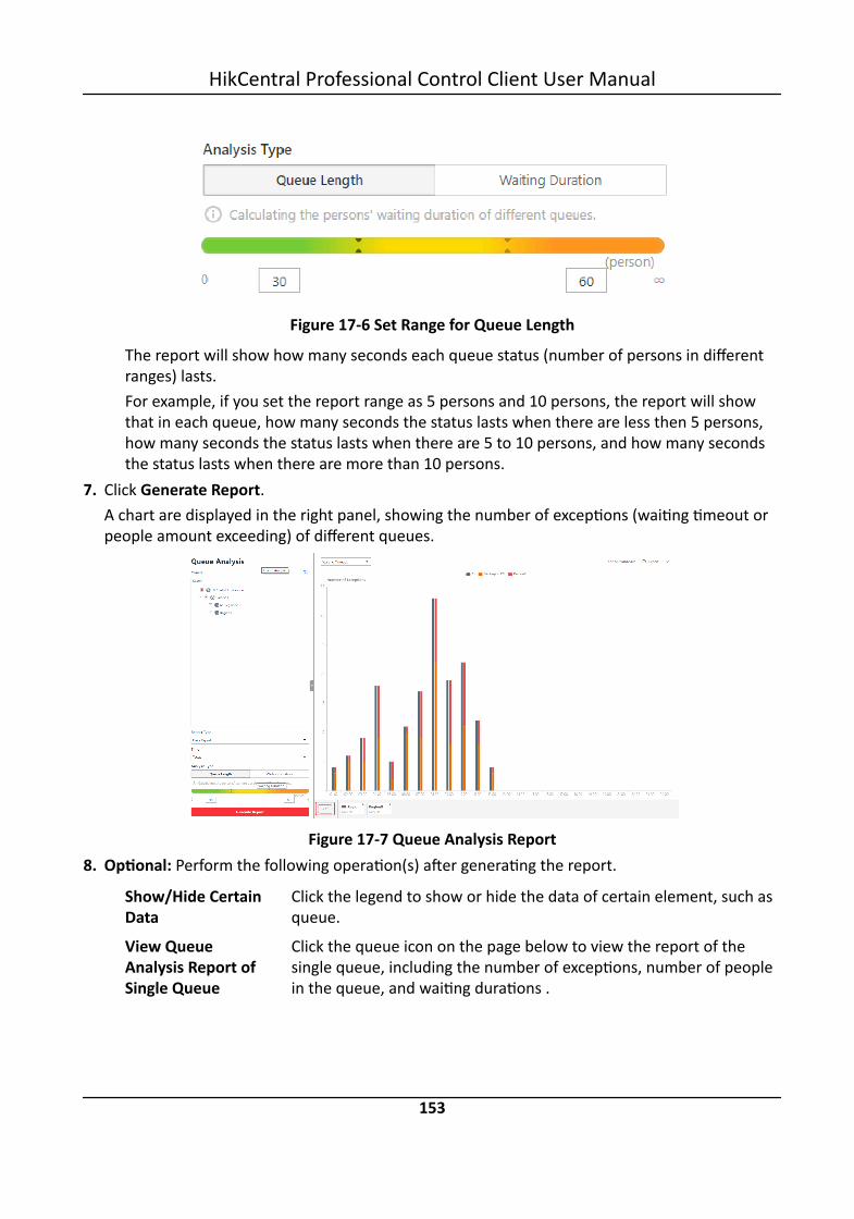
Figure 17-6 Set Range for Queue Length
The report will show how many seconds each queue status (number of persons in differentranges) lasts.For example, if you set the report range as 5 persons and 10 persons, the report will showthat in each queue, how many seconds the status lasts when there are less then 5 persons,how many seconds the status lasts when there are 5 to 10 persons, and how many secondsthe status lasts when there are more than 10 persons.
7. Click Generate Report.A chart are displayed in the right panel, showing the number of exceptions (waiting timeout orpeople amount exceeding) of different queues.
Figure 17-7 Queue Analysis Report8. Optional: Perform the following operation(s) after generating the report.
Show/Hide CertainData
Click the legend to show or hide the data of certain element, such asqueue.
View QueueAnalysis Report ofSingle Queue
Click the queue icon on the page below to view the report of thesingle queue, including the number of exceptions, number of peoplein the queue, and waiting durations .
HikCentral Professional Control Client User Manual
153

Switch BetweenNumber ofExceptions, Numberof People, andQueue Length
Click on the page below to view the report of all the selectedqueues.If you select the report type as Daily Report, Weekly Report, orMonthly Report, and set the analysis type as Waiting Duration, clickthe drop-down list to view the number of waiting timeoutexceptions, or number of people in different and all queues.If you select the report type as Annual Report, and set the analysistype as Waiting Duration, click the drop-down list to view thenumber of waiting timeout exceptions or number of people in allqueues.If you select the report type as Daily Report, Weekly Report, orMonthly Report and set the analysis type as Queue Length, click thedrop-down list to view the number of people amount exceedingexceptions or queue length of different queues.If you select the report type as Annual Report, and set the analysistype as Queue Length, the people amount exceeding exceptions willshow.
9. Optional: Export the report and save it in local PC.1) Click Export.
The following panel will display with camera and queue selected and time configuredaccording to the range you defined in step 2 to 5.
HikCentral Professional Control Client User Manual
154

Figure 17-8 Export Queue Analysis Report2) (Optional) Select the camera and queue, and set the report type and report time if needed.3) Select shorter time period to view more detailed data of each queue.
HikCentral Professional Control Client User Manual
155
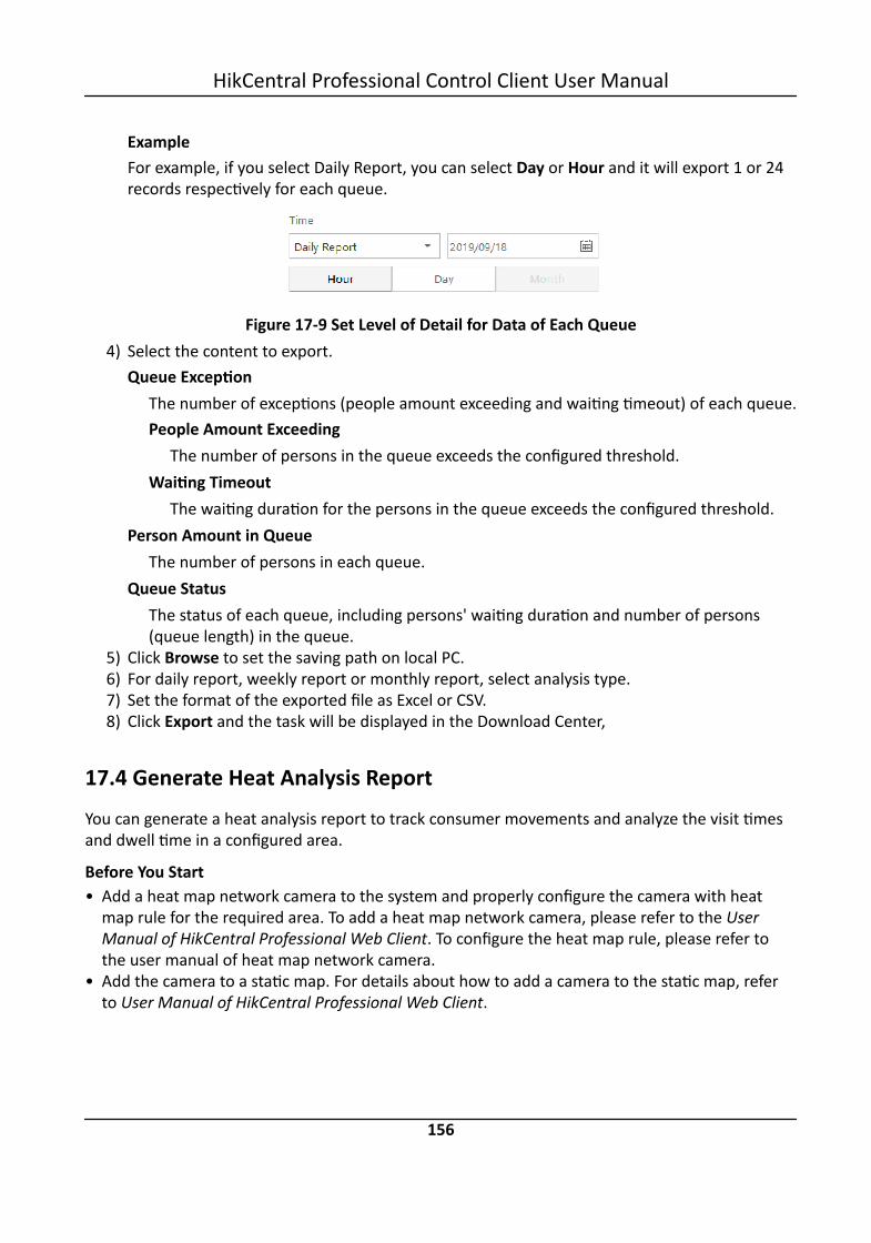
ExampleFor example, if you select Daily Report, you can select Day or Hour and it will export 1 or 24records respectively for each queue.
Figure 17-9 Set Level of Detail for Data of Each Queue4) Select the content to export.
Queue ExceptionThe number of exceptions (people amount exceeding and waiting timeout) of each queue.People Amount Exceeding
The number of persons in the queue exceeds the configured threshold.Waiting Timeout
The waiting duration for the persons in the queue exceeds the configured threshold.Person Amount in Queue
The number of persons in each queue.Queue Status
The status of each queue, including persons' waiting duration and number of persons(queue length) in the queue.
5) Click Browse to set the saving path on local PC.6) For daily report, weekly report or monthly report, select analysis type.7) Set the format of the exported file as Excel or CSV.8) Click Export and the task will be displayed in the Download Center,
17.4 Generate Heat Analysis ReportYou can generate a heat analysis report to track consumer movements and analyze the visit timesand dwell time in a configured area.
Before You Start• Add a heat map network camera to the system and properly configure the camera with heat
map rule for the required area. To add a heat map network camera, please refer to the UserManual of HikCentral Professional Web Client. To configure the heat map rule, please refer tothe user manual of heat map network camera.
• Add the camera to a static map. For details about how to add a camera to the static map, referto User Manual of HikCentral Professional Web Client.
HikCentral Professional Control Client User Manual
156

Steps1. Click People Analysis → Heat Analysis to enter the Heat Analysis page.2. Select analysis type.
Heat Analysis for One CameraA heat analysis report based on the data from the selected cameras will be generated. Thedata of different cameras will be displayed and you can compare the data of differentcameras.
Heat Analysis in One RegionA heat analysis report based on the data from the selected heat analysis groups will begenerated. The data of different groups will be displayed and you can compare the data fromdifferent groups.
NoteYou should have added heat analysis group(s). For details, see .
3. Select heat analysis camera(s) or heat analysis group(s) for statistics.1) Click .
NoteOnly heat analysis camera or heat analysis group will be displayed here.
2) Check the heat analysis camera(s) or heat analysis group(s) for statistics.4. Select camera(s) for the report in the camera list.
NoteUp to 20 heat analysis cameras can be selected for statistics at the same time.
5. Set the report type to daily report, weekly report, monthly report, annual report, or customizethe time interval for a report.Daily Report
Daily report shows data on a daily basis. The system will calculate the number of people orpeople dwell time in each hour of one day.
Weekly Report, Monthly Report, Annual ReportAs compared to daily report, weekly report, monthly report, and annual report can be lesstime-consuming, since they are not to be submitted every day. The system will calculate thenumber of people or people dwell time in each day of way week, in each day of one month,and in each month of one year.
Custom Time IntervalUsers can customize the days in the report to analyze the number of people or people dwelltime in each day or month of the custom time interval.
6. Optional: Set the time or time period in the Time field for statistics.
HikCentral Professional Control Client User Manual
157

NoteFor custom time interval report, you need to set the start time and end time to specify the timeperiod.
7. Set the analysis type.Dwell Time
The minutes that the people stay at the same location during each time period for eachcamera.
People AmountThe number of people detected during each time period for each camera.
NoteThis analysis type is only supported by the second generation of heat analysis cameras.
Average Dwell TimeThe average dwell time for the each person stay at the same location during each timeperiod for each camera.
8. Click Generate Report.The static maps of the selected cameras will appear.
Figure 17-10 Static Map of selected Cameras
9. Click the map to view the detailed heat data of the cameras on the map. You can view eachcamera's field of view, and the fields are color coded. The red color block (255, 0, 0) indicatesthe most welcome region (most persons detected or longest dwell time), and blue color block(0, 0, 255) indicates the less-popular region (least persons detected or shortest dwell time).
HikCentral Professional Control Client User Manual
158

NoteMove the cursor to the field of view to view the detected value, including people amount ordwell time.
10. Optional: Click the camera icon on the page below to view heat analysis of single camera.
Figure 17-11 Heat Map of Single Camera
The image of the camera is color coded. The red color block (255, 0, 0) indicates the mostwelcome region (most persons detected or longest dwell time), and blue color block (0, 0, 255)indicates the less-popular region (least persons detected or shortest dwell time).You can drag the slider on the upper-right to adjust the range of the heat value. The heat dataout of the range will not be displayed.
11. Optional: Click to switch among heat map, histogram, line chart to view the details.
HikCentral Professional Control Client User Manual
159

Figure 17-12 Line Chart of Heat Analysis12. Optional: Export the report and save it in local PC.
1)Click Export.A panel will display with camera selected and time configured according to the range youdefined in step 2 to 6.
2)(Optional) Select the camera, and set the analysis type and report time if needed.3)Select shorter time period to view more detailed data of each queue.
ExampleFor example, if you select Daily Report, you can select Day or Hour and it will export 1 or 24records respectively for each camera.
4)Click Browse to set the saving path on local PC.5)Set the format of the exported file as Excel or PDF.6)Click Export and the task will be displayed in the Download Center.
17.5 Generate Pathway Analysis ReportPathway analysis is mainly used to analyze the people counting on the pathways in the shoppingmalls. With the help of fisheye cameras, the system can collect the consumers data (for example,where the customers walk mostly) and translate that data onto a dashboard for mall managers.This helps managers analyze which areas/shops of the mall best catch a shopper's attention andwhich are overlooked. After setting the fisheye camera's pathways and their directions, the systemcalculates the people dwell time at each pathway and number of people walking by, thus helpsthem make decisions.
HikCentral Professional Control Client User Manual
160

Before You Start• Properly add the camera to a static map and set its pathways on the map via the Web Client first.
For details about adding camera to map and set pathways, refer to the User Manual ofHikCentral Professional Web Client.
• You should have added pathway analysis groups. For details, see the user manual of the WebClient.
Steps
NoteThis function is only supported by the second generation of fisheye cameras.
1. Click People Analysis → Pathway Analysis to enter the Pathway Analysis page.2. Select path analysis group(s) from the Resource Group list for statistics.3. Select the report type as daily report, weekly report, monthly report, annual report, or
customize the time interval for a report.Daily Report
Daily report shows data on a daily basis. The system will calculate the number of people orpeople dwell time in each hour of one day.
Weekly Report, Monthly Report, Annual ReportAs compared to daily report, weekly report, monthly report, and annual report can be lesstime-consuming, since they are not to be submitted every day. The system will calculate thenumber of people or people dwell time in each day of way week, in each day of one month,and in each month of one year.
Custom Time IntervalUsers can customize the days in the report to analyze the number of people or people dwelltime in each day or month of the custom time interval.
4. Optional: Set the time or time period in the Time field for statistics.
NoteFor custom time interval report, you need to set the start time and end time to specify the timeperiod.
5. Click Generate Report.The static map with the cameras and pathways color coded on the map will be displayed. Thered color block (255, 0, 0) indicates the most welcome pathway (most persons detected orlongest dwell time), and blue color block (0, 0, 255) indicates the less-popular pathway (leastpersons detected or shortest dwell time).
HikCentral Professional Control Client User Manual
161

Figure 17-13 Pathway Analysis Report
6. Move the cursor to the camera hot spot to view the line chart or heat map of the peopleamount and people dwell time in the pathways during this time period.
Figure 17-14 View Heat Map or Line Chart7. Optional: Export the report and save it in local PC.
1) Click Export.The following panel will display with map selected and time configured according to therange you defined in step 2 to 4.
HikCentral Professional Control Client User Manual
162

Figure 17-15 Export Pathway Analysis Report2) Edit the report type and report time if needed.3) Select shorter time period to view more detailed data of each queue.
HikCentral Professional Control Client User Manual
163

ExampleFor example, if you select Daily Report, you can select Day or Hour and it will export 1 or 24records respectively for each camera.
4) Click Browse to set the saving path on local PC.5) Set the format of the exported file as Excel or PDF.6) Click Export and the task will be displayed in the Download Center,
17.6 Generate Person Feature Analysis ReportThe system supports saving features (including age and gender) of recognized human faces andgenerating reports in various time periods. The reports tells the percentage and number of peopleof different gender and age groups in different time period. It can be used in places such asshopping mall to analyze interests of people in different gender and age.
Before You StartMake sure you have added a person feature analysis group if you want to perform feature analysisin one region. See User Manual of HikCentral Professional Web Client for details about adding aperson feature analysis group.
Steps1. Click People Analysis → to enter the Person Feature Analysis page.2. Select analysis type.
Feature Analysis for One CameraCompare percentage and number of people of different gender and age groups detected byspecified camera(s).
Feature Analysis in One RegionCompare percentage and number of people of different gender and age groups detected bythe cameras in specified person feature analysis group(s) of multiple regions.
3. Select camera(s)/resource group(s).
Note• Up to 20 cameras/resource groups can be selected for statistics at the same time.• The system supports selecting one resource group of a remote site.
4. Select the report type as daily report, weekly report, monthly report, annual report, orcustomize the time interval for a report, and the system will generate statistics of the selectedcamera(s)/resource group(s) of the current day/week/month/year or the customized period.
5. Set the time or time period in the Time field for statistics.
NoteFor custom time interval report, you need to set the start time and end time to specify the timeperiod.
HikCentral Professional Control Client User Manual
164

6. Click Generate Report.
NoteThe statistics of all the selected cameras/resource groups are displayed on the right panel.
Figure 17-16 Person Feature Analysis7. Optional: Click Add to Dashboard to display the report on the Dashboard.8. Optional: Save the report to the current computer.
1) Click Export.The selected camera(s)/resource group(s) and configured time will be displayed on theExport panel.
HikCentral Professional Control Client User Manual
165

Figure 17-17 Export Panel2) Optional: Select the camera and set the report type and report time if needed.3) Select shorter time period to view more detailed data of each camera.
Exampleif you select Daily Report, you can select Day or Hour, and it will export 1or 24 recordsrespectively for each camera.
4) Click Browse to set the saving path on the computer.5) Set the format of the exported file.6) Click Export and the task will be displayed in the Download Center.
17.7 Generate Temperature ReportFor thermal cameras, you can generate a report to show the number of exceptions (temperaturetoo high or too low) and maximum/minimum temperature of different thermometry points ondifferent presets.
Steps1. Click Temperature on control panel to enter the Temperature Analysis page.
HikCentral Professional Control Client User Manual
166

2. Select thermal camera(s) for statistics.1) Click in the camera panel.2) Select a current site or Remote Site from the drop-down site list to show its thermal cameras.
NoteOnly thermal cameras will be displayed here.
3) Check the thermal camera(s) for statistics.The cameras will be added to the camera list.
3. Select the preset(s) configured on the camera and the system will collect the data on thethermometry point in these presets.
NoteFor configuring the thermometry point with temperature measurement rules, refer to the usermanual of the thermal camera.
4. Select the report type as daily report, weekly report, monthly report, annual report, orcustomize the time interval for a report.Daily Report
Daily report shows data on a daily basis. The system will calculate the temperature datadetected in each hour of one day.
Weekly Report, Monthly Report, Annual ReportAs compared to daily report, weekly report, monthly report, and annual report can be lesstime-consuming, since they are not to be submitted every day. The system will calculate thetemperature data detected in each day of way week, in each day of one month, and in eachmonth of one year.
Custom Time IntervalUsers can customize the days in the report to analyze temperature data detected in each dayor month of the custom time interval.
5. Set the time or time period in the Time field for statistics.
NoteFor custom time interval report, you need to set the start time and end time to specify the timeperiod.
6. Click Generate Report.The temperature statistics of all the selected presets are displayed in the right panel.
HikCentral Professional Control Client User Manual
167

Figure 17-18 Temperature Report7. Optional: Perform the following operation(s) after generating the temperature report.
Show/Hide CertainData
Click the legend to show or hide the data of certain element, such ascertain preset or thermometry point.
View TemperatureReport of SinglePreset
Click the preset icon on the page below to view the report in thesingle preset.
View TemperatureReport of SingleThermometry Point
a. Click the preset icon on the page below to view the report in thesingle preset.
b. In the Item for Comparison field, select one thermometry point.c. In the Item for Comparison field, select the indicator you want to
view in the chart.High/Low Temperature
Shows the number of exceptions that the temperature at thisthermometry point is higher or lower than the pre-definedtemperature.
Max. TemperatureShows the maximum temperature at this thermometry pointduring the set time period.The temperature is displayed in line chart, indicating the trend.
Min. TemperatureShows the minimum temperature at this thermometry pointduring the set time period.The temperature is displayed in line chart, indicating the trend.
8. Optional: Export the report and save it in local PC.1) Click Export.
HikCentral Professional Control Client User Manual
168

The following panel will display with camera and preset selected and time configuredaccording to the range you defined in step 2 to 5.
Figure 17-19 Export Temperature Report
HikCentral Professional Control Client User Manual
169

2) (Optional) Select the camera and preset, and set the report type and report time if needed.3) Select shorter time period to view more detailed data of each thermometry point.
ExampleFor example, if you select Daily Report, you can select Day or Hour, or Minute and it willexport 1, 24, or 24×60 records respectively for each thermometry point.
Figure 17-20 Set Level of Detail for Data of Each Thermometry Point4) Select the content to export.
Temperature ExceptionExport the number of exceptions on temperature (temperature too high or too low) ofeach thermometry point.
Temperature StatusExport the maximum temperature and minimum temperature of each thermometrypoint.
5) Click Browse to set the saving path on local PC.6) Set the format of the exported file as Excel or CSV.7) Click Export and the task will be displayed in the Download Center,
17.8 Generate Vehicle Analysis ReportFor ANPR cameras, you can generate a report to show the number of passing vehicles detected bythe specified cameras during specified time period.
Steps1. Click Vehicle Analysis on control panel to enter the Vehicle Analysis page.2. Select the camera(s) for statistics.
1) Click in the camera panel.2) Select a current site or Remote Site from the drop-down site list to show its ANPR cameras
which support this function.
NoteOnly ANPR cameras will be displayed here.
3) Check the camera(s) for statistics.The cameras will be added to the camera list.
3. Select camera(s) for the report in the camera list.
HikCentral Professional Control Client User Manual
170

NoteUp to 20 ANPR cameras can be selected for statistics at the same time.
4. Select the report type as daily report, weekly report, monthly report, annual report, orcustomize the time interval for a report.Daily Report
Daily report shows data on a daily basis. The system will calculate the number of vehicles ineach hour of one day.
Weekly Report, Monthly Report, Annual ReportAs compared to daily report, weekly report, monthly report, and annual report can be lesstime-consuming, since they are not to be submitted every day. The system will calculate thenumber of vehicles in each day of way week, in each day of one month, and in each month ofone year.
Custom Time IntervalUsers can customize the days in the report to analyze the number of vehicles in each day ormonth of the custom time interval.
5. Set the time or time period in the Time field for statistics.
NoteFor custom time interval report, you need to set the start time and end time to specify the timeperiod.
6. Click Generate Report.The passing vehicles statistics detected by all the selected cameras are displayed in the rightpanel.
7. Optional: Export the report and save it in local PC.1) Click Export.
The following panel will display with camera selected and time configured according to therange you defined in step 2 to 5.
HikCentral Professional Control Client User Manual
171

Figure 17-21 Export Vehicle Report2) (Optional) Select the camera and set the report type and report time if needed.3) Select shorter time period to view more detailed data of each camera.
HikCentral Professional Control Client User Manual
172

ExampleFor example, if you select Daily Report, you can select Day, Hour, or Minute and it will export1, 24, or 24×60 records respectively for each camera.
Figure 17-22 Set Level of Detail for Data of Each Camera4) Click Browse to set the saving path on local PC.5) Set the format of the exported file as Excel or CSV.6) Click Export and the task will be displayed in the Download Center,
HikCentral Professional Control Client User Manual
173

Chapter 18 Maintenance
The Control Client allows you to monitor resource health status and search resource logs. The dataof resource health status and resource logs, which is of especially importance for maintenance ofthe system, helps you locate the source of exceptions and determine methods for troubleshooting.
18.1 Health MonitoringHealth monitoring provides both near-real-time and history information about the status of theSYS server and added resources. It is critical to multiple aspects of operating the servers or devicesand is especially important for maintenance. When a resource exception occurs, you can enter thismodule to check the resource status and find out the abnormal device(s) and view the exceptiondetails.
Click Health Monitoring on control panel to enter the Health Monitoring page.
18.1.1 Real-Time Overview
The Real-Time Overview provides an at-a-glance view of the status of the resources added to thesystem with charts and basic data of resource status.
Click Health Monitoring and then click Real-Time Overview on the navigation panel on the left toenter the Real-Time Overview page.
View Status InformationYou can view the overall status of the resources managed in the system, such as the camerasmanaged in the Central System, the access points, servers, devices, etc.
NoteYou can go to the Control Panel and then click System → Health Monitoring to set the interval forautomatically refreshing the status of the resources.
You can click the numbers and status types on the chart to enter the corresponding status page toview the details.• For HikCentralProfessional service, you can click to open the System Management Server
window to view the followings.• CPU: The real-time CPU usage.• RAM: The real-time RAM usage.• Network: The real-time network traffic sent and received.
HikCentral Professional Control Client User Manual
174

• Streaming Gateway: The incoming or outgoing streaming situation of the Streaming Gatewayrunning on SYS server.
• Picture Storage: The real-time usage of picture storage.• The Remote Site status is only available for the Central System with Remote Site Management
module (based on the license you purchased).
Export DataYou can perform the following task to export the Real-Time Overview page as a PDF file to the localPC.1. Click Export to open the Export panel.
Figure 18-1 The Export Panel2. Select a saving path for the to-be-exported data.3. Click Save.You can also perform the following task to export the abnormal data to the local PC.1. Click Export to open the Export panel.2. Check Export Exception Data.3. Select CSV or Excel as the format of the to-be-exported data.4. Click Save.
18.1.2 History Overview
You can view the overview of history resource online rate, device online rate, and recordingintegrity rate.
HikCentral Professional Control Client User Manual
175

Click Health Monitoring and then click History Overview on the navigation panel on the left toenter the History Overview page.You can select a time period from the drop-down list for filtering data.You can also click Export to export the history overview to the local PC. For details, see ExportData .
Resource Online RateOn the line chart, you can perform the following operations.• Move the cursor on the line chart to view the camera online rate and the number of offline
cameras at specific time points.• Click the a dot on the line to go to Resource Log page to view the detailed network status of
cameras at that time point.On the doughnut chart, you can perform the following operations.• Move the cursor to red part of the doughnut chart to view the number of the cameras which
once were offline and the offline rate during the time period you select.• Move the cursor to the green part of the doughnut chart to view the number of the cameras
which stay online and the online rate during the time period you select.On the table, you can do one of the followings.• Click Total Offline Duration to rank the cameras in terms of total offline duration within the time
period you select.• Click Offline Times to rank the cameras in terms of offline times within the time period you
select.
Device Online RateOn the line chart, you can do one of the followings.• Move the cursor on the line chart to view the device online rate and the number of offline
devices at specific time points.• Click the a dot on the line to go to Device Log page to view the detailed network status of
devices at that time point.On the doughnut chart, you can perform the following operations.• Move the cursor to red part of the doughnut chart to view the number of the devices which
once were offline and the offline rate during the time period you select.• Move the cursor to the green part of the doughnut chart to view the number of the devices
which stay online and the online rate during the time period you select.On the table, you can do one of the followings.• Click Total Offline Duration to rank the devices in terms of total offline duration within the time
period you select.• Click Offline Times to rank the devices in terms of offline times within the time period you
select.
HikCentral Professional Control Client User Manual
176

Recording Integrity RateOn the line chart, you can move the cursor to view the recording integrity rate at specific timepoints. Click the a dot on the line to go to Device Log page to view the detailed resource status ofdevices at that time point.
Figure 18-2 History Overview
18.2 Resource StatusYou can monitor the near-real time status of the added resources, such as Recording Servers,Streaming Servers, and encoding devices, to find out and maintain the abnormal resources in time,ensuring the smooth running of the system to the greatest extent.
Click Real-Time Status of Resource and select a resource type from the navigation panel on theleft.The resource status will be automatically refreshed in a specified interval. You can also clickRefresh to refresh all the resource status manually.
NoteFor details about specifying the interval for refreshing resource status, see Set Health MonitoringParameters .
You can perform the following operations for different resource types.• Check Include Sub-area to display the cameras of child areas.• Check the checkbox beside the drop-down list on the upper-right and then select an abnormal
type (such as Camera Offline and Video Loss to filter data.• Click Export to export the status data as CSV or Excel to the local PC.
Camera StatusOn the camera status page, you can view camera status such as network status, arming status, andrecording status.
HikCentral Professional Control Client User Manual
177

You can also perform the following operations.• Click the camera name to view its status and basic information.• Click the IP address to view the status of the device to which the camera is connected to.• Click in the Operation column to view the online/offline records of the camera. For details,
see Search Online/Offline Logs of Resource .• Click in the Operation column to view the recording status of the camera. For details, see
Search Recording Status of Resource .• Click in the Operation column to go to the HikCentral Professional Web Client to configure the
camera parameters.
NoteContact the admin user to edit the exceptional configuration of camera's event or alarm via theWeb Client if an icon appears near the camera name.
Elevator StatusOn the elevator status page, you can view information such as network status of the elevatorcontrol device and the card reader status.You can click the name of the elevator control device to view its detailed status.You can also click in the Operation column to go to the HikCentral Professional Web Client toconfigure the elevator parameters.
Door StatusOn the door status page, you can view the information such as the network status of the accesscontrol device and the door status.You can click in the Operation column to go to the HikCentral Professional Web Client toconfigure the door parameters.You can click the door status icon in the Operation column to control the door status.Unlock
When the door is locked, unlock the door and it will be open. After the open duration(configured via the Web Client), the door will be closed and locked again automatically.
LockWhen the door is unlocked, lock the door and it will be closed. The person who has the accesspermission can access the door with credentials.
Remain UnlockedThe door will be unlocked (no matter closed or open). All the persons can access the door withno credentials required (free access).
Remain LockedThe door will be closed and locked. No person can access the door even if he/she has theauthorized credentials, except the super users.
HikCentral Professional Control Client User Manual
178

Remote Site StatusYou can view the remote site status such as network status and default stream.You can click or in the Operation column to switch the mode for accessing the resources onRemote Site between Automatically Judge mode and Proxy mode.• Automatically Judge: The system will automatically judge the condition of network connection
and then set the device access mode accordingly as accessing directly or accessing via StreamingGateway and Management Service.
• Proxy: The system will access the device via Streaming Gateway and Management Service.You can click Restore All Network Connections to restore the connection mode of all the addedRemote Site's resources to Automatically Judge mode.The Default Stream in the table refers to the default stream type for accessing the resources onthe Remote Site. You can select the Remote Site(s) and click Switch Stream to switch the streamtype. When starting live view of the Remote Site's resources in Central System, the Control Clientwill get this default stream to start live view.• Main Stream: Main stream provides higher quality video, higher resolution, but brings about
higher bandwidth usage.• Sub-Stream: Sub stream can save on bandwidth, but the video quality is lower than main
stream.• Smooth Stream: This stream type is usually used in low-bandwidth situation. After switching to
smooth stream, the live view and playback will be smoother in slow network performance, butthe image quality will be lower accordingly.
• Default Stream Type: If you select Default Stream Type, the stream type for accessing theselected Remote Site's resources will be restored to the global stream type you set in System →General .
UVSS StatusOn the UVSS status page, you can view the information such as line scan camera status and capturecamera status.You can click in the Operation column to go to the HikCentral Professional Web Client toconfigure the UVSS parameters.
Streaming Server StatusYou can view the streams via each added Streaming Server (including incoming streams andoutgoing streams), and view the hardware status such as network status, CPU usage, and RAMusage.
Recording Server StatusClick the status in Recording Status column to view the recording status of the channels configuredto store the video files in this Recording Server.Click the status in Hardware Status or HDD Status column to view the hardware status and HDDexception details if the status is exceptional.
HikCentral Professional Control Client User Manual
179

DeepinMind Server StatusYou can view the network status, CPU usage, and RAM usage, etc., of the DeepinMind servers.
Security Audit Server StatusYou can view the HDD status, network status, and first added time, etc., of the audit server.
Encoding Device StatusYou can view the encoding device status including recording status, HDD usage, default stream, etc.In the Operation colunm, you can perform the following operations.• Click in the Operation column to view the online/offline records of the encoding device. For
details, see Search Online/Offline Logs of Device .• Click in the Operation column to go to the HikCentral Professional Web Client to configure the
device parameters.Click the status in Recording Status column to view the recording status of the channels configuredto store the video files in this Recording Server.Click Switch Device Access Mode to switch the access mode for the Control Client to access thedevices.• Restore Default: Restore the device access mode as configured in the System → Device Access
Mode on the Web Client.• Automatically Judge: Judge the device access mode according to the current network.• Directly Access: Access the device directly, not via HikCentral Professional Streaming Service.
NoteWhen the encoding device is in the same LAN with the SYS server, the Direct Access mode is notavailable.
• Proxy: Access the device via HikCentral Professional Streaming Gateway and HikCentralProfessional Management Service. It is less effective and less efficient than accessing directly.
The Default Stream in the table refers to the default stream type for accessing the resources of theencoding device. You can select the encoding device(s) and click Switch Stream to switch thestream type. When starting live view, the Control Client will get this default stream to start liveview of the encoding device's resources.• Main Stream: Main stream provides higher quality video, higher resolution, but brings about
higher bandwidth usage.• Sub-Stream: Sub stream can save on bandwidth, but the video quality is lower than main
stream.• Smooth Stream: This stream type is usually used in low-bandwidth situation. After switching to
smooth stream, the live view and playback will be smoother in slow network performance, butthe image quality will be lower accordingly.
• Default Stream Type: If you select Default Stream Type, the stream type for accessing theselected encoding device(s) will be restored to the global stream type you set in System →General .
HikCentral Professional Control Client User Manual
180

Access Control Device StatusYou can view the network status and battery status of the added access control devices.If the device is turnstile, you can view the status of master lane controller, slave lane controller, andcomponent.Click in the Operation column to go to the HikCentral Professional Web Client to configure thedevice parameters.
Security Control Panel StatusYou can view the managed devices' network status and battery status.Click in the Operation column to go to the HikCentral Professional Web Client to configure thedevice parameters.
Dock Station StatusYou can view the network status and HDD status of the added dock station.Click in the Operation column to go to the HikCentral Professional Web Client to configure thedock station parameters.
Elevator Control DeviceYou can view the information such as network status, arming status, and distributed elevatorcontroller status.Click in the Operation column to go to the HikCentral Professional Web Client to configure thedevice parameters.
Decoding Device StatusYou can view the status information such network status, first added time, and checking time.
18.3 Log SearchThree types of log files are provided: server logs, device logs, and resource logs. The server logsrefer to the logs files stored in the SYS server on the Current Site and the Remote Site; The devicelogs refer to the log files stored on the connected devices, such as encoding device and securitycontrol device; The resource logs refers the logs about camera recording status and online status.You can search the log files, view the log details and backup the log files.
18.3.1 Search Server Logs for Current Site
You can search the server logs for the current site, which contains error logs, warning logs andinformation logs. The server logs allow you to view the historical logs for the selected user orservice, such as admin user, SYS service, and so on. You can search these log files and view theirdetails.
Perform this task when you need to search the server logs for the current site.
HikCentral Professional Control Client User Manual
181

Steps1. Click Audit Trail on the control panel to enter the Audit Trail page.2. Select Server Logs on the left navigation bar.3. Select the current site.4. Select the major log type and the corresponding minor log type as you desired.
NoteThe error logs refer to the log files containing failed or error operations; the warning logs recordthe license expired event, and the information logs refer to other general logs which recordsuccessful or unknown operation results.
5. click and select the user or service as the source which you want to search the logs for.
NoteYou can also enter the key words to filter the source.
6. Enter the resource name related to the log.7. Select the time period.
NoteYou can select Custom Time Interval to specify the start time and end time for the search.
8. Click Search.The matched log files with details are listed on the page.
NotePlease narrow the search condition if there are too many log files.
18.3.2 Search Server Logs for Remote Site
You can search the server logs for the Remote Site, which contains error logs, warning logs andinformation logs. The server logs allow you to view the historical logs for the selected user orservice, such as admin user, SYS service, and so on. You can search these log files and view theirdetails.
Steps1. Click Audit Trail on the control panel to enter the Audit Trail page.2. Select Server Logs on the left navigation bar.3. Select a Remote Site for search.4. Select the major log type and the corresponding minor log type as you desired.
HikCentral Professional Control Client User Manual
182
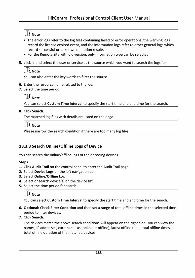
Note• The error logs refer to the log files containing failed or error operations; the warning logs
record the license expired event, and the information logs refer to other general logs whichrecord successful or unknown operation results.
• For the Remote Site with old version, only information type can be selected.
5. click and select the user or service as the source which you want to search the logs for.
NoteYou can also enter the key words to filter the source.
6. Enter the resource name related to the log.7. Select the time period.
NoteYou can select Custom Time Interval to specify the start time and end time for the search.
8. Click Search.The matched log files with details are listed on the page.
NotePlease narrow the search condition if there are too many log files.
18.3.3 Search Online/Offline Logs of Device
You can search the online/offline logs of the encoding devices.
Steps1. Click Audit Trail on the control panel to enter the Audit Trail page.2. Select Device Logs on the left navigation bar.3. Select Online/Offline Log.4. Select or search device(s) on the device list.5. Select the time period for search.
NoteYou can select Custom Time Interval to specify the start time and end time for the search.
6. Optional: Check Filter Condition and then set a range of total offline times in the selected timeperiod to filter devices.
7. Click Search.The devices match the above search conditions will appear on the right side. You can view thenames, IP addresses, current status (online or offline), latest offline time, total offline times,total offline duration of the matched devices.
HikCentral Professional Control Client User Manual
183

NoteNarrow the search condition if there are too many matched devices.
8. Optional: Perform the following operations if required.
ViewOfflineHistory
Click the device name to view the history online duration (displayed as a linechart) and history status (displayed as a list).You can perform the following operations.• Filter Data: Select a time period and a status (online, offline or all) from the
drop-down lists respectively to filter data.
NoteIf you select Custom Time Interval as the time period, you can specify thestart time and end time for filtering data.
• View Details: Move the cursor on the line chart to view the detailed offlineand online duration at each time point.
ViewDeviceLogs
Click on the Operation column to view the device logs.
18.3.4 Search Device Logs
You can search the device logs, which refer to the log files stored on encoding devices, decodingdevice, and security control devices.
Steps1. Click Audit Trail on the control panel to enter the Audit Trail page.2. Select Device Logs on the left navigation bar.3. Select Log on Device.4. Select the device type and device.5. Select the major log type and the corresponding minor log type as you desired.6. Select the time period.
NoteYou can select Custom Time Interval to specify the start time and end time for the search.
7. Click Search.The matched log files with details are listed on the page.
NotePlease narrow the search condition if there are too many log files.
HikCentral Professional Control Client User Manual
184

18.3.5 Search Online/Offline Logs of Resource
You can search the online/offline logs of the cameras, which provide information of current status(online or offline), latest offline time, total offline duration, etc.
Steps1. Click Audit Trail on the control panel to enter the Audit Trail page.2. Select Resource Logs on the left navigation panel.3. Select Online/Offline Log.4. Click to select camera(s) from the area list.5. Optional: Edit the selected camera(s). Click to edit.
Reselect Camera(s) Click and then reselect camera(s) from the area list.
Delete a Single Camera Click and then click to delete the selected camera.
Delete All SelectedCamera(s)
Click and then click to delete all the selected camera(s).
6. Select the time period for search.
NoteYou can select Custom Time Interval to specify the start time and end time for the search.
7. Optional: Check Filter Condition and then set a range of total offline times in the selected timeperiod to filter cameras.
8. Click Search.The cameras match the above search conditions will appear on the right side. You can view thenames, IP addresses, areas, current status (online or offline), latest offline time, total offlinetimes, total offline duration of the matched cameras.
NoteNarrow the search condition if there are too many matched cameras.
9. Optional: Perform the following operations if required.
ViewOfflineHistory
Click the camera name to view the history online duration (displayed as a linechart) and history status (displayed as a list).You can perform the following operations.• Filter Data: Select a time period and a status (online, offline or all) from the
drop-down lists respectively to filter data.
HikCentral Professional Control Client User Manual
185
NoteIf you select Custom Time Interval as the time period, you can specify thestart time and end time for filtering data.
• View Details: Move the cursor on the line chart to view the detailed offlineand online duration at each time point.
ViewDeviceOnline/Offline Logs
Click the IP address to view the online/offline logs of the device to which thecamera is connected to.
18.3.6 Search Recording Status of Resource
You can search recording status of cameras. After search, you can view the information such asrecording integrity rate, total time length when recording was abnormal, and times of recordinginterruptions, etc.
Steps1. Click Audit Trail on the control panel to enter the Audit Trail page.2. Select Resource Logs on the left navigation panel.3. Select Recording Status.4. Click to select camera(s) from the area list.5. Optional: Edit the selected camera(s). Click to edit.
Reselect Camera(s) Click and then reselect camera(s) from the area list.
Delete a Single Camera Click and then click to delete the selected camera.
Delete All SelectedCamera(s)
Click and then click to delete all the selected camera(s).
6. Select the time period for search.
NoteYou can select Custom Time Interval to specify the start time and end time for the search.
7. Optional: Check Filter Condition and then set the filter condition(s).Retention Duration (Days)
Set a range of the retention duration of the recorded video footage to filter cameras.Recording Integrity Rate
Set a range of the recording integrity rate to filter cameras. The recording integrity rate refersthe percentage obtained from dividing the actual recording duration by the scheduledrecording time.
HikCentral Professional Control Client User Manual
186

NoteFor details about recording schedule, refer to the User Manual of HikCentral ProfessionalWeb Client .
8. Click Search.The cameras match the above search conditions will appear on the right side. You can view theinformation including camera names, camera IP addresses, areas where the cameras belong to,video storage type, etc.Start Time
The time point when the camera started recording.End Time
The latest time point when the camera was recording.Retention Duration (Days)
The retention duration (unit: days) of the recorded video footage refers to the durationbetween the Start Time and the End Time mentioned above.
Total LengthThe total time length of video storage.
Abnormal Total LengthThe total time length of the video loss within the scheduled time.
Recording InterruptionThe total times of recording interruption within the scheduled time.
NoteNarrow the search condition if there are too many matched cameras.
9. Optional: View history recording status.1) Click the camera name to open the History Recording Status panel.
HikCentral Professional Control Client User Manual
187

Figure 18-3 History Recording Status
NoteThe blue parts on the time bars represent the time periods during which video footage wererecorded. And the orange parts on the time bars represent the time periods during whichvideo loss occurred or the time periods during which no recording schedule exists.
2) Select a time period and a status (exception or all) from the drop-down lists respectively tofilter data.
NoteIf you select Custom Time Interval as the time period, you can specify the start time and endtime for filtering data.
3) Optional: Select the number of records displayed on each page of the History RecordingStatus panel from the drop-down list at the lower-left corner of the panel.
4) Optional: Move the cursor on the time bar to show the 24 hours on it, and click one hour toview recording status details within the hour.
HikCentral Professional Control Client User Manual
188

Figure 18-4 Recording Status Details within One Hour
18.3.7 Back Up Logs
After searching for log files, you can export the matched log files to the local storage for backup.
Steps1. Click Audit Trail on the control panel to enter the Audit Trail page.2. Search for log files.3. Move the mouse over Export in the upper right corner and select Excel or CSV for saving log file.4. Select a local saving path.5. Click Save to export the matched log files.
Note
You can click to view the downloading log files in the download center.
HikCentral Professional Control Client User Manual
189
Chapter 19 Tools
The Control Client provides multiple tools: Smart Wall, VSPlayer, Broadcast, Alarm Output, andTwo-Way Audio.
Smart WallPlay the live view or playback on smart wall. See Manage Smart Wall (Decoding Device) fordetails.
VSPlayerRun the player and play the video files stored on the local PC.
BroadcastDistribute audio content to the added device if the device has an audio output. See Broadcast toConnected Devices for details.
Alarm OutputEnable alarm output to control the connected external devices by events or alarms, or manuallyby client. See Control Alarm Output for details.
Two-Way AudioEnable the voice talk between the Control Client and devices, See Perform Two-Way Audio fordetails.
19.1 Play Video via VSPlayerYou can run the VSPlayer software and play the video files stored in the local PC via the software.
Perform this task when you need to play video via VSPlayer.
Steps1. Click VSPlayer on the control panel to run the VSPlayer.
The available video files are listed on the playlist.2. Double-click the video to play.3. Optional: Click in the upper-right corner of the VSPlayer page and select User Manual to
view the VSPlayer's user manual for more detailed operations.
19.2 Broadcast to Connected DevicesPerform the broadcast function to distribute audio content to the added device if the device has anaudio output.
HikCentral Professional Control Client User Manual
190

Note• Your PC should have available microphone for broadcasting audio to the device.• If the client is performing two-way audio with the device's camera, you cannot start broadcast
with the device, and vice versa.• The Cloud P2P device supports broadcast if it enables DDNS.
On the control panel, select Tool → Broadcast , select the device(s) to broadcast to and click StartBroadcast one by one, then you can broadcast audio to the selected device(s) through themicrophone. Or you can click Open All to start broadcasting to all devices.For stopping broadcasting, select Tool → Broadcast , select the device(s) that you want to cancelbroadcast and click Stop Broadcast one by one. Or you can click Close All to stop broadcasting toall devices.
19.3 Perform Two-Way AudioTwo-way audio function enables the voice talk between the Control Client and devices. You can getand play not only the live video but also the real-time audio from the device in the Control Client,and the device can also get and play the real-time audio from the Control Client.
Perform this task when you need to perform the two-way audio function.
NoteThis function is not supported by the devices added in remote site.
Steps1. Click Two-Way Audio on the control panel to open the two-way audio window.2. Click Select Camera to open the selecting camera window.3. Select a camera and click OK.4. Click Start to start the two-way audio.5. Optional: Click to adjust the microphone volume, and click to adjust the speaker volume.
19.4 Control Alarm OutputAn alarm output is an output on the device that can be connected to an peripheral device, such asa light, a barrier, etc. Device can send signal to control the connected external device, e.g., turn onlight, open the barrier gate. The connected peripheral device can be controlled automatically byevents or alarms, or manually by client, and here we introduce the process for controlling alarmoutput remotely by client.
On the control panel, select Tool → Alarm Output Control , select the alarm output(s) to controland click Open one by one, then the selected alarm output(s) are enabled. Or you can click OpenAll to enable all alarm outputs.
HikCentral Professional Control Client User Manual
191

For disabling alarm output, select Tool → Alarm Output Control , select the alarm output(s) thatyou want to disable and click Close one by one. Or you can click Close All to disable all alarmoutputs.
HikCentral Professional Control Client User Manual
192

Chapter 20 System Settings
The System page contains basic settings and application settings. Use Basic Settings to configuregeneral parameters, image parameters, file saving paths, and keyboard and joystick settings. UseApplication Settings to configure alarm sounds, and the icons shown on the Live View toolbar andPlayback toolbar.
20.1 Set General ParametersYou can set the frequently-used parameters, including the global stream, picture format, etc.
Steps1. Click System on the control panel to enter the System page.2. Click General to enter the General Settings page.3. Configure the general parameters.
Global StreamSelect the default stream type for live view for global usage. If the network is in goodcondition, select main stream or sub-stream. If the network is in poor condition, selectsmooth stream.If the device doesn't support smooth stream, it will use sub-stream. If the device doesn'tsupport sub-stream, it will use main stream.If you don't want to adopt global stream settings for certain encoding device, you can enterHealth Monitoring → Encoding Device and set its stream type. The Control Client will getthis stream type to start live view of the encoding device's resources. For details, refer toHealth Monitoring .
Threshold for Main/Sub-StreamIf a window's proportion of the displaying area is larger than the configured threshold, thestream type will be main stream. If the proportion is smaller than the threshold, it will beswitched to sub-stream.For example, if you set the threshold as ¼, when the window division turns to 5-window, thecamera's stream type will be switched from main-stream to sub-stream.
NoteThis parameter is only available when the Global Stream is set as Main Stream.
Network TimeoutThe default waiting time for the Control Client. The operations will be regarded as failure ifno response within the configured time.
HikCentral Professional Control Client User Manual
193

The minimum default waiting time of the interactions between the Control Client and SYSserver is 30s, the minimum time between SYS server and devices is 5s, and the minimumtime between the Control Client and devices is 5s.
Picture FormatSet the file format for the captured pictures during live view or playback.
Maximum ModeSelect Maximize or Full Screen as the maximum mode. For selecting Maximize, the client willbe maximized and the task bar will display. For selecting Full Screen, the client will bedisplayed in full-screen mode.
Time ZoneDevice Time
The Control Client will adopt the time of the time zone where the device locates in.Client Time
The Control Client (except the Video Analysis modules) will adopt the time of the timezone where the PC running the Control Client locates in.
Time DifferenceIf enabled, the time zone information will displayed on the time. For example, 2018-12-1212:12:12 +8:00.
BandwidthSet the bandwidth upper limit for downloading video from pStor, which is used as aRecording Server for storing video files and pictures.
NoteFor details about adding pStor as the Recording Server, see the User Manual of HikCentralProfessional Web Client.
Auto-loginThe system will remember the user name and password and log in to the Control Clientautomatically when you start the PC running the Control Client.
Resume Last InterfaceRestore the interface last opened when you run the client next time.
Display Window No.Display the No. of each window in Monitoring module.
Resume Last InterfaceAutomatically resume the last interface or view after launching the client.Control Panel
Automatically display the control panel of the client after launching the client.
HikCentral Professional Control Client User Manual
194

Last InterfaceRestore the interface last opened when you run the client next time.
Specified ViewAutomatically display the specified view you set after launching the client.
Note• You can click Show Screen No. to show the screen number of current PC running the
Control Client. And you can select the specified view(s) according to your requirement.For details about setting view, refer to Manage View .
• Supports displaying the specified view on the auxiliary screen or on the smart wall(graphic card).
• For displaying on the smart wall (graphic card), you should set displaying contents onsmart wall (graphic card) in smart wall mode. (See Display Contents on Smart Wall inSmart Wall Mode for details)
• For displaying on the smart wall (graphic card), when you select the specified view, theview should be displayed on the smart wall (graphic card) at the same time, and thenthe view will be displayed on the smart (graphic card) after launching the client nexttime, otherwise the view will be displayed on the auxiliary screen after launching theclient next time.
4. Click Save.
20.2 Set Image ParametersYou can set image parameters, including view scale, video caching, etc.
Steps1. Click System on the control panel to enter the System page.2. Click Image to enter the Image Parameters page.3. Configure the image parameters.
View ScaleThe image display mode in each display window in live view or playback.
Window ScaleThe scale of the video in live view or playback. You can set it set as 4:3 or 16:9.
Video CachingLarger frame caching will result in better video performance. It is determined based onnetwork performance, computer performance, and bit rate.
Continuous DecodingDecode continuously when switching window division between one window and multiplewindows.
HikCentral Professional Control Client User Manual
195

Enable HighlightEnable this function to mark the detected objects with green rectangles in live view andplayback.
VCA RuleWhen On, displays the VCA rule in the live view and playback.
GPU Hardware DecodingWhen On, enables the GPU decoding for live view and playback to save CPU resources. Whenthe performance of the graphic card is good, you can enable GPU decoding to lower the PC'sperformance consumption. It is not recommended to enable this function if the graphiccard's performance is poor.
Note• Your PC must support GPU decoding.• After enabling GPU decoding, restart live view and playback for GPU decoding to takeeffect.
• If the client shows a blurred screen after enabling GPU decoding, disable GPU decoding.• If GPU decoding is enabled, Overlay Transaction Information in live view and playback is
not supported.
Overlay Transaction InformationWhen On, displays the transaction information on the live view and playback image.
Overlay Temperature InformationWhen On, displays the temperature information on the live view and playback image.
4. Click Save.
20.3 Set File Saving PathYou can set the saving paths for the files you downloaded to your PC (manual recorded ordownloaded video files, captured pictures, and package files).
Perform this task when you need to set file saving path.
Steps1. Click System on the control panel to enter the System page.2. Click Basic Settings → File to enter the File Saving Path Settings page.3. Set the local saving path for the files.
Save Video toThe video files refer to the video files recorded manually during live view, the clipped videoduring playback, the downloaded video files during playback and the video files downloadedfrom the Download Center page.
Save Picture to
HikCentral Professional Control Client User Manual
196

The pictures refer to the captured pictures during live view and playback.Save Package to
The package files refer to the client installation packages.4. Click Save.
20.4 Set Keyboard and Joystick ParametersYou can set shortcuts for the following hardware for quick and convenient access to the commonlyused actions: network keyboard, USB joystick, and USB keyboard.
Steps
NoteFor detailed operations of connecting the network keyboard to a PC that runs Control Client, referto the user manual of corresponding keyboard.
1. Click System on the control panel to enter the System page.2. Click Keyboard and Joystick to enter the Keyboard and Joystick Parameters page.3. Select a function, and double-click the item field to select the compound keys operation or
number from the drop-down list to set it as the shortcuts for the function.4. Click Save.
20.5 Set Screen PositionFor users adopting expanded screen during live view/playback or smart wall (graphic card), youneed to set the screen position according to their real layout in order to switch screen by anetwork keyboard conveniently.
Click System → Basic Settings → Screen Position to display the current screen position on the rightpanel. You can hover the cursor on a screen to make sure the corresponding screens of thedisplayed windows. Drag a window to another window to change the relative position of thewindows so that the controlling direction by joystick will also change.
20.6 Set Alarm SoundWhen an alarm, such as a motion detection alarm, video exception alarm, etc., is triggered, youcan set the client to give an audible warning, and you can configure the sound of the audiblewarning for different priority levels.
Perform this task when you need to set alarm sounds.
Steps1. Click System on the control panel to enter the System page.
HikCentral Professional Control Client User Manual
197

2. Click Alarm Center to enter the Alarm Sound Settings page.3. Select the alarm sound type.
- If you select Voice Engine, the PC will play the voice text configured on the Web Client whenthe alarm is triggered.
NoteThe Voice Engine function should be supported by the operating system of your PC.
- If you select Local Audio Files, follow steps 4 and 5.4. Click Browse and select audio files from the local PC for different alarm levels.
Note• For configuring the priority level, refer to the User Manual of HikCentral Professional Web
Client.• The format of the audio file can only be in WAV format.
5. Click to test the audio file.6. Click Save.
20.7 Set Health Monitoring ParametersYou can set the interval for automatically refreshing resource status in the Health Monitoringmodule.
NoteFor details about health monitoring, see Maintenance .
Click System on the Home page and select Application Settings → Health Monitoring to enter thehealth monitoring settings page. You can select the interval from the Auto-Refresh Interval drop-down list and then click Save to set the interval for auto-refreshing resource status.
HikCentral Professional Control Client User Manual
198

UD16533B