US8538457 Location tracking method in coordinator-based wireless network
23
(12) United States Patent Choi et a1. US008504057B2 US 8,504,057 B2 Aug. 6, 2013 (10) Patent N0.: (45) Date of Patent: (54) (75) (73) (21) (22) (65) (30) Jul. 26, 2004 Oct. 27, 2004 (51) (52) (58) LOCATION TRACKING METHOD IN COORDINATOR-BASED WIRELESS NETWORK Inventors: Yun-hWa Choi, Seoul (KR); Hyong-uk Choi, Seoul (KR) Assignee: Samsung Electronics Co., Ltd., SuWon-si (KR) Notice: Subject to any disclaimer, the term of this patent is extended or adjusted under 35 U.S.C. 154(b) by 513 days. Appl. N0.: 11/189,061 Filed: Jul. 26, 2005 Prior Publication Data US 2006/0018295 A1 Jan. 26, 2006 Foreign Application Priority Data (KR) ...................... .. 10-2004-0058263 (KR) ...................... .. 10-2004-0086226 Int. Cl. H04 W24/00 H04 W 4/00 H04L 12/28 H04L 12/66 US. Cl. USPC ................ .. 455/4561; 455/4562; 455/4563; 370/354; 370/338; 370/351 Field of Classi?cation Search USPC ............. .. 370/338, 256, 354, 351; 455/456.1, 455/456.2, 456.3 See application ?le for complete search history. (2009.01) (2009.01) (2006.01) (2006.01) (56) References Cited U.S. PATENT DOCUMENTS 5,666,662 A 9/1997 Shibuya 6,304,556 B1* 10/2001 Haas ........................... .. 370/254 6,370,378 B1 4/2002 Yahagi 6,438,380 B1* 8/2002 Bi et al. ................... .. 455/4561 6,674,403 B2 1/2004 Gray et al. 7,042,867 B2 * 5/2006 Whitehill et al. ........... .. 370/338 2001/0012279 A1* 8/2001 Haumont et al. ........... .. 370/331 2002/0115448 A1 8/2002 Amerga et al. 2002/0169539 A1* 11/2002 Menard et al. .............. .. 701/200 (Continued) FOREIGN PATENT DOCUMENTS 1261436 A 7/2000 1135040 C 1/2004 (Continued) OTHER PUBLICATIONS CN CN Ogino Aso, Hisasihara Gashiko, Yano Kagasi, Watanabe Goji, Gato Dakesi, Sjki Hideya, “Wireless LAN General Access System” (l)i Examination of Position-detecting Systemi, 2003 Electronic Infor mation Communication Society Convention Collection of Learned Papers 1, p. 662, B-5-203, Mar. 2, 2003. (Continued) Primary Examiner * Christopher M Brandt Assistant Examiner * MuthusWamy Manoharan (74) Attorney, Agent, or Firm * Sughrue Mion, PLLC (57) ABSTRACT A location tracking method in a coordinator-based Wireless network is provided. The location tracking method in a coor dinator-based Wireless netWork includes transmitting a ?rst frame including its oWn identi?er and time information to the Wireless netWork by a device associated With the Wireless netWork in order to disclose its location information; and receiving a second frame including the location information of the device transmitted from the Wireless netWork by the device, as a response to the ?rst frame. 13 Claims, 12 Drawing Sheets I . PAN COORDINATOR . FULL FUNCTION DEVICE CLUSTER HEADER
Transcript of US8538457 Location tracking method in coordinator-based wireless network

(12) United States Patent Choi et a1.
US008504057B2
US 8,504,057 B2 Aug. 6, 2013
(10) Patent N0.: (45) Date of Patent:
(54)
(75)
(73)
(21)
(22)
(65)
(30)
Jul. 26, 2004 Oct. 27, 2004
(51)
(52)
(58)
LOCATION TRACKING METHOD IN COORDINATOR-BASED WIRELESS NETWORK
Inventors: Yun-hWa Choi, Seoul (KR); Hyong-uk Choi, Seoul (KR)
Assignee: Samsung Electronics Co., Ltd., SuWon-si (KR)
Notice: Subject to any disclaimer, the term of this patent is extended or adjusted under 35 U.S.C. 154(b) by 513 days.
Appl. N0.: 11/189,061
Filed: Jul. 26, 2005
Prior Publication Data
US 2006/0018295 A1 Jan. 26, 2006
Foreign Application Priority Data
(KR) ...................... .. 10-2004-0058263
(KR) ...................... .. 10-2004-0086226
Int. Cl. H04 W24/00 H04 W 4/00 H04L 12/28 H04L 12/66
US. Cl. USPC ................ .. 455/4561; 455/4562; 455/4563;
370/354; 370/338; 370/351 Field of Classi?cation Search USPC ............. .. 370/338, 256, 354, 351; 455/456.1,
455/456.2, 456.3 See application ?le for complete search history.
(2009.01) (2009.01) (2006.01) (2006.01)
(56) References Cited
U.S. PATENT DOCUMENTS
5,666,662 A 9/1997 Shibuya 6,304,556 B1* 10/2001 Haas ........................... .. 370/254
6,370,378 B1 4/2002 Yahagi 6,438,380 B1* 8/2002 Bi et al. ................... .. 455/4561
6,674,403 B2 1/2004 Gray et al. 7,042,867 B2 * 5/2006 Whitehill et al. ........... .. 370/338
2001/0012279 A1* 8/2001 Haumont et al. ........... .. 370/331 2002/0115448 A1 8/2002 Amerga et al. 2002/0169539 A1* 11/2002 Menard et al. .............. .. 701/200
(Continued) FOREIGN PATENT DOCUMENTS
1261436 A 7/2000 1135040 C 1/2004
(Continued) OTHER PUBLICATIONS
CN CN
Ogino Aso, Hisasihara Gashiko, Yano Kagasi, Watanabe Goji, Gato Dakesi, Sjki Hideya, “Wireless LAN General Access System” (l)i Examination of Position-detecting Systemi, 2003 Electronic Infor mation Communication Society Convention Collection of Learned Papers 1, p. 662, B-5-203, Mar. 2, 2003.
(Continued) Primary Examiner * Christopher M Brandt Assistant Examiner * MuthusWamy Manoharan
(74) Attorney, Agent, or Firm * Sughrue Mion, PLLC
(57) ABSTRACT A location tracking method in a coordinator-based Wireless network is provided. The location tracking method in a coor dinator-based Wireless netWork includes transmitting a ?rst frame including its oWn identi?er and time information to the Wireless netWork by a device associated With the Wireless netWork in order to disclose its location information; and receiving a second frame including the location information of the device transmitted from the Wireless netWork by the device, as a response to the ?rst frame.
13 Claims, 12 Drawing Sheets
I
. PAN COORDINATOR
. FULL FUNCTION DEVICE
CLUSTER HEADER

US 8,504,057 B2 Page 2
US. PATENT DOCUMENTS
2003/0227895 A1 12/2003 Strutt et a1. 2004/0002346 A1 1/2004 Santhoff 2004/0078151 A1* 4/2004 Aljadeff et al. ............... .. 702/40 2005/0058084 A1* 3/2005 Hester et a1. . 370/254 2005/0122929 A1* 6/2005 Zuniga . 370/328 2005/0202832 A1* 9/2005 Sudit . 455/456.1 2005/0251326 A1* 11/2005 Reeves 701/200 2006/0007863 A1* . 370/238 2006/0015503 A1* 2006/0116170 A1* 2006/0125631 A1* 2007/0279167 A1
1/2006 Naghian 1/2006 Simons et a1. 707/10
6/2006 Brahmbhatt et al. . 455/560 6/2006 Sharony ................. .. 340/539.13
12/2007 Schmid et al. 2008/0279167 A1 11/2008 Cardei et al. 2010/0189082 A1 7/2010 Choi et al.
FOREIGN PATENT DOCUMENTS
JP 2001-523337 A 11/2001 JP 2003087175 A 3/2003 JP 2004-080312 A 11/2004 KR 2002-0015546 A 2/2002 KR 2003-0024460 A 3/2003 KR 2003-0052841 A 6/2003 W0 WO 2004/054304 A1 6/2004
OTHER PUBLICATIONS
Hisasihara Gashiko, Ogino Aso, Hujisima Gensabura, Gato Dakesi, Sjki Hideya, “Wireless LAN General Access System (2)iExamina tion of Position detecting Systemi” 2003 Electronic Information Communication Society Convention Collection of Learned Papers 1, p. 663, B-5-204, Mar. 2, 2003. Guroj aki Yassi, Saito Daro, “Utilization of Wireless Information System using Wireless LAN”, Computer & LAN, Issue of Nov. 2003, p, 49-56, Ohomi, Co‘, Ltd‘, Nov, 1, 2003, Jose A Gutierrez et. al.: “IEEE 802154: A Developing Standard for Low-Power Low-Cost Wireless Personal Area Networks” IEEE Net work, IEEE Service Center, NewYork, NY, US, vol. 15, No. 5, Sep. 1, 2001, pp. 12-19. “IEEE Standard for Information technologyiTelecommunications and information exchange between systemsiLocal and metropoli tan area networks Speci?c requirements Part 15.4: Wireless Medium Access Control (MAC) and Physical Layer (PHY) Speci?cations for Low-Rate Wireless Personal Area Networks (LR-WPANs)”, Jan. 1, 2003, IEEE Std. 802.15.41m-2003; IEEE, New York, NY, US, pp. 1-680. Sahinoglu Z. et. al.: “A Hybrid Location Estimation Scheme (H-LE S) for Partially Synchronized Wireless Sensor Networks”, TR-2003 142, Jan. 2004.
Feng Zhao et. al.: “Wireless Sensor Networks”, Jan. 15, 2004, MK publishers, XP040426274, 378 pages. Ed Callaway et. al.: “Home Networking with IEEE 802154: A Developing Standard for Low-Rate Wireless Personal Area Net works” IEEE Communications Magazine, IEEE Service Center, Piscataway, US, vol. 40, No. 8, Aug. 1, 2002, pp. 70-77. “IEEE P802.15 Wireless Personal Area Networks”, IEEE, Piscataway, NJ. USA, XP040388838, Jul. 23, 2004, pp. 1-34. Hara S et. al.: “Propagation Characteristics of IEEE 802.15.4 Radio Signal and Their Application for Location Estimation” 2005 IEEE 61st Vehicular Technology Conference, May 30-Jun. 1, 2005* Stockholm, Sweden, IEEE, Piscataway, NJ, USA LNKD DOI: 10.1109/VETECS.2005.1543257, vol. 1, May 30, 2005, pp. 97-101. Vernez J. et. al.: “Adaptation ofthe IEEE 802.15.4 Mac Layer to an ultra wide band radiofrequency physical layer” Personal, Indoor and Mobile Radio Communications, 2004. PIMRC 2004.15th IEEE International Symposium on Barcelona, Spain 5-8, 2004, Piscataway, NJ, USA, IEEE, Piscataway, NJ, USA LNKD DOI:10. 1109/PIMRC. 2004.1368867, vol. 4, Sep. 5, 2004, pp. 2983-2987. Ying-Hong Wang et. al.: “A Hybrid Wireless Network Approach to Support QoS Data Transmission” Parallel and Distributed Systems, 2005, Proceedings. 1 1th International Conference on Fukuoka, Japan Jul. 20-22, 2005, Piscataway, NJ, USA, IEEE, vol. 2, Jul. 20, 2005, pp. 393-396. Ash J. N. et. al.: “Locating the nodes” IEEE Signal Processing Maga zine, IEEE Service Center, Piscataway, NJ, US LNKD DOI: 10.1 109/ MSP.2005.1458287, vol. 22, No. 4, Jul. 1, 2005, pp. 54-69. Ai-Chun Pang et. al.: “Dynamic Backoff for wireless personal net works” Global Telecommunications Conference, 2004. GLOBECOM ’04. IEEE Dallas, TX, USA Nov. 29-Dec. 3, 2004, Piscataway, NJ, USA, IEEE, Piscataway, NJ, USA LNKD DOI: 10.1109/GLOCOM.2004.1378248, vol. 3, Nov. 29, 2004, pp. 1580 1584. Communication and Extended European Search Report dated Sep. 6, 2010, issued by the European Patent Of?ce in counterpart European Application No. 05254601.7-2414. Non-Final Of?ce Action dated Jul. 29, 2010 issued in US. Appl. No. 12/ 75 1, 13 1 . Final Of?ce Action dated Jan. 6, 2011 issued in US. Appl. No. 12/ 75 1, 13 1 . Final Of?ce Action dated Feb. 2, 2011 issued in US. Appl. No. 12/ 75 1, 13 1 . Non-Final Of?ce Action dated Jun. 22, 2011 issued in US. Appl. No. 12/ 75 1, 13 1 . Final Of?ce Action dated Dec. 9, 2011 issued in US. Appl. No. 12/ 75 1, 13 1 .
* cited by examiner

US. Patent Aug. 6, 2013 Sheet 1 0f 12 US 8,504,057 B2
PAN COORDINATOR CLUSTER HEADER
FULL FUNCTION DEVICE


US. Patent Aug. 6, 2013 Sheet 3 0f 12 US 8,504,057 B2
-5 .................................................................................. .. E22. 659 623%2 28 =8 H862 v 6&2 $2082 28 :8 6909 \ s59 323mg 250 =8 some 0
*0 $3 5
a- ||||||||||||||||||||||||||||| I > ||||||||||||||||||||||||||||||||||||||||||||||||||| I.
5N9 E8 @5528“: v 0 :82 E8 mcag?é
5526
*0 $8 5 V V r
6&9 3239mm =8 Esme ‘ 5&9 awc?wmm :8 6209 \ 6&2 @238”. =8 6209 \
-51 .................................................... -1 .......................... 3 Q52
“0: ,6 mciumb 5:32 w>>o=m wuSmu uwxuwz m5 .5 m >> mEEFCm m I
e g . . H U :59 @832 :8 “839 <
A $39 Ewcommmm cozsuowms J‘ Comm‘ cwmzcmm 5.6.6035 J\ V
M some 2889 M :82 2882 :89 28,09 r
8.50
8 <5 55¢ 59:: $530 85%
8E mm ED225500 22 “055% NE W W N8 6Q C.
m .QI

US. Patent Aug. 6, 2013 Sheet 4 0f 12 US 8,504,057 B2
-a ................................................................................. - - - - - -
mcicmu
B 88 5 6&9 amsawmm F3 :8 same 6&2 32.252 PS :8 6209 689 3288i 98 :8 6209
a! ................................................................................ I II >
s89 23mm 628 :09 0
E225 ABNQ A23 @5528“: v 0 C89 33 E5285:
8 83 5
$89 @292. :8 same 0 s89 3283a :8 some v 582 swcawwm =8 6209 v
- ‘I. |||||||||||||||||||||||||||||||||||||||||||||||||||||||||||||||||||||||||||||||| || . | ||
88w. 8: B mciog v 5:82 “323 33% v36“: 9: k
552; 22.55% 2 $82 @332 :8 same
:22 2832 :8 same
85% ESE ESQ. 5.630 85% 86$; wozwm?wm 2022558 25 855% N9 N8 5 5w
v .@E


US. Patent Aug. 6, 2013 Sheet 7 0f 12 US 8,504,057 B2

US. Patent Aug. 6, 2013 Sheet 8 0f 12 US 8,504,057 B2
5m 2
w GE


US. Patent Aug. 6, 2013 Sheet 12 0f 12 US 8,504,057 B2
I
@2225 29209 ME lo 650 ME w_ I91; 853 ME to $525
\ \
\ \
\ \
\
NP. GI

US 8,504,057 B2 1
LOCATION TRACKING METHOD IN COORDINATOR-BASED WIRELESS
NETWORK
CROSS-REFERENCE TO RELATED APPLICATIONS
This application claims priority from Korean Patent Appli cation Nos. 10-2004-0058263 and 10-2004-0086226 ?led on Jul. 26, 2004 and Oct. 27, 2004, respectively, in the Korean Intellectual Property Of?ce, the disclosures of Which are incorporated herein by reference in their entireties.
BACKGROUND OF THE INVENTION
1. Field of the Invention Methods consistent With the present invention relate to
location tracking in a coordinator-based Wireless netWork. 2. Description of the Related Art A recent trend in networking is to interconnect devices that
need to exchange data, in addition to computers. In the past, Wired netWorking Was the norm. But, the disadvantages of the Wired networking, such as Wiring construction and limited mobility, necessitate Wireless communication technology. Wireless Local Area NetWork (WLAN) and Wireless Per sonal Area NetWork (WPAN) standards are being developed. A WPAN has a range of 10 m, While WLAN has a range of 50 m to 100 m. The WPAN is more suitable for electronic home appliances in terms of mobility and range because it con sumes less poWer and supports Ad-hoc netWorking. The coordinator-based Wireless netWork uses a coordinator
to manage the communication time and competition mode of the Wireless netWork. It uses many of the protocols decided by IEEE 802.15 Working group, Which Was founded to establish a WPAN standard. The IEEE 802.15 Working group is divided into four task groups. TG 1 Works on the standards for WPAN based on Bluetooth 1.x. TG 2 studies co-existence of the Wireless netWorks. TG 3 studies Ultra Wideband (UWB), Which provides a high transmission rate of 20 Mbps or more With loW poWer consumption. TG 4 studies LoW Rate WPAN (LR-WPAN), a technology to provide a loW transmission rate (maximum 250 kbps) at a loW poWer consumption. LR WPAN is concerned With loW-co st communication net
Works that require loW data transmission rates. The IEEE 802.15.4 standard knoWn as “ZigBee” is a Wireless transmis sion technology for netWorks of loW cost, loW poWer devices such as Wireless integration remote controllers, home appli ance controllers, building management controllers and toys. The ZigBee group Was established in July, 2000 and since then it has ?nished Working on the standards for the physical layer and MAC.
The standard speci?es that the transmission is 250 kbps (16 channels in the 2.4 GHZ band) or 40 kbps/20 kbps (10 chan nels in the 915 MHZ band or one channel in the 868 MHZ band), and the range is 1 m to 100 M. Work is still being done on the upper layer, Which includes
a netWork layer. Fifty companies including Philips, Motorola, HoneyWell, Mitsubishi, Invensys, and Samsung are promot ers in a ZigBee Alliance in order to supplement the existing standard by adding ad-hoc Wireless netWorking and a net Work protocol for dispersed devices.
ZigBee does the job of preparing check lists and speci? cally de?ning applications to practically perform the interop erability test. The requirements of IEEE 802.154 include loW poWer consumption, loW cost, and simple infrastructure. These requirements are necessary to netWork sensors and control devices.
20
25
30
35
40
45
50
55
60
65
2 IEEE 802.15.4a de?nes the standard for a loW-rate loca
tion-based netWork using Ultra Wideband (UWB), Which is a neW netWorking technology implementing a precise location aWareness service making a ubiquitous environment achiev able. IEEE 802.15.4a is a subgroup of 802.154 and it uses the
same Medium Access Control (MAC) as 802.154, but sub stitutes UWB for the Physical Layer (PHY). But, it does not de?ne a location tracking protocol. So, a location-based ser vice has to be added to the coordinate-based Wireless netWork to embody the location tracking technology of IEEE 802.15.4a. A privacy protection service should also be added in a manner that alloWs a user control over the location track
1ng.
SUMMARY OF THE INVENTION
An aspect of the present invention is to provide a location tracking function in a coordinator-based Wireless netWork.
Another aspect of the present invention is to track the location of a device based on a Wireless communication tech nology such as UWB by using the location tracking function of the coordinator-based Wireless netWork. The aspects of the present invention are not limited to the
above-mentioned aspects and other aspects Which are not mentioned Will become more apparent from the beloW description by those of ordinary skill in the art. The present invention provides a location tracking method
in a coordinator-based Wireless netWork. The location track ing method in a coordinator-based Wireless netWork accord ing to one exemplary embodiment of the present invention comprises transmitting a ?rst frame including an identi?er and time information to the Wireless netWork by a device associated to the Wireless netWork in order to disclose its location; and receiving a response frame including the loca tion information of the device transmitted from the Wireless netWork.
The location tracking method in a coordinator-based Wire less netWork according to an exemplary embodiment of the present invention comprises transmitting a ?rst frame includ ing identi?ers of a ?rst device and a second device to the Wireless netWork so that the ?rst device associated to the Wireless netWork becomes aWare of the location of the second device; and receiving a response frame including location information of the second device transmitted from the Wire less netWork by the ?rst device. The location tracking method in a coordinator-based Wire
less netWork according to an exemplary embodiment of the present invention comprises receiving a ?rst frame including an identi?er of a ?rst device Which requests location tracking of a second device and an identi?er of the second device from the Wireless netWork by the second device; and transmitting a second frame including the identi?er of the ?rst device, the identi?er and the time information of the second device to the Wireless netWork by the second device, as the response of the ?rst frame. The location tracking method in a coordinator-based Wire
less netWork according to an exemplary embodiment of the present invention comprises receiving a ?rst frame including an identi?er of a ?rst device Which requests location tracking of a second device, and an identi?er of the second device from the Wireless netWork by the second device; determining Whether location tracking is alloWed; and if location tracking is alloWed, the second device transmits a second frame including the identi?er of the ?rst device, and the identi?er and the time information of the second device to the Wireless netWork, as the response to the ?rst frame.

US 8,504,057 B2 3
The location tracking method in a coordinator-based Wire less network according to an exemplary embodiment of the present invention comprises receiving a ?rst frame including an identi?er and time information of a device transmitted by the device; obtaining location calculating information used in calculating the location of the device using the time informa tion; and transmitting a second frame including the identi?er of the device and the location calculating information to a netWork coordinator.
The location tracking method in a coordinator-based Wire less netWork according to an exemplary embodiment of the present invention comprises receiving a ?rst frame including an identi?er of a ?rst device Which requests location tracking of a second device, an identi?er and time information of a second device transmitted by the second device; obtaining location calculating information used in calculating the loca tion of the second device using the time information; and transmitting a second frame including the identi?er of the ?rst device, the identi?er of the second device and the location calculating information to a netWork coordinator.
The location tracking method in a coordinator-based Wire less netWork according to an exemplary embodiment of the present invention comprises receiving a plurality of frames including an identi?er of a device and location calculating information of the device from the netWork; calculating the location of the device using the location calculating informa tion; and transmitting a frame including location information to the device.
The location tracking method in a coordinator-based Wire less netWork according to an exemplary embodiment of the present invention comprises receiving a plurality of frames including an identi?er of a ?rst device Which requests loca tion tracking of a second device, an identi?er and location calculating information of a second device from a netWork; calculating the location of the second device using the loca tion calculating information; and transmitting a frame includ ing the location of the second device to the ?rst device.
The location tracking method in a coordinator-based Wire less netWork according to an exemplary embodiment of the present invention comprises receiving a ?rst frame including an identi?er of a ?rst device Which requests location tracking of a second device, and an identi?er of a second device from a netWork; transmitting the ?rst frame to the second device of the netWork; receiving a second frame for notifying that loca tion tracking has been denied from the second device; and transmitting the second frame to the ?rst device.
The location tracking method in a coordinator-based Wire less netWork according to an exemplary embodiment of the present invention comprises receiving a ?rst frame including an identi?er of a ?rst device and an identi?er of a second device transmitted by the ?rst device so that the coordinator of a ?rst Wireless netWork can track the second device; transmit ting a second frame including an identi?er of the ?rst Wireless netWork, the identi?er of the ?rst device and the identi?er of the second device to the coordinator of a second Wireless netWork by the coordinator of the ?rst Wireless netWork; receiving a third frame including the identi?er of the ?rst Wireless netWork, the identi?er of the ?rst device, the identi ?er of the second device and the location information of the second device transmitted by the coordinator of the second Wireless netWork, by the coordinator of the ?rst Wireless netWork, as the response to the second frame; and transmit ting a fourth frame including the location information of the second device to the ?rst device by the coordinator of the ?rst Wireless netWork.
The location tracking method in a coordinator-based Wire less netWork according to an exemplary embodiment of the
20
25
30
35
40
45
50
55
60
65
4 present invention comprises receiving a ?rst frame including an identi?er of a ?rst device and an identi?er of a second device transmitted by the ?rst device so that the coordinator of a ?rst Wireless netWork can track the second device; transmit ting a second frame including the identi?er of the ?rst Wire less netWork, the identi?er of the ?rst device and the identi?er of the second device to the coordinator of a second Wireless netWork by the coordinator of the ?rst Wireless netWork; receiving a third frame including the identi?er of the ?rst Wireless netWork, the identi?er of the ?rst device, the identi ?er of the second device by the coordinator of the ?rst Wire less netWork, as the response of the second frame, if the second device Which received the second frame denies loca tion tracking; and transmitting a fourth frame including the information that the second device denies location tracking to the ?rst device by the coordinator of the ?rst Wireless net Work.
The location tracking method in a coordinator-based Wire less netWork according to an exemplary embodiment of the present invention comprises receiving a ?rst frame including an identi?er of a ?rst Wireless netWork, an identi?er of a ?rst device Which requests location tracking of a second device, and an identi?er of a second device transmitted by the coor dinator of the ?rst Wireless netWork, by a coordinator of a second Wireless netWork; transmitting a second frame includ ing the identi?er of the ?rst Wireless netWork, the identi?er of the ?rst device and the identi?er of the second device to the second device associated With the second Wireless netWork by the coordinator of the second Wireless netWork; receiving a plurality of third frames including the identi?er of the ?rst Wireless netWork, the identi?er of the ?rst device, the identi ?er of the second device and location calculating information of the second device from the second Wireless netWork by the coordinator of the second Wireless netWork; calculating the location of the second device using the location calculating information of the second device by the coordinator of the second Wireless netWork; and transmitting a fourth frame including the identi?er of the ?rst Wireless netWork, the iden ti?er of the ?rst device, the identi?er of the second device and the calculated location information of the second device to the coordinator of the ?rst Wireless netWork by the coordinator of the second Wireless netWork.
The location tracking method in a coordinator-based Wire less netWork according to an exemplary embodiment of the present invention comprises receiving a ?rst frame including an identi?er of a ?rst Wireless netWork, an identi?er of a ?rst device Which requests location tracking of a second device, and an identi?er of a second device transmitted by the coor dinator of the ?rst Wireless netWork; transmitting a second frame including the identi?er of the ?rst Wireless netWork, the identi?er of the ?rst device and the identi?er of the second device to a coordinator of a third Wireless netWork by the coordinator of the second Wireless netWork; receiving a third frame including the identi?er of the ?rst Wireless netWork, the identi?er of the ?rst device, the identi?er of the second device and the location information of the second device transmitted by the third Wireless netWork, by the coordinator of the sec ond Wireless netWork; and transmitting a fourth frame includ ing the identi?er of the ?rst Wireless netWork, the identi?er of the ?rst device, the identi?er of the second device and the location information of the second device to the coordinator of the ?rst Wireless netWork by the coordinator of the second Wireless netWork.
BRIEF DESCRIPTION OF THE DRAWINGS
The above and other aspects of the present invention Will become more apparent by describing in detail exemplary embodiments thereof With reference to the attached draWings in Which:

US 8,504,057 B2 5
FIG. 1 illustrates the structure of a cluster-tree network of 802.154 according to an exemplary embodiment of the present invention;
FIG. 2 is a ?owchart illustrating the process which a tracked device requests the self location awareness to a coor
dinator according to an exemplary embodiment of the present invention;
FIG. 3 is a ?owchart illustrating the process which the coordinator requests the remote location awareness to the tracked device according to an exemplary embodiment of the present invention;
FIG. 4 is a ?owchart illustrating the process which the device other than a PAN coordinator or a cluster header requests the location tracking of the other device according to an exemplary embodiment of the present invention;
FIG. 5 is a ?owchart illustrating the process for tracking the location of the tracked device which exists at the outside of the cluster in which the PAN coordinator exists according to an exemplary embodiment of the present invention;
FIG. 6 is a ?owchart illustrating the process for tracking the location of the tracked device which exists at the outside of a relay device according to an exemplary embodiment of the present invention;
FIG. 7 is a concept diagram illustrating the location track ing by a TOA method according to an exemplary embodiment of the present invention;
FIG. 8 illustrates the structure illustrating the location tracking by the TDOA method according to an exemplary embodiment of the present invention;
FIG. 9 illustrates a frame format of an MAC layer for embodying a location tracking function according to an exemplary embodiment of the present invention in 802154; and
FIGS. 10, 11, 12 are block diagrams illustrating command payloads of a frames according to an exemplary embodiment of the present invention.
DETAILED DESCRIPTION OF EXEMPLARY EMBODIMENTS OF THE INVENTION
Terminology used in the speci?cation will be described in the following.
Coordinator-based Wireless Network A network including a wireless network device functioning
as a coordinator (hereinafter, referred to as coordinator-based wireless network) forms a single independent wireless net work on the basis of the coordinator. If pluralities of coordi nator-based wireless networks exist in the same area, each coordinator-based wireless network has a unique identi?ca tion that distinguishes it. The coordinator-based network is different from an infrastructure network for performing wire less communication through an access point or a base station, and it may include a plurality of coordinators and be included in an ad-hoc network. The coordinator can transmit time information required for a wireless network, and the wireless network devices that receive this information can transmit it to other network devices. In this speci?cation, an IEEE 802.1454 coordinator-based wireless network will be described, but this is only an exemplary embodiment of the present invention and the present invention is not limited to this.
Beacon Frame The beacon frame noti?es of the existence of a network and
it also performs an important role in the maintenance of the network. The beacon frame includes a payload that is required when network devices associate with the network.
20
25
30
35
40
45
50
55
60
65
6 The network coordinator periodically transmits the beacon frame so that a device participating in the wireless network can recogniZe the network.
Probe Request The probe request frame is sent by a network device to ?nd
a network.
Probe Response The network coordinator which receives the probe request
from the network device transmits a probe response frame which sets information required when the device associates with the network.
Device, Network Device The device is a component of the wireless network that can
communicate with other devices. For example, in IEEE 802154, in addition to the wireless integration remote con troller and the electronic home appliance controller, there is a building management controller, a toy, a mouse, and a cooker. A device having a communication function, a controlling function and a sensor function in a home network or a ubiq uitous environment is also included.
Location Awareness Frame The location awareness frame allows both the network
device and other devices to know its location. The other devices that receive the location awareness frame can become aware of the location of the network device through a location tracking algorithm. The location awareness frame may include the time of transmission of the frame, an identi?er of the seeking device, and an identi?er of the device that is the object of the location tracking.
Location Information Positioning Frame (Location Calcu lating Information Frame) The location information frame includes the location of the
device, which is calculated using the frame transmission time and the frame reception time, the angle of the received signal including the frame or the received signal strength. The loca tion may be expressed as a time difference; that is, the differ ence between the frame transmission time and the frame reception time.
Location Result Frame The location result frame includes the location information
obtained by a speci?c device that receives the location infor mation frame (the location calculating information frame). This frame may be transmitted to a device that wants to know its own location.
Location Awareness Request Frame The location awareness request frame is to request the
transmission of the location awareness frame so that a device located outside the cluster can know the location of a speci?c device. The location awareness request frame can be trans mitted by a cluster coordinator located outside the cluster or by a coordinator located inside the cluster. In addition, the location awareness request frame can be transmitted by a device located inside or outside the cluster, which can insert its identi?er in the frame.
FIG. 1 illustrates the structure of a cluster-tree network of 802.154 according to an exemplary embodiment of the present invention. 802.15.4 includes the star, peer-to-peer, and cluster-tree topology which is a modi?cation of peer-to peer topology.
The star topology is shown by reference numeral 20 of FIG. 1 and has one network coordinator 21. The communication between the network devices is performed by this coordina tor, and a full function device (FFD) and a reduced function device (RFD) can participate in the star topology. The full function device can communicate with other network devices and can act as the network coordinator. The reduced function device can communicate only through the network coordina

US 8,504,057 B2 7
tor. The reduced function device cannot become the network coordinator, since it cannot independently communicate with other devices.
Reference numeral 10 of FIG. 1 shows a peer-to-peer topology having one network coordinator. Devices can com municate with the other devices in this type of network. The above-mentioned reduced function device cannot participate in a peer-to-peer network.
The cluster-tree network is the modi?cation of the peer-to peer topology and it may integrate several networks (e. g., 10, 20, and 30). It is composed by associating at least two net works. Each network is called a cluster. In FIG. 1, there are three clusters 10, 20, 30 and the network coordinators of these clusters are labeled 11, 21, and 31, respectively. The network coordinator of the cluster is called a cluster header. The coor dinator 31, which is a PAN coordinator, for coordinating the cluster-tree network can be determined among the network coordinators. It may be preferable that the PAN coordinator 31 has more computing capability and resources than the other network devices. The device passing through the net work of FIG. 1 can communicate with the network devices in the corresponding cluster according.
Location awareness can be largely divided into two cases. In the ?rst case, the network device requests location aware ness from the PAN coordinator or the cluster header in order to know its location. In the other case, the PAN coordinator or the cluster header requests the location of the network device. The former is referred to as a self location awareness request and the latter is referred to as a remote location awareness
request. For convenience of explanation, hereinafter, the network
device that has its location tracked is referred to as a tracked device and the network device that receives the location track ing information from the tracked device is referred to as a reference device.
FIG. 2 is a ?owchart illustrating the process where a tracked device requests the self location awareness from a coordinator according to an exemplary embodiment of the present invention. In FIG. 2, the tracked device 101, which participates in the cluster, requests location awareness in order to know its location, and the PAN coordinator or the cluster header serves as the coordinator. A cluster is a portion of the network in FIG. 1, but it can be the entire network if there is only one cluster. Among various topologies of IEEE 802.154, cluster-tree network (the most complicated topol ogy) is illustrated in the present speci?cation, but the star or the peer-to-peer topology may be applied.
FIG. 2 shows the active scanning process. The coordinator 31 continuously transmits a beacon frame (S101). However, the tracked device 101, which has not received the beacon frame, transmits a probe request frame in order to notify that it wants to participate in the network (S103). The coordinator 31 becomes aware that a device wants to participate in the network and transmits a probe response frame including the network information (Si04). The tracked device 101 obtains the information required for network association through the received probe response frame and transmits an association request frame (S107). The coordinator 31 transmits an asso ciation response frame, which sets the information required for the association, to the tracked device (S108). Hereafter, the tracked device can communicate with the network. The tracked device associated to the network transmits a self detect initiation frame in order to search its location (S115). This frame is received by reference devices 301, 302 and the coordinator 31 (the PAN coordinator or the cluster header). Using the received signal strength (RSS) of the frame and the time information included in this frame, the position of the
20
25
30
35
40
45
50
55
60
65
8 tracked device can be calculated. The reference devices 301, 302 transmit positioning data to the coordinator 31 (S121) and the coordinator 31 calculates the location using this data and the location tracking algorithm. If the coordinator 31 transmits a self detect result frame including the location value to the tracked device 101 (S150), the tracked device 101 becomes aware of its location. Then, if the tracked device 101 is moved, it can become aware of its location through opera tions SI 15 to SI 50, because it is associated with the network. The location tracking algorithm will be explained in the fol lowing. The difference between the reference device and the
tracked device depends on whether it is the object to be tracked. Accordingly, since the tracked device 101 became aware of its location, it can now become a reference device. In case that another device participates in the network, the tracked device 101 can act as a reference device and receive the location information of the other device. Also, even when the device 101 acts as a reference device, a new location thereof may be ascertained through operations 115 to 150, if the device 101 is moved. That is, although the device is a reference device, it may become the tracked device again. The difference between the reference device and the tracked device depends on whether it is the reference for ascertaining a device location or the object to be tracked.
FIG. 3 is a ?owchart illustrating the process where the coordinator 11 requests the remote location awareness according to the other exemplary embodiment of the present invention. FIG. 3 shows an example of a passive scanning process where the network coordinator searches for the tracked device and transmits the information. A new network device is labeled a tracked device 102, in order to distinguish from the other network devices. The coordinator 11 continu ously transmits a beacon frame in order to maintain and manage the network (S201). The tracked device, which becomes aware of the existence of the network by the beacon frame, transmits an association request frame (S207). If the coordinator 11 transmits the association response frame accepting the association request (S208), the tracked device 102 can communicate with the network. The coordinator 11, which has associated the tracked
device with the network, transmits a detect call request frame in order to know the location of the tracked device (S211). The detect call request frame is different from the self detect initiation frame of FIG. 2. In order to ensure privacy, whether the tracked device 102 allows location tracking is determined in operation S212. When the tracked device 102 allows loca tion tracking, it transmits its location information to the coor dinator and the peripheral devices. The tracked device 102 transmits the detect call response
frame, which contains its network identi?er and a timestamp, so that its location can be known (S215). The reference devices 401, 402 and the coordinator 11 which receive this frame positions the location and the related data of the tracked device by the information such as the received signal strength (RSS) of the frame and the time information included in this frame. The reference devices 401, 402 transmit this position ing data to the coordinator (S221) so that the coordinator 11 can calculate the location of the tracked device 102 using the location tracking algorithm. When the tracked device 102 does not allow location track
ing, the tracked device 102 transmits a detect call deny response frame to the coordinator 11 and the peripheral devices (S216). The location information is important for network manage
ment. Accordingly, the coordinator 11 needs to know the location information of the devices composing the network or

US 8,504,057 B2
the cluster, although every device need not know the location information. Accordingly, the PAN coordinator or cluster header can get the location information of the devices accord ing to the network con?guration, though the device denies notifying its location. When the location information is sent to both the PAN
coordinator 31 and the cluster header 11 (case 1) the detect call deny response frame is transmitted (S216). When the location information is forcibly sent to only the PAN coordi nator 31 (case 2) the tracked device cannot transmit the detect call deny response frame and the detect call response frame.
In case 2, there is a method for unconditionally transmit ting the detect call response frame; that is, without asking the user whether he/ she allows location tracking. For conve nience of explanation, the method for transmitting the detect call response frame without userpermission will be explained in the following. When the coordinator that transmits the detect call request
frame is the cluster header, the cluster header cannot obtain the location information of the other device, because only the PAN coordinator can forcibly obtain the location of the device. This is because the cluster exists only for a certain time. Accordingly, in case that the tracked device 102 denies notifying its own location, the detect call deny response frame is transmitted to the cluster header 11 and the reference devices 401, 402 (S216), and the process halts. When the location information is forcibly sent to the PAN coordinator and the cluster header the tracked device 102 cannot deny the detect call request. The location of the device is noti?ed to the coordinator, regardless of user permission. As such, for user convenience, the process can progress to operations S215 to S221.
Operation S212 of FIG. 3 is optional. If the network can forcedly know the location between the devices, the process progresses, whether the tracked device allows or denies loca tion tracking. If the tracked device 102 is forced to allow location tracking, the process is progresses to the operation where the tracked device transmits the detect call response frame, without transmitting the message that asks for permis sion. At this time, only operations S201 to S221 are per formed. The location information may be transmitted to the coordinator even if the user denies location tracking, but it is varied according to the allowance or denial of the user. On the other hand, for the sake of convenience, the user can
previously set the response of the tracked device 102. For example, when the device that requests location tracking is the coordinator, the detect call response frame can be set to be unconditionally transmitted. The response may be set such that the tracked device 102 allows every device or only devices in the cluster to which it belongs to track its location. After the response is set, the detect call response frame is transmitted to only the allowed device or the coordinator, and the detect call deny response is transmitted to all other devices, without user input. The location tracking method of FIG. 3 includes privacy protection. Accordingly, operations S212 to S216 may be omitted according to the structure of the network.
FIGS. 2 and 3 show the process for participating in the network and for obtaining the location of the tracked device 102. The process of FIG. 2 for actively associating with the network the device that requests self location awareness is not necessarily performed. The self detect initiation frame can be transmitted after the tracked device is associated with the network by the passive scanning of FIG. 3. On the contrary, even after the active network scanning of FIG. 2, the coordi nator may transmit the detect call request frame in order to know the location of the tracked device 102. Also, the refer
20
25
30
35
40
45
50
55
60
65
10 ence device can be a relay device that receives the frame for establishing the location of the tracked device, and sends the location information contained in this frame to the cluster header.
FIG. 4 is a ?owchart illustrating the process where a device other than a PAN coordinator or a cluster header requests location tracking of a third device according to an exemplary embodiment of the present invention. In addition to FIGS. 2 and 3, additional operations may be needed. Since tracking the location of the other device may infringe user privacy, a location tracking request can be sent. The reference device 401 can request location tracking of the device 102. At this time, the device 401 can include its identi?er and request the identi?er of the tracked device in the frame (S251). The coordinator (the cluster header) 11 receives the detect call request frame and transmits it to the tracked device 102 (S252). The tracked device 102 becomes aware that the ref erence device 401 wants to track its location. A message such as: “A device 401 requests location tracking. Will you allow location tracking?” may be displayed to the user of the tracked device 102. If the user sees the message and allows location tracking, the frame including the time information for tracking its own location (detect call response frame) is transmitted (S255). The reference devices 401, 402 receive the detect call response frame, calculate positioning data and transmit this data to the coordinator (the cluster header) 11 (S257). The coordinator 11 then transmits the location infor mation of the tracked device 102 to the reference device 401
(S260). However, when the user does not allow location tracking in
operation S253, the device 102 transmits the detect call deny response frame to the coordinator 11 and the reference devices 401, 402 (S256).
In FIG. 4, the information on whether the user of the tracked device 102 allows or denies the detect call response frame can be previously set, and it can be set for every device or for speci?c device(s). By this setting, the user can maintain his/her privacy, without having to respond to location track ing queries.
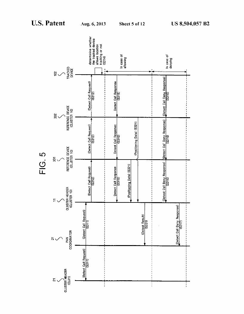
FIG. 5 is a ?owchart illustrating the process of tracking the location of a tracked device that exists outside the cluster that the PAN coordinator resides in according to an exemplary embodiment of the present invention. The embodiment of FIG. 5 includes the case where the PAN coordinator 31 requests the location of the tracked device 102, and the case where another device requests the location of the tracked device 102. The PAN coordinator 31 transmits the detect call request
frame to the cluster headers 11, 21 in operation S311 in order to track the location of a speci?c device. The PAN coordinator 31 can also receive the location tracking frame transmitted by the cluster header CLH1 21 and transmit it to the whole network. The cluster header 11 which receives this frame transmits the detect call request frame in order to know if the tracked device exists in its cluster (S312). Operations S311 and S312 may have the same or different content according to the embodiment of the frame. The frame is received by the cluster header 11 in operation S311 and it is transmitted to the network devices in its cluster in operation S312. The tracked device 102 receives the detect call request frame and deter mines whether it allows location tracking (S314).
If location tracking is allowed, a detect call response frame including location information is transmitted to the reference devices 401, 402 and the cluster header 11 (S315). The ref erence device transmits positioning data, which is obtained from information included in the received detect call response frame, to the cluster header 11 (S321). As a result, the cluster

US 8,504,057 B2 11
header 11 becomes aware of the location of the tracked device 102 and it transmits a detect result frame to the PAN coordi nator 31 (S331).
Also, in this situation the process can progress even With out asking the user of the tracked device Whether he/she alloWs location tracking as previously described With refer ence to FIG. 3. Even if there is a denial response from the user, the detect call response frame can be transmitted to the PAN coordinator 31.
If a third device attempts to track the location of the tracked device 102 through the PAN coordinator 31 or if the PAN coordinator 31 does not force location tracking of the other device, the user of the tracked device 102 can prevent its location from being tracked. Here, the tracked device 102 transmits the detect call deny response frame to the reference devices 301, 302 and the cluster header 11 (S316). The cluster header 11 transmits the received detect call deny response frame to the PAN coordinator 31 (S317) and the PAN coor dinator 31 becomes aWare that the tracked device cannot be tracked. Also, the detect call deny response frame can be transmitted to other devices that request the location of the tracked device 102.
FIG. 6 is a ?owchart illustrating the process of device location tracking using a relay device according to another exemplary embodiment of the present invention. The PAN coordinator may directly transmit the detect call request to the cluster header or it may indirectly transmit it to the cluster header through another cluster header. Accordingly, the clus ter header that receives and transmits the detect call request frame functions as a relay device.
In FIG. 6, the PAN coordinator transmits the detect call request frame to the cluster header 51 (S411). The cluster header 51 transmits the detect call request frame to a third cluster header 11 (S412) and cluster header 11 tracks the location of the device, Which exists in its cluster. Here, dif ferent methods are performed depending on Whether the tracked device alloWs or denies location tracking, as illus trated in the examples of FIGS. 2 to 5. When the tracked device alloWs its location to be tracked in
operation S414, the cluster header 11 calculates position of tracked device in operation S420, and tracks the location and transmits the detect result frame to the cluster header 51 (S431), Which also transmits the detect call request frame (S432). When the tracked device denies location tracking in opera
tion S414, the cluster header 11 makes detect call deny response frame in operation S422, and transmits the detect call deny response frame (S434). The relay device 51 that receives the detect call deny response frame transmits the detect call deny response frame to the PAN coordinator 31
(S436). There is various location tracking algorithms that can be
used. FIG. 7 is a concept diagram illustrating location tracking
by a Time of Arrival (TOA) method according to an embodi ment of the present invention. The TOA method measures the delivery time of the signals sent betWeen the tracked device 101 and the other netWork devices 11, 301, 302 in order to calculate the distance. The signal delivery time can be obtained by the difference betWeen the transmission times of the frames (for example, the self detect initiation and the detect call response). By calculating this difference and knoWing the speed of the signal containing the frame, three spherical ranges With the netWork devices 11, 301, 302 as their centers are obtained. Three devices are required to per form the calculation of this method. If at least three reference devices transmit the values, the coordinator 11 can select the
20
25
30
35
40
45
50
55
60
65
12 three data values that are judged to be the most accurate. In one embodiment, the accuracy of the data values can be judged by the received signal strength. For example, Table 1, shown beloW, lists four devices 11, 301, 302, 307 and the RSS and Positioning Data of signals sent by these devices. Since the device 307 of Table 1 has the Weakest received signal strength, it is disregarded (the positioning data from this device may be inaccurate).
TABLE 1
RSS Values and Positioning Data
POSITIONING DATA DEVICE RSS (m)
11 70 15 301 so 10 302 90 s 307 30 10
HoWever, the received signal strength is exemplary, and the reference device may be determined according to the signal distortion or other characteristics of the signal.
FIG. 8 illustrates location tracking by the Time Difference of Arrival (TDOA) method according to an exemplary embodiment of the present invention. The TDOA method measures the difference betWeen the arrival times of tWo signals to determine the location, and it includes a forWard link method composed of multiple signal sources and one receiver and a reverse link method composed of one signal source and multiple receivers. The basic principle of TDOA is the signal arrival time difference is proportional to the differ ence betWeen the distances from the tWo signal sources to the receiver. These distances are calculated and a receiver is chosen that is equidistant from the tWo signal sources, that is, a hyperbola centering on the tWo signal sources. At this time, each base station must be synchroniZed and the time synchro niZation of the base stations is accomplished using a satellite clock. TWo hyperbolas are obtained from three signal sources and the intersection point of the tWo curves is the location of the receiver.
FIG. 8 shoWs the application of TDOA to IEEE 802.154. Here, the intersection of the hyperbola obtained from the netWork devices 11, 301 and the hyperbola obtained from the netWork devices 11, 302 is the location of the tracked device 101. In order to obtain the intersection point betWeen the hyperbolas, the TOA data is transmitted to the coordinator 11 by the reference netWork devices 301, 302. If the coordinator 11 receives several signals, it can select a device according to RSS and calculate the positioning data.
In addition to the methods depicted in FIGS. 7 and 8, an Angle of Arrival (AOA) method and a Radio Frequency (RF) Finger Printer method may be used. The AOA method mea sures the incident angle of the frame signal transmitted from the tracked device and searches in this direction. In the present embodiment, the strongest signal can be selected among the values measured by several netWork devices. The RF ?ngerprinting method takes a snapshot of the
received signal, analyZes the snapshot and extracts a unique characteristic of the signal, and compares this signal With the existing database to locate the receiver in order to obtain a characteristic value of the frame transmitted by the tracked device. The location tracking algorithms explained in the present
speci?cation are only exemplary. FIG. 9 illustrates a frame format of an MAC layer for
embodying a location tracking function according to an