Upper-Bound Solutions for Bearing Capacity of Foundations
10
JOURNAL OF GEOTECHNICAL AND GEOENVIRONMENTAL ENGINEERING / JANUARY 1999 / 59 UPPER-BOUND SOLUTIONS FOR BEARING CAPACITY OF FOUNDATIONS By Abdul-Hamid Soubra 1 ABSTRACT: The static and seismic bearing capacity problem of shallow strip footings is investigated. Two kinematically admissible failure mechanisms M1 and M2 are considered in the framework of the upper-bound method of the limit analysis theory. The M1 mechanism is symmetrical, and it permits the calculation of the bearing capacity in the case of no-seismic loading. It is composed of a triangular active wedge under the footing and two radial shear zones composed of a sequence of rigid triangles. The M2 mechanism is nonsymmetrical and is composed of a single radial shear zone. This mechanism permits the calculation of the bearing capacity in the presence of seismic loading. Quasi-static representation of earthquake effects using the seismic coefficient concept is adopted. The solutions obtained are rigorous upper-bound ones in the framework of the limit analysis theory. The numerical results of the static and seismic bearing capacity factors are presented in the form of design charts for practical use in geotechnical engineering. These results are compared with results of other authors. INTRODUCTION The bearing capacity of strip footings in no-seismic areas has been extensively studied by several investigators [Terzaghi (1943), Caquot and Ke ´risel (1953), Meyerhof (1963), Vesic (1973), and Chen (1975) among others]. However, very few attempts have been made to study the effect of an earthquake on the bearing capacity of foundations. The few studies avail- able in the literature describing the seismic effect on the bearing capacity concern the work of Meyerhof (1951) and Shinohara et al. (1960). Both approaches are pseudostatic: horizontal and vertical accelerations are applied to the center of gravity of the structure and the problem is reduced to a static case of bearing capacity with inclined eccentric loads. However, in these solu- tions, the inertia of the soil mass is not included. Sarma and Iossifelis (1990) and Richards et al. (1993) suggested more rig- orous approaches for calculating the seismic bearing capacity of strip footings in seismic areas by considering the inertia forces on all parts of the soil-structure system (soil and foun- dation). The theoretical approaches they used are based on the limit-equilibrium method. It is well known that this method gives an approximate solution of the failure load and that the solution cannot be said to be an upper- or a lower-bound one with respect to the exact solution. Recently, Dormieux and Pecker (1995) and Soubra (1997) used the upper-bound method of the limit analysis theory and developed upper-bound solu- tions of the seismic bearing capacity factors. These solutions are rigorous upper-bound ones with respect to the exact solu- tions for an associated flow rule Coulomb material. In this paper, both the static and seismic bearing capacity problems are investigated by the upper-bound method of the limit analysis theory using respectively symmetrical and non- symmetrical failure mechanisms. These mechanisms allow the slip surface to develop more freely in comparison with the available mechanisms given by Chen (1975) and Soubra (1997); hence, they lead to smaller upper-bound solutions of the bearing capacity problem. UPPER AND LOWER BOUND THEOREMS OF LIMIT ANALYSIS The upper-bound theorem, which assumes a perfectly plastic soil model with an associated flow rule, states that the internal 1 Maı ˆtre de Confe ´rences, Ecole Nationale Supe ´rieure des Arts et In- dustries de Strasbourg, 24, Bd de la victoire, 67084 Strasbourg cedex, France. Note. Discussion open until June 1, 1999. To extend the closing date one month, a written request must be filed with the ASCE Manager of Journals. The manuscript for this paper was submitted for review and possible publication on October 2, 1997. This paper is part of the Journal of Geotechnical and Geoenvironmental Engineering, Vol. 125, No. 1, January, 1999. qASCE, ISSN 1090-0241/99/0001-0059 – 0068/$8.00 1 $.50 per page. Paper No. 16729. power dissipated by any kinematically admissible velocity field can be equated to the power dissipated by the external loads and so enables a strict upper-bound on the true limit load to be deduced. A kinematically admissible velocity field is one that satisfies compatibility, the flow rule, and the ve- locity boundary conditions. To provide solutions that are use- ful in practice, the upper-bound theorem is often used in tan- dem with the lower-bound theorem. The latter also assumes a perfectly plastic soil model with an associated flow rule and states that any statically admissible stress field (which satisfies equilibrium and the stress boundary conditions and nowhere violates the yield criterion) will furnish a lower-bound estimate of the true limit load. By using these two theorems, the exact limit load can often be bracketed with an accuracy that is sufficient for design purposes. In this paper, only the upper-bound theorem of limit analysis is applied to the static and seismic bearing capacity problem using kinematically admissible velocity fields. It should be noted here, that the upper-bound theorem gives an unsafe es- timate of the ultimate bearing capacity. The aim of this work is to improve the best available upper-bound solutions given by Chen (1975) in the symmetrical failure mechanism and by Soubra (1997) in the nonsymmetrical mechanism. THEORETICAL ANALYSIS OF STATIC AND SEISMIC BEARING CAPACITY PROBLEM A soil-foundation system with translational movement is as- sumed. Two distinct translational failure mechanisms, referred to as the M1 and M2 mechanisms, are utilized in the analysis. In the following investigation, the terms ‘‘mechanism’’ and ‘‘velocity field’’ will be used interchangeably. Note that the velocity fields used are composed of rigid blocks that move with constant velocities. Since no general plastic deformation of the soil mass is permitted to occur, the power is dissipated solely at the interfaces between adjacent blocks, which con- stitute velocity discontinuities. The soil is homogeneous and isotropic. It is assumed to be an associated flow rule Coulomb material obeying Hill’s max- imal work principle. The consequence of applying the nor- mality condition to a frictional soil with its angle of internal friction equal to f will be a necessary occurrence of a volume expansion with C = f during the plastic flow. However, fric- tional soils are found experimentally to dilate at increments considerably less than those predicted by the normality con- dition, that is, C < f. Hence, real soils do not obey the as- sociative flow rule. Furthermore, it is well known that a non- associative material cannot be stronger than the associative one. On the other hand, it should be mentioned that in trans- lational failure mechanisms, the energy balance approach for evaluation of the limit load is always equivalent to the equi- librium of forces approach, because the energy balance equa-
-
Upload
independent -
Category
Documents
-
view
2 -
download
0
Transcript of Upper-Bound Solutions for Bearing Capacity of Foundations

UPPER-BOUND SOLUTIONS FOR BEARING CAPACITY OF FOUNDATIONS
By Abdul-Hamid Soubra1
ABSTRACT: The static and seismic bearing capacity problem of shallow strip footings is investigated. Twokinematically admissible failure mechanisms M1 and M2 are considered in the framework of the upper-boundmethod of the limit analysis theory. The M1 mechanism is symmetrical, and it permits the calculation of thebearing capacity in the case of no-seismic loading. It is composed of a triangular active wedge under the footingand two radial shear zones composed of a sequence of rigid triangles. The M2 mechanism is nonsymmetrical andis composed of a single radial shear zone. This mechanism permits the calculation of the bearing capacity in thepresence of seismic loading. Quasi-static representation of earthquake effects using the seismic coefficient conceptis adopted. The solutions obtained are rigorous upper-bound ones in the framework of the limit analysis theory.The numerical results of the static and seismic bearing capacity factors are presented in the form of design chartsfor practical use in geotechnical engineering. These results are compared with results of other authors.
INTRODUCTION
The bearing capacity of strip footings in no-seismic areas hasbeen extensively studied by several investigators [Terzaghi(1943), Caquot and Kerisel (1953), Meyerhof (1963), Vesic(1973), and Chen (1975) among others]. However, very fewattempts have been made to study the effect of an earthquakeon the bearing capacity of foundations. The few studies avail-able in the literature describing the seismic effect on the bearingcapacity concern the work of Meyerhof (1951) and Shinoharaet al. (1960). Both approaches are pseudostatic: horizontal andvertical accelerations are applied to the center of gravity of thestructure and the problem is reduced to a static case of bearingcapacity with inclined eccentric loads. However, in these solu-tions, the inertia of the soil mass is not included. Sarma andIossifelis (1990) and Richards et al. (1993) suggested more rig-orous approaches for calculating the seismic bearing capacityof strip footings in seismic areas by considering the inertiaforces on all parts of the soil-structure system (soil and foun-dation). The theoretical approaches they used are based on thelimit-equilibrium method. It is well known that this methodgives an approximate solution of the failure load and that thesolution cannot be said to be an upper- or a lower-bound onewith respect to the exact solution. Recently, Dormieux andPecker (1995) and Soubra (1997) used the upper-bound methodof the limit analysis theory and developed upper-bound solu-tions of the seismic bearing capacity factors. These solutionsare rigorous upper-bound ones with respect to the exact solu-tions for an associated flow rule Coulomb material.
In this paper, both the static and seismic bearing capacityproblems are investigated by the upper-bound method of thelimit analysis theory using respectively symmetrical and non-symmetrical failure mechanisms. These mechanisms allow theslip surface to develop more freely in comparison with theavailable mechanisms given by Chen (1975) and Soubra(1997); hence, they lead to smaller upper-bound solutions ofthe bearing capacity problem.
UPPER AND LOWER BOUND THEOREMS OF LIMITANALYSIS
The upper-bound theorem, which assumes a perfectly plasticsoil model with an associated flow rule, states that the internal
1Maıtre de Conferences, Ecole Nationale Superieure des Arts et In-dustries de Strasbourg, 24, Bd de la victoire, 67084 Strasbourg cedex,France.
Note. Discussion open until June 1, 1999. To extend the closing dateone month, a written request must be filed with the ASCE Manager ofJournals. The manuscript for this paper was submitted for review andpossible publication on October 2, 1997. This paper is part of the Journalof Geotechnical and Geoenvironmental Engineering, Vol. 125, No. 1,January, 1999. qASCE, ISSN 1090-0241/99/0001-0059–0068/$8.00 1$.50 per page. Paper No. 16729.
JOURNAL OF GEOTECHN
power dissipated by any kinematically admissible velocityfield can be equated to the power dissipated by the externalloads and so enables a strict upper-bound on the true limitload to be deduced. A kinematically admissible velocity fieldis one that satisfies compatibility, the flow rule, and the ve-locity boundary conditions. To provide solutions that are use-ful in practice, the upper-bound theorem is often used in tan-dem with the lower-bound theorem. The latter also assumes aperfectly plastic soil model with an associated flow rule andstates that any statically admissible stress field (which satisfiesequilibrium and the stress boundary conditions and nowhereviolates the yield criterion) will furnish a lower-bound estimateof the true limit load. By using these two theorems, the exactlimit load can often be bracketed with an accuracy that issufficient for design purposes.
In this paper, only the upper-bound theorem of limit analysisis applied to the static and seismic bearing capacity problemusing kinematically admissible velocity fields. It should benoted here, that the upper-bound theorem gives an unsafe es-timate of the ultimate bearing capacity. The aim of this workis to improve the best available upper-bound solutions givenby Chen (1975) in the symmetrical failure mechanism and bySoubra (1997) in the nonsymmetrical mechanism.
THEORETICAL ANALYSIS OF STATIC AND SEISMICBEARING CAPACITY PROBLEM
A soil-foundation system with translational movement is as-sumed. Two distinct translational failure mechanisms, referredto as the M1 and M2 mechanisms, are utilized in the analysis.In the following investigation, the terms ‘‘mechanism’’ and‘‘velocity field’’ will be used interchangeably. Note that thevelocity fields used are composed of rigid blocks that movewith constant velocities. Since no general plastic deformationof the soil mass is permitted to occur, the power is dissipatedsolely at the interfaces between adjacent blocks, which con-stitute velocity discontinuities.
The soil is homogeneous and isotropic. It is assumed to bean associated flow rule Coulomb material obeying Hill’s max-imal work principle. The consequence of applying the nor-mality condition to a frictional soil with its angle of internalfriction equal to f will be a necessary occurrence of a volumeexpansion with C = f during the plastic flow. However, fric-tional soils are found experimentally to dilate at incrementsconsiderably less than those predicted by the normality con-dition, that is, C < f. Hence, real soils do not obey the as-sociative flow rule. Furthermore, it is well known that a non-associative material cannot be stronger than the associativeone. On the other hand, it should be mentioned that in trans-lational failure mechanisms, the energy balance approach forevaluation of the limit load is always equivalent to the equi-librium of forces approach, because the energy balance equa-
ICAL AND GEOENVIRONMENTAL ENGINEERING / JANUARY 1999 / 59

tion can be interpreted as an expression of the virtual rate ofwork principle. This observation has often been made (Davis1968; Mroz and Drescher 1969; Michalowski 1989; Salencon1990; De Buhan and Salencon 1993; Drescher and Detournay1993). The equivalence of the two approaches plays a key rolein the derivations of the limit loads for nonassociative mate-rials. Recent theoretical considerations made on translationalfailure mechanisms (Drescher and Detournay 1993; Michal-owski and Shi 1995, 1996) allow one to conclude that for anonassociative material, the limit load can be obtained by theuse of the flow rule associated with a new yield condition inwhich c and f are replaced by c* and f* as follows:
cos C sin ftan f* = (1)
1 2 sin C sin f
cos C cos fc* = c (2)
1 2 sin C sin f
Hence, the results presented in the present paper can be usedfor nonassociative material provided the internal friction anglef and the cohesion c are replaced with f* and c* calculatedfrom (1) and (2), respectively.
Failure Mechanisms
M1 Mechanism
The M1 mechanism is shown in Fig. 1. This mechanism issymmetrical, and it permits the calculation of the bearing ca-
60 / JOURNAL OF GEOTECHNICAL AND GEOENVIRONMENTAL ENGIN
pacity in the case of no-seismic loading. The wedge ABC istranslating vertically as a rigid body with the same initialdownward velocity as the footing. The downward movementof the footing and wedge is accommodated by the lateralmovement of the adjacent soil as indicated by the two radialshear zones. The angles u, ai, and bi (i = 1, . . . , n) are as yetunspecified. Since the movement is symmetrical about thefooting, it is only necessary to consider the movement on theright-hand side of Fig. 1.
The radial shear zone BCD is composed of n triangular rigidblocks. As shown in Fig. 2(a), all the triangles move as rigidbodies in directions that make an angle f with the disconti-nuity lines di (i = 1, . . . , n). The velocity of each triangle isdetermined by the condition that the relative velocity betweenthe triangles in contact must have the direction that makes anangle f to the contact surface. The velocity hodographs areshown in Fig. 2(b). The velocities so determined constitute akinematically admissible velocity field.
As shown in Fig. 3, the external forces contributing to theincremental external work consist of the foundation load, theweight of the soil mass, and the surcharge q on the foundationlevel. The incremental external work for the different externalforces can be easily obtained; the calculations are presented inAppendix I.
Energy is dissipated at the discontinuity surfaces di (i = 1,. . . , n) between the material at rest and the material in motionand at the discontinuity surfaces li (i = 1, . . . , n) within theradial shear zone. The incremental energy dissipation per unit
FIG. 2. (a) Velocity Field of M1 Mechanism; (b) Velocity Hodographs
FIG. 1. Failure Mechanism M1 for Static Bearing Capacity Analysis
EERING / JANUARY 1999
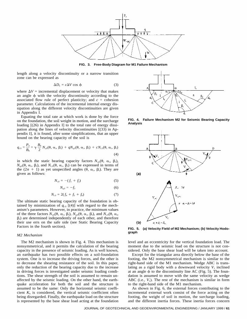
FIG. 3. Free-Body Diagram for M1 Failure Mechanism
length along a velocity discontinuity or a narrow transitionzone can be expressed as
DD = cDV cos f (3)L
where DV = incremental displacement or velocity that makesan angle f with the velocity discontinuity according to theassociated flow rule of perfect plasticity; and c = cohesionparameter. Calculations of the incremental internal energy dis-sipation along the different velocity discontinuities are givenin Appendix I.
Equating the total rate at which work is done by the forceon the foundation, the soil weight in motion, and the surchargeloading [(26) in Appendix I] to the total rate of energy dissi-pation along the lines of velocity discontinuities [(33) in Ap-pendix I], it is found, after some simplifications, that an upperbound on the bearing capacity of the soil is
P BS 0q = = g N (u, a , b ) 1 qN (u, a , b ) 1 cN (u, a , b )cS gS i i qS i i cS i i
B 20
(4)
in which the static bearing capacity factors ai, bi),N (u,gS
NqS(u, ai, bi), and NcS(u, ai, bi) can be expressed in terms ofthe (2n 1 1) as yet unspecified angles (u, ai, bi). They aregiven as follows:
N = 2( f 1 f ) (5)gS 1 2
N = 2f (6)qS 3
N = 2( f 1 f 1 f ) (7)cS 4 5 6
The ultimate static bearing capacity of the foundation is ob-tained by minimization of qcS [(4)] with regard to the mech-anism’s parameters. However, in practice, the minimum valuesof the three factors ai, bi), NqS(u, ai, bi), and NcS(u, ai,N (u,gS
bi) are determined independently of each other, and thereforetheir use errs on the safe side (see Static Bearing CapacityFactors in the fourth section).
M2 Mechanism
The M2 mechanism is shown in Fig. 4. This mechanism isnonsymmetrical, and it permits the calculation of the bearingcapacity in the presence of seismic loading. As is well known,an earthquake has two possible effects on a soil-foundationsystem. One is to increase the driving forces, and the other isto decrease the shearing resistance of the soil. In this paper,only the reduction of the bearing capacity due to the increasein driving forces is investigated under seismic loading condi-tions. The shear strength of the soil is assumed to remain un-affected by the seismic loading. On the other hand, the earth-quake acceleration for both the soil and the structure isassumed to be the same: Only the horizontal seismic coeffi-cient Kh is considered, the vertical seismic coefficient oftenbeing disregarded. Finally, the earthquake load on the structureis represented by the base shear load acting at the foundation
JOURNAL OF GEOTECH
FIG. 4. Failure Mechanism M2 for Seismic Bearing CapacityAnalysis
FIG. 5. (a) Velocity Field of M2 Mechanism; (b) Velocity Hodo-graph
level and an eccentricity for the vertical foundation load. Themoment due to the seismic load on the structure is not con-sidered. Only the base shear load will be taken into account.
Except for the triangular area directly below the base of thefooting, the M2 nonsymmetrical mechanism is similar to theright-hand side of the M1 mechanism. Wedge ABC is trans-lating as a rigid body with a downward velocity V1 inclinedat an angle f to the discontinuity line AC (Fig. 5). The foun-dation is assumed to move with the same velocity as wedgeABC (i.e., V1). The rest of the mechanism is similar in formto the right-hand side of the M1 mechanism.
As shown in Fig. 6, the external forces contributing to theincremental external work consist of the force acting on thefooting, the weight of soil in motion, the surcharge loading,and the different inertia forces. These inertia forces concern
NICAL AND GEOENVIRONMENTAL ENGINEERING / JANUARY 1999 / 61

FIG. 6. Free-Body Diagram for M2 Failure Mechanism
the base shear load, the inertia forces of the soil in motion,and the surcharge loading. Energy is dissipated along the linesli (i = 1, . . . , n 2 1) and di (i = 1, . . . , n). Calculations ofthe incremental external work and the internal energy dissi-pation along the different velocity discontinuities are given inAppendix II.
Equating the total external rate of work [(44) in AppendixII] to the total internal rate of energy dissipation [(49) in Ap-pendix II], it is found that the value of the upper bound onthe bearing capacity is
P BE 0q = = g N (a , b ) 1 qN (a , b ) 1 cN (a , b ) (8)cE gE i i qE i i cE i i
B 20
in which the seismic bearing capacity factors bi),N (a ,gE i
NqE(ai, bi), and NcE(ai, bi) can be expressed in terms of the(2n) as yet unspecified angles (ai, bi). They are given as fol-lows:
1N = 2 (g 1 K g ) (9)gE 1 h 2sin(b 2 f) 1 K cos(b 2 f)1 h 1
1N = 2 (g 1 K g ) (10)qE 3 h 4sin(b 2 f) 1 K cos(b 2 f)1 h 1
1N = (g 1 g ) (11)cE 5 6sin(b 2 f) 1 K cos(b 2 f)1 h 1
From these equations, it is clear that only the factor in-NgE
cludes the soil inertia. The NqE factor includes the inertia ofthe foundation load and the surcharge loading; however, theNcE factor only includes the inertia of the foundation load andthus corresponds to the case of a footing subject to an inclinedload.
As in the static case, the minimum value of qcE gives theultimate seismic bearing capacity of the foundation. However,in practice, the minimum values of the three factors N (a ,gE i
bi), NqE(ai, bi), and NcE(ai, bi) are determined independentlyof each other, and therefore their use errs on the safe side.
NUMERICAL RESULTS
The most critical bearing capacity factors can be obtainedby minimization of these factors [(5)–(7) and (9)–(11)] withregard to the mechanism’s parameters. The minimization pro-cedure can be performed using the optimization tool availablein most spreadsheet software packages. In this paper, one usesthe Solver optimization tool of Microsoft Excel. Two computerprograms using the Visual Basic programming language thatresides in Microsoft Excel have been written to define thestatic and seismic bearing capacity factors as function of themechanism’s parameters [(5)–(7) and (9)–(11)]. Initial valuesneed to be assigned to the different angular parameters. Thesolver tool is then invoked to ‘‘minimize’’ the bearing capacityfactor ‘‘by changing’’ the angular parameters, ‘‘subject to’’ theconstraints {u 1 ai = p (cf. Fig. 1) and ai 1 bi $n( bi=1 i11
[cf. Fig. 2(b)]} for the M1 mechanism and ai = p (cf.n{(i=1
62 / JOURNAL OF GEOTECHNICAL AND GEOENVIRONMENTAL ENGIN
FIG. 7. Critical Slip Surface for f = 45& and n = 12
TABLE 1. NgS Value versus Number of Rigid Blocks n for f =45& from M1 Symmetrical Mechanism
n(1)
NgS
(2)
Reduction(%)(3)
2 741.93 —3 447.94 39.64 384.28 14.25 359.50 6.46 347.19 3.47 340.16 2.08 335.76 1.39 332.82 0.9
10 330.77 0.611 329.27 0.512 328.14 0.313 327.27 0.314 326.59 0.2
Fig. 4) and ai 1 bi $ [cf. Fig. 5(b)]} for the M2 mech-bi11
anism. The method of minimization used is the general re-duced gradient method. Additional information on Solver op-tions and algorithms can be found in the Microsoft ExcelSolver’s help file and at the website www.frontsys.com.
In the following sections, we present and discuss in succes-sion (1) the static bearing capacity factors NqS, and NcSN ,gS
given by both the M1 and M2 mechanisms; and (2) the seismicbearing capacity factors NqE, and NcE given by the M2N ,gE
nonsymmetrical mechanism.
Static Bearing Capacity Factors
First, the results given by the M1 symmetrical mechanismwill be presented and compared to those given by other ex-isting solutions. Second, the results of the M2 nonsymmetricalmechanism for Kh = 0 will be presented and compared to thosegiven by the M1 symmetrical mechanism. This permits us toestimate the difference between results when considering anonsymmetrical mechanism for a centrally loaded footing.
Table 1 presents the factor obtained from the M1 mech-NgS
anism for f = 457 and for various values of n (the number ofthe triangular rigid blocks). It can be observed that the upper-bound solution can be improved by increasing the number ofrigid blocks. The reduction in the value decreases with theNgS
n-increase and attains 0.2% for n = 14. It should be mentionedthat the same trend is also observed for the NqS and NcS factors.
Fig. 7 shows the critical slip surface obtained from the nu-merical minimization of the factor for f = 457 and for nNgS
= 12. It can be observed that the critical failure mechanismobtained by the computer program is composed of two radialshear zones sandwiched between an active triangular wedgeunder the footing and a Rankine passive wedge. It should benoted that the radial shear zones are not bounded by log-spiralslip surfaces as is the case of the Prandtl mechanism. Finally,note that all subsequent calculations are made for n = 14.
Table 2 presents the NqS, and NcS factors obtained fromN ,gS
the computer program for f ranging from 0 to 507.To check the effect of the superposition method, one cal-
culates the ultimate load Pdirect obtained by direct numericalminimization of PS [(4)] and compares it to the one obtainedby the superposition method Psuperposition using the NqS, andN ,gS
NcS factors. For f = 307, c = 10 kPa, q = 10 kPa, B0 = 1 m,and g = 18 kN/m3, one obtains Pdirect = 726.13 kN/m and
EERING / JANUARY 1999

TABLE 2. NqS, and NcS Values from M1 Symmetrical Mech-N ,gS
anism
f(1)
NgS
(2)NqS
(3)NcS
(4)
0 — 1.00 5.151 — 1.09 5.382 — 1.20 5.643 — 1.31 5.914 — 1.43 6.195 — 1.57 6.506 — 1.72 6.827 — 1.88 7.178 — 2.06 7.549 — 2.26 7.93
10 — 2.47 8.3611 — 2.71 8.8112 — 2.98 9.3013 — 3.27 9.8214 1.62 3.59 10.3915 1.95 3.95 10.9916 2.32 4.34 11.6517 2.75 4.78 12.3618 3.25 5.27 13.1319 3.82 5.81 13.9620 4.49 6.41 14.8621 5.26 7.08 15.8522 6.15 7.84 16.9223 7.19 8.68 18.0924 8.40 9.62 19.3725 9.81 10.69 20.7726 11.46 11.88 22.3227 13.39 13.23 24.0128 15.67 14.76 25.8829 18.35 16.49 27.9530 21.51 18.46 30.2431 25.26 20.70 32.7932 29.71 23.26 35.6233 35.02 26.19 38.7934 41.37 29.56 42.3435 49.00 33.44 46.3336 58.21 37.93 50.8237 69.35 43.13 55.9138 82.91 49.19 61.6839 99.48 56.27 68.2540 119.84 64.58 75.7741 144.99 74.36 84.4042 176.23 85.95 94.3543 215.27 99.73 105.8744 264.39 116.20 119.2945 326.59 135.99 134.9946 405.97 159.91 153.4647 508.04 189.00 175.3148 640.42 224.59 201.3249 813.64 268.44 232.4950 1,042.48 322.88 270.09
Psuperposition = 680.58 kN/m, which indicates that the superpo-sition effect errs on the safe side.
Comparison of Results with Existing Solutions
NgS Factor. As is well known, there are a great manysolutions for in the literature based on different methodsNgS
and the differences among them are sometimes substantial.Because of the great sensibility of the factor to the frictionNgS
angle, particularly for f > 307, the tendency today, in practice,is to use the values given by Caquot and Kerisel (1953), Mey-erhof (1963) [cf. (12)], and Vesic (1973) [cf. (13)]
N (Meyerhof) = (N 2 1)tan 1.4f (12)gS qS
N (Vesic) = 2(N 1 1)tan f (13)gS qS
where NqS is given as follows:
p f2N = exp(p tan f)tan 1 (14)qS S D4 2
JOURNAL OF GEOTECHN
TABLE 4. Comparison of Present Factor with Other Upper-NgS
Bound Solutions
f(1)
Presentsolution (M1)
(2)
Chen (1975)
Prandtl1(3)
Prandtl2(4)
Prandtl3(5)
15 1.9 2.7 2.3 2.120 4.5 5.9 5.2 4.625 9.8 12.4 11.4 10.930 21.5 26.7 25.0 31.535 49.0 60.2 57.0 138.040 119.8 147.0 141.0 1,803.0
FIG. 8. Comparison of Present Factor with Results ofNgS
Other Authors
TABLE 3. Comparison of Present Factor with that of OtherNgS
Authors
f(1)
Presentsolution (M1)
(2)
Caquot andKerisel (1953)
(3)
Meyerhof(1963)
(4)
Vesic(1973)
(5)
20 4.49 4.97 2.87 5.3925 9.81 10.4 6.77 10.8830 27.51 21.8 15.67 22.435 49.0 48.0 37.15 48.0340 119.84 113.0 93.69 109.4145 326.59 297.0 262.74 271.76
The values given by Caquot and Kerisel and the expressionsuggested by Vesic are being increasingly used. Table 3and Fig. 8 show the comparison with the aforementioned au-thors. The maximal difference between the present solutionand that of Caquot and Kerisel is smaller than 10% for f #457.
On the other hand, rigorous upper-bound solutions for anassociated flow rule Coulomb material are proposed in theliterature. Chen (1975) considered three symmetrical failuremechanisms referred to as Prandtl1, Prandtl2, and Prandtl3 andgave rigorous upper-bound solutions in the framework of thelimit analysis theory. Prandtl1 is composed of a triangular ac-tive wedge under the footing, two radial log-spiral shear zonesand two triangular passive wedges. Prandtl2 differs fromPrandtl1 only in that an additional rigid body zone has beenintroduced. Finally, Prandtl3 resembles closely the Prandtl1mechanism; however, each shear zone is now bounded by acircular arc. The upper-bound solutions given by the presentM1 mechanism and those given by the three aforementionedmechanisms proposed by Chen are presented in Table 4. It isclear that the present upper-bound solutions are better than
ICAL AND GEOENVIRONMENTAL ENGINEERING / JANUARY 1999 / 63

TABLE 5. NqS, NcS Values from M2 Nonsymmetrical Mech-N ,gS
anism
f(1)
NgS
(2)NqS
(3)NcS
(4)
0 — 1.00 5.151 0.03 1.09 5.382 0.07 1.20 5.643 0.11 1.31 5.914 0.17 1.43 6.195 0.25 1.57 6.506 0.33 1.72 6.827 0.43 1.88 7.178 0.55 2.06 7.549 0.69 2.26 7.93
10 0.85 2.47 8.3611 1.03 2.71 8.8112 1.24 2.98 9.3013 1.49 3.27 9.8214 1.77 3.59 10.3915 2.10 3.95 11.0016 2.47 4.34 11.6517 2.91 4.78 12.3618 3.41 5.26 13.1319 3.99 5.81 13.9620 4.67 6.41 14.8721 5.45 7.08 15.8522 6.35 7.84 16.9223 7.40 8.68 18.0924 8.63 9.62 19.3825 10.06 10.69 20.7826 11.73 11.88 22.3227 13.68 13.23 24.0228 15.98 14.76 25.8929 18.69 16.49 27.9630 21.88 18.46 30.2531 25.67 20.70 32.8032 30.16 23.25 35.6333 35.52 26.18 38.8034 41.93 29.55 42.3635 49.62 33.43 46.3536 58.90 37.91 50.8437 70.13 43.11 55.9338 83.78 49.17 61.7139 100.47 56.24 68.2840 120.96 64.55 75.8041 146.27 74.33 84.4442 177.70 85.91 94.4043 216.97 99.68 105.9444 266.35 116.13 119.3745 328.88 135.91 135.0946 408.65 159.81 153.5847 511.22 188.86 175.4548 644.19 224.42 201.5049 818.14 268.22 232.7050 1,047.90 322.59 270.36
those of Chen (1975); the improvement attains 15% for f =407.
NqS and NcS Factors. Based on the upper-bound methodof the limit analysis theory, the bearing capacity factors ob-tained from Prandtl mechanism are given by (14) for NqS andby (15) for NcS [cf. Chen (1975)]
N = (N 2 1)cot f (15)cS qS
It should be mentioned here that Chen (1975) has alsoshown that the bearing capacity factors NcS and NqS asgiven by (14) and (15) are also lower bounds and hence arethe exact solutions in the framework of the limit analysis the-ory.
The comparison of the present factors with those given by(14) and (15) has shown that the present solutions are veryclose to the exact solutions; the error does not exceed 1.2%.
64 / JOURNAL OF GEOTECHNICAL AND GEOENVIRONMENTAL ENGIN
FIG. 9. Comparison of Bearing Capacity Factors given by M1and M2 Mechanisms
TABLE 6. Seismic Bearing Capacity Factor NgE
Kh
(1)
f
15(2)
20(3)
25(4)
30(5)
35(6)
40(7)
45(8)
0 2.10 4.67 10.06 21.88 49.62 120.96 328.880.05 1.51 3.57 7.91 17.43 39.69 96.48 259.930.1 1.01 2.61 6.04 13.59 31.23 75.92 203.110.15 0.58 1.80 4.45 10.35 24.14 58.94 156.980.2 0.26 1.13 3.14 7.67 18.32 45.12 120.050.25 0.04 0.62 2.09 5.51 13.61 34.05 90.850.3 — 0.26 1.28 3.80 9.89 25.31 68.050.35 — — 0.69 2.49 6.99 18.51 50.440.4 — — 0.28 1.51 4.77 13.29 36.990.45 — — 0.04 0.81 3.12 9.34 26.820.5 — — — 0.35 1.92 6.40 19.190.55 — — — 0.07 1.08 4.24 13.540.6 — — — — 0.51 2.69 9.38
Comparison of Results with Solutions of M2 Mechanism
The NqS, and NcS factors given by the M2 nonsym-N ,gS
metrical mechanism for Kh = 0 are presented in Table 5 andcompared to those given by the M1 mechanism in Fig. 9.While the NqS and NcS factors are practically identical in bothmechanisms, the M2 mechanism gives greater upper-boundsolutions than the M1 mechanism for the factor. Notice,NgS
however, that the maximal difference does not exceed 4% forf $ 207.
Seismic Bearing Capacity Factors
Earthquakes have the unfavorable effect of decreasing thebearing capacity of foundations. To investigate how the bear-ing capacity factors NqE, and NcE are affected, extensiveN ,gE
numerical results based on the M2 failure mechanism are pre-sented in Tables 6–8. All results are given for n = 14, whichmeans that the minimization procedure is made with regard to28 angular parameters.
Fig. 10 shows the critical slip surfaces obtained from thenumerical minimization of the factor for f = 307 and forNgE
three values of Kh (Kh = 0, 0.15, and 0.3). It can be observedthat the critical slip surface becomes shallower as the accel-eration intensity increases.
Charts relating bearing capacity factors NqE, and NcE toN ,gE
various governing parameters are presented in Figs. 11–13.
EERING / JANUARY 1999

TABLE 7. Seismic Bearing Capacity Factor NqE
Kh
(1)
f
15(2)
20(3)
25(4)
30(5)
35(6)
40(7)
45(8)
0 3.95 6.41 10.69 18.46 33.43 64.55 135.910.05 3.52 5.72 9.51 16.35 29.44 56.39 117.460.1 3.07 5.02 8.35 14.34 25.70 48.89 100.850.15 2.59 4.32 7.24 12.44 22.25 42.08 86.050.2 2.07 3.62 6.17 10.67 19.08 35.96 73.000.25 1.46 2.94 5.17 9.04 16.22 30.52 61.600.3 — 2.25 4.22 7.54 13.65 25.73 51.710.35 — 1.46 3.33 6.19 11.37 21.53 43.210.4 — — 2.47 4.97 9.36 17.89 35.930.45 — — 1.56 3.86 7.59 14.74 29.750.5 — — — 2.85 6.04 12.04 24.510.55 — — — 1.86 4.69 9.72 20.090.6 — — — — 3.49 7.75 16.36
TABLE 8. Seismic Bearing Capacity Factor NcE
Kh
(1)
f
15(2)
20(3)
25(4)
30(5)
35(6)
40(7)
45(8)
0 11.00 14.87 20.78 30.25 46.35 75.80 135.090.05 10.26 13.79 19.14 27.64 41.95 67.84 119.270.1 9.50 12.69 17.50 25.09 37.74 60.38 104.740.15 8.72 11.60 15.91 22.64 33.76 53.46 91.560.2 7.96 10.54 14.37 20.32 30.06 47.12 79.700.25 7.21 9.51 12.91 18.14 26.63 41.36 69.140.3 6.48 8.53 11.53 16.12 23.50 36.18 59.810.35 5.79 7.61 10.25 14.26 20.67 31.56 51.620.4 5.14 6.75 9.07 12.58 18.12 27.47 44.490.45 4.54 5.96 8.00 11.05 15.85 23.86 38.290.5 3.98 5.23 7.02 9.68 13.83 20.69 32.940.55 3.47 4.58 6.14 8.46 12.04 17.93 28.330.6 3.01 3.98 5.36 7.37 10.48 15.53 24.37
FIG. 10. Critical Slip Surfaces for f = 30& and Kh = 0, 0.15, and 0.3
JOURNAL OF GEOTECHN
FIG. 11. Design Chart for NgE
FIG. 12. Design Chart for NqE
FIG. 13. Design Chart for NcE
Comparison of Results with Existing Solutions
To see the validity of the present upper-bound solution, theseismic bearing capacity factors are calculated and comparedwith other solutions. The differences between them are dis-cussed.
Soubra (1997) considered two nonsymmetrical failuremechanisms and gave rigorous upper-bound solutions in theframework of the limit analysis theory. One mechanism is
ICAL AND GEOENVIRONMENTAL ENGINEERING / JANUARY 1999 / 65

TABLE 9. Comparison of Present Seismic Bearing CapacityFactors with Upper-Bound Solutions Given by Soubra (1997) forf = 40&
Kh
(1)
NgE
Presentsolution
(2)
Soubra(1997)
(3)
NqE
Presentsolution
(4)
Soubra(1997)
(5)
NcE
Presentsolution
(6)
Soubra(1997)
(7)
0 121.0 140.5 64.6 64.2 75.8 75.30.1 75.9 88.4 48.9 48.7 60.4 60.10.2 45.1 53.0 36.0 35.9 47.1 46.90.3 25.3 30.1 25.7 25.7 36.2 36.10.4 13.3 16.0 17.9 17.9 27.5 27.40.5 6.4 7.8 12.0 12.0 20.7 20.70.6 2.7 3.3 7.8 7.7 15.5 15.5
FIG. 14. Comparison of Present Factor with that of Rich-NgE
ards et al. (1993) for f = 30&
FIG. 15. Comparison of Present NqE Factor with that of Rich-ards et al. (1993) for f = 30&
composed of a triangular active wedge under the footing, oneradial log-spiral shear zone, and one triangular passive wedge.The other closely resembles the previous mechanism; how-ever, the shear zone is now bounded by a circular arc. In thespirit of the upper-bound approach, the lesser of these twosolutions was given in the form of design charts [cf. Soubra(1997)]. The upper-bound solutions given by the present M2mechanism and those given by Soubra (1997) are presentedin Table 9. It is clear that the present upper-bound solutionsare better than those of Soubra (1997) for the factor; theNgE
improvement exceeds 15% for Kh = 0.3. However, the NqE andNcE factors are practically identical.
On the other hand, Figs. 14–16 show the comparison be-
66 / JOURNAL OF GEOTECHNICAL AND GEOENVIRONMENTAL ENGIN
FIG. 16. Comparison of Present NcE Factor with that of Rich-ards et al. (1993) for f = 30&
tween the present results and those given by Richards et al.(1993). From Fig. 14, it can be observed that the solutionsgiven by Richards et al. (1993) slightly overestimate the NgE
factor with regard to the present upper-bound solutions. Con-cerning the NqE factor (cf. Fig. 15), the maximal differencewith Richards et al. (1993) does not exceed 14%. However,for the NcE factor (cf. Fig. 16), the difference is equal to 11%for f = 307 and Kh = 0 and attains 40% for Kh = 0.3. Thisdifference may be explained by the fact that Richards et al.(1993) have used (15) to calculate the seismic factor NcE with-out any real justification as they mentioned in their paper.
CONCLUSIONS
Two failure mechanisms have been considered for the anal-ysis of the static and seismic bearing capacity factors usingthe upper-bound method of the limit analysis theory. The so-lutions presented are rigorous upper-bound ones in the frame-work of the limit analysis theory. The numerical results ob-tained lead to the following conclusions.
For the static case, both the M1 symmetrical and the M2nonsymmetrical mechanisms give the exact solution of thestatic NqS and NcS factors. For the factor, the M2 mecha-NgS
nism gives greater upper-bound solutions than the M1 mech-anism. Notice, however, that the maximal difference does notexceed 4% for f $ 207. The present upper-bound solutionsare better than those of Chen (1975) since one obtains smallerupper-bound solutions; the improvement attains 15% for f =407. On the other hand, the comparison between the presentsolutions and the currently accepted values of Caquot and Ker-isel has shown that the maximal difference between the resultsis smaller than 10% for f # 457.
For the seismic case, the present upper-bound solutionsgiven by the M2 nonsymmetrical mechanism are better thanthose of Soubra (1997) for the factor, the improvementNgE
exceeds 15% when f = 407 and Kh = 0.3. However, the NqE
and NcE factors are practically identical to those given bySoubra (1997). On the other hand, the comparison with thesolutions given by Richards et al. (1993) using the limit-equi-librium method has shown that the present upper-bound so-lutions are in agreement with regard to the results of Richardset al. for the and NqE factors. However, for the NcE factor,NgE
the difference between the present solution and that of Rich-ards et al. attains 40% for f = 307 and Kh = 0.3. The presentnumerical results are presented in the form of design chartsfor practical use in geotechnical engineering.
EERING / JANUARY 1999

APPENDIX I. M1 Mechanism
In this appendix, we present the different expressions forthe incremental external work of mechanism M1, together withthe internal energy dissipation from the same mechanism.
Geometry
For the triangular block i, the lengths li and di, and thesurface Si are given as follows:
i21B sin b0 j
l = (16)i P2 cos u sin(a 1 b )j jj=1
i21B sin a sin b0 i j
d = (17)i P2 cos u sin(a 1 b ) sin(a 1 b )i i j jj=1
i212 2B sin a sin b sin b0 i i jS = (18)i P2 22 4 cos u sin(a 1 b ) sin (a 1 b )i i j jj=1
Incremental External Work
The different elements of the incremental external work forthe M1 mechanism can be calculated as follows.
1. Incremental external work due to self-weight of triangleABC1
2gB0DW = [ f (a , b , u)]V (19)ABC 1 i i 01 2
where
tan uf = (20)1 2
2. Incremental external work due to self-weights of the re-maining 2n triangular blocks
2n 2gB0[DW ] = [ f (a , b , u)]V (21)j 2 i i 0O 2j=1
where
cos(u 2 f)f =2 22 cos u sin(b 2 2f)1
n i21sin a sin bi i
? sin b 2 u 2 a 2 fi jO F S O Dsin(a 1 b )i ii=1 j=1
i21 2sin b sin(a 1 b 2 2f)j j j?P G2sin (a 1 b )sin(b 2 2f)j j j11j=1 (22)
3. Incremental external work due to the foundation load
DW = P V (23)P S 0S
4. Incremental external work due to the surcharge loading
DW = qB f (a , b , u)V (24)q 0 3 i i 0
wheren21
cos(u 2 f) sin bnf = sin b 2 u 2 a 2 f3 n jS O Dcos u sin(b 2 2f) sin(a 1 b )1 n n j=1
n21sin b sin(a 1 b 2 2f)j j j
?P sin(a 1 b )sin(b 2 2f)j j j11j=1 (25)
The total incremental external work is the summation ofthese four contributions, that is, (19), (21), (23), and (24)
2n
[DW ] = DW 1 [DW ] 1 DW 1 DW (26)ext ABC j P qO O1 Sj=1
JOURNAL OF GEOTECHN
Incremental Internal Energy Dissipation
1. Along BC
DD = cB f (a , b , u)V (27)BC 0 4 i i 0
where
cos f cos(b 2 u 2 f)1f = (28)4 2 cos u sin(b 2 2f)1
2. Along lines di (i = 1, . . . , n)
DD = cB f (a , b , u)V (29)d (i=1,.. . ,n) 0 5 i i 0i
where
cos(u 2 f)cos ff =5 2 cos u sin(b 2 2f)1
n i21sin a sin b sin(a 1 b 2 2f)i j j j
?O F P Gsin(a 1 b ) sin(a 1 b )sin(b 2 2f)i i j j j11i=1 j=1 (30)
3. Along the radial lines li (i = 2, . . . , n)
DD = cB f (a , b , u)V (31)l (i=2,.. . ,n) 0 6 i i 0i
where
cos(u 2 f)cos ff =6 2 cos u sin(b 2 2f)1
n i21sin(b 2 b 1 a ) sin bi21 i i21 j
?O F Psin(b 2 2f) sin(a 1 b )i j ji=2 j=1
i22sin(a 1 b 2 2f)j j
?P Gsin(b 2 2f)j11j=1 (32)
The total incremental energy dissipation is twice the summa-tion of these three parts, that is, (27), (29), and (31)
[DD] = 2(DD 1 DD 1 DD ) (33)BC d (i=1,.. . ,n) l (i=2,.. . ,n)O i i
APPENDIX II. M2 Mechanism
In this appendix, we present the different expressions forthe incremental external work of mechanism M2, together withthe internal energy dissipation for the same mechanism.
Geometry
For the triangular block i, the lengths li and di, and thesurface Si are given as follows:
isin b sin b1 j
l = B (34)i 0 Psin(a 1 b ) sin(a 1 b )1 1 j jj=2
isin b sin a sin b1 i j
d = B (35)i 0 Psin(a 1 b ) sin b sin(a 1 b )1 1 i j jj=2
i2 2 2B sin b sin a sin(a 1 b ) sin b0 1 i i i jS = (36)i P2 22 sin (a 1 b ) sin b sin (a 1 b )1 1 i j jj=2
Incremental External Work
The different elements of the incremental external work forthe M2 mechanism can be calculated as follows.
1. Incremental external work due to self-weights and inertiaforces of the n triangular rigid blocks
2gB0DW = [g (a , b ) 1 K g (a , b )]V (37)soil 1 i i h 2 i i 12
where
ICAL AND GEOENVIRONMENTAL ENGINEERING / JANUARY 1999 / 67
n i212sin b sin a sin(a 1 b )1 i i ig = sin b 2 f 2 a1 i jOF S O D2sin (a 1 b ) sin b1 1 ii=1 j=1
i i212sin b sin(a 1 b 2 2f)j j j?P P G2sin (a 1 b ) sin(b 2 2f)j j j11j=2 j=1 (38)
n i212sin b sin a sin(a 1 b )1 i i ig = cos b 2 f 2 a2 i jOF S O D2sin (a 1 b ) sin b1 1 ii=1 j=1
i i212sin b sin(a 1 b 2 2f)j j j?P P G2sin (a 1 b ) sin(b 2 2f)j j j11j=2 j=1 (39)
2. Incremental external work due to the foundation load andthe corresponding inertia force
DW = P [sin(b 2 f) 1 K cos(b 2 f)]V (40)P E 1 h 1 1E
3. Incremental external work due to the surcharge loadingand the corresponding inertia force
DW = qB [g (a , b ) 1 K g (a , b )]V (41)q 0 3 i i h 4 i i 1
wheren21
sin b1g = sin b 2 f 2 a3 n jS O Dsin(a 1 b )1 1 j=1
n n21sin b sin(a 1 b 2 2f)j j j
?P Psin(a 1 b ) sin(b 2 2f)j j j11j=2 j=1 (42)n21
sin b1g = cos b 2 f 2 a4 n jS O Dsin(a 1 b )1 1 j=1
n n21sin b sin(a 1 b 2 2f)j j j
?P Psin(a 1 b ) sin(b 2 2f)j j j11j=2 j=1 (43)
The total incremental external work is the summation of thesecontributions, that is, (37), (40), and (41)
[DW ] = DW 1 DW 1 DW (44)ext soil P qO E
Incremental Internal Energy Dissipation
1. Along lines di (i = 1, . . . , n)
DD = cB g (a , b )V (45)d (i=1,.. . ,n) 0 5 i i 1i
wheren i
sin b cos f sin a sin b1 i jg =5 O F Psin(a 1 b ) sin b sin(a 1 b )1 1 i j ji=1 j=2
i21sin(a 1 b 2 2f)j j
?P Gsin(b 2 2f)j11j=1 (46)
2. Along the radial lines li (i = 1, . . . , n 2 1)
DD = cB g (a , b )V (47)l (i=1,.. . ,n21) 0 6 i i 1i
wheren21 i
sin b cos f sin(b 2 b 1 a ) sin b1 i i11 i jg =6 O F Psin(a 1 b ) sin(b 2 2f) sin(a 1 b )1 1 i11 j ji=1 j=2
i21sin(a 1 b 2 2f)j j
?P Gsin(b 2 2f)j11j=1 (48)
The total incremental energy dissipation is the summation ofthese two parts, that is, (45) and (47)
[DD] = DD 1 DD (49)d (i=1,.. . ,n) l (i=1,.. . ,n21)O i i
APPENDIX III. REFERENCES
Caquot, A., and Kerisel, J. (1953). ‘‘Sur le terme de surface dans le calculdes fondations en milieu pulverulent.’’ Proc., 3rd Int. Conf. on SoilMech. and Found. Engrg., ICOSOMES, Zurich, Vol. I, 336–337.
68 / JOURNAL OF GEOTECHNICAL AND GEOENVIRONMENTAL ENGI
Chen, W. F. (1975). Limit analysis and soil plasticity. Elsevier ScientificPublishing Company, London, 637.
Davis, E. H. (1968). ‘‘Theories of plasticity and the failure of soilmasses.’’ Soil mechanics: Selected topics, I. K. Lee, ed., Butterworth’s,London, 341–380.
De Buhan, P., and Salencon, J. (1993). ‘‘A comprehensive stability anal-ysis of soil nailed structures.’’ Eur. J. Mech. Ser. A/Solids, Paris, 12(3),325–345.
Dormieux, L., and Pecker, A. (1995). ‘‘Seismic bearing capacity of foun-dations on cohesionless soil.’’ J. Geotech. Engrg., ASCE, 121(3),300–303.
Drescher, A., and Detournay, E. (1993). ‘‘Limit load in translational fail-ure mechanisms for associative and non-associative materials.’’ Geo-technique, The Institution of Civil Engineers, London, 43(3), 443–456.
Meyerhof, G. G. (1951). ‘‘The ultimate bearing capacity of foundations.’’Geotechnique, The Institution of Civil Engineers, London, 2, 301–332.
Meyerhof, G. G. (1963). ‘‘Some recent research on the bearing capacityof foundations.’’ Can. Geotech. J., Ottawa, 1(1), 16–26.
Michalowski, R. L. (1989). ‘‘Three-dimensional analysis of locally loadedslopes.’’ Geotechnique, The Institution of Civil Engineers, London,39(1), 27–38.
Michalowski, R. L., and Shi, L. (1995). ‘‘Bearing capacity of footingsover two-layer foundation soils.’’ J. Geotech. Engrg., ASCE, 121(5),421–428.
Michalowski, R. L., and Shi, L. (1996). ‘‘Closure on ‘Bearing capacityof footings over two-layer foundation soils.’ ’’ J. Geotech. Engrg.,122(8), 701–703.
Mroz, Z., and Drescher, A. (1969). ‘‘Limit plasticity approach to somecases of flow of bulk solids.’’ J. Engrg. Ind. Trans., ASCE, 91, 357–364.
Richards, R., Elms, D. G., and Budhu, M. (1993). ‘‘Seismic bearing ca-pacity and settlement of foundations.’’ J. Geotech. Engrg., ASCE,119(4), 662–674.
Salencon, J. (1990). ‘‘An introduction to the yield design theory and itsapplication to soil mechanics.’’ Eur. J. Mech. Ser. A/Solids, Paris, 9(5),477–500.
Sarma, S. K., and Iossifelis, I. S. (1990). ‘‘Seismic bearing capacity fac-tors of shallow strip footings.’’ Geotechnique, The Institution of CivilEngineers, London, 40(2), 265–273.
Shinohara, T., Tateishi, T., and Kubo, K. (1960). ‘‘Bearing capacity ofsandy soil for eccentric and inclined load and lateral resistance of singlepiles embedded in sandy soil.’’ Proc., 2nd World Conf. on EarthquakeEngrg., Tokyo, Gabujutsu bunken sukyu-rai, Vol. 1, 265–280.
Soubra, A.-H. (1997). ‘‘Seismic bearing capacity of shallow strip footingsin seismic conditions.’’ Proc., Instn. Civ. Engrs., Geotech. Engrg., Lon-don, 125(4), 230–241.
Terzaghi, K. (1943). Theoretical soil mechanics. Wiley, New York, 510.Vesic, A. S. (1973). ‘‘Analysis of ultimate loads of shallow foundations.’’
Proc., ASCE, 99(1), 45–73.
APPENDIX IV. NOTATION
The following symbols are used in this paper:
B0 = width of footing;c = cohesion;
c* = residual cohesion due to nonassociativeness;di, li = discontinuity lines;
Kh = horizontal seismic coefficient;NqE, NcEN ,gE = seismic bearing capacity factors;NqS, NcSN ,gS = static bearing capacity factors;
n = number of rigid blocks in failure mechanisms;PE = seismic ultimate load;PS = static ultimate load;q = surcharge loading;
qcE = seismic bearing capacity of footing;qcS = static bearing capacity of footing;Si = area of block i;V0 = initial downward velocity of footing for M1
mechanism;V1, V2, . . . , Vn = velocities of blocks 1, 2, . . . , n;
g = unit weight of soil;DV = velocity along velocity discontinuity;
u, ai, bi = angular parameters of failure mechanisms;f = angle of internal friction of soil;
f* = residual friction angle due to nonassociative-ness; and
C = dilatancy angle.
NEERING / JANUARY 1999