UNIVERSITY OF NAIROBI SCHOOL OF ENGINEERING DEPT. OF ELECTRICAL AND INFORMATION ENGINEERING PROJECT...
92
UNIVERSITY OF NAIROBI SCHOOL OF ENGINEERING DEPT. OF ELECTRICAL AND INFORMATION ENGINEERING PROJECT REPORT TITLE OF PROJECT: VEHICLE TRACKING USINGGPS NAME: GICHANA MARTIN OGETO ADM NO: F17/37585/2010 YEAR OF STUDY: 5 TH YEAR PROJECT SUPERVISOR: MR. AHMED SAYYID EXAMINER: PROF. ELIJAH MWANGI
-
Upload
ayi-asociados -
Category
Documents
-
view
0 -
download
0
Transcript of UNIVERSITY OF NAIROBI SCHOOL OF ENGINEERING DEPT. OF ELECTRICAL AND INFORMATION ENGINEERING PROJECT...

UNIVERSITY OF NAIROBI
SCHOOL OF ENGINEERINGDEPT. OF ELECTRICAL AND INFORMATION
ENGINEERING
PROJECT REPORT
TITLE OF PROJECT: VEHICLE TRACKING USINGGPS
NAME: GICHANA MARTIN OGETO
ADM NO: F17/37585/2010
YEAR OF STUDY: 5TH YEAR
PROJECT SUPERVISOR: MR. AHMED SAYYID
EXAMINER: PROF. ELIJAH MWANGI

DUE DATE: Thursday, April 23,
2015Project leading to the award of Bachelor of Science in Electrical and Information
Engineering

DECLARATIONOF ORIGINALITY
GICHANA MARTIN OGETO
F17/37585/2010
COLLEGE OF ARCHITECTURE AND ENGINEERING
SCHOOL OF ENGINEERING
DEPARTMENT OF ELECTRICAL AND INFORMATION ENGINEERING
Bachelor of Science in Electrical and Information Engineering
VEHICLE TRACKING USING GPS
i. I understand what plagiarism is and I am aware of the
university policy in this regard.
ii. I declare that this final year project is my own
originality work and has not been submitted elsewhere for
examination, award of a degree or publication. Where
other peoples work, or my own work has been used, this
has properly been acknowledged and referenced in
accordance with the University of Nairobi`s requirements.
iii. I have not sought or used the service of any professional
agencies to produce the work.
iv. I have not allowed, shall not allow anyone to copy this
work with the intention of passing it as his/her own
work.
v. I understand that any false claim in respect of this work
shall result in disciplinary action, In accordance with
University anti-plagiarism policy.
i

Signature: _________________________________
Date: _________________________________

DEDICATION
To my father and mother, David Okeyo Gichana and Zaveria Wanjiru
Gichana together with my brothers Kevin Mochiemo and Newton Mogaka
and my girlfriend Renalda Mwanyuma.

ACKNOWLEDGEMENT
I am greatly indebted to a number of people without whose
assistance and input this project could not be a success.
I am more indebted to my supervisor, Mr. Ahmed Sayyid who guided me
throughout the project ups and downs. He remained as my great
source of inspiration and always opened my way of looking at things
beyond what I could imagine as possible. Great thanks to all the
lecturers and other staff members who have assisted me during the
course of my studies and also throughout the project implementation
period.
I am also thankful to the two most beloved women in my life, my
mother and my girlfriend for their continuous support both
financially and emotionally during the entire life in campus. They
stood by me at times of need when I was almost losing it and helped
me rise back to my feet.
To my beloved father for the life teachings that he gave me
throughout my study in campus and for being there to ensure I don’t
lack motivation to better myself in this life time since we only
live ones.
Lastly and most importantly, I would like to appreciate my
classmates for their suggestions and opinions on my project and to
University of Nairobi for giving me the opportunity to study BSc.
Electrical and Information Engineering for five years and through
Fablab to help me complete my project.
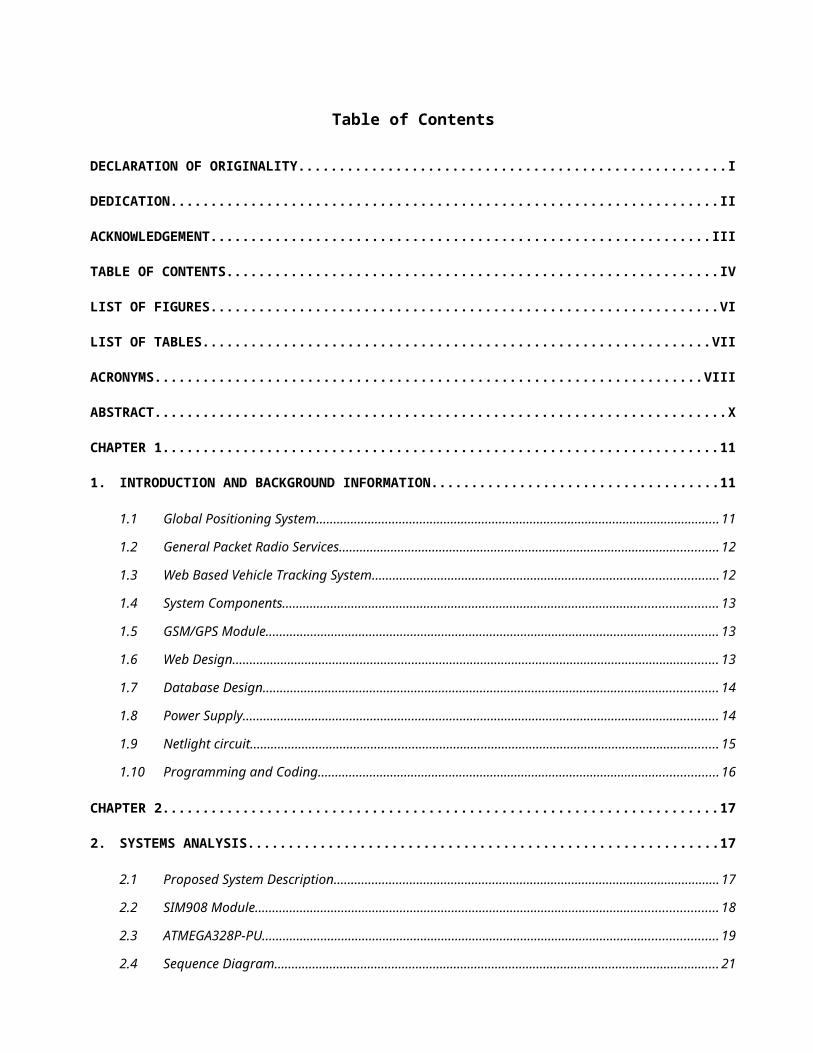
Table of Contents
DECLARATION OF ORIGINALITY.....................................................I
DEDICATION....................................................................II
ACKNOWLEDGEMENT..............................................................III
TABLE OF CONTENTS.............................................................IV
LIST OF FIGURES...............................................................VI
LIST OF TABLES...............................................................VII
ACRONYMS....................................................................VIII
ABSTRACT.......................................................................X
CHAPTER 1.....................................................................11
1. INTRODUCTION AND BACKGROUND INFORMATION....................................11
1.1 Global Positioning System.....................................................................................................................11
1.2 General Packet Radio Services.............................................................................................................. 12
1.3 Web Based Vehicle Tracking System....................................................................................................12
1.4 System Components.............................................................................................................................. 13
1.5 GSM/GPS Module................................................................................................................................... 13
1.6 Web Design............................................................................................................................................. 13
1.7 Database Design.................................................................................................................................... 14
1.8 Power Supply.......................................................................................................................................... 14
1.9 Netlight circuit........................................................................................................................................ 15
1.10 Programming and Coding....................................................................................................................16
CHAPTER 2.....................................................................17
2. SYSTEMS ANALYSIS...........................................................17
2.1 Proposed System Description................................................................................................................ 17
2.2 SIM908 Module...................................................................................................................................... 18
2.3 ATMEGA328P-PU.................................................................................................................................... 19
2.4 Sequence Diagram................................................................................................................................. 21

2.5 Database Design.................................................................................................................................... 22
CHAPTER 3.....................................................................24
3. SYSTEMS DESIGN.............................................................24
3.1 SIM908 Interface connection................................................................................................................24
3.2 Power Supply Design............................................................................................................................. 26
3.3 Power on/off SIM908............................................................................................................................. 27
3.4 Charging Interface................................................................................................................................. 29
3.5 SIM card Interface................................................................................................................................. 31
3.6 GPIO Selection........................................................................................................................................ 34
3.7 Design of Circuit PCB............................................................................................................................. 36
CHAPTER 4.....................................................................38
4. IMPLEMENTATION AND TESTING.................................................38
4.1 SCHEDULING OF THE WHOLE PROJECT................................................................................................38
4.2 SOFTWARE IMPLEMENTATION............................................................................................................... 43
4.3 HARDWARE IMPLEMENTATION.............................................................................................................. 47
CHAPTER 5.....................................................................50
5. CONCLUSIONS AND RECOMMENDATIONS............................................50
5.1 Conclusion.............................................................................................................................................. 50
5.2 Recommendation for future work........................................................................................................50
APPENDIX.......................................................................I
APPENDIX A: PROGRAM CODE.......................................................I
APPENDIX A 01: Index.html.............................................................................................................................. i
APPENDIX A 02: config.php............................................................................................................................. vi
APPENDIX A 03: auth.php............................................................................................................................... vi
APPENDIX A 04: client_index.php.................................................................................................................. vii
APPENDIX A 05: ATMEGA328P_P...................................................................................................................... x
REFERENCES....................................................................XX


List of Figures
Figure 1.................Web Based Vehicle Tracking System Overview
17
Figure 2..................................SIM908 Functional Diagram
18
Figure 3...........................ATMEGA328P-PU Functional Diagram
20
Figure 4.........Interaction between Application Layer and Database
21
Figure 5...............................Database Architecture Layers
23
Figure 6..........................SIM908 Circuit connection diagram
25
Figure 7............................Power supply circuit connection
26
Figure 8...........................Power on scenario timing diagram
27
Figure 9.........................Power down scenario timing diagram
28
Figure 10..............Power Key input circuit connection to SIM908
29

Figure 11...................................Charging module circuit
30
Figure 12........................Simcard circuit connection diagram
31
Figure 13..................ATMEGA328P-PU circuit connection diagram
33
Figure 14..........................AVR SPI 6 pin connection diagram
34
Figure 15.......................Netlight circuit connection diagram
35
Figure 16.........................Status circuit connection diagram
36

List of Tables
Table 1:.......................................SIMcard pin connections
31

Acronyms
GPS Global Positioning System
GPRS General Packet Radio Service
SIM Subscriber Identification Module
HTTP Hypertext Transfer Protocol
GSM Global System for Mobile communications
EGSM Extended Global System for Mobile communications
DCS Digital Cellular Service
PCS Personal Communications Service
TTFF Time-To-First-Fix
CS Communication Service
PHP Hypertext Preprocessor
XML Hypertext Mark-up Language
WAMP Windows Apache MySQL PHP
GGSN Gateway GPRS Support Node
PCB Power Circuit Board
AT ATtention commands
MISO Master In Slave Out
MOSI Master Out Slave In
SCK Clock Signal from master to slave
GND Ground Signal
GPIO General Purpose Input/Output
MCU MicroController Unit
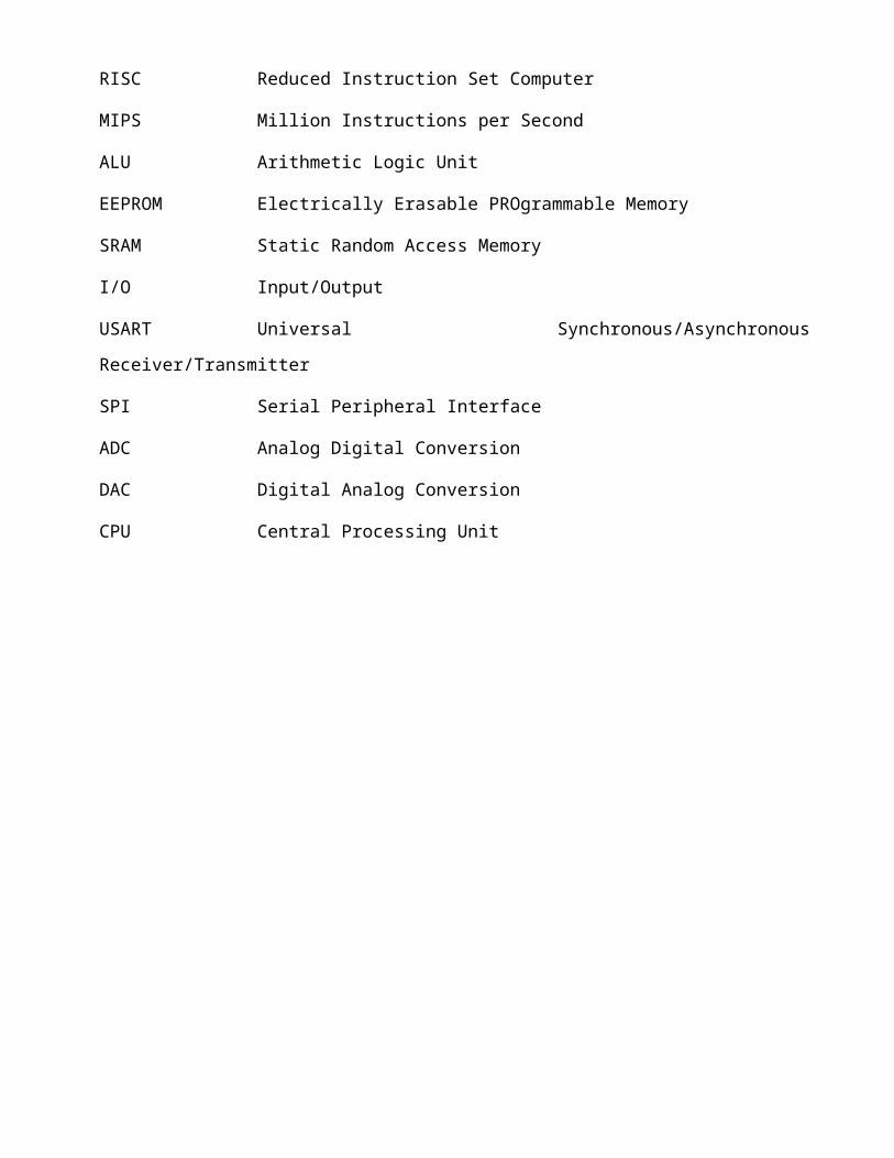
RISC Reduced Instruction Set Computer
MIPS Million Instructions per Second
ALU Arithmetic Logic Unit
EEPROM Electrically Erasable PROgrammable Memory
SRAM Static Random Access Memory
I/O Input/Output
USART Universal Synchronous/Asynchronous
Receiver/Transmitter
SPI Serial Peripheral Interface
ADC Analog Digital Conversion
DAC Digital Analog Conversion
CPU Central Processing Unit

ABSTRACT
The current position of the vehicle was acquired by a GPS device
(SIM 908) which is integrated in the target vehicle and the
location coordinates are sent through GPRS service provided by the
GSM network. The GPS data are sent using Get method of HTTP
protocol, the data at server side are stored in a database tables
and can be retrieved as request for position browsing on map. A web
application is developed using;
i. PHP
ii. JavaScript
iii. Ajax
iv. XML
v. MySQL
vi. Mozilla Firefox -32
All the above are embedded Google Map top retrieve and display web
page.In this project, an integrated cost effective web based GPS-
GPRS vehicle tracking system was designed andimplemented. The
system enables enterprises owners to viewthe present and past
positions recorded of the target vehicle onGoogle Map through
purpose designed web site. The currentposition of the vehicle was
acquired by GPS device which isintegrated in the target vehicle and
the location coordinatesare sent through GPRS service provided by
the GSM network.
The GPS data are sent using Get method of HTTP protocol,the data at
server side are stored in a database tables and canbe retrieved as
request for position browsing on map. A webapplication is developed

using PHP, JavaScript, XML,and MySQL with embedded Google Map to
retrieve anddisplay on the clients’ homepage the position and other
track details.

CHAPTER 1
Table 1: INTRODUCTION AND BACKGROUND INFORMATIONThe GPS-GPRS based vehicle tracking system is one that makes
use of the Global Positioning System (GPS) to determine the precise
location of a vehicle to which it is attached. I therefore sought
to design a cost effective web-based GPS-GPRS vehicle tracking
system that enables owners to view the present and past positions
recorded of the target vehicle on Google Map through a purpose
designed website. With the rapidly increase in number of vehicles
in Kenya, there is an increase need of tracking your vehicle or
fleet of vehicles due to the following reasons:
i. Increase in carjacking incidences that are unresolved by the
police
ii. Increase in unrecovered stolen motor vehicles
iii. To know exactly where all your vehicles are and of what use
they are being used for. It will tell you what time your
driver started, how long is being spent on breaks or whether
the vehicle is being used to pursue non-work related
activities.
iv. Can be used to settle false claim or complaints against the
company that may arise hence prove indubitably where the
vehicle was at the time of the alleged and thus demonstrate
that the claim is bogus.
A GPS-GPRS based tracking system gives all the specifications
about the location of a vehicle. The system utilizes geographic
position and time information from the Global Positioning
Satellites.In order to track the movement of the vehicle Google
15

Maps used for mapping the location. The GSM modem fetches the GPS
location and sends it to the server using GPRS.
The integration of GPS and GSM was first established using SMS
as a method of transmitting GPS coordinates. The inclusion of GPRS
technology to transmit location coordinates to a remote server
facilitates the tracking of object remotely using any computer
connected to the web.
Table 2: Global Positioning System
The GPS is a space-based satellite navigation system that
provides location and time information in all weather conditions,
anywhere on or near the Earth where there is an unobstructed line
of sight to three or more GPS satellites. GPS technology can be
described in terms of three segments:
i. Space Segment: Consists of twenty-four satellites
orbiting 11,000 nautical miles above the earth.
ii. Control Segment: Consists of 5 ground stations around the
globe that manage the operational health of the
satellites by transmitting orbital corrections and clock
updates.
iii. User Segment: Consists of various types of GPS receivers
that can vary in complexity and sophistication.
GPS receivers are able to identify their location when three
GPS satellites triangulate and measure the distance to the receiver
and compare the measurements. A fourth satellite measures the time
to the receiver. The information from all four satellites is
compiled to determine the location. The sophistication of a GPS
receiver impacts the reliability and accuracy of the GPS data
received.
Table 3: General Packet Radio Services
General Packet Radio Service GPRS is a packet switched service
based on Global System for Mobile Communications GSM, an
extensively deployed voice technology. GPRS is a 2.5 G cellular
network. It provides affordable and fast internet connections to
service users. Billing is based on the amount of data transferred
rather than on the connection time. This is achieved by allocating
resources radio channels to users only when they need to send data.
GPRS utilizes most nodes in an existing GSM network; two additional
nodes are introduced in the GSM network to support GPRS Serving
GPRS Support node SGSN and Gateway GPRS Support Node GGSN, these
two nodes constitute the core network of a GPRS sub-network and
they are connected through an IP based GPRS backbone network.
Table 4: Web Based Vehicle Tracking System
The web based tracking system is a system designed using a
combination of several modern information and communications
technologies. The system comprises of vehicle-mounted tracking
devices, a central server system and a web-based application.
Through the system, users will have the facility of monitoring the
location graphically and other relevant information of vehicle.
This system is designed to serve enterprises with an unlimited
number of vehicles and complex usage requirements. The web based
system enables user to browse location track on map through
developed web application embed Google Map and interact with

database server for vehicles track details. Using the web based
system enables users with different operating system platforms to
easily reach the demanded details by the existence of internet
access.
Table 5: System Components
The overall system functionality outcomes from interaction between
the system components which are:
i. Quad-band SIM908 GSM-GPS module
ii. Web application and purpose designed database
iii. Desktop application
Table 6: GSM/GPS Module
Quad-Band SIM908 module is used which combines GPS technology for
satellite navigation with worldwide known technology GSM. This
module is configured to connect to navigation satellite and gets
GPS location at predetermined intervals and sends this information
to web application through GPRS service provided by GSM. The
GSM/GPRS engine works on frequencies GSM 850MHz; EGSM 900MHz, DCS
1800MHz and PCS 1900MHz. SIM908 supports the GPRS coding schemes
CS-1, CS-2, CS-3 and CS-4. The GPS solution offers best- in-class
acquisition and tracing sensitivity, TTFF and accuracy. With a tiny
configuration of 30*30*3.2mm, the device can meet almost all the
space requirements in user applications and is designed with power
saving technique so that the current consumption is as low as 1.0mA
in sleep mode.
Table 7: Web Design
The overall functionality and usage eased using various web
application development languages where the interaction between
several purposes designed applications resulted in complete
integrated system enables the users to reach and benefit of the
system. The overall design goals of the web application can be
summarized in the following:
i. Define and manage all client accounts information by system
administrator.
ii. Define, manage and browse all agents’ accounts information and
tracking data by clients.
iii. Receive and identify tracking information from each device
unit.
iv. Store tracking information received from tracking device to
the related agent in the database.
v. Display track locations on electronic map through using
several browsing types.
Generate reports of agent’s movements showing agent information
and tracking details. Web pages formatted using HTML elements.
Appearances and text layout formatted using. HTML embeds scripts
such as JavaScript and PHP which performs functions and adds
effects on the behavior of HTML pages.
JavaScript performs all background operations and functions such
as login checking, data validation, and paging function; also
JavaScript embeds Google Map API on the web site using key and
Google maps class provided by Google where vehicle locations
coordination are presented.
Administration of accounts implemented using PHP functions; PHP
commands can be embedded directly into HTML source document rather
than calling external file to process data. The administration
functions include adding, editing, deleting, browsing clients and
agents accounts, and formatting those accounts into tables. PHP
used at the server side to store the received GPS data in forms
which is easier to examine and check relevant parts of received
data. Detailed reports of agents track also generated using PHP
function where the relevant data are presented into table contains
agent basic information and detailed track including exact time and
location coordination.
Table 8: Database Design
The database responsible for storing all system information
including user login credentials, clients information, agent
information, and tracking data. Databases also enforce data
integrity by ensuring that data is collected and presented using a
consistent format. For the system to be usable, it must retrieve
data efficiently. The need for efficiency has led to use complex
data structures to represent data in the database. The database
architecture consists of the following layers:
i. Presentation layer: This is the topmost level of
application. The presentation layer displays information
related services. The presentation layer communicates
with other tiers by outputting results to the
browser/client tier and all other tiers in the network.
ii. Business Logic Layer, Data Access Layer (or middle
layer): The logical layer is pulled out from the
presentation layer and, as its own layer; it controls an
application’s functionality by performing detailed
processing. Another in-between layer added to make
benefit of the reusable set of functions performing
database operations, this is the DB Worker Layer.
iii. Data layer: This layer consists of database servers. Here
the information is stored and retrieved. This keeps data
neutral and independent from application servers or
business logic. Giving data its own tier also improves
scalability and performance.
Table 9: Power Supply
The power supply of SIM908 is from a single source of VBAT,
its normal operating voltage is from +3V to +5V. The peak working
current can rise up to 2A during maximum power transmitting period,
which cause a voltage drop lower than 3V, and the module may will
automatically power down. In our Tracker, VBAT was set to 5V.
The input voltage to the power supply is 12V or 24V DC supply
voltage, which a practical values that a present in our motor
vehicles on the roads. A suitable voltage regulator was chosen that
could regulate both 12V and 24V input to give a stable output of
5V.
Table 10: Netlight circuit
Status of the module during the power on/off will be done by
the netlight circuit. After power up, AT commands will not respond
till the status pin change to high, and status pin will change to

low after the module is logged off from the base station in a power
down procedure.
Netlight is a net status indicator. It can drive a transistor
to control a LED which will blink slowly or quickly according to
different states.

Table 11: Programming and Coding
In the design of a car tracker requires a lot of knowledge in
various programming language to ensure a coherent communication and
storage of data. One has first of all design a desktop application
which will be the presentation layer. Here one has to know how to
code and accurately configure:
i. WAMP Server
ii. PHP as a scripting language
iii. HTML
With the interface designed and connected to a WAMP server, it
has to get data from the tracker to process and map on the website.
The tracker has a microprocessor chip and a SIM908 modem module
that have also to be programmed to be able to communicate together
with each other and send coordinates to the server. For this to
happen successfully one has to be able to program the
microprocessor and the modem using:
i. Atmel for the micro-processor
ii. AT commands for the SIM908

CHAPTER 2
Table 12: SYSTEMS ANALYSIS
Table 13: Proposed System Description
This proposed car tracking system will be well equipped and up
to date with cutting edge technology. What it does best is to be
cost effective and readily available to its users since the
components used are readily available to the public and can easily
be purchased without government restrictions.
In this project, we build a GPS tracker with integrated Google
maps. The GPS chip outputs the position information of the car
which is transferred over GPRS link to a mobile operator`s GGSN and
then to a remote server over HTTP connection. The HTTP server
stores the incoming positional data in a MySQL database. When a
client logs in to the tracking webpage, a PHP web application
embedded with JavaScript code. The JavaScript runs in the browser
and integrates this information into Google Maps through Google
Maps API which displays the position on a map. Since the positional
information is retrieved every second and the maps updated at the
same frequency, a real time GPS tracking effect is achieved.

Table 14: Web Based Vehicle Tracking System Overview

Table 15: SIM908 Module
This module has different functional parts that makes it best
suited to be used as a car tracker in this project, these are:
i. The GSM baseband engine
ii. The GPS engine
iii. Flash
iv. The GSM radio frequency part
v. The antenna interface
vi. Power management unit
The above are the main functional parts of the SIM908 module.
Table 16: SIM908 Functional Diagram

Table 17: ATMEGA328P-PU
This MCU is a low-power CMOS 8-bit MCU based on the AVR
enhanced RISC architecture. By executing powerful instructions in
asingle clock cycle, the MCU achieves throughputs approaching 1
MIPS per MHz that allowed me to optimize power consumption and
processing speed. The AVR core combines a rich instruction set with
32 general purpose working registers. All the32 registers are
directly connected to the ALU, allowing two registers to be
accessed in one single instruction executed in one clock cycle. The
resultingarchitecture is more code efficient while achieving
throughputs up to ten times faster than conventional
microcontrollers.
The MCU has a in-System programmable Flash with Read-While-
Write capabilities, 1K bytes EEPROM,2K bytes SRAM, 23 general
purpose I/O lines, 32general purpose working registers, three
flexible Timer/Counters with compare modes, internaland external
interrupts, a serial programmable USART, a byte-oriented 2-wire
Serial Interface,an SPI serial port, a 6-channel 10-bit ADC, a
programmable Watchdog Timer with internal Oscillator, and five
software selectable power savingmodes. The Idle mode stops the CPU
while allowing the SRAM, Timer/Counters, USART, 2 wireSerial
Interface, SPI port, and interrupt system to continue functioning.
The Power-down modesaves the register contents but freezes the
Oscillator, disabling all other chip functions until thenext
interrupt or hardware reset. In Power-save mode, the asynchronous
timer continues to run,allowing the user to maintain a timer base
while the rest of the device is sleeping. The ADCNoise Reduction
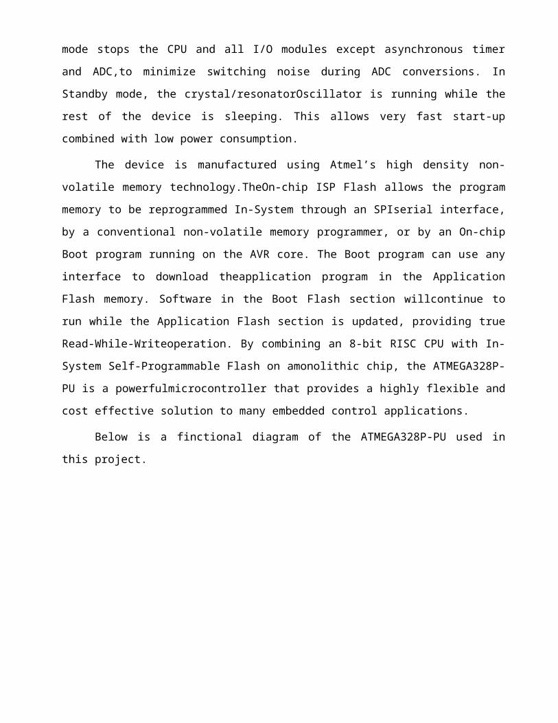
mode stops the CPU and all I/O modules except asynchronous timer
and ADC,to minimize switching noise during ADC conversions. In
Standby mode, the crystal/resonatorOscillator is running while the
rest of the device is sleeping. This allows very fast start-up
combined with low power consumption.
The device is manufactured using Atmel’s high density non-
volatile memory technology.TheOn-chip ISP Flash allows the program
memory to be reprogrammed In-System through an SPIserial interface,
by a conventional non-volatile memory programmer, or by an On-chip
Boot program running on the AVR core. The Boot program can use any
interface to download theapplication program in the Application
Flash memory. Software in the Boot Flash section willcontinue to
run while the Application Flash section is updated, providing true
Read-While-Writeoperation. By combining an 8-bit RISC CPU with In-
System Self-Programmable Flash on amonolithic chip, the ATMEGA328P-
PU is a powerfulmicrocontroller that provides a highly flexible and
cost effective solution to many embedded control applications.
Below is a finctional diagram of the ATMEGA328P-PU used in
this project.
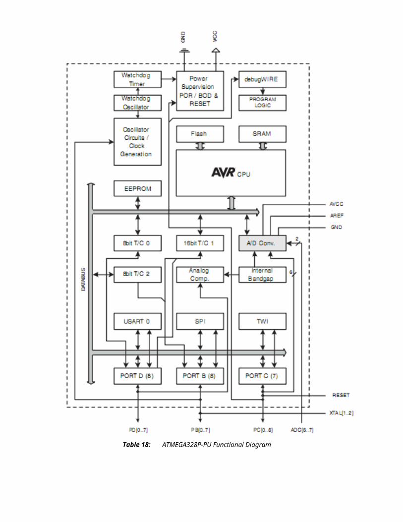
Table 18: ATMEGA328P-PU Functional Diagram
Table 19: Sequence Diagram
This is a pictorial representation of how the different users
will be interacting with the system. It is a general overview of
how each of them queries the system for a desired function
including:
i. Login to the website
ii. Logout from the website
iii. Registration of user
iv. Listing of users
v. Tracking record listing
This sequence diagram makes it easy to understand how the
website interacts between the application layer and the database.
All user interactions designed to be through presentation layer,
were information related accounts administration and tracking on
map displayed in forms of HTML web pages. The figure below shows
the interaction between application layer and database.
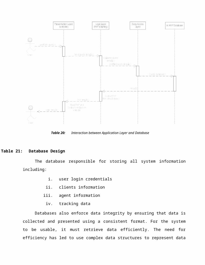
Table 20: Interaction between Application Layer and Database
Table 21: Database Design
The database responsible for storing all system information
including:
i. user login credentials
ii. clients information
iii. agent information
iv. tracking data
Databases also enforce data integrity by ensuring that data is
collected and presented using a consistent format. For the system
to be usable, it must retrieve data efficiently. The need for
efficiency has led to use complex data structures to represent data
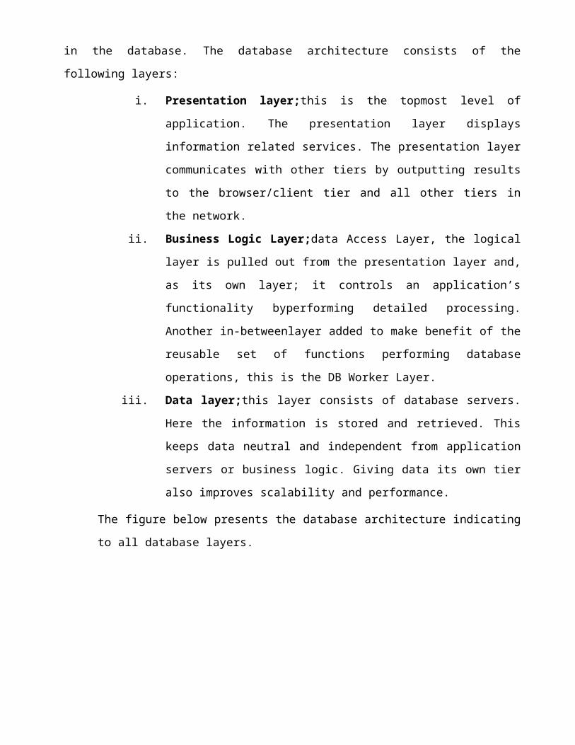
in the database. The database architecture consists of the
following layers:
i. Presentation layer;this is the topmost level of
application. The presentation layer displays
information related services. The presentation layer
communicates with other tiers by outputting results
to the browser/client tier and all other tiers in
the network.
ii. Business Logic Layer;data Access Layer, the logical
layer is pulled out from the presentation layer and,
as its own layer; it controls an application’s
functionality byperforming detailed processing.
Another in-betweenlayer added to make benefit of the
reusable set of functions performing database
operations, this is the DB Worker Layer.
iii. Data layer;this layer consists of database servers.
Here the information is stored and retrieved. This
keeps data neutral and independent from application
servers or business logic. Giving data its own tier
also improves scalability and performance.
The figure below presents the database architecture indicating
to all database layers.

Table 22: Database Architecture Layers

CHAPTER 3
Table 23: SYSTEMS DESIGN
Table 24: SIM908 Interface connection
SIM908 is the modem module of choice for this project. It’s
the latest SIMCom modem module and has a lot of in built functions
that can be advantageous in the design of a car tracker. The module
was connected as shown below and various connections done described
in detail henceforth.
Initially, the SIM908 module is initialized to start gathering
GPS data from the satellite; device initiation is done using AT
commands and includes GPS and GSM module; to turn on the GPS, first
it is powered on and put in reset mode then in the worm mode where
the module become ready for receiving coordinates from satellite.
The GPRS is next turned on; the process includes GPRS power on,
setting APN of service provider, initiating HTTP protocol, and
setting protocol method (Get method). Device initialization process
may take up to 1 minute to worm up and calculate the accurate
position. In the SIM908 module initialization process, the process
starts with powering the module and setting the reset mode, the
wormto the provider. In case of network un-availability,
theacquisitioned GPS coordinates and other data such as timeand
speed are stored temporarily until the network returnsback to
service then the stored coordinates are sent withtheir time stamp
and speed.

Table 25: SIM908 Circuit connection diagram
Table 26: Power Supply Design
The power range of SIM908 is from 3.2V to 4.8V. The
transmitting burst will cause voltage drop and the power supply
must be able to provide sufficient current up to 2A. For the DC car
power input, a bypass capacitor of 100µF was used and placed as
close as possible to SIM908 DC input pins.
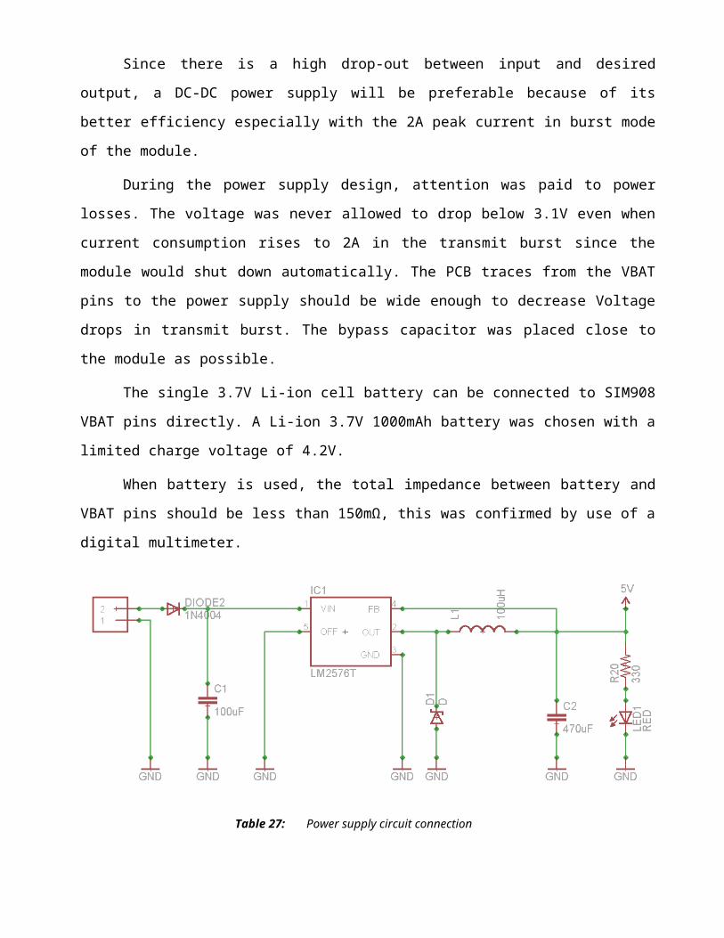
Since there is a high drop-out between input and desired
output, a DC-DC power supply will be preferable because of its
better efficiency especially with the 2A peak current in burst mode
of the module.
During the power supply design, attention was paid to power
losses. The voltage was never allowed to drop below 3.1V even when
current consumption rises to 2A in the transmit burst since the
module would shut down automatically. The PCB traces from the VBAT
pins to the power supply should be wide enough to decrease Voltage
drops in transmit burst. The bypass capacitor was placed close to
the module as possible.
The single 3.7V Li-ion cell battery can be connected to SIM908
VBAT pins directly. A Li-ion 3.7V 1000mAh battery was chosen with a
limited charge voltage of 4.2V.
When battery is used, the total impedance between battery and
VBAT pins should be less than 150mΩ, this was confirmed by use of a
digital multimeter.
Table 27: Power supply circuit connection

Table 28: Power on/off SIM908
When powering on SIM908 we pull down the PWRKEY pin for at
least 1 second and release. This pin is already pulled up to 3V in
the module internal, so there was no need to have an external pull
up.
The power on scenarios is illustrated as in the figure below:
Table 29: Power on scenario timing diagram
When power on procedure is completed, SIM908 will send RDY
(ready) command to indicate that the module is ready to operate at
a fixed baud rate but since we are not using a screen, we will use
the status and netlight indicator. In this mode during normal
operation, all operations and AT commands are available.
The SIM908 will automatically turn on when the car battery is
connected to the switched off SIM908 of which VBAT pin voltage is
greater than 3.2V. SIM908 will go into the charge –only mode. In
this mode, the module does not register to the network, and has a
few AT commands available.
When the module is powered on using the VCHG signal, SIM908
status pin LED continuously lights red. This only occurs when the

car battery is discharged or doesn’t supply enough voltage to power
on the module.

SIM908 will be powered down in the following situations:
i. Normal power down procedure using PWRKEY pin.
ii. Normal power down using AT command “AT+CPOWD=1”.
iii. Abnormal power down during under/over voltages
automatic power down.
iv. Abnormal power down during over/under temperature
automatic power down.
When powering down SIM908, we pull down the PWRKEY pin for at
least 1 second and release. The power down scenario is illustrated
in the following figure:
Table 30: Power down scenario timing diagram
This procedure makes the module log off from the network and
allows the software to enter into a secure state to save data
before shut down. At this moment, AT commands cannot be executed
any more. Power down mode will therefore be indicated by STATUS
pin, which is at low level at this time.
The following is the power on key circuit:

Table 31: Power Key input circuit connection to SIM908
Table 32: Charging Interface
SIM908 has integrated a charging circuit inside the module for
Li-ion batteries charging control, which makes it very convenient
for battery charging support.
SIM908 has optimized the charging algorithm for the Li0Ion
battery that meets the following characteristics listed below:
i. The maximum voltage of the Li-Ion battery pack is 4.2V
and the recommended capacity is 1100mAh if exceeded the
battery pack will take longer to charge.
ii. The battery pack should have a protection circuit to
avoid overcharging,deep discharging and over current, and
the circuit should be insensitive to pulsed current.
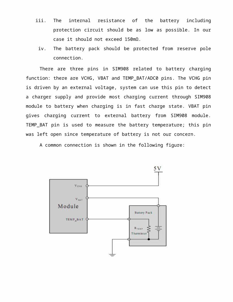
iii. The internal resistance of the battery including
protection circuit should be as low as possible. In our
case it should not exceed 150mΩ.
iv. The battery pack should be protected from reserve pole
connection.
There are three pins in SIM908 related to battery charging
function: there are VCHG, VBAT and TEMP_BAT/ADC0 pins. The VCHG pin
is driven by an external voltage, system can use this pin to detect
a charger supply and provide most charging current through SIM908
module to battery when charging is in fast charge state. VBAT pin
gives charging current to external battery from SIM908 module.
TEMP_BAT pin is used to measure the battery temperature; this pin
was left open since temperature of battery is not our concern.
A common connection is shown in the following figure:

Table 33: Charging module circuit

Table 34: SIM card Interface
The SIM interface complies with the GSM specifications (phase
1 and phase 2). The SIM interface is powered from an internal
regulator in the module. There is no need of a pull up resistor on
the SIM_DATA line is already added in the modules internal design.
The following table shows pin connections of SIM card interface.
Table 35: SIMcard pin connections
Pin Name Signal Description
C1 SIM-VDD SIM card power supply
C2 SIM-RST SIM card reset
C3 SIM-CLK SIM card clock
C4 SIM-DATA SIM card data I/O
C5 VPP Not connected
C6 GND Connect to ground(GND)
The following is a circuit design for the SIM card interface:

Table 36: Simcard circuit connection diagram
3.4 ATMEGA328P-PU interface connection
A supply voltage of 5V was supplied to the microcontroller as
per design specification to the three power pins VCC, AVCC, and
AREF from the power supply circuit. VCC is the digital supply
voltage, AVCC is the supply voltage pin for the A/D converter,
PC3:0 and ADC7:6. It is connected to the VCC externally regardless
of whether the pins are used or not. The AREF is the analog
reference pin for the A/D converter.
Port B is an 8-bit bidirectional I/O port with internal pull
up resistors. They can therefore be used as both inputs and
outputs. For this reason they are used to program the ATMEGA328P-PU
using pins PB3, PB4 and PB5 as MOSI, MISO and SCK respectively.
Port C6/RESET is used as an I/O pin. In our case PC6 was used
as a reset input. A low level on this pin for longer than the
minimum pulse length will generate a reset even if the clock is not
running. We need to use an external 10KΩ pull-up resistor to the
reset pin.
Port D is an 8-bit bidirectional I/O port with internal pull
up resistors, this is the reason pins PD0 and PD1 were used as
transmission and reception pins. The port D output buffers have
symmetrical drive characteristics with both high sink and source
capability, this is the reason why port PD5 was used to power the
SIM908 module. As inputs, Port D pins that are externally pulled
low will source current if the pull-up resistors are activated. The
port D pins are tri-stated when a reset condition becomes active,
even if the clock is not running.
All ground connections are shorted and connected to GND.

To be able to program the microcontroller, a six pin AVR_SPI
connector was integrated in the design circuit of the tracker and
was connected as shown on the diagram.

Table 37: ATMEGA328P-PU circuit connection diagram

Table 38: AVR SPI 6 pin connection diagram
Table 39: GPIO Selection
Table 40: NETLIGHT Circuit
This is a net status indicator. It can drive a transistor to
control a LED which will blink slowly or quickly according to
different states. The module cannot drive the LED directly on its
own hence the need of the transistor.
NETLIGHT has a dedicated pin in the SIM908. The circuit below
is the circuit responsible for netlight in the design.

Table 41: Netlight circuit connection diagram
Table 42: STATUS Circuit
This pin is used to monitor the module status during the power
on/off process. After power up, AT commands will not respond till
the status pin change to high and change to low after the module is
logged off from the base station in the power down procedure.
STATUS pin has a dedicated pin in SIM908 and was connected to GPIO
of the MCU.
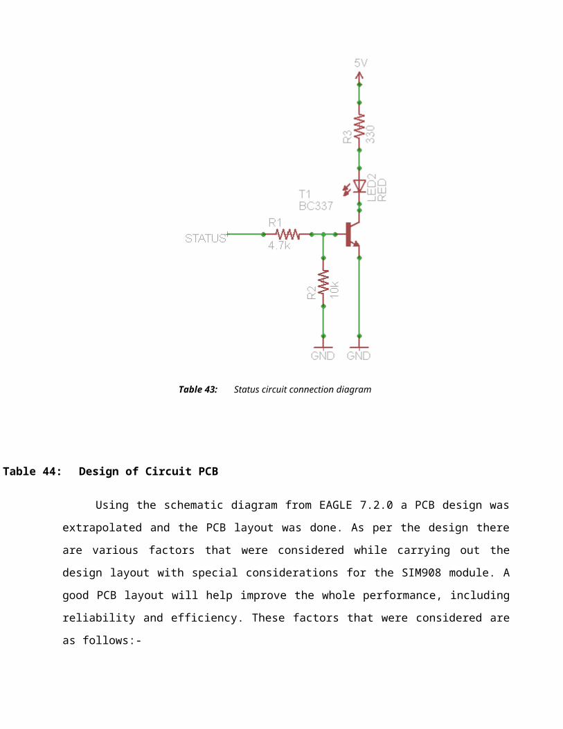
Table 43: Status circuit connection diagram
Table 44: Design of Circuit PCB
Using the schematic diagram from EAGLE 7.2.0 a PCB design was
extrapolated and the PCB layout was done. As per the design there
are various factors that were considered while carrying out the
design layout with special considerations for the SIM908 module. A
good PCB layout will help improve the whole performance, including
reliability and efficiency. These factors that were considered are
as follows:-
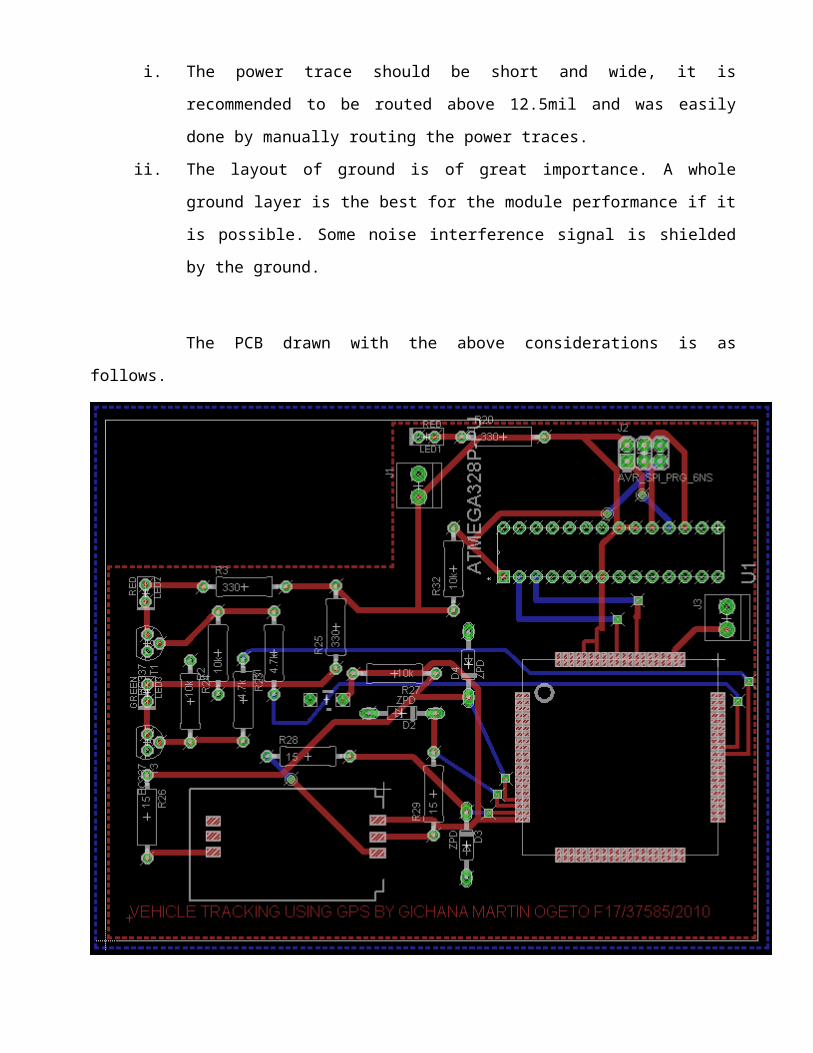
i. The power trace should be short and wide, it is
recommended to be routed above 12.5mil and was easily
done by manually routing the power traces.
ii. The layout of ground is of great importance. A whole
ground layer is the best for the module performance if it
is possible. Some noise interference signal is shielded
by the ground.
The PCB drawn with the above considerations is as
follows.

Table 45: PCB design layout of vehicle tracker using GPS

CHAPTER 4Table 46: IMPLEMENTATION AND TESTING
4.1 SCHEDULING OF THE WHOLE PROJECT
The project had various tasks that were carried from
commencement to completion. A Gantt chart was developed to
keep track of project progress. Project tasks were listed
against their estimated start and completion times to
accurately complete the project within the estimated time.
However there were delays in the implementation of the project
due to the fact that SIM908 was not readily available in the
local market and had to be imported which took a long time
almost a month. The Gantt chart used was as below:

54


4.2 SOFTWARE IMPLEMENTATION
The software design was implemented first from the
application layer. The design of the homepage was simple and
could easily be understood and used by most users. It had few
links to navigate through the website. My home page interface was
implemented as follows:
Table 47: Home page of the website
The client will login and the interface below will appear as the
figure shown below. It will contain all the parameters captured
by SIM908 GPS module. This parameters include speed, time and
date, course, longitude and latitude that are displayed using the
google embedded maps which was optimized to be 1000px by 500px in
dimension.
58

Table 48: Client login index page
After completion of the interface implementation, PHP scripts
were programmed to do all the form handling that are done with the
administrator and the agent. The scripts also were used to handle
POST and GET functions to and from the database.
The admin interface is as shown below:

Table 49: Admin index page
Table 50: Admin page listing enrolled agents

Alongside programming the interface design on my computers
localhost, I also programmed my database phpMyAdmin and created
four tables as shown below:
Table 51: Megawcoc_cartracker database with admin login details table

Table 52: Megawcoc_cartracker database with agent details table
Table 53: Megawcoc_cartracker database with client details table
4.3 HARDWARE IMPLEMENTATION
Hardware implementation started with developing the board. Thefollowing procedure was followed to develop the board and latercomponents mounted on the board.
i. Circuit was prepared and printed on a transparent film layoutpaper.
ii. The board was cut to the desired size and the black protectionfilm was pilled of and the board exposed in the KinstenExposure box on both sides for 60seconds
iii. In the process of developing, one litre of sodium hydroxidewas poured into a tray and the exposed board suspended in thedeveloper. The board was agitated until the artwork was clear.The board was then rinsed with running water to completelywash away the developer.
iv. The parts that were not clearly visible were enhanced using apermanent mark pen.

v. The board was then immersedfor eight minutes in Kinstenetching tank that had been turned on for 30 minutes to warmthe ferric chloride to a temperature of about (50-60C).
vi. The board was then removed and rinsed for 15minutes.vii. Appropriate holes were drilled to complete the design of the
PCB ready for mounting.viii. Components were then mounted on the PCB and the circuit was
ready.
Table 54: The front side of PCB design

Table 55: The backside of the PCB design

CHAPTER 5
Table 56: CONCLUSIONS AND RECOMMENDATIONS
5.1 Conclusion
The main objective of the project was to develop a GPS
tracking system that uploads a set of given parameters to a
database server through a GGSN network to a website where it can be
viewed remotely. The expected results were obtained as it can be
evident as analysed as in CHAPTER 4 above.
5.2 Recommendation for future work
The recommendations for future work are as follows:
i. Investigate how to protect the data collected on the website
by making sure users only get to access only those devices
that they are authorized to. Generally increased security to
protect Vehicle tracker identity.
ii. To develop a mobile application for the different types of
mobile Operating Systems rather than just using a desktop
application.
iii. Developing a means to show track record of where the vehicle
has been rather than just the position it is located.

APPENDIX
APPENDIX A: Program Code
There are two distinct important programs that are responsible for the
functionality of the system, these are:
i. The web server program which handles the recording and displaying
of the data posted by the GPS module via GGSN network. The web
server program is divided into various parts but will only list
the most important parts, namely:
a) Index.html that handles the client user interface.
b) The config.php and auth.php both of which handles
establishment and authentication of HTTP connection
between the module and the server.
c) gpsinsert.php which handles the entry of the data
posted by the GPS module to the megawcoc_cartracker
database in the tracklog table.
d) client_index.php that contains the google embedded
maps that shows the map and given parameters to the
client.
ii. The microcontroller program that controls the GPS module to get a fix, send the fix
through GGSN network to the webserver(database and
client_index.php)
Table 57: Index.html
//homepage
<html>
<head>
i

<meta http-equiv="Content-Type" content="text/html; charset=utf-
8" />
<title>CarTracker Home</title>
<meta name="keywords" content="Megawco tracking system" />
<meta name="description" content="Megawatt company is a new entrant
in the tracking business, it is well equipped with cutting edge
technology to suit your needs." />
<meta name="keywords" content="Admin" />
<meta name="description" content="Admin should log in here!!!" />
<meta name="keywords" content="Agent" />
<meta name="description" content="Agent should log in here!!!" />
<link href="stylesheet.css" rel="stylesheet" type="text/css" />
<link href="s3slider.css" rel="stylesheet" type="text/css" />
<!-- JavaScripts-->
<script type="text/javascript" src="js/jquery.js"></script>
<script type="text/javascript" src="js/s3Slider.js"></script>
<script type="text/javascript">
$(document).ready(function()
$('#slider').s3Slider(
timeOut: 1600
);
);
</script>
</head>
<body>

<div id="templatemo_wrapper">
<div id="templatemo_menu">
<ul>
<li><a href="index.html" class="current">Home</a></li>
<li><a href="portfolio.html">Gallery</a></li>
<li><a href="about.html">About Us</a></li>
<li><a href="contact.html">Contact</a></li>
</ul>
</div><!-- end of templatemo_menu -->
<div id="templatemo_left_column">
<div id="templatemo_header">
<div id="site_title">
<h1><a href="#index.html"
target="_parent">Car<strong>Tracker</strong><span>Always on the
look out!!</span></a></h1>
</div><!-- end of site_title -->
</div><!-- end of header -->
<div id="templatemo_sidebar">
<div id="templatemo_rss">
<a
href="http://www.ti.com/lsds/ti/microcontrollers_16-bit_32-bit/over
view.page">SUBSCRIBE NOW <br /><span>to our rss feed</span></a>
</div>
<h4>Client Login</h4>

<form id="loginForm" name="loginForm" method="post" action="client-
exec.php">
<table width="250" border="0" align="center" cellpadding="2"
cellspacing="0">
<tr>
<td width="112"><b>Username</b></td>
<td width="188"><input name="uname" type="text" class="textfield"
id="uname" /></td>
</tr>
<tr>
<td><b>Password</b></td>
<td><input name="password" type="password" class="textfield"
id="password" /></td>
</tr>
<tr>
<td> </td>
<td><input type="submit" name="Submit" value="Login" /></td>
</tr>
</table>
</form>
<div class="cleaner_h40"></div>
<h4>Adminstrator Login</h4>
<ul class="templatemo_list">
<li><a href="ADMIN/index.php" target="_parent">Adminstrator
Login</a></li>

<li><a href="AGENT/index.php" target="_parent">Agent Login</a></li>
</ul>
</div><!-- end of templatemo_sidebar -->
</div><!-- end of templatemo_left_column -->
<div id="templatemo_right_column">
<div id="featured_project">
<div id="slider">
<ul id="sliderContent">
<li class="sliderImage">
<a href=""><img src="images/slider/1.jpg" alt="1" /></a>
<span class="top"><strong>THE GLOBE</strong><br />GPRS has made the
whole to fit on your hand.</span>
</li>
<li class="sliderImage">
<a href=""><img src="images/slider/2.jpg" alt="2" /></a>
<span class="bottom"><strong>VIEW POINT</strong><br />The ability
to connect and view the whole world from the comfort of your
home.</span>
</li>
<li class="sliderImage">
<img src="images/slider/3.jpg" alt="3" />
<span class="left"><strong>NETWORKING</strong><br />Different GSM
network providers all link up all over the world by
Satellites.</span>
</li>

<li class="sliderImage">
<img src="images/slider/4.jpg" alt="4" />
<span class="right"><strong>SATELLITES</strong><br />The world has
been put under a microscope with the onset of satellites.</span>
</li>
<li class="clear sliderImage"></li>
</ul>
</div>
</div>
<div id="templatemo_main">
<p>The GPS-GPRS based vehicle tracking system is one that makes
use of the Global Positioning System (GPS) to determine the
precise location of a vehicle to which it is attached. I therefore
sought to design a cost effective web-based GPS-GPRS vehicle
tracking system that enables owners to view the present and past
positions recorded of the target vehicle on Google Map through a
purpose designed website. With the rapidly increase in number of
vehicles in Kenya, there is an increase need of tracking your
vehicle or fleet of vehicles due to the following reasons:</p>
<ol>
<li>Increase in carjacking incidences that are unresolved by the
police</li>
<li>Increase in unrecovered stolen motor vehicles </li>
<li>To know exactly where all your vehicles are and of what use
they are being used for. It will tell you what time your driver

started, how long is being spent on breaks or whether the vehicle
is being used to pursue non-work related activities.</li>
<li>Can be used to settle false claim or complaints against the
company that may arise hence prove indubitably where the vehicle
was at the time of the alleged and thus demonstrate that the claim
is bogus.</li>
</ol>
<p> A GPS-GPRS based tracking system gives all the
specifications about the location of a vehicle. The system
utilizes geographic position and time information from the Global
Positioning Satellites. In order to track the movement of the
vehicle Google Maps used for mapping the location. The GSM modem
fetches the GPS location and sends it to the server using GPRS.
<br />
The integration of GPS and GSM was first established
using SMS as a method of transmitting GPS coordinates. The
inclusion of GPRS technology to transmit location coordinates to a
remote server facilitates the tracking of object remotely using
any computer connected to the web. </p>
</div>
<div class="cleaner"></div>
</div>
<!-- end of templatemo_main -->
<div class="cleaner_h20"></div>
<div id="templatemo_footer">

Copyright © 2015 <a
href="http://www.uonbi.ac.ke">UNIVERSITY OF NAIROBI </a> |
<a href="#" target="_parent">Vehicle Tracking Device </a> by <a
href="https://www.facebook.com/gichana02" target="_parent">Gichana
Martin(F17/37585/2010) </a>
</div>
<div class="cleaner"></div>
</div><!-- end of warpper -->
</body>
</html>
Table 58: config.php
<?php
define('DB_HOST', 'localhost');
define('DB_USER', 'megawcoc_client');
define('DB_PASSWORD', 'GKFyn%^c0_GN');
define('DB_DATABASE', 'megawcoc_cartracker');
?>
Table 59: auth.php
<?php
//Start session
session_start();
//Check whether the session variable SESS_CLIENT_ID is present
or not

if(!isset($_SESSION['SESS_CLIENT_ID']) ||
(trim($_SESSION['SESS_CLIENT_ID']) == ''))
header("location: access-denied.php");
exit();
?>
Table 60: client_index.php<?php
if (!empty($_GET['latitude']) && !empty($_GET['longitude']) && !empty($_GET['time']) && !empty($_GET['satellites']) && !empty($_GET['speedOTG']) && !empty($_GET['course']))
function getParameter($par, $default = null) if (isset($_GET[$par]) && strlen($_GET[$par])) return$_GET[$par]; elseif (isset($_POST[$par]) && strlen($_POST[$par])) return $_POST[$par]; else return $default;
//$file = 'gps.txt'; $lat = getParameter("latitude"); $lon = getParameter("longitude"); $time = getParameter("time"); $sat = getParameter("satellites"); $speed = getParameter("speedOTG"); $course = getParameter("course"); $person = $lat.",".$lon.",".$time.",".$sat.",".$speed.",".$course."\n";
echo " DATA:\n Latitude: ".$lat."\n

Longitude: ".$lon."\n Time: ".$time."\n Satellites: ".$sat."\n Speed OTG: ".$speed."\n Course: ".$course;
if (!file_put_contents($file, $person, FILE_APPEND | LOCK_EX)) echo "\n\t Error saving Data\n"; else echo "\n\t Data Save\n"; else
?><head><meta http-equiv="Content-Type" content="text/html; charset=iso-8859-1" /><title>Client Index</title><link href="loginmodule.css" rel="stylesheet" type="text/css" /><scriptsrc="//ajax.googleapis.com/ajax/libs/jquery/2.1.1/jquery.min.js"></script><!-- Load Jquery -->
<script language="JavaScript" type="text/javascript" src="jquery-1.10.1.min.js"></script>
<!-- Load Google Maps Api -->
<!-- IMPORTANT: change the API v3 key -->
<script src="http://maps.googleapis.com/maps/api/js?key=AIzaSyChCCC5_hDzQbonSDvSngtZPQZd5YuMdvA&sensor=false"></script><!--AIzaSyChCCC5_hDzQbonSDvSngtZPQZd5YuMdvA-->
<!-- Initialize Map and markers -->
<script type="text/javascript"> var myCenter=new google.maps.LatLng(-1.29206586 ,36.82194647);
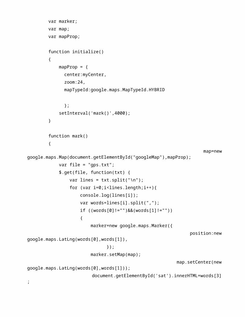
var marker; var map; var mapProp;
function initialize() mapProp = center:myCenter, zoom:24, mapTypeId:google.maps.MapTypeId.HYBRID
; setInterval('mark()',4000);
function mark() map=newgoogle.maps.Map(document.getElementById("googleMap"),mapProp); var file = "gps.txt"; $.get(file, function(txt) var lines = txt.split("\n"); for (var i=0;i<lines.length;i++) console.log(lines[i]); var words=lines[i].split(","); if ((words[0]!="")&&(words[1]!="")) marker=new google.maps.Marker( position:newgoogle.maps.LatLng(words[0],words[1]), ); marker.setMap(map); map.setCenter(newgoogle.maps.LatLng(words[0],words[1])); document.getElementById('sat').innerHTML=words[3];

document.getElementById('speed').innerHTML=words[4]; document.getElementById('course').innerHTML=words[5]; marker.setAnimation(google.maps.Animation.BOUNCE); );
google.maps.event.addDomListener(window, 'load', initialize);</script></head><body><h1>Welcome <?php echo $_SESSION['SESS_TITLE_ID'];?><?php echo$_SESSION['SESS_FIRST_NAME'];?></h1><a href="member-profile.php">My Profile</a> | <ahref="logout.php">Logout</a><?php echo '
<!-- Draw information table and Google Maps div -->
<div><center><br /><b> CAR TRACKER </b><br /><br /><div id="superior" style="width:1000px;border:1px solid;color:purple"><table style="width:100%"><tr><td>Time</td><td>Satellites</td><td>Speed OTG</td><td>Course</td></tr><tr><td id="time">'. date("Y M d - H:m") .'</td>

<td id="sat"></td><td id="speed"></td><td id="course"></td></tr></table></div><br /><br /><div id="googleMap" style="width:1000px;height:500px;"></div></center>
</div>'; ?></body>//<scriptsrc="//ajax.googleapis.com/ajax/libs/jquery/2.1.1/jquery.min.js"></script></html><?php ?>
Table 61: ATMEGA328P_P
int8_t answer;
int onModulePin= 2;
char data[100];
int data_size;
char aux_str[30];
char aux;
int x = 0;
char N_S,W_E;
char url[] = "www.megawco.com";
char frame[200];
char latitude[15];
char longitude[15];

char altitude[6];
char date[16];
char time[7];
char satellites[3];
char speedOTG[10];
char course[10];
void setup()
pinMode(onModulePin, OUTPUT);
Serial.begin(115200);
Serial.println("Starting...");
power_on();
delay(3000);
// sets the PIN code
sendATcommand("AT+CPIN=****", "OK", 2000);
delay(3000);
// starts the GPS and waits for signal
while ( start_GPS() == 0);
while (sendATcommand("AT+CREG?", "+CREG: 0,1", 2000) == 0);
// sets APN , user name and password
sendATcommand("AT+SAPBR=3,1,\"Contype\",\"GPRS\"", "OK", 2000);
sendATcommand("AT+SAPBR=3,1,\"APN\",\"apn\"", "OK", 2000);
sendATcommand("AT+SAPBR=3,1,\"USER\",\"user_name\"", "OK", 2000);
sendATcommand("AT+SAPBR=3,1,\"PWD\",\"password\"", "OK", 2000);
// gets the GPRS bearer
while (sendATcommand("AT+SAPBR=1,1", "OK", 20000) == 0)
delay(5000);

void loop()
// gets GPS data
get_GPS();
// sends GPS data to the script
send_HTTP();
delay(5000);
void power_on()
uint8_t answer=0;
// checks if the module is started
answer = sendATcommand("AT", "OK", 2000);
if (answer == 0)
// power on pulse
digitalWrite(onModulePin,HIGH);
delay(3000);
digitalWrite(onModulePin,LOW);
// waits for an answer from the module
while(answer == 0)
// Send AT every two seconds and wait for the answer
answer = sendATcommand("AT", "OK", 2000);

int8_t start_GPS()
unsigned long previous;
previous = millis();
// starts the GPS
sendATcommand("AT+CGPSPWR=1", "OK", 2000);
sendATcommand("AT+CGPSRST=0", "OK", 2000);
// waits for fix GPS
while(( (sendATcommand("AT+CGPSSTATUS?", "2D Fix", 5000) ||
sendATcommand("AT+CGPSSTATUS?", "3D Fix", 5000)) == 0 ) &&
((millis() - previous) < 90000));
if ((millis() - previous) < 90000)
return 1;
else
return 0;
int8_t get_GPS()
int8_t counter, answer;
long previous;
// First get the NMEA string
// Clean the input buffer
while( Serial.available() > 0) Serial.read();
// request Basic string

sendATcommand("AT+CGPSINF=0", "AT+CGPSINF=0\r\n\r\n", 2000);
counter = 0;
answer = 0;
memset(frame, '\0', 100); // Initialize the string
previous = millis();
// this loop waits for the NMEA string
do
if(Serial.available() != 0)
frame[counter] = Serial.read();
counter++;
// check if the desired answer is in the response of the module
if (strstr(frame, "OK") != NULL)
answer = 1;
// Waits for the asnwer with time out
while((answer == 0) && ((millis() - previous) < 2000));
frame[counter-3] = '\0';
// Parses the string
strtok(frame, ",");
strcpy(longitude,strtok(NULL, ",")); // Gets longitude
strcpy(latitude,strtok(NULL, ",")); // Gets latitude
strcpy(altitude,strtok(NULL, ".")); // Gets altitude
strtok(NULL, ",");

strcpy(date,strtok(NULL, ".")); // Gets date
strtok(NULL, ",");
strtok(NULL, ",");
strcpy(satellites,strtok(NULL, ",")); // Gets satellites
strcpy(speedOTG,strtok(NULL, ",")); // Gets speed over ground. Unit is knots.
strcpy(course,strtok(NULL, "\r")); // Gets course
convert2Degrees(latitude);
convert2Degrees(longitude);
return answer;
/* convert2Degrees ( input ) - performs the conversion from input
* parameters in DD°MM.mmm’ notation to DD.dddddd° notation.
* Sign '+' is set for positive latitudes/longitudes (North, East)
* Sign '-' is set for negative latitudes/longitudes (South, West)
*
*/
int8_t convert2Degrees(char* input)
float deg;
float minutes;
boolean neg = false;
//auxiliar variable
char aux[10];
if (input[0] == '-')
neg = true;
strcpy(aux, strtok(input+1, "."));

else
strcpy(aux, strtok(input, "."));
// convert string to integer and add it to final float variable
deg = atof(aux);
strcpy(aux, strtok(NULL, '\0'));
minutes=atof(aux);
minutes/=1000000;
if (deg < 100)
minutes += deg;
deg = 0;
else
minutes += int(deg) % 100;
deg = int(deg) / 100;
// add minutes to degrees
deg=deg+minutes/60;
if (neg == true)
deg*=-1.0;
neg = false;

if( deg < 0 )
neg = true;
deg*=-1;
float numeroFloat=deg;
int parteEntera[10];
int cifra;
long numero=(long)numeroFloat;
int size=0;
while(1)
size=size+1;
cifra=numero%10;
numero=numero/10;
parteEntera[size-1]=cifra;
if (numero==0)
break;
int indice=0;
if( neg )
indice++;
input[0]='-';
for (int i=size-1; i >= 0; i--)
input[indice]=parteEntera[i]+'0';

indice++;
input[indice]='.';
indice++;
numeroFloat=(numeroFloat-(int)numeroFloat);
for (int i=1; i<=6 ; i++)
numeroFloat=numeroFloat*10;
cifra= (long)numeroFloat;
numeroFloat=numeroFloat-cifra;
input[indice]=char(cifra)+48;
indice++;
input[indice]='\0';
void send_HTTP()
// Initializes HTTP service
answer = sendATcommand("AT+HTTPINIT", "OK", 10000);
if (answer == 1)
// Sets CID parameter
answer = sendATcommand("AT+HTTPPARA=\"CID\",1", "OK", 5000);
if (answer == 1)
// Sets url
sprintf(aux_str, "AT+HTTPPARA=\"URL\",\"http://%s/demo_sim908.php?", url);
Serial.print(aux_str);
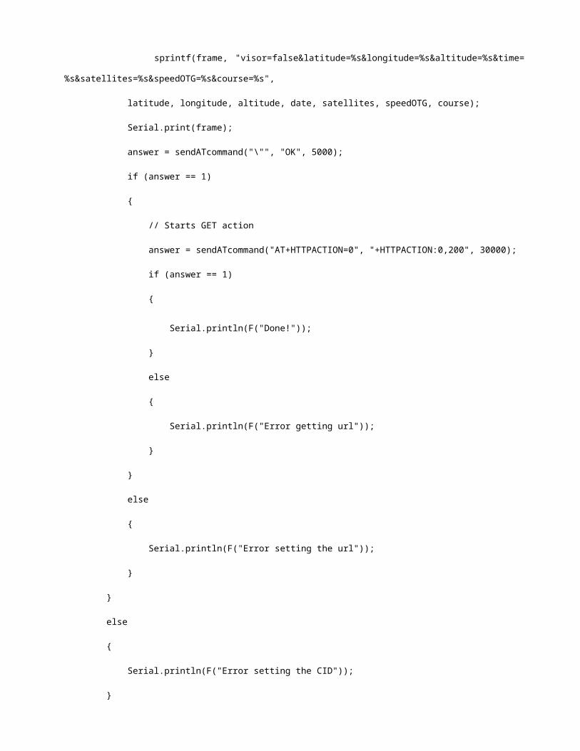
sprintf(frame, "visor=false&latitude=%s&longitude=%s&altitude=%s&time=
%s&satellites=%s&speedOTG=%s&course=%s",
latitude, longitude, altitude, date, satellites, speedOTG, course);
Serial.print(frame);
answer = sendATcommand("\"", "OK", 5000);
if (answer == 1)
// Starts GET action
answer = sendATcommand("AT+HTTPACTION=0", "+HTTPACTION:0,200", 30000);
if (answer == 1)
Serial.println(F("Done!"));
else
Serial.println(F("Error getting url"));
else
Serial.println(F("Error setting the url"));
else
Serial.println(F("Error setting the CID"));

else
Serial.println(F("Error initializating"));
sendATcommand("AT+HTTPTERM", "OK", 5000);
int8_t sendATcommand(char* ATcommand, char* expected_answer1, unsigned int timeout)
uint8_t x=0, answer=0;
char response[100];
unsigned long previous;
memset(response, '\0', 100); // Initialize the string
delay(100);
while( Serial.available() > 0) Serial.read(); // Clean the input buffer
Serial.println(ATcommand); // Send the AT command
x = 0;
previous = millis();
// this loop waits for the answer
do
if(Serial.available() != 0)
response[x] = Serial.read();
x++;
// check if the desired answer is in the response of the module
if (strstr(response, expected_answer1) != NULL)
answer = 1;

// Waits for the asnwer with time out
while((answer == 0) && ((millis() - previous) < timeout));
return answer;
REFERENCES
[1] SIM908 AT Command Manual_Version 1.01 by SIMCom Tech
company, China, 2011
[2] SIM908 Hardware Design Manual_V2.00 by SIMCom Tech
company, China, 2013
[3] SIM908 Reference Design Guide_Application Note_Version
1.00 by SIMCom Tech company, China, 2011-08-10
[4] www.ijcset.net - WEB BASED VEHICLE TRACKING SYSTEM by
Khalifa A. Salim et al | IJCSET | December 2013 | Vol 3, Issue
12, 443-448 | ISSN: 2231-0711 443IV.