
UNIT 1: AKTU Last Five Year Solutions [Computer Networks
99
1 UNIT 1: AKTU Last Five Year Solutions [Computer Networks: RCS-601] 1. What are the number of cable links required for n devices connected in mesh, ring, bus and star topology? [2014-15] Ans: The number of cables for each type of network is: a. Mesh: n (n – 1) / 2 b. Star: n c. Ring: n – 1 d. Bus: one backbone and n drop lines 2. Differentiate between bit rate and baud rate. State two reason for using layered protocols. [2014-15] Ans: Bit rate and Baud rate, these two terms are often used in data communication. Bit rate is simply the number of bits (i.e., 0's and 1's) transmitted in per unit time. While Baud rate is the number of signal units transmitted per unit time that is needed to represent those bits. There are two main reasons for using the layered protocols and these are: 1. Specialization and 2. Abstraction - A neutral standard is created by a protocol which can be used by the rival companies for creating programs that are compatible. - So many protocols are required in the field and that should also be organized properly and these protocols have to be directed to the specialists that can work up on these protocols. - A network program can be created using the layered protocols by a software house if the guidelines of one layer are known. - The services of the lower level protocols can be provided by the companies. - This helps them to specialize. - In abstraction, it is assumed that another protocol will provide the lower services. - A conceptual framework is provided by the layered protocol architecture that divides the complex task of information exchange into much simpler tasks between the hosts. - The responsibility for each of the protocols is narrowly defined. - A protocol provides an interface for the successive higher layer protocol. - As a result of this, it goes in to hiding the details of the higher protocol layers that underlies. - The advantage of using the layered protocols is that the same application i.e., the user level program can be used by a number of diverse communication networks. - For example, when you are connected to a dial up line or internet via LAN you can use the same browser. - For simplifying the networking designs, one of the most common techniques used is the pro- tocol layering. - The networking designs are divided in to various functional layers and the protocols are assigned for carrying out the tasks of each layer. - It is quite common to keep the functions of the data delivery separate from each other and separate layers for the connection management too. - Therefore, we have one protocol for performing the data delivery tasks and second one for performing connection management. - The second one is layered up on the first one. - Since the connection management protocol is not concerned with the data delivery, it is also quite simple. - The OSI seven layer model and the DoD model are one of the most important layered protocols ever designed. - A fusion of both the models is represented by the modern internet.
-
Upload
khangminh22 -
Category
Documents
-
view
2 -
download
0
Transcript of UNIT 1: AKTU Last Five Year Solutions [Computer Networks
1
UNIT 1: AKTU Last Five Year Solutions [Computer Networks: RCS-601]
1. What are the number of cable links required for n devices connected in mesh, ring, bus and star topology? [2014-15]
Ans: The number of cables for each type of network is: a. Mesh: n (n – 1) / 2 b. Star: n c. Ring: n – 1 d. Bus: one backbone and n drop lines
2. Differentiate between bit rate and baud rate. State two reason for using layered protocols.
[2014-15] Ans: Bit rate and Baud rate, these two terms are often used in data communication. Bit rate is
simply the number of bits (i.e., 0's and 1's) transmitted in per unit time. While Baud rate is the number of signal units transmitted per unit time that is needed to represent those bits. There are two main reasons for using the layered protocols and these are:
1. Specialization and 2. Abstraction - A neutral standard is created by a protocol which can be used by the rival companies for creating programs that are compatible. - So many protocols are required in the field and that should also be organized properly and these protocols have to be directed to the specialists that can work up on these protocols. - A network program can be created using the layered protocols by a software house if the guidelines of one layer are known.
- The services of the lower level protocols can be provided by the companies. - This helps them to specialize. - In abstraction, it is assumed that another protocol will provide the lower services. - A conceptual framework is provided by the layered protocol architecture that divides the complex task of information exchange into much simpler tasks between the hosts. - The responsibility for each of the protocols is narrowly defined. - A protocol provides an interface for the successive higher layer protocol. - As a result of this, it goes in to hiding the details of the higher protocol layers that underlies. - The advantage of using the layered protocols is that the same application i.e., the user level program can be used by a number of diverse communication networks. - For example, when you are connected to a dial up line or internet via LAN you can use the same browser. - For simplifying the networking designs, one of the most common techniques used is the pro-tocol layering. - The networking designs are divided in to various functional layers and the protocols are assigned for carrying out the tasks of each layer. - It is quite common to keep the functions of the data delivery separate from each other and separate layers for the connection management too. - Therefore, we have one protocol for performing the data delivery tasks and second one for performing connection management. - The second one is layered up on the first one. - Since the connection management protocol is not concerned with the data delivery, it is also quite simple. - The OSI seven layer model and the DoD model are one of the most important layered protocols ever designed. - A fusion of both the models is represented by the modern internet.

2
- Simple protocols are produced by the protocol layering with some well defined tasks. - These protocols then can be put together to be used as a new whole protocol. - As required for some particular applications, the individual protocols can be either replaced or removed. - Networking is such a field involving programmers, electricians, mathematicians, designers, electricians and so on. - People from these various fields have very less in common and it is because of the layering that people with such varying skills to make an assumption or feel like others are carrying out their duty. - This is what we call abstraction. - Protocols at a level can be followed by an application programmer via abstraction assuming that network exists and similarly electricians assume and do their work. - One layer can provide services to the succeeding layer and can get services in return too. - Abstraction is thus the fundamental foundation for layering. - Stack has been used for representing the networking protocols since the start of network engi-neering. - Without stack, it would be unmanageable as well as overwhelming. - Representing the layers of specialization for the first protocols derived from TCP/ IP.
3. Calculate the required bandwidth, if in a communication channel the signal power is 100 W and noise power is 10 W and the information transmission rate is 10kbps. [2014-15]
Ans:
Signal power is 100 W Noise power is 10 W Data rate of 10 kbps Bandwidth? Data rate = bandwidth * log (1 + (Signal power / Noise power)) 10 = bandwidth * log (1 + (100 / 10)) { log (1 + (100 / 10)) = 3.4594 approx. equal to 4 is taken here} 10 = bandwidth * 4 Bandwidth = 2.5 KHz
4. It is required to transmit a data at a rate of 64kbps over a 3 kHz telephone channel. What is the
minimum SNR required to accomplish this? [2014-15] Ans:
Given: Bit Rate = 64Kbps W = 3KHz C = W log2 (1 + SNR), C ≥ Cmin = 64 kbps Cmin = W log2 (1 + SNRmin) ⇒ log2 (1 + SNRmin) = ���� / � = �� / ⇒ 1 + SNRmin = 2 64K/3 ⇒ SNRmin = 2.64 x 10⁶ In dB: SNRmin = 10 log10 (2.64 x 10⁶) = 64.2 dB
3
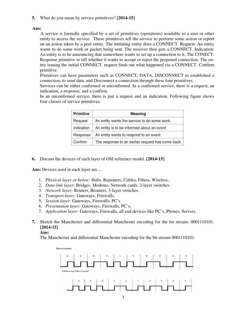
5. What do you mean by service primitives? [2014-15] Ans:
A service is formally specified by a set of primitives (operations) available to a user or other entity to access the service. These primitives tell the service to perform some action or report on an action taken by a peer entity. The initiating entity does a CONNECT. Request: An entity wants to do some work or packet being sent. The receiver then gets a CONNECT. Indication: An entity is to be announcing that somewhere wants to set up a connection to it. The CONECT. Response primitive to tell whether it wants to accept or reject the proposed connection. The en-tity issuing the initial CONNECT. request finds out what happened via a CONNECT. Confirm primitive. Primitives can have parameters such as CONNECT, DATA, DISCONNECT to established a connection, to send data, and Disconnect a connection through these four primitives. Services can be either confirmed or unconfirmed. In a confirmed service, there is a request, an indication, a response, and a confirm. In an unconfirmed service, there is just a request and an indication. Following figure shows four classes of service primitives.
6. Discuss the devices of each layer of OSI reference model. [2014-15]
Ans: Devices used in each layer are….
1. Physical layer or below: Hubs, Repeaters, Cables, Fibers, Wireless.. 2. Data-link layer: Bridges, Modems, Network cards, 2-layer switches. 3. Network layer: Routers, Brouters, 3-layer switches. 4. Transport layer: Gateways, Firewalls. 5. Session layer: Gateways, Firewalls, PC’s. 6. Presentation layer: Gateways, Firewalls, PC’s. 7. Application layer: Gateways, Firewalls, all end devices like PC’s, Phones, Servers.
7. Sketch the Manchester and differential Manchester encoding for the bit stream: 0001110101. [2014-15] Ans: The Manchester and differential Manchester encoding for the bit stream 0001110101:

8. What is the transmission time
million bytes and the bandwidthAns:
Transmission time = (packet l
= 2million bytes / 300kbps
= 2000000 bytes / 300000 bps
=6.67 s
9. What are the applications of Co
Ans:
A network is a collection or secommunication and also share hardware devices. You can havputer networks make it possiblcommunicate taking the shortesoftware applications that utilizform useful functions for exampfrom one point to another within
There are 2 types of network a
1. Pure network applications 2. Standalone network applicati
(A) Pure Network Application
These are applications created tosingle computer doesn't make senetwork. Such applications haveinstance:-
Outlook Express
Outloo
4
e of a packet sent by a station if the length ofth of the channel is 300 kbps? [2014-15]
t length)/(bandwidth)
omputer Networks? [2015-16][2017-18]
set of computing devices connected to one anore available resources. A network will comprise ave a network even if you are not connected to thible for people to transfer files from one place tortest time possible. Computer network applicatiolize the Internet or other network hardware inframple file transfers within a network. They help ushin the network.
k applications:-
ation
ons
to be used in networks; using pure network appli sense. They help us to transfer data and communive a separate and distinct user interface that users
look Express, an email program | Source
of the packet is 2
nother to establish se of software and the internet. Com- to another and to tions are network
frastructure to per- us to transfer data
plications on a nicate within a rs must learn for
5
1. Email Programs
They allow users to type messages at their local nodes and then send to someone on the net-work. It is a fast and easy way of transferring mail from one computer to another. Examples of electronic mail programs (Clients) are:-
• Pegasus Mail • Outlook express • Eudora Windows mail • Fox mail • Opera • Poco mail • Mozilla Thunderbird • Windows mail
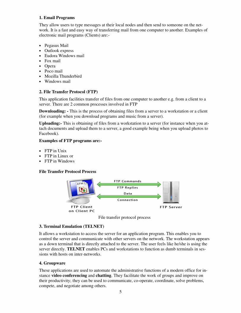
2. File Transfer Protocol (FTP)
This application facilities transfer of files from one computer to another e.g. from a client to a server. There are 2 common processes involved in FTP
Downloading: - This is the process of obtaining files from a server to a workstation or a client (for example when you download programs and music from a server).
Uploading:- This is obtaining of files from a workstation to a server (for instance when you at-tach documents and upload them to a server, a good example being when you upload photos to Facebook).
Examples of FTP programs are:-
• FTP in Unix • FTP in Linux or • FTP in Windows
File Transfer Protocol Process
File transfer protocol process
3. Terminal Emulation (TELNET)
It allows a workstation to access the server for an application program. This enables you to control the server and communicate with other servers on the network. The workstation appears as a down terminal that is directly attached to the server. The user feels like he/she is using the server directly. TELNET enables PCs and workstations to function as dumb terminals in ses-sions with hosts on inter-networks.
4. Groupware
These applications are used to automate the administrative functions of a modern office for in-stance video conferencing and chatting. They facilitate the work of groups and improve on their productivity; they can be used to communicate, co-operate, coordinate, solve problems, compete, and negotiate among others.
6
(i) Video Conferencing
This is the process of conducting a conference between two or more participants at different sites by using computer networks to transmit audio and video data. For example, a point-to-
point (two-person) video conferencing system works much like a video telephone.
Each participant has a video camera, microphone, and speakers mounted on his or her comput-er. As the two participants speak to one another, their voices are carried over the network and delivered to the others speakers, and whatever images appear in front of the video camera ap-pear in a window on the other participant’s monitor.
(ii) Chatting
It is real-time communication between two users via computer. Once a chat has been initiated, either user can enter text by typing on the keyboard and the entered text will appear on the oth-er user’s monitor. The two must be online for a chat to be initiated. Most networks, cybers and online services offer a chat feature which enables computer users to chat as they go on with their work.
(B) Stand Alone Applications
These are applications that run on stand-alone computers (computers not connected to any other). In order to extend their activity, they are rebuilt to run on network environments e.g. word processors, spreadsheets, database management systems, presentations graphics, project management etc. They function even when the computer is offline.
10. What is OSI model? Explain the functions and protocols and services of each layer. [2015-16]
[2017-18] [2018-19] or
Explain functionalities of every layer in OSI model with neat block diagram. [2016-17]
Ans:
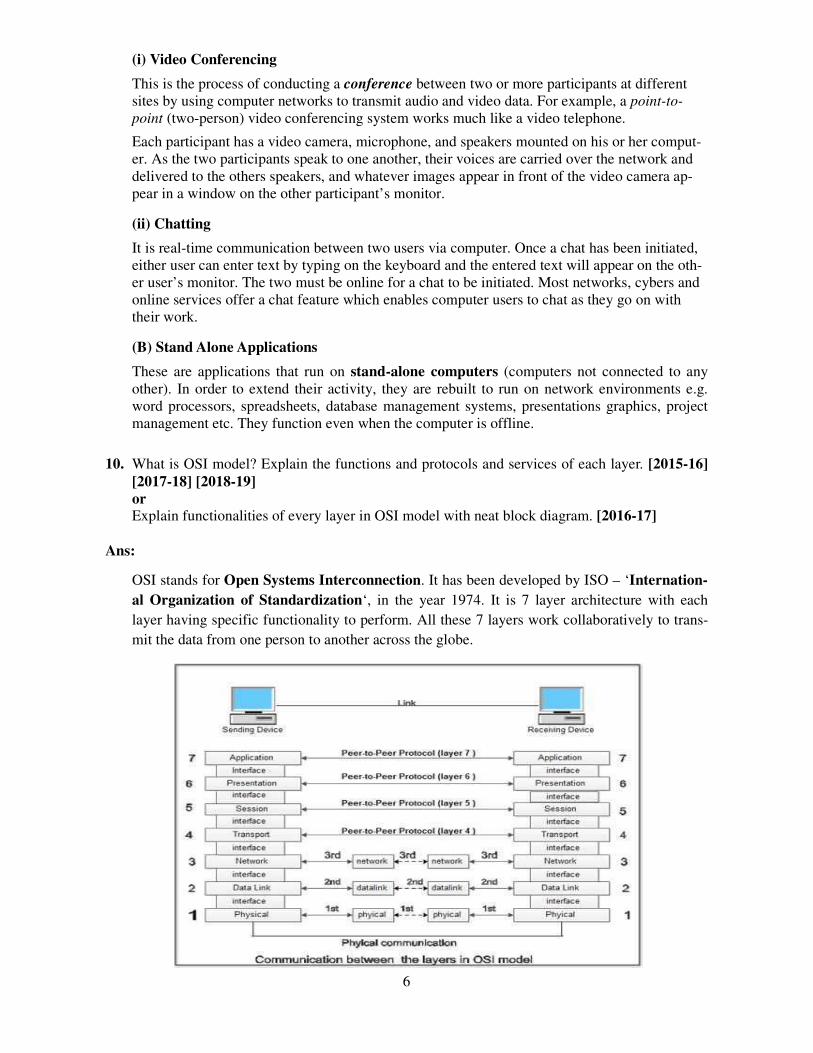
OSI stands for Open Systems Interconnection. It has been developed by ISO – ‘Internation-
al Organization of Standardization‘, in the year 1974. It is 7 layer architecture with each
layer having specific functionality to perform. All these 7 layers work collaboratively to trans-
mit the data from one person to another across the globe.
7
1. Physical Layer (Layer 1):
The lowest layer of the OSI reference model is the physical layer. It is responsible for the actual physical connection between the devices. The physical layer contains information in the form of bits. It is responsible for the actual physical connection between the devices. When receiving data, this layer will get the signal received and convert it into 0s and 1s and send them to the Data Link layer, which will put the frame back together.
2. Data Link Layer (DLL) (Layer 2):
The data link layer is responsible for the node to node delivery of the message. The main func-tion of this layer is to make sure data transfer is error free from one node to another, over the physical layer. When a packet arrives in a network, it is the responsibility of DLL to transmit it to the Host using its MAC address.
Data Link Layer is divided into two sub layers:
1. Logical Link Control (LLC)
2. Media Access Control (MAC)
3. Network Layer (Layer 3):
Network layer works for the transmission of data from one host to the other located in different networks. It also takes care of packet routing i.e. selection of the shortest path to transmit the packet, from the number of routes available. The sender & receiver’s IP address are placed in the header by network layer.
The functions of the Network layer are:
1. Routing: The network layer protocols determine which route is suitable from source to des-tination. This function of network layer is known as routing.
2. Logical Addressing: In order to identify each device on internetwork uniquely, network layer defines an addressing scheme. The sender & receiver’s IP address are placed in the header by network layer. Such an address distinguishes each device uniquely and universal-ly.
4. Transport Layer (Layer 4):
Transport layer provides services to application layer and takes services from network layer. The data in the transport layer is referred to as Segments. It is responsible for the End to End delivery of the complete message. Transport layer also provides the acknowledgment of the successful data transmission and re-transmits the data if an error is found.
The functions of the transport layer are:
1.Segmentation and Reassembly: This layer accepts the message from the (session) layer, breaks the message into smaller units. Each of the segments produced has a header associated with it. The transport layer at the destination station reassembles the message.
2.Service Point Addressing: In order to deliver the message to correct process, transport layer header includes a type of address called service point address or port address. Thus by speci-fying this address, transport layer makes sure that the message is delivered to the correct process.
8
The services provided by transport layer:
1. Connection Oriented Service: It is a three-phase process which include – Connection Establishment – Data Transfer – Termination / disconnection In this type of transmission, the receiving device sends an acknowledgment, back to the source after a packet or group of packet is received. This type of transmission is reliable and secure.
2. Connection less service: It is a one phase process and includes Data Transfer. In this type of transmission, the receiver does not acknowledge receipt of a packet. This approach allows for much faster communication between devices. Connection oriented Service is more relia-ble than connection less Service.
5. Session Layer (Layer 5):
This layer is responsible for establishment of connection, maintenance of sessions, authentica-tion and also ensures security.
The functions of the session layer are:
1. Session establishment, maintenance and termination: The layer allows the two processes to establish, use and terminate a connection.
2. Synchronization: This layer allows a process to add checkpoints which are considered as synchronization points into the data. These synchronization point help to identify the error so that the data is re-synchronized properly, and ends of the messages are not cut prema-turely and data loss is avoided.
3. Dialog Controller: The session layer allows two systems to start communication with each other in half-duplex or full-duplex.
6. Presentation Layer (Layer 6):
Presentation layer is also called the Translation layer. The data from the application layer is extracted here and manipulated as per the required format to transmit over the network.
The functions of the presentation layer are:
1. Translation: For example, ASCII to EBCDIC.
2. Encryption/ Decryption: Data encryption translates the data into another form or code. The encrypted data is known as the cipher text and the decrypted data is known as plain text. A key value is used for encrypting as well as decrypting data.
3. Compression: Reduces the number of bits that need to be transmitted on the network.
7. Application Layer (Layer 7):
At the very top of the OSI Reference Model stack of layers, we find Application layer which is implemented by the network applications. These applications produce the data, which has to be transferred over the network. This layer also serves as a window for the application services to access the network and for displaying the received information to the user.
9
The functions of the Application layer are:
1. Network Virtual Terminal
2. FTAM-File transfer access and management
3. Mail Services
4. Directory Services
11. Write about user access in ISDN. [2016-17]
Ans: ISDN is a circuit -switched telephone network system, that also provides access to packet switched networks, designed to allow digital transmission of voice and data over ordinary telephone copper wires, resulting in better voice quality than· an analog phone. It offers circuit-switched connections (for either voice or data), and packet-switched connections (for data), in increments of 64 Kbit/s.
Another major market application is Internet access, where ISDN typically provides a
maximum of 128 Kbit/s in both upstream and downstream directions (which can be considered
to be broadband speed, since it exceeds the narrowband speeds of standard analog 56k
telephone lines). ISDN B-channels can be bonded to achieve a greater data rate; typically 3 or 4
BRIs (6 to 8 64 Kbit/s channels) are bonded.
12. List the advantages and disadvantages of star topology. [2016-17] Ans: Advantages of Star Topology:
1) As compared to Bus topology it gives far much better performance, signals don’t necessarily get transmitted to all the workstations.
2) Easy to connect new nodes or devices. In star topology new nodes can be added easily without affecting rest of the network. Similarly components can also be removed easily.
3) Centralized management. It helps in monitoring the network. 4) Failure of one node or link doesn’t affect the rest of network. At the same time it's easy to
detect the failure and troubleshoot it.
Disadvantages of Star Topology:
1) Too much dependency on central device has its own drawbacks. If it fails whole network goes down.
2) The use of hub, a router or a switch as central device increases the overall cost of the network.
3) Performance and as well number of nodes which can be added in such topology is depended on capacity of central device.
13. List the advantages and disadvantages of ring topology. [2017-18] Ans:
Advantages of ring topology:
1) Data can transfer between workstations at high speeds.
2) All data flows in one direction, reducing the chance of packet collisions.

Disadvantages of ring topology:
1) This topology is not verybroken.
2) The entire network will b
14. If a binary signal is sent over a maximum achievable data rate?
Ans:
According to Shannon theorem whicB*log_2^(1+S/N) where B is the banin "decibel", not just a ratio. DecibelTherefore, we get S/N first by 20dB
Substitute S/N into Shannon's theore3k*log2^(1+S/N)=3log2^101kbps=1
However, the maximum data rate, asNyquist rate. Therefore, the final ans
15. Explain network topological ddisadvantages of various topoloor
Define topology and explain the[2018-19]
Ans:
Mesh Topology:
In mesh topology, every device is co
Figure 1: Every device is connec
• If suppose, N number of devi
number of ports that is requir
connected to each other, henc
• If suppose, N number of devi
number of dedicated links re
there are 5 devices connected
10.
10
ry reliable, because when a link fails the entire ri
l be impacted if one workstation shuts down.
a 3 kHz channel whose signal to noise ratio is 20e? [2017-18]
hich specifies the maximum data rate in a noisy chbandwidth, S/N is the signal-to-noise ratio. Usuallel is calculated by dB=10log_10^(S/N) B=10log_10^(S/N) ==> S/N=10^2=100
rem, we get the maximum bps as =19.97kbps.
assuming the channel is noise free, is only 6kbps,answer should be 6kbps.
design with necessary diagram and brief the logies. [2017-18]
the advantage and disadvantage of Bus, Star and
connected to another device via particular channe
nected with another via dedicated channels. These
known as links.
evices are connected with each other in mesh topo
uired by each device is N-1. In the Figure 1, there
nce total number of ports required is 4.
evices are connected with each other in mesh topo
required to connect them is NC2 i.e. N(N-1)/2. In
ted to each other, hence total number of links requ
ring connection is
20dB. What is the
channel as ally, S/N is given
ps, according to
e advantages and
d Ring topologies.
nel.
se channels are
pology, then total
re are 5 devices
pology, then total
In the Figure 1,
quired is 5*4/2 =
Advantages of this topology:
• It is robust.
• Fault is diagnosed easily. Da
through dedicated channels o
• Provides security and privacy
Problems with this topology:
• Installation and configuration
• Cost of cables are high as bu
• Cost of maintenance is high.
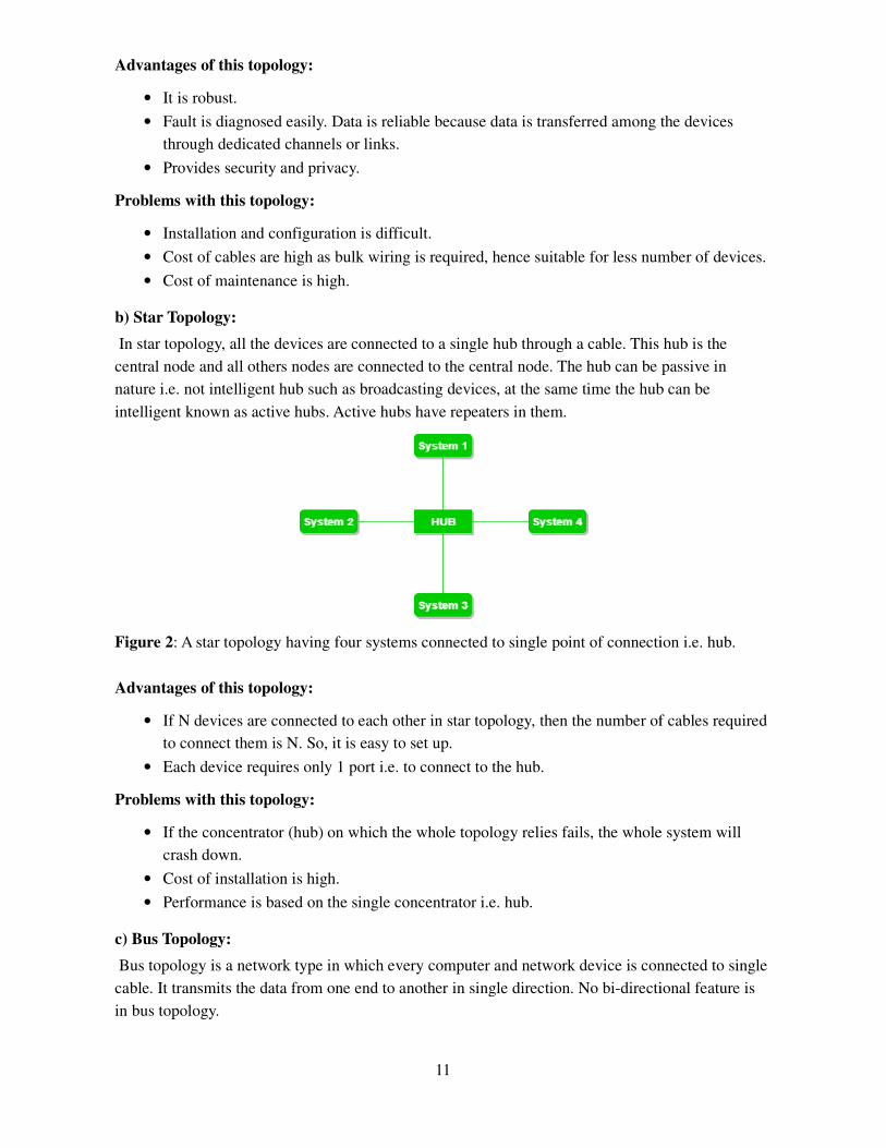
b) Star Topology:
In star topology, all the devices are
central node and all others nodes are
nature i.e. not intelligent hub such as
intelligent known as active hubs. Ac
Figure 2: A star topology having fou
Advantages of this topology:
• If N devices are connected to
to connect them is N. So, it is
• Each device requires only 1 p
Problems with this topology:
• If the concentrator (hub) on w
crash down.
• Cost of installation is high.
• Performance is based on the
c) Bus Topology:
Bus topology is a network type in w
cable. It transmits the data from one
in bus topology.
11
ata is reliable because data is transferred among t
s or links.
cy.
ion is difficult.
bulk wiring is required, hence suitable for less num
re connected to a single hub through a cable. This
re connected to the central node. The hub can be p
as broadcasting devices, at the same time the hub
ctive hubs have repeaters in them.
four systems connected to single point of connecti
to each other in star topology, then the number of
t is easy to set up.
1 port i.e. to connect to the hub.
n which the whole topology relies fails, the whole
e single concentrator i.e. hub.
which every computer and network device is con
ne end to another in single direction. No bi-directi
g the devices
umber of devices.
is hub is the
e passive in
ub can be
ction i.e. hub.
of cables required
le system will
onnected to single
ctional feature is

Figure 3: A bus topology with share
drop lines.
Advantages of this topology:
• If N devices are connected to
to connect them is 1 which is
• Cost of the cable is less as co
networks.
Problems with this topology:
• If the common cable fails, th
• If the network traffic is heavy
protocols are used in MAC la
d) Ring Topology:
In this topology, it forms a ring con
Figure 4: A ring topology comp
The following operations takes p
1. One station is known as mon
operations.
2. To transmit the data, station h
is to be released for other sta
3. When no station is transmitti
4. There are two types of token
after the transmitting the data
acknowledgement is received
12
red backbone cable. The nodes are connected to th
to each other in bus topology, then the number of
is known as backbone cable and N drop lines are
compared to other topology, but it is used to build
then the whole system will crash down.
vy, it increases collisions in the network. To avoid
layer known as Pure Aloha, Slotted Aloha, CSMA
onnecting a devices with its exactly two neighbour
prises of 4 stations connected with each forming
s place in ring topology are:
onitor station which takes all the responsibility to
n has to hold the token. After the transmission is d
tations to use.
tting the data, then the token will circulate in the r
en release techniques: Early token release release
ata and Delay token release releases the token aft
ed from the receiver.
the channel via
of cables required
re required.
ild small
oid this, various
MA/CD etc.
uring devices.
g a ring
to perform the
s done, the token
e ring.
ses the token just
after the
Advantages of this topology:
• The possibility of collision is
• Cheap to install and expand.
Problems with this topology:
• Troubleshooting is difficult i
• Addition of stations in betwe
16. Discuss the different physical laAns: The transmission medium is
transmission system.
1. Guided Media:
It is also referred to as Wireddirected and confined in a na
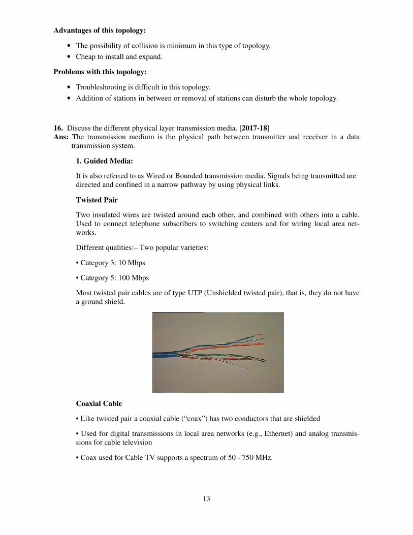
Twisted Pair
Two insulated wires are twisUsed to connect telephone sworks.
Different qualities:– Two pop
• Category 3: 10 Mbps
• Category 5: 100 Mbps
Most twisted pair cables are a ground shield.
Coaxial Cable
• Like twisted pair a coaxial
• Used for digital transmissiosions for cable television
• Coax used for Cable TV su
13
is minimum in this type of topology.
t in this topology.
een or removal of stations can disturb the whole
layer transmission media. [2017-18] is the physical path between transmitter and re
ed or Bounded transmission media. Signals being narrow pathway by using physical links.
isted around each other, and combined with othe subscribers to switching centers and for wiring
opular varieties:
re of type UTP (Unshielded twisted pair), that is, t
al cable (“coax”) has two conductors that are shiel
sions in local area networks (e.g., Ethernet) and a
supports a spectrum of 50 - 750 MHz.
le topology.
receiver in a data
ng transmitted are
thers into a cable. ing local area net-
, they do not have
ielded
d analog transmis-

Optical Fiber
Optical fiber is a thin (2-125
• Fiber is built of various gla
• Very high bandwidth (curre
• Used for long-distance trun
• Inherently unidirectional.
Types of Optical Fiber
Multimode Fiber:
– Rays may take different pa
Single Mode Fiber:
– By reducing the radius of can pass.
Single Mode fiber has superiof a LED for multimode fibe
14
5 mm), flexible medium capable of conducting an
lasses or plastics.
rrently up to 10 Gbps).
unks, local area networks, high-speed transmission
paths
f the fiber core to the order of the wavelength, o
erior performance but needs a laser diode as a lighber).
an optical ray.
ions.
, only the axial ray
ght source (instead
15
2. Unguided Media:
It is also referred to as Wireless or Unbounded transmission media. No physical medium is required for the transmission of electromagnetic signals.
There are 3 major types of Unguided Media:
(i) Radio waves
These are easy to generate and can penetrate through buildings. The sending and receiving antennas need not be aligned. Frequency Range: 3 KHz – 1GHz. AM and FM radios and cordless phones use Radio waves for transmission.
Further Categorized as: (i) Terrestrial and (ii) Satellite.
(ii) Microwaves
It is a line of sight transmission i.e. the sending and receiving antennas need to be properly aligned with each other. The distance covered by the signal is directly proportional to the height of the antenna. Frequency Range: 1GHz – 300GHz. These are majorly used for mo-bile phone communication and television distribution.
(iii) Infrared
Infrared waves are used for very short distance communication. They cannot penetrate through obstacles. This prevents interference between systems. Frequency Range: 300GHz – 400THz. It is used in TV remotes, wireless mouse, keyboard, printer, etc.
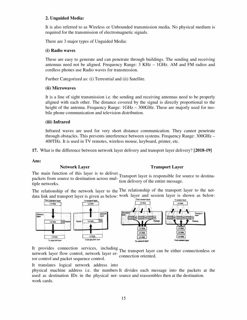
17. What is the difference between network layer delivery and transport layer delivery? [2018-19] Ans:
Network Layer Transport Layer
The main function of this layer is to deliver packets from source to destination across mul-tiple networks.
Transport layer is responsible for source to destina-tion delivery of the entire message.
The relationship of the network layer to the data link and transport layer is given as below:
The relationship of the transport layer to the net-work layer and session layer is shown as below:
It provides connection services, including network layer flow control, network layer er-ror control and packet sequence control.
The transport layer can be either connectionless or connection oriented.
It translates logical network address into physical machine address i.e. the numbers used as destination IDs in the physical net-work cards.
It divides each message into the packets at the source and reassembles then at the destination.
ECS-601NCS-601 2015-16 Q-1d Measurement of slotted ALOHA channel with infinite number of users show that the 10 percents slots are idle.
i. what is channel load?
a. Ans-Pr[0] is the probability of a slot that does not contain frame, i.e., idle frame
slot. Pr[0]=0.1. Pr[0]=G0e-G/0!=1*e-G=0.1. ln(e-G)=ln(0.1). -G=-2.30259.
G=2.30259.
The channel load is 2.30259. ii. what is throughput?
a. S=Ge-G=2.30259*e-2.30259=0.230258. The throughput is 23.0258%, below the
optimal 36.8%.
Q-2b(i) An aloha network user 19.2 kbps19.2 kbps channel for sending message
packets of 100 bits100 bits longsize. Calculate the maximum throughput for pure aloha network.
Ans: we know that for pure aloha efficiency = G×e−2G
and in the maximum case we find it to be 0.1840.184
throughput=efficiency ×× Bandwidth
=.184∗19.2=3.5328kbps.184∗19.2=3.5328kbps
if we find it in packets/sec then,3.5328/packet size=3.5328/100=.035328 kilo packets
per second
ii) What is hammimg code ? Explain its working with suitable example? Hamming code is a set of error-correction codes that can be used to detect and correct the errors that can occur when the data is moved or stored from the sender to the receiver. It is technique developed by R.W. Hamming for error correction. Redundant bits – Redundant bits are extra binary bits that are generated and added to the information-carrying bits of data transfer to ensure that no bits were lost during the data transfer. The number of redundant bits can be calculated using the following formula:
2^r ≥ m + r + 1
where, r = redundant bit, m = data bit
Suppose the number of data bits is 7, then the number of redundant bits can be calculated using: = 2^4 ≥ 7 + 4 + 1 Thus, the number of redundant bits= 4
Parity bits – A parity bit is a bit appended to a data of binary bits to ensure that the total number of 1’s in the data is even or odd. Parity bits are used for error detection. There are two types of parity bits:
1. Even parity bit: In the case of even parity, for a given set of bits, the number of 1’s are counted. If that count is odd, the parity bit value is set to 1, making the total count of occurrences of 1’s an even number. If the total number of 1’s in a given set of bits is already even, the parity bit’s value is 0.
2. Odd Parity bit – In the case of odd parity, for a given set of bits, the number of 1’s are counted. If that count is even, the parity bit value is set to 1, making the total count of occurrences of 1’s an odd number. If the total number of 1’s in a given set of bits is already odd, the parity bit’s value is 0.
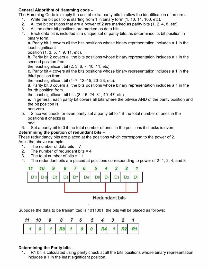
General Algorithm of Hamming code – The Hamming Code is simply the use of extra parity bits to allow the identification of an error.
1. Write the bit positions starting from 1 in binary form (1, 10, 11, 100, etc). 2. All the bit positions that are a power of 2 are marked as parity bits (1, 2, 4, 8, etc). 3. All the other bit positions are marked as data bits. 4. Each data bit is included in a unique set of parity bits, as determined its bit position in
binary form. a. Parity bit 1 covers all the bits positions whose binary representation includes a 1 in the least significant position (1, 3, 5, 7, 9, 11, etc). b. Parity bit 2 covers all the bits positions whose binary representation includes a 1 in the second position from the least significant bit (2, 3, 6, 7, 10, 11, etc). c. Parity bit 4 covers all the bits positions whose binary representation includes a 1 in the third position from the least significant bit (4–7, 12–15, 20–23, etc). d. Parity bit 8 covers all the bits positions whose binary representation includes a 1 in the fourth position from the least significant bit bits (8–15, 24–31, 40–47, etc). e. In general, each parity bit covers all bits where the bitwise AND of the parity position and the bit position is non-zero.
5. Since we check for even parity set a parity bit to 1 if the total number of ones in the positions it checks is odd.
6. Set a parity bit to 0 if the total number of ones in the positions it checks is even. Determining the position of redundant bits – These redundancy bits are placed at the positions which correspond to the power of 2. As in the above example:
1. The number of data bits = 7 2. The number of redundant bits = 4 3. The total number of bits = 11 4. The redundant bits are placed at positions corresponding to power of 2- 1, 2, 4, and 8
Suppose the data to be transmitted is 1011001, the bits will be placed as follows:
Determining the Parity bits – 1. R1 bit is calculated using parity check at all the bits positions whose binary representation
includes a 1 in the least significant position.

R1: bits 1, 3, 5, 7, 9, 11
To find the redundant bit R1, we check for even parity. Since the total number of 1’s in all the bit positions corresponding to R1 is an even number the value of R1 (parity bit’s value) = 0
2. R2 bit is calculated using parity check at all the bits positions whose binary representation includes a 1 in the second position from the least significant bit. R2: bits 2,3,6,7,10,11
To find the redundant bit R2, we check for even parity. Since the total number of 1’s in all the bit positions corresponding to R2 is odd the value of R2(parity bit’s value)=1
3. R4 bit is calculated using parity check at all the bits positions whose binary representation includes a 1 in the third position from the least significant bit. R4: bits 4, 5, 6, 7

To find the redundant bit R4, we check for even parity. Since the total number of 1’s in all the bit positions corresponding to R4 is odd the value of R4(parity bit’s value) = 1
4. R8 bit is calculated using parity check at all the bits positions whose binary representation includes a 1 in the fourth position from the least significant bit. R8: bit 8,9,10,11
To find the redundant bit R8, we check for even parity. Since the total number of 1’s in all the bit positions corresponding to R8 is an even number the value of R8(parity bit’s value)=0.
Thus, the data transferred is:
Error detection and correction – Suppose in the above example the 6th bit is changed from 0 to 1 during data transmission, then it gives new parity values in the binary number:
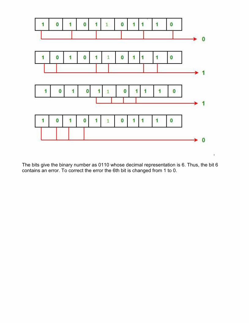
‘
The bits give the binary number as 0110 whose decimal representation is 6. Thus, the bit 6 contains an error. To correct the error the 6th bit is changed from 1 to 0.
2016- 2017
Section A
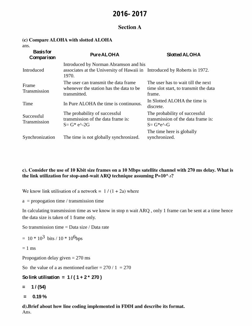
(c) Compare ALOHA with slotted ALOHA
ans.
Basis for Comparison
Pure ALOHA Slotted ALOHA
Introduced
Introduced by Norman Abramson and his
associates at the University of Hawaii in
1970.
Introduced by Roberts in 1972.
Frame
Transmission
The user can transmit the data frame
whenever the station has the data to be
transmitted.
The user has to wait till the next
time slot start, to transmit the data
frame.
Time In Pure ALOHA the time is continuous. In Slotted ALOHA the time is
discrete.
Successful
Transmission
The probability of successful
transmission of the data frame is:
S= G* e^-2G
The probability of successful
transmission of the data frame is:
S= G*e^-G
Synchronization The time is not globally synchronized.
The time here is globally
synchronized.
c). Consider the use of 10 Kbit size frames on a 10 Mbps satellite channel with 270 ms delay. What is
the link utilization for stop-and-wait ARQ technique assuming P=10^-3?
We know link utilisation of a network = 1 / (1 + 2a) where
a = propogation time / transmission time
In calculating transmission time as we know in stop n wait ARQ , only 1 frame can be sent at a time hence
the data size is taken of 1 frame only.
So transmission time = Data size / Data rate
= 10 * 103 bits / 10 * 106bps
= 1 ms
Propogation delay given = 270 ms
So the value of a as mentioned earlier = 270 / 1 = 270
So link utilisation = 1 / ( 1 + 2 * 270 )
= 1 / (54)
= 0.19 %
d).Brief about how line coding implemented in FDDI and describe its format.
Ans.
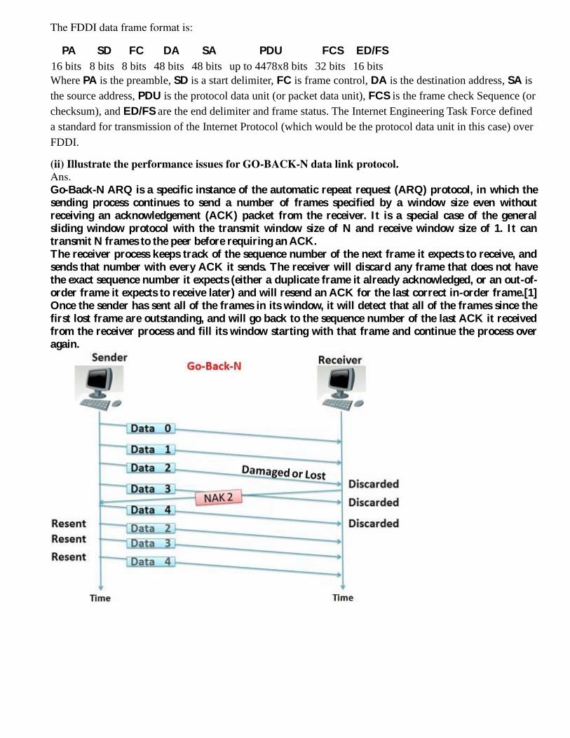
The FDDI data frame format is:
PA SD FC DA SA PDU FCS ED/FS
16 bits 8 bits 8 bits 48 bits 48 bits up to 4478x8 bits 32 bits 16 bits
Where PA is the preamble, SD is a start delimiter, FC is frame control, DA is the destination address, SA is
the source address, PDU is the protocol data unit (or packet data unit), FCS is the frame check Sequence (or
checksum), and ED/FS are the end delimiter and frame status. The Internet Engineering Task Force defined
a standard for transmission of the Internet Protocol (which would be the protocol data unit in this case) over
FDDI.
(ii) Illustrate the performance issues for GO-BACK-N data link protocol.
Ans.
Go-Back-N ARQ is a specific instance of the automatic repeat request (ARQ) protocol, in which the sending process continues to send a number of frames specified by a window size even without receiving an acknowledgement (ACK) packet from the receiver. It is a special case of the general sliding window protocol with the transmit window size of N and receive window size of 1. It can transmit N frames to the peer before requiring an ACK. The receiver process keeps track of the sequence number of the next frame it expects to receive, and sends that number with every ACK it sends. The receiver will discard any frame that does not have the exact sequence number it expects (either a duplicate frame it already acknowledged, or an out-of-order frame it expects to receive later) and will resend an ACK for the last correct in-order frame.[1] Once the sender has sent all of the frames in its window, it will detect that all of the frames since the first lost frame are outstanding, and will go back to the sequence number of the last ACK it received from the receiver process and fill its window starting with that frame and continue the process over again.
2017-2018
(f)Pr[0] is the probability of a slot that does not contain frame, i.e., idle frame slot.
1) Pr[0]=0.1. Pr[0]=G0e-G/0!=1*e-G=0.1. ln(e-G)=ln(0.1). -G=-2.30259. G=2.30259.
The channel load is 2.30259.
2)S=Ge-G=2.30259*e-2.30259=0.230258. The throughput is 23.0258%, below the optimal 36.8%.
b) Issues with Data link layer
1. Providing a well-defined service interface to the network layer
2. Determining how the bits of the physical layer are grouped into frames
3. Dealing with transmission errors
4. Regulating the flow of frames so that slow receivers are not swamped by fast senders.
(c)Congestion control refers to the techniques used to control or prevent congestion. Congestion control
techniques can be broadly classified into two categories
Open loop congestion control
Open loop congestion control policies are applied to prevent congestion before it happens. The congestion
control is handled either by the source or the destination.
1. Retransmission Policy :
It is the policy in which retransmission of the packets are taken care. If the sender feels that a sent packet
is lost or corrupted, the packet needs to be retransmitted. This transmission may increase the congestion
in the network. To prevent congestion, retransmission timers must be designed to prevent congestion and
also able to optimize efficiency.
2. Window Policy :
The type of window at the sender side may also affect the congestion. Several packets in the Go-back-n
window are resent, although some packets may be received successfully at the receiver side. This
duplication may increase the congestion in the network and making it worse.Therefore, Selective repeat
window should be adopted as it sends the specific packet that may have been lost.
3. Discarding Policy :
A good discarding policy adopted by the routers is that the routers may prevent congestion and at the same
time partially discards the corrupted or less sensitive package and also able to maintain the quality of a
message.In case of audio file transmission, routers can discard less sensitive packets to prevent
congestion and also maintain the quality of the audio file.
4. Acknowledgment Policy :
Since acknowledgement are also the part of the load in network, the acknowledgment policy imposed by the
receiver may also affect congestion. Several approaches can be used to prevent congestion related to
acknowledgment.The receiver should send acknowledgement for N packets rather than sending
acknowledgement for a single packet. The receiver should send a acknowledgment only if it has to sent a
packet or a timer expires.
5. Admission Policy :
In admission policy a mechanism should be used to prevent congestion. Switches in a flow should first
check the resource requirement of a network flow before transmitting it further. If there is a chance of a
congestion or there is a congestion in the network, router should deny establishing a virtual network
connection to prevent further congestion.
Closed loop congestion control
Closed loop congestion control technique is used to treat or alleviate congestion after it happens. Several
techniques are used by different protocols; some of them are:
1. Backpressure :
Backpressure is a technique in which a congested node stop receiving packet from upstream node. This
may cause the upstream node or nodes to become congested and rejects receiving data from above
nodes. Backpressure is a node-to-node congestion control technique that propagate in the opposite
direction of data flow. The backpressure technique can be applied only to virtual circuit where each node
has information of its above upstream node.In above diagram the 3rd node is congested and stops
receiving packets as a result 2nd node may be get congested due to slowing down of the output data flow.
Similarly 1st node may get congested and informs the source to slow down.
2. Choke Packet Technique :
Choke packet technique is applicable to both virtual networks as well as datagram subnets. A choke packet
is a packet sent by a node to the source to inform it of congestion. Each router monitor its resources and
the utilization at each of its output lines. whenever the resource utilization exceeds the threshold value
which is set by the administrator, the router directly sends a choke packet to the source giving it a feedback
to reduce the traffic. The intermediate nodes through which the packets has traveled are not warned about
congestion.

Implicit Signaling :
In implicit signaling, there is no communication between the congested nodes and the source. The source
guesses that there is congestion in a network. For example when sender sends several packets and there
is no acknowledgment for a while, one assumption is that there is a congestion.
Explicit Signaling :
In explicit signaling, if a node experiences congestion it can explicitly sends a packet to the source or
destination to inform about congestion. The difference between choke packet and explicit signaling is that
the signal is included in the packets that carry data rather than creating different packet as in case of choke
packet technique.
4)a
This method was developed to decrease the chances of collisions when two or more stations start sending
their signals over the datalink layer. Carrier Sense multiple access requires that each station first check the
state of the medium before sending.
There Are Three Different Type of CSMA Protocols
(I) I-persistent CSMA
(ii) Non- Persistent CSMA
(iii) p-persistent CSMA
I-persistent CSMA
• In this method, station that wants to transmit data continuously senses the channel to check whether the
channel is idle or busy.
• If the channel is busy, the station waits until it becomes idle.
• When the station detects an idle-channel, it immediately transmits the frame with probability 1. Hence it is
called I-persistent CSMA.
• This method has the highest chance of collision because two or more stations may find channel to be idle
at the same time and transmit their frames.
• When the collision occurs, the stations wait a random amount of time and start allover again.
Non-persistent CSMA
• In this scheme, if a station wants to transmit a frame and it finds that the channel is busy (some other station is transmitting) then it will wait for fixed interval oftime.
• After this time, it again checks the status of the channel and if the channel is.free it will transmit.
• A station that has a frame to send senses the channel.
• If the channel is idle, it sends immediately.
• If the channel is busy, it waits a random amount of time and then senses the channel again.
• In non-persistent CSMA the station does not continuously sense the channel for the purpose of capturing
it when it detects the end of previous transmission
p-persistent CSMA
• This method is used when channel has time slots such that the time slot duration is equal to or greater
than the maximum propagation delay time.
• Whenever a station becomes ready to send, it senses the channel.
• If channel is busy, station waits until next slot.
• If channel is idle, it transmits with a probability p.
• With the probability q=l-p, the station then waits for the beginning of the next time slot.
• If the next slot is also idle, it either transmits or waits again with probabilities p and q.
• This process is repeated till either frame has been transmitted or another station has begun transmitting.
• In case of the transmission by another station, the station acts as though a collision has occurred and it waits a random amount of time and starts again.
4)b
i)Stop and Wait ARQ
Characteristics
● It uses link between sender and receiver as half duplex link
● Throughput = 1 Data packet/frame per RTT
● If Bandwidth*Delay product is very high, then stop and wait protocol is not so useful. The
sender has to keep waiting for acknowledgements before sending the processed next packet.
● It is an example for “Closed Loop OR connection oriented “ protocols
● It is an special category of SWP where its window size is 1
● Irrespective of number of packets sender is having stop and wait protocol requires only 2
sequence numbers 0 and 1

1) Sender A sends a data frame or packet with sequence number 0.
2) Receiver B, after receiving data frame, sends and acknowledgement with sequence number 1
(sequence number of next expected data frame or packet)
There is only one bit sequence number that implies that both sender and receiver have buffer for one frame
or packet only.
ii)Sliding Window protocols
Frames have sequence number 0 to maximum 2n - 1 (n bit field).
At any moment, the sender maintains a list of sequence numbers it is permitted to send - these fall within
the sending window. These are frames sent-but-no-ack and frames not-yet-sent.
When new packet from Network layer comes in to send, it is given highest no, and upper edge of window
advanced by 1.
When ack comes in, lower edge of window advanced by 1.
Receiver has receiving window - the frames it is permitted to accept.
Sliding window size 1. Sequence nos. 0 to 7.
(a) At start. Receiver waits for 0.
(b) Sender sends 0.
(c) Receiver receives 0. Waits for 1.

(d) Sender got ack for 0. Hasn't got 1 from its Network layer yet.
iii)Go-Back-N ARQ
1)Packets transmitted continuously (when available) without waiting for ACK, up to N outstanding,
unACK’ed packets
2 )a logically different sender timer association with each unACK’ed packet: extension of AB protocol
Receiver: ACK packet if correctly received and in-order, pass to higher layer
NACK or ignore (possibly discard) corrupt or out-of-order packet
Sender :if NACK received, or timeout, for packet n, begin resending from n all over again cumulative ACK:
ACK of n implicitly acknowledges up through n
1. no receiver transport buffering with discard
2. saves resources at receiver
3. avoids large bursts of packet delivery to higher layers
4. simplicity in buffering and protocol processing at sender and receiver
2018-2019
SECTION-A
D. Subnet mask 255.255.248.0 find max no host –
No of 1 in mask=21(n)
max no host =232-21
-2=2046
E)Counting to infinity is just another name for a routing loop. In distance vector routing, routing loops
usually occur when an interface goes down, or when two routers send updates to each other at the same
time.
SECTION B
2c.-Unicast Routing – Link State Routing
Prerequisite – Distance Vector Routing, Dijkstra algorithm, Distance vector routing v/s Link state
routing, OSPF, RIP
Unicast – Unicast means the transmission from a single sender to a single receiver. It is a point to point
communication between sender and receiver. There are various unicast protocols such as TCP, HTTP, etc.
TCP is the most commonly used unicast protocol. It is a connection oriented protocol that relay
on acknowledgement from the receiver side.
HTTP stands for Hyper Text Transfer Protocol. It is an object oriented protocol for
communication.
There are three major protocols for unicast routing:
1. Distance Vector Routing
2. Link State Routing
3. Path-Vector Routing
LinkStateRouting –
Link state routing is the second family of routing protocols. While distance vector routers use a
distributed algorithm to compute their routing tables, link-state routing uses link-state routers to exchange
messages that allow each router to learn the entire network topology. Based on this learned topology, each
router is then able to compute its routing table by using a shortest path computation. Features of link state
routing protocols –
Link state packet – A small packet that contains routing information.
Link state database – A collection information gathered from link state packet.
Shortest path first algorithm (Dijkstra algorithm) – A calculation performed on the database
results into shortest path
Routing table – A list of known paths and interfaces.
Calculationofshortestpath –
To find shortest path, each node need to run the famous Dijkstra algorithm. This famous algorithm uses
the following steps:
Step-1: The node is taken and chosen as a root node of the tree, this creates the tree with a single
node, and now set the total cost of each node to some value based on the information in Link
State Database
Step-2: Now the node selects one node, among all the nodes not in the tree like structure, which is
nearest to the root, and adds this to the tree.The shape of the tree gets changed .
Step-3: After this node is added to the tree, the cost of all the nodes not in the tree needs to be
updated because the paths may have been changed.
Step-4: The node repeats the Step 2. and Step 3. until all the nodes are added in the tree
Link State protocols in comparison to Distance Vector protocols have:
1. It requires large amount of memory.
2. Shortest path computations require many CPU circles.
3. If network use the little bandwidth ; it quickly reacts to topology changes
4. All items in the database must be sent to neighbors to form link state packets.
5. All neighbors must be trusted in the topology.
6. Authentication mechanisms can be used to avoid undesired adjacency and problems.
7. No split horizon techniques are possible in the link state routing.
Open shortest path first (OSPF) routing protocol –
Open Shortest Path First (OSPF) is a unicast routing protocol developed by
working group of the Internet Engineering Task Force (IETF).
It is a intradomain routing protocol.
It is an open source protocol.
It is similar to Routing Information Protocol (RIP)
OSPF is a classless routing protocol, which means that in its updates, it includes
the subnet of each route it knows about, thus, enabling variable-length subnet
masks. With variable-length subnet masks, an IP network can be broken into
many subnets of various sizes. This provides network administrators with extra
network-configuration flexibility.These updates are multicasts at specific
addresses (224.0.0.5 and 224.0.0.6).
OSPF is implemented as a program in the network layer using the services
provided by the Internet Protocol

IP datagram that carries the messages from OSPF sets the value of protocol field
to 89
OSPF is based on the SPF algorithm, which sometimes is referred to as the
Dijkstra algorithm
OSPF has two versions – version 1 and version 2. Version 2 is used mostly
OSPF Messages – OSPF is a very complex protocol. It uses five different types of messages. These are as
follows:
10. Hello message (Type 1) – It is used by the routers to introduce itself to the other routers.
11. Database description message (Type 2) – It is normally send in response to the Hello message.
12. Link-state request message (Type 3) – It is used by the routers that need information about
specific Link-State packet.
13. Link-state update message (Type 4) – It is the main OSPF message for building Link-State
Database.
14. Link-state acknowledgement message (Type 5) – It is used to create reliability in the OSPF
protocol.
2D-TCP
Transmission Control Protocol is a transport layer protocol.
It continuously receives data from the application layer.
It divides the data into chunks where each chunk is a collection of bytes.
It then creates TCP segments by adding a TCP header to the data chunks.
TCP segments are encapsulated in the IP datagram.
TCP Header-
The following diagram represents the TCP header format-Let us discuss each field of TCP header
one by one.
1. Source Port-
Source Port is a 16 bit field.
It identifies the port of the sending application.
2. Destination Port-
Destination Port is a 16 bit field.
It identifies the port of the receiving application.

NOTE
It is important to note-
A TCP connection is uniquely identified by using-
Combination of port numbers and IP Addresses of sender and
receiver
IP Addresses indicate which systems are communicating.
Port numbers indicate which end to end sockets are
communicating.
TCP segment consists of data bytes to be sent and a header that is added to the data by TCP as
shown:
3. Sequence Number-
Sequence number is a 32 bit field.
TCP assigns a unique sequence number to each byte of data contained in the TCP segment.
This field contains the sequence number of the first data byte.
4. Acknowledgement Number-
Acknowledgment number is a 32 bit field.
It contains sequence number of the data byte that receiver expects to receive next from the sender.
It is always sequence number of the last received data byte incremented by 1.
5. Header Length-
Header length is a 4 bit field.
It contains the length of TCP header.
It helps in knowing from where the actual data begins.
Minimum and Maximum Header length-
The length of TCP header always lies in the range-
[20 bytes , 60 bytes]
The initial 5 rows of the TCP header are always used.
So, minimum length of TCP header = 5 x 4 bytes = 20 bytes.
The size of the 6th row representing the Options field vary.
The size of Options field can go up to 40 bytes.
So, maximum length of TCP header = 20 bytes + 40 bytes = 60 bytes.
Concept of Scaling Factor-
Header length is a 4 bit field.
So, the range of decimal values that can be represented is [0, 15].
But the range of header length is [20, 60].
So, to represent the header length, we use a scaling factor of 4.
Header length = Header length field value x 4 bytes
Examples-If header length field contains decimal value 5 (represented as 0101), then-
Header length = 5 x 4 = 20 bytes
If header length field contains decimal value 10 (represented as 1010), then-
Header length = 10 x 4 = 40 bytes
If header length field contains decimal value 15 (represented as 1111), then-
Header length = 15 x 4 = 60 bytes
Services and Segment structure in TCP
The Transmission Control Protocol is the most common transport layer protocol. It works
together with IP and provides a reliable transport service between processes using the network
layer service provided by the IP protocol.
The various services provided by the TCP to the application layer are as follows:
1. Process-to-Process Communication – TCP provides process to process communication, i.e, the transfer of data takes place between
individual processes executing on end systems. This is done using port numbers or port addresses.
Port numbers are 16 bit long that help identify which process is sending or receiving data on a
host.
2. Stream oriented – This means that the data is sent and received as a stream of bytes(unlike UDP or IP that divides
the bits into datagrams or packets). However, the network layer, that provides service for the
TCP, sends packets of information not streams of bytes. Hence, TCP groups a nuber of bytes
together into a segment and adds a header to each of these segments and then delivers these
segments to the network layer. At the network layer, each of these segments are encapsulated in
an IP packet for transmission. The TCP header has information that is required for control
purpose which will be duscussed along with the segment structure.
3. Full duplex service – This means that the communication can take place in both directions at the same time.
4. Connection oriented service – Unlike UDP, TCP provides connection oriented service. It defines 3 different phases:
Connection establishment
Data transfer
Connection termination
(IMP: This is a virtual connection, not a physical connection, means during the transmission the
resources will not be reserved and the segments will not follow the same path to reach the
destination but it is a connection orientation in the sense that segments will arrive in order by the
help of sequence number.)
5. Reliability – TCP is reliable as it uses checksum for error detection, attempts to recover lost or corrupted
packets by re-transmission, acknowledgement policy and timers. It uses features like byte number
and sequence number and acknowledgement number so as to ensure reliability. Also, it uses
congestion control mechanisms.
6. Multiplexing – TCP does multiplexing and de-multiplexing at the sender and receiver ends respectively as a
number of logical connections can be established between port numbers over a physical
connection.
Byte number, Sequence number and Acknowledgement number: All the data bytes that are to be transmitted are numbered and the beginning of this numbering is
arbitrary. Sequence numbers are given to the segments so as to reassemble the bytes at the
receiver end even if they arrive in a different order. Sequence number of a segment is the byte
number of the first byte that is being sent. Acknowledgement number is required since TCP
provides full duplex service. Acknowledgement number is the next byte number that the receiver
expects to receive which also provides acknowledgement for receiving the previous bytes.
cronym for Transmission Control User Datagram
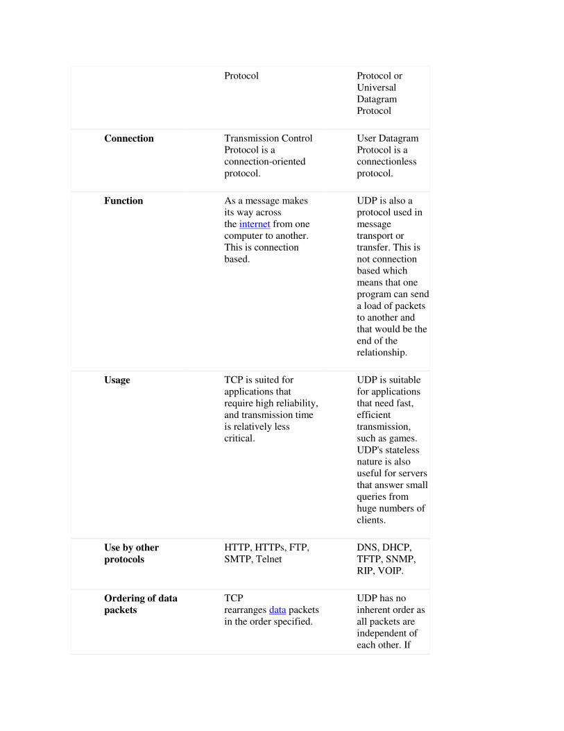
Protocol Protocol or
Universal
Datagram
Protocol
Connection Transmission Control
Protocol is a
connection-oriented
protocol.
User Datagram
Protocol is a
connectionless
protocol.
Function As a message makes
its way across
the internet from one
computer to another.
This is connection
based.
UDP is also a
protocol used in
message
transport or
transfer. This is
not connection
based which
means that one
program can send
a load of packets
to another and
that would be the
end of the
relationship.
Usage TCP is suited for
applications that
require high reliability,
and transmission time
is relatively less
critical.
UDP is suitable
for applications
that need fast,
efficient
transmission,
such as games.
UDP's stateless
nature is also
useful for servers
that answer small
queries from
huge numbers of
clients.
Use by other
protocols
HTTP, HTTPs, FTP,
SMTP, Telnet
DNS, DHCP,
TFTP, SNMP,
RIP, VOIP.
Ordering of data
packets
TCP
rearranges data packets
in the order specified.
UDP has no
inherent order as
all packets are
independent of
each other. If
ordering is
required, it has to
be managed by
the application
layer.
Speed of transfer The speed for TCP is
slower than UDP.
UDP is faster
because error
recovery is not
attempted. It is a
"best effort"
protocol.
Reliability There is absolute
guarantee that the data
transferred remains
intact and arrives in
the same order in
which it was sent.
There is no
guarantee that the
messages or
packets sent
would reach at
all.
Header Size TCP header size is 20
bytes
UDP Header size
is 8 bytes.
Common Header
Fields
Source port,
Destination port,
Check Sum
Source port,
Destination port,
Check Sum
Streaming of data Data is read as a byte
stream, no
distinguishing
indications are
transmitted to signal
message (segment)
boundaries.
Packets are sent
individually and
are checked for
integrity only if
they arrive.
Packets have
definite
boundaries which
are honored upon
receipt, meaning
a read operation
at the receiver
socket will yield
an entire message
as it was
originally sent.
Weight TCP is heavy-weight.
TCP requires three
packets to set up a
socket connection,
UDP is
lightweight.
There is no
ordering of

before any user data
can be sent. TCP
handles reliability and
congestion control.
messages, no
tracking
connections, etc.
It is a small
transport layer
designed on top
of IP.
Data Flow
Control
TCP does Flow
Control. TCP requires
three packets to set up
a socket connection,
before any user data
can be sent. TCP
handles reliability and
congestion control.
UDP does not
have an option
for flow control
Error Checking TCP does error
checking and error
recovery. Erroneous
packets are
retransmitted from the
source to the
destination.
UDP does error
checking but
simply discards
erroneous
packets. Error
recovery is not
attempted.
Fields 1. Sequence Number,
2. AcK number, 3.
Data offset, 4.
Reserved, 5. Control
bit, 6. Window, 7.
Urgent Pointer 8.
Options, 9. Padding,
10. Check Sum, 11.
Source port, 12.
Destination port
1. Length, 2.
Source port, 3.
Destination port,
4. Check Sum
Acknowledgement Acknowledgement
segments
No
Acknowledgment
Handshake SYN, SYN-ACK,
ACK
No handshake
(connectionless
protocol)
5.a Advantages of IPV6 over IPV4
IPv4 has been the reigning Internet Protocol version for several decades now, even to this date.
The IPv4 address space is 32-bits which allows for just over 2^32, or, 4 billion addresses which,
up until now, has been sufficient. Recently, we are seeing a trend where virtually everything and
anything is connected to the internet. Therefore, it is expected that soon enough, the 4 billion
address spaces provided by the IPv4 will be used up. his is where IPv6 comes into play, which is
an extension of the IPv4 and was mainly deployed to fulfill the need for more internet addresses.
The IPv6 address space is 128-bits which allows for over 2^128, or, 340 undecillion addresses.
Undecillion? This sounds like a magic spell straight out of a Harry Potter book, but, it is actually
a number that is equivalent to 340 trillion trillion, or, in a more visual sense,
340,282,366,920,938,000,000,000,000,000,000,000,000 address spaces. Did you know that such
a big number even existed? An increased number of IP addresses is the primary purpose and
benefit for IPv6, but not the only one.
Therefore, in this blog post we will talk about what IPv6 actually is and what other benefits it has
over its predecessor, IPv4. Finally, we will provide an example of a technology that uses IPv6
communication, which is Radiocrafts’ newest product line, RIIM™, Radiocrafts Industrial IP
Mesh.
More Efficient Routing – IPv6 reduces the size of routing tables and makes routing more
efficient and hierarchical. In IPv6 networks, fragmentation is handled by the source device, rather
than a router, using a protocol for discovery of the path’s maximum transmission unit.
More efficient packet processing – Compared with the IPv4, IPv6 contains no IP-level
checksum, so the checksum does not need to be recalculated at every router hop.
Directed Data Flows – IPv6 supports multicast rather than broadcast. Multicast allows
bandwidth-intensive packet flows to be sent to multiple destinations simultaneously, saving
network bandwidth.
Simplified network configuration – IPv6 devices can independently auto-configure themselves
when connected to other IPv6 devices. Configuration tasks that can be carried out automatically
include IP address assignment and device numbering.
Security – IPSec security, which provides confidentiality, authentication, and data integrity, is
engraved into IPv6.
2017-18
(g) Reasons of congestion in network
1. Low Bandwidth.
2. Multicasting.
3. Too many hosts in broadcast domain.
4. Outdated Hardware.
(c)Congestion control refers to the techniques used to control or prevent congestion. Congestion
control techniques can be broadly classified into two categories
Open loop congestion control
Open loop congestion control policies are applied to prevent congestion before it happens. The
congestion control is handled either by the source or the destination.
1. Retransmission Policy :
It is the policy in which retransmission of the packets are taken care. If the sender feels that a
sent packet is lost or corrupted, the packet needs to be retransmitted. This transmission may
increase the congestion in the network. To prevent congestion, retransmission timers must be
designed to prevent congestion and also able to optimize efficiency.
2. Window Policy :
The type of window at the sender side may also affect the congestion. Several packets in the
Go-back-n window are resent, although some packets may be received successfully at the
receiver side. This duplication may increase the congestion in the network and making it
worse.Therefore, Selective repeat window should be adopted as it sends the specific packet that
may have been lost.
3. Discarding Policy :
A good discarding policy adopted by the routers is that the routers may prevent congestion and
at the same time partially discards the corrupted or less sensitive package and also able to
maintain the quality of a message.In case of audio file transmission, routers can discard less
sensitive packets to prevent congestion and also maintain the quality of the audio file.
4. Acknowledgment Policy :
Since acknowledgement are also the part of the load in network, the acknowledgment policy
imposed by the receiver may also affect congestion. Several approaches can be used to prevent
congestion related to acknowledgment.The receiver should send acknowledgement for N packets
rather than sending acknowledgement for a single packet. The receiver should send a
acknowledgment only if it has to sent a packet or a timer expires.
5. Admission Policy :
In admission policy a mechanism should be used to prevent congestion. Switches in a flow
should first check the resource requirement of a network flow before transmitting it further. If
there is a chance of a congestion or there is a congestion in the network, router should deny
establishing a virtual network connection to prevent further congestion.
Closed loop congestion control
Closed loop congestion control technique is used to treat or alleviate congestion after it happens.
Several techniques are used by different protocols; some of them are:
1. Backpressure :
Backpressure is a technique in which a congested node stop receiving packet from upstream
node. This may cause the upstream node or nodes to become congested and rejects receiving data
from above nodes. Backpressure is a node-to-node congestion control technique that propagate in
the opposite direction of data flow. The backpressure technique can be applied only to virtual
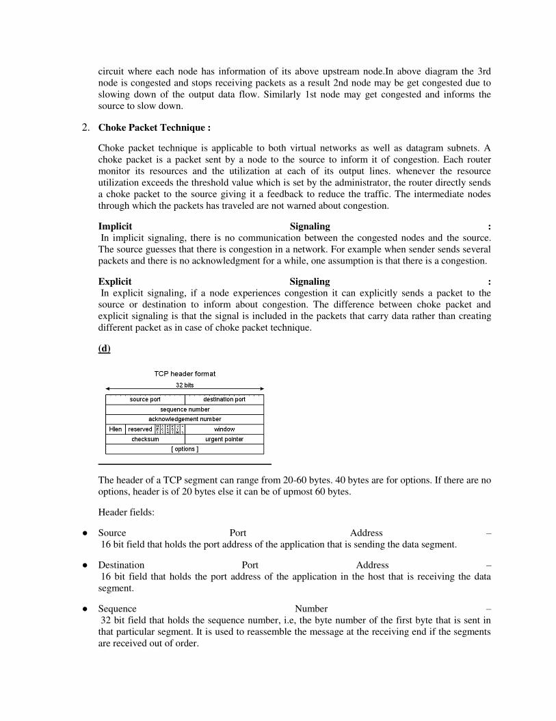
circuit where each node has information of its above upstream node.In above diagram the 3rd
node is congested and stops receiving packets as a result 2nd node may be get congested due to
slowing down of the output data flow. Similarly 1st node may get congested and informs the
source to slow down.
2. Choke Packet Technique :
Choke packet technique is applicable to both virtual networks as well as datagram subnets. A
choke packet is a packet sent by a node to the source to inform it of congestion. Each router
monitor its resources and the utilization at each of its output lines. whenever the resource
utilization exceeds the threshold value which is set by the administrator, the router directly sends
a choke packet to the source giving it a feedback to reduce the traffic. The intermediate nodes
through which the packets has traveled are not warned about congestion.
Implicit Signaling :
In implicit signaling, there is no communication between the congested nodes and the source.
The source guesses that there is congestion in a network. For example when sender sends several
packets and there is no acknowledgment for a while, one assumption is that there is a congestion.
Explicit Signaling :
In explicit signaling, if a node experiences congestion it can explicitly sends a packet to the
source or destination to inform about congestion. The difference between choke packet and
explicit signaling is that the signal is included in the packets that carry data rather than creating
different packet as in case of choke packet technique.
(d)
The header of a TCP segment can range from 20-60 bytes. 40 bytes are for options. If there are no
options, header is of 20 bytes else it can be of upmost 60 bytes.
Header fields:
● Source Port Address –
16 bit field that holds the port address of the application that is sending the data segment.
● Destination Port Address –
16 bit field that holds the port address of the application in the host that is receiving the data
segment.
● Sequence Number –
32 bit field that holds the sequence number, i.e, the byte number of the first byte that is sent in
that particular segment. It is used to reassemble the message at the receiving end if the segments
are received out of order.

● Acknowledgement Number –
32 bit field that holds the acknowledgement number, i.e, the byte number that the receiver
expects to receive next. It is an acknowledgment for the previous bytes being received
successfully.
● Header Length (HLEN) –
This is a 4 bit field that indicates the length of the TCP header by number of 4-byte words in the
header, i.e, if the header is of 20 bytes(min length of TCP header), then this field will hold 5
(because 5 x 4 = 20) and the maximum length: 60 bytes, then it’ll hold the value 15(because 15 x
4 = 60). Hence, the value of this field is always between 5 and 15.
● Control flags –
These are 6 1-bit control bits that control connection establishment, connection termination,
connection abortion, flow control, mode of transfer etc. Their function is:
○ URG: Urgent pointer is valid
○ ACK: Acknowledgement number is valid( used in case of cumulative acknowledgement)
○ PSH: Request for push
○ RST: Reset the connection
○ SYN: Synchronize sequence numbers
○ FIN: Terminate the connection
● Window size –
This field tells the window size of the sending TCP in bytes.
● Checksum –
This field holds the checksum for error control. It is mandatory in TCP as opposed to UDP.
● Urgent pointer –
This field (valid only if the URG control flag is set) is used to point to data that is urgently
required that needs to reach the receiving process at the earliest. The value of this field is added to
the sequence number to get the byte number of the last urgent byte
TCP is a connection-oriented protocol. UDP is the Datagram oriented protocol.
TCP is reliable as it guarantees delivery
of data to the destination router.
The delivery of data to the destination
cannot be guaranteed in UDP.

TCP provides extensive error checking
mechanisms. It is because it provides
flow control and acknowledgment of
data.
UDP has only the basic error checking
mechanism using checksums.
Retransmission of lost packets is
possible in TCP, but not in UDP.
There is no retransmission of lost
packets in User Datagram Protocol
(UDP).
TCP header size is 20 bytes. UDP Header size is 8 bytes.
5)-a
IP address is an address having information about how to reach a specific host, especially outside
the LAN. An IP address is a 32 bit unique address having an address space of 232.
Generally, there are two notations in which IP address is written, dotted decimal notation and
hexadecimal notation.
Classful Addressing
The 32 bit IP address is divided into five sub-classes. These are:
● Class A
● Class B
● Class C
● Class D
● Class E
Class A:

IP address belonging to class A are assigned to the networks that contain a large number of hosts.
● The network ID is 8 bits long.
● The host ID is 24 bits long.
The higher order bits of the first octet in class A is always set to 0. The remaining 7 bits in first
octet are used to determine network ID. The 24 bits of host ID are used to determine the host in
any network. The default sub-net mask for class A is 255.x.x.x. Therefore, class A has a total of:
● 2^7= 128 network ID
● 2^24 – 2 = 16,777,214 host ID
IP addresses belonging to class A ranges from 1.x.x.x – 126.x.x.x
Class B:
IP address belonging to class B are assigned to the networks that ranges from medium-sized to
large-sized networks.
● The network ID is 16 bits long.
● The host ID is 16 bits long.
The higher order bits of the first octet of IP addresses of class B are always set to 10. The
remaining 14 bits are used to determine network ID. The 16 bits of host ID is used to determine
the host in any network. The default sub-net mask for class B is 255.255.x.x. Class B has a total
of:
● 2^14 = 16384 network address
● 2^16 – 2 = 65534 host address
IP addresses belonging to class B ranges from 128.0.x.x – 191.255.x.x.
Class C:
● IP address belonging to class C are assigned to small-sized networks.
○ The network ID is 24 bits long.
○ The host ID is 8 bits long.
● The higher order bits of the first octet of IP addresses of class C are always set to 110. The
remaining 21 bits are used to determine network ID. The 8 bits of host ID is used to determine the
host in any network. The default sub-net mask for class C is 255.255.255.x. Class C has a total of:
○ 2^21 = 2097152 network address
○ 2^8 – 2 = 254 host address
IP addresses belonging to class C ranges from 192.0.0.x – 223.255.255.x.
Class D
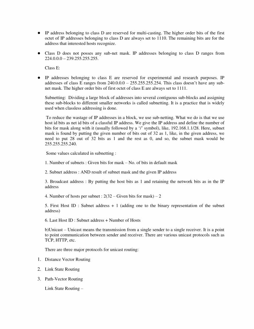
● IP address belonging to class D are reserved for multi-casting. The higher order bits of the first
octet of IP addresses belonging to class D are always set to 1110. The remaining bits are for the
address that interested hosts recognize.
● Class D does not posses any sub-net mask. IP addresses belonging to class D ranges from
224.0.0.0 – 239.255.255.255.
Class E:
● IP addresses belonging to class E are reserved for experimental and research purposes. IP
addresses of class E ranges from 240.0.0.0 – 255.255.255.254. This class doesn’t have any sub-
net mask. The higher order bits of first octet of class E are always set to 1111.
Subnetting: Dividing a large block of addresses into several contiguous sub-blocks and assigning
these sub-blocks to different smaller networks is called subnetting. It is a practice that is widely
used when classless addressing is done.
To reduce the wastage of IP addresses in a block, we use sub-netting. What we do is that we use
host id bits as net id bits of a classful IP address. We give the IP address and define the number of
bits for mask along with it (usually followed by a ‘/’ symbol), like, 192.168.1.1/28. Here, subnet
mask is found by putting the given number of bits out of 32 as 1, like, in the given address, we
need to put 28 out of 32 bits as 1 and the rest as 0, and so, the subnet mask would be
255.255.255.240.
Some values calculated in subnetting :
1. Number of subnets : Given bits for mask – No. of bits in default mask
2. Subnet address : AND result of subnet mask and the given IP address
3. Broadcast address : By putting the host bits as 1 and retaining the network bits as in the IP
address
4. Number of hosts per subnet : 2(32 – Given bits for mask) – 2
5. First Host ID : Subnet address + 1 (adding one to the binary representation of the subnet
address)
6. Last Host ID : Subnet address + Number of Hosts
b)Unicast – Unicast means the transmission from a single sender to a single receiver. It is a point
to point communication between sender and receiver. There are various unicast protocols such as
TCP, HTTP, etc.
There are three major protocols for unicast routing:
1. Distance Vector Routing
2. Link State Routing
3. Path-Vector Routing
Link State Routing –
Link state routing is the second family of routing protocols. While distance vector routers use a
distributed algorithm to compute their routing tables, link-state routing uses link-state routers to
exchange messages that allow each router to learn the entire network topology. Based on this
learned topology, each router is then able to compute its routing table by using a shortest path
computation.
Distance-vector routing (DVR) protocol requires that a router inform its neighbors of topology
changes periodically.
Distance Vector Algorithm
1. A router transmits its distance vector to each of its neighbors in a routing packet.
2. Each router receives and saves the most recently received distance vector from each of its
neighbors.
3. A router recalculates its distance vector when:
○ It receives a distance vector from a neighbor containing different information than before.
○ It discovers that a link to a neighbor has gone down.
Path Vector Routing
Path Vector Routing is a routing algorithm in unicast routing protocol of network layer, and it is
useful for interdomain routing. The principle of path vector routing is similar to that of distance
vector routing. It assumes that there is one node in each autonomous system that acts on behalf of
the entire autonomous system is called Speaker node .The speaker node in an AS creates a
routing cable and advertises to the speaker node in the neighbouring ASs .A speaker node
advertises the path, not the metrics of the nodes, in its autonomous system or other autonomous
systems.
6)-a
The basic function of the Transport layer is to accept data from the layer above, split it up into
smaller units, pass these data units to the Network layer, and ensure that all the pieces arrive
correctly at the other end.
Furthermore, all this must be done efficiently and in a way that isolates the upper layers from the
inevitable changes in the hardware technology.
The Transport layer also determines what type of service to provide to the Session layer, and,
ultimately, to the users of the network. The most popular type of transport connection is an error-
free point-to-point channel that delivers messages or bytes in the order in which they were sent.
The Transport layer is a true end-to-end layer, all the way from the source to the destination. In
other words, a program on the source machine carries on a conversation with a similar program
on the destination machine, using the message headers and control messages.
Functions of Transport Layer
1. Service Point Addressing: Transport Layer header includes service point address which is port
address. This layer gets the message to the correct process on the computer unlike Network
Layer, which gets each packet to the correct computer.
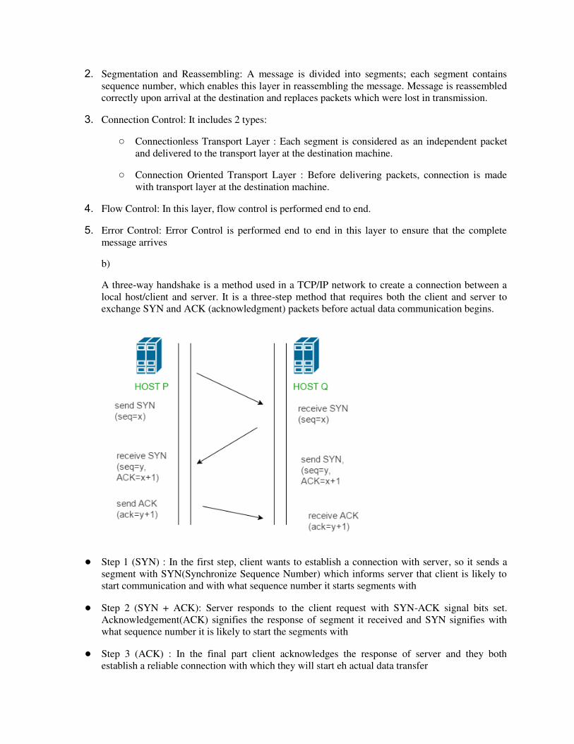
2. Segmentation and Reassembling: A message is divided into segments; each segment contains
sequence number, which enables this layer in reassembling the message. Message is reassembled
correctly upon arrival at the destination and replaces packets which were lost in transmission.
3. Connection Control: It includes 2 types:
○ Connectionless Transport Layer : Each segment is considered as an independent packet
and delivered to the transport layer at the destination machine.
○ Connection Oriented Transport Layer : Before delivering packets, connection is made
with transport layer at the destination machine.
4. Flow Control: In this layer, flow control is performed end to end.
5. Error Control: Error Control is performed end to end in this layer to ensure that the complete
message arrives
b)
A three-way handshake is a method used in a TCP/IP network to create a connection between a
local host/client and server. It is a three-step method that requires both the client and server to
exchange SYN and ACK (acknowledgment) packets before actual data communication begins.
● Step 1 (SYN) : In the first step, client wants to establish a connection with server, so it sends a
segment with SYN(Synchronize Sequence Number) which informs server that client is likely to
start communication and with what sequence number it starts segments with
● Step 2 (SYN + ACK): Server responds to the client request with SYN-ACK signal bits set.
Acknowledgement(ACK) signifies the response of segment it received and SYN signifies with
what sequence number it is likely to start the segments with
● Step 3 (ACK) : In the final part client acknowledges the response of server and they both
establish a reliable connection with which they will start eh actual data transfer
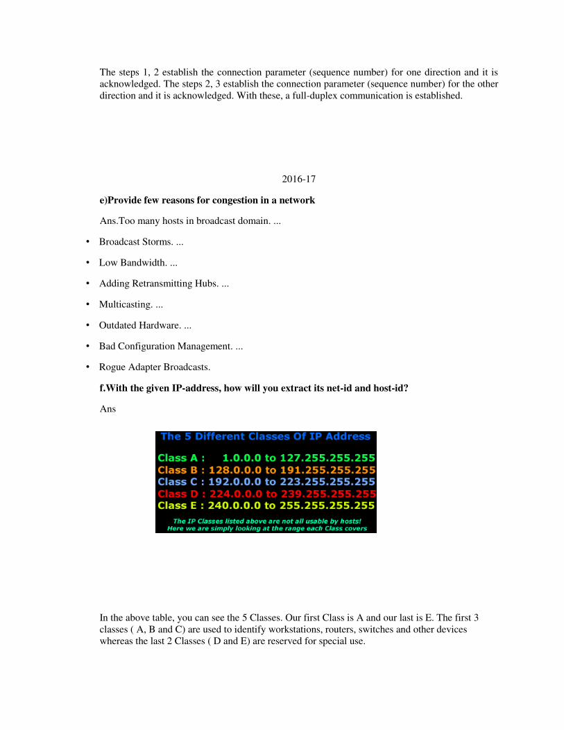
The steps 1, 2 establish the connection parameter (sequence number) for one direction and it is
acknowledged. The steps 2, 3 establish the connection parameter (sequence number) for the other
direction and it is acknowledged. With these, a full-duplex communication is established.
2016-17
e)Provide few reasons for congestion in a network
Ans.Too many hosts in broadcast domain. ...
• Broadcast Storms. ...
• Low Bandwidth. ...
• Adding Retransmitting Hubs. ...
• Multicasting. ...
• Outdated Hardware. ...
• Bad Configuration Management. ...
• Rogue Adapter Broadcasts.
f.With the given IP-address, how will you extract its net-id and host-id?
Ans
In the above table, you can see the 5 Classes. Our first Class is A and our last is E. The first 3
classes ( A, B and C) are used to identify workstations, routers, switches and other devices
whereas the last 2 Classes ( D and E) are reserved for special use.

As you would already know an IP Address consists of 32 Bits, which means it's 4 bytes long. The
first octet (first 8 Bits or first byte) of an IP Address is enough for us to determine the Class to
which it belongs. And, depending on the Class to which the IP Address belongs, we can
determine which portion of the IP Address is the Network ID and which is the Node ID.
For example, if I told you that the first octet of an IP Address is "168" then, using the above table,
you would notice that it falls within the 128-191 range, which makes it a Class B IP Address.
f).Explain the three way handshaking protocol to establish the transportlevel connection?
Ans.
three-way handshake is primarily used to create a TCP socket connection. It works when:
• A client node sends a SYN data packet over an IP network to a server on the same or an external
network. The objective of this packet is to ask/infer if the server is open for new connections.
• The target server must have open ports that can accept and initiate new connections. When the
server receives the SYN packet from the client node, it responds and returns a confirmation
receipt – the ACK packet or SYN/ACK packet.
• The client node receives the SYN/ACK from the server and responds with an ACK packet.
4.i) Describe the problem of count to infinity associated with distance vector routing
technique.
Ans. Count to infinity problem:
1. One of the important issue in Distance Vector Routing is County of Infinity Problem.
2. Counting to infinity is just another name for a routing loop.
3. In distance vector routing, routing loops usually occur when an interface goes down.
4. It can also occur when two routers send updates to each other at the same time.
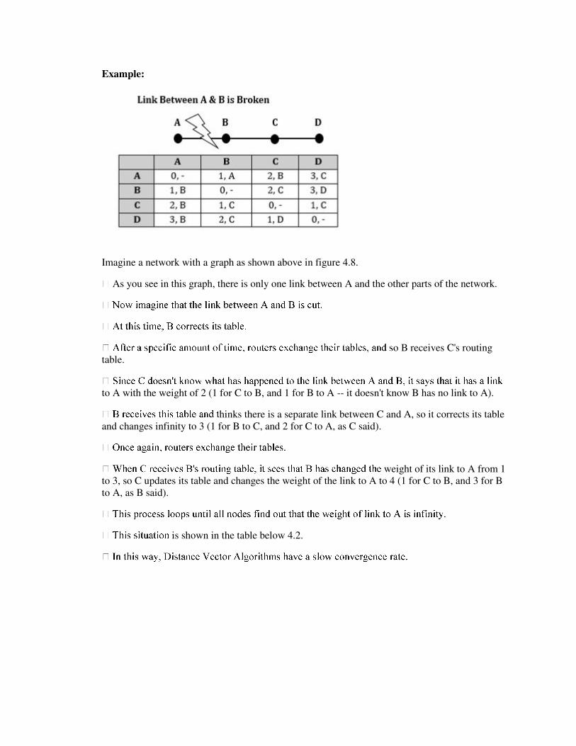
Example:
Imagine a network with a graph as shown above in figure 4.8.
As you see in this graph, there is only one link between A and the other parts of the network.
o B receives C's routing
table.
to A with the weight of 2 (1 for C to B, and 1 for B to A -- it doesn't know B has no link to A).
hinks there is a separate link between C and A, so it corrects its table
and changes infinity to 3 (1 for B to C, and 2 for C to A, as C said).
weight of its link to A from 1
to 3, so C updates its table and changes the weight of the link to A to 4 (1 for C to B, and 3 for B
to A, as B said).
is shown in the table below 4.2.
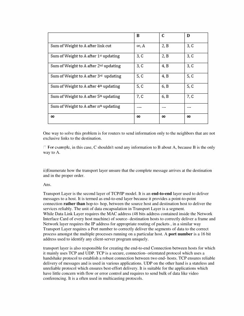
One way to solve this problem is for routers to send information only to the neighbors that are not
exclusive links to the destination.
, in this case, C shouldn't send any information to B about A, because B is the only
way to A.
ii)Enumerate how the transport layer unsure that the complete message arrives at the destination
and in the proper order.
Ans.
Transport Layer is the second layer of TCP/IP model. It is an end-to-end layer used to deliver
messages to a host. It is termed as end-to-end layer because it provides a point-to-point
connection rather than hop-to- hop, between the source host and destination host to deliver the
services reliably. The unit of data encapsulation in Transport Layer is a segment.
While Data Link Layer requires the MAC address (48 bits address contained inside the Network
Interface Card of every host machine) of source- destination hosts to correctly deliver a frame and
Network layer requires the IP address for appropriate routing of packets , in a similar way
Transport Layer requires a Port number to correctly deliver the segments of data to the correct
process amongst the multiple processes running on a particular host. A port number is a 16 bit
address used to identify any client-server program uniquely.
transport layer is also responsible for creating the end-to-end Connection between hosts for which
it mainly uses TCP and UDP. TCP is a secure, connection- orientated protocol which uses a
handshake protocol to establish a robust connection between two end- hosts. TCP ensures reliable
delivery of messages and is used in various applications. UDP on the other hand is a stateless and
unreliable protocol which ensures best-effort delivery. It is suitable for the applications which
have little concern with flow or error control and requires to send bulk of data like video
conferencing. It is a often used in multicasting protocols.

SOLUTION COMPUTER NETWORKS –(2015-16)
SECTION-A
Q-1a Given the id address 180:25:21:172 and subnet mask 255:255:192:0 what is
subnet address ?
Ans -According to rule: As 180.25.21.172 as IPand255.255.192.0 as Subnet address then Subnet
address will be comparing ip to subnet mask where there is 255 written copysame ip address as
subnet address and where there is 0 written in subnet replace the ipwith 0 and apply AND
operation over 192 and 21 then the final output will be180.25.0.0. The blank value will be
calculated by Applying AND operation over 192and 21 192- binary- 11000000 AND
OPERATION 21- binary- 00010101=00000000. Thenthe final subnet address will be 180.25.0.0.
Q-1b What is count to infinity problem?
A problem with distance-vector routing is that any decrease in cost (good news)propagates
quickly, but any increase in cost (bad news) will propagate slowly. For arouting protocol to work
properly, if a link is broken (cost becomes infinity), everyother router should be aware of it
immediately, but in distance-vector routing, this takes some time. The problem to refer as count
to infinity problem.
Q-1e What is the net mask of the gateway interface in a subnetwork where maximum of 25
hosts exist and ip address of one of the hosts is 192:168:1:1?
Ans- For 25 host we require 5-bits reserve for host. This means prefix length is /27(27continious
1’s followed by all 0’s). So net mask is 255.255.255.192.
Q-2b(ii) What si unicast routing? Discuss unicast
routing protocols.
Ans: Unicast – Unicast means the transmission from a single sender to a singlereceiver. It is a
point to point communication between sender and receiver. There are various unicast protocols
such as TCP, HTTP, etc.
tion oriented protocol thatrelay
on acknowledgement from the receiver side.
forcommunication.
There are three major protocols for unicast routing:
1. Distance Vector Routing2. Link State Routing3. Path-Vector Routing
Link State Routing –Link state routing is the second family of routing protocols. While distance
vector routers usea distributed algorithm to compute their routing tables, link-state routing uses
link-state routers to exchange messages that allow each router to learn the entire network
topology.Based on this learned topology, each router is then able to compute its routing table by
using a shortest path computation.
Features of link state routing protocols –
Link state packet – A small packet that contains routing information.
Link state database – A collection information gathered from link state packet.
Shortest path first algorithm (Dijkstra algorithm) – A calculation performed on the
database results into shortest path
Routing table – A list of known paths and interfaces.
Calculation of shortest path –To find shortest path, each node need to run the famous Dijkstra
algorithm. This famous Step-1: The node is taken and
chosen as a root node of the tree, this creates the tree with a single node, and now set the total
cost of each node to some value based on the information in Link State Database
Step-2: Now the node selects one node, among all the nodes not in the tree like structure,
which is nearest to the root, and adds this to the tree.The shape of the tree gets changed .
Step-3: After this node is added to the tree, the cost of all the nodes not in the tree needs to be
updated because the paths may have been changed.
Step-4: The node repeats the Step 2. and Step 3. until all the nodes are added in the tree
Link State protocols in comparison to Distance Vector protocols have:
1. It requires large amount of memory.
2. Shortest path computations require many CPU circles.
3. If network use the little bandwidth ; it quickly reacts to topology changes
4. All items in the database must be sent to neighbors to form link state packets.
5. All neighbors must be trusted in the topology.
6. Authentication mechanisms can be used to avoid undesired adjacency and problems.
7. No split horizon techniques are possible in the link state routing.
Open shortest path first (OSPF) routing protocol –
g
group of the Internet Engineering Task Force (IETF).
t includes the subnet of
each route it knows about, thus, enabling variable-length subnet masks. With variable-length
subnet masks, an IP network can be broken into many subnets of various sizes. This provides
network administrators with extra network-configuration flexibility.These updates are multicasts
at specific addresses (224.0.0.5 and 224.0.0.6).
the
Internet Protocol
PF sets the value of protocol field to 89
algorithm
– version 1 and version 2. Version 2 is used mostly
OSPF Messages – OSPF is a very complex protocol. It uses five different types of messages.
These are as follows:
10. Hello message (Type 1) – It is used by the routers to introduce itself to the other routers.
11. Database description message (Type 2) – It is normally send in response to the Hello
message.
12. Link-state request message (Type 3) – It is used by the routers that need information about
specific Link-State packet.
13. Link-state update message (Type 4) – It is the main OSPF message for building Link-State
Database.
14. Link-state acknowledgement message (Type 5) – It is used to create reliability in the OSPF
protocol.

Q-2 d: Explain TCP congestion Control algorithm in internet. What is TCP segment
Header? Also discuss TCP connection management.
TCP Congestion Control:The sender's window size is determined not only by the receiver but
also by congestion in the network. The sender has two pieces of information: the receiver-
advertised window size and the congestion window size. The actual size of the window is the
minimum of these two.Actual window size = minimum (rwnd, cwnd)
Congestion Policy
TCP's general policy for handling congestion is based on three phases: slow start, congestion
avoidance, and congestion detection. In the slow-start phase, the sender starts with a very slow
rate of transmission, but increases the rate rapidly to reach a threshold. When the threshold is
reached, the data rate is reduced to avoid congestion. Finally if congestion is detected, the sender
goes back to the slow-start or congestion avoidance phase based on how the congestion is
detected.
Slow Start: Exponential Increase:The slow-start algorithm is based on the idea that the size of
the congestion window (cwnd) starts with one maximum segment size (MSS), but it increases one
MSS each time an acknowledgment arrives.
Congestion Avoidance: Additive Increase To avoid congestion before it happens, we must slow
down this exponential growth. TCP defines another algorithm called congestion avoidance,
which increases the cwnd additively instead of exponentially. When the size of the congestion
window reaches the slow-start threshold in the case where cwnd = i, the slow-start phase stops
and the additive phase begins. In this algorithm, each time the whole “window” of segments is
acknowledged, the size of the congestion window is increased by one. A window is the number of
segments transmitted during RTT.
Congestion Detection: Multiplicative Decrease:
If congestion occurs, the congestion window size must be decreased. The only way the sender can
guess that congestion has occurred is by the need to retransmit a segment.
However,retransmission can occur in one of two cases: when a timer times out or when three
Duplicate ACKs are received. In both cases, the size of the threshold is dropped to one-half, a
multiplicative decrease.
TCP implementations have two reactions:1. If a time-out occurs, there is a stronger possibility
of congestion; a segment has probably been dropped in the network, and there is no news about
the sent segments.In this case TCP reacts strongly:
a. It sets the value of the threshold to one-half of the current window size.b. It sets cwnd to the
size of one segment.c. It starts the slow-start phase again.2. If three ACKs are received, there is a
weaker possibility of congestion; a segment may have been dropped, but some segments after that
may have arrived safely since three ACKs are received. This is called fast transmission and fast
recovery.
In this case, TCP has a weaker reaction:
a. It sets the value of the threshold to one-half of the current window size.
b. It sets cwnd to the value of the threshold.
c. It starts the congestion avoidance phase.
An implementations reacts to congestion detection in one of the following ways:
If detection is by time-out, a new slow-start phase starts.
If detection is by three ACKs, a new congestion avoidance phase starts.
Example: We assume that the maximum window size is 32 segments. The threshold is set to 16
segments (one-half of the maximum window size). In the slow-start phase the window size starts
from 1 and grows exponentially until it reaches the threshold. After it reaches the threshold, the
congestion avoidance (additive increase) procedure allows the window size to increase linearly
untila timeout occurs or the maximum window size is reached. In Figure 24.11, the time-out
occurs when the window size is 20. At this moment, the multiplicative decrease procedure takes
over and reduces the threshold to one-half of the previous window size. The previous window
size was 20 when the time-out happened so the new threshold is now 10.TCP moves to slow start
again and starts with a window size of 1, and TCP moves to additive increase when the new
threshold is reached. When the window size is 12, a three duplicate ACKs event happens. The
multiplicative decrease procedure takes over again. The threshold is set to 6 and TCP goes to the
additive increase phase this time. It remains in this phase until another timeout or another three
duplicate ACKs happen.
TCP Segment Header:
A packet in TCP is called a segment. Source port address. This is a 16-bit field that defines the
port number of the application program in the host that is sending the segment.
Destination port address. This is a 16-bit field that defines the port number of the application
program in the host that is receiving the segment.
Sequence number. This 32-bit field defines the number assigned to the first byte of data
contained in
this segment. TCP is a stream transport protocol. To ensure connectivity, each byte to be
transmitted
is numbered. The sequence number tells the destination which byte in this sequence is the first
byte
in the segment. During connection establishment (discussed later) each party uses a random
number
generator to create an initial sequence number (ISN), which is usually different in each
direction.
Acknowledgment number. This 32-bit field defines the byte number that the receiver of the
segment
is expecting to receive from the other party. If the receiver of the segment has successfully
received
byte number x from the other party, it returns x+1 as the acknowledgment number.

Acknowledgment and data can be piggybacked together.
Header length. This 4-bit field indicates the number of 4-byte words in the TCP header. The
length of
the header can be between 20 and 60 bytes. Therefore, the value of this field is always between 5
(5x4=20) and 15 (15x4=60).
Control. This field defines 6 different control bits or flags, as shown in Figure 24.8. One or more
of
these bits can be set at a time.
Window size. This field defines the window size of the sending TCP in bytes. Note that the length
of
this field is 16 bits, which means that the maximum size of the window is 65,535 bytes. This
value is
normally referred to as the receiving window (rwnd) and is determined by the receiver. The
sender
must obey the dictation of the receiver in this case.
Checksum. This 16-bit field contains the checksum. The calculation of the checksum for TCP
follows
the same procedure as the one described for UDP
Urgent pointer. This 16-bit field, which is valid only if the urgent flag is set, is used when the
segment
contains urgent data.
Options. There can be up to 40 bytes of optional information in the TCP header.
TCP Connection Management
TCP is connection-oriented. a connection-oriented transport protocol establishes a logical path
between the source and destination.
In TCP, connection-oriented transmission requires three phases: connection establishment, data
transfer, and connection termination.
Connection Establishment
TCP transmits data in full-duplex mode. When two TCPs in two machines are connected, they are
able to send segments to each other simultaneously.
Three-Way Handshaking: The connection establishment in TCP is called three-way
handshaking.

The process starts with the server. The server program tells its TCP that it is ready to accept a
connection. This request is called a passive open. Although the server TCP is ready to accept a
connection from any machine in the world, it cannot make the connection itself.
The client program issues a request for an active open. A client that wishes to connect to an open
server tells its TCP to connect to a particular server. TCP can now start the three-way
handshaking
process.
1. The client sends the first segment, a SYN segment, in which only the SYN flag is set. This
segment is for synchronization of sequence numbers. The client in our example chooses a
random number as the first sequence number and sends this number to the server. This
sequence number is called the initial sequence number (ISN).
A SYN segment cannot carry data, but it consumes one sequence number.
2. The server sends the second segment, a SYN + ACK segment with two flag bits set as: SYN
and ACK. This segment has a dual purpose.
A SYN + ACK segment cannot carry data, but it does consume one sequence number.
3. The client sends the third segment. This is just an ACK segment. It acknowledges the receipt
of the second segment with the ACK flag and acknowledgment number field.
An ACK segment, if carrying no data, consumes no sequence number.
SYN Flooding Attack:
The connection establishment procedure in TCP is susceptible to a serious security problem
called
SYN flooding attack. This happens when one or more malicious attackers send a large number of
SYN segments to a server pretending that each of them is coming from a different client by
faking
the source IP addresses in the datagrams. The server, assuming that the clients are issuing an
active open, allocates the necessary resources, such as creating transfer control block (TCB)
tables
and setting timers.
TCP server then sends the SYN + ACK segments to the fake clients, which are lost. When the
server
waits for the third leg of the handshaking process, however, resources are allocated without being

used. If, during this short period of time, the number of SYN segments is large, the server
eventually runs out of resources and may be unable to accept connection requests from valid
clients. This SYN flooding attack belongs to a group of security attacks known as a denial of
service
attack, in which an attacker monopolizes a system with so many service requests that the system
overloads and denies service to valid requests.
Data Transfer:
Connection Termination:
Using Three-Way Handshaking:
Using Half Close:
Q-2e : What is the Total delay(Latency) for a frame size of 10 million bits
that is being sent up on link with 15 routers each having queuing time of 2
micro sec and a processing time of 1 micro sec? The length of the link is
3000km. The speed of light inside the link is 2 x 10⁸ m/sec. The link has
bandwidth of 6Mbps.
Ans:
Latency =propagation time +transmission time +queuing time + processing delay
Processing delay=15x1 μs = 15 μs=0.000015s
Queuing time= 15x2 μs = 30 μs = 0.000030s
Transmission time = 10000000/6Mbps=1.66s
Propagation time= 3000x103/2x108 = 0.015s
Latency= 0.000015+0.000030+1.66+0.015=1.6750s
Q-2g What is IP addressing? How it is classified? How is subnet addressing is performed?
Ans: An Internet Protocol address (IP address) is a numerical label assigned to each device
connected to a computer network that uses the Internet Protocol for communication. An IP
address serves two principal functions: host or network interface identification and location
addressing. There are two types of IPaddress IPv4 and IPv6.
IPV4 ADDRESSES:
)

An IPv4 address is a 32-bit address that uniquely and universally defines the connection of a host
or a router to the Internet. IPv4 addresses are unique in the sense that each address defines one,
and only one, connection to the Internet.IPv4 addresses are universal in the sense that the
addressing system must be accepted by any host that wants to be connected to the Internet.
IPv6 ADDRESSING:
The main reason for migration from IPv4 to IPv6 is the small size of the address space in IPv4.An
IPv6 address is 128 bits or 16 bytes (octets) long, four times the address length in IPv4 The bits in
the subnet mask and the Internet address have a one-to-one correspondence. The prefix length is
equal to the number of contiguous one-bits in the traditional subnet mask. This means that
specifying the network address 130.5.5.25 with a subnet mask of 255.255.255.0 can also be
expressed as 130.5.5.25/24
note----All questions of 2014 are covered above.
Thanks
Dr.Vinesh Kumar
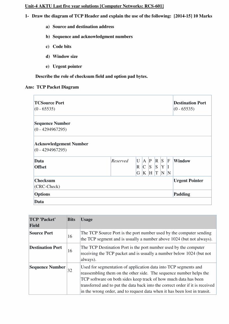
Unit-4 AKTU Last five year solutions [Computer Networks: RCS-601]
1- Draw the diagram of TCP Header and explain the use of the following: [2014-15] 10 Marks
a) Source and destination address
b) Sequence and acknowledgment numbers
c) Code bits
d) Window size
e) Urgent pointer
Describe the role of checksum field and option pad bytes.
Ans: TCP Packet Diagram
TCSource Port
(0 - 65535)
Destination Port
(0 - 65535)
Sequence Number
(0 - 4294967295)
Acknowledgement Number
(0 - 4294967295)
Data
Offset
Reserved U
R
G
A
C
K
P
S
H
R
S
T
S
Y
N
F
I
N
Window
Checksum
(CRC-Check)
Urgent Pointer
Options Padding
Data
TCP 'Packet'
Field
Bits Usage
Source Port 16
The TCP Source Port is the port number used by the computer sending
the TCP segment and is usually a number above 1024 (but not always).
Destination Port 16
The TCP Destination Port is the port number used by the computer
receiving the TCP packet and is usually a number below 1024 (but not
always).
Sequence Number 32
Used for segmentation of application data into TCP segments and
reassembling them on the other side. The sequence number helps the
TCP software on both sides keep track of how much data has been
transferred and to put the data back into the correct order if it is received
in the wrong order, and to request data when it has been lost in transit.
Data Offset 4
The TCP Data Offset indicates number of bytes into the TCP packet
where data can be found Thus, it actually indicates the number of bytes
in the TCP header and allows the receiver to jump directly to the data.
Reserved 6
URG
Urgent Flag 1
ACK
Acknowledgement
Flag
1 Used during 3-way handshake and data transfers.
PSH
Push Flag 1
Used for TCP push, which returns the buffer to the user application.
Used primarilly in streaming.
RST
Reset Flag 1
Used to reset a TCP connection
SYN
Synchronize Flag 1
Used during 3-way handshake
FIN
End of data 1
Indicates end of the TCP session
Window 16
Number of octets in the TCP header
Checksum 16
A Cyclic Redundancy Check (CRC) checksum is calculated by the
sender and added to this field before transmission. This field is used by
the receiver to verify the integrity of the data in the TCP payload and
rejects data that fails the CRC check.
Urgent Pointer 16
Points to the end of "urgent" data in the packet, but this field only exists
if the URG flag is set.
Options Varies
Padding Varies
Data Varies
This field contains a segment of data from the user application, such as
part of an email or web page.
Checksum- 16 bits.
This is computed as the 16-bit one's complement of the one's complement sum of a pseudo header of
information from the IP header, the TCP header, and the data, padded as needed with zero bytes at the
end to make a multiple of two bytes.
Options- 0 to 40 bytes.
Options occupy space at the end of the TCP header. All options are included in the checksum. An option
may begin on any byte boundary. The TCP header must be padded with zeros to make the header length
a multiple of 32 bits.
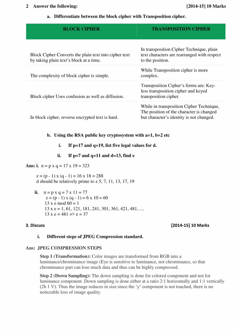
2 Answer the following: [2014-15] 10 Marks
a. Differentiate between the block cipher with Transposition cipher.
BLOCK CIPHER TRANSPOSITION CIPHER
Block Cipher Converts the plain text into cipher text
by taking plain text’s block at a time.
In transposition Cipher Technique, plain
text characters are rearranged with respect
to the position.
The complexity of block cipher is simple.
While Transposition cipher is more
complex.
Block cipher Uses confusion as well as diffusion.
Transposition Cipher’s forms are: Key-
less transposition cipher and keyed
transposition cipher.
In block cipher, reverse encrypted text is hard.
While in transposition Cipher Technique,
The position of the character is changed
but character’s identity is not changed.
b. Using the RSA public key cryptosystem with a=1, b=2 etc
i. If p=17 and q=19, list five legal values for d.
ii. If p=7 and q=11 and d=13, find e
Ans: i. n = p x q = 17 x 19 = 323
z = (p - 1) x (q - 1) = 16 x 18 = 288
d should be relatively prime to z 5, 7, 11, 13, 17, 19
ii. n = p x q = 7 x 11 = 77
z = (p - 1) x (q - 1) = 6 x 10 = 60
13 x e mod 60 = 1
13 x e = 1, 61, 121, 181, 241, 301, 361, 421, 481, ....
13 x e = 481 => e = 37
3. Discuss [2014-15] 10 Marks
i. Different steps of JPEG Compression standard.
Ans: JPEG COMPRESSION STEPS
Step 1 (Transformation): Color images are transformed from RGB into a
luminance/chrominance image (Eye is sensitive to luminance, not chrominance, so that
chrominance part can lose much data and thus can be highly compressed.
Step 2 (Down Sampling): The down sampling is done for colored component and not for
luminance component .Down sampling is done either at a ratio 2:1 horizontally and 1:1 vertically
(2h 1 V). Thus the image reduces in size since the ‘y’ component is not touched, there is no noticeable loss of image quality.
Step 3 (Organizing in Groups): The pixels of each color component are organized in groups of
8×2 pixels called “ data units” if number of rows or column is not a multiple of 8, the bottom row and rightmost columns are duplicated.
Step 4 ( Discrete Cosine Transform): Discrete Cosine Transform ( DCT) is then applied to each
data unit to create 8×8 map of transformed components.DCT involves some loss of information
due to the limited precision of computer arithmetic. This means that even without the map there
will be some loss of image quality but it is normally small.
Step 5 (Quantization): Each of the 64 transformed components in the data unit is divided by a
separate number called its ‘Quantization Coefficient (QC)’ and then rounded to an integer. This is where information is lost irretrievably, Large QC cause more loss. In general, the most JPEG
implements allow use QC tables recommended by the JPEG standard.
Step 6 (Encoding): The 64 quantized transformed coefficients ( Which are now integers) of each
data unit are encoded using a combination of RLE and Huffman coding.
Step 7 (Adding Header): The last step adds header and all the JPEG parameters used and output
the result.
The compressed file may be in one of the 3 formats:
1. Interchange Format: In which the file contains compressed image and all the tables needed by
the decoder. (Quantization table and Huffman code table).
2. Abbreviated Format: Where the file contains compressed image and may contain first a few
table. (Since the same encoder-decoder pair is used and they have some tables built in)
3. Abbreviated format for table and specification data: Where the file contains just tables and
number of compressed images. Since images compressed by same encoder and same tables,
hence when it is to be decoded, they are sent to decoder preceded by one file with table
specification data).
The JPEG decoder performs the reverse steps. Thus JPEG is a symmetric compression method.
ii. The RPC design and implementation issues
Ans: Remote Procedure Call (RPC) is a powerful technique for constructing distributed, client-server
based applications. It is based on extending the conventional local procedure calling so that the called
procedure need not exist in the same address space as the calling procedure. The two processes may
be on the same system, or they may be on different systems with a network connecting them.
When making a Remote Procedure Call:
1. The calling environment is suspended, procedure parameters are transferred across the network to
the environment where the procedure is to execute, and the procedure is executed there.
2. When the procedure finishes and produces its results, its results are transferred back to the calling
environment, where execution resumes as if returning from a regular procedure call.
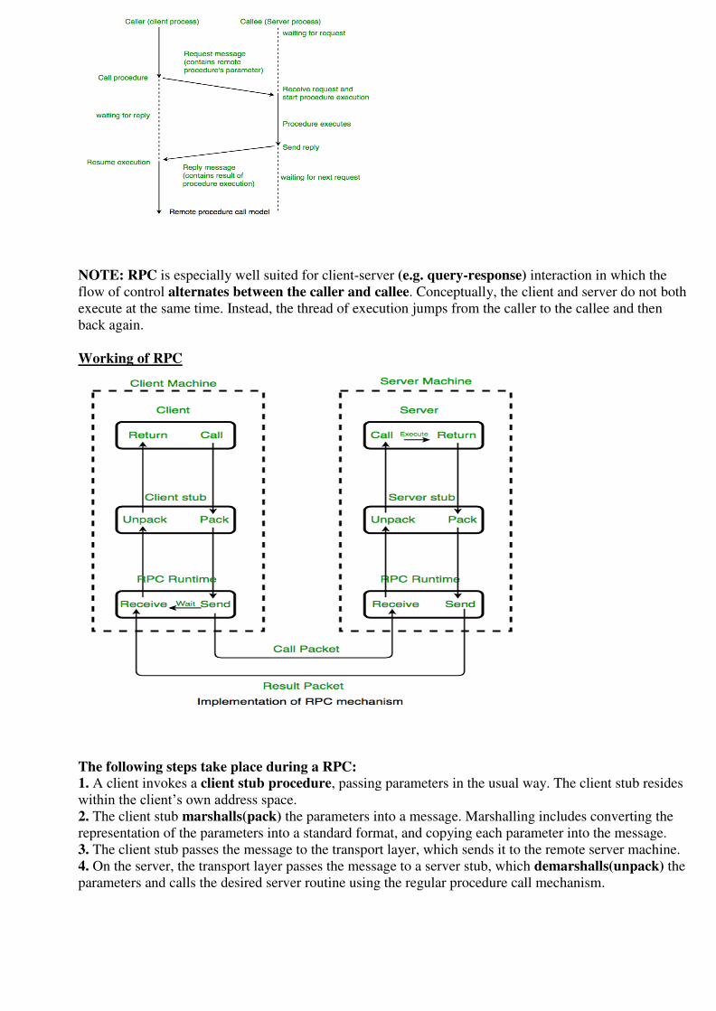
NOTE: RPC is especially well suited for client-server (e.g. query-response) interaction in which the
flow of control alternates between the caller and callee. Conceptually, the client and server do not both
execute at the same time. Instead, the thread of execution jumps from the caller to the callee and then
back again.
Working of RPC
The following steps take place during a RPC: 1. A client invokes a client stub procedure, passing parameters in the usual way. The client stub resides
within the client’s own address space.
2. The client stub marshalls(pack) the parameters into a message. Marshalling includes converting the
representation of the parameters into a standard format, and copying each parameter into the message.
3. The client stub passes the message to the transport layer, which sends it to the remote server machine.
4. On the server, the transport layer passes the message to a server stub, which demarshalls(unpack) the
parameters and calls the desired server routine using the regular procedure call mechanism.
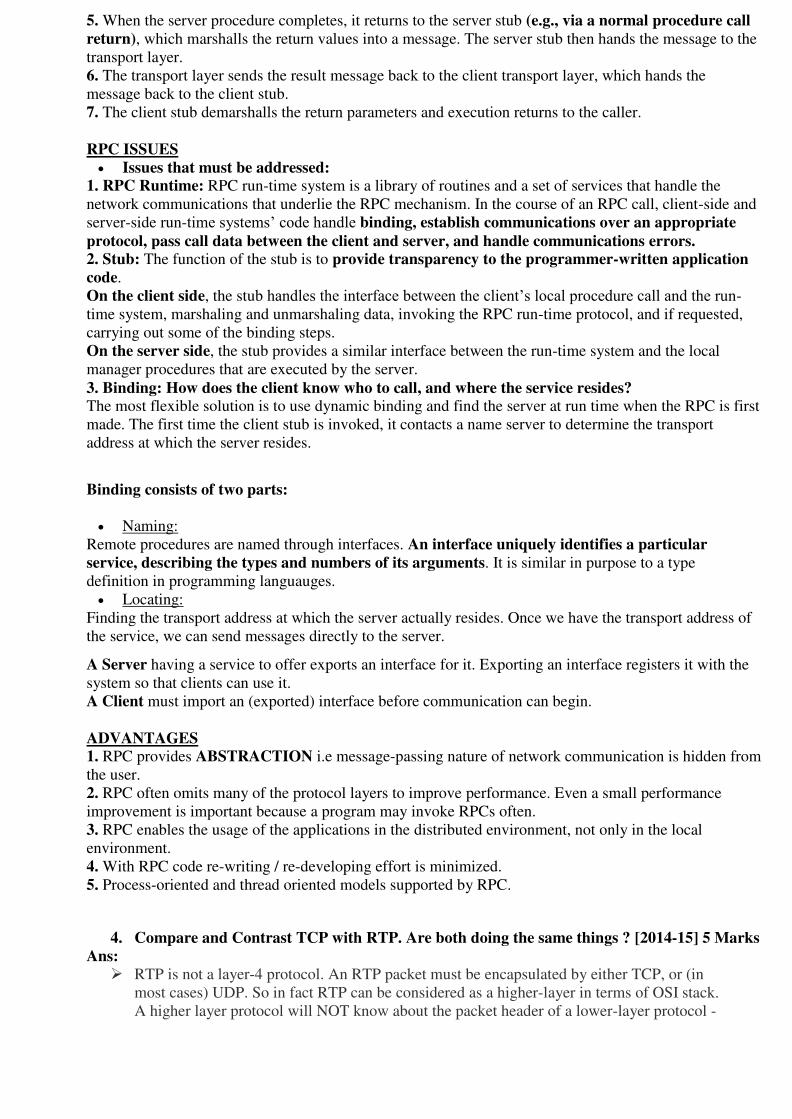
5. When the server procedure completes, it returns to the server stub (e.g., via a normal procedure call
return), which marshalls the return values into a message. The server stub then hands the message to the
transport layer.
6. The transport layer sends the result message back to the client transport layer, which hands the
message back to the client stub.
7. The client stub demarshalls the return parameters and execution returns to the caller.
RPC ISSUES
Issues that must be addressed: 1. RPC Runtime: RPC run-time system is a library of routines and a set of services that handle the
network communications that underlie the RPC mechanism. In the course of an RPC call, client-side and
server-side run-time systems’ code handle binding, establish communications over an appropriate
protocol, pass call data between the client and server, and handle communications errors. 2. Stub: The function of the stub is to provide transparency to the programmer-written application
code.
On the client side, the stub handles the interface between the client’s local procedure call and the run-
time system, marshaling and unmarshaling data, invoking the RPC run-time protocol, and if requested,
carrying out some of the binding steps.
On the server side, the stub provides a similar interface between the run-time system and the local
manager procedures that are executed by the server.
3. Binding: How does the client know who to call, and where the service resides? The most flexible solution is to use dynamic binding and find the server at run time when the RPC is first
made. The first time the client stub is invoked, it contacts a name server to determine the transport
address at which the server resides.
Binding consists of two parts:
Naming:
Remote procedures are named through interfaces. An interface uniquely identifies a particular
service, describing the types and numbers of its arguments. It is similar in purpose to a type
definition in programming languauges.
Locating:
Finding the transport address at which the server actually resides. Once we have the transport address of
the service, we can send messages directly to the server.
A Server having a service to offer exports an interface for it. Exporting an interface registers it with the
system so that clients can use it.
A Client must import an (exported) interface before communication can begin.
ADVANTAGES 1. RPC provides ABSTRACTION i.e message-passing nature of network communication is hidden from
the user.
2. RPC often omits many of the protocol layers to improve performance. Even a small performance
improvement is important because a program may invoke RPCs often.
3. RPC enables the usage of the applications in the distributed environment, not only in the local
environment.
4. With RPC code re-writing / re-developing effort is minimized.
5. Process-oriented and thread oriented models supported by RPC.
4. Compare and Contrast TCP with RTP. Are both doing the same things ? [2014-15] 5 Marks
Ans:
RTP is not a layer-4 protocol. An RTP packet must be encapsulated by either TCP, or (in
most cases) UDP. So in fact RTP can be considered as a higher-layer in terms of OSI stack.
A higher layer protocol will NOT know about the packet header of a lower-layer protocol -
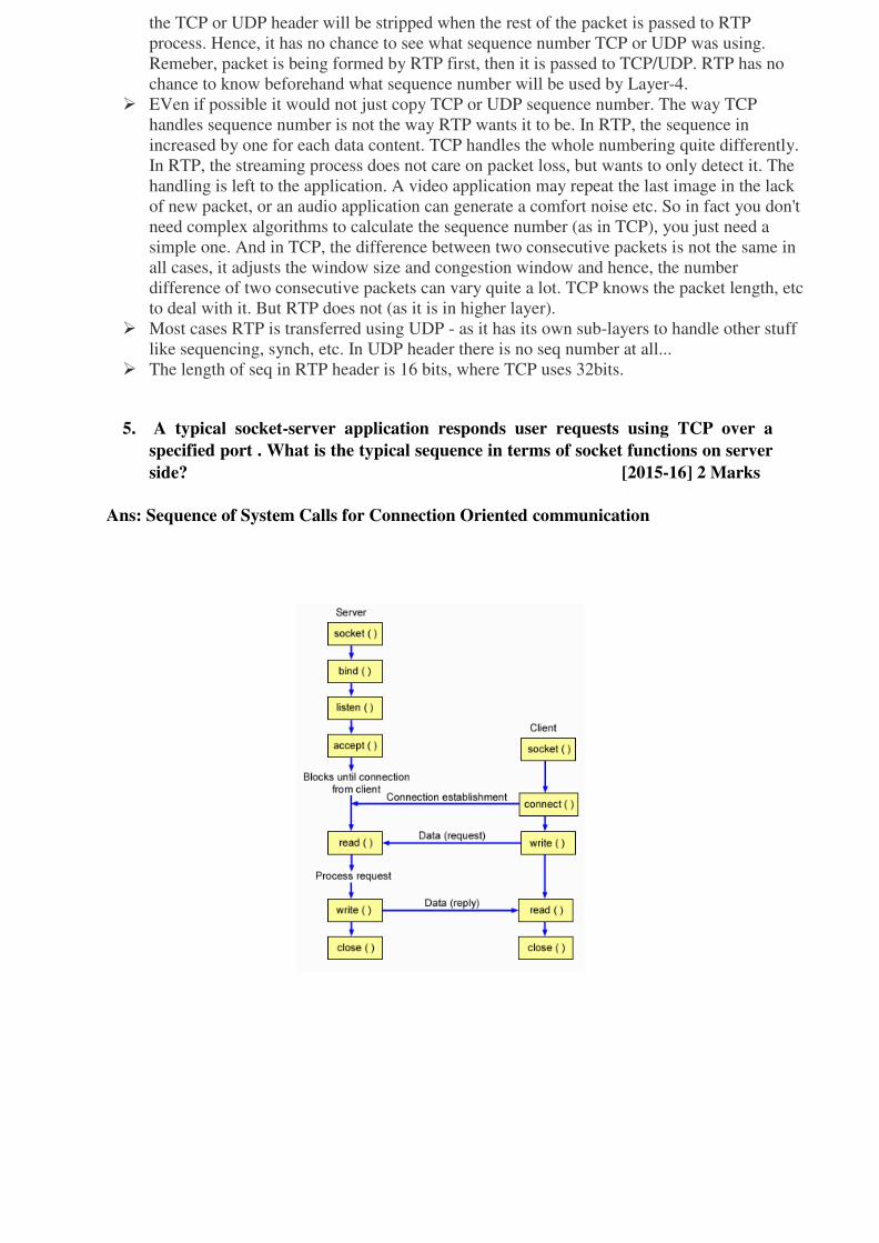
the TCP or UDP header will be stripped when the rest of the packet is passed to RTP
process. Hence, it has no chance to see what sequence number TCP or UDP was using.
Remeber, packet is being formed by RTP first, then it is passed to TCP/UDP. RTP has no
chance to know beforehand what sequence number will be used by Layer-4.
EVen if possible it would not just copy TCP or UDP sequence number. The way TCP
handles sequence number is not the way RTP wants it to be. In RTP, the sequence in
increased by one for each data content. TCP handles the whole numbering quite differently.
In RTP, the streaming process does not care on packet loss, but wants to only detect it. The
handling is left to the application. A video application may repeat the last image in the lack
of new packet, or an audio application can generate a comfort noise etc. So in fact you don't
need complex algorithms to calculate the sequence number (as in TCP), you just need a
simple one. And in TCP, the difference between two consecutive packets is not the same in
all cases, it adjusts the window size and congestion window and hence, the number
difference of two consecutive packets can vary quite a lot. TCP knows the packet length, etc
to deal with it. But RTP does not (as it is in higher layer).
Most cases RTP is transferred using UDP - as it has its own sub-layers to handle other stuff
like sequencing, synch, etc. In UDP header there is no seq number at all...
The length of seq in RTP header is 16 bits, where TCP uses 32bits.
5. A typical socket-server application responds user requests using TCP over a
specified port . What is the typical sequence in terms of socket functions on server
side? [2015-16] 2 Marks
Ans: Sequence of System Calls for Connection Oriented communication

6. Explain TCP congestion Control algorithm in internet. What is TCP segment
Header? Also discuss TCP connection management. [2015-16] 2 Marks
Ans: TCP Congestion Control:
The sender's window size is determined not only by the receiver but also by congestion in the
network. The sender has two pieces of information: the receiver-advertised window size and the
congestion window size. The actual size of the window is the minimum of these two.
Congestion Policy
Actual window size = minimum (rwnd, cwnd)
TCP's general policy for handling congestion is based on three phases: slow start, congestion
avoidance, and congestion detection. In the slow-start phase, the sender starts with a very slow rate
of transmission, but increases the rate rapidly to reach a threshold. When the threshold is reached,
the data rate is reduced to avoid congestion. Finally if congestion is detected, the sender goes back
to the slow-start or congestion avoidance phase based on how the congestion is detected.
Slow Start: Exponential Increase:
The slow-start algorithm is based on the idea that the size of the congestion window (cwnd) starts
with one maximum segment size (MSS), but it increases one MSS each time an acknowledgment
arrives.
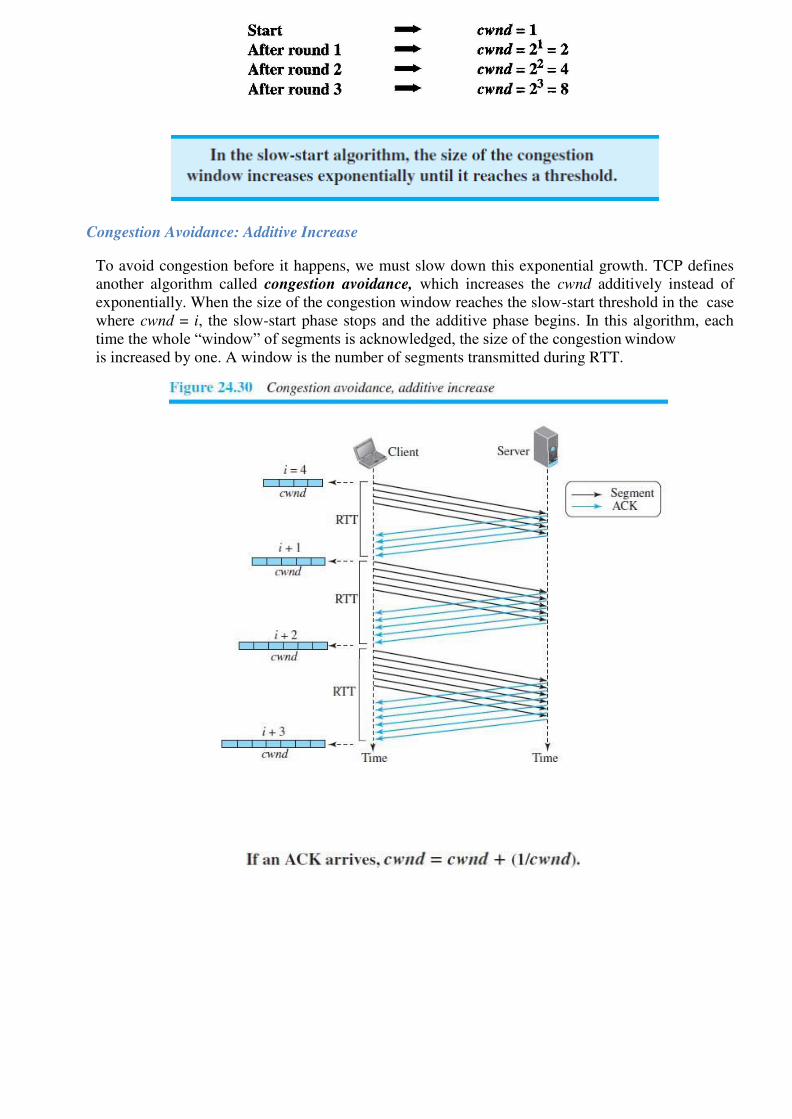
Congestion Avoidance: Additive Increase
To avoid congestion before it happens, we must slow down this exponential growth. TCP defines
another algorithm called congestion avoidance, which increases the cwnd additively instead of
exponentially. When the size of the congestion window reaches the slow-start threshold in the case
where cwnd = i, the slow-start phase stops and the additive phase begins. In this algorithm, each
time the whole “window” of segments is acknowledged, the size of the congestion window
is increased by one. A window is the number of segments transmitted during RTT.

Congestion Detection: Multiplicative Decrease:
If congestion occurs, the congestion window size must be decreased. The only way the sender can
guess that congestion has occurred is by the need to retransmit a segment. However, retransmission
can occur in one of two cases: when a timer times out or when three Duplicate ACKs are received.
In both cases, the size of the threshold is dropped to one-half, a multiplicative decrease.
TCP implementations have two reactions:
1. If a time-out occurs, there is a stronger possibility of congestion; a segment has probably
been dropped in the network, and there is no news about the sent segments.
In this case TCP reacts strongly:
a. It sets the value of the threshold to one-half of the current window size.
b. It sets cwnd to the size of one segment.
c. It starts the slow-start phase again.
2. If three ACKs are received, there is a weaker possibility of congestion; a segment may have
been dropped, but some segments after that may have arrived safely since three ACKs are
received. This is called fast transmission and fast recovery.
In this case, TCP has a weaker reaction:
a. It sets the value of the threshold to one-half of the current window size.
b. It sets cwnd to the value of the threshold.
c. It starts the congestion avoidance phase.
An implementations reacts to congestion detection in one of the following
ways: If detection is by time-out, a new slow-start phase starts.
If detection is by three ACKs, a new congestion avoidance phase starts.

Example: We assume that the maximum window size is 32 segments. The threshold is set to 16
segments (one-half of the maximum window size). In the slow-start phase the window size starts
from 1 and grows exponentially until it reaches the threshold. After it reaches the threshold, the
congestion avoidance (additive increase) procedure allows the window size to increase linearly
until a timeout occurs or the maximum window size is reached. In Figure 24.11, the time-out
occurs when the window size is 20. At this moment, the multiplicative decrease procedure takes
over and reduces the threshold to one-half of the previous window size. The previous window size
was 20 when the time-out happened so the new threshold is now 10.
TCP moves to slow start again and starts with a window size of 1, and TCP moves to additive
increase when the new threshold is reached. When the window size is 12, a three duplicate ACKs
event happens. The multiplicative decrease procedure takes over again. The threshold is set to 6
and TCP goes to the additive increase phase this time. It remains in this phase until another time-
out or another three duplicate ACKs happen.
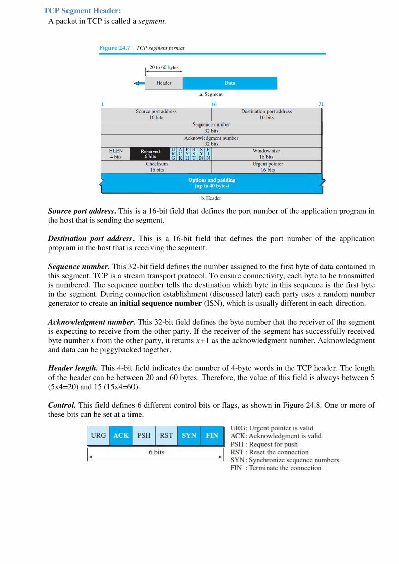
TCP Segment Header:
A packet in TCP is called a segment.
Source port address. This is a 16-bit field that defines the port number of the application program in
the host that is sending the segment.
Destination port address. This is a 16-bit field that defines the port number of the application
program in the host that is receiving the segment.
Sequence number. This 32-bit field defines the number assigned to the first byte of data contained in
this segment. TCP is a stream transport protocol. To ensure connectivity, each byte to be transmitted
is numbered. The sequence number tells the destination which byte in this sequence is the first byte
in the segment. During connection establishment (discussed later) each party uses a random number
generator to create an initial sequence number (ISN), which is usually different in each direction.
Acknowledgment number. This 32-bit field defines the byte number that the receiver of the segment
is expecting to receive from the other party. If the receiver of the segment has successfully received
byte number x from the other party, it returns x+1 as the acknowledgment number. Acknowledgment
and data can be piggybacked together.
Header length. This 4-bit field indicates the number of 4-byte words in the TCP header. The length
of the header can be between 20 and 60 bytes. Therefore, the value of this field is always between 5
(5x4=20) and 15 (15x4=60).
Control. This field defines 6 different control bits or flags, as shown in Figure 24.8. One or more of
these bits can be set at a time.
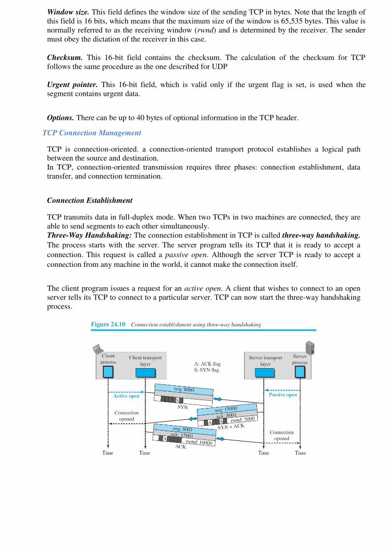
Window size. This field defines the window size of the sending TCP in bytes. Note that the length of
this field is 16 bits, which means that the maximum size of the window is 65,535 bytes. This value is
normally referred to as the receiving window (rwnd) and is determined by the receiver. The sender
must obey the dictation of the receiver in this case.
Checksum. This 16-bit field contains the checksum. The calculation of the checksum for TCP
follows the same procedure as the one described for UDP
Urgent pointer. This 16-bit field, which is valid only if the urgent flag is set, is used when the
segment contains urgent data.
Options. There can be up to 40 bytes of optional information in the TCP header.
TCP Connection Management
TCP is connection-oriented. a connection-oriented transport protocol establishes a logical path
between the source and destination.
In TCP, connection-oriented transmission requires three phases: connection establishment, data
transfer, and connection termination.
Connection Establishment
TCP transmits data in full-duplex mode. When two TCPs in two machines are connected, they are
able to send segments to each other simultaneously.
Three-Way Handshaking: The connection establishment in TCP is called three-way handshaking.
The process starts with the server. The server program tells its TCP that it is ready to accept a
connection. This request is called a passive open. Although the server TCP is ready to accept a
connection from any machine in the world, it cannot make the connection itself.
The client program issues a request for an active open. A client that wishes to connect to an open
server tells its TCP to connect to a particular server. TCP can now start the three-way handshaking
process.
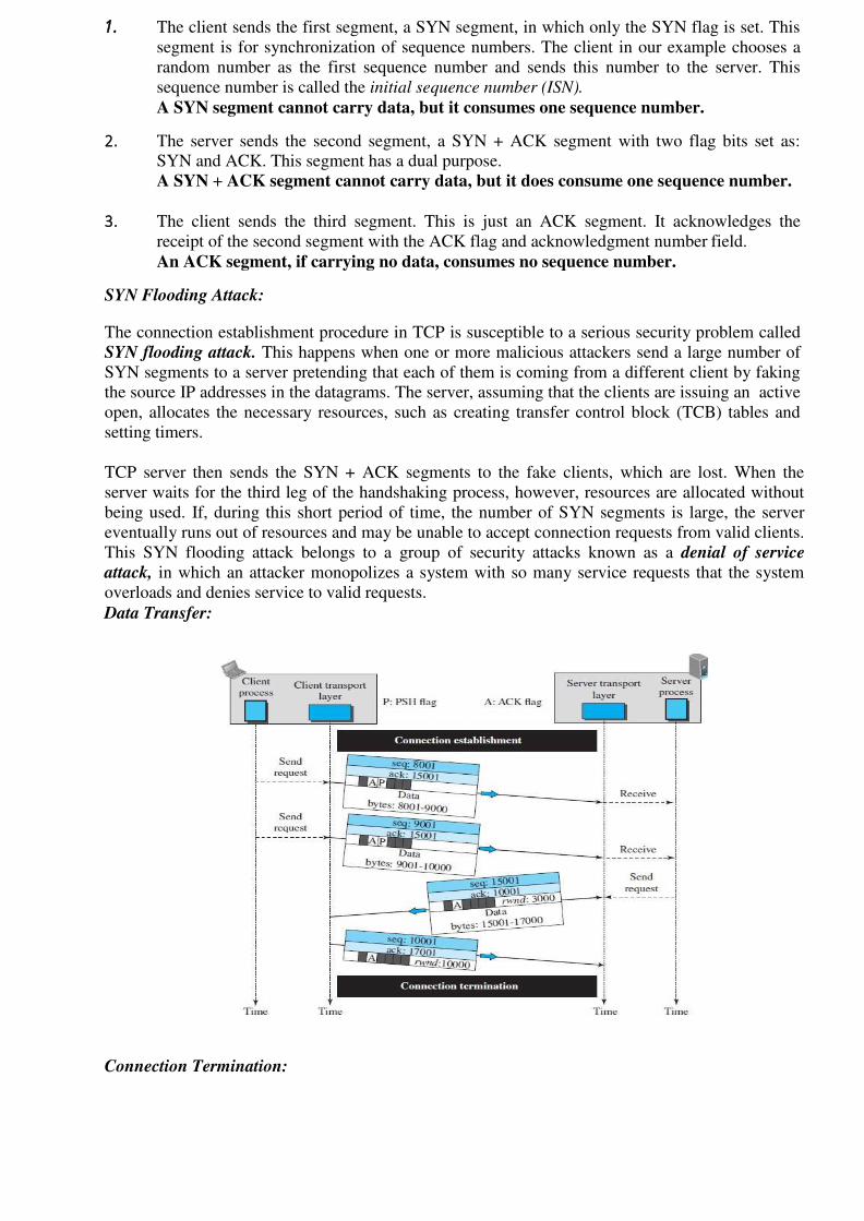
1. The client sends the first segment, a SYN segment, in which only the SYN flag is set. This
segment is for synchronization of sequence numbers. The client in our example chooses a
random number as the first sequence number and sends this number to the server. This
sequence number is called the initial sequence number (ISN).
A SYN segment cannot carry data, but it consumes one sequence number.
2. The server sends the second segment, a SYN + ACK segment with two flag bits set as:
SYN and ACK. This segment has a dual purpose.
A SYN + ACK segment cannot carry data, but it does consume one sequence number.
3. The client sends the third segment. This is just an ACK segment. It acknowledges the
receipt of the second segment with the ACK flag and acknowledgment number field.
An ACK segment, if carrying no data, consumes no sequence number.
SYN Flooding Attack:
The connection establishment procedure in TCP is susceptible to a serious security problem called
SYN flooding attack. This happens when one or more malicious attackers send a large number of
SYN segments to a server pretending that each of them is coming from a different client by faking
the source IP addresses in the datagrams. The server, assuming that the clients are issuing an active
open, allocates the necessary resources, such as creating transfer control block (TCB) tables and
setting timers.
TCP server then sends the SYN + ACK segments to the fake clients, which are lost. When the
server waits for the third leg of the handshaking process, however, resources are allocated without
being used. If, during this short period of time, the number of SYN segments is large, the server
eventually runs out of resources and may be unable to accept connection requests from valid clients.
This SYN flooding attack belongs to a group of security attacks known as a denial of service
attack, in which an attacker monopolizes a system with so many service requests that the system
overloads and denies service to valid requests.
Data Transfer:
Connection Termination:

Using Three-Way Handshaking:
Using Half Close:
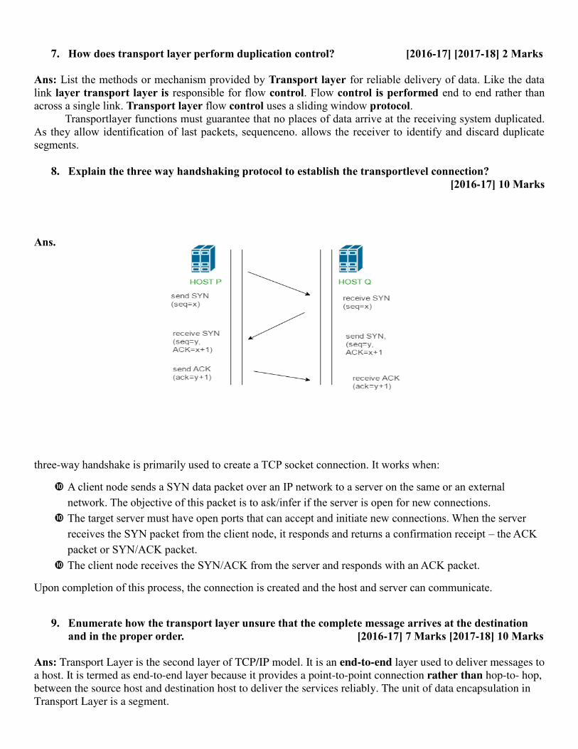
7. How does transport layer perform duplication control? [2016-17] [2017-18] 2 Marks
Ans: List the methods or mechanism provided by Transport layer for reliable delivery of data. Like the data link layer transport layer is responsible for flow control. Flow control is performed end to end rather than across a single link. Transport layer flow control uses a sliding window protocol. Transportlayer functions must guarantee that no places of data arrive at the receiving system duplicated. As they allow identification of last packets, sequenceno. allows the receiver to identify and discard duplicate segments.
8. Explain the three way handshaking protocol to establish the transportlevel connection? [2016-17] 10 Marks
Ans.
three-way handshake is primarily used to create a TCP socket connection. It works when:
A client node sends a SYN data packet over an IP network to a server on the same or an external network. The objective of this packet is to ask/infer if the server is open for new connections.
The target server must have open ports that can accept and initiate new connections. When the server receives the SYN packet from the client node, it responds and returns a confirmation receipt – the ACK packet or SYN/ACK packet.
The client node receives the SYN/ACK from the server and responds with an ACK packet.
Upon completion of this process, the connection is created and the host and server can communicate.
9. Enumerate how the transport layer unsure that the complete message arrives at the destination and in the proper order. [2016-17] 7 Marks [2017-18] 10 Marks
Ans: Transport Layer is the second layer of TCP/IP model. It is an end-to-end layer used to deliver messages to
a host. It is termed as end-to-end layer because it provides a point-to-point connection rather than hop-to- hop,
between the source host and destination host to deliver the services reliably. The unit of data encapsulation in
Transport Layer is a segment.
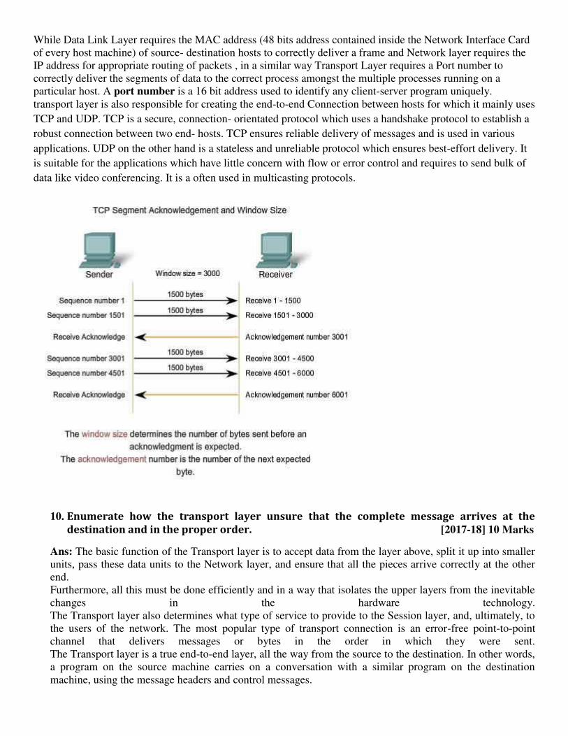
While Data Link Layer requires the MAC address (48 bits address contained inside the Network Interface Card
of every host machine) of source- destination hosts to correctly deliver a frame and Network layer requires the
IP address for appropriate routing of packets , in a similar way Transport Layer requires a Port number to
correctly deliver the segments of data to the correct process amongst the multiple processes running on a
particular host. A port number is a 16 bit address used to identify any client-server program uniquely.
transport layer is also responsible for creating the end-to-end Connection between hosts for which it mainly uses
TCP and UDP. TCP is a secure, connection- orientated protocol which uses a handshake protocol to establish a
robust connection between two end- hosts. TCP ensures reliable delivery of messages and is used in various
applications. UDP on the other hand is a stateless and unreliable protocol which ensures best-effort delivery. It
is suitable for the applications which have little concern with flow or error control and requires to send bulk of
data like video conferencing. It is a often used in multicasting protocols.
10. Enumerate how the transport layer unsure that the complete message arrives at the
destination and in the proper order. [2017-18] 10 Marks
Ans: The basic function of the Transport layer is to accept data from the layer above, split it up into smaller
units, pass these data units to the Network layer, and ensure that all the pieces arrive correctly at the other
end.
Furthermore, all this must be done efficiently and in a way that isolates the upper layers from the inevitable
changes in the hardware technology.
The Transport layer also determines what type of service to provide to the Session layer, and, ultimately, to
the users of the network. The most popular type of transport connection is an error-free point-to-point
channel that delivers messages or bytes in the order in which they were sent.
The Transport layer is a true end-to-end layer, all the way from the source to the destination. In other words,
a program on the source machine carries on a conversation with a similar program on the destination
machine, using the message headers and control messages.
Functions of Transport Layer
1. Service Point Addressing: Transport Layer header includes service point address which is port
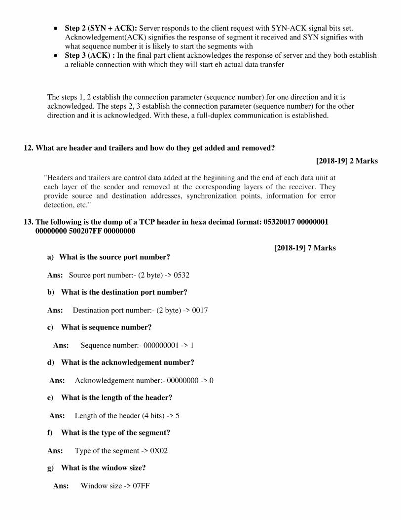
● Step 2 (SYN + ACK): Server responds to the client request with SYN-ACK signal bits set.
Acknowledgement(ACK) signifies the response of segment it received and SYN signifies with
what sequence number it is likely to start the segments with
● Step 3 (ACK) : In the final part client acknowledges the response of server and they both establish
a reliable connection with which they will start eh actual data transfer
The steps 1, 2 establish the connection parameter (sequence number) for one direction and it is
acknowledged. The steps 2, 3 establish the connection parameter (sequence number) for the other
direction and it is acknowledged. With these, a full-duplex communication is established.
12. What are header and trailers and how do they get added and removed?
[2018-19] 2 Marks
"Headers and trailers are control data added at the beginning and the end of each data unit at
each layer of the sender and removed at the corresponding layers of the receiver. They
provide source and destination addresses, synchronization points, information for error
detection, etc."
13. The following is the dump of a TCP header in hexa decimal format: 05320017 00000001
00000000 500207FF 00000000
[2018-19] 7 Marks
a) What is the source port number?
Ans: Source port number:- (2 byte) -> 0532
b) What is the destination port number?
Ans: Destination port number:- (2 byte) -> 0017
c) What is sequence number?
Ans: Sequence number:- 000000001 -> 1
d) What is the acknowledgement number?
Ans: Acknowledgement number:- 00000000 -> 0
e) What is the length of the header?
Ans: Length of the header (4 bits) -> 5
f) What is the type of the segment?
Ans: Type of the segment -> 0X02
g) What is the window size?
Ans: Window size -> 07FF

14. Explain about the TCP header and working of TCP protocol and differentiate between TCP and
UDP with frame format. [2016-17] 10 Marks , [2018-19] 7 Marks
Ans: The Transmission Control Protocol (TCP) header is the first 24 bytes of a TCP segment that
contains the parameters and state of an end-to-end TCP socket. The TCP header is used to track the
state of communication between two TCP endpoints. Since TCP segments are inserted (encapsulated)
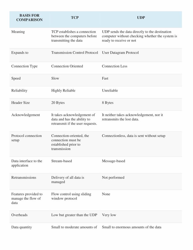
BASIS FOR
COMPARISON TCP UDP
Meaning TCP establishes a connection
between the computers before
transmitting the data
UDP sends the data directly to the destination
computer without checking whether the system is
ready to receive or not
Expands to Transmission Control Protocol User Datagram Protocol
Connection Type Connection Oriented Connection Less
Speed Slow Fast
Reliability Highly Reliable Unreliable
Header Size 20 Bytes 8 Bytes
Acknowledgement It takes acknowledgement of
data and has the ability to
retransmit if the user requests.
It neither takes acknowledgement, nor it
retransmits the lost data.
Protocol connection
setup
Connection-oriented, the
connection must be
established prior to
transmission
Connectionless, data is sent without setup
Data interface to the
application
Stream-based Message-based
Retransmissions Delivery of all data is
managed
Not performed
Features provided to
manage the flow of
data
Flow control using sliding
window protocol
None
Overheads Low but greater than the UDP Very low
Data quantity Small to moderate amounts of Small to enormous amounts of the data

BASIS FOR
COMPARISON TCP UDP
suitability data
Implemented over Applications where reliable
transmission of data matters.
Application where data delivery speed matters.
Applications and
protocols
FTP, Telnet, SMTP, IMAP
etcetera.
DNS, BOOTP, DHCP, TFTP etcetera.
Frame format of UDP
Source port - Port number of the application that is transmitting data from the source computer
Destination port - Port number of the application that will receive the data at destination.
Length - Denotes the length of the UDP header and the UDP data
Checksum - CRC of the complete segment
Data - Data which it received from the application

UNIT 5
Q1 Write short notes on any two : (2018-2019)
a) SMTP
b) TELNET
c) HTTP
SOULATION: A) SMTP
Simple Mail Transfer Protocol-
SMTP is short for Simple Mail Transfer Protocol.
It is an application layer protocol.
It is used for sending the emails efficiently and reliably over the internet.
Working-
SMTP server is always on a listening mode.
Client initiates a TCP connection with the SMTP server.
SMTP server listens for a connection and initiates a connection on that port.
The connection is established.
Client informs the SMTP server that it would like to send a mail.
Assuming the server is OK, client sends the mail to its mail server.
Client’s mail server use DNS to get the IP Address of receiver’s mail server.
Then, SMTP transfers the mail from sender’s mail server to the receiver’s mail server.
While sending the mail, SMTP is used two times-
1. Between the sender and the sender’s mail server
2. Between the sender’s mail server and the receiver’s mail server
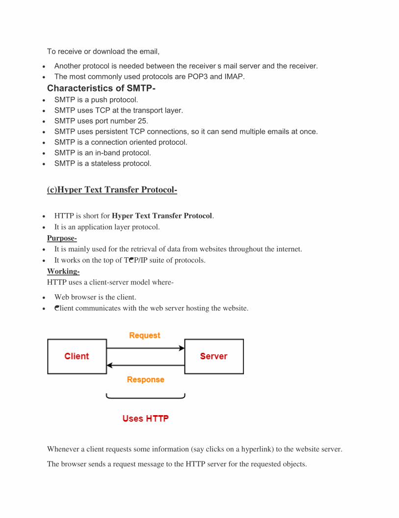
To receive or download the email,
Another protocol is needed between the receiver’s mail server and the receiver.
The most commonly used protocols are POP3 and IMAP.
Characteristics of SMTP-
SMTP is a push protocol.
SMTP uses TCP at the transport layer.
SMTP uses port number 25.
SMTP uses persistent TCP connections, so it can send multiple emails at once.
SMTP is a connection oriented protocol.
SMTP is an in-band protocol.
SMTP is a stateless protocol.
(c)Hyper Text Transfer Protocol-
HTTP is short for Hyper Text Transfer Protocol.
It is an application layer protocol.
Purpose-
It is mainly used for the retrieval of data from websites throughout the internet.
It works on the top of TCP/IP suite of protocols.
Working-
HTTP uses a client-server model where-
Web browser is the client.
Client communicates with the web server hosting the website.
Whenever a client requests some information (say clicks on a hyperlink) to the website server.
The browser sends a request message to the HTTP server for the requested objects.
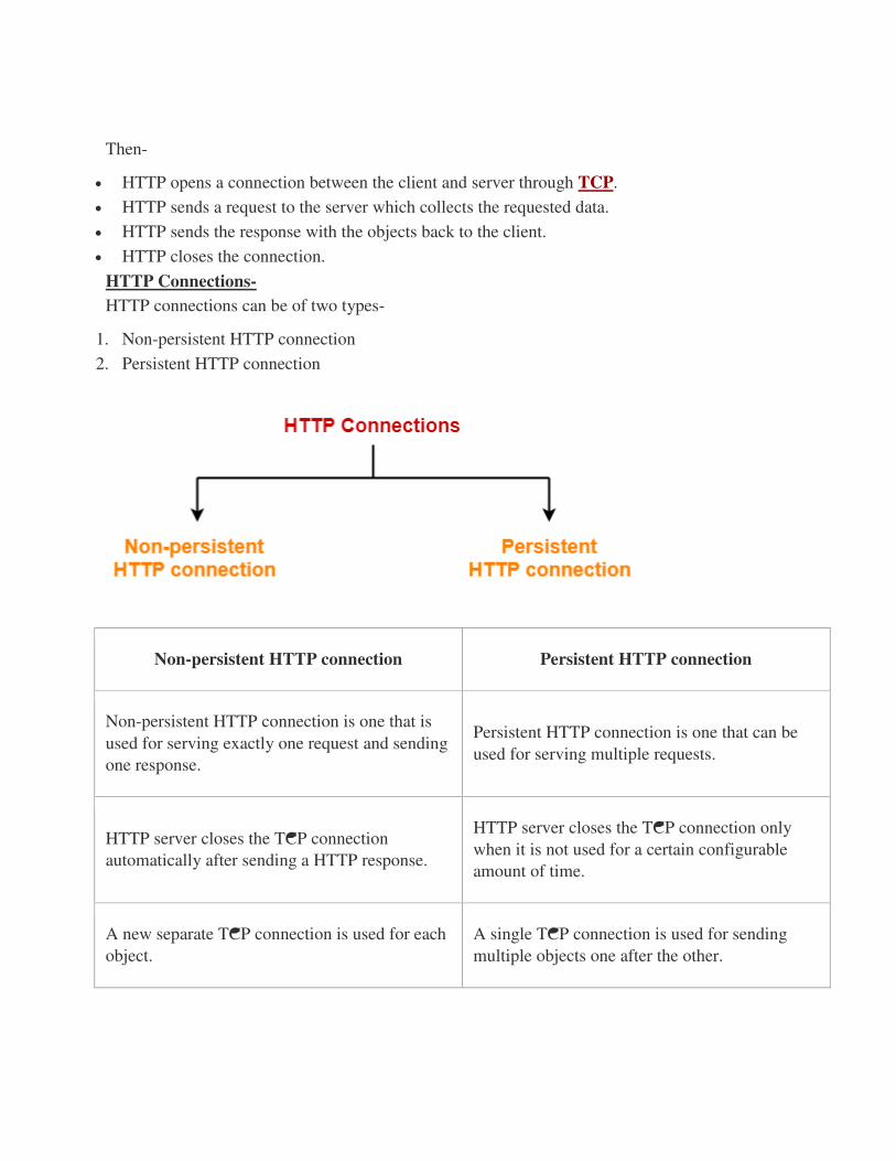
Then-
HTTP opens a connection between the client and server through TCP.
HTTP sends a request to the server which collects the requested data.
HTTP sends the response with the objects back to the client.
HTTP closes the connection.
HTTP Connections-
HTTP connections can be of two types-
1. Non-persistent HTTP connection
2. Persistent HTTP connection
Non-persistent HTTP connection Persistent HTTP connection
Non-persistent HTTP connection is one that is
used for serving exactly one request and sending
one response.
Persistent HTTP connection is one that can be
used for serving multiple requests.
HTTP server closes the TCP connection
automatically after sending a HTTP response.
HTTP server closes the TCP connection only
when it is not used for a certain configurable
amount of time.
A new separate TCP connection is used for each
object.
A single TCP connection is used for sending
multiple objects one after the other.

HTTP 1.0 supports non-persistent connections
by default.
HTTP 1.1 supports persistent connections by
default.
Example-
Suppose a request has been made for a HTML
page that contains 10 images (called objects).
Then,
With non-persistent connection, all the 11
objects (1 page + 10 images) will be sent one by
one.
For getting each object, a new separate
connection will be opened and used.
Example-
Suppose a request has been made for a HTML
page that contains 10 images (called objects).
Then,
With persistent connection, all the 11 objects (1
page + 10 images) will be sent one after the
other using a single TCP connection.
b) Telnet
TELNET In this section, we discuss such a client/server application program: TELNET. TELNET
is an abbreviation for TErminaL NETwork. It is the standard TCP/IP protocol for virtual
terminal service as proposed by the International Organization for Standards (ISO). TELNET
enables the establishment of a connection to a remote system in such a way that the local
terminal appears to be a terminal at the remote system. TELNET is a general-purpose
client/server application program. TELNET was designed at a time when most operating
systems, such as UNIX, were operating in a timesharing environment. In such an
environment, a large computer supports multiple users. The interaction between a user and
the computer occurs through a terminal, which is usually a combination of keyboard,
monitor, and mouse. Even a microcomputer can simulate a terminal with a terminal
emulator. In a timesharing environment, users are part of the system with some right to
access resources. Each authorized user has an identification and probably, a password. The
user identification defines the user as part of the system. To access the system, the user logs
into the system with a user id or log-in name. The system also includes password checking to
prevent an unauthorized user from accessing the resources. Figure shows the logging
process.
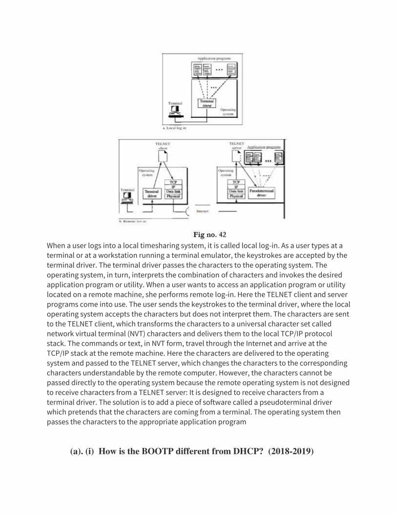
When a user logs into a local timesharing system, it is called local log-in. As a user types at a
terminal or at a workstation running a terminal emulator, the keystrokes are accepted by the
terminal driver. The terminal driver passes the characters to the operating system. The
operating system, in turn, interprets the combination of characters and invokes the desired
application program or utility. When a user wants to access an application program or utility
located on a remote machine, she performs remote log-in. Here the TELNET client and server
programs come into use. The user sends the keystrokes to the terminal driver, where the local
operating system accepts the characters but does not interpret them. The characters are sent
to the TELNET client, which transforms the characters to a universal character set called
network virtual terminal (NVT) characters and delivers them to the local TCP/IP protocol
stack. The commands or text, in NVT form, travel through the Internet and arrive at the
TCP/IP stack at the remote machine. Here the characters are delivered to the operating
system and passed to the TELNET server, which changes the characters to the corresponding
characters understandable by the remote computer. However, the characters cannot be
passed directly to the operating system because the remote operating system is not designed
to receive characters from a TELNET server: It is designed to receive characters from a
terminal driver. The solution is to add a piece of software called a pseudoterminal driver
which pretends that the characters are coming from a terminal. The operating system then
passes the characters to the appropriate application program
(a). (i) How is the BOOTP different from DHCP? (2018-2019)
(ii) What is the purpose of the Domain Name System? Discuss the three main
divisions of domain name space.
Solution (i) Different between BOOTP and DHCP?
BOOTP
The BOOTP uses UDP/IP. It is run when the machine boots. The protocol allows
diskless machines to discover their IP address and the address of the server host.
Additionally name of the file to be loaded from memory and executed is also
supplied to the machine. This protocol is an improvement over RARP which has the
follwing limitations:
1. Networks which do not have a broadcast method can't support RARP as it uses
the broadcast method of the MAC layer underneath the IP layer.
2. RARP is heavily dependent on the MAC protocol.
3. RARP just supplies the IP address corresponding to a MAC address It doesn't
support respond with any more data.
4. RARP uses the computer hardware's address to identify the machine and
hence cannot be used in networks that dynamically assign hardware
addresses.
Events in BOOTP
1. The Client broadcasts its MAC address (or other unique hardware identity
number) asking for help in booting.
2. The BOOTP Server responds with the data that specifies how the Client should
be configured (pre-configured for the specific client)
Note: BOOTP doesn't use the MAC layer broadcast but uses UDP/IP.
Configuration Information
The important informations provided are:
IP address
IP address of the default router for that particular subnet
Subnet mask
IP addresses of the primary and secondary nameservers
Additionaly it may also provide:
Time offset from GMT

The IP address of a time server
The IP address of a boot server
The name of a boot file (e.g. boot image for X terminals)
The IP domain name for the client
But the problem with BOOTP is that it again can't be used for the dynamic IP's
as in RARP servers.For getting dynamic IP's we use DHCP.
DHCP (Dynamic Host Configuration Protocol)
DHCP (Dynamic Host Configuration Protocol) is a protocol that lets network
administrators manage centrally and automate the assignment of Internet Protocol
(IP) addresses in an organization's network. If a machine uses Internet's set of
protocol (TCP/IP), each machine that can connect to the Internet needs a unique IP
address. When an organization sets up its computer users with a connection to the
Internet, an IP address must be assigned to each machine. Without DHCP, the IP
address must be entered manually at each computer and, if computers move to
another location in another part of the network, a new IP address must be entered.
DHCP lets a network administrator supervise and distribute IP addresses from a
central point and automatically sends a new IP address when a computer is plugged
into a different place in the network.
IP Address Allocation Mechanism
DHCP supports three mechanisms for IP address allocation.
Automatic allocation: DHCP assigns a permanent IP address to a host.
Dynamic allocation: DHCP assigns an IP address to a host for a limited period
of time (or until the host explicitly relinquishes the address).
Manual allocation: Host's IP address is assigned by the network administrator,
and DHCP is used simply to convey the assigned address to the host. A
particular network will use one or more of these mechanisms, depending on
the policies of the network administrator.
Messages Used by DHCP
DHCP Discover - Client broadcast to locate available servers. It is assumed
atleast one of the servers will have resources to fulfill the request.( may
include additional pointers to specific services required eg. particular
subnet, minimum time limit etc ).
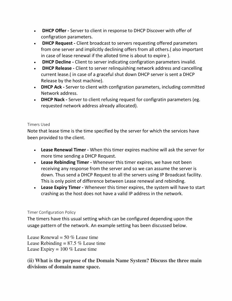
DHCP Offer - Server to client in response to DHCP Discover with offer of
configration parameters.
DHCP Request - Client broadcast to servers requesting offered parameters
from one server and implicitly declining offers from all others.( also important
in case of lease renewal if the alloted time is about to expire ).
DHCP Decline - Client to server indicating configration parameters invalid.
DHCP Release - Client to server relinquishing network address and cancelling
current lease.( in case of a graceful shut down DHCP server is sent a DHCP
Release by the host machine).
DHCP Ack - Server to client with configration parameters, including committed
Network address.
DHCP Nack - Server to client refusing request for configratin parameters (eg.
requested network address already allocated).
Timers Used
Note that lease time is the time specified by the server for which the services have
been provided to the client.
Lease Renewal Timer - When this timer expires machine will ask the server for
more time sending a DHCP Request.
Lease Rebinding Timer - Whenever this timer expires, we have not been
receiving any response from the server and so we can assume the server is
down. Thus send a DHCP Request to all the servers using IP Broadcast facility.
This is only point of difference between Lease renewal and rebinding.
Lease Expiry Timer - Whenever this timer expires, the system will have to start
crashing as the host does not have a valid IP address in the network.
Timer Configuration Policy
The timers have this usual setting which can be configured depending upon the
usage pattern of the network. An example setting has been discussed below.
Lease Renewal = 50 % Lease time
Lease Rebinding = 87.5 % Lease time
Lease Expiry = 100 % Lease time
(ii) What is the purpose of the Domain Name System? Discuss the three main
divisions of domain name space.
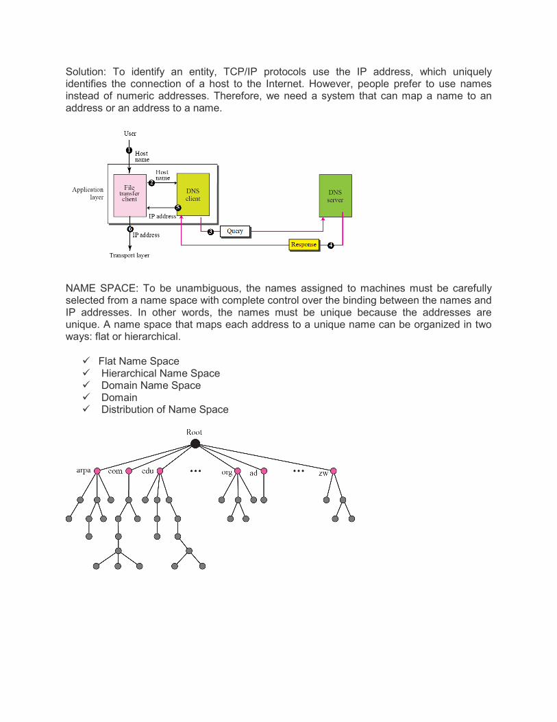
Solution: To identify an entity, TCP/IP protocols use the IP address, which uniquely identifies the connection of a host to the Internet. However, people prefer to use names instead of numeric addresses. Therefore, we need a system that can map a name to an address or an address to a name.
NAME SPACE: To be unambiguous, the names assigned to machines must be carefully selected from a name space with complete control over the binding between the names and IP addresses. In other words, the names must be unique because the addresses are unique. A name space that maps each address to a unique name can be organized in two ways: flat or hierarchical.
Flat Name Space Hierarchical Name Space Domain Name Space Domain Distribution of Name Space
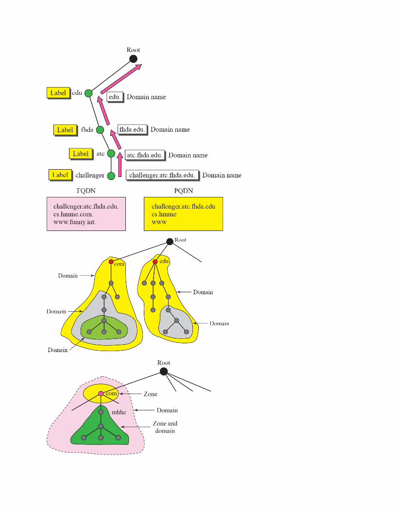

A primary server loads all information from the disk file; the secondary server loads all information from the primary server. When the secondary downloads information from the primary, it is called zone transfer.
DNS IN THE INTERNET: DNS is a protocol that can be used in different platforms. In the Internet, the domain name space (tree) is divided into three different sections: generic domains, country domains, and the inverse domain
Generic Domains:


5. Write shorts notes on any three of the following: (2015-2016)
i) DNS in the internet Ans-Domain Name Servers (DNS) are the Internet's equivalent of a phone
book. They maintain a directory of domain names and translate them to Internet Protocol (IP)
addresses. This is necessary because, although domain names are easy for people to remember,
computers or machines, access websites based on IP addresses. Information from all the domain
name servers across the Internet are gathered together and housed at the Central Registry. Host
companies and Internet Service Providers interact with the Central Registry on a regular
schedule to get updated DNS information. When you type in a web address, e.g.,
www.jimsbikes.com, your Internet Service Provider views the DNS associated with the domain
name, translates it into a machine friendly IP address (for example 216.168.224.70 is the IP for
jimsbikes.com) and directs your Internet connection to the correct website. After you register a
new domain name or when you update the DNS servers on yourdomain name, it usually takes
about 12-36 hours for the domain name servers world-wide to be updated and able to access the
information. This 36-hour period is referred to as propagation.
ii) Voice over IP Ans-Voice over Internet Protocol (VoIP), also called IP telephony, is a
methodology and group of technologies for the delivery of voice communications and
multimedia sessions over Internet Protocol (IP) networks, such as the Internet. The terms Internet
telephony, broadband telephony, and broadband phone service specifically refer to the
provisioning of communications services (voice, fax, SMS, voice-messaging) over the public
Internet, rather than via the public switched telephone network (PSTN). The steps and principles
involved in originating VoIP telephone calls are similar to traditional digital telephony and
involve signaling, channel setup, digitization of the analog voice signals, and encoding. Instead
of being transmitted over a circuit-switched network, the digital information is packetized, and
transmission occurs as IP packets over a packet-switched network. They transport media streams
using special media delivery protocols that encode audio and video with audio codecs, and video
codecs. Various codecs exist that optimize the media stream based on application requirements
and network bandwidth; some implementations rely on narrowband and compressed speech,
while others support high-fidelity stereo codecs. Some popular codecs include μ-law and A-law
versions of G.711, G.722, an open sourcevoice codec known as iLBC, a codec that uses only 8
kbit/s each way called G.729, and many others.
iii) SNMP Ans-Simple Network Management Protocol (SNMP) – SNMP is an application layer
protocol which uses UDP port number 161/162.SNMP is used to monitor network, detect
network faults and sometimes even used to configure remote devices. SNMP components –
There are 3 components of SNMP: 1. SNMP Manager – It is a centralised system used to
monitor network.It is also known as Network Management Station (NMS) 2. SNMP agent – It is
a software management software module installed on a managed device. 3. Management
Information Base – MIB consists of information of resources that are to be managed. These
information is organised hierarchically. SNMP messages – Different variables are: 1. GetRequest
– SNMP manager sends this message to request data from SNMP agent. It is simply used to
retrieve data from SNMP agent.
3. GetNextRequest – This message can be sent to discover what data is available on a
SNMP agent. The SNMP manager can request for data continously until no more data is
left. 3. GetBulkRequest – This message is used to retrieve large data at once by the
SNMP manager from SNMP agent. It is introduced in SNMPv2c. 4. SetRequest – It is
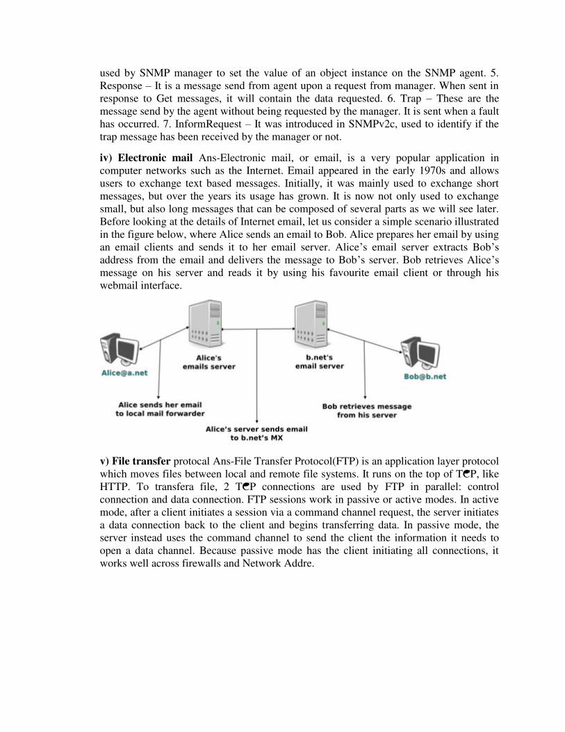
used by SNMP manager to set the value of an object instance on the SNMP agent. 5.
Response – It is a message send from agent upon a request from manager. When sent in
response to Get messages, it will contain the data requested. 6. Trap – These are the
message send by the agent without being requested by the manager. It is sent when a fault
has occurred. 7. InformRequest – It was introduced in SNMPv2c, used to identify if the
trap message has been received by the manager or not.
iv) Electronic mail Ans-Electronic mail, or email, is a very popular application in
computer networks such as the Internet. Email appeared in the early 1970s and allows
users to exchange text based messages. Initially, it was mainly used to exchange short
messages, but over the years its usage has grown. It is now not only used to exchange
small, but also long messages that can be composed of several parts as we will see later.
Before looking at the details of Internet email, let us consider a simple scenario illustrated
in the figure below, where Alice sends an email to Bob. Alice prepares her email by using
an email clients and sends it to her email server. Alice’s email server extracts Bob’s
address from the email and delivers the message to Bob’s server. Bob retrieves Alice’s
message on his server and reads it by using his favourite email client or through his
webmail interface.
v) File transfer protocal Ans-File Transfer Protocol(FTP) is an application layer protocol
which moves files between local and remote file systems. It runs on the top of TCP, like
HTTP. To transfera file, 2 TCP connections are used by FTP in parallel: control
connection and data connection. FTP sessions work in passive or active modes. In active
mode, after a client initiates a session via a command channel request, the server initiates
a data connection back to the client and begins transferring data. In passive mode, the
server instead uses the command channel to send the client the information it needs to
open a data channel. Because passive mode has the client initiating all connections, it
works well across firewalls and Network Addre.

Q. Answer the following (2014-2015)
(i) Differentiate between the block cipher with transposition cipher.

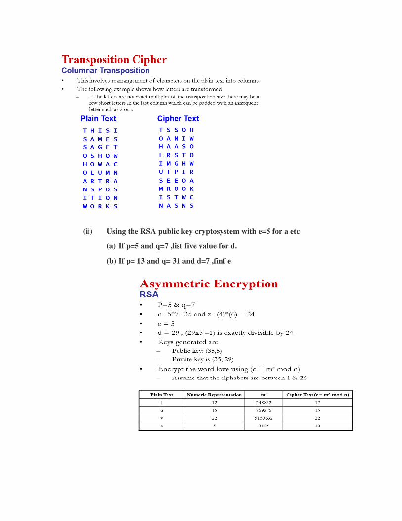
(ii) Using the RSA public key cryptosystem with e=5 for a etc
(a) If p=5 and q=7 ,list five value for d.
(b) If p= 13 and q= 31 and d=7 ,finf e