UMG 96-PQ-L - Janitza
120
Doc. no. 2.061.073.3.b Dated 12/2021 Power Analyzer UMG 96-PQ-L (from firmware 3.3 - hardware index 1) User manual and technical data Janitza electronics GmbH Vor dem Polstück 6 D-35633 Lahnau Support tel. +49 6441 9642-22 Email: [email protected] www.janitza.de www.janitza.de Image may differ from the original!
-
Upload
khangminh22 -
Category
Documents
-
view
0 -
download
0
Transcript of UMG 96-PQ-L - Janitza

Doc
. no.
2.0
61.0
73.3
.b
D
ated
12/
2021
Power Analyzer
UMG 96-PQ-L (from firmware 3.3 - hardware index 1)
User manual and technical data
Janitza electronics GmbHVor dem Polstück 6D-35633 LahnauSupport tel. +49 6441 9642-22Email: [email protected]
ww
w.ja
nitz
a.d
e
Imag
e m
ay d
iffer
from
the
orig
inal
!

UMG 96-PQ-L www.janitza.de
2
UMG 96-PQ-L (from firmware 3.3 / hardware index 1)Measurement device for recording energy quantities Doc. no.: 2.061.073.3.b Date: 12/2021 The German version is the original edition of the documentation

www.janitza.de
3
UMG 96-PQ-L
Subject to technical changes.The contents of our documentation have been compiled with great care and reflect the current state of the information available to us. Nonetheless, we wish to point out that updates of this document are not always possible at the same time as technical refinements are implemented in our products. Please see our website under www.janitza.de for the current version. Please see our website under www.janitza.de for the current version.

UMG 96-PQ-L www.janitza.de
4
TABLE OF CONTENTS
1. Information on the device and the user manual . . . . . . . . . . . . . . . . . . . . . . . . . . . . . . . . . . . . . . . 10
1.1 Disclaimer . . . . . . . . . . . . . . . . . . . . . . . . . . . . . . . . . . . . . . . . . . . . . . . . . . . . . . . . . . . . . . . 10
1.2 Copyright notice . . . . . . . . . . . . . . . . . . . . . . . . . . . . . . . . . . . . . . . . . . . . . . . . . . . . . . . . . . 10
1.3 Technical changes. . . . . . . . . . . . . . . . . . . . . . . . . . . . . . . . . . . . . . . . . . . . . . . . . . . . . . . . . 10
1.4 About this user manual . . . . . . . . . . . . . . . . . . . . . . . . . . . . . . . . . . . . . . . . . . . . . . . . . . . . . 10
1.5 Defective device/disposal . . . . . . . . . . . . . . . . . . . . . . . . . . . . . . . . . . . . . . . . . . . . . . . . . . . 11
2. Safety . . . . . . . . . . . . . . . . . . . . . . . . . . . . . . . . . . . . . . . . . . . . . . . . . . . . . . . . . . . . . . . . . . . . . . . . 12
2.1 Display of warning notices and safety information . . . . . . . . . . . . . . . . . . . . . . . . . . . . . . . . 12
2.2 Hazard levels . . . . . . . . . . . . . . . . . . . . . . . . . . . . . . . . . . . . . . . . . . . . . . . . . . . . . . . . . . . . . 12
2.3 Product safety . . . . . . . . . . . . . . . . . . . . . . . . . . . . . . . . . . . . . . . . . . . . . . . . . . . . . . . . . . . . 13
2.4 Dangers when handling the device . . . . . . . . . . . . . . . . . . . . . . . . . . . . . . . . . . . . . . . . . . . . 13
2.5 Electrically qualified personnel . . . . . . . . . . . . . . . . . . . . . . . . . . . . . . . . . . . . . . . . . . . . . . . 14
2.6 Warranty in the event of damage . . . . . . . . . . . . . . . . . . . . . . . . . . . . . . . . . . . . . . . . . . . . . 14
2.7 Safety information for handling current transformers and measurement devices with residual current measurement . . . . . . . . . . . . . . . . . . . . . . . . . . . . . . . . . . . . . 14
2.8 Handling batteries/accumulators . . . . . . . . . . . . . . . . . . . . . . . . . . . . . . . . . . . . . . . . . . . . . 15
3. Product description . . . . . . . . . . . . . . . . . . . . . . . . . . . . . . . . . . . . . . . . . . . . . . . . . . . . . . . . . . . . . 16
3.1 Device description . . . . . . . . . . . . . . . . . . . . . . . . . . . . . . . . . . . . . . . . . . . . . . . . . . . . . . . . 16
3.2 Incoming goods inspection . . . . . . . . . . . . . . . . . . . . . . . . . . . . . . . . . . . . . . . . . . . . . . . . . . 16
3.3 Intended use . . . . . . . . . . . . . . . . . . . . . . . . . . . . . . . . . . . . . . . . . . . . . . . . . . . . . . . . . . . . . 17
3.4 Performance characteristics . . . . . . . . . . . . . . . . . . . . . . . . . . . . . . . . . . . . . . . . . . . . . . . . . 17
3.5 EU conformity declaration . . . . . . . . . . . . . . . . . . . . . . . . . . . . . . . . . . . . . . . . . . . . . . . . . . 18
3.6 FCC Declaration of Conformity . . . . . . . . . . . . . . . . . . . . . . . . . . . . . . . . . . . . . . . . . . . . . . . 18
3.7 Scope of delivery . . . . . . . . . . . . . . . . . . . . . . . . . . . . . . . . . . . . . . . . . . . . . . . . . . . . . . . . . 18
3.8 Accessories . . . . . . . . . . . . . . . . . . . . . . . . . . . . . . . . . . . . . . . . . . . . . . . . . . . . . . . . . . . . . . 18
3.9 Measuring method . . . . . . . . . . . . . . . . . . . . . . . . . . . . . . . . . . . . . . . . . . . . . . . . . . . . . . . . 19
3.10 Transformer . . . . . . . . . . . . . . . . . . . . . . . . . . . . . . . . . . . . . . . . . . . . . . . . . . . . . . . . . . . . . . 19
3.11 Operating concept . . . . . . . . . . . . . . . . . . . . . . . . . . . . . . . . . . . . . . . . . . . . . . . . . . . . . . . . 19
3.12 GridVis® network analysis software . . . . . . . . . . . . . . . . . . . . . . . . . . . . . . . . . . . . . . . . . . . 19
4. Structure of the device . . . . . . . . . . . . . . . . . . . . . . . . . . . . . . . . . . . . . . . . . . . . . . . . . . . . . . . . . . . 20
4.1 Front panel - Display and controls . . . . . . . . . . . . . . . . . . . . . . . . . . . . . . . . . . . . . . . . . . . . 20
4.2 Rear of the device - Connections . . . . . . . . . . . . . . . . . . . . . . . . . . . . . . . . . . . . . . . . . . . . . 21
4.3 Rating plate . . . . . . . . . . . . . . . . . . . . . . . . . . . . . . . . . . . . . . . . . . . . . . . . . . . . . . . . . . . . . . 22
5. Mounting . . . . . . . . . . . . . . . . . . . . . . . . . . . . . . . . . . . . . . . . . . . . . . . . . . . . . . . . . . . . . . . . . . . . . . 23
5.1 Installation location . . . . . . . . . . . . . . . . . . . . . . . . . . . . . . . . . . . . . . . . . . . . . . . . . . . . . . . . 23
5.2 Mounting orientation . . . . . . . . . . . . . . . . . . . . . . . . . . . . . . . . . . . . . . . . . . . . . . . . . . . . . . . 23
5.3 Securing . . . . . . . . . . . . . . . . . . . . . . . . . . . . . . . . . . . . . . . . . . . . . . . . . . . . . . . . . . . . . . . . 23

www.janitza.de
5
UMG 96-PQ-L
6. Grid systems . . . . . . . . . . . . . . . . . . . . . . . . . . . . . . . . . . . . . . . . . . . . . . . . . . . . . . . . . . . . . . . . . . . 24
7. Installation . . . . . . . . . . . . . . . . . . . . . . . . . . . . . . . . . . . . . . . . . . . . . . . . . . . . . . . . . . . . . . . . . . . . 25
7.1 Nominal voltages . . . . . . . . . . . . . . . . . . . . . . . . . . . . . . . . . . . . . . . . . . . . . . . . . . . . . . . . . 25
7.1.1 Three-phase four-conductor network with grounded neutral conductor . . . . . . . 25
7.3.1 Three-phase three-conductor system . . . . . . . . . . . . . . . . . . . . . . . . . . . . . . . . . 26
7.2 Disconnect switch . . . . . . . . . . . . . . . . . . . . . . . . . . . . . . . . . . . . . . . . . . . . . . . . . . . . . . . . . 26
7.3 Supply voltage . . . . . . . . . . . . . . . . . . . . . . . . . . . . . . . . . . . . . . . . . . . . . . . . . . . . . . . . . . . 26
7.4 Voltage measurement . . . . . . . . . . . . . . . . . . . . . . . . . . . . . . . . . . . . . . . . . . . . . . . . . . . . . . 28
7.4.1 Overvoltage . . . . . . . . . . . . . . . . . . . . . . . . . . . . . . . . . . . . . . . . . . . . . . . . . . . . . 28
7.4.2 Frequency . . . . . . . . . . . . . . . . . . . . . . . . . . . . . . . . . . . . . . . . . . . . . . . . . . . . . . . 28
7.4.3 Connection variants for voltage measurement . . . . . . . . . . . . . . . . . . . . . . . . . . . 29
7.5 Current measurement . . . . . . . . . . . . . . . . . . . . . . . . . . . . . . . . . . . . . . . . . . . . . . . . . . . . . . 30
7.5.1 Current direction . . . . . . . . . . . . . . . . . . . . . . . . . . . . . . . . . . . . . . . . . . . . . . . . . . 31
7.5.2 Summation current measurement . . . . . . . . . . . . . . . . . . . . . . . . . . . . . . . . . . . . 31
7.5.3 Ammeter . . . . . . . . . . . . . . . . . . . . . . . . . . . . . . . . . . . . . . . . . . . . . . . . . . . . . . . . 31
7.5.4 Connection variants for current measurement . . . . . . . . . . . . . . . . . . . . . . . . . . . 32
8. Connection and PC connections . . . . . . . . . . . . . . . . . . . . . . . . . . . . . . . . . . . . . . . . . . . . . . . . . . . 34
8.1 Connection variants . . . . . . . . . . . . . . . . . . . . . . . . . . . . . . . . . . . . . . . . . . . . . . . . . . . . . . . 34
8.2 RS-485 interface . . . . . . . . . . . . . . . . . . . . . . . . . . . . . . . . . . . . . . . . . . . . . . . . . . . . . . . . . . 35
8.3 Shielding . . . . . . . . . . . . . . . . . . . . . . . . . . . . . . . . . . . . . . . . . . . . . . . . . . . . . . . . . . . . . . . . 35
8.4 Termination resistors . . . . . . . . . . . . . . . . . . . . . . . . . . . . . . . . . . . . . . . . . . . . . . . . . . . . . . . 36
8.5 Bus structure . . . . . . . . . . . . . . . . . . . . . . . . . . . . . . . . . . . . . . . . . . . . . . . . . . . . . . . . . . . . . 36
9. Digital inputs and outputs . . . . . . . . . . . . . . . . . . . . . . . . . . . . . . . . . . . . . . . . . . . . . . . . . . . . . . . . 38
9.1 Digital inputs . . . . . . . . . . . . . . . . . . . . . . . . . . . . . . . . . . . . . . . . . . . . . . . . . . . . . . . . . . . . . 38
9.1.1 S0 pulse input . . . . . . . . . . . . . . . . . . . . . . . . . . . . . . . . . . . . . . . . . . . . . . . . . . . . 38
9.2 Digital outputs . . . . . . . . . . . . . . . . . . . . . . . . . . . . . . . . . . . . . . . . . . . . . . . . . . . . . . . . . . . . 39
9.3 LED status bar . . . . . . . . . . . . . . . . . . . . . . . . . . . . . . . . . . . . . . . . . . . . . . . . . . . . . . . . . . . 39
10. Analog outputs . . . . . . . . . . . . . . . . . . . . . . . . . . . . . . . . . . . . . . . . . . . . . . . . . . . . . . . . . . . . . . . . . 40
11. Operation . . . . . . . . . . . . . . . . . . . . . . . . . . . . . . . . . . . . . . . . . . . . . . . . . . . . . . . . . . . . . . . . . . . . . 41
11.1 Button function . . . . . . . . . . . . . . . . . . . . . . . . . . . . . . . . . . . . . . . . . . . . . . . . . . . . . . . . . . . 41
11.2 Measuring display “Summary” . . . . . . . . . . . . . . . . . . . . . . . . . . . . . . . . . . . . . . . . . . . . . . . 41
11.3 Menu . . . . . . . . . . . . . . . . . . . . . . . . . . . . . . . . . . . . . . . . . . . . . . . . . . . . . . . . . . . . . . . . . . . 41
11.4 Overview of menu displays . . . . . . . . . . . . . . . . . . . . . . . . . . . . . . . . . . . . . . . . . . . . . . . . . . 42
11.5 Configuring a new start screen . . . . . . . . . . . . . . . . . . . . . . . . . . . . . . . . . . . . . . . . . . . . . . . 43

UMG 96-PQ-L www.janitza.de
6
12. Configuration . . . . . . . . . . . . . . . . . . . . . . . . . . . . . . . . . . . . . . . . . . . . . . . . . . . . . . . . . . . . . . . . . . 44
12.1 The Configuration window . . . . . . . . . . . . . . . . . . . . . . . . . . . . . . . . . . . . . . . . . . . . . . . . . . 44
12.2 Language . . . . . . . . . . . . . . . . . . . . . . . . . . . . . . . . . . . . . . . . . . . . . . . . . . . . . . . . . . . . . . . 44
12.3 Communication . . . . . . . . . . . . . . . . . . . . . . . . . . . . . . . . . . . . . . . . . . . . . . . . . . . . . . . . . . . 44
12.4 Measurement . . . . . . . . . . . . . . . . . . . . . . . . . . . . . . . . . . . . . . . . . . . . . . . . . . . . . . . . . . . . 46
12.4.1 Current and voltage transformers . . . . . . . . . . . . . . . . . . . . . . . . . . . . . . . . . . . . . 46
12.4.2 Connection variant . . . . . . . . . . . . . . . . . . . . . . . . . . . . . . . . . . . . . . . . . . . . . . . . 47
12.4.3 Nominal current . . . . . . . . . . . . . . . . . . . . . . . . . . . . . . . . . . . . . . . . . . . . . . . . . . 48
12.4.4 Nominal frequency . . . . . . . . . . . . . . . . . . . . . . . . . . . . . . . . . . . . . . . . . . . . . . . . 49
12.5 Display . . . . . . . . . . . . . . . . . . . . . . . . . . . . . . . . . . . . . . . . . . . . . . . . . . . . . . . . . . . . . . . . . 50
12.5.1 Brightness . . . . . . . . . . . . . . . . . . . . . . . . . . . . . . . . . . . . . . . . . . . . . . . . . . . . . . . 50
12.5.2 Standby after . . . . . . . . . . . . . . . . . . . . . . . . . . . . . . . . . . . . . . . . . . . . . . . . . . . . 50
12.5.3 Brightness (standby) . . . . . . . . . . . . . . . . . . . . . . . . . . . . . . . . . . . . . . . . . . . . . . . 50
12.5.4 Colors . . . . . . . . . . . . . . . . . . . . . . . . . . . . . . . . . . . . . . . . . . . . . . . . . . . . . . . . . . 51
12.6 System . . . . . . . . . . . . . . . . . . . . . . . . . . . . . . . . . . . . . . . . . . . . . . . . . . . . . . . . . . . . . . . . . 51
12.6.1 Firmware/Serial number . . . . . . . . . . . . . . . . . . . . . . . . . . . . . . . . . . . . . . . . . . . . 52
12.6.2 Date/time . . . . . . . . . . . . . . . . . . . . . . . . . . . . . . . . . . . . . . . . . . . . . . . . . . . . . . . 52
12.6.3 Password . . . . . . . . . . . . . . . . . . . . . . . . . . . . . . . . . . . . . . . . . . . . . . . . . . . . . . . 52
12.6.4 Reset . . . . . . . . . . . . . . . . . . . . . . . . . . . . . . . . . . . . . . . . . . . . . . . . . . . . . . . . . . . 53
12.7 Modbus editor . . . . . . . . . . . . . . . . . . . . . . . . . . . . . . . . . . . . . . . . . . . . . . . . . . . . . . . . . . . . 55
12.8 Events . . . . . . . . . . . . . . . . . . . . . . . . . . . . . . . . . . . . . . . . . . . . . . . . . . . . . . . . . . . . . . . . . . 57
13. Commissioning . . . . . . . . . . . . . . . . . . . . . . . . . . . . . . . . . . . . . . . . . . . . . . . . . . . . . . . . . . . . . . . . . 58
13.1 Applying the supply voltage . . . . . . . . . . . . . . . . . . . . . . . . . . . . . . . . . . . . . . . . . . . . . . . . . 58
13.2 Measured voltage . . . . . . . . . . . . . . . . . . . . . . . . . . . . . . . . . . . . . . . . . . . . . . . . . . . . . . . . . 58
13.3 Measured current . . . . . . . . . . . . . . . . . . . . . . . . . . . . . . . . . . . . . . . . . . . . . . . . . . . . . . . . . 58
13.4 Frequency . . . . . . . . . . . . . . . . . . . . . . . . . . . . . . . . . . . . . . . . . . . . . . . . . . . . . . . . . . . . . . . 59
13.5 Direction of rotary field . . . . . . . . . . . . . . . . . . . . . . . . . . . . . . . . . . . . . . . . . . . . . . . . . . . . . 59
13.5.1 Fundamentals on the phasor diagram . . . . . . . . . . . . . . . . . . . . . . . . . . . . . . . . . 60
13.6 Checking of voltage and current inputs by means of phasor diagram . . . . . . . . . . . . . . . . . 61
13.7 Overrange . . . . . . . . . . . . . . . . . . . . . . . . . . . . . . . . . . . . . . . . . . . . . . . . . . . . . . . . . . . . . . . 61
13.8 Checking the time . . . . . . . . . . . . . . . . . . . . . . . . . . . . . . . . . . . . . . . . . . . . . . . . . . . . . . . . . 61
13.9 Control of the power measurement . . . . . . . . . . . . . . . . . . . . . . . . . . . . . . . . . . . . . . . . . . . 62
13.10 Control of the communication . . . . . . . . . . . . . . . . . . . . . . . . . . . . . . . . . . . . . . . . . . . . . . . 62
13.11 Delete min./max. values . . . . . . . . . . . . . . . . . . . . . . . . . . . . . . . . . . . . . . . . . . . . . . . . . . . . 64
13.12 Harmonics current (harmonics) . . . . . . . . . . . . . . . . . . . . . . . . . . . . . . . . . . . . . . . . . . . . . . . 66
13.13 Communication in the bus system . . . . . . . . . . . . . . . . . . . . . . . . . . . . . . . . . . . . . . . . . . . . 67
13.13.1 RS-485 . . . . . . . . . . . . . . . . . . . . . . . . . . . . . . . . . . . . . . . . . . . . . . . . . . . . . . . . . 67

www.janitza.de
7
UMG 96-PQ-L
13.14 Digital inputs/outputs . . . . . . . . . . . . . . . . . . . . . . . . . . . . . . . . . . . . . . . . . . . . . . . . . . . . . . 68
13.14.1 Digital inputs . . . . . . . . . . . . . . . . . . . . . . . . . . . . . . . . . . . . . . . . . . . . . . . . . . . . . 68
13.14.2 Digital outputs . . . . . . . . . . . . . . . . . . . . . . . . . . . . . . . . . . . . . . . . . . . . . . . . . . . . 70
13.15 Configuration of the analog output . . . . . . . . . . . . . . . . . . . . . . . . . . . . . . . . . . . . . . . . . . . . 74
13.16 Drag indicator function . . . . . . . . . . . . . . . . . . . . . . . . . . . . . . . . . . . . . . . . . . . . . . . . . . . . . 75
13.16.1 Internal synchronization . . . . . . . . . . . . . . . . . . . . . . . . . . . . . . . . . . . . . . . . . . . . 75
13.16.2 External synchronization . . . . . . . . . . . . . . . . . . . . . . . . . . . . . . . . . . . . . . . . . . . . 76
13.16.3 Synchronization priority . . . . . . . . . . . . . . . . . . . . . . . . . . . . . . . . . . . . . . . . . . . . 78
13.16.4 Drag indicator - Measurement device displays . . . . . . . . . . . . . . . . . . . . . . . . . . 79
13.16.5 Delete drag indicator . . . . . . . . . . . . . . . . . . . . . . . . . . . . . . . . . . . . . . . . . . . . . . 80
13.17 Recordings . . . . . . . . . . . . . . . . . . . . . . . . . . . . . . . . . . . . . . . . . . . . . . . . . . . . . . . . . . . . . . 81
13.17.1 Default settings, memory partition A . . . . . . . . . . . . . . . . . . . . . . . . . . . . . . . . . . 82
13.17.2 Default settings, memory partition B . . . . . . . . . . . . . . . . . . . . . . . . . . . . . . . . . . 83
13.17.3 Use cases – Recording examples . . . . . . . . . . . . . . . . . . . . . . . . . . . . . . . . . . . . 85
13.18 Internal and external events . . . . . . . . . . . . . . . . . . . . . . . . . . . . . . . . . . . . . . . . . . . . . . . . . 86
13.19 Event lists . . . . . . . . . . . . . . . . . . . . . . . . . . . . . . . . . . . . . . . . . . . . . . . . . . . . . . . . . . . . . . . 89
13.20 Tariff switching . . . . . . . . . . . . . . . . . . . . . . . . . . . . . . . . . . . . . . . . . . . . . . . . . . . . . . . . . . . 90
13.21 Alarms for “Low battery voltage” and “Set time” . . . . . . . . . . . . . . . . . . . . . . . . . . . . . . . . . 91
14. Overview of measuring displays . . . . . . . . . . . . . . . . . . . . . . . . . . . . . . . . . . . . . . . . . . . . . . . . . . . 92
14.1 Menu overview (Start screen) . . . . . . . . . . . . . . . . . . . . . . . . . . . . . . . . . . . . . . . . . . . . . . . . 92
14.2 Voltage menu . . . . . . . . . . . . . . . . . . . . . . . . . . . . . . . . . . . . . . . . . . . . . . . . . . . . . . . . . . . . 93
14.3 Current menu . . . . . . . . . . . . . . . . . . . . . . . . . . . . . . . . . . . . . . . . . . . . . . . . . . . . . . . . . . . . 94
14.4 Power menu . . . . . . . . . . . . . . . . . . . . . . . . . . . . . . . . . . . . . . . . . . . . . . . . . . . . . . . . . . . . . 94
14.5 Energy menu . . . . . . . . . . . . . . . . . . . . . . . . . . . . . . . . . . . . . . . . . . . . . . . . . . . . . . . . . . . . . 95
14.6 Consumption overview menu . . . . . . . . . . . . . . . . . . . . . . . . . . . . . . . . . . . . . . . . . . . . . . . . 95
14.7 Drag indicator menu . . . . . . . . . . . . . . . . . . . . . . . . . . . . . . . . . . . . . . . . . . . . . . . . . . . . . . . 96
14.8 Harmonics menu . . . . . . . . . . . . . . . . . . . . . . . . . . . . . . . . . . . . . . . . . . . . . . . . . . . . . . . . . . 97
14.9 Oscilloscope menu . . . . . . . . . . . . . . . . . . . . . . . . . . . . . . . . . . . . . . . . . . . . . . . . . . . . . . . . 98
14.10 Events menu . . . . . . . . . . . . . . . . . . . . . . . . . . . . . . . . . . . . . . . . . . . . . . . . . . . . . . . . . . . . . 99
14.11 System Info menu . . . . . . . . . . . . . . . . . . . . . . . . . . . . . . . . . . . . . . . . . . . . . . . . . . . . . . . . 102
15. Overview of displays in the Configuration menu . . . . . . . . . . . . . . . . . . . . . . . . . . . . . . . . . . . . . 104
15.1 Language submenu . . . . . . . . . . . . . . . . . . . . . . . . . . . . . . . . . . . . . . . . . . . . . . . . . . . . . . 104
15.2 Communication submenu . . . . . . . . . . . . . . . . . . . . . . . . . . . . . . . . . . . . . . . . . . . . . . . . . . 104
15.3 Measurement submenu . . . . . . . . . . . . . . . . . . . . . . . . . . . . . . . . . . . . . . . . . . . . . . . . . . . 105
15.4 Display submenu . . . . . . . . . . . . . . . . . . . . . . . . . . . . . . . . . . . . . . . . . . . . . . . . . . . . . . . . 105
15.5 System submenu . . . . . . . . . . . . . . . . . . . . . . . . . . . . . . . . . . . . . . . . . . . . . . . . . . . . . . . . 106
15.6 Modbus editor submenu . . . . . . . . . . . . . . . . . . . . . . . . . . . . . . . . . . . . . . . . . . . . . . . . . . . 106

UMG 96-PQ-L www.janitza.de
8
16. Service and maintenance . . . . . . . . . . . . . . . . . . . . . . . . . . . . . . . . . . . . . . . . . . . . . . . . . . . . . . . 108
16.1 Repair and calibration . . . . . . . . . . . . . . . . . . . . . . . . . . . . . . . . . . . . . . . . . . . . . . . . . . . . . 108
16.2 Front panel foil and display . . . . . . . . . . . . . . . . . . . . . . . . . . . . . . . . . . . . . . . . . . . . . . . . . 108
16.3 Service . . . . . . . . . . . . . . . . . . . . . . . . . . . . . . . . . . . . . . . . . . . . . . . . . . . . . . . . . . . . . . . . 108
16.4 Device adjustment . . . . . . . . . . . . . . . . . . . . . . . . . . . . . . . . . . . . . . . . . . . . . . . . . . . . . . . 108
16.5 Firmware update . . . . . . . . . . . . . . . . . . . . . . . . . . . . . . . . . . . . . . . . . . . . . . . . . . . . . . . . . 108
16.6 Clock/Battery . . . . . . . . . . . . . . . . . . . . . . . . . . . . . . . . . . . . . . . . . . . . . . . . . . . . . . . . . . . 109
17. Procedure in the event of a malfunction . . . . . . . . . . . . . . . . . . . . . . . . . . . . . . . . . . . . . . . . . . . . 110
18. Technical data . . . . . . . . . . . . . . . . . . . . . . . . . . . . . . . . . . . . . . . . . . . . . . . . . . . . . . . . . . . . . . . . 111
19. Performance characteristics of functions . . . . . . . . . . . . . . . . . . . . . . . . . . . . . . . . . . . . . . . . . . . 114
19.1 Modbus addresses of frequently used measured values . . . . . . . . . . . . . . . . . . . . . . . . . . 116
19.2 Number formats . . . . . . . . . . . . . . . . . . . . . . . . . . . . . . . . . . . . . . . . . . . . . . . . . . . . . . . . . 117
19.3 Note on saving measured values and configuration data . . . . . . . . . . . . . . . . . . . . . . . . . . 117
19.4 Dimensional drawings . . . . . . . . . . . . . . . . . . . . . . . . . . . . . . . . . . . . . . . . . . . . . . . . . . . . . 118
19.5 Connection example 1 . . . . . . . . . . . . . . . . . . . . . . . . . . . . . . . . . . . . . . . . . . . . . . . . . . . . 119

www.janitza.de
9
UMG 96-PQ-L

UMG 96-PQ-L www.janitza.de
10
1. Information on the device and the user manual
1.1 Disclaimer
Compliance with the usage information for the devices is a prerequisite for safe operation and attaining the stated performance characteristics and product features.
Janitza electronics GmbH assumes no liability for bodily injury, material damage or financial losses which result from disregard of the usage informa-tion.
Make sure that your usage information is readily available and legible.
1.2 Copyright notice
© 2020 - Janitza electronics GmbH - Lahnau. All rights reserved.
Any reproduction, processing, distribution or other use, in whole or in part, is prohibited.
All trademarks and the rights arising from them are the property of the respective owners of these rights.
1.3 Technical changes
· Make sure that your device matches the user manual.
· This user manual applies to the UMG 96-PQ-L. Separate validities and distinctions are marked.
· First make sure you have read and understood the usage information accompanying the prod-uct.
· Keep the usage information associated with the product available for the entire service life and pass it on to any possible subsequent users.
· Find out about device revisions and the associat-ed modifications of the usage information associ-ated with your product at www.janitza.de.
· This manual is also valid for alternative device fronts.
1.4 About this user manual
If you have questions, suggestions or ideas for im-provement of the user manual, please let us know via email at: [email protected].
INFORMATION
This user manual describes the device UMG PQ-L and provides information on its operation.In addition to this user manual, please refer to addi-tional usage information for your device, such as: · Installation instructions. · “GridVis® software” quick guide. · “Safety Information” supplement.
If applicable, also refer to the usage information about expansion modules, such as · User manuals and · Installation instructions.
Moreover, the GridVis® software has an online help feature and e-learning modules.
INFORMATION
Our usage information uses the grammatical mascu-line form in a gender-neutral sense! This form always refers equally to women, men and diverse. In order to make the texts more readable, distinctions are not made. We ask for your understanding for these simplifications.

www.janitza.de
11
UMG 96-PQ-L
1.5 Defective device/disposal
Before sending defective devices, modules or components back to the manufacturer for testing: · Contact the manufacturer's Support department. · Send devices, modules or components complete with all accessories.
· When doing so, please bear the terms for trans-portation in mind.
INFORMATION
Please return defective or damaged devices to Janitza electronics GmbH in accordance with the shipping instructions for air or road freight (complete with accessories).Observe special regulations for devices with built-in batteries or rechargeable batteries!
Do not attempt to open or repair the device (the component) on your own because otherwise all warranty claims become invalid!
For the Disposal of the device please observe national regulations! Dispose of individual parts, as applicable, depending on their composition and existing country-specific regulations, e.g. as · Electronic waste, · Batteries and rechargeable batteries. · Plastics. · Metals.Engage a certified disposal company to handle scrapping as needed.
Information on service and maintenance of your device can be found in chapter „16. Service and maintenance“ on page 108.

UMG 96-PQ-L www.janitza.de
12
The chapter on Safety contains information which must be observed to ensure your personal safety and avoid material damage.
2.1 Display of warning notices and safety information
The warning notices shown below · are found throughout all of the documentation, · can be found on the devices themselves. · indicate potential risks and hazards, · underscore aspects of the information provided that clarifies or simplifies procedures.
The additional symbol on the device itself indi-cates an electrical danger that can result in serious injuries or death.
This general warning symbol draws attention to a possible risk of injury. Be certain to observe all of the information listed under this symbol in order to avoid possible injury or even death.
2. Safety
2.2 Hazard levels
Warning and safety information is marked by a warning symbol, and the hazard levels are shown as follows, depending on the degree of hazard:
DANGERWarns of an imminent danger which, if not avoid-ed, results in serious or fatal injury.
WARNINGWarns of a potentially hazardous situation which, if not avoided, could result in serious injury or death.
CAUTIONWarns of an immediately hazardous situation which, if not avoided, can result in minor or mod-erate injury.
ATTENTIONWarns of an immediately hazardous situation which, if not avoided, can result in material or envi-ronmental damage.
INFORMATION
Indicates procedures in which there is no hazard of personal injury or material damage.

www.janitza.de
13
UMG 96-PQ-L
WARNINGRisk of injury due to electrical voltage!Severe bodily injury or death can result! Therefore please abide by the following: · Switch off your installation before commenc-ing work! Secure it against being switched on! Check to be sure it is de-energized! Ground and short circuit! Cover or block off adjacent live parts!
· During operation and troubleshooting (espe-cially for DIN rail devices), check your system for dangerous voltages and switch these off if necessary!
· Wear protective clothing and protective equip-ment in accordance with applicable guidelines when working on electrical systems!
· Before making connections to the device/the component, ground the device by means of the ground wire connection, if present.
· Do not touching bare or stripped leads that are energized! Equip stranded conductors with wire ferrules!
· Hazardous voltages can be present in all circuit-ry parts that are connected to the power supply.
· Protect wires, cables and devices with a suitable line circuit breaker/fuse!
· Never switch off, remove or tamper with safety devices!
· There can still be hazardous voltages present in the device or in the component even after it has been disconnected from the supply voltage (capacitor storage).
· Do not operate equipment with current trans-former circuits when open.
· Only connect screw terminals with the same number of poles and design!
· Do not exceed the limit values specified in the user manual and on the rating plate! This must also be observed during testing and commis-sioning.
· Take note of the safety and warning notices in the documents that belong to the device!
2.3 Product safety
The device reflects current engineering practice and accepted safety standards, but hazards can arise nonetheless.
Observe the safety regulations and warning no-tices. If notices are disregarded, this can lead to personal injury and/or damage to the product.
Every type of tampering with or use of this device, · which goes beyond the mechanical, electrical or other operating limits can lead to personal injury and/or damage to the product;
· constitutes “misuse” and/or “negligence” under the product’s warranty and thus voids the war-ranty for any possible resulting damage.
Read and understand the user manual before installing, operating, maintaining and using the device.
Only operate the device when in perfect condition and in compliance with this user manual and the usage information that is included. Send defective devices back to the manufacturer in compliance with proper transport conditions.Retain the user manual throughout the service life of the device and keep it at hand for consultation.
When using the device, also observe the legal and safety regulations for your system that are applica-ble for the respective use case.
2.4 Dangers when handling the device
When operating electric devices, it is unavoid-able for certain parts of these devices to conduct hazardous voltage. Consequently, severe bodily injury or material damage can occur if they are not handled properly.
Therefore, when handling our devices, always observe the following: · do not exceed the limit values specified in the user manual and on the rating plate! This must also be observed during testing and commission-ing!
· Take note of the safety and warning notices in all usage information that belongs to the device!

UMG 96-PQ-L www.janitza.de
14
WARNINGWarning against unauthorized manipulation or improper use of the device or its components!Opening, dismantling or unauthorized manipula-tion of the device and its components which goes beyond the mechanical, electrical or other operat-ing limits indicated can lead to material damage or injury, up to and including death. · Only electrically qualified personnel are permit-ted to work on the devices and their compo-nents, assemblies, systems and current circuits.
· Always use your device or component only in the manner described in the associated docu-mentation.
· If there is discernible damage, send the device or the component back to the manufacturer!
2.5 Electrically qualified personnel
To avoid bodily injury and material damage, only electrically qualified personnel are permitted to work on the devices and their components, mod-ules, assemblies, systems and current circuits who have knowledge of: · the national and international accident prevention regulations,
· safety technology standards, · installation, commissioning, operation, discon-nection, grounding and marking of electrical equipment,
· the requirements concerning personal protective equipment.
Electrically qualified persons within the scope of the technical safety information of all usage information associated with the device and its components are persons who can furnish proof of qualification as an electrically skilled person.
2.6 Warranty in the event of damage
Any unauthorized tampering with or use of the device constitutes “misuse” and/or “negligence” under the product’s warranty and thus voids the warranty of any possible resulting damage. In this regard, please take note of section “3.3 Intended use” on page 12.
2.7 Safety information for handling current transformers and measurement devic-es with residual current measurement
WARNINGRisk of injury due to large currents and high electrical voltage on the current transformers!Current transformers operated while open on the secondary side (high voltage peaks pose a hazard when touched) can result in severe bodily injury or death. · Avoid operating the current transformers while open; short circuit the unloaded transformers!
· Before interrupting the current supply, short circuit the secondary connections of the current transformers. Switch any test switches that automatically short circuit the secondary lines of the current transformers to the “Test” status (Check the test switch/short circuiting connec-tion beforehand)!
· Only use current transformers with basic insula-tion to IEC 61010-1:2010!
· Caution, even current transformers rated as safe for open operation can pose a hazard when touched during operation while open!
· Make sure to mount screw terminals for the current transformer connection on the meter and, if necessary, fasten them with the enclosed screws!
· Comply with the information and provisions in the documentation of your current transformers!
CAUTIONRisk of injury or damage to the meter due to high measurement currents at the connections of the current transformers!High measurement currents can cause tempera-tures of up to 80 °C (176 °F) on the connections of the current transformers · Use wiring that is designed for an operating temperature of at least 80 °C (176 °F)!
· The current transformers can be hot even after the power supply has been switched off. Allow the connections of the current transformers and the connecting cables to cool down before touching them!
WARNINGRisk of injury or damage to the meter due to improper use!Meters with residual current measurement can trig-ger warning pulses if limit values are exceeded, and these are used exclusively for monitoring residual currents or failure monitoring. Use of the warning pulses as a stand-alone protective device against electrical shock can lead to injury and even death! · Do not use devices with residual current mea-surement as a stand-alone protective device. Employ suitable protective devices for your system!

www.janitza.de
15
UMG 96-PQ-L
CAUTIONRisk of injury or damage to the meter/your sys-tem due to short circuit!Inadequate insulation of the operating equipment at the residual current measuring input with respect to the supply circuits can cause voltages at the measuring input which represent a hazard when touched or damage to your device or system. · Ensure reinforced or double insulation with re-spect to the supply circuits!
· Ensure galvanic isolation of the residual current measuring inputs from each other!
2.8 Handling batteries/accumulators
The following apply for the battery used in the device:
CAUTIONRisk of injury due to fire or burns!The battery used in the device may cause fire or burns if used improperly. · Only replace the battery with the same type or types recommended by Janitza!
· Observe the polarity when installing the battery! · Remove batteries only with non-conductive tools (e.g. plastic tweezers)!
· Do not recharge, disassemble, burn or heat batteries above 100 °C (212 °F)!
· Do not dispose of batteries with household waste! Follow the disposal instructions in the respective device documentation!
· Keep batteries away from children and animals! · In case of damage, return devices with a sol-dered battery to the manufacturer, observing proper transport conditions!

UMG 96-PQ-L www.janitza.de
16
3. Product description
3.1 Device description
The measurement device is a multifunctional net-work analyzer and is suitable for: · Measurements and calculations of electrical quantities such as voltage, current, power, ener-gy, harmonics current in building installations, on distribution boards, circuit breakers and busbar trunking systems.
· Measurements of voltages and currents from the same network.
· Measurements in low-voltage networks in which nominal voltages of up to 417 V from conduc-tors to ground and surge voltages of overvoltage category III occur.
· Measurements in medium and high voltage net-works via current and voltage transformers. Mea-surements in medium and high voltage networks are made via current and voltage transformers!
· Current measurement via external ../1 A or ../5 A current transformers
· Installation in stationary switchboard cabinets or small distribution boards, in any mounting orientation.
· Use in residential and industrial areas. · A modular extension of the range of functions with RCM modules (for the range of functions, see the user manual for the modules).
Measurement results are displayed by the mea-surement device and can be read and processed via interfaces.
3.2 Incoming goods inspection
Safe and trouble-free operation of this device and its components presupposes proper transport, proper storage, set-up and assembly as well as operation and maintenance in addition to com-pliance with the safety information and warning notices.
Exercise due caution when unpacking and packing the device, do not use force and only use suitable tools.
Before installing the device, please check the following: · Its flawless mechanical condition by visual in-spection.
· The scope of delivery for completeness.
If it can be assumed that safe operation of the device is no longer possible: · Disconnect the device from operation immediate-ly!
· Secure the device against being switched on again!
It can be assumed that safe operation is no longer possible if the device, for example: · Has visible damage. · No longer functions despite an intact power supply.
· Was subjected to extended periods of unfavor-able conditions (e.g. storage outside of the per-missible climate thresholds without adjustment to the room climate, condensation, etc.) or transport stress (e.g. falling from an elevated position, even without visible external damage, etc.).
CAUTIONMalfunction and damage of the device or risk of injury due to improper connection.Improperly connected devices can deliver incorrect measured values, damage the device or pose a risk of injury to persons.Observe the following: · Measured voltages and currents must originate from the same network.
· Do not use the measurement device for measur-ing direct current!
· Ground current-conducting switchboards!
INFORMATION
The measurement device is available in variants for TN/TT grid systems and TN/TT/IT grid systems (for differences, see chapter „6. Grid systems“ one page 24).
You can distinguish between the UMG 96-PQ-L and the UMG 96-PQ-L in the IT variant by the part number. The part number can be found on the rating plate of your measurement device: · UMG 96-PQ-L: 5236001/5236002. · UMG 96-PQ-L (IT variant): 5236005.

www.janitza.de
17
UMG 96-PQ-L
3.3 Intended use
The device is: · Only for use in the industrial sector. · Intended for installation in switchboard cabinets and small installation distributors.
· Not intended for installation in vehicles! Use of the device in non-stationary equipment consti-tutes an exceptional environmental condition and is only permissible by special agreement.
· Not intended for installation in environments with harmful oils, acids, gases, vapors, dusts, radia-tion, etc.
· Designed as an interior meter.
Safe and trouble-free operation of the device requires proper transport, storage, assembly, installation, operation and maintenance.
3.4 Performance characteristics
General · Front panel installation device with dimensions of 96 x 96 mm (3.78 x 3.78 in).
· Expansion by means of module · Connection via screw terminals · Color graphic display 320 x 240 px · Operation via 6 buttons · 3 voltage measurement inputs (600 V, CAT III) · 3 current measurement inputs (via current trans-former)
· 3 digital outputs · 3 digital inputs (configured as pulse counter with simultaneous power calculation)
· 1 analog output (0 - 20 mA) · Data memory 64 MByte flash · RS-485 interface (Modbus RTU, slave, up to 115 kbps)
· Clock and battery · Working temperature range -10 °C (14 °F) to +55 °C (131 °F).
Measurement uncertainty · Active energy, measurement uncertainty class 0.2S for ../5 A transformer
· Active energy, measurement uncertainty class 0.5 for ../1 A transformer
· Reactive energy class 1
Measurement · Acquisition of more than 800 measured values · Measurement in TN and TT networks · Measurement in TN/TT/IT networks (IT variant of the measurement device – part no.: 5236005)
· Measurement in networks with nominal voltages up to L-L 720 Vrms and L-N 417 Vrms (according to IEC)
· Measuring range, current 0.005 .. 6 Arms
· True effective value measurement (TRMS) · Continuous sampling of the voltage and current measurement inputs
· Frequency range of the fundamental oscillation 45 Hz .. 65 Hz
· Measurement of harmonics current, 1st to 65th for ULN and I
· ULN, ULL, I, P (consumption/delivered), Q (ind./cap.)
· 2 tariffs (switching via Modbus or digital input 1)

UMG 96-PQ-L www.janitza.de
18
3.5 EU conformity declaration
Please see the EU declaration of conformity post-ed at www.janitza.de for the laws, standards and directives applied by Janitza electronics GmbH for the devices. The CE conformity marking require-ments for the device arise from the EU conformity declaration and the laws, standards and directives mentioned therein.
3.6 FCC Declaration of Conformity
The device: · complies with Part 15 of the FCC Rules for Class B digital devices (limits to protect against harmful interference in a residential installation).
· generates, uses and can radiate high-frequency energy
· can cause harmful interference to radio commu-nications if not installed and used properly. There is no guarantee that interference will not occur in a particular installation.
If there is radio or television reception interference, which can be determined by turning the device on and off, proceed as follows: · Align or reposition the receiving antenna. · Increase the distance between the device and the radio/television receiver.
· Connect the device and the radio/television receiver in different circuits.
· if necessary, contact Janitza support or a radio/television technician.
Code of Federal Regulations, Title 47, Part 15, Subpart B - Unintentional Radiators.
3.7 Scope of delivery
Quan-tity Part. no. Designation
1 52.32.xxx 1) UMG 96-PQ-L / UMG 96-PQ-L (IT variant)
1 33.03.389 Installation instructions
1 33.03.342 Supplement “Safety Information”
1 33.03.361 “GridVis Software” Quick Guide
1 10.01.896 Screw terminal, pluggable, 3-pole (auxiliary supply)
1 10.01.849 Screw terminal, pluggable, 4-pole (voltage measurement)
1 10.01.871 Screw terminal, pluggable, 6-pole (current measurement)
1 10.01.909 Screw terminal, pluggable, 3-pole (RS-485)
1 10.01.865Screw terminal, plug-in, 10-pole (digital inputs/outputs, analog output)
1 52.22.251 Mounting kit
1) For part number see delivery note Tab. Scope of delivery
Quan-tity Part. no. Designation
1 21.01.058 Battery type, lithium CR2032, 3 V (approval according to UL 1642)
1 29.01.065 Silicone seal, 96 x 96
1 15.06.015 Interface converter RS-485 <-> RS-232
1 15.06.107 Interface converter RS-485 <-> USB
3.8 Accessories
INFORMATION
· All supplied options and design variants are described on the delivery note.

www.janitza.de
19
UMG 96-PQ-L
CAUTIONRisk of injury due to fire or burns!The battery used in the device may cause fire or burns if used improperly. · Only replace the battery with the same type or types recommended by Janitza!
· Observe the polarity when installing the battery! · Remove batteries only with non-conductive tools (e.g. plastic tweezers)!
· Do not recharge, disassemble, burn or heat batteries above 100 °C (212 °F)!
· Do not dispose of batteries with household waste! Follow the disposal instructions in the respective device documentation!
· Keep batteries away from children and animals! · In case of damage, return devices with a sol-dered battery to the manufacturer, observing proper transport conditions!
The following apply for the battery used in the device:
3.9 Measuring method
The device measures · Continuously and calculates all effective values using in a 200 ms interval.
· The true RMS value (TRMS) of the voltages and currents applied to the measuring inputs.
3.10 Transformer
Please note! It is not permitted to use the outputs of Janitza measurement devices and components for switching protective devices or protective re-lays! Use only “Current transformers for measuring purposes” for Janitza measurement devices and Janitza components!
3.11 Operating concept
The operating concept of the measurement device incorporates the following methods: · 6 function buttons with display for configuration and acquisition of data.
· The GridVis network analysis and programming software® for programming and analysis of data.
· The Modbus protocol and the Modbus address list to configure and read out data. The Modbus address list is available at www.janitza.de.
This user manual describes how to operate the measurement device using the 6 function buttons and how to use the Modbus editor. The GridVis® network analysis software has its own “online help” and e-learning tutorials.
3.12 GridVis® network analysis software
The GridVis® software (download at www.janitza.de) is the perfect tool for the configu-ration, readout and analysis of measurement data.
Performance characteristics of the GridVis® software · Configure and read out data from your measure-ment device.
· Graphic display of measured values. · Store measurement data in databases. · Analyze measurement data that has been read out.
· Create reports.
Connections to the PC (GridVis® software)Connections for communication between the PC and the measurement device can be found in chap. „8. Connection and PC connections“ on page 34.

UMG 96-PQ-L www.janitza.de
20
4. Structure of the device
4.1 Front panel - Display and controls
Fig. Front view UMG 96-PQ-L
Imag
e m
ay d
iffer
from
the
orig
inal
!
Item Function/Designation
1
Button 1: · Display Menu · Exit Menu · Cancel action (ESC)
2
Button 2: · Go to the start screen. (Default setting: “Summary” display) · Select position (to the left “”). · Configuration of a measuring display as the start screen (press until message appears).
3Button 3: · Select menu item or position(down “”). · Change (selection, number -1).
4Button 4: · Select menu item or position (up “”). · Change (selection, number +1).
5 Button 5: · Select position (to the right “”).
6 Button 6: · Open selection menu, activate input, confirm selection (Enter).
7 Description of the function buttons
8 Device type
Tab.: Front panel - Display and controls
1 2 3 4 5 6
7
8

www.janitza.de
21
UMG 96-PQ-L
Fig. Rear view UMG 96-PQ-L
4.2 Rear of the device - Connections
1
4 5 632
7
8
Item Function/Designation
1 Voltage measurement inputs V1 to V3 and VN
2 Supply voltage
3 RS-485 interface
4 Digital inputs
5 Digital outputs
6 Analog outputs
7 Module connector socket
8 Current measurement inputs I1 to I3
Tab.: Rear of the device - Connections

UMG 96-PQ-L www.janitza.de
22
Aux: 90..277V, 50/60Hz . 90..250V . 4,5VA300V CAT III
Made in Germany • www.janitza.com
UMG 96xxxXXXX/XXXX1234567
10H • 000
UMG 96-PA UMG 96-PAMID
M19 0366
3 x 230/400 V . 0,01-1(6) A . 50 Hz . 2018 Cl.B . 10000 Imp/kWh . -10 °C...+55 °CJanitza electronics GmbHVor dem Polstück 6 . D-35633 Lahnau
UMG96-PA-MID
VDE-40048947
4.3 Rating plate
UMG 96-PQ-L
1
32
4
5 6 7
89
11
Item Designation Description
1 Operational data
· Supply voltage, AC in V · Nominal frequency in Hz · Supply voltage, DC in V · Power consumption in VA · Overvoltage category
2 Part number Manufacturer’s part number
3 Symbol for “Danger sign”
General hazard symbol. Be certain to observe the warning notices applied to the device and shown in the documentation in order to avoid possible injury or even death.
4 Device type Device designation
5 Data matrix code Coded manufacturer data
6 Manufacturer’s logo Logo of the device manufacturer
7 CE conformity marking
see section „3.5 EU conformity declaration“ on page 18.
8 Manufacturer- specific data Manufacturer data
9 Hardware version Hardware version of your device
10 Type/serial number Number for identification of the device
11Designation of ori-gin/web address Country of origin and manufactur-
er’s web address
Tab.: Rating plate
10

www.janitza.de
23
UMG 96-PQ-L
5. Mounting
Fig. Mounting orientation of the UMG 96-PQ-L (rear view)
ATTENTION
Material damage due to disregard of the instal-lation instructions!Disregard of the installation instructions candamage or destroy your device. · Observe the information on the mounting orien-tation in the sections “Mounting” and “Technical Data”.
· Provide adequate air circulation in your installa-tion environment and, as needed, cooling when the temperatures are high!
5.1 Installation location
DANGERDanger of electric shock!Electric shocks lead to serious injuries, including death. · Disconnect your system from the power supply before mounting and connecting the device!
· Secure it against being switched on! · Check to be sure it is de-energized! · Ground and short circuit! · Cover or block off adjacent live parts! · The installation must only be carried out by qualified personnel with electrical training!
The measurement device is suitable for installation in stationary and weather-protected indoor switch-boards. Ground conductive switchboards!
5.2 Mounting orientation
The cut-out dimension in the switchboard is 92+0.8 mm x 92+0.8 mm (3.62+0.03 in x 3.62+0.03 in).
Minimum clearances for adequate ventilation:
Fig. Side view of UMG 96-PQ-L with fastening clip.
Mounting plate
Clamping screw
Screwdriver
Fasteningclip
Once the clamping screws touch the mounting plate, max. 2 further turns to secure the device
· Guide the device through the switchboard (mounting plate) from the front.
· Attach the clips to the side of the device by push-ing them in and snapping them into place.
· Screw in the clamping screws until they touch the mounting plate.
· Then tighten the clamping screws with two further turns each. Too tightly tightened clamping screws can destroy the fastening clips!
5.3 Securing
Secure the device inside the switchboard (mount-ing plate) with the fastening clips on the side. To do so, proceed as follows:
· Before inserting the device, remove the fastening clips (e.g. with a screwdriver) by levering them horizontally.
Fig. Side view of UMG 96-PQ-L with procedure for securing.

UMG 96-PQ-L www.janitza.de
24
6. Grid systems
The measurement device can be used in: · TN and TT networks. · IT networks (IT variant - part number: 5236005). · Residential and industrial areas.
UMG 96-PQ-L and UMG 96-PQ-L (IT variant)
Three-phase 4-conductor systemswith grounded neutral conductor
Three-phase 3-conductor systemswith grounded phase
L1L2
L3EE
N
E
L1L2
L3E
N
R
L1
L2L3EE
L1
L2EE
L
NEE
L1
L2L3EE
L1
L2
N
EE
IEC UL-N / UL-L: 417 VLN / 720 VLL IEC UL-L: 600 VLL
UL UL-N / UL-L: 347 VLN / 600 VLL UL UL-L: 600 VLL
WARNING
Risk of injury due to electrical voltage!Rated surge voltages above the permitted over-voltage category can damage the insulation in the device. This impairs the safety of the device. This can result in serious injury or death. · Only use the device in environments which comply with the permissible rated surge voltage.
· Observe the limit values specified in the user manual and on the rating plate.
Grid systems and maximum rated voltages ac-cording to DIN EN 61010-1/A1:
L1L2
L3EE
N
E
L1L2
L3E
N
R
L1
L2L3EE
L1
L2EE
L
NEE
L1
L2L3EE
L1
L2
N
EE
UMG 96-PQ-L (IT variant)
Three-phase 4-conductor systemswith non-grounded neutral conductor
(IT networks)
Three-phase 3-conductor systemsungrounded
L1L2
L3EE
N
E
L1L2
L3E
N
R
L1
L2L3EE
L1
L2EE
L
NEE
L1
L2L3EE
L1
L2
N
EE
IEC UL-N / UL-L: 347 VLN / 600 VLL IEC UL-L: 600 VLL
UL UL-N / UL-L: 347 VLN / 600 VLL UL UL-L: 600 VLL
L1L2
L3EE
N
E
L1L2
L3E
N
R
L1
L2L3EE
L1
L2EE
L
NEE
L1
L2L3EE
L1
L2
N
EE
INFORMATION
You can distinguish between the UMG 96-PQ-L and the UMG 96-PQ-L in the IT variant by the part number. The part number can be found on the rating plate of your measurement device: · UMG 96-PQ-L: 5236001/5236002. · UMG 96-PQ-L (IT variant): 5236005.

www.janitza.de
25
UMG 96-PQ-L
7. Installation
WARNING
Risk of injury due to electrical voltage! Do not short-circuit secondary connections of volt-age transformers! This can result in serious injury or death. · Connect voltage transformers according to their documentation!
· Check your installation!
Use the measurement device for voltage measure-ment in TN and TT grid systems or the IT variant measurement device with the approved overvolt-age category of 600V CATIII (rated surge voltage 6 kV).
WARNING
Disregard of the connection conditions of the transformers to Janitza measurement devices or their components can lead to injuries or even death or to material damage! · Do not use the outputs of the Janitza measure-ment devices or their components for switching protective devices or protective relays! Do not use “Transformers for protection purposes”!
· For Janitza measurement devices and their components use only“Transformers for mea-surement purposes” which are suitable for the energy monitoring of your system.
· Observe the information, regulations and limit values in the use information on “Transformers for measuring purposes”, specifically during testing and commissioning of the Janitza mea-surement device, the Janitza component and your system.
7.1 Nominal voltages
7.1.1 Three-phase four-conductor network with grounded neutral conductor
Networks and nominal voltages suitable for your measurement device:
Maximum nominal voltage of the network according to UL
UL-N / UL-L
66 V / 115 V120 V / 208 V127 V / 220 V220 V / 380 V230 V / 400 V240 V / 415 V260 V / 440 V277 V / 480 V347 V / 600 V400 V / 690 V417 V / 720 V Maximum nominal voltage of
the network
Fig. Nominal network voltages suitable for measuring inputs according to EN 60664-1:2003 (valid in three-phase 4-conductor systems with grounded neutral conductor - see chapter “Grid systems”).
Fig. Example, schematic diagram (UMG 96-PQ-L) - Measurement in three-phase 4-conductor systems.
DC
AC/DC
PE
347V/600V 50/60Hz
L2
L3
N
L1
Auxiliary supply
Voltage measurement
4M 4M 4M 4M
V1 V3V2 VN
UMG 96-PQ-L
N
L1
230 V 50/60 Hz
Ground-ing of the system
INFORMATIONThe device optionally allows the connection of 100 V voltage transformers!
INFORMATIONPlease take special note of the maximum nomi-nal voltages of the Measurement device in the IT variant for three-phase 4-wire systems with a non-grounded neutral conductor (IT networks) - For details see chapter „6. Grid systems“ one page 24.

UMG 96-PQ-L www.janitza.de
26
WARNINGRisk of injury due to electrical voltage! Severe bodily injury or death can result from: · Touching bare or stripped leads that are ener-gized.
· Device inputs that pose a hazard when touched.Switch off your installation before commenc-ing work! Secure it against being switched on! Check to be sure it is de-energized! Ground and short circuit! Cover or block off adjacent live parts!
CAUTIONMaterial damage due to disregard of the con-nection instructions!Disregard of the connection instructions can dam-age or destroy your device.Therefore please abide by the following: · Observe the voltage and frequency specifica-tions on the rating plate!
· Connect the supply voltage via a fuse according to the technical data!
· Do not tap the supply voltage from the voltage transformers!
· Provide a fuse for the neutral conductor if the neutral conductor terminal of the source is not grounded!
7.2 Disconnect switch
Install a suitable circuit breaker for the supply volt-age in the building installation in order to discon-nect the device from voltage and current. · Install the circuit breaker near the device and within reach of the user.
· Mark the circuit breaker as the isolation device for this piece of equipment.
7.3 Supply voltage
WARNINGRisk of injury due to electrical voltage!Severe bodily injury or death can result from: · Touching bare or stripped leads that are ener-gized.
· Device inputs that pose a hazard when touched.
· Disconnect your system from the power supply before mounting and connecting the device!
· Secure it against being switched on! · Check to be sure it is de-energized! · Ground and short circuit! · Cover or block off adjacent live parts!
7.3.1 Three-phase three-conductor system
Networks and nominal voltages suitable for your device:
UL-L
100 V120 V200 V240 V347 V380 V400 V415 V440 V480 V600 V Maximum nominal voltage of the
network according to IEC and UL
Fig. Nominal network voltages suitable for measuring inputs according to EN 60664-1:2003 (valid in three-phase 3-conductor systems - see chapter “Grid systems”).
Operation of the device requires a supply voltage. The type and level of the supply voltage for your device can be found on the rating plate. Also note: · Before applying the supply voltage, ensure that the voltage and frequency match the specifica-tions on the rating plate.
· Connect the supply voltage via a UL/IEC ap-proved fuse to the plug-in terminals on the rear of the device.
· After connecting the supply voltage, the display appears.
INFORMATION
Note that the device requires an initialization phase (boot time) at startup!
If no display appears, check: · The connection of your device. · The supply voltage.

www.janitza.de
27
UMG 96-PQ-L
Overcurrent protective device for the line pro-tection of the supply voltage
Recommendation for the overcurrent protective device of the supply voltage line protection (depen-dent on the device variants): · Option 230 V --> 6 - 16 A (Char. B) · Option 24 V * --> 1 - 6 A (Char. B)
N
L
PE/FE
1)
2) Func
tiona
l ear
th
1) Fuse (UL/IEC listed)2) Isolation device
(disconnect switch or circuit breaker)
Fig. “Supply voltage” connection example
INFORMATION
The fuse is a line protection, not a device protec-tion!
INFORMATION
Without a functional earth, the device indicates a residual voltage that is not applied.

UMG 96-PQ-L www.janitza.de
28
WARNINGRisk of injury due to electrical voltage!Serious bodily injury or death can result from failure to observe the connection conditions for the volt-age measurement inputs. Therefore please abide by the following: · Switch off your installation before commenc-ing work! Check to be sure it is de-energized!
· Connect voltages above the permitted nom-inal network voltages via voltage transform-ers.
· The voltage measurement inputs on the de-vice are dangerous to touch!
· Install a circuit breaker (see section 7.2 on page 26).
· Use a UL/IEC approved overcurrent protective device with a nominal value rated for the short circuit current at the connection point.
CAUTION
Malfunction due to improper connection.Improper connection of the device can result in incorrect measured values.Therefore please abide by the following: · Measured voltages and currents must originate from the same network.
· The device is not suitable for measuring DC voltage.
7.4 Voltage measurement
There are 3 voltage measurement inputs (V1 to V3) on the rear of the device.
7.4.1 Overvoltage
The voltage measurement inputs are suitable for measurement in networks where overvoltages of category 600 V CAT III (rated surge voltage 6 kV) can occur.
7.4.2 Frequency
The device: · Requires the mains frequency for the measure-ment and calculation of measured values.
· Is suitable for measurement in networks in which the fundamental oscillation of the voltage is in the range from 45 Hz to 65 Hz.
The mains frequency is determined from the mea-sured voltage of phase L1. The sampling frequen-cy of the voltage and current measurement inputs results from the mains frequency.
When measuring with strongly distorted volt-ages, the frequency of the voltage fundamental oscillation can no longer be determined exactly. This means that for strongly distorted measured voltages, the corresponding mains frequency should have a fixed specification. Voltage distor-tions occur, for example, during measurements on consumers that are operated with phase-angle control. Distortions of the current do not influence the frequency determination.
Further information can be found in the section „12.4.4 Nominal frequency“ on page 49.
Fig. Connection example for voltage measurement.
L2
L3
N
L1
1) 1) 1)
2) 2) 2)
1.) Isolation device (disconnect switch or circuit breaker)
2.) Fuse (UL/IEC listed)

www.janitza.de
29
UMG 96-PQ-L
7.4.3 Connection variants for voltage measurement
V1 V2 V3 VN
Fig.: Voltage measurement in three-phase 4-conductor system
V1 V2 V3 VN
Fig.: Voltage measurement in a single-phase 3-con-ductor system.
Fig.: Voltage measurement in a three-phase 3-conductor system (asymmetrical load).
V1 V2 V3 VN
Fig.: Voltage measurement in a single-phase 2-conductor system.
Load
Load
Load
Connection variant “Voltage measurement with functional earthing (FE)”
For a measurement in a grounded 3-phase sys-tem without N, connect the PE as a functional earth (FE) to the voltage measurement input VN of the device. Make sure to use the color “pink” (DIN EN 60445/VDE 0197) for the functional earth con-ductor and to observe the limits for the voltage measurement.
DC
AC/DC
L2
L3
L1
Auxiliary supply
Voltage measurement
4M 4M 4M 4M
V1 V3V2 VN
UMG 96-PQ-L
N
L1
240 V 50/60Hz
Ground-ing of the system
Functional earth (FE)
Fig. Connection variant - Voltage measurement in a grounded 3-phase system.
Do not use the protective earthing present in your system as functional a earthing!
INFORMATION · The device only determines measured values if a voltage L1-N of greater than 20 Veff (4-conduc-tor measurement) or a voltage L1-L2 of greater than 34 Veff (3-conductor measurement) is applied to voltage measurement input V1.
· Use a line protection (1-10 A) with IEC/UL approval as an overcurrent protective device for voltage measurement.
INFORMATION
The device only allows the setting of one voltage transformer ratio for all phases!The voltage transformer ratios can be conve-niently configured via: · The device menu. · The GridVis® software.For information on voltage transformer configura-tion, see the section „12.4.1 Current and voltage transformers“ on page 46.For information on overrange, see the section „13.7 Overrange“ on page 61.
L3L2L1
V1 V2 V3 VN
Load
V1 V2 V3 VN
L3L2L1
Fig.: Voltage measurement in a three-phase 3-conduc-tor system with voltage transformer.
Load
The measurement device is suitable for TN, TT and IT networks (IT variant)!

UMG 96-PQ-L www.janitza.de
30
7.5 Current measurement
The device: · Is designed for the connection of current trans-formers with secondary currents of ../1 A and ../5 A.
· Is only approved for current measurement via current transformers.
· Does not measure DC currents.The factory-set current transformer ratio is 5/5 A and must be adapted to the current transformers used as needed.
WARNINGRisk of injury due to electrical voltage at current transformers!Current transformers which are operated exposed on the secondary side can carry haz-ardous live high voltage peaks which can lead to serious bodily injury or death. Therefore please abide by the following: · Switch off your installation before commencing work! Check to be sure it is de-energized!
· Avoid exposed operation of the current trans-formers.
· Short circuit unloaded current transformers. · Before interrupting the supply of power, it is essential to short the secondary connections of the current transformers.
· If there is a test switch which automatically short-circuits the secondary current transformer lines, it is sufficient to set it to the “Test” po-sition, provided that the short-circuiters have been checked beforehand.
· Only use current transformers with basic insula-tion according to IEC 61010-1:2010.
· Make sure to mount the screw terminals for the current transformer connection, which are included in the scope of delivery, on the meter and fasten them with the enclosed screws!
· Even current transformers rated as safe for ex-posed operation are dangerous to touch if they are operated exposed.
· Observe the documentation for the current transformers!
WARNINGRisk of injury due to electrical voltage!At high measuring currents, temperatures of up to 80 °C (176 °F) can occur at the connections.Use wiring that is designed for an operating temperature of at least 80 °C (176 °F)!
WARNINGRisk of injury due to electrical voltage!Severe bodily injury or death can result from: · Touching bare or stripped leads that are ener-gized.
· Device inputs that pose a hazard when touched.Disconnect your system from the power supply before starting work! Check to be sure there is no voltage! Ground the system! Use the ground connection points with the ground symbol to do so!
Fig. Connection example, “Current measurement via current transformer”.
L2
L3
N
L1
S1 S2
S1 S2
S1 S2 Load
INFORMATION
The device only allows the setting of one current transformer ratio for all phases!You can configure current transformer ratios conveniently via · The device menu. · The GridVis® software.For information on current transformer configura-tion, see the section „12.4.1 Current and voltage transformers“ on page 46.

www.janitza.de
31
UMG 96-PQ-L
7.5.1 Current direction
You can correct the current direction for each phase individually via the serial interfaces pro-vided. This means that in the case of incorrect connection, no subsequent reconnection of the current transformers is necessary.
7.5.2 Summation current measurement
For a summation current measurement via two current transformers, first set their total ratio on the device. The setting of the current transformer ratios is described in section 12.4.1 on page 46. Example:The current is measured via two current trans-formers. Both current transformers have a ratio of 1000/5 A. The summation measurement is car-ried out with a summation current transformer of 5+5/5 A.
The device must then be adjusted as follows:Primary current: 1000 A + 1000 A = 2000 ASecondary current: 5 A
UMG
S2
IS1
P1 P2
Einspeisung 1Supply 1
Einspeisung 2Supply 2
1P1
1P2
(K)
(L)(k)(l)
1S2
1S1
1S1 1S2 2S1 2S2
2S1
2S2
(k)(l)
(K)(L)
2P1
2P2
Verbraucher AConsumer A
Verbraucher BConsumer B
Fig. Example for current measurement via a summation current transformer
7.5.3 Ammeter
If you want to measure the current not only with the UMG, but also with an ammeter, connect the ammeter to the UMG in series.
UMG
S2
IS1
EinspeisungSupply
VerbraucherConsumer
A
(k)S1 S2(l)
P2(L)(K)P1
Fig. Circuit diagram with additional ammeter con-nected in series

UMG 96-PQ-L www.janitza.de
32
L1
N
Fig.: Current measurement via current transformer in a three-phase 4-con-ductor system
Fig.: Current measure-ment in a sin-gle-phase 3-conduc-tor system
Fig.: Current measurement in a single-phase 2-conductor system
7.5.4 Connection variants for current measurement
Load
Load
Load
INFORMATIONYou can configure current transformer ratios conveniently via · The device menu. · The GridVis® software.See section „12.4.1 Current and voltage transform-ers“ on page 46.
If the measuring range is exceeded, the device display shows the warning Overrange with speci-fication of the current or voltage circuit.For information on overrange, see the section „13.7 Overrange“ on page 61.
Fig.: Current measurement via 2 current transform-ers (Aron circuit) in a three-phase 4-conduc-tor system
Load
Fig.: Current measurement via current transformer in a three-phase 3-con-ductor system
Load
Load
Fig.: Current measurement via 2 current transform-ers (Aron circuit) in a three-phase 3-conduc-tor system

www.janitza.de
33
UMG 96-PQ-L

UMG 96-PQ-L www.janitza.de
34
8. Connection and PC connections
1. Use of the UMG 96-PQ-L (server device) via a UMG with gateway functionality (e.g. UMG 512 client device):
PC with GridVis®
UMG 96-PQ-L
RS-232 RS-485RS-232
RS-485
PC with GridVis®
UMG 512-PROas gateway UMG 96-PQ-L
Server device 1UMG 96-PQ-LServer device 2
UMG 103Server device 3
Ethernet
ModbusModbus Modbus
Ethernet
PC with GridVis®
USB RS-485USB
RS-485
CAUTION
Material damage due to incorrect network settings.Incorrect network settings can cause faults in the IT network. Ask your network administrator about the cor-rect network settings for your device.
INFORMATION
· As an option to these connection possibilities, an expansion module for the UMG 96-PQ-L offers an Ethernet interface for communication.
· Information on the Expansion module with Ethernet interface can be found in the usage information on the module.
8.1 Connection variants
When connecting the device to a PC, there are several possibilities:1. Connection via an interface converter:
UMG 96-PQ-L

www.janitza.de
35
UMG 96-PQ-L
8.2 RS-485 interface
The device communicates with the Modbus RTU protocol via an RS-485 interface (3-pole plug contact).
Recommended cable type: · Unitronic Li2YCY(TP) 2x2x0.22 (Lapp cable)
Connection capacity of the terminal: · 0.2 - 1.5 mm2
(see the chapter “Technical Data”)
e.g. connectionto the
UMG 604as a gateway (client device)
e.g. connection of furtherserver devices
RS-485 bus
A
B
A
B
Dat
a G
ND
Fig. RS-485 interface, 3-pole plug contact
RS-485 busA
B
Dat
a G
ND
120 Ω
Fig. RS-485 interface, 3-pole plug contact with termina-tion resistor (part no. 52.00.008)
INFORMATION
· CAT cables are not suitable for bus wiring! Use the recommended cable types (see above).
· A segment of an RS-485 bus structure contains up to 32 nodes/devices. Connect more than 32 nodes/devices with repeaters.
· The device does not contain an integrated ter-mination resistor (see section „8.4 Termination resistors“ on page 36).
· In an RS-485 bus structure, please observe the address settings for your server and client devices in the respective documentation.
Fig. Shielding design for cabinet entry.
CableStrain relief
Braided shielding of the cable
Grounding clamp
Noiseless ground
8.3 Shielding
Provide a twisted and shielded cable for connec-tions via the interfaces and observe the following points for shielding: · Ground the shields of all cables leading into the cabinet at the cabinet entrance.
· Connect the shield to a noiseless ground and en-sure a large surface area with good conductivity.
· Do NOT connect the shield to terminal C (GND) · Mechanically restrain the cables before the grounding clamp to prevent damage from cable movement.
· Use suitable cable glands, for example PG glands, to lead the cable into the switchboard cabinet.
WARNINGTransmission error and risk of injury due to electrical fault!Atmospheric discharge can cause transmission errors and hazardous voltages on the device. Therefore please abide by the following: · Connect the shielding to functional earth (PE) at least once.
· In the case of larger sources of interference, fre-quency converters in the switchboard cabinet, connect the shielding to functional earth (PE) as close as possible to the device.
· Observe the maximum cable length of 1200 m (3960 ft.) at a baud rate of 38.4 k.
· Use shielded cables. · Route interface cables spatially separated or additionally insulated from mains voltage-carry-ing system components.

UMG 96-PQ-L www.janitza.de
36
8.4 Termination resistors
At the beginning and end of a segment, the cable is to be terminated with resistors (120 Ω, 1/4 W).
Right
Wrong
Terminal strip in the switchboard cabinet.
Device with RS-485 interface.(Without termination resistor)
Device with RS-485 interface. (With termination resistor on the device)
INFORMATION
The device does not contain an integrated termina-tion resistor!
8.5 Bus structure
In a bus structure: · Connect all devices in line. · Each device has its own address. · One segment contains up to 32 nodes/devices. At the beginning and end of a segment, the cable must be terminated with resistors (bus termina-tion, 120 ohms, 1/4 W)!
· With more than 32 participants, use repeaters (line amplifiers) to connect segments!
· Devices with bus termination switched on must be powered.
· It is recommended that the client device be placed at the end of a segment. If the serv-er device is replaced with the bus termination switched on, the bus is out of operation.
· The bus can become unstable if a server device with bus termination switched on is replaced or is de-energized.
· Devices that are not involved in the bus termina-tion can be replaced without the bus becoming unstable.

www.janitza.de
37
UMG 96-PQ-L
Server device
Fig. Representation of a bus structure *
Server device Server device Server device Repeater
Server device Server device Server device
Client device
Power supply necessary
Bus terminator onT
T
TT
T
Client device - e.g. UMG 604-PRO
Server device - UMG 96PA
In a Modbus system the Modbus organization (modbus.org) uses the terms “client” and “server” to describe Modbus communication, characterized by communication between client devices - formerly master devices - that initiate communication and make requests, and server devices - formerly slave devices - that process the requests and return an appropriate response (or error message).
*

UMG 96-PQ-L www.janitza.de
38
9.1.1 S0 pulse input
Each digital input is designed for the connection of an S0 pulse generator according to DIN EN62053-31.
You need an external auxiliary voltage with an output voltage in the range of 18 .. 28 VDC and a resistor of 1.5 kohms.
- +
24 VDC
External auxiliary voltage
S0 pulse generator
1.5k
Fig. Example for the connection of an S0 pulse generator to digital input 1.
17
18
19
20
2k21
2k21
2k21
2k21
2k21
2k21
DigitalInput 1
DigitalInput 2
DigitalInput 3
UMG 96-PQ-LDigital inputs 1-3
LED
LED
LED
9. Digital inputs and outputs
9.1 Digital inputs
The device has 3 digital inputs for the connection of, for example, one signal generator each. If a signal is present, the corresponding LED lights up green.
The device recognizes an input signal at the digital input if: · A voltage of at least 18 V and at most 28 V DC (typically at 4 mA) is present.
· A current of at least 0.5 mA and at most 6 mA flows.
The device has: · 3 digital inputs and · 3 digital outputs
-
+
Fig. Connection of digital inputs
Fig. Example for the connection of the external switching contacts S1-S3 to the digital inputs 1, 2 and 3.
17
18
19
20
2k21
2k21
2k21
2k21
2k21
2k21
DigitalInput 1
DigitalInput 2
DigitalInput 3
- +
24 VDC
S1
S2
External auxiliary voltage
UMG 96-PQ-LDigital inputs 1-3
S3
LED
LED
LED
Observe the polarity of the supply voltage!
CAUTIONTransmission error and material damage due to electrical malfunction.With a cable length of more than 30 m (32.81 yd), there is an increased probability of transmission er-rors and damage to the device due to atmospheric discharge!Use shielded cables for the connections to the digital inputs and outputs!

www.janitza.de
39
UMG 96-PQ-L
9.2 Digital outputs
The device has 3 digital outputs, which: · Are electrically isolated from the evaluation elec-tronics via optocouplers.
· Have a common reference. · Are not short-circuit proof. · Require an external auxiliary voltage. · Can be used as impulse outputs. · Are able to switch direct and alternating current loads.
· Can be controlled via Modbus. · Output the results of comparators.
CAUTIONMaterial damage due to connection errors.The digital outputs are not short-circuit proof! Con-nection errors can therefore lead to damage to the connections.Make sure that the wiring is correct when con-necting the outputs.
CAUTIONMeasurement error when used as a pulse out-put.When the digital outputs are used as pulse outputs, measurement errors can occur due to residual ripple.For the supply voltage (DC) of the digital inputs and outputs, use a power supply whose residual ripple is less than 5% of the supply voltage.
Fig. Connection example of two relays to the digital outputs
K2
External auxiliary voltage
+
24 VDC
-
K1
DC
DC
21
22
23
24
Digital Ouput 1
Digital Ouput 2
Digital Ouput 3
UMG 96-PQ-L
LED
LED
LED
9.3 LED status bar
The LED status bar on the back of the device shows the different states of the inputs and out-puts.
Digital inputsThe LED assigned to the respective input lights up green if a signal of at least 4 mA is flowing at this interface.
Digital outputsThe respective LED assigned to the output lights up green when the output is set as active - inde-pendent of any further connection to this interface.
LED status bardigital inputs
LED status bardigital outputs
~
Fig. Connection of digital/pulse outputs
INFORMATION
· Functions for the digital outputs can be config-ured easily and clearly in the GridVis® software (see www.janitza.de).
· Use of the GridVis® software requires a con-nection between the device and the PC via an interface.

UMG 96-PQ-L www.janitza.de
40
10. Analog outputs
The device has 1 passive analog output which can deliver a current of 0 - 20 mA. An external power supply unit (24 V DC) is required for operation.
The connectable load must not exceed a resis-tance of 300 ohms.If the analog output is loaded with a higher resis-tance, the output range (20 mA) is restricted.
The measured value assigned to the analog out-put, the start and end values and the output range 4 - 20 mA or 0 - 20 mA must be set using the GridVis® software (for more information, refer to section „13.15 Configuration of the analog output“ on page 74)
230 VAC
24 VDC
+ -
26
25
Analog output 1
+
Ana
log
inp
uts
UMG 96-PQ-L
External operating voltage
+
-=
Fig. Analog output connection

www.janitza.de
41
UMG 96-PQ-L
11. Operation
The device is operated via 6 function buttons which have different functions:
· Selecting measuring displays. · Navigation within the menus. · Editing device settings.
Fig. 96-PQ-L measuring display “Summary”
11.1 Button function
Button Function
· Display Menu · Exit Menu · Cancel action (Esc)
· Go to the start screen. · Select position (to the left “”). · Configuration of a measuring display as the start screen (press until mes-sage appears).
· Select menu item or position (down “”)
· Change (selection, number -1).
· Select menu item or position (up “”)
· Change (selection, number +1)
· Select position (to the right “”)
· Confirm selection (Enter)
11.2 Measuring display “Summary”
Start screen, UMG 96-PQ-L:After restoration of network power, the UMG 96-PQ-L starts with the measuring display Summary.
The measuring display Summary contains the de-vice name and an overview of important measured values. In the delivery condition, the device name consists of the type and the serial number of the measurement device.
Button 2 (Home) takes you back to the start screen Summary from any display (default setting).
Fig. Measuring display “Summary” - measurement in a three-phase four-wire network (default setting).
11.3 Menu
Button 1 opens the menu of your measurement device:
Button 1:Menu
Fig. UMG 96-PQ-L “Summary”
Item Function/Designation
1 Title displayed
2 Measured values
3 Labeling of the function buttons
4 Function buttons
Tab.: Operating the device
1
2
3
4
INFORMATION · The representation above of the measuring dis-play “Summary” depends on the network system configuration of your measurement device. In this regard, please take note of section „12.4.2 Connection variant“ on page 47.
· To configure a new start screen, please refer to section „11.5 Configuring a new start screen“ on page 43.

UMG 96-PQ-L www.janitza.de
42
Overview
(UMG 96-PQ-L start screen - default setting)
Voltage
Voltage L-N (3P4W network only)
Voltage L-L
History
Phasor diagram 1
Current
Current
THD-I
History
History L4 (3P4W network only)
Power
Total power
Active power (3P4W network only)
Reactive power (3P4W network only)
Apparent power (3P4W network only)
Active power history
Reactive power history
Apparent power history
Energy
Active energy (start screen)
Reactive energy
Apparent energy
Tariff
Consumption overview
Daily
Active energy
Reactive energy
Apparent energy
Monthly
Active energy
Reactive energy
Apparent energy
11.4 Overview of menu displays Drag indicator
Current
Current L1
Current L2
Current L3
Active power
Active power L1
Active power L2
Active power L3
Active power L1 .. L3
Apparent power
Apparent power L1
Apparent power L2
Apparent power L3
Apparent power L1 .. L3
Harmonics
Voltage
L1
L2
L3
Current
L1
L2
L3
Oscilloscope
Voltage
L1
L2
L3
L1-3
Current
L1
L2
L3
L1-3
Events
All events
Voltage interruption
Undervoltage
Overvoltage
Overcurrent
External event: Modbus
External event: Digital inputs 1 .. 3
Menu
1... 3P4W network system - star 3P3W network system - triangle

www.janitza.de
43
UMG 96-PQ-L
System info
Com. RS-485
Peripherals
Comparator 1
Comparator 2
Basic device info
Configuration
Language
German
English
Communication/Fieldbus
Device address
Baud rate
Data frame
Measurement
Transformer
Connection variant
Nominal current
Nominal frequency
Display
Brightness
Standby after
Brightness (standby)
Colors
System
Version *
Serial number *
Time
Password
Reset
Modbus editor
Address
Value
Minimum *
Maximum *
Type *
Access *
Select the menu item: · Use buttons 3 () and 4 () to select the menu item.
· Confirm this with button 6 (Enter). · Use button 1 (Esc) to leave the selection. · Use button 2 (Home) to go to the start screen “Sum-mary” (default setting).
* ... not configurable
INFORMATION
· Ex works, the UMG 96-PQ-L has the Pass-word 00000 (no password).
· The measurement device locks the device con-figuration for 10 min. if the password is entered incorrectly 5 times.
· Write down your password and keep it safe! · Without the password you cannot configure your device! Notify the device manufacturer’s Support if the password is lost!
INFORMATION
The entries in the menu display overview depend on the network system configuration of your mea-surement device (three-phase 4-wire system or three-phase 3-wire system). In this regard, please take note of section „12.4.2 Connection variant“ one page 47
INFORMATION · In the default setting of the measurement device, the display “Summary” is configured as the start screen.
· Any measuring display of the device can be configured as the new start screen by pressing and holding button 2 (Home). To do so, go to the corresponding measuring display and press button 2 (Home) until the message “Home dis-play reset” appears.
11.5 Configuring a new start screen

UMG 96-PQ-L www.janitza.de
44
12. Configuration
12.1 The Configuration window
The Configuration menu of the device contains all parameters in which you make settings. The de-vice requires the supply voltage for configuration. To do so, proceed as described in 13.1 on page 58:
· Use button 2 (Home) to go to the start screen Summary (default setting).
· Open the menu with button 1 (Menu). · Use buttons 3 () and 4 () to select the menu item “Configuration” and confirm with button 6 (Enter).
· The Configuration window appears.
· Use buttons 3 () and 4 () to select the lan-guage (German or English) and confirm with button 6 (Enter).
· The user interface entries change to the selected language.
· Use button 1 (Esc) to return to the menu. · Then press button 2 Home to go to the start screen.
Fig. The Language Configuration window
Fig. “Configuration” menu item
Fig. Configuration window with activated language item.
12.2 Language
Use the Language item of the Configuration window to configure the language for the device's user interface:
· Open the Configuration window as previously described.
· Use buttons 3 () and 4 () to select the item Language and and confirm with button 6 (Enter).
· The item Language is shown in yellow letters.
12.3 Communication
Use the Communication item of the Configuration window to configure parameters for the RS-485 interface of your device.
· Open the Configuration window as previously described.
· Use buttons 3 () and 4 () to select the item Communication and and confirm with button 6 (Enter).
· The Communication window appears with the parameters:
- Device address. - Baud rate. - Data frame.
INFORMATION
Password-protected devices require entry of a password before configuration! If your device is password protected, enter your password to access the Configuration window (see section „Setting the password“ on page 52).

www.janitza.de
45
UMG 96-PQ-L
· Use the Communication window to configure the parameters for the fieldbus (RS-485 interface), such as Device address, Baud rate and Data frame by selecting the respective item and con-firming with button 6 (Enter).
· Depending on the parameter selected, the corre-sponding entry is shown in “yellow”.
· Use buttons 2 () and 5 () to change the position of the digit to be set for each item and use buttons 3 () and 4 () to change the digit (-1/+1).
· Confirm your entries with button 6 (Enter) or end the action by pressing button 1 (Esc).
· To return to the start screen, press button 1 twice (Esc) and then press button 2 (Home).
Settings
· Device address: Select a device address for the device with which the device can be addressed in the bus structure. Each device address exists only once in a bus structure! Setting range: 1 - 250 Default value: 1
· Baud rate: Select a uniform baud rate for all devices in the bus structure! Setting range: Auto, 9600, 19200, 38400, 57600, 115200 kbps Default value: Auto
CAUTIONMaterial damage due to incorrect network settings.Incorrect network settings can cause faults in the IT network.Consult your network administrator for the cor-rect network settings for your device.
Fig. Communication window for fieldbus parameters (RS-485 interface)
· Data frame: Select a uniform data framework for all devices in the bus structure. Setting range:
· “odd” (parity odd , with 1 stop bit)
· “even” (parity even, with 1 stop bit)
· “1 stop bit” (parity none, with 1 stop bit).
· “2 stop bits” (parity none, with 2 stop bits).
· Default value: 1 stop bit(no parity).
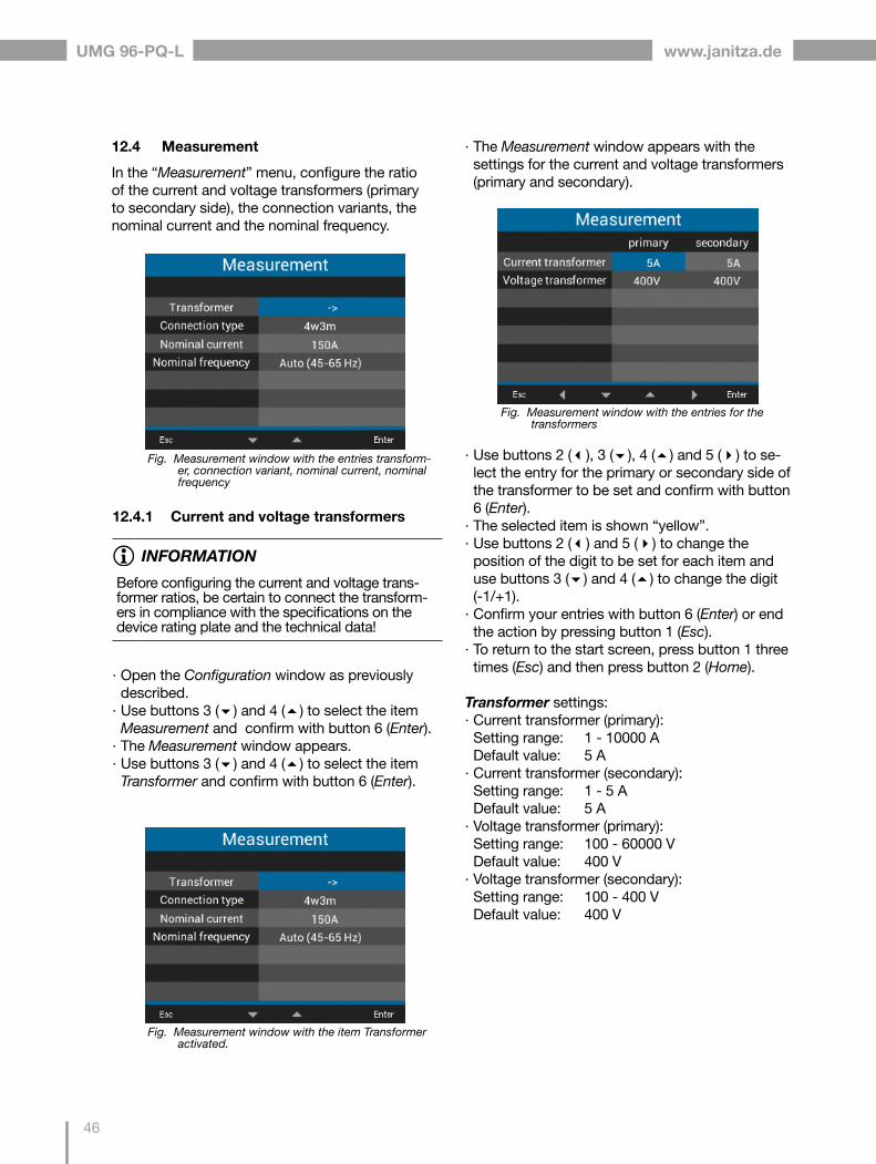
UMG 96-PQ-L www.janitza.de
46
12.4 Measurement
In the “Measurement” menu, configure the ratio of the current and voltage transformers (primary to secondary side), the connection variants, the nominal current and the nominal frequency.
12.4.1 Current and voltage transformers
INFORMATION
Before configuring the current and voltage trans-former ratios, be certain to connect the transform-ers in compliance with the specifications on the device rating plate and the technical data!
· Open the Configuration window as previously described.
· Use buttons 3 () and 4 () to select the item Measurement and confirm with button 6 (Enter).
· The Measurement window appears. · Use buttons 3 () and 4 () to select the item Transformer and confirm with button 6 (Enter).
· The Measurement window appears with the settings for the current and voltage transformers (primary and secondary).
Fig. Measurement window with the item Transformer activated.
Fig. Measurement window with the entries for the transformers
· Use buttons 2 (), 3 (), 4 () and 5 () to se-lect the entry for the primary or secondary side of the transformer to be set and confirm with button 6 (Enter).
· The selected item is shown “yellow”. · Use buttons 2 () and 5 () to change the position of the digit to be set for each item and use buttons 3 () and 4 () to change the digit (-1/+1).
· Confirm your entries with button 6 (Enter) or end the action by pressing button 1 (Esc).
· To return to the start screen, press button 1 three times (Esc) and then press button 2 (Home).
Transformer settings: · Current transformer (primary): Setting range: 1 - 10000 A Default value: 5 A
· Current transformer (secondary): Setting range: 1 - 5 A Default value: 5 A
· Voltage transformer (primary): Setting range: 100 - 60000 V Default value: 400 V
· Voltage transformer (secondary): Setting range: 100 - 400 V Default value: 400 V
Fig. Measurement window with the entries transform-er, connection variant, nominal current, nominal frequency

www.janitza.de
47
UMG 96-PQ-L
12.4.2 Connection variant
· Open the Configuration window as previously described.
· Use buttons 3 () and 4 () to select the item Measurement and confirm with button 6 (Enter).
· The Measurement window appears. · Use buttons 3 () and 4 () to select the item Connection variant and confirm with button 6 (Enter).
· The selected item is shown “yellow”. · Select the desired connection variant with but-tons 3 () and 4 ().
· Confirm your entries with button 6 (Enter) or end the action by pressing button 1 (Esc).
· To return to the start screen, press button 1 three times (Esc) and then press button 2 (Home).
Setting ranges Connection variant: · 4w3m · 3w2u · 3w2m
Fig. Measurement window with the entry Connection Variant marked
Connection variant 4w3m
L1L2L3N
V1 V2 V3 VN V1 V2 V3 VN4w 3m I1 I2 I3S1 S2 S1 S2 S1 S2
L1L2L3N
4w 3mhv I1 I2 I3
S1 S2 S1 S2 S1 S2
L1L2L3N
L1 L2 L3 N4w 2i I1 I2 I3S1 S2 S1 S2 S1 S2
L1L2L3N
L1 L2 L3 N4w 2m I1 I2 I3S1 S2 S1 S2 S1 S2
L1L2L3N
L1 L2 L3 N4w 2u
hv I1 I2 I3S1 S2 S1 S2 S1 S2
L1L2L3N
L1 L2 L3 N4w 2u I1 I2 I3S1 S2 S1 S2 S1 S2
Connection variant 3w2u
L1L2L3N
V1 V2 V3 VN V1 V2 V3 VN4w 3m I1 I2 I3S1 S2 S1 S2 S1 S2
L1L2L3N
4w 3mhv I1 I2 I3
S1 S2 S1 S2 S1 S2
L1L2L3N
L1 L2 L3 N4w 2i I1 I2 I3S1 S2 S1 S2 S1 S2
L1L2L3N
L1 L2 L3 N4w 2m I1 I2 I3S1 S2 S1 S2 S1 S2
L1L2L3N
L1 L2 L3 N4w 2u
hv I1 I2 I3S1 S2 S1 S2 S1 S2
L1L2L3N
L1 L2 L3 N4w 2u I1 I2 I3S1 S2 S1 S2 S1 S2
Fig. Connection variant 4w3m - measurement in a three-phase 4-conductor network with asymmetrical load.
Fig. Connection variant 4w3m hv - measurement via 3 volt-age transformers in a three-phase 4-conductor network with asymmetrical load.
L1
N
L1 L2 L3 N2w 1m I1 I2 I3S1 S2 S1 S2 S1 S2
L1L2L3
L1 L2 L3 N3w 3m I1 I2 I3S1 S2 S1 S2 S1 S2
L1L2L3
L1 L2 L3 N3w 2i I1 I2 I3S1 S2 S1 S2 S1 S2
L1L2L3
3w 2m I1 I2 I3S1 S2 S1 S2 S1 S2
L1L2L3
3w 2mhv I1 I2 I3
S1 S2 S1 S2 S1 S2
L1 L2 L3 N2w 2m I1 I2 I3S1 S2 S1 S2 S1 S2
L1
L2
L1L2L3
3w 2u I1 I2 I3S1 S2 S1 S2 S1 S2
V1 V2 V3 VN
L1L2L3
3w 2uhv I1 I2 I3
S1 S2 S1 S2 S1 S2
V1 V2 V3 VN
V1 V2 V3 VN V1 V2 V3 VN
Fig. Connection variant 3w2u - measurement in a three-phase 3-conductor network with asymmetrical load.
L1
N
L1 L2 L3 N2w 1m I1 I2 I3S1 S2 S1 S2 S1 S2
L1L2L3
L1 L2 L3 N3w 3m I1 I2 I3S1 S2 S1 S2 S1 S2
L1L2L3
L1 L2 L3 N3w 2i I1 I2 I3S1 S2 S1 S2 S1 S2
L1L2L3
3w 2m I1 I2 I3S1 S2 S1 S2 S1 S2
L1L2L3
3w 2mhv I1 I2 I3
S1 S2 S1 S2 S1 S2
L1 L2 L3 N2w 2m I1 I2 I3S1 S2 S1 S2 S1 S2
L1
L2
L1L2L3
3w 2u I1 I2 I3S1 S2 S1 S2 S1 S2
V1 V2 V3 VN
L1L2L3
3w 2uhv I1 I2 I3
S1 S2 S1 S2 S1 S2
V1 V2 V3 VN
V1 V2 V3 VN V1 V2 V3 VN
Fig. Connection variant 3w2u hv - measurement via 2 voltage transformers in a three-phase 3-conductor network with asymmetrical load.

UMG 96-PQ-L www.janitza.de
48
12.4.3 Nominal current
For a defined operation of the device, you need the nominal current in addition to the settings of the current and voltage transformer ratios.
· Open the Configuration window as previously described.
· Use buttons 3 () and 4 () to select the item Measurement and confirm with button 6 (Enter).
· The Measurement window appears. · Use buttons 3 () and 4 () to select the item Nominal current and confirm with button 6 (En-ter).
Fig. Measurement window with the item Nominal current activated.
· The item for the Nominal current is shown “yel-low”.
· Use buttons 2 () and 5 () to change the position of the digit to be set for each item and use buttons 3 () and 4 () to change the digit (-1/+1).
· Confirm your entries with button 6 (Enter) or end the action by pressing button 1 (Esc).
· To return to the start screen, press button 1 twice (Esc) and then press button 2 (Home).
Nominal current settings:Setting range: 0 - 999999 A Default value: 150 A
Connection variant 3w2m
L1
N
L1 L2 L3 N2w 1m I1 I2 I3S1 S2 S1 S2 S1 S2
L1L2L3
L1 L2 L3 N3w 3m I1 I2 I3S1 S2 S1 S2 S1 S2
L1L2L3
L1 L2 L3 N3w 2i I1 I2 I3S1 S2 S1 S2 S1 S2
L1L2L3
3w 2m I1 I2 I3S1 S2 S1 S2 S1 S2
L1L2L3
3w 2mhv I1 I2 I3
S1 S2 S1 S2 S1 S2
L1 L2 L3 N2w 2m I1 I2 I3S1 S2 S1 S2 S1 S2
L1
L2
L1L2L3
3w 2u I1 I2 I3S1 S2 S1 S2 S1 S2
V1 V2 V3 VN
L1L2L3
3w 2uhv I1 I2 I3
S1 S2 S1 S2 S1 S2
V1 V2 V3 VN
V1 V2 V3 VN V1 V2 V3 VN
Fig. Connection variant 3w2m - measurement in a three-phase 3-conductor network with asymmetrical load.
L1
N
L1 L2 L3 N2w 1m I1 I2 I3S1 S2 S1 S2 S1 S2
L1L2L3
L1 L2 L3 N3w 3m I1 I2 I3S1 S2 S1 S2 S1 S2
L1L2L3
L1 L2 L3 N3w 2i I1 I2 I3S1 S2 S1 S2 S1 S2
L1L2L3
3w 2m I1 I2 I3S1 S2 S1 S2 S1 S2
L1L2L3
3w 2mhv I1 I2 I3
S1 S2 S1 S2 S1 S2
L1 L2 L3 N2w 2m I1 I2 I3S1 S2 S1 S2 S1 S2
L1
L2
L1L2L3
3w 2u I1 I2 I3S1 S2 S1 S2 S1 S2
V1 V2 V3 VN
L1L2L3
3w 2uhv I1 I2 I3
S1 S2 S1 S2 S1 S2
V1 V2 V3 VN
V1 V2 V3 VN V1 V2 V3 VN
Fig. Connection variant 3w2m hv - measurement via 2 volt-age transformers in a three-phase 3-conductor network with asymmetrical load.

www.janitza.de
49
UMG 96-PQ-L
To determine the mains frequency, the measure-ment device requires a voltage > 20Vrms (4-wire measurement) or a voltage L1-L2 > 34Vrms (3-wire measurement) on voltage measurement input V1.
Fig. Measurement window with the item Nominal frequency activated.
· The item for the Nominal frequency is shown “yellow”.
· Select your frequency range with buttons 3 () and 4 ().
· Confirm your entries with button 6 (Enter) or end the action by pressing button 1 (Esc).
· To return to the start screen, press button 1 twice (Esc) and then press button 2 (Home).
Setting ranges for Nominal frequency: · Auto (45-65 Hz) - Standard setting · 60 Hz (const. frequency) · 50 Hz (const. frequency)
INFORMATION
Measurement devices with the setting Auto need about 5 seconds to determine the mains frequency. During this time, the measured values do not main-tain the guaranteed measurement uncertainty.
INFORMATION
If the mains frequency is outside the range of 45-65 Hz: · There is no error or warning alert. · When a constant frequency (50/60 Hz) is indi-cated, the corresponding setting is used.
· When automatic frequency detection is select-ed (Auto), the last determined frequency in the range of 45-65 Hz is used.
The determination of the frequency runs over a period of 10 seconds. The frequency does not represent a 200 ms measured value!
12.4.4 Nominal frequency
The device requires the mains frequency for the measurement and calculation of measured values. The device is suitable for measurements in net-works with a frequency range of 45 - 65 Hz.
· Open the Configuration window as previously described.
· Use buttons 3 () and 4 () to select the item Measurement and confirm with button 6 (Enter).
· The Measurement window appears. · Use buttons 3 () and 4 () to select the item Nominal frequency and confirm with button 6 (Enter).

UMG 96-PQ-L www.janitza.de
50
12.5 Display
Use the item Display of the measurement device to configure the following display settings: · Brightness, · Standby after, · Brightness (standby) and · Colors.
· Open the Configuration window as previously described.
Fig. Display window
· Use buttons 3 () and 4 () to select the corre-sponding item of the Display window and confirm with button 6 (Enter).
· The entries for Brightness, Standby after and Brightness (Standby) are shown “yellow”. The item Colors leads to the Colors window.
· Use buttons 2 () and 5 () to change the position of the digit to be set for each item and use buttons 3 () and 4 () to change the digit (-1/+1).
Fig. Configuration window with Display item activated.
· Use buttons 3 () and 4 () to select the item Display and confirm with button 6 (Enter).
· The Display window appears.
· Confirm your entries with button 6 (Enter) or end the action by pressing button 1 (Esc).
· To return to the start screen, press button 1 twice (Esc) and then press button 2 (Home).
12.5.1 Brightness
Display brightness of the measurement device.
· Setting range: 30% - 100% Default value: 70% with 30% = dark 100% = very bright
12.5.2 Standby after
Time in seconds after which the display brightness is set to the Brightness (Standby) that has been configured.
· Setting range: 60 s - 3600 s Default value: 900 s
12.5.3 Brightness (standby)
Display brightness to which the meter switches after the standby time has expired.
· Setting range: 20% - 60% Default value: 30% with 20% = dark 60% = very bright

www.janitza.de
51
UMG 96-PQ-L
12.5.4 Colors
Colors for the display of current and voltage in the graphical visualizations.
· Open the Configuration window as previously described.
· Use buttons 3 () and 4 () to select the item Display and confirm with button 6 (Enter).
· The Display window appears. · Use the buttons 3 () and 4 () to select the item Colors and confirm with button 6 (Enter).
· The Colors window appears.
Fig. Colors window
· Use buttons 2 (), 3 (), 4 () and 5 () to select the color for the voltage or current of the phase to be set and confirm with button 6 (Enter).
· The selected color is shown framed in blue. · Use buttons 3 () and 4 () to select the desired color and confirm with button 6 (Enter) or end the action with button 1 (Esc).
· To return to the start screen, press button 1 three times (Esc) and then press button 2 (Home).
12.6 System
In the System window, the user of the measure-ment device can: · View device-specific system settings. · Configure a password. · Delete or reset measured values and device parameters.
· Open the Configuration window as previously described.
· Use buttons 3 () and 4 () to select the item System and confirm with button 6 (Enter).
Fig. Configuration window with the System item activated.
Fig. System window
· The System window appears.
Item Function/Designation
1 Firmware version
2 Serial number of the measurement device
3 Date/time
4 Password function
5 Reset function
Tab.: Entries in the System window
1
2
3
4
5

UMG 96-PQ-L www.janitza.de
52
12.6.1 Firmware/Serial number
The firmware and the serial number of the mea-surement device are required for support requests or registration on the homepage (www.janitza.de).
12.6.2 Date/time
Setting the date and time. You can change the settings for synchronization, the date and time zones via · the GridVis® software or · the Modbus addresses(See section “14.12 Synchronization” on page 53).
12.6.3 Password
Use a password to block access to the config-uration. The device can only be configured after entering the password.
The password consists of a number combination of up to 5 digits. Setting ranges: · 1-99999 = with password · 00000 = without password
Default value:00000 = without password
The UMG 96-PQ-L is delivered ex works with the password 00000 (no password) configured.For a password change, you need the current password!
INFORMATION
· The measurement device locks the device con-figuration for 10 min. if the password is entered incorrectly 5 times.
· Write down your password and keep it safe! · Without the password you cannot configure your device! Notify the device manufacturer’s Support if the password is lost!
Setting the password
· Open the Configuration window as previously described.
· Use buttons 3 () and 4 () to select the item System and confirm with button 6 (Enter).
· The System window appears. · Use buttons 3 () and 4 () to select the item Password and confirm with button 6 (Enter).
· The entry for the Password is shown “yellow”.
· Use buttons 2 () and 5 () to change the position of the digit to be set for each item and use buttons 3 () and 4 () to change the digit (-1/+1).
· Confirm your entries with button 6 (Enter) or end the action by pressing button 1 (Esc).
· To return to the start screen, press button 1 twice (Esc) and then press button 2 (Home).
Fig. System window with the item Password activated

www.janitza.de
53
UMG 96-PQ-L
12.6.4 Reset
This function is used to delete and reset measured values and device parameters.
Energy
You can delete all energy meters in the device simultaneously. It is not possible to select certain energy meters.
· Open the Configuration window as previously described.
· Use buttons 3 () and 4 () to select the item System and confirm with button 6 (Enter).
· The System window appears. · Use buttons 3 () and 4 () to select the item Reset and confirm with button 6 (Enter).
· The Reset window appears.
Fig. Reset window, resetting the energy meters
· Use buttons 3 () and 4 () to select the item Energy and confirm with button 6 (Enter).
· The entry for the Energy is shown “yellow”. · Use buttons 3 () and 4 () to select “Yes” or “No”.
· Confirm your entries with button 6 (Enter) or end the action by pressing button 1 (Esc).
· To return to the start screen, press button 1 three times (Esc) and then press button 2 (Home).
Minimum and maximum values
With this function, the device user deletes all min. and max. values in the device simultaneously. It is not possible to select certain energy meters.
INFORMATION
Before commissioning, delete any production-relat-ed contents of the energy meters, Min./Max. values and records!
· Open the Configuration window as previously described.
· Use buttons 3 () and 4 () to select the item System and confirm with button 6 (Enter).
· The System window appears. · Use buttons 3 () and 4 () to select the item Reset and confirm with button 6 (Enter).
· The Reset window appears.
· Use buttons 3 () and 4 () to select the item Min./max. values and confirm with button 6 (En-ter).
· The entry Min./Max. values is shown “yellow”. · Use buttons 3 () and 4 () to select “Yes” or “No”.
· Confirm your entries with button 6 (Enter) or end the action by pressing button 1 (Esc).
· To return to the start screen, press button 1 three times (Esc) and then press button 2 (Home).
Fig. Reset window, delete min/max values

UMG 96-PQ-L www.janitza.de
54
Standard factory settings
This function resets all settings, such as configura-tions and recorded data, to the factory settings. · Open the Configuration window as previously described.
· Use buttons 3 () and 4 () to select the item System and confirm with button 6 (Enter).
· The System window appears. · Use buttons 3 () and 4 () to select the item Reset and confirm with button 6 (Enter).
· The Reset window appears. · Use buttons 3 () and 4 () to select the item Standard factory setting and confirm with button 6 (Enter).
Fig. Reset window, standard factory settings
· The item Standard factory setting is shown “yel-low”.
· Use buttons 3 () and 4 () to select “Yes” or “No”.
· Confirm your entries with button 6 (Enter) or end the action by pressing button 1 (Esc).
· Use button 6 (Enter) to confirm the warning mes-sage or end the action with button 1 (Menu).
· Pressing button 6 (Enter) resets the device to the standard factory settings.
Fig. Reset window, restart device
Restart
This function restarts the measurement device. · Open the Configuration window as previously described.
· Use buttons 3 () and 4 () to select the item System and confirm with button 6 (Enter).
· The System window appears. · Use buttons 3 () and 4 () to select the item Reset and confirm with button 6 (Enter).
· The Reset window appears.
· Use buttons 3 () and 4 () to select the item Restart and confirm with button 6 (Enter).
· The item Restart appears in “yellow”. · Use buttons 3 () and 4 () to select “Yes” or “No”.
· Confirm your entries with button 6 (Enter) or end the action by pressing button 1 (Esc).
· Pressing button 6 (Enter) restarts the device.

www.janitza.de
55
UMG 96-PQ-L
12.7 Modbus editor
The function Modbus Editor is used to configure various functions or to read out measured val-ues directly on the measurement device, without parametrization software or a network connection. Your measurement device does not require a net-work connection for this.
INFORMATION
Optionally, you can configure Modbus addresses easily and conveniently in the GridVis® software.
You can use the Modbus address list (download at www.janitza.de) to configure the analog output of the measurement device, for example, via the device keyboard.
Example of configuring the measured value for the analog output:
To assign a measured value to the analog output of your measurement device, write the Modbus address of the measured value (see the table of frequently used measured values) to the
Modbus address 30001
To configure a start value for your measured value, write the start value to the
Modbus address 30002
A final value for your measured value can be entered in
Modbus address 30004
To assign the output ranges to the analog out-put of a device, write as follows to the
Modbus address 30006
· a 0 for the output range 0-20 mA; · a 1 for the output range 4-20 mA.
Modbus address Measured value
19026 Active power, sum L1-L3, instantaneous value
19042Reactive power, sum L1-L3, instantaneous value
19012 Current L1, instantaneous value
19014 Current L2, instantaneous value
19016 Current L3, instantaneous value
1050 Cos phi sum L1-L3, instantaneous value
For measurement devices with RCM module
20053Neutral conductor current I4, instantaneous value
20055Residual current RCM 1 (I5), instantaneous value
20057Residual current RCM 2 (I6), instantaneous value
20061 Temperature, instantaneous value
Tab.: Modbus addresses of frequently required measured values.
Table of frequently used measured values
Frequently used measured values and their Mod-bus addresses for output on the analog output (Modbus address 30001):
INFORMATION
Further information on the analog outputs can be found in chapter „10. Analog outputs“ on page 40 and in section „13.15 Configuration of the analog output“ on page 74.
INFORMATION
A continuation of the table can be found in section „19.1 Modbus addresses of frequently used mea-sured values“ on page 116.

UMG 96-PQ-L www.janitza.de
56
You can access the Modbus editor as follows: · Open the Configuration window as previously described.
· Use buttons 3 () and 4 () to select the item Modbus editor and confirm with button 6 (Enter).
Fig. Configuration window, Modbus editor
· The Communication window appears with the Modbus editor.
· Use buttons 3 () and 4 () to select the item Address or Value and confirm with button 6 (Enter).
· The selected item is shown “yellow”. · Use buttons 2 () and 5 () to change the position of the digit to be set for each item and use buttons 3 () and 4 () to change the digit (-1/+1).
· Confirm your entries with button 6 (Enter) or end the action by pressing button 1 (Esc).
· To return to the start screen, press button 1 twice (Esc) and then press button 2 (Home).
Fig. Communication window, Modbus editor
Example for the measured value Active power:
· In the Configuration window, select the item Modbus editor and confirm with button 6 (Enter).
· The Communication/Modbus Editor window ap-pears with the items Address and Value.
· Select the item Address and press button 6 (Enter).
· The item Address is shown “yellow”. · Use buttons 2 (), 5 (), 3 () and 4 () to con-figure the number 30001.
· Confirm the entry with button 6 (Enter). · Then select the item Value and press button 6 (Enter).
· The item Value is shown “yellow”. · Use buttons 2 (), 5 (), 3 () and 4 () to con-figure the number 19026 for the measured value Active power sum, L1-L3.
· Then configure the Start and End value of the active power in the addresses 30002 and 30004. For example, start value 500 W and end value 1000 W. Please note that the measured value variables must always be entered in the basic unit (e.g. W, A, V).
Further information on this example can be found in section „13.15 Configuration of the analog output“ on page 74.
INFORMATION
· Measured values and Modbus addresses for the analog outputs can be configured easily and clearly in the GridVis® software (see www.janitza.de).
· Using the GridVis® software requires a connec-tion between the measurement device and a PC (server) running the GridVis® software (see chapter „8. Connection and PC connections“ on page 34).
· Also observe the documentation for the RCM modules.

www.janitza.de
57
UMG 96-PQ-L
12.8 Events
INFORMATION
Please note! · You must configure events in the GridVis® software.
· Only Meters with firmware version 3.3 or higher have the "Events" function for recording faults in the supply or power grid.
· Further information on the "Events function" can be found on Page 86 and in the online GridVis® software help.
Fig. Configuration of the events in the GridVis software®
In the GridVis® software, you can easily and clearly configure all the important parameters for record-ing events, such as: · Nominal values · Event types · Measured values · Limit values · Hysteresis
In addition, the GridVis® software visualizes re-corded events in an event browser and provides assistance concerning the events in the form of informational texts and graphics.

UMG 96-PQ-L www.janitza.de
58
13. Commissioning
13.1 Applying the supply voltage
1. Connect the supply voltage with a terminal on the back of the device.
2. After connection of the supply voltage, the start screen Summary appears (default setting) on the display of your measurement device.
3. If no display appears, check whether the sup-ply voltage is within the nominal voltage range.
13.2 Measured voltage
INFORMATION
In networks with nominal voltages that exceed the specified nominal voltages, connect the voltage measurement inputs via voltage transformers (see section „7.1 Nominal voltages“ on page 25)!
Connect measured voltage:1. Connect the measured voltage to the termi-
nals of the voltage measurement inputs on the back of the device.
2. After connecting the measured voltage, check the measured values displayed by the device for the voltages L-N and L-L. Take into account any voltage transformer factors that may be set!
CAUTIONMaterial damage due to disregard of the con-nection instructions!Disregard of the connection instructions can dam-age or destroy your device.Observe the following: · Observe the voltage and frequency specifica-tions on the rating plate!
· Do not use the device for measuring DC volt-age!
WARNINGRisk of injury due to electrical voltage!If the device is exposed to surge voltages above the permissible overvoltage category, safety-rele-vant areas of insulation in the device can be dam-aged. This means that the safety of the product can no longer be guaranteed.Only use the device in environments in which the permissible overvoltage category is not exceeded.
13.3 Measured current
The device: · Is designed for the connection of current trans-formers with secondary currents of ../1 A and ../5 A.
· Does not measure DC currents.
The factory-set current transformer ratio is 5/5 A and must be adapted to the current transformers used as needed.
1. Short-circuit all current transformer outputs except one.
2. Compare the current displayed on the device with the applied input current. - The currents must match after taking the cur-rent transformer ratio into account.
- In the short-circuited current measurement inputs, the device must indicate approx. 0 amperes.
Fig. Phasor diagram
INFORMATION
Before commissioning, delete any production-relat-ed contents of the energy meters, Min./Max. values and records (see section „Minimum and maximum values“ on page 53)!

www.janitza.de
59
UMG 96-PQ-L
UL1-UL2-UL3 = right rotating fieldUL1-UL3-UL2 = left rotating field
Fig. Phasor diagram window showing the phase sequence according to the direction of the rotary field
Fig. Voltage menu item
Fig. Submenu item Phasor diagram
To check the voltage rotating field, open the menu display “Phasor diagram”:
· If you are not in the start screen, you can go to this view by pressing button 2 (Home).
· Open the menu with button 1 (Menu).
· Use buttons 3 () and 4 () to select the item Voltage and confirm with button 6 (Enter).
· The submenu with the item Phasor diagram appears.
· Use buttons 3 () and 4 () to select the item Phasor diagram and confirm with button 6 (Enter).
· The Phasor diagram window appears.
13.4 Frequency
For the measurement and calculation of measured values, the device requires the nominal or mains frequency. The mains frequency can either be specified by the user or determined automatically by the device.
· To determine the mains frequency, the voltage measurement input V1 requires a voltage greater than 20 Veff (4-wire measurement) or an L1-L2 voltage of greater than 34 Veff (3-wire measure-ment).
· The mains frequency must be in the range from 45 Hz to 65 Hz.
· If the measured voltage is not sufficiently high, the device cannot determine the mains frequency and therefore cannot carry out a measurement.
For further information, see section „12.4.4 Nomi-nal frequency“ on page 49.
13.5 Direction of rotary field
Check the direction of the voltage rotating field in the measuring display of the device. · Usually it is a “right” rotating field.
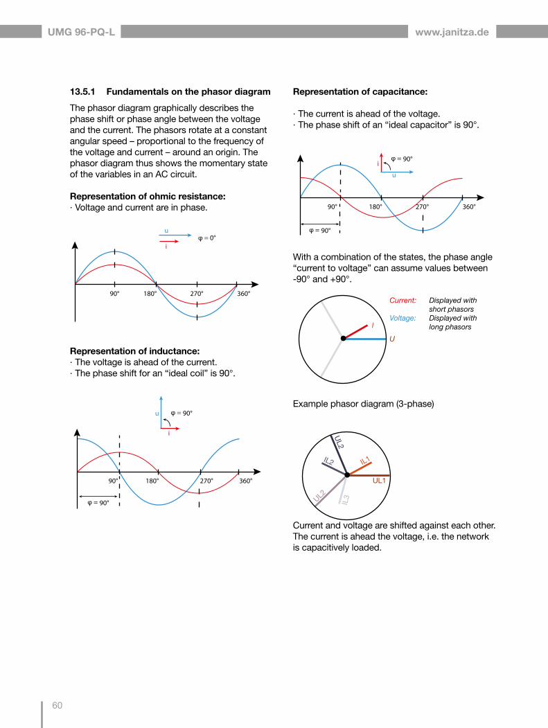
UMG 96-PQ-L www.janitza.de
60
13.5.1 Fundamentals on the phasor diagram
The phasor diagram graphically describes the phase shift or phase angle between the voltage and the current. The phasors rotate at a constant angular speed – proportional to the frequency of the voltage and current – around an origin. The phasor diagram thus shows the momentary state of the variables in an AC circuit.
Representation of ohmic resistance: · Voltage and current are in phase.
u
i
u
i
u
i
Representation of inductance: · The voltage is ahead of the current. · The phase shift for an “ideal coil” is 90°.
u
i
u
i
u
i
Representation of capacitance:
· The current is ahead of the voltage. · The phase shift of an “ideal capacitor” is 90°.
u
i
u
i
u
i
With a combination of the states, the phase angle “current to voltage” can assume values between -90° and +90°.
U
I
Current: Displayed with short phasorsVoltage: Displayed with long phasors
Example phasor diagram (3-phase)
Current and voltage are shifted against each other. The current is ahead the voltage, i.e. the network is capacitively loaded.
UL1
IL1IL2
UL2
UL2
IL3

www.janitza.de
61
UMG 96-PQ-L
13.7 Overrange
If the measuring range is exceeded, a warning appears in the device display, e.g. for the voltage, the warning “Overvoltage” with an indication of the voltage circuit.
The overrange message is displayed as long as the condition is present. Alarms can be acknowl-edged with button 5 Alarms. The measuring range is exceeded if at least one of the voltage or current measurement inputs lies outside its specified mea-suring range.
Limit values for overrange (200 ms effective val-ues):
I = 6 ArmsUL-N = 600 Vrms
13.6 Checking of voltage and current inputs by means of phasor diagram
The phasor diagram can be used to check incor-rect connections at the voltage and current inputs.
Example 1Primarily ohmic load.
Voltage and current have only a small deviation in the phase position.
· The current measurement input is assigned to the correct voltage measurement input
Example 2Primarily ohmic load.
Voltage and current have a deviation of about 180° in the phase position.
· The measured current input is assigned to the correct voltage measurement input.
· In the current measurement under consideration, the connections k and I are reversed or there is a feedback into the supply network.
WARNINGMaterial damage due to disregard of the con-nection instructions!Voltages and currents outside the permissible measuring range can destroy the device.Comply with the measuring range specifica-tions from the technical data.
Fig. Example warning message, overvoltage in phase L1.
13.8 Checking the time
To enable correct assignment of times to the mea-surement data records requires a correct specifi-cation of the time. Check and, if needed, correct the time and date settings in the Configuration / System menu (see section „12.6.2 Date/time“ on page 52).
INFORMATION
If the measuring range is exceeded, please check your installation and connections. Comply with the connection conditions specified in the technical data.

UMG 96-PQ-L www.janitza.de
62
13.9 Control of the power measurement
Short-circuit all current transformer outputs except one and check the indicated powers.
· The device must only display power in the phase with the current transformer input that is not short-circuited.
· If this is not the case, check the connection of the measured voltage and measured current.
If the amount of active power is correct, but the sign of the active power is negative, this can have two causes:
1. The connections S1(k) and S2(l) on the current transformer are reversed.
2. Active energy is returned to the grid.
13.10 Control of the communication
The device counts all received (RX), all sent (TX) and all faulty data packets.
Ideally, the number of errors in the Error column will be “0” (see figure below, window Com. RS-485).
· If you are not in the start screen, you can go to this view by pressing button 2 (Home).
· Open the menu with button 1 (Menu). · Use buttons 3 () and 4 () to select the item System Info from the menu and confirm with button 6 (Enter).
· The following submenu appears:
Call up the phasor diagram with details on the power: · If you are not in the start screen, you can go to this view by pressing button 2 (Home).
· Open the menu with button 1 (Menu). · Use buttons 3 () and 4 () to select the item Voltage and confirm with button 6 (Enter).
· The submenu with the item Phasor diagram appears.
· Use buttons 3 () and 4 () to select the item Phasor diagram and confirm with button 6 (Enter).
· The Phasor diagram window appears.
· Use buttons 3 () and 4 () to select the menu item Com. RS-485 and confirm with button 6 (Enter).
· The Com. RS-485 window appears with the parameters for the RS-485 communication inter-face.
Fig. System Info submenu with Com. RS-485 item activated.
Fig. The phasor diagram shows voltages with long phasors and currents with short phasors.
Fig. Display of the parameters that are set for the RS-485 communication interface.

www.janitza.de
63
UMG 96-PQ-L
Now check the RS-485 communication parame-ters, such as: · All received (RX), all sent (TX) and all faulty data packets. Ideally, the number of errors in the col-umn Error will equal “0”.
· The mode that is set, the device address, baud rate and timeout.
Check the parameters of the measurement device to the digital inputs and outputs and the analog output as follows:
· If you are not in the start screen, you can go to this view by pressing button 2 (Home).
· Open the menu with button 1 (Menu). · Use buttons 3 () and 4 () to select the item System Info from the menu and confirm with button 6 (Enter).
· The following submenu appears:
· Use buttons 3 () and 4 () to select the sub-menu item Peripherals and confirm with button 6 (Enter).
· The Peripherals window appears with the states of the digital inputs and outputs and the value of the analog output:
Fig. Submenu System Info with activated Peripherals entry
Fig. Displays the states of the digital inputs and outputs and the value of the analog output.

UMG 96-PQ-L www.janitza.de
64
13.11 Delete min./max. values
In the measuring displays for voltage, current and power, the device offers the function of deleting Min./Max. values using button 6 (Enter). The Min./Max. values can be deleted for the following mea-sured values:
In the submenu Voltage: · Voltage L-N · Voltage L-L
In the window Current: · Current · THD-I (Total harmonic distortion - current)
In the window Power: · Total power · Active power · Reactive power · Apparent power
· If you are not in the start screen, you can go to this view by pressing button 2 (Home).
· Open the menu with button 1 (Menu). · Use buttons 3 () and 4 () to select the item Voltage, Current or Power and confirm with but-ton 6 (Enter).
Fig. Voltage, current and power menus
The following description explains the Delete min./max. values function using the example of the measuring display Voltage L-N. Deleting the Min./Max. values for current and power requires the same procedure.
· The submenu for Voltage appears. · In the submenu, select the item Voltage L-N with buttons 3 () and 4 () and confirm with button 6 (Enter).
· The voltage measuring display appears with the measured values L1-N, L2-N and L3-N.
· To delete the Min./Max. values, press button 6 (Enter).
· The Min./max. values submenu appears. · In the Min./Max. values submenu, use buttons 3 () and 4 () to select the item Delete or end the action with the item Cancel.
· Confirm your action by pressing button 6 (Enter).
Fig. Measuring display, voltage L-N with menu Delete/Cancel min./max. values

www.janitza.de
65
UMG 96-PQ-L

UMG 96-PQ-L www.janitza.de
66
Fig. Measuring display for harmonics (e.g. Voltage L1)
13.12 Harmonics current (harmonics)
Harmonics current (harmonics) are caused, for example, by equipment with non-linear character-istics. These additional frequencies represent the integral multiple of a fundamental oscillation and show how the equipment affects the mains. Possi-ble effects of harmonics are, for example: · Additional heating of operating equipment. · An additional current on the neutral conductor. · An overload and a reduced service life of electri-cal consumers.
Harmonic loads are the main cause of invisible power quality problems involving enormous costs for servicing and investments for the replacement of defective equipment.
The device measures the fundamental oscilla-tion of the voltage in the range of 45 - 65 Hz. The calculated harmonics of the voltages and currents refer to this fundamental oscillation.
The UMG 96-PQ-L calculates harmonics up to 65 times the fundamental oscillation.
· If you are not in the start screen, you can go to this view by pressing button 2 (Home).
· Open the menu with button 1 (Menu). · Use buttons 3 () and 4 () to select the item Harmonics and confirm with button 6 (Enter).
· A selection list appears with voltage and current. · Use buttons 3 () and 4 () to select Voltage, for example, and confirm with button 6 (Enter).
· A further selection list appears with the entries L1, L2 and L3.
· Use buttons 3 () and 4 () to select the respec-tive phase (e.g. L1) and confirm with button 6 (Enter).
· The Harmonics window of the selected measured value appears.

www.janitza.de
67
UMG 96-PQ-L
13.13 Communication in the bus system
13.13.1 RS-485
The device sends and receives data via the RS-485 interface. For example, the device receives data from the parameter and measured value list via a MODBUS RTU protocol with CRC check.
Modbus functions (server device)03 Read Holding Registers04 Read Input Registers 06 Preset Single Register16 (10Hex) Preset Multiple Registers 23 (17Hex) Read/Write 4X Registers
The order of the bytes is high before low byte (Mo-torola format).
Transmission parametersData bits: 8Parity: odd even none (1 stop bit) none (2 stop bits)
Stop bits (UMG 96-PQ-L): 1 / 2 External stop bits: 1 / 2
Number formatsshort 16 bit (-215 .. 215 -1)Float 32 bit (IEEE 754)
For further information on configuring the RS-485 interface on the device, see section „12.3 Com-munication“ on page 44. For explanations of the connection and of the PC connection of the device via the interface, see section „8.2 RS-485 inter-face“ on page 35.
Example: Reading the voltage L1-NThe voltage L1-N is located in the list of parame-ters and measured values at address 19000 in the FLOAT format.In this example 01 is assumed as the device ad-dress.
The “Query Message” then looks as follows:
Designation Hex Comment
Device address 01 Address=1
Function 03 “Read Holding Reg”
Start address Hi 4A 19000dec = 4A38hex
Start address Lo 38
No. of values Hi 00 2dec = 0002hex
No. of values Lo 02
Error check (CRC)
-
The “response” of the device can then look as follows:
Designation Hex Comment
Device address 01 Address=1
Function 03
Byte counter 06
Data 00 00hex=00dec
Data E6 E6hex=230dec
Error check (CRC)
-
The voltage L1-N sent from address 19000 is 230 V.

UMG 96-PQ-L www.janitza.de
68
13.14 Digital inputs/outputs
Your device has three digital outputs and three digital inputs.
· You configure the digital inputs and outputs using the GridVis® software
· The GridVis® software is available for download from our website (www.janitza.de).
13.14.1 Digital inputs
The digital inputs are used to send information to your device from other devices which have a digital output (pulse counter).There is also the option to configure digital inputs as function inputs (function mode). As a function input, each digital input has its own function. A function input cannot be configured as a pulse counter!
Using the configuration window of the GridVis® software, you can configure the digital inputs in the “Peripherals” area:
Function mode (On/Off mode) · Function assigned to the digital input.
Pulse counter · Value type of the incoming signal (e.g. electrical energy, gas/water consumption, CO2 ...)
· Pulse valency for measured or power values. · Length of the averaging time.
The states of the digital inputs each have their own Modbus address.For each digital input, the last 16 switching operations (events) are logged with a time stamp.
Fig. Configuration of the digital inputs via the GridVis ® software
Function mode (On/Off mode)A separate function can be assigned to each digi-tal input: · Digital input 1: Configuration as tariff switching (HT/LT).
· Digital input 2: Configuration for a synchronization of the device clock with the selection of minute or hour syn-chronization. The synchronization is also possible via a Mod-bus address.
· Digital input 3: Configuration as a reset input for the synchro-nous values of the drag indicator function. The synchronization of the drag indicator is also possible via a Modbus address.
21 22 23
24V DC
K1 K2
=-
+
=+
- S1 S2
Digital Outputs
17 18 19Digital Inputs
20
S3
24
K3
Fig. Digital outputs and inputs

www.janitza.de
69
UMG 96-PQ-L
Pulse counterAll digital inputs can be operated with a frequency of 25 Hz. The pulse duration (pulse width) and the pulse pause must be greater than 20 ms. The typical pulse duration for S0 pulses is 30 ms.
The maximum number of pulses per hour is cal-culated based on the minimum pulse duration and the minimum pulse pause:
Pulse length(pulse
duration)
Pulse pause(pulse pause)
Max. pulses/h
20 ms 20 ms 90000 pul./h
30 ms 30 ms 60000 pul./h
50 ms 50 ms 36000 pul./h
100 ms 100 ms 18000 pul./h
500 ms 500 ms 3600 pul./h
1 s 1 s 1800 pul./h
10 s 10 s 180 pul./h
The pulse counters can be configured with simul-taneous measured-value or power calculation. The pulses are counted as a 64-bit number and will overflow after approx. 1.17 x 10¹⁰ years of continu-ous operation (25 Hz).
Pulse valencyA pulse valency can be assigned to each digital input. With the pulse valency you specify which measured value or power value (e.g. energy) should correspond to one pulse.
Measured value calculation:
Measured value = pulse x pulse valency
Power value calculation:
Power value = Pulse x pulse valency
Time [s]
Since the pulse interval can be very large, contin-uous calculation of the measured or power values is not possible. Consequently, only average values are calculated. The calculation of the average values for the measured value calculation results from the number of pulses per period multiplied by the pulse valency. For the calculation of the mean power values, this value must be divided by a con-figurable time value.
The period is assigned to the respective digital input and can be set to between 1 and 60 minutes. After the period has expired, the value can be called up via Modbus.
An external synchronization can be connected for each digital input, whereby one synchronization pulse completes a period and starts a new one. A capture time of 30 seconds is permanently preset for the external synchronization. If there is still no synchronous pulse after the period has expired, the software waits a maximum of 30 seconds and then synchronizes. All further periods are then synchronized by the software.
Fig. Examples for the maximum number of pulses per hour.
Pulse duration > 20 ms
Pulse pause > 20 ms
A period of 15 minutes is set at the factory.
The calculation result of the S0 power value is only available at the end of the period.
INFORMATION
The pulse interval is proportional to the power within the selected settings.
INFORMATION
There is a selection of energy values derived from power values available in the GridVis® software for the configuration of pulse counters.

UMG 96-PQ-L www.janitza.de
70
13.14.2 Digital outputs
Different functions can be assigned to the 3 digital outputs:
· Digital output 11) - Pulse output for active energy - Output for timer switch - Modbus remote output
· Digital output 2 - Pulse output for reactive energy - Output for comparator group 1 - Output for timer switch - Modbus remote output
· Digital output 3 - Output for comparator group 2 - Output for timer switch - Modbus remote output
Using the configuration window of the GridVis® software, you can define the digital outputs in the “Peripherals” area:
Pulse outputDigital output 1 and 2 can be used to output puls-es for counting active and reactive energy. To do so, a pulse is applied to the output after a certain, configurable amount of energy has been reached.
To use a digital output as a pulse output, you must make various settings in the configuration menu using the GridVis® software: · Pulse width · Mode for the digital input: S0 output · Output polarity: Normally open, normally closed · Pulse valency
Determine pulse valency1. Set the pulse length according to the require-
ments of the connected pulse receiver. With a pulse length of 30 ms, for example, the device can emit a maximum of 60,000 pulses (see table „Examples for the maximum number of pulses per hour.“ one page 69) per hour.
Determine maximum connected load: Example: Current transformer = 150/5 A Voltage L-N = max. 300 V Power per phase = 150 A x 300 V = 45 kW Power with 3 phases = 45 kW x 3 Max. Connected load = 135 kW
Pulse valencyThe pulse valency indicates how much energy (Wh or varh) corresponds to one pulse.
The pulse valency is determined by the maximum connected load and the maximum number of pulses per hour.
If you indicate the pulse valency with: · With a positive sign, pulses are only output if the measured value also has a positive sign.
· With a negative sign, pulses are only output if the measured value also has a negative sign.
Fig. Configuration of the digital outputs via the GridVis® software
INFORMATION
Since the Active energy meter operates with a reverse running stop, the device only sends pulses when electrical energy is consumed.
Since the Reactive energy meter operates with a reverse running stop, the device only sends pulses when there is an inductive load.

www.janitza.de
71
UMG 96-PQ-L
Pulse valency = Max. connected load
Max. number of pulses/h[Wh/pulse]
Pulse valency = 135 kW / 60000 pulses/hPulse valency = 0.00225 kWh/pulsePulse valency = 2.25 Wh/pulse
Fig. Connection example for wiring as a pulse output.
+ -
230 VAC
24 VDC
Externaloperating voltage
1.5k
Data logger
UMG 96-PQ-LSwitching and pulse outputs
21
22
23
Digital Output 1
Digital Output 2
+24V=
Timer switch output64 independent weekly timers can be configured in the device with: · A resolution of 1 minute. · A definable active period within one day. The active day within the week can be chosen.
Example:Time 9:25 to 11:45 on Sunday, Monday and Friday.The weekly timers can be configured as · Tariff switching (1 and 2) · Setting the digital outputs 1 to 3 · “no function”. The status can be called up via Modbus. The states of the timers at the digital output are linked with “OR”.
Fig. Configuration of the weekly timer (GridVis ® software)
2. Calculate pulse valency: The weekly timers can be configured via the GridVis® software in the menu item "Timer" in the "Configuration" window.
Output for Modbus remoteSwitches the outputs via a Modbus address.
Configure the digital outputs as Modbus remote outputs in the GridVis® software as follows: · Open the device configuration in GridVis®. · Set the mode of the digital outputs under “Pe-ripherals” to “Modbus Remote Output”.
· Specify the output polarity with: - Current flow active (normally open contact) - Current flow inactive (normally closed contact)
Fig. Configuration of the digital outputs as “Modbus Re-mote” in the GridVis ® software
CAUTIONMeasurement error when used as a pulse out-put.When the digital outputs are used as pulse out-puts, measurement errors can occur due to resid-ual ripple.For the supply voltage of the digital inputs and outputs, use a power supply whose residual ripple is less than 5% of the supply voltage.

UMG 96-PQ-L www.janitza.de
72
Fig. “Comparators” in the “Peripherals / Com-parators” menu
Output for comparator groupTwo comparator groups (comparator 1 and 2) each with 3 comparators (A - C) are available for moni-toring limit values.
The results of comparators A to C can be linked with “AND” or “OR”.
The logic result of comparator group 1 can be assigned to digital output 2 and the logic result of comparator group 2 can be assigned to digital output 3. The comparators can be configured exclusively via the GridVis® software in the “Comparator” config-uration area.
Read out comparator settings on the device: · Open the menu with button 1. · Use buttons 3 () and 4 () to select the item Peripherals.
· Confirm using button 6 (Enter). · The submenu appears. · Use buttons 3 () and 4 () to select the item Comparator 1 for comparator group 1 and Com-parator 2 for comparator group 2.
· Confirm using button 6 (Enter).
Fig. Configuration of the comparators in the GridVis ® software
Item Function/Designation
1 Actual value
2 Limit value
3 Comparator
4 Comparator running time
5 Logic
6 Status
Tab.: Comparator entries
12
3
4 5 6

www.janitza.de
73
UMG 96-PQ-L
Comparator running timeComparator running times are time counters that add up continuously for a set comparator output. This means that if the condition of the comparator is fulfilled and the lead time has expired, the count-er increases by the corresponding amount of time. The minimum initialization time is not considered here!
Comparator with limit violation set · The set limit value is compared with the mea-sured value.
· If there is a limit violation for at least the dura-tion of the lead time, the comparator result is changed.
· The result is retained at least for the duration of the minimum initialization time and at most for the duration of the limit violation. If there is no longer a limit violation and the minimum initializa-tion time has expired, the result is reset.
Measured value
Limit value
Limit violation (e.g. exceeding)
Lead time
Minimumswitch-on time
Comparator result
Comparator running time
Fig. Block diagram “Use of digital output 2 for limit value monitoring”
Digital-output 1
21
23
0/1
Comparator group 1
Comparator A
Comparator B
Comparator C
Logi
c
Result
UMG 96-PQ-L
0/1
Inverter
- not inverted- inverted
Displaystatus

UMG 96-PQ-L www.janitza.de
74
“Peripherals”.Examples:Allocation of active power L1 (output range 4 - 20 mA)
· With an active power of 500 W, the current at the analog output is 4 mA; with an active power of 1000 W --> 20 mA. The measured active power is proportional to the current at the analog output.
Assignment of the calculated active power factor cos ϕ (math.) (output range 4 - 20 mA).
· Monitoring of the active power factor cos ϕ (math.) with: cos ϕ (math.) > 0 active power, applied. cos ϕ (math.) < 0 active power, delivered.
13.15 Configuration of the analog output
The device has an analog output that can output a maximum current of 20 mA.An external 24 VDC power supply unit is required for operation.
The configuration of the analog output can be carried out in a user-friendly manner using the GridVis® software. To do so, enter the assigned measured value, the start and end value and the output range in the device configuration under
20 mA
4 mA
230 VStart value
250 VEnd value
Fig. Principle of analog output with voltage monitoring
Fig. Configuration of the analog output in the GridVis ® software
20 mA
4 mA
500 WStart value
1000 WEnd value
20 mA
4 mA
cos ϕ = -1Start value
cos ϕ = 1End value
20 mA
0
INFORMATION
Information on configuring the analog output via the device keyboard can be found in section „12.7 Modbus editor“ on page 55.

www.janitza.de
75
UMG 96-PQ-L
13.16 Drag indicator function
The “Drag indicator” function describes the 3 highest average values of value types over a defined period (time base).
· The device displays the measured maximum average values in the Drag Indicator menu (see section „13.16.4 Drag indicator - Measurement device displays“ on page 79).
· The average values determined can be called up via the GridVis® software and via a parameter with a time stamp.
· The period duration (time base), synchronization and capture time can be set in the GridVis® soft-ware or by setting the corresponding parameters.
· The average value calculation is made from the measured values of the following value types: - Current L1 - Current L2 - Current L3 - Active power L1 - Active power L2 - Active power L3 - Active power sum (L1...L3) - Apparent power L1 - Apparent power L2 - Apparent power L3 - Apparent power sum (L1...L3)
Period duration (time base):Individually configurable period duration in sec-onds for the calculation of the average values over this period (duration of measured value recording). If internal synchronization is selected, the average values are recalculated after the set period of time has elapsed.
Synchronization mode:A synchronization determines a start time for the calculation periods of the average values. You can optionally start a synchronization via · the internal device clock (internal synchroniza-tion);
· the setting of a parameter (via Modbus); · digital input 3 (external synchronization).
Capture time:The individually configurable Capture time de-scribes a time window in which an incoming pulse synchronizes the point in time. If the device receives a pulse outside the capture time, the calculated average values are deleted and the time is reset.Note: The setting for the capture time – e.g. in the GridVis® software – describes half the time window of the total capture time!
13.16.1 Internal synchronization
The average values are calculated after the con-figurable period of time (time base) has expired. The internal synchronization takes place at the full minute if this is a multiple of the time base.
Fig. Principle of synchronization
Capture time
Capture time
Capture time
Capture time
Time base
Time base
Time base
Point in time Average value
calculation
Point in time Average value
calculation
Point in time Average value
calculation
Point in time Average value
calculation
Time base [min]
Sync 1 (time)
Sync 2 (time)
Sync 3 (time)
Sync 4 (time)
2 09:00:00 09:02:00 09:04:00 09:06:00
5 09:00:00 09:05:00 09:10:00 09:15:00
15 09:00:00 09:15:00 09:30:00 09:45:00
Fig. Examples of internal synchronization with different time bases
INFORMATION
For an internal synchronization, the options Syn-chronization via Modbus AND Synchronization via digital output 3 must both be deactivated!

UMG 96-PQ-L www.janitza.de
76
13.16.2 External synchronization
An external synchronization for the calculation of the 3 highest average values is performed: · via digital input 3 (e.g. via a pulse generator) or · via a Modbus command.
External synchronization scenarios:
“No pulse despite setting”If there is no pulse via digital input 3 or a Modbus command, the measured values are stored as with an internal synchronization – but not only at each full minute!
“One pulse”If the device receives a pulse or a Modbus com-mand once outside the capture time, the mea-sured values added up to that point are reset for the calculation of the average value and the time. The time is redefined as a relative zero point and a new calculation is performed!
Example:
The power increases with time. The values are re-set to 0 by the pulse (09:06:47) outside the capture time. A new summation of the intermediate values begins from this point on. As no further impulse is received, the average value is calculated after the set time (time base).
Fig. Principle of synchronization with “No pulse despite setting”
Capture time
Capture time
Capture time
Capture time
Time base
Time base
Time base
Pulse progression of digital input 3
Synchronization principle
Example Maximum value Value Time stamp
Effective current L1 Drag indicator 1 3.51 A 09:13:07
Effective current L1 Drag indicator 2 2.52 A 09:08:07
Effective current L1 Drag indicator 3 1.52 A 09:03:07
Fig. Example of drag indicator storage with a time stamp (with set time base of 5 min)
Fig. Principle of synchronization with “One impulse outside the capture time”
Capture time
Capture time
Capture time
Capture time
Time base
Time base
Time base
Pulse progression of digital input 3
Synchronization principle
Resynchronization
Relative Zero point
Time base
Time base
Time base
Example Maximum value Value Time stamp
Active power L1
Drag indicator Consumption 1 396.73 W 09:18:47
Active power L1
Drag indicator Consumption 2 207.34 W 09:13:47
Active power L1
Drag indicator Consumption 3 80.59 W 09:08:47
Fig. Example of drag indicator storage with a time stamp (with set time base of 5 min)

www.janitza.de
77
UMG 96-PQ-L
“Periodic pulses”If the device receives periodic pulses via digital input 3 or periodic Modbus commands, there are different scenarios.
Scenario “Pulse outside the capture time”: · Summed intermediate values are set to 0. · The time is set to 0 (new relative zero point). · There is no value calculation.
Scenario “Pulse after time base, but within the capture time”: · Summed intermediate values are set to 0. · The time is set to 0 (new relative zero point). · There is no value calculation.
Scenario “Pulse before time base, within the capture time”: · Perform value calculation now. · The time is set to 0 (new relative zero point). · Delete summed intermediate values.
Fig. Principle of synchronization with “periodic pulses” to digital input 3
Capture time
Capture time
Capture time
Capture time
Time base
Time base
Time base
Pulse progression of digital input 3
Synchronization principle
Resynchronization
2 min.
Relative zero point
Pulse
Time baseend
Capture time
Pulse
Time baseend
Pulse
Time baseend
INFORMATION
With periodic synchronization, the time is synchro-nized with each pulse!

UMG 96-PQ-L www.janitza.de
78
13.16.3 Synchronization priority
An external synchronization takes place according to different priorities:
· Priority 1: Modbus synchronization For this, set the “Enable flag” (addr.: 822) using the Modbus tool or select the “Synchronization via Modbus” option in the GridVis® software in the drag indicator configuration area.
· Priority 2: Synchronization via digital input 3 For this, set the Modbus parameter “FUNC_SYNC_RECORD” (addr. 30048) to the value 4, or select the option “Drag indicator synchronization” in the GridVis® software in the peripherals (digital input 3) configuration area. Note: Do NOT select the option “Synchronization via Modbus” in the drag indicator configuration!
· Priority 3: Internal synchronization
Modbusaddress Function
Configura-tion
range
820 Set trigger flag for drag indicator synchronization 0 .. 1
821 Time base in seconds 60 .. 65535
822 Enable flag of the Modbus trigger 0 .. 1
823 Capture time in seconds 0 .. 255
30048 Configuration of the inputs 0 .. 4*
Fig. Table of Modbus addresses for a synchronization
* 0 = FUNC_NONE; 1 = FUNC_TARIFF; 2 = FUNC_SYNC_CLOCK_MIN; 3 = FUNC_SYNC_CLOCK_H; 4 = FUNC_SYNC_RECORD
Fig. Configuration “Synchronization via digital input 3 in the GridVis ® software”
Fig. Drag indicator configuration in the GridVis ® software

www.janitza.de
79
UMG 96-PQ-L
13.16.4 Drag indicator - Measurement device displays
As already described in section “13.16 Drag indi-cator function”, the drag indicator function shows the 3 highest average values of value types over a defined period (time base).
The drag indicators of the respective measured value types can be called up on the measurement device display under Menu > Drag indicator. To do so, proceed as follows: · If you are not in the start screen, you can go to this view by pressing button 2 (Home).
· Open the menu with button 1 (Menu). · Use buttons 3 () and 4 () to select the item Drag indicator and confirm with button 6 (Enter).
· The submenu with the entries Current, Active power and Apparent power appears.
· Use buttons 3 () and 4 () to select, for exam-ple, the item Current and then in the drop-down menu, for example, the item L2.
· Confirm using button 6 (Enter). · The Current L2 window appears with the following measured values:
Fig. Drag indicator display - Current L2 (effective) - of the 3 last maximum values with a time stamp.
In addition to the drag indicators of the Currents L1, L2, L3, the measurement device also shows you the drag indicators for Active power (applied and delivered) and Apparent power - individually for phases L1, L2, L3 and for the totals L1 - L3.
Fig. Drag indicator display - active power sum (applied and delivered) - of the last 3 maximum values with a time stamp.
Fig. Drag indicator display - Apparent power sum - of the last 3 maximum values with a time stamp.
Fig. Drag indicator menu item
Fig. Drag indicator display with the submenu items Cur-rent, Active power and Apparent power.

UMG 96-PQ-L www.janitza.de
80
13.16.5 Delete drag indicator
In each drag indicator display of the device - cur-rent, active and apparent power - a dialog box for deleting the drag indicator values appears when button 6 is pressed:
Fig. Dialog box for deleting the drag indicator values
INFORMATION
The deletion of current, active power or apparent power drag indicator values of one phase also causes the deletion of the drag indicator values for the other phases of the respective category. If, for example, you delete the drag indicator “Current” of phase L1, the device also deletes the drag indica-tor “Current” for phases L2 and L3!

www.janitza.de
81
UMG 96-PQ-L
13.17 Recordings
You can configure measured value recordings for the measurement device easily and conveniently in the GridVis® software.
The default settings of the measurement device already include recording profiles (recording sets with integrated measured values) for 2 memory partitions: · Memory Partition A = 4 recording sets. · Memory Partition B = 3 recording sets.Additional measured values can be added to the recording profiles of the default settings.
In the GridVis® software, you can configure up to 7 recording profiles (recording sets) per mem-ory partition. Among other things, the recording sets cover the requirements of EN 50160, which defines and specifies measured values according to the characteristics of voltage in public electricity supply networks.
Further notes on configuration: · The minimum averaging time for measured value recordings on memory partition A is 60 s (default setting, 600 s).
· The minimum averaging time for measured value recordings on memory partition B is 3 s (default setting, 600 s).
· The measurement device allows 7 recordings per partition with 30 measured values each.
· Within the recording configuration, measured values are defined via a time base according to the types Average value, Sample, Maximum or Minimum.
· Average value type: Arithmetic mean value of the measured values over a defined period of time.
· Maximum and Minimum type: Maximum or minimum values of a specified time period.
· Sample type: Measured value at the end of the specified time period.
Note: A recording of work values is only possible with the type Sample.The following pages show the recording profiles (recording sets with integrated measured values) configured in the default settings of the measure-ment device. A detailed description of the mea-sured value recordings can be found in the online help of the GridVis® software.
Fig. Recording configuration of memory partition A in the GridVis ® software

UMG 96-PQ-L www.janitza.de
82
INFORMATION
Please note before configuration!The lower the averaging time that is set, the greater the volume of data in the respective partitions of the measurement device and in the database of the GridVis® software. In this regard, note the indi-cation of "Recording duration in days": · High recording duration = low data volume. · Low recording duration = high data volume.A full partition has a data volume of 24 MB, and a readout via the RS-485 interface can take several hours.Recommendation: Use the RCM-EL module for reading out large data volumes! Regular reading of your data does not require any action.
13.17.1 Default settings, memory partition A
The measurement device uses memory partition A for recording measured values relevant for energy management systems.
Recording profile 1 (9 measured values)On the time base of 600 seconds (averaging time), the meter records the following measured values (arithmetic mean values): · Effective voltage L1 · Effective voltage L1-L3 · Effective voltage L2 · Effective voltage L2-L1 · Effective voltage L3 · Effective voltage L3-L2 · THD voltage [%] L1 · THD voltage [%] L2 · THD voltage [%] L3
Recording profile 2 (20 measured values)On the time base of 600 seconds (averaging time), the meter records the following measured values (arithmetic mean values): · Reactive power fundamental oscillation L1 · Reactive power fundamental oscillation L2 · Reactive power fundamental oscillation L3 · Reactive power fundamental oscillation sum L1..L3
· Cos phi (math.) L1 · Cos phi (math.) L2 · Cos phi (math.) L3 · Cos phi (math.) Sum L1..L3 · Apparent power L1 · Apparent power L2 · Apparent power L3 · Apparent power, sum L1..L3 · Effective current L1 · Effective current L2 · Effective current L3 · Effective current, sum L1..L3 · Active power L1 · Active power L2 · Active power L3 · Active power, sum L1..L3
· Recording profile 3 (4 measured values)On the time base of 900 seconds (averaging time), the meter records the following measured values (sample): · Active energy applied, overall tariff L1 · Active energy applied, overall tariff L2 · Active energy applied, overall tariff L3 · Active energy applied, overall tariff, sum L1..L3
Recording profile 4 (8 measured values)On the time base of 3600 seconds (averaging time), the meter records the following measured values (sample): · Active energy applied, overall tariff L1 · Active energy applied, overall tariff L2 · Active energy applied, overall tariff L3 · Active energy applied, overall tariff, sum L1..L3 · Inductive reactive energy, overall tariff L1 · Inductive reactive energy, overall tariff L2 · Inductive reactive energy, overall tariff L3 · Inductive reactive energy, overall tariff, sum L1..L3

www.janitza.de
83
UMG 96-PQ-L
13.17.2 Default settings, memory partition B
The meter uses memory partition B for recording measured values relevant for power quality (PQ – quality of supply).
The recording on memory partition B has 3 re-cording variants (configurable via the GridVis® software):
1. Recording always active The meter records the selected measured values 24 hours a day, 7 days a week.
2. Event triggered recording The meter starts recording when an event occurs and records the selected measured values for 15 min. If another event occurs during these 15 min, recording starts again. This recording variant is recommended for recording event-relevant measured values with a low time base.
3. Manually started/stopped recording Start or stop the recording of the selected measured values with the Start/Stop button in the GridVis software or via Modbus regis-ter 533 (start = value 1, stop = value 2). This recording mode is recommended for recording many measured values at a low time base over a certain period of time.
Recording profile 1 (25 measured values)On the time base of 600 seconds (averaging time), the meter records the following measured values (arithmetic mean values): · 1st voltage harmonic, L1 · 2nd voltage harmonic, L1 · 3rd voltage harmonic, L1 · 4th voltage harmonic, L1 · 5th voltage harmonic, L1 · 6th voltage harmonic, L1 · 7th voltage harmonic, L1 · 8th voltage harmonic, L1 · 9th voltage harmonic, L1 · 10th voltage harmonic, L1 · 11th voltage harmonic, L1 · 12th voltage harmonic, L1 · 13th voltage harmonic, L1 · 14th voltage harmonic, L1
Fig. Recording configuration of memory partition B in the GridVis ® software

UMG 96-PQ-L www.janitza.de
84
· 15th voltage harmonic, L1 · 16th voltage harmonic, L1 · 17th voltage harmonic, L1 · 18th voltage harmonic, L1 · 19th voltage harmonic, L1 · 20th voltage harmonic, L1 · 21st voltage harmonic, L1 · 22nd voltage harmonic, L1 · 23rd voltage harmonic, L1 · 24th voltage harmonic, L1 · 25th voltage harmonic, L1
Recording profile 2 (25 measured values)On the time base of 600 seconds (averaging time), the meter records the following measured values (arithmetic mean values): · 1st voltage harmonic, L2 · 2nd voltage harmonic, L2 · 3rd voltage harmonic, L2 · 4th voltage harmonic, L2 · 5th voltage harmonic, L2 · 6th voltage harmonic, L2 · 7th voltage harmonic, L2 · 8th voltage harmonic, L2 · 9th voltage harmonic, L2 · 10th voltage harmonic, L2 · 11th voltage harmonic, L2 · 12th voltage harmonic, L2 · 13th voltage harmonic, L2 · 14th voltage harmonic, L2 · 15th voltage harmonic, L2 · 16th voltage harmonic, L2 · 17th voltage harmonic, L2 · 18th voltage harmonic, L2 · 19th voltage harmonic, L2 · 20th voltage harmonic, L2 · 21st voltage harmonic, L2 · 22nd voltage harmonic, L2 · 23rd voltage harmonic, L2 · 24th voltage harmonic, L2 · 25th voltage harmonic, L2
Recording profile 3 (25 measured values)On the time base of 600 seconds (averaging time), the meter records the following measured values (arithmetic mean values): · 1st voltage harmonic, L3 · 2nd voltage harmonic, L3 · 3rd voltage harmonic, L3 · 4th voltage harmonic, L3 · 5th voltage harmonic, L3 · 6th voltage harmonic, L3 · 7th voltage harmonic, L3 · 8th voltage harmonic, L3 · 9th voltage harmonic, L3 · 10th voltage harmonic, L3 · 11th voltage harmonic, L3 · 12th voltage harmonic, L3 · 13th voltage harmonic, L3 · 14th voltage harmonic, L3 · 15th voltage harmonic, L3 · 16th voltage harmonic, L3 · 17th voltage harmonic, L3 · 18th voltage harmonic, L3 · 19th voltage harmonic, L3 · 20th voltage harmonic, L3 · 21st voltage harmonic, L3 · 22nd voltage harmonic, L3 · 23rd voltage harmonic, L3 · 24th voltage harmonic, L3 · 25th voltage harmonic, L3

www.janitza.de
85
UMG 96-PQ-L
13.17.3 Use cases – Recording examples
Use case 1The meter is read out daily. Recording runs on both memory partitions 24 hours a day, 7 days a week. For example, the meter records the conven-tional measured values for energy management such as current, voltage, power, energy.
Use case 2 The meter is read out daily. In addition to the conventional measured values for energy manage-ment, measured values are to be recorded over specific time periods or on an event-driven basis with a low time base.
Application case 3 The meter is read out once a year (e.g. meters in distribution substations). The meter user uses both partitions in order to obtain a very high recording depth overall. This use case occurs, for example, with utilities that record for up to 4 years.
Application case 4 The meter is read out once a year (e.g. meters in distribution substations). For example, the meter user uses partition A for recording long-term data (approx. 1400 days) such as current, voltage, power, energy, THD and cos phi, plus partition B for PQ data such as the 1st - 65th harmonics (81 days). Thus, in addition to the recording of all long-term data, the meter user also has the PQ data for a possible error case retroactively for 81 days.

UMG 96-PQ-L www.janitza.de
86
13.18 Internal and external events
The meter has the "Events" function for recording faults in the supply or power grid (as of firmware 3.3). The meter differentiates between internal and external events during detection:
· Internal events – direct triggering of event log-ging for: - Voltage interruption (Uoff) - Undervoltage (Umin). - Overvoltage (Umax). - Overcurrent (Imax).
· External events – triggering of event logging with a 20 s lead time and 20 s lag time via: - Modbus. - Digital inputs 1, 2 and 3.
An internal event exists when set limit values for current and voltage are exceeded or undershot. When doing so, the meter compares the set limit values with the full-wave RMS values from the measuring channels.
Fig. Events submenu
INFORMATION
You must configure all parameters for recording internal and external events for the UMG 96-PQ-L in the GridVis® software. The GridVis® software visualizes recorded events in an event browser (cf. Page 57).The meter captures · The full-wave RMS values with a resolution of 20 ms for events.
· 204.8 sample points per full wave at 50 Hz and 170.6 sample points at 60 Hz.
· The type of event, the duration, the deviation, the date and the RMS value.
· 6000 events "Qualitatively" and 200 "Quantita-tively" and shows them in the display.
The meter initializes the event logging accord-ing to the configuration in the GridVis® soft-ware.
You must configure limit values and the hysteresis for internal events in percent of the nominal value for: · The voltage interruption · The undervoltage · The bus overvoltage · The bus overcurrent
If an event has occurred, the meter records the as-sociated measured value with the lead time (20 s) and lag time (20 s) and the corresponding number of full waves.
The length of the RMS recording is determined by the number of full-wave RMS values up to the start of the event (lead time) and by the number of full-wave RMS values after the start of the event (lag time).
After a detected event, the meter display shows a sequence segment of the event in the time span of 2.5 s before and after the trigger time (cf. example 1 on Page 87).
In the case of longer events (> 20 s), the meter starts another recording sequence (with lead and lag time) at the end time of the event. The meter display does not show a sequence segment of the end time of the event (see example 2 on page 87)!

www.janitza.de
87
UMG 96-PQ-L
Limit value
Measured valueFull-wave RMS values
Event start time(Trigger time)
End time
Sequenzaufzeichnung
Sequence segment
Event
Hysteresis
Lead time Lag time
Limit value
Measured valueFull-wave RMS values
Event start time(Trigger time)
End time
Sequence recording
Sequence segment
Event
Hysteresis
Lead time Lag time
Sequence recording
Lead time Lag time
Example 2 of an event (> 20 s) with sequence recording (lead and lag time), sequence segment (displayed visualization) and se-quence recording at the end time (lead and lag time)
Example 1 of an event with sequence recording (lead and lag time) and a sequence segment (displayed visualization)

UMG 96-PQ-L www.janitza.de
88
The external event logging via the digital inputs and via Modbus starts with corresponding "trig-gers".
The external event logging via Modbus appears with a time stamp in the event list of the meter.
When a Modbus event occurs, the meter starts sequence recording, which provides 20 ms values with a lead and lag time of 20 s each for the cur-rent and voltage.
You must configure the external Modbus event in the GridVis® software or write a 1 to Modbus register 806.
The meter identifies an event via Modbus and displays it in the meter display as follows:
Fig. Event list – entries of the Modbus events.
The external event logging via the digital inputs · appears with a time stamp in the event list of the meter.
· "triggers" the meter on a rising, falling or chang-ing edge of the input signal.
You must configure the digital inputs in the GridVis® software (function mode of the digital inputs: External event logging) or in the follow-ing Modbus addresses:
Digital input
Modbus address
Entry (short) Function
Dig. In. 1 30046
5 Rising edge
6 Falling edge
7 Changing edge
Dig. In. 2 30047
5 Rising edge
6 Falling edge
7 Changing edge
Dig. In. 3 30048
5 Rising edge
6 Falling edge
7 Changing edge
Modbus addresses for event configuration
The meter identifies an event at the corresponding digital input and displays it in the meter display as follows:
Fig. Event list – entries of the events on the respective digital input.
With "Event logging via the digital inputs", external devices that have a digital output send signals to the digital inputs of your meter.
This signal is sent, for example, by devices (signal generators) that detect voltage dips when loads such as capacitors, motors, etc. with high starting currents or inrush currents are added to circuits (cf. „9.1 Digital inputs“ on page 38).

www.janitza.de
89
UMG 96-PQ-L
13.19 Event lists
The meter records events in event lists for · All events · Voltage interruptions · Undervoltage · Overvoltage · Overcurrent · External Modbus event (Ext. Modbus) · External digital input event (Ext. Dig. In)
The event list shows events (event types), if neces-sary on several display pages.
Proceed as follows to display and evaluate a spe-cific event on the meter: · If you are not in the start screen, you can go to this view by pressing button 2 (Home).
· Open the menu with button 1 (Menu). · Use buttons 3 () and 4 () to select the item Event and confirm with button 6 (Enter).
· The submenu with the following event lists ap-pears.
· Use buttons 3 () and 4 () to select your event type, e.g. the entry All events.
· Press button 6 (Enter). · The All events window appears with an indication of the phase, event type, date and time of all events.
· To display and evaluate an event, use buttons 3 () and 4 () to select the corresponding event (hold down button 3 () or 4 ()).
· Confirm the selected list entry with button 6 (Enter).
· The window for evaluation of your event appears (in the example, the sequence of an undervoltage event Umin).
Fig. Event list with all events
Fig. Events submenu
Fig. Sequence visualization of the undervoltage event
· Use button 6 (Legend) to show or hide the legend of the measuring channels.
· Use buttons 3 () and 4 () to switch the display to the previous or next event.
· Use button 1 (Menu) to go back through the displays step by step and button 2 (Home) to return to the start screen (Overview).

UMG 96-PQ-L www.janitza.de
90
13.20 Tariff switching
The recording of electrical energy values (active, reactive and apparent energy) is done via internal meters for two tariffs each.
Switching between the tariffs (HT/LT) is supported by: · Modbus, · digital input 1 (see section “Digital inputs”) or
· the weekly timer (see section “Timer switch output”)
Fig. Device display of the sum (L1..L3) of active, reactive and apparent energy according to tariffs
Fig. Configuration of digital input 1 as a tariff control input in the GridVis ® software
Fig. Timer configuration in the GridVis ® software
INFORMATION
Configure tariff switching using the GridVis® software!

www.janitza.de
91
UMG 96-PQ-L
13.21 Alarms for “Low battery voltage” and “Set time”
INFORMATION
The device: · Sets the time to the factory setting when the supply voltage is disconnected and the battery is simultaneously spent or after the battery is changed, meaning it is therefore considered “not set”!
· Saves correct data records only when the time is set!
To ensure that a battery change is carried out with-out loss of data, the device issues a warning with the alarm “Battery voltage low”:
Figures: Device alarm “Battery voltage low”
After a battery replacement, an alarm appears on the device display stating “Please set time”.
Figures: Device alarm “Please set time”
Configure the time (date, time) as described in section 12.6 on page 51.
INFORMATION
If the alarm “Battery voltage low” appears on the device display, replace the battery as described in the section „16.6 Clock/Battery“ on page 109!

UMG 96-PQ-L www.janitza.de
92
14. Overview of measuring displays
Use button 1 (Menu) of your meter to open the menu. The menu with the following items appears:
To access the measuring displays, use buttons 3 () and 4 () to select the corresponding menu item and confirm with button 6 (Enter).
INFORMATION
A graphical presentation of the menu structure can be found in section „11.4 Overview of menu displays“ one page 42
Three-phase 4-conductor system: Display of · Voltage L1-N, L2-N, L3-N, frequency; · Current L1, L2, L3 and sum of L1..L3; · Power L1, L2, L3 and sum of L1..L3; · Power factor and sum of L1..L3; · Sum of active and reactive energy L1-L3
14.1 Menu overview (Start screen)
Three-phase 3-conductor system: Display of · Voltage L1-L2, L2-L3, L3-L1, frequency; · Current L1, L2, L3 and vectorial sum of L1..L3; · Sum values: Power; power factor; active and re-active energy L1-L3
Network analysis (Start screen)
SummaryVoltageCurrentPowerEnergyConsumption overviewDrag PointerHarmonicsOscilloscopeEventsSystem InfoConfiguration

www.janitza.de
93
UMG 96-PQ-L
Display of voltage L1-N, L2-N, L3-N and their min. / max. values
Voltage L-N
Display of voltage L1-L2, L2-L3, L1-L3 and their min. / max. values
Voltage L-L
Display of voltage history of L1-N, L2-N, L3-N
History
Display of voltage history of L1-N, L2-N, L3-N
Phasor diagram (star)(Three-phase 4-conductor system)
Display of voltage history of L1-L2, L2-L3, L3-L1
Phasor diagram (triangle)(Three-phase 3-conductor system)
14.2 Voltage menu

UMG 96-PQ-L www.janitza.de
94
14.3 Current menu
Displays sum (L1..L3) of active, reactive and apparent power and their min./max. values
Total power
Display of power values (active, reactive or ap-parent power) L1-N, L2-N, L3-N and their min./max. values
Active / reactive / apparent power(Three-phase 4-conductor system only)
Displays the history of active, reactive or apparent power (sum L1..L3)
History of active / reactive / apparent power
Display of current L1, L2, L3 and their min. / max. values
Current
Display of distortion factors for the current (THD-I) L1, L2, L3 and their min. / max. values
THD-I
Display of current histories L1, L2, L3
History
14.4 Power menu

www.janitza.de
95
UMG 96-PQ-L
Displays sum (L1..L3) of active, reactive and apparent energy
Active, reactive, apparent energy
Displays the sum (L1..L3) of active, reactive and apparent energy according to tariffs
Tariff
Display of the active, reactive or apparent energy “Daily” (per day of the current month)
Active, reactive, apparent energy / Daily
Display of the active, reactive or apparent ener-gy “Monthly” (per month of the last three years)
Active, reactive, apparent energy / Monthly
14.5 Energy menu
14.6 Consumption overview menu

UMG 96-PQ-L www.janitza.de
96
Drag indicator display of the currents L1, L2 and L3 with the 3 maximum values and a time stamp.
Current L1, L2, L3Current
Active power
Drag indicator display of the active powers L1, L2 and L3 (App. and Del.) with the 3 maximum values and a time stamp.
Active power (Appl. and Del.) L1, L2, L3
Active power sum (Appl. and Del.) L1..L3
Drag indicator display of the active power sum L1..L3 (App. and Del.) with the 3 maximum values and a time stamp.
14.7 Drag indicator menu

www.janitza.de
97
UMG 96-PQ-L
Apparent power
Drag indicator display of the apparent powers L1, L2 and L3 with the 3 maximum values and a time stamp.
Apparent power L1, L2, L3
Apparent power, sum L1..L3
Drag indicator display of the apparent power sum L1..L3 with the 3 maximum values and a time stamp.
Display of the harmonics up to the 65th harmonic (voltage L1, L2, L3)
Voltage L1 / L2 / L3
Display of the harmonics up to the 65th harmonic (current L1, L2, L3)
Current L1, L2, L3
14.8 Harmonics menu

UMG 96-PQ-L www.janitza.de
98
14.9 Oscilloscope menu
Display oscillogram of voltage L1, L2 or L3
Voltage L1 / L2 / L3
Display oscillogram of voltages L1, L2 and L3
Voltage L1..L3
Display oscillogram of the currents L1, L2 or L3
Current L1, L2, L3
Display oscillogram of the currents of L1, L2 and L3
Current L1..L3

www.janitza.de
99
UMG 96-PQ-L
14.10 Events menu
Display list of all events in the three-phase 4-wire system
All events
Events
Display – sequence of an undervoltage in the three-phase 4-wire system
Display list of all events in the three-phase 3-wire system
Display – sequence of an overvoltage in the three-phase 3-wire system
All events
INFORMATION
Please note:Depending on the configured connection variant (cf. section „12.4.2 Connection variant“ one page 47), the meter has different displays for events and sequences.

UMG 96-PQ-L www.janitza.de
100
Display list of all overcurrent events
Overcurrent event
Display – sequence of an overcurrent event
Display list of the overvoltage events
Overvoltage event
Display – sequence of an overvoltage event
Display list of voltage interruptions
Voltage interruption event
Display – sequence of a voltage interruption
Display list of the undervoltage events
Undervoltage event
Display – sequence of an undervoltage event

www.janitza.de
101
UMG 96-PQ-L
Display list of the ext. Modbus events
Ext. Modbus event
Display – sequence of ext. Modbus event
Display list of ext. dig. inputs events
Ext. digital input event
Display – sequence of ext. dig. inputs event

UMG 96-PQ-L www.janitza.de
102
Display of received (RX), transmitted (TX) and faulty data packets, RS-485 mode, device address, baud rate and timeout.
Com. RS-485
Display of the states of the digital inputs and out-puts, value of the analog output.
Peripherals
System Info submenu
Display of limit value, actual value, comparator run-ning time, logic and status.
Comparator 2
Display of limit value, actual value, comparator run-ning time, logic and status.
Comparator 1
Device type, serial number, firmware version, soft-ware ID, running time and Malo ID.
Basic device info
14.11 System Info menu

www.janitza.de
103
UMG 96-PQ-L

UMG 96-PQ-L www.janitza.de
104
15. Overview of displays in the Configuration menu
Fieldbus settings device address, baud rate and data frame.
15.1 Language submenu
Setting the language to German. Setting the language to English.
INFORMATION
For advanced information on the items in the Configuration menu, see chapter „12. Configuration“ one page 44.
15.2 Communication submenu

www.janitza.de
105
UMG 96-PQ-L
15.3 Measurement submenu
Settings of the transformers, the nominal current and the nominal frequency.
Settings of current and voltage transformers (primary and secondary).
15.4 Display submenu
Settings for brightness, standby time after, bright-ness (standby) and the display colors for voltage and current (L1, L2, L3).
Settings for the display colors of voltage and current (L1, L2, L3).
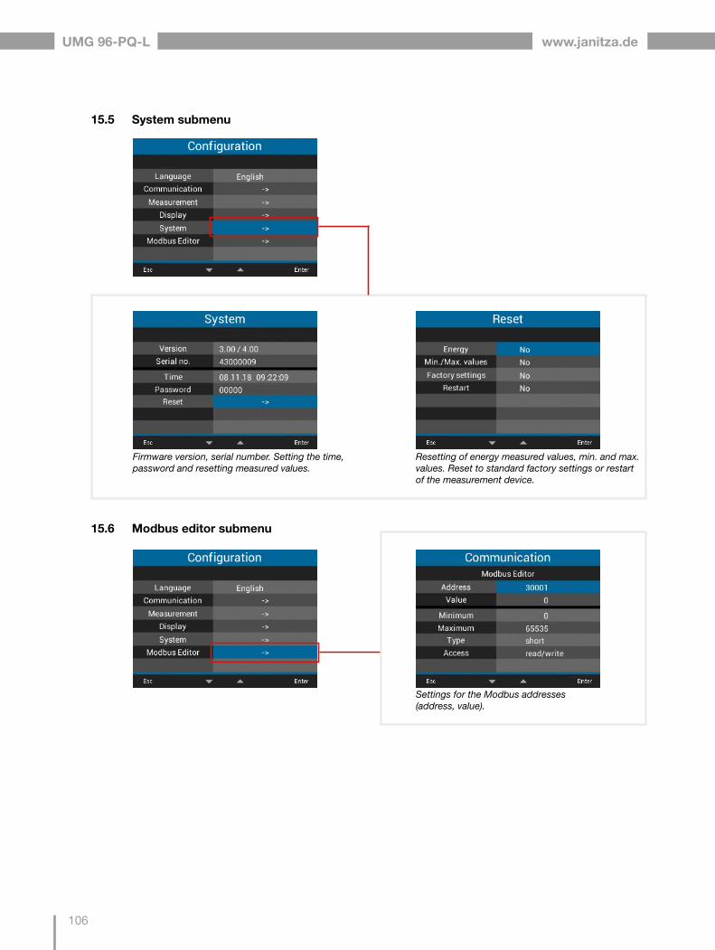
UMG 96-PQ-L www.janitza.de
106
Settings for the Modbus addresses (address, value).
Firmware version, serial number. Setting the time, password and resetting measured values.
Resetting of energy measured values, min. and max. values. Reset to standard factory settings or restart of the measurement device.
15.5 System submenu
15.6 Modbus editor submenu

www.janitza.de
107
UMG 96-PQ-L

UMG 96-PQ-L www.janitza.de
108
16. Service and maintenance
Prior to outbound delivery, the device is subjected to various safety tests and is marked with a seal. If a device is opened, the safety tests must be re-peated. A warranty is only assumed for unopened devices.
16.1 Repair and calibration
Repair and calibration of the device must only be carried out by the manufacturer or an accredited laboratory! The manufacturer recommends cali-brating the device every 5 years!
WARNINGWarning of unauthorized tampering or improper use of the device. Opening, dismantling or unauthorized manipulation of the device which goes beyond the mechanical, electrical or other operating limits indicated can lead to material damage or injury, up to and includ-ing death. · Only electrically qualified personnel are permit-ted to work on the devices and their compo-nents, assemblies, systems and current circuits!
· Always use your device or component only in the manner described in the associated docu-mentation.
· In the event of visible damage, or for the pur-pose of repair and calibration, return the device to the manufacturer!
16.2 Front panel foil and display
Please note the following for the care and cleaning of the front foil and the display:
INFORMATION
Material damage due to improper care and cleaning of the device. The use of water or other solvents, such as dena-tured alcohol, acids, acidic agents for the front foil or the display can damage or destroy the device during cleaning. Water can, for example, penetrate into the device housing and destroy the device. · Clean the device, the front foil or the display with a soft cloth.
· Use a cloth moistened with clear water for heavy soiling.
· Clean the front panel foil and the display, · e.g. fingerprints, with a special LCD cleaner and a lint-free cloth.
· Do not use acids or acidic agents to clean the devices.
16.3 Service
For questions not answered or described in this manual, please contact the manufacturer. Please be certain to have the following information ready to answer any questions: · Device designation (see rating plate) · Serial number (see rating plate) · Software release (see system display) · Measured voltage and supply voltage · An exact error description.
16.4 Device adjustment
The manufacturer adjusts the devices before deliv-ery. No readjustment is required when the environ-mental conditions are complied with.
16.5 Firmware update
For a firmware update, connect your device to a computer and obtain access via the GridVis® software:
· Open the Firmware Update Wizard by clicking on “Update Device” in the “Extras” menu.
· Select your update file and perform the update.
Fig. Updating the device firmware in the GridVis ® software

www.janitza.de
109
UMG 96-PQ-L
16.6 Clock/Battery
The supply voltage supplies the internal clock of the meter. If the supply voltage fails, the battery takes over the supply of voltage to the clock. The clock provides date and time information, for ex-ample for recordings and min. and max. values.
INFORMATION
The device: · Saves correct data records only when the time is set!
· Sets the time to the factory setting when the supply voltage is disconnected and the battery is simultaneously spent or after the battery is changed, meaning it is therefore considered “not set”.
The life expectancy of the battery is at least 5 years at a storage temperature of +45° C. The typical battery life is 8 to 10 years.
The battery can be replaced via the battery insert on the bottom of the device. When replacing the battery, make sure that the battery type and polarity are correct (positive pole points to the rear of the device; negative pole points to the front of the device)!
Pay attention to the following when replacing the battery:
WARNINGRisk of injury due to electrical voltage!Severe bodily injury or death can result from: · Touching bare or stripped leads that are ener-gized.
· Device inputs that pose a hazard when touched.Observe the following when handling your device and when changing the battery, before starting work: · Disconnect the system/device from the power supply!
· Secure it against being switched on! · Check to be sure it is de-energized! · Ground and short circuit! · Cover or block off adjacent live parts!
INFORMATION
Grease or dirt on the contact surfaces forms a contact resistance which shortens the service life of the battery. Only touch the battery by the edges.

UMG 96-PQ-L www.janitza.de
110
17. Procedure in the event of a malfunction
Failure mode Cause Remedy
No display External fuse for the supply voltage has tripped.
Replace fuse.
No current display. No measured voltage connected. Connect measured voltage.
No measured current connected. Connect measured current.
Displayed current istoo great or too small.
Current measurement on the wrong phase.
Check connection and correct if necessary.
Current transformer factor incorrectly programmed.
Read and program the current transformer ratio on the current transformer.
The peak current value at the measuring input was exceeded by current harmon-ics.
Install current transformers with a higher current transformer ratio.
The current at the measuring input is too low.
Install current transformers with a lower current trans-former ratio.
Displayed voltage is too low or too high.
Measurement on the wrong phase. Check connection and correct if necessary.
Voltage transformer programmed incor-rectly.
Read the voltage transformer ratio on the voltage transformer and program.
Displayed voltageis too low. Overrange. Use a voltage transformer.
The voltage peak value at the measuring input was exceeded due to harmonics current.
Attention! Make sure that the measuring inputs are not overloaded.
Phase shift, ind./cap. Current circuit is assigned to the wrong voltage circuit.
Check connection and correct if necessary.
Active power applied / delivered is interchanged.
At least one current transformer connec-tion is reversed.
Check connection and correct if necessary.
A current circuit is assigned to the wrong voltage circuit.
Check connection and correct if necessary.
Active power too small or too great.
The programmed current transformer ratio is incorrect.
Read and program the current transformer ratio on the current transformer
The current circuit is assigned to the wrong voltage circuit.
Check connection and correct if necessary.
The programmed voltage transformer ratio is incorrect.
Read the voltage transformer ratio on the voltage transformer and program.
An input/output is not re-sponding.
The input/output was programmed incorrectly.
Check programming and correct if necessary.
The input/output was connected incor-rectly.
Check connection and correct if necessary.
Display “Overrange” The measuring range has been exceed-ed
Check connection and correct if necessary.Correct the current/voltage transformer ratio.
No connection to the device. RS-485- Incorrect device address.- Different bus speeds (baud rate) and / or data frames- Incorrect protocol.- No termination.
- Correct the device address.- Correct the speed (baud rate). Correct the data frame.- Correct the protocol.- Terminate bus with termination resistor.
Despite the above measures, the device does not function.
Device defective. Send the device and error description to the manufac-turer for inspection.

www.janitza.de
111
UMG 96-PQ-L
18. Technical data
Transport and storageThe following information applies to devices that are transported or stored in their original packaging.
Free fall 1 m (39.37 in)
Temperature -25 °C (-13 °F) to +70 °C (158 °F)
Relative air humidity (non-condensing) 0 to 90% RH
Environmental conditions during operation
Install the device in a weather-protected and stationary location.Protection class II according to IEC 60536 (VDE 0106, Part 1).
Rated temperature range -10 °C (14 °F) ... +55 °C (131 °F)
Relative air humidity (non-condensing) 0 to 75% RH
Operating elevation 0 .. 2000 m (6562 ft) above sea level
Pollution degree 2
Mounting orientation As desired
Ventilation No forced ventilation required.
Protection against foreign matter and water- Front- Rear- Front with seal
IP40 according to EN60529IP20 according to EN60529IP54 according to EN60529
Supply voltage
Option 230 V Nominal range AC 90 V - 277 V (50/60 Hz) or DC 90 V - 250 V, 300 V CATIII
Power consumption max. 4.5 VA / 2 W
Option 24 V Nominal range AC 24 V - 90 V (50/60Hz) or DC 24 V - 90 V, 150 V CATIII
Power consumption max. 4.5 VA / 2 W
Operating range +-10% of nominal range
Internal fuse, not replaceable Type T1A / 250 V DC / 277 V AC according to IEC 60127
Recommended overcurrent protective device for the line protection (UL approval)
Option 230 V: 6 - 16 A (Char. B)Option 24 V: 1 - 6 A (Char. B)
General
Net weight (with attached plug-in connectors) approx. 250 g (0.55 lbs)
Package weight (incl. accessories) approx. 500 g (1.1 lbs)
Battery Type Lithium CR2032, 3 V, (UL 1642 approved)
Data memory 64 MB
Backlight service life 40000 h (backlight reduces to approx. 50% over this period)
Impact resistance IK07 according to IEC 62262

UMG 96-PQ-L www.janitza.de
112
Voltage measurement
Three-phase 4-conductor systems with rated voltages up to 417 V / 720 V (+-10%) according to IEC347 V / 600 V (+-10%) according to UL
Three-phase 3-conductor systems with rated voltages up to 600 V (+10%)
Single-phase 2-conductor system with rated voltages up to 480 V (+-10%)
Overvoltage category 600 V CAT III
Rated surge voltage 6 kV
Protection of the voltage measurement 1 - 10 A tripping characteristic B(with IEC/UL approval)
Measuring range L-N 01) .. 600 Vrms (max. overvoltage 800 Vrms)
Measuring range L-L 01) .. 1040 Vrms (max. overvoltage 1350 Vrms)
Resolution 0.01 V
Crest factor 2.45 (related to the measuring range)
Impedance 3 MΩ/phase
Power consumption approx. 0.1 VA
Sampling frequency 13.67 kHz
Sampling frequency (IT variant) 13.98 kHz
Frequency of the fundamental oscillation- Resolution
45 Hz .. 65 Hz0.01 Hz
Fourier analysis 1st - 65th harmonic
1) The device only determines measured values if a voltage L1-N of greater than 20 Veff (4-conductor measurement) or a voltage L1-L2 of greater than 34 Veff (3-conductor measurement) is applied to voltage measurement input V1.
Current measurement
Nominal current 5 A
Measuring range 0.005 .. 6 Arms
Crest factor 2 (relative to 6 Arms)
Overvoltage category 300 V CAT II
Rated surge voltage 2 kV
Power consumption approx. 0.2 VA (Ri=5 mΩ)
Overload for 1 s 60 A (sinusoidal)
Resolution 0.1 mA (display 0.01 A)
Sampling frequency 13.67 kHz
Sampling frequency (IT variant) 13.98 kHz
Fourier analysis 1st - 65th harmonic
Serial interface
RS-485 - Modbus RTU/client device 9.6 kbps, 19.2 kbps, 38.4 kbps, 57.6 kbps, 115.2 kbps
Digital inputs3 digital inputs, solid state relays, not short-circuit proof.
Maximum counter frequency 20 Hz
Input signal applied 18 V .. 28 V DC (typically 4 mA)
Input signal not applied 0 .. 5 V DC, current less than 0.5 mA
Digital outputs3 digital outputs, solid state relays, not short-circuit proof.
Switching voltage max. 33 V AC, 40 V DC
Switching current max. 50 mAeff AC/DC
Response time approx. 200 ms
Pulse output max. 50 Hz (energy pulses)
Cable length (digital inputs/outputs)
Up to 30 m (32.81 yd) Unshielded
Greater than 30 m (32.81 yd) Shielded

www.janitza.de
113
UMG 96-PQ-L
Connecting capacity of the terminals (digital inputs/outputs, analog output)Connectible conductors. Only connect one conductor per terminal point!
Single core, multi-core, fine-stranded 0.2 - 1.5 mm2, AWG 28-16
Wire ferrules (non-insulated) 0.2 - 1.5 mm2, AWG 26-16
Wire ferrules (insulated) 0.2 - 1.5 mm2, AWG 26-16
Tightening torque 0.2 - 0.25 Nm (1.77 - 2.21 lbf in)
Strip length 7 mm (0.2756 in)
Terminal connection capacity (serial interface)Connectible conductors. Only connect one conductor per terminal point!
Single core, multi-core, fine-stranded 0.2 - 1.5 mm2, AWG 28-16
Wire ferrules (non-insulated) 0.2 - 1.5 mm2, AWG 26-16
Wire ferrules (insulated) 0.2 - 1.5 mm2, AWG 26-16
Tightening torque 0.2 - 0.25 Nm (1.77 - 2.21 lbf in)
Strip length 7 mm (0.2756 in)
Connecting capacity of the terminals (current measurement)Connectible conductors. Only connect one conductor per terminal point!
Single core, multi-core, fine-stranded 0.2 - 4 mm2, AWG 28-12
Wire ferrules (non-insulated) 0.2 - 4 mm2, AWG 26-12
Wire ferrules (insulated) 0.2 - 2.5 mm2, AWG 26-14
Tightening torque 0.4 - 0.5 Nm (3.54 - 4.43 lbf in)
Strip length 7 mm (0.2756 in)
Connecting capacity of the terminals (voltage measurement)Connectible conductors. Only connect one conductor per terminal point!
Single core, multi-core, fine-stranded 0.2 - 4.0 mm2, AWG 28-12
Wire ferrules (non-insulated) 0.2 - 2.5 mm2, AWG 26-14
Wire ferrules (insulated) 0.2 - 2.5 mm2, AWG 26-14
Tightening torque 0.4 - 0.5 Nm (3.54 - 4.43 lbf in)
Strip length 7 mm (0.2756 in)
Connecting capacity of the terminals (supply voltage)Connectible conductors. Only connect one conductor per terminal point!
Single core, multi-core, fine-stranded 0.2 - 4.0 mm2, AWG 28-12
Wire ferrules (non-insulated) 0.2 - 2.5 mm2, AWG 26-14
Wire ferrules (insulated) 0.2 - 2.5 mm2, AWG 26-14
Tightening torque 0.4 - 0.5 Nm (3.54 - 4.43 lbf in)
Strip length 7 mm (0.2756 in)
Analog outputs
External power supply max. 33 V
Current 0 .. 20 mA
Update time 1 s
Load max. 300 Ω
Resolution 10 bit

UMG 96-PQ-L www.janitza.de
114
Function Symbol Accuracy class Measuring range Display range
Total active power P 0.55) (IEC61557-12) 0 W .. 12.6 kW 0 W .. 999 GW *
Total reactive power QA, Qv 1 (IEC61557-12) 0 var .. 16.6 kvar 0 var .. 999 Gvar *
Total apparent power SA, Sv 0.55) (IEC61557-12) 0 VA .. 12.6 kVA 0 VA .. 999 GVA *
Total active energy Ea 0.25) (IEC61557-12)0.2S5) (IEC62053-22)
0 Wh .. 999 GWh 0 Wh .. 999 GWh *
Total reactive energy ErA, ErV 1 (IEC61557-12) 0 varh .. 999 Gvarh 0 varh .. 999 Gvarh *
Total apparent energy EapA, EapV 0.55) (IEC61557-12) 0 VAh .. 999 GVAh 0 VAh .. 999 GVAh *
Frequency f 0.05 (IEC61557-12) 45 Hz .. 65 Hz 45.00 Hz .. 65.00 Hz
Phase current I 0.2 (IEC61557-12) 0 Arms .. 7 Arms 0 A .. 999 kA
Neutral conductor current calcu-lated
INc 1.0 (IEC61557-12) 0.03 A .. 25 A 0.03 A .. 999 kA
Voltage U L-N 0.2 (IEC61557-12) 10 Vrms .. 600 Vrms 0 V .. 999 kV
Voltage U L-L 0.2 (IEC61557-12) 18 Vrms .. 1040 Vrms 0 V .. 999 kV
Power factor PFA, PFV 0.5 (IEC61557-12) 0.00 .. 1.00 0.00 .. 1.00
Short-term flicker, long-term flicker
Pst, Plt - - -
Voltage dips (L-N) Udip - - -
Voltage swells (L-N) Uswl - - -
Transient overvoltages Utr - - -
Voltage interruptions Uint - - -
Voltage imbalance (L-N) 1) Unba - - -
Voltage imbalance (L-N) 2) Unb - - -
Voltage harmonics Uh Cl. 1 (IEC61000-4-7) 1 .. 65 0 V .. 999 kV
THD of voltage 3) THDu 1.0 (IEC61557-12) 0% .. 999% 0% .. 999%
THD of voltage 4) THD-Ru - - -
Current harmonics Ih Cl. 1 (IEC61000-4-7) 1 .. 65 0 A .. 999 kA
THD of current 3) THDi 1.0 (IEC61557-12) 0% .. 999% 0% .. 999%
THD of current 4) THD-Ri - - -
Mains signal voltage MSV - - -
19. Performance characteristics of functions
*When the maximum total energy values are reached, the display returns to 0 W.
1) Referenced to the amplitude.2) Referenced to the phase and amplitude.3) Referenced to the fundamental oscillation.4) Referenced to the effective value.5) Accuracy class 0.2/0.2S with ../5A transformer.
Accuracy class 0.5/0.5S with ../1A transformer.

www.janitza.de
115
UMG 96-PQ-L

UMG 96-PQ-L www.janitza.de
116
19.1 Modbus addresses of frequently used measured values
* The assignment of the marked device addresses does not correspond to the assignment of other devices of the UMG series.
Address Format RD/WR Variable Unit Comment19000 float RD _ULN[0] V Voltage L1-N19002 float RD _ULN[1] V Voltage L2-N19004 float RD _ULN[2] V Voltage L3-N19006 float RD _ULL[0] V Voltage L1-L219008 float RD _ULL[1] V Voltage L2-L319010 float RD _ULL[2] V Voltage L3-L119012 float RD _ILN[0] A Apparent current, L119014 float RD _ILN[1] A Apparent current, L219016 float RD _ILN[2] A Apparent current, L319018 float RD _I_SUM3 A Sum; IN=I1+I2+I319020 float RD _PLN[0] W Active power L119022 float RD _PLN[1] W Active power L219024 float RD _PLN[2] W Active power L319026 float RD _P_SUM3 W Sum; Psum3=P1+P2+P319028 float RD _SLN[0] VA Apparent power L119030 float RD _SLN[1] VA Apparent power L219032 float RD _SLN[2] VA Apparent power L319034 float RD _S_SUM3 VA Sum; Ssum3=S1+S2+S319036 float RD _QLN[0] var Reactive power (mains frequency) L119038 float RD _QLN[1] var Reactive power (mains frequency) L219040 float RD _QLN[2] var Reactive power (mains frequency) L319042 float RD _Q_SUM3 var Sum; Qsum3=Q1+Q2+Q319044 float RD _COS_PHI[0] Fund. power factor, CosPhi; UL1 IL119046 float RD _COS_PHI[1] Fund. power factor, CosPhi; UL2 IL219048 float RD _COS_PHI[2] Fund. power factor, CosPhi; UL3 IL319050 float RD _FREQ Hz Frequency19052 float RD _PHASE_SEQ Rotating field; 1=right, 0=none, -1=left19054* float RD _WH_V[0] Wh Active energy L1, applied19056* float RD _WH_V[1] Wh Active energy L2, applied19058* float RD _WH_V[2] Wh Active energy L3, referred19060 float RD _WH_V_HT_SUML13 Wh Active energy L1..L319062 float RD _WH_V[0] Wh Active energy L1, applied19064 float RD _WH_V[1] Wh Active energy L2, applied19066 float RD _WH_V[2] Wh Active energy L3, referred19068 float RD _WH_V_HT_SUML13 Wh Active energy L1..L3, applied, tariff 119070 float RD _WH_Z[0] Wh Active energy L1, delivered19072 float RD _WH_Z[1] Wh Active energy L2, delivered19074 float RD _WH_Z[2] Wh Active energy L3, delivered19076 float RD _WH_Z_SUML13 Wh Active energy L1..L3, delivered19078 float RD _WH_S[0] VAh Apparent energy L119080 float RD _WH_S[1] VAh Apparent energy L219082 float RD _WH_S[2] VAh Apparent energy L319084 float RD _WH_S_SUML13 VAh Apparent energy L1..L319086* float RD _IQH[0] varh Reactive energy, inductive, L119088* float RD _IQH[1] varh Reactive energy, inductive, L219090* float RD _IQH[2] varh Reactive energy, inductive, L319092 float RD _IQH_SUML13 varh Reactive energy L1..L319094 float RD _IQH[0] varh Reactive energy, inductive, L1

www.janitza.de
117
UMG 96-PQ-L
Type Size Minimum Maximum
short 16 bit -215 215 -1
ushort 16 bit 0 216 -1
int 32 bit -231 231 -1
uint 32 bit 0 232 -1
float 32 bit IEEE 754 IEEE 754
19.2 Number formats
Address Format RD/WR Variable Unit Comment19096 float RD _IQH[1] varh Reactive energy, inductive, L219098 float RD _IQH[2] varh Reactive energy, inductive, L319100 float RD _IQH_SUML13 varh Reactive energy L1..L3, ind.19102 float RD _CQH[0] varh Reactive energy, capacitive, L119104 float RD _CQH[1] varh Reactive energy, capacitive, L219106 float RD _CQH[2] varh Reactive energy, capacitive, L319108 float RD _CQH_SUML13 varh Reactive energy L1..L3, cap.19110 float RD _THD_ULN[0] % Harmonics, THD,U L1-N19112 float RD _THD_ULN[1] % Harmonics, THD,U L2-N19114 float RD _THD_ULN[2] % Harmonics, THD,U L3-N19116 float RD _THD_ILN[0] % Harmonics, THD,I L119118 float RD _THD_ILN[1] % Harmonics, THD,I L219120 float RD _THD_ILN[2] % Harmonics, THD,I L3
19.3 Note on saving measured values and configuration data
INFORMATION
Saving measured values and configuration data! In the event of an operating voltage failure the recording can be interrupted for a maximum of 5 minutes. The following measured value-sare saved by the device every 5 minutes in a non-volatile memory: · Comparator timer · S0 meter readings · Minimum, maximum and average values (without date and time)
· Energy values
The device saves configuration data immedi-ately!

UMG 96-PQ-L www.janitza.de
118
19.4 Dimensional drawings
96
mm
3.
78 in
0.19
in 4
,9 m
m
96 mm 3.78 in
87,2 mm 3.43 in 0.24 in
6 mm
87,
2 m
m
3.43
in0.
24 in
6 m
m
96 mm 3.78 in
Fig. Front view
92+0,8 mm
3.62+0.03 in
92+0
,8 m
m
3.62
+0.0
3 in
Battery
1) Bottom view
Fig. Side view Fig. Cutout dimensions
· The figures are for illustration purposes only and are not to scale.

www.janitza.de
119
UMG 96-PQ-L
19.5 Connection example 1
1) UL/IEC approved overcurrent protective device2) UL/IEC approved overcurrent protective device 3) Short circuit bridges (external)
UMG 96-PQ-L
Voltage measurement
1 2 3 4
Supplyvoltage
Con
sum
er
230V/400V 50Hz
21 22 23 24 25 26
Analogoutput
K3 K4 K5
=-
+
=+
- S1 S2 S3
V1 V2 V3 VNN/-L/+
V+ 1 2 3 V+
Digital outputs
17 18 19 201 2 3
Digital inputs
N
L1
L2
L3
PE
S1 S2
S1
S1
S2
S2
Current measurement
S1 S2 S1 S2 S1 S2
5 6 7 8 9 1011 12 13
N
L1
PE/FE
I1 I2 I3
RS485
15 16A B
14
Data GND
AC
B
=-
+
C
2)1) 2) 2)
3) 3) 3)
Func
tiona
l ear
th

Doc. no. 2.061.073.3.b | Date 12/2021 | Subject to technical alterations.The latest version of the document can be found in the download area at www.janitza.de.
Janitza electronics GmbHVor dem Polstück 6
D-35633 Lahnau
Tel.: +49 6441 - 9642-0Fax: +49 6441 - 9642-30
Email: [email protected]