tw pto/150h wood chipper - uk instruction manual - Almovi
44
timberwolf-uk.com TW PTO/150H WOOD CHIPPER UK INSTRUCTION MANUAL
-
Upload
khangminh22 -
Category
Documents
-
view
0 -
download
0
Transcript of tw pto/150h wood chipper - uk instruction manual - Almovi

timberwolf-uk.com
TW PTO/150H WOOD CHIPPERUK INSTRUCTION MANUAL

© Copyright Timberwolf Ltd 2021The content of this publication may not be copied, reproduced, republished, posted, broadcast, transmitted
or used in any way in any medium without the written permission of Timberwolf Ltd.
TW PTO/150HCONTENTS
C1900223 17.06.2021 Rev. 2.0
1 / 41
Section Page No. INTRODUCTION 2 PURPOSE OF MACHINE 3 MACHINE SPECIFICATIONS 3 PARTS LOCATION DIAGRAMS 4 SAFE WORKING 5 Operator’s Personal Protective Equipment Required 5 Basic Woodchipping Safety 5 General Safety Matters Do’s and Don’ts 6 Noise Test 7 OPERATING INSTRUCTIONS 8 Delivery 8 Operator’s Personal Protective Equipment Required 8 Connecting to Tractor 8 PTO Shaft 9 Moving the Chipper 9 Daily Checks before Starting Tractor 9 Before Using Chipper 9 Hydraulic Oil Thermometer / Oil Lever Indicator 9 Manual Controls 10 Auto Controls 10 Blade Wear 11 Emergency Stopping 11 Starting the Chipper 11 Chipping 11 Stopping the Chipper 12 Blockages 12 SERVICE INSTRUCTIONS 13 Service Schedule 14 Safe Lifting of the Chipper 14 Spares 14 Check Hoses 14 Safe Maintenance 15 Copper Ease Safety Information 15 Check Fittings 15 Change Blades 16 PTO Drive Shaft Maintenance 17 Grease the Roller Spline and Bearing 17 Grease the Roller Box Slides 17 Tension Belts 18 Change Hydraulic Oil and Filter 18 WARRANTY STATEMENT 19 EC DECLARATION OF CONFORMITY CERTIFICATE 20 IDENTIFICATION PLATE 21 DECALS 22 ELECTRICAL DETAIL 24 WIRING DIAGRAM 25 HYDRAULIC LAYOUT 26 V BELT TENSIONING TABLE 27 WARRANTY SERVICE CHECK RECORD 28 SERVICE RECORD 29 PARTS LISTS 30

TW PTO/150H2 / 41INTRODUCTION
C1900223 17.06.2021 Rev. 2.0
Thank you for choosing Timberwolf. Timberwolf chippers are designed to give safe and dependable service if operated according to the instructions. IMPORTANT HEALTH AND SAFETY INFORMATION Before using your new chipper, please take time to read this manual. Failure to do so could result in: personal injury equipment damage damage to property 3rd party injuries This manual covers the operation and maintenance of the Timberwolf TW PTO/150H. All information in this manual is based on the latest product information available at the time of purchase. All the information you need to operate the machine safely and effectively is contained within pages 3 to 12. Ensure that all operators are properly trained for operating this machine, especially in safe working practices. Timberwolf's policy of regularly reviewing and improving their products may involve major or minor changes to the chippers or their accessories. Timberwolf reserves the right to make changes at any time without notice and without incurring any obligation. Due to improvements in design and performance during production there may be, in some cases, minor discrepancies between the actual chipper and the text in this manual. The manual should be considered an important part of the machine and should remain with it if the machine is resold.
CAUTION or WARNING
BE AWARE OF THIS SYMBOL AND WHERE SHOWN,
CAREFULLY FOLLOW THE INSTRUCTIONS.
THIS SYMBOL INDICATES IMPORTANT SAFETY
MESSAGES IN THIS MANUAL. WHEN YOU SEE THIS
SYMBOL, BE ALERT TO THE POSSIBILITY OF INJURY TO YOURSELF OR OTHERS AND
CAREFULLY READ THE MESSAGE THAT FOLLOWS.
ALWAYS FOLLOW SAFE OPERATING AND
MAINTENANCE PRACTICES

TW PTO/150H3 / 41
C1900223 17.06.2021 Rev. 2.0
Serial No. Location The serial number can be found on the identification plate located on the rotor housing
The Timberwolf PTO/150H brushwood chipper, is designed to chip solid wood material including timber branches, saplings and brushwood up to a maximum of 150mm in diameter. It is capable of chipping over 3 tonnes of brushwood per hour. The Timberwolf PTO/150H brushwood chipper is required to be securely 3 point coupled with a 2560hp tractor unit with 540rpm PTO when in use. Power from the attached tractor unit is to be supplied to the chipper via PTO drive shaft.
DIMENSIONS
2035
mm
(144
0 m
m w
ith d
isch
arge
rem
oved
)
2880 mm (1775 mm with feed tray folded)
1110 mm
TIMBERWOLF TW PTO/150H SPECIFICATION
Power source: Tractor PTO Drive PTO speed: 540rpm Required engine power: 25 ‐ 60hp 3 Point Mounting Cat. 1 / 2 Overall weight: 400kg
Type of feed: Hydraulic Maximum diameter material: 150 mm (6”) Material processing capacity: 3 tonnes/hr
THE TIMBERWOLF TW PTO/150H

TW PTO/150H4 / 41PARTS LOCATOR
C1900223 17.06.2021 Rev. 2.0
DISCHARGE BUCKET
SAFETY BAR
CONTROL BOX
FEED TRAY
FUNNEL
ROTOR HOUSING
ROLLER BOX COVER
DISCHARGE CLAMPS
POWER CABLE SOCKET
DISCHARGE TUBE
OIL TANK
HYDRAULIC PUMP
OIL LEVEL GAUGE
TANK TOP FILTER
FAN SECTION (X2)
ROTOR
ROTOR DRIVE PULLEY
MACHINE NO. PLATE
NO STRESS SENSOR
DIRECTIONAL CONTROL
VALVE (DCV)
GEARBOX
PTO CONNECTION
BREATHER PIPE
5 / 41SAFE WORKING TW PTO/150H
C1900223 17.06.2021 Rev. 2.0
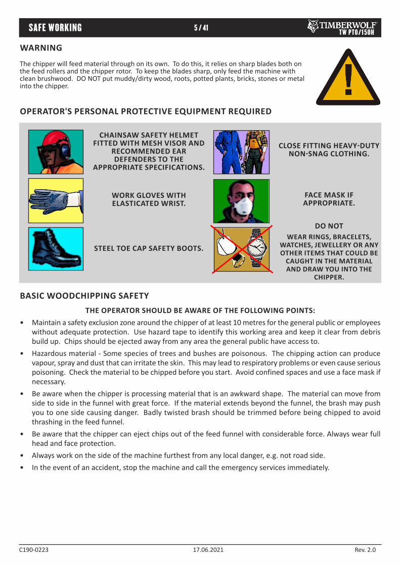
THE OPERATOR SHOULD BE AWARE OF THE FOLLOWING POINTS: Maintain a safety exclusion zone around the chipper of at least 10 metres for the general public or employees •without adequate protection. Use hazard tape to identify this working area and keep it clear from debris build up. Chips should be ejected away from any area the general public have access to. Hazardous material Some species of trees and bushes are poisonous. The chipping action can produce •vapour, spray and dust that can irritate the skin. This may lead to respiratory problems or even cause serious poisoning. Check the material to be chipped before you start. Avoid confined spaces and use a face mask if necessary. Be aware when the chipper is processing material that is an awkward shape. The material can move from •side to side in the funnel with great force. If the material extends beyond the funnel, the brash may push you to one side causing danger. Badly twisted brash should be trimmed before being chipped to avoid thrashing in the feed funnel. Be aware that the chipper can eject chips out of the feed funnel with considerable force. Always wear full •head and face protection. Always work on the side of the machine furthest from any local danger, e.g. not road side. •In the event of an accident, stop the machine and call the emergency services immediately.•
WARNING
The chipper will feed material through on its own. To do this, it relies on sharp blades both on the feed rollers and the chipper rotor. To keep the blades sharp, only feed the machine with clean brushwood. DO NOT put muddy/dirty wood, roots, potted plants, bricks, stones or metal into the chipper.
BASIC WOODCHIPPING SAFETY
OPERATOR'S PERSONAL PROTECTIVE EQUIPMENT REQUIRED
CHAINSAW SAFETY HELMET FITTED WITH MESH VISOR AND
RECOMMENDED EAR DEFENDERS TO THE
APPROPRIATE SPECIFICATIONS.
WORK GLOVES WITH ELASTICATED WRIST.
CLOSE FITTING HEAVY-DUTY NON-SNAG CLOTHING.
FACE MASK IF APPROPRIATE.
DO NOT WEAR RINGS, BRACELETS,
WATCHES, JEWELLERY OR ANY OTHER ITEMS THAT COULD BE
CAUGHT IN THE MATERIAL AND DRAW YOU INTO THE
CHIPPER.
STEEL TOE CAP SAFETY BOOTS.

DO NOT ALLOW THE FOLLOWING
TO ENTER THE MACHINE, AS DAMAGE IS
LIKELY
BRICKS STRING ROOTS BEDDING PLANTS
STONES METAL GLASS RUBBER
CLOTH PLASTIC
Do not smoke when refuelling.
Do not let anyone who has not received instruction operate the machine.
Do not climb on the machine at any time.
Do not handle material that is partially engaged in the machine.
Do not touch any exposed wiring while machine is running.
Do not use the chipper inside buildings.
TW PTO/150H6 / 41SAFE WORKING
C1900223 17.06.2021 Rev. 2.0
üGENERAL SAFETY MATTERS
DO’S AND DON’TS
Do not operate chipper unless available light is sufficient to see clearly.
Do not attempt to engage PTO without the feed funnel, belt guard, guards and discharge unit securely in place.
Do not stand directly in front of the feed funnel when using the chipper. Stand to one side.
Always stop the tractor engine, remove ignition key and disconnect the PTO shaft before making any adjustments.
Always check machine has stopped rotating and remove tractor ignition key before maintenance of any kind, or whenever the machine is to be left unattended.
Always check machine is securely coupled to tractor pin hitch and on firm level ground.
Always run tractor engine at required speed to acheive correct PTO speed.
Always check (visually) for fluid leaks.
Always take regular breaks. Wearing personal protective equipment for long periods can be tiring and hot.
Always keep hands, feet and clothing out of feed opening, discharge and moving parts.
Always use the next piece of material or a push stick to push in short pieces. Under no circumstances should you reach into the funnel.
Always keep the operating area clear of people, animals and children.
Always keep the operating area clear from debris build up.
Always keep clear of the chip discharge tube. Foreign objects may be ejected with great force.
Always ensure protective guarding is in place before commencing work. Failure to do so may result in personal injury or loss of life.
Always operate the chipper in a well ventilated area exhaust fumes are dangerous.
ü

TW PTO/150H7 / 41SAFE WORKING
C1900223 17.06.2021 Rev. 2.0
Noise levels above 80dB (A) will be experienced at the working position. Prolonged exposure to loud noise may cause permanent hearing loss. All persons within a 4 metre radius must also wear good quality ear protection (EN 352) at all times to prevent possible damage to hearing.
NOISE TEST
Machine: TW PTO/150H NOTES: Attached to a 40hp tractor, tested chipping 4 inch round poles. All readings represent tractor with chipper chipping.
93.3 dB95.2 dB
96.3 dB96.6 dBR= 4 metres
Guaranteed Sound Power: 120dB (A)
101.5 dB
96.8 dB
As required by Annex III of Directive 2000/14/EC “Noise Emission in the environment by equipment for use outdoors”.
R= 10 metres
90.8
dB C
alcu
late
d
90.8dB Calculated
90.8dB Calculat
ed

TW PTO/150H8 / 41
C1900223 17.06.2021 Rev. 2.0
OPERATING INSTRUCTIONS
DELIVERY
OPERATOR’S PERSONAL PROTECTIVE EQUIPMENT REQUIRED
All Timberwolf TW PTO/150H machines have a full pre delivery inspection before leaving the factory and are ready to use. Read and understand this instruction manual before attempting to operate the chipper. In particular, read pages 57 which contain important health and safety information and advice.
Chainsaw safety helmet fitted with visor and •recommended ear defenders to an appropriate specification. Heavyduty gloves with elasticated wrist area. •
Close fitting heavyduty nonsnag clothing. •Safety footwear. •Face mask (if appropriate).•
See page 5 for more detailed information.
CONNECTING PTO SHAFT
CONNECTING TO TRACTOREnsure tractor horsepower and lift capacity meets the chippers requirements and has the correct PTO speed. •Ensure tractor and chipper are on firm level ground •Check tractor drop arms are equal length, adjust if necessary. •Attach chipper securely to tractor 3 point linkage. •Stop engine and apply handbrake, •Set tractor top link to ensure chipper is level and top link is lower at tractor end. •Ensure tractor engine is turned off and the ignition key has been removed. •Connect PTO drive shaft female half shaft to be fitted to tractor unit. •Connect power cable from tractor to chipper. •Ensure all PTO guards on tractor, drive shaft and chipper are refitted and drive shaft guard chain is attached to •prevent rotation.
Check the angle of the drive shaft between tractor and chipper will not exceed 16o whilst in work and rotating. •Check when lifted for transport the angle of the drive shaft between tractor and chipper will not exceed 40o. •Ensure two sliding halves of the drive shaft have at least 150mm of engagement and be of a suitable length to •prevent ‘butting up’ when chipper is lifted.
MOVING THE CHIPPERDo not move the chipper with the rotor running. •Always ensure the retaining nuts and clamp are tight when transporting with a discharge tube in place. •Never pull the machine by the red safety bar as linkages will be damaged. •
TW PTO/150H9 / 41OPERATING INSTRUCTIONS
C1900223 17.06.2021 Rev. 2.0
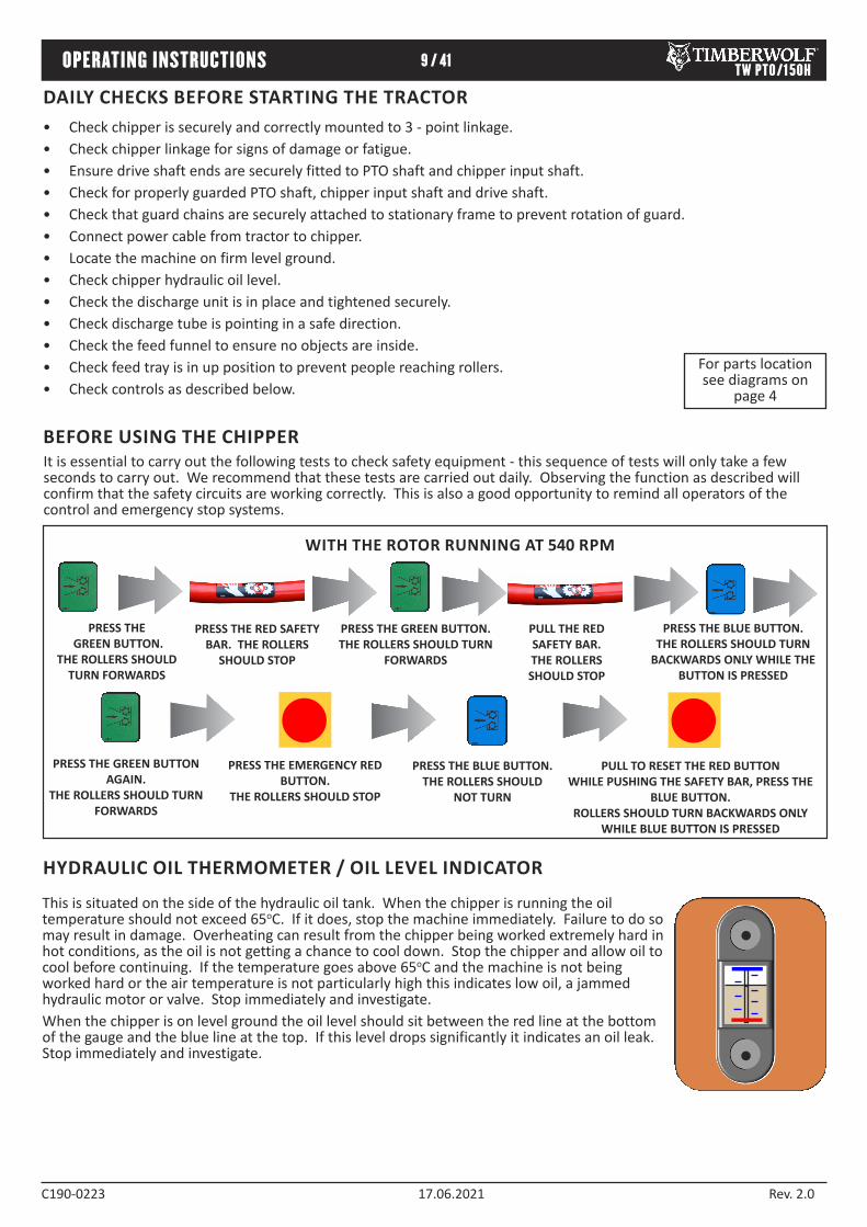
DAILY CHECKS BEFORE STARTING THE TRACTORCheck chipper is securely and correctly mounted to 3 point linkage. •Check chipper linkage for signs of damage or fatigue. •Ensure drive shaft ends are securely fitted to PTO shaft and chipper input shaft. •Check for properly guarded PTO shaft, chipper input shaft and drive shaft. •Check that guard chains are securely attached to stationary frame to prevent rotation of guard. •Connect power cable from tractor to chipper. •Locate the machine on firm level ground. •Check chipper hydraulic oil level. •Check the discharge unit is in place and tightened securely. •Check discharge tube is pointing in a safe direction. •Check the feed funnel to ensure no objects are inside. •Check feed tray is in up position to prevent people reaching rollers. •Check controls as described below. •
For parts location see diagrams on
page 4
It is essential to carry out the following tests to check safety equipment this sequence of tests will only take a few seconds to carry out. We recommend that these tests are carried out daily. Observing the function as described will confirm that the safety circuits are working correctly. This is also a good opportunity to remind all operators of the control and emergency stop systems.
PRESS THE GREEN BUTTON.
THE ROLLERS SHOULD TURN FORWARDS
PRESS THE RED SAFETY BAR. THE ROLLERS
SHOULD STOP
PRESS THE BLUE BUTTON. THE ROLLERS SHOULD TURN
BACKWARDS ONLY WHILE THE BUTTON IS PRESSED
PRESS THE EMERGENCY RED BUTTON.
THE ROLLERS SHOULD STOP
PRESS THE BLUE BUTTON. THE ROLLERS SHOULD
NOT TURN
WITH THE ROTOR RUNNING AT 540 RPM
PRESS THE GREEN BUTTON. THE ROLLERS SHOULD TURN
FORWARDS
PULL THE RED SAFETY BAR. THE ROLLERS SHOULD STOP
PULL TO RESET THE RED BUTTON WHILE PUSHING THE SAFETY BAR, PRESS THE
BLUE BUTTON. ROLLERS SHOULD TURN BACKWARDS ONLY
WHILE BLUE BUTTON IS PRESSED
PRESS THE GREEN BUTTON AGAIN.
THE ROLLERS SHOULD TURN FORWARDS
BEFORE USING THE CHIPPER
This is situated on the side of the hydraulic oil tank. When the chipper is running the oil temperature should not exceed 65oC. If it does, stop the machine immediately. Failure to do so may result in damage. Overheating can result from the chipper being worked extremely hard in hot conditions, as the oil is not getting a chance to cool down. Stop the chipper and allow oil to cool before continuing. If the temperature goes above 65oC and the machine is not being worked hard or the air temperature is not particularly high this indicates low oil, a jammed hydraulic motor or valve. Stop immediately and investigate. When the chipper is on level ground the oil level should sit between the red line at the bottom of the gauge and the blue line at the top. If this level drops significantly it indicates an oil leak. Stop immediately and investigate.
HYDRAULIC OIL THERMOMETER / OIL LEVEL INDICATOR

TW PTO/150H10 / 41OPERATING INSTRUCTIONS
C1900223 17.06.2021 Rev. 2.0
The no stress unit controls the feed rate of the material going into the chipping chamber. If the rotor speed is below the predetermined level the no stress unit will not allow the feed rollers to work in the forward direction until the rotor speed rises above the predetermined level, at which point the feed rollers will start turning without warning. The reverse function will operate at any speed. The same sensor unit will also detect if an overspeed condition exists ie. PTO speed too high. When an overspeed condition is detected the power supply to the foward feed rollers is disengaged. To reestablish power to the rollers once an overspeed has occured; lower tractor revs to idle, disengage PTO and turn off engine. The control system must be reset by removing, then reconnecting the power cable between chipper and tractor, the feed rollers will then operate via the green button as detailed above.
ROLLER CONTROL BOX this is the control box above the feed opening of the chipper funnel. Its function is to control the feed rollers. The feed rollers draw material into the machine. It does not control the main rotor. RED SAFETY BAR: This is the large red bar that surrounds the feed tray and side of the feed funnel. The bar is spring loaded and connected to a switch that will interrupt the power to the rollers. The switch is designed so that it only activates if the bar is pushed to the limit of its travel. The rollers stop instantly, but can be made to turn again by pressing either the GREEN FEED or BLUE REVERSE control buttons. RED SAFETY BAR TEST To ensure the safety bar is always operational it must be activated once before each work session. The rollers will not function until the bar is activated. This procedure must be repeated each time the ignition is switched off.
GREEN BUTTON: forward feed Push the button once this activates the rollers and will allow you to start chipping (if the rotor speed is high enough and no overspeed condition exists). RED BUTTON: emergency stop This button stops the rollers from feeding. It overrides all other buttons or bars and will not allow the other buttons to function until it has been reset. To reset, pull out until it returns to its original position. The forward and reverse buttons will now function. BLUE BUTTON: reverse feed allows you to back material out of the rollers. The rollers will only turn in reverse as long as you keep pressing the button. You do not have to press the STOP button before pressing the GREEN FEED button to recommence feeding.
GREEN FORWARD
FEED PANEL
BLUE REVERSE
FEED PANEL
RED STOP FEED - EMERGENCY STOP BUTTON
RED SAFETY BAR
Do not rely on the red bar to keep the rollers stationary if it is necessary to clear or touch the rollers. Always turn off tractor engine, remove ignition key and disconnect PTO shaft before approaching the rollers.
CONTROL PANEL DIAGRAM
MANUAL CONTROLS
AUTO CONTROLS
DO NOT REMOVE, JAM, DISABLE, BYPASS, OVERRIDE OR OTHERWISE IMPEDE THE EFFECTIVENESS OF THE RED
SAFETY BAR.WARNING

11 / 41OPERATING INSTRUCTIONS TW PTO/150H
C1900223 17.06.2021 Rev. 2.0
Start tractor. •Gently engage PTO clutch. •Increase tractor revs until tractor PTO speed = 540 •rpm. DO NOT RUN ON ANY OTHER PTO SPEED SETTING. Check that chipper is running smoothly. •Release the catch on the feed tray and lower. •
Pull to release the red stop button, perform safety bar •tests (as shown on page 9). Press the green control button. The rollers will •commence turning. Stand to one side of the feed funnel. •Proceed to feed material into the feed funnel. •
Wood up to 150 mm diameter can be fed into the feed funnel. Put the butt end in first and engage it with the feed roller. The hydraulic feed rollers will pull the branch into the machine quite quickly. Large diameter material will have its feed rate automatically controlled depending on the tractor power available. Sometimes a piece of wood that is a particularly awkward shape is too strong for the feed rollers to break. This will cause the top roller to either bounce up and down on the wood or both rollers to stall. If this occurs, press the BLUE REVERSE button until the material has been released. Pull the material out of the feed funnel and trim it so the chipper can handle it. Both feed rollers should always turn at the same speed. If one or both rollers stop or suddenly slow down it may be that a piece of wood has become stuck behind one of the rollers. If this occurs press the BLUE REVERSE button and hold for 2 seconds then repress GREEN FEED button. This should enable the rollers to free the offending piece of material and continue rotation at the correct speed. If the rollers continue to stall in the 'forward feed' or 'reverse feed' position push the RED STOP BUTTON, turn tractor engine off, remove ignition key and investigate.
STARTING TO CHIP
EMERGENCY STOPPING
CHIPPING
BLADE WEARThe most important part of using a wood chipper is keeping the cutter blades sharp. Timberwolf chipper blades are hollow ground to an angle of 40 degrees. When performing daily blade checks ensure blade edge is sharp and free from chips, if there is any evidence of damage, or the edge is “dull” change the blade(s). The TW PTO 150H is fitted with 2 blades 101mm (4") long. They are 44 mm wide when new. A new blade should chip for up to 25 hours before it requires sharpening. This figure will be drastically reduced by feeding the machine with stony, sandy or muddy material. As the blade becomes blunt, performance is reduced. With increased stress and load on the machine the chips will become more irregular and stringy. At this point the blade should be sent to a reputable blade sharpening company. The blade can be sharpened several times in its life. A wear mark on the reverse side indicates the safe limit of blade wear. Replace when this line is exceeded. The machine is also fitted with a static blade (anvil). It is important that the anvil is in good condition to allow the cutting blades to function efficiently. Performance will be poor, even with sharp cutter blades, if the anvil is worn.
ENSURE FEED FUNNEL, FEED TRAY, FEED ROLLER GUARD, PROP SHAFT GUARDS AND ACCESS COVERS ARE FITTED AND
SECURE, AND THAT THE DISCHARGE UNIT IS FITTED AND POINTING IN A SAFE DIRECTION.
WARNING
Push the RED STOP button or push the RED SAFETY BAR (whichever is the quickest for you to reach). Turn off tractor ignition key or operate tractor stop lever. The emergency stop will prevent any more material being fed into the chipper. The rotor will still be turning. The tractor must be disengaged or powered down to stop the rotor.
12 / 41OPERATING INSTRUCTIONS TW PTO/150H
C1900223 17.06.2021 Rev. 2.0
Push the RED STOP button (see control panel diagram, page 10). •Shut feed funnel. •Keeping PTO engaged set tractor speed to idle. •When idle speed steady stop tractor engine. •When engine stationary disengage PTO clutch. •WARNING! DO NOT disengage the PTO clutch while engine is running as the chipper cutting disc may continue to •free wheel for a long time.
Ensure tractor and chipper are stationary on firm level ground. •Ensure tractor PTO clutch is disengaged and handbrake applied. •Lower the chipper to the ground and adjust top link until machine is seated in a stable safe condition. •Ensure tractor engine is switched off and the ignition key is removed. •Disconnect PTO drive shaft and stow on support bracket provided. •Disconnect power cable from tractor and stow lead safely. •Uncouple chipper from tractor 3 point linkage leaving pins and retainers in place.•
STOPPING THE CHIPPER
DISCONNECTION FROM TRACTOR
BLOCKAGES
Always be aware that what you are putting into the chipper must come out. If the chips stop coming out of the discharge tube but the chipper is taking material in STOP IMMEDIATELY. Continuing to feed material into a blocked machine may cause damage and will make it difficult to clear. If the chipper becomes blocked proceed as follows:
DO NOT REV ENGINE AND INCREASE PTO SPEED ABOVE 540RPM IN AN ATTEMPT TO CLEAR BLOCKAGES. ALWAYS FOLLOW PROCEDURE AS OUTLINED BELOW TO PROTECT OPERATOR AND BYSTANDERS FROM EJECTED MATERIAL.
WARNING
Stop the tractor engine and remove the ignition keys. •Ensure tractor engine has come to a complete stop. •Remove the discharge tube. Check that it is clear. •Wearing gloves, reach into the rotor housing and scoop out the majority of the debris causing the blockage.•
DO NOT REACH INTO THE ROTOR HOUSING WITH UNPROTECTED HANDS. THERE ARE SHARP BLADES AND
ANY SMALL MOVEMENT OF THE ROTOR MAY CAUSE SERIOUS INJURY.
WARNING
Replace the discharge tube. •Restart the tractor engine and increase revs to achieve PTO speed of 540 rpm. •Allow machine time to clear excess chips still remaining in rotor housing before you continue feeding brushwood. •Feed in a small piece of wood while watching to make sure that it comes out of the discharge. If this does not clear it, repeat the process and carefully inspect the discharge tube to find any obstruction.
NOTE Continuing to feed the chipper with brushwood once it has become blocked will cause the chipper to compact the chips in the rotor housing and it will be difficult and time consuming to clear. AVOID THIS SITUATION WATCH THE DISCHARGE TUBE AT ALL TIMES.

TW PTO/150H13 / 41SERVICE INSTRUCTIONS
C1900223 17.06.2021 Rev. 2.0
THE FOLLOWING PAGES DETAIL ONLY BASIC
MAINTENANCE GUIDELINES SPECIFIC TO YOUR CHIPPER.
THIS IS NOT A WORKSHOP MANUAL. The following guidelines are not exhaustive and do not extend to generally accepted standards of engineering/mechanical maintenance that should be applied to any piece of mechanical equipment and the chassis to which it is mounted. Authorised Timberwolf service agents are fully trained in all aspects of total service and maintenance of Timberwolf wood chippers. You are strongly advised to take your chipper to an authorised agent for all but the most routine maintenance and checks. Timberwolf accepts no responsibility for the failure of the owner/user of Timberwolf chippers to recognise generally accepted standards of engineering/mechanical maintenance and apply them throughout the machine. The failure to apply generally accepted standards of maintenance, or the performance of inappropriate maintenance or modifications, may invalidate warranty and/or regulatory compliance, in whole or in part. Please refer to your authorised Timberwolf service agent for service and maintenance.

TW PTO/150H14 / 41SERVICE INSTRUCTIONS
C1900223 17.06.2021 Rev. 2.0
Only fit genuine Timberwolf replacement blades, screws and chipper spares. Failure to do so will result in the invalidation of the warranty and may result in damage to the chipper, personal injury or even loss of life.
SERVICE SCHEDULEWARNING
ALWAYS IMMOBILISE THE MACHINE BY STOPPING THE TRACTOR AND REMOVING THE IGNITION KEY BEFORE UNDERTAKING ANY MAINTENANCE WORK. WHEN THE
TRACTOR IS STOPPED IT WILL BE NECESSARY TO DISENGAGE THE PTO SO THAT THE ROTOR CAN BE TURNED.
NOTE: Your Timberwolf wood chipper is covered by a full 12 months parts and labour warranty. Subject to correct maintenance and proper machine usage, the bearings are guaranteed for 12 months regardless of hours worked by the machine. In conditions of 'heavy usage' i.e. in excess of 500 hours per year it is recommended that the bearings are changed annually to ensure that the machine retains optimum working performance.
The lifting eye is designed to lift the machine’s weight only. Do not use hoist hook directly on the lifting eye, use a correctly rated safety shackle. Inspect the lifting eye prior to each use DO NOT USE IF DAMAGED.
All the hydraulic hoses should be regularly inspected for chafing and leaks. The hydraulic system is pressurized up to 150 Bar and thus the equipment containing it must be kept in good condition. Identify the hoses that run to the top motor. These have the highest chance of damage as they are constantly moving. If any hydraulic components are changed, new seals should be installed during reassembly. Fittings should then be retightened.
SAFE LIFTING OF THE CHIPPER
CHECK HOSES
SPARES
SERVICE SCHEDULE Daily 25 Hours 50 Hours (once a month)
400 Hours (once a year)
Check linkage points for damage or signs of fatigue. üCheck feed funnel, feed roller cover, rotor access cover,discharge tube and PTO guards are securely fitted ü
Check safety bar mechanism ü
Lubricate PTO shaft coupling grease nipples. ü
Inspect blades and change if necessary. ü
Check hoses for signs of chafing or leakage. ü
Check for loose electrical wiring ü
Check for tightness all visible nuts bolts and other fasteners. ü
Check (and adjust if necessary) tension of rotor belts. ü ü
Check (and adjust if necessary) pump belt tension. ü
Grease the roller box slides ü
Grease the roller spline and bearing. ü
Grease hydraulic motor spline drives. ü
Check anvil for wear. ü
Change hydraulic oil and filter. ü
Replace anvil RETURN TO DEALER FOR ANVIL CHANGE
1st time then
TW PTO/150H15 / 41SERVICE INSTRUCTIONS
C1900223 17.06.2021 Rev. 2.0
ALWAYS IMMOBILISE THE TRACTOR BEFORE UNDERTAKING ANY MAINTENANCE WORK ON THE CHIPPER.
Always stop the tractor engine before installing or removing the prop shaft. •Handle blades with extreme caution to avoid injury. Gloves should always be worn when handling the cutter •blades. Avoid contact with hydraulic oil. •Whenever possible the pump belt should be connected while changing blades, as this will restrict sudden •movement of the rotor. The major components of this machine are heavy. Lifting equipment must be used for disassembly. •CLEAN machines are safer and easier to service.•
Product name: Copper Ease. Copper Ease contains no hazardous ingredients at or above regulatory disclosure limits, however, safety precautions should be taken when handling (use of oilresistant gloves and saftey glasses are recommended respiratory protection is not required). Avoid direct contact with the substance and store in a cool, well ventilated area avoiding sources of ignition, strong oxidising agents and strong acids. Dispose of as normal industial waste (be aware of the possible existance of regional or national regulations regarding disposal), do not discharge into drains or rivers. In case of fire: in combustion the product emits toxic fumes, extinguish with alcohol or polymer foam, carbon dioxide or dry chemical powder. Wear selfcontained breathing apparatus and protective clothing to prevent contact with skin and eyes. First Aid Skin contact: there may be mild irritation at the site of contact, wash immediately with plenty of soap and water. Eye contact: there may be irritation and redness, bathe the eye with running water for 15 minutes. Ingestion: there may be irritation of the throat, do not induce vomiting, wash out mouth with water. A safety data sheet for this product can be obtained by writing to the manufacturer at the following address: Comma Oil and Chemicals Ltd., Deering Way, Gravesend, Kent DA12 2QX. Tel: 01474 564311, Fax: 01474 333000.
The Timberwolf PTO/150H is subject to large vibrations during the normal course of operation. Consequently there is always an possibility that nuts and bolts will work themselves loose. It is important that periodic checks are made to ensure the security of all fasteners. Fasteners should be tightened using a torque wrench to the settings listed below. Uncalibrated torque wrenches can be inaccurate by as much as 25%. It is therefore essential that a calibrated torque wrench is used to achieve the tightening torques listed below.
Size Pitch Head Torque Ib ft Torque Nm
Blade Bolts M10 Standard T50 Torx 45 61 Hyd Motor Retaining Bolts M10 Standard 17mm Hex 34 46 Funnel Retaining Nuts M12 Standard 17mm Hex 38 51 General M8 Standard 13 mm Hex 20 27 General M10 Standard 17 mm Hex 45 61 General M12 Standard 19 mm Hex 65 88
SAFE MAINTENANCE
COPPER EASE SAFETY INFORMATION
CHECK FITTINGS

TW PTO/150H16 / 41SERVICE INSTRUCTIONS
C1900223 17.06.2021 Rev. 2.0
WEAR RIGGERS GLOVES FOR THE BLADE CHANGING OPERATION.WARNING
Turn the tractor off and remove the ignition keys. 1Remove PTO shaft. 2Remove screw retaining roller box cover and lift guard. 3Remove the two springs on the roller box slide. 4NOTE: Rollerbox weighs in excess of 20kg. Lift the 5roller box slide and wedge a suitably sized piece of wood to hold in place. Remove blade access cover. 6Remove discharge tube. Turn the rotor by hand by 7grasping fan section on rear of rotor disc until blade is visible through aperture. Use a small screwdriver to remove sap and debris from 8Torx socket in screw be particularly careful to ensure every last piece has been removed. Undo blade screws using Torx socket drive provided. 9Rotor will turn until socket has located on machine. Before fitting replacement blades carefully clean blade 10recess in rotor so that no debris is trapped between blade and rotor.
3
4
5
6
8
9
10
3
7
When fitting blades replace any damaged screws with 11new and coat each screw with copperslip over the whole of the thread. Retighten each screw to 60Nm (45lbs ft). Note: This 12torque setting is vitally important to ensure your bolts come out at a later date and Timberwolf recommend you use a calibrated torque wrench for this and other jobs on the chipper. Grease all surfaces of the roller box sliding 13mechanism (see diagram on page 17). NOTE: Rollerbox weighs in excess of 20kg. Remove 14wedge, lower roller and replace springs (take care when lowering the slide as it weighs in excess of 20kg). Replace blade access cover. 15Close roller box guard making sure that it is located 16over the retaining bracket, and ensure bolt and washer (as note 3) are tightened.
CHANGE BLADES
ALWAYS SHARPEN BLADES ON A REGULAR BASIS. FAILURE TO DO SO WILL CAUSE THE MACHINE TO UNDER PERFORM
AND WILL OVERLOAD ENGINE AND BEARINGS CAUSING MACHINE BREAKDOWN. BLADES MUST NOT BE
SHARPENED BEYOND THE WEAR MARK (SEE DIAGRAM). FAILURE TO COMPLY WITH THIS COULD RESULT IN MACHINE
DAMAGE, INJURY OR LOSS OF LIFE.WEAR MARK
WARNING

17 / 41SERVICE INSTRUCTIONS TW PTO/150H
C1900223 17.06.2021 Rev. 2.0
Lubricate regularly, at least every 16 hours on coupling grease nipples (1) and 8 hours on all other lubricated points. Replace prop shaft shear bolts only with correct grade of bolt available from the shaft supplier.
1
SEE SEPARATE PROP SHAFT INSTRUCTION SHEET FOR FULL DETAILS. FURTHER INFORMATION ON THE SAFE USE OF PTO SHAFTS CAN BE FOUND IN HSE LEAFLET AS 24
NOTE: This should be done regularly. In dirty and dusty conditions or during periods of hard work it should be weekly. If the bearings and splines are allowed to run dry premature wear will occur resulting in a breakdown and the need for replacement parts. This failure is not warranty. Early signs of insufficient grease includes squeaking or knocking rollers.
Remove bolt and washer retaining roller box guard and lift guard (see diagram 1on page 16). Locate two grease nipples; one in the centre of each roller shaft. 2Use a pump action grease gun to apply a generous amount of grease to each 3roller drive. DO NOT USE GRAPHITE BASED GREASE. After applying grease, to penetrate all the bearing surfaces thoroughly, start 4the machine and operate the rollers for 20 seconds. Switch off the machine. Repeat this greasing/running procedure a further 3 times. Close roller box guard making sure that it is located over the retaining bracket, 5and ensure bolt and washer are tightened.
Turn the tractor off and remove the ignition keys. 1Ensure machine has come to a complete stop remove power cable. 2Remove the bolt and washer retaining roller box guard and lift guard. 3Remove the two springs on the roller box slide. 4NOTE: Rollerbox slide weighs in excess of 20kg. Lift the top roller and wedge a 5suitably sized piece of wood to hold in place. Apply thin grease with a brush to each slide on roller box and on inner cheeks 6of slider. DO NOT USE GRAPHITE BASED GREASE. NOTE: Rollerbox slide weighs in excess of 20kg. Remove wedge, lower roller 7box slide and replace springs. Close roller box guard making sure that it is located over the retaining bracket, 8and ensure bolt and washer (as note 3) are tightened. Refit power cable.9
6
3
2
5
4
GREASE THE ROLLER SPLINE AND BEARING
PTO DRIVE SHAFT MAINTENANCE
GREASE THE ROLLER BOX SLIDESNOTE: This should be done regularly. In dirty or dusty conditions or during periods of hard work it should be done weekly. If the slides become dry the top roller will tend to hang up and the pullingin power of the rollers will be much reduced. Excessive wear will ensue.
18 / 41SERVICE INSTRUCTIONS TW PTO/150H
C1900223 17.06.2021 Rev. 2.0
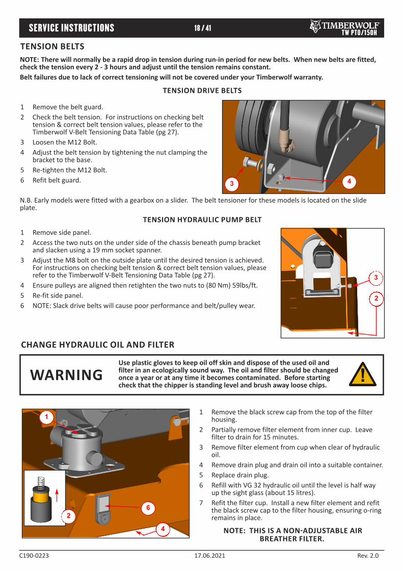
Remove the black screw cap from the top of the filter 1housing. Partially remove filter element from inner cup. Leave 2filter to drain for 15 minutes. Remove filter element from cup when clear of hydraulic 3oil. Remove drain plug and drain oil into a suitable container. 4Replace drain plug. 5Refill with VG 32 hydraulic oil until the level is half way 6up the sight glass (about 15 litres). Refit the filter cup. Install a new filter element and refit 7the black screw cap to the filter housing, ensuring oring remains in place.2
1
4
6
NOTE: THIS IS A NON-ADJUSTABLE AIR BREATHER FILTER.
Remove side panel. 1Access the two nuts on the under side of the chassis beneath pump bracket 2and slacken using a 19 mm socket spanner. Adjust the M8 bolt on the outside plate until the desired tension is achieved. 3For instructions on checking belt tension & correct belt tension values, please refer to the Timberwolf VBelt Tensioning Data Table (pg 27). Ensure pulleys are aligned then retighten the two nuts to (80 Nm) 59lbs/ft. 4Refit side panel. 5NOTE: Slack drive belts will cause poor performance and belt/pulley wear.6
3 4
Remove the belt guard. 1Check the belt tension. For instructions on checking belt 2tension & correct belt tension values, please refer to the Timberwolf VBelt Tensioning Data Table (pg 27). Loosen the M12 Bolt. 3Adjust the belt tension by tightening the nut clamping the 4bracket to the base. Retighten the M12 Bolt. 5Refit belt guard.6
2
3
N.B. Early models were fitted with a gearbox on a slider. The belt tensioner for these models is located on the slide plate.
TENSION HYDRAULIC PUMP BELT
TENSION BELTSNOTE: There will normally be a rapid drop in tension during runin period for new belts. When new belts are fitted, check the tension every 2 3 hours and adjust until the tension remains constant. Belt failures due to lack of correct tensioning will not be covered under your Timberwolf warranty.
CHANGE HYDRAULIC OIL AND FILTER
TENSION DRIVE BELTS
Use plastic gloves to keep oil off skin and dispose of the used oil and filter in an ecologically sound way. The oil and filter should be changed once a year or at any time it becomes contaminated. Before starting check that the chipper is standing level and brush away loose chips.
WARNING

TW PTO/150H19 / 41WARRANTY STATEMENT
C1900223 17.06.2021 Rev. 2.0
TIMBERWOLF NO-NONSENSE WARRANTY All new Timberwolf machines come with peace of mind built in. Our nononsense warranty is your guarantee of your Timberwolf wood chipper not letting you down. Your warranty statement is included in your manual pack. Please ensure you register your machine with your dealer to ensure you are eligible for the full Timberwolf warranty period.

TW PTO/150H20 / 41DECLARATION OF CONFORMITY
C1900223 17.06.2021 Rev. 2.0

21 / 41IDENTIFICATION PLATE TW PTO/150H
C1900223 17.06.2021 Rev. 2.0
EXAMPLE

TW PTO/150H22 / 41DECALS
C1900223 17.06.2021 Rev. 2.0
Clean under blades before refitting or turning.
Failure to do so may result in blade(s) coming loose and
damage being caused to the rotor housing.
Danger. Rotating blades.
Keep hands and feet out.
High velocity discharge keep clear
Reverse feed
Forward feed
Personal Protective Equipment required
Push to stop, Pull to reset.
(rollers)
Read the instruction manual for greasing and
maintenance information
When refitting this guard ensure that steel retaining bracket is on
the inside. Damaged guards due to incorrect assembly will not be covered by
your Timberwolf warranty.
The instruction manual with this machine contains important operating,
maintenance and health and safety information. Failure to follow the information
contained in the instruction manual may lead to death or
serious injury.
Lifting eye is designed to lift the machine’s weight only.
Do not use hoist directly on lifting eye. Use correctly rated
shackle only through lifting eye. Lifting eye to be inspected every
6 months or before each use. Always visually inspect lifting eye prior to each use. Do not
use lifting eye if damaged.
Push to stop. Do not pull here.
3022
617
670
1661
1662
4099
2800 2801
2802
18438
2949
1399 P691
DECAL DESCRIPTION DECAL DESCRIPTION

TW PTO/150H23 / 41DECALS
C1900223 17.06.2021 Rev. 2.0
Danger. Do not operate without this
cover in place.
Danger. Rotating blades inside.
Stop engine and remove key before removing discharge unit.
Caution. Do not put road sweepings in machine as grit will damage
blades.
Caution. When transporting, discharge clamps may work loose.Check
frequently.
Caution. Avoid standing directly in front of feed funnel to reduce exposure
to noise, dust and risk from ejected particles.
Danger. Do not use this machine without the discharge unit fitted. failure to comply may result in serious
inury or damage.
Exceeding the nominal rotational speed of the machine will place both operator and bystanders in
danger from ejected material.
Danger. Autofeed system fitted. Rollers
may turn without warning!When the engine is switched off the rollers will turn during the run
down period.
New drive belts need retensioning.
When new belts are fitted check tension every 23 hours & adjust until tension remains constant.
Danger. Ensure machine is secure to 3
point linkage of the tractor before operation.
Danger. Ensure machine is on level
surface before detaching from the tractor PTO shaft and 3point
linkage.
Disconnect the pto drive shaft before servicing and
maintenance. Stop tractor and remove ignition
key before making any adjustments.
P637
P652
P655
P653
P654
P656
P65019330
DECAL DESCRIPTION
850KG MAX
18393
3004 2998 1363 1849 P160
TIMBERWOLFT W PTO/150HdB
LWA
119 92 dB
LAeq
19332
19343 19331
DECAL DESCRIPTION
24 / 41ELECTRICAL PARTS LOCATOR TW PTO/150H
C1900223 17.06.2021 Rev. 2.0

25 / 41CIRCUIT DIAGRAM TW PTO/150H
C1900223 17.06.2021 Rev. 2.0
SP
LIT
TO
FU
NN
EL
LO
OM
BL/
GB
WG
P
D E FC
B/G
A
B
B
LAC
K
BL
B
LUE
BR
B
RO
WN
P
P
UR
PLE
W
W
HIT
E
B/G
B
LAC
K W
ITH
GR
EE
N T
RA
CE
R
BL/
R
BLU
E W
ITH
RE
D T
RA
CE
R
BL/
G
BLU
E W
ITH
GR
EE
N T
RA
CE
R
KE
Y T
O W
IRIN
G
O
OR
AN
GE
P/W
P
UR
PLE
WIT
H W
HIT
E T
RA
CE
R
B/W
BLA
CK
WIT
H W
HIT
E T
RA
CE
R
BL/
O B
LUE
WIT
H O
RA
NG
E T
RA
CE
R
21
(IN
DU
CT
IVE
)
SP
D S
IGN
AL
PO
WE
RF
US
E
CO
NN
EC
TO
RP
OW
ER
BL
BL/
G
B/G
BY
PA
SS
NO
ST
RE
SS
NO
ST
RE
SS
BY
PA
SS
P
P
BR
B
B
BR
BL/
R
B
SO
LE
NO
ID A
FW
D
23
1
SO
LE
NO
ID B
RE
V
23
1
SP
SP
RE
LA
YF
WD
8630
87a 8587
G
P
BRB B B
MA
IN L
OO
M:
1933
5
B BLBR
O
GL
OW
PL
UG
LA
MP
OU
T 3
BA
T
OU
T 5
OU
T 1
OU
T 2
15 16 17 18141312
FU
EL
HO
LD
SO
LE
NO
ID
BA
T 1
2 V
IGP
SO
L G
ND
SP
EE
D C
ON
TR
OL
LE
D
EM
ER
GE
NC
Y/R
OT
OR
SW
ITC
H
RE
SE
T R
EV
ER
T T
O R
ES
ET
MO
DE
ST
T
RS
T
AX
1
AX
2
GN
D
EP
C
8 9 10 1175 6
GN
D 0
v
GL
OW
PL
UG
I/P
IN-
EP
A
IN+
EP
B
1 32 4
SP
EE
D S
IG -
SP
EE
D S
IG +
OIL
PR
ES
SU
RE
SW
WA
TE
R T
EM
P S
W
CO
NT
RO
LL
ER
H-B
OX
PC
U
FR
OM
SA
FE
TY
SW
ITC
H
AX
2
AX
1
OU
T 4
AU
TO
RE
VE
RS
E P
UL
SE
OU
TP
UT
G
3 4
BL WP/W OB/G
RE
VS
TO
PF
WD
SA
FE
TY
SW
ITC
H
BL/
G
BLBO
OB
LB
Par
t No
. 140
6
Par
t No
. 197
5
SP
LIT
TO
SA
FE
TY
SW
ITC
H
N.O
./N.C
.
1314
2122
N.C
./N.C
.
CD
AB
N.O
.
CD
N.O
./N.C
.
1313
1313
B
DO
CU
ME
NT
No.
ISS
UE
CIR
CU
IT D
IAG
RA
M F
OR
: P
TO
150
WIT
H H
IGH
FU
NN
EL
AN
D H
-BO
X1
PT
O 1
50 H
IGH
- C
D

26 / 41HYDRAULIC LAYOUT TW PTO/150H
C1900223 17.06.2021 Rev. 2.0
0323
MOTOR MOTOR
PUMP
TANK
04890475
0381
1823
1302
FILTER
DCV
1822
Kit No. 1856

TW PTO/150H27 / 41V-BELT TENSIONING TABLE
C1900223 17.06.2021 Rev. 2.0
METHOD:
Set the deflection distance on the lower scale of the tension gauge so that the underside of the 'o'ring equals the 1'h' value given in the table.
Ensure that the deflection force scale is zero'd by pushing the upper 'o'ring all the way down. 2
Place the tension gauge in the centre of the belt span as shown in the diagram. 3
Press downwards on the rubber buffer, deflecting the belt until the underside of the lower 'o'ring is level with 4the belt behind (use a straight edge if there is only 1 belt).
Take the reading from the deflection scale of the tension meter (read at the lower edge of the 'o'ring) & compare 5this value with that given in the table.
Tighten or loosen belts as required following procedure given in this operator's manual. 6Tension gauges are available from Timberwolf spares, quoting part no. 18091
TIPS ON BELT TIGHTENING: There will normally be a rapid drop in tension during •the runin period for new belts. When new belts are fitted, check the tension every 23 hours & adjust until the tension remains constant. The best tension for Vbelt drives is the lowest tension •at which the belts do not slip or ratchet under the highest load condition.
Too much tension shortens belt & bearing life. •Too little tension will affect the performance of your •machine especially in respect of nostress devices. Ensure that belt drives are kept free of any foreign •materials. If a belt slips tighten it! •
TW PTO/150H Rotor Belts Pump Belts
Belt Mffr / Type Gates Super HCMN Gates Super HCMN
Belt Pitch Designation SPA SPA
Belt Length in mm 900 925
Belt Deflection in mm = h 2 2.59
Force Reading (Kg)New belt 4.36 4.67 2.89 3.09
Used Belt 3.74 4.04 2.47 2.68
Rotor Pulley
Engine Pulley
Rotor Pulley
Pump Pulley
ROTOR BELTS PUMP BELTS

28 / 41WARRANTY SERVICE CHECK RECORD TW PTO/150H
C1900223 17.06.2021 Rev. 2.0
Model number: Serial number:
Date of delivery/ handover:
Options/extras:
Dealer pre delivery check:
Inspected by:
Date:
Hours:
Invoice number:
Signature:
Next service due:
Authorised dealer stamp50 HOUR WARRANTY SERVICE CHECK
Date:
Hours:
Invoice number:
Signature:
Next service due:
Authorised dealer stamp11 MONTH WARRANTY SERVICE CHECK
Date:
Hours:
Invoice number:
Signature:
Next service due:
Authorised dealer stamp23 MONTH WARRANTY SERVICE CHECK

29 / 41SERVICE RECORD
C1900223 17.06.2021 Rev. 2.0
Date:
Hours:
Invoice number:
Signature:
Next service due:
Authorised dealer stamp
Date:
Hours:
Invoice number:
Signature:
Next service due:
Authorised dealer stamp
Date:
Hours:
Invoice number:
Signature:
Next service due:
Authorised dealer stamp
Date:
Hours:
Invoice number:
Signature:
Next service due:
Authorised dealer stamp
TW PTO/150H

C1900223 17.06.2021 Rev. 2.0
PARTS LIST
THE FOLLOWING ILLUSTRATIONS ARE FOR PARTS IDENTIFICATION ONLY. THE REMOVAL OR FITTING OF THESE PARTS MAY CAUSE A HAZARD AND SHOULD ONLY BE CARRIED OUT BY TRAINED PERSONNEL.
PARTS LISTS
30 / 41 TW PTO/150H
Page No. CONTROL BOX 31 DISCHARGE / FRAME 32 DRIVE TRAIN 33 ELECTRICAL CONTROL PANEL 34 ELECTRICAL LAYOUT 35 FUNNEL 36 HYDRAULICS 37 ROLLER BOX 38 ROTOR 39 DECALS 40

PTO/150H31 / 41
C1900222 17.03.2020 Rev 1.0
Item Part No Part Name Q’ty
1 2794FB Control Box Cover 1
2 2803 M10/240 Bolt 1
3 0839 M10 C Washer 2
4 4345 M10 P Nyloc Nut 1
5 2795FB Control Box Base 1
6 0709 M6 C Washer 4
7 1658 M6/12 Bolt 4
8 2853 Stop Switch 1
9 2796FS Finger Plate 2
10 2834 AV Mount 2
11 2804 Bush M10 Top Hat 4
12 2807 AV Mount 20 x 16 2
Item Part No Part Name Q’ty
13 0857 M5 A Washer 2
14 18103 M5/8 Pan Pozi 2
15 18168 M4/35 Pan Pozi 4
16 1348 Limit Switch 2
17 18100 M4 Washer 6
18 18235 M4 P Nyloc Nut 6
19 made in production 65mm Spacer 1
20 2793FB Bracket Mounting Control Box 1
21 0712 M8 C Washer 2
22 0344 M8/16 Bolt 4
23 0711 M8 A Washer 2
2
1
8
11
9
10
15
1314
2021
22
3
45
12
67
16
17
18
19
23

32 / 41
C1900222 17.03.2020 Rev 1.0
PTO/150H
1
21
4
3
7
8
1113
1415
16
1812
17x11
19 20
27
22
24
25
23
15
14
15
26
x4
5
28
Item Part No Part Name Q’ty
1 P*1147 Discharge Tube 1
2 P*1411 Discharge Bucket 1
3 0644 M12 P Nyloc Nut 2
4 0702 M12 A Washer 2
5 0430 M12/35 Cup Square 1
6 18023PS Guard Stand-Off Plate 1
7 4109M Large Clamp Nut 1
8 2837MS Small Clamp Nut 1
9 0434 M16/70 Hex Bolt 1
10 0333 M16/60 Hex Bolt 1
11 1267FO Front Plate 1
12 0704 M12 C Washer 8
13 1268FO Access Cover 1
14 0045 M12 T Nyloc Nut 7
15 0702 M12 A Washer 11
16 0588O Access Cover 1
17 18451FO Rotor Housing 1
18 0277 M12/25 Bolt 8
19 0942 Linch Pin 3
Item Part No Part Name Q’ty
20 0943 Top Pin 1
21 19282 M12/30 Cup Square 1
22 0236 M5 P Nyloc Nut 3
23 0483 Trailer Socket 1
24 0708 M5 C Washer 3
25 1589 M5/35 Pan Pozi 3
26 0321 M12/30 Bolt 4
27 0941 Side Pin 2
28 1163 Oil Level Gauge 1
29 4041 Prop Shaft 1
30 1649MS Discharge Clamp Handle 1
31 4131 Roll Pin 1
32 1354 M16 C Washer 1
33 18190 M24 Washer 1
34 1511 M16 P Nyloc Nut 1
35 4143FO Access Cover 1
36 0355 M8/16 C/Sunk Bolt 2
37 0101MH Anvil Vertical 1
30
33
31
9
32
34
10
29
1812
35
3
2
36
37
6
4
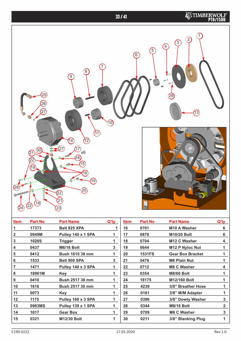
PTO/150H33 / 41
C1900222 17.03.2020 Rev 1.0
Item Part No Part Name Q’ty
1 17373 Belt 925 XPA 1
2 0949M Pulley 140 x 1 SPA 1
3 1028S Trigger 1
4 0437 M6/16 Bolt 3
5 0412 Bush 1610 38 mm 1
6 1533 Belt 900 SPA 3
7 1471 Pulley 140 x 3 SPA 1
8 18961M Key 1
9 0410 Bush 2517 38 mm 1
10 1616 Bush 2517 30 mm 1
11 0073 Key 1
12 1175 Pulley 160 x 3 SPA 1
13 0983MS Pulley 139 x 1 SPA 1
14 1617 Gear Box 1
15 0321 M12/30 Bolt 1
Item Part No Part Name Q’ty
16 0701 M10 A Washer 6
17 0878 M10/20 Bolt 6
18 0704 M12 C Washer 4
19 0644 M12 P Nyloc Nut 1
20 1531FS Gear Box Bracket 1
21 0476 M8 Plain Nut 1
22 0712 M8 C Washer 4
23 0354 M8/60 Bolt 1
24 18175 M12/160 Bolt 1
25 4239 3/8” Breather Hose 1
26 0161 3/8” M/M Adapter 1
27 0396 3/8” Dowty Washer 3
28 0344 M8/16 Bolt 2
29 0709 M6 C Washer 3
30 0211 3/8” Blanking Plug 1
12
6
7
8
9
10
11
12
13
5
14
15
18
17
16
19
20
24
22
21
23
34
25
26
27
21
22
19
28
1822
x6
29
30 27
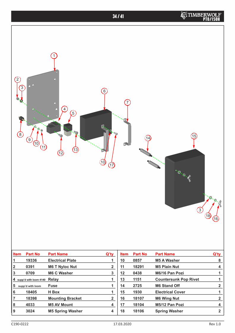
34 / 41
C1900222 17.03.2020 Rev 1.0
PTO/150H
Item Part No Part Name Q’ty
1 19336 Electrical Plate 1
2 0391 M6 T Nyloc Nut 2
3 0709 M6 C Washer 3
4 supp’d with loom 4140 Relay 1
5 supp’d with loom Fuse 1
6 18405 H Box 1
7 18398 Mounting Bracket 2
8 4033 M5 AV Mount 4
9 3024 M5 Spring Washer 4
Item Part No Part Name Q’ty
10 0857 M5 A Washer 8
11 18291 M5 Plain Nut 4
12 0438 M6/16 Pan Pozi 1
13 1151 Countersunk Pop Rivet 1
14 2725 M6 Stand Off 2
15 1930 Electrical Cover 1
16 18107 M6 Wing Nut 2
17 18104 M5/12 Pan Pozi 4
18 18106 Spring Washer 2
8
3
2
1
910
11
12
6
7
45
1415
16
13
1017
18
3
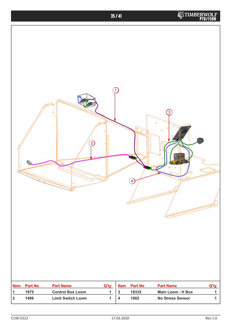
35 / 41
C1900222 17.03.2020 Rev 1.0
PTO/150H
Item Part No Part Name Q’ty
1 1975 Control Box Loom 1
2 1406 Limit Switch Loom 1
Item Part No Part Name Q’ty
3 19335 Main Loom - H Box 1
4 1902 No Stress Sensor 1
1
2
3
4

36 / 41
C1900222 17.03.2020 Rev 1.0
PTO/150H
1
7
6
13
9
20
1819
21
24
23
17
22
10
2728
11
2
16
12
16
30 31
31
32
33
34
25
8
2
14
33
34
15
34
Item Part No Part Name Q’ty
1 2809F Control Box (see pg. 27) 1
2 1721 M8/10 Bolt 6
3 0654 Blank Grommet 2
4 4345 M10 P Nyloc Nut 2
5 1006 M4/30 Pan Pozi 2
6 4206 Nylon Bush 1
7 4238FO Funnel 1
8 1644 M8 Anti-Vibration Mount 3
9 0321 M12/30 Bolt 2
10 2919FO Feed Tray 1
11 2922FS Hinge Pin 2
12 0178 Rubber End Stop 1
13 1600 Nylon Pistons 2
14 4342 M8/30 Csk Soc. 1
15 4018S Pin Bracket 2
16 0712 M8 C Washer 8
17 1603 Die Springs 2
18 1605M Stainless Spacer 2
19 1599 Bearing Washer 2
20 1570FR Safety Bar 1
21 1348 Limit Switch 1
Item Part No Part Name Q’ty
22 1812 M10/35 Bolt 2
23 1591 Nylon Spacer 2
24 0479 M8 P Nyloc Nut 1
25 2727FS Bracket Actuator 1
26 0045 M12 T Nyloc Nut 2
27 2986 1/2” Spring Bolt 2
28 0391 M6 T Nyloc Nut 8
29 P*144 Operator’s Manual Cannister 1
30 0046 M12 Plain Nut 4
31 0704 M12 C Washer 8
32 4344 M10 Repair Washer 2
33 0709 M6 C Washer 12
34 0437 M6/16 Bolt 12
35 2493 Rubber Cap 2
36 0481 M8 T Nyloc Nut 4
37 18104 M5/12 Pan Pozi 4
38 0857 M5 A Washer 4
39 18924 Square Reflector 2
40 18102 M5 T Nyloc Nut 2
41 0347 M8/20 Button Head 3
3126
5
33
4
16
36 3
35
39
40
37
38
29 36
41
x3
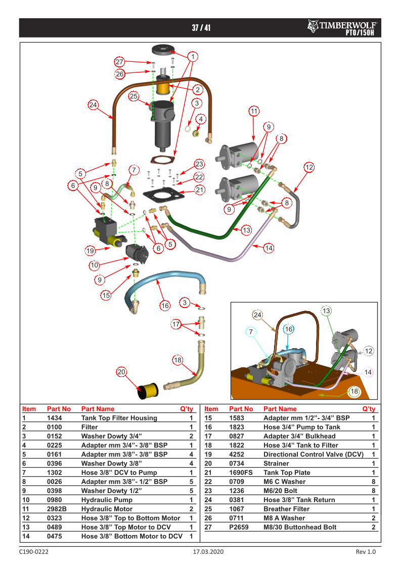
37 / 41
C1900222 17.03.2020 Rev 1.0
PTO/150H
Item Part No Part Name Q’ty
1 1434 Tank Top Filter Housing 1
2 0100 Filter 1
3 0152 Washer Dowty 3/4” 2
4 0225 Adapter mm 3/4”- 3/8” BSP 1
5 0161 Adapter mm 3/8”- 3/8” BSP 4
6 0396 Washer Dowty 3/8” 4
7 1302 Hose 3/8” DCV to Pump 1
8 0026 Adapter mm 3/8”- 1/2” BSP 5
9 0398 Washer Dowty 1/2” 5
10 0980 Hydraulic Pump 1
11 2982B Hydraulic Motor 2
12 0323 Hose 3/8” Top to Bottom Motor 1
13 0489 Hose 3/8” Top Motor to DCV 1
14 0475 Hose 3/8” Bottom Motor to DCV 1
Item Part No Part Name Q’ty
15 1583 Adapter mm 1/2”- 3/4” BSP 1
16 1823 Hose 3/4” Pump to Tank 1
17 0827 Adapter 3/4” Bulkhead 1
18 1822 Hose 3/4” Tank to Filter 1
19 4252 Directional Control Valve (DCV) 1
20 0734 Strainer 1
21 1690FS Tank Top Plate 1
22 0709 M6 C Washer 8
23 1236 M6/20 Bolt 8
24 0381 Hose 3/8” Tank Return 1
25 1067 Breather Filter 1
26 0711 M8 A Washer 2
27 P2659 M8/30 Buttonhead Bolt 2
9
15
8
17
7
9
5
10
4
3
1
2
6
56
9
8
11
9
8
12
13
14
163
18
20
24
12
14
18
16
13
19
7
21
22
23
27
26
24
25

38 / 41
C1900222 17.03.2020 Rev 1.0
PTO/150H
Item Part No Part Name Q’ty
1 0672 Rollerbox Cover 1
2 4340 M12/50 Caphead 4
3 0481 M8 T Nyloc Nut 3
4 18027M Plate Top Damper Carrier 1
5 P0000146 M8/18 Csk Screw 1
6 1962MS Block Top Damped 1
7 18024M Drive Side Plate 1
8 0429 M12/35 Bolt 4
9 0702 M12 A Washer 6
10 18025M Non Drive Side Plate 1
11 1162S Motor Studs 2
12 18028FS Bracket Spring Hanger 2
13 18070 Roller Box Spring 2
14 0305 M10/25 Caphead 2
15 1768 AV Mount 30x30 4
16 0701 M10 A Washer 2
17 0382 M10/30 Bolt 4
18 1361M Drive Spline 1
19 4345 M10 P Nyloc Nut 2
20 2757 Bush Bearing Spline 1
21 0103MH Anvil 1
Item Part No Part Name Q’ty
22 0228MS Roller Box 1
23 0985 Straight Grease Nipple 1
24 0986 45o Grease Nipple 1
25 0055 Bearing Boss 2
26 0788 Plastic Bush 2
27 1362M Roller Body 2
28 0325M Roller Blade 12
29 0428 M12/30 Csk Soc. 24
30 4100M Spline 6B Retro Bottom 1
31 0360 M10/25 Bolt 1
32 0350 M8/25 Bolt 2
33 4068 M10/40 Cap Head Bolt 8
34 0839 M10 C Washer 3
35 0534FS Cover Bracket 1
36 0045 M12 T Nyloc Nut 1
37 0319 M12/220 Bolt 1
38 0356 Funnel Studs M12/50 4
39 2982B Motor 2
40 0476 M8 Plain Nut 2
41 1985 M12/30 Caphead 2
42 0711 M8 A Washer 5
27
2928
1
8
9
10
2
7
9 8
14
11
16
4
12
1534
31
9
42
32
19
16
41
21
22
17
23
24
3334
35
37
36
2526
2526
2038
27
18
33
13
28
29
33
13
3
42
6
3039
40
x6
x6
5
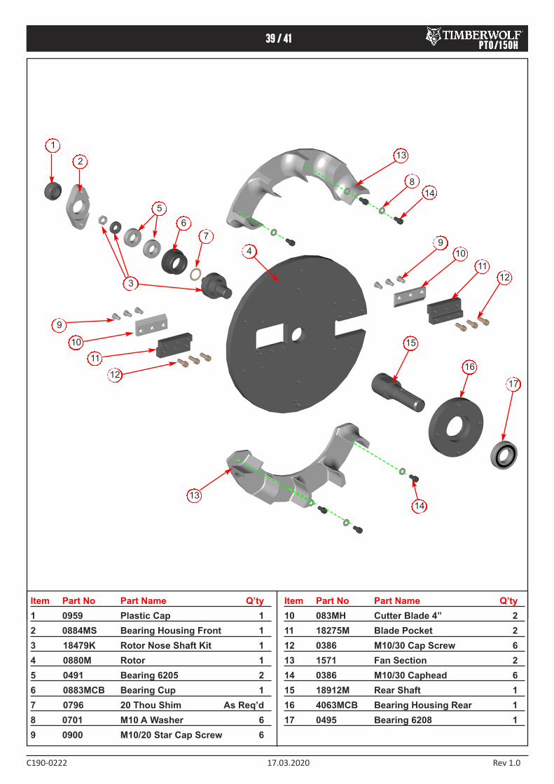
39 / 41
C1900222 17.03.2020 Rev 1.0
PTO/150H
Item Part No Part Name Q’ty
1 0959 Plastic Cap 1
2 0884MS Bearing Housing Front 1
3 18479K Rotor Nose Shaft Kit 1
4 0880M Rotor 1
5 0491 Bearing 6205 2
6 0883MCB Bearing Cup 1
7 0796 20 Thou Shim As Req’d
8 0701 M10 A Washer 6
9 0900 M10/20 Star Cap Screw 6
Item Part No Part Name Q’ty
10 083MH Cutter Blade 4” 2
11 18275M Blade Pocket 2
12 0386 M10/30 Cap Screw 6
13 1571 Fan Section 2
14 0386 M10/30 Caphead 6
15 18912M Rear Shaft 1
16 4063MCB Bearing Housing Rear 1
17 0495 Bearing 6208 1
1
2
3
9
10
11
12
5
6
4
13
15
16
14
13
17
9
10
12
11
14
7
8

40 / 41
C1900222 17.03.2020 Rev 1.0
PTO/150H
617
1363
19
33
0
1849
2949
P6
37
18
43
8
P653
P656
P654
1363
3022
850KG
M
AX
18
39
3
P6
50
19331
19
34
3
19332
P160
TIMBE
RWOL
FTW
PTO
/150
H
P6
37
85m
m
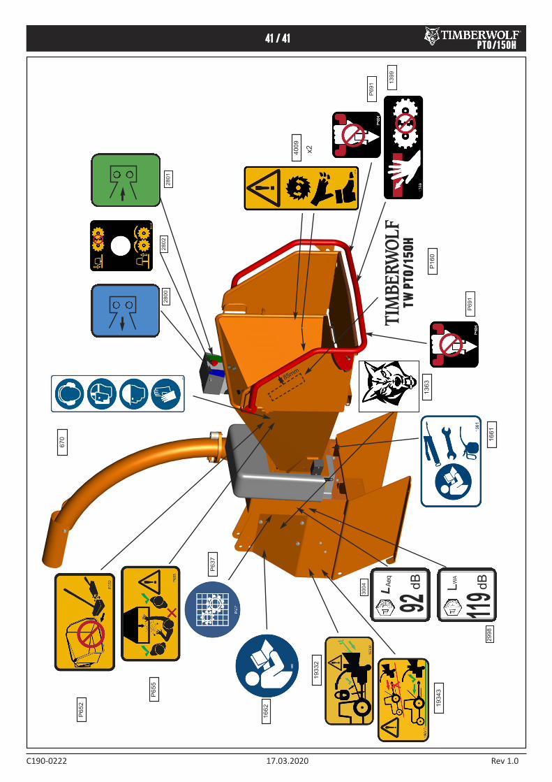
41 / 41
C1900222 17.03.2020 Rev 1.0
PTO/150H
1363
1661
13
99
670
P160
P6
55
P652
4009
x2
2800
2802
2801
19
33
2
19
34
3
TIMBE
RWOL
FTW
PTO
/150
H92
dB
L Aeq
LW
A
dB
29
98
30
04
16
62
P637
P6
91
P6
91
85mm
119

timberwolf-uk.com
Timberwolf Ltd Wood Chippers & ShreddersTomo Industrial Estate, Stowmarket, Suffolk IP14 5AY, United KingdomT: +44 1449 765800 E: [email protected] W: timberwolf-uk.com