Tutorial – Arduino Uno and SM5100B GSM Cellular
13
Tutorial – Arduino Uno and SM5100B GSM Cellular Connect your Arduino Uno or compatible to the cellular network with the SM5100 GSM module shield. This is chapter twenty-six of a series originally titled “Getting Started/Moving Forward with Arduino! ” by John Boxall – A tutorial on the Arduino universe. The first chapter is here , the complete series is detailed here . If you are looking for tutorials using the SIMCOM SIM900 GSM module, click here , and here if you have an Arduino Mega. Updated 15/01/2014 Introduction The purpose of this tutorial is to have your Arduino to communicate over a GSM mobile telephone network using the SM5100B GSM Cellular Shield : My goal is to illustrate various methods of interaction between an Arduino and the GSM cellular network using the SM5100B GSM shield from Sparkfun, with which you can then use your existing knowledge to build upon those methods. Doing so isn’t easy – but it isn’t that difficult. Stop! Please read first: It is assumed that you have a solid understanding of how to program your Arduino. If not, start fromchapter zero Sending SMS messages and making phone calls cost real money, so it would be very wise to use a prepaid cellular account or one that allows a fair amount of calls/SMS The GSM shield only works with “2G” GSM mobile networks operating on the 850, 900 and PCS1800 MHz frequencies. If in doubt, ask your carrier first Australians – you can use any carrier’s SIM card Canadians – this doesn’t work with Sasktel North Americans – check with your cellular carrier first if you can use third-party hardware (i.e. the shield) I cannot offer design advice for your project nor technical support for this article. If you are working on a college/university project and need specific help – talk to your tutors or academic staff. They get paid to help you. Please don’t make an auto-dialler…
-
Upload
khangminh22 -
Category
Documents
-
view
0 -
download
0
Transcript of Tutorial – Arduino Uno and SM5100B GSM Cellular
Tutorial – Arduino Uno and SM5100B GSM Cellular
Connect your Arduino Uno or compatible to the cellular network with the SM5100 GSM module shield.
This is chapter twenty-six of a series originally titled “Getting Started/Moving Forward with Arduino!” by John
Boxall – A tutorial on the Arduino universe. The first chapter is here, the complete series is detailed here.
If you are looking for tutorials using the SIMCOM SIM900 GSM module, click here, and here if you have an Arduino
Mega.
Updated 15/01/2014
Introduction
The purpose of this tutorial is to have your Arduino to communicate over a GSM mobile telephone network using
the SM5100B GSM Cellular Shield:
My goal is to illustrate various methods of interaction between an Arduino and the GSM cellular network using the
SM5100B GSM shield from Sparkfun, with which you can then use your existing knowledge to build upon those
methods. Doing so isn’t easy – but it isn’t that difficult.
Stop! Please read first:
It is assumed that you have a solid understanding of how to program your Arduino. If not, start fromchapter
zero
Sending SMS messages and making phone calls cost real money, so it would be very wise to use a prepaid
cellular account or one that allows a fair amount of calls/SMS
The GSM shield only works with “2G” GSM mobile networks operating on the 850, 900 and PCS1800 MHz
frequencies. If in doubt, ask your carrier first
Australians – you can use any carrier’s SIM card
Canadians – this doesn’t work with Sasktel
North Americans – check with your cellular carrier first if you can use third-party hardware (i.e. the shield)
I cannot offer design advice for your project nor technical support for this article.
If you are working on a college/university project and need specific help – talk to your tutors or academic
staff. They get paid to help you.
Please don’t make an auto-dialler…

Getting started
As mentioned previously, we’re using the Sparkfun GSM shield with the SM5100B module. When you order the
shield, don’t forget to order the stacking header pin set as they’re not included with the shield, and you’ll need to
solder them on yourself. Power -the GSM shield can often require up to 2A of current in short bursts – especially
when turned on, reset, or initiating a call.
However your Arduino board can only supply just under 1A. It is highly recommended that you use an external
regulated 5V power supply capable of delivering 2A of current – from an AC adaptor, large battery with power
regulator, etc. Otherwise there is a very strong probability of damaging your shield and Arduino.
Ignore this at your own risk
When connecting this supply DO NOT use the DC socket on the Arduino. Instead, connect the 5V (positive) from the
supply to the 5V pin on the GSM shield, and the negative to the GND pin.
If you’re looking for a more permanent or easy-to-wire solution, get yourself a DFRobot power shield:

This shield sits on top of your GSM shield (which sits on top of your Arduino). Before use you need to set it up:
1. The only jumpers that should be on the power shield are as shown in the image above;
2. Connect a power supply of between 9 and 35V DC to the blue terminal block at the bottom-left of the shield;
3. Connect a voltmeter/multimeter to the other blue terminal block at the top-left and adjust the potentiometer
(blue thing between the terminal blocks) until the voltage measured is 5 volts; ignore the LEDs on the shield as
they’re not that accurate;
4. Run a wire from the positive power output to the 5V pin on the shield, and run another one from the negative
power output to a GND pin on the shield;
5. If you have the USB cable connected to your project while operating the GSM shield, remove the USB cable
before turning off external power to the project.
Here’s what it looks like once assembled with the antenna:
Next – use an antenna! The wire hanging from the shield is not an antenna. YOU NEED THE ANTENNA! There are
two choices. Either use the smaller one for areas where handheld mobile reception is acceptable,such as this one:
Or if you are in an area of weaker reception, use an external antenna such as that used on a motor vehicle. If you are
using the larger vehicle-style aerial, you might find that the plug will not fit to the shield’s connector. For example,
consider the following:
On the left is the end of the lead from the carphone aerial, the right is the lead from the GSM shield. Problem! The
solution is in the centre: an FME male to SMA male adaptor. This one came from element-14, part number 1826209
(it is a Multicomp R23-014-00-002611000).
Furthermore, care needs to be taken with your GSM shield with regards to the aerial lead-module connection, it is
very fragile:

And finally, download this document (.pdf). It contains all the AT and ERROR codes that will turn up when you least
expect it. Please review it if you are presented with a code you are unsure about.
Wow – all those rules and warnings?
The sections above may sound a little authoritarian, however I want your project to be a success. With the previous
iterations of the tutorial people just didn’t follow the instructions – so I hope you do
Are you using an Arduino Mega or Leonardo board?
Things are a little different for you. Those boards don’t support SoftwareSerial on digital pins 2 and 3 thus rendering
the GSM shield a little trickier to use. Instead, bend back the D2 and D3 pins on the GSM shield as such (click image
to enlarge):
Then run jumpers from D2 on the attached shield to D10 and another from D3 to D11. If you’re using the
aforementioned power shield it would be on top of the GSM shield however the jumper wires would be the same.
Finally in all the sketches, change the line SoftwareSerial cell(2,3); to SoftwareSerial cell(10,11); . If you have a
Leonardo, get a Uno.
Initial check – does it work?
This may sound like a silly question, but considering the cost of the shield and the variables involved, it is a good idea
to check if your setup is functioning correctly before moving on. From a hardware perspective for this article, you will
need your Arduino board, the GSM shield with activated SIM card and an aerial, and a range of previously used
components.
Make sure your SIM card is set to not require a PIN when the phone is turned on. You can check and turn this
requirement off with your cellphone. For our initial test, upload the following sketch:
1 2 3 4 5 6 7 8 9
10 11 12 13 14 15 16 17 18 19
// Example 263.1 #include <SoftwareSerial.h> char incoming_char=0; //Will hold the incoming character from the Serial Port. SoftwareSerial cell(2,3); //Create a 'fake' serial port. Pin 2 is the Rx pin, pin 3 is the Tx pin. void setup() { //Initialize serial ports for communication. Serial.begin(9600); cell.begin(9600); Serial.println("Starting SM5100B Communication..."); } void loop() { //If a character comes in from the cellular module... if(cell.available() >0) {

20 21 22 23 24 25 26 27 28 29
incoming_char=cell.read(); //Get the character from the cellular serial port. Serial.print(incoming_char); //Print the incoming character to the terminal. } //If a character is coming from the terminal to the Arduino... if(Serial.available() >0) { incoming_char=Serial.read(); //Get the character coming from the terminal cell.print(incoming_char); //Send the character to the cellular module. } }
Then connect the GSM shield, aerial, insert the SIM card and apply power. Open the serial monitor box in the
Arduino IDE and you should be presented with the following:
It will take around fifteen to thirty seconds for the text above to appear in full. What you are being presented with is a
log of the GSM module’s actions. But what do they all mean?
+SIND: 1 means the SIM card has been inserted;
the +SIND: 10 line shows the status of the in-module phone book. Nothing to worry about there for us at the
moment;
+SIND: 11 means the module has registered with the cellular network
+SIND: 3 means the module is partially ready to communicate
and +SIND: 4 means the module is registered on the network, and ready to communicate
From this point on, we will need to use a different terminal program, as the Arduino IDE’s serial monitor box isn’t
made for full two-way communications. You will need a terminal program that can offer full two-way com port/serial
communication. For those running MS Windows, an excellent option is available here.
It’s free, however consider donating for the use of it. For other operating systems, people say this works well. So
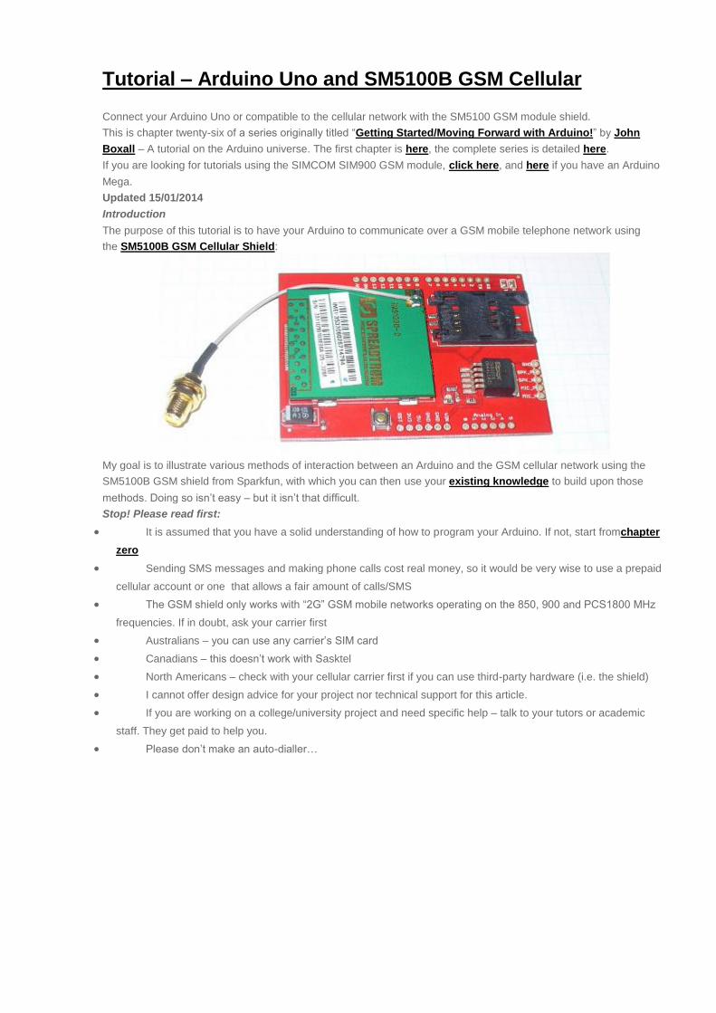
now let’s try it out with the terminal software. Close your Arduino IDE serial monitor box if still open, then run your
terminal, set it to look at the same serial port as the Arduino IDE was. Ensure the settings are 9600, 8, N, 1. Then
reset your Arduino and the following should appear:
The next step is to tell the GSM module which network frequency(ies) to use. Please download thisdocument (.pdf),
and view page 127. There is a range of frequency choices that our module can use. If you don’t know which one to
use, contact the telephone company that your SIM card came from. Australia – use option 4. Choose your option,
then enter
1 AT+SBAND=x
(where X is the value matching your required frequency) into the terminal software and click SEND. Then press reset
on the Arduino and watch the terminal display. You should hopefully be presented with the same text as above,
ending with +SIND: 4. If your module returns +SIND: 4, we’re ready to move forward.
If your terminal returned a +SIND: 8 instead of 4, double-check your hardware, power supply, antenna, and the
frequency band chosen. If all that checks out call your network provider to see if they’re rejecting the GSM module on
their network.
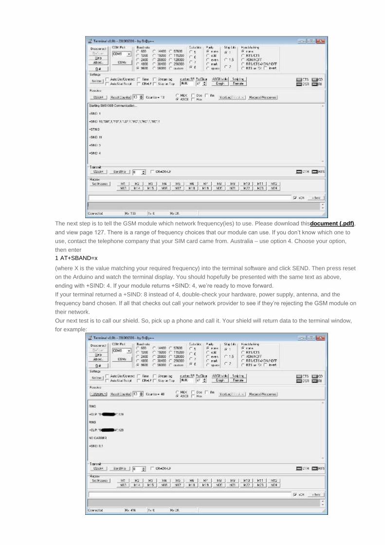
Our next test is to call our shield. So, pick up a phone and call it. Your shield will return data to the terminal window,
for example:

As you can see, the module returns what is happening. I let the originating phone “ring” twice, and the module
received the caller ID data (sorry, blacked it out). Some telephone subscribers’ accounts don’t send caller ID data, so
if you don’t see your number, no problem. “NO CARRIER” occurred when I ended the call. +SIND: 6,1 means the call
ended and the SIM is ready.
Have your Arduino “call you”
The document (.pdf) we downloaded earlier contains a list of AT commands – consider this a guide to the language
with which we instruct the GSM module to do things. Let’s try out some more commands before completing our initial
test. The first one is:
1 ATDxxxxxx
which dials a telephone number xxxxxx. For example, to call (212)-8675309 use
1 ATD2128675309
The next one is
1 ATH
which “hangs up” or ends the call. So, let’s reach out and touch someone. In the terminal software, enter your
ATDxxxxxxxx command, then hit send. Let your phone ring. Then enter ATH to end the call. If you are experimenting
and want to hang up in a hurry, you can also hit reset on the Arduino and it will end the call as well as resetting the
system.
So by now you should realise the GSM module is controlled by these AT commands. To use an AT command in a
sketch, we use the function
1 cell.println()
for example, to dial a phone number, we would use
1 cell.println("ATD2128675309");
To demonstrate this in a sketch, consider the following simple sketch which dials a telephone number, waits, then
hangs up. Replace xxxxxxxx with the number you wish to call.
1 2 3 4 5 6 7 8 9
10 11 12 13 14 15 16 17 18 19 20 21 22 23 24 25
// Example 26.2 #include <SoftwareSerial.h> SoftwareSerial cell(2,3); void setup() { cell.begin(9600); delay(25000); // give the GSM module time to initialise, locate network etc. // this delay time varies. Use example 26.1 sketch to measure the amount // of time from board reset to SIND: 4, then add five seconds just in case } void loop() { cell.println("ATDxxxxxxxxx"); // dial the phone number xxxxxxxxx // change xxxxxxx to your desired phone number (with area code) delay(20000); // wait 20 seconds. cell.println("ATH"); // end call do // remove this loop at your peril { delay(1); } while (1>0); }
The sketch in example 26.2 assumes that all is well with regards to the GSM module, that is the SIM card is ok, there
is reception, etc. The delay function in void setup() is used to allow time for the module to wake up and get connected
to the network. Later on we will read the messages from the GSM module to allow our sketches to deal with errors
and so on.
However, you can see how we can simply dial a telephone. You could now have a home alarm system that can call
you upon an event happening, etc.
Send an SMS from your Arduino
Another popular function is the SMS or short message service, or text messaging. Before moving forward, download
and install Meir Michanie’s SerialGSM Arduino library from here. Sending a text message is incredibly simple –
consider the following sketch:

1 2 3 4 5 6 7 8 9
10 11 12 13 14 15 16 17 18 19 20 21 22 23 24 25 26 27 28 29 30
// Example 26.3 #include <SerialGSM.h> #include <SoftwareSerial.h> SerialGSM cell(2,3); void setup() { delay(30000); // wait for GSM module cell.begin(9600); } void sendSMS() { cell.Verbose(true); // used for debugging cell.Boot(); cell.FwdSMS2Serial(); cell.Rcpt("+xxxxxxxxx"); // replace xxxxxxxxx with the recipient's cellular number cell.Message("Contents of your text message"); cell.SendSMS(); } void loop() { sendSMS(); do // remove this loop at your peril { delay(1); } while (1>0); }
It’s super-simple – just change the phone number to send the text message, and of course the message you want to
send. The phone numbers must be in international format, e.g. Australia 0418 123456 is +61418123456 or USA
(609) 8675309 is +16098675309.
Reach out and control something
Now let’s discuss how to make something happen by a simple telephone call. And the best thing is that we don’t
need the the GSM module to answer the telephone call (thereby saving money) – just let the module ring a few times.
How is this possible? Very easily. Recall Example 26.1 above – we monitored the activity of the GSM module by
using our terminal software.
In this case what we need to do is have our Arduino examine the text coming in from the serial output of the GSM
module, and look for a particular string of characters.
When we telephone the GSM module from another number, the module returns the text as shown in the image
below:

We want to look for the text “RING”, as (obviously) this means that the GSM shield has recognised the ring signal
from the exchange. Therefore need our Arduino to count the number of rings for the particular telephone call being
made to the module. (Memories – Many years ago we would use public telephones to send messages to each other.
For example, after arriving at a foreign destination we would call home and let the phone ring five times then hang up
– which meant we had arrived safely). Finally, once the GSM shield has received a set number of rings, we want the
Arduino to do something.
From a software perspective, we need to examine each character as it is returned from the GSM shield. Once an “R”
is received, we examine the next character. If it is an “I”, we examine the next character. If it is an “N”, we examine
the next character. If it is a “G”, we know an inbound call is being attempted, and one ring has occurred.
We can set the number of rings to wait until out desired function is called. In the following example, when the shield is
called, it will call the function doSomething() after three rings.
The function doSomething() controls two LEDs, one red, one green. Every time the GSM module is called for 3 rings,
the Arduino alternately turns on or off the LEDs. Using this sketch as an example, you now have the ability to turn
basically anything on or off, or call your own particular function.
1 2 3 4 5 6 7 8 9
10 11 12 13 14 15 16 17 18 19 20 21 22 23 24 25
// Example 26.4 #include <SoftwareSerial.h> char inchar; // Will hold the incoming character from the Serial Port. SoftwareSerial cell(2,3); //Create a 'fake' serial port. Pin 2 is the Rx pin, pin 3 is the Tx pin. int numring=0; int comring=3; int onoff=0; // 0 = off, 1 = on void setup() { pinMode(12, OUTPUT); pinMode(13, OUTPUT); // LEDs - off = red, on = green digitalWrite(12, HIGH); digitalWrite(13, LOW); //Initialize serial port for communication. cell.begin(9600); } void doSomething() { if (onoff==0) { onoff=1; digitalWrite(12, HIGH);

26 27 28 29 30 31 32 33 34 35 36 37 38 39 40 41 42 43 44 45 46 47 48 49 50 51 52 53 54 55 56 57 58 59 60 61 62 63 64 65 66 67 68 69 70 71
digitalWrite(13, LOW); } else if (onoff==1) { onoff=0; digitalWrite(12, LOW); digitalWrite(13, HIGH); } } void loop() { //If a character comes in from the cellular module... if(cell.available() >0) { inchar=cell.read(); if (inchar=='R') { delay(10); inchar=cell.read(); if (inchar=='I') { delay(10); inchar=cell.read(); if (inchar=='N') { delay(10); inchar=cell.read(); if (inchar=='G') { delay(10); // So the phone (our GSM shield) has 'rung' once, i.e. if it were a real phone // it would have sounded 'ring-ring' numring++; if (numring==comring) { numring=0; // reset ring counter doSomething(); } } } } } } }
And now for a quick video demonstration. The first call is made, and the LEDs go from red (off) to green (on). A
second call is made, and the LEDs go from green (on) to red (off). Although this may seem like an over-simplified
example, with your existing Arduino knowledge you now have the ability to run any function by calling your GSM
shield:
Control Digital I/O via SMS
Now although turning one thing on or off is convenient, how can we send more control information to our GSM
module? For example, control four or more digital outputs at once? These sorts of commands can be achieved by the
reception and analysis of text messages.
Doing so is similar to the method we used in example 27.1. Once again, we will analyse the characters being sent
from the GSM module via its serial out. However, there are two AT commands we need to send to the GSM module
before we can receive SMSs, and one afterwards. The first one you already know:
1 AT+CMGF=1
Which sets the SMS mode to text. The second command is:
1 AT+CNMI=3,3,0,0
This command tells the GSM module to immediately send any new SMS data to the serial out. An example of this is
shown in the terminal capture below:

Two text messages have been received since the module was turned on. You can see how the data is laid out. The
blacked out number is the sender of the SMS. The number +61418706700 is the number for my
carrier’s SMSC (short message service centre). Then we have the date and time. The next line is the contents of the
text message – what we need to examine in our sketch.
The second text message in the example above is how we will structure our control SMS. Our sketch will wait for a #
to come from the serial line, then consider the values after a, b, c and d – 0 for off, 1 for on. Finally, we need to send
one more command to the GSM module after we have interpreted our SMS:
1 AT+CMGD=1,4
This deletes all the text messages from the SIM card. As there is a finite amount of storage space on the SIM, it is
prudent to delete the incoming message after we have followed the instructions within. But now for our example. We
will control four digital outputs, D9~12. For the sake of the exercise we are controlling an LED on each digital output,
however you could do anything you like.
Although the sketch may seem long and complex, it is not – just follow it through and you will see what is happening:
1 2 3 4 5 6 7 8 9 10 11 12 13 14 15 16 17 18 19 20 21 22
// Example 26.5 #include <SoftwareSerial.h> char inchar; //Will hold the incoming character from the Serial Port. SoftwareSerial cell(2,3); //Create a 'fake' serial port. Pin 2 is the Rx pin, pin 3 is the Tx pin. int led1 = 9; int led2 = 10; int led3 = 11; int led4 = 12; void setup() { // prepare the digital output pins pinMode(led1, OUTPUT); pinMode(led2, OUTPUT); pinMode(led3, OUTPUT); pinMode(led4, OUTPUT); digitalWrite(led1, LOW); digitalWrite(led2, LOW); digitalWrite(led3, LOW); digitalWrite(led4, LOW);

23 24 25 26 27 28 29 30 31 32 33 34 35 36 37 38 39 40 41 42 43 44 45 46 47 48 49 50 51 52 53 54 55 56 57 58 59 60 61 62 63 64 65 66 67 68 69 70 71 72 73 74 75 76 77 78 79 80 81 82 83 84 85 86 87 88 89 90 91 92 93
//Initialize GSM module serial port for communication. cell.begin(9600); delay(30000); // give time for GSM module to register on network etc. cell.println("AT+CMGF=1"); // set SMS mode to text delay(200); cell.println("AT+CNMI=3,3,0,0"); // set module to send SMS data to serial out upon receipt delay(200); } void loop() { //If a character comes in from the cellular module... if(cell.available() >0) { inchar=cell.read(); if (inchar=='#') { delay(10); inchar=cell.read(); if (inchar=='a') { delay(10); inchar=cell.read(); if (inchar=='0') { digitalWrite(led1, LOW); } else if (inchar=='1') { digitalWrite(led1, HIGH); } delay(10); inchar=cell.read(); if (inchar=='b') { inchar=cell.read(); if (inchar=='0') { digitalWrite(led2, LOW); } else if (inchar=='1') { digitalWrite(led2, HIGH); } delay(10); inchar=cell.read(); if (inchar=='c') { inchar=cell.read(); if (inchar=='0') { digitalWrite(led3, LOW); } else if (inchar=='1') { digitalWrite(led3, HIGH); } delay(10); inchar=cell.read(); if (inchar=='d') { delay(10); inchar=cell.read(); if (inchar=='0') { digitalWrite(led4, LOW); } else if (inchar=='1') { digitalWrite(led4, HIGH); }

94 95 96 97 98 99
100 101 102
delay(10); } } cell.println("AT+CMGD=1,4"); // delete all SMS } } } } }
And now for a video demonstration:
Conclusion
So there you have it – controlling your Arduino digital outputs via a normal telephone or SMS. Now it is up to you and
your imagination to find something to control, sensor data to return, or get up to other shenanigans. If you enjoyed
this article, you may find this of interest – controlling AC power outlets via SMS.
And if you enjoyed the tutorial, or want to introduce someone else to the interesting world of Arduino – check out my
book (now in a third printing!) “Arduino Workshop” from No Starch Press.
Have fun and keep checking into tronixstuff.com. Why not follow things on twitter, Google+, subscribe for email
updates or RSS using the links on the right-hand column, or join our Google Group – dedicated to the projects and
related items on this website. Sign up – it’s free, helpful to each other – and we can all learn something.