Tractor Maintenance Manual - Agricultural Knowledge and ...
55
-
Upload
khangminh22 -
Category
Documents
-
view
5 -
download
0
Transcript of Tractor Maintenance Manual - Agricultural Knowledge and ...
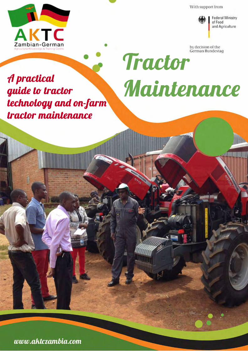
Tractor Maintenance
A practical guide to tractortechnology and on-farm tractor maintenance

AKTC Zambian-German
AKTC is supported by the following partners:
■ BayWar.e. renewable energy BHBW
ZAMBIA� i �A� (.flieg/ -·-
KseGJ � GRIMME
OPl
00
lfl.j�!!�.� @LE,..KEN ao '!F.<�� POTTINGER
A!«W � IAK GFAJ�T A1ricuttu,.&Fina•uCon1ult•nll AGRAR CONSULTINCi CONSULTING GROUP
International
Find more information about trainings organized by the AKTC:
www.aktczambia.com
CONTENTS
1. INTRODUCTION 1
2. SAFETY INSTRUCTIONS 2
3. A WELL ORGANIZED FARM WORKSHOP 3
4. BASICS OF METAL WORKING 4
5. BASICS OF MAINTENANCE MECHANICS 6
6. BASICS OF TRACTOR- AND ENGINE TECHNOLOGY 8
6.1. THE ENGINE LUBRICATION SYSTEM 10
6.2. THE ENGINE INTAKE- AND EXHAUST SYSTEM 12
6.3. THE ENGINE FUEL SYSTEM 14
6.4. THE ENGINE COOLING SYSTEM 16
6.5. THE ENGINE ELECTRICAL SYSTEM 18
6.6. BEARINGS AND ROTATING COMPONENTS 20
6.7. THE HYDRAULIC SYSTEM 22
6.8. THE STEERING MECHANISM 24
6.9. THE WHEELS AND TIRES 26
6.10. THE BRAKE-SYSTEM 28
6.11. THE TRANSMISSION SYSTEM 30
6.12. THE MECHANICAL FRONT WHEEL DRIVE 32
6.13. THE PTO 33
6.14. THE THREE-POINT HITCH 34
6.15. SUMMARY OF THE MAINTENANCE INTERVALS 35
6.16. TROUBLE SHOOTING 36
7. STORAGE OF THE TRACTOR 38
8. FUEL SAVING ON THE FARM 39
9. REFERENCES AND FURTHER INFORMATION 40
10. APPENDICES 41
10.1. RECOMMENDED LUBRICANTS 41
10.2. ESSENTIAL WORKSHOP TOOLS FOR TRACTOR MAINTENANCE 42
10.3. TIRE INFLATION PRESSURE CHART 46
10.4. ELECTRIC AND HYDRAULIC SYMBOLS 47
10.5. TAP AND DRILL CHART 50
10.6. TRACTOR MAINTENANCE LOG SHEET 51
1 | P a g e
1
1. INTRODUCTION [sources: 2,8,9,11,19]
The regular maintenance of tractors and farm machinery is often neglected by farmers and tractor-operators and can lead to expensive machine failures and downtime. Therefore, preventive maintenance is one of the most important tasks that can be performed on agricultural machinery. Time that is spent in the off-season to conduct these maintenance tasks will be well rewarded during the working season. Maintenance costs are often small compared with repair costs that result from the lack of proper maintenance. Many of these maintenance tasks can be carried out in a simple but well equipped farm workshop, if the operator has the proper knowledge, experience and tools.
Tractor maintenance is a combination of inspection and technical operations, conducted at regular time-intervals, with the aim to preserve the proper and safe functioning of the tractor and to extend its longevity. However, appropriate tractor maintenance already starts with the careful operation of the tractor. All machines eventually wear out. How quickly this happens depends on how well they are operated and how well the preventative maintenance is carried out. The constant attention and responsibility of the tractor operator are key to the sustainable use of the farm machinery.
Appropriate tractor maintenance can be learned by everyone and is a matter of training, experience and exchange with colleague-farmers and mechanics. With this training manual we want to give Zambian farmers and students an introduction to the basics of tractor technology and on-farm tractor maintenance. We will start with a brief introduction to workshop organization, metal working, maintenance mechanics and tractor technology. Thereafter we will discuss every engine- and tractor system in a systematic and practical way: “What you should know about it”, “What you can do yourself”, “The maintenance frequencies” and the “NO-GO’s”. We’ll end this manual with recommendations regarding the storage of the tractor and fuel saving on the farm. Because of the many different types and brands of tractors available on the Zambian farms, which all have their specific techniques for service and repair, the practical instructions in this manual are limited to general descriptions of the specific maintenance operations.
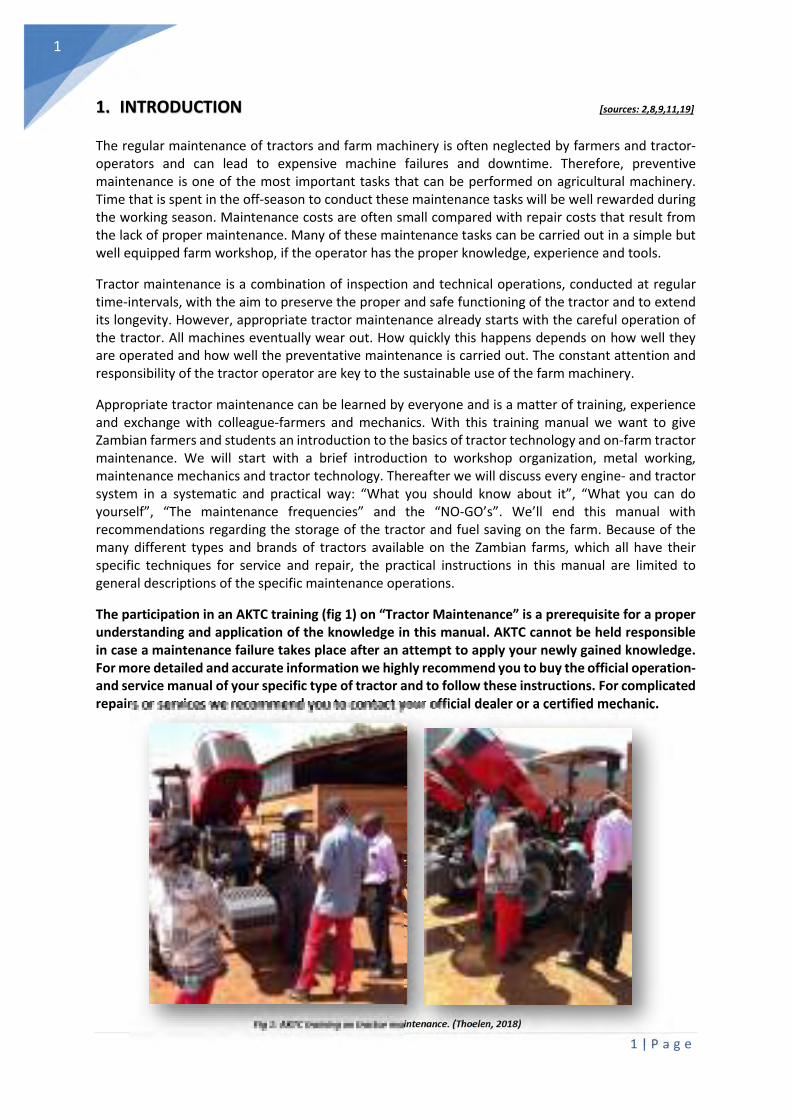
The participation in an AKTC training (fig 1) on “Tractor Maintenance” is a prerequisite for a proper understanding and application of the knowledge in this manual. AKTC cannot be held responsible in case a maintenance failure takes place after an attempt to apply your newly gained knowledge. For more detailed and accurate information we highly recommend you to buy the official operation- and service manual of your specific type of tractor and to follow these instructions. For complicated repairs or services we recommend you to contact your official dealer or a certified mechanic.
Fig 1: AKTC training on tractor maintenance. (Thoelen, 2018)
2 | P a g e
2
2. SAFETY INSTRUCTIONS [sources: 1,5,13,17,19]
Always read, understand, and follow the instructions in the manufacturer's operation- and maintenance manual (when this is available) before conducting any service or repair works.
Before starting with the maintenance activities: stop the engine and remove the key from the tractor. Allow the tractor to cool down. Never service, or adjust while the engine is running.
Apply the parking brake and choke the wheels when necessary. Place the gear shift lever in neutral.
Ensure that all service work and repairs are carried out on a flat area, when possible with a concrete or similar floor.
Where a tractor is started in a confined area, ensure that the area is well ventilated as exhaust gases are very harmful.
Avoid wearing loose fitting clothes, jewellery and be wary of long hair. Serious accidents could be caused by moving parts of the tractor. Wear protective clothing and safety equipment appropriate to the job. Always wear safety glasses when working with fluids.
Clean the tractor or tractor components that will be serviced with air or water.
Disconnect the battery ground cable (neg.) before making adjustments on the electrical systems or conducting welding-work on the tractor.
Do not work under any hydraulically supported devices. They can settle, suddenly leak down, or be accidentally lowered. If it is necessary to work under tractor or any machine elements for servicing or adjustment, securely support them with fixed stands or suitable blocking.
When changing wheels or tires, ensure that a suitable wheel stand is placed under the axle prior to removing the wheel, and that the wheels are chocked.
Never work on the fuel-system near a naked flame or with an overheated engine. Ensure to turn off the engine before refuelling. Do not smoke when working on the battery or when refuelling
The cooling system operates under pressure, take care when removing the radiator cap on a hot engine to prevent being scalded by steam or hot water.
Escaping hydraulic fluid under pressure has sufficient force to penetrate the skin, causing serious injuries. Before disconnecting hydraulic lines, be sure to release all residual pressure. Before applying pressure to the hydraulic system, make sure that all connections are tight and that all lines, pipes, and hoses are free of damage. Always lower the three-point hitch or front-loader before conducting maintenance operations.
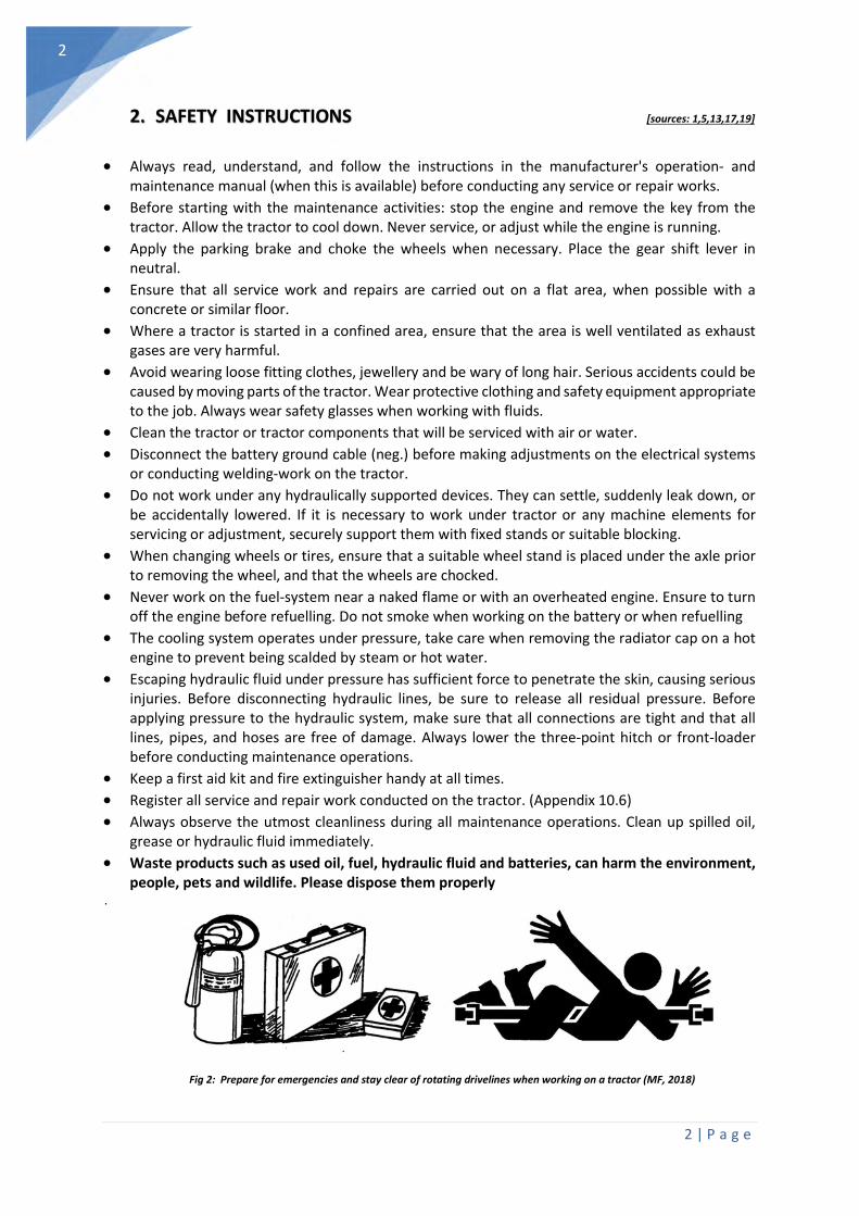
Keep a first aid kit and fire extinguisher handy at all times.
Register all service and repair work conducted on the tractor. (Appendix 10.6)
Always observe the utmost cleanliness during all maintenance operations. Clean up spilled oil, grease or hydraulic fluid immediately.
Waste products such as used oil, fuel, hydraulic fluid and batteries, can harm the environment, people, pets and wildlife. Please dispose them properly
.
Fig 2: Prepare for emergencies and stay clear of rotating drivelines when working on a tractor (MF, 2018)

3 | P a g e
3
3. A WELL ORGANIZED FARM WORKSHOP [sources: 2,3,8,9,19]
A farm-workshop is the central point of the farm for the repair and maintenance of tractors, implements and farm-structures. It also provides a place where tools can be stored in an orderly manner, a store for supplies and spare parts and a shelter where work can be carried out during inclement weather. A facility of this type should be available on every farm. The workshop facilities should however be “cost effective”. That means that enough savings should be realized from timely maintenance, repairs and construction projects, to pay for the cost of the building and the necessary tools and equipment. Consider also that a workshop could provide maintenance and repairs to others and might become a small business in itself. Such activities can help to cover the initial costs of setting up the workshop as well as offsetting its operational costs.
In the beginning you may be adequately served with a large tool storage cupboard that can be locked for security (fig 3) and a workbench with a simple vice (fig 4) for holding tools while they are being repaired, adjusted or sharpened. From this simple beginning a more complete facility may gradually evolve as mechanized farm operations grow and more equipment is required. Since repair tools and supplies represent a considerable investment, most farmers will want to store them in a secure place. The workshop should be located close to the work center of the farm and convenient to the farm home on ground that is well drained and sufficiently level to allow easy maneuvering of equipment. Where electric power is available, proximity to the power source should be considered.
While a simple earth floor is often satisfactory, concrete offers the advantages of an easily cleaned, level surface. To do a clean repair job, a clean work area is essential and this is particularly important when lubricated mechanisms are reassembled. The level surface is also helpful in some assembly or alignment operations. Essential in every farm workshop is a heavy workbench (fig 4) attached to the wall or otherwise firmly supported. It should be at least 1 m high, up to 800mm deep and 2-3m long. There must be sufficient clear space around it to maneuver workpieces and, if attached to a solid wall, ample window openings above it to provide light. Tractor-lubricants should be stored clean and safe in a rack placed inside a drainable collector bin.
The equipment that is needed in the workshop will depend on the type and extent of work that needs to be done. Generally this means those spanners, pliers and screwdrivers to perform day-to-day maintenance on machines and to carry out general repair work. However, any workshop, regardless of size, will also need some simple metal working tools (files, taps and dies, angle grinder) and a welding machine when possible. Chapter 10.2 provides a summary of the workshop-tools essential for tractor maintenance and small repair works. A mobile toolbox with all basic spanners and pliers (fig 5) should also be available to conduct fast and urgent field-repairs.
Fig 3: A closable storage cupboard (MICMAR,
2018)
Fig 4: Steel workbench for a farm workshop
(Storefab, 2018)
Fig 5: Mobile toolbox for a fast on-site
repair of farm machinery (Thoelen, 2018)
4 | P a g e
4
4. BASICS OF METAL WORKING [sources: 3,4,7,12,14,17,19,20]
Basic on-farm metalwork involves measuring and marking, cutting, drilling, filing, cutting internal and external threads, and joining. It’s not extremely difficult to work with metal, but it requires specific skills and specialized tools. Fortunately, most of this can be learned rather fast via intensive training courses and can be conducted with relatively inexpensive hand tools that you can buy in a hardware store.
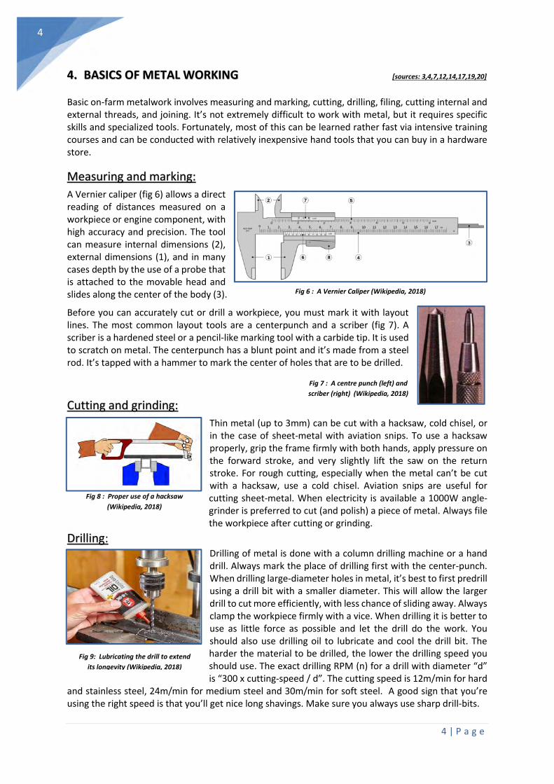
Measuring and marking:
A Vernier caliper (fig 6) allows a direct reading of distances measured on a workpiece or engine component, with high accuracy and precision. The tool can measure internal dimensions (2), external dimensions (1), and in many cases depth by the use of a probe that is attached to the movable head and slides along the center of the body (3).
Before you can accurately cut or drill a workpiece, you must mark it with layout lines. The most common layout tools are a centerpunch and a scriber (fig 7). A scriber is a hardened steel or a pencil-like marking tool with a carbide tip. It is used to scratch on metal. The centerpunch has a blunt point and it’s made from a steel rod. It’s tapped with a hammer to mark the center of holes that are to be drilled.
Cutting and grinding:
Thin metal (up to 3mm) can be cut with a hacksaw, cold chisel, or in the case of sheet-metal with aviation snips. To use a hacksaw properly, grip the frame firmly with both hands, apply pressure on the forward stroke, and very slightly lift the saw on the return stroke. For rough cutting, especially when the metal can’t be cut with a hacksaw, use a cold chisel. Aviation snips are useful for cutting sheet-metal. When electricity is available a 1000W angle-grinder is preferred to cut (and polish) a piece of metal. Always file the workpiece after cutting or grinding.
Drilling: Drilling of metal is done with a column drilling machine or a hand drill. Always mark the place of drilling first with the center-punch. When drilling large-diameter holes in metal, it’s best to first predrill using a drill bit with a smaller diameter. This will allow the larger drill to cut more efficiently, with less chance of sliding away. Always clamp the workpiece firmly with a vice. When drilling it is better to use as little force as possible and let the drill do the work. You should also use drilling oil to lubricate and cool the drill bit. The harder the material to be drilled, the lower the drilling speed you should use. The exact drilling RPM (n) for a drill with diameter “d” is “300 x cutting-speed / d”. The cutting speed is 12m/min for hard
and stainless steel, 24m/min for medium steel and 30m/min for soft steel. A good sign that you’re using the right speed is that you’ll get nice long shavings. Make sure you always use sharp drill-bits.
Fig 6 : A Vernier Caliper (Wikipedia, 2018)
Fig 7 : A centre punch (left) and
scriber (right) (Wikipedia, 2018)
Fig 9: Lubricating the drill to extend
its longevity (Wikipedia, 2018)
Fig 8 : Proper use of a hacksaw
(Wikipedia, 2018)

5 | P a g e
5
Filing:
Files are used for shaving, smoothing and fitting metal parts, and for basic sharpening. For most basic metalwork, a double-cut machine file and a single-cut mill file will work well. They are available in four levels of coarseness: coarse, bastard, second and smooth cut. Mill files leave a smoother finish than machine files but cut more slowly. For typical cross-filing, grip the file with one hand on the handle and the other hand on the point. Stroke the file forward across the workpiece at a shallow angle. Apply pressure on the forward stroke and lift the file clear of the work on the return stroke. Draw-filing is done when a smooth, polished finish is desired.
Cutting internal and external threads:
Cutting internal threads is a two-step process. First, you drill a hole, then you cut threads on its wall. The drill bit used to make the hole must be of a specific size to work with a given tap. Often the tap will have the drill-bit information stamped on its side (also see appendix 10.5). It’s helpful to first countersink the tap hole. Keep the tap perpendicular to the workpiece surface, and turn it backward slightly after each half-turn forward. Often tapping a specific thread is done in 3 stages with 3 different taps (start/ intermediate/finish). Use ordinary machine oil to lubricate the tap when cutting threads in steel and kerosene for tapping in brass and aluminum. A die is used to cut external threads, and the process is known as threading. To thread a rod, first bevel its end and clamp it in a vise. Place the die on the rod, and lock the die guides in place. Keep the die perpendicular to the rod, and turn it backward slightly and after each half-turn a bit forward. Use the same kinds of lubricants as in tapping. Like a tap, a die will have the necessary thread information stamped on it.
Joining:
The simplest mean of joining two pieces of sheet-metal is to use a blind rivet. This is especially useful when the back or blind side of the workpiece is not accessible. When you squeeze the rivet tool’s handles together, you pull the pin through the rivet. The two pieces of metal are forced together because the existing flange is bearing down on one side of the joint, while the ball is drawing through the rivet, forming a flange on the opposite side.
In most cases metal is joined together by welding. Many welding processes and techniques are available nowadays. The most common on-farm technique is (shielded metal) arc welding also known as "electric welding" or “stick welding”. Here an electrode, that is coated in flux, protects the weld puddle. Slag protects the weld puddle from atmospheric contamination. Stick welding in the flat, horizontal and overhead positions uses a drag or backhand welding technique. You should hold the electrode perpendicular to the
joint, and then tilt the top in the direction of travel approximately 5 to 15 degrees. Your travel speed should allow you to keep the arc in the leading one-third of the weld pool.
Fig 11 : Cutting internal thread
with a tap (Wikipedia, 2018)
Fig 10 : Different coarseness of files
(Wikipedia, 2018)
Fig 12 : Riveting sheet metal (Wikipedia,
Fig 13 : Principle of arc welding (Wikipedia, 2018)
6 | P a g e
6
5. BASICS OF MAINTENANCE MECHANICS [sources: 3,4,7,12,14,17,19,20]
A maintenance mechanic conducts regular maintenance interventions and repairs malfunctions of machinery. A combination of metal working skills and the knowledge of locking, locating and sealing devices, bearings, belts and pulleys, chains and sprockets, electrical-, hydraulic- and pneumatic systems will lead to a timely failure diagnosis and the optimal maintenance of the machinery.
Fasteners:
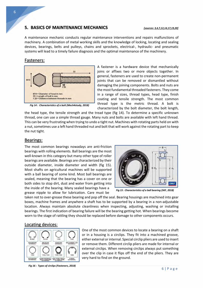
A fastener is a hardware device that mechanically joins or affixes two or more objects together. In general, fasteners are used to create non-permanent joints that can be removed or dismantled without damaging the joining components. Bolts and nuts are the most fundamental threaded fasteners. They come in a range of sizes, thread types, head type, finish coating and tensile strength. The most common thread type is the metric thread. A bolt is characterized by the bolt diameter, the bolt length,
the head type, the tensile strength and the tread type (fig 14). To determine a specific unknown thread, one can use a simple thread gauge. Many nuts and bolts are available with left hand thread. This can be very frustrating when trying to undo a tight nut. Machines with rotating parts held on with a nut, sometimes use a left hand threaded nut and bolt that will work against the rotating part to keep the nut tight.
Bearings:
The most common bearings nowadays are anti-friction bearings with rolling elements. Ball bearings are the most well-known in this category but many other type of roller bearings are available. Bearings are characterized by their outside diameter, inside diameter and width (fig 15). Most shafts on agricultural machines will be supported with a ball bearing of some kind. Most ball bearings are sealed, meaning that the bearing has a cover on one or both sides to stop dirt, dust and water from getting into the inside of the bearing. Many sealed bearings have a grease nipple to allow for lubrication. Care must be taken not to over-grease these bearing and pop off the seal. Bearing housings are machined into gear boxes, machine frames and anywhere a shaft has to be supported by a bearing in a non-adjustable location. Always maintain absolute cleanliness when inspecting, adjusting, washing or installing bearings. The first indication of bearing failure will be the bearing getting hot. When bearings become worn to the stage of rattling they should be replaced before damage to other components occurs.
Locating devices: One of the most common devices to locate a bearing on a shaft or in a housing is a circlips. They fit into a machined groove, either external or internal. Special circlip pliers are used to insert or remove them. Different circlip pliers are made for internal or external circlips. When removing circlips always put something over the clip in case it flips off the end of the pliers. They are very hard to find on the ground.
Fig 14 : Characteristics of a bolt (Mech4study, 2018)
Fig 15 : Characteristics of a ball bearing (SKF, 2018)
Fig 16 : Types of circlips (Fasteners, 2018)

7 | P a g e
7
Seals and gaskets
There are a range of different types of seals an gaskets, all designed to either keep something in or out. When there is no movement between the surfaces static seals are used. These include gaskets, O-rings and (liquid) sealants. Where moving parts need to be sealed, dynamic seals are used. These include lip seals, packing and mechanical end-face. Gasket material should be soft and pliable, enabling the gasket to follow surface irregularities. Gaskets are usually used to make a gas-, steam- or liquid tight seal between parts of a machine or engine (e.g cylinder head gasket). O-rings are used especially where high pressure is involved as in hydraulic components. Radial lip seals are the most common seals found on farm machinery. They are used in gear boxes and rotating shafts with open bearings. The sealing ring is formed with a knife edge at the contact point which engages wit the rotating shaft. One of the most common causes of lip seal failure is damage that occurs when fitting the seal. Push evenly on the outside ring only when mounting the seal and make sure the shaft surface is smooth and clean.
Belts and pulleys
V-belts and pulleys are a widely use way to transmit engine-power because they are clean and require no lubrication. They are smooth starting and running, and can cover a wide horsepower range. They tent to dampen vibration between driving and driven machines and are therefore quiet. They come in a wide range of diameters, with single or multi V-belts. Most agricultural V-belts should have 10 to 25 mm of slack from the straight belt when pressure is applied, depending on the length, belt section and horse power transmitted. A V-belt should never run on the bottom of the pulley. This can only be caused by a worn belt or wear of the pulley. Properly designed and adjusted V-belt drives should not squeal or howl under peak load conditions. During the off-season, V-belts should be removed from outdoor agricultural machines and stored in a dark dry area. Misaligned pulleys can cause rapid wear of the V-belt sidewalls and pulleys. Pulley alignment should be checked and corrected in the order: horizontal/angular, vertical/angular, and finally parallel.
Chains and sprockets
Chains and sprockets are used where different rotating components have to be correctly timed. They maintain a constant speed ratio between the driving and the driven sprockets. They also require more maintenance. Chains should be properly lubricated and protected from dirt where possible. New chains should not be installed on badly worn sprockets. Chain drives must be properly tensioned. For chains with adjustment on the shafting, the slack should be app. 2% of the shaft center distance. Sometimes a link may have to be removed. Roller chains are joined with a special connecting link that can be opened with a pair of pliers. It is important to remember that chains need to be readjusted from time to time.
Fig 17 : Lip seal on a shaft (SKF, 2018)
Fig 18 : Most common belts (Gates, 2018)
Fig 19 : Sprocked dimensions (Wikipedia, 2018)

8 | P a g e
8
6. BASICS OF TRACTOR- AND ENGINE TECHNOLOGY [sources: 3,7,11,14,17,19,20]
Tractors are built in many forms and sizes according to the particular functions that they are required to perform (fig 20). The common tractor is a self-propelled power unit, with wheels or tracks, for operating agricultural implements, construction or forestry machinery. The word 'traction' and name 'tractor' come from the word to 'draw' or 'pull', so in essence a tractor is a machine for pulling. Besides pulling, the power of the tractor engine can also be transferred to rotating implements and stationary farm machinery via the power take-off shaft (PTO). The main components of a tractor are: the engine with the different engine systems, the clutch, the transmission or power train, the front axle, the rear axle, the wheel and brake-system, the steering mechanism, the hydraulic system, the power take-off unit, the 3-point hitch, the cabin and control panel. Dividing the tractor (and the engine) in different “systems” can help you to understand how they work, and contribute to properly diagnose failures.
A diesel engine, the main source of the tractor power, is an internal combustion engine. Combustion of the fuel causes one or more reciprocating pistons, each contained in a cylinder, to turn a crankshaft. Other than petrol engines, diesel engines work by compressing air (fig 21). During the induction or suction stroke, air at atmospheric pressure is drawn inside the cylinder through the inlet valve, due to the suction created. During the compression stroke, the upward movement of the piston compresses the air into a small space between the piston and the top dead center (TDC) of the cylinder. The air is compressed into 1/22 of its original volume. This increases the temperature inside the cylinder to such a high degree (500-800°C) that
Fig 20: Tractor concepts (CIGR, 1999)
Fig 21: basic principles of a 4-stroke diesel engine (Quora, 2018)

9 | P a g e
9
the diesel fuel, that is injected into the combustion chamber, ignites spontaneously. During the power stroke, the internal explosion pushes the piston downwards with a pressure of 40-90 bar. The connection rod carries this force to the crankshaft which makes the flywheel turning. At the end of power stroke the piston reaches the bottom dead center (BDC). A this moment the exhaust valve opens. The pressure of the burnt gases is higher than atmospheric pressure. This pressure difference allows burnt gases to escape through the exhaust port and the piston moves unimpeded towards the TDC. At the end of exhaust all burned gases escape and the exhaust valve is closed. Diesel engines are produced with two significantly different fuel injection locations: "direct" and "indirect." Indirect injection engines place the injector in a pre-combustion chamber in the head, which, due to thermal losses, generally require a "glow plug" to start. Direct injection engines use a generally donut-shaped combustion chamber void on the top of the piston. The direct injection (DI) process is significantly more internally violent and thus requires careful design and more robust construction.
The main building blocks of a diesel engine are (fig 22): the engine block, the cylinder head, the camshaft, the combustion chamber, the pistons the cylinders, the valves (inlet and outlet), the crankshaft, the connecting rod, the oil pan or sump. The diesel engine is controlled, driven and maintained by the timing system, the lubrication system, the exhaust system, the Intake system, the cooling system, the fuel system, the electric system. Again, dividing the engine in different “systems” can help you to understand how they work, and to properly diagnose failures. A key-issue in engine-maintenance is the change of filters and oils. The main function of the different filters is to prevent tractor- and engine systems to come in contact with polluting and abrasive particles. All systems, filters and oils will be described in detail in the following chapters.
WHERE TO START ? - Identify and locate all the components of your tractor and diesel engine,
and try to understand how they work. - Closely monitor then engine performance and control panel while driving the tractor. - Conduct a regular visual and auditive diagnosis of all the tractor- and engine systems. Inspect
for leaks, loose or worn parts, hoses, nuts or bolts. - In case of a severe failing of the tractor: Try to identify the component that might cause the
failing of the tractor and discuss the repair approach with a colleague farmer or mechanic. Inform about the prices of spare parts and service. Prepare and clean the respective components so that an official dealer or certified mechanic can do a fast and effective repair.
Fig 22: Components of an diesel engine with a pre-combustion chamber and an underlying camshaft (Encyclopedia Britannica, 2007)

10 | P a g e
10
6.1. THE ENGINE LUBRICATION SYSTEM [sources: 1,4,5,7,12,13,17,19,20]
What should you know?
The function of the engine lubrication system is to give a flow of clean oil, at the accurate temperature, and with the appropriate pressure, to each part of the engine. The major components of the lubrication system (fig 23) are the oil pump, the oil cooler (if present), the oil filter, the oil pan or sump, the oil pressure gauge, the oil pressure regulating valve. The oil is sucked out from the oil-sump or crankcase by the oil-pump, than forced between the oil filter and is fed to the rotating engine components in the engine block and the main bearings. The oil pressure gauge monitors the oil-pressure. The oil passes through feed- holes to the main bearings and into the drilled passages of the crankshaft and the connecting rod. The bearings of the piston-pin and cylinder walls get lubricated by the oil which is dispersed by the rotating crankshaft. The excess of oil on the cylinder walls will be scraped by the lower piston-rings.
Fig 23: Schematic design of the engine lubrication system (Europa Lehrmittel, 2017; Lubrita 2018)
Cam-shaft
Air compressor Turbo
charger
Oil filter
Oil pressure valve
Oil pump
Diesel pump
Oil-cooler
Connecting
rod bearing
Crankshaft
Spray nozzle for piston-bottom
Valve push rod Rocker
Spur
wheel
drive

11 | P a g e
11
What can you do yourself?
Check the engine oil level: Park the tractor on flat and level terrain. Withdraw the dipstick, clean it and dip it again. The oil level should be between the two marks on dipstick (A). Do not operate the engine if oil level is below minimum mark. If below the mark, add the appropriate oil through the filler neck (B) until full. Always use the oil recommended by the dealer. Always use the same brand and viscosity of engine oil. (see Chapter 10.1)
Changing the engine oil and oil filter: Run the engine to warm up the oil, then turn off the engine. Remove the drain plug (A) of the crankcase and drain the oil. Change the engine oil filter during the oil change (using an appropriate oil-filter wrench). Apply a fine film of oil or grease to the seal of the
new filter before installing it. Tighten the filter an additional 1/2 turn, by hand. Close the drain plug (A) again using a new cupper seal. Add the recommended oil according to the engine crankcase capacity. Check the oil-level again after 10 engine hours and top-up when necessary. Change the oil and filter every 250 hours or once a year, whichever occurs first. Always check the drained oil for metal particles. This might indicate an internal failing of the engine. Always mark the new filter with the engine hours and date of replacement
Replace a leaking oil pan gasket: Remove the oil drain plug and allow several minutes for the oil to drain into the pan. Dispose of the oil and filter properly. Remove the oil pan bolts, leaving one at each corner loosely in place. Remove the pan carefully as to not damage the oil pick up located within the oil pan. Clean the area on the lower engine block where the oil pan attaches. also, clean the oil pan inside and out with a cleaner/degreaser. Using the scraper, gently remove any gasket material on the oil pan as well as the engine block mounting surface. Apply a thin film of gasket-silicone to the oil pan mounting surface. Once the gasket silicone has set, apply the pan gasket to the surface, applying even pressure all around. Insert all the oil pan bolts hand tight to start. Then fasten according to the recommendations in the manual. Reinstall the oil pan drain plug and add new oil.
MAINTENANCE FREQUENCY (unless stated differently in your tractor service manual)
- Check the crankcase oil level: Every 10 engine hours - Inspect for oil leaks: Every 10 engine hours - Change the engine oil: Every 250 engine hours (at least once/year) - Change the oil- filter: Every 250 engine hours (at least once/year)
WHAT IS A NO-GO? - Use engine oil for longer than 250 engine hours or 1 year. - Running the tractor without a working oil pressure gauge. - Running the tractor with (a too high or) too low oil level. - Mix different brands and viscosities of oil or use low quality engine oil. - Change the oil without changing the oil filter. - Running the tractor with a serious oil leak. - Running the tractor with insufficient oil pressure indicated on the oil pressure gauge. - Running the tractor when excessive blue or black smoke is coming out of the exhaust pipe.
Fig 24: Checking the engine oil level (JD, 2018)
Fig 25: Drain plug of the crankcase (JD, 2018)
12 | P a g e
12
6.2. THE ENGINE INTAKE-AND EXHAUST SYSTEM [sources: 3,5,7,12,13,14,15,17,19,20]
What should you know?
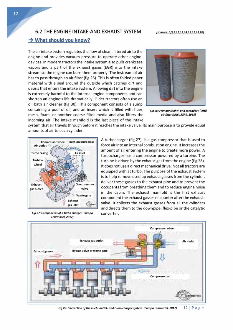
The air intake system regulates the flow of clean, filtered air to the engine and provides vacuum pressure to operate other engine-devices. In modern tractors the intake system also pulls crankcase vapors and a part of the exhaust gases (EGR) into the intake stream so the engine can burn them properly. The instream of air has to pass through an air filter (fig 26). This is often folded paper material with a seal around the outside which catches dirt and debris that enters the intake system. Allowing dirt into the engine is extremely harmful to the internal engine components and can shorten an engine’s life dramatically. Older tractors often use an oil bath air cleaner (fig 30). This component consists of a sump containing a pool of oil, and an insert which is filled with fiber, mesh, foam, or another coarse filter media and also filters the incoming air. The intake manifold is the last piece of the intake system that air travels through before it reaches the intake valve. Its main purpose is to provide equal amounts of air to each cylinder.
A turbocharger (fig 27), is a gas compressor that is used to force air into an internal combustion engine. It increases the amount of air entering the engine to create more power. A turbocharger has a compressor powered by a turbine. The turbine is driven by the exhaust gas from the engine (fig 28). It does not use a direct mechanical drive. Not all tractors are equipped with at turbo. The purpose of the exhaust system is to help remove used up exhaust gasses from the cylinder, deliver these gasses to the exhaust pipe and to prevent the occupants from breathing them and to reduce engine noise in the cabin. The exhaust manifold is the first exhaust component the exhaust gasses encounter after the exhaust-valve. It collects the exhaust gasses from all the cylinders and directs them to the downpipe, flex-pipe or the catalytic converter.
Fig 26: Primary (right) and secondary (left)l air-filter (KNFILTERS, 2018)
Fig 27: Components of a turbo charger (Europa Lehrmittel, 2017)
Fig …: Working mechanism of a turbo charger (Europa Lehrmittel, 2017)
Inlet-pressure hose Compressor wheel Air outlet
Turbo casing
Turbine
wheel
Exhaust
gas outlet
Exhaust
gas Inlet
Over pressure
valve
Air inlet
Waste gate
Compressor wheel
Air - inlet Exhaust gas outlet
Bypass valve or waste-gate Exhaust gasses
Compressed air
Fig 28: Interaction of the inlet-, outlet- and turbo charger system (Europa Lehrmittel, 2017)

13 | P a g e
13
What can you do yourself?
Replacing the air filter: Open the hood and remove the lateral screens when necessary. Loosen the clips (A) of the filter housing cover. Remove the filter cover. Remove the primary filter insert, replace or clean it depending on the maintenance interval (250h). Clean the internal housing, taking care not to damage the secondary insert. Replace the secondary filter insert every 500 engine hours to prevent dust entering the air intake system. Check the unloader valve (B) frequently (when present). Empty it as often as needed. If the valve is allowed to fill with dust, the air cleaner element will plug rapidly.
Change the oil of the oil bath cleaner: Remove the oil bath cleaner from the tractor and dump the old oil in an oil disposal bin. Fill a recipient with kerosene and soak the filter in the bucket for 15 to 20 minutes. Agitate the filter every two to three minutes. Fill a bucket full of hot water and 2 tbsp. of dish soap. Place the filter into the water and allow it to soak for 20 minutes. Empty the buckets of water and kerosene in an oil disposal bine. Fill the water bucket with fresh water and soak the filter to rinse it off. Allow the filter to air-dry and place new engine oil in the oil cup. Place the filter in the oil cup and place it back into your tractor.
Checking hose and clamp tightness: Check clamp tightness of the hoses between air filter and intake (A). Check hoses for cracks which could cause leaks. Replace if necessary. A torn inlet hose can allow dust particles to enter the engine and cause severe damage to the cylinder walls.
MAINTENANCE FREQUENCY (unless stated differently in your tractor service manual)
- Clean the air intake system: Every 50 engine hours - Change the air filter: Every 250 (prim.) and 500 (sec.) engine hours - Clean the oil bath cleaner: Every 250 engine hours (at least once/year)
WHAT IS A NO-GO? - Driving the tractor with no, a clogged or a torn air filter. - Cleaning the secondary insert filter with high air pressure (risk of rupture). - Remove or shorten the exhaust pipe. Exhaust gases of tractors are more toxic and hotter than
from regular cars. - Operating the tractor with a broken inlet- or outlet manifold. - Running the tractor for a longer period of time with a failing turbo charger. - Insufficient cleaning of the oil bath air cleaner. - Driving the tractor with torn air inlet hoses.
Fig 29: Air filter housing (JD, 2018)
Fig 30: Oil bath cleaner (KNFILTERS, 2018)
Fig 31: Air inlet hose (JD, 2018)
14 | P a g e
14
6.3. THE ENGINE FUEL SYSTEM [sources: 3,5,7,12,13,14,15,17,19,20]
What should you know?
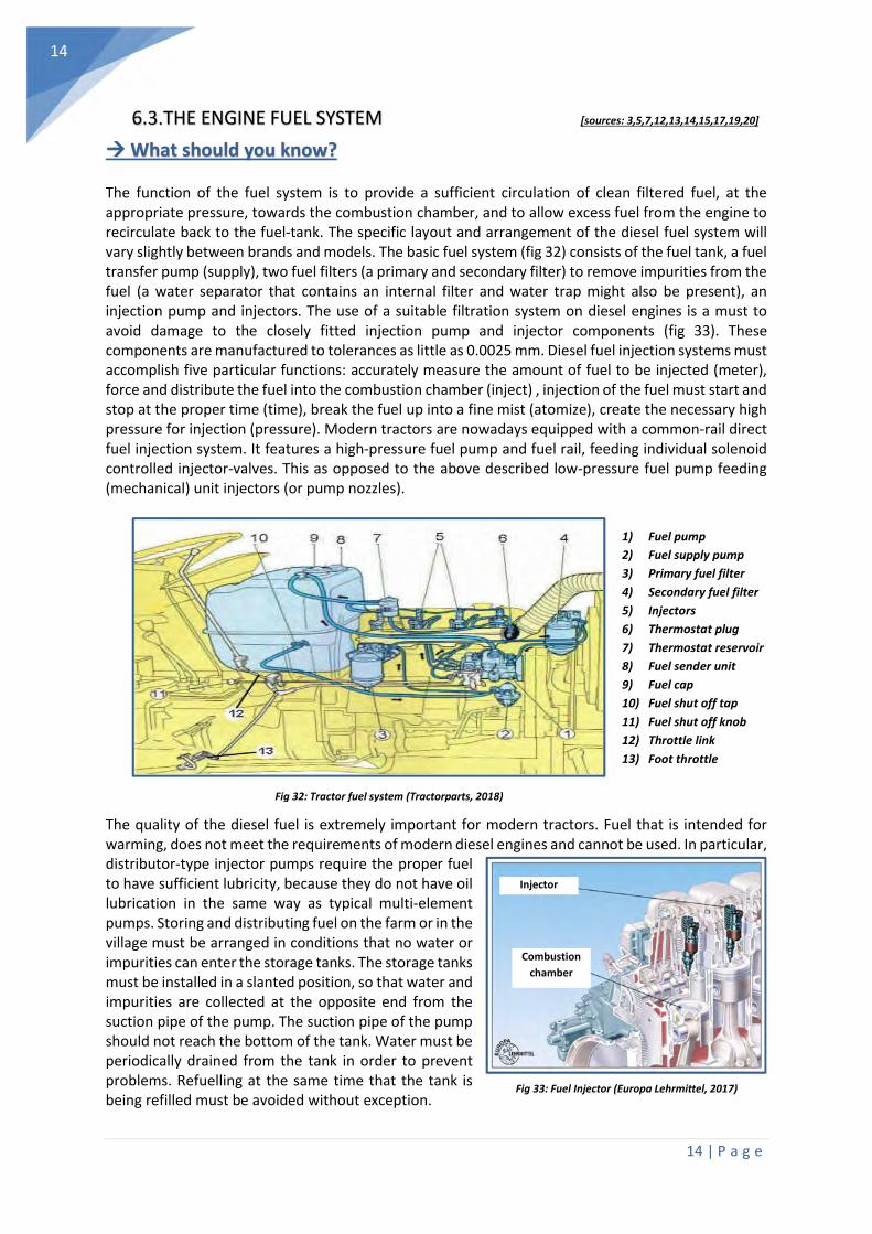
The function of the fuel system is to provide a sufficient circulation of clean filtered fuel, at the appropriate pressure, towards the combustion chamber, and to allow excess fuel from the engine to recirculate back to the fuel-tank. The specific layout and arrangement of the diesel fuel system will vary slightly between brands and models. The basic fuel system (fig 32) consists of the fuel tank, a fuel transfer pump (supply), two fuel filters (a primary and secondary filter) to remove impurities from the fuel (a water separator that contains an internal filter and water trap might also be present), an injection pump and injectors. The use of a suitable filtration system on diesel engines is a must to avoid damage to the closely fitted injection pump and injector components (fig 33). These components are manufactured to tolerances as little as 0.0025 mm. Diesel fuel injection systems must accomplish five particular functions: accurately measure the amount of fuel to be injected (meter), force and distribute the fuel into the combustion chamber (inject) , injection of the fuel must start and stop at the proper time (time), break the fuel up into a fine mist (atomize), create the necessary high pressure for injection (pressure). Modern tractors are nowadays equipped with a common-rail direct fuel injection system. It features a high-pressure fuel pump and fuel rail, feeding individual solenoid controlled injector-valves. This as opposed to the above described low-pressure fuel pump feeding (mechanical) unit injectors (or pump nozzles).
The quality of the diesel fuel is extremely important for modern tractors. Fuel that is intended for warming, does not meet the requirements of modern diesel engines and cannot be used. In particular, distributor-type injector pumps require the proper fuel to have sufficient lubricity, because they do not have oil lubrication in the same way as typical multi-element pumps. Storing and distributing fuel on the farm or in the village must be arranged in conditions that no water or impurities can enter the storage tanks. The storage tanks must be installed in a slanted position, so that water and impurities are collected at the opposite end from the suction pipe of the pump. The suction pipe of the pump should not reach the bottom of the tank. Water must be periodically drained from the tank in order to prevent problems. Refuelling at the same time that the tank is being refilled must be avoided without exception.
Fig 32: Tractor fuel system (Tractorparts, 2018)
Fig 33: Fuel Injector (Europa Lehrmittel, 2017)
1) Fuel pump
2) Fuel supply pump
3) Primary fuel filter
4) Secondary fuel filter
5) Injectors
6) Thermostat plug
7) Thermostat reservoir
8) Fuel sender unit
9) Fuel cap
10) Fuel shut off tap
11) Fuel shut off knob
12) Throttle link
13) Foot throttle
Injector
Combustion
chamber
15 | P a g e
15
What can you do yourself?
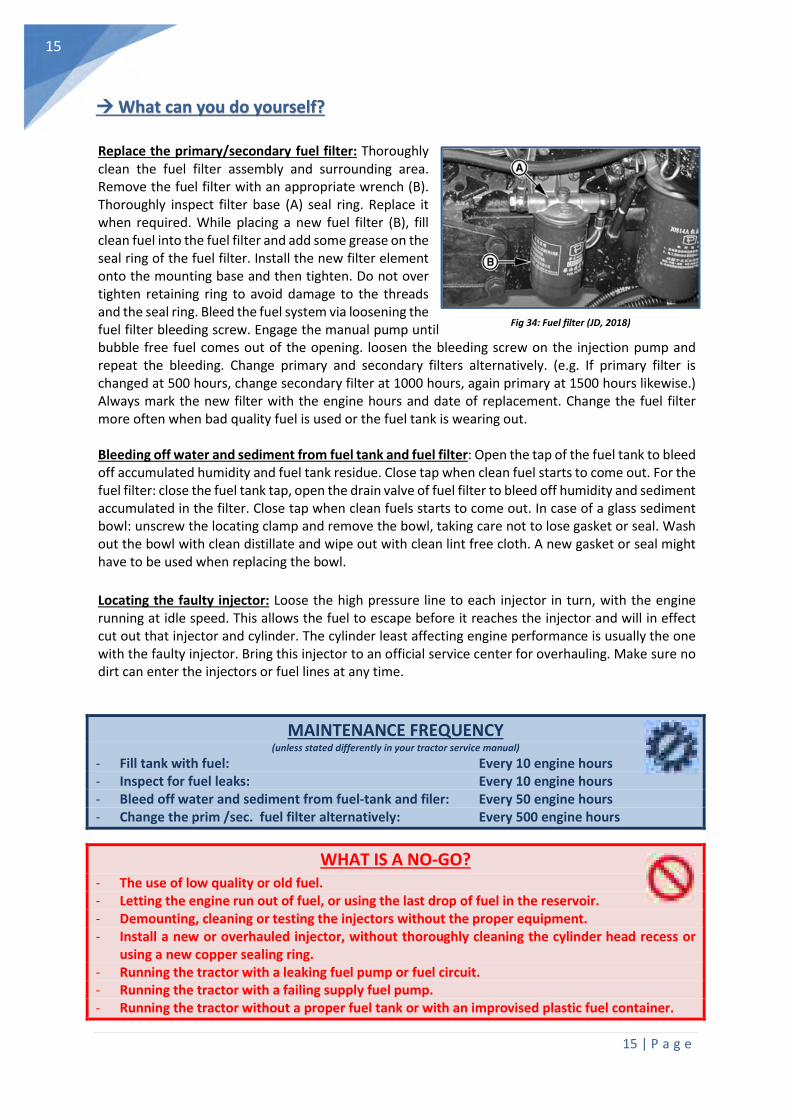
Replace the primary/secondary fuel filter: Thoroughly clean the fuel filter assembly and surrounding area. Remove the fuel filter with an appropriate wrench (B). Thoroughly inspect filter base (A) seal ring. Replace it when required. While placing a new fuel filter (B), fill clean fuel into the fuel filter and add some grease on the seal ring of the fuel filter. Install the new filter element onto the mounting base and then tighten. Do not over tighten retaining ring to avoid damage to the threads and the seal ring. Bleed the fuel system via loosening the fuel filter bleeding screw. Engage the manual pump until bubble free fuel comes out of the opening. loosen the bleeding screw on the injection pump and repeat the bleeding. Change primary and secondary filters alternatively. (e.g. If primary filter is changed at 500 hours, change secondary filter at 1000 hours, again primary at 1500 hours likewise.) Always mark the new filter with the engine hours and date of replacement. Change the fuel filter more often when bad quality fuel is used or the fuel tank is wearing out.
Bleeding off water and sediment from fuel tank and fuel filter: Open the tap of the fuel tank to bleed off accumulated humidity and fuel tank residue. Close tap when clean fuel starts to come out. For the fuel filter: close the fuel tank tap, open the drain valve of fuel filter to bleed off humidity and sediment accumulated in the filter. Close tap when clean fuels starts to come out. In case of a glass sediment bowl: unscrew the locating clamp and remove the bowl, taking care not to lose gasket or seal. Wash out the bowl with clean distillate and wipe out with clean lint free cloth. A new gasket or seal might have to be used when replacing the bowl.
Locating the faulty injector: Loose the high pressure line to each injector in turn, with the engine running at idle speed. This allows the fuel to escape before it reaches the injector and will in effect cut out that injector and cylinder. The cylinder least affecting engine performance is usually the one with the faulty injector. Bring this injector to an official service center for overhauling. Make sure no dirt can enter the injectors or fuel lines at any time.
MAINTENANCE FREQUENCY (unless stated differently in your tractor service manual)
- Fill tank with fuel: Every 10 engine hours - Inspect for fuel leaks: Every 10 engine hours - Bleed off water and sediment from fuel-tank and filer: Every 50 engine hours - Change the prim /sec. fuel filter alternatively: Every 500 engine hours
WHAT IS A NO-GO? - The use of low quality or old fuel. - Letting the engine run out of fuel, or using the last drop of fuel in the reservoir. - Demounting, cleaning or testing the injectors without the proper equipment. - Install a new or overhauled injector, without thoroughly cleaning the cylinder head recess or
using a new copper sealing ring. - Running the tractor with a leaking fuel pump or fuel circuit. - Running the tractor with a failing supply fuel pump. - Running the tractor without a proper fuel tank or with an improvised plastic fuel container.
Fig 34: Fuel filter (JD, 2018)
16 | P a g e
16
6.4. THE ENGINE COOLING SYSTEM [sources: 3,5,7,12,13,14,15,17,19,20]
What should you know?
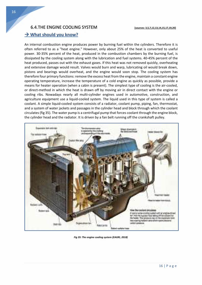
An internal combustion engine produces power by burning fuel within the cylinders. Therefore it is often referred to as a "heat engine." However, only about 25% of the heat is converted to useful power. 30-35% percent of the heat, produced in the combustion chambers by the burning fuel, is dissipated by the cooling system along with the lubrication and fuel systems. 40-45% percent of the heat produced, passes out with the exhaust gases. If this heat was not removed quickly, overheating and extensive damage would result. Valves would burn and warp, lubricating oil would break down, pistons and bearings would overheat, and the engine would soon stop. The cooling system has therefore four primary functions: remove the excess heat from the engine, maintain a constant engine operating temperature, increase the temperature of a cold engine as quickly as possible, provide a means for heater operation (when a cabin is present). The simplest type of cooling is the air-cooled, or direct-method in which the heat is drawn off by moving air in direct contact with the engine or cooling ribs. Nowadays nearly all multi-cylinder engines used in automotive, construction, and agriculture equipment use a liquid-cooled system. The liquid used in this type of system is called a coolant. A simple liquid-cooled system consists of a radiator, coolant pump, piping, fan, thermostat, and a system of water jackets and passages in the cylinder head and block through which the coolant circulates (fig 35). The water pump is a centrifugal pump that forces coolant through the engine block, the cylinder head and the radiator. It is driven by a fan belt running off the crankshaft pulley.
Fig 35: The engine cooling system (EAGRI, 2018)

17 | P a g e
17
Fig 37b: Testing thermostat
What can you do yourself?
Top up the coolant liquid: Remove the expansion tank cover (A) only when the engine is cool. Slowly loosen the cover to the first stage, to alleviate pressure before opening fully. Never add cold water to an overheated cooling system or engine, this could result in cylinder block cracks. Visually check coolant level in expansion tank periodically. With a cold engine, it should be at "LOW " mark. With a hot engine, it should be at "FULL.
Cleaning radiator screens and fins: Each time dirt accumulates on the screen of the tractor front or on the lateral screens clean them with a steel brush or with compressed air. Reduce compressed air to less than 2.1 bar, (30 psi) when using for cleaning purposes. If more cleaning is needed, clean the radiator from the rear with compressed air or water. Straighten bent fins before closing up the hood. Replacing the fan-belt:. Force the belt-tensioner out from the belt. Keep the tensioner in the retracted position. Install a new belt in reverse order. Run the engine for 5 min. to warm up the cold belt. Let the hot belt cool for 15 min. before adjustment. Check the tension by pressing the belt midway between the pulleys. The belt should deflect about 10—15 mm. Adjust tension by adjusting the nut of the tensioner or apply force on the alternator frame until tension is correct. Tighten the adjusting nut first, then the alternator mounting bolt. A fan-belt should never show any serious signs of wear.
Testing the condition of the water pump bearing: Grasp the blades of the fan and check for lateral movement. If any movement is detected, the bearings and water pump seal should both be replaced. To remove the pump, the radiator needs to be drained and all locating bolts need to be removed. The water pump pulley and the impeller usually have to be pressed off. Therefore contact your dealer or a certified mechanic.
Testing the condition of the thermostat: Drain the coolant when necessary. Remove the thermostat. Measure the length of the cold thermostat. Put the thermostat in cooking water. The thermostat should open and should be 7mm longer. Use a new seal when mounting the thermostat.
MAINTENANCE FREQUENCY (unless stated differently in your tractor service manual)
- Check the coolant level: Every 10 engine hours - Inspect for coolant leaks: Every 10 engine hours - Inspect and adjust the fan-belt tension: Every 250 engine hours - Drain, clean and refill the cooling system: Every 1000 engine hours
WHAT IS A NO-GO? - Do not operate the engine without coolant, even for just a few minutes. - Don’t allow the radiator cooling fins to be clogged for long periods of time - Do not run the tractor without a fan belt. Only use the appropriate V-belt to drive the fan.
Fig 36: Expansion tank cover (JD, 2018)
Fig 37: Radiator screen (JD, 2018)

18 | P a g e
18
6.5. THE ENGINE ELECTRICAL SYSTEM [sources: 3,5,7,12,13,14,15,17,19,20]
What should you know?
The electrical system of a tractor is designed to perform a variety of functions. Most tractors run on a 12-Volt direct current (DC) system. The common tractor electrical system contains five electrical circuits: the charging circuit (fig 40) , the starting circuit, the fuel-system circuit, the lighting circuit and the accessory circuit. The internal combustion engine is not capable of self-starting but is cranked by a small but powerful electric motor. This motor is called a starting motor, or starter. The battery sends current to the starter when the operator turns the ignition
switch to start. This causes a pinion gear in the starter to mesh with the teeth of the ring gear, thereby rotating the engine crankshaft for starting. The typical starting circuit (fig 40) consists of a battery, a starter motor (fig 38) and drive mechanism, an ignition switch, the starter relay or solenoid, and the wiring to connect these components. The charging system recharges the battery after engine cranking and it supplies all the electricity for the vehicle when the engine is running. The battery provides current to energize or excite the alternator and assists in stabilizing the initial alternator output. An alternator (fig 39) is a generator that uses mechanical (engine) power to produce electricity. An alternator belt links the engine crankshaft pulley with the alternator pulley to drive the alternator.
Fig 40: Basic principles of the engine starter- (top) and charging (bottom) system (Autosystempro, 2018)
Fig 39: Exploded view of an alternator
(Europa lehrmittel, 2017)
Rotor
Alternator
pulley
Stator
Regula
tor
Slip rings
Fan
Fig 38: Exploded view of a starter (Auto electro, 2018)
Charging circuit
Starting circuit
19 | P a g e
19
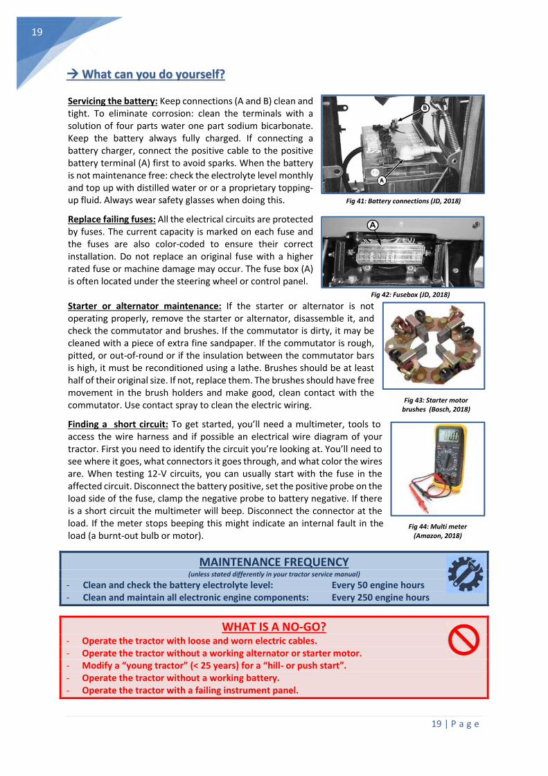
Fig 41: Battery connections (JD, 2018)
Fig 42: Fusebox (JD, 2018)
What can you do yourself?
Servicing the battery: Keep connections (A and B) clean and tight. To eliminate corrosion: clean the terminals with a solution of four parts water one part sodium bicarbonate. Keep the battery always fully charged. If connecting a battery charger, connect the positive cable to the positive battery terminal (A) first to avoid sparks. When the battery is not maintenance free: check the electrolyte level monthly and top up with distilled water or or a proprietary topping-up fluid. Always wear safety glasses when doing this.
Replace failing fuses: All the electrical circuits are protected by fuses. The current capacity is marked on each fuse and the fuses are also color-coded to ensure their correct installation. Do not replace an original fuse with a higher rated fuse or machine damage may occur. The fuse box (A) is often located under the steering wheel or control panel.
Starter or alternator maintenance: If the starter or alternator is not operating properly, remove the starter or alternator, disassemble it, and check the commutator and brushes. If the commutator is dirty, it may be cleaned with a piece of extra fine sandpaper. If the commutator is rough, pitted, or out-of-round or if the insulation between the commutator bars is high, it must be reconditioned using a lathe. Brushes should be at least half of their original size. If not, replace them. The brushes should have free movement in the brush holders and make good, clean contact with the commutator. Use contact spray to clean the electric wiring.
Finding a short circuit: To get started, you’ll need a multimeter, tools to access the wire harness and if possible an electrical wire diagram of your tractor. First you need to identify the circuit you’re looking at. You’ll need to see where it goes, what connectors it goes through, and what color the wires are. When testing 12-V circuits, you can usually start with the fuse in the affected circuit. Disconnect the battery positive, set the positive probe on the load side of the fuse, clamp the negative probe to battery negative. If there is a short circuit the multimeter will beep. Disconnect the connector at the load. If the meter stops beeping this might indicate an internal fault in the load (a burnt-out bulb or motor).
MAINTENANCE FREQUENCY (unless stated differently in your tractor service manual)
- Clean and check the battery electrolyte level: Every 50 engine hours - Clean and maintain all electronic engine components: Every 250 engine hours
WHAT IS A NO-GO? - Operate the tractor with loose and worn electric cables. - Operate the tractor without a working alternator or starter motor. - Modify a “young tractor” (< 25 years) for a “hill- or push start”. - Operate the tractor without a working battery. - Operate the tractor with a failing instrument panel.
Fig 43: Starter motor brushes (Bosch, 2018)
Fig 44: Multi meter (Amazon, 2018)

20 | P a g e
20
6.6. BEARINGS AND ROTATING COMPONENTS [sources: 3,5,7,12,13,14,15,17,19,20]
What should you know?
Without lubrication, rotating parts and bearings overheat and wear from friction. It is difficult to say how often a bearing should be greased, since that depends on the conditions of operation. Depending on the size of the bearing It is important to add 2-3 shots of grease (with a grease-gun) at regular intervals (2-4 weeks depending on the intensity of use), but it is equally important to
avoid adding too much grease. Too much grease builds pressure, pushing the rolling elements through the fluid film and against the outer race. The bearing has to work much harder to push the rolling elements through a mud bog of grease. The bearing frame should be kept clean, since contamination of foreign matter that may get into the housing can destroy the bearings within a short period of time. When cleaning bearings, use a bearing or an industrial cleaning solvent. Use a lint-free cloth. For greasing, a regular universal bearing grease should be used, but a standard commercial vaseline can be substituted if really necessary. Grease, made from animal or vegetable oils, should not be used because of the danger of deterioration and the forming of acid. For the specific recommendations of your tractor, consult the manufacturer's manual. Grease nipples come in many different sizes, shapes and thread types. Some of the most common grease nipples are shown in the table below. Always replace a broken or clogged grease nipple immediately.
Fig 45: Bearing mounted on shaft (SKF, 2018)
Fig 46: Grease Gun (SKF, 2018)
Fig 47: Most common grease nipples (SKF, 2018)

21 | P a g e
21
Fig 48: Most common tractor greasing points (MF, 2018)
Fig 48: Grease nipple removal tool (SAE
products, 2018)
What can you do yourself?
Apply grease regularly and appropriately: always clean the grease nipples before applying the grease gun. Apply grease through the nipples until clean grease oozes out (2 à 3 shots, unless otherwise instructed). Wipe away superfluous grease which has been pressed out at the lubricating point. Preferably carry out lubrication with bearing points and joints unloaded and with the bearings in different positions. The most common tractor greasing points are shown below.
Use, maintain and load your grease gun properly: Use extreme caution when loading grease into the grease gun to ensure that contaminants are not introduced. If using a cartridge, be careful when removing the metal lid so that no metal slivers are introduced into the grease. Bleed the grease gun properly after loading. When necessary renew the jaw grease coupler. Replace a clogged or broken grease nipple: When replacing worn or damaged grease nipples make sure the thread type is the same on the replacement. Dirt in many “plain bearings” tends to pack in the bottom of the grease nipple. To remove this compacted dirt, the grease nipple has to be removed and the dirt dug out with wire until the shaft is visible. Do not use wire to remove the dirt from the base of the grease nipple, this may damage the small ball and retaining spring in the nipple. Connect the nipple to a gun and force the dirt out with grease. A grease nipple removal tool or reverse threaded screw extractor can be used in case a grease nipple has broken off.
MAINTENANCE FREQUENCY (unless stated differently in your tractor service manual)
- Check the main lubrication points: Every 10 engine hours - Lubricate the main greasing points and replace grease nipples: Every 50 engine hours
WHAT IS A NO-GO? - Operating the tractor with dry (ungreased) bearings or rotating components - Not greasing the bearing when a grease nipple is simply clogged. - Continue to work with the tractor when a clear metal sound comes from rotating components
or bearings.
3 – point hitch lift lnk
Lift arms

22 | P a g e
22
Fig 51: Basic principles of an hydraulic system (TPUB, 2018)
6.7. THE HYDRAULIC SYSTEM [sources: 3,5,7,12,13,14,15,17,19,20]
What should you know?
A hydraulic system uses a compressed fluid to transfer force generated at one point to another point. The basic components that make up a hydraulic system (fig 51) are an oil-reservoir, an hydraulic pump, the hydraulic valves, the hydraulic fluid, , hydraulic hoses, a filter system, a hydraulic cylinder or/and a hydro-motor. The hydraulic reservoir stores the non-pressurized hydraulic fluid, typically hydraulic oil. The hydraulic oil travels through a filter that collects impurities. An hydraulic pump transfer the fluid from the reservoir to the hydraulic system. This transfer raises the energy level of the fluid by increasing its pressure. The engine provides the power source for the pump. In case of a hydraulic cylinder the high-pressure fluid acts upon the internal rod and piston. Each stroke of the cylinder converts the fluid power (pressure) into work (mechanical
force). The reservoir oil level falls while the rod and piston are extending. When the rod and piston retract, the fluid returns to the reservoir. The metal walls of the reservoir cool the fluid by allowing heat to escape. Hydraulic valves control and steer the oil-stream (fig 50). Directional control valves manage the flow path of the fluid in the system. Pressure relief valves protect the system plumbing and components against pressure overloads. They also limit the output force exerted by rotary motors and cylinders. These valves open whenever the pressure goes beyond the set value, allowing oil to flow back into the reservoir. The fluid travels from one component to the next within a hydraulic system through a hydraulic hose (fig 49). Most modern farm tractors use the same oil for both the transmission and hydraulic system. As the tolerances of hydraulic components are extremely low, the quality of the hydraulic oil and filtration of the system are extremely important to prevent internal wear.
Fig 50: Electro hydraulic valve (Europa Lehrmittel, 2018)
Fig 49: Hydraulic hose (Europa Lehrmittel, 2018)
Hose-
connector
Hose with 4 layers
Pressed sleeve
Connection
plate
Intermediate valve
3
Intermediate valve
2
Intermediate valve
1
Electro
hydraulic valve

23 | P a g e
23
Fig 53: Correct and incorrect mounting of hydraulic hoses (TPUB, 2018)
What can you do yourself?
Checking the hydraulic oil level: Withdraw the dipstick and clean it. Insert dipstick fully. The oil level should be between the marks on the dipstick. Add appropriate oil if the level is low. Change the hydraulic system oil and replace the oil filter: Remove the transmission housing drain plug and drain the oil. Lower the 3-point hydraulic hitch to remove oil from the circuit. After the oil is drained (and when an oil-filter mesh is present) remove the mesh and examine it for damage. Replace a damaged mesh. Clean the mesh in solvent and dry them with compressed air. Remove the cartridge filter (C). Apply a film of oil or grease to the edge of the new filter and install it. Tighten the filter by hand. Fill the system with transmission/hydraulic oil. Check the oil level after filling and again after 5 minutes of machine operation. Always mark the new filter with the engine hours and date of replacement. Hydraulic hose assembly: adequate hose length is necessary to distribute hose movement on flexing applications and avoid abrasion. Allow enough slack in the hose to provide for the length change which will occur when pressure is applied. Avoid twisting of hose lines. Reduce the number of pipe thread joints. Use an angle adaptor to avoid sharp bends. Makes sure the hose is kept away from hot parts or insulate the hose. Often clamps are required to support long hose runs or keep hoses away from moving parts. When ordering a new hose make sure to communicate the specifications of hose and connector properly.
MAINTENANCE FREQUENCY (unless stated differently in your tractor service manual)
- Check for hydraulic oil leaks: Every 10 engine hours - Check the hydraulic oil level: Every 10 engine hours - Replace the hydraulic oil filter: Every 500 engine hours - Clean the hydraulic/transmission oil filter mesh: Every 500 engine hours - Change the hydraulic/transmission oil + filter: Every 1000 engine hours
WHAT IS A NO-GO? - Neglecting the maintenance of the hydraulic system - Operate the tractor with seriously leaking hydraulic couplings, leaking fittings, leaking seals or
worn hoses. - Using old engine oil or low quality hydraulic oil in the hydraulic circuit !!! - Not covering control valves or hoses appropriately when working on the hydraulic system.
Fig 52: Drain plug and filter, transmission system (JD, 2018)
24 | P a g e
24
6.8. THE STEERING MECHANISM [sources: 3,5,7,12,13,14,15,17,19,20]
What should you know?
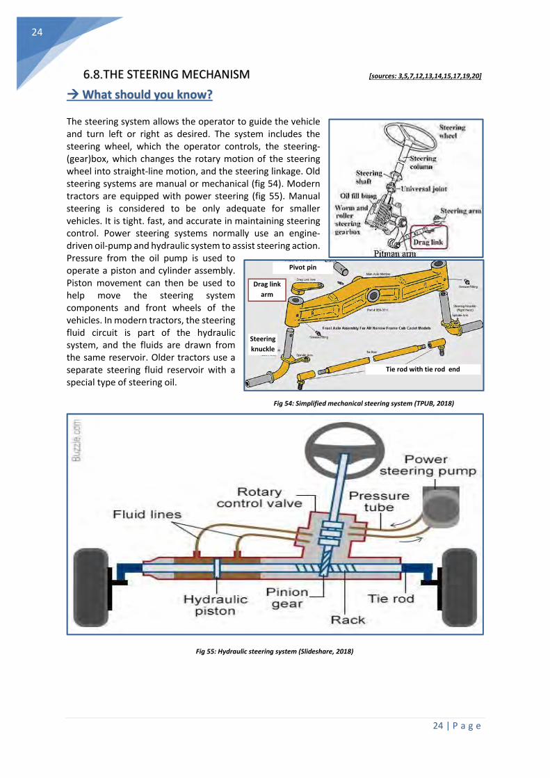
The steering system allows the operator to guide the vehicle and turn left or right as desired. The system includes the steering wheel, which the operator controls, the steering-(gear)box, which changes the rotary motion of the steering wheel into straight-line motion, and the steering linkage. Old steering systems are manual or mechanical (fig 54). Modern tractors are equipped with power steering (fig 55). Manual steering is considered to be only adequate for smaller vehicles. It is tight. fast, and accurate in maintaining steering control. Power steering systems normally use an engine-driven oil-pump and hydraulic system to assist steering action. Pressure from the oil pump is used to operate a piston and cylinder assembly. Piston movement can then be used to help move the steering system components and front wheels of the vehicles. In modern tractors, the steering fluid circuit is part of the hydraulic system, and the fluids are drawn from the same reservoir. Older tractors use a separate steering fluid reservoir with a special type of steering oil.
Fig 54: Simplified mechanical steering system (TPUB, 2018)
Fig 55: Hydraulic steering system (Slideshare, 2018)
Pivot pin
Drag link
arm
Steering
knuckle
Tie rod with tie rod end
25 | P a g e
25
What can you do yourself?
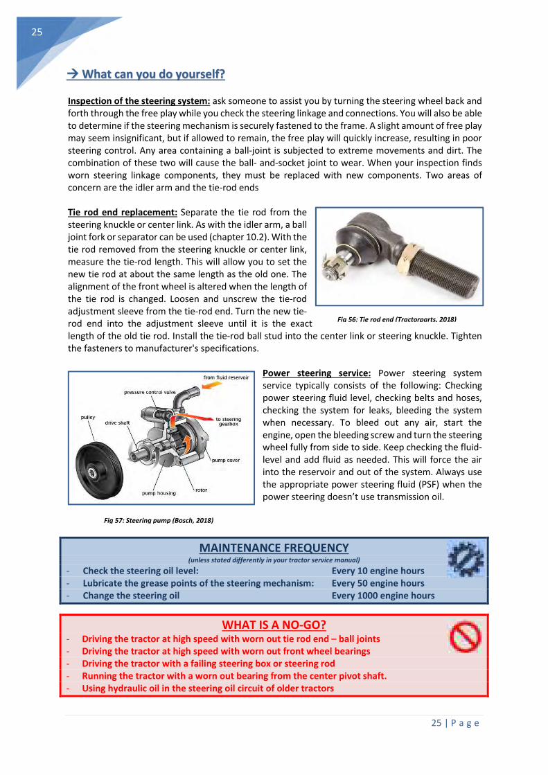
Inspection of the steering system: ask someone to assist you by turning the steering wheel back and forth through the free play while you check the steering linkage and connections. You will also be able to determine if the steering mechanism is securely fastened to the frame. A slight amount of free play may seem insignificant, but if allowed to remain, the free play will quickly increase, resulting in poor steering control. Any area containing a ball-joint is subjected to extreme movements and dirt. The combination of these two will cause the ball- and-socket joint to wear. When your inspection finds worn steering linkage components, they must be replaced with new components. Two areas of concern are the idler arm and the tie-rod ends Tie rod end replacement: Separate the tie rod from the steering knuckle or center link. As with the idler arm, a ball joint fork or separator can be used (chapter 10.2). With the tie rod removed from the steering knuckle or center link, measure the tie-rod length. This will allow you to set the new tie rod at about the same length as the old one. The alignment of the front wheel is altered when the length of the tie rod is changed. Loosen and unscrew the tie-rod adjustment sleeve from the tie-rod end. Turn the new tie-rod end into the adjustment sleeve until it is the exact length of the old tie rod. Install the tie-rod ball stud into the center link or steering knuckle. Tighten the fasteners to manufacturer's specifications.
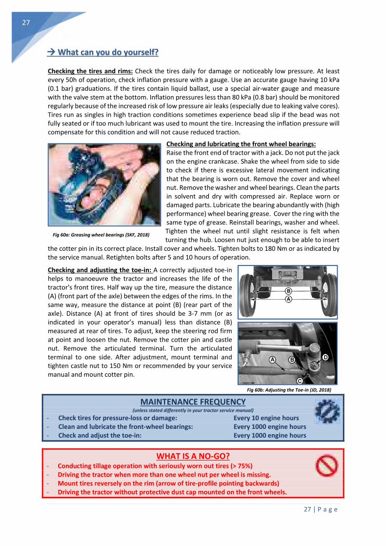
Power steering service: Power steering system service typically consists of the following: Checking power steering fluid level, checking belts and hoses, checking the system for leaks, bleeding the system when necessary. To bleed out any air, start the engine, open the bleeding screw and turn the steering wheel fully from side to side. Keep checking the fluid-level and add fluid as needed. This will force the air into the reservoir and out of the system. Always use the appropriate power steering fluid (PSF) when the power steering doesn’t use transmission oil.
MAINTENANCE FREQUENCY (unless stated differently in your tractor service manual)
- Check the steering oil level: Every 10 engine hours - Lubricate the grease points of the steering mechanism: Every 50 engine hours - Change the steering oil Every 1000 engine hours
WHAT IS A NO-GO? - Driving the tractor at high speed with worn out tie rod end – ball joints - Driving the tractor at high speed with worn out front wheel bearings - Driving the tractor with a failing steering box or steering rod - Running the tractor with a worn out bearing from the center pivot shaft. - Using hydraulic oil in the steering oil circuit of older tractors
Fig 56: Tie rod end (Tractorparts, 2018)
Fig 57: Steering pump (Bosch, 2018)

26 | P a g e
26
6.9. THE WHEELS AND TIRES [sources: 3,5,7,12,13,14,15,17,19,20]
What should you know?
Wheels must have enough strength to carry the weight of the tractor and withstand a wide range of road and field conditions. Wheel bearings allow the wheel and tire assembly to turn freely around the spindle, in the steering knuckle, or in the bearing support. Wheel bearings are normally lubricated with high performance wheel bearing grease. This allows the bearings to operate with very little friction and wear. The wheel-spindle or stub axle is a stationary shaft that extends outward from the steering knuckle or suspension system. The wheel bearings are normally tapered roller bearings, mounted on the spindle and in the wheel hub. The hub outer housing holds the brake-disc or drum, the wheel and the wheel bearing. A safety washer keeps the outer wheel bearing from rubbing on and possibly turning the adjusting nut. A spindle adjusting nut is used for adjusting the wheel bearing and a thin, slotted nut fits over the main spindle (castle-nut). A dust cap fits over the outer end of the hub to keep grease in and dirt out of the bearings.
Most tractors use tubeless tires that do not have a separate inner tube. The tire and wheel form an airtight unit. Tires perform the following two basic functions: They must act as a soft cushion between the land/road and the metal wheel, they must provide adequate traction (friction) with the land/road surface. Tires must transmit driving, braking, and cornering forces to the road in all types of weather. At the same time, they should resist puncture and wear. The markings on the tire should be interpreted as displayed in figure 59. Excessive tire wear especially on front wheel assisted tractors may
indicate poor set up and operation. Tire wear is increased when tire pressure is not set correctly (Appendix 10.3). During tillage operations over-inflated tires will lead to an increase in fuel use and soil compaction (Chapter 8).
Fig 58: Front wheel hub, exploded view (TPUB, 2018)
Fig 59: Tractor tire identification (Petlas, 2018)
Grease
cap
Wheel hub
Stub axle
Inner
bearing
Outer bearing
Trust washer
Stub axle
housing
Oil seal
27 | P a g e
27
Fig 60b: Adjusting the Toe-in (JD, 2018)
What can you do yourself?
Checking the tires and rims: Check the tires daily for damage or noticeably low pressure. At least every 50h of operation, check inflation pressure with a gauge. Use an accurate gauge having 10 kPa (0.1 bar) graduations. If the tires contain liquid ballast, use a special air-water gauge and measure with the valve stem at the bottom. Inflation pressures less than 80 kPa (0.8 bar) should be monitored regularly because of the increased risk of low pressure air leaks (especially due to leaking valve cores). Tires run as singles in high traction conditions sometimes experience bead slip if the bead was not fully seated or if too much lubricant was used to mount the tire. Increasing the inflation pressure will compensate for this condition and will not cause reduced traction.
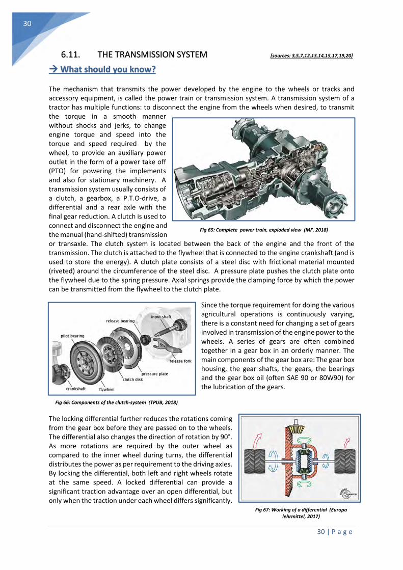
Checking and lubricating the front wheel bearings: Raise the front end of tractor with a jack. Do not put the jack on the engine crankcase. Shake the wheel from side to side to check if there is excessive lateral movement indicating that the bearing is worn out. Remove the cover and wheel nut. Remove the washer and wheel bearings. Clean the parts in solvent and dry with compressed air. Replace worn or damaged parts. Lubricate the bearing abundantly with (high performance) wheel bearing grease. Cover the ring with the same type of grease. Reinstall bearings, washer and wheel. Tighten the wheel nut until slight resistance is felt when turning the hub. Loosen nut just enough to be able to insert
the cotter pin in its correct place. Install cover and wheels. Tighten bolts to 180 Nm or as indicated by the service manual. Retighten bolts after 5 and 10 hours of operation.
Checking and adjusting the toe-in: A correctly adjusted toe-in helps to manoeuvre the tractor and increases the life of the tractor's front tires. Half way up the tire, measure the distance (A) (front part of the axle) between the edges of the rims. In the same way, measure the distance at point (B) (rear part of the axle). Distance (A) at front of tires should be 3-7 mm (or as indicated in your operator’s manual) less than distance (B) measured at rear of tires. To adjust, keep the steering rod firm at point and loosen the nut. Remove the cotter pin and castle nut. Remove the articulated terminal. Turn the articulated terminal to one side. After adjustment, mount terminal and tighten castle nut to 150 Nm or recommended by your service manual and mount cotter pin.
MAINTENANCE FREQUENCY (unless stated differently in your tractor service manual)
- Check tires for pressure-loss or damage: Every 10 engine hours - Clean and lubricate the front-wheel bearings: Every 1000 engine hours - Check and adjust the toe-in: Every 1000 engine hours
WHAT IS A NO-GO? - Conducting tillage operation with seriously worn out tires (> 75%) - Driving the tractor when more than one wheel nut per wheel is missing. - Mount tires reversely on the rim (arrow of tire-profile pointing backwards) - Driving the tractor without protective dust cap mounted on the front wheels.
Fig 60a: Greasing wheel bearings (SKF, 2018)

28 | P a g e
28
6.10. THE BRAKE-SYSTEM [sources: 3,5,7,12,13,14,15,17,19,20]
What should you know?
The brake system is from a safety standpoint, the most important system on a tractor. Braking action is the use of a controlled force to accomplish three basic tasks: to slow down, stop, or hold the wheels of a vehicle stationary. Braking action is accomplished by rubbing two surfaces together that cause friction and heat. The most commonly used brake systems are mechanical, hydraulic or pneumatic braking systems. In earlier days mechanical band- and drum brakes (fig 61,62) were used in tractors. Nowadays with advancement in technology, mechanical brakes have been replaced by hydraulic or pneumatic brakes. In an hydraulic braking system the wheel cylinders are controlled via the master cylinder. When the pedal is pressed, the piston of the master cylinder is forced into the cylinder and the entire system turns to a pressure system. Immediately, the piston of the wheel cylinder slides outward which moves the brake shoes to stop the rotating drum or disc. Air brakes or, more formally, a compressed air brake system, is a type of friction brake for vehicles in which compressed air pressing on a piston is used to apply the pressure to the brake pad needed to stop the vehicle. Air brakes are mainly used in large heavy vehicles. The air compressor is driven by the engine either by crankshaft pulley via a belt or directly from the engine timing gears.
Fig 61: Principles of an hydraulic (left) and mechanical (right) braking system (TPUB), 2018)
Fig 62: Principles of a disc brake (left) and drum brake (right) (Slideshare, 2018)

29 | P a g e
29
Fig 64: Bleeding of the front brakes (JD, 2018)
What can you do yourself?
A general brake system inspection: Check pads, linings and brake fluid levels. Check all the discs, drums, brake linings and linkages for any signs of wear and damage. Check the wheel cylinders and that there are no brake fluid leaks. Check that the brake pedals properly lock together and that brakes pull evenly. Lubricate where applicable. Check if there is nothing under the brake pedal to hinder application (e.g mud or tools). Only add the brake fluid recommended by your dealer (DOT3, DOT4,…) Adjusting the brake pedal free travel: Park the tractor on a level surface. Chock the wheels to prevent any machine movement. Unlock the brake pedals. Apply force on one of the brake pedals, measure distance (E) between the engaged pedal and the disengaged pedal. Loosen the lock nuts (C). Turn the adjusting screw pipe (D) when needed to increase or decrease tension on adjusting screw pipe (D), in order to obtain the free travel (E) specification (often 70-90mm). After the pedal travel is within the specification, tighten lock nuts (C) on both sides of adjusting screw pipe (D). Adjust free play on both pedals to the same given specification, else sharp reflex on one side may cause accident on urgent braking. Bleeding the brake system: Shut off the engine. Slide two transparent bleed tubes over the appropriate bleed screws. Place the other ends of the two bleed tubes in the oil filler neck (filled with DOT3, DOT4 or as recommended). Open the bleed screws by half a turn. Start the engine. Brake pedals must be coupled together. Apply gentle pressure to the brake pedals and hold them in this position until the fluid escaping from the bleed screws is free of air bubbles. Depress the pedals briefly and release. Repeat this a few times. This should flush out any air bubbles left in the fluid. Hold the pedals in the depressed position and close the bleed screws. Shut off the engine and actuate the brake pedals several times each (separately!) with the engine shut off. This bleeds the last of the air out of the brake valve. There must be perceptible (increasing) resistance before each pedal reaches its limit of travel. If the pedal does sink noticeably after resistance has been reached, leaks in the brake system may be the cause. Brake fluid is hygroscopic and must be exchanged once per two years.
MAINTENANCE FREQUENCY (unless stated differently in your tractor service manual)
- Check the brakes: Every 10 engine hours - Adjust brake pedal free-travel: Every 250 engine hours - Change the brake fluid: Every 1000 engine hours
WHAT IS A NO-GO? - Operating the tractor with a failing brake system and/or hand break. - Running the tractor with an activated hand break. - Using low quality or inappropriate oil in the brake fluid reservoir
Fig 63: Adjusting the brake pedal free travel (JD, 2018)
30 | P a g e
30
6.11. THE TRANSMISSION SYSTEM [sources: 3,5,7,12,13,14,15,17,19,20]
What should you know?
The mechanism that transmits the power developed by the engine to the wheels or tracks and accessory equipment, is called the power train or transmission system. A transmission system of a tractor has multiple functions: to disconnect the engine from the wheels when desired, to transmit the torque in a smooth manner without shocks and jerks, to change engine torque and speed into the torque and speed required by the wheel, to provide an auxiliary power outlet in the form of a power take off (PTO) for powering the implements and also for stationary machinery. A transmission system usually consists of a clutch, a gearbox, a P.T.O-drive, a differential and a rear axle with the final gear reduction. A clutch is used to connect and disconnect the engine and the manual (hand-shifted) transmission or transaxle. The clutch system is located between the back of the engine and the front of the transmission. The clutch is attached to the flywheel that is connected to the engine crankshaft (and is used to store the energy). A clutch plate consists of a steel disc with frictional material mounted (riveted) around the circumference of the steel disc. A pressure plate pushes the clutch plate onto the flywheel due to the spring pressure. Axial springs provide the clamping force by which the power can be transmitted from the flywheel to the clutch plate.
Since the torque requirement for doing the various agricultural operations is continuously varying, there is a constant need for changing a set of gears involved in transmission of the engine power to the wheels. A series of gears are often combined together in a gear box in an orderly manner. The main components of the gear box are: The gear box housing, the gear shafts, the gears, the bearings and the gear box oil (often SAE 90 or 80W90) for the lubrication of the gears.
The locking differential further reduces the rotations coming from the gear box before they are passed on to the wheels. The differential also changes the direction of rotation by 90°. As more rotations are required by the outer wheel as compared to the inner wheel during turns, the differential distributes the power as per requirement to the driving axles. By locking the differential, both left and right wheels rotate at the same speed. A locked differential can provide a significant traction advantage over an open differential, but only when the traction under each wheel differs significantly.
Fig 65: Complete power train, exploded view (MF, 2018)
Fig 66: Components of the clutch-system (TPUB, 2018)
Fig 67: Working of a differential (Europa lehrmittel, 2017)
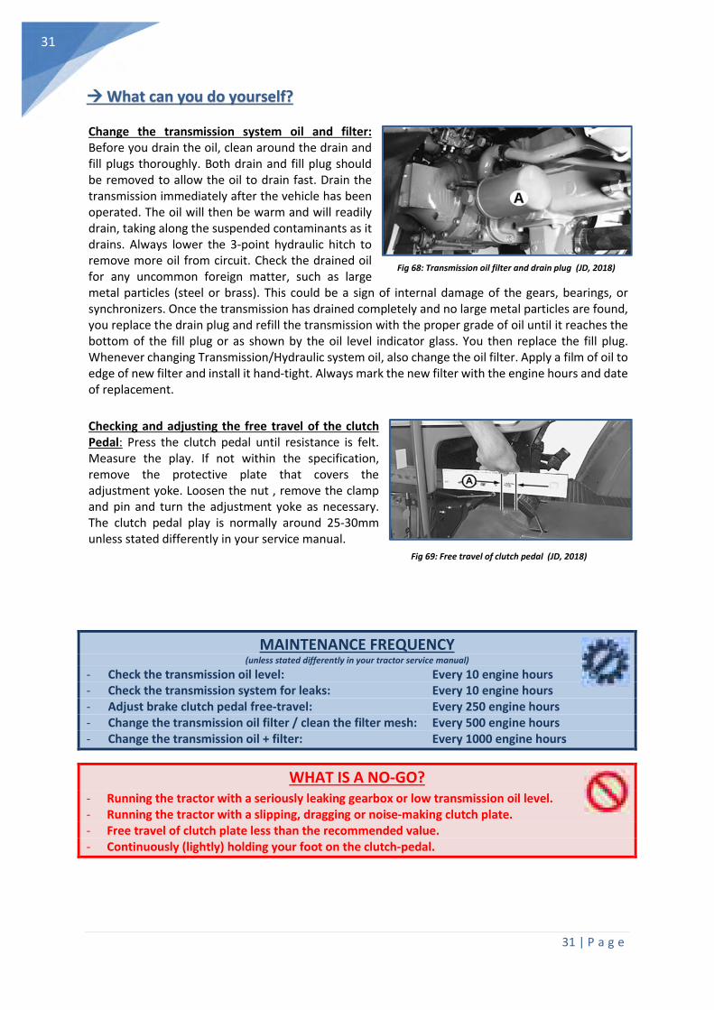
31 | P a g e
31
What can you do yourself?
Change the transmission system oil and filter: Before you drain the oil, clean around the drain and fill plugs thoroughly. Both drain and fill plug should be removed to allow the oil to drain fast. Drain the transmission immediately after the vehicle has been operated. The oil will then be warm and will readily drain, taking along the suspended contaminants as it drains. Always lower the 3-point hydraulic hitch to remove more oil from circuit. Check the drained oil for any uncommon foreign matter, such as large metal particles (steel or brass). This could be a sign of internal damage of the gears, bearings, or synchronizers. Once the transmission has drained completely and no large metal particles are found, you replace the drain plug and refill the transmission with the proper grade of oil until it reaches the bottom of the fill plug or as shown by the oil level indicator glass. You then replace the fill plug. Whenever changing Transmission/Hydraulic system oil, also change the oil filter. Apply a film of oil to edge of new filter and install it hand-tight. Always mark the new filter with the engine hours and date of replacement. Checking and adjusting the free travel of the clutch Pedal: Press the clutch pedal until resistance is felt. Measure the play. If not within the specification, remove the protective plate that covers the adjustment yoke. Loosen the nut , remove the clamp and pin and turn the adjustment yoke as necessary. The clutch pedal play is normally around 25-30mm unless stated differently in your service manual.
MAINTENANCE FREQUENCY (unless stated differently in your tractor service manual)
- Check the transmission oil level: Every 10 engine hours - Check the transmission system for leaks: Every 10 engine hours - Adjust brake clutch pedal free-travel: Every 250 engine hours - Change the transmission oil filter / clean the filter mesh: Every 500 engine hours - Change the transmission oil + filter: Every 1000 engine hours
WHAT IS A NO-GO? - Running the tractor with a seriously leaking gearbox or low transmission oil level. - Running the tractor with a slipping, dragging or noise-making clutch plate. - Free travel of clutch plate less than the recommended value. - Continuously (lightly) holding your foot on the clutch-pedal.
Fig 68: Transmission oil filter and drain plug (JD, 2018)
Fig 69: Free travel of clutch pedal (JD, 2018)
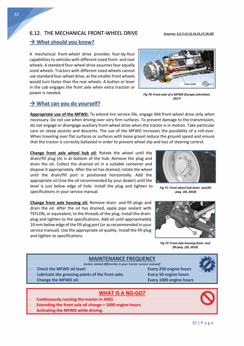
32 | P a g e
32
6.12. THE MECHANICAL FRONT-WHEEL DRIVE [sources: 3,5,7,12,13,14,15,17,19,20]
What should you know?
A mechanical front-wheel drive provides four-by-four capabilities to vehicles with different-sized front- and rear wheels. A standard four-wheel drive assumes four equally sized wheels. Tractors with different sized wheels cannot use standard four-wheel drive, as the smaller front wheels would turn faster than the rear wheels. A button or lever in the cab engages the front axle when extra traction or power is needed.
What can you do yourself?
Appropriate use of the MFWD: To extend tire service life, engage 4X4 front-wheel drive only when necessary. Do not use when driving over very firm surfaces. To prevent damage to the transmission, do not engage or disengage auxiliary front-wheel drive when the tractor is in motion. Take particular care on steep ascents and descents. The use of the MFWD increases the possibility of a roll-over. When traveling over flat surfaces or surfaces with loose gravel reduce the ground speed and ensure that the tractor is correctly ballasted in order to prevent wheel slip and loss of steering control. Change front axle wheel hub oil: Rotate the wheel until the drain/fill plug (A) is at bottom of the hub. Remove the plug and drain the oil. Collect the drained oil in a suitable container and dispose it appropriately. After the oil has drained, rotate the wheel until the drain/fill port is positioned horizontally. Add the appropriate oil (Use the oil recommended by your dealer) until the level is just below edge of hole. Install the plug and tighten to specifications in your service manual. Change front axle housing oil: Remove drain- and fill plugs and drain the oil. After the oil has drained, apply pipe sealant with TEFLON, or equivalent, to the threads of the plug. Install the drain-plug and tighten to the specifications. Add oil until approximately 10 mm below edge of the fill-plug port (or as recommended in your service manual). Use the appropriate oil quality. Install the fill-plug and tighten to specifications.
MAINTENANCE FREQUENCY (unless stated differently in your tractor service manual)
- Check the MFWD oil level: Every 250 engine hours - Lubricate the greasing points of the front axle: Every 50 engine hours - Change the MFWD oil: Every 1000 engine hours
WHAT IS A NO-GO? - Continuously running the tractor in 4WD. - Extending the front axle oil change > 1000 engine hours. - Activating the MFWD while driving.
Fig 71: Front wheel hub drain- and fill-plug (JD, 2018)
Fig 72: Front axle housing drain- and fill-plug (JD, 2018)
Fig 70: Front-axle of a MFWD (Europa Lehrmittel, 2017)
Drive-shaft

33 | P a g e
33
6.13. THE PTO [sources: 3,5,7,12,13,14,15,17,19,20]
What should you know?
The power take off (PTO) is a mean of transmitting tractor engine power to a rotating implement connected to the tractor, either by a drawbar or by the three point linkage. The PTO of the tractor is usually located at the rear of the tractor, although some tractors are also equipped with front- or mid mounted PTO ‘s. There are generally two main types of PTO tractor shafts: a 6-spline, 35 mm diameter shaft for either 540 rpm or 1000 rpm (The speed is
selected by moving a lever near the operator’s seat) and a 21 splined 35 mm diameter shaft designed specifically for 1000 rpm. Another PTO drive available on some tractors is the “ground speed”, where the PTO is driven off the rear axle rather than the engine. This can be used where it is more efficient for ground speed to regulate the output of the driven machine or where the machine can be turned backwards (to clear blockages). The PTO and its associated shafts and universal joints are a common cause of incidents and injury in farming and industry. Implements are attached to the tractor PTO via a PTO connection shaft (fig 73) or via a belt-pulley (fig 74).
What can you do yourself?
Replacing the PTO oil seal: To avoid replacing the transmission oil: back the tractor up ramps or a slope so the oil runs to the front. There is a plate with bolts in it to remove from the back of the PTO. Unscrew the PTO cap (when present) and pull it, it should pull out the boss in which the seal sits in, whilst leaving the actual PTO shaft in place. Lever out the seal and carefully replace with a new one. Always change the outer O-ring and clean and lubricate all surfaces before carefully refitting. Turn the PTO shaft whilse refitting. Adjusting the PTO clutch rod: Park the tractor and engage parking brake. Position the PTO lever (A) backwards (disengaged position). Remove the clip pin (A) from front end of clutch drive rod and loosen nut (B). Adjust rod length so as to eliminate play. Increase rod length turning clip half a turn, so as to provide a small play for the lever. This leaves the clutch bearing free when it is not engaged.
MAINTENANCE FREQUENCY (unless stated differently in your tractor service manual)
- Check the PTO system: Every 50 engine hours - Adjust the PTO clutch rod: Every 500 engine hours
WHAT IS A NO-GO? - Running the tractor with a leaking PTO oil seal. - Running the tractor with a worn out PTO bearing. - Operating the tractor with a failing PTO clutch or clutch lever.
Fig 73: PTO connection shaft (Walterscheid, 2018)
Fig 74: PTO belt pulley (TPUB, 2018)
Fig 75: Worn PTO oil seal (Thoelen, 2018)
Fig 76: PTO clutch rod (JD, 2018)
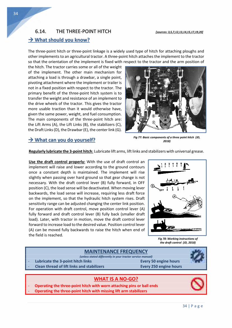
34 | P a g e
34
Fig 77: Basic components of a three point hitch (JD, 2018)
Fig 78: Working instructions of the draft control (JD, 2018)
6.14. THE THREE-POINT HITCH [sources: 3,5,7,12,13,14,15,17,19,20]
What should you know?
The three-point hitch or three-point linkage is a widely used type of hitch for attaching ploughs and other implements to an agricultural tractor. A three-point hitch attaches the implement to the tractor so that the orientation of the implement is fixed with respect to the tractor and the arm position of the hitch. The tractor carries some or all of the weight of the implement. The other main mechanism for attaching a load is through a drawbar, a single point, pivoting attachment where the implement or trailer is not in a fixed position with respect to the tractor. The primary benefit of the three-point hitch system is to transfer the weight and resistance of an implement to the drive wheels of the tractor. This gives the tractor more usable traction than it would otherwise have, given the same power, weight, and fuel consumption. The main components of the three-point hitch are: the Lift Arms (A), the Lift Links (B), the stabilizers (C), the Draft Links (D), the Drawbar (E), the center link (G).
What can you do yourself?
Regularly lubricate the 3-point hitch: Lubricate lift arms, lift links and stabilizers with universal grease. Use the draft control properly: With the use of draft control an implement will raise and lower according to the ground contours once a constant depth is maintained. The implement will rise slightly when passing over hard ground so that gear change is not necessary. With the draft control lever (B) fully forward, in OFF position (C), the load sense will be deactivated. When moving lever backwards, the load sense will increase, requiring less draft force on the implement, so that the hydraulic hitch system rises. Draft sensitivity range can be adjusted changing the center link position. For operation with draft control, move position control lever (A) fully forward and draft control lever (B) fully back (smaller draft load). Later, with tractor in motion, move the draft control lever forward to increase load to the desired value. Position control lever (A) can be moved fully backwards to raise the hitch when end of the field is reached.
MAINTENANCE FREQUENCY (unless stated differently in your tractor service manual)
- Lubricate the 3-point hitch links Every 50 engine hours - Clean thread of lift links and stabilizers Every 250 engine hours
WHAT IS A NO-GO? - Operating the three-point hitch with worn attaching pins or ball ends - Operating the three-point hitch with missing lift arm stabilizers
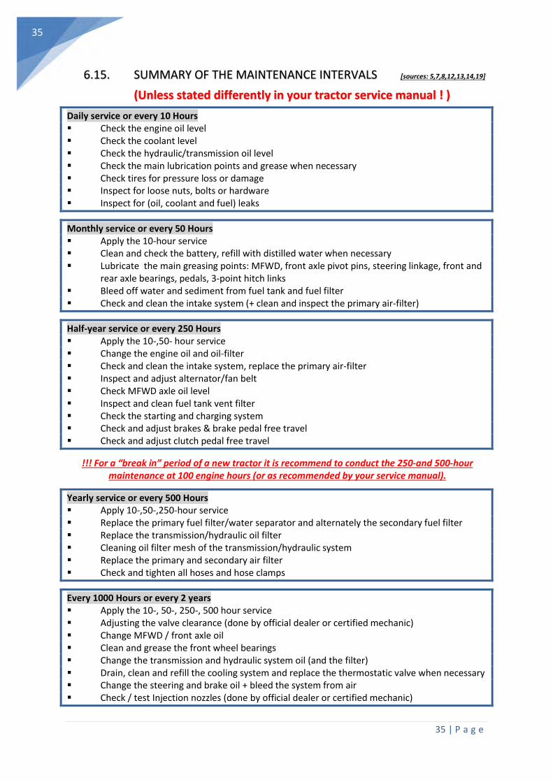
35 | P a g e
35
6.15. SUMMARY OF THE MAINTENANCE INTERVALS [sources: 5,7,8,12,13,14,19]
(Unless stated differently in your tractor service manual ! )
Daily service or every 10 Hours Check the engine oil level Check the coolant level Check the hydraulic/transmission oil level Check the main lubrication points and grease when necessary Check tires for pressure loss or damage Inspect for loose nuts, bolts or hardware Inspect for (oil, coolant and fuel) leaks
Monthly service or every 50 Hours Apply the 10-hour service Clean and check the battery, refill with distilled water when necessary Lubricate the main greasing points: MFWD, front axle pivot pins, steering linkage, front and rear axle bearings, pedals, 3-point hitch links Bleed off water and sediment from fuel tank and fuel filter Check and clean the intake system (+ clean and inspect the primary air-filter)
Half-year service or every 250 Hours Apply the 10-,50- hour service Change the engine oil and oil-filter Check and clean the intake system, replace the primary air-filter Inspect and adjust alternator/fan belt Check MFWD axle oil level Inspect and clean fuel tank vent filter Check the starting and charging system Check and adjust brakes & brake pedal free travel Check and adjust clutch pedal free travel
!!! For a “break in” period of a new tractor it is recommend to conduct the 250-and 500-hour maintenance at 100 engine hours (or as recommended by your service manual).
Yearly service or every 500 Hours Apply 10-,50-,250-hour service Replace the primary fuel filter/water separator and alternately the secondary fuel filter Replace the transmission/hydraulic oil filter Cleaning oil filter mesh of the transmission/hydraulic system Replace the primary and secondary air filter Check and tighten all hoses and hose clamps
Every 1000 Hours or every 2 years Apply the 10-, 50-, 250-, 500 hour service Adjusting the valve clearance (done by official dealer or certified mechanic) Change MFWD / front axle oil Clean and grease the front wheel bearings Change the transmission and hydraulic system oil (and the filter) Drain, clean and refill the cooling system and replace the thermostatic valve when necessary Change the steering and brake oil + bleed the system from air Check / test Injection nozzles (done by official dealer or certified mechanic)

36 | P a g e
36
6.16. TROUBLESHOOTING [sources: 5,7,8,12,13,14,19]
“The engine is difficult to start or will not start”
Incorrect starting procedure Press the clutch pedal or turn off the
PTO. Air in fuel system
Purge (bleed air) from filter and final fuel filter
Lever from the manual fuel pump raised Push manual pump downwards.
Batterie connections loose, fuse blown or short circuit Check the electrical system
Oil in crankcase too viscous
Use the correct oil viscosity. Water, dirt or air in fuel system.
Drain, clean, fill and bleed the system. Plugged fuel filter
Replace the filter element. Dirty or faulty injectors
Test the injectors. Fuel shut-off valve closed
Open the valve or service the fuel pump
“Lack of engine power”
Engine overloaded Reduce load or change to lower gear
Air intake restriction Service the air cleaner
Plugged fuel filter Replace the filter element.
Very low engine temperature Remove and check the thermostat.
Dirty or faulty injectors
Test the injectors. Injector pump out of synch
Contact your dealer/mechanic. Restricted fuel line
Examine and clean the fuel line.
“High oil consumption”
Oil in crankcase too light Use correct oil viscosity.
Oil leaks Check for leaks and correct if
necessary.
Worn piston rings Ask your dealer for a compression test,
and overhaul the engine when needed Crankcase vent tube restricted
Clean vent tube
“Engine emits white smoke”
Bad quality fuel. Use correct fuel.
Low engine temperature Warm up the engine to normal
operational temperature. Defective thermostat
Remove and check thermostat.
Defective injectors Contact your dealer/mechanic.
Engine not properly timed Contact your dealer/mechanic.
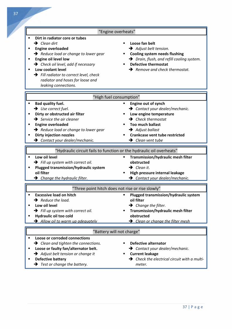
37 | P a g e
37
“Engine overheats”
Dirt in radiator core or tubes Clean dirt
Engine overloaded Reduce load or change to lower gear
Engine oil level low Check oil level, add if necessary
Low coolant level Fill radiator to correct level, check
radiator and hoses for loose and leaking connections.
Loose fan belt
Adjust belt tension. Cooling system needs flushing
Drain, flush, and refill cooling system. Defective thermostat
Remove and check thermostat.
“High fuel consumption”
Bad quality fuel. Use correct fuel.
Dirty or obstructed air filter Service the air cleaner
Engine overloaded Reduce load or change to lower gear
Dirty injection nozzles Contact your dealer/mechanic.
Engine out of synch Contact your dealer/mechanic.
Low engine temperature Check thermostat
Too much ballast Adjust ballast
Crankcase vent tube restricted Clean vent tube
“Hydraulic circuit fails to function or the hydraulic oil overheats”
Low oil level Fill up system with correct oil.
Plugged transmission/hydraulic system oil filter Change the hydraulic filter.
Transmission/hydraulic mesh filter obstructed Clean it.
High pressure internal leakage Contact your dealer/mechanic.
“Three point hitch does not rise or rise slowly”
Excessive load on hitch Reduce the load.
Low oil level Fill up system with correct oil.
Hydraulic oil too cold Allow oil to warm up adequately
Plugged transmission/hydraulic system oil filter Change the filter.
Transmission/hydraulic mesh filter obstructed Clean or change the filter mesh
“Battery will not charge”
Loose or corroded connections Clean and tighten the connections.
Loose or faulty fan/alternator belt. Adjust belt tension or change it
Defective battery Test or change the battery.
Defective alternator
Contact your dealer/mechanic. Current leakage
Check the electrical circuit with a multi-meter.
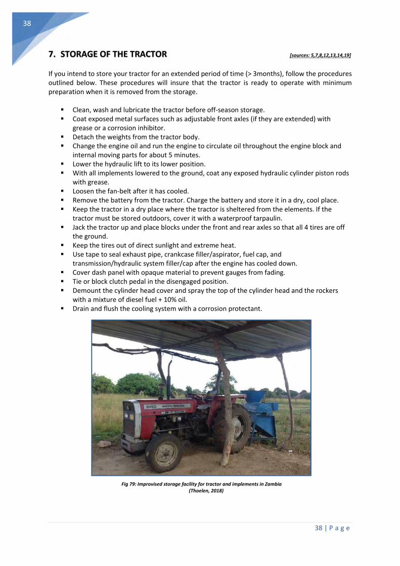
38 | P a g e
38
7. STORAGE OF THE TRACTOR [sources: 5,7,8,12,13,14,19]
If you intend to store your tractor for an extended period of time (> 3months), follow the procedures outlined below. These procedures will insure that the tractor is ready to operate with minimum preparation when it is removed from the storage.
Clean, wash and lubricate the tractor before off-season storage. Coat exposed metal surfaces such as adjustable front axles (if they are extended) with
grease or a corrosion inhibitor. Detach the weights from the tractor body. Change the engine oil and run the engine to circulate oil throughout the engine block and
internal moving parts for about 5 minutes. Lower the hydraulic lift to its lower position. With all implements lowered to the ground, coat any exposed hydraulic cylinder piston rods
with grease. Loosen the fan-belt after it has cooled. Remove the battery from the tractor. Charge the battery and store it in a dry, cool place. Keep the tractor in a dry place where the tractor is sheltered from the elements. If the
tractor must be stored outdoors, cover it with a waterproof tarpaulin. Jack the tractor up and place blocks under the front and rear axles so that all 4 tires are off
the ground. Keep the tires out of direct sunlight and extreme heat. Use tape to seal exhaust pipe, crankcase filler/aspirator, fuel cap, and
transmission/hydraulic system filler/cap after the engine has cooled down. Cover dash panel with opaque material to prevent gauges from fading. Tie or block clutch pedal in the disengaged position. Demount the cylinder head cover and spray the top of the cylinder head and the rockers
with a mixture of diesel fuel + 10% oil. Drain and flush the cooling system with a corrosion protectant.
Fig 79: Improvised storage facility for tractor and implements in Zambia (Thoelen, 2018)

39 | P a g e
39
8. FUEL SAVING ON THE FARM [sources: 3,18,19,20]
What should you know?
A tractor transforms diesel energy nearly into 75 % of losses. These losses are composed of heat and friction losses, rolling resistance on the field and road, tire slip during field operations and bulldozing and compacting the soil. The fuel usage of a well maintained and operated engine can be easily calculated. Fuel consumption should not exceed the rated engine power (kW) x 0.25. This means a 30kw ( 40 hp) tractor should not use more than 7 litres per hour. For reasons of economy and ecology farmers and contractors should aim to increase the fuel efficiency of their tractor at all times.
What can you do yourself?
• Reduce tillage operations: Switch to no-till or minimum tillage options. This can reduce fuel use by 86% by reducing the number of field operations.
• Avoid using big tractors to pull small loads. Match the tractor to the power requirements of the job
• Replace air- and fuel filters regularly, especially when working in dusty conditions. • Avoid idling the tractor for long periods of time. • Operate tractors in higher gears at low throttle settings rather than lower gears at high
throttle settings. • Use engine oil with the proper viscosity for your engine. Change oil and oil filters according
to the manufacturer's recommendations. • Use proper tractor ballasting to reduce wheel slip, thus reducing fuel consumption. Tractor
tire slippage should be from 10 to 15 percent. Insufficient ballast can create excessive tire slippage and increase fuel consumption, not to mention premature engine wear.
• Replacing worn tires reduces excessive wheel slip and fuel consumption. • Check tractor- and equipment tires to ensure they are at the recommended inflation
pressures for the best traction, the lowest rolling resistance and minimum soil compaction. (http://www.tirepressurecalculator.com/)
• Store your fuel correctly. Paint above ground fuel tanks a light colour and keep them shaded to prevent the loss of fuel by evaporation.
• Optimize fuel efficiency with effective travel patterns. Every minute spent on turning, road travel and opening gates results in higher fuel consumption and lost productivity. Lay out your fields to minimize turning and overlapping tillage operations. Plan your on-road travel efficiently.
• Avoid tilling the soil too frequently and too intensively. Too loose soil can create a bulldozing effect and lead to soil compaction (fig 80)
Fig 80: Fuel consuming bulldozing effect and soil compaction due to too loose soil (Volk,
2011) and soil compaction related to tire pressure (AGCO, 2017)

40 | P a g e
40
9. REFERENCES AND FURTHER INFORMATION
[1] AGCO CORP (2018) Operator’s manual T-series. Retrieved from www.valtek.lv/lv/catalog/download/118
[2] BENGTSSON, L., WHITAKER, J., (1988) Farm structures in tropical climates, A Textbook for Structural 3
Engineering and Design, , FAO. Retrieved from http://www.fao.org/docrep/s1250e/S1250E00.htm
[3] CIGR (1999). CIGR Handbook of Agricultural Engineering: Plant production engineering. American Society of
agricultural engineers. 1-632
[4] DÄNZER D,. (1993) Reparaturhelfer für den Landwirt, Band : Traktormotoren, Traktorhydraulik,
Gelenkwellen. Verlagsunion agrar.
[5] DEERE & COMPANY (2013) Operator manual: 5055E, 5065E and 5075E Tractors. Retrieved from
http://manuals.deere.com/omview/OMSJ16026_19/?tM=HO
[6] DHINGRA H.S.,( (2018) Hydraulic Drive & Controls . IASRI Agricultural engineering. Retrieved from
http://ecoursesonline.iasri.res.in/course/view.php?id=40
[7] EUROPA LEHRMITTEL (2016). Fachkunde Land- und Baumaschinen-technik. Verlag Europa Lehrmittel.
[8] FAO/CIMMYT. (2018). Hire services as a business enterprise. A training manual for small-scale
mechanization service providers. Retrieved from http://www.fao.org/3/I9207EN/i9207en.pdf
[9] FAO. (1990). Agricultural engineering in development : guidelines for mechanization systems and
machinery rehabilitation programmes. Retrieved from http://www.fao.org/sustainable-agricultural-
mechanization/resources/publications/details/en/c/450702/
[10] FEIX, H. (1977) Wartung un pflege der land-maschinen. 3., Auflage. Leopold Stacker Verlag.
[11] IOWA STATE UNIVERSITY (1980), Planning and Equipping a Service Center for Your Farm, Ames, Iowa,
Cooperative Extension Service Iowa State University, 1980.
[12] Kletzl, W., Schott, M., Auer, S., (2006) HANDBUCH REPARATUREN AN LANDMASCHINEN UND TRAKTOREN,
7., AUFLAGE, Ulmer
[13] MASSEY FERGUSSON (2018) Operator’s manual MF 135 tractor
[14] RIEDL, H., (2015) Handbuch praktische Traktorentechnik. 6., Auflage. Ulmer.
[15] ROHINISH, K., (2018) Tractor Systems & controls. IASRI Agricultural engineering. Retrieved from
http://ecoursesonline.iasri.res.in/course/view.php?id=520
[16] THOELEN, J., (2018) New approaches to training and education in sustainable agricultural mechanization
for emerging farmers in Zambia. Hohenheim University.
[17] TPUB (2018) Construction Mechanic basic Volume 1,2 & advanced. Integrated publishing. Retrieved from:
Constructionmanuals.tpub.com
[18] VOLK, L., DENKER, S., ROSE, S. (2011) How to increase Diesel fuel efficiency in agriculture. Landtechnek,
agricultural engineering. Retrieved from https://www.landtechnik-online.eu/ojs-
2.4.5/index.php/landtechnik/article/viewFile/2011-2-140-143/514
[19] WHILEY, P., (1996) Farm machinery maintenance. Inkata Press
[20] WIKIPEDIA. (2018). Information related to Engine systems, mechanics and metal-working. Retrieved from
www.wikipedia.org
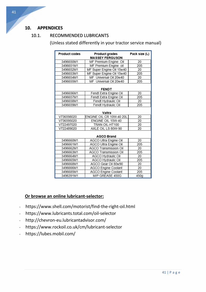
41 | P a g e
41
10. APPENDICES
10.1. RECOMMENDED LUBRICANTS
(Unless stated differently in your tractor service manual)
Or browse an online lubricant-selector:
- https://www.shell.com/motorist/find-the-right-oil.html
- https://www.lubricants.total.com/oil-selector
- http://chevron-eu.lubricantadvisor.com/
- https://www.rockoil.co.uk/cm/lubricant-selector
- https://lubes.mobil.com/
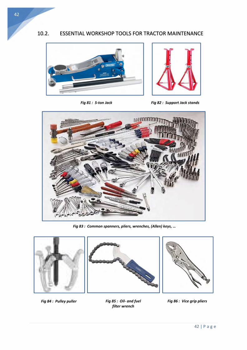
42 | P a g e
42
10.2. ESSENTIAL WORKSHOP TOOLS FOR TRACTOR MAINTENANCE
Fig 81 : 5-ton Jack Fig 82 : Support Jack stands
Fig 83 : Common spanners, pliers, wrenches, (Allen) keys, …
Fig 84 : Pulley puller Fig 85 : Oil- and fuel filter wrench
Fig 86 : Vice grip pliers
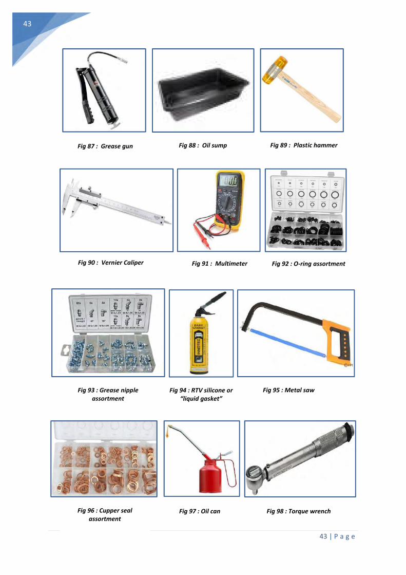
43 | P a g e
43
Fig 87 : Grease gun Fig 88 : Oil sump Fig 89 : Plastic hammer
Fig 90 : Vernier Caliper Fig 91 : Multimeter Fig 92 : O-ring assortment
Fig 93 : Grease nipple assortment
Fig 94 : RTV silicone or “liquid gasket”
Fig 95 : Metal saw
Fig 98 : Torque wrench Fig 97 : Oil can Fig 96 : Cupper seal assortment
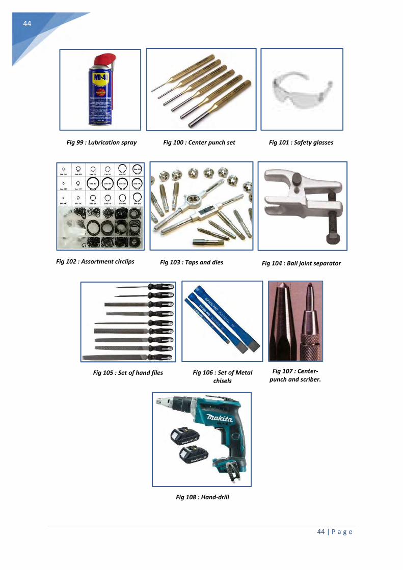
44 | P a g e
44
Fig 99 : Lubrication spray Fig 100 : Center punch set Fig 101 : Safety glasses
Fig 102 : Assortment circlips Fig 103 : Taps and dies Fig 104 : Ball joint separator
Fig 105 : Set of hand files Fig 106 : Set of Metal chisels
Fig 107 : Center-punch and scriber.
Fig 108 : Hand-drill
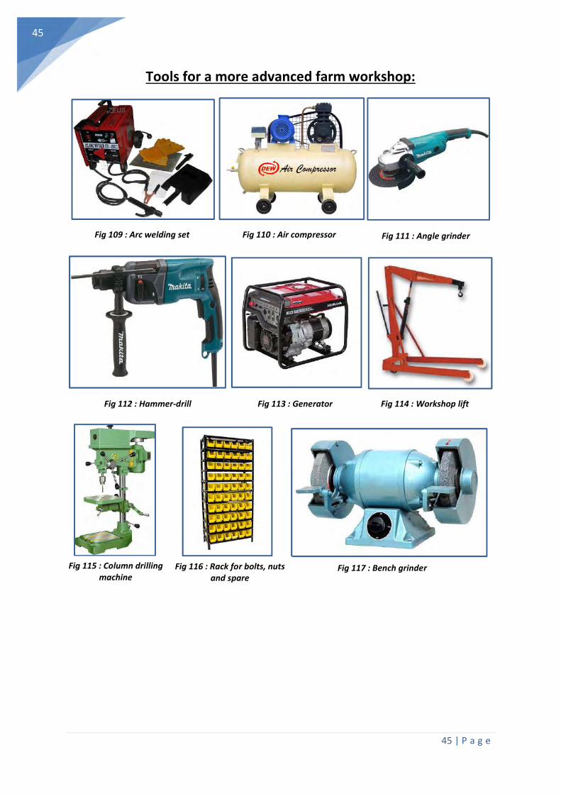
45 | P a g e
45
Tools for a more advanced farm workshop:
Fig 109 : Arc welding set Fig 110 : Air compressor Fig 111 : Angle grinder
Fig 113 : Generator Fig 112 : Hammer-drill Fig 114 : Workshop lift
Fig 117 : Bench grinder Fig 116 : Rack for bolts, nuts and spare
Fig 115 : Column drilling machine

46 | P a g e
46
10.3. TIRE INFLATION PRESSURE CHARTS (for MAX. 30km/h)
(Unless stated differently in your tractor service manual)

47 | P a g e
47
10.4. ELECTRIC AND HYDRAULIC SYMBOLS
General control panel symbols:
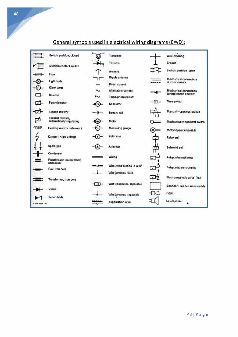
48 | P a g e
48
General symbols used in electrical wiring diagrams (EWD):

49 | P a g e
49
General symbols used in hydraulic and pneumatic diagrams:

50 | P a g e
50
10.5. TAP AND DRILL CHART.
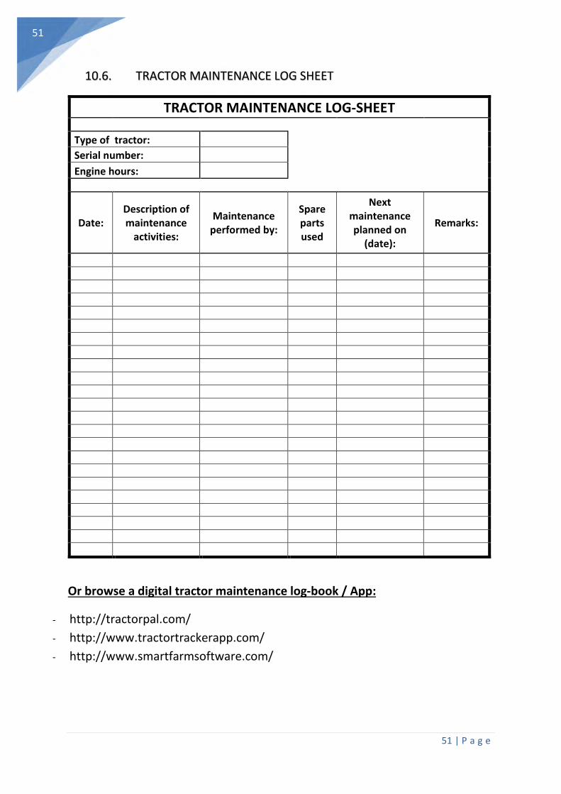
51 | P a g e
51
10.6. TRACTOR MAINTENANCE LOG SHEET
Or browse a digital tractor maintenance log-book / App:
- http://tractorpal.com/
- http://www.tractortrackerapp.com/
- http://www.smartfarmsoftware.com/
TRACTOR MAINTENANCE LOG-SHEET
Type of tractor:
Serial number:
Engine hours:
Date: Description of maintenance
activities:
Maintenance performed by:
Spare parts used
Next maintenance planned on
(date):
Remarks: