This manual has been updated for MultiOne version ... - Signify
146
This manual has been updated for MultiOne version 3.13 © 2019 Signify Holding. All rights reserved.
-
Upload
khangminh22 -
Category
Documents
-
view
2 -
download
0
Transcript of This manual has been updated for MultiOne version ... - Signify

This manual has been updated for MultiOne version 3.13
© 2019 Signify Holding. All rights reserved.

2
1 Introduction
Today’s customer demands more flexibility and customization possibilities than
“physical configurations” can offer. With new Philips configurable devices with built-in
controls or separate controllers you can configure the luminaire’s behavior. You can
control output levels, or even pre-configure dynamic dimming on the client’s request;
either directly in the factory or during installation on location. All you need is ONE
intuitive tool that when plugged into a device can calibrate ALL the different
functions required by any lighting solution.
Creating the perfect lighting solution has been made very easy with Philips MultiOne.
With MultiOne, you can configure all features that are supported by a Philips device.
A feature typically belongs to one or two product groups (LED Indoor/Outdoor, HID
or FLUO), but this does not mean that every device from a product group does
support all features.
Philips MultiOne is supported by Windows 7 SP1, 8, 8.1 and 10 operating systems. It
works only in combination with the Philips LCN8600 MultiOne interface USB2DALI,
with Philips LCN8650 MultiOne interface USB2ZigBee, LCN9610, LCN9620 or
LCN9630 MultiOne interface SimpleSet.

3
2 Table of contents
1 Introduction........................................................................................................................................2
3 System requirements ......................................................................................................................9
4 Downloading and installing MultiOne and the documentation package ................ 10
5 Attention points ............................................................................................................................. 11
5.1 General ...................................................................................................................................... 11
5.2 DALI ............................................................................................................................................ 11
5.3 SimpleSet interface............................................................................................................... 11
6 The MultiOne interfaces ............................................................................................................. 12
6.1 DALI ............................................................................................................................................ 12
6.2 ZigBee ....................................................................................................................................... 13
6.3 SimpleSet ................................................................................................................................. 13
7 Starting MultiOne .......................................................................................................................... 14
7.1 Activating MultiOne ............................................................................................................. 14
7.2 Application mode selector................................................................................................. 17
8 Selecting the interface ................................................................................................................. 18
8.1 Interface Auto detection .................................................................................................... 18
8.2 Interface Manual selection ................................................................................................ 18
8.2.1 Art-Net.............................................................................................................................. 19
9 Working with the Philips LCN8600 MultiOne interface USB2DALI ............................. 21
9.1 The main application window .......................................................................................... 21
9.2 Managing the DALI network ............................................................................................. 21
9.2.1 Identifying devices ....................................................................................................... 21
9.2.2 Selecting devices for communication ................................................................... 24
9.2.3 Managing user-defined groups .............................................................................. 25
9.2.4 Managing groups ......................................................................................................... 26
10 Working with the Philips LCN8650 MultiOne interface USB2ZigBee ......................... 30
10.1 The main application window ...................................................................................... 30
10.2 Connecting to a ZigBee network ................................................................................ 30
4
10.2.1 Identifying devices ................................................................................................... 30
10.2.2 Selecting devices for communication ............................................................... 31
10.3 Advanced commissioning .............................................................................................. 31
10.3.1 Identifying devices ................................................................................................... 31
10.3.2 Managing networks ................................................................................................. 31
10.3.3 Managing zones ....................................................................................................... 32
11 Working with the Philips MultiOne SimpleSet interface(s)............................................. 34
11.1 The main application window ...................................................................................... 34
11.2 Scanning a SimpleSet device ........................................................................................ 34
11.2.1 Identifying devices ................................................................................................... 34
11.2.2 Auto read ..................................................................................................................... 35
11.3 Selecting devices for communication ....................................................................... 35
11.4 Starting communication ................................................................................................. 35
12 Working with MultiOne............................................................................................................... 36
12.1 Viewing device properties ............................................................................................. 36
12.2 Communicating with a device ...................................................................................... 36
12.3 Configuring device features .......................................................................................... 37
12.3.1 0-10V / 1-10V (SR bridge) ..................................................................................... 41
12.3.2 0-10V / 1-10V (LED driver) .................................................................................... 42
12.3.3 ActiLume General ..................................................................................................... 43
12.3.4 ActiLume Mode ......................................................................................................... 44
12.3.5 ActiLume Scene ......................................................................................................... 46
12.3.6 Active Cooling ........................................................................................................... 46
12.3.7 Adjustable Light Output ........................................................................................ 47
12.3.8 Adjustable Output Current ................................................................................... 48
12.3.9 Adjustable Output Current Multi-Channel ...................................................... 48
12.3.10 Adjustable Startup Time ........................................................................................ 49
12.3.11 AmpDim ....................................................................................................................... 49
12.3.12 Auxiliary Power Supply Voltage .......................................................................... 50
12.3.13 Coded Light On and Off......................................................................................... 50

5
12.3.14 Coded Mains .............................................................................................................. 50
12.3.15 Coded Mains Standalone Receiver .................................................................... 52
12.3.16 Constant Light Output ............................................................................................ 52
12.3.17 Constant Light Output Multi-Channel .............................................................. 55
12.3.18 Correlated Color Temperature............................................................................. 56
12.3.19 Correlated Color Temperature Dual Channel................................................. 56
12.3.20 Corridor Mode ........................................................................................................... 58
12.3.21 DALI 102 ...................................................................................................................... 59
12.3.22 DALI 202 ...................................................................................................................... 60
12.3.23 DALI Power Supply................................................................................................... 61
12.3.24 Daylight override / Daylight switching ............................................................. 61
12.3.25 DC Emergency ........................................................................................................... 61
12.3.26 Device Info .................................................................................................................. 62
12.3.27 DiiA specification DALI Part 253 - Luminaire Maintenance ...................... 63
12.3.28 Dimming Interface ................................................................................................... 63
12.3.29 Driver addressing ..................................................................................................... 65
12.3.30 Driver Temperature Limit....................................................................................... 65
12.3.31 Dwell Time .................................................................................................................. 66
12.3.32 Dynadimmer ............................................................................................................... 67
12.3.33 End Of Life indication .............................................................................................. 69
12.3.34 FCC ................................................................................................................................. 70
12.3.35 FccRed .......................................................................................................................... 71
12.3.36 FlexTune ....................................................................................................................... 72
12.3.37 Field Task Tuning ...................................................................................................... 73
12.3.38 Field Task Tuning / Occupancy Sensing / Daylight Harvesting ............... 74
12.3.39 Lamp Burn-in ............................................................................................................. 75
12.3.40 Lamp Selection .......................................................................................................... 75
12.3.41 Light Source Operating Hours ............................................................................. 76
12.3.42 LineSwitch ................................................................................................................... 76
12.3.43 Load Fault Indicator Thresholds .......................................................................... 78

6
12.3.44 Logical Signal Input ................................................................................................. 79
12.3.45 Lumen Level................................................................................................................ 80
12.3.46 Luminaire (Fixture) Information ........................................................................... 81
12.3.47 Luminaire Production Test .................................................................................... 82
12.3.48 LumiStep ...................................................................................................................... 82
12.3.49 Min Dim Level ............................................................................................................ 84
12.3.50 Motor Control ............................................................................................................ 85
12.3.51 Module Temperature Protection ........................................................................ 86
12.3.52 NTC on LEDset ........................................................................................................... 87
12.3.53 Occupancy Sensing / Daylight Harvesting ...................................................... 88
12.3.54 Occupancy sharing / Group light behavior ..................................................... 89
12.3.55 OEM Write Protection ............................................................................................. 89
12.3.56 Push Button Unit LCU2070 ................................................................................... 90
12.3.57 Push Button Unit LCU2071 ................................................................................... 91
12.3.58 Quick Lamp Start ...................................................................................................... 91
12.3.59 Relay Switched Output ........................................................................................... 92
12.3.60 Self Contained Emergency .................................................................................... 92
12.3.61 SR Power Supply ....................................................................................................... 93
12.3.62 Step Dimming ............................................................................................................ 94
12.3.63 Touch and Dim .......................................................................................................... 94
12.3.64 Tx Power ...................................................................................................................... 95
12.4 Using the features summary ......................................................................................... 96
12.5 Saving and opening a feature configuration file ................................................... 96
12.6 Configuring a single device........................................................................................... 99
12.7 Configuring multiple DALI devices (simultaneously) ........................................... 99
12.8 Configuring multiple DALI devices (consecutively) ............................................ 100
12.8.1 MultiOne .................................................................................................................... 100
12.9 Configuring multiple ZigBee devices....................................................................... 100
12.10 Offline feature configuration preparation ............................................................. 101
12.11 Sending DALI commands ............................................................................................ 102
7
12.12 Traceability ........................................................................................................................ 104
12.13 Working with DALI command scripts ...................................................................... 104
12.14 Querying devices ............................................................................................................ 107
12.15 Accessing Diagnostics ................................................................................................... 108
12.15.1 Diagnostics ............................................................................................................... 108
12.15.2 Set Lamp On Time .................................................................................................. 118
12.16 Accessing Energy Meter ............................................................................................... 119
12.16.1 Energy Meter ............................................................................................................ 120
12.16.2 DiiA specification DALI Part 252 - Energy reporting ................................. 120
12.17 Accessing Installer .......................................................................................................... 121
12.17.1 Coded Light Randomize ...................................................................................... 121
12.18 Working with the DALI Sniffer ................................................................................... 122
12.18.1 Sniffing with multiple interfaces ....................................................................... 123
12.19 Art-Net export functionality........................................................................................ 123
12.20 DALI Firmware update .................................................................................................. 124
12.21 The logging window ...................................................................................................... 127
12.22 Setting preferences ........................................................................................................ 127
12.22.1 General preferences............................................................................................... 128
12.22.2 DALI ............................................................................................................................. 130
12.22.3 Updates ...................................................................................................................... 131
12.22.4 Proxy ........................................................................................................................... 132
12.23 Manually selecting the USB2DALI interface .......................................................... 132
12.24 Enabling/Disabling the power supply of the USB2DALI interface ................ 133
12.25 Supported features ........................................................................................................ 133
12.26 Device-specific technical descriptions .................................................................... 136
12.27 Error handling .................................................................................................................. 136
12.27.1 Reporting and correction of errors/warnings when reading from a ... 136
feature configuration file ......................................................................................................... 136
12.27.2 Reporting of errors when reading from a device ....................................... 136
12.27.3 Reporting of errors when entering incorrect values in a feature .......... 136

8
12.28 Troubleshooting .............................................................................................................. 136
13 Keyboard shortcuts..................................................................................................................... 138
14 Software Update .......................................................................................................................... 139
15 Copyright........................................................................................................................................ 141
16 Disclaimer ....................................................................................................................................... 142
17 Limitations of damages ............................................................................................................. 143
18 List of tables .................................................................................................................................. 144
19 Index ................................................................................................................................................ 145

9
3 System requirements
The minimum system requirements for using MultiOne are:
- PC or laptop with Microsoft Windows 7 SP1, 8, 8.1 or 10
- USB 2.0 ports:
o Two free USB 2.0 ports for use with USB2DALI interface
o One free USB 2.0 port for use with USB2ZigBee interface
o One free USB 2.0 port for use with SimpleSet interface
- Ethernet port:
o One free Ethernet port for use with Art-Net protocol
- At least 45 MB of free disk space
- Microsoft .NET Framework 4.6.1 (download here for offline installation)
10
4 Downloading and installing MultiOne and the
documentation package
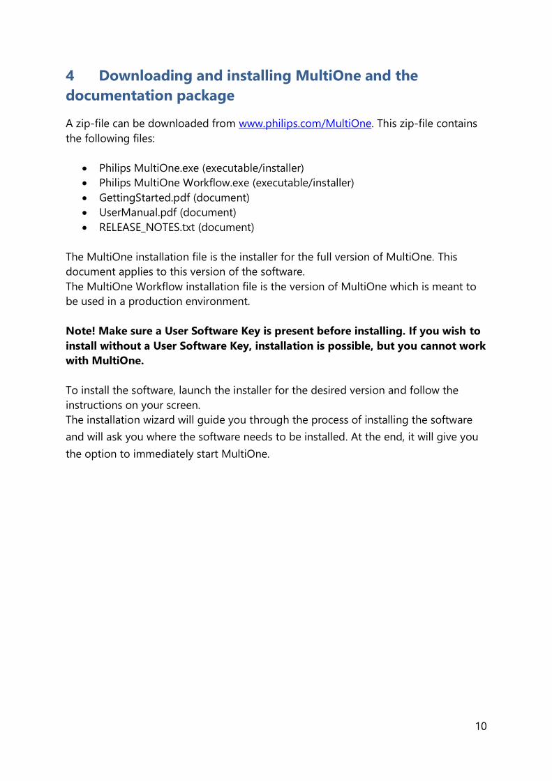
A zip-file can be downloaded from www.philips.com/MultiOne. This zip-file contains
the following files:
Philips MultiOne.exe (executable/installer)
Philips MultiOne Workflow.exe (executable/installer)
GettingStarted.pdf (document)
UserManual.pdf (document)
RELEASE_NOTES.txt (document)
The MultiOne installation file is the installer for the full version of MultiOne. This
document applies to this version of the software.
The MultiOne Workflow installation file is the version of MultiOne which is meant to
be used in a production environment.
Note! Make sure a User Software Key is present before installing. If you wish to
install without a User Software Key, installation is possible, but you cannot work
with MultiOne.
To install the software, launch the installer for the desired version and follow the
instructions on your screen.
The installation wizard will guide you through the process of installing the software
and will ask you where the software needs to be installed. At the end, it will give you
the option to immediately start MultiOne.

11
5 Attention points
5.1 General
Before starting MultiOne, make sure that the correct interface (USB2DALI,
USB2ZigBee or SimpleSet) has been connected to your computer.
When upgrading the Windows Operating System, make sure the connection settings
are correct when using MultiOne again.
When starting multiple instances of MultiOne for parallel configuring, make sure
every instance of MultiOne uses another interface. The unique id of an interface is
shown in the Connection Settings window where the interface port is selected. Also,
for the currently selected interface the unique id can be found in the About box and
in the tooltip of the connection status indicator in the status bar at the bottom-right
part of MultiOne.
5.2 DALI
Lighting applications with DALI devices can be seriously affected by the
presence/absence of the DALI short address. Make sure the DALI short address is as
you expect, after finishing working with MultiOne.
5.3 SimpleSet interface
For SimpleSet there are three interfaces which can be used for communication (see
§6.3): the Philips LCN9610, LCN9620 or LCN9630 MultiOne interface SimpleSet.

12
6 The MultiOne interfaces
6.1 DALI
The Philips LCN8600 MultiOne interface USB2DALI (USB2DALI interface) is the
interface between the PC and the DALI devices. It has a mini- USB input connector
and two parallel DALI output connectors. The USB2DALI interface status is indicated
by three LED’s located near the mini-USB connector.
The USB2DALI interface is supplied with a USB cable that can supply the DALI
network with up to 220mA. It is advised to only use the supplied cable, in order to
assure correct functioning of the USB2DALI interface.
Safety: Class II, double insulated
DALI open circuit voltage (when power supply enabled): 15V
or
mini-USB input connector
Status LEDs:
DALI power supply enabled
DALI active
Power
Double DALI
output
connector

13
6.2 ZigBee
The Philips LCN8650 MultiOne interface USB2ZigBee (USB2ZigBee interface) is an
USB dongle which interfaces between the PC and the ZigBee devices.
6.3 SimpleSet
The Philips LCN9610, LCN9620 and LCN9630 MultiOne interface SimpleSet are USB
devices which interface between the PC and the SimpleSet devices:
Philips LCN9610 Philips LCN9620 Philips LCN9630

14
7 Starting MultiOne
Before starting MultiOne, make sure that the correct interface (USB2DALI,
USB2ZigBee or SimpleSet) has been connected to your computer.
7.1 Activating MultiOne
When starting MultiOne for the first time, the first window that appears is the
MultiOne user software key information. Here you can activate your copy of
MultiOne with your own user software key.
Note! MultiOne must be connected to the internet upon first usage in order to
activate.
Use the Activate… button to continue activation.
Use the Proxy settings button to enter the proxy credentials if this is required for
your infrastructure. An example of the information that can be entered can be found
in chapter Proxy.
Use the Help button to show the User Manual.

15
Select Activate MultiOne online now and follow the instructions.
The other items on this window are less relevant. For completeness:
Select Buy a new product key online brings you to www.philips.com/MultiOne.
Actually buying keys online is not supported.
Once you have activated MultiOne with a user software key, you can select Retype
your product key to switch to a different user software key.
The other items shown on the dialog are not supported.
If all goes well the activation is successful and the MultiOne user software key
information screen should show the correct details and supported features
corresponding to the user software key.

16
MultiOne is now ready for use!
Use the Refresh status button to refresh the license key status.
Note! Not all functionality described in this document applies to all MultiOne user
software keys. For instance, some device features might not be available, or they
might only be partially configurable.
17
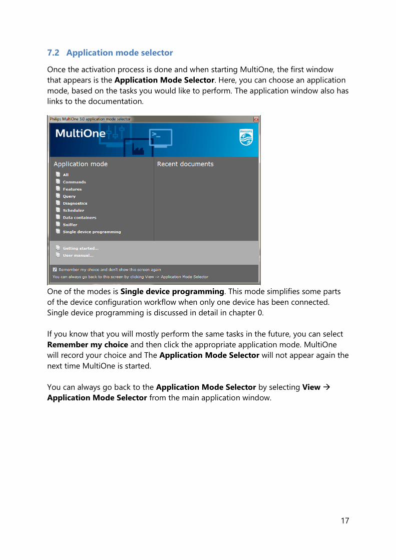
7.2 Application mode selector
Once the activation process is done and when starting MultiOne, the first window
that appears is the Application Mode Selector. Here, you can choose an application
mode, based on the tasks you would like to perform. The application window also has
links to the documentation.
One of the modes is Single device programming. This mode simplifies some parts
of the device configuration workflow when only one device has been connected.
Single device programming is discussed in detail in chapter 0.
If you know that you will mostly perform the same tasks in the future, you can select
Remember my choice and then click the appropriate application mode. MultiOne
will record your choice and The Application Mode Selector will not appear again the
next time MultiOne is started.
You can always go back to the Application Mode Selector by selecting View
Application Mode Selector from the main application window.
18
8 Selecting the interface
After the Application Mode Selector you must select the interface (USB2DALI,
USB2ZigBee, Ethernet or SimpleSet) to work with.
8.1 Interface Auto detection
Interface can be automatically detected in case of DALI and SimpleSet.
On first start MultiOne will detect whether DALI or SimpleSet interfaces are connected
to your PC or laptop.
When only one interface is connected this one will be automatically chosen.
Otherwise the Connection Settings window will appear.
Whenever MultiOne is started again and a previously selected interface is not
connected anymore the following selection or action will take place:
When only one interface is connected (independent of the type of interface)
this one will be automatically chosen.
When two interfaces are connected and one of them is of the same type as the
previously selected interface this interface is automatically selected.
Otherwise the Connection Settings window will appear.
Connecting multiple similar SimpleSet interfaces is currently only supported when
using a LCN9610, LCN9620 or LCN9630 interface.
Notice! Whenever MultiOne is started again, if the previously selected interface is not
either Dali or SimpleSet the auto detection will not work and MultiOne will start with
the previously selected interface.
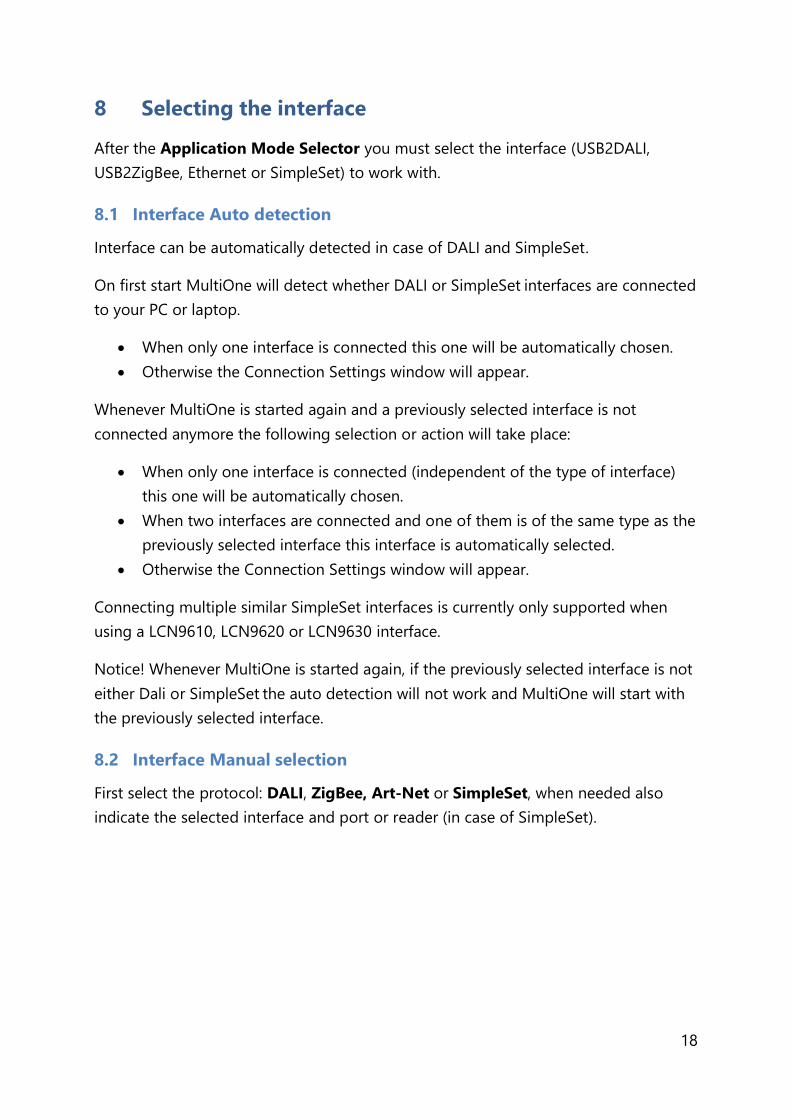
8.2 Interface Manual selection
First select the protocol: DALI, ZigBee, Art-Net or SimpleSet, when needed also
indicate the selected interface and port or reader (in case of SimpleSet).
19
This protocol can always be changed later, by going to the Tools Connection
settings.
Notice! For DALI and SimpleSet the unique id of the interface is shown at the
port/reader selection. This, to be able to identify which interface is used by which
MultiOne instance (when configuring devices in parallel using multiple instances of
MultiOne).
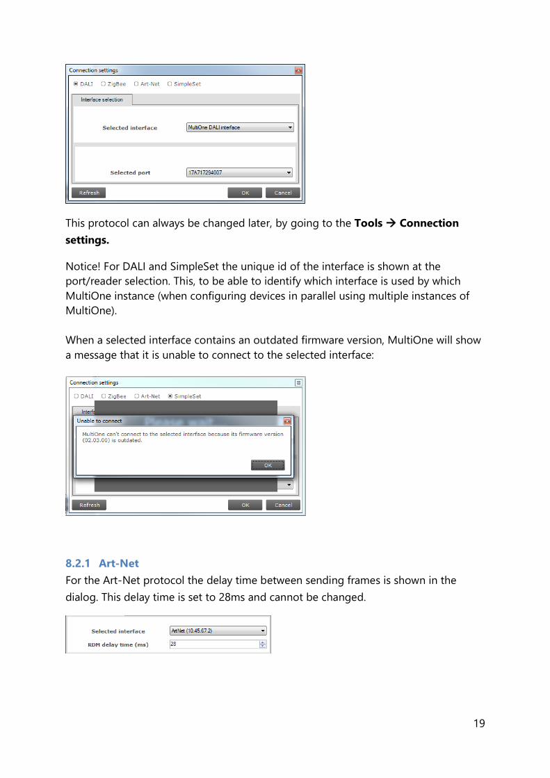
When a selected interface contains an outdated firmware version, MultiOne will show
a message that it is unable to connect to the selected interface:
8.2.1 Art-Net
For the Art-Net protocol the delay time between sending frames is shown in the
dialog. This delay time is set to 28ms and cannot be changed.

20
Note! Please make sure that the selected interface corresponds to the connected Art-
Net network and has the correct IP address (for example use the 10.45.67.2 interface
to connect with a Luminex network).
Note! Please make sure that Windows Firewall is not blocking the Art-Net network,
this will cause troubles during scan.
21
9 Working with the Philips LCN8600 MultiOne interface
USB2DALI
Before using MultiOne with the USB2DALI interface make sure that all devices that
need to be commissioned are connected to the mains and the DALI network. Finally
the DALI network must be connected to one of the DALI connectors of the USB2DALI
interface.
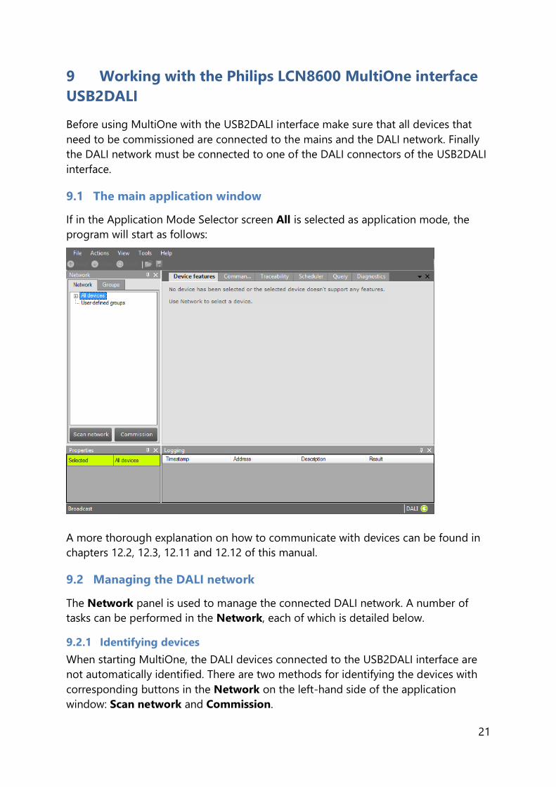
9.1 The main application window
If in the Application Mode Selector screen All is selected as application mode, the
program will start as follows:
A more thorough explanation on how to communicate with devices can be found in
chapters 12.2, 12.3, 12.11 and 12.12 of this manual.
9.2 Managing the DALI network
The Network panel is used to manage the connected DALI network. A number of
tasks can be performed in the Network, each of which is detailed below.
9.2.1 Identifying devices
When starting MultiOne, the DALI devices connected to the USB2DALI interface are
not automatically identified. There are two methods for identifying the devices with
corresponding buttons in the Network on the left-hand side of the application
window: Scan network and Commission.

22
Note! A Scan network or Commission execution will place all found devices into
manufacturer specific operating mode. Take care of this in case you need to use a
connected driver in the DALI standard operating mode!
9.2.1.1 Scan network
There are two ways to scan a network: by short address or by random address. You
can choose which method to use by going to Tools->Preferences->DALI scanning.
The key differences between scanning by short address and scanning by random
address are the following:
Scanning by short address will not change the random addresses of the
connected devices. You should use this method if random addresses should
not be affected. Additional user input might be required to find all connected
devices (see below).
Scanning by random address will change the random addresses of all
connected devices. Any devices that do not have a short address yet will be
assigned one automatically. Any devices that share the same short address will
be automatically assigned (new) unique short addresses. This method is most
likely to find all connected devices without user intervention.
Scan by short address. This method queries all short addresses without changing
anything in the configurations of the connected devices. If all connected devices have
a unique short address, this method will be able to find all devices. If, however, some
devices share the same short address, or if there are devices without a short address
(uncommissioned devices), additional decisions need to be made.
The following situations can occur while scanning a network by short address:
There are uncommissioned devices. You will see the following dialog:
23
By clicking Yes, the uncommissioned devices will be commissioned. As a side
effect, the random addresses of all connected devices will be changed.
By clicking No, no additional actions will be done and the Network will not
display all devices.
There are devices with the same short address. You will see the following
dialog:
By clicking Yes, the devices that have the same short address will be
recommissioned. As a side effect, the random addresses of all connected
devices will be changed.
By clicking No, no additional actions will be done and the Network will not
display all devices. Errors are likely to occur, indicated by a warning icon next
to the name of the device(s).
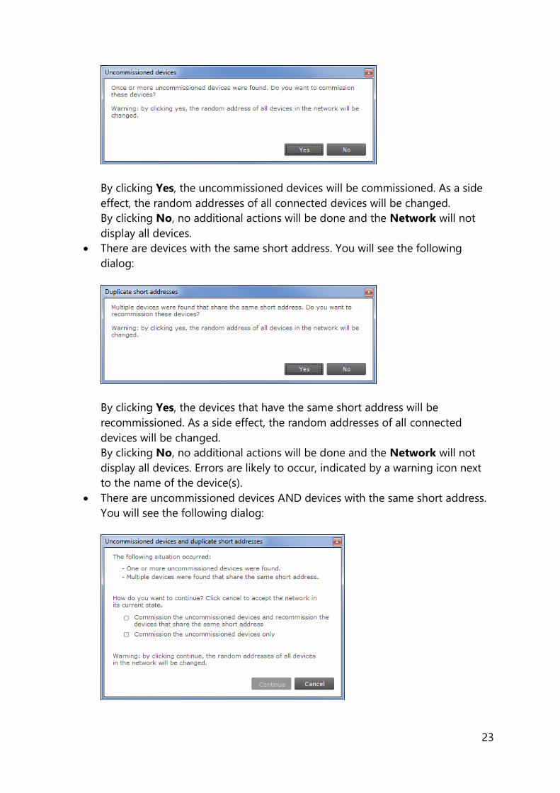
There are uncommissioned devices AND devices with the same short address.
You will see the following dialog:

24
By choosing the first option, all uncommissioned devices will be
commissioned, and all devices with the same short address will be
recommissioned. By choosing the second option, only the uncommissioned
devices will be recommissioned. By clicking Cancel, no additional actions will
be done and the Network will not display all devices. Errors are likely to occur,
indicated by a warning icon next to the name of the device(s).
Scan by random address. This method re-initializes the random addresses of all
connected devices. If there are any uncommissioned devices, or devices that have the
same short address, these devices will automatically be (re)commissioned.
9.2.1.2 Commissioning
All devices are given a new unique short address, starting at 0. Be aware that existing
short addresses are erased and new short addresses are re-assigned to all connected
devices. This procedure ensures that all devices have a short address and that there
are no duplicate short addresses.
After commissioning or scanning the network, the list of identified devices is shown in
the Network.
9.2.2 Selecting devices for communication
After having commissioned or scanned the network, the Network shows all devices
present in the DALI network.
By clicking a device you will make that particular device the active one, meaning that
all commands will be sent to this device only, and will be ignored by all other devices.

25
Besides selecting a single device for communication, it is also possible to
communicate with groups of devices. The options are:
All devices in the network. Select All devices. All commands will now be sent
as broadcast commands. Note that unidentified but connected DALI devices
will also respond to commands.
All user-defined groups. Select User-defined groups. All commands will now
be sent to devices that belong to a user-defined group. User defined groups
are explained in the section 9.2.3.
A specific user-defined group. Expand User-defined groups and select the
desired user-defined group. All commands will now be sent to devices that
belong to this specific user-defined group.
9.2.3 Managing user-defined groups
Using the Network, devices can temporarily be grouped into user-defined groups.
The purpose of user-defined groups is that they facilitate easy clustering so that a
number of devices can be addressed simultaneously.
The user-defined groups are lost when MultiOne is closed.
A new user-defined group can be created by right-clicking User-defined groups and
selecting Add new group.
Alternatively choose Actions Add user-defined group. A new group is created
with a default name. To add a device to a user-defined group, right-click the device,
select Add to custom group and select one of the available user-defined groups.
Alternatively, the device can be dragged onto the desired user-defined group to add
it to that group.
To immediately add a device to a new user-defined group, right-click a device and
select Add to user-defined group and select Add new group.

26
The user-defined group will be created and the selected device will be added to the
newly created user-defined group.
To rename a user-defined group, right-click the group and select Rename. This will
set the user-defined group to edit mode so that the new name can be entered.
To remove a device from a user-defined group, right-click the device in the group
and select Remove.
To remove an entire user-defined group (including its devices), right-click the group
and select Remove.
Note! The number of devices in a user-defined group is limited to 64.
9.2.4 Managing groups
Once all the devices in the DALI network are commissioned, i.e. have a unique short
address, it is possible to work with DALI groups.
Select the Groups tab and click Scan groups. After having scanned the network for
groups, the Groups tab shows all the DALI groups and the found devices for every
group.

27
DALI groups are much more comprehensive than user-defined groups. The important
difference is that with DALI grouping information is stored in the devices themselves.
Therefore, DALI grouping is more permanent than user-defined grouping.
By clicking on a device you will make that particular device the active one, meaning
that all actions will be performed on this device only, and will be ignored by all other
devices.
The options are:
With a right-click on an un-grouped device you can:
o Identify the device
o Add to, add the device to one group
o Configure…, add device to multiple groups

28
With a right-click on a device in a group you can:
o Identify the device
o Add to, add the device to one other group
o Configure…, add/remove device to/from multiple groups
o Remove, remove device from current group
Besides selecting a single device for communication, it is also possible to
communicate with a group of devices.
The options are:
With a right-click on a group you can:
o Identify the devices in the group
o Configure…, add/remove multiple devices to/from the group
o Clear group, remove the devices from the group

29
Note! The number of devices in a DALI group is limited to 64.

30
10 Working with the Philips LCN8650 MultiOne interface
USB2ZigBee
10.1 The main application window
If in the Application Mode Selector screen All is selected as application mode, the
program will start as follows:
10.2 Connecting to a ZigBee network
The Network panel is used to manage a connected ZigBee network. A number of
tasks can be performed in the Network panel, each of which is detailed below.
10.2.1 Identifying devices
The ZigBee devices and networks in the area of the USB2ZigBee interface are not
automatically known.

31
To find devices and networks in the area click Connect to network: MultiOne scans
for an open network in the area and connects to the network. After connecting has
finished, the network and the found devices are shown in the Network panel.
10.2.2 Selecting devices for communication
After having connected to the network, the Network panel shows all devices and the
network to which MultiOne is connected. By clicking on a device or network you will
make that particular device or network the active one, meaning that all actions will be
performed on this device or network only, and will be ignored by all other devices or
networks.
With a right click on a device you can:
Identify the device
10.3 Advanced commissioning
To commission a ZigBee network, right click the Network panel and choose Enable
advanced commissioning.
The Network panel switches to a different view making it possible to manage ZigBee
networks.
10.3.1 Identifying devices
Click Scan area to scan for all the devices and network in the area of the USB2ZigBee
interface. After scan has finished the devices and networks in range of the interface
are shown in the Network panel.
10.3.2 Managing networks
The options are:
With a right-click on an unassigned device you can:

32
o Add to, move the device to an existing network or move the device to a
new network
With a right-click on a device in a network you can:
o Add to, move the device to an existing network or move the device to a
new network
o Reset, from network, the device will become unassigned. If the network
becomes empty, the network will be removed
With a right-click on a network you can:
o Query network, to find all devices in the network, including the devices
that are out of range of the USB2ZigBee interface
o Open network, to add more devices
10.3.3 Managing zones
Once you have scanned the area and found devices and networks in range, it is
possible to scan a specific network for zones. Select the Zones tab, select the
Network and click Scan zones. After having scanned the network, the Zones tab
shows the found devices and zones within the specified network.
By clicking on a device or zone you will make that particular device or zone the active
one, meaning that all actions will be performed on this device or zone only, and will
be ignored by all other devices.
With a right-click on an unassigned device you can:
o Identify the device
o Add to, move the device to an existing or new zone
With a right-click on a device in a zone you can:
o Identify the device
o Add to, move the device to an another or new zone
o Configure…, move the device to another zone

33
o Remove, the device will become unassigned. If the zone becomes
empty, the zone will be removed
With a right-click on a zone you can:
o Identify the zone
o Configure…, add/remove multiple devices to/from the zone. If other
zones become empty, they will be removed
o Remove zone, the zone will be removed and the devices will become
unassigned

34
11 Working with the Philips MultiOne SimpleSet
interface(s)
11.1 The main application window
If in the Application Mode Selector screen All is selected as application mode, the
program will start as follows:
11.2 Scanning a SimpleSet device
The Network panel is used to manage the scanned SimpleSet devices. A number of
tasks can be performed in the Network panel, each of which is detailed below.
11.2.1 Identifying devices
The SimpleSet device near the SimpleSet interface is not automatically known by
MultiOne. To get the device click Scan for device: a pop-up will appear indicating
the device must touch the interface.
Touch and hold the device close to the SimpleSet interface until the scan has
completed. The scanned device will be shown in the Network panel.

35
11.2.2 Auto read
After a device gets selected all features are shown on the Features tab and auto read
gets activated. Auto read automatically start reading the configuration of all features.
Progress is shown as described in chapter 12.2
11.3 Selecting devices for communication
After having scanned the SimpleSet device, the Network panel shows the device. By
clicking on a device you will make that particular device the active one, meaning that
all actions will be performed on this device only, and will be ignored by all other
devices.
11.4 Starting communication
In order to communicate with a SimpleSet device, the device has to touch the
SimpleSet interface. Before starting the communication MultiOne will show a pop-up
when the device is not near the SimpleSet interface. This pop-up waits until the
device and the SimpleSet interface touch, or disappears after 20 seconds. After
touching the action will be executed. Touch and hold the device close to the
SimpleSet interface until all communication has finished.
36
12 Working with MultiOne
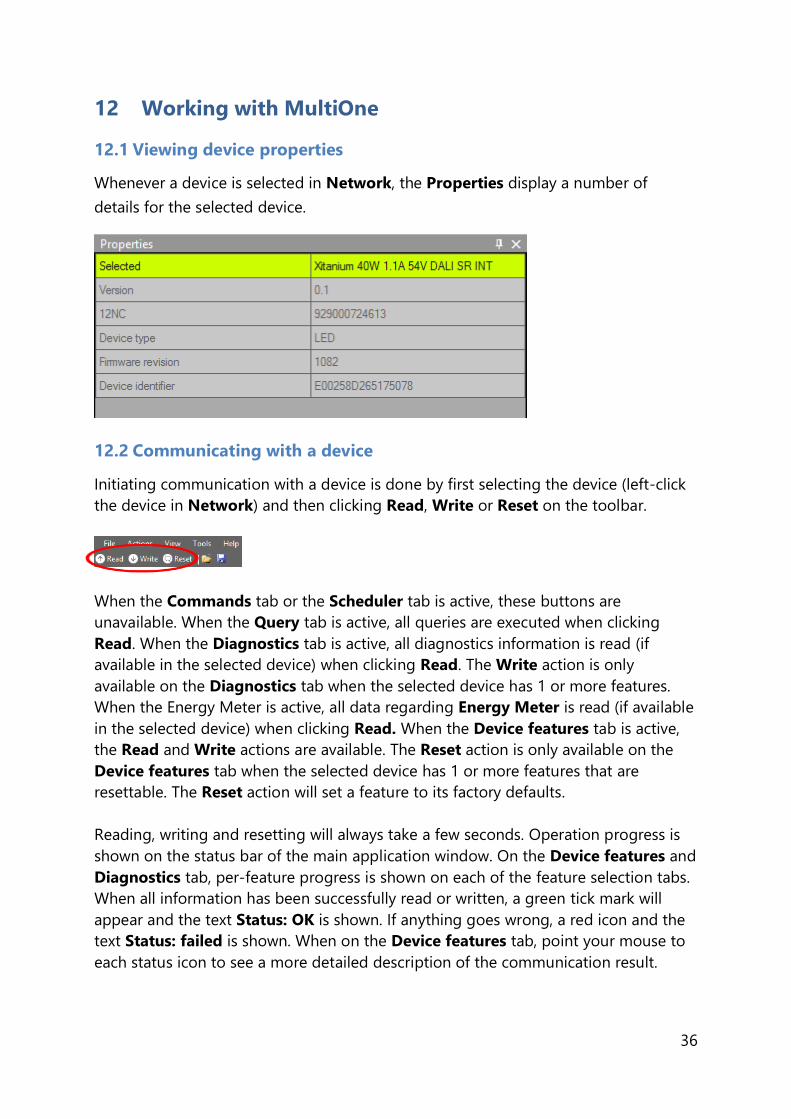
12.1 Viewing device properties
Whenever a device is selected in Network, the Properties display a number of
details for the selected device.
12.2 Communicating with a device
Initiating communication with a device is done by first selecting the device (left-click
the device in Network) and then clicking Read, Write or Reset on the toolbar.
When the Commands tab or the Scheduler tab is active, these buttons are
unavailable. When the Query tab is active, all queries are executed when clicking
Read. When the Diagnostics tab is active, all diagnostics information is read (if
available in the selected device) when clicking Read. The Write action is only
available on the Diagnostics tab when the selected device has 1 or more features.
When the Energy Meter is active, all data regarding Energy Meter is read (if available
in the selected device) when clicking Read. When the Device features tab is active,
the Read and Write actions are available. The Reset action is only available on the
Device features tab when the selected device has 1 or more features that are
resettable. The Reset action will set a feature to its factory defaults.
Reading, writing and resetting will always take a few seconds. Operation progress is
shown on the status bar of the main application window. On the Device features and
Diagnostics tab, per-feature progress is shown on each of the feature selection tabs.
When all information has been successfully read or written, a green tick mark will
appear and the text Status: OK is shown. If anything goes wrong, a red icon and the
text Status: failed is shown. When on the Device features tab, point your mouse to
each status icon to see a more detailed description of the communication result.

37
Apart from using Read and Write on the toolbar, you can directly send DALI
commands. This can be done on the Commands tab and the Scheduler tab.
In the Preferences window it is possible to enable extra verification when writing (see
chapter 12.22).
12.3 Configuring device features
You can configure all features that are supported by a specific Philips device. For any
device selected in the Network, the Device features tab displays the set of device
features that corresponds to this device. Upon selecting another device, the Device
features tab will be updated as well. This mechanism ensures that only the features
supported by the selected device can be configured.
The Device features tab has a panel with a column of tabs on the left-hand side.
Each feature has its own tab. For most devices a Summary tab is available as well.
To make sure that the feature information in the Device features tab corresponds to
the selected device, click Read on the toolbar.

38
Note that some features might be OEM Readout-protected. OEM Readout-protected
features are indicated by a padlock icon in the Read feature configuration window.
If an OEM Readout-protected feature is read, a dialog will appear asking for an access
level and a password.
After providing a correct access level and password, and clicking OK, the OEM
Readout-protected features will be read. By clicking Cancel none of the selected
features will be read. If an incorrect access level and/or password were provided, the
OEM Readout-protected features will receive a status icon indicating failure (see
below).
To make sure that the feature information is stored in the selected device, click Write
on the toolbar. If you want to reset certain features to its default settings, click Reset
on the toolbar. Be aware that you need to click the Read button afterwards to reload
the reset values.
Note also that some features might be OEM Write-protected. OEM Write-protected
features are also indicated by a padlock icon in the Write feature configuration
window.

39
Also note that you must select a check box to indicate that the device already has an
OWP password configured. MultiOne does not know this, because the configuration
of a device is not always read before a Write action takes place. When the check box
is selected and the Write button is clicked, a dialog will appear asking for a password.
When the OWP configuration was already read, MultiOne knows the current OWP
configuration and the check box will not be shown. In that way, MultiOne will show
the password dialog only in case if OWP is enabled in the device and a write
protected feature is selected.
After providing a correct password and clicking OK, the OEM Write-protected
features will be written. By clicking Cancel none of the selected features will be
written. If an incorrect password was provided, the OEM Write-protected features will
receive a status icon indicating failure (see below).
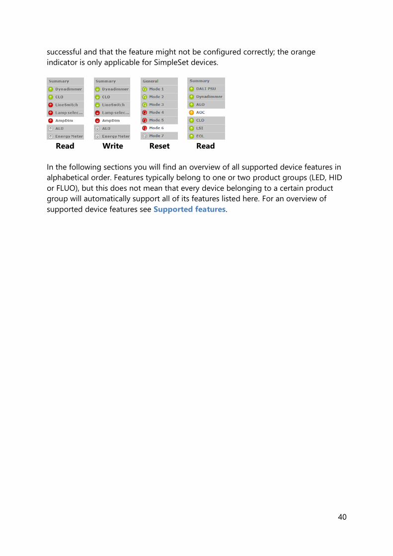
For Read, Write and Reset actions, status icons will be shown when a feature is being
read or written. There are four different colors used for the icons: red, orange, green
and grey.
Red means that the read or write action failed. The green icon indicates that reading
or writing was successful and that all the data was sent to the driver. This does not
mean that all data is actually received (see Write and Verify in chapter 12.18.1). The
grey icon is used to display that the read or write action is pending for the specific
feature. An orange icon indicates that the last write action for the feature was not
40
successful and that the feature might not be configured correctly; the orange
indicator is only applicable for SimpleSet devices.
Read Write Reset Read
In the following sections you will find an overview of all supported device features in
alphabetical order. Features typically belong to one or two product groups (LED, HID
or FLUO), but this does not mean that every device belonging to a certain product
group will automatically support all of its features listed here. For an overview of
supported device features see Supported features.

41
12.3.1 0-10V / 1-10V (SR bridge)
Product group
CONTROL
Description
The 0-10V interface requires special configuration to match the 0-10V (or 1-10V)
dimming curves of the connected drivers. The SR Bridge needs to correctly and
accurately translate the DALI arc power commands to the correct 0-10V dimming
voltages for the connected drivers such that the appropriate LED driver output
current is achieved. This feature is used to configure the dimming curve by either
selecting a predefined fixed curve or specifying a curve manually.
Usage
Use the drop down box to select the 0-10V (or 1-10V) curve that should be used for
the SR Bridge. There are four fixed curves (1-10V curved, 0-10V linear, 1-9V linear and
0-10V logarithmic) selectable and there is a possibility to select the User specified
option.

42
Selecting the ‘User specified’ ZTV curve makes the User specified curve properties
visible which can be used to construct a specific 0-10V (or 1-10V) curve. Both the Dim
level and 0-10V / 1-10V values can be changed to create a specific 0-10V (or 1-10V)
curve.
Note! 0-10V linear curve also includes the European 1-8V linear curve.
12.3.2 0-10V / 1-10V (LED driver)
Product group
LED
Description
Use this feature to set the minimum dim level when using 1-10V.
Usage
Use the slider or the text field to select a value. The value represents the light
level.
Use the drop down box to select the wanted curve selection (0-10V linear, 1-
9V linear, 1-10V curved or 0-10V logarithmic). The curve selection is device
dependent. Note! 0-10V linear curve also includes the European 1-8V linear
curve.
Use the Enable dim to off checkbox to enable or disable the dim to off
functionality.
Use the first drop down box to select the wanted fade on time value. This
value represents the time to turn on and start dimming up to target dim level.
Use the second drop down box to select the wanted fade off time value. This
value represents the time to start dimming down until the light is off.

43
12.3.3 ActiLume General
Product group/family
CONTROL/ActiLume DALI
Description
Use this feature to configure general ActiLume settings.
Usage
Use the various drop down boxes, check boxes and text fields to make a
configuration.
Please refer to the ActiLume DALI gen2 Application Guide for further details.

44
Product group/family
CONTROL/ActiLume Wireless
Description
Use this feature to configure general ActiLume settings.
Usage
Use the various drop down boxes, check boxes and text fields to make a
configuration.
Please refer to the ActiLume Wireless Application Guide for further details.
12.3.4 ActiLume Mode
Product group/family
CONTROL/ActiLume DALI

45
Description
Use this feature to configure ActiLume settings that apply to the system’s modes. For
ActiLume DALI gen2, up to 16 modes are shown, each of which has its own feature
tab on the left-hand side. Use the ActiLume Mode feature to configure settings for
each individual mode.
Usage
Use the various drop down boxes, check boxes and text fields to make a
configuration. Click the Reset to factory defaults button to reset the current mode
to the factory defaults.
Please refer to the ActiLume DALI gen2 Application Guide for further details.
Product group/family
CONTROL/ActiLume Wireless
Description
Use this feature to configure ActiLume settings for that apply to the system’s modes.
For ActiLume Wireless, up to 32 modes are shown, each of which has its own feature
tab on the left-hand side. Use the ActiLume Mode feature to configure settings for
each individual mode.
Usage
Use the various drop down boxes, check boxes and text fields to make a
configuration.
Please refer to the ActiLume Wireless Application Guide for further details.
46
12.3.5 ActiLume Scene
Product group/family
CONTROL/ActiLume DALI
Description
Use this feature to configure ActiLume settings that apply to the system’s scenes. For
ActiLume DALI gen2, 5 scenes are shown, each of which has its own feature tab on
the left-hand side. Use the ActiLume Scene feature to configure settings for each
individual scene.
Usage
Use the various check boxes and text fields to make a configuration.
Please refer to the ActiLume DALI gen2 Application Guide for further details.
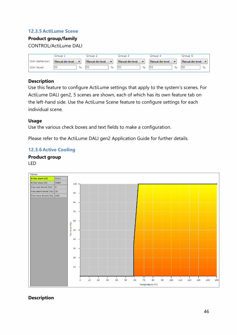
12.3.6 Active Cooling
Product group
LED
Description

47
Use this feature to control the fan of the LED module and minimize audible noise
from the active cooling unit. The driver increases the fan output level (and so the
speed of the fan) when temperature of the LED module becomes too high. When the
fan output level increases the temperature of the LED module should be reduced.
The customer can specify the temperature limits to make sure the fan output level is
kept as low as possible and will only increase when needed so the audible noise is
reduced.
Usage
Drag the points or the lines in the resulting graph to adjust the configuration.
Alternatively, use the table to enter values directly.
Note! For a detailed technical description of the characteristics of the device model,
like constraints and limitations, please refer to Device-specific technical description.
12.3.7 Adjustable Light Output
Product group
HID, LED
Description
Use the Adjustable Light Output (ALO) feature to regulate the light output to a
desired optimum value. You can create a “virtual lamp” with output different than
what the standard wattages offer.
Usage
Select the Enable check box to use this feature. Use the slider or the text field to
select an ALO value. The value represents the light level. The ALO min value (only
available for LED devices, not available for all devices) can be used to set the lowest
possible ALO value.
48
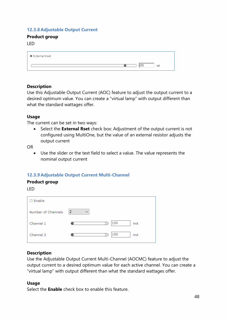
12.3.8 Adjustable Output Current
Product group
LED
Description
Use this Adjustable Output Current (AOC) feature to adjust the output current to a
desired optimum value. You can create a “virtual lamp” with output different than
what the standard wattages offer.
Usage
The current can be set in two ways:
Select the External Rset check box: Adjustment of the output current is not
configured using MultiOne, but the value of an external resistor adjusts the
output current
OR
Use the slider or the text field to select a value. The value represents the
nominal output current
12.3.9 Adjustable Output Current Multi-Channel
Product group
LED
Description
Use the Adjustable Output Current Multi-Channel (AOCMC) feature to adjust the
output current to a desired optimum value for each active channel. You can create a
“virtual lamp” with output different than what the standard wattages offer.
Usage
Select the Enable check box to enable this feature.

49
Select the Number of Channels box to define the number of channels that will be
available to adjust the output current. Use the slider or the text field to select a value
for each active channel. The value represents the nominal LED output current.
Note! There is a range limit in the values that corresponds with the maximum and
minimum values of the total nominal LED current that is used in MultiOne.
12.3.10 Adjustable Startup Time
Product group
LED
Description
At power on, the fast fade-up of light can be unpleasant in certain applications. To
avoid such a situation, the device fade-up time at startup can be adjusted.
Usage
Use the slider or the text field to select a value. The value represents the start fade-up
time in milliseconds.
12.3.11 AmpDim
Product group
HID, LED
Description
Use this feature to adjust the light output of a lamp by adjusting the mains voltage of
the device.

50
Usage
Select the Enable* check box to use this feature (note that LED devices do not have
this check box). Drag the points or the lines in the graph to create the desired
configuration. Alternatively, use the table to directly enter values.
Note! For a detailed technical description of the characteristics of the device model,
like constraints and limitations, please refer to Device-specific technical description.
* Note! If the device supports interface selection, then this feature can only be
enabled through the interface selection and the enable will not be shown here.
12.3.12 Auxiliary Power Supply Voltage
Product group
LED
Description
Use this feature to configure the Auxiliary Power Supply feature in the device.
Usage
Select the Output voltage box to define the desired output voltage for the auxiliary
supply.
12.3.13 Coded Light On and Off
Product group
LED
Description
Use this feature to enable/disable the Coded Light feature in the device.
Usage
Select the Enable check box to use this feature.
12.3.14 Coded Mains
Product group
LED

51
Description
Use this feature to configure the coded mains settings that are used when a coded
mains command is received from a transmitter regarding the requested dimming
scene for the driver.
Usage
Select the Enable* check box to use this feature and enable the coded mains
interface on the driver. This feature has the following parameters:
Override*: If the check box is selected, that means the dim level can be
overridden by other dimming interfaces.
Fade time: Used to indicate how long it takes to perform a fade when
switching scenes. The corresponding timings can be found in the driver
specifications, and the corresponding time for the selected Fade time is also
displayed next to the selection. In case Fade time is 0, the Fast fade time
setting is used.
Fast fade time: Used to indicate how long it takes to perform a fade when
switching scenes. The corresponding timings can be found in the driver
specifications, and the corresponding time for the selected Fast fade time is
also displayed next to the selection. In case both Fade time and Fast fade
time are 0, it means that there is no fade and the transition between scenes
takes place immediately.
Fallback detection time: Indicates the time after a driver power cycle that is
used to wait for a valid coded mains command. In case no valid command is
received within this time frame, the driver will switch to the fallback scene
(Scene 0).
Power on level: The light level applied when the driver is powered and before
the first valid coded mains command is received.
Scenes: Configurable dimming levels for a driver. A driver contains 13 scenes
which can be configured individually between 0 and 100%. Scene 0 is the

52
fallback scene which can also be configured as ‘keep the last defined dim-
level’.
* Note! If the device supports interface selection, then this option can only be
configured through the interface selection and the option will not be shown here.
12.3.15 Coded Mains Standalone Receiver
Product group
CONTROL
Description
Use this feature to configure the control output for the coded mains standalone
receiver.
Usage
Select one of the options to set the desired control output.
12.3.16 Constant Light Output
Product group
HID, LED
12.3.16.1 HID version
The HID version of Constant Light Output (CLO) has two check boxes. Select the
Enable check box to use the device’s built-in Constant Light Output profile. Select the
Reset check box to reset this feature, including resetting the lamp operating hours
parameters. This is useful when replacing the HID lamp.
12.3.16.2 LED version
The Constant Light Output feature for LED devices will show the following window:

53
When a newer version of CLO is present in the device, the following window will be
displayed:
Description
The lumen output of a LED module usually decreases over its lifetime. To
compensate, a schedule can be created that gradually increases the lamp’s power
level over time.
Usage

54
Select the Enable check box to use this feature. Click the New button to create a
default schedule or click the Plus button to individually add scenes.
When creating a new schedule, in the dialog window that pops up you can either
select an empty schedule, a default schedule or a custom schedule.
When selecting a custom schedule, you have to enter a number of parameters that
will define the CLO schedule. These are:
Maximum working hours: the largest number of working hours for which the
CLO schedule is defined. This corresponds to the maximum value of the
horizontal axis in the resulting CLO graph.
Number of scenes: the number of scenes (bars in the graph, or in the newer
version the points in the graph) into which the total number of burning hours
is divided
Initial power level: the power level that is the starting point at 0 burning
hours
Final power level: the power level at the end of the defined lifetime (the value
given for maximum number of burning hours)
After clicking Finish a CLO schedule will be created using linear interpolation of the
provided values.
Drag the points or the lines in the resulting graph to adjust the configuration.
Alternatively, use the table to enter values directly. Single or multiple table rows can
be removed by clicking the Minus button.
Note! The reliable use of Constant Light Output requires extensive LED specification
assessment of life time behavior of LEDs.
12.3.16.3 LED version (simplified)
The simplified Constant Light Output feature will show the following window:

55
Description
The lumen output of a LED module usually decreases over its lifetime. To
compensate, a schedule can be created that gradually increases the lamp’s power
level over time. By configuring the Maximum working hours and the Initial power
level a linear schedule is defined which consists of 16 scenes. The first scene starts at
0h and at the specified initial power level. The last scene starts at the specified
working hours and at 100% power level.
Usage
Select the Enable check box to use this feature. Use the Maximum working hours
slider to configure the moment in time where the LED module will use the final power
level.
Use the Initial power level slider to configure at which power level the LED module
will initially start.
Note! The reliable use of Constant Light Output requires extensive LED specification
assessment of life time behavior of LEDs.
12.3.17 Constant Light Output Multi-Channel
Product group
LED
Description
Use the Constant Light Output Multi-Channel (CLOMC) feature to adjust the light
output for each active channel.
56
Usage
Select the Enable check box to enable this feature.
Select the Number of Channels box to define the number of channels that will be
available to adjust the light output. Modify the values in the table to achieve the
desired schedule.
12.3.18 Correlated Color Temperature
Product group
LED
Description
The CCT value is the actual Correlated Color Temperature value of a Luminaire
device. In this way, the user can configure the requested light color of the Luminaire's
LED module.
Usage
Select the CCT value from the drop down box to change the Correlated Color
Temperature. This value is represented in Kelvin.
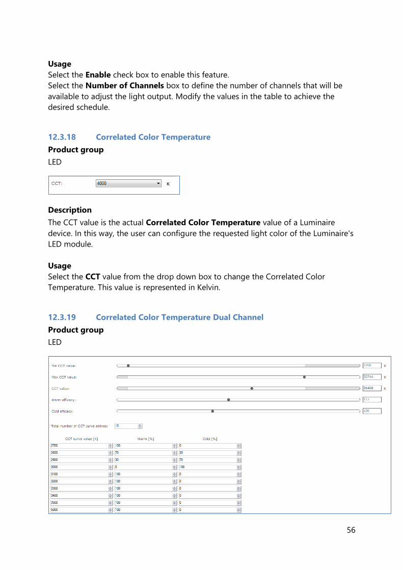
12.3.19 Correlated Color Temperature Dual Channel
Product group
LED

57
Description
Use the Correlated Color Temperature Dual Channel (CCTDC) to configure the
light color of the Luminaire's LED module.
Usage
Use the Min CCT value slider to select the minimum permitted of CCT value of the
luminaire’s LED module. This value is represented in Kelvin.
Use the Max CCT value slider to select the maximum permitted of CCT value of the
luminaire’s LED module. This value is represented in Kelvin.
Use the CCT value slider to select the CCT value based in Min CCT value and Max
CCT value set. This value is represented in Kelvin.
Use the Warm efficacy slider to select a value. This is the number of LEDs that
radiate warm light in the LED module.
Use the Cold efficacy slider to select a value. This is the number of LEDs that radiate
cold light in the LED module.
Select the Total number of CCT curve entries to construct the CCT curve that will be
available to adjust the LED color. The entries should be in the ascending order of the
color temperature.
Each CCT curve entry will represent color temperature with warm percentage and
cold percentage.

58
12.3.20 Corridor Mode
Product group
FLUO, LED
Description
Corridor Mode feature depends on Touch and Dim feature. The Corridor Mode
feature adjusts the light to a defined level when a presence sensor detects a person.
Corridor Mode can only be activated when the device is in Touch and Dim mode.
Usage
Select the Enable check box to use this feature. It is not possible to activate the driver
via Touch and Dim, when this check box is not selected.
This feature has the following parameters:
Normal level: Light level to be set when presence sensor detects activity
Background level: Low light level to be set when no presence is detected
after the fade time
Delay time: The time from the moment the sensor has switched off and the
moment the device will start to fade to background level
Fade time: The time used to fade from normal level to background level
Prolong time: When reaching background level, the time after which the
device will be switched off
Activation time: The time during which a mains signal must be detected,
before the device will switch to Corridor Mode
59
Alternatively to using the sliders, some lines and points in the graph can be dragged
to adjust the configuration.
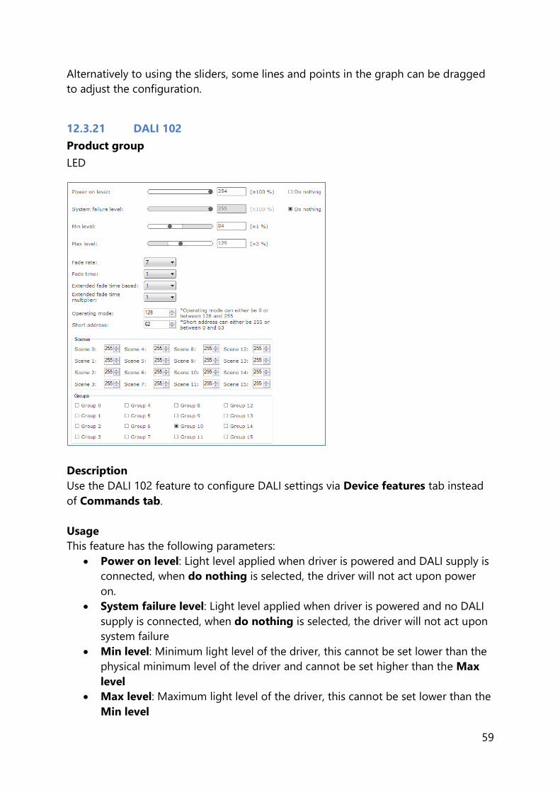
12.3.21 DALI 102
Product group
LED
Description
Use the DALI 102 feature to configure DALI settings via Device features tab instead
of Commands tab.
Usage
This feature has the following parameters:
Power on level: Light level applied when driver is powered and DALI supply is
connected, when do nothing is selected, the driver will not act upon power
on.
System failure level: Light level applied when driver is powered and no DALI
supply is connected, when do nothing is selected, the driver will not act upon
system failure
Min level: Minimum light level of the driver, this cannot be set lower than the
physical minimum level of the driver and cannot be set higher than the Max
level
Max level: Maximum light level of the driver, this cannot be set lower than the
Min level

60
Fade rate: Number of fade steps
Fade time: This is used to indicate how long it takes to perform fade
Extended fade time base: Used to calculate extended fade time
Extended fade time multiplier: Used to calculate extended fade time
Operating mode: Operating mode of the driver
Short address: Short address of the driver
Scenes: A configurable preset level for the driver, a driver contains 16 scenes
for which can be configured individually
Groups: Defines in which groups the driver is located
12.3.22 DALI 202
Product group
LED
Description
Use the DALI 202 feature to configure DALI settings via Device features tab instead
of Commands tab.
Usage
This feature has the following parameters:
Emergency level: Arc power level during emergency, when do nothing is
selected, the driver will not act upon emergency level
Prolong time: Duration of extended emergency mode
Function test interval: Interval between function tests
Duration test interval: Interval between duration tests
Test execution timeout: Timeout for a pending function or duration test
Lamp emergency time: Accumulated lamp on time while powered by battery
Lamp total operation time: Accumulated lamp on time

61
12.3.23 DALI Power Supply
Product group
LED
Description
Use the DALI Power Supply (DALI PSU) feature to enable the device so it will deliver
the power supply for DALI communication by itself.
Usage
Select the Enable check box to use this feature.
12.3.24 Daylight override / Daylight switching
Product group
CONTROL
Description
Use the DLO/DLS feature to configure the daylight dependent settings for the device.
Usage
This feature has the following parameters:
Enable daylight dependent override: When the Enable daylight dependent
override check box is selected, the lights remain off in case occupancy is
detected.
Enable daylight dependent switching: Select the Enable daylight
dependent switching check box to switch the light off in case sufficient
daylight is available.
12.3.25 DC Emergency
Product group
FLUO, LED

62
Description
This feature is used together with a DC central battery system. The device will dim to
a specific level, as soon as a DC voltage is detected at the mains input instead of an
AC voltage on the mains input of the device. The dimming of the lamps can either be
enabled or disabled during this DC Emergency operation.
Usage
Select the Enable check box to use this feature. Use the slider or the text field to
select a value. The value represents the arc power level when in DC Emergency mode
(the label on the right gives the approximate light level percentage). Select the Allow
dimming check box to allow dimming when in DC Emergency mode.
12.3.26 Device Info
Product group
LED
Description
Use the Device Info feature to get or set the device information which may be
luminaire specific.
Usage
Select the Device Info feature tab to read or write the device information.
63
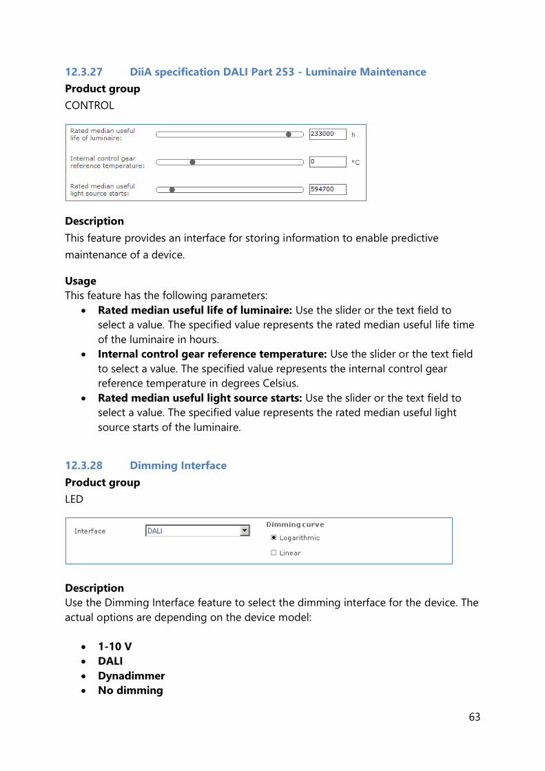
12.3.27 DiiA specification DALI Part 253 - Luminaire Maintenance
Product group
CONTROL
Description
This feature provides an interface for storing information to enable predictive
maintenance of a device.
Usage
This feature has the following parameters:
Rated median useful life of luminaire: Use the slider or the text field to
select a value. The specified value represents the rated median useful life time
of the luminaire in hours.
Internal control gear reference temperature: Use the slider or the text field
to select a value. The specified value represents the internal control gear
reference temperature in degrees Celsius.
Rated median useful light source starts: Use the slider or the text field to
select a value. The specified value represents the rated median useful light
source starts of the luminaire.
12.3.28 Dimming Interface
Product group
LED
Description
Use the Dimming Interface feature to select the dimming interface for the device. The
actual options are depending on the device model:
1-10 V
DALI
Dynadimmer
No dimming

64
AmpDim
LineSwitch
Coded Mains
When DALI has been selected, an additional setting appears with which the dimming
behavior can be set. Options are Logarithmic and Linear dimming curves.
Usage
Use Dimming Interface to select the desired dimming interface.
Product group
FLUO, LED
Description
Use the Dimming Interface feature to select the dimming interface for the device.
Usage
The available dimming interfaces are stored in the device and therefore need to be
read out. When the interfaces are found it will be possible to select Automatic
selection (enable all interfaces), No dimming (disable all interfaces) or a single
interface.
Product group
LED
Description
Use the Dimming Interface feature to enable dimming interfaces for the device.
Usage
The available dimming interfaces are stored in the device and therefore need to be
read out. When the interfaces are found it will be possible to select and enable the
main interface. Some interfaces have the possibility to be overridden by another
interface. If that’s the case the Can be overridden by part will show the other
possible interfaces that can be enabled together with the main dimming interface.

65
Note! All selected interfaces (both the main interface and the selected Can be
overridden by interfaces) will have their Enable value set to true if present. Else the
value is set to false.
Note! The Override for the main interface is automatically set to true if any Can be
overridden by interface is selected. Else the value is set to false. The Override value
for all other interfaces (if present) are set to false even if the main interface does not
support any Can be overridden by interfaces.
12.3.29 Driver addressing
Product group
LED
Description
Use the Driver addressing feature to determine the DMX settings for the device.
Usage
DMX address: DMX address
Enable: When the check box is cleared the grouping feature within one DMX
address is not used.
Group size: Number of devices that operate within one group, all responding
to the same DMX address.
Group address: Device number within the group of devices that respond to
the same address.
DMX Personality: RDM Personality.
12.3.30 Driver Temperature Limit
Product group
LED

66
Description
Use the Driver Temperature Limit feature to determine the temperature protection
settings for the device.
Usage
Select the Enable check box to use this feature. Use the sliders to changes the values
for this feature.
Enable: Select the Enable check box to use this feature.
Start dim: Set the temperature at which dimming start.
Stop dim: Set the temperature at which the dimming stops.
Shut down: Set the temperature at which the dim level will be set to zero.
When selecting the N/A checkbox, the shutdown temperature is not applied
Dim level: Set the dim level for the Stop dim temperature.
12.3.31 Dwell Time
Product group
CONTROL
Description
Use the Dwell Time feature to postpone present detection for a certain time.
Usage
This feature has the following parameters:
Activated: Select the Activated check box to activate the feature.
Enabled: Select the Enabled check box to turn Dwell Time on.

67
12.3.32 Dynadimmer
Product group
HID, LED
Description
Use Dynadimmer to create a dynamic dimming schedule over a period of time.
Usage
Select the Enable* check box to use this feature. This feature has a number of
options, depending on the device model:
Time based: switch between absolute and relative time schedules. When the
Time based check box is cleared, the Dynadimmer schedule will use its
automatically learned midnight point as a reference for timekeeping. When the
Time based check box is selected, the reference point is the moment when
the mains are switched on. Selecting the Time based check box changes the
graph and removes its dotted midnight line. Note that not all devices support
Time based Dynadimmer.
Midnight shift: the midnight point depends on the geographical location.
Enter the midnight shift in minutes or use the midnight shift calculation
window to automatically adjust the midnight point by the specified offset. Use
the calculation button to either manually provide latitude and longitude
coordinates or to choose a predefined location. The midnight shift option is
unavailable when the Time based check box has been selected.
The midnight shift calculation dialog window looks as follows:

68
Latitude: the latitude of the location in degrees, minutes and seconds. The
value that represents the degrees cannot be negative.
N-S: the direction for latitude of the location. The user can either select North
or South value.
Longitude: the longitude of the location in degrees, minutes and seconds. The
value that represents the degrees cannot be negative.
E-W: the direction for longitude of the location. The user can either select East
or West value.
Time zone: the time zone of the location. For GMT+1 enter 1, for GMT-1 enter
-1, and so on.
Daylight saving: indication whether daylight saving should be dealt with or
not.
Click OK to save result of your calculation as the new midnight shift. Note that
clicking OK is not directly saving your data to the driver. To save midnight shift to a
driver you will have to write the whole feature.
Click the New button to create a default schedule or click the Plus button to add
scenes individually. Drag the points or the lines in the graph to create the desired
configuration. Alternatively, use the table to enter values directly. Remove single or
multiple table rows by clicking the Minus button.
Note! The device will follow the dimming schedule. When the output level in the
dimming schedule is below the physical min level of the selected lamp, the physical
min level will be used. However, some devices are also capable to switch off during
the dimming schedule, if a scene was configured at 0 %.
The physical min level of the selected lamp is indicated by the gray-dotted line in the
graph.
Note! This feature can contain the override check box in some cases. If the check
box is selected, that means the dim level can be overridden by other dimming
interfaces.
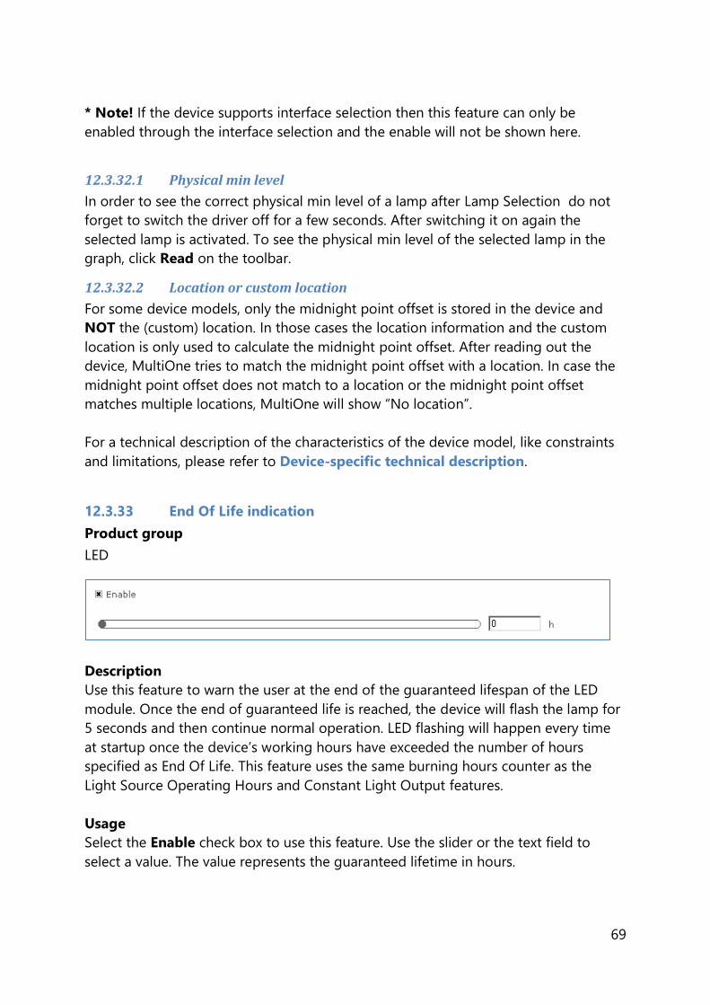
69
* Note! If the device supports interface selection then this feature can only be
enabled through the interface selection and the enable will not be shown here.
12.3.32.1 Physical min level
In order to see the correct physical min level of a lamp after Lamp Selection do not
forget to switch the driver off for a few seconds. After switching it on again the
selected lamp is activated. To see the physical min level of the selected lamp in the
graph, click Read on the toolbar.
12.3.32.2 Location or custom location
For some device models, only the midnight point offset is stored in the device and
NOT the (custom) location. In those cases the location information and the custom
location is only used to calculate the midnight point offset. After reading out the
device, MultiOne tries to match the midnight point offset with a location. In case the
midnight point offset does not match to a location or the midnight point offset
matches multiple locations, MultiOne will show “No location”.
For a technical description of the characteristics of the device model, like constraints
and limitations, please refer to Device-specific technical description.
12.3.33 End Of Life indication
Product group
LED
Description
Use this feature to warn the user at the end of the guaranteed lifespan of the LED
module. Once the end of guaranteed life is reached, the device will flash the lamp for
5 seconds and then continue normal operation. LED flashing will happen every time
at startup once the device’s working hours have exceeded the number of hours
specified as End Of Life. This feature uses the same burning hours counter as the
Light Source Operating Hours and Constant Light Output features.
Usage
Select the Enable check box to use this feature. Use the slider or the text field to
select a value. The value represents the guaranteed lifetime in hours.

70
12.3.34 FCC
Product group
CONTROL
Description
Use this feature to enter the settings for the FCC test, and to enable the FCC test.
Usage
Select the Enable check box to use this feature. The feature has the following
parameters:
Test id: use the drop down box to select the test.
ZigBee channel: use the drop down box to select the ZigBee channel for the
test.
Attenuation: use the slider or the text field to select a value. The value
represents the attenuation for the test.
Light level: use the slider or the text field to select a value. The value
represents the light level for the test.

71
12.3.35 FccRed
Product group
Control
Description
Use this feature to put the device in a specific mode (with a constant carrier on the
wireless interface) in order to be able to perform the necessary measurements for
RED and FCC approbation.
Usage
Select the Enable check box to use this feature. The feature has the following
parameters:
Test id: use the drop down box to select the test.
Interface: use the drop down to select the desired interface.
Channel: use the drop down to select the channel on which the test will be
executed. Depending on the selected interface a number of different channels
are available.
Light level: use the slider or the text field to select a value. The value
represents the light level for the test.
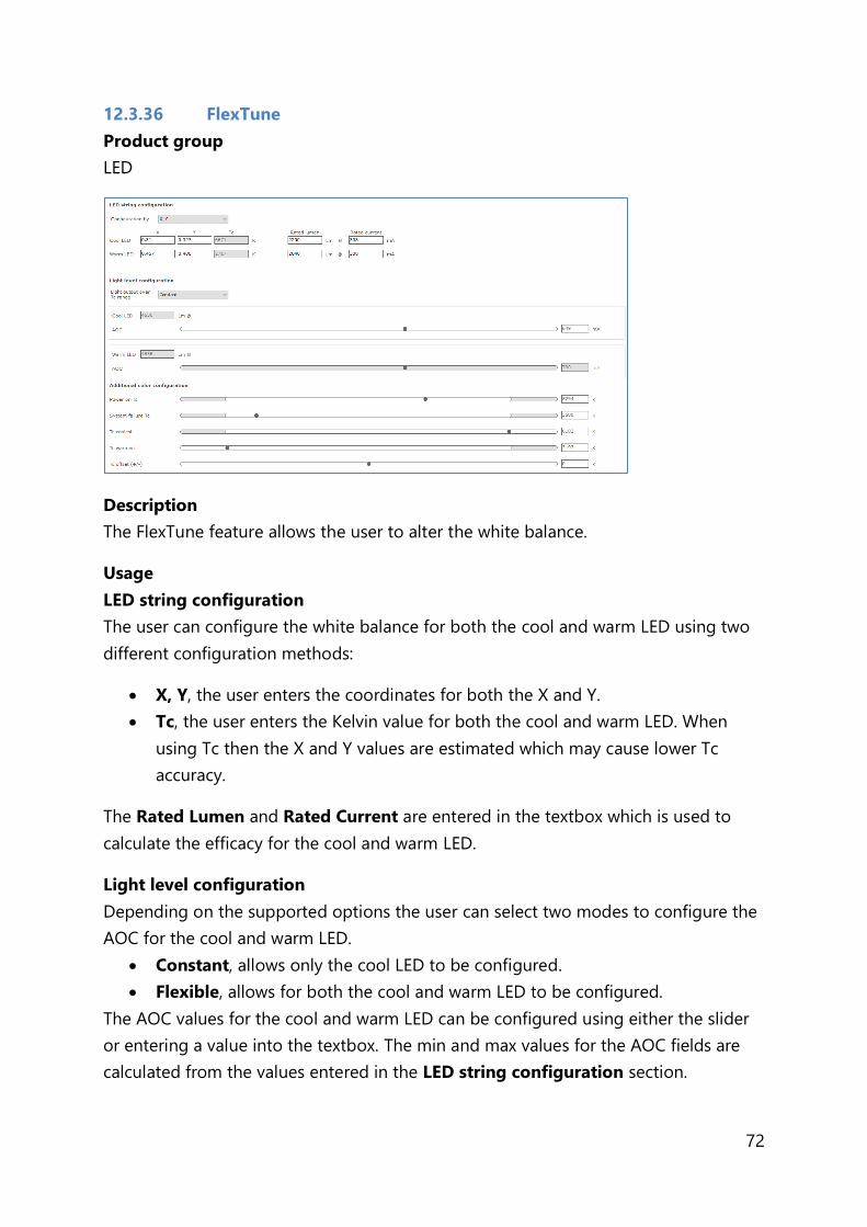
72
12.3.36 FlexTune
Product group
LED
Description
The FlexTune feature allows the user to alter the white balance.
Usage
LED string configuration
The user can configure the white balance for both the cool and warm LED using two
different configuration methods:
X, Y, the user enters the coordinates for both the X and Y.
Tc, the user enters the Kelvin value for both the cool and warm LED. When
using Tc then the X and Y values are estimated which may cause lower Tc
accuracy.
The Rated Lumen and Rated Current are entered in the textbox which is used to
calculate the efficacy for the cool and warm LED.
Light level configuration
Depending on the supported options the user can select two modes to configure the
AOC for the cool and warm LED.
Constant, allows only the cool LED to be configured.
Flexible, allows for both the cool and warm LED to be configured.
The AOC values for the cool and warm LED can be configured using either the slider
or entering a value into the textbox. The min and max values for the AOC fields are
calculated from the values entered in the LED string configuration section.

73
Additional color configuration
The additional color configuration allows to set extra parameters for the FlexTune
feature.
Power on Tc, sets the color for Tc when powered on.
Tc coolest, the coolest Tc value that can be reached by DALI commands.
Tc warmest, the warmest Tc value that can be reached by DALI commands.
Tc offset, allows a positive or negative Tc offset in Kelvin. This may be used to
offset for color shifts caused by secondary optics, light guides or external
influences.
12.3.37 Field Task Tuning
Product group
CONTROL
Description
Use this feature in combination with the EasySense so the light output can be limited
according to the selected value.
Usage
The field task tuning level is intended as maximum light level (clip level) of the
luminaire. The light output shall not be scaled against the field task tuning level.
If this level is below 100%, not the whole DALI range will be used. This is acceptable,
since when a lot of daylight is present also a small part of the range is used.
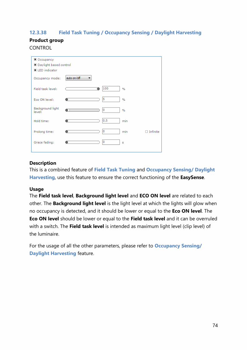
74
12.3.38 Field Task Tuning / Occupancy Sensing / Daylight Harvesting
Product group
CONTROL
Description
This is a combined feature of Field Task Tuning and Occupancy Sensing/ Daylight
Harvesting, use this feature to ensure the correct functioning of the EasySense.
Usage
The Field task level, Background light level and ECO ON level are related to each
other. The Background light level is the light level at which the lights will glow when
no occupancy is detected, and it should be lower or equal to the Eco ON level. The
Eco ON level should be lower or equal to the Field task level and it can be overruled
with a switch. The Field task level is intended as maximum light level (clip level) of
the luminaire.
For the usage of all the other parameters, please refer to Occupancy Sensing/
Daylight Harvesting feature.

75
12.3.39 Lamp Burn-in
Product group
FLUO
Description
Lamp Burn-in prevents dimming below a predefined level in the first hours of a
lamp’s life. This is to ensure that the lamp will be properly “burned in” before
dimming.
Usage
Select the Enable check box to use this feature. This feature has of two parameters:
Burn-in level: use the slider or the text field to select a value. The value
represents the maximum arc power level for dimming (the label on the right
gives the approximate light level in percent). Alternatively, select the Use
default check box to use the default value.
Burn-in time: use the slider or the text field to select a value. The value
represents the time in minutes during which the burn-in level is active.
Alternatively, select the Use default check box to use the default value.
12.3.40 Lamp Selection
Product group
HID, FLUO
Description
Use the Lamp Selection feature to select the lamp type that is connected to the
device. Options depend on the device model.
Usage

76
Use Selection to select the lamp type. Note that this feature has to be read first in
order for the options to become available. To read the feature configuration, click
Read on the toolbar.
Note! After selecting a different lamp, it is necessary to switch the driver off for a few
seconds. After switching is on again the selected lamp is activated.
12.3.41 Light Source Operating Hours
Product group
LED
Description
Use this feature to manually set or reset the number of operating hours for the LED
module. This is useful when replacing the LED module, thereby resetting features like
Constant Light Output and End Of Life indication.
Usage
Use the slider or the text field to select a value. The value represents the number of
operating hours.
12.3.42 LineSwitch
Product group
HID, LED
Description
This feature provides an interface for easy dimming via pilot-line or external sensor
(presence) of a group of lamps. Dimming to desired level can be controlled by

77
applying a 230V between the DALI inputs. The fade times can also be set using the
fade on-, fade off and switch off delay time.
Usage
Select the Enable* check box to use this feature. This feature has the following
parameters:
High V level: Use the slider or the text field to select a value. The value
represents the light level to be set when high voltage is detected on the mains.
Low V level: Use the slider or the text field to select a value. The value
represents light level to be set when low voltage is detected on the mains.
Fade up time: Use the slider or the text field to select a value. The value
represents the fade on time to be used.
Switch off delay time: Use the slider or the text field to select a value. The
value represents the switch off delay time to be used.
Fade down time: Use the slider or the text field to select a value. The value
represents the fade off time to be used.
In case the device supports Level 2 settings, these will be visible on the UI. Select the
Enabled Level 2** check box to use the second dim level function. This option has
the following parameters:
Delay for Level 2: Use the slider or the text field to select a value. The value
represents the delay time to be used in activation of the second dim level.
Level 2: Use the slider or the text field to select a value. The value represents
the light level to be set when the second dim level is active.
When the [Switch Off delay time] is programmed in combination with the second
level, the dim level during the switch off delay is the active level (depending on the
polarity this is [High V level] or [Low V level]). The [Delay for Level 2] will start after
the [Switch Off delay time] has expired.
* Note! If the device supports interface selection then this feature can only be
enabled through the interface selection and the enable will not be shown here.
** Note! When the LineSwitch function is disabled, the enabled second level function
is implicitly also not effective. The second level uses the same fade up and fade down
times as the High V and Low V levels.

78
12.3.43 Load Fault Indicator Thresholds
Product group
CONTROL
Description
To allow the SR Bridge to set the DALI lamp failure detection properly, the SR Bridge
must be configurable to set a power limit that corresponds to the lamp failure level.
This involves setting the correct maximum power of all downstream drivers combined
and the minimum detection dimlevel for which the SR Bridge will not update the
lamp failure status.
Usage
This feature has the following parameters:
Lamp failure power level: Use the slider or the text field to select a value.
This value corresponds to the maximum power of all downstream drivers
combined.
Minimum Driver Dim Level: Use the slider or text field to select a value. This
value corresponds to the minimum detection dimlevel for which the SR Bridge
will not update the lamp failure status.

79
12.3.44 Logical Signal Input
Product group
LED
Description
Use this feature to configure an additional input signal that can be used to connect
sensors (e.g. occupancy or photo sensors) to a driver without the need for a
sophisticated OLC.
Usage
Select the Enable check box to use this feature. This feature has the following
parameters:
Mode: Use the drop down box to select the sensor connected to the
logical signal input.
Active dim level: Use the slider or the text field to select a value. The
specified value represents the active dim level in percent. The active dim
level is the dim level which will be used when the input voltage level is
equal to the selected polarity, i.e. the input signal is active.
Inactive dim level: Use the slider or the text field to select a value. The
specified value represents the inactive dim level in percent. The inactive
dim level is the dim level which will be used when the input voltage
level is opposite to the selected polarity, i.e. the input signal is inactive.
Polarity: Use the radio buttons to select the polarity of the input
voltage on which LSI should be active.
Fade on time: Use the slider or the text field to select a value. The
specified value represents the fade on time in seconds. The fade on

80
time is the time used to softly fade from the inactive dim level to the
active dim level from the moment the LSI state becomes active.
Hold off delay: Use the slider or the text field to select a value. The
specified value represents the hold off delay in seconds. The hold off
delay is the applied delay when LSI switches from active to inactive
before the fade off starts.
Fade off time: Use the slider or the text field to select a value. The
specified value represents the fade off time in seconds. The fade off
time is the time used to softly fade from the active dim level to the
inactive dim level from the moment the LSI state becomes inactive and
the hold off delay has passed.
Switch off delay: Use the slider or the text field to select a value. The
specified value represents the switch off delay in seconds. The switch off
delay is the applied delay when the fade off time is expired and Enable
output off is enabled.
Enable output off: Use the check box to enable or disable switching
the output.
The schematic below gives a visual representation of the usage of the different
parameters.
12.3.45 Lumen Level
Product group
LED
Description
This feature provides an interface for setting the lumen output value of a device.
Usage

81
Select the Luminaire efficiency correction enabled check box to use the Light
output ratio (LOR) slider. This slider is used to configure the range and step size of
the Lumen output slider.
The Light output ratio percentage will change the Lumen output slider min range,
max range, current value and step size by the same percentage.
12.3.46 Luminaire (Fixture) Information
Product group
LED
Description
Luminaire (Fixture) Information contains three mandatory fields: the Content format
ID to select the content format, the GTIN and the Identification number of the
luminaire which are used as traceability information for OEMs.
Depending on the selected Content format ID, additional fields are available for
storing more detailed information. For example, when selecting ‘Unformatted
content’ as Content format ID, the Additional info field can be used for additional
control gear information.
Usage
Content format ID: Select the format in which to store the information.
Additional fields to fill are shown on the UI (or in some cases only their
maximum allowed length change) when changing the Content format ID.
GTIN: Use the textbox to change the value. The GTIN always contains 13
digits: if the value given by the user is less than 13 digits, leading 0s will be
added till the number reach 13 digits.
Identification number: Use the textbox to change the value. The
Identification number can have up till 15 digits, however, the value given by
the user shall not exceed the value shown above in the picture.
Select Use device UID checkbox to enable copy identification number at
power-on. If the checkbox is enabled, the field Identification number is not
editable.
Additional fields are available for storing more detailed information.

82
Note! If the field Use device UID is changed, the user will need restart the device.
12.3.47 Luminaire Production Test
Product group
CONTROL
Description
This feature provides an interface to execute specific tests and validate the result.
Usage
Test id (0-31): Use the drop down box to select the test id to be executed.
Execution state: Use the drop down box to select the execution state.
o Idle: No test to execute.
o Start: Execute test at power up or when new test is selected
Test result: Result of the test.
o Not started: No test executed.
o Passed: Test executed successfully, test not started at power up.
o Failed: Test failed and will be started again at next power up.
o Unknown test id: Test not implemented, not started at next power up.
12.3.48 LumiStep
Product group
LED
Description
This feature provides a simplified version of Dynadimmer.
Usage
Select the Enable* check box to use this feature. This feature has the following
parameters:

83
Dim period: Use the drop down box to select the wanted dim period. This is
the time period the dim level will be used.
Dim level: Use the slider or the text field to select a value. The value
represents the dim level in percent. The dim level will be used during the dim
period.
* Note! If the device supports interface selection then this feature can only be
enabled through the interface selection and the enable will not be shown here.
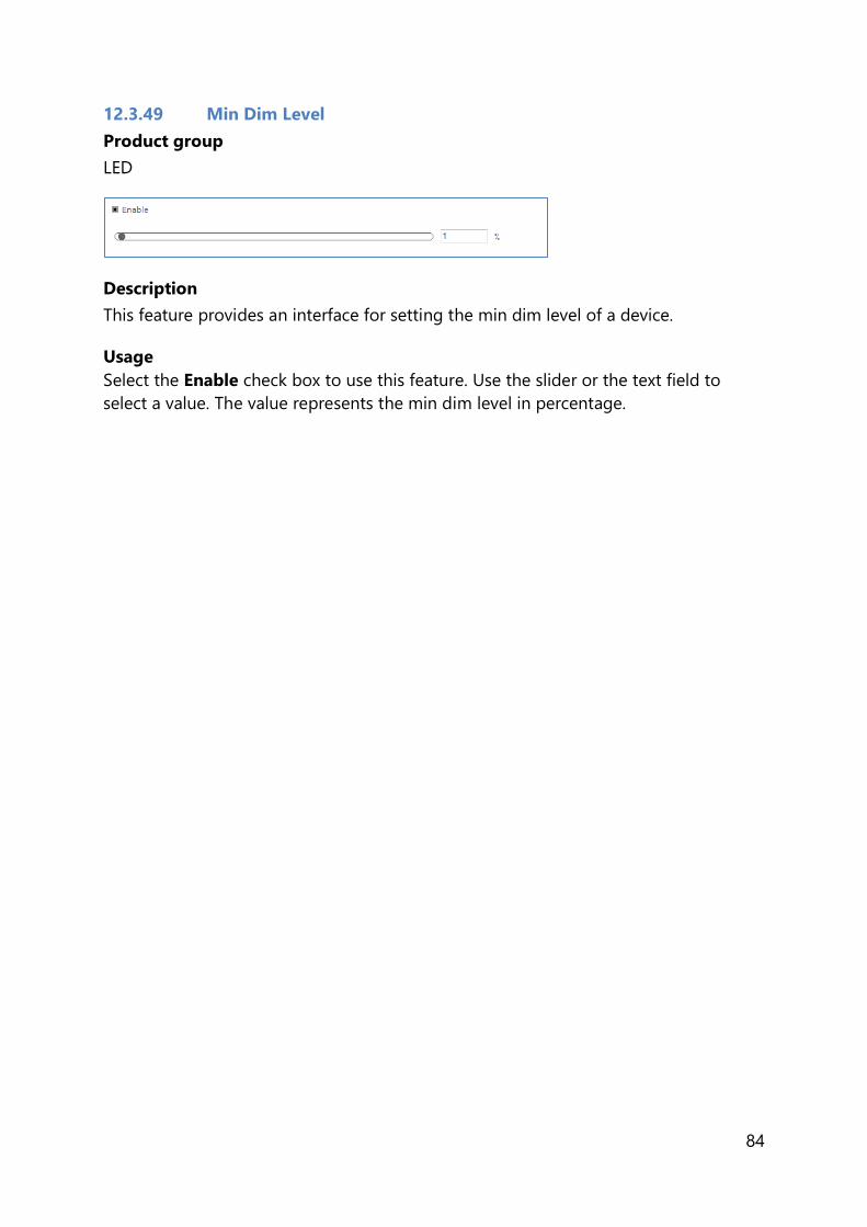
84
12.3.49 Min Dim Level
Product group
LED
Description
This feature provides an interface for setting the min dim level of a device.
Usage
Select the Enable check box to use this feature. Use the slider or the text field to
select a value. The value represents the min dim level in percentage.

85
12.3.50 Motor Control
Product group
CONTROL
Description
This feature provides an interface for setting the motor control for tilt, pan and zoom
functions of a device.
Usage
For each functions it is possible to configure the following parameters:
Select the Enable Tilt/Pan/Zoom check box to use tilt/pan/zoom
functionality.
Minimum tilt/pan/zoom range: Use the slider or the text fields to select a
value. The specified value represents the minimum range for tilt/pan/zoom
function in degrees.
Maximum tilt/pan/zoom range: Use the slider or the text fields to select a
value. The specified value represents the maximum range for tilt/pan/zoom
function in degrees.
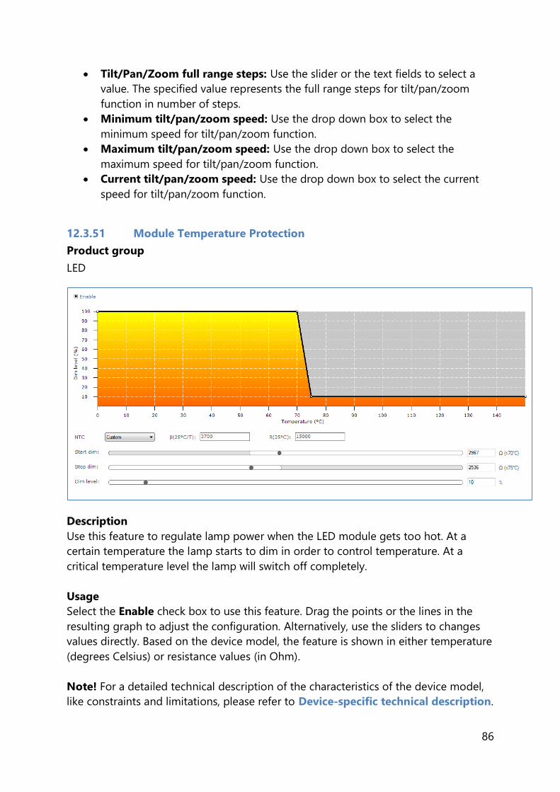
86
Tilt/Pan/Zoom full range steps: Use the slider or the text fields to select a
value. The specified value represents the full range steps for tilt/pan/zoom
function in number of steps.
Minimum tilt/pan/zoom speed: Use the drop down box to select the
minimum speed for tilt/pan/zoom function.
Maximum tilt/pan/zoom speed: Use the drop down box to select the
maximum speed for tilt/pan/zoom function.
Current tilt/pan/zoom speed: Use the drop down box to select the current
speed for tilt/pan/zoom function.
12.3.51 Module Temperature Protection
Product group
LED
Description
Use this feature to regulate lamp power when the LED module gets too hot. At a
certain temperature the lamp starts to dim in order to control temperature. At a
critical temperature level the lamp will switch off completely.
Usage
Select the Enable check box to use this feature. Drag the points or the lines in the
resulting graph to adjust the configuration. Alternatively, use the sliders to changes
values directly. Based on the device model, the feature is shown in either temperature
(degrees Celsius) or resistance values (in Ohm).
Note! For a detailed technical description of the characteristics of the device model,
like constraints and limitations, please refer to Device-specific technical description.

87
12.3.52 NTC on LEDset
Product group
LED
Description
Use this feature to regulate lamp power when the LED module gets too hot. At a
certain temperature the lamp starts to dim in order to control temperature. Configure
the resistance values to determine the dimming behavior.
Usage
Select the Enable check box to use this feature. Drag the points or the lines in the
resulting graph to adjust the configuration. Alternatively, use the sliders to changes
values directly.
Note! For a detailed technical description of the characteristics of the device model,
like constraints and limitations, please refer to Device-specific technical description.

88
12.3.53 Occupancy Sensing / Daylight Harvesting
Product group
CONTROL
Description
Use this feature in combination with the EasySense to setup an occupancy sensing
and/or a daylight harvesting mode. The occupancy sensing mode configures how
light is being controlled, based on occupancy information. The daylight harvesting
mode configures how light is being controlled, based on the amount of light in an
indoor space (contribution of natural light entering the indoor space).
Usage
The Hold time is the time whereby occupancy is no longer detected but the lights
are still on and being regulated. The Prolong time is the time at which the
background level is maintained at a fixed level. Background light level is the light
level at which the lights will glow when no occupancy is detected and Grace fading is
the time during which the lights are being dimmed down from the current light level
to the background level.
The Occupancy check box enables/disables the occupancy sensing mode. The
Daylight based control check box enables/disables the daylight harvesting mode.
When the LED indicator is enabled, the 2 LED indicators on the sensor will become
active. The yellow LED indicates whether the sensor is functional. The red LED
indicates whether occupancy is detected when the hold time is not expired yet.
The Occupancy mode defines how the lights of the system will behave.
The Eco ON level is used relative to the Field task tuning level. Only difference is
that the Eco ON level can be overruled with a switch. This can result in additional
energy savings.
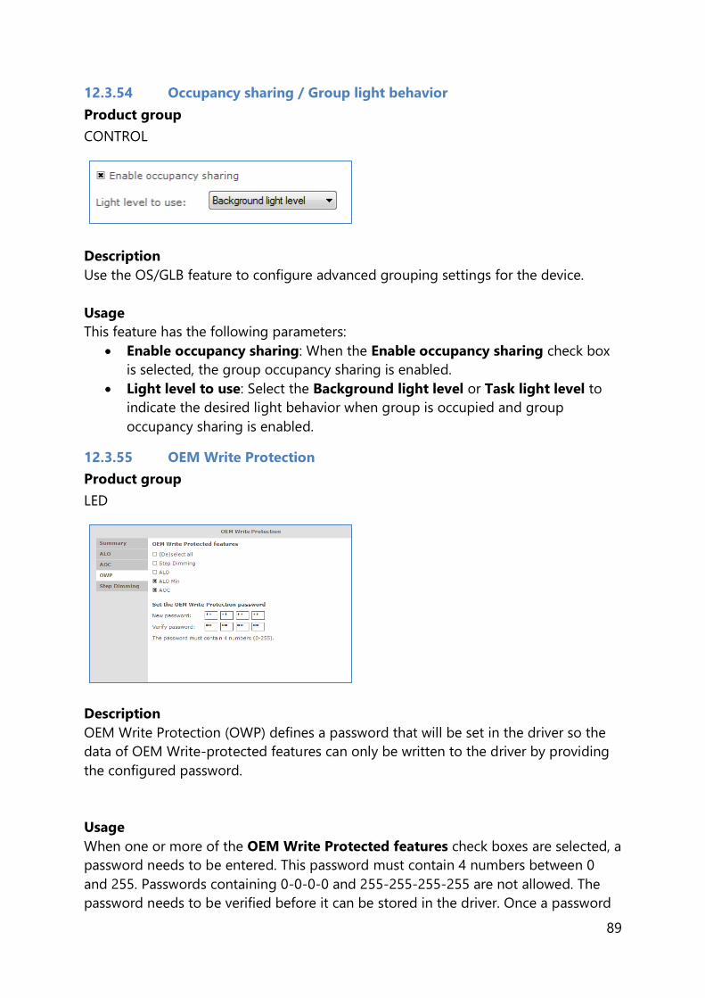
89
12.3.54 Occupancy sharing / Group light behavior
Product group
CONTROL
Description
Use the OS/GLB feature to configure advanced grouping settings for the device.
Usage
This feature has the following parameters:
Enable occupancy sharing: When the Enable occupancy sharing check box
is selected, the group occupancy sharing is enabled.
Light level to use: Select the Background light level or Task light level to
indicate the desired light behavior when group is occupied and group
occupancy sharing is enabled.
12.3.55 OEM Write Protection
Product group
LED
Description
OEM Write Protection (OWP) defines a password that will be set in the driver so the
data of OEM Write-protected features can only be written to the driver by providing
the configured password.
Usage
When one or more of the OEM Write Protected features check boxes are selected, a
password needs to be entered. This password must contain 4 numbers between 0
and 255. Passwords containing 0-0-0-0 and 255-255-255-255 are not allowed. The
password needs to be verified before it can be stored in the driver. Once a password

90
is configured into the device, it is necessary to provide the current password when
writing other features that are OEM Write-protected. These features are indicated by
a padlock icon in the Write screen.
When the OWP feature is read, only the values of the feature check boxes are shown
on-screen, so it is not possible to retrieve the currently configured password.
12.3.56 Push Button Unit LCU2070
Product group
CONTROL/ActiLume DALI
Description
The push button unit can be used to trigger one or all groups when a button is
pressed. In total there are four different buttons that can be configured.
Usage
Use the drop down boxes to select the group(s) that should be triggered when the
corresponding button is pressed.
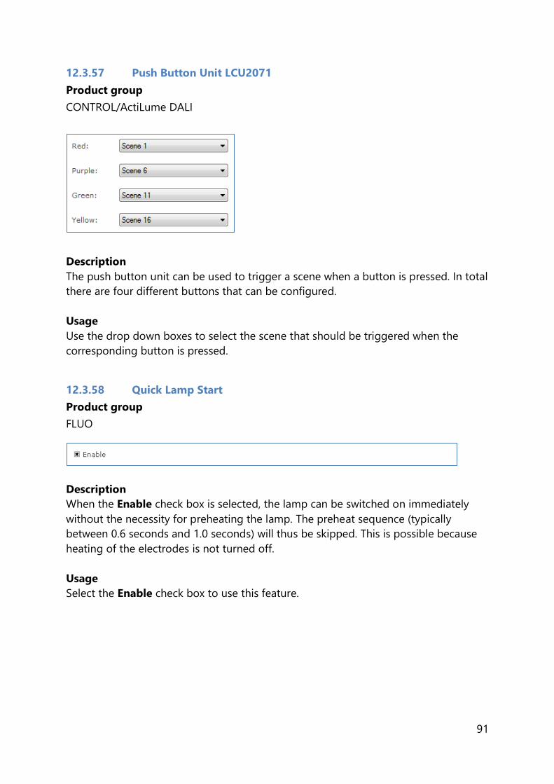
91
12.3.57 Push Button Unit LCU2071
Product group
CONTROL/ActiLume DALI
Description
The push button unit can be used to trigger a scene when a button is pressed. In total
there are four different buttons that can be configured.
Usage
Use the drop down boxes to select the scene that should be triggered when the
corresponding button is pressed.
12.3.58 Quick Lamp Start
Product group
FLUO
Description
When the Enable check box is selected, the lamp can be switched on immediately
without the necessity for preheating the lamp. The preheat sequence (typically
between 0.6 seconds and 1.0 seconds) will thus be skipped. This is possible because
heating of the electrodes is not turned off.
Usage
Select the Enable check box to use this feature.
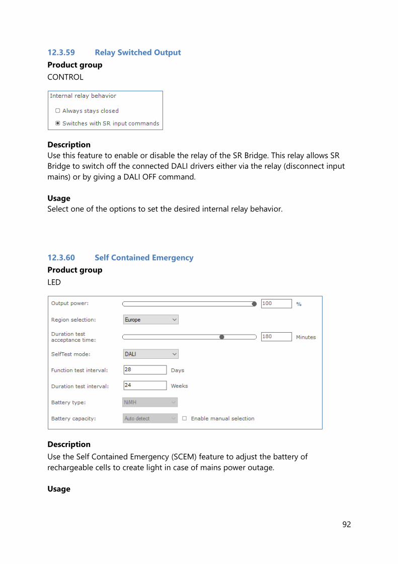
92
12.3.59 Relay Switched Output
Product group
CONTROL
Description
Use this feature to enable or disable the relay of the SR Bridge. This relay allows SR
Bridge to switch off the connected DALI drivers either via the relay (disconnect input
mains) or by giving a DALI OFF command.
Usage
Select one of the options to set the desired internal relay behavior.
12.3.60 Self Contained Emergency
Product group
LED
Description
Use the Self Contained Emergency (SCEM) feature to adjust the battery of
rechargeable cells to create light in case of mains power outage.
Usage

93
Output power: use the slider or the text field to select a value. The value
represents the percentage of output power. The default is 100%.
Region selection: use the drop down box to select the region specific mode.
The default is Europe.
Duration test acceptance time: use the slider or the text field to select a
value. The value represents the emergency time. If the region selection is set to
Australia mode, the emergency duration is fixed at 90 minutes.
SelfTest mode: use the drop down box to select the standard mode (DALI or
Fixed). The default is fixed.
Function test interval: use the textbox to set the value. The value represents
the number of days. If the selftest mode is set to fixed, the function test
interval is set to 28.
Duration test interval: use the textbox to set the value. The value represents
the number of weeks. If the selftest mode is set to fixed, the duration test
interval is set to 24.
Battery type: use the drop down box to select the battery type value.
Battery capacity: use the drop down box to select the battery capacity size.
The value represents the capacity of battery cell count. This value only can be
changed once the Enable manual selection is checked.
12.3.61 SR Power Supply
Product group
LED
Description
Use the SR Power Supply (SR PSU) feature to enable the device so it will deliver the
power supply for DALI communication by itself.
Usage
Select the Enable check box to use this feature.
Select the High range current check box to enable the high range current
functionality.
Select the Auto disable check box to enable the auto disable functionality.
Select the Heartbeat check box to enable the heartbeat functionality.
Select the Last gasp check box to enable the last gasp functionality.

94
12.3.62 Step Dimming
Product group
LED
Description
Step dimming is the basic dimming requirement for energy efficiency.
Usage
Select the Enable check box to use this feature.
Select Bi-level radio button to edit Bi active dim level.
Select Tri-level radio button to edit Tri line dim levels.
12.3.63 Touch and Dim
Product group
FLUO, LED
Description
This feature defines the startup behavior of a touch and dim controlled device after a
power failure during dimming.

95
Usage
When the Use last known level check box is selected, the device will start up at the
last known dim level that was used during dimming.
If this is not checked the power on level can be configured between 0 and 100% of
the light.
When the Ignore toggle limits check box is selected, the normal toggle limits are
ignored and dimming starts directly.
If this is not checked the normal toggle limits are used.
12.3.64 Tx Power
Product group
CONTROL
Description
Use this feature to modify the Tx power output level in order to tune/optimize the
wireless performance of the luminaire.
Usage
Use the slider or the text field to select a value.

96
12.4 Using the features summary
For most devices an additional tab is shown on the Device features tab, called
Summary. The Summary tab gives a compact overview of the settings that have
been entered for all the features of this device. As the features are different per
product group, the summary is also different. The features cannot be changed on the
Summary tab.
12.5 Saving and opening a feature configuration file
To save and open a feature configuration file, the Device features tab must be active.
Feature configurations can be saved to a file for later use. To do so, first select the
Device features tab to make feature configurations for the selected device. Then,
click the disk icon on the toolbar or select File Save as.
A dialog window pops up that lists the features of the device:

97
Select any number of features and click Save. The save file dialog window appears.
Choose a location and a file name and click Save. The selected features will now be
written to the file.
It is also possible to save the device information alongside the features. This data can
later be used in MultiOne Workflow to ensure the configuration can only be
configured in the saved device model.
As mentioned before, some features can be OEM Write-protected. These features will
be marked with a padlock icon in the dialog.
In this case it is possible to save the current password alongside the features, so
MultiOne Workflow can use this password to be able to write the data of the features
that are OEM Write-protected to the driver.

98
When using SimpleSet, MultiOne compares the provided password with the password
in the device before writing the new data. When there is a mismatch, an error
message will be shown.
When using DALI, it is also possible to save DALI settings along with the feature
configuration. This can be done by checking the Include DALI settings in a separate
file.
Note that this feature can be enabled or disabled from Preferences.
To open a feature configuration file, click the folder icon on the toolbar or select File
Open. The open file dialog window appears. Select a file and click Open.
The contents of the Device features tab are updated to show the information that
was read from the file.
Only feature configurations are stored in the file. This means that a file made for a
certain device can be read into the Device features tab for a different device.
MultiOne attempts to read as many feature configurations as possible.

99
Example: a feature configuration file exists that was made for device D1, which has
features AOC, CLO and MTP. A different device, D2, has features AOC and Touch and
Dim. When opening the feature configuration file for device D1 while device D2 is
selected, only the configuration for feature AOC will be read, since features CLO and
MTP are not supported by device D2.
Feature configuration files can be distributed to other users of MultiOne. This user
then opens the file and configures the connected device.
12.6 Configuring a single device
There are situations in which only one device will be configured at the time. In this
case it is not necessary to have the full functionality of the Network, including Scan
and Commission buttons. To optimize the workflow for single device configuration,
select Single device programming in the Application Mode Selector.
When Single device programming has been selected, MultiOne will automatically
scan the DALI network and select the connected device for communication. In this
mode, the Network panel is collapsed by default. If multiple devices have been
found, MultiOne will show a message and switch to regular configuring mode.
12.7 Configuring multiple DALI devices (simultaneously)
There are situations in which multiple devices need to be configured at the same
time. The procedure to simultaneously configure multiple devices of the SAME TYPE
AND VERSION is as follows:
1. Connect maximum 64 devices of the SAME TYPE AND VERSION, in parallel to
the DALI connectors of the USB2DALI interface
2. Connect the USB2DALI interface to the USB port (both black and red USB
plugs (USB-A)).
3. Connect the devices to the mains.
4. Start MultiOne
5. Choose Tools Preferences
6. Clear the Write & verify check box and click OK
7. Click the Commission button on the Network panel to start commissioning.
8. Choose Actions Add virtual device.
9. Select the device of the same type and version as the ones connected on the
Network panel.
10. Select the Device features tab
11. Change any of the features.
12. Click Write on the toolbar.

100
Note! There will not be an individual confirmation for every device. So if any of them
failed to be configured, it is not known which one.
Note! Remember that applications can be affected by the availability of the short
address.
12.8 Configuring multiple DALI devices (consecutively)
There are situations in which multiple devices need to be configured one after
another. The procedure to consecutively configure multiple devices of the SAME TYPE
AND VERSION should follow the next steps.
12.8.1 MultiOne
1. Connect one device
2. Connect the USB2DALI interface to the USB port (both black and red USB
plugs (USB-A))
3. Connect the device to the mains
4. Start MultiOne
5. If needed, select All in the Application mode selector
6. Click Scan network in the Network panel to start scanning
7. Select FileOpen to open the required feature configuration file
8. Right click the device in the Network panel and select Reset short address
9. Select the Device features tab
10. Click Write on the toolbar
11. Replace device
12. Click Write on the toolbar
13. Replace device
14. Etc.
Note! Remember that applications can be affected by the removal of the short
address.
12.9 Configuring multiple ZigBee devices
There are situations in which multiple devices need to be configured one after
another. The procedure to configure multiple devices of the SAME TYPE AND
VERSION is described below.
1. Join multiple devices in a ZigBee network
2. Connect the USB2ZigBee interface to the USB port
3. Start MultiOne
4. If needed, select All in the Application mode selector

101
5. Click Connect to network in the Network panel to start scanning
6. Right click in the Network panel and select Add virtual device…
7. Select the device you want to configure and click OK
8. Configure the virtual device as desired
9. Select the virtual device in the Network panel and click Write to current
network… in the Actions menu
10. (De)select the features you want to write in the pop-up that appears and click
Write
Note! When devices of different types and/or versions are joined in the same
network, only the features that correspond to the features of the virtual device will be
configured. All other features will be ignored.
12.10 Offline feature configuration preparation
When a device or network is not present, it is still possible to prepare a feature
configuration. This might be useful when you would like to prepare a feature
configuration file that can be read at a later time, and written to the device when it is
connected. To make a configuration you need to add one or more virtual devices.
To add a virtual device, right-click All devices in the Network and choose Add
virtual device.
Alternatively choose Actions Add virtual device.
A dialog window pops up that lists all devices supported by MultiOne.
Make a selection and click OK. An item called Virtual devices appears in the
Network. Expand it by clicking the + sign to see the list of virtual devices. Note that
virtual devices do not have a short address and MultiOne will show Broadcast on the
location of the short address. Virtual devices can only be addressed using broadcast
commands.
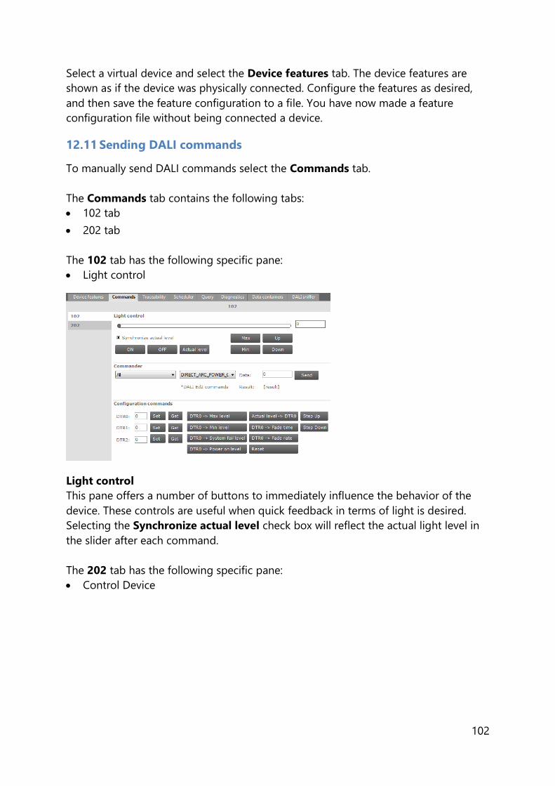
102
Select a virtual device and select the Device features tab. The device features are
shown as if the device was physically connected. Configure the features as desired,
and then save the feature configuration to a file. You have now made a feature
configuration file without being connected a device.
12.11 Sending DALI commands
To manually send DALI commands select the Commands tab.
The Commands tab contains the following tabs:
102 tab
202 tab
The 102 tab has the following specific pane:
Light control
Light control
This pane offers a number of buttons to immediately influence the behavior of the
device. These controls are useful when quick feedback in terms of light is desired.
Selecting the Synchronize actual level check box will reflect the actual light level in
the slider after each command.
The 202 tab has the following specific pane:
Control Device

103
Control Device
This pane gives direct access to emergency controls that immediately influence the
behavior of the emergency device. These controls allow users to get quick feedback
in terms of the behavior of an emergency device in different situations.
Both tabs contain the following panes:
Commander
Configuration commands
Commander
To send a DALI command as a broadcast command, first select All devices in the
Network, then select the DALI command in the Commander pane and finally click
the Send button. To send a DALI command to a specific address or group, select the
corresponding device or group in the Network.
Note! DALI Ed2 commands are marked by an asterisk (*).
Configuration commands
Both tabs contain this pane. However, the content of this pane is different for each
tab. To manually set or get the so-called DTR (Data Transfer Register) values of the
device, use the buttons in the left part of this pane.
To use the actual DTR value of the device with a number of DALI commands, go to
102 tab to use the buttons in the right part of this pane. Besides a number of DALI
commands using the DTR value, other DALI102 commands such as Reset, Step Up
and Step Down are directly available.
To configure values like Prolong Time, Function Test Interval, Duration Test
Interval, Test Delay Time High, Test Delay Time Low and Test Execution Timeout

104
that are needed while using emergency commands, go to 202 tab to use the sliders
or text fields in the right part of this pane to modify their values. The allowed range
for those values is between 0 and 255.
12.12 Traceability
The Traceability tab summarizes how many times the configuration of the device was
changed, when the last configuration change happened using unknown software and
a pane showing details of the first, second and last configuration change (if present).
Every entry in the list shows the date of the configuration change, which software
version was used and which type of interface was used at the time of the
configuration change.
12.13 Working with DALI command scripts
To run a series of DALI commands, a script can be created in the Scheduler tab. This
script can be executed any number of times. Furthermore it is possible to save the
script to a file for easy reuse.
The Scheduler tab has the following panes:
Add item

105
o A CMD button to insert DALI commands
o A FOR button to insert a loop, consisting of a FOR and an END FOR
Selected, containing buttons to work with (Up, Down, Delete, Clear All) the
currently selected item in the schedule
Items, representing the schedule
Selected item, the settings of the currently selected item
Schedule playback buttons (Play, Pause, Stop)
To add a command to the schedule, click the CMD button. The command is added to
the schedule and it is automatically highlighted. On the Selected item pane, choose
the desired DALI command and settings. By selecting the Start time check box and
providing a time, this command will be sent at an exact moment in time.
Alternatively, commands can be sent relative to each other. Select the Delay check
box and provide a value in milliseconds to do so. At Device address you can select to
which device to send this command. You can choose between the currently selected
device, a broadcast or one of the 64 available short addresses (0-63). Then, select
which DALI command will be sent by using the two drop down boxes; the first selects
the command group and the second selects the actual command. If a command
parameter is required, enter it into the Data field.
Note! DALI Ed2 commands are marked by an asterix(*).
By repeatedly clicking the CMD button, a series of DALI commands can be created.
Each command has its own settings.
A schedule can also contain loops. A loop has a FOR-item, one or more commands,
and finally an END FOR-item to mark the end of the loop. Click the FOR button to
create a loop. By default, the loop will run infinitely (that is, until schedule playback is
manually stopped or paused by clicking Stop or Pause). To change the number of
times the loop will be executed, select the FOR-item and enter a value for Maximum
count on the Selected item pane.
To rearrange the schedule, select a command and use the Up and Down buttons to
move this up or down respectively. Delete a command by clicking the Delete button.
To clear all the commands use Clear All button.
To start, pause, or stop a schedule playback, use the Play, Pause and Stop buttons.
If the command is a query, the return data of the executed command will be
displayed.
To save a schedule to file for later use, click the disk icon on the toolbar. Alternatively,
select File Save or File Save As. Choose a location, a filename and click Save.
The schedule has now been saved.

106
To open a previously stored schedule, click the folder icon on the toolbar.
Alternatively, select File Open. Choose a schedule file and click Open. The
Scheduler tab now shows the schedule from the file.
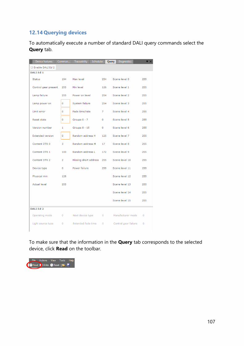
107
12.14 Querying devices
To automatically execute a number of standard DALI query commands select the
Query tab.
To make sure that the information in the Query tab corresponds to the selected
device, click Read on the toolbar.

108
12.15 Accessing Diagnostics
You can configure all diagnostics features that are supported by a specific Philips
device. For a device selected in the Network, the Diagnostics tab displays the set of
diagnostics features that corresponds to this device. Upon selecting another device,
the Diagnostics tab will be updated as well. This mechanism ensures that only the
features supported by the selected device can be configured.
The Diagnostics tab has a panel with a column of tabs on the left-hand side. Each
feature has its own tab.
The Read and Write functionality for Diagnostics works the same way as what has
been described in chapter 12.3 of this manual.
12.15.1 Diagnostics
Product group
HID, LED and CONTROL
Description
Use this feature to consult the diagnostics values.
Note that some diagnostics might be OEM Readout-protected and require a
password before being read out.
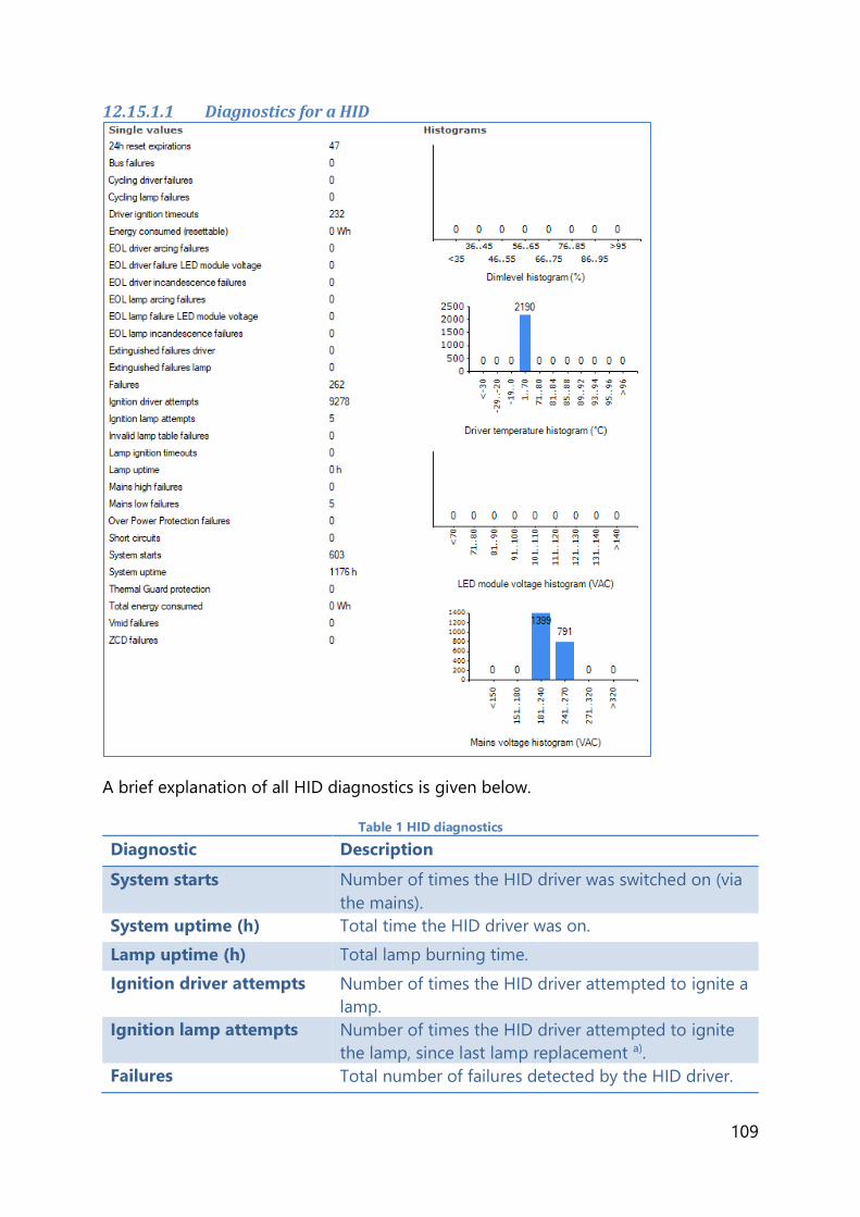
109
12.15.1.1 Diagnostics for a HID
A brief explanation of all HID diagnostics is given below.
Table 1 HID diagnostics
Diagnostic Description
System starts Number of times the HID driver was switched on (via
the mains).
System uptime (h) Total time the HID driver was on.
Lamp uptime (h) Total lamp burning time.
Ignition driver attempts Number of times the HID driver attempted to ignite a
lamp.
Ignition lamp attempts Number of times the HID driver attempted to ignite
the lamp, since last lamp replacement a).
Failures Total number of failures detected by the HID driver.
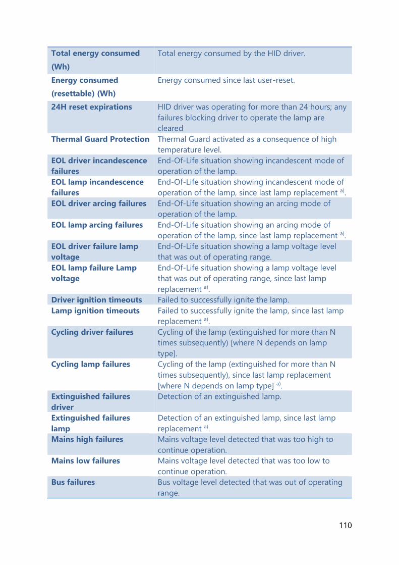
110
Total energy consumed
(Wh)
Total energy consumed by the HID driver.
Energy consumed
(resettable) (Wh)
Energy consumed since last user-reset.
24H reset expirations HID driver was operating for more than 24 hours; any
failures blocking driver to operate the lamp are
cleared
Thermal Guard Protection Thermal Guard activated as a consequence of high
temperature level.
EOL driver incandescence
failures
End-Of-Life situation showing incandescent mode of
operation of the lamp.
EOL lamp incandescence
failures
End-Of-Life situation showing incandescent mode of
operation of the lamp, since last lamp replacement a).
EOL driver arcing failures End-Of-Life situation showing an arcing mode of
operation of the lamp.
EOL lamp arcing failures End-Of-Life situation showing an arcing mode of
operation of the lamp, since last lamp replacement a).
EOL driver failure lamp
voltage
End-Of-Life situation showing a lamp voltage level
that was out of operating range.
EOL lamp failure Lamp
voltage
End-Of-Life situation showing a lamp voltage level
that was out of operating range, since last lamp
replacement a).
Driver ignition timeouts Failed to successfully ignite the lamp.
Lamp ignition timeouts Failed to successfully ignite the lamp, since last lamp
replacement a).
Cycling driver failures Cycling of the lamp (extinguished for more than N
times subsequently) [where N depends on lamp
type].
Cycling lamp failures Cycling of the lamp (extinguished for more than N
times subsequently), since last lamp replacement
[where N depends on lamp type] a).
Extinguished failures
driver
Detection of an extinguished lamp.
Extinguished failures
lamp
Detection of an extinguished lamp, since last lamp
replacement a).
Mains high failures Mains voltage level detected that was too high to
continue operation.
Mains low failures Mains voltage level detected that was too low to
continue operation.
Bus failures Bus voltage level detected that was out of operating
range.

111
Vmid failures Midpoint voltage level detected that was out of
operating range.
Short circuits Short circuit detected in the lamp connection.
ZCD failures Critical failure detected in lamp or driver.
Over Power Protection
failures
Over power detected.
Invalid lamp table failures HID driver switched-on with a non-supported or
corrupt lamp table selected.
a) lamp replacement triggers an erase of predefined lamp-specific items such as ignition attempts, lamp errors.
12.15.1.2 Diagnostics for a LED
A brief explanation of all LED diagnostics is given below.
Table 2 LED diagnostics
Diagnostic Description
LED module voltage (V) Represents the output LED module voltage.
LED module current (mA) Represents the output LED module current
LED module dim level (%) Represents the current dim level set by the LED
driver. Takes into account all factors that can
influence dimming like Constant Light Output,

112
Module Temperature Protection, all dimming
interfaces etc.
LED module temperature
(ºC)
Represents the LED module temperature. Available
only when Module Temperature Protection is
selected and an NTC value is selected.
Driver temperature (ºC) Represents the internal driver temperature. It does
not represent Tcase of the driver. Though there is a
correlation between Tcase and internal driver
temperature, the difference can vary depending on
current setting of driver.
System starts Represents the number of times the LED driver is
powered ON.
System on time (h) Represents the hours the LED driver is ON. (LED
module is OFF)
Module on time (h) Represents the number of hours the LED module is
powered ON.
Module energy consumed Represents the energy consumed by LED module
alone. Only output parameters (LED module voltage
and current) are used to calculate energy. The LED
driver energy consumption is not accounted. Hence
it does not represent true input energy
consumption of the LED system.
Short circuit This indicates if output LED module is shorted.
Open circuit This indicates if output LED module is open or not
connected to LED driver
Module NTC missing This indicates missing NTC on the LED module.
Available only when Module Temperature
Protection is selected and 10k NTC is selected.
Missing NTC flag will not be activated if 15k+390 Ω
NTC is selected.
Module temperature
reduction active
This indicates light level reduction due to module
temperature being active.
Module temperature too
high
This indicates whether the LED module temperature
exceeds 90 ºC causing module to turn OFF.

113
Mains too low This indicates that the LED driver is not operating
since input voltage at power ON is too low.
Adjustable Startup Time
active
This indicates that the LED driver is in the startup
phase as defined by the Adjustable Startup Time.
For example if the Adjustable Startup Time is set to
20000 ms, and the diagnostic information is read at
startup within 20 s, this check box will be selected
indicating startup condition.
12.15.1.3 Subset of LED diagnostics
Table 3 Subset of LED diagnostics
Diagnostic Description
System on time (h:m:s) Represents the hours, minutes and seconds the LED
driver is ON. (LED module is OFF).
Module on time (h:m:s) Represents the number of hours, minutes and
seconds the LED module is powered ON.
System starts Represents the number of times the LED driver is
powered ON.
Maximum recorded driver
temperature (°C)
Maximum driver temperature ever reached during
the lifetime of the driver.

114
Minimum recorded driver
temperature (°C)
Minimum driver temperature ever reached during
the lifetime of the driver.
Maximum recorded LED
module temperature (°C)
Maximum module temperature ever reached during
the lifetime of the driver.
Minimum recorded LED
module temperature (°C)
Minimum module temperature ever reached during
the lifetime of the driver.
Mains overvoltage count Number of times the mains exceeded the maximum
allowed mains voltage level.
The table above describes some of the available diagnostic features. Depending on
the availability of the different LED subset diagnostic features in a device, more or
less diagnostic values will be shown.
12.15.1.4 Motor control diagnostics
Table 4 Motor control diagnostics
Diagnostic Description
Lamp on time (h:m:s) Represents the number of hours, minutes and
seconds the lamp is on.
Pan motor on time (h:m:s) Represents the number of hours, minutes and
seconds the pan motor is on.
Tilt motor on time (h:m:s) Represents the number of hours, minutes and
seconds the tilt motor is on.
Zoom motor on time
(h:m:s)
Represents the number of hours, minutes and
seconds the zoom motor is on.
Pan motor move count Represents the number of times of the pan motor
received a movement command.
Tilt motor move count Represents the number of times of the tilt motor
received a movement command.
Zoom motor move count Represents the number of times of the zoom motor
received a movement command.

115
12.15.1.5 Emergency Diagnostics
Table 5 Emergency diagnostics
Diagnostic Description
Lamp emergency time (h) Represents the number of hours the lamp was in
emergency mode.
Lamp total operation time
(h)
Represents the number of hours the lamp is on.
Last duration test time (m) Represents the number of minutes the last duration
test took to run.
Time since last duration
test (d:h:m)
Represents the time passed since the last performed
duration test, mentioned in days, hours or minutes.
Total number of discharge
cycles
Represents the total number of battery discharge
cycles.

116
12.15.1.6 DiiA specification DALI Part 253 - Diagnostics
Table 6 DiiA diagnostics
Diagnostic Description
Control gear operating time
(h:m:s)
Represents the operating time of the control gear in
hours, minutes and seconds.
Control gear start counter Represents the amount of times the control gear
started.
Control gear external supply
voltage (Vrms)
Represents the external supply voltage of the
control gear in Vrms.
Control gear external supply
voltage frequency (Hz)
Represents the external supply voltage frequency of
the control gear in Hz.

117
Control gear power factor Represents the power factor of the control gear.
Control gear overall failure
condition
Represents the overall failure condition of the
control gear.
Control gear overall failure
condition counter
Represents the amount of times the control gear
overall failure condition occurred.
Control gear external supply
undervoltage
Represents the external supply under voltage of the
control gear.
Control gear external supply
undervoltage counter
Represents the amount of times the control gear
external supply undervoltage occurred.
Control gear external supply
overvoltage
Represents the external supply overvoltage of the
control gear.
Control gear external supply
overvoltage counter
Represents the amount of times the control gear
external supply overvoltage occurred.
Control gear output power
limitation
Represents the output power limitation of the
control gear.
Control gear output power
limitation counter
Represents the amount of times the control gear
output power limitation occurred.
Control gear thermal
derating
Represents the thermal rating of the control gear.
Control gear thermal
derating counter
Represents the amount of times the control gear
thermal derating occurred.
Control gear thermal
shutdown
Represents the thermal shutdown of the control
gear.
Control gear thermal
shutdown counter
Represents the amount of times the control gear
thermal shutdown occurred.
Control gear temperature
(°C)
Represents the temperature of the control gear in
°C.
Control gear output current
percent (%)
Represents the output current percentage of the
control gear in %.
Light source start counter
resettable
Represents the resettable amount of starts of the
light source.
Light source start counter Represents the amount of starts of the light source.
Light source on time
resettable (h:m:s)
Represents the resettable light source operating
time in hours, minutes and seconds.

118
Light source on time (h:m:s) Represents the light source operating time in hours,
minutes and seconds.
Light source voltage (V) Represents the light source voltage in V.
Light source current (A) Represents the light source current in A.
Light source overall failure
condition
Represents the overall failure condition of the light
source.
Light source overall failure
condition counter
Represents the amount of times the light source
overall failure condition occurred.
Light source short circuit Represents the short circuit status of the light
source.
Light source short circuit
counter
Represents the amount of times the light source
short circuit occurred.
Light source open circuit Represents the open circuit status of the light
source.
Light source open circuit
counter
Represents the amount of times the light source
open circuit occurred.
Light source thermal
derating
Represents the thermal rating of the light source.
Light source thermal
derating counter
Represents the amount of times the light source
thermal derating occurred.
Light source thermal
shutdown
Represents the thermal shutdown of the light
source.
Light source thermal
shutdown counter
Represents the amount of times the light source
thermal shutdown occurred.
Light source temperature
(°C)
Represents the temperature of the light source in
°C.
Depending on the availability of the different DiiA diagnostic features in a device,
more or less diagnostic values will be shown.
12.15.2 Set Lamp On Time
Product group
LED

119
Description
Use this feature to set the lamp on time or reset the diagnostics values.
Usage
Use the slider or the text field to set the Lamp on time value.
Select the Reset module diagnostics check box to reset the following diagnostics:
Lamp on time counter
Maximum and minimum module temperature
Module Steady state temperature histogram
Lamp On Cycles
12.16 Accessing Energy Meter
To access energy meter, select a device in the Network and select the Energy Meter
tab. This tab displays the set of energy meter features that correspond to this device
to get an indication of the energy consumption of the device. Upon selecting another
device, the Energy Meter tab will be updated as well. This mechanism ensures that only
the features supported by the selected device can be configured.
The Energy Meter tab has a panel with a column of tabs on the left-hand side. Each
feature has its own tab.
The Read functionality for Energy Meter works the same way as what has been
described in chapter 12.3 of this manual. Write functionality is not available for
Energy Meter.
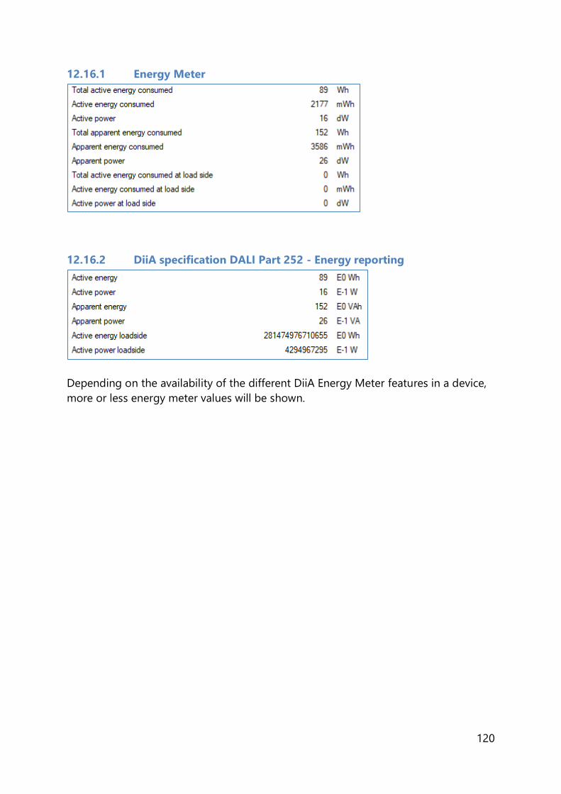
120
12.16.1 Energy Meter
12.16.2 DiiA specification DALI Part 252 - Energy reporting
Depending on the availability of the different DiiA Energy Meter features in a device,
more or less energy meter values will be shown.

121
12.17 Accessing Installer
You can configure all installer features that are supported by a specific Philips device.
For a device selected in the Network, the Installer tab displays the set of installer
features that corresponds to this device. Upon selecting another device, the Installer
tab will be updated as well. This mechanism ensures that only the features supported
by the selected device can be configured.
The Installer tab has a panel with a column of tabs on the left-hand side. Each
feature has its own tab.
12.17.1 Coded Light Randomize
Product group
LED
Description
Use this feature to create a random id for coded light data.
Usage
When the Randomize flag is enabled, the device will generate a new random id, write
this id into coded light data and clear the flag.

122
12.18 Working with the DALI Sniffer
Start Sniffing/Stop Sniffing: When clicked, starts/stops the actual sniffing
Auto scroll: When checked the result window automatically scrolls to the
latest entry.
Auto save: Automatically save the sniffing results to the selected file
Browse…: Select file to store sniffing results.
To save the result to a file that is not the auto save file, click on the save button in the
menu bar.
An example:
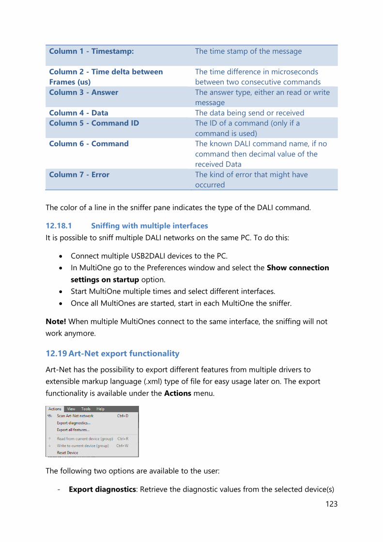
123
Column 1 - Timestamp: The time stamp of the message
Column 2 - Time delta between
Frames (us)
The time difference in microseconds
between two consecutive commands
Column 3 - Answer The answer type, either an read or write
message
Column 4 - Data The data being send or received
Column 5 - Command ID The ID of a command (only if a
command is used)
Column 6 - Command The known DALI command name, if no
command then decimal value of the
received Data
Column 7 - Error The kind of error that might have
occurred
The color of a line in the sniffer pane indicates the type of the DALI command.
12.18.1 Sniffing with multiple interfaces
It is possible to sniff multiple DALI networks on the same PC. To do this:
Connect multiple USB2DALI devices to the PC.
In MultiOne go to the Preferences window and select the Show connection
settings on startup option.
Start MultiOne multiple times and select different interfaces.
Once all MultiOnes are started, start in each MultiOne the sniffer.
Note! When multiple MultiOnes connect to the same interface, the sniffing will not
work anymore.
12.19 Art-Net export functionality
Art-Net has the possibility to export different features from multiple drivers to
extensible markup language (.xml) type of file for easy usage later on. The export
functionality is available under the Actions menu.
The following two options are available to the user:
- Export diagnostics: Retrieve the diagnostic values from the selected device(s)
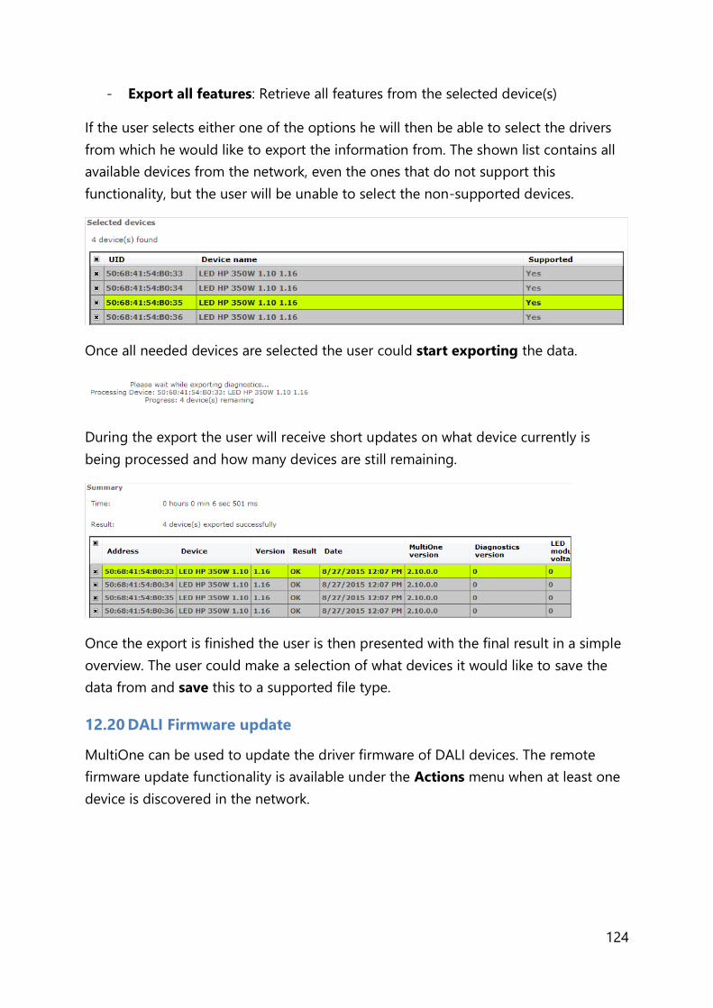
124
- Export all features: Retrieve all features from the selected device(s)
If the user selects either one of the options he will then be able to select the drivers
from which he would like to export the information from. The shown list contains all
available devices from the network, even the ones that do not support this
functionality, but the user will be unable to select the non-supported devices.
Once all needed devices are selected the user could start exporting the data.
During the export the user will receive short updates on what device currently is
being processed and how many devices are still remaining.
Once the export is finished the user is then presented with the final result in a simple
overview. The user could make a selection of what devices it would like to save the
data from and save this to a supported file type.
12.20 DALI Firmware update
MultiOne can be used to update the driver firmware of DALI devices. The remote
firmware update functionality is available under the Actions menu when at least one
device is discovered in the network.

125
On selecting the Remote firmware update option the user is asked to select the
update file. After selecting the file, the details of the file are displayed.
Click Next to continue the update procedure. On the following screen the user can
configure the update settings used during the update procedure. If the connected
device needs a password and access level before the remote firmware update can
start, then the Password and Access level fields will be enabled so that the user can
specify them.
The following update settings can be specified:
- Password: The password needed for unlocking the device before the remote
software update can start.
- Access level: The access level needed for unlocking the device before the
remote software update can start.
- Number of attempts: The number of automatic attempts done for every
update step in case a failure occurs during the remote firmware update
procedure.
Note! If a 4-byte password is desired, fill the first 3 text boxes with 0.
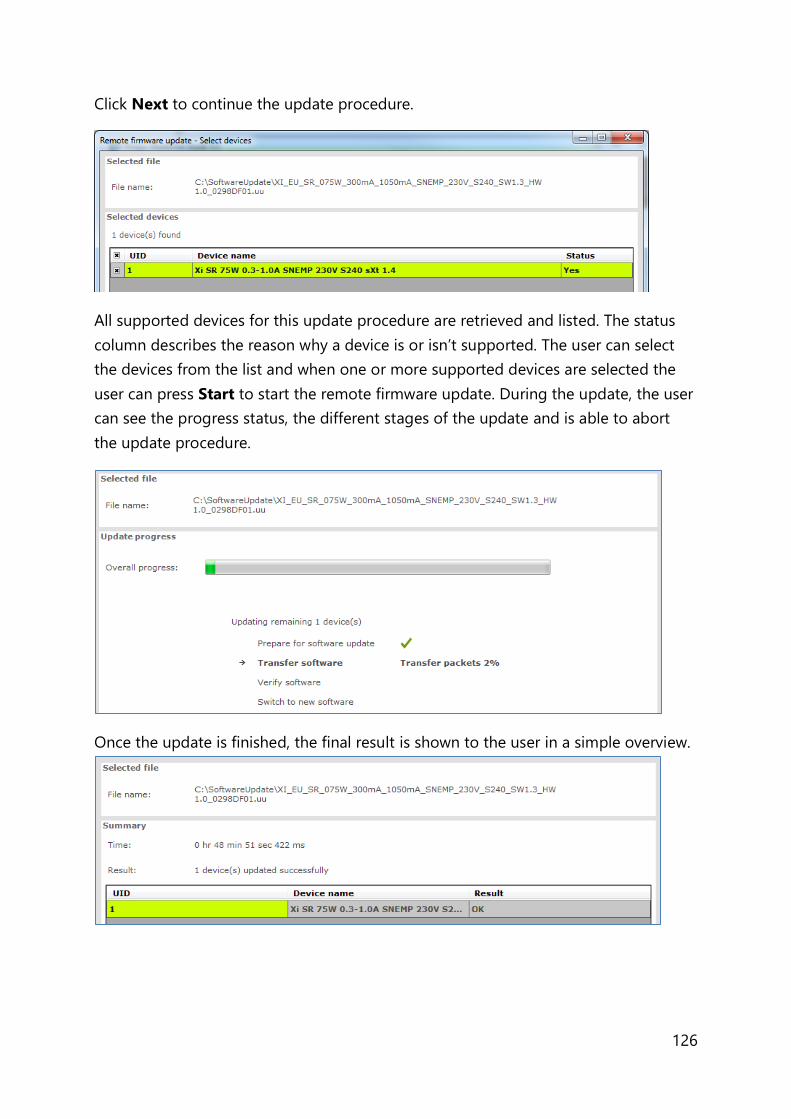
126
Click Next to continue the update procedure.
All supported devices for this update procedure are retrieved and listed. The status
column describes the reason why a device is or isn’t supported. The user can select
the devices from the list and when one or more supported devices are selected the
user can press Start to start the remote firmware update. During the update, the user
can see the progress status, the different stages of the update and is able to abort
the update procedure.
Once the update is finished, the final result is shown to the user in a simple overview.

127
12.21 The logging window
The logging window shows the communication related to the features currently
being read or written or when DALI commands are sent or received through the
USB2DALI interface.
Timestamp
The time the feature was read or written or the time the command was sent. The
format of the timestamp is: <date> <time>.
Address
The short address to which the feature or command was sent. In case Broadcast is
mentioned, all devices are addressed.
Description
The name of the feature or the actual DALI command.
Result
Result of the communication.
12.22 Setting preferences
MultiOne has a preferences window that allows you to customize the way MultiOne
works. To access the preferences window select Tools Preferences.
The Preferences window that pops up allows you to set MultiOne preferences.

128
12.22.1 General preferences
The following list summarizes the available preferences and gives an explanation for
each.
Show application mode selector on startup. When MultiOne is started you
are presented with a screen that allows you choose an application mode,
based on the tasks you would like to perform. You can disable this screen by
clearing the Show application mode selector on startup check box.
Changing this settings only takes effect once MultiOne is restarted.
Scan network automatically on startup. By selecting this check box
MultiOne will automatically initiate a network scan on startup. Changing this
settings only takes effect once MultiOne is restarted.
Start maximized on startup. By selecting this checkbox MultiOne will be
started full screen. Changing this settings only takes effect once MultiOne is
restarted.
Play sounds when features are configured. When this check box is selected,
MultiOne will make a sound when a feature configuration is (un)successfully
written to a driver.
Play sounds when features, diagnostics or energy meter are read. When
this check box is selected, MultiOne will make a sound when a feature
configuration is (un)successfully read from a driver, when energy meter or
when diagnostics are (un)successfully read from a driver.
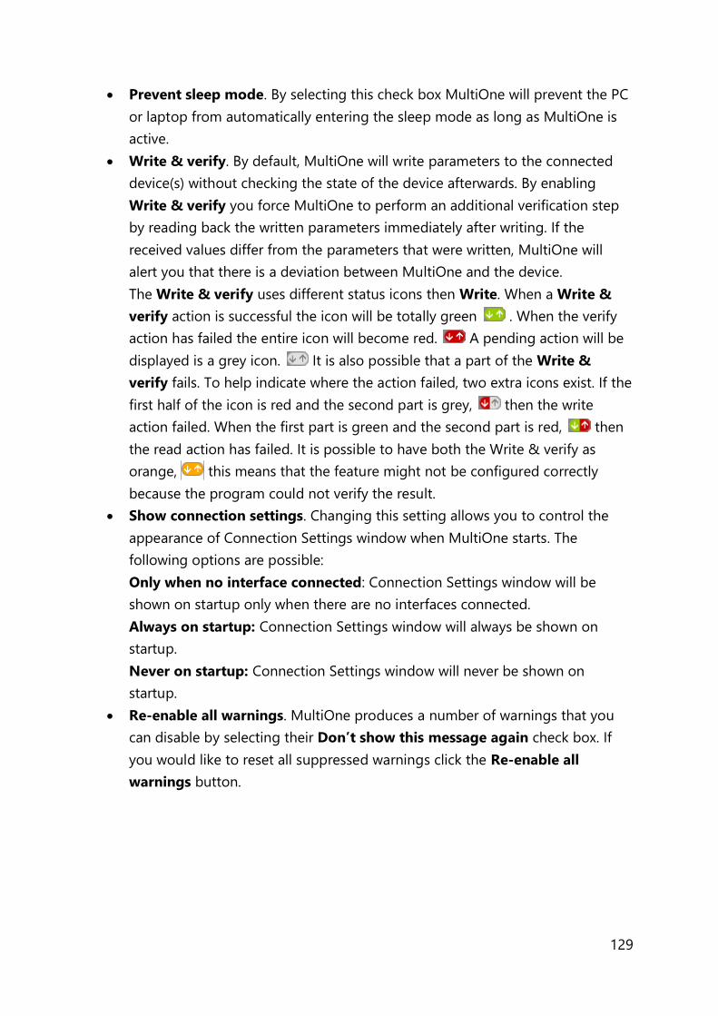
129
Prevent sleep mode. By selecting this check box MultiOne will prevent the PC
or laptop from automatically entering the sleep mode as long as MultiOne is
active.
Write & verify. By default, MultiOne will write parameters to the connected
device(s) without checking the state of the device afterwards. By enabling
Write & verify you force MultiOne to perform an additional verification step
by reading back the written parameters immediately after writing. If the
received values differ from the parameters that were written, MultiOne will
alert you that there is a deviation between MultiOne and the device.
The Write & verify uses different status icons then Write. When a Write &
verify action is successful the icon will be totally green . When the verify
action has failed the entire icon will become red. A pending action will be
displayed is a grey icon. It is also possible that a part of the Write &
verify fails. To help indicate where the action failed, two extra icons exist. If the
first half of the icon is red and the second part is grey, then the write
action failed. When the first part is green and the second part is red, then
the read action has failed. It is possible to have both the Write & verify as
orange, this means that the feature might not be configured correctly
because the program could not verify the result.
Show connection settings. Changing this setting allows you to control the
appearance of Connection Settings window when MultiOne starts. The
following options are possible:
Only when no interface connected: Connection Settings window will be
shown on startup only when there are no interfaces connected.
Always on startup: Connection Settings window will always be shown on
startup.
Never on startup: Connection Settings window will never be shown on
startup.
Re-enable all warnings. MultiOne produces a number of warnings that you
can disable by selecting their Don’t show this message again check box. If
you would like to reset all suppressed warnings click the Re-enable all
warnings button.

130
12.22.2 DALI
DALI scan method. Changing this setting allows the user to control the way in
which a DALI network is scanned. The following options are possible:
By short address: DALI devices are scanned by their short address.
By random address: DALI devices are scanned by their random address.
Save DALI configuration. Checking this setting give the users the ability to
save DALI settings when saving a feature file. By clearing this check box, the
save DALI settings option will not appear when saving a feature file.
For more details on the DALI scan methods, see Identifying devices.
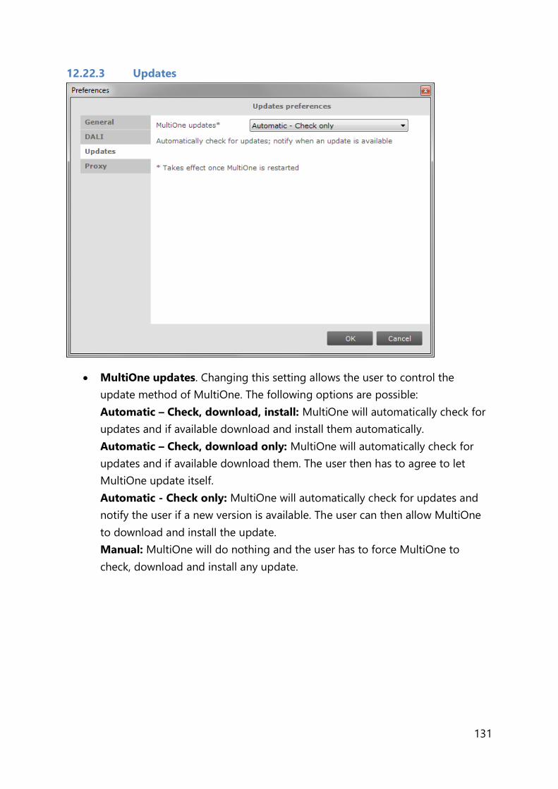
131
12.22.3 Updates
MultiOne updates. Changing this setting allows the user to control the
update method of MultiOne. The following options are possible:
Automatic – Check, download, install: MultiOne will automatically check for
updates and if available download and install them automatically.
Automatic – Check, download only: MultiOne will automatically check for
updates and if available download them. The user then has to agree to let
MultiOne update itself.
Automatic - Check only: MultiOne will automatically check for updates and
notify the user if a new version is available. The user can then allow MultiOne
to download and install the update.
Manual: MultiOne will do nothing and the user has to force MultiOne to
check, download and install any update.
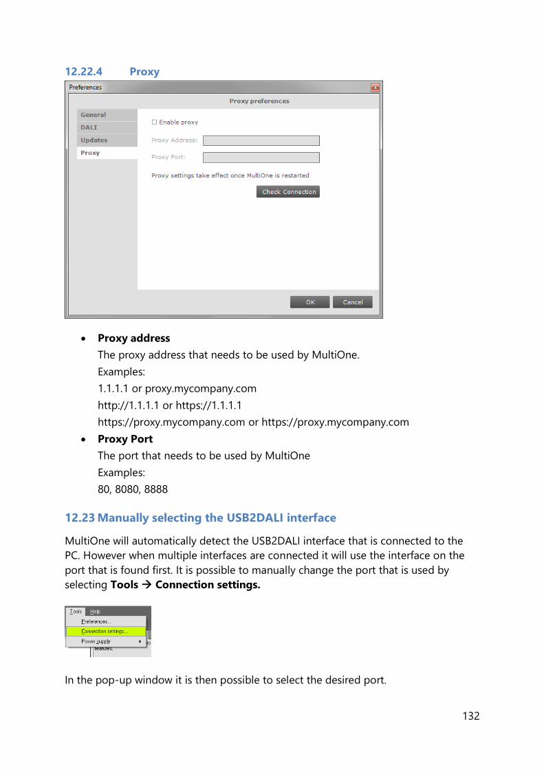
132
12.22.4 Proxy
Proxy address
The proxy address that needs to be used by MultiOne.
Examples:
1.1.1.1 or proxy.mycompany.com
http://1.1.1.1 or https://1.1.1.1
https://proxy.mycompany.com or https://proxy.mycompany.com
Proxy Port
The port that needs to be used by MultiOne
Examples:
80, 8080, 8888
12.23 Manually selecting the USB2DALI interface
MultiOne will automatically detect the USB2DALI interface that is connected to the
PC. However when multiple interfaces are connected it will use the interface on the
port that is found first. It is possible to manually change the port that is used by
selecting Tools Connection settings.
In the pop-up window it is then possible to select the desired port.

133
Notice! The unique id of the interface is shown at the port selection. This, to be able
to identify which interface is used by which MultiOne instance (when configuring
devices in parallel using multiple instances of MultiOne).
12.24 Enabling/Disabling the power supply of the USB2DALI interface
The USB2DALI interface will automatically detect if the DALI bus is powered by
another device (for example a DALI power supply). If the DALI network is not
powered, it will use its internal power supply.
If, during operation, the DALI network is changed in a way that it requires the
USB2DALI interface to switch on or off its internal power supply, you can do so using
the option Tools Power supply.
12.25 Supported features
The table below gives an overview of all features that are supported by MultiOne and
to which product groups they apply.
Table 7 Supported features
Device feature Product group
LED HID FLUO CONTROL
Indoor Outdoor
0-10V / 1-10V (SR
bridge)
x
0-10V / 1-10V (LED
driver)
x
ActiLume General x
ActiLume Mode x
ActiLume Scene x

134
Active Cooling x
Adjustable Light
Output
x x x
Adjustable Output
Current
x x
Adjustable Output
Current Multi-Channel
x x
Adjustable Startup
Time
x
AmpDim x x
Auxiliary Power Supply
Voltage
x
Constant Light Output x x x
Constant Light Output
Multi-Channel
x x
Coded Light x
Coded Light Randomize x
Coded Mains x x
Coded Mains
Standalone Receiver
x
Correlated Color
Temperature
x x
Correlated Color
Temperature Dual
Channel
x x
Corridor Mode x x
DALI 102 x x
DALI 202 x x
DALI Power Supply x
Daylight override /
Daylight switching
x
Device Info x
DiiA specification DALI
Part 253 - Luminaire
Maintenance
x
Dimming Interface x x
Driver addressing x
Driver Temperature
Limit
x
Dwell Time x
Dynadimmer x x
DC Emergency x
End Of Life indication x

135
FCC x
FccRed x
FlexTune x x
Field Task Tuning x
Field Task Tuning/
Occupancy Sensing /
Daylight Harvesting
x
Lamp Burn-in x
Lamp Selection x x
Light Source Operating
Hours
x
LineSwitch x x
Load Fault Indicator
Thresholds
x
Logical Signal Input x
Lumen Level x x
Luminaire (Fixture)
Information
x x
Luminaire Production
Test
x
LumiStep x
Min Dim Level x
Motor Control x
Module Temperature
Protection
x x
NTC on LEDset x x
Occupancy Sensing /
Daylight Harvesting
x
Occupancy sharing /
Group light behavior
x
OEM Write Protection x x
Push Button Unit
LCU2070
x
Push Button Unit
LCU2071
x
Quick Lamp Start x
Relay Switched Output x
Self Contained
Emergency
x
Set Lamp On Time x
SR Power Supply x
Step Dimming x x
Summary x x x x
136
Touch and Dim x x
Tx Power x
12.26 Device-specific technical descriptions
For a detailed technical description of the characteristics of the devices, please visit
the product-specific web sites:
Table 8 Product-specific web sites
Product group Visit:
LED www.philips.com/Xitanium
HID www.philips.com/Xtreme
FLUO www.philips.com/HFR-Intelligent
CONTROL www.philips.com/Actilume
12.27 Error handling
12.27.1 Reporting and correction of errors/warnings when reading from a
feature configuration file
When, after opening a feature configuration file, incorrect parameters are detected,
MultiOne tries to correct these parameters for the selected (virtual) device. When a
correction is made, a red border will be shown. In cases when no logical correction
can be made, an orange border will be shown.
12.27.2 Reporting of errors when reading from a device
When after reading from a device a mismatch is signaled between the parameters of
the device and MultiOne, MultiOne will not correct the parameters, but will show a
red border.
12.27.3 Reporting of errors when entering incorrect values in a feature
Entering an incorrect value for a parameter will be indicated by a red border.
12.28 Troubleshooting
Problem: After starting MultiOne, no devices are displayed.
Solution: Click the Scan network button on the Network panel to start discovering
the devices in the network. If the devices connected have already a DALI short
address this will not be changed. Devices without a short address will be
programmed with a short address. When the Commission button is clicked, the short
addresses of all connected devices will be renewed, whether they already had a short
address or not.
Problem: I would like to assign a specific short address to a device.

137
Solution: First scan the network for devices. Right-click the device you would like to
give a short address and select Set short address.
A dialog window will appear in which you can enter the desired short address.
Click OK to program the short address into the device.
Problem: I would like to remove the short address of a device.
Solution: First scan the network for devices. Right-click the device whose short
address you would like to remove and select Reset short address.
You will be informed that the short address was reset.
Problem: I would like to configure the special features of the connected device.
Solution: After scanning the network for devices, a device has to be selected by
clicking it in the Network. Select the Device features tab. The related features will
appear. To update the view to the actual status of the features, click Read on the
toolbar. If you now change any of the features, and want this to be stored into the
device, click Write on the toolbar.
Problem: I would like to know more technical details of a device.
Solution: Please refer to the Philips website for more detailed information

138
13 Keyboard shortcuts
Keyboard shortcuts can make it easier to work with MultiOne without using the
mouse.
Table 9 Keyboard shortcuts
USB2DALI interface USB2ZigBee interface
The File menu Working with feature configuration files
Ctrl+O Open a feature configuration
file
Not supported
Ctrl+S Save a feature configuration
file (Save)
Not supported
Ctrl+Shift+S Save a feature configuration
file
(Save As)
Not supported
Alt+F4 Exit MultiOne
The Action menu Working with devices
Ctrl+D Scan network Scan area
Ctrl+Q Commission Not supported
Ctrl+R Read from current device Not supported
Ctrl+W Write to current device Not supported
The Tools menu
Ctrl+M Open the Application mode selector
The Help menu
Shift+F1 Open the Getting started document
F1 Open the User manual

139
14 Software Update
MultiOne has the possibility to update itself to a newer version. This can be done
either automatically or manually and can be set in the preference window, see the
Setting Preferences for more info.
If the preference is set to Manual then the user can check for an update on MultiOne
by selecting Help Check for updates option.
After a manual update check, or by using the automatic options, the update status
near the Help menu will show if a new version is available. The user can then decide
to continue downloading/updating by either using the update status or the Help
menu to carry on.
After downloading the update status will inform the user to restart to continue.
Restarting MultiOne will install the update.
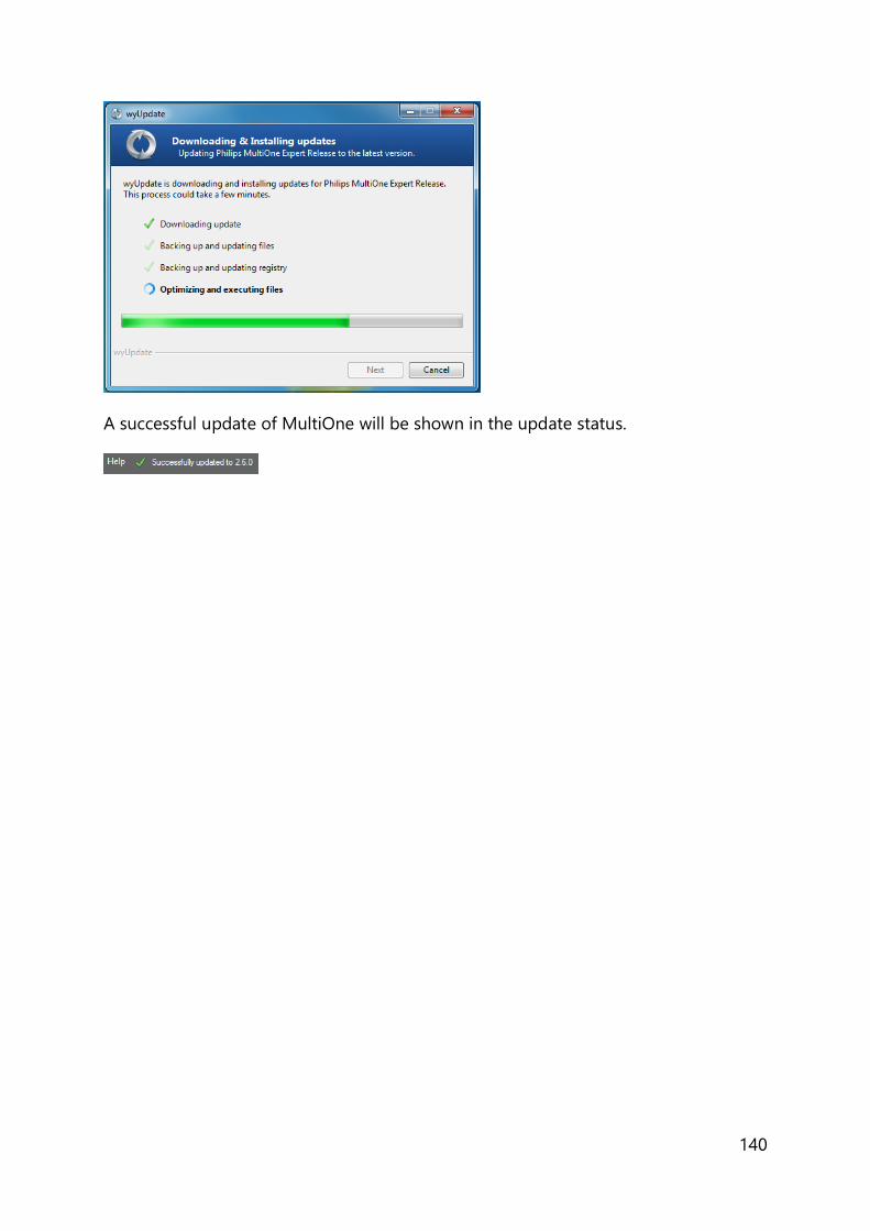
140
A successful update of MultiOne will be shown in the update status.

141
15 Copyright
© 2019 Signify Holding. All rights reserved.
All rights reserved. No part of this publication may be reproduced, transmitted,
transcribed, stored in a retrieval system or translated into any language or computer
language, in any form or by any means, electronic, mechanical, magnetic, optical,
chemical, manual or otherwise, without prior written permission from Signify. Brands
and product names are trademarks or registered trademarks of their respective
companies.

142
16 Disclaimer
Signify makes no warranty of any kind with regard to this material, including, but not
limited to, the implied warranties of merchantability and fitness for a particular
purpose.
Signify assumes no responsibility for any error that may appear in this document.
Signify makes no commitment to update nor to keep current the information
contained in this document.

143
17 Limitations of damages
The vendor will not be liable for any indirect, special, incidental or consequential
damages (including damages for loss of business, loss of profits, or the like), whether
based on breach of contract, tort (including negligence), product liability or
otherwise, even if the vendor or its representatives have been advised of the
possibility of such damages and even if a remedy set forth herein is found to have
failed its essential purpose.

144
18 List of tables
Table 1 HID diagnostics .................................................................................................................... 109
Table 2 LED diagnostics .................................................................................................................... 111
Table 3 Subset of LED diagnostics ................................................................................................ 113
Table 4 Motor control diagnostics ................................................................................................ 114
Table 5 Emergency diagnostics ...................................................................................................... 115
Table 6 DiiA diagnostics .................................................................................................................... 116
Table 7 Supported features ............................................................................................................. 133
Table 8 Product-specific web sites ................................................................................................ 136
Table 9 Keyboard shortcuts ............................................................................................................. 138

145
19 Index
0-10V / 1-10V (LED driver) ........................................................................................................42, 133
0-10V / 1-10V (SR bridge) .........................................................................................................41, 133
ActiLume General .........................................................................................................................43, 133
ActiLume Mode ..................................................................................................................... 44, 45, 133
ActiLume Scene .............................................................................................................................46, 133
Active Cooling ................................................................................................................................46, 134
Adjustable Light Output .............................................................................................................47, 134
Adjustable Output Current ................................................................................................ 48, 55, 134
Adjustable Output Current Multi-Channel .................................................................. 48, 55, 134
Adjustable Startup Time ................................................................................................... 49, 113, 134
AmpDim ................................................................................................................................... 49, 64, 134
Auxiliary Power Supply Voltage ..............................................................................................50, 134
Coded Light On and Off .............................................................................................................50, 134
Coded Light Randomize .......................................................................................................... 121, 134
Coded Mains ................................................................................................................... 50, 52, 64, 134
Coded Mains Standalone Receiver ........................................................................................52, 134
Constant Light Output ......................................................................... 52, 54, 55, 69, 76, 111, 134
Constant Light Output Multi-Channel ..................................................................................55, 134
Correlated Color Temperature ......................................................................................... 56, 57, 134
Correlated Color Temperature Dual Channel ............................................................. 56, 57, 134
Corridor Mode ................................................................................................................ 51, 58, 60, 134
DALI 102 ...........................................................................................................................................59, 134
DALI 202 ...........................................................................................................................................60, 134
DALI Power Supply .......................................................................................................................61, 134
Daylight override / Daylight switching .................................................................................61, 134
DC Emergency ....................................................................................................................... 61, 62, 134
Device Info ......................................................................................................................................62, 134
Diagnostics ......................................................................................................... 36, 108, 109, 111, 115
DiiA specification DALI Part 252 - Energy reporting ............................................................... 120
DiiA specification DALI Part 253 - Diagnostics ......................................................................... 116
DiiA specification DALI Part 253 - Luminaire Maintenance...........................................63, 134
Dimming Interface................................................................................................................ 63, 64, 134
Driver addressing ..........................................................................................................................65, 134
Driver Temperature Limit ................................................................................................... 65, 66, 134
Dwell Time .......................................................................................................................................66, 134
Dynadimmer .................................................................................................................... 63, 67, 82, 134
End Of Life indication .......................................................................................................... 69, 76, 134
Energy Meter ........................................................................................................................ 36, 119, 120
FCC ............................................................................................................................................. 70, 71, 135
FccRed...............................................................................................................................................71, 135

146
Field Task Tuning .................................................................................................................. 73, 74, 135
Field Task Tuning/ Occupancy Sensing / Daylight Harvesting ........................................... 135
FlexTune ................................................................................................................................... 72, 73, 135
Lamp Burn-in ..................................................................................................................................75, 135
Lamp Selection ...................................................................................................................... 69, 75, 135
Light Source Operating Hours ......................................................................................... 69, 76, 135
LineSwitch......................................................................................................................... 64, 76, 77, 135
Load Fault Indicator Thresholds ..............................................................................................78, 135
Logical Signal Input .....................................................................................................................79, 135
Lumen Level ....................................................................................................................................80, 135
Luminaire (Fixture) Information ...............................................................................................81, 135
Luminaire Production Test ........................................................................................................82, 135
LumiStep .................................................................................................................................. 80, 82, 135
Min Dim Level ................................................................................................................................84, 135
Module Temperature Protection .................................................................................. 86, 112, 135
Motor Control ................................................................................................................................85, 135
NTC on LEDset ...............................................................................................................................87, 135
Occupancy Sensing / Daylight Harvesting ........................................................... 61, 74, 88, 135
Occupancy sharing / Group light behavior .........................................................................89, 135
OEM Write Protection .................................................................................................................89, 135
Push Button Unit LCU2070 ................................................................................................ 90, 91, 135
Push Button Unit LCU2071 ........................................................................................................91, 135
Quick Lamp Start .................................................................................................................. 91, 94, 135
Relay Switched Output ...............................................................................................................92, 135
Self Contained Emergency ........................................................................................................92, 135
Set Lamp On Time ..................................................................................................................... 118, 135
SR Power Supply ................................................................................................................... 61, 93, 135
Step Dimming ................................................................................................................................94, 135
Touch and Dim ............................................................................................................... 58, 94, 99, 136
Tx Power...........................................................................................................................................95, 136


![Turning Back [updated 6.5.2015]](https://static.fdokumen.com/doc/165x107/6335f35102a8c1a4ec01fd86/turning-back-updated-652015.jpg)


![[Updated Constantly] - ITExamAnswers.net](https://static.fdokumen.com/doc/165x107/631602506ebca169bd0b61e0/updated-constantly-itexamanswersnet.jpg)