The wonders of modern mechanism. A rsum of recent ...
418
THE WONDERS OF MODBRN MECHANISM
-
Upload
khangminh22 -
Category
Documents
-
view
1 -
download
0
Transcript of The wonders of modern mechanism. A rsum of recent ...

THE WONDERSOF MODBRNMECHANISM

TO MEMOEIAMProfessor J. Henry Senger


A CABLE-RAILWAYROBERT POOLE, SON A CO.'S DESIGN.

THE WONDERSOF
MODERN MECHANISMA RESUME OF
KECENT PROGRESS IN MECHANICAL PHYSICAL,
AND ENGINEERING SCIENCE.
BY
CHARLES HENRY COCHRANE,Mechanical Engineer,
AUTHOR OF " ARTISTIC HOMER. AND HOW TO BUILD THEM." "THE HISTORYOF MARLBOROUOH." ETC.
ILLUSTRATED.
PHILADELPHIA :
J. B. LIPPINCOTT COMPANY.
1896.

cc
COPYRIGHT, 1895,
BY
J. B. LIPPINCOTT COMPANY.
MEMOR/AM
\
|\ o. ^V M ^
ELECTROTYPED AND PRINTED BY J. B. LIPPINCOTT COMPANY, PHILADELPHIA, U.S.A.

TO TOE
ARMY OF AMERICAN INVENTORS,
WHO OCCUPY THE FIRST PLACE IN THE WORLD'S MARCH OF
PROGRESS, THIS BOOK
18
APPRECIATIVELY DEDICATED.
922699


PREFACE.
THE design of tho writer of the following pages is to
present to the public, in ]><piilur language, the results ob-
tained within recent years by engineering and mechanical
seienee, together with suggestions as to what the future
mav bring forth, such inferences Ix'ing drawn from the
known lines of research upon which great minds are bent.
There exists an unfortunate tendency in the newspajKT
press, when publishing accounts of new inventions, to laud
each one in accordance with some one's flights of fancy,
claiming so much, and making so many exaggerated and
unscientific statements, that careful readers have* learned
that they cannot depend upon the daily newspajxr, as a
rule, to give them an accurate record of the world's
progress in mechanics and physical science. Amongtechnical journals, on the other hand, there is frequently
an equally unfortunate tendency to so hide the descriptions
of present and coming inventions in a maze of technical
detail that only a favored few can understand them. Be-
tween these two the writer has tried to steer his course,
ever on the watch to maintain accuracy with plain and
simple statement. If there are occasional lapses into tech-
nical language, varied by flights of speculation into the
realms of the possible rather than the existent, it is hopedthat the reader will pardon such sandwiching for the sake
of the facts that lie between. For these no apology is
necessary. The facts given, gleaned from the workshopsof inventors, are worthy the attention of all. There is
7

8 PREFACE.
no calling more admirable than that of the inventor. Hewho does that which has never been done before, and
shows his fellow-men how to make improved use of the
forces of Nature, confers a blessing on all posterity. The
search for that which is not known must ever fascinate
the greatest and wisest of men, and the triumphs of in-
vestigating genius recorded in this book are but a few of
the results of the labor of the thinkers who have kept in
advance of the crowd and added to the sum of human
knowledge.The number and value of inventions have increased so
rapidly of recent years that the public has come to accept
the most marvellous innovations with a readiness that soon
makes of them an old story. While there are thousands
of people alive to-day who remember the first railroad,
the first steamboat, and the first telegraph, we have amongus a younger generation who never knew what it was
to be without the electric light, the telephone, the electric
railway, or the mammoth daily newspaper. The genera-
tion that is to come will live in an age of new wonders,
and surrounded by new creature conveniences, a few of
which we can discern darkly. Some day, mayhap, this
book will fall into the hands of some favored one living
in an age made vastly more brilliant than our own, and
he may smile at the so-called progress here recorded that
marks the close of the nineteenth century. Let such ah
one reflect that there is beyond him a higher and a wider
and a greater field of undiscovered knowledge, and that
he, too, in his turn, will some day sleep with the useless,
lumbering relics of the past.
CHAS. H. COCHRANE.
WEST NEW BRIGHTON, NEW YORK, Sept. 21, 1895.

CONTENTS.
PAOI
Bio BUSINESS BUILDINGS . . 11
EXTRAORDINARY BRIDGE* . . 20
SOMK GRKAT TUNNELS . . :{;
CANALS, OLD AND NEW 44
ELECTRICITY AND ITS FUTURE 55
THE KlNETO-PlIONOGRAPH . . TO
THE ELECTRIC STORAGE-BATTERY 75
ELECTRIC PLEASURE BOATS 8'>
THE OCEAN GREYHOUNDS '.
RECENT PROGRESS IN GUNS AND ARMOR ... 102
SUBMARINE BOATS ... 120
FLYING MACHINES 127
HORSELESS VEHICLES 1:10
BICYCLE MANUFACTURE 150
COMPRESSED-AIR MECHANISMS 158
THE CHAINING OF NIAGARA FALLS 165
IMPROVEMENTS IN TELEGRAPHY 173
ELECTRICITY DIRECT FROM COAL 180
NIKOLA TESLA AND HIS OSCILLATOR 183
THE ELECTRIC LOCOMOTIVE 187
LIGHT-TRAFFIC RAILWAY SYSTEMS 190
CONDUIT ELECTRIC RAILWAYS . 208
A HUNDRED AND TWENTY MILES AN HOUR 219
THE MANUFACTURE OF STEKL . . 225
MACHINE TOOLS 237
MINING AND MINING-MACHINERY . . 257
ORE-CONCENTRATING MACHINERY 205
THE PELTON WATER-WHEEL 279
ILLUMINATING GAS 286
OIL-WELLS AND THEIR PRODUCTS 297
COAL-HANDLING MACHINERY 307
ICE-MAKING AND REFRIGERATING 317
9

10 CONTENTS.PAGE
ALUMINUM, THE METAL OF THE FUTURE 325
WIRE NETTING IN GLASS 333
MACHINE-MADE WATCHES 339
PROGRESS IN PRINTING 348
PHOTOMECHANICAL PROCESSES 362
STEREOTYPING AND ELECTROTYPING 368
SUGAR-MAKING MACHINERY 373
THE EMERY TESTING-MACHINE 380
THE SPECTROSCOPE 388
MISCELLANEOUS INVENTIONS . .396

THE WONDERSOF
MODERN MECHANISM,
BIG BUSINESS BUILDINGS.
Towering Steel Structures that dwarf Churches and MonumentsThe Principles and Methods involved in their Construction.
MAN is giv<n to admiration for that which is largo.
The Egyptians who built the pyramids no doubt felt
great satisfaction in their achievements, and their work
has l>een admired by all succeeding ages. Within recent
years, however, the world has reached a point where
business necessities cause the erection of toller and taller
edifices, and already the spires of beauteous churches are
being dwarfed by apartment houses and office buildings
whose owners desire to obtain a larger income from the
valuable land which they occupy.It is not so everywhere. There are great cities, as in
Asia and Europe, where one-story and two-story buildings
are the rule, and anything above these in height stands
out as a landmark. In Havana, Cuba, for instance, they
keep to the lower levels, because it is (or was) necessary to"buy the winds"
;that is, pay a tax for the privilege of
building above a certain height. Thus local laws and11

12 "JP6&DERS OF MODERN MECHANISM.
s often'make it impracticable to erect tall struc-
tures. But in the United States, where large cities spring
up in a generation, the increase in land values has been so
rapid as to give great stimulus to high building in centres
of business. The four-story affairs that were the common
thing in the seventies have sunk into the shadow of the
seven- and eight-story buildings that are now everywhereto be seen in the most valuable portions of the larger
cities of this republic.
While the massive cathedrals of ancient Europe and
the more modern Washington Monument prove that it is
possible to build to a height of five hundred feet or more
with stone and brick, yet the cost of these structures, and
the enormous thickness of the walls, make it impossible
to attempt such elevations with these materials when
building for purely commercial purposes. It is here that
modern cheap steel finds an immense and growing market.
It permits the construction of tall buildings, with com-
paratively thin walls and large areas for window spaces,
at a cost that is not excessive, and of a strength and dura-
bility that are unquestioned. Unfortunately, these steel
buildings are not fire-proof, unless the iron is protected
against the warping that would result from exposure to
great heat followed by the contraction incident to throwingon streams of cold water. It is, therefore, necessary to
use a facing of stone, terra-cotta, or the like, giving such
buildings the resemblance to the more common stone struc-
tures that surround them. Sometimes these exterior stone
Avails carry their own weight, being simply anchored to the
steel frame to insure steadiness, but more often the metal
has to carry the added weight of the stone above the sixth
or seventh story. For these reasons every added story to
a great building increases greatly the total cost of the struc-

BIO BUSINESS BUILDINGS 13
tu re, .since every story below must IK? designed to carry its
additional weight.
The first consideration of a builder who is called uponto erect one of these towering steel business buildings is the
nature of the foundations. If he can build UJMHI the U-d-
roek, that part of the work is easy, and almost any weight
that human beings can pile on will l>c taken care of bv
Mother Earth. Hut frequently he is called UJMUI to build
on sand or gravel, or even mud. In such a ease he mayfind almost as much work to do l>elow as above the pave-ment. In many seaside cities the usual bottom is fine
sand or gravel. If this is reasonably hard, and not given
to shifting, a pile foundation may be used. The piles are
driven in groups all over the building lot, the tops Ix'ing
tied together by beds of concrete, usually fifteen to twentyinches thick, to avoid any chance of spreading, which
might otherwise occur where adjacent heavy buildings
were removed or excavations made alongside. Such a
foundation will bear a weight of forty thousand jxuinds
per pile. If the soil is very soft and yielding, it l>ecomes
necessary to resort to other methods. In Chicago, masses
of long steel rails have been laid in beds of cement, the
rails being so crossed and the whole so connected as to
form practically one solid mass, of immense solidity. In
a case in New York, caissons, somewhat similar to those
commonly used in the construction of bridge foundations,
were used with success. The ground was a regular quick-
sand, and the bed-rock fifty-seven feet below the street-
level. To dig down to the rock would have been to un-
dermine surrounding structures. It was therefore decided
to sink steel caissons, made like great boxes open at the
bottom. The workmen dug inside of these, lowering them
as they progressed, and sending up the removed material
2

14 WONDERS OF MODERN MECHANISM.
through metal shafts that were sunk with the caissons.
There were fifteen of these caissons in all, and they were
lowered at the rate of four feet a day. When bed-rock
was reached the caissons were filled with concrete, brick
piers being erected on top, each bearing a huge block of
granite for a cap, to support the lower girders of the
structure above.
With brick and stone buildings it is customary to rest
the walls upon courses of stone, so that the weight is con-
tinuously distributed along the line. But with steel struc-
tures, involving greater weight with thinner wr
alls, it be-
comes desirable to distribute the weight on numerous piers.
As all such buildings are erected on very valuable ground,it is usually necessary to run the walls to the extreme edgeof the property. The walls being but a few feet in thick-
ness the weight would naturally come on the outside of the
lot, and the tendency is to tip over the piers upon whose
outer edges the walls rest. To avoid this the cantilever
truss is commonly used. It is
... a reversal of the truss used
in cantilever bridges, and its
construction is best shown bythe accompanying drawing.These cantilever girders maybe anywhere from ten tons to
eighty tons each in weight.
The larger sizes are made in
sections, owing to the impracticability of handling such
heavy masses of metal.
The steel and iron used in these structures must be of
known good quality, and the specifications customarily
require that the maker shall submit to certain tests a piece
of each batch rolled, so that the limit of safety may not be

BIO BUMXESS BUILDIXGS. 15
endangered. Good structural steel will have an ultimate
strength of sixty thousand pounds i>er square inch, and
wrought iron forty-five thousand or fifty thousand pounds.Where the only strain to be borne is weight, east iron is
nearly as gcxxl as steel, and it is often used in the main
columns of the lower stories. Both bolts and rivets are
used to connect the jwrts of the steel framing, the latter
iK-ing considered best. They have to be put in hot, as in
bridge-building, and it is an interesting sight to see a
riveter catching red-hot rivets in a keg, as tossed to him
from an adjacent forge, this met IKK! being often used to
prevent the bolts from cooling in transit.
Steel columns are commonly made in two-story lengths,
the section, or end view, of the metal l>eing in the form of
a Z. This shaj>e is nearly as strong as a tulie, and pre-
sents many advantages that a tulx? does not. The edges
are convenient for the riveting on of braces, tiers, and
girders, and the recesses are just the thing for concealing
pi}>es, wires, etc. It is usual to punch all the holts in the
steel at the rolling-mill, so that the workmen on the build-
ing have only to hoist the pieces in place and rivet them
together according to the plans. Great accuracy of work
is requisite in order that every part may fit, and every hole
come exactly in the right place, for if a hole is made onlythe thirty-second of an inch to one side it makes great
trouble for the riveter. The method of securing uniform-
ity in the position of the holes is to use templates, which
are patterns of wood or metal drilled just as the steel is to
be punched. By placing this template over a piece, and
punching or drilling the holes through the templates, the
holes in that piece are made to bear the same relation to
each other as the holes in similar pieces.
In calculating the strains on tall buildings wind press-

16 WONDERS OF MODERN MECHANISM.
ure becomes an important item. If it is over two hun-
dred feet high and rather narrow, it is deemed safe to
allow for a possible wind pressure of thirty pounds to the
foot a pressure that would blow an empty box-car oif a
railway track. If there is a tower or finial running still
higher, an allowance of fifty pounds per square foot is
proper. To meet this pressure angle-braces are put in, or
extra wide plate-girders are used at different points to
stiffen the frame.
The mechanism used to put the steel and masonry in
place is collectively called an erecting-plant. It consists
of a platform of a size suitable to be elevated within the
walls of the building. Here are placed hoisting devices,
as sheer-legs, masts, cranes, etc., together with hoisting-
engines. The various heavy pieces are hauled to the spot
by teams, tied with great cables, and swung up into place.
When the framework for two stories has been thus set into
place, the erecting-plant itself is hoisted to the new level,
set on solid girders, and the work goes on. If it is to be a
twenty-story building or thereabouts, a temporary roof is
erected at about the tenth story, to protect the workmen
below, who can then go on with the plumbing, plastering,
etc., without being subject to a drenching from the rain or
a crack on the head from falling rivets.
A very important part of the roof construction in such
buildings lies in arrangements for the water supply. City
mains are designed to supply only about four stories.
These big buildings require large tanks, so constructed
that they can never annoy the tenants by freezing, or
damage the building by flooding. To avoid the first
danger they are surrounded by an attic connected with
the top of the elevator-shafts, so that the spare heat of
the building always collects around the tanks. The dan-

BIG BUSINESS BUILDINGS. 17
ger of flooding is further avoided by the use of curved
connections, and by placing pij>es away from the wall
wherever possible. For this purpose they are often orna-
mentally constructed, so its to be rather an improvementto the looks of a hall or toilet-room. If a stoppage occurs
in a pipe, it is easily got at and remedied before any
damage results.
The heating arrangements require excessive care, for
the comfort and safety of all concerned. The most com-
mon plan is to use the exhaust steam from the boilers,
providing arrangement for the introduction of live steam
when necessary. As there is no pressure in the pi|cs,
and as exhaust steam costs nothing, l>cing the waste after
use in the engines, such an arrangement is most economi-
cal. Steam-engines or some other source of jxwer are
always required to run the elevators, without which no
one would ever occupy these great towers. There are
often as many as six or eight elevators, set in two or more
shafts, so that in case of fire there may be various means
of exit for the occupants. Although steam is the commonsource of power, yet most of the elevators are oj>erated
by an hydraulic apjwiratus, where the pressure of stored
water serves to keep a reserve of power, always likely to
be in demand in elevator service.
It is possible to put up one of these colossal twenty-
story buildings within a twelvemonth. When we consider
that many of the great cathedrals of Europe required
several centuries for their erection, the dome of St. Peter's
at Rome being of itself a work of one hundred years, we
the better appreciate the wonders of modern building.
And what an army of men are employed, and how system-
atically they work ! The lower stories are finished while
the upper ones are in course of erection, and often there
b 2*

18 WONDERS OF MODERN MECHANISM.
are tenants inside doing business while the work goes on*
The most tedious delay is that caused by waiting for the
FIG. 2.
THE MANHATTAN LIFE INSURANCE COiMPANY BUILDING.
drying of the plaster. The partitions are made of hollow
bricks, which are not accurate as to size. The masons,
therefore, lay them even on one side, leaving all the irregu-

BIO BUSINESS BUILDINGS. 19
larities on the other. A very thin coat of plastering does
for the true side and is soon dry, hut the uneven side mayrequire an inch or an inch and a half of plaster in some
parts. This dries but slowly, and often shrinks so un-
evenly as to require further plastering to render the sur-
face true. But despite all such delays these big structures
seldom occupy two years of time in the building. In one
case, that of the Reliance building, corner of Washingtonand State Streets, Chicago, a sixteen-story structure was
made to replace an old five-story building, and opportunityafforded the occujKint to keep at least one floor for busi-
ness during the entire progress of the work, yet the whole
was run up without special delay.
The enormous amount of plumbing in one of these great
buildings may be inferred from the statement that there
are ten and a half miles of water-, gas-, waste-, and vent-
pipes in the Manhattan Life Insurance Company's build-
ing, corner Broadway and New Streets, New York. Here
are also laid thirty-five miles of electric wires. Amongother curiosities of construction in such buildings are the
great number of steam-pumps. In one case the contract
called for twenty-three of these, though the building was
designed for ordinary uses. Another novelty is an ice-
water plant, which has been introduced with success, being
supplied from a refrigerating apparatus in the sub-cellar.
The object of this is to avoid the nuisance of having ice
carried all through the building by tenants. Fountains
are therefore supplied in each of the halls, connected with
a special shaft run through the building to carry the cold-
water pipes, and keep them separated from steam-pipesand radiators. The method used is to compress air, which
in compressing gathers heat enormously. This compressedair is then cooled to a normal temperature by the waste

20 WONDERS OF MODERN MECHANISM.
water, after which it is introduced into a coil of pipewithin a water tank. Here it is allowed to expand, and,
according to the laws of gases, loses in temperature as
much as it gained by compression. This fall in tempera-ture is communicated to the water, reducing it to about
35 or 40 Fahrenheit. It is then pumped up through in-
sulated pipes to the floors above. The waste water returned
(after having served to cool the compressed air, as before
mentioned, and thereby acquire heat) is used as feed-water
to the boilers, effecting an all-around economy.The cost of these big structures depends more nearly
upon the number of cubic feet they contain than would be
supposed at first. The extremes are twenty-five and sixty
cents per foot, as shown by the following data concerning
large buildings of different cities : The Masonic Temple,
Chicago, twenty stories, fourteen passenger elevators, rich
marble work, cost fifty-eight cents per cubic foot; Pu-
litzer building, New York, stone front, fire-proof, thirty-
eight cents per cubic 'foot;New England Mutual Life
Insurance Company's building, Boston, granite, richly
decorated, sixty cents per cubic foot;Monadnock build-
ing, Chicago, sixteen stories, rich marble work, forty-twoand a half cents per cubic foot; eight to sixteen story
office buildings in New York, thirty to sixty cents percubic foot; Wainwright building, St. Louis, ten stories,
twenty-five cents per cubic foot;Union Trust building,
St. Louis, fourteen stories, twenty-eight cents per cubic
foot; Equitable Life Insurance Company's building, Den-
ver, nine stories, marble wainscoting in first story, forty-
two cents per cubic foot; Rookery building, Chicago,eleven stories, ten passenger elevators, thirty-two cents percubic foot
;Brown's Palace Hotel, Denver, nine stories,
iron and onyx, thirty cents per cubic foot.

BIG BUSINESS BUILDINGS. 21
To give the reader an idea of the amount of steel used
in one of these structures, it may IK? stated as a roughestimate that a one-million-dollar steel building will con-
tain |>erhaps eight million jx)unds of steel.
A recent improvement in the laying of mosaic floors in
these buildings is the use of semi-soil asphalt. By this
means the floor is rendered additionally fire-proof, and the
asphalt accommodates itself to all shrinkages, so that no
cracking results. The mosaics can be made only one inch
in thickness, whereas a thickness of from two and a half
to three inches is required with a concrete basis.
Steel construction has advanced so rapidly that it is now
cheaj>er for moderately large buildings than either brick
or stone. At least one church is in course of erection
having a steel framework. This is the Church of St.
Mary the Virgin, oil West Forty-sixth Street, New York.
It is of moderate size, seating a little over eight hundred,and Iwing but one hundred and fifteen feet high, with a
ground plan of a hundred and eighty by forty-six feet.
About four hundred tons of steel are used in its construc-
tion, the frame being entirely of rolled steel. All the
visible walls will be of Indiana buff limestone, the com-
posite arrangement being cheaper than if built in the old
way, of brick and stone. Steel roof-trusses have been
used in churches for many years, but this is the first in-
stance of the durable metal being used for the entire frame-
work. It is an open question whether the cheapness of
steel will not eventually result in making it the principal
constituent of all buildings of a permanent character. Its
durability considered, it is the lowest-priced building-
material in the market. The chapter on steel-making will
give the reader a better conception of the reasons why steel
can now be manufactured at so low a price.

22 WONDERS OF MODERN MECHANISM.
Some details of the great buildings of several American
cities may be of interest here. The Manhattan Life In-
surance Company's building on Broadway, New York, is
twenty-three stories high, and two hundred and forty-two
feet from the sidewalk to the top of the main roof, one
hundred and eight feet more to the foot of the flagstaff,
and four hundred and seven feet from the bottom of the
foundations to the foot of the flagstaff. It cost nearly
two million dollars, and is believed to be the tallest build-
ing ever erected for business purposes.
The American Tract Society's building, corner Nassau
and Spruce Streets, New York, is also t\venty-three stories
high, and the main roof is two hundred and forty feet
above the street. With its finial, the total height is about
three hundred feet. The contract price for erection was
nine hundred thousand dollars.
The Pulitzer building, the home of the New York
World, on Nassau Street, was at the time of its erection
(1890) the tallest business building in New York. It is
fifteen stories high, and three hundred and nine feet from
the lantern to the ground. Measured from the tip of
the flag-staff to the bottom of the foundations, it is three
hundred and seventy-five and a half feet. The cost is
believed to be about one million five hundred thousand
dollars, and the weight sixty-eight million tons.
The Commercial buildings, Broadway, New York, are
twelve stories high, arranged in the form of a two-hundred
foot cube, and cost one million six hundred and forty
thousand dollars to erect.
The City Hall at Philadelphia is believed to be the
largest building of any kind in the Western Hemisphere,
covering an area of four and a half acres exclusive of the
large court-yard in the centre. The central tower is five

BIG BUSINESS BUILDINGS. 23
hundred and ton feet high, being tipped with a statue of
William Penn that increases the height to five hundred
and forty-seven feet. This structure is not, however, of
the class described, l>eing properly a stone building, thoughsteel is used in the tower.
The Broad Street Station of the Pennsylvania Railroad
is the tallest business building in Philadelphia, rising to a
height of two hundred and forty feet at one corner. The
building projKT is ten stories in height, and has a frontage
of three hundred and seven feet.
The Bet/ office building on Broad Street, Philadelphia,
is of thirteen stories, and one hundred and ninety-fourfeet above the sidewalk.
The Masonic Temple, corner of State and Randolph
Streets, Chicago, has twenty stories, and rises two hundred
and seventy-four feet from the street level. It has four-
teen elevators.
The Reliance building, corner of Washington and State
Streets, Chicago, has sixteen stories, and is a trifle over
two hundred feet in height.
The Ames building in Boston measures one hundred
and eighty-six feet from the sidewalk to the top of the
cornice, and has thirteen stories. It is the tallest of its
kind in New England, and cost about nine hundred thou-
sand dollars.
It is difficult to form an opinion as to how much higherthe big buildings of the future may rise, but it may be
safely estimated that thirty- or even forty-story buildingsare to be expected within a score of years, and that it is
mechanically possible to erect steel buildings a fifth of a
mile in height, the only serious objection being the cost.
These advances would be no more surprising for the close
of the twentieth century than the fact that fifteen buildings,

24 WONDERS OF MODERN MECHANISM.

BIO BUSINESS BUILDIXGS. 25
ranging between ten and twenty-three stories, were begunin New York City during the year 1894, a year of generalfinancial depression.
Some reference to the dimensions of the Eiffel Towerseems appropriate here for purposes of comparison, since it
was the first large iron structure ever attempted, and ojxnedthe eyes of architects and builders to what was |>ossiblc
where steel or iron is substituted for stone. The tower
consists, essentially, of a pyramid comjx>sed of four great
columns, independent of each other, and connected together
only by belts of girders at the different stories until the
columns unite towards the top of the tower, where they
are connected by bracing. There are four independent
foundations, each standing at one angle of a square, about
three hundred feet apart measuring from centre to centre.
The piers are built upon l>eds of concrete seven feet in
thickness, two of them being sunk by caissons much
lower than the others, because of the soft soil encoun-
tered. Kach pier was built with one face vertical towards
the centre of the tower, the outer corresponding face l>eing
inclined at the same angle as the column of the tower. The
other two faces are vertical and parallel. The load carried
by the piers is about three tons to the square foot. Fromthe top of the lightning conductor to the ground-level is
one thousand feet, but the tower proper terminates at a
height of eight hundred and ninety-six feet, with a platform
about fifty-three feet square. The width of the column at
this level is thirty-three feet, the gallery being carried bybrackets. Above the platform rises the campanile. Four
latticed arched girders rise diagonally from each corner of
the lower part of the campanile and unite fifty-four feet
above the platform. By means of a spiral staircase, often
in the clouds, another gallery is reached, this one beingB 3
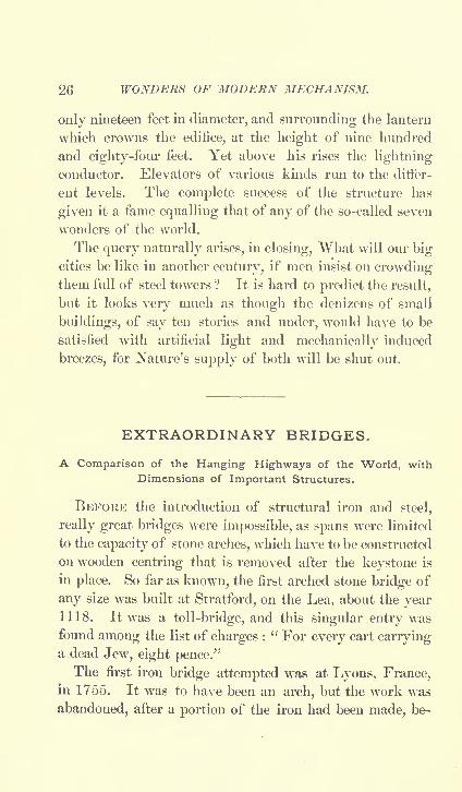
26 WONDERS OF MODERN MECHANISM.
only nineteen feet in diameter, and surrounding the lantern
which crowns the edifice, at the height of nine hundred
and eighty-four feet. Yet above his rises the lightning
conductor. Elevators of various kinds run to the differ-
ent levels. The complete success of the structure has
given it a fame equalling that of any of the so-called seven
wonders of the world.
The query naturally arises, in closing, What will our bigcities be like in another century, if men insist on crowdingthem full of steel towers ? It is hard to predict the result,
but it looks very much as though the denizens of small
buildings, of say ten stories and under, would have to be
satisfied with artificial light and mechanically induced
breezes, for Nature's supply of both will be shut out.
EXTRAORDINARY BRIDGES.
A Comparison of the Hanging Highways of the World, with
Dimensions of Important Structures.
BEFORE the introduction of structural iron and steel,
really great bridges were impossible, as spans were limited
to the capacity of stone arches, which have to be constructed
on wooden centring that is removed after the keystone is
in place. So far as known, the first arched stone bridge of
any size was built at Stratford, on the Lea, about the year1118. It was a toll-bridge, and this singular entry was
found among the list of charges :
" For every cart carryinga dead Jew, eight pence."
The first iron bridge attempted was at Lyons, France,in 1755. It was to have been an arch, but the work was
abandoned, after a portion of the iron had been made, be-

EXTRAORDINARY BRIDGES. 27
cause of the great expense. In 1777-79 the first iron
bridge was built in England, over the Severn River, in
Shropshire, the place taking the name Ironbridge. It
stands to-day a monument to the durability of cast iron.
Its design is that of an arch, of one hundred feet SJKIII and
forty-five feet rise. The next iron bridge built was also
in England, at Wearmouth, in Devonshire. This was no
mean structure, Ix'ing in the form of a segmental arch of
two hundred and thirty-six ft>et span, and costing alnmt
twenty-seven thousand |xmnds. Not until ISO.'J was the
first iron bridge actually erected in France, l>cing thrown
across the Seine at Paris. It has nine arches, and a total
length of five hundred and sixteen feet. Other cast-iron
bridges followed rapidly, until the improved methods of
making wrought iron caused it to be substituted. Within
recent years wrought iron is giving place to mild steel,
which is as cheap and considerably stronger for the same
weight.
The first susj>ension bridge built was over Menai Straits,
in North Wales, in 1820-20, at a eost of twenty thousand
pounds. The suspension was accomplished by means of
sixtwn great chains. The length of the bridge over all is
a third of a mile, the suspended portion Ix'ing five hundred
and seventy-nine feet in length. The success of this caused
another suspension bridge to be built at Vienna across the
Danube two years later. The susjwnded portion of this
wits three hundred and thirty-four feet, and linked steel
bars were used instead of chains. Shortly afterwards a
bridge of wire chains, eight hundred and seventy feet long,
was built at Fribourg, Switzerland.
The famous Britannia Tubular Bridge across Menai
Straits was built in 1846-50, and is so named because
constructed of two independent continuous tubes or beams.

28 WONDERS OF MODERN MECHANISM.
Each of the tubes is fifteen hundred and eleven feet longand thirty feet in diameter. They rest on three piers and
two abutments. The structure is satisfactory, but as its
weight is three times that of a girder bridge of the same
strength, it is never likely to be imitated.
M. Gustav Eiffel, the same who built the famous tower,
designed a bridge or viaduct that crosses the Truyere
Valley at Garabit, and presents some remarkable features
of construction. It is fifteen hundred feet long, four hun-
dred feet high, and its centre rests on a metallic arch of
five hundred and forty-one feet span. It is built of lat-
ticed girders, after the fashion of the Eiffel Tower.
The monarch among bridges is the gigantic cantilever
over the Frith of Forth in Scotland. Its magnitude is
best illustrated by comparison with other large bridges, as
in the accompanying drawing, where it is shown groupedwith three remarkable American bridges. How it dwarfs
them ! Yet the smallest of the four cost six million five
hundred and thirty-six thousand seven hundred and thirty
dollars, and was seven years in building. It spans the
river at St. Louis in three grand arches, each of over five
hundred feet. Fourteen men died from the effects of
working in the compressed air essential to the sinking of
the caissons for its piers, which had to be carried down
one hundred and ten feet below the water. This work is
not now so dangerous, owing to improved methods. The
Poughkeepsie bridge, which ranks next in the group, cost
less than three million dollars an astonishingly econom-
ical figure, when we consider that it has five spans of over
five hundred feet each, besides shorter spans on each shore
of approach, and rises to allow a vessel-clearance of one
hundred and seventy feet, in which respect it excels the
Forth bridge. The second in the group is the New York-

EXTRAORDINARY BRIDGES. 29
Brooklyn bridge, the proudest structure of its kind on the
Western Hemisphere. It cost about six million dollars,
exclusive of land damages. ItsS central span is 1 ">(Jo feet
lon<r, the towers are alxjut two hundred feet total height,
and the anchorages contain fifty-six thousand cubic vards
of masonry. It is crossed by more ]>eople daily than anyother bridge in the world.
COMPARISON OF FOUR FAMOUS RRIIXiES.
Site Forth. Hrooklvn. I'ough-St. Louis.

30 WONDERS OF MODERN MECHANISM.
By the table it will be seen that the great Forth bridge
exceeds the others even more in its carrying capacity than
in its size. Its piers are sunk ninety feet below high
water, and the caisson work on them was done under an
air pressure of from ten to thirty-five pounds. The two
main spans are each seventeen hundred and ten feet (or
about one-third of a mile) long, and the shore spans are
six hundred and seventy- five feet each. The main towers
are three hundred and sixty feet above the level of highwater. This gives an extreme height from the river bed-
rock to the top of towers of four hundred and fifty feet.
The total length with approaches is nearly two miles. It
is justly considered the greatest engineering structure in
the world. One of its enormous spans weighs seventeen
thousand nine hundred tons, or the equivalent of twenty-
five heavily-loaded freight trains. If clumsily designed,
it would sink of its own weight. The main compression
FIG. 4.
9 I
: _ ;*.-*i- 930- # 1595V
members of the cantilevers (as the vast balanced frames
are called) are tubes of twelve feet diameter and one and
a quarter to one and seven-eighths inches thick, this form
giving the most strength with the least weight. Each of
these tubes is subject to a strain of two thousand five
hundred and fifty-five tons of dead load, eleven hundred

EXTRAORDINARY BRIDGES. 31
and forty-five tons live or moving load, and three thou-
sand two hundred and seventy tons of wind pressure.
The plate's of which all the cylindrical columns are made
are l>ent into shape while hot U'tween |>owerful rolls, an
extra pressure Inking applied in a final roll when nearlyeold to prevent them from twisting. The site of the
bridge is the scene of frequent .-torms, for which reason
an allowance of fiftv-six pounds JKT square foot of strength
was made for wind pressure.
The suspension bridge In-low Niagara Falls has been
widely descrilxnl and illustrated. It was built in 18.VJ,
but so many great bridges have l>een built since then that
its length of eight hundred and twenty-one feet now seems
little. It is two hundred and forty-five feet alx>ve the
water.
The vibration on wire-rope susj>ensioii bridges is very
great, and was not at first fully appreciated by engineers.
The first train (and the last also) that was run over the
three-hundred-foot bridge at Stockton, California, at the
usual train s|>eed of thirty miles an hour, was cheeked bya wave of vibrations that rose before the locomotive to a
height of two feet. After that the train sj)eed on the
bridge was limited to three miles an hour.
Among interesting foreign bridges the following maybe named : The bridge over the Hooghly River at Cal-
cutta, built of iron girders, and resting on twenty-eight
pontoons. It is elevated to allow the passage of small
river craft, and is fifteen hundred and thirty feet long and
sixty-three feet wide. The Chilean State Railway bridge,
over the Mallen River, which it crosses at a height of
three hundred and thirty-three feet. It is fourteen hun-
dred and nineteen feet in length, and includes five spans.
The movable ferry bridge at Bilboa, Spain. This is simply

32 WONDERS OF MODERN MECHANISM.
a high iron-girder bridge, which, instead of having a road-
way, bears a large basket-like platform, or car, swung un-
derneath so that it may be run across by a travelling crane,
carrying over a load of passengers and freight. It is
built high to admit of the passing of vessels, and it has the
advantage that no shore approaches are required, thus
lessening the cost materially. The span is about five hun-
dred feet, and one hundred and fifty passengers may be
carried across at a time, the trip occupying only one
minute.
A bridge is planned to cross the Hudson at New York
City with a single span, connecting the States of NewYork and New Jersey. It is to cost twenty-five million
dollars, and will be the largest as well as the most costly
bridge on the globe. There appears to be no doubt that it
will be begun at an early date. The great bridge will be
of the suspension type, the clear span being one hundred
and fifty feet in height and three thousand one hundred
and ten feet (nearly two-thirds of a mile) in length. This
is almost double the span of the famous Forth bridge.
On the New York side will be approaches of five hundred
and seventy-five feet span and four hundred feet span re-
spectively. On the New Jersey side the approaches are
made up of short deck spans. The two main towers will
be five hundred and eighty-seven feet above high water, or
about seven hundred feet from the bottom of the founda-
tions. These towers will have eight legs, braced in two
directions, and resting upon masonry piers set on the bed-
rock. The main steel cables, twelve in number, will be
twenty-three inches in diameter, and will bear a tensile
strain of one hundred and eighty thousand pounds per
square inch. Six tracks will cross the bridge on a level,
and each track is designed to bear three thousand pounds

EXTRAORDINARl' BRIDGES. 33
load JKT lineal foot. The load upon these tracks will l>e
distributed by the use of stiffening trusses every one hun-
dred and twenty-five feet. The trusses will IK' of how-
string design, and will IK? constructed of high-grade medium
steel. A svsteni of lateral bracing is provided at the floor
level to resist wind pressure. There is also a vertical set
of vibration braces at each panel |>oint, connected with
top chord lateral bracing. The ends of the cables will IK*
set into anchorages of masonry made by running long tun-
nels under ground.
Among drawbridges the swinging form has l)omme the
more jM>pular ty|x'. They might bettor be called rotating
than swing bridges, because they have a purely rotary
motion. The mechanism of the pivot-centre of a sub-
stantial type, as made by William Sellers A: Co., is shown
herewith. The weight is designed to IK? carried ujxm the
plates of the centre-jx^t, the rollers of the circular track
simply serving to prevent tipping.
The longest bridge in the United States spans the Ohio
River at Caire>, Illine)is. It is ten thousand five hundred
and sixty feet, most of which is taken up in the ajv-
pr< >aches. It has seven principal spans and forty three
minor ones. Over twenty-one million jMmnds of steel
enter into its construction, besides thirty-two thousand
yards e>f masonry. Another bridge over the Ohio River
at Cincinnati is a trifle over six thousand feet long, and is
principally remarkable for the very large steel girders used
in its construction, many of them weighing thirty-seven
thousand tons each. The largest cantilevers used in a
bridge in this country are across the Colorado River just
below the Needles, where there is a span of nine hundreel
and ninety feet. The Memphis (Tennessee) bridge over
the Mississippi is a notable structure. The longest of

34 WONDERS OF MODERN MECHANISM.
its three main spans is seven hundred and twenty feet. It
is built on the cantilever principle and rests on four piers.
Iron bridges are commonly made of trusses, which bear
various names. Among the most common is the Howe
FIG. 5.
PIVOT-CENTRE FOR SWING-BRIDGE.
truss, consisting of X-shaped braces between beams or
girders. The triangular or Y-shaped truss is also com-
mon. The parabolic truss is a comparatively new and
handsome form, and is shown in Figure 6. The lattice
form of girder is also a favorite style of construction.

EXTRA 07?/>/.V.-l RY BRIDGES. 35
It has an upjM-r and a lower U-ani connected by a lattice-
work of crossed l)ars. Tlu* plate bridge or plate-girder
bridge is made of very wide steel beams, usually in cross
section resembling an I. Such bridges are called deck
bridges when the roadway is on a level with the top of the
trusses, through bridgis when the roadway passes Ix-tween
the trusses on a line with the lower In-ams, and hall-deck
when the roadway is midway of the trusses.
FKJ. 6.
HIGHWAY BRIDGE AT BIXOHAJITON. HEW YORK.
Bridge-building is undoubtedly on the increase, and
with the deereased priee of steel, together with the in-
creased strains which it is made to bear, we may rca^on-
ably expect to see many more such mammoth structures
as that contemplated over the Hudson. Indeed, greater
ones are possible with present materials, and the cost is
the only thing that prevents the building of spans a mile
in length. As materials cheapen, and the world's ideas
of necessity and convenience advance, probably the one-
mile span will spring into being.

36 WONDERS OF MODERN MECHANISM.
SOME GREAT TUNNELS.Methods of blasting through Mountains, driving Shields under
Rivers, and forcing Needles under City Streets.
NEXT to the aspiration for fame that leads men to erect
sky-kissing towers, there comes the desire to dig far down
into the bowels of the earth, to scorn the opposing moun-
tain that will not be crossed, and make a straight road
through its vitals to daylight. No engineering feats are
more interesting and none have called for grander genius
than the construction of great tunnels. According to an
estimate of 1894, there are in the world about eleven hun-
dred and forty-two tunnels worthy of the name. Onethousand of these have been built for railway purposes,
and their total length is three hundred and fifty miles.
Twelve are subaqueous, affording passage under rivers,
and of a total length of nine miles. Ninety have been
built to allow the passage of canals, and their length is
seventy miles. Forty have been made as conduits for
various commercial purposes, and their length is eighty-
five miles, the total length being five hundred and fourteen
miles, or about half a mile each. These figures seem
disappointingly small at first sight, but the work in spe-
cial cases has proved sufficiently difficult to satisfy the
most exacting seeker after onerous and arduous engineer-
ing enterprises.
When ancient Babylon was in her prime, a tunnel of
masonry was constructed at that point under the mighty
Euphrates. The Romans also built many tunnels, the
most important of which was the one constructed to drain
Lake Fucinus, which was built shortly after the time of
Christ. It was three and a half miles long, and had
twenty-two perpendicular shafts, some of them four hun-

SOME GREAT TUNXELS. 37
dred feet long, serving to curry away the waste dirt and
to convey supplies to the workers. Copper hoisting-
buckets were used in these shafts and oj>erated by wind-
lasses from alx>ve. The enormous numl>er of thirty thou-
sand men are said to have been employed in the tedious
task of digging it by hand labor.
There are four mountain tunnels that are regarded as
among modern wonders of engineering. They are the
Hoosae, Mount Cenis, St. Gothard, and Arll>erg. The
Hoosac is almost five miles in length, and occupied twenty
years in the building, at a cost of about sixteen million
dollars. The Mount Cenis, seven and five-eighths miles
long, occupied fourteen years, at a cost of fifteen million
dollars. The St. Gothard, the greatest of all, nine and a
half miles in length, was finished in nine years, at a cost
of eleven million one hundred and seventy-five thousand
dollars. The Arlberg, six and three-eighths miles long,
occupied three and a half years in construction, and the
cost was seven million three hundred thousand dollars.
They are given in the order of their construction, the
Hoosac being begun in 1855, Mount Cenis in 1857, St.
Gothard in 1872, and Arlberg in 1880.
It will be observed that the time and cost per mile were
reduced in each succeeding work. A large ]>ortion of the
work on the first two was done by hand, with very ineffi-
cient machinery. The Hoosac was in many respects the
most difficult feat of the four, since it was the first of its
kind, and involved many problems previously untried, and
it is gratifying to think that if European engineers have
surpassed Americans in the size and number of their great
tunnels, at least our engineers showed them the way, and
made success easier in later examples.
The Hoosac passes under two mountains, one fourteen
4

38 WONDERS OF MODERN MECHANISM.
hundred feet and the other seventeen hundred feet higher
than the level of the tunnel. Between them is a valley
or gorge whose bottom lies within a thousand feet of the
tunnel roof. In this gorge the work was begun, and a
shaft sunk to the grade of the tunnel, which here reaches
its highest point. From the shaft tunnelling was begunboth ways, which, with the headings sunk at the extremi-
ties of the route, enabled the work to progress in four
directions. It was remarked of the Mount Cenis tunnel
that the engineers must have been very sure of their
measurements, since they worked from both ends. Our
engineers set themselves a doubly difficult task of the
same sort, and their four roads met in the bowels of the
mountains with an error of only two or three inches. The
last ten years of their work were considerably lightened
by the introduction of the compressed-air rock-drill, which
came into use about 1865 for drilling blasting-holes.
The most important of the railway tunnels made in the
United States within recent years is the Stampede or Cas-
cade tunnel, on the line of the Northern Pacific Railway.This tunnel is over two thousand eight hundred feet above
the sea level, and is nine thousand eight hundred and fifty
feet long. The difficulties of its construction were in-
creased by the fact that the work had to be done in a wild
unsettled region, and that the contractor was allowed only
twenty-eight months in which to complete the undertaking.It was finished in 1889, exactly on time. A description
of the methods of work will serve to show how all such
tunnels are now constructed. The points of entrance to
the mountain having been decided upon, they were accu-
rately located as to line by taking a sight survey across
the top of the mountain. This was done with a transit
so accurately that the headings met within an inch of the

SOME GREAT TUNNELS. 39
calculated points. The contractors then built a railroad
across the mountains for their own use, at a cost of four
hundred thousand dollars. Curiously enough, they sold it
afterwards at a good profit. After some six months sj>ent in
building this road and getting the tools and machinery on
the ground the real work was begun. The headings were
run in two levels or steps, the upjier level being kept about
thirty feet in advance of the lower level. This allows!
the using of about twice as many men and machines for
drilling as could have been accommodated if the work had
been all done on one level. It permitted the men workingon the upper level to bore downward, as well as into the
face of the rock, more than doubling the area of rock
available for drilling. The blasting-holes were drilled
about five feet apart and twelve feet deep. In soft rock
each drill was expected to bore six or seven of these holes
in five hours, when all hands retired to get out of the wayof the blast. Four hundred pounds of powder were used
for such a blast Of course if the rock was specially hard
the work progressed more slowly, and sometimes only five
or six feet of advance were made to a blast, after fifteen
hours of hard drilling. By using two shifts of men, workwas kept up night and day, and an average advance of
nearly seven feet a day was obtained in each heading.About three hundred and fifty men were on the pay-rolls
during the whole period, and thirteen of them were killed
by accidents, which was considered to be below the averagerecord.
The work of timbering progressed with the drilling and
blasting, and interfered with the drillers about one-fourth
of the time. The tracks were laid close after the work-
men, so as to run cars back and forth for removing the
debris. A novel arrangement, designed especially for

40 WONDERS OF MODERN MECHANISM.
this work, was in the use of a sort of two-story flat-car,
built to run entirely above and around the ordinary dump-
cars, so that when they met in the tunnel the dump-cars
passed underneath the big car which ran on outer tracks.
This big, two-story car was the same height as the upperlevel on which the workmen operated the drills, and was
used to carry off the upper rock and earth after blasting.
The contract price for this tunnel was one million one
hundred and sixty thousand dollars, but the Northern
Pacific Kailroad found it necessary later to put in masonryarches and concrete to protect the rock, which was shale,
from the damaging moisture of the* atmosphere, which
work added materially to the cost.
The Croton aqueduct in New York is properly a tunnel,
though it does not go by that name. It is thirty miles
long, and almost wholly under ground. It is not only the
longest but the most costly of modern tunnels, the expense
being about twenty-four million dollars.
The tunnelling of rivers to secure a convenient means
of crossing without interfering with navigation, suggesteditself in ancient times, but the first modern instance was
about 1800, when the Thames tunnel was projected. So
little interest was taken in this, however, that it fizzled
along for over forty years before completion. The greatest
subaqueous tunnels have been built by the English, those
under the Severn and Mersey being each nearly five miles
in length, the former over five miles if the approaches be
included. It was built at a cost greatly in excess of the
original estimates, the soft soil being subject to a leakagealmost impossible to overcome. Twice during tunnelling
operations the work was flooded, with loss of life and
great damage. Had the difficulties been fully foreseen
at the outset it never would have been undertaken, as it

SOME GREAT TUXXELS. 41
affords only a slight saving in time of travel. But the
British spirit is apt to carry things through, and this
tunnel stands as an example of man's triumph over the
forces of nature.
Fro. 7.
CAISSON IN COURSE OF CONSTRUCTION FOR BLACKWALL TUNNEL, UNDER THAMES.
In subaqueous tunnelling the hydraulic shield is com-
monly used. This is the invention of Alfred E. Beach,of New York. It was used with success on the tunnel
under the St. Clair River at Sarnia for the Grand Trunk
Railway of Canada. This tunnel is six thousand feet
long, two thousand three hundred feet being under the
river bottom. It was finished in 1890, and a description
of the methods employed will serve to give a fair idea of
modern methods of building river tunnels. The soil was
principally soft clay, with occasional beds of gravel and4*

42 WONDERS OF MODERN MECHANISM.
quicksands. This is usual in river beds, and as a conse-
quence the methods of work are entirely different from
those employed in tunnelling through rock, as under moun-
tains. A steel cylindrical shield was used, twenty-one
and a half feet in diameter and fifteen and a quarter feet
long. It was made of one-inch steel plate, and was forced
forward a foot and a half at a time by a series of hydraulic
jacks pressing against the rear edge. These jacks were
capable of exerting a thrust of three thousand tons, hence
the shield would push aside any ordinary small boulders
that might chance to be in the way. The shield had rear
doors, through which the workmen who removed the clay,
etc., might escape and shut off the flow if any sudden
stream of water should burst in on them. The excavated
material was passed back through these doors and run out
upon small dump-cars. As the work progressed under the
river, bulkheads constituting air-locks were placed back
of the workmen and compressed air supplied them, to a
pressure sometimes as great as twenty-eight pounds. This
served as a check to keep back the water, which otherwise
would have flowed in almost constantly. As the shield
was pushed forward, cast-iron rings two inches thick were
inserted behind it. By making these rings slightly oval
instead of circular, a ring can be passed into place through
rings of the same size by simply turning it so that its nar-
rowest diameter comes opposite the widest diameter of the
rings already in place and forming the tunnel. In this
tunnel, however, it was deemed best to make the rings in
segments and bolt them together. The shield was made
with a rear hood an inch larger in diameter than the rings,
and the latter were readily put in place within the protec-
tion of this hood. If the shield showed a disposition to
work to one side, the jacks on that side were subjected to

SOME GREAT TUXXELS. 43
a trifle more pressure, and thus the work was kept practi-
cally in line, so that the shields from the opposite sides of
the river met accurately in the centre as calculated. The
six thousand lift of shield work were completed in just
one year, and at no time was there serious annoyance from
water. Practically the same method has been used in
tunnelling under the streets of cities, where it was im-
portant not to interfere with buildings al>ove. The Croton
aqueduct under Broadway, New York, is built in this
manner, as is also the London Electric Underground Rail-
way tunnel.
At King's Cross Station in London an ingenious system
of tunnelling wits successfully used. It is useful in a clay
soil, and consists in driving sheet-iron piles, or needles,
through the clay horizontally, so as to supi>ort the clay
alx>ve when material is removed from below. These
needles are ten and a half lift long and a foot wide, and
are tongued and groved like matched boards, so that noth-
ing can work through between them. They are pushedforward as the work advances, and the space of two
inches which they leave vacant is filled with cement, forced
in through pipes under pressure. In this way foundations
above are not interfered with in the least. This is cheaj)er
than shield-work, and quite as suitable for tunnelling under
cities.
For tunnelling in chalk there is probably no better
method than that tried in the proposed tunnel under the
English Channel, alx)iit 1882. The engineers used steel
cutters, mounted upon the ends of a rotating arm. This
machine cut into the rock at a rate as high as eighty-
seven feet in a day of twenty-four hours, a speed never
approached in any other tunnelling operations. Unfortu-
nately, political jealousies have prevented the completion
44 WONDERS OF MODERN MECHANISM.
of this work, though about a mile of progress had been
made on each end. No doubt the commercial advantages
of such a tunnel between France and England will event-
ually cause the resumption of this interesting tunnel, and
make it possible for Londoners and Parisians to travel
back and forth without danger of sea-sickness.
CANALS, OLD AND NEW.
A Brief Description of the Great Artificial Waterways of the
World, with a Summary of Important Proposed Additions.
THE earliest record we have of a canal enterprise dates
back sixteen hundred years before Christ, to the time of
Sesostris, when, according to tradition, a canal existed
across the Isthmus of Suez, where to-day is located the
greatest canal in the world. It is very possible that this
is true, since the isthmus is nothing but a sand formation,
and may have been very much narrower in those days than
at the present time. The great Imperial Canal of China
was built many hundreds of years ago, and is still in use.
Canal-building is in principle the simplest of engineering
enterprises, consisting mainly in digging a path for water.
There are other problems that arise in a country where hills
and streams abound, but these would not have troubled
the ancient Egyptians, since the land is dry and sandy.Whether this time-honored tradition be true or not, it is
well established that both Darius and Nero contemplated
cutting the isthmus, and the historian Harcourt, who wrote a
book on " Rivers and Canals," states that there is evidence
that a canal existed here from 600 B.C. to 800 A.D., when it
was allowed to fall into decay, and gradually disappeared.

CANALS, OLD AND NEW. 45
111 more modern times, Pojx? Sixtus V., Louis XIV., and
Napoleon I. each had the building of a canal at the
isthmus under advisement, hut without ultimate result.
The Dutch, always troubled by an excess of water in
Flanders, began to cut canals aUmt the twelfth century,and in 1560 they finished a great canal connecting Brussels
with the Scheldt. In France, the first canal enterprise of
importance was the Canal du Midi, or Languedoc, which
was finished in 1681. This was a really great enterprise,
Ix'ing one hundred and forty mill's long, and costing seven
million two hundred thousand dollars. It has one hundred
and nineteen locks, but is hardly a ship-canal in the mod-
ern sense, since it was designed to contain but six and a
half feet of water. Great Britain's first canal was built
in 1572.
Canal-building may be regarded as the engineering sci-
ence of the eighteenth century, since it flourished principally
between 1725 and the era of railroads, about 1S.30. At the
time that Stephenson ran his first locomotive there were
more than six thousand miles of canals in successful oj>era-
tion. Probably one-half of these have gone into disuse, as
they were designed to carry freight, which is now more con-
veniently transported by rail. Modern canals are built
usually for the passage of large ships between contiguousbodies of water. Prominent among the canals of the
old style is the Erie Canal, three hundred and sixty-three
miles long, connecting Lake Erie with the Hudson. It
was finished in 1825, at a cost of fifty-one million six
hundred thousand dollars. There have been in all about
five thousand miles of canals built in the United States,
about half of which are now in a state of desuetude.
England has four thousand seven hundred miles of canals,
much more than any other country in the world.

46 WONDERS OF MODERN MECHANISM.
The great Suez Canal, which made De Lesseps famous,
was begun in 1859, and finished within ten years, at a cost
of about eighty-three million dollars. It is ninety-five
miles long, and was twenty -six feet deep, but since 1866
workmen have been engaged in deepening it, at an esti-
mated cost of forty million dollars more. Its annual ton-
nage, which in 1870 was four hundred and thirty-six
thousand six hundred and nine, has steadily increased, and
is now over ten millions. The stock is quoted at about
five times the par value.
The unfortunate Panama Canal enterprise, which failed
under the leadership of De Lesseps, was to have been
forty-seven miles long, and the estimated cost was one
hundred and twenty million dollars. It was begun in
1881, and two hundred and fifty million dollars were
expended in completing about one-third of the work, when
it collapsed, under speculative financiering, amid gravescandals.
It is more interesting to turn to the Isthmus of Corinth
Canal, which was opened in 1893, after nine years' labor.
It is but four miles long, yet saves two hundred miles of
navigation, and is expected to have a traffic almost half as
large as the Suez Canal. Nero began a canal at the same
place eighteen hundred years ago, and traces of his work are
still to be seen in the vicinity. That tyrannical monarch is
said to have turned the first sod himself with a golden spade,
but after some time abandoned the work because the sci-
entists of that day told him that the sea was higher on one
side than on the other. May 2, 1882, the king of Greece
started in a silver spade, while the queen did more efficient
work in touching off a train of dynamite mines. A firm
contracted the job of completing what the king and queenhad begun so magnificently for five million two hundred

CANALS, OLD AND NEW. 47
and eighty thousand dollars, but found more rock than
they anticipated, and failed. It was finally completed at
a cost of about twelve million dollars. A Unit three thou-
sand men were employed at the {icriod of greatest activity,
together with seven hundred cars and eight dredge's. The
deepest cut is two hundred and twenty-eight feet. There
are no locks.
A remarkable canal that is but little known is the St.
Marv's, or Sault Ste. Marie Canal, forming the outlet of
I^ake Sujx'rior to Lake Huron. It has the largest lock in
the world, being eight hundred feet long, one hundred feet
wide, and having a lift of eighteen feet. Its tonnage is
double that of the Sue/ Canal. It is only one mile long,
was built in 1855, and has l>een twice enlarged. Its great
lock, only recently completed, is manipulated wholly by
hydraulic j>ower taken from the fall at the lock, so that the
only expense is for maintenance and attendance. The
charge to passing vessels is about one-half cent JKT ton.
The city of Chicago has dug or is digging a canal to
connect the Chicago River with a tributary of the Missis-
sippi, desiring, for sewerage purposes, to divert the ChicagoRiver from Lake Michigan. The work is to be extended
ultimately to the Mississippi, at a depth of fourteen feet.
It will probably cost some sixty million dollars before
completion.
The Manchester Ship-Canal, completed in 1894, is
thirty-five miles long, and cost seventy-five million dollars.
Manchester is sixty-five feet above the sea-level, and five
locks were necessary to elevate the incoming ships. Should
this prove profitable, there is no telling how many inland
cities will become seajx)rts. This canal is chiefly remark-
able for its great width, being one hundred and twentyfeet wide at the bottom. Its construction presented some
48 WONDERS OF MODERN MECHANISM.
unusual difficulties. The Mersey River, which is one of
the most crooked on the globe, lay so in the way that it had
to be crossed six times, while the Bridgewater Canal had to
be crossed once. This latter was accomplished in a novel
manner. Across the Manchester Canal is constructed what
might be called a swinging water-bridge. Into this the
Bridgewater boats are hoisted by an hydraulic lift, swungacross the Manchester Canal, and let down on the other
side by another lift. The swinging water-bridge is then
turned to one side, and traffic continues on the Manchester
Canal until another Bridgewater craft demands passage.
The Baltic and North Sea Canal is an important engi-
neering work, begun in 1887 and opened in 1895. It
cost forty million dollars, and will save vessels the dan-
gerous trip by way of the Cattegat around the north shore
of Denmark. Nearly three thousand vessels have been
wrecked in passing through this sound within thirty years,
with a loss of life of over seven hundred. Prussia's im-
portance as a naval power will be augmented by the canal,
which was an equally potent reason with that governmentfor undertaking the work. It is sixty-one miles long, and
twenty-nine and a half feet deep, sufficient to carry the
largest vessels in the German navy. It is expected to
aiford accommodation to twenty thousand ships annually.
The working plant consisted of ninety locomotives, two
thousand four hundred and seventy-three cars, sixty-eight
dredges, one hundred and thirty-three lighters, fifty-five
steam-engines, and four thousand seven hundred to eightthousand six hundred men. It has tide-locks at either
end, the one on the Baltic end being usually left open.A speed of five and three-tenths miles an hour will be
allowed passing vessels. The toll will be seventy-five
pfennigs (eighteen cents) per ton capacity. It should be
CANALS, OLD AXD NEW. 49
stated, in this connection, that there are already three canals
connecting the Baltic and the North Sea, all of them old-
time affairs of little depth, and two of them having l>een
abandoned. The present canal is an almost direct cut,
and is specially designed to allow of quick travel for the
Prussian gunboats. It will lx* a saving to commercial
vessels of three or four hundred miles.
Projected canals are of quite as much interest as those
which have existed in the past or are being built in the
present. One of the most remarkable is a long-mooted
enterprise for connecting the North Sea with the Mediter-
ranean by cutting across France. There are two routes
now under consideration, one via Marseilles, Lyons, and
Dunkirk, and the other by Marseilles, Lyons, Paris, and
Rouen. That portion of the canal from Rouen to Paris, a
distance of over a hundred miles, is most seriously con-
sidered.
There is agitation in several English commercial cities
for a closer intimacy with old Neptune. A ship-canal to
London, at a cost of five million dollars, is mooted. Thetowns along the Trent want a barge-canal, while those on
the Mersey talk of a ship-canal, eleven feet deep, to cost
eleven million dollars. Birmingham is very likely to put
through a ship-canal to the Severn, at a cost of six or seven
million dollars. An extension of this scheme is desired
by merchants of the manufacturing centres tributary to the
Bristol Channel, the projected route being from Stalford,
on the Bristol Channel, via Taunton to Seaton, a distance
of sixty-two miles. This would cost about fifteen million
dollars more. Other proposed British canals are from the
Tyne to the Solway Frith and from the Clyde to the Forth.
A canal route has been surveyed across Italy, from
Fano on the Adriatic to near Castro on the Mediterra-c d 6

50 WONDERS OF MODERN MECHANISM.
nean. It would be one hundred and eighty miles longy
and an undoubted gain to navigation, but the estimated
cost of one hundred million dollars stands in the way.
Austria desires a canal, deep enough for war-vessels,
cutting from the Danube, near Vienna, to the Oder, near
Breslau, thus connecting the Baltic and Black Seas. Thedistance is two hundred miles, but the route is easy, so that
the cost is set down as not over thirty-seven million dollars.
Other proposed enterprises in that part of the world are
a canal to connect the Black and Caspian Seas, and another
to cut the Isthmus of Perekop, which unites the Crimea
with the mainland.
It has been proposed to fulfil the prophesy in Ezekiel,.
and obliterate the historic Jordan, Dead Sea, and Sea of
Tiberias, by running a canal from Acre on the Mediterra-
nean to the valley of the Jordan and on to the Dead Sea,
which would then be flooded, as it is thirteen hundred feet
below the sea-level. This section, sacred to so many Chris-
tians, would be turned into a lake of one hundred and forty-
seven by ten miles, connected on the north with the Medi-
terranean by a sixty-seven-mile canal and on the south
with the Gulf of Akabah by a two-hundred-and-forty-milecanal. It is claimed that this would make a route to
India four hours shorter than the Suez Canal, and that it
would cost less than one hundred million dollars to build
it. The scheme is generally regarded as a lever for Eng-lish merchants to use in keeping down tolls on the Suez
Canal. Another canal for the same purpose, connectingwith the Persian Gulf, has been suggested.On the Western Hemisphere we have the continually
mooted question of a canal dividing North and South
America, with De Lesseps's gigantic failure at Panama to
check the enthusiasm of investors. Let us hope that the

CANALS, OLD AND NEW. 51
Xicaragiian plan, with its one hundred and seventv
of route and estimated cost of seventy-five million dollars,
will be put through.
In the United States there has l>een projx)sed a ship-
canal to connect the Chesaj>eake and Delaware Bays, by a
thirty-mile route, at a cost of ten million dollars. This
would bring Baltimore two hundred and eighty-six miles
nearer Philadelphia by water, and save coasters two hun-
dred and fifteen miles between Baltimore and New York.
A canal around Niagara Falls on the American side is fre-
quently discussed, since the Wei land Canal, which forms
the connection on the Canadian side, is only fourteen feet
dee}). The new canal would have to be twenty or twenty-five miles long, and would cost eighteen to twenty million
dollars. Of course there have been plenty of j>eople whodesired to cut the Florida peninsula. A company was
once organized for the purjwse, but failed to raise the re-
quired forty-six million dollars.
Another project is the enlargement of the Delaware and
Raritan Canal for the use of vessels of deep draught. This
would complete an inland route via the Caj>e Cod Canal
(now under way), the proposed Delaware and Chesapeake
Canal, and the Dismal Swamp Canal, forming a convenient
protected waterway between Boston, New York, Philadel-
phia, Baltimore, Norfolk, and the Carolina Sounds. Such
a route might become of vast military importance in case
of a war with some foreign naval power, which blocked
our ports. Admiral Luce made this project the substance
of a government report, showing how it might enable us
to gather our navy at any point on the Atlantic coast, pos-
sibly without the knowledge of a hostile fleet, and probablywithout their intervention.
Among other proposed canal enterprises in this country

52 WONDERS OF MODERN MECHANISM.
are the following : From Lake Borgne to the Mississippi ;
length, twelve miles; cost, four hundred and fifty thousand
dollars ;would save two hundred and sixty-five miles of
gulf navigation. Cincinnati and Lake Erie; enlargement
of present canals; cost, twenty-eight million dollars.
Fresno and San Joaquin Rivers; cost, three million
dollars. Saugatuck to Detroit via Kalamazoo River;
length, one hundred and seventy-eight miles; designed to
complete an air-line water route between New York and
Chicago. Bay Autrain on Lake Superior to Little Bay de
Noquet on Lake Michigan ; length, thirty-six miles; cost,
five million dollars;would save two hundred and seventy-
one miles between Duluth and Chicago. Lake Erie to
the Ohio River; length, one hundred and thirty-six miles
;
designed to connect the Great Lakes with the Gulf of
Mexico. A ship-canal, through the Great Lakes, whollyin American territory. The Dominion of Canada has a
similar one all on British territory, built at a cost of
sixty-seven million dollars.
From this it will be gathered that canal-building is not
on the decline, but that interior waterways are sufficiently
esteemed by civilized nations that they will be built
wherever demand arises, if the contour of the ground
permits. Their advantage as a means of cheap freight
transportation, and for quickly gathering the vessels of a
navy, cannot readily be overestimated.
It is very possible that barge-canals may receive a sub-
stantial boom because of electrical propulsion, which has
been tried successfully of late. If trolley railways can
carry passengers cheaper than steam- railroads, why cannot
trolley canals carry freight cheaper than the steam-rail-
roads ? This is the question which those who are studyingthe matter are trying to solve. During the latter part of

CANALS, OLD AND NEW. 53
1893, F. W. Hawley, of Pittsfbrd, New York, began
experimenting with street-railway motors mounted on a
canal-boat and oj>erating a propeller-screw placed at the
rear, the j>ower being derived from double overhead trolley
wires. A fairly satisfactory result was obtained, and a plan
Fio. s.
THE TROLLEY TUG ON TUB CANAL DE BOfRGOGNE.
was then devised for allowing such boats to pass each other
on the canal. This is accomplished by supporting the
trolley-wires on cross-wires so that the trolley wires are
free to slide sideways on the insulating connections. As it
would be expensive to fit up all eanal-tx>ats with motors, it
has been proposed to use propeller tugs, or to make a de-
tachable stern-post, bearing the rudder and motor. The
principal objection, however, to the whole project is that
urged against all methods of power as applied to canal-
boats the banks would suffer from wash, and it would
cost more to keep them in repair than would be saved by
improved methods of propulsion. If we are to have trol-
leys and screw-propelled boats on canals we shall have to
rebuild them with permanent masonry banks that are not
affected by wash. We might then run the canal-boats at
twenty miles an hour, if that proved to be an economical
6*

54 WONDERS OF MODERN MECHANISM.
speed. If rebuilding is considered an unremunerative in-
vestment, we can at least adopt the German method of draw-
ing the canal-boats by means of a tug that picks up a chain
from the bottom and runs it over a reel, drawing itself along.
The Germans use steam-power on the tug, but if we madeuse of a motor, driven by the overhead trolley, it would
appear to be a saving, and there would be no wash of the
banks, as where a propeller is used. This has actuallybeen done on the Canal de Bourgogne in France. A por-tion of the canal, about three miles and three-quarters
long, is in a deep cutting and tunnel, where a tow-path was
impracticable. A submerged chain and steam-tug were
therefore provided for propelling the barges through the
cutting. As there was ample water-power in the vicinity,
it was decided later to abandon the tug, and in 1893 a
power-house was built, with a trolley-wire over the canal.
An electric tug takes the current by means of a trolley-
pole, and the work of towing the barges is all done by a
neighboring waterfall of twenty-three feet. The sub-
merged chain is picked up and passed around a drum on
the tug, and by hauling on this the tug makes slow head-
way with its tow. The tug motor is nineteen horse-power.The cost of canalage through the tunnel by this methodhas been reduced from a slight fraction over two cents a
ton by steam-power to one and four-tenths cents per ton
by trolley, and the time of passage is slightly shortened.
The cost of installing the electric plant was twenty-seventhousa'nd dollars.
It is only a question of time when some such improvedmethods of propulsion come into use on all canals, or else
the canal-barge must become a thing of the past. It is
already behind this progressive age, and requires to catch
up to avoid being dropped.

ELECTRICITY AND ITS FUTURE. 55
ELECTRICITY AND ITS FUTURE.
The Nature of the Electric Fluid, and the Wondrous Possibilities
that lie before Electrical Inventors.
ELECTRICITY is the modern agency by which we may
produce action at a distance. It has Ijeen compared to an
infinitely flexible connecting-rod, by means
of which we can transmit energy and re-
produce it in any desired form at a dis-
tance. By its aid we can turn the sunshine
of thousands of years gone by, whose en-
ergy is stored up in coal we can convert
this sunshine back into light, or heat, or,
better still, we can reconvert it into energy and make it do
our work.
There is a good deal of unnecessary mystery about this
wonderful force which man has so lately harnessed and
brought under control. Either scientists and electricians
are too prone to keep their knowledge of what it is to
themselves, or else there exists among them a great lack
of ability to express in plain understandable English just
what electricity is. Some of them go so far as to say that
we do not know what electricity is, that we can judge of
it only by its effects, and that we have learned, partly byaccident and partly by experiment, that it is governed bycertain natural laws, and that under given conditions it
will do certain things. While all these statements are
true, they are only half-truths. That is the way to tell
a thing when you wish to overshadow a man with your
learning and keep him from getting at the truth. Is it
not true of all the forces of Nature that we judge of them
by their effects ? There is a philosophic theory that man

56 WONDERS OF MODERN MECHANISM.
cannot really know anything, but simply receives impres-
sions of what exists about him. That is one way of put-
ting it, but some impressions are much more vivid than
others. A blow on the head with a club is the police-
man's method of conveying the impression to a ruffian
that he must behave himself and cease to make trouble.
That sort of impression is easily conveyed. But the im-
pression as to what electricity really is has not entered
clearly into the mind of one educated person in a dozen.
Even this sweeping assertion probably understates the
fact. Let us take a definition from one of the authorities.
This will serve as a fair average statement of the case :
Electricity is "an imponderable and invisible agent pro-
ducing various manifestations of energy, and generally
rendered active by some molecular disturbances, such as
friction, rupture, or chemical action. At rest it is called
static, is produced usually by friction, manifests itself
chiefly in attractions and repulsions and violent dischargeslike that of lightning, and has no use in the arts. In
motion it is called dynamic or current electricity, and this
form has been widely developed."This is as scholarly and concise a statement as can be
found in any text-book. But the man who is trying to
learn what electricity is turns from it with a sigh it has
not conveyed the idea to his mind.
Let us try and see if we cannot make this thing clear.
The primary reason why we do not comprehend electricity
readily is because it does not easily or directly manifest
itself to our senses. True, we see it in the electric arc,
we feel it in the battery, and we hear it in the thunder's
roar;but we know that the electric fluid is all about us,
in us, and through us when we experience no sensations of
its presence. We therefore fail to comprehend it, just as

ELECTRICITY AXD ITS FUTURE. 57
a man born blind fails to comprehend light, or a deaf mute
to understand music. Yet by a simple analogy with such
well-known manifestations as sound, light, and heat, we
get a better appreciation of what electricity is than in anyother way. These things are familiar to us. The child
knows to a great extent what light is before it learns to
spell the word. Heat is essential to our existence, and we
observe very slight changes in temj>erature most keenly.
When we consider that the difference in temperature be-
tween our bodies and the heat of melting iron is alxmt two
thousand eight hundred and fifty degrees, and that these
extremes are common and moderate in nature, the fact that
an alteration of only fifty degrees sends us from lemon
ices to fur overcoats serves to show how extremely sensi-
tive we are to heat. As for sound, we do not need to have
that defined for us. We had an inherent understandingof what it was long before we were taught that it was due
to vibrations, as of the air.
Having, then, an appreciation of what light, heat, and
sound are, we desire to be able to appreciate electricity in
the same way. Just here the scientific knowledge of light,
heat, and sound will help us to comprehend electricity in
a commonplace way. Space is filled with a medium, vastly
lighter than air, called the luminiferous ether. It exists
not only in space, but permeates all solid and liquid bodies
in fact, everything. This ether is subject to vibrations
of inconceivable rapidity. It is these vibrations that con-
vey to our eyes the light of stars across measureless space.
A difference in the rapidity of these light vibrations con-
veys to our eyes the sense of color. At one speed of
vibration we see red, at another yellow, and at a third blue,
and so on through the intermediate combinations and
shades. The light vibrations in the ether are like the

1)8 WONDERS OF MODERN MECHANISM.
sound vibrations in the air they go through it without
moving it, as a ripple passes over the surface of a lake
without disturbing its occupants. The air is, however,
subject to violent disturbances in the form of winds, and
so the ether is subject to similar disturbances whose mani-
festations we call electricity. Do you begin to under-
stand ? Sound is a wave motion passing through the air.
Light is a wave motion passing through the ether. Heat
is a more pronounced molecular disturbance of the ether,
that may affect the ether within our bodies. Electricity
is as the wind of ether a still more violent disturbance
of the molecules, capable of exerting tremendous force,
and of passing through solid bodies. It is tasteless and
odorless, and in many ways inappreciable to the senses,
but it is not at all a mystery. Sound travels without dis-
turbing the air, and light travels without disturbing the
ether. On the contrary, wind travels by disturbing the
air, and electricity by a disturbance of the ether. Bykeeping this analogy in mind, that electricity is the onflow
of ether, as wind is the onflow of air, we gain a realistic
conception of this thing that we cannot see or appreciate
in the way that we appreciate sound or light. There are
blind insects that live, and breed, and die in caves, and
have no knowledge or use for light. We have, as a race,
been blind to electricity for ages. Perhaps our day is
coming, and human beings may yet develop a new sense,
enabling them to know what electricity is, just as the in-
sects that do not live in caves have a sense of light.
The next point to be cleared up is as to the means bywhich we use this wind of ether, electricity. We knowthat if we confine air in a pipe and put a bellows or
blower in operation at one end, the wind created will giveus power at the other end of the pipe, which power we can

ELECTRICITY AND ITS FUTURE 59
use for driving a fan, or operating machinery, as by means
of a cylinder and piston. For electricity, we require not a
pipe with a hole through it, but a line composed of a sub-
stance through which electricity travels easily, and shielded
from going astray by a substance through which it does
not travel or flow readily. In a copjxT wire we Hud the
former, which we call a conductor. Along this wire elec-
tricity will flow as the air flows through a pipe, only very
much more rapidly. The insulation or non-conducting
covering of this wire serves to keep the electricity in the
desired line as the walls of the pij>e confine the wind.
Thus we convey electricity.
If we wish to get light from this current on the wire
we have but to use a very fine jx)rtion of heat-resisting
wire, such as platinum, and confine it in a vacuum in a
glass bulb, so that it will not burn up quickly, and when
the current flows through our wire in the bulb we have an
incandescent electric light. Or, if we want an arc light,
we use a much more powerful current and make a slight
break in the line of wire, using pieces of carbon at the
point of breakage, as ordinary wire would not stand the
heat. The electricity, in seeking to continue its flow along
the wire, leaps across the little break or gap, and in so
doing makes a manifestation of light, as the lightning
does when electricity leaps from one cloud to another, or
to the earth.
How do we get the current or etheric wind that flows
along our wire? It is by utilizing the law that electricity
makes a temporary magnet of iron when it flows around
it. Thus, if we wind a bar of iron with a coiled wire, and
pass a current through that wire, it may exert a magneticforce and draw towards it an armature. If the current Ix?
then shut off the armature may continue on in a circuit,

60 WONDERS OF MODERN MECHANISM.
and as it comes around to the original point of starting
the iron bar is again magnetized by turning on the current,
and draws the armature along, producing rotary motion.
This is the principle of an electric motor. And we get
the electricity for operating our electric motor by using a
similar machine in a reverse manner, which machine is
then called a dynamo or generator. In this dynamo we
move an iron bar to and fro, or more commonly in a cir-
cular path, towards and away from a bar of iron about
which a wire is coiled, and the coil becomes stored with
electricity, and is a temporary magnet. We may use a
steam-engine to move our armature and set up this current,
which may be led from the generator to an electric motor
to do work, as in running the machinery of a factory ;or
we may send it out on a trolley-wire to be conveyed to the
motors of a street-car, and carry it along ;or we may elec-
trify a wire so that it shall reproduce the vibrations of
sound on sensitive disks, giving us the telephone ;or send
it along another wire to a little bit of a motor, that can do
no better work than to make little clicks with its arma-
ture, which, properly used, according to the Morse code,
conveys a telegraphic despatch.
It is all very simple, and easy to understand, when once
you have the principles ingrafted in your mind.
Now that we have gained some appreciation of what
electricity is, and how it performs the tasks which we have
learned to set it, let us try to go a step farther, and see if
we can discern any future uses for this most subtle of
fluids, which we are just beginning to learn to use, to en-
able us to annihilate space, and do our will, across the
trackless waters, or threading through the mazes of a hive
of industry.
We have access to a fourth state of matter, of which the
ELECTRICITY AND ITS FUTURE. 61
others may be given as the gaseous state, the liquid state,
and the solid state. This fourth state is made up of ether,
which moves with the velocity of light, and it we are ever
to communicate with other worlds it will be by this
medium. As we can never run a wire to another sphere,
we must, then, learn to send our currents by other means.
It is just this thing which eminent electricians tell us is
possible. Nikola Tesla has demonstrated that it is not
necessary to have a return wire to connect a motor and its
generator, or even to use a wire at all. He says,"It is not
necessary to have even a single connection between the
motor and the generator, except, |>erhaps, through the
ground ;for not only is an insulated plate caj>able of
giving off energy into space, but it is likewise capable of
deriving it from an alternating electrostatic field, thoughin the latter case the available energy is much smaller."
When we have learned to make practical use of this
principle we shall have no need to transmit power in anyother way. He says, further,
" We shall have no need to
transmit power at all. Ere many generations pass, our
machinery will be driven by a power obtainable at any point
of the universe. . . . Throughout space there is energy.
Is this energy static or kinetic ? If static, our hopes are
in vain;
if kinetic and this we know it is for certain
then it is a mere question of time when men will succeed
in attaching their machinery to the very wheel-work of
Nature."
Already we know of one practical means of conveyinguseful intelligence by electricity without a connecting wire,
and it is reasonably sure to come into use before long.
Suppose the problem is to convey information between
two passing ships, on a dark and stormy night, from a
distance at which neither can see or hear the other by or-
6

62 WONDERS OF MODERN MECHANISM.
dinary means. The roaring winds drown the powerful
fog-horns, and the dense mist shuts out the strong arc
lights. Suppose, now, that each of these vessels has an
insulated wire running from stem to stern, and dipping
into the sea at either end. Connected with each wire is a
generator capable of producing strong, rapidly alternating
currents of electricity. Also on each wire is a receiving
telephone. The sounds from one vessel will then create
electric undulations through the ether that pervades the
water, and be conveyed for miles, despite the racket and
the raging of the elements, to the ear of a listener at the
telephone of the other vessel. By such means can our
ocean greyhounds continue at full speed in the storm and
darkness with the same safety that they fly onward in the
warm sunshine of a June day.
FIG. 10.
magnet
Battery
MORSE'S METHOD OF TELEGRAPHING ACROSS A RIVER WITHOUT WIRES.
a, a, a, a, copper plates.
The proof that this is practicable, and not mere theory,has been shown many times. It was done by Morse
across a small river, and since his time at greater dis-
tances. An experiment was tried in the Bristol Channela couple of years since, at Lavernock Point, which is
more than three miles from Flatholm Island and five anda half from Steepholm Island. Wires six hundred yards
long were laid at each place, the ends extending into the
water below low-water mark. A steam-launch in the

ELECTRICITY AND ITS FUTURE. 63
Channel was also supplied with such a wire. A two-
horse engine was made to work an alternator, sending one
hundred and ninety-two complete alternations JKT second
with a voltage of 150, and a maximum strength of fifteen
amperes. These alternating currents were broken into
Morse signals by a telegraphic key. Ordinary telephonereceivers were used on the secondary circuits. The ex-
periment was found wholly successful between Flatlmlm
and the shore, and a numlxT of messages were enchanged.On the more distant island the sounds telegraphed were
heard too indistinctly to be interpretable. It was found
necessary to keep the line that entered the water near the
surface, as with deep submergence the sound was alto-
gether lost. This method, if brought into general use,
would be very serviceable in warning ships of the presence
of lighthouses.
The telectroscope, a hypothetical instrument invented byLeon le Pontois, is even more wonderful. By its aid lie
expects to make visible that which is at the other end of
the wire, just as we now hear what goes on at the other
end of the telephone. Though the instrument is only in a
proposed stage as yet, it is clearly conceived on scientific
principles, and is a reasonable possibility of the near future.
He proposes to use a rotating disk, having say twentyholes in its periphery. As this disk rotates, it will conveyto the observer a continuous picture of the light thrown
towards these holes from a receiving instrument con-
structed to vibrate in accord with the light vibrations car-
ried over an electric wire from a corresponding instrument
that receives the image at the far end of the wire. Theentire description of the apparatus is too technical for
popular reading, but the following from the pen of the
inventor throws further light upon the operation :

64 WONDERS OF MODERN MECHANISM.
" With the apparatus, it can be easily understood that,
if the disk is caused to revolve, each of the rays of light
forming the picture will successively set in the line cur-
rents of varying strength. These currents act at the re-
ceiving apparatus upon a microphonic relay acting on the
telephone receiver, modified by the addition of a narrow
chamber placed between the disk and a cover hermetically
closing the telephone." One of the chambers is full of oxygen, brought in by
a pipe, and the other is full of hydrogen. On the topof the covers is tubing properly adjusted and providedwith regulating valves. The two gases are brought under
pressure near the surface of a cylinder of carbonate of
calcium." The variations in the strength of the current of the
microphonic relay cause pulsation of the diaphragms.But those pulsations, even if they are of a molecular
nature, impart to the molecules of the gas an excess of
speed, causing proportional variations in the intensity of
the oxyhydrogen light. A lens and a reflector concen-
trate the light on a ground glass or screen after having
previously passed by one of the perforations of a disk
absolutely similar to the disk placed in the transmitting
apparatus."Then, according to the position occupied by the per-
foration on the surface of the disk, the beam of light pass-
ing by this point makes a more or less luminous point at
some place on the depolished glass." But as the two disks are revolved synchronously by
the two pulsating current motors, whose pulsations are con-
trolled and even created by the vibrations of a tuning-fork,when the light of the receiver passes through a certain
perforation of the receiving disk one of the rays of light

ELECTRICITY AND ITS FUTURE. 65
emitted by the object passes by the same perforation of the
transmitting disk. If the disk turn slowly, eacli ray of
light emitted by the different points of the object placed in
the Held of the transmitting apparatus is converted into an
electric current of proportional intensity, which current is
reconverted at the receiving apparatus into a l>eam of light
of proportional intensity, and if a sensitive plate were sub-
stituted for the ground gla*s, a picture would be taken of
the object placed in view of the transmitter after a com-
plete revolution of the disk. But if the disks are revolved
at a rate of ten revolutions JKT second, each jK>int of the
depolished glass is more or less luminous or dark ten times
a second, and on account of the ]>ersistenee of vision the
retina is not affected by the successive disappearance of the
points, which taken together reproduce exactly the object
placed in view of the transmitter.
"It does not matter even if this object moves or not,
because the image of the receiver is constantly modified byits movements."
Let us hojKJ that this talented inventor may live to see
his instruments perfected and in daily use.
The greatest money harvest, however, awaits the in-
ventor who discovers a satisfactory method of convertingcoal directly into electrical energy. At present, Tesla's
oscillator comes nearer this goal than anything developed,
yet all electrical engineers are convinced that there will be
discovered some simple and less wasteful method than that
of burning the coal under a boiler to make steam, passingthe steam through cylinders to make use of its pressure,
and from the power thus derived driving a dynamo to send
out a current on the wires. Some day a genius will devise
a machine in which the burning of a gas flame at the bot-
tom will enable electricity to be taken from the top, and wee 6*

66 WONDERS OF MODERN MECHANISM.
shall secure twenty times the power from a pound of coal
that we now receive. Then we can build steamships that
will cross the Atlantic in three days or circumnavigate the
globe inside of one month. Then we shall have electric
locomotives that will make the run over perfect railwaysbetween our large cities at a speed of one hundred and fifty
miles an hour a speed limited not by the capacity of the
locomotives, but by the ability of the steel mechanism to
avoid dismemberment by centrifugal force. This is not
visionary talk, but the serious conclusions of men whohave given more thought to these subjects than their
fellows.
The power which we have just begun to draw from
Niagara, and upon which we may draw from every water-
fall, has a source further back than gravity. The sun's
rays give out a heat that results in the gathering of the
waters that descend the falls. The same luminary suppliesthe inhabitants of the tropics with more heat than they
require. May we not some day draw upon this heat byelectrical wires, and soften the icebergs of the frozen
North? As Sidney F. Walker has aptly put it
" If what we know as electricity be a form of molecular
motion at a lower rate than the slowest of the invisible heat
waves, the day on which it becomes possible to reduce the
rate of the molecules, when vibrating under the influence
of heat, directly until their motion corresponds with the
rate we know as electricity without the at present necessary
repeated transformations, an enormous stride will have been
made towards neutralizing the inequalities of climates onour globe.
" It is some years since Professor Oliver Lodge added to
Lord Rayleigh's work the discovery that floating dust par-ticles might be aggregated in the same manner as the rain-

ELECTRICITY AND ITS FUTURE. 67
drops are by discharges of static electricity. Is it too bold,
wickedly lx>ld, to hope that in the future, by means of
electricity, we may be able, at least in part, to control our
seasons? Why need we have a dry summer, as in 1.SU3,
when the moisture is present in the atmosphere, and can IK?
made to descend? Why need we have superlatively wet
seasons if the atmosphere is not allowed to retain a SUJKT-
abundanoe of moisture, when it may be caused to discharge
its cargo when desired ?"
There is good reason to believe that before many years
the submarine ocean cables will IKJ available for telephony,
and that the sounds of the human voice* may be heard
under the broad Atlantic. Ocean telegraphy is undeniably
slow, about twenty-five words a minute being all that can
be obtained. The gutta-jHTeha insulation of the cable re-
tards the rate of signalling, and various ingenious devices
have only partially improved the sjx'ed. No electrician
will be found, however, who doubts that, in spite of this
retardation, which now makes telephony impossible in a
submarine cable, a time Is corning when the telephone will
triumph over the difficulty. Already Dr. Silvanus P.
Thompson has announced that he believes that he has
found a way to overcome the obstacle, by introducing a
series of shunts in the cable, and dividing the cable-wires
into sections of about eighty miles. His scheme is very
technical, but is endorsed by other eminent electricians.
It is well known that, notwithstanding the moderate
cost of the arc electric light, it is obtained by a most
wasteful method. Only one per cent, of the energy in the
current goes to make the light! The remaining ninety-
nine per cent, is lost. The waste of heat begins in the
furnace, and there is loss by friction, leakage, lack of bal-
ance, etc., in every part of the steam-engine. The best of

68 WONDERS OF MODERN MECHANISM.
engines develop but a small per cent, of the heat energyfrom the coal. There is great waste by belt friction in
connecting with the dynamo, and the dynamo itself wastes
about ten per cent. Thirty per cent, more is lost on the
wires of the system, and of the small remainder that reaches
the arc light, ninety-nine per cent, is dissipated in passingthe carbons. We look to Tesla's oscillator to save the
wastes in the engine and belts, but for the saving of that
ninety-nine per cent, we have not yet found a means.
We have noted that light is the result of etheric vibra-
tions of high pitch, and it should be added that they are
much higher than the heat vibrations. If, then, we have
to make light by beginning with nothing and continuing
through all the lower vibrations until we get to the light
vibrations, we are wasting a great deal of energy. Yetthat is just what we are doing. If we must needs do it.
that way we require a light-producer that shall acquire the
higher vibrations in a marvellously short space of time.
Light is the product of etheric vibrations whose rate is
estimated to be about five hundred trillions a second. It
is a difficult task some inventors have set themselves, to" cateh on" to this mighty exhibition of energy, but Edisonand others tell us that it can be done.
Mr. Tesla believes that the production of a small electrode
or terminal button is necessary to the production of a satis-
factory incandescent light. He says :
" The intensity of the light emitted depends principallyon the frequency and potential of the impulses and on the
electric density on the surface of the electrode. It is ofthe greatest importance to employ the smallest possible
button, in order to push the density very far. Under the
violent impact of the molecules of the gas surrounding it,
the small electrode is, of course, brought to an extremely

ELECTRICITY ASD ITS FUTURE. 69
high temperature, but around it is a mass of highly-incan-
descent gas, a flame photosphere many hundred times the
volume of the electrode.
"To whatever kind of motion light mav lx> due, it is
produced by tremendous electrostatic stresses vibrating
with extreme rapidity. . . . Electrostatic force is the
force which governs the motion of the atoms, which causes
them to collide and develop the life-sustaining energy of
heat and light, and which causes them to aggregate in an
indefinite variety of ways, according to nature's fanciful
designs, and form all these wondrous structures we see
around us;
it is, in fact, if our present views be true, the
most important force for us to consider in nature."
We can safely leave such problems in the hands of such
geniuses as Edison, Tesla, Thompson, and Le Pontois.
Indeed, let us be thankful that it does not fall to the com-
mon lot to be obliged to solve these questions for ourselves.
Such work requires godlike genius and an entire devotion
to one line of research. Some day the world will realize
all the advances in electrical science that have been hinted
at here, and that probably before the close of the twentieth
century. The favored ones who live in that time will no
doubt dream of possibilities that are unborn to living
minds. It seems not unreasonable to presume that the
Creator designed man to eventually master all knowledge.Sic itur ad astro, !

70 WONDERS OF MODERN MECHANISM.
THE KINETO-PHONOGRAPH.Professor Edison's Invention for reproducing continuously Sights
and Accompanying Sounds Its Wondrous Possibilities.
IN 1887, Thomas A. Edison set himself to work to de-
velop the idea found in the zoetrope, and to perfect it so as to
reproduce to the eye the effect of human motion by means
of a swift and graded succession of pictures, and of linking
these photographic impressions with the phonograph in one
combination so as to present to the eye and ear simultane-
ously the sounds and sights of events gone by. The zoe-
trope contains a cylinder, ten inches wide and open at the
top, bearing a series of pictures on the lower portion of its
interior. These pictures represent a sequence of movingevents, as wrestling, or the tumbling of acrobats. The
pictures are jerked along one after another so as to give a
clumsy suggestion of continuity of action in one picture.
Instantaneous photography, as developed by Muybridgeand others, furnished the opportunity of making muchmore perfect pictures for continuous reproduction, and Mr.
Edison, with infinite pains, produced an apparatus to ex-
hibit a series of such photographs with such rapidity as to
deceive the eye and present an apparently perfect repro-duction of moving scenes, and which might be exhibited
in connection with the phonograph. The different forms
of this invention he terms the phono-kinetograph, phono-
kinetoscope, kinetograph, and kinetoscope, while the com-
bination of the whole is the kineto-phonograph. For the
facts concerning these the writer is indebted to a pamphletwritten by W. K. L. Dickson, who was associated with
Mr. Edison during the perfecting of the devices. Theillustration is from the same source, by the courtesy of
Mr. Dickson.

THE KIXETO-PHONOGRAPH. 71
The experiments which resulted in giving the world this
series of apparatus lasted through a |>eriod of six years.
The first photographs taken were of microscopic size, and
were mounted on a cylinder like that of the phonograph.The idea was to rotate the cylinder in unison with the
phonographic cylinder, and ojH'rate them synchronously.
At first it was found ini|M>ssible to secure clear-cut outlines
for the minute photographs. Then a new sensitive coating
was tried for the cylinder, which gave an exaggerated
coarseness. This difficulty was obviated by enlarging the
size of the photographs. These larger pictures were taken
on the jKriphery of a disk, which wits swiftly rotated, and
by turning on an electric light for inappreciably short
intervals a series of suitable pictures was obtained.
Jt was deemed necessary to prtxluce these photographson the inside of a drum. A highly sensitized strip of
celluloid, half an inch wide, was tried, and subsequently
superseded by a strip an inch and a half wide, with mar-
gins on the edges for perforations at close and regular in-
tervals. These perforations were designed to enable the
teeth of a locking device to hold the film steady for nine-
tenths of the one forty-sixth part of a second, when a
shutter opened rapidly to admit the beam of light, causingan image to be photographed. In the remaining one-tenth
of the forty-sixth part of a second the film was jerked
forward, only to be again arrested for the shutter to admit
another beam of light, so that forty-six impressions are
taken jxr second, or two thousand seven hundred and sixty
a minute. This speed is sufficiently fast to deceive the eyewith the impression that a continuous moving scene is
being viewed. Despite the required forty-six absolutelydead stops per second, the speed maintained is actually
twentv-six miles an hour.

72 WONDERS OF MODERN MECHANISM.
Positive pictures were formed from the negatives thus
obtained by passing the negatives through a machine, in
conjunction with a blank strip of film, which after devel-
opment is placed in the kinetoscope for the benefit of those
who peep in. The next step was to reproduce this series of
pictures in exact harmony with accompanying sounds. It
was obviously necessary to take the pictures at the same
time that the rotating cylinder of the phonograph took in
the sounds. The minute stops and starts of the picture-
cylinder rendered this a task of almost insuperable diffi-
culty, which was conquered in a manner too intricate and
complicated to detail here. Suffice it to say that the syn-
chronous motion was established, with all the perfection
of result hoped for.
The kineto-phonograph, or combined apparatus for re-
producing sights and sounds, as in a theatre, is well shown
in the accompanying illustration. The actors in the kineto-
graphic theatre are obliged to group themselves as closely
as possible, and they are either blinded by the direct rays
of the sun or exposed to twenty arc lamps so arranged with
reflectors as to give some fifty thousand candle-power.
The kinetoscope as best known to the public of to-day
is a nickel-in-the-slot affair for reproducing dances and
boxing bouts. Such is not its true mission, however. It
is meant to present reproductions of grand opera and
the higher class of enduring theatrical performances, with
the action and the sounds in unison. Such results maybe made more life-like by viewing the pictures througha magnifying-glass or projecting them upon a screen,
Woodville Latham has experimented with methods for
reproducing in magnified form on a screen the pictures as
seen in the kinetoscope. He has been successful, devisinga means for making the performance continuous when de-

THE KINETO-PHONOORAPH. 73
sired. He calls his apparatus the eidoscope, and has given
exhibitions in New York city and elsewhere, throwing
nearly life-size moving pictures upon a screen.
The possibilities of the kineto-phonograph arc almost
endless. It may bring to our doors the sights and scenes
11.
.: i
THE KINKTO-PHONOORAFH.
which heretofore have been obtainable only by travelling
in distant lands. It will carry the eloquence of comingorators and the voices of gifted singers to the ears of
waking mortals long after the original voices are hushed
in death. It will bring to the bedside of the invalid all
manner of amusement suited to his fancy. It will giveD 7

74 WONDERS OF MODERN MECHANISM.
to all the privileges now open only to those few who gaze
through the large telescopes at the wonders of the planets.
The student of history in the year 5000 will be able to
drop into some public resort and select from a catalogue
some stirring event of a by-gone age, and lo ! the scene
is before him as real in its action as on the day of its
happening. He may gaze on the beauteous women who
have been famous because they outrivalled the beauties
of their day ;he may view the tremendous carnage that
resulted from the last war;he may see the volcano belch
forth its fires or listen to the tornado's wrath. The ghosts
of all the past since 1895 will be at his beck and call as
easily as now we turn a page of history. As Mr. Dickson
eloquently puts it
" What is the future of the kinetograph ? Ask, rather,
from what conceivable phase of the future can it be de-
barred? In the promotion of business interests, in the
advancement of science, in the revelation of unguessed
worlds, in its educational and re-creative powers, and in its
ability to immortalize our fleeting but beloved associations,
the kinetograph stands foremost among the creations of
modern inventive genius. It is the crown and flower
of nineteenth-century magic, the crystallization of eons of
groping enchantments. In its wholesome, sunny, and ac-
cessible laws are possibilities undreamt of by the occult
lore of the East;the conservative wisdom of Egypt, the
jealous erudition of Babylon, the guarded mysteries of
Delphic and Eleusinian shrines. It is the earnest of the
coming age, when the great potentialities of life shall no
longer be in the keeping of cloister and college, sword or
money-bag, but shall overflow to the nethermost portionsof the earth at the command of the humblest heir of the
divine intelligence."

THE ELECTRIC STORAGE-BATTERY. 75
THE ELECTRIC STORAGE-BATTERY.
Success of the Chloride Accumulator due to a Mechanical Changein the Plates An Auxiliary for Light and Power Stations.
THE ideal system of electrical propulsion is by the util-
ixation of a battery in which the jxnver is stored so that it
may l>e carried on the vehicle, always ready for use and
involving no exj>ense when idle. By the employment of
this method outside wires are disj>ensed with, and the
vehicle can go anywhere on a good road until the powerin the battery is exhausted. A vast amount of money has
been expended in applying this system of propulsion to
street-cars. There have been numerous com panics organ-
ized all over the world, who have placed their ears on the
market and proclaimed great things for them. As a rule,
they accomplished all that was expected of them in the
way of drawing certain loads at desired sjxwls, but were
all subject to two fatal objections the batteries were too
heavy, and the plates broke down and buckled so fre-
quently as to prove disastrously costly.
A brief description of their use in connection with the
Julian system will suffice for all the others. This was
tried on Fourth Avenue, in New York, in 1889. Thebatteries were placed under the seats, and recharged from a
dynamo every four or five hours. Each car had two sets
of batteries, and exhausted ones were taken out and chargedones inserted, at a convenient station, with no appreciableloss of time. The cars were given the equivalent of thirty-
five horse-power at the start, and were exj>ected to consume
twelve horse-power during a trip. A car was run into the
station, panels at the ends of the seats were removed, and
fresh batteries taken from shelves within reach. The ex-
hausted batteries were placed on a shelf, and the whole

76 WONDERS OF MODERN MECHANISM.
number automatically shifted to the generator to be re-
charged. The motors under the cars were flexibly con-
nected with the batteries, and the large margin of powerwas considered ample to oifset accidents. But the plates
in the batteries would become short-circuited and buckle,
and cease to be of use, and so the plant was finally aban-
doned.
This unfortunate result, with many others similar, cre-
ated the public impression that the storage-battery would
never be a success;but about the same time that the cars
were being abandoned on Fourth Avenue a company in
Paris and another in Philadelphia were experimenting on
parallel lines towards the goal of success. It was discov-
ered that a fusion of chloride of zinc and chloride of lead,
when properly treated, would produce pure lead in a crys-
talline form, in which the molecules are arranged in a per-
fectly symmetrical order instead of fortuitously, as in the
mechanical mixtures which had theretofore constituted the
active material of the plates in storage-batteries. This
discovery was rendered of commercial value only after a
long series of experiments and improvements, conducted
on somewhat different lines, in Paris by the Societe"
Anonyme pour le Travail Electrique des Metaux, and in
Philadelphia by the Electric Storage-Battery Company.The Paris company completed its experiments and went to
manufacturing in 1889, and by the end of the following
year had supplied the city of Paris with storage-batteries
for a lighting-plant comprising over two hundred thousand
sixteen-candle-power lamps. The Philadelphia companydid not complete a battery fit for the market until 1892,in which year it sold its European rights to a London
syndicate, and entered into a triplicate alliance with them
and with the Paris company to control the perfected

THE ELECTRIC STORAGE-BATTERY. 77
storage- battery throughout the civilized world. To perfect
its grip in America the Philadelphia company bought upall its competitors in the United States.
The French company are operating three lines of street
railway in Paris, and are to o|>erate others in Marseilles,
Nice, and Avignon. They operated the cars of the Intra-
mural Railroad at the Lyons Exhibition in 1894.
The advantages of the chloride accumulator, as this
perfected storage -battery is called, can be U'st conveyed
by a short description of the Paris cars, which have been
in operation three years. There are two lines runningfrom Paris into the suburb of St. Denis, with a charging
station and a depot at the latter place. The generating
plant consists of three one hundred and fifty horse-powerlw)ilers and three engines of corresjjonding capacity. The
company has twenty-five cars, each fitted up complete with
one hundred and eight chloride cells specially designed for
traction purposes. The life of this latest type of cells has
not as yet been ascertained, since none of them are as yetworn out, but it is thought that it will prove to be be-
tween twelve thousand and twenty thousand car-miles.
Each cell is fitted with eleven plates, and fifty-two batteries
are used on the line, giving a total of five thousand six
hundred and sixteen cells and sixty-one thousand seven
hundred and seventy-six plates.
The work that has to be performed is severe, the gra-dients being as much as one in twenty-five for considerable
distances. There are also numerous short curves. Thecars are of a heavy type, with inside and outside seats, and
constructed to carry fifty passengers, their total weightwith full load being about fourteen tons. The weight of
a battery of one hundred and eight cells, with which each
car is fitted, is, approximately, two and a half tons, com-7*

78 WONDERS OF MODERN MECHANISM.
plete with all accessories, acids, and boxes, and the capacity
of the same is such as to be sufficient to run the car for a
distance of about forty miles under the severe conditions
of grade and curve before mentioned. As would naturally
be expected, it is found that the best results in efficiency
and life are obtained by running a car but twenty-five or
thirty miles before returning it to the depot to have the
cells recharged. The work performed daily upon these
lines is equivalent to fifteen hundred and fifty car-miles.
A complete understanding of just what this perfected
accumulator is will be of interest, as showing why this
form has triumphed where all others failed. The elements
are made of cast tablets, or pastilles, of a salt of lead, en-
closed in a dense frame composed of lead and antimonycast around them under heavy pressure. This plate of
lead salt so framed is then reduced electro-chemically to
pure metallic lead. This gives a plate composed whollyof metallic lead, partly in compact form, partly in minute
crystalline subdivision, differing only from a plate of cast
or rolled lead in that some of its parts are of a crystalline
character a difference purely mechanical. This is the
same plate that Plants used, except for this important me-
chanical difference. These plates, requiring oxidizing, are
then put with alternate lead plates in an electrolytic cell,
and a current is passed through them for a sufficient time
to convert the pure crystalline metallic lead into peroxideof lead. The principle is well explained in the following
paragraph from the proceedings of the Franklin Institute :
" It is well known that in a crystalline form the mole-
cules of matter are arranged in a different order from what
they are in any mechanical mixture. In the mechanical
mixture the aggregation of the atoms is strictly fortuitous
that is to say, it is a mere question of chance how they

THE ELECTRIC STORAGE-BATTERY. 79
are arranged, and they have no cohesion among themselves
beyond that which is given to them by the cementing mix-
ture which holds them together. In the crystalline form,
however, all this is changed : the molecules of the bodyare arranged in perfect symmetrical order, and they are held
together by molecular affinities which regulate the order of
their distribution and secure the coherence of the mass. It
is quite true that the material is denser unless some means
are employed to modify the density ; but although this is
the case, the molecular channels which exist in the inter-
stices of the crystals are arranged in as regular order as the
molecules of the crystals themselves."
In the illustration it will be observed that there is a
negative plate, with round tablets of active material, which
have perforations that permit the circulation of the battery
fluid. Next is a separating piece of wood, that has lxen
soaked in some insulating compound, and that has holes op-
posite the tablets in the plate. Grooves connect these holes,
to permit the circulation of the liquid and to afford a pas-
sage for gas. A thickness of asl>estos cloth is seen next
enwrapping a positive plate, which is made heavier than
the negative. This asbestos prevents any active material
which may be loosened from falling where it can short-
circuit the plates.
The discovery and successful application of this principle
has enabled the production of an accumulator with a highrate of charge and discharge without injury to the plate, a
high capacity of storage, and the maintenance of the volt-
age through a very large percentage of the capacity. Alongwith this there is also a very greatly increased durability ;
and the fact that the same number of ampere hours can be
stored in half the weight of plates, as against every other
previous system, not only makes their introduction a dis-

80 WONDERS OF MODERN MECHANISM.
tinct era in electrical science, but opens up an increasingly
wide field for their use in every-day life.
Although it is very encouraging to observe that the
chloride accumulator is in successful use, it must be borne
in mind that for the operation of independent tram-cars it
FIG. 12.
THE CHLORIDE ACCUMULATOR.
will always be more expensive than the trolley, since there
is a necessary waste of electricity in storing and withdraw-
ing the charge. Nevertheless, this form of storage-battery
has found another and a larger field as an auxiliary to the
trolley.
A storage- battery operated in connection with the power-

THE ELECTRIC STORAGE-BATTERY. 81
plant of a trolley road acts not only as an auxiliary to the
dynamos, but also as a regulator of the load on the gener-
ating apparatus?, allowing it to run at a steady and etlicicnt
point, and protecting it from the great strains due to grades
and to the starting of a number of cars at one time, etc. Abattery has been installed for this class of work in the Isle
of Man, where its successful oj>eration has fully demon-
strated the economy of this system. The first installation
of the kind in this country was made in the city of Mer-
rill, Wisconsin, in January, 1895. The plant there con-
sists of two hundred and forty chloride accumulators, with
a capacity of five hundred amj>ere hours at a n'tty-am|xre
rate of discharge. The batteries are divided into four
series of sixty cells each, connected to a switch-board and
so arranged that cells may be connected to the railwaytwo hundred and forty in a series or to lighting circuits
in two parallel series of sixty cells each. On January 4,
when the battery was connected to the railway circuit, the
great improvement in the running of the cars was imme-
diately noticed by all, but it was at night that the contrast
was most apparent. Instead of one dimly-lighted, slow-
running car, two brilliantly-lighted cars were operated at
the highest speed allowable on the streets. Instead of a
succession of sharp peaks, the voltage curve of lighting
became practically a straight line. On several occasions
the cars were operated by the battery alone for several
hours at a stretch, thus allowing in the daytime the entire
shutting down of the power-plant and at night the full
capacity of the power for lighting. This installation
clearly demonstrates the great value of storage-battery in-
stallation in connection with light and railway plants. Anew plant can be put in at a lower cost with a storage-
battery than without, because less reserve power is required
82 WONDERS OF MODERN MECHANISM.
of the engines, boilers, generators, etc., and established
plants can be increased in capacity by this means at trifling
cost.
Tommasi's multitubular storage-battery, which has been
introduced in Paris, is another practical and efficient form
of accumulator, free from the defects of the early types.
The electrodes are formed of perforated tubes of lead,
celluloid, or the like, the bottom being closed by an ebonite
plate, in which is fixed a lead conducting-rod. Oxide of
lead fills the intervening space of the tube. By usingmetallic contacts between the rods of the positive and
negative tubes the current is spread through the entire
mass, producing a chemical circuit with uniform action.
The tubes do not expand, and the active material is so
shut in that it cannot fall and cause short-circuiting.
The storage-battery is coming into use in many minor
fields, and the more important of them are noted below.
Battery locomotives for mill purposes have recently
attracted a good deal of attention. Locomotives of this
character have been used in this country with great suc-
cess, particularly in the works of Norton Brothers, near
Chicago, where locomotives operated by chloride accumu-
lators run through the mills, in and out of the rooms, and
about the yard, hauling trains of cars loaded with tin-plate.
Battery locomotives are also the ideal method of haulagein mines, and without doubt will be adopted in the verynear future.
An interesting application that has not progressed veryfar in this country is the propulsion of carriages, omibuses,
delivery-wagons, etc. This delay is largely due to the fact
that the roads in the United States are far inferior to those
of the long-settled countries of Europe. However, wehave some progress to record in these vehicles. An elec-
THE ELECTRIC STORAGE-BATTER r. 83
trie-ally propelled carriage has been running in the parksof Chicago supplied with chloride accumulators, and in
Boston a similar vehicle has recently been equipped. The
Franklin Electric Company, of Kansas Citv, has just made
a motor for a carriage to be run by twenty-five chloride
cells. Another vehicle, designed by Morris A: Salom, has
l>een running successfully about the streets of Philadelphia.The Holt/er-Cabot Electric Company, of Boston, have
built an electric carriage in the shaj>e of an English drag,
with three seats, carrying eight to eleven persons. This
carriage, like the others, is run by the chloride storage-
battery.
The electric launches used at the World's Fair in Chi-
cago were run by these same accumulators. The attractive
feature in an electric launch is the fact that, besides beingfree from noise, smell, and danger, no engineer or attendant
of any description is necessary to o|>erate the boat, and
wherever a trolley, an arc circuit, or an incandescent circuit
is available, the batteries can be recharged with very little
trouble and expense.
Electric light and power stations cannot afford to be
without accumulators. The French company has equippedsome twenty-six central stations with the batteries. TheEdison Illuminating Company, on Twelfth Street, NewYork, has introduced a large plant of chloride accumu-
lators. Another installation has been in operation since
1893 in the central station of the Germantown (Pennsyl-
vania) Electric Light Company. Many public institutions
also use them.
A great many hundred storage-cells have been sold for
train-lighting. In some cases, where conditions permit, bat-
teries are removed from the train for charging, and when on
the train operate the full complement of lights. In other

84 WONDERS OF MODERN MECHANISM.
cases, a smaller battery, permanently located on the car, is
charged from a small dynamo connected to and operated
from the axle of the car. This latter application prom-ises to do away with all objections raised against former
methods of electrically lighting trains. An official of the
Intercolonial Railway of Canada experimented with the
chloride accumulators furnished that road, and short-
circuited one cell fifty-seven times, each time for a period
of an hour and a half, without being able to damage it.
Yacht-lighting is a field in which storage-batteries are
indispensable. On a vessel the noise of a dynamo in
operation is intensified, and when the machine is run
throughout the night becomes very objectionable. To
keep up steam simply to run a dynamo when the vessel is
in harbor is expensive. A storage-battery obviates these
objections. A large battery was installed in 1894 on the"Marguerita," owned by Colonel A. J. Drexel.
The lighting of carriages, advertising wagons, etc., is
another field in which chloride accumulators have been
adopted. A large number of private carriages have been
so equipped, and theatre-advertising wagons are beginningto use them. A bicycle lamp operated by the same means
has been placed on the market. Similar lamps are used
in oil refineries by the men who go into the retorts for
making repairs, and who have to encounter explosive
gases. No doubt they will come rapidly into use amongminers also.
The laboratories in many institutions of learning are
fitted with the chloride accumulator, among them Yale,
Harvard, Columbia, and Pennsylvania.For medical and surgical work these outfits consist of
two chloride accumulators, arranged to give two or four
volts and five or ten amperes. They are used for cautery

THE ELECTRIC STORAGE-BATTERY. 85
work, the lighting of small lamps, as for examining the
inner ear, and the like.
Accumulators are also used for operating dental drills
and for heat-regulating devices in hotels and large office-
buildings. Being considered absolutely reliable, they are
used in several of the large railroad-yards of this countryto operate the switches and signals. The kinetoscope, pho-
nograph, and graphophone are all operated by these accu-
mulators. Also the range-finders used in coast defence to
determine the range of guns.
The chloride accumulator is used in telegraph work, the
Western Union and the Postal Telegraph Companies
having installed a number of plants. Among the uses to
which the battery is put in New York may be mentioned
the installation, at 16 Broad Street, of a battery plant used
in the oj>eratiou of stock-tickers. The battery is in use' in
the telegraph service of numerous railroads, and has been
generally adopted by the telephone companies throughoutthe United States.
By the use of the accumulators, in connection with the
process of electroplating, the work may be kept going on
for twenty-four hours a day, the batteries charged by the
dynamo, when in operation, being thrown into circuit when
the dynamo is shut down. As the batteries do not require
attention when discharging, but one shift of men is required
for twenty-four hours' work.
The accumulators are also serviceable for automaton
pianos, sewing-machines, or any other domestic mechanism
requiring small power. In fact, the field is so wide that
there is no telling where it will end, and whether we shall
not all carry our pocket-accumulators before a score of
years has passed.
86 WONDERS OF MODERN MECHANISM.
ELECTRIC PLEASURE-BOATS.The Development of Storage-Battery Propulsion for Launches
Proposed Novel Ferry-Boats.
SUMMER outings have come to be a necessity with the
American people, and a vivid interest is displayed in any-
thing that affords more enjoyment to tired workers duringthe vacation period. Pleasure-boats have been in increasing
demand for some years, and if they were as uniformly
cheap as bicycles they would be nearly as common. Theelectric launch, which first came into general notice in the
United States at the time of the Columbian Exposition, has
proved sufficiently low in price and efficient in practice to
cause a boom in its manufacture. In many respects the
electric launch is peculiarly suited to pleasure excursions.
Sails and steam-power both involve a certain amount of
labor or the presence of a hired crew, neither of which is
agreeable to excursionists. The storage-batteries of the
electric launch, on the other hand, yield up their poweron the turn of a little switch that a child can operate ;
they involve the use of a current that does not give an
unpleasantly severe shock;and they cannot blow up or
blow away. There is no smoke, dust, or dirt about them,and the mechanism is so simple that it can be placed under
the seats, etc., leaving almost the whole boat available for
the use of the occupants. The running expenses are small,and there is no cost for fuel-supply when the boat is not
running.
A Frenchman named TrouvS may be called the father
of storage-battery boats, since he built the first really prac-tical crafts of the kind. At the Paris Exposition of 1881he exhibited an electric boat on the Seine, driven by a
propeller, directly over which he mounted a small motor,

ELECTRIC PLEASURE-BOATS. 87
connecting the two with a vertical chain. He used fluid-
batteries, which were practical though comparatively costly
to run. M. Trouve also built a stern-wheeler that is, a
boat with two paddle-wheels set in the stern as some
river-boats are now built for shoal-water navigation.
An Austrian engineer, Anthony Reckenzaun, designed a
number of practical electric boats in 1882 and later. Hebuilt a twenty-five-foot launch that carried forty-five accu-
mulators and made a speed of eight knots. In 1883 the
Yarrows firm of English ship-builders scored the next ad-
vance, building a forty-six-foot launch, carrying seventy
accumulators, and showing a durable speed of eight miles
or more per hour.
These boats were used in England some time U'fore they
became known in America. The slow development of the
storage battery hindered their progress at the start. Five
years before the Columbian Exj>osition a number of the
electric launches were in regular use on the Thames River,
and a little later on Lake Windermere, in Lancashire.
The largest of these was christened " Viscountess Bury,"and accommodates seventy passengers, though only sixty-
five feet long. She has a ten-horse-po\ver motor and a
bronze propeller. She rents for sixty dollars a day, in-
cluding a crew, so that a party can club together and secure
a day's outing in her on the water for only a dollar a head.
Smaller craft of the same sort on the Thames rent as low
as fifteen dollars per day, including the services of a deck-
hand, and minor charges. The larger sizes of such boats
are capable of making a speed of fifteen or sixteen miles
an hour in spurts, and have a durable speed of nine or ten
miles an hour. The regulations on the Thames restrict
them to six miles an hour, so that the enjoyment of travel-
ling in them is of a decidedly placid nature.

88 WONDERS OF MODERN MECHANISM.
Doubtless one reason why the boats were introduced in
Chicago in 1892 was because of the success met with by a
small flotilla at the Edinburgh International Exhibition in
1890. Four forty-foot boats plied there during the season,
carrying as high as two thousand five hundred passengersin a day, at a four-cent fare. In these launches the seats
were run around the sides, so that forty passengers could
be accommodated. The accumulators were arranged under
the seats, so as to give ballast to the craft.
The Electric Launch and Navigation Company of NewYork bought the franchise for navigating the Exposition
water-ways at Chicago, and ran fifty thirty-six-foot boats
there through the season, carrying about one million pas-
sengers, mostly on three-mile trips, at a cost of a fraction
under six cents per mile per boat. The receipts were close
to half a million dollars, and, as the boats cost less than
one hundred and fifty thousand dollars and were afterwards
sold for about half that sum, it will be seen that, with
operating expenses of only fifteen thousand dollars, there
was a good margin for some one to make a profit.
FIG. 13.
ELECTRIC LAUNCH.
The illustration shows one of these boats in section.
The little propeller is driven by a shaft directly connected
to the motor in the bottom of the boat, the thrust-bearing
being fitted with friction-balls, like a bicycle-wheel. The

ELECTRIC PLEASURE-BOATS. 89
motors were four horse-power, and were arranged for four
speeds. Sixty-six accumulator cells of one hundred and
fifty ampere hours' capacity were used, the charging re-
quiring from four to seven hours, according to the strength
of current used, and being done entirely at night. The
cost of charging the batteries was about fifty-five cents a
day. The method of charging was simply to run the boat
into a slip at the charging station and connect the accumu-
lators with wires to a dynamo. A small steering-wheel
was placed forward, and this, with a lever-switch for
turning the current on and off, completed the operating
mechanism.
In 1888, Reckenzaun, being then in America, built a
launch in Newark carrying batteries good for ten hours'
run of sixty to seventy-five miles. She created consider-
able attention about New York harbor, and later at San
Francisco. She was lighted with incandescent lamps, and
would carry some twenty passengers. A line was run
from the factory of the Electrical Accumulator Company,in Newark, a distance of a quarter of a mile, to the water,
to charge her batteries.
John Jacob Astor has taken an interest in these boats,
and had two or three built for his own use. The United
States navy also had a few electric gigs. One of them so
interested the Grand Duke Alexander, of Russia, that
the Navy Department presented him with it. Since then
the boats have come into considerable favor in Russia.
General C. H. Barney, who managed the World's Fair
fleet at Chicago, was so impressed with the good points of
the business that he has gone into it at Boston, with other
capitalists, on a very large scale, and expects shortly to
have two hundred and fifty electric boats, of all sizes and
styles, plying about the waters of the Hub parks and in the
8*

90 WONDERS OF MODERN MECHANISM.
harbor. This is the largest undertaking of its kind, and,
if it proves profitable, will result in their utilization in all
the park lakes of the country. Indeed, several other places
are being provided with these pleasure-boats. New Haven
has them at Lake Saltonstall, Philadelphia at Fairrnount
Park, Altoona at Lakemont Park, Milwaukee is to have
them on the river, and Newport, Asbury Park, and other
resorts are falling into line. It may be interesting to some
to know that these launches cost but eight hundred and
sixty dollars for a twenty-foot size, equipped with twenty
batteries, and capable of four and a half to five miles an
hour, which may be increased to seven miles if it is desired
to race. The largest electric launch in use is believed to be
the "Electron," owned by James Bigler, and run at Atlan-
tic City, New Jersey. She is seventy-six feet long, and
carries three hundred and seventy-six cells, developing a
capacity of about sixteen miles an hour. Her cost is esti-
mated at eight thousand to ten thousand dollars. Naphthalaunches sell at about the same prices. They have the ad-
vantage at present of being more readily supplied with fuel,
since they use a fluid which is sold in every small town,
while the electric launches can only be charged in large
cities or at special stations. On the other hand, the dirt
and annoyance of an engine, together with the bother of
running it, tend to prejudice the public in favor of the
more recent invention.
An interesting row-boat is made on the principle of the
electric launch. It is something of a misnomer to call it a
row-boat, since it is propelled by a little battery and motor,
but, as it can be rowed when the battery gives out, the namewill pass. A seventeen-foot boat has a floating capacity of
about nine hundred and fifty pounds, and may be expectedto carry four passengers at a speed of three miles an hour,

ELECTRIC PLEASURE-BOATS. 91
for six or seven hours, at a cost of three eents an hour for
electricity. The boat with equipment weighs four hundred
and ninetv pounds, and the cost is nearly a dollar a pounda figure which competition may be expected to reduce
in time. For fishing, such a boat has one rare advantage.
An incandescent lamp may be attached to the battery and
let down to lure the silly fish.
A few years since, Louis S. Clarke, of Pittsburg, Penn-
sylvania, built an electrical catamaran that attracted much
attention. He used sheet-iron for the twin hulls, which were
twenty-two feet long. These were set four and a half feet
apart, and a platform was laid on to carry the batteries,
motor, and passengers. Twenty-six cells were used, and,
being the owner of a steam-launch which carried a dyn-
amo, Mr. Clarke is able to use the catamaran as a service-
boat for the larger craft, and charge it at its batteries at his
convenience. The motor is of the Gramme type, made on
the owner's designs. Two little switches suffice to do all
the manoauvring, the tiller being the only other device
with which the occupants have to bother. The speed of
this curious little craft is about four miles an hour.
Mrs. F. A. Truax, of New York City, has had a novel
electric boat built on her own designs, showing that there
are women as well as men who can invent mechanisms. It
is a four-wheeled paddle-boat, so constructed that it can be
run on land on the wheels when portage is desirable. Thewhole affair is very light, the motor, which is of the recip-
rocating type, connecting directly with one of the axles,
weighing but eighty-seven pounds, while the weight of the
twenty-cell battery is given at sixty-four pounds, which
must be a mistake, since batteries for this purpose are
made of lead, and are always heavy.Electric boats for ferries may be operated in two othei
92 WONDERS OF MODERN MECHANISM.
ways than those described, as is very ingeniously set forth
by Messrs. T. C. Martin and Joseph Sachs, in their book
on " Electrical Boats and Navigation/' to which the writer
is indebted for many of the facts here stated. The methods
suggested appear to be the invention of Mr. Sachs, thoughthe fact is not stated. One plan is a trolley ferry, the boat
carrying a wire rope depending from a wire hung highabove the river and riding along on a trolley-wheel. The
wire, of course, is connected with some near-by power-station. The plan seems entirely feasible, especially for a
ferry connecting with an electric railway. As the boat
would require no engines, only a motor and propeller, it
could be built at a very small first expense, and the cost of
operating should be quite as cheap as steam. Such a ferry
could be easily arranged under the Brooklyn bridge, and
might relieve that structure of some of its surplus traffic.
Where an overhead wire would be an obstruction to naviga-tion an alternate plan is proposed, the wire being submergedin a cable, and picked up and run over a reel as the ferry
proceeds. How the difficulty of insulating the wire in the
cable, and rendering it available for use on the boat, is gotover is not stated, but probably there is a way of doing it.
The future for electric boats is bright. Their develop-ment has been slower than that of electric cars, but it is
just as sure. The battery principle confines them to short
voyages, but for inland and coast travel they easily have
the call.

THE OCEAN GREYHOUNDS. 93
THE OCEAN GREYHOUNDS.Some Time we shall cross the Atlantic in Four Days, if Improve-
ments keep coming Recent Fast Liners.
THOUGH Robert Fulton is usually credited with build-
ing and operating the first steamboat in the United States,
it is a fact that he was anticipated over twenty-one years
by James Rumsey, of Charleston, West Virginia. In
1785 he built an eighty-foot Ixxit in Frederick County,
Maryland, the making of the boilers, engines, and metal-
work being divided between several near-by concerns. The
inventor did not use either paddle-wheels or propellers,
but pumps, drawing in water at the bows and forcing it
out at the stern. His machinery was very inadequate, as
may be inferred from the fact that it only weighed six
hundred and sixty-five pounds, including boiler, engine,
pumps, and pipes. A public trial of the boat took place
March 14, 1786, on the Potomac River. The sj>eed made
is not recorded, but of course it could have been nothing
satisfactory with such crude apparatus. Rumsey was
patronized by both George Washington and Governor
Thomas Johnson, of Maryland, who hoped for his success
principally as a means of expediting travel on the then
proposed Chesapeake and Ohio Canal. This experimentis a matter of record in several State paj>ers.
In 1805, Colonel A. E.Stevens built a launch with twin
propeller-screws, arranged as in the modern ocean flyers,
and driven by a small steam-engine. For some reason
he failed to demonstrate the value of his device, and the
screw-propeller did not come into approved use until 1840.
There were also other experimenters in the field pre-
vious to 1807, the year of Fulton's successful run with the"Clermont," but, as none of them perfected their inven-

94 WONDERS OF MODERN MECHANISM.
tions, Fulton is entitled to the full measure of credit which
historians unanimously accord him that of being the first
to demonstrate that steamboat navigation was a practical
and remunerative method of travelling the waters of the
deep. The " Clermont" was a fair-sized steamer, being
one hundred and thirty-three feet long and eighteen feet
beam, with a capacity of one hundred and sixty tons.
Her design was scarcely beautiful, since her lines were
those made familiar to us by the modern canal-boat. The
side paddle-wheels were not protected by boxes, and the
engine, boiler, and other machinery were also exposed.
After a few experimental trips, in which she developed a
speed of about five miles an hour, she was put in the docks
to be enlarged, and for various alterations in mechanism
which the test had shown to be necessary. Colonel John
Stevens, of Brooklyn, was only a few days behind Fulton
with a steamboat, and his" Phoenix" was the first steamer
to venture on an ocean voyage, making a trip to Phila-
delphia.
Our English cousins built their first practical steamboat
five years after Fulton's trip on the Hudson, Henry Bell
being the designer. This boat was named the "Comet,"
and was forty feet long. She was propelled by a three-
horse-power engine. All the early designers seemed to
fail to appreciate the need of a large engine to secure a
desirable speed.
In 1808 three steamboats began to make regular trips
between Albany and New York, and three years later
steam navigation began on the Mississippi. Within the
following five years steamboat lines were established on
the Great Lakes, the St. Lawrence River, and on manyof the river and coast routes of Great Britain.
The first Atlantic steamship, as well as the last of the
THE OCEAN GREYHOUNDS. 95
ocean greyhounds, was built in America. The " Savannah"
was originally a sailing vessel, but was fitted with paddle-
wheels that could be removed inboard in bad weather, a
precaution that makes one smile nowadays. She crossed
from New York to Liverpool in June, 1819, in twenty-five
days, creating the first record between those cities. She
used her sails a part of the time, and her engines were not
deemed an entire success, l>eing afterwards removed. Jn
1838 the "Sirius" and "Great Western" were built on the
other side, and in April of that year they crossed to NewYork in nineteen and fifteen days respectively. This
shortening of the time settled the future of ocean naviga-
tion, and, the screw-propeller being introduced by Ericsson
a little later, the trips regularly increased in speed. The
first Cunarder was the "Britannia," which left Liverpool
on its first trip on July 4, 1840, and reached Boston four-
teen days and eight hours later.
The first man-of-war to which the screw-propeller was
applied was the "Princeton," whose machinery was de-
signed by Captain John Ericsson in 1841. The first
large iron steamboat was the " Great Britain," built about
1842, though iron was used in the construction of vessels'
frames as early as 1820. She was three hundred and
twenty-two feet long and three thousand four hundred
tons burden. She was still in use as a coal hulk in 1894.
Steel began to replace iron about 1880, and now it is rarely
that any other material is used for large steamers for ocean
traffic. The famous "Great Eastern," built in 1854, to
show what ship-builders could do when they tried, provedtoo big to pay dividends, and probably would have been
left to rot had not the submarine cable-laying industry
sprung up in time to furnish her with employment. Herenormous capacity twenty-seven thousand tons rendered

96 WONDERS OF MODERN MECHANISM.
her suitable for carrying great lengths of cable. The most
recent of the modern steamers, however, closely approachher in size, and, if the course of development keeps on,
some of them will surpass her within twenty years.
The Atlantic steamers are undoubtedly the finest ocean
steamers in the world, and have steadily improved since
the days of the first Cunarder. There has been great
rivalry between competing lines in the matter of reducingthe time of crossing, and each new vessel brought out has
succeeded in shaving the record. In 1868 it required nine
or ten days to cross the big pond. In 1874 the "Ger-
manic" and " Britannia" cut the record to about seven and
a quarter days. In the latter part of 1893 and 1894 the" Lucania" and "
Campania," twin ships of the Cunard
line, took turns in reducing the record for some months,
bringing the time to less than five and a half days. The
vessels are almost identical in every respect, being built as
near alike as possible. The length is six hundred and
twenty-two feet over all; breadth, sixty- five and a quarter
feet; depth from shade deck, fifty-nine and a half feet;
displacement, thirteen thousand tons. The keel is a flat
plate one inch thick and fifty-four inches wide. The side
frames or ribs are placed thirty inches apart, and are
mostly of channel section, eight by four by four inches.
There are eighteen transverse bulkheads, almost as strongly
made as the main shell. They are all water-tight, and the
greatest distance between any two athwartship is sixty-five
feet. It would be impossible to sink one of these vessels
without literally crushing at least two-thirds of her bulk.
The coal-bunkers and bulkheads are so arranged as to afford
protection to her machinery from rapid-fire guns, should
she ever encounter pirates or be called upon to do cruiser-
service in time of war. Each set of engines has five

THE OCEAN GREYHOUNDS. 97
cylinders for quintuple expansion of the steam. This fea-
ture has created much discussion among engineers, and the
consensus of opinion would seem to be that it remains to
be proved whether anything over three cylinders is an ad-
vantage in operation. Each added cylinder is necessarily
larger than the others, and requires a greater jxwer to
move its piston. The Cramps have declared in favor of
four cylinders as giving the best results, but probably there
are more modern vessels afloat with three cylinders than
any other number. The "Campania's" high-pressure cyl-
inders are thirty-seven inches in diameter, the intermediate
cylinder is seventy-nine inches, and the two low-pressure
cylinders each ninety- eight inches. The stroke of all the
pistons is the same sixty-nine inches all being connected
with the same crank-shafl. From the base of the engines
to the top of the cylinders is forty-seven feet. Each crank-
shaft, together with the thrust-shaft, with which it connect**
to send the power to the propeller, weighs one hundred
and ten tons. There are two profilers, each of which
consists of three blades of manganese bronze and a boss
of Vickers steel. Each blade weighs eight tons. Great
care has been taken to guard against any chance of the
propellers racing that is, running at enormously high
speed when out of the water. There are governors on the
shafts and on the engines, and, in addition, an emergency
governor-gear that will stop the engines automatically if
the rate of speed for which they are set is exceeded.
No less than a hundred and two furnaces are used for
the boilers. The latter are worked at a pressure of one
hundred and sixty-five pounds, and are the largest ever
built for that pressure. Each of the main boilers con-
tains a mile and a quarter of tubing, or a total of fifteen
miles of tubing for the ship. There is a funnel or smoke-K 9 9
98 WONDERS OF MODERN MECHANISM.
stack for each of the groups of boilers, and the size of
them gives some hint of the combustion below. They are
oval in shape, being thirteen by nineteen feet in diameter,
and over one hundred feet in length. They are made oval
in shape so that they may present the narrow surface fore
and aft, reducing the loss from wind-pressure when going
against the wind.
A few other figures will serve to give an idea of the size
and complete appointments of these vessels. The upperdeck affords a promenade of a quarter of a mile before
coming around to the starting-point. There are thirteen
hundred and fifty electric lights, supplied through fifty
miles of wires. The draught of water under load is thirty
feet. There are seven levels or decks. The pumps deliver
thirty-two thousand gallons of water per minute to the
boilers. The boilers have a capacity of thirty thousand
horse-power. The durable speed obtained is twenty-oneand a half knots an hour.
Another pair of twin ships equal in interest to the"Campania" and " Lucania" is the "
St. Louis'7 and "
St.
Paul/7 of the American line. These are the first great
ocean passenger steamers built in the United States, havingcome from the Cramps' ship-yard in Philadelphia. Onher maiden run along the coast the "
St. Louis" developeda speed of twenty-two and three-quarter knots, which
gives reason for hoping that the new pair may prove the
fastest of their kind, though exceeded in size and powerby some of the foreign builds. The "
St. Louis" is five
hundred and fifty-four feet over all, and sixty-three feet
beam, with a depth of forty-two feet. The length is ten
feet in excess of the "Paris" and "New York," and
sixty-eight feet less than the "Campania" and " Lucania."
The engines develop twenty-six thousand horse-power, and


THE OCEAN GREYHOUND?.*.
are of the quadrublc type, expanding the steam four times.
Steam is used at two hundred pounds pressure. Each
engine has six cylinders and four piston-rods. In the
ordinary type of quadruple-expansion engine there are
four cylinders set in line. In the "St. Louis" the high-
pressure and low-pressure cylinders are divided into two,
each pair having a common piston. Steam enters the
two high-pressure cylinders simultaneously, is partially
expanded, and passes in turn to the first intermediate and
the second intermediate cylinders. Then it is again di-
vided, and passes simultaneously to the two large' low-
pressure cylinders. After working in these it is combined
again, passing into the condensers, where it is turned into
water and pumped back into the boilers to be made into
steam again. Electricity is used in the lighting and to
o|HTate the ventilating plants, of which there are four.
The outfit of life-boats is very complete, there being four-
teen of the ordinary type, fourteen of collapsable design,
and four metal, besides a cutter and a gig. The appoint-
ments for passengers are most complete and ornate.
The query is often raised, Are we not almost at the
fastest limit of steamboat si>eed? Can we ever exj)ect
steamboats to cross the Atlantic in less than five days?Has not development in this direction about exhausted
itself? The writer thinks not. If we could not hope for
tatter engines than we have now, and had to depend wholly
on increased size for more efficiency, the end would be near
at hand. The present growth is limited principally by the
enormous coal consumption. Some statistician has figured
that a vessel could be built with a forty-knot speed if ar-
rangements were made for one hundred and sixty thousand
horse-power engines and storage for a coal consumption of
two thousand tons a dav. The fastest of the liners now

102 WONDERS'. OF MODERN MECHANISM.
carries two thousand five hundred tons of coal on a trip,
from which it may be gathered that the size of the forty-
knot vessel would be so great as to prohibit its use with
present engines. There are torpedo-boats which make
thirty or more knots an hour, but it must be remembered
that they do not carry coal enough to last them for more
than a day's travel at that speed. It follows that if wecan save coal consumption we can get more speed, for wecan build the engines. Tesla has shown us that a boiler
can be run at three hundred pounds pressure, and his oscil-
lator promises a great saving in fuel. If a steamboat
could be built with oscillators instead of steam-engines,
and consume acetylene gas instead of coal for fuel, then
we could lop off a day or two more from the time of cross-
ing. The indications are that such improvements will be
made in the future, and that in this way the time \vill be
shortened, so that in twenty years we shall look back on the
fast steamers here described as slow old tubs.
RECENT PROGRESS IN GUNS ANDARMOR.
The Supremacy of Rapid-Fire Guns Improvements in hardeningArmor The New Dynamite Gun and the Position-Finder.
HUMANITARIANS generally are in hopes that the science
of war has developed until it closely resembles the science
of peace, which must come to civilized nations when war
means utter annihilation. That this period is close at hand
is a conviction which forces itself upon the mind after
a review of the progress made in offensive weapons since
the Civil War. At that date the muzzle-loading rifle, with

RECENT PROGRESS IN GUNS AND ARMOR. 103
the percussion cap, was the principal weapon of the foot-
soldier. With this two shots a minute could be fired, and
it was possible to inflict harm within a range of half a
mile, though it was really difficult to shoot to kill at three
hundred yards. To-day the troops of the United States
use the Krag-Jorgensen magazine rifle, carrying four
cartridges at a loading, and capable of discharging about
twenty shots a minute. The bullets are longer, of less
calibre, and lighter than formerly, but owing to improved
powder have a much greater range and penetration. Theywill kill at a distance of two miles, which is about as far
as a man can comfortably see another without the aid of a
glass. They are further dangerous in that the path of the
bullet is so nearly a straight line as to sweep all the terri-
tory between the firer and the point aimed at, whereas
with old-time guns the bullets mostly passed over the
FIG. 15.
heads of intervening soldiers. The best bullets used are
made with a hard lead core enveloped in a case of sheet
steel that has been plated with nickel-copper. These will
penetrate about five feet of pine wood or a foot of hard9*

104 WONDERS OF MODERN MECHANISM.
sand. William Sellers & Co.'s machine for rifling such
guns is here shown.
The Lee rifle, designed by James Paris Lee, of Hart-
ford, Connecticut, has been adopted by the United States
navy, and is much like the United States army rifle,
though using a bullet of smaller calibre. The former is
two hundred and ninety- five thousandths of an inch, the
latter two hundred and thirty-six thousandths, which givesa lighter weapon capable of killing at about a mile and a
half. The charge is thirty-six grains of rifleite one of
the most powerful of the new smokeless powders. The
cartridges are put up in little packages of five, which con-
stitute a load for the magazine. They can be slipped in so
rapidly that it is possible to fire eight rounds (forty shots)
in one minute. Other nations use equally effective patterns
of rifle : the French use the Lebel, the British the Lee-
Metford, Austria the Maunlicher, Germany the Hebler,and so on, all these having been introduced within a veryfew years.
Machine-guns, firing from a series of barrels, have been
made to discharge twelve hundred bullets a minute. This
has been deemed an unnecessary waste of powder and lead,
and the best of them, as the Maxim, now discharge about
two hundred and forty to four hundred cartridges a minute.
They are arranged to spread the shot so effectively that
nothing unprotected can live before their fire.
The improvement in large guns has been as marked as
in small-arms. The great weapon of assault is now the
quick-firing rifled gun of from four to eight inches calibre.
At the close of the Civil War we were using quite formi-
dable cannon, the eight- inch Parrott rifle firing a one-hun-
dred-and-fifty-pound shot with a force calculated to carry-it through five inches of wrought iron armor, which was

RECENT PROGRESS IN GUNS AND ARMOR. 105
about the heaviest armor employed at that time. Modern
six- inch rapid- fire guns are much lighter than the Parrott,
as well as more effective. They discharge projectiles of
from ninety to one hundred pounds with a force that will
penetrate a foot and a half of wrought iron, and, as they can
be fired at the remarkable speed of eight or even ten shots a
minute, they are the most useful artillery we have. Theywere introduced about 1886, and have undergone marked
improvement since that time. The greatest gain in their
efficiency comes from the use of cordite instead of pebble
powder. Cordite is so called because it is made in lengths
resembling short pieces of cord. It is a mixture of nitro-
cellulose and nitro-glycerin, with a little added mineral
matter. It is smokeless and possesses fully three times the
explosive force of j>ebble powder.The Armstrong gun, shown in the illustration, is one of
the best guns of this type, being of the design marketed in
1894. It is made in sizes from four to eight inches. It
has a protective shield some two inches thick, sheltering
the gunners from rifle-bullets. The wheels for training
the gun are on the right, out of view. The breech-block,
it will be seen, swings on a stout hinge, and may be openedwith a single motion. The block is secured in place bywhat is termed an interrupted screw, having alternate lines
of threads and blanks. By this arrangement, instead of
having to screw in the breech-block with numerous turns,
it may be swung right into place, and tightly fastened with
one-tenth of a revolution. The arrangement of the threads
in the block is such as to distribute the strain as much as
possible The conical shape of the block is considered very
advantageous, as allowing it to be directly hinged, whereas,
if it were cylindrical in shape, it would have to be with-
drawn and then swung open a loss of one complete mo-

106 WONDERS OF MODERN MECHANISM.
tion. The projectile is loaded from a little hand-barrow,
and the shell after firing is removed in the same way a
powerful extractor loosening the shell so that it can be re-
moved from the chamber with a slight pull. This extractor
consists of a rod passing through one side of the gun, and
fitting into the groove for the rim of the cartridge-case, in
FIG. 16.
m
ARMSTRONG GUN.
such a manner that, when it is turned about its own axis,
the fitted part acts as a lever or pry, and brings the car-
tridge to the rear. The extractor is brought back to its
place, as the breech is closed, by means of a strong helical
spring outside the gun. The gun itself is of wrought iron,
the inner tube being of steel, iron-bound.
A somewhat similar gun is the Nordenfelt, which is
made in smaller calibres, the one illustrated having a two-

RECENT PROGRESS IN GUNS AND ARMOR. 107
and-a-quarter-inch bore. It is shown with a halt-shield,
as arranged for naval use, being designed to stand behind
a breastwork a yard in height. It is five feet seven inches
long, and weighs less than five hundred pounds, yet it fires
a six-pound shot with an initial velocity of a quarter of a
mile a second, with a fraction over half a pound of smoke-
FIG. 17.
NORDENFELT GUN.
less powder. The same gun is arranged to be mounted on
a field-carriage for land service.
Among other modern guns should be mentioned the
Canet, adopted in 1891 by Russia, and to some extent byChili. It has a tube the length of the piece, and is
strengthened by a jacket and hoops. A seven-inch gunof this make weighs five and a half tons, and requires five
men to operate it. A muzzle velocity of two thousand
eight hundred and eighty-seven feet has been obtained with
an eighty-pound projectile, and six to eight shots can be
fired in a minute.

108 WONDERS OF MODERN MECHANISM.
A very formidable weapon is the Hotchkiss revolving
cannon, which fires a nine-inch cartridge, six feet long, and
weighing eleven hundred and sixty pounds. The cartridge
is filled with shrapnel, and the rate of discharge is ninetyrounds a minute, or the equivalent of two thousand two
hundred and fifty projectiles. It is mounted on a truck,
being designed to protect ditches and fortifications. Onlytwo men are required for its operation.
The largest guns in actual use to-day are of about
seventeen-inch calibre, and capable of discharging a two-
thousand-five-hundred-pound projectile with a velocity of
over two thousand feet per second. They will pierce over
forty inches of wrought-iron plate at a short range, or over
twenty inches of hardened steel plate. They are about
forty times as effective as the two-hundred-pound Parrott
gun of the Civil War. About twelve-inch calibre guns are
generally preferred as heavy artillery for naval use, since
they are lighter and fire projectiles that are equally pene-
trative. The range of the best of these, under favorable
circumstances, is about twelve or thirteen miles.
In recent war-ships the guns are mounted in citadels, or
turrets, or barbettes. A very heavy belt of armor is placed
abreast of the engines and boilers, the thickest point being
at the water-line. The remainder of the vessel is only
protected sufficiently to guard the crew from fire with
small-arms. In what is called the central-citadel system,
that part of the water-line abreast the engines and boilers
is armored, and a protective deck extends down from the
citadel. The unprotected hull is made in compartments,so that it is necessary to blow in at least half a dozen pro-
jectiles below the water-line before there can be danger of
sinking. The inflow of water at shot-holes is reduced by
building the hull with a double skin, the space between the

RECENT PROGRESS IN GUNS AND ARMOR 109
two skins being filled with eellulose, a material that swells
with great rapidity when wet. This cellulose is usually
obtained from the husks of cocoauuts, but a Philadelphia
inventor has recently succeeded in making a better and
cheaper article of cornstalks, and this new cellulose is said
to be so efficient that it will greatly reduce the danger of
sinking war-ships with rapid-fire guns.
The deflective method of armament is universally prac-
tised, and consists in so armoring a vessel that no flat
surfaces are presented towards an enemy, the curved sur-
faces giving the shots a tendency to glance. This is veryeffective on a deck, because of the large angle obtainable.
It is obtained in turrets by giving them a spheroidal shajx?,
and in casemates by convexing the fronts. The turrets for
the new United States cruiser " Iowa" are to be made ellip-
tical instead of circular. The disadvantage of the circular
turret is that, owing to the position and great weight of
the guns, its centre of weight is necessarily nearer the front
than the rear. While the ship is standing perfectly level
this makes but little difference, but, as the vessel rolls, the
turret, with its three to four hundred tons weight, tries to
swing alternately in opposite directions with the roll of the
ship. In spite of such tendency, it must be forced to movein a direction and at a speed entirely independent of such
roll. This requires powerful mechanism and interferes
with accurate aim. The elliptical turret, which is twenty-three by thirty feet, rotates about the centre of its weight,instead of its centre of form, so that it can be controlled
by a quarter of the power required in the case of a circular
turret. What is even better, the accuracy of aim is in-
creased, and the target presented by the front to the enemyis reduced seven feet. It is also possible to make the front
plate heavier with the same total weight of metal.

110 WONDERS OF MODERN MECHANISM.
Armor is made of rolled iron, chilled cast iron, forged
and tempered steel, and nickel-steel. Compound armor is
made of rolled iron and faced with steel. Wrought-ironarmor has been made under the steam-hammer and by
rolling, the latter process being most common. It has
been subject to much experimentation. Chilled cast iron
has been largely used in defending European forts. It is
FIG. 18.
SELLERS'S ROLLS FOR BENDING SHIP PLATES.
cheaper than hardened steel, and the increased weight
necessary to afford the same protection is an advantagerather than otherwise. Compound plates have been made
largely by the Wilson process. This consists in the cast-
ing of Bessemer steel in an iron mould, the back of the
mould adhering to the cast steel, so that the two become
one, and are rolled together to complete the welding. The
plate is then bent, shaped, tempered, and annealed to re-


THE ONE-HUNDRED-AND-TWENTY-FIVE-TON HAMMER, BETHLEHEM IRON WORKS.
RECENT PROGRESS IX GUNS AXD ARMOR. Ill
move internal strains. Wilson has also employed a similar
process, in which a series of thin iron plates, made by the
ordinary process of rolling, are joined in a mould by pour-
ing molten steel between them and subjecting to further
rolling and shaping, as in the first-described process. The
Kills system of making compound plates consists in taking
an iron and a steel plate, and joining them by putting
through or partly through stout pins of about two and a
half inches diameter. The plates are then heated quite
hot, and molten steel poured in the crack, after which the
whole is placed in a powerful hydraulic press and reduced
in thickness to complete the union. It is then bent, planed,
tempered, and annealed as in the Wilson process.
In making forged steel armor at the Bethlehem Iron
Works, South Bethlehem, Pennsylvania, immense ingots
of steel are first cast, then conveyed when nearly cool to
reheating furnaces previous to being pounded by the onc-
hundred-and-twenty-h'vc-ton hammer. A seventy-five-ton
ingot requires about nine heatings before it is properly
condensed by hammering. It is then ready to be bent and
planed into shape, after which it is annealed and the face
tempered in oil. Nickel steel armor is made in the same
way, about three and a quarter ]>cr cent, of nickel Ix'ing
used in the alloy of which the ingot is cast. This gives the
steel slightly more resistance than it has without the nickel.
Harveyizing is a process of surface hardening which has
been introduced within a few years to increase the resist-
ance of armor-plates. It is used both for steel and steel-
nickel plates, and consists in carbonizing the face in a
manner somewhat similar to the cementation process of
making steel. This face-hardening grades off towards the
interior of the plate, which is not increased in brittleness,
as would be the case if the whole thickness were hardened.10

112 WONDERS OF MODERN MECHANISM.
The Whitworth armor is made in plates about an inch
thick, arranged in scale-fashion, with the hardest plate
outside. These are bolted together, and, being made in
small pieces, a shot does not damage so large a section as
is sometimes the case with large plates, which develop great
cracks under severe bombardment. In all systems of man-
ufacture it is customary to bend the plates to form, while
hot, in enormous hydraulic presses, or to shape them with
the steam-hammer. They are next trimmed up by special
planing;- and sawing-machines. Large plates are usually
fastened to the ship by bolts of two to three inches diam-
eter screwed part way into the plate. One plate of each
group made is selected by the government to be tested, by
firing into it at short range, and discovering just what
it will bear. In a recent important test by the United
States government of plates made by several competing
firms, a series of ten-and-a half-inch nickel steel plates were
bombarded with six-inch guns at a distance of only fifty-
seven feet from the muzzle. Most of the plates began to
crack about the fifth shot, and were severely cracked after
fifteen shots.
There exists a difference of opinion as to the value of
all steel (or nickel-steel) versus compound plates. TheItalian government has declared in favor of all steel, the
French use both sorts, the United States uses steel, Ger-
many and Russia use compound, while Spain and Chili
cling to steel. Since the introduction of Harveyizing the
tendency appears to be towards the all-steel plates. Thesame is true of projectiles. These are commonly made of
chilled cast iron, because of its cheapness, but the steel
projectiles have considerably more penetration. The heads
of projectiles are made in all forms, the flat head being
preferable if deflective armor is to be attacked, and

RECENT PROGRESS IN GUNS AND ARMOR. 113
some pointed form if a flat opposing surface is to be
battered.
There has existed a long-time struggle between guns and
armor for supremacy. At present the armor seems to have
the best of it on shore, and the guns at sea. In recent
wars vessels have been very shy of approaching land-
batteries. Even as far back as the Franco-Prussian War,
though each nation possessed an efficient fleet, no attemptswere made to assault each other's harbors. In contests
between naval vessels it lias been demonstrated that accu-
rate fire will damage a vessel to the jx>int of annihilation.
Battle-ships are by no means invulnerable, and a reaction
exists in favor of light-armored cruisers that can win bytheir speed more than they lose by not loading themselves
with a heavy armament. If they encounter a vessel with
guns of greater range than their own they can run away.So the value of the heaviest battle-ships is nullified, since
they cannot fight shore-batteries on even terms and light
cruisers will not lie around to be whipped. If this opinionis correct, Great Britain is destined to lose something of
her supremacy, for her vast navy is largely made up of
vessels of the heavy class. The present year ten first-class
battle-ships are being added to the queen's navy, the
largest one costing nine hundred and eighty-three thousand
pounds, which shows that the British are not yet convinced
that the day of floating batteries has gone by. The de-
mand for fast cruisers is also recognized, however, and ten
of them are under contract, with guaranteed speeds of
eighteen and nineteen knots. Twenty torpedo-boat de-
stroyers are also to be built, and the rumor is that they are
each to have a speed of thirty knots an hour.
Meantime, Uncle Sam, who does not aim to rule the
seas, but simply to be safe at home, is perfecting a system

114 WONDERS OF MODERN MECHANISM.
of harbor defence that would seem to be impregnable. Atthe entrance to New York bay, on Sandy Hook, are earth-
works, shielding disappearing guns, and others are projected
on Coney Island and vicinity. Across Romer Shoal it is
proposed to erect four steel turrets, set on steel piling in
the most substantial manner, and protected from the cor-
roding action of the water by masonry. The magazines,
machinery, and quarters for the men will be located under
water, safe behind a bank of sand. The turrets will be
circular and revolving, and, being on land, they can be
protected with any desired thickness of steel plates that is
thought necessary. Each turret will carry two guns of
the largest calibre, and a number of rapid-fire six-inch and
eight-inch guns will also be provided. The situation of
these turrets is such that the guns will sweep all ap-
proaches to New York, and it is not thought that anyhostile fleet would ever undertake to come within their
range in daylight, as the aim from a land-battery is much
surer than from a vessel, and the fleet would stand little
chance of getting away uninjured. The battery at SandyHook is provided with ten- and twelve-inch steel rifles, a
number of twelve-inch steel mortars, and some pneumatic
dynamite guns. The proposed batteries at Coney Island
and along the Jamaica shore will no doubt be similarly or
better armed. All these weapons will be under or back
of bomb-proof shelters, and will pop up to send their
deadly missiles and disappear before an enemy can train a
gun on the spot.
Recent inventions render it a matter of doubt whether
there is such a thing as a bomb-proof shelter, for the latest
improvement in dynamite guns seems capable of blowing
up any structure of man's manufacture. The original
dynamite gun, invented by Lieutenant Zalinski, is more

RECENT PROGRESS IN GUNS AND ARMOR. 115
properly called the pneumatic gun, since it makes use of
compressed air to discharge the projectile of explosive ma-
terial. It consists essentially of a tube, forty to sixty feet
long, not very heavily made, and supported by a truss to
insure it against warping out of a true line because of its
weight. Below its carriage is a chamber for compressed
air, which is stored at a pressure of four thousand pounds,and used at an effective pressure of two thousand jx>uiids.
FIG. 19.
THE NEW DYNAMITE GUN.
The most difficult part of the invention was the construc-
tion of proper valves for admitting the compressed air
with such rapidity that the pressure could be increased as
the projectile came near the end of the long tube. Byusing a low pressure at the start and increasing it as the
projectile left the tube it was possible to get more force,
and to send the projectile a greater distance than could l>e
done in any other way. It is impossible to use great initial
pressure on a projectile containing dynamite or other high
explosive, because the shock will explode the projectile in
h 10*

116 WONDERS OF MODERN MECHANISM.
the gun, whereas the object sought is to have it explodewhere it falls, after being hurled with all the cushioned force
that it is safe to use. The range of the pneumatic gun is
about two and a half miles, and the public has been in-
formed that this could probably be increased to four or five
miles;but as there are rifled guns that could stand off at
a distance of ten miles and knock the pneumatic dynamite
gun to pieces, its value as a military weapon has been sub-
ject to much discount. It is at this point that the recent
improvement comes in. Hudson Maxim, brother of HiramS. Maxim, inventor of the flying-machine that flew, and
Dr. Schupphaus, the gunpowder expert, have been puttingtheir heads together, with the result that within a few
months they have taken out patents in all civilized coun-
tries on what they call "the Maxim-Schupphaus systemof throwing aerial torpedoes from guns by means of a
special powder, which starts the projectile with a low
pressure and increases its velocity by keeping the press-
ures well up throughout the whole length of the gun."In other words, they have discovered a method of dis-
charging a dynamite projectile with a powder gun instead
of a pneumatic gun. They are able to do this because
they have devised a powder that will give out its gas
gradually, if we may apply the word to a process that
takes place within an infinitely small fraction of a second.
It should be understood that high explosives for cannon
are now put up, not in the form of powder, but of cylin-
drical rods or sticks, sometimes half an inch or more in
thickness, usually tied up in a bundle. The Maxim-
Schupphaus invention consists in manufacturing these
explosive sticks with small holes, that perforate them
lengthwise, and are capable of giving out the gases at the
forward end while the whole is burning. In practice the
RECENT PROGRESS IN GUNS AND ARMOR. 117
rods are ignited simultaneously at both ends, along their
outer circumference, and through these little holes or per-
forations, so that by the time the projectile has reached the
end of the long tube the pressure behind it is sixteen times
as great as it was at the starting-point. This acceleration
of speed makes it possible to start with an initial shock
so mild that a highly explosive projectile may be fired
instead of a steel shot, with a possibility of destruction
that is terrible to contemplate. The effective range is
said to be ten miles, or almost equal to that of guns firing
the solid shot. When one of these torpedo projectiles from
the new gun strikes an object it will not simply shatter it,
but obliterate it from the face of the earth or the sea.
The inventors make use of an explosive that has been
christened Maximite, which owes its force principally to
nitro-glycerin, but has been rendered safer to handle, in
order that it may withstand the first shock of firing in the
new gun. As a matter of fact, this new gun is not yet
finished, but it is an assured success, since the principle
has been tried with smaller guns. One of the SandyHook ten-inch rifled guns fired a shot eight miles with the
new powder, which exhibited what the experts term a more
uniform pressure than any before recorded, with the result
of securing greater accuracy of aim, or rather delivery.
The inventors have fired their explosive projectile from a
four-inch gun, with the result of annihilating a sand-bank.
The big weapon they are now building is to be a twenty-
inch gun, especially designed for coast-defence. It has a
single steel tube thirty feet long, with walls only two inches
thick, so that it will be a light weight, like the pneumatic
gun. The recoil is to be taken up by buffers sinking back
into an hydraulic chamber filled with water and oil. Whenthe gun is fired, some of the water and oil will be displaced

118 WONDERS OF MODERN MECHANISM.
and forced into side chambers. These side chambers are
thus charged with a power that may be used to manipulatethe gun, as for erecting it on disappearing-levers. The
gun is so light and simple in its construction that it will
be much cheaper to build than any other large gun.If a few of these guns are placed at Romer Shoals, no
hostile vessel would dare to approach within range, for if
one of the projectiles dropped within fifty feet of the biggest
battle-ship it would shatter and sink the whole structure.
Even at a distance of a hundred and fifty feet the shock
of explosion would be so great when the Maximite struck
the adjacent water that the heaviest steel-clad boat would
be rendered unfit for further service. A naval battle under
such circumstances would become a grand chasing act, the
hostile fleets endeavoring to deliver a shot that would reach
and to get away before being hit in return.
The gunners who would defend a harbor with the latest
improved mechanisms would be entirely ignorant at the
time of what they shot at, whether they hit anything, or
what were the circumstances of the battle. They would
simply take their orders from the man with the position-
finder, and blaze away blindly. This position-finder is
the invention of Lieutenant Bradley A. Fiske, and is an
apparatus designed to locate exactly the position and dis-
tance of any object within range and convey the informa-
tion electrically to the gunners, so that the pieces may be
directed continuously and automatically on a moving ob-
ject, as an enemy's ship. The position-finder will conveythe information to as many guns as are connected with it,
and by using several position-finders different groups of
guns may be brought to bear on one point, and other
groups on other points, as desired. The plan is to estab-
lish a directing station on some high point, from which

RECENT PROGRESS IN GUNS AND ARMOR. 119
there is an unobstructed view, and which is far enoughback to be out of range. Here are stationed operators,
with two telescopes and a chart of the harbor, over which
are electrical pointers made to vary according to the point-
ing of the telescopes. Similar pointers beside the guns are
electrically connected on the principle of the Wheatstone
bridge, with the result that the guns may be kept constantly
pointed at the object upon which the telescoj>es are trained.
The apparatus is too complicated and technical to allow of
a popular description, but suffice it to say that the guns
themselves may be used as pointers at the receiving station,
and that the man in charge of the training (or side-motion)
of the gun has simply to watch one galvanometer, while
the man in charge of the elevation of the gun watches an-
other, and by keeping the needles of their galvanometers at
zero the gun is sure to be aimed as accurately as are the
telescopes, and may follow a moving ship, while loading is
going on, so as to be exactly pointed at the instant of dis-
charge. This method of firing has been tested at the
Sandy Hook batteries, with the result that ten consecutive
shots all fell within a space one hundred and ninety-five
and one-third yards long and eight and a half yards wide,
or about the space occupied by a large ocean steamer. Ofcourse nothing that floats could withstand such an assault.
Shore-batteries armed with the new Maxim-Schupphaus
guns, and sunk behind sand-bars where they were out of
sight, would blow a hostile fleet similarly armed out of the
water before the artillerymen of the fleet had learned where
the batteries were to fire at them.
The inevitable result of all these remarkably destructive
appliances must be the cessation of wars between civilized
nations. In fact, war is not a civilized thing. It is a
relic of barbarism that the world is just beginning to out-
120 WONDERS OF MODERN MECHANISM.
grow. After providing themselves for a few hundred yearswith expensive and deadly armaments that involve destruc-
tion to whoever opposes them, the enlightened nations of
the world will some day agree to allow the whole lot to goto decay under mutual agreement for endless peace.
SUBMARINE BOATS.
Naval Authorities of the World mostly interested in or experi-
menting with Electric Boats designed to carry Torpedoes be-
neath the Waves.
EVER since the days of Jules Verne's "Twenty Thou-
sand Leagues under the Sea" there have been many whowished to see a real boat capable of navigating below the
surface and examining the wonders of the deep after the
fashion of Captain Nemo, who sailed the fabled " Nauti-
lus." The romantic enterprise of such a journey, akin to
searching for the North Pole, and involving experiences
never before tried by men, creates an interest which is more
or less common to all. Novelty is agreeable to most of us,
and the desire for novelty has in the past encouraged manymen to try to navigate the air, and there is no good reason
why they should not also strive to explore the depths of
the waters. Only within a very few years has the latter
seemed at all possible, but recent attempts at submarine
travel indicate that these air-tight boats may one day be
able to reach depths which are now known only throughthe medium of the sounding-line.
It is to torpedo warfare that we owe the progress madein submarine boats. Naval powers desire boats that will
steal unawares upon the big battle-ships of an enemy, and

SUBMARINE BOATS. 121
deliver the deadly explosives where they will accomplishthe most certain destruction, themselves remaining unseen.
In 1888 this sentiment culminated in several attempts to
construct boats for this subaqueous warfare. Lieutenant
Feral, of the Spanish navy, designed one of seventy-twofeet length, nine and a half feet beam, and a displacementof eighty-six tons. Her form was cigar-shaped, which is
a construction that has been universally adopted, perhapswithout wholly good reason, as has been demonstrated in
the case of aerial ships. This boat was called the "Peral,"
and was operated entirely by electricity, carrying six hun-
dred and thirteen Julien cells as a storage-battery. She
was designed for a speed of ten or eleven knots. Twin
propellers were used, each separately driven by its ownmotor. The two other propeller-screws were used to draw
the vessel downward in the water and secure the required
submersion. There were large water compartments, which
could be filled or emptied by pumping, for the purpose of
raising or lowering the vessel, or assisting those operations.
The double method of securing buoyancy served as a safe-
guard against accident. A most ingenious mechanism was
adopted for regulating the depth of travel below the sur-
face. It operated on the principle of an aneroid barometer,
the change in pressure resulting from a change of depth
being made use of to regulate the action of the immersion-
screws. A curved tube of elliptical cross-section was ex-
tended from the boat into the water, so that it might be
deformed by changes in pressure, such deformation oper-
ating a switch to set the immersion-screws revolving so as
to raise or lower the craft as the case required. A contact-
pendulum operated somewhat similarly to keep the stem and
stern at corresponding elevations. If the stem sank a trifle
the pendulum swung against the forward contact, establish-

122 WONDERS OF MODERN MECHANISM.
ing a current of electricity that adjusted the screws so
that the boat was righted.
The first practical attempt in England was made in the
same year (1888) by J. F. Waddington. His boat is
smaller than the "Feral," being designed to be carried on
the davits of a large naval vessel for use in emergencies.The length is thirty-seven feet, and the circular section
amidships six feet in diameter. A little tower on top en-
ables the steersman to look around when skimming just
below the surface. There are two compressed-air compart-ments designed to refresh the air when requisite, and pro-vision is made to allow the foul air to escape whenever the
pressure is greater inside than outside. The electrical
motor develops eight electrical horse-power and drives the
propeller at a speed of seven hundred and fifty revolutions
per minute. Forty-five large accumulator-cells are used,
and the speed developed is about twelve miles an hour,
while at a slow speed a travel of one hundred and fifty
miles can be made before it is necessary to recharge the
batteries. Water-tanks are used, into which a flow is ad-
mitted to sink the vessel, and pumped out again to assist
its rise. A weight is also hung to the bottom, so that it
may be detached in case of accidental difficulty in reach-
ing the surface. Side planes are made use of to guide the
vessel on an upward or downward inclination, assisted bythe force of the propeller-screw. There are also vertical
propellers, mounted in large tubes passing vertically
through the vessel, which may be used to assist the raising
or depression of the craft. Four rudders are employedone pair serving to guide the boat laterally and the other
pair vertically. The latter operate automatically. Thecrew consists of only two men one to manage the motive
machinery and steering devices, the other to fire the tor-

SUBMARINE BOATS. 123
pecloes, of which there are two of the automobile type and
one of the mine type. The trials of this vessel are said to
have been very satisfactory.
France came forward the same year as Spain and Eng-land with an electrical submarine boat designed by M.Gustave Zede, of the Mediterranean Engineer Corps, with
the assistance and advice of Captain Krebbs and EngineerRomazzotti. Strange to say, though all three of the ves-
sels described were built in a single year in different coun-
tries, by men who could scarcely have had any communi-
cation with each other, yet the general principles of these
boats are the same. The illustration shows the "Gymuote,"
FIG. 20.
THE "GYMNOTE."
as M. ZeclS's craft is named, in the act of diving. She is
fifty-nine feet long, six feet in diameter, and has an outer
skin made of riveted steel plates two and a half by three
feet in size. The propeller H has four blades, and a diam-
eter of four feet ten inches, and is directly connected with
the motor M. An outlook for the steersman is provided
at T, and he operates the steering-gear connecting with the
rudders G, G. The accumulators, weighing nearly six
tons, are stored at A, A. Man-holes are shown at O, O, O.
F 11

124 WONDERS OF MODERN MECHANISM.
The motor, as well as the rest of the electrical arrange-
ments, was designed by Captain Krebbs, and develops
fifty-five horse-power, with a weight of only four thousand
four hundred pounds. Horizontal rudders or guides, as-
sisted by the power of the screw, are used to submerge the
boat. Hydraulic power is used for their operation. The
speed is ten knots an hour at the surface, or five to six
knots at a depth of eight yards, which is as deep as she is
designed to go. Incandescent electric lights are used for
illumination. There are water-chambers and compressed-air chambers, as in the previously-described vessels.
Though an experimental boat, the "Gymnote" is declared
to be a complete success, and the French government has
appropriated about two hundred and twenty-five thousand
dollars for a larger vessel of the same design, properly
armored with torpedoes. The "Gymnote" has been pub-
licly tried on several occasions, and has always behaved
satisfactorily, diving and manoeuvring entirely as desired.
The French government has also built two small sub-
marine boats the "Gouber," eighteen feet long, and a
torpedo-mine destroyer fifteen feet in length. Each is
designed to carry two men, and the former carries an air-
supply capable of supplying the crew for a period of
thirty-three hours, which would appear to be ample for
any submarine work.
Russia has also built some submarine boats, but, with
her usual caution, that power declines to publish anyinformation concerning them.
A firm at Foce, Italy, have built a steel submarine boat
for examining the bottom of the Mediterranean in search
for treasure, and probably also for the amusement of those
concerned. She. is twenty- eight feet long, seven feet beam,and eleven and a half feet high at the centre a form not

SUBMARINE BOATS. 125
common to other designs. Electricity is the motive-power,
and a screw-propeller utilizes the same. She is so arranged
in compartments that divers can crawl out of her, when
resting on the bottom three hundred feet below the surface,
and examine wrecks, chase for pearl oysters, etc. None of
the other boats have attained any such depth as this little
vessel, which seems to come nearer real i/ing the dream of
Jules Verne than any of the torpedo-boats.
The best-known submarine boat which has been con-
structed in the United States is that built by George C.
Baker, of Chicago, which was tried on Lake Michigan in
May, 1892, and at a later date. This boat, which has
been often described in the newspapers, is radically differ-
ent from the foreign craft of the same class. The shell is
made of oak six inches thick, to form which planks of
proper curve, three inches thick, were spiked together with
their edges outward. She is forty feet long, eight feet
beam, and thirteen feet high. She makes use of storage-
battery cells, an electric motor that may serve as a
dynamo, and a steam-engine. In practice, the design is to
come to the surface, get up steam, charge the batteries bymeans of the dynamo, and, when sufficient power is thus
stored, put out the fires, use the dynamo as a motor, and speed
away beneath the blue waves. The smoke stack is protruded
through a valve or withdrawn at pleasure. There is a
little observation-tower for the pilot's head, its sides being
fitted with plate-glass panes. This conning-tower also serves
as a cover for the manhole. Two propeller-screws, each four-
bladed and two feet in diameter, are arranged to be driven
at adjustable angles, so that the pilot can direct the boat to
right or left, or up or down, by a proper adjustment. The
dynamo-motor used is of fifty horse-power capacity, and
is connected with two hundred and thirty-two Woodward

126 WONDERS OF MODERN MECHANISM.
storage-cells. The pressure used does not exceed two hun-
dred volts. The shaft makes nine hundred revolutions a
minute, which gives a speed of about nine miles an hour.
Two men constitute a crew, and they have to manage the
steering apparatus that controls the rudder and the wheel
that alters the angle of the propellers. The trials of this
boat have been satisfactory as a whole, though minor details
have been noted that might be improved. She has attracted
the attention of the United States navy as a practical tor-
pedo-boat, but as yet this government has taken no steps
to secure her. A few years ago the navy advertised for a
submarine boat, but demanded so much of her that no one
undertook to supply the demand. Among the requirementswas a speed of fifteen knots for a period of thirty hours,
without detriment to her power of service under water.
A submarine boat named the " Nautilus" was tried in
New York harbor a few years since, but was not entirely
satisfactory. By the advice of the late Andrew Campbell,the well-known maker of printing-presses, her buoyancy
apparatus was changed and four extensile cylinders placed
in her sides in such a manner that by thrusting them out-
ward the air-space was increased and the boat rose, or by
withdrawing them the boat could be sunk. It would ap-
pear that this principle might be advantageously employedin making a boat designed to explore the ocean depths. If
the boat itself were made telescopic, a vast variation of
buoyancy could be secured, and if to this were added
the use of inclined wings driving the boat downward bythe force of her propeller, and also a detachable weight
supplied to be thrown off when it was desired to rise, it
might be possible to attain a depth of several hundred feet,
and by the aid of powerful search-lights learn more of the
unknown regions hid beneath the waters of the ocean.

FLYING MACHINES. 127
Inventors, having built principally for torpedo service,
have neglected this interesting branch of research. Since
no great speed is required of a boat designed primarily for
diving, the form might be changed from the cylindrical to
triangular, which would save something in the cost of con-
struction. By placing one flat side of the triangle upwardan effect similar to that of aeroplanes might be obtained to
aid in driving downward. A boat so designed might be
very useful in inspecting ocean cables, examining wrecks,
etc. The idea is so attractive that some day some one will
furnish the money to carry it out.
FLYING MACHINES.
Navigation of the Air by means of Aeroplanes Successful Ex-
periments of Hiram S. Maxim.
MACHINES that would fly have been the ambition of
many inventors, but never could one of them be pulledoff the ground without a gas-bag until July 31, 1894,
when Hiram S. Maxim, inventor of the Maxim gun,turned loose his aeroplane flyer in England, and skimmedover some five hundred feet. For several years past the
attention of scientific men has been turned from the bal-
loon, as a means of aerial navigation, towards forms of
inclined planes that could be propelled through the air and
lift themselves after the manner of a boy's kite. Professor
Langley, of the Smithsonian Institution, as well as Mr.
Maxim, had demonstrated by experiments that at a speedof thirty-five miles an hour the lifting power of air was
11*

128 WONDERS OF MODERN MECHANISM.
FIG. 21.
sufficient to sustain a light form of apparatus carrying a
motor, fuel, and operator.
Several experimenters worked on these lines, 1893 beingthe year prolific of promising devices. Among these in-
ventors was Professor George Wellner, of Brunn, Austria,
who exhibited designs of
an air-ship of the novel
form shown in the illus-
tration. There are in-
terior sail-wheels, for
which he obtained a pat-
ent in England in May,1893. He gave these
wheels an oscillating,
rotary motion, which he
expected to sustain the
machine in the air at the
same time that it was
driven forward. No one has been found to furnish the
money to build one;therefore its feasibility remains in
doubt.
In the same year, Otto Lilienthal, as the result of some
years' experimenting, built a wing-like framework, and
practised soaring in the vicinity of Berlin, in the hope of
being able to maintain himself in the air as do the birds.
His wings were fifteen metres in area, and his method was
to take a run against the wind, from a roof-top situated on
a hill, and jump into the air. In this manner he was able
to soar a distance of about eight hundred feet on a down
grade before reaching the ground. His experience was so
unique that it would not be surprising if it were tried byothers as a sport, though no man can ever expect to develop
enough strength to fly in this way.
PROFESSOR WELLNER'S AIR-SHIP.

FLYING MACHINES.
FIG. 22.
129
LILIENTHAL S SOAKING APPARATUS.
Lawrence Hargrave, of England, built this same year a
singularly light machine designed to imitate the flight of a
bird. It was seven feet long, and consisted of a tube or
backbone on which were mounted a pair of wings, yet the
weight was only fifty-nine ounces. The backbone being
charged with compressed air, this mechanical bird flew
away, covering a distance of three hundred and fifty feet
before falling. His design was much like that of a Mr.
Pichancourt, who had previously made smaller mechanical
birds, using twisted rubber as a motive power. These
birds flew sixty-three feet. Mr. Hargrave's experiments
led to the conclusion that by using steam in the backbone
of his bird it could be made to fly over five hundred yards.
Mr. Hargrave has also built a seven-pound steam-engine
that developed two-thirds of a horse-power.
Between 1890 and 1893, Horatio Phillips, of England,made extensive experiments with a rotary track, such as
Maxim and Langley used in their experiments, but his
track was the largest and his apparatus the most completeof the three. He has common-sense theories, and it would

130 WONDERS OF MODERN MECHANISM.
not surprise those who have observed his operations if
he also made a machine that would actually fly. His
machine weighed three hundred and thirty pounds, its
aeroplanes being arranged like the slats of a Venetian
blind. The slats were twenty-two inches wide, with a
cross-section shaped like the curve of an albatross's wing.The propeller was six feet in diameter, with eight feet
pitch. It was designed to make four hundred revolutions
a minute. His boiler was of phosphor-bronze, twelve bysixteen inches, and contained three-quarter-inch tubes.
Professor Langley's aluminum aeroplane is like a great
bird, measuring ten feet from tip to tip of the wings. Thelatter incline upward, and the air-ship is sustained muchlike a kite, except that, instead of depending on the wind,there are two small screw-propellers. A light steam-
engine furnishes the motive power. It was recently tested
at Quantico, Maryland ;but the aeroplane was eccentric in
its motions, and requires further experimentation to perfect
the machine.
As early as 1 856, Mr. Maxim's father had the idea of a
flying machine, but at that date no suitable motor could be
obtained to drive the propellers. In 1858, Peter Cooper,
working on independent lines, undertook to make a motor
for a like purpose, exploding chloride of nitrogen in a
cylinder, but, receiving a severe hurt in the eye from a
little explosion, he concluded that it was best to stop while
his head remained on his shoulders. Cooper's idea, and
also Maxim's at that time, was to lift the machine by a
propeller turning on a vertical shaft and thrusting down-
ward. At first thought this seems the only feasible way,
yet the problem was solved by making propellers that
thrust backward like those of ocean steamers, inclined
planes, called aeroplanes, being used to sustain the weight.

FLYING MACHINES. 131
Maxim's experiments were made in a large field, where he
laid a railway track, his idea being to run the machine
along the track until it acquired a sj>eed of about thirty- five
miles an hour, when it ought to leave the track and soar
upward. He met with a great deal of difficulty in securing
a motor sufficiently light. The oil-engine seemed suitable
because of the light weight of the fuel, but he was unable
to build one light enough to come within the necessarv*
limits. Next he tried an engine using naphtha as steam is
Fro. 23.
MAXIM'S FLYING MACHINE.
used. Naphtha vaporizes at such a low temperature that
this seemed likely to succeed. It was a mechanical suc-
cess, but the extreme danger, resulting from the great
inflammability of the vapor, caused its abandonment. Atlast Mr. Maxim came back to the steam-engine, and
sought to devise one that might meet his wants. Herethe great difficulty was with the boiler. He must avoid
carrying a great steel shell with a large body of water.
He finally succeeded in building a boiler having thin
i

132 WONDERS OF MODERN MECHANISM.
copper water-tubes, through which a forced circulation of
water was kept up, and secured eight hundred feet of
heating surface with only thirty feet of flame surface. His
fuel is gasoline, and, although the boiler makes more
steam than the three hundred and sixty-four horse-power
engines consume, yet it weighs but twelve hundred pounds,
including the two hundred pounds of water it requires.
The gasoline fuel is blown in a generator, weighing one
hundred pounds, at a pressure of fifty pounds, making a
flame twenty-two inches high.
The double-expansion engines weigh six hundred pounds,or a little less than two pounds to the horse-power, a result
never attained before, if we except LavaPs steam turbine.
They are designed to use steam at a pressure of over three
hundred pounds. The piston-speed is seven hundred and
fifty feet per minute, and the stroke one foot. These enginesare made throughout of high-grade steel, many of the parts
being tempered to give them greater strength. Some maywonder why aluminum was not used, since that metal is so
very light and no longer of serious cost. The reason is
that, weight for weight, a high grade of steel is two to
three times as stout as aluminum, the popular impressionto the contrary being erroneous.
The screw-propellers are of seventeen feet six inches
diameter, and have sixteen feet pitch. Mr. Maxim is
now satisfied that they should be longer. The propellers
are mounted side by side, and the steering is effected by
slightly reducing the speed of the engine and its propeller
on the side towards which it is desired to turn.
The next difficulties to be overcome were in the con-
struction of suitable aeroplanes. Experiments satisfied
Mr. Maxim that they should be superposed, and set at
considerable elevations, so as not to interfere with each

FLYING MACHINES. 133
other's supply of air. The arrangement finally decided
on is best shown by the illustration, but it does not show
their construction. Each aeroplane consists of two thick-
nesses of balloon cloth, stretched on a tubular framework.
The lower sheet is slightly porous, allowing some air to
pass through against the upper sheet, which is air-tight,
and which in operation becomes corrugated into billow-
like vibrations. This arrangement was found necessary
because the lower sheet must be kept flat, to be of proper
service as a lifting plane. When made in one thickness
the sheet would bag and flap, but the doubling of the sheet
allows all the flapping to go into the top sheet, where it is
of little disadvantage. This arrangement is found to be
nearly as efficient as if made of solid wood, and of course
is of less weight. These aeroplanes were placed at an
angle of one foot in eight, and the whole framework was
well braced with tubes and wires of the toughest steel. Agyroscopic wheel was depended upon to keep the machine
running in the same plane. The total area of lifting sur-
face was four thousand square feet, the width of the machine
being one hundred and four feet, and the length one hun-
dred and twenty-five feet. The weight of the apparatus,
with three men, is about eight thousand pounds, and its
lifting capacity ten thousand pounds.The great credit due Mr. Maxim for his success is
emphasized when we consider how many things he had
to invent to accomplish his purpose. He had to make a
boiler and engines lighter than any had ever been made
before. He had to invent aeroplanes that would not flap,
and he had to design an arrangement of the whole combi-
nation that would come within the very limited restrictions
of weight, to go beyond which insured failure. He did all
these things, and he promises to do even better in the future.

134 WONDERS OF MODERN MECHANISM.
On the memorable day when this machine was tried
July 31, 1894 it was run over the seventeen hundred
feet of track to see how much lifting power it would exert
on the upper rails, for the careful inventor had arrangedboth upper and lower rails, so that when the machine was
raised off the ground it might not fly away and get lost.
Fia. 24.
DIAGRAM OF MAXIM'S MACHINE.?, P, propellers ; S, S, shafts ; p, p, pumps ;
T, T, tanks ; M, M, pipes ; B, boiler ; G, gasoline boiler , W, W, W, W, wheels for
lower track ; U, U, U, U, wheels for upper rail.
On the third trip the flying machine left the lower track
after running four hundred and fifty feet, with the steam at
two hundred and seventy-five pounds, when it began to
oscillate against the upper rails. At a distance of six hun-
dred feet it rode entirely against the upper rails, the steam-
pressure being then three hundred and ten pounds. Whenabout one thousand feet were covered the lifting pressure
became so great that the rear rail-wheels were bent out of
position and tore up the track, consisting of three-by- nine-
inch timber rails, for a distance of about one hundred feet,
resulting in the wrecking of the machine. Maxim had a
dynograph attached, for recording the amount of lift at
various distances run and the amount of steam-pressure at

FLYING MACHINES. 135
the time. The two previous runs over the track gave him
actual experience as to the lifting power of his aeroplanes
under different circumstances. On a run of seventeen
hundred feet, with one hundred and fifty pounds of steam,
a lift of two thousand five hundred pounds was exerted
during a little over five hundred feet of travel. With two
hundred and forty pounds of steam, in a run of seventeen
hundred feet, the two-thousand-fivc-hundred-pound lifting
point was passed after making only three hundred and fifty
feet of run, and four thousand five hundred i>ounds lift
was attained after running nine hundred feet, and main-
tained for fully six hundred feet. On the last run, when
the steam went up to three hundred and ten pounds, the
dynograph recorded an amazing rise, the lifting power at
each one hundred feet of that trip increasing as follows :
700, 1700, 3000, 3700, 3950, 5750, 6600, 6450, 6500, 8700.
From this record it is easy to see that a steam-pressure of
three hundred and fifty pounds would have given a speed,
in a run of one thousand feet, sufficient to cause a lifting
effort of ten thousand pounds. When we reflect how little
headway a railway train can make in a thousand feet, this
result is little short of marvellous. As Mr. Maxim's en-
gines and boiler are capable of being run at four hundred
pounds pressure, even more astonishing results may be ex-
pected. Since nobody was hurt in the final break-down,and as the machine has demonstrated that it can fly, the
achievement has passed into history as most remarkable,
and the public await with interest the next attempt of this
now famous inventor. He has built a machine that can
lift itself clear of the ground, with two thousand pounds
pull to spare. Will he be able to guide it safely throughthe air and alight without danger? These are difficult
problems, yet not so difficult as those which he has already12
136 WONDERS OF MODERN MECHANISM.
overcome. His next machine will have the advantage of
propellers twenty-two feet in diameter, engines of larger
stroke, and aeroplanes set at a less angle. In other
respects the design of the wrecked machine will be fol-
lowed.
Mr. Maxim is of the opinion that flying machines will
never be of much utility except in war. As freight-
carriers he does not think that they will ever competewith surface lines. Probably he is correct. Yet the gen-eral introduction of flying machines would be no greater
marvel in these days of progress than was the locomotive
a few years ago. Nobody expected such a development of
railroad travel as followed, and while nobody of to-day
looks for aerial travel to become as common as railroading,
it is among the possibilties of the future.
HORSELESS VEHICLES.
Electric and Gasoline Carriages and Bicycles coming into Use,and likely to bring about the Disuse of the Horse for driving.
THE horse is doomed. The noble animal has withstood
the inroads of the steam-railways, and seen the bicycle and
the trolley usurp fields of usefulness in which he once
reigned supreme, but he cannot remain in the face of the
automobile carriage for pleasure and business purposes,and his sphere henceforth will be purely that of a trotter,
reared for speed and sport, but not for usefulness. Such
is the conclusion arrived at after a study of the progressmade in this form of vehicles, and a knowledge that man-
ufacturers are already in the field prepared to flood the
country with all sorts and shapes and sizes of horseless

HORSELESS VEHICLES. 137
vehicles. The only drawback at present to their general
use is the lack of good roads, but the public everywhere is
awake to the necessity of bettering the roads, and within a
few years the United States will make as good a showing in
this respect as any of the old countries of the globe. The
bicycle is so universally used by young and old that all
have learned more or less of the desirability and necessity
of good roads for wheeling, and such roads are coming as
fast as they can l>e built.
The bicycle has done another thing towards opening the
way for automobile carriages. It has taught mechanics
how to construct vehicles of great strength and extreme
lightness, and how to make them easy-riding. Whenhorses did all the pulling, men did not care much whether
the animal had to exert his strength to draw a hundred or
two pounds extra because a vehicle was not made as fric-
tionless as it might be. But just as soon as men and
women came to furnish the propelling power, they found
out that a multitude of minor devices could be introduced
to lighten the labor and increase the speed. So we now
have pneumatic tires, ball-bearings, and tempered tubular
steel frames, to lessen the work and increase the pleasure
of the rider. It is just these things that are desirable in
a carriage propelled by a small self-contained motor, and
which make it possible to build them of moderate weightand with fairly large carrying capacity.
As long ago as 1889 a good road-vehicle propelled bysteam was in use in France. M. Serpollet, the inventor
of a steam-tricycle, and M. Archdeacon, an aeronaut, made
a trip in one from Paris to Lyons in that year, nine days
being spent en route. As they met with some accidents,
and stopped in all the large towns, this must not be taken
as a measure of the speed attained.

138 WONDERS OF MODERN MECHANISM.
One firm of American bicycle manufacturers is now
arranging to put on the market a bicycle carriage arrangedto be propelled by two sets of treadles and to carry passen-
gers. No doubt it will have a sale, though the greatest
success is anticipated for those vehicles that carry a motive
power, as an electric accumulator or gasoline engine. Mr.
Thomas C. Martin, a New York electrical engineer, ex-
pects to see such vehicles hitch on to the trolley in the
near future. He says, in a recent interview with a writer
for Munsey's Magazine :
" It is not impossible that in the near future we shall
have power-wires strung along our roads, to which anyone can hitch his electric carriage, to drive it in either
direction for business or pleasure. To facilitate this there
should be switches and turnouts, of course. If the i two-
decker' streets, which all our big cities must eventually
adopt, are established, the power-wires for electrical car-
riages and carts will probably be relegated beneath the
surface roads. How soon may this system be established ?
Already all the new buildings go down three or four stories
below the normal street level;and there seems to be no
good reason why traffic should not be stratified in the same
manner, with the help of electric power. Electricity, or,
for that matter, any agency that will drive the horse from
the streets of our great cities, should be welcomed, for
horses are the cause of much disease and unsanitary con-
ditions. There are laws preventing citizens from keepingcertain domestic animals within the city limits. I believe
the advance in electricity will soon add the horse to the
prohibited list, along with pigs and cows."
The opinion is not by any means extravagant. It is the
deliberate judgment of a man who has given a great deal
of attention to the future progress of electricity and me-

HORSELESS VEHICLES. 139
chanics generally. Engineers will endorse the view, though
opinions will differ as to the motive powers likely to be em-
ploved. In a machine which is made in Springfield, Massa-
chusetts, a gasoline engine is used, hid away under the seat.
This engine is an admirable one, and constitutes the valu-
able feature of this invention. Jt only weighs one hundred
and twenty pounds, although it has double cylinders. The
gasoline used is vaporized, a few drops at a time, and ig-
nited by an electric spark, causing a sudden expansion
(in the nature of an explosion under control) that drives
the piston, after the manner of a gas-engine. Forty cents'
worth of gasoline is claimed by the makers as sufficient to
carry the vehicle one hundred and fifty miles over good
roads with a light load. The gearing is regulated for
speeds of three, six, ten, and (it is claimed) sixteen miles
an hour. This gearing is of the tyj>e used in trolley-cars
to lessen noise, being made of alternate layers of rawhide
and iron plates. Ball-bearings are used throughout, and
the wheels are rubber-tired, or pneumatic tires can be added
at an extra cost. The forward wheels do not turn in con-
nection with the axle, as do those of most vehicles, but are
pivoted in the hub, and turned by connecting-levers con-
trolled by the driver. Side-movement of the driver's lever
guides the carriage to the right or left, and starting, stop-
ping, or reversing or altering the speed are all accomplished
by vertical movements of the lever. A thumb-button oper-ates a brake powerful enough to stop the carriage within a
few feet, and another button serves to put the carriage at
its utmost speed, as for racing. The total weight of the
vehicle is six hundred pounds, about that of an ordinary
pleasure carriage of the same capacity.
Another horseless vehicle is the invention of a Mr.
Morrison, of Des Moines, Iowa. He uses a storage-12*

140 WONDERS OF MODERN MECHANISM.
battery, and claims a speed of fourteen miles an hour and
a capacity of running one hundred and eighty-two miles
before recharging the battery.
Dr. H. C. Barker and J. E. Elbing, of Kansas City,
Missouri, have constructed a carriage, using an electric
motor designed by W. H. Blood, Jr., of the same place.
They use a chloride accumulator of twenty-five cells, which
can be stored with electricity at any electric-light or powerstation.
A. Schilling & Sons, of Santa Maria, California, have
recently built a tricycle for three persons, operated by a
two-horse gasoline engine, and carrying a twelve hours*
supply of gasoline as fuel.
FIG. 25.
HITCHCOCK QUADRICYCLE.
The Hitchcock Manufacturing Company, of Cortland,
New York, have placed a quadricyle and a bicycle on the
market, both of which are operated by miniature motors.

HORSELESS VEHICLES. 141
The form of the quaclricycle is well shown in the illustra-
tion. It has twenty-two-inch front wheels and twenty-inch rear wheels. Notwithstanding the fact that the motor
develops five horse-power, the whole machine weighs onlya hundred and fifty pounds, and makes very little noise.
The seat is made wide enough lor two persons, and the
steering is accomplished by simply moving the steering-
bar to right or left. The pneumatic tires are the thickest
that have been seen on this side of the Atlantic, thoughvehicles are built in London with even larger diameter
tire than these. The four-inch tires are said to make
riding easy on the roughest roads. When the weight is on
they cover about sixty square inches of ground, giving a
surface that overcomes holes, stones, mud, or sand. Theydo not require to be as fully inflated as the small tires.
The seat is so low that upsetting is out of the question.
One gallon of naphtha answers for a trip of fifty miles.
The makers say that it will go as fast as any one dares to
ride. The same form of motor is used on the Hitchcock
bicycle, which weighs only sixty pounds. The little oil-
tonk is on the top of the frame, between the saddle and
the handles. It feeds a drop at a time, down through the
hollow frames to the cylinders, one on each side of the
rear wheel. Here the naphtha is mixed with enough air
to cause a miniature explosion, when lighted by an electric
spark, which gives the impulse to the piston. The tool-
bag carries the battery that furnishes the electric spark.
The motor is really a double engine of two horse-power.Either half can be laid off and the other will run the cycle,
yet the motive mechanism only weighs twelve pounds, a
remarkable lead over the French automobile carriages.
The speed of the machine can be governed by the amount
of oil let down, this being regulatable by a finger-rod on the

142 WONDERS OF MODERN MECHANISM.
handle-bar. To start the machine the rider uses the pedals,
at the same time turning the switch that starts the little
battery to working. In an instant the power is developed,
and he can coast away, leaving his feet on the pedals if he
chooses, as they are set on with a ratchet mechanism so that
they do not turn, but operate only as the feet are worked
FIG. 26.
HITCHCOCK BICYCLE.
up and down. The single gallon of oil in the tank will
run the machine under favorable conditions for a hundred
miles. The machine is suited to all weathers. When it
is extremely hot the rider can cool himself in the breeze
created by the motion. When it is quite cold, he can
switch the exhaust air, which is hot, into the handle-bars
and frame and warm himself. In dusty and muddyweather the large tires enable the machine to progress
more easily than any other form of vehicle. An attach-
ment for the front wheel, in the shape of a pair of adjust-
able runners, is designed for use in winter, when a sleigh-
ride is desired. If bare ground is struck after a time the
runners are switched up, and the journey continued on
wheels. The frame is so low that the rider can place his
feet on the ground in stopping or starting.

HORSELESS VEHICLES. 143
A tandem bicycle is also built on the same principle,
with three seats, for lady, gentleman, and child. If this
series of vehicles is all that is claimed, there would appearto be nothing more to desire, as the maximum of speed
and comfort is provided for, and the cost of running is
but a trifle.
At the Columbian Exposition in Chicago there were ex-
hibited a number of electrically-driven vehicles, one being a
three-seated wagon capable of travelling sixty miles. As it
weighed two thousand pounds it was not considered prac-tical. A quadricycle driven by gasoline was also on exhi-
bition, and this was designed to carry ton people, itself
weighing a thousand pounds, a figure which ought to
insure its practicability.
Morris & Salom, engineers, of Philadelphia, have built
an automobile carriage that is said to operate to their sat-
isfaction.
The Holtzer-Cabot Electric Company, of Boston, have
just placed on the market an electric carriage, built to
imitate an English drag, and accommodating ten persons.
It is driven by the chloride accumulator form of battery.
For several years past the Paris Petit-Journal has con-
ducted competitions for automobile carriages, offering
prizes to the most successful. Forty-two competitors en-
tered in the race of 1894, showing how many concerns
there are interested in the production and perfection of this
form of vehicle. The petroleum-motor was the one most
used by the contestants, and doubtless some form of oil-
engine and the storage-battery will be the competing forms
of motor in the near future. When acetylene gas comes
into general use it will no doubt contest with these two for
the supremacy. It is likely to prove the lightest fuel to
carry, and will run small steam-engines to be used on car-

144 WONDERS OF MODERN MECHANISM.
riages. For further information regarding this interesting
gas see the chapter on "Illuminating Gas/'
The Daimler motor, which was used on the four carriages
whose builders divided the first prize at the Paris competi-tion of 1894, is a two-cylinder gasoline motor, whose axis
is placed parallel to that of the vehicle. Its rotating parts
make seven hundred revolutions a minute, and are con-
nected to the rear wheels through friction-gearing and a
train of wheels that permits altering the speed in four
gradations. The driver effects these alterations readily
with a pedal. The brake which is made to go with this
motor operates upon the hub or elsewhere, where it will
not damage the rubber or pneumatic tire by being applied
suddenly and with force. The Daimler motor is to be
introduced in America the present year (1895) for driving
pleasure and business vehicles.
The carriage which arrived first at the destination in the
Paris trial of 1894, but which received only second prize
because its design failed to fulfil certain conditions as to
cost, was built by De Dion, Bouton & Co., and weighedfour thousand four hundred pounds in running order. It
was of the traction locomotive type, and exhibited a capacity
of travelling eighteen miles an hour while" hauling two
thousand two hundred pounds over a level road. It is
thought that the French army will adopt it for hauling
light artillery.
Most of the vehicles in this Parisian competition were
four-wheeled carriages weighing loaded over two thousand
pounds. The exception was an eight-hundred-pound steam-
carriage arranged as a tricycle, which received honorable
mention. No electrically-propelled vehicles were entered
in this contest, owing to the conditions imposed, by which
they were practically ruled out. Since the contest, how-

HORSELESS VEHICLES. 145
ever, a French inventor, M. Jeantaud, of Paris, who has
been struggling with automobile carriages off and on for
eighteen years, has perfected an electric carriage, run byFulmen's accumulators, which marks a step of advance,
although it is as heavy as the rim of the French vehicles
of this type. Ready for travel, with two passengers, it
weighs two thousand five hundred pounds. The motor
produces two and six-tenths horse- power at an angular
velocity of twelve hundred revolutions per minute, but
can be arranged to give out over four horse-power. The
tests of this carriage showed that it would travel eighteen
miles in an hour and a half on a level macadamized road
before the accumulators required to be recharged. M.
Jeantaud is not satisfied with this, and is constructing
another carriage with a capacity of twenty-six miles of
travel before being recharged.
The French competition of 1895 was arranged by James
Gordon Bennett and Baron de Neufeldt, with a prize of
forty thousand francs to the four-seated automobile vehicle
making the best time from Versailles to Bordeaux and
return, a distance of seven hundred and thirty-six miles.
Minor prizes were offered for other types of vehicles.
There were twenty starters. The fastest time was made
by MM. Panhard & Levassor's two-seated petroleum car-
riage, which covered the distance in forty-eight hours and
fifty-three minutes, including all stoppages. Les Fils de
Peugeot Freres' four-seated petroleum carriage came in
next, in about fifty-four and a half hours, and received
the first prize. All the prize-winners used petroleum
motors, carrying enough to run them about two hundred
miles.
A gasoline bicycle of French manufacture was recentlyexhibited in the United States, attracting considerable

146 WONDERS OF MODERN MECHANISM.
attention. Its mechanism is best shown by the accom-
panying sketch. .There are five cylinders arranged spoke-fashion in the rear wheel, which is the driver. A small
gasoline tank is mounted forward of the steering handles,
and is carried down through the frame, as in the Hitch-
cock machine, being ignited in the cylinders by an electric
FIG. 27.
A. FRENCH MOTOR BICYCLE.
spark at the rider's feet. Just how the gasoline gets to
the cylinders, which are rotating with the wheel, or how
they act on the wheel, is not clear. A pair of runners at
the lower forward side of the rear wheel may be lowered
to serve as a brake. The foot-cranks can be used when
desired, but, as the machine weighs one hundred and forty
pounds, this would not be very often unless the rider was
fond of hard work. A speed of thirty-two miles an hour
on a macadamized road is claimed for the machine. Until
the weight is reduced it can hardly compete with the
Hitchcock.
An interesting motor bicycle has recently been patented
in Germany and has been introduced there and in France.
Messrs. Wolfmuller and Geisenhof are the inventors. Its
mechanism will be easily understood from the two dia-
grams appended, taken from La Nature. It will be ob-
served that the rear wheel is solid, instead of being made

HORSELESS VEHICLES. 147
of light spokes. The reason given for this construction is
that the little motor develops two and a half horse-power,and that if the rear wheel were made to weigh six pounds,as in many bicycles, there would be danger, in a wet sjx)t,
of its slipping and causing the engine to race in a danger-
FIG. 28.
WOLFMULLER & GEisENHOF's GASOLINE BICYCLE. A, driving-wheel ; B, steering-wheel ; C, D, E, F, G, H; frame tubes ; M, gasoline reservoir ; N, evaporator ; O,valve box ; P, lamp and ignition chamber ; p. ignition tube ; R, Water reservoir ;
S, cock for regulating the entrance of gasoline into the evaporator ; T, funnel ofthe evaporator; U, regulator of water for cooling cylinders; V, distributingmechanism ; W, cylinders ; I J, connecting rod ; K, cam ; K', roller ; K", rod ofthe distributing mechanism ; L, piston.
ous manner. It is necessary to oppose more resistance to
the pistons. The mechanism is covered with wire guards,not shown in the accompanying illustration because theyobscure the parts. This bicycle weighs one hundred and
ten pounds, and the touch of a button serves to vary its
Q k 13

148 WONDERS OF MODERN MECHANISM.
speed from three to twenty-three miles an hour. The
inventor exercised some ingenuity in making use of the
hollow tubes of the frame (which is double) to circulate
water for the cooling of his cylinder. The gasoline reser-
voir is said to contain enough fluid to furnish means for
one hundred and twenty miles of travel. It must be con-
fessed that it looks small for such a claim. The gasoline
is vaporized, drop by drop, and mixed with air in the
driving-cylinder, as in the gas-engine, a small lamp being
provided to explode the mixture. On the handle-bar is a
thumb-piece by which the rider controls the operation of
the motor. It is true that the mechanism of this bicycle
appears a trifle too complicated, but it is probable that it
will be simplified as it comes more into use. It is already
an assured success on the Continent, and will soon find its
way to America, unless some of the home inventions provebetter.
While speed is a desideratum in all these vehicles, it is
probable that the public will not demand great velocity,
but rather give preference to the vehicle that will show the
greatest carrying capacity at about eight or ten miles an
hour. That is fast enough for street travel, and in most
cities the speed is restricted by local ordinance to ten miles
an hour. The vehicle that will carry four persons most
economically at a speed of ten miles an hour will have the
call.
In England electric carriages are in a more forward
state than in America. The better roads there have in-
duced the manufacturers to take hold of them more
promptly. Already storage-battery vehicles are in use in
London, and Radcliffe Ward has begun to operate carts
and express-wagons on the streets with electric motors.
An electric power-station is being erected in that city for

HORSELESS VEHICLES. 149
the special purpose of charging the batteries used by such
vehicles, and it will not be long before the same thing is
done in the large cities of the United States.
It is pertinent to remark here that these vehicles are
considered much safer than horses. Most of our street
accidents (barring the reckless trolley) come from the un-
manageability or fright of horses. The automobile vehicle
never gets frightened, and its driver is sure to be at least as
good as the driver of the average horse. Since they can
turn out and be stopped promptly, there is no prospect of
any repetition of the murderous record which has been
made in several cities by the criminal disregard of humanlife among street-railway managers.As proof that the days of the horse as a motive j>ower
are numbered, it is sufficient to note that the breeding of
common horses in the United States has practically ceased,
owing to the fact that the prices obtainable are no longer
remunerative, a sure sign that the market is overstocked.
More than half the street-cars of the country are now
operated by other means, and the lesser half are only
waiting for needed legislation to enable them to do without
the horse. It is estimated that over one hundred thousand
of these animals have been dispensed with in ten years in
the United States alone. The saddle-horse has almost dis-
appeared before the bicycle, and the driving-horse is about
to be ushered out by the automobile carriage. The cabbies
of the twentieth century will all have vehicles of this class,
and they will no longer stand in awe of the agents of the
societies for the prevention of cruelty to animals. There
will be no more elopements of the daughters of aristocracy
with the family coachman, for the ladies will usually pre-
fer to do their own driving. The express companies will
hail the innovation as a boon, and neglect to put down their

150 WONDERS OF MODERN MECHANISM.
rates. The public will adapt itself to the changes as
calmly as it accepted the telephone or the trolley, and
everybody will be better off. But does it not seem funnyto think that our grandchildren may live to see horses
exhibited in museums as curiosities ?
BICYCLE MANUFACTURE.
Ingenious Mechanisms contrived to cheapen and improve the
Steel Steeds Severe Tests to which Material is subjected.
THE bicycle is a very simple machine in principle, yet
its manufacture has been brought to a degree of perfection
perhaps only equalled in the case of the watch. The ne-
cessity for lightness has caused an excellence of workman-
ship and a carefulness of detail to be found only in the
highest class of machinery. When the modern rubber-
tired machine was first introduced, about 1870, well-made
machines weighed from sixty to seventy pounds, and no
American rider was able to cover a mile inside of three
minutes on one. To-day twenty-pound wheels are common,and wheels of less than ten pounds weight have been built
for exhibition purposes. The speed is correspondingly re-
duced, a number of riders being credited with a mile inside
of two minutes. In order the better to understand howsuch a perfect machine can be made, it is advisable to give
a detailed description of the methods employed by the
best makers. Some of the special machinery invented to
aid its production is almost as remarkable as the bicycle
itself.
For the manufacture of hubs a reproducing lathe is
used, having guides by means of which each hub is turned

BICYCLE MANUFACTURE. 151
to exactly the same shape as others of its kind. The
blank is usually made of bronze or mild steel, and has
been stamped to a close approximation of its form before
going into the lathe to be finished. In boring the hub to
receive the spokes, the hub is mounted upon a dividing-
plate that insures the accurate spacing of the holes without
effort on the part of the operator.
FIG. 29.
THE WAVKRLRY AXLE.
For the spokes the wire-makers draw a very tenacious
steel, which for straight spokes has to be upset, or thick-
ened on the end, so that it will not be weakened by thread-
ing. The rim end of straight spokes is usually simply
spread so that it will not slip through its hole. The tan-
gent spokes, which by reason of their braced arrangement
may be made of lighter wire than the straight spokes, are
usually connected with the hub by a head and with the rim
by a nipple.
Rims are made either of selected hickory or of bar steel
rolled to the desired thinness and brought to a curve by
running between grooved rollers. The ends are sometimes
united by brazing, but the latest and preferred method is
electric welding. This unites the ends so perfectly that
the place of junction is lost so as to be afterwards unob-
servable. The machine used crowds the opposed ends
together, while an electric current heats the parts to a
welding temperature. A most ingenious machine has been
invented for boring the rims. It will be readily under-
13*

152 WONDERS OF MODERN MECHANISM.
stood from the cut. The drills operate from the exterior
of the rims, and the interior braces are adjustable to any of
the common sizes of wheel, and serve as guides in drilling.
The hub, rim, and spokes, being finished, go to an assem-
bling-room, where a workman puts them together, and with
infinite patience tests and tries each spoke by tightening
and loosening until the wheel is exactly true in form.
FIG. 30.
RIM-BORING MACHINE.
The steering-bar is usually of hollow steel drawn very
thin, and rendered conical towards the ends by hammeringwith a steam-hammer. Many makers curve it while cold
by filling it with a powder that prevents distortion while
bending.The steering-fork is made in several parts, the crown
being drop-forged or made of brazed pieces of sheet steel.
The sides of the fork are flattened tubes, tapered in a
machine made for the purpose.
The cranks are simply made, being drop-forged from a
good quality of spring steel. After forming they are hard-

BICYCLE MANUFACTURE. 153
ened by a slight tempering, so as to bear a strain of about
six hundred pounds. The slotted hole in the crank is made
with a milling machine, the crank being fed forward slowly
until the hole is lengthened as far as desired. The attach-
ment to the crank-shaft is accomplished by tapering the
latter into a square end, or by means of a pin or key. The
latter method is usually preferred. The key has to be
made exceedingly hard to withstand the strain.
Sprockets are made of drop-forged steel, the teeth being
accurately cut later in a machine similar to one for cutting
gear-teeth. They are screwed onto their hubs in such a
manner that the running of the bicycle tends to tighten
them. Some makers build the forward sprocket in one
piece with the crank, a most desirable arrangement.
Chains are usually bought from chain manufacturers,
and some of the bicycle-makers use a machine for lim-
bering them up to secure easy running. On one of these
six sets of sprockets are set up and chained at a time.
They are run for an hour under a considerable strain, after
which they will go like"greased lightning."
Ball-bearings have been so much written about as to
have become familiar to all. They are now used all over
the bicycle. About ten are used at the end of each hub,
twelve to fifteen on the end of each crank-hanger, twenty
to forty more in the steering-head, and about twenty- five
in each pedal, so that the total number in a good bicycle
varies from one hundred to one hundred and fifty. Theyare excessively hard and are ground to shape between
oppositely rotating disks. In these disks are grooves in
which the balls are revolved along with emery powder.
There is a tendency of late towards the use of larger
balls, which it is thought reduce friction more than the
smaller sizes. Some builders make them as large as

154 WONDERS OF MODERN MECHANISM.
three-eighths of an inch in diameter. The cups in which
the balls revolve are made separate from the hubs or other
portion of the machine in which they are placed. This is
done for convenience in tempering. The object in temper-
ing is to secure hardness. The disadvantages of temperingare increased brittleness and a slight distortion of the part.
The distortion involves shaping again in the lathe. This
is extremely difficult, because the tempered cup has already
been made almost as hard as the tools with which it is to
be turned down. Manufacturers have succeeded in makingextra hard tools that will cut the cups, though the tools are
necessarily very brittle and subject to breakage.
Special lathes are made for turning several axles at once.
Some of them are fitted with bells to notify the workmanin charge, who has to look after several machines, when it
is necessary to readjust the tools.
The tubes composing the main frame are made of cold
drawn steel. That is to say, they are drawn through dies
that reduce their thickness and tend to concentrate and
harden the metal. These tubes are cut off to the exact
length required, in a machine designed for the purpose, that
severs them with a clean, smooth cut. The joints are drop-
forged and bored out in a special lathe that has an adjust-
able jaw on the face-plate for holding the part to be bored
at the desired angle against a drill fixed in a centre. An-
other special machine shaves out, with a single cut, the
cavities that hold the ball-cups. The putting together of
the parts of the frame demands very careful workmanship.The tubes are now made so thin being about like thick
card -board that the joinings with the connections must be
perfect, and so accomplished as to avoid twists and strains
that injure the steel and shorten its life. The parts are set
up in a jig or framework that holds each piece in exactly

BICYCLE MANUFACTURE. 155
the required position. A gas blow-pipe is then employedto braze the parts together. The Waverley method is here
FIG. 31.
BRAZING A BICYCLE FRAME.
illustrated. Brazing is not equal in strength to welding,therefore the joints are lapped to allow of the brazing of a
Fio. 32.
THE WAVERLEY BRAZED JOINT.
larger surface and to get greater strength. Borax and zinc
are used to assist the brazing, and when the work is done

156 WONDERS OF MODERN MECHANISM.
and cooled it is washed in acidulated water to remove the
borax. The frame then goes to a filer, who smooths upthe joints, taking extreme care not to weaken them. Theframe is then polished \vith an emery stick and brush, and
enamelled.
For pedals, the rat-trap styles are becoming more com-
mon than the rubber. They are made of sheet steel,
stamped into a pattern. The foot-rest also is usually
stamped, as well as numerous minor parts which are
cheaply formed in this way.The saddle- post, in the best makes, is hollow, and of T-
form. The saddle-springs are made in so many patterns
that no shape can be said to be standard. Any one of a
dozen forms gives equally good results. Two wires, with
numerous curves, form the prevailing types. The wire is
of the best spring steel, and has to be very accurately
tempered. Some ingenuity is exercised in attaching the
leathern saddle to its springs by riveting in such a manner
as to avoid tearing the leather, or straining it unduly in any
part.
Before nickel-plating or enamelling, the parts of a bi-
cycle must all be polished, first with a coarse emery-wheel,then with a fine one, and lastly with a revolving brush,
using emery putty. Being well cleaned, and rubbed with
rotten-stone or Tripoli powder, and washed, it is readyfor the galvanic bath, in which it receives a thin coat of
nickel. After nickel-plating the parts are rubbed with
sawdust and a pasty cloth.
During the process of manufacture of high-grade bi-
cycles, every piece and part is subjected to the most severe
tests and examination. The steel bought comes in batches
into the testing-room. One piece of each lot is subjected
to tortional strains to see if it comes up to the required

BICYCLE MANUFACTURE. 157
standard, or at what point it will break or twist before
becoming permanently distorted. Another piece is tested
for compression, and another strained lengthwise to the
point of rupture, and so on until the tester is abundantly
satisfied that every piece of metal in the lot is up to grade.
If some of it falls below grade lie orders the whole lot
destroyed. Finished parts are subjected to the same sort
of usage, to see that they have not lx*en unduly weakened.
This costs a good deal of money, and results in the wasting
of some material, but it saves the bones of bicycle riders,
and explains why it is sometimes cheaper to buy a high-
priced wheel. You may get as good material in a cheap
wheel, but the chances are that you will not.
Pneumatic tires are made in several different ways, and
there are various patents dealing with their construction.
Removable tires are liked the best. Some of them are
simply endless tubes hooked into the hollow of the rim.
A good form consists of an inner tube rendered air-tight
by rubber and protected by an outside cover or shoe which
is open all the way around on the inner side, and fastens
into the rim by projecting flanges which pass under the
turned-over edges of the rim, and are held there by the
pressure of the tire. This tire will remain on the rim
even when exhausted of air. The best air-tubes are madeof pure rubber, and are moulded in two or three layers, so
that the joints of the layers come in different places. Thefabric used in the outer case is a high grade of cotton.
The setting up of a completed bicycle is no small task.
It is well known that any machine when first put togetherruns hard until the parts become so adjusted together as to
run perfectly. Purchasers of bicycles will not allow for anysuch "
working easy" after use. The bicycle must be madeto run easily and perfectly before it leaves the shop. This

158 WONDERS OF MODERN MECHANISM.
requires patience and perfect adjustment. The fitter-up in
time acquires an intuitive sense that guides him to the
cause of the trouble when a machine runs hard.
The lamps, bags, and etceteras of a bicycle are frequently
purchased wholesale, to avoid the nuisance of cluttering
up a shop with too much trifling machinery.
COMPRESSED-AIR MECHANISMS.
A Synopsis of the numerous Uses to which this Form of Poweris being applied A Competitor of Electricity.
AIR is a subtle and elastic fluid, and it is not surprising
that its use as a motive power, and for various mechanical
purposes, should have grown to enormous proportions
without attracting wide attention. Certain it is that no
one not intimately familiar with the history of compressedair during the past dozen years has any conception of the
extent and variety of its uses. This may be the age of
electricity, yet compressed air is coming into use for pur-
poses entirely similar;
in fact, it steals in where electricity
leads the way. The power of compressed air was known
long before we began to understand that the electric cur-
rent could be made useful, yet air as a motive power for
railways, and in shops for driving tools individually, has
only come to be used after we had tried electricity and
found that such installations were convenient and econom-
ical.
The machine that renders air serviceable as a motive
power is called an air-compressor. It looks much like a
steam-engine, and usually there is a steam-engine cylinder
incorporated in its mechanism at one end of its bed, while

COMPRESSED-AIR MECHANISMS. 159
an air-cylinder occupies the other end. At every stroke a
cylinderful of air is compressed by a piston and driven
out through a large pipe, the action being the reverse of
that by which steam drives the piston in its cylinder.
FIG. 33.
THE RAND DIRECT-ACTING STEAM AIIM O.MPKKS-OR.
The best forms are of the horizontal duplex type of steam-
engine, with air-cylinders behind and in line with the
steam-cylinders, and so coupled that one piston-rod serves
for both cylinders.
Storage-tanks of compressed air for use in driving street-
cars are quite as much in use as are storage-batteries for the
same purpose. Air is so used to-day in France on a line
between Paris and Nogent-sur-Marne and on the Nantes
Railway. The Paris road is operated by about six large
tanks per car, each set of tanks containing a supply of com-
pressed air sufficient to carry the loaded car over five miles
of graded road, or about eight or nine miles on a nearlylevel road. As a matter of fact, however, the cars are re-
charged at stations about one and a half miles apart. Theyhave the advantage of being smokeless, also of making
very little noise and dirt, while their independence of a
locomotive or of wires is a material advantage. Each
motor on the Paris line carries a pressure of two thousand14

160 WONDERS OF MODERN MECHANISM.
pounds to the square inch. A simlar railway is operated
at Berne, Switzerland, with a storage capacity of only
three hundred and fifty pounds pressure. In either case
the air is used through cylinders, as in a steam-engine, at
pressures of about one hundred to one hundred and seventy-
five pounds.There are no such railways in America, but a syndicate
has been formed to introduce them. A new line is now
(1895) in progress in France between the Louvre and St.
Cloud. Here atmospheric locomotives will be used to
draw trains of three or four cars each.
European nations have been more prompt in seeing the
usefulness of compressed air than have Americans. Most
of the large cities on the other side have systems of pneu-matic tubes for the delivery of small packages. The Paris
installation is the largest, and is operated on the plans of
M. Victor Popp. The company sells compressed air as
electricity is sold in the United States. They supply
pressure to about two thousand pneumatic clocks, to sev-
eral street-railways, to refrigerating establishments, and for
utilization as power in driving machinery. It costs them
only ten cents for every three thousand cubic feet of com-
pressed air delivered to customers. The London, Berlin,
and Vienna pneumatic-tube services are used principally
for letters and small packages.In the United States there are but three cities having a
system of pneumatic tubes worthy of the name viz., Phila-
delphia, Chicago, and New York. Philadelphia's systemmakes use of the largest pipes known to such service,
six and one-half inches being the diameter. The plant
was installed in 1893 for the use of the post-office in
delivering packages to a substation half a mile distant.
It is to be extended for the convenience of the business

COMPRESSED-AIR MECHANISMS. 161
public. Chicago has a short pneumatic-tube system, con-
necting the newspaper offices and press associations. NewYork has one owned and operated by the Western Union
Telegraph Company for assisting the delivery of its mes-
sages between up-town and down-town offices.
Compressed air is probably u^-ed more in mining enter-
prises than in any other business. No mine worked on a
sound basis, situated within five miles of an effective water-
power, should be without its air-compressing plant, located
at the fall, and utilizing the power to compress air and
send it to the mine to work as much of the machinery-
drills, pumps, engines, hoisters, etc. as the power will
allow. The splendid success of the Hydraulic Power
Company, of Michigan, in leading air three miles from
the Quinnesec Falls to Iron Mountain, to drive all the
machinery of the Chapin and Ludington iron mines, is the
largest and most striking proof of this fact.
When competent engineers assert that compressed air
can be delivered for utilization as power at a cost not
exceeding twenty-one dollars per horse-power per year, it
is evident that it has a future in cities, where power is com-
monly sold at from sixty to one hundred dollars, or even
more, per horse-power.
The compressed-air rock-drill came into use about 1865,
and by its aid the great tunnels of the world have been
built that is to say, the blasting-holes have been bored
by the rock-drill, to which compressed air was supplied
through the convenient medium of a hose.
Railroad shops are introducing compressed air exten-
sively to operate cranes, hoists, and machine-tools generally.
It is liked because it is convenient, and because it lends
itself to a variety of peculiar uses, such as hoisting oil
from barrels by turning in a stream of air, the cleansing

162 WONDERS OF MODERN MECHANISM.
of steam passages, and even for running letter-copying-
presses in the offices. Another novel use is the sweepingand dusting of railway cars, shops, etc., by means of an
ordinary hose. Car-cushions are thus cleaned better and
quicker than by beating. A dump-car has been invented
recently that is operatable from the locomotive by meansof the train-pipe. A ten-inch dumping cylinder is placedunder the car, after the manner of the air-cylinder of an
air brake. Numerous safety appliances for railroads are
operated by air, as switch and signal systems, etc., it&
reliability being held in esteem. In winter, alcohol is in-
troduced in the exposed pipes of such systems to prevent
freezing.
Many portable tools are operated by compressed air.
Convenient drills have been recently introduced for metal-
boring, the power being applied through a rubber hoser
enabling the user to place the tool in any position. War-
ships have been calked in the Cramp's ship yards for three
years past by air-calkers, one of which does the work of
four men and does it better. Boilers and tanks are calked
in the same way, and makers are glad to be rid of the
unevenness incident to hand-calking.A considerable revolution is likely to be worked in the
business of dressing marble and hard stone by an air-
driven portable tool introduced in 1894. A long adjust-
able horizontal arm bears a reciprocating piston with a tool.
By a succession of rapid blows a stone may be surfaced
nearly ten times as fast as by hand. Ornamental carvingand lettering is also done by a similar tool, and it is possibleto reproduce bas- reliefs in marble from dies a thing never
before accomplished.A recently-patented invention that promises much is a
system of moving fluids automatically by compressed air.
COMPRESSED-AIR MECHANISMS. 163
In the case of an artesian well, a small pipe is run down
to introduce the air at the bottom of the large pipe proper.
In rising through this large pipe the air carries the water
with it, thus dispensing with plungers, buckets, etc. Ob-
jectionable mud and sand are got rid of by simply blowingthem out. This system has been introduced for local water-
works at Rockford, Illinois, and at Wayne, a suburb of
Philadelphia.
The fog-siren, for warning vessels off a coast, or the
like, is often run by compressed air. The French have
discarded steam for this purpose as inconvenient. Theynow use the air at a pressure of only twenty-eight pounds,
having tried various higher pressures with less satisfactory
results.
A large machine-shop in St. Louis has been fitted up
entirely with compressed-air apparatus, a twenty-ton crane
and the smallest tools being alike connected with the reser-
voirs. The larger tools have their own individual motors,
which are started by turning on a cock. There is thus no
necessity for idle power. Shafting is dispensed with ex-
cept in cases where several small tools are connected with
one motor.
Riveters and stay-bolt cutters, as used in bridge con-
struction, are now frequently run by compressed air. The
Liverpool electric overhead railway was put together with
a pneumatic riveting plant, the air-compressor beingmounted on a track and run along the rails. In this
work it was common to put in three thousand two hundred
and forty rivets in ten hours with one machine.
Compressed air is used to spray petroleum for boiler-
fuel, and has the advantage of furnishing a uniform heat,
regulatable by a cock. In tempering, welding, japanning,
etc., this aerated petroleum spray is much valued. Water-l 14*

164 WONDERS OF MODERN MECHANISM.
supplies for cities are also aerated, as at Little Rock,
Arkansas, by means of air-compressors. By using both
filters and an aerating plant, a very poor quality of water
may be made fresh and sweet.
Asphalt requires agitation at the boiling-point for several
days during process of manufacture. Compressed air is
the only satisfactory agent for this purpose. The mixture
of acids in compounding nitro-glycerin is also best accom-
plished by a similar process.
The brilliancy of lamps is often increased by a draft of
air, as noticeably in the lucigen, which employs a pressure
of thirty pounds to atomize the oil. Paint is also atom-
ized, and put on with a little nozzle at the end of a hose,
being fairly driven into the wood if desired, or sprayed on
in the most delicate manner if for tinting or the like.
Cellulose silk is made from wood-pulp by air pressure,
being forced out of minute holes in a tiny thread, six of
which have to be twisted into one before it is fit for
weaving. Wood already forms the principal constituent
of our paper, and, if this invention prospers, it may also
furnish us with clothing.
When natural gas wells weaken, an artificial pressure
of air may be used, thus enabling the gas to be distributed
to a distance impossible by the natural pressure. Com-
pressed air is also used to raise sunken vessels, in numerous
ice-making and refrigerating plants, and in pneumatictires. A London concern has even introduced a pneu-matic wheel. It is a hollow, flattened, spherical chamber,made of tough material, having two metal side-plates, and
a hollow centre for the axle. A vehicle wheel thirty-one
inches in diameter is eleven inches thick. They are said
to make riding over cobble-stones a luxury.Other and more familiar uses of compressed air deserve

THE CHAINING OF NIAGARA FALLS. 165
only a passing mention. The air-brake has ceased to be a
novelty. The pneumatic or dynamite gun is described in
another chapter of this work. Air-cushions have been
used for invalids for many years, and blowers have be-
come so common that the inventor is forgotten. Probablv
the reader is already convinced that compressed air is des-
tined to increase in use, since it is so peculiarly convenient
and can be distributed with so much economy.
THE CHAINING OF NIAGARA FALLS.
The Mightiest Water-Power of the World at last trained to serve
Mankind Details of the Construction and Power-Plant.
THE utilization of a part of the power which has been
going to waste over the greatest falls in the world is not a
remarkable thing in itself. The real wonder is that it
should have been so long delayed. While minor water-
powers have been developed all over the land, and most of
them fail at times to give the desired flow, here is one
universally known to be constant and practically exhaust-
less, which has remained untouched until 1889, and is only
partially available for use in 1895. So long since as 1847,
Judge Augustus Porter commented upon the desirability
of making use of the Niagara power, and issued a circular
setting forth its advantages, and outlining a scheme for
establishing a system of canals and wheel-pits to distribute
the power for use at moderate distances. Nothing came of
it, and it was not until 1886 that the matter received that
general attention wrhich presaged success. In that year the
New York Legislature was asked to charter the NiagaraFalls Power Company, the prime movers in the matter

166 WONDERS OF MODERN MECHANISM.
being citizens of the locality, who had become enthused
over a plan laid out by Thomas Evershed, M.E., of
Rochester, New York.
That a charter and a scheme will not erect a plant and
start business was demonstrated to the promoters of the
enterprise during the next three years, which elapsed before
FIG. 34.
THE TAIL-RACE TUNNEL.
the money was forthcoming for active work. In 1889 the
Cataract Construction Company was formed by capitalists
of New York City, and entered into a contract with the
original company to equip a plant that should develop one
hundred thousand horse-power. Later, the Niagara Devel-
opment Company and the Niagara Junction Company were
organized to develop the land adjacent and construct railway
conveniences for manufacturers. They acquired two and
a half square miles of land on which manufacturers have
been invited to locate, with the surety of obtaining cheapand reliable power for driving their machinery.
The general plan adopted for utilizing the power is quite
simple. A main canal leads the water from above the
THE CHAINING OF NIAGARA FALLS. 167
falls to a power-house, where the water takes a drop of
one hundred and thirty-six feet through great pipes onto
turbines, which in turn convey the power to the surface
by means of shafting connected with vertical dynamos,from which the power is distributed by wire to anydesired locality within a hundred miles or so. As the
wheel-pit is made very long, new turbines and connections
can be added as wanted. This arrangement was not de-
cided upon without calling into consultation the most ex-
j>erienced and well-qualified engineers of the world. Acommission was called together in London to decide on the
best plans, and its members were Lord Kelvin, of Eng-
land, president ;Professor Cawthorne Unwin, of London,
secretary ;Professor E. Mascart, of Paris
;and Dr. Cole-
man Sellers, of Philadelphia. The only means seriously
discussed for distributing the power were electricity and
compressed air. The results to be obtained were figured
as about the same, and probably the reason why the com-
mission decided upon electricity as the best means was
because its possibilities of development in the future were
considered greater than those of compressed air. There is
not good reason for supposing that we shall discover many
improvements in methods of using compressed air, but
there do exist good reasons why we may expect material
simplification of electrical appliances, as we learn more
about them.
The average fall of water over Niagara, according to
careful estimates, is nearly sixteen million cubic feet per
minute, or eight and a quarter millions of horse-power.
By extending their system the Niagara Falls Power Com-
pany could eventually secure four millions of this horse-
power, the larger half being lost because the company only
makes use of one hundred and thirty-six feet head, while

168 WONDERS OF MODERN MECHANISM.
the Falls and Whirlpool Rapids together give a head of
two hundred and seventy-six feet.
The first power-house erected by the Cataract Construc-
tion Company has or will have a capacity of fifty thousand
horse-power. It is located on what is called the main
canal, about a mile and a half above the American Fall.
This canal is about a quarter of a mile in length, and one
hundred and eighty-eight feet wide and seventeen feet deepar the river end, tapering to a width of one hundred and
sixteen feet. It will carry twelve feet of water, as a rule.
The walls of this canal are constructed of solid masonry,seven feet thick at the bottom and three feet thick at the
top, the stone coping being two and a half feet wide. The
wheel-pits are arranged parallel to the canal, with which
they are separately connected by conduits. The first of these
wheel-pits is one hundred and seventy-nine feet in depth,
one hundred and forty feet long, and twenty-one feet wide.
Its arrangement is shown in the illustration. The diggingof this wheel-pit involved much labor, since it is blasted
from the solid rock. The ragged sides are protected in the
most substantial manner with heavy masonry. It is de-
signed for eventual extension to a length of two hundred
and sixty feet, and after such extension proves inadequate
a second power-house and wheel-pit will be added, which
will use all the present capacity of the canal. For further
increase of power the canal will have to be extended. The
tunnel for the discharge of the water from the wheel-pit
is more than a mile and a quarter in length, emptyinginto the river below the Falls. Its horseshoe section will
be observed in Fig. 34, also a hint as to its construction.
The extreme height is twenty-one feet and the greatest
width nineteen feet, giving a capacity of three hundred
and eighty-six square feet of section. The concrete casing

THE CHAINING OF NIAGARA FALLS. 169
FIG. 35.
I. THE FIVE THOUSAND HORSE-POWER DYNAMO. 2. CROSS-SECTION OF SAME. 3. IN-
TERIOR OF POWER-HOUSE AND WHEEL-PIT.
is made of one part Portland cement and three parts gravel.
A track extends through the conduit, having been laid for
the convenience of the workmen in building. The gradeis very slight, being only a trifle over thirty feet for the
whole distance, but it is calculated that it will deliver over

170 WONDERS OF MODERN MECHANISM.
six hundred thousand feet of water per minute, a quantity
that will develop somewhat over one hundred thousand
horse-power at the head here obtained.
The power-house is an L-shaped structure over the
wheel-pit, on the west side of the canal. It is a stone
building, with steel frame and roof, the latter having sixty
feet span. The principal entrance is a large archway that
will admit a railway-car. To the left of this are the
offices, which are arranged in four stories in the L. The
power-house proper is one large room, so arranged that
the great fifty-ton travelling-crane can be used to lift ma-
chinery at any part of it. Here we see the row of dynamosor generators, over whose selection there was so much con-
troversy. The illustration gives both an interior cross-
section and an exterior view. These dynamos were of
necessity constructed under severe limitations, being re-
quired to deliver five thousand electrical horse-power, with
a fly-wheel effect of five hundred and fifty thousand tons,
and not to rest more than forty tons of weight on the shaft.
A variety of plans were offered the company, which rejected
them all, and gave the design into the hands of their con-
sulting electrical engineer, Professor George Forbes, who
evolved the design here shown. Several of the engineers
who submitted designs have protested that the design used
was but a utilization and combination of the best points in
the designs offered. However that may be, the dynamosare quite different from any before constructed, as might be
expected from the unusual condition of building them on
vertical instead of horizontal shafts. In order to obtain the
necessary fly-wheel effect, the fields are made to rotate out-
side of the stationary armature. A two-phase alternating
current is used, of low frequency. The potential may be
as great as two thousand four hundred volts. The design

THE CHAINING OF NIAGARA FALLS. 171
was somewhat modified by the engineers of the Westing-house Electric and Manufacturing Company, who built
the first three dynamos, before they would guarantee their
efficiency.
A difficult problem in the arrangement of the installa-
tion was the taking care of the forty tons' weight of the
dynamo, with thirty-six added tons of shafting, etc., to-
gether with the enormous downward pressure of the falling
water in the pipe or penstock. This was solved by closing
the bottom of the casing, so that the water cannot act
downward upon any of the parts attached to the shaft,
while in the upper end of the casing are aj>crtures, throughwhich the water can act upon the under side of the disk
carrying the movable blades of the upj>er turbine, and
relieve the bearings of the weight of the shaft. In this
way the pressure due to the head of water is made to act
upwrard and assist in supporting the rotating shaft, while
the weight of the water column is sustained by the sta-
tionary structure. These turbines are made of the same
quality of cast bronze that is used in propellers for ocean
steamers. They are of the outward-discharge pattern,
having the buckets divided into three sections, so that the
same efficiency can be obtained at the opening of a part of
the gates as if the whole are opened. These gates are
operatable from above, both by the governor and by hand.
The speed of revolution is two hundred and fifty a minute,
and the diameter five feet three inches, which seems verylittle when we reflect that each will develop five thousand
horse-power. Though the wheel-pit is one hundred and
seventy-nine feet deep, the available head is but one hun-
dred and thirty-six feet, measured from the surface to a
point midway between the opposed wheels. The vertical
shaft that makes direct connection between the turbines
H 15

172 WONDERS OF MODERN MECHANISM.
and dynamos is a rolled-steel tube of thirty-eight inches
diameter, reduced to eleven inches of solid steel at the
bearings.
The Pittsburg Reduction Company has erected a plant
about two thousand five hundred feet from the power-
house, where they will manufacture aluminum, using about
three thousand horse-power. The Niagara Falls Paper
Company is also located there, and will use nearly as much
power. Various other concerns are negotiating for the
location of factories, including one to make calcium carbide
for use in manufacturing acetylene gas.
The city of Buffalo, which is but eighteen miles from
the Niagara Falls Power Company's plant, is to be sup-
plied with electricity direct. Their water-works will be
furnished at a charge of twenty dollars per annual horse-
power, and arc lights maintained for fifty dollars a year.
The city's contract reserves the privilege of buying the
local plant at the end of twenty-five years, and stipulates
for one price to all consumers, large or small.
The future of the Power Company is regarded as very
bright, and the original investors should reap large re-
wards. It is thought that in time they,will be able to
deliver power to New York City at a rate commercially
profitable. With present appliances the leakage of such a
line would be too great to maintain it with profit, even if
the theoretical first cost of the power was only represented
by moderate interest charges.
It is interesting to note in this connection a near-byelectrical enterprise, at present only proposed, but which,if it goes through, will undoubtedly prove a customer for
power. Some genius has designed an aerial electric rail-
way and organized the Aerial Tramway Company. Theyhave petitioned the New York Legislature for permis-

IMPROVEMENTS IN TELEGRAPHY. 173
sion to establish a landing-place and a tower in the State
Reservation Park to carry one end of their cables. They
already have j>ermi.ssion from the Canadian governmentto erect their conveniences on that side of the river. If
they secure the desired privileges, they will cany passen-
gers over the very brink of the cataract, and only thirty
feet above it. A double set of cables will be stretched
from the towers in the Canadian and American parks, with
a supporting tower on Goat Island. On these cables cage-
like cars will be suspended by trolleys, and o]x?rated by
electricity from the American side. The aerial line will
follow along the brink of the American Falls to Goat
Island, and thence to the Canadian shore, forming a sort
of cord to the bow of the Horseshoe Falls. The cars and
cables will be of steel. The car-floors will be so perforated
that tourists can look through Mow without leaning over
the sides. If properly constructed, this aerial tramway,as the projectors choose to call it, will be as safe as any
suspension bridge, and its extreme novelty will insure its
success as a commercial venture.
IMPROVEMENTS IN TELEGRAPHY.
A Practical Printing Telegraph already in Operation, and a Pic-
torial Telegraph that reproduces Engravings is coming soon.
SAMUEL, F. B. MORSE did a great deal for the world
by his inventions pertaining to telegraphy, and J. H.
Rogers, of Washington, promises to double the utility of
the telegraph as an adjunct to modern business conveniences.
The Morse alphabet is simple and easily learned, but the
operation of sending a message by means of its characters

174 WONDERS OF MODERN MECHANISM.
has proved sufficiently difficult to require the aid of trained
operators. Mr. Rogers has devised a system by means of
which an ordinary typewriter may be used with an attach-
ment that punches a paper tape. This tape is taken to the
telegraph office and run through a machine, whose opera-
tion is synchronous with a machine at the receiving station,
where the message is automatically printed, and delivered
to its destination in the form of a letter. This system gives
FIG. 36.
ROGERS'S TYPEWRITER PREPARING TAPE.
a speed of two hundred or more words a minute, which is
as fast as a person can talk who desires to make himself
understood. It has the added advantage of insuring the
correctness of the message. No repeating at double price
is required to insure accuracy. The message received must
be the same as that originally written on the typewriter.
This system is now actually in operation between
Washington and Baltimore by the United States Postal
Printing Telegraph Company, and seems destined to have
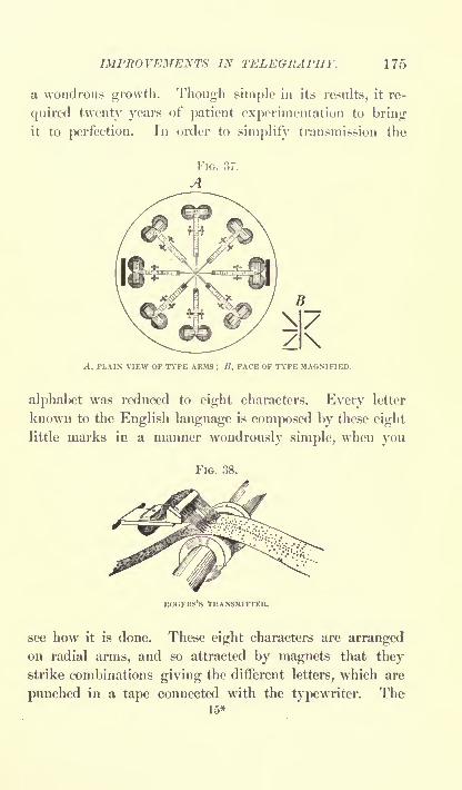
IMPROVEMENTS IN TELEGRAPHY. 175
a wondrous growth. Though simple in its results, it re-
quired twenty years of patient experimentation to bringit to perfection. In order to simplify transmission the
A, PLAIN VIEW OF TYPE ARMS ; B, FACE OF TYPE MAGNIFIED.
alphabet was reduced to eight characters. Every letter
known to the English language is composed by these eight
little marks in a manner wondrously simple, when you
FIG. 38.
ROGERS'S TRANSMITTER.
see how it is done. These eight characters are arrangedon radial arms, and so attracted by magnets that theystrike combinations giving the different letters, which are
punched in a tape connected with the typewriter. The15*

176 WONDERS OF MODERN MECHANISM.
tape is then run through an automatic telegraphic trans-
mitter, as shown in the illustration.
The process of telegraphing is to slip the perforated tapeon a small rotating cylinder under a row of metal pointsor brushes, so that each of them may drop into the holes
FIG. 39.
ROGERS'S SYNCHRONOUS WHEEL RECEIVING.
on its line, the holes representing the letters, so that at
every rotation of the little cylinder a current passes over
the line which is calculated to operate the impression of the
type at the other end by means of magnets. The illustra-
tion shows the stylus points and perforated strip on the

IMPROVEMENTS IN TELEGRAPHY. 177
cylinder. The centre holes serve to guide and regulate
the movement of the tape automatically, so that no manip-ulation is required to assist the operation. By moans of
synchronous wheels at either end of the wire the messageis repeated at the terminus by a process too complicated to
be here described. Suffice it to say that Mr. Rogers calls
it visual synchronism, and that the receiving operator as-
sists the synchronism of the wheels by occasional pressure
with his thumb, when he observes that they are getting out
of regularity. In this manner he has succeeded in receiving
as many as five hundred words per minute, but only two
hundred are claimed as an average durable speed. The
receiving operator has nothing to do with the receipt of
the message but to keep his wheel in unison with the send-
ing wheel. If he does that the message is bound to come
out all printed as sent.
For assisting long-distance transmission an automatic
relay has been devised that responds to impulses repre-
senting the vibrations of the musical sounds. If this
system proves to be all that its promoters claim, it is likely
to revolutionize the postal system as far as business com-
munications are concerned.
A kindred invention is that of N. S. Amstutz, of Cleve-
land, Ohio, who has devised the eleetro-artograph, a mech-
anism for transmitting copies of photographs to a distance
by means of the electric wire, and reproducing the same at
the receiving station in the form of a line engraving ready
for the printing-press. The wrhole operation is so simple and
quickly performed, and the results are so excellent, from an
artistic stand-point, that the process seems likely to come
into use for mechanical engraving without any distance
transmission, as it is much quicker in operation than any of
the processes now in use. The success of the method hung

178 WONDERS OF MODERN MECHANISM.
upon the synchronous motion of two cylinders, as with the
Rogers invention, and Mr. Amstutz claims to have over-
come all difficulties in this direction. Certain it is that the
work he exhibits as done by his machines in his laboratory
is good enough to print in any periodical, and vastly better
than any of the crude attempts previously offered the
public.
In this invention the undulatory or wave current is used,
as in the telephone, and the transmitting and receiving
apparatuses each bear synchronously rotating cylinders.
On the transmitting cylinder is mounted a prepared gela-
tine film, whose construction will be understood by readingthe chapter on photo-mechanical processes. This gelatin
film has been hardened, and presents a surface of elevations
and depressions elevations where the picture should print
black and depressions where it should print white. As it
rotates on the advancing cylinder of the transmitter, a
tracer or point is rested on the surface of the film, rising
and falling with the undulations, and exaggerating them
by leverage so as to communicate motion to four tappets,
which, as they rise and fall, send electric impulses over the
line. In the receiving apparatus these impulses are com-
municated to a lever bearing a diamond cutter that traces
on a wax film on the receiving cylinder a duplicate of the
gelatin film on the transmitting cylinder. From this waxfilm a plate can be made for printing, the result being a
line engraving, which may be made as fine as desired.
The reader will readily understand that the principles-
involved are such that the work is not necessarily confined
to reproductions for the printing-press. Ornamental de-
signs upon gold and silverware may be copied automati-
cally, and monograms, etc., duplicated indefinitely with
this apparatus. The largest field is for illustrative pur-
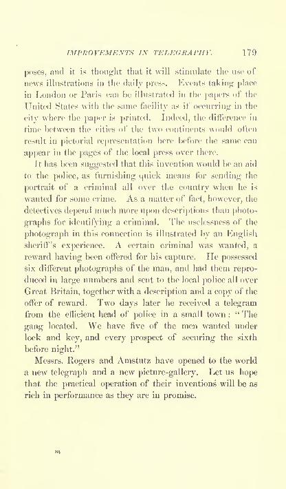
IMPROVEMENTS IN TELEGRAPHY. 179
poses, and it is thought that it will stimulate the use of
news illustrations in the daily press. Events taking place
in London or Paris can be illustrated in the papers of the
United States witli the same facility as if occurring in the
city where the paper is printed. Indeed, the difference in
time between the cities of the two continents would often
result in pictorial representation here before the same can
appear in the pages of the local press over there.
It has been suggested that this invention would be an aid
to the police, as furnishing quick means for sending the
portrait of a criminal all over the country when he is
wanted for some crime. As a matter of fact, however, the
detectives depend much more upon descriptions than photo-
graphs for identifying a criminal. The uselessness of the
photograph in this connection is illustrated by an Englishsheriff's experience. A certain criminal was wanted, a
reward having been offered for his capture. He possessed
six different photographs of the man, and had them repro-
duced in large numbers and sent to the local police all over
Great Britain, together with a description and a copy of the
offer of reward. Two days later he received a telegram
from the efficient head of police in a small town :
" The
gang located. We have five of the men wanted under
lock and key, and every prospect of securing the sixth
before night."
Messrs. Rogers and Amstutz have opened to the world
a new telegraph and a new picture-gallery. Let us hopethat the practical operation of their inventions will be as
rich in performance as they are in promise.

180 WONDERS OF MODERN MECHANISM.
ELECTRICITY DIRECT FROM COAL.
A Problem which Edison and Others have sought to solve The
Key may yet be found.
THE thoughtful attention of many investigators has
been given to the great problem of converting the poten-tial energy of coal directly into electrical energy, without
the wasteful intervention of the steam-engine, and, thoughthe solution still evades the profoundest thinkers, so much
light has been thrown upon the subject by various experi-menters that at the present time we know much more about
the conditions that govern success or failure than we did a
few years ago.
Electricians have known for a long time that heat could
be turned directly into electricity by means of the thermo-
electric couple, but that electricity could be thus produced
economically has never been suspected. Indeed, it is a
most expensive way of producing a very minute current.
Nevertheless, a recent inventor claims to have developed a
practical motor on this principle that will produce more
electricity per pound of coal burned than is now obtainable
through the medium of the steam-engine.
The metals vary in conductivity. Silver is the best con-
ductor among them, and lead is one of the poorest. If we
join a bar of silver and a bar of lead and alternately heat
and cool the junction, an electric current will be set up in
a wire connecting the opposite ends of the bars. This cur-
rent is so trifling as to equal only the one-hundredth of a
volt at a temperature of 530 C. The Clamond generator
is a philosphical toy constructed on this principle. It con-
sists of the arrangement in superposed rings of pieces of
metal alloys that have been found to produce the greatest

ELECTRICITY DIRECT FROM COAL. 181
currents. These rings are insulated by asbestos and heated
in the centre by a gas-flame, while the outer ends are cooled
by radiation. The alloys of metals have peculiar and un-
expected qualities, often widely different from what the
component metals possess alone. It has, therefore, been an
interesting study with some to try new alloys in the hope
of finding a combination that should set up a current of
reasonable force.
Some twelve years ago, Mr. Edison gave much attention
to the solution of the problem by means of thermo-elec-
tricity, designing a generator in which he sought to attain
the desired end by apparatus of highly ingenious construc-
tion. The operative feature was the magnetization and
demagnetization of iron by rapid alternations of temj>era-
ture. These alternations of magnetic intensity were utilized
to generate induced currents in surrounding coils. This
idea, which appeared promising at first sight, never went
further than an experimental machine that was not satis-
factory except in strengthening the opinion of electricians
that a large efficiency could never be hoped for from anythermo-electric generator.
Very recently, however, announcement has been made
in the newspapers that a Hartford inventor was trying to
improve upon diamond's apparatus, having been experi-
menting with alloys in the hope that he might discover
some of such widely different conductivity as to render a
thermo-electric generator a useful and cheap means of se-
curing the electric current direct from the coal. He now
claims to have discovered suitable alloys, and to have per-
fected a generator for putting the same into practical use.
He will have to make a public demonstration of these
things before he gains credence from the scientific world.
He is understood to form his alloys into wedges, which are

182 WONDERS OF MODERN MECHANISM.
combined in ring -form, pains being taken to avoid well-
defined junctions and to merge one alloy gradually with the
other where the wedges meet. Several of these rings are
formed, one above the other, as in the Glamond generator,
being separated by sheets of asbestos. The central cylin-
der, through which the heat is applied to the inner ends of
the couples, is lined with a fire-proof plastic cement, and
the cooling of the outer ends is accomplished by means of
a circulating current of cold water. A common coal-stove
furnishes the heat, and the electricity is carried off by two
wires, as from a dynamo. Further information as to the
development of this interesting apparatus will be awaited
with interest.
Efforts are also being made to solve the problem from
the chemical side. The correlation between chemical and
electrical energy is a well-established fact, and in the case
of many substances, such as carbon, is capable of being
expressed quantitatively, and with as great accuracy as the
relation between heat and mechanical force, which finds its
mathematical expression in the figures expressing the me-
chanical equivalent of heat. In the ordinary voltaic cell,
which we see in batteries for house use, as in ringing door-
bells, the electric energy developed is derived from the direct
conversion of the energy of chemical combination, and the
quantity of the one which it is possible to realize from an
electrolytic cell of any predetermined constituents may be
calculated with the same accuracy in terms of the other,
as the possible mechanical energy which can be developed
from the combustion of a ton of coal.
Dr. W. Borchers, of Duisburg, Germany, has attacked
this problem and sought to solve it by chemistry, his line
of research involving the construction of a voltaic cell in
which the cold combustion of carbon can be effected with

NIKOLA TESLA AND HIS OSCILLATOR. 183
the hope of obtaining an efficiency approximating nearly
to that which theory indicates. It is stated that the learned
doctor has been so far successful as to obtain twenty-seven
per cent, of the energy of combustion of the fuel in the
form of electrical energy. The fuel used was not coal, but
the result obtained is none the less remarkable. When we
consider that only about fifteen per cent, of the energystored in the coal is now obtained in the dynamo bv the
medium of the steam-engine, Dr. Borchers's success is the
more marked, and, as this is the result of his first experi-
mentation on these lines, we may reasonably hope for
further efficiency as the problem is studied more under-
standingly. Dr. Borchers has communicated the result
of his experiments in a pajx?r read before the German
Electro-Chemical Society, and announces the conclusion
that the problem of the cold combustion of the gaseous
products of coal and oil, in a gas battery, and its direct
conversion into electrical energy can certainly be accom-
plished. Considering how many intelligent brains are
struggling with this problem, and the success already
attained, it seems not too much to prophesy a triumph
early in the coming century.
NIKOLA TESLA AND HIS OSCILLATOR.
A Wonderful Electric Machine devised by a Wonderful Engineer,who bids us throw all the Steam -Engines in the Scrap-Heap.
NIKOLA TESLA, the engineer who came from Europesome ten or a dozen years ago to beg a place in Edison's
workshop, has proved himself a fit pupil of the Wizard
of Menlo Park, and capable of standing with him as his
16

184 WONDERS OF MODERN MECHANISM.
peer. In his oscillator we have the promise of an inven-
tion as great as any of Professor Edison's an invention
that is liable to turn a third of the machinery of the globeinto old metal fit but for the scrap-heap. He has har-
nessed a steam-cylinder to the core of a dynamo, and
released the intervening mechanism from further service.
Steam-engines of all sorts, locomotives, dynamos, electric
motors all these, as at present made, will be useless whenTesla's oscillator comes into general use. It may solve the
problem of knocking a couple of days off the time requiredto cross the Atlantic, and it will save our coal so that we can
make one pound do almost the work that was done by two
pounds. For conferring this boon upon the world, Tesla
deserves the thanks of a grateful race.
The personality of the man is as interesting as his work.
He looks like a young overworked Slav, and that is what
he is; but he writes and speaks like a poet with this
difference, that his visions are real, that he dreams of that
which is possible of accomplishment, of mechanical and
scientific projects which he will put into being, if his daysare sufficiently long. No one who knows him expects that
Nikola Tesla will stop inventing when he has completedthe oscillator. Already his mind is set on a score of other
problems as useful in their solution as the one that is
likely to be settled by the machine with which we are now
specially interested. He suggests that in the not distant
future he may be able to give us light at a small fraction
of present cost, and to transmit electric intelligence without
wires or other artificial media.
The oscillator has been made in several forms, Mr. Tesla
preferring to perfect it before seeking to introduce it
generally. That shown in the illustration is the one that
was exhibited at the World's Columbian Exposition in
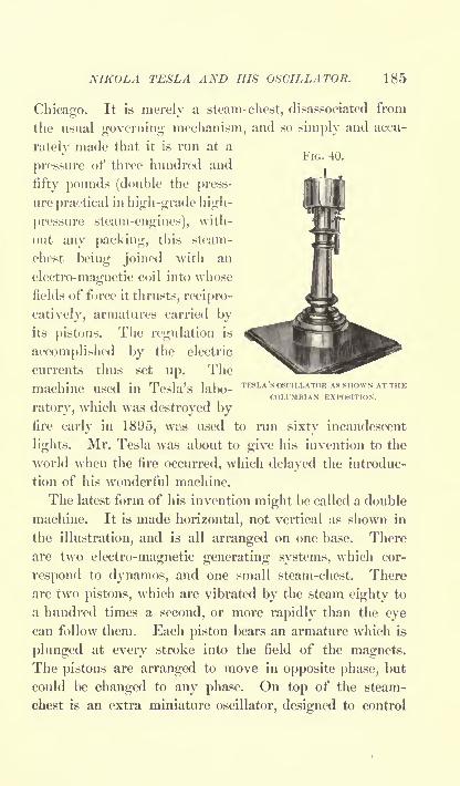
NIKOLA TESLA AND HIS OSCILLATOR. 185
Chicago. It is merely a steam- chest, disassociated from
the usual governing mechanism, and so simply and accu-
rately made that it is run at a
pressure of three hundred and
fifty pounds (double the press-
ure practical in high-grade high-
pressure steam-engines), with-
out any packing, this steam-
chest being joined with an
electro-magnetic coil into whose
fields of force it thrusts, reci pro-
catively, armatures carried byits pistons. The regulation is
accomplished by the electric
currents thus set up. The
machine Used in Tesla's labo-TESLA'S OSCILLATOR AS SHOWN AT THE
COLUMBIAN EXPOSITION.
ratory, which was destroyed byfire early in 1895, was used to run sixty incandescent
lights. Mr. Tesla was about to give his invention to the
world when the fire occurred, which delayed the introduc-
tion of his wonderful machine.
The latest form of his invention might be called a double
machine. It is made horizontal, not vertical as shown in
the illustration, and is all arranged on one base. There
are two electro-magnetic generating systems, which cor-
respond to dynamos, and one small steam-chest. There
are two pistons, which are vibrated by the steam eighty to
a hundred times a second, or more rapidly than the eyecan follow them. Each piston bears an armature which is
plunged at every stroke into the field of the magnets.The pistons are arranged to move in opposite phase, but
could be changed to any phase. On top of the steam-
chest is an extra miniature oscillator, designed to control

186 WONDERS OF MODERN MECHANISM.
the admission of steam and make the vibration of the
engine independent of the load. There was never any
leakage of steam from this oscillator, notwithstanding the
absence of packing. In a short time another machine of
this perfected type will be completed and offered to the
public.
It has been calculated that the oscillator will save about
eighteen per cent, of friction, as existing in the average
steam-engine, besides ten per cent, of belt friction, as
wasted by the indirect connection of engines and dynamos,and thirty-two per cent, of waste of energy which occurs
in the ordinary form of dynamo a total of fifty per cent.
In addition, we have the advantage of a machine with so
few parts that wear is reduced to a minimum, and so auto-
matically self- regulating as to require the least possible
attention. Engineers generally are agreed that these
things are to be expected of Tesla's oscillator. It is de-
signed to convert steam into electric energy by as direct a
process as possible, and to that end dispenses with rotary
motion in the fields of the magnets, which is not essential.
In fact, some of the early forms of dynamos generated
electricity by a reciprocating and not a rotary motion. It
is primarily designed for use in electric lighting plants,
and will find a place next in power-houses and later prob-
ably in .steamboat propulsion and electric locomotives. It
should cheapen power so that electrical plants will sell it
at greatly reduced rates, causing an immense increase in
the use of electrical power and doing away with stationary
engines of all sorts.
Concerning what he may give us in the future, Tesla has
this to say :
"Every thinker, when considering the barbarous methods
employed, the deplorable losses incurred in our best system

THE ELECTRIC LOCOMOTIVE. 187
of light production, must have asked himself, What is
likely to be the light of the future ? Is it to be an incan-
descent solid, as in the present lamp, or an incandescent
gas, or a phosphorescent body, or something like a burner,
but incomparably more efficient ? . . . Alternate currents,
especially of high frequencies, pass with astonishing free-
dom through even slightly rarefied gases. To reach a
number of miles into space requires the overcoming of
difficulties of a merely mechanical nature. There is no
doubt that, with the enormous potentials obtainable by the
use of high frequencies and oil insulation, luminous dis-
charges might be passed through many miles of rarefied
air, and that, by thus directing the energy of many hun-
dreds of thousands of horse- power, motors or lamps mightbe operated at considerable distances from the stationary
THE ELECTRIC LOCOMOTIVE.
A Number actually in Use, and Others being developed Theymay in Time crowd out the Steam- Locomotive.
ABOUT 1887 or 1888, when electricity came to be ac-
cepted as the motive power of the future, many persons
expected to see the steam-engine driven out of use. Grad-
ually they learned that the dynamo was not a source of
power, but that a steam-engine, water-wheel, or somethingof the sort was required to furnish power, which a dynamoor generator would convert into electricity and transmit
along a wire, from which it might be taken again and
used through an electric motor. Therefore the steam-
engine is still with us, and likely to remain. For similar
reasons the steam-locomotive has continued in use while
16*

188 WONDERS OF MODERN MECHANISM.
electric roads have developed all over the world, and onlywithin a very short period has the downfall of the " iron
horse" been predicted. Truth compels the admission that
the latter has not been greatly improved since the days of
Stephenson. True, locomotives are vastly bigger, stronger,
and faster now than they were then. Still they are verywasteful machines. While perfected stationary engines
develop as much as eighty-five per cent, of efficiency, the
locomotive, owing to forced speed, eats up coal in a manner
perfectly regardless of dividends to stockholders, and with
but little disposition to assist in settling interest due bond-
holders.
It has been and is the endeavor of inventors of electric
locomotives to develop a machine that would be more eco-
nomical than the steam-locomotive, and perhaps exhibit
more speed, though locomotives as now built will run faster
than railroad managers care to have them, owing to the
frightful results to be anticipated from accidents at high
speeds.
Professor C. C. Page, of the Smithsonian Institution,
was among the first experimenters with the electric loco-
motive. He designed one in which a fly-wheel was driven
by a piston-rod" sucked'
7 back and forth between two
hollow cylindrical magnets. In 1851 he mounted this
motor on wheels, and furnished it with electricity from
batteries of the type now used to ring electric door-bells,
though much larger. On this locomotive he succeeded in
travelling from Washington to Baltimore, but found that
the jarring prevented the successful operation of the bat-
teries. His best speed was a mile in about three minutes
on a favorable grade.
In 1879, Dr. Siemens exhibited an electric locomotive
at Berlin. It was regarded simply as a novelty.

THE ELECTRIC LOCOMOTIVE. 189
In 1880, Professor Thomas A. Edison experimentedwith an electric locomotive at Menlo Park, New Jersey.
This was improved by Stephen D. Field, and in 1883
Edison and Field exhibited an electric railroad at the
Chicago Railway Exposition, using a three-loot gauge and
three-wired rails. Their locomotive consisted of an electric
motor mounted on a carriage, and o|x?rating the driving-wheels by means of a connecting belt and pulleys. Theywere able to show a speed of twelve miles an hour on a
circular track of fifteen hundred and filly-three feet,
Leo Daft, about 1883, exhibited an electric locomotive
at Saratoga. With a two-ton motor he succeeded in pull-
ing an ordinary passenger-car with sixty-eight persons at
a speed of eight miles an hour on a route that was not
favorable as to grades and curves. Mr. Daft subsequent! v
built several exhibition roads that attracted much attention
to his locomotive. It was tried for commercial purposeson a street railway in Baltimore in 1885, but was after-
wards abandoned in favor of the trolley. Both the Edison-
Field and the Daft locomotives were tried on the elevated
railroads of New York City, but failed to supplant the
steam-locomotives.
The Thomson-Houston and other wmpanies introduced
small electric locomotives about 1891 for haulage in mines.
They operate by overhead trolleys, and have a moderate
sale.
The J. J. Heilmann electric locomotive is being tried in
France the present year (1895), and gives great promiseof success. It is really an electric power plant on wheels.
Instead of producing the electric energy at a station, and
sending it out by overhead wires to the cars, the entire
mechanism is carried as a locomotive. The first one built
was of small power (six hundred horse-), though fifty feet

190 WONDERS OF MODERN MECHANISM.
in length. As will be seen from the illustration, there are
sixteen wheels, bearing a platform of steel girders. Thesmoke-stack is at the rear end, strange to say, the cab with
its pointed end being forward. The steam-engine and
boiler are much like those of any steam-locomotive. They
FIG. 41.
THE HEILMANN ELECTRIC LOCOMOTIVE.
are of the Brown type, and as well made as it is possible
to build a modern compound condensing engine, and, being
directly connected with the large dynamo, which occupies
the greater portion of the cab, there can be no lost powerfrom friction between the two machines. A switchboard
stands in front of the driver, with controlling levers on
either hand. Each of the axles bears a rotary electric
motor, so that all of the wheels are drivers, presentingless chance of slipping on the track than with the ordinarysteam-locomotive, part of whose weight rests on truck-
wheels. As each axle of the Heilmann locomotive is
independent, there is no difficulty in turning short curves
at good speed. The cars to be drawn by this locomotive
may also bear electric motors on the axles, to which the
current will be conveyed by wires from the dynamo on
the locomotive.
The total weight of this locomotive is one hundred and
fourteen long tons, and the tests show a draw-bar pull of

THE ELECTRIC LOCOMOTIVE. 191
fifty thousand pounds, which is enough to pull a two-
hundred-ton train at a high speed.
The principle of this electric locomotive of Heilraann's
seems preposterous at first thought. People say, If he
must use a steam-engine, why bother with converting the
power into electric energy and then conveying it to the
wheels? Why not dispense with the dynamo and motors,
and couple the engine directly to the drivers, as in the
ordinary locomotive? This reasoning is not correct, how-
ever. The utilization of the dynamo and motors saves
more coal than it costs t<3 carry their added weight or than
is lost by their friction. There is an economy of time
during which the fires have to be run, because greater
speed is obtainable without forcing. The saving in jar
and friction by dispensing with the heavy reciprocating
parts is very great. Anyway, the Compagnic de 1'Ouest,
on whose lines this locomotive was tried, were so well
satisfied with the tests that they have agreed to rent two
larger locomotives of the same pattern. These are now
building, and will be on a much larger scale. Each is to
be of fifteen hundred horse-power, and capable of haulinga two-hundred-and-fifty-ton train at a speed of sixty-two
miles an hour. Their operation is looked forward to with
interest by railroad men the world over. Their cost is
estimated at about thirty thousand dollars each, or about
three times that of an average steam-locomotive.
The Sprague electric locomotive, shown in the illus-
tration, was built at the Baldwin Locomotive Works, in
Philadelphia, after designs by Messrs. Sprague, Duncan,and Hutchinson, and was completed in 1895. The North
American Company are to use it in hauling heavy freight
and in switching. There are four pairs of drivers coupled
together by quarter-cranked connecting-rods. The weight

192 WONDERS OF MODERN MECHANISM.
is one hundred and thirty-four thousand pounds, equallydistributed between the fifty-six-inch drivers. It is de-
signed for a speed of thirty-five miles an hour. The
draw-bar pull exceeds ten thousand pounds, each of the four
FIG. 42.
THE SPRAGUE ELECTRIC LOCOMOTIVE.
motors being of about two hundred and fifty horse-power.The brackets which carry the motors are pedestal boxes of
peculiar form made of cast steel, the lower sides being
arranged to be dropped out. These boxes carry both the
axles upon which the armatures are rigidly mounted, the
field magnets being concentric to them. The motors are
iron-clad, the field magnets consisting of two steel castings,
having two field coils placed at the ends of the motors,
forming two consequent and two salient poles. Com-
pound-wound magnets are used, and slotted Westinghousearmatures. The whole structure is carried on equalizing
springs. The controlling apparatus in the cab is so
arranged that the engineer sits at the right-hand side
looking forward, no matter which way he is running, for
the locomotive is a double ender.
E. Moody Boynton, of West Newbury, Massachusetts,

THE ELECTRIC LOCOMOTIVE. 193
whose bicycle railway has attracted much attention within
a few years, is now experimenting with an electric locomo-
tive for the same. He uses upper and lower rails, guide-
wheels engaging the upper rail. The driver has removable
web plates fastened to hubs rotating loose on a shaft situ-
ated in the frame. The armature and field magnets are
between these web plates, one element fast to the wheel-
tire and the other to the shaft.
The General Electric Company of New York are now
placing an electric locomotive on the market, intended for
use in drawing heavy trains. It operates on the trolley
principle, receiving the current from an overhead con-
ductor. One of thirty tons and another of forty tons
have been completed, and these are in use in railroad yardsas switch-engines.
But the triumph of the electric locomotive is best de-
monstrated by the ninety-five-ton locomotive just placed
(1895) by this company with the Baltimore and Ohio road
for use in the Belt Line tunnel, and built for a speed of
fifty miles an hour. It is about thirty feet long, and
stands very high. The cab rests on two enormous trucks,
having four wheels, each of sixty-two inches diameter.
The axle of each pair of wheels is in the centre of the
armature of a motor, so that the construction is very muchlike that of an electric motor set to run upon a pair of fly-
wheels. The motors are six-pole, gearless, and are flexibly
supported upon the trucks, transmitting their motion from
the armatures to the wheels by means of an especially de-
signed flexible coupling. The method of spring suspen-sion has been carefully modified to allow of the immediate
adjustment of the wheels to the irregularities of the tracks,
thus effecting a diminution in the wear both of the motors
and tracks. The massive armatures are of the iron-clad

194 WONDERS OF MODERN MECHANISM,
type. A hollow shaft serves to carry each armature, and
through this passes the wheel-axle, to which it is connected
by a universal coupling that allows freedom of movement
FIG. 43.
THE BALTIMORE AND OHIO ELECTRIC LOCOMOTIVE.
in any direction. The motors are the largest ever used in
railroad service.
The cab is spring-supported on the truck, and is built
of sheet iron and wood, having windows on all sides, so
that the occupants have an unobstructed view. Within
the cab is set up the series parallel-controller, by means
of which the movements of the locomotive will be at the
command of the driver, as also the air-pumps, operated by

THE ELECTRIC LOCOMOTIVE. 195
a small electric motor, to supply air to the brakes and the
whistle.
The overhead arrangement is of the trolley type, yet
the trolley or wheel is entirely dispensed with. Fixed
above the track in the tunnel is a broad, grooved band of
metal, through whose length a slider may run. This
slider is connected by a pole with the locomotive. The
grooved metal is the conductor that carries the current,
which is too powerful for an ordinary wire, and the slider
takes the place of the trolley-wheel, whose rolling contact
is insufficient to carry the strong current. This locomo-
tive is also equipped with bells, safety devices, etc., and
has a Janney automatic coupler at each end. This is un-
doubtedly a thoroughly efficient electric locomotive, calcu-
lated to handle as heavy trains as any steam-locomotive.
It remains to be seen whether it will stand the test of
time.
The electric locomotive has a slight advantage over the
steam-locomotive in that it will start a greater load, the
pull being constant throughout the entire revolution of the
wheel, the difficulty of variation in pull caused by the
dead-centre of the steam-locomotive being avoided. The
other advantages are : a considerable economy in coal, re-
duction of the hammering and side-strains to the track,
probable less cost of repairs, and the practicability of
using the electric locomotive several more hours daily than
the steam-locomotive. These considerations lead many to
ask whether the days of the steam-horse are not numbered.
Already their manufacture has seriously decreased, owingto electric roads taking business from steam-roads. Me-chanics are agreed that they cannot be materially improved,while the electric locomotive, being so recent, is likely to do
much better in the future,
i n 17

196 WONDERS OF MODERN MECHANISM.
It remains to be seen which type will develop fastest,
the Heilmann, large and cumbrous, but self contained, or
the General Electric Co.'s or the somewhat similar Sprague
type, compact and mighty, but operating from a power-house by means of an overhead conductor. The Boyntonlocomotive will not be a competitor with either, being
designed for light railways only. It seems best adaptedfor pleasure railways at sea-side resorts.
LIGHT-TRAFFIC RAILWAY SYSTEMS.
Transportation by the Electric Trolley, Steam, Compressed Air,
Coal Gas, or Ammonia, over Elevated, Surface, or Under-
ground Roads.
IT is asserted, apparently with truth, that the street-
railways of the United States now carry more passengersthan the great steam-railways connecting the cities of the
country. By the name street-railway is designated all
those means of traffic in and about large cities and towns,
and classed as trolley roads, elevated roads, rapid transit,
or underground roads, etc. Some years ago the capital of
the country was directed towards the construction of longlines of railway across uninhabited territory, and it is be-
cause of this fact that we lead the world in railway mile-
age. Only within a few years has it dawned upon the
people who sunk their money in those roads for developingthe far West that the best place to build railroads was right
in large cities, where there were plenty of people to ride on
them.
Though it must be admitted that the American capitalist
has been slow in appreciating the value of city railways,,

LIGHT-TRAFFIC RA IL WA Y SYSTEMS. 197
he is now thorougly convinced of their value, and it is
comparatively easy to capitalize any street-railway for which
a franchise can be obtained. There are now about twelve
thousand miles of street-railways in the United States and
Canada, nearly half of them still using horse-power, while
the remainder are o[x?rated by electricity, steam-motors,
and cables, in the order named.
New York City uses or has tried about all the systemsin vogue, and exhibits a preference for the elevated steam-
railroad. When these elevated roads were first talked of,
it was proposed to build them with drawbridges about a
mile apart, for the convenience of teams or wagons of un-
usual height desiring to pass below. This reckless propo-sition for the convenience of those below was never carried
out. In 1868 the first road constituting what is now the
lower part of the Ninth Avenue road was built. Manythought that cars run on a track supported on a single row
of iron posts could not be safe, and for this and other reasons
the traffic on the road was small for some years. Duringthe first two years endless cables were used for drawing the
cars, but later were abandoned for small steam-locomotives,
the Forney engines being the type used to-day. In time the
New York public came to like the elevated cars, and the
Ninth Avenue road was several times extended. In 1878
the Sixth Avenue and Third Avenue elevated roads were
opened, and in 1887 the Second Avenue. These roads
now carry nearly half a million people twice a day that
is to say, they bring that number of people to business
every week-day morning and carry them back at night.
They maintain thirty-six miles of double-track road, which
cost a total of thirty-five million dollars.
New York also maintains cable-roads on One Hundred
and Twenty-fifth Street, Broadway, and on Third Avenue.

198 WONDERS OF MODERN MECHANISM.
It is thought that these lines will substitute an electric
wire in the conduit for the cable in the near future, that
system having been much perfected within a few years.
FIG. 44.
CABLE-DRIVING PLANT, AS DESIGNED BY ROBERT POOLE A SON.
In fact, a successful conduit-electric system has been in
operation in Buda-Pesth since 1889, being built on the
plans of Siemens and Halske. Americans seem not to
have been so successful, but they can now profit by copy-
ing the good points of the Hungarian line. For further
information on this point see the chapter on conduit rail-
ways. The other lines of New York City are operated by

LIGHT-TRAFFIC RAILWAY SYSTEMS. 199
horses, though it is rumored that one or more of them will
change to the storage-battery in the near future.
The combined means of transit above described being
inadequate to meet the demands of the travelling public, it
is now proposed to build a system of underground roads,
and two routes are projected with every prospect of being
built in the near future. The motive power has not as yet
been decided upon, but it is thought that the electric loco-
motive will be chosen.
Chicago has three elevated railways. They are not as
popular there as in New York, the surface roads carrying
nine-tenths of the traffic;but as all three are of recent con-
struction, no doubt their traffic will increase as the public
become habituated to their use. The last of these roads is
not yet (1895) in running order. It is to be equippedwith electric motive-power, one motor-car drawing a short
train, according to the demand. It is thought that this will
be cheaper than using steam-locomotives, and the annoy-ance from smoke will be avoided. They also have cable-
roads whose tracks have a mileage of 34.77. These carried
one-fourth of the traffic in 1894.
The street-railways of Philadelphia carry one hundred
and seventy-five million passengers annually. The trolley
is the most favored means of propulsion, though the cable
was used first, and taught the public the value of rapid
transit. The reduced expenses of the trolley system caused
the cables to be superseded thereby in 1895. The trolley
roads have caused a fearful record of deaths, killing a
number of hapless pedestrians every month and injuring
many more.
Brooklyn's record of killed and maimed by trolley acci-
dents is equal to that of Philadelphia. In two years' time
a hundred deaths and five hundred personal injuries were17*
200 WONDERS OF MODERN MECHANISM.
reported. Nearly all the surface lines of the city are oper-
ated by the trolley system. There are twenty-six and a
half miles of elevated roads, constructed in a manner verysimilar to those in New York. The combined street-
railway travel of the city is about three hundred thousand
passengers daily.
In Boston trolley roads are used, the cars being quite
large for street-cars. A subway for electric cars is also
being constructed at the Hub. In San Francisco the
cable-road is used. In most of the minor cities of the
country the trolley roads prevail.
London's underground railway has been much written
about. The passengers ascend and descend at the stations
by means of elevators, a method that would add to the
comfort of American elevated roads. The fare is four
cents. There are two companies operating underground
lines, and they carry over three hundred million passengers
annually, while the omnibuses and suburban steam rail-
ways carry about twice that number.
The street-railways of Paris employ steam, horse flesh,
and compressed air as motive powers on the surface, and the
storage-battery on the underground line. These batteries
are carried on a sort of tender which supplies the motors
of the cars, which are coupled up as short trains. The total
transportation is about one million persons daily.
In Berlin the horse-car lines are arranged to radiate
from the centre of the city. The Berliners ride less
than the Parisians, their roads carrying one hundred and
twenty million persons a year. The universal fare in
Germany is ten pfennigs, or a trifle over two cents. Anumber of electric roads are being built throughout the
country, the extent of trackage at the close of 1894 being
one hundred and eighty miles, with six hundred and thirty

LIGHT-TRAFFIC RAILWAY SYSTEMS. 201
cars, and power stations of a total horse-power of eight
thousand.
The light-traffic railways of the United States have been
cutting into the local patronage of the trunk lines seriously
by paralleling them for considerable distances. A nearly
complete trolley line now extends between New York and
Philadelphia ;the New York, New Haven and Hartford
Railroad has been a sufferer in Connecticut;the suburban
cities around Boston present a perfect net-work of electric
roads;while lines are now projected to connect Philadel-
phia and Harrisburg, Baltimore and Washington, Chicagoand Milwaukee.
Of the various methods of railway building for street
lines, the underground or tunnel system is the most costly,
the equipment involving an expense of from three to five
million dollars per mile. The elevated or overhead
system comes next, with a cost of from one-half to three-
quarters of a million dollars per mile. Then cable rail-
ways, with a charge of three hundred and fifty thousand
dollars per mile. Probably the electric conduit system,
which is described in another chapter, may involve an
expenditure of one hundred and seventy-five thousand
dollars per mile. Next in first cost is the horse-railway,
which will average close to seventy-five thousand dollars
a mile for equipment. The electric trolley outfit only in-
volves a cost of forty-five thousand dollars a mile. The
storage-battery and compressed-air systems are said to l)e
even lower in first cost. The cheapest for ordinary use is
undoubtedly the trolley, as is evidenced by its general
adoption. Under special circumstances, any one of the
other systems may be preferred.
The trolley system is too well known to require any
description here. In a few places, as Cincinnati, what is
202 WONDERS OF MODERN MECHANISM.
called the double trolley system is used. In this there are
two overhead exposed conducting wires and two trolley-
poles on each car. The extra wire is for direct return of the
current instead of employing ground connections. This
system avoids interference with underground pipes, which
sometimes suffer from electrolysis because of the ground-
ing of the current from the single trolley wires;but it
cumbers up the streets badly, and at corners, where double
tracks cross, the whole crossing is covered with a net-work
of exposed trolley wires, which is unsightly and somewhat
dangerous.A combination of the electric and cable systems is in use
on a most interesting road at Stanserhorn, near Lucerne,
Switzerland. This is a mountain railway, over three miles
in length, ascending to a hotel at an elevation of six thou-
sand two hundred and thirty-three feet, almost at the peak
of the mountain. The road is built in three sections, the
grade of the highest section being sixty per cent, of forty-
five degrees. So far as known, this is the only mountain
road in which a continuous cogged rail or rack is dispensed
with. The cars depend entirely upon the grip upon the
cable and upon automatic brakes for gripping the track for
their safety. At the ordinary speed the brakes will stop
a loaded car within one-third of its length. There has
never been any hitch or accident in the operation of
the road since it was built, in 1893. On each of the three
sections is an electric motor-house, where are located two
motors, each of sixty horse-power, one for use, the other
for a reserve. These motor-houses derive their power byfeeder-wires from a power-station several miles away, at
Buochs, where the river Aa has a fall. This same power-house supplies another railway and sells power for local
uses. The Stanserhorn Railway only pays one hundred

LIGHT-TRAFFIC RAILWAY SYSTEMS. 203
francs (twenty dollars) per horse-power per annum, and, as
it buys only one hundred and fifty horse-power, its annual
bill for power is only three thousand dollars. Six cars are
operated during busy seasons, and each car seats thirty-two
passengers, weighing, with that load, a little less than seven
tons. Each car carries electric signalling-rods, and all the
stations are telephonically connected. The cable is made
of crucible steel, with a hemp core to facilitate bending.
Its diameter is an inch and one-third on the steepest sec-
tion, and its tensile strength sixty tons. This road cost
only three hundred thousand dollars, notwithstanding it is
built over most difficult ground, a part of the route re-
quiring to be tunnelled through a loose mass of fallen
boulders.
Another interesting mountain railway is that at Pike's
Peak, completed in 1891. It is constructed on the Abt
system, having a rack or double-cogged rail made of
parallel bars in which the openings are staggered that is,
arranged with a tooth always back of a space and, there
being two cog-wheels meshing with the rack, it is almost
impossible for an accident to happen, which would throw
all out of gear at once. The power of the locomotive is
applied to these cog-wheels under a reduction of speed,
the grade l>eing twenty-five per cent, in places. The road
is eight and three-quarters miles long, and attains an alti-
tude of fourteen thousand two hundred feet.
The steepest mountain railway in the world is that
projected at the Jungfrau in the Alps. Its grade is within
two per cent, of forty-five degrees, and its construction
resembles that of a lengthy elevator. It is to be a cable-
road, the whole line being within a tunnel, and the cars
are to be so shaped that they exactly fill the circular hole
made by the rings of the tunnel. Then, by introducing a

204 WONDERS OF MODERN MECHANISM.
powerful air-tight door at the lower end, all serious dangerof accident due to a breakage is avoided, for if a car falls
back it is cushioned by the air behind so that it comes to
the foot at a very gentle speed.
The hydraulic sliding-railway system has attracted in-
terest at various times because of its novelty, but no one
with capital has been sufficiently convinced of its practica-
bility to put a line in operation for general use, though an
experimental line has been built in London. The pecu-
liarity of the system is that it makes use of runners instead
of wheels for the cars, operating on the principle of a sleigh.
These runners are broad iron shoes, shaped like the face of
the rail on which they rest. The sliding surface is obtained
by forcing water at a higli pressure through small orifices
in the soles of the shoes, or runners, so that the escaping
water actually lifts the runner and allows it to glide on a
very thin surface of water. The experiments demonstrate
that with a perfect track on a level the friction is verymuch less than with wheels, and a speed of one hundred
and twenty-five miles an hour, with an enormous saving
of coal, has been theoretically demonstrated as possible.
The propelling power is also furnished by water, there
being water-jets placed between the rails so that they can
be automatically opened and closed by the train itself.
These jets impinge on pallets located under the cars, much
as water strikes against a water-wheel. As the railway
involves neither locomotives nor wheels of any sort, it in-
volves a very large saving in one direction. It is apparent,
however, that it would be very wasteful of water, and the
cheapness with which this could be obtained would be an
important element to consider in its construction. Possibly
such a road, drawing upon the Niagara supply, might be
made to pay if the route were level. On heavy grades
LIGHT-TRAFFIC RAILWAY SYSTEMS. 205
the system could scarcely be expected to give satisfac-
tion.
The mechanism of a cable road is shown by the illus-
tration used as a frontispiece, representing a design built byRobert Poole & Son Company, of Baltimore, Maryland.San Francisco was the first city to adopt this equipment,
Chicago following. When the first Philadelphia cable-
road was built, it was thought that several hundred thou-
sand dollars could be saved by constructing the casing of
the conduit of comparatively thin sheet-iron. This was
used, and did very well until the frost began to work in
the ground, when the sheet-iron was warped out of shape,
and had to be taken out and thrown into the scrap-heap,
heavy castings being substituted. A cable-car, with its
arrangement of grips, costs a little more than the trolley-
car, but the running expenses are not materially greater, so
that where exposed wires have been objected to the cable-
road has proved a boon.
Some information regarding the storage-battery systemof operating cars will be found in the chapter on " The
Storage-Battery," and the compressed-air system is also
referred to in the chapter on "Compressed-Air Mechan-
isms."
Ammonia-motors and gas- motors have received someattention as affording desirable means of power for
street-cars. As ammonia vaporizes at a very low temper-
ature, it has been particularly attractive to experimenters
searching for a better expansive medium than steam. Atthe recent Chicago Exposition the world was made ac-
quainted with a promising form of ammonia-motor, de-
vised by a Mr. MacMahon. He has developed a meansof securing highly purified anhydrous ammonia, and of
preserving the exhaust vapor, which, in the case of a

206 WONDERS OF MODERN MECHANISM.
steam-engine, is allowed to escape. The ammonia being
used over and over, the only cost of operation is the coal
FIG. 45.
AMMONIA-MOTOR APPLIED TO STREET CiR.
burned. Under somewhat unfavorable conditions, Mr.
MacMahon was able to drive his motor-car at a speed of
fifteen miles an hour, with a coal consumption of only two
cents a mile. This showing was so favorable that more
may be expected of the ammonia-motor in the future.
The compressed-gas system of car-propulsion offers the
same general advantages that are claimed for the storage-
battery and compressed air systems viz., absence of smoke,
dirt, wires, and noise. There are two systems of gas motor-
power before the public, both European the Guillieron
and Amrein, and the Luhrig systems. The latter is shown
in the illustration. Twin engines are placed on each side of
the car, under the seats, which run lengthwise. Fourteen
horse-power is required for a car seating sixteen persons.
In the roof are cold-water reservoirs, while the gas reser-
voirs a are under the front and rear platforms. The speedcan be altered by means of a pedal under the foot of the
motorman. He also operates hand-levers to throw the
motors in or out of gear in stopping and starting the car.

LIGHT-TRAFFIC RAILWAY SYSTEMS. 207
The compressed gas is delivered by regulators to the motor-
cylinders bj of which there are four, so that one may always
FIG. 46.
cJL
LUHRIG COMPREtWED-GAS MOTOR.
be in action upon the driving-shaft c (for gas-engines only
give out power every fourth stroke). The gas is admitted
to the cylinders, mixed with a certain quantity of air, and
ignited, causing an expansion or small explosion of gas,
which does the work, d is the driving-gear for connecting
the driving-shaft with the driving-axles e. The car illus-
trated and described weighs seven and a half tons, but the
maker reports that he has succeeded in reducing the weightto four and a half tons, or about the same as a trolley-car
of the same capacity. The small car, \vhich has but a
single motor, consumes thirty-five feet of gas per car- mile,
and the large one forty-two feet. The cylinders of the
18

208 WONDERS OF MODERN MECHANISM.
large car contain ninety cubic feet of gas compressed to
eight atmospheres, so that the capacity should run the car
about seventeen miles. The cost of fitting up a charging-
station is stated to be three thousand dollars. If in prac-
tice there arise no unforeseen objections to this system, it
appears likely that American gas companies will seek to
introduce it here in order to increase their sales.
While electricity undoubtedly has the call against all
other systems of railway power, yet we may expect to see
various other motors used from time to time as being espe-
cially suited to some particular form of transportation.
CONDUIT ELECTRIC RAILWAYS.
The Coming Substitute for the Deadly Trolley Various Plans,
Some of them Successful, for placing the Wires Under-
ground.
THE hue and cry against the overhead trolley railways,
because of the annoyance and unsightliness of their poles
and wires, and the nuisance of exposing bare wires in the
streets, and also because of the number of persons whohave been killed and maimed by being run down, has
caused the public mind to become turned towards other
forms of electric traction for light railways. It is true
that the trolley in itself is not responsible for the manyaccidents that have been laid at its door. Any other
system of propulsion, operated at a like speed, without
proper fenders, and by workmen often uneducated and
always overworked, would have been equally destructive
to life. The fault has not been with the trolley, but with
the methods of operating trolley roads.

CONDUIT ELECTRIC RAILWAYS. 209
Nevertheless, some other system, doing away with over-
head wires, is going to come into use, and very many are
looking to the conduit electric system, with its underground
xxmductors, to solve the problem. The fiat has gone forth
in many large cities that electric wires of all sorts shall go
underground, and practice in methods of properly insulating
them for underground service has given experience that is
useful to projectors of conduit railway systems.
One of the necessities of the conduit system appears to
be a low voltage not more than three hundred being con-
sidered desirable. This involves more expense in con-
structing plants and stations, but is compensated for by a
great saving in leakage. The success of a conduit railway
appears to be dependent more upon care and excellence of
construction and moderate climate than uj>on any special
form that has been tried. It will always be more costly
of installation than the exposed wire system of the trolley,
but when once generally introduced such first cost should
be so reduced as not to prove prohibitive. In any case,
when once it is known that the system is feasible, city
governments will begin to force corporations to put the
wires below ground.The many advantages apparent from using a conduit
system of electric railway propulsion are so manifest that
they hardly require recording. There are no exposed wires
to annoy any one, and it should prove as cheap in oper-
ation as the trolley, which has outstripped every other
system and all of them combined. One of the first elec-
tric roads built (at Buda-Pesth) was on this principle, and
it is often quoted as successful, yet the conditions in more
northern cities are so different that projectors of roads in
the United States have clung to the trolley as affording a
surer success.

210 WONDERS OF MODERN MECHANISM.
The difficulty has been from the inability to secure
perfect insulation of the underground wire. Electricity
has a sad habit of going off to any near-by parallel con-
ductor, and in a conduit the ground is always near by, and
always parallel, and when things are moist which is about
one-third of the time in the climate of New York the
electricity escapes at a rate that is highly expensive, and
causes trouble with adjacent water- and gas-pipes, with
resultant suits for damages. The open slot affords an
entrance for snow and moist dirt, which discharges the
electricity in a very annoying manner. It is a difficulty,
however, which electricians think can be overcome, and, if
some of the experimental conduit lines now being tried are
satisfactory, the cable-roads of New York will shortly
adopt the conduit electric system, placing electric con-
ductors in the conduit now occupied by the cable, and
passing a trolley-pole or plough instead of a grip throughthe slot. This will make it impossible for the cars ever to
escape from control and run away, as is occasionally the
case when a grip gets fast to a cable and refuses to let goits hold.
About six hundred patents have been issued in the
United States for forms of conduit electric railways, which
goes to show that inventors are very much alive to the de-
mand for a suitable and practical system on this principle.
The ordinary idea of such a railway is that it is necessarily
a simple trolley-wire run through a slotted conduit between
the tracks, connection being made with the cars by means
of some form of plough passing through the slot. Our
American inventors have shown that they are not ham-
pered by any such confining conditions. Joseph Sachs has
classified the conduit systems as follows :
"1. Open slot continuous conductor conduits, in which

CONDUIT ELECTRIC RAILWAYS. 211
a continuous bare conductor is placed in an open slotted
trough. 2. Movable or flexible slot cover conduits, using
a flexible or movable cover to protect the wires and keep
FIG. 47.
THE LOVE CONDUIT, WASHINGTON, D. C.
the slot closed. 3. Surface contact systems, in which the
conductor is placed on the surface of the roadbed. 4.
Sectional open slot conduits, with a sectional conductor
placed in the conduit, the sections being switched in and
out of connection with the main line. 5. Raised contact
systems, in which the conductor is raised above the surface
of the roadbed by devices on the car. 6. Induction sys-
tems, in which the car has no connection with the wire,
but the current is transmitted from the supply wires to
the car by induction. 7. Miscellaneous and combination
systems."
The first conduit electric railway was built in Cleve-
land, Ohio, in 1884 (the same year that saw the birth
of the first trolley road), by Messrs. Bentley & Knight,over a two-mile route. They made use of a small-
sized, nearly square trough, set in the middle of the
o 18*

212 WONDERS OF MODERN MECHANISM.
track, and connected to the rails at distances of a few feet
by U-shaped irons. Through an open slot in the top of
the trough passed a plough depending from the car and
rubbing against the conducting wires, which were sus-
pended within. The motor was placed at the front of the
car, connecting with the axles by cables. The undertakingdid not prove a success, and was finally abandoned. Veryshortly afterwards, and partly coincident with this road, a
very similar system was tried in Alleghany, Pennsylvania,with a like unfortunate result.
Another form of conduit was tried later by Messrs.
Bentley & Knight, on an experimental road in Boston.
In this case a horseshoe trough was used, set outside the
rails, and gathering the power from two wires as before
by means of a dependent plough connecting the wires as it
dragged along. This time the motor was geared to the
axle, but the result was the same another failure.
Other efforts at establishing conduit roads were doomed
to a like fate at Denver, Colorado;San Jose, California
;
and Philadelphia. There are three conduit roads, how-
ever, that have been financial successes and if three can
be made to operate, why not three hundred ? Buda-
Pesth, Hungary ; Washington, D. C.;and Blackpool, Eng-
land, are the favored cities where the electric cars skim
along without overhead wires. The Buda-Pesth road is
the oldest, and to those experienced European electrical
engineers, Siemens and Halske, is due the credit of
building the first road of the sort which was a commercial
success. So successful has this road proved that the
original route, of one and a half miles in 1889, has been
extended to seven miles and double-tracked nearly the
whole distance. About fifty cars are run. The conduit is
placed beneath one rail, or, more accurately, beneath a

CONDUIT ELECTRIC RAILWAYS. 213
pair of rails, for the peculiarity of the arrangement is that
each side-rail of the track is made of two rails lying close
together. Between the pair, on one side of the track, is
the open slot that admits the plough or travelling connec-
tion to the conduit. This latter is almond-shaped, and a
fraction over eleven by thirteen inches in size, with a slot
one and three-tenths inches wide. The conduit has con-
crete walls, and the drainage is excellent, so that there is
no serious loss from electric leakage, which has been the
death of most American conduit systems.
The Love conduit system has proved successful at
Washington, D. C., having been installed in 1893 on the
Kock Creek line. The route is only a mile and a half
long, and the conduit is very much like that of the
Broadway cable road in New York. A large casting
supports at intervals the central slot and the side-tracks,
together with a pair of pipes for carrying feeder-wires.
Two copper wires are used to carry the current, and theyare supported on mica insulators, and kept in tension bymeans of springs at the end of each section. The travel-
ling-contact is mounted on a trolley carriage, running in
the slot, and detachably connected with the car-truck. Theconduit which is twenty inches deep and fourteen wide
can be inspected at any point by moving one of the detach-
able slot-rails. There are also man-holes at distances of a
hundred feet. The cars are arranged as for a trolley road
in fact, they are also used with an overhead trolley on
another part of the same line.
The Smith conduit at Blackpool, England was com-
pleted the present year, and it is too early to say muchabout its success, but the management say that it is entirely
satisfactory. They make use of a central conduit and slot,
which is set on chairs of cast iron at distances of three

214 WONDERS OF MODERN MECHANISM.
feet, the whole resting in a bed of masonry. The conduit
is the smallest in use, being only six by ten inches. The
sides are of wood and the slot-rails of steel. Instead of
using wires for conductors, small slotted tubes are hung
FIG. 48.
THE BLACKPOOL CONDUIT.
on insulators to carry the current. The pressure is three
hundred volts, the figure to which European lines are
usually restricted, though that used on trolley lines in the
United States is almost universally five hundred volts.
Another conduit road is being built in Washington,D. C., by the Metropolitan Railroad Company for its
Ninth Street line, on plans made by Engineer A. W. Con-

CONDUIT ELECTRIC RAILWAYS. 215
nett. A central conduit of good size is used, and small
T-shaped rails are used as conductors, the contact plough
sliding between them. The castings that form the yoke
being large and substantial, the drainage arrangements ex-
cellent, and the climate of Washington moderate, success
is anticipated.
The Metropolitan Traction Company of New York are
equipping an experimental line on Lenox Avenue which
has some new features. A continuous vault more than
three feet deep extends under the whole line, having a
concrete floor and brick walls, on which the tracks rest and
which afford support to the yokes or cross-supports. The
FIG. 49.
THE LENOX AVENUE CONDUIT, NEW YORK.
conduit is of sheet iron and about fifteen by twenty-five
inches, and its slot-rails are supported in the firmest man-
ner by bolting to the yoke and by occasional rods connected
with the rails of the track. The conductors are remark-

216 WONDERS OF MODERN MECHANISM.
ably heavy, being formed of four-and-a-half-inch rails,
supported on soapstone piers at thirty -foot distances, with
intervening lead insulation. The piers rest in sulphur-lined troughs, which arrangement would seem to be amplysufficient to protect them from leakage. There is a man-
hole at every insulated pier, to render access easy. Verylittle moisture can enter the narrow slot, and the snow
would have to drift in to a height of over two feet before
it reached the conducting rails. The contact-shoe slides on
the conductors. This is the first Northern road that gives
promise of success, which its excellent construction would
seem to insure.
It will be noted that all the successful roads, and those
which promise success, make use of two conductors in the
conduit, with a travelling device for making a connection
between the two and receiving the current. It is admitted
by electricians that a single wire or conductor could be
used, and many such have been devised, but never got
beyond the experimental stage, as the double wire has
more advantages in practice. Various patents have been
secured for devices for protecting the slot so that snow and
water could not enter, and interfere with the service by in-
ducing leakage of the electrical current. Professor Elihu
Thomson is the inventor of one, which consists in closing
the slot with a series of wire brushes, which would bend
aside to permit the passage of the plough. He proposes to
use either a single or a double brush, as may be desired. The
Van Depoele conduit patent proposes the use of two strips
of flexible material to cover the slot. There are a number
of other patents of the same sort, most of which are value-
less, since there is no known flexible material but what
would be subjected to ruinous wear in being constantly
rubbed by the ploughs and exposed to all weathers. A

CONDUIT ELECTRIC RAILWAYS. 217
better idea is that of A. F. Petersen Griffin and other
inventors, who place the conductors to one side in the con-
duit, and protect them with a shield, so that the water
cannot reach them. This involves a much-twisted form
of plough, and probably for that reason has not yet been
adopted.
Other inventors have been attracted to the idea of
making the whole conduit of insulating material, and
others to the introduction of heat to preserve the needed
dryness. Either method is feasible, but the cost involved
is serious.
What is known as the surface-contact method has been
tried by many devisers of systems, and two or three of
them have been put into actual use in an experimental
way. One is the Wheless system, used on a short line in
Washington, D. C., which seems to be the city for nascent
enterprises of an electrical nature. This makes use of
contact-heads or plates placed at distances of less than a
car-length between the tracks, an electro-magnetic switch
being fastened to the under side of the contact-plates, so
that, while the car may easily make contacts between the
switches, their distance prevents annoyance to other ve-
hicles, and the switches themselves are amply covered and
protected by the plates. Wheless has also tried a modifica-
tion of this system in which he makes use of a continuous
slot. The other system referred to is the Johnson-Lundell,
which is being tested in New York. A brush or roller is
carried beneath the car, to collect the current from sectional
rails or bars which are placed at intervals, under the con-
trol of magnets. It is necessary to use a storage-battery
of small capacity to start the car and to furnish power to
carry it over crossings, etc. There are probably a hundred
patents making use of the switch principle, which consists

218 WONDERS OF MODERN MECHANISM.
in having a number of individual switches operated in
succession by a contact device which shall always cover at
least two switches, so as to maintain the current. TheLawrence system has been tried at Wilmington, Delaware,
consisting of sectional rails, operated by means of a trolley
through a slot, the rails being thrown into contact with a
current by leverage as they are passed.
Among other proposed systems is the Feltrow raised
conductor system, in which the conductor wire is drawn
out of the slot as the car travels over, and dropped back
again after having given off a portion of its current. The
Perrin system is an oddity, since the cars have neither
trucks nor wheels, but are supported by a motor within
the conduit by means of stout bars projecting from the
slot.
Amid a multitude of counsellors there is wisdom, and
among the many hundred devices that have been proposedno doubt some will be found sufficiently practical to be in-
troduced wherever electrical propulsion is demanded but the
overhead trolley forbidden. Experience seems to indicate
that such a system will make use of the open slot, and use
a low voltage, perhaps not over two hundred and fifty, and
that these features, together with great attention to details
in the matters of insulation and avoidance of leakage, will
result in success for conduit electric railways.

A HUNDRED AND TWENTY MILES AN HOUR. 219
A HUNDRED AND TWENTY MILES ANHOUR.
Railroad Speed that is not only Possible but Very Probable in the
Near Future, by the Brott System of Rapid Transit.
IT is generally conceded that sixty miles an hour is the
practical limit of speed on steam-railways, as at present
constructed. It is rather startling, therefore, to be told
that a company has been formed and that capital has been
obtained for the purpose of erecting a railway which will
bear trains at double this speed. A hundred and twentymiles an hour is a speed that, if maintained, would carry
one around the world in a trifle over eight days. It is
faster than the hurricane, the carrier-pigeon, or anythingelse that moves upon this mundane sphere. Yet the
National Rapid Transit Company is asking the United
States Senate for privileges looking to the establishment of
a line between New York and Washington, and specifying
in the proposed bill that the schedule-time shall not be less
than one hundred miles an hour, which necessitates a speed
of a hundred and twenty miles per hour to cover loss from
stops. Further, the General Electric Company of NewYork is willing to guarantee motors, generators, and other
electric mechanism for such a road, warranting them to
maintain a speed of one hundred and fifty [note thefifty]
miles an hour when delivering a hundred horse-power per
motor, with two motors per car.
All this is possible through what is known as the Brott
rapid transit system. This system makes use of what is
miscalled a bicycle railway. It is not a bicycle construc-
tion in any proper usage of the word, which means two
wheels;but the likeness to the bicycle is found in the fact
K 19

220 WONDERS OF MODERN MECHANISM.
that the supporting wheels are in line and run on a single
rail, instead of on a parallel track, as in the ordinary rail-
way. It is an elevated road, as no chances can be taken
with grade crossings. The supporting wheels or traction
wheels, as they are called have very wide flanges to keepthem on the track, and balance is assured by side wheels
which may occasionally touch the side stringers if the cars
oscillate a little. It is well known that a body running on
wheels arranged in a line tends to remain upright, so that
these side wheels will have little to do except when a train
is starting or stopping. These side wheels are to have
pneumatic tires, to prevent jar to the passengers when they
impinge against the stringers. The cars are to be made of
steel and vulcanized timber. The electric motors will be
of the gearless type, operating directly on the axle, one on
each side. The electric current will be taken from a con-
ductor on the trolley principle, and power-stations will be
erected about fifty miles apart to supply the current byfeeder wires to intervening points. The conductor, which
will be almost too large to be termed a wire, will probablybe carried under the cars instead of overhead. It will
deliver the current to the car-motors at a pressure of one
thousand volts, double that used on street-railways. The
generators at the power-stations will develop it at ten
thousand volts, and transformers will be used to reduce it
as it reaches the conductors. The three-phase alternating
current system will be used.
The elevated double-track construction is such as to-
mutually brace the tracks. An even grade will be main-
tained by simply altering the length of the poles, which
will be cheaper than the building of embankments and
cuttings necessary in the construction of surface-roads.
An almost absolutely straight line will be preserved, as

A HUNDRED AND TWENTY MILES AN HOUR. 221
curves interfere with speed. The supporting poles will be
about twenty-five feet apart, and will be set into under-
ground sills and braced below the frost line. Light trains,
preferably of two cars, will be run, and, as the system is
entirely express, a higher rate of fare may be expected
than is charged on existing lines.
An experimental single-track line of thirty miles is to
be built between Washington, D. C., and Chea*apeake
Bay, on the design shown in the illustration. The con-
THE BROTT ELECTRIC BICYCLE RAILWAY.!. Car of Washington and Chesapeake
Bay Line. 2. End view of same. 3. Double-track construction.
struction is most economical, requiring no iron or steel
except for the track-rails. It will be observed that the
cross-sill or tie rests on the ground, and to it are secured
the posts that support the stringers and side rails. The
centre stringer has supports midway of each span, and
being so near the surface the roadway will have all the
strength and stability required. The centre rail will have
normally an elevation of about two feet, except at road-cross-
ings, where it will be elevated to afford passage underneath.
The cross-ties may lie on the ground or be elevated, as the

222 WONDERS OF MODERN MECHANISM.
nature of the ground renders desirable. A steel-truss
construction will be used in crossing rivers or deep gullies.
The wood used in construction is to be subjected to a pre-
serving process. The peculiar story-and-a-half design of
the car should be noted, the half-story being below, and
constituting a room forty feet long, six feet wide, and four
feet high, suitable for carrying baggage, the mails, etc. It
is reached by outside doors. Above is the compartmentfor passengers.
Another line is projected in the vicinity of Minneapolis.The simple construction would seem to be well suited for
pleasure railways and light passenger traffic, and the success
of these lines would undoubtedly lead to the construction
of express lines between the great business centres of the
world.
It is interesting to consider the reasons for believing that
it is practical to maintain the high speeds possible with this
system. The'principal resistance to speed is, of course, fric-
tional, and in the case of a railway is of three sorts flange
friction, journal friction, and rolling friction. Asa bicycle
railway-car will tend to stand upright without mechanical
assistance, the side friction of the flanges will be reduced
to a minimum. A reduction in the curves of the track
will also effect a saving, and between the two the saving of
flange friction ought to be at least seventy-five per cent.
Journal friction can be reduced in about the same propor-
tion by using modern steel-ball bearings. Rolling friction
can be reduced by the use of lighter cars. It does not
amount to much, anyway. Locomotives have a recipro-
cating motion of the pistons that cannot approach in speed
the rotary motion of an electric motor. With every stroke
the piston and connections have to come to a dead halt and
be reversed. A rotary motion is continuous, and in practice

A HUNDRED AND TWENTY MILES AN HOUR. 223
admits of certainly twelve times the speed obtainable with
an equivalent reciprocating mechanism. Improved tracks,
having no severe grades or curves, will do the rest.
How about the resistance of the air? some one will
query, at this point. It is scarcely worth figuring on. If
air-resistance increased with the square of the velocity, as
many have maintained, how would it be possible to fire a
projectile twelve miles with a single impulse? It is now
claimed that it does not increase in that ratio. Mr. F. ().
Crosby has demonstrated that air-pressure increases with
the velocity, so that at one hundred and sixty miles an hour
there would be twice the resistance as at sixty miles an
hour.*
It remains to be seen whether his conclusions will
be accepted by physicists ;but whatever this resistance may
amount to, it is in practice reducible about two-thirds by
making the forward end of the train in the form of a
pointed cone, so that the air simply glances off.
Engineer F. L. Averill, of Washington, who has figured
on this problem, says that nine hundred and forty-seven
horse-power would be sufficient to drive a train of the
character described one hundred miles an hour, on a two-
per-cent. up-grade, against a head wind blowing thirty
miles an hour. He adds :
" The tractive force necessary to move the train in this
last example requires a total weight on driving-wheels of
eleven thousand eight hundred pounds, far within the
necessary weight of motors and cars.
" The power shown above to be necessary would require
only from eighty to one hundred and eighteen horse-powermotors to be applied to each of eight driving-axles.
With six-feet drivers, to make one hundred and fifty miles
per hour would require seven hundred revolutions perminute. That the power and velocity of motors would
19*

224 WONDERS OF MODERN MECHANISM.
be well within present possibilities goes without say-
ing." The electricians say that there is no difficulty likely in
conducting the electric current from a trolley-wire to motors
at this speed." Lubrication seems without difficulty, provided that all
wheels are made somewhat larger than in the present rail-
way cars and that the journals are ample in size to reduce
the pressure on bearings." It would seem as if the promoters of high-speed
projects had only to provide first-class machinery, cars,
and roadway, taken with a good system, in order to fulfil
their expectations with perfect safety. The benefits from
such a high-speed service are incalculable. The influence
upon commerce and all business would be marked. The
great economy of time in travel and transportation would
greatly stimulate both, and ought to bring a golden return
to the successful project."
The whole plan is so entirely practical that it is only a
matter of time when such roads will be established between
all important points. The substitution of the electric
motor and special devices for fast travel may be delayed
by the managers of steam-railways, whose business will be
injured thereby, but the change has got to come. Present
methods are not in keeping with the progressive science of
the age. The steam-roads carry a ton of car-weight for
every passenger they transport, where only four hundred
pounds are required with the new system. The slaughter
of people by crossing roads built at grade on the surface
must be stopped, and this is one way to avoid it. Whyshould the mails occupy twenty- four hours in transit
between New York and Chicago when the distance can
be covered in eight hours? Why should passengers be

THE MANUFACTURE OF STEEL. 225
bothered with sleeping-car accommodations to make a
journey that can be accomplished within the short hours
that now constitute a legal working-day ?
In the Brott system locomotives are dispensed with.
The motors are on the axles, under the cars. Hence it is
possible to dispense witli the mighty locomotive, that has
to be made nearly as heavy as the whole train in order to
secure a proper hold upon the track. Now that ocean
steamers have so closely approached railroad speed, it is
high time that the land roads forged ahead before designers
of water craft catch up.
THE MANUFACTURE OF STEEL.
Improved Methods which have cheapened Steel Bessemer's
New Process for rolling Fluid Steel.
THE very low price at which steel is now sold and the
vast increase in its use afford the plainest evidence of im-
proved methods of manufacture. Sir Henry Bessemer
gave us a cheap method of making steel, so that it was at
once brought into common use. Both British and Ameri-
can steel-makers have improved on the original process,
and to-day steel is as common and as low in price as iron.
That structural steel can be sold for one and three-tenths
cents a pound is a marvel that can be accounted for only
by noticing the steady progress of improved methods. The
development in steel-making has been greater on this side
of the water than in England or on the Continent, and that
this is recognized appears from a quotation from a paperread by Sir Henry Bessemer a few years since before the
Iron and Steel Institute of Great Britain, in which he says,

226 WONDERS OF MODERN MECHANISM.
" Our American cousins . . . are prompt to recognize, to
adopt, and to improve upon the inventions brought forward
in Europe."
Perhaps the best way to give the reader an idea of pres-
ent methods employed in steel-making will be to describe
one of the latest and largest plants established. In June,
1894, the Johnson Company, having decided to leave their
works at Johnstown, Pennsylvania, and build greater, began
the erection of a Bessemer steel plant at Loraine, Ohio. As
a preparatory step they purchased four thousand acres of
ground and obtained four miles of river front contiguous
to Lake Erie. They also built an electric railway from
Loraine to Elyria, a distance of ten miles, on which they
run their trains at from thirty to forty miles an hour.
Three thousand men were set at work, and within ten
months the manufacture of steel was begun. The build-
ings of the plant are a power-house, bottom house, cupola
building, converter-house, stripper-house, furnace build-
ing, boiler-house, blooming-mill, Bessemer boiler-house,
roll-shop furnace building, roll-grinding building, shape-
mill, hot-beds building, straightening buildings, cold-
finishing building, and splice-bar shop. As several of
these buildings are from three hundred to five hundred
feet long, the magnitude of the plant can be inferred. Six
thousand two hundred and fifty feet of trenches were dugfor the sewerage and water-supply, and over two miles of
narrow-gauge tracks were laid to connect the buildings and
handle the material. The boilers supply nine thousand
horse-power. A large dam was built, where sixty million
gallons of pure water can be stored.
In the bottom-house is a plant for preparing the refrac-
tory material with which the converters are lined.
The power-house, which is two hundred and twenty-two


THE MANUFACTURE OF STEEL. 229
feet long, contains a very powerful blowing-engine of the
latest cross-compound type, and two pressure-pumps and
an accumulator, to furnish and regulate the hydraulic ser-
vice throughout the plant. There are six thousand feet of
pipe in the hydraulic service, all laid in accessible tunnels,
so that leaks can be promptly mended. Two steam-pumpsare used to supply the water, and these have a combined
capacity of two million five hundred thousand gallons.
Four large dynamos and one arc-light machine, with
directly-connected engines, are used to supply power to the
electric road, while another large engine and dynamo fur-
nish power to the various electric cranes.
The pig-iron is melted in four cupolas in the cupola-
house. Each of these is twenty-five feet high. Theyreceive blasts of air from mammoth tuyere-pipes. All
deliver at a common point above the track on which
stands the iron ladle used to carry the metal to the con-
verter-house. In the latter building are two of the
largest converters ever made. Each will hold twelve
gross tons of metal. These converters are great metal
retorts mounted on central trunnions, like a cannon, so
that they can be tipped and poured. In them the pig-iron
is converted into steel by the Bessemer process. When the
metal is ready the converter is tipped by great gear-wheels,
and the molten steel run out into a twenty-ton ladle-crane,
which serves both conveyors, but which is so carefully
mounted on ball-bearings that it can be operated by a single
man. The steel ingots are cast into cars, and are made in
two sizes, weighing five thousand five hundred and six
thousand five hundred pounds respectively. The cars
bearing the moulds are moved along slowly by hydraulic
power while the pouring is going on. This and all the
other operations in the converter-house are controlled byP

230 WONDERS OF MODERN MECHANISM.
levers from a "pulpit" that stands within view of all the
mechanism.
The ingots go to the heating-pits, where there are two
furnaces, each with six pits, and each pit having a capacity
of four ingots. The pit covers open as if by magic, but
really by means of hydraulic cylinders. Arrangementsof air-valves are provided for each pit so that high or low
carbon steels can each be heated to the proper temperaturein adjoining pits. Overhead travelling-cranes of fifty-two
feet span serve to handle the heavy ingots, lowering and
raising them as desired. The power used in gripping is
compressed air, the compresser itself being run by an elec-
tric motor. The longitudinal and lateral movements of
the crane are performed directly by the electric motor.
From the heating-pits the cars are run to the blooming-mill table. For the benefit of those who are unfamiliar
with the language of steel-making, it should be stated that
a blooming-mill is the first set of rolls through which the
metal'
is rolled, after which it is relieved of slag, made
malleable^ and is called a bloom. The mill shown in the
illustration is of thirty-eight-inch size, and contains in its
framework some of the largest castings in the world. Aspecial train had to be devised for bringing six of these
castings from Pittsburg, where they were made. Two of
them weighed sixty-eight thousand pounds each, two sixty
thousand each, and two forty-eight thousand each.
This big blooming-mill requires the services of a ten
thousand horse-power engine, which is directly coupled to
one of its shafts. Smaller engines are used to work the
rolls that lead up to the squeezing rolls of the train. An
hydraulic manipulator, consisting of two jaws, is used to
handle the hot billets. The engine and blooming-mill are
both operated by levers from one platform by two men.


THE MANUFACTURE OF STEEL. 233
Such perfect arrangement and almost entire abolition of
hand-labor are the secrets of the improvements in steel-
making. Adjoining the blooming-mill is an hydraulic
shear for reducing the blooms to the desired length. It
makes nothing of shearing a seven by nine piece of steel.
From this shear the blooms are rolled along on one of two
tracks by hydraulic power. Defective blooms are swung
by a jib-crane to a steam-hammer for chipping. The rail-
blooms, as they come from the shears, are taken to re-
heating furnaces, of which there are three with fourteen-
by-thirty- foot hearths and eight working-doors on each
side. Both the charging and delivery are controlled byelectric overhead cranes, and the bloom-tongs are also
electrically controlled.
The rail mill is something of a novelty. In the centre
stand the roll-trains, and on either side are carriages movingat right angles to the train over a row of live rotating rollers.
There are three of these carriages on each side of the train.
They assist in passing the blooms back and forth throughthe first set of rolls, called the roughing rolls
;then the car-
riage and rails are conveyed bodily by geared cross-tracks,
or racks, to a position opposite the next set of rolls, and so
on. All the movements are carried out by means of elec-
tric motors mounted individually on each carriage, and all
is controlled by levers and switches from two "pulpits" on
either side of the train. The stands of rolls are changedwhen desired by means of a forty-ton electric crane of
forty-eight feet span. Twelve spare stands of rolls are
kept for changes, and a stand can be removed and another
put in its place in less than an hour.
Beyond the rail -train extend the delivery-tables, with
three steel-saws, such as that shown in the illustration.
These saws run at an enormous velocity, and sever the

234 WONDERS OF MODERN MECHANISM.
rails by melting or burning. Here is also a cambering-machine. At right angles to the tables are two series of
hot-beds, to either of which the rails may be moved by a
pusher worked by a wire rope. These hot-beds will ac-
FIG. 53.
THE SELLERS STEEL-SAW.
commodate girder-rails as long as sixty feet. The arrange-
ment of the hot-beds divides the product of the mill into
two parts, each of which has its own straightening-shed.
Eight automatic rail-straightening machines are employedhere. Next the rails go to a finishing-mill, in which the
ends of the rails are milled off, drilled, and fitted. Theyare then delivered to the cars for shipment.
The two boiler-houses are supplied with coal by auto-
matic contrivances, so that there is no touching of the coal
by hand from first to last. Electric elevators and con-

THE MANUFACTURE OF STEEL. 235
veyors bring in the coal, and it is fed to the boilers by
Murphy mechanical stokers. Slack coal is used, at a cost
of only ninety cents a ton delivered, so that the power is
obtained very cheaply.
In the manufacture of cast steel the progress of recent
years has been as marked as in that of rolled steel. Soft-
steel castings for plate armor were first made in this coun-
try about 1886. The castings of that period were very
porous, the use of silicon for solidifying the steel beingthen unknown. Along in 1876 hammer-heads and dies
of moderate size were cast satisfactorily, but large castings
were imperfect, and the moulding-sand adhered to them
with great tenacity. By altering the moulding mixture,
and washing the mould with finely-ground clay fire-brick,
a considerable improvement was obtained. But the changein mixture was not suited to complicated shapes, because
it offered resistance to the shrinkage, so that there was a
tendency to crack. A mixture of silica sand and flour was
then tried, with good results in the case of small castings.
The difficulties in the way of good castings were largely
removed later by the introduction of silicon in combination
with the steel, for assisting solidification, and by the use of
a mixture of moulding-sand consisting principally of silica
sand and molasses thoroughly ground together.
Steel castings are ordinarily hard to clean, but they yield
under the effective influence of the sand-blast. The ma-
chine used for supplying the sand has the appearance of a
vertical boiler, fitted with the necessary mechanism of feed-
valves, sand chambers, etc., so arranged that an air-pressure
of about ten pounds per square inch catches the sand and
delivers it through a pure rubber hose, which must be
handled in such a way as not to kink, because a sharpbend is always liable to be cut by the sand. In use this
20

236 WONDERS OF MODERN MECHANISM.
hose is turned on the castings and sand poured out under
pressure, much as a garden would be watered with a hose
attached to a water-supply.While it is now possible to buy steel castings of excellent
quality and uniformity, in order to be sure of such it is usu-
ally necessary to patronize one foundry making a specialtyof small castings, and another foundry making a specialty
of large castings, and perhaps a third making a specialty
of thin castings, such as are used in stoves. The business
involves a large amount of individual skill, and minor
conveniences for different grades of work.
FIG. 54.
THE MANUFACTURE OF STEEL TRUSSES, AS CARRIED ON BY THE BERLIN IRON-
BRIDGE COMPANY.
Sir Henry Bessemer has recently proposed an improvedmethod of making thin steel plates direct from the fluid
metal, instead of casting into ingots and rolling down as
is now done. His plan is to allow the metal to flow from
a reservoir, in small streams of regulatable size, between

MACHINE TOOLS. 237
two large rollers, which rotate slowly so as to chill the
metal, at the same time drawing it in so that it passes out
as a thin sheet of steel, and is led away by curved guides
between other and smaller rolls that steady it so that it can
be sheared off at desired lengths and piled up in a stack.
With such an apparatus, Mr. Bessemer thinks that he could
make a ton of plates the twentieth of an inch in thickness
in seven and a half minutes. If this process proves to be
the same in practice as in theory, the manufacture of steel
plates of less than an inch in thickness will be revolution-
ized.
MACHINE TOOLS.
The Ingenious Machinery that has been devised for building other
Machines and manufacturing Material for Metal Structures.
THE cheap and rapid production of machinery of all
kinds possible by modern methods has only been attained
by the development of machine tools or to state it more
clearly special machines, whose office is to assist in the
making of other machines and structures required in the
various industries of the world.
One of the commonest operations in the making of
machinery is the forming of a hole for some purpose, as for
admitting bolts or rivets to bind the parts together. Such
holes in metal-work are formed in four different ways. If
in a casting, they may be formed conveniently in the mould,if over one inch in diameter and so situated as not to entail
any serious difficulties in drawing the patterns from the
moulding-sand. If in wrought iron, steel, etc., they maybe punched, provided the plates are not over an inch and

238 WONDERS OF MODERN MECHANISM.
a half thick or the holes more than four inches in diameter
or thereabouts, and provided further that great accuracyas to the form of hole is not requisite. For the majorityof small holes, however, the drilling machine is required,
and for large holes the boring-mill. The unsophisticated
may inquire what is the difference between drilling and
boring a hole. In common language the two words are
used interchangeably, but among machinists to drill is to
cut a small hole out of solid metal with a tool that rotates
about its centre, while to bore is to shape a large hole bymeans of a cutter that may be set out of centre and will
shape a hole of the diameter of its rotary motion. In other
words, a drill turns in the middle of a hole, cutting all sides
at once, and cannot be used for large holes because it would
require too much power, while a boring-bar will carry a tool
that will travel around the edge of a large hole, taking off
a chip or shaving that requires little power.
The every-day drill-press is a convenient tool, to be
found in all machine-shops, but as it bores only one hole
at a time, and usually has a hand-feed to avoid danger of
breaking the drills, its operation is too slow to admit of
some mechanisms being produced at low cost. To reduce
cost of the manufactured product there have been intro-
duced a variety of multiple drills that will form a large
number of holes at one operation. There are two-spindle
and three-spindle rail-drilling machines, for making the
holes by which railway rails are connected through the
medium of fish-plates. Four-, six-, and eight-spindle
machines are made for use in boring holes in rows, at
spaced distances, a very common requirement. One of
these is the Niles multiple drill shown in Fig. 55. This
has six spindles, three of which are driven from one end
and three from the other end, by the cone-pulleys, securing

-


MACHINE TOOLS. 241
more power than could be had if they were all driven from
one pulley. The table is provided with water-trough and
power-pump for keeping a continuous supply of lubri-
cant on the work during drilling. This arrangement of
drills is of great advantage when holes of different size
and depth are to be drilled at the same time in the same or
different pieces. A somewhat similar machine is made
with three spindles for either drilling or tapping holes.
Tapping is the cutting of an internal thread in a hole so
that it may receive a screw. Another form of multipledrill has a circular table for the work, and as many as
twenty-two drill-spindles above it, so that numerous holes
of odd or irregular arrangement may be drilled at one time.
The drills are arranged in two groups, one group having a
faster speed than the other for use in boring smaller holes
or in softer metal.
William Sellers & Co. build universal drilling machines
arranged so as to drill the hole in any required direction.
Large work can be run alongside and drilled with great
facility. The same firm build a radial drilling machine
that has a radial arm for the drill, and will make a hole
anywhere within a radius of eighty-three inches. In these
machines the arm is hinged to a saddle carried upon the
face of a rectangular column or upright. It is easilyrotated by hand, and is raised and lowered by power bymeans of a hand-lever. The arm is thus quickly adjustedto the proper height to suit the work, and, as the saddle
that carries the tool is so fitted and is of such length as not
to require any clamping to place, this adjustment of heightis rendered extremely simple.A variety of horizontal drilling machines are made that
resemble in general appearance a lathe, but have no dead
centre.
20*

242 WONDERS OF MODERN MECHANISM.
Boring machines are made of both horizontal and ver-
tical form, the most familiar type being the upright boring-
and turning-mill shown in Fig. 56. In this style there are
three saddles for bearing the boring-tools. The housings,
or large upright members, may be moved forward or back
according to convenience, being retained in the forward
position for small work and run back when in the way of
larger work. The circular table in front is arranged so
that it will rotate the work, and has large radial slots for
bolting the work on solidly. Horizontal boring-mills are
also made that are adjustable to the work, and convenient
where very heavy castings are to be bored.
Punching machines usually resemble a very thick-set
full-face capital G> this form giving the strength which is
required between the opposed sides and permitting the
piece punched to pass between the jaws. They are pon-derous and weighty. The largest sizes will exert a punch-
ing force of half a million pounds, with an overreach of
four feet that is, with the punch at a distance of four feet
from the backbone of the machine. Shearing machines
are frequently combined with punching machines, the
general construction being the same. The shearing is
done by flat, hardened surfaces of steel that slide past
each other much like the blades of a pair of scissors.
For punching fish-plates, angle-irons, or other work not
of very heavy character, multiple punching machines are
manufactured, some of which make as many as six holes
at once. Punching is much cheaper than drilling, since it
can be accomplished more quickly, but as it tends to
weaken the material in a slight degree it is not always
preferred. Shearing machines for trimming the edges of
iron plates are made of a strength and capacity sufficient
to take off an edge sixty inches long and an inch thick.
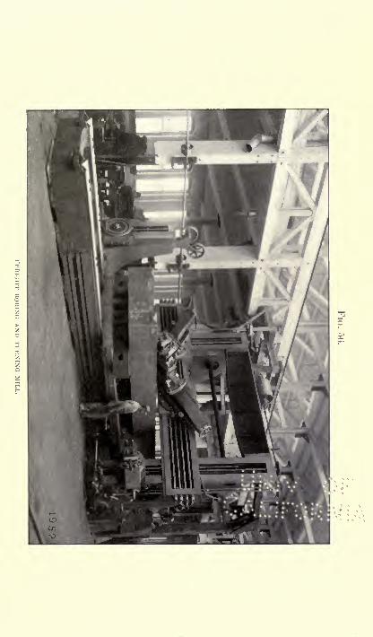


MACHINE TOOLS. 245
FIG. 57.
STKAM-KIVKTKK.
These are principally used by bridge-builders and in
shearing the metal plating for iron or steel ships.
Riveting requires much less strength on the part of a
machine than do punching and shearing, yet the steam-
riveter shown here is a very heavy
machine, of William Sellers & Co.'s
make, and presents a six-foot gapfor the work. It operates by press-
ure, and not by hammering. The
result is preferable to riveting ac-
complished by a succession of blows
on the head of the rivet, because in
the squeezed rivet the shank is up-
set so as to fill the hole completely
before forming a head, and the parts
that are being riveted are broughtinto close and firm contact
;but in
hammering, either by hand or power, the head is formed
without necessarily upsetting the shank throughout its
length, and the rivet is almost certain to be loose in some
parts of the hole, especially if the punching does not
match exactly, and the plates are not clamped together
with the same solidity as where pressure is used. Hy-draulic riveters are also made, which operate by pressure
and do excellent work. They are of practically the same
pattern as the riveter shown here, but water instead of
steam is used to force in the pressure-cylinder. Some of
them are made with an auxiliary cylinder for tightly
clamping the plates so that their surfaces are brought
rigidly together, a necessary thing in boiler-making or the
like. Riveters are made as large as sixteen feet betwreen
the jaws that is, of a size to fasten a rivet in the centre
of a plate thirty-two feet square.

,246 WONDERS OF MODERN MECHANISM.
The wheel-press is a modern special machine that has
attained a wide field. It is designed for pressing on
or off a wheel as of a locomotive from its axle. It is
often operated by hydraulic power. The operation is
easily understood. The axle is swung into proper posi-
tion by central hooks, one end resting in a resistance-post.
If a wheel is to be put on it is then crowded between the
cylinder and the axle, and the pressure of the \vater in the
hydraulic cylinder exerted to force it on. A pressure of
about thirty tons is required to put on a car-wheel suffi-
ciently tight to insure its never coming off by accident. Amuch greater force has to be exerted at times to remove it,
and therefore the larger sizes of these machines are given a
capacity of two hundred tons.
Though the above description does not by any means
cover the extent of machines that have to do with hole-
forming, yet it may serve to give the reader who is not
informed on the subject some idea of the general methods
employed in this department of machine-construction in
the largest and best shops in the United States, which is
equivalent to saying" in the world," for in no other
country has machine-construction attained as high a devel-
opment as in our own.
Machine tools for shaping and forming are most varied
in their construction, including the indispensable lathe,
planing and stamping machines, bending-rolls, slotting,
gear-cutting, grinding, and numberless other mechanisms.
It is believed that the first lathe made by primitive man was
formed by tying a thong of hide to a young tree, passing
it around some piece fixed at both ends so as to rotate when
the lower end of the thong was pulled. By tying the free
end of the thong to his foot the primitive man turned the
rotating piece one way, and by lifting up his foot the spring
MACHINE TOOLS. 247
of the young tree turned it the other. Then, by pressing
against the rotating piece with a sharp-edged stone it
could be formed into circular shape. Such is the principle
involved in the lathes of to-day, but the primitive man
would hardly recognize any of them as evolved from his
handiwork.
A machinist's lathe, as ordinarily constructed, has a
frame with a pointed centre at each end, between which
the work to be turned is hung. One centre rotates, and
is called the live centre, while the other centre is called the
dead centre because it has no rotary motion. The mandrel
of the live centre is driven by pulleys, of graded speeds,
and there is usually a face-plate to which work may be
attached. The cutting-tool is mounted on a travelling
carriage, so that the workman can cause it to pass back
and forth over the surface of the work and cut it in almost
any circular or conic form.
Lathes are made in a seemingly endless variety of forms,
suited to special work. A recent form is the turret-lathe,
which has a cylinder set upright on an axis so as to slide
over the ways, the cylinder having several faces with chucks
or spindles for the reception of drills or other tools, anyone of which may be presented in succession in the axial
line of the work. When a lathe is fitted with two cutting
tools operating at once it is termed a duplex lathe;
if there
is an abrading wheel, it may be called a grinding lathe.
Many lathes are fitted for drilling or boring. Some are
provided with two driving-heads, for turning at a single
operation two mounted car-wheels or the like.
Planing machines are designed to reduce a level or flat
surface by taking off continuous chips or shavings in paral-
lel lines. The common form has a bed that carries the
work back and forth between a heavy framework, on which

248 WONDERS OF MODERN MECHANISM.
is mounted the cutting tool. Rotary planers are used,
however, that have twenty-five to seventy-five cutting
tools arranged on a powerful wheel, mounted on a saddle,
that travels back and forth while the work remains sta-
tionary. They are much used in shaping bridge-work.
For planing large plates there is used a type of machine
having a long plate girder to hold the tool to its work.
The tool travels back and forth and bevels or otherwise
shapes the edge of the plate, being held down to its duty
by a stout clamping-bar. It is used for planing boiler-
plates, safe-plates, and the like. Other plate-planing ma-
chines are made with very stout carriages, so that they do
not require a clamping-bar. The Niles Tool-Works Com-
pany also build a gigantic machine for planing and slotting
that is mounted on a railway track below the level of the
floor, as shown in Fig. 59. Large work may be clampedto the adjoining floor-plate, and is planed by the travel of
the planer on its railway. This powerful machine has a
bed-length of thirty-eight feet, and will plane to a width
of almost nine feet. Its uprights are sixteen feet high,
and it is driven by a long belt carried under the ceiling.
Slotting machines are sometimes built like planers,
though the more common form has a tool that receives an
up-and-down motion from a crank-wheel. A chain slot-
ting machine has been recently introduced that has a series
of cutters mounted on an endless chain. It is chiefly
useful for such wood-work as mortising door-frames. The
gear-cutting machine is a form of slotter, since it shapes the
cogs and spaces. This machine has been brought to a high
degree of perfection. Though the teeth of a gear must be
very accurate in form, and every change in size of the
wheel or in the number of the teeth involves a change in
the form of each tooth, yet gear-cutting machines are


MACHINE TOOLS. 251

252 WONDERS OF MODERN MECHANISM.
mostly automatic, and divide off the teeth and cut them
from the solid metal blank with only the most trifling
attention. One man can run four of them at a time. Ablank wheel being put in place, and the proper cutter
adjusted to depth of teeth, length of stroke of cutter-head,
etc., the cutter will pass across the face of the space between
teeth, and return at a quick pace to the starting side of
the wheel, while the blank is automatically shifted so as
to present the next space to be cut, and the cutter starts in
to do its work again.
Milling machines are used to finish and shape parts of
machines by means of rotating cutters. Shapers are really
small planing machines adapted for light and rapid work.
Stamping presses are used to shape parts of wroughtiron or steel. Many forming machines are operated by
hydraulic power. For stamping coins the approved form
is an hydraulic press with very heavy frame, and dies
between which the coin or medal can be pressed to form.
The Philadelphia Mint uses a machine that exerts a
pressure of two million pounds. It consists of two semi-
circular heads, separated by strong columns, and united by
heavy steel bands, between which is a cross-head operated
by a large s,teel cylinder in the upper head and small re-
turn cylinders in the lower head. Power is supplied by a
direct-acting plunger-pump, which maintains a constant
flow of oil from an overhead tank. The movement of
the coining-head is controlled by a lever. The pressure
applied is determined by an adjustable safety-valve. The
head is made to move at the rate of an inch a minute when
under pressure, and three feet a minute wrhen comingtowards or from the work. This same form of press is
used for punching and stripping, or may be made to do the
work of a drop-press or fly-press.


MACHINE TOOLS. 255
The bending of plates of metal is accomplished between
sets of rolls, which may be adjusted so as to give any curve
to the plate. Four rolls are commonly used, one pair being
larger than the other two and being used for compressionand to carry the plate. '1 he smaller rolls do the bending.
The machine, Fig. 60, is of the largest size made in this
country, and will bend cold steel ship-plates twenty-twofeet wide and two inches thick. It was built by the Niles
Tool-Works for the Mare Island Navy-Yard, and weighstwo hundred and fifty tons. It is operated by independent
engines, as shown, for driving the rolls and adjusting their
position. Two heavy pinching- and feeding-rolls are
thirty-two inches in diameter, the bending-rolls being
twenty-five and a half inches thick. Graduated index-
scales are provided to show the operator just how his rolls
are set. The machine is designed to rest on masonry below
the floor surface, so that the plates can be run in from the
level of a low truck.
Very similar machines are made for straightening plates
of metal. In these more rolls are used, ordinarily seven.
The rolls are made of forged steel, and are particularly use-
ful in straightening boiler-plate or for tank- or safe-plates.
For forging, trip-hammers are used if the work is small.
For large forgings the steam-hammer is the tool that is
never likely to be superseded. It has been considerably
improved since the days of Naysmith, the inventor. There
are two types of direct-acting steam-hammers now made,one in which the weight of the falling mass is concen-
trated in a head, or which works between guiding surfaces,
and is connected by a piston-rod of relatively small diam-
eter with the steam-piston in a cylinder situated above it.
The other type, known as the Morrison, arranges the fall-
ing mass in the form of a heavy cylindrical bar, of whichL q 21

256 WONDERS OF MODERN MECHANISM.
the piston is an integral part, and is situated near the cen-
tre of the length, so that the bar extends above the piston
and passes through the upper cylinder-head. The latter,
style is generally preferred, as the bar is better able to
withstand the shocks of concussion than a piston-rod. In
the smaller sizes the mechanism is supported on a single
bent column. In the larger sizes the falling-bar operates
between two stupendous supports.
FIG. 61.
WM. SELLERS A CO.'S TOOL-GRINDER.
The grinding of drills is very particular work, as, if im-
properly done, the holes made will not be uniform. Special

MINING AND MINING-MACHINERY. 257
machines have been built to do this work, and one of them
is here illustrated. It is supplied with a cooling stream
of water, so that it is not necessary to draw the temperfrom the drills.
Such are a few of the more important machines used in
the manufacture of other machines. Anything like a com-
plete description of them would fill a work several times
larger than this. As a rule, these machines are built bet-
ter in America than abroad. Hiram S. Maxim, the in-
ventor of the Maxim gun and flying-machine, himself an
Englishman, has put himself on record as saying that this
nation has the best mechanics in the world, and the manwho investigates some of the large and excellently designed
machine tools of the leading American makers is very apt
to come to the same conclusion, whatever his nationality.
MINING AND MINING-MACHINERY.
Hoists, Drills, Compressors, and Safety Appliances The Deep-est Shaft in the World Methods of Mine Timbering.
THE most important machine connected with a mine is
the hoisting-engine, which is usually a combined steam-
engine and hoist. There are two common styles. The
Pennsylvania and Lake Superior mines mostly use hoists
having very large drums, around which is wound, in spiral
grooves, the wire rope that supports the cages. These are
directly connected with the engines, and controlled by
powerful brakes, usually of the band type, passing nearly
around the large drum, on which they take hold by fric-
tion. An objection to this type is that the drums are
necessarily heavy, and acquire a momentum like a fly-

258 WONDERS OF MODERN MECHANISM.
wheel, which renders them hard to stop and slow in start-
ing. The other style, more used in the Western States,
makes use of a comparatively light reel and a flat rope,
arranged to wind over and over on itself within a small
space, so as to avoid the fly-wheel effect as far as possible.
FIG. 62.
^ ,_ iiUU.|.JttM ->\V^ --**/--*-*
fx
A MINE REEL-HOISTING ENGINE.
In the larger plants air-brakes are made use of, very simi-
lar in construction to those employed on railway trains.
In making calculations for mine-hoists the length of rope
is an important factor. A depth of three thousand feet
will require a size and weight of rope different from that
in a fifteen-hundred-foot mine, where the hoisting capacity
is to be the same. For a depth of two thousand five hun-
dred feet the size of flat steel rope required would be five
by three-eighths inches, with engine cylinders twenty inches
long and with sixty inches stroke. For a depth of six
hundred feet the rope would be required to be only half

MINING AND MINING-MACHINERY. 259
the size to carry the same load, and the engines of less
than half the capacity. It is hard to say what a mine-
cage usually weighs, as there is so much variation in size.
Perhaps twelve hundred pounds would be a lair average.
The shafts of deep mines are commonly small, four byfour and a half feet being a common size. The ordinary
cage is a simple platform connected by two uprights with
a cross-piece. There are stout iron braces, and the sup-
porting ro|)e is so hung that its breaking will release a
spring that throws out clutches, engaging the guides, and
preventing the fall of the cage.
Many other safety devices are in use. One of them is
the electrical chair-indicator, for showing the engineer at
the surface the position of the various chairs or landing-
dogs at the levels. These chairs are devices for stoppingand supporting a mine-cage in an upright shaft at a point
opposite a level, so that men or material may be conven-
iently transferred from shaft to level, or ivce versa. It is
necessary that the engineer should know when these chairs
are open so that a cage can go by, or when they are closed
for its reception at a particular point. If he does not
know, a collision may result. The old way of keeping the
engineer informed was by means of wires, bell-cranks, and
indicators. But as wires get bent, and lengthen and shorten
with changes in temperature, they were not absolutely
reliable. Connection by electricity has been found to be
more certain. That in use at the Drum Lummon mine
has returned eight hundred thousand indications to the
engineer without error or failure in a single case. Theindicator used with this device shows the engineer just
where the cage is, so that he cannot drop the cage upon a
chair because he may have happened to forget what level
he is hoisting from, and if chairs are shifted carelessly or
21*

260 WONDERS OF MODERN MECHANISM.
with malicious intent he is informed of the fact. If a wire
should in any manner become broken or disconnected, a
danger signal is hoisted, and chance of disaster averted.
The mine-levels are supplied with tracks of very narrow
gauge, seventeen to thirty-six inches, the commoner width
being eighteen inches. Man-power, mule-power, steam,
and electricity are used as means of propelling these. The
smoke of the steam-locomotive is an annoyance, of course;
but as blowers and air-compressors are in constant use,
purifying and changing the air, it does not matter much,and mine-owners have been slow in adopting the little
electric trolley locomotives that have been invented for
their use.
For the carrying of ores down a mountain-side to the
mill at the foot, or for transporting material up again to1
the mouth of the mine, wire tramways or aerial railwaysare much used. They are cheaper to erect than any other
form of railway over a rough country, and they carry
loads of half a ton at a time most economically. The
double rope system is most in favor. The supports maybe made of timber hewn on the spot, and they are not
necessarily close together. Spans of a thousand feet have
been built and operated successfully. The material car-
ried up to the mine " back freight," as it is called is
hauled up by descending loads of ore, etc., so that the
work on the engines and the coal consumption are materi-
ally lessened, being required only to regulate the load.
Shaft No. 3, of the Tamarack copper mine, in the Lake
Superior mining district, State of Michigan, is believed to
be the deepest in the world. In August, 1894, it reached
a depth of four thousand two hundred feet, and it is de-
signed to carry it down below the mile limit in 1896.
There are two other shafts belonging to this mine, each of

MINING AND MINING-MACHINERY. 261
which is over three thousand feet, and a fourth shaft is
designed eventually to go deeper than Shaft No. 3. The
first shaft of this mine was sunk on faith to a depth of
two thousand two hundred and seventy feet, or nearly half
a mile, before the expected lode was struck. It is located
near the famous Calumet and Hecla mine, where the vein
of ore is remarkably rich and wide, and of regular dip.
It was calculated that, if this vein held its course, the pro-
jectors of the Tamarack mine would strike it at two thou-
sand two hundred and fifty feet. They took the chances
and sunk a shaft, not a bored hole put down to test the
presence of copper below, but a full-sized mine-shaft, suit-
able for a large business. The vein proved straight, and
was struck within twenty feet of the point calculated upon.
, The shafts are sunk vertically until they reach the vein
of copper ore, at which point they are inclined to follow
the vein. The trip down No. 3 shaft occupies almost five
minutes, and is accomplished in a cage hung from a drum-
hoist. When there are no men in the cage the speed is
doubled, as fast working is necessary to get up the ore.
The miners below drill the rock with compressed air drills,
the air being forced down through three-quarters of a mile
of tubing by means of compressors. When a sufficient
number of holes are drilled a blast is made, and, as soon
as the gases dissipate, men are set to work gathering the
ore into the cars, while another gang goes on drilling.
Shaft No. 3 was sunk first through fifteen feet of drift,
then a hundred feet or more of trap-rock, then throughseveral seams of amygdaloid rock, which is full of small
cavities. In many mines these cavities are more or less
filled with pure metal, but here there is no copper until
the conglomerate vein, composed of fragments of pre-
existing rocks, is struck. The ore hoisted from the

262 WONDERS OF MODERN MECHANISM.
shafts is carried seventy-five feet above the surface, to
concentration works, where it passes through a series of
crushers, etc. For a description of these see the chapter
on ore-crushing machinery.
FIG. 63.
ROCK-DRILLING.
The timbering of mines constitutes an important part
of mine-engineering. It is especially difficult in " swell-
ing ground," as the miners term it, that tends to bulgeinto the shafts, or in loose, watery ground, or in quick-
sand. There are cases where mines have been abandoned
as unprofitable because of these annoyances. The shafts

MINING AND MINING-MACHINERY. 263
on the Comstock, and in Calaveras and Amador Counties,
California, also at Leadville, Colorado, were difficult in
the extreme, and reflect great credit on the engineers.
The size of timbering in shafts varies all the way from
eight by eight to twenty by twenty-four, or even larger.
Inclined shafts require heavier timbers than vertical shafts,
as they have to support a part of the weight as well as the
thrust of the ground. Very stout wall-plates are used,
and joints are made by mortising. Pumping and man-
way compartments do not require lining as a rule, but
hoisting compartments, where cages are run, should be
lined throughout to prevent accidents to the men, who
sometimes, through crowding or carelessness, lean beyondthe limits of the cage. All shafts are or should be pro-
vided with ladder-ways for use in case of accident to the
hoisting mechanism.
In sinking large shafts it is sometimes necessary, if the
ground is wet or soft, to drive lagging or planks ahead bythe system called forepoling. This has the double ad-
vantage of retaining the sides in good shape and of keep-
ing the ground in which the work is done better than it
otherwise would be, as the planks confine the water.
Thus the ground is more easily worked. In practice it is
found better to keep one side several feet in advance of
the other.
Where the ground is very loose and shifting it some-
times becomes necessary to make use of iron caissons to
maintain the work. In watery ground a double thickness
of planks with a lining of two or more inches of clay be-
tween is sometimes satisfactory. This is arranged in box
form something like a caisson. Within a few years a pat-
ented process has come into use for freezing the ground at
such points until the work has been carried by. The air-
264 WONDERS OF MODERN MECHANISM.
compressors of a mining plant form a convenient means
of supplying a temporary refrigeration at any desired
point, as will be understood by any one reading the chap-
ter on ice-making machinery, where the principle of arti-
ficial cold is explained.
Mine-shafts are now almost invariably made rectangular
in section. L forms are not in favor, and circular ones
have gone out of date. Of course the circular form is
well calculated to sustain itself, but the rectangular is
much more convenient for the arrangement of compart-
ments, guides, etc.
In shafts it is very necessary that the upright timbers
of the guides for the cage should be very neatly joined, so
that there may be no jamming or danger from warping.
Such joints are best made by means of a tongue and groove
fastened with log-bolts, though lap-joints are much used.
The principle to be borne in mind in mine-timbering is
that heavy beams should be set continuously in rectangu-
lar form. If we have an inclined shaft six feet wide, the
cross timbers are best placed at six-foot distances, the tim-
bering forming the outlines of a succession of cubes. Tim-
ber is usually squared before coming into the mine, but
occasionally round timber has been preferred, as at the
Utica-Stickles mine, Calaveras County, California. Here
the gold-bearing rock is forty to a hundred feet wide, and
about four hundred feet high, necessitating its being stoped
that is, worked by steps. The round timbers are all
cut into eight-foot lengths, and set up staircase-fashion as
the work progresses. The management buy the thickest
timbers they can get, with the result that they weigh all
the way from seven hundred pounds to ten or twelve hun-
dred, and in a few cases sixteen hundred pounds. The
handling of these becomes quite a business. They are

ORE-CONCENTRATING MACHINERY. 265
usually lashed together, and sent down the shaft in or
attached to a stout iron bucket called a skip, and at the
levels are transferred to small flat-cars, called trolleys,
specially built for hauling them. Two men and a lot of
eight-foot chains constitute an equipment for sending down
the timbers. These chains bear hooks and rings, and with
them the timbers are securely fastened in the skip. At
the Utica mine, however, they hang them below the skip,
and thus are able to make quicker work of it; but this
method cannot be used where the shaft departs much from
the vertical. Winzes, or minor upright passages connect-
ing levels, are very convenient in handling timbers, afford-
ing opportunities for lowering them at convenient points.
At the diamond mines of South Africa suitable timber
is not obtainable, and it is imported all the way from the
Baltic Sea, or sometimes from California. This is ex|x?n-
sive, but as they occasionally find down there diamonds
of three or four hundred carats, the stockholders can afford
to pay big freight charges on timber.
ORE-CONCENTRATING MACHINERY.
The Mechanisms in Present Use for removing the Less Valu-able Portions of Ore, with some Hints as to
Gold and Silver Milling.
ORE comes from the mine in all shapes and sizes, just
as it happens to be broken up, and the first process in its
treatment is to render it more uniformly fine. For this
purpose it is dumped on a great screen of iron bars, called
a grizzly, the bars being so inclined that the coarse ma-
terial is slid off to a crusher, while that which is already

266 WONDERS OF MODERN MECHANISM,
sufficiently fine falls through into a bin, which later re-
ceives the ore from the crusher. One of the best knownforms of crusher is the Blake, which has moving jaws of
enormous strength, that open and close with a motion that
lets down a little rock at a time, and drops it through as
soon as it is sufficiently small. When set to crush not over
an inch and a half in size, a large crusher will dispose of
about seven cubic yards of rock per hour. The Dodgecrusher is a very similar machine, but is suited to finer
crushing. It is especially adapted to preparing ores for
the Huntington mill, which is described farther on. Gy-ratory crushers are also made, of which the Comet crusher
is the best known. It is serviceable where large capacityis desired in a particular place, and has been installed in
the famous De Beers South African diamond mines and
also in some gold mines.
If the ore handled is gold and is to be treated by a wet
milling process, it goes from the crusher-bin to an auto-
matic feeder to be fed directly to the stamps, etc. TheTulloch automatic ore-feeder is a common form, consisting
of a hopper-like box, below which is an oscillating trayof wrought iron. The back of the hopper has an adjust-
able scraper, and at each motion of the tray a portion of
the ore is scraped forward to the stamp-battery. The
Challenge ore-feeder is especially adapted to wet ores. It
has a circular bottom-plate, set at an angle so as to bringdown the ore as it rotates.
If the ore handled is silver, and it is to be treated bythe dry process or by roasting, a revolving dryer is placedbelow the crusher, so that it may be thoroughly dried be-
fore being subjected to a finer crushing.The ore-stamp as commonly made is a very simple ma-
chine, consisting of a heavy upright rod, with a stamp or
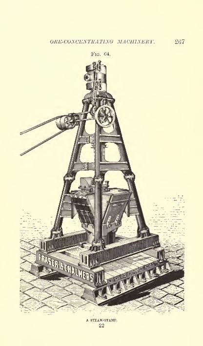
ORE-CONCENTRATING MACHINERY. 267
FIG. 64.
A STEAM-STAMP.
22

268 WONDERS OF MODERN MECHANISM.
pounder on the lower end, and a projection by which it
may be raised by a cam on a rotating shaft, so as to fall
by gravity. They are set up five or ten in a frame, and
often a whole row of frames, together constituting a stamp-
battery. This primitive mechanism is giving way rap-
idly to the steam-stamp, which is designed somewhat after
the manner of a steam-hammer. This machine is pyrami-dal in form, having four principal columns that meet in a
ring at the top and rest in heavy cast-iron sills at the base.
Surmounting the top ring is a steam-cylinder set vertically,
so that the descending piston can be used to raise and lower
the powerful stamp. Within the four columns, at the
base, is a large mortar, resting on a heavy cast-iron bed-
plate or anvil twenty inches in thickness, and weighingabout eleven tons, this in turn being supported by a row
of stout wooden sills, designed to spring when the blow is
delivered. Between the anvil and the springy timber is a
rubber cushion an inch thick, which assists further in re-
ducing the jar. The piston of the cylinder and the stamp-stem are connected by a disk, and between the two, in the
junction piece, is another piece of rubber to prevent too
great jar of the steam-cylinder. Ore and water are fed in
at the top of the mortar, the water being continually thrown
against the sides of the stamp-stem to keep it from beingscored and cut to pieces by the sharp sand. The largest
size of these stamps has a stroke of thirty inches, and its
capacity is about one hundred and fifty tons of fine crush-
ing per day of twenty-four hours, or two hundred and
thirty tons of coarse crushing in the same time. This
enormous machine stands about thirty feet high, and weighs
seventy tons. It will do the work of about seventy-five
of the old-fashioned stamps.The old stamp-battery continues to have its adherents

ORE-CONCENTRATINO MACHINERY. 269
for fine crushing, and in some cases fast-running rolls are
preferred in place of stamps, but this depends upon a par-
ticular ore, as upon an extremely hard ore the wear and
tear upon the rollers is liable to prove expensive, and the
additional machinery required by fine crushing dry with
rolls adds to the exj>ense of erection and running, and also
the wear and tear. With these rolls a system of revolving
screens is generally used, and various elevators to turn the
material back to the rolls for recrushing, and usually it is
necessary to maintain several sizes of rolls.
Crushing rolls are employed on either wet or dry ore,
where it is desired to granulate the material and avoid the
pulverizing action of stamps that produces slimes. The
common form is known as the Cornish geared crushing-
rolls, and consists of a pair of heavy iron rollers, as much
as eighteen inches in diameter in the larger sizes, and ro-
tating oppositely to draw in the ore. One roll is set in
spring bearings to avoid danger of breakage if the pressure
rises above a certain point. Removable steel faces are
used on the rolls that can be replaced when they are worn
out. -During recent years they have been improved in
construction, so that they do faster work, and a completemachine has an automatic feeder that carries the ore regu-
larly across its face. For certain classes of work there
has been a demand of late for the belt-driven class of rolls,
operating entirely without geared connections between the
crushing shafts, which are independently driven by belts
run on large pulleys. The speed is higher, and the belts
do not wear out as fast as the gears, which are subject to
severe friction.
Under some circumstances complete pulverization of the
ore is desired, and for this purpose no machine has been
as successful as the Huntington mill. This makes use of

270 WONDERS OF MODERN MECHANISM.
upright rolls, having an oiled bearing above, away from
the grit and slime, and no bearings at all below, as the
rolls run around on a horizontal steel tire. This arrange-
ment gives the mill great wearing qualities, not possible
in any mill where the slimes have a chance to work into
the bearing. The accompanying illustration shows the
FIG. 65.
THE HUNTINGTON MILL.
operation of the Huntington mill, as built by Fraser &Chalmers. The ore and water are both received at the
hopper on the right. The rotating rolls, 7 and 9, throw
the ore against the ring-die 1, being kept to their work of
crushing by the centrifugal force. Complete pulverization

ORE-CONCENTRATING MACHINERY. 271
can be obtained. It will be observed that the only oiled
bearings are on the three shafts, set in the upper frame.
The lower surface and the weight of the rolls all assist
in the pulverization, giving most economical results. The
ends of a screen are shown in the part broken away, and
through this the water and pulverized ore find exit, no
ore being permitted to esca}>e until of the required fineness
of the screen. The discharge is so perfect that very little
slime results, the pulp being in good condition for concen-
tration.
One more crushing machine should be mentioned before
closing the subject. It is the Sturtevant mill, which has
been borrowed from the cement-makers. It has been
found very useful for coarse crushing, and has a peculiar
action. There are two cylindrical heads rotating in oppo-site directions within a screen-lined casing. The heads
become filled with a conical lining of the material to be
crushed, and these, by centrifugal force, throw the ore
which falls on them against the pieces thrown in the op-
posite direction by the other head. In this way the ma-
terial is broken against itself without scoring or abradingthe mill. To prove that the theory of the machine is
correct, balls of the hardest white cast iron have been in-
troduced and thrown around until they smashed themselves
against each other, the mill being uninjured. As a pre-
paratory machine, combining the duties of the rock-breaker
and coarse roller in one operation, this mill is being used
by many smelting-works.
Jigs or jigging machines are used to separate the ore in
imitation of the shaking of a sieve by hand under water.
The ordinary type of jig consists of a water-tank divided
by a partition above, not reaching the bottom. On one
side of the partition is fixed a horizontal screen on whichr 22*

272 WONDERS OF MODERN MECHANISM.
the sized ore is fed, and on the other side a loosely work-
ing plunger is operated vertically by a crank or the like.
The reciprocating or up-and-down motion of this plungercauses a regular pulsation of water through the screen,
shaking and agitating the ore so that the heavier parti-
cles settle down and either come through the screen or
are worked through a gate above the screen-level, while
the lighter particles of rock move on horizontally and
discharge over the side or end of the screen. Jigging
machinery is usually employed for coarse material, and
operates on the principle that a mixture of ore particles
varying in weight, because some contain more metal than
others, tend to arrange themselves in layers when shaken,as by a pulsating column of water. Jigs are made with
as many as four compartments, the larger number being
required when more than two products are desired. In
the case of three- or four-compartment jigs, the plungersare regulated as to stroke and speed independently of each
other and with reference to the work to be done respec-
tively on the screen-beds they govern. It is usual to de-
press the plungers by means of a tappet or eccentric, and
throw them up with a metal spring as they are released.
An hydraulic separator is manufactured which consists
of a V-shaped trough, into which the pulp flows through a
smaller trough, or launder, while the slimes are discharged
by overflow through another trough. A partition or
diving board is set down into the principal trough to
prevent any direct flow from the entrance to exit. Astream of clean water is forced in near the bottom under
sufficient pressure to drive the slimes and mud to the
surface, where they are discharged at the overflow, while
the heavier particles and clean water are dischargedbelow.

ORE-CONCENTRATING MACHINERY. 273
Another form of separator is known as the Calumet
classifier, and consists of a trough having four or five de-
pressions along the bottom. The water and sand undergosuccessive washings in each depression as they pass along.
Shields are used to guard the depressions, which retain the
heavier particles. This form is said to use very little water
as compared with other separators.
In a general concentrating plant separate settling-boxes
are used to divide the slimes for dressing or fine concen-
tration, but in a distinctively fine concentration mill the
ore is at once reduced to pulp for treatment. In this crise
buddies and tables of different types are used where the
product is of various grades, some requiring further treat-
ment, but for clean concentration the Frue vanner is uni-
versally used. Where gold and silver are the metals
sought the ore requires fine crushing, and the same is true
FIG. 66.
THE FRUE VANNING MACHINE.
in a less degree of lead, copper, and tin ores. For such,
stamps and Frue vanners are the regulation outfit, the
vanners producing a cleaner mineral than other slime-

274 WONDERS OF MODERN MECHANISM.
dressing machines, with exceptionally low loss. They also
have the advantage of immediate automatic treatment of
the pulp without sizing, at one operation, and without any
rehandling. They require a minimum of power, water,
and attendance.
The Frue vanner has an endless rubber belt presenting a
top surface twelve feet long and four feet wide, supported
by rollers so as to form an inclined plane bounded on the
sides by rubber flanges. By means of a drum the belt is
given an upward travel along the incline, and at the same
time receives a regular shaking or settling motion from a
crank-shaft running along one side at right angles to the
travel of the belt. At the head of the belt is arranged a
row of jets of water, while the ore is fed upon the belt in
a stream of water about three feet from the head, and flows-
down the incline slowly, the constant shaking depositingthe mineral on the belt so that it is carried upward. The
water-jet washes back the light sand, allowing only the
heavy mineral to pass to the water-tank below. The Em-
brey ore concentrator is a very similar machine, having an
end shake instead of a side shake.
The revolving buddle or slime-table is a very useful
machine for separating ores. The revolving Evans's table
is perhaps the best-known type. It has a circular table
about fourteen feet in diameter that is slightly coned. Theore is fed to this from the centre, along with the water.
The rotation of the table carries around the deposited
material, which is subjected to the washing action of clear
water flowing down from the centre, and is eventually
washed oif the table by strong jets of water, sometimes
assisted by stationary brushes if water is scarce, and
dropped into launders below. The table thus continuously
arrives clean to receive the flow of pulp, being freed of

ORE-CONCENTRATING MACHINERY. 275
waste, middlings, and clean mineral before the full rotation
is completed. The surface of the table is commonly made
of soft pine wood, but cement and rubber are also used.
Another form of this machine has the cone inverted, re-
ceiving the ore at the outer edge, and discharging at the
lowest point, the centre. In yet another form the buddle
or table is stationary, the feed-spout and washing pipes
doing the travelling, the effect being precisely the same.
Within a few years a double or two-story slime- table has
been introduced which gives better results, though with
any slime-table it is necessary to partially classify the
material, in the first place, as by an hydraulic classifier.
The Evans's slime-table will handle about twenty-five tons
of material per day of twenty-four hours. The rotation
is of necessity comparatively slow, one complete turn being
made every eighty seconds.
The percussion-table is a sort of compromise between a
vanner and a revolving buddle. It is much used in Ger-
many in place of the latter machine. It has an inclined
table or, more commonly, several such tables made of
wood, rubber, slate, stone, or even plate-glass. This table
is usually about four by eight feet in surface, and is regu-
larly shocked or jarred by a cam and spring operating
alternately against the frame. The ore is fed over the
surface with a stream of water from one of the uppercorners. The downward motion of the current of water
combined with the side-jarring of the table tend to work
the heavier particles along in a diagonal course, so that the
grades may be separated by guides.
The various processes used in obtaining metals from the
ore are too numerous and exhaustive to be more than hinted
at here. For the milling of silver ores the Boss continuous
process of amalgamation, patented by M . P. Boss, has come

276 WONDERS OF MODERN MECHANISM.
into extensive use within a few years. It is undoubtedly
superior in many respects to the old system of pan amalga-mation. The first cost of plant is also considerably re-
duced. The illustration shows a cross-section of a silver-
mill as arranged for this process by Fraser & Chalmers.
FIG. 67.
CROSS-SECTION OF A SILVER-MILL.
The ore passes through the grizzly and crusher, on the
right and upper end of the picture, in the usual manner,and by means of the automatic feeders to the stamps in
the centre. The pulp from the stamp-battery is flowed
through pipes to special grinding pans, on the next to the
lowest elevation, thence by other pipes to the first amal-
gamating-pan, and continuously through a line of pansand settlers on the lower floor, the tailings being run off
or led over concentrators. The quicksilver necessary
to draw the particles of silver into contact is let into the
pans by means of pipes from a distributing tank, and the
amalgam so formed is flowed through pipes to a strainer.
The chemicals are supplied to the pans by two automatic
feeders. Steam-siphons are used for cleaning out the pans
ORE-CONCENTRATING MACHINERY. 277
and for carrying the pulp past any pan when it is necessary
to cut it out for repairs. The main line shaft runs directly
under the pans and settlers, each of which is driven from it
by a friction-clutch. The arrangement of separate clutches
is made for the purpose of enabling any pan or settler to
be stopped or cleaned without stopping the whole line.
The largest quartz- mill in the world is believed to be
that of the Alaska Treadwell Gold-Mining Company, at
Douglas Island, Alaska. Here are run two hundred
and forty stamps of eight hundred and fifty pounds each,
six rock-breakers, and ninety-six concentrators, with a
capacity of six hundred tons of ore per day of twenty-
four hours. The mill was erected by the Risdon Iron
Works of San Francisco. Here the gold ores are treated
in vats by the chlorination process, which is based uponthe property of chlorine gas for transforming metallic goldinto a soluble chloride of gold. In this condition it can
be dissolved in cold water and precipitated in a metallic
state by a solution ofsulphide of iron, or as a sulphide ofgold
by sulphuretted hydrogen gas, this method being known as
the Plattner process. The sulphurets, as the gold-bearing
pyrites are called, are collected at the mill on Frue van-
ners, and contain, on an average, forty per cent, of sulphur.The gangue is quartzose, with a little calcite, on account
of which it is necessary to roast with salt. Four reverber-
atory furnaces are used for the roasting, and each is a
monster of its kind, being thirteen feet wide and sixty-five
feet long. The four have a total capacity of twenty tons
of sulphurets daily. When the roasting is completed, the
charge is removed from the pit under the furnace, and
spread on the cooling-floors, sufficiently moistened to pre-vent dusting and packing, and carefully sifted into large
vats. The lids of the vats are then lowered, the joints

278 WONDERS OF MODERN MECHANISM.
carefully cemented with clay, and the chlorine gas turned
on. Four hours are sufficient for the gas to permeate the
material, after which the gas is shut off and the vats are
allowed to stand for about thirty hours. The leaching
requires twelve hours. The tailings are sampled and
assayed, and if found to be worth less than three dollars
per set of vats they are allowed to run to waste. For
convenience and safety the gold is run into intermediate
tanks, and from these into precipitating vats. When a
vat is full, or all the solution is run in, the pulp is stirred
and allowed to settle for from eighteen to twenty-fourhours. The supernatant liquor, containing such gold as
has not been precipitated, is then drawn off through a
large filter, which gathers the remainder, amounting to
only twenty-five cents' worth for each ton of material that
has been treated. A clean-up is made twice a month, at
which time all the gold is washed into a small tub, in
which it is allowed to settle all night, when the superna-tant liquor is drawn off and returned to one of the precipi-
tating vats. The gold in the small tub is then placed in
an iron drying-pan, where it is gently annealed over a
small stove, taken, into the melting-room and run into
bars. The drying and melting of twelve thousand dollars'
worth of gold can thus be accomplished in a single day byone man.
In the Black Hills Mills battery amalgamation is used
to extract the gold. It begins in the mortar, where mer-
cury is added at intervals, and ends on the apron-plates,
where nearly all the amalgam not retained by the inside
amalgamated copper plates is collected daily, any defici-
ency in the collecting mercury and amalgam on the plates
being supplemented by the various traps.

THE PELTON WATER-WHEEL. 279
THE PELTON WATER-WHEEL.A Simple Machine which has attained Marvellous Results, by a
Return to First Principles A Steam Turbine similarly con-
structed.
THE use of a fall of water to develop power to do work
dates from such an early period as to be lost in myths.No doubt this was the very first power which man har-
nessed to his primitive machines. As long as Nature
continues to draw the moisture from the seas, and drop it
in the form of rain upon the mountain-tops so that the
rivulets are formed and combine to make mighty rivers, so
long shall we have water-power; and as long as such
power exists it is likely to be used, for it is the simplest
and least expensive natural source.
Considering these things, it is a little surprising to learn
that only five per cent, of the water-power of the world
has been rendered available for use. Only at the present
time, 1895, is the great Niagara Fall, the mightiest natural
power of the sort on the globe, about to be utilized for
man's benefit.
A more widespread form of neglect as regards water-
powers has been in the overlooking of the advantages of
small streams of great fall, the tendency having been to
develop and use only large streams with a low head or fall
of water. When we observe the cumbersome mechanism
required to use the power of a large river of slight fall
the great dam and monstrous turbines, with huge pipes
and shafting and contrast these with very simple means
devised within a few years for using the water of small
streams having a high head, we are filled with wonder as
to why somebody did not think of this before. The Pel-
ton system of water-power, to which the world is indebted
M 23

280 WONDERS OF MODERN MECHANISM.
for a means of producing great forces from little streams,makes use of not only the very simplest form of mechan-
ism, but a form which assuredly was very like the first
that man devised. It is amazing to think that the very
simple water-wheel shown in the illustration was not put
FIG. 68.
THE PELTON WATER-WHEEL.
on the market three thousand years ago instead of some
ten years since. It is simply a wheel with a ring of
buckets on its periphery, driven by water from a pipedelivered through one or more nozzles at an angle. Yet
this wheel received the highest award at the World's
Columbian Exposition, as a recent invention of unusual
merit. Under the high heads for which it is designed, it
makes available almost the whole of the theoretical power
more, probably, than any other machine manufactured.
The power of the Pelton wheel does not depend upon its
diameter but upon the head and the amount of water

THE PELTON WATER-WHEEL. 281
applied to it. Where a very considerable amount of
power is wanted under a comparatively low head, a wheel
of larger diameter is necessary to admit of buckets of cor-
responding capacity, as also the application of two or more
nozzles, for the purpose of multiplying power. The
smaller sizes are principally in demand, but wheels as large
as fifteen or twenty feet in diameter are sometimes made for
the purpose of direct connection to crank-shafts of pumps,
compressors, etc. Small buckets are frequently used on
wheels of large diameter for the purpose of reducing speed
when operating under high heads and running slow sj)eed
machinery. More than one nozzle is sometimes used to
increase the power by applying more water or for securing
a higher speed than can be obtained from a larger wheel
with a single nozzle. By using multiple- nozzles sufficient
power can often be obtained from a wheel of small diam-
eter to admit of direct connection to the shaft of a dynamoor other high-speed machinery without intermediate gear-
ing, or of giving such increase of speed as to admit of
belting direct without the use of countershafts, etc.
The transmission of power by electricity has opened upa wider range for the utilization of such sources of powerthan has been possible by any previous methods, and the
field is continually widening as the science advances.
Water that for thousands of years has run to waste can
now be transformed into electrical energy, and carried longdistances and made as useful as at the point where gener-
ated, and at small cost in most cases as compared with
steam. The immeasurably vast resources of power avail-
able by this means open up in all directions new fields for
enterprise, affording profitable employment for both labor
and capital.
It is under heads of fifty feet or more that the Pelton

282 WONDERS OF MODERN MECHANISM.
wheel develops its advantages, and under heads of several
hundred feet the power developed is simply enormous, and
not to be obtained from any other form of wheel. Let us
look at the figures : A twelve-inch wheel run under a
twenty-foot fall develops only one-eighth of a horse-power.
Give it a hundred feet of fall and we secure nearly one
and a half horse-power; make it two hundred feet fall,
and we have four horse-power ;while at five hundred
feet, we get sixteen horse-power ;and at a thousand feet,
fifty-two horse-power. This is a tremendous power for so
small a wheel, but if you want fifty horse-power, and have
but eighty feet of fall, use a six-foot wheel and you get it.
At a head of two hundred and fifty feet your six-foot
wheel will give you two hundred and sixty-seven horse-
power ;at five hundred feet, seven hundred and fifty-five
horse-power ;while at one thousand feet you will receive
the enormous power of twenty-one hundred and thirty-six
horses all from a six-foot wheel that one horse could
carry without trouble. All these figures are given on the
basis of one nozzle. If the figures are not high enough,
put on three or four more nozzles, and you can get any
power you want.
One of the most notable features of the Pelton system is
the facility with which adaptation can be made to widelydifferent conditions of water-supply and power without
loss of useful effect. This is accomplished by a simple
change of nozzle-tip, varying the size of the stream thrown
on the wheel the power of which may be varied by this
means from its maximum down to twenty-five per cent,
without appreciable loss thus working to its full capacity
with an ample water supply, or to the same relative advan-
tage with a reduced quantity, when for any reason the
supply fails in part. This system also admits of using,

THE PELTON WATER-WHEEL. 283
without disadvantage, a wheel of larger capacity than
present wants require with reference to an increase of powerwrhen wanted. Variations of construction as to diameter
of wheel, size of buckets, number of streams applied, also
admit of adaptation to all conditions and requirements of
service either as to speed or power, in the most simple and
efficient way, and at the smallest possible cost.
At the Comstock mines in Virginia, Nevada, there is a
Pelton wheel, of three feet diameter, that develops more
power than any other contrivance of its size in practical
use in the world. It is made excessively strong, being a
solid steel disk with phosphor-bronze buckets securely
riveted to the rim. It is located at the Sutro tunnel level
of the California and Consolidated Virginia shaft, sixteen
hundred and forty feet below the surface. In addition to
the head afforded by the depth of the shaft, the pipe is
connected to the line of the Gold Hill Water Company,which carries a head of four hundred and sixty feet, giving
the wheel a vertical head of two thousand one hundred feet,
equivalent to a pressure of nine hundred and eleven pounds.
The water, after passing the wheel, is carried out throughthe tunnel, four miles in length. The wheel makes eleven
hundred and fifty revolutions a minute, giving it a periph-
eral velocity of a hundred and twenty miles an hour. If
it ran without load it could be speeded to just double these
figures, giving the rim a speed of twenty-one thousand six
hundred and eight feet per minute, or two hundred and
forty miles an hour. With a half-inch stream of water it
develops one hundred horse-power. This wheel has run
several years under these conditions without any cost for
repairs.
The Hydraulic Power Company, of Chester, England,run wheels under nearly as severe pressures. They have
23*

284 WONDERS OF MODERN MECHANISM.
an eighteen-inch wheel, weighing but thirty pounds, that
gives twenty-one horse-power with a quarter-inch stream.
The Pelton wheels are also built for use in cities as
motors, having for this purpose an iron case, with a pipe
bringing in water from the mains. They are very desirable
where the pressure is high, and may be conveniently con-
nected with a dynamo, as shown in the illustration. The
FIG.
THE PELTON MOTOR WITH DYNAMO CONNECTED.
wheel, under these circumstances, is made of a diameter to
give proper speed to the dynamo under the water-head
available. Where a considerable head of water is obtain-
able, a small stream may be used to run an electric lighting
plant at small cost. The water being free, the only chargeis for interest, repairs, and attendance.
Right in line with this discovery of the virtues of the
simple form of water-wheel here described comes an inven-
tion for using steam in the same manner. No doubt the
first endeavor to use steam was by allowing it to blow
a draft in a rotating fan or wheel of some sort, but the

ILLUMINATING GAS. 285
power thus developed in the early experiments did not
compare with that obtained by using steam under pressure
through the medium of a cylinder, as in the steam-engine.
In 1890, Dr. Gustaf de Laval made a little wheel designed
to rotate fast enough to secure the full force of escaping
steam. It was a miniature turbine wheel, of less than four
inches diameter, constructed in the most substantial manner
of steel and aluminum bronze, and arranged to admit steam
through its axle and deliver it at the periphery, after havingserved to do work by impinging on the inner guides of the
wheel. He secured a rotation of fifty times a second, de-
veloping five horse-power with this insignificantly small
contrivance. This wheel was exhibited at the Columbian
Exposition, where it attracted much attention. A larger
size of about seven inches diameter developed twenty
horse-power. The only difficulty would apj)ear to be the
utilization of such a speed without enormous frictioual
losses in reducing the speed to common necessities. For
this purpose De Laval devised gear-wheels rotating in oil,
but it is fair to presume that he was not wholly successful,
since the steam-turbine, as he calls it, has not been placed
upon the market. If it can be made to deliver its power
economically there will surely be a great demand, because
of the economy of first cost and of space in using such a
device in place of an ordinary engine.
ILLUMINATING GAS.
How Coal-Gas was made, how it is made and enriched, and howit is likely to give way to the New Illummant, Acetylene Gas.
FEW people have any clear idea as to how the illumi-
nating gas which they burn is manufactured. In a general
way they know that a gas company somehow extracts vapor

286 WONDERS OF MODERN MECHANISM.
from coal and gathers it in a big tank or holder for distri-
bution. If they look up the matter in the encyclopaedias
they gain some notion of the methods and principles, but
little of the latest and newest processes that have come in
within a very few years, displacing older methods because
they are better.
The principle of making coal-gas consists in heating the
coal in a large metal or fire-clay vessel, called a retort, so
as to distil oif the gas. By this simple process a ton of
coal used in a retort will yield about ten thousand cubic
feet of illuminating gas. A vast improvement on this
process is obtained by taking the coal used in the first
operation, which has now become coke, heating it to in-
candescence, and forcing steam through the mass. By this
means about thirty thousand more feet of gas are obtained
from the ton of coal, not including such coal as is used for
the fires producing the heat. The gas produced by this
process, in which steam is used, is called water-gas, since it
is the decomposition of the water that releases the hydro-
gen forming the gas. A vapor made from crude oil is
commonly added in small quantities to give greater illumi-
nating power.
Carbon when highly heated has so much affinity for
oxygen that it will decompose steam in order to combine
with the oxygen that forms a part of the steam. This is
the principle that makes water-gas possible. Either an-
thracite coal or coke may be used to secure the necessary
carbon.
There are a number of recently perfected processes in use
for making a rich gas economically, and a description of
the Rose-Hastings process will serve as well as any other,
for they are much alike. This is a combination process
for making coal-gas, water-gas, and oil-gas at the same

ILL UMINA TING GAS. 287
time, and securing the benefits of a desirable combination.
It is much used in connection with natural-gas plants,
which have a bad habit of giving out as the thermometer
approaches zero, hence require to be supplemented by a
system of manufactured gas. This apparatus consists of
one or more heating chambers or retorts, used for the distil-
lation of soft coal into gas ;also chambers for coke, carbu-
FIG. 70.
THE ROSE-HASTINGS COAL-GAS APPARATUS.
retting, gas-fixing, and steaming, all arranged in a circle;
and a central chamber for distributing hot air the whole
set of chambers being enclosed in a great steel shell, as
shown in the illustration. The sections for soft coal and
coke are arched midway of their height ^yith perforated di-
visions, the chambers above the arches being respectively for

288 WONDERS OF MODERN MECHANISM.
storing heat and for carburetting, the latter being the process
of impregnating the gas with carbon to increase its illumi-
nating power. The heat-storing and carburetting chambers
communicate near the top, and the coke and gas-fixing sec-
tions near the bottom. The chambers using coal have
mechanical feeders by which the coal can be supplied at
any time. The coke chamber may be charged once or
twice a day through the doors.
The coke and coal being supplied and the fires properly
regulated, air is driven up through the coal chambers,
burning a portion of the coal, and heating it to a high
temperature. The hot gases so obtained are carried down
through the coke, in this way heating without burning it.
When the apparatus is brought to the right heat, and before
the hot-air blast is stopped, a charge of soft coal is dumpedinto each of the coal chambers. The blast is then stoppedand steam turned on under each of the coal chambers, and
oil turned in at the top of the coke chamber. As a result
water-gas is produced in each of the coal chambers, and,
mingling with the coal-gas distilled off from the fresh
charge of soft coal, passes over to the coke chamber, down
through the red-hot coke, where it encounters and mixes
with the vapors of crude oil, the whole forming a " fixed"
gas that is, a gas that will stand a low temperature with-
out condensing. This combination secures the best results
of three processes in one, combining a water-gas plant with
a coal-gas plant and enriching the mixture with oil-gas.
With this apparatus thirty-eight pounds of coal, thirteen
pounds of coke, and three and a half gallons of oil will
make one thousand cubic feet of twenty-two candle-power
gas, including the coal consumed in heating the apparatus.
The gas leaves the machine at a temperature of about
800 F., which is above the melting-point of the softer

ILLUMINATING GAS. 289
metals, as zinc and lead, and, when we consider how
readily gas burns, it seems at first a dangerously high
temperature. This hot gas passes through a multitu-
bular condenser, so that it may heat the water for the
boilers while cooling itself, thus effecting an economy.The condenser is usually so hot as actually to generate a
considerable quantity of steam that goes over to the boilers
with the feed-water. After leaving the condenser the gas
passes through a seal and washer, an apparatus for re-
moving impurities ;and thence to the scrubber, where the
condensable matter is got rid of; then to a purifier, and
finally to a gas-holder, the great telescopic tank by which
we always recognize a gas-works.
Gas made by the above process mixes readily with natu-
ral gas, and a first-rate article has the following analysis :
hydrogen, 36.40; marsh-gas, 23.20
;carbonic oxide, 19.10;
heavy hydrocarbons (illuminants), 14.05; nitrogen, 3.08
;
carbonic acid, 3.02; oxygen, 1.15.
With apparatus now on the market, it is possible, in
sections where coal is cheap, to sell gas at thirty-five cents
per thousand feet, and this is actually done in Louisville,
Kentucky. There are few places, however, where it sells
for less than one dollar, though the tendency of prices is
downward.
A very material cheapening in the use of gas for light-
ing is accomplished by placing a chemically-prepared hood
over the gas-flame, producing incandescence of the whole
hood, resulting in the development of four times as much
light without increasing the gas consumption. Dr. Auer
von Welsbach experimented with the salts of rare earths,
until he found a combination that produced the above re-
sults. At first the discovery was of little commercial value,
because of the scarcity of the earths, cerium, lanthanum,

290 WONDERS OF MODERN MECHANISM.
thorium, yttrium, zirconium, praseodymium, neodymium,and erbium, but as soon as it was known that a commercial
demand existed for them they were found in considerable
quantities, in Henderson County, North Carolina, in Nor-
way, in the Ural Mountains, in northern California, and in
parts of Texas. These deposits have been promptly bought
up by interested parties, and, as a result, the manufacture
of the hoods is in a fair way to become a valuable monop-
oly. In manufacturing the hoods for the lights, the first
process is to weave a cotton hood, which is then soaked in
the salts obtained from the earths by various patented
processes. After drying, the cotton is burned out, and the
hood is ready for use. The light obtained by these incan-
descent hoods is so soft and powerful, and the amount of
gas used is so small, that they are likely to supplant the
incandescent electric light in many cases.
So much for coal-gas. It is possible, in spite of these
marked improvements, that the world is on the point of
discarding it altogether in favor of acetylene, for which the
most astonishing claims are made, and apparently substan-
tiated. This gas surpasses in brilliancy and economy all
other forms of light, and would be likely to distance
electricity were it not that the methods of manufacturingelectric light are liable to great improvement in the next
few years. Acetylene, when burned at the rate of six feet
an hour, the pressure common to good gas-burners, emits
a light equal to three hundred candle-power, as against
twenty-two to twenty-seven candle-power for good qualities
of enriched water-gas. That it is more than twelve times
as valuable was demonstrated to an audience recently at
the Franklin Institute in Philadelphia.In order to understand what acetylene gas is we must
first premise that a carbide is a compound of carbon with

ILLUMINATING GAS. 291
one or more positive elements;that the carbides of the
alkali and alkaline-earth metals, such as potassium, so-
diurn, borium, strontium, and calcium, when brought into
combination with water will decompose the same, forminga hydrated oxide of the metal and acetylene gas. In
other words, the combination of calcium (lime) with carbon
(charcoal) and with water can be made to produce a bril-
liantly-burning gas. Since these three things are exceed-
ingly cheap, it remains only to find an economical method
of manufacture, and we have a light and a fuel that will
beat the world. Such a process is described in a United
States patent granted to Edward X. Dickerson and Julius
J. Suckert, March 19, 1895.
Calcium carbide, the principal constituent of this gas, as
prepared by Thomas L. Willson, is a dark-brown, dense
substance, having a crystalline metallic fracture of blue or
brown appearance, and a specific gravity of 2.26, or a little
less than charcoal. It has a peculiar odor, due to moisture
in the atmosphere. It will withstand a very high tem-
perature, a Bunsen blast-lamp raising it to a white heat
without other effect than to convert the exterior into lime.
When brought into contact with water, or water vaporthat is not extremely hot, it is rapidly decomposed, one
pound of calcium carbide forming nearly six feet of acety-
lene gas at the temperature of 64 F.
Acetylene gas is colorless, smells somewhat like garlic,
and is very slightly lighter than the air. It may be heated
to a temperature of 370 F., under a pressure of forty-
three atmospheres, without decomposition. It can be con-
densed to a liquid with ease, the critical point of tempera-
ture, above which it will not liquefy, being about 100 F.
One pound of the liquefied gas, when evaporated at 64 F.,
gives forth fourteen and one-half feet of gas at atmospheric24

292 WONDERS OF MODERN MECHANISM.
pressure ;in other words, its bulk increases four hundred
times.
Dr. J. J. Suckert thus describes a beautiful experimentwith the gas :
" We will now show you the liquefied gas contained in
this glass tube surrounded by a metal casing. As youwill observe, the liquefied gas forms a colorless, mobile,
highly refractive liquid, which, when the pressure is slightly
relieved, commences to boil and evolves a gas which, ignited
as it issues from this gas tip, burns with an intensely white
flame. If the liquefied gas be suddenly relieved of its
pressure, or allowed to escape in its liquefied state to the
atmosphere, a portion evaporates rapidly, thereby abstract-
ing from the remaining portion sufficient heat to solidify it.
This tank, which is now shown you, contains liquefied ace-
tylene, which has been cooled to a temperature of 28 F.,
in order to prevent the escape of too large a volume of gas
during the process of its solidification. Attached to this
valve, inside of the tank, is a tube which reaches within
half an inch of the tank bottom, and is open at its lower
end. We now attach to the valve a flannel bag to receive
the solidified gas. Upon opening the valve the liquefied
gas escapes, the solidified portion remaining in the bagwhile the gas formed escapes through the pores of the
bag. This bag will hold about three-quarters of a
pound of the solidified gas, and this is about the quantitywhich is now being emptied on the plate. A portion of
this solidified gas will now be passed to you for inspection ;
another portion is packed into this wooden tube, a ther-
mometer is inserted, and, as you will observe, the tempera-ture falls to 118 below zero. Another portion is placedon one pound of mercury contained in this saucer
;the
intense cold of the solidified gas almost immediately solidi-

ILLUMINATING GAS. 293
fies the liquid metal. A portion of the solidified gas, or
"acetylene snow/' is now dropped into this vessel contain-
ing water. Being lighter than water, it floats upon its sur-
face, and when touched with a light the gas surroundingeach particle of the solidified gas burns witli a sooty flame,
and continues to burn until all the solidified gas has disap-
peared. I will now ignite the gas evolving from the
acetylene snow contained in this dish, and you have the
interesting exhibit of a solidified gas at 118 F., givingoff gas which can be ignited, and which, although evolved
at this low temperature, possesses the same illuminating
power as at higher temperatures. You have now seen
acetylene in its three physical conditions, namely, as a gas,
a liquid, and a solid;and the mere fact that it readily
assumes the gaseous and liquid conditions is of vital im-
portance to its commercial application."
Acetylene was first discovered and isolated by Davy, in
1837. He obtained it in the manufacture of potassium.In 1862, Woehler produced calcium carbide by heating a
mixture of lime, zinc, and carbon to a white heat. Hefound that the carbide gave off acetylene gas when broughtinto connection with water, and his researches might have
produced some results of commercial value but for his
untimely death. In 1893, H. Moissan began experiment-
ing with acetylene gas and calcium carbide. In 1 894 he
produced the carbide with an electric furnace operatingwith lime and carbon.
While attempting to procure metallic calcium by means
of an electric furnace in 1894 or 1895, Thomas L. Will-
son obtained calcium carbide from a mixture of lime and
carbon subjected to five thousand amperes. He has since
built and patented an electrical furnace for the manufacture
of this calcium carbide, in which he heats a mixture of

294 WONDERS OF MODERN MECHANISM.
lime with some form of carbon, as coke or coal-tar, aiid
obtains about one-third the weight of the original materials
in carbide. By using limestone and coal-dust it is claimed
that the calcium carbide can be made for fifteen dollars per
ton, while the by-products obtained will still further reduce
this cost. At the Willson Illuminating Company's plant,
at Spray, North Carolina, about one ton a day is now beingturned out from twelve thousand pounds of coal-dust and
two thousand pounds of burnt lime, using one hundred
and eighty horse-power. The quality is stated to be almost
perfect, as five and three-quarters feet of acetylene gas are
producible from a pound of the carbide out of a possible
theoretical 5.89 feet. Negotiations are in progress between
the Electro-Gas Company of New York City and the
Niagara Falls Power Company, for the use of one thousand
electrical horse-power to be used in making calcium car-
bide, with a privilege of extending the use to five thousand
horse-power.
As a matter of fact, calcium carbide sells in the market
at this time (May, 1895) for one hundred and sixty dollars
a ton, so that those interested have a big undertakingon their hands to get it down to fifteen dollars. So san-
guine are they, however, that one of the patentees claims
that the cost will eventually be brought as low as five or
six dollars a ton. Be that as it may, the eminent German
firm of electricians, Siemens & Halske, have already lent
their aid towards the establishment of a factory on the
Continent for the manufacture of calcium carbide, to be
used in making acetylene gas, showing that it is their
judgment that this new illuminant is coming into use at
once, and can be sold at a price that will cause it to be in
demand.
Acetylene requires to be diluted with six hundred to one

ILLUMINATING GAS. 295
thousand per cent, of atmospheric air, to give forth the
best flame. If burned in its natural condition without such
admixture, it gives off a smoky flame. Acetylene is ex-
plosive if too much air be added, and considerable care
must be taken in mixing them. Even expert chemists
have met with accidents through allowing themselves toC5 O
forget this. Some automatic system of regulating the
mixture will have to be devised before the public is
allowed to undertake its own mixing of the gases. The
carbide can be kept a year or more without deterioration
if the air is carefully excluded. Small quantities are con-
veniently stored in a tightly corked bottle, covered with
kerosene or other petroleum oil. It then looks like a
lustrous black mineral, but if exposed to the air it gradu-
ally disintegrates into a dull gray powder.The ease with which acetylene gas can be liquefied, by
applying a moderate pressure, makes it extremely probablethat after a time it will be handled and sold in this form,
as we now sell headlight and astral oil. In the liquefying
apparatus the gas, upon escaping from the tank in which it
has been generated, flows through a coil surrounded bywater to condense and drain off as much aqueous vapor as
possible. It next passes through another tank in which
pieces of calcium carbide are exposed, in order to rob the
gas of any remaining moisture. Then it is admitted
through another coil, surrounded by a cooling mixture, and
finally into the removable storage cylinder, which is con-
nected with the apparatus.
Portable acetylene lamps are made with a stout steel
gas-holder, about four by sixteen inches, fitted with a top
opening of a size suitable to admit a stick of calcium car-
bide. There is an opening at the bottom of the gas-holder,
which is normally closed, which may be used when desired
24*

296 WONDERS OF MODERN MECHANISM.
to clean out the lime left by decomposition. In operationwater is poured into the lamp, and the burner screwed on.
The stick of carbide, being coated with a slowly-soluble
glaze, gives off gas as slowly as desired, the burner auto-
matically absorbing such atmospheric air as is requiredfor mixing. Such a lamp will burn ten hours without
attention.
FIG. 71.
DOMESTIC ARRANGEMENT FOR BURNING LIQUID ACETYLENE.
An acetylene burner emitting half a foot an hour will
give a light better than the average gas-jet, and the con-
sumption of a foot an hour gives a light which is the
equivalent of the incandescent electric light. Therefore
ten pounds of liquefied acetylene gas will give a light the
equivalent of the incandescent electric light for a period of
one hundred and forty-five hours. For this service the

OIL-WELLS AND THEIR PRODUCTS. 297
average electric-light company would charge one dollar
and forty-five cents. It is likely that the acetylene gas
eventually can be made for twenty-five cents per liquid ten
pounds, and it would seem as though the public might
expect to get it for not more than seventy-five cents or a
dollar, until the patents expire, when we shall buy calcium
carbide as we now buy coal, only at about double the price,
and it will furnish us light, heat, and power at about one-
fourth the present cost. Doubtless gas companies will
soon take to furnishing it in the mains to consumers, thoughits easy liquefaction makes it so suitable for household use
that it may eventually kill off the coal-gas industry alto-
gether.
OIL WELLS AND THEIR PRODUCTS.
Methods employed in obtaining Petroleum, and in refining and
dividing Crude Oil into the Oils of Commerce.
PETROLEUM will always be an interesting fluid, the
speculative element that attends its search giving it some-
thing of the same enchantment that leads men to dig for
gold. The first Pennsylvania oil-well was sunk in 1859,
since which time fields have been discovered in many
parts of the world, and in several of the United States.
Wyoming has several wells, and promises to be a large
field. In Indiana the Terre Haute Gas Company, in drill-
ing for natural gas, struck a good oil-field. Oil is also
found near Toronto in Canada. When other nations take
to boring the earth as generally as has been done in North
America, no doubt the world's supply will be largely
increased.

298 WONDERS OF MODERN MECHANISM.
FIG. 72.
DIAGRAM OP A STEEL RIG FOR DRILLING OIL-WELLS. A, Upright plan. B,Ground plan. 1. Derrick frame. 2. Crown pulley. 3. Sand-pump pulley. 4.
Derrick girt. 5. Braces. 6. Ladder. 7. Bailer. 8. Walking-beam. 9. Headache
post. 10. Bull-wheels. 11. Band-wheels. 12. Sand-reel. 13. Ropes connectingwith steam-engine. 14. Top of well. 15. Sand-line. 16. Bull-rope.
A great deal has been written about oil-wells, gas-wells,
and artesian wells in general, but somehow the average
young person has a very indistinct notion of how they are
drilled or operated. Many think the tools used in sinking

OIL-WELLS AND THEIR PRODUCTS. 299
resemble big gimlets, that spiral their way into the mar-
rows of Mother Earth. This error arises from a miscon-
ception of the words " bore" and "drill," which they hear
used in this connection. They are not familiar with the
rock drill, which is, strictly speaking, not a drill at all, but
a cold chisel that can be made to cut a hole in the rock bymeans of repeated rapid blows. This is the sort of drilling
that is meant when oil-wells are referred to, and which
would be better understood if it were termed chiselling.<5
Free-falling tools, suspended by a cable and worked by
steam-power, are used, the weight of the tools being so great
as to give blows of sufficient force to pierce the hardest rock.
The methods of drilling for petroleum are mainly what
they were in the sixties, but the tools have been vastly im-
proved since then, and the cost of sinking a well is much
less. A good oil-well rig, with sufficient tools and piping
to put down a two-thonsand-foot well, costs only ten thou-
sand dollars. Drilling is accomplished by raising and
dropping a heavy tool on the rock. This is the same
principle that was used in China a thousand years ago, the
chief difference being that the Westerner uses steam and
choice tools, while the Celestial was satisfied with a ropeand man-power. Over sixty thousand wells have been
sunk in the United States, most of them in Pennsylvania.An outfit consists primarily of a derrick, seventy to eightyfeet high, made either of wood or steel, the latter beingthe best, as a matter of course.
Some of the parts bear odd names, as headache-post,
bull-wheel, and sand-line. The headache-post probablyreceived this name because of its trembling, the shaking
giving a headache to any one obliged to stand near it.
The sand-line is so named because it is used to operate the
sand-pump. The bull-rope connects with the bull-wheels,

300 WONDERS OF MODERN MECHANISM.
which are mounted on a shaft or reel carrying the principalcable used in rope-drilling.
The derrick has pulleys at the top, over which ropes are
run to operate the tools. Drilling is begun by suspendinga tool from the top of a derrick and jumping it up and
down with a rope until a hole is made deep enough to
admit a string of tools. These are then made fast to one
end of a big walking-beam, that gives an up-and-downstroke of perhaps three feet. The string of tools is rather
formidable, being usually about eighty feet long, and
weighty in proportion. The top tool is the temper-screw,which is attached to that end of the walking-beam that is
over the well, being designed to clutch a cable and lower
it at intervals, and also to admit of constant rotation.
The cable is slipped through the lower end of the temper-screw and fastened to a rope-socket, connecting with the
sinker-bar, which is usually a heavy iron rod twenty feet
in length, the weight serving to drive the drill.
There are sliding links called jars on the string of tools,
preventing the blows from jarring the machinery and in-
suring the dropping of the whole weight of the string
below the jars. It is the duty of a man at the top to keep
turning this string of tools between blows, so that the tool's
edge may cut in all directions. The upper part of the
well, as sunk, is supplied with a pipe of eight inches inside
diameter, called a drive-pipe, because it is driven in. Atemporary head is screwed to the top of a length and the
whole is sunk by pounding it down. Sometimes a big maul
is used for this purpose, being raised and dropped by a rope
from above, and sometimes a clamp is applied to the top
of the string of tools, and they are alternately raised and
dropped until the pipe is down far enough to resume
drilling.

OIL-WELLS AND THEIR PRODUCTS. 301
When the well has been con- FlG - 73 -
tinued in this manner perhaps for
four hundred feet, a smaller size of
pipe, called the casing, is inserted.
This is usually of about five and
a half inches diameter, and con-
stitutes the major portion of the
well. It is sunk into place with
a disk of thin metal closing the
lower end. The object of this is
to allow the water that gathers in
the well to assist in buoying upthe great weight of the many hun-
dred feet of casing. When work
is resumed this disk is easily
knocked out. Numerous packers
are used to insure tightness be-
tween the pipes and between the
pipe and rock. These packers
are sometimes made of rubber
and sometimes are simply inflated
bags.
Inside the casing is placed
the tubing, through which the
working-barrel or pump is to be
worked. This tubing is made
anywhere from one to five inches
in diameter. A temporary disk
is also placed at the bottom of the
tubing to keep out the oil until
the workmen are ready for it to
flow. The lowest section of tubing consists of a perforated
pipe called the anchor.
MANNER OP DRILLING OIL-WELL.

302 WONDERS OF MODERN MECHANISM.
When a tool becomes dulled in the operation of drilling
it has to be removed and a sharp one inserted in its place.
At such a time it is customary to pump out the sand in the
hole. Special pumps are made for this purpose, havingvalves into which the sand is sucked and drawn out.
For cleaning the hole, bailers, sand-pumps, and swabs
are used. A bailer is a tube with valves that may be let
down, and fills with water. When it strikes the bottom
the blow closes the valves, and it is hauled up full. The
sand-pump is made on much the same principle. A swab
is a pipe bearing a big rubber collar at the lower end. It
is used to remove paraffine and the heavier oils from the
well. There are valves that allow the oil to rise above the
rubber collar, so that it may be drawn up.
The work of drilling is kept up night and day, and if
everything progresses favorably it is most monotonous.
But, as a rule, all does not run smoothly. No business
under the sun (or under the ground) is more uncertain
than drilling an oil-well. Tools and pipes have to be
operated from a distance of hundreds and sometimes
thousands of feet.
In drilling through earth down to the rock a broad, flat,
dull tool is used. For drilling in the rock very heavy bits
are required, so large that in handling them above-grounda truck has to be used.
Holes have a bad habit of working off to one side, as
when a glancing rock throws the tool into softer material.
This will not do, and when the workmen discover by the
jamming of the tool that this is the case, they have to
withdraw the string of tools, and substitute special tools
designed to correct such faults.
Sometimes it is found necessary, in drilling through rock
that has many crevices, to use a winged bit that will not

OIL-WELLS AND TilKIR PRODUCTS. 303
work off sideways and make the hole crooked. If the
hole does Income crooked a straightening-bit is required.
This is u large bit, nearly the full size of the hole, with a
protu IK?ranee on one side. Patent collars are also made
to be serewed on to an anger-stem at various points, to
keej) the bit in line.
There is often serious trouble from the loss of tools
that break or become disjointed. Any quantity of sj>ecial
tools have been invented to recover lost tools. Some are
made with an inverted bowl in the lower end, having an
internal thread or female screw to cut into the top of the
lost tool, and obtain a grip upon it. Others take hold by
friction, or with barbs. There are also grabs, and barlxni
spears to take up lost rope, and knives to cut off or chop
up a rope. Sometimes a tool Ixvomes so jammed that
nothing can be done to withdraw it. A very long, heavytool called a whipstock is then worked down to crowd the
lost tools off to one side, and allow the well to go on.
When it is desired to remove the casing from a well for
any cause a casing-sjwar is lowered into it. Proi>crly
8}>caking it is not a spear, but a device with an expanding
screw, designed to obtain a firm hold on the inside of the
casing. If the casing is so tight as to resist all efforts at
raising, however, a splitter or cutter is put down, and the
casing so cut as to allow the outside sediment to run into
the well, when it is possible, usually, to remove the casing.
It is not uncommon for the drive-pipe to become in-
dented by outside pressure, as from a loosened rock. This
has to be overcome by dropping in a big swedge with a
rounded end, and pounding it until the pipe is bulged back
into shape. Sometimes difficulties arise which render it
necessary to remove the casing. Perhaps it is full of sedi-
ment, and so loaded that its weight cannot be manipulatedN t 25

304 WONDERS OF MODERN MECHANISM.
FIG. 74.
from above. A casing-splitter is then run down to break
it open and allow the sand and water to run out. If it is
still too heavy after this, a circular cutter
is inserted, and a length cut off that can
be removed. Thus the searcher for oil is-
often obliged to destroy the work of weeks,
and spoil expensive material, because of
some stoppage or accident that would be
trifling if his tools were within easy access
above-ground.When at last the tubing is sunk into-
good oil sand, the workmen remove their
drills, and lower a torpedo, charged with
five to twenty pounds of nitro-glycerin. Apiece of pointed steel called a go-devil i&
then dropped to set off the torpedo. The
explosion is not felt seriously at the sur-
face, but a great spout of oil comes surging
up, and the well flows for a time until the
pressure from below is relieved. The two-
inch tubing before referred to is then sunk
with a packer at the bottom, and the
pressure thus caused sets the well to flow-
ing again. When this pressure ceases to-
be effective pumping is resorted to again.
This may continue for a year or more, until
the well is exhausted, when another tor-
pedo is used, and a fresh supply obtained.
Few wells last over three or four years,
after which time the owners should have
acquired enough wealth to retire.
The deepest bored well in the world, so far as known,is in Silesia in Northern Austria. The depth was six
A TORPEDO.

OIL-WELLS AND THEIR PRODUCTS. 305
thousand five hundred and sixty-eight feet at last reports,
and it is designed to extend it ultimately to eight thousand
two hundred feet. The major portion of the l>oring is
only two and three-quarter inches in diameter.
The refining of petroleum haslxm inueh improved under
the fostering care of the oil trust. In the days of competi-
tion among refineries all discoveries of value were relig-
iously guarded to prevent competitors from receiving the
benefit of such improved methods. Now the superintend-
ents confer together and exchange experiences, so that the
processes in all American refineries are practically identical,
and any useful improvement adopted by one speedily finds
its way into all the refineries.
Crude oil is the name applied to jK'troleum in the condi-
tion in which it is obtained from the earth. To refine it a
division of the oil into its various components is first
requisite, and the products are then purified. From the
lighter parts of the oil Iwnzine is obtained. The heavy
portions yield paraffine and wax. The residuum is tar,
which when evaporated to dryness leaves coke.
The primary distilling is done in a cylindrical still of
riveted sheet iron, set on its side with a heating apparatusunderneath. A large blow-off valve in the top preventsthe pressure from rising above one and a half pounds.The vapor that would thus be wasted is carried around
below and used for fuel. The vajx>r proper is carried
tlirough a large pipe to a condenser, where it is cooled in a
long coil of pipe of gradually-diminishing size, and then
flows on to the monitor. This is a great kettle-like tank,
having a double bottom with gates or sliding doors, throughwhich the oil may be flowed to various other tanks. Thefirst product of the condenser, light benzine, is here exam-
ined, and if all right switched to its proper tank, and so

306 WONDERS OF MODERN MECHANISM.
on. Heavy benzine is then brought in from the condenser,
then water-white distillate, etc., through all the grades,
until the tar is reached, when the fires are allowed to go
out, after which the tar is pumped from the still, and it is
cleaned for a new run.
The products of this first distillation are muddy and
foul-smelling. Some paraffine and some highly volatile
oils remain in the benzine, and the latter would be danger-ous to consumers. A further distillation in steam-stills is
therefore necessary. This is accomplished after the man-
ner of the first distillation, except that instead of igniting
a fire beneath the still, steam is turned in to carry off the
lighter impurities by vaporization.
From the steam-still's monitor commercial benzine is
drawn. To purify the remainder the oil is pumped into an
agitator, where the oil is forced through it by a blower.
Sulphuric acid is introduced, which causes the impurities to
settle after the agitation ceases. The impurities and acid
are then drawn off from the bottom, and water is intro-
duced, followed by further agitation with the blower. The
oil is next drawn off into settling tanks, from which are
drawn the various commercial products known as gasoline,
naphtha, headlight, astral, water white, standard white, ship
oil, etc.
The residue of the stills is subjected to yet another dis-
tillation to secure the remaining paraffine oil and its wax.
Paraffine is drawn off in several grades, the heaviest being
a stiff product suitable for wagon-grease or car-axles. The
most solid part of the paraffine is chilled until it becomes
like vaseline. It is then subjected to great pressure in a
hydraulic press, and the solid product is a wax that goes
to make paraffine candles, chewing gum, and many similar
articles. The oil that flows from the paraffine press is
COAL-HAXDLIXQ MACHINERY. 307
very light and fine, and is the so-called sewing-machine or
bicycle oil of commerce.
The residue in the stills, after the paraffine is exhausted,
is baked until dry, when it becomes coke, and is cooled
and broken up.
Thus are the very numerous products of |>etroleum
cheaply manufactured, nothing going to waste.
COAL-HANDLING MACHINERY.
The Massive Automatic Mechanisms devised for doing awaywith Manual Labor Gravity and Cable Railways, Coal- Pockets,
and Elevators.
THE methods employed in handling the enormous quan-tities of coal brought from the mines to large consumers
have vastly improved within a few years. Formerly the
coal which was dumped from the mine-tipple into a lx>at
was emptied from the boat at its destination by a gang of
sturdy coal-heavers, who, with much sweat of the brow,each handled an average of six tons a day. The hoisting
of coal, with a roj)e and pulley, by horse power was the
first improvement on hand ix^wer. Half-barrels were used
as buckets, and the work of the shoveller was confined to
filling the buckets. The poor horse was hard worked, and
had to do a deal of backing, which he hated, but the sys-
tem was a great improvement on using man power. Thenext advancement came about 1857, when George Focht
devised an iron bucket so shaped that it was top-heavywhen filled and bottom-heavy when empty, so that it was
easily dum|>ed and self-righting. By using a horse and
this tub the coal could be removed at the rate of twelve
26*

308 WONDERS OF MODERN MECHANISM.
tons per man. The Dederick horse hoisting-machine was
the next improvement. This was so rigged that the horse
walked in a rotary path, and had no backing to do.
Hoisting-engines came into use so soon after this that
Dederick's machine was short-lived. These engines were
used in connection with gravity railroads. The plan was
to erect a tower on the wharf, hoist the coal, and tip it into
a car which, when started, ran by gravity along an in-
clined railway to a coal-dump. There the force of the
stoppage was used to tip the car, emptying it. The return
was accomplished by means of a rope and weight, which
the loaded car had raised on its down-grade journey, and
which developed sufficient power to return the empty car
to the point of starting. Thus the railway was automatic,
but one man being required to start the car. This method
is so good that it is still the means used where a moderate
supply of coal is received. For large quantities more
complicated mechanisms are preferred.
An automatic railway will handle as much as sixty tons
of coal per hour. The early makes, with five men
three shovellers in the hold, an engineer, and a car-atten-
dant usually took care of about thirty tons a day per
man.
The increased speed used in hoisting by steam made the
swinging about of the heavy bucket a serious matter.
This was overcome by the use of an elevator with inclined
booms running out over the vessel, so that the hoisting
was vertical until the level of the booms was reached, when
the bucket proceeded up an inclined way to the place of
tipping. With this apparatus larger buckets could be used,
and the rate of unloading increased to forty tons per man
daily. The increase in weight of the buckets, and the
faster travel of the rope, caused rapid wear on the hoist-

COAL-HAXDLIXG MACHL\ER}'. 309
ing-ropes. Wire ro|>es were tried as a substitute, but as
the workmen in the hold found it very convenient to start
loaded buckets up when ten or fifteen feet to one side of
the hatehwav, the sharp bend of the ro|x proved disastrous
to the wire, breaking the strands. To obviate this, there
has l>een introduced an all-manilla roj>c, laid up with
plumbago and tallow. This roj>e proved slipjK'rv enoughto stand the strains, and is the roj>e used to-day.
As the principal exj>ense for manual lalxr was now in
the shovelling of the coal, inventors next turned their at-
tention to reducing the shovellers' lal>ors. The accepted
device is a steam-shovel, so called, but which in reality is
a double-jawed grab, that descends, mouth OJKMI, upon the
coal, closes its jaws, taking in from one to three tons, ac-
cording to capacity, closing tight on the same, and starting
on its upward vovage without any aid from the shovel-
ler. That shown in Fig. 75 was built by the C. W.Hunt Company. This steam-shovel reduced the force in
the hold to one man, whose duty was to clear out the
corners, and assist the shovel in taking up the last remains
of the coal near his hatch. With a one-ton shovel, the
average speed of unloading cargoes of coal is from fifty to
seventy tons an hour to each hatch, making a total of
from five to seven hundred tons a day, or, three men being
employed, from one hundred and sixty to two hundred and
thirty tons per day for each man a gain of about thirty-
five to one in forty years.
The cost of unloading a coaler is still further reduced bythe use of vessels whose holds are so sha|>ed that the coal
naturally slides by gravity within reach of the shovels.
The cost of unloading large vessels varies between one and
a half and three cents a ton.
Equally improved means have been adopted for storing

310 WONDERS OF MODERN MECHANISM.
and conveying coal after unloading. The universal custom
used to be to dump the coal on the ground in great heaps,
and leave it in the weather. Then manufacturers and
dealers who used large quantities found that it paid to
FIG. 75.
A STEAM COAL-SHOVEL AT WORK.
build sheds, which, in course of time, came to be very
large, and the teamsters wasted as much time in getting
the coal out as it cost under old methods to get it in. Toobviate this trouble, the coal-pocket was invented. It is a
storage building, made very strong, and set up on posts one

COAL-HANDLING MACHINERY. 311
story above the ground, so that teamsters can drive under-
neath, and load their carts by simply drawing the dtx)r of
a chute in the floor of the building above them. Advan-
tage is taken of this handling to screen anthracite coal by
sliding it across a sieve in loading. Thus it goes clean to
the user.
When it is desired to convey the coal more than six
hundred feet from the wharf, the automatic or gravity
railroad ceases to be serviceable, and cable-roads are con-
structed. These roads are also largely automatic. Theymake use of an endless cable, and a number of small cars.
When a car is loaded, a workman steps al>oard, grips it to
the cable, and stejw off'. The car proceeds entirely unat-
tended, at a sj>eed of about three miles an hour, dumps its
load automatically at the terminus, or wherever the trijn
ping device has been set, turns around a half circle, and
returns to the point of starting, where the workman again
steps on, unloosens the grip, and puts the car in place for
reloading. These cable- roads are run over any sort of
ground, up-hill and down, around curves, etc., without
serious difficulty. There is one at West Point that carries
coal and supplies from the wharfs on the Hudson to the
level of the bluff three-quarters of a mile away, at an
elevation of one hundred and thirty feet, over a tortuous
path. The expense of running the road is very slight,
as the cars require no attendance.
Another method of handling coal is by conveyors.These are made in several forms. The Hunt conveyorconsists of a row of iron buckets hung between endless
parallel chains. These buckets are run along very slowly,and may be filled from a continuous filler or by any con-
venient method suited to the plant. They are dum|)ed
by tripping devices set at the desired point, and the line

312 WONDERS OF MODERN MECHANISM.
of empty buckets returns underneath the line of filled
buckets.
The Dodge trough chain-conveyor utilizes a sheet-iron
trough, along which, at intervals of a few feet, are draggedsheet-iron scoops, that draw the coal along to the place of
deposit.
In handling coal which has to be stored on the wharf
for a time the usual method is to employ several travelling
elevators, running on a track, on the edge of the wharf,where their booms can be swung out over the vessels. If
there are cars ready to be loaded, the coal is dumpeddirectly into them, on the opposite side of, or directly
underneath, the elevator. But if there are no cars, and
the coal is to be stored, it is dumped into a conveyor that
carries it up an incline, dropping it so as to form a greatconical heap on the wharf. There is a separate pile for
each size and kind of coal, and when it is desired to gatherthe coal from the piles to load into cars, a conveyor run-
ning on the level of the ground, and working up againstthe heap radially, will remove the whole at a rapid rate,
leaving the ground almost clean of coal, without the aid
of hand labor.
Several forms of fillers are used for conveyors, of which
the spout continuous filler is perhaps the most ingeni-
ous. Its operation should be easily understood from Fig.76. The conveyor-buckets move slowly and continu-
ously on the long chain, while a series of guides revolve
on a short endless chain. The coal coming in from the
spout cannot spill between the conveyor buckets, owing to
the guides, and the arrangement insures each bucket beingloaded in a level and even manner.
The elevated railroads have a specially-devised method
of storing coal for the convenient loading of locomotives.

COA L-HA XDLL\G MA CHIXER )'. 313
A large coal-pocket is erected near the tracks. From this
run endless conveyors to a smaller coal-pocket built
above the tracks. The conveyor-buckets pass under the
large coal-jxK'ket and receive a supply of coal from one or
more chutes. Then they pass to the top of the small coal-
pocket, where they dump their loads. The locomotives
THE C. W. HUNT COMPANY'S CONTINUOUS FILLER.
can stop under the small coal -pocket and take in a tender-
load of coal through a chute without delaying a train any
longer than the ordinary stoppage at a station.
In electric-light stations, gas-works, etc., it is usually
desired to get rid of the ashes as well as bring in the coal.

314 WONDERS OF MODERN MECHANISM.
For this purpose the endless conveyors, after bringing in
coal and depositing it at the boilers, are led to the under side
of the ash-pit, from which they receive the ashes by means
of a filler, and carry them to a place of deposit, usually an
elevated pocket outside of the buildings, where they are
left while the conveyors continue their round. For out-
side conveyors the C. W. Hunt Company manufacture a
patent non freezing engine, so constructed as to be with-
out pockets in which water can lodge and freeze.
FIG. 77.
THE HUNT ELEVATORS UNLOADING A SHIP.
Ocean steamers use the conveyors to bring the coal from
the bunkers to the boilers, doing away with coal-passers.
Steamers are also loaded with coal by means of the con-
veyors, which are run direct from dump-cars over the free-
board of the vessel and down the hatch. The coal gets a
fall of two or three feet in dumping, which does not break
it materially. Another mode of loading steamers is bymeans of floating elevators, which are run between the
steamer and the coal-barge from which the coal is taken,
and hoist the coal directly into the steamer.

COAL-irANDLIXG MACHINERY. 315
In addition to the machinery described, a great variety
of more or less ingenious dump-ears are manufactured,
and a recent car has been brought into use lor depositing
its load all in one small spot, as the mouth of a chute,
without tipping the car. This is accomplished by build
ing the car very high for its width and length, and placing
the discharge gate at one comer, which is sufficiently lower
than the other corners to cause all the coal to slide that way
by gravity.
Where there are two thousand five hundred tons or
less of coal handled annually bv a manufacturing concern
the automatic or gravity railway answers all pur|>oses,
provided the distance is not great. Up to five thousand
tons a year an improved hoisting engine and self-dumpingbuckets of half a ton capacity should be used, together
with a substantial coal-pocket If over five thousand
tons a year are received, it pays to put in a steam-
shovel, and for ten thousand tons or more the very best
outfit obtainable is the cheaj>est. Where the cargoes are
large, and the vessels in a hurry, as is apt to be the case
at the jK)rts on the Great Lakes, where steamers tow up a
line of barges at a time, it is desirable to use several ele-
vators with the largest size steam-shovels, working all the
hatches at one time. The Lehigh Coal and Iron Company,at West Superior, Wisconsin, have nine elevators at one
plant, capable of working in almost any combination, as
from three hatches in each of three vessels, or from five
hatches in one vessel and four in another. This is all
done to save time, as vessel owners prefer to do business
with those who detain them least.
These elevators are built with interchangeable parts in
different standard sizes, according to the work expected of
them. The smaller size is suitable for handling buckets
26

316 WONDERS OF MODERN MECHANISM.
of less than one ton capacity. The medium size is for the
regulation steam-shovel that makes so much speed. Aspecial size is built for handling ten-ton boxes of coal, a
form sometimes used in shipping from cars to vessels. In
all the styles horizontal booms are used that swing laterally
so as to cover at least two hatches of a vessel without
moving the elevator. The chock on a set of booms is
movable, so that the bucket can be made to descend at any
point from the extreme outer end of the booms to the inner
side of the vessel. In operation, the engine hoists the
bucket vertically from the hold of the vessel until the
running-block attached to the tub strikes the truck on the
projecting booms. As the engine continues to hoist the tub
and truck, both run up the boom until over the hopper or
car, when the bucket strikes a dumping attachment, which
deposits the coal. The rope is then slackened, permittingthe truck and the bucket to run down the booms until the
truck strikes the chock, which arrests the motion of the
truck. As the engine continues to pay out the rope, the
bucket then descends vertically into the hold of the vessel,
when the steam-shovel fills itself with coal. In hoisting
with a steam-shovel, but one is used to an elevator;but
if tubs are used, three to five of them may be operated at
once, as they are not run with the speed of the shovel.
When docks have a long water-front, the elevators are set
on double-flange wheels running on a track parallel with
the water- front, or on top of the trestle-work or the build-
ing. The engine is placed inside the elevator, and the
whole affair can be moved to any part of the wharf-front.
In this way the whole front is available for hoisting, and
only as many elevators are bought as may be required at
one time.
Very recently a plan has been suggested for pulverizing

ICE-MAKING AND REFRIGERATING. 317
all the coal at the mines and .sending it through pipe-lines
bv a flood of water. Coal is very little heavier than water,
and can be carried along readily. On receipt it is pro-
posed to subject the powdered coal to hydraulic pressure,
moulding it into lumps of any desired si/c. If tins shall
prove feasible the methods of coal-handling may be changed
entirely, and the railway monopolies that now control the
output of coal may give way to a pi|>c-line monopoly that
will strive to emulate the Standard Oil Company.
ICE-MAKING AND REFRIGERATING.
The Theory and Practice of manufacturing Artificial Cold Value
of Natural Gas in this Connection.
THE manufacture of ice and the production of machines
for causing artificial cold have increased to large proportions
during the last generation, and numerous and varied mechan-
isms have been invented for assisting the commercial prog-
ress of the industry. In order that the reader may under-
stand how these machines operate, a slight knowledge of
the physical laws on which they are based is requisite. It
should be understood that permanent gases, such as hydro-
gen, or compound gases, as the air, are only forms of
matter, which, if subjected to sufficient pressure and cold,
become condensed and liquid. Steam condenses into water
when below a temperature of 212 F., while ammonia
boils at 28J. By subjecting ammonia to pressure its
boiling point is raised in proportion to the pressure. It
follows that by taking ammonia gas and subjecting it to
pressure, thus enormously increasing its heat, and then

318 WONDERS OF MODERN MECHANISM.
pouring cold water on the vessel containing the compressed
ammonia, we shall liquefy it, and if we later allow the
liquefied ammonia to expand by removing the pressure, it
falls very rapidly in temperature, losing theoretically as
much heat as we added to it by compressing. On this
principle a large number of convenient gases may be used
to produce artificial cold.
Saline solutions and endothermic combinations are the
features which have been employed by some in the manu-
facture of similar machines, but such have not been mark-
edly successful.
Another method has been the vaporizing of a more or
less volatile liquid in a vacuum, and afterwards allowingthe escape of the vapor into the atmosphere, or absorbingit in some manner. This is called the absorption system,
and was introduced by a Frenchman named Carre, whose
ingenuity brought him considerable celebrity, but his sys-
tem proved both dangerous . and complicated, and was
finally abandoned by him. He used water as the volatile
liquid, and sulphuric acid as the absorbent. His method
was improved by Blythe & Southby, by substitution of
condensation for absorbtion of the vapors, but the productwas so small that it did not pay expenses. The Reece,
Stanley, Pontifex & Wood, and Kropff machines are all of
this order, and open to the defects of the system, which
has failed of general adoption, though because of the
cheaper price this class of machines has had some sale.
The process generally recognized as practical, and most
widely employed, is that of the expansion of a compressed
gas, or of a liquefied vapor cooled during its compression.
Two classes of machines come under this head, those which
employ compressed, and those which use liquefied, gases.
Those that liquefy the gas are called compression-machines

ICE-MAKING AND REFRIGERATING. 319
when the liquefaction is accomplished by compression, and
if a solution is used they are termed affinity-machines. Air
frigoric machines are much used for cooling the holds of
vessels ibr the preservation of fruits and meats and simi-
lar uses where a great degree of cold is not demanded
or where the amount of production is a secondary con-
sideration.
Machines utilizing gases liquefied by compression are the
most common in use, which is equivalent to saying that
they are the best for general purj>oses. In these the gas is
liquefied during compression and vajK)ri/xHl during expan-
sion. They have the advantages over air machines that
they occupy less space and yield a larger product. Amongthe gases which are used or may l>e used in them are ether
in various forms, ethylene, carbonic acid, chloride of
methyl, and ammonia. The ether machines, despite the
advantages of low pressure, have gone out of use as dan-
gerous. They furnished about fifteen jxmnds of ice to a
pound of coal.
Chloride of methyl is used in the Crespio machines.
The Pictet, Reece, and Maekay machines make use of sul-
phuric acid, which liquefies at a low pressure, and is
inflammable. They are particularly adapted for use in
countries where the temperature is high all the year round.
Carbonic acid frigoric machines are used to some extent,
the compressing mechanism required being very small,
about one-fifteenth the size of ammonia-compressors. As
they are run under much higher pressure, this advantage is
somewhat nullified.
The gaseous ammonia frigoric machines command the
largest market, though the mechanism is not the cheapest.
They employ anhydrous ammonia, that is ammonia free
from water, and this is obtained by distillation of the com-u 26*

320 WONDERS OF MODERN MECHANISM.
mon form of ammonia. They can be relied on to produceabout thirty-two pounds of ice per pound of coal con
sunied. Before describing these in detail it may be well
to understand just what ammonia is. Chemically it con-
tains three parts of hydrogen and one of nitrogen. It is
obtained principally from the ammoniacal liquid manufac-
tured as a by-product in the making of coal-gas, and from
the liquid manure of stables. It boils or becomes gaseous-
at 28| below zero.
In its simplest form an ammonia frigoric machine con-
sists of three parts an evaporator or congealer, in which
the ammonia is vaporized ;a suction or compressor pump
for sucking in or aspirating the gas formed in the evapo-rator as fast as formed
;a liquefier or condenser, into which
the gas is forced by the pump, and by the pressure of the
pump, combined with the cold maintained in the condenser
by flowing water, reconverted into a liquid, to be againused in the congealer. The compressor-pump and con-
denser are required only because ammonia is expensive and
must be used over and over. To utilize the cold produced
by this form of apparatus either of two methods is em-
ployed the brine system or the direct-expansion system.
In the brine system the congealer contains numerous
ammonia-evaporating coils, that are surrounded by a strong
brine made with common salt, which does not freeze readily.
The evaporation or expansion of the ammonia in these
coils robs the brine of heat, the process of thus storing
cold in the brine going on continuously, and being regula-
table by a gas-expansion valve. This brine may then 'be
circulated by means of a pump throughout the rooms or
apartments which it is desired to cool, much after the man-
ner in which we circulate heat in steam-pipes. In the
direct-expansion system there is no brine used, but the

ICE-MAKING AND REFRIGERATING. 321
expansion- or eva|>orating-coils are placet! directly in the
rooms which it is desired to cool, so that the air is reduced
in temperature.Fio. 78.
SECTIONAL VIEW OF THE FRICK COMPANY'S ICE-MAKING MACHINE.
The brine system is considered preferable to the direct-
expansion system for several reasons. It requires the use
of less ammonia, a saving in first cost. The danger of

322 WONDERS OF MODERN MECHANISM.
leakage of the ammonia is much less, since it is all contained
in one room, or two at most, and not distributed all over
the premises. Leaking ammonia is deleterious to goods as
well as to human beings. The pumping machinery can be
stopped at night, with very little increase of temperature,
whereas in the direct-expansion system the frost on the
pipes is depended upon to maintain the cold at night, and
tends to melt and fill the rooms with moisture that is aptto be damaging to goods.
The machines used for refrigerating by the above-
described process are a compressor-pump and steam-engine
combined, the one shown in the illustration being the
Eclipse type, made by the Frick Company, of Waynes-
borough, Pennsylvania. The larger sizes are about eigh-
teen feet high, and have an ice-making capacity of one
hundred and fifty tons every twenty- four hours.
The manufacture of ice in the United States is largely
confined to the Southern States, for the obvious reason that
in the North it is cheaper to gather it and store it in ice-
houses. Machine-made ice has the advantage of beingmuch purer than river-ice, since the water used is easily
filtered, distilled, or otherwise rendered pure before freez-
ing. Manufacturers exhibit photographs of cakes a foot
or more in thickness to show how glass-like and trans-
parent it is, objects in the rear being distinguished with
great ease. It is claimed that artificial ice requires more
time to melt than natural ice, because of its density, absence
of air, and low temperature. Anyway, it is a fact that the
ice-machines are every year creeping farther North, and
manufacturers of ice-machines claim that they will some
day drive out the natural article.
An ice-making plant is expensive, and consists of an
ice-machine, with a pair of single-acting gas compressor

ICE-MAKLVG AND REFRIGERATING. 323
pumps, and steam-engine, with separators, panics, and
connections; an ammonia-condenser, with liquefying coils,
etc.; system of tanks, ice-moulds, evaporating coils, wood
grating and covers, cranes, thawing apparatus, agitating
apparatus, distributing pi|>cs, shafting, etc.; distilling and
purifying system, consisting of a separator, purifier, dis-
tiller, and various tanks and filters;steam-boiler plant,
with pumps, etc. ; water-pumping system, with pumps and
pipes. If a cold storage-room system is desired in addi-
tion, then a brine-tank and pump, with a system of pijK's,
are also required.
Ice is made in two forms, by the can system or the plate
system, the names indicating the form of the ice produced.
Can moukls are made to hold from one hundred to three
hundred jMHinds, or slightly more to allow for waste Ix-fore
reaching the consumer. These cans are filled with distilled
water from a tank and stood in a row Ix'twecn ammonia-
pipes in a tank of cold brine. When projierly congealed,
the ice in the cans is carried out by overhead travelling
cranes. In making ice by the plate system a water-poweris desirable, as no steam- or distilling-apparatus is required
to make transparent ice, and a steam-engine and Inuler are
therefore non-essential. Cakes are made eight by sixteen
feet in size and twelve to sixteen inches thick. From
eight to twelve days are required to freeze one of these
great cakes, and they are handled by cranes as readily as
the can-ice. As the plate system is the latest thing in the
business, a description of its operation is in order.
The tanks being cleansed and everything in good work-
ing shape, the ice-compartments are filled within about nine
inches of the top with water drawn through filters. The
freezing-cells are filled with brine, the liquid ammonia
expansion valves are ojxuied, and carefully watched and

324 WONDERS OF MODERN MECHANISM.
adjusted. A much larger feed is required at the start, as
the water, brine, tanks, etc., are all comparatively warm,and will evaporate a larger quantity of ammonia in the
coils than after the water has been cooled to the freezing-
point and the formation of ice begins. The coils then
require a reduced feed to prevent heavy frosting on the
suction side. To ascertain when the ice is of proper thick-
ness, there are oblong holes left in the compartment covers,
through which a gauge can be inserted to test the ice.
When the ice-cakes in a compartment have formed on
either side and extended within about four inches of each
other, it is time to shut off the ammonia valves, as the ice-
building will continue for ten or twelve hours longer because
of the stored cold, and will add perhaps another inch to
the thickness of the cakes. The brine is then drawn off
from the tanks, also any turbid water remaining in the
freezing compartment. The brine-coils are then filled with
water from a thawing-hydrant, at a temperature of 50 to
60. This is done to loosen the cakes from the compart-
ments, to which they are frozen fast. Chains are then
passed around the great cakes and they are hoisted out.
The ice-plate is taken at once to the cutting-table and
sawed up into commercial sizes. This system is used bythe Consumers' Ice Company of New Orleans, which is
believed to have the largest ice-factory in the world.
Within a year or two it has occurred to some American
engineers that a natural-gas well afforded the most con-
venient and cheapest means of manufacturing ice to be
found anywhere. Probably this idea was late in develop-
ing because the gas-wells are mostly found where natural
ice is plenty and cheap. However that may be, a companywas formed in Indianapolis in 1894 for making ice and
establishing cold-storage facilities in connection with nat-

ALUMIXCM, THE METAL OF THE FUTURE. 325
ural gas. It must lx> remembered that natural gas issues
from the wells at a pressure sometimes a.s great as twenty
atmospheres, and at the uniform tenijH'rature of 4'J.
According to Pictet's formula, by expanding a g:is from a
pressure of twenty atmospheres to that of one atmosphere,
its temjH'rature would be reduced .'US Fahr. From this
it is figured that a thousand cubic feet of gas, allowed to
expand in coils in freezing tanks, ought to produce a result
of seventv-two pounds of good ice, if we assume that the
initial temjxTature of the water is 02. An average gas-
well may be said to supply a million and a half cubic feet
per day, which would give a theoretical product of fifty
tons of ice per diem or, say, a practical result of thirty
tons a day, at a cost of about eighty cents a ton. This
would detract nothing from the value of the gas for heat-
ing and lighting, and would bo a clear profit. It is quite
within reason to presume that within a few years the gas-
wells of Indiana and Ohio will supply those States and
outlying territory with all the ice they can use, just as
they now furnish nearly all the required heat and a large
share of the light.
ALUMINUM, THE METAL OF THEFUTURE.
The Process by which it is now obtained, its many Valuable
Qualities, and the Numerous Uses to which it is being applied.
THAT aluminum is destined to supersede steel, iron,
copper, or any other one of the useful metals, no one whohas given attention to the subject will for a moment con-
tend. It has, however, a great variety of valuable uses,
and fills a long-felt want. Its value lies in its freedom

326 WONDERS OF MODERN MECHANISM.
from corrosion, its light weight, and its handsome appear-
ance. It has long been known to exist, but only within
a few years has it been possible to produce it at a moderate
cost, electric decomposition being made use of to secure
the metal. It is now manufactured on a large scale by the
Pittsburg Reduction Works at Pittsburg, and will shortly
be made on a larger scale at their new works at NiagaraFalls. It is also made at Spray, North Carolina, by the
Willson Aluminum Company, and at Lamont, Illinois,
by the Illinois Pure Aluminum Company. In this coun-
try the Hall process is principally used, and in Europe the
Herault-Kiliani and Minet processes.
The Hall process, w^hich takes its name from Charles M.
Hall, of Oberlin, Ohio, the inventor, is thus described byhim :
"I form an electrolyte, or bath, of the fluorides of cal-
cium, sodium, and aluminum, the fluorides of calcium and
sodium being obtained in the form of fluor-spar and cryo-
lite, respectively, and the fluoride of aluminum beingobtained by saturating hydrated alumina (A1 2
HO6 ) with
hydrofluoric acid. The compound resulting from the mix-
ture of the above-mentioned fluorides, which is represented
approximately by the formula Na2Al
2F
8 -f- CaAl2F8 ,
is
placed in a suitable vessel, preferably formed of metal and
lined with pure carbon, for the purpose of preventing the
admixture of any foreign material with the bath or with
the aluminum when reduced. The vessel is placed in a
furnace, and subjected to sufficient heat to fuse the mate-
rials placed therein. Two electrodes of any suitable ma-
terial, preferably carbon when pure aluminum is desiredr
and connected to the positive and negative poles of anysuitable generator of electricity, preferably a dynamo-electric machine, are placed in the fused bath, or, if desired,

ALUMINUM, THE METAL OF THE FUTURE. 327
the carlxm-lined vessel may be employed as the negative
electrode. Alumina in the 1'orin of bauxite, anhydrous ox-
ide of aluminum, or any other suitable form of alumina,
preferably the pure anhydrous oxide A12O3 artificially pre-
pared, is then placed in the bath, and, being dissolved
thereby, aluminum is reduced by the action of an electric
current at the negative electrode, and, being fused by the
heat of the bath, sinks down to the lx>ttom of the vessel,
the bath Ix'ing of a less s|>ecific gravity than the alumi-
num. This difference in specific gravity is an important
feature of mv process, as the superincumbent bath serves
to protect the aluminum from oxidation. The oxygenof the alumina is lilx'rated by the action of the electric
current at the |x>sitive electrode, and, when the latter is
formed of carbon combines therewith and escajx^s in the
form of carbonic oxide (CO) or carlxmir acid (CX)2).
" As the aluminum is reduced, more alumina is added,
so that the bath may lx> maintained in a saturated condi-
tion with the fused alumina. The addition of more alumina
than can be dissolved at one time is not detrimental, pro-
vided the bath is not chilled, as such excess will sink to
the bottom and be taken up by the bath, as required." The projx)rtions of the materials employed in forming
the bath or the electrolyte are approximately as follows :
Fluoride of calcium, two hundred and thirty-four parts ;
cryolite, the double fluoride (NagAljF,,), four hundred and
twenty-one parts; and fluoride of aluminum, eight hun-
dred and forty-five parts by weight. These proportions,
however, can be widely varied without materially changing
the efficiency of the bath. During the reduction of the
aluminum the positive electrode, when formed of carlx>n,
is slowly consumed and must be renewed from time to
time, but the bath or electrolyte remains unchanged for a
o 27

328 WONDERS OF MODERN MECHANISM.
long time. In time, however, a partial clogging occurs,
which, however, does not render the bath wholly ineffec-
tive, but does necessitate an increase in the electromotive
force of the reducing current, the resistance of the bath
being increased in proportion to the degree to which the
bath becomes clogged, thereby increasing the cost of reduc-
tion. In order to entirely prevent any clogging of the
bath, I add approximately three or four per cent, (more or
less) of calcium chloride to the bath or electrolyte herein-
before described. As the addition of the calcium chloride
prevents, as stated, any clogging or increase of resistance
in the bath, it can be used continuously without renewals
or any additions, except such as may be needed to replace
loss by evaporation, and without increasing the electro-
motive force of the reducing current, and, further, the addi-
tion of the calcium chloride enables each atom of carbon
of the positive electrode to take up two atoms of oxygen,
forming carbonic acid (CO2), thereby reducing the amount
of carbon consumed in proportion to the amount of alu-
minum produced. The calcium chloride being quite vola-
tile is subject to loss faster than the rest of the bath, and
must be renewed occasionally on this account." In reducing aluminum, as above described, I prefer to
-employ an electric current of about six volts electromotive
force, but the electromotive force can be varied within
large limits/7
Aluminum, the metal, thus obtained from alumina, the
arth, which is very common, has the following proper-ties :
1. Extreme lightness. A cubic foot weighs one hundred
and sixty-eight pounds, while the same quantity of cast iron
weighs four hundred and forty-four pounds ; bronze, five
hundred and twenty-five pounds ; wrought iron, four hun-

ALUMINUM, THE METAL OF THE FUTURE. 3 *29
<lrc<l and eighty jxmnds ;and structural steel, four hun-
dred and ninety pounds.
2. High resistance to corrosion. Almost all of the com-
mon metals rust when ex|x>sed to a moist atmosphere, hut
aluminum is scarcely affected after prolonged exjx>sure.
5. Tensile strength, ranking next to steel and iron if the
comparison 1x3 made by weight and not by bulk. Its tor-
sional strength is alxmt the same as that of eopper.
4. Conductivity, rendering it useful for electrical pur-
jx>scs. Here it stands next to copjx?r and gold, silver
being the highest. It has more than three times the
conductivity of iron, hence is very suitable for telegraph
and telephone wires.
5. Malleability. It is extremely ductile, and can be
hammered, rolled, stani|)cd, or pressed with ease.
6. The numerous valuable alloys into which it enters.
The projx3rty of lightness has had much to do with the
introduction of aluminum for domestic utensils, and has
also caused it to be in demand in the construction of cer-
tain parts of machines where momentum was to be over-
come. Many have had the impression that it wa>* the Ixst
material for bicycle construction. This is not so, since,
weight for weight, steel is the stronger. It has been
alloyed with steel, however, in making bicycle frames,
with good results. For boat-building it is much favored,
being only three times heavier than most woods, and resist-
ing the corroding action of the water. Yarrow & Co., the
famous English firm of boat-builders, constructed a small
torjxKlo-lxxit with a hull of aluminum, in 1894, with
which they were well pleased. A steel framework was
used. Aluminum racing shells have been built of about
fifty pounds' weight, which were considered better than
cedar. The record on the Schuylkill River course has been

330 WONDERS OF MODERN MECHANISM.
lowered nine seconds by their use. For constructions under
water this metal has been successfully used, and is un-
doubtedly the best for such purposes. Care must be taken
to use pure aluminum, however, as the alloys are some-
times lacking in this quality. The corrosion in sea-water
is a little more than one-thousandth of an inch per year,
an amount not worth figuring on. This non-corrosive
quality renders it further useful in connection with steam.
Being more porous than iron or steel, it has to be madethicker when cast for use in steam apparatus.
Aluminum is dissolvable by several acids, as hydro-chloric acid, or concentrated sulphuric acid when the
aluminum is heated. A strong solution of caustic alkali
also dissolves it, and ammonia has a partially dissolvent
action upon it.
Aluminum has been rolled as thin as the one two-thou-
sandth of an inch, and in the form of leaf-metal is especially
suitable for decorative purposes, its rich, silver-white color
being easily maintained. Those who visited the Transpor-tation building at the Columbian Exposition will remem-
ber the artistic leaf decorations of this metal that attracted
so much attention.
The casting of aluminum is accomplished with compara-tive readiness. It melts at about 1 1 60 F., and should not
be heated much hotter, or it will occlude (that is, absorb) the
air to some extent. The shrinkage is double that of iron,
being a minute fraction over a quarter of an inch to the foot.
Aluminum is used as an alloy for steel castings, largely
because in this case it tends to prevent the retention of the
gases otherwise occluded in the steel, and thus tends to
insure sound castings, which, until recent years, were not
universally obtained. The alloying of aluminum with
cast iron tends to convert the combined carbon in the iron

ALUMIXUM, THE METAL OF THE FUTURE. 331
into the graphitic* state, softening the iron, reducing the
shrinkage, and lessening the tendency to chill. A slight
quantitv of it much improves an inferior grade of pig iron.
Aluminum-bronze alloys are among the most valuable
discovered up to date. The proportion of aluminum used
varies from five to eleven and one-half JHT cent. It is
stated that the ten ]>ercent. bronze has l>een made in forged
bars with a tensile strength of one hundred thousand
pounds to the square inch, the elastic limit Ix'ing sixty
thousand jxninds, and the elongation ten JXT cent, in eight
inches. This alloy is yellow in color, and melts at alxmt
1700 F. It is malleable at a red heat, a jx-culiarity
which is quite convenient, as none of the other bronzes are
malleable at a high heat. As an acid-resisting combina-
tion aluminum-bronze stands high, and it is Ix'ing used for
coal-screens and similar articles subject to acid mine waters,
and in parts of machines used in the manufacture of acids.
The addition of about one-half of one per cent, of alu-
minum to Babbitt metal has proved sufficiently valuable
to become the subject of a jmtent by A. W. Cadman, of
Pittsburg. It assists the malleability of Babbitt metal so
that it can be more readily rolled into bar-form.
Lead and mercury are the only metals with which
aluminum will not alloy, though combination with anti-
mony is accomplished only with difficulty. A little silver
added to aluminum improves its color and adds strength.
This combination is well suited to various surgical and
scientific instruments.
An alloy of about thirteen parts tin with aluminum
gives a combination that has the merit of casting with
very slight shrinkage, and might be useftd as a substitute
for electrotype metal. Both zinc and brass are improved
by slightly alloying with aluminum, the galvanizing27*
332 WONDERS OF MODERN MECHANISM.
properties of the latter being increased. Cast aluminumis much improved by the addition of about fifteen percent, of zinc and a minute quantity of tin.
It is in being soldered that aluminum falls short of
one's expectations. About twenty different combinations
of metals are prescribed as useful in soldering aluminumor its alloys, which may be taken as a sign that none of
them are good for much, else the best would have been
sifted out for use. The trouble is that aluminum, beingan excellent conductor of heat, draws the heat out of the
soldering compounds before they can flow sufficiently.
For domestic utensils aluminum is destined to be in
increasing demand. They are so pretty, so light, and so
easy to keep clean, and they cost just enough more than
other kinds to make them fashionable. The Illinois Pure
Aluminum Company manufactures a complete kitchen
outfit, from coffee-pot to frying-pan. It is certain that
water can be boiled quicker in an aluminum pot or panthan in a vessel of any other metal for two reasons, the
aluminum is made very thin and it is an excellent con-
ductor of heat. For covered dishes designed to retain the
heat aluminum is the best metal we have.
The cook-rooms of the government cruisers" San Fran-
cisco" and "Montgomery" are each supplied with sixty-
gallon steam-jacketed kettles. Hotels and eating-houses
will not be long in adopting these utensils of aluminum, as
their extreme durability renders them cheap in the longrun. It is a remarkable feature of some of these utensils
that they are cast, and not stamped. A tea-kettle can be
cast only the sixteenth of an inch in thickness that will
stand an amount of banging and denting which would
lead any one not familiar with the facts to suppose that it
was made of rolled or stamped metal.

WIRE XETTIXO IX GLASS. 333
Among the odd uses to which aluminum is put may be
named : slate-pencils, which are simply bits of aluminum
wire, that mark a slate as well as if made of the slate
itself, and which do not break or wear out ; horseshoes,
which are said to last better than iron, and of course the
lightness is a ]>oint in their favor; sounding-boards for
musical instruments, giving forth a sound of a character
different from that called metallic, and more musical than
the wooden sounding-lx>ards in common use; printers'
type, giving a metal that is indestructible as comparedwith the soft alloys in use, and which is equally free from
rust, and that easts readily.
From the above it will be seen that aluminum has so
many varied valuable qualities that its use is sure to extend.
Unfortunately, there is no present prospect of a reduction
in the cost of obtaining it. The metal exists in great
plenty. When some cheaper means of releasing it from
the earth are found it will be in still greater demand.
WIRE NETTING IN GLASS.
A Recent Product of American Inventive Genius that is coming
rapidly into Use Description of Various Processes.
IIRE-GLASS is the shortened name
given to the combination of wire
netting and glass that has come into
use within a few years. When the
necessities of the travelling public
obliged railway corporations to build
great stations, with wide-arched roofs
spanning perhaps a dozen tracks, it was found that the
only practical way of lighting such buildings was to make

334 WONDERS OF MODERN MECHANISM.
the roof largely of glass. As glass panes in a roof have a
bad habit of occasionally breaking and dropping dangerous
fragments, it became necessary to protect the people below
from accident, and the companies from suits for damages,
by placing nettings of wire below the glass, thus supportingbroken fragments until such time as it might be convenient
to make repairs. This answered tolerably well for a time,
but the netting was found to be very perishable when ex-
posed to the corroding influence of the gases and smoke that
invariably rise in a railway station, chemical works, etc.,
while in other large buildings where it was so used its life
was short, and it became almost as much of a nuisance to
keep it in repair as to take care of the broken glass.
In September, 1892, Frank Shuman patented a process
of making wire glass which has changed all this, and the
transparent roofs of a large building can now be made as
permanent as the rest of the structure. Mr. Shuman was
not the first to think of embedding the wire in the glass,
but he was the first to concoct a method of embedding it
that was commercially practical. When so embedded the
glass protects the wire from corrosion and the wire adds
strength to the glass, and it is very seldom that a broken
fragment will not be sustained in its place, so that the
whole combination is extremely satisfactory ; and, althoughMr. Shuman's invention was not fairly on the market until
late in 1893, there are now (1895) two large concerns in the
United States engaged in its manufacture the American
Wire Glass Manufacturing Company, at Tacony, Phila-
delphia, and the Mississippi Glass Company, at St. Louis,
Missouri. The works of the first-mentioned companycover an acre and a half of ground, and they keep an
eight-pot Siemens's regenerative furnace of the latest design
busy melting ten tons of glass per diem.

WIRE XKTTIXV I\ GLASS. 335
The first invention of which there is record relating to
the combination of wire and gla^ was made by one New-
ton, who secured a British patent in 1<S.")O. He had a
notion that wiring was desirable for the purjMise of making
glass fire-proof and burglar-proof. He proposed to ]>oiir a
thickness of glass in a mould, lay on a sheet of wire netting
and then pour on more glass, after which the whole was to
lx subjected to pressure. Whether lie ever really tried the
process is not known, but if he did subsequent experience
goes to show that he met with disappointment, as wire can-
not be satisfactorily embedded in this manner, Ixinuse it
heats and warps. In 1871, Thaddeus Hyatt, of England,
ap|>eared on the scene with another and letter process, and
experimented largely. His plan was to stretch the \viir
netting in a mould, then to pour the molten glass on top of
the wire, and force it through by hydraulic pressure. Hefound it impossible to keep the wire netting in the centre
of his glass sheet. It would sag and warp. The glass
could only l>e made in very small sizes at a cost beyondwhat it might be expected to bring when sold. He was
therefore obliged to abandon the enterprise.
Another Englishman, Armstrong by name, in 1887, came
nearer the goal, and, had he persevered in his experiments,
might have been successful. His method was to depress
the wire netting into the surface of molten glass, by means
of a heavy roller, and cover the wire in the glass by means
of a following roller. He had the germ of the correct
idea, but because of inadequate machinery, and other rea-
sons, he stopped short, and failed.
In 1888 a German, named Tenner, patented a process
that operated satisfactorily for small sizes, but, as the
demand for wire-glass is for large sizes, the invention was
not a complete success. His method was to roll a sheet of

336 WONDERS OF MODERN MECHANISM.
molten glass quite thin, to lay on this a wire netting heated
red hot, and to pour on another thickness of glass and roll
it, after which the whole was subjected to hydraulic pres-sure. It was this last requirement that limited the size, as
it was found impracticable to press over two feet square.Another German patent (Sievert, 1882) produces the
same result, though it is a better process than Tenner's,inasmuch as only one rolling of the glass is required, the
hot wire netting being supported by the corrugations of
the bottom of the mould.
The Shuman patents, for there are two of them, simul-
taneously issued under date of September 20, 1892, are the
only United States patents granted for wire-glass up to
that time, and constitute one of those rare instances of a
process springing full-fledged and practical in a very short
space of time to a most profitable and useful business. Forthe invention of a practical method of making wired glass,
Mr. Shuman received the John Scott legacy and premiummedal from the Franklin Institute in Philadelphia, in
1893.
In the Shuman process four rollers are used upon the
molten glass, so arranged as to pass over in succession,
without waste of time, the hot wire being fed in automati-
cally between the first and second rollers. The wire net-
ting is heated very hot, being at the time of incorporationwithin a few degrees of the temperature of the melted
glass. A very long, cast-iron table is set in the floor and
heated by gas flames, so that it will not chill the glass.
When all is ready, a large ladle of molten glass is with-
drawn from the blazing furnace, and carried between two
workmen to the table, where it is tipped up and poured, in
such a manner as to distribute its contents well over the
table. Then the vehicle on the table, with its four rollers.

WIRK \ETTL\f; L\ GLASS. 337
which have also l)een kept lint, is rolled i'min the end of
the table, along a little track.
Roller No. 1 smooths and spreads the glass so that it pre-
sents a level surface. With and In 1fore roller No. 2 comes
the red-hot netting, which slides down an inclined iron
table and is prcssul deep into the glass by the corrugations
with which this roller is furnished. Roller No. 3 serves
FIG. 79.
to smooth over the glass and cover the wire, while roller
No. 4 prevents the glass, which tends to become plastic
at this stage, from curling up behind roller No. 3, and also
assists a further smoothing of the glass.
The next process is the annealing, which serves to
toughen the product. After this the glass requires only
trimming to standard size to be ready for the market. Asit is both inconvenient and difficult to cut both glass and
wire in trimming, the wire introduced is of the size of the
completed product, and the trimmer simply cuts the glass
down close to the edge of the wire.

338 WONDERS OF MODERN MECHANISM.
Sometimes it is desired to corrugate the wire within the
glass, and this is readily done by making the ribbed sur-
face of roller No. 2 with undulations that depress the
hot wire more at some points than at others. The rolls
are very heavy, being made to deliver a pressure of fifty
pounds to the square inch. The wire netting used varies
in mesh from a quarter-inch to three inches. The mediumsizes are most in demand. The regular sizes of glass made
by this process run up to two by seven and three by
eight feet square. The thickness of the glass varies from
three-sixteenths to three-eighths of an inch for common
purposes. For special uses it is sometimes made an inch
thick. The lesser thickness can be rolled in eighteen
seconds, the three-eighths glass requiring twice that time.
The difference in thickness is obtained by adjusting the
height of the track that bears the rollers.
When it becomes necessary to cut the glass where it is
wired, the method is to use a diamond, and break the glass,
as would be done with any other glass, and then to work
the glass back and forth until there is room to introduce a
thin-bladed, fine steel-tempered saw, with which the wires
can be cut. This is rather tedious, but it is an operation
that does not have to be performed except in special cases.
The wire netting used is preferably a good grade of an-
nealed steel. Before heating it is washed in benzine, then
wiped and polished by being passed between rolls covered
with bristles and buffing-rolls covered with flannel. Beingthus rendered perfectly clean, it is fit to be impressed in
the glass.
One of the advantages of this wire-glass is that it maybe made thinner than other glass intended for the same use,
as in roofs, since the wire gives greater strength. This not
only lessens the cost, but removes a considerable portion of

MACHINE-MADE WATCHES. 339
weight, an item of importance in large roofs. It is not
readily damaged by vibration, and it is hail-proof. Its
strength is <s|>ecially valuable when a bed of snow has to
be supported, and it eatehes and retains falling articles,
that would shiver any other sort of glass. Where glass is
used protected by a wire screen it is practically impossibleto keep the under surface of the glass clean, and it shortly
becomes clouded and obscure, and never admits the amount
of light that is to Ix? had from the thinner and more
easily cleaned wire-glass. As it becomes better known it
will no doubt come into a variety of new uses, such a* for
port-holes and deck-lights in vessels, and for sky-lights in
dwellings and business buildings.
MACHINE-MADE WATCHES.
The Simple Mechanical Principles which are required in the
Manufacture of Modern Time-Pieces.
THE cheapness and high grade of American watches
long since ceased to be a marvel with the people. They
simply buy them and use them, glad that they are lx>th
good and cheap, and only occasionally does some inquisi-
tive individual, usually a boy, pull his watch to pieces
to see how it is made. The real wonder about these
tiny machines is that people know so little about them.
Every farmer understands his mowing-machine; every
printer knows the parts of the presses he uses; every
woman learns something of the mechanism of her sewing-
machine; yet, though nearly every person carries a watch,
there are comparatively few who understand how they

340 WONDERS OF MODERN MECHANISM.
work, and why the winding of a tiny spring for fifteen
seconds should keep the hands moving for nine thousand
times fifteen seconds.
Every one who aspires to know something of mechanism
should acquire a knowledge of the principles on which
time-pieces operate, and to this end a brief description is
given here. The first thing to be borne in mind is that
what is required in a watch is simply some mechanism that
will keep going, and turn pointers around on a dial at an
even speed. The simplest mechanism that will do this is
the best. Some form of power must be used, for no ma-
chine will do work without power. A spiral spring has
been found the most convenient form of motor, and it is
given power by the daily act of winding it up. In order to
make this unwinding of the spring take up as long a periodof time as possible, what is known as the train of wheels is
used. This is shown in Fig. 80, the wheels being arranged
FIG. 80.
THEORETICAL WATCH-TRAIN.
in a line, for the sake of clearness, instead of crowded to-
gether, as in a watch, to save space. In the centre of the
large wheel (Fig. 80) we see a little square post which the
watch-key grasps when we wind it. Turning this post or
arbor tends to wrap the spring around it, and when the
spring is wound, it is held in its case or barrel, as it is
called by the pawl which we see stopping one of the sharpratchet-teeth in its periphery. In its endeavor to unwind,

MACHINE-MADE WATCHES. 341
the spring exerts a pressure of several ounces against this
pawl, and, as the pawl is fast to the Ixxly of the wheel, the
tendency is to make the wheel turn around, which is what
it does. The wheel would turn around and allow the spring
to unwind even more rapidly than it was wound up if it
were not cheeked by delaying mechanism, which we shall
describe further on. At present we must trace the motion
through this train of wheels. At the centre of the second,
or next to largest wheel (Fig. 80), we see a circular spot
that represents the end of the pinion. This pinion is a
little toothed axle fast to the large toothed wheel, of which
it forms the centre. The teeth of big wheel No. 1 engage
the teeth of the pinion of wheel No. 2, and thus drive
No. 2 as many times faster than No. 1 as the big wheel is
times larger than the pinion. If there are seventy-eight
teeth on the big wheel, and ten teeth on the pinion, the
second wheel will have about one eighth the sjx?ed of
the first. In like manner the second wheel acts on the
third, and the third on the fourth, so that the third wheel
revolves sixty times as fast as the first, and so on.
Having now reduced the speed of the wheels sufficiently,
we must next use a regulating machanism to check the
motion of the whole train, which would still be entirely
too fast for our use if left to run, checked only by the
friction of its bearings. The mechanism we make use of
is the escapement, which is partly shown in Fig. 80, as
driven by the fourth wheel, but better in Fig. 81. This
escapement-wheel we see has odd-shaped teeth, so made
that the wheel can only turn around as the fork above it is
worked or oscillated, so that the black teeth or pallets rise
alternately, allowing one tooth of the escapement-wheel to
escape at every motion. Thus this fork answers the same
purpose as the pendulum of the clock, and the rate at

342 WONDERS OF MODERN MECHANISM.
FIG. 81.
which the pendulum or fork allows the escapement- wheel
to turn determines the rate of the watch. As it is impossi-
ble to use a pendulum in a watch that is required to go in
any position, it becomes necessary to use other means to
oscillate the fork. We can see how this
is accomplished by consulting Fig. 82,
which gives a view of the principal parts
of a Waltham watch. Here we find the
train of wheels differently grouped, but
still arranged the same as to working.On the bottom of the cut, on the right, is
the escapement-wheel, commonly short-
ened in name to escape-wheel or scape-
wheel, and its fork is nearly hidden
under the balance-wheel. It is this bal-
ance-wheel and the hair-spring, which
we see curled up in its centre, that deter-
mines the oscillation of the fork. Whenthe pressure of the main-spring makes
itself felt through all the train of wheels,
and turns the escape-wheel as far as it
will go, it moves the fork to one side, thus
partially winding up the hair-spring. Then a tooth of the
escape-wheel escapes or slips by, and the hair-spring beingreleased whirls the balance-wheel and turns the fork the
other way, admitting another tooth of the escape-wheel,
when the main-spring again comes into play, and the
operation is repeated until the watch runs down. The
balance-wheel is kept turning first one way, then the other,
as it alternately takes its impulse from the main-spring or
the hair-spring. The main-spring really furnishes all the
power, setting the hair-spring every time, so that it maygive a recoil and bring the fork back to place when the
ESCAPE-WHEEL ANDFORK.

MACHINE-MADE WATCHES. 343
escape-wheel escai>es. On the periphery of tin* balance-
wheel will be observed a Dumber of small screws. These
are useful in regulating the watch to tcinjierature. At
DIAGRAM OK THE PRINCIPAL PARTS OK A WALTHAM WATCH.
Fig. 83 will be seen a balance-wheel arranged with what is
called the compensation balance, which was invented more
than a hundred years ago. It will be observed that the
rim is cut in two parts, which are maintained in position
by a cross-piece. The black part of the rim is made of
steel, the lighter part of brass, and being firmly fastened
together a result is obtained that causes the balance to
maintain the same speed whether the temperature is hot or
cold. As the usual vibration of a balance-wheel is at the
rate of eighteen thousand an hour, it can be seen that a
slight expansion of the rim by heat would slow down the
watch materially, while exposure to cold would make it
28*

344 WONDERS OF MODERN MECHANISM.
run fast. In the compensation balance, however, the brass
expands faster than the steel, and tends to make the rim
curl in with an increase of temperature, so that when it is
hot the watch is inclined to run fast instead of slow, which
would otherwise be the case. This tendency of the com-
pensation balance to run fast when heated must be made to
exactly balance the tendency which exists in the hair-springto slow down because of lost elasticity under heat. Whenthis is properly done we have a watch that will run accu-
3
THE COMPENSATION BALANCE.
rately at all common temperatures. The small screws in
the balance-wheel may be set at any of the points numbered
from 1 to 12, and by shifting them an adjustment of weight
is obtained that causes the balance to throw in and out the
exact weight required to alter the centrifugal force to meet
the requirements previously stated. If it is found that an
increase of twenty-five degrees in temperature causes the
watch to lose seven seconds an hour, screw No. 3 might be
moved to position No. 11, adding to the weight of the part
of the rim that curled in with the heat, and causing the

MACHINE-MADE WATCHES. 345
balance to travel faster, since the shifted weight would
under increase of tenijx'rature l>e nearer the centre, and
exert less centrifugal force.
Another device is provided to adjust the sj>eed of the
watch when it is found to vary constantly in one direction.
It is the lever or pointer on a scale which we move towards
S to make the watch go slower, or towards F to increase
its sj>eed. This oj>erates by increasing or lessening the
tension on the hair-spring, to which it is attached.
Referring again to Fig. 8*2 we see at the top the windingmechanism that has replaced the old-fashioned key. Turn-
ing the winding post at the top serves to turn the barrel
that carries the main-spring, through the medium of a
toothed wheel called the crown-wheel, which is not here
shown.
The fourth wheel of the train, seen at the bottom of Fig.
82, carries the seconds-hand (as it is pro|>erly called to
avoid confusion with the more familiar adjective second-
hand, associated with worn-out furniture or machinery).
The second wheel of the train, called the centre-wheel,
because of its location, revolves once an hour, carrying the
minute-hand. In order to drive the hour-hand, two other
wheels are required. These are not shown, as they would
complicate the drawing, but it is sufficient to state that they
act like the other wheels of the train, and that the one that
bears the hour-hand is set on a collar, so that it may re-
volve about the same centre as the minute-hand underneath
it, without either interfering with the other's motion.
It will be noticed that in each case two wheels are used
to cause the difference of movement between one hand of
the watch and another. One wheel would do, if propor-
tioned as one to sixty, but if thus directly connected, the
hands would have a reverse motion on the dial, two turn-

346 WONDERS OF MODERN MECHANISM.
ing to the right, and one to the left, or vice versa. This
has to be prevented by the use of two wheels, as the public
would find it hard to grow accustomed to a watch that
measured its minutes or hours backward.
There are other pieces and parts in a watch, but they are
non-essential to an understanding of the principles on which
it operates to maintain a regular speed. There are the jew-
els, or bits of ruby, that are turned in a minute lathe, and
which serve as hardened bearings for the parts that are
subjected to most friction and wear. A watch made with-
out jewels can be sold for a dollar, and will keep tolerable
time for a year or two. Stem-winding watches have a set-
ting mechanism, operating from the stem. A small sliding
or shifting lever is pulled from the side of the case, or the
stem itself is shifted by pushing it in, and this serves to
put out of gear the mechanism for winding, and bringabout a connection with the centre wheel, bearing the min-
ute-hand, which being set only friction-tight, may be
adjusted either way without affecting the main-spring.There is very little difference in the mechanism of the
leading makes of watches, except in the escapement. This
has been made in a great variety of forms, though the one
here described is probably the most common. It is called
the anchor-escapement, from the form of the fork. Thename lever-escapement is also applied to this form. An-
other form is called the cylinder-escapement, and in this a
cylinder takes the place of the fork, having points which
engage the escape-wheel. The crown- or verge-escapement,also named the vertical escapement, has the escape-wheel
mounted at a right angle to the train of wheels.
Large mechanical ability and a natural capacity for that
sort of thing is requisite to the designing of a watch, and
still more so to the making of the machines used in watch-

MACHINE-MADE WATCHES. 347
making. We no longer have the old-fashioned watch-
makers, men who coultl make about one watch a year
between the times they attended to customers in a little
jewelry store. Superintendents of watch-factories and a
few others are the only men who understand watch-makingin all its details. The workmen air taught but one branch
of the work, and kept at that, in order to arrive at the
highest decree of skill and s|>eed in that one thing. As
a consequence only a few get to know the whole trade.
Some of these few exhibit a degree of s|>eeial training that
is remarkable. The story is told of a superintendent in
one of the leading watch-making establishments of the
country who, on being shown a steel ball designed for use
in a bicycle taaring, and requests! to note its accuracy,
jocularly remarked,"Why don't you make them round?"
"I guess it couldn't be made much rounder," said the
maker of the ball. After some banter, the man of watches
took out his lead ]x>ncil and mark(nl three sjxrts, and offered
to wager that they were below the radius of the rest of the
ball's surface. Recourse being had to a very accurate
micrometer, it was found that the spots indicated by the
watch-factory superintendent were each alxnit j^ of an
inch low, showing the marvellous sense of touch and ac-
curacy that he had acquired in dealing with small things.
It is the development of genius and accuracy of this sort
that has made it possible to produce a watch of high gradethat will retail for ten dollars, and very fair watches for
four or five dollars each.

348 WONDERS OF MODERN MECHANISM.
PROGRESS IN PRINTING.The Development of Web Perfecting Machines for Daily News-
papersType-Setting and Line-Casting Machines.
IN no other trade has there been more manifest im-
provement in methods and results for the past twenty yearsthan in the art of printing. The invention of movable
types was made about the middle of the fifteenth century,and is generally spoken of as the invention of printing,since it made cheap printing possible. From that time upto 1800 there was little progress in the methods of work
employed, though the printing of books became common,and there was established a considerable number of news-
papers. About the beginning of this century, Napier in-
vented the cylinder press, and steam was shortly appliedto these machines. Since 1830 improvements have been
rapid, and as the demand for cheaper literature grew the
machinery has been perfected to meet the want, until to-
day every large city in America has a press that will print
from five to even fifty miles of paper in an hour, and in-
genious machines that almost seem to think as they set upa hundred thousand types in a working day of ten hours.
The quality of the printing executed has improved as
fast as the quantity. This is largely owing to the intro-
duction of beautiful coated papers which are now producedas cheaply as were the rag papers on which newspaperswere printed thirty years ago. The delightful half- tone
pictures also have had a large share in the improved
appearance of printing. These are fully treated of in the
chapter on photo-mechanical processes.
Let us first consider the improvements in printing-
machines. Most prominent among makers in America has-

PROGRESS IX PRINTING. 349
been Richard Hoo, and after him Andrew Campbell, Tay-
lor, Potter, Cottrell, ete. Hoc, Camplx-ll, and Taylor each
introduced cylinder newspajKT presses, Wore the Civil
War, that would print one thousand papers an hour on
one side, or by straining could be made to produce nearly
double that speed.FIG. 84.
HOE'S SEXTUPLE PERFECTING PRF>*<.
These machines were so well designed that the two for-
mer are manufactured to-day with few variations from the
early patterns, and can lx? found in thousands of country
printing-offices. With the war, newspaj>er circulations in-
creased, and publishers demanded faster machines. Both
Hoe and Taylor met the demand with double-cylinder
machines, in which the bed of tvpe was made to pass
under two impression-cylinders at a single travel, so that
double the work could be done with them. By makingthe machine quite large and heavy, it was possible to print
both sides at once, on what is called the turn-and-cut
principle, so that these presses really quadrupled the speedof the single cylinders, turning out usually two thousand
four hundred perfected papers an hour, where the single
cylinder printed but one thousand two hundred on one side
only. Soon, however, the New York and Philadelphia
papers began to break these machines to pieces trying to

350 WONDERS OF MODERN MECHANISM.
get out of them double the speed they were designed to
furnish. Then Hoe came to the rescue with four-, six,-
eight-, and even ten-cylinder machines which increased the
output in proportion to the number of cylinders, so that a
ten-cylinder press was capable of turning out fifteen thou-
sand to twenty thousand papers, under favorable circum-
stances. These machines were regarded as wonders, and
they were wonderful in many respects. On a big central
cylinder were wedged the pages of type, secured by in-
genious devices in "turtles" to prevent the letters from
being flung out by the centrifugal force of rotation. With
the best of them some types were always sure to work out,
marring the print. Around the central type-cylinder were
arranged the impression-cylinders, to each of which a feeder
supplied single sheets of paper that were carried around
the impression-cylinder and printed as the type came
around. If one of the ten feeders accidentally allowed a
sheet of paper to go in crooked, it was very apt to jam upthe press, and stop the whole machine. Further, the
machine was very large, and required the attendance of
about fifteen men. It cost more to print ten thousand
papers in this way than it did to print them on single cyl-
inders, the only gain being the saving in time, the essential
thing in the printing of newspapers. It was evident that
a better machine would have to be invented. About this
time Walter began to build rotary web presses in London,
printing from the roll of paper. Hoe and Bullock in-
troduced the same principle in the United States, and the
machines began to come into use early in the seventies.
They would not have been wholly successful but for the
invention, about this time, of a method of curving stereo-
type plates. This made it possible to print from a cylinder
without making direct use of the type, and with a roll of

PROGRESS L\ PRIXTIXG. 351
nearlv endless paper passing around a cylinder so as to
come in contact with another cylinder on which were
clamped the curved stereotyjK? plates, it then became JM>S-
sible to print at railroad sj>eed, the limit l>eing set by the
rapidity with which the paper could lx? cut and folded.
Hoe's linn for a long time controlled the market in this
line of presses because of a patent folder that was alxmt
three times as speedy as any other that had been devised.
In the ordinary types of folders, there is a dull knife that
strikes the printed sheet of paper, doubling it, and thrust-
ing it between two rollers so rotating together as to draw
in the sheet so doubled. This dull knife has an up-and-down motion, and will not work satisfactorily at a faster
sj>eed than seven thousand an hour. Hoe devised a planfor mounting three of these dull knives on a cylinder, so
that three doubling blows might be delivered to the paper
every time the cylinder revolved. This secured almut
three times the speed of the old folders, and the patent was
worth a great deal of money to the Hoes, as no other
maker was able to build as speedy presses as these for a
number of years.
Within a few years past the firm of R. Hoe & Co. have
introduced a variety of valuable improved machines.
Among these may be mentioned an electrotype perfecting
press, with cover-machine, paster, wire-stapling device,
and folder, designed especially for printing illustrated
magazines and periodicals. It is really two presses coupled
together, one being for the body of the magazine, the other
serving to print the cover. The folder and other devices
bring the printed paper together and deliver the whole
bound ready for delivery. The speed for thirty-two-page
periodicals is ten thousand an hour, smaller sizes being
proportionately faster.
v w 29

352 WONDERS OF MODERN MECHANISM.
A somewhat similar machine is made by the same firm
for printing coverless illustrated periodicals, at a speed of
four thousand to eight thousand an hour, doing fine work.
Hoe's newspaper perfecting presses are made in all sorts
of sizes and combinations. The speed is practically limited
to twenty-four thousand an hour, but by doubling and
quadrupling results as high as ninety-six thousand an hour
are obtained.
Walter Scott has obtained over a hundred patents within
a few years, and manufactured a most interesting line of
fast printing machines. Among them are many cylinder
FIG. 85.
WALTER SCOTT AND COMPANY'S LARGE INSETTING NEWSPAPER PRESS.
presses arranged to print from the roll, also double cylindermachines for printing both sides of the sheet before delivery.One of his flat-bed single cylinder machines prints from
the roll, on both sides of the sheet, and delivers it folded
at a speed of three thousand six hundred an hour, which
is the greatest amount of work ever accomplished with a
single cylinder machine. He has also designed a series of
magazine presses, designed for fine work. He makes one
that delivers completed almanacs at a speed of from eightto fifteen thousand an hour. His rotary web perfecting

PROGRESS AV PRIXTIXG. 353
newspajjer machines ojx>rate satisfactorily up to speeds of
seventy-two thousand an hour. A numlxT of other firms
are now making fast ncwspagxT presses.
In the development of presses feeding from the roll, for
job printing, Kidder, of Boston, and Kekerson, of Xew
York, have IXXMI prominent. Kidder has. devised a series
of machines tor special work, printing from tyjK forms on
Hat Ixils. Cox, of Battle Creek, Michigan, struggled with
the problem of printing newspapers on both sides from a
web of pajxT, using type-forms from a flat bed. lie
finally succeeded, and has placed a press of this sort on the
market that prints four thousand five hundred jx'rfected
sheets an hour, and d is|tenses with all stereotyping apparatus.
Machines designed to sujx^rsede the coni[M>sitor in tvpe-
setting have been agitated lor some thirty years past. Theyare of two classes, either composingthe type, as in hand setting, or com-
posing a line of matrices from which
a solid bar, or linotype, is cast. Ofthe first kind the Thome and Em-
pire machines are successful exam-
ples. The Thome has an upright
cylinder on top of the machine, con-
taining channels for the type. The
ojxirator manipulates a keyboard,and each touch of a key releases a
type from its channel, and it slides
by gravity to its place in the line.
The lines are pushed out into aII j .
, ./. j i . ,THE TIIORXE TYPE-SETTING
galley and justified by an assistant. MACHINE.
Dead type is distributed automati-
cally by being laid in the top of the type cylinder. Each
type being differently" nicked, and each style of nick cor-
Fio.

354 WONDERS OF MODERN MECHANISM.
responding to the form of a type-channel, the type all fall
into their appropriate channels as the cylinder carrying
them comes around.
The Empire is somewhat similar, but employs a separate
machine to do the distributing, the type being pushed into
little trays and carried by a boy to the composing machine.
FIG. 87.
THE EMPIRE TYPE-SETTING MACHINE.
At the top of this machine are three cases, containing
eighty-four channels, each in a separate cradle with glass
fronts. The cradles are tipped up so that the type in the
cases is all in view of the operator through the glass
fronts.
Behind the bottom of each channel of the case is a steel

PROGRESS IX PRIXTL\0. 355
pusher, A, which the depression of the correspmding key
B will force through the slot at the bottom of the ease
against the foot of the lowest type in the channel, which it
will force, forward, out of the ease. The key being released,
a spring withdraws the pusher, and the row of tyi>cs, under
their own weight and that of a free slug, falls to the bot-
tom of the channel, leaving the next type in jxisition to be
Fio. 88
THE EMPIRE'S METHOD OK RELEASING THE TYPE.
forced out by a pusher when its key is again touched. As
soon as the key is released the corresponding type drops or
slides foot foremost down the glass to its place in the line.
A cam running in a race drives each letter as it drops, and
the whole line, ahead, keeping a place continually open for
another type, and pushing the line toward the justifier.
That individual holds in his left hand a little device called
a grab, adjusted to the required measure, and draws the
needed length for a line into the upper end of a galley that
takes the place of a composing-stick. Convenient to his
hand are a lot of thumb-pieces, which when pinched bythe justifier leave a space in his fingers, and with the dif-
ferent thicknesses of these he spaces out or justifies his
29*

356 WONDERS OF MODERN MECHANISM.
line, at the same time reading it and correcting any surface
errors.
Other machines, as the Lanston monotype, dispense with
distribution by casting new type for each setting. Whenthe type is dead, it is simply thrown into the melting-pot.
Two successful machines on the line-casting principle
have been introduced, the Rogers typograph and the Mer-
genthaler linotype. The typograph operates from a key-
board, the matrices being assembled for casting, and re-
turned to position by raising a hinged frame which allows
them to slide back to place.
The Mergenthaler linotype machine is in use in the lead-
ing newspaper offices of the world. It is not properly a
FIG. 89.
THE MERGENTHALER LINOTYPE MACHINE.
type-setting machine, but produces and assembles, side by
side, metal bars or slugs, each of the length and width of
a line of type, and having on the upper edge the type
characters to print an entire line. These bars, having the

PROGRESS L\ PRINTING. 357
appearance of solid lines of type, and answering the same
purpose, are called linotypes. When assembled in columns
side by side, they constitute jointly a form, presenting on
its surface the same ap|>earance as a form of ordinary tyj>e,
and adapted to be used in the same manner. After Ix-ing
used, the linotypes are returned to the melting-pot to l>e
recast into other lines, thus doing away entirely with dis-
tribution. The machine contains a large number of small
Fio. 90.
THE LINOTYPE MECHANISM.
brass matrices, representing the different letters and charac-
ters. These are stored in the matrix magazine shown in
the accompanying cut. When one of the finger-keys, as D,is depressed, it permits a single matrix, bearing the corre-
sponding character, to fall out of the mouth of the maga-
zine, and downward through channel E to an incline*} belt,
F, by which the matrices are carried down one after an-
other, and delivered into the slotted assembling block G

358 WONDERS OF MODERN MECHANISM.
in which they are set up or composed side by side in a line
or row. A stationary box, H, contains a series of spaces, I,
and a delivery service connected with the finger-bar J, bywhich the spaces are discharged and permitted to fall into
line at their proper places. When enough matrices and
spaces are assembled in the block G to complete one line
of print, they are transferred, as shown by the dotted lines
and arrow, to the face of a vertical mould-wheel, K, where
they form the face or top of a mould. Molten type-metal
being forced into this mould from the melting-pot M, bythe action of the pump, a slug or linotype is cast bearing
the characters of a line on its face. After the assembled
matrices have thus answered their purpose in front of the
mould, it is necessary to distribute them and return them to
the magazine, from which they are again in due time dis-
charged in order for use in succeeding lines. To accom-
plish this restoration to place the matrices are lifted from
the mould, as shown by the dotted lines and arrows, into
contact with the plate R, on whose lower side they are sus-
pended by little grooves. This plate then rises, as indi-
cated by dotted lines, lifting the entire line of matrices to
the distributing mechanism at the top of the magazine.The spaces remain behind when the matrices are lifted to
the distributor, and are transferred laterally to the box or
holder H, to be used again.
It must be borne in mind that all these operations pro-
ceed while the compositor goes on working the keyboard,
very much as he would run a typewriter. He rattles off
a line, pulls a lever, and the machine does the rest auto-
matically. The speed is ordinarily about four thousand
ems or some ten thousand letters per hour, thoughdouble this has been accomplished as a matter of record.
Among the conveniences of the machine may be noted the

PROGRESS IN PRL\TL\0. 359
fact that the length of lino may l>e altered by changing the
mould, and that by using a mould of larger size as to
width, extra space may l>e obtained l>etween the lines,
which are thus leaded automatically. In order to make
corrections the method is to throw away the lines containing
errors and substitute others correctly composed.While the Mergenthaler machine just dcscrilxd has
proved entirely satisfactory for newspaj)ers, it does not
produce a face satisfactory to magazine publishers, and
such continue to set their type by hand or use such
machines as the Empire. There is a foreign machine,
invented by a Catholic priest, Father Calendoli, which is
said to distance all the machines in use. The keyboardincludes fifteen alphabets, each of which is arranged in a
square. The order of the keys in one square Is made veryfavorable to the spelling out of a number of common words
and combinations. The order of the keys in the next squareis such as to facilitate the spelling of another set of words,
and so on through the fifteen alphabet-squares. The capitals
and points are arranged in a long row% the more commonones being repeated. Thus, letters are distributed over the
board according to the frequency of their use. The object
of this is to enable the ojxrator to manipulate the keys as
the piano is played with all ten fingers. He can do this
because such words as" write" are to be found with their
it e t
five letters practically in order, as wr e, or w t,or wri e
ri
always continuously from left to right, so that the five can
be rattled off with rapidity. The keys are connected byelectric wrires so that they move little magnets that pull a
slide and release a type from one of a series of upright
channels, when it slides down to its place in the line.

360 WONDERS OF MODERN MECHANISM.
The arrangement is such that the type represented by the
key first struck is sure to reach its place before any letter
released later can get there. The speed claimed for this
machine is fifty thousand letters per hour, which is too
great for credence. Superior operators on other machines
do not set over ten thousand letters per hour, and if this
piano-playing idea proves to add fifty per cent, to the speedit will have done all that can reasonably be expected of
such a system. It remains to be proved whether the gainin the arrangement of the keyboard is a real one, or
whether there is as much lost by looking up and reachingfor far-off keys as is saved by the convenient arrangementof letters when found. If the idea prove practical it
should become in time a feature not only of all type-
setting machines, but of typewriters and similar keyboardmachines.
A German type-setting machine has just been announced
from Berlin under the name "plectrotype." It consists of
a form of typewriter that punches holes in a paper tape.
The tape may then be read for corrections, which are made
by hand, after which the tape is fed to an automatic type-
setter that selects the proper types by means of electric
currents set up by wires forming connections as they pass
the perforations in the paper. The machine is wholly
automatic, requiring but one person to attend several of
them put in dead type for distribution, take away com-
posed type, and keep up the supply of copy-tape. It has
five times the speed of keyboard machines, composing
twenty thousand ems an hour. If this invention proves
to be what is claimed for it, editors will in time set uptheir articles on the typewriter, read and correct the copy-
tape, and pass it on to the composing machines, dispensing
entirely with the compositor.

PROGRESS L\ PKIXTIXG. 361
Paul F. Cox, of Battle Creek, Michigan, has recently
designed a machine for setting tyj>e, in which the spacing
of the lines is accomplished by using crimped spaces.
The lines are simply set to the full width, or wider, and
then subjected to a pressure which reduces the thickness
of the crimped sjuices so that the line is of the proper
length.
General T. T. Heath, of Cincinnati, is the inventor of
another machine, which he styles a matrix-making device.
This has a keylxnml, o|>erating like a tyj>ewriter, to so
indent the letters into a paj>er that the pa|>er may l>e used
as a matrix to make a cast from, as of a page at a time.
This method has the advantage of utilizing the original
punches, and thus securing clearness of outline for the
letters, but it is obvious that the correction of errors must
be a tedious affair.
Various improvements in tyj>e have apj>eared within a
few years. What is called self-spacing tyj>e has proved a
great convenience in table work and the like. It is so
proportioned that there is no difficulty in bringing a word
or figure in one line exactly below one in the previous line.
This was not easy with other kinds of type, because of the
great variation in thickness of the letters. The present
year (1895) a new alloy for type-metal has apj>eared in
the market that mav create a revolution. A mixture ofw
lead, tin, and antimony is now used, but this new alloy is
said to be very much lighter and harder. The makers do
not tell us what it contains, but it is presumed that alumi-
num is one of the components. It is so tough as to render
copier-facing and electrotyping entirely unnecessary.
Color-printing has progressed as rapidly as any other
branch of the business. The improvement in inks and
paper has helped the production of beautiful effects. For

362 WONDERS OF MODERN, MECHANISM.
some years various experimenters have endeavored to
produce illustrations in the three primary colors, so super-
posed as to give the effect of all the colors. This result
has at last been attained, and is more fully described in
the chapter on " Photo-Mechanical Processes."
PHOTOMECHANICAL PROCESSES.
The Development of the Art of Ornamental Illustrations in Con-nection with Printing, culminating in Three-color Half-tone
Pictures.
THE term "photomechanical" is applied to any of the
modern processes for the production of illustrations, as for
books and periodicals, in which the work is done partly
by photography and partly by machine or hand. Duringrecent years photography has become a most importantbranch of illustrative work, and has been utilized to such
an extent that wood-engraving has gone into a serious
decline. The new processes have the advantage of beingmore accurate and more artistic, and of requiring less time
and less money for their production.
There has existed much confusion of nomenclature
among the various processes that have been devised for
superseding engraving by hand, so much so that the Inter-
national Photographic Congress of 1889 gave prescribed
definitions for leading words in the trade, in the hope of
regulating the matter so that the names used would have
a definite meaning. This confusion of names came from,
a desire on the part of individual firms to impress the
public with the idea that they had a process which was

PHOTOMECHANICAL PROCESSES. 363
better than that of others, and each one, to distinguish his
process, gave it some high-sounding name, when in reality
it was the same process used by others under a ditlcrcnt
name.
The Congress we have referred to adopted the followingnames: PhotochTomography, for the art of reproducing,
by the printing press, photographic images in several
colors; photooollography, for the art of producing plates
for printing by the gelatin process ; photoglyphtographv,for the production of photoengraved plates in intaglio, that
is, with indented instead of raised printed surfaces; photo-
plastography, for those processes in which a plastic sub-
stance is so acted on by light and water a.s to change its
form, in accordance with a negative, and become suitable
for direct printing on paper; photoprint, for any print
obtained by any one of the photomechanical processes;
phototypography, for any of the mechanical processes of
engraving that produce a relief plate that can lx printed
from with tyjx?.
While the alx)ve are the names which should be used
principally, and which doubtless will Ix? used in the future,
yet, for the sake of a brief historical record of the develop-
ment of these processes, it is necessary to revert to manyof the old names.
The first discovery of which there is record was of a pho-
toplastic process. It was about 1822 that Joseph Nicephore
Niepce produced a printing plate by coating a metal sur-
face with a solution of bitumen, and exposing the same to
the image in a camera, after which the parts not rendered
insoluble by the light were washed away with oil of lav-
ender, and an etching acid was used to bite into the metal
beneath. In this process, rude as were its results, we have
the leading elements of all the processes of to-day, the
80

364 WONDERS OF MODERN MECHANISM.
later methods tending to perfect and beautify the work,but operating on the same general principles.
The next inventor who appears on the scene had an
almost equally noneuphonious name Mungo Ponton. In
1 838 he discovered that gelatin was better than bitumen for
making plates, and he produced the first photocollograph.
The last great discovery upon which the photomechanicalart has been built up was made by Fox Talbot, in 1853.
He discovered that a film made of gelatin treated with a
dichromate, when dried at a moderate temperature and ex-
posed to the light below a negative, could subsequently be
used for printing on the principle used in lithography.
Thus was produced the first photolithograph, the surface
produced, after washing and drying, tending to absorb
water and refuse greasy ink in the white parts, and to take
ink and refuse water in the parts which it was desired to
print.
Photocollography, or the gelatin process, owes it great-
est development to Sir Walter B. Woodbury, who was
the inventor of those improved methods commonly known
as the Woodburytype, Woodburygravure, and stannotype.
The Woodbury process consists in coating a glass plate
with collodion and afterwards with dichromated gelatin.
The plate being exposed under a negative, and washed in
warm water, the soluble parts are removed, and the desired
design stands out in relief. The gelatin film so made
becomes so hard when dry that it can be impressed in a
soft lead plate, forming an intaglio mould. Warm gelatin
is then poured on the intaglio plate, a sheet of prepared
paper being subjected to hydraulic pressure in such man-
ner as to drive out the gelatin from the flat surfaces, and
leave on the paper a gelatin image. The metal plate
may then be printed from, after the manner of a copper-

PHOTOMKCHAXICAL PROCESSES. 365
plate, the tone or gradation depending upon the thickness
of the gelatin at the various jx tints.
The stannotype process is a cheapened form of the
Woodburytype, an India-rubber solution, tin-foil, and
rublxT rollers lx'in<r used instead of the lead plate and* I
hydraulic pressure. It is printed from in the same man-
ner as the Woodburytype.The Woodburygravure was the last invention of the
late W. H. Woodbury. It is an adaptation of the Wixnl-
burvtvpe, producing a result in imitation of photogravure.
In this proeess the unsightly margins are masked so that
there is no serious amount of mechanical trimming to do
later.
The Albertype or collotype process is one which has
been blessed by a great variety of manufactured and high-
sounding names. In this a pieee of ground plate glass
receives a film of dichromated gelatin and albumen.
After receiving a second coat of gelatin, it is dried and
exposed beneath a reversed negative, then soaked, hardened
with alum, and dried. The plate so made may be stuck in
plaster on the Ixxl of a lithographic press, and printed in
the ordinary manner. The heliotype, artotype, and indo-
tint processes are slight modifications of the above.
For phototypographic printing a variety of fancy names
are appended to the processes, but all of them are virtually
one. A sheet of chromatized gelatin is exposed under a
negative, the light that shines through making the contigu-
ous parts of the gelatin film insoluble and incapable of
absorbing water. The gelatin is next soaked in water to
swell the soluble parts, or the soluble parts are washed
away. In either case a mould can be obtained, in wax
or plaster, from which an electrotype may be made for
printing with type on any ordinary printing- press.

366 WONDERS OF MODERN MECHANISM.
In phototypography, or process-work, as the last-de-
scribed method is often loosely called, there are two com-
mon methods, the line engraving and the half-tone. Theline method is that in which the picture appears in sharplydefined lines, reproduced from a pen-drawing, a reprint cut,
or the like. These are usually reduced in size by photog-
raphy, a one-half reduction of a drawing going far toward
hiding minor defects.
Half-tones present a surface of very fine dots, givingtones and shades of exquisite beauty, but exhibit no sharplines of any sort. For these a glass screen is used in
taking the photograph. This screen has a number of fine
black lines ruled on it so as to cross. This ruling is done
with a diamond point, and the closeness of the lines deter-
mines the fineness of the resultant picture, practice varyingbetween seventy-five lines per inch for newspaper illustra-
tion and two hundred Hues per inch for fine magazine
reproduction. These lines on the screen being filled in
with a fine black substance interrupt the light that goes to
the negative, with the result that the image formed is all in
dots that vary in size according to the amount of light that
struggles through the screen at that point.
The latest and greatest success in photomechanical pro-
cesses is in the department of photochromography. In
1865, Henry Collin, of England, suggested that if three
photographs of the same thing were taken in red, blue,
and yellow light respectively, and the plates made from the
same printed in the same colors, one on top of the other, a
picture printed in the colors of nature ought to result, since
there would be combined all the primary colors. A num-
ber of inventors have struggled with the problem ever
since, but the mechanical difficulties encountered have been
so great as to delay success until the present year (1895).
PHOTOMECHANICAL PROCESSES. 367
For several years back the public has Ixvn informed j>eri-
odically that the result had been obtained, but when the
demonstration cam; 1 it appeared that the experimenterswere too eager to accept approximate results, and rushed
before the public with an incomplete method. In May,
181)5, however, the In/and Printer, of Chicago, contained
two of these three-color pictures, produced by photographic
half-tones, that are most artistic in apj>earance, and provethat the process is at last on a commercial footing. Tomake these pictures three negatives are used, the plates
being color sensitized by means of three different dyes,
each of which absorbs one-third of the spectrum and
reflects the other two-thirds. In photographing, color-
screens are used to absorb those rays which are not wanted
for a particular plate. Three half-tone electrotypes are
made from the photographs so taken one for printing in
yellow, another for red, and a third for blue. As each
plate has failed to receive the light of the other colors, if
correctly made, the printing will be a reproduction of the
original in the colors of nature. As a matter of fact, this
result is not wholly accomplished, for though the three
plates when printed approach in value a high-class chromo
in forty or fifty colors, yet at the present stage of the art
they fail to equal it, mainly because there are no inks in
use of the necessary transparency. No doubt ink-makers
will in time meet the demand. For the present the most
that can fairly be said of these pictures is that they are
better than any other three-color pictures that the world
has yet seen, and certainly equal to the results obtained bythe old methods where six or eight colors were used.
*
30*

368 WONDERS OF MODERN MECHANISM.
STEREOTYPING AND ELECTROTYPING.
The most Recent Processes in Kindred Arts that have contributed
much to the Perfection of Printing.
THE duplication of printers' forms by stereotyping or
electrotyping may be performed for any or all of several
objects the saving of the wear on the type in printing,
the convenience of having the type released for other uses,
or to secure several casts or plates that may be printed on
different presses at the same time. Stereotyping is the
ruder process of the two, and is used principally for daily
newspapers, where time has to be saved. Electrotyping
produces better results, and is usually adopted in the case
of magazines and books.
Early printers tried stereotyping for the purpose of
avoiding the errors that might creep into pages of movable
type, kept standing and liable to squabbling or other de-
rangement. Brass appears to have been the metal at first
used for this purpose, impressions of the form being taken
in loam moulds. About 1700 a German clergyman, Jean
Muller, tried fusing the backs of the pages of type by
resting them on a hot plate. In this way he secured pages
of the New Testament that were proof against falling
apart. About 1725 the plaster process of stereotyping was
introduced, consisting in the use of a plaster- of-Paris
mould, from which casts were made in type metal, with
very fair results. This was the ordinary process up to
the time when the paper process was invented, apparently
by several individuals working independently. It has
been somewhat improved by later users, and is the process
commonly used to-day for all sorts of stereotyping. This
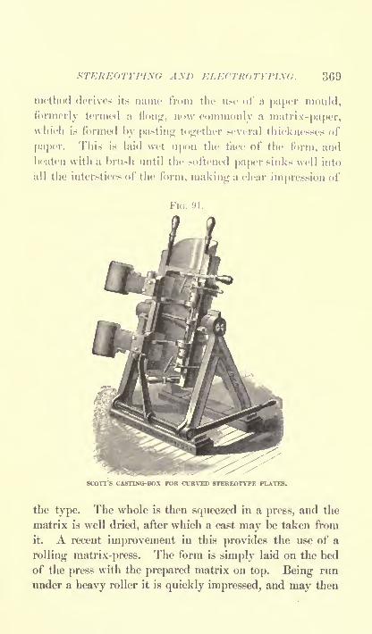
AXD ELECTROTYPIKQ. 369
method derives its name from the use of a paper mould,
formerly termed a Hong, now commonly 'a matrix-paper,which is formed by pasting together several thicknesses of
paper. This is laid wet upon the face of the form, and
Ix-aten with a brush until the softened pajKT sinks well into
all the interstices of the form, making a clear impression of
FIG. 91.
SCOTT'S CASTING-BOX FOR CURVED STEREOTYPE PLATES.
the type. The whole is then squeezed in a press, and the
matrix is well dried, after which a cast may be taken from
it. A recent improvement in this provides the use of a
rolling matrix-press. The form is simply laid on the bed
of the press with the prepared matrix on top. Being run
under a heavy roller it is quickly impressed, and may then

370 WONDERS OF MODERN MECHANISM.
be steam-dried and cast. Until 1893 the matrix, being
moist, had to be thoroughly dried before a good cast could
be obtained. Since then a dry matrix-paper has been in-
troduced, which is said to give good results.
In casting for daily papers, a curved plate is generally
desired, and this is obtained by the use of a curved cast-
ing-box, as shown in the cut (Fig. 91). Within this the
matrix-paper is simply curled into shape, and as the hot
metal is poured in its weight presses the matrix-paper into
correct form. When cast, the plate must be sawed, trimmed,
and bevelled, after which it is ready to be clamped on the
press. To such perfection has this process been broughtthat during the rush of getting off the last plates of a daily
paper not more than ten or twelve minutes elapse between
the time the form is brought to the matrix-press and the
plate is on the press ready for printing.
For job-work the plates are usually cast flat, and maybe screwed on to wood bases, though this method is goinginto disuse in favor of electrotypes.
Electrotype plates are made on a different principle. In
this process the first cast is made in beeswax. The wax is
melted in a kettle and poured out on a flat plate called a
moulding-case. When this moulding-case bears a film of
wax about the sixth of an inch in thickness it is placed in
the moulding-press. The form of type to be reproduced,
having been dusted with black lead (plumbago), is laid face
downward upon the wax surface and subjected to a mod-
erate squeezing in the moulding-press. The wax matrix
is next trimmed up on the edges and receives a thoroughcoat of plumbago. This matrix is then suspended in a
bath containing a solution of sulphate of copper (rarely
of nickel). A plate of copper is also suspended in the
bath, and a battery or small dynamo is connected. Elec-

STEREOTYPING AXD ELECTROTYPIXG. 371
trical deposition of copjxT on the wax follows, and after
some hours a sufficiently thick shell has Invn formed for
use. This thin electrotyj)e shell is then removed, washed,
cleared of wax, and taken to a furnace, where it is suf-
ficiently heated to allow a plate of tin-foil to adhere to the
back. The shell next goes to the backing- stand, where it
is laid face downward and a ladleful of electrotype metal
is ]X)iired on to a thickness of alx)ut one-sixth of an inch.
After cooling, this plate goes to various machines to be
planed to a certain thickness, trued up on the margins, etc.
It is then subjected to a critical examination, and trued
up by hammering on the back, after which it is ready to
be mounted on a block and printed from. It is often
desirable to make corrections in electrotype plates, which
may be accomplished by driving through a sharp punch,and inserting type to take the place of letters thus obliter-
ated. The type are crowded in to the level of the face of
the plate and cut off, so that they virtually lx?come a part
of the plate.
Walter Scott & Co. have introduced within a few
months the electroplate bending machine shown in the
illustration. The electroplate is introduced between the
resilient steel plates shown in the cut, a press-board being
put over the surface of the plate to prevent injury against
the steel. The two are then drawn round by the cylinders
between a series of small rolls hinged on chains at their
ends, these rolls being close together. They travel over
the surface of the steel plate, advancing forward at one-
half the speed of the plate. This difference in speed is
caused by the rolls that revolve between the steel plate and
the concave back. These rolls are supported their entire
length against the concave surface between which they
pass as the cylinder is turned round. The edge where the
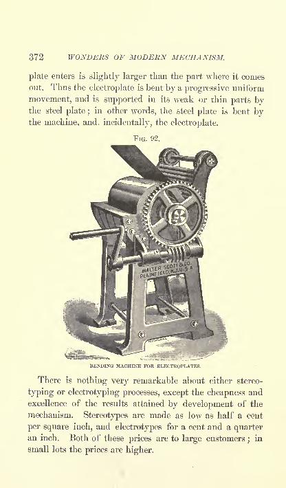
372 WONDERS OF MODERN MECHANISM.
plate enters is slightly larger than the part where it conies
out. Thus the electroplate is bent by a progressive uniform
movement, and is supported in its weak or thin parts bythe steel plate ;
in other words, the steel plate is bent bythe machine, and. incidentally, the electroplate.
FIG. 92.
BENDING MACHINE FOR ELECTROPLATES.
There is nothing very remarkable about either stereo-
typing or electrotyping processes, except the cheapness and
excellence of the results attained by development of the
mechanism. Stereotypes are made as low as half a cent
per square inch, and electrotypes for a cent and a quarteran inch. Both of these prices are to large customers
;in
small lots the prices are higher.

SUGAR-MAKING MACHINERY. 373
SUGAR-MAKING MACHINERY.
The Mysteries of Vacuum-Pans, Triple Effects, Centrifugal
Machines, Mixers, Defecators, Charcoal Filters, etc.
THE world's supply of sugar comes almost wholly from
the sugar-cane, which grows most abundantly in Cuba and
the Sandwich Islands. The sugar is obtained by express-
ing the juice, expelling the water therefrom by evaporation,
throwing out the remaining molasses, and allowing the
resultant sugar to crystallize. The theory is extremely
.simple, but the perfection which the mechanism has obtained
within recent years makes the process apjK*ar complicated.
When the sugar-cane is brought to the mill it is dunifKil
on a cane-carrier, which is nothing but an endless travelling
conveyor, formed of wood slats or boards, carried by two
endless chains. It is perhaps six feet wide in the larger
sizes, and feeds the cane slowly to the cane-cutter, if one
be used, such cutters being not absolutely necessary to the
process, though a decided advantage. This cutter consists
of two large corrugated rolls made of iron, but havingsteel rings on the face which are so cast as to present cor-
rugations or undulations of surface of a depth of two
inches and a length of six inches. These corrugations are
so zigzagged that a piece of cane cannot pass throughwithout being broken to at most six inches of length.
Krajewski, Pesant & Co., of New York, control the
market in these machines by virtue of a patent on the
corrugations. About sixty per cent, of the juice is ex-
pressed from the cane in passing through the cutter.
The cane-mill or sugar-mill, as it is less properly
called consists of three heavy cast-iron rolls, between

374 WONDERS OF MODERN MECHANISM.
which the cane is passed, they being set about half an inch
apart. The top roll is called the king-roller, the lower
roll, to which the cane is fed, the cane roller, and the
other lower roll the bagasse- roller. These rolls in manu-
facture are slightly scored by the lathe-tool, so as to preventsmoothness and cause them to grip the cane instead of
sliding over it. The upper roll is the largest, and it is
sometimes thirty-eight inches in diameter, though thirty-
six is the common size. A guide-piece or returning-knife
is placed between the lower rolls to turn the cane from the
cane-roll so that it will pass over the bagasse-roll. Themill is driven by enormous gearing, and is made very
heavy in all its parts, because there is no telling to what
strains it may be subjected. The escaping juice flows into
a tank below. If the juice is not thoroughly expressed
by one crushing it is put through the mill again, after
which it is thrown aside to be used as fuel to feed the flame
under the boilers of the establishment.
The juice in the tank under the mill is in a quite impure
condition, and is pumped through strainers to a higher tank
from which it is fed by gravity to the defecators. This
consists of a large open pan or pot, in which a small
quantity of lime is thrown to assist in settling the impuri-
ties. It is slightly heated by steam, which coagulates the
albumen. From the defecator the juice is drawn off in
such a manner as to leave the scum and settlings behind.
The next process is the boiling of the juice to evaporate
the water, which at this stage forms seven-eighths or more
of the juice. The old method of doing this was to flow
the liquid through a series of open pans set upon a furnace.
Norbert Rillieux, of New Orleans, invented the vacuum-
pan process, which is so much better that it has entirely
superseded the other. It has been much improved, and

SUGAR-MAKING MACHINERY. 375
the type commonly used now Is called the utriple effect,"
IxTause three vacuum-pans are used. If four pans are
used it is a"quadruple effect," or any Dumber of pans
al>ove one is calledumultiple effect." These vacuum-
pans are it-ally large cylindrical tanks, round-topped, and
having a big pijK1 in the top for conveying the steam to
the next pan. Inside is a huge drum, with seven hundred
to one thousand cop|>er tubes, each about two inches in
FIG. 93.
juici ro OAH..
176-

376 WONDERS OF MODERN MECHANISM.
and boiling. The steam that comes off the first vacuum-
pan is led to the drum of the second pan, where it boils
the juice brought in from the first pan. A better vacuumis maintained in the second pan, and therefore the steam
which has now fallen to 160 or 175 is still sufficient to
further boil the liquor. The steam from the second pan
passes on to the third pan in the same manner, and here
the vacuum is made as perfect as possible, partly by
pumping and partly by condensing the steam. The juice
is flowed from one pan to another by taking advantage of
the difference in pressure, so that no pumping is necessary.
While there is no theoretical limit to the reduction in
the consumption of steam due to increasing the number
of vacuum-pans in a multiple effect, the practical limit is
soon reached. The gain in economy from each additional
vessel is a rapidly-falling quantity, and is soon overtaken
by the extra cost, complication, and loss by radiation,
which are practically constant for each addition, though
partially compensated for by the reduced capacity of the
condenser and air-pump, rendered permissible by the re-
duction in the volume of vapor discharged from the last
vessel. This explains the apparent anomaly that the larger
the number of vessels in the series, the smaller the con-
denser and air-pump required. In practice, with heatingsteam at five to ten pounds pressure, as common in sugar-
works, triple effects are almost universally employed,
having been found to be more economical than the double,and quite as satisfactory as the more costly quadrupleeffect. A type different from that illustrated has been used,
having horizontal instead of vertical pans, with tubes
about twelve feet long, provided with steam chambers
projecting from the main shell. The steam is in the tubes,
and the liquor surrounds them. The construction is

SUOA R-MA KIXG ^fACHIXER V. 377
cheaper than the vertical, but less effective. Some French
makers have graduated the size of" the pans, giving in-
creased heating surface as the juice increased in intensity,
but the advantage gained has been so trifling that the idea
is not copied.
It should be noted that the temperature differences of the
triple effect are automatically adjusted. When first built,
it was thought necessary to add valves, by which an at-
tendant could add steam when and where he thought itO
necessary. This proved to be a mistake, as should a ves-
sel from any cause fail to condense the vajx)r as fast as
it comes forward from the previous pan, the vapor will
accumulate and the pressure and temperature increase,
causing a twofold correction.
Within a few years two new designs of triple effects have
been placed on the market, the Yaryan and the Lillie. In
both of these the leading idea is, instead of filling the
heating tubes with liquor, to pass only a small stream
through a considerable length of steam-heated tube, and
as far as practicable to cause this liquor to form a thin film
over the surface of the tul>e.
After passing through the triple effect, the juice, which
is now sufficiently thickened to be called syrup, is clarified
by further boiling and skimming, as there remain in it im-
purities that are more easily removed at this stage than
before reaching the triple effect. The clarified syrup is
then pumped to another vacuum-pan, where the final
evaporation takes place. By this time it is so free from
moisture that it forms a sticky mass that flows with greatslowness and difficulty. At the bottom of the final panis the strike-valve, which is a hole sixteen or eighteeninches in diameter, through which the pasty mass is drawn
off, the operation being termed a "strike." The mass,

378 WONDERS OF MODERN MECHANISM.
which is now a mixture of sugar and molasses, is passedinto cooling cars, where the sugar begins to crystallize, and
the longer it stands, up to a certain point, the larger will
be the crystals. A mixer, having rotating paddles, is next
employed to stir the mass, after which it passes to the cen-
trifugal machines, and the molasses is entirely got rid of by
centrifugal force, which throws it out while retaining the
grains of sugar. The centrifugal machine has an outer
case of metal, within which is a rotating basket, so perfo-rated that the juice has a chance to flow away. The pullingof a lever starts the rotating basket, in which perhapstwo hundred pounds of sugar have been placed, and it
soon attains a speed of one thousand revolutions per min-
ute. Three or four minutes of this rapid whirling are
sufficient to remove all traces of moisture.
Sugar so made is nearly white in color, and in fit
condition for immediate use, but fashion has ordained that
it shall be refined or whitened, a process that rather detracts
from the saccharine qualities of the sugar, but which ren-
ders it of more commercial value because it looks better.
The first process in the refining of sugar is to dissolve it
in hot water in a cistern. The liquor is then pumped upinto tanks called blow-up pans, where it is treated much as
the juice was in the defecator. The liquor next goes
through a series of five or six long cylindrical filters of
animal charcoal and bone-black. Then it goes into a
vacuum-pan to be evaporated, and later to a centrifugal
machine, from which it emerges as the granulated white
sugar of commerce. If loaf-sugar is desired, however,instead of going into the centrifugal machine, the syrupis poured into moulds, and allowed to cool. The mould
of sugar is then run under a gang of small saws, set the
distance apart that the lumps are to be. These saws first
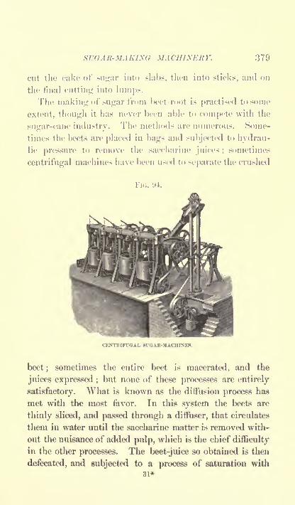
SUGAIt-)TAKL\G MACHINERY. 379
cut the cake of sugar into slabs, then into sticks, and on
the final cutting into lumps.
The making of sugar from l>eet-r<M)t is practised to some
extent, though it has never been able to coinjK'te with the
sugar-cane industry. The methods are numerous. Some-
times the beets are placed in bags and subjected to hydrau-
lic pressure to remove the saccharine juices ;sometimes
centrifugal machines have Ixjen used to separate the crushed
FIG. 94.
CENTRIFTOAL 8TGAROIACHIXE8.
beet; sometimes the entire beet is macerated, and the
juices expressed ; but none of these processes are entirely
satisfactory. What is known as the diffusion process has
met with the most favor. In this system the beets are
thinly sliced, and passed through a diffuser, that circulates
them in water until the saccharine matter is removed with-
out the nuisance of added pulp, which is the chief difficulty
in the other processes. The beet-juice so obtained is then
defecated, and subjected to a process of saturation with
31*
380 WONDERS OF MODERN MECHANISM.
carbonic-acid gas. The juice so carbonated then goes to a
settling-tank. It may then be filtered and evaporated in
much the same manner as the juice extracted from the
cane.
The use of sugar steadily increases, though its future
production as an industry is much clouded by trusts,
politics, tariffs, and revolutions.
THE EMERY TESTING-MACHINE.
A Mechanism indicating with Equal Facility the Breaking Strain
of a Hair or an Egg-shell and the Force required to break a Mas-sive Steel Link.
THE great extent to which iron and steel now enter
into the construction of large and valuable machines and
structures has greatly increased the importance of accu-
rately testing the materials used, in order that there maybe no misconception of the strength of parts, with a result-
ant possibility of danger to those who come in contact with
them. The margin between the breaking strain of a part
or mechanism and the strains which it is liable to encounter
in actual use is often ten to one that is to say, ma-
chinery is designed to be ten times as strong as theoreti-
cally it need be to do the work. In machines like bicycles,
however, where lightness is especially in demand, the factor
of safety may be and is reduced to five to one, and even
less. Some makers advertise that they test the cranks of
their cycles to a strain of six hundred pounds. In starting
a bicycle the ordinary man will apply a pressure of a hun-
dred and fifty pounds on one of the cranks, so that the
factor of safety in such a case is only four to one. In high

THE EMERY TESTiyQ-MACHIXK 381
buildings, where time is sure to create some difference in
the strength of the structural steel, and where the lives of
hundreds of occupants dejHMid upon its solidity, the factor
of safety should be as great as eight or ten to one. The
same is true of elevated railways, bridges, and other
structures where accidents would be peculiarly disastrous
and destructive to life.
It follows, of course, that engineers have always paid
great attention to the quality and strength of their mate-
rials, and have tested them in the best manner known.
Within the last filly years a variety of testing-machines
have been manufactured, all of which seem crude in com-
parison with the Emery hydraulic testing-machine. Thev
were built like scale-beams or stout weighing-machines,and in some of the early forms the balance-weights were
scrap-iron, which flew all over the shop when the sj>ecimen
under examination broke. As it is usual to strain speci-
mens to the breaking-point, it can be understood that
dodging was one of the first requisites of a good workman
with one of these machines. A feature common to all of
them was the steel-yard balance, resting on a knife-edge.
The best of these did very well for small work, and are so
used all over the world to-day, but for large and heavywork they are inadequate, and when the knife-edges be-
come dulled, they are rendered inaccurate.
It was this state of affairs which induced Mr. A. H.
Emery to study out new lines for a machine equal to
the demands of modern machinery constructors. To say
that he has succeeded is putting it mildly. What the
steam-hammer was in its day to the forger, so is the Emery
testing-machine to the mechanical engineer of to-day. It
will exert a pressure of one million pounds, and measure
it with perfect accuracy, and the next instant crush an egg-

382 WONDERS OF MODERN MECHANISM.
shell and record the minute power exerted. In a recent
government test one of these machines pulled apart a
forged iron link, five inches in diameter between the eyes,
at a strain of seven hundred and twenty-two thousand
eight hundred pounds, and immediately afterwards pulleda horse-hair slowly in two, registering the facts that it
stretched thirty per cent, before breaking, and withstood
sixteen ounces of strain. What other machine is there
that could stand the rack of such enormous strains without
deterioration ?
William Sellers & Co., the owners of the Emery patent,
have somewhat improved the machine since its first con-
ception, and we will examine it in its latest form. Its
essential peculiarity is the method by which the stress pro-duced upon the piece tested is conveyed to the scale and
accurately weighed by mechanism that is practically fric-
tionless, and not subject to wear, and hence records everyincrease in strain without loss by friction. This is accom-
plished by the use of water in a flat-closed cylinder called
the hydraulic support. The principle involved is this : If
we take a cylinder of water standing on end, and place a
weight upon an absolutely tight plunger on top of the
water, and if we have a hole in the bottom of the cylinder
whose diameter is one thousandth of the top aperture of
the cylinder, upon which the weight rests, and if we then
measure the pressure of the water at the little hole in the
bottom, we have only to multiply it by one thousand to
get the weight of the load on the cylinder.
The means by which Mr. Emery produced an absolutely
tight cylinder operating without appreciable friction are
very ingenious, and will be understood by examining the
accompanying diagram of the weighing mechanism. A is
the hydraulic-support cylinder, the white space represent-

THE EMERY TESTING-MACHINE. 383
ing water;c is the piston, and 6 and dd are thin sheets of
metal. The piston rests on the lower sheet, and is secured
to the cylinder by the sheets dd, which are flexible, al-
lowing a movement of perhaps three thousandths of an
FKJ. 'J5.
DETAILS OF WEIGHING MECHANISM.
inch, which is all the motion needed between a full load
and no load. By this arrangement the fluid is entirely
enclosed, and no packing is required, and the friction is all
in the fluid. A tube connects the water-chamber of the
hydraulic support with a smaller and similar chamber, B.
The piston c' of this latter chamber acts through the block
H against the first lever C of the scale, which thus receives a
fraction of the load upon the piston c, of the large cylinder,
determined by the difference in size between the two hy-draulic cylinders A and B, which in practice is much
greater than that shown in the diagram.At the upper left hand of the larger figure in the diagram
y

384 WONDERS OF MODERN MECHANISM.
will be observed a row of figures, and au upright scale
marked by a long needle, F. When the hydraulic cylindersexert a pressure upon the first lever (7, this pressure is com-
municated by the arm D to the lever E of the poise-frame.It will be observed that the lever E rests on a knife-edge like
the long beam of any ordinary weighing-machine. Fromthis leverE depend three weight-holders technically termed"poise-frames'
7 and marked N. These have an upper cross-
head 8 (see left figure) and a lower cross-head T united bythree vertical bars disposed at equal intervals about the
cross-heads. These bars are provided on their inner faces
with short projecting brackets, V, having a horizontal sur-
face and a bevelled surface corresponding with similar sur-
faces formed on the weights A, which are short cylinders or
rings with bevelled edges. The weights are carried by the
flat surfaces and centred by the bevelled surfaces. M is
a weight-frame of similar construction, for carrying the
weights when not in use. This weight-frame can be thrown
in and out of use by operating the hand-lever coupled to
the rod projecting from the cross-head R. The brackets on
the weight-frame bars are differently spaced from those on
the poise-frame, and when the weight-frame is at the top of
its stroke, it carries all of the weights clear of the poise-
frame;a small movement downward transfers one weight
to the poise-frame, the bevelled surfaces on the brackets
centring the weight if it becomes displaced sideways by a
too sudden movement;a further movement transfers an-
other, and so on. In the diagram the weights / and g are
shown carried by the poise-frame and k by the weight-
frame, while h is being transferred from one to the other.
The weights in the poise-frame on the left have a value of
one hundred pounds, those on the next frame one thousand
pounds, and on the last ten thousand, and the results

THE EMERY TESTING-MACHINE. 385
are read on the scale and by the figures shown in the slot
adjoining.
The indicator-needle F constitutes the final lever of the
scale, having a movement at the point of about two inches,
and this movement is calculated to lx three hundred thousand
times greater than the movement of the piston c in the
first hydraulic chamber, and in the largest sizes has Ixvn
made to indicate six million times as much. That the
machine does not suffer by related strains is shown by the
fact that this needle returns to exact zero after every trial,
whether strained in one direction by the compression of a
piece, or in the other by rending a sjxx'imen in two. Tiie
machine, as now manufactured, is diffeient in ap|>earance
Fio. 06.
THE EMERY TESTING-MACHINE TWO-HUNDBED-THOU8AND-POUND SIZE.
from the diagram just discussed. While the weighingmechanism is the same, it will be seen that the first
hydraulic cylinder is laid on its side, so as to constitute a
horizontal rather than a vertical machine. This change

386 WONDERS OF MODERN MECHANISM.
affords certain advantages in overcoming the enormous
shocks of recoil. In all but the smallest size of machine
the weighing-head, shown on the left of illustration, and the
straining-head, shown on the right, are made so as to rest
on wrought-iron girders, or frames, along which they can
slide without injury to anything. The machine here shown
is of the two-hundred-thousand-pound class, and back of
it, to the right of the weighing mechanism, is shown a
pump for delivering the water-supply to the straining-head,
which exerts the required force through the massive screws
called straining-screws, that connect the heads.
In operation, for the purpose of insuring that everythingabout the hydraulic chamber has a solid bearing, it is neces-
sary to produce an initial loading of about five per cent, of
the maximum load, for which purpose springs are supplied
to move the draw-bar in the direction in which the stress to
be applied to the specimen will move it, and after this the
scale is balanced by the sliding weights on the poise-beam.
When a specimen breaks the blow is carried to the massive
parts of the weighing-head, and is absorbed by them in
such a manner as to protect the more delicate hydraulic
supports, so that these machines can be used regularly for
breaking high steel specimens up to their full capacity
without risk of injury. The weighing-head is returned to
its place on the bed after movement due to recoil by a set
of spiral springs locked up in boxes secured to the bed.
The specimens to be broken are held in dies that close uponthem in such manner as to insure their protection against
breakage in the part weakened by the cutting of the gripped
part. When the specimen breaks it is always firmly held
in the dies, so that there is no danger from flying pieces,
which without such protection would be liable to scatter
with terrific force. It is surprising to note that when rup-

THE EMERY TESTING-MACHINE. 387
ture occurs the only noticeable noise is that of the breaking
piece, the machine readjusting itself and the parts sliding
on the frame almost noiselessly.
The water for Gyrating the straining-head is supplied
from the pump through the jointed pipes that stand up
high on the right of the machine. It will be seen that
they are connected with the straining-head, and being
arranged for either pressure or exhaust, their force may be
exerted either in compression or tension, or, in simpler lan-
guage, arranged so as to either push or pull.
The gearing on top of the straining head is designed for
operation either by hand or power, moving the head either
back or forth to accommodate the length of sj>ecimens.
This machine is considered by engineers to have reached
perfection in principle, and as marking an astonishing
advance over former types. Its invention necessitated the
construction of an exceedingly powerful and costly appa-
ratus, constructed on somewhat similar lines, for calibrating
the machines turned out and verifying by actual test the
accuracy of each individual machine manufactured. This
tester of testing-machines will indicate a variation of four
ounces in half a million pounds. A weight of two hun-
dred grains laid on the main platform of this remarkable
machine is sufficient to put in motion material weighingmore than twenty thousand pounds, as shown by a varia-
tion of the needle the fiftieth part of an inch, and the sen-
sitiveness is the same whether loaded or not loaded.
32

388 WONDERS OF MODERN MECHANISM.
THE SPECTROSCOPE.
A Wide- spread Field of Research opened up by an Instrument
that was at first little understood.
To that wonderful instrument, the spectroscope, we owe
nearly all the recent increase in knowledge of the stars. It
tells us of what they are made, and the direction and speed
in which they are journeying. Let us first consider what
the instrument is, and then the principles on which it
operates. In its simplest form it is a glass prism, through
FIG. 97.
METHOD OP OBTAINING A SPECTRUM.
which a ray of light is allowed to shine. This prism
disperses the light, giving the beautiful rainbow colors
that children admire. These colors arrange themselves
naturally in the order of red, orange, yellow, green, blue,
and violet, and their graduations, and form what is called
a spectrum. This spectrum is usually viewed through a
magnifying eye-piece, like that of a telescope. There is
also usually a minute scale, whose image is thrown uponthe spectrum to enable the observer to measure it. Instead
of the scale a fine wire or line of light from a slit may be
moved over the spectrum, and by means of a micrometer-

THE SPECTROSCOPE. 389
screen the movement or distance of any ]>oint of the spec-
trum from any other can Ix 1 read off. The tube through
which the light enters should be a coll imating tube that is,
a tnl>e having glass lenses that cause the rays of light to
enter in parallel lines. Instead of a simple prism, a train
of prisms or a diffraction grating is commonly used in the
bodv of the instrument. Such a grating may be one of
two kinds a transjwrent or transmission grating composedof glass, or a reflection grating made of brightly polished
speculum metal. Upon one of these, extremely fine lines
are ruled by means of a diamond point. To such j>erfec-
tion has the art of ruling these lines been brought that
twenty-eight thousand eight hundred and seventy-six have
been drawn within a single inch, this result being attained
by Professor Rowland, of Baltimore. These minute rulings
act as obstacles to the light, whether transmitted or reflected,
and generate secondary waves, which by their interference
produce a sj>ectrum that has the advantage of having its
different parts equally extended, which is not the case with
refraction spectra, because the violet end of the spectrum
obtained by a prism is more refracted than the red end,
and as a consequence the violet rays are relatively more
spread out, so that the amount of space occupied by these
rays is out of proportion to the relative difference of their
wave-length. This defect, which is termed the "irration-
ality" of the prismatic spectrum, is quite absent from that
obtained by means of the diffraction grating, as the forma-
tion of the spectrum has been seen in the latter case to be
solely dependent upon the different wave-lengths of the
respective rays.
If a Rowland concave grating is used no observing
telescope is required, a real image being formed that maybe thrown on a screen or photographic plate.

390 WONDERS OF MODERN MECHANISM.
In other instruments the telescope itself can be movedin the horizontal plane, and thus a fine wire across the
occular can be brought into exact coincidence with any
part of the spectrum, and the position may be seen by the
amount of motion of the telescope, which can be read off
FIG. 98.
PRINCIPLE OF THE SPECTROSCOPE. a, prism ; 6, telescope through which[the light
may pass ; c, magnifying eye-piece ; d, scale.
from a suitable scale on the stand. For astronomical use
the spectroscope has a still different form, and is attachable
to a telescope, through which the light of a star may be
received.
Owing to the way in which the rays are turned aside
from their path in the prism, the telescope and collimator
in the ordinary forms of spectroscope must be placed at an
angle to each other, but by an ingenious arrangement direct-
vision spectroscopes are made that have the two tubes in
line, so that they can be conveniently handled, or even
carried in the pocket. This is possible because crown and
flint glass differ in their power of refraction and dispersion.

THE SPECTROSCOPE. 391
The crown glass, being less dispersive, is used to bend
back the slightly refracted and much-dispersed rays of the
flint-glass prism, so that the central position of the dis-
persed ray comes to form a straight line with the incident
ray of the collimator.
The first investigation into the s{>ectrtini of which we
have record was conducted by Thomas Melvin, of Edin-
burgh, who published the result of his exj>eri incuts in
1752, in a paj>er entitled" The Examination of Colored
Flames by the Prism." After him came Wollaston, then
Fraunhofer, and Sir John Herschel, each of whom added
much to the world's knowledge of spectra. About 1830
the spectroscope was accepted as a useful instrument for
detecting substances in flames and for analyzing solutions
by noting their absorptive power on the light passing
through them.
Every one of the chemical elements, as iron, lead,
sodium, nitrogen, hydrogen, etc., when heated to a glowing
gas or vapor emits a light that is different from everyother element. The differences are not readily perceptible
to the eye, but seen through the sj)ectroscope they are
clearly separated. Each element exhibits a series of bright
narrow lines, always occupying certain definite positions,
which are different for each element. Zinc, for instance,
when vaporized and analyzed in the spectroscope exhibits
three blue lines and one red line; copper presents three
green lines; hydrogen gives double violet lines
;iron
presents an immense number of lines;and other metals
have their lines, all of which fall in different places in the
spectrum.
When a substance is heated red-hot it gives a continuous
glowing spectrum, but, as soon as it vaporizes, the spectrumforms into lines. If several substances are mingled the
32*

392 WONDERS OF MODERN MECHANISM.
spectrum appears in the same manner, and if vaporized the
substances under analysis will be revealed by their lines.
Minute quantities that would evade observation in any
ordinary analysis are readily found in this manner.
It was reserved for KirchhofF, the renowned physicist of
Heidelberg, to show to the world the real importance of
the spectroscope, in 1859, by explaining the true signifi-
cance of the relation of the bright bands of flames and
the dark lines of the solar spectrum. He identified the
dark lines at D in the sun's spectrum as identical with
the bright lines of sodium. The lines were dark instead
of bright because the strong light of the sun absorbed
those rays with which the vapor would shine alone. It
followed that if the sodium lines were recognized in the
sun's spectrum, others might also be found. By investi-
gating on this theory Kirchhoif by 1861 had identified
sodium, iron, calcium, magnesium, nickel, barium, copper,
zinc, and cobalt as existing in the sun.
Since Kirchhoff's time the examination of the solar spec-
trum has been extremely thorough, and nearly all of the
seventy or more elements known on the earth are knownto exist also in the sun. There have been found also two
unknown elements, which have been named helium and
coronium. Early in 1895, Lord Rayleigh, a British
physicist, announced that he had found helium on the
earth, in connection with a new gas, argon, previouslydiscovered by him. His discovery of helium was very
shortly confirmed by other physicists. Scientists are nowin hopes that coronium will be found also. Thus was
accomplished the wonderful result of finding a new sub-
stance ninety-five million miles away several years before it
was discovered on this planet.
The spectroscope tells us that there are immense quan-

THE SPECTROSCOPE. 393
tides of iron in the sun, more than two thousand iron
lines having been found in its spectrum. Sodium is also
there in quantities. Hydrogen exists in the exterior,
forming the gigantic red flames that astonished observers
until they were understood. Calcium, the metallic base of
limestone, is also present. All the familiar metals have
been identified except gold. Perhaps there has l>een a
corner in the sun's gold market lor some years, and the
yellow metal may lx> found later.
But the sun is only one of many stars, and each has a
spectrum to be examined, and it is one of the astonishing
features of this instrument that it is capable of receiving
the very faint light that falls from a single distant star
and separating it into a spectrum that may be read. In
such work it is necessary to use a large lens to condense
as many rays as possible. As the star appears only as a
jK)int of light, this involves the use of a cylindrical lens
in order to spread out the rays into a line of light which
can yield a spectrum having a visible breadth. On account
of the feebleness of the light, very few prisms can be used
in the train.
The stars are now undergoing classification according to
their spectra, and those placed in the same class all have
something in common. Those having very bright lines
generally exhibit much hydrogen and helium. When the
lines are bright instead of dark, as occasionally happens,
it is thought that the vapors surrounding the star may be
hotter than the interior, an anomalous condition of affairs
that cannot be accounted for satisfactorily. One classifica-
tion includes : First, a group in which the presence of
metals is prominent. Our sun comes under this head, also
Capella, the brightest star in Auriga. Second, the white
or bluish-white group, which is the largest, including such

394 WONDERS OF MODERN MECHANISM.
luminous stars as Sirius and Vega. These give a spectrumrich in blue rays, and marked by four dark lines due to
hydrogen. They are believed to have dense atmospheres,
under considerable pressure, and to be hotter and less dense
than our sun.
The red and orange-colored stars form the third group,
of which iron is a prominent constituent, and which exhibit
absorptive atmospheres. They are believed to be astro-
nomically old, and in a state of cooling, as their spectra
resemble those of the sun's spots.
While learning the age and constituents of the stars bymeans of this wonderful spectroscope, that tells the tale
over countless miles of space, by analyzing light-waves
that have been years on their way, we gather yet more
astonishing news from the observations. When a star is
approaching or receding from us there is a marked shifting
of the lines of the spectrum to one side. If the star's
movement be towards us, the lines are shifted to the blue
end of the spectrum ;if away from us, to the red end.
The amount of the shifting is the measure of the speed.
Our eyes are so constituted that a certain number of vibra-
tions of the ether per second are interpreted by the brain
as a color, as red. Each color of the spectrum is the
result of a corresponding number of vibrations per second
of the wave-lengths of light. If a star is naturally of a
green color, and if it neither approaches nor recedes from
us, it will still appear green ;but if it be coming towards
us, the vibrations are altered and it grows blue. If the
speed be still greater it is indigo, or if the velocity was
enormous it would be violet. And if the star is recedingit takes the color of the other half of the spectrum ;
if
slowly, it grows yellowish ;if much faster, orange ;
and if
at marvellous speed, even red. Some stars are known in

THE SPECTROSCOPE. 395
this way to move at a rate of more than one hundred miles
per second, and astronomers are satisfied that the pos-
sibility of error in these estimates is l>elow five per cent.
Argol, which is a very noticeable star in Perseus, has been
called the Demon Star, because of its irregularities, visible
to the naked eye. It retains a uniform lustre lor two daysand ten hours, as a star of the second magnitude, then it
wanes and weakens to less than half of its former bright-
ness;but after a period returns to its original lustre, only
to repeat the performance as regularly as the sun rises.
This puzzled astronomers until the sj>ectroseo|>e showed
that during the bright |>criod Argol moved towards us as
rapidly as twenty-six miles a second, and during the dull
period receded at a like speed. The explanation, then, is
that Argol simply revolves in a small elliptical orbit.
The moon and planets, which shine by light reflected
from the sun, return to our ol>servation the solar spwtrummodified more or less according as they have absorbent
atmospheres. The moon's spectrum is precisely the same
as the sun, which is one of the reasons for believing that
the moon is entirely destitute of an atmosphere. The
spectra of the largest planets convey to us a hint that
they are still at comparatively high temperatures. Manynebula? have been proved by the spectroscope to be princi-
pally gaseous in their formation, wrhile the very diapha-nous nuclei of comets are shown to be similarly formed.
The spectra of comets' tails convey the information that
they, like the planets, shine by reflected light.
Of all the inventions of the century the possibilities
of the spectroscope are greatest and grandest. It has
opened up entirely new fields of research for scientists.
We can see the great suns hurrying hither and thither, on
some divine plan that we have not yet fathomed. But the

396 WONDERS OF MODERN MECHANISM.
spectroscope appears to be the key, and time and patience
will give us the secret of motion of these mysterious orbs,
just as we have learned of the motions of the system of
planets of which our earth forms a part.
MISCELLANEOUS INVENTIONSThe Theatrophone, Convertible Theatre, Big Pleasure-Wheel,
Rain-Making Appliances, Hydraulic Accumulators, Rope Ma-chinery, and Minor Mechanisms.
THERE are very many more wonderful mechanisms
than can be mentioned within the compass of this book.
The ingenuity of mankind continues to prompt to new
efforts, and the ideas of one inventor furnish food for an-
other, so that the increase is constantly augmented. Afew of these are briefly noted here by way of conclusion.
There exists in Paris a Theatrophone Company, whose
name will suggest their business to any student of Greek.
Since 1882 they have been connecting their patrons by
telephone with the various theatres of the city, and their
mechanism has been perfected so as to give a satisfactory
service. The first experiment was made in 1881, twenty
pairs of transmitters being placed on the stage of an opera-
house, on either side of the prompter's box and in front of
the footlights. A battery was connected, and double wires
led to a line of receivers. Each receiver connected with a
transmitter on the right of the stage and with another on
the left of the stage, so that the listener could hear equally
well, no matter on which side the action might be taking
place. The result was so satisfactory that the above-named
company was formed and the system developed. Theynow have a central office and seven radiating lines of

MISCELLANEOUS INVENTIONS. 397
wires, to which arc connected hotels, restaurants, and
dwellings. A special room is provided for them in each
of the theatres, with an attendant to see that all the trans-
mitters are maintained in working order. At the (vntrnl
office are two young women one to talk to subscrilKTs
who may desire to have this theatre or that one connected,
and the other to make the connections and watch to see
that all the lines are working projx'rly. There are sjHH'ial
contrivances for regularly verifying the condition of the
lines. Between the acts the Theatrophone Company con-
nects subscribers with music of its own production, so that
something is to be heard the whole evening. By these
means the company has maintained a reliable service, and
secures good prices, varying according to the numl>er of
theatres connected. The receiving telephones are arrangedfor individual use like an ordinary telephone, or with a
wide-mouthed funnel to disperse the sound so that several
persons can hear at the same time. No doubt the com-
pany will shortly, if they have not already, add the
kinetoscope in some manner to their service, so as to givea more perfect representation of the performances.
There is another novelty in the theatrical world that
has just been added to the attractions in that progressiveSouth American city, Buenos Ayres. It is a mammothconvertible theatre, which actually seats five thousand per-
sons, and is provided with elevators to carry the patrons of
boxes and galleries from the level of the street to anyof the tiers above. By means of ingenious convertible
mechanism the pit can be almost instantly transformed into
a circus ring, a racing track, a ring for a bull fight, or a
miniature lake for a swimming contest.
The enormous revolving pleasure-wheel built recently
at Earl's Court, London, is most interesting from a me-

398 WONDERS OF MODERN MECHANISM.
chanical point of view. It is three hundred feet high, and
constructed of steel throughout. The axle is a steel tube
seven feet in diameter, and thirty-five feet long, beingmade in three sections of one inch steel plates. There are
forty passenger-cars, arranged as were the cars in the big
Ferris wheel in Chicago. Each is twenty-four feet long,
and seats thirty persons, so that the total number of per-
sons who may ride at one time is twelve hundred. Ten of
the oars are called first-class, and five of this ten are for
smokers. Thirty are denominated second-class. The cars
are loaded with passengers from eight levels near the
ground, so that all the cars may be filled at five stoppages.
The rotation of the wheel is accomplished by two endless
chains, each over a thousand feet in length and of eight
tons weight. These chains run in brackets on the extreme
outer edge of the wheel-rim, and pass underground to
driving pulleys. The power is obtained from two fifty-
horse-power engines. On a level with the axle are two
promenade saloons, reached by spiral stairs, and connected
by a passageway leading right through the axle. Properbalance of the structure is maintained by the filling and
emptying of water-tanks in the bottom of the passenger
cars. The water is pumped up to the top of the columns,
where are located storage-tanks, and the car-tanks are filled
on the descending side. The erecting of the wheel involved
a number of difficulties. The columns were first erected
and the axle put in place. One of the forty sections of the
wheel was then hung on, hauled to one side and the next
one hung on. The work proceeded in this manner until
one-half of the wheel was in place. The upper half had
to be put on with the aid of scaffolding. There were no
accidents during the erection, though a violent gale sprung
up when the work was about half complete.

MISCELLANEOUS INVENTIONS. 399
Rain-making is a business that has not received much
sanction from scientists. Yet it is largely carried on in the
Mississippi Valley, especially in the States of Kansas,
Nebraska, Iowa, and Oklahoma Territory. The prairie
settlers club together and hire some of the rival rain- makers
to l>cdew their district for prices ranging from two hundred
dollars cash to one hundred dollars down, and five hun-
dred dollars more when the rain comes. The most con-
spicuous of the rain-makers carries his apparatus in three
box-cars, locating one at each corner of a triangle of the
district that is to be deluged. The cars contain water-
tanks, gas-producing chemicals, and an electric battery, the
duty of the latter Ix'ing"to electrify the gases," whatever
that may mean. For three days the rain-makers send oft'
warm gas into the air, claiming that at a height of four
thousand to eight thousand feet it turns cold, drops, and
"causes a vacuum that attracts moisture and induces rain."
As a high wind may blow it off to one side, the rain-makers
are enabled to claim any rain that falls within three dayswithin a radius of fifty or sixty miles. Of course this is
wholly unscientific, but it pays. If the rain-makers would
discover a way of sending very fine dust particles into the
upper air, they might succeed in getting up a little shower
occasionally, but even this method, which is baed on scien-
tific theory, remains to be proved as effective in practice.
In all hydraulic systems accumulators are requisite to
meet sudden demands for extra power, and also for deter-
mining the pressure. In the Sellers hydraulic pump and
accumulator, here shown, will be observed a series of heavy
weights on the right. These are suspended on cross-pins
when out of use, but may be thrown into action by pullingout the pins. The weights when in use rest upon the plun-
ger in the hydraulic cylinder which they surround, andR 2 33

400 WONDERS OF MODERN MECHANISM.
their gravity is made to bear upon the column of water
within, this in turn being connected with the tank at the
left, where a pressure is kept up by means of the upright
cylinder pumps. The weight used regulates the amount
of the pressure in the tank, so that it may not alter with
sudden changes in the work performed.
FIG. 99.
SELLERS'S HYDRAULIC ACCUMULATOR.
Within a few years the manufacture of rope has been
entirely revolutionized, largely by one man, John Good, of
New York City. He has caused the old rope-walk to be

MISCELLANEOUS INVENTIONS. 401
superseded by automatic machines that manufacture the
finest twine and the largest cable without hand labor. Hehas recently added to his other inventions an electric bind-
ing-twine spinner, that does alx>ut double or treble the
work of the machines now in use. This will l>e introduced
as soon as present patents expire. Good's rope-machine, as
at present used, is really two separate machines, a former and
a laver. The former has a circular gauge-plate, full of small
holes, through which the threads from the bobbins are
introduced. Thence they pass to a revolving horizontal
capstan, which twists them into a cord that is gathered on
a reel. These reels are taken to the layer, which is much
larger than the forming-machine, and laid or twisted into
a thick rope by means of a revolving capstan, similar to
that of the former.
John A. Secor, an engineer of Brooklyn, New York,
claims to have invented a practical method of vessel pro-
pulsion that will do away with steam-engines, screws,
shafting, etc., on steamships, securing greater sjxxxl and
increased room. His plan is a modification of the princi-
ple of the rocket, which is propel led by the gases that it
shoots out backward. Mr. Secor proposes to use in a
vessel a stout, cannon-like cylinder, extending lengthwise
of the vessel and projecting into the water from the stern.
From this cylinder or cannon he fires, at regular intervals,
an explosive mixture of air and gas. This gas is manu-
factured from coal, and its explosion is managed as in a
gas- or petroleum-engine. Mr. Secor has experimentedwith a vessel one hundred feet long, using a firing-cylinder
ten feet long and eighteen inches in diameter. For a great
ocean steamer he would use a battery of these firing-cyl-
inders. His experiments and claims have attracted atten-
tion because of his standing as a mechanic, and because

402 WONDERS OF MODERN MECHANISM.
of the success of motors made on similar principles, which
are now coming into use for propelling bicycles and road-
wagons.It would be interesting to explore further, and note such
interesting machines as the electric weed-killer, that maybe attached to a locomotive and used to destroy the weeds
growing on or near the track by the burning of a strong
current;or the machine for dipping tin-plate, that handles
three crates of plate at one time, picks them off the car,
dips them in the molten tin, shaking them up and down a
few dozen times, then lifts them out, into a cleansing or
swilling tank, all automatically, by the power of steam;
or the envelope-machine, that gathers in a roll of paper,
some mucilage, and some green ink and turns out govern-
ment envelopes all cut, gummed, stamped, and tied up in
packs of twenty-five ;or any one of a thousand others :
but space forbids. We have gone far enough to gain a
glimpse of what man is doing and is likely to do in the
near future, and it is time to close the book.
FINIS.


UNIVERSITY OF CALIFORNIA LIBRARYBERKELEY
Return to desk from which borrowed.
This book is DUE on the last date stamped below.
FEb I 2 1954 LI
' " ~
.
MAY 1
APR 31987
rose. MAR 10*87
LD 21-100m-7,'52(A2528sl6)476
U.C. BERKELEY LIBRARIES
8001024084
- 8
933699
THE UNIVERSITY OF CALIFORNIA LIBRARY