
Help! They Don't Speak English Starter Kit for Teachers ... - ERIC
Upload
khangminh22Category
view
0download
0
Http://www.elegoo.com
1 / 116
THE POWER SUPPLY ULTIMATE STARTER
KIT TUTORIAL

Http://www.elegoo.com
2 / 116
Preface Our Company
Established in 2011, Elegoo Inc. is a professional manufacturer and exporter that is
concerned with the design, development production and marketing of arduino, 3d printers,
raspberry pi and STM32. We are located in Shenzhen which is known as Chinese Silicon
Valley. All of our products comply with international quality standards and are greatly
appreciated in a variety of different markets throughout the world.
Our official website is: Http://www.elegoo.com
Our USA amazon shop is: Http://www.amazon.com/shops/A2WWHQ25ENKVJ1
Our Tutorial The tutorial is for beginners. In the tutorial, you can learn how to use arduino controller board,
sensors and components. You can also learn the basic knowledge of all the parts. But if you
want to study arduino systematically, we recommend you to buy the book "Arduino
Cookbook" which is written by Michael Margolis.
Our after-sales If you have any question or suggestion about our company, product or tutorial. Please send
us a email. Our email address is [email protected]
We will very appreciate and improve ourselves so that we can offer you a better service.

Http://www.elegoo.com
3 / 116
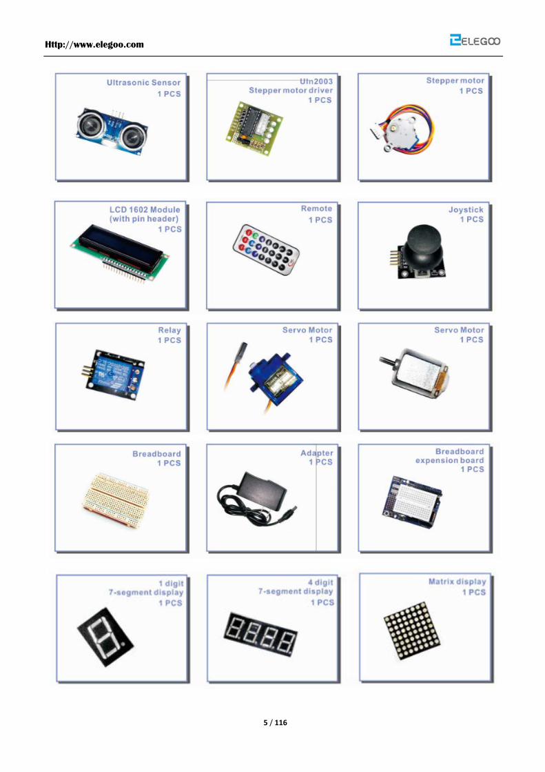
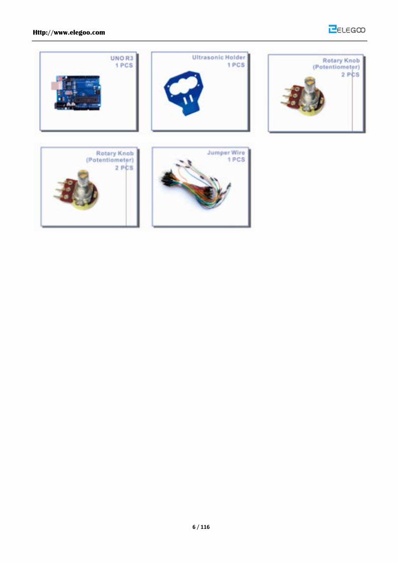
Packing List

Http://www.elegoo.com
4 / 116
Http://www.elegoo.com
5 / 116
Http://www.elegoo.com
6 / 116
Http://www.elegoo.com
7 / 116
Lesson Listing Lesson 0 Installing IDE ............................................................................................................................................. 8
Lesson 1 Add Libraries ...........................................................................................................................................16
Lesson 2 Blink.........................................................................................................................................................20
Lesson 3 LED ...........................................................................................................................................................27
Lesson 4 RGB LED ...................................................................................................................................................33
Lesson 5 Digital Inputs ...........................................................................................................................................39
Lesson 6 Eight LED with 74HC595 .........................................................................................................................43
Lesson 7 The Serial Monitor ..................................................................................................................................49
Lesson 8 Photocell .................................................................................................................................................55
Lesson 9 Making Sounds .......................................................................................................................................59
Lesson 10 Passive Buzzer .......................................................................................................................................63
Lesson 11 Relay Module ........................................................................................................................................67
Lesson 12 74HC595 And Segment Display ............................................................................................................70
Lesson 13 Four Digital Tube Segment Display ......................................................................................................75
Lesson 14 Servo .....................................................................................................................................................78
Lesson 15 LCD Display ...........................................................................................................................................81
Lesson 16 Thermometer ........................................................................................................................................86
Lesson 17 Ultrasonic Sensor Module ....................................................................................................................90
Lesson 18 Analog Joystick Module ........................................................................................................................94
Lesson 19 IR Receiver Sensor ................................................................................................................................97
Lesson 20 LED Dot Matrix ................................................................................................................................... 101
Lesson 21 MPU6050 Module .............................................................................................................................. 106
Lesson 22 DC Motors .......................................................................................................................................... 110
Lesson 23 Stepper Motor ................................................................................................................................... 115

Http://www.elegoo.com
8 / 116
Lesson 0 Installing IDE
Introduction
In this lesson, you will learn how to setup your computer to use Arduino and how to set about
the lessons that follow.
Installing Arduino (Windows)
The Arduino software that you will use to program your Arduino is available for Windows,
Mac and Linux. The installation process is different for all three platforms and unfortunately
there is a certain amount of manual work to install the software. There is no installer program,
but rather you have to unzip a folder which gives you an Arduino folder that contains the
Arduino program and a few other items.
In a separate step, you must then install USB drivers, which is the only bit that is a bit fiddly.
Get started by visiting the Arduino.cc website. As of April 2014 we suggest v1.05 as 1.5 is still
in beta. If 1.5 is no longer in beta when you read this you can try it out!
Start by downloading the zip file for Windows. There is only one version of the software,
whether you are using Windows XP through to Windows 7.

Http://www.elegoo.com
9 / 116
When the zip file has downloaded, extract the contents onto the Desktop, by right-clicking
on the file and selecting 'Extract All...' from the pop-up menu.
Next select your Desktop and click 'Extract'. You can move it somewhere else onto your
computer later, just by moving the folder, but for now, just keep it on the Desktop.
The Arduino folder contains both the Arduino program itself and also the drivers that allow
the Arduino to be connected to your computer by a USB cable. Before we launch the
Arduino software, you are going to install the USB drivers.
Plug one end of your USB cable into the Arduino and the other into a USB socket on your
computer. The power light on the LED will light up and you may get a 'Found New Hardware'
message from Windows. Ignore this message and cancel any attempts that Windows makes
to try and install drivers automatically for you.
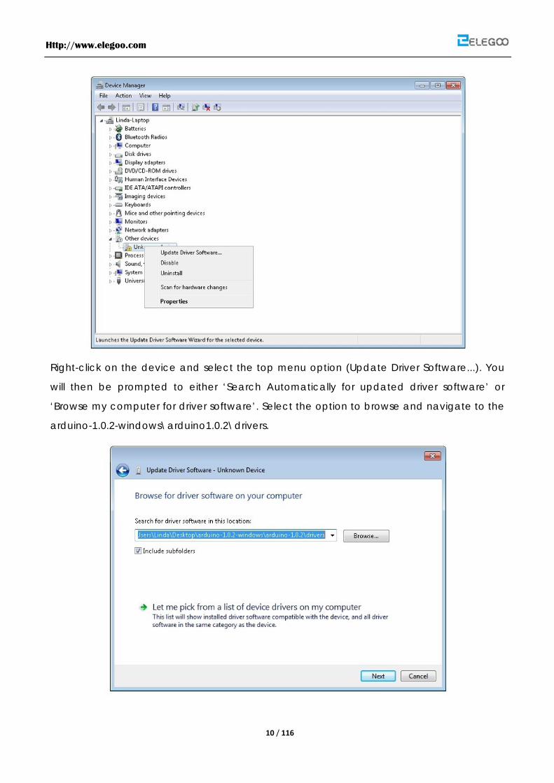
The most reliable method of installing the USB drivers is to use the Device Manager. This is
accessed in different ways depending on your version of Windows. In Windows 7, you first
have to open the Control Panel, then select the option to view Icons, and you should find
the Device Manager in the list.
Under the section ‘Other Devices’ you should see an icon for ‘unknown device’ with a little
yellow warning triangle next to it. This is your Arduino.
Http://www.elegoo.com
10 / 116
Right-click on the device and select the top menu option (Update Driver Software...). You
will then be prompted to either ‘Search Automatically for updated driver software’ or
‘Browse my computer for driver software’. Select the option to browse and navigate to the
arduino-1.0.2-windows\arduino1.0.2\drivers.

Http://www.elegoo.com
11 / 116
Click 'Next' and you may get a security warning, if so, allow the software to be installed.
Once the software has been installed, you will get a confirmation message.
That's it, you are now ready for action, so Skip the next section on installation on Mac and
Linux and move straight on to 'Boards and Ports'.
Installing Arduino (Mac and Linux)
Get started by visiting the Arduino.cc website and downloading the matching IDE for your
operating system. As of April 2014 we suggest v1.05 as 1.5 is still in beta. If 1.5 is no longer in
beta when you read this you can try it out!
Http://www.elegoo.com
12 / 116
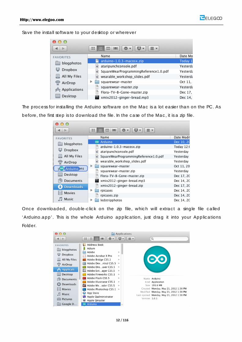
Save the install software to your desktop or wherever
The process for installing the Arduino software on the Mac is a lot easier than on the PC. As
before, the first step is to download the file. In the case of the Mac, it is a zip file.
Once downloaded, double-click on the zip file, which will extract a single file called
‘Arduino.app’. This is the whole Arduino application, just drag it into your Applications
Folder.
Http://www.elegoo.com
13 / 116
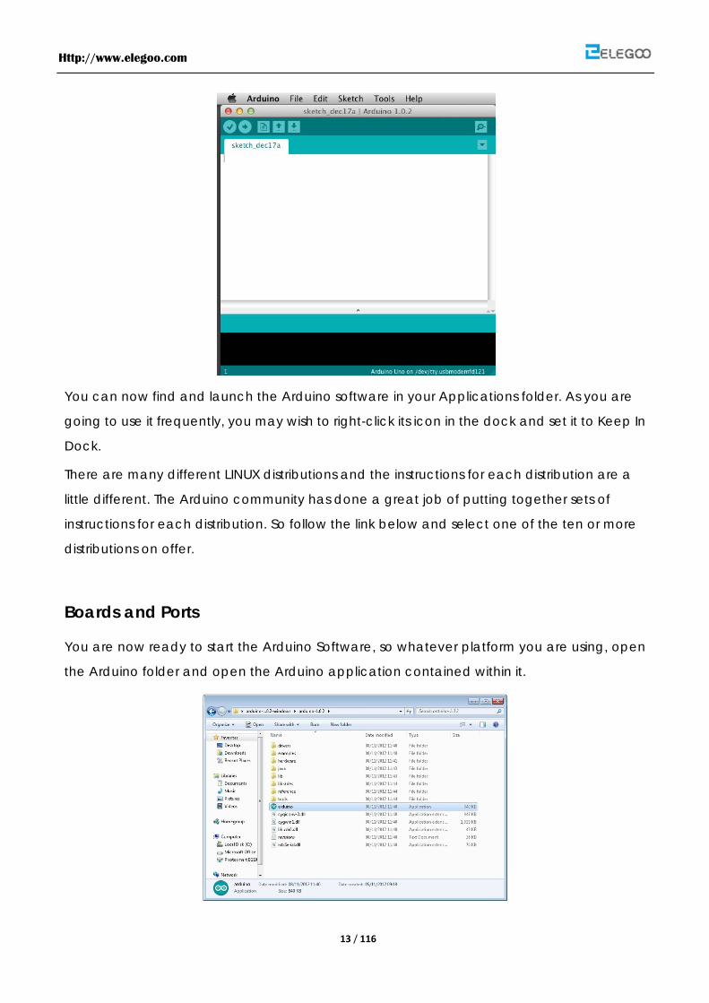
You can now find and launch the Arduino software in your Applications folder. As you are
going to use it frequently, you may wish to right-click its icon in the dock and set it to Keep In
Dock.
There are many different LINUX distributions and the instructions for each distribution are a
little different. The Arduino community has done a great job of putting together sets of
instructions for each distribution. So follow the link below and select one of the ten or more
distributions on offer.
Boards and Ports
You are now ready to start the Arduino Software, so whatever platform you are using, open
the Arduino folder and open the Arduino application contained within it.
Http://www.elegoo.com
14 / 116
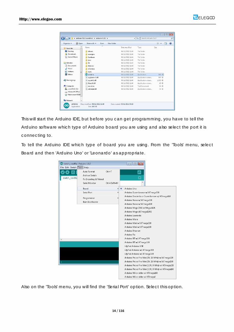
This will start the Arduino IDE, but before you can get programming, you have to tell the
Arduino software which type of Arduino board you are using and also select the port it is
connecting to.
To tell the Arduino IDE which type of board you are using. From the 'Tools' menu, select
Board and then 'Arduino Uno' or 'Leonardo' as appropriate.
Also on the 'Tools' menu, you will find the 'Serial Port' option. Select this option.
Http://www.elegoo.com
15 / 116
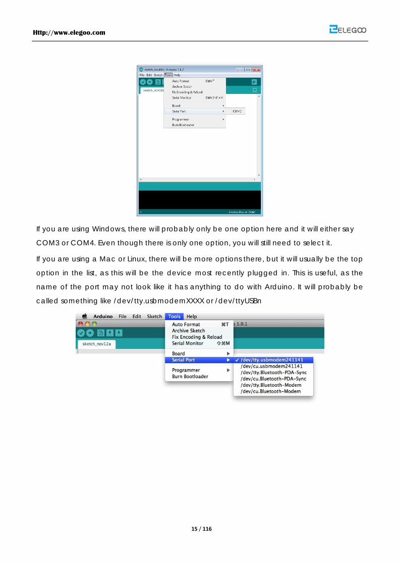
If you are using Windows, there will probably only be one option here and it will either say
COM3 or COM4. Even though there is only one option, you will still need to select it.
If you are using a Mac or Linux, there will be more options there, but it will usually be the top
option in the list, as this will be the device most recently plugged in. This is useful, as the
name of the port may not look like it has anything to do with Arduino. It will probably be
called something like /dev/tty.usbmodemXXXX or /dev/ttyUSBn

Http://www.elegoo.com
16 / 116
Lesson 1 Add Libraries
Once you are comfortable with the Arduino software and using the built-in functions, you may want to extend the ability of your Arduino with additional libraries.
What are Libraries?
Libraries are a collection of code that makes it easy for you to connect to a sensor, display,
module, etc. For example, the built-in LiquidCrystal library makes it easy to talk to character
LCD displays. There are hundreds of additional libraries available on the Internet for
download. The built-in libraries and some of these additional libraries are listed in the
reference. To use the additional libraries, you will need to install them.
How to Install a Library
Using the Library Manager
To install a new library into your Arduino IDE you can use the Library Manager (available
from IDE version 1.6.2). Open the IDE and click to the "Sketch" menu and then Include
Library > Manage Libraries.

Http://www.elegoo.com
17 / 116
Then the library manager will open and you will find a list of libraries that are already installed
or ready for installation. In this example we will install the Bridge library. Scroll the list to find it,
then select the version of the library you want to install. Sometimes only one version of the
library is available. If the version selection menu does not appear, don't worry: it is normal.
Finally click on install and wait for the IDE to install the new library. Downloading may take
time depending on your connection speed. Once it has finished, an Installed tag should
appear next to the Bridge library. You can close the library manager.
You can now find the new library available in the Include Library menu. If you want to add
your own library open a new issue on github.

Http://www.elegoo.com
18 / 116
Importing a .zip Library
Libraries are often distributed as a ZIP file or folder. The name of the folder is the name of the
library. Inside the folder will be a .cpp file, a .h file and often a keywords.txt file, examples
folder, and other files required by the library. Starting with version 1.0.5, you can install 3rd
party libraries in the IDE. Do not unzip the downloaded library, leave it as is.
In the Arduino IDE, navigate to Sketch > Include Library. At the top of the drop down list,
select the option to "Add .ZIP Library''.
You will be prompted to select the library you would like to add. Navigate to the .zip file's
location and open it.
Return to the Sketch > Import Library menu. You should now see the library at the bottom of
the drop-down menu. It is ready to be used in your sketch. The zip file will have been
expanded in the libraries folder in your Arduino sketches directory.
NB: the Library will be available to use in sketches, but examples for the library will not be
exposed in the File > Examplesuntil after the IDE has restarted.
Manual installation
To install the library, first quit the Arduino application. Then uncompress the ZIP file containing
the library. For example, if you're installing a library called "ArduinoParty", uncompress
ArduinoParty.zip. It should contain a folder calledArduinoParty, with files like
ArduinoParty.cpp and ArduinoParty.h inside. (If the .cpp and .h files aren't in a folder, you'll
need to create one. In this case, you'd make a folder called "ArduinoParty" and move into it
all the files that were in the ZIP file, like ArduinoParty.cpp and ArduinoParty.h.)
Http://www.elegoo.com
19 / 116
Drag the ArduinoParty folder into this folder (your libraries folder). Under Windows, it will likely
be called "My Documents\Arduino\libraries". For Mac users, it will likely be called
"Documents/Arduino/libraries". On Linux, it will be the "libraries" folder in your sketchbook.
Your Arduino library folder should now look like this (on Windows):
My Documents\Arduino\libraries\ArduinoParty\ArduinoParty.cpp
My Documents\Arduino\libraries\ArduinoParty\ArduinoParty.h
My Documents\Arduino\libraries\ArduinoParty\examples
....
or like this (on Mac and Linux):
Documents/Arduino/libraries/ArduinoParty/ArduinoParty.cpp
Documents/Arduino/libraries/ArduinoParty/ArduinoParty.h
Documents/Arduino/libraries/ArduinoParty/examples
....
There may be more files than just the .cpp and .h files, just make sure they're all there. (The
library won't work if you put the .cpp and .h files directly into the libraries folder or if they're
nested in an extra folder. For example: Documents\Arduino\libraries\ArduinoParty.cpp and
Documents\Arduino\libraries\ArduinoParty\ArduinoParty\ArduinoParty.cpp won't work.)
Restart the Arduino application. Make sure the new library appears in the Sketch->Import
Library menu item of the software. That's it! You've installed a library!
Summary
In this lesson, we will install all the libraries which we will use in the tutorial. So in the following
lesson, we don't need to install them anymore. We just connect the component as the
schematic and upload the code provided. Then the kit will work.

Http://www.elegoo.com
20 / 116
Lesson 2 Blink
Overview
In this lesson, you will learn how program your Uno R3 controller board to make the Arduino's
built-in LED blink.
Component Required:
(1) x Elegoo Uno R3
Principle
The Arduino has rows of connectors along both sides that are used to connect to electronic
devices and plug-in 'shields' that allow the Arduino to do more.
However, the Arduino also has a single LED that you can control from your sketches. This LED
is built onto the Arduino board and is often referred to as the 'L' LED as this is how it is labelled
on the board.
Http://www.elegoo.com
21 / 116
You may find that your Arduino board's 'L' LED already blinks when you connect it to a USB
plug. This is because Arduino boards are generally shipped with the 'Blink' sketch
pre-installed.
In this lesson, we will reprogram the Arduino with our own Blink sketch and then change the
rate at which it blinks.
In lesson 0, you setup your Arduino IDE and made sure that you could find the right serial port
for it to connect to your Arduino board. The time has now come to put that connection to
the test and program your Arduino board.
The Arduino IDE includes a large collection of example sketches that you can load up and
use. This includes an example sketch for making the 'L' LED blink.
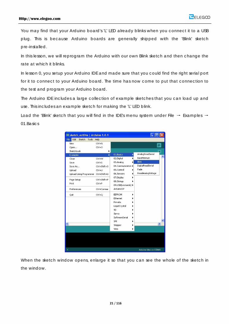
Load the 'Blink' sketch that you will find in the IDE's menu system under File → Examples →
01.Basics
When the sketch window opens, enlarge it so that you can see the whole of the sketch in
the window.
Http://www.elegoo.com
22 / 116
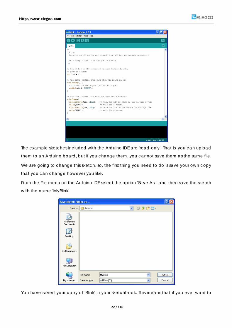
The example sketches included with the Arduino IDE are 'read-only'. That is, you can upload
them to an Arduino board, but if you change them, you cannot save them as the same file.
We are going to change this sketch, so, the first thing you need to do is save your own copy
that you can change however you like.
From the File menu on the Arduino IDE select the option 'Save As..' and then save the sketch
with the name 'MyBlink'.
You have saved your copy of 'Blink' in your sketchbook. This means that if you ever want to
Http://www.elegoo.com
23 / 116
find it again, you can just open it using the File → Sketchbook menu option.
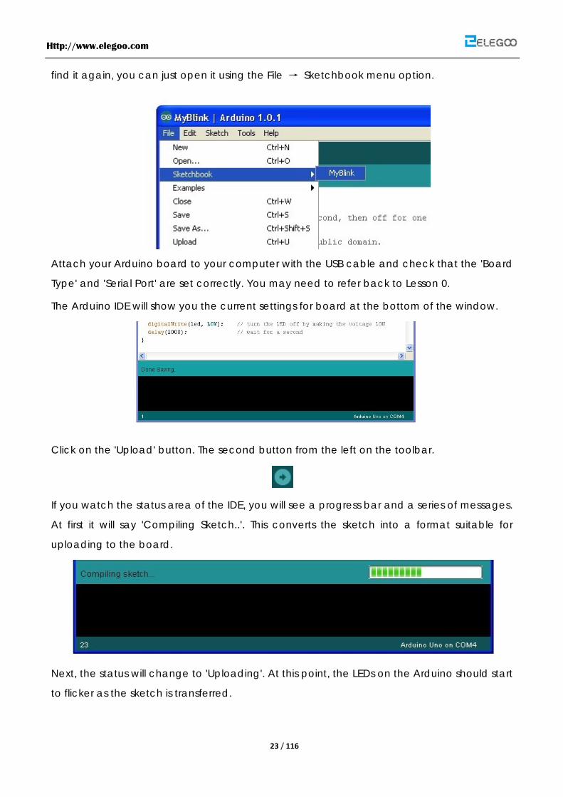
Attach your Arduino board to your computer with the USB cable and check that the 'Board
Type' and 'Serial Port' are set correctly. You may need to refer back to Lesson 0.
The Arduino IDE will show you the current settings for board at the bottom of the window.
Click on the 'Upload' button. The second button from the left on the toolbar.
If you watch the status area of the IDE, you will see a progress bar and a series of messages.
At first it will say 'Compiling Sketch..'. This converts the sketch into a format suitable for
uploading to the board.
Next, the status will change to 'Uploading'. At this point, the LEDs on the Arduino should start
to flicker as the sketch is transferred.

Http://www.elegoo.com
24 / 116
Finally, the staus will change to 'Done'.
The other message tells us that the sketch is using 1,084 bytes of the 32,256 bytes
available.After the 'Compiling Sketch..' stage you could get the following error message:
The clue is at the top here, it probably means that your board is not connected at all, or the
drivers have not been installed (if necessary) or that the wrong serial port is selected.
If you get this, go back to Lesson 0 and check your installation.
Once the upload has completed, the board should restart and start blinking.
Open the code
The first thing to note is that quite a lot of this sketch is what is called 'comments'. Comments
are not actual program instructions, they are just comments about how the program works.
They are there for out benefit, so that there is some explanation to accompany the sketch.
Everything between /* and */ at the top of the sketch is a block comment, that explains
what the sketch is for.
There are also single line comments that start with // and everything up until the end of the
line counts as being a comment.
The first actual line of code is:

Http://www.elegoo.com
25 / 116
Copy Code
1. int led = 13;
As the comment above explains, this is giving a name to the pin that the LED is attached to.
This is 13 on most Arduinos, including the Uno and Leonardo.
Next, we have the 'setup' function. Again, as the comment says, this is run when the reset
button is pressed. It is also run whenever the board resets for any reason, such as power first
being applied to it, or after a sketch has been uploaded.
Copy Code
1. void setup() {
2. // initialize the digital pin as an output.
3. pinMode(led, OUTPUT);
4. }
Every Arduino sketch must have a 'setup' function, and the part of it where you might want
to add instructions of your own is between the { and the }.
In this case, there is just one command there, which, as the comment states tells the Arduino
board that we are going to use the LED pin as an output.
It is also mandatory for a sketch to have a 'loop' function. Unlike the 'setup' function that only
runs once, after a reset, the 'loop' function will, after it has finished running its commands,
immediately start again.
Copy Code
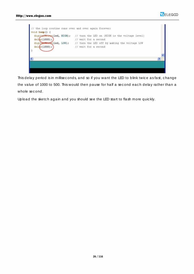
1. void loop() {
2. digitalWrite(led, HIGH); // turn the LED on (HIGH is the voltage level)
3. delay(1000); // wait for a second
4. digitalWrite(led, LOW); // turn the LED off by making the voltage LOW
5. delay(1000); // wait for a second
6. }
Inside the loop function, the commands first of all turn the LED pin on (HIGH), then 'delay' for
1000 milliseconds (1 second), then turn the LED pin off and pause for another second.
You are now going to make your LED blink faster.As you might have guessed, the key to this
lies in changing the parameter in () for the 'delay' command.
Http://www.elegoo.com
26 / 116
This delay period is in milliseconds, and so if you want the LED to blink twice as fast, change
the value of 1000 to 500. This would then pause for half a second each delay rather than a
whole second.
Upload the sketch again and you should see the LED start to flash more quickly.

Http://www.elegoo.com
27 / 116
Lesson 3 LED
Overview
In this lesson, you will learn how to change the brightness of an LED by using different values
of resistor.
Component Required:
(1) x Elegoo Uno R3
(1) x 5mm red LED
(1) x 220 ohm resistor
(1) x 1k ohm resistor
(1) x 10k ohm resistor
(2) x M-M wires
Component Introduction
BREADBOARD MB-102:
Breadboard enables you to prototype circuits quickly, without having to solder the
connections. Bellow shows an example of a breadboard.
Breadboards come in various sizes and configurations. The simplest kind is just a grid of holes
in a plastic block. Inside are strips of metal that provide electrical connection between holes
in the shorter rows. Pushing the legs of two different components into the same row joins
Http://www.elegoo.com
28 / 116
them together electrically. A deep channel running down the middle indicates that there is
a break in connections there, meaning you can push a chip in with the legs at either side of
the channel without connecting them together. Some breadboards have two strips of holes
running along the long edges of the board that are separated from the main grid. These
have strips running down the length of the board inside, and provide a way to connect a
common voltage. They are usually in pairs for +5 volts and ground. These strips are referred
to as rails and they enable you to connect power to many components or points in the
board.
While breadboards are great for prototyping, they have some limitations. Because the
connections are push-fit and temporary, they are not as reliable as soldered connections. If
you are having intermittent problems with a circuit, it could be due to a poor connection on
a breadboard.
LED:
LEDs make great indicator lights. They use very little electricity and they pretty much last
forever.
In this lesson you will use perhaps the most common of all LEDs a 5mm red LED. 5Mm refers to
the diameter of the LED and as well as 5mm, other common sizes are 3mm and the large fun
10mm LEDs.
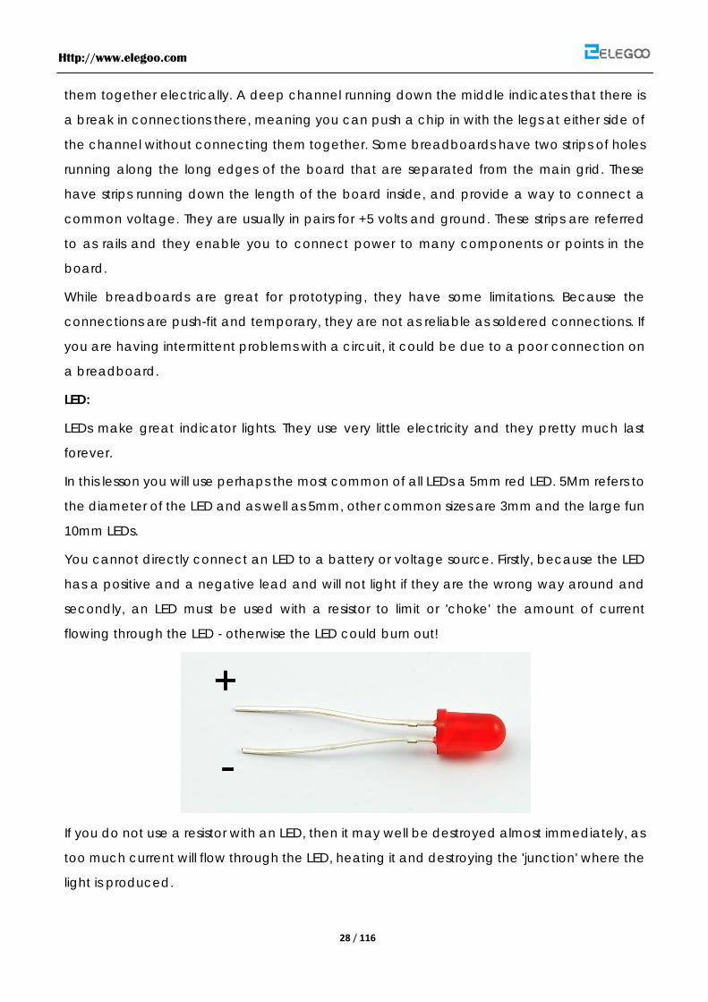
You cannot directly connect an LED to a battery or voltage source. Firstly, because the LED
has a positive and a negative lead and will not light if they are the wrong way around and
secondly, an LED must be used with a resistor to limit or 'choke' the amount of current
flowing through the LED - otherwise the LED could burn out!
If you do not use a resistor with an LED, then it may well be destroyed almost immediately, as
too much current will flow through the LED, heating it and destroying the 'junction' where the
light is produced.
Http://www.elegoo.com
29 / 116
There are two ways to tell which is the positive lead of the LED and which the negative.
Firstly, the positive lead is longer.
Secondly, where the negative lead enters the body of the LED, there is a flat edge to the
case of the LED.
If you happen to have an LED that has a flat side next to the longer lead, you should assume
that the longer lead is positive.
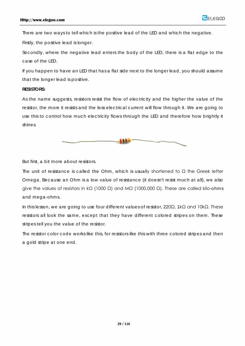
RESISTORS:
As the name suggests, resistors resist the flow of electricity and the higher the value of the
resistor, the more it resists and the less electrical current will flow through it. We are going to
use this to control how much electricity flows through the LED and therefore how brightly it
shines.
But first, a bit more about resistors.
The unit of resistance is called the Ohm, which is usually shortened to Ω the Greek letter
Omega. Because an Ohm is a low value of resistance (it doesn't resist much at all), we also
give the values of resistors in kΩ (1000 Ω) and MΩ (1000,000 Ω). These are called kilo-ohms
and mega-ohms.
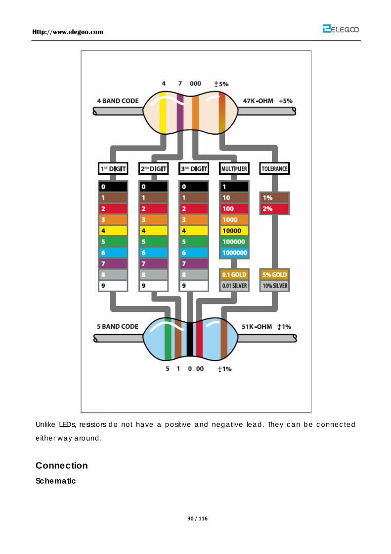
In this lesson, we are going to use four different values of resistor, 220Ω, 1kΩ and 10kΩ. These
resistors all look the same, except that they have different colored stripes on them. These
stripes tell you the value of the resistor.
The resistor color code works like this, for resistors like this with three colored stripes and then
a gold stripe at one end.
Http://www.elegoo.com
30 / 116
Unlike LEDs, resistors do not have a positive and negative lead. They can be connected
either way around.
Connection Schematic

Http://www.elegoo.com
31 / 116
wiring diagram
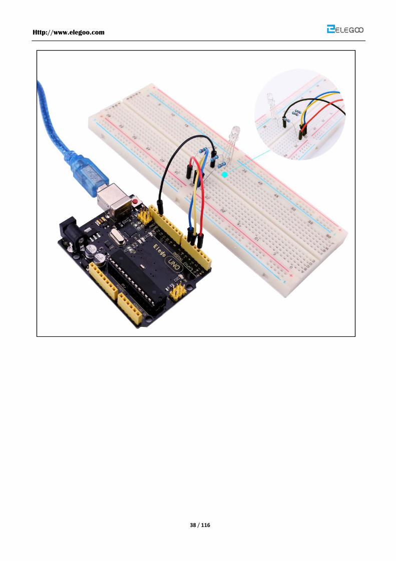
The UNO is a convenient source of 5 Volts, that we will use to provide power to the LED and

Http://www.elegoo.com
32 / 116
resistor. You do not need to do anything with your UNO, except plug it into a USB cable.
With the 220 Ω resistor in place, the LED should be quite bright. If you swap out the 220 Ω
resistor for the 1kΩ resistor, then the LED will appear a little dimmer. Finally, with the 10 kΩ
resistor in place, the LED will be just about visible. Pull the red jumper lead out of the
breadboard and touch it into the hole and remove it, so that it acts like a switch. You should
just be able to notice the difference.
At the moment, you have 5V going to one leg of the resistor, the other leg of the resistor
going to the positive side of the LED and the other side of the LED going to GND. However, if
we moved the resistor so that it came after the LED, as shown below, the LED will still light.
Note, you will probably want to put the 220Ω resistor back in place.
So, it does not matter which side of the LED we put the resistor, as long as it is there
somewhere.
Http://www.elegoo.com
33 / 116
Lesson 4 RGB LED
Overview
RGB LEDs are a fun and easy way to add some color to your projects. Since they are like 3
regular LED in one, the way to use and connect them is not much different.
They come mostly in 2 versions: Common Anode or Common Cathode.
Common Anode uses 5V on the common pin, while Common Cathode connects to
Ground.
As with any LED, we need to connect some resistors inline (3 total) so we limit the current
being drawn.
In our sketch we will start with the LED in the Red color state, then fade to Green, then fade
to Blue and finally back to the Red color. By doing this we will cycle through most of the
color that can be achieved.
Component Required:
(1) x Elegoo Uno R3
(1) x Bread board
(4) x M-M wires
(1) x RGB LED
(3) x 220 ohm resistors
Component Introduction
RGB:
At first glance, RGB (Red, Green, Blue) LEDs look just like regular LEDs, however, inside the
usual LED package, there are actually three LEDs, one red, one green and yes, one blue. By
controlling the brightness of each of the individual LEDs you can mix pretty much any color
you want.
We mix colors just like you would mix audio with a 'mixing board' or paint on a palette - by
adjusting the brightness of each of the three LEDs. The hard way to do this would be to use

Http://www.elegoo.com
34 / 116
different value resistors (or variable resistors) as we played with in lesson 2. That's a lot of work!
Fortunately for us, the Arduino has an analogWrite function that you can use with pins
marked with a ~ to output a variable amount of power to the appropriate LEDs.
The RGB LED has four leads. There is one lead going to the positive connection of each of
the single LEDs within the package and a single lead that is connected to all three negative
sides of the LEDs.
The common negative connection of the LED package is the second pin from the flat side
of the LED package. It is also the longest of the four leads. This lead will be connected to
ground.
Each LED inside the package requires its own 270Ω resistor to prevent too much current
flowing through it. The three positive leads of the LEDs (one red, one green and one blue)
are connected to UNO output pins using these resistors.
COLOR:
The reason that you can mix any color you like by varying the quantities of red, green and
blue light is that your eye has three types of light receptor in it (red, green and blue). Your
eye and brain process the amounts of red, green and blue and convert it into a color of the
spectrum.
In a way, by using the three LEDs we are playing a trick on the eye. This same idea is used in
TVs, where the LCD has red, green and blue color dots next to each other making up each
pixel.
Http://www.elegoo.com
35 / 116
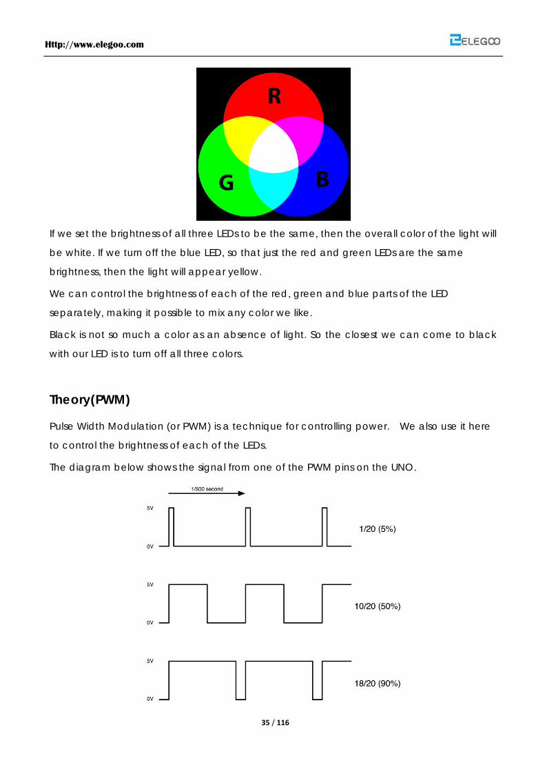
If we set the brightness of all three LEDs to be the same, then the overall color of the light will
be white. If we turn off the blue LED, so that just the red and green LEDs are the same
brightness, then the light will appear yellow.
We can control the brightness of each of the red, green and blue parts of the LED
separately, making it possible to mix any color we like.
Black is not so much a color as an absence of light. So the closest we can come to black
with our LED is to turn off all three colors.
Theory(PWM)
Pulse Width Modulation (or PWM) is a technique for controlling power. We also use it here
to control the brightness of each of the LEDs.
The diagram below shows the signal from one of the PWM pins on the UNO.

Http://www.elegoo.com
36 / 116
Roughly every 1/500 of a second, the PWM output will produce a pulse. The length of this
pulse is controlled by the 'analogWrite' function. So 'analogWrite(0)' will not produce any
pulse at all and 'analogWrite(255)' will produce a pulse that lasts all the way until the next
pulse is due, so that the output is actually on all the time.
If we specify a value in the analogWrite that is somewhere in between 0 and 255 then we
will produce a pulse. If the output pulse is only high for 5% of the time then whatever we are
driving will only receive 5% of full power.
If however the output is at 5V for 90% of the time then the load will get 90% of the power
delivered to it. We cannot see the LEDs turning on and off at that speed, so to us, it just looks
like the brightness is changing.
Connection Schematic

Http://www.elegoo.com
37 / 116
wiring diagram
The Code
Our code will use FOR loops to cycle through the colors.
The First FOR loop will go from RED to GREEN
The Second FOR will go from GREEN to BLUE
and finally the last FOR will go from BLUE to RED.
Http://www.elegoo.com
38 / 116
Http://www.elegoo.com
39 / 116
Lesson 5 Digital Inputs
Overview
In this lesson, you will learn to use push buttons with digital inputs to turn an LED on and off.
Pressing the button nearer the top of the breadboard will turn the LED on, pressing the other
button will turn the LED off.
Component Required:
(1) x Elegoo Uno R3
(1) x Breadboard
(1) x 5mm red LED
(1) x 220 ohm resistor
(2) x push switches
(6) x M-M wires
Component Introduction
PUSH SWITCHES:
Switches are really simple components. When you press a button or flip a lever, they
connect two contacts together so that electricity can flow through them.
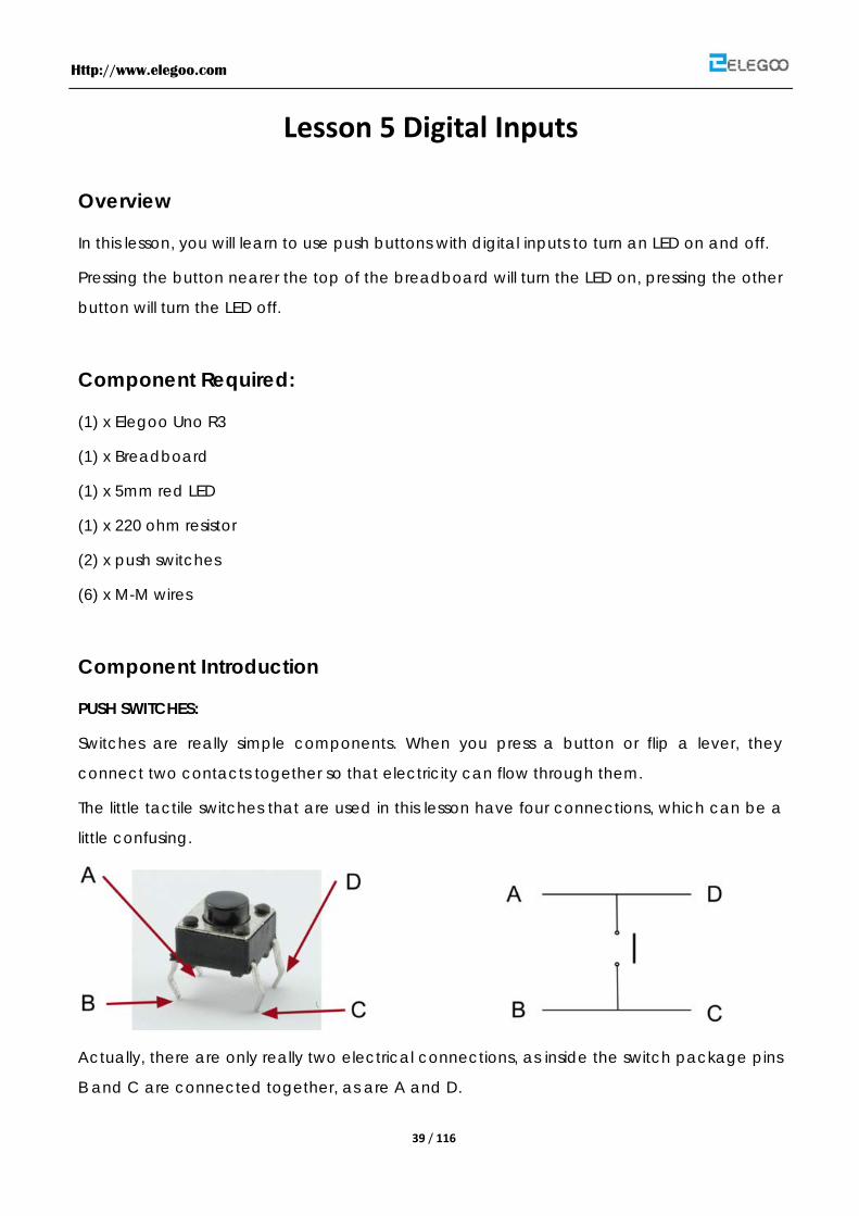
The little tactile switches that are used in this lesson have four connections, which can be a
little confusing.
Actually, there are only really two electrical connections, as inside the switch package pins
B and C are connected together, as are A and D.
Http://www.elegoo.com
40 / 116
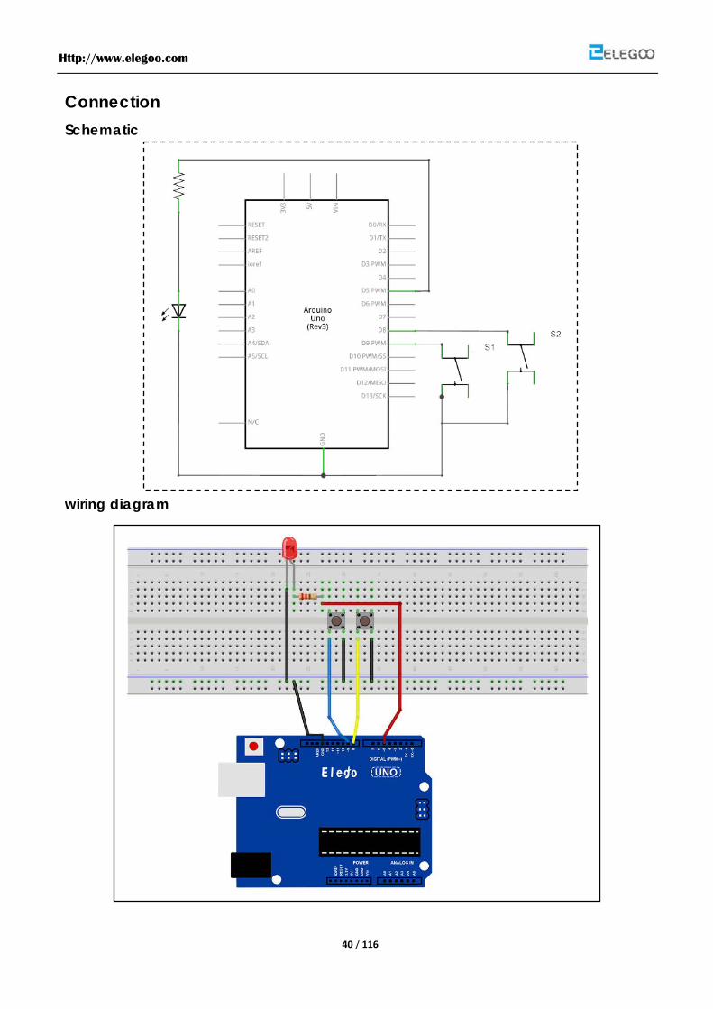
Connection Schematic
wiring diagram
Http://www.elegoo.com
41 / 116
Although the bodies of the switches are square, the pins protrude from opposite sides of the
switch. This means that the pins will only be far enough apart when they are the correct way
around on the breadboard.
Remember that the LED has to be the correct way around with the shorter negative lead to
the right.
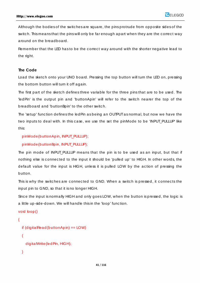
The Code
Load the sketch onto your UNO board. Pressing the top button will turn the LED on, pressing
the bottom button will turn it off again.
The first part of the sketch defines three variable for the three pins that are to be used. The
'ledPin' is the output pin and 'buttonApin' will refer to the switch nearer the top of the
breadboard and 'buttonBpin' to the other switch.
The 'setup' function defines the ledPin as being an OUTPUT as normal, but now we have the
two inputs to deal with. In this case, we use the set the pinMode to be 'INPUT_PULLUP' like
this:
pinMode(buttonApin, INPUT_PULLUP);
pinMode(buttonBpin, INPUT_PULLUP);
The pin mode of INPUT_PULLUP means that the pin is to be used as an input, but that if
nothing else is connected to the input it should be 'pulled up' to HIGH. In other words, the
default value for the input is HIGH, unless it is pulled LOW by the action of pressing the
button.
This is why the switches are connected to GND. When a switch is pressed, it connects the
input pin to GND, so that it is no longer HIGH.
Since the input is normally HIGH and only goes LOW, when the button is pressed, the logic is
a little up-side-down. We will handle this in the 'loop' function.
void loop()
{
if (digitalRead(buttonApin) == LOW)
{
digitalWrite(ledPin, HIGH);
}

Http://www.elegoo.com
42 / 116
if (digitalRead(buttonBpin) == LOW)
{
digitalWrite(ledPin, LOW);
}
}
In the 'loop' function there are two 'if' statements. One for each button. Each does an
'digitalRead' on the appropriate input.
Remember that if the button is pressed, the corresponding input will be LOW, if button A is
low, then a 'digitalWrite' on the ledPin turns it on.
Similarly, if button B is pressed, a LOW is written to the ledPin.

Http://www.elegoo.com
43 / 116
Lesson 6 Eight LED with 74HC595
Overview
In this lesson, you will learn how to use eight large red LEDs with an UNO without needing to
give up 8 output pins!
Although you could wire up eight LEDs each with a resistor to an UNO pin you would rapidly
start to run out of pins on your UNO. If you don't have a lot of stuff connected to your UNO.
It's OK to do so - but often times we want buttons, sensors, servos, etc and before you know it
you've got no pins left. So, instead of doing that, you are going to use a chip called the
74HC595 Serial to Parallel Converter. This chip has eight outputs (perfect) and three inputs
that you use to feed data into it a bit at a time.
This chip makes it a little slower to drive the LEDs (you can only change the LEDs about
500,000 times a second instead of 8,000,000 a second) but it's still really fast, way faster than
humans can detect, so it's worth it!
Component Required:
(1) x Elegoo Uno R3
(1) x Breadboard
(8) x led
(8) x 220 ohm resistors
(1) x Breadboard
(1) x 74hc595 ic
(14) x M-M wires
Component Introduction
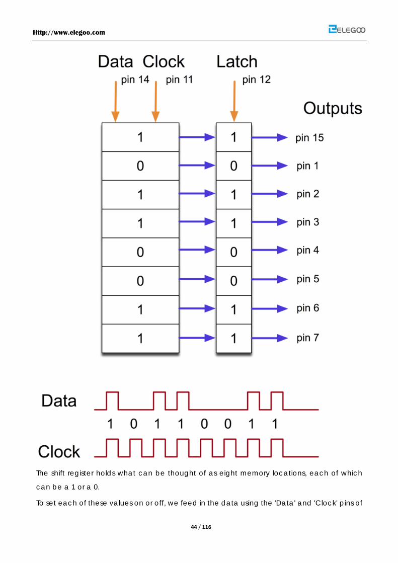
74HC595 Shift Register:
The chip is of a type called a shift register.
Http://www.elegoo.com
44 / 116
The shift register holds what can be thought of as eight memory locations, each of which
can be a 1 or a 0.
To set each of these values on or off, we feed in the data using the 'Data' and 'Clock' pins of
Http://www.elegoo.com
45 / 116
the chip.
The clock pin needs to receive eight pulses, at the time of each pulse, if the data pin is high,
then a 1 gets pushed into the shift register, otherwise a 0. When all eight pulses have been
received, then enabling the 'Latch' pin copies those eight values to the latch register. This is
necessary, otherwise the wrong LEDs would flicker as the data was being loaded into the
shift register.
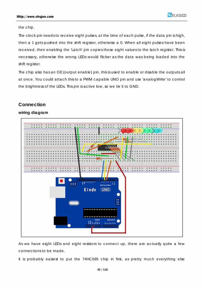
The chip also has an OE (output enable) pin, this is used to enable or disable the outputs all
at once. You could attach this to a PWM capable UNO pin and use 'analogWrite' to control
the brightness of the LEDs. This pin is active low, so we tie it to GND.
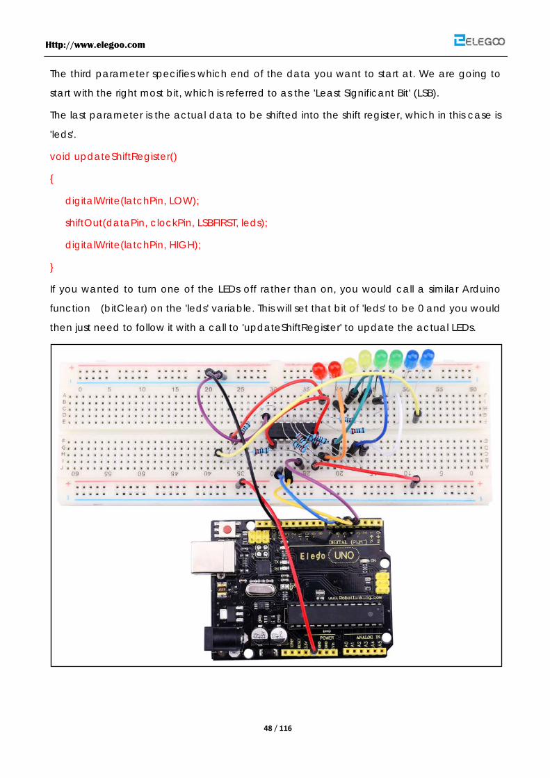
Connection wiring diagram
As we have eight LEDs and eight resistors to connect up, there are actually quite a few
connections to be made.
It is probably easiest to put the 74HC595 chip in first, as pretty much everything else
Http://www.elegoo.com
46 / 116
connects to it. Put it so that the little U-shaped notch is towards the top of the breadboard.
Pin 1 of the chip is to the left of this notch.
Digital 4 from the UNO goes to pin #14 of the shift register
Digital 5 from the UNO goes to pin #12 of the shift register
Digital 6 from the UNO goes to pin #11 of the shift register
All but one of the outputs from the '595 are on the left hand side of the chip, hence, for ease
of connection, that is where the LEDs are too.
After the chip, put the resistors in place. You need to be careful that none of the leads of the
resistors are touching each other. You should check this again, before you connect the
power to your UNO. If you find it difficult to arrange the resistors without their leads touching,
then it helps to shorten the leads so that they are lying closer to the surface of the
breadboard.Next, place the LEDs on the breadboard.
The longer positive LED leads must all be towards the chip, whichever side of the
breadboard they are on.
It now just remains to attach the jumper leads as shown above. Do not forget the one that
goes from pin 8 of the IC to the GND column of the breadboard.
Load up the sketch listed a bit later and try it out. Each LED should light in turn until all the
LEDs are on, and then they all go off and the cycle repeats.
The Code
The first thing we do is define the three pins we are going to use. These are the UNO digital
outputs that will be connected to the latch, clock and data pins of the 74HC595.
int latchPin = 5;
int clockPin = 6;
int dataPin = 4;
Next, a variable called 'leds' is defined. This will be used to hold the pattern of which LEDs
are currently turned on or off. Data of type 'byte' represents numbers using eight bits. Each
bit can be either on or off, so this is perfect for keeping track of which of our eight LEDs are
on or off.
byte leds = 0;
Http://www.elegoo.com
47 / 116
The 'setup' function just sets the three pins we are using to be digital outputs.
void setup()
{
pinMode(latchPin, OUTPUT);
pinMode(dataPin, OUTPUT);
pinMode(clockPin, OUTPUT);
}
The 'loop' function initially turns all the LEDs off, by giving the variable 'leds' the value 0. It
then calls 'updateShiftRegister' that will send the 'leds' pattern to the shift register so that all
the LEDs turn off. We will deal with how 'updateShiftRegister' works later.
The loop function pauses for half a second and then begins to count from 0 to 7 using the
'for' loop and the variable 'i'. Each time, it uses the Arduino function 'bitSet' to set the bit that
controls that LED in the variable 'leds'. It then also calls 'updateShiftRegister' so that the leds
update to reflect what is in the variable 'leds'.
There is then a half second delay before 'i' is incremented and the next LED is lit.
void loop()
{
leds = 0;
updateShiftRegister();
delay(500);
for (int i = 0; i < 8; i++)
{
bitSet(leds, i);
updateShiftRegister();
delay(500);
}
}
The function 'updateShiftRegister', first of all sets the latchPin to low, then calls the UNO
function 'shiftOut' before putting the 'latchPin' high again. This takes four parameters, the first
two are the pins to use for Data and Clock respectively.
Http://www.elegoo.com
48 / 116
The third parameter specifies which end of the data you want to start at. We are going to
start with the right most bit, which is referred to as the 'Least Significant Bit' (LSB).
The last parameter is the actual data to be shifted into the shift register, which in this case is
'leds'.
void updateShiftRegister()
{
digitalWrite(latchPin, LOW);
shiftOut(dataPin, clockPin, LSBFIRST, leds);
digitalWrite(latchPin, HIGH);
}
If you wanted to turn one of the LEDs off rather than on, you would call a similar Arduino
function (bitClear) on the 'leds' variable. This will set that bit of 'leds' to be 0 and you would
then just need to follow it with a call to 'updateShiftRegister' to update the actual LEDs.

Http://www.elegoo.com
49 / 116
Lesson 7 The Serial Monitor
Overview
In this lesson, you will build on lesson 6, adding the facility to control the LEDs from your
computer using the Arduino Serial Monitor. The serial monitor is the 'tether' between the
computer and your UNO - it lets you send and receive text messages, handy for debugging
and also controlling the UNO from a keyboard!
For example, you will be able to send commands from your computer to turn on LEDs.
In this lesson, you will use exactly the same parts and a similar breadboard layout as Lesson 6.
So, if you have not already done so, follow lesson 6 now.
Steps taken
After you have uploaded this sketch onto your UNO, click on the right-most button on the
toolbar in the Arduino IDE. The button is circled below.
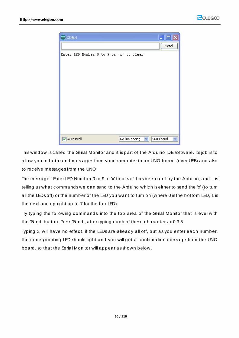
The following window will open.
Http://www.elegoo.com
50 / 116
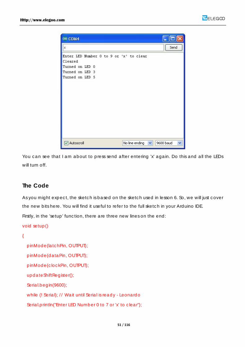
This window is called the Serial Monitor and it is part of the Arduino IDE software. Its job is to
allow you to both send messages from your computer to an UNO board (over USB) and also
to receive messages from the UNO.
The message “Enter LED Number 0 to 9 or 'x' to clear” has been sent by the Arduino, and it is
telling us what commands we can send to the Arduino which is either to send the 'x' (to turn
all the LEDs off) or the number of the LED you want to turn on (where 0 is the bottom LED, 1 is
the next one up right up to 7 for the top LED).
Try typing the following commands, into the top area of the Serial Monitor that is level with
the 'Send' button. Press 'Send', after typing each of these characters: x 0 3 5
Typing x, will have no effect, if the LEDs are already all off, but as you enter each number,
the corresponding LED should light and you will get a confirmation message from the UNO
board, so that the Serial Monitor will appear as shown below.
Http://www.elegoo.com
51 / 116
You can see that I am about to press send after entering 'x' again. Do this and all the LEDs
will turn off.
The Code
As you might expect, the sketch is based on the sketch used in lesson 6. So, we will just cover
the new bits here. You will find it useful to refer to the full sketch in your Arduino IDE.
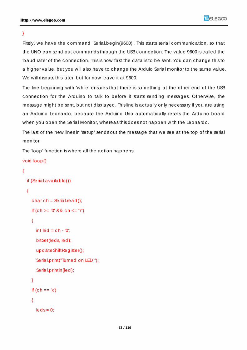
Firstly, in the 'setup' function, there are three new lines on the end:
void setup()
{
pinMode(latchPin, OUTPUT);
pinMode(dataPin, OUTPUT);
pinMode(clockPin, OUTPUT);
updateShiftRegister();
Serial.begin(9600);
while (! Serial); // Wait until Serial is ready - Leonardo
Serial.println("Enter LED Number 0 to 7 or 'x' to clear");
Http://www.elegoo.com
52 / 116
}
Firstly, we have the command 'Serial.begin(9600)'. This starts serial communication, so that
the UNO can send out commands through the USB connection. The value 9600 is called the
'baud rate' of the connection. This is how fast the data is to be sent. You can change this to
a higher value, but you will also have to change the Arduio Serial monitor to the same value.
We will discuss this later, but for now leave it at 9600.
The line beginning with 'while' ensures that there is something at the other end of the USB
connection for the Arduino to talk to before it starts sending messages. Otherwise, the
message might be sent, but not displayed. This line is actually only necessary if you are using
an Arduino Leonardo, because the Arduino Uno automatically resets the Arduino board
when you open the Serial Monitor, whereas this does not happen with the Leonardo.
The last of the new lines in 'setup' sends out the message that we see at the top of the serial
monitor.
The 'loop' function is where all the action happens:
void loop()
{
if (Serial.available())
{
char ch = Serial.read();
if (ch >= '0' && ch <= '7')
{
int led = ch - '0';
bitSet(leds, led);
updateShiftRegister();
Serial.print("Turned on LED ");
Serial.println(led);
}
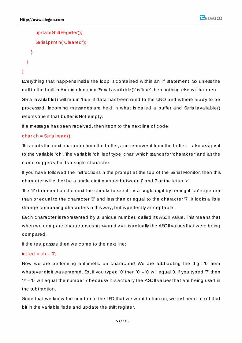
if (ch == 'x')
{
leds = 0;
Http://www.elegoo.com
53 / 116
updateShiftRegister();
Serial.println("Cleared");
}
}
}
Everything that happens inside the loop is contained within an 'if' statement. So unless the
call to the built-in Arduino function 'Serial.available()' is 'true' then nothing else will happen.
Serial.available() will return 'true' if data has been send to the UNO and is there ready to be
processed. Incoming messages are held in what is called a buffer and Serial.available()
returns true if that buffer is Not empty.
If a message has been received, then its on to the next line of code:
char ch = Serial.read();
This reads the next character from the buffer, and removes it from the buffer. It also assigns it
to the variable 'ch'. The variable 'ch' is of type 'char' which stands for 'character' and as the
name suggests, holds a single character.
If you have followed the instructions in the prompt at the top of the Serial Monitor, then this
character will either be a single digit number between 0 and 7 or the letter 'x'.
The 'if' statement on the next line checks to see if it is a single digit by seeing if 'ch' is greater
than or equal to the character '0' and less than or equal to the character '7'. It looks a little
strange comparing characters in this way, but is perfectly acceptable.
Each character is represented by a unique number, called its ASCII value. This means that
when we compare characters using <= and >= it is actually the ASCII values that were being
compared.
If the test passes, then we come to the next line:
int led = ch – '0';
Now we are performing arithmetic on characters! We are subtracting the digit '0' from
whatever digit was entered. So, if you typed '0' then '0' – '0' will equal 0. If you typed '7' then
'7' – '0' will equal the number 7 because it is actually the ASCII values that are being used in
the subtraction.
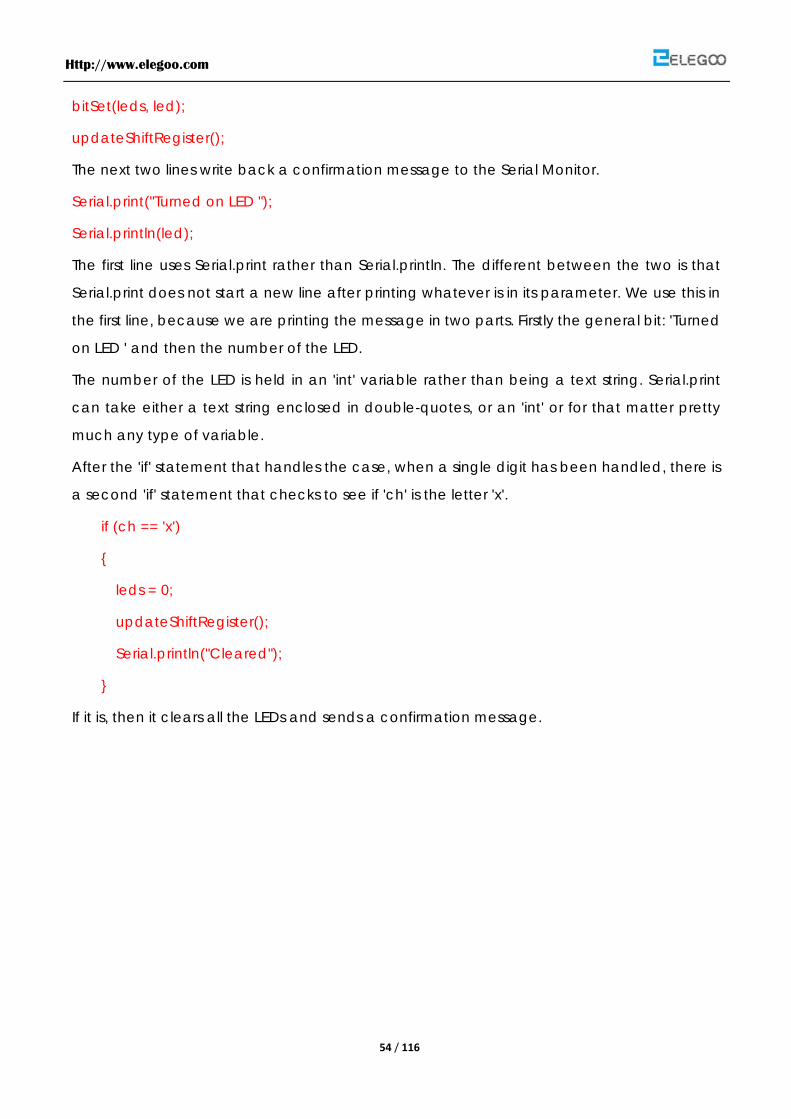
Since that we know the number of the LED that we want to turn on, we just need to set that
bit in the variable 'leds' and update the shift register.
Http://www.elegoo.com
54 / 116
bitSet(leds, led);
updateShiftRegister();
The next two lines write back a confirmation message to the Serial Monitor.
Serial.print("Turned on LED ");
Serial.println(led);
The first line uses Serial.print rather than Serial.println. The different between the two is that
Serial.print does not start a new line after printing whatever is in its parameter. We use this in
the first line, because we are printing the message in two parts. Firstly the general bit: 'Turned
on LED ' and then the number of the LED.
The number of the LED is held in an 'int' variable rather than being a text string. Serial.print
can take either a text string enclosed in double-quotes, or an 'int' or for that matter pretty
much any type of variable.
After the 'if' statement that handles the case, when a single digit has been handled, there is
a second 'if' statement that checks to see if 'ch' is the letter 'x'.
if (ch == 'x')
{
leds = 0;
updateShiftRegister();
Serial.println("Cleared");
}
If it is, then it clears all the LEDs and sends a confirmation message.
Http://www.elegoo.com
55 / 116
Lesson 8 Photocell
Overview
In this lesson, you will learn how to measure light intensity using an Analog Input. You will
build on lesson 8 and use the level of light to control the number of LEDs to be lit.
The photocell is at the bottom of the breadboard, where the pot was above.
Component Required:
(1) x Elegoo Uno R3
(1) x Breadboard
(8) x led
(8) x 220 ohm resistors
(1) x 1k ohm resistors
(1) x Breadboard
(1) x 74hc595 ic
(1) x Photocell
(14) x M-M wires
Component Introduction
PHOTOCELL:
The photocell used is of a type called a light dependent resistor, sometimes called an LDR.
As the name suggests, these components act just like a resistor, except that the resistance
changes in response to how much light is falling on them.
This one has a resistance of about 50 kΩ in near darkness and 500 Ω in bright light. To
convert this varying value of resistance into something we can measure on an Arduino's
analog input, it need to be converted into a voltage.
The simplest way to do that is to combine it with a fixed resistor.
Http://www.elegoo.com
56 / 116
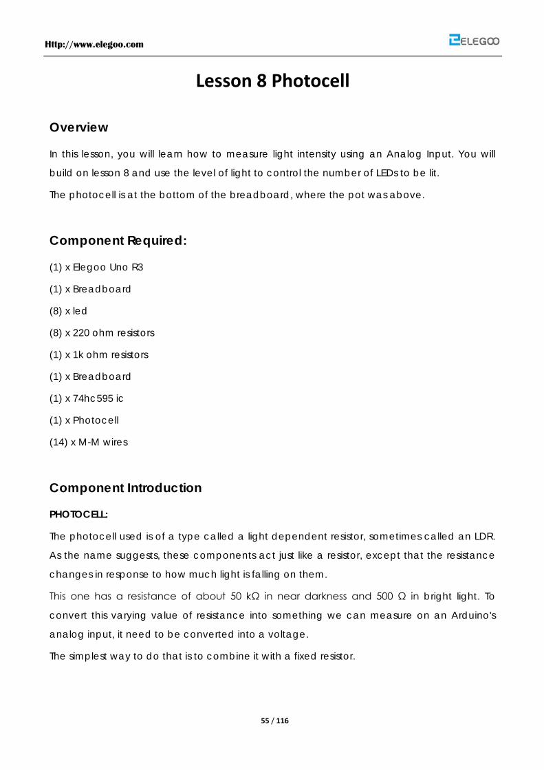
The resistor and photocell together behave rather like a pot. When the light is very bright,
then the resistance of the photocell is very low compared with the fixed value resistor, and
so it is as if the pot were turned to maximum.
When the photocell is in dull light the resistance becomes greater than the fixed 1kΩ resistor
and it is as if the pot were being turned towards GND.
Load up the sketch given in the next section and try covering the photocell with your finger,
and holding it near a light source.
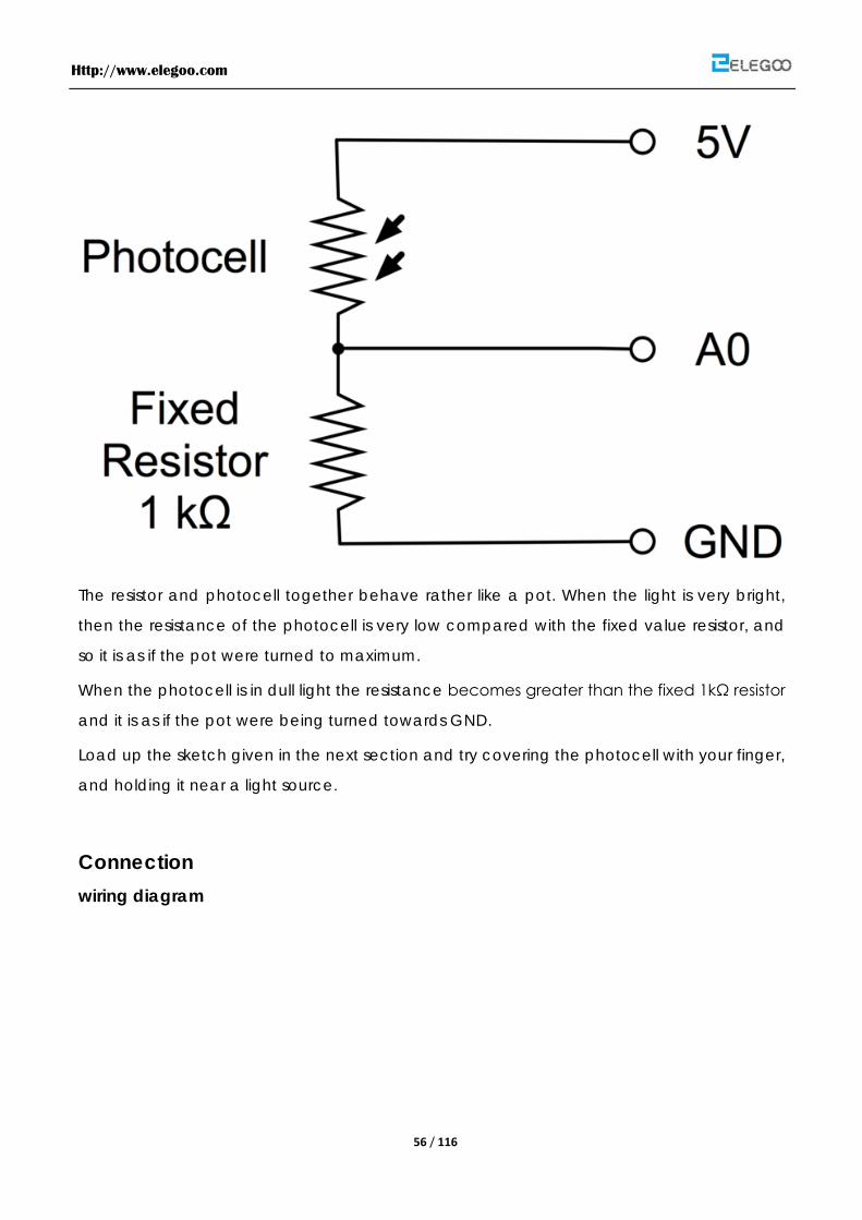
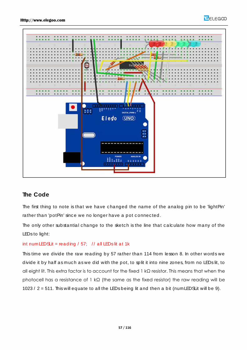
Connection wiring diagram
Http://www.elegoo.com
57 / 116
The Code
The first thing to note is that we have changed the name of the analog pin to be 'lightPin'
rather than 'potPin' since we no longer have a pot connected.
The only other substantial change to the sketch is the line that calculate how many of the
LEDs to light:
int numLEDSLit = reading / 57; // all LEDs lit at 1k
This time we divide the raw reading by 57 rather than 114 from lesson 8. In other words we
divide it by half as much as we did with the pot, to split it into nine zones, from no LEDs lit, to
all eight lit. This extra factor is to account for the fixed 1 kΩ resistor. This means that when the
photocell has a resistance of 1 kΩ (the same as the fixed resistor) the raw reading will be
1023 / 2 = 511. This will equate to all the LEDs being lit and then a bit (numLEDSLit will be 9).
Http://www.elegoo.com
58 / 116
Http://www.elegoo.com
59 / 116
Lesson 9 Making Sounds
Overview
In this lesson, you will learn how to make sound with a active buzzer.
Component Required:
(1) x Elegoo Uno R3
(1) x Passive buzzer
(2) x F-M wires
Component Introduction
BUZZER:
As a type of electronic buzzer with integrated structure, buzzers, which are supplied by DC
power, are widely used in computers, printers, photocopiers, alarms, electronic toys,
automotive electronic devices, telephones, timers and other electronic products for voice
devices. Buzzers can be categorized as active and passive ones (see the following picture).
Turn the pins of two buzzers face up, and the one with a green circuit board is a passive
buzzer, while the other enclosed with a black tape is an active one.
The difference between an active buzzer and a passive buzzer is:
An active buzzer has a built-in oscillating source, so it will make sounds when electrified. But
a passive buzzer does not have such source, so it will not tweet if DC signals are used;
instead, you need to use square waves whose frequency is between 2K and 5K to drive it.
The active buzzer is often more expensive than the passive one because of multiple built-in
oscillating circuits.
Connection Schematic
Http://www.elegoo.com
60 / 116
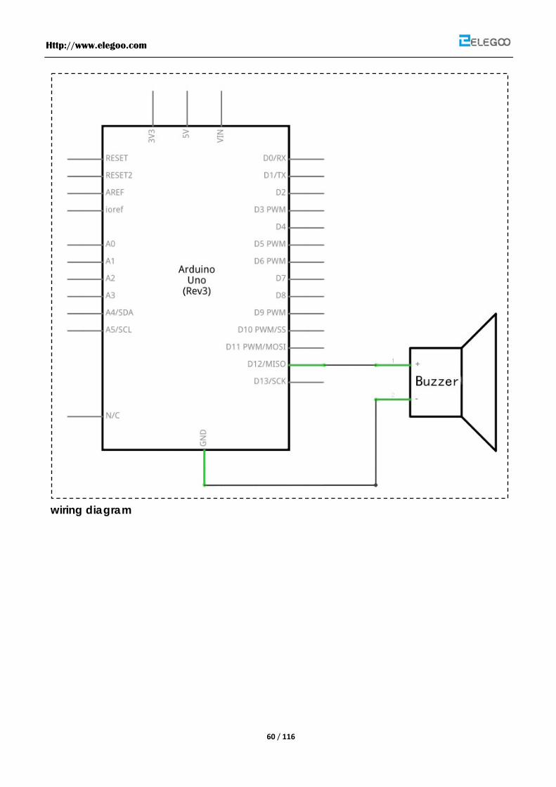
wiring diagram

Http://www.elegoo.com
61 / 116
The code
See the code file.
Http://www.elegoo.com
62 / 116
Http://www.elegoo.com
63 / 116
Lesson 10 Passive Buzzer
Overview
In this lesson, you will learn how to use a passive buzzer
Purpose of the experiment control buzzer, allowing the buzzer Alto Do (523Hz), Re (587Hz), Mi
(659Hz), Fa (698Hz), So (784Hz), La (880Hz), Si (988Hz) to Treble Do (1047Hz) This scale of eight
different sounds, each sound scale 0.5 seconds.
Component Required:
(1) x Elegoo Uno R3
(1) x Passive buzzer
(2) x F-M wires
Component Introduction
Passive Buzzer:
Passive buzzer, in fact, just use PWM generating audio, drives the buzzer, allowing the air to
vibrate, can sound. Appropriately changed as long as the vibration frequency, it can
generate different sound scale. For example, sending a pulse wave can be generated
523Hz Alto Do, pulse 587Hz can produce midrange Re, 659Hz can produce midrange Mi. If
you then with a different beat, you can play a song. Here be careful not to use the Arduino
analog Write () function to generate a pulse wave, because the frequency analog Write ()
is fixed (500Hz), no way to scale the output of different sounds.
Connection Schematic

Http://www.elegoo.com
64 / 116
wiring diagram
Http://www.elegoo.com
65 / 116
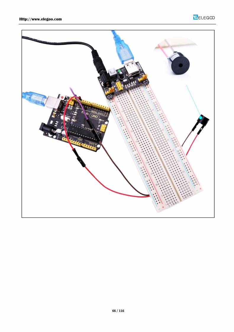
Wiring the buzzer connected to the Arduino board, the red (positive) to the pin8, black wire
(negative) to the GND
Description:
L04 ~ L05: definition of alto Do, Re, Mi, So, La, Si and treble Do eight octave frequency, the
frequency of each scale is already defined in pitches.h file in, so just find the eight Constant
scale and stored in the array to melody.
L06: definition of variable duration, representing each scale response time duration,
because the scale to make each sound 0.5 seconds, so the duration is set to 500 (in
milisecond)
L13 ~ L19: Let the buzzer Alto Do ( 523Hz), Re (587Hz), Mi (659Hz), Fa (698Hz), So (784Hz), La
(880Hz), Si (988Hz) to treble Do (1047Hz) which eight voices of different scales, each scale
ring 0.5 seconds
L22: every two seconds, and then replay the content pitches.h stalls:
in this example is based, together with a few LED and modify the program, at the same time
to play a sound control LED lights change, so that this paradigm has become a shot in the
program. Try to generate an ambulance siren. Tip: Just let the buzzer continuously generate
Alto Do (523Hz) and Alto Fa (698Hz), each about 0.8 seconds of sound, you can simulate
ambulance siren.
The code
See the code file.
Http://www.elegoo.com
66 / 116
Http://www.elegoo.com
67 / 116
Lesson 11 Relay Module
Overview
In this lesson, you will learn how to use a relay module.
Component Required:
(1) x Elegoo Uno R3
(1) x Relay module
(3) x F-M wires
Component Introduction
Relay:
A relay is an electrically operated switch. Many relays use an electromagnet to
mechanically operate a switch, but other operating principles are also used, such as
solid-state relays. Relays are used where it is necessary to control a circuit by a low-power
signal (with complete electrical isolation between control and controlled circuits), or where
several circuits must be controlled by one signal. The first relays were used in long distance
telegraph circuits as amplifiers: they repeated the signal coming in from one circuit and
re-transmitted it on another circuit. Relays were used extensively in telephone exchanges
and early computers to perform logical operations.
A type of relay that can handle the high power required to directly control an electric motor
or other loads is called a contactor. Solid-state relays control power circuits with no moving
parts, instead using a semiconductor device to perform switching. Relays with calibrated
operating characteristics and sometimes multiple operating coils are used to protect
electrical circuits from overload or faults; in modern electric power systems these functions
are performed by digital instruments still called "protective relays".
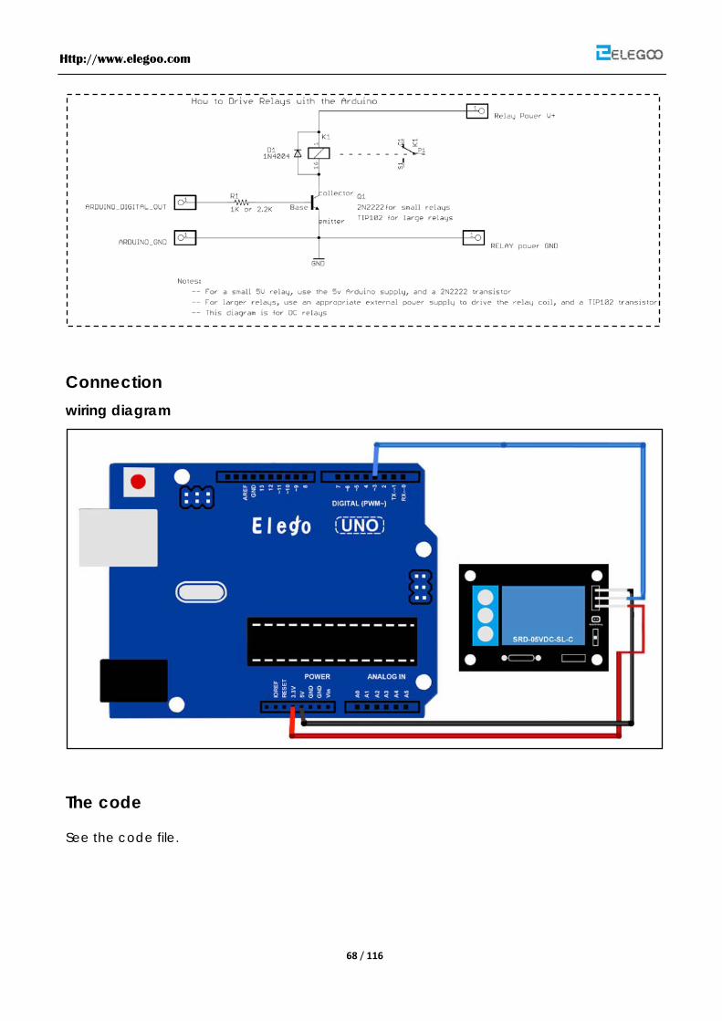
Bellow is the schematic of how to drive relay with arduino (down load from the arduino.cc)
Http://www.elegoo.com
68 / 116
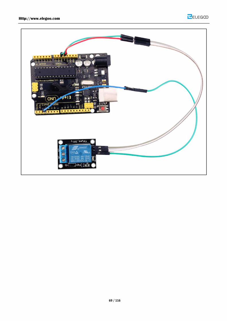
Connection wiring diagram
The code
See the code file.
Http://www.elegoo.com
69 / 116
Http://www.elegoo.com
70 / 116
Lesson 12 74HC595 And Segment Display
Overview
Rewrite " Lab7 make use of seven-segment display countdown function "to 74HC595 shift
register control a seven-segment display sequentially displays the number from 9-0, making
the effect of the digital countdown on the seven-segment display.
Note: This test assumes that you have done, " Lab7 make reciprocal use of seven-segment
display function "and"Lab11 use 74HC595 and three pins to control 8 LED "principle has been
known seven-segment display and a 74HC595 using separate ways.
Component Required:
(1) x Elegoo Uno R3
(2) x Breadboard
(1) x 74HC595
(1) x Segment Display
(8) x 220 ohm resistor
(20) x M-M wires
Component Introduction
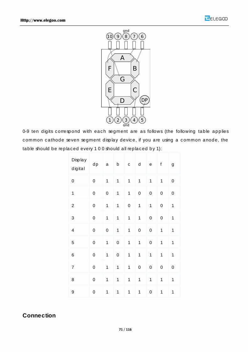
Seven segment display
Seven segment display pin diagram below (the picture shows common cathode
seven-segment display):
Http://www.elegoo.com
71 / 116
0-9 ten digits correspond with each segment are as follows (the following table applies
common cathode seven segment display device, if you are using a common anode, the
table should be replaced every 1 0 0 should all replaced by 1):
Display
digital dp a b c d e f g
0 0 1 1 1 1 1 1 0
1 0 0 1 1 0 0 0 0
2 0 1 1 0 1 1 0 1
3 0 1 1 1 1 0 0 1
4 0 0 1 1 0 0 1 1
5 0 1 0 1 1 0 1 1
6 0 1 0 1 1 1 1 1
7 0 1 1 1 0 0 0 0
8 0 1 1 1 1 1 1 1
9 0 1 1 1 1 0 1 1
Connection
Http://www.elegoo.com
72 / 116
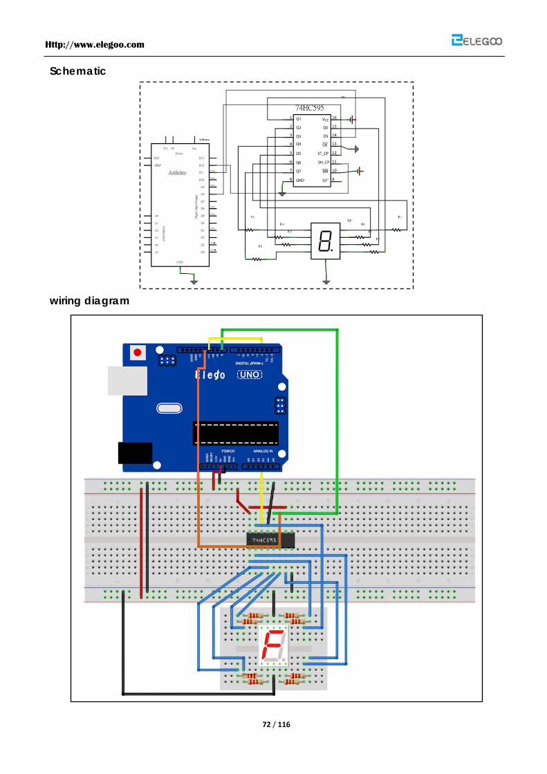
Schematic
wiring diagram
Http://www.elegoo.com
73 / 116
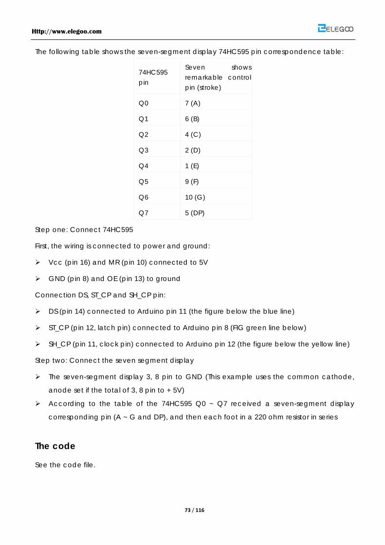
The following table shows the seven-segment display 74HC595 pin correspondence table:
74HC595 pin
Seven shows remarkable control pin (stroke)
Q0 7 (A)
Q1 6 (B)
Q2 4 (C)
Q3 2 (D)
Q4 1 (E)
Q5 9 (F)
Q6 10 (G)
Q7 5 (DP)
Step one: Connect 74HC595
First, the wiring is connected to power and ground:
Vcc (pin 16) and MR (pin 10) connected to 5V
GND (pin 8) and OE (pin 13) to ground
Connection DS, ST_CP and SH_CP pin:
DS (pin 14) connected to Arduino pin 11 (the figure below the blue line)
ST_CP (pin 12, latch pin) connected to Arduino pin 8 (FIG green line below)
SH_CP (pin 11, clock pin) connected to Arduino pin 12 (the figure below the yellow line)
Step two: Connect the seven segment display
The seven-segment display 3, 8 pin to GND (This example uses the common cathode,
anode set if the total of 3, 8 pin to + 5V)
According to the table of the 74HC595 Q0 ~ Q7 received a seven-segment display
corresponding pin (A ~ G and DP), and then each foot in a 220 ohm resistor in series
The code
See the code file.

Http://www.elegoo.com
74 / 116
Http://www.elegoo.com
75 / 116
Lesson 13 Four Digital Tube Segment Display
Overview
In this lesson, we will learn how to use a four digital tube segment.
When using one digit 7-segment display, if it is common anode, we will connect common
anode pin to power source; if it is common cathode, we will connect common cathode pin
to GND. When using four digit 7-segment display, the common anode or common cathode
pin are used to control which digit is displayed. There is only one digit working. However,
based on the principle of Persistence of Vision, we can see four 7-segment display is all
displaying numbers. This is because electronic scanning speed is fast and we cannot notice
it.
Component Required:
(1) x Elegoo Uno R3
(1) x Breadboard
(1) x 74HC595
(1) x Four Digital Tube Segment Display
(1) x 220 ohm resistor
(20) x M-M wires
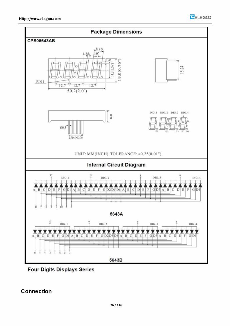
Component Introduction
Four Digital Seven segment display
Http://www.elegoo.com
76 / 116
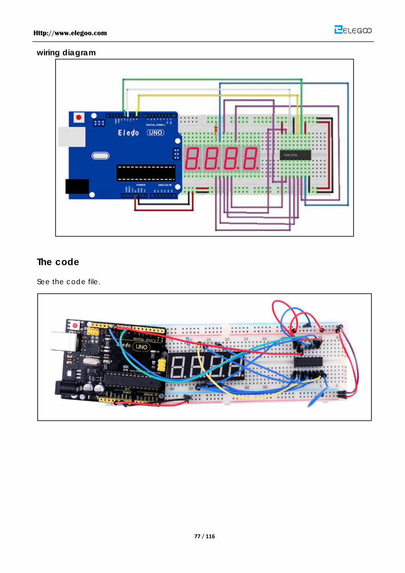
Connection
Http://www.elegoo.com
77 / 116
wiring diagram
The code
See the code file.

Http://www.elegoo.com
78 / 116
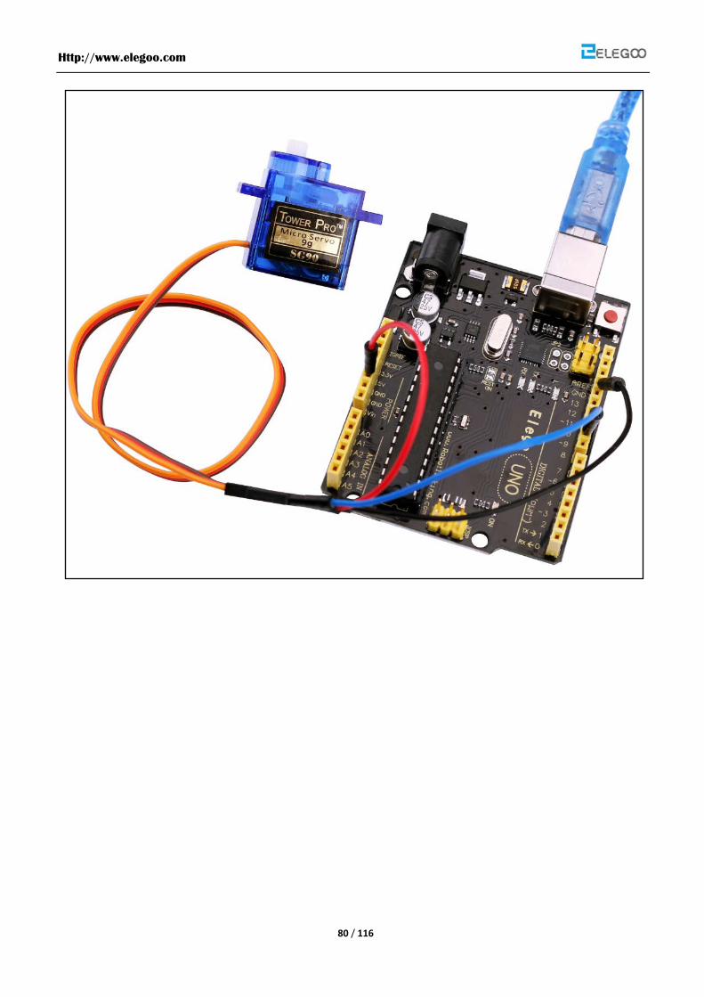
Lesson 14 Servo
Overview
Servo is a type of geared motor that can only rotate 180 degrees. It is controlled by sending
electrical pulses from your Elegoo Uno board. These pulses tell the servo what position it
should move to. A servo has three wires, the brown wire is GND, the red one is VCC, and the
orange one is signal line.
Component Required:
(1) x Elegoo Uno R3
(1) x Servo
(2) x F-M wires
Connection Schematic

Http://www.elegoo.com
79 / 116
wiring diagram
The code
See the code file.
Http://www.elegoo.com
80 / 116
Http://www.elegoo.com
81 / 116
Lesson 15 LCD Display
Overview
In this lesson, you will learn how to wire up and use an alphanumeric LCD display.
The display has an LED backlight and can display two rows with up to 16 characters on each
row. You can see the rectangles for each character on the display and the pixels that make
up each character. The display is just white on blue and is intended for showing text.
In this lesson, we will run the Arduino example program for the LCD library, but in the next
lesson, we will get our display to show the temperature and light level, using sensors.
Component Required:
(1) x Elegoo Uno R3
(1) x LCD1602 display
(1) x Potentiometer
(1) x Breadboard
(16) x F-M wires
Component Introduction
LCD1602
introduction to the pins of LCD1602:
VSS: A pin that connects to ground
VDD: A pin that connects to a +5V power supply
VO: A pin that adjust the contrast of LCD1602
RS: A register select pin that controls where in the LCD’s memory you are writing data to. You
can select either the data register, which holds what goes on the screen, or an instruction
register, which is where the LCD’s controller looks for instructions on what to do next.
R/W: A Read/Write pin that selects reading mode or writing mode
E: An enabling pin that, when supplied with low-level energy, causes the LDC module to

Http://www.elegoo.com
82 / 116
execute relevant instructions.
D0-D7:Pins that read and write data
A and K: Pins that control the LED backlight
Connection Schematic
wiring diagram
Http://www.elegoo.com
83 / 116
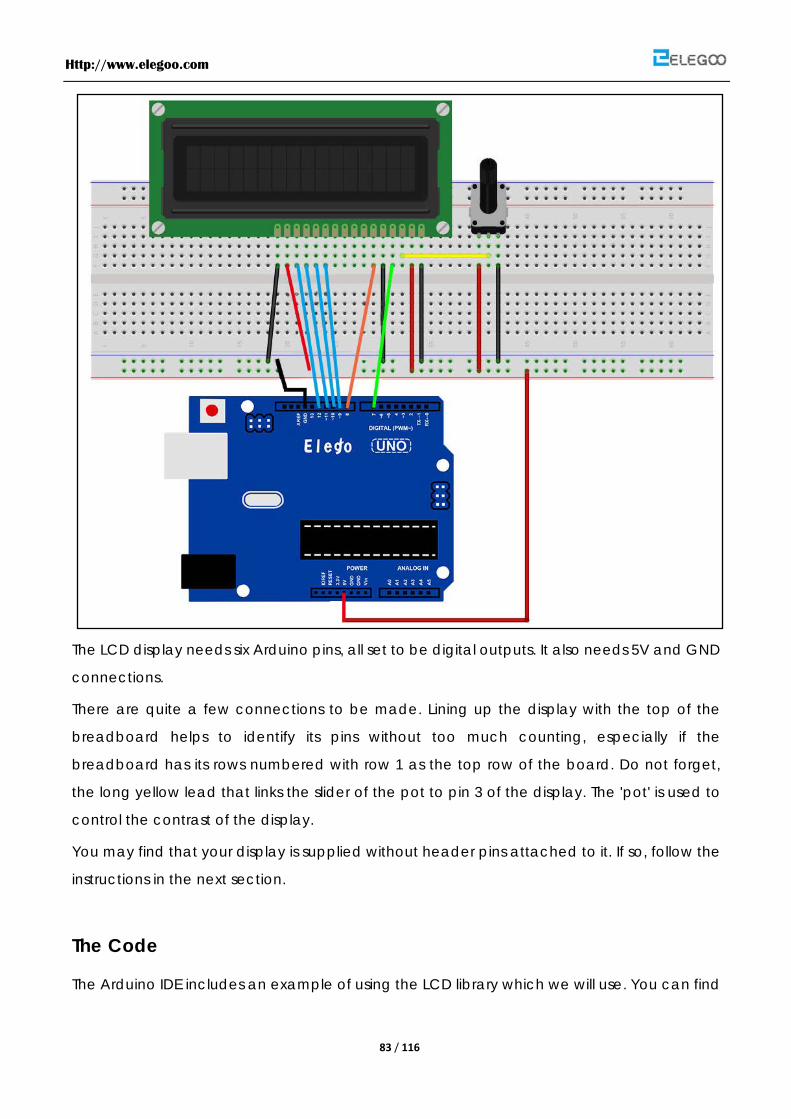
The LCD display needs six Arduino pins, all set to be digital outputs. It also needs 5V and GND
connections.
There are quite a few connections to be made. Lining up the display with the top of the
breadboard helps to identify its pins without too much counting, especially if the
breadboard has its rows numbered with row 1 as the top row of the board. Do not forget,
the long yellow lead that links the slider of the pot to pin 3 of the display. The 'pot' is used to
control the contrast of the display.
You may find that your display is supplied without header pins attached to it. If so, follow the
instructions in the next section.
The Code
The Arduino IDE includes an example of using the LCD library which we will use. You can find
Http://www.elegoo.com
84 / 116
this on the File menu under Examples → Liquid Crystal → HelloWorld.
This example uses different pins to the ones we use, so find the line of code below:
LiquidCrystal lcd(12, 11, 5, 4, 3, 2);
and change it to be:
LiquidCrystal lcd(7, 8, 9, 10, 11, 12);
Upload the code to your Arduino board and you should see the message 'hello, world'
displayed, followed by a number that counts up from zero.
The first thing of note in the sketch is the line:
#include <LiquidCrystal.h>
This tells Arduino that we wish to use the Liquid Crystal library.
Next we have the line that we had to modify. This defines which pins of the Arduino are to
be connected to which pins of the display.
LiquidCrystal lcd(7, 8, 9, 10, 11, 12);
The arguments to this are as follows:
Display Pin Name Display Pin Number Arduino Pin (in this example) RS 4 7 E 6 8 D4 11 9 D5 12
10 D6 13 11 D7 14 12
After uploading this code, make sure the backlight is lit up, and adjust the potentiometer all
the way around until you see the text message
In the 'setup' function, we have two commands:
lcd.begin(16, 2);
lcd.print("hello, world!");
The first tells the Liquid Crystal library how many columns and rows the display has. The
second line displays the message that we see on the first line of the screen.
In the 'loop' function, we aso have two commands:
lcd.setCursor(0, 1);
lcd.print(millis()/1000);
The first sets the cursor position (where the next text will appear) to column 0 & row 1. Both
column and row numbers start at 0 rather than 1.
The second line displays the number of milliseconds since the Arduino was reset.

Http://www.elegoo.com
85 / 116

Http://www.elegoo.com
86 / 116
Lesson 16 Thermometer
Overview
In this lesson, you will use a LCD display to show the temperature.
Component Required:
(1) x Elegoo Uno R3
(1) x LCD1602 display
(1) x 10k ohm resistor
(1) x Thermistor
(1) x Potentiometer
(1) x Breadboard
(16) x F-M wires
Connection Schematic
Http://www.elegoo.com
87 / 116
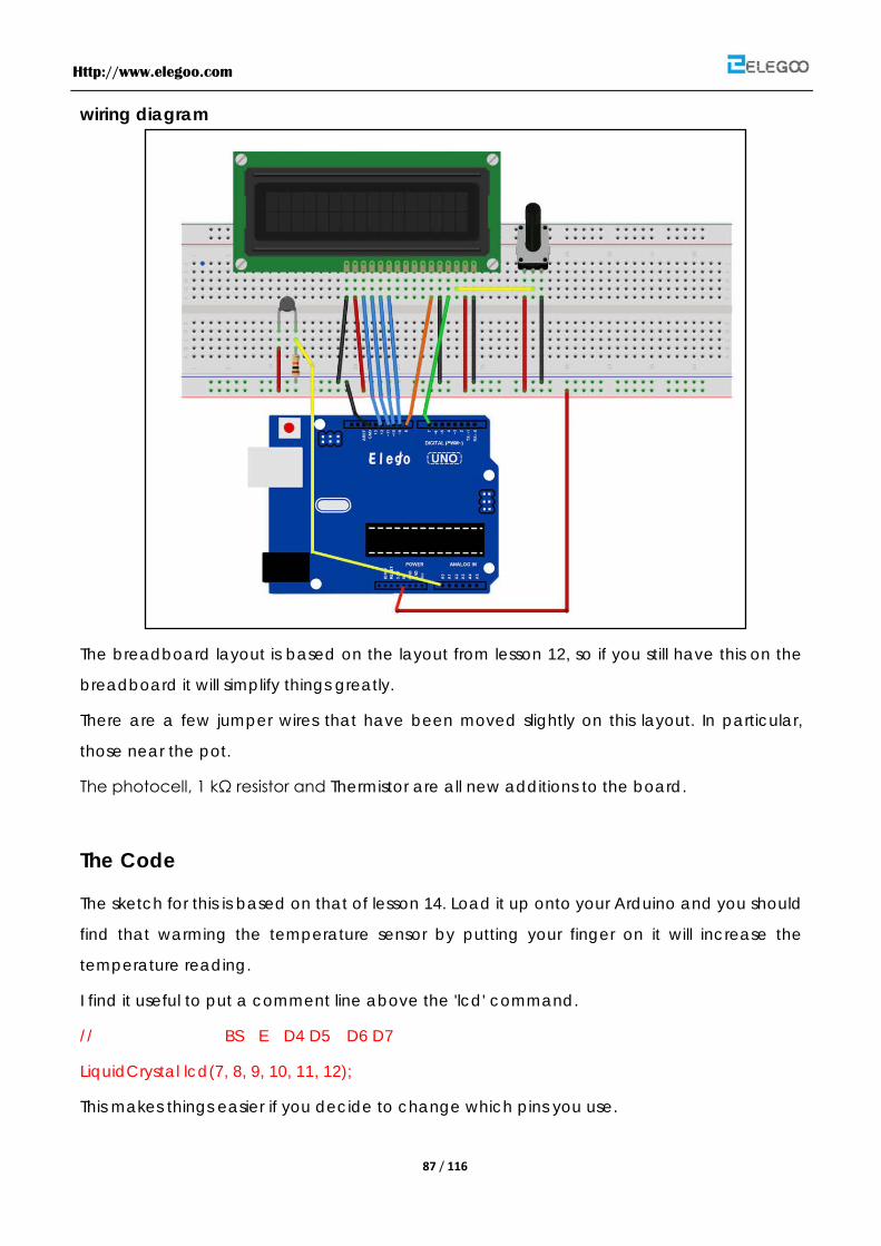
wiring diagram
The breadboard layout is based on the layout from lesson 12, so if you still have this on the
breadboard it will simplify things greatly.
There are a few jumper wires that have been moved slightly on this layout. In particular,
those near the pot.
The photocell, 1 kΩ resistor and Thermistor are all new additions to the board.
The Code
The sketch for this is based on that of lesson 14. Load it up onto your Arduino and you should
find that warming the temperature sensor by putting your finger on it will increase the
temperature reading.
I find it useful to put a comment line above the 'lcd' command.
// BS E D4 D5 D6 D7
LiquidCrystal lcd(7, 8, 9, 10, 11, 12);
This makes things easier if you decide to change which pins you use.
Http://www.elegoo.com
88 / 116
In the 'loop' function there are now two interesting things going on. Firstly we have to
convert the analog from the temperature sensor into an actual temperature, and secondly
we have to work out how to display them.
First of all, let's look at calculating the temperature.
int tempReading = analogRead(tempPin);
float tempVolts = tempReading * 5.0 / 1024.0;
float tempC = (tempVolts - 0.5) * 100.0;
float tempF = tempC * 9.0 / 5.0 + 32.0;
The raw reading from the temperature sensor is first multiplied by 5 and then divided by 1024
to give us the voltage (between 0 and 5) at the 'tempPin' analog input.
To convert the voltage coming from the TMP36 into a temperature in degrees C, you have
to subtract 0.5V from the measurement and then multiply by 100.
To convert this into a temperature in Fahrenheit, you then have to multiply it by 9/5 and then
add 32.
Displaying changing readings on an LCD display can be tricky. The main problem is that the
reading may not always be the same number of digits. So, if the temperature changed from
101.50 to 99.00 then the extra digit from the old reading is in danger of being left on the
display.
To avoid this, write the whole line of the LCD each time around the loop.
// ----------------
lcd.print("Temp F ");
lcd.setCursor(6, 0);
lcd.print(tempF);
The rather strange comment serves to remind you of the 16 columns of the display. You can
then print a string of that length with spaces where the actual reading will go.
To fill in the blanks, set the cursor position for where the reading should appear and then
print it.
Exactly the same approach is used for displaying the light level. There are no units for the
light level, we just display the raw reading from the analog read.
Http://www.elegoo.com
89 / 116

Http://www.elegoo.com
90 / 116
Lesson 17 Ultrasonic Sensor Module
Overview
Ultrasonic sensor are great for all kind of projects that need distance measurements,
avoiding obstacles as examples.
The HC-SR04 are inexpensive and easy to use since we will be using a Library specifically
designed for these sensor.
Component Required:
(1) x Elegoo Uno R3
(1) x Ultrasonic sensor module
(4) x F-M wires
Component Introduction
Ultrasonic sensor
Ultrasonic ranging module HC - SR04 provides 2cm - 400cmnon-contactmeasurement
function, the ranging accuracy can reach to 3mm. The modules includes ultrasonic
transmitters, receiver and control circuit. The basic principle of work:
(1) Using IO trigger for at least 10us high level signal,
(2) The Module automatically sends eight 40 kHz and detect whether there is a pulse signal
back.
(3) IF the signal back, through high level , time of high output IO duration is the time from
sending ultrasonic tore turning.
Test distance = (high level time × velocity of sound (340M/S) /2
The Timing diagram is shown below. You only need to supply a short10uSpulse to the trigger
input to start the ranging, and then the module will send out an 8 cycle burst of ultrasound
at 40 kHz and raise its echo. The Echo is a distance object that is pulse width and the range
in proportion .You can calculate the range through the time interval between sending
trigger signal and receiving echo signal. Formula: uS / 58 = centimeters or uS / 148 =inch; or:
Http://www.elegoo.com
91 / 116
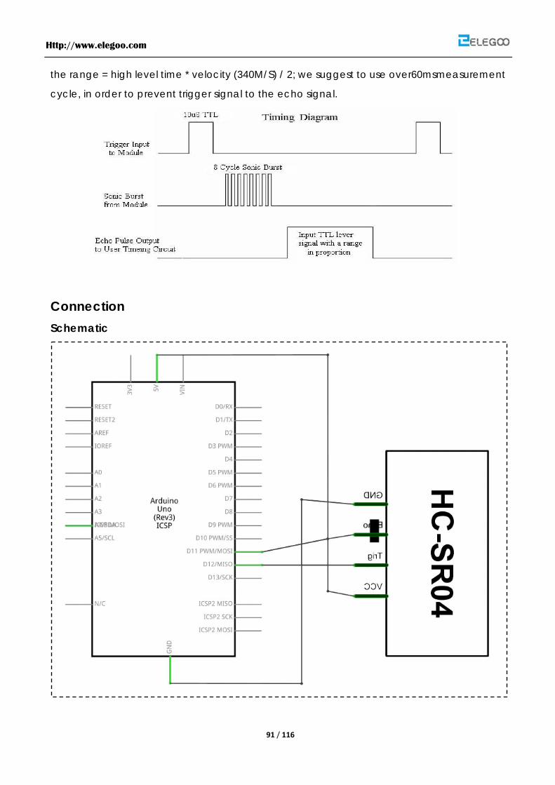
the range = high level time * velocity (340M/S) / 2; we suggest to use over60msmeasurement
cycle, in order to prevent trigger signal to the echo signal.
Connection Schematic
Http://www.elegoo.com
92 / 116
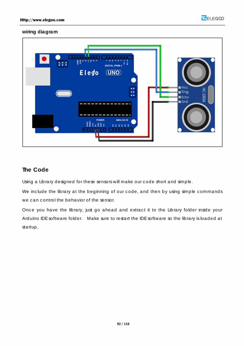
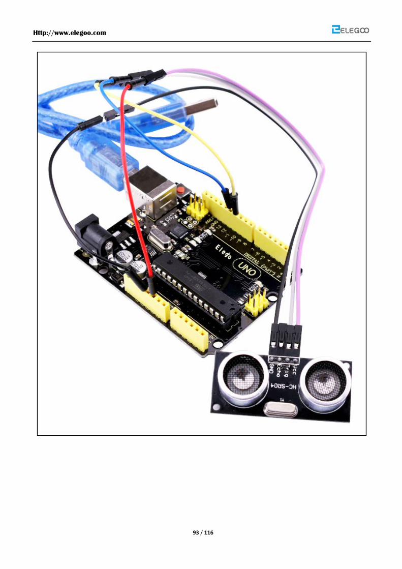
wiring diagram
The Code
Using a Library designed for these sensors will make our code short and simple.
We include the library at the beginning of our code, and then by using simple commands
we can control the behavior of the sensor.
Once you have the library, just go ahead and extract it to the Library folder inside your
Arduino IDE software folder. Make sure to restart the IDE software so the library is loaded at
startup.
Http://www.elegoo.com
93 / 116

Http://www.elegoo.com
94 / 116
Lesson 18 Analog Joystick Module
Overview
Analog joysticks are a great way to add some control in your projects.
In this tutorial we will learn how to use the analog joystick module.
Component Required:
(1) x Elegoo Uno R3
(1) x Joystick module
(5) x F-M wires
Component Introduction
Joystick
The module has 5 pins: Vcc, Ground, X, Y, Key. Note that the labels on yours may be slightly
different, depending on where you got the module from. The thumb stick is analog and
should provide more accurate readings than simple ‘directional’ joysticks tact use some
forms of buttons, or mechanical switches. Additionally, you can press the joystick down
(rather hard on mine) to activate a ‘press to select’ push-button.
We have to use analog Arduino pins to read the data from the X/Y pins, and a digital pin to
read the button. The Key pin is connected to ground, when the joystick is pressed down,
and is floating otherwise. To get stable readings from the Key /Select pin, it needs to be
connected to Vcc via a pull-up resistor. The built in resistors on the Arduino digital pins can
be used. For a tutorial on how to activate the pull-up resistors for Arduino pins, configured as
inputs
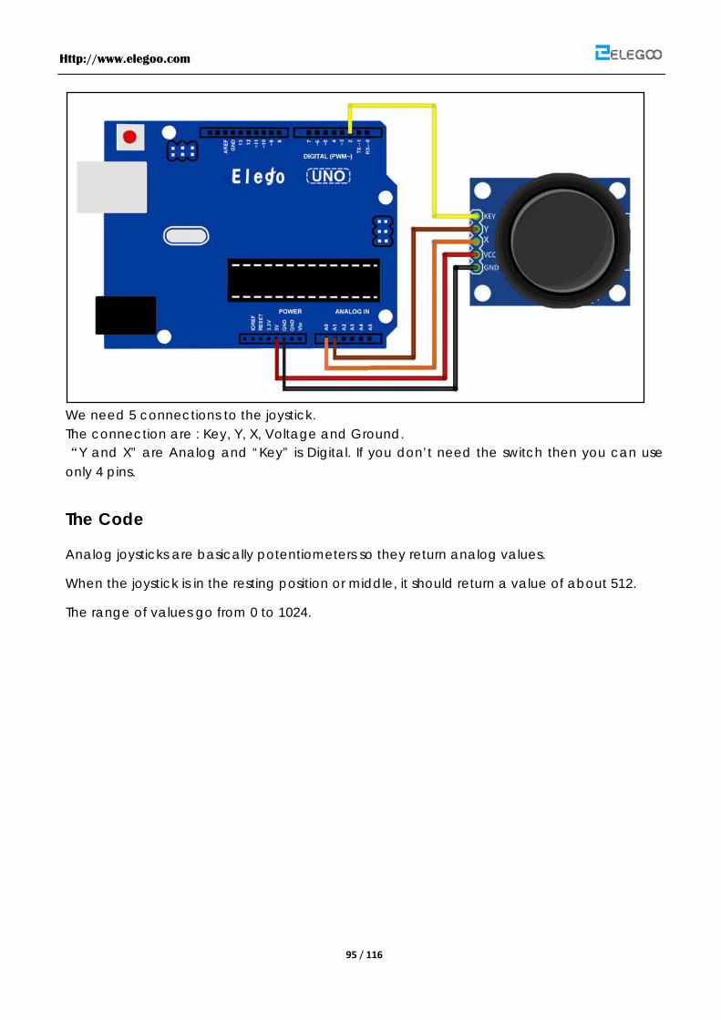
Connection wiring diagram
Http://www.elegoo.com
95 / 116
We need 5 connections to the joystick. The connection are : Key, Y, X, Voltage and Ground. “Y and X” are Analog and “Key” is Digital. If you don’t need the switch then you can use only 4 pins.
The Code
Analog joysticks are basically potentiometers so they return analog values.
When the joystick is in the resting position or middle, it should return a value of about 512.
The range of values go from 0 to 1024.

Http://www.elegoo.com
96 / 116

Http://www.elegoo.com
97 / 116
Lesson 19 IR Receiver Sensor
Overview
Using an IR Remote is a great way to have wireless control of your Arduino project.
Infrared remotes are simple and easy to use. In this tutorial we will be connecting the IR
receiver to the UNO, and then use a Library that was designed for this particular sensor.
In our sketch we will have all the IR Hexadecimal codes that are available on this remote,
we will also detect if the code was recognized and also if we are holding down a key.
Component Required:
(1) x Elegoo Uno R3
(1) x Breadboard
(1) x IR receiver sensor
(1) x IR remote
(3) x F-M wires
Component Introduction
IR RECEIVER SENSOR:
IR detectors are little microchips with a photocell that are tuned to listen to infrared light.
They are almost always used for remote control detection - every TV and DVD player has
one of these in the front to listen for the IR signal from the clicker. Inside the remote control is
a matching IR LED, which emits IR pulses to tell the TV to turn on, off or change channels. IR
light is not visible to the human eye, which means it takes a little more work to test a setup.
There are a few difference between these and say a CdS Photocells:
IR detectors are specially filtered for Infrared light, they are not good at detecting visible
light. On the other hand, photocells are good at detecting yellow/green visible light, not
good at IR light
IR detectors have a demodulator inside that looks for modulated IR at 38 KHz. Just
shining an IR LED wont be detected, it has to be PWM blinking at 38KHz. Photocells do
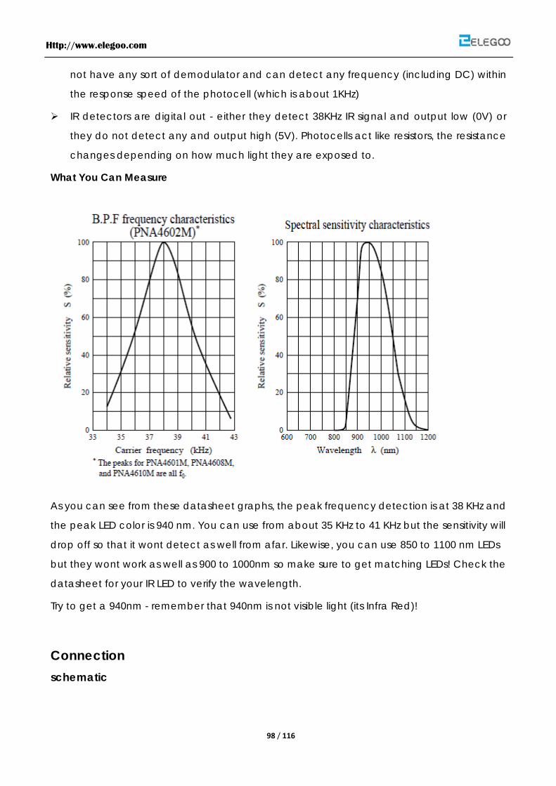
Http://www.elegoo.com
98 / 116
not have any sort of demodulator and can detect any frequency (including DC) within
the response speed of the photocell (which is about 1KHz)
IR detectors are digital out - either they detect 38KHz IR signal and output low (0V) or
they do not detect any and output high (5V). Photocells act like resistors, the resistance
changes depending on how much light they are exposed to.
What You Can Measure
As you can see from these datasheet graphs, the peak frequency detection is at 38 KHz and
the peak LED color is 940 nm. You can use from about 35 KHz to 41 KHz but the sensitivity will
drop off so that it wont detect as well from afar. Likewise, you can use 850 to 1100 nm LEDs
but they wont work as well as 900 to 1000nm so make sure to get matching LEDs! Check the
datasheet for your IR LED to verify the wavelength.
Try to get a 940nm - remember that 940nm is not visible light (its Infra Red)!
Connection schematic
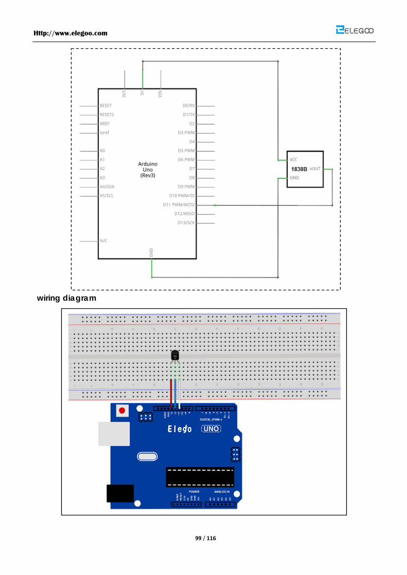
Http://www.elegoo.com
99 / 116
wiring diagram

Http://www.elegoo.com
100 / 116
There are 3 connections to the IR Receiver.
The connections are : Signal, Voltage and Ground.
The “-” is the Ground, “S” is signal, and middle pin is Voltage 5V.
The Code
First download the Library (link below) and extract it to your “Library” folder inside your IDE
software, it should be named “IRremote”
Next we will move the “RobotIRremote” out of the Library folder, we do this because that
library conflicts with the one we will be using. You can just drag it back inside the library
folder once you are done programming your microcontroller.
Once you have installed the Library, just go ahead and restart your IDE Software.
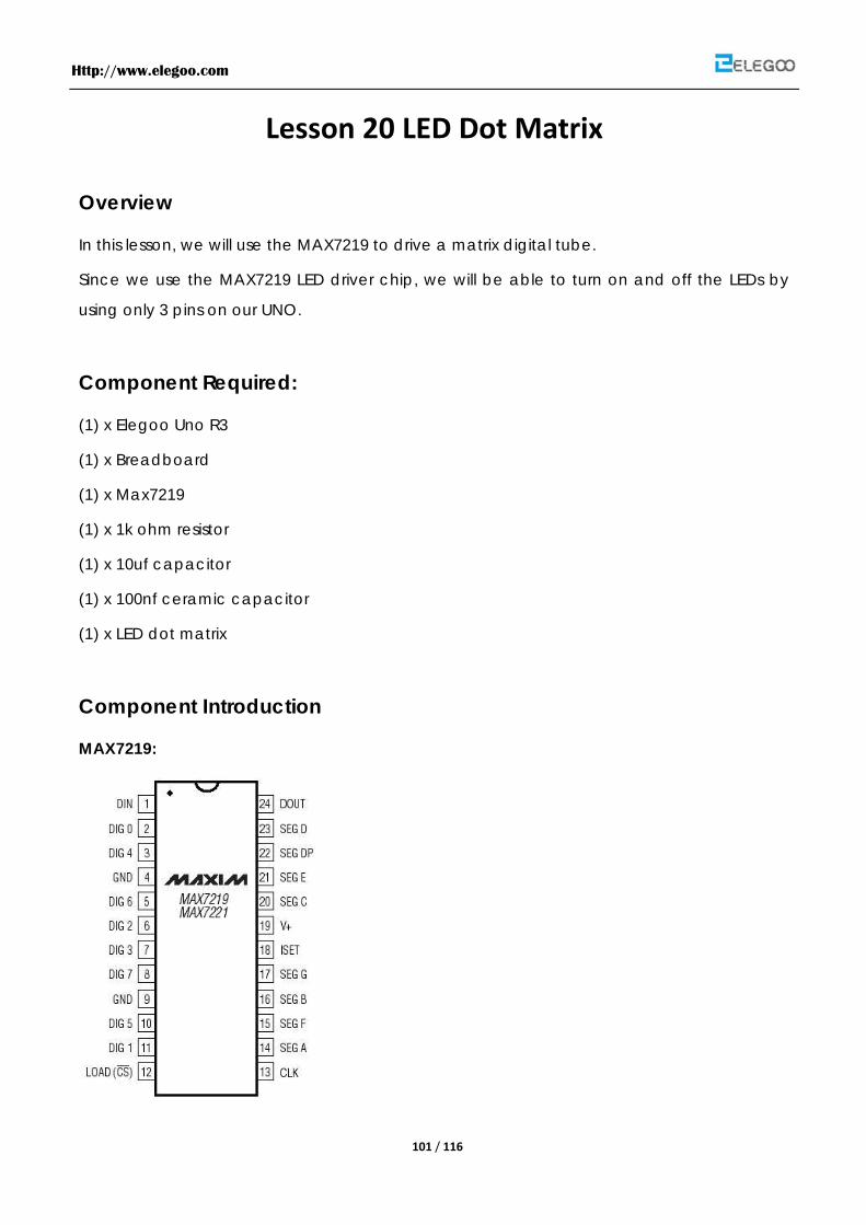
Http://www.elegoo.com
101 / 116
Lesson 20 LED Dot Matrix
Overview
In this lesson, we will use the MAX7219 to drive a matrix digital tube.
Since we use the MAX7219 LED driver chip, we will be able to turn on and off the LEDs by
using only 3 pins on our UNO.
Component Required:
(1) x Elegoo Uno R3
(1) x Breadboard
(1) x Max7219
(1) x 1k ohm resistor
(1) x 10uf capacitor
(1) x 100nf ceramic capacitor
(1) x LED dot matrix
Component Introduction
MAX7219:

Http://www.elegoo.com
102 / 116
MAX7219:
Connection schematic
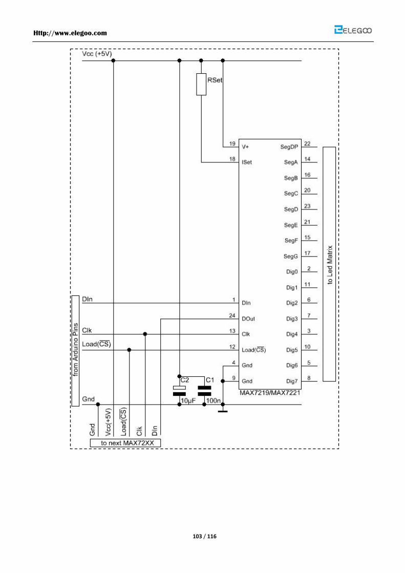
Http://www.elegoo.com
103 / 116
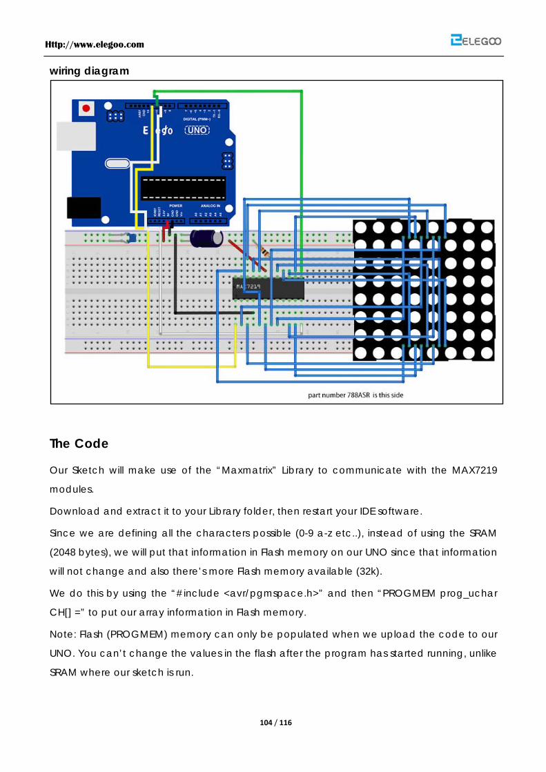
Http://www.elegoo.com
104 / 116
wiring diagram
The Code
Our Sketch will make use of the “Maxmatrix” Library to communicate with the MAX7219
modules.
Download and extract it to your Library folder, then restart your IDE software.
Since we are defining all the characters possible (0-9 a-z etc..), instead of using the SRAM
(2048 bytes), we will put that information in Flash memory on our UNO since that information
will not change and also there’s more Flash memory available (32k).
We do this by using the “#include <avr/pgmspace.h>” and then “PROGMEM prog_uchar
CH[] =” to put our array information in Flash memory.
Note: Flash (PROGMEM) memory can only be populated when we upload the code to our
UNO. You can’t change the values in the flash after the program has started running, unlike
SRAM where our sketch is run.

Http://www.elegoo.com
105 / 116
Http://www.elegoo.com
106 / 116
Lesson 21 MPU6050 Module
Overview
In this lesson, we will learn how to use MPU6050 module which is one of the best IMU (Inertia
Measurement Unit) sensors, compatible with arduino. IMU sensors like the MPU 6050 are used
in self balancing robots, UAVs, smart phones, etc.
Component Required:
(1) x Elegoo Uno R3
(1) x MPU6050 module
(8) x F-M wires
Component Introduction
MPU6050 SENSOR
The InvenSense MPU-6050 sensor contains a MEMS accelerometer and a MEMS gyro in a
single chip. It is very accurate, as it contains 16-bits analog to digital conversion hardware
for each channel. Therefore it captures the x, y, and z channel at the same time. The sensor
uses the I2C-bus to interface with the Arduino.
IMU sensors are one of the most inevitable type of sensors used today in all kinds of
electronic gadgets. They are seen in smart phones, wearables, game controllers, etc. IMU
sensors help us in getting the attitude of an object, attached to the sensor in three
dimensional space. These values usually in angles, thus help us to determine its attitude. Thus,
they are used in smart phones to detect its orientation. And also in wearable gadgets like
the nike fuel band or fit bit, which use IMU sensors to track movement.
How does it work?
IMU sensors usually consists of two or more parts. Listing them by priority, they are :
accelerometer, gyroscope, magnetometer and altimeter. The MPU 6050 is a 6 DOF
(Degrees of Freedom) or a six axis IMU sensor, which means that it gives six values as output.
Three values from the accelerometer and three from the gyroscope. The MPU 6050 is a

Http://www.elegoo.com
107 / 116
sensor based on MEMS (Micro Electro Mechanical Systems) technology. Both the
accelerometer and the gyroscope is embedded inside a single chip. This chip uses I2C (Inter
Integrated Circuit) protocol for communication.
How does an accelerometer work?
An accelerometer works on the principle of piezo electric effect. Here, imagine a cuboidal
box, having a small ball inside it, like in the picture above. The walls of this box are made
with piezo electric crystals. Whenever you tilt the box, the ball is forced to move in the
direction of the inclination, due to gravity. The wall with which the ball collides, creates tiny
piezo electric currents. There are totally, three pairs of opposite walls in a cuboid. Each pair
corresponds to an axis in 3D space: X, Y and Z axes. Depending on the current produced
from the piezo electric walls, we can determine the direction of inclination and its
magnitude. For more information check this.
How does a gyroscope work?
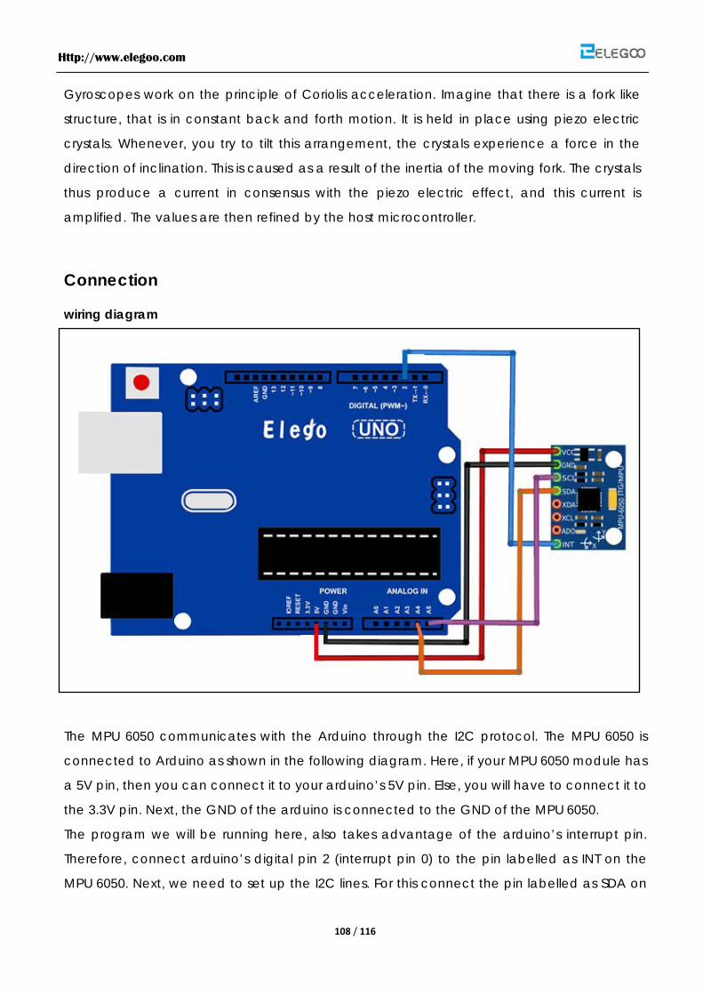
Http://www.elegoo.com
108 / 116
Gyroscopes work on the principle of Coriolis acceleration. Imagine that there is a fork like
structure, that is in constant back and forth motion. It is held in place using piezo electric
crystals. Whenever, you try to tilt this arrangement, the crystals experience a force in the
direction of inclination. This is caused as a result of the inertia of the moving fork. The crystals
thus produce a current in consensus with the piezo electric effect, and this current is
amplified. The values are then refined by the host microcontroller.
Connection
wiring diagram
The MPU 6050 communicates with the Arduino through the I2C protocol. The MPU 6050 is
connected to Arduino as shown in the following diagram. Here, if your MPU 6050 module has
a 5V pin, then you can connect it to your arduino’s 5V pin. Else, you will have to connect it to
the 3.3V pin. Next, the GND of the arduino is connected to the GND of the MPU 6050.
The program we will be running here, also takes advantage of the arduino’s interrupt pin.
Therefore, connect arduino’s digital pin 2 (interrupt pin 0) to the pin labelled as INT on the
MPU 6050. Next, we need to set up the I2C lines. For this connect the pin labelled as SDA on

Http://www.elegoo.com
109 / 116
the MPU 6050 to the arduino’s analog pin 4 (SDA). And the pin labelled as SCL on the MPU
6050 to the arduino’s analog pin 5 (SCL). And that’s it, you have finished wiring up the
Arduino MPU 6050.
Libraries needed I2Cdev
MPU6050
The Code
See the code file.
Http://www.elegoo.com
110 / 116
Lesson 22 DC Motors
Overview
In this lesson, you will learn how to control a small DC motor using an UNO R3 and a
transistor.
Component Required:
(1) x Elegoo Uno R3
(1) x Breadboard
(1) x 6v dc motor
(1) x PN2222
(1) x 1N4007
(1) x 220 ohm resistor
(3) x M-M wires
Component Introduction
TRANSISTORS
The small DC motor, is likely to use more power than an Arduino digital output can handle
directly. If we tried to connect the motor straight to an Arduino pin, there is a good chance
that it could damage the Arduino.
A small transistor like the PN2222 can be used as a switch that uses just a little current from
the Arduino digital output to control the much bigger current of the motor.

Http://www.elegoo.com
111 / 116
The transistor has three leads. Most of the electricity flows from the Collector to the Emitter,
but this will only happen if a small amount is flowing into the Base connection. This small
current is supplied by the Arduino digital output.
The diagram below is called a schematic diagram. Like a breadboard layout, it is a way of
showing how the parts of an electronic project are connected together.
The pin D3 of the Arduino is connected to the resistor. Just like when using an LED, this limits
the current flowing into the transistor through the base.
There is a diode connected across the connections of the motor. Diodes only allow
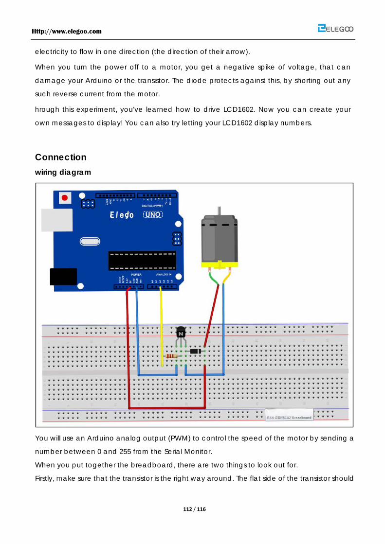
Http://www.elegoo.com
112 / 116
electricity to flow in one direction (the direction of their arrow).
When you turn the power off to a motor, you get a negative spike of voltage, that can
damage your Arduino or the transistor. The diode protects against this, by shorting out any
such reverse current from the motor.
hrough this experiment, you've learned how to drive LCD1602. Now you can create your
own messages to display! You can also try letting your LCD1602 display numbers.
Connection wiring diagram
You will use an Arduino analog output (PWM) to control the speed of the motor by sending a
number between 0 and 255 from the Serial Monitor.
When you put together the breadboard, there are two things to look out for.
Firstly, make sure that the transistor is the right way around. The flat side of the transistor should

Http://www.elegoo.com
113 / 116
be on the right-hand side of the breadboard.
Secondly the striped end of the diode should be towards the +5V power line - see the image
below!
The motor that comes with Adafruit Arduino kits does not draw more than 250mA but if you
have a different motor, it could easily draw 1000mA, more than a USB port can handle! If you
aren't sure of a motor's current draw, power the Arduino from a wall adapter, not just USB.
The transistor acts like a switch, controlling the power to the motor, Arduino pin 3 is used to
turn the transistor on and off and is given the name 'motorPin' in the sketch.
When the sketch starts, it prompts you, to remind you that to control the speed of the motor
you need to enter a value between 0 and 255 in the Serial Monitor.
In the 'loop' function, the command 'Serial.parseInt' is used to read the number entered as
text in the Serial Monitor and convert it into an 'int'.
You could type any number here, so the 'if' statement on the next line only does an analog
write with this number if the number is between 0 and 255.
The Code

Http://www.elegoo.com
114 / 116
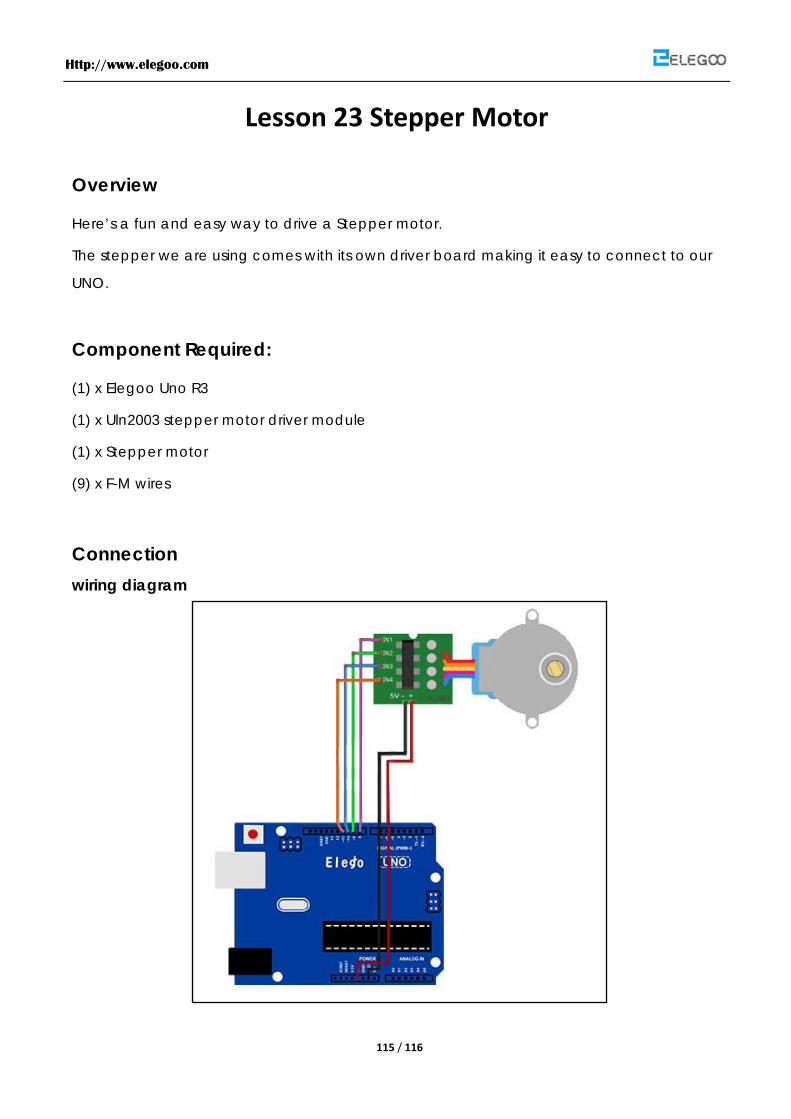
Http://www.elegoo.com
115 / 116
Lesson 23 Stepper Motor
Overview
Here’s a fun and easy way to drive a Stepper motor.
The stepper we are using comes with its own driver board making it easy to connect to our
UNO.
Component Required:
(1) x Elegoo Uno R3
(1) x Uln2003 stepper motor driver module
(1) x Stepper motor
(9) x F-M wires
Connection wiring diagram
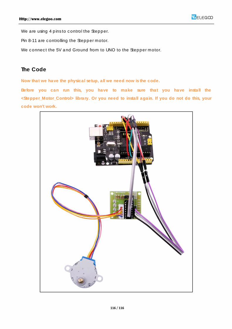
Http://www.elegoo.com
116 / 116
We are using 4 pins to control the Stepper.
Pin 8-11 are controlling the Stepper motor.
We connect the 5V and Ground from to UNO to the Stepper motor.
The Code
Now that we have the physical setup, all we need now is the code.
Before you can run this, you have to make sure that you have install the
<Stepper_Motor_Control> library. Or you need to install again. If you do not do this, your
code won't work.
Copyright © 2022 FDOKUMEN