the minimum workable lhc – plans and requirements for beam ...
305
THE MINIMUM WORKABLE LHC – PLANS AND REQUIREMENTS FOR BEAM COMMISSIONING IN YEARS 1 AND 2 R.Bailey, CERN, Geneva, Switzerland INTRODUCTION Getting to nominal conditions in the LHC is not going to be easy. While the injectors have demonstrated that they can produce the required beams, the filling schemes are rather complex and will need careful commissioning. In the LHC ring, emittance conservation has to be mastered through injection, the energy ramp and the beta squeeze, and with such large numbers of bunches per beam a crossing angle is needed to minimise parasitic beam-beam interactions. Last but not least, a stored energy of 362MJ per beam is some two orders of magnitudes above that achieved at other machines, and will have to be approached with the utmost care. With these things in mind, the proposal for early proton running is to aim for a pilot physics run with a few tens of bunches per beam (Stage I), and the commissioning strategy has been developed with this in mind. Following this, attention will shift to many-bunch operation, first with 75ns spacing (Stage II) and later with 25ns spacing (Stage III), thereby allowing both the complexity of the machine operation and the destructive power of the high intensity beams to be introduced in a controlled, incremental manner. Bunch currents will be gradually increased throughout this. This approach means that in years 1 and 2 of machine operation, the demands on numerous accelerator systems may be somewhat reduced compared to nominal. In this session these considerations were examined for the electrical circuits driving the magnet and RF systems, for beam measurements and associated instrumentation, for feedback systems, for applications software needed to exploit these systems, and for vacuum and radiation protection systems. Session 2 concentrated on machine protection systems, while session 3 asked the providers of the accelerator systems to comment on their readiness. The three sessions should be regarded as a whole. ELECTRICAL CIRCUITS Clearly all the circuits for the dipole and quadrupole magnets in the arcs and the dispersion suppressors, and those for the separation dipoles and insertion quadrupoles, are needed from day 1. Experiment spectrometer magnets and associated compensation dipoles will be needed for the first physics run. With reduced beam intensities, it would be possible to operate without all the RF cavities, but for reasons of longitudinal acceptance it is recommended that all are made available from the start. The corrector circuits have all been assessed in terms of the functionality that they provide in the light of specifications on various beam parameters. The outcome is a definition of the corrector circuits needed on day 1, those needed a little later but still during Stage I, and those not needed until later stages. It turns out that the circuits not needed for Stage I are so few that it makes no sense to omit them from the hardware commissioning phase. The conclusion is therefore to get ALL circuits ready for day 1. BEAM MEASUREMENTS From an examination of the systematic and random field components in the LHC dipole magnets at injection and their change during snapback, the errors expected on important machine parameters can be estimated. Comparing the estimated errors to the tolerances on the various parameters, it is clear that the LHC cannot be commissioned without numerous beam based optics measurements and corrections. The measurements required, and the instruments needed to perform them, have been analysed through the different commissioning steps for Stage I. The extra measurements needed in Stages II and III have also been identified. While this approach establishes the techniques and instrumentation needed at the various stages of LHC commissioning, experience from other facilities shows that some redundancy could be very helpful to deal with unforeseen problems, particularly during the initial stages of operation. FEEDBACK SYSTEMS While measurement and control of numerous beam parameters will be an integral part of LHC operation from the start, manual control of certain key parameters may soon become a limitation in terms of precision and efficiency. Feedback systems are therefore considered for stabilisation of orbit, energy, tune, chromaticity and coupling. Assuming that the systematic magnetic field imperfections are sufficiently well corrected, the perturbations relevant for feedbacks are driven mainly by ground motion, eddy currents and snapback at the start of the ramp, and the beta squeeze. These dynamic perturbations have been estimated and compared to the requirements on their control during first commissioning, though Stage I and for nominal performance. This analysis shows that chromaticity is the most critical parameter to control, but automated control of other parameters may also be needed to a certain level. In any case, in order to provide chromaticity control early on, a reliable measurement of the tune is needed. Furthermore, it will be necessary to have the coupling under control, especially during the early part of the ramp. LHC Project Workshop - 'Chamonix XV' 1
-
Upload
khangminh22 -
Category
Documents
-
view
14 -
download
0
Transcript of the minimum workable lhc – plans and requirements for beam ...
THE MINIMUM WORKABLE LHC – PLANS AND REQUIREMENTS FOR BEAM COMMISSIONING IN YEARS 1 AND 2
R.Bailey, CERN, Geneva, Switzerland
INTRODUCTION
Getting to nominal conditions in the LHC is not going to be easy. While the injectors have demonstrated that they can produce the required beams, the filling schemes are rather complex and will need careful commissioning. In the LHC ring, emittance conservation has to be mastered through injection, the energy ramp and the beta squeeze, and with such large numbers of bunches per beam a crossing angle is needed to minimise parasitic beam-beam interactions. Last but not least, a stored energy of 362MJ per beam is some two orders of magnitudes above that achieved at other machines, and will have to be approached with the utmost care.
With these things in mind, the proposal for early proton running is to aim for a pilot physics run with a few tens of bunches per beam (Stage I), and the commissioning strategy has been developed with this in mind. Following this, attention will shift to many-bunch operation, first with 75ns spacing (Stage II) and later with 25ns spacing (Stage III), thereby allowing both the complexity of the machine operation and the destructive power of the high intensity beams to be introduced in a controlled, incremental manner. Bunch currents will be gradually increased throughout this.
This approach means that in years 1 and 2 of machine operation, the demands on numerous accelerator systems may be somewhat reduced compared to nominal.
In this session these considerations were examined for the electrical circuits driving the magnet and RF systems, for beam measurements and associated instrumentation, for feedback systems, for applications software needed to exploit these systems, and for vacuum and radiation protection systems. Session 2 concentrated on machine protection systems, while session 3 asked the providers of the accelerator systems to comment on their readiness. The three sessions should be regarded as a whole.
ELECTRICAL CIRCUITS Clearly all the circuits for the dipole and quadrupole
magnets in the arcs and the dispersion suppressors, and those for the separation dipoles and insertion quadrupoles, are needed from day 1. Experiment spectrometer magnets and associated compensation dipoles will be needed for the first physics run. With reduced beam intensities, it would be possible to operate without all the RF cavities, but for reasons of longitudinal acceptance it is recommended that all are made available from the start.
The corrector circuits have all been assessed in terms of the functionality that they provide in the light of specifications on various beam parameters. The outcome is a definition of the corrector circuits needed on day 1,
those needed a little later but still during Stage I, and those not needed until later stages. It turns out that the circuits not needed for Stage I are so few that it makes no sense to omit them from the hardware commissioning phase. The conclusion is therefore to get ALL circuits ready for day 1.
BEAM MEASUREMENTS From an examination of the systematic and random
field components in the LHC dipole magnets at injection and their change during snapback, the errors expected on important machine parameters can be estimated. Comparing the estimated errors to the tolerances on the various parameters, it is clear that the LHC cannot be commissioned without numerous beam based optics measurements and corrections.
The measurements required, and the instruments needed to perform them, have been analysed through the different commissioning steps for Stage I. The extra measurements needed in Stages II and III have also been identified.
While this approach establishes the techniques and instrumentation needed at the various stages of LHC commissioning, experience from other facilities shows that some redundancy could be very helpful to deal with unforeseen problems, particularly during the initial stages of operation.
FEEDBACK SYSTEMS While measurement and control of numerous beam
parameters will be an integral part of LHC operation from the start, manual control of certain key parameters may soon become a limitation in terms of precision and efficiency. Feedback systems are therefore considered for stabilisation of orbit, energy, tune, chromaticity and coupling.
Assuming that the systematic magnetic field imperfections are sufficiently well corrected, the perturbations relevant for feedbacks are driven mainly by ground motion, eddy currents and snapback at the start of the ramp, and the beta squeeze. These dynamic perturbations have been estimated and compared to the requirements on their control during first commissioning, though Stage I and for nominal performance. This analysis shows that chromaticity is the most critical parameter to control, but automated control of other parameters may also be needed to a certain level. In any case, in order to provide chromaticity control early on, a reliable measurement of the tune is needed. Furthermore, it will be necessary to have the coupling under control, especially during the early part of the ramp.
LHC Project Workshop - 'Chamonix XV'
1

The LHC orbit feedback is the most advanced, driven by collimation and machine protection requirements. The system has been optimised for robust and failure-tolerant operation, and many lessons can be learned from this. With a functioning orbit feedback available, an energy feedback system could be made available at an early stage.
With these somewhat conflicting priorities in mind, the proposal for feedback systems is the following: Get the coupling under control early on, and then implement feedback systems for tune, chromaticity, orbit and energy.
APPLICATIONS SOFTWARE The previous sections have implications for the
applications software needed for management of settings, accessing equipment, making measurements and applying the necessary corrections. The high level software is being developed to provide a common functionality across all equipment and measurement classes, and as such is supported by a core system that has to be in place to control anything. That being said, it is possible to prioritise the order in which different systems have to be available, notably in the domain of measurement and correct systems. This has been done and should be taken into consideration in software development planning.
VACUUM CONDITIONS The LHC vacuum system has been designed for
operation at nominal or even ultimate intensities. However, the limited performance of the machine during early operation opens up the possibility to consider running with an unbaked vacuum system. The performance of such a system and the consequences of
proton scattering by the increased residual gas have been investigated.
From the point of view of many aspects of machine operation (vacuum pressure, beam lifetime, magnet quench levels and dissipated power in the cold mass) there would be no problem. However, increased radiation dose due to the scattering off residual gas is a limiting factor. There are also concerns from the experiments, which have based their rates on nominal vacuum pressures, and the RF regions. For collimator installation, there would be clear advantages of no bake out in the beam cleaning regions.
In any case, full bake out of all regions would be made by 2008.
RADIATION PROTECTION ISSUES As CERN enters the LHC era, the definition of
radiation zones has been refined in terms of limits, constraints and reference values. These changes have consequences for the way in which access into these zones is managed. In particular, new procedures will be introduced for access into controlled areas, according to activation levels and the associated risk of exposure to personnel.
Against this background, a preliminary estimate of the expected rates during the different stages of commissioning has been made. This indicates that during Stage I, the classification of the different areas of the LHC could be relaxed compared to nominal operation. It was also noted that the full functionality of the special installations to control air activation in point 7 would not be needed for Stage I. In all cases, the final situation will prevail for Stage II and beyond.
LHC Project Workshop - 'Chamonix XV'
2
SUMMARY: MACHINE PROTECTION ISSUES AFFECTING BEAM COMMISSIONING
R.Schmidt and J.Uythoven, CERN, Geneva, Switzerland
1. LIST OF PRESENTATIONS
1. Commissioning and (early) operation - view from machine protection, Jan Uythoven
2. What Systems request a Beam Dump, Jörg Wenninger
3. What is required to safely fill LHC, Verena Kain 4. What is required to get the beam safely out of LHC,
Brennan Goddard 5. Beam Commissioning of the Collimation Systems,
Ralph Assmann 6. Critical Beam Losses during Commissioning and
Initial Operation, Guillaume Robert-Demolaize 7. Commissioning of Beam Loss Monitors, Bernd
Dehning
2. COMMISSIONING AND EARLY OPERATION – WHAT SYSTEMS
REQUEST A BEAM DUMP Machine protection and collimation for LHC is very
complex and a full session was therefore dedicated to its commissioning and early operation. The damage level for fast proton losses at 450 GeV is about 1-2·1012 and at 7 TeV to about 1-2·1010. For 7 TeV, a pilot bunch is close to the damage limit. The proton-proton luminosity operation with safe beam would be limited to some 1027 s-1 cm-2.
A substantial part of the commissioning can already be done without beam during equipment tests and hardware commissioning.
As for the general beam commissioning presented in [1], commissioning of the machine protection systems will take place in stages. For protection, a stage depends on several parameters, such as momentum, beam intensity and operational states. Since the stages for general commissioning do not have the required granularity, “sub”-stages are proposed:
• first pilot with an intensity of less than 1010 protons • beam with 1012 protons, safe at 450 GeV • 43 bunches per beam The commissioning stages will be different for different
types of equipment. Tables are given in [2] defining what protection systems are required for each stage.
The stages and the formal acceptance of the machine protection systems should be defined, documented and approved before the tests. Corresponding procedures need to be written and agreed upon.
One risk is an uncontrolled modification of critical parameters in the protection systems, such as thresholds
for beam loss monitors. Direct and uncontrolled access to front-end crates of critical systems is not acceptable. A comprehensive system to manage critical settings is required.
The creation of a Machine Protection Coordination Team is proposed, supported by many key players in machine protection. Such team should drive the formalisation of the commissioning procedures and validate tests together with operation. The team would be composed by a small team of experts, also available for consultation during commissioning and operation.
3. INJECTION AND DUMPING THE BEAMS
The damage limit at 450 GeV is ~ 2·1012 protons (~5 % of nominal full batch). Injection protection must be in place and working correctly when the intensity of the injected beam from the SPS exceeds this limit.
Injection protection systems should be operational for 156 on 156 with 9·1010 protons per bunch in stage I and therefore need commissioning at latest during operation with 43 on 43 bunches, to authorise starting operation with 156 bunches.
According to the overall commissioning strategy for protons, it is mandatory to have all injection protection systems fully operational for commissioning stage II (936 bunches per ring, 96 bunches maximum injected, maximum intensity per bunch: 9·1010 protons).
Starting from extraction from the SPS, the injection protection systems that are required for the different stages are given in table in [3].
The TCLI absorbers can be commissioned later since these devices are only required above 50% of nominal injected intensity.
Extraction of high intensity beams from the SPS and transport through beam-lines with tight apertures will be commissioned before LHC beam operation. The commissioning of CNGS and TI 8 with high(er) intensity beams are foreseen for 2006. Beams for CNGS operation in 2006 have more stored energy than nominal beams for injection into LHC.
A sequencer will drive the LHC through various states to ensure safe operation. "Operational states" in the sequencer for the various sub-systems including the protection systems have to been defined (e.g. TDI "ready for pilot", TDI "ready for intermediate",..). Clearly the interplay between the various software systems such as sequencer, management of critical settings and software
LHC Project Workshop - 'Chamonix XV'
3

interlocking plays a crucial role in guaranteeing safe operation and needs to be further addressed.
The commissioning pathway for injection protection needs formalisation. For passive protection systems (beam absorbers), setting-up methods should be established.
Already for operation with pilot bunches, the LHC Beam Dumping System should be operational to safely extract the protons. No beam without a functioning beam dumping system! There are a number of safety critical aspects of the Beam Dumping System, with different levels of criticality.
In a first phase, many tests can be performed during hardware commissioning and during the reliability run that has been proposed. As an example, the interconnectivity between the subsystems and reliability assumptions will be validated.
The second phase requires careful commissioning with pilot beam:
• At 450 GeV in the LHC before extraction, to check the beam optics and aperture for the stored beam in the beam dumping elements
• At 450 GeV before first ramp, to check the beam optics and apertures at injection energy
• At 450 GeV to check the “Inject & Dump” mode • During the ramp, to validate the energy tracking
and other settings for the different beam energies • Specific checks are required when the LHC beam
parameters change (more bunches, more intensity, different bunch pattern, etc.), to verify instrument response, diagnostics and losses
Commissioning of the TCDQ/TCS positioning in IR6 can be relaxed in the case of limited β squeeze and limited number of bunches. The beam halo load on the TCDQ during “minimum collimation”, see section 4, might lead to Q4 quenches. This issue needs further investigation.
The “Inject and dump mode” should be available from the start and needs to be addressed. There are still many details to be finalised: timing, data recording, diagnostics, configuration management, etc.
During stage I abort gap monitoring and cleaning could be important for operational efficiency, although this is not required for damage protection.
4. COLLIMATION The collimation system provides several functions: • Beam cleaning • Passive machine protection • Background control for the particle physics
experiments Each collimator scenario must be compatible with all
three functions. Based on recent simulation results, the full LHC
collimation system of phase 1 should allow reaching 40% of nominal intensity. Taking into account machine
imperfections, the cleaning efficiency could be lower by a factor between 2-5.
There is a clear view on how to commission the phase 1 collimation system with well defined priorities, based on performance studies. Commissioning will start from reduced sets of collimators and relaxed tolerances. Then collimator sub-systems will be added. If only cleaning efficiency is considered, secondary collimators could be delayed, but they will be used for the required passive protection (“safer” minimal system).
Passive protection is not as complete as with all collimators at tight settings in this approach, even with “safer” system. The early use of W collimators simplifies the system but with higher sensitivity to damage (reduced robustness).
Many collimators can initially be put in after the start of the ramp (e.g. to avoid problems during snapback), if controls and machine stability allows to do so safely.
Significant risk and uncertainties in minimal approach: Collimator production and installation must aim at a full collimator complement so that we can adequately optimize performance, passive protection and robustness.
There are ~40 collimators per ring for phase 1 of the collimation system. About 3700 Beam Loss Monitors are installed around the machine. Assuming that the beam halo is intercepted by a collimator, a limited number of BLMs at fixed locations are expected to always detect beam losses. Most of these are monitors at the collimators and downstream in the arc. The loss locations are fairly insensitive to closed orbit distortions. Some locations close to dipole magnets in the dispersion suppressor downstream of the cleaning insertion have been identified where additional BLMs should be positioned.
It should be kept in mind that all results come from computer simulations... reality will show.
5. BEAM LOSS MONITOR SYSTEM There are several steps for the commissioning of the
Beam Loss Monitor system, starting before beam operation:
• Establishing BLM thresholds to avoid quenches. A small safety factor is sufficient.
• Establishing BLM thresholds to avoid damage. A large safety factor is required. Most monitors will have thresholds that are much lower, since they are also used to prevent quenches. The threshold for protection against damage must never be excceded.
• The thresholds are loaded into the BLM controllers.
• The system is validated without beam. The next step is after start-up LHC with beam: • Analysis of beam losses causing beam aborts or
quenches to identify/verify model uncertainties (parasitic to operation).
• Beam quench tests to optimise threshold tables (sector test will establish procedure).
LHC Project Workshop - 'Chamonix XV'
4

In case of an excessive number of beam aborts or quenches, there must be some flexibility to change the thresholds of the beam loss monitors.
Tools for analysis of beam aborts and quenches must be available for the start-up (logging, post mortem, etc.)
There are about 4000 BLMs, and the threshold for each BLM depends on energy and on integration time. This is a very complex system, and the question was asked if we could reduce the complexity for initial operation?
6. CONCLUSIONS It was pointed out by several speakers that settings used
in the machine protection systems should be well controlled. Wrong settings could compromise the correct functioning of BLMs, collimators, and other systems. Work on the Management of Critical Settings is ongoing and a draft for functional specification has been written. For the start-up, such a system must be in place.
Access to equipment via the controls system will not be as easy as for other CERN accelerators in the past, due to the large risk. The separation of technical network and office network is a clear progress and the first step. A strategy for accessing equipment via the network, from inside and outside CERN, is required.
Machine protection systems will be required for the different operational stages. Not everything is required for day one, but most systems should become available when accelerating 156 bunches per beam. A follow-up should ensure that the protection systems are ready when they are required.
The commissioning of the Beam Dumping System requires other systems to be operational, such as beam monitors (BPMs, Screens, BLMs), collimators (TCDQ & TCS in IR6, other collimators). It is important that everyone is aware and understands the implications for the Beam Dumping System. Colleagues from several groups are concerned, RF, BI, CO, ATB, etc.
Although the calculated cleaning efficiency improved with respect to the last workshop, operation of LHC will be strongly affected by cleaning efficiency. The allowed beam intensity during operation at a certain stage will be limited to survive high loss rates without quench. An increase in the allowed beam intensity will be obtained by improving the machine (lifetime, orbit etc.) and the collimation system (more jaws, tighter gaps etc.).
There is a factor of 1000 in cleaning efficiency with respect to other machines – we must be prepared to learn with beam.
A simplification for the early operation is to use fewer jaws, and/or with relaxed collimator settings, then bring up the complex system in steps.
The commissioning of the collimation system must be done in a controlled way with good beam conditions. During the early operation it only requires beam loss monitors at collimators and some few other locations.
Operation of the beam cleaning system requires a powerful controls system. Collimator positions are critical and must be managed accordingly.
Sophisticated controls for the collimators are required, and software to optimise setting-up procedures.
For each operational stage, operational settings are known, maximum allowed settings of collimators for machine protection need to be worked out in detail.
The Beam Loss Monitor System (detectors, electronics etc.) is expected to be operational before beam. The commissioning and operational scenarios must be further developed.
Formalised procedures, documented and approved, for machine protection systems is required for different stages. This is successfully being done for Hardware Commissioning, but it is important that this approach for beam commissioning is agreed upon and taken seriously.
Operating conditions for the different commissioning stages have to be defined. Each system including the beam dumping system will be commissioned for the current operating conditions. A move to the next commissioning stage must be authorized. Testing and acceptance procedures and required state for the next stage e.g. "beam dumping system ready for 43 on 43" etc. have to be defined.
Operation of the LHC will be strongly confined by machine protection issues. Therefore integration of the commissioning for Machine Protection Systems into general beam operation is required, by close collaboration between machine protection experts and operation / commissioning team.
The creation of a Machine Protection Coordination Team is proposed. Do we agree that such team would be useful, and what would be the mandate? How could the activities of such team be integrated into operation?
Today, commissioning is mainly discussed in two working groups, LHC-OP and MPWG, both reporting to LTC. The organisation of LHC beam commissioning should be revisited, aiming at an improved integration of machine protection commissioning and general LHC commissioning.
8. ACKNOWLEDGEMENTS Thanks to all speakers in this session on machine
protection and collimation as well as everyone who contributed outside the session.
9. REFERENCES
[1] R.Bailey, Overall commissioning strategy for protons, these proceedings
[2] J.Wenninger, What Systems request a Beam Dump, these proceedings
[3] V.Kain, What is required to safely fill LHC, these proceedings
LHC Project Workshop - 'Chamonix XV'
5
SUMMARY: THE MINIMUM WORKABLE LHC – PROVIDERS' COMMITMENTS
JJ. Gras, S. Bart Pedersen, CERN, Geneva, Switzerland
RESPONSIBILITIES AND RESOURCES After 2003 major re-structuration, the AB department
refined this year its organisation. The resulting responsibility dispatching is basically the following: Equipment groups are responsible for:
o The equipments o The front end electronics o The front end software and corresponding expert
application whenever necessary Controls group is in charge of:
o The control services (timing, DB, Alarms, Operating systems, FESA…)
o The software above front end servers necessary to operate the machine (operational GUIs, real time feedback, BPM, BLM concentrators…). This work is done in close collaboration with OP.
The equipment groups which contributed to the session (i.e. ATB, BI and RF) are all heavily loaded but should be able to fulfil their commitments with their available resources. CO on its side claims still missing several competent java programmers to complete the necessary developments. Project associate with the right skills seems difficult to find and this could eventually lead to a de-facto ‘regulation by saturation’ of the development instead of a planned regulation. Another big concern in this domain are the 24/365 necessary piquet services (like for Alarms for instance). CO is currently not able to provide them
ATB COMMITMENTS AND MAJOR ISSUES
O. Aberle
The AB/ATB group is responsible for the LHC dumps (TED, TBSE, TDE, TDI), masks (TCDD, TCLIM, TCDIM) and collimators (TCP, TCS, TCT, TCLA, TCLP…).
All screens and dump should be ready for Stage I (some equipments may be late for the sector test). ATB however has significant delays on collimators production.
In order to cope with this delays, ATB will install the collimators in two major phases. Phase I will provide the collimators necessary to run the machine up to 40% of the nominal intensity. The Phase II upgrade will add the necessary collimators to reach the nominal intensity. Unfortunately, the current delays and uncertainties (brazing issues) on production are not compatible with the installation planning. It has been proposed and accepted last year that the collimator Phase I installation will be
split into two campaigns. Available collimators will follow the installation planning and a second campaign will be organized later (late Spring 2007) to install the missing collimators.
This staging strategy should allow ATB to provide all standard Phase I collimators for the LHC start-up with Phase II locations prepared for an efficient installation.
BI COMMITMENTS AND MAJOR ISSUES
B. Holzer – R. Jones
AB-BI is currently working in close collaboration with TS/MME for the production of the different instruments which represents a huge activity. The production of these different monitors is currently on schedule with respect to the installation planning under discussion but most of these items are on the ‘just in time’ path. The expected performance of the different instruments with respect to the proposed scenario is summarized below.
BPM The Beam Position Monitors are expected to be fully
functional for the LHC start-up. According to the LHC planning stages, the commissioning of the BPM systems will be progressive. The only concern is the ability to measure beam intensity via the BPMs which may not be ready for the start-up. The importance of the measurement has been confirmed during the session and BI will to its best to cover this need.
BLM The Beam Loss Monitors with threshold tables as a
function of quench level and energy will be ready for the LHC start-up and connected to the machine protection system. Some issues on the definition and handling of these threshold are still under discussion but the implemented strategy should be decided soon. The BLM will be extensively tested during the sector test and the logging and the post-mortem infrastructure will be used for their commissioning.
BOB The beam synchronous timing system will be available
for the LHC start-up. The final version that covers the requested needs is currently being tested. The BOB system will be commissioned for the SPS in 2006 and assessed during the LHC sector test.
LHC Project Workshop - 'Chamonix XV'
6
Beam current and lifetime measurement The LHC will be equipped with two DCCTs per ring,
two fast beam current transformers per ring and two fast BCTs for the dump lines. The layout for these monitors has been finalized and the construction is ongoing. Only a minimal integration of machine protection requirements based on a software implementation will be available for Stage I/II. The complete integration is only foreseen for later stages.
Tune, chromaticity and coupling measurement A 3 stage approach for Q, Q’ and coupling
measurement has been proposed and accepted. 1. classical FFT analysis 2. then with PLL tune tracking 3. finally with full PLL based feedbacks.
The speed of the sequence will depend on experience with beam but for operational beams, the Base Band Tune (BBQ) measurement system seems to give excellent results.
Beam size measurement To measure beam size, the base-line instruments are: 1) Wire scanners (BWS) 2) Synchrotron light monitors (BSRT) 3) Rest gas ionization monitors (BGI) 4) Optical transition radiation monitors (BTV) (only
for inject&dump modes) The LHC wire scanners, which are mainly intended for
calibration, will not meet their nominal specifications for Stage I/II (reduced accuracy and lower intensity limit due to low speed) but they’ll cover Stage I/II requirements. New electronics for the motorization system will be installed and commissioned for Stage IIII, allowing the full specifications to be met.
The LHC synchrotron light monitor (BSRT) will be used at start-up with a limited electronic installation only providing average beam sizes at 10Hz. The fast camera for bunch to bunch measurements will only be installed for Stage III.
With the SPS experience, the rest gas ionization monitor (BGI) is expected to be made operational very soon after initial start-up.
The BSRT and BGI will require dedicated commissioning time to calibrate them with respect to both beam intensity and energy.
The BTV systems are already used operationally in LTI and will be ready for start-up but the matching functionality will not be provided before Stage III.
Abort gap monitoring The abort gap monitor (BSRA) tests have confirmed that the detection levels required for protons can be reached at all energies. For ions, however, no solution currently exists. A long term solution, possibly for Phase II, would mean replacing the current undulator with a shorter period undulator.
RF COMMITMENTS AND MAJOR ISSUES
E. Ciapala
Equipment under the responsibility of the AB-RF group, i.e. the ACS 400 MHz accelerating system, the ADT transverse damping systems and the APW wideband longitudinal pick-ups are all in the final stages of assembly.
The LHC RF is in ‘good shape’ but time scales and resources are tight for some items, notably completion of all four SC modules and the low level RF systems since almost everything has already to be commissioned during the hardware commissioning.
The RF group will try to implement the final LHC timing and synchronization equipment for the sector test, rather than improvised additions to the SPS timing but RF is still lacking clear definitions of the initial timing scenarios for first beam and hope they will be formalized soon.
Operation with first beams should bring no major problems. All requested measurement equipment will be available for first beams but some work still has to be done for higher intensities mainly on safe injection schemes, e.g. to prevent injection in the wrong buckets, and power system transient studies, some protection systems may be needed there for high intensity operation.
COMMITMENTS AND MAJOR ISSUES ON CONTROL SERVICES
H. Schmickler – E. Hatziangeli
The AB-CO group has just recently been restructured in order to meet the requirements of the LHC. The new group structure has been finalised and most projects now have a technical responsible. However, CO is currently fighting against a lack of resources that makes the covering of activities critical.
The AB-CO group nevertheless aim to deliver the requested functionalities in time. A new software policy that combines complex but flexible versioning should guarantee the long term stability. The LHC sector test with beam would allow major validation tests on scalability issues linked to the control system.
The large number of requested LHC applications will be mainly written in JAVA, LabVIEW and UNICOS. The software production will rely on a common architecture already tested and deployed on other machines (LEIR, SPS, LTI).
Most of the applications to control the different equipments will be ready for the start up but some technical responsible people are still missing. Only the critical instruments have a delivery date defined and a responsible assigned. For the others, it will be done during the second half of the year 2006.
Finally, a strategy on security issues for equipment access is still missing and has to be formalized soon.
LHC Project Workshop - 'Chamonix XV'
7

ACTIONS This session and the following discussions raised the
need of several actions summarized here:
Actions on Controls Requirements Somebody or some working group should be mandated
to publish: o the LHC setting management interface and security
strategy before the end of March for immediate implementation in controls frameworks
o the General Machine Timing behaviour and interface before the end of March for immediate implementation in controls framework
o Application and front end SW release test and deployment procedures before sector test
o the BLM threshold management (remote settings yes/no, function of energy yes/no, limited set of integration times yes/no…) before the end of the year
Actions on Commitments In order to avoid ‘Regulation by Saturation’ on LHC
applications: o OP should be mandated to decide when a piece of
software reached an acceptable state, allowing the re-deployment of resources on other subjects until everything becomes acceptable.
o LSA team should make a list of applications that could be covered by equipment groups or ABP
Expert GUIs as a first stage and to discuss it with the groups concerned.
Early dry runs and controls infrastructure scalability
and performance tests should be organized in addition to Sector Test and integrated into the planning.
The necessary Piquet Services (Alarms, timing,
network, equipment front ends…) should be described and organized. This is activity is already in progress.
There seems to be a consensus that ions will not be
injected into LHC before Q4 2008. This statement would allow equipment providers to refine their commitments.
Actions on Layout and Installation It is felt by several key actors that the following actions
would be beneficial to the overall efficiency of the installation process: o Define the minimum acceptable for the
configuration of the machine o Freeze around April the layout of this machine to
be initially installed and ask AT/VAC to foresee vacuum chambers to replace the equipments that may not be ready and are not strictly necessary.
o Trace, drill and install the corresponding machine in good conditions, solving production delays issues by planning or vacuum pipes based on previous definition.
o
LHC Project Workshop - 'Chamonix XV'
8
MAGNETIC REQUIREMENTS FOR COMMISSIONING
Ezio Todesco, CERN, Geneva, Switzerland
INTRODUCTION
The magnet production is approaching the end: between 85% and 95% of the main magnet coils have been assembled. The activities related to the magnet field quality and performances are shifting from the production follow-up to the recovery of all the information that could easy the beam commissioning and the machine operation. Therefore, more time of the test benches is being allocated for special measurements to better understand the behaviour of the orbit correctors (Section 1), of the tune and chromatic correctors (Section 3), and of the dynamic effects and powering history to build a field model of the machine (Section 4). Other relevant issues presented in the session are the estimate of the beta-beating based on the available measurement and taking into account the installation sequence (Section 2), and the evaluation of the magnet training in the tunnel needed to operate at nominal energy (Section 6). Finally, a report on the activities of the Magnet Evaluation Board, focused on the gain obtained through sorting (Section 5) and a discussion on the ongoing estimation of the parasitic fields (Section 7) are given.
1. ORBIT CORRECTION AND FEEDBACK (R. STEINHAGEN)
The orbit correctors, made with the superconducting technology, are expected to undergo many field changes during the same run. For this reason, a pre-cycle is necessary to bring the correctors in the same reproducible state at the beginning of each run.
The behaviour of the MCBH and MCBV orbit correctors has been measured in Block4. These correctors are operated at a maximum current of 55 A, corresponding to a kick of 1.3 mrad at injection, and of 81 μrad at high field. The standard pre-cycle has been defined as 0 A→55A→0A: this gives a remenant field of 8.4 10-4 T, with a spread of 0.8 10-4 T (one standard deviation). This corresponds to a kick of 0.56±0.05 μrad, which gives a negligible effect on the beam and poses no problem for operation. Therefore, there is no need of a degaussing cycle which would set the systematic part to zero.
The impact of small hysteresis loops on the feedback system has been also analysed, showing that they do not affect the convergence of the correction algorithm. Finally, it has been shown that the measured stability of the power supply meets the requirements.
2. ESTIMATES OF BETA-BEATING (S. SANFILIPPO ET AL.)
The aim of the work is estimating the beta-beating based on the results of the magnetic measurements and on
the installation sequence. The budget allocated to the beta-beating (21%) is related to constraints on the mechanical aperture of the machine. The sources are • the spread in the transfer function of the quadrupoles
powered in series; • the knowledge of the transfer function of the
individually powered quadrupoles; • the uncertainty in the absolute knowledge of the
transfer function; • the systematic and random b2 in the dipoles; • the dependence on the powering history.
A quadrupole transfer function model is being developed. It relies on the measurements at 1.9 K when available (sampling of ∼ 10%), on the room temperature measurements, on the slot allocation and on the uncertainty in the calibration of the measuring systems. In case of missing data (magnets still to be manufactured, or not measured at 1.9 K), values are generated from Gaussian distributions whose parameters are determined on the ground of the acquired experience.
The model predicts a beta-beating of 17%-18%, i.e. within targets. The more relevant contribution comes from the b2 spread in the main quadrupoles, which accounts for 10-12% of beta-beating. Additional work is needed to estimate the dynamic part in the quadrupoles. Moreover, investigations will be carried out to evaluate the contribution given by the feed-down of the sextupole correctors.
3. TUNE AND CHROMATICY CORRECTION (W. VENTURINI)
The tune and chromaticity correction magnets, as the orbit ones, are made with the superconducting technology, and exhibit a significant hysteresis. This can have implications on the reproducibility of the magnet transfer function between different runs, and on the feedback control. Hysteresis heavily depends on the superconducting properties of the cable, and it has been shown that it can vary up to a factor two, depending on the deformation of the Nb-Ti filaments.
Six modules of trimming quadrupoles MQT have been measured. The hysteresis corresponds to a tune shift of 0.005, above the tolerance of 0.003. The nominal value of the trim quadrupoles is zero current, and this is not optimal since around this value the magnetic behaviour is less reproducible. For this reason it is suggested to operate the trim quadrupoles around a nominal current of 6 A, providing a tune shift of 0.2. The decay of b2 in the quadrupoles and the subsequent snap-back (2 units) corresponds to a tune shift of 0.01, and therefore it has to be corrected. If the hysteresis is neglected and a linear model is adopted to determine the current of the
LHC Project Workshop - 'Chamonix XV'
9

correctors, one has a residual uncorrected tuneshift of 0.0014, i.e. within specification. It has been verified that minor hysteresis loops can be easily absorbed by the feedback system.
The maximum width of the hysteresis loop for the MS (lattice sextupoles) and MCS (spool pieces) corresponds to 18 and 6 units of chromaticity respectively, i.e. well above the tolerance of ±2 units. For the MCS, if a linear model is assumed to correct the decay of b3 in the dipoles, an uncorrected chromaticity of up to ±3 units is found. This is not critical for the early phase of commissioning, but should be worked out to obtain the final chromaticity tolerance of ±2 units.
The residual field of Landau octopuses is critical, since it is above the specified value imposed by beam dynamics. For this reason a degaussing cycle has been proposed and successfully tested in one magnet.
4. FIELD MODEL DELIVERABLES (M. LAMONT)
The aim of the field model is to provide a first estimate of the optimal values of the magnet currents to be used in the machine cycle, based on the knowledge acquired with magnetic measurements.
Both for the dipoles and for the quadrupoles, the transfer function in its dependence on the current can be evaluated for a set of magnets connected to the same power supply. The model estimates the field by splitting the different contributions in static components (geometric, magnetization, saturation and residual) and dynamic components (decay, snapback and coupling currents). The second ones also depend on the powering history and on the ramp rate. The same approach is used for estimating the field harmonics.
Implementation in a code (FiDeL) is ongoing and a first version should be available for the sector test, which would allow a first relevant validation of some of the machine settings based on magnetic measurements. It is foreseen to have the code on-line, so to provide the optimal current settings at each fill of the machine, and allowing to take into account of the powering history.
5. WHAT WE GAINED WITH SORTING (L. BOTTURA)
The Magnet Evaluation Board (MEB) has the mandate of assigning the magnets to optimal positions in the lattice to maximize the machine performances. This activity has to satisfy the stringent installation schedule. Nearly half of the main dipoles and one third of the main quadrupoles have been allocated in January 2006.
Since very small systematic differences between dipole manufacturers have been found at the beginning of the production, it has been decided to give up the initial baseline of installing the same dipole manufacturer in the same sector. The only constraint which is still retained is to avoid mixing the inner cable manufacturer in the same sector.
For the main dipoles, the criteria used for allocating slots are 1) maximizing the physical aperture of the machine by allocating magnets with the worse geometry in the slots which require less aperture; 2) minimizing the spread in the transfer function to insure that the closed orbit can be corrected with less than 30% of the corrector strength; 3) minimizing the driving term of the 3rd order resonance by reducing the effective spread of b3; 4) controlling the coupling resonance and vertical dispersion through an appropriate compensation of the a2 components. The obtained results are the following ones. 1. The allocation to specific slots taking into account of
the actual size of the beam has allowed to install magnets with a shape out of tolerances, without affecting the physical aperture of the machine.
2. A sorting to minimize the spread of the transfer function has been used for the very early phase of the production, when this parameter was above the target.
3. The initial phase of the production, characterized by high values of the systematic b3 due to the geometry of the coil lay-out, has been assigned to the first two sectors. For these two sectors the spread of b3 is 15% larger than target: local compensation and pairing at 180° or 360° of phase advance has allowed to reduce it by a factor three. Even though the spread of b3 in the rest of the production is from 5% to 30% below target, these sorting algorithms have been used to further reduce the driving term of the 3rd order resonance.
For the main quadrupoles, one has less freedom in the installation due to the different types, and the batch selection is made before the cold test to fit the schedule. The two criteria use for allocating slot are 1) maximizing the physical aperture of the machine and 2) minimizing the beta-beating by reducing the effective spread of the quadrupole transfer function. 1. For the quadrupoles, the aperture requirements are
the same for all positions. Therefore, in case of out of geometry out of specifications, a special installation with shift and rolls has been adopted to avoid the loss of physical aperture.
2. The expected beta-beating from the quadrupoles, within targets for each sector, has been further minimized by an appropriate pairing of magnets with large b2 spread, gaining a factor 2 to 3.
6. EXPECTED QUENCH LEVEL WITHOUT BEAM (P. PUGNAT)
An estimate of the number of quenches necessary to have the LHC working at the nominal energy of 7 TeV has been carried out. The analysis presented at the workshop is restricted to the main dipoles and quadrupoles.
For the main dipoles, the quench performance of 908 magnets has been evaluated; most of them have been cooled down, tested, and warmed up only once, whereas 115 have been tested a second time after the warm-up (the
LHC Project Workshop - 'Chamonix XV'
10

so-called test after thermal cycle). The data relative to these magnets show that 79% reach the nominal field (8.33 T) without quench, 17% reach after 1 quench, 3% after 2 quenches and 1% after 3 quenches. A plain extrapolation of these results to the 1232 main dipoles of the machine gives a total number of ∼300 quenches to reach nominal field, i.e. ∼40 per octant. Indeed, only the magnets with the weakest performance underwent this type of test. For this reason, the statistics is probably biased: taking onto account of this effect, a new estimate of 25 quenches per octant is found out. Taking into account the detraining phenomena, one obtains 30 quenches per octant. The error associated to these estimates is 3 to 6 quenches per octant (one standard deviation), depending on the assumed scenario.
For the main quadrupoles, 196 of them have been tested: 55% reached the nominal field gradient (220 T/m) without quench, and 32% after one quench. Only 9 quadrupoles have been tested after a thermal cycle, and 3 of them reached the nominal field gradient without quench. Using the same method applied for the dipoles one obtains a total of 60 quenches for the 392 quadrupoles of the machine, i.e. 8 per octant.
7. CHASING FOR PARASITIC FIELDS (A. DEVRED)
There is a long history of parasitic magnetic field affecting the performances of several accelerator machines. An effort aimed at inventorying potential sources of parasitic magnetic fields and evaluating the impacts on beam dynamics has been launched in February 2005 by the Field Quality Working Group.
The beam screen in the main dipoles produces a systematic effect on the allowed field harmonics, which is not negligible for b5 and b7. Indeed, the coil cross-section of the main dipoles has been designed to include this effect, estimated through numerical codes. To validate the simulations, measurements of beam screen prototypes have been carried in Block4 at the beginning of the production. A final version of the beam screen has been recently measured in the MFISC dipole (used for testing the superconducting cables). Results show that the measured effect is around 1/3 less that what expected; this can be explained by an horizontal misalignment of the beam screen inside the aperture of 1 mm. Unexpected values of a2 and b2 are also observed: they can be interpreted by the b11 shift induced by the beam screen, leading to an offset in the centre estimate based on the feed-down method. A new post-processing of measurement data should clarify if the measured impact of beam screen on field quality agrees with the simulations.
In 2005 it has been discovered that the PbSb plates present in the connection cryostats used at the extremities of the dispersion suppressors can have transitions to the superconductive state. Such transitions would give a kick to the beam of 1.5 to 17 σ, i.e. well above the collimation requirements. To avoid this effect, it has been proposed to
add a thermal link from the plates to the 60-65 K thermal shields to ensure that the PbSb plates are always above their critical temperature. This solution will be adopted both for the already built cryostats and for that ones that are still in production.
The stray fields generated by bus-bars in the LHC magnet interconnects are being modelled through EUCLID with ROXIE. The whole 3D geometry must be taken into account, sensitivities matrices have to be evaluated, and the impact on the beam has to be worked out. These activities are expected to be completed within 2006.
OUTLOOK ON CRITICAL ISSUES We give here our interpretation of the open points and
priorities for the next year related to magnetic requirements for the beam commissioning. • The test activity at CERN should be further shifted
from the follow-up of the production to the characterization of the dynamic behaviour of the main magnets and of the hysteretic properties of the correctors.
o The dynamic behaviour of the main quadrupoles is to be measured.
o More statistics is needed for the dynamic behaviour of the main dipoles, which dominate the machine beam dynamics at injection energy.
o The determination of the transfer function for all the correctors and for the expected cycles, including hysteresis when needed, should be completed.
• The model of the machine optics which couples magnetic measurements, geometry, and slot allocation should be continuously updated with the new measurements and with the MEB assignments. Estimates of the beam dynamic parameters such as closed orbit, beta functions, tuneshift, natural chromaticity, resonance strengths, physical and dynamic aperture could be given. Results could be partially benchmarked with the outcome of the sector test with beam.
• An estimate of the difference in main magnets and corrector settings for each octant, based on magnetic measurements and slot allocation, could be provided. The impact of an initial simplified setting (the same in all octants) and the expected performance loss could be evaluated.
• Hardware commissioning could allow to verify the expected quench level of an octant without beam, and the possibility of training in the tunnel.
• The search for parasitic fields should be completed.
LHC Project Workshop - 'Chamonix XV'
11
SUMMARY OF SESSION 5: EXPERIMENT-MACHINE INTERFACE
D. Macina, K.M. Potter, CERN, Geneva, Switzerland
Abstract
This is a very brief outline of the more important issues in each talk in Session 5 on the Experiment-Machine interface at the LHC including the main questions and points of discussion after each presentation. The topics include machine induced background studies, collision rate monitoring, the effects of experimental magnets on the LHC beams, the expectations of the experiments concerning beam dump triggering, interlocking of equipment interacting with beam operations and the monitoring of radiation and beam conditions in the experimental areas. All these topics reflect the current interface concerns of both the machine and the experiments.
INTRODUCTORY REMARKS During all stages of the commissioning of the LHC
machine a similar process will be going on in parallel for the experimental detectors in all four collision regions. As will be described, all experiments of the initial physics programme will be well advanced in their installation and commissioning of detectors and be ready to make good use of the first 14 TeV, centre of mass collisions and rapidly obtain first physics results. The talks in this session reflect some of the more important interface issues and concerns of the experiments during the commissioning and initial operation period. Topics where there are still decisions to be taken and work to do in 2006 will be emphasised.
COMMISSIONING THE LHC PHYSICS PROGRAMME
E. Tsesmelis
As introduction to the session Emmanuel Tsesmelis reminded the workshop of the excellent progress being made with the construction and installation of their detectors by the experimental collaborations of all approved experiments. There will be detectors in all four experimental areas ready for the first collisions. He then recalled that the physics motivating the construction of the LHC and the experiments ATLAS and CMS is to elucidate the nature of electroweak symmetry breaking, or as is usually presumed study the Higgs mechanism and discover one or more Higgs boson. For this an integrated luminosity in the 10fb-1 per experiment is generally thought to be needed, but he underlined that with some luck a discovery is always possible with as little as 2 fb-1,
if the Higgs boson is in a favorable mass range. Other physics such as SuperSymmetry (SUSY) may also be revealed with very modest integrated luminosity.
Similarly the LHCb detector, dedicated to the study of CP violation, does not require very high luminosity (L ~ 2 x 1032 cm-2s-1) or integrated luminosity to do excellent physics in the early days, as soon as their detectors are commissioned. The dedicated heavy-ion experiment ALICE will also be waiting to do proton-proton physics and needs an even more modest proton luminosity (L ~ 1029cm-2s-1) for detector commissioning and this part of their physics programme.
In addition to the standard commissioning of the LHC leading to nominal performance, there are also some dedicated detectors which will require special operating conditions such as very high beta* optics for the elastic scattering and total cross-section measurements of TOTEM as well as particular physics such as forward detectors for ATLAS. Both of these last require the installation of “Roman Pot” stations to allow particle detection and measurement only a few millimeters away from the LHC beam. He completed his outline of the initial physics programme by referring to another dedicated experiment to study forward physics and improve the understanding of very high energy cosmic ray data. This proposed experiment, LHCf, which requests a few short low luminosity runs with special detectors installed in the TAN absorbers at IR1 is currently being studied by the LHCC.
Discussing the accelerator aspects of this early running he underlined that all experiments will be able to make good use of any collisions with 43 or 156 bunches and unsqueezed or only partially squeezed optics. He also reminded the operations group that LHCb would require special displaced bunches to have any collisions at all with these few-bunch beams. While runs with 75 ns bunch spacing can be well used by all experiments, there is no particular request from experiments for this. ATLAS and CMS will always ask for the beam set-up most likely to produce the largest integrated luminosity while LHCb will definitely prefer 25 ns bunch spacing as they are bunch luminosity limited and hence will always get more physics from more bunches.
There will be no request for low energy runs in the early stages although comparison with Tevatron data has been mentioned by TOTEM. After the initial colliding beam pilot runs, there are no specific shutdown requests from ATLAS and LHCb, but both CMS and ALICE are requesting a 3 - 4 months shutdown to complete their detector installation. Concluding, he underlined that it will be necessary for the appropriate bodies to set
LHC Project Workshop - 'Chamonix XV'
12
priorities with such a rich physics programme and so many different operating conditions.
Discussion S. Myers said that the machine needs to know when
special runs, like the TOTEM run, have to be accommodated taking into account that, since they require a completely new setting of the machine, a non negligible fraction of machine development time will be spent on them.
J. Engelen replied that the highest priority has to be given to the ATLAS and CMS physics plans and, therefore, to deliver 10 useful fb-1.
He also said that it had been agreed to set-up a new body to be called CRAG (Commissioning and Running Advisory Group) to set the priorities at the LHC.
K. Eggert said that TOTEM is working on a new optics with beta* = 90 m The setting up for this optics looks simpler compared to the nominal high beta optics and, therefore, it could be used at the beginning to measure the total cross section, even if with a bigger error compared to the high beta optics.
O. Brunning later suggested that the setting up of any new optics would always be an interruption to the smooth running-in of the LHC.
L. Evans said that the fastest way to deliver the maximum integrated luminosity to the experiments may be to use 75 ns bunch spacing and increase the bunch intensity.
J. Virdee replied that this is correct assuming that the experiments will be able to understand their detectors right from the beginning in order to disentangle overlapping events. He added that a 2 - 3 weeks run with 75 ns is certainly welcome to experiments for synchronization purposes.
M. Giovannozzi underlined that, at the moment, the optics group has no information about the super high beta optics for ATLAS, which is expected to be delivered by the Collaboration itself.
ASPECTS OF MACHINE INDUCED BACKGROUND IN THE LHC
EXPERIMENTS
G. Corti
The machine induced background in experiments at the LHC is the subject of a working group with representatives of all experiments. At this workshop an overview of some of the more recent studies was given by Gloria Corti the ‘background specialist’ of LHCb. The talk was prepared together with Vadim Talanov a CERN Scientific Associate from IHEP, Protvino, who has made beam-gas background simulation studies for all experiments over several years.
The main sources of background discussed are: • beam proton collisions with residual gas molecules.
• beam cleaning inefficiency (out-scattering from collimators),
• collision products from one IP that reach the next IR. The estimates depend on the machine optics and
parameters, residual gas densities, collimation schemes and operational scenarios. In addition the importance of any background will be different for the different types of experiment, such as general purpose high luminosity (ATLAS and CMS), dedicated physics (ALICE or LHCb), forward physics detectors (TOTEM, LHCf).
In general the detectors of both ATLAS and CMS are well shielded from particles in the machine tunnels and also particles at small radii by the TAS absorber. Estimates of backgrounds vary widely, but are between one and five orders of magnitude below the rates from nominal p-p collisions. High energy muons will be present out to larger radii, but at tolerable rates and both experiments have studied the use of these muons for alignment and calibration of detectors. Since the low luminosity experiments will use the same high intensity beams, they are more sensitive both because of an intrinsically worse signal/noise ratio and because they have less beam-line shielding. The residual gas in the long straight sections upstream of these experiments is expected to be the dominant source but effects due to the presence of the tertiary collimators TRT’s are still under study. Preliminary results suggest that the charged hadron flux from the TCT’s will be below beam-gas background at least out to a radius of 1m from the beam, but they risk to be the dominant source of large radius muons beyond a radius of only 30 cm.
The effect of shielding in the tunnels upstream of ALICE and LHCb is still being studied, but there is every hope that machine induced background can be kept under control, even for the most sensitive experiments. This does, however, mean that attention should be given to this important topic from the first day. Background in experiments has often turned out to be one of the most important performance limitations at previous hadron colliders.
Discussion S. Myers said that it is very important to have information in the CCC about the background at the IPs. In addition, the information should be “normalised”, i.e. it should be easy to compare different IPs. He added that a “background coordinator” from the machine side, would be very useful. In addition, it was said that it is very important to have the right tools to understand the background from the beginning. The experiments replied that it will take a while before they will be able to understand the background. For what concerns the AT/VAC proposal not to bake the LSS, it was said that this has no impact on the background to the experiments if the proposal is restricted only to the betatron and momentum cleaning insertions.
LHC Project Workshop - 'Chamonix XV'
13
BRINGING THE FIRST LHC BEAMS INTO COLLISION AT ALL 4 IP'S
E. Bravin
The aim of the LHC is to produce 14 TeV proton and later ion collisions in each of the four collision regions. For ATLAS and CMS the collision rate should be as high as possible while for ALICE and LHCb the rate should be set and kept at the optimum level. After reminding the Workshop of the definition of luminosity and the performance of the monitors required to satisfy the functional specification Enrico Bravin described the proposed monitors. At IP1 and IP5 the rate of collisions will be monitored using ionization chambers built by LBNL and installed in the TAN absorbers while at IP2 and IP8, CdTe solid state detectors will be used.
The methodology to bring the LHC beams into collision will be to use the BPM’s to position the beams with an error of around ± 200 μm, the collision rate will then be maximized in the monitors by making a raster scan around this position. This should be rather easy because the sigma of the beam is already 100 μm at beta* = 18 m, although it is only 16 μm at beta* = 0.55 m. However, at low bunch currents the rate to be monitored will be low and the backgrounds may be high, particularly at the start-up. The detectors will have to be operational immediately and initial scans may be lengthy. Machine induced background may make the detection of collisions in the first days very difficult and coincident detection on each side of the IP is being studied as a guaranteed, essentially background-free method, to be used if needed.
In concluding, that although the project has suffered from delays it is expected to be available in time for first collisions, the speaker drew attention to the fact that interference with the monitors needs to be followed carefully as there are several proposals to put other physics detectors in the TAN absorber slots. A plan has been made to discuss this in a forthcoming workshop (March 2006).
Discussion K. Eggert said that it will be very difficult to measure
the luminosity rate with a precision of 1%. E. Bravin replied that the 1% represents the change in
rate which the luminosity monitor is sensitive to. Anyway it is clear that background will be an issue for this kind of measurement.
THE SOLENOIDS AND DIPOLE MAGNETS OF LHC EXPERIMENTS
W. Herr
The main LHC experiments all include particle analyzing magnets in their detectors and in the introduction of his presentation, Werner Herr pointed out which of the many solenoids and dipoles would put significant magnetic
fields on the LHC beams and hence require some degree of compensation. He then explained in detail the compensation needed for the ATLAS and CMS solenoids and the ALICE and LHCb dipoles, which are the four magnets which result in significant fields near the beam axis. The solenoids will produce coupling, focusing and orbit effects, the latter as a result of the beam crossing angle, while the dipoles will give severe orbit distortions and separation of the beams at the collision point. As well as the compensation schemes, which have already been worked out and the special magnets which have been built and will be installed, a number of operational issues were discussed. Notably the spectrometer magnets of LHCb and ALICE must both be ramped with beam energy, together with their compensators. The polarity change requested by LHCb turns out to have a very significant effect on the crossing angle of the two beams and it will not be possible to have the same crossing angle for both polarities, at least not for the minimal LHC. Crossing in both planes would appear to offer a solution, if this asymmetry is a problem to either the machine or the experiment, but this would require a different beam screen, or at least a different orientation of the existing and already installed beam screens. In conclusion it was underlined that the effects of all experimental magnets are being included in the machine model and present no conceptual problem, but that the effects are more important at injection. Although operational procedures need to be carefully established the present scenario is compatible with requirements.
Discussion J. Wenninger said that the proposed new crossing
scheme for IP8 looks very interesting also from the injection point of view. In fact, the actual scheme requires changes in the settings of the transfer lines, including the repositioning of the injection protection elements, whenever the dipole polarity is changed.
S. Myers said that the proposal looks interesting and that we should look at the possibility of changing the hardware in the future.
For what concerns the operation of the experimental magnets, S. Myers underlined that it is clear that the magnets status will have to be monitored in the CCC and all changes agreed with the machine.
BEAM DUMP AND INJECTION INHIBITS
J. Wenninger
Introducing his topic concerning beam dump and injection inhibits from the LHC experiments, Jorg Wenninger explained that the exchange of signals related to machine operation and protection between the machine and experiments have been defined and specified in the LEADE working group. A Functional specification, ‘LHC Experiments Beam Interlocking’ is currently under approval. The categories of interlock signals are:
• Beam dump requests
LHC Project Workshop - 'Chamonix XV'
14
• Injection inhibits • Interlocks related to moveable devices • Interlocks related to experimental magnets
Each LHC experiment will need most, if not all of these interlock signals, but their effect will depend on the LHC operational modes, which at present are defined as:
• Access • Filling • Ramp • Adjust • Stable beams • Unstable beams
It was underlined that these mode names and the manner of their use during LHC operation still have to be officially defined. This will be important for the experiments from the first day of LHC operation with beam, but can be refined with experience. An injection inhibit, based on the state of detectors and totally independent of the beam dump interlock is strongly requested by all experiments, but is not foreseen in the present Beam Interlock System (BIS). Possible solutions are under discussion, but the principle still needs to be accepted by the machine and depending on the implementation, additional resources have to be found. The functional specification mentioned above also contains proposals for handling interlocks related to the moveable devices, described in the next presentation as well as those related to magnets. In addition to formal approval by both experiments and the machine there are a number of technical issues which must be settled. In particular, the experiments request non-maskable connections to the BIC module. As only two are provided at each IR for the use of experiments there is a problem at IR5 where CMS and TOTEM will together need three such inputs. A way of combining signals, which doesn’t cause confusion has to be found, or in at least one case an input which is maskable by the SAFE beam signal has to be used. In conclusion Jorg Wenninger pointed out that there are still a number of decisions to be taken in 2006 and a few technical issues to be solved.
Discussion S. Myers said that he is not convinced about the
necessity of a dedicated hardware to be able to inhibit injection without dumping the beam.
J. Wenninger replied that this kind if inhibit was already existing (and used often) at LEP even though it was only at a software level.
A. Ball said that the special signals which are foreseen to facilitate automatic preparation of the experiments for procedures should never replace the voice contact in particular at the beginning.
D. Swoboda noted that the time constant of the ALICE solenoid is not 0.1 s as stated, but 80 s.
BEAM CONDITION MONITORING AND RADIATION DAMAGE,
CONCERNS OF THE EXPERIMENTS
A. Macpherson
All experiments are planning to monitor the radiation fields in their experimental area with a view to ensure that the planned 10 year resistance to radiation damage is achieved. They will also implement a separate beam condition monitoring system capable of providing a highly reliable fast beam dump if high local beam losses risk to damage detectors and equipment. The concerns and present status of implementation of both these systems in all experiments was outlined by Alick Macpherson, a physicist with CMS.
The Radiation fields in the experimental areas will be monitored online by the same RADMON units that will be used in the machine tunnel and additional information will be obtained from passive dosimeters and the RAMSES personnel protection and activation monitors. Understanding the radiation fields as a function of LHC operational mode is considered to be very important by all experiments.
The beam condition monitors being planned in all four experimental areas will be based on diamond particle detectors. They will not only provide a beam dump trigger above a certain threshold, but will complete the information from the Beam Loss Monitors of the machine.
It was underlined that the experiments are particularly concerned about ultra-fast losses and are designing their beam condition monitors accordingly.
The specific concerns of each experiment and the implementation and status of their BCM systems were described, together with the planned interfacing to the LHC Beam Interlock System and the information available to LHC operations.
Discussion It was said that, for what concerns the calibration of the
monitors, not only the threshold but also the integration time plays an important role.
The very different conditions in the four IR’s mean that it will be very difficult to provide the ‘normalised’, directly comparable beam condition information, as requested by S. Myers in the discussion following G. Corti’s presentation on background estimates.
EXPERIMENTAL EQUIPMENT INTERACTING WITH BEAM
OPERATION
D. Macina
After giving a brief overview of the many experimental magnets around the LHC ring, Daniela Macina, described the agreed operational procedures. In particular:
LHC Project Workshop - 'Chamonix XV'
15
• the spectrometer dipoles of ALICE and LHCb will be operated from the CCC and ramped with beam energy,
• the solenoids of ATLAS and CMS will be operated by the experiments themselves, but monitored in the CCC,
• the solenoid of ALICE will be operated by the CCC in order to be coherent with their dipole magnet.
There are also a number of moveable devices to be installed for the experiments which because of their closeness to the beams will be of concern for LHC operation. The ALICE ZDC, Vertex Locator (VELO) of LHCb and the Roman Pots for TOTEM and at a later stage ATLAS were all described. The ZDC of ALICE is not inside the beam-pipe but the movement of this heavy device in a very restricted space, only a few millimeters away has been a great concern to ALICE. However, the mechanical design includes protection devices and ALICE has agreed to control the movement, while always underlining that this detector is in a machine controlled area. The VELO of LHCb will be controlled by the experiment as its position with respect to the collision region will be continuously monitored by the silicon detectors in the VELO tanks. The closest approach to the beams will be around 5 mm or some 70 σ.
The detectors in the Roman Pots of TOTEM must approach much closer to the LHC beams and their movement has to be linked to the beam cleaning
collimators. The movement of the Roman Pots will therefore be controlled from the CCC. The information exchange between the TOTEM experiment and the machine control room must be excellent as their position will always be set as a function of the on-line data taking.
Functional specifications for their operation have been prepared by TOTEM and are under discussion.
Discussion R. Assmann said that the Collimation Control Project
has been reorganized and, therefore, he believes that from now on the control of the Roman Pots will proceed as foreseen.
P. Collier asked the meaning of the statement « the machine is responsible for the zone were the ZDC is located ». D. Macina explained that the machine is responsible for granting access to this zone mainly for access to machine equipment. ALICE do not expect to have to request access to the ZDC. P. Collier underlined that the machine does not check hardware after access is granted. D. Macina replied that ALICE is aware of this and that therefore all possible precautions have been taken in the design in order to protect the vacuum beam pipe and the calorimeters from possible accidents (anti-collision switches and covers have been implemented).
LHC Project Workshop - 'Chamonix XV'
16
SESSION 6 – INSTALLATION
Chairman : T.Pettersson ; Scientific Secretary: Félix Rodríguez-Mateos
CERN, Geneva, Switzerland
Abstract The installation session treated seven subjects of immediate interest to the LHC project: scheduling, safety, LHC and SPS access system issues, progress in the QRL installation and first experiences of QRL operations, progress of the TS-MME work packages, Electrical Quality Assurance and magnetic circuit verification. The sessions gave a good overview of the progress and the important issues in this phase of the project. Safety remains as always an important subject with so many concurrent activities in the tunnel.
ARE WE STILL ON TIME? – S. WEISZ The presentation gave an overview of the project status as it was a year ago, showed the impressive progress made during the last 12 months and discussed finally what delays can be expected if the current installation rates were maintained. S.Weisz also gave a perspective of some of the presently well-understood “hard” limits that have to be overcome if the current delays are to be recuperated. Earlier delays have been handled by excluding some extensive tests from the schedule e.g. the planned cold tests for the entire QRL complex have been restricted to sectors (7-8 & 8-1). It is assumed that these tests are representative of the other sectors. Another strategy change is to install magnets completely in parallel with the QRL installation and leak tests. Today however, the QRL installation is about three months behind schedule. In sector 7-8 the sub-sectors A & B were expected to be ready in July, the cold tests started mid-September and the completion of the full sector which was expected for September, was finally done in December In sector 8-1 the cold tests were expected for September, and were done in December 2005. Here a delay of three months exists with respect to the schedule. The Distribution Feed Box project has suffered delays that still are not completely recovered, despite concerted efforts from AT, TS and IHEP, a six months delay exists relative to the schedule. Magnet transportation capacities have been improved from a nominal 10 magnets/week to 20 magnets/week. However in 2005 although it was expected to transport ~600 magnets, only 249 were handled. This implies a 4 months delay assuming that the transport rate 20 magnets/week is maintained. In 2005, despite the progress, delays between 3 and 5 months have been introduced, sometimes for reasons of missing/late equipment and sometimes due to overoptimistic estimations of actual work duration and an
underestimation of the impact of co-activities. The project has gained much experience with new activities: QRL pressure and associated cold tests, large scale magnet transports, interconnect issues, the installation and tests of power converters, etc. It is now well understood that leak tests and leak finding in the QRL are very delicate activities and that they consume more time than initially expected. The known “hard limits” for the LHC installation originates in the following subprojects or activities: QRL, magnet transportation, special SSS procurement and DFB. The present schedule for QRL installation indicates that the QRL installation in sector 1-2 is finalized by November 2006. Any leak testing and repair delays have to be added to this date. The magnet transport rates are given by the following elements: LHC has 1232 main dipoles, 24 Low-β, 24 long special SSS, 16 D1/2/3/4 = 1296 main magnetic elements that are transported with CTV and MCTV convoys. Of these, 240 dipoles are in place today, leaving 1056 elements on the surface. With an assumed transport rate with CTV & MCTV convoys of 15 elements/week until Easter and an accelerated rate with 18 elements /week, transportation will last for 61 weeks (end date March 2007). By using Point 6 for SSS elements going to sector 5-6 and 6-7 the delay expected can be reduced to three months relative to the present schedule. The rate of production of special SSS has to increase; presently the last special SSS will be installed in the tunnel at the end of March 07. The present schedule for the DFBs are indicating a lag of up to four months in the installation compared to the magnet installation – this issue has been acknowledged and steps are being taken to remedy it. The scenario for interconnection and handover of the sectors to the Hardware Commissioning team has been worked out and presently it assumes a minimum of 95 days between the end of the magnet transport and the availability of the sector for HW commissioning. In addition to this constraint the complexity of the DFB’s are such that it is assumed that a minimum of 80 days between the installation of DFBA’s and the sector becoming available for HW commissioning is required. The schedule presentation’s first conclusion: many new activities were successfully ramped-up in 2005: QRL repair, installation and tests; surface logistics, preparation and underground magnet transport; alignment, and
LHC Project Workshop - 'Chamonix XV'
17
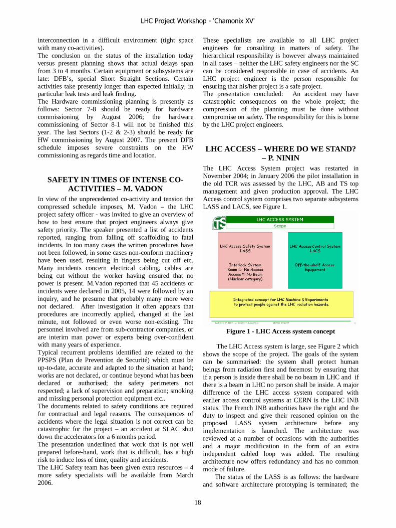
interconnection in a difficult environment (tight space with many co-activities). The conclusion on the status of the installation today versus present planning shows that actual delays span from 3 to 4 months. Certain equipment or subsystems are late: DFB’s, special Short Straight Sections. Certain activities take presently longer than expected initially, in particular leak tests and leak finding. The Hardware commissioning planning is presently as follows: Sector 7-8 should be ready for hardware commissioning by August 2006; the hardware commissioning of Sector 8-1 will not be finished this year. The last Sectors (1-2 & 2-3) should be ready for HW commissioning by August 2007. The present DFB schedule imposes severe constraints on the HW commissioning as regards time and location.
SAFETY IN TIMES OF INTENSE CO-ACTIVITIES – M. VADON
In view of the unprecedented co-activity and tension the compressed schedule imposes, M. Vadon – the LHC project safety officer - was invited to give an overview of how to best ensure that project engineers always give safety priority. The speaker presented a list of accidents reported, ranging from falling off scaffolding to fatal incidents. In too many cases the written procedures have not been followed, in some cases non-conform machinery have been used, resulting in fingers being cut off etc. Many incidents concern electrical cabling, cables are being cut without the worker having ensured that no power is present. M.Vadon reported that 45 accidents or incidents were declared in 2005, 14 were followed by an inquiry, and he presume that probably many more were not declared. After investigation it often appears that procedures are incorrectly applied, changed at the last minute, not followed or even worse non-existing. The personnel involved are from sub-contractor companies, or are interim man power or experts being over-confident with many years of experience. Typical recurrent problems identified are related to the PPSPS (Plan de Prevention de Securité) which must be up-to-date, accurate and adapted to the situation at hand; works are not declared, or continue beyond what has been declared or authorised; the safety perimeters not respected; a lack of supervision and preparation; smoking and missing personal protection equipment etc.. The documents related to safety conditions are required for contractual and legal reasons. The consequences of accidents where the legal situation is not correct can be catastrophic for the project – an accident at SLAC shut down the accelerators for a 6 months period. The presentation underlined that work that is not well prepared before-hand, work that is difficult, has a high risk to induce loss of time, quality and accidents. The LHC Safety team has been given extra resources – 4 more safety specialists will be available from March 2006.
These specialists are available to all LHC project engineers for consulting in matters of safety. The hierarchical responsibility is however always maintained in all cases – neither the LHC safety engineers nor the SC can be considered responsible in case of accidents. An LHC project engineer is the person responsible for ensuring that his/her project is a safe project. The presentation concluded: An accident may have catastrophic consequences on the whole project; the compression of the planning must be done without compromise on safety. The responsibility for this is borne by the LHC project engineers.
LHC ACCESS – WHERE DO WE STAND? – P. NININ
The LHC Access System project was restarted in November 2004; in January 2006 the pilot installation in the old TCR was assessed by the LHC, AB and TS top management and given production approval. The LHC Access control system comprises two separate subsystems LASS and LACS, see Figure 1.
Figure 1 - LHC Access system concept
The LHC Access system is large, see Figure 2 which
shows the scope of the project. The goals of the system can be summarised: the system shall protect human beings from radiation first and foremost by ensuring that if a person is inside there shall be no beam in LHC and if there is a beam in LHC no person shall be inside. A major difference of the LHC access system compared with earlier access control systems at CERN is the LHC INB status. The French INB authorities have the right and the duty to inspect and give their reasoned opinion on the proposed LASS system architecture before any implementation is launched. The architecture was reviewed at a number of occasions with the authorities and a major modification in the form of an extra independent cabled loop was added. The resulting architecture now offers redundancy and has no common mode of failure.
The status of the LASS is as follows: the hardware and software architecture prototyping is terminated; the
LHC Project Workshop - 'Chamonix XV'
18
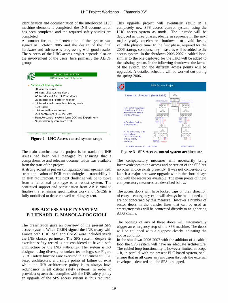
identification and documentation of the interlocked LHC machine elements is completed; the INB documentation has been completed and the required safety studies are completed. A contract for the implementation of the system was signed in October 2005 and the design of the final hardware and software is progressing with good results. The success of the LHC access project depends also on the involvement of the users, here primarily the AB/OP group.
Figure 2 - LHC Access control system scope
The main conclusions: the project is on track; the INB issues had been well managed by ensuring that a comprehensive and relevant documentation was available from the start of the project. A strong accent is put on configuration management with strict application of ECR methodologies – traceability is an INB requirement. The next challenge will be to move from a functional prototype to a robust system. The continued support and participation from AB is vital to finalise the remaining specification work and TS/CSE is fully mobilised to deliver a well working system.
SPS ACCESS SAFETY SYSTEM – P. LIENARD, E. MANOLA-POGGIOLI
The presentation gave an overview of the present SPS access system. When CERN signed the INB treaty with France both LHC, SPS and CNGS were included inside the INB classed perimeter. The SPS system, despite its excellent safety record is not considered to have a safe architecture by the INB authorities. The system is not designed using diverse, redundant technology, see Figure 3. All safety functions are executed in a Siemens S5 PLC based architecture, and single points of failure do exist while the INB architecture policy is to always have redundancy in all critical safety systems. In order to provide a system that complies with the INB safety policy an upgrade of the SPS access system is thus required.
This upgrade project will eventually result in a completely new SPS access control system, using the LHC access system as model. The upgrade will be deployed in three phases, ideally in sequence in the next major yearly accelerator shutdowns to avoid losing valuable physics time. In the first phase, required for the 2006 startup, compensatory measures will be added to the access system. In the shutdown 2006-2007 a cabled loop, similar to the one deployed for the LHC will be added to the existing system. In the following shutdowns the kernel of the system and the different access points will be upgraded. A detailed schedule will be worked out during the spring 2006.
Figure 3 - SPS Access control system architecture
The compensatory measures will necessarily bring inconveniences to the access and operation of the SPS but no other choice exists presently. It was not conceivable to launch a major hardware upgrade within the short delays and with the resources available. The main points of these compensatory measures are described below. The access doors will have locked caps on their direction of entry – emergency exits will always be maintained and are not concerned by this measure. However a number of sector doors in the transfer lines that can be used as emergency exits will be connected directly to neighboring AUG chains. The opening of any of these doors will automatically trigger an emergency stop of the SPS machine. The doors will be equipped with a signpost clearly indicating the above condition. In the shutdown 2006-2007 with the addition of a cabled loop the SPS system will have an adequate architecture. The cabled loop functionality is however limited in scope – it, in parallel with the present PLC based system, shall ensure that in all cases any intrusion through the external envelope is detected and the SPS is stopped.
LHC Project Workshop - 'Chamonix XV'
19

TS-MME WORKPACKAGES – V. VUILLEMIN
The TS department provides design, engineering and manufacturing support to the LHC equipment groups in both the AT and AB departments. The presentation gave an overview of the activities particularly linked to the AB department’s BDI and ATB groups. The policy of the TS department is to accept work in the form of work-packages, packages that have well defined objectives, clearly understood resource requirements and deliverables. The AB/BDI group is responsible for the LHC beam instrumentation in general, installation issues will be resolved in collaboration with the TS/IC and TS/MME groups. The presentation gave an overview of the different instrumentation types that will be designed, manufactured and installed and the volumes involved. For the “classical” beam instrumentation concerning devices such as beam position monitors, beam tv screens, gas ionization monitors, flying wire scanners, beam loss monitors and current transformers two design engineers and 11 designers are active. The CERN internal manufacturing effort for this package, excluding some BPM’s and the BLM’s is estimated to be, until March 2006 3’500 man-hours. The progress of this work-package has been satisfactory, the design work is nearly finished in all cases, and manufacturing is progressing well. Some of the instruments require access to specialized machine tools such as electron beam welding machines which are in general already in strong demand, thus forcing the TS/MME group to set priorities.
Figure 3 - Beam monitoring devices
Figure 3 above gives an impression of the variety of the beam instrumentation devices that are being designed and manufactured.
The second major TS/MME work-package concerns the LHC collimators. This package and its conditions date back to the EST division era:
“The EST provided output will be the required number of prototype collimators within the required schedule and drawings for the series production”. Since then the requirements have gone through a considerable evolution with the equipment group deepening its understanding of the system. The number of collimators and their associated masks has seen some inflation compared with the original estimates in the project and more than 700 blueprints have been created over the two last years.
The speaker expressed some general concerns concerning the Collimator project’s production phase. Since presently TS/MME has no slack in its production facilities nor in its user support team; no additional help for any production/repair/quality control should be envisaged. The AB department must provide its own resources for the complete handling of the 10 collimators delivered by the Contractor each month.
The TS/SU group has made a proposal based on their experience from other accelerators, for a system to make regular control of the alignment of the collimators once they are installed taking into account the highly radioactive environment. The speaker encouraged AB to provide an answer to the proposal without too much delay. The presentation ended with some general comments on present and planned future activities, priorities and available resources. For the months of January to April 2006 11.000 hours of work are already scheduled in the TS assembly shops, implying that overtime will be necessary. The LHC has obviously a high priority, but activities for the LHC experiments are equally important and cannot be neglected. The resources presently allocated to the two AB work-packages are extensive. For the beam instrumentation work-package directly assigned are 11 designers and 6-7 persons from the assembly workshop. For the collimator work-package, directly assigned are 3-4 designers (13 different types of collimators have to be designed) with 3-4 additional designers assigned to the masks design (7 different types). In addition the project coordinators, the outsourcing team from the workshop and the mechanical workshop, the surface treatment team, mechanical engineers and applied physicists are making substantial contributions.
For any new problem, TS/MME will assist in the search for external support but it should be kept in mind that this also requires the use of scarce resources. As a final note it was underlined that experience however shows that urgencies where TS/MME must be present with its specific expertise in e.g. welding regularly occurs (LEIR, SSS in Building 904, ATLAS).
LHC Project Workshop - 'Chamonix XV'
20
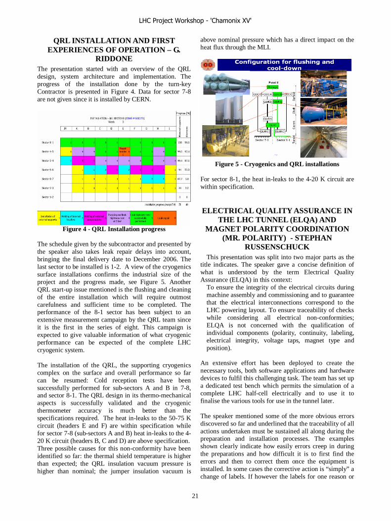
QRL INSTALLATION AND FIRST EXPERIENCES OF OPERATION – G.
RIDDONE The presentation started with an overview of the QRL design, system architecture and implementation. The progress of the installation done by the turn-key Contractor is presented in Figure 4. Data for sector 7-8 are not given since it is installed by CERN.
Figure 4 - QRL Installation progress
The schedule given by the subcontractor and presented by the speaker also takes leak repair delays into account, bringing the final delivery date to December 2006. The last sector to be installed is 1-2. A view of the cryogenics surface installations confirms the industrial size of the project and the progress made, see Figure 5. Another QRL start-up issue mentioned is the flushing and cleaning of the entire installation which will require outmost carefulness and sufficient time to be completed. The performance of the 8-1 sector has been subject to an extensive measurement campaign by the QRL team since it is the first in the series of eight. This campaign is expected to give valuable information of what cryogenic performance can be expected of the complete LHC cryogenic system. The installation of the QRL, the supporting cryogenics complex on the surface and overall performance so far can be resumed: Cold reception tests have been successfully performed for sub-sectors A and B in 7-8, and sector 8-1. The QRL design in its thermo-mechanical aspects is successfully validated and the cryogenic thermometer accuracy is much better than the specifications required. The heat in-leaks to the 50-75 K circuit (headers E and F) are within specification while for sector 7-8 (sub-sectors A and B) heat in-leaks to the 4-20 K circuit (headers B, C and D) are above specification. Three possible causes for this non-conformity have been identified so far: the thermal shield temperature is higher than expected; the QRL insulation vacuum pressure is higher than nominal; the jumper insulation vacuum is
above nominal pressure which has a direct impact on the heat flux through the MLI.
Figure 5 - Cryogenics and QRL installations
For sector 8-1, the heat in-leaks to the 4-20 K circuit are within specification.
ELECTRICAL QUALITY ASSURANCE IN THE LHC TUNNEL (ELQA) AND
MAGNET POLARITY COORDINATION (MR. POLARITY) - STEPHAN
RUSSENSCHUCK This presentation was split into two major parts as the
title indicates. The speaker gave a concise definition of what is understood by the term Electrical Quality Assurance (ELQA) in this context:
To ensure the integrity of the electrical circuits during machine assembly and commissioning and to guarantee that the electrical interconnections correspond to the LHC powering layout. To ensure traceability of checks while considering all electrical non-conformities; ELQA is not concerned with the qualification of individual components (polarity, continuity, labeling, electrical integrity, voltage taps, magnet type and position).
An extensive effort has been deployed to create the necessary tools, both software applications and hardware devices to fulfil this challenging task. The team has set up a dedicated test bench which permits the simulation of a complete LHC half-cell electrically and to use it to finalise the various tools for use in the tunnel later. The speaker mentioned some of the more obvious errors discovered so far and underlined that the traceability of all actions undertaken must be sustained all along during the preparation and installation processes. The examples shown clearly indicate how easily errors creep in during the preparations and how difficult it is to first find the errors and then to correct them once the equipment is installed. In some cases the corrective action is “simply” a change of labels. If however the labels for one reason or
LHC Project Workshop - 'Chamonix XV'
21

another are removed from the equipment, confusion is inevitable. Due to a partial traceability the error detection sometimes becomes pure detective work, trying to understood what the sequence of events have been – something definitely not acceptable when the work will progress on 8 fronts in parallel in the tunnel, see Figure 6.
Figure 6 – ELQA - What happened?
The second part of the presentation concerned the activities related to magnet polarity configuration management. This was identified as a critical issue at the last LHC Workshop and the speaker was given the co-ordination task – Mr Polarity. An instructive overview of the consequences of the different conventions used was given underlining the importance of this task. A specific case of polarity mismatch and the reasons behind it was demonstrated. When doing magnetic measurements tests of the DS-SSS a wrong polarity on the quadrupole of the external aperture was detected. The error causes were traced backwards and the demonstration showed that such errors are very easy to commit when the procedures are not sufficiently detailed and precise. The presentation concluded that the tools are available and can guarantee the integrity of the electrical interconnections in the LHC tunnel and detect polarity errors in the cryogenic magnets. However the project teams must remain vigilant and ensure the coherence of procedures and definitions (inner triplets, power supplies, controls, warm leads). The team is ready to manage verifications in 8 fronts of arc interconnections, but it is limited in specialists for the follow up of electrical non-
conformities and it is suggested to improve the component verifications.
Due to the tight schedule the ELQA of LSS and the LHC Hardware Commissioning will have to be performed in parallel.
CONCLUSIONS Schedule – good progress has been made but present rates have to be further increased to meet our success oriented schedule. The presentation indicated some areas of concern that are now being attended to. New official schedule will be released during the spring.
Security – accidents can and must be prevented. Responsibilities are DG-DH-GL-project engineer – no parallel hierarchy exists in matters of security.
Access systems – LHC is back on track and doing good progress. The upgrade of the SPS system will be a major challenge to do in parallel with all the other activities.
QRL – the supplier is now getting closer to the nominal rates. The issues about leak detection and repair delays will be permanently present during the installation.
MME support – Presently there is no slack left in the group’s resource allocation. The design office and workshops are providing a major effort handling both planned and unplanned activities – Any new incidents or any badly organised projects will have to wait or will cause delays in other important activities.
ELQA and Mr Polarity - Major exercises in quality control in the field, well prepared for a most challenging task.
ACKNOWLEDGEMENTS The speakers in the Installation session have all made
great efforts to present the efforts of their work or their teams in a succinct and clearly readable way. The Chairman and the Scientific Secretary express their thanks for these efforts made despite the speakers’ heavy engagements elsewhere.
The Chairman wishes to express his thanks to the
Editor in Chief of these proceedings for his patience to ensure a maximum of written contributions.
LHC Project Workshop - 'Chamonix XV'
22

SUMMARY OF SESSION 7: I-LHC
O. Brüning and D. Manglunki CERN, Geneva, Switzerland.
Abstract Even though 2005 was a year without operation of the
main machines in the CERN accelerator complex, it still featured the installation and commissioning of the LEIR machine which represents a key component for the LHC ion program. The LEIR commissioning provides the last experience of a commissioning campaign at CERN before the LHC start-up. Furthermore it had been decided to use the LEIR machine as a test bed for the LHC control system. Both aspects, the timing of the LEIR commissioning with respect to the LHC commissioning and its use as a test bed for key components of the LHC control system justify a close look at the commissioning effort in 2005 during a dedicated session of the 2006 LHC performance workshop.
SESSION ORGANIZATION The session was organized into 6 talks: 1. I-LHC Project Overview and Status (S. Maury) 2. Experience with the GTS Ion Source (D. Kuchler) 3. LEIR Commissioning (C. Carli) 4. LEIR Controls I: Post mortem of experience with
LEIR controls (S. Pasinelli) 5. LEIR Controls II: Gain of Experience for the
running in of the LHC (M. Pace) 6. LEIR Electron Cooler (G. Tranquille)
Table 1: Questions and Topics for session 7 talks
Talk Questions & Topics to be covered 1)
What would be the consequences of not commissioning the PS and SPS with ions in 2006? -What has been done (Source, LEIR) -What has to be done in 2006 (LEIR, PS, maybe SPS) -Expected early performance
2)
- Performance - Policy for spare parts
3)
- Hardware tests - Beam commissioning
4)
What were the main difficulties? - LSA, cycle generation - FESA - OASIS - Passerelle
5) How will LHC benefit from using LEIR as a test bed for the control system? -Experience from LEIR - Strategy for LHC
6)
-Commissioning the electron beam - Performance with O4+ and Pb82+ - Policy for maintenance
Each speaker was given a set of key questions and keywords that should be addressed in their presentations. Table 1 lists the questions and topics for each of the session presentations.
ILHC PROJECT OVERVIEW Stephan Maury summarized the main objectives for the
I-LHC project, namely: • to commission LEIR injection line during
June/July 2005; • commission the early Pb ion beam in LEIR
from August 2005 until March 2006; • Commissioning the new cooler and the beam
extraction from LEIR in 2006. • Provide an estimate for the intensity and
luminosity limitations in the LHC with Pb82+ ions.
All objectives for 2005 could be achieved and the milestones set for 2006 are well under way. The beam losses in the LHC due to the cleaning system inefficiency and the Bound Free Pair Production (BFPP) process limit the LHC perform during ion operation. Both processes limit the Pb beam intensities to approximately half of the nominal beam intensities. It was therefore decided to devise an ‘early’ Pb ion scheme which keeps the losses due to both processes far below the magnet quench limits during all operation phases. The initial Pb operation with reduced Pb beam intensities can then be used for studying the limitations due to the above process in more detail. Table 2 summarizes the main parameters of the nominal and the early Pb ion beams.
Table 2: Parameters for nominal and ‘early‘ Pb beams
Addressing the question how long it will take to change in the LHC from a proton to an ion run Stephan quoted from the previous experience at CERN and from RHIC. RHIC changed a few times, typically from ions to p-p, with 1 week setup + 1 week performance “ramp-up”. However, at this stage it is difficult to extrapolate this experience to the LHC operation. The main conclusion from the discussions at the workshop was that the optical configuration for the Pb ion operation should be as close
Parameter Units Nominal Early Beam Energy per nucleon TeV/n 2.76 2.76 Initial Luminosity L0 cm-2 s-1 1 1027 5 1025 # bunches / bunch harmonic
592/891 62/66
Bunch spacing ns 99.8 1350 β* m 0.5 1.0 Number of Pb ions/bunch
7 107 7 107
Transv. norm. rms emittance
mm 1.5 1.5
Longitudinal emittance eVs/charge 2.5 2.5 Luminosity half-life (1,2,3 expts.)
h 8,4.5,3 14,7.5,5.5
LHC Project Workshop - 'Chamonix XV'
23

as possible to the optical configuration during proton operation and that one should try to avoid the commissioning of special configurations during the early commissioning period.
The tentative schedule for the further Pb beam
commissioning foresees hardware tests for the PS and the new TT2 line in February 2006 and commissioning with beam in September 2006. The commissioning of the Pb beam in the SPS is planned for spring 2007 and the first operation of Pb in the LHC in 2008. During the discussions it was highlighted that the Pb run should be scheduled at the end of the LHC proton runs in order to reduce the cool down time of the LHC for the machine shut down. Applying this rule already to the first proton commissioning run would put the first Pb beam operation then to the end of 2008. Stephan Maury highlighted further that the Pb beam commissioning in the SPS in 2007 is in competition with the high intensity proton beam operation. Delaying the Pb commissioning in the PS and the SPS therefore implies LHC Pb runs not before 2009.
Questions during the discussion: • J.Schukraft: you mention you can complete the I-
LHC project with only one 1 m.y? -> S.Maury: the 1 m.y. in question concerns only the remaining SPS modifications
• S.Myers: one should highlight that the early ion scheme is magnetically identical to the protons;
• S.Myers: we are making an effort to deliver the ions in 2008; in case we have large beam losses during the proton operation, an ion run would provide an ideal cool-down period before working on the collimators for instance
• O.Brüning: the collision optics for ALICE is different from the one in proton operation implying some re-commissioning of the optics.
• J.Jowett: there will be other IPs to squeeze in addition to IP2 and the ion and proton machines are therefore quite different
• G.Arduini: for the nominal beam in 2009, there are still some open questions on the SPS, namely the space charge tune shift and the IBS-induced emittance growth times. We will need time using the early beam to study these effects and the transition period may be longer if we need to implement hardware solutions.
• J.Schukraft: it took RHIC 4 years to reach the nominal performance, so if it takes LHC 1 year less it won't be considered a scandal.
• O.Brüning: the early beam is not only beneficial for the injectors but also for the beam collimation in the LHC.
• J.Jowett: and for checking fundamental limits while doing useful physics. For instance there
are some unknowns with the beam-beam effect. During the first run we suggest to use injection value for the β* in the IP.
• R.Assmann: requiring a compatibility of the LHC collimation system with beam lifetimes as low as 0.2 h there is presently no solution for the nominal beam collimation in the LHC (physics limitation for the scattering processes in the collimator jaws).
• O.Brüning: is it only ALICE which is interested in taking data during the early beam runs? -> J.Schukraft: No, ATLAS and CMS want to take data too.
EXPERIENCE WITH THE GTS ION SOURCE
Detlef Küchler summarizes the main motivation for adopting and the main performance characteristics of the GTS source from Grenoble. The source commissioning in 2005 was very successful and achieved the beam parameters required for the early Pb beam operation. However, at the same time there are still many open questions (e.g. Pb consumption in the oven, operation of the bias voltage and transport efficiency in the linacs and transfer lines) and the first operation identified several potential weak points of the source hardware. Detlef Küchler therefore proposes to agree on a spare part policy for the new source and to keep critical items on stock at CERN. His wish list of spare parts includes: a new oven, extraction electrodes and insulators, an additional plasma chamber (� total investment of ca 10k€) and a new RF source (14kGHz or 18GHz � total investment of ca 100k€). Detlef also mentions that a dedicated test stand would be beneficial for the further development of the source but adds that this would require a rather large investment (� of the order of 1 MCHF). Questions during the discussion
• J.Jowett: any idea on the reliability of the microwave generator? -> D.Küchler: No, we can only say we changed the klystron once. The motherboard failed every second year and was repaired every time.
• S.Myers: the first 4 items on your list of desired
spares are cheap but what would you buy with 105
€? -> D.Küchler: the first 4 items are cheap indeed but still we do not have the budget. With 105
€ we would rather buy a new 18GHz RF generator than a spare for the old 14GHz one.
• O.Brüning: You estimate the cost of the test stand to 1MCHF. Do we need it to study the other types of ions? -> D.Küchler: yes it would help but is not strictly speaking
LHC Project Workshop - 'Chamonix XV'
24
required. In addition it would be a hot spare for the whole source
• J.Schukraft: Physics will request other ion species, but not before the third year of operations (2012?). The concern is that Pb might not reach the necessary performance, in which case we would request other species which would give a higher intensity, hence luminosity.
• J.Jowett: is it still the case that you would first ask proton-on-lead, then Ar-Ar? -> J.Schukraft: P-Pb first yes, but for the rest it still is under discussion.
LEIR COMMISSIONING Christian Carli presents a summary of the main achievements during the LEIR commissioning in 2005 and highlights the open issues that still need to be addressed in 2006. Christian underlines that the LEIR commissioning was a joint effort across several groups and departments (AB-ABP, AB-CO, AB-OP, AT-VAC). Even though the commissioning in 2005 was successful in the end too many things were done in parallel and the commissioning could have been more efficient if each phase (installation; operation with beam, control software development) could have done in dedicated segments. This applies in particular to commissioning of the LEIR injection line. One lesson learned for the LHC start-up might therefore be to take the required time for a proper commissioning of all subsystems before the operation with beam starts. For example, the first operation with beam featured an aperture limitation in an monitor opposite the cooler section due to beam diagnostics components and a damage of the PU cables due to ramp induced currents inside the magnets. Both issues could , in principle, have been identified and fixed before the commissioning with beam. Furthermore, Christian underlines that, even though the commissioning was successful in 2005, there are still many points that require more studies in 2006 (establishment of the nominal cycle and ramp rate, vacuum and beam lifetime optimizations and operation of the electron cooler). Questions during the discussion
• O.Brüning: the support from AT/VAC was a key contribution to the success of the 2005 commissioning and we will still need it until the end of commissioning in 2006.
• S.Myers: the controls were not perfect, but from that point of view it was a big success
LEIR CONTROLS The next two presentations covered issues related to the
LEIR control software. The first presentation by S. Pasinelli described the experience from the operator point of view (client) and the second presentation by Marine
Pace from the controls group point of view (provider). Both presentations acknowledged that not all software was ready from the start-up and that it took some time to get it operational during the commissioning. At the same time both presentations underlined that all applications worked well in the end indicating that the debugging during the commissioning was a success. Furthermore it was stated that the transition from GM to FESA was particularly difficult in LEIR as FESA, being a completely new and ambitious system, suffered from a lack of maturity and stability when it was deployed. Not surprisingly, the experience with LEIR also underlined that the previous experience of the new control software during the TI8 and TT40 tests was not sufficient for the preparation of the LEIR run. This might indicate that additional difficulties might appear during the application of the new control software to the SPS (planned for 2006) and the LHC sector test (planned for end of 2006). Since the experience with the LEIR commissioning allowed an extremely valuable validation of some key components (mainly FESA, LSA and OASIS) it will be interesting to see to what extend the experience in the SPS in 2006 can confirm this positive assessment.
Questions during the discussion
• M.Albert: LSA was not designed with only transfer lines in mind, but also circular machines (i.e. SPS and LHC)
• R.Schmidt: some tests of PLC based controls for the magnet interlocks, foreseen for the LHC, were performed on LEIR, but somehow independently of the rest of the control system.
• E.Ciappala: You mentioned a new interface for the RF timing of the SPS at start-up. Do you confirm this? The existing software was OK! -> M.Pace: yes, it will consist of working sets and knobs.
• S.Myers: Was there a big communications problem? Everyone was supposed to know LEIR was to be used as a test bed for LHC controls. Is the problem due to the fact that no LEIR operator was involved in writing the software? -> M.Pace: both the fact that main software components were not available at start-up, and the fact that no LEIR operator was involved in writing it. -> M.Albert: and conversely the developers were not involved in the LEIR commissioning team. They could have been since the SPS was stopped anyway.
• G.Arduini: some of the frustration came from the fact that in end of August some software needed immediate attention and the LEIR crew was told by CO that the LEIR software was not a priority. -> S.Myers (surprised): LEIR SW should have been a priority for CO at that time. -> L.Normann: LEIR SW certainly was a priority for the LSA team.
LHC Project Workshop - 'Chamonix XV'
25

• S.Myers: LEIR Operators knew LEIR was going to be used as a test bed for the LHC controls. Is their complaint a way for them to say they didn't agree with the decision? -> P.Collier: it was not only the "LEIR operators" who complained about the controls, but the whole LEIR commissioning team. By the way the next big step is the start-up of the SPS with the new controls.
• O.Brüning: when is the PS machine going to switch to the new controls? -> M.Pace: a set of new control components (LASER, JAVA Console manager and generic tools) will be introduced gradually, in parallel with the old one, during 2006
• H.Schmickler (back on priority issue): for CO the main line for LHC was HW commissioning; the priority was given back to LEIR in September.
• J.Wenninger: we may face the same sort of priority issue next year between CNGS and SPS software.
• R.Schmidt: there are indeed lots of unsolved software issues for CNGS.
• S.Baird: CNGS commissioning is supposed to be finished in July.
• O.Brüning: LEIR as test bed for LHC software could not test all the functionalities. Will the SPS start-up test the remaining ones? -> M.Pace: Not everything. A lot will have to be tested during the LHC hardware commissioning (e.g. scalability of the controls infrastructure and machine protection system)
• L.Normannn: what is the conclusion? Is LSA still on or should it be stopped? -> M.Pace : It is still on and the way to go.
• C.Carli: As a concluding comment, lots of software issues have been solved since Spring 2005, thanks to the effort of many CO experts involved in the commissioning and we now have a control system with which we can work.
LEIR COOLING Gerard Tranquille summarises the first experience with
the new electron cooler. The old LEAR cooling system was missing a factor 2.5 compared to the nominal Pb beam requirement. It was therefore decided to use the old system in the AD ring and to build a new, state of the art cooling system for the new LEIR ring in collaboration with BINP. The construction and pre-commissioning was carried out by BINP between October 2003 and December 2004. The cooler commissioning in LEIR started in October 2005. However, due to the limited beam life time in LEIR there is not yet a clear signal of beam cooling. So far one can only conclude that the observed signals are compatible with cooling but better beam lifetimes are required before the system can be better optimized.
Questions during the discussion
• O.Brüning: how do you interpret the data? -> G.Tranquille: for me there is a clear signal of momentum cooling, as one can see the density increase in longitudinal phase space.
• O.Brüning: O4+ was supposed to have a longer life time, do you need more time with it? -> G.Tranquille: for us it is now time to move to Pb54+, we have reached the limit of what we could observe with O4+, for which the cooling times are too long.
• S.Baird: Schottky signals present evidence of beam instabilities. What about the transverse feedback? -> M.Chanel: it is installed and has been put into operation at the very end of the run. Further test are still necessary before it can be used in the routine LEIR operation.
• G.Tranquille: We also need to power the cleaning electrodes as we probably have some residual gas ions trapped in the electron beam.
• E.Mahner: how can you explain losing beam on a cable which is 50mm off-centre? -> M.Chanel/G.Tranquille: it probably happened during injection.
LHC Project Workshop - 'Chamonix XV'
26

SECTOR TEST WITH BEAM M.Lamont, CERN, Geneva, Switzerland.
INTRODUCTIONThe aim is to inject beam into a sector of the partially
completed LHC in 2006. The LHC sector test will take in the last 200 metres of TI8 and 3.3 km of the LHC including one experiment insertion and a full arc.
The LHC sector test is an important milestone. It provides an opportunity to thoroughly test full integration of a wide variety of accelerator systems, all of which will be needed for machine commissioning. It also allows important beam based checks of the ongoing installation.
The time spent will be recuperated during eventual commissioning, and perhaps, more profoundly it will allow more effective and rapid commissioning having given time for problem resolution and improvements.
The test will required around a week’s preparation during which the access system is commissioned, temporary vacuum BCT, and dump are installed in point 7 and a cold checkout and acceptance tests are performed. This is followed by 2 weeks test with beam with a 1 week recovery period during which a radiation survey is performed, access gates removed and the temporary installations, including the dump, in IR7 are removed.
Although it does impact on installation, its effects are well constrained and manageable. The test will halt magnet transport through sector 7-8 for 28 days, and prevent access to part of 6-7 and part of 8-1 during the test (17 days).
There clearly delimited demands on what is to be installed and operational. It should be noted that the test is essentially baseline. There is very little additional installation or not as final configuration.
There are knock-on effects for Hardware Commissioning, Radiation Protection and LHCb. These are discussed in detail elsewhere in these proceedings.
PROPOSED TESTS WITH BEAM The beam used will be mainly pilot beam - single
bunch 5 x 10⁹ protons with low absolute losses. The essential outline of the planned tests is: - Commission TI 8 end, injection and thread to IR7 - Commission trajectory acquisition and correction - Commission Beam Loss Monitor system - Optics measurements - Aperture checks - Effect of magnetic cycle - Field quality checks - Quench limits and BLM response - Setting up of injection machine protection The test will verify the proper functioning of the
fundamental BDI systems, with checks of the BPM resolution, cabling, polarity and offsets, BLM response and resolution, and BTV resolution. The tests will verify with certitude that the aperture is as expected in the critical injection region and also in the arc and around
IP8. In addition to the BDI, other hardware will be commissioned with beam, including the main magnets, injection system, orbit correctors, timing and machine protection. The beam will sample all magnetic fields over 1/8 of the machine, which gives direct information about many aspects, including polarities, optics, key field errors to 1 unit, misalignments and corrector cabling. The test allows the deployment of control and correction procedures, via the beam threading, trajectory correction and bumps, and allows the magnetic model accuracy to be checked, providing data about the reproducibility of LHC cycle at injection and confirmation of the expected performance. The test also provides an opportunity to determine magnet quench levels and BLM response.
MAGNET QUENCHES WITH BEAM Beam based machine protection will hang on the BLM
system. Properly calibrated, they will allow safe and efficient operation and they will be a key element in avoiding quenches and damage. The aim during the sector test is to quench selected magnets with beam under controlled, well defined conditions to establish absolute quench limits; BLM threshold values; and to aid understanding of correlation between loss patterns, the quench level, and associated BLM signals.
These tests are an important first stage in understanding the above issues and it will help the efficient commissioning of the large, distributed BLM system with circulating beam.
BEAM INSTRUMENTATION FORESEEN FOR THE LHC SECTOR TEST
The key beam instrumentation for LHC operations, LHC commissioning and thus the LHC sector test are the distributed systems – the beam position monitors (BPMs) and beam loss monitors (BLMs). Implicated in sector test for these systems are consideration of the component production, component installation, tunnel electronics, acquisition electronics, acquisition transmission, calibration, and system tests.
Discrete systems also to be tested are a number of screens (BTV) and beam current transformers (BCT), one of which is a temporary installation for the test.
Required during the test are the key components of the Beam Synchronous Timing (BST) system and a large slice of the complete controls infrastructure which includes: Ethernet, slow and fast timing distribution, WIFI, VME infrastructure, and WorldFIP.
Although not strictly required, the test will also provide the opportunity to test the BLM to BIC connection and the Post Mortem system with beam.
The LHC Sector test provides an important mile-stone for beam instrumentation. It is the last chance to test with
LHC Project Workshop - 'Chamonix XV'
27

beam BPM and BLM ring systems before 2007 start-up. No show-stoppers for an LHC sector test with beam are foreseen, although a lot of equipment will only become available during spring 2006. It is now necessary to finalise procedures for test, installation and commissioning.
MAGNETS The sector test will provide an appreciable scope (some
20 magnet families), comparable to the ring itself, and thus will provide a good test for magnet model.
The sector test will required transfer functions for the main magnet strings in 7-8 (MB, MQ); and for the insertion, matching section and dispersion suppressor quadrupoles which include MQY, MQM, MQX etc. These transfer functions can be provided by FiDeL - a Field Description for the LHC which is seen as a general framework for magnet setting generation. FiDeL will also provide the harmonic components for the main bends and quadrupoles, and other elements as necessary.
De-Gauss and nominal cycling prescriptions are described for the main bends, as well has cycling prescription for all other quadrupole and corrector circuits.
The work to be performed in 2006 is clear, and it is in line with the needs for the LHC commissioning and operation. The resources required are modest, but not negligible: the work to be done includes data reduction, model testing, data-fits, storage and tests, database work and the development of software tools.
CONTROLS REQUIREMENTS The Sector Test is another progressive and important
milestone for LHC controls and must be used for testing key functionality. It allows staged deployment and is absolutely critical to providing a satisfactory solution for eventual beam commissioning.
Among the systems implicated in the test for which controls plays a key role are the injection kickers, BLM, BPM, BTC, BTV, and beam interlocks. Required infrastructure includes VME, Ethernet, WorldFIP, and cabling. Frameworks and key components include configuration, FESA, and fast & slow timing. Some of these still demand development and testing.
Other important controls related implementations are interlocks & Safe Beam Parameters, application software, logging, Post Mortem, Alarms, Data exchange and Analog Acquisition. All of these will benefit from the serious field testing they will receive during the test.
CONCLUSIONS The Sector Test is a very important milestone for a
number of critical subsystems. It provides a very important integration staging point wherein a large number of problems will be addressed. We are given time to react to these problems, resolution of which will be critical to effective full commissioning. Besides this
important first checks can be performed with beam, and again lessons learnt will ease establishment of circulating beam and the huge amount of commissioning effort that is to follow.
The test can take place in the partial shadow of installation and with good planning the impact can be minimized.
Performing the test is essentially win-win. If things go relatively smoothly, resolution of the inevitable, minor problems will speed up full beam commissioning. If we hit any major problems, we will at least some time to react.
ACKNOWLEDGEMENTS Many thanks to the speakers in the sector test with
beam session whose presentations are summarized here. Namely: Brennan Goddard, Alex Koschik, Lars Jensen, Luca Bottura, and Robin Lauckner.
Thanks also to Verena Kain for acting as scientific secretary and for her help in organizing the session.
LHC Project Workshop - 'Chamonix XV'
28
SECTOR TEST – PREPARATION
P. Strubin, CERN, Geneva, Switzerland
Abstract
INTRODUCTION This session of the 15th Chamonix Workshop was devoted to the definition of the required hardware and its availability for the sector test. Planning aspects for both the components and the hardware commissioning were also presented.
PLANNING E. Barbero Soto presented the detailed planning from the installation of the continuous cryostat to the hardware commissioning that has to be followed to inject beam through sector 7-8 at the end of 2006. She summarised the required hardware, recalling that the helium distribution line (QRL) cannot be sectorised. The implication of the latter is that all components for the helium distribution line (in particular the electrical feed-boxes, DFBs) must be available not later than May or June 2006, if both sectors are partially commissioned. Even so, the available time for hardware commissioning is critical and any delay may compromise the quality of the testing work. It clearly came out in the discussion that one should not compromise on the proper hardware tests. Thus all components for the helium distribution line must be available no later than April in sector 7-8, and May for sector 8-1. It was also mentioned that the planning did not take into consideration the actual failure rates on interconnects, evaluated to 3 ‰ from industrial data, also confirmed by the experience with the QRL. As transport is blocked in the area of the temporary dump in LSS 7 for 5 weeks, there is also an impact on the progress of the installation in sector 6-7. Studies are going on to use UX65 as a temporary storage for short straight sections and having main dipoles transported from the other side. Alignment work downstream LSS7, as well as installation of room temperature components (e.g. collimators) will also be affected. The closure of TI8 for 6 weeks does not impact on the LHC activities.
GLOBAL HARDWARE STATUS M. Jimenez presented the state of the layout and summarised the known availability of all major components. He emphasised that the configuration for the sector test must be the final LHC one, except for LSS7. The integration activity is well advanced and should be completed before May with the last part of TI8 and IR8R. However, there still are a number of difficulties to solve in the area where the beam joins the LHC tunnel coming out of TI8. Lack of space is the main issue in this context. As a general point for the integration activity, it is now absolutely mandatory to
freeze the layout so as to be able to complete the 3D mock-up and produce the installation drawings. As for the availability of the components, M. Jimenez showed a list of equipment to be closely followed-up, like some beam instrumentation equipment or the vacuum chambers and pumping ports for the septum. As identified earlier, the DFBs are on the critical path, but also some of the collimation equipment for which the design is completed but the manufacturing only starts now.
LAYOUT IN LSS7 J. Uythoven presented the layout of LSS7, where a temporary dump block as well as some shielding have to be installed downstream of Q6. The latter and its electrical feed-box (DFBM) have to be installed to complete the helium distribution line. The location of the dump block is chosen to be far enough from the helium distribution return module to avoid potential radiation problems. The dump block is “borrowed” from TI2, to avoid importing already irradiated materials into the LHC tunnel. The final elements downstream of Q6 will be replaced by a 29 metre long vacuum pipe, made out of standard vacuum chambers and components. No collimators will be installed, only one beam current transformer is required between Q6 and the dump block. The base line beam loss monitors should be installed, no additional ones are required. Removing the dump block and the temporary vacuum chamber will be the only additional work before continuing with the installation after the sector test.
HARDWARE COMMISSIONING R. Saban presented the hardware commissioning scenario, summarising the state of commissioning the various components must have before beam can be injected. The discussion focussed on the tests required for the super-conducting magnet circuits. The allocated time and resources will make it nearly impossible to do a complete commissioning. There was a large consensus, however, that it will not be acceptable to put equipment at risk as a consequence of a partial hardware commissioning sequence. Even though only some 20% of the nominal current is required for the test, this level is high enough to provoke severe damages in the case the quench protection system would not have been fully debugged. A partial hardware commissioning is also likely to be more demanding on resources.
LHC Project Workshop - 'Chamonix XV'
29

STATE OF LHCB FOR THE SECTOR TEST
M. Ferroluzzi described the LHCb experiment, in particular the minimum to be installed for the sector test. This includes the Vertex Locator (VELO) tank, although with blanks instead of the detector modules, and the complete vacuum chamber. He also presented an “agreement” between LHCb and the accelerator in order to minimise the perturbations the sector test would induce on the completion of the LHCb experiment, in particular in matters of radiation aspects. LHCb expects that the installation activity will not be affected after the sector test by radiation problems. He also showed that the overall LHCb planning integrates the sector test.
RADIATION ISSUES H. Vincke presented two facets of the radiation aspects linked with the sector test. The first part covers the status of the area downstream TI8 after the high intensity injection test foreseen in October 2006. Intensities up to 4 1014 protons will have to be absorbed by the dump block (TED). Copper samples will be placed in the R88 gallery and the UJ88 junction region to witness the possible activation of the already installed LHC equipment. FLUKA calculations have been conducted to predict the dose rates due to prompt radiation (during the test), the dose rates after test, the activation of material and the activation of TED cooling water. Dose rates in the 50 µSv / h range must be expected downstream of the dump after one hour of cooling time, decreasing to 0.1 µSv / h after one week. Materials in the LHC tunnel will very likely become activated, hence the zone will become a supervised area (personnel dosimeter mandatory) and all material must be controlled before being removed from the area. The cooling water of the dump block will be activated, but can be considered as non-radioactive. For the sector test, the requirements are that the sector should be reclassified to non-designated area and that there must be no radiological consequences for LHCb. Again, FLUKA calculations are used to predict the dose rates and potential activation of materials. During the test, access must be prohibited in the area 1 km downstream of the dump in LSS7, access in the LHCb service area behind shielding wall will only be permitted in case access to the detector area is prevented (access doors). The temporary dump can (and should) be removed 4 or 5 days after the end of the run. Before re-
classification, a thorough radiation survey will have to be performed in the dump zone. For the LHCb experiment, it will be extremely important to minimise any beam losses in the area and to move the detector parts as far away as possible from the beam pipe. Here also, a thorough radiation survey is needed after the test and samples will be placed at adequate locations to assess the potential activation of materials.
TEMPORARY ACCESS SYSTEM P. Ninin reported on the foreseen temporary access system required for the sector test. In order to protect personnel against radiation hazard during the tests, access to underground areas around Points 8 and 7 (and the arc in between) must be fully operational during the test. Access doors must be interlocked to disable beam in a failsafe way if safety conditions are violated. Temporary interlocked gates will be installed in sectors 8-1 and 7-6. The machine access gates in point 7 and 8 must be fully operational. The interlock chain to inject from TI8 must also be operational. As the new access system relies on biometric identification, good preparation of enrolment and authorisations must start promptly. The sector test is, however, considered as an excellent opportunity to validate the equipment and procedures (e.g. the patrol before closing the tunnel).
SUMMARY Based on our present knowledge of availability of components, the sector test is still a reachable objective. However, so far, little experience has been gathered with the interconnection work of the magnets, a very complex activity. Also some components (electrical feed-boxes and collimators in particular) are on the critical path from the manufacturing point of view. There is a consensus that no compromise should be done during the system tests and the hardware commissioning which could put all or part of the cryogenic magnets at risk. Also, no temporary solutions should be implemented, but rather aim at installing according to the layout for first colliding beams.
ACKNOWLEDGMENTS I would like to warmly thank all authors mentioned above, as well as my scientific secretary, K. Foraz, for the excellent quality of their contribution.
LHC Project Workshop - 'Chamonix XV'
30

SUMMARY OF OVERALL COMMISSIONING STRATEGY FOR PROTONS
R.Bailey, CERN, Geneva, Switzerland
Abstract
After a brief reminder of the various requirements on the LHC, the strategy for a staged commissioning with protons is summarised. Typical machine parameters and associated performance levels are given for each stage. Dedicated runs with ions and protons are mentioned, and how machine operation may be scheduled through a year is shown.
INTRODUCTION Getting to nominal LHC conditions is not going to be
easy. While the injectors have demonstrated that they can produce the required beams, the filling schemes are rather complex and will need careful commissioning. In the LHC ring, emittance conservation has to be mastered through the injection process, the energy ramp and the beta squeeze, and with almost 3000 bunches per beam a crossing angle is needed to minimise unwanted beam-beam interactions. Last but not least, the stored energy of 362MJ per beam is some two orders of magnitudes above that achieved at other machines, and will have to be approached with the utmost care.
Performance estimates given are based on the standard
luminosity equation where N is the number of protons per bunch, kb the
number of bunches per beam, f the revolution frequency, γ the relativistic factor, εn the normalised emittance, β* the value of the betatron function at the interaction point, and F the reduction factor caused by the crossing angle, which is 1 for head on collisions and about 0.85 for the nominal crossing angle according to
2
*21/1 ⎟
⎠
⎞⎜⎝
⎛+=σσθ zcF
where θc is the crossing angle, σz the bunch length and σ
* the transverse beam size at the IP.
GLOBAL REQUIREMENTS The LHC machine will have numerous clients to satisfy
[1]. For ATLAS and CMS we need a strategy to get to proton collisions at 7TeV with a nominal luminosity of 1034 cm-2s-1. LHCb require a nominal luminosity in the region of 5 1032 cm-2s-1 at point 8, while for ALICE a luminosity at point 2 of 1030 cm-2s-1 is around optimum with protons. In points 2 and 8 the beta functions are
tuneable in order to meet these needs as a function of the beam intensity. In point 2 transverse beam separations will also be needed to maintain the luminosity below an acceptable level for ALICE with higher intensities.
The high luminosity experiments will eventually have to handle almost 20 events per beam crossing. However, it will take time to learn how to do this and during early running they request that the event pileup is limited to 2 events per crossing. Similarly LHCb is designed for around 1 event per crossing and so significant event pileup should be avoided here also.
For ion running ALICE will require data at various energies and during this mode of operation ATLAS and CMS will also take data. Finally TOTEM request proton collisions at various energies and with special optics.
A STAGED APPROACH It is clear from the above that both machine and
experiments will have to learn how to stand running at nominal intensities. An early aim is to find a balance between robust operation and satisfying the experiments. Robust operation means avoiding quenches and at all costs damage. Satisfying the experiments means delivering integrated luminosity without significant event pileup.
To avoid quenches three parameters are considered: • Higher β* in IP 1 and 5 to avoid problems in the
later, delicate part of the beta squeeze. • Lower total current either by reducing the
number of bunches or the bunch intensity, or both.
• Lower energy to provide more margin against transient beam losses or against magnets operating close to their training limits.
Event pileup ~ N2/β* and hence lower bunch currents
also ensure that this is also acceptable except for very low betas.
With lower currents in mind, two important machine
systems will be staged. For the collimators, a phased approach will be adopted which will provide the necessary protection but will require higher beta functions or lower currents. For the beam dump, 4 out of 10 dilution kickers will be installed for each beam, which will restrict the total circulating intensity to around 50%.
The resulting proposal for early proton running is to aim for a pilot physics run with a few tens of bunches per beam, and the commissioning strategy has been developed with this in mind. Following this, attention will shift to many-bunch operation, first with 75ns spacing and later with 25ns spacing.
FfkN
Ln
b*
2
4 βπεγ
=
LHC Project Workshop - 'Chamonix XV'
31

Stage 1 – Pilot physics run The aim here is to bring two moderate intensity beams
to high energy and to collide them for physics. The target is 43 on 43 bunches of 3 to 4 1010 protons at 7TeV. The energy may be lower for reasons of overall machine reliability, as dictated by the performance of the magnets at high field with beam.
In order to provide collisions in LHCb, a certain number of bunches in one beam will be displaced by 75ns. The number of displaced bunches can vary from fill to fill if required, but it should be noted that increasing the number of bunches colliding in LHCb results in an equivalent reduction in the luminosity of the other experiments. Alternatively dedicated runs could be made for LHCb, but of course without collisions in the other experiments.
Initial physics will be with the injection optics. Once this has been achieved the squeeze will be partially commissioned.
The commissioning phases foreseen to achieve this [2]
are summarised in Table 1.
Table 1: Commissioning phases for pilot physics
1 Transfer and injection
2 First turn
3 Circulating beam
4 450GeV – initial commissioning
5 450GeV – consolidation
6 450GeV – 2 beam operation
7 Switch to nominal cycle
8 Snapback – single beam
9 Ramp – single beam
10 Single beam to physics energy
11 Two beams to physics energy
12 Physics – no beta squeeze
13 Commission squeeze – single beam
14 Physics with partially squeezed beams
At each of these phases, a number of activities will be pursued in an iterative manner;
• Equipment commissioning with beam
• Machine protection systems
• Instrumentation
• Checks with beam (polarity checks)
• Measurements with beam (optics checks)
The luminosities expected for this pilot run are shown in Table 2, where a beta squeeze to 2m in IP1 and IP5 is supposed with 43 bunches of 4 1010.
Table 2: Performance expectations during the pilot physics run
Pilot physics run Beam energy (TeV) 6.0, 6.5 or 7 Number of particles per bunch 4 1010
Number of bunches per beam 43 Crossing angle (μrad) 0 Norm. transverse emittance (μm rad) 3.75 Bunch length (cm) 7.55 Beta function at IP 1, 2, 5, 8 (m) 2,10,2,10 Luminosity in IP 1 & 5 (cm-2s-1) ~5 1030 Events per crossing in IP 1 & 5 0.76 Luminosity in IP 2 & 8 (cm-2s-1) ~ 1 1030 Transverse beam size at IP 1 & 5 (μm) 31.7 (7TeV) Transverse beam size at IP 2 & 8 (μm) 70.9 (7TeV) Stored energy per beam (MJ) 2 (7TeV)
Note that the stored energy per beam of 2MJ, while significantly reduced compared to nominal, is still comparable to that of other facilities.
In this mode it is possible to increase the number of
bunches to 156 per beam with a corresponding 4-fold increase in luminosity, still without the need for a crossing angle to avoid parasitic collisions. This should get us to 2 1031 cm-2s-1 in the high luminosity experiments. The insertion in IP8 could be tuned to increase the luminosity for LHCb. Luminosities in IP2 look to be good for ALICE. Tuning is possible if required.
If the experiments can stand the event rate, the bunch intensity could be pushed higher. With 156 bunches per beam at an intensity of 9 1010, and all other parameters as in Table 2, a luminosity of 1032 cm-2s-1 is in reach.
It is also proposed at this stage to commission the crossing angle scheme, to see what effect this has on machine performance before the added complexity of parasitic collisions comes into play.
A number of questions are still open;
1. Do the experiments need single beam runs at 450GeV?
2. Should we provide collisions at 450GeV? ALICE has requested this.
3. Should we use a low energy cycle for machine setup, in order to reduce the turnaround time?
4. First high energy collisions will be 1 on 1 to provide data in points 1 and 5. A minimum of 2 on 2 is needed to provide collisions in points 2 and 8. What we should we do next? Trains of 4 can be provided with just 1 SPS cycle needed to fill each LHC ring, using the 43 bunch injection scheme. Similarly trains of 16 can be provided with just 1 SPS cycle per ring, using the 156 bunch injection scheme. Both of these scenarios would keep the LHC injection plateau as short as possible. 12 SPS cycles are needed to fill each LHC ring with either 43 or 156 bunches.
LHC Project Workshop - 'Chamonix XV'
32

Stage 2 – 75ns operation Once the pilot physics run is complete as described, a
period of operation with 75ns spacing in proposed. There are several advantages to this [3];
• The reduced number of parasitic beam-beam encounters allows a relaxed crossing angle. This would be exploited, moving to the full crossing angle only in preparation for 25ns operation
• Electron cloud is not expected to be a problem • Total beam intensities and power are increased
in an incremental way, allowing the machine protection systems to adapt.
Initial operation at 75ns would be with the β* achieved
in the pilot physics run, say 2m, and a crossing angle of 250μrad. In this mode the beta squeeze would be pushed as far as possible. A typical performance expected is given in Table 3.
Table3: Performance expectations with 75ns operation
75ns operation Beam energy (TeV) 6.0, 6.5 or 7 Number of particles per bunch 4 1010
Number of bunches per beam 936 Crossing angle (μrad) 250 Norm. transverse emittance (μm rad) 3.75 Bunch length (cm) 7.55 Beta function at IP 1, 2, 5, 8 (m) 1,10,1,10 Luminosity in IP 1 & 5 (cm-2s-1) ~2 1032 Events per crossing in IP 1 & 5 1.4 Luminosity in IP 2 & 8 (cm-2s-1) ~ 2 1031 Transverse beam size at IP 1 & 5 (μm) 22.4 (7TeV) Transverse beam size at IP 2 & 8 (μm) 70.9 (7TeV) Stored energy per beam (MJ) 42 (7TeV)
Stage 3 – 25ns operation I In this mode with bunch intensities in excess of 3 to 4
1010 protons beam scrubbing may be needed. Otherwise the transition should be fairly smooth with moderate currents.
Table 4 shows the performance level possible up to the intensity limits resulting from the staging of collimators and beam dump. A luminosity of 1033 cm-2s-1 for the high luminosity experiments is in reach. Luminosities for LHCb in IP8 are now fairly optimal with the injection optics, while in IP2 detuning and transverse beam separation will be required for ALICE.
Stage 4 – 25ns operation II Once the performance levels for Phase I have been
achieved, installation of the full complement of beam dump dilution kickers and of the Phase II collimators will need to be scheduled. Following this, bunch intensities will be progressively increased toward nominal. Finally, the last part of the beta squeeze will need to be brought into operation before nominal performance is achieved.
Table 5 shows nominal performance.
Table 4: Performance expectations with Phase I 25ns operation
25ns operation with Phase I collimators Beam energy (TeV) 6.0, 6.5 or 7 Number of particles per bunch 5 1010
Number of bunches per beam 2808 Crossing angle (μrad) 285 Norm. transverse emittance (μm rad) 3.75 Bunch length (cm) 7.55 Beta function at IP 1, 2, 5, 8 (m) 1,10,1,10 Luminosity in IP 1 & 5 (cm-2s-1) ~1 1033 Events per crossing in IP 1 & 5 2.1 Luminosity in IP 2 & 8 (cm-2s-1) ~ 1 1032 Transverse beam size at IP 1 & 5 (μm) 22.4 (7TeV) Transverse beam size at IP 2 & 8 (μm) 70.9 (7TeV) Stored energy per beam (MJ) 157 (7TeV)
Table 5: Nominal performance (Phase II 25ns operation)
Nominal parameters Beam energy (TeV) 7 Number of particles per bunch 1.15 1010
Number of bunches per beam 2808 Crossing angle (μrad) 285 Norm. transverse emittance (μm rad) 3.75 Bunch length (cm) 7.55 Beta function at IP 1, 2, 5, 8 (m) 0.55,10,0.55,10 Luminosity in IP 1 & 5 (cm-2s-1) 1 1034 Events per crossing in IP 1 & 5 19.2 Luminosity in IP 2 & 8 (cm-2s-1) 5 1032 Transverse beam size IP 1 & 5 (μm) 16.7 Transverse beam size IP 2 & 8 (μm) 70.9 Stored energy per beam (MJ) 362
DEDICATED RUNS
TOTEM The TOTEM experiment will measure the total pp
cross-section and study elastic proton scattering, and is also interested in the study of diffractive events. This results in various run scenarios, most of which require a particular machine configuration that is considerably different from the standard configuration in IP5. The experiment suggests several runs, typically of one day duration, spread throughout the first years of machine operation. Furthermore the total-cross section measurements should begin in the initial phase of LHC operation.
While these runs are expected to be short, requiring perhaps just one substantial physics coast per measurement, the time to switch in and out of this mode of operation should not be underestimated. The experience with LEP polarisation runs shows that 2-3 shifts should be allocated for preparation and recovery each time. Furthermore, considerably longer will be needed to commission the new optics with tight beam
LHC Project Workshop - 'Chamonix XV'
33

conditions the first time it is tried on the machine, and to understand how to safely operate the Roman pots located either side of IP5.
Ions The ALICE experiment has requested a short run with
ions as early as possible. As with TOTEM running, the time to prepare for this mode of operation should not be underestimated, particularly the first time it is tried.
The first ions runs will be made using the so-called “early ion scheme”, which foresees 62 bunches per beam and a β* of 1m in IP2. With all other parameters as nominal, the performance levels that can be expected under these conditions are about a factor 20 (10 from the number of bunches and 2 from the beta) below the nominal luminosity for ion operation of 1027 cm-2s-1.
SCHEDULING Every year a long shutdown will be needed by several
machine groups for equipment servicing and major preventive maintenance [4]. The length of time estimated varies up to a maximum of 16 weeks, with some interdependence between the various activities. This fits with the requirements of the ALICE, ATLAS and CMS experiments, which also require an annual shutdown of 3-4 months.
Recovery from a long shutdown will need some time, firstly without beam (Machine Checkout, 4 weeks) and then with (Setup with Beam, 2 weeks).
Once the machine has been restarted after the annual shutdown, operation with beam will be interrupted by
short stops for equipment repair and minor preventive maintenance. For the latter, the machine groups have given their requests [4], and a 3 day technical stop should be planned every month. Equipment groups can then plan the necessary activities, for which the necessary tools are available and should be used. Maintenance work using outside contracts needs particular attention.
After each technical stop, it will take time (between a shift and a day) to re-establish machine performance.
It will be necessary during the first years of running to allocate a significant amount of Machine Development. Based on the experience with LEP, some 15% of the available time will be devoted to studies.
Taking into account shutdowns, machine checkout, setup with beam, scrubbing runs, technical stops, restarts and machine development time, there will be around 150 days left for physics in a normal year. This will be used for proton luminosity running and to accommodate dedicated runs with ions and for TOTEM.
REFERENCES [1] D.Macina, Desires and constraints during early LHC
operation, Chamonix XIV proceedings, p 84. [2] M.Lamont, Beam commissioning, Chamonix XIV
proceedings, p 1. [3] O.Bruning, Parameter evolution for the first
luminosity runs, Chamonix XII proceedings, p 268. [4] R.Bailey, What LHC operation will look like,
Chamonix XIII proceedings, p 219.
LHC Project Workshop - 'Chamonix XV'
34

ELECTRICAL CIRCUITS REQUIRED FOR THE MINIMUM WORKABLE LHC DURING COMMISSIONING AND FIRST TWO YEARS OF
OPERATION
M. Giovannozzi, AB Department
Abstract In this report the issue of availability of electrical
circuits, both for magnetic elements and for RF devices, is considered. Based on the agreed stages to commission and operate the LHC during the first two years, the minimum number of required circuits will be presented and discussed. The analysis will also consider how to deal with not required, but available circuits, as well as a possible schedule for making all circuits available for operation.
INTRODUCTION The aim of this study is to define the criticality of the
various magnetic circuits and the devices related with the RF. Of course, the outcome of the analysis will strongly depend on the scenarios assumed for the commissioning of the LHC machine and the plans for the forthcoming two years. The boundary conditions are set in the talk by R. Bailey [1] and are reported in Fig. 1.
The various stages of the beam commissioning, in terms of beam conditions, are detailed as follows:
I. Pilot physics run � First collisions � 43 bunches, no crossing angle, no squeeze,
moderate intensities � Push performance (156 bunches, partial squeeze
in 1 and 5, push intensity) II. 75ns operation
� Establish multi-bunch operation, moderate intensities
� Relaxed machine parameters (squeeze and crossing angle)
� Push squeeze and crossing angle III. 25ns operation I
� Nominal crossing angle � Push squeeze � Increase intensity to 50% nominal
IV. 25ns operation II � Push towards nominal performance
As far as a more detailed split of the commissioning
organisation is concerned, additional information is already available since the last Chamonix Workshop [2] and it is reported in Table 1.
In general, it possible to state that the low-order corrector circuits, i.e. dipolar and quadrupolar, are mandatory since the very beginning of the commissioning. The other correctors, however, might be really needed only at a later stage. Of course, the analysis strongly depends on the actual beam conditions: a change in the commissioning strategy might entail a revision of the conclusions presented in this paper.
Table 1: Definition of the stages for the LHC commissioning with beam according to the considerations presented in Ref. [2].
Stage Beam type Intensity 1 Injection Pilot 5-10×109 2 First turn Pilot
3 Circulating beam, RF capture
Pilot
4 450 GeV: initial commissioning
Single bunch, intermediate
3-4×10¹⁰
5 450 GeV: detailed measurements
Single bunch, intermediate
6 450 GeV: 2 beams Single bunch, intermediate
7 Nominal cycle Pilot
8 Snapback – single beam
Pilot ++ 1-2×10¹⁰
9 Ramp – single beam Pilot ++
10 Single beam to physics energy
Pilot ++
11 Two beams to physics energy
Pilot ++
12 Physics 1 on 1; 43 on 43
1-4×10¹⁰
13 Commission squeeze Pilot ++
14 Physics partially squeezed
43 on 43 1-4×10¹⁰
?25ns ops I
Install Phase II and MKB
25ns ops II
75ns ops
43 bunch operation
Beam commissioning
Machine checkout
Hardware commissioning ?
25ns ops I
Install Phase II and MKB
25ns ops II
75ns ops
43 bunch operation
Beam commissioning
Machine checkout
Hardware commissioning
Stage I II III
No beam Beam
IV
Beam
Figure 1: Overall scheme of the commissioning stages of the LHC, including both the hardware commissioning, the commissioning with beam and the first two years of operation.
LHC Project Workshop - 'Chamonix XV'
35
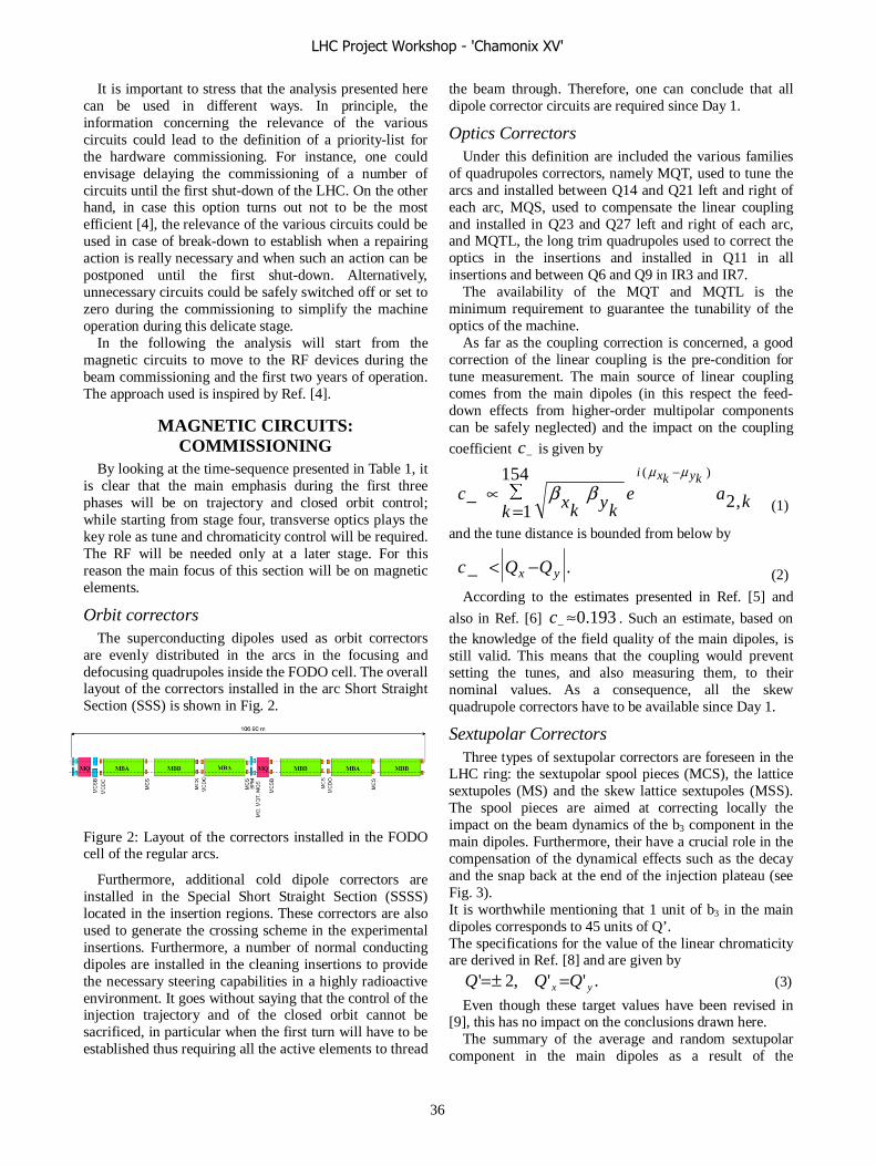
It is important to stress that the analysis presented here can be used in different ways. In principle, the information concerning the relevance of the various circuits could lead to the definition of a priority-list for the hardware commissioning. For instance, one could envisage delaying the commissioning of a number of circuits until the first shut-down of the LHC. On the other hand, in case this option turns out not to be the most efficient [4], the relevance of the various circuits could be used in case of break-down to establish when a repairing action is really necessary and when such an action can be postponed until the first shut-down. Alternatively, unnecessary circuits could be safely switched off or set to zero during the commissioning to simplify the machine operation during this delicate stage.
In the following the analysis will start from the magnetic circuits to move to the RF devices during the beam commissioning and the first two years of operation. The approach used is inspired by Ref. [4].
MAGNETIC CIRCUITS: COMMISSIONING
By looking at the time-sequence presented in Table 1, it is clear that the main emphasis during the first three phases will be on trajectory and closed orbit control; while starting from stage four, transverse optics plays the key role as tune and chromaticity control will be required. The RF will be needed only at a later stage. For this reason the main focus of this section will be on magnetic elements.
Orbit correctors The superconducting dipoles used as orbit correctors
are evenly distributed in the arcs in the focusing and defocusing quadrupoles inside the FODO cell. The overall layout of the correctors installed in the arc Short Straight Section (SSS) is shown in Fig. 2.
Figure 2: Layout of the correctors installed in the FODO cell of the regular arcs.
Furthermore, additional cold dipole correctors are installed in the Special Short Straight Section (SSSS) located in the insertion regions. These correctors are also used to generate the crossing scheme in the experimental insertions. Furthermore, a number of normal conducting dipoles are installed in the cleaning insertions to provide the necessary steering capabilities in a highly radioactive environment. It goes without saying that the control of the injection trajectory and of the closed orbit cannot be sacrificed, in particular when the first turn will have to be established thus requiring all the active elements to thread
the beam through. Therefore, one can conclude that all dipole corrector circuits are required since Day 1.
Optics Correctors Under this definition are included the various families
of quadrupoles correctors, namely MQT, used to tune the arcs and installed between Q14 and Q21 left and right of each arc, MQS, used to compensate the linear coupling and installed in Q23 and Q27 left and right of each arc, and MQTL, the long trim quadrupoles used to correct the optics in the insertions and installed in Q11 in all insertions and between Q6 and Q9 in IR3 and IR7.
The availability of the MQT and MQTL is the minimum requirement to guarantee the tunability of the optics of the machine.
As far as the coupling correction is concerned, a good correction of the linear coupling is the pre-condition for tune measurement. The main source of linear coupling comes from the main dipoles (in this respect the feed-down effects from higher-order multipolar components can be safely neglected) and the impact on the coupling
coefficient −c is given by
kaek kykxc
kykxi
,2
154
1
)( μμ
ββ−
∑
=∝− (1)
and the tune distance is bounded from below by
.yx QQc −<− (2)
According to the estimates presented in Ref. [5] and
also in Ref. [6] 193.0≈−c . Such an estimate, based on the knowledge of the field quality of the main dipoles, is still valid. This means that the coupling would prevent setting the tunes, and also measuring them, to their nominal values. As a consequence, all the skew quadrupole correctors have to be available since Day 1.
Sextupolar Correctors Three types of sextupolar correctors are foreseen in the
LHC ring: the sextupolar spool pieces (MCS), the lattice sextupoles (MS) and the skew lattice sextupoles (MSS). The spool pieces are aimed at correcting locally the impact on the beam dynamics of the b3 component in the main dipoles. Furthermore, their have a crucial role in the compensation of the dynamical effects such as the decay and the snap back at the end of the injection plateau (see Fig. 3). It is worthwhile mentioning that 1 unit of b3 in the main dipoles corresponds to 45 units of Q’. The specifications for the value of the linear chromaticity are derived in Ref. [8] and are given by
.'',2' yx QQQ =±= (3)
Even though these target values have been revised in [9], this has no impact on the conclusions drawn here.
The summary of the average and random sextupolar component in the main dipoles as a result of the
LHC Project Workshop - 'Chamonix XV'
36
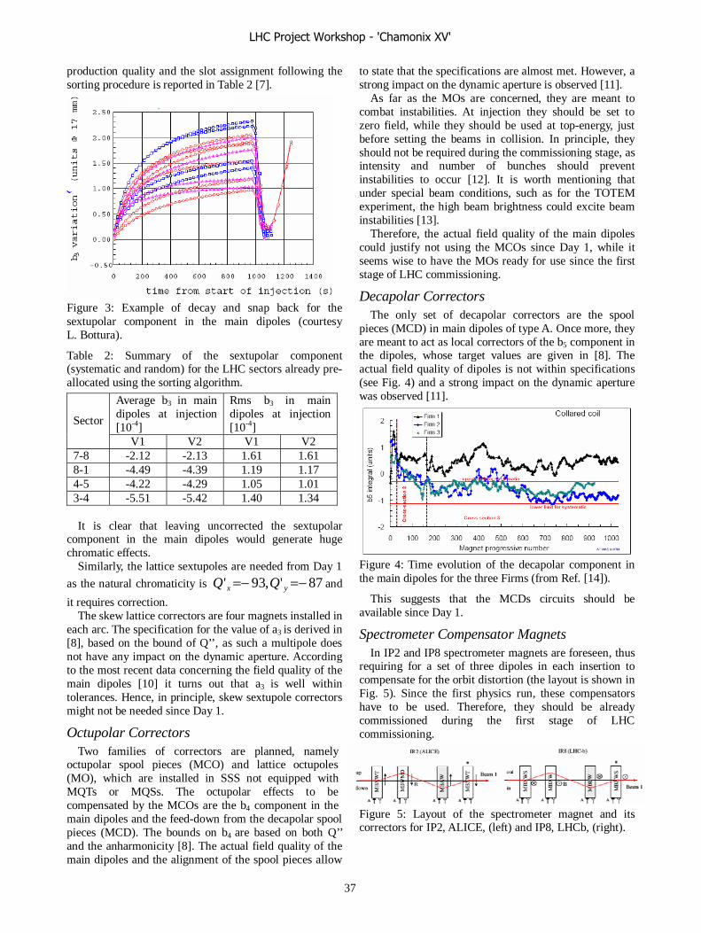
production quality and the slot assignment following the sorting procedure is reported in Table 2 [7].
Figure 3: Example of decay and snap back for the sextupolar component in the main dipoles (courtesy L. Bottura).
Table 2: Summary of the sextupolar component (systematic and random) for the LHC sectors already pre-allocated using the sorting algorithm.
Average b3 in main dipoles at injection [10-4]
Rms b3 in main dipoles at injection [10-4]
Sector
V1 V2 V1 V2 7-8 -2.12 -2.13 1.61 1.61 8-1 -4.49 -4.39 1.19 1.17 4-5 -4.22 -4.29 1.05 1.01 3-4 -5.51 -5.42 1.40 1.34 It is clear that leaving uncorrected the sextupolar
component in the main dipoles would generate huge chromatic effects.
Similarly, the lattice sextupoles are needed from Day 1
as the natural chromaticity is 87',93' −=−= yx QQ and
it requires correction. The skew lattice correctors are four magnets installed in
each arc. The specification for the value of a3 is derived in [8], based on the bound of Q’’, as such a multipole does not have any impact on the dynamic aperture. According to the most recent data concerning the field quality of the main dipoles [10] it turns out that a3 is well within tolerances. Hence, in principle, skew sextupole correctors might not be needed since Day 1.
Octupolar Correctors Two families of correctors are planned, namely
octupolar spool pieces (MCO) and lattice octupoles (MO), which are installed in SSS not equipped with MQTs or MQSs. The octupolar effects to be compensated by the MCOs are the b4 component in the main dipoles and the feed-down from the decapolar spool pieces (MCD). The bounds on b4 are based on both Q’’ and the anharmonicity [8]. The actual field quality of the main dipoles and the alignment of the spool pieces allow
to state that the specifications are almost met. However, a strong impact on the dynamic aperture is observed [11].
As far as the MOs are concerned, they are meant to combat instabilities. At injection they should be set to zero field, while they should be used at top-energy, just before setting the beams in collision. In principle, they should not be required during the commissioning stage, as intensity and number of bunches should prevent instabilities to occur [12]. It is worth mentioning that under special beam conditions, such as for the TOTEM experiment, the high beam brightness could excite beam instabilities [13].
Therefore, the actual field quality of the main dipoles could justify not using the MCOs since Day 1, while it seems wise to have the MOs ready for use since the first stage of LHC commissioning.
Decapolar Correctors The only set of decapolar correctors are the spool
pieces (MCD) in main dipoles of type A. Once more, they are meant to act as local correctors of the b5 component in the dipoles, whose target values are given in [8]. The actual field quality of dipoles is not within specifications (see Fig. 4) and a strong impact on the dynamic aperture was observed [11].
Figure 4: Time evolution of the decapolar component in the main dipoles for the three Firms (from Ref. [14]).
This suggests that the MCDs circuits should be available since Day 1.
Spectrometer Compensator Magnets In IP2 and IP8 spectrometer magnets are foreseen, thus
requiring for a set of three dipoles in each insertion to compensate for the orbit distortion (the layout is shown in Fig. 5). Since the first physics run, these compensators have to be used. Therefore, they should be already commissioned during the first stage of LHC commissioning.
Figure 5: Layout of the spectrometer magnet and its correctors for IP2, ALICE, (left) and IP8, LHCb, (right).
LHC Project Workshop - 'Chamonix XV'
37

Nonlinear Correctors in Triplet Quadrupoles These correctors (see Fig. 6) are aimed at compensating
the nonlinear field errors of the key elements of each experimental insertion, i.e. the triplet quadrupoles and the separation dipoles, in collision. It is well-known that no
correction is required whenever *β is larger than 1 m. This means that they are not needed since Day 1.
Figure 6: Layout of the nonlinear correctors in the triplet quadrupoles.
The only two types of correctors that might be needed are the skew quadrupoles (MQSX) in all insertions and normal sextupoles (MCSX) in IP2.
Two main effects could require the use f MQSXs, namely the compensation of the coupling at injection from the experimental solenoids and the skew quadrupole component in the triplet quadrupoles. The first effect is known to be negligible at top energy [15]. However, they
are expected to generate a 3105 −− ×≈c [16], which is
not completely negligible. In IP2, the vertical crossing angle combined with the
requirement of changing periodically the polarity of the spectrometer magnet, make it impossible the correction of the skew quadrupole multipole due to feed-down from the normal sextupole. The MQSXs cannot be used to compensate the effect for both beams and a non-local compensation performed by using the MQS in the regular arcs is not effective. Therefore, the only viable solution consists in compensating the sextupolar component by means of the MCSX.
MAGNETIC CIRCUITS: FIRST TWO YEARS OF OPERATION
During these two stages following the initial commissioning, the beam conditions will be pushed towards the nominal ones. Hence, all the corrector circuits will be needed to ensure reaching the nominal machine performance.
RF CIRCUITS In the nominal scheme, two modules containing four
RF cavities each (see Fig. 7) are used to accelerate the proton beams. At injection 8 MV are necessary to capture the beam, while at top energy the voltage has to be increased to 16 MV. This allows dedicating 8 MV to compensate for beam loading effects at injection.
In principle, during the commissioning stage, due to the limited bunch intensity it could be envisaged to accelerate the beam with only 8 MV, thus sparing one module. The main drawback of such an approach is that during the
initial test of beam capture, it would be advisable to use full voltage to reduce the sensitivity to energy errors between the SPS and the LHC.
Figure 7: Layout of one RF module.
In other words, this would correspond to maximising the longitudinal acceptance. Hence, it seems safer to start-up the LHC machine with all the RF modules operational, also to have some redundancy in case of failure of one of the modules (see, e.g., Ref. [17]).
CONCLUSIONS The analysis presented in this report can be summarised
as follows: • Circuits mandatory since Day 1
o Orbit correctors. o Quadrupole correctors: MQTs, MQTLs,
MQSs. o Sextupolar correctors: MCS, MS. o Spectrometer compensators. o All RF modules.
• Circuits required since Day 2: o Decapolar correctors: MCD. o Octupolar correctors: MCO. o Skew quadrupole correctors in the triplets:
MQSX. o Normal sextupolar correctors in the
triplets in IP2: MCSX. o Lattice octupoles: MO.
• Circuits not required since Day 1: o Skew sextupolar correctors: MSS o Nonlinear correctors in the triplet
quadrupoles. These conclusions are valid for the LHC
commissioning stage. Whenever the first two years of operations are considered, all the corrector circuits foreseen for the nominal machine should be in operation.
ACKNOWLEDGEMENTS The material presented in this paper is the result of
many fruitful discussions with H. Burkhardt, S. Fartoukh, E. Métral, F. Ruggiero, R. Saban, E. Shaposhnikova, E. Todesco and J. Tuckmantel, which are warmly acknowledged.
REFERENCES [1] R. Bailey, “Summary of overall commissioning
strategy for protons”, talk given at the Third LHC Project Workshop, Chamonix XV, 2006.
LHC Project Workshop - 'Chamonix XV'
38
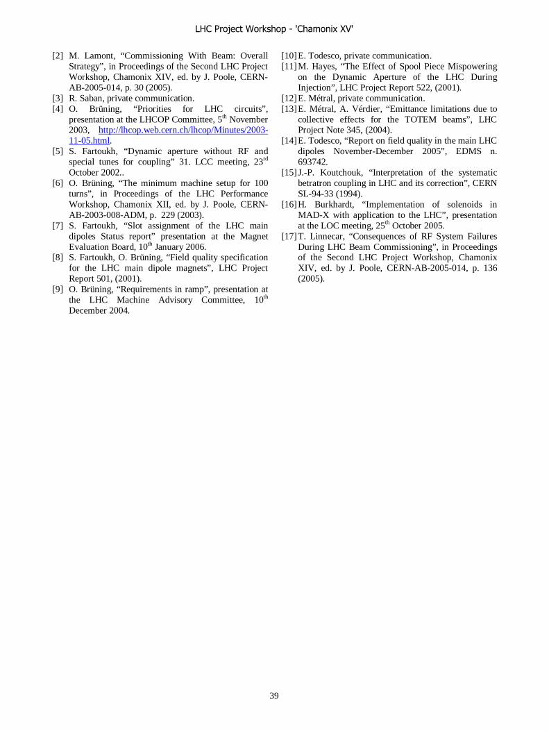
[2] M. Lamont, “Commissioning With Beam: Overall Strategy”, in Proceedings of the Second LHC Project Workshop, Chamonix XIV, ed. by J. Poole, CERN-AB-2005-014, p. 30 (2005).
[3] R. Saban, private communication. [4] O. Brüning, “Priorities for LHC circuits”,
presentation at the LHCOP Committee, 5th November 2003, http://lhcop.web.cern.ch/lhcop/Minutes/2003-11-05.html.
[5] S. Fartoukh, “Dynamic aperture without RF and special tunes for coupling” 31. LCC meeting, 23rd October 2002..
[6] O. Brüning, “The minimum machine setup for 100 turns”, in Proceedings of the LHC Performance Workshop, Chamonix XII, ed. by J. Poole, CERN-AB-2003-008-ADM, p. 229 (2003).
[7] S. Fartoukh, “Slot assignment of the LHC main dipoles Status report” presentation at the Magnet Evaluation Board, 10th January 2006.
[8] S. Fartoukh, O. Brüning, “Field quality specification for the LHC main dipole magnets”, LHC Project Report 501, (2001).
[9] O. Brüning, “Requirements in ramp”, presentation at the LHC Machine Advisory Committee, 10th December 2004.
[10] E. Todesco, private communication. [11] M. Hayes, “The Effect of Spool Piece Mispowering
on the Dynamic Aperture of the LHC During Injection”, LHC Project Report 522, (2001).
[12] E. Métral, private communication. [13] E. Métral, A. Vérdier, “Emittance limitations due to
collective effects for the TOTEM beams”, LHC Project Note 345, (2004).
[14] E. Todesco, “Report on field quality in the main LHC dipoles November-December 2005”, EDMS n. 693742.
[15] J.-P. Koutchouk, “Interpretation of the systematic betratron coupling in LHC and its correction”, CERN SL-94-33 (1994).
[16] H. Burkhardt, “Implementation of solenoids in MAD-X with application to the LHC”, presentation at the LOC meeting, 25th October 2005.
[17] T. Linnecar, “Consequences of RF System Failures During LHC Beam Commissioning”, in Proceedings of the Second LHC Project Workshop, Chamonix XIV, ed. by J. Poole, CERN-AB-2005-014, p. 136 (2005).
LHC Project Workshop - 'Chamonix XV'
39

BEAM MEASUREMENTS REQUIRED IN THE FIRST TWO YEARS OFLHC COMMISSIONING
Frank Zimmermann
Abstract
Many beam measurements are essential already in thefirst stage of the LHC commissioning. Others become nec-essary only as the intensity and the number of bunches israised. I will review the beam measurements needed in thevarious phases of the LHC commissioning, their sequence,and the tools required for performing them. An earlier talkat Chamonix XII has discussed beam measurements on theLHC flat bottom [1]. The present discussion also addressesacceleration and collision, the priority or order of the vari-ous measurements, as well as requirements for instrumentsand timing.
INTRODUCTION
The LHC will be commissioned in stages [2], which aresummarized in Table 1. The first stage for protons fore-sees an initial several-month period with pilot and medium-intensity bunches, followed by 43-bunch operation, whichis then extended to 156 bunches. The final pushed param-eters of this first stage are characterized by �� � � min interaction points (IPs) 1 and 5, a bunch population�� � ������, and a luminosity of �������� cm��s��. Inthe second stage of LHC commissioning, 936 bunches arestored per ring with 75-ns separation, avoiding problemswith electron cloud, and keeping the number of long-rangeinteractions moderate. The IP beta functions in IPs 1 and 5are squeezed to 1 m, the bunch population stays at ������
protons per bunch, and a crossing angle of about 250 �radis needed. The luminosity reaches ��� � ���� cm��s��.Stage 3 finally refers to 25-ns operation with 2808 bunches,nominal IP beta functions of 0.55 m, about half the nominalbunch intensity, namely �� � � � ����, and a luminosityof ��� � ���� cm��s��. Now the missing dilution kick-ers and new ‘phase-2’ collimators are installed, before thenominal performance and a luminosity of ���� cm��s��
can be established.This paper discusses the measurements and instruments
needed in the first three stages of LHC commissioning,spanning from the first pilot bunch to 2808 bunches at halfthe nominal intensity. Measurements, procedures and toolsabsolutely needed in the first stage are distinguished fromthose which are either required only in stage 2 or of sec-ondary importance. LHC commissioning sequences withpertinent measurements and instruments were already pre-sented in previous Chamonix workshops, e.g., by M. Lam-ont [3, 4], H. Schmickler [5, 6], P. Collier [7] and B. God-dard [8]. An updated plan for the various comissioning
phases is available on the LHC commissioning web site[9].
ESSENTIAL SYSTEMS
Before at the LHC beams of any significant intensity canbe injected, accelerated and collided, three essential com-ponents have to be set up: machine protection, beam lossmonitors, and collimation.
Machine protection is crucial, since at 7 TeV already asingle pilot bunch with an intensity of � � ��� protons isclose to the damage limit of metallic surfaces, which is es-timated at �� ��� protons [10, 11]. At injection, the metaldamage limit is reached for about 50 nominal bunches [10].For comparison, the damage limit of the more robust col-limators for fast losses is estimated above �� ���� (�260nominal bunches) and ������ (� nominal bunches) pro-tons at 450 GeV and 7 TeV, respectively [10]. Fast losses of��� and ����� protons can lead to magnet quenches at in-jection and top energy, respectively. The quench limit dur-ing a beam dump is reached for about ����� and ������
protons per meter in the abort gap at 7 TeV and at injec-tion, respectively [12, 13]. For comparison, debunching43 bunches with �� � � � ���� protons each and dis-tributing them around the ring would produce a line den-sity of �� � �� protons per meter, which is about 100times higher than the 7-TeV quench limit. Therefore, at 7TeV losing three percent of the beam from the bucket with43 bunches, or less than 1 percent with 156 bunches, mayresult in a critical density at the abort gap. An abort gapmonitor will be required, if beam dumps frequently lead toquenches due to this effect.
About 3700 beam-loss monitors (BLMs) are installed inthe two LHC rings [14]. They are an integral part of themachine protection system [15]. Calibration of these mon-itors and their reliability are issues to be addressed early on[16].
The collimation system features about 400 degrees offreedom, which need to be optimized by beam-based ad-justments. For example, the collimator jaws must be set towithin 50 �rad with respect to the beam direction [17].
At injection the limited mechanical aperture of the coldarc equals 7.2� [18, 19], accounting for 21% beta beat-ing. The primary collimators are nominally set to 5.7�[20]. The requirement that the cold-arc aperture shouldnot become the primary aperture of the machine restrictsthe maximum permissible beta beating to about 90% 1, for
1This number needs to be confirmed by the collimation team.
LHC Project Workshop - 'Chamonix XV'
40

Table 1: Stages of LHC Beam Commissioning [2].stage �� #bunches �� �� � at IP1 and 5Ia �� ��� � � ���� 1 18 m 0 ��� cm��s��
Ib � ���� � �� ���� 43� �� 18 m� 2 m 0 ��� ���� � ���� ���� cm��s��
II � ���� � �� ���� 936 18 m� 1 m 250 �rad ���� ���� � ���� ���� cm��s��
III � ���� � �� ���� 2808 18 m� 0.55 m 285 �rad �� ���� � �� ���� cm��s��
low-intensity beams with a single-stage collimation dur-ing early commissioning. At higher intensity, with a 2-stage collimation system, the (off-momentum) beta beat-ing should be less than 21% at all times for a maximumclosed-orbit error of 4 mm [19].
EXPECTED ERRORS AND TOLERANCES
Table 2 lists data for systematic and random field com-ponents in the LHC dipole magnets at injection and theirchange during snapback. The effect of sextupole spool-piece misalignments, by 0.3 mm on average and 0.6 mmrms, has been taken into account in the values quoted for�� and �.
Table 2: Table of selected dipole and quadrupole mag-net errors, in standard units of ���� for a reference radius� � �� mm [21]; the values quoted for �� and � of thedipoles include the effect of feeddown from systematic andrandom sextupole spool-piece misalignments of 0.3 mmand 0.6 mm rms, respectively.
multi- injection decaypole mean rms mean rms���� 5 6 1.4 1.2���� (�)1.2 0.6 0.07 0.1��� 0.2 2 0.07 0.3���� 5 2 2 0.5��� 0.1 0.4 0.07 0.07������ � — — 2 2
Momentum
A systematic error in �� yields a momentum error of
��
��
��
�� � ������ � (1)
with ��� � ���� the Lorentz factor for the LHC transitionenergy. As an illustration, with a �� of 10 units, and using� � ���, the momentum error is about ����.
Orbit
During the snapback, an rms change of �� by 1.2 units,leads to a change in the rms closed orbit of
� ��
���������� � � �
��������
�
��� ������
� (2)
equal to about 0.7 mm, with ������� � ���� the number ofdipoles, and ��� � ��� m the dipole length. During thesqueeze an error of 10 units in the D1 dipole can change theclosed orbit by 3� in the triplet quadrupole magnets [22].
Tune
Static tune errors will predominantly arise from errorsin the quadrupole gradients or in the dipole field, as wellas from (systematic) horizontal orbit offsets in the latticesextupoles. As a smaller contribution, the systematic mis-aligment of the sextupole spool-pieces results in a statictune shift of 0.03. Initial total tune errors up to 0.4 may beexpected.
Concerning the dynamic variation of the tune, a system-atic decay ����� � by 2 units in the quadrupole strengthyields a tune change of about [23]
�� � ������� ����� � ���� � (3)
Dynamic tune changes on the ramp also arise from theconspiracy between the snapback of �� in the dipoles andthe misalignment of sextupole spool-pieces via feeddown.This contribution can be estimated as
�� � �
�� � �
���
���������
����������
�
�� (4)
where �� here refers to the mean decay, and ������ ���� mm to the systematic error in the spool-piece align-ment. From (4) the �� decay of 2 units during the snapbackyields a tune change of 0.015, while the total change duringthe ramp is 7/2 times larger, or�� � ����. Another sourceof dynamic tune variation are tracking errors between thedipole and quadrupole magnets. The tune change from arelative dipole tracking error ������ is
�� � ��
� �
���
��� (5)
where ��
� � � � denotes the natural chromaticity ofthe LHC. The measured magnetic field reproducibility be-tween ramps is ��� ��� ���� [24], which implies a tunevariation �� of 0.01–0.04. Adding the various contribu-tions, we may expect total dynamic tune changes on theramp of order 0.1.
Tune shifts during the squeeze are generated by errors inthe low-beta quadrupoles: A 10 unit error of a single tripletQ2 magnet changes the tune by 0.03.
LHC Project Workshop - 'Chamonix XV'
41
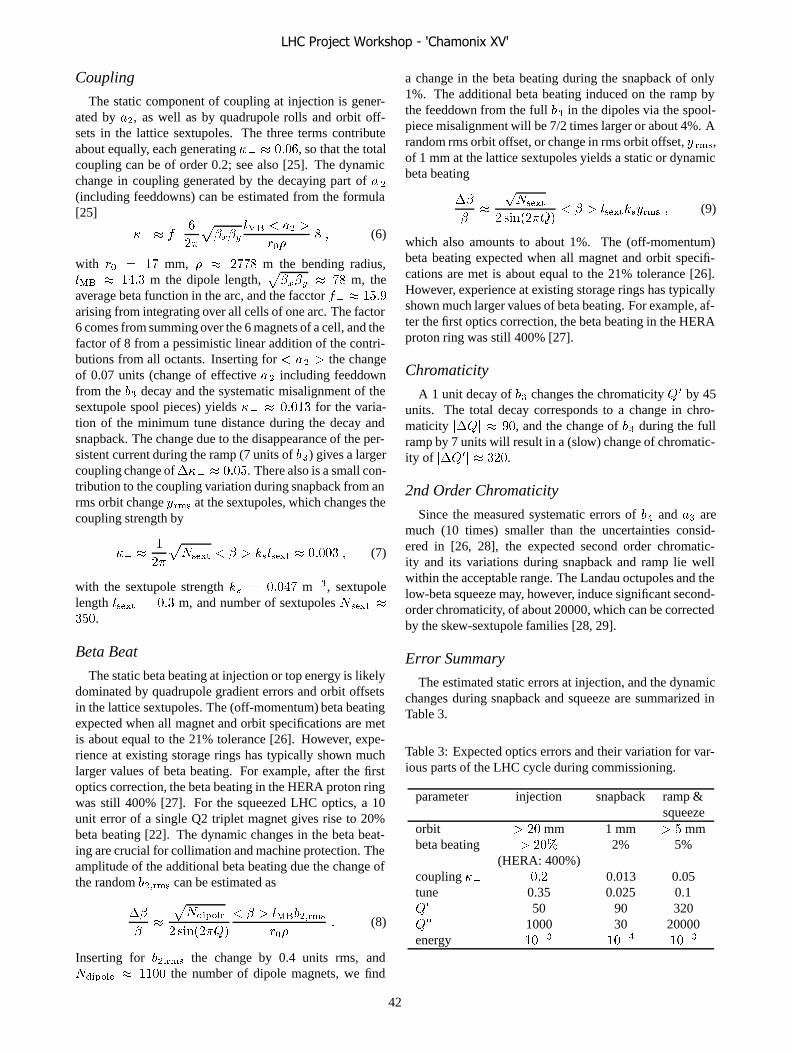
Coupling
The static component of coupling at injection is gener-ated by �, as well as by quadrupole rolls and orbit off-sets in the lattice sextupoles. The three terms contributeabout equally, each generating �� � ���, so that the totalcoupling can be of order 0.2; see also [25]. The dynamicchange in coupling generated by the decaying part of �
(including feeddowns) can be estimated from the formula[25]
�� � ��
��
�����
��� � � �
��� � (6)
with � � �� mm, � � ���� m the bending radius,��� � ��� m the dipole length,
����� � �� m, the
average beta function in the arc, and the facctor �� � ����arising from integrating over all cells of one arc. The factor6 comes from summing over the 6 magnets of a cell, and thefactor of 8 from a pessimistic linear addition of the contri-butions from all octants. Inserting for � � � the changeof 0.07 units (change of effective � including feeddownfrom the �� decay and the systematic misalignment of thesextupole spool pieces) yields �� � ����� for the varia-tion of the minimum tune distance during the decay andsnapback. The change due to the disappearance of the per-sistent current during the ramp (7 units of ��) gives a largercoupling change of��� � ����. There also is a small con-tribution to the coupling variation during snapback from anrms orbit change ���� at the sextupoles, which changes thecoupling strength by
�� � �
��
������ � � � ������� � ����� � (7)
with the sextupole strength �� � ���� m��, sextupolelength ����� � ��� m, and number of sextupoles ����� ����.
Beta Beat
The static beta beating at injection or top energy is likelydominated by quadrupole gradient errors and orbit offsetsin the lattice sextupoles. The (off-momentum) beta beatingexpected when all magnet and orbit specifications are metis about equal to the 21% tolerance [26]. However, expe-rience at existing storage rings has typically shown muchlarger values of beta beating. For example, after the firstoptics correction, the beta beating in the HERA proton ringwas still 400% [27]. For the squeezed LHC optics, a 10unit error of a single Q2 triplet magnet gives rise to 20%beta beating [22]. The dynamic changes in the beta beat-ing are crucial for collimation and machine protection. Theamplitude of the additional beta beating due the change ofthe random ������ can be estimated as
��
���
�������
� �������
� � � ���������
��� (8)
Inserting for ������ the change by 0.4 units rms, and������� � ���� the number of dipole magnets, we find
a change in the beta beating during the snapback of only1%. The additional beta beating induced on the ramp bythe feeddown from the full �� in the dipoles via the spool-piece misalignment will be 7/2 times larger or about 4%. Arandom rms orbit offset, or change in rms orbit offset, � ���,of 1 mm at the lattice sextupoles yields a static or dynamicbeta beating
��
��
������
� �������� � � ����������� � (9)
which also amounts to about 1%. The (off-momentum)beta beating expected when all magnet and orbit specifi-cations are met is about equal to the 21% tolerance [26].However, experience at existing storage rings has typicallyshown much larger values of beta beating. For example, af-ter the first optics correction, the beta beating in the HERAproton ring was still 400% [27].
Chromaticity
A 1 unit decay of �� changes the chromaticity �� by 45units. The total decay corresponds to a change in chro-maticity ���� � ��, and the change of �� during the fullramp by 7 units will result in a (slow) change of chromatic-ity of ����� � ���.
2nd Order Chromaticity
Since the measured systematic errors of �� and � aremuch (10 times) smaller than the uncertainties consid-ered in [26, 28], the expected second order chromatic-ity and its variations during snapback and ramp lie wellwithin the acceptable range. The Landau octupoles and thelow-beta squeeze may, however, induce significant second-order chromaticity, of about 20000, which can be correctedby the skew-sextupole families [28, 29].
Error Summary
The estimated static errors at injection, and the dynamicchanges during snapback and squeeze are summarized inTable 3.
Table 3: Expected optics errors and their variation for var-ious parts of the LHC cycle during commissioning.
parameter injection snapback ramp &squeeze
orbit � �� mm 1 mm � � mmbeta beating � ��� 2% 5%
(HERA: 400%)coupling �� ��� 0.013 0.05tune 0.35 0.025 0.1�� 50 90 320��� 1000 30 20000energy ���� ���� ����
LHC Project Workshop - 'Chamonix XV'
42

Tolerances
Table 4 compiles tolerances for various optical parame-ters and compares their magnitude with that of the errorsexpected in the absence of correction.
Table 4: Expected errors and correction goals for injection,ramp and squeeze [30].
parameter tolerance error /tolerance
orbit change �� � �������� � beta beating � ��� (HERA: 400%) 1-40coupling �� ����� ����� 20–200tune change ������ ����������� � ���chromaticity �� �� �� �� � � ���2nd order chr. ��� 1000/2000 � ��energy ���� 10
From Table 4, it is evident that the LHC cannot be com-missioned without optics measurements and corrections.
COMMISSIONING STEPS ANDPROCEDURES
First Turn and Injection Matching
Necessary steps include (1) threading, closure, and or-bit smoothing, (2) the tuning of injection kicker, injectionseptum, and kicker timing, and (3) the adjustment of thehorizontal orbit correctors in each octant to the beam en-ergy from the SPS. Beta matching is considered optional.It could be performed for 43 bunches.
The instruments needed to perform these steps are fastbeam-current transformers (BCTs) [31], screens in the in-jection region showing the beam image on the first pas-sage, as well as the horizontal and vertical readings of thebeam-position monitors (BPMs) [32]. Desirable for first-turn steering would also be the sum readings of the BPMs,which could be obtained by using the electronics of the sec-ond ring. The BPM sum signal was extremely helpful inthe HERA commissioning, where it allowed discriminatingvalid beam position readings from spurious ones. Alterna-tively, in the LHC one may get information about beamloss from the auto-triggering of the BPMs. The BPMs canalso be used to infer the integer and fractional part of thetune. For the latter, a few turns of circulating beam willbe required. The BPM readings should be triggered on thefirst turn, which is automatically fulfilled, if they are auto-triggered.
RF Capture
The rf phase and rf frequency need to be adjusted to min-imize the longitudinal injection oscillation and to center thebeam in the aperture, respectively. A measurement of the
longitudinal bunch profile and its evolution after injectionwould be useful for monitoring centroid and bunch lengthoscillations as well as longitudinal tails. Less importantly,the synchrotron frequency could be measured as a func-tion of rf voltage, which would allow cross-checking thephasing of the rf cavities, the voltage calibration, and themomentum compaction factor.
Required instruments include the arc BPMs (turn-by-turn readings) [32], the fast beam-current transformers (fastBCTs), the dc beam-current transformers (BCTs) [31], andlongitudinal profile monitors, e.g., wall-current pick-upsignal provided by the rf group.
Extraction & Dump
The extraction and beam dump have to be set up earlyon, so as not to activate the LHC machine and as a pre-requisite for intensities above the pilot bunch. Similar asfor injection, the septum and kicker strengths as well as thekicker timing are to be adjusted with the help of screens andBPMs. The local optics in the vicinity of septum and kickercould be checked in order to exclude huge mismatches,which could lead to excessive losses in the extraction chan-nel. The available set of dilution kickers will be turned onand their effect measured shortly after the start of stage I.Dilution kickers are necessary for 156 bunches and likelyfor 43 to prevent the destruction of the LHC beam dump.
The following instruments will be needed for these com-missioning steps: Screens in the extraction region and infront of the beam dump [33], fast BCTs, BLMs at the ex-traction region and in the dump line, and a post-mortemsystem recording beam positions and beam losses on thelast couple of turns prior to extraction, in particular theturn-by-turn beam position on the last turn.
Orbit Bumps
A versatile technique which can be used for several dif-ferent types of studies, performed either simultaneously ofsuccessively, are orbit bumps. Sliding orbit bumps canidentify aperture limitations, magnet misalignments andgross optical errors. Mapping the phyical aperture aroundthe ring likely requires a minimum of 8 bumps per arc andper straight (2 phases, 2 planes and 2 beams) or a total of128 orbit long bumps for the two rings. If the only goalis to measure the physical aperture, the bumps can be gen-erated by changing the setpoints of the orbit feedback sys-tem. If linear optics errors are also to be detected, via thebump leakage [34], it may be advisable to switch of thefeedback (in principle the leakage could also be inferredfrom changes in the feedback corrector currents; howeverthe feedback noise is thought to degrade the quality of suchan indirect measurement [35]). The bumps can be usedto verify the ��� matrix elements of the model or revealdiscrepancies. Coupling sources and sextupole fields aredetected as orbit changes induced in the plane orthogonalto the bump, and identified by their amplitude dependence.
LHC Project Workshop - 'Chamonix XV'
43
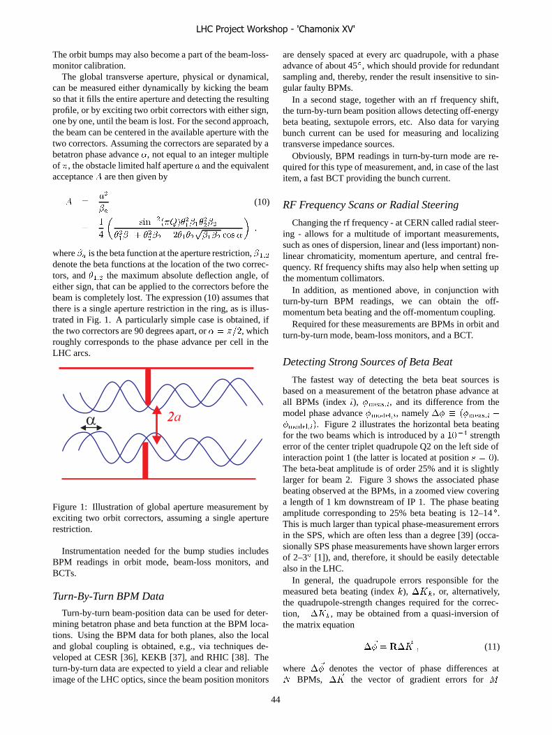
The orbit bumps may also become a part of the beam-loss-monitor calibration.
The global transverse aperture, physical or dynamical,can be measured either dynamically by kicking the beamso that it fills the entire aperture and detecting the resultingprofile, or by exciting two orbit correctors with either sign,one by one, until the beam is lost. For the second approach,the beam can be centered in the available aperture with thetwo correctors. Assuming the correctors are separated by abetatron phase advance �, not equal to an integer multipleof �, the obstacle limited half aperture and the equivalentacceptance � are then given by
� �
�(10)
��
� ��������������
����
����� � ����� � ���������� �� �
��
where � is the beta function at the aperture restriction, ����
denote the beta functions at the location of the two correc-tors, and ���� the maximum absolute deflection angle, ofeither sign, that can be applied to the correctors before thebeam is completely lost. The expression (10) assumes thatthere is a single aperture restriction in the ring, as is illus-trated in Fig. 1. A particularly simple case is obtained, ifthe two correctors are 90 degrees apart, or � � ���, whichroughly corresponds to the phase advance per cell in theLHC arcs.
α 2a2
Figure 1: Illustration of global aperture measurement byexciting two orbit correctors, assuming a single aperturerestriction.
Instrumentation needed for the bump studies includesBPM readings in orbit mode, beam-loss monitors, andBCTs.
Turn-By-Turn BPM Data
Turn-by-turn beam-position data can be used for deter-mining betatron phase and beta function at the BPM loca-tions. Using the BPM data for both planes, also the localand global coupling is obtained, e.g., via techniques de-veloped at CESR [36], KEKB [37], and RHIC [38]. Theturn-by-turn data are expected to yield a clear and reliableimage of the LHC optics, since the beam position monitors
are densely spaced at every arc quadrupole, with a phaseadvance of about 45Æ, which should provide for redundantsampling and, thereby, render the result insensitive to sin-gular faulty BPMs.
In a second stage, together with an rf frequency shift,the turn-by-turn beam position allows detecting off-energybeta beating, sextupole errors, etc. Also data for varyingbunch current can be used for measuring and localizingtransverse impedance sources.
Obviously, BPM readings in turn-by-turn mode are re-quired for this type of measurement, and, in case of the lastitem, a fast BCT providing the bunch current.
RF Frequency Scans or Radial Steering
Changing the rf frequency - at CERN called radial steer-ing - allows for a multitude of important measurements,such as ones of dispersion, linear and (less important) non-linear chromaticity, momentum aperture, and central fre-quency. Rf frequency shifts may also help when setting upthe momentum collimators.
In addition, as mentioned above, in conjunction withturn-by-turn BPM readings, we can obtain the off-momentum beta beating and the off-momentum coupling.
Required for these measurements are BPMs in orbit andturn-by-turn mode, beam-loss monitors, and a BCT.
Detecting Strong Sources of Beta Beat
The fastest way of detecting the beta beat sources isbased on a measurement of the betatron phase advance atall BPMs (index �), ��� ��, and its difference from themodel phase advance �������, namely �� ���� �� ���������. Figure 2 illustrates the horizontal beta beatingfor the two beams which is introduced by a ���� strengtherror of the center triplet quadrupole Q2 on the left side ofinteraction point 1 (the latter is located at position � �).The beta-beat amplitude is of order 25% and it is slightlylarger for beam 2. Figure 3 shows the associated phasebeating observed at the BPMs, in a zoomed view coveringa length of 1 km downstream of IP 1. The phase beatingamplitude corresponding to 25% beta beating is 12–14 Æ.This is much larger than typical phase-measurement errorsin the SPS, which are often less than a degree [39] (occa-sionally SPS phase measurements have shown larger errorsof 2–3Æ [1]), and, therefore, it should be easily detectablealso in the LHC.
In general, the quadrupole errors responsible for themeasured beta beating (index �), �!�, or, alternatively,the quadrupole-strength changes required for the correc-tion, ��!�, may be obtained from a quasi-inversion ofthe matrix equation
�"� � �� "! � (11)
where �"� denotes the vector of phase differences at� BPMs, � "! the vector of gradient errors for #
LHC Project Workshop - 'Chamonix XV'
44

Figure 2: Relative horizontal beta beating �� ����� � gen-erated by a ���� strength error of Q2 on the left side of IP1, as a function of position around the LHC ring in units ofmetre; ��� � is the design beta function at position .
Figure 3: Phase beating in degrees at the BPMs as a func-tion of position in metre over the first 1 km of the LHCring; the beating was generated by a strength error of ����
for Q2 on the left side of IP 1.
quadrupoles, and the response matrix � contains the ele-ments [39]
�� �
�����������
��� ���� ���� ������� ��� ���
� ���������
�!
��� �� � � ����� � �� ���� ��� �� ���� ���������
� ���������
�!
��� �� � �
�
(12)where �� is the tune without the quadrupole errors. In thecase of the LHC, the matrix � could be the combined re-sponse matrix for the two rings, including phases at com-mon BPMs and errors of shared quadrupoles. The avail-ability of data from two beams should facilitate the properidentification of gradient errors in the high-beta regionsaround the primary collision points.
Gradient errors may also be obtained by global multi-parameter fits of orbit response data in LOCO style [40,
41], where the orbit response to all ring correctors is mea-sured one by one. This is likely much more time consumingthan taking turn-by-turn data. A faster variant would con-sist of exciting only 3 pairs of correctors per plane, againfollowed by an appropriate fit. The latter technique is ap-plied in KEKB [42]. A possible advantage is the 10-timeshigher resolution of the BPM orbit reading compared withthe turn-by-turn measurement.
For either method, a fit to an optics model is necessary.Application software and an online model could greatlyspeed up the beta-beat measurement and its correction.
The localization of beta beating sources requires BPMsin either turn or orbit mode.
Ramp
On the ramp we will encounter many dynamicchanges: the initial rapid snapback (regeneration of per-sistent currents), power-converter tracking errors betweenquadrupoles and dipoles, and the gradual reduction of thepersistent current as the magnet current is increased allconspire to render operation interesting. Fast significanttune changes are expected. Therefore, a quasi-continuoustune signal, as soon as possible augmented by a tune feed-back, is recommended. Frequent chromaticity measure-ments during the ramp may also be necessary, either usingthe conventional radial steering, or a fast rf phase modu-lation together with a phase-locked loop for the tune mea-surement [43], or a head-tail monitor plus kick excitation.Chromaticity measurements on the RHIC ramp have beenperformed by a PLL tune meter in combination with radialsteering [44]. The chromaticity evolution in the first sec-onds of the Tevatron ramp, during the snap back, has beenmeasured by a headtail monitor [45]. However, if the LHCchromaticity if sufficiently reproducible, one might mea-sure and correct it also by changing the rf frequency forsuccessive ramps (classical Tevatron approach) or it can bemeasured and corrected once at the start of a run (classicalRHIC approach). Another back-up solution could be a co-herence monitor, as is also employed in RHIC [46]. Thismonitor is described in the appendix.
Beta beating and coupling need also to be controlled onthe ramp. Presumably at higher energy the pertinent toler-ance on the beta beating could be relaxed, since the relativearc aperture widens, until the collimators are closed for thesqueeze. The coupling must remain corrected at a levelwhich permits tune control.
Needed instrumentation for the ramp comprises thebaseband Q (BBQ) meter, augmented by a phase-lockedloop (PLL) for tune control, radial steering for chromatic-ity measurements (RHIC, HERA), the headtail chromatic-ity monitor, and turn-by-turn BPM readings. Synchroniza-tion at the level of 10s of turns is required between varioustypes of equipment. For example, one will want to kick thebeam on the ramp and measure the resulting oscillationswith the turn-by-turn BPM mode. Acquiring also the tuneand the chromaticity at the same instant would be an ad-
LHC Project Workshop - 'Chamonix XV'
45

vantage, and provide a full optics snapshot at a particulartime of the ramp.
Instruments which could come at a later stage are a ‘tick-ler’ for weakly exciting individual bunches, e.g., for tunemeasurements or optics control, and a Schottky tune mon-itor.
Squeeze
For the squeeze, we can either apply the same techniquesas for the ramp, and/or we can proceed in steps with staticcorrections at the stops. In Chamonix XIV, the correctionwith stops was not thought to be meaningful for the ramp.However, in case of the squeeze persistent-current effectsin the triplets are considered too small to cause complica-tions.
At a later time, e.g., for the commissioning phase II, aspecial triplet alignment optics [47] is available which canbe used to define a reference straight line for the tripletalignment. This will aid in disentangling strength errorsof the D1 and D2 separation dipoles from misalignmentsof the triplet [48]. It seems preferred to perform the tripletalignment at injection energy.
Diagnostics and tools needed to commission and controlthe squeeze are the BBQ tune monitor, ideally with phase-locked loop, radial steering (as in RHIC, HERA), head-tail chromaticity monitor, turn-by-turn BPM readings, syn-chronization of beam kicks with BPM readings, tune andchromaticity measurements, and, later, a Schottky monitor.
Beam Evolution and Lifetime
Monitoring the dc beam current and the bunched beamcurent as a function of time yields the dc beam lifetime andthe bunch lifetime. At 7 TeV particles which leave the rfbucket are lost after about 6.5 minutes due to synchrotronradiation (at injection after 390 hours) [49]. We will alsowant to measure the beam size and bunch length evolutionduring a store, as well as monitor the bunch structure anddensity inside the abort gap. From stage II onwards, wewill also be interested in detecting beam tails and perform-ing measurements of diffusion rates.
The suite of instruments required includes BCT, fastBCT, bunch length monitor (e.g., wall-current monitor pro-vided by the rf group), wire scanner, synchrotron-lightmonitor and/or ionization profile monitor for the transversebeam size [50]. For stage II, we wish the Schottky monitor,a fast scraper (for diffusion measurements), the abort gapmonitor, and a tail monitor.
With its nominal speed the wire scanner should be ableto scan up to two complete PS batches in the LHC at 7 TeV[50]. The initial wire scanner will have a reduced speed,so that it can only be used for a few bunches. The mainuse of the wire scanner may be the calibration of the othertwo transverse profile monitors, which are based on syn-chrotron radiation and gas ionization, respectively, and areboth capable of sustaining the full LHC beam intensity.
Collision and Luminosity
To bring the two LHC beams into collision, a 2-dimensional transverse scan and a longitudinal scan of thebeam position or rf phase, respectively, are necessary. Lateron, with nonzero crossing angle, the transverse and longi-tudinal collision points are coupled. Since a good equaliza-tion of the transverse beam sizes is important, it will be ad-vantageous to have in hands IP tuning knobs, for equalizingthe IP beta functions or correcting IP coupling and disper-sion. The detection and control of a spurious crossing an-gle may also prove important. The TOTEM experiment re-quires a knowledge of the crossing angle with a precision of0.2�rad, to be compared with an expected resolution fromthe interaction-region BPMs of��� � �� �m [51], withouttaking into account any possible degradation of the BPMsignals by collision debris. Considering a BPM resolutionof � �m at a distance of �20 m at either side from the IP,one might think that the crossing angle could be measuredwith a resolution of the order ����������� � ��� �rad.However, the crossing-angle resolution is limited by thesystematic error in the zero BPM reading for the two beams(taken from the two sides of the monitor stripline using dif-ferent electronics), which is of order 200 �m [52].
The measurement and control of the crossing angle towithin 10�rad precision is consistent with the operationalexperience at the Tevatron [53]. At the Tevatron cross-ing angles of 20–40 �rad increase detector backgrounds by40%, which is attributed to the detector geometry [53]. Bycontrast, at RHIC the crossing angle is kept constant only atthe level ���� mrad (twice the nominal LHC crossing an-gle) due to unreliable BPMs at the separation dipoles anddue to diurnal orbit motion caused most likely by thermalmovement of the triplet quadrupoles [54]. The RHIC pro-ton stores show a poor reproducibility and lifetime prob-lems, which could be related to the lack of crossing-anglecontrol [54].
Instrumentation required includes the beam-positionmonitors in the interaction region [32], in particular thestripline BPMs which are common to both beams, and aluminosity monitor. A ‘granular’ luminosity was expectedto potentially fulfil the TOTEM requirements [51], but nosuch monitor is foreseen at the LHC.
Collective Effects
Already in LHC stage I, we may encounter a num-ber of collective effects, since the bunch intensity reaches� � ����, which is 80% of the nominal value. A con-trolled blow up of the longitudinal emittance will both re-duce emittance growth rates from intrabeam scattering andalso suppress beam instabilities.
The reduction of intrabeam scattering is easily estimated.Assuming half the nominal longitudinal emittance (namely1.25 eVs), the longitudinal emittance growth rate due to in-trabeam scaterring is about 24 h, and the horizontal one 86h, scaling the numbers of [55]. The controlled blow up ofthe longitudinal emittance to its nominal value of 2.5 eVs,
LHC Project Workshop - 'Chamonix XV'
46

as planned for the nominal scheme, increases the emittancelifetime to 75 h longitudinally, and 134 h horizontally.
The effect of the crossing angle on the luminosity can bestudied during stage I, in order to derive tolerances and toprepare stage II.
Measurements of the betatron tune as a function ofsingle-bunch current with collimators open and closed canbe performed at injection, in order to validate impedanceestimates, which will be important in view of the subse-quent intensity raises in stages II and III.
During these latter two stages, additional experimentsbecome possible and necessary, such as a study of the ef-fect of the long-range beam-beam collisions, and watchingout for signs of the electron cloud, e.g., electron flux at thewall, pressure rises, heat load on the cryogenic system, tuneshift along a bunch train, incoherent tune spread, single-and coupled-bunch instabilities.
To observe and control these collective phenomena weagain require interaction-region BPMs, in particular thecommon stripline BPMs, and luminosity monitors. Later,for stages II and III, bunch-by-bunch and turn-by-turnBPMs, electron-cloud diagnostics [56], synchrotron-lightmonitor, ionization profile monitor, and Schottky detectorswill also be desired.
Schedule of Instrumentation Needs
The instruments and their required functionality for thevarious stages of LHC commissioning, according to thediscussion in this chapter, are summarized in Fig. 4.
SUGGESTIONS
‘Sacrificial’ Non-Colliding Bunches
Sacrificial non-colliding bunches are used at severalcolliding-beam storage rings, for example at HERA [57]and KEKB [42]. Such non-colliding bunches can be em-ployed for precise diagnostics and control, e.g., for measur-ing and controlling the tunes, the beta functions, dispersion,dynamic aperture, without any degradation due to the col-lision, whereas non-colliding bunches suffer from beam-beam tune spread, coherent beam-beam modes, and poorlifetime in case of mismatched beam sizes (for example,after an optics diagnostics kick, or a head-tail chromatic-ity measurement), all of which complicate diagnostics andfeedback.
At KEKB, a clear tune signal can only be measured forthe non-colliding bunches, and it is this signal which isused by the tune feedback [42]. The current-dependentfeedback setpoints take into account the tune differencesbetween the non-colliding test bunches and the majority ofcolliding bunches.
Non-colliding bunches in LHC could be excited by a fasttune kicker, a gated aperture kicker, or a bunch-selective‘tickler’ derived from the transverse damper.
Further benefits include the measurements of emittancegrowth and beam lifetime for a non-colliding bunch, which
can be compared with those of colliding bunches under oth-erwise identical conditions. Thereby, beam-beam effectscan be unambiguously separated from other phenomenalike IBS or gas scattering.
At HERA the non-colliding bunches are greatly valuedby the experimenters, since they allow a continual record-ing of beam-gas experimental backgrounds [57]. A similarproposal for measuring single-beam rates in the LHC ex-periments has been made by K. Potter [51, 58], who sug-gested to shift the rf phase slightly for the two beams, toleave some bunches without counterpart. The scheme ofnon-colliding test bunches could serve the same purpose.
Monitors and Procedures Useful at Other Collid-ers
Experience at other colliders suggests a number of usefultools and instruments.
The BPM sum signal was instrumental for steering thefirst turn in HERA, since it allowed discriminating betweenreliable and spurious BPM readings.
Fits to online optics models were a standard means inthe control system of the SLC and PEP-II. Typically, herea region of an accelerator could, or can, be selected for afit to the model, and the fit then extrapolated over a largerrange. Deviations between extrapolated model and mea-surement help identifying regions with optics errors. Theuser can select between different underlying models (typi-cally TRANSPORT, DIMAD, MAD,...) in various refine-ments, and the fit and display are available in real timewithin seconds, while, for example, a magnet strength isbeing varied.
Application software for all instruments will be help-ful. During HERA commissioning, at times only specialistsoftware was available, which slowed down the progress.
History buffers at SLC and PEP-II allowed, or allow,post-analysis and cross correlations between any measuredbeam property (orbit, intensity, tune, beam size,...), magnetsettings, outside temperature, etc. The data stored intiallyat 120 Hz or 10 Hz are sparsified after about one month.The sparsified data sets are available for all years since thestart of the SLC. This gives ample opportunity to track andto understand changes in the accelerator performance. Thecontrol system also offers correlation functions and his-tograms for displaying the data.
At RHIC and HERA, Schottky tune monitors werehighly appreciated.
The coherence monitor at RHIC was already mentioned.It is described in the appendix.
The electronic logbook at the Tevatron is valuable andwell structured. Every person on the FNAL site can addcomments or subsequent analyses. Any pictures taken onscopes or screens can be added with the click of a mouse.The logbook can be read from the office, and it offersa comprehensive and up-to-date overview of the achieve-ments during the previous shift or day.
Wide-band wall current monitors are in use at HERA and
LHC Project Workshop - 'Chamonix XV'
47
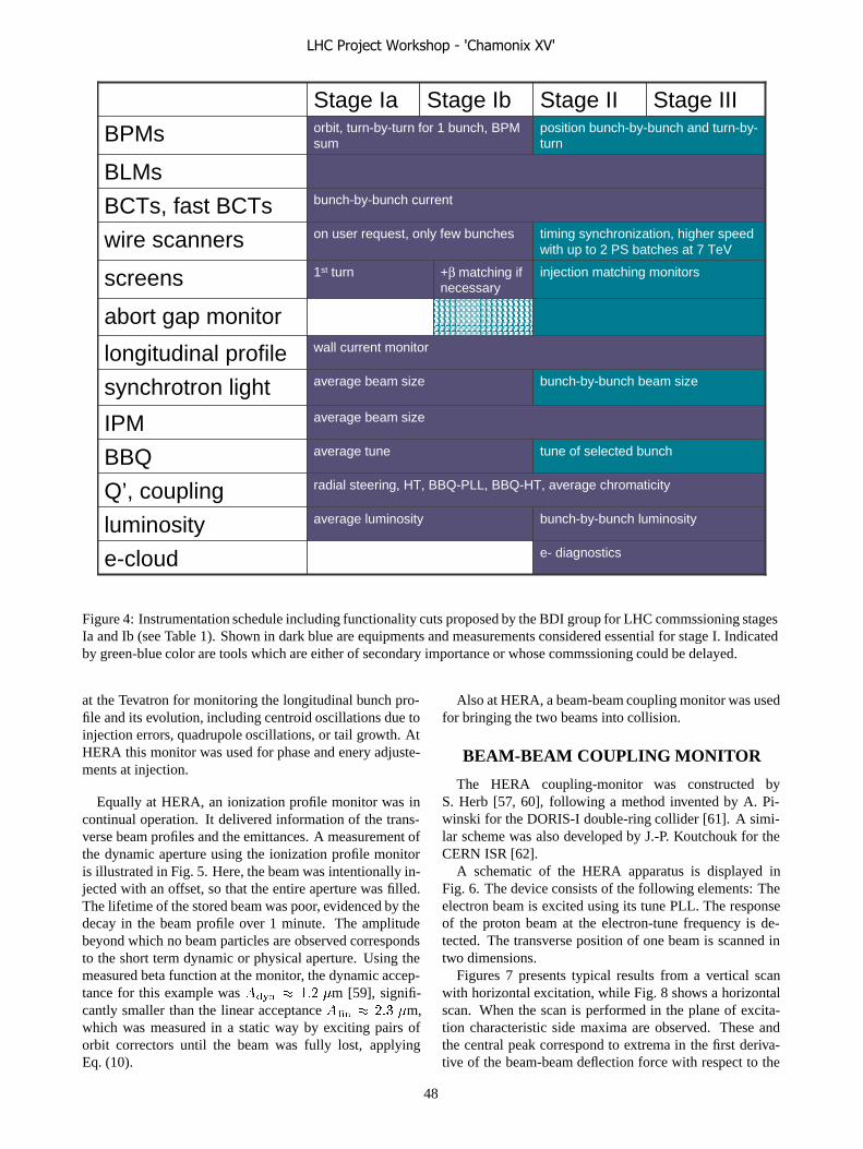
radial steering, HT, BBQ-PLL, BBQ-HT, average chromaticityQ’, couplingbunch-by-bunch luminosityaverage luminosityluminositye- diagnostics
tune of selected bunch
bunch-by-bunch beam size
injection matching monitors
timing synchronization, higher speedwith up to 2 PS batches at 7 TeV
bunch-by-bunch current
position bunch-by-bunch and turn-by-turn
Stage II
e-cloud
average tuneBBQ
average beam sizeIPM
average beam sizesynchrotron light
wall current monitorlongitudinal profile
abort gap monitor
+β matching ifnecessary
1st turnscreens
on user request, only few buncheswire scanners
BCTs, fast BCTs
BLMs
orbit, turn-by-turn for 1 bunch, BPMsumBPMs
Stage IIIStage IbStage Ia
Figure 4: Instrumentation schedule including functionality cuts proposed by the BDI group for LHC commssioning stagesIa and Ib (see Table 1). Shown in dark blue are equipments and measurements considered essential for stage I. Indicatedby green-blue color are tools which are either of secondary importance or whose commssioning could be delayed.
at the Tevatron for monitoring the longitudinal bunch pro-file and its evolution, including centroid oscillations due toinjection errors, quadrupole oscillations, or tail growth. AtHERA this monitor was used for phase and enery adjuste-ments at injection.
Equally at HERA, an ionization profile monitor was incontinual operation. It delivered information of the trans-verse beam profiles and the emittances. A measurement ofthe dynamic aperture using the ionization profile monitoris illustrated in Fig. 5. Here, the beam was intentionally in-jected with an offset, so that the entire aperture was filled.The lifetime of the stored beam was poor, evidenced by thedecay in the beam profile over 1 minute. The amplitudebeyond which no beam particles are observed correspondsto the short term dynamic or physical aperture. Using themeasured beta function at the monitor, the dynamic accep-tance for this example was ��!� � ��� �m [59], signifi-cantly smaller than the linear acceptance � ��� � ��� �m,which was measured in a static way by exciting pairs oforbit correctors until the beam was fully lost, applyingEq. (10).
Also at HERA, a beam-beam coupling monitor was usedfor bringing the two beams into collision.
BEAM-BEAM COUPLING MONITOR
The HERA coupling-monitor was constructed byS. Herb [57, 60], following a method invented by A. Pi-winski for the DORIS-I double-ring collider [61]. A simi-lar scheme was also developed by J.-P. Koutchouk for theCERN ISR [62].
A schematic of the HERA apparatus is displayed inFig. 6. The device consists of the following elements: Theelectron beam is excited using its tune PLL. The responseof the proton beam at the electron-tune frequency is de-tected. The transverse position of one beam is scanned intwo dimensions.
Figures 7 presents typical results from a vertical scanwith horizontal excitation, while Fig. 8 shows a horizontalscan. When the scan is performed in the plane of excita-tion characteristic side maxima are observed. These andthe central peak correspond to extrema in the first deriva-tive of the beam-beam deflection force with respect to the
LHC Project Workshop - 'Chamonix XV'
48
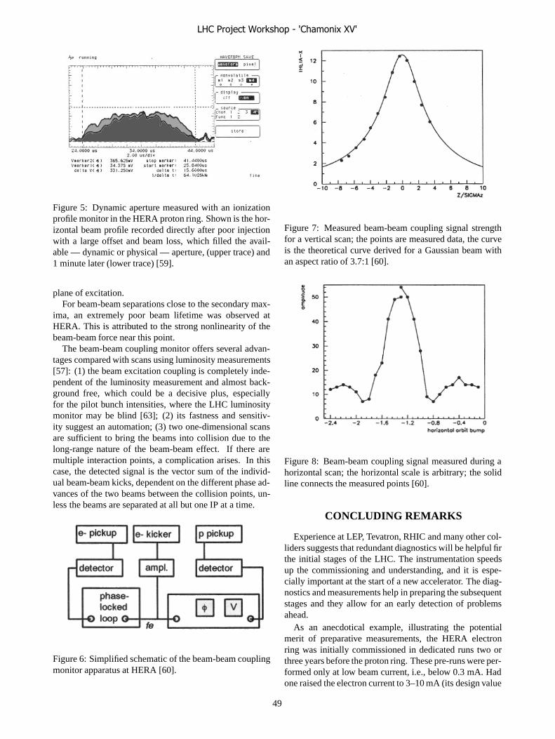
Figure 5: Dynamic aperture measured with an ionizationprofile monitor in the HERA proton ring. Shown is the hor-izontal beam profile recorded directly after poor injectionwith a large offset and beam loss, which filled the avail-able — dynamic or physical — aperture, (upper trace) and1 minute later (lower trace) [59].
plane of excitation.For beam-beam separations close to the secondary max-
ima, an extremely poor beam lifetime was observed atHERA. This is attributed to the strong nonlinearity of thebeam-beam force near this point.
The beam-beam coupling monitor offers several advan-tages compared with scans using luminosity measurements[57]: (1) the beam excitation coupling is completely inde-pendent of the luminosity measurement and almost back-ground free, which could be a decisive plus, especiallyfor the pilot bunch intensities, where the LHC luminositymonitor may be blind [63]; (2) its fastness and sensitiv-ity suggest an automation; (3) two one-dimensional scansare sufficient to bring the beams into collision due to thelong-range nature of the beam-beam effect. If there aremultiple interaction points, a complication arises. In thiscase, the detected signal is the vector sum of the individ-ual beam-beam kicks, dependent on the different phase ad-vances of the two beams between the collision points, un-less the beams are separated at all but one IP at a time.
Figure 6: Simplified schematic of the beam-beam couplingmonitor apparatus at HERA [60].
Figure 7: Measured beam-beam coupling signal strengthfor a vertical scan; the points are measured data, the curveis the theoretical curve derived for a Gaussian beam withan aspect ratio of 3.7:1 [60].
Figure 8: Beam-beam coupling signal measured during ahorizontal scan; the horizontal scale is arbitrary; the solidline connects the measured points [60].
CONCLUDING REMARKS
Experience at LEP, Tevatron, RHIC and many other col-liders suggests that redundant diagnostics will be helpful firthe initial stages of the LHC. The instrumentation speedsup the commissioning and understanding, and it is espe-cially important at the start of a new accelerator. The diag-nostics and measurements help in preparing the subsequentstages and they allow for an early detection of problemsahead.
As an anecdotical example, illustrating the potentialmerit of preparative measurements, the HERA electronring was initially commissioned in dedicated runs two orthree years before the proton ring. These pre-runs were per-formed only at low beam current, i.e., below 0.3 mA. Hadone raised the electron current to 3–10 mA (its design value
LHC Project Workshop - 'Chamonix XV'
49

is 58 mA), one would have encountered the threshold of asevere beam lifetime breakdown later ascribed to trappeddust particles. In the absence of such studies, no precautionor countermeasures were taken, and the lifetime problemwas discovered only during the final two-beam commis-sioning of HERA [64, 65]. It hampered HERA operationfor a number of years, ultimately necessating a completereplacement of the distributed ion pumps in the dipole vac-uum chambers all around the electron ring. Indeed, thedust trapping in the electron was the most severe prob-lem faced during the HERA commissioning, while the an-ticipated problems like persistent current, proton-ring dy-namic aperture, asymmetric beam-beam interaction, etc.,all proved fairly benign.
Similarly, while much of the world had expected that Bfactory performance would be limited by fast beam-ion in-stabilities in the electron rings, these ion instabilties turnedout to be easily suppressed by the multibunch feedback sys-tems in both PEP-II and KEKB. The real limitation for ei-ther factory instead proved to be the single-bunch electron-cloud instability in the positron rings, which was discov-ered and understood only during the KEKB commission-ing, and which occurred in PEP-II despite of the fact thatafter applying TiN coating to the arc vacuum chambers noelectron-cloud build up had been expected.
These two examples suggest that we better not ruleout the encounter during commissioning of ‘unknown un-knowns’ [66] whose proper understanding will likely re-quire reliable and comprehensive beam diagnostics.
ACKNOWLEDGEMENTS
I thank Ralph Aßmann, Gianluigi Arduini, Roger Bai-ley, Luca Bottura, Hans Braun, Oliver Bruning, Hel-mut Burkhardt, Stephane Fartoukh, Wolfram Fischer,Marek Gasior, Massimo Giovannozzi, Brennan Goddard,Jean-Jacques Gras, Bernard Jeanneret, Alex Koschik,Jean-Pierre Koutchouk, Robert Michnoff, Hitoshi Mu-rayama, Francesco Ruggiero, Stephane Sanfilippo, Her-mann Schmickler, Rudiger Schmidt, Tanaji Sen, RalphSteinhagen and many other colleagues for helpful discus-sions and information.
APPENDIX - RHIC COHERENCEMONITOR
The RHIC coherence monitor measures the rms value ofthe beam oscillations in real time. The monitor has been de-scribed by R. Michnoff and W. Fischer as follows. A beamposition monitor pickup provides the inut to an analog sig-nal conditoning module, which normalizes the differencesignal to the sum, and computes the rms of the normalizeddifference signal using an Analog Devices AD8361. Therms output is digitized and logged at 720 Hz during a RHICramp. The measured coherence signal approximately indi-cates the amplitude of the beam oscillations. One difficultywith the measurement is that due to filtering the measured
signal depends on the duration of the beam oscillations aswell as on its amplitude. For example, a very short durationhigh-amplitude coherence signal may produce results simi-lar to a longer duration low-amplitude one. In any case, theRHIC chromaticity on the ramp is fine adjusted by handwhen a signal has been observed on the coherence monitor.
REFERENCES
[1] F. Zimmermann, “Flat Bottom Optimization and Tuning,”Proc. Chamonix XII, LHC Performance Workshop Cha-monix, p. 242 (2003).
[2] R. Bailey, “Summary of Overall Commissioning Strategyfor Protons,” Session 1 - The Minimum Workable LHC –Plans and Requirements for Beam Commissioning, Years 1and 2, Chamonix XV Workshop, Divonne (2006).
[3] M. Lamont, “Commissioning with Beam: Overall Strategy,”LHC Project Workshop, Chamonix XIV, CERN (2005).
[4] M. Lamont, “Commissioning with Beam: Session Sum-mary,” LHC Project Workshop, Chamonix XIV, CERN(2005).
[5] H. Schmickler, “Running In the Diagnostics,” LHC ProjectWorkshop, Chamonix XIII, Chamonix (2004)
[6] H. Schmickler, “Beam Commissionng of Instrumentation,”LHC Project Workshop, Chamonix XIV, CERN (2005)
[7] P. Collier, “450 GeV,” LHC Project Workshop, ChamonixXIV, CERN (2005)
[8] B. Goddard, “Commissioning with Beam of the LHC Trans-fer Lines and Injection Systems,” LHC Project Workshop,Chamonix XIV, CERN (2005).
[9] http://lhccommissioning.web.cern.ch/
[10] B. Jeanneret, H. Burkhardt, “Functional Specification: Onthe Measurement of the Beam Losses in the LHC Rings,”LHC-B-ES-0001 Rev 2.0 (2004).
[11] J.B. Jeanneret, D. Leroy, L. Oberli, T. Trenkler, “QuenchLevels and Transient Beam Losses in LHC Magnets,” LHC-Project-Report-044 (1996).
[12] B. Goddard and B. Jeanneret, “Critical Beam Density in theAbort Gap and Longitudinal Profile Monitor,” LHC Com-missioning Committee, 17 July 2002 (2002).
[13] C. Fischer, “Functional Specification: High Senstivity Mea-surement of the Longitudinal Distribution of the LHCBeams,” LHC-B-ES-0005.00 rev 2.0 (2003).
[14] R. Jones, “Beam Instrumentation Status,” LHC MAC no. 18,08. December 2005 (2005)
[15] R. Schmidt, J. Wenninger, “Machine Protect Issues andStrategies for the LHC,” LHC Project Report 784 (2004).
[16] B. Dehning, “Commissioning of Beam Loss Monitors,” Ses-sion 1 - The Minimum Workable LHC — Machine Protec-tion and Collimation, Chamonix XV Workshop, Divonne(2006).
[17] R. Assmann, J.B. Jeanneret, D. Kaltchev, “Efficiency forthe Imperfect LHC Collimation System,” EPAC 2002, Paris(2002).
[18] J.B. Jeanneret, R. Ostijic, “Geometrical Acceptance in LHCVersion 5.0,” LHC Project Note 111 (1997).
LHC Project Workshop - 'Chamonix XV'
50
[19] S. Redaelli, R. Assmann, G. Robert-Demolaize, “LHCAperture and Commissioning of the Collimation System,”LHC Project Report Chamonix XIV (2005).
[20] R.W. Aßmann, private communication (2005).
[21] S. Sanfilippo, private communication (2006).
[22] O. Bruning, “Squeeze Criteria & Requirements,” LHCProject Workshop Chamonix XIV (2005).
[23] O. Bruning, “Accumulation and Ramping in the LHC,” Cha-monix X, p. 198.
[24] V. Granata et al., “Magnetic Field Tracking Experiments forLHC,” LHC Project Report 738 (2004).
[25] O. Bruning, “Linear Coupling Compensation for the LHCVersion 6.1,” EPAC 2000, Vienna (2000).
[26] S. Fartoukh, O. Bruning, “Field Quality Specification for theLHC Main Dipole Magnets,” LHC Report 501 (2001).
[27] R. Bacher et al., “First Commissioning of the HERA ProtonRing – A Summary of the HERA Proton Run 1,” compiledby W. Schuutte and F. Willeke, Harz Seminar, Bad Lauter-berg, DESY HERA 92-07 (1992)
[28] S. Fartoukh, J.-P. Koutchouk, “Functional Specification: Onthe Measurement of the Tunes, Coupling and Detuningswith Momentum and Amplitude in LHC,” LHC-B-ES-0009rev 1.0 (2004).
[29] S. Fartoukh, “Second Order Chromaticity Correction ofLHC V6.0 at Collision,” LHC Project Report 308 (1999).
[30] S. Fartoukh, private communication and discussion (2006).
[31] C. Fischer, R. Schmidt, “Functional Specification: On theMeasurements of the Beam Current, Lifetime and DecayRate in the LHC Rings,” LHC-BCT-ES-0001 rev 1.0 (2005).
[32] J.-P. Koutchouk, “Functional Specification: Measurementof the Beam Position in the LHC Main Rings,” LHC-BPM-ES-0004 rev 2.0 (2002).
[33] J. Wenninger, B. Goddard, “Functional Specification: In-strumentation for the LHC Beam Dumping System,” LHC-B-ES-0008 rev 2.0 (2004).
[34] S. Kamada, “Experimental Techniques and Observations ofNonlinear Dynamics in Particle Accelerators,” Workshopon Nonlinear Dynamics in Particle Accelerators, Theory &Experiment, Arcidosso, Italy, AIP Conf. Proc. 344, 1–10(1994).
[35] R. Steinhagen, private communication (2006).
[36] D. Sagan and D. Rubin, “Linear Analysis of Coupled Lat-tices,” PRST-AB 2, 074001 (1999).
[37] E. Perevedentsev, “Measurement of X-Y Coupling Parame-ters,” KEKB, unpublished note, April 4, 2000.
[38] W. Fischer, “Robust Linear Coupling Correction with N-Turn Maps,” PRST-AB 6, 062801 (2003).
[39] G. Arduini. C. Carli, F. Zimmermann, “LocalizingImpedance Sources from Betatron Phase Beating in theCERN SPS,” Proc. EPAC 2004, Lucerne (2004).
[40] J. Safranek, “Experimental Determination of Storage RingOptics Using Orbit Response Measurements,” NIM A388,27 (1997).
[41] J. Wenninger, “Orbit Response Measurements at the SPS,”CERN-AB-2004-009 (2004).
[42] K. Akai et al., “Commissioning of KEKB,” NIM A499, 191(2003).
[43] O.S. Bruning et al., “Chromaticity Measurements viaRF Phase Modulation and Continuous Tune Tracking,”EPAC’02 Paris, CERN-SL-2002-037 (2002).
[44] S. Tepikian et al., “Measuring Chromaticity along the Rampusing the PLL Tune-Meter in RHIC,” EPAC 2002, Paris(2002).
[45] V.H. Ranjibar et al., “Commissioning of the HEead-TailMonitoring Application for the Tevatron,” EPAC’2004Lucerne (2004).
[46] R. Michnoff, W. Fischer, private communication,12.01.2006.
[47] A. Verdier, “Alignment Optics for LHC,” LHC-PROJECT-NOTE-325 (2003).
[48] O. Bruning, “Squeeze Criteria & Requirements,” LHCProject Workshop, Chamonix XIV, CERN (2005).
[49] F. Zimmerman and M.-P. Zorzano, “Touschek Scattering inHERA and LHC,” LHC Project Report 244 (2000).
[50] C. Fischer, “Functional Specification: Measurement of theTransverse Beam Distribution in the LHC Rings,” LHC-B-ES-0006 rev 1.0 (2003).
[51] R. Assmann, J.-P. Koutchouk, M. Placidi, E. Tsesmelis,“Functional Specification: On the Measurement of the Rel-ative Luminsoity in LHC,” LHC-B-ES-0007 rev 1.1 (2004).
[52] R. Jones, private communication at the Divonne workshop(2006).
[53] V. Shiltsev, private communication, 29.08.2005.
[54] W. Fischer, private communication, 29.08.2005.
[55] F. Zimmermann, “Intrabeam Scattering with Non-Ultrarelativistic Corrections and Vertical Dispersionfor MAD-X,” CERN-AB-2006-002 (2006).
[56] J.M. Jimenez, “Engineering Change Order - Class 1: Elec-tron Cloud Diagnostics in the LHC,” LHC-VI-EC-0001(2003).
[57] F. Zimmermann et al., “Beam Finding Allgorithms inHERA,” Proc. B Factories: The Stae of the Art in Accel-erators, Detectors, and Physics, Stanford, California, April6–10, 1992, and DESY HERA 92-10 (1992).
[58] K. Potter in 1st Luminosity Workshop, 9/12/2002,http://est-div-lea.web.cern.ch/est-div-lea/luminosity/1stlumi workshop.htm
[59] F. Zimmermann, “Dynamische Apertur und Emittanzwach-stum im HERA-Protonen-Ring,” HERA Seminar, BadLauterberg, Harz, 1993, p. 139 (1993).
[60] S. Herb and F. Zimmermann, “Measurement by Tune Cou-pling of the Overlap of Colliding Bunches in HERA,”Proc. HEACC’92, Hamburg, p. 227 (1992).
[61] A. Piwinski, “Einstellung der Kreuzung der beiden Strahlenmit Hilfe des Raumladungseffektes,” DESY H2-75/03(1975).
[62] J.-Y. Hemery, A. Hofmann, J.-P. Koutchouk, S. My-ers, L. Vos, “Investigation of the Coherent Beam-BeamEffects in the ISR,” PAC 81, Washington DC, IEEETrans. Nucl. Sci. 28, 2497–2499, and CERN-ISR-OP-CO-TH-RF-81-13 (1981).
LHC Project Workshop - 'Chamonix XV'
51

[63] E. Bravin, “Bringing the First LHC Beams into Collision atall 4 IP’s,” Session 5 - Experiment-Machine Interface, Cha-monix XV Workshop, Divonne (2006).
[64] F. Zimmermann, “Trapped Dust in HERA and DORIS,”DESY-HERA-93-8 (1993).
[65] F. Zimmermann, J.T. Seeman, M. Zolotorev, W. Stoeffl,“Trapped Macrparticles in Electron Storage Rings,” PAC’95Dallas (1995).
[66] D. Rumsfeld, US Department of Defense News Briefing12.02.2002; quoted by H. Murayama at Nanobeam’05, Ky-oto, October 17–21 (2005).
LHC Project Workshop - 'Chamonix XV'
52
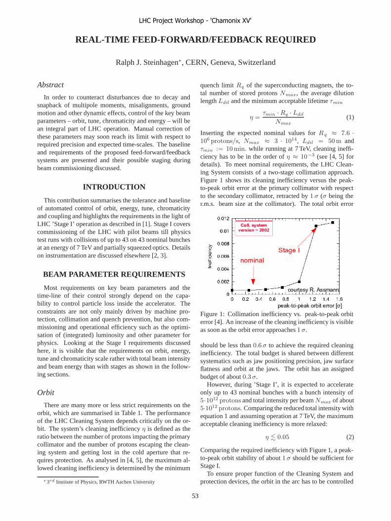
REAL-TIME FEED-FORWARD/FEEDBACK REQUIRED
Ralph J. Steinhagen∗, CERN, Geneva, Switzerland
Abstract
In order to counteract disturbances due to decay andsnapback of multipole moments, misalignments, groundmotion and other dynamic effects, control of the key beamparameters – orbit, tune, chromaticity and energy – will bean integral part of LHC operation. Manual correction ofthese parameters may soon reach its limit with respect torequired precision and expected time-scales. The baselineand requirements of the proposed feed-forward/feedbacksystems are presented and their possible staging duringbeam commissioning discussed.
INTRODUCTION
This contribution summarises the tolerance and baselineof automated control of orbit, energy, tune, chromaticityand coupling and highlights the requirements in the light ofLHC ’Stage I’ operation as described in [1]. Stage I coverscommissioning of the LHC with pilot beams till physicstest runs with collisions of up to 43 on 43 nominal bunchesat an energy of 7 TeV and partially squeezed optics. Detailson instrumentation are discussed elsewhere [2, 3].
BEAM PARAMETER REQUIREMENTS
Most requirements on key beam parameters and thetime-line of their control strongly depend on the capa-bility to control particle loss inside the accelerator. Theconstraints are not only mainly driven by machine pro-tection, collimation and quench prevention, but also com-missioning and operational efficiency such as the optimi-sation of (integrated) luminosity and other parameter forphysics. Looking at the Stage I requirements discussedhere, it is visible that the requirements on orbit, energy,tune and chromaticity scale rather with total beam intensityand beam energy than with stages as shown in the follow-ing sections.
Orbit
There are many more or less strict requirements on theorbit, which are summarised in Table 1. The performanceof the LHC Cleaning System depends critically on the or-bit. The system’s cleaning inefficiency η is defined as theratio between the number of protons impacting the primarycollimator and the number of protons escaping the clean-ing system and getting lost in the cold aperture that re-quires protection. As analysed in [4, 5], the maximum al-lowed cleaning inefficiency is determined by the minimum
∗3rd Institute of Physics, RWTH Aachen University
quench limit Rq of the superconducting magnets, the to-tal number of stored protons Nmax, the average dilutionlength Ldil and the minimum acceptable lifetime τmin
η =τmin · Rq · Ldil
Nmax(1)
Inserting the expected nominal values for Rq ≈ 7.6 ·106 protons/s, Nmax ≈ 3 · 1014, Ldil = 50 m andτmin := 10 min. while running at 7 TeV, cleaning ineffi-ciency has to be in the order of η ≈ 10−3 (see [4, 5] fordetails). To meet nominal requirements, the LHC Clean-ing System consists of a two-stage collimation approach.Figure 1 shows its cleaning inefficiency versus the peak-to-peak orbit error at the primary collimator with respectto the secondary collimator, retracted by 1 σ (σ being ther.m.s. beam size at the collimator). The total orbit error
Figure 1: Collimation inefficiency vs. peak-to-peak orbiterror [4]. An increase of the cleaning inefficiency is visibleas soon as the orbit error approaches 1 σ.
should be less than 0.6 σ to achieve the required cleaninginefficiency. The total budget is shared between differentsystematics such as jaw positioning precision, jaw surfaceflatness and orbit at the jaws. The orbit has an assignedbudget of about 0.3 σ.
However, during ’Stage I’, it is expected to accelerateonly up to 43 nominal bunches with a bunch intensity of5·1012 protons and total intensity per beam Nmax of about5·1012 protons. Comparing the reduced total intensity withequation 1 and assuming operation at 7 TeV, the maximumacceptable cleaning inefficiency is more relaxed:
η � 0.05 (2)
Comparing the required inefficiency with Figure 1, a peak-to-peak orbit stability of about 1 σ should be sufficient forStage I.
To ensure proper function of the Cleaning System andprotection devices, the orbit in the arc has to be controlled
LHC Project Workshop - 'Chamonix XV'
53
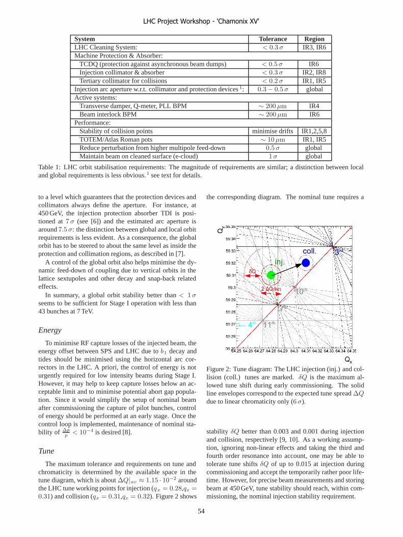
System Tolerance RegionLHC Cleaning System: < 0.3 σ IR3, IR6Machine Protection & Absorber:
TCDQ (protection against asynchronous beam dumps) < 0.5 σ IR6Injection collimator & absorber < 0.3 σ IR2, IR8Tertiary collimator for collisions < 0.2 σ IR1, IR5
Injection arc aperture w.r.t. collimator and protection devices 1: 0.3 − 0.5 σ globalActive systems:
Transverse damper, Q-meter, PLL BPM ∼ 200 μm IR4Beam interlock BPM ∼ 200 μm IR6
Performance:Stability of collision points minimise drifts IR1,2,5,8TOTEM/Atlas Roman pots ∼ 10 μm IR1, IR5Reduce perturbation from higher multipole feed-down 0.5 σ globalMaintain beam on cleaned surface (e-cloud) 1 σ global
Table 1: LHC orbit stabilisation requirements: The magnitude of requirements are similar; a distinction between localand global requirements is less obvious.1 see text for details.
to a level which guarantees that the protection devices andcollimators always define the aperture. For instance, at450 GeV, the injection protection absorber TDI is posi-tioned at 7 σ (see [6]) and the estimated arc aperture isaround 7.5 σ: the distinction between global and local orbitrequirements is less evident. As a consequence, the globalorbit has to be steered to about the same level as inside theprotection and collimation regions, as described in [7].
A control of the global orbit also helps minimise the dy-namic feed-down of coupling due to vertical orbits in thelattice sextupoles and other decay and snap-back relatedeffects.
In summary, a global orbit stability better than < 1 σseems to be sufficient for Stage I operation with less than43 bunches at 7 TeV.
Energy
To minimise RF capture losses of the injected beam, theenergy offset between SPS and LHC due to b1 decay andtides should be minimised using the horizontal arc cor-rectors in the LHC. A priori, the control of energy is noturgently required for low intensity beams during Stage I.However, it may help to keep capture losses below an ac-ceptable limit and to minimise potential abort gap popula-tion. Since it would simplify the setup of nominal beamafter commissioning the capture of pilot bunches, controlof energy should be performed at an early stage. Once thecontrol loop is implemented, maintenance of nominal sta-bility of Δp
p < 10−4 is desired [8].
Tune
The maximum tolerance and requirements on tune andchromaticity is determined by the available space in thetune diagram, which is about ΔQ|av ≈ 1.15 · 10−2 aroundthe LHC tune working points for injection (qx = 0.28,qx =0.31) and collision (qx = 0.31,qx = 0.32). Figure 2 shows
the corresponding diagram. The nominal tune requires a
Figure 2: Tune diagram: The LHC injection (inj.) and col-lision (coll.) tunes are marked. δQ is the maximum al-lowed tune shift during early commissioning. The solidline envelopes correspond to the expected tune spread ΔQdue to linear chromaticity only (6 σ).
stability δQ better than 0.003 and 0.001 during injectionand collision, respectively [9, 10]. As a working assump-tion, ignoring non-linear effects and taking the third andfourth order resonance into account, one may be able totolerate tune shifts δQ of up to 0.015 at injection duringcommissioning and accept the temporarily rather poor life-time. However, for precise beam measurements and storingbeam at 450 GeV, tune stability should reach, within com-missioning, the nominal injection stability requirement.
LHC Project Workshop - 'Chamonix XV'
54
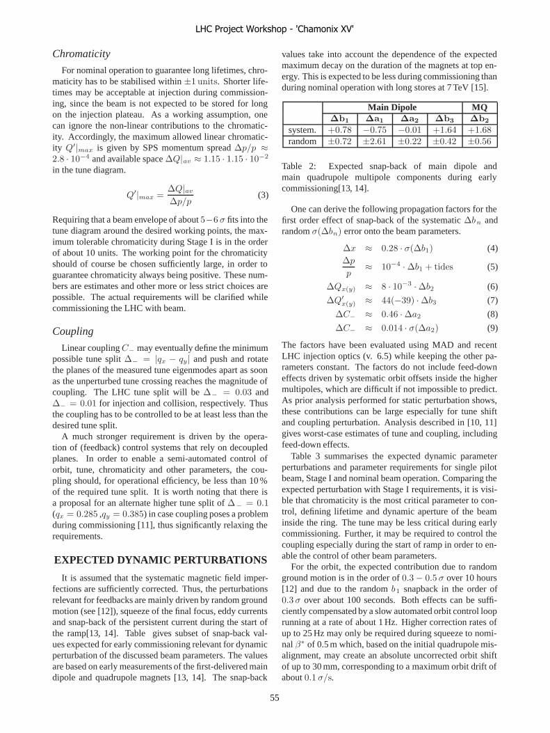
Chromaticity
For nominal operation to guarantee long lifetimes, chro-maticity has to be stabilised within ±1 units. Shorter life-times may be acceptable at injection during commission-ing, since the beam is not expected to be stored for longon the injection plateau. As a working assumption, onecan ignore the non-linear contributions to the chromatic-ity. Accordingly, the maximum allowed linear chromatic-ity Q′|max is given by SPS momentum spread Δp/p ≈2.8 · 10−4 and available space ΔQ|av ≈ 1.15 · 1.15 · 10−2
in the tune diagram.
Q′|max =ΔQ|av
Δp/p(3)
Requiring that a beam envelope of about 5−6 σ fits into thetune diagram around the desired working points, the max-imum tolerable chromaticity during Stage I is in the orderof about 10 units. The working point for the chromaticityshould of course be chosen sufficiently large, in order toguarantee chromaticity always being positive. These num-bers are estimates and other more or less strict choices arepossible. The actual requirements will be clarified whilecommissioning the LHC with beam.
Coupling
Linear coupling C− may eventually define the minimumpossible tune split Δ− = |qx − qy| and push and rotatethe planes of the measured tune eigenmodes apart as soonas the unperturbed tune crossing reaches the magnitude ofcoupling. The LHC tune split will be Δ− = 0.03 andΔ− = 0.01 for injection and collision, respectively. Thusthe coupling has to be controlled to be at least less than thedesired tune split.
A much stronger requirement is driven by the opera-tion of (feedback) control systems that rely on decoupledplanes. In order to enable a semi-automated control oforbit, tune, chromaticity and other parameters, the cou-pling should, for operational efficiency, be less than 10 %of the required tune split. It is worth noting that there isa proposal for an alternate higher tune split of Δ− = 0.1(qx = 0.285 ,qy = 0.385) in case coupling poses a problemduring commissioning [11], thus significantly relaxing therequirements.
EXPECTED DYNAMIC PERTURBATIONS
It is assumed that the systematic magnetic field imper-fections are sufficiently corrected. Thus, the perturbationsrelevant for feedbacks are mainly driven by random groundmotion (see [12]), squeeze of the final focus, eddy currentsand snap-back of the persistent current during the start ofthe ramp[13, 14]. Table gives subset of snap-back val-ues expected for early commissioning relevant for dynamicperturbation of the discussed beam parameters. The valuesare based on early measurements of the first-delivered maindipole and quadrupole magnets [13, 14]. The snap-back
values take into account the dependence of the expectedmaximum decay on the duration of the magnets at top en-ergy. This is expected to be less during commissioning thanduring nominal operation with long stores at 7 TeV [15].
Main Dipole MQΔb1 Δa1 Δa2 Δb3 Δb2
system. +0.78 −0.75 −0.01 +1.64 +1.68random ±0.72 ±2.61 ±0.22 ±0.42 ±0.56
Table 2: Expected snap-back of main dipole andmain quadrupole multipole components during earlycommissioning[13, 14].
One can derive the following propagation factors for thefirst order effect of snap-back of the systematic Δbn andrandom σ(Δbn) error onto the beam parameters.
Δx ≈ 0.28 · σ(Δb1) (4)Δp
p≈ 10−4 · Δb1 + tides (5)
ΔQx(y) ≈ 8 · 10−3 · Δb2 (6)
ΔQ′x(y) ≈ 44(−39) · Δb3 (7)
ΔC− ≈ 0.46 · Δa2 (8)
ΔC− ≈ 0.014 · σ(Δa2) (9)
The factors have been evaluated using MAD and recentLHC injection optics (v. 6.5) while keeping the other pa-rameters constant. The factors do not include feed-downeffects driven by systematic orbit offsets inside the highermultipoles, which are difficult if not impossible to predict.As prior analysis performed for static perturbation shows,these contributions can be large especially for tune shiftand coupling perturbation. Analysis described in [10, 11]gives worst-case estimates of tune and coupling, includingfeed-down effects.
Table 3 summarises the expected dynamic parameterperturbations and parameter requirements for single pilotbeam, Stage I and nominal beam operation. Comparing theexpected perturbation with Stage I requirements, it is visi-ble that chromaticity is the most critical parameter to con-trol, defining lifetime and dynamic aperture of the beaminside the ring. The tune may be less critical during earlycommissioning. Further, it may be required to control thecoupling especially during the start of ramp in order to en-able the control of other beam parameters.
For the orbit, the expected contribution due to randomground motion is in the order of 0.3 − 0.5 σ over 10 hours[12] and due to the random b1 snapback in the order of0.3 σ over about 100 seconds. Both effects can be suffi-ciently compensated by a slow automated orbit control looprunning at a rate of about 1 Hz. Higher correction rates ofup to 25 Hz may only be required during squeeze to nomi-nal β∗ of 0.5 m which, based on the initial quadrupole mis-alignment, may create an absolute uncorrected orbit shiftof up to 30 mm, corresponding to a maximum orbit drift ofabout 0.1 σ/s.
LHC Project Workshop - 'Chamonix XV'
55

Orbit Tune Chroma. Energy Coupling[σ] [Q] [Q’] Δp/p C−
Exp. Perturbations: 0.5 0.0014 (0.06) 70 (140) ±1.5 · 10−4 0.01 (0.1)Pilot Bunch: - ±0.1 +10 - 0.1Stage I Requirements: ± ∼ 1 ±0.015 → 0.003 > 0 & ±5 ± · 10−4 � 0.1 → 0.03Nominal: ±0.3/0.5 ±0.003/± 0.001 > 0 & ±2 ± · 10−4 � 0.01
Table 3: Summary of pilot, Stage I and nominal requirements in comparison to expected dynamic perturbation. Staticworst-case estimates are given in brackets [10, 11].
The simulated expected snapback of chromaticity decayand its rate of change is shown in Figure 3.
Figure 3: Chromaticity during snap-back.
The maximum rate ΔQ′/Δt at which the chromaticitychanges is less than about 1.3 units/s. Assuming this as aconstant snap-back rate and that a maximum chromaticityof 10 units can be tolerated, tolerance is reached after about10 seconds. Hence, an automated control every 10 secondsor less may be sufficient during Stage I operation.
FORESEEN FEEDBACK BASELINE
Two basic parameter control techniques, feed-forwardand feedback, are available. In the LHC, the use of a hybridcombining both these techniques is foreseen, as illustratedin Figure 4.
• Feed-Forward control is applied in case expected per-turbations and machine responses are well known.The foreseen LHC feed-forward model is based onmagnet measurement as described in [16]. However,model uncertainties as well as random and potentialmodel imperfections may limit the achievable param-eter stability required. In any case, this will be thefirst and only control choice for the LHC sector testand the very first beam inside the LHC.
• Feedback control using beam-based measurements,on the other hand, does not require a precise model ofmachine parameter response or prediction of the ex-pected perturbations and are particularly robust withrespect to random and unknown non-included pertur-bations. However, the Achilles’ heel of such systemsis often the measurement of the parameter itself. Cer-tain parameters are not directly accessible for mea-surements, or measurements do not fulfil the required
level of ”transparency”, in the sense that they poten-tially perturb the beam. Two types of feedbacks rele-vant for the LHC can be distinguished: feedbacks thatact within a cycle and at repetition rates in the orderof minutes to fractions of seconds and those that use(commonly averaged) measurements of one cycle butwith applications as corrections for the next cycle. Al-though the latter, occasionally referred to as ’cycle-to-cycle feed-forward’, has often relaxed requirementson timing, it is strictly speaking still a feedback andhas the same issues with respect to required beam in-strumentation, diagnostics and control algorithms.
From the point of view of available correctors circuits, alldiscussed beam parameters can be controlled [17]. Theactual decision between feed-forward or feedback is thusmainly driven by the availability and robustness of the cor-responding beam instrumentation and diagnostics.
From the controls point of view, the work of an oper-ator is equivalent to a manual ’smart’ feedback system.Semi-automated feedbacks are, if resources permit, the pre-ferred choice, since they free operators, engineers in chargeand other people involved in the operation of the machinefor more important tasks such as beam measurements pro-posed in [18]. Also, robust and reliable feedback imple-mentations are helpful for fast commissioning of the ramp,squeeze and other machine phases. Experience with LEPcommissioning showed that many beams were lost due toabsence of orbit and tune feedbacks [19]. In the LHC, thismay become an issue with respect to the turnaround time,which is expected to be in the order of a few hours.
The following sections summarise the foreseen feed-backs as well as their principles and requirements concern-ing beam instrumentation.
Orbit
The LHC orbit feedback is the most advanced feed-back, driven by collimation and machine protection re-quirements. The (present) design is based on a Singu-lar Value Decomposition (SVD)-based global correctionscheme with local constraints in space-domain as well asa Proportional-Integral-Derivative (PID) controller in time-domain, common in all modern light sources. The feedbackhas been optimised for a robust and failure-tolerant opera-tion. Its prototype has been very successfully tested in theSPS [20, 21].
LHC Project Workshop - 'Chamonix XV'
56

Figure 4: Schematic hybrid FF/FB scheme: For coherent control and avoidance of cross-talk, the feedback (blue) shouldbe aware of the feed-forward correction (red).
In case of problems with the LHC-wide synchronised ac-quisition trigger, it is possible to run the feedback controllerin self-triggered mode at about 1-2 Hz. The early use ofan orbit feedback operation would help minimise dynamicfeed-downs due to the orbit. The orbit feedback does not,by design, correct the dispersion orbit in order to minimisethe cross-talk between energy feedback and measurementssuch as the chromaticity, that may require a change of mo-mentum Δp/p.
An early use of the orbit feedback is feasible sincethreading of the first injected beam requires the availabilityof beam position monitors (BPMs) as well as the verifiedpolarity of BPMs and orbit dipoles. The proposed baselinecan and should be used at an early stage as soon as circulat-ing beam has been established. It is favourable to use thissystem prior to the first ramp.
Energy
The feedback minimising the SPS to LHC energy offsetis based on a robust measurement using the oscillation am-plitude Δx of the injected beam with respect to the closedorbit to estimate the injection momentum mismatch Δp/pas sketched in Figure 5. The individual measurement is av-eraged over all N ≈ 300 arc monitors to minimise effectsdue to BPM systematics and oscillations due to imperfectinjections:
Δp
p=
∑Ni Di · Δxi∑N
i D2i
(10)
The strength of this measurement is that the BPM system-atics on the dispersion Di and oscillation amplitude Δxi
at the BPM intrinsically cancel each other. Hence, a time-consuming high-precision calibration of about 1060 BPMsusing beam is not necessarily required. Already, a mod-erate turn-by-turn acquisition resolution of Δx ≈ 200 μm(pilot) and the averaging over about 300 arc monitor yieldsa Δp/p resolution of a few 10−6, sufficient for nominal op-eration. The horizontal arc corrector dipole magnets will beused to adjust LHC energy. At a later stage, it is possibleto extend the feedback and to compensate for solar and lu-nar tides in order to optimise (preserve) the aperture duringcollisions.
Figure 5: Schematic injection oscillation due to energymismatch. The momentum mismatch Δp/p is propor-tional to the difference Δx between first turn amplitude andclosed orbit after energy oscillation has been attenuated.
In order to be available for Stage I, the beam syn-chronous timing (BST) should be able to trigger a turn-by-turn acquisition on the injection of an individual batch inthe presence of a circulating beam, if applicable. The read-out of the 100k data should not block orbit acquisition.
The energy feedback could be used at an early stage assoon as circulating beam is established. It should be usedbefore RF capture losses become an issue.
Tune
The traditional method of tune measurement requires akick of the beam and a Fourier analysis of the acquiredBPM multi-turn turn data. The kick should be in the orderof 1 mm (1 σ beam r.m.s.) for a good signal-to-noise ratioof the turn-by-turn acquisition. This may cause emittanceblow-up and is hence not ideal for a continuously runningfeedback. The kick is also an issue with respect to machineprotection and collimation that requires beam oscillation tobe less than 0.3 σ. As a consequence, these types of mea-surements may only be possible with slightly retracted col-limators or with low intensity beam. Since this is a simplemethod, it will be a backup option in case of problems.
The new BI baseline foresees the Base-Band-Q Meter
LHC Project Workshop - 'Chamonix XV'
57
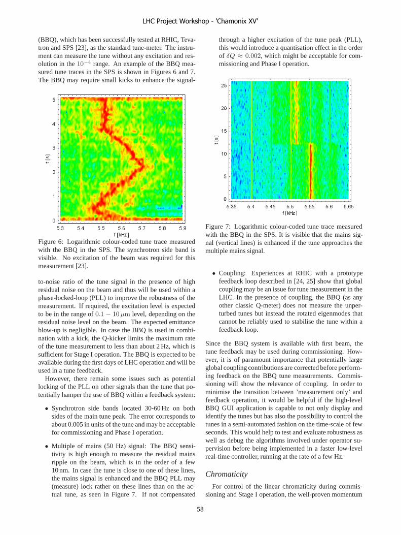
(BBQ), which has been successfully tested at RHIC, Teva-tron and SPS [23], as the standard tune-meter. The instru-ment can measure the tune without any excitation and res-olution in the 10−4 range. An example of the BBQ mea-sured tune traces in the SPS is shown in Figures 6 and 7.The BBQ may require small kicks to enhance the signal-
Figure 6: Logarithmic colour-coded tune trace measuredwith the BBQ in the SPS. The synchrotron side band isvisible. No excitation of the beam was required for thismeasurement [23].
to-noise ratio of the tune signal in the presence of highresidual noise on the beam and thus will be used within aphase-locked-loop (PLL) to improve the robustness of themeasurement. If required, the excitation level is expectedto be in the range of 0.1 − 10 μm level, depending on theresidual noise level on the beam. The expected emittanceblow-up is negligible. In case the BBQ is used in combi-nation with a kick, the Q-kicker limits the maximum rateof the tune measurement to less than about 2 Hz, which issufficient for Stage I operation. The BBQ is expected to beavailable during the first days of LHC operation and will beused in a tune feedback.
However, there remain some issues such as potentiallocking of the PLL on other signals than the tune that po-tentially hamper the use of BBQ within a feedback system:
• Synchrotron side bands located 30-60 Hz on bothsides of the main tune peak. The error corresponds toabout 0.005 in units of the tune and may be acceptablefor commissioning and Phase I operation.
• Multiple of mains (50 Hz) signal: The BBQ sensi-tivity is high enough to measure the residual mainsripple on the beam, which is in the order of a few10 nm. In case the tune is close to one of these lines,the mains signal is enhanced and the BBQ PLL may(measure) lock rather on these lines than on the ac-tual tune, as seen in Figure 7. If not compensated
through a higher excitation of the tune peak (PLL),this would introduce a quantisation effect in the orderof δQ ≈ 0.002, which might be acceptable for com-missioning and Phase I operation.
Figure 7: Logarithmic colour-coded tune trace measuredwith the BBQ in the SPS. It is visible that the mains sig-nal (vertical lines) is enhanced if the tune approaches themultiple mains signal.
• Coupling: Experiences at RHIC with a prototypefeedback loop described in [24, 25] show that globalcoupling may be an issue for tune measurement in theLHC. In the presence of coupling, the BBQ (as anyother classic Q-meter) does not measure the unper-turbed tunes but instead the rotated eigenmodes thatcannot be reliably used to stabilise the tune within afeedback loop.
Since the BBQ system is available with first beam, thetune feedback may be used during commissioning. How-ever, it is of paramount importance that potentially largeglobal coupling contributions are corrected before perform-ing feedback on the BBQ tune measurements. Commis-sioning will show the relevance of coupling. In order tominimise the transition between ’measurement only’ andfeedback operation, it would be helpful if the high-levelBBQ GUI application is capable to not only display andidentify the tunes but has also the possibility to control thetunes in a semi-automated fashion on the time-scale of fewseconds. This would help to test and evaluate robustness aswell as debug the algorithms involved under operator su-pervision before being implemented in a faster low-levelreal-time controller, running at the rate of a few Hz.
Chromaticity
For control of the linear chromaticity during commis-sioning and Stage I operation, the well-proven momentum
LHC Project Workshop - 'Chamonix XV'
58
modulation and tune tracking method will be used, as wasin LEP. The resulting chromaticity can be derived throughthe following equation:
Q′ ≈ ΔQ
Δp/p(11)
A slow trapezoidal excitation of Δp/p ≈ 10−4 seems to befeasible within the RF baseline [8]. This feedback could beimplemented and used for early commissioning and may beenough to cope with snap-back and ramp-induced b 3 driftsexpected during Stage I operation. Since this measurementrelies on the tracking of the tune, it requires a good controlof coupling.
At a later stage the head-tail-chromaticity measurementmay be used. Presently this method requires large kicksand can, consequently, only be used in dedicated machineruns. However, modification of the measurement to a sim-ilar principle as in the BBQ is envisaged. This would re-duce the required excitation level and make it potentiallycompatible with continuous feedback during nominal op-eration. This system requires time for commissioning andis not likely to be available for commissioning.
Coupling
Prototype studies at RHIC show that a reliable tune feed-back operation has been thwarted by transition crossing andcoupling [24, 25]. In reply to this experience, a real-timecoupling measurement based on a BBQ-PLL principle wasdeveloped and tested at RHIC and will be tested in the SPSthis year and later used in the LHC. Besides a direct mea-surement of the coupling C−, this system can measure theunperturbed tunes and the split Δ− that would be presentin the absence of coupling. These signals are favourable fora robust tune feedback loop. Figure 8 shows an example ofthis measurement during a copper beam ramp at RHIC.
A common problem of tune, chromaticity and couplingfeedback is that the measurement may break in the pres-ence of large coupling and chromaticity. As a result, thecontrol of tune, chromaticity and coupling will evidentlyfail. The proposed solution to break this ’chicken-egg’problem is to control the chromaticity and coupling be-fore its measurement becomes an issue. Thus, it would befavourable to commission these feedbacks at an early stage,possibly before starting the first ramp in order to counteractpotential problems during the ramp. Some control strate-gies for global coupling control exist but need more refinedanalysis. Since a coupling feedback system will be usedat RHIC during 2006, valuable experiences may be gainedthat could be helpful for commissioning the tune and cou-pling measurement system in the SPS and LHC
CONCLUSIONS
The beam parameter perturbation predicted for Stage Ioperation indicate that automated control of energy, orbit,tune, chromaticity and coupling is required to a certain
level. The control of the parameters has a direct impacton losses in the machine. Their requirements scale ratherwith the total stored beam intensity and energy than withthe actual operational phase.
Feedbacks are most useful and efficient at an early com-missioning stage where the machine is in a less preciselyknown state. They cope well with random effects and ma-chine uncertainties that are minimised intrinsically duringcontinuous operation. The beam instrumentation requiredfor feedbacks could partially be an issue. The orbit andenergy feedback pose the least problems since the BPMsystem is expected to be fully available right from commis-sioning. However, tune, chromaticity and coupling feed-back may not be available on day 0 due to potential PLLissues, which must be clarified with first beam during earlycommissioning.
There are two reasons to foster and establish feedbacks atan early stage: If working properly, they free the LHC en-gineers in charge, operators and others for more importanttasks during commissioning. Secondly, large uncontrolledcoupling and chromaticity makes it difficult to measure andcontrol tune, coupling and chromaticity in the first place.
In order to meet their requirements at an early stage, itwould be favourable to commission the tune PLL and cou-pling measurement to an operational stage as early as possi-ble to counteract potential problems of tune and other mea-surements due to coupling and chromaticity.
ACKNOWLEDGEMENTS
The numerous discussions concerning requirements, in-strumentation issues and commissioning experiences withR. Assmann, R. Bailey, M. Gasior, B. Goddard, R. Jones,V. Kain, M. Lamont, M. Giovannozzi, S. Redaelli, R.Schmidt, J. Wenninger and F. Zimmermann are gratefullyacknowledged.
REFERENCES
[1] R. Bailey, “Summary of overall commissioning strategy forprotons”, these proceedings
[2] E. B. Holzer, “BDI Commitments and Major Issues for Dis-tributed Instrumentation”, these proceedings
[3] R. Jones, “BDI Commitments and Major Issues for IndividualInstruments”, these proceedings
[4] R. Assmann, “Collimation and Cleaning: Could this limit theLHC Performance?”, Proceedings of Chamonix XII, 2003
[5] S. Redaelli, “LHC aperture and commissioning of the Colli-mation System”, Proceedings of Chamonix XIV, 2005
[6] V. Kain et al., “The Expected Performance of the LHC Injec-tion Protection System”, LHC Project Report 746, 2004
[7] R. J. Steinhagen, “Closed Orbit and Protection”, MPWG #53,2005-12-16
[8] E. Chapochnikova et al., “RF Requirements and constraintsfor Stage I commissioning”. private communications, 2005
[9] S. Fartoukh, O. Brning, “Field Quality Specification for theLHC Main Dipole Magnets”, LHC Project Report 501, 2001
LHC Project Workshop - 'Chamonix XV'
59
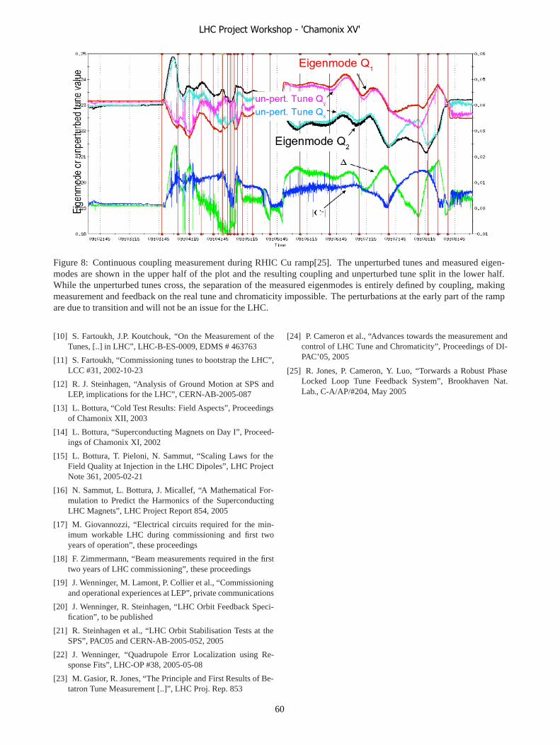
Figure 8: Continuous coupling measurement during RHIC Cu ramp[25]. The unperturbed tunes and measured eigen-modes are shown in the upper half of the plot and the resulting coupling and unperturbed tune split in the lower half.While the unperturbed tunes cross, the separation of the measured eigenmodes is entirely defined by coupling, makingmeasurement and feedback on the real tune and chromaticity impossible. The perturbations at the early part of the rampare due to transition and will not be an issue for the LHC.
[10] S. Fartoukh, J.P. Koutchouk, “On the Measurement of theTunes, [..] in LHC”, LHC-B-ES-0009, EDMS # 463763
[11] S. Fartoukh, “Commissioning tunes to bootstrap the LHC”,LCC #31, 2002-10-23
[12] R. J. Steinhagen, “Analysis of Ground Motion at SPS andLEP, implications for the LHC”, CERN-AB-2005-087
[13] L. Bottura, “Cold Test Results: Field Aspects”, Proceedingsof Chamonix XII, 2003
[14] L. Bottura, “Superconducting Magnets on Day I”, Proceed-ings of Chamonix XI, 2002
[15] L. Bottura, T. Pieloni, N. Sammut, “Scaling Laws for theField Quality at Injection in the LHC Dipoles”, LHC ProjectNote 361, 2005-02-21
[16] N. Sammut, L. Bottura, J. Micallef, “A Mathematical For-mulation to Predict the Harmonics of the SuperconductingLHC Magnets”, LHC Project Report 854, 2005
[17] M. Giovannozzi, “Electrical circuits required for the min-imum workable LHC during commissioning and first twoyears of operation”, these proceedings
[18] F. Zimmermann, “Beam measurements required in the firsttwo years of LHC commissioning”, these proceedings
[19] J. Wenninger, M. Lamont, P. Collier et al., “Commissioningand operational experiences at LEP”, private communications
[20] J. Wenninger, R. Steinhagen, “LHC Orbit Feedback Speci-fication”, to be published
[21] R. Steinhagen et al., “LHC Orbit Stabilisation Tests at theSPS”, PAC05 and CERN-AB-2005-052, 2005
[22] J. Wenninger, “Quadrupole Error Localization using Re-sponse Fits”, LHC-OP #38, 2005-05-08
[23] M. Gasior, R. Jones, “The Principle and First Results of Be-tatron Tune Measurement [..]”, LHC Proj. Rep. 853
[24] P. Cameron et al., “Advances towards the measurement andcontrol of LHC Tune and Chromaticity”, Proceedings of DI-PAC’05, 2005
[25] R. Jones, P. Cameron, Y. Luo, “Torwards a Robust PhaseLocked Loop Tune Feedback System”, Brookhaven Nat.Lab., C-A/AP/#204, May 2005
LHC Project Workshop - 'Chamonix XV'
60

VACUUM CONDITIONS REQUIRED
V. Baglin, CERN, Geneva, Switzerland
Abstract
Several years will be required to reach the LHC nominal performances. During years 1 and 2, the LHC beam current will be limited, therefore the nominal performances of the vacuum system are not required. In this context, the vacuum performances for years 1 and 2 will be analysed. Particularly, the bake-out of the Long Straight Sections could be questioned. The implications of an unbaked vacuum system onto the resources, the installation schedule, the beam lifetime, the quench level, the dissipated power into the cold masses and the radiation dose onto the machine elements will be discussed.
INTRODUCTION The Large Hadron Collider (LHC) beam vacuum
system is composed with elements operating at room temperature or at cryogenic temperature. The full vacuum system is geographically divided in three areas: the arcs, the experimental region and the Long Straight Sections (LSS).
In the arcs, there are two vacuum systems: the beam vacuum and the insulation vacuum. These systems are fully integrated in the magnet cold bore and cryostat. So, they are required from day 1.
The vacuum system in the experimental areas is surrounded by the detectors. The final vacuum system is also entirely required from day 1.
The vacuum system of the LSS includes the standalone magnet (operating either at room temperature or cryogenic temperature) and the room temperature vacuum chambers. There are 265 vacuum valves which delimit vacuum sectors in the eight LSS. The LSS contains the accelerator equipments which are required for its operation (injection, extraction, diagnostics, collimation). Part of these equipments will not be required for the day 1 of operation. Therefore, it is worth looking at if all the vacuum system components and functionality is required for day 1.
This paper focuses on the vacuum conditions which are required in the LSS for day 1 of operation. The first section discusses the requirements and the minimum machine required for day 1, showing that the bake-out of the LSS could be questionable. The second section discusses the consequences of the absence of bake-out in the LSS. In the last section, a backup possibility to the bake-out of all the room temperature parts, as defined by the base line, is proposed in given circumstances.
REQUIREMENTS AND MINIMUM MACHINE
Before the installation of the vacuum components in the LHC LSS themselves, some other points shall be completed. The LHC layout shall be frozen, the layout database shall be filled and the integration of the vacuum system shall be finished [1]. The installation drawings shall be completed, approved and ready on time. All the components (vacuum chambers, instruments, controls … ) shall be delivered and accepted on time.
Besides these fundamental requirements, a minimum of achievements are required for the operation of the machine at day 1. The supports of the vacuum chambers and the other devices shall be in place at the correct position. The vacuum chambers shall be connected and the vacuum system shall be leak tight. The pumping system shall be installed and operational. The controls and the interlocks to the LHC machine shall be installed and operational. All these aspects are part of the minimum machine for day 1 as far as they form an operational vacuum system.
However, the room temperature part of the LSS vacuum system shall be baked as it is defined by the base line. Considering the reduced machine performances required for the first years of operation, it can be questioned whether the vacuum system shall be operated with nominal performances. The next section discusses the consequence of the absence of bake-out in some of the room temperature vacuum sectors of the LSS.
ABSENCE OF BAKE-OUT IN THE LSS The LHC will reach its nominal performances after
several years of operation. During the first years, the machine performances will be limited [2]. In Table 1, the performances expected in stage 1 and stage 2 i.e. 2007 and 2008, are compared to the nominal performances of the machine.
At nominal, the vacuum pressure is dominated by the dynamic vacuum [3]. The pressure increase is stimulated by the photon, electron and ion desorption. However, in stage 1 and, in a less extend, in stage 2, these phenomena are greatly reduced or totally absent. In fact, only photon stimulated molecular desorption and ion stimulated molecular desorption could play a minor role in stage 2. It can be demonstrated that the corresponding pressure increase would be of a few 10-10 Torr. Finally, The bunch spacing will be such that no electron cloud and therefore no electron stimulated desorption will be present [2]. Therefore, the dynamic pressure in stage 1 and 2 is
LHC Project Workshop - 'Chamonix XV'
61

negligible compared to the thermal desorption of the unbaked LSS i.e. the vacuum is static.
In the following part of the paper, we will look at the performances of an unbaked vacuum system and look at the consequences of the beam particle scattering onto the residual gas.
Stage 1 Stage 2 Nominal
Months of operation
4 7 7
Days of operation
100 175 175
Bunches 1/43/156 936/2808 2808 Protons/bunch 1010-9 1010 1010-9 1010 1.1 1010
Protons 1010-1.4 1013 (3.7–9.8) 1013 3.2 1014 Current (mA) 0.02 - 25 70 - 80 582
Average current (mA)
8 140 582
Table 1 : Comparison of the estimated performances of stage 1 and 2 with the nominal LHC performances [2].
Unbaked vacuum system The pressure in a static vacuum system is defined by
the ratio of the thermal outgassing rate to the pumping speed.
When performing the bakeout of a vacuum system, the temperature of the vacuum chambers is increased in the range 200 – 300 ºC. In doing so, the chemically bound molecules are released from the oxide layer and are pumped away from the vacuum system. During the bake-out, the thermal desorption rate of the chemically bounded molecules is increased exponentially and, correspondingly, the amount of gases in the oxide layer’s reservoir decreased. After cooling down to room temperature, the thermal desorption rate is strongly reduced and the residual gas is dominated by H2. The bake-out is a well known recipe to reduce the pressure down to a few 10-10 Torr within a week. The price to pay is the compatibility to 200 – 300 ºC of the vacuum components and the installation and operation of (removable) insulation jackets, thermocouples and heating tapes.
In the case of an unbaked vacuum system, the residual gas is dominated by H2O and the system requires several weeks of pump down. In the LSS, of course, the Non Evaporable Getter (NEG) will not be activated if there is no bake-out, and the pumping system will rely only on sputter ion pumps. To estimate the pump down, we assume a typical Cu chamber of 8 cm diameter with lumped ions pumps spaced by ~ 30 m at maximum. The pumping speed is 30 l/s and the specific conductance equals 80 l.m/s. The outgassing rate of water, as a function of time t, is measured to be 3 10-5 / t i.e. 10-10 Torr.l/(s.cm2) after 100 h of pumping [4].
Figure 1 shows the evolution of the maximum and average pressure in the unbaked Cu vacuum chambers of the LSS. After 3 month of pump down, the pressure is
10-8 Torr. For the purpose of the discussions in this paper, we will assume that the pressure in the unbaked vacuum chambers of the LSS is given after 3 months and 12 months of pumping for stage 1 and stage 2 respectively. So, a pressure of 10-8 Torr and 5 10-9 Torr are expected in stage 1 and stage 2.
It shall be noted that, in the LSS, the distance between two successive ion pumps is not strictly 30 m. On average, it equals 20 m. Reducing the distance to 20 m between two pumps will reduce the pressure to 5 10-9 Torr and 10-9 Torr in stage 1 and stage 2.
Figure 1 : Expected evolution, with time, of the maximum and average pressure in the unbaked vacuum chambers of
the LSS. A distance of 30 m is assumed between two successive ion pumps
Vacuum lifetime At nominal, for the proton beams, the vacuum lifetime,
τ, equals 100 h. This lifetime guarantees a luminosity lifetime of 15 h [5]. With reduced current, taking into account the collisions, the intra beam scattering lifetime and the luminosity decay time, a vacuum lifetime of 35 h and 50 h shall be guaranteed for stage 1 and stage 2 respectively. So, the maximum pressure shall be limited to a given level. This maximum H2O pressure is a function of the length, L, of the unbaked system. Due to the fact that the gas density in the arcs is negligible, the maximum pressure scales like (1), where σH2O is the proton scattering cross section onto the nucleus of the H2O molecules.
H2Omax L
1~P
στ (1)
Figure 2 shows the maximum pressure as a function of the number of unbaked LSS. The length of one LSS is about 530 m. The figure shows that maximum pressure above 5 10-8 Torr in all the LSS still guarantee a vacuum lifetime of 100 h. So, leaving the LSS unbaked is not a limiting factor for the luminosity lifetime.
1.0E-09
1.0E-08
1.0E-07
1.0E-06
0 1 2 3 4 5 6
MonthsP
ress
ure
(Tor
r)
PmaxPaverage
LHC Project Workshop - 'Chamonix XV'
62
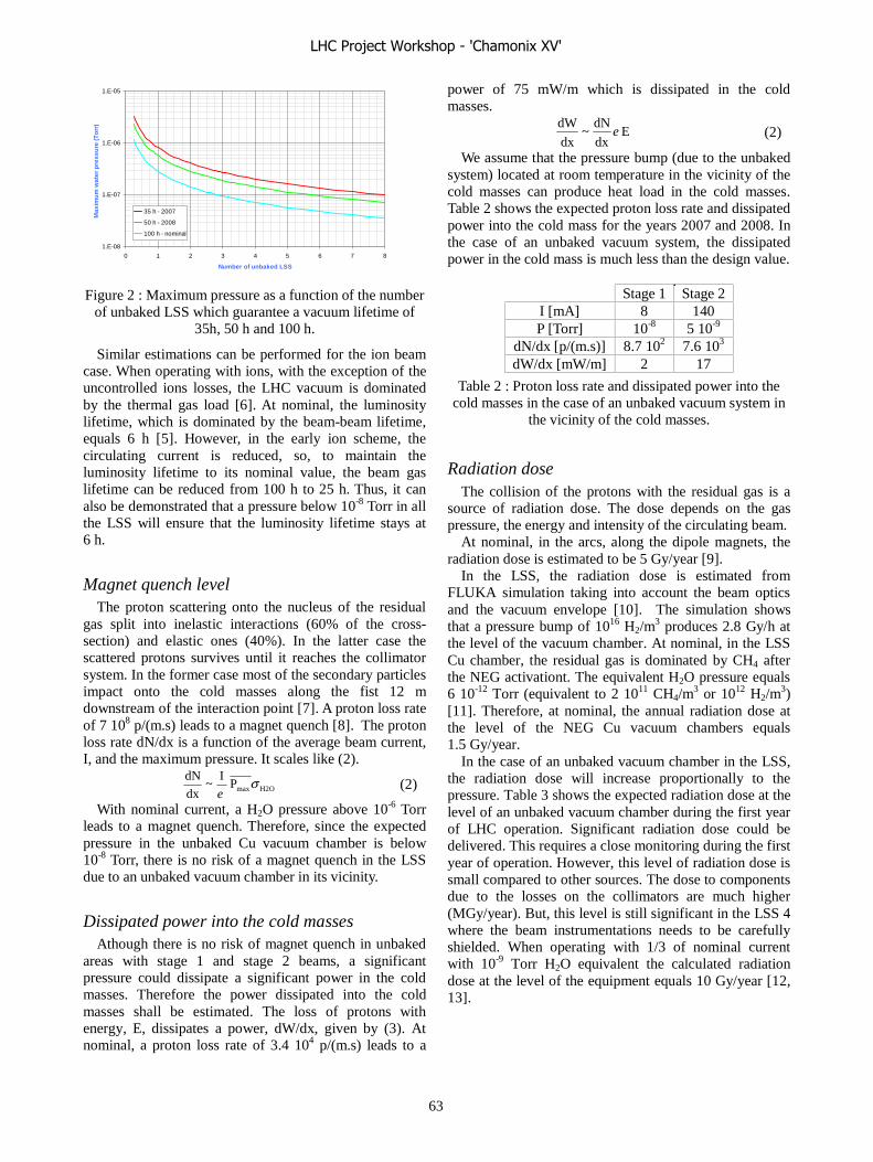
Figure 2 : Maximum pressure as a function of the number of unbaked LSS which guarantee a vacuum lifetime of
35h, 50 h and 100 h.
Similar estimations can be performed for the ion beam case. When operating with ions, with the exception of the uncontrolled ions losses, the LHC vacuum is dominated by the thermal gas load [6]. At nominal, the luminosity lifetime, which is dominated by the beam-beam lifetime, equals 6 h [5]. However, in the early ion scheme, the circulating current is reduced, so, to maintain the luminosity lifetime to its nominal value, the beam gas lifetime can be reduced from 100 h to 25 h. Thus, it can also be demonstrated that a pressure below 10-8 Torr in all the LSS will ensure that the luminosity lifetime stays at 6 h.
Magnet quench level The proton scattering onto the nucleus of the residual
gas split into inelastic interactions (60% of the cross-section) and elastic ones (40%). In the latter case the scattered protons survives until it reaches the collimator system. In the former case most of the secondary particles impact onto the cold masses along the fist 12 m downstream of the interaction point [7]. A proton loss rate of 7 108 p/(m.s) leads to a magnet quench [8]. The proton loss rate dN/dx is a function of the average beam current, I, and the maximum pressure. It scales like (2).
H2OmaxP
I~
dx
dN σe
(2)
With nominal current, a H2O pressure above 10-6 Torr leads to a magnet quench. Therefore, since the expected pressure in the unbaked Cu vacuum chamber is below 10-8 Torr, there is no risk of a magnet quench in the LSS due to an unbaked vacuum chamber in its vicinity.
Dissipated power into the cold masses Athough there is no risk of magnet quench in unbaked
areas with stage 1 and stage 2 beams, a significant pressure could dissipate a significant power in the cold masses. Therefore the power dissipated into the cold masses shall be estimated. The loss of protons with energy, E, dissipates a power, dW/dx, given by (3). At nominal, a proton loss rate of 3.4 104 p/(m.s) leads to a
power of 75 mW/m which is dissipated in the cold masses.
E dx
dN~
dx
dWe (2)
We assume that the pressure bump (due to the unbaked system) located at room temperature in the vicinity of the cold masses can produce heat load in the cold masses. Table 2 shows the expected proton loss rate and dissipated power into the cold mass for the years 2007 and 2008. In the case of an unbaked vacuum system, the dissipated power in the cold mass is much less than the design value.
Stage 1 Stage 2
I [mA] 8 140 P [Torr] 10-8 5 10-9
dN/dx [p/(m.s)] 8.7 102 7.6 103 dW/dx [mW/m] 2 17
Table 2 : Proton loss rate and dissipated power into the cold masses in the case of an unbaked vacuum system in
the vicinity of the cold masses.
Radiation dose The collision of the protons with the residual gas is a
source of radiation dose. The dose depends on the gas pressure, the energy and intensity of the circulating beam.
At nominal, in the arcs, along the dipole magnets, the radiation dose is estimated to be 5 Gy/year [9].
In the LSS, the radiation dose is estimated from FLUKA simulation taking into account the beam optics and the vacuum envelope [10]. The simulation shows that a pressure bump of 1016 H2/m
3 produces 2.8 Gy/h at the level of the vacuum chamber. At nominal, in the LSS Cu chamber, the residual gas is dominated by CH4 after the NEG activationt. The equivalent H2O pressure equals 6 10-12 Torr (equivalent to 2 1011 CH4/m
3 or 1012 H2/m3)
[11]. Therefore, at nominal, the annual radiation dose at the level of the NEG Cu vacuum chambers equals 1.5 Gy/year.
In the case of an unbaked vacuum chamber in the LSS, the radiation dose will increase proportionally to the pressure. Table 3 shows the expected radiation dose at the level of an unbaked vacuum chamber during the first year of LHC operation. Significant radiation dose could be delivered. This requires a close monitoring during the first year of operation. However, this level of radiation dose is small compared to other sources. The dose to components due to the losses on the collimators are much higher (MGy/year). But, this level is still significant in the LSS 4 where the beam instrumentations needs to be carefully shielded. When operating with 1/3 of nominal current with 10-9 Torr H2O equivalent the calculated radiation dose at the level of the equipment equals 10 Gy/year [12, 13].
1.E-08
1.E-07
1.E-06
1.E-05
0 1 2 3 4 5 6 7 8
Number of unbaked LSS
Max
imu
m w
ater
pre
ssu
re (T
orr
)
35 h - 2007
50 h - 2008
100 h - nominal
LHC Project Workshop - 'Chamonix XV'
63
Stage 1 Stage 2 I [mA] 8 140 P [Torr] 10-8 5 10-9
Dose [Gy/year] 15 280
Table 3 : Radiation dose expected at the level of the unbaked vacuum chambers during the first years of LHC
operation.
IMPLICATIONS The previous section has shown that some of the room
temperature sectors of the LSS could remain unbaked for the first years of the LHC operation.
The installation of the vacuum system in the LSS is a 1.5 years long project. Based on previous experience, the installation has been studied in details and is divided in several parts [14].
• Installation of the sectorisation modules (vacuum valves with instrumentation) upstream and downstream to the standalone magnets. Connection to the beam vacuum of these magnets.
• Installation of the insertion elements (Roman pots, beam instruments…) and installation of the vacuum components (vacuum chambers, instrumented bellows…) of the room temperature parts.
• Installation and test of the bake-out system. • Installation of the control system in parallel with the
mechanical installation and the bake-out installation. • Reception of the vacuum sectors of commissioning
of the controls. • Bake-out and NEG activation. Due to space constraints, a maximum of 2 teams can
work in parallel per half LSS. The mechanical and bake-out installation of “simple” vacuum sectors will be done by 4 teams of the subcontractor and the installation of the complex vacuum sectors (kickers, RF cavities….) will be done by 1 AT/VAC team. The bake-out and the NEG activation will be done by 2-3 AT/VAC-TS/MME teams. In addition, there is one AT/VAC backup team and another one available either for backup or exploitation of the PS and SPS complex.
From the information above, a schedule and a resource planning is built [15]. About 45 weeks and 53 weeks are required to perform the full installation of the bake-out system and the full activation of the NEG in the LSS. The resource planning shows that, for some periods of a few weeks long, the available manpower for the bake-out and the NEG activation is about two times lower than required.
Since, skipping the bake-out is the last resort to allow a closure of the vacuum system in time, an alternative to the “full” bake-out scenario to stay within the schedule can be acceptable when :
• The vacuum installation is facing too many problems (leak, non conformities, layout errors…).
• Part of the components within the same vacuum sectors are delayed, i.e. the vacuum sector cannot be closed.
In these cases, the deployment of the AT/VAC and TS/MME bake-out and activation teams as rescue teams (Vacuum SAMU) is required.
The decision to skip the bake-out of a vacuum sector shall be made, at least, in collaboration with the equipment owners, TS/IC, the experience interface if applicable and the management.
The base line remains the “full” bake-out and NEG activation of the vacuum system. In a minimal scenario, at least, the 4 experimental zones will be baked and NEG activated, all the permanent bake-out system will be installed and as much as possible vacuum sectors will be baked and NEG activated. The remaining unbaked vacuum sectors will be baked and NEG activated before stage 2 (2008).
It should be noted that when the vacuum sector valves are open, the thermally desorbed H2O from the unbaked surfaces will be pumped in the standalone magnet. Given the large pumping speed of the cryosurfaces with respect to the ion pumps, most of the H2O will be condensed over ~ 0.5 m at each extremity of the standalone. After 6 months of operation, ~ 50 monolayers of H2O will be adsorbed at each standalone extremity. Before operating above the electron cloud threshold, the H2O shall be removed from the standalone magnet by a warm up above 190 K to avoid vacuum transients and significant heat loads [16, 17]
CONCLUSIONS The LHC will reach its nominal performances after
several years of operation. Therefore, the vacuum system might not have to be operated to its nominal performances from day 1. So, the minimum vacuum system does not require a “full” bake-out of the LSS. From the LHC operation point of view, it is shown that the radiation dose in the unbaked vacuum sector is the limiting factor. In fact, due to the background limitation in the experiments and the radiation dose onto the equipment, only some vacuum sectors of the LSS 3, 6 and 7 might remain unbaked.
It should be stressed that the base line is a “full” bake-out and NEG activation of the LSS. However, in the case of difficulties e.g. delay in the delivery of complex components, postponing the bake-out of some vacuum sectors may be the only possibility to guarantee that the vacuum system will be operational in due time. The few vacuum sectors which might remain unbaked at stage 1 will be baked before stage 2.
ACKNOWLEDGEMENTS The author would like to gratefully acknowledge
A. Rossi, P. Cruikshank, D. Forkel-Wirth, J-M. Jimenez, N. Hilleret, S. Roesler, P. Strubin and H. Vincke for their
LHC Project Workshop - 'Chamonix XV'
64
help to collect the required inputs and for the fruitful discussions.
REFERENCES [1] Compressed Schedule - The Layout point of View.
S. Chemli. Proceedings of the LHC Project Workshop – Chamonix XIV, CERN, January 2005. CERN-AB-2005-014, CERN, Geneva, 2005.
[2] R. Bailey. These proceedings. [3] Overview of the LHC Vacuum System. O. Gröbner.
Vacuum 60 (2001) 25-34. [4] Le dégazage des matériaux. J-P. Bojon. CERN
Vacuum Technical Note 02-03, Mars 2003. [5] LHC Design Report, vol 1, the LHC Main ring.
Edited by O. Brüning, P. Collier, P. Lebrun, S. Myers, R. Ostojic, J. Poole, P. Proudlock. CERN-2004-003, CERN, Geneva, 2004.
[6] Residual Gas Pressure during LHC Ion Operations. A. Rossi. I-LHC/LEIR meetings, 14 December 2004. http://project-i-lhc.web.cern.ch/project-i-lhc/ILHCandLEIR/Meeting_04_12_14/DynPressureLHC_04_12_14.pdf
[7] Momentum losses and momentum collimation in LHC : a first approach. J.B. Jeanneret. CERN SL/92-44 (EA), LHC note 211, CERN, Geneva, 1992.
[8] Quench Levels and Transient Beam Losses in LHC Magnets. J.B. Jeanneret, D. Leroy, L. Oberli, T. Trenkler. LHC Project Report 44, July 1996, CERN, Geneva, 1996.
[9] Radiation Dose for Equipment in the LHC Arcs. K. Wittenburg, R. Schmidt, T. Spickermann. Proceedings of EPAC’ 98, Stockholm, Sweeden. CERN LHC Project Report 274, February 1999, CERN, Geneva, 1999.
[10] Radiation Monitors as a Vacuum Diagnostic for the Room Temperature Parts of the LSS. V. Baglin, V. Talanov, T. Wijnands. CERN LHC Project Note 378, January 2006, CERN, Geneva, 2006.
[11] Residual Gas density Estimations in the LHC Experimental Interaction Regions. A. Rossi, N. Hilleret. CERN LHC Project Report 674, CERN, Geneva, 2003.
[12] S. Roesler, private communication 20/01/2006. [13] Simulation of the radiation levels and shielding
studies at the BDI positions in IR4. A. Tsoulou, V. Vlachoudis, A. Ferrari. CERN LHC Project Note 367, May 2005, CERN, Geneva, 2005.
[14] Installation et mise en service du système à vide des sections droites longues (LSS) du LHC. M. Jimenez. CERN EDMS nº 593852, May 2005, CERN, Geneva, 2005.
[15] Installation Schedule for the Vacuum Activities in the Long Straight Section of the Machine : Standalone, Mechanical, NEG Activation. K. Foraz.
CERN EDMS nº 673368, October 2005, CERN, Geneva, 2005.
[16] Vacuum Transients during LHC Operation. V. Baglin, Proceedings of the LHC Project Workshop – Chamonix XII, CERN, January 2004. CERN-AB-2004-014, CERN, Geneva, 2004.
[17] Gas Condensates onto a LHC Type Cryogenic Vacuum System Subjected to Electron Cloud. V. Baglin, B. Jenninger. Proceedings of EPAC’ 04, Luzern, Switzerland. CERN LHC Project Report 742, August 2004, CERN, Geneva, 2004.
LHC Project Workshop - 'Chamonix XV'
65
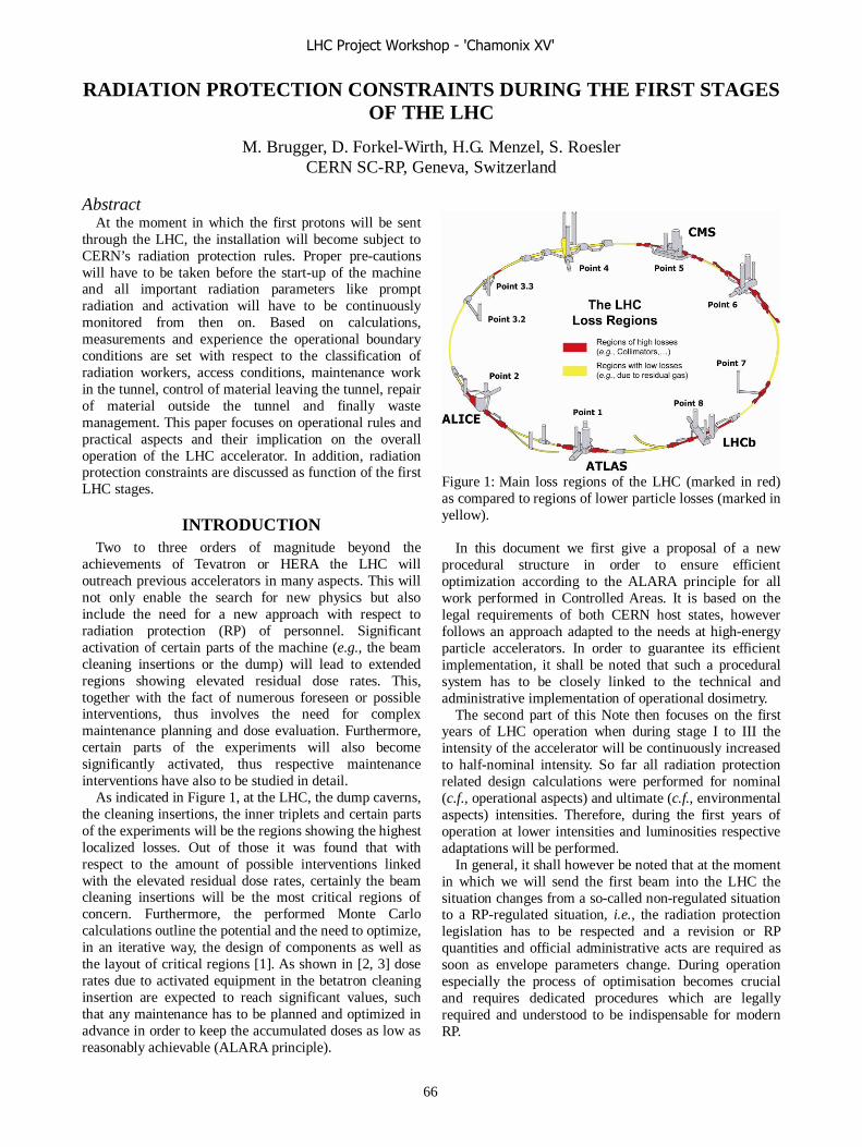
RADIATION PROTECTION CONSTRAINTS DURING THE FIRST STAGES OF THE LHC
M. Brugger, D. Forkel-Wirth, H.G. Menzel, S. Roesler CERN SC-RP, Geneva, Switzerland
Abstract At the moment in which the first protons will be sent
through the LHC, the installation will become subject to CERN’s radiation protection rules. Proper pre-cautions will have to be taken before the start-up of the machine and all important radiation parameters like prompt radiation and activation will have to be continuously monitored from then on. Based on calculations, measurements and experience the operational boundary conditions are set with respect to the classification of radiation workers, access conditions, maintenance work in the tunnel, control of material leaving the tunnel, repair of material outside the tunnel and finally waste management. This paper focuses on operational rules and practical aspects and their implication on the overall operation of the LHC accelerator. In addition, radiation protection constraints are discussed as function of the first LHC stages.
INTRODUCTION Two to three orders of magnitude beyond the
achievements of Tevatron or HERA the LHC will outreach previous accelerators in many aspects. This will not only enable the search for new physics but also include the need for a new approach with respect to radiation protection (RP) of personnel. Significant activation of certain parts of the machine (e.g., the beam cleaning insertions or the dump) will lead to extended regions showing elevated residual dose rates. This, together with the fact of numerous foreseen or possible interventions, thus involves the need for complex maintenance planning and dose evaluation. Furthermore, certain parts of the experiments will also become significantly activated, thus respective maintenance interventions have also to be studied in detail.
As indicated in Figure 1, at the LHC, the dump caverns, the cleaning insertions, the inner triplets and certain parts of the experiments will be the regions showing the highest localized losses. Out of those it was found that with respect to the amount of possible interventions linked with the elevated residual dose rates, certainly the beam cleaning insertions will be the most critical regions of concern. Furthermore, the performed Monte Carlo calculations outline the potential and the need to optimize, in an iterative way, the design of components as well as the layout of critical regions [1]. As shown in [2, 3] dose rates due to activated equipment in the betatron cleaning insertion are expected to reach significant values, such that any maintenance has to be planned and optimized in advance in order to keep the accumulated doses as low as reasonably achievable (ALARA principle).
Figure 1: Main loss regions of the LHC (marked in red) as compared to regions of lower particle losses (marked in yellow).
In this document we first give a proposal of a new
procedural structure in order to ensure efficient optimization according to the ALARA principle for all work performed in Controlled Areas. It is based on the legal requirements of both CERN host states, however follows an approach adapted to the needs at high-energy particle accelerators. In order to guarantee its efficient implementation, it shall be noted that such a procedural system has to be closely linked to the technical and administrative implementation of operational dosimetry.
The second part of this Note then focuses on the first years of LHC operation when during stage I to III the intensity of the accelerator will be continuously increased to half-nominal intensity. So far all radiation protection related design calculations were performed for nominal (c.f., operational aspects) and ultimate (c.f., environmental aspects) intensities. Therefore, during the first years of operation at lower intensities and luminosities respective adaptations will be performed.
In general, it shall however be noted that at the moment in which we will send the first beam into the LHC the situation changes from a so-called non-regulated situation to a RP-regulated situation, i.e., the radiation protection legislation has to be respected and a revision or RP quantities and official administrative acts are required as soon as envelope parameters change. During operation especially the process of optimisation becomes crucial and requires dedicated procedures which are legally required and understood to be indispensable for modern RP.
LHC Project Workshop - 'Chamonix XV'
66

LEGISLATION CERN's guidelines for the protection of the
environment and personnel are compiled in the CERN Radiation Safety Manual [4] which is currently being updated and will be closely related to the Swiss and the French National Legislation [5-9] and to the European Council Directive 96/29/EURATOM [10]. All legislation contain consistent guidelines related to radiation protection with respect to maintenance interventions in radiation environments, briefly summarised in the following for the two host-states:
Switzerland In the Swiss legislation Controlled Areas are defined as
[5, 6]: • work places for handling open radioactive sources; • areas in which it is possible for the atmospheric
concentration of radionuclides to exceed 1/20 of the guideline values;
• areas in which it is possible for the surface contamination to exceed the guideline values;
• areas in which it is possible for people to accumulate an effective annual dose of more than 1 mSv through exposure to external radiation;
• areas in which the installation is operated without the complete shielding in place;
• areas designated as such by the regulatory agency. Furthermore it states that the principle of optimization
shall be regarded as satisfied for activities which under no circumstances lead to an effective dose of more than 100 μSv per year for occupationally exposed persons or more than 10 μSv per year for persons not occupationally exposed.
France The French legislation also gives clear guidelines as to
when operational dosimetry becomes necessary and what measures have to be taken in order to guarantee the optimization process according to the ALARA principle. Controlled Areas are defined as [7-9]: • all areas where it is possible that personnel receives an
annual effective dose of more then 6mSv (or 3/10 of other related annual limits, e.g., extremities); Furthermore, in both host-states, all work in Controlled
Areas must fulfil the following requirements: • all access must be controlled and work optimization
has to be performed; • the use of an additional active dosimeter is obligatory; • all interventions are subject to dose evaluation; In order to quantify radiation exposure of CERN personnel performing work in radioactive areas the following two quantities are used:
Individual dose Individual dose is often used in the context of
intervention planning as the effective dose to one person during one specific intervention. It is subject of optimization in case it exceeds 100 μSv per intervention and year. Optimization must be performed by choosing appropriate work procedures and individual doses cannot be kept below given levels simply by increasing the number of persons involved in this intervention.
Collective dose The task of radiological protection is not only to protect individual persons but also to optimise and reduce the radiation exposure of groups of occupationally exposed persons. For the purpose of optimization the collective (effective) dose has been introduced, being the sum of all related individual doses of an intervention. Guidance for the choice of acceptable collective doses in an optimization process has to be found in comparison with other similar practices.
NEW CONCEPT OF OPERATIONAL RADIATION PROTECTION AT CERN Optimization of worker radiation exposure can be
achieved only if all persons involved in radiological activities have a coherent understanding of radiation protection and the consequences of poor radiological control practices. The following basic principles of radiation protection have to be fulfilled at all times in order to lead to an efficient approach towards operational dosimetry: • Optimization methods are used to assure that
occupational exposure is maintained ALARA in developing and justifying facility design and physical controls.
• During operations in Supervised Areas, the combination of physical design properties (barriers, etc…) and administrative control provide that: o The ALARA process is utilized to help minimizing
personnel exposures to ionizing radiation. o The design objective for personnel exposure from external
sources of radiation in areas of continuous occupancy (2000 hours/year) shall be to maintain exposure levels below 3 or 15 μSv/hour (see [11]).
o The design objective for a potential dose to a radiological worker where the occupancy or duration of the exposure differs from the above shall be ALARA and shall not exceed 20 percent of the applicable legal limits (i.e., corresponding to ~1 mSv in case of a radiation worker B).
• In case of operations in Controlled Areas and exceeding a personal dose of 100 μSv/intervention, optimization is ensured by existing procedures and intervention planning in close collaboration with RP.
• All interventions categorized in security levels and controlled by so-called trigger values (guideline values) ensuring that work procedures are subject to consistent reviews and adequate levels of optimization.
LHC Project Workshop - 'Chamonix XV'
67

In the following we apply this concept to the radiation protection at CERN by introducing a new scheme ensuring its conformity with the legislation. It shall be noted that guidelines for Controlled Areas with respect to a possible risk of contamination are not subject to this note.
Classification of Areas In order to limit and monitor radiation hazards,
buildings and areas of the site are classified according to the degree of the hazard [4]. These areas are clearly delimited and their classification is indicated at their entrance. With respect to maintenance operations and work to be carried out around the LHC accelerator, areas are classified as follows (see Table 1): • A person wording in a Non-designated Area must not
exceed an effective dose of 1 mSv in any consecutive 12-month period.
• An area is classified as a Supervised Radiation Area if under normal working conditions a person could receive an effective dose exceeding 1 mSv in any consecutive 12-month period.
• An area must be classified as a Controlled Radiation Area if under normal working conditions a person could receive an effective dose exceeding 6 mSv in any consecutive 12-month period.
Table 1: Classification of areas according to the new Radiation Safety Code [4].
Inside Controlled Radiation Areas special zones exist
where dose rates or radioactive contamination exceed specified levels and allow for adequate optimization procedures. It shall furthermore be noted, that radioactive materials must only be handled in Supervised or Controlled Radiation Areas.
In order to classify an area in practice (see Table 1), annual dose is not a useful measure. Therefore, the standard practice is to relate the annual limit (given in effective dose) into dose rates (measured as ambient dose equivalent rate). This can be done for two different cases: (1) permanent workplaces by conservatively assuming a working year of 2000 hours (e.g., computer terminal); and (2) locations without permanent occupations (e.g., corridors). Both dose rate values are to be taken as time wise and spatial averages in the designated area with a minimum time-span comparable with the typical time personnel spends in the respective area. The spatial average however, should extend over all accessible areas regardless of the respective occupancy time. As proposed
in [11] for the transient occupation the guideline values will be relaxed by a factor of five.
Figure 2: Classification of radiation areas at CERN including respective annual dose limits as well as guideline values for dose rates. The latter are given separately for cases including permanent work places (2000 hours) and for zones subject to maintenance work where transient occupation becomes important [11].
Figure 2 summarises the annual limits for the respective areas and gives furthermore the derived guideline values. In this figure, two further subdivisions of Controlled Areas are introduced, a so-called High Radiation Area, where the ambient dose equivalent may exceed 2 mSv/h and a Prohibited Area, where dose rates might exceed 100 mSv/h.
In the following, the key point certainly is to bring
together two necessities, i.e., on the one hand side the need of a consistent definition of the radiation zones in agreement with operational requirements and on the other hand a consistent access control and maintenance planning for all work performed in Controlled Areas.
Conceptual Approach A tailored approach based on a facility's complexity
and potential impacts has to be considered when applying legal guidelines to high-energy accelerators. Legislations as well as respective guidelines usually relate to nuclear power plants or similar installations, thus intrinsically have certain shortcomings.
For example, accelerator operations require a high
degree of flexibility for the efficient operation of the machine to ensure experiment programs and related research activities, whereby all activities must be conducted in a safe and environmentally sound manner. Therefore, only accelerator-specific and detailed guidelines as well as appropriate procedures for accelerator operation and for conducting experiments will ensure that a high level of performance is achieved and still applying a high safety standard. The latter is guaranteed in accordance with applicable safety and health policies, as well as the contractor’s origin.
For this purpose, the Safety Code as well as procedures
or other definitive documentation have to clearly describe and follow the lines of authority and responsibilities for
LHC Project Workshop - 'Chamonix XV'
68

the safe execution of the accelerator and related experiments. This includes interfaces between intervening groups and RP, related operations, monitoring, training and safety rules.
Job and Dose Planning Procedure According to the French legislation, any work to be
performed in Controlled Areas is subject to optimization and following the ALARA principles. Operational dosimetry (in form of an additional active dosimeter) is mandatory and entry and exit doses have to be recorded for later dose evaluation. For access to all Controlled Areas dose rate maps are put at disposal including values of dose rates for localized hot spots as well as average values for the region of concern. This allows all intervening personnel to calculate in a simple way expected individual and collective doses for the planned intervention. This estimate then serves as starting point in order to decide the procedural level to be followed before the work can be performed in the respective Controlled Area.
Figure 3: Proposed procedural structure for maintenance planning and operational dosimetry for all work to be performed in Controlled Areas at the LHC. Different security levels are introduced to be controlled by so-called trigger values.
The proposed procedural system (see Figure 3) consists
of different security levels linked to respective approval procedures as a function of so-called trigger values. The latter are given separately for maximum dose rates at the work location (H'), the maximum individual dose (HI) as well as the collective dose (HC) of the intervention. Independently, for all procedural levels entry and exit doses have to be recorded and the following constraints for personal dose (HP) as measured with active and/or passive dosimeters have to be fulfilled at all times: • the intervening worker should not exceed 2
mSv/month; • the intervening worker should not exceed 6 mSv/year. In case either of the two constraints cannot be guaranteed access should be refused and the intervention should be directly discussed with the RP responsible. It shall be noted that stated individual doses (HI) refer to one intervention (i.e., possibly to more than one accesses) and
individual, as well as given values for collective dose (HC) relate to the entire process of the work to be performed and all related personnel.
Level 0 To link Supervised with Controlled Areas, in a formal
way, all interventions occurring in so-called ’Supervised Areas’ are considered as ’Level 0’. The latter thus refers to all work to be performed when under normal working conditions persons could receive a dose of more than 1 mSv but less than 6 mSv in any consecutive 12-months period, ensured by the design of the area and controlled by the mandatory use of passive dosimeters. Areas are correspondingly indicated and no special access procedures are required. It shall be noted that all work has to be justified and optimised.
Level 1 An intervention in a Controlled Area not leading to an
individual dose of more than 100 μSv or a collective dose of 100 man-μSv, as well as not containing work at locations with a dose rate of more than 100 μSv per hour is considered as 'Level 1'. In this case the use of an additional active dosimeter becomes mandatory; however the entry and exit doses have to be recorded for each intervening person, together with the respective job code of the intervention. It is the responsibility of the trained worker or foreman to arrive at the reasoned decision not exceeding the ‘Level 1’ constraints (trigger values) with the direct support of radiation protection personnel. The recorded entry and exit doses are subject to regular spot checks and to dose evaluation by RP.
Level 2 An intervention in a Controlled Area leading to an
individual dose of more than 100 μSv or a collective dose of more than 100 man-μSv or exceeding dose rates at any of the respective work location of 100 μSv per hour is considered as 'Level 2'. In this case any access requires making a formal enquiry. Furthermore, all work including machining in Controlled Areas, thus being susceptible to leading to contamination is automatically considered as 'Level 2'.
Depending on the intervention and related possible
existing procedures, two general cases have to be distinguished: • either an already available 'RP work procedure' (WPC)
has to be used and has after completion of the corresponding work form to be approved by the responsible RSO or RP before access can be granted;
• or a special 'RP work' permit' (WP) has to be completed and is subject of a detailed approval by RP. In case of expected repetitive interventions this permit can be transformed into a procedure in order to facilitate recurring access. All interventions requiring 'Level 2’ access are also
subject to detailed dose evaluation to be performed by RP.
LHC Project Workshop - 'Chamonix XV'
69
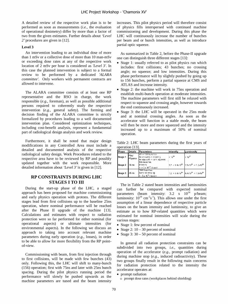
A detailed review of the respective work plan is to be performed as soon as measurements (i.e., the evaluation of operational dosimetry) differ by more than a factor of two from the given estimates. Further details about ‘Level 2’ procedures are given in [12].
Level 3 An intervention leading to an individual dose of more
than 1 mSv or a collective dose of more than 10 man-mSv or exceeding dose rates at any of the respective work location of 2 mSv per hour is considered as 'Level 3'. In this case the planned intervention is subject to a formal review to be performed by a dedicated 'ALARA committee'. Only workers with permanent contracts are allowed to intervene.
The ALARA committee consists of at least one RP
representative and the RSO in charge, the work responsible (e.g., foreman), as well as possible additional persons required to coherently study the respective intervention (e.g., general safety). The forming and decision finding of the ALARA committee is strictly formalized by procedures leading to a well documented intervention plan. Considered optimization techniques, including cost-benefit analysis, represent a fundamental part of radiological design analysis and work review.
Furthermore, it shall be noted that major design
modifications in any Controlled Area must include a detailed and documented analysis of the respective radiological safety design. Work Procedures related to the respective area have to be reviewed by RP and possibly updated together with the work responsible. More detailed information about ‘Level 3’ is given in [12].
RP CONSTRAINTS DURING LHC STAGES I TO III
During the start-up phase of the LHC, a staged approach has been proposed for machine commissioning and early physics operation with protons. The different stages lead from first collisions up to the baseline 25ns operation, where nominal performance will be reached after the Phase II upgrade of the machine [13]. Calculations and estimates with respect to radiation protection were so far performed for either nominal (for operational aspects) or ultimate intensities (for environmental aspects). In the following we discuss an approach to taking into account relevant machine parameters during early operation (e.g., losses), in order to be able to allow for more flexibility from the RP point-of-view.
Commissioning with beam, from first injection through
to first collisions, will be made with few bunches (43) only. Following this, the LHC will shift to many-bunch (156) operation; first with 75ns and later with 25ns bunch spacing. During the pilot physics running period the performance will slowly be pushed upwards as the machine parameters are tuned and the beam intensity
increases. This pilot physics period will therefore consist of physics fills interspersed with continued machine commissioning and development. During this phase the LHC will continuously increase the number of bunches per beam and or bunch intensities, as well as introduce partial optic squeeze.
As summarized in Table 2, before the Phase-II upgrade
one can distinguish three different stages [13]: • Stage 1: usually referred to as pilot physics run which
includes: first collisions; 43 bunches; no crossing angle; no squeeze; and low intensities. During this phase performance will by slightly pushed by going up to 156 bunches, perform a partial squeeze at CMS and ATLAS and increase intensity.
• Stage 2: the machine will work in 75ns operation and establish multi-bunch operation at moderate intensities. The machine parameters will first still be relaxed with respect to squeeze and crossing angle, however towards the end continuously increased.
• Stage 3: the LHC will be operated in the 25ns mode and at nominal crossing angles. As soon as the accelerator will function in a stable mode, the beam will then be more and more squeezed and the intensity increased up to a maximum of 50% of nominal operation.
Table 2: LHC beam parameters during the first years of operation [13].
The in Table 2 stated beam intensities and luminosities
can further be compared with expected nominal parameters (beam intensity: 3.2 x 10¹⁴ p/beam; luminosity: 1034 cm-2s-1). This allows one under the first assumption of a linear dependence of respective particle losses on the beam intensity and luminosity, to give an estimate as to how RP-related quantities which were estimated for nominal intensities will scale during the various stages: • Stage 1: few percent of nominal • Stage 2: 10 – 30 percent of nominal • Stage 3: 30 – 50 percent of nominal
In general all radiation protection constraints can be subdivided into two groups, i.e., quantities during operation of the accelerator (e.g., prompt radiation) and during machine stop (e.g., induced radioactivity). These two groups finally result in the following main concerns for radiation protection related to the intensity the accelerator operates at: • prompt radiation o prompt dose rates (workplaces behind shielding)
LHC Project Workshop - 'Chamonix XV'
70

• induced radioactivity o residual dose rates (maintenance) o material activation (zonage, waste)
• releases o air activation and control (e.g., dose to critical groups) o water activation and control (e.g., infiltration water)
To illustrate the respective consequences of lower
losses during the early stages of LHC operation, in the following two examples are given.
Functionality of Air-Bypass Duct at IR7 Point 7 can be considered the most critical site of the
LHC with regard to air releases as IR7 will accommodate the betatron cleaning insertions with its associated significant particle losses and due to the fact that the site is located close to a densely populated area. Therefore, air activation was carefully evaluated with particular emphasis on a careful analysis of the local environment and on an optimization of the ventilation system.
Without modifications to the original ventilation
system, the annual dose to the critical group was calculated to be about 50 μSv. Although this value is well below the annual site limit of 300 μSv/year it is legally required to perform a careful optimization, for which CERN has set a design target value of 10 μSv/year in order to follow the ALARA-principle [4, 14].
For optimization, several scenarios were studied and
the most effective modifications were found to be: • the removal of the ventilation ducts in the transfer
tunnel TZ76 thus lengthen the cooling time until the activated air reaches the pit. This modification results in a reduction of the dose by a factor of two, i.e., 25 μSv;
• guiding the air flow with ducts through the critical parts of the collimation regions in order to reduce the cross section of the affected air region (8 μSv). Therefore, keeping in mind the target value
(10 μSv/year) and the fact that the ventilation ducts in TZ76 will be removed as from start-up onwards, it can be concluded that the full functionality of the air bypass duct would only be required as soon as half-nominal intensities are reached. However, it shall be noted that due to the significant residual activation in the respective collimation region all civil engineering and the technical implementation must be performed before start-up in order to avoid excessive doses to personnel.
Area Classification During beam operation most of the LHC areas are
closed for all access. The only exceptions will be the counting rooms of the experiments (e.g., ATLAS, CMS) as well as some limited areas of access tunnels (see Figure 4) [15].
As outlined before, depending on the residual radiation level, after shutdown of the accelerator areas will be classified either as supervised or as controlled radiation areas. Figure 5 shows the expected subdivision as expected after operation at nominal intensities.
However, the situation could be different during the
early stages of the LHC. Lower particle losses will lead to a more relaxed situation which will allow one to declare - at least during stage one - most of the areas as supervised only (after verification with survey measurements).
Figure 4: Prohibited (red) and supervised (green) areas during LHC operation.
Figure 5: Controlled (yellow) and supervised (green) areas after shutdown of the machine.
For a better estimate as how many zones of the
accelerator can be declassified during the early stages of LHC operation into Supervised Areas only, one can first take a closer look at one of the most activated regions, e.g., the betatron cleaning insertion at IR7. FLUKA Monte-Carlo calculations have shown that for nominal operation and for a cooling time of 8 hours residual dose rates are expected to be significant and in the order of: • 0.5 - 2 mSv/hour in the aisle • 1 - 10 mSv/hour close to hotspots
Assuming the expected loss to be only a few percent of
those estimated for nominal operation, at IR7 this still results in significant dose rates close to hotspots and
LHC Project Workshop - 'Chamonix XV'
71
average values exceeding 15 μSv/h in the aisle. Therefore, delimitation of hotspots, local shielding as well as cooling times of several weeks will have to be anticipated before this critical area could be declassified into a Supervised Area.
For most of the remaining zones of the LHC expected residual dose rates are significantly lower, thus a relaxed situation during stages 1 and 2 can be expected. It shall however be noted, that any declassification of areas requires prior detailed survey measurements.
CONCLUSION Based on the legislation of both host states and tailored
to the complexity of CERN’s accelerators a new conceptual approach of operational radiation protection has been introduced. For work to be performed in Controlled Areas different security levels in combination with so-called trigger values are suggested. This ensures a general and formalized approach to optimization according to the ALARA principle, coupled to the flexibility required from the operational point-of-view. In addition the staged LHC start-up will enable a smooth implementation following a transition phase while the new system needs to be optimised in close collaboration with all groups of concern.
Similar approaches can be found at nuclear installations in France and do already exist in comparable high-energy laboratories around the world. It is therefore expected that the suggested approach will be accepted by both legislations of the host-states.
It shall however be noted that such a structural change also implies consequences in related areas like the training of personnel and the preparation of interventions. Especially to keep the 'Level 1' approach justified requires adequate instructions to both external and internal working personnel. Furthermore, an efficient implementation is only possible with the corresponding technical and administrative bases, as outlined in [16].
Furthermore, the radiological situation during the early stages of the LHC was addressed. Assuming a linear dependence of particle losses on beam intensities and luminosities, radiological quantities will approximately scale accordingly. Therefore, the radiological constraints are expected to be relaxed during stage 1 and most of stage 2.
For illustration, two examples were given: the functionality of the ventilation bypass duct at IR7 which could be waived up to stage 3; and the required area classification distinguishing between Controlled and Supervised Areas with the betatron cleaning insertion again serving as worst case example.
ACKNOWLEDGEMENT The authors are grateful to T. Otto and the entire RP/SL
section for many stimulating discussions.
REFERENCES [1] M. Brugger et al., The Estimation of Individual and
Collective Doses for Interventions at the LHC Beam Cleaning Insertions, LHC Project Workshop - Chamonix XIV, CERN, January 17-21 (2005).
[2] M. Brugger, D. Forkel-Wirth, S. Roesler, Summary of Individual and Collective Doses for Interventions at the LHC Betatron Cleaning Insertion (IR7), in preparation, CERN Technical Note, CERN-SC-2005-093-RP-TN, (2005).
[3] M. Brugger, D. Forkel-Wirth, S. Roesler, Remanent Dose Rate Maps of the LHC Betatron Cleaning Insertion (IR7), CERN Technical Note, in preparation, CERN-SC-2005-092-RP-TN, (2005).
[4] CERN Safety Code F, Protection against Ionising Radiations, Radiation Safety Manual, Revision 1996, CERN (1996), under revision.
[5] Switzerland, Ordonnance sur la radioprotection (ORaP) du 22 juin 1994 (Etat le 4 avril2000) 814.501 (2000).
[6] Switzerland, Ordonnance sur l'utilisation des sources radioactives non-scellées du 21 Novembre 1997 (Etat 23 Decembre 1997), 814.554 (1997).
[7] Republique Francaise, Protection contre le rayonnement ionisants, J.O. de Republique Francaise no 1420, edition mise à jour 31 aout 2000 (2000).
[8] Republique Francaise, Decret No 2002-460 du 4 Avril 2002 " relatif à la Protection generale des personnes contre les dangers des rayonnement ionisants ", J.O. de la Republique Francaise no 81, du 6 avril 2002 (2002).
[9] Republique Francaise, Decret No 2003-296 du 31 Mars 2003 " relatif a la protection des travailleurs contre les dangers des rayonnement ionisants ", J.O. de la Republique Francaise no 78, du 2 Avril 2003 (2003).
[10] EURATOM, Council Directive 96/29/EURATOM of 13 May 1996, Office Journal of the European Communities, Vol. 39, L159 (1996).
[11] T. Otto, Classification of Designated Radiation Areas at CERN, in preparation,CERN-SC-2005-079-RP-TN, EDMS No. 656 119 v. 1, (2005).
[12] M. Brugger, D. Forkel-Wirth, H. Menzel, S. Roesler, A New Procedural Concept for the Operational Radioprotection at the LHC, CERN-SC-2005-095-RP-TN, (2005).
[13] R. Bailey, Overall Strategy for Early Luminosity Operations with Protons, CERN, LHC-OP-BCP-0001 rev 1.0, (2006).
[14] R. Aßmann, M. Brugger, D. Forkel-Wirth, H.G. Menzel, S. Roesler, P.Vojtyla, S. Weisz, Radiation impact of the LHC beam cleaning insertions and possible improvements in the machine layout: Evaluation and recommendations for LHC, Internal Report, CERN, October (2004).
[15] S. di Luca, Accessibilité des Zones Verrouillées du LHC en Fonction de la Classification Radiologique, CERN, LHC-Y-ES-0001, EDMS #352114, (2003).
LHC Project Workshop - 'Chamonix XV'
72

[16] M. Brugger, N. Conan, D. Forkel-Wirth, J-C. Gaborit, T. Otto, M. Rettig, Dosimétrie
Opérationnelle - Statut Actuel et Nécessités, CERN-SC-2005-094-RP-TN, EDMS No.689231 , (2005).
LHC Project Workshop - 'Chamonix XV'
73
LHC COMMISSIONING: REQUIRED APPLICATION SOFTWARE M.Lamont, CERN, Geneva, Switzerland.
AbstractEffective commissioning of the LHC with beam
demands a well-designed, coherent suite of high level software. The challenges include a large amount of heterogeneous equipment, large distributed beam instrumentation systems, the dynamic effects of superconducting magnets and tight constraints on the key beam parameters. All of which have to be dealt with while respecting the destructive power of the beams. The required software is briefly elucidated.
INTRODUCTIONThe LHC will pose some major operating challenges.
These include the need to deal with large amount of heterogeneous equipment; drive the accelerator through a complex cycle in the presence of dynamic effects and very tight beam constraints. This must be done while respecting the destructive power of the LHC beams.
The overall requirements for the LHC high level controls system include:
Monitoring, recording and logging of accelerator status and process parameters; Display of operator information regarding the accelerator status and beam parameters; Provision of operator controls to affect changes to the accelerator; Automatic process control and sequence control during all beam related modes of operation and covering all operational scenarios i.e. control within normal operating limits; Commissioning, Physics (proton-proton, ion-ion, TOTEM..), Machine studies etc..;Fault diagnostic and recovery; Prevention of automatic or manual control actions which might initiate a hazard; Detection of onset of hazard and automatic hazard termination (i.e. dump the beam), or mitigation (i.e. control within safe operating limits).
Herein the focus is on the requirements for beam based commissioning. The high level controls requirements for technical services; vacuum; cryogenics; machine protection; and quench protection and energy extraction are taken as given.
A large proportion of the final software will be required for effective commissioning. An attempt is made, however, to prioritise the demands of the first two years’ operation with beam.
The breakdown of the requirements is as follows: Core Functionality Equipment
Instrumentation Measurements/Optimisation Exploitation Standard facilities Interfaces to other systems Other issues
Space and time limit this paper to a quick run through of the key requirements. More details of the LHC high level software requirements may be found at [1].
CORE FUNCTIONALITY Experience has shown [2,3] that the provision of
common functionality for use by all applications addressing all equipment and instrumentation classes can greatly facilitate: the production of the required code; maintenance; and the effective exploitation of the accelerator.
This core functionality should include:
Settings Management LHC operational settings will span a complex
parameter space which will include: settings for the machine cycle (injection, decay, snapback, ramp, squeeze etc) in terms of high level physics parameters (for example, momentum; tune; chromaticity; orbit including various bump and angle adjustments). Magnet properties will have to be dealt with in terms of strengths, multipole errors, transfer functions etc. Equipment settings will need to cover: Power Converters, RF, Kickers, Collimators, TDI. Feed forward & feedback settings management tools will also be required.
A coherent settings management system covering all relevant equipment and beam related settings is required. Closely related, of course, is the facility to generate all requisite settings, a process generally known as settings generation.
Along with the settings one needs archive, reload, rollback and copy facilities. Tools for database configuration of the parameter space and associated data are also required.
TrimAdjustment of all settings must be possible where
required. This should be done with an appropriate high level view of beam & accelerator parameters.
All trims must be recorded with undo, rollback functionality as standard.
Equipment Expert Settings Management Management of the settings of the specialised
equipment settings usually only visible and adjustable by the equipment expert should ideally use the same operational settings management system outline above.
LHC Project Workshop - 'Chamonix XV'
74

Equipment State Control The core layer should provide ability to manage the
state of state aware equipment. Traversal of the associated state transition diagram should be possible automatically. One should be able to control the state of multiple equipment thorough a simple, standard interface.
Equipment Monitoring All critical equipment states and settings should be
monitored. Alarms, and possibly interlocks, should be raised if state or setting is not that demanded.
Standard Equipment/Instrumentation Access A standard API should be provided to allow equipment
and instrumentation access. This mechanism should provide the expected functionality of a modern middleware (get - set, publish - subscribe, synchronous - asynchronous, security etc.).
OpticsA standard interface should provide access to the on-
line Twiss parameters and other optics related parameters.
Machine Mode & Run configuration Machine mode and run configuration data (beam
characteristics, crossing angle configuration etc.) should be managed centrally and published to any subsystem needing this data.
EQUIPMENT SUBSYSTEMS Although all equipment has eventually to lock into the
machine cycle, there is a clear need to treat the systems independently when looking at performance, monitoring, and fault recovery.
One would expect standard tools for the core functionality described above. These tools will allow:
Operation Settings management Expert Settings Management Equipment State Management Equipment Monitoring
In addition the following functionality will be required by some systems:
XPOC. Post operational checks to confirm proper equipment functioning. Critical for the beam dump for example, where the post operation checks would include beam line trajectories, screen images, beam losses etc., Post Mortem, Management of Critical Settings, Timing: time of day, event and data distribution.
Running briefly through the various subsystems and highlighting particular issues:
Collimators The collimators will require:
A dedicated application allowing adjustment of settings, optimisation with respect to closed orbit, beam size, Automated set-up process via interface with beam loss system. Probably implemented at the gateway level, Generation and editing of ramp & squeeze settings.
Fixed displays, logging, post-mortem and alarms as standard plus safe settings management will be required.
Injection Kickers The injection kickers will require:
A high level application allowing traversal of system state transition diagram, settings management (including usual trim/archive functionality), Definition of operational state diagram taking into account external conditions – interface to sequencer, Verification of proper receipt of pre-pulses & slow timing, Visualization of kicker waveform (shall be recorded every cycle), XPOC: Post Operation Checks: Typical signals acquired are the magnet current pulse shape, the currents of the injected and circulating beams, and the beam permit and beam abort gap signals Safe settings management, Post Mortem - Logging – Alarms – Visual confirmation of states.
Beam dump system The beam dump system will require:
Application for basic control and diagnostics. Kicker: safe settings management with no trim possibilities for operators. Status. Synchronisation. All manipulations to be recorded. Septa: FGC plus all associated functionality but current tracked. Current reference dealt with by operations. No trimming outside tolerances. Operational state management: On, reset, check, validation dump, inject and dump mode. Access into zone: re-close, check, validation dump sequencing. Test sequences. XPOC. Analogue acquisition: check kicker pulse against extracted beam etc. Extraction channel instrumentation monitoring.
Power Converters A large system intimately involved in most accelerator operations. Requirements will include:
Full integration into settings and trim management. Generation and editing of injection plateau ramp & squeeze settings.
LHC Project Workshop - 'Chamonix XV'
75

Real-time channel - use as orbit, tune and chromaticity feedback actuators. State control. Monitoring. Post Mortem – Alarms – Logging – Fixed Display.
MagnetsPutting aside the magnet model requirements for a
moment, it is clear that monitoring the state of the cryo-magnets will be important:
Monitoring – display, summary, alarms etc, Logging, Interlock status.
RFThe RF system’s requirements will include:
All equipment shall be controllable from main operational software. The system shall use the standard high level settings management facilities: control of phase, frequency, voltage etc. Traversal of state transition diagram, RF line and module control. Function generation via FGCs. Interface to Schneider PLCs for control & surveillance of power equipment (klystrons, power supplies etc.) High bandwidth remote acquisition: mountain ranges, analog signals, time waveforms, phase loop, injection transient signals. Monitoring of APW wideband longitudinal pickups, plus signals of first N turns at injection. Fast synchronization signals – diagnostics required. Low level control & Beam control – synchro, phase, radial loops. Diagnostics and alarms. Cavity control – STD – settings – fast feedback & tuning. Longitudinal feedback: feedback response, monitoring and control – STD & functions Alarms, Logging & Post-mortem Unit control, state, status Bunch length via Wall Current Monitor. Timing signals, injection requests
Transverse Feedback The transverse feedback system will require:
Stand alone application providing state management, parameter control, and settings management. The system shall be fully integrated into high level system. XPOC plus diagnostics. Analogue acquisition – a large amount of data plus appropriate analysis tools.
MQA & MKA MQA and MKA will require an application providing
mode aware state and settings management. Actions will have to be synchronized with measurement acquisitions.
BEAM INSTRUMENTATION General
As above, interfaces are required to allow invocation of standard facilities:
Operational Settings management Expert Settings Management Equipment State Management Equipment Monitoring
Besides these, functionality is required to allow: Acquisition (On demand, subscription, event driven), Synchronisation with equipment actions, Concentration of data from the large distributed systems: BPMs, BLMs, Management of critical settings, Logging, Post Mortem, Alarms, Fixed Display.
Given the standard facilities, the particular demands of the individual beam instrumentation systems are shown in table 1.
System Special requirements Pty. App.
BPMConcentration, Post Mortem, various acquisition modes, real-time
1 xxx
BLM Concentration, Post Mortem, Critical Settings, real-time 1 x
BCT 1
BTV Settings, state, interlocks, analysis 1 x
Rest Gas Settings, state, interlocks 2 xSync. Rad. Settings, state, interlocks 1 xWire Scanners Settings, state, interlocks 2 xLuminosity 1 xTune plus derivatives
FFT, PLL, settings, state, timing, analysis 1 xx
Abort Gap 2Schottky 3 xWall Current 1 xBST Diagnostics 1
Table 1: Prioritized overview of BI requirements. App indicates the needs for dedicated application software.
MeasurementsAll measurements are to be recorded together with
associated measurement parameters. Standard facilities are to be provided for display; browsing; analysis; archiving; and the use of reference measurements for comparison etc.
An API to allow access to the data for post-mortem, post-run analysis, from the web should be provided. A
LHC Project Workshop - 'Chamonix XV'
76

standard data format should be used with appropriate interface to analysis tools (MAD, Mathematica, etc.).
Key ApplicationsThere are a small number of vitally important enabling
applications utilizing the results of common beam measurements. The essential list is: Tune FFT utilizing the QKA and the damper; Tune PLL utilizing the damper and ticklers and the BPM system in various modes (described below).
The importance of these applications is their ability to get a handle on, for example: chromaticity; central frequency; non-linear Chromaticity; and coupling via the closest tune approach.
MEASURE AND ADJUST Full integration of trim/measure functionality will be
required. This will allow dynamic configuration of complex measure/trim procedures. These need not necessarily be realized as separate applications. Some examples are shown in table 2.
Measurement Method PriorityDynamic Aperture Kick 2Aperture Bumps, lifetime, BLMs 1 Matching - screens BTVs, quads 1Tune scans Lifetime, beam size 2Field error feed down Local orbit bumps 1
Emittance WS or SR 1 Table 2: Potential measurement procedures
ScansDedicated applications will be required for routine
optimisation. These will include: collimator positioning with respect to the orbit and BLMs; luminosity scans.
OrbitThe BPMs, in their, various acquisition modes, provide
data that can be harnessed in numerous ways. Potential uses include:
Trajectory - Threading - Linear optics, polarities checks - Injection point steering - Momentum - Momentum offset [sector to sector] - First N turns - closure - Sum signal Orbit
- Closed Orbit Correction - Dispersion - Sliding Bumps - Crossing, separation, spectrometers 1000+ turns - Phase advance, Beta Beating - Tune - Beam response after kick
- Off momentum beating Dedicated applications should be in place to provide
this wide functionality. Prioritization is possible.
SEQUENCERA powerful sequencer will be required to safely drive
the accelerator through the designated operational cycle. The requirements on the sequencer include the following.
Perform tasks in parallel Handle multithreading/distributed processing logic Multipole sequence definitions. Re-use of sub-sequences Easily configurable Catch return code of executed tasks and react appropriatelyDisplay progress, handle break points Abort executing task(s). Manually drive sequence Manually drive sequence for given subsystem Manually abort sequence SecurityLogging and error reporting Condition actions based on external input from monitoring/machine protection
Injection Sequencer Also required, possibly as a separate application from
the machine sequencer, will be an injection sequencer. This will be responsible for driving and monitoring the injection process. It will have to interface to the timing system and make appropriate request for beam nominally qualified by the ring number, beam intensity, number of batches and position in the LHC ring (RF bucket number). After each injection, input from beam quality monitoring processes must be accepted and the decision on whether to carry on the injection process evaluated. The sequencer should provide manual and automatic modes.
STANDARD HIGH LEVEL FACILITES A number of important facilities must be standardized
across all systems. This is includes the interface to the equipment level, transport mechanism, analysis and retrieval tools etc. The main reason for standardized solutions, besides economy of effort, is the need to be able to cross- correlate easily signals from the numerous sub- systems. Standard high level facilities shall include:
Logging Alarms - a universal system with 24/365 availability. Post Mortem Fixed Displays. Numerous demands, the display should be easily configurable, mode dependent. Analogue Acquisition
LHC Project Workshop - 'Chamonix XV'
77

Shot Data Analysis allowing easy fill-to-fill analysis.
MACHINE MODEL On-line model
There is a need to establish easy transport of data between the machine settings, beam measurements, the results of beam based analysis, and MAD-X. Conversely we should be able to run MAD on-line and check results of proposed adjustments to the machine against a realistic machine model. Parameter adjustments calculated by MAD should be easily introducible into the control system. We would not expect a direct interface between MAD and the machine.
Magnet Model As elucidated elsewhere in these proceedings [4] there
is a clear need to incorporate an on-line, and the results from offline invocation of the, magnet model. These will provide transfer functions, DC harmonics, and predictions of decay and snapback harmonics which will have to be fully integrated in the settings management system.
INTERFACES TO OTHER SYSTEMS The LHC will be critically dependent on the proper
functioning of the technical and essential machine infrastructure. Beam based operations will need reliable exchange of data relating to the mode of operation and key process parameters of the following systems:
Vacuum Cryogenics Cryostat Instrumentation Quench protection & energy extraction systems Technical services
Other key systems include: AccessRadiation monitors (RAMSES)
All data coming from these systems should feed into the standard logging, alarm, fixed display systems.
Clearly a well defined data exchange mechanism with the experiments is also required. Again data from this channel must be logged and displayed as appropriate.
Machine Protection The integration of the machine protection system with
beam based operations needs to be carefully considered and all interfaces must be clearly defined. MPS considerations should be fully integrated in the machine mode model.
Feedback/real time The real time controllers and associated acquisitions
and actuation will run independently of the application layer. However, it is clear that the real-time architecture has to be carefully integrated into the overall system.
Data and control flow between the two systems will include:
Optics changes during squeeze Twiss/matrices Magnet transfer functions EnergyPre-programmed I(t) in corrector circuits Circuit configuration Knob definitions Correction limits Reference orbits References in general. High level control of the controllers Control loop parameters RT corrections for use in run-to-run feed forward.
OTHER ISSUES Security
There are a number of issues here but basically unauthorized write access to process parameters during beam operation must be prevented.
Remote Access While respecting the above constraint, access from
outside the technical network to piquets and, perhaps, LHC@FNAL should be possible: firstly in read mode, secondly in write mode for a configurable set of devices and parameters.
Scripting Environment A scripting environment providing the means of rapid
application development will be requied. Care must be taken over the reliability of any code thus developed and its possible detrimental effect on machine functioning.
Software Interlocks State and settings of equipment, and key beam
measurables should be monitored. Interlocks should be thrown if states and/or settings are out of tolerances.
STANDARD OPERATIONAL FACILITIES Standard operational facilities should include: - Console manager - standard operating system - Standard error handling facilities - Alarm system interface - Electronic Logbook - Web based documentation - Database utilities - Screen capture & print utilities - Standard components for data visualisation - Standard support applications such as phonebook etc. - Page 1 or equivalent
LHC Project Workshop - 'Chamonix XV'
78

Control systemFacilities for monitoring and troubleshooting the
controls infrastructure should include, for example: timing system diagnostics and tests, CBCM monitoring and BST/TTC diagnostics.
The status of and diagnostics for front-ends/field buses, gateways, network, servers and databases should also be readily available. A remote reboot utility will be useful.
CONCLUSIONS A summary of the application requirements for the
beam based commissioning of the LHC has been presented. Some prioritisation has been performed. Only a brief evaluation has been performed here, more details are available at [1].
The software provided should, of course, be developed in a coherent framework, and be implemented using appropriate, maintainable technologies. The code itself should be maintainable and extensible and be reliable and well tested.
REFERENCES 1. M. Lamont et al, LHC Software Analysis,
//cern.ch/lhc-software-analysis. 2. L. Mestre et al, “A Pragmatic and Versatile
Architecture for LHC Controls Software”, ICALEPCS’2005, Geneva, October 2005.
3. M. Albert et al, “LHC Software Architecture: TI8 Commissioning”, LHC Project Note 368.
4. M. Lamont, Field Model deliverables for sector test and commissioning, these proceedings.
LHC Project Workshop - 'Chamonix XV'
79

THE MINIMUM WORKABLE LHC: PLANS AND REQUIREMENTS FORBEAM COMMISSIONING, YEARS 1 AND 2 - DISCUSSION
Chairman: R. Bailey - Scientific secretary: S. RedaelliCERN, Geneva, Switzerland
SUMMARY OF OVERALLCOMMISSIONING STRATEGY FOR
PROTONS (R. BAILEY)
M. Huhtinen asks when the change from 75 ns spacingto 25 ns will take place. R. Bailey replies that this basicallydepends on the requests from the experiments and on howthe overall commissioning will proceed. It is not possibleto predict now the required time for the transition.
S. Myers asks whether or not the operation at 75ns is re-ally necessary. Why can’t we go directly to the nominal25ns operation? R. Schmidt agrees that in principle, formachine protection issues, what matters is the total beamintensity and this could be achieved at 25ns spacing withless intensity per bunch. B. Bailey says that the 75ns op-eration would be useful to relax the operation procedurein various respects, without requiring major modificationswith respect to the nominal cycle. In this respect, R. Ass-mann stresses that a clear advantage is that the beam-beameffects, which are expected to seriously affect the LHC per-formance, will be greatly reduced with larger bunch spac-ing. M. Huhtinen comments that for the detector triggerit could be useful to operate for some time with a reducedbunch repetition frequency.
M. Huhtinen also asks what is the effect of the operationwith shifted IP at LHCb on the other detectors. R. Baileyreplies that this will induce, likewise, IP shifts at the otherIP’s.
R. Assmann comments that the TOTEM operation withlarge �� at IP1 and IP5 might be of a concern for the beamcleaning. Ralph asks if there are detailed plans on when theTOTEM operation will take place. K. Eggert replies that heis trying to fit the TOTEM operation into the 43-on-43 op-eration, with minimal impact on the schedule. This wouldminimize the impact on the commissioning schedule. Apossible solution could be to have some runs with interme-diate �� once the 43-on-43 operation will be established.For example, an optics with ��
� ��m is presently underinvestigation.
S. Myers stresses strongly that as soon as possible itshould be worked out in detail when to switch to the ionand TOTEM operations. It is clear that these are majorvariations of the operation routine that could significantlyslow down the path towards the commissioning of protonruns, which for the time being is the highest priority forthe early LHC operation. The experiments must urgentlyexpress their priorities.
ELECTRICAL CIRCUITS REQUIREDDURING COMMISSIONING
(M. GIOVANNOZZI)
R. Saban welcomes the list of the circuits that couldin principle be commissioned after the LHC startup withbeam. However, he underlines that it is clear that any com-missioning of subsystems performed with closed machinewill be very critical. The baseline is to test everything atonce before starting the beam runs.
S. Myers asks what is the point of talking about correc-tion of high-order effects (Q”, Q”’, ...) if at startup onemight not be able to even measure the quantities to correct.M. Giovannozzi replies that, since the multipole errors ofthe various magnet types will be measured, one should ad-just the corrector values fields to compensate the knownfield errors. Steve agrees.
R. Assmann asks if the (possibly) delayed correctors willbe properly installed (cabling, power supplies, ...). Mas-simo replies that this will certainly be the case. All the cor-rectors will be available. In case of problems/delays duringcommissioning, the commissioning of some correctly fam-ilies could be delayed without affecting the stage I opera-tion of the LHC.
However, R. Wolf stresses that for superconducting cor-rectors it is not easily possible to switch off the magneticfield. As soon as they are powered once, they require fullcommissioning otherwise their magnetic history will not beknown and one will not be able to know their operationalconditions. Only if the corrector circuits are NEVER pow-ered one can ensure that they will produce no field.
K.H. Mess comments that the gain of not commissioningthe few circuits that are not strictly required at day-1 seemsextremely marginal because only a few families would beexcluded. Better to do everything properly!
BEAM MEASUREMENTS REQUIRED INTHE FIRST TWO YEARS OF LHC
COMMISSIONING (F. ZIMMERMANN)
P. Limon asks if there are plans to systematically test thevarious measurement equipments. For example, what is thestrategy to make sure that the BPM’s will be operational?F. Zimmermann replies that we will try to test as many de-vices as possible at the sector test this year. Concerningthe BPM’s, R. Steinhagen states that the LHC system is in-trinsically redundant and there is no doubt that we will beable to make use of it. Nevertheless, there are diffused con-cerns that a systematic plan should be carried out to make
LHC Project Workshop - 'Chamonix XV'
80

sure that the various measurement equipment are properlychecked out.
R. Schmidt comments that various measurements amongthe list proposed by F. Zimmermann depend on beam en-ergy and intensity. It should be defined which measure-ments can be done at which beam energy. Measurementsthat can potentially put in danger the machine should beclearly identified. F. Zimmermann replies that most of themeasurements he proposed can be carried out with pilotbeam and should therefore not put in danger the machine.
J.P. Koutchouk states that for the LHC it will be an issueto figure out which BPM’s give a wrong signal. He sug-gests that, at the latest at the next Chamonix workshop, sys-tematic methods to assess the BPM measurements shouldbe figured out.
REAL-TIME FEEDBACK REQUIRED(R. STEINHAGEN)
R. Assmann asks if there are systematic effects that areexpected to limit the performance of the orbit feedback sys-tem. For example, it is known that setting up an orbit feed-back at LEP took a long time. R. Steinhagen believes thatcritical issues for the LHC might be coupling and chro-maticity. �J. Wenninger comments that the setup of an orbitfeedback at LEP was slowed down by lack of manpowerand lack will rather than by fundamental problems. S. My-ers agrees.
Q. King asks if we will have real-time input into theRF’s. R. Steinhagen replies that technically this is possible(compatible with the available hardware) but this solutionshould be approved bu the RF experts.
VACUUM CONDITIONS REQUIRED(V. BAGLIN)
The proposal by V. Baglin of starting up the LHC withreduced vacuum performance in the long straight sections(LSS) triggers various comments: There is a general con-cern (ATLAS, CMS) that the luminosity performance ofthe LHC with reduced vacuum in the LSS’s might con-siderably affect the detector commissioning in early LHCoperation. So far, the detector commissioning plan has as-sumed that the nominal vacuum will be available from day1. Therefore, a start-up with reduced vacuum performanceshould be approved by the experiments before a decision ismade.
K. Potter stresses that ALICE and LHCb might be partic-ularly affected by vacuum problems (signal-to-noise ratiowill worsen more than at CMS and ATLAS).
J. Jowett comments that the statement that “worse vac-uum performance is acceptable for IBS emittance growths”does actually not take into account the operation with leadions. This issue should be addressed.
T. Linnecar expresses some concerns for the operationof the RF’s with poor vacuum. This issue has not beenconsidered by V. Baglin but deserves more detailed studies.
R. Assmann says that the proposed solution with reducedvacuum performance is also supported by the collimationproject. The installation of collimators at IR3 and IR7 willbe facilitated by a staged installation at the cleaning inser-tions (collimators produced later could be installed at anymoment if the insertions will not be baked out).
RADIATION PROTECTIONCONSTRAINTS DURING THE LIFE TIME
OF LHC (M. BRUGGER)
No discussion after the talk.
BEAM COMMISSIONING: REQUIREDAPPLICATIONS (M. LAMONT)
S. Myers asks whether there will be applications to checkthe magnet polarities. M. Lamont replies that this kind oftests should be carried out during the hardware commis-sioning and there are not under his responsibility. R. Bai-ley confirms that a few weeks are indeed allocated in thecommissioning schedule before the start-up with beam fora thorough machine checkout.
R. Assmann asks if the application software will be testedby a dedicate team, independently from whom wrote thesoftware. M. Lamont replies that the manpower to do thatis not available. Thorough checks (basic functions, com-patibility, etc.) are carried out at the building phase.
S. Peggs asks if, at the sector test, it will be possible tosimulate various stages of the LHC operation (e.g., energyramping) to properly check the applications. M. Lamontreplies that this will be the case (see next sessions).
R. Aymar asks how much has actually been done on soft-ware development. M. Lamont replies that the project forthe LHC software development started about three yearsago. Considerable progresses have been made since then.Notably, the new proposed system has been already used atLEIR and will be adopted this year at the SPS. A detailedplan, with crucial milestones, is defined to make sure thatthe LHC requirements will be fulfilled.
LHC Project Workshop - 'Chamonix XV'
81

COMMISSIONING AND EALY OPERATION – VIEW FROM MACHINE PROTECTION
J. Uythoven, CERN, Geneva, Switzerland.
Abstract Before first beam is injected into LHC, the large part of
the protection systems that does not require beam for commissioning will already have been formally validated. Some systems require to be commissioned with beam at the start of beam operation. With increasing stored energy, increased performance of some protection systems is required, and also additional systems must be commissioned. It is proposed to define operational stages with limits on the stored beam energy. An increase of the stored energy, either by filling more beam, or by increasing the maximum energy, requires formal validation of the protection systems that are required for the next stage of operation, and an agreement between operation and machine protection experts to go on. The functions of a ‘Machine Protection Coordination Team’ are proposed.
INTRODUCTION The Machine Protection System (MPS) has to
guarantee the safe operation of the LHC. A not properly working MPS can lead to significant damage of LHC components and long downtime periods [1]. For this
reason commissioning of the MPS needs to be done with great care and the details of the commissioning need to be well defined in advance. The commissioning of the MPS will be a recurring task during the commissioning of the LHC but also after shutdowns and access periods.
Figure 1 gives and overview of the MPS and the systems connected to it. It shows the complexity of the system [2]. To commission such a complex and important systems, a clear strategy and formal procedures are required.
SYSTEMS TO BE COMMISSIONED The systems to be commissioned can be divided in four
groups, each consisting of a number of subsystems. The first group consists of the core of the system:
• The Beam Interlock System (BIS) • The LHC Beam Dumping System (LBDS)
The second group consists of the systems connected to the MPS:
• Beam Loss Monitors (BLM) • Quench Protection and Power Interlock Controllers • Collimation System • Etc.
Beam Energy Tracking
Beam Dumping System
4 x DCCT Dipole Current
(4/5, 5/6, 6/7, 7/8)
RF turn clock
Powering Interlock System Quench
Protection
Power Converters
Discharge Switches
AUG
UPS
Cryogenics essentialcircuits
auxiliarycircuits
Safe LHCParameters
Beam Current Monitors Current
Energy Energy
SafeBeam Flag
Required also for safe beam
SPS Extraction Interlocks
TL collimators
TimingPM Trigger
BLMs aperture
BPMs for Beam Dump
LHC Experiments
Collimators / Absorbers
NC Magnet Interlocks
Vacuum System
RF + Damper
dI/dt beam current
BLMs arc
BPMs for dx/dt + dy/dt
dI/dt magnet current
Operators Software Interlocks
Screens
Injection Kickers
LHCBeam
Interlock System
Access Safety System
Beam DumpTrigger
Required for unsafe beam
Figure 1: Overview of the Machine protection system and the connected equipment.
LHC Project Workshop - 'Chamonix XV'
82

The third group consists of the related hardware systems: • Safe Beam Parameters • Beam Presence Flag
The fourth group consists of the related software systems: • Post Mortem system • Management of Critical Settings (MCS) • Software Interlock System (SIS) • Sequencer
STAGES IN COMMISSIONING Without Beam
The commissioning of the MPS and the connected equipment starts with tests in the laboratory, followed by equipment tests in the machine. This is followed by the hardware commissioning, where the equipment is tested under normal operating conditions and the interface between the different systems has to be tested. A maximum of functions should be tested without beam: the individual equipment and their interface but also the Post Mortem system, sequencer, Safe Beam Parameters etc., even if they can only be partially tested without beam.
With Beam Many systems, like the BLMs, the collimators and the
LBDS will also need to be commissioned with beam. The tests will consist of individual system tests and tests of the interface between the systems. These tests will need to be repeated at the different stages of the LHC commissioning and can depend on:
• The beam intensity • The beam energy • The different operational states, like optics (squeeze),
polarities of the magnets of the experiments or proton – ion operation.
DEFINITION OF THE STAGES The different stages of commissioning can be defined
according on the increasing risk during the operational period or according to the operation state of the machine which has not been checked before. After the commissioning of a certain stage, the operation should be declared safe for the given conditions (intensity, energy, state). Operation outside these conditions should not be allowed.
The ‘jump’ to the next stage should be small enough so that the commissioning process itself is safe. Several systems might move into the next stage together, but only one should be commissioned at a time.
The systems can be classified in two groups: the system which only need to be commissioned once and are either ‘on’ or ‘off’. These systems can already be commissioned at an earlier stage than formally required. This is in contrast with the systems that need to be retested at several instances to check there behavior under the different beam conditions. They will need to re-commissioned at each stage defined for this system.
The definition of the stages needed for Machine Protection commissioning will need to be more refined than the ones defined for the LHC commissioning [3]. A general overview of different stages and the systems which are required for these stages are given in [4]. This will need to be further refined for the actual MPS commissioning plan.
To simultaneously commission all the different systems requires a complex description of the different stages and the machine protection elements required. For the main systems, the logical order of commissioning for the same stage seems to be: fist the commissioning of the injection system, followed by the LBDS, the other systems (as required for diagnostics), the BLM system and last the collimation system.
The different stages might not follow in a ‘linear order’ like always increasing beam intensity As an example: it might well be possible that injection has already been commissioned up to higher intensities, followed by the first energy ramp which will need to be done with a pilot beam.
FORMAL TEST PROCEDURES The tests to be performed during the commissioning of
the MPS should be established and agreed upon well before the tests will be made. If the test results are negative (the conditions are not met) the operation of the LHC should not be allowed to move to the next stage. This can be tests either with or without beam. Similar procedures as already in place for the LHC hardware commissioning could be used.
Formal MPS test procedures should already be used in 2006 for the commissioning of the following beam operations:
• CNGS operation with nominal intensity • TI 8 operation with high(er) intensity • TT40 operation with high intensity LHC type beams
(collimator tests) • Sector test (low intensity, but important to check
functionality and to establish procedures).
MACHINE PROTECTION COORDINATION TEAM
The creation of a Machine Protection Coordination Team (MPCT) is proposed. This team would have the following tasks:
• Definition of the different stages of the commissioning of the MPS. This should be done in collaboration with the Operation group and the equipment experts.
• Definition of the details of the different tests to be performed for the different types of equipment to go from one stage to the next. This is likely to be a dynamic specification, which can change during the LHC operational period.
• Declaration of whether a protection system is commissioned for a specific stage.
LHC Project Workshop - 'Chamonix XV'
83
• Participation in the commissioning of the MPS. • Consultation in the case of non-standard situations. If
certain pre-defined conditions are not met, the MPCT can be consulted if and under which conditions LHC operation can continue. This should avoid and rushed ‘over night’ decision making.
The MPCT could consist of a small team of machine protection experts (4 – 6 persons), always available on short notice. If required, a contact person can be assigned to be one duty for a period of one week at a time. The MPCT can be contacted by the Machine Coordinator, EiCs etc. They can also bring any potential dangers, not foreseen, to the attention of the operations team and will closely follow the machine operation. They will contact other MPS specialists if required.
CONCLUSIONS The commissioning of the Machine Protection System
will take place in stages. The different stages and the formal acceptance tests will need to be clearly defined and agreed upon before LHC beam operation starts. The commissioning should already start with tests without beam and during the hardware commissioning period, followed by the many different stages with beam. These stages can be different for the different equipment types and will depend on beam intensity, beam energy and machine state.
The creation of a Machine Protection Coordination Team is proposed. Its task will be to formalize the above procedures and validate tests. It will consist of a small team of experts, available for consultation on short notice.
ACKNOWLEDGEMENTS This paper is the result of fruitful discussions within the
Machine Protection Working Group.
REFERENCES [1] J. Uythoven et al., ”Possible Causes and Conse-
quences of Serious Failures of the LHC Machine Protection Systems”, 9th European Particle Accelerator Conference EPAC04, Lucerne, Switzerland, July 2004.
[2] R. Schmidt, “Machine Protection System(s) – overview”, Proc. of the LHC Project Workshop Chamonix XIV, CERN, January 2005, pp. 255-260.
[3] R. Bailey, “Summary of Overall Commissioning Strategy for Protons”, these proceedings.
[4] J. Wenninger, “What Systems Request a Beam Dump”, these proceedings.
LHC Project Workshop - 'Chamonix XV'
84
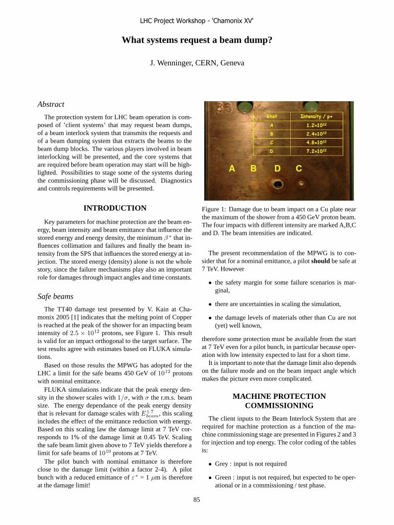
What systems request a beam dump?
J. Wenninger, CERN, Geneva
Abstract
The protection system for LHC beam operation is com-posed of ’client systems’ that may request beam dumps,of a beam interlock system that transmits the requests andof a beam dumping system that extracts the beams to thebeam dump blocks. The various players involved in beaminterlocking will be presented, and the core systems thatare required before beam operation may start will be high-lighted. Possibilities to stage some of the systems duringthe commissioning phase will be discussed. Diagnosticsand controls requirements will be presented.
INTRODUCTION
Key parameters for machine protection are the beam en-ergy, beam intensity and beam emittance that influence thestored energy and energy density, the minimum β ∗ that in-fluences collimation and failures and finally the beam in-tensity from the SPS that influences the stored energy at in-jection. The stored energy (density) alone is not the wholestory, since the failure mechanisms play also an importantrole for damages through impact angles and time constants.
Safe beams
The TT40 damage test presented by V. Kain at Cha-monix 2005 [1] indicates that the melting point of Copperis reached at the peak of the shower for an impacting beamintensity of 2.5 × 10¹² protons, see Figure 1. This resultis valid for an impact orthogonal to the target surface. Thetest results agree with estimates based on FLUKA simula-tions.
Based on those results the MPWG has adopted for theLHC a limit for the safe beams 450 GeV of 1012 protonswith nominal emittance.
FLUKA simulations indicate that the peak energy den-sity in the shower scales with 1/σ, with σ the r.m.s. beamsize. The energy dependance of the peak energy densitythat is relevant for damage scales with E1.7
beam, this scalingincludes the effect of the emittance reduction with energy.Based on this scaling law the damage limit at 7 TeV cor-responds to 1% of the damage limit at 0.45 TeV. Scalingthe safe beam limit given above to 7 TeV yields therefore alimit for safe beams of 1010 protons at 7 TeV.
The pilot bunch with nominal emittance is thereforeclose to the damage limit (within a factor 2-4). A pilotbunch with a reduced emittance of ε∗ = 1 μm is thereforeat the damage limit!
Figure 1: Damage due to beam impact on a Cu plate nearthe maximum of the shower from a 450 GeV proton beam.The four impacts with different intensity are marked A,B,Cand D. The beam intensities are indicated.
The present recommendation of the MPWG is to con-sider that for a nominal emittance, a pilot should be safe at7 TeV. However
• the safety margin for some failure scenarios is mar-ginal,
• there are uncertainties in scaling the simulation,
• the damage levels of materials other than Cu are not(yet) well known,
therefore some protection must be available from the startat 7 TeV even for a pilot bunch, in particular because oper-ation with low intensity expected to last for a short time.
It is important to note that the damage limit also dependson the failure mode and on the beam impact angle whichmakes the picture even more complicated.
MACHINE PROTECTIONCOMMISSIONING
The client inputs to the Beam Interlock System that arerequired for machine protection as a function of the ma-chine commissioning stage are presented in Figures 2 and 3for injection and top energy. The color coding of the tablesis:
• Grey : input is not required
• Green : input is not required, but expected to be oper-ational or in a commissioning / test phase.
LHC Project Workshop - 'Chamonix XV'
85

Figure 2: Table of required interlock clients as a functionof the machine commissioning stage for injection.
• Red : no beam operation without this input.
For machine protection, the relevant phases are:
• First pilot bunch.
• Beam of 1012 protons.
• 43 bunches.
• 156 bunches.
• 936 bunches (75 ns).
From the two figures it is clear that state transitions of themachine protection system appear during commissioningfor:
• pilot bunch ramp to 7 TeV : a large fraction of inputsrequired
• 43 bunch operation ramp to 7 TeV : majority of inputsrequired
• injection for 156 bunch operation : majority of inputsrequired
Although the majority of interlock systems must be op-erational for 43 bunch operation at 7 TeV, the requiredsafety level or complexity is by far not the same as for2808 bunches. The collimation system is a good exam-ple, where only a subset of collimators is required duringinitial stages [2]. This table is clearly not cast in stone. It isexpected to evolute until the LHC starts up.
Software components
Requirements on software components are shown in Fig-ures 4 and 5 for injection and top energy. Again it is clearthat constraints and requirements are not the same for a pi-lot bunch and for 43 bunches or even for 2808 bunches.Initially the SW component core must be available, with
Figure 3: Table of required interlock clients as a functionof the machine commissioning stage for 7 TeV.
Figure 4: Table of required ’safety’ software componentsas a function of the machine commissioning stage for in-jection.
a functionality that is a adapted to a given commissioningstage. The Software Interlock System itself hides a largesystem, with a core to transmit interlocks and a long list ofclients: this a an interlock system of its own. A first versionof this system is expected to be operational at the SPS forthe 2006 machine startup (CNGS commissioning).
Interlock settings
A large effort is put into building a BIS with very highsafety standard of SIL3-4. But many interlocks depend onreference and tolerance settings. Some of those settingsmust be adjustable during operation. Changes of such set-tings MUST be protected by adequate access control. Anuncontrolled modification can be equivalent to MASKINGthe corresponding interlock.
Front-end frameworks like FESA are presently open andvery easy to access, and settings may be changed from anyWEB browser at CERN! The separation of technical andgeneral purpose network has improved the situation some-what but not sufficiently. The development of systems like
Figure 5: Table of required ’safety’ software components asa function of the machine commissioning stage for 7 TeV.
LHC Project Workshop - 'Chamonix XV'
86

MCS (Management of Critical Settings) to provide (rea-sonably) safe and controlled access to critical interlock set-tings is essential for safe operation of the LHC machineprotection system.
First pilot at 450 GeV
From a pure DAMAGE protection point of view there isno need of the BIS and its clients for the first injections.Only an interlock on the SPS beam intensity is required.
Some key inputs of the beam interlock system will betested and ready to go before first beam in the LHC: theBeam Interlock System and some of the key beam inter-lock clients (Vacuum, Access, Powering interlock system,Dump system, critical BLMs, Experiments) that are notmaskable. Those inputs will be active already for the firstinjections.
First pilot at 7 TeV
The pilot bunch being at the edge of the damage limitat 7 TeV, the BIS must provide some protection even fora pilot, thus requiring a significant number of inputs. Inparticular a minimal collimation (primary collimator andabsorber) with rough positions must be in place [2]. Beamloss monitors around the collimators must be operational.Orbit control must be available for the TCDQ, since anasynchronous beam dump is possibly the worst event fora pilot (the probability to hit the pilot is of course not veryhigh).
43 bunches
With 43 bunches the stored energy reaches a level thatis comparable to what is accelerated routinely in the SPSsince many years, but which also requires significant in-terlocking. At the LHC the aim is to reach such storedenergy levels in a short time. The SPS experience showsthat one can provoke damage with such beams and at theLHC the price to pay is larger: this is therefore a naturalstage where the machine protection system must be in anadvanced stage of commissioning proportionally more ad-vanced than beam operation. Systems that may not berequired at this stage (to be studied): RF and damper in-terlocks, fast beam current decay and fast position changemonitors.
Ions
The ion beams will profit from a MP system that is al-ready commissioned with protons, at least up to a cer-tain intensity, but the safe-unsafe transition must still beanalyzed with ions. It is also necessary to analyze whatsub-systems of the MP system must be at least partly re-commissioned for ions. More detailed studies on ions areforeseen by the MPWG in 2006.
CONCLUSION
For the first injection of a pilot bunch, no machine pro-tection is required except a limitation of the intensity ex-tracted from the SPS. But the BIS and all non-maskableinputs to the BIS will be ready and (pre-)commissioned.
A beam of 1012 p constitutes the safe intensity limit fordamage protection at injection.
The damage limit at 7 TeV corresponds to 1% of thedamage limit at 450 GeV. A pilot bunch is therefore close tothe damage limit at 7 TeV. The MPWG presently assumesthat the pilot is possibly safe, but some protection will berequired (minimal collimation and BLMs) as soon as thepilot bunch is ramped to 7 TeV.
The majority of the MPS must be operational for 43bunches 7 TeV for 156 bunches at 450 GeV
It is essential to address the issue of how to manage crit-ical interlock settings.
REFERENCES
[1] V. Kain, Damage Levels: Comparison of experiment andsimulation, Proc. of the LHC project Workshop 2005,CERN-AB-2005-014.
[2] R. Assmann, these proceedings.
LHC Project Workshop - 'Chamonix XV'
87

What is required to safely fill the LHC?
V. Kain, CERN, Geneva, Switzerland
Abstract
Machine protection consisting of passive and active sys-tems will be used to prevent damage during the LHC in-jection process. Concerning beam 2, parts of the SPS ex-traction and transfer line beam interlock system has al-ready been successfully tested during the TI 8 commis-sioning. Key elements of the final system for beam 2 willbe validated during the LHC Sector Test with low inten-sity beam, together with parts of the passive protection sys-tem, the TDI and at least one transfer line collimator TCDI.The remaining issues after the sector test will be discussedin detail, where the entire injection protection system to-gether with post mortem, management of critical settings,sequencer and software interlocking system must be testedwith beam, for different intensities and filling patterns dur-ing the LHC beam commissioning. Requirements fromother systems and interdependencies for test modes, suchas inject & dump, are important input for the overall LHCcommissioning strategy and will be discussed.
SYSTEMS CONCERNED
The different systems required for adequate injectionprotection are described in detail in [1].
Besides the actual injection into the LHC the injectionprotection system also has to cover extraction from the SPSin LSS4 and LSS6 and the transfer via the transfer linesTI 2 and TI 8, Fig. 1.
SPS-Extraction Transfer LHC-InjectionSPS-Extraction Transfer LHC-Injection
Figure 1: Overview of the injection process: extractionfrom the SPS in LSS6 and LSS4, transfer via the transferlines TI 2 and TI 8 and injection into the LHC in IR 2 andIR 8.
The machine protection system consists of activeand passive systems - active protection in the form ofsurveillance systems and interlocking to inhibit extrac-tion/injection in case of failure; - passive protection withcollimators and absorbers. The main characteristics of theprotection systems are briefly summarised below.
Passive Protection: TCDI
Transfer line collimators (TCDI) are needed to protectthe LHC aperture, assumed to be 7.5 � at 450 GeV, fromany failures upstream of the collimation section. They pro-vide full phase space coverage with 3 double-jawed colli-mators per plane and a setting of 4.5 �. The expected phasespace coverage was simulated including nominal errors forsetting-up, optics and trajectory and amounts to about 6.9 �maximum amplitudes escaping the system, Fig. 2.
In total there will be seven collimators per line. Themomentum collimator is at the beginning of the lines andthe 6 betatron collimators are located in the last 300 m,mostly downstream of the last beam dump (TED), Fig. 3.This means that these TCDI need the LHC beam permit forsetting-up. Concerning the commissioning this means thatthe LHC has to be ready to complete the beam commis-sioning of the collimators. In case of TI 8 the TCDI canalready be tested with beam during the LHC Sector Test.
0
5
10
15
20
25
30
35
6.4 6.5 6.6 6.7 6.8 6.9 7
max. amplitude [σx]
0
5
10
15
20
25
30
6.4 6.5 6.6 6.7 6.8 6.9 7
max. amplitude [σy]
Figure 2: Expected phase space coverage with TCDI col-limators as fraction of seeds versus maximum amplitudesescaping the system.
TED TED TDIMKE MKI
TCDIMOM TCDIH/V
SPS TT40/60 TI 8/2 LHC
TED TED TDIMKE MKI
TCDIMOM TCDIH/V
SPS TT40/60 TI 8/2 LHCMKE MKI
TCDIMOM TCDIH/V
SPS TT40/60 TI 8/2 LHC
Figure 3: The momentum transfer line collimator is at thebeginning of the line, the 6 betatron collimators are locatedin the last 300 m.
Passive Protection: TDI-TCDD-TCLI
The other passive protection system involved in the in-jection process is located in the injection regions in theLHC and consists of the 4.25 m long injection stopperTDI, the mask TCDD(M) and the auxiliary collimatorsTCLIA/B. This system protects the LHC against injectionkicker (MKI) failures, the required setting is 6.8 �.
The TDI will be installed 90Æ downstream of the MKI,followed by the mask TCDD in front of the superconduct-ing dipole D1, Fig. 4. The TCLI collimators are located
LHC Project Workshop - 'Chamonix XV'
88

on the other side of the IP and complement the protectionwith the TDI in case of phase changes between the injectionstopper and the MKI. TCLIA will be installed downstreamof the experimental area close to the D1 and TCLIB closeto the Q6 downstream of the insertion. A mask (TCLIM)is required to shield the superconducting quadrupole frompossible showers generated in the collimator jaws.
Figure 4: Horizontal overview of the injection regionaround IP2.
Active Protection
Active protection has to guarantee correct settings forSPS extraction, transfer lines and LHC injection via thesurveillance of e.g.:
� magnet currents with ROCS surveillance and FastMagnet Current Change Monitor (FMCM)
� collimator positions
� beam position in SPS extraction region
� SPS extraction septum girder position
� kicker charging voltage
Active protection also has to make sure that high intensitybeam can only be injected into the LHC when beam is al-ready circulating (beam presence condition). BCT signalsfrom the SPS and the LHC are required to verify this con-dition:
� SPS safe beam intensity
� LHC beam presence
These two intensity signals (in the form of flags) alongwith the User Inputs from the surveillance systems are in-put to the Beam Interlock System (BIS) via Beam InterlockControllers (BIC). A schematic of the BIS for the injectionprocess of beam 2 as well as CNGS can be seen in Fig. 5.
LHC
inje
ct p
erm
it
SPS
extra
ct p
erm
it
SPS MKDdump
SPS MKE extract
LHC MKIinject
LHC MKDdump
SPS ringBIC
SPS LSS4MASTER
BIC
SPS LSS4/ TT40
BIC
TI 8 upstream
BIC
TI 8 downstream
BIC
LHC IR8 injection
BIC
LHC ringBIC
SPS
beam
per
mit
LHC
bea
m p
erm
it
SPS
ring
UPs
LSS4
/TT4
0 U
Ps
TI8
upst
ream
UPs
TI8
dow
nstre
am U
Ps
TED
TT4
0
TED
TI8
TDI I
R8
SPS safe intensity flag
Includes TI 8 after TED
TT40/CNGS/TI 8 and injection interlocking
TT41 & CNGS
TT41CNGS
BIC
UPs
MBSGSwitch
+ MB PC switch
LHC safe parameters
LSS4/TT40 TI 8 down LHC injection LHC SPS TI 8 up
?
LHC
inje
ctio
n U
Ps
LHC
ring
UPs
SPS timing
Figure 5: Schematic of the interlock system for the injec-tion process of beam 2 and CNGS.
Software
Besides hardwired active and passive protection also anumber of software ingredients are required for adequateinjection protection.
Software interlocking system (SIS)Beam quality aspects like trajectories along the transferlines, but also screen positions and other less safety criticalissues are covered by the software interlocking system.
Management of critical setting (MCS)The MCS is a software to remotely manage interlock set-tings in a secure way. It needs the SIS for full functionality.The MCS will be used for a lot of surveillance systems ofdevices involved in the injection process, examples are theMKI, MKE, TDI, TCLI, TCDI, ROCS, BLMs, BPCE andMSE. The first version of this software is planned to beready for the extraction and transfer tests in 2006.
Extraction/transfer/injection data analysis and di-agnosticsA tool for extraction, transfer and injection data anal-ysis and diagnostics is required. It will have to covershot-by-shot beam quality checks to allow the next ex-traction/injection as well as post mortem analysis afterabnormal situations e.g. in case of an interlock.
LHC injection sequencerSetting up of the TDI and TCLI collimators needs tobe driven by the LHC injection sequencer to guaranteecoherency with the different injection preparation andfilling steps. The sequencer will also have to provide theLHC machine mode inject & dump, which is required forsetting up the transfer line collimators, as will be discussedbelow.
LHC Project Workshop - 'Chamonix XV'
89

WHEN DO WE NEED INJECTIONPROTECTION?
Injection protection must be in place and working cor-rectly when the injected intensity exceeds the damagelimit. The damage limit is assumed to be about � � ����
protons at 450 GeV, corresponding to about 5 % of a nom-inal full batch extracted from the SPS towards the LHC.
According to the “overall commissioning strategy forprotons” [2], injection protection is absolutely mandatoryfrom commissioning stage II onwards.
Before a beam intensity above the damage limit canbe authorised, formal tests and acceptance of the protec-tion system performance are needed. Injection protectionshould hence be operational for 156 on 156 bunches and becommissioned at latest during the operation with 43 on 43bunches.
The only exception are the TCLI collimators. They en-hance the protection performance against injection kickerfailures, the main protection however is provided by theTDI. The TCLIs are needed above an injected intensity of50 % of nominal and can be commissioned later than therest of the protection system.
There will also be some earlier milestones before theLHC start-up. The SPS extraction will be commissionedwith high intensity during the commissioning of CNGS in2006, TI 8 will be commissioned with higher intensity in2006 and finally the LHC Sector Test will allow to test andverify procedures.
ISSUES AFFECTING THECOMMISSIONING STRATEGY
Before showing the time-line indicating when the differ-ent protection systems have to be in place and work prop-erly, issues which might affect the commissioning strategyare discussed.
Transfer Line Collimators
The setting-up procedures for TCDI centering, align-ment and beam size measurement for single pass in thetransfer lines have to be defined. A possible single-passmethod for the alignment was already tested during the TI 8commissioning in 2004. This method is based on a trans-mission measurement with BCTs and non-local BLMs.The promising results of the tests can be seen in Fig. 6.In test phase 3 one of the jaws was moved into the beamand its tilt was varied by 300 �rad. This variation had aclear effect on the transmitted intensity on the downstreamBCT. For a realistic set-up a complete scan of transmis-sion versus tilt would have to be carried out with about 10measurement points. The optimum alignment would thencorrespond to the maximum in the obtained transmissioncurve [3].
As already mentioned, the TCDIs need the LHC beampermit for setting-up and hence the LHC inject & dump
0.1
0.2
0.3
0.4
0.5
0.6
0.7
0.8
0.9
1
1.1
1:55 am1:30 am1:05 am12:40 am12:15 am11:50 pm11:25 pm11:00 pm
tran
smis
sion
IT
I8/I
SPS
jaws out
➁first jaw in
jaws out
second jaw in
first jaw in +tilt variation
➂
b0
b1
b2
b3
➀
Figure 6: The transmitted intensity at the BCT at the down-stream TED in TI 8 during a setting-up test of a collimator.
mode. Thus the whole of the LHC has to be ready, the in-ject & dump mode working (interplay between sequencer,timing, BIS etc.) and the beam dump has to be commis-sioned, before the TCDIs can finally be commissioned withbeam.
The transfer line collimators will be installed in the partof the transfer line which is already close to the apertureof the LHC superconducting magnets. Beam losses onthe TCDI during nominal operation, during setting-up ofthe collimators or during accidental loss of a full batchon one collimator jaw could lead to quenches of the adja-cent LHC magnets. FLUKA simulations were carried outwhere 70 m of TI 8 with the adjacent LHC were modeledand loss scenarios studied, Fig. 7. Preliminary results showthat even for an accidental loss of a full ultimate batch theLHC magnets do not quench (assuming a quench limit of38 ������). The results for an accidental loss onTCDIV.87804 can be seen in Figs. 7 and 8.
TCDIV.87804
MB.A9R8
TI 8
LHC
Figure 7: The FLUKA model to study losses on the TCDIand the resulting energy deposition in the adjacent LHCmagnets. In this case a full ultimate batch was lost at TC-DIV.87804.
TDI
The setting-up procedures for the TDI, the injectionstopper, have not been defined yet. As this diluter is al-ready in the LHC it can either be set up on the circulating
LHC Project Workshop - 'Chamonix XV'
90

RR88
TI8
Coil: max. 8 mJ/cm3Coil: max. 8 mJ/cm3
MB.A9R8
Figure 8: Energy deposition in MB.A9R8 for an accidentalloss of a full ultimate batch at TCDIV.87804 in the TI 8transfer line.
beam or on the injected beam. During the Sector Test it is(obviously) planned to set it up on injected beam.
The halo load on the TDI from the circulating beam is ofconcern. The baseline TDI does not include cooling and theout-scattered particles could lead to D1 quenches. In caseof unacceptable heat load on the TDI or the D1, retractingthe TDI further might be considered. In this case the TCLIcollimators would be needed earlier than discussed beforeto provide sufficient protection of the LHC aperture, seealso [4].
The reproducibility of optics and orbit at the location ofthe TDI (TCLI) is an issue and data from the Sector Test iseagerly awaited. Orbit feedback might be necessary.
The TDI is fixed in the horizontal plane and not muchspace is left for the non-injected beam, Fig. 9. The aperturefor the non-injected beam has been validated according tothe standard procedure for LHC apertures, Fig. 10, never-theless care has to be taken as the TDI is a movable device.
Non-injected beam
Correctly injected beam
Figure 9: Cross-section of the TDI.
Figure 10: TDI at IP2: the available aperture for the non-injected beam corresponds to n1 � 7.
TCLI
One of the two TCLI collimators per injection inser-tion, TCLIA, will be installed in an area of the LHC whereboth beams share a common beam pipe. A special col-limator design is required to accommodate two beams inone collimator tank. The TCLIs are vertical collimators,TCLIA however will most probably also need to be set upin the horizontal plane to provide enough aperture for theother beam. Special setting-up procedures will be required,where crosstalk between the beams might be of an issue.
Collimator Control System
All movable devices in the LHC and also the transfer linecollimators will eventually be under a common collimatorcontrol system. It is not clear yet when this will be avail-able. A rudimentary version of this system is required forthe TI 8 tests and the Sector Test towards the end of thisyear to be able to test the TCDIs and the TDI.
The interplay of the MCS and the collimator control sys-tem has to be defined. One question to answer is whether tostore absolute or normalised interlock settings for the col-limators in the MCS. In the case of normalised settings theorbit at the device locations might be locally folded into theinterlock setting.
At a later stage automatic setting-up procedures will berequired (e.g. for 43 on 43 bunches). The automatic pro-cedures developed by the collimation project for the ringcollimators will be reused as much as possible.
Active Protection
Interdependencies are a general issue. As an example,for the testing of the interlocking functionality of parts ofthe surveillance equipment, the MCS and also the SIS haveto be available.
About 15 magnet families involved in the injection pro-cess have to be equipped with FMCMs to guarantee safeinjection [5, 6]. Three out of the 5 required for CNGS willbe installed for CNGS commissioning, not all are available.TI 8 needs six in total. Whether TI 8 commissioning withhigher intensity 2006 should/can take place if not all FM-CMs are ready, has to be clarified.
LHC Project Workshop - 'Chamonix XV'
91
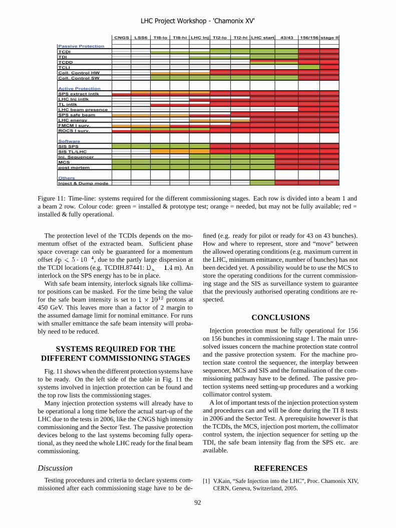
Passive Protection
Active Protection
Software
OthersInject & Dump mode
post mortem
Inj. SequencerMCS
TL intlkLHC beam presenceSPS safe beamLHC energy
SIS SPSSIS TL/LHC
FMCM I surv.ROCS I surv.
TCDD
SPS extract intlkLHC Inj intlk
TCDITDI
TCLIColl. Control HWColl. Control SW
43/43 156/156 stage IILHC Inj TI2-lo TI2-hi LHC startCNGS LSS6 TI8-lo TI8-hi
Figure 11: Time-line: systems required for the different commissioning stages. Each row is divided into a beam 1 anda beam 2 row. Colour code: green = installed & prototype test; orange = needed, but may not be fully available; red =installed & fully operational.
The protection level of the TCDIs depends on the mo-mentum offset of the extracted beam. Sufficient phasespace coverage can only be guaranteed for a momentumoffset � � � � ����, due to the partly large dispersion atthe TCDI locations (e.g. TCDIH.87441: � ��� m). Aninterlock on the SPS energy has to be in place.
With safe beam intensity, interlock signals like collima-tor positions can be masked. For the time being the valuefor the safe beam intensity is set to � � ���� protons at450 GeV. This leaves more than a factor of 2 margin tothe assumed damage limit for nominal emittance. For runswith smaller emittance the safe beam intensity will proba-bly need to be reduced.
SYSTEMS REQUIRED FOR THEDIFFERENT COMMISSIONING STAGES
Fig. 11 shows when the different protection systems haveto be ready. On the left side of the table in Fig. 11 thesystems involved in injection protection can be found andthe top row lists the commissioning stages.
Many injection protection systems will already have tobe operational a long time before the actual start-up of theLHC due to the tests in 2006, like the CNGS high intensitycommissioning and the Sector Test. The passive protectiondevices belong to the last systems becoming fully opera-tional, as they need the whole LHC ready for the final beamcommissioning.
Discussion
Testing procedures and criteria to declare systems com-missioned after each commissioning stage have to be de-
fined (e.g. ready for pilot or ready for 43 on 43 bunches).How and where to represent, store and “move” betweenthe allowed operating conditions (e.g. maximum current inthe LHC, minimum emittance, number of bunches) has notbeen decided yet. A possibility would be to use the MCS tostore the operating conditions for the current commission-ing stage and the SIS as surveillance system to guaranteethat the previously authorised operating conditions are re-spected.
CONCLUSIONS
Injection protection must be fully operational for 156on 156 bunches in commissioning stage I. The main unre-solved issues concern the machine protection state controland the passive protection system. For the machine pro-tection state control the sequencer, the interplay betweensequencer, MCS and SIS and the formalisation of the com-missioning pathway have to be defined. The passive pro-tection systems need setting-up procedures and a workingcollimator control system.
A lot of important tests of the injection protection systemand procedures can and will be done during the TI 8 testsin 2006 and the Sector Test. A prerequisite however is thatthe TCDIs, the MCS, injection post mortem, the collimatorcontrol system, the injection sequencer for setting up theTDI, the safe beam intensity flag from the SPS etc. areavailable.
REFERENCES
[1] V.Kain, “Safe Injection into the LHC”, Proc. Chamonix XIV,CERN, Geneva, Switzerland, 2005.
LHC Project Workshop - 'Chamonix XV'
92

[2] R.Bailey, “Summary of Overall Commissioning Strategy forProtons”, these proceedings.
[3] V.Kain et al., “Beam based Alignment of the LHC TransferLine Collimators”, Proc. PAC 2005, Knoxville, Tennessee,USA.
[4] G.Robert-Demolaize, “Critical Beam Losses during Com-missioning and Initial Operation”, these proceedings.
[5] V.Kain et al., “Protection Level during Extraction, Transferand Injection into the LHC”, Proc. PAC 2005, Knoxville,Tennessee, USA.
[6] M.Zerlauth et al., “Requirements for the Fast Magnet Cur-rent Change Monitors (FMCM) in the LHC and the SPS-LHCTransfer Lines”, LHC-CIW-ES-0002-00-10, CERN, Geneva,Switzerland, 2005.
LHC Project Workshop - 'Chamonix XV'
93
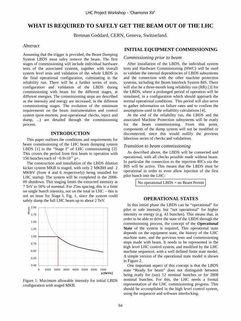
WHAT IS REQUIRED TO SAFELY GET THE BEAM OUT OF THE LHC
Brennan Goddard, CERN, Geneva, Switzerland.
Abstract
Assuming that the trigger is provided, the Beam Dumping System LBDS must safey remove the beam. The first stages of commissioning will include individual hardware tests of the associated systems, together with overall system level tests and validation of the whole LBDS in the final operational configuration, culminating in the reliability run. There will be a further series of tests, configuration and validation of the LBDS during commissioning with beam for the different stages, at different energies. The commissioning steps are described as the intensity and energy are increased, in the different commissioning stages. The evolution of the minimum requirements on the beam instrumentation and control system (post-mortem, post-operational checks, inject and dump, ...) are detailed through the commissioning process.
INTRODUCTION
This paper outlines the conditions and requirements for beam commissioning of the LHC beam dumping system LBDS [1] in the “Stage I” of LHC commissioning [2]. This covers the period from first beam to operation with 156 bunches each of ~0.9×10¹¹ p+.
The construction and installation of the LBDS dilution kicker system MKB is staged, with only 2 MKBH and 2 MKBV (from 4 and 6 respectively) being installed for LHC startup. The system will be completed in the 2008-09 shutdown. This staging limits the extracted intensity at 7 TeV to 50% of nominal. For 25ns spacing, this is a limit on single bunch intensity, not on the total in LHC – this is not an issue for Stage I, Fig. 1, since the system could safely dump the full LHC beam up to about 2 TeV.
0.00
0.25
0.50
0.75
1.00
1.25
1.50
1.75
2.00
0 1000 2000 3000 4000 5000 6000 7000p [GeV/c]
I/In
om
Figure 1: Maximum allowable intensity for initial LBDS configuration with staged MKB.
INITIAL EQUIPMENT COMMISSIONING
Commissioning prior to beam
After installation of the LBDS, the individual system tests and Hardware Commissioning (HWC) will be used to validate the internal dependencies of LBDS subsystems and the connection with the other machine protection systems, including the Beam Interlock System BIS. There will also be a three-month long reliability run (RR) [3] for the LBDS, where a prolonged period of operation will be simulated, in a configuration which should approach the normal operational conditions. This period will also serve to gather information on failure rates and to confirm the assumptions used in the reliability calculations [4].
At the end of the reliability run, the LBDS and the associated Machine Protection subsystems will be ready for the beam commissioning. From this point, components of the dump system will not be modified or disconnected, since this would nullify the previous laborious series of checks and validations.
Transition to beam commissioning
As described above, the LBDS will be connected and operational, with all checks possible made without beam. In particular the connection to the injection BICs via the BIS will be active. This means that the LBDS must be operational in order to even allow injection of the first pilot bunch into the LHC:
No operational LBDS = no Beam Permit
OPERATIONAL STATES
In this initial phase the LBDS can be “operational” for pilot or safe intensity, but “not operational” for higher intensity or energy (e.g. 43 bunches). This means that, in order to be able to drive the state of the LBDS through the commissioning process, the concept of the Operational State of the system is required. This operational state depends on the equipment state, the history of the LHC machine state, and the previous tests and commissioning steps made with beam. It needs to be represented in the high level LHC control system, and modified by the LHC machine sequencer, with a well defined finite state model. A simple version of the operational state model is shown in Figure 2.
One important aspect of this concept is that the LBDS state “Ready for beam” does not distinguish between being ready for (say) 12 nominal bunches or for 2808 nominal bunches. For this, the LHC needs a formal representation of the LHC commissioning progress. This should be accomplished in the high level control system, using the sequencer and software interlocking.
LHC Project Workshop - 'Chamonix XV'
94

Ready for no beam
Not ready .
Ready for pilot
Arming procedure
Beam dump triggered
Ready for beam
Tests with beam
Diagnostics IPOC, XPOC
Figure 2: Simplified operational states (white boxes) and transitions for the LBDS system.
SAFETY CRITICAL LBDS ASPECTS In addition to the many internal safety critical
functionalities, the LBDS has many interdependencies with other LHC systems, encompassing controls, hardware and beam, Fig. 3. Many of these are safety critical, and must be commissioned or tested with beam:
• Beam Permit signal from BIS (test in HWC/RR) : no
trigger = no beam dump. • Energy tracking : potentially catastrophic (whole
beam at “any” amplitude). • MKD retriggering (test in HWC/RR) : no retriggering
could put whole 7 TeV beam at ~10 σ. • TCDQ setting w.r.t. orbit: fault exposes LHC arc /
triplets / collimators to beam in abort gap. • System self-tests and post-mortem : undetected
‘dead’ MKD severely reduces reliability. • Aperture, optics and orbit : dump with bad orbit
could damage MSD, TCDS or MKB • MKD – MKB connection and sweep form :
insufficient dilution could damage TDE, BTVDD and TDE entrance window
• Abort gap ‘protection’ : beam in the abort gaps risks quench, or LHC damage if TCDQ position error
• Fault tolerance with 14/15 MKD : system is designed to operate safely with only 14 out of the 15 MKDs.
Abort gap monitor
TCDQ position
IR6 orbit feedback
Software interlock
BPM IR6
DCCTs
BICinterface
Access
Slow timing
LHC control system
LBDS
Injection
LHC beam permit loop
BLM6Fast timing(RF synch)
Ethernet
SLP
Direct triggers (to TSU)
Externalinputs
MachineProtectioninterfaces
Mains &UPS status
Emergencystop status IR6 PM
trigger
Externaloutputs
Figure 3. Functional dependencies of the LBDS on other LHC systems.
LHC Project Workshop - 'Chamonix XV'
95
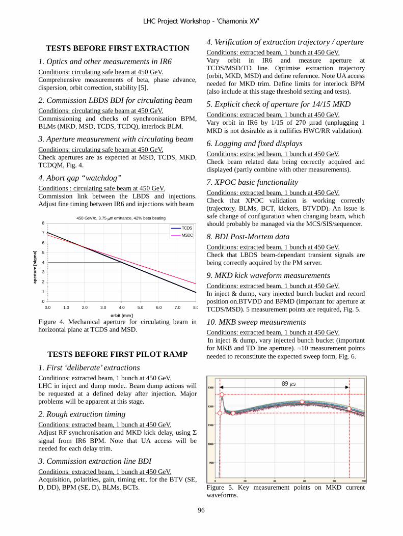
TESTS BEFORE FIRST EXTRACTION
1. Optics and other measurements in IR6 Conditions: circulating safe beam at 450 GeV. Comprehensive measurements of beta, phase advance, dispersion, orbit correction, stability [5].
2. Commission LBDS BDI for circulating beam Conditions: circulating safe beam at 450 GeV. Commissioning and checks of synchronisation BPM, BLMs (MKD, MSD, TCDS, TCDQ), interlock BLM.
3. Aperture measurement with circulating beam Conditions: circulating safe beam at 450 GeV. Check apertures are as expected at MSD, TCDS, MKD, TCDQM, Fig. 4.
4. Abort gap “watchdog” Conditions : circulating safe beam at 450 GeV. Commission link between the LBDS and injections. Adjust fine timing between IR6 and injections with beam
0
1
2
3
4
5
6
7
8
0.0 1.0 2.0 3.0 4.0 5.0 6.0 7.0 8.0
orbit [mm]
aper
ture
[si
gm
a]
TCDS
MSDC
450 GeV/c, 3.75 μm emittance, 42% beta beating
Figure 4. Mechanical aperture for circulating beam in horizontal plane at TCDS and MSD.
TESTS BEFORE FIRST PILOT RAMP
1. First ‘deliberate’ extractions Conditions: extracted beam, 1 bunch at 450 GeV. LHC in inject and dump mode.. Beam dump actions will be requested at a defined delay after injection. Major problems will be apparent at this stage.
2. Rough extraction timing Conditions: extracted beam, 1 bunch at 450 GeV. Adjust RF synchronisation and MKD kick delay, using Σ signal from IR6 BPM. Note that UA access will be needed for each delay trim.
3. Commission extraction line BDI Conditions: extracted beam, 1 bunch at 450 GeV. Acquisition, polarities, gain, timing etc. for the BTV (SE, D, DD), BPM (SE, D), BLMs, BCTs.
4. Verification of extraction trajectory / aperture Conditions: extracted beam, 1 bunch at 450 GeV. Vary orbit in IR6 and measure aperture at TCDS/MSD/TD line. Optimise extraction trajectory (orbit, MKD, MSD) and define reference. Note UA access needed for MKD trim. Define limits for interlock BPM (also include at this stage threshold setting and tests).
5. Explicit check of aperture for 14/15 MKD Conditions: extracted beam, 1 bunch at 450 GeV. Vary orbit in IR6 by 1/15 of 270 μrad (unplugging 1 MKD is not desirable as it nullifies HWC/RR validation).
6. Logging and fixed displays Conditions: extracted beam, 1 bunch at 450 GeV. Check beam related data being correctly acquired and displayed (partly combine with other measurements).
7. XPOC basic functionality Conditions: extracted beam, 1 bunch at 450 GeV. Check that XPOC validation is working correctly (trajectory, BLMs, BCT, kickers, BTVDD). An issue is safe change of configuration when changing beam, which should probably be managed via the MCS/SIS/sequencer.
8. BDI Post-Mortem data Conditions: extracted beam, 1 bunch at 450 GeV. Check that LBDS beam-dependant transient signals are being correctly acquired by the PM server.
9. MKD kick waveform measurements Conditions: extracted beam, 1 bunch at 450 GeV. In inject & dump, vary injected bunch bucket and record position on.BTVDD and BPMD (important for aperture at TCDS/MSD). 5 measurement points are required, Fig. 5.
10. MKB sweep measurements Conditions: extracted beam, 1 bunch at 450 GeV. In inject & dump, vary injected bunch bucket (important for MKB and TD line aperture). ≈10 measurement points needed to reconstitute the expected sweep form, Fig. 6.
Figure 5. Key measurement points on MKD current waveforms.
LHC Project Workshop - 'Chamonix XV'
96
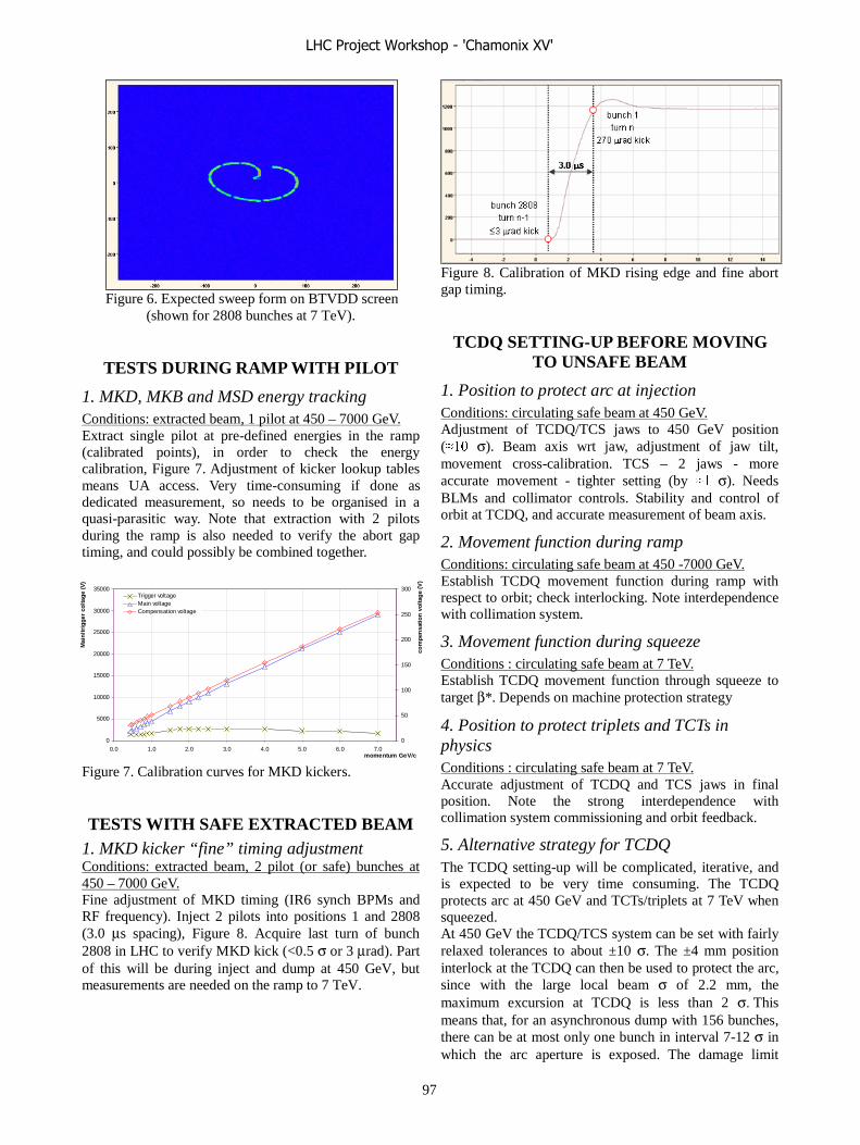
Figure 6. Expected sweep form on BTVDD screen
(shown for 2808 bunches at 7 TeV).
TESTS DURING RAMP WITH PILOT
1. MKD, MKB and MSD energy tracking Conditions: extracted beam, 1 pilot at 450 – 7000 GeV. Extract single pilot at pre-defined energies in the ramp (calibrated points), in order to check the energy calibration, Figure 7. Adjustment of kicker lookup tables means UA access. Very time-consuming if done as dedicated measurement, so needs to be organised in a quasi-parasitic way. Note that extraction with 2 pilots during the ramp is also needed to verify the abort gap timing, and could possibly be combined together.
0
5000
10000
15000
20000
25000
30000
35000
0.0 1.0 2.0 3.0 4.0 5.0 6.0 7.0momentum GeV/c
Mai
n/tr
igge
r co
ltag
e (V
)
0
50
100
150
200
250
300
com
pen
satio
n v
olta
ge
(V)
Trigger voltageMain voltageCompensation voltage
Figure 7. Calibration curves for MKD kickers.
TESTS WITH SAFE EXTRACTED BEAM 1. MKD kicker “fine” timing adjustment Conditions: extracted beam, 2 pilot (or safe) bunches at 450 – 7000 GeV. Fine adjustment of MKD timing (IR6 synch BPMs and RF frequency). Inject 2 pilots into positions 1 and 2808 (3.0 μs spacing), Figure 8. Acquire last turn of bunch 2808 in LHC to verify MKD kick (<0.5 σ or 3 μrad). Part of this will be during inject and dump at 450 GeV, but measurements are needed on the ramp to 7 TeV.
Figure 8. Calibration of MKD rising edge and fine abort gap timing.
TCDQ SETTING-UP BEFORE MOVING TO UNSAFE BEAM
1. Position to protect arc at injection Conditions: circulating safe beam at 450 GeV. Adjustment of TCDQ/TCS jaws to 450 GeV position (���� σ). Beam axis wrt jaw, adjustment of jaw tilt, movement cross-calibration. TCS – 2 jaws - more accurate movement - tighter setting (by ��� σ). Needs BLMs and collimator controls. Stability and control of orbit at TCDQ, and accurate measurement of beam axis.
2. Movement function during ramp Conditions: circulating safe beam at 450 -7000 GeV. Establish TCDQ movement function during ramp with respect to orbit; check interlocking. Note interdependence with collimation system.
3. Movement function during squeeze Conditions : circulating safe beam at 7 TeV. Establish TCDQ movement function through squeeze to target β*. Depends on machine protection strategy
4. Position to protect triplets and TCTs in physics Conditions : circulating safe beam at 7 TeV. Accurate adjustment of TCDQ and TCS jaws in final position. Note the strong interdependence with collimation system commissioning and orbit feedback.
5. Alternative strategy for TCDQ The TCDQ setting-up will be complicated, iterative, and is expected to be very time consuming. The TCDQ protects arc at 450 GeV and TCTs/triplets at 7 TeV when squeezed. At 450 GeV the TCDQ/TCS system can be set with fairly relaxed tolerances to about ±10 σ. The ±4 mm position interlock at the TCDQ can then be used to protect the arc, since with the large local beam σ of 2.2 mm, the maximum excursion at TCDQ is less than 2 σ. This means that, for an asynchronous dump with 156 bunches, there can be at most only one bunch in interval 7-12 σ in which the arc aperture is exposed. The damage limit
LHC Project Workshop - 'Chamonix XV'
97
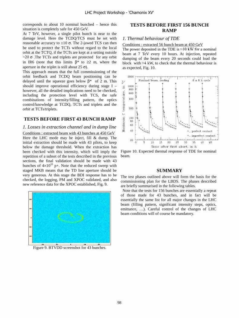
corresponds to about 10 nominal bunched – hence this situation is completely safe for 450 GeV. At 7 TeV, however, a single pilot bunch is near to the damage level. Here the TCDQ/TCS must be set with reasonable accuracy to ±10 σ. The 2-jawed TCS can then be used to protect the TCTs without regard to the local orbit at the TCTQ, if the TCTs are kept at a setting outside ��� σ .The TCTs and triplets are protected for any orbit in IR6 (note that this limits β* to ≥2 m, where the aperture in the triplet is still about 25 σ). This approach means that the full commissioning of the orbit feedback and TCDQ beam positioning can be delayed until the squeeze goes below β* of 2 m. This should improve operational efficiency during stage I – however, all the detailed implications need to be checked, including the protection level with TCS, the safe combinations of intensity/filling pattern, the optics control/knowledge at TCDQ, TCTs and triplets and the orbit at TCTs/triplets.
TESTS BEFORE FIRST 43 BUNCH RAMP
1. Losses in extraction channel and in dump line Conditions : extracted beam with 43 bunches at 450 GeV Here the LHC mode may be inject, fill & dump. The initial extraction should be made with 43 pilots, to keep below the damage threshold. When the extraction has been checked with this intensity, which will imply the repetition of a subset of the tests described in the previous sections, the final validation should be made with 43 bunches of 4×10¹⁰ p+. Note that the reduced sweep with staged MKB means that the TD line aperture should be very generous. At this stage the BDI response has to be checked, the logging, PM and XPOC validated, and also new reference data for the XPOC established, Fig. 9.
Figure 9. BTVDD screenshot for 43 bunches.
TESTS BEFORE FIRST 156 BUNCH RAMP
1. Thermal behaviour of TDE Conditions : extracted 56 bunch beam at 450 GeV The power deposited in the TDE is ���������a nominal beam at 7 TeV every 10 hours. At injection, repeated dumping of the beam every 20 seconds could load the block with ���kW, to check that the thermal behaviour is as expected, Fig. 10.
Figure 10. Expected thermal response of TDE for nominal beam.
SUMMARY The test phases outlined above will form the basis for the commissioning plan for the LBDS. The phases described are briefly summarised in the following tables. Note that the tests for 156 bunches are essentially a repeat
of those made for 43 bunches, and in fact will be essentially the same list for all major changes in the LHC beam (filling pattern, significant intensity steps, optics, emittance, …). Careful control of the changes of LHC beam conditions will of course be mandatory.
LHC Project Workshop - 'Chamonix XV'
98

450-7000Extract 2 pilotsRampFine timing in ramp
450Extract 2 pilotsInject & dumpFine timing adjustment
450Circulating, safe beamInjectionCommission abort gap watchdog
450Circulating, safe beamInjectionCommission IR6 orbit BPM interlock
450Circulating, safe beamInjectionCommission SW interlock on beam position at TCDQ
7000Circulating, 1 pilotAdjust/squeezeTCDQ positioning at 7 TeV
450Circulating, safe beamInjectionTCDQ “injection setting” positioning
450Circulating 1 pilotInjectionCommission dedicated LBDS BDI in IR6
…before moving to operation with potentially “unsafe” beams
450-7000Extract 1 pilotRampEnergy tracking measurements
… with the pilot ramp
… before first pilot ramp
Things to do before first pilot extraction
450
450
450
450
450
450
450
450
Energy GeV
Circulating 1 pilotInjectionExtraction element aperture measurements
Beam typeLHC modeLBDS beam commissioning activity
Inject & dump
Inject & dump
Inject & dump
Inject & dump
Inject & dump
Inject & dump
Injection
Extract 1 pilot
Extract 1 pilot
Extract 1 pilot
Extract 1 pilot
Extract 1 pilot
Extract 1 pilot
Circulating 1 pilot
MKB sweep measurements
MKD waveform overshoot measurements
Data diagnostics: IPOC, logging, FDs, PM, XPOC
Extraction trajectory and aperture measurements
TD line BDI commissioning
First extractions: rough timing adjustment
IR6 optics measurements
450Extract 43bInject & dumpData diagnostics: XPOC
450Circulating, 43bInjectionOrbit feedback / stability checks at TCDQ
450Extract 43 pilotsInject & dumpExtraction trajectory checks
… with 43b at 7 TeV
7000Circulating, 43bAdjust/squeezeTCDQ positioning at 7 TeV
450-7000Extract 43bRampEnergy tracking and abort gap timing checks
… with the 43b ramp
… before first 43b ramp
Things to do before first 43b extraction
450
Energy GeVBeam typeLHC modeLBDS beam commissioning activity
Inject & dump Extract 43bTD line BDI checks
450Extract, 156bInject & dumpData diagnostics: XPOC
450-7000Extract, 156bInject & dumpEnergy tracking and abort gap timing checks
…with 156b at 7 TeV
450Extract, 156bInject & dumpTDE thermal behaviour
… with the 156b ramp
450Extract, 156 pilotsInject & dumpExtraction trajectory and BDI checks
… before first 156b ramp
Things to do before first 156b extraction
7000
450
450
Energy GeVBeam typeLHC modeLBDS beam commissioning activity
Adjust/squeeze
Inject & dump
Injection
Circulating, 156b
Extract, 156b
Circulating, 156b
TCDQ positioning at 7 TeV
Extraction trajectory and BDI checks
Orbit feedback / stability checks at TCDQ
LHC Project Workshop - 'Chamonix XV'
99

ISSUES AND CONTINUING WORK A certain number of issues remain to be resolved or completed. These include:
Inject and dump mode This is needed from first extractions, for efficient commissioning. There are details which remain to be finalisd (timing, PM/logging,, multiple injections, turn delays, HW,SW)
Data diagnostics The split between IPOC, XPOC, logging and PM remains to be fully defined. In addition, the question of how to manage XPOC configurations remains open.
Abort gap monitoring and cleaning This is assumed not required for protection – it could however be important for the efficiency of the LHC operation, if quenches of Q4 are a problem
LHC operational state control Ensuring that only ‘authorised’ beam can be used is conditional on how the operational states and allowed LHC beam conditions are implemented – the interaction of the MCS, SIS and sequencer are still to be defined.
Halo at TCDQ The effect of “minimum collimation” strategy has to be evaluated for the TCDQ, since here there is clearly a risk of high beam load on the TCDQ and Q4 quenches. The FLUKA energy deposition simulations made to date have given cause for concern, and are being refined. To note is that beam 2 will be the least favourable case and has not been checked yet.
CONCLUSION The commissioning phases for the LBDS beam
commissioning for phase I operation will depend heavily on the HWC/RR, which must provide a validation of subsystem interconnectivity and reliability assumptions. Many key elements will be fully commissioned without beam, and must then remain operational.
The LBDS requires careful commissioning with pilot beam, with measurements needed at 450 GeV before extraction, to check the optics and aperture, and a substantial set of measurements to be performed at 450 GeV in “Inject & Dump” mode, to check in detail the guts of the correct LBDS functioning.
During the ramp to 7 TeV, a check of the energy tracking must be made.
The setting up of the TCDQ will be one of the most difficult parts of the LBDS commissioning – this is satefy-critical and with dependencies on the orbit feedback, LHC energy and collimations system. S has been shown, the requirements for the early commissioning can be somewhat relaxed by taking
advantage of the limited β* squeeze and reduced umber of bunches.
The LBDS will require specific checks to be performed or repeated whenever the LHC beam changes, in order to verify that the instrument response, the diagnostics, the thermal behaviour and the losses.
Concerning the organisation of the preparation, the interdependencies with other LHC systems must be carefully defined, to ensure that all required subsystems will be available when required. A careful preparation of the beam commissioning of the LBDS needs to be made in close collaboration with the preparation for the commissioning of the overall machine protection system and of the LHC machine itself.
ACKNOWLEDGEMENT The contributions of E.Carlier, J.Uythoven,
R.Assmann, V.Kain, J.Wenninger and V.Mertens are gratefully acknowledged.
REFERENCES [1] LHC design report, http://ab-div.web.cern.ch/ab-
div/Publications/LHC-DesignReport.html . [2] R.Bailey, “Summary of overall commissioning
strategy for protons”, Proceedings of the 2006 Chamonix Workshop on LHC Performance, 2006. [3] B.Goddard, “Getting and maintaining a reliable beam dumping system”, Proceedings of the 2004 Chamonix Workshop on LHC Performance, 2004.
[4] R.Filippini et al., “Reliability Analysis of the LHC Beam Dumping System” Proceedings PAC 2005 Particle Accelerator Conference, 2005.
[5] F.Zimmermann, “Beam measurements required in the first two years of LHC commissioning”, Proceedings of the 2006 Chamonix Workshop on LHC Performance, 2006.
LHC Project Workshop - 'Chamonix XV'
100
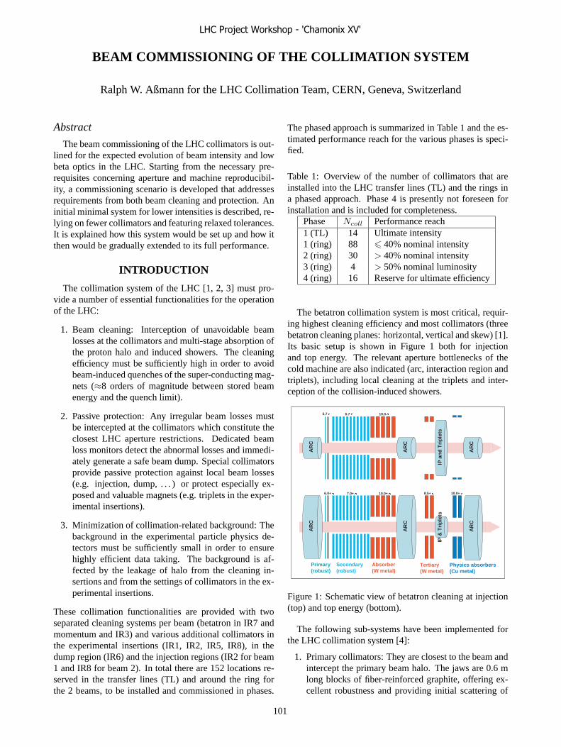
BEAM COMMISSIONING OF THE COLLIMATION SYSTEM
Ralph W. Aßmann for the LHC Collimation Team, CERN, Geneva, Switzerland
Abstract
The beam commissioning of the LHC collimators is out-lined for the expected evolution of beam intensity and lowbeta optics in the LHC. Starting from the necessary pre-requisites concerning aperture and machine reproducibil-ity, a commissioning scenario is developed that addressesrequirements from both beam cleaning and protection. Aninitial minimal system for lower intensities is described, re-lying on fewer collimators and featuring relaxed tolerances.It is explained how this system would be set up and how itthen would be gradually extended to its full performance.
INTRODUCTION
The collimation system of the LHC [1, 2, 3] must pro-vide a number of essential functionalities for the operationof the LHC:
1. Beam cleaning: Interception of unavoidable beamlosses at the collimators and multi-stage absorption ofthe proton halo and induced showers. The cleaningefficiency must be sufficiently high in order to avoidbeam-induced quenches of the super-conducting mag-nets (≈8 orders of magnitude between stored beamenergy and the quench limit).
2. Passive protection: Any irregular beam losses mustbe intercepted at the collimators which constitute theclosest LHC aperture restrictions. Dedicated beamloss monitors detect the abnormal losses and immedi-ately generate a safe beam dump. Special collimatorsprovide passive protection against local beam losses(e.g. injection, dump, . . . ) or protect especially ex-posed and valuable magnets (e.g. triplets in the exper-imental insertions).
3. Minimization of collimation-related background: Thebackground in the experimental particle physics de-tectors must be sufficiently small in order to ensurehighly efficient data taking. The background is af-fected by the leakage of halo from the cleaning in-sertions and from the settings of collimators in the ex-perimental insertions.
These collimation functionalities are provided with twoseparated cleaning systems per beam (betatron in IR7 andmomentum and IR3) and various additional collimators inthe experimental insertions (IR1, IR2, IR5, IR8), in thedump region (IR6) and the injection regions (IR2 for beam1 and IR8 for beam 2). In total there are 152 locations re-served in the transfer lines (TL) and around the ring forthe 2 beams, to be installed and commissioned in phases.
The phased approach is summarized in Table 1 and the es-timated performance reach for the various phases is speci-fied.
Table 1: Overview of the number of collimators that areinstalled into the LHC transfer lines (TL) and the rings ina phased approach. Phase 4 is presently not foreseen forinstallation and is included for completeness.
Phase Ncoll Performance reach1 (TL) 14 Ultimate intensity1 (ring) 88 � 40% nominal intensity2 (ring) 30 > 40% nominal intensity3 (ring) 4 > 50% nominal luminosity4 (ring) 16 Reserve for ultimate efficiency
The betatron collimation system is most critical, requir-ing highest cleaning efficiency and most collimators (threebetatron cleaning planes: horizontal, vertical and skew) [1].Its basic setup is shown in Figure 1 both for injectionand top energy. The relevant aperture bottlenecks of thecold machine are also indicated (arc, interaction region andtriplets), including local cleaning at the triplets and inter-ception of the collision-induced showers.
Primary(robust)
Secondary(robust)
Absorber(W metal)
Tertiary(W metal)
AR
C
AR
C
AR
C
IP &
Tri
ple
ts
Physics absorbers(Cu metal)
6.0+ 7.0+ 10.0+ 8.5+ 10.0+
AR
C
AR
C
AR
C
IP a
nd
Tri
ple
ts
5.7 6.7 10.0
Figure 1: Schematic view of betatron cleaning at injection(top) and top energy (bottom).
The following sub-systems have been implemented forthe LHC collimation system [4]:
1. Primary collimators: They are closest to the beam andintercept the primary beam halo. The jaws are 0.6 mlong blocks of fiber-reinforced graphite, offering ex-cellent robustness and providing initial scattering of
LHC Project Workshop - 'Chamonix XV'
101

protons (generating the secondary halo). There is oneprimary collimator per cleaning plane.
2. Secondary collimators: They intercept the secondarybeam halo. The jaws are 1.0 m long blocks of fiber-reinforced graphite, offering very good robustness,stopping impacting protons through inelastic interac-tions and leaking a tertiary halo.
3. Absorbers: They intercept the showers that were in-duced at the primary and secondary collimators plusa fraction of the tertiary halo. The jaws are 1.0 mlong tungsten blocks, offering excellent absorption butpoor robustness against beam damage.
4. Tertiary collimators: They intercept at 7 TeV the ter-tiary halo in front of the triplets. The jaws are 1.0 mlong tungsten blocks, offering excellent absorption butpoor robustness against beam damage.
5. Physics absorbers: They intercept at 7 TeV the show-ers from the proton-proton interactions in the interac-tion point. The jaws are 1.0 m long copper blocks,offering good absorption but poor robustness againstbeam damage.
It is seen that a three-stage cleaning and absorption pro-cess is put into place before the super-conducting arc atinjection. At top energy this setup is complemented with afourth stage cleaning and protection at the triplets.
Here we do not comment in detail on the important pro-tection duties that are fulfilled by the various collimatorsub-systems. This would be beyond the scope of this paper.It is, however, essential that all required functionalities areincluded in any setup procedure for the collimators. Thishas been taken into account for the results presented in thefollowing. For example, the tertiary collimators do not onlyprovide cleaning at the triplets, they also protect the expen-sive triplets against rare but possible beam-induced damageand play a role for background in the particle physics ex-periments.
ALLOWED INTENSITY WITHOUT BEAMCLEANING
The needs for collimators evolve with beam intensity andthe encountered beam lifetime. The most relevant param-eter for the cleaning efficiency is the beam loss rate Rp
which depends on the total beam population Ntot and thebeam intensity lifetime τ . It can be approximated as:
Rp ≈ Ntot
τ(1)
The crucial role of the beam intensity lifetime is evident.Collimation does not only depend on the stored intensitybut also on the minimum beam lifetime that is encounteredduring the beam cycle.
The beam loss rate Rp can be compared to the quenchlimits Rq of the super-conducting LHC magnets:
Rq(0.45 TeV) = 7.0 × 10⁸p/m/s (2)
Rq(7 TeV) = 7.8 × 10⁶p/m/s (3)
The quench limit rates must be multiplied by the lengthover which the losses are distributed (e. g. by particle show-ers). Assuming a minimum beam intensity lifetime of 0.2 hat top energy [3] and and that losses occur over 1 m wecan calculate the allowed maximum beam intensity with-out any collimation (losses occur at cold magnets and arespread over 1 m):
Nqtot(0.45 TeV) ≈ 5.0 × 10¹¹p (4)
Nqtot(7 TeV) ≈ 5.6 × 10⁹p (5)
Below these intensities no collimation should be requiredfor the specified minimum beam lifetime of 0.2 h [3]. Itis noted that also no passive machine protection is re-quired for these low intensities (”safe beam”), so that onecan work without any collimators. In case of reducedbeam lifetime during commissioning, the limit for opera-tion without collimators can be significantly lower.
The foreseen beam commissioning steps for the LHC aresummarized in Table 2 and characterized in maximum ex-pected beam loss rate Rp. It is seen that the initial beamcommissioning can be performed without any collimatorsfor beam cleaning. As intensity is increased, more andmore collimators must be placed.
Table 2: Various important steps in commissioning of theLHC are characterized in terms of number of bunches kb,the bunch population Nb, the total beam population Ntot
and the beam loss rate Rp for a beam intensity lifetime of0.2 h.
Stage kb Nb Ntot Rp
[1010 p] [p] [p/s]Pilot 1 0.5 5.0 × 10⁹ 6.9 × 10⁶
43 bunch 43 4.0 1.7 × 10¹² 2.4 × 10⁹
156 bunch 156 4.0 6.2 × 10¹² 8.7 × 10⁹
9.0 1.4 × 10¹³ 2.0 × 10¹⁰
75 ns 936 4.0 4.7 × 10¹³ 5.2 × 10¹⁰
25 ns 2808 4.0 1.1 × 10¹⁴ 1.6 × 10¹¹
5.0 1.4 × 10¹⁴ 2.0 × 10¹¹
11.5 3.2 × 10¹⁴ 4.5 × 10¹¹
The energies stored in the beam and the energy densitiesare shown in Figures 2 and 3 for various machines. Thereis a strong evolvement from present colliders like TEVA-TRON and HERA, illustrating the extraordinary LHC re-quirements for collimation. The energy density is com-pared to the estimated damage limit of metals [5] and thefiber-reinforced graphite (CC) jaws of the robust collima-tors [2].
LHC Project Workshop - 'Chamonix XV'
102

0.01
0.1
1
10
100
1000
1 10 100 1000 10000
Sto
red
ener
gy [M
J]
Beam momentum [GeV/c]
SNS
ISR
LEP2
TEVATRONHERA
LHC
TT
43 bunches
156 bunches75 ns25 ns
Figure 2: Stored energy versus beam momentum for vari-ous accelerators. The different phases of LHC beam com-missioning are indicated.
0.01
0.1
1
10
100
1000
1 10 100 1000 10000
Ene
rgy
dens
ity [M
J/m
m2 ]
Beam momentum [GeV/c]
SNS ISR LEP2
TEVATRON HERA
Metal damage limit
CC collimator damage limit
LHC43 b
unches
156 bunch
es
75 ns
25 ns
pilot
Figure 3: Energy density versus beam momentum for vari-ous accelerators. The different phases of LHC beam com-missioning and estimated damage limits are indicated.
STAGES IN BEAM COMMISSIONING OFTHE COLLIMATION SYSTEM
The required number of collimators and their gaps area function of the beam loss rate. In the following we as-sume a minimal operational beam lifetime of 0.2 h, whichimplies a peak beam loss of 1% in 10 s. This is the valueused for the design of the LHC collimation system at topenergy. A more refined model of commissioning could usean evolution in this important parameter.
Commissioning Stages
One approach to define commissioning stages is toput the various collimation sub-systems into use in well-defined steps. Here, this approach is detailed for 7 TeV:
1. First commissioning without collimators.
2. Operation with minimal one-stage cleaning and pro-tection:
• Primary collimators (TCP) are used for definingthe closest aperture restriction.
• The TCDQ collimator pair is used for localdump protection [6].
• The tertiary collimators (TCT) are used for localprotection and cleaning at the triplets, includingall 4 interaction points.
• In total 14 collimation-related components areused per beam.
3. Operation with one-stage cleaning and active ab-sorbers.
• Same collimators as above.
• The tungsten absorbers towards the end of thecleaning insertions are used for absorption ofcleaning-induced showers and for basic second-stage cleaning.
• In total 23 collimation-related components areused per beam.
4. Operation with two-stage cleaning and active ab-sorbers.
• Same collimators as above.
• The secondary collimators are used for full two-stage cleaning and enhancement of passive pro-tection for the accelerator.
• In total 38 collimation-related components areused per beam.
5. Operation with two-stage cleaning, active absorbersand absorption of collision-induced showers for highluminosity.
• Same collimators as above.
• The copper absorbers in the experimental inser-tions of IR1 and IR5 are used for intercepting theproton-proton induced showers.
• In total 42 collimation-related components areused per beam.
The numbers of collimators listed above refer to thenominal number of installed collimators and will likely beslightly reduced for the LHC startup (in dependence of thecollimator production and the LHC schedule).
The same commissioning sequence can be used for in-jection with the exception that the movable injection pro-tection devices (TDI, TCLI and TCDI) must be introducedbetween steps 2 and 3. This staging of the collimationsub-systems is summarized in Figures 4 and 5 for injec-tion and top energy. The required use of the various sys-tems is shown as a function of beam intensity. This givesan idea about the operational stage where the various colli-mation sub-systems must be put into usage. It is noted thatthese are estimates that must be adjusted to the encounteredbeam loss rates and the available aperture in the LHC. Forexample, the minimum beam lifetime might be lower ini-tially, resulting in higher beam loss rates and the need toput more collimators with smaller gaps for more efficientcleaning.
LHC Project Workshop - 'Chamonix XV'
103

0
1
2
3
4
5
6
7
1e+010 1e+011 1e+012 1e+013 1e+014 1e+015
Col
limat
or s
ubsy
stem
Beam intensity
single b
unch
(pilo
t to n
omin
al)
multi
-bunch
to
43 bunch
es
up to 156 b
unches
75 ns r
unning
25 ns r
unning
TCP
TCS
TCT
TCL A
TCDQ
TDI/TCLI/TCDI
Figure 4: Required collimation subsystems at injection as afunction of total beam intensity. A minimum beam lifetimeof 0.2 h is assumed.
0
1
2
3
4
5
6
1e+010 1e+011 1e+012 1e+013 1e+014 1e+015
Col
limat
or s
ubsy
stem
Beam intensity
TCP
TCS
TCT
TCL A
TCDQ
single b
unch
(pilo
t to n
omin
al)
multi
-bunch
to
43 bunch
es
up to 156 b
unches
75 ns r
unning
25 ns r
unning
Figure 5: Required collimation subsystems at top energyas a function of total beam intensity. A minimum beamlifetime of 0.2 h is assumed.
Handling of the Energy Ramp
The staging of the collimation sub-systems, as illustratedin Figures 4 and 5 shows that collimators are generally usedrequired at top energy before they become important at in-jection. This is no surprise and is the reason that collima-tion systems at Tevatron and HERA are used exclusively attop energy. For the LHC two possibilities can be consid-ered:
1. Collimators are moved to their positions required attop energy at the end of the injection process and be-fore the start of the energy ramp. This would im-ply tightest tolerances but would provide best possiblecleaning and protection.
2. The start of the ramp is performed with collimatorsat injection settings, providing maximum tolerancesduring the critical phase of snapback. Collimators arethen moved to intermediate settings during the rampand closed to top energy settings before or during thesqueeze of the IP beta values.
The second approach is recommended. Optimized rampsettings for collimators have been discussed in [4].
Evolution in Number of Collimators and Toler-ance Budget at 7 TeV
The beam commissioning of the collimation system canbe characterized by the number of collimators to be usedand the tolerance budget that must be respected for the re-quired collimation gaps. The tolerance budget for colli-mation Tcoll is defined as the normalized distance betweenthe closest primary collimator jaw (n1) and the next closestnon-primary collimator jaw (n2), reduced by 0.4 σ (takinginto account a ”limited” performance reduction):
Tcoll = n2 − n1 − 0.4σ (6)
The tolerance budget is essentially the ”retraction behindprimary jaw”. It must be distributed between several im-portant imperfections:
• Beam position at the collimator jaws (setup accuracy,reproducibility and stability).
• Beam size at the collimator with local β value (setupaccuracy, reproducibility and stability).
• Positioning accuracy of the single collimator jaws(setup accuracy, reproducibility and stability).
• Non-flatness of a jaw, due to production tolerancesand jaw heating.
The tolerance budget has been evaluated for the ”early” andnominal values of β∗ in IR1 and IR5 and the 7 TeV com-missioning stages of the collimation system, as describedabove. The collimator settings used for this study are sum-marized in Table 3. It is assumed that at lower intensi-ties the TCDQ can act as a secondary collimator withoutquenching the close-by super-conducting magnets. De-tailed FLUKA studies should confirm this. The momentumcleaning is not taken into account, relying on the expectedgood longitudinal beam lifetime at 7 TeV.
The estimated number of needed collimators and the ex-pected tolerance budget are shown in Figure 6. It is seenthat initially the collimation system can be used with lesscollimators and with a strongly relaxed overall tolerancebudget. This will allow setting up the collimation systemin steps of increasing difficulty, following a natural learn-ing experience.
LHC Project Workshop - 'Chamonix XV'
104

Table 3: Summary of the assumed collimator settings as afunction of intensity and β∗. The settings of primary (n1),secondary (n2), tertiary (n3) and TCDQ (ntcdq) collima-tors are listed, as are the settings (na) for the movable ab-sorbers. Momentum collimators have not been included butare expected to have more relaxed settings.
Intensity β∗ n1 n2 na n3 ntcdq
[m] [σ] [σ] [σ] [σ] [σ]5.0 × 10⁹ 2.00 10.0 - - 17.0 13.51.5 × 1012 2.00 6.0 - 10.0 17.0 8.03.0 × 1012 2.00 6.0 9.5 10.0 17.0 8.01.0 × 1013 2.00 6.0 8.0 10.0 17.0 8.01.3 × 1014 2.00 6.0 7.0 10.0 17.0 8.05.0 × 1014 2.00 6.0 7.0 10.0 17.0 8.05.0 × 109 0.55 6.0 - - 8.3 7.51.5 × 1012 0.55 6.0 - 10.0 8.3 7.53.0 × 1012 0.55 6.0 8.0 10.0 8.3 7.51.0 × 1013 0.55 6.0 7.0 10.0 8.3 7.51.3 × 1014 0.55 6.0 7.0 10.0 8.3 7.55.0 × 1014 0.55 6.0 7.0 10.0 8.3 7.5
0
0.5
1
1.5
2
2.5
3
3.5
4
1e+009 1e+010 1e+011 1e+012 1e+013 1e+014 1e+015 0
10
20
30
40
50
60
Tol
eran
ce b
udge
t [σ
]
Num
ber
of c
ollim
ator
s
Beam population [p]
Tolerance [β* = 2m]
Tolerance [β* = 0.55 m]
Number of collimatorsper beam
Figure 6: Number of collimators to be used (right scale)and overall tolerance budget (left scale) versus beam pop-ulation (assuming a minimum beam lifetime of 0.2 h). Thetolerances were evaluated for the foreseen early and nom-inal values of β∗ in IR1 and IR5, assuming nominal emit-tance values.
PERFORMANCE OF FULL ANDMINIMAL SYSTEM
Based on the previous section a minimal workable beta-tron collimation system was defined as a one-stage clean-ing system with active absorbers (step 3 in the list of theprevious section). This minimal betatron cleaning systemis illustrated in Figure 7, together with the nominal systemand an intermediate stage.
Cleaning Performance
The cleaning performance of the LHC collimation sys-tem is assessed with tracking simulations [7]. A halo of
AR
C
AR
C
AR
C
IP &
Tri
ple
ts
6.0+ 10.0+ 8.5+
AR
C
AR
C
AR
C
IP &
Tri
ple
ts
6.0+ 9.5+ 10.0+ 8.5+ 10.0+
Primary(robust)
Secondary(robust)
Absorber(W metal)
Tertiary(W metal)
AR
C
AR
C
AR
C
IP &
Tri
ple
ts
Physics absorbers(Cu metal)
6.0+ 7.0+ 10.0+ 8.5+ 10.0+
Figure 7: The collimation setup at top energy for a minimalworkable system (top), a safer version of this (middle) andthe full system (bottom).
5 million particles is tracked for 200 turns, such that allparticles initially interact with a primary collimator and arethen cleaned in the various collimators. A proton is dis-carded from the tracking if it either has an inelastic inter-action in a collimator or if it hits any point of the LHCaperture. A detailed aperture model of the LHC with a lon-gitudinal resolution of 0.1 m is used for this purpose [8].Simulated loss maps around the LHC ring are obtained.The local inefficiency ηc is defined from the number of lostprotons Nhit in a given longitudinal bin of length Lbin andthe total number of simulated lost protons Nsim:
ηc =Nhit
Lbin · Nsim(7)
The loss maps for the nominal full and the minimal work-able collimation setups are shown in Figures 8 and 9 for7 TeV and beam 1. The local inefficiency values are com-pared to the estimated quench limits. The full collima-tion system of phase 1 reaches almost the nominal inten-sity and is expected to be limited by the collimator-inducedimpedance. However, due to unavoidable imperfections itis expected that the cleaning performance will be reducedby a factor 2-5, depending on machine imperfections andthe accuracy of the collimator set-up. The full phase 1 sys-tem might in the end be equally limited by impedance andcleaning performance. It is noted that this performance isthe result of extensive system optimizations. The predictedcleaning inefficiencies were much higher (10 times abovethe quench limit) for the collimation system that was stud-ied in early 2005 [8].
LHC Project Workshop - 'Chamonix XV'
105

1e-007
1e-006
1e-005
0.0001
0.001
0.01
0 5 10 15 20 25
Loca
l ine
ffici
ency
[1/m
]
S [km]
Quench limit:
full nominal
Collimator
SC aperture
warm aperture
Figure 8: Proton loss map (local cleaning inefficiency)around the LHC ring for the nominal system, beam 1and top energy. The estimated quench limit is indicated.The statistical resolution for low inefficiencies is limited:The loss of 1 simulated particle corresponds to about10−6 m−1.
1e-007
1e-006
1e-005
0.0001
0.001
0.01
0 5 10 15 20 25
Loca
l ine
ffici
ency
[1/m
]
S [km]
Quench limit:
10% of nominal
full nominal
Collimator
SC aperture
warm aperture
Figure 9: Proton loss map (local cleaning inefficiency)around the LHC ring for the minimal workable system,beam 1 and top energy. The estimated quench limit isindicated. The statistical resolution for low inefficienciesis limited: The loss of 1 simulated particle corresponds toabout 10−6 m−1.
From Figure 9 it is seen that the minimal workable sys-tem has a performance reach of up to 10% of nominal in-tensity. As this system will not be limited by impedance,the performance reaches almost 25% of the performancewith the full phase 1 system. In addition, the minimal sys-tem has more relaxed tolerances and will be less affectedby imperfections.
The cleaning performance is not only characterized bythe proton loss maps but even more importantly by the en-ergy deposited into the various super-conducting magnets.The energy deposition is obtained by using the proton lossmaps as a starting point for detailed FLUKA simulationsof the proton-induced showers [9]. The results of FLUKAcalculations are listed in Table 4. It is seen that the peakenergy deposition can be up to a factor 7 higher for theminimal than for the full system. Again, the results arecompatible with a performance reach of the minimal sys-
Table 4: Peak energy deposition in the most critical super-conducting magnets downstream of IR7 for the full andminimal phase 1 betatron cleaning system.
Full system Minimal system
Magnet P peakdep P peak
dep
[mW/cm3] [mW/cm3]Q6 (MQTL) 0.22 1.34
Q11 1.55 9.94MB9 0.55 4.05
tem up to 10% of nominal beam intensity.
Machine Protection Performance
Each collimator provides passive protection to the LHCmachine. In case of irregular beam losses the losses shouldalways occur first at a collimator. This allows 1) detectingthe abnormal losses early with dedicated beam loss mon-itors and 2) safely dumping the beam. If beam losses arevery high before the beams can be dumped, the collimatorswill also intercept these high losses and protect the sen-sitive accelerator magnets against possible damage. Thejaws of the primary and secondary collimators have highlyrobust jaws (see Figure 3) and will survive most of thesehigh-loss conditions without damage [2]. It is thereforebeneficial and advisable to use the robust collimators asearly as possible in LHC commissioning, such to providethe best possible and most robust passive protection to theLHC.
The minimal system does not provide this robust passiveprotection. Instead it uses sensitive tungsten collimatorsthat provide excellent protection, however, will be easilydamaged. A ”safer minimal system” is therefore proposed,as illustrated in Figure 7. This minimal system will putthe robust secondary collimators at some relaxed openinginstead of retracting them completely. The gain in opera-tional tolerances is kept and the passive protection of theLHC is significantly enhanced.
SINGLE COLLIMATOR CALIBRATION
A single collimator is usually set up or calibrated witha well known method that is used at all existing accelera-tors. The method relies on precise movements of a colli-mator jaw and measurement of the downstream beam lossrates with dedicated beam loss monitors (BLM). The col-limator/BLM configuration is identical for all collimators.This setup can be done for the LHC with nominal bunchintensity but with a strongly reduced number of bunches(up to 20 at injection and up to 2 at top energy). This re-duced intensity is mandatory because the collimation sys-tem acts as in single-stage cleaning mode during calibra-tion. For example, during calibration of a secondary colli-mator jaw, this jaw will become primary collimator as soonas the beam edge is touched. This prevents run-to-run re-
LHC Project Workshop - 'Chamonix XV'
106
calibrations of all collimators at top energy, like used atother colliders. As a result strict requirements on beam re-producibility are imposed for the LHC.
Independent and dedicated calibration runs must be fore-seen for the LHC at injection and at top energy. Subsequentphysics fills will rely on the recorded reference settings, themachine reproducibility and limited fine tuning. If foundnecessary, run-to-run calibrations can in principle be envis-aged during LHC injection and extrapolated to top energy.
It is foreseen to use the following slightly adapted cali-bration method with stored beam:
1. Several nominal bunches are stored with well estab-lished reference conditions for orbit, optics, tune, etc.
2. An edge in the beam distribution is created with ascraper or a collimator jaw at a normalized positionNedge
√εβs, where βs is the local beta function at the
scraper. The scraping is performed such that the re-sulting beam losses do not perturb the relevant beamloss monitors (e.g. usage of a downstream collimatoror a collimator in another insertion).
3. A selected collimator jaw is moved to the well-definedbeam edge until a target value is read at the down-stream beam loss monitor (this can be done indepen-dently for the up- and downstream edge of the colli-mator jaw).
4. The jaw position for the target BLM reading isrecorded and the jaw is retracted.
5. The next collimator jaw is selected . . .
At the end of this procedure all collimator jaws are cali-brated to the same normalized beam position Nedgeσ, forthe reference beam orbit and local beta functions. The prin-ciple of this procedure was successfully tested with an LHCprototype collimator for the SPS beam [2, 8].
The described calibration procedure can be used to deter-mine the beam offset and the local beta function in a givencollimator. Considering a horizontal collimator, the cali-bration procedure provides the normalized offsets x1 andx2 for the two opposite jaws. The beam offset Δx in thecollimator is calculated as follows:
Δx = x1 − x2 (8)
The collimation gap Gx is precisely measured with bothjaws in reference position. Assuming this has been donefor three collimators with the beam edge at Nedgeσx andan emittance εx one obtains:
Gx,1 = Nedge ·√
εx · βx,1 (9)
Gx,2 = Nedge ·√
εx · βx,2 (10)
Gx,3 = Nedge ·√
εx · βx,3 (11)
The three local beta functions are given by:
βx,1 =G2
x,1
N2edge · εx
(12)
βx,2 =G2
x,2
N2edge · εx
(13)
βx,3 =G2
x,3
N2edge · εx
(14)
If the values for Nedge and εx have been determined withother methods (for example full beam scraping), then theabsolute local beta values can be calculated. In absenceof this the beta beat (for example βx,1/βx,2) can be easilyassessed from the measured gap values.
It is noted that this description presents a simplified viewof the calibration process. The LHC collimation system hasjaws at various azimuthal angles and a generalized descrip-tion and formalism is required. It can be easily derived.
SET-UP OF THE COLLIMATION SYSTEM
Once all single collimators have been calibrated with re-spect to the beam then the full system is set up by placingall collimator jaws at their theoretical normalized settings.The following procedure would be implemented:
1. Re-establishment of the reference orbit, optics, tunes,coupling, . . .
2. Setting of all collimator jaws to the required normal-ized settings, taking into account the collimator cali-bration data.
3. Monitoring of beam loss readings at the collimatorsand at critical locations [10] during collimator move-ment. If required, stop of collimator movement and/orbeam dump.
4. Generation of defined beam loss rate (p/s) at the pri-mary collimators and recording of reference beam lossreadings.
5. Performance reach and BLM threshold can be testedby inducing higher beam loss rates until a magnetis quenching (would require temporary ”bypass” ofBLM quench protection).
At this stage the proper multi-stage cleaning process is inplace with a calibrated performance reach in beam loss rateand a measured quench level at the most critical super-conducting magnet. This performance calibration mightbe required independently for horizontal, vertical and off-momentum beam halos.
In routine operation the set up procedure would only fol-low steps 1-3 of the preceding list and would be followedby limited fine-tuning based on BLM readings.
CONCLUSION
A staged scenario for beam commissioning of thephase 1 LHC collimation system has been worked out. TheLHC operation can start without cleaning and protectionfrom collimators up to about 5 × 10¹¹ p at 450 GeV and
LHC Project Workshop - 'Chamonix XV'
107

6 × 10⁹ p at 7 TeV, if the minimal beam intensity lifetimeduring operation is 0.2 h. Beyond the quoted threshold in-tensity, collimators must be placed for a defined cleaningprocess and for good machine protection.
The staged commissioning of the LHC collimation sys-tem has been described and the expected performancereach has been discussed. A minimal one-stage clean-ing system with absorbers has been defined and its perfor-mance reach was studied in detail. Such a minimal systemhas clear advantages:
• It relies on fewer collimators, requires less setup workand has easier controls requirements.
• The impedance limit of the full system is avoided [11,12].
• The setup tolerances are relaxed by about a factor 5.
• The performance reach can be up to 25% of the reachfor the full system (up to 10% of nominal intensity).
The minimal collimation system will be an important stepin the commissioning of the full system, compatible withthe requirements of early LHC physics. It should be en-hanced for a robust passive protection of the LHC by plac-ing the jaws of the secondary collimators at relaxed posi-tions.
Once the full phase 1 collimation system has been setup, it will be possible to have the best possible cleaningefficiency, the lowest experimental background, the high-est machine robustness and the best passive protection. Atthe same time the limitations of phase 1 will be known,providing an important input to the decisions for a phase 2collimation system.
The full phase 1 system must be installed for the LHCcommissioning and early operation in order to allow react-ing to possible problems. Various surprises might be en-countered during early operation (reduced aperture, lowerbeam lifetimes, lower quench limits, higher failure rates,increased beam-induced background, . . . ) and might re-quire the usage of more collimators with smaller gaps.
ACKNOWLEDGEMENTS
The presented plans for beam commissioning of the col-limation system are the result of work and discussionswith many colleagues. C. Bracco, A. Ferrari, G. Robert-Demolaize, M. Magistris, S. Redaelli, M. Santana-Leitnerand V. Vlachoudis contributed technical results for thispaper. The discussions with B. Dehning, B. Goddard,E.B. Holzer, M. Jonker, V. Kain, M. Lamont, R. Schmidtand T. Weiler are gratefully acknowledged.
REFERENCES
[1] The LHC Design Report, Vol. 1, Chapter 18. CERN-2004-003.
[2] R. Assmann et al, “LHC Collimation: Design and Resultsfrom Prototyping”. PAC 2005. CERN-LHC-Project-Report-850.
[3] R. Assmann et al, “Requirements for the LHC CollimationSysytem”. EPAC 2002. CERN-LHC-Project-Report-599.
[4] R. Assmann, “Collimators and Beam Absorbers for Clean-ing and Machine Protection”. LHC Project Workshop, 14thChamonix Workshop, CERN (2005).
[5] V. Kain, “Damage Levels: Comparison of Experiment andSimulation”. LHC Project Workshop, 14th Chamonix Work-shop, CERN (2005).
[6] B. Goddard, “What is required to get the beam safely out ofLHC”. These Proceedings.
[7] G. Robert-Demolaize, R. Assmann, S. Redaelli andF. Schmidt, “A new version of SixTrack with collimation andaperture interface,” CERN-AB-2005-033 (2005).
[8] S. Redaelli, R. W. Assmann and G. Robert-Demolaize, “LHCaperture and commissioning of the collimation system”. LHCProject Workshop, 14th Chamonix Workshop, CERN (2005).
[9] V. Vlachoudis et al, “Energy Deposition Studies for the Be-tatron Cleaning Insertion”. PAC 2005. CERN-LHC-Project-Report-825.
[10] G. Robert-Demolaize et al, “Critical Beam Losses duringCommissioning and Initial Operation”. These Proceedings.
[11] E. Metral, “Overview of Impedance and Single-Beam Insta-bility Mechanisms”. PAC 2005. CERN-AB-2005-041.
[12] H. Burkhardt et al, “Measurements of the LHC CollimatorImpedance with Beam in the SPS”. PAC 2005. CERN-LHC-Project-Report-831.
LHC Project Workshop - 'Chamonix XV'
108

CRITICAL BEAM LOSSES DURING COMMISSIONING ANDINITIAL OPERATION OF THE LHC
G. Robert-Demolaize, R. A�mann, C. Bracco, S. Redaelli, T. Weiler, CERN, Geneva, Switzerland
Abstract
Results of first simulations with all movable elementsof the LHC collimation system �1� for various operationmodes are discussed. Compared to previous results, the in-clusion of all collimators in the tracking brought down thebeam losses by a factor 10 in the ideal machine case, i.e.nominal optic settings for both 450 GeV and 7 TeV en-ergy. The sensitivity of the system to free orbit oscillationsfollowing multiple scenarios is addressed. These resultsshow that it is sufficient to use a limited number of beamloss monitors (BLMs) for the setup and optimization of theLHC Collimation System.
INTRODUCTION
The main purpose of the LHC collimation system is toprovide efficient cleaning and protection from halo lossesusing a combination of collimators and absorbers. DuringLHC operation, proton losses must be monitored in orderto avoid quenches of superconducting magnets. Studies onquench levels for slow, continuous proton losses �2� givethe maximum allowed proton loss rates for the LHC as:
����� � �� ��� protons m�� s�� (450 GeV) (1)
������ � ���� ��� protons m�� s�� (7 TeV) (2)
For the nominal LHC beam intensity of � � ���� pro-tons, losses must be controlled for ���� to ���� of the to-tal beam population to avoid limitation in maximum beamintensity. Understanding the cleaning performance of thecollimation system is therefore mandatory for safe com-missioning and operation of the LHC.
To monitor and control the losses, about 3700 BLMs areinstalled in the LHC for the two beam lines. In the earlystages of machine commissioning, the full set of BLM in-formation is not required. Two types of critical BLMs canbe distinguished for study and commissioning of the colli-mation system:
� BLMs located close to the collimators and absorbers:required for the beam-based alignment of the movableelements to get the correct opening of the collimatorjaws �3�,
� BLMs at critical loss locations of the leakage halo:the halo exiting the LHC cleaning insertions (momen-tum or betatron) gets lost in characteristic locations,hence determining the efficiency of the system.
Identifying the BLM channels needed for early operationrequires the study of loss locations. This problem is ad-dressed using state-of-the-art tracking tools which include
a correct treatment of chromatic effects, non-linear fieldsand an aperture model with a 10 cm resolution �4�. Forthe first time, full simulations for the LHC have been per-formed taking into account all movable elements of the col-limation system. This paper presents the results for beamhalo tracking considering various ideal and error scenariosfor Beam 1 and the betatron cleaning. A list of critical losslocations is introduced as a baseline for a minimum work-able BLM system for commissionning and early operationsof the LHC collimation system.
SCENARIOS FOR HALO TRACKING
The LHC collimators, located in the two warm insertionsdedicated for cleaning, intercept beam halo. A small frac-tion of the halo leaks out and gets lost at characterisitc lo-cations around the ring. The level of performance of thesystem is given by its local cleaning inefficiency �:
� �number of protons lost in the machine aperturenumber of protons absorbed by the system� L
, (3)
with L a given length of aperture, which will be 10 cm in thefollowing. Critical loss locations are spotted by comparingthe local inefficiency values with the magnet quench lim-its derived from (1)� (2) (see Table � below) for estimatedminimal beam lifetimes �5�.
Simulations are first done for nominal machine optics.Afterwards error models are applied. The mechanical pa-rameters of collimators are listed in Appendices A and B.
Nominal optics
The nominal reference cases are defined with the param-eters listed in Tables � and .
Table 1: Optics parameters of the simulated nominal cases.
Case E [TeV] IR 1 & 5 IR 2 & 8
Injection 0.45 �� = 17 m �� = 10 m
Collision 7 �� = 0.55 m �� = 10 m
Table 2: Beam lifetimes � and corresponding quench levelsfor the simulated nominal cases.
Case � [h] ����� [m��]
Injection 0.1 ����
Collision 0.2 � ����
LHC Project Workshop - 'Chamonix XV'
109
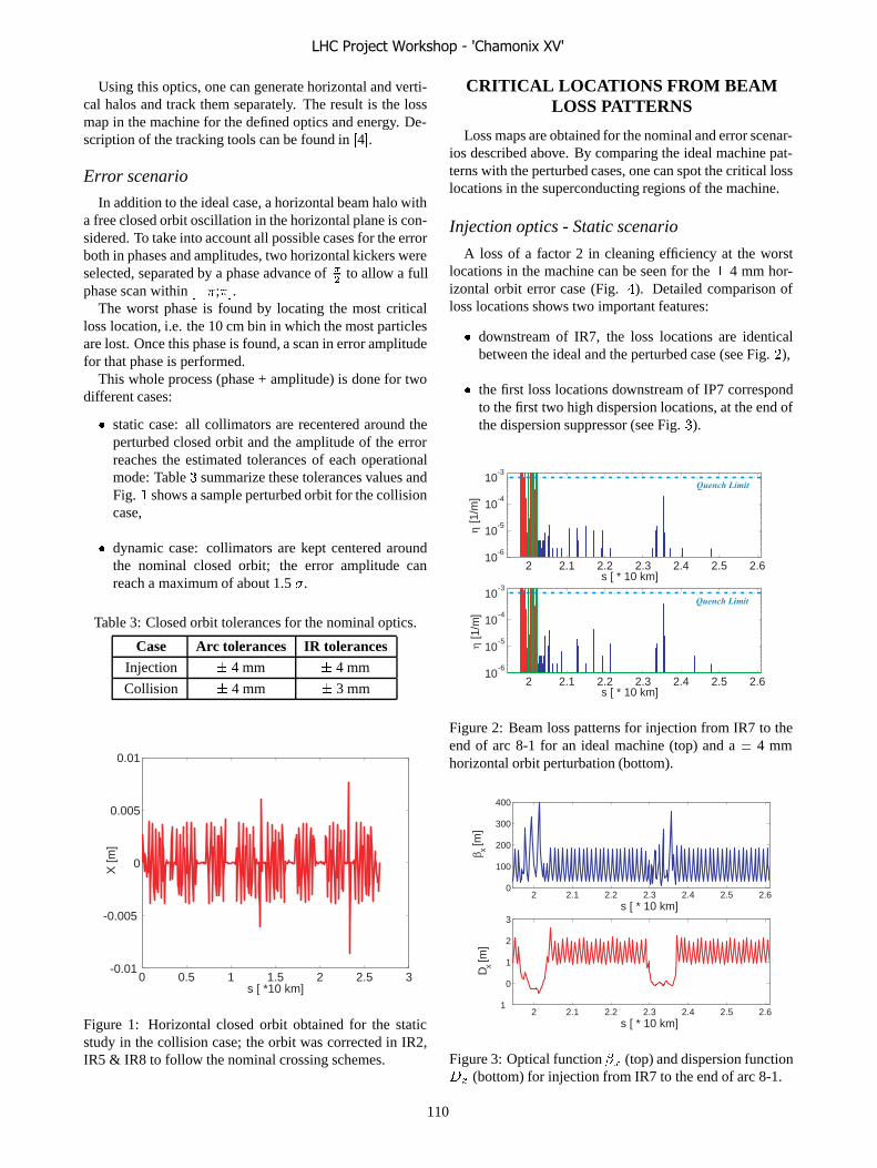
Using this optics, one can generate horizontal and verti-cal halos and track them separately. The result is the lossmap in the machine for the defined optics and energy. De-scription of the tracking tools can be found in �4�.
Error scenario
In addition to the ideal case, a horizontal beam halo witha free closed orbit oscillation in the horizontal plane is con-sidered. To take into account all possible cases for the errorboth in phases and amplitudes, two horizontal kickers wereselected, separated by a phase advance of
�to allow a full
phase scan within ���;��.The worst phase is found by locating the most critical
loss location, i.e. the 10 cm bin in which the most particlesare lost. Once this phase is found, a scan in error amplitudefor that phase is performed.
This whole process (phase + amplitude) is done for twodifferent cases:
� static case: all collimators are recentered around theperturbed closed orbit and the amplitude of the errorreaches the estimated tolerances of each operationalmode: Table � summarize these tolerances values andFig. � shows a sample perturbed orbit for the collisioncase,
� dynamic case: collimators are kept centered aroundthe nominal closed orbit; the error amplitude canreach a maximum of about 1.5 �.
Table 3: Closed orbit tolerances for the nominal optics.
Case Arc tolerances IR tolerancesInjection � 4 mm � 4 mm
Collision � 4 mm � 3 mm
0 0.5 1 1.5 2 2.5 3-0.01
-0.005
0
0.005
0.01
s [ *10 km]
X [m
]
Figure 1: Horizontal closed orbit obtained for the staticstudy in the collision case; the orbit was corrected in IR2,IR5 & IR8 to follow the nominal crossing schemes.
CRITICAL LOCATIONS FROM BEAMLOSS PATTERNS
Loss maps are obtained for the nominal and error scenar-ios described above. By comparing the ideal machine pat-terns with the perturbed cases, one can spot the critical losslocations in the superconducting regions of the machine.
Injection optics - Static scenario
A loss of a factor 2 in cleaning efficiency at the worstlocations in the machine can be seen for the � 4 mm hor-izontal orbit error case (Fig. �). Detailed comparison ofloss locations shows two important features:
� downstream of IR7, the loss locations are identicalbetween the ideal and the perturbed case (see Fig. ),
� the first loss locations downstream of IP7 correspondto the first two high dispersion locations, at the end ofthe dispersion suppressor (see Fig. �).
2 2.1 2.2 2.3 2.4 2.5 2.610
-6
10 -5
10 -4
10 -3
s [ * 10 km]
η [1
/m]
2 2.1 2.2 2.3 2.4 2.5 2.610
-6
10 -5
10 -4
10 -3
s [ * 10 km]
η [1
/m]
Quench Limit
Quench Limit
Figure 2: Beam loss patterns for injection from IR7 to theend of arc 8-1 for an ideal machine (top) and a � 4 mmhorizontal orbit perturbation (bottom).
2 2.1 2.2 2.3 2.4 2.5 2.60
100
200
300
400
s [ * 10 km]
β x [m]
2 2.1 2.2 2.3 2.4 2.5 2.61
0
1
2
3
s [ * 10 km]
D x [m]
Figure 3: Optical function �� (top) and dispersion function� (bottom) for injection from IR7 to the end of arc 8-1.
LHC Project Workshop - 'Chamonix XV'
110

0 0.5 1 1.5 2 2.510
-6
10 -5
10 -4
10 -3
10 -2
10 -1
100
101
s [ * 10 km]
η [1
/m]
Octant 2 Octant 3 Octant 4 Octant 5 Octant 6 Octant 7 Octant 8
Quench Limit
0 0.5 1 1.5 2 2.510
-6
10 -5
10 -4
10 -3
10 -2
10 -1
100
101
s [ * 10 km]
η [1
/m]
Octant 2 Octant 3 Octant 4 Octant 5 Octant 6 Octant 7 Octant 8
Quench Limit
Figure 4: Global beam loss patterns for an ideal machine (top) and a 4 mm orbit offset (bottom) for injection.
Losses in the dispersion suppressor cannot be avoided:off-momentum halo is generated at the primary collima-tors due to single-diffractive scattering during the interac-tion between an incoming proton and the collimator ma-terial. The off-momentum protons will always get lost atthe first high dispersion location. This defines a character-istic location for proton losses, but at the same time sets afundamental limitation to the betatron cleaning efficiency.
Losses seen in the IR2 region come from particles beingscattered off from the TDI jaws and then getting lost in thedownstream cold aperture of the machine.
Going through the whole line (Beam 1), one can count13 critical loss locations which should be added to the lo-cations of the installed collimators. Additional locationsmust be identified around IR3 (momentum cleaning).
Collision optics - Static scenario
For collision (see Fig. �, there are less loss locationsalong the machine compared to the injection optics casebut at the same time a higher proportion of them are gettingcloser to the quench limit. When comparing the ideal ma-chine case with the case of an orbit error reaching the toler-ances in orbit offset, it can be seen in Fig. � that the clean-ing system looses at a factor 2.98 in efficiency, with thelosses in the dispersion suppressor going over the quenchlimit (instead of being just below it in the ideal case).
Going downstream of IR7 (see Fig. ), it can be seen thatthe main loss locations are mostly identical for the ideal andthe perturbed case; plus, if one would check the locationsof the peaks showing up in the perturbed case, it can benoticed that they correspond to the critical locations alreadyspotted in the injection case (with a few exceptions).
Additional locations for IR3 should be taken into ac-count. Loss locations identified in our simulations only re-fer to protons getting directly lost in the cold aperture ofthe machine, but energy deposition studies are performedin parallel to check the influence of particle showers origi-nated in the tertiary collimators (TCT) protecting the tripletmagnets close to the experimental insertions.
2 2.1 2.2 2.3 2.4 2.5 2.610
-6
10 -5
10 -4
s [ * 10 km]
η [1
/m]
2 2.1 2.2 2.3 2.4 2.5 2.610
-6
10 -5
10 -4
s [ * 10 km]
η [1
/m]
Quench Limit
Quench Limit
Figure 5: Beam loss patterns for collision from IR7 to theend of arc 8-1 for an ideal machine (top) and a 3 mm (IR)/4mm (arc) orbit perturbation (bottom).
Counting losses from the halo exiting the betatron clean-ing insertion, one finds 18 locations for critical BLMs atcollision.
Summary
After having scanned all phases and amplitudes in thestatic scenario, it was possible to spot 13 critical locationsfor injection and 18 for collision. This sums up to 25 dif-ferent locations though, as 6 elements are critical in bothcases: these 6 locations correspond to the end of the dis-persion suppressor of IR7 and the arc between insertions 7and 8.
Tables � and summarize the predicted locations for�golden� BLMs, i.e. characteristic loss locations due tothe collimation system. These locations form the minimumworkable LHC BLM system for the set-up and commis-sioning of the collimation system. BLMs at similar loca-tions around IR3 and at the triplet magnets must be added.
The tracking tools also allow checking the longitudinal
LHC Project Workshop - 'Chamonix XV'
111

0 0.5 1 1.5 2 2.510
-6
10 -5
10 -4
10 -3
10 -2
10 -1
100
101
s [ * 10 km]
Octant 2 Octant 3 Octant 4 Octant 5 Octant 6 Octant 7 Octant 8
Quench Limit
η [1
/m]
0 0.5 1 1.5 2 2.510
6
10 -5
10 -4
10 -3
10 -2
10 -1
100
101
s [ * 10 km]
η [1
/m]
Octant 2 Octant 3 Octant 4 Octant 5 Octant 6 Octant 7 Octant 8
Quench Limit
Figure 6: Global beam loss patterns for an ideal machine (top) and a 3 mm (IR)/4 mm (arc) orbit offset (bottom) forcollision.
Table 4: Critical loss locations at injection optics.
Element LocationQ11 right of IR3
DFBA @ Q5 right of IR6
Q11 right of IR7
Q13 right of IR7
Q23 right of IR7
Q27 right of IR7
Q31 right of IR7
Q33 left of IR8
Q29 left of IR8
Q25 left of IR8
Q2 right of IR8
Q6 right of IR8
distribution of losses over any magnetic element. Fig. �shows an example of the longitudinal loss distribution. Theplanned geometry of the BLM system for each element isshown in Fig. �. By comparing the two figures, we cansee that it would be sufficient to use the channels from thefirst 2 BLMs at a quadrupole since the losses appear to beconcentrated at the beginning of the element (see also �6�for more details).
PRELIMINARY RESULTS FOR THEDYNAMIC SCENARIO
The dynamic scenario is used to check of the sensitiv-ity of the betatron cleaning system to orbit perturbations.In order to do so, it is assumed that the worst case occurswhen a secondary collimator becomes a primary collimatordue to an orbit error. The worst phase for the error wouldthen leave the orbit unchanged at the primary collimator
Table 5: Critical loss locations at collision.
Element LocationQ6 left of IR3
Q8 right of IR7
MB9 right of IR7
Q9 right of IR7
MB11 right of IR7
Q11 right of IR7
Q13 right of IR7
Q19 right of IR7
Q21 right of IR7
Q27 right of IR7
Q33 left of IR8
Q25 left of IR8
Q17 left of IR8
Q16 right of IR8
Q30 right of IR8
Q22 left of IR1
Q14 left of IR1
and create a maximum offset at a critical secondary colli-mator.
For a horizontal halo, the relevant horizontal primarycollimator is the TCP.C6L7 and the critical horizontalsecondary collimator is the TCSG.B4L7. The trackedorbits for a 0.4 � (solid), 0.95 � (dash-dotted) and 1.1 �
(dashed) offset are shown in Fig. �. In the latter case, thesecondary collimator becomes a primary. Tracking theseorbits allows checking how much is lost in performanceof the IR7 collimation system. This is done by comparingthe values of the global inefficiency of the system at agiven amplitude (e.g. the cold aperture of the machine) for
LHC Project Workshop - 'Chamonix XV'
112

2.032 2.0325 2.033 2.0335 2.03410
-6
10 -5
10 -4
s [ * 10 km ]
η [1
/m]
Figure 7: Beam loss pattern for a 1 m long bin for collisionin the dispersion suppressor downstream of IP7: longitudi-nal distribution of the losses along a dipole magnet (dashedbox) and a quadrupole magnet (dotted box).
MB
SEX
T
BPM
OC
TU
MQ MCBH/V
DE
CA
MBxx x xx x
z=−248
z=−243
z=−154 z=0
z=−353
z=−325
Figure 8: Shower development in the cryostat of aquadrupole. The positioning of the detectors (blue boxes)has been optimized to catch losses and to minimize un-certainty of ratio of energy deposition in coil and detector(courtesy of L. Ponce).
each orbit configuration. Results are shown in Fig. �� forcollision.
It is noted that the sextupoles were turned off in thesesimulations in order to keep the impact parameter at thecollimator constant between the different cases. Fig. ��shows that we loose a factor 8.68 in cleaning efficiencyat collision if one of the secondary collimators becomesthe primary collimator. Further studies on theses accidentcases are currently being performed to analyze effects onbeam loss patterns and BLM thresholds.
1.966 1.976 1.986
-1.5
-1
-0.5
0
0.5
1
1.5
s [ * 10 km]
0.40 σ @ TCS0.95 σ @ TCS1.10 σ @ TCS
X [m
m]
1.971 1.981 1.991
TCP TCS
Figure 9: Orbit oscillations over 250 meters of the IR7 be-tatron cleaning insertion. The orbit at the horizontal pri-mary collimator is left unchanged while 3 different offsetsare applied at the relevant secondary collimator.
6 7 8 9 10 11 12 13 14 1510
-4
10 -3
10 -2
10 -1
100
Radial Amplitude [σ ]
Rad
ial I
neffi
cien
cyNominal case0.95 σ orbit offset @ TCS1.10 σ orbit offset @ TCS
Figure 10: Global inefficiency curves at different orbit off-set for the dynamic scenario. The system looses a factor8.68 in efficiency when a secondary collimator becomes aprimary.
CONCLUSION
The response of the LHC collimation system to free orbitoscillations for Beam 1 has been reviewed. With the spec-ified LHC orbit errors, critical locations along the machinecan be identified and used to define a minimum workableBLM system for the commissioning and set-up of the col-limators during the early stages of operations. Some lo-cations are critical for 450 GeV and 7 TeV. The disper-sion suppressor immediately downstream of IP7 is the mostcritical region of the machine, with many losses concen-trated over a few elements (the equivalent of two cells ofthe lattice). Energy deposition studies are ongoing for par-ticle showers generated by inelastic proton-matter interac-tion in the tertiary collimators (close to the triplet magnets)and downstream of the beam dump protection equipment
LHC Project Workshop - 'Chamonix XV'
113
(TCDQ). Additional locations should be obtained fromsimulations for the momentum cleaning insertion.
Further studies are planned to include beta-beating er-rors, tables of magnetic field errors for the dipoles, align-ment errors for magnets in the aperture models and errorscenarios for the mechanical parameters of the collimators(e.g. longitudinal tilt angle of one jaw). The setup for track-ing of Beam 2 is also being finalized.
AKNOWLEDGEMENTS
The authors would like to thank T. Risselada and W. Herrfrom the AB/ABP group and J. Wenninger from the AB/OPgroup for the help provided on the generation of optics files.Many thanks also to B. Dehning, E. Holzer and L. Poncefrom the AB/BDI group for discussions on the setup of theBLM system. Thanks to A. Bertarelli, M. Magistris and M.Santana-Leitner from the AB/ATB for their energy deposi-tion studies with FLUKA. Finally, thanks to F. Schmidt andE. McIntosh for the support they provided on the develop-ment of the tracking code.
REFERENCES
[1] ”LHC Design Report”, Volume I, Ch. 18, CERN, 2004
[2] J.B. Jeanneret, D. Leroy, L. Oberli and T. Trenckler: ”Quenchlevels and transient beam losses in the LHC magnets”,CERN-LHC-PROJECT-REPORT-44, 1996.
[3] S. Redaelli: ”LHC aperture and commissioning of the colli-mation system”, Proc. Chamonix 2005.
[4] G. Robert-Demolaize, R. A�mann, S. Redaelli, F. Schmidt:”A new version of SixTrack with collimation and apertureinterface”, Proc. PAC 2005.
[5] R. A�mann: ”Collimators and cleaning: could this limit theLHC performance? ”, Proc. Chamonix 2003.
[6] B. Dehning: ”Commissioning of beam loss monitors”, theseproceedings.
LHC Project Workshop - 'Chamonix XV'
114

APPENDIX A
Table 6: Mechanical parameters of Phase 1 collimators for injection. Collimators which are not used at that energy areset to a 900 � opening.
Name Length [m] Angle [radians] Material Halfgap [m] Halfgap [�]
TCL.5R1.B1 1.00 0.000 CU 1.242 900.0
TCTH.L2.B1 1.00 0.000 W 0.5477 900.0
TDI.4L2 4.00 1.571 CU 4.092� ���� 6.8
TCTV.4L2.B1 1.00 1.571 W 0.5837 900.0
TCLIA.4R2.B1 1.00 1.571 C 6.531� ���� 6.8
TCLIB.6R2 1.00 1.571 C 3.231� ���� 6.8
TCP.6L3.B1 0.60 0.000 C 7.891� ���� 8.0
TCSG.5L3.B1 1.00 0.000 C 5.913� ���� 9.3
TCSG.4R3.B1 1.00 0.000 C 4.067� ���� 9.3
TCSG.A5R3.B1 1.00 2.980 C 5.288� ���� 9.3
TCSG.B5R3.B1 1.00 0.189 C 5.931� ���� 9.3
TCLA.A5R3.B1 1.00 1.571 W 1.143� ���� 10.0
TCLA.B5R3.B1 1.00 0.000 W 1.060� ���� 10.0
TCLA.6R3.B1 1.00 0.000 W 9.759� ���� 10.0
TCLA.7R3.B1 1.00 0.000 W 6.931� ���� 10.0
TCTH.L5.B1 1.00 0.000 W 1.001 900.0
TCTV.L5.B1 1.00 1.571 W 0.744 900.0
TCL.5R5.B1 1.00 0.000 CU 1.254 900.0
TCDQ.4R6.B1 8.00 0.000 C 1.506� ���� 8.0
TCS.TCDQ.B1 1.00 0.000 C 1.339� ���� 7.0
TCP.D6L7.B1 0.60 1.571 C 4.170� ���� 5.7
TCP.C6L7.B1 0.60 0.000 C 6.168� ���� 5.7
TCP.B6L7.B1 0.60 2.225 C 5.045� ���� 5.7
TCSG.A6L7.B1 1.00 2.463 C 6.046� ���� 6.7
TCSG.B5L7.B1 1.00 2.504 C 7.081� ���� 6.7
TCSG.A5L7.B1 1.00 0.710 C 7.229� ���� 6.7
TCSG.D4L7.B1 1.00 1.571 C 4.781� ���� 6.7
TCSG.B4L7.B1 1.00 0.000 C 6.565� ���� 6.7
TCSG.A4L7.B1 1.00 2.349 C 6.664� ���� 6.7
TCSG.A4R7.B1 1.00 0.808 C 6.708� ���� 6.7
TCSG.B5R7.B1 1.00 2.470 C 7.797� ���� 6.7
TCSG.D5R7.B1 1.00 0.897 C 7.809� ���� 6.7
TCSG.E5R7.B1 1.00 2.277 C 7.828� ���� 6.7
TCSG.6R7.B1 1.00 0.009 C 1.074� ���� 6.7
TCLA.A6R7.B1 1.00 1.571 W 5.744� ���� 10.0
TCLA.C6R7.B1 1.00 0.000 W 1.092� ���� 10.0
TCLA.E6R7.B1 1.00 1.571 W 1.052� ���� 10.0
TCLA.F6R7.B1 1.00 0.000 W 6.750� ���� 10.0
TCLA.A7R7.B1 1.00 0.000 W 6.604� ���� 10.0
TCTH.L8.B1 1.00 0.000 W 0.528 900.0
TCTV.4L8.B1 1.00 1.571 W 0.558 900.0
TCTH.L1.B1 1.00 0.000 W 1.001 900.0
TCTV.L1.B1 1.00 1.571 W 0.744 900.0
LHC Project Workshop - 'Chamonix XV'
115
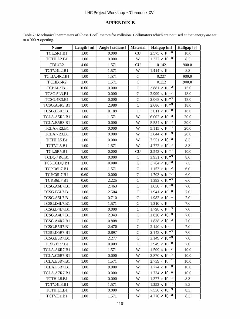
APPENDIX B
Table 7: Mechanical parameters of Phase 1 collimators for collision. Collimators which are not used at that energy are setto a 900 � opening.
Name Length [m] Angle [radians] Material Halfgap [m] Halfgap [�]
TCL.5R1.B1 1.00 0.000 CU 2.575� ���� 10.0
TCTH.L2.B1 1.00 0.000 W 1.327� ���� 8.3
TDI.4L2 4.00 1.571 CU 0.142 900.0
TCTV.4L2.B1 1.00 1.571 W 1.414� ���� 8.3
TCLIA.4R2.B1 1.00 1.571 C 0.227 900.0
TCLIB.6R2 1.00 1.571 C 0.112 900.0
TCP.6L3.B1 0.60 0.000 C 3.881� ���� 15.0
TCSG.5L3.B1 1.00 0.000 C 2.999� ���� 18.0
TCSG.4R3.B1 1.00 0.000 C 2.068� ���� 18.0
TCSG.A5R3.B1 1.00 2.980 C 2.686� ���� 18.0
TCSG.B5R3.B1 1.00 0.189 C 3.011� ���� 18.0
TCLA.A5R3.B1 1.00 1.571 W 6.002� ���� 20.0
TCLA.B5R3.B1 1.00 0.000 W 5.554� ���� 20.0
TCLA.6R3.B1 1.00 0.000 W 5.115� ���� 20.0
TCLA.7R3.B1 1.00 0.000 W 3.644� ���� 20.0
TCTH.L5.B1 1.00 0.000 W 7.551� ���� 8.3
TCTV.L5.B1 1.00 1.571 W 4.772� ���� 8.3
TCL.5R5.B1 1.00 0.000 CU 2.543� ���� 10.0
TCDQ.4R6.B1 8.00 0.000 C 3.951� ���� 8.0
TCS.TCDQ.B1 1.00 0.000 C 3.764� ���� 7.5
TCP.D6L7.B1 0.60 1.571 C 1.153� ���� 6.0
TCP.C6L7.B1 0.60 0.000 C 1.703� ���� 6.0
TCP.B6L7.B1 0.60 2.225 C 1.393� ���� 6.0
TCSG.A6L7.B1 1.00 2.463 C 1.658� ���� 7.0
TCSG.B5L7.B1 1.00 2.504 C 1.941� ���� 7.0
TCSG.A5L7.B1 1.00 0.710 C 1.982� ���� 7.0
TCSG.D4L7.B1 1.00 1.571 C 1.310� ���� 7.0
TCSG.B4L7.B1 1.00 0.000 C 1.798� ���� 7.0
TCSG.A4L7.B1 1.00 2.349 C 1.826� ���� 7.0
TCSG.A4R7.B1 1.00 0.808 C 1.838� ���� 7.0
TCSG.B5R7.B1 1.00 2.470 C 2.140� ���� 7.0
TCSG.D5R7.B1 1.00 0.897 C 2.143� ���� 7.0
TCSG.E5R7.B1 1.00 2.277 C 2.149� ���� 7.0
TCSG.6R7.B1 1.00 0.009 C 2.949� ���� 7.0
TCLA.A6R7.B1 1.00 1.571 W 1.509� ���� 10.0
TCLA.C6R7.B1 1.00 0.000 W 2.870� ���� 10.0
TCLA.E6R7.B1 1.00 1.571 W 2.759� ���� 10.0
TCLA.F6R7.B1 1.00 0.000 W 1.774� ���� 10.0
TCLA.A7R7.B1 1.00 0.000 W 1.734� ���� 10.0
TCTH.L8.B1 1.00 0.000 W 1.277� ���� 8.3
TCTV.4L8.B1 1.00 1.571 W 1.353� ���� 8.3
TCTH.L1.B1 1.00 0.000 W 7.556� ���� 8.3
TCTV.L1.B1 1.00 1.571 W 4.776� ���� 8.3
LHC Project Workshop - 'Chamonix XV'
116

Commissioning of Beam Loss Monitors
B. Dehning, CERN, Geneva, Switzerland
Abstract
The commissioning task of the LHC beam loss moni-tors can be done in periods before the start-up with beams,parasitically during operation and with dedicated beams.It is foreseen to commission the detectors, the acquisitionelectronics, the analysis electronics and the beam permitinhibiting system before the start-up. The analysis of beamloss events together with the generation of beam permit in-hibits will be used to verify the foreseen operation of thesystem. To check the integrity of the system automatic testprocedures will be executed during and in between of peri-ods with beams.
A calibration of the system is needed to cope with thevarying quench levels for different magnet types and vary-ing response of the detectors depending on the secondaryshower spectrum and other sources. These calibration fac-tors will be absorbed in the threshold tables and they willbe based on measurements and simulations. Dedicatedquench level measurements during the sector test could beused to verify the models. In case of excessive number ofquenches or beam aborts, beam induced quench tests couldbe used to improve the models.
INTRODUCTION
The efforts for the LHC beam loss monitoring (BLM)system are motivated by the required protection and pre-vention function of the system. The protection functionis given by the beam permit inhibit in case of potentiallydamaging losses (see Fig. 1). The number of beam dump
Figure 1: Dump request distribution and the employmentof the beam loss system [1].
requests, which reaches the dump system over the machineinterlock, is to 60 % operator initiated request (inspired dis-tribution by HERA [2]). The remaining dump requests areto 30 % caused by beam loss initiated dumps and to 10% by various other reasons. The beam initiated requests
are equally subdivided in losses with a duration below 10ms and above. The short losses can only be detected bythe beam loss system except losses with durations shorterthan 4 turns. The loss measurements, the signal transmis-sion and the dump system response require these few turnfor the beam extraction. In case of shorter loss durationsprotection will be given by absorbers and collimators. Thelong losses can be detected in addition to the BLM systemwith the quench protection system (QPS, PIC). In this casetwo independent systems are available for the detection.
The prevention function is given by the beam permit in-hibit in case that the losses exceed quench level thresholds.The quench level thresholds are 2 to 3 orders of magni-tude below the damage levels in most cases insuring a largesafety margin. For the beam permit inhibit generation theBLM system is the only one in the range of the quenchlevels.
STEPS OF COMMISSIONING
The commissioning steps are divided in environmentaltests before the installation, functional tests before and dur-ing installation and tests during the operation (see Fig. 2).
Figure 2: Commissioning steps of the beam loss system.
The environmental tests are done on the detector andtunnel electronic components, because they are exposed tolarge temperature changes and potential radiation damage(see Fig. 3).
Figure 3: Test and commissioning scheme of the beam lossmeasurement system.
Functional tests are done before the installation with allBLM equipment. The detectors are tested with a radioac-tive source and the electronic acquisition chain is testedwith a current source simulating the detector signal. These
LHC Project Workshop - 'Chamonix XV'
117

tests are repeated in the tunnel with the final cabling andset-up. Especially the source test, done shortly before start-up, should ensure the correct identity of each channel. Theconnectivity of the channels can also be tested remotelyby modulating the high voltage supply of the detectors.The capacitive coupling between high voltage electrodesand signal electrodes allows the induction of a current inthe system used to check the whole acquisition chain (seeFig. 3). An offset current induced in the tunnel electronicor the use of a redundant signal transmission path allows tosurvey the system during the operation [3].
The commissioning procedure includes the determina-tion of the calibration of the BLM system. A model of thedetector, shower and quench behavior based on simulationand measurements is determined before the start-up (seeFig. 4). The left column shows the elements to which a
Figure 4: Scheme of the BLM calibration.
calibration has to be applied. The right column indicatesthe used simulation programs and their verification proce-dure. The different calibration results are combined in thequench level threshold tables.
CALIBRATION AND VERIFICATION OFTHE MODELS
The detector response has been tested with differentbeams ranging from the very short exposure time of 100ns and � � ��
�� protons to exposure times of seconds with afew � ���
� protons (see. Fig. 5). The momentum range wasbetween a few GeV to 450 GeV. The observed relative vari-ations were about a factor 2 [4]. The response variation isidentical to the specified uncertainty of the whole system,therefore it is not acceptable for a single component.
The shower code prediction uncertainty is largest in thetransverse tails of the showers where the loss monitors arelocated (outside of the cryostat) (see Fig. 6: blue rectan-gles and lower shower distributions). These uncertaintieswill be determined with a set-up at the inline dump ofHERA. Monitors are located along the dump to determinethe longitudinal shower profile. The impacting proton den-sity is accurately measured by the beam current transformershortly before the abort of the beam. It is expected that theremaining uncertainty will be below 50 % as for the uncer-tainty in the shower core .
The quench level uncertainties are determined byGEANT simulations of the energy deposition in magnet
momentum [GeV/c]
N [c
harg
es/c
m/p
roto
n]
intensity [protons]
N [c
harg
es/c
m/p
roto
n]
time [s]
N [c
harg
es/c
m/p
roto
n]
70
80
90
100
110
120
130
140
10 102
70
80
90
100
110
120
130
140
107
108
109
1010
1011
1012
70
80
90
100
110
120
130
140
10-7
10-6
10-5
10-4
10-3
10-2
10-1
1 10
Figure 5: Signal response of a ionisation chamber as func-tion of proton momentum, intensity and exposure time.
Figure 6: Number of secondary shower particles in coils(top curves) and along the outside cryostat (bottom curves).The location of the detectors are indicated by blue rectan-gles.
coils (see Fig. 6, top curves) and verified by quench testswith short duration beams. This procedure will mainly ver-ify the GEANT predictions for the case of a negligible heatflow out of the shower area. These tests are foreseen tobe done during the sector test period of the LHC [5]. Forlosses with durations longer than 0.1 ms the heat flow in thecoils and from the coil into the helium bath has to be takeninto account. In the extreme case of steady loss durationthe heat flow limitation will determine the temperature in-crease and therefore the quench levels [6]. To simulate thisbehavior a model is under development and a verificationis foreseen to be done by using the quench heater systemof the coil for a defined deposition of heat into the magnetcoil.
LHC Project Workshop - 'Chamonix XV'
118
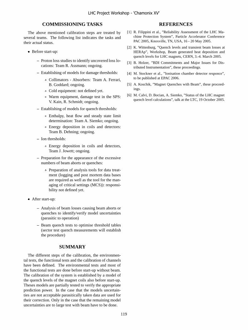
COMMISSIONING TASKS
The above mentioned calibration steps are treated byseveral teams. The following list indicates the tasks andtheir actual status.
� Before start-up:
– Proton loss studies to identify uncovered loss lo-cations: Team R. Assmann; ongoing.
– Establishing of models for damage thresholds:
� Collimators - Absorbers: Team A. Ferrari,B. Goddard; ongoing.
� Cold equipment: not defined yet.
� Warm equipment, damage test in the SPS:V. Kain, R. Schmidt; ongoing.
– Establishing of models for quench thresholds:
� Enthalpy, heat flow and steady state limitdetermination: Team A. Siemko; ongoing.
� Energy deposition in coils and detectors:Team B. Dehning; ongoing.
– Ion thresholds:
� Energy deposition in coils and detectors,Team J. Jowett; ongoing.
– Preparation for the appearance of the excessivenumbers of beam aborts or quenches:
� Preparation of analysis tools for data treat-ment (logging and post mortem data basesare required as well as the tool for the man-aging of critical settings (MCS)): responsi-bility not defined yet.
� After start-up:
– Analysis of beam losses causing beam aborts orquenches to identify/verify model uncertainties(parasitic to operation)
– Beam quench tests to optimise threshold tables(sector test quench measurements will establishthe procedure)
SUMMARY
The different steps of the calibration, the environmen-tal tests, the functional tests and the calibration of channelshave been defined. The environmental tests and most ofthe functional tests are done before start-up without beam.The calibration of the system is established by a model ofthe quench levels of the magnet coils also before start-up.Theses models are partially tested to verify the appropriateprediction power. In the case that the models uncertain-ties are not acceptable parasitically taken data are used fortheir correction. Only in the case that the remaining modeluncertainties are to large test with beam have to be done.
REFERENCES
[1] R. Filippini et al., ”Reliability Assessment of the LHC Ma-chine Protection System”, Particle Accelerator ConferencePAC 2005, Knoxville, TN, USA, 16 - 20 May 2005.
[2] K. Wittenburg, ”Quench levels and transient beam losses atHERAp”, Workshop, Beam generated heat deposition andquench levels for LHC magnets, CERN, 3.-4. March 2005.
[3] B. Holzer, ”BDI Commitments and Major Issues for Dis-tributed Instrumentation”, these proceedings.
[4] M. Stockner et al., ”Ionisation chamber detector responce”,to be published at EPAC 2006.
[5] A. Koschik, ”Magnet Quenches with Beam”, these proceed-ings.
[6] M. Calvi, D. Bocian, A. Siemko, ”Status of the LHC magnetquench level calculations”, talk at the LTC, 19 October 2005.
LHC Project Workshop - 'Chamonix XV'
119

DISCUSSION: THE MINUMUM WORAKBLE LHC – MACHINE PROTECTION AND COLLIMATION
J. Uythoven, CERN, Geneva, Switzerland.
COMMISSIONING AND (EARLY) OPERATION – VIEW FROM MACHINE
PROTECTION (J. UYTHOVEN) Q: Have the procedures for commissioning during the hardware commissioning period been defined? A: This has been described within the framework of the LHC Hardware Commissioning Working Group and this now needs to be extended to LHC commissioning period. Q: How will those tests be defined? A: The Machine Protection Coordination Team should start soon (months), in collaboration with LHC-OP and equipment experts, to define the details of the tests to be performed. Q: What happens to the machine protection system if there is general power cut? A: Everything is foreseen that the beam will still be properly dumped, but this is actually one of the things which could be on the list of scenarios to be tested.
WHAT SYSTEMS REQUEST A BEAM DUMP (J. WENNINGER)
Q: Can the CERN access card be used for identification at the computers in the control room? The use of such a system is being studied at CERN. A: Might be unpractical in the control room as operators change console. People in the control room are supposed to be trusted. A: However, for some applications (FESA), the security will need to be improved. A: Some combination of cards and codes (like for e-banking) must be able to guarantee a SIL3/SIL4 safety. Something like this could be used for changing settings, especially Machine Protection settings. A: The EIC should not always be able to change the Machine Protection settings. An accident happened at HERA when an EIC changed the MP settings. A: It could be an option to have upper limits of protection settings in hardware and lower limits in software. A: The Machine Protection Coordination Committee could have the function of coordinating changes of Machine Protection settings.
WHAT IS REQUIRED TO SAFELY FILL THE LHC? (V. KAIN)
Q: Should the inject and dump mode include the option to be able to dump after a known number of turns? A: Yes, this should be available from ‘day 1’.
WHAT IS REQUIRED TO GET THE BEAM SAFELY OUT OF THE LHC?
(B. GODDARD) Q: Can the commissioning of the LBDS over the energy ramp be done in parallel with other activities? A: Partly. This depends on the way the ramp is commissioned. We will get input automatically after every beam dump, but may need to request dumps at certain energies to ‘fill in the gaps’ in the tracking table. Q: Can one inject a pilot bunch into the LHC without having commissioned the LBDS? A: Yes – the LBDS will be armed and “ready for pilot” and will react to the first trigger, hopefully executing a correct dump. Q: How are the LBDS look-up tables going to be stored? A: The settings are in hardware (flash e-prom) which are compared with a copy in software (possibly in the MCS or in a ‘secure’ reference database for the SIS to use). Q: What happens after a thunderstorm? A: After a thunderstorm the LBDS state is forced to “not ready for beam”. All the settings will be compared against each other and a test dump with a pilot beam will also be obligatory, before high intensity beam can be injected. This requires the sequencer to enforce this. Q: To what level has the EMI of the LBDS been tested? A: This has been tested and agrees with the ‘norms’. In any case the main source of EMI is the kicker system itself, and this has been shown to pose no problem so far. A: It has been tested up to 4 kV. A: The electronics has a fault tolerant or redundant design and the post mortem after every dump will discover any missing redundancy. Q: What happens if a pilot is badly extracted at 7 TeV, e.g. with half the nominal kick? A: The beam will probably hit the TCDQ / TCDS. The worst case is to hit the MSD (for a kick larger than nominal).
BEAM COMMISSIONING OF THE COLLIMATION SYSTEM (R. ASSMANN)
Q: Which intensity will be used for setting up the collimation system? A: Few nominal bunches – limited intensity.
LHC Project Workshop - 'Chamonix XV'
120

R: Relaxing on the collimator settings (> 8 σ) can lead to more experimental background. The experiments need to be well informed of the state of the collimators. Q: Does the collimation need to be recommissioned for each new fill? A: Reproducibility from one fill to the next is assumed, by having the same beam and the same collimator positions. Q: Does one need the scrapers? A: Yes, for the higher intensities. Q: Do all the tertiary collimators foreseen for points 2 and 8 need to be there from the start? A: Yes, but can survive if there is a large β* in 2 and 8. Q: What is the precision required for the collimator positioning? A: In the SPS the initial accuracy was 200 μm, later improved to 50 μm. Finally 20 μm will be required.
CRITICAL BEAM LOSSES DURING COMMISSIONING AND INITIAL
OPERATION (G. ROBERT-DEMOLAIZE) Q: In how far do the presented results depend on the special optics? A: Changes in the IPs should have little effect in the arcs. Q: The studies are in the H plane. Losses in IR 2 after the TDI are reported, but the TDI is in the vertical plane? A: Some collimators are ‘skew’ and work in both planes. R: The studies quoted are for a β* of 0.5 m. This is only expected to be used at the end of stage 3. Studies should now be made for β* = 2 m and β* = 1 m. R: Some loss locations are not yet covered by BLMs. The positions of the BLMs need to optimised following the presented studies.
COMMISSIONING OF THE BEAM LOSS MONITORS (B. DEHNING)
Q: The thresholds to be applied are functions of time and energy. How are they going to be commissioned? A: This depends on results from the sector test for instant losses and results from SM18 for steady state losses. This gives the extreme cases for obtaining the quench levels. Q: The damage level of the sc cables are based on a relative old publication by B. Jeanneret. Should one improve these studies and how? A: This could be done in more details in the TS department, considering the heat deposition and the elastic limit.
R: The temperature of the Helium bath could be used as calorimeter, giving an instantaneous measurement of the deposited power. R: Simulations of beam losses have been made for RHIC and can be compared with their measurements.
LHC Project Workshop - 'Chamonix XV'
121

ATB’S COMMITMENTS AND MAJOR ISSUES FOR THE LHC
O. Aberle, J. Lettry, R. Losito, CERN, Geneva, Switzerland
Abstract This paper states ATB’s responsibility and organisation for LHC collimation, dumps, stoppers and masks. In particular, it will address the strategy during the collimator production to assure the system functionality and performance expected for the different operation stages and the procedures and tests to be put in place to reach these objectives. Finally, current major issues (i.e. uncovered requirements) and possible ‘Plan B’ are presented.
DUMPS AND STOPPERS • TED : External dumps for the transfer lines and TBSE : Stoppers The dumps (TED) and safety stoppers (TBSE) in the transfer lines (between SPS and LHC, including CNGS) have all been produced and installed, except the TED to be installed in 2007 in TI2. All equipments have been tested and partially been used during the 2004 runs. • TDE : LHC beam dumps (point 6) The LHC beam dumps in point 6 will be installed as scheduled in two phases, the first installation will be in March 2006, the second campaign will be in December 2006 and includes also the spare dumps in UD 62 and UD 68. • TDI : Injection dumps (point 8 and 2) The TDI production is close too completion. The installation of the TDI in point 8 is scheduled for May 2006. Planning is very tight, but all efforts will be undertaken to reach the installation date.
MASKS • TCDD : Injection protection masks (point 8 / 2) A new energy deposition study is deemed necessary to decide on cooling. In the meantime replacement chambers or a fixed aperture mask TCDDM will be produced and installed in point 8 according to the installation schedule. In point 2 a mobile device (collimator type) is foreseen, its new design will be based on the Collimator design (TCS type) and on the transfer line mask design (TCDIM). The schedule depends on the outcome of the new study (June 2006) and will result in a late installation of the TCDD. • TCDIM : Transfer line masks (TI2 and TI8) The design for the transfer line masks has been finalized. The production will be outsourced. Installation according to schedule is expected. • TCLIM : Masks in point 6 The design for the masks in point 6 (together with TCDQM) started in January. The experience from the TCDIM types will reduce the design effort. A planning for
production and installation is not available at the moment. A start-up without these masks is possible.
COLLIMATORS ATB Responsibilities and organization
The work packages for the LHC collimators concerning ATB are shown in the following table
Table 1: Work packages under ATB responsibility. There are similar descriptions used for other packages in other groups and departments.
AllCommissioningAB/ATB10
TD-LPEPhase 2 engineeringAB/ATB9
TD-EETCollimator installationAB/ATB6b
TDCERN reception, testing and assemblyAB/ATB7
TD-EETProduction support, control and calibrationAB/ATB6
LPEPosition Readout and Survey systemAB/ATB5
LPESensors and calibrationAB/ATB4
LPEMotor and Local ControlAB/ATB3
LPE-TDCollimation InfrastructureAB/ATB2
EETFLUKA simulationsAB/ATB8
TD-EETPhase 1 R&D, prototyping, testsAB/ATB1
ATB sectionDescriptionWP #
Strategy for collimator installation Following the analysis of the mismatch of the installation schedule to industrial production, reception assembly and test plannings illustrated in fig. 2, the following points and agreed upon (LTC 29th June): • All standard Phase One collimators installed for LHC
start-up • Phase Two locations prepared for quick installation
(infrastructure and base support) • Vacuum chambers collimator replacement ordered Installation campaigns: • Most important collimators to be installed during the
standard LHC installation campaign (April 2006 – February 2007).
• Special installation campaign for delayed collimators (late spring 2007)
• Third installation campaign during the shutdown 2007/2008.Production for special design collimators listed in table 2.
Table 2: location of specialcollimators
IR1 2 TCLP IR5 2 TCLP IR2 1 TCLI, 2 TCT IR7 4 TCHS IR3 4 TCHS IR8 1 TCLI, 2 TCT
LHC Project Workshop - 'Chamonix XV'
122

Availability vs. installation The figure 2 shows the planning of the collimator production in industry including the time required for assembly, testing and transport at CERN with respect to the installation planning (Dec. 2005). Delays will increase the backlog by 10 collimators /month that will have to be installed in the second phase.
Figure 2: Collimator availability (Dec-05) vs. installation schedule
Status of the production in Industry (with reference to the last updated planning in Dec.): • Production of TCDI: Following a problems on the
beams machining, a delay of several weeks is announced. Installation date in May is jeopardized. The problem is now solved and a second subcontractor has been launched to speed up the machining.
• TCS beams for qualification: The brazing samples are under investigation. New samples will be produced. After their acceptance, the assembly and delivery of TCS collimators can go ahead (brazing accepted by CERN Feb. 10th).
Availability of the collimator components Base supports: Delivery end of Feb. 2006 at CERN. The assembly at CERN is compatible with the installation schedule. The base support guides are designed to act as support for replacement vacuum chambers. The base supports will be installed on schedule in the tunnel for Phase one and two. Upper supports: The upper supports will be pre-assembled, depending on type, angle on production schedule. The plug-in and the 5th axis parts will be delivered to CERN in March, on schedule.
Reception, assembly, tests and calibration The time estimates below are based on the experience from the prototyping at CERN. The detailed procedures for commissioning will be published in a specific EDMS document. The timing based on prototyping work (man-
Weeks /collimators) will be optimized with the experience of the first batch of collimators qualified at CERN.
Mechanics: 10 man-Weeks • Reception test: for leak test, cooling circuit,
mechanical functionality and precisions. • Base support assembly. • Upper support assembly. • Collimator assembly: Prepare orientation/type.
Assemble the cooling system. Installation of motors and LVDTs. Test auto-retraction, positions and gaps.
• Alignment: Positioning of alignment targets. Electronics: 4 man-Weeks Cabling, calibration of position sensors and motorization. Bake-out: 3 collimators in parallel / week (AT-VAC). Staff: 4 teams in parallel, for mechanics and 3 teams for electronics, 10 FSU + 9 staff/associates are currently available.
Installation of first collimators • TCDI: 6 transfer line collimators have to be
installed in May. Actually only 4 collimators are in production. Delays for installation are expected.
• TCT: The installation in LSS8 (L/R) and LSS1L is scheduled in May, however, the April delivery falls short for full testing. A delay of a few weeks is expected.
• TCS: Installation in June in point 6: Production matches the installation planning.
Installation of infrastructure Cabling and cooling: The cables are pulled in P3, P1, P8, TI2 and TI8, and to be pulled in P2, P5, P7 on schedule. The bake-out in the tunnel is disturbed by the presence of cooling water; the design has to be finalized. Tracing (TS/SU) and drilling (TS/IC) are ready for base support installation in time. Base support installation (TS/IC): The base supports arrive at CERN by end of Feb. 2006. They will be assembled in time for installation. Traceability: The labeling of position, type, angle and phase will be stored in a data base. Base support: The local cooling system, connection of water and cables will be mounted on time. The alignment of the base support will be done by TS/SU.
Installation of electronics • Motors and drivers: Assembly in the tunnel must be
avoided. • LVDT’s: The calibration in the Laboratory is
mandatory. The tendering is completed and the offers received. Some of the bidders are able to deliver LVDT’s 4 weeks after signature of the contract.
• After installation of the base, all connections and coupling will be checked.
LHC Project Workshop - 'Chamonix XV'
123

• Low level control: Ready for commissioning in 2007. For the sector test, a pre-series will be organized.
Commissioning The document on commissioning is under finalization. The work estimation is of 2 x 200 man days (LPE/EA/IF) in the tunnel. Dry runs on the first delivered collimators will be performed during summer 2006.
MAJOR ISSUES The planning for the production and installation is very tight, there are no margins. The different types give some flexibility during production to optimize the distribution between installation phases 1 and 2. The sectors cannot be completed during the original installation schedule due to special design, collimators. Additional work for vacuum, alignment and transport is expected.
LHC Project Workshop - 'Chamonix XV'
124

BI GROUP COMMITMENTS AND MAJOR ISSUES FOR DISTRIBUTEDSYSTEMS
E. B. Holzer, CERN AB/BI, Geneva, Switzerland
Abstract
This presentation will detail BI responsibility and orga-nization for LHC distributed instrumentation, i.e. the beamposition monitoring system (BPM), the beam loss monitor-ing system (BLM) and the beam synchronous timing sys-tem (BOB). It will also present BI commitments on the re-quirements listed in the 2 previous sessions. In particular,it will address the BPM and BLM functionality and per-formance expected for the different operation stages andthe procedures and tests foreseen to reach these objectives.Finally, current major issues (i.e. uncovered requirements)and possible alternatives will be presented.
BI RESPONSIBILITIES
AB/BI will provide the monitors, the electronics, thefront end software and corresponding expert applicationsnecessary to develop, test, deploy, diagnose and maintainthe different instruments produced by the group.
AB/BI is not responsible for any software above the BDIfront end servers necessary to operate the machine. There-fore, the BPM and BLM concentrators, the real-time feed-back loops, the fixed displays, the middle tier black boxes,the operational applications, the post-mortem applications,the video and the analog signal transmission are outside theresponsibility of the AB/BI group.
Table 1 gives a list of the people in the AB/BI group re-sponsible for the different components of the BPM system,the BLM system and the BST system. All components ofthe BI mandate are covered. The commissioning expertsfor the BPM and the BLM system from the AB/ABP andAB/OP group are also shown in the table. The BOB systemwill be commissioned by AB/BI experts.
BEAM SYNCHRONOUS TIMING
Commitments
The beam synchronous timing (BOB) consists of themaster (BOBM) and receivers (BOBR). The BOB systemis based on TTC technology. It will provide the 40 MHzbunch synchronous clock and the 11 kHz LHC revolutionfrequency to the LHC beam instrumentation. In addi-tion to these two basic clocks, it will allow the encodingof beam synchronous messages which can be updated onevery LHC turn. They will be used for LHC instrumen-tation triggering and broadcasting of the machine status(mode, intensity, energy, turn number, ...). The BOB sys-tem is expected to be available right from the start-up of theLHC, as soon as it receives the RF signal.
Clients
The BPM system relies on the BOB for orbit, trajectoriesand multi-turn acquisitions as well as for the post mortemfreeze trigger. The BLM will rely on the BOB only for thepost-mortem freeze and the logging trigger. The BOB willbe used by other instruments to synchronize themselves orto synchronize amongst each other (BTVM, BWS, BSRT,...). The machine status has also proven to be of interest tothe LHC experiments. They will receive this informationusing their standard TTC receivers and decoders [1].
Testing Plans
The BOB system is a collaboration between the AB/COgroup and the AB/BI group. AB/CO is responsible for themaster hardware and the master firmware. AB/BI is re-sponsible for the master server, the master real-time task aswell as for the receiver hardware, firmware and software.In total, three BOB systems are foreseen, one for the SPS,and one for each of the two LHC beams. The functionalityof the recent BOB version two covers all the requirements.The system is being tested at the moment, and it will becommissioned on the SPS in 2006. Its performance will beassessed during the LHC sector test, using the SPS BOBmaster.
BEAM POSITION MONITOR SYSTEM
Status of the BPM Electronic Components
The network infrastructure, i.e. the optical cables, thecoaxial cables and the WorldFIP control links have alreadybeen installed. The analogue front-end part of the BPMsystem, the Wide Band Time Normalizer, was successfullytested in TI8 and the SPS in 2004. Series production of the4500 units is currently being launched. The Digital Acqui-sition Board, DAB64x, was designed by TRIUMF. Seriesproduction of the 1800 units has now started. The DAB64xcard is the BI standard module for the digital data acqui-sition of the BPM system, the BLM system, the fast beamcurrent transformer, the tune measurement system, the wirescanners and the luminosity monitors. The BPM acquisi-tion hardware is expected to be fully functional for the LHCstart-up.
Performance
Figure 1 gives the linearity and the noise level for theBPM system as a function of the number of charges perbunch. It can be seen that the BPM operating threshold ofapproximately ��
� charges per bunch corresponds to 17%
LHC Project Workshop - 'Chamonix XV'
125

Table 1: Responsibilities for the system components.
Equipment ProjectLeader
Monitor Electronics FE Software Exp.Appl.
Commissioning
BOB J.J. Savioz n.a. J.J. Savioz P. Karlsson BLM, BPM experts
BPM R. Jones C. Boccard E. Calvo L. Jensen J. Wenninger (OP),W. Herr (ABP), Y.Papaphilippou (ABP)
BLM B. Dehning E.B. Holzer C. Zamantzas,E. Effinger, J.Emery
S. Jackson R. Assmann (ABP),H. Burkhardt (ABP),J.B. Jeanneret (ABP),S. Gilardoni (ABP)
of the nominal ion bunch intensity. This does not leavemuch margin for the ion commissioning. Table 2 showsthe rms resolution for pilot beams and for nominal intensitybeams. It should be possible to reach the nominal resolu-tion of 5�m on the global orbit measurement for Stage Irunning with 43 pilot bunches.
Commissioning
This section describes the functionality and availabilityof the BPM system during the different stages of commis-sioning.
Before Beam The system has been tested in the SPSand in the TI8 transfer line. The testing will continue in2006. The full calibration of the LHC acquisition chain ispart of the BPM hardware commissioning.
First Turn As long as the beam synchronous timing(BST) is not available, the BPM will acquire data in anasynchronous mode. In this mode the system is auto-triggered and does not depend on any external timing.
It is intended to have the BPM intensity measurementoperational for the start-up of the LHC, but at this momentit is not sure if the goal will be attained. The efforts are cur-rently concentrated on the completion of the position mon-itoring system. The intensity measurement has the nexthighest priority and the work on the required acquisitioncard will be started as soon as manpower becomes avail-able. This measurement implies a considerable amount ofadditional software as it uses the acquisition system of theposition measurement of the other LHC ring. During thismeasurement the positions in the second ring cannot bemeasured. Should the intensity measurement not be readyin time, it would not affect the position measurement.
First few to 1000 Turns As soon as the BST systembecomes available, the BPM will be phased-in with theBST 40 MHz bunch synchronous clock. This can takeplace in parallel to the asynchronous acquisition of the
beam position. Once the BPM system is timed-in it willallow bunch tagging and turn tagging.
Circulating Beam at 450 GeV Two modes of opera-tion will be available, the global orbit mode and the cap-ture mode. The global orbit mode requires the timing-in ofthe BST to be completed. It will provide the real-time orbitdata at 10 Hz and the full functionality of the post-mortem.The capture mode can be triggered on request. It will givebunch to bunch and turn by turn data on a selected num-ber of turns. This mode of operation can generate a largeamount of data and will require concentrators and powerfulanalysis software to be exploited.
Snapback, Ramp and Squeeze At that time of com-missioning the real-time global orbit data will be availableas input to the orbit feedback correction. The concentrator,the feed-back algorithm and the real-time orbit correctionneed to be available to implement the orbit feedback.
Cuts proposed on the Capture Mode for Stage I
The AB/BI group proposes the following limitations onthe capture mode for stage I of the commissioning, in orderto reduce the workload. The multi turn acquisition will beable to capture the position readings of either one user se-lected bunch or of the beam average for a maximum of upto 10000 turns. The acquisition will always be on consecu-tive turns and always on all BPMs at the same time.
BEAM LOSS MONITOR SYSTEM
Status
The network infrastructure has been completed.Almost all detector components have been received. The
production of 40 ionization chambers has started at CERNin January 2006. In February 2006 the series productionof about 3800 chambers will start in IHEP, Prodvino, Rus-sia. A production rate of 20 chambers per day is foreseenin Prodvino. The total production time is about one year.
LHC Project Workshop - 'Chamonix XV'
126

-5%
-4%
-3%
-2%
-1%
0%
1%
2%
3%
4%
5%
1E+08 1E+09 1E+10 1E+11 1E+12
Number of Charges per Bunch
Pe
rce
nta
ge
Erro
rw
.r.t.H
alfR
adiu
s[%
]
Linearity - High Sensitivity
Linearity - Low Sensitivity
Noise - High Sensitivity
Noise - Low sensitivity
Pilot Nominal Ultimate
NominalPb ion
-5%
-4%
-3%
-2%
-1%
0%
1%
2%
3%
4%
5%
1E+08 1E+09 1E+10 1E+11 1E+12
Number of Charges per Bunch
Pe
rce
nta
ge
Erro
rw
.r.t.H
alfR
adiu
s[%
]
Linearity - High Sensitivity
Linearity - Low Sensitivity
Noise - High Sensitivity
Noise - Low sensitivity
Pilot Nominal Ultimate
NominalPb ion
Figure 1: Linearity and noise level as a function of the number of charges per bunch.
Table 2: BPM rms resolutions for different intensities
Intensity rms Resolution
Pilot Bunch Trajectory (single shot) 200�m
Orbit (224 turn average) 20�m
Nominal Bunch Intensity Trajectory (single shot, single bunch) 50�m
Trajectory (average of all 2808 bunches) 5�m
Orbit (average of all bunches over 224 turns) 5�m
The total production rate could possibly be increased, tobalance unforeseen delays. In case of problems with theproduction or installation, it would also be possible to in-stall a smaller number of monitors without compromisingthe beam loss measurements too much. However, it seemsunlikely that this option needs to be adopted. In additionto the ionization chambers, 320 secondary emission mon-itors will have to be produced. Prototypes have been suc-cessfully tested. Currently, improvements to the design arebeing tested. The production is foreseen to start beginningof 2007 and is expected to last two months. The secondaryemission monitors are expected to be ready for LHC com-missioning, but not for the sector test. The intensity of thesector test beam is expected to just about reach the satura-tion level of the ionization chambers, in case the total beamintensity is lost within one meter. Therefore, the secondaryemission monitors are not critical for the sector test.
The installation of the electronic crates (456 in the tun-nel and 105 on the surface) and of their power supplieshas started. Pre-series (50 out of 750 cards) production ofthe tunnel acquisition card has started in December 2005.For the digital surface acquisition, series production of theDAB64x cards has started and pre-series (30 out of 400cards) production has started of the mezzanine card. The25 combiner cards for interlock and testing are still in the
design phase.In summary, the BLM hardware is expected to be ready
for LHC start-up. The tasks which are still to be performedbefore the start-up, are: The post-mortem has to be addedto the DAB program. The testing of the communication ofthe FPGA with the threshold tables has to be finished. Thecombiner card has to be designed. And one additional highvoltage system test has to be implemented in the charge-to-frequency converter program.
Threshold Calibration
For the BLM system to fulfill the specifications, thethreshold tables have to be calibrated. These calibrationsare based on simulations [2]. In case the calibrations are notprecise enough, calibration measurements with the LHCbeam will have to be performed. The analysis effort ofthe BLM logging and post-mortem data will have to bestarted in 2006. The required tools are needed for the sec-tor test already. This analysis is essential for the calibrationof threshold tables on one hand and for the interpretationof BLM signal patterns (beam particle loss patterns) on theother hand. Very large amounts of data will have to be an-alyzed, when the beam commissioning starts. Extensivesoftware tools for data analysis will be required to fulfill
LHC Project Workshop - 'Chamonix XV'
127

the specifications. We have to start now to specify and im-plement them. Equally important is an operational loggingand post-mortem system for the Sector Test.
System Tests
The testing procedure are described in [3]. They havebeen defined in order to achieve the required reliability andavailability of the system. The functionality of all compo-nents will be tested before installation. Thereafter, thereare three different inspection frequencies: tests after instal-lation and during yearly maintenance, test before (each) filland tests which take place with beam, in parallel to the datataking. Figure 2 lists the most important tests and their fre-quency.
Updating the Threshold Tables
The threshold tables can be downloaded on the charge-to-frequency converter card via the VME interface. Thispossibility will only be used in the lab. Before installationit will be disabled by a hardware switch. During LHC com-missioning and operation the threshold tables can only bechanged locally (i.e. in the surface buildings which housesthe electronics cards) via a dedicated interface.
Conceptually, two different approaches will have to beused when changing the threshold tables. An empiricalprocedure needs to be defined to apply fast changes accord-ing to the needs of the LHC operation and within certainsafety limits. After an analysis of loss data, more funda-mental changes can be applied. They can then also affectthe energy and loss duration dependence of the thresholdvalues.
For the generation, the failsafe management and thearchiving of the threshold tables software tools will have tobe specified and developed. It should be possible to groupmonitors according to magnet type for a faster changing ofthe threshold tables.
Synchronization
For reliability reasons the BLM system does not use anyexternal timing (other than the post-mortem and loggingtrigger). So the different DAB cards are not synchronizedamongst each other. Table 3 gives the duration of the 12time intervals over which the losses are integrated and therate with which the integrated values are refreshed. Everysecond an external logging trigger prompts the read out ofthe loss values. For the intervals below one second, themaximum value over the last second is sent for loggingand data display. For the larger intervals, the most recentvalue is sent. E.g. the integration window of 5.5 s is up-dated every 82 ms. At the time of the readout this value cantherefore not be older than 82 ms on any of the DAB cards.Hence, the maximum time jitter of all the 5.5 s values onall the DAB cards is 82 ms.
Table 3: Refreshing rate of the 12 integration intervals ofthe BLM system.
Moving Average Refreshing Rate
40�s 40�s
80�s 40�s
0.3 ms 40�s
0.6 ms 40�s
2.6 ms 80�s
10 ms 80�s
82 ms 2.6 ms
0.3 s 2.6 ms
1.3 s 82 ms
5.5 s 82 ms
21 s 1.3 s
84 s 1.3 s
BLM for Ions
Considerably less beam loss simulations are available forthe ions than for protons. Therefore, the performance of theBLM system for ions has much higher uncertainties. Theions loss maps have been simulated for beam one and beamtwo [4]. These simulations yielded additional loss posi-tions left and right of the collimation regions in IR3 andIR7. Like in a spectrometer, the loss position of the dif-ferent ion species (which are produced through interactionin the collimator jaws) are fanned out over the dipole mag-nets. These simulations lead to the request for additionalmonitors. Error studies on the loss maps are foreseen to beperformed within the AB/ABP group.
The bound free pair production (BFPP) has been sim-ulated for the interaction region of the ALICE experi-ment [5]. The simulation shows a localized loss position inD6 (Bernd?), which has to be monitored by an additionaldetector as well. The induced hadronic shower throughthe dipole magnet has been simulated [6]. This simulationshows that for the LHC main dipole magnets the ratio ofenergy deposited in the magnet versus the energy depositedin the BLM detector is roughly the same as for protons.The ratio of the quench (damage) level to the BLM signalis, therefore, about the same as for protons. This meansthat similar threshold tables can be used for protons andions. Also the shape of the hadronic shower is similar forions and protons. Hence the standard BLMs, which are in-stalled at local aperture limitations, are also well positionedfor ions. Future simulations of other electro-magnetic pro-cesses (which have a lower cross section) might lead to ad-ditional requests for BLM locations.
LHC Project Workshop - 'Chamonix XV'
128
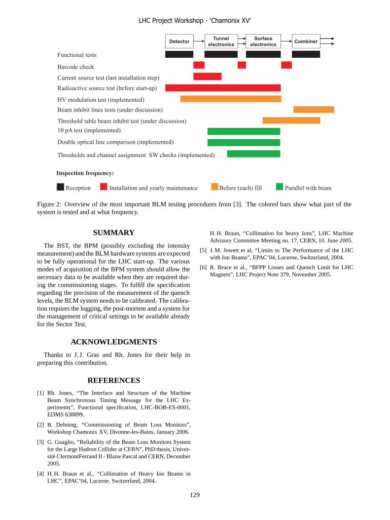
Radioactive source test (before start-up)
Functional tests
Barcode check
HV modulation test (implemented)
Double optical line comparison (implemented)
10 pA test (implemented)
Thresholds and channel assignment SW checks (implemented)
Beam inhibit lines tests (under discussion)
DetectorTunnel
electronics
Surface
electronicsCombiner
Inspection frequency:
Reception Installation and yearly maintenance Before (each) fill Parallel with beam
Current source test (last installation step)
Threshold table beam inhibit test (under discussion)
Figure 2: Overview of the most important BLM testing procedures from [3]. The colored bars show what part of thesystem is tested and at what frequency.
SUMMARY
The BST, the BPM (possibly excluding the intensitymeasurement) and the BLM hardware systems are expectedto be fully operational for the LHC start-up. The variousmodes of acquisition of the BPM system should allow thenecessary data to be available when they are required dur-ing the commissioning stages. To fulfill the specificationregarding the precision of the measurement of the quenchlevels, the BLM system needs to be calibrated. The calibra-tion requires the logging, the post-mortem and a system forthe management of critical settings to be available alreadyfor the Sector Test.
ACKNOWLEDGMENTS
Thanks to J. J. Gras and Rh. Jones for their help inpreparing this contribution.
REFERENCES
[1] Rh. Jones, “The Interface and Structure of the MachineBeam Synchronous Timing Message for the LHC Ex-periments”, Functional specification, LHC-BOB-ES-0001,EDMS 638899.
[2] B. Dehning, “Commissioning of Beam Loss Monitors”,Workshop Chamonix XV, Divonne-les-Bains, January 2006.
[3] G. Guaglio, “Reliability of the Beam Loss Monitors Systemfor the Large Hadron Collider at CERN”, PhD thesis, Univer-site ClermontFerrand II - Blaise Pascal and CERN, December2005.
[4] H. H. Braun et al., “Collimation of Heavy Ion Beams inLHC”, EPAC’04, Lucerne, Switzerland, 2004.
H. H. Braun, “Collimation for heavy Ions”, LHC MachineAdvisory Committee Meeting no. 17, CERN, 10. June 2005.
[5] J. M. Jowett et al, “Limits to The Performance of the LHCwith Ion Beams”, EPAC’04, Lucerne, Switzerland, 2004.
[6] R. Bruce et al., “BFPP Losses and Quench Limit for LHCMagnets”, LHC Project Note 379, November 2005.
LHC Project Workshop - 'Chamonix XV'
129
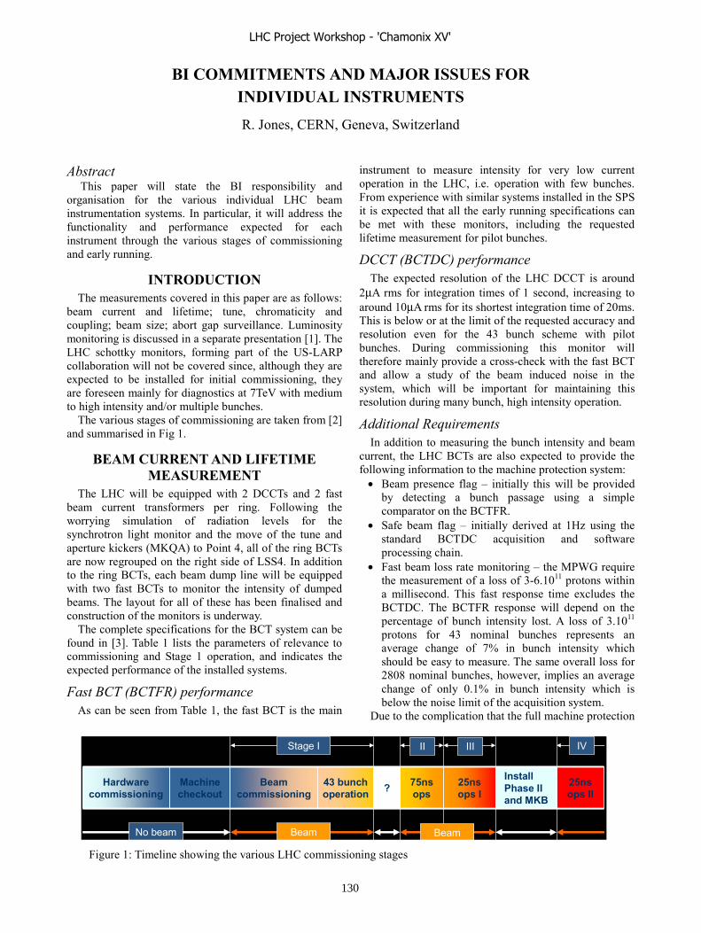
BI COMMITMENTS AND MAJOR ISSUES FOR INDIVIDUAL INSTRUMENTS R. Jones, CERN, Geneva, Switzerland
Abstract This paper will state the BI responsibility and
organisation for the various individual LHC beam instrumentation systems. In particular, it will address the functionality and performance expected for each instrument through the various stages of commissioning and early running.
INTRODUCTION The measurements covered in this paper are as follows:
beam current and lifetime; tune, chromaticity and coupling; beam size; abort gap surveillance. Luminosity monitoring is discussed in a separate presentation [1]. The LHC schottky monitors, forming part of the US-LARP collaboration will not be covered since, although they are expected to be installed for initial commissioning, they are foreseen mainly for diagnostics at 7TeV with medium to high intensity and/or multiple bunches.
The various stages of commissioning are taken from [2] and summarised in Fig 1.
BEAM CURRENT AND LIFETIME MEASUREMENT
The LHC will be equipped with 2 DCCTs and 2 fast beam current transformers per ring. Following the worrying simulation of radiation levels for the synchrotron light monitor and the move of the tune and aperture kickers (MKQA) to Point 4, all of the ring BCTs are now regrouped on the right side of LSS4. In addition to the ring BCTs, each beam dump line will be equipped with two fast BCTs to monitor the intensity of dumped beams. The layout for all of these has been finalised and construction of the monitors is underway.
The complete specifications for the BCT system can be found in [3]. Table 1 lists the parameters of relevance to commissioning and Stage 1 operation, and indicates the expected performance of the installed systems.
Fast BCT (BCTFR) performance As can be seen from Table 1, the fast BCT is the main
instrument to measure intensity for very low current operation in the LHC, i.e. operation with few bunches. From experience with similar systems installed in the SPS it is expected that all the early running specifications can be met with these monitors, including the requested lifetime measurement for pilot bunches.
DCCT (BCTDC) performance The expected resolution of the LHC DCCT is around
2μA rms for integration times of 1 second, increasing to around 10μA rms for its shortest integration time of 20ms. This is below or at the limit of the requested accuracy and resolution even for the 43 bunch scheme with pilot bunches. During commissioning this monitor will therefore mainly provide a cross-check with the fast BCT and allow a study of the beam induced noise in the system, which will be important for maintaining this resolution during many bunch, high intensity operation.
Additional Requirements In addition to measuring the bunch intensity and beam
current, the LHC BCTs are also expected to provide the following information to the machine protection system:
• Beam presence flag – initially this will be provided by detecting a bunch passage using a simple comparator on the BCTFR.
• Safe beam flag – initially derived at 1Hz using the standard BCTDC acquisition and software processing chain.
• Fast beam loss rate monitoring – the MPWG require the measurement of a loss of 3-6.1011 protons within a millisecond. This fast response time excludes the BCTDC. The BCTFR response will depend on the percentage of bunch intensity lost. A loss of 3.1011 protons for 43 nominal bunches represents an average change of 7% in bunch intensity which should be easy to measure. The same overall loss for 2808 nominal bunches, however, implies an average change of only 0.1% in bunch intensity which is below the noise limit of the acquisition system.
Due to the complication that the full machine protection
? 25ns ops I
Install Phase II and MKB
25ns ops II
75ns ops
43 bunch operation
Beam commissioning
Machine checkout
Hardware commissioning ? 25ns
ops I
Install Phase II and MKB
25ns ops II
75ns ops
43 bunch operation
Beam commissioning
Machine checkout
Hardware commissioning
Stage I II III
No beam Beam
IV
Beam
Figure 1: Timeline showing the various LHC commissioning stages
LHC Project Workshop - 'Chamonix XV'
130

requirements imply for both BCT systems, only a minimal integration will be provided for Stage I. Complete integration is foreseen for later running once the stored energy becomes significant. This will, however, require extensive changes to the current acquisition system if a purely hardware solution is to be envisaged, and will not improve the resolution of the system.
TUNE, CHROMATICITY AND COUPLING MEASUREMENT
The implementation of tune, chromaticity and coupling measurements will proceed in three clear three steps:
1) Day 1 – These measurements will be carried out with kicked beams and classical motion analysis. - The tune measured by Fourier analysis of
beam oscillations. - Chromaticity measured either via the head-tail
method or by observing the tune change due to slow momentum variations.
- Coupling measured by combining information from horizontal and vertical beam oscillation data.
A tune kicker will be available for exciting both planes & both beams at up to a 2Hz repetition rate. The possibility also exists to provide chirp excitation using the transverse damper, which would allow for even faster measurement rates.
2) Day N – As soon as possible this single kick approach will be replaced with PLL tune tracking.
3) Day N++ – Once the PLL measurement has been confirmed to be robust then feedback on tune, chromaticity and coupling can be attempted.
The time scale for Day N and N++ will depend on the quality of the tune measurement and on the robustness of the PLL (see section below on feedback).
For operational beams the additional problems will be lowering the excitation level to an insignificant level, coping with coupling and achieving compatibility with resistive transverse damping. The full specifications can be found in [4].
The Base Band Tune Measurement System Considerable progress has been made over the past two
years in addressing the first of the problems mentioned above, namely detecting oscillations at very low amplitudes. This has been made possible by the development of the Base Band Tune (BBQ) measurement system [5], which has now been installed and tested in the PS, SPS, LEIR, RHIC and Tevatron. Based on AM detection techniques, the advantages of this system are:
• Sensitivity - the noise floor of the RHIC system has been calculated to be in the 10nm range.
• Robustness against saturation. • Simplicity and low cost. • Base band operation allowing the use of excellent 24
bit audio ADCs and powerful signal conditioning. It is also independent of the machine filling pattern,
which makes it ideal for operation with varying bunch structures. Conversely, this does not allow the system to measure on individual bunches unless the signal is gated. Such gating has been successfully implemented at the Tevatron, where the recently installed BBQ is the only instrument capable of measuring pbar tunes. For LHC Stage I, however, tune measurement of individual bunches using the BBQ is not foreseen.
Measurement Mode Beam type Requested Accuracy/
Resolution
Equivalent Bunch charge/ Beam current
Fast BCT (BCTFR)
DC BCT (BCTDC)
Pilot bunch ±20% / ±20% ±109 / ±109 OK N/A Injection
Nominal bunch ±3% / ±1% ±3·109 / ±109 OK N/A
Pilot bunch ±10% / ±10% ±0.5·109
±1μA (on 10μA) OK
Not attainable requires1 second
integration to obtain 2μA rms resolution
Nominal bunch ±1% / ±1% ±109
±2μA (on 180μA) OK at limit even for long integration times
Circulating Beam (>200 turns)
43 pilot bunches ±1% / ±1% ±109
±2μA (on 390μA) OK at limit even for long integration times
Pilot bunch 10% (10hrs/1min) OK N/A Lifetime
Nominal bunch 10% (30hrs/10sec) OK N/A
Table 1: Summary table showing the requirements and expected performance of the LHC BCTs
LHC Project Workshop - 'Chamonix XV'
131

The BBQ system will be operational from Day 1 as the main LHC tune measurement system using kicked beams and is expected to give a resolution on the fractional part of the tune at the 10-4 level.
PLL Tune Tracking The LHC PLL tune tracker is being developed in
collaboration with BNL as part of the US-LARP. The advantage of this technique is that it provides a continuous tune measurement with a resolution in the 10-5 range for a bandwidth of 1-10Hz. The LHC PLL tune tracker acquisition system will use a BBQ front-end, to detect the low amplitude oscillations, combined with a digital PLL algorithm implemented in an FPGA. The aim is to make this available from a very early stage, as in addition to tracking the tune it allows the measurement of chromaticity via momentum variation and, if configured correctly, can also provide a continuous measurement of coupling [6].
The main problems encountered when trying to obtain stable PLL operation are:
• Reducing the applied excitation to very small amplitude to avoid emittance blow-up due to the continuous excitation required.
• Coping with coupling. From RHIC experience, PLL functioning is strongly linked to coupling and in extreme cases can lead to the PLL losing lock.
• Mains ripple in the beam spectrum. Due to the very high sensitivity of the BBQ measurement, these lines have been observed in all machines fitted with such a system. The strength of these lines seems to determine the minimum level of excitation which has to be applied for correct PLL functioning.
• Coexistence with active transverse damping. This issue is still to be studied in detail.
Tune, Chromaticity and Coupling Feedback Experience from other machines has shown that it is
not trivial to go from a PLL tune tracker to a complete tune feedback loop. Although feedback was available from an early stage at RHIC, for example, there has been considerable difficulty in making it reliable under varying machine conditions. The two main problems encountered were the fact that excessive coupling immediately breaks the feedback loop, and the saturation of the front-end electronics due to closed orbit variations.
Through collaboration with BNL, and with the advances in detection sensitivity and coupling measurement mentioned above it is hoped that these problems have, to a large extent been solved. RHIC will attempt their start-up in February 2006 with both tune and coupling feedback and the experience from this run will be very valuable for LHC commissioning.
No attempt has yet been made to try chromaticity feedback on high energy hadron machines. The best candidate still seems to involve calculating the chromaticity through observing the tune variation for small momentum deviations using the PLL tune tracker.
BEAM SIZE MEASUREMENT The main workhorse foreseen for proton beam profile
measurements in the LHC is the synchrotron light monitor (BSRT), with the wire scanners (BWS) used for cross calibration. A rest gas ionisation monitor (BGI) is foreseen for ion beams and as a back-up for the synchrotron light monitor during proton running.
Various optical transition radiation monitors (BTV) will be in place for injection and ejection beam profile measurements in the injection lines, the LHC ring and the dump lines. Although the vacuum hardware for the injection matching monitor will be installed by Stage I, it is currently not foreseen to install the acquisition system and develop the necessary software for this monitor before Stage II.
The full specifications for beam size measurement in the LHC can be found in [7].
LHC Wire Scanners The LHC wire scanners are intended mainly for
calibration of the other profile measurement devices. In the baseline scenario the electronics for the wire movement and position system is recuperated from LEP. This system is too slow (1ms-1 instead of 2ms-1) to meet the specifications on the total bunch intensity measurable at 7TeV (2 full PS batches, i.e. 144 nominal bunches). It will, however, be useable for 43 nominal bunches. Use of new detection electronics, based on the 40MHz fast BCT integrator will allow the system to have bunch to bunch capability.
A parallel development of new electronics for the motorisation system is already underway for Phase II. This will allow the movement of the wire at up to 2ms-1, so meeting the intensity limit specifications at 7TeV. In addition, an improved wire position measurement will enhance the accuracy of this system.
The BI Group still has to work on the following outstanding issues:
• Investigation of wire heating due to trapped RF modes (currently under test).
• Verification that wire scan does not provoke a quench!
• Determination of the photomultiplier detector signal strength and simulation of the variation of its amplitude with the position of the detector.
These last two points are linked to the final choice of wire diameter.
The Synchrotron Light Monitor Two light sources are foreseen for the LHC synchrotron
light monitor (BSRT). From 450Gev to 2TeV a 5T, 2 period, superconducting undulator will be used, while from 2TeV to 7TeV there is enough light from the D3 magnet.
At start-up with protons the BSRT will work in the visible light region. It will have a limited electronic installation, which will not provide full functionality. The system will be based on a 10Hz camera providing the rms
LHC Project Workshop - 'Chamonix XV'
132
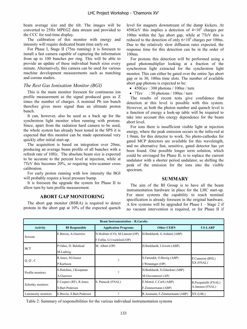
beam average size and the tilt. The images will be converted to 25Hz MPEG2 data stream and provided to the CCC for real-time display.
The calibration of this monitor with energy and intensity will require dedicated beam time early on.
For Phase I, Stage II (75ns running) it is foreseen to install a fast camera capable of capturing the information from up to 100 bunches per ring. This will be able to provide an update of these individual bunch sizes every minute. Alternatively, this camera can be used for various machine development measurements such as matching and corona studies.
The Rest Gas Ionisation Monitor (BGI) This is the main monitor foreseen for continuous ion
profile measurement as the signal produced goes as Z times the number of charges. A nominal Pb ion bunch therefore gives more signal than an ultimate proton bunch.
It can, however, also be used as a back up for the synchrotron light monitor when running with protons. Since, apart from the radiation hard camera to be used, the whole system has already been tested in the SPS it is expected that this monitor can be made operational very quickly after initial start-up.
The acquisition is based on integration over 20ms, producing an average beam profile of all bunches with a refresh rate of 10Hz. The absolute beam size is expected to be accurate to the percent level at injection, while at 7TeV this becomes 20%, so requiring wire-scanner cross calibration.
For early proton running with low intensity the BGI will probably require a local pressure bump.
It is foreseen the upgrade the system for Phase II to allow turn by turn profile measurement.
ABORT GAP MONITORING The abort gap monitor (BSRA) is required to detect
protons in the abort gap at 10% of the expected quench
level for magnets downstream of the dump kickers. At 450GeV this implies a detection of 4×10⁹ charges per 100ns within the 3μs abort gap, while at 7TeV this is reduced to the detection of only 6×10⁶ charges per 100ns. Due to the relatively slow diffusion rates expected, the response time for this detection can be in the order of 100ms.
For protons this detection will be performed using a gated photomultiplier looking at a fraction of the synchrotron light extracted for the synchrotron light monitor. This can either be gated over the entire 3μs abort gap or in 30, 100ns time slots. The number of available abort gap photons is expected to be:
• 450Gev : 300 photons / 100ns / turn • 7Tev : 50 photons / 100ns / turn The results of recent tests give confidence that
detection at this level is possible with this system. However, as both the photon number and quench level is a function of energy a look-up table will be required to take into account this energy dependence for the beam abort level.
For ions there is insufficient visible light at injection energy, where the peak emission occurs in the infra-red at 1.9mm, for this detector to work. No photo-cathodes for gated MCP detectors are available for this wavelength, and no alternative fast, sensitive, gated detector has yet been found. One possible longer term solution, which could be envisaged for Phase II, is to replace the current undulator with a shorter period undulator, so shifting the peak of the emission for the ions into the visible spectrum.
SUMMARY The aim of the BI Group is to have all the beam
instrumentation hardware in place for the LHC start-up. For most systems the capability to reach nominal specification is already foreseen in the original hardware. A few systems will be upgraded for Phase I – Stage 2 if no vacuum intervention is required, or for Phase II if
Table 2: Summary of responsibilities for the various individual instrumentation systems
Activity BI Responsible Application Programs Other CERN US-LARP
E.Bravin, A.Guerrero N.Hoibian (CO), M.Lamont (OP) H.Burkhardt, G.Arduini (ABP)
F.Follin, G Crockford (OP)
P.Odier, D. Belohrad M. Albert (OP) H.Burkhardt, J.Jowett (ABP)
M.Ludwig
R.Jones, M.Gasior S.Fartoukh, O.Berrig (ABP)
P.Karlsson J.Wenninger (OP)
S.Hutchins, J.Koopman H.Burkhardt, S.Gilardoni (ABP)
A.Guerrero M.Giovannozzi (AP)
F.Caspers (RF), R.Jones S. Panacek (FNAL) E.Metral, C.Carli (ABP)
S.Bart-Pedersen F.Zimmermann (ABP)
Luminosity monitors E.Bravin, S.Bart-Pedersen ? R.Assmann, F.Zimmermann (ABP) XX (LBL)
Schottky monitors R.Pasquinelli (FNAL)A.Janssen (FNAL)
Q, Q’, C P.Cameron (BNL)XX (FNAL)
Profile monitors
?
?
Beam Instrumentation – R.Garoby
BCT
Screens
LHC Project Workshop - 'Chamonix XV'
133

vacuum intervention is necessary. The large task now is to produce software that allows
the full hardware capability to be used. This software functionality is also expected to evolve with the commissioning phases and the use of the instruments. Table 2 shows a summary of the persons responsible for the instruments, the low level software, the application programs and aiding in the commissioning. Most of this is now well defined, with a few names still missing for the application programs.
REFERENCES [1] E. Bravin, “Bringing the first LHC beams into
collision at all 4 IP's” in these proceedings. [2] R. Bailey, “Summary of overall commissioning
strategy for protons” in these proceedings.
[3] C. Fischer and R. Schmidt, “LHC Ring Beam Current and Lifetime Measurement”, LHC-BCT-ES-0001-10 (http://edms.cern.ch/document/359172).
[4] S. Fartoukh and JP. Koutchouk, “On the measurement of the Tunes, Coupling & Detunings with Momentum and Amplitude in LHC”, LHC-B-ES-000910 (https://edms.cern.ch/document/463763).
[5] M. Gasior and R. Jones, “The principle and first results of betatron tune measurement by direct diode detection”, CERN-LHC-Project-Report-853, 2005.
[6] R. Jones, P. Cameron and Y. Luo, “Towards a robust phase locked loop tune feedback system”, DIPAC'05, Lyon, France, 2005.
[7] C. Fischer, “LHC Ring Beam Transverse Distribution”, LHC-B-ES-0006-10,
(http://edms.cern.ch/document/328147).
LHC Project Workshop - 'Chamonix XV'
134

�������������� ���� ����������
��������������� ����������������
������������������������������������������� ������������ �����
������������� !��� "#��� $�� ���� ��������� ��� ��%%��%�������� ���� ��&����%����� ������ ��� ���������� ��������������� $������������ ��� ��� �������� ���� �&���%����'� !���������� ����� ���!��%����� �(������� !��� ���� ��!!������ ����������������������������������������������!�������������������������)������������� ���������%�)�������������������������
������������&���%���� ������ ���� ������������ � �!� ���� *+,���
������ ����� ���� *��� -..�/#�� ������������ � ���%� ����*0���������������%������ ���%����������*12��������������������� %�������� ���� �� ��� ���� !���� ������� �!�����%� �� 1����������� !��� ������ ����������� ��� ���� 34-5�������������34-5������������������������$�����������������,���������!� �� �&���%������� ����������!���� ���������� �!� ��������� ��%%���������� ��� $�-� ������� �������� !��%� 6������� ����� ����� *!���� �����������%%���������������������� ���%�����������������%�)���������!��������� ���%�!���������� ��������!������ ����%�������������������!�����&���%���������-������ ����� �������� !��� ��������� ��%%���������� ���� ��� ��%���� ����� ��������������������������� !��� ���� ������� ������+��%�������� �&���%���� ��� ��-� ��� ����� ��� ��� ������� ������%%�������������� !��������%������������ ������ ����������������%� ������������%� � ���� �� � ����� ��%%�����������!���%�������������&���%���������������������������������!���������!�%�� ��(�������� ���%���
�������� ��� ���� ������������������������
���� !������� ��� �� ����!� ������� �!� ���� ������ �!� ������������ � ���%�� ����� ��%�� ��%��7�� ���������� ����������!��� %�)��� %��������8� ��������� ��%%���������� ����������������!��������%���
��� ��������������������������������!�������%������%��������������������!��������
������ �!� ��������� ��%%���������� ����� ��� !���� ���������%������������������������������������������������9�"�� ��� �������� :,-� ���� -,5� ��!���� !����� ���,�������������� ������ ���� �!� !���� %������ ����� ����� !������ ����������� �������� ���� ������������ ��� !�� ������ ���� !����������%���������!��������������� ������������,���������������������� ���������� ��%������� �!� ���� !������ %����� ���;..5��/�������� �!� �������� ��� ����� %����� ��� ����������������������������������������� ����(������� ������������ � ��� � ��%%��� ;..<�� 6����� %��������� %���!�������������������!������������� ���������/=>������?������ ���������������!����,���������%���������������������%������������%�����!������������������,��������!������������������$%�������� %���!��������� ����� %���� !����������%���(�4$@� A=B� ����������� ���� �� �� ������������ C�
��������������%������������������������!������������������������%�������� �������������,��������!�����#����!�� ���%��������������������������#��������*+,������������������� ��� ��7�������� ������� ���� ����������� ���������� �*�,�����
��� ���������������� ���!�����(�����7 �����������������������������������������
�����������������������%���������������D�����������#@��&���%���� ����������� ��� ������ ���������� ������� ���� ����������������� �������������������C� �� �������%�����!����������������������������������!��%�"�1����*��!������������&���%������������������!������������
��%%�����������
�"#$��$�������!���%�������� =<� 7��7���� ���� �������� ������ �%��!����� E����
������F�����������%���!�����������0������������������������� G$���� 2���� %�� � ��!!�������� ����� ��������������� ���� ��������������������������(�����������7��7�������� ������ ����%���� ���� ��7��� ���� ���� ��� ������ �����%��!���� ������� ����������� ���� �������� ���� ������ ������� ������!���������������%%�����������
&'�()�&'�(�������������
��������=8�$������������ �����!�������34-5��
�������=� ������ ���� � ���� �!���� �&���%���� ���34-5�������� !��%� �!�� ��� ������ ���� ����*�������*0�������������7�����H3I�� ������������#@����7����E�����F��������������� � ������ E���F� !��� ���� ��� ���� ��� ���!��%��E�����F���������� ����=<�7 ������� ��� ��������������������������� ��� ���� ����������� ���� ���� ���� ��� %������ ����34-5��������������������*0��7��7��������*12���������+�������������������� ���7� �!� ��������� ��!������������ ���� �������
������������������� ���%����������������������;������������������������*������;..5?��������!��%������������������������� #@� ���7���� ���� ���� �������� ���7��� ������� :� !��%�G����� �;..<�,��������%�����������������1J-5����������������� � ������ ��� ������ ����� ��� �� ���� ��� ����� ����
LHC Project Workshop - 'Chamonix XV'
135

���������������������������������7��!������������������ ���%�� ������� ��� ������ ��� /� � ;..<� ����� ������!������������ ��� !� � ��� ������ ���� ��%�� !��� ������������������,�������!���������������!������������%%��������������(���%� ���������
��������;8�������34-5�,�*������;..5�
��*��������!�������1����� ���� ���� ��� ����� ����� !���� ����%�������� �!� ����
��������� �������� ��%�������� ���� ������� ����������� �����������������*12�%�����������������������������%�!���������������������%�!���*+,+0$��
+������������,��!���������������� ������� ���34-5�������:;�@/��������� !���
����"����������� ���%��!�������*��������������������%��������� ���%��!���*�������*0��������������������!������%���� ���� � �������������� � ���%�� ��� ��� �������� �����-�� $�� �� ����� ;..� @/�� %������ ���� ������� ��� =5���!!������ ��������� *� ����� ����� ��� ������� !��� �����������%%����������������������������� ����������������������������%�!��� ���� !����������%����������������������������� ������ �� �� *� %���%�� ���� ��!!������� ���%� �������� ���%� ��� ��� �������� !��� ����� ���%�� *���������!���������� ��������������� ������� ������� !��� ��������������%��������������� ������������������!������%����� ���%������������������������������������!��������������������������������������������������������!������
�������-������������%�����.���/������������������� ���%��!�������������&���%�������������
7��7������������������������1"����/�����!������&���%������������� ������������������������������2��7������������������*+,�6���� ������������ ����� ���� ������� � ���%������@/�� � ���%�� ���� ������ ��� ��������� *+,�6� !����� ������!������ E���*F� ���� ������%���� �!� �������� ����������������!����������������������������������*� %���%�%� ��!������ ���� E!����� ���� ��!������ ����
������������ ��������� ������� ���� ���%�F� ��� ����������!������ ���%��!��������������%%�����������������
��
�������:8�������34-5�,�G����� �;..<�
���������� ������������ ��1������� ������������!���������� ��������������!���
���������� ����� !��� ����� ���%��*�*������������ ������� ���%������ ��������&���%������������������*�*0���&���%���� ��� ����� ��� ��� ����������� !��� ��)������� ������%�������������������������� ������������������������!��������������!������7������ �������� ������� ���%�� ���� ���%� � ���%�� ���
����� ����� ��!����� ������� ��������� ��%%����������� �������%� ���� ����� %����%� � ���%� ���� !���� ��������������!������%����������������������������!��������������������������� � !������7���������
����� ��� ��� ����������8� ����� *��� ����� � ������� ���!������7�����7 ����������������������������������!���������� ��� ����� ��!���� ���%� ������ ��� ���� �����������%%������������������*��������%��������������������!������� ����� � ������ ����� ���� ������ ����� ��� �����&������ ������� ����� ����!�� ���� �������� !����� ����� ������ ����*0����������������������� !������7� �������������%� ������� ���� !������7� � ���%�� ��� ����� !��&�����%���������������������� ����������7���������� ������������%� ������� +����� ���� ����������� ������� ��� ��� %������������������������EG�����*+,���*+,61�����*+��6����������������F�����%�� ���������� !�������������� �������� ��� ����� ������
�!� �������������� � ���,���)������� ��%������ !��� ���� ,���������������������
�0��-�������������1�2������� �������������� �!� ��)������� �1�� ��,�������� ��!����
��)������� ����������� �!� ������ !��� �1�� �(��������� "#����)���������������"#�����%���%����!�������������7�����!� ���� ���� ���%�� !��� ���� ���� ������ �!���� ��)������� ��� ���������������� ��!�����*+,���������������&���%�����������������������������������������������-�������� ����������������� ���� ������� �!� ���� -../#�� �������� ������ ������(������� � ��� ������ � ���%�� ��� ��� ��� ������ 6������&���%���� !����� ���� *+,��D�+� �������I�� ���������$������������� ���� ��&�������� �!� �����!���� ���� ���7���������������������������� ����� ������/�������E /F���%����� ���%�E*+,�6F���
LHC Project Workshop - 'Chamonix XV'
136
�����!���������!�������������)���������������������������� ������ ���� ���� ��� ���� ��&�������� �!� ��� �&���%�������7��� ��������� ���� /� ��%���� ��� ���� ������������ � �!����� *+,61� ������ A;B�� ������� �����!����� ���� ���*��������!�����������&���%�������������������� �*+,��������� ��)������� � ���%� �������� %�� � ����������������
�����������%�����!���������������������,����������������������� ��� ���� ������ �!� ����� ����������� ������ ������������������������%��%�����������������*�� �%�������� ������� �!� ���� ��������� ���� ��!������
���������������������� �������������������������!���������� ��� �������� ��� ��%���2���� �������� ��7��%���� �!!��������� ��������� �� ��%����� � � ���%� ��� �1�� ����� ��������� �����������!����������������*� !����!���������!� ���� �������� ���� ����������������
����� ��)������� ������������ ������%�� !��� ����� ���� ��� ����%� ��������� ����� ���� ����������� ��%����� ����� ������!�������������!���������������,���������!����&���%����������������������%%������������
��!���/@����������!��������������������������%��������������� �
!�������� ����������� �������� *��� ����� ���� ������ E��� $�����9F����������!�����=<��������������������������������!��&���������!�+��%�=����+��%�;����������� �����*0����%���D!������7� ������� ���� !�������� ���������� ��� ����� ������������ �*+,16�����������������������������������!�������������� �*+,����*+,16������7��� ������������������������������� ���!�������������� ����������*����� ���� ��%�� ������� ����������� ��� �����!���� ����
��������� �*+,61�����*+,�6���������������������� ������%�� �������!���������� ��������!���%������%����������������������%������ ����������������������������������������� ��������� ���%� !��������� ��%���� ��� ������ !��� ������%���������%����� ���� !��&���� � ���������� ��� ��������� ��� ����%%������
������&������!��&���� ��������EK=�7#�� !��%���)������� ���!��� ���� !��� �������� ���� KL� 7#�� !��� �����,������ ��� ������!!�������!�����������������������)�������F��������������������������������������������������������������������(������ �(��������� ������� ����� ����� ����� ����� ����
*0�� � ���%� !��� ����� %������%����� ������� !��%� *+,+0$��&���%�������������7������!������7����������������������-���������� ��������7��7�����
�������+��%�=� ���� +��%�;� -.� /#�� ���� ���������� �������
�����������������������(����%������������������������ �������� �����!���������� ���� *+,��� ������ ��� �������������� !��� �����%������� ����� ���� �(����%��������������1#,��������������� ������� ��� ������������!� ����@/��������!����������������%�������������������%��������� �������������������
���� �������� ��
��������!�3���%%*� ��%���� �!� %������%����� ��� ��� ������� ��� ����! �
����������� ����%������ ��!���� ����%������ ��� �������� �������%��������,�����������%�������������������0���������
*12����������%�������������������%���������������!��� ������ %������%������ 1����� ���� ����� �������� ��� ������%���� ��)������� !��&���� � ���� ���� ����� ��&������� �������7� ���� ��)������� ����� �� ����� ���� ��� ������� � ���� ���������� ������ ���� �(������� ������ ������%������� �!� �������������������������������������2���� ;��� ������ ������ ���� ����� � ;� #�� *12�
���������� ������ ����� ��&��������� ���� ��� ����� ��������%%����� � �������� ;� #�� -,>� �D�� ��&���������%����������������&���������������������������� ���������!� ��������� ���� ������%���� �!� ��!������ ������ ����6*�$��!��%����7�������������������� ���������1���
������������"�!���%�� %������%����� ��� ��� �%���� ���� !����� ��� ���
����� ������ ������ *12� %�������� ���� ������������� ���������������E9�F�%������%���������������&�������C������ ���� ��� ����� � � �������� ��� ���� �!� ���� ������������%������� ������� �!� ���� ���� ����� ���� ��� ��!� ��������� ���%�7�� ���� ������%����������*��������� �� ������������������7�������������������������� ����������!��&���� � E����� � ;�!�F� ���� ��� ����%����� � � ����������� �����*� !�(���� %�������� ������ ����� � ������ ��� ���� !����
����������� ����� ��!!������� %�%�� � ����� ���� � ��������%�����!�������%������%������
#���������������/������%����� ���� ��� ����� ������ � ������ ���� *0��
13��E*+,+0$F�����������������������#��������!��&���� ���������������������������������
����������� ������� ������� ����
���-�������������6� � ��� � ��� ����������� ���%� ������������ ���� ���
��������� ��� ��� ��� ����� � %����� ����� ��� ���� ����� *����������!�.�:�MD������������%��������5..��*����%���������EG���N�7%����F�� *����� ����� �������� � ����%� ���� ��������������������7��%���������������������������%����%������������������%�����������������!�����%��%�����������%��7� �������� ������ %������� �������7�� E:�5� %*� ��� -5.� �@F��*���!���������7���������������!�������������� ������������ �����!����%���������%�����������*� �������� ���� ��� ��������� �!� ���� �(������ ������ ��� ����
��%���� !��� 9,%������%����� ��������� � �(�����������������%��������6�,���� %������%���� �!� ��� !��&���� � ���� �����
��&������������%���������%���!�������������������!���%�������������!���������!������ ��*���%���%���!���������!��������� -..�/#�� �������� ����� ����� � ��� ��������� �����%������%��������� �5.�%��������������������!�;.�#���������%������� �!� ��� !������� ��� ���� ���%� ���%��� ���
��%�� ���� ���%� ��!���� ��������� ����������� ��������������������!����%��������������%��%�������������!,��%������������ ��$���������������%�����������������%������������ ��� ��� ��!,��%���� �������� � !��� ���� ����� �!� ����
LHC Project Workshop - 'Chamonix XV'
137
7 ������ A:B�� #�������� ������������ !��%� ���� �������7�� ���%����������������������������������
,��! �����0��������+�2���� �������������%������!������������� �������� � ����
��)����������������������%��%������%��(�������������,���&������� !��������� ����� ��� ���%� &���� � %���������� ����1������"#���������! ��������!����)��������!�������������������������������������)��������!�������(���������������������� � �!� ���� � ����� ���� ��%�� ���7���� �!���� �����(��������D��)������� ��� ������ ���� �� $�� ���� ����� ������E*+,�6F���������� /���%����� ���%�����������������!����������� ���� ������� ��)������� ������ ��� ��%�� !��� ��������������!������������!�������(���������������1���
�������/��2���������-�����/���$��$�)������� ����� ����� � ��������� ���7���� ���� ��� �� �
��!������ !���� ��� ���� ��%���� ������� ��� ������ ����(�������� ���������� ���� �������� ��%����� *� ���������� ���%����������������������������������
�����/��!��������/����� ������������������������������E���F� ��������
��� $�-� ��� ��� ����� !��� ����� ��������� E*+,+0$F�� ���%������� ������ ��� ��� ���� �!� ��� ���������� ��� ���� ���%����������!��%���,������������������ ���,�����������%���� ���� ���� ����� ���� ����� �������� ���� ������ ����� ��� �����1��A-B����������%� ���� �����!!���������� �������������������������������������%�������%� �������� ����������������� ���� �(������� %���%�%� ���������� ���%� ���������!!������������ ������������%�����3����!�+���������������� ��������������������������������������������+���������� !��������������� ���� !����+��������������������� ������������������������������!����������������
�����/���������/����������� �(��������� ����� ���� ��%���� ���� ������
�����������������������1������������������������A-B�������������!��������������*+,+���
��%������$������!�������. It is planned to install the longitudinal damper electronics at the end of 2007, as the initial intensities will be low. As the intensity slowly rises the precision required for energy and phase matching will increase. ��������� �%��������������)������������������������
���������������=,�����!������7��������� �����������!�����������������������������!���%�����
#�����������!�����%%���������� ���� ��� � ���%� ���������� ���� �����
���������������%���(�4$�A5B������*0��� ���%�������������������������!��%�!��������%�!�����)���������%������*�� ��� ������������ ����������� !������7� ������ ���� ���������� ���� ���� ��%���� ����� ����� ��� �������� ��� ����� ���%� ��������� �!!� ����� � �!���� ��)�������� #�������������������!�����)���������%����������������� ���%�����!������)������������!������7�� ���%����������������%�)���
��%���������������������������������������%����������������������
+��/���������!�����������3������� ��� ����� � � ������������ ������ ��� ��������� ������
�%��������� $��� �������� ��� ��� �������� ���� �������� ������������ �%�������� ��� L� ��@� ��� ����%���� ��������%������������ �!���%�� ��� ���� ��������� �!� � �������������������� ��%����� ���� ��� 7���� ��������� � ������������������� ������� ���� ��%�� � � ��%���������� !��� ��������������� ��������� �%�������� ����� ����� �� $�� ���������� � ��� � ��� ��� ��� ���� ��� ��������� ���� ���� ������������� ��� ������������#������� ����������� ��������������������������1���������%��������%�����������%��������!������%,��������!!�����E�������!����F���
4�-����������*�� ����� �������� � ���� ����������� ���� �����������
���������������� ���%� ���� ��� ������ ��� ��!������ ����������� ��� ������ ������ �&���%���� ����� ����������� ��������������������������������������������������������$������������������!�������7��������������������������������?��������� ����������� !��� ���������� ���� �!!����� ���� ���������� �E*+,��F����������������� �7 ���������������������!��%�������
���������� ���%������ ��� �� ��������� ������ �!� ����� ���%��!���%�� ���� ��� �� ��������� ������������ �!!���� ���� �����%���������������������������������%������E*+,16F�������� %���%���� ������ �������� ����� !��%� ���� 7 ������%��������� ��� ���� 7 ������ !������7� � ���%�� �������������� ��� ���� ������ ��%������� ������ ����� ����������������������������(�����������!��%��1���D������(�����������
������������=F�#����������%%���������8����� "#�� ��� ��� ��� H����� �����I� ���� ��%�� ������ ����
��������������������!�����%�����%������� ���%��������!���!�������%������������������������� ���%���
�
;F������������8������ ��� ������ ����� ���!��� ��� ���� !���� "#�� ��%����
���� � �������������� �&���%���� ������� ����� �%������������������� ��� ���� �1�� ��%����� 0�!�������� �!� ������� ��%�������������� !��� !����� ���%� ����� ��� ��� � ���!�� !��������������%%������������
�
:F�����������!���!��������%8��*����� ���� "#�� ��� ��� ��� ��� �� ����� ������ �!� ����
��%%���������� ���34-5� ������-� ��� ���������� ��� ��������� ���� !�� ����� ������%� ��� ��%������� 6��������� �������������%����������������%�)��������%���*���&�������%������%�����&���%������������������!���!��������%���
��
-F�#�����������������8����� ������ %������� ����������� !���������� � ���� �����
������������*���������%����������� ���%������������������������������!�������������������*+,+������!����)�����������%���������������������)��������������
���������7����%� ������������!���!����������7��
LHC Project Workshop - 'Chamonix XV'
138

�1������ ���%����������������������������������� ���%��%� � ��� ������� !��� ������ ��!,��%���� �������� ����������?��������������������� ��
������������/�� � ����7�� ���� ���� ���1��+������������6��+�������
���+��� *��+����������� 2��#O!�� ���"��������������������7��������G���N�7%�����!��������������������������������������
�������A=B� ������������� P���� �� �������� � ���%� ��� ��� -8�
���������������Q����%���(�4$@������;..5��A;B���/��"�%����P+��%���%%���������8���&������
*����������Q���������7������A:B� ���"�������� P�����&������� �!� ��� � ���%� !�������
�������"#�����%���%%���������Q����%���(�4$@������;..5���
A-B� ������������7���� P*����� ���� �������� ���� ���� ���%Q����%���(�4$$�;..:���
A5B� 2��#�!�� P6��������� �!� ���� "#�� ����������� ��%����E!������7F�������������� ��Q����%���(�4$�;..=��
�
LHC Project Workshop - 'Chamonix XV'
139

COMMITMENTS AND MAJOR ISSUES ON LHC CONTROLS SERVICES
H.Schmickler, CERN, Geneva, Switzerland
Abstract This presentation will state CO group responsibility and
organization for LHC control services, i.e. timing, interlocks, logging, post-mortem... It will also present CO commitments on the requirements listed in the 2 previous sessions. In particular, it will address the functionality and performance expected for the different operation stages and the procedures and tests foreseen to reach these objectives. Finally, current major issues (i.e. uncovered requirements) and possible ‘Plan B’ will be presented.
THE NEW AB-CO ORGANIGRAM The Chamonix workshop is defined as technical
workshop. But the title of the presentation and the guidelines issued by the chairman demand a concentration on the human resources situation of the AB-CO group. For this reason at first the new organigram of the AB-CO group as defined on the 11th January 2006 is discussed. (see http://cern.ch/ab-div-co/AB_CO_Organigramme.pdf) From the previous 6 sections the structure has been changed to contain 8 sections of more equal size. The sections have been arranged in order to minimize interdependencies between the sections. Sections dealing with the core activity of controlling the beams in CERNs accelerators have been distinguished from controls of industrial services and from interlocks.
With this new structure the group is confident, that most of the workload can be accomplished with the assigned permanent resources, but a significant number of temporary staff has to be added in order to fulfil the immediate requirements on accelerator controls at CERN.
A LIST OF AB-CO ACTIVITIES/PROJECTS FOR THE LHC
AND THE RELATED INJECTORS In total AB-CO will deliver about 50 different large
work-packages for the LHC, for which going into technical details would be impossible. Therefore the convention is that if there are no particular mentions, the work will be completed in time according to the user needs.
1) Activities in the AP section;
Application Programs section leader: Eugenia Hatziangeli
• Common Console Manager for the CCC
Responsible: Veronique Paris • Fixed Displays and online monitoring
Responsible : Jakob Wozniak An important project for LHC operations and for
Hardware Commissioning, which is entrusted to a non CERN staff.
• JAPC = Common access to equipment in Front-Ends Responsible: Roman Gorgonosov An important project for operations, which is entrusted to a non CERN staff.
• Java GUI components Responsible: Greg Kruk
• LASER : Alarm system for all CERN machines and services Responsible: Katarina Sigerud
• Logging: Logging applications for LHC/LEIR and for Hardware Commissioning Responsible: Marine Pace-Gourber
• LSA project inside AB-CO Core software for LHC/LEIR beam operation and for Hardware Commissioning Responsible: Grzegorz Kruk
• LEIR controls coordination Responsible: Marine Pace-Gourber
• Sequencer for Hardware Commissioning Responsible: Francois Chevrier
• SIS: Redevlopment of Software Interlocks Responsible: Vito Baggiolini
• OASIS: Analog Observation System (replacing nA0s) Responsible: Stephane Deghaye
The software effort is well organized as collaboration
between AB-CO and AB-OP. The basic software components are defined. There is a large amount of implementation, testing and commissioning work to be done, for which the section will rely on temporary programmers. A need for 2 additional persons for hardware commissioning has been identified and 3 more for LHC beam applications. The path of getting these resources as project associates has so far not worked out and very soon other measures have to be taken in order to find people with the right profile.
A significant part of this software effort will be done by operators on their so called “2nd job”. In order for this scheme to be efficient a significant training effort for these operators has to be organized.
2) Activities in the DM section;
Data Management section leader: R.Billen
• Logging Service: Reception, storage and
making available time-dependent data from the LHC or any of the LHC components, equipment or beam related, throughout the LHC lifecycle.
LHC Project Workshop - 'Chamonix XV'
140

• Measurement Service: Similar as Logging Service with more frequent and rapid transfers of short-lived data, serving as temporary buffering with persistence for Java measurement applications.
Responsible: Chris Roderick • Controls Configuration management:
Topology, relations and description of the controls infrastructure: application programs, servers, front-end computers with hardware components and software devices; including interfaces to maintain the information. For LHC the software device implementation is FESA. Responsible: Maciej Peryt
• Layout Management: Topology, relations and description of LHC layout components: functional positions of the LHC machine, electrical circuits and electronic racks; including navigation from different viewpoints and interfaces to MAD and DMU Responsible: Pascal Le Roux
• Asset Management: Registering and keeping track of physical equipment throughout its lifecycle from design, manufacturing, test, commissioning to operation and finally destruction. Responsible: Zory Zaharieva
• Naming Service: Identification (naming) is a prerequisite for all data management services, from conceptual design, drawings, and layout components to physical equipment. Responsible: Ronny Billen
The most important information to pass it that the users
themselves are responsible for the quality of their data and that still significant effort is needed from several equipment groups in order to fill and maintain the data in the databases.
3) Activities in the FE section;
Front Ends section leader: Marc vanden Eynden
• Department wide VME, cPCI and PC HW
procurement, installation and maintenance (processors, crates, remote reset, terminal services); Responsible: Guy Surback
• CERN wide WorldFIP network infrastructure installation, commissioning and maintenance Responsible: Raymond Brun
• Department wide LHC control system installation coordination; Responsible: Claude Dehavay
• Timing distribution hardware installation and maintenance (for the copper and fibre systems) Responsible: Roland Chery
• Front end operating system, system administration and remote diagnostics Responsible: Nicolas de Metz-Noblat
• FESA: Front ends software architecture; development and support: Responsible: to be announced by AB-CO in February 2006
4) Activities in the HT section;
Hardware and Timing section leader: Javier Serrano
• General machine Timing (GMT) Generation Responsible: Julian Lewis
• Beam Synchronous timing (BST) generation Responsible: Pablo Alvarez
• General Machine Timing (GMT) Reception Responsible: Ioan Kozsar
5) Activities in the IN section;
Infrastructure section leader: Pierre Charrue • File and application servers:
Responsibles: Alastair Bland and Enzo Genuardi
• Operational Consoles: Responsible: Edwige Bournonville
• Monitoring, Support and Maintenance: Responsible: Alastair Bland
• LHC test benches support; Responsible: Markus Bjork
• CMW: Common Middleware: Essential communication protocol Responsible: Kris Kostro
• CNIC implementation: Responsible: Pierre Charrue
6) Activities in the IS section;
Industrial Systems section leader: Philippe Gayet • CERN wide UNICOS framework for
industrial controls and PVSS application support Responsible: Herve Milcent
• Support for UNICOS applications development within equipment groups: Responsibles: Philippe Durant; Claude-Henri Sicard
• PLC small applications, development and CERN wide support; Responsible: Jacky Brahy
LHC Project Workshop - 'Chamonix XV'
141

7) Activities in the MA section; Measurements and Analysis section leader: Adriaan Rijllart • Post mortem analysis software;
Responsible: Hubert Reymond • Fast Measurement Systems for Test Benches
(FAME) Responsible: Cedric Charrondierre • Magnet Rescue Factory Systems (MAR)~
and SM18 test systems Responsible: Allesesandro Raimondo
• Test systems in industry Responsible: Adriaan Rijllart
• Corrector Tests in Bloc 4 and warm measurements: Responsible: Hubert Reymond
• Insertion Quadrupoles and SSS measurements Responsible: Cedric Charrondiere
• Cable and Busbar test systems Responsible: Eric Michel
8) Activities in the MI section
(machine interlocks) section leader: Bruno Puccio • BIC; Beam interlock systems
Responsible: Benjamin Todd One of the most important interlock systems with a doctoral student as main responsible
• PIC; Powering Interlock Systems Responsible: Markus Zerlauth
• WIC; Warm magnet interlock system Responsible: Pierre Dahlen
• FMCM; Fast Magnet Current Change Monitors Responsible: Markus Zerlauth There will be fewer units than expected for 2006, but the full lot will be available in July 2007
• Safe beam parameters Generation Responsible: Bruno Puccio The SLP will be distributed by the timing system under the responsibility of Javier Serrano
9) Other Activities
• Real Time Feedback on beam parameters Responsible: Michel Jonker
• Collimation Controls Responsible: Michel Jonker
• Hardware Commissioning Controls Coordination Responsible: Robin Lauckner
• Post Mortem Project Responsible: Robin Lauckner
• Machine Protection Responsible: Ruediger Schmidt
PARTICULAR TECHNICAL ISSUES 1) Software release policy
The LHC as high energy and high intensity machine requires a more rigid control of software deployment and versioning control. Two major subsystems are handled in the following way:
FESA: Front end software: The software package is developed according to user needs between one official release to the next. Every new release is carefully tested before deployment. The testing period is presently about 2 weeks, so no rapid turn around can be expected. This software has to be stable before the LHC is commissioned. Application programs: A powerful versioning tools has been put into place, which allows the operation to switch dynamically between the current release, the past releases and the next release. This is very much needed, since the application software will develop together with the increasing knowledge on the machines.
2) Performance issues of the LHC control systems All the relevant components of the LHC controls
system have been tested on laboratory systems and on small machines/transfer lines. There are unsolved questions on the scalability of the system to its full size for the LHC.
The controls group will propose in spring 2006 an appropriate dry run by the end of the year 2006 in order to do significant scalability tests. In case of failure, significant modifications would have to be made to the controls architecture in order to gain on performance.
3) Sector Test
A major milestone in the planning of controls effort is the LHC sector test scheduled for late in the year 2006. This or an equivalent milestone has to be maintained for the final integration of the LHC controls system. 4) System Security and remote access
With the CNIC approach CERN has made a first and important step towards protecting the technical network from unwanted access. On the other hand several user communities (AB equipment experts, external collaborators) badly need efficient remote access to their equipment. The controls group will study an additional layer of security to be implemented on top of CNIC during spring 2006.
LHC Project Workshop - 'Chamonix XV'
142
COMMITMENTS AND MAJOR ISSUES ON LHC APPLICATIONS
E. Hatziangeli, CERN, Geneva, Switzerland
Abstract
This presentation will clarify CO group responsibility and organisation put in place to produce the LHC operational applications. It will also present CO commitments on the requirements listed in the two previous sessions.
In particular, it will address the present architecture for the LHC Beam operational software, the functionality and performance expected for the different operation stages and the procedures and tests foreseen to reach these objectives.
Finally, current major issues will be presented and explained in details.
RESPONSIBILITIES AND ORGANISATION
The AB Controls group is responsible for • Providing core control functionality & applications
(HWC sequencer, equip state, equip monitoring, SDDS,…) in collaboration with AB/OP
• Producing and maintaining standard facilities (Logging, FDs, LASER, JAPC, SIS, BIC, OASIS, CCM, …)
• Developing, maintaining and supporting UNICOS based applications (Cryo, QPS, PIC, WIC,..) for industrial control system
• Providing support for modelling of the Controls database (SPS, HWC, LEIR, LHC) and for the logging and measurement services (Timber, Meter).
In addition. AB/CO is responsible to provide the
development environment, tools and graphical components [2] to be used by application developers, equipment and MD specialists. A set of tools already used by several developers is described below:
• FESA editor • Java dataviewer • General purpose graphical beans • Java GUI frame • LabVIEW development environment • UNICOS frame • Working sets & Knobs • Jython • Build and release tools
To foster collaboration and efficient development a special development lab has been created in close proximity to the java application team to host the operation developers and to provide with continuous support during all phases of the software development lifecycle.
The AB Controls group is not responsible for
• Providing equipment expert GUI applications (except QPS, CRYO)
• Providing MD software GUI applications
Nevertheless expert and MD developments can be based on the rich tool kit of GUI components and libraries already provide by CO.
THE LHC BEAM OPERATION
SOFTWARE ARCHITECTURE Three approaches have been put in place to build
software applications: • The Beam based control applications, which cover
the majority of the applications, are built on top of our Java infrastructure
• Industrial control PLC/SCADA based applications are built on top of the UNICOS frame based on PVSS, and finally
• The Post Mortem data analysis system is based on LabVIEW.
Java Applications Development A considerable amount of applications for stage I & II
is requested. This will be achieved since we have put in place a common architecture [3] based on:
• a solid core functionality • a standard equipment access • a set of reusable software components, • a group of standard facilities upon which the LHC applications are being built This java infrastructure does not come without a serious
investment. It requires high competence in software engineering for the development of the core system. Nevertheless it is clear that our initial investment has paid back.
The complex self-contained applications of the past are replaced by lightweight GUI applications based on the core which are easier to develop and that are less error prone. The fig.1 below describes the Controls System Core that interacts with the equipment via standard interface (JAPC) and that offers services to the lightweight GUI applications.
LHC Project Workshop - 'Chamonix XV'
143
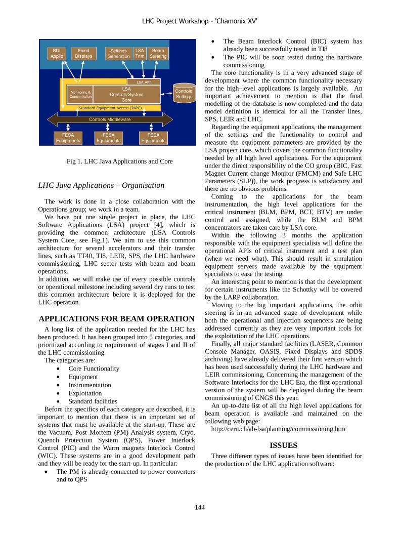
Fig 1. LHC Java Applications and Core
LHC Java Applications – Organisation
The work is done in a close collaboration with the
Operations group; we work in a team. We have put one single project in place, the LHC
Software Applications (LSA) project [4], which is providing the common architecture (LSA Controls System Core, see Fig.1). We aim to use this common architecture for several accelerators and their transfer lines, such as TT40, TI8, LEIR, SPS, the LHC hardware commissioning, LHC sector tests with beam and beam operations. In addition, we will make use of every possible controls or operational milestone including several dry runs to test this common architecture before it is deployed for the LHC operation.
APPLICATIONS FOR BEAM OPERATION A long list of the application needed for the LHC has
been produced. It has been grouped into 5 categories, and prioritized according to requirement of stages I and II of the LHC commissioning.
The categories are: • Core Functionality • Equipment • Instrumentation • Exploitation • Standard facilities
Before the specifics of each category are described, it is important to mention that there is an important set of systems that must be available at the start-up. These are the Vacuum, Post Mortem (PM) Analysis system, Cryo, Quench Protection System (QPS), Power Interlock Control (PIC) and the Warm magnets Interlock Control (WIC). These systems are in a good development path and they will be ready for the start-up. In particular:
• The PM is already connected to power converters and to QPS
• The Beam Interlock Control (BIC) system has already been successfully tested in TI8
• The PIC will be soon tested during the hardware commissioning
The core functionality is in a very advanced stage of development where the common functionality necessary for the high–level applications is largely available. An important achievement to mention is that the final modelling of the database is now completed and the data model definition is identical for all the Transfer lines, SPS, LEIR and LHC.
Regarding the equipment applications, the management of the settings and the functionality to control and measure the equipment parameters are provided by the LSA project core, which covers the common functionality needed by all high level applications. For the equipment under the direct responsibility of the CO group (BIC, Fast Magnet Current change Monitor (FMCM) and Safe LHC Parameters (SLP)), the work progress is satisfactory and there are no obvious problems.
Coming to the applications for the beam instrumentation, the high level applications for the critical instrument (BLM, BPM, BCT, BTV) are under control and assigned, while the BLM and BPM concentrators are taken care by LSA core.
Within the following 3 months the application responsible with the equipment specialists will define the operational APIs of critical instrument and a test plan (when we need what). This should result in simulation equipment servers made available by the equipment specialists to ease the testing.
An interesting point to mention is that the development for certain instruments like the Schottky will be covered by the LARP collaboration.
Moving to the big important applications, the orbit steering is in an advanced stage of development while both the operational and injection sequencers are being addressed currently as they are very important tools for the exploitation of the LHC operations.
Finally, all major standard facilities (LASER, Common Console Manager, OASIS, Fixed Displays and SDDS archiving) have already delivered their first version which has been used successfully during the LHC hardware and LEIR commissioning, Concerning the management of the Software Interlocks for the LHC Era, the first operational version of the system will be deployed during the beam commissioning of CNGS this year.
An up-to-date list of all the high level applications for beam operation is available and maintained on the following web page:
http://cern.ch/ab-lsa/planning/commissioning.htm
ISSUES Three different types of issues have been identified for
the production of the LHC application software:
LHC Project Workshop - 'Chamonix XV'
144
Resources Major core activities are presently staffed by temporary
or departing staff, and that includes the system architect and core developer of the Java software infrastructure.
The same application developers are working for the development of the applications for LHC hardware commissioning, LEIR, CNGS, PS and SPS start-up and their availability to develop applications for LHC beam operations is reduced. This can be clearly seen from the list of the LHC applications, which is not fully staffed clearly showing lack of resources.
Moreover the development of the core system of the Java software architecture needs experienced Java software developers.
Remote Access and Security Experts and piquet require access to LHC controls from
outside the main control room. A policy on who has the right to modify LHC parameters and from where should be defined and implemented.
Control of certain devices (e.g. Schottky) from other institutes is already requested (US-LARP collaboration), adding to the requirements for remote access to devices for controls.
We need remote access and role based access policy and manpower to implement it and the CNIC policy does not provide the answer.
Time Allocated for Testing While TT40/TI8, HWC, LEIR, and SPS ring will be
used to test the LSA core and applications extensively, the tests foreseen in 2006 (CNGS, TI8/TT40, LHC sector test) will be the only validation of the LHC software. Therefore we need well-coordinated dry runs beforehand.
Moreover, it is important to have formally allocated time during LHC commissioning for the final software tests of the deployed software.
CONCLUSIONS A solid architecture on which to base the LHC
applications exists with main core services and several GUI applications already being deployed.
This architecture has been tested and validated with TT40/TI8, LHC hardware commissioning, LEIR and it is going to be further validated in the start-up of the SPS, during the commissioning of CNGS with beam and, of course, with the sector tests with beam.
We have a complete list of the LHC applications with assigned developers but with evident lack of resources for several applications.
There are issues on resources, time for testing, remote access and security, which need to be addressed and resolved.
Finally we are convinced that we have the right tools for the job and we will be able to do it successfully, provided effort is not diverted into lower priority work.
REFERENCES [1] http://cern.ch/ab-lsa/planning/commissioning.htm [2] Development Process of Accelerator Controls Software, G. Kruk, et all. ICALEPCS 2005 [3] A Pragmatic And Versatile Architecture for LHC Controls Software, L. Mestre, ICALEPCS 2005 [4] LHC Era Core Control Application Software, M. Lamont, ICALEPCS 2005.
LHC Project Workshop - 'Chamonix XV'
145
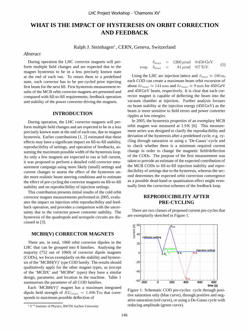
WHAT IS THE IMPACT OF HYSTERESIS ON ORBIT CORRECTIONAND FEEDBACK
Ralph J. Steinhagen∗, CERN, Geneva, SwitzerlandAbstract
During operation the LHC corrector magnets will per-form multiple field changes and are expected due to themagnet hysteresis to be in a less precisely known stateat the end of each run. To return them to a predefinedstate, each corrector has to be pre-cycled prior injectingfirst beam for the next fill. First hysteresis measurement re-sults of the MCB orbit corrector magnets are presented andcompared with fill-to-fill requirements, feedback operationand stability of the power converter driving the magnets.
INTRODUCTION
During operation, the LHC corrector magnets will per-form multiple field changes and are expected to be in a lessprecisely known state at the end of each run, due to magnethysteresis. Earlier contributions [1, 2] estimated that theseeffects may have a significant impact on fill-to-fill stability,reproducibility of settings, and operation of feedbacks, as-suming the maximum possible width of the hysteresis loop.As only a few magnets are expected to run at full current,it was proposed to perform a detailed cold corrector mea-surement campaign using more likely (small) settings andcurrent changes to assess the effect of the hysteresis un-der more realistic beam steering conditions and to estimatethe effect of pre-cycling the corrector magnets on fill-to-fillstability and on reproducibility of injection settings.
This contribution presents initial results of the cold orbitcorrector magnet measurements performed in 2005, evalu-ates the impact on injection orbit reproducibility and feed-back operation, and provides a comparison with the uncer-tainty due to the corrector power converter stability. Thehysteresis of the quadrupole and sextupole circuits are dis-cussed in [3].
MCBH(V) CORRECTOR MAGNETS
There are, in total, 1060 orbit corrector dipoles in theLHC that can be grouped into 8 families. Analysing themajority (752 out of 1060) of corrector dipole magnets(CODs), we focus exemplarily on the stability and hystere-sis of the ’MCBH(V)’ type COD family. The results shouldqualitatively apply for the other magnet types, as (exceptof the ’MCBX’ and ’MCBW’ types) they have a similardesign, parameter, and location in the machine. Table 1summarises the parameter of all COD families.
Each ’MCBH(V)’ magnet has a maximum integrateddipole field strength of BL|max = 1.896 Tm that corre-sponds to maximum possible deflection of
∗3rd Institute of Physics, RWTH Aachen University
δmax = 1260 μrad @450 GeVresp. δmax = 81 μrad @7 TeV.
(1)
Using the LHC arc injection lattice and βmax ≈ 180 m,each COD can create a maximum beam orbit excursion ofabout δxmax ≈ 144 mm and δxmax ≈ 9 mm for 450 GeVand 450 GeV beam, respectively. It is clear that each cor-rector magnet is capable of deflecting the beam into thevacuum chamber at injection. Further analysis focuseson beam stability at the injection energy (450 GeV) as thebeam is more sensitive to field errors and power converterripples at low energies.
In 2005, the hysteresis properties of an exemplary MCBorbit magnet was measured at 1.9 K [6]. This measure-ment series was designed to clarify the reproducibility anddeviation of the hysteresis after a predefined cycle, e.g. cy-cling through saturation or using a ’De-Gauss’-cycle andto check whether there is a minimum required currentchange in order to change the magnetic field/deflectionof the CODs. The purpose of the first measurement wastaken to provide an estimate of the expected contribution ofthe MCB CODs to fill-to-fill injection stability and repro-ducibility of settings due to the hysteresis, whereas the sec-ond determines the expected orbit correction convergenceas a possible dead-band or quantisation effect might even-tually limit the correction schemes of the feedback loop.
REPRODUCIBILITY AFTERPRE-CYCLING
There are two classes of proposed current pre-cycles thatare exemplarily sketched in Figure 1.
time [s]-200 0 200 400 600 800
time [s]-200 0 200 400 600 800
curr
ent [
A]
-60
-40
-20
0
20
40
60
collision setting
injection setting
0 A 0 A 0 A
nom+I
nom-I
De-Gauss
Figure 1: Schematic COD pre-cycles: cycle through posi-tive saturation only (blue curve), through positive and neg-ative saturation (red curve), or using a De-Gauss cycle withreducing amplitude (green curve).
LHC Project Workshop - 'Chamonix XV'
146
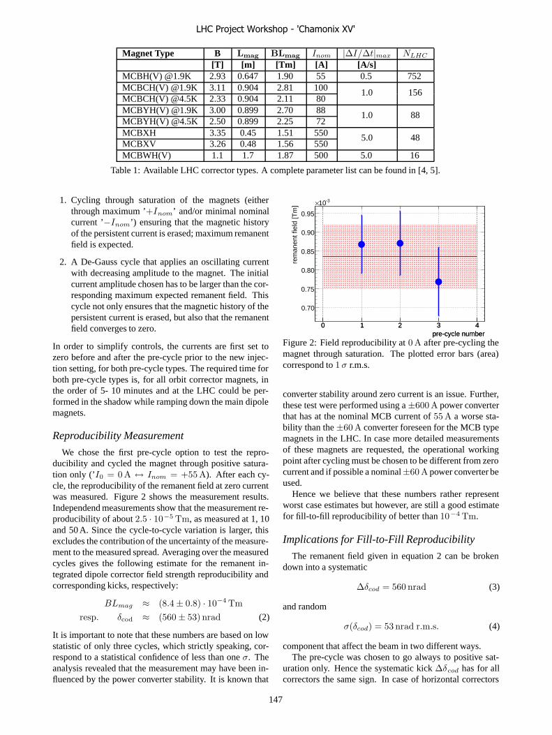
Magnet Type B Lmag BLmag Inom |ΔI/Δt|max NLHC
[T] [m] [Tm] [A] [A/s]MCBH(V) @1.9K 2.93 0.647 1.90 55 0.5 752MCBCH(V) @1.9K 3.11 0.904 2.81 100MCBCH(V) @4.5K 2.33 0.904 2.11 80
1.0 156
MCBYH(V) @1.9K 3.00 0.899 2.70 88MCBYH(V) @4.5K 2.50 0.899 2.25 72
1.0 88
MCBXH 3.35 0.45 1.51 550MCBXV 3.26 0.48 1.56 550
5.0 48
MCBWH(V) 1.1 1.7 1.87 500 5.0 16
Table 1: Available LHC corrector types. A complete parameter list can be found in [4, 5].
1. Cycling through saturation of the magnets (eitherthrough maximum ’+Inom’ and/or minimal nominalcurrent ’−Inom’) ensuring that the magnetic historyof the persistent current is erased; maximum remanentfield is expected.
2. A De-Gauss cycle that applies an oscillating currentwith decreasing amplitude to the magnet. The initialcurrent amplitude chosen has to be larger than the cor-responding maximum expected remanent field. Thiscycle not only ensures that the magnetic history of thepersistent current is erased, but also that the remanentfield converges to zero.
In order to simplify controls, the currents are first set tozero before and after the pre-cycle prior to the new injec-tion setting, for both pre-cycle types. The required time forboth pre-cycle types is, for all orbit corrector magnets, inthe order of 5- 10 minutes and at the LHC could be per-formed in the shadow while ramping down the main dipolemagnets.
Reproducibility Measurement
We chose the first pre-cycle option to test the repro-ducibility and cycled the magnet through positive satura-tion only (’I0 = 0 A ↔ Inom = +55 A). After each cy-cle, the reproducibility of the remanent field at zero currentwas measured. Figure 2 shows the measurement results.Independend measurements show that the measurement re-producibility of about 2.5 · 10−5 Tm, as measured at 1, 10and 50 A. Since the cycle-to-cycle variation is larger, thisexcludes the contribution of the uncertainty of the measure-ment to the measured spread. Averaging over the measuredcycles gives the following estimate for the remanent in-tegrated dipole corrector field strength reproducibility andcorresponding kicks, respectively:
BLmag ≈ (8.4 ± 0.8) · 10−4 Tmresp. δcod ≈ (560 ± 53) nrad (2)
It is important to note that these numbers are based on lowstatistic of only three cycles, which strictly speaking, cor-respond to a statistical confidence of less than one σ. Theanalysis revealed that the measurement may have been in-fluenced by the power converter stability. It is known that
pre-cycle number0 1 2 3 4
pre-cycle number0 1 2 3 4
rem
anen
t fie
ld [T
m]
0.70
0.75
0.80
0.85
0.90
0.95
-310×
Figure 2: Field reproducibility at 0 A after pre-cycling themagnet through saturation. The plotted error bars (area)correspond to 1 σ r.m.s.
converter stability around zero current is an issue. Further,these test were performed using a ±600 A power converterthat has at the nominal MCB current of 55 A a worse sta-bility than the ±60 A converter foreseen for the MCB typemagnets in the LHC. In case more detailed measurementsof these magnets are requested, the operational workingpoint after cycling must be chosen to be different from zerocurrent and if possible a nominal±60 A power converter beused.
Hence we believe that these numbers rather representworst case estimates but however, are still a good estimatefor fill-to-fill reproducibility of better than 10−4 Tm.
Implications for Fill-to-Fill Reproducibility
The remanent field given in equation 2 can be brokendown into a systematic
Δδcod = 560 nrad (3)
and random
σ(δcod) = 53 nrad r.m.s. (4)
component that affect the beam in two different ways.The pre-cycle was chosen to go always to positive sat-
uration only. Hence the systematic kick Δδcod has for allcorrectors the same sign. In case of horizontal correctors
LHC Project Workshop - 'Chamonix XV'
147

this increases the total integrated dipole field and, as a re-sult, the energy of the LHC. The maximum expected en-ergy shift ΔE/E due to the horizontal MCB hysteresis isabout 2 · 10−5. Compared to the expected energy shiftsof 1.5 · 10−4 caused by the b1 decay of the main dipolefield and sun and moon tides, this contribution is negligi-ble since this shift is reproducible from fill-to-fill and has,in principle, to be corrected only once. If required, a De-Gauss pre-cycle would minimise this contribution.
The σ(δcod) component of about 53 nrad r.m.s.(σ(δcod)/δmax ≈ 4 · 10−5) around the systematic part ofthe hysteresis causes a random orbit perturbation Δx(s)
Δx(s) =
√βiβ(s)
2 sin(πQ)cos(μ(s) − πQ) · σ(δcod) (5)
around the ring that contributes to the total random fill-to-fill variation. Using either an analytical approach and ap-plying an incoherent sum of the orbit corrector response(equation 5) or a numerical evaluation of the orbit responsematrix due to random dipole kicks leads to the follow-ing estimate of the propagation factor between the randomCOD deflection σ(δcod) and resulting orbit r.m.s. σH andσV , respectively:
σH ≈ (966 ± 245) [m/rad] · σ(δcod) (6)
σV ≈ (1004 ± 275) [m/rad] · σ(δcod) (7)
The simulated estimates are based on the LHC injectionoptics (LHC 6.5) and a seed of about 104 different orbits.The spread of the prediction reflects the distribution of dif-ferent beta function and phase advance combinations thatare sampled by the different seeds, and is not a numericalerror. See [7] for details.
The expected orbit r.m.s during injection due to the hys-teresis can be estimated to about 50 μm r.m.s. (0.05σ withσ being the beam size), using equation 4 and 7. This orbitexcursion, solely due to the MCB hysteresis, is very smallcompared to the available aperture of about 11 mm, col-limation requirements (Δx < 0.3σ) or expected groundmotion contribution [7] (0.3 − 0.5σ). It is barely de-tectable with a LHC BPM shot-by-shot resolution of about50 − 100 μm for a single nominal LHC bunch.
In conclusion, the expected systematic and random com-ponent of the hysteresis after pre-cycling the magnet shouldnot pose a problem for reproducibility of the injection orbitor for threading the first circulating beam as it is within theshadow of much larger effects such as b1 decay of the maindipole magnets, ground motion and other effects.
SMALL HYSTERESIS LOOPS
The orbit perturbations on the injection plateau, whichare corrected by the orbit feedback, are expected to be inthe order of about 0.5 mm as described in [7]. Assumingan arc COD at β = 180 m, this amplitude correspondsto an average current modulation around the initial CODworking point of about 0.2 A at 450 GeV, which is small
compared to the nominal current (55 A). 1 and 10 A arelikely working points of the CODs, assuming a static ran-dom misalignment of the quadrupole magnets of 0.5 mmr.m.s. during injection and collision, respectively.
Small Hysteresis Loop Measurement
The small hysteresis loop of 0.2 A was measured around1 and 10 A. Figure 3 shows the result of the 1 A measure-ment
current [A]1 1.05 1.1 1.15 1.2
current [A]1 1.05 1.1 1.15 1.2
[Tm
]m
agB
L
0.032
0.033
0.034
0.035
0.036
0.037
0.038
0.039 MCB (MSCB269) hysteresis loop
) = 2.5e-04 Tm ~ 4 %mag
(BLΔ
Figure 3: Exemplary small MCB hysteresis loop around1 A.
The width of the small hysteresis loops are 2.4·10−4 Tmand 1.1 · 10−4 Tm at 1 A and 10 A, which correspondto deflections of about Δδcod = 167 nrad and Δδcod =73 nrad, respectively. This additional deflection due to thehysteresis can be translated into a scale error εscale of about4 %. In a feed-forward-only environment, this scale errorwould translate directly into a 4 % error with respect to thegiven reference orbit. It is important to note that, thoughthe requested field change is less due to hysteresis, nei-ther quantisation nor a dead-band effect has been observed.This shows that even a small current change yields an im-mediate change of the field, and hence deflection of themagnet. This hysteresis effect can be measured with thebeam and corrected by beam-based alignment proceduressuch as the LHC Orbit Feedback.
Implication for Orbit Feedback Operation
The LHC Orbit Feedback relies on a Singular ValueDecomposition (SVD) based global correction schemewith local constraints in space-domain and a Proportional-Integral-Derivative (PID) controller in time-domain as usedin all modern light sources.
Space Domain The SVD algorithm is a eigenvalue-based method (see [8]) used to create the pseudo-inverse ofthe orbit response matrix. The strength of this algorithm isthat near-singular solutions can be easily eliminated by the
LHC Project Workshop - 'Chamonix XV'
148

choices of numbers of eigenvalues #λSV D used for invert-ing the orbit response matrix. Singular solutions may arise,for example, due to optics errors, COD and BPM errors,and other effects that may potentially make the feedbackloop instable. As an intrinsic property, the correction usesall (selected) CODs with rather small correction strengthscompatible with the results from the small hysteresis mea-surements. Generally, a large number of used eigenvaluescorrespond to a more precise orbit correction, but which ismore prone to BPM/COD failures and errors than if a smallnumber of eigenvalues is used as shown in [10, 11].
The stability of the feedback in space domain has, amongother errors, been studied for scale errors of the beam trans-fer function. The hysteresis has a similar impact on thebeam transfer function as a quadrupole induced beta-beatfor which the stability of the correction algorithm has beensimulated for various LHC optics. The stability of the cor-rection algorithm in space domain is given by the attenua-tion of the correction defined as:
attenuation = 20 · logorbit r.m.s. afterorbit r.m.s. before
∣∣∣∣ref
(8)
For a good loop convergence in space domain, it is requiredthat the attenuation be less than -3 dB. An exemplary resultfor the sensitivity to beta-beat of the SVD-based orbit cor-rection using LHC injection optics and correcting the orbitsfor beam 1 and 2 is shown in Figure 4. It is visible that the
svdλ#0 100 200 300 400 500
-bea
t [%
]β
peak
-to-
peak
0
10
20
30
40
50
60
70
atte
nuat
ion
[dB
]
-50
-40
-30
-20
-10
0
Figure 4: Orbit Feedback sensitivity to optics failures: Thecolour-coded attenuation of the orbit correction is plottedas a function of peak-to-peak beta-beat and for the inver-sion of the orbit response matrix used number of eigen-values #λSV D. It is visible that the −3dB line is for#λSV D > 20 above about 100% peak-to-peak beta-beat.
correction algorithm can cope with beta-beat up to about100 % once #λSV D > 20. Compared to the expected beta-beat, the small loop hysteresis effect will have a negligibleeffect on the spacial correction.
Time Domain In time domain, the feedback uses astandard PID controller to optimise the transition from theactual COD setting to the required steady-state deflection
given by the space domain algorithm. The PID functionand optimisation is well understood and does not requirean accurate process model in order to get good parame-ter stabilisation [9]. The integral part of the PID is es-sentially responsible for the minimisation of model uncer-tainties (steady-state errors), non-linearities of magnet andbeam transfer functions. It uses the integrated measurederror signal which, in case of the orbit feedback, is the dif-ference between reference and the measurement orbit. Incontrast to feed-forward only, a continuous running feed-back will measure the orbit error and minimise the effectof the hysteresis within a few iterations and will convergeif underlying perturbations are slow compared to the feed-back bandwidth. The MCB hysteresis, other uncertainties,as well as scale errors of transfer function thus rather affectthe convergence speed (feedback bandwidth) than maxi-mum achievable stability, which is determined by the noisefloor of the beam position measurement and of the actua-tors (CODs).
POWER CONVERTER STABILITY
In 2005, a ±8 V/ ± 60 A power converter that is fore-seen for the LHC MCBH(V) magnets has been tested witha MCB cryogenic load attached[12]. The stability of thepower converter was measured to ΔI
Inom= 5 · 10−6 with
respect to its nominal current Inom = 55 A. The stabil-ity corresponds to a random r.m.s. deflection of each MCBmagnet in the LHC of
σ(δcod) = 6.3 nradr.m.s. (9)
Using equations 9 and 7, the noise floor due to the CODpower converter can hence be estimated to
Δx ≈ (6 ± 2)μmr.m.s (10)
corresponding to a stability of about 0.01 σ (σ being thebeam size), which is about the noise floor of LHC BPMsystem measuring with single nominal bunch (100 μmshot-to-shot, 255 turn average).
REACHING NOMINAL STABILITY
In order to meet the tight requirements on energy, orbit,tune, chromaticity and other parameters, the following two-stage approach will be used in the LHC:
1. The first injected low-intensity beam, which (for ma-chine protection reasons) is required prior to a nom-inal beam in the machine, is used to perform beam-based alignment and to minimise the fill-to-fill un-certainties due to hysteresis, b1 decay random groundmotion, and other effects.
2. Once the beam parameters have been optimised, thenominal beam may be injected and will be further sta-bilised by the feedbacks.
LHC Project Workshop - 'Chamonix XV'
149
This procedure guarantees that the nominal beam will findsimilar beam parameter conditions as the low-intensitybeam, since the beam physics does not change significantlyfrom low to high intensities at the LHC energies. Eventhough the expected perturbations may be smaller thanthe tolerance, a continuously running orbit feedback is re-quired to guarantee the stability in the event of unexpectedeffects that may perturb the orbit.
CONCLUSION
The hysteresis of the MCB type orbit correctors mainlyaffects the closed orbit of the first injected low-intensitybeam and does not significantly affect feedback operationwith circulating beam due to the integral part of their PIDcontroller and intrinsically minimises unknown effects anderrors due to wrong transfer function scale and hystere-sis. For a good fill-to-fill reproducibility, each correctionmagnet should be cycled after the end of each run to re-turn it to a more defined state for the next injection, forinstance by cycling the magnets through positive satura-tion or a de-gauss pre-cycle. Both pre-cycle types re-quire about 5 to 10 minutes and could be performed in theshadow while ramping down the main dipole magnets. The2005 measurements of cold MCB corrector dipole hystere-sis shows a reproducibility of the remanent field after pre-cycling through saturation better than 10−4 Tm, which issmall and compatible with requirements on the injectionorbit. However, the estimate is based on very low statis-tic and confirms rather the qualitative low order of magni-tude than the absolute precision. The stability of the MCBpower supplies are likely to define the minimum achiev-able stability of the orbit after feedback correction to about(6 ± 2)μm r.m.s (0.01σ). In order to ensure the requiredorbit stability, a continuous operation of the orbit feedbackfrom the first low-intensity beam till the end of the fill isforeseen.
ACKNOWLEDGEMENTS
The numerous discussions and MCB magnet and powerconverter measurements of W. Venturini, A. Cantone, V.Montabonnet and J. Wenninger are gratefully achnowl-edged.
REFERENCES
[1] W. Venturini, “Magnetic Behaviour of LHC correctors: Is-sues for Machine Operation”, Proceedings of ChamonixXIV, 2005
[2] J. P. Koutchouk, S. Sanfilippo, “Magnetic Issues affectingBeam Commissioning, Session Summary”, Proceedings ofChamonix XIV, 2005
[3] W. Venturini, “Hysteresis in magnet correctors versus tuneand chromatic correction”, Proceedings of Chamonix XV,2006
[4] F. Bodry, “LHC Power Converters - Performance Require-ments”, Proceedings of Chamonix XI, 2001
[5] CERN, “LHC - The Large Hadron Collider”,http://lhc.web.cern.ch/lhc/ and references therein
[6] W. Venturini et al., “Hysteresis measurement of a twin aper-ture MCB orbit corrector”, AT-MTM internal Memo, 2005-10-19
[7] R. J. Steinhagen, “Analysis of Ground Motion at SPSand LEP, Implications for the LHC”, CERN-AB-2005-087,2005
[8] G. Golub and C. Reinsch, “Handbook for automatic compu-tation II, Linear Algebra”, Springer, NY, 1971
[9] G. Ziegler and N. B. Nichols, “Optimum settings for auto-matic controllers”, Trans. A.S.M.E., Vol. 64, pp. 759-765,1942
[10] R. J. Steinhagen, “Can the LHC Orbit Feedback save thebeam in case of a closed orbit dipole failure?”, MPWG #46,2005-06-01
[11] R. J. Steinhagen, “Closed Orbit and Protection”, MPWG#53, 2005-12-16
[12] A. Cantone, V. Montabonnet, “60A Converter Testing inSM18”, private communications, 2005
LHC Project Workshop - 'Chamonix XV'
150
TRANSFER FUNCTION OF THE QUADRUPOLES AND β-BEATING
S. Sanfilippo, P. Hagen, J.-P. Koutchouk, M. Giovannozzi, T. Risselada
CERN, Geneva, Switzerland Abstract We present data relative to the transfer function of all the quadrupoles in the machine, specifying how many different measurement systems are involved, how cross-calibrations are carried out, and what is the final level of absolute and relative accuracy that will be reached according to the present baseline. Other sources of perturbation of the optic functions such as the precision of the power supply and the absolute accuracy relative to the transfer function of the main dipoles are considered. A final estimate of the induced beta beating in the machine is given.
INTRODUCTION One challenge of the LHC machine is to respect the
tight tolerances imposed by the mechanical aperture. The budget for the peak β-beating compatible with the nominal machine performance is 21 % and 25 % at injection and collision, respectively [1]. Such a budget is split between two contributions, which are added linearly. The off-momentum β-beating at injection is assumed to be 7 % and 5 %, in the horizontal and vertical plane, respectively. Hence, the remaining budget is allocated for the perturbation coming from the quadrupole gradient. It is 14 % and 16 % in the horizontal and vertical planes, respectively. The production and the cold tests of the magnets are now well-advanced. A significant amount of data concerning both warm and cold measurements was collected, thus allowing a better knowledge of the contribution to the overall β-beating from the quadrupoles imperfections. The purpose of this paper is to review the different contributions in light of the actual magnetic field quality of the quadrupoles and not on the expected performance. The study is restricted to the injection optics and concerns only the static error sources. The paper is organised as follows. The first section recalls the expression of the β-beating due to field imperfections and the various sources of β-beating. In the second section the gradient errors from the arc-quadrupoles as well as those located in the insertion regions are investigated. Then an analytical estimate of the contribution to β-beating for each magnet-class is presented. Finally, a model taking into account the magnet allocation in the machine, the gradient error from every single magnet together with other sources of perturbations, such as the precision of the power supply, is described. The first results of numerical simulations using the realistic model with MAD are presented and compared to the estimates presented in 2005 [2].
EXPRESSION OF THE β BEATING
General calculation The perturbation of the β-function driven by
quadrupolar imperfections along the ring is given by the following expression [1]:
∫ −−⋅Δ⋅
=Δ
ring
dsQKQs
s σσμμπσσβπβ
β))()(22cos()()(
)2sin(21
)()(
0000
(1)
where β0 is the unperturbed β-function, μ(s)-μ(σ) is the difference in betatronic phase between the location of the gradient error and the observation point and ΔK is the integrated normalised gradient error. ΔK is related to the nominal integrated G0 by:
4
00
20 10)()(
)( −Δ=Δ
ρσσ
σB
bGK (2)
Assuming that the gradient error ΔK is constant over the entire magnet length and considering the average betatron function over the magnet length, the integral in (1) can be replaced by a discrete sum as:
)(..)2sin(2
1
)(
)(2
00
ibKQs
s
iii Δ⋅
⋅=Δ
∑ βπβ
β (3)
It is customary to consider the rms value of the β-beating in the horizontal (or vertical) plane for a class of quadrupoles corresponding to a given distribution of magnetic errors. In this case, one can show that
2,,
byx
rms
yx
C σββ ⋅=Δ (4)
where 2bσ stands for the rms value of distribution of
gradient errors, expressed in units, and Cx,y is a constant depending only on the optics in the horizontal or vertical plane. It is also common to assume that the distribution of the β-beating is Gaussian and, therefore, the peak value is given by three times the rms.
This simple expression (4) allows deriving analytical estimates of the β-beating for various classes of quadrupole magnets. The values of Cx,y are derived in Ref. [2].
Sources of b2 errors. Four main sources of b2 random errors are considered (see Ref. [1]):
• The random b2 of the LHC main dipoles, dipoleb2σ .
• Errors from the feed-down downfeedb
⋅σ 2 of sextupoles,
i.e. the alignment errors between the main dipole
LHC Project Workshop - 'Chamonix XV'
151
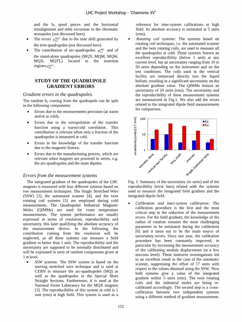
and the b3 spool pieces and the horizontal misalignment and orbit excursion in the chromatic sextupoles (not discussed here).
• The errors MQTb2σ due to the tune shift generated by
the trim quadrupoles (not discussed here). • The contribution of arc-quadrupoles MQ
b2σ and of
the stand-alone quadrupoles (MQY, MQM, MQW, MQX, MQTL) located in the insertion regions quad
b2σ .
STUDY OF THE QUADRUPOLE GRADIENT ERRORS
Gradient errors in the quadrupoles. The random b2 coming from the quadrupole can be split in the following components:
• Errors due to the measurements precision (at warm and/or at cold).
• Errors due to the extrapolation of the transfer function using a warm/cold correlation . This contribution is relevant when only a fraction of the quadrupoles is measured at cold.
• Errors in the knowledge of the transfer function due to the magnetic history.
• Errors due to the manufacturing process, which are relevant when magnets are powered in series, e.g. the arc-quadrupoles and the main dipoles.
Errors from the measurement systems The integrated gradient of the quadrupoles of the LHC
magnets is measured with four different systems based on two measurement techniques. The Single Stretched Wire (SSW) [3], the automated scanner [4], and the twin rotating coil systems [5] are employed during cold measurements. The Quadrupoles Industrial Magnetic Moles (QIMMs) are used for room temperature measurements. The system performance are usually expressed in terms of resolution, reproducibility and uncertainty, this later qualifying the absolute accuracy of the measurement device. In the following, the contribution coming from the resolution will be neglected, as all these systems can measure a field gradient to better than 1 unit. The reproducibility and the uncertainty are supposed to be normally distributed and will be expressed in term of random components given at 1 σ level.
• SSW systems: The SSW system is based on the moving stretched wire technique and is used at CERN to measure the arc-quadrupoles (MQ) as well as the quadrupoles in the Special Short Straight Sections. Furthermore, it is used at the National Fermi Laboratory for the MQX magnets [3]. The reproducibility of this system at cold is 1 unit (rms) at high field. This system is used as a
reference for inter-system calibrations at high field. Its absolute accuracy is estimated at 5 units (rms).
• Rotating coil systems: The systems based on rotating coil techniques, i.e. the automated scanner and the twin rotating coils, are used to measure all the quadrupoles at cold. These systems feature an excellent reproducibility (below 1 unit) at any current level, but an uncertainty ranging from 10 to 50 units depending on the instrument and on the test conditions. The coils used in the vertical facility are immersed directly into the liquid helium, resulting in a significant uncertainty on the absolute gradient value. The QIMMs feature an uncertainty of 20 units (rms). The uncertainty and the reproducibility of these measurement systems are summarized in Fig.1. We also add the errors related to the integrated dipole field measurements for comparison.
1
10
100
indus
try m
ole
verti
cal tes
t fac
ility
long sh
aft
scan
ner
Sing
le St
retch
ed W
ireuncertainty(units@17 mm)
B1
B2
Fig. 1: Summary of the uncertainty (in units) and of the reproducibility (error bars) related with the systems used to measure the integrated field gradient and the integrated dipole field.
• Calibration and inter-system calibration: The calibration procedure is the first and the most critical step in the reduction of the measurement errors. For the field gradient, the knowledge of the radius of rotation remains the most challenging parameter to be estimated during the calibration [6] and it turns out to be the main source of uncertainty errors. Since one year, the calibration procedure has been constantly improved, in particular by increasing the measurement accuracy of the calibrating module displacement (at a few microns level). These intensive investigations led to an excellent result in the case of the automatic scanner, suppressing the offset of 17 units with respect to the values obtained using the SSW. Now both systems give a value of the integrated gradient within 5 units (rms). The twin rotating coils and the industrial moles are being re-calibrated accordingly. The second step is a cross-calibration between two independent systems using a different method of gradient measurement.
LHC Project Workshop - 'Chamonix XV'
152
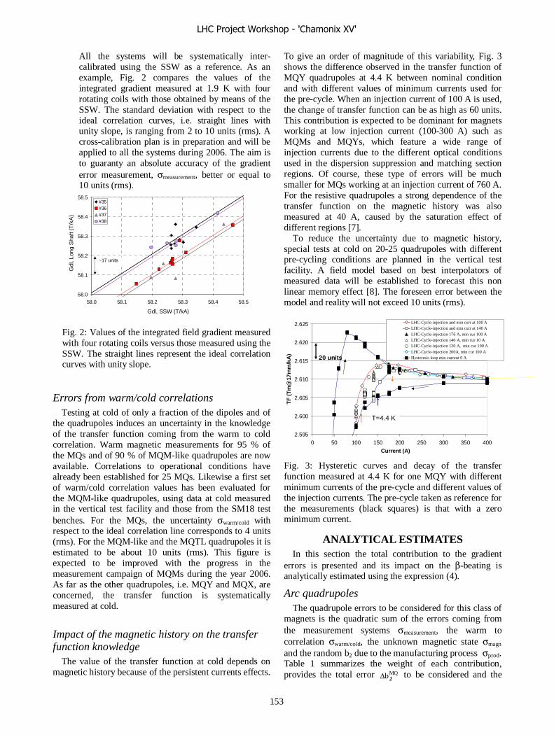
All the systems will be systematically inter-calibrated using the SSW as a reference. As an example, Fig. 2 compares the values of the integrated gradient measured at 1.9 K with four rotating coils with those obtained by means of the SSW. The standard deviation with respect to the ideal correlation curves, i.e. straight lines with unity slope, is ranging from 2 to 10 units (rms). A cross-calibration plan is in preparation and will be applied to all the systems during 2006. The aim is to guaranty an absolute accuracy of the gradient error measurement, σmeasurement, better or equal to 10 units (rms).
58.0
58.1
58.2
58.3
58.4
58.5
58.0 58.1 58.2 58.3 58.4 58.5
Gdl, SSW (T/kA)
Gdl
, Lon
g S
haft
(T/k
A)
#35#36#37#38
~17 units
Fig. 2: Values of the integrated field gradient measured with four rotating coils versus those measured using the SSW. The straight lines represent the ideal correlation curves with unity slope.
Errors from warm/cold correlations Testing at cold of only a fraction of the dipoles and of
the quadrupoles induces an uncertainty in the knowledge of the transfer function coming from the warm to cold correlation. Warm magnetic measurements for 95 % of the MQs and of 90 % of MQM-like quadrupoles are now available. Correlations to operational conditions have already been established for 25 MQs. Likewise a first set of warm/cold correlation values has been evaluated for the MQM-like quadrupoles, using data at cold measured in the vertical test facility and those from the SM18 test benches. For the MQs, the uncertainty σwarm/cold with respect to the ideal correlation line corresponds to 4 units (rms). For the MQM-like and the MQTL quadrupoles it is estimated to be about 10 units (rms). This figure is expected to be improved with the progress in the measurement campaign of MQMs during the year 2006. As far as the other quadrupoles, i.e. MQY and MQX, are concerned, the transfer function is systematically measured at cold.
Impact of the magnetic history on the transfer function knowledge
The value of the transfer function at cold depends on magnetic history because of the persistent currents effects.
To give an order of magnitude of this variability, Fig. 3 shows the difference observed in the transfer function of MQY quadrupoles at 4.4 K between nominal condition and with different values of minimum currents used for the pre-cycle. When an injection current of 100 A is used, the change of transfer function can be as high as 60 units. This contribution is expected to be dominant for magnets working at low injection current (100-300 A) such as MQMs and MQYs, which feature a wide range of injection currents due to the different optical conditions used in the dispersion suppression and matching section regions. Of course, these type of errors will be much smaller for MQs working at an injection current of 760 A. For the resistive quadrupoles a strong dependence of the transfer function on the magnetic history was also measured at 40 A, caused by the saturation effect of different regions [7].
To reduce the uncertainty due to magnetic history, special tests at cold on 20-25 quadrupoles with different pre-cycling conditions are planned in the vertical test facility. A field model based on best interpolators of measured data will be established to forecast this non linear memory effect [8]. The foreseen error between the model and reality will not exceed 10 units (rms).
2.595
2.600
2.605
2.610
2.615
2.620
2.625
0 50 100 150 200 250 300 350 400
Current (A)
TF
(T
m@
17m
m/k
A)
LHC-Cycle-injection and min curr at 100 ALHC-Cycle-injection and min curr at 140 ALHC-Cycle-injection 176 A, min cur 100 ALHC-Cycle-injection 140 A, min cur 10 ALHC-Cycle-injection 120 A, min cur 100 ALHC-Cycle-injection 200A, min cur 100 AHysteresis loop min current 0 A
T=4.4 K
20 units
Fig. 3: Hysteretic curves and decay of the transfer function measured at 4.4 K for one MQY with different minimum currents of the pre-cycle and different values of the injection currents. The pre-cycle taken as reference for the measurements (black squares) is that with a zero minimum current.
ANALYTICAL ESTIMATES In this section the total contribution to the gradient
errors is presented and its impact on the β-beating is analytically estimated using the expression (4).
Arc quadrupoles The quadrupole errors to be considered for this class of
magnets is the quadratic sum of the errors coming from the measurement systems σmeasurement, the warm to correlation σwarm/cold, the unknown magnetic state σmagn and the random b2 due to the manufacturing process σprod. Table 1 summarizes the weight of each contribution, provides the total error MQb 2Δ to be considered and the
LHC Project Workshop - 'Chamonix XV'
153

estimate of the resulting β-beating (peak) in the horizontal and vertical planes. With 95 % of the warm magnetic measurements available the spread in the integrated field gradient coming from the production is currently 13 units [9]. A sorting strategy is being applied to reduce the impact of this spread on the β-beating by 30 % [10]. It is worthwhile noting that the estimate quoted in Table 1 of the field gradient error is 50 % higher, i.e. 15 units, than the target value [2]. This results in a peak β-beating contribution of 11 %.
Table 1: Contributions to the error in the measured field gradient MQ
2bΔ for the arc-quadrupoles and analytical
estimate of the peak β−beating.
Type of Errors
b2 errors [units]
Comments
σmeasurement 5 SSW/scanner inter -calibration.
σwarm/cold 4 based on 25 MQs
σmagn 2 guess
σprod 13 95 % of MQs measured
MQ2bΔ 15 Total (Quadratic sum)
[%]/peakpeak
yxββΔ
ββΔ
11 % /11 %
Estimate using :
2,,
bC yx
peak
yx
Δ⋅=Δββ
Stand-alone magnets In this class are included all superconducting
quadrupoles located in the dispersion suppressors (MQM-like, MQTL), in the matching sections (MQM-like, MQY and MQTL) and the low-beta quadrupoles (MQXA and MQXB) as well as the normal conducting magnets MQW located in the cleaning insertions. For a first analytic estimation these magnets can be treated identically and be considered as independently powered. This is in fact not always the case. Namely for the quadrupoles of the triplet assembly the Q1 and the Q3 are powered in series. We also do not take into account that the β-beat due to the transfer function of the Q2 partially compensates that generated by the Q1+Q3. These considerations will play a role in the detailed calculation presented in the next section.
Table 2: Contributions to the error in the measured field gradient Quad
2bΔ for each type of quadrupole and analytical
estimation of the peak β−beating.
Type Quadtmeasuremenσ
[unit]
Quadcold/warmσ
[unit]
Quadmagnσ
[unit]
Quad2bΔ
[unit]
peak
y/xββΔ
[%] MQM 10 8 10 16 7 % / 8 % MQY 10 NA 10 14 5 % / 5 % MQX 5 NA 10 11 8 % / 9 % MQW 20 NA 10 22 4 % / 4 % MQTL 10 10 10 17 2 % / 2 %
The list of field gradient errors remains therefore the same as for the MQs apart from the random part coming from the production that is not considered. Table 2 provides an estimate of each contribution, the total error gradient Quad
2bΔ and the value of β-beating generated by each class of quadrupoles.
Depending on the quadrupole type, the total estimated random error in the gradient Quadb 2Δ is ranging from 11 to
22 units with an average of 16 units. This represents an increase of more than 50 % with respect to the first assumptions [2]. The resulting β-beating caused by the stand-alone quadrupoles is close to 13 %.
MAD-X NUMERICAL COMPUTATIONS
Model description At present, a large fraction of the LHC magnets are
produced and magnetically measured at warm and for a fraction at cold. The installation of the machine started and a significant number of magnets are either installed or allocated a position in the tunnel. With this wealth of information, though still incomplete, it becomes possible to estimate better the beam parameters and their likely ranges. For that purpose, an adaptative simulation model of the LHC optics has been built in a first version. This version includes all the information on the magnetic properties at injection and collision. The geometry information (misalignments in the cryostats and alignment) will be implemented in the next version.
The simulation model uses whatever information is available on the day, such as magnetic field measurements at warm or cold for existing magnets, magnet allocation to machine positions, and statistical evaluations for the magnets yet to be built, measured or allocated to slots
In addition to the information on the magnet field levels, provision is made to describe accurately their uncertainty sources: resolution of the magnetic measurements, absolute calibrations, and warm-to-cold correlations for the majority of magnets not measured at cold, hysteresis and magnetic history. Depending on the uncertainty source, the imperfections are allocated to single magnets or families of magnets of the same type. In addition, the power supplies have their own resolution (stability per day) and proper account is taken of the magnets, possibly of different types, connected in series on the same power supply.
A pre-processor prepares a number of instances of the LHC for the MAD-X program. Each instance corresponds to a particular draw of the stochastic parameters, such as the uncertainty sources, the non-yet existing magnets and their machine position allocation. A post-processor computes in a first version the beta-beating around the machine, its distribution and distribution statistical parameters.
The activation of subsets of errors and other options allows estimating the importance of issues like the contribution of different magnet classes, and allows for
LHC Project Workshop - 'Chamonix XV'
154
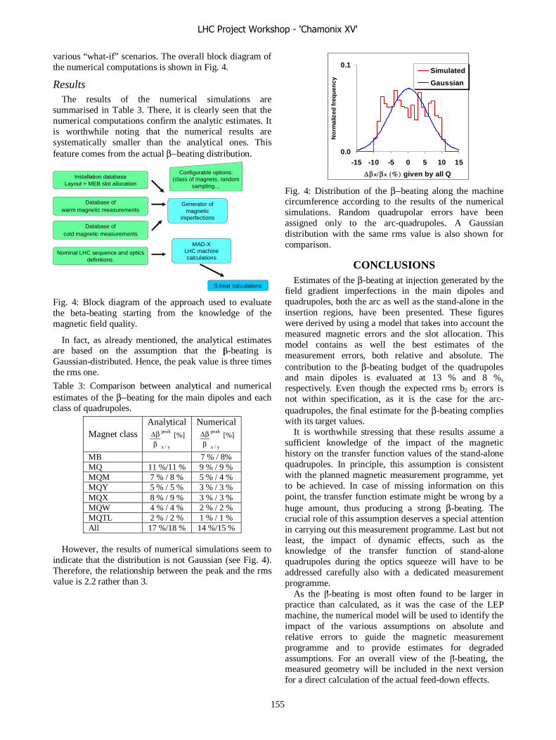
various “what-if” scenarios. The overall block diagram of the numerical computations is shown in Fig. 4.
Results The results of the numerical simulations are
summarised in Table 3. There, it is clearly seen that the numerical computations confirm the analytic estimates. It is worthwhile noting that the numerical results are systematically smaller than the analytical ones. This feature comes from the actual β−beating distribution.
Installation databaseLayout + MEB slot allocation
Database of warm magnetic measurements
Database of cold magnetic measurements
Generator of magnetic
imperfections
Configurable options:(class of magnets, random
sampling…
MAD-XLHC machine calculations
Nominal LHC sequence and optics definitions.
ß-beat calculations
Fig. 4: Block diagram of the approach used to evaluate the beta-beating starting from the knowledge of the magnetic field quality.
In fact, as already mentioned, the analytical estimates are based on the assumption that the β-beating is Gaussian-distributed. Hence, the peak value is three times the rms one.
Table 3: Comparison between analytical and numerical estimates of the β−beating for the main dipoles and each class of quadrupoles.
Magnet class Analytical
peak
y/xββΔ [%]
Numerical peak
y/xββΔ [%]
MB 7 % / 8% MQ 11 %/11 % 9 % / 9 % MQM 7 % / 8 % 5 % / 4 % MQY 5 % / 5 % 3 % / 3 % MQX 8 % / 9 % 3 % / 3 % MQW 4 % / 4 % 2 % / 2 % MQTL 2 % / 2 % 1 % / 1 % All 17 %/18 % 14 %/15 %
However, the results of numerical simulations seem to
indicate that the distribution is not Gaussian (see Fig. 4). Therefore, the relationship between the peak and the rms value is 2.2 rather than 3.
0.0
0.1
-15 -10 -5 0 5 10 15
Δβx/βx (%) given by all Q
No
rmal
ized
freq
uen
cy
Simulated
Gaussian
Fig. 4: Distribution of the β−beating along the machine circumference according to the results of the numerical simulations. Random quadrupolar errors have been assigned only to the arc-quadrupoles. A Gaussian distribution with the same rms value is also shown for comparison.
CONCLUSIONS Estimates of the β-beating at injection generated by the
field gradient imperfections in the main dipoles and quadrupoles, both the arc as well as the stand-alone in the insertion regions, have been presented. These figures were derived by using a model that takes into account the measured magnetic errors and the slot allocation. This model contains as well the best estimates of the measurement errors, both relative and absolute. The contribution to the β-beating budget of the quadrupoles and main dipoles is evaluated at 13 % and 8 %, respectively. Even though the expected rms b2 errors is not within specification, as it is the case for the arc-quadrupoles, the final estimate for the β-beating complies with its target values.
It is worthwhile stressing that these results assume a sufficient knowledge of the impact of the magnetic history on the transfer function values of the stand-alone quadrupoles. In principle, this assumption is consistent with the planned magnetic measurement programme, yet to be achieved. In case of missing information on this point, the transfer function estimate might be wrong by a huge amount, thus producing a strong β-beating. The crucial role of this assumption deserves a special attention in carrying out this measurement programme. Last but not least, the impact of dynamic effects, such as the knowledge of the transfer function of stand-alone quadrupoles during the optics squeeze will have to be addressed carefully also with a dedicated measurement programme.
As the β-beating is most often found to be larger in practice than calculated, as it was the case of the LEP machine, the numerical model will be used to identify the impact of the various assumptions on absolute and relative errors to guide the magnetic measurement programme and to provide estimates for degraded assumptions. For an overall view of the β-beating, the measured geometry will be included in the next version for a direct calculation of the actual feed-down effects.
LHC Project Workshop - 'Chamonix XV'
155

Acknowledgements The authors would like to gratefully acknowledge the
colleagues of the AT/MEL, AT/MAS and AT/MTM Groups for their work in the calibration, magnet measurements and analysis and for their help to collect the required inputs. The authors would also like to thank S. Fartoukh, A. Lombardi and Y. Papaphilippou for their direct contribution on the β-beating calculations and for fruitful discussions.
REFERENCES [1] S. Fartoukh and O. S. Brüning, “Field Quality
Specification of the LHC Main Dipole Magnet”, CERN-LHC Project Report-501 (2001).
[2] S. Fartoukh and M. Giovannozzi, “Revision of the tolerance budget for the beta-beating at injection”, minutes of the FQWG, 8th March 2005.
[3] J. DiMarco et al., “Field Alignment of Quadrupole Magnets for the LHC Interaction Regions”, IEEE Trans. Appl. Super. 10 (1), p. 127, 2000.
[4] L. Bottura et al., “A system for Series Magnetic Measurements in the LHC Main Quadrupoles”, IEEE Trans. Appl. Super. 12 (1), p. 168, 2002.
[5] J. Billan et al., “Twin Rotating Coils for Cold Magnetic Measurements of 15m long Dipoles”, IEEE Trans. Appl. Super. 10 (1), p. 1142, 2000.
[6] N. Smirnov et al., “Focusing Strength (Gdl) Measurements of the Main Quadrupoles of the LHC”, MT19, Genova, September 2005, to be published.
[7] D. Cornuet and S. Ramberger, private communication.
[8] L. Deniau, “The LHC Reference Magnetic System”, LHC, in Proceedings of the LHC Project Workshop, ed. by J. Poole, CERN-AB-2004-014-ADM, p. 190, 2004.
[9] E. Todesco, “Bimonthly Report for Field Quality Quadrupoles October-November 2005”, EDMS 694091, January 2006.
[10] Y. Papaphilippou, Minutes of the MEB-108 meeting, held on 17th January 2006.
LHC Project Workshop - 'Chamonix XV'
156
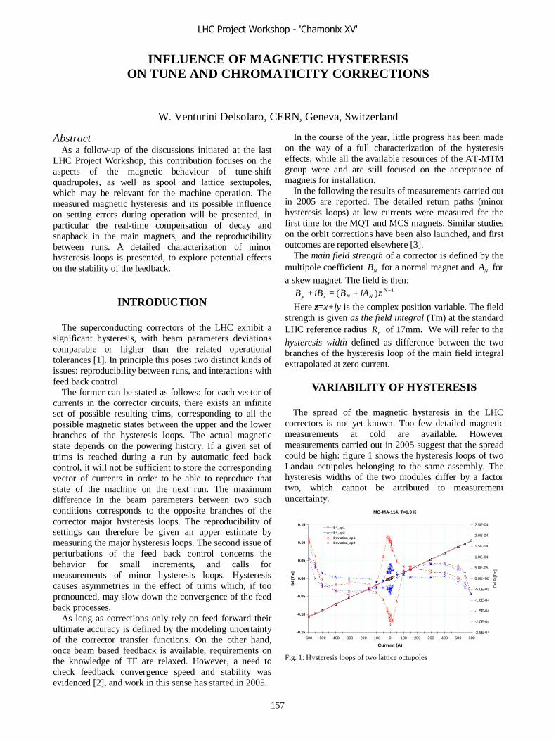
INFLUENCE OF MAGNETIC HYSTERESIS ON TUNE AND CHROMATICITY CORRECTIONS
W. Venturini Delsolaro, CERN, Geneva, Switzerland
Abstract As a follow-up of the discussions initiated at the last
LHC Project Workshop, this contribution focuses on the aspects of the magnetic behaviour of tune-shift quadrupoles, as well as spool and lattice sextupoles, which may be relevant for the machine operation. The measured magnetic hysteresis and its possible influence on setting errors during operation will be presented, in particular the real-time compensation of decay and snapback in the main magnets, and the reproducibility between runs. A detailed characterization of minor hysteresis loops is presented, to explore potential effects on the stability of the feedback.
INTRODUCTION The superconducting correctors of the LHC exhibit a
significant hysteresis, with beam parameters deviations comparable or higher than the related operational tolerances [1]. In principle this poses two distinct kinds of issues: reproducibility between runs, and interactions with feed back control.
The former can be stated as follows: for each vector of currents in the corrector circuits, there exists an infinite set of possible resulting trims, corresponding to all the possible magnetic states between the upper and the lower branches of the hysteresis loops. The actual magnetic state depends on the powering history. If a given set of trims is reached during a run by automatic feed back control, it will not be sufficient to store the corresponding vector of currents in order to be able to reproduce that state of the machine on the next run. The maximum difference in the beam parameters between two such conditions corresponds to the opposite branches of the corrector major hysteresis loops. The reproducibility of settings can therefore be given an upper estimate by measuring the major hysteresis loops. The second issue of perturbations of the feed back control concerns the behavior for small increments, and calls for measurements of minor hysteresis loops. Hysteresis causes asymmetries in the effect of trims which, if too pronounced, may slow down the convergence of the feed back processes.
As long as corrections only rely on feed forward their ultimate accuracy is defined by the modeling uncertainty of the corrector transfer functions. On the other hand, once beam based feedback is available, requirements on the knowledge of TF are relaxed. However, a need to check feedback convergence speed and stability was evidenced [2], and work in this sense has started in 2005.
In the course of the year, little progress has been made on the way of a full characterization of the hysteresis effects, while all the available resources of the AT-MTM group were and are still focused on the acceptance of magnets for installation.
In the following the results of measurements carried out in 2005 are reported. The detailed return paths (minor hysteresis loops) at low currents were measured for the first time for the MQT and MCS magnets. Similar studies on the orbit corrections have been also launched, and first outcomes are reported elsewhere [3].
The main field strength of a corrector is defined by the multipole coefficient NB for a normal magnet and NA for a skew magnet. The field is then:
1)( = + −+ NNNxy ziABiBB
Here z=x+iy is the complex position variable. The field strength is given as the field integral (Tm) at the standard LHC reference radius rR of 17mm. We will refer to the hysteresis width defined as difference between the two branches of the hysteresis loop of the main field integral extrapolated at zero current.
VARIABILITY OF HYSTERESIS The spread of the magnetic hysteresis in the LHC
correctors is not yet known. Too few detailed magnetic measurements at cold are available. However measurements carried out in 2005 suggest that the spread could be high: figure 1 shows the hysteresis loops of two Landau octupoles belonging to the same assembly. The hysteresis widths of the two modules differ by a factor two, which cannot be attributed to measurement uncertainty.
Fig. 1: Hysteresis loops of two lattice octupoles
MO-MA-114, T=1.9 K
-0.15
-0.10
-0.05
0.00
0.05
0.10
0.15
-600 -500 -400 -300 -200 -100 0 100 200 300 400 500 600
Current (A)
B4
[Tm
]
-2.5E-04
-2.0E-04
-1.5E-04
-1.0E-04
-5.0E-05
0.0E+00
5.0E-05
1.0E-04
1.5E-04
2.0E-04
2.5E-04
Del
B [
Tm
]
B4_ap1
B4_ap2
Deviation_ap1
Deviation_ap2
LHC Project Workshop - 'Chamonix XV'
157
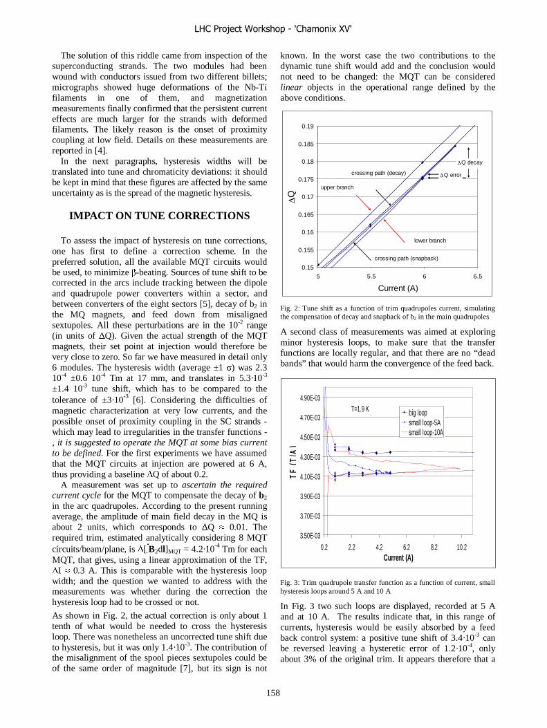
The solution of this riddle came from inspection of the superconducting strands. The two modules had been wound with conductors issued from two different billets; micrographs showed huge deformations of the Nb-Ti filaments in one of them, and magnetization measurements finally confirmed that the persistent current effects are much larger for the strands with deformed filaments. The likely reason is the onset of proximity coupling at low field. Details on these measurements are reported in [4].
In the next paragraphs, hysteresis widths will be translated into tune and chromaticity deviations: it should be kept in mind that these figures are affected by the same uncertainty as is the spread of the magnetic hysteresis.
IMPACT ON TUNE CORRECTIONS To assess the impact of hysteresis on tune corrections,
one has first to define a correction scheme. In the preferred solution, all the available MQT circuits would be used, to minimize β-beating. Sources of tune shift to be corrected in the arcs include tracking between the dipole and quadrupole power converters within a sector, and between converters of the eight sectors [5], decay of b2 in the MQ magnets, and feed down from misaligned sextupoles. All these perturbations are in the 10-2 range (in units of ΔQ). Given the actual strength of the MQT magnets, their set point at injection would therefore be very close to zero. So far we have measured in detail only 6 modules. The hysteresis width (average ±1 σ) was 2.3 10-4 ±0.6 10-4 Tm at 17 mm, and translates in 5.3·10-3 ±1.4 10-3 tune shift, which has to be compared to the tolerance of ±3·10-3 [6]. Considering the difficulties of magnetic characterization at very low currents, and the possible onset of proximity coupling in the SC strands - which may lead to irregularities in the transfer functions - , it is suggested to operate the MQT at some bias current to be defined. For the first experiments we have assumed that the MQT circuits at injection are powered at 6 A, thus providing a baseline ΔQ of about 0.2.
A measurement was set up to ascertain the required current cycle for the MQT to compensate the decay of b2 in the arc quadrupoles. According to the present running average, the amplitude of main field decay in the MQ is about 2 units, which corresponds to ΔQ ≈ 0.01. The required trim, estimated analytically considering 8 MQT circuits/beam/plane, is Δ[∫B2dl]MQT = 4.2·10-4 Tm for each MQT, that gives, using a linear approximation of the TF, ΔI ≈ 0.3 A. This is comparable with the hysteresis loop width; and the question we wanted to address with the measurements was whether during the correction the hysteresis loop had to be crossed or not.
As shown in Fig. 2, the actual correction is only about 1 tenth of what would be needed to cross the hysteresis loop. There was nonetheless an uncorrected tune shift due to hysteresis, but it was only 1.4·10-3. The contribution of the misalignment of the spool pieces sextupoles could be of the same order of magnitude [7], but its sign is not
known. In the worst case the two contributions to the dynamic tune shift would add and the conclusion would not need to be changed: the MQT can be considered linear objects in the operational range defined by the above conditions.
0.15
0.155
0.16
0.165
0.17
0.175
0.18
0.185
0.19
5 5.5 6 6.5
Current (A)ΔQ
lower branch
upper branch
crossing path (decay)
crossing path (snapback)
ΔQ decay
ΔQ error
Fig. 2: Tune shift as a function of trim quadrupoles current, simulating the compensation of decay and snapback of b2 in the main quadrupoles
A second class of measurements was aimed at exploring minor hysteresis loops, to make sure that the transfer functions are locally regular, and that there are no “dead bands” that would harm the convergence of the feed back.
Fig. 3: Trim quadrupole transfer function as a function of current, small hysteresis loops around 5 A and 10 A
In Fig. 3 two such loops are displayed, recorded at 5 A and at 10 A. The results indicate that, in this range of currents, hysteresis would be easily absorbed by a feed back control system: a positive tune shift of 3.4·10-3 can be reversed leaving a hysteretic error of 1.2·10-4, only about 3% of the original trim. It appears therefore that a
3.50E-03
3.70E-03
3.90E-03
4.10E-03
4.30E-03
4.50E-03
4.70E-03
4.90E-03
0.2 2.2 4.2 6.2 8.2 10.2Current (A)
TF
(T
/A)
big loopsmall loop-5Asmall loop-10A
T=1.9 K
LHC Project Workshop - 'Chamonix XV'
158

single iteration would already be enough to complete the requested correction within the tolerance.
IMPACT ON CHROMATICITY CORRECTIONS
In order to correct the linear chromaticity of the LHC,
the setting points of the MS magnets at injection are at 1.1% and at 1.8% of full strength for the SF and the SD respectively [9]. The assumed tolerance on chromaticity is ±2 units [10]. Only 3 MS lattice sextupoles have been measured at cold so far; transfer functions are shown in Fig. 4. The maximum width of the hysteresis loop is about 10-3 Tm at 17 mm. This value corresponds to 10 and 18 units of chromaticity for the horizontal and vertical planes at injection [9]. Thus, if the settings are given in terms of currents (with no knowledge of the magnetic history), and taking into account that the relative measurement uncertainty on the transfer functions is of the order of a few %, magnetic hysteresis would dominate the uncertainty on Q’.
The hysteresis of the MCS is equivalent to 6 units of Q’ at injection [9].
0.0E+00
2.0E-04
4.0E-04
6.0E-04
8.0E-04
1.0E-03
1.2E-03
1.4E-03
0 2 4 6 8 10 12 14
Current (A)
TF
(T
m/A
@ 1
7mm
)
MSCB271-S2
MSCB271-S1
MS23
Fig. 4: Lattice Sextupoles transfer functions as a function of current
As done for the MQT, also for the MCS we have carried out measurements to asses the impact of hysteresis during decay and snapback compensation. The assumption made on the correction scheme was that the MCS would locally compensate the b3(t) of the main dipole: this can of course only be done in average over one sector. We thus started from the expected average b3(t) of the dipoles in sector 7-8, and used a first order approximation of the MCS transfer function to generate a current cycle for the corrections: the assumed transfer function TFMCS was just a real number and the current-field relationship was therefore a straight line passing through the origin. The current function for the corrector is then: I(t)MCS= -b3(t)/TFMCS. The resulting MCS field
was measured and its difference with respect to b3(t) was translated in a residual (uncorrected) chromaticity.
Fig. 5: Spool pieces sextupoles integrated strength as a function of current, simulating the compensation of decay and snapback of b3 in the main dipoles of sector 7-8
In Fig. 5 the measured MCS field integral is shown as a function of current. The setting current at t=0 for the MCS is -14.5 A; and at the end of the decay it is of +0.6 A. As visible in the plot, with the pre cycle adopted in the experiment, the current to field relationship of the corrector during the decay and the snapback phases is fairly linear; nevertheless the slope is different from that of the linear best fit of the whole hysteresis loop. The uncorrected chromaticity, as defined above, is shown in Fig. 6. As already arguable by the fact that the hysteresis width corresponds to 6 units of Q’, the error never exceeds 3 units.
-4.00
-3.00
-2.00
-1.00
0.00
1.00
2.00
0 200 400 600 800 1000 1200
Time at injection (s)
Q
' [u
nits
]
Fig. 6: Uncorrected chromaticity as a function of time during decay and snapback, resulting from non taking into account the corrector hysteresis
-1.0E-03
-5.0E-04
0.0E+00
5.0E-04
1.0E-03
1.5E-03
-20 -15 -10 -5 0 5 10 15 20
Current (A)
MC
S B
3 in
tegr
al @
17 m
m (
Tm
)
crossing path (decay and snapback)
setting at t=0
end of decay
LHC Project Workshop - 'Chamonix XV'
159
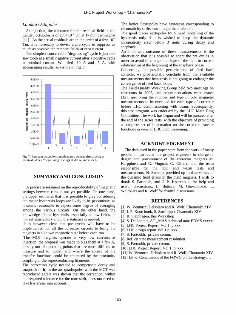
Landau Octupoles At injection, the tolerance for the residual field of the
Landau octupoles is of ±7.4 10-5 Tm at 17 mm per magnet [11]. As the actual residuals are in the order of a few 10-4 Tm, it is necessary to devise a pre cycle to suppress as much as possible the remnant fields at zero current.
The simplest conceivable “degaussing” cycle is just one saw tooth at a small negative current after a positive cycle at nominal current. We tried -10 A and -5 A, with encouraging results, as visible in Fig. 7.
Fig. 7: Remnant octupole strength at zero current after a cycle at nominal, after 2 “degaussing” swings at -10 A, and at -5 A.
SUMMARY AND CONCLUSION
A precise assessment on the reproducibility of magnetic settings between runs is not yet possible. On one hand, the upper estimates that it is possible to give considering the major hysteresis loops are likely to be pessimistic, as it seems reasonable to expect some degree of averaging among the various circuits. On the other hand, the knowledge of the hysteresis, especially at low fields, is not yet satisfactory and more statistics is needed. It is however clear that pre cycles will have to be implemented for all the corrector circuits to bring the magnets in a known magnetic state before each run. The MQT magnets operate at very low currents at injection: the proposal was made to bias them at a few A, to stay out of operating points that are more difficult to measure and to model, and where the spread of the transfer functions could be enhanced by the proximity coupling of the superconducting filaments. The correction cycle needed to compensate decay and snapback of b2 in the arc quadrupoles with the MQT was reproduced and it was shown that the correction, within the required tolerance for the tune shift, does not need to take hysteresis into account.
The lattice Sextupoles have hysteresis corresponding to chromaticity shifts much larger than tolerable. The spool pieces sextupoles MCS need modelling of the hysteresis only if it is wished to keep the dynamic chromaticity error below 3 units during decay and snapback. An important outcome of these measurements is the observation that it is possible to adapt the pre cycles in order to avoid to change the slope of the field to current relationships at the beginning of the snapback phase. Concerning the possible perturbations of feed back controls, we provisionally conclude from the available measurements that hysteresis is not going to endanger the convergence of feed back loops. The Field Quality Working Group held two meetings on correctors in 2005, and recommendations were issued [12], specifying the number and type of cold magnetic measurements to be executed for each type of corrector before LHC commissioning with beam. Subsequently, this test program was endorsed by the LHC Main Ring Committee. The work has begun and will be pursued after the end of the series tests, with the objective of providing a complete set of information on the corrector transfer functions in view of LHC commissioning.
ACKNOWLEDGEMENT The data used in the paper stem from the work of many
people, in particular the project engineers in charge of design and procurement of the corrector magnets M. Karppinen and G. Mugnai; C. Giloux, and the team responsible for the cold and warm tests and measurements. N. Sammut provided up to date values of the dynamic field errors in the main magnets. I wish to thank S. Fartoukh, and J. P. Koutchouk, for help and useful discussions; L. Bottura, M. Giovannozzi, L. Walckiers and R. Wolf for fruitful discussions.
REFERENCES [1] W. Venturini Delsolaro and R. Wolf, Chamonix XIV [2] J. P. Koutchouk, S. Sanfilippo, Chamonix XIV [3] R. Steinhagen, this Workshop [4] S. De Lanour, AT _MAS technical note EDMS xxxxx [5] LHC Project Report, Vol 1, p.xxx [6] LHC design report Vol 1 p. xxx [7] S. Fartoukh, private comm. [8] Ref. on tune measurement resolution [9] S. Fartoukh, private comm. [10] LHC Project Report, Vol 1, p. xxx [11] W. Venturini Delsolaro and R. Wolf, Chamonix XIV [12] J.P.K. Conclusions of the FQWG on the strategy….
0.0E+00
5.0E-05
1.0E-04
1.5E-04
2.0E-04
2.5E-04
3.0E-04
3.5E-04
4.0E-04
4.5E-04
5.0E-04
1 2 3 4 5
Rem
nat B
4 in
teg
ral (
Tm@
17m
m)
LHC Project Workshop - 'Chamonix XV'
160
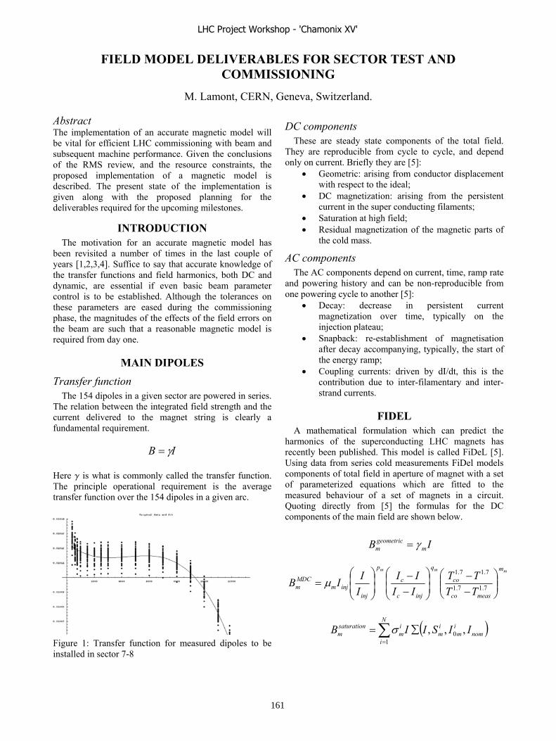
FIELD MODEL DELIVERABLES FOR SECTOR TEST AND COMMISSIONING
M. Lamont, CERN, Geneva, Switzerland.
AbstractThe implementation of an accurate magnetic model will be vital for efficient LHC commissioning with beam and subsequent machine performance. Given the conclusions of the RMS review, and the resource constraints, the proposed implementation of a magnetic model is described. The present state of the implementation is given along with the proposed planning for the deliverables required for the upcoming milestones.
INTRODUCTIONThe motivation for an accurate magnetic model has
been revisited a number of times in the last couple of years [1,2,3,4]. Suffice to say that accurate knowledge of the transfer functions and field harmonics, both DC and dynamic, are essential if even basic beam parameter control is to be established. Although the tolerances on these parameters are eased during the commissioning phase, the magnitudes of the effects of the field errors on the beam are such that a reasonable magnetic model is required from day one.
MAIN DIPOLES Transfer function
The 154 dipoles in a given sector are powered in series. The relation between the integrated field strength and the current delivered to the magnet string is clearly a fundamental requirement.
IB
Here is what is commonly called the transfer function. The principle operational requirement is the average transfer function over the 154 dipoles in a given arc.
Figure 1: Transfer function for measured dipoles to be installed in sector 7-8
DC components These are steady state components of the total field.
They are reproducible from cycle to cycle, and depend only on current. Briefly they are [5]:
Geometric: arising from conductor displacement with respect to the ideal; DC magnetization: arising from the persistent current in the super conducting filaments; Saturation at high field; Residual magnetization of the magnetic parts of the cold mass.
AC components The AC components depend on current, time, ramp rate
and powering history and can be non-reproducible from one powering cycle to another [5]:
Decay: decrease in persistent current magnetization over time, typically on the injection plateau; Snapback: re-establishment of magnetisation after decay accompanying, typically, the start of the energy ramp; Coupling currents: driven by dI/dt, this is the contribution due to inter-filamentary and inter-strand currents.
FIDELA mathematical formulation which can predict the
harmonics of the superconducting LHC magnets has recently been published. This model is called FiDeL [5]. Using data from series cold measurements FiDel models components of total field in aperture of magnet with a set of parameterized equations which are fitted to the measured behaviour of a set of magnets in a circuit. Quoting directly from [5] the formulas for the DC components of the main field are shown below.
IB mgeometricm
mmm m
measco
co
q
injc
c
p
injinjm
MDCm TT
TTIIII
IIIB 7.17.1
7.17.1
nomim
im
N
i
im
saturationm IISIIB ,,, 0
1
LHC Project Workshop - 'Chamonix XV'
161

where
is a rounded step function.
The associated coefficients and fitted parameter values for the dipoles of sector 7-8 are shown in table 1.
Coefficient Transfer Function Value Component 10.119 geometric -0.005 magnetisation
p 1.11 magnetisation q -0.29 magnetisation m 2 saturation
1 0.247 saturation I0
1 10739 saturation S1 1.691 saturation
2 -0.545 saturation I0
2 13599 saturation S2 3.23 saturation
0.003 residual r 1.86 residual
Table 1: parameters used for modelling the main field in sector 7-8.
By plugging the coefficients into the above equations and summing the various contributions it is straightforward to produce the transfer function, as shown in figure 2 [5].
Figure 2: Transfer function – model and data – from all cold tested magnets in sector 7-8
ImplementationThe transfer function results from [5] are reproduced
here to show that, given the mathematical formulation provided by FiDeL, it is reasonably straight forward to implement the model inside the framework provided by LSA [6]. A first cut implementation has been executed:
The coefficients shown in table 1 are stored on the LSA database; The equations are implemented as functions in Java;
For the necessary current range, the associated B field is calculated using these functions and the results are written to another Oracle table on the same database; 2
1atan1,,, 00
nomnommm I
IISIISI
This data is used as a look-up table in the angle to current translation function, either during the settings generation process or when trimming the momentum.
nrinj
mresidualm I
IIB
Thus given the ramp momentum function, for example, the machinery is in place for generating the current function for the main bend power converters. Additional magnet strings or elements would naturally follow the same schema.
HARMONICSThe formulation for the harmonics follows a very
similar form to equations above with associated coefficients for each of the harmonics b2, a2, b3, a3, b4, b5 being given in [5]. An example result is shown in figure 3.
Figure 3: FiDeL model and measurements for the DC b3 component of sector 7-8 dipoles.
Again, given the FiDeL formulation it is straightforward to implement the following within the LSA framework:
Calculate bn versus I using the appropriate equations and coefficients and put the results in a database table to be used in look-up mode Given a current function I(t) one can use the look up table to establish the corresponding bn(t).It is straightforward to now calculate the normalised strength kn(t) required in the corresponding corrector circuit. For example, in the case of b3, the compensating strength in sextupole spool pieces is calculated. Given the transfer function of the magnets in the correction circuit, the current function in the circuit is easily obtained.
Again a first cut implementation has been performed with settings generated within LSA for sector 7-8 b3,sextupole spool piece strength, and sextupole spool piece current as a function of time through LHC reference momentum ramp.
LHC Project Workshop - 'Chamonix XV'
162

OTHER ELEMENTS The FideL formulation should follow for other
elements given appropriate measurements. Harmonics can given to the level appropriate to the elements in question. Further discussion of this point can be found elsewhere in these proceedings [7].
DECAY A parameterised model of the decay is also presented in
[5]. The time behaviour and amplitude dependence is given in terms of various normalisation and fitting parameters. Powering history dependency is taken into account.
Again given values for the parameters and knowledge of the powering history which should be naturally available in the operational software, it should relatively easy to implement the decay prediction inside LSA and invoke it at the start of every injection plateau, if required.
SNAPBACK If the amplitude of the b3 decay can be measured on-
line, a fit to the snapback can be predicted without the use of multi-parameter algorithm [8].
where I(t) is the dipole current at time t; Iinjection is the value of the dipole current at injection; b3 and I are fitting constants. b3 and I are correlated. b3 in the dipoles can be extracted from slow Q’ measurements and the applied b3 corrections made on the injection plateau. (If the model works well b3 could in fact be given by the decay prediction). I can then be obtained from the pre-established correlation. The aim would be to:
Ensure proper chromaticity correction by measurement Extract the total b3 persistent current correction during the decay phase Just before the ramp, invoke the fit to obtain a b3(t) snapback prediction Convert the prediction to corrector currents and download appropriate functions to the power converters Functions invoked at ramp start by the standard
is generally better than 0.02 units
, a possible implementation would follow e
,
in Java;
decay prediction; On-line invocation before ramp to produce
p table should be evaluated with the possibility of using the model in-line as an obvious alternative.
DELIVERABLES
etc. Further details are av
e main bends, as well has for all other quadrupole and corrector the test.
nso
will be required, together with full integration of all harmonic component correction into the
ents. Effort is required within th
in place. Details are to be finalized with aim of having version 1 o ctor test.
timing event The quality of the fit
on the r.m.s. error [8].
IMPLEMENTATION Given the above
th outline: Field Model interpolates and extrapolates data from measured data;
Fitting parameters stored on LSA databaseentry and adjustment by magnet team; Powering history naturally on LSA database; Mathematical formulation of FiDeLInvocation to produce: Transfer functions and normalised harmonic coefficients; On-line invocation at start of each fill (if necessary) to produce
snapback prediction.
Details need to be discussed. The errors induced by using a look-u
Sector Test The sector test will required transfer functions for the
main magnet string in 7-8 MB, MQ and for the insertion, matching section and dispersion suppressor quadrupoles which include MQY, MQM, MQX
ailable in these proceedings [7]. A full list of all required circuits is available at [9].
A decay prediction of b1 and b3 could possibly be tested. Also required are the de-Gauss and nominal cycling prescriptions for th
IItI
snapbackinjection
ebtb 33
cycling prescriptioncircuits involved in
CommissioningCommissioning will require the above for practically
all circuits in the machine. There is a lower priority ome of the higher order correction circuits. This issue is
discussed in detail elsewhere in these proceedings [10]. In addition, snapback predictions
ramp and squeeze.
CONCLUSIONS Based on magnet measurements FiDeL provides a
robust parameterized formulation of the DC and AC components of the transfer functions and field harmonics, including models of decay and snapback. Attention has concentrated on the main dipoles for the moment; however the model is extensible to other magnet types given sufficient measurem
e magnet group to process the measurement data for other magnet strings [7].
The FiDeL formulation is amenable to implementation within LSA using Java/Oracle. A preliminary prototype is
f final implementation in place for se
LHC Project Workshop - 'Chamonix XV'
163

ACKNOWLEDGEMENTS This paper draws heavily on “A Mathematical
Formulation to Predict the Harmonics of the Superconducting LHC Magnets” by N. Sammut, L. Bottura, and J. Mic
Many thanks to holas Sammut for
4.
7.
9.
0 M. Giovannozzi, Electrical circuits required for the minimum workable LHC during commissioning and first two years of operation, these proceedings.
allef. Luca Bottura and Nic
their input.
REFERENCES 1. M. Haverkamp, “Decay and Snapback in
Superconducting Accelerator Magnets”, Ph. D. thesis, University of Twente (2003).
2. M. Haveramp, M. Schneider, L. Bottura, “Study of the decay and snap-back effects on the LHC dipole magnet”, proc. 4th European Conference on Applied Superconductivity, Sept. 1999.
3. L. Bottura, “Superconducting Magnets on Day 1”, XIth Chamonix workshop on LHC performance, 2001. L. Bottura et al, “Field Quality of LHC Dipole Magnets in Operating Conditions”, EPAC 2002.
5. N. Sammut, L. Bottura, J. Micallef, A Mathematical Formulation to Predict the Harmonics of the Superconducting LHC Magnets, LHC project report 854, November 2005
6. L. Mestre et al, “A Pragmatic and Versatile Architecture for LHC Controls Software”, ICALEPCS’2005, Geneva, October 2005. L. Bottura, Magnets: Sector Test Requirements, these proceedings.
8. L. Bottura, G. Ambrosio, P. Bauer, T. Pieloni, “Status of the study of sextupole compensation during snap-back in collaboration with FNAL”, CERN AT-MTM memo: 425883, Nov. 2003. M. Lamont et al, LHC Sector Test, //cern.ch/lhc-injection-test.
1 .
LHC Project Workshop - 'Chamonix XV'
164

SORTING THE MAGNETS IN THE MACDHINE: WHAT DID/WILL WEGAIN ?
L. BotturaCERN, Geneva, Switzerland
Contribution not received
LHC Project Workshop - 'Chamonix XV'
165
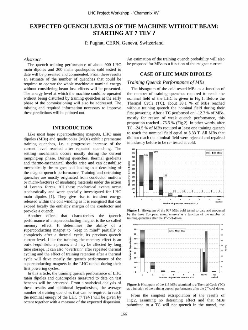
EXPECTED QUENCH LEVELS OF THE MACHINE WITHOUT BEAM: STARTING AT 7 TEV ?
P. Pugnat, CERN, Geneva, Switzerland
Abstract
The quench training performance of about 900 LHC main dipoles and 200 main quadrupoles cold tested to date will be presented and commented. From these results an estimate of the number of quenches that could be required to operate the whole machine at nominal energy without considering beam loss effects will be presented. The energy level at which the machine could be operated without being disturbed by training quenches at the early phase of the commissioning will also be addressed. The missing and required information necessary to improve these predictions will be pointed out.
INTRODUCTION Like most large superconducting magnets, LHC main
dipoles (MBs) and quadrupoles (MQs) exhibit premature training quenches, i.e. a progressive increase of the current level reached after repeated quenching. The settling mechanism occurs mostly during the current ramping-up phase. During quenches, thermal gradients and thermo-mechanical shocks arise and can destabilise mechanically the magnet coil leading to a detraining of the magnet quench performance. Training and detraining quenches are mostly originated from conductor motions or micro-fractures of insulating materials under the action of Lorentz forces. All these mechanical events occur stochastically and were specially investigated for LHC main dipoles [1]. They give rise to transient energy released within the coil winding as it is energised that can exceed locally the enthalpy margin of the conductor and provoke a quench.
Another effect that characterises the quench performance of a superconducting magnet is the so-called memory effect. It determines the ability of a superconducting magnet to “keep in mind” partially or completely after a thermal cycle, its previous quench current level. Like the training, the memory effect is an out-of-equilibrium process and may be affected by long time storage. It can also “overtrain” after repeated thermal cycling and the effect of training retention after a thermal cycle will drive mostly the quench performance of the superconducting magnets in the LHC tunnel during their first powering cycles.
In this article, the training quench performance of LHC main dipoles and quadrupoles measured to date on test benches will be presented. From a statistical analysis of these results and additional hypothesises, the average number of training quenches that can be required to reach the nominal energy of the LHC (7 TeV) will be given by octant together with a measure of the expected dispersion.
An estimation of the training quench probability will also be proposed for MBs as a function of the magnet current.
CASE OF LHC MAIN DIPOLES
Training Quench Performance of MBs The histogram of the cold tested MBs as a function of
the number of training quenches required to reach the nominal field of the LHC is given in Fig.1. Before the Thermal Cycle (TC), about 38.1 % of MBs reached without training quench the nominal field during their first powering. After a TC performed on ∼12.7 % of MBs, mostly for reason of weak quench performance, this proportion reached ∼75.5 % (Fig.2). In other words, after TC ∼24.5 % of MBs required at least one training quench to reach the nominal field equal to 8.33 T. All MBs that did not reach the nominal field were rejected and repaired in industry before to be re- tested at cold.
11141126
158
346360
0
50
100
150
200
250
300
350
400
450
500
550
600
0 1 2 3 4 5 6 7 notreached
Number of quenches to reach 8.33 T
Nu
mb
er o
f C
ryo
-dip
ole
s
01 02 03
Figure 1: Histogram of the 907 MBs cold tested to date and produced by the three European manufacturers as a function of the number of training quenches after the 1st cool-down.
0
10
20
30
40
50
60
70
80
90
100
0 1 2 3 4 5 No TC notreachedNumber of quenches to reach 8.33 T
Nu
mb
er o
f C
ryo
-dip
ole
s
0
50
100
150
200
250
300
350
400
450N
o T
C
01 02 03
Figure 2: Histogram of the 115 MBs submitted to a Thermal Cycle (TC) as a function of the training quench performance after the 2nd cool-down.
From the simplest extrapolation of the results of Fig.2, assuming no detraining effect and that MBs submitted to a TC will not quench in the tunnel, the
LHC Project Workshop - 'Chamonix XV'
166

number of quenches that may occur during the first powering cycles is (1232-115)×(0.17+2×0.03+3×0.01) ≈ 300 i.e. about 40 by octant. This number corresponds to a worst case scenario with a low probability of occurrence as it is based on a biased statistics coming from the sample of the weakest MBs for which a TC was performed. This estimate will be corrected in the next paragraph.
Estimate of the Number of Quenches by octant for MBs to reach the nominal field of the LHC
The result oriented cold test program for MBs and MQs was reviewed and streamlined in 2003 [2]. As a result, the quench performance was first based on a two quench criteria [3] and a thermal cycle performed for cryomagnets that did not reach 9 T after 8 quenches. In 2005, the rule was slightly modified to improve the assessment of the quench performance. It is now based on a three quench criteria [4] with the same rule for the extended test with a TC. The obvious consequence of these test programs is to introduce a statistical bias for the sample {MBs with TC} that must be corrected for a reliable training quench prediction for the machine.
One of the possible ways is to consider the statistics of the number of quench needed to reach the nominal field during cold tests. In Table 1, the two main parameters summarizing these statistics, i.e. the average and the standard deviation, are given for the data coming from the two samples {MBs with TC} and {MBs with no TC}.
Table 1: Statistics for MBs related to the number of quenches to reach the nominal field of 8.33 T
Sample {MBs with TC} {MBs without TC}
Average Number before TC
1.82 1
Standard Deviation 1.35 1
Average Number after TC
0.33 0.181*
Standard Deviation 0.78 0.58**
Population 115 785
* assuming the same reduction of 82 % after TC as for {MBs with TC} ** assuming the same reduction of 42 % after TC as for {MBs with TC} The average number of quenches to reach 8.33 T is found to be reduced by 82 % after a TC for the sample {MBs with TC}. Assuming the same reduction for MBs not submitted to a TC, in average a fraction of about 0.181 MBs can quench once below the nominal field during their 1st powering cycles in the tunnel without beam. From this average value, the number of quenches that can be expected to occur below the nominal field is simply equal to (1232-115)×0.181/8 ≈ 25 training quenches by octant. To estimate the possible dispersion around this average value, the same approach can be used for the standard deviation after the TC and the standard error is found to be about (1232-115)×0.58/(8× 785 ) ≈ 3 training quenches by octant. The “blind statistics” gives 2 times this number, a more conservative estimate.
The implicit assumptions made for the above estimates are now underlined before to be commented:
i) No “nasty” MBs will be accepted; ii) No drift in quench performance for future MBs; iii) No quench is expected for MBs submitted to a
TC on test benches; iv) No long time relaxation effect of the quench
performance of the trained magnets; v) No detraining quenches.
The hypothesis i) do not require further development as the acceptance of the remaining MBs should be based on the same criteria. In addition a reserve of 30 MBs was ordered. For ii), as the firm producing the MBs with quench performance above the average had already delivered all its production, a slight drift may occur and has to be looked at. Concerning iii), all the MBs for which at least two TC were performed, reached 8.33 T without quench after the third cool-down. For iv), the two targeted MBs for the study of the long term stability did not reveal a significant drift of the quench performance but of course the statistics is too poor [5]. The last hypothesis v) is the most questionable. It can be relaxed and an estimate of the number of quench due to a detraining effect can be given. The probability to have a detraining effect around the nominal field after a TC was found to be ∼4 % from the sample {MBs with TC}. If it is assumed that when a MB quenchs, in average its two neighbours will also quench because of the quench-back induced by the warm GHe, then the number of additional quenches due to the detraining effect is of the order of 0.04×3×25 < 5 by octant, i.e. a value comparable with the estimated standard error. The detraining effect will be a more serious problem when the magnets will be pushed to current value much higher than the nominal one.
Quench probability versus current for MBs From the cumulative statistics of MBs (Fig.3), it can be
seen that the probability level of 0.181 reported in Table 1 and used to estimate the number of quenches to reach nominal field after a thermal cycle corresponds to the curve of the 2nd quench level for the sample {MBs with no TC}. This result can be interpreted considering that in average the gain in the quench performance obtained with a third and subsequent training quench(es), is lost during the TC due to the incomplete memory effect.
0.00
0.20
0.40
0.60
0.80
1.00
6.00 6.50 7.00 7.50 8.00 8.50 9.00
Field Level (T)
Cu
mu
lati
ve F
ract
ion
of
MB
s
TC, 1st Q
No TC, 1st Q
TC, 1st Q ATC
TC_2nd Q
No TC, 2nd Q
TC, 2nd Q ATC
Figure 3: Cumulative statistics of MBs related to the field level reached without quench.
LHC Project Workshop - 'Chamonix XV'
167

As a consequence, the data of the 2nd quench level for the sample {MBs with no TC} were considered as the most representative to estimate the probability to have a MB quench as a function of the B field. They were plotted in Fig.4 using a semi-logarithmic scale. An exponential increase of the probability can be observed as a function of the magnetic field with a characteristic value equal to 0.381 T. The probability to have a quench is very close to 1 for the ultimate field of the machine equal to 9 T. If the magnetic field is reduced by 1 T from the nominal field, the probability to have a training quench of a MB fall-down from 0.18 to 0.01.
Probability of a MB quench
0.0010
0.0100
0.1000
1.0000
6.00 6.50 7.00 7.50 8.00 8.50 9.00
B (T)
P{B(T)} = 5.24 10-11 exp(2.623 B)
Figure 4: Estimate probability of a MB quench deduced from the cumulative statistics of the 2nd quench level for the sample {MBs with no TC} and considered as the most representative.
CASE OF LHC MAIN QUADRUPOLES
Training Quench Performance of MQs The histogram of the cold tested MQs as a function of the number of training quenches required to reach the nominal field gradient of 223 T/m is given in Fig.1. Before the thermal cycle, about 56.1 % of MQs reached the nominal field during their 1st powering without training quench. After a TC performed on only 9 MQs for reason of weak quench performance, this proportion is equal to 3/9. In other words, 6/9 MQs required at least one training quench to reach the nominal field gradient. The memory effect of MQs seems to be weaker with respect to MBs but the statistics is poor.
Number of quenches to reach the nominal Field gradient
110
16
62
17
0
10
20
30
40
50
60
70
80
90
100
110
120
0 1 2 3 or more Not reached
Nu
mb
er o
f S
SS
SSS277Under investigation
Figure 5: Histogram of the 196 MQs cold tested to date as a function of the training quench performance after the 1st cool-down.
Estimate of the Number of Quenches for MQs by octant to reach the nominal field The same approach as for MBs can be applied. From the results given in Table 2, the number of quenches that can be expected to occur below the nominal field gradient is simply equal to 360 × 0.17/8 ≈ 8 training quenches by octant. An estimate of the standard error obtained from the quadratic sum of the three relative error contributions gives about 3 training quenches by octant.
Table 2: Statistics for MQs related to the number of quenches to reach
the nominal field gradient of 223 T/m
Sample {MQs with TC} {MQs without TC}
Average Number before TC
2.33 0.58
Standard Deviation�1 0.70
Average Number after TC
0.67 0.17*
Standard Deviation 0.50 0.35**
Population 9 196
* assuming the same reduction of 71 % after TC as for {MQs with TC} ** assuming the same reduction of 50 % after TC as for {MQs with TC}
HOW TO IMPROVE THE ESTIMATES ? The statistics concerning the quench performance of
MQs after a thermal cycle is not sufficient to allow a precise estimate of the average number of quenches that can occur below the nominal field gradient in the tunnel without beam. The values could be reassessed when all MQs will be cold tested.
The assumption iv) made for the estimates and concerning the long time relaxation of the training quench performance during the storage is questionable also for MQs. It is based on results obtained for only two MB cases and no study were performed for MQ.
More generally, to reduce the uncertainty of the predictions, the same statistical approach could be re-iterated by considering each octant individually with its specific content in MQs and MBs.
CONCLUSION Some of the main superconducting magnets exhibited
training quench(es) below the LHC nominal current during their first powering on test benches. After a thermal cycle, a great improvement of the quench performance was observed. The average numbers of quenches below nominal current were found to be reduced by 82 % and 71 % for MBs and MQs respectively. As a first estimate and from extrapolations of present data, 25-30 ±6 and 8 ±6 training quenches by octant for MBs and MQs respectively are expected during the hardware commissioning phase before reaching the LHC requirements for a 7 TeV beam energy. The uncertainties are given for both magnet types at ± 2σ whereas the
LHC Project Workshop - 'Chamonix XV'
168

systematic error for MBs is related to possible detraining effect. At the level of probability of few %, training quenches will start typically at current value in MBs of about 11 kA (6.5 TeV) and probably at a close level for MQs. To improve the estimations for MQs, the memory effect needs to be study and more statistics is required. When all main magnets will be cold tested, these numbers can be reassessed, octant by octant. It must be emphasized that only training quenches are considered in this article but many other quench types can occur during the hardware commissioning phase, such as the ones due to bad electrical connections or cryogenic problems. Such possibilities stress the importance of the diagnostic that should be successful after each quench.
Expected quench Levels of the Machine without Beam: Starting at 7 TeV ? It depends on the time available for training quenches but this objective should be maintained as much as possible. As a baseline strategy, any “spare” time should be dedicated to the training of magnets, all octants in parallel. This is a part of the hardware commissioning and then a dedicated analysis will be required after each training quench to give the green light for the next powering. The same approach as for cold tests on benches should be maintained and the acquired experience used. Postmortem Tools should be available as well as trained experts for the analysis. Finally, training quenches could come from magnets other than MBs and MQs but also,
other more serious problems could arise before starting the training of a certain number of magnets in the LHC machine…
ACKNOWLEDGMENTS The author would like to thanks all members of the
Operation and the Equipment Support teams for the production and the validation of the data respectively, N. Smirnov for providing the results of SSSs, M. Pojer to regularly update the statistics of MBs and A. Siemko for fruitful discussions.
REFERENCES [1] P. Pugnat et al., IEEE Trans. Appl. Supercond. 11 (2001) no. 1/2, pp.1705-8, CERN-LHC-Project-Report-455, http://doc.cern.ch/archive/electronic/cern/preprints/lhc/lhc-project-report-455.pdf; M. Calvi et al., IEEE Trans. Appl. Supercond.: 14 (2004) no. 2, pp.223-226, CERN-LHC-Project-Report-699, http://doc.cern.ch/archive/electronic/cern/preprints/lhc/lhc-project-report-699.pdf; M. Calvi, Ph.-D Thesis, University of Geneva, December 2004. [2] Review of reception tests of LHC dipole cryomagnets, July 2003, CERN-EDMS Id 399278; Review of Reception Tests of LHC Cryomagnets, December 2003, CERN-EDMS Id 427483. [3] MARIC 2004-85. [4] MARIC 2005-112. [5] F. Seyvet et al., to be published in IEEE Trans. Appl. Supercond.
LHC Project Workshop - 'Chamonix XV'
169

CHASING PARASITIC MAGNETIC FIELDS IN THE LHC
A. DevredCERN, Geneva, Switzerland
Contribution not received
LHC Project Workshop - 'Chamonix XV'
170

DISCUSSION: MAGNETIC REQUIREMENTS FOR COMMISSIONING
S. Ramberger, CERN, Geneva, Switzerland
WHAT IS THE IMPACT OF HYSTERESISON ORBIT CORRECTION ANDFEEDBACK? - R. STEINHAGEN
S. Myers: When we first measured the beta-beat in LEPit was 200 %! Can we have simulations up to these values?
R. Steinhagen: The calculation scripts work only up to100 % in the injection case and up to 70 % at collision,beyond they become unstable.
R. Assmann: You focused on one type of corrector andmentioned that the others are most like this type includingthe warm correctors. Will you extend the study to includeall of them or do you think this is not necessary since theyall have similar features?
R. Steinhagen: The main group of corrector mag-nets have similar beta-functions and can be treated simi-larly. However, though having similar beta-functions, theMCBXH nested correctors in the triplets are more difficultto control. We did not consider the warm corrector mag-nets, which are 8 per beam. Their effect should be small.The magnets on the list affect mainly the injection stabil-ity of the first beam. As soon as the feedback starts, thehysteresis is automatically minimized and should not be anissue anymore.
J.-P. Koutchouk: When you refer to the estimate of�� �� of uncertainty in the closed orbit when you pre-cycle the correctors, does this include the effect of differentpowering history of the correctors?
R. Steinhagen: I assume, if we do the pre-cycling af-ter the beam abort, which I think is important to be imple-mented, we should be within the �� ��. But it is impor-tant to note that this is only the effect due to the correctors.Concerning injections stability: as long as the total effectsare below 0.5 mm, it should not pose a problem for orbitsteering.
O. Bruning: I would have expected there must be twocontributions: One is the remanent field once you gothrough a cycle and the other is the decay of the field.
R. Steinhagen: The decay of the corrector circuits is rel-atively small compared to the main magnets.
S. Fartoukh: You showed a hysteresis curve with a hys-teresis of about 8 units so you should have at least about 1unit decay.
R. Steinhagen: We did several measurement cycles andaveraged over 10 measurements and we did not see a sig-nificant change between ramping up or down.
E. Todesco: Is this magnet cycling able to wipe out theprevious history of powering?
W. Venturini: Of course, if you erase the history, youalso erase the useful history, so what was learned duringfeedback.
R. Wolf: Under worst conditions, the maximum error youcan get in setting the correctors up again is 560 nrad aswith the many corrections you did, you would not know onwhich branch of the loop you were actually on when yousaved the settings.
(Note: The pre-cycle was designed to go (for all correc-tors) through positive saturation only. Hence, the measured560 nrad is the maximum expected systematic shift and hasthe same sign for all MCB CODs. As a consequence, thiscontribution changes the beam energy rather than the or-bit. The part that is important for the injection stabilityis the random spread around the 560 nrad which is muchsmaller.)
S. Fartoukh: So you are saying that the hysteresis branchon which every corrector is lying cannot be the same foreach corrector?
R. Steinhagen: Each of the correctors has been on a dif-ferent current before doing this cycling.
F. Bordry: Why are you going through the loop of 0 A– 55 A – 0 A and not doing a degaussing cycle of -55 A– 55 A – -55 A as you don’t know in beforehand to whichpolarity you will go?
E. Todesco: The aim is not a degaussing but a pre-cycling to put the magnets in a reproducible state.
S. Fartoukh: This means for some magnets you willchange the hysteresis branch. So in this case, these560 nrad can be the random error for some correctors andin respect to the closed orbit this reduces the expectationby a factor of 10. So it is better to go up to +55 A or -55 Aand not back to 0 A but directly to the actual value whichcan be positive or negative.
TRANSFER FUNCTION OFQUADRUPOLES AND EXPECTED BETA
BEATING - S. SANFILIPPO
Y. Papaphilippou: You said that in the simulations youare taking into account the slot allocation as it was givenby MEB as far as it is done. The problem is that the MEBis not approving the magnets in a sequence and this meansthat the sorting having holes in some sectors is not efficientat all. So I would see that this is a worst case estimate.
S. Sanfilippo: This is why when I did this analytical es-timate, I did not take the 13 units, but 13 units reduced by30 %.
Y. Papaphilippou: The target we had is a random of theb2 of 10 units. If you have an uncertainty of 10 units, thesorting is completely penalized. I then would not do anysorting at all.
S. Sanfilippo: For the moment we can guarantee that
LHC Project Workshop - 'Chamonix XV'
171
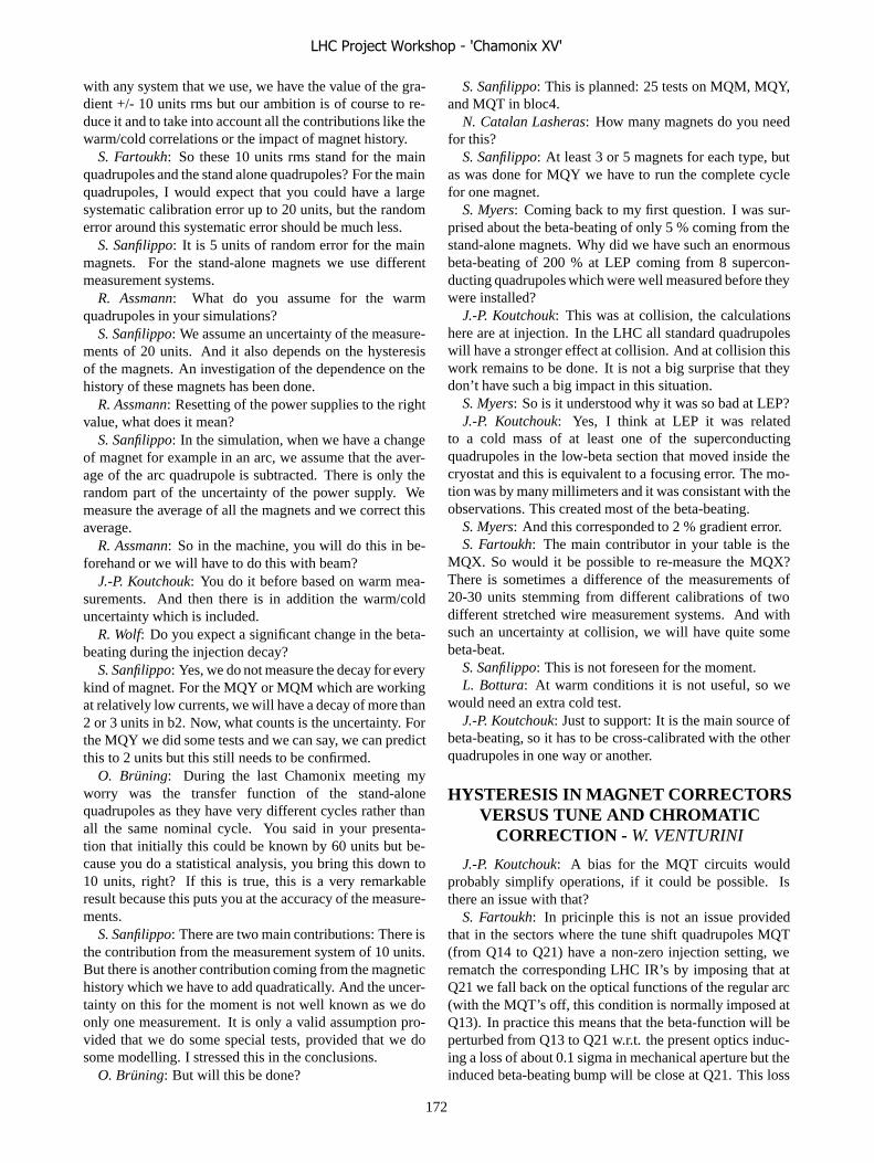
with any system that we use, we have the value of the gra-dient +/- 10 units rms but our ambition is of course to re-duce it and to take into account all the contributions like thewarm/cold correlations or the impact of magnet history.
S. Fartoukh: So these 10 units rms stand for the mainquadrupoles and the stand alone quadrupoles? For the mainquadrupoles, I would expect that you could have a largesystematic calibration error up to 20 units, but the randomerror around this systematic error should be much less.
S. Sanfilippo: It is 5 units of random error for the mainmagnets. For the stand-alone magnets we use differentmeasurement systems.
R. Assmann: What do you assume for the warmquadrupoles in your simulations?
S. Sanfilippo: We assume an uncertainty of the measure-ments of 20 units. And it also depends on the hysteresisof the magnets. An investigation of the dependence on thehistory of these magnets has been done.
R. Assmann: Resetting of the power supplies to the rightvalue, what does it mean?
S. Sanfilippo: In the simulation, when we have a changeof magnet for example in an arc, we assume that the aver-age of the arc quadrupole is subtracted. There is only therandom part of the uncertainty of the power supply. Wemeasure the average of all the magnets and we correct thisaverage.
R. Assmann: So in the machine, you will do this in be-forehand or we will have to do this with beam?
J.-P. Koutchouk: You do it before based on warm mea-surements. And then there is in addition the warm/colduncertainty which is included.
R. Wolf: Do you expect a significant change in the beta-beating during the injection decay?
S. Sanfilippo: Yes, we do not measure the decay for everykind of magnet. For the MQY or MQM which are workingat relatively low currents, we will have a decay of more than2 or 3 units in b2. Now, what counts is the uncertainty. Forthe MQY we did some tests and we can say, we can predictthis to 2 units but this still needs to be confirmed.
O. Bruning: During the last Chamonix meeting myworry was the transfer function of the stand-alonequadrupoles as they have very different cycles rather thanall the same nominal cycle. You said in your presenta-tion that initially this could be known by 60 units but be-cause you do a statistical analysis, you bring this down to10 units, right? If this is true, this is a very remarkableresult because this puts you at the accuracy of the measure-ments.
S. Sanfilippo: There are two main contributions: There isthe contribution from the measurement system of 10 units.But there is another contribution coming from the magnetichistory which we have to add quadratically. And the uncer-tainty on this for the moment is not well known as we doonly one measurement. It is only a valid assumption pro-vided that we do some special tests, provided that we dosome modelling. I stressed this in the conclusions.
O. Bruning: But will this be done?
S. Sanfilippo: This is planned: 25 tests on MQM, MQY,and MQT in bloc4.
N. Catalan Lasheras: How many magnets do you needfor this?
S. Sanfilippo: At least 3 or 5 magnets for each type, butas was done for MQY we have to run the complete cyclefor one magnet.
S. Myers: Coming back to my first question. I was sur-prised about the beta-beating of only 5 % coming from thestand-alone magnets. Why did we have such an enormousbeta-beating of 200 % at LEP coming from 8 supercon-ducting quadrupoles which were well measured before theywere installed?
J.-P. Koutchouk: This was at collision, the calculationshere are at injection. In the LHC all standard quadrupoleswill have a stronger effect at collision. And at collision thiswork remains to be done. It is not a big surprise that theydon’t have such a big impact in this situation.
S. Myers: So is it understood why it was so bad at LEP?J.-P. Koutchouk: Yes, I think at LEP it was related
to a cold mass of at least one of the superconductingquadrupoles in the low-beta section that moved inside thecryostat and this is equivalent to a focusing error. The mo-tion was by many millimeters and it was consistant with theobservations. This created most of the beta-beating.
S. Myers: And this corresponded to 2 % gradient error.S. Fartoukh: The main contributor in your table is the
MQX. So would it be possible to re-measure the MQX?There is sometimes a difference of the measurements of20-30 units stemming from different calibrations of twodifferent stretched wire measurement systems. And withsuch an uncertainty at collision, we will have quite somebeta-beat.
S. Sanfilippo: This is not foreseen for the moment.L. Bottura: At warm conditions it is not useful, so we
would need an extra cold test.J.-P. Koutchouk: Just to support: It is the main source of
beta-beating, so it has to be cross-calibrated with the otherquadrupoles in one way or another.
HYSTERESIS IN MAGNET CORRECTORSVERSUS TUNE AND CHROMATIC
CORRECTION - W. VENTURINI
J.-P. Koutchouk: A bias for the MQT circuits wouldprobably simplify operations, if it could be possible. Isthere an issue with that?
S. Fartoukh: In pricinple this is not an issue providedthat in the sectors where the tune shift quadrupoles MQT(from Q14 to Q21) have a non-zero injection setting, werematch the corresponding LHC IR’s by imposing that atQ21 we fall back on the optical functions of the regular arc(with the MQT’s off, this condition is normally imposed atQ13). In practice this means that the beta-function will beperturbed from Q13 to Q21 w.r.t. the present optics induc-ing a loss of about 0.1 sigma in mechanical aperture but theinduced beta-beating bump will be close at Q21. This loss
LHC Project Workshop - 'Chamonix XV'
172

will be manageable if we put (and have enough) additionalgolden quadrupoles and dipoles in the zones Q13-Q21 onboth sides of the sector under consideration.
FIELD MODEL DELIVERABLES FORSECTOR TEST AND COMMISSIONING:
WHEN AND WHAT? - M. LAMONT
O. Bruning: Regarding the deliverables for the transferfunctions and multipoles, what of these can we measurewith beam in the end? Sextupoles if one doesn’t correctanything?
M. Lamont: You will get the sextupole within a unit.O. Bruning: In the sector test in a single pass?M. Lamont: b1 obviously.O. Bruning: And the other effects can be measured by a
feed-down? - Just being curious.M. Lamont: We will be limited by the resolution of the
BPMs in a single pass.R. Schmidt: Some years ago, Luca had some predictions
on what the chromaticity will be. To what kind of levelcould one control it by these models and what would haveto be taken by chromaticity measurements?
L. Bottura: The figures haven’t changed since the dis-cussion.
E. Todesco: What is the process of validation of yourmodel? Are you planning to cycle over the parameters ofyour model to improve it and fit it better to the machine? -In the sector test and later?
M. Lamont: The transfer function is the main parameterand we will be able to measure the momentum with respectto the incoming beam. We could look at the decay of themagnets by injecting multiple times perhaps.
S. Fartoukh: I think even b3 we would be able to mea-sure in the sector test. We would inject with a �� of 1.or ������ or, conversely change the field of the MB bythe same quantity, and you would have a sizable chromaticphase shift if you measure it at the end of the sector.
O. Bruning: What accuracy would we get?No answerE. Todesco: If you have magnets that were not measured,
do you assume that on average they behave as the measuredones, independently of their cable manufacturer, or do youalso use this information ?
N. Sammut: No, the cable manufacturer is not taken intoaccount for magnets which are not cold tested.
SORTING THE MAGNETS IN THEMACHINE: WHAT DID/WILL WE GAIN? -
L. BOTTURA
R. Assmann: What is the expected change in geometri-cal behaviour from the transport of the magnets from thesurface to the tunnel? Are you sure it makes sense to op-timize on a ��� �� level on the geometry before loweringthe magnet ?
L. Bottura: We are not optimizing on a ��� �� level.We are dealing with cases that are 0.5 mm or 1 mm outof specification. With respects to the limits, the magnetsare looked at on a one-by-one basis. Shifts are then seton a ��� �� level, deviations below are usually ignored.If there are changes due to transport, I assume there havebeen tests done, I am not an expert in that. There has beena budget allocated to all steps in the production. And withthe final budget we are left with is what was shown in thispresentation. We are trying to stay within that, so that wehave enough space for the rest.
J.-B. Jeanneret: Yes, and stability was checked. Just be-fore going down to the tunnels, we remeasure the extrem-ities of the magnets and we see that the difference to theinitial values is compatible with the procedure except for afew cases where we have fully understood the issue.
O. Bruning: It is quite remarkable the results that all ofyou have achieved with sorting. You are saying that youare right between the different parties having the magnetinstallation schedule and asking for field quality. Who ismaking in the end the decision? Who is the body?
L. Bottura: I am currently in the process of dealing withit.
P. Lebrun: By mandate the MEB has executive power.Unknown: Are you taking dynamic properties into ac-
count in sorting?L. Bottura: The only thing we are trying is to keep the
inner cable of the magnets in a sector the same. But whatwe have seen is that the spread in the b3 snapback does notdepend on the inner cable where it is a uniform distributionthroughout the production. So in that respect there is noallocation for dynamic behaviours.
EXPECTED QUENCH LEVELS OF THEMACHINE WITHOUT BEAM: STARTING
AT 7 TEV. - P. PUGNAT
F. Bordry: Imagine during hardware commissioning youhave one magnet that will quench at 8.2 T another magnetshould quench at 8.3 T but it quenches at the same time.Does this help or not?
P. Pugnat: No because a quench is always a destabiliza-tion process. A ramp without quench is a stabilization pro-cess during which the magnet coil is shaking-down. Whena quench occurs, thermal gradients and then thermome-chanical forces develop; the hottest turns of the coil canreach up to 400 K, but typically 300 K, whereas the otherscan stay around 80 K.
R. Schmidt: I remember at the string, the time that an ad-jacent magnet quenches is several 10 seconds, so the fieldin the adjacent magnet would have gone down from 8 T toe.g. 5 T and so maybe it is less critical.
S. Fartoukh: In case of two neighbouring “weak” mag-nets, could the training of the two be a non-convergent pro-cess? Imagine a magnet with a bad training memory closeto one with a bad performance?
LHC Project Workshop - 'Chamonix XV'
173

P. Pugnat: Of course detraining could lead to a non-convergent process that could also be triggered by beamloss effects. This is the reason why there are magnets ofclass R in MTF, i.e. accepted with Reserve and most fre-quently because they showed detraining effects during coldtests and they should be put in a quiet zone from the beamloss point of view to reduce its probability to quench.
L. Rossi: Training and detraining is real but it goesquadratically or cubically according to how far you arefrom the critical surface. The detraining curve that youshowed was for a magnet that reached 9.5 T. Down you go,detraining is less and less an issue. This typically meanswithin few days or a week of hardware commissioning theyappear more often. So going in parallel this is one of thefew cases where we gain as all quenches we see, cost twoweeks to the machine commissioning and start of opera-tion.
P. Pugnat: For the estimations of the number ofquenches, I considered for the probability of a detrainingonly cases with a quench around nominal field.
CHASING PARASITIC MAGNETICFIELDS IN THE LHC - A. DEVRED
L. Rossi: Don’t we have any idea about the possible ef-fect of the bus-bar connections as we have no cure?
J.-P. Koutchouk: It is not easy to make an estimatelike that, as these busbars are not in parallel to the beam.The big difficulty is the lyra where the two conductors arespaced by a distance which is not large as compared to thedistance to the beam but this occurs on short section of theinterconnect and it is not a straight line.
Jean-Bernard Jeanneret: Of course only the longitudinalpart of the current contributes.
Unknown: Assuming nevertheless the PbSb block wouldquench, with what time-constant would this happen?
A. Devred: It would quench in the order of milliseconds.Unknown: This is a relatively long time for us.F. Bordry: You look at the interconnect but wouldn’t it
be more interesting to look at the DFBs?A. Devred: As I said, we wanted to start with something
that is not too complicated. It took one month to retrieve thedata from Euclid in order to introduce it in Roxie models.
F. Bordry: Isn’t it possible to make a first estimation ofthe order of magnitude. Otherwise it will be too late.
J.-P. Koutchouk: The overhead due to this transformationis expressed in weeks while the problem has been with usnow for years. The aim was to have a tool which is genericand which can now be used for other problems.
S. Russenschuck: The problem with the interconnects isan order of magnitude less than with the shielding as thefield is steady. We have also made estimates for the DFBsalready quite a while ago for the old version and this was ano issue. However it would make sense now to re-evaluatethis for the new version.
R. Steinhagen: Do we have to expect that we get a kickdue to PbSb shielding?
A. Devred: No, this issue should be solved.R. Wolf: The bus bars are super-conducting so they
should have a residual field. Would this give an additionalproblem?
A. Devred: We can also put it into Roxie.G. de Rijk: Did you have a look at the experimental ar-
eas? There, the configuration is very complicated.A. Devred: Not yet, but this is on the list of studies to be
done.
LHC Project Workshop - 'Chamonix XV'
174

COMMISSIONING THE LHC PHYSICS PROGRAMME
E. Tsesmelis, CERN, Geneva, Switzerland Abstract
All experiments are expected to have installed initial working detectors and will be ready for commissioning with beam at the start of LHC operation in 2007. The physics programme is expected to be rich even at the projected initial luminosities. This paper presents the requirements and expectations of the experiments for single beams, the accelerator start-up with beam and early collisions, the heavy-ion runs and the special proton runs, and may be used subsequently to set priorities in order to exploit optimally the first LHC beams for physics.
LUMINOSITY RUNNING
ATLAS and CMS Of central importance for ATLAS and CMS and
for the LHC is to elucidate the nature of electroweak symmetry breaking for which the Higgs mechanism and the accompanying Higgs boson(s) are presumed to be responsible. In order to make significant inroads into the Standard Model Higgs search, sizeable integrated luminosities of about 10 fb-1 are needed. However, even with 2 fb-1 per experiment, discovery of the Standard Model Higgs Boson is still possible in certain mass regions.
In addition, the potential for discovery of particles predicted in Supersymmetry (SUSY) is sizeable even at LHC start-up. Due to their high production cross-sections, squarks and gluinos can be produced in significant numbers even at modest luminosities.
ATLAS and CMS request beam conditions that will maximise the integrated luminosity, accumulated with an instantaneous luminosity of at least 1033 cm-2 s-1 in a low machine-induced background environment. The beam energy should be the nominal 7 TeV.
Construction of the general-purpose ATLAS and CMS detectors is approaching completion and installation and commissioning of sub-systems of these experiments is well underway. Both experiments are expected to have experimental set-ups installed and commissioned for the start of LHC operation in 2007.
LHCb The LHCb experiment has been conceived to study CP
Violation and other rare phenomena in B meson decays with very high precision. LHCb will investigate quark flavour physics in the framework of the Standard Model and look for signs of physics beyond the Standard Model.
Due to their high production cross-sections, study of B mesons is possible from the outset of LHC operations in LHCb, as is the case also for ATLAS and CMS. The LHCb experiment is designed for instantaneous luminosities of about 2 1032 cm-2 s-1 and a bunch spacing of 25 ns., providing optimal physics conditions with single pp interaction events per bunch crossing. Such an
instantaneous luminosity can be achieved even with the low bunch intensities expected in the early LHC running period by varying β* between 2 m. and 50 m. and with a bunch spacing of 25 ns.
It is expected that LHCb will have their experimental set-up installed and commissioned for the beginning of LHC operation in 2007.
ALICE ALICE is a general-purpose heavy-ion experiment
designed to study physics of strongly-interacting matter and the quark-gluon plasma in nucleus-nucleus collisions.
The ALICE heavy-ion programme is based on two components:
• Collisions of the largest available nuclei at the highest possible energies.
• The systematic study of various collision systems (pp, pA, and AA) at various beam energies.
As the number of possible combinations of collision systems and energies is large, continuous updating of priorities will be required as data becomes available.
Proton running at the nominal 7 TeV beam energy is requested for the commissioning and starting-up of the experiment, for the accumulation of reference and calibration data and for the study of minimum bias event properties. In order to satisfy the constraint of an average of one event per 88 μs, which is the drift time of the Time Projection Chamber (TPC) detector, an instantaneous luminosity of 1029 cm-2 s-1 is requested, preferably obtained by tuning the β* in order to provide a more stable luminosity and a better-defined vertex spread. For instantaneous luminosities beyond 1031 cm-2 s-1, certain ALICE sub-detectors will need to be switched off and the risk of radiation damage to sub-detectors increases.
The pp runs should be followed by the initial Pb runs with the so-called `Early Ion Scheme’, consisting of 62 bunches per beam and β*=1 m. ALICE requests a short Pb run of a few days as early as feasible and a 4-week ion run before the end of 2008.
The ALICE experimental set-up is expected to be ready for first LHC operation in 2007.
In addition to ALICE, ATLAS and CMS have the potential to study ion-ion collisions.
Spectrometer Magnets The ATLAS magnet system consists of a
superconducting 2 T solenoid and air-core toroids in the barrel and end-cap regions, while CMS has a single superconducting 4 T solenoid. These magnets will be kept on during LHC filling as they have a long ramping time. However, if required for LHC commissioning, they may be switched off for dedicated runs.
The ALICE experiment includes a 0.5 T solenoid (constructed for the L3 experiment at LEP) and a large
LHC Project Workshop - 'Chamonix XV'
175
warm dipole magnet with a field integral of 3 Tm in the horizontal plane perpendicular to the beam axis. The solenoid and dipole magnet polarities will be changed together in order to calibrate the ALICE detector whenever there is a change in the experiment set-up. For detector alignment purposes, a few runs with both magnets off may also be requested.
The LHCb experiment consists of a warm dipole magnet with a field integral of 4 Tm oriented vertically. The magnet polarity will be reversed once per week to reduce systematic errors resulting from left-right asymmetries of the detector. However, during LHC commissioning, the dipole magnet polarity can be left unchanged. As for ALICE, for detector alignment purposes, a few runs with both magnets off may also be requested.
SPECIAL RUNS
TOTEM The TOTEM experiment will measure the total pp cross
section and will study elastic scattering and diffractive dissociation at the LHC [1].
In the first three years of LHC operation, TOTEM requests to run at reduced luminosities and with special insertion optics. Several runs, typically of one day duration each, could be spread throughout this time period. A standard TOTEM period would consist of 3 short 1-day runs at β*=1540 m. and two short runs at β*=18 m. TOTEM would accumulate significant statistics during a single 1-day run, but understanding the systematic uncertainties would require several such runs.
The Roman Pots will be positioned at 10σ from the beam and the TOTEM physics measurements require clean and stable beam coupled with an excellent vacuum. A normalised emittance of 1 μm rad reduces the beam size and angular spread of the beam for the Coulomb region of the elastic scattering. However, this is not required for the luminosity independent measurement of the total pp cross section, and a normalised emittance of 3.75 μm rad is acceptable.
TOTEM is presently evaluating additional running scenarios and the requests concerning beam conditions are therefore expected to evolve.
Production of the first Roman Pot prototype is progressing well and TOTEM plans to be ready for the LHC start-up in 2007.
ATLAS Forward Detectors The experimental set-up of the ATLAS Forward
Detectors [2] consists of Roman Pot stations located at 240 m. on either side of the main ATLAS detector at LSS1. The detectors will measure the elastically scattered protons in the Coulomb region for the determination of absolute luminosity of the LHC at IP1.
Construction of the ATLAS Roman Pots will proceed subsequent to the completion of the TOTEM Roman Pot
production. This is in line with the installation before the first LHC run or for the first LHC shutdown period.
The beam conditions requested by ATLAS are the following:
• β* = 2625 m. • Instantaneous luminosity of 1027 cm-2 s-1. • Normalised emittance of 1μm rad. If this is not
feasible during the early LHC running, measurements with larger values of the normalised emittance remain interesting as the total pp cross section can be calculated using the luminosity measurement from the accelerator parameters, while the absolute luminosity can be derived using the total pp cross section from TOTEM.
It should be noted that the ATLAS Forward Detectors can run in parallel with TOTEM.
LHCf The LHCf Collaboration has put forth a measurement
of photons and neutral pions in the very forward region of the LHC to provide information for the elaboration of the cosmic-ray spectrum in the high energy region and to assist in the understanding in the determination of the primary composition of cosmic-rays [3]. The measurements may also be used to calibrate Monte Carlo generators, especially in the forward region.
LHCf requests a bunch spacing of at least 2 μs. in order to reduce event pile-up in their calorimeters. This is compatible with the 43-bunch pattern expected at the LHC start-up. An instantaneous luminosity of at most 1030 cm-2 s-1 is requested in order to avoid the contamination of data with multiple events per bunch crossings, while an instantaneous luminosity of 1030 cm-2 s-1 would already provide adequate data rates. Three short runs of a few hours duration each during early LHC operation would provide the statistics required for the LHCf physics measurements.
The LHCf calorimeters will be installed in the first 30 cm. of the TAN slot on each side of IP1. Construction of the LHCf calorimeters will start in early 2006. This is in line with the realisation of the final set-up for LHC start-up in 2007.
ACCELERATOR CONSIDERATIONS
Single Beams No specific requests have been made by the
experiments to run with single beams. However, should they be available, the experiments can make use of single beam runs for studies on detector synchronisation, machine-induced background and the vacuum quality. Moreover, the event rates expected in ATLAS and CMS from beam halo muons and beam-gas collisions during a single beam run are found to be significant and are useful for commissioning the experiments in terms of aligning and calibrating the detectors. Given the single-arm spectrometer configurations, ALICE and LHCb would
LHC Project Workshop - 'Chamonix XV'
176
prefer to have Beam-1 should any single beam runs be available. TOTEM would use single beams to study how close the Roman Pots could approach the beam.
Machine Start-up with Beam – Stage I All experiments will make profit of collisions during
the LHC start-up with beam, the so-called Stage I period. This period is characterised with 43 or 156 bunches per beam, a zero crossing angle, a partial optics squeeze down to β* = 2 m., and an instantaneous luminosity of between 3 1028 cm-2 s-1 and 2 1031 cm-2 s-1[4].
The nominal LHCb luminosity can be obtained by tuning β* down to 2 m. However, in order to provide collisions in LHCb, bunches in one beam will need to be displaced by 75 ns during Stage I, resulting in a corresponding reduction in luminosity in the other experiments.
75 ns Versus 25 ns Bunch Spacing LHC running with 75 ns bunch spacing will be used by
all experiments for detector synchronisation, setting-up for physics and studies on the machine-induced background. ATLAS and CMS would like to switch to 25 ns bunch spacing when such running would deliver a higher useful integrated luminosity. LHCb would like to move to 25 ns bunch spacing as soon as possible in order to maximise the fraction of events with one pp interaction per bunch crossing and ALICE could stay at 75 ns bunch spacing given the modest instantaneous luminosity requirements of at most 5 1031 cm-2 s-1 and the comparable bunch spacing of 100 ns for Pb running.
Low Energy Runs Operation of the LHC at beam energies lower than the
nominal 7 TeV is not part of the baseline programme of ATLAS and CMS, as the production cross sections for the Higgs boson(s) and SUSY particles are reduced, thus making the search for such particles more difficult. Lowering the beam energy would have no significant effect on the B meson production cross section. TOTEM would make use of low energy runs – at √s = 1.8 TeV for comparison with the TEVATRON data and at √s = 8 TeV in order to probe smaller values of the four-momentum transfer in the study of interference between the nuclear and Coulomb interactions.
LHC Shutdown The detectors of the experiments and the experimental
areas, together with the required radiation shielding, are to be closed and the experimental beam pipes are to be in place, conditioned for beam and under vacuum by the end of June 2007.
Components of the experiments not installed by the start of LHC operation in 2007 will be staged. Their installation in a long shutdown would complete the
experiments as described in the approved Technical Design Reports.
Given the current knowledge regarding the experiments and accelerator, the planning for a possible shutdown in 2007-2008 winter period is along the following lines:
• No specific request for a shutdown has been made by ATLAS and LHCb.
• ALICE has a preference for a 3-to-4 month shutdown.
• CMS requests a 3-to-4 month shutdown in order to install the Pixel Detector and the End-cap Electromagnetic Calorimeter.
CONCLUSIONS It is realistic to expect all LHC experiments to have an
initial working detector ready for the start of LHC operation in 2007, although detector installation can be foreseen beyond this date.
Commissioning of the LHC detectors can commence with single beam runs and physics data can be collected immediately with the machine start-up conditions in `Stage I’.
The LHC physics programme is indeed rich. Of central importance is the detection of the Higgs boson(s) by ATLAS and CMS, for which a sizeable integrated luminosity is required and for which changes in the accelerator settings should be minimised. Priorities for the physics runs need to be set by the appropriate bodies, including the newly-created Commissioning and Running Advisory Group (CRAG).
ACKNOWLEGMENTS We would like to thank the AB Department for the invitation to make this contribution and for the excellent organisation of the very useful workshop. We would also like to thank the experiment collaborations and the machine groups for the useful discussions in preparing this contribution.
REFERENCES [1] TOTEM Collaboration, TOTEM Technical Design
Report, CERN/LHCC/2004-002, January 2004
[2] ATLAS Collaboration, ATLAS Forward Detectors for Luminosity Measurement and Monitoring, CERN/LHCC/2004-010, March 2004
[3] LHCf Collaboration, LHCf Technical Design Report, CERN/LHCC/2006-004, February 2006
[4] R. Bailey, these proceedings.
LHC Project Workshop - 'Chamonix XV'
177

ASPECTS OF MACHINE INDUCED BACKGROUND IN THE LHCEXPERIMENTS
G.Corti and V.Talanov �, CERN, Geneva, SwitzerlandAbstract
In our report we review different aspects of the LHCMachine Induced Background and their implication on thespecific experiments. Based on different assumptions andestimates of the various parameters of the problem, we willpresent a few examples of the effect of this background onthe experiments’ detectors. Using the present understand-ing of the background sources and its formation in the ma-chine structure, we provide indications on possible rangeof variation in the Machine Induced Background at variousstages of LHC commissioning and operation.
INTRODUCTION
Products of the secondary cascades, initiated by protonlosses upstream and downstream of the LHC interactionpoints (IP’s), compose the machine induced background —the secondary radiation that reaches the zones of the exper-iments from the machine tunnel. The rate of this type ofbackground is proportional to the machine beam currentand depends on a given machine operating condition. Ini-tial studies of the machine induced background at the LHCwere presented in [1]. Since then significant progress wasachieved in the understanding of this phenomenon.
SOURCES OF MACHINE INDUCEDBACKGROUND
For a particular LHC interaction point, the total rate ofthe machine induced background depends on the contribu-tion to the particle flux from secondary cascades, originat-ing from sources that can be grouped as [2]:
� Inelastic and elastic interactions of the beam particleswith the nuclei of the residual gas.
� Cleaning inefficiency which results in beam halo pro-tons out-scattered and not absorbed in the collimationsystem but rather lost on the limiting apertures down-stream of the cleaning insertions.
� Collisions in the interaction points, giving a fractionof the products that may reach the insertion region(IR) of the neighboring IP.
Secondary particles, produced in any of these sources,have different probability to reach a particular IP depend-ing on where they originate with respect to the interactionpoint [3]. Inelastic and elastic scattering on the residualgas should be taken into account in the long straight sec-tion (LSS) of the given IP. From the general scheme of the
�On leave from IHEP, Protvino
Figure 1: An overview of the LHC structure.
machine at Figure 1 one can conclude that elastic beam–gas scattering should be accounted for only on the lengthof the sectors between the given IP and the closest clean-ing insertion. This cleaning insertion should absorb mostof the upstream beam halo except for its part that will belost at tertiary collimators in the experimental IR due to thecleaning inefficiency. The losses from one IP to another arerelevant only for the case of influence of IP1 on the back-ground in the IR2 and 8.
Numerical estimation of the machine induced back-ground depends on the combination of the machine oper-ation parameters, which in their turn may depend on eachanother [4]:
� Machine optics and apertures.
� Machine filling scheme.
� Residual gas density estimates.
� Cleaning inefficiency.
During the lifetime of the LHC, certain variations ofthese parameters are expected, some of them, like cleaninginefficiency, directly affecting the total background rates[5], some changing the background formation and dynam-ics [6]. To analyze the relative importance of these varia-tions, different sources of the machine induced backgroundshould be evaluated separately with respect to each of theparameters.
In this report we present a set of snapshots of the ma-chine induced background and its impact on the LHC ex-periments. The estimations in the experiments were donewith the best available knowledge at the time of the stud-ies, and they reflect the evolution of the understanding of
LHC Project Workshop - 'Chamonix XV'
178

background sources. Extrapolation and interpolation of theexisting data can be based on the evaluation of expectedvariation of a given parameter of the calculations.
BACKGROUND IMPACT ON THE LHCEXPERIMENTS
With respect to the problem of the machine inducedbackground we groups the LHC experiments in three cat-egories: “general purpose” at high luminosity, dedicatedphysics experiments at lower luminosities and forwardphysics experiments at dedicated luminosities, running atspecific machine conditions.
High Luminosity Experiments
High luminosity LHC experiments, ATLAS and CMS,will operate at the nominal luminosity of L = 10�� cm��/s.The subdetectors of these experiments are well shieldeddown to a radius very close to the beam line from the sec-ondary particle flux from the machine tunnel since there isa heavy shielding around TAS and Q1 at the LHC tunnelentrance to the experimental zones. As a result, the particlerates in the detectors from the machine induced backgroundwere estimated in the high luminosity experiments to giveminor contributions to those due to the �–� collisions innominal running conditions.
In ATLAS and CMS the impact of the machine inducedbackground was estimated for different specific cases ofthe machine operation. In ATLAS, the hadron rates arriv-ing from the machine tunnel are a factor � 25 lower thanthose predicted from the �–� collisions at the radius of EOMuon chamber [7]. In CMS Forward Muon system the rateof all particles but muons from the machine backgroundwas estimated to be 2–5 orders of magnitude lower thanthe background from the IP [8].
The inner or forward shielding of the high luminosity ex-periments is very effective in suppressing the hadron com-ponent of the background. However, a typical spectra ofthe machine induced background at the entrance to the ex-
Figure 2: Spectra of charged hadrons (left) and muons(right), generated in the IR1 due to the proton losses alongbeam 1 in the SS1L (blue) and two upstream sectors of theLHC (red).
perimental area [9] in Figure 2 shows a substantial numberof muons with energy above a few GeV. This backgroundcomponent will not be fully attenuated by the shielding andmay still affect the performance of the trigger in the ex-periments. Also a high energy hadron flux inside the un-shielded beam aperture which will reach the region of theinner detectors of the experiments has to be evaluated ac-curately from realistic beam losses.
At the same time the use of the high energy muon com-ponent of the machine induced background is considered asone of the options for the commissioning of the experimen-tal detectors. In ATLAS the study of muons from beam–gasinteractions scaled to the case of machine operation with abeam current of 0.01 A gave the rate of 59 Hz in the MDTend-cap and 29 Hz in the MDT barrel [10], which wasfound significant and useful for the detector commission-ing and alignment. Similar investigations are in progress inCMS [11].
Experiments at Lower Luminosities
Dedicated ion and B-physics experiments, ALICE andLHCb, will operate at the moderate luminosities ofL = 3�10�� cm��/s and 2�10�� cm��/s. At the nominalLHC beam intensity the problem of the machine inducedbackground can be considered more relevant for these ex-periments. Because of the low luminosity in the IP there isno TAS in front of the Q1 in the experimental zones of IP2and 8 to provide shielding around the tunnel entrance thatcan absorb the machine induced background. Shielding inthe low luminosity IR’s will be installed inside the LHCtunnel [12].
SPD1 SDD1 TPCIP collisions 2000 190 2Beam–gas around IP 250 12 0.05Beam–gas in LSS 500 45 0.2Total 2750 250 2.2
Table 1: Dose levels, [Gy] in the mid-rapidity region detec-tors of ALICE from the �–� and beam–gas sources of thebackground.
The effect of the machine induce background was an-alyzed in ALICE relative to the radiation levels from the�–� and Ar–Ar collisions [13]. An example of the obtainedestimates for the dose levels in the mid-rapidity detectorsare given in Table 1. These estimates were found to be asizable contribution to the radiation levels in normal run-ning conditions in several detectors. In LHCb the ratesfrom the beam–gas induced background were investigatedfor different operation scenarios, with various beam cur-rent and residual gas pressures [14]. An overview of theestimated number of particles per bunch from the beam–gas background is given in Table 2. With the 31.5 MHzfilled bunches the muon rate at the entrance of the LHCbcavern may vary from 34 MHz in the extreme conditions
LHC Project Workshop - 'Chamonix XV'
179
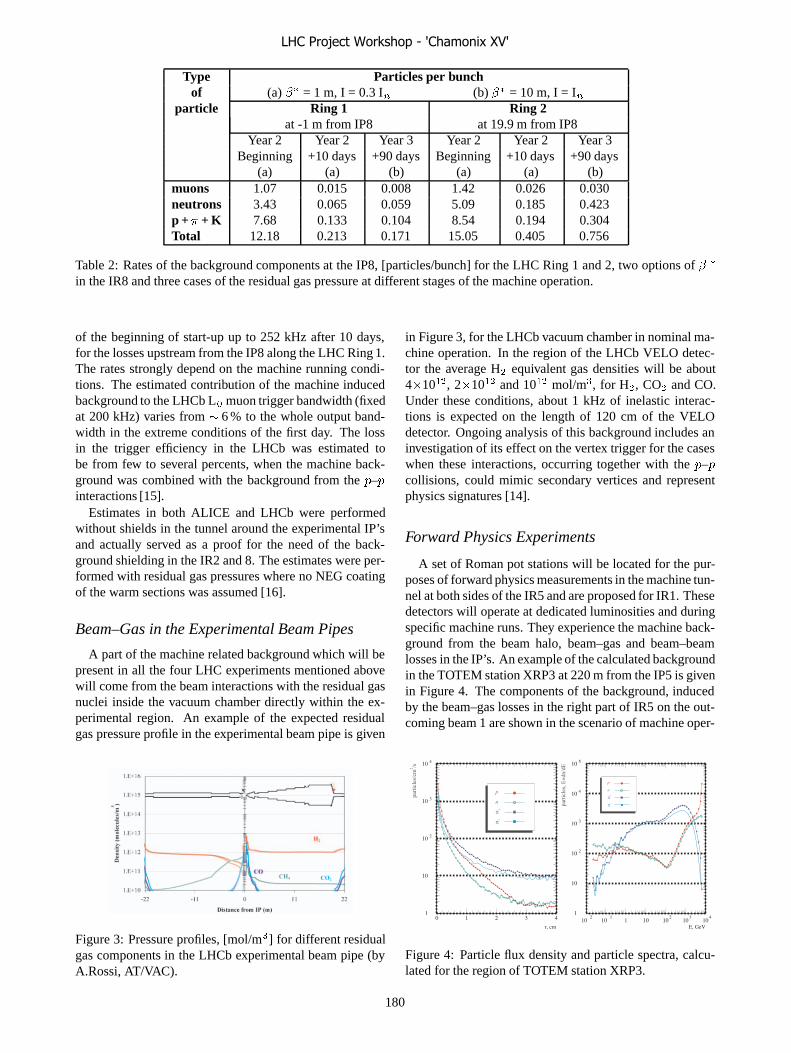
Type Particles per bunchof (a) �� = 1 m, I = 0.3 I� (b) �� = 10 m, I = I�
particle Ring 1 Ring 2at -1 m from IP8 at 19.9 m from IP8
Year 2 Year 2 Year 3 Year 2 Year 2 Year 3Beginning +10 days +90 days Beginning +10 days +90 days
(a) (a) (b) (a) (a) (b)muons 1.07 0.015 0.008 1.42 0.026 0.030neutrons 3.43 0.065 0.059 5.09 0.185 0.423p +� + K 7.68 0.133 0.104 8.54 0.194 0.304Total 12.18 0.213 0.171 15.05 0.405 0.756
Table 2: Rates of the background components at the IP8, [particles/bunch] for the LHC Ring 1 and 2, two options of � �
in the IR8 and three cases of the residual gas pressure at different stages of the machine operation.
of the beginning of start-up up to 252 kHz after 10 days,for the losses upstream from the IP8 along the LHC Ring 1.The rates strongly depend on the machine running condi-tions. The estimated contribution of the machine inducedbackground to the LHCb L� muon trigger bandwidth (fixedat 200 kHz) varies from � 6 % to the whole output band-width in the extreme conditions of the first day. The lossin the trigger efficiency in the LHCb was estimated tobe from few to several percents, when the machine back-ground was combined with the background from the �–�interactions [15].
Estimates in both ALICE and LHCb were performedwithout shields in the tunnel around the experimental IP’sand actually served as a proof for the need of the back-ground shielding in the IR2 and 8. The estimates were per-formed with residual gas pressures where no NEG coatingof the warm sections was assumed [16].
Beam–Gas in the Experimental Beam Pipes
A part of the machine related background which will bepresent in all the four LHC experiments mentioned abovewill come from the beam interactions with the residual gasnuclei inside the vacuum chamber directly within the ex-perimental region. An example of the expected residualgas pressure profile in the experimental beam pipe is given
Figure 3: Pressure profiles, [mol/m�] for different residualgas components in the LHCb experimental beam pipe (byA.Rossi, AT/VAC).
in Figure 3, for the LHCb vacuum chamber in nominal ma-chine operation. In the region of the LHCb VELO detec-tor the average H� equivalent gas densities will be about4�10��, 2�10�� and 10�� mol/m�, for H�, CO� and CO.Under these conditions, about 1 kHz of inelastic interac-tions is expected on the length of 120 cm of the VELOdetector. Ongoing analysis of this background includes aninvestigation of its effect on the vertex trigger for the caseswhen these interactions, occurring together with the �–�collisions, could mimic secondary vertices and representphysics signatures [14].
Forward Physics Experiments
A set of Roman pot stations will be located for the pur-poses of forward physics measurements in the machine tun-nel at both sides of the IR5 and are proposed for IR1. Thesedetectors will operate at dedicated luminosities and duringspecific machine runs. They experience the machine back-ground from the beam halo, beam–gas and beam–beamlosses in the IP’s. An example of the calculated backgroundin the TOTEM station XRP3 at 220 m from the IP5 is givenin Figure 4. The components of the background, inducedby the beam–gas losses in the right part of IR5 on the out-coming beam 1 are shown in the scenario of machine oper-
Figure 4: Particle flux density and particle spectra, calcu-lated for the region of TOTEM station XRP3.
LHC Project Workshop - 'Chamonix XV'
180

ation with 156 bunches and dedicated TOTEM optics [17].The rates of the beam–gas background in the TOTEM
stations were estimated to be of the same order of mag-nitude as those of the beam–beam, scaling particle fluxesin the detectors, calculated for the L = 10�� cm��/s in IP5[18], down to the 2�10�� cm��/s. Special techniques forthe background analysis are being developed that alreadyappeared effective in the rejection of the low energy andneutral components of the background [19].
EXPECTED VARIATION OF THEBACKGROUND
Estimations of the machine induced background in theexperimental insertions depend on the machine operatingconditions which define the relative contribution of differ-ent sources to the background. The rate of the backgroundfrom the beam–gas losses depends directly on the residualgas pressure in the LHC sections, while the backgroundfrom the particles out-scattered from the cleaning inser-tions is proportional to the cleaning inefficiency. Below wereport the expected range of the variations for these quan-tities and evaluate the corresponding effect on the machineinduced background rates.
Residual Gas Pressure in LSS’s
Interactions of the beam with the residual gas nucleifrom H�, CO, CO� and CH� are the main source of beamlosses in the LSS’s. The resulting background depends onthe absolute value of the density for a particular gas com-ponent and on the pressure profile in the structure of thestraight section. An example of pressure profiles, calcu-lated for the IR5 for two distinct cases of machine op-eration, are given in Figure 5. At machine start-up withthe 0.2 A current and unconditioned surface of the vacuumchamber the maximal value for the H� equivalent gas den-sity is expected to be at the level of 10�� mol/m� in thecold sections of the LSS. After a period of machine condi-tioning, in the nominal operation with the full current themaximal level of the gas pressure is expected to decreaseto a few 10�� H� eq. mol/m�. The level of the gas pressurein the warm sections of the LSS which have the NEG coat-ing is predicted to be about two orders of magnitude lowerrespect to the cold sections in both cases.
n� 43 156 2808Start-up 1.8�10�� 5.7�10�� 4.3�10��
Nominal 4.2�10�� 6.3�10�� 5.3�10��
Table 3: Average H� equivalent residual gas density,[mol/m�] in the IR1 & 5 at the machine start-up and at nom-inal operation after the machine conditioning with the beamof different intensity.
Average values for the residual gas density in the IR1and 5, estimated for different scenarios of machine filling
Figure 5: Pressure profiles, [mol/m�] for different residualgas components in the CMS experimental insertion, for themachine start-up with the current of 0.2 A (top) and nomi-nal operation with 0.56 A (bottom) (by A.Rossi, AT/VAC).
and operation [20] are given in Table 3. The average pres-sure at the machine start-up is expected to be �4–8 timeshigher then during machine operation with a conditionedvacuum chamber surface and maximal beam intensity. Thecomparison of the pressure profiles and gas density valuesavailable from the vacuum calculations shows that a varia-tion of an order of magnitude may be expected in the levelof the machine background induced by the beam–gas lossesin the LSS’s.
Gas Pressure in the Cold Sectors
The variation in the residual gas pressure in the cold sec-tors has a direct influence on the rate of the background atthe entrance to the experimental areas. Figure 6 shows therate of the particles, calculated as a function of the primaryloss distance to the IP8, per unit of density of beam–gas in-teractions [2]. As can be seen from this Figure, the differ-ence between the number of background particles, reachingthe IP due to the beam–gas losses in the dispersion sup-pressor (DS) and the first arc cell (Arc), and those due tolosses on the residual gas in the LSS itself is about 2–3 or-ders of magnitude. If the gas pressure in the cold DS andArc will be more then 3 orders of magnitude higher thenin the LSS, the beam–gas losses in these cold sectors willbecome the dominant source of the muon machine inducedbackground.
The present estimate of the residual gas pressure in thecold sectors of the machine is the H� equivalent gas den-sity of 10�� mol/m�, which corresponds to the beam life-time of 100 hours [21]. This number may be considered as
LHC Project Workshop - 'Chamonix XV'
181
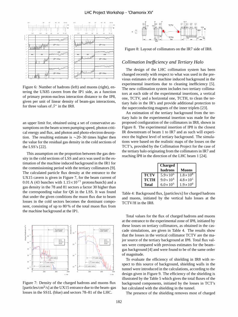
Figure 6: Number of hadrons (left) and muons (right), en-tering the UX85 cavern from the IP1 side, as a functionof primary proton-nucleus interaction distance to the IP8,given per unit of linear density of beam-gas interactions,for three values of �� in the IR8.
an upper limit for, obtained using a set of conservative as-sumptions on the beam screen pumping speed, photon criti-cal energy and flux, and photon and photo-electron desorp-tion. The resulting estimate is �20–30 times higher thenthe value for the residual gas density in the cold sections ofthe LSS’s [22].
This assumption on the proportion between the gas den-sity in the cold sections of LSS and arcs was used in the es-timation of the machine induced background in the IR1 forthe commissioning period with the tertiary collimators [9].The calculated particle flux density at the entrance to theUX15 cavern is given in Figure 7, for the beam current of0.01 A (43 bunches with 1.15�10�� protons/bunch) and agas density in the 78 and 81 sectors a factor 30 higher thanthe corresponding value for Q6 in the LSS. It was foundthat under the given conditions the muon flux due to beamlosses in the cold sectors becomes the dominant compo-nent, consisting of up to 80 % of the total muon flux fromthe machine background at the IP1.
Figure 7: Density of the charged hadrons and muons flux[particles/cm�/s] at the UX15 entrance due to the beam–gaslosses in the SS1L (blue) and sectors 78–81 of the LHC.
Figure 8: Layout of collimators on the IR7 side of IR8.
Collimation Inefficiency and Tertiary Halo
The design of the LHC collimation system has beenchanged recently with respect to what was used in the pre-vious estimates of the machine induced background in theexperimental insertions due to cleaning inefficiency [5].The new collimation system includes two tertiary collima-tors at each side of the experimental insertions, a verticalone, TCTV, and a horizontal one, TCTH, to clean the ter-tiary halo in the IR’s and provide additional protection tothe superconducting magnets of the inner triplets [23].
An estimation of the tertiary background from the ter-tiary halo in the experimental insertion was made for theproposed configuration of the collimators in IR8, shown inFigure 8. The experimental insertion of IP8 is the closestIR downstream of beam 1 to IR7 and as such will experi-ence the highest level of tertiary background. The simula-tions were based on the realistic maps of the losses on theTCT’s, provided by the Collimation Project for the case ofthe tertiary halo originating from the collimators in IR7 andreaching IP8 in the direction of the LHC beam 1 [24].
Chargedhadrons Muons
TCTV 5.9�10� 1.8�10�
TCTH 9.0�10� 4.8�10�
Total 6.0�10� 1.9�10�
Table 4: Background flux, [particles/s] for charged hadronsand muons, initiated by the vertical halo losses at theTCTV/H in the IR8.
Total values for the flux of charged hadrons and muonsat the entrance to the experimental zone of IP8, initiated bythese losses on tertiary collimators, as obtained in the cas-cade simulations, are given in Table 4. The results showthat the losses in the vertical collimator TCTV are the ma-jor source of the tertiary background at IP8. Total flux val-ues were compared with previous estimates for the beam–gas background [4] and were found to be of the same orderof magnitude.
To evaluate the efficiency of shielding in IR8 with re-spect to this source of background, shielding walls in thetunnel were introduced in the calculations, according to thedesign given in Figure 9. The efficiency of the shielding isillustrated by the Table 5 which gives the total fluxes of thebackground components, initiated by the losses in TCT’sbut calculated with the shielding in the tunnel.
The presence of the shielding removes most of charged
LHC Project Workshop - 'Chamonix XV'
182
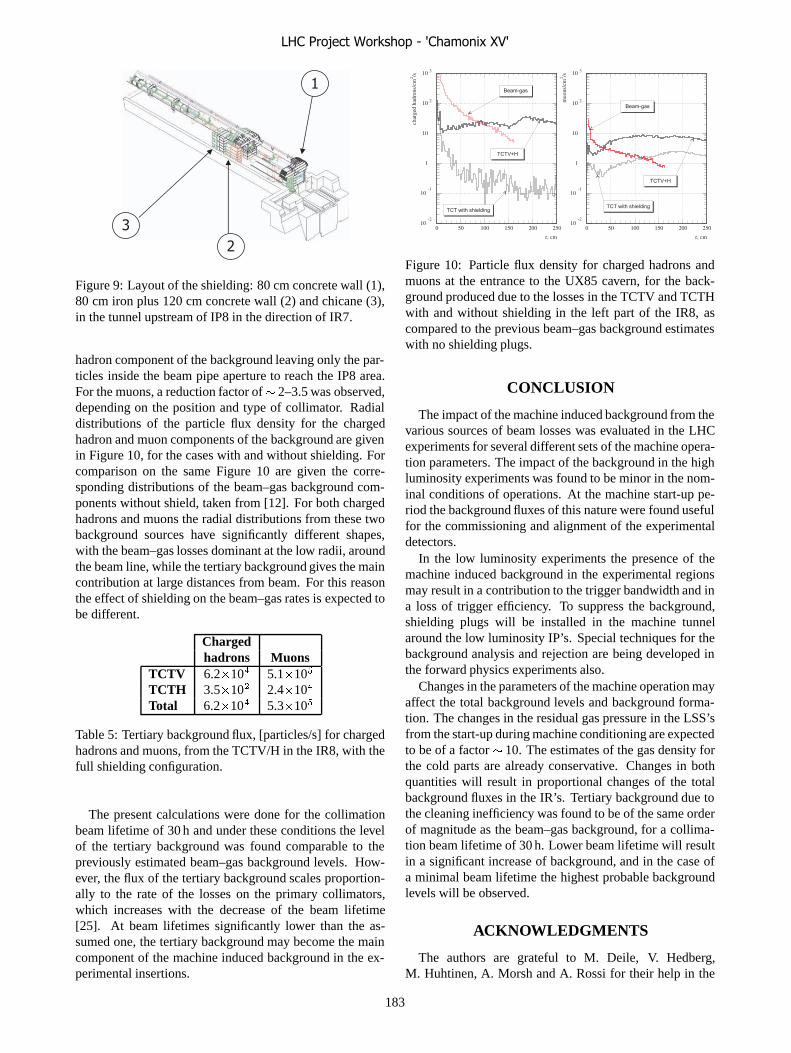
Figure 9: Layout of the shielding: 80 cm concrete wall (1),80 cm iron plus 120 cm concrete wall (2) and chicane (3),in the tunnel upstream of IP8 in the direction of IR7.
hadron component of the background leaving only the par-ticles inside the beam pipe aperture to reach the IP8 area.For the muons, a reduction factor of� 2–3.5 was observed,depending on the position and type of collimator. Radialdistributions of the particle flux density for the chargedhadron and muon components of the background are givenin Figure 10, for the cases with and without shielding. Forcomparison on the same Figure 10 are given the corre-sponding distributions of the beam–gas background com-ponents without shield, taken from [12]. For both chargedhadrons and muons the radial distributions from these twobackground sources have significantly different shapes,with the beam–gas losses dominant at the low radii, aroundthe beam line, while the tertiary background gives the maincontribution at large distances from beam. For this reasonthe effect of shielding on the beam–gas rates is expected tobe different.
Chargedhadrons Muons
TCTV 6.2�10� 5.1�10�
TCTH 3.5�10� 2.4�10�
Total 6.2�10� 5.3�10�
Table 5: Tertiary background flux, [particles/s] for chargedhadrons and muons, from the TCTV/H in the IR8, with thefull shielding configuration.
The present calculations were done for the collimationbeam lifetime of 30 h and under these conditions the levelof the tertiary background was found comparable to thepreviously estimated beam–gas background levels. How-ever, the flux of the tertiary background scales proportion-ally to the rate of the losses on the primary collimators,which increases with the decrease of the beam lifetime[25]. At beam lifetimes significantly lower than the as-sumed one, the tertiary background may become the maincomponent of the machine induced background in the ex-perimental insertions.
Figure 10: Particle flux density for charged hadrons andmuons at the entrance to the UX85 cavern, for the back-ground produced due to the losses in the TCTV and TCTHwith and without shielding in the left part of the IR8, ascompared to the previous beam–gas background estimateswith no shielding plugs.
CONCLUSION
The impact of the machine induced background from thevarious sources of beam losses was evaluated in the LHCexperiments for several different sets of the machine opera-tion parameters. The impact of the background in the highluminosity experiments was found to be minor in the nom-inal conditions of operations. At the machine start-up pe-riod the background fluxes of this nature were found usefulfor the commissioning and alignment of the experimentaldetectors.
In the low luminosity experiments the presence of themachine induced background in the experimental regionsmay result in a contribution to the trigger bandwidth and ina loss of trigger efficiency. To suppress the background,shielding plugs will be installed in the machine tunnelaround the low luminosity IP’s. Special techniques for thebackground analysis and rejection are being developed inthe forward physics experiments also.
Changes in the parameters of the machine operation mayaffect the total background levels and background forma-tion. The changes in the residual gas pressure in the LSS’sfrom the start-up during machine conditioning are expectedto be of a factor � 10. The estimates of the gas density forthe cold parts are already conservative. Changes in bothquantities will result in proportional changes of the totalbackground fluxes in the IR’s. Tertiary background due tothe cleaning inefficiency was found to be of the same orderof magnitude as the beam–gas background, for a collima-tion beam lifetime of 30 h. Lower beam lifetime will resultin a significant increase of background, and in the case ofa minimal beam lifetime the highest probable backgroundlevels will be observed.
ACKNOWLEDGMENTS
The authors are grateful to M. Deile, V. Hedberg,M. Huhtinen, A. Morsh and A. Rossi for their help in the
LHC Project Workshop - 'Chamonix XV'
183
preparation of this talk.
REFERENCES
[1] K.M. Potter (editor). Proc. of the Workshop on LHC Back-grounds, CERN, Geneva, March 22, 1996.
[2] I. Azhgirey, I. Baishev, K.M. Potter et al., “MethodicalStudy of the Machine Induced Background Formation in theIR8 of LHC”, LHC Project Note 258, CERN, Geneva, 2001.
[3] I. Azhgirey, I. Baishev, V. Talanov, “Machine Induced Back-ground Sources Analysis for the IP1 Interaction Region ofthe LHC”, In: Proc. of RUPAC’2004, Dubna, 2004, p.511–513.
[4] I. Azhgirey, I. Baishev, K.M. Potter et al., “Calculation ofthe Machine Induced Background Formation in IR2 of theLHC Using New Residual Gas Density Distributions”, LHCProject Note 273, CERN, Geneva, 2001.
[5] I. Baichev, J.B. Jeanneret, K.M. Potter, “Proton Losses Up-stream of IP8 in LHC”, CERN LHC Project Report 500,Geneva, 2001.
[6] I. Azhgirey, I. Baishev, K.M. Potter et al. “Machine InducedBackground in the Low Luminosity Insertions of the LHC”,CERN LHC Project Report 567, Geneva, 2002. Pres. at: 8thEuropean Particle Accelerator Conference: a EurophysicsConference, La Vilette, Paris, France, 3–7 June 2002.
[7] V. Hedberg, “LHC Induced Background in ATLAS”, LHCMachine Induced Background Working Group meeting,CERN, Geneva, April 2005,����������������� ��������
[8] A. Drozhdin, M. Huhtinen, N. Mokhov. NIM A381 (1996)531.
[9] V. Talanov, “Estimation of the Machine Induced Back-ground for the Commissioning Period with Tertiary Colli-mators in the IR1 of the LHC”, CERN LHC Project Note371, CERN, Geneva, 2005.
[10] M. Boonekamp, F. Gianotti, R.A. McPherson et al., “Cos-mic Ray, Beam–Halo and Beam–Gas Rate Studies for AT-LAS Commissioning”, ATLAS Note GEN-001, CERN,Geneva, 2004.
[11] E. Barberis, P. Biallass, V. Drollinger et al., “Trigger and Re-construction Studies with Beam Halo and Cosmic Muons”,CMS Analysis Note 2005-046, CERN, Geneva, 2005.
[12] I. Azhgirey, I. Baishev, K.M. Potter et al., “Evaluation ofSome Options for Shielding from Machine Induced Back-ground in the IR8”, LHC Project Note 307, CERN, Geneva,2002.
[13] A. Morsh, “Machine Background in ALICE”, LHC Ma-chine Induced Background Working Group meeting, CERN,Geneva, April 2005,����������������� ��������
[14] G. Corti, “LHCb: Status of the Studies”, LHC Ma-chine Induced Background Working Group meeting, CERN,Geneva, October 2005,����������������� ��������
[15] E. Aslanides, F. Derue, R. le Gac et al., “Performance ofthe Muon Trigger with a Realistic Simulation”, LHCb Note2002-041, CERN, Geneva, 2002.
[16] I.R. Collins and O.B. Malyshev, “Dynamic Gas Density inthe LHC Interaction Regions 1&5 and 2&8 for Optics Ver-sion 6.3”, CERN LHC Project Note 274, Geneva, 2001.
[17] V. Avati, M. Deile, D. Macina et al., “First Results of theMachine Induced Background Estimation for the ForwardPhysics Detectors in the IR5 of the LHC”, CERN LHCProject Note 360, Geneva, 2004.
[18] A. Drozhdin, D. Macina, N. Mokhov et al., “AcceleratorRelated Backgrounds in the LHC Forward Detectors”, In:Proc. of the PAC’2003, Portland, OR, May 12–16 2003,p.1742–1744.
[19] M. Deile, “Beam–Gas Background Studies for the TOTEMRoman Pots”, LHC Machine Induced Background WorkingGroup meeting, CERN, Geneva, June 2005,����������������� ��������
[20] A. Rossi, “Residual Gas Density Estimations in the LHCInsertion Regions IR1 and IR5 and the Experimental Re-gions of ATLAS and CMS for Different Beam Operations”,CERN LHC Project Report 783, Geneva, 2004.
[21] A. Rossi, “Expected Vacuum Performance in the ColdArcs”, LHC Machine Induced Background Working Groupmeeting, CERN, Geneva, June 2005,����������������� ��������
[22] A. Rossi, Private communication.
[23] R. Assmann, C. Fischer, D. Macina et al., “Integration ofTertiary Collimators, Beam-Beam Rate Monitors and SpaceReservation for a Calorimeter in the Experimental LSS’s,”LHC Project Document LHC-LJ-EC-0003, CERN, Geneva,2004.
[24] R. Assmann, S. Redaelli, G. Rodert-Demolaize, “LHC Col-limation System Studies Using SIXTRACK”, LHC Ma-chine Induced Background Working Group meeting, CERN,Geneva, October 2005,����������������� ��������
[25] R. Assmann, “Collimators and Cleaning: Could This LimitThe LHC Performance ?” In: Proc. of the LHC PerformanceWorkshop — Chamonix XII, 2003, p.163–170.
LHC Project Workshop - 'Chamonix XV'
184
BRINGING THE FIRST LHC BEAMS INTO COLLISION AT ALL 4 IPs E. Bravin, CERN, Geneva, Switzerland
Abstract Collision rate monitors are essential in bringing particle
beams into collision and optimizing the performances of a collider. In the case of LHC the relative luminosity will be monitored by measuring the flux of small angle neutral particles produced in the collisions. The LHC rate monitors (BRAN) are being developed by Berkeley National Laboratory (USA) in the framework of the LARP collaboration and consist of a fast ionization chamber that will be installed on both sides of each IP and at about 140m from it. The monitors aim at measuring the relative luminosity of LHC bunch by bunch with a few percent resolution.
INTRODUCTION The ultimate aim of LHC is producing collisions inside
the four experimental detectors: ATLAS, CMS, ALICE and LHC-b. This will allow the further understanding of the nature of matter and of the forces holding it together.
Looking more in details there are differences in the way this should be done. ATLAS and CMS will profit from the highest collision rate possible while ALICE and LHC-b require the collision rate to be set and controlled at optimal levels. In the case of ALICE the radiation damage sustained by the sub-detectors in case of long terms p-p luminosities above 1030 cm-2s-1 is dangerous. For LHC-b the upper limit is defined by the requirement of not having more that one p-p interaction during the same bunch crossing. This limits the “bunch” luminosity to 1.8×1029 cm-2s-1 and thus the maximum luminosity to 5×1032 cm-2s-1 for 2808 bunches.
LUMINOSITY In order to express the collision rate in a univocal way
the concept of “Luminosity” is normally used as collisions can be of many different kinds and shades.
Luminosity is defined as the ratio between the collision rate of any particular process and the respective cross section. Cross sections of known processes have been calculated, measured or estimated and are available.
x
xNL
σ&
= (1)
Luminosity can also be expressed as a relation between the parameters of the colliding beams:
Where: Nbi are the bunch populations, frev is the revolution frequency, kb is the number of bunches per beam, σm are the transverse beam sizes and xi and yi are the transverse centre positions of the two beams.
The term on the left gives the maximum theoretical luminosity with the given beam parameters. The term on the right indicates the reduction of the luminosity due to the transverse offset between the two beams.
As explained before the luminosity of the machine at all four interaction points must be known with certain accuracy [1]. Eq. 2 could be used to calculate the luminosity if all parameters were known with the same accuracy. Unfortunately this is not the case, especially for the offset between the two beams. Assuming, equal, round beams, an offset of one beam size will reduce the luminosity by 20%. At nominal luminosity the incertitude on the beams position at the IP will be of several sigmas.
For this reason the luminosity must be monitored using a dedicated, robust and reliable device, independent of the incertitude on the beam parameters and optics.
COLLISION RATE MONITORS (“LUMINOSITY MONITORS”)
In the tuning of the machine the most important information will be the relative impact of the different trims on the luminosity. Devices that measure the rate of a particular group of events are sufficient for this task, even if the value of the “equivalent” cross section for these events is not known; these will in fact be constant and not influenced by the trims. These devices will of course not allow measuring directly the absolute value of the luminosity. It is however possible to periodically calibrate the readings of these monitors with the results of the experiments and thus obtain a sufficiently accurate absolute knowledge of the luminosity.
In the p-p collisions at LHC many particles will be generated, in particular there will be neutral particles like neutrons and photons arising from “soft” interactions. These particles will in general follow the trajectories of the protons they descend from. Tacking advantage of the geometry of the IPs it is possible to intercept these neutral particles at a location where the two proton beams have been sufficiently deviated by the bending magnets D1 and D2. At about 140 m from the IP the two proton beams are separated by about 160 mm. This leaves a space of about 100mm between the two vacuum chambers where a
detector can be placed. The straight trajectory of the neutral particles coming from the IP will intercept the
⎥⎥⎦
⎤
⎢⎢⎣
⎡
+−−
+−−⋅
++=
)(2)(
)(2)(exp
))((2 22
21
221
22
21
221
22
21
22
21
21
yyxxyyxx
brevbb yyxxkfNNLσσσσσσσσπ
(2)
LHC Project Workshop - 'Chamonix XV'
185
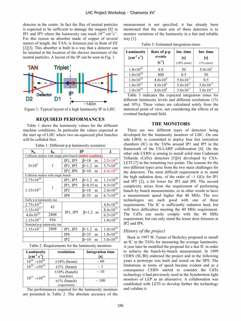
detector in the centre. In fact the flux of neutral particles is expected to be sufficient to damage the magnet D2 in IP1 and IP5 where the luminosity can reach 1034 cm-2s-1. For this reason an absorber made of copper of several meters of length, the TAN, is foreseen just in front of D2 [2][3]. This absorber is built in a way that a detector can be inserted at the location of the shower maximum of the neutral particles. A layout of the IP can be seen in Fig. 1.
Figure 1: Typical layout of a high luminosity IP in LHC.
REQUIRED PERFORMANCES Table 1 shows the luminosity values for the different
machine conditions. In particular the values expected at the start up of LHC where two un-squeezed pilot bunches will be collided first.
Table 1: Different p-p luminosity scenarios Nb kb IP L
Collision studies with single pilot bunch (Initial condition) IP1, IP5 β=18 m 2.5×1026 IP1, IP5 β=1.2 m 3.7×1027 5×10⁹ 1 IP2, IP8 β=10 m 4.4×1026
Collision studies with single bunch 2.75×10¹⁰ IP1, IP5 β=1.2 m 1.1×1029
IP1, IP5 β=0.55 m 4.3×1030 IP2 β=10 m 2.4×1029 1.15×10¹¹
1
IP8 β=35 m 6.7×1028 Early p-p luminosity run 2.75×10¹⁰ 4.8×1030 1.15×10¹¹
43 8.4×1031
4.0×10¹⁰ 2808 6.5×1032 1.15×10¹¹ 936
IP1, IP5 β=1.2 m
1.8×1033 Nominal p-p luminosity run 1.15×10¹¹ 2808 IP1, IP5 β=1.2 m 1.0×1034
IP8 β=35 m 1.9×1032 IP2 β=10 m 3.0×1030
Table 2: Requirements for the luminosity monitors Luminosity
[cm-2 s-1] resolution Integration time
[s] 1026 →1028 ±10% (beam) ~ 60 1028 →1034 ±1% (beam) ~ 1
±10% (bunch) (machine)
~ 10 1033 →1034
±1% (bunch) (experiment)
~ 100
The performances required for the luminosity monitors are presented in Table 2. The absolute accuracy of the
measurement is not specified, it has already been mentioned that the main aim of these detectors is to monitor variations of the luminosity in a fast and reliable way [1].
Table 3: Estimated integration times
Luminosity[cm-2 s-1]
Rate of p-p events
[s-1]
Int. time [s]
(10% error)
Int. time [s]
(1% error)
1.0×1026 8.0 50 5.0×10³ 1.0×1028 800 0.5 50 1.0×1030 8.0×10⁴ 5.0×10⁻³ 0.5 1.0×1032 8.0×10⁶ 5.0×10⁻⁵ 5.0×10⁻³ 1.0×1034 8.0×10⁸ 5.0×10⁻⁷ 5.0×10⁻⁵
Table 3 indicates the expected integration times for different luminosity levels and different resolutions (1% and 10%). These values are calculated solely from the statistical point of view, not considering the effects of an eventual background field.
THE MONITORS There are two different types of detectors being
developed for the luminosity monitors of LHC. On one side LBNL is committed to deploy four fast ionization chambers (IC) in the TANs around IP1 and IP5 in the framework of the US-LARP collaboration [4]. On the other side CERN is aiming to install solid state Cadmium Telluride (CdTe) detectors [5][6] developed by CSA-LETI [7] in the remaining two points. The reasons for the two different types arise from the two main challenges for the detectors. The most difficult requirement is to stand the high radiation dose, of the order of ~1 GGy for IP1 and IP5 [2], a bit lower for IP2 and IP8. The second complexity arises from the requirement of performing bunch by bunch measurements, or in other words to have a measurement speed higher that 40 MHz. The two technologies are each good with one of these requirements. The IC is sufficiently radiation hard, but will have difficulties meeting the 40 MHz requirement. The CdTe can easily comply with the 40 MHz requirement, but can only stand the lesser dose foreseen at IP2 and IP8.
History of the project Back in 1997 W. Turner of Berkeley proposed to install
an IC in the TANs for measuring the average luminosity. A year later he modified the proposal for a fast IC in order to achieve the bunch-by-bunch measurement. In 1999 CERN (SL/BI) endorsed the project and in the following years a prototype was built and tested on the SPS. The limitations in terms of speed became evident and as a consequence CERN started to consider the CdTe technology it had previously used in the Synchrotron light monitors of LEP as an alternative. A collaboration was established with LETI to develop further the technology and validate it.
~140m
LHC Project Workshop - 'Chamonix XV'
186
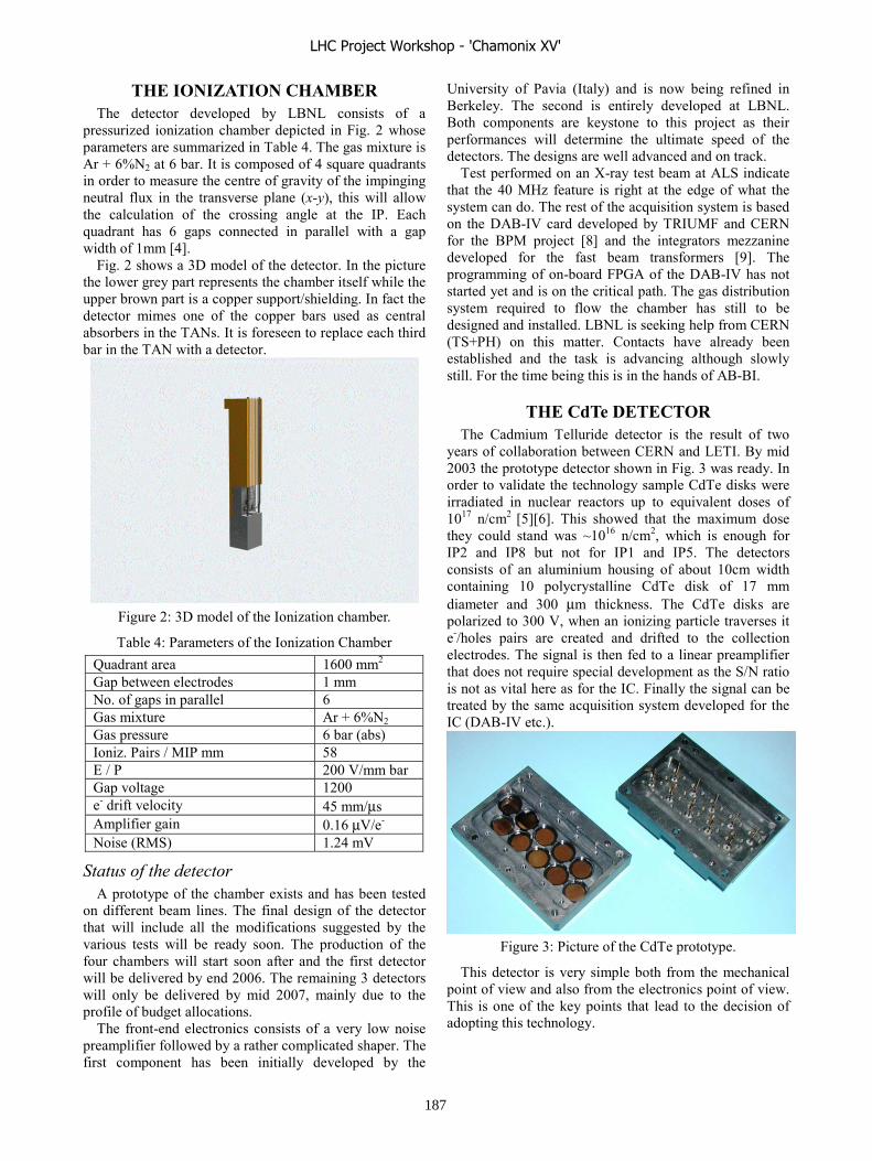
THE IONIZATION CHAMBER The detector developed by LBNL consists of a
pressurized ionization chamber depicted in Fig. 2 whose parameters are summarized in Table 4. The gas mixture is Ar + 6%N2 at 6 bar. It is composed of 4 square quadrants in order to measure the centre of gravity of the impinging neutral flux in the transverse plane (x-y), this will allow the calculation of the crossing angle at the IP. Each quadrant has 6 gaps connected in parallel with a gap width of 1mm [4].
Fig. 2 shows a 3D model of the detector. In the picture the lower grey part represents the chamber itself while the upper brown part is a copper support/shielding. In fact the detector mimes one of the copper bars used as central absorbers in the TANs. It is foreseen to replace each third bar in the TAN with a detector.
Figure 2: 3D model of the Ionization chamber.
Table 4: Parameters of the Ionization Chamber Quadrant area 1600 mm2 Gap between electrodes 1 mm No. of gaps in parallel 6 Gas mixture Ar + 6%N2 Gas pressure 6 bar (abs) Ioniz. Pairs / MIP mm 58 E / P 200 V/mm bar Gap voltage 1200 e- drift velocity 45 mm/μs Amplifier gain 0.16 μV/e- Noise (RMS) 1.24 mV
Status of the detector A prototype of the chamber exists and has been tested
on different beam lines. The final design of the detector that will include all the modifications suggested by the various tests will be ready soon. The production of the four chambers will start soon after and the first detector will be delivered by end 2006. The remaining 3 detectors will only be delivered by mid 2007, mainly due to the profile of budget allocations.
The front-end electronics consists of a very low noise preamplifier followed by a rather complicated shaper. The first component has been initially developed by the
University of Pavia (Italy) and is now being refined in Berkeley. The second is entirely developed at LBNL. Both components are keystone to this project as their performances will determine the ultimate speed of the detectors. The designs are well advanced and on track.
Test performed on an X-ray test beam at ALS indicate that the 40 MHz feature is right at the edge of what the system can do. The rest of the acquisition system is based on the DAB-IV card developed by TRIUMF and CERN for the BPM project [8] and the integrators mezzanine developed for the fast beam transformers [9]. The programming of on-board FPGA of the DAB-IV has not started yet and is on the critical path. The gas distribution system required to flow the chamber has still to be designed and installed. LBNL is seeking help from CERN (TS+PH) on this matter. Contacts have already been established and the task is advancing although slowly still. For the time being this is in the hands of AB-BI.
THE CdTe DETECTOR The Cadmium Telluride detector is the result of two
years of collaboration between CERN and LETI. By mid 2003 the prototype detector shown in Fig. 3 was ready. In order to validate the technology sample CdTe disks were irradiated in nuclear reactors up to equivalent doses of 1017 n/cm2 [5][6]. This showed that the maximum dose they could stand was ~1016 n/cm2, which is enough for IP2 and IP8 but not for IP1 and IP5. The detectors consists of an aluminium housing of about 10cm width containing 10 polycrystalline CdTe disk of 17 mm diameter and 300 μm thickness. The CdTe disks are polarized to 300 V, when an ionizing particle traverses it e-/holes pairs are created and drifted to the collection electrodes. The signal is then fed to a linear preamplifier that does not require special development as the S/N ratio is not as vital here as for the IC. Finally the signal can be treated by the same acquisition system developed for the IC (DAB-IV etc.).
Figure 3: Picture of the CdTe prototype.
This detector is very simple both from the mechanical point of view and also from the electronics point of view. This is one of the key points that lead to the decision of adopting this technology.
LHC Project Workshop - 'Chamonix XV'
187

Status of the CdTe detector The design of the detector has been ready since 2003.
Financial problems and the initial proposal of having the same detectors in all 4 IPs (then discarded as non necessary) caused the temporary freezing of this development. In the mean time LETI has improved further the technology and the required founds have been obtained at CERN. Seen also the question marks left on the IC performances, at the end of 2005 AB-BI decided to diversify and revise this option. A purchase contract is being placed with LETI for the delivery of 4 detectors, this will have to go trough the upcoming finance committee of March. After the signature of the contract LETI will take 12 months to deliver. The four detectors will thus be available at the beginning of 2007. The preamplifier will have to be procured or manufactured, although this is not expected to be a lengthy or complicated task it is however undermanned at the moment and actions need to be taken soon. As mentioned the remaining part of the acquisition system will be a copy of the system developed by LBNL for the IC.
THE QUEST FOR A PLACE IN THE TAN It has already been mentioned that the initial plan was
to install the IC as replacement of the 3rd copper bar of the TANs; at least this was the plan up to 2003.
In the last 3 years several other detectors have been proposed inside the TANs replacing more copper bars. In fact at the moment there is no more space left for Cu bars in the TANs as all space has been reserved for experimental detectors.
These detectors are: ATLAS-ZDC (Zero degree Calorimeter) + LHC-f (forward physics studies) at IP1 and CMS-ZDC at IP5. Not all detectors are in a design state suited for integration. Interferences with the operation of the luminosity monitors are expected, especially with LHC-f and this requires some coordination.
COLLIDING BEAMS “The final approach” Once the machine will have been commissioned and
the two beams will be smoothly circulating around the two rings the moment will come to bring them into collision.
In principle the beam position monitors could be used to overlap beam 1 on beam 2. In fact the resolution of these devices will leave an uncertainty of about 200 μm on their transverse overlap. This is equivalent to 13 beam sizes (σ) separation at β= 0.5 m (squeezed optics) and 2 σ separation at β= 18 m (un-squeezed optics). First collisions will be carried out with very little beam current, probably only one pilot bunch per beam. This means that the p-p event rate will be very low. At this point the only way to overlap the two beams will be scanning one beam against the other while monitoring the collision rate. The four experiments could deliver signals proportional to the collision rate, but their reliability, resolution and above all
measurement speed will probably not be sufficient at this point. This is the reason why the machine luminosity detectors have been included from the beginning in the LHC design.
Background effects At very low luminosity the probability of having a p-p
interaction in one bunch crossing is very small. In this condition the integration of the analogue signal generated in the detector could be heavily influenced by noise sources. A better approach is to count the rate of events that generate signals above a certain threshold. In this case only background events that generate high signals need to be considered such that beam losses or beam gas interactions. Table 5 reports the estimations for the rate of events used to measure the collision rate as well as the background events that could perturb the measurement. In the same table the scaling factor for these sources is given. In the calculation of the values a residual gas pressure of 10-10 torr has been assumed as well as a cleaning efficiency of 1:6500.
As can be seen the major difference between the wanted and the unwanted events is that while the firsts depend quadratically on the bunch charge the seconds only depend linearly, moreover the background is virtually independent from the squeeze. This means that at very low luminosity the effect of background sources is much more important, even more if the luminosity is reduced acting on the geometry of the collision (beam sizes and separation). Detecting coincident events on both sides of the IP could improve the measurement if the cross section for such events is sufficiently big. This option is currently being investigated.
Table 5: Rates for the different types of events Process Scaling Rate [s-1]
L= 1034 Rate [s-1] L=2.5× 1026
p-p inelastic collisions Ib
2, Nb, β, L 8.0×10⁸ 16
Beam-gas collisions Ib, Nb 3.5×10⁴ 0.6
Beam -Halo scraping Ib, Nb 8.0×10⁴ 1.3
CONCLUSIONS Measuring the collision rates at the four IPs will be
fundamental for the LHC setting up and operation. For this reliable and fast monitors capable of measuring small variations in luminosity are needed. Two different technologies are being used: a fast ionization chamber developed by LBNL for IP1 and IP5 and solid state CdTe detectors developed by CERN and LETI for IP2 and IP8. Currently the limitations of resources on both sides of the Atlantic have delayed the project to the point that there is no more slack left.
The TAN absorbers where the IC should be installed, once a lonely and awkward place, are becoming more and more crowded with different detectors. This requires an accurate orchestration for the installations and also for
LHC Project Workshop - 'Chamonix XV'
188

avoiding or at least reducing the interferences during their operation.
REFERENCES [1] R. Assmann et al., “ON THE MEASUREMENT OF
THE RELATIVE LUMINOSITY AT THE LHC”, LHC-Project-Document LHC-B-ES-0007 rev 1.0, Geneva : CERN, 15 Apr 2004.
[2] N. Mokhov et al., “Protecting LHC IP1/IP5 Components Against Radiation Resulting from Colliding Beam Interactions”, LHC-Project-Report-633, Geneva : CERN, 17 Apr 2003.
[3] E.H. Hoyer and W.C. Turner, “Absorbers for the High Luminosity Insertions of the LHC”, Proc. EPAC98, 22-26 June 1998.
[4] W.C. Turner et al., “Development of a detector for bunch by bunch measurement and optimisation of Luminosity in the LHC”, NIMA 461 (2001) 107-110, 2001.
[5] E. Rossa et al., “Fast Polycrystalline-CdTe Detectors for LHC Luminosity Measurements”, Proc. IEEE Nuclear Science Symposium, San Diego, CA, 4-10 Nov., 2001.
[6] E. Gschwendtner et al., “Polycrystalline CdTe Detectors : A Luminosity Monitor for the LHC”, CERN-AB-2003-003-BDI; Geneva : CERN, 10 Jan 2003
[7] LETI (Laboratoire d’Electronique, de Technologie et d’Instrumentation), CEA/Grenoble, 17 Rue des Martyrs, F38054 Grenoble Cedex, France.
[8] R. Jones, “VME64x DIGITAL ACQUISITION BOARD FOR THE LHC TRAJECTORY AND CLOSED ORBIT SYSTEM”, LHC-BP-ES-0002 rev. 1.1 , Geneva : CERN, 9 Mar 2004.
[9] H. Jakob et al., “A 40 MHz Bunch by Bunch Intensity Measurement for the CERN SPS and LHC”, CERN-AB-2003-056-BDI; Geneva : CERN, 19 Jun 2003.
LHC Project Workshop - 'Chamonix XV'
189
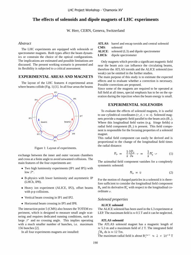
The effects of solenoids and dipole magnets of LHC experiments
W. Herr, CERN, Geneva, Switzerland
Abstract
The LHC experiments are equipped with solenoids orspectrometer magnets. Both types affect the beam dynam-ics or constrain the choice of the optical configurations.The implications are estimated and possible limitations arediscussed. The present working scenario is presented andits flexibility is subjected to a critical assessment.
EXPERIMENTAL AREAS AND MAGNETS
The layout of the LHC features 4 experimental areaswhere beams collide (Fig. 1) [1]. In all four areas the beams
IP1
beam2beam1
IP3
IP8
IP5
IP6
IP7
IP4
IP2
Figure 1: Layout of experiments.
exchange between the inner and outer vacuum chambersand cross at a finite angle to avoid unwanted collisions. Themain features of the four experiments are:
� Two high luminosity experiments (IP1 and IP5) withlow ��.
� B-physics with lower luminosity and asymmetric IP(LHCb, IP8).
� Heavy ion experiment (ALICE, IP2), offset beamswith p-p collisions.
� Vertical beam crossing in IP1 and IP2.
� Horizontal beam crossing in IP5 and IP8.
The interaction point 5 (CMS) also houses the TOTEM ex-periment, which is designed to measure small angle scat-tering and requires dedicated running conditions, such aslarge �� and no crossing angle. This implies operatingwith a much smaller number of bunches, i.e. maximum156 bunches [2].
In all four experiments magnets are installed:
ATLAS: barrel and encap toroids and central solenoidCMS: solenoidALICE: solenoid (L3) and dipole spectrometerLHCb: dipole spectrometer
Only magnets which provide a significant magnetic fieldnear the beam axis can influence the circulating beams,therefore the ATLAS toroids and the ALICE solenoid (tooweak) can be omitted in the further studies.The main purpose of this study is to estimate the expectedeffects and to evaluate whether a correction is necessary.Possible corrections are proposed.Since some of the magnets are required to be operated atfull field at all times, special emphasis has to be on the op-eration during the injection when the beam energy is small.
EXPERIMENTAL SOLENOIDS
To evaluate the effects of solenoid magnets, it is usefulto use cylindrical coordinates (�� �� � � �). Solenoid mag-nets provide a magnetic field parallel to the beam axis (B�).Where this longitudinal field varies (e.g. fringe fields) aradial field component (B�) is present. This field compo-nent is responsible for the focusing properties of a solenoidmagnet.This radial field component can easily be derived and isproportional to the change of the longitudinal field timesthe radial distance:
�� � ��
�
���
��� � � �
�
���
� � � (1)
The azimuthal field component vanishes for a completelysymmetric solenoid:
�� � � (2)
For the motion of charged particles in a solenoid it is there-fore sufficient to consider the longitudinal field componentB� and its derivative B�
� with respect to the longitudinal co-ordinate �.
Solenoid properties
ALICE solenoidThe ALICE solenoid has been used in the L3 experiment atLEP. The maximum field is� 0.5 T and it can be neglected.
ATLAS solenoidThe ATLAS solenoid magnet has a magnetic length of� 5.3 m and a maximum field of 2 T. The integrated field�
B� ds is � 12 Tm.The maximum radial field is about B���
� � � � ���� T
LHC Project Workshop - 'Chamonix XV'
190

at 1 mm from the axis.The field components along the beam axis are shown inFig. 2 [3].
Bs ATLAS
Bs (
T)
s (m)−10 −5 0 5 10
0.5
2.5
2
1.5
1
0
−10 −5 0 5 10
s (m)
0.0
−0.2
−0.4
0.4
0.2Br/r
(T/m
)
Figure 2: ATLAS solenoid field properties.
CMS solenoidThe CMS solenoid magnet has a magnetic length of� 13.2 m and a maximum field of 4 T. It is therefore signif-icantly stronger than the ATLAS solenoid. The integratedfield
�B� ds is � 52 Tm.
The maximum radial field is about B���� � �� � ���� T
at 1 mm from the axis.The field components as a function of � are shown in Fig. 3[4]. Due to the long ramping time of the CMS solenoid, itwill be at full field at all times.
SOLENOID BEAM DYNAMICS
From the solenoid fields we have to expect small effectson the motion of the particles such as:
� Coupling between the two transverse planes
� Transverse focusing
� Orbit effects (crossing angle)
The beam dynamics effects of solenoids can easily be un-derstood looking at the (linear) equations of motion:
�� � �
���� �
��
�
��
����
� � (3)
�� � �
���� �
� ��
��
����
� � (4)
Bs CMS
4
3
2
1
0
−15 −10 −5 0 5 10 15
Bs (T
)
s (m)
−15 −10 −5 0 5 10 15
s (m)
1.0
0.0
−1.0
−2.0
2.0
Br/r
(T/m
)Figure 3: CMS solenoid field properties.
Solenoid focusing
From (1) we know that B� � r, therefore the focusingof a solenoid is the same in both planes. The effect in theLHC is small and can easily be corrected, if required.
Solenoid coupling
From the equations (3) and (4) the strong coupling froma solenoid becomes obvious: the variation of a coordinatein one plane depends only on the coordinates of the otherplane. The contribution of a solenoid to the coupling canbe computed in terms of the coupling coefficients �� [5].The contributions ���� of the solenoid to the coefficientsare then:
���� � � ����
����
�����
����
�������
�(5)
For round beams we have ��� � ��� and therefore:
���� � � � ���� � � ����
����(6)
For the CMS solenoid at full field at 450 GeV/c we get���� � -5i � 10��. This should be compared to the toler-ances of ���� 0.03 (at 450 GeV/c) and ���� 0.01 (at7 TeV/c) [1]. The contribution is therefore relevant whenthe solenoid is at full field at injection. The contributionto the global coupling will be corrected at injection energy.Whether a local compensation is possible and useful is un-der study [6].
LHC Project Workshop - 'Chamonix XV'
191

Solenoid orbit distortions
From the equations (3) and (4) one can easily derive theorbit distortions produced by a solenoid. Particles travel-ling parallel to the solenoidal fields experience no force,however traversing a solenoid with a finite angle � or �
produces an orbit deflection into the other plane (equations(3) and (4). Since in the experimental regions of ATLASand CMS the beams cross at an angle to avoid parasiticbeam-beam interactions, a small orbit distortion is pro-duced by the solenoids.At injection the crossing angles are 160 �rad in both,CMS and ATLAS. The CMS solenoid gives a vertical de-flection of � 5 �rad to the beam which produces a closedorbit distortion of about 0.1 mm r.m.s. around the ring.This distortion should be corrected at injection while at topenergy the effect can be ignored. A local correction with asmall number of correctors around the interaction region ispossible and recommended. Assuming the optics squeezeof the �� is performed at top energy, this correction can bestatic and computed for the injection optics.The effect of the ATLAS solenoid on the closed orbit canbe neglected.During the early commissioning and for dedicated runningconditions (e.g. TOTEM) the crossing angles will be zeroand no orbit distortion is produced by the solenoids.
EXPERIMENTAL DIPOLES
In the interaction regions 2 (ALICE) and 8 (LHCb)strong dipole magnets are installed as spectrometers. Thesedipoles are close to the interaction region and act on bothbeams simultaneously.
Dipole properties
ALICE:The ALICE spectrometer dipole is positioned approxi-mately 10 m to the right of the interaction point 8 and theintegrated field is
�B dl = 3 m which produces a deflection
of � 130 �rad deflection at top energy of 7 TeV. Thefield direction is in the horizontal plane and the deflectiontherefore in the vertical plane.
LHCb:The LCHb spectrometer dipole is positioned approxi-mately 5 m to the right of the interaction point 2 andthe integrated field is
�B dl = 4.2 Tm which produces
a deflection of � 180 �rad deflection at top energy of7 TeV. The field direction is in the vertical plane and thedeflection therefore in the horizontal plane.
DIPOLE EFFECTS
Since the dipoles act on both beams simultaneously, theywould create a strong orbit distortion around the machine
for both beams. Their effects must therefore be compen-sated exactly to avoid loss of aperture or beam offsets atany of the collision points.This compensation is provided by 3 dedicated magnetswhich, together with the spectrometer magnets, producea closed, antisymmetric bump. Since no other active el-ements are inside these bumps, the compensation is inde-pendent of the optics.However, since they act on both beams, they produce cross-ing angles of 70 �rad in ALICE and 135 �rad inLHCb. This is shown for one case in Fig. 4. All num-
−0.0008
−0.0006
−0.0004
−0.0002
0
0.0002
0.0004
0.0006
0.0008
23260 23280 23300 23320 23340 23360 23380 23400
beam 2beam 1
Orbit from spectrometer
position s (m)or
bit
(mm
)
Figure 4: Beam orbits from dipole magnet and compensa-tion magnets in IP8.
bers and Fig. 4 correspond to top energy.The bump produced by the dipole and its compensators isshort and to minimize unwanted long range beam-beam in-teractions, an additional (external) crossing angle is super-imposed [2, 7]. In the base-line design [1] these externalangles are vertical (ALICE) and horizontal (LHCb), i.e.they follow the crossing planes given by the dipole mag-nets. The effective crossing angles are therefore differentfrom the values quoted above and depend on the runningconditions [2].
Operational issues in ALICE
The ALICE experiment is designed for ion collisions andcannot take to full interaction rate of proton-proton colli-sions. In order to reduce the luminosity, the beams collidewith a small offset. Decreasing the luminosity by increas-ing the �� function at the interaction point is limited, sincefor �� � 35 m a sufficient separation of the beam-beamencounters is not possible for the regular bunch spacing of25 ns.The intensity for operation with ions is much lower and thebunch spacing is larger, therefore long range beam-beaminteractions can be neglected. It is possible to reduce theeffective crossing angle or set it to zero by superimposingan external angle with the opposite sign of the crossing an-gle caused by the dipole magnet.
Polarity changes It is foreseen to change the polarityof the spectrometer dipole on a regular basis. Since thecrossing in IP2 is in the vertical plane, this can be achievedby changing the sign of the external angle together with
LHC Project Workshop - 'Chamonix XV'
192
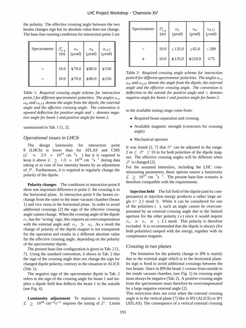
the polarity. The effective crossing angle between the twobeams changes sign but its absolute value does not change.The base-line running conditions for interaction point 2 are
Spectrometer ����� �� �� �(m) (�rad) (�rad) (�rad)
� 10.0 �70.0 �80.0 �150
� 10.0 70.0 80.0 150
Table 1: Required crossing angle scheme for interactionpoint 2 for different spectrometer polarities. The angles��,�� and � denote the angle from the dipole, the externalangle and the effective crossing angle. The convention isupward deflection for positive angle and � denotes nega-tive angle for beam 1 and positive angle for beam 2.
summarized in Tab. 1 [1, 2].
Operational issues in LHCb
The design luminosity for interaction point8 (LHCb) is lower than for ATLAS and CMS(� � ��� � 10�� cm��s��) but it is required tokeep it above � ��� � 10�� cm��s�� during datataking or in case of low intensity beams by an adjustmentof ��. Furthermore, it is required to regularly change thepolarity of the dipole.
Polarity changes The conditions in interaction point 8show one important difference to point 2: the crossing is inthe horizontal plane. In interaction point 8 the beams ex-change from the outer to the inner vacuum chamber (beam1) and vice versa in the horizontal plane. In order to avoidadditional crossings [2] the sign of the effective crossingangle cannot change. When the crossing angle of the dipole�� has the ’wrong’ sign, this requires an overcompensationwith the external angle and: �� � ��. As a result thechange of polarity of the dipole magnet is not transparentfor the operation and results in a different absolute valuefor the effective crossing angle, depending on the polarityof the spectrometer dipole.
The present base-line configuration is given in Tab. 2 [1,7]. Using the standard convention, it shows in Tab. 2 thatthe sign of the crossing angle does not change the sign forchanged dipole polarity, contrary to the situation in ALICE(Tab. 1).
The negative sign of the spectrometer dipole in Tab. 2refers to the sign of the crossing angle for beam 1 and im-plies a dipole field that deflects the beam 1 to the outside(see Fig. 4).
Luminosity adjustment To maintain a luminosity� 10�� cm��s�� requires the tuning of ��. Limits
Spectrometer ����� �� �� �(m) (�rad) (�rad) (�rad)
� 10.0 �135.0 �65.0 �200
� 10.0 135.0 �210.0 �75
Table 2: Required crossing angle scheme for interactionpoint 8 for different spectrometer polarities. The angles��,�� and � denote the angle from the dipole, the externalangle and the effective crossing angle. The convention isdeflection to the outside for positive angle and � denotesnegative angle for beam 1 and positive angle for beam 2.
to the available tuning range come from:
� Required beam separation and crossing
� Available magnetic strength (correctors for crossingangle)
� Mechanical aperture
It was found [2, 7] that �� can be adjusted in the range:2 m � �� � 10 m for both polarities of the dipole mag-net. The effective crossing angles will be different when�� is changed [2].For the assumed intensities, including the LHC com-missioning parameters, these options ensure a luminosity� 10�� cm��s��. The present base-line scenario istherefore compatible with the requirements.
Injection field The full field of the dipole (and its com-pensators) at injection energy produces a rather large an-gle (� 2.1 mrad !). While it can be considered for oneof the polarities (�), such an angle cannot be overcom-pensated by an external crossing angle due to the limitedaperture for the other polarity (�) since it would require�� � �� � � 2.1 mrad. This polarity is thereforeexcluded. It is recommended that the dipole is always (forboth polarities) ramped with the energy, together with itscompensator magnets.
Crossing in two planes
The limitation for the polarity change in IP8 is mainlydue to the external angle which is in the horizontal plane.Its sign is fixed to avoid additional crossings between thetwo beams. Since in IP8 the beam 1 crosses from outside tothe inside vacuum chamber, (see Fig. 1) its crossing anglemust always be negative (Tab. 2). A positive crossing anglefrom the spectrometer must therefore be overcompensatedby a large negative external angle [2].This restriction does not exist when the external crossingangle is in the vertical plane [7] like in IP2 (ALICE) or IP1(ATLAS). The consequence of a vertical external crossing
LHC Project Workshop - 'Chamonix XV'
193

angle would be that the effective crossing plane is tiltedwhere the beams collide.Crossing in the two planes simultaneously was already con-sidered previously [8] for the high luminosity interactionregions to reduce the long range beam-beam effects. Hor-izontal and vertical external angles would reduce the longrange tune spread, but cause transverse coupling and thisoption was discarded. However, this proposed type ofcrossing scheme in interaction point 8 is rather differentfrom these earlier deliberations because:
� External crossing angle only in one plane.
� Tilted crossing plane produced locally by spectrome-ter arrangement.
� Only very few long range interactions occur in thetilted crossing plane.
� These few long range interactions near the interactionpoint occur at very large normalized separation andcan be ignored.
The option to cross at a finite angle in the � plane hasadvantages for the experiment as well as for the acceleratoroperation [7]:
� External crossing angle decoupled from dipole polar-ity.
� Dipole polarity change does not require change of ex-ternal crossing angle.
� Absolute value of effective crossing angle indepen-dent of dipole polarity.
� Simplified operation and setting up of injection.
What needs to be clarified is whether or not it is acceptablefor the experiment to have an effective crossing planedifferent from the x-y plane.To allow for a vertical external crossing angle, the orienta-tion of the beams screen needs to be modified which forthe start of the LHC is excluded.
It is further necessary to study possible side effectsand implications for injection, protection etc. Should it befound that this option is superior to the present scenario, itshould be considered for the future.
SUMMARY
It can be summarized that the experimental magnets dohave noticeable effects on the beam. Corrections are re-quired for some modes of operation. The basic results are:
� Only solenoids in IP1 and IP5 and the dipoles in IP2and IP8 have to be considered.
� The coupling and orbit effects of the solenoids are sig-nificant for IP5 and at injection energy, a correction issuggested.
� The spectrometer dipole in IP2 and IP8 need localcompensation.
� Polarity changes are without problems in IP2.
� Polarity changes in IP8 require modification of themachine parameters.
� The present scenario can fulfill all the requirements,i.e. required modes of operation and luminosity.
� Possible improvements need to be studied.
REFERENCES
[1] LHC Design Report; CERN-2004-003.
[2] W. Herr, Which optical configurations are feasible for p-pcollisions at the LHC; LHC Project Report, to be published.
[3] F. Bergsma, T. Nikitina, W. Kosanecki, S. Snow; private com-munication.
[4] D. Macina; private communication.
[5] G. Guignard, The general theory of all sum and differenceresonances in a three dimensional magnetic field in a syn-chrotron; CERN 76-06 (1976).
[6] A. Koschik and M. Giovannozzi; private communication.
[7] W. Herr, Machine operation and effect of the LHCb dipolemagnet; presentation at LHCb Week, 1.12.2005.
[8] W. Herr, Is there an alternative to alternating crossingschemes for the LHC ?; CERN/SL/93-45 (AP) and LHC Note258 (1993).
LHC Project Workshop - 'Chamonix XV'
194
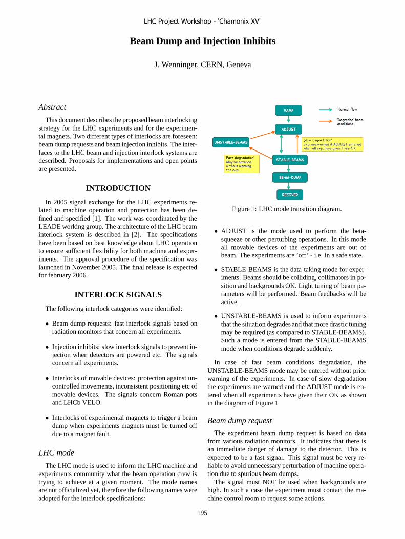
Beam Dump and Injection Inhibits
J. Wenninger, CERN, Geneva
Abstract
This document describes the proposed beam interlockingstrategy for the LHC experiments and for the experimen-tal magnets. Two different types of interlocks are foreseen:beam dump requests and beam injection inhibits. The inter-faces to the LHC beam and injection interlock systems aredescribed. Proposals for implementations and open pointsare presented.
INTRODUCTION
In 2005 signal exchange for the LHC experiments re-lated to machine operation and protection has been de-fined and specified [1]. The work was coordinated by theLEADE working group. The architecture of the LHC beaminterlock system is described in [2]. The specificationshave been based on best knowledge about LHC operationto ensure sufficient flexibility for both machine and exper-iments. The approval procedure of the specification waslaunched in November 2005. The final release is expectedfor february 2006.
INTERLOCK SIGNALS
The following interlock categories were identified:
• Beam dump requests: fast interlock signals based onradiation monitors that concern all experiments.
• Injection inhibits: slow interlock signals to prevent in-jection when detectors are powered etc. The signalsconcern all experiments.
• Interlocks of movable devices: protection against un-controlled movements, inconsistent positioning etc ofmovable devices. The signals concern Roman potsand LHCb VELO.
• Interlocks of experimental magnets to trigger a beamdump when experiments magnets must be turned offdue to a magnet fault.
LHC mode
The LHC mode is used to inform the LHC machine andexperiments community what the beam operation crew istrying to achieve at a given moment. The mode namesare not officialized yet, therefore the following names wereadopted for the interlock specifications:
Figure 1: LHC mode transition diagram.
• ADJUST is the mode used to perform the beta-squeeze or other perturbing operations. In this modeall movable devices of the experiments are out ofbeam. The experiments are ’off’ - i.e. in a safe state.
• STABLE-BEAMS is the data-taking mode for exper-iments. Beams should be colliding, collimators in po-sition and backgrounds OK. Light tuning of beam pa-rameters will be performed. Beam feedbacks will beactive.
• UNSTABLE-BEAMS is used to inform experimentsthat the situation degrades and that more drastic tuningmay be required (as compared to STABLE-BEAMS).Such a mode is entered from the STABLE-BEAMSmode when conditions degrade suddenly.
In case of fast beam conditions degradation, theUNSTABLE-BEAMS mode may be entered without priorwarning of the experiments. In case of slow degradationthe experiments are warned and the ADJUST mode is en-tered when all experiments have given their OK as shownin the diagram of Figure 1
Beam dump request
The experiment beam dump request is based on datafrom various radiation monitors. It indicates that there isan immediate danger of damage to the detector. This isexpected to be a fast signal. This signal must be very re-liable to avoid unnecessary perturbation of machine opera-tion due to spurious beam dumps.
The signal must NOT be used when backgrounds arehigh. In such a case the experiment must contact the ma-chine control room to request some actions.
LHC Project Workshop - 'Chamonix XV'
195
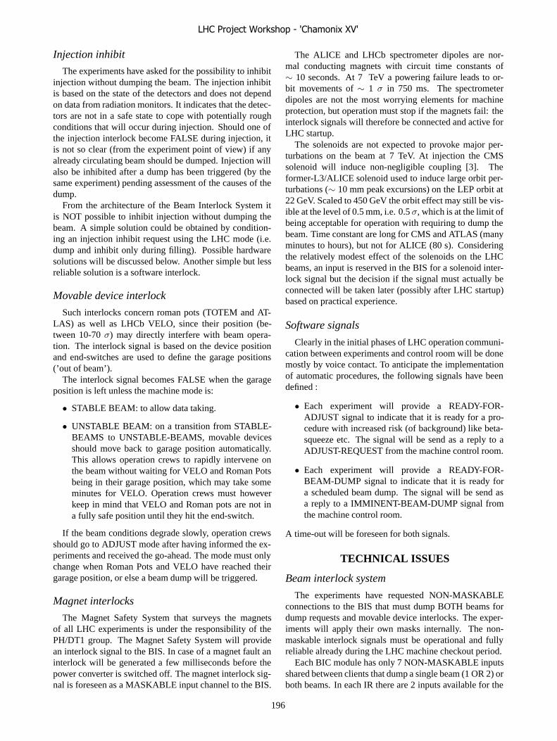
Injection inhibit
The experiments have asked for the possibility to inhibitinjection without dumping the beam. The injection inhibitis based on the state of the detectors and does not dependon data from radiation monitors. It indicates that the detec-tors are not in a safe state to cope with potentially roughconditions that will occur during injection. Should one ofthe injection interlock become FALSE during injection, itis not so clear (from the experiment point of view) if anyalready circulating beam should be dumped. Injection willalso be inhibited after a dump has been triggered (by thesame experiment) pending assessment of the causes of thedump.
From the architecture of the Beam Interlock System itis NOT possible to inhibit injection without dumping thebeam. A simple solution could be obtained by condition-ing an injection inhibit request using the LHC mode (i.e.dump and inhibit only during filling). Possible hardwaresolutions will be discussed below. Another simple but lessreliable solution is a software interlock.
Movable device interlock
Such interlocks concern roman pots (TOTEM and AT-LAS) as well as LHCb VELO, since their position (be-tween 10-70 σ) may directly interfere with beam opera-tion. The interlock signal is based on the device positionand end-switches are used to define the garage positions(’out of beam’).
The interlock signal becomes FALSE when the garageposition is left unless the machine mode is:
• STABLE BEAM: to allow data taking.
• UNSTABLE BEAM: on a transition from STABLE-BEAMS to UNSTABLE-BEAMS, movable devicesshould move back to garage position automatically.This allows operation crews to rapidly intervene onthe beam without waiting for VELO and Roman Potsbeing in their garage position, which may take someminutes for VELO. Operation crews must howeverkeep in mind that VELO and Roman pots are not ina fully safe position until they hit the end-switch.
If the beam conditions degrade slowly, operation crewsshould go to ADJUST mode after having informed the ex-periments and received the go-ahead. The mode must onlychange when Roman Pots and VELO have reached theirgarage position, or else a beam dump will be triggered.
Magnet interlocks
The Magnet Safety System that surveys the magnetsof all LHC experiments is under the responsibility of thePH/DT1 group. The Magnet Safety System will providean interlock signal to the BIS. In case of a magnet fault aninterlock will be generated a few milliseconds before thepower converter is switched off. The magnet interlock sig-nal is foreseen as a MASKABLE input channel to the BIS.
The ALICE and LHCb spectrometer dipoles are nor-mal conducting magnets with circuit time constants of∼ 10 seconds. At 7 TeV a powering failure leads to or-bit movements of ∼ 1 σ in 750 ms. The spectrometerdipoles are not the most worrying elements for machineprotection, but operation must stop if the magnets fail: theinterlock signals will therefore be connected and active forLHC startup.
The solenoids are not expected to provoke major per-turbations on the beam at 7 TeV. At injection the CMSsolenoid will induce non-negligible coupling [3]. Theformer-L3/ALICE solenoid used to induce large orbit per-turbations (∼ 10 mm peak excursions) on the LEP orbit at22 GeV. Scaled to 450 GeV the orbit effect may still be vis-ible at the level of 0.5 mm, i.e. 0.5 σ, which is at the limit ofbeing acceptable for operation with requiring to dump thebeam. Time constant are long for CMS and ATLAS (manyminutes to hours), but not for ALICE (80 s). Consideringthe relatively modest effect of the solenoids on the LHCbeams, an input is reserved in the BIS for a solenoid inter-lock signal but the decision if the signal must actually beconnected will be taken later (possibly after LHC startup)based on practical experience.
Software signals
Clearly in the initial phases of LHC operation communi-cation between experiments and control room will be donemostly by voice contact. To anticipate the implementationof automatic procedures, the following signals have beendefined :
• Each experiment will provide a READY-FOR-ADJUST signal to indicate that it is ready for a pro-cedure with increased risk (of background) like beta-squeeze etc. The signal will be send as a reply to aADJUST-REQUEST from the machine control room.
• Each experiment will provide a READY-FOR-BEAM-DUMP signal to indicate that it is ready fora scheduled beam dump. The signal will be send asa reply to a IMMINENT-BEAM-DUMP signal fromthe machine control room.
A time-out will be foreseen for both signals.
TECHNICAL ISSUES
Beam interlock system
The experiments have requested NON-MASKABLEconnections to the BIS that must dump BOTH beams fordump requests and movable device interlocks. The exper-iments will apply their own masks internally. The non-maskable interlock signals must be operational and fullyreliable already during the LHC machine checkout period.
Each BIC module has only 7 NON-MASKABLE inputsshared between clients that dump a single beam (1 OR 2) orboth beams. In each IR there are 2 inputs available for the
LHC Project Workshop - 'Chamonix XV'
196

experiments. For ATLAS, LHCb and ALICE this is clearlysufficient. In IR5 CMS and TOTEM must share the twoavailable connections. For any new experiment that mustbe added, we must either share channels, i.e experimentscombine their signals, or accept a MASKABLE input, orhave a signal concentrator for the interlock signals, for ex-ample an independent BIC crate.
Injection inhibit
There are two possible solutions to implement an injec-tion inhibit for the experiments:
• Build an injection interlock loop around the ring. Theloop interfaces to the injection elements and to theSPS extractions in IR2 and IR8. Such an implementa-tion has a high price per channel. But it has the advan-tage that the hardware is identical to that of the BIS,that it is easy to accommodate further clients and thatthe maintenance is eased.
• Add dedicated point-to-point links between eachclient experiment and the IR2 and IR8 injection BICmodules (PLC and optical fiber links). This solutionhas potentially a lower price per channel. On the otherhand the hardware is different than for the BIS.
Decisions on implementations depend of manpower andbudget decisions.
Safe LHC mode
The LHC mode plays a critical role for the interlockingof movable devices. It must therefore be send to the exper-iments with high reliability. The LHC mode will be partof the Safe LHC Parameters that will be distributed aroundthe machine in a failsafe and highly reliable way: Withinthe Safe LHC Parameters STABLE-BEAMS will only besent when the energy is 7 TeV (or whatever the physicsenergy will be !). The present concept uses the GeneralMachine Timing system for data distribution, with a spe-cial HW module to enter the data into the system. Detailshave still to be finalized. In addition the mode will also bedistributed over the DIP system for data exchange machine-experiments.
CONCLUSION
The experiments will provide up to interlock 3 signalsfor beam dump request, injection inhibit and for movabledevice positions.
Interlock signals are foreseen for all experiments mag-nets: spectrometer dipoles will be connected at LHCstartup, while for solenoids and toroids the decision to con-nect the signals will be taken later.
A number of technical issues have to be solved in 2006:implementation of the injection inhibit, number of signals,cables and rack locations as well as distribution of the SafeParameters (mostly mode) to the experiments.
REFERENCES
[1] D. Macina, W. H. Smith and J. Wenninger, LHC Ex-periments Beam Interlocking, LHC-CIB-ES-0002 Rev 0.2,EMDS 653932.
[2] B. Puccio et al, The beam interlock system for the LHC,LHC-CIB-ES-0001-00-10, EDMS No. 567256.
[3] W. Herr, these proceedings.
LHC Project Workshop - 'Chamonix XV'
197

BEAM CONDITIONS AND RADIATION MONITORING AT THE LHC EXPERIMENTS
A. Macpherson, CERN, Geneva, Switzerland and Rutgers University, NJ 08854, U.S.A.
Abstract Monitoring of all aspects of the radiation field in and
around the LHC experiments is essential for protection, operation, and performance optimisation of the LHC experiments. An overview of both the radiation and beams conditions monitor systems presently being implemented by the experiments is given. Attention is drawn to the design and functionality of these systems, and their interface to the LHC
INTRODUCTION The purpose of Beam Conditions and Radiation monitoring within the LHC experiments is two fold; a fast real time safety system, and a long term monitoring system. A Beam Conditions Monitor (BCM) system is a real time monitoring system that is to detect the onset of adverse beam conditions in the experimental volume on sub-LHC orbit timescales. As a compliment to this, radiation monitoring addresses long term operation of the experiment and lifetime issues of their components due to radiation damage. All of the LHC experiments are implementing both beam conditions and radiation monitoring systems, and this note gives an overview of the current state of affairs.
RADIATION MONITORING Radiation damage is a concern for all the experiments, and indeed the accelerator itself, as radiation induced damage can affect not only the performance of detectors, but more importantly the control functionality and operation efficiency of subsystems. However, the experiments have been designed to successfully operate for at least 10 years of LHC running, so that unexpected equipment failure is not expected. Indeed, significant effort has been invested in quality assurance and radiation hardness programmes[1]. Where systems are expected to incur substantial radiation damage over the 10 year lifetime, replacement and upgrade schedules are well understood and for this reason it is essential to monitor the degree of radiation damage within the experiments. For the LHC experiments the primary objectives in radiation monitoring in the first years of running is to understand and map the radiation field within the detectors and throughout the experimental cavern. Such a mapping then allows:
• Identification of potential holes in shielding in and around the experimental region.
• Provide an understanding of the machine related backgrounds and their potential to compromise the physics performance of the experiment.
• Allow for an in-situ initial assessment of the long term functionality of sub detectors systems.
• Chart the pattern of single event upset (SEU) events, which in turn shape the operational modes of the sub detectors in terms of resets and resynchronisations.
• Benchmarking of the radiation field simulations. The benchmarking of the radiation field is a key point
in the radiation monitoring strategy of the experiments, as it allows prediction both in terms of radiation damage and the effective lifetime of detector components, but also enables quantitative predictions for the expected activation in the different detector regions during shutdown and access. An understanding of the activation maps is essential for the planning of the operation and maintenance of tall systems within the experimental caverns.
The mapping of the radiation fields has been thoroughly simulated by all experiments[2], typically using the FLUKA, MARS and GCALOR simulation packages[3]. Charged hadron and neutron fluxes (and associated energy spectrums), total dose, and activation maps have been generated by the experiments, and an example of the neutron flux in ATLAS at high luminosity running (1034 cm-2s-1) see Figure 1.
Figure 1: Neutron flux (kHz/cm2) of one quadrant of the ATLAS detector. The simulations are done with GCALOR package
In benchmarking these simulations, a reliable monitoring system is needed as radiation field mapping simulations are limited by uncertainties[4]. Uncertainties intrinsic to the simulation packages are estimated to be of the order of 30%, but realistic uncertainties may be as high as 200-300% in the actual experiments. These differences can be due to deviations from the “as-designed” geometry, differences in material composition
LHC Project Workshop - 'Chamonix XV'
198
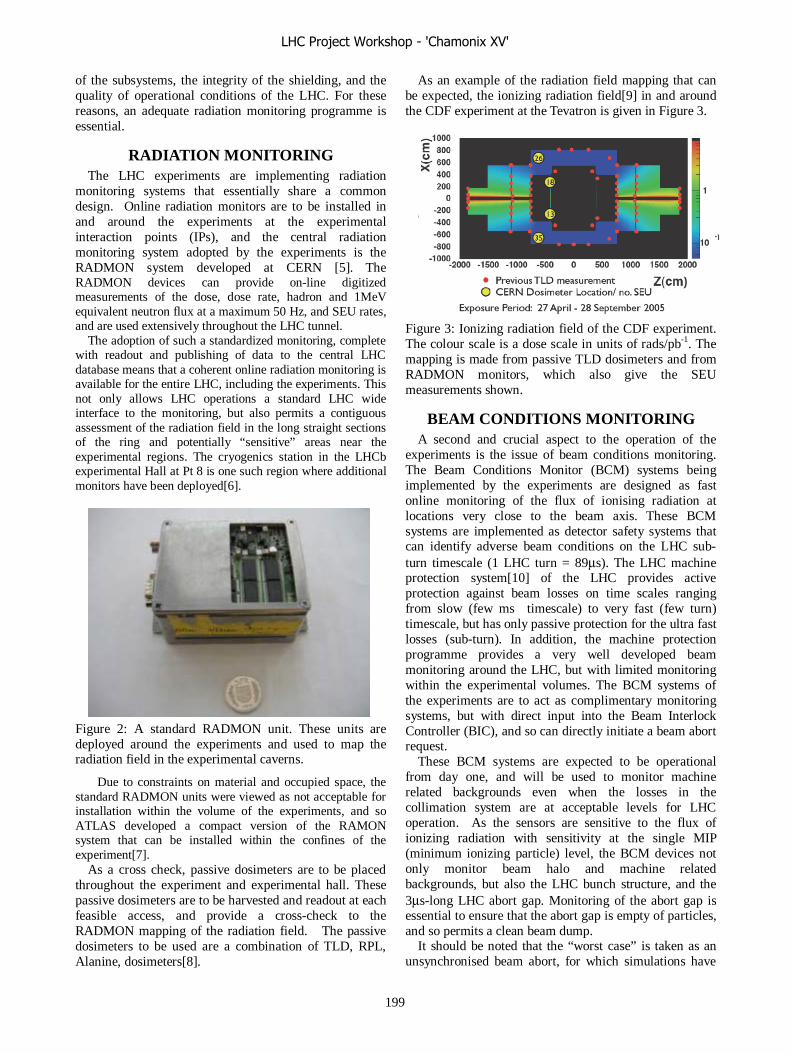
of the subsystems, the integrity of the shielding, and the quality of operational conditions of the LHC. For these reasons, an adequate radiation monitoring programme is essential.
RADIATION MONITORING The LHC experiments are implementing radiation
monitoring systems that essentially share a common design. Online radiation monitors are to be installed in and around the experiments at the experimental interaction points (IPs), and the central radiation monitoring system adopted by the experiments is the RADMON system developed at CERN [5]. The RADMON devices can provide on-line digitized measurements of the dose, dose rate, hadron and 1MeV equivalent neutron flux at a maximum 50 Hz, and SEU rates, and are used extensively throughout the LHC tunnel.
The adoption of such a standardized monitoring, complete with readout and publishing of data to the central LHC database means that a coherent online radiation monitoring is available for the entire LHC, including the experiments. This not only allows LHC operations a standard LHC wide interface to the monitoring, but also permits a contiguous assessment of the radiation field in the long straight sections of the ring and potentially “sensitive” areas near the experimental regions. The cryogenics station in the LHCb experimental Hall at Pt 8 is one such region where additional monitors have been deployed[6].
Figure 2: A standard RADMON unit. These units are deployed around the experiments and used to map the radiation field in the experimental caverns.
Due to constraints on material and occupied space, the standard RADMON units were viewed as not acceptable for installation within the volume of the experiments, and so ATLAS developed a compact version of the RAMON system that can be installed within the confines of the experiment[7].
As a cross check, passive dosimeters are to be placed throughout the experiment and experimental hall. These passive dosimeters are to be harvested and readout at each feasible access, and provide a cross-check to the RADMON mapping of the radiation field. The passive dosimeters to be used are a combination of TLD, RPL, Alanine, dosimeters[8].
As an example of the radiation field mapping that can be expected, the ionizing radiation field[9] in and around the CDF experiment at the Tevatron is given in Figure 3.
Figure 3: Ionizing radiation field of the CDF experiment. The colour scale is a dose scale in units of rads/pb-1. The mapping is made from passive TLD dosimeters and from RADMON monitors, which also give the SEU measurements shown.
BEAM CONDITIONS MONITORING A second and crucial aspect to the operation of the
experiments is the issue of beam conditions monitoring. The Beam Conditions Monitor (BCM) systems being implemented by the experiments are designed as fast online monitoring of the flux of ionising radiation at locations very close to the beam axis. These BCM systems are implemented as detector safety systems that can identify adverse beam conditions on the LHC sub-turn timescale (1 LHC turn = 89μs). The LHC machine protection system[10] of the LHC provides active protection against beam losses on time scales ranging from slow (few ms timescale) to very fast (few turn) timescale, but has only passive protection for the ultra fast losses (sub-turn). In addition, the machine protection programme provides a very well developed beam monitoring around the LHC, but with limited monitoring within the experimental volumes. The BCM systems of the experiments are to act as complimentary monitoring systems, but with direct input into the Beam Interlock Controller (BIC), and so can directly initiate a beam abort request.
These BCM systems are expected to be operational from day one, and will be used to monitor machine related backgrounds even when the losses in the collimation system are at acceptable levels for LHC operation. As the sensors are sensitive to the flux of ionizing radiation with sensitivity at the single MIP (minimum ionizing particle) level, the BCM devices not only monitor beam halo and machine related backgrounds, but also the LHC bunch structure, and the 3μs-long LHC abort gap. Monitoring of the abort gap is essential to ensure that the abort gap is empty of particles, and so permits a clean beam dump.
It should be noted that the “worst case” is taken as an unsynchronised beam abort, for which simulations have
LHC Project Workshop - 'Chamonix XV'
199
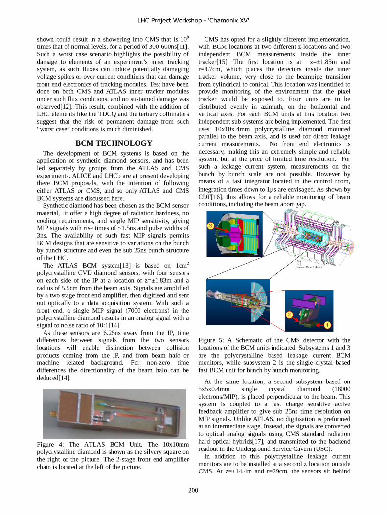
shown could result in a showering into CMS that is 108 times that of normal levels, for a period of 300-600ns[11]. Such a worst case scenario highlights the possibility of damage to elements of an experiment’s inner tracking system, as such fluxes can induce potentially damaging voltage spikes or over current conditions that can damage front end electronics of tracking modules. Test have been done on both CMS and ATLAS inner tracker modules under such flux conditions, and no sustained damage was observed[12]. This result, combined with the addition of LHC elements like the TDCQ and the tertiary collimators suggest that the risk of permanent damage from such “worst case” conditions is much diminished.
BCM TECHNOLOGY The development of BCM systems is based on the
application of synthetic diamond sensors, and has been led separately by groups from the ATLAS and CMS experiments. ALICE and LHCb are at present developing there BCM proposals, with the intention of following either ATLAS or CMS, and so only ATLAS and CMS BCM systems are discussed here.
Synthetic diamond has been chosen as the BCM sensor material, it offer a high degree of radiation hardness, no cooling requirements, and single MIP sensitivity, giving MIP signals with rise times of ~1.5ns and pulse widths of 3ns. The availability of such fast MIP signals permits BCM designs that are sensitive to variations on the bunch by bunch structure and even the sub 25ns bunch structure of the LHC.
The ATLAS BCM system[13] is based on 1cm2 polycrystalline CVD diamond sensors, with four sensors on each side of the IP at a location of z=±1.83m and a radius of 5.5cm from the beam axis. Signals are amplified by a two stage front end amplifier, then digitised and sent out optically to a data acquisition system. With such a front end, a single MIP signal (7000 electrons) in the polycrystalline diamond results in an analog signal with a signal to noise ratio of 10:1[14].
As these sensors are 6.25ns away from the IP, time differences between signals from the two sensors locations will enable distinction between collision products coming from the IP, and from beam halo or machine related background. For non-zero time differences the directionality of the beam halo can be deduced[14].
Figure 4: The ATLAS BCM Unit. The 10x10mm polycrystalline diamond is shown as the silvery square on the right of the picture. The 2-stage front end amplifier chain is located at the left of the picture.
CMS has opted for a slightly different implementation, with BCM locations at two different z-locations and two independent BCM measurements inside the inner tracker[15]. The first location is at z=±1.85m and r=4.7cm, which places the detectors inside the inner tracker volume, very close to the beampipe transition from cylindrical to conical. This location was identified to provide monitoring of the environment that the pixel tracker would be exposed to. Four units are to be distributed evenly in azimuth, on the horizontal and vertical axes. For each BCM units at this location two independent sub-systems are being implemented. The first uses 10x10x.4mm polycrystalline diamond mounted parallel to the beam axis, and is used for direct leakage current measurements. No front end electronics is necessary, making this an extremely simple and reliable system, but at the price of limited time resolution. For such a leakage current system, measurements on the bunch by bunch scale are not possible. However by means of a fast integrator located in the control room, integration times down to 1μs are envisaged. As shown by CDF[16], this allows for a reliable monitoring of beam conditions, including the beam abort gap.
Figure 5: A Schematic of the CMS detector with the locations of the BCM units indicated. Subsystems 1 and 3 are the polycrystalline based leakage current BCM monitors, while subsystem 2 is the single crystal based fast BCM unit for bunch by bunch monitoring.
At the same location, a second subsystem based on 5x5x0.4mm single crystal diamond (18000 electrons/MIP), is placed perpendicular to the beam. This system is coupled to a fast charge sensitive active feedback amplifier to give sub 25ns time resolution on MIP signals. Unlike ATLAS, no digitisation is preformed at an intermediate stage. Instead, the signals are converted to optical analog signals using CMS standard radiation hard optical hybrids[17], and transmitted to the backend readout in the Underground Service Cavern (USC).
In addition to this polycrystalline leakage current monitors are to be installed at a second z location outside CMS. At z=±14.4m and r=29cm, the sensors sit behind
LHC Project Workshop - 'Chamonix XV'
200

the forward hadron calorimeter and so are shielded from collision products coming from the IP. However, at this location the sensors are open to flux impinging on CMS from outside, and so it is expected that these monitors are sensitive to the directionality of beam halo or machine related background in CMS. Further, eight sensors per side are distributed in azimuth, so to be sensitive to skewed tertiary halo losses as well as the halo losses expected due to the horizontal crossing angle of the LHC beams at the CMS IP.
BCM THRESHOLDS The BCM systems are primarily a detector safety
system, with the ability to request a beam dump. In order to ensure that the BCMs protect the experiments, but do not impact the LHC operational efficiency by means of unwarranted beam abort requests, the BCM thresholds and integration time scales need to be thoroughly commissioned.
The CMS approach to this issue is a two stage commissioning. The first stage has been to install BCM prototypes in the CDF experiment at the Tevatron[18]. In the coming running period, the output of these monitors will be matched to both CDF and Tevatron beam instrumentation, and to the operational conditions of the machine. Thresholds and integration times can then be tuned to give an optimised monitoring of the environment of an experiment at a proton machine. It is understood that the settings may not be transferable to the LHC environment, but the experience and understanding gained is expected to provide a useful insight into commissioning the BCM at the LHC.
The second stage of the commissioning is to be done during first beam in the LHC. It is expected that the early stages of the Pilot Run, including single beam operation, will be used to establish the “normal” signal levels for each location. With colliding beams established, in-situ calibration will then be done, and only after this, will the BCM be connected to the BIC. This commissioning phase will require direct interaction and agreement between the experiments and the LHC operations, and for all experiments, must be done in the early stages of the Pilot Run, so that the BCM is active and functional whenever there is possibility of beam in the LHC.
For ATLAS, installation and schedule constraints imply that only in-situ pilot run commissioning is possible, while for ALICE and LHCb, the details are not yet clear, (but are expected to be similar).
THE BCM INTERFACE The monitoring information that the BCM generates is
to be used for both experiment protection and for optimisation of beam conditions for delivered luminosity and physics performance. In both cases, a clear and clean interface to the control rooms of the LHC and the experiments is necessary.
To date, most of the work in the BCM groups has been to develop fast MIP sensitive sensors, and to insure that
they can be installed with the necessary services into very restricted volumes well within the experiments. With the front end hardware in hand, attention is turning to the backend readout and machine interface.
As an example, for the processing of the asynchronous signals coming from the detector front end, CMS is adopting a backend interface to the LHC taken from the LHC machine protection system. Specifically, the CMS BCM is using a backend that is based on the Beam Loss Monitor (BLM) and Beam Position Monitor (BPM) systems[19]. This system uses the DAB64 VME board[20] with a custom mezzanine card to manage and process the asynchronous output of data from the front end, interfaces with the BIC, and insures that post-mortem data is past to the LHC in the advent of a beam abort. Like the BLM and BPM, the mezzanine card has to process the asynchronous front end signals, synchronise to the bunch crossing clock, determine if the signals are above the warning/alarm/abort threshold, and store the information for transfer to the monitoring database or post mortem analysis in the case of a beam abort.
Clearly, for bunch by bunch monitoring within the BCM, it is not feasible to record each measurement. In practice the CMS BCM uses a series of staggered ring buffers with the average of a full buffer making a single entry in the next level ring buffer, as is done by the BLM/BPM groups. In this way, monitoring data from the 25ns to 100s time scale can be kept so that for a post-mortem analysis bunch by bunch measurements are available immediately prior to the abort, while also giving increasingly more general trends over increasing time scales. This staggered buffer structure then allows user defined integration intervals over which beam abort decisions can be made, and as averaged analog levels are stored, user defined warning/alarm/abort are easily configurable. For normal operational monitoring, it is envisaged that the average of one of the higher level ring buffers be exported to the central database.
SUMMARY A clear and standard radiation monitoring programme
has been identified by all the LHC experiments, and uses the online RADMON devices as the corner stone of the monitor system. In doing so, a standardised interface to LHC Operations can be achieved giving a clear monitoring network that covers the experimental regions and the surrounding long straight sections.
For beam loss and other transient effects, much progress has been made in developing synthetic diamond for application to the monitoring of machine related backgrounds and beam conditions. The LHC experiments are now all in the process of implementing BCM systems as part of their experiment protection system, with the BCM inputting directly into the LHC beam abort system. These BCM systems will be in place for day one of LHC operations, and with the hardware now establish, the focus is on the LHC interface and the commissioning of these BCM systems.
LHC Project Workshop - 'Chamonix XV'
201
REFERENCES [1] See for example the ATLAS Radiation Hard
Electronics website: http://atlas.web.cern.ch/Atlas/GROUPS/FRONTEND
/radhard.htm [2] For radiation field mappings see: ATLAS:http://atlas.web.cern.ch/Atlas/GROUPS/PH
YSICS/RADIATION/Radiation_Levels.html ALICE:http://aliceinfo.cern.ch/static/Offline/fluka/W
elcome.html CMS: http://cms-project-radiation-
monitoring.web.cern.ch/cms-project-radiation-monitoring/default.htm
LHCb: http://lhcb-background.web.cern.ch TOTEM: V.Talanov, V.Avati, M. Deile, D. Macina,
“First results of the machine induced background estimation for the forward physics detectors in the IR5 of the LHC”, LHC-PROJECT-NOTE-360.
[3] Simulation package official websites: FLUKA: http://www.fluka.org
GEANT-CALOR:http://www.physik.uni-mainz.de/zeitnitz/gcalor/gcalor.html
MARS: http://www-ap.fnal.gov/MARS/ [4] M Huhtinen, private communication. [5] C. Pignard et al, Poroceeding 8th RADECS
conference, France, 19-23 September 2005. [6] A. L. Perrot, T. Wijnands, “Radiation Tolerance of
the Cryogenic Equipment Installed in the LHCb Experimental Cavern”, CERN-TS-Note-2006-001, 15 December 2005
[7] G. Kramberger, V. Cindro, A. Gorišek, I. Mandić, M. Mikuž, “ATLAS Inner detector Radiation Monitor”, ATLAS Inner Detector DCS Review, 19 January 2006.
[8] M Silari, “Passive Dosimeters in the LHC”, 5th LHC Radiation Workshop, CERN, Switzerland, 29 November 2005. http://indico.cern.ch/conferenceDisplay.py?confId=a056455
[9] R. Tesarek, “Mitigation of SEE in the CDF Collision Hall”, 5th LHC Radiation Workshop, CERN, Switzerland, 29 November 2005.
http://indico.cern.ch/conferenceDisplay.py?confId=a056455
[10] See the LHC Machine Protection Review website: http://indico.cern.ch/conferenceDisplay.py?confId=a
055 [11] M. Huhtinen, N. Mokhov , S. Drozhdin, “Accidental
Beam Losses at LHC and Impact on CMS Tracker” CMS Tracker General Meeting: 16 March 1999. [12] M. Fahrer, G. Dirkes, F. Hartmann, S. Heier, A.
Macpherson, T. Muller, T. Weiler, “Beam-Loss-Induced Electrical Stress Test on CMS Silicon Strip Modules”, Nucl.Instrum.Meth.A518:328-330,2004.
[13] H. Pernegger, “Early Beam Monitoring with the BCM”, ATLAS Overview Week, Paris, France, 3-7 October 2005.
[14] A. Gorišek, “The Design and Test of the ATLAS Diamond Beam Conditions Monitor”, Proceedings 9th ICATPP Conference on Astroparticle, Particle, Space Physics, Detectors and Medical Physics Applications, Como, Italy, 17-21 October 2005.
[15] L. Fernandez Hernando, D. Chong, R. Gray, C. Ilgner, A. Macpherson, A. Oh, T. Pritchard, R. Stone, S. Worm, “Development of a CVD Diamond Beam Conditions Monitor For CMS at the Large Hadron Collider”,Nucl.Instrum.Meth.A552:183-188,2005.
For the official CMS Beam and Radiation Moniotor webpage see http://cms-project-radiation-monitoring.web.cern.ch/cms-project-radiation-monitoring/default.htm
[16]For details of the CDF BLM fast integrator http://garlic.fnal.gov/~cdrennan/Integ-www/TevBLM.htm
[17] See the CMS Optical Links website: http://cms-tk-opto.web.cern.ch/cms-tk-opto/
[18] R Wallny, private communication, 13 February 2006.
[19] See the Equipment and beam monitoring session of the LHC Machine Protection Review.
http://indico.cern.ch/conferenceDisplay.py?confId=a055 [20] R. Jones, “VME64x Digital Acquisition Board for
the LHC Trajectory and Closed Orbit System”, LHC Engineering Specification, LHC-BP-ES-0002.
LHC Project Workshop - 'Chamonix XV'
202
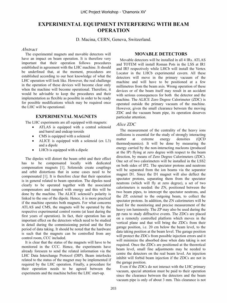
EXPERIMENTAL EQUIPMENT INTERFERING WITH BEAM OPERATION
D. Macina, CERN, Geneva, Switzerland.
AbstractThe experimental magnets and movable detectors will
have an impact on beam operation. It is therefore very important that their operation follows procedures established in agreement with the LHC machine. It should be underlined that, at the moment, procedures are established according to our best knowledge of what the LHC operation will look like. However, the real challenge in the operation of these devices will become clear only when the machine will become operational. Therefore, it would be advisable to keep the procedures and their implementation as flexible as possible in order to be ready for possible modifications which may be required once the LHC will be operational.
EXPERIMENTAL MAGNETS The LHC experiments are all equipped with magnets:
ATLAS is equipped with a central solenoid and barrel and endcap toroids CMS is equipped with a solenoid ALICE is equipped with a solenoid (ex L3) and a dipole LHCb is equipped with a dipole
The dipoles will distort the beam orbit and their effect has to be compensated locally with dedicated compensation magnets [1]. Solenoids create couplings and orbit distortions that in some cases need to be compensated [1]. It is therefore clear that their operation is in general related to beam operation. The dipoles need clearly to be operated together with the associated compensators and ramped with energy and this will be done by the machine. The ALICE solenoid’s polarity is linked to the one of the dipole. Hence, it is more practical if the machine operates both magnets. For what concerns ATLAS and CMS, the magnets will be operated by the respective experimental control rooms (at least during the first years of operation). In fact, their operation has an important effect on the detectors which need to be studied in detail during the commissioning period and the first period of data taking. It should be noted that the hardware is such that the magnets can be controlled from any control room, CCC included.
It is clear that the status of the magnets will have to be monitored in the CCC. Hence, the experiments have already foreseen to send the related information via the LHC Data Interchange Protocol (DIP). Beam interlocks related to the status of the magnet may be implemented if required by the LHC operation. Finally, a procedure for their operation needs to be agreed between the experiments and the machine before the LHC start-up.
MOVABLE DETECTORS Movable detectors will be installed in all 4 IRs. ATLAS
and TOTEM will install Roman Pots in the LSS at IR1 and IR5 respectively while LHCb will install the Vertex Locator in the LHCb experimental cavern. All these detectors will move in the primary vacuum of the machine and will have to be positioned at a few millimetres from the beam axis. Wrong operation of these devices or of the beam itself may result in an accident with serious consequences for both the detector and the machine. The ALICE Zero Degree Calorimeter (ZDC) is operated outside the primary vacuum of the machine. However, given the small clearance between the moving ZDC and the vacuum beam pipe, its operation deserves particular attention.
Alice ZDC The measurement of the centrality of the heavy ions
collisions is essential for the study of strongly interacting matter at extreme energy densities (QCD thermodynamics). It will be done by measuring the energy carried by the non-interacting nucleons (produced at the IP) flying at zero degree with respect to the beam direction, by means of Zero Degree Calorimeters (ZDC). One set of two calorimeters will be installed in the LSS2 on both sides of IP2. The spectator protons and neutrons will be separated from the ion beams via the separator magnet D1. Since the D1 magnet will also deflect the spectator protons, separating them from the spectator neutrons (which will fly at zero degree), a set of two calorimeters is needed: the ZN, positioned between the two beam pipes, to intercept the spectator neutrons, and the ZP, external to the outgoing beam, to collect the spectator protons. In addition, the ZN calorimeters will be used for the monitoring and precise measurement of the heavy ion luminosity. The ZP may also be used during the pp runs to study diffractive events. The ZDCs are placed on a remotely controlled platform which moves in the vertical plane and that will bring the ZDCs from their garage position, i.e. 20 cm below the beam level, to the data taking position at the beam level. The garage position will protect the ZDCs from possible injection errors and it will minimize the absorbed dose when data taking is not required. Once the ZDCs are positioned at the theoretical beam level, small fine adjustments may be needed to centre the detectors on the real beam level. An injection inhibit will forbid beam injection if the ZDCs are not in the garage position.
Even if the ZDCs do not interact with the LHC primary vacuum, special attention must be paid to their operation since the clearance between the detectors and the beam vacuum pipe is only of about 3 mm. This clearance is not
LHC Project Workshop - 'Chamonix XV'
203

of a concern with a ZDC well positioned and aligned. However, accidents and mistakes during the work carried out during access time, may miss-align the ZDCs and, if not detected in time, lead to serious consequences. Therefore, anti-collision switches and a top cover have been recently introduced in the design of the ZDC platform to detect possible miss-alignment and minimize the possibility of accidents due to mistakes (Figure 1). The top cover is also required for personal protection as for all machines remotely controlled.
Figure 1: ZDC platform with the top cover
The machine luminosity monitor [2], placed in front of the ZN, may degrade the performance of the detector. Studies carried out by the ALICE Collaboration show that, if the absorber required by the luminosity monitor is of the order of 10-20 of an interaction length, the energy measurement is not affected. However, the effect on the measurement of the impact position of the particles needs further studies. Nevertheless, if the presence of the luminosity monitor will be shown to be incompatible with the operation of the ZN, backup solutions are available. In fact, in this case, the absorber can be put on a movable support and the ZN can be used as the machine luminosity monitor during the heavy ions runs [3].
The ALICE Collaboration will be responsible for the operation of the ZDCs. However, the Collaboration underlines that the ZDC is placed in a zone which is completely under the responsibility of the machine. Therefore, it will be impossible for ALICE to monitor the activities carried out in the zone and be aware of the possible consequences for the ZDC operation.
LHCb VELO
The VErtex LOcator has to provide precise measurements of track coordinates close to the interaction region. For this, the VELO features a series of silicon stations placed along the beam direction. They are placed at a radial distance from the beam which is smaller than the aperture required by the LHC during injection and must therefore be retractable. Figure 2 is a schematic of
the VELO design. A description of the VELO detector can be found in [4].
Figure 2: A schematic of the VELO design
VELO will be operated from the LHCb Collaboration. It is able to move along the horizontal plane and also in the vertical plane to adjust it symmetrically with respect to the real beam axis. Following a wrong operation, VELO could touch the beam with serious consequences for both the detector and the machine. The VELO operation will make use of an on-line monitoring which is able to reconstruct, in a fraction of a second, the collision vertices and, therefore the luminous region, with a precision of ~ 10 m in the transverse plane. In general, VELO will not move in the absence of collisions. The VELO will be protected by an interlock system (as described in [5]) based on the knowledge of its position and on the signal from the radiation monitors located close to it. The radiation monitors are supposed to detect the signal from dangerous situations like beam scraping or touching the VELO vacuum shield and dump the beam before either VELO or the machine gets damaged. However, the effectiveness in discriminating the signal over the background from pp interactions has still to be demonstrated. It should be noted that the details about a safe operation of the VELO detector will become clear once the machine will be operating. VELO is able to go back to its garage position in about 5 minutes if beam operation requires it. However, it should be taken into account that the retraction and the repositioning of the VELO detector will cause a loss of physics data and that, therefore, it will be performed only if required for safety reasons.
Roman Pots
The Roman Pots will be installed in the LHC tunnel around IP1 (ATLAS) and IP5 (TOTEM). The TOTEM Roman Pot station is composed of two units with each unit consisting of two pots that move vertically and one that moves horizontally (see Figure 3). The ATLAS Roman Pot is similar but it does not have the horizontal pots.
LHC Project Workshop - 'Chamonix XV'
204

Figure 3: TOTEM Roman Pot Station
The Roman Pot operation is very similar to the VELO operation. The main difference is that the operational distance from the beam is smaller (~ 2 mm) and comparable to that of the tertiary collimators. In addition, the Roman Pots are not equipped with an on-line monitoring able to measure the beam position with very high precision. However, as in the VELO case, due to wrong operation, the Roman Pot is able to touch the beam with serious consequences for both the machine and the detector. The Roman Pots will be protected by an interlock system (as described in [5]) based on the knowledge of their position and on the signal from the Beam Loss Monitors located close to them. The movement will be guided by the response of the BLMs and of the Beam Position Monitor integrated in the Roman Pot design. The final position will be determined looking at the signals from the detectors. If beam conditions, like beam halo, are not good enough the Roman Pots may not be able to reach their nominal position to avoid too many faulty triggers which may compromise the quality of the data taking. LVDT sensors and resolvers will also be used as redundant information on the position of the pots. TOTEM proposes to interlock the position of the Roman Pots once the data taking is started since accidental movement of the pots may compromise the data quality. This proposal is actually under the evaluation of the Machine Protection Working Group. In fact, this proposal is not entirely compatible with machine safety, since, under very particular
circumstances, it may be required to retract the pots as soon as possible. Clearly a compromise is needed. The experiments have finally agreed to operate the Roman Pots from the CCC given the tight relation between machine operation and Roman Pot operation. Should in future Roman Pots become a routine operation, a revised procedure may be required if the Roman Pots positioning will result in a non negligible overload for the operators in the CCC. Since the Collimator Control System will have to ensure that the Roman Pots are always in the shadow of the collimators for safety reasons, the Roman Pots Control System will be integrated into the Collimator one. A preliminary agreement has been reached in the COCOST meeting held in October 2005. The experiments will be responsible for writing the functional specifications for their system and of the implementation of the software of the low level systems of the Roman Pots Control.
CONCLUSIONS Responsibilities for the control of the experimental
equipment with an impact on beam operation has been clarified and agreed between the machine and the experiments. Detailed procedures on their operation need to be sorted out before the LHC start-up with the awareness that only experience in LHC operation will certify the correctness of these procedures. A non negligible amount of work needs to be done on the Control System of the Roman Pots to be operational before the LHC start-up.
REFERENCES [1] W. Herr, “The effects of solenoids and dipole
magnets of LHC experiments”, these Proceedings. [2] E. Bravin, “Bringing the first LHC beams into
collision at all 4 IPs”, these Proceedings [3] D, Macina, 30.LTC minutes [4] D. Macina, “Experiment’s equipment directly
interfering with beam operation, Proceedings of Chamonix XIV, p.181
[5] J. Wenninger, “Beam dump and injection inhibits”, these Proceedings
LHC Project Workshop - 'Chamonix XV'
205
SCHEDULE: STILL ON TIME?
S. Weisz CERN, Geneva, Switzerland.
Abstract The status of installation across the LHC will be given
with particular attention to Sector 78 and 81. This will illustrate some of the difficulties encountered during the past year and limitations related to co-activities in narrow underground areas. The talk will then describe how to profit from the experience gathered on the two first LHC sectors with a view to limit the impact of the delays accumulated so far.
INTRODUCTION We will first review the present status of the LHC
hardware installation and then give an estimate of the evolution of the delays of the main components versus the present master planning. The situation a year ago, in January 2005, can be summarized as follows: • Civil engineering just finished a couple of months
earlier, last underground area to be delivered was RB/UJ56 at Point 5 by mid-November 2004;
• The general service phase was almost completed all around the ring, but the collimation region at Point 7 was just re-designed and all services in LSS7L/R had to be re-installed;
• The QRL in Sector 7-8 had to be repaired and re-installed, there were only 2 validation cells ready in Sector 8-1;
• The production of the cryo-dipoles was running full swing, and we had to struggle to store at the surface some 480 magnets that we could not transport in the tunnel since the situation of the QRL did not allow to free any underground slot. This situation led us to revisit the planning, with a
view to maintain the objective to circulate the first LHC beams by summer 2007. This compressed installation planning assumed several shortcuts, as skipping the QRL cold tests after the first 2 sectors (7-8 & 8-1). It also introduced parallelism between major activities, such as cryo-magnet installation and interconnection while QRL installation and testing is still on-going in that sector. The delays discussed in this paper all refer to this compressed installation planning that was issued April 1st , 2005 [1].
STATUS OF LHC INSTALLATION
QRL Installation The completion of the QRL installation triggers a
variety of new activities since it frees slots where we can install cryo-magnets. CERN took over the repair and the re-installation of Sector 7-8, which allowed giving first priority to the completion and tests of the two sub-sectors close to Point 8 (sub-sectors A & B). The master schedule assumed that these first cold tests of the QRL in the tunnel would be carried in July 2005, they finally started
by mid-September. Moreover, the completion of the full cryo-line of Sector 7-8 was expected for September, it was achieved by the end of the year. The situation in Sector 8-1, where the QRL is installed by Air Liquide, shows a similar pattern: cold tests were expected for September, they were carried in December. This altogether leads to attribute a 3 months delay to the QRL activity.
Power tests in LSS8L and availability of DFB’s Once the first 600m of QRL were installed and tested,
we could foresee the installation and power tests of the cryo-magnets in the long straight section left of Point 8. This early rehearsal of the hardware commissioning was scheduled for the end of 2005, but it had to be postponed since the cryogenics current feed boxes (DFB’s) to power D2-Q5 and Q6 were not available. The DFBMA/C were expected for September 2005, but their availability is now estimated for February 2006, 5 months behind our schedule. However, the power converters were installed and tested at Point 8, in UA83, according to the planning.
Cryo-magnet transport As already mentioned, the compressed installation
planning assumed that cryo-magnets would be transported underground as soon as a sub-sector of the QRL would be installed and leak tested. According to the installation schedule of Sector 7-8, all arc and dispersion-suppressor (DS) magnets would have been in place by September, and those in LSS8L by October 2005: we in fact had, by the end of the year, 40 dipoles and 17 short straight sections (SSS) in the arc and, in LSS8L, only the Low-β quadrupoles and D1/D2/Q4 were in place, Q5 being non available yet. Concerning Sector 8-1, the arc and DS magnets were expected in place by September: we had 111 dipoles and 18 SSS’s transported by the end of the year (note that the installation had to stop in 8-1 for 6 weeks due to the cold tests of the QRL). Finally, all magnet in the arc and DS of Sector 4-5 should have been in place by the end of 2005, there were only 48 dipoles and 9 SSS’s transported by that time. As a summary, instead of about 600 cryo-magnets transported in 2005, we had a score of 248, representing a delay of 4 months when considering the nominal rate of 20 magnets per week, a rate that was indeed achieved during the 2 weeks of January 2006 preceding the Workshop.
It is worth mentioning that under the header “cryo-magnet transport problems” there is a mix of unavailability of slots liberated by the QRL, of magnets that are not available on time and, last but not least, pure transport vehicle issue: • On many occasions, leak testing and repairs took
much longer than anticipated and the corresponding QRL sub-sector was not ready on time for magnet
LHC Project Workshop - 'Chamonix XV'
206

installation. Moreover, about 15 service modules in Sector 8-1 need to be repaired, and some leaks appeared in Sector 4-5 after the pressure tests in December, and this precludes cutting the jumpers in those sectors, which in turn does not free the corresponding SSS slots.
• We had to face many non-conformity problems with the dipoles in summer 2005, due to the so-called “collarette” welds, but the situation has been cleared since and all required dipoles are now available on time. The situation is however more tight with the SSS with plugs (required to sectorise the magnet string) and with special SSS’s, in the straight sections and in the DS, that are still late.
• Among the most disturbing problems we experienced with the transport vehicles, one should quote the need to replace all breakers on the powering line, the replacement of the safety valves on the unloading equipment and the oil overheat when driving on long distances. We also had difficulties maintaining a clean guiding line and insuring a good lubrication of the wheel axles that lead to some un-reliability of the transport system.
Cryo-magnet interconnect The connection of the cryo-magnets in LSS8L was
expected for November 2005 but it has not started yet, and only 29 interconnects are in progress in Sector 7-8 when we expected 50% of the arc done by the end of the year. Concerning Sector 8-1, the schedule indicates that 70% of the arc should be done by the end of the year when only 52 interconnect are in progress. This is a new activity where some ramping up is expected, one can evaluate the delay to 3 months on the basis that it takes 6 months to interconnect a Sector.
To summarise this first part on the status of the LHC installation, we presently have a minimal delay of 3 months with up to 5 months on the procurement of certain elements. We however got experience with many new installation activities that started during year 2005 such as QRL pressure and cold tests, magnet transport and interconnection, installation and tests of power converters. We also learned that leak tests and leak finding are very delicate and require more time than anticipated. It is also clear that piling up co-activities in a narrow tunnel lead to a situation where small incidents have large impacts on the overall installation efficiency.
EVOLUTION OF THE INSTALLATION DELAYS
The question now is how to limit the increase of the delays accumulated on the installation of the LHC? The answer has to take account of hard constraints on the rate of installation of the QRL, on the magnet transport capacity, on the procurement of special SSS and of the DFBs. The rate and test procedure of the cryo-magnet
interconnects allow to foresee the dates when each sectors would be available for hardware commissioning.
QRL Plans A revisited schedule of the QRL installation was
issued late November 2005, taking account of the actual situation in the tunnel and of the achieved rate of production of the QRL elements. This schedule also assumes that the installation teams would install on 2 sectors in parallel, and would not end working in 3 sectors at the same time, as it was anticipated with the previous scenario from Air Liquide. This new schedule expects that the QRL installation would be achieved by November 2006, and this is about 3 months behind our planning: we can thus expect to maintain the present delay on the QRL installation.
Cryo-magnet transport rates The transport of the cryo-magnets is achieved by mean
of 6 vehicles with specific characteristics: • 2 “CTV” type convoys can handle the long arc and DS
dipoles; • 2 “MCTV” type convoys can handle all cryo-dipoles
and the long special SSS (>8m); • 2 “STV” type convoys can handle the arc and the short
special SSS. There are 1296 elements in total to transport with CTV
and MCTV vehicles: 1232 main bending dipoles, 24 long special SSS and 16 insertion cryo-dipoles. At the time when writing this paper, there was 240 of them in place, thus 1056 still to transport. Counting on 3 CTV and MCTV convoys available at any time while one vehicle is on maintenance, we can actually transport 15 such cryo-magnet per week, and expect to raise this rate to 18 per weeks after mid-April when an extra team would allow working on Saturdays. This would then allow transporting all dipoles by March 2007, which is 3 months behind our planning. We also plan to transport the SSS through Point 6 when installing Sectors 5-6 and 6-7, and this should catch back the delays accumulated with the SSS transport.
Provision of special elements There has been a recent review of the production of
the SSSs with an overview of the different steps from cold mass production to final preparation for installation in the tunnel. A reallocation of resources, such as the number of benches allocated to SSSs cold tests in SM18, allows scheduling the procurement of all cryo-magnets, ready for installation in the LHC tunnel, by March 2007.
The fabrication of the power feed boxes, the DFBs, is less advance and, as already mentioned, the DFBM for le long straight sections left of Point 8 are lagging 5 months behind our installation planning. The present production schedule of the DFBs is summarised in Table 1: the date for sector 8-1 is obviously very late when compared to the installation of the cryo-magnets that should end during the first quarter of 2006. Moreover, the production of the DFBs does not follow the natural installation of the LHC
LHC Project Workshop - 'Chamonix XV'
207
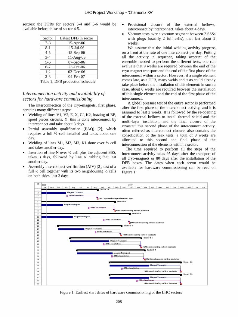
sectors: the DFBs for sectors 3-4 and 5-6 would be available before those of sector 4-5.
Sector Latest DFB in sector
7-8 15-Apr-06 8-1 15-Jul-06 4-5 15-Sep-06 3-4 11-Aug-06 5-6 07-Sep-06 6-7 23-Oct-06 1-2 02-Dec-06 2-3 04-Feb-07
Table 1: DFB production schedule
Interconnection activity and availability of sectors for hardware commissioning
The interconnection of the cryo-magnets, first phase, contains many different steps: • Welding of lines V1, V2, E, X, C’, K2, brazing of BP,
spool pieces circuits, Y: this is done interconnect by interconnect and take about 8 days.
• Partial assembly qualification (PAQ) [2], which requires a full ½ cell installed and takes about one day.
• Welding of lines M1, M2, M3, K1 done over ½ cell and takes another day.
• Insertion of line N over ½ cell plus the adjacent SSS, takes 3 days, followed by line N cabling that last another day.
• Assembly interconnect verification (AIV) [2], test of a full ½ cell together with its two neighbouring ½ cells on both sides, last 3 days.
• Provisional closure of the external bellows, interconnect by interconnect, takes about 4 days.
• Vacuum tests over a vacuum segment between 2 SSSs with plugs (usually 2 full cells), that last about 2 weeks. We assume that the initial welding activity progress
on a front at the rate of one interconnect per day. Putting all the activity in sequence, taking account of the ensemble needed to perform the different tests, one can evaluate that 9 weeks are required between the end of the cryo-magnet transport and the end of the first phase of the interconnect within a sector. However, if a single element comes late, as a DFB, many welds and tests could already take place before the installation of this element: in such a case, about 6 weeks are required between the installation of this single element and the end of the first phase of the interconnect.
A global pressure test of the entire sector is performed after the first phase of the interconnect activity, and it is assumed to last 2 weeks. It is followed by the re-opening of the external bellows to install thermal shield and the multi-layer insulation, and the final closure of the cryostat: this second phase of the interconnect activity, often referred as interconnect closure, also contains the consolidation of the leak tests: a total of 8 weeks are allocated to this second and final phase of the interconnection of the elements within a sector.
The time required to perform all the steps of the interconnect activity takes 95 days after the transport of all cryo-magnets or 80 days after the installation of the DFB boxes. The dates when each sector would be available for hardware commissioning can be read on Figure 1.
Figure 1: Earliest start dates of hardware commissioning of the LHC sectors
ID
1
2
3
4
5
6
7
8
9
10
11
12
13
14
15
16
17
18
19
20
21
22
23
24
25
26
27
28
29
30
31
32
Sector 7-8
Magnet Transport
DFBs installation
HW Commissioning earliest start date
Sector 8-1
Magnet Transport
DFBs installation
HW Commissioning earliest start date
Sector 4-5
Magnet Transport
DFBs installation
HW Commissioning earliest start date
Sector 3-4
Magnet Transport
DFBs installation
HW Commissioning earliest start date
Sector 5-6
Magnet Transport
DFBs installation
HW Commissioning earliest start date
Sector 6-7
Magnet Transport
DFBs installation
HW Commissioning earliest start date
Sector 1-2
Magnet Transport
DFBs installation
HW Commissioning earliest start date
Sector 2-3
Magnet Transport
DFBs installation
HW Commissioning earliest start date
Jan Feb Mar Apr May Jun Jul Aug Sep Oct Nov Dec Jan Feb Mar Apr May Jun Jul Aug Sep Oct Nov2006 2007
LHC Project Workshop - 'Chamonix XV'
208

CONCLUSIONS
Many new installation activities started in 2005 and a lot of them are now in a ramping-up phase: installation and tests of the QRL, preparation and underground transports of cryo-magnets, alignment and interconnect of magnets in a difficult environment. The situation is totally different from what it was a year ago and we now have gained experience in the field, dealing with intricate logistics and organization of co-activities in a narrow tunnel with a limited number of access shafts. We also learned to organize the work with enough flexibility to cope with unexpected incidents, such as late leak detection and repair that consumes much more time than initially anticipated.
The delays accumulated are of the order of 3 months when comparing the status of the installation with the schedule issued beginning of 2005. The QRL installation, which is on the critical path since it frees the slots required for the installation of the cryo-magnets, was the main contributor: it is now well under control and we can be confident that it will not contribute to new additional delays. Moreover, the teething problems encountered with the logistics of the cryo-magnets and their underground transport are now solved, and we can plan for an increase of the installation rate above the nominal 20 cryo-magnets per week.
The procurement of some special components is however still worrying. The preparation of the cryo-feed boxes (DFBs) that insure the warm-cold transition of the
current leads, is on the critical path and will impact on the starting dates of the hardware commissioning phase of many sectors: it is in particular the case for Sector 8-1 which is required for the test with beam scheduled for the end of 2006 [3]. The present schedule of the DFBs also imposes drastic time and geographical constraints for the hardware commissioning, and needs to be revisited.
REFERENCES [1] LHC Construction and Installation, General Co-
ordination Schedule, EDMS Document N° 102509. [2] Polarity and electrical quality assurance – S.
Russenschuck, in these proceedings. [3] Planning of the Sector Test with Beam – E. Barbero
Soto, in these proceedings.
LHC Project Workshop - 'Chamonix XV'
209

LHC SAFETY COORDINATION – A REMINDER IN TIMES OF INTENSEACTIVITY
M. Vadon, CERN, Geneva, Switzerland.
AbstractIn view of the very tight schedule of the LHC project
many installation activities will progress in parallel in thetunnel at many work sites. This paper will give anoverview of the accident that occurred in 2005 and recallthe most important safety aspects that have to be takeninto account by the project engineers in charge of theinstallation of equipment. The LHC project engineershave the responsibility to ensure that a tight schedule doesnot have a negative impact on the safety of the installationactivities. The LHC project Safety Coordination team isalways available to help the project engineers to mitigatethe inherent risks of a multi-activity worksite.
RULES AND REGULATIONS
Main rulesThe Safety Coordination rules have been presented
several times and will not be developed here. It isnevertheless useful to recall the main steps:• General Health and Safety Coordination Plan
(PGC or PGCSPS): this contractual document ispart of any call for tenders related to work to beperformed on the LHC.
• Bidders’ Conference: The Safety Coordinationteam proposes to present to the future contractorsthe rules in vigour on the LHC installationworksites. This presentation can be tailored tofocus on the specific work to be performed and itsassociated risks.
• Particular Health and Safety Plan (PPSPS): Thisdocument, written by each contractor and sub-contractor must be submitted to the safetycoordinator at least 30 days before the start ofwork. In addition to general informationconcerning the firm, an extensive and precisedescription of the tasks to be carried out ismandatory.
• Work Package Analysis: This meeting is usuallyorganised for experimental zones in order toanalyse all aspects of the intervention, in particularco-activities that are very difficult to manage incaverns. Superposition of work places shall beavoided.
• Joint Inspection (VIC): The contractor shall askthe safety coordinator for this worksite visit. Itshall be organised one week before the start ofwork. The CERN Project Engineer must bepresent.
News organisational rulesCo-activities between contractors and CERN personnel
(staff, collaborators, members from institutes) cannot be
avoided, therefore it was decided that everybody has tofollow the safety coordination procedures applicable tooutside contractors.
The PPSPS can be limited to a simple task descriptionif a PPSPS was already done for similar works on theLHC and if administrative information and personnel listsare up-to-date.
LHC Safety Coordinators are staff members since July2004 and the team was reinforced with three newcoordinators and an engineer in January 2006. The scopeof the Project Safety Officer was extended to all LHCexperimental zones.
New safety regulationsIn November 2003, a platform collapsed on the Queen
Mary’s worksite in Saint Nazaire, 29 were injured and 15killed. Following this accident, a new French Decree waspublished (1 Sep. 2004) modifying drastically the rulesapplying to work at height (scaffolding, platforms,qualification of personnel, training of workers wearingsafety harness, etc.). It is strongly recommended to takenotice of these new regulations, and in case of doubt askthe safety coordinators.
Rules applicable to contractorsThe rules applicable to contractors working on the
CERN site are those of the host state.The project engineers do not have the duty of checking
that their contractors respect legal working hours, butshall not ask for work nor impose a schedule that maycause the contractor to violate the host states regulations.
A mix of hierarchical lines cannot be accepted. Thesupervision of a contractors’ employee by a CERN staffor the supervision of a CERN staff by a contractor is notallowed. The same exact rule applies between contractorsand sub-contractors.
SUMMARY OF ACCIDENTS
In 2005, 14 accidents were followed by an enquiry,which is on average what was observed since thedismantling of LEP (45 total). Manual handling, falls,electrical incidents or accidents were numerous last year.Table 1 summarises all these accidents.
Procedure were often badly applied, changed at the lastminute, not followed, or sometime did not exist.
It can be noted that sub-contractors and interim staffwere more subject to accidents than other categories ofpersonnel. Similarly, very experienced workers, who wereover-confident, caused some serious accidents. Theseexperts should question regularly their working methods,and not just assume they work safely since they werenever got seriously injured in their career.
LHC Project Workshop - 'Chamonix XV'
210
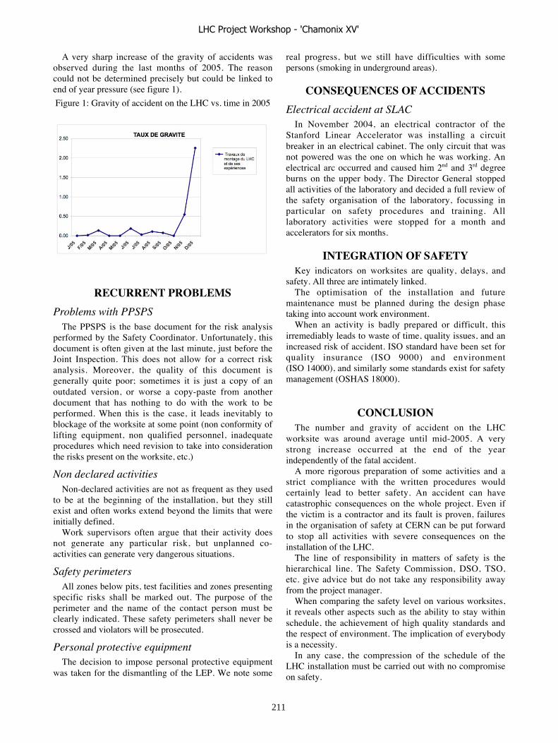
A very sharp increase of the gravity of accidents wasobserved during the last months of 2005. The reasoncould not be determined precisely but could be linked toend of year pressure (see figure 1).
Figure 1: Gravity of accident on the LHC vs. time in 2005
RECURRENT PROBLEMS
Problems with PPSPSThe PPSPS is the base document for the risk analysis
performed by the Safety Coordinator. Unfortunately, thisdocument is often given at the last minute, just before theJoint Inspection. This does not allow for a correct riskanalysis. Moreover, the quality of this document isgenerally quite poor; sometimes it is just a copy of anoutdated version, or worse a copy-paste from anotherdocument that has nothing to do with the work to beperformed. When this is the case, it leads inevitably toblockage of the worksite at some point (non conformity oflifting equipment, non qualified personnel, inadequateprocedures which need revision to take into considerationthe risks present on the worksite, etc.)
Non declared activitiesNon-declared activities are not as frequent as they used
to be at the beginning of the installation, but they stillexist and often works extend beyond the limits that wereinitially defined.
Work supervisors often argue that their activity doesnot generate any particular risk, but unplanned co-activities can generate very dangerous situations.
Safety perimetersAll zones below pits, test facilities and zones presenting
specific risks shall be marked out. The purpose of theperimeter and the name of the contact person must beclearly indicated. These safety perimeters shall never becrossed and violators will be prosecuted.
Personal protective equipmentThe decision to impose personal protective equipment
was taken for the dismantling of the LEP. We note some
real progress, but we still have difficulties with somepersons (smoking in underground areas).
CONSEQUENCES OF ACCIDENTS
Electrical accident at SLACIn November 2004, an electrical contractor of the
Stanford Linear Accelerator was installing a circuitbreaker in an electrical cabinet. The only circuit that wasnot powered was the one on which he was working. Anelectrical arc occurred and caused him 2nd and 3rd degreeburns on the upper body. The Director General stoppedall activities of the laboratory and decided a full review ofthe safety organisation of the laboratory, focussing inparticular on safety procedures and training. Alllaboratory activities were stopped for a month andaccelerators for six months.
INTEGRATION OF SAFETYKey indicators on worksites are quality, delays, and
safety. All three are intimately linked.The optimisation of the installation and future
maintenance must be planned during the design phasetaking into account work environment.
When an activity is badly prepared or difficult, thisirremediably leads to waste of time, quality issues, and anincreased risk of accident. ISO standard have been set forquality insurance (ISO 9000) and environment(ISO 14000), and similarly some standards exist for safetymanagement (OSHAS 18000).
CONCLUSIONThe number and gravity of accident on the LHC
worksite was around average until mid-2005. A verystrong increase occurred at the end of the yearindependently of the fatal accident.
A more rigorous preparation of some activities and astrict compliance with the written procedures wouldcertainly lead to better safety. An accident can havecatastrophic consequences on the whole project. Even ifthe victim is a contractor and its fault is proven, failuresin the organisation of safety at CERN can be put forwardto stop all activities with severe consequences on theinstallation of the LHC.
The line of responsibility in matters of safety is thehierarchical line. The Safety Commission, DSO, TSO,etc. give advice but do not take any responsibility awayfrom the project manager.
When comparing the safety level on various worksites,it reveals other aspects such as the ability to stay withinschedule, the achievement of high quality standards andthe respect of environment. The implication of everybodyis a necessity.
In any case, the compression of the schedule of theLHC installation must be carried out with no compromiseon safety.
LHC Project Workshop - 'Chamonix XV'
211
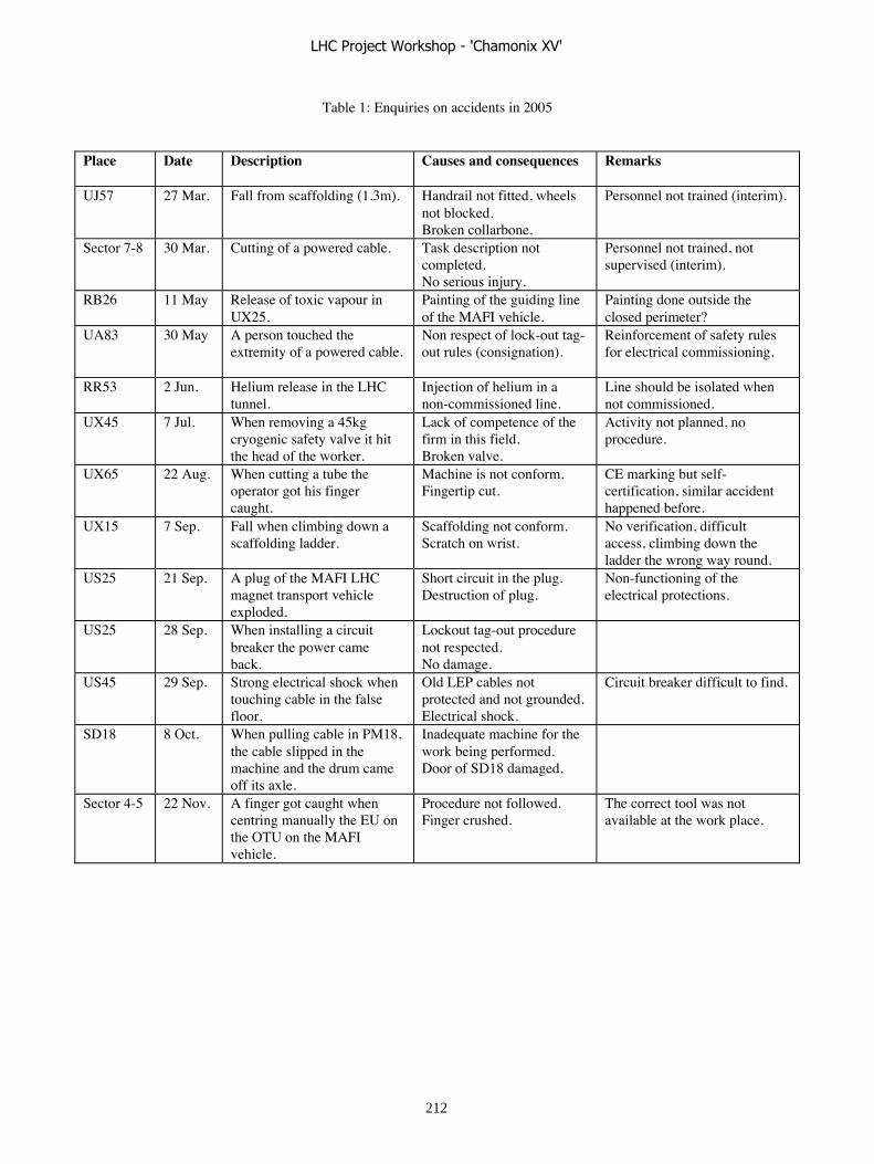
Table 1: Enquiries on accidents in 2005
Place Date Description Causes and consequences Remarks
UJ57 27 Mar. Fall from scaffolding (1.3m). Handrail not fitted, wheelsnot blocked.Broken collarbone.
Personnel not trained (interim).
Sector 7-8 30 Mar. Cutting of a powered cable. Task description notcompleted.No serious injury.
Personnel not trained, notsupervised (interim).
RB26 11 May Release of toxic vapour inUX25.
Painting of the guiding lineof the MAFI vehicle.
Painting done outside theclosed perimeter?
UA83 30 May A person touched theextremity of a powered cable.
Non respect of lock-out tag-out rules (consignation).
Reinforcement of safety rulesfor electrical commissioning.
RR53 2 Jun. Helium release in the LHCtunnel.
Injection of helium in anon-commissioned line.
Line should be isolated whennot commissioned.
UX45 7 Jul. When removing a 45kgcryogenic safety valve it hitthe head of the worker.
Lack of competence of thefirm in this field.Broken valve.
Activity not planned, noprocedure.
UX65 22 Aug. When cutting a tube theoperator got his fingercaught.
Machine is not conform.Fingertip cut.
CE marking but self-certification, similar accidenthappened before.
UX15 7 Sep. Fall when climbing down ascaffolding ladder.
Scaffolding not conform.Scratch on wrist.
No verification, difficultaccess, climbing down theladder the wrong way round.
US25 21 Sep. A plug of the MAFI LHCmagnet transport vehicleexploded.
Short circuit in the plug.Destruction of plug.
Non-functioning of theelectrical protections.
US25 28 Sep. When installing a circuitbreaker the power cameback.
Lockout tag-out procedurenot respected.No damage.
US45 29 Sep. Strong electrical shock whentouching cable in the falsefloor.
Old LEP cables notprotected and not grounded.Electrical shock.
Circuit breaker difficult to find.
SD18 8 Oct. When pulling cable in PM18,the cable slipped in themachine and the drum cameoff its axle.
Inadequate machine for thework being performed.Door of SD18 damaged.
Sector 4-5 22 Nov. A finger got caught whencentring manually the EU onthe OTU on the MAFIvehicle.
Procedure not followed.Finger crushed.
The correct tool was notavailable at the work place.
LHC Project Workshop - 'Chamonix XV'
212
LHC ACCESS – WHERE DO WE STAND P. Ninin, L. Scibile, T. Ladzinski, S. Grau, E. Sanchez-Corral Mena, L. Hammouti, S. Di Luca,
G. Smith, M. Munoz-Codoceo, J-F Juget, CERN Geneva, Switzerland.
AbstractThe LHC access system consists of two subsystems, the
LHC Access Control System (LACS) and the LHC Access Safety System (LASS). The prototype of both subsystems has been installed in the TCR and is under acceptance testing - the results of these tests are discussed. Extensive work has also been done on the man machine interface and the supervisory system. The current challenge for the project team is now the upgrade from a functional prototype to a robust system that can be confidently installed in the LHC.
Finally the installation schedule and the constraints are mentioned.
INTRODUCTIONThe LHC Access project is in its design and realisation
stage. A pilot installation of the LHC access system has been realised. The pilot installation concerns the access control equipment, the access safety control equipment, the control room’s software, and the external interfaces.
A prototype of the hardware and software of the LHC Access Safety system has been done, a contract for the realisation has been established, the concept of the system has been presented to the French Nuclear Authorities, a diversified redundant system has been introduced.
In order to verify that the global architecture fulfils the safety requirements, the safety objectives of the systems have been clarified, the safety functions have been defined and a detailed functional safety study of the architecture and interfaces performed [2].
BACKGROUNDThe LHC complex is divided into a number of zones
with different levels of access control [3]. Inside the interlocked areas, the personnel protection is ensured by the LHC Access System. This system is made of two parts: the LHC Access Safety System and the LHC Access Control System [13]. During machine operation, the LHC Access Safety System ensures the collective protection of the personnel against the hazards arising from the operation of the accelerator. By interlocking the LHC key safety elements, it will permit access to authorized personnel in the underground premises during the accelerator shutdowns and will deny access during accelerator operation.
Complementary to this, the LHC Access Control System, regulates the access to the accelerator and the numerous support systems. It allows a remote, local or automatic operation of the access control equipment that verifies the users’ authorization, identifies them, locks and unlocks access control equipment and restricts the number of users working simultaneously in the interlocked areas [5]
LHC ACCESS CONTROL SYSTEM The contract for the realisation of the LHC Access
Control system runs since September 2004. The technical specifications for the Design, Supply,
Installation and Maintenance of the system were documented in [12].
The global system engineering has been completed according to the requirements baseline [14], however some specific study concerning the scaling of the system still remains to be done. A pilot installation that consists of a Personal Access Device, Material Access Device, 8 sector doors, and all the control infrastructure of a LHC Access Point has been installed, integrated and commissioned in the former TCR.
Acceptance testing was carried out according to the quality procedures setup in [15].
The lessons learned from this pilot installation are: - The “way is long” from a prototype integrating all
the functions of the system to an installation that is ready to go on site. All the maintenance and supervision aspects need to be carefully studied and planned.
- Contract follow-up: serious difficulties were encountered with the contractors in this stage, this was due to a lack of resources affected to the project as well as the absence of regular project documentation provided by the contractor. Unfortunately the threat of the GO/NO milestone, foreseen in the contract, ending the design stage of the project, had to be flourished. The positive results were the allocation of senior and experienced resources. Nevertheless, a delay of three months needs to be recuperated and will force the parallel installation in the LHC points 8, 7 and 4. In case of deviation from the plan strong action shall be taken earlier.
- As several functionalities such as the patrol or the veto radiation were given a higher degree of safety, they were moved to the LHC Access Safety System. This forced several iterations, slowed down the realisation of the system and induced additional expenses. Limpid specification and validation of the system functional analysis are a mandatory practice.
- Off-the-shelf equipment: the original idea was to build the LHC Access Control System using off-the-shelf equipment. However, the pilot installation shows that many modifications are required to fulfil the specific CERN requirements. Examples are: integration of the biometry identification, the access control server, token distributors, etc.
LHC Project Workshop - 'Chamonix XV'
213
LHC ACCESS SAFETY SYSTEM
In 2005, the activities of the LHC Access Safety System concerned the following topics:
- Specification of the systems and the interface with the machine elements.
- Prototyping of the selected hardware and software. - Demonstration to the French Nuclear Authorities
that the system fulfils the safety requirements. - Set up of a contract for the realisation of the
system.
The specification of the system and its interface with the machine elements is documented in the following references [7],[8].
Prototyping activities: the chosen Siemens safety programmable logic controllers have been tested in a prototype connected to the access control LHC0 facility. Difficulties were encountered with the definition of the proper interfaces between the two systems and demonstrated the need to document them carefully. The same remark applies to the safety PLC which goes in a failsafe fallback mode in case of incoherence between the redundant input signals.
The project strategy to demonstrate that the system fulfils the safety requirements is based on the rigorous follow-up of the IEC 61508 functional safety standards. The complete lifecycle is applied to the design of the system [1],[2],[10].
The concept of the architecture based on Siemens Safety PLCs has been presented to the French Nuclear Authorities. After discussion it has been decided to complement this architecture with a cable loop that will stop the accelerator in case of intrusion. It brings a new level of redundancy and independence between the two systems. A complete project documentation based on this concept has been prepared [9],[11].
For the realisation of the system a call for tender has been released leading to the pre-selection of three companies. The consortium Cegelec-SEMER has been selected. The work started in October 2005 with a review of the specification.
INSTALLATION The definition of the cabling is progressing, the LHC
site 8 is now completed and the work is now focused on the LHC sites 1, 4 and 7. The cabling definition requires the validation of the LHC access sector definition. This definition is progressing and is today completed at 70% [4]. The various requirements for the installation of the access equipment were documented in [16]. All the items to be installed were collected in the Assembly Breakdown Structure of the system [17].
Other activities that revealed to be time consuming were the integration of all the access equipment in the
integration database as well as the preparation of the locations for all the system racks particularly at the pits head. Very good progress is done in this activity.
The team that will plan and supervise the work is ready to apprehend its task.
CONTROL ROOM INFRASTRUCTURE The LHC Access system control room infrastructure is
a complex software made of heterogeneous bricks namely:
- The access safety console for the selection of the beam or access mode (hardware man-machine interface).
- The access control console for the selection of the various mode of operation.
- The audio and video components. - The monitoring systems. The functions of all these bricks have been defined in a
comprehensive set of documents and discussed with the AB/OP representatives.
CONCLUSIONS Despite difficulties encountered at the specification
level, or with the contractor, the project evolves according to plan.
The Challenge for the project team is now the upgrade from a functional prototype to a robust system that can be confidently installed in the LHC.
REFERENCES [1] P. Ninin, S. Grau, G. Roy, LASS Synthèse de l’analyse préliminaire de risques, EDMS 479041.
[2] B. Lusson, Schneider, LASS Dossier de Sûreté Provisoire, 11/10/2005, EDMS 626633.
[3] E. Cennini, S. Di Luca, Sectorisation des zones verrouillées du LHC, EDMS 344410.
[4] S. Di Luca, http://lhc-proj-access.web.cern.ch/lhc-proj-access/
[5] E. Cennini, G. Roy, Functional specification, The LHC Access Control System, EDMS 386759.
[6] L. Hammouti, M. Munoz, Spécification du pupitre de contrôle du LHC, EDMS 578789.
[7] P. Ninin, T. Ladzinski, EDMS 571277, Spécification technique détaillée du système de sûreté d’accès.
[8] P. Ninin, F. Rodriguez, Description des interface avec les éléments de la machine, EDMS 456769.
[9] M. Munoz 4, Spécification technique de la voie câblée, EDMS 69585.
[10] M. Munoz, S. Grau, Spécification des functions de sécurité du LASS, EDMS 480871.
LHC Project Workshop - 'Chamonix XV'
214

[11] D. Malengrez (Cegelec), E. Manola-Poggioli, Document réglementaire - système de sûreté d’accès du LHC, EDMS 697353.
[]2] L. Scibile et all, Technical Specification for the Design, Supply, Installation and Maintenance of the LHC Access Control system, EDMS 399737.
[13] L. Scibile, P. Ninin, The LHC Access system, European Particle Accelerator Conference, 2004, July 5-9, Lucerne, Switzerland.
[14] L. Scibile & all, LHC Access Control Technical Requirements, EDMS 399737.
[15] L. Scibile & all, LHC Access Control Acceptance Test Document, EDMS 399737.
[16] L. Scibile & all, LHC Access Control Installation Description & Requirements, EDMS 399737.
[17] LHC Access system, Assembly Breakdown Structure, EDMS 603047.
LHC Project Workshop - 'Chamonix XV'
215
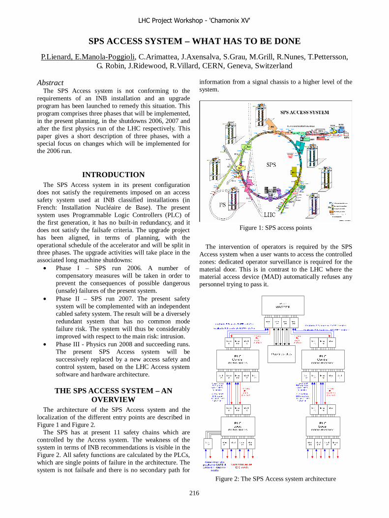
SPS ACCESS SYSTEM – WHAT HAS TO BE DONE
P.Lienard, E.Manola-Poggioli, C.Arimattea, J.Axensalva, S.Grau, M.Grill, R.Nunes, T.Pettersson, G. Robin, J.Ridewood, R.Villard, CERN, Geneva, Switzerland
Abstract The SPS Access system is not conforming to the
requirements of an INB installation and an upgrade program has been launched to remedy this situation. This program comprises three phases that will be implemented, in the present planning, in the shutdowns 2006, 2007 and after the first physics run of the LHC respectively. This paper gives a short description of three phases, with a special focus on changes which will be implemented for the 2006 run.
INTRODUCTION The SPS Access system in its present configuration
does not satisfy the requirements imposed on an access safety system used at INB classified installations (in French: Installation Nucléaire de Base). The present system uses Programmable Logic Controllers (PLC) of the first generation, it has no built-in redundancy, and it does not satisfy the failsafe criteria. The upgrade project has been aligned, in terms of planning, with the operational schedule of the accelerator and will be split in three phases. The upgrade activities will take place in the associated long machine shutdowns:
• Phase I – SPS run 2006. A number of compensatory measures will be taken in order to prevent the consequences of possible dangerous (unsafe) failures of the present system.
• Phase II – SPS run 2007. The present safety system will be complemented with an independent cabled safety system. The result will be a diversely redundant system that has no common mode failure risk. The system will thus be considerably improved with respect to the main risk: intrusion.
• Phase III - Physics run 2008 and succeeding runs. The present SPS Access system will be successively replaced by a new access safety and control system, based on the LHC Access system software and hardware architecture.
THE SPS ACCESS SYSTEM – AN OVERVIEW
The architecture of the SPS Access system and the localization of the different entry points are described in Figure 1 and Figure 2.
The SPS has at present 11 safety chains which are controlled by the Access system. The weakness of the system in terms of INB recommendations is visible in the Figure 2. All safety functions are calculated by the PLCs, which are single points of failure in the architecture. The system is not failsafe and there is no secondary path for
information from a signal chassis to a higher level of the system.
Figure 1: SPS access points
The intervention of operators is required by the SPS
Access system when a user wants to access the controlled zones: dedicated operator surveillance is required for the material door. This is in contrast to the LHC where the material access device (MAD) automatically refuses any personnel trying to pass it.
Figure 2: The SPS Access system architecture
LHC Project Workshop - 'Chamonix XV'
216
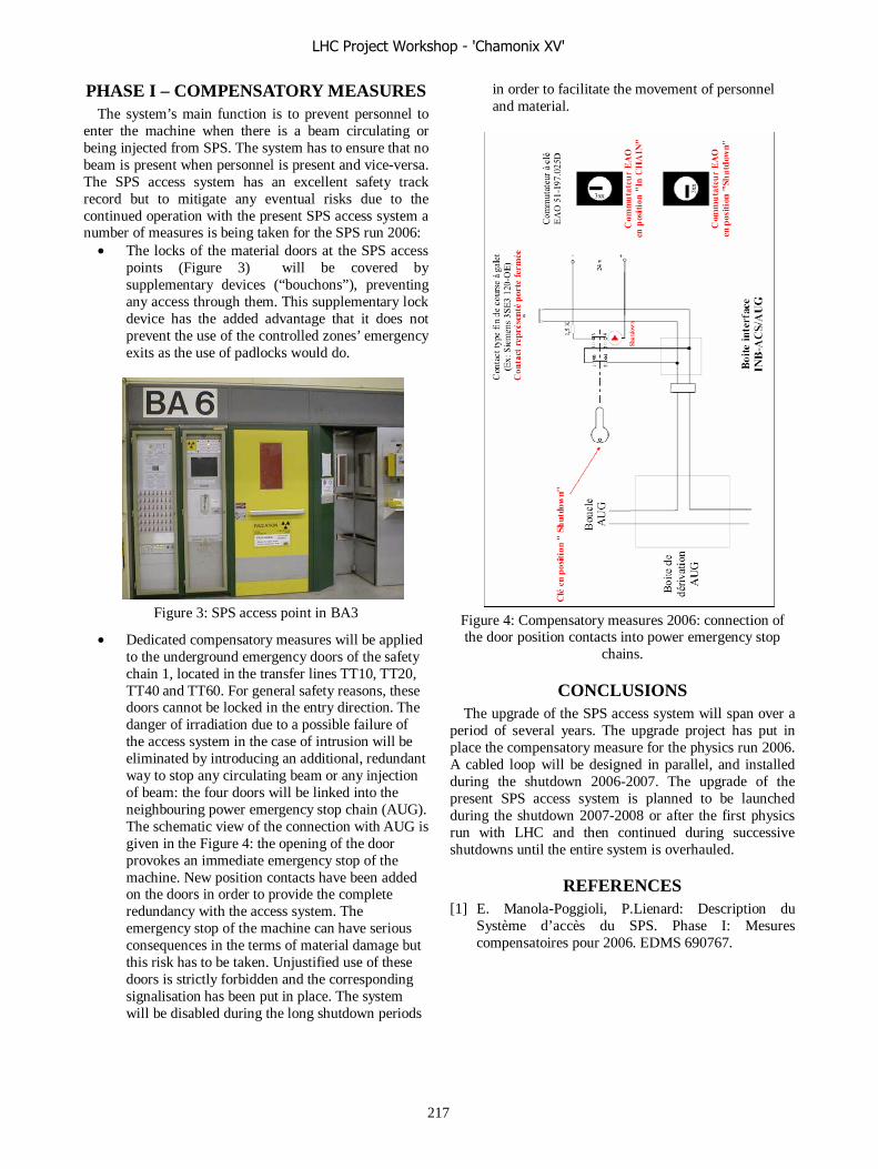
PHASE I – COMPENSATORY MEASURES The system’s main function is to prevent personnel to
enter the machine when there is a beam circulating or being injected from SPS. The system has to ensure that no beam is present when personnel is present and vice-versa. The SPS access system has an excellent safety track record but to mitigate any eventual risks due to the continued operation with the present SPS access system a number of measures is being taken for the SPS run 2006:
• The locks of the material doors at the SPS access points (Figure 3) will be covered by supplementary devices (“bouchons”), preventing any access through them. This supplementary lock device has the added advantage that it does not prevent the use of the controlled zones’ emergency exits as the use of padlocks would do.
Figure 3: SPS access point in BA3
• Dedicated compensatory measures will be applied to the underground emergency doors of the safety chain 1, located in the transfer lines TT10, TT20, TT40 and TT60. For general safety reasons, these doors cannot be locked in the entry direction. The danger of irradiation due to a possible failure of the access system in the case of intrusion will be eliminated by introducing an additional, redundant way to stop any circulating beam or any injection of beam: the four doors will be linked into the neighbouring power emergency stop chain (AUG). The schematic view of the connection with AUG is given in the Figure 4: the opening of the door provokes an immediate emergency stop of the machine. New position contacts have been added on the doors in order to provide the complete redundancy with the access system. The emergency stop of the machine can have serious consequences in the terms of material damage but this risk has to be taken. Unjustified use of these doors is strictly forbidden and the corresponding signalisation has been put in place. The system will be disabled during the long shutdown periods
in order to facilitate the movement of personnel and material.
Figure 4: Compensatory measures 2006: connection of the door position contacts into power emergency stop
chains.
CONCLUSIONS The upgrade of the SPS access system will span over a
period of several years. The upgrade project has put in place the compensatory measure for the physics run 2006. A cabled loop will be designed in parallel, and installed during the shutdown 2006-2007. The upgrade of the present SPS access system is planned to be launched during the shutdown 2007-2008 or after the first physics run with LHC and then continued during successive shutdowns until the entire system is overhauled.
REFERENCES [1] E. Manola-Poggioli, P.Lienard: Description du
Système d’accès du SPS. Phase I: Mesures compensatoires pour 2006. EDMS 690767.
LHC Project Workshop - 'Chamonix XV'
217

QRL INSTALLATION AND FIRST EXPERIENCES OF OPERATION
G. Riddone on behalf of the QRL team, CERN, Geneva, Switzerland .
Abstract The cryogenic distribution line (QRL) is divided in
eight sectors, each of them about 3.2-km long. The installation of the sector 7-8 started in summer 2003, but due to serious technical problems the installed elements were cut, repaired and re-installed by CERN. The installation of the other 7 sectors was left to QRL Contractor and started with the sector 8-1 at the end of 2004. This paper gives the status of the QRL installation and the main results from the reception tests performed at cryogenic condition on the first two sectors (a portion of the sectors 7-8 and the full 8-1). The measured heat inleaks for different QRL configurations are also given and compared to the specified values.
INTRODUCTION The cryogenic distribution line (QRL) [1] is divided in
eight sectors, and each of them is a continuous cryostat starting at the cryogenic interconnection box located in the underground caverns, and ending at the return module installed on the opposite side.
Each sector is sectorised in 9 vacuum sub sectors (named from A to I), to easy installation and commissioning, and is composed of about 235 pipe elements, 40 fixed point (or vacuum barrier) elements, 10 steps and elbows mainly located in the so-called junction region connecting the interconnection box to the QRL in the tunnel, 2 cryogenic extensions and 40 service modules feeding the cryomagnets with helium at different temperature levels via so-called jumper connections. Each standard QRL cell (about 107 m) comprises 1 service module, 1 fixed point element and 8 standard pipe elements. The QRL insulation vacuum is divided from the machine insulation vacuum by means of vacuum barrier housed inside each jumper connection. A typical QRL cross section, showing the five process headers is given in Figure 1.
E
F
BD
C
E
F
BD
C
Figure 1: QRL cross-section
INSTALLATION The installation of a QRL sector comprises the
installation of about 700 external supports, the positioning of about 325 elements and the welding of about 325 interconnections. Three main types of inner header interconnections can be defined as illustrated in Figure 2:
- the “O” type for which one butt-weld per header has to be realised;
- the “C” type for which two butt-welds per header have to be realised. These interconnections contain the internal compensators;
- the “A” type for which three welds per header have to be realised. These interconnections are those allowing for the final adjustment of each half-cell (about 53.5 m).
Figure 2: Main types of interconnections
The overall QRL installation is carried out by 6 teams spread over two or three sectors. The installation is carried out by sub-sectors. The inner headers are welded with orbital welding machines, whereas the external sleeves are manually welded.
The technical objectives of the QRL installation have now been reached, such as 20 standard interconnections a week and helium leak tighness test of each sub sector (about 400 m) in less than 3 weeks.
For the internal welds the following NDT tests are performed:
- internal (by using a video camera) and external visual controls at 100 %;
- radiography tests from 100 % to 10 % as a function of the weld quality;
- leak tightness tests at 100 % by using dedicated clamp shell tooling.
Each sub sector is then leak tightness tested individually before the final combined leak and pressure test of the entire sector.
LHC Project Workshop - 'Chamonix XV'
218

PRESENT STATUS OF THE QRL INSTALLATION AND QRL SCHEDULE At present the re-installation of the sector 7-8 by CERN
is complete, as well as the installation by the QRL contractor of the sectors 8-1, 4-5 and 3-4. The installation of the sector 5-6 is advanced at about 75 % and that of the sector 6-7 at about 30 %. The installation of the sector 2-3 shall start mid on March 2006 and that of the sector 1-2 mid of June 2006. Figure 3 shows, for each sector, the schedule for the delivery of the main elements (service module, pipe elements and fixed points elements, and steps/elbows), as well as the time period for the installation, the tests and the consolidations after tests.
At present the production of the standard QRL elements is not critical for the installation schedule. As the service modules, pipe elements and fixed points elements will be delivered with sufficient margin not to delay the QRL installation. On the contrary, the production of the steps and elbows shall be followed very closely not to delay the installation of the last two junction regions.
Based on the present installation rate, it is possible to install one sector in about 20 weeks. This means that the installation of the last sector can be completed by the end of 2006.
Figure 3: QRL schedule
RECEPTION TEST
Reception test schedule The first two sub-sectors of the sector 7-8 (sub-sectors A and B, about 735 m) [2] and the full sector 8-1 [3] have been tested both at room temperature and at cryogenic conditions. They underwent to pneumatic tests, flushing with helium at high rate, cooldown to nominal temperatures, heat inleak measurements and warmup. The following two sectors (sectors 4-5 and 3-4) passed successfully the pressure test. The overall schedule for the reception tests of the sectors 7-8 and 8-1 is given in Figure 4. The pressure test is always
performed during a week end and it is followed by the flushing with helium at high flow rate which has the aim of cleaning the circuits before cooldown. The cooldown of the sector 7-8 lasted about 3 days, whereas that for the sector 8-1 lasted one week. Once nominal cold conditions were reached the instrumentation could be validated (about 1.5 weeks), as well as the tuning of the refrigerator for the heat inleak measurements. The heat inleak measurements lasted about 2 weeks as different configurations had been tested (with and without active cooling in the jumper connections). The last phase of the reception test was the warm up which lasted few days.
2005
Pressure test
Flushing
Cool-down
Instrumentation commissioning
Heat inleak measurement
Warm-up
Sector 7-8, 700 m Sector 8-1, 3200 mCW 48
CW 49
CW 50
CW 51
CW 44
CW 45
CW 46
CW 47
CW 40
CW 41
CW 42
CW 43
CW 36
CW 37
CW 38
CW 39
Figure 4: Schedule for the reception tests
Pressure test The pressure test of the process headers is carried out at
1.25 their design pressure. For header B the design pressure is 4 bar, for headers C and D it is 20 bar and for headers E and F it is 22 bar. The test is declared as successful if the pressure is maintained inside the headers for at least one hour without significant variation, and if no relevant changes of the insulation vacuum are observed. The pressurisation is performed with helium at room temperature (see Figure 5). Up to about 20 bar the helium storage tanks and the warm compressors are used. From 20 bar to 27.5 bar, helium trailers and helium batteries are used.
0
5
10
15
20
25
30
7:5
5
8:4
5
9:3
6
10:
26
11:
16
12:
07
12:
57
13:
48
14:
38
15:
28
16:
19
17:
09
18:
00
Pre
ssur
e [b
ar]
Header E
Header C
Header D
Header F
Header B
1
2
3a
3b
4
5
C-D
E-F
B
1: Tanks2: Tanks3a et 3b: Compressors4: Trailer 5: He batteries
Figure 5: Pressure test of a typical QRL sector
Flushing of the circuits Before starting the cooldown it is necessary to clean the
circuits by circulation of room temperature helium at high
LHC Project Workshop - 'Chamonix XV'
219

mass flow rate. The circuits are cleaned one by one and the helium is returned to the refrigerator via header D. In the interconnection box a filter mounted on header D collects all the impurities coming from the headers. After the flushing of the circuits of the sectors 7-8 and 8-1, the header D filter was extracted and dust and metallic particles were found around the filtering surface.
Cool-down, thermometer validation and heat inleak measurement
The different phases (cool-down, instrumentation commissioning, heat inleak measurements and warm-up) of the tests at cryogenic temperature (named cold tests) for the sector 8-1 are illustrated in Figure 6.
Figure 6: Cold tests of the sector 8-1
The schematic layout used for the QRL cold tests is shown in Figure 7. For the cold tests dedicated modules were required, such as the test module and the two test equipments. The test module was located in the tunnel between the junction region and the first service module and it housed all the required instrumentation to perform the heat inleak measurements.
F
E
B
D
C
Warm recovery l ine
QUITT
980F
B
D
C
ETT TT TTEH
TT TT EH TT
TT
TTEH
QRL
Test module Return module
Test box
EH
EH TT
TT
TT
TTTT
JunctionRegion
TT
970
TT
990
TT
960
TT
900
TT
981
TT
971
TT
991
TT
961
TT
901
TT
980
TT
970
TT
990
TT
960
TT
900
TT
981
TT
971
TT
991
TT
961
TT
901
EH
985
TT
985
FT
985
TT
EH
905
TT
905
FT
905
TT
TT
TT
TT
TT
TT
TT
CV971
CV998
CV988
CV968
CV969
Test equipment
Test equipment
3.1 km
Figure 7: Schematic layout of the QRL cold tests
In absence of the cryomagnets, the two test equipments allowed for the helium in header E to return to the low pressure line of the refrigerator. During the test, each jumper connection was equipped with test boxes where short cuts between the different pipes could guarantee the continuity of the helium circuits. Two main circuits could be identified:
- the circuit at 4-20 K composed of header C (inlet header) and headers B and D (return headers)
- the circuit at 50-75 K composed of header E and F (both inlet headers for the cold test)
Before performing the heat inleak measurements, the thermometers have been validated at cryogenic temperature. Figure 8 shows the temperature distribution over the whole sector length. The result is very positive, as the measured temperature accuracy (considering the mounting of the sensor as well as the complete measuring chain) is about ±50 mK to be compared to the specified value of ± 1 K at about 10 K.
Figure 8: Longitudinal temperature distribution of the
sector 8-1
The heat inleaks have been measured by enthalpy balance method knowing for each header the corresponding inlet-to-outlet temperatures (located in the junction region or in the service modules depending on the tested configurations) and the mass flow rate. The measured heat inleaks have been also cross-checked by using independent refrigerator input. The mass-flow rate in headers E and F have been obtained by using the mass-flowmeters installed in the test equipments. For the sector 7-8 (735 m) and 8-1 (3200 m), the measured and calculated (specified without any contingency) heat inleaks to headers E and F are given in Table 1. We can notice that the measured heat inleaks are lower than the calculated values.
Table 1: Heat inleaks to headers E and F
Heat inleaks [W] Sector 7-8 Sector 8-1
Calculated 2400 9850 Measured 2250 ± 150 9000 ± 400
The mass-flow rates in headers B, C and D were
calculated by using the heaters in the test module, and cross checked by knowing the opening and the flow characteristics of the concerned valves. For the heat inleaks to headers B, C and D different configuration have been measured:
- QRL without the junction region (JR) and without the jumper connection (JC)
- QRL without the JR and with the JC - full QRL with the JR and the JC.
LHC Project Workshop - 'Chamonix XV'
220
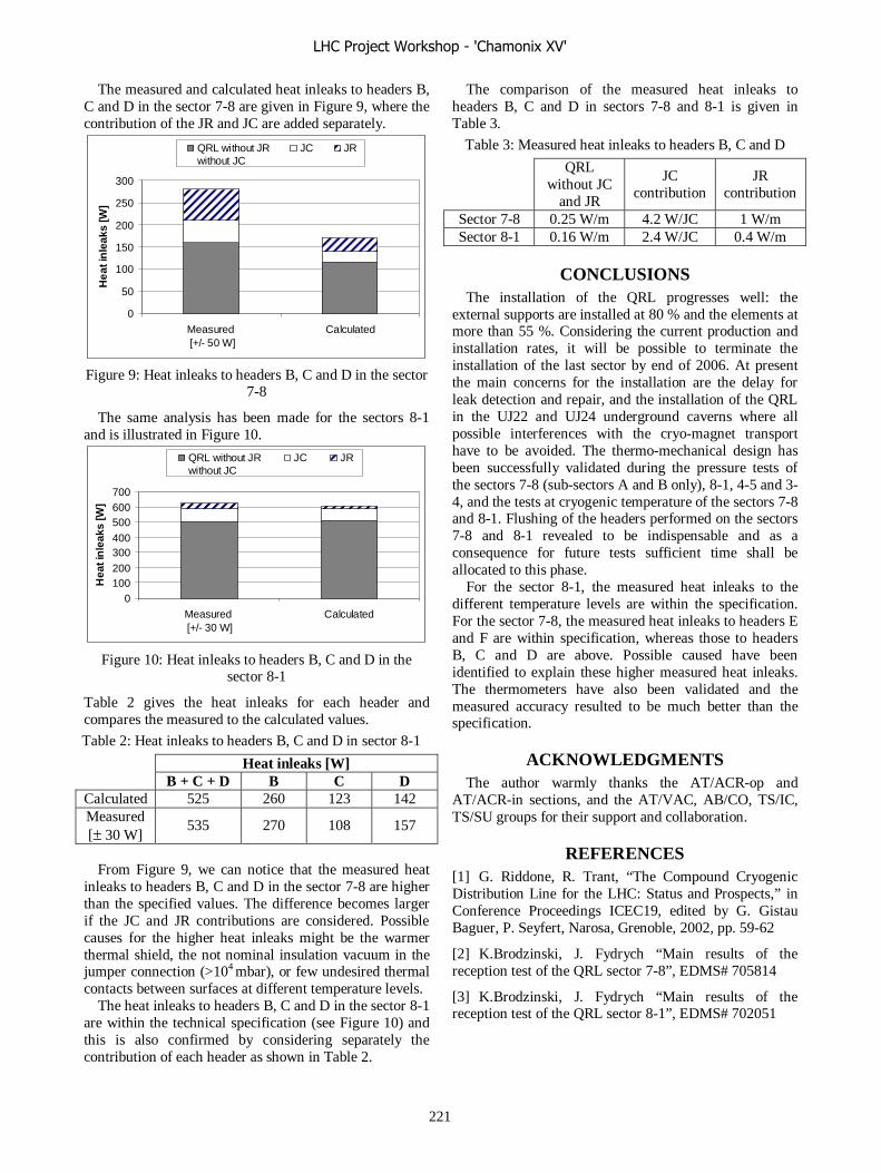
The measured and calculated heat inleaks to headers B, C and D in the sector 7-8 are given in Figure 9, where the contribution of the JR and JC are added separately.
0
50
100
150
200
250
300
Measured [+/- 50 W]
Calculated
Hea
t in
leak
s [W
]
QRL without JRwithout JC
JC JR
Figure 9: Heat inleaks to headers B, C and D in the sector
7-8
The same analysis has been made for the sectors 8-1 and is illustrated in Figure 10.
0100200
300400
500600700
Measured [+/- 30 W]
Calculated
Hea
t in
leak
s [W
]
QRL without JRwithout JC
JC JR
Figure 10: Heat inleaks to headers B, C and D in the
sector 8-1
Table 2 gives the heat inleaks for each header and compares the measured to the calculated values.
Table 2: Heat inleaks to headers B, C and D in sector 8-1
Heat inleaks [W] B + C + D B C D Calculated 525 260 123 142 Measured [± 30 W]
535 270 108 157
From Figure 9, we can notice that the measured heat
inleaks to headers B, C and D in the sector 7-8 are higher than the specified values. The difference becomes larger if the JC and JR contributions are considered. Possible causes for the higher heat inleaks might be the warmer thermal shield, the not nominal insulation vacuum in the jumper connection (>104 mbar), or few undesired thermal contacts between surfaces at different temperature levels.
The heat inleaks to headers B, C and D in the sector 8-1 are within the technical specification (see Figure 10) and this is also confirmed by considering separately the contribution of each header as shown in Table 2.
The comparison of the measured heat inleaks to headers B, C and D in sectors 7-8 and 8-1 is given in Table 3.
Table 3: Measured heat inleaks to headers B, C and D
QRL
without JC and JR
JC contribution
JR contribution
Sector 7-8 0.25 W/m 4.2 W/JC 1 W/m Sector 8-1 0.16 W/m 2.4 W/JC 0.4 W/m
CONCLUSIONS The installation of the QRL progresses well: the
external supports are installed at 80 % and the elements at more than 55 %. Considering the current production and installation rates, it will be possible to terminate the installation of the last sector by end of 2006. At present the main concerns for the installation are the delay for leak detection and repair, and the installation of the QRL in the UJ22 and UJ24 underground caverns where all possible interferences with the cryo-magnet transport have to be avoided. The thermo-mechanical design has been successfully validated during the pressure tests of the sectors 7-8 (sub-sectors A and B only), 8-1, 4-5 and 3-4, and the tests at cryogenic temperature of the sectors 7-8 and 8-1. Flushing of the headers performed on the sectors 7-8 and 8-1 revealed to be indispensable and as a consequence for future tests sufficient time shall be allocated to this phase.
For the sector 8-1, the measured heat inleaks to the different temperature levels are within the specification. For the sector 7-8, the measured heat inleaks to headers E and F are within specification, whereas those to headers B, C and D are above. Possible caused have been identified to explain these higher measured heat inleaks. The thermometers have also been validated and the measured accuracy resulted to be much better than the specification.
ACKNOWLEDGMENTS The author warmly thanks the AT/ACR-op and
AT/ACR-in sections, and the AT/VAC, AB/CO, TS/IC, TS/SU groups for their support and collaboration.
REFERENCES [1] G. Riddone, R. Trant, “The Compound Cryogenic Distribution Line for the LHC: Status and Prospects,” in Conference Proceedings ICEC19, edited by G. Gistau Baguer, P. Seyfert, Narosa, Grenoble, 2002, pp. 59-62
[2] K.Brodzinski, J. Fydrych “Main results of the reception test of the QRL sector 7-8”, EDMS# 705814
[3] K.Brodzinski, J. Fydrych “Main results of the reception test of the QRL sector 8-1”, EDMS# 702051
LHC Project Workshop - 'Chamonix XV'
221
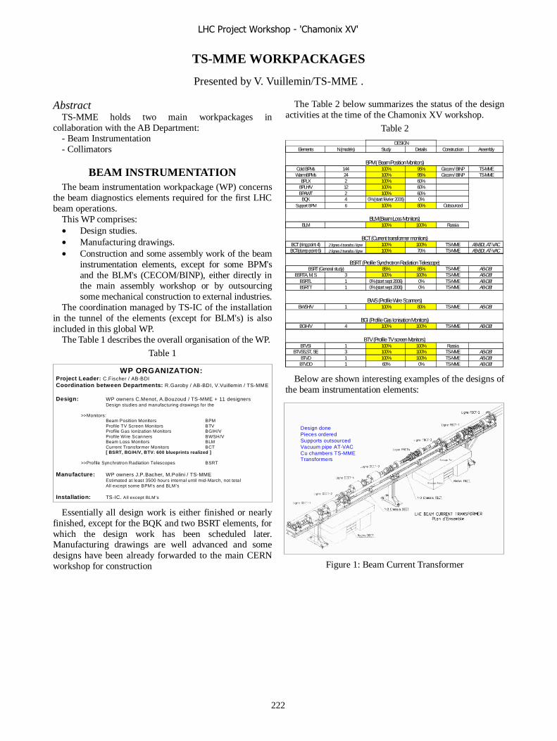
TS-MME WORKPACKAGES
Presented by V. Vuillemin/TS-MME .
Abstract TS-MME holds two main workpackages in
collaboration with the AB Department: - Beam Instrumentation - Collimators
BEAM INSTRUMENTATION The beam instrumentation workpackage (WP) concerns
the beam diagnostics elements required for the first LHC beam operations.
This WP comprises: • Design studies. • Manufacturing drawings. • Construction and some assembly work of the beam
instrumentation elements, except for some BPM's and the BLM's (CECOM/BINP), either directly in the main assembly workshop or by outsourcing some mechanical construction to external industries.
The coordination managed by TS-IC of the installation in the tunnel of the elements (except for BLM's) is also included in this global WP.
The Table 1 describes the overall organisation of the WP.
Table 1
Essentially all design work is either finished or nearly finished, except for the BQK and two BSRT elements, for which the design work has been scheduled later. Manufacturing drawings are well advanced and some designs have been already forwarded to the main CERN workshop for construction
The Table 2 below summarizes the status of the design activities at the time of the Chamonix XV workshop.
Table 2
Below are shown interesting examples of the designs of
the beam instrumentation elements:
Figure 1: Beam Current Transformer
Elements N (models) Study Details Construction Assembly
Cold BPMs 144 100% 95% Cecom / BINP TS-MMEWarm BPMs 24 100% 95% Cecom / BINP TS-MME
BPLX 2 100% 60%BPLH/V 12 100% 60%BPAWT 2 100% 60%BQK 4 0% (start février 2006) 0%
Support BPM 6 100% 80% Outsourced
BLM 100% 100% Russia
BCT (ring point 4) 2 lignes 4 transfos / ligne 100% 100% TS-MME AB-BDI, AT-VACBCT(dump point 6) 2 lignes 2 transfos / ligne 100% 70% TS-MME AB-BDI, AT-VAC
85% 85% TS-MME AB-DBIBSRTA, M, S 3 100% 100% TS-MME AB-DBI
BSRTL 1 0% (start sept 2006) 0% TS-MME AB-DBIBSRTT 1 0% (start sept 2006) 0% TS-MME AB-DBI
BWSH/V 1 100% 80% TS-MME AB-DBI
BGIH/V 4 100% 100% TS-MME AB-DBI
BTVSI 1 100% 100% RussiaBTVSS,ST, SE 3 100% 100% TS-MME AB-DBI
BTVD 1 100% 100% TS-MME AB-DBIBTVDD 1 60% 0% TS-MME AB-DBI
BTV (Profile TV screen Monitors)
BGI (Profile Gas Ionisation Monitors)
BWS (Profile Wire Scanners)
BSRT (Profile Synchrotron Radiation Telescope)
DESIGN
BSRT (General study)
BPM ( Beam Position Monitors)
BCT (Current transformer monitors)
BLM (Beam Loss Monitors)
WP ORGANIZATION:Project Leader: C.Fischer / AB-BDICoordination between Departments: R.Garoby / AB-BDI, V.Vuillemin / TS-MME
Design: WP owners C.Menot, A.Bouzoud / TS-MME + 11 designersDesign studies and manufacturing drawings for the
>>Monitors:Beam Position Monitors BPMProfile TV Screen Monitors BTVProfile Gas Ionization Monitors BGIH/VProfile Wire Scanners BWSH/VBeam Loss Monitors BLMCurrent Transformer Monitors BCT[ BSRT, BGIH/V, BTV: 600 blueprints realized ]
>>Profile Synchrotron Radiation Telescopes BSRT
Manufacture: WP owners J.P.Bacher, M.Polini / TS-MMEEstimated at least 3500 hours internal until mid-March, not totalAll except some BPM’s and BLM’s
Installation: TS-IC. All except BLM’s
Design donePieces orderedSupports outsourcedVacuum pipe AT-VACCu chambers TS-MMETransformers
Design donePieces orderedSupports outsourcedVacuum pipe AT-VACCu chambers TS-MMETransformers
LHC Project Workshop - 'Chamonix XV'
222

Figure 2: Beam Profile Synchrotron Radiation Telescope
Figure 3: Beam Profile Gas Ionization Monitor (H = horizontal, V = Vertical)
Figure 4: Beam Profile TV screen Monitors
The construction of several elements is on a very tight schedule. The priority in construction will be given to those parts of the elements that are connected to the LHC vacuum. Presently, up to mid-march 2006 (the WP is not yet complete) 3500 hours of construction and assembly have been scheduled in the main workshop, following the main LHC installation schedule. The most critical point is due to the fact that TS-MME has only one large folding
press, with one expert technician. The press will have to work more than 8 hours/day in order to meet the production schedule.
Table 3 below describes the present schedule in terms of construction, assembly and installation.
A more precise scenario concerning the installation of the elements will be discussed in the beginning of 2006.
Table 3
COLLIMATORS The TS-MME WP owners are: A. Bertarelli, M. Mayer
and R. Perret. This WP was defined already when the EST Division existed:
"The EST provided output will be the required number of prototype collimators within the required schedule and drawings for the series production",
namely the technical specification, the thermo-mechanical calculations, the design and drawings for series production as well as the production of 2 prototypes, including some testing.
As the years have passed, the original requirements have gone through an evolution and the number of collimators/masks required have increased compared to what was defined at the beginning of the project. Including the prototypes, more than 1000 drawings have been realized in 2 years for 30 different variants and geometrical configurations, test benches and paloniers.
The Table 4 summarizes the list of the collimators, masks and absorbers.
All design work for the primary and secondary collimators (TCP and TCS) are finished and the production drawings have been delivered on time. The work on the masks has started with additional designers allocated to this task.
BGIH / BGIV (Beam Profile Gas Ionization Monitors)
Design doneTight construction (Electron Beam welding)
BGIH / BGIV (Beam Profile Gas Ionization Monitors)
Design doneTight construction (Electron Beam welding)
BTV (Beam Profile TV Screen Monitors)
Design done (BTVDD mid-March)Tight construction
BTV (Beam Profile TV Screen Monitors)
Design done (BTVDD mid-March)Tight construction
ELEMENT TASK
1 2 1 2 1 2 1 2 1 2 1 2 1 2 1 2 1 2 1 2 1 2 1 2
BSRT ConstructionAssembly
Installation RA43Installation RA47
BTVBTVST
Construction
AssemblyInstallation
BTVSS
ConstructionAssemblyInstallation
BTVSEConstruction
AssemblyInstallation
BTVD
Design / drawingsConstruction
AssemblyInstallation
BTVDD
Design / drawings
ConstructionAssembly
Installation
BGIH / V ConstructionAsembly
Installation RA43Installation RA47
BSWH / V Construction
AssemblyInstallation RA43
Installation RA 47
BCT Drawings RA6Construction RA47
CadmiumAssembly RA4x
Installation RA47
Construction RA6xCadmium
Assembly RA6xInstallation RA63Installation RA67
BPM Installation
BPM special Design BQKConstructionInstallation RA43
Installation RA47
CRITICAL
TIGHT
Sep Oct Nov DecMay Jun Jul AugJan Feb Mar Apr
BSRT (Beam Profile Synchrotron Radiation Telescope)
BSRTA on scheduleBSRTM: BSTRS outsourced (shielding)
design to workshop end JanTransition beam pipe: need approval AT-VAC
BSRT (Beam Profile Synchrotron Radiation Telescope)
BSRTA on scheduleBSRTM: BSTRS outsourced (shielding)
design to workshop end JanTransition beam pipe: need approval AT-VAC
LHC Project Workshop - 'Chamonix XV'
223
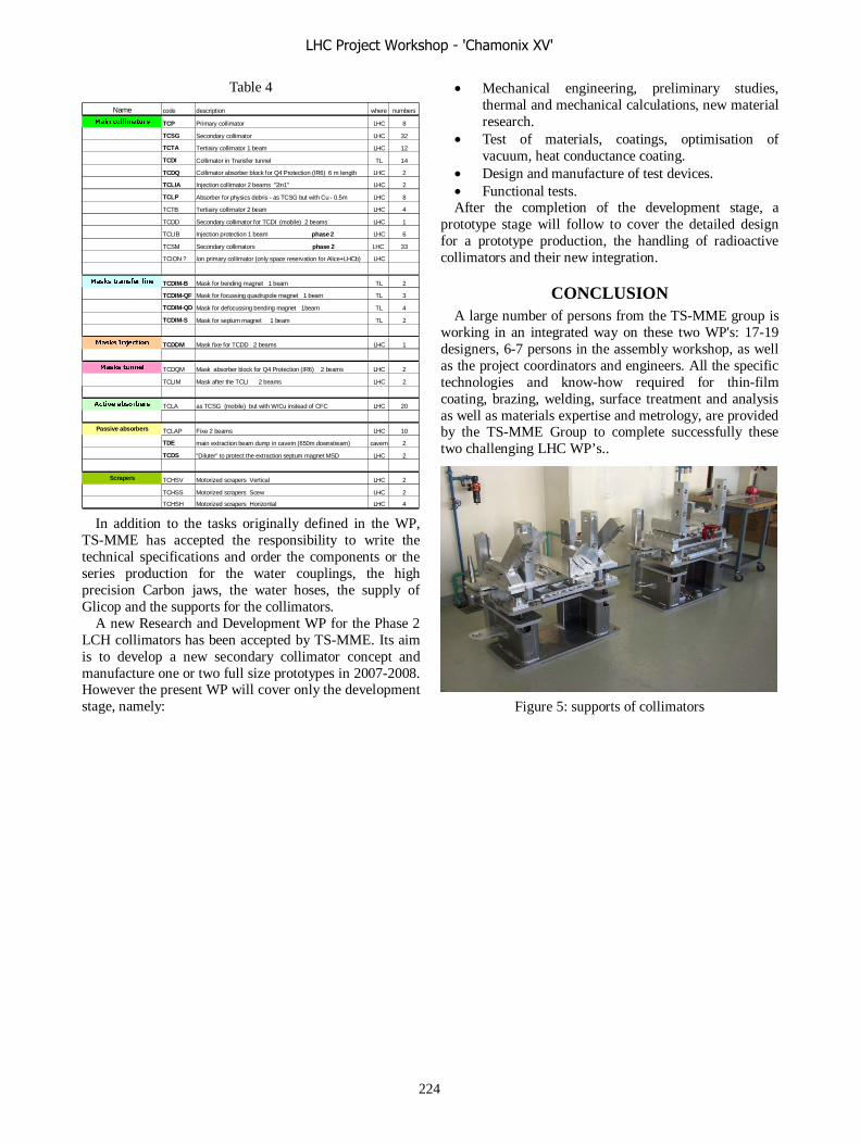
Table 4
In addition to the tasks originally defined in the WP,
TS-MME has accepted the responsibility to write the technical specifications and order the components or the series production for the water couplings, the high precision Carbon jaws, the water hoses, the supply of Glicop and the supports for the collimators.
A new Research and Development WP for the Phase 2 LCH collimators has been accepted by TS-MME. Its aim is to develop a new secondary collimator concept and manufacture one or two full size prototypes in 2007-2008. However the present WP will cover only the development stage, namely:
• Mechanical engineering, preliminary studies, thermal and mechanical calculations, new material research.
• Test of materials, coatings, optimisation of vacuum, heat conductance coating.
• Design and manufacture of test devices. • Functional tests. After the completion of the development stage, a
prototype stage will follow to cover the detailed design for a prototype production, the handling of radioactive collimators and their new integration.
CONCLUSION A large number of persons from the TS-MME group is
working in an integrated way on these two WP's: 17-19 designers, 6-7 persons in the assembly workshop, as well as the project coordinators and engineers. All the specific technologies and know-how required for thin-film coating, brazing, welding, surface treatment and analysis as well as materials expertise and metrology, are provided by the TS-MME Group to complete successfully these two challenging LHC WP’s..
Figure 5: supports of collimators
Name code description where numbers
Main collimators TCP Primary collimator LHC 8
TCSG Secondary collimator LHC 32
TCTA Tertiairy collimator 1 beam LHC 12
TCDI Collimator in Transfer tunnel TL 14
TCDQ Collimator absorber block for Q4 Protection (IR6) 6 m length LHC 2
TCLIA Injection collimator 2 beams "2in1" LHC 2
TCLP Absorber for physics debris - as TCSG but with Cu - 0.5m LHC 8
TCTB Tertiairy collimator 2 beam LHC 4
TCDD Secondary collimator for TCDI (mobile) 2 beams LHC 1
TCLIB Injection protection 1 beam phase 2 LHC 6
TCSM Secondary collimators phase 2 LHC 33
TCION ? Ion primary collimator (only space reservation for Alice+LHCb) LHC
Masks transfer line TCDIM-B Mask for bending magnet 1 beam TL 2
TCDIM-QF Mask for focussing quadrupole magnet 1 beam TL 3
TCDIM-QD Mask for defocussing bending magnet 1beam TL 4
TCDIM-S Mask for septum magnet 1 beam TL 2
Masks Injection TCDDM Mask fixe for TCDD 2 beams LHC 1
Masks tunnel TCDQM Mask absorber block for Q4 Protection (IR6) 2 beams LHC 2
TCLIM Mask after the TCLI 2 beams LHC 2
Active absorbers TCLA as TCSG (mobile) but with W/Cu instead of CFC LHC 20
Passive absorbers TCLAP Fixe 2 beams LHC 10
TDE main extraction beam dump in cavern (650m downstream) cavern 2
TCDS "Diluter" to protect the extraction septum magnet MSD LHC 2
Scrapers TCHSV Motorized scrapers Vertical LHC 2
TCHSS Motorized scrapers Scew LHC 2
TCHSH Motorized scrapers Horizontal LHC 4
LHC Project Workshop - 'Chamonix XV'
224

Electrical Quality Assurance in the LHC Tunnel (ELQA) andMagnet Polarity Coordination (Mr. Polarity)
Davide Bozzini, Vincent Chareyre, Stephan Russenschuck, Andrzej Kotarba
Abstract
The paper describes the methods and tools for the Elec-trical Quality Assurance in the LHC tunnel which have re-cently been validated by finding two non-conformities atinstalled magnet components. In the second part, the co-herence between the magnet construction and measurementon one side, and the magnet interconnection and the Elec-trical Quality Assurance (ELQA) on the other side is dis-cussed. This activity is known as magnet polarity coordi-nation. Some detected incoherences are reported.
INTRODUCTION
Electrical Quality Assurance and magnet polarity co-ordination are two sides of the same medal. ElectricalQuality Assurance under the responsibility of AT-MEL-EM with the collaboration of HNINP is performed in orderto ensure the integrity of the electrical circuits during ma-chine assembly and commissioning and to guarantee thatthe electrical interconnections correspond to the LHC pow-ering layout. A further objective is to ensure traceabilityof checks while considering all electrical non-conformities.However, ELQA is not (and cannot) be concerned with thequalification of individual components which includes po-larity, continuity, labeling, electrical integrity, voltage taps,magnet type and position. It has to be assumed that the in-dividual magnet components are conform before the tunnelinstallation. The two reported cases show, however, thatthis is not always the case.
Magnet Polarity Coordination that we call in chest “Mr.Polarity”, on the other hand is concerned with the coher-ence between magnet construction and measurement onone side, and the magnet interconnection according to thelayout database and the hard and software for ELQA on theother side. The same understanding and application of theengineering specification for LHC magnet polarities by allteams involved has to be ensured. We will report incoher-ences resulting from permutations in the magnet polaritydue to the position of the connection terminals of the in-stalled magnet components.
ELECTRICAL QUALITY ASSURANCE
The parameters to be verified in the framework of theELQA during machine assembly include:
1. continuity of bus-bars and magnet interconnections,2. authentication of the magnet type by means of its mea-
sured ohmic resistance,3. magnet polarity check using the voltage taps on the A
terminal, and
4. insulation to ground and to other circuits.
The methodology applied to the continuity verification hasbeen described in various papers and at previous LHC per-formance meetings [1]. It consists of feeding a stable DCcurrent into a branch of the tested circuit. Voltage dropsacross precision resistors, connected in series at both ex-tremities of the branch, confirm its continuity. The authen-tication and polarity of magnets connected in series withinthe branch are verified by measuring differential voltagedrops between voltage taps at the magnet’s A terminal andthe source or sink of the branch. The voltage measurementsare compared to known parameters stored in a database.In order to define a systematic approach for the verifica-tion of the about 70000 splices, all different electrical in-terconnection types and corresponding configurations havebeen determined by analyzing the data in the LHC refer-ence database. This analysis resulted in the definition of 5interconnection types in the N-line circuits, 6 types for thecircuits of the spool-pieces in the arc zone, and 6 types forthe circuits of the spool-pieces in the dispersion suppressorregion.
For the verification of the 42 auxiliary bus-bars in the N-line, the access to three successive interconnection planesis required at the level of the N-line interconnection board,see Fig. 1. It has to be stressed that the smallest sectionof the ARC that can be verified is composed of two half-cells. The two associated auxiliary N-line cables must beinstalled. Thus the smallest “seed crystal” for two advanc-ing fronts is composed of at least 5 fully equipped halfcells. As of the verification of the 6th half cell, the firstinterconnect can be released and welding operations canbe completed.
Fig. 2 shows the scheme for the verification of a mag-net powered from the 42 auxiliary N-line cable. First thecontinuity of the circuit is assured by measuring voltagedrops across the current reading resistors. Measured volt-age drops between the allocated wire slots on the centralinterconnection board and the source and sink ends indi-cate the correct distribution of the wires. Finally the polar-ity and the type of the connected magnet are checked bymeasuring the expected voltage between the voltage tap at-tached to the magnet and the sink end. The verification ofthe auxiliary spool-piece bus-bars only requires the accessto the extremities of a cell [2].
Arc Interconnection Verification
The Arc Interconnection Verification (AIV) is an ELQAapplication allowing the above mentioned verifications us-ing an automated mobile system with the following char-acteristics:
LHC Project Workshop - 'Chamonix XV'
225

Figure 1: Left: Position of the interconnection board inthe interconnection region between SSS and MB. Bottomright: Interconnection board assembled and awaiting testbefore ultrasonic welding. Top right: Slot assignment onthe interconnection board.
1. Verification of a full cell,2. qualification of all types of interconnections with a
single tool, which can be independently operated bytwo persons,
3. hardware optimized for tunnel dimensions and storageunderneath the cryo-magnets,
4. fast connection of cables and connectors, and5. software for the automatic validation of measured data
with respect to the LHC reference database.
The mobile system is composed of a central unit to beplaced at the center of the cell and includes a portable com-puter running the software application, two de-multiplexerspositioned at the extremities of the cell, and the connectorsand cables for pick-up, routing and dispatching of measure-ment and control signals.
The required signals are picked-up by connectors espe-cially developed to ensure a fast plug-in and a reliable elec-trical contact. At the extremities of the cell two relay-basedde-multiplexers allow the selection of a subset of signals.The selection of the required channel is done via 6 digitallines driven from the central unit. The signals coming fromthe central N-line interconnection board are directly routedto the connection box of the central unit. The voltage tapsignals needed for the polarity checks are routed from each
Figure 2: Scheme for the verification of a magnet poweredfrom the 42 auxiliary N-lines cable.
Figure 3: Scheme of the mobile test system.
cryo-magnet instrumentation interface box to the connec-tion box via four dedicated cables, see Fig. 3.
The central unit contains a data acquisition system, in-cluding a high precision digital multimeter, two switchingmatrices allowing the independent reading of the 3160 pos-sible voltage combinations generated from the 217 signalsgathered along the cell, and an I/O card for the control ofthe whole system. In total, sixteen digital output lines areused in a sink mode to provide the control of the two de-multiplexers. Five analog channels are used. Four providethe current reading and the fifth allows for the differen-tial voltage reading of two signals out of the 3160 possi-ble combinations. The system is controlled by a LabVIEWbased program with a GPIB Universal Serial Bus (USB)interface using the standard protocol IEEE 488.2. The sys-tem allows fully automatic verification and it is adapted toany configuration of the electrical circuit under test.
The control of the system is based on the LabVIEWapplication and an Oracle database containing the infor-mation needed to perform the electrical qualification andallowing the storage of the test results. The ELQA-DBdatabase contains two parts, one containing the test ta-bles and one containing the results tables. The tests tableshave been automatically generated by applying a packageof PL/SQL scripts to the LHC reference database. This en-sures that the latest version of the LHC machine parametersis used. The generated database contains all electrical inter-connection data necessary to perform and validate the elec-trical verification. The Oracle database is duplicated intoa MS-Access format which can be exploited on portablecomputers, in order to have a self-sufficient test system inthe LHC tunnel.
Validation of the procedures and equipment
The ELQA methodology as well as the hard and soft-ware applications were successfully validated in Septem-ber 2005 by finding a non-conformity at a SSS cryomagnetinstalled in the LHC tunnel. Powering the adjacent orbitcorrector in Aperture 1, a voltage drop on the voltage tap ofthe orbit corrector in Aperture 2 was detected. As the con-formity of magnet elements cannot be taken for granted,three different errors could lead to the observations, seeFig. 4: 1) wrong voltage tap labeling, 2) wrong labelingof the bus-bars, 3) internal connection error of magnet el-ements. By opening the beam tube of Aperture 1 and byinsertion of a hall-probe it was found that indeed the firsterror was present.
LHC Project Workshop - 'Chamonix XV'
226
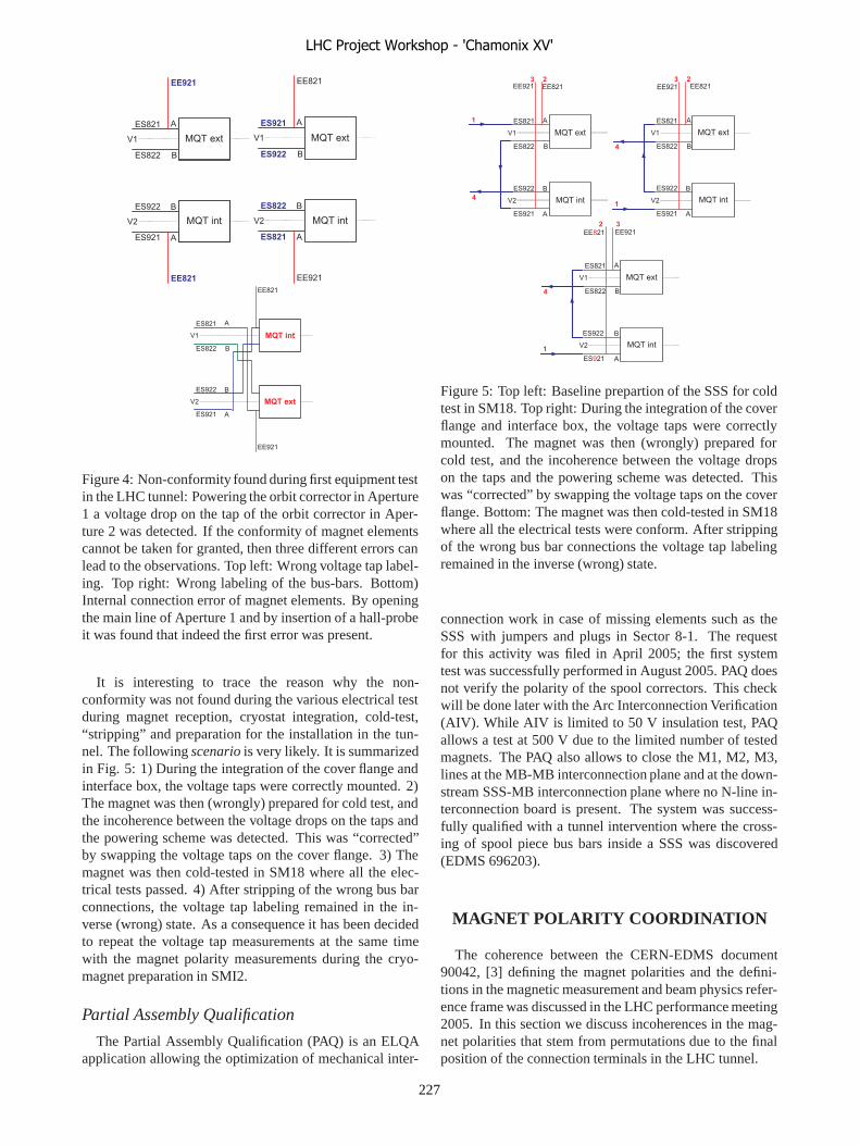
� � �
�
�
� � � � �
� � �
� �
� � �
�
�
� � � � �
� � �
� � � �
� � � � � �
� � � � � �
� �
�
�
�
� � �
� � � � �
� � � � �
�
�
� � � �
� � � � �
� � � � �
� � � � � �
� � � � � �
� �
�
�
�
� � �
� � �
� �
�
�
� � � �
� � �
� � � �
� � � �
� � � � �� �
�
Figure 4: Non-conformity found during first equipment testin the LHC tunnel: Powering the orbit corrector in Aperture1 a voltage drop on the tap of the orbit corrector in Aper-ture 2 was detected. If the conformity of magnet elementscannot be taken for granted, then three different errors canlead to the observations. Top left: Wrong voltage tap label-ing. Top right: Wrong labeling of the bus-bars. Bottom)Internal connection error of magnet elements. By openingthe main line of Aperture 1 and by insertion of a hall-probeit was found that indeed the first error was present.
It is interesting to trace the reason why the non-conformity was not found during the various electrical testduring magnet reception, cryostat integration, cold-test,“stripping” and preparation for the installation in the tun-nel. The following scenario is very likely. It is summarizedin Fig. 5: 1) During the integration of the cover flange andinterface box, the voltage taps were correctly mounted. 2)The magnet was then (wrongly) prepared for cold test, andthe incoherence between the voltage drops on the taps andthe powering scheme was detected. This was “corrected”by swapping the voltage taps on the cover flange. 3) Themagnet was then cold-tested in SM18 where all the elec-trical tests passed. 4) After stripping of the wrong bus barconnections, the voltage tap labeling remained in the in-verse (wrong) state. As a consequence it has been decidedto repeat the voltage tap measurements at the same timewith the magnet polarity measurements during the cryo-magnet preparation in SMI2.
Partial Assembly Qualification
The Partial Assembly Qualification (PAQ) is an ELQAapplication allowing the optimization of mechanical inter-
�
�
� � �
� �
�
�� � �
� � � �
� � � � � �
� � � � � �
� �
�
�
�
� � �� � � �
��
�
�
� � �
� � �
� �
�
�
� � � �
� � �
� � � �
� � � � � �
� � � � � �
� �
� �
��
�
�
�
� � �
� �
�
�� � �
� � � �
� � � � � �
� � � � � �
� �
� �
�
� � � � � � �
� �
Figure 5: Top left: Baseline prepartion of the SSS for coldtest in SM18. Top right: During the integration of the coverflange and interface box, the voltage taps were correctlymounted. The magnet was then (wrongly) prepared forcold test, and the incoherence between the voltage dropson the taps and the powering scheme was detected. Thiswas “corrected” by swapping the voltage taps on the coverflange. Bottom: The magnet was then cold-tested in SM18where all the electrical tests were conform. After strippingof the wrong bus bar connections the voltage tap labelingremained in the inverse (wrong) state.
connection work in case of missing elements such as theSSS with jumpers and plugs in Sector 8-1. The requestfor this activity was filed in April 2005; the first systemtest was successfully performed in August 2005. PAQ doesnot verify the polarity of the spool correctors. This checkwill be done later with the Arc Interconnection Verification(AIV). While AIV is limited to 50 V insulation test, PAQallows a test at 500 V due to the limited number of testedmagnets. The PAQ also allows to close the M1, M2, M3,lines at the MB-MB interconnection plane and at the down-stream SSS-MB interconnection plane where no N-line in-terconnection board is present. The system was success-fully qualified with a tunnel intervention where the cross-ing of spool piece bus bars inside a SSS was discovered(EDMS 696203).
MAGNET POLARITY COORDINATION
The coherence between the CERN-EDMS document90042, [3] defining the magnet polarities and the defini-tions in the magnetic measurement and beam physics refer-ence frame was discussed in the LHC performance meeting2005. In this section we discuss incoherences in the mag-net polarities that stem from permutations due to the finalposition of the connection terminals in the LHC tunnel.
LHC Project Workshop - 'Chamonix XV'
227

Position of the connection terminals
The position of the external connection terminals ofmagnets or magnet assemblies defines the normal instal-lation direction in the tunnel, e.g., with the external con-nection terminals upstream or downstream of Beam 1. Inparticular multipole correctors within the magnet assemblymight have their connection terminals facing downstreamof Beam 1, e.g., MCB in the SSS, MCS in the MB, ref.Table 1 (column D).
The magnet’s optical function may change depending onthe multipole order, i.e.,
Bupn = (−1)n−1Bdown
n , (1)
Aupn = (−1)nAdown
n . (2)
The terminals are (re)-labeled such that if the current entersthe A terminal the field is indeed positive in the sense of thepolarity conventions.
Remark: It has to be noted that the field quality of themagnet modules is always measured in the magnet frameand consequently the relative higher order field harmonicsmay change sign in the magnet assembly depending on themultipole order, i.e., for the relative multipoles of a normalmagnet:
bupn = (−1)n−Nbdown
n , (3)
aupn = (−1)n−N+1adown
n , (4)
and for a skew magnet:
bupn = (−1)n−N+1bdown
n , (5)
aupn = (−1)n−Nadown
n . (6)
�
The normal installation direction of the magnets is given inTable 1 in the Appendix together with the number of mag-nets, the operation temperature and current, the magneticlength, the inductance and the resistance at room tempera-ture. The kickers and experimental magnets are excluded.
Colums A and C give the number of apertures and thenumber of connection terminals, correspondingly. Fourdifferent types of magnets can be identified.
• Single aperture magnets, e.g., MQY with one apertureand one pair of terminals (A=1,C=1).
• Two-in-one magnets with one pair of connection ter-minals, e.g., MB (A=2,C=1).
• Two-in-one magnets with two pairs of connection ter-minals for individual powering of the apertures, e.g.,MQ (A=2,C=2).
• Magnet modules (individually powered) assembled intwin aperture sub-assemblies, e.g., MO, MQS, MQTL(A=2,C=2).
This classification scheme avoids having to distinguish be-tween two-in-one magnets with a common iron yoke (moreor less magnetically coupled) and magnet modules in a
common (twin aperture) support structure (magneticallydecoupled), which in some cases also allow an individualcold testing of the modules. These technicalities are notimportant for polarity issues.
The following magnet assemblies are found in the LHCmachine:
• MCBCA (35): Superconducting twin-aperture dipolecorrector magnet assembly in a MQM-type commonsupport structure. In the MCBCA, the modules are ar-ranged with MCBCV in the internal aperture, i.e, themagnetic field is horizontal, while MCBH is mountedin the external aperture, i.e, the magnetic field is ver-tical.
• MCBCB (33): Superconducting twin-aperture dipolecorrector magnet assembly in a MQM-type commonsupport structure. In the MCBCB, the modules are ar-ranged with MCBCH in the internal aperture, i.e, themagnetic field is vertical, while MCBV is mounted inthe external aperture, i.e, the magnetic field is hori-zontal.
• MCBCC (8): Superconducting twin-aperture dipolecorrector magnet assembly in a MSCB-type commonsupport structure. In the MCBCC, the modules are ar-ranged with MCBCV in the internal aperture, i.e, themagnetic field is horizontal, while MCBH is mountedin the external aperture, i.e, the magnetic field is ver-tical.
• MCBCD (8): Superconducting twin-aperture dipolecorrector magnet assembly in a MSCB-type commonsupport structure. In the MCBCD, the modules are ar-ranged with MCBCH in the internal aperture, i.e, themagnetic field is vertical, while MCBV is mounted inthe external aperture, i.e, the magnetic field is hori-zontal.
• MCBX (16): Concentrically nested single aperturedipole correctors, one horizontal MCBXH (inside)and one vertical MCBXV (outside) associated to Q1(between Q1 and Q2) and to Q2 (between the two Q2modules).
• MCBXA (8): Nested single aperture horizontal andvertical dipole correctors identical to MCBX withadditional concentrically nested multipole correctorsMCSX (B3) inside, and MCTX (B6) outside. Assem-bly associated to Q3 (between Q3 and D1).
• MCBYA (18): Superconducting twin wide-aperturedipole corrector magnet assembly in a MQM-typecommon support structure. In the MCBYA, the mod-ules are arranged such that the field in the internalaperture is horizonal, while the external is vertical.
• MCBYB (20): Superconducting twin wide-aperturedipole corrector magnet assembly in a MQM-typecommon support structure. In the MCBYB, the mod-ules are arranged such that the field in the internalaperture is vertical, while the external is horizontal.
• MCDO (1232): Nested multipole spool correctorsMCD (B5) and MCO (B4) inside, mounted on eachbeam on the MBA dipoles.
LHC Project Workshop - 'Chamonix XV'
228
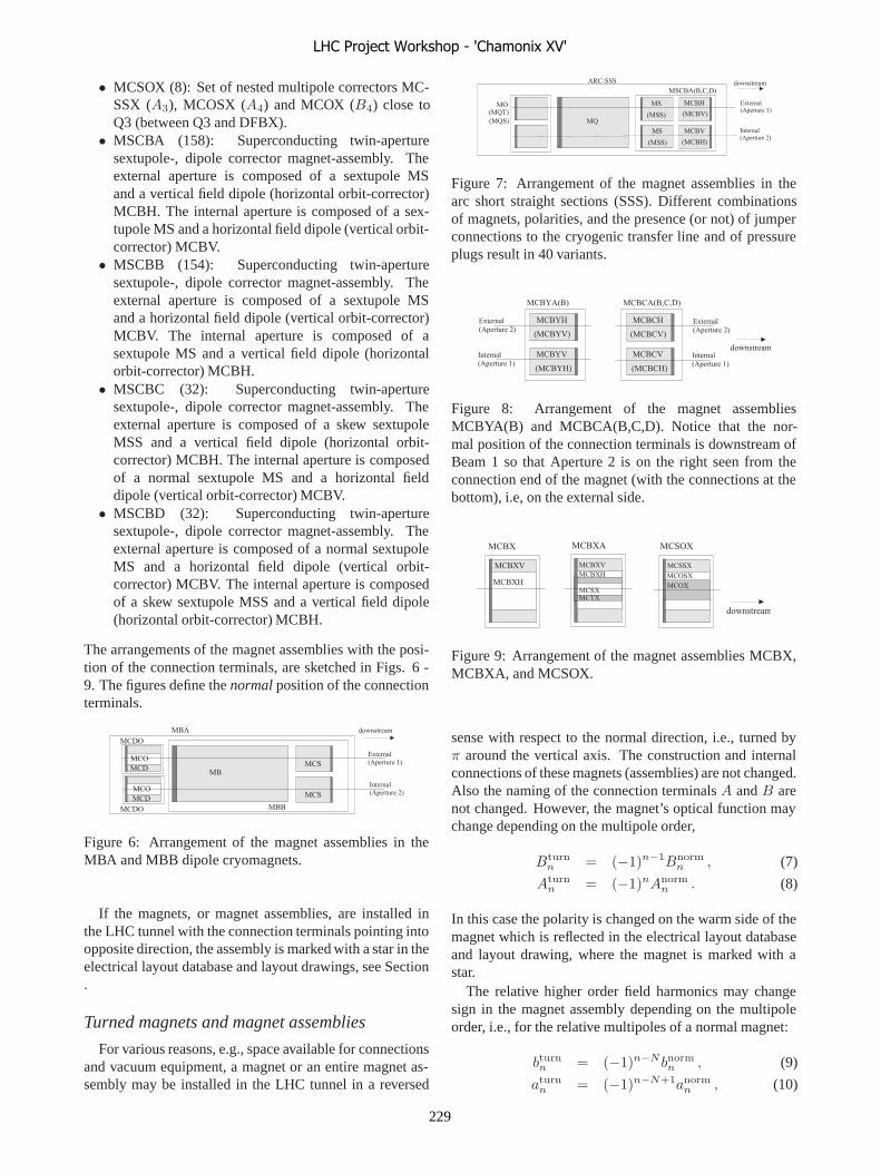
• MCSOX (8): Set of nested multipole correctors MC-SSX (A3), MCOSX (A4) and MCOX (B4) close toQ3 (between Q3 and DFBX).
• MSCBA (158): Superconducting twin-aperturesextupole-, dipole corrector magnet-assembly. Theexternal aperture is composed of a sextupole MSand a vertical field dipole (horizontal orbit-corrector)MCBH. The internal aperture is composed of a sex-tupole MS and a horizontal field dipole (vertical orbit-corrector) MCBV.
• MSCBB (154): Superconducting twin-aperturesextupole-, dipole corrector magnet-assembly. Theexternal aperture is composed of a sextupole MSand a horizontal field dipole (vertical orbit-corrector)MCBV. The internal aperture is composed of asextupole MS and a vertical field dipole (horizontalorbit-corrector) MCBH.
• MSCBC (32): Superconducting twin-aperturesextupole-, dipole corrector magnet-assembly. Theexternal aperture is composed of a skew sextupoleMSS and a vertical field dipole (horizontal orbit-corrector) MCBH. The internal aperture is composedof a normal sextupole MS and a horizontal fielddipole (vertical orbit-corrector) MCBV.
• MSCBD (32): Superconducting twin-aperturesextupole-, dipole corrector magnet-assembly. Theexternal aperture is composed of a normal sextupoleMS and a horizontal field dipole (vertical orbit-corrector) MCBV. The internal aperture is composedof a skew sextupole MSS and a vertical field dipole(horizontal orbit-corrector) MCBH.
The arrangements of the magnet assemblies with the posi-tion of the connection terminals, are sketched in Figs. 6 -9. The figures define the normal position of the connectionterminals.
� � � � � � �
� � � � � � � � � �
� � � � � � �
� � � � � � � � � �
� � �
� �
� � �
� � �
� � �
� � �
� � �
� � � �
� � �
� � �
� � � �
� � � � � � � � � �
Figure 6: Arrangement of the magnet assemblies in theMBA and MBB dipole cryomagnets.
If the magnets, or magnet assemblies, are installed inthe LHC tunnel with the connection terminals pointing intoopposite direction, the assembly is marked with a star in theelectrical layout database and layout drawings, see Section.
Turned magnets and magnet assemblies
For various reasons, e.g., space available for connectionsand vacuum equipment, a magnet or an entire magnet as-sembly may be installed in the LHC tunnel in a reversed
� � � � � � �
� � � � � � � � � �
� � � � � � �
� � � � � � � � � �
� � � � � � �
�
� � � � � !
� � � � � "
� �
� # �
� � �
� � � �
� � � � � � � ! �
� � � " �
� � � � � � $ � $ � �
� � � � � � � � � �
Figure 7: Arrangement of the magnet assemblies in thearc short straight sections (SSS). Different combinationsof magnets, polarities, and the presence (or not) of jumperconnections to the cryogenic transfer line and of pressureplugs result in 40 variants.
� � � � � � �
� � � � � � � � � �
� � � � � � �
� � � � � � � � � �
� � � % "
� � � % !
� � � % " �
� � � % ! �
� � � % � � �
� � � � "
� � � � !
� � � � " �
� � � � ! �
� � � � � � $ � $ � �
� � � � � � � � � �
� � � � � � �
� � � � � � � � � �
� � � � � � �
� � � � � � � � � �
Figure 8: Arrangement of the magnet assembliesMCBYA(B) and MCBCA(B,C,D). Notice that the nor-mal position of the connection terminals is downstream ofBeam 1 so that Aperture 2 is on the right seen from theconnection end of the magnet (with the connections at thebottom), i.e, on the external side.
� � � &
� � � & !
� � � & "
� � � & �
� � � & !
� � � & "
� � # &
� � � &
� � � � &
� � � � &
� � � � &
� � � &
� � � � � � � � � �
Figure 9: Arrangement of the magnet assemblies MCBX,MCBXA, and MCSOX.
sense with respect to the normal direction, i.e., turned byπ around the vertical axis. The construction and internalconnections of these magnets (assemblies) are not changed.Also the naming of the connection terminals A and B arenot changed. However, the magnet’s optical function maychange depending on the multipole order,
Bturnn = (−1)n−1Bnorm
n , (7)
Aturnn = (−1)nAnorm
n . (8)
In this case the polarity is changed on the warm side of themagnet which is reflected in the electrical layout databaseand layout drawing, where the magnet is marked with astar.
The relative higher order field harmonics may changesign in the magnet assembly depending on the multipoleorder, i.e., for the relative multipoles of a normal magnet:
bturnn = (−1)n−Nbnorm
n , (9)
aturnn = (−1)n−N+1anorm
n , (10)
LHC Project Workshop - 'Chamonix XV'
229
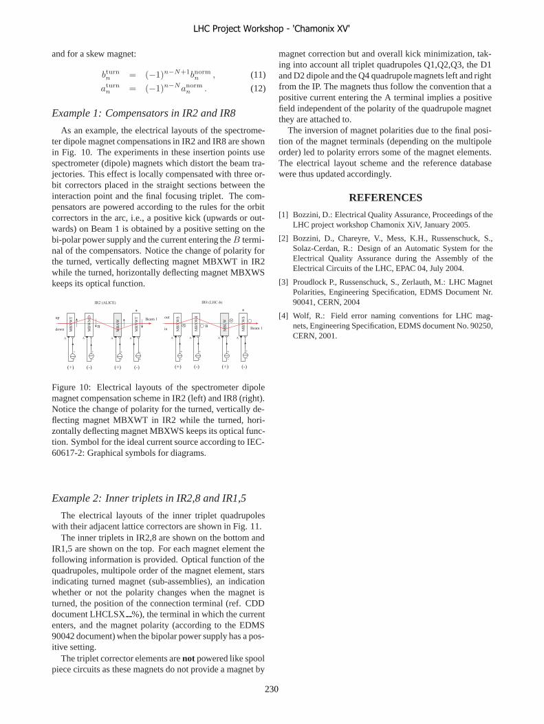
and for a skew magnet:
bturnn = (−1)n−N+1bnorm
n , (11)
aturnn = (−1)n−Nanorm
n . (12)
Example 1: Compensators in IR2 and IR8
As an example, the electrical layouts of the spectrome-ter dipole magnet compensations in IR2 and IR8 are shownin Fig. 10. The experiments in these insertion points usespectrometer (dipole) magnets which distort the beam tra-jectories. This effect is locally compensated with three or-bit correctors placed in the straight sections between theinteraction point and the final focusing triplet. The com-pensators are powered according to the rules for the orbitcorrectors in the arc, i.e., a positive kick (upwards or out-wards) on Beam 1 is obtained by a positive setting on thebi-polar power supply and the current entering the B termi-nal of the compensators. Notice the change of polarity forthe turned, vertically deflecting magnet MBXWT in IR2while the turned, horizontally deflecting magnet MBXWSkeeps its optical function.
�
'
�
��&(#
�
'
�
��(��
�
'
�
���(
�
��&(# � � � � � �
� � � � � ) � � � �
*
�
� � � ��
�
'
�
��&(�
�
'
�
��&(!
�
'
�
��)(
�
��&(�
� � � � � �
� � + � ) ! � � , �
*
� �
- ��
'
�
' � � � ' � � � ' � � � ' � � �
Figure 10: Electrical layouts of the spectrometer dipolemagnet compensation scheme in IR2 (left) and IR8 (right).Notice the change of polarity for the turned, vertically de-flecting magnet MBXWT in IR2 while the turned, hori-zontally deflecting magnet MBXWS keeps its optical func-tion. Symbol for the ideal current source according to IEC-60617-2: Graphical symbols for diagrams.
Example 2: Inner triplets in IR2,8 and IR1,5
The electrical layouts of the inner triplet quadrupoleswith their adjacent lattice correctors are shown in Fig. 11.
The inner triplets in IR2,8 are shown on the bottom andIR1,5 are shown on the top. For each magnet element thefollowing information is provided. Optical function of thequadrupoles, multipole order of the magnet element, starsindicating turned magnet (sub-assemblies), an indicationwhether or not the polarity changes when the magnet isturned, the position of the connection terminal (ref. CDDdocument LHCLSX %), the terminal in which the currententers, and the magnet polarity (according to the EDMS90042 document) when the bipolar power supply has a pos-itive setting.
The triplet corrector elements are not powered like spoolpiece circuits as these magnets do not provide a magnet by
magnet correction but and overall kick minimization, tak-ing into account all triplet quadrupoles Q1,Q2,Q3, the D1and D2 dipole and the Q4 quadrupole magnets left and rightfrom the IP. The magnets thus follow the convention that apositive current entering the A terminal implies a positivefield independent of the polarity of the quadrupole magnetthey are attached to.
The inversion of magnet polarities due to the final posi-tion of the magnet terminals (depending on the multipoleorder) led to polarity errors some of the magnet elements.The electrical layout scheme and the reference databasewere thus updated accordingly.
REFERENCES
[1] Bozzini, D.: Electrical Quality Assurance, Proceedings of theLHC project workshop Chamonix XiV, January 2005.
[2] Bozzini, D., Chareyre, V., Mess, K.H., Russenschuck, S.,Solaz-Cerdan, R.: Design of an Automatic System for theElectrical Quality Assurance during the Assembly of theElectrical Circuits of the LHC, EPAC 04, July 2004.
[3] Proudlock P., Russenschuck, S., Zerlauth, M.: LHC MagnetPolarities, Engineering Specification, EDMS Document Nr.90041, CERN, 2004
[4] Wolf, R.: Field error naming conventions for LHC mag-nets, Engineering Specification, EDMS document No. 90250,CERN, 2001.
LHC Project Workshop - 'Chamonix XV'
230

APPENDIX
Magnet E Description N T Inom lm L R A C D
Units K A m H Ω
MB 1 B1 Main dipole coldmass 1232 1.9 11850 14.3 0.102 2 1 u
MBRB 2 B1 Twin apert. sep. dipole (194 mm) D4 2 4.5 5520 9.45 0.052 2 1 uMBRC 2 B1 Twin apert. sep. dipole (188 mm) D2 8 4.5 6000 9.45 0.052 2 1 uMBRS 2 B1 Single apert. sep. dipole D3 4 4.5 5520 9.45 0.026 1 1 u
MBW 2 B1 Twin apert. dipole D3,D4 in IR3,7 20 NC 720 3.4 0.18 0.055 2 1 u
MBWMD 8 A1 Dipole compensator for ALICE, IR2 1 NC 550 2.62 0.639 0.172 1 1 u
MBX 2 B1 Single apert. sep. dipole D1 4 1.9 5800 9.45 0.026 1 1 uMBXW 2 B1 D1 dipole in IR1,5 24 NC 750 3.4 0.145 0.06 1 1 u
MBXWH 8 B1 Dipole compensator for LHC-b, IR8 1 NC 750 3.4 0.145 0.04 1 1 uMBXWS 8 B1 Dipole compensator for LHC-b, IR8 2 NC 780 0.78 0.04 0.05 1 1 uMBXWT 8 A1 Dipole compensator for ALICE, IR2 2 NC 600 1.53 0.08 1 1 u
MCBCH 7 B1 Orbit corr. in MCBCA(B,C,D) 84 1.9/4.5 100+ 0.904 2.84 1 1 dMCBCV 7 A1 Orbit corr. in MCBCA(B,C,D) 84 1.9/4.5 100+ 0.904 2.84 1 1 d
MCBH 7 B1 Arc orbit corr. in MSCBA(B,C,D), hor. 376 1.9 55 0.647 6.02 1 1 dMCBV 7 A1 Arc orbit corr. in MSCBA(B,C,D), vert. 376 1.9 55 0.647 6.02 1 1 d
MCBWH 7 B1 Single apert. orbit corr., hor. 8 NC 550 1.7 0.05 0.043 1 1 uMCBWV 7 A1 Single apert. orbit corr., vert. 8 NC 550 1.7 0.05 0.043 1 1 u
MCBXH 7 B1 Horizontal orbit corr. in MCBX(A) 24 1.9 550 0.45 0.287 1 1 uMCBXV 7 A1 Vertical orbit corr. in MCBX(A) 24 1.9 550 0.48 0.175 1 1 u
MCBYH 7 B1 Orbit corr. in MCBYA(B) 38 4.5 72 0.899 5.27 1 1 dMCBYV 7 A1 Orbit corr. in MCBYA(B) 38 4.5 72 0.899 5.27 1 1 d
MCD 6 B5 Decapole corr. in MCDO 1232 1.9 550 0.066 0.0004 1.34 1 1 u
MCO 6 B4 Octupole corr. in MCDO 1232 1.9 100 0.066 0.0004 3.11 1 1 u
MCOSX 6 A4 Skew octupole in MCSOX 8 1.9 100 0.138 0.0032 12.1 1 1 uMCOX 6 B4 Octupole associated to MCSOX 8 1.9 100 0.137 0.0044 13.0 1 1 u
MCS 6 B3 Sextupole corr. 2464 1.9 550 0.11 0.0008 0.1 1 1 dMCSSX 6 A3 Skew sextupole in MCSOX 8 1.9 100 0.132 0.0078 13.7 1 1 uMCSX 6 B3 Sextupole in MCBXA 8 1.9 100 0.576 0.0047 1 1 u
MCTX 6 B6 Dodecapole in MCBXA 8 1.9 80 0.615 0.0292 1 1 u
MO 5 B4 Octupole lattice corr. in arc SSS 168 1.9 550 0.32 0.00015 4.5 2 2 u
MQ 3 B2 Lattice quadrupole in the arc 392 1.9 11870 3.1 0.0056 0.87 2 2 u
MQM 4 B2 Insertion region quad. 3.4 m 38 1.9/4.5 5390∗ 3.4 0.0151 2 2 uMQMC 4 B2 Insertion region quad. 2.4m 12 1.9/4.5 5390∗ 2.4 0.0107 2 2 uMQML 4 B2 Insertion region quad. 4.8 m 36 1.9/4.5 5390∗ 4.8 0.0213 2 2 u
MQS 5 A2 Skew quad. lattice corr. in arc SSS 32 1.9 550 0.32 0.031 0.33! 2 2 uMQSX 6 A2 Skew quadrupole Q3 8 1.9 550 0.223 0.014 8.02 1 1 uMQT 5 B2 Tuning quad. in arc SSS 160 1.9 550 0.32 0.031 0.33! 2 2 u
MQTLH 5 B2 MQTL (Half Shell Type) 24 4.5 400 1.3 0.120 1.49 2 2 dMQTLI 5 B2 MQTL (Inertia Tube Type) 36 1.9 550 1.3 0.120 2 2 d
MQWA 4 B2 Twin apert. quad. in IR3,7. FD or DF 40 NC 710 3.108 0.028 0.037 2 1 uMQWB 4 B2 Twin apert. quad. in IR3,7. FF or DD 8 NC 600 3.108 0.028 0.037 2 1 u
MQXA 4 B2 Single apert. triplet quad. Q1, Q3 16 1.9 6450 6.37 0.090 1 1 uMQXB 4 B2 Single apert. triplet quad. Q2 16 1.9 11950 5.5 0.019 1 1 u
MQY 4 B2 Insertion wide apert. quad. 3.4 m 24 4.5 3610 3.4 0.074 2 2 u
MS 5 B3 Arc sext. corr. next to MCBH, MCBV 688 1.9 550 0.369 0.036 0.21! 1 1 u
MSDA 9 A1 Ejection dump septum, module A 10 NC 880 4.088 0.036 0.027 1 1 uMSDB 9 A1 Ejection dump septum, module B 10 NC 880 4.088 0.056 0.034 1 1 uMSDC 9 A1 Ejection dump septum, module C 10 NC 880 4.088 0.079 0.041 1 1 uMSIA 9 B1 Injection septum, module A 4 NC 950 3.73 0.010 0.011 1 1 uMSIB 9 B1 Injection septum, module B 6 NC 950 3.73 0.024 0.0164 1 1 u
MSS 5 A3 Arc skew sextupole corr. in MCBH 64 1.9 550 0.369 0.036 1 1 u
Table 1: LHC magnet equipment names. Kickers and experimental magnets are excluded. E = Type (see text). N =Number of magnets, T = operation temperature, I = nominal current, l m = magnetic length, L = self inductance R =ohmic resistance at room temperature (if apertures are individually powered then R and L are given for one aperture), A= number of apertures, C = number of pairs of connection terminals, D = Normal position of the connection terminals, u:upstream, d: downstream of Beam 1. NC = Normal conducting. (*) 4310 A at 4.5 K. (+) 80 A at 4.5 K. (!) Protectionresistor in parallel. Reference: LHC functional layout database.
LHC Project Workshop - 'Chamonix XV'
231
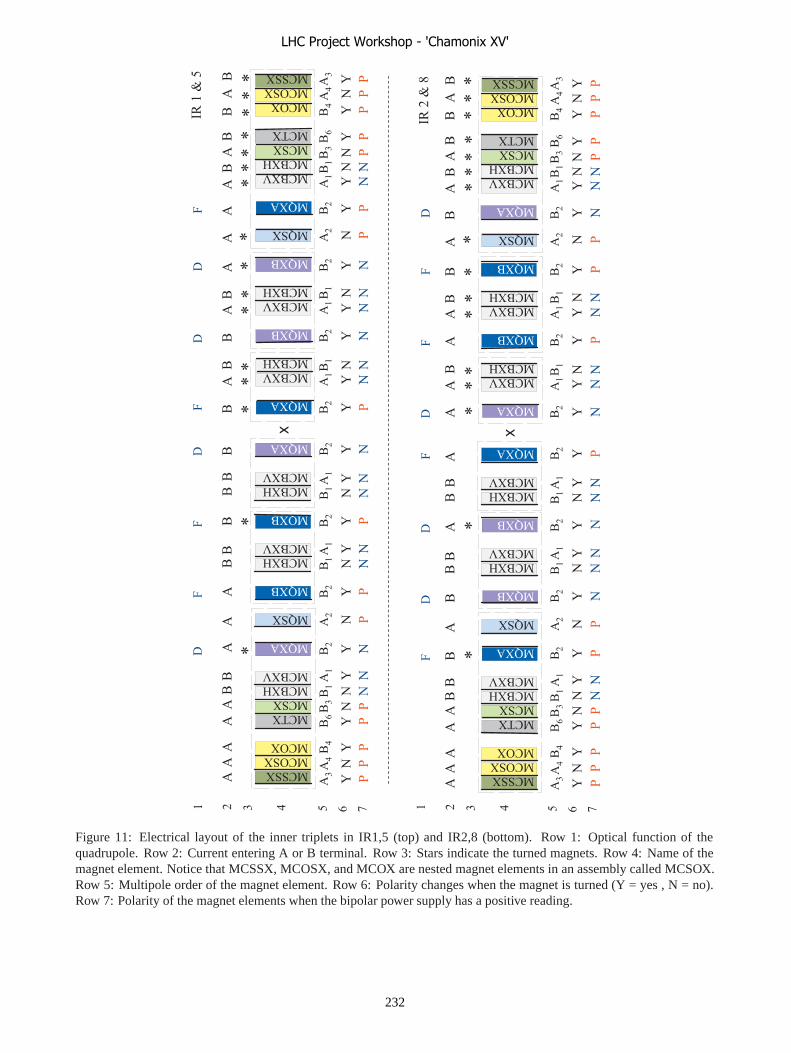
����&
����&
���&
��#&
���&
���&!
���&"
� &�
� �&
� &�
���&!
���&"
� &�
���&!
���&"
� &�
� &�
���&"
���&!
� &�
���&"
���&!
� &�
� �&
� &�
���&"
���&!
���&
��#&
���&
����&
����&
�
.�
�.
.�
�.
�/�
0�0
�1�/����
����
��
��
��
��
��
����
�0
�1
�/
��
��
��
��
��
��
��
��
��
��
��
�0�/
����&
����&
���&
��#&
���&
���&!
���&"
� &�
� �&
� &�
���&!
���&"
� &�
���&!
���&"
� &�
� &�
���&"
���&!
� &�
���&"
���&!
� &�
� �&
� &�
���&"
���&!
���&
��#&
���&
����&
����&
�
.�
�.
.�
�.
�����2
�3
**
****
**
**
****
**
****
**
**
****
44
45
45
44
44
45
44
44
55
45
55
55
45
55
55
54
**
**
��
��
��
��
��
��
��
��
��
��
��
��
��
��
��
��
��
��
��
��
��
��
��
��
��
��
��
��
��
��
��
��
%5
%%
5%
%5
%5
%%
%5
%5
%5
%%
5%
%5
%5
%%
%5
%5
�/�
0�0
�1�/����
����
��
��
��
��
��
����
�0
�1
�/
��
��
��
��
��
��
��
��
��
��
��
�0�/
44
45
45
44
44
45
44
44
55
45
55
55
45
55
55
54
%5
%%
5%
%5
%5
%%
%5
%5
%5
%%
5%
%5
%5
%%
%5
%5
� � / 0 3 1 6 � � / 0 3 1 6
�����2
�+�
Figure 11: Electrical layout of the inner triplets in IR1,5 (top) and IR2,8 (bottom). Row 1: Optical function of thequadrupole. Row 2: Current entering A or B terminal. Row 3: Stars indicate the turned magnets. Row 4: Name of themagnet element. Notice that MCSSX, MCOSX, and MCOX are nested magnet elements in an assembly called MCSOX.Row 5: Multipole order of the magnet element. Row 6: Polarity changes when the magnet is turned (Y = yes , N = no).Row 7: Polarity of the magnet elements when the bipolar power supply has a positive reading.
LHC Project Workshop - 'Chamonix XV'
232

��������������� �����
���������� ������������� ���������� ������������������� ������� ��!���"����#� ���$���
������ ����� �������
������������������ %�� �&���� �'(()� ����*��$� �����$��� � �� � ���
#��$�� ���� ��������*����$�"�����������++���������,�������� -� �� �./�������� #�� +��� ��� ������ ��� ���
&��������� �� ����./����������������"���'((0��#������$����"� ������� ������ �+�� ��$��1��� �� ����
�� ������� ��� ����/�� � �� �� ��� 23� +���� �4#��1� �� �����+�� ����� ��� ���� ����+���� �� � ����� ���� ���"���� ������ �+�,�
������� ��� ��������� � � /����� � ��� ����� �� � ������"������� �� �������$�/��� �����"������� �������+��*��1�������� ��� ���� ��� �� �� ���� #�$$� *�� �$�������� ���������� ��� ����� ���� � � /����� � 5(� /��/$�� #��1���� ��� ����/�� � �� �"� ���� 6���$������ +��� �������� ���"�������� �7�
���������� ��� �+/�������� ��� �� � ��� �� ���� ���������#�$$� *�� ��+/$������ *������� ��� $����� �+��� � ��� ����� �"� ����#�������"���'((0�#�$$����������
������� %� �+� �� � ����� �� � ����� �"� ���� #�$$� ��� ��� ����������
����������%������� ������./�� �������� �"� �����$�1��������� ����� +��������$� ��� �$$� ����� *����� ���$����� � � �����+�� �+�� ���� #�$$� ��� ���$�� ������� 8�"�� ������ ���� ��� �����������������������+/ ����,�
������� ���� ��� �+�� *����� #�� ���� *$��1��� *�� $��1��� �� �����������������%�� ���������#�$$���� �������� �� ����� �� ����#�$$���� ���$���+/��"��
�������-�� ���� �������� ��� ���������$��1�����1�����%�+���� ���+���+�+�� ����� �� ���������$��1�����1,�
������������ ��� ��� ���+�� � ���� ���� ���9�:�/�/��;� ��� ����$� ����"����+� ��� ���+�� ����"����<((+�=�� ��������+���� �� ������ "����+� *�������� ���� ��� �$$��� �"����'���$$��6>�'((�+� ���7�
�� �������������+��$������#��������+�� � ������������$�������//$���� ����������
��������������������������������������������
���� ���� ������ ?�� ��� /������� #��� ���� ��+����� #��1����
#� ��� �/�� �� �������������������"���� ���� �� ��� �/� ���#��1��++���� �$�,�
����������=�����������"����������� ����� ���� ������ ���
�*$��� ���� ������ �
�����������������������
������������������ @��� ��"�� +�� ������ �� � ��"�$"�+�� � ����
��//�� � ���+� ��� &A� ?�/�� +�� � ���� �� *�� ��� ������-�� ������������,��
������ -�� � �$$� ����� ��� �7� ������� ������� ��� �������� ���� "� �� ���� ��� �� ���� ���� ��� ��� ��#� ����#�����$��/���� ���*��+��� ��$��1���� ��$$�������� ���*��+���+/���� �+�� ��7� ��+/$� �� ��� ��� ����� ���� ���� ���7� ������������/��� ����$���/�� ������/����������
��������� ����������� �/��� ���� ���� /����������� #����"�� �$������ ��/� � � � ��"���$� ����������� ��� ���� �����+���,�
������ -�� ��"�� �� 1��/� ��� ����������� ��+�� �/����������
���������8�"������ �$1��� ���B���������+�� ,� �������@����#�������$������������ �� �
�������������������������
����� ���� ��� ������������ 6���������� �� ��� ����� ��� ��� ������ ��� ���
��������$��������������+���������.� �7�-�$$�����/� ����������� ���������$�1��C��$���/��������������������D,�
�������� ������� -�� ��"�� �� /� � �� �$���� +�������� ��������� �$$�*������������
������� 8�#� $���� ��� ���� ���1��� ���� ����� �������/�����'����� ������ �$$� ������� ��������� �$��/,�
�������� ������� &� ��#� +�� ��� % � +�� � *����+/� �*$��#� �� ������ ��#������ ����
!�� �����������-�����E �1��#��� ��/���$$�$��� �"� ��������#��1�#�$$�*����F������
�������������������������� �+�#��������������2GG0�*� ����� ������ �+������ �*��$ �#� ������"�������������������+/���� ���� +�������� ���� �� *�� /� � ��� /$���� ����� ������ ���� �� ���� �� � ���� ���� �� � �� � *���� �����"��������� ���%�� ��� ���� ����#�� � ����"��������$���� ��$���� ����+/$�+�� � ������� �����+���������
�� ����� �����������������������������������
������� �����"��#������ @��� ��"�� +�� ������ �� � �$������� ���
�������� ��� ���������� ���� �� � ��������� � �+�� ����$�� *��
LHC Project Workshop - 'Chamonix XV'
233

�$$��� ��� -�� � �*�� � �$������� #� �� ��� +���� �������� ������#�+���� �+��#�$$�������F����,�
$�%����������+���+�+� �+����F��������� �����#��1�����*��:�����#�� �� ��������� ����/��� ,�
���������$�����������*����������/���$$�$� �� ���"����+�$��1�+������+�� ��
���������������
����������������������1�H�%����������=���������#������#��1�����������+/�������
�+�� ������$��� *� � #�� ���� "���� �� ������� #� �� ������$$�*��� ���� %���"������++�� ��*�� � ��������//��"������#����� �� �����+�� ������� ����� $��������� �� � ��� ������I� ����/� #��� ������������ �� � ���� ��1��� ��� ��#�/������ ���� �� �������� � "��#� ��� +���� ��/�� �� ���� ��� �������F������#��$�� � �+��
��&���������� &$$� ����� �� ����$�� *�� /� � ��#� �� �� �/�� � �/��� �� ��������������/����*$��
%�$�������-�� ��"�� �� ������� ��� ���� ��� �� ����+�/�#���������/����� ���������$���$��������������#�$$���/������� ��������������� �� �#�$$� �1��/$������. �#��1�#� �� ���"����+�����/�
����������� ��� +�� ���� ��. � #��1� #�$$� ��/���$$���$������ ����� �� ����
%�$������� %� #��$�� $�1�� �� ���1� ����� ��$$�*��� ������� �����#� �� �����+���/��� H��
�� ��������� ������� ��� ������������
������������������������� ���+� �$$� ��� �� �� �� � ���� ��"�� ������ ����
#�� �� � �� ������������������,�����������
��%����������'�� %� �+� �� � ������ ���� � � �� ����� #���+/�� �� � ����������+� ���� �����"����� �� � ��� #���� ��"�� �����6���+��$$� ��� ����<0(7���� ��� ����$�
���������������������. ����"�� �� ��#� ��*��+,�=�����������"���������������������9&�/�����++�,�%�+���� �� �#�� ���$�� ��� ��+� ����� ��� �+� ���$$�� #����� ������� ���9&�#� ��� ����$������� �
�����������% ����+����������� ���//$��9&��������#���� ����#� ��*��+�
(�"�������-�������� �����1���� ���/�$��� �� �����$�������*� ������� ����-����"�� ���� � �������� ����+� ������ ��$����+��������2H�
)�&�*�����-�� ��*�� � ���/�$��� �������� ���#��+�/�� ���� ��������� �,�
��%����������'������+�� �*���� �� ������%�������� ?������ ��� ���� � ������ � �� � ��+/������ $�1��
��� ���� #�� ���� ������ ���� ����� ����� ��� J&35�� ���/�$��� ������1������������ ��$$�
+�&������� @��� +�� ���� ��� ������ ��� ��� ������������ �*���� 8�#� ���� ���� ����� �� � �"������� ��� ������ ���$� �� �"���������� ������ �*���,�
��%����������'��-��������/��������� ������ �� ����� ����� �*���� &��� ����� ��� �� �� 6��� #�$$� ��� ��� �$�� ����$������� � ���#����7� ��"�� �� *�� ����1��� ���� ���� �������1��� -�� ��� ��$$�#� �$$� ����������+� ���� =�� �������/�� �� #�� ��"�� �������� �� � ��� $�*�$�� #�� ���� ������� ������� ����$�� *�� ������ � ���� �"��#�� �� /������$�/��� ����
�����������������������C���*��$ D��� �*��������*�����$����������������-���������#��#� �� ���,�K ��/�� ���$������#������+� �������+L�
��%����������'�� %� ������ �� � � � ��� �����+�� �$� �� ��"�����C���*��$ D��� �*��������#�$$����C���*��$ D����#�����
%�������� ����� ���� ���� ����$� ����1�� �� � ���� ���� ���#���� ���/�#�����*$�����������$$�������� ��� �� ���$��������� ������� ����#���� ��++���������� -�� ���� ������ ����������#� ������#�� �����*��������������
��
��
LHC Project Workshop - 'Chamonix XV'
234
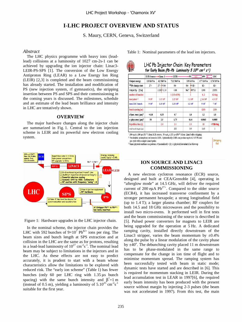
I-LHC PROJECT OVERVIEW AND STATUS
S. Maury, CERN, Geneva, Switzerland
Abstract
The LHC physics programme with heavy ions (lead-lead) collisions at a luminosity of 1027 cm-2s-1 can be achieved by upgrading the ion injector chain: Linac3-LEIR-PS-SPS [1]. The conversion of the Low Energy Antiproton Ring (LEAR) to a Low Energy Ion Ring (LEIR) [2,3] is completed and the beam commissioning has already started. The installation and modification of PS (new injection system, rf gymnastics), the stripping insertion between PS and SPS and their commissioning in the coming years is discussed. The milestones, schedule and an estimate of the lead beam brilliance and intensity in LHC are tentatively shown.
OVERVIEW The major hardware changes along the injector chain
are summarized in Fig. 1. Central to the ion injection scheme is LEIR and its powerful new electron cooling system.
Figure 1: Hardware upgrades in the LHC injector chain.
In the nominal scheme, the injector chain provides the LHC with 592 bunches of 9×10⁷ Pb82+ ions per ring. The beam sizes and bunch length at SPS extraction and at collision in the LHC are the same as for protons, resulting in a lead-lead luminosity of 1027 cm-2s-1. The nominal lead beam may be subject to limitations in the injectors and in the LHC. As these effects are not easy to predict accurately, it is prudent to start with a beam whose characteristics allow the limitations to be explored with reduced risk. The “early ion scheme” (Table 1) has fewer bunches (only 60 per LHC ring with 1.35 μs bunch spacing) with the same bunch intensity and β*=1 m (instead of 0.5 m), yielding a luminosity of 5.1025 cm-2s-1 suitable for the first year.
Table 1: Nominal parameters of the lead ion injectors.
ION SOURCE AND LINAC3 COMMISSIONING
A new electron cyclotron resonance (ECR) source, designed and built at CEA/Grenoble [4], operating in “afterglow mode” at 14.5 GHz, will deliver the required current of 200 eμA Pb27+. Compared to the older source (ECR4), it has increased transverse confinement by a stronger permanent hexapole; a strong longitudinal field (up to 1.4 T); a larger plasma chamber; RF couplers for both 14.5 and 18 GHz microwaves and the possibility to install two micro-ovens. It performed well in first tests and the beam commissioning of the source is described in [5]. Pulsed power converters for magnets to LEIR are being upgraded for the operation at 5 Hz. A dedicated ramping cavity, installed directly downstream of the Linac3 stripper, varies the beam momentum by ±0.4% along the pulse by a linear modulation of the cavity phase by ±40o. The debunching cavity placed 11 m downstream has to be phase-modulated in the same range to compensate for the change in ion time of flight and to minimise momentum spread. The ramping system has been successfully tested with beam in static mode; dynamic tests have started and are described in [6]. This is required for momentum stacking in LEIR. During the lead accumulation test in LEAR in 1997[6], the required early beam intensity has been produced with the present source without margin by injecting 2-3 pulses (the beam was not accelerated in 1997). From this test, the main
LHC Project Workshop - 'Chamonix XV'
235

improvements needed to reach the nominal beam requirement were:
- to double the linac intensity, - to build a faster electron cooling system, - to improve the beam lifetime and the injection
efficiency.
LEIR COMMISSIONING
LEIR machine
The role of LEIR is to transform a series of long (~200 μs), low-intensity ion pulses from Linac3 into short (~200 ns), high-brightness bunches using multi-turn injection, electron cooling and accumulation. Each Pb54+ linac pulse is injected with a 70% efficiency by stacking 70 turns into horizontal, vertical (by an inclined electrostatic septum) and longitudinal (by energy ramping) phase space. On a 4.2 MeV/n plateau in LEIR, the electron cooler strongly reduces the phase space volume of the beam in less than 400 ms and decelerates it into a stack sitting slightly inside the central orbit. For the early beam only one Pb54+ linac pulse is injected (instead of 4 for the nominal), cooled, adiabatically captured on h=1 and accelerated to 72 MeV/n. The sequence of events is sketched in Fig. 2; for the early beam the length of the LEIR cycle is reduced by 1.2 s. The beam commissioning started in October 2005 is described in [7].
Figure 2: LEIR cycle, nominal and early beam
Transfer lines The 4.2 MeV/n beam from Linac3 and the 72 MeV/n
one extracted towards the PS share ~60 m of a common transfer line in which they travel in opposite directions within 1.2 s of each other. This necessitates laminated magnets. Beam diagnostics, vacuum equipment and other infrastructure have been recovered from the former LEAR injection line, but most of the power converters are new. Whereas the bending magnets have to change polarity, this was avoided for the quadrupoles by special optics in both directions, leading to significant savings in power
converter costs. An emittance measurement device comprising three secondary emission grids is added. The beam commissioning of the injection line is described in [7].
Electron Cooling
This key element produces the required beam brightness, which is a factor of 30 higher than for fixed-target ion operation. Tests in 1997 with lead ions in LEAR [6] demonstrated a cool-down time of 400 ms at 4.2 MeV/n using a 3 m electron cooler and an electron current of 60 mA. The new system, manufactured at INP Novosibirsk and, assembled at CERN, has a length of 2.5 m but a current of up to 500 mA. The aim is a cool-down time of 200 ms. A control electrode will allow hollow electron beams to be generated in order to minimize the recombination of ions of the stack with electrons. The first beam commissioning is described in [8].
Vacuum
Pb54+ ions at 4.2 MeV/n tend to capture electrons from the residual gas molecules. For a beam lifetime of ~15 s, an average dynamic pressure in the low 10-12 mbar range is required. The LEIR vacuum system [1] is a bake-out at 300°C; NEG-coating wherever possible; low-outgassing collimators to control ion losses; and "beam scrubbing" (lost ions enhance desorption and clean the vacuum envelope) if necessary.
RF and feedback systems
Two new large-bandwidth cavities based on Finemet® high-permeability magnetic alloy have been built in collaboration with KEK. They cover a very wide frequency range (0.35–5 MHz) without any tuning. Acceleration at LEIR's moderate ramp rate requires an RF voltage of less than 4 kV, keeping the amplifier power down to a reasonable 60 kW. The cavities are being commissioned.
LEIR is the first CERN accelerator to be equipped with all-digital signal processors for the low-level RF. The first tests with beam have started.
Other systems
Most of the 164 power converters for LEIR and its transport lines have been recuperated and rebuilt from past machines, notably LEP. Most are based on thyristor or switch-mode technologies but there are also pulsed power converters as well as HV supplies for RF and electron cooling. The power converters have been installed and are being successfully commissioned with beam.
Beam diagnostic devices are largely recovered from LEAR but have been adapted to ions as well as to new standards for electronics and control. Of particular importance are the DC current transformer (2 μA to 50 mA), the Schottky pick-ups (to measure the emittance and energy spread of the coasting beam), and beam
LHC Project Workshop - 'Chamonix XV'
236
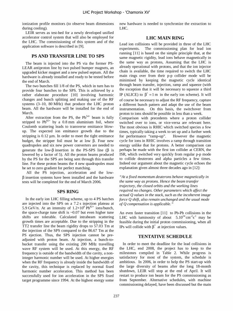
ionization profile monitors (to observe beam dimensions during cooling).
LEIR serves as test-bed for a newly developed unified accelerator control system that will also be employed for the LHC. The commissioning of this system and of the application software is described in [9].
PS AND TRANSFER LINE TO SPS
The beam is injected into the PS via the former PS-LEAR antiproton line by two pulsed bumper magnets, an upgraded kicker magnet and a new pulsed septum. All the hardware is already installed and ready to be tested before the end of March.
The two bunches fill 1/8 of the PS, which in turn has to provide four bunches to the SPS. This is achieved by a rather elaborate procedure [10] involving harmonic changes and bunch splitting and making use of the RF systems (3–10, 80 MHz) that produce the LHC proton beam. All the hardware will be installed for the end of March.
After extraction from the PS, the Pb54+ beam is fully stripped to Pb82+ by a 0.8 mm aluminium foil, where Coulomb scattering leads to transverse emittance blow-up. The expected ion emittance growth due to the stripping is 0.12 μm. In order to meet the tight emittance budget, the stripper foil must be at low β. Four new quadrupoles and six new power converters are needed to generate the low-β insertion in the PS-SPS line (β is lowered by a factor of 5). All the proton beams produced by the PS for the SPS are being sent through this transfer line. For these proton beams the 4 new quadrupoles must be set to zero gradient for perfect matching.
All the PS injection, acceleration and the low-β insertion systems have been installed and the hardware tests will be completed for the end of March 2006.
SPS RING
In the early ion LHC filling scheme, up to 4 PS batches are injected into the SPS on a 7.2 s injection plateau at 5.9 GeV/n. At an intensity of 1.2×10⁸ Pb82+ ions/bunch, the space-charge tune shift is ~0.07 but even higher tune shifts are tolerable. Calculated intrabeam scattering growth times are acceptable. Due to the stripping in the TT2 transfer line the beam rigidity drops to 57.03 Tm at the injection of the SPS compared to the 86.67 Tm at the PS ejection. Thus, the SPS injection cannot be pre-adjusted with proton beam. At injection, a bunch-to-bucket transfer using the existing 200 MHz travelling wave RF system will be used. At this energy, the RF frequency is outside of the bandwidth of the cavity, a non-integer harmonic number will be used. At higher energies when the RF frequency is already inside the bandwidth of the cavity, this technique is replaced by normal fixed harmonic number acceleration. This method has been successfully used for ion acceleration in the SPS fixed target programme since 1994. At the highest energy some
new hardware is needed to synchronize the extraction to LHC.
LHC MAIN RING Lead ion collisions will be provided in three of the LHC experiments. The commissioning plan for lead ion running [11] is based on the simple principle that, at the same magnetic rigidity, lead ions behave magnetically in the same way as protons, Assuming that the LHC is already operational with protons, and that the ion injector chain is available, the time required to switch the LHC main rings over from their p-p collider mode will be minimised by keeping the magnetic cycle identical through beam transfer, injection, ramp and squeeze (with the exception that it will be necessary to squeeze a third IP (ALICE) to * 1 mβ = in the early ion scheme). It will of course be necessary to adjust the RF frequency, capture a different bunch pattern and adapt the use of the beam instrumentation. On this basis, the switchover from proton to ions should be possible in less than a week. Comparison with precedents where a proton collider switched over to ions, or vice-versa are relevant here. The most obvious is RHIC which switched species a few times, typically taking a week to set up and a further week for performance “ramp-up”. However the magnetic cycle for ions in RHIC involves a ramp through transition energy unlike that for protons. A better comparison can perhaps be made with the first ion collider at CERN, the ISR, which switched very quickly from regular p-p mode to collide deuterons and alpha particles a few times. Indeed our argument about the magnetic cycle echoes the explanation given almost three decades ago in [12]: “At a fixed momentum deuterons behave magnetically in the same way as protons. Hence the beam transfer trajectory, the closed orbits and the working lines required no changes. Other parameters which affect the actual Q values in the stack, such as the incoherent image force Q shift, also remain unchanged and the usual mode of Q compensation is applicable.” An even faster transition [11] to Pb-Pb collisions in the LHC with luminosity of about 5.1024 cm-2s-1 may be feasible during the initial proton commissioning, when all IPs will collide with β* at injection values.
TENTATIVE SCHEDULE
In order to meet the deadline for the lead collisions in the LHC, end 2008, the project has to keep to the milestones compiled in Table 2. While progress is satisfactory for most of the system, the schedule is ambitious. In 2006, in order to help the PS start-up with the large diversity of beams after the long 18-month shutdown, LEIR will stop at the end of April. It will restart to produce ion beam for the PS commissioning as from September. Alternative schedules, with machine commissioning delayed, have been discussed but the main
LHC Project Workshop - 'Chamonix XV'
237

reasons to maintain the commissioning schedule for Pb-ion injectors are as follows:
• All the hardware (except for SPS) will be operational by the end of March 2006, the LHC is not running in 2006 and early 2007.
• As this year is not a standard year (with most accelerators restarting after an 18-month shutdown), the expected beam time requirement for CNGS is less demanding in protons. Thus, it will be easier to accommodate commissioning periods for the PS and SPS.
Table 2: Tentative schedule
hardware test
Start with beam
Problems
Source, Linac3 Feb. 2005 Mar 2005 New source LEIR inj. line Mar 2005 Jun 2005 LEIR ring Apr. 2005 Oct.2005 Commissioning through
winter to April 2006 PS/TT2 Feb. 2006 Sept. 2006 Stop from April-August 2006 SPS summer 2007 SPS experts busy
commissioning LHC ring at the end of 2007
LHC End of 2008 Physics with the early beam in LHC
CONCLUSION
The baseline LHC ion programme foresees lead-lead collisions with reduced luminosity (early ion scheme) in 2 or 3 experiments in 2008. The task of the injectors is facilitated by the early beam scheme. The project is on schedule to finish the LEIR commissioning at the end of April 2006, to start the PS as from September, the SPS in 2007 and finally the LHC at the end of 2008 after the first
proton run. But we should remember that the early beam scenario is just the first step: studies on the nominal beam have to be pursued as from 2007, even before the commissioning of the injectors is finished, in order to go forward to the nominal LHC luminosity. After the early scheme run, the number of bunches can progressively be increased towards nominal and to complete the first phase of LHC ion programme as from 2009.
REFERENCES [1] The LHC Design report Vol. III, Chapters 32-38,
CERN-2004-003. [2] M. Chanel, "LEIR: The low energy ion ring", Proc.
EPAC 2002. [3] C. Carli, "Preparation for running-in of LEIR", Proc.
Chamonix 2004 Workshop on LHC Performance, CERN-AB-2004-014 ADM.
[4] C.E.Hill et al, "GTS-LHC: a new source for the LHC ion injector chain", AIP Conf. Proc. 749,p.127,2005.
[5] D. Kuchler, “Experience with the GTS-LHC Ion Source”, this workshop.
[6] J. Bosser et al, "Experimental investigations of electron cooling and stacking of lead ions in a low energy accumulator ring", Part. Acc. Vol. 63, pp. 171-210, June 1999.
[7] C. Carli, “LEIR Commissioning”, this workshop. [8] G. Tranquille, “LEIR Electron Cooler”, this
workshop. [9] S. Pasinelli, “Post-Mortem of Experience with LEIR
Controls”, this workshop M. Gourber-Pace, “Gain of Experience for the Running-in of LHC”, this workshop.
[10] The LHC Design report Vol. III, Chapters 37.4, CERN-2004-003.
[11] J.M. Jowett, in Proceedings of the LHC Project Workshop, Chamonix XIV, CERN-AB-2005-014.
LHC Project Workshop - 'Chamonix XV'
238

EXPERIENCE WITH THE GTS-LHC ION SOURCE
C. E. Hill, D. Küchler, C. Mastrostefano, M. O'Neil and R. Scrivens, CERN, Geneva, Switzerland D. Hitz, L. Guillemet, J. Chartier, J.-M. Mathonnet and G. Rey-Giraud,
CEA-DSM Département de Recherches Fondamentale sur la Matière Condensée, Service des Basses Températures, 17 rue des Martyrs, Grenoble, France.
Abstract For the heavy ion programme of the LHC a new ECRIS
type heavy ion source had to be designed and built for Linac3 to fullfill the intensity requirements. Experience acquired during the installation and commissioning of the source and during operation for the LEIR ring commissioning will be presented. The performance of the source and its reliability are evaluated. Further requirements for high reliability, low down time, easy maintenance and for future physics needs will be discussed.
SOURCE UPGRADING Experiments to prove the feasibility of stacking and
electron cooling of highly charged ions in the LEAR ring were successful. Phase space stacking in three planes in the ring together with electron cooling were performed. At a 2.5 Hz stacking rate at least 25% of the required number of ions per PS pulse could be accumulated in the ring [1]. Vacuum limits the accumulation. By doubling the injection rate to 5 Hz, doubling the source current and improving the LEIR dynamic vacuum, the desired number of ions per injection should be achieved [2].
An upgrade of the present CERN ECRIS was needed. A collaboration had been set up under the European Union Framework 5 research programme [3] to study scaling in ECRIS and to try to understand the parameters affecting source performance. It was felt that by increasing the frequency to 18 GHz, by accelerating Pb25+, by studying and eliminating possible bottlenecks in the Linac, and by tuning to peak performance on demand rather than stability (LHC filling will be programmed) the desired number of ions could be produced. This initial scenario was pursued, in spite of some doubts being expressed as to the adequacy of the radial confinement provided by the hexapole. From the observation that the longitudinal fields used in the 14.5 GHz ECR4 in optimised afterglow mode were weaker than those expected from CW operation, it was felt that a weaker radial confinement could be an advantage.
During 2003 information became available on a prototype ECRIS that had demonstrated 200 eμA of Bi24+ in afterglow mode at 14.5 GHz with moderate RF power [4]. This source, the Grenoble Test Source (GTS) [5, 6], uses a modified minimum-B configuration optimised to obtain a better compromise between plasma confinement and ion losses. The principles of this optimisation were one of the spin-offs of the Innovative ECRIS collaboration [3]. This source could be adapted into the existing infrastructure in the Ion Linac building with a
minimum of expenditure and modification. The final design of the source includes the possibility of an upgrade to 18 GHz or to 14+18 GHz with only very minor modifications. Two medium temperature ovens designed and constructed in collaboration with GSI are installed in the source (another spin-off of “Innovative ECRIS”). Overall, the cost of this upgrade will fall within the budget envelope defined for the earlier ideas. Additionally the source could be commissioned within the current timetable of the LHC project. Figure 1 shows the source in the present state.
Figure 1: Picture of the GTS-LHC source.
CONSTRUCTION AND INSTALLATION Restrictions placed on manpower due to the LHC
construction programme meant that CERN had no resources to build a GTS source in-house. Thus, the decision was taken at the end of 2003 to purchase a customised version from CEA-Grenoble. During the tendering process CEA announced its intention to close its ion source service but arrangements could be made to allow the source to be built by them.
Final delivery took place in January 2005 when installation could begin. The source was measured out to establish alignment references and presented to its rail system. From this point onwards the cabling and provision of services to the source could be pursued. Thermal problems arose with the coils which limited the current to 1000A instead of 1250A. By increasing the water pressure to 19 bar, it proved possible to make the initial controls of the magnetic field alignment and polarities. An auxiliary heat exchanger was eventually required to reach nominal current, reliably, for operation.
LHC Project Workshop - 'Chamonix XV'
239
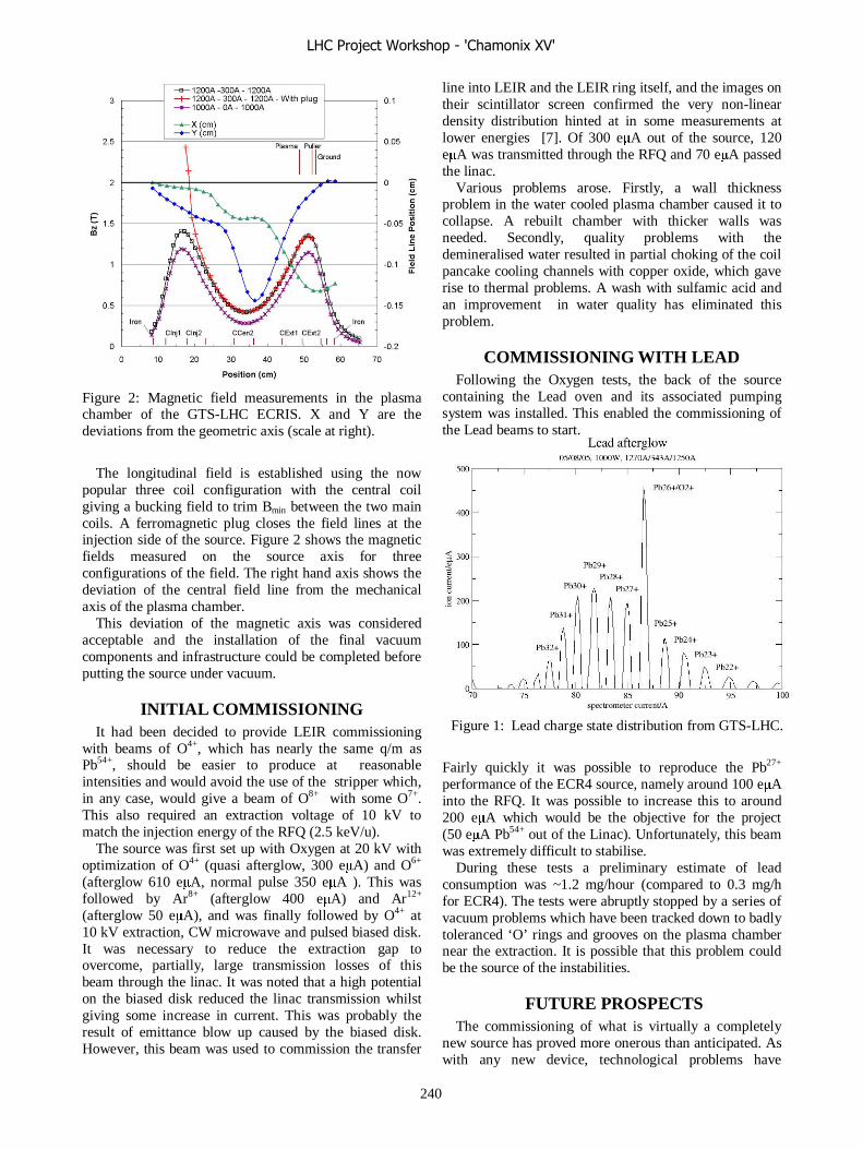
Figure 2: Magnetic field measurements in the plasma chamber of the GTS-LHC ECRIS. X and Y are the deviations from the geometric axis (scale at right).
The longitudinal field is established using the now
popular three coil configuration with the central coil giving a bucking field to trim Bmin between the two main coils. A ferromagnetic plug closes the field lines at the injection side of the source. Figure 2 shows the magnetic fields measured on the source axis for three configurations of the field. The right hand axis shows the deviation of the central field line from the mechanical axis of the plasma chamber.
This deviation of the magnetic axis was considered acceptable and the installation of the final vacuum components and infrastructure could be completed before putting the source under vacuum.
INITIAL COMMISSIONING It had been decided to provide LEIR commissioning
with beams of O4+, which has nearly the same q/m as Pb54+, should be easier to produce at reasonable intensities and would avoid the use of the stripper which, in any case, would give a beam of O8+ with some O7+. This also required an extraction voltage of 10 kV to match the injection energy of the RFQ (2.5 keV/u).
The source was first set up with Oxygen at 20 kV with optimization of O4+ (quasi afterglow, 300 eμA) and O6+ (afterglow 610 eμA, normal pulse 350 eμA ). This was followed by Ar8+ (afterglow 400 eμA) and Ar12+ (afterglow 50 eμA), and was finally followed by O4+ at 10 kV extraction, CW microwave and pulsed biased disk. It was necessary to reduce the extraction gap to overcome, partially, large transmission losses of this beam through the linac. It was noted that a high potential on the biased disk reduced the linac transmission whilst giving some increase in current. This was probably the result of emittance blow up caused by the biased disk. However, this beam was used to commission the transfer
line into LEIR and the LEIR ring itself, and the images on their scintillator screen confirmed the very non-linear density distribution hinted at in some measurements at lower energies [7]. Of 300 eμA out of the source, 120 eμA was transmitted through the RFQ and 70 eμA passed the linac.
Various problems arose. Firstly, a wall thickness problem in the water cooled plasma chamber caused it to collapse. A rebuilt chamber with thicker walls was needed. Secondly, quality problems with the demineralised water resulted in partial choking of the coil pancake cooling channels with copper oxide, which gave rise to thermal problems. A wash with sulfamic acid and an improvement in water quality has eliminated this problem.
COMMISSIONING WITH LEAD Following the Oxygen tests, the back of the source
containing the Lead oven and its associated pumping system was installed. This enabled the commissioning of the Lead beams to start.
Figure 1: Lead charge state distribution from GTS-LHC.
Fairly quickly it was possible to reproduce the Pb27+ performance of the ECR4 source, namely around 100 eμA into the RFQ. It was possible to increase this to around 200 eμA which would be the objective for the project (50 eμA Pb54+ out of the Linac). Unfortunately, this beam was extremely difficult to stabilise.
During these tests a preliminary estimate of lead consumption was ~1.2 mg/hour (compared to 0.3 mg/h for ECR4). The tests were abruptly stopped by a series of vacuum problems which have been tracked down to badly toleranced ‘O’ rings and grooves on the plasma chamber near the extraction. It is possible that this problem could be the source of the instabilities.
FUTURE PROSPECTS The commissioning of what is virtually a completely
new source has proved more onerous than anticipated. As with any new device, technological problems have
LHC Project Workshop - 'Chamonix XV'
240

abounded, with only the most important mentioned above. Even so, it is necessary to prepare for the running in of the Ions for LHC injectors and for this it is now intended to use the following strategy: Firstly the Pb27+ beam will be consolidated to obtain at least 25 eμA of Pb54+ out of the Linac. This will require around 120 eμA of analysed Pb27+ beam at the entry of the RFQ. This beam should be stable and be fully characterized. Record intensities will be attempted only after this initial phase.
Up to now the source showed a good performance and reliability if one considers that the source is a prototype. For lead this has to be proven.
There is a need to improve reliability, which will probably require a close examination of the source design, to see the long term behaviour of the source and to gain real life operational experience. The consumption of lead has to be improved. A lack of spare parts is crucial in view of the long term operation and maintenance. One of the most crucial parts is the present 14.5 GHz microwave generator. It is a more than ten year old prototype. To replace it with a new one or by a 18 GHz generator ~100 k€ are necessary.
To study the source behaviour more in detail beside operation or to prepare for beams of other than lead a test stand would be appreciated. For a future LHC operation with elements other than lead an early enough discussion between all participating parties would be desirable.
REFERENCES [1] J. Bosser et al. “Experimental Investigations of
Electron Cooling and Stacking of Lead Ions in a Low Energy Accumulation Ring”, Particle Accelerators, 63, 171, 1999.
[2]. O. Brüning et al.. (Eds), “LHC Design report, Vol 3, The LHC Injector Chain”, CERN 2004-003, 2004.
[3] European Commission Framework 5 Contract HPRI-1999-50014 “New Technologies for the Next Generation ECRIS”.
[4] D. Hitz, Private Communication, 2003. [5] D. Hitz et al., “Grenoble Test Source (GTS): A
multipurpose Room Temperature ECRIS”, Proc. 15th Int. Workshop on ECR Sources, Jyväskylä, 2002, JYFL Research Report 4/2002, 2002.
[6] D. Hitz et al., “Production of Highly Charged Ions with the Grenoble Test ECT Ion Source”, Proc. 10th Int., Conf. Ion Sources, Dubna, 2003, Rev. Sci. Inst., 75,.1403, 2004.
[7] C. Andresen et al., “Characterisation and Performance of the CERN ECR4 Ion Source”. Proc. 16th Int. Workshop on ECR Sources, Berkeley, 2004 AIP Conference Proceedings 749, 161, 2005.
LHC Project Workshop - 'Chamonix XV'
241

LEIR COMMISSIONING
C. Carli, CERN, Geneva, Switzerland on behalf of the LEIR Commissioning Team
Abstract After reporting on already completed phases of LEIR
commissioning, an outlook and tentative schedule until completion aiming at providing the beam needed for first LHC ion runs will be given. Expected and unexpected problems and actions to tackle them are highligthed.
INTRODUCTION The role of the LEIR ring, as a central part in the ion
injector chain for the LHC, is well documented in [1,2,3,4]. It transforms several long Linac 3 pulses into short bunches, with high density needed for LHC ion operation.
Since nominal LHC ion operation is very demanding for both the LHC and the injector chain, first LHC ion operation will take place with a lower luminosity and less bunches using the so-called “early scheme” [1,5]. The aim of LEIR commissioning described in this paper is to provide the beam for this early scheme and to transport it as far as possible towards the PS (observation at the last TV station ETP.MTV10 in front of the PS ion injection).
LEIR commissioning follows a schedule with alternating commissioning and installations phases [6] proposed in the wake of discussions at the Chamonix XII workshop. LEIR injection line has taken place as planned between May and very beginning of July; LEIR ring commissioning has started almost on time at the beginning of October 2005 (instead of August).
The first phase of LEIR ring commissioning until December 2005 (and injection line commissioning as well) has been carried with O4+ ions instead of the nominal Pb54+ beam. The reason is that, extrapolating from observations with O8+ and O6+ beams in LEAR, a much longer vacuum life-time (lower cross section for charge exchange processes with rest gas molecules) had been expected and that the beam rigidity is very close
(only small re-adjustments needed to switch to Pb54+ operation).
It is planned to complete LEIR commissioning early (end of April) in 2006 in order to free the operations team for the AD run (due to manpower restrictions only one operations team is available for LEIR and AD). LEIR will be stopped during the AD run and be restarted towards the end of the summer and provide the beam needed for commissioning the early LHC ion beam in the PS.
The fact, that LEIR controls are to a large extent based on developments for LHC, implies that getting LEIR the control system fully operational was expected to be a challenge. The resulting “teething problems” and lessons learnt will be reported in [7,8]. It is an achievement that, thanks to the work of many people involved, a working (although not yet perfect) LEIR control system is available now and allows LEIR commissioning.
LEIR COMMISSIONING UP TO NOW
General comments Commissioning of the Linac 3 to LEIR transfer line
(for a layout, see Fig. 1) has taken place as scheduled between May and beginning of July 2005. The very first phase has been dominated, as described in detail in [7,8], by “teething problems” and debugging of the control system, largely based already on developments for LHC. Later-on, coordination has been rendered complicated due to the fact that several activities took place in parallel: installation of the last part of the line, hardware tests and controls debugging, and already commissioning with beam of the first part of the line. Actual progress of commissioning with beam has taken place in rather sharp steps with longer preparation phases in-between:
Linac 3
ETL line
PS ring
Injection
Ejection
LEIR ringITE loop
ETL.MTV10
ETL.MTV40
ER.MTV12
Fig.1 : Layout of the LEIR transfer lines and LEIR ring
LHC Project Workshop - 'Chamonix XV'
242
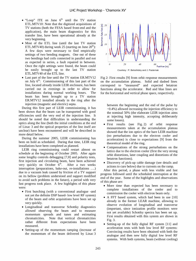
• “Loop” ITE on June 6th until the TV station ETL.MTV10: Note that the digitized acquisitions of TV stations (both the FESA based front-end and the application), the main beam diagnostics for this transfer line, have been operational already at the very beginning.
• Most of the ETL line (until the last TV station ETL.MTV40) during week 25 (starting on June 20th): A few days were necessary to find empirically settings of two bending magnets. One out of these two bendings had coils connected in parallel and not as expected in series, a fault repaired in between. Once the right settings were found, the beam could be easily brought up to the last TV station ETL.MTV40 of the ETL line.
• Last part of the line until the TV station ER.MTV12 on July 6th: Commissioning of this last part of the line, located already inside LEIR enclosure, has been carried out in evenings in order to allow for installations during normal working hours. The beam has been brought up to a TV station ER.MTV12 installed already in the ring after the injection (magnetic and electric) septa.
During this first part of LEIR commissioning, it has been shown that the beam can be transported with good efficiencies until the very end of the injection line. It should be noted that difficulties in understanding the optics along the line (both the initial conditions at the end of Linac 3 and the optical properties of the line itself are unclear) have been encountered and will be described in more detail below.
During the summer 2005, LEIR commissioning has been on hold as scheduled. During that time, LEIR ring installations have been completed as planned.
LEIR ring commissioning could restart almost on schedule at the beginning of October 2005. After again some lengthy controls debugging [7,8] and polarity tests, first injection and circulating beam, have been achieved very quickly on October 6th. After a two weeks interruption (preparations, bake-out, re-installations ….) due to a vacuum leak caused by friction of a TV support on its bellow (problem understood and support modified to avoid such problems in the future), a period with very fast progress took place. A few highlights of this phase were:
• First bunching (with a conventional analogue -and not yet the definite DSP based- low level RF system) of the beam and orbit acquisitions have been set up very quickly.
• Longitudinal and transverse Schottky diagnostics allowed observing the beam and to measure momentum spreads and tunes and estimating chromaticities. Note that vertical chromaticities rather different from expectations have been measured.
• Setting-up of the momentum ramping (increase of the momentum of the beam delivered by Linac 3
between the beginning and the end of the pulse by ~0.4%) allowed increasing the injection efficiency to the nominal 50% (the elaborate LEIR injection aims at injecting high intensity, accepting deliberately some losses).
• First results (see Fig. 2) of orbit response measurements taken at the accumulation plateau showed that the ion optics of the bare LEIR machine (no perturbations due to the electron cooler and acceleration) is close to expectations [9] from the theoretical model of the ring.
• Compensations of the strong perturbations on the lattice due to the electron cooler (first the very strong orbit distortions, later coupling and distortions of the betatron functions).
• Discovery of pick-up cable damage (see details and actions to cure below) due to currents on the ramp.
After this period, a phase with less visible and fast progress followed until the scheduled interruption at the end of the year. Some of the highlights and observations of this phase are:
• More time than expected has been necessary to complete installations of the cooler and to commission the cooler with electron beam only.
• A FFT based system, which had been in use [10] already in the former LEAR machine, allowing to observe evolution of longitudinal and transverse (important, since ionization profile monitors were not yet available) Schottky spectra has been set up. First results obtained with this system are shown in Fig. 3.
• Setting-up of the fully digital RF system [11] and acceleration tests with both low level RF systems: Convincing results have been obtained with both the analogue and then new fully digital low level RF systems. With both systems, beam (without cooling)
Position (m)
Betatronfunction (m)
Courtesy : P. Beloshitsky and J. Pasternak Fig 2: First results [9] from orbit response measurements on the accumulation plateau. Solid and dashed lines correspond to “measured” and expected betatron functions along the accelerator. Red and blue lines are for the horizontal and vertical phase space, respectively.
LHC Project Workshop - 'Chamonix XV'
243
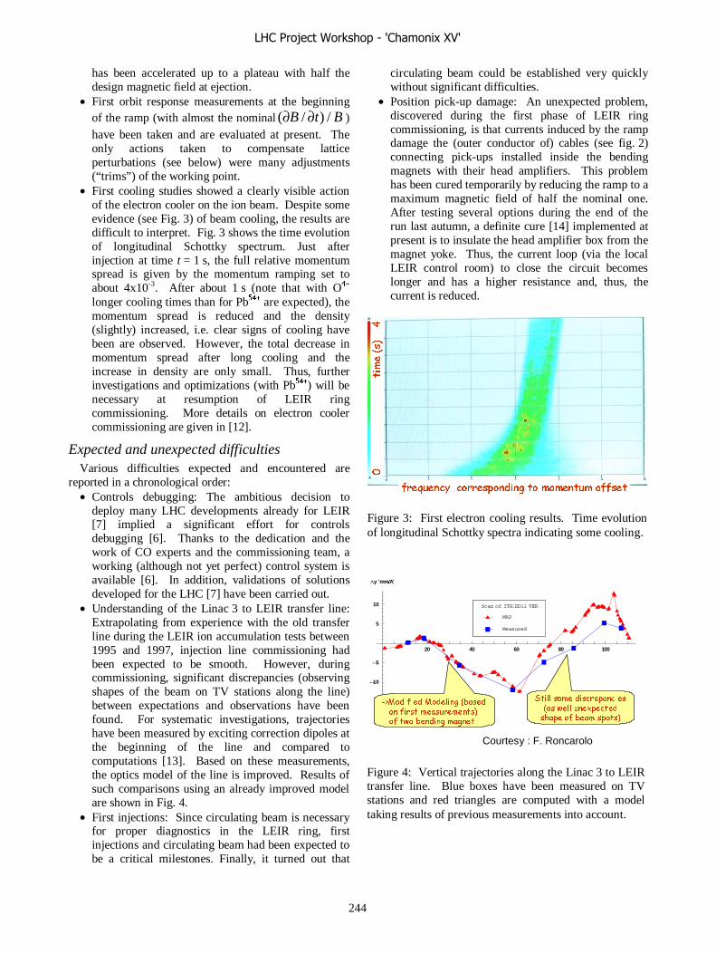
has been accelerated up to a plateau with half the design magnetic field at ejection.
• First orbit response measurements at the beginning of the ramp (with almost the nominal BtB /)/( ∂∂ ) have been taken and are evaluated at present. The only actions taken to compensate lattice perturbations (see below) were many adjustments (“trims”) of the working point.
• First cooling studies showed a clearly visible action of the electron cooler on the ion beam. Despite some evidence (see Fig. 3) of beam cooling, the results are difficult to interpret. Fig. 3 shows the time evolution of longitudinal Schottky spectrum. Just after injection at time t = 1 s, the full relative momentum spread is given by the momentum ramping set to about 4x10⁻³. After about 1 s (note that with O4+ longer cooling times than for Pb54+ are expected), the momentum spread is reduced and the density (slightly) increased, i.e. clear signs of cooling have been are observed. However, the total decrease in momentum spread after long cooling and the increase in density are only small. Thus, further investigations and optimizations (with Pb54+) will be necessary at resumption of LEIR ring commissioning. More details on electron cooler commissioning are given in [12].
Expected and unexpected difficulties Various difficulties expected and encountered are
reported in a chronological order: • Controls debugging: The ambitious decision to
deploy many LHC developments already for LEIR [7] implied a significant effort for controls debugging [6]. Thanks to the dedication and the work of CO experts and the commissioning team, a working (although not yet perfect) control system is available [6]. In addition, validations of solutions developed for the LHC [7] have been carried out.
• Understanding of the Linac 3 to LEIR transfer line: Extrapolating from experience with the old transfer line during the LEIR ion accumulation tests between 1995 and 1997, injection line commissioning had been expected to be smooth. However, during commissioning, significant discrepancies (observing shapes of the beam on TV stations along the line) between expectations and observations have been found. For systematic investigations, trajectories have been measured by exciting correction dipoles at the beginning of the line and compared to computations [13]. Based on these measurements, the optics model of the line is improved. Results of such comparisons using an already improved model are shown in Fig. 4.
• First injections: Since circulating beam is necessary for proper diagnostics in the LEIR ring, first injections and circulating beam had been expected to be a critical milestones. Finally, it turned out that
circulating beam could be established very quickly without significant difficulties.
• Position pick-up damage: An unexpected problem, discovered during the first phase of LEIR ring commissioning, is that currents induced by the ramp damage the (outer conductor of) cables (see fig. 2) connecting pick-ups installed inside the bending magnets with their head amplifiers. This problem has been cured temporarily by reducing the ramp to a maximum magnetic field of half the nominal one. After testing several options during the end of the run last autumn, a definite cure [14] implemented at present is to insulate the head amplifier box from the magnet yoke. Thus, the current loop (via the local LEIR control room) to close the circuit becomes longer and has a higher resistance and, thus, the current is reduced.
20 40 60 80 100
-10
-5
5
10
Dy @mmêAD
Measured
MAD
Scan of ITH.DD11 VER
->Modified Modeling (basedon first measurements) of two bending magnet
Still some discrepancies(as well unexpected
shape of beam spots)
Courtesy : F. Roncarolo
Figure 4: Vertical trajectories along the Linac 3 to LEIR transfer line. Blue boxes have been measured on TV stations and red triangles are computed with a model taking results of previous measurements into account.
0 time (s) 4
frequency corresponding to momentum offset
Figure 3: First electron cooling results. Time evolution of longitudinal Schottky spectra indicating some cooling.
LHC Project Workshop - 'Chamonix XV'
244
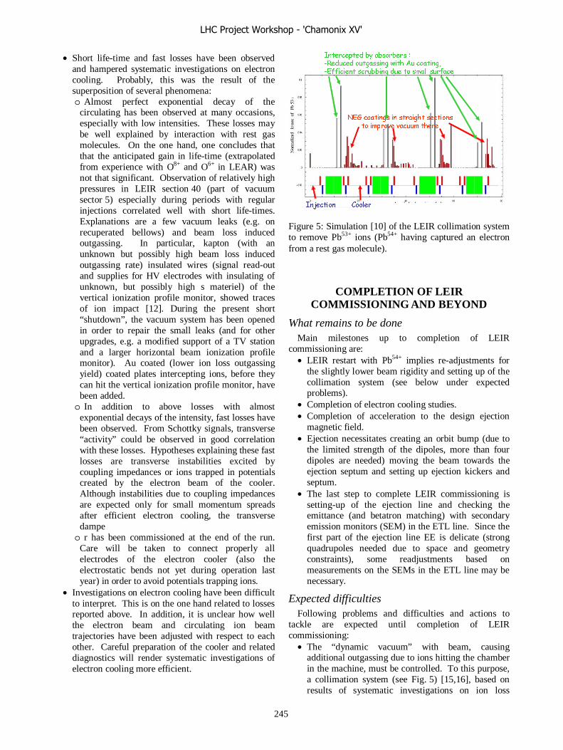
• Short life-time and fast losses have been observed and hampered systematic investigations on electron cooling. Probably, this was the result of the superposition of several phenomena: o Almost perfect exponential decay of the
circulating has been observed at many occasions, especially with low intensities. These losses may be well explained by interaction with rest gas molecules. On the one hand, one concludes that that the anticipated gain in life-time (extrapolated from experience with O8+ and O6+ in LEAR) was not that significant. Observation of relatively high pressures in LEIR section 40 (part of vacuum sector 5) especially during periods with regular injections correlated well with short life-times. Explanations are a few vacuum leaks (e.g. on recuperated bellows) and beam loss induced outgassing. In particular, kapton (with an unknown but possibly high beam loss induced outgassing rate) insulated wires (signal read-out and supplies for HV electrodes with insulating of unknown, but possibly high s materiel) of the vertical ionization profile monitor, showed traces of ion impact [12]. During the present short “shutdown”, the vacuum system has been opened in order to repair the small leaks (and for other upgrades, e.g. a modified support of a TV station and a larger horizontal beam ionization profile monitor). Au coated (lower ion loss outgassing yield) coated plates intercepting ions, before they can hit the vertical ionization profile monitor, have been added. o In addition to above losses with almost
exponential decays of the intensity, fast losses have been observed. From Schottky signals, transverse “activity” could be observed in good correlation with these losses. Hypotheses explaining these fast losses are transverse instabilities excited by coupling impedances or ions trapped in potentials created by the electron beam of the cooler. Although instabilities due to coupling impedances are expected only for small momentum spreads after efficient electron cooling, the transverse dampe o r has been commissioned at the end of the run.
Care will be taken to connect properly all electrodes of the electron cooler (also the electrostatic bends not yet during operation last year) in order to avoid potentials trapping ions.
• Investigations on electron cooling have been difficult to interpret. This is on the one hand related to losses reported above. In addition, it is unclear how well the electron beam and circulating ion beam trajectories have been adjusted with respect to each other. Careful preparation of the cooler and related diagnostics will render systematic investigations of electron cooling more efficient.
COMPLETION OF LEIR COMMISSIONING AND BEYOND
What remains to be done Main milestones up to completion of LEIR
commissioning are: • LEIR restart with Pb54+ implies re-adjustments for
the slightly lower beam rigidity and setting up of the collimation system (see below under expected problems).
• Completion of electron cooling studies. • Completion of acceleration to the design ejection
magnetic field. • Ejection necessitates creating an orbit bump (due to
the limited strength of the dipoles, more than four dipoles are needed) moving the beam towards the ejection septum and setting up ejection kickers and septum.
• The last step to complete LEIR commissioning is setting-up of the ejection line and checking the emittance (and betatron matching) with secondary emission monitors (SEM) in the ETL line. Since the first part of the ejection line EE is delicate (strong quadrupoles needed due to space and geometry constraints), some readjustments based on measurements on the SEMs in the ETL line may be necessary.
Expected difficulties Following problems and difficulties and actions to
tackle are expected until completion of LEIR commissioning:
• The “dynamic vacuum” with beam, causing additional outgassing due to ions hitting the chamber in the machine, must be controlled. To this purpose, a collimation system (see Fig. 5) [15,16], based on results of systematic investigations on ion loss
Intercepted by absorbers :-Reduced outgassing with Au coating,-Efficient scrubbing due to small surface
Injection Cooler
NEG coatings in straight sectionsto improve vacuum there
Figure 5: Simulation [10] of the LEIR collimation system to remove Pb53+ ions (Pb54+ having captured an electron from a rest gas molecule).
LHC Project Workshop - 'Chamonix XV'
245

impact induced outgassing [17,18] has been installed and must be commissioned. Most ions hit absorbersblocks installed at appropriate locations in the bending magnets. Au coatings and perpendicular incidence reduce the beam loss induced outgassing rate. Most ions not intercepted by the absorbers are lost in the straight sections and are pumped efficiently by NEG coatings installed wherever possible in these regions.
• Optics perturbations due to gradients seen by the beam during the ramp inside the bending magnets: During the ramp, a net current flows along the vacuum chamber inside the C-shaped bending magnets and excites quadrupolar fields. Corrections of the resulting very strong lattice perturbations have been implemented in the magnetic cycle generation software. The fact, that it has been possible to take first orbit response measurements on the ramp only applying “trims” of the working point, is a good sign that these lattice perturbations can be brought under control.
Beyond LEIR Commissioning If LEIR commissioning can be completed as planned
until April 21st, 2006, the machine will be stopped during the summer and the operations team will work for the AD. In the late summer, LEIR will be restarted in order to provide the beam for commissioning the early LHC ion beam in PS in autumn 2006. This schedule leaves just enough time to provide first LHC ion operation with the “early beam” on time [1].
SUMMARY AND CONCLUSIONS Thanks to the work of many people from several
departments involved in the I-LHC project, LEIR installations have been completed almost on time and allowed to start LEIR injection line commissioning as scheduled and LEIR ring commissioning almost on time.
Significant progress of LEIR commissioning has been achieved up to now. Still, many commissioning milestones remain to be completed. After re-adjustment for Pb54+ ions and setting up of the collimation scheme, electron cooling studies and optimization will be completed. Then, setting up of acceleration, together with corrections of lattice perturbations during the ramp, will be completed. Finally, ejection and transfer to the PS will be commissioned. For the moment, no showstopper ruling out completion of LEIR commissioning until end of April has been identified. Completion of LEIR commissioning until the target date (April 21st) looks very challenging, but feasible.
REFERENCES [1] S. Maury, “I-LHC Project Overview”, these
Proceedings. [2] S. Maury, “Milestones for the Lead Injector Complex
Commissioning”, Proceedings of the XIVth Chamonix Workshop on the LHC Project.
[3] K. Schindl, “Ion Injector Issues”, Proceedings of the XIIIth Chamonix Workshop on the LHC Project.
[4] M. Chanel, “Status and Planning of the PS Ions for LHC Project”, Proceedings of the XIth Chamonix Workshop on LHC Project.
[5] C. Carli and J.-P. Riunaud, “Summary of the Session I-LHC Project Overview”, Proceedings of the XIIth Chamonix Workshop LHC Performance.
[6] C. Carli, “Preparation for Running-in LEIR in 2005”, Proceedings of the XIIIth Chamonix Workshop on the LHC Project.
[7] S. Pasinelli, “Post-mortem of Experience with LEIR Controls”, these Proceedings.
[8] M. Gourber-Pace, “Gain of Experience for the Running-in of LHC”, these Proceedings.
[9] P. Beloshitsky and J. Pasternak, private communications.
[10] M. Chanel, U. Oeftiger, E. Roux, “HP View Version 1.5”, Tech Note PS/OP/98-18.
[11] M.E. Angoletta, A. Findlay, “First Experience with the new LEIR digital Beam Control System”, AB-Note-2006-003-RF.
[12] G. Tranquille, “LEIR Electron Cooler”, these Proceedings.
[9] F. Roncarolo, private communications. [9] L. Soby, private communication. [10] J. Pasternak, “Loss pattern of Pb ions with charge
changing processes in the LEIR ring”, CERN-AB-Note-2004-066.
[11] C. Bal, C. Carli, M. Chanel, E. Mahner, J. Pasternak, “A Collimation Scheme for Ions Changing Charge State in the LEIR Ring”, Proceedings of PAC 2005 and LHC-Project-Report-846.
[12] E. Mahner, J. Hansen, J.-M. Laurent, N. Madsen, “Molecular Desorption of stainless Steel Vacuum Chambers irradiated with 4.2 MeV/u Lead Ions”, LHC Project Report 624.
[13] E. Mahner, J. Hansen, D. Küchler, M. Malabaila, M. Taborelli, “Ion-stimulated gas desorption yields of electropolished, chemically etched, and coated (Au, Ag, Pd, TiZrV) stainless steel vacuum chambers and St707 getter strips irradiated with 4.2 MeV/u lead ions”, Phys. Rev. Spec. Top. Accel. Beams 8 (2005) and CERN-AT-2005-008.
LHC Project Workshop - 'Chamonix XV'
246

POST-MORTEM OF EXPERIENCE WITH LEIR CONTROLS
S. Pasinelli, CERN, Geneva, Switzerland.
Abstract The Low Energy Ion Ring LEIR was selected as a test
bed, to validate certain concepts which will compose the LHC control system. LEIR is inserted between the Linac3 and PS accelerators which are completely controlled by the CPS control system. The LEIR control system is hybrid, as it is the aggregation of parts coming from the PS Complex control system and different components from the LHC. After a period of strong instabilities, modifications, adjustments and training, this control system is usable in a commissioning environment. Before it is declared operational, some components or functionalities need to be added, and others should be corrected in order to improve the speed, reliability and ergonomics.
INTRODUCTION The Low Energy Ion Ring LEIR was selected as a test
bed, to validate the concepts and technologies which will be used for the new control system of the LHC. LEIR is inserted between the Linac3 and PS accelerators which are completely controlled by the CPS control system. The LEIR control system is hybrid, as it is the aggregation of parts coming from the PS Complex control system and different components from the LHC.
The design of the control system of the CPS was made at the end of the Eighties with an architecture 2-tier. The main part of the applications were built with Xmotif/C++ and the front end software in C/C++ were built with the concept of GM (General Module). Since the year 2000, the new applications are built with Java. For the new LHC control system the architecture of the control system is 2-tier or 3-tier and the applications are built with Java. The front end software in C++ is build with the concept of FESA (Front End Software Architecture). For the LEIR we use 2-tier or 3-tier architecture, applications are Xmotif/C++ or Java and in the front end we have GM or/and FESA.
From its experience on the fast cycling machine and to guarantee a good commissioning, the LEIR OP team has required that all the currently available functionalities in the CPS control system should be implemented in the LEIR.
During all the period 2005, the use of these technologies and of these concepts, on a new machine, has been a challenge for all the people involved.
THE COMMISSIONING The commissioning team has produced and submitted a
list of control software needs which cover • Sequencing (CBCM) • Basic Controls (Working Set, Knobs)
• Observation (OASIS, Samplers, Orbit …) • Instrumentation: (MTV, Orbit …) • Function Editor, Cycle Editor (LSA) • Tools (Logbook, Archives, References …) • Alarms
In agreement with the group CO, we planned a gradual startup, of the various software according to the schedule of the commissioning. These phases were: 1. Hardware Commissioning: Basic control &
Sequencing available at the beginning of May. 2. Beam Injection: Partial Controls of the injection
lines available at the beginning of June. 3. Ring : Full Controls available at the beginning of
August 4. Ejection : Control available at the beginning of
February 2006 Status of Hardware Commissioning (May): This phase was to allow the validation of the equipment as well as their controls. Except for the new timing class LTIM, the major part of the new software was not available during this phase. The Working Set & Knobs didn’t receive correctly the data from the middleware or from the FESA. The persistence of the data in the FESA was not ready and we were losing the data at each DSC reboot. We began this phase by employing the applications of Xmotif/C++, but tested only the equipment controlled with the GM (Xmodif/C++ application cannot manage equipments controlled with FESA) Status of the Beam Injection (June): This part of the commissioning was to validate the software necessary for the LEIR injection line and the first injection elements in the ring. Except for the MTV application, the situation was the same as the hardware commissioning. OASIS (Open Analogue Signal Information System) was also in hard debugging state. The major problems with OASIS were bad signals synchronization, connection difficulties, several GUI faults etc... When we have started to use intensively the new applications, we have encountered problems of memory leak and we had to reboot several times per day the workstations. The alarm application LASER was not able to receive GM equipments errors. A new magnet interlock system based on the PLC was successfully installed and tested during this period. Status of the Ring (September): We used this period to validate one of the major software, the new Cycle Editor (LSA). After some difficulties in the precedent phases, and a lot of works of the different software developers the Working Set & Knobs, FESA, OASIS, LASER were
LHC Project Workshop - 'Chamonix XV'
247

90% available. The application Orbit was a success, after the first correction the orbit was almost perfect! The Cycle Editor, except a confuse GUI, was ready at 90%. The commissioning team, in close collaboration with the LSA team, spent time debugging and validating the functionalities implemented in the Editor. Functionalities such as Archives, References, PPM copy, EQP survey and the Passerelle, very useful for the operation, were not ready. The memory leak was resolved by increasing to 2GB the memory and with a deep analysis of the new software.
Figure 1: Beam snapshots in the eLogbook
Status end 2005: After 8 months of commissioning, the control system was usable in a commissioning environment and all necessary software was in the optimization phase. But before it was completely operational, some components or functionalities needed to be added, and others should be corrected in order to improve the speed, reliability and ergonomics. Requests for 2006: Except the optimization of several software, the most requested tools are to have full operational Archives, PPM copy, the Passerelle and the EQP survey for GM and FESA equipments.
CONCLUSION The use of the software of the LHC was very ambitious, because even with the excellent support and reactivity of the developers, there were delays in planning and in the availability of various software. During this startup phase, we could note a lack of communication between the various protagonists of the CO projects. For the new software implemented at the LEIR both experience and knowledge from the CPS and CSL complex are used. The most important thing for everyone is: A Control system allowing working (not yet perfect) is available.
REFERENCES LEIR project: http://project-i-lhc.web.cern.ch Electronic logbook (intranet): http://elogbook.cern.ch Electronic logbook (extranet): http://ab-dep-op-elogbook.web.cern.ch FESA: http://project-fesa.web.cern.ch LSA: http://proj-sps2001.web.cern.ch/proj-sps2001 OASIS: http://project-oasis.web.cern.ch
ACKNOWLEDGEMENTS From the commissioning team, thanks to all people
involved in the LEIR software and especially to E. Roux, I. Kozsar, M. Pace, V. Baggiolini and the team’s CO Team, LSA Team, BDI Team, PO Team, Vacuum Team, OP Team.
LHC Project Workshop - 'Chamonix XV'
248
������������ ������������������������ �
������������ �������������������
�
�������������������� � ��������� ��� ������������������������������ ���� ���������� � �� ���� ������ � ���� �� ������������ �� � ������������ ���� �� ���������� �������� � ����
������ � ������������� ��� ������������������� ������ ����� �� ����� ���� ����������������������� � �� ������ ���� �!"� ���� ���� ��� ����� ����� � ���� ���������
��������������"��#�$%&�"�����'����������� ��( ������!"����������� ������)����� ����������� ����������������������� ������� ������� ���� ����� ����������� ��� *++, �
������ ���� ���������������� ��� �������������)��� ������� ���� ���� � � ���� �!"� "���� � � ���� �����������-����� � ����� �� � �� � ����� �� ��������� ���������.��
��������������� �����������������������������)�� �������� � ���� ���� ����� � �� ����� ��� � �� � �� �����)��������������������
��������������� ����������������� �������� ������������������������� ���)���)/�������� ������� �������������� ������������ ���� ���� �� � � ������� ��� ����� � ���� �!"�
���������
����������
���� �� ���� � ����� "���� � ������� ������ ����
������� �� ������ .� ����� ���������� ����� � �� ���������!"����������� ������ ����!"��������������������� ����� ����� ���� ����� ��/���� ������� ����� *++*�� ���
�������� ��� ���� � ����� ��� � ��/���� �� � ��������� �� ������� �)������������������"���� ����� ������������� %&� ���� &�� 0��� �� �� ��� ���� ����� � ����
���������� � ���� �������� �� � �� ������� ������� ����� � ��������� � �)��� ��� ���� ����� � � ����� �������� ����� � ����� ��������� �� ����� ���� �!"� ��������
������ �����"��#�������� ������������ ������1�� ��������������������� �����������������)�������� ������������� �� ����)����� ���������������� ������ �������� �������
�� � �� ������ ���������� �� ��� �� ���� ������� � ����������� ������� � ������ ���� ����� ���������� ��� ������� ������������ ���������������� �����������������
������������������� ��� ������.�����"���� ������������������������������ ���� ���)��������������� ���� ���� ������� � � � ���� �������� �� � 2����� ������� ����
3�������� ���� � ��� ���� ��������� �� ���� ������������ ���� ��� �� ������� ����� � ������� ��2�� ���� �� ���������� ��� ���)��� ����� ������ � ����� "� �2������ ������ ��������� � � �� �� ��)��� �� �� ���)��� � ����
����� � �� )�� �������� ��� ��� ���������� ���� �� ������ ������������"���� � ������� � ������������������������������������ ���� ������������ ��
�
��� �����
��� �������������( ��������� ��� ��� ������ �������������������*++*�
���� )���� �� ������ �� ���� �!"� ��� � ������� ��� �����������������������(����������� �������������������������&(� &����� � ��������� �� ������ ��� �� ������ ����� �!"�
���� �� � ������/����� &%& � �� � �������� �� ���� �������� ����� &%&� �� �!"� ���� ��� ������ ��� � �� ���)��� ����������������� ��� ����� ������������������������
� � �� �� �� ��������� ���������� � ����� �� )���� ����� ����������� �� ������ �������� ��������� ���������� � ��������������������&(� ����������)���� ��������������� �
���� ������� ���������� ���� ��� � � �� ������ � ��� ������� ������ ����� ���� ���������� �� ������ �� ������������ ���������� � � ���� ���� ������ ����� ���� )����
�� � ������ ���� ������� ���� �� (������ �������������������� �� � �� �� ��� � ������� ���� ������ ���� �������� ����� � ��� 2����� �� ���� ����� ���� � ����� �� ����������������
�
���������������������� ���� ��������� ��� �������� �� � ����� ���������
������������� 1���� �� � ���� ������ � ���� ��� "���� ����� � �� ���2��� �������� ��� ������� )��� �������� ����� � ���� �� )�� ������� ��� ��� ���� � ���� "���� �
����� ���� �� )����� ���� ���� � ��� �������� ������� ������� �� ������ �� ����� ������ � ������������ �� ����� �������������� ���� ��� �� ��� ���� ����� ���� � ���� 3��������
���� � ��� ��� ���2��� ������� � ���� �� )�� ���� �������������� �� ������� ������ ��)�� � ��� ����� �� ������� ��������� ��� ���������� ��
�������������� �����������
(�� �� ����������� ��� ���� ����� ����� � � ��� � ����
������� � ����� �� ������ �� ���� �!"� )��� �������� ������� �� ������ �� �� ������ � ���� ����� ����� �� � �� �������� ��������������������������������������)������
�� ������ �� ������������
�����������������������!"� ������������������� ��� ��������������
4-�� ������� �� (��� ������ ����� ����� ������� �������� ����� ���� )���������� 5�� �������� ���� ������� ���������
-���� � 6"��7 � �� ������ ��������� �� ����� ���� �!"� �����������2�������� ���������������� �����/������������������� ������� (�� ��������� ���������� � ���� ����������������� � � "�� � �� � ���������� ���� ���� ����
���� ��������� �������� � ����� ������� �� ����� �����������������!"��������������������� ��
��
�
LHC Project Workshop - 'Chamonix XV'
249
��������������������&(� � � ���� ���������� ���� �������� �� ����
����������� � ���������� ������� ������� ��� �� � )������������ �������������1� �10� ��� ���-�#8������� ������ ���� � ��� � ��/���� �� � ��������� ����� ��)���� �
�������� ��� ����� ���� ������ ��������� ��� ��� � ��� ���������������������������������������������������� ��������������������� ��������������������� ��
����� � ���� ���� ����� � ���� ����� ������ � ����� ���� � ��)��� � � ��)������ ���� ��������� � � ����� � ������ � ��� ���� ��������� � ��� ��������� ������ �� ������������������������� ��� � ���&(��� �)����������/��
����� � ����� �� ����� �� ���� ������ � ��������������������������� ��������������9���� �������������������2����� ��������� �� � ����� ������������ � ���� ��� ���
����������������������������������������� �����&(���������� ���������)��� ���������������������!"��
�
�������� ��� �������������� ����� � ����� ������� ������ � 6)���� ����� �
��������������)������ :7 ������)���������������� ��� �
)���� ������ �� ���� �&(� "��� ������� �� � ��������������� � ��� �� ������������ ��2�������� � ���� ��������� �� � )���� ����������� �� � � ������������� ����
���������� � ���� �&(� "��� ������ ���� �� ���� �� �)����� ���� ������� � ��� ������ ���� ��������� ����� � ������������ ������)������������������ ������������������
������� � �� ������� ��� ��� ���������� �����)��� ������������&(��
�
��������� ������������� ���
���� 3(&�&� ��/��� � �� ������ �� ������ �� ���� "��#����������� ��������������� ��� ������������������ ������
���� ���� ������� � ������ ��� ���������� ���� 3(&�&����������� �� ����� ������� �� ���������� ���������� ��������� �!" � ��� ���� �� ����)����� � ����)������� ����;�
����� ������������������ ����������������������������&(� ���� ���� ����������� ����� �� � �� � � � �� � ������������ ��� ����� �� � � ����� ����� ������� ����
���� ������ ���� ���� ����� ������������ � ���� ��� ����������
��������� ���� �����������
"�������� �������� � ����� ����� ������������ ������� ������ ���� ��� �� � ���� ��/���� ����� �������� ������� ����
���� ����������������3��������������� ���� �������)�� ���������2�����������6�����%&����� ��7�����
�� � �������� ��� �����)��� �� ���� �� � ���������� ������!"����������� ��� ��������������������������
�� )�� �������� ����� �� ����������� %&� ����� ����� �������������-����� ��� �������� ������������������������ � ��� ���� ������ ����������� ��/�� � �������������������� ������������)�������������������
���� ����� ����������� ��/����� ��� � ����� ����� �������������� ����������� � �&(� ������ � ���� ���� ���������������������� 1����� ���� ������ ���� �� ������� ��� ��
����������������� ���������� ���������� ������������ ��������������������������������������������������� ��� ���� ���� ��� � � ��� ��������� ������������� ��� ����
���������� ��� ��������������������
������������� ����
������ ��� �������������������� ��������������� ����� �������� � � ���� ����)������ � ���� ���������� �����������������)�����������#���)�� ����)������
� � �� ��������� � ��� ����� ���� � �� )�� ����� ��� � � �� � �� �)�������������!"����� ������������� ��� ������������������� �������� �� ������������ �
��� ��2����� �������� ��������� � ��� � 6� � ����� ����)���� �������� � ����� ����� ���)��� � 2�������������� :�7�� "� �2������ � ���� � ��� �� � ��� ��
�� ������� � � �������)��� �� ���� �!"�� �� � )���������������������������������� ����������
��� �����
����� 3�������� ���� ����� "���� � ������� � ��������������� ������������������3�����������������
���� ��� ����� ����� �� <++=� ��������� ���� �����)�������� � � ��������������"���� �8���������&(������� ��������� ����� ��)������!"� �������"���� ������
���������������� �� ���������� �)���������������������������������������������������� ��� ����/�����������)������ ���������� ������� ��/��������������>�����������
������������3��)���*++,����������� � � ������ ��������� �������� ��� ��� ������������)�������� ������������ ��������2������������*++,�� �?�������������)���
���������@� � ���������� ���� ����� � ����� � ���� � ����� �� � �� ���2������������� �� �� ������ ����� ���������� � ���� ����� �
������������ 1�� ��������� ��� � ��������� � ��� ������������� ��������� ������!"��� ����������)���������������
�
�
LHC Project Workshop - 'Chamonix XV'
250

LEIR ELECTRON COOLER
G. TranquilleCERN, Geneva, Switzerland
Contribution not received
LHC Project Workshop - 'Chamonix XV'
251
SECTOR TEST: OVERVIEW, MOTIVATION AND SCHEDULING M. Lamont CERN, Geneva, Switzerland
AbstractAn overview of, and the motivation for the sector test, are recalled. The scheduling of the preparatory steps, the test itself and recovery from the test are presented. This is presented together with the potential impact and interaction with hardware commissioning and ongoing installation.
INTRODUCTIONAn LHC sector test was approved in 2003. This test
plans to inject beam down TI8, into the LHC at the injection point right of IP8, traverse IR8 and LHCb, through sector 8-7 to a temporary dump located near the position of Q6 right of point 7. The motivations for performing this test were originally outlined at Chamonix 2003 [1,2]. However, there are many consequences and the potential impact was also examined [3].
The test will involve the final part of TI8 and 3.3 km of the LHC including one experiment insertion and a full arc. As such it may be regarded as very representative of the challenges we will face in commissioning the whole machine.
It is clear that the test is inconvenient, coming as it does, during installation and hardware commissioning, but, it will be argued, it is justified.
BeamThe aim is to use pilot beam for the most part i.e. a
single bunch with an intensity of 5 - 10 x 109 protons. The clear aim to minimise losses, use beam sparingly and only when we know where it’s going.
The planned total intensity will be at maximum 4 x 10¹³
protons delivered over 2 weeks. This is comparable with one nominal intensity LHC extraction from the SPS.
MOTIVATION A test with beam of part of an accelerator during the
installation process is standard and the motivations in the case of the LHC have been well debated [1,2,3]. Such a test allows one to:
Verify system wide integration: full-blown system wide integration tests necessary for beam go one step beyond hardware commissioning. It allows one to field test beam related equipment such as: power converters, kickers, septa, dumps, pickups, synchronisation, timing, and to get them all working together. It stress tests the controls infrastructure and will fully validate integration and highlight oversights, and force the debugging of problems. There will be problems and the lessons learnt will undoubtedly speed full commissioning.
Check that the installed equipment works with beam, and that there are no problems with ongoing
installation. Beam will confirm that the aperture in the cold machine is free and has the expected size. The beam samples all electromagnetic fields in the vacuum pipe and will allow polarity checks of the corrector elements and the beam position monitors, measurements of field errors, and determination of any large offsets between beam and magnet. Linear optics checks are also possible.
It will be the first exposure to beam of much of the hardware and will, potentially, allow verification of assumed quench limits and spatial resolution of beam losses.
Pre-commission essential acquisition and correction procedures. First tests of important beam diagnostic system will be possible. The beam provides the only way to verify the proper functioning of the diagnostics: timing, BPM resolution, BPM cabling, BPM offsets, BLM resolution. It will allow tests of the control and correction systems (including correctors, cabling, the control system, software, procedures etc.).
Last but not least it will provide an extremely high profile milestone forcing the preparedness of all components. These would include controls, timing, transfer from the injectors, instrumentation, interlocks, access, radiation protection etc.
These systems are absolutely critical for the effective exploitation of the machine. They must be ready and tested when we come to commission the whole machine. The test can potentially highlight oversights, misconceptions and shortcomings.
Operationally the exercise would be extremely valuable and it can be argued that the time and effort spent on the test will be more than compensated by a more efficient start-up of the completed machine.
Commissioning of the first sector will have to be done sooner or later. We will have to wrestle with the problems that will be encountered during this phase. Discovering the problems during a sector test will give us several months at least to resolve any problems, perform a critical analysis of the performance of the systems involved and implement improvements. Operationally, any time spent in 2006 on an injection test will be paid back during the first year’s commissioning, enabling us to deliver physics faster.
A successful test would also validate the project to the wider world.
De-motivationIt might be argued that if any serious problems are
uncovered then it would be too late to change anything. Related is the question: “What do you if you can’t get beam around after two weeks?” Clearly the sooner any problems, serious or otherwise, are revealed the better.
LHC Project Workshop - 'Chamonix XV'
252

Anything uncovered during the test would give us at least some lead time to find a possible resolution.
It is also argued that many things will change between the test and full commissioning and we will have to re-do the exercise anyway. The counter-argument is that most of the accelerator systems will necessarily be in the final configuration for the test. Every attempt should be made to avoid temporary solutions for the test.
We are going to be busy enough anyway installing and commissioning other sectors and the test will provide a distraction and a draw on valuable resources. It is undoubtedly true that the test will place demands on the teams involved and draw resources from the installation and hardware commissioning. The impact and potential cost of the test is discussed below.
IMPACT Installation
The test will necessitate the closing of sector 7-8, part of 6-7 and part of 8-1. Thus transport of magnets through the sector 7-8, and interconnect work in the closed part of 6-7 will not be possible for the duration of the test.
No transport through 7-8 during preparation (7 days), tests with beam (14 days) and recovery (7 days). No access to part of 6-7 during test (17 days). No access to part of 8-1 during test (17 days).
Details of how these constraints can be accommodated into the overall planning are given elsewhere in these proceedings [4]. One should note that work should have finished in sector 8-1; that work can continue in the unclosed part of 6-7; and that it is possible for magnet transport to continue albeit not through sector 7-8.
Hardware Commissioning The test sets a hard deadline for the hardware
commissioning of sector 7-8 and the requisite part of 8-1. Given that the test is to be performed at 450 GeV, the
possibility that the circuits involved (particularly the main bends and quadrupoles) be commissioned to less than nominal current is a possibility. Hardware safety must, of course, be guaranteed. A full list of required circuits and expected operational range may be found at [5].
Partial hardware commissioning would, however, mean the hardware commissioning team re-visiting sector 7-8 after the test, with inevitable overheads. For a further discussion of the hardware commissioning issues see [6].
Radiation Protection Remenant radiation after the test will potentially force
parts of 7-8 and 8-1 to be declared a Supervised Radiation Areas with knock-on effects for magnet transport and subsequent installation [7,8].
ResourcesThe test will clearly use resources: both manpower in
the preparation, execution and recovery, material costs for
items, which are not part of the final LHC configuration, plus exploitation expenses.
Clearly the test places demands on what is to be installed and operational. There are also some small constraints on what is not to be installed in the area to the right of IP7.
CostInitial estimates made in 2003 [3] included the need to
re-cool and re-hardware commission sector 7-8. This will be unnecessary given the present schedule. However, running the PS/SPS complex solely for the test during part of November/December suffers from the high cost of electricity at this time of the year.
As before the capital costs are relatively small, given the closeness of the machine to the final configuration.
SCHEDULEAn overview of the near test schedule is shown in table
1. The dates shown reflect the schedule as of February 2006. If the dates for the test were to change the essential breakdown would stay the same. A detailed breakdown is available at [5].
Task Date Comment IR7 Vacuum & BDI 1-7/11 No interference
Machine Checkout 13-24/11 Control from CCC
Install Dump IR7 15-17/11 7-8 blocked
Access system 20-23/11 Tests
Close sector 23/11 Qualification
Beam to TI TED 24/11 Point 8 closed
Sector test with beam 27/11 – 10/12 6-7,7-8, 8-1 closed
Radiation survey 11/12 Access gates out 12-13/11 6-7, 8-1 free
Dump out 18-19/11 7-8 free
Table 1: Overview of near test schedule
CONCLUSIONS The LHC sector test is an important milestone. It
provides an opportunity to thoroughly test full integration of a wide variety of accelerator systems, all of which will be needed for machine commissioning. It also allows important beam based checks of the ongoing installation.
The time spent will be recuperated during eventual commissioning, and perhaps, more profoundly it will allow more effective and rapid commissioning, having given time for problem resolution and improvements.
Although it does impact on installation, its effects are well constrained and manageable. Careful planning is required to fully anticipate the requirements and effects of the test in order to minimise the disruption it will cause to other ongoing activities.
REFERENCES 1. F. Rodriguez-Mateos, Proc. XIIth Chamonix LHC
workshop on LHC performance, 2003.
LHC Project Workshop - 'Chamonix XV'
253

2. R. Assmann, Proc. XIIth Chamonix LHC workshop on LHC performance, 2003.
3. M. Lamont, TCC minutes 2003-07.4. E. Barbero Soto, Sector Test: Planning, these
proceedings. 5. M. Lamont et al, http://cern.ch/lhc-injection-test/6. R. Saban, Sector Test: Hardware Commissioning,
these proceedings.
7. D. Forkel-Wirth, S. Roesler, G.R. Stevenson, H. Vincke, Radiation Issues Associated with the LHC Machine Sector Tests, Radiation Safety Officers Committee, May 2003.
8. H. Vincke, Sector Test: Radiation Issues, these proceedings.
LHC Project Workshop - 'Chamonix XV'
254

PROPOSED TESTS WITH BEAM
B.Goddard, CERN, Geneva, Switzerland.
Abstract
An overview of the proposed tests is presented, with time and beam load estimates. The necessary instrumentation and associated requirements on controls are discussed. The tests will include optics checks, aperture scans, instrumentation performance, magnet checks, injection protection, stability and quenches. For each test the methods are outlined, with the requirements on instrumentation, equipment and controls highlighted.
THE LHC INJECTION TEST The LHC injection test [1] will provide an important
milestone to the overall LHC project. The test requires an extensive and almost representative cross-section of the LHC machine sub-systems to be operational [2,3] and fully integrated into the control system, with associated application software and cycle management [4]. The beam tests allow a huge amount of progress to be made. It will be possible to validate magnet circuit polarities [5], aperture, and alignment, and to begin the detailed commissioning of critical equipment systems like the BPMs, BLMs and machine protection devices [6]. The reproducibility and decay of the persistent current effects can be measured and compared to the magnetic model [7], and the linear optics can be determined, together with some of the more important higher order effects. The quench limits of the LHC magnets can be studied [8] and correlated with the observed beam loss patterns.
OBJECTIVES AND CONSTRAINTS
Main objectives of beam tests The main objective of the beam test is to transport the
pilot beam to the IR7 TED and to perform the measurements to demonstrate that fundamental aspects of the LHC design function correctly when these are integrated into the installed machine and control system. The objectives are broken down into the following parts: 1. Commission end of TI 8 and injection with beam 2. Commission trajectory acquisition and correction 3. Linear optics measurements 4. Commission Beam Loss Monitor system 5. Aperture checks 6. Quench limits and BLM response 7. Commission nominal cycle 8. Stability and reproducibility tests 9. Field quality checks 10. Commission machine protection subsystems 11. Commission crossing and separation bump
Priorities The beam time will be limited and obviously should be
minimised to limit the impact on the remaining LHC
installation and commissioning; for this reason the tests will be prioritised. Although all the tests are important and are considered necessary, items 1-5 are highest priority, 6-9 medium priority and 10-11 lowest priority.
Radiological constraints With regard to the beam tests, the possible radiological
consequences [9] and the requirements for subsequent activity in the machine areas impose two constraints: • The LHC machine should be reclassified to a non-
radiologically designated area • There should be no radiological consequences for
LHCb This means that particular care must be taken to
minimise beam losses, by using the beam sparingly and knowing at all times where the beam is actually going. This will be done by starting the tests with zero separation/crossing angle in LHCb to maximise the local aperture, and quantifying the losses in the experiment, probably with BPM intensity signals. The beam used for the tests will be pilot intensity (5×10⁹
p+ in one bunch) where possible, which is below the quench limit and about a factor of 100 below the damage threshold. There will be tests which need 1-3×10¹⁰ for improved BPM resolution, and the quench test where up to 1×10¹¹ p+ may be required in one bunch. The LHCb spectrometer and compensation magnets will be locked off.
BREAKDOWN OF TEST PHASES
1. Commission end of TI 8 and injection 24 hours foreseen Estimate 500 shots with 5×10⁹ p+
The last 200 m of TI 8 and the injection systems must be commissioned, threading the beam through the line onto the TDI diluter, Fig. 1. The kickers must be timed in and their performance checked.
The key hardware systems are the TI 8 elements, the injection elements MSI, MKI and TDI, the LHC magnets Q5, Q4, D2 and correctors to the right of IP8, the beam instrumentation BTVs, BPMs and BLMs, and timing, radiation monitoring and control system.
In addition to the generic control requirements, dedicated or expert application software will be needed for injection steering, injection post-mortem, TCDI/TDI setup, injection fixed displays, equipment expert applications and possibly online aperture display and re-matching routines. Remaining issues or areas for study include the tight vertical aperture at the MSI septum, Fig. 2, which may require a specific local correction strategy, the synchronisation of the shot-by-shot logging for each injection (not “Post-Mortem”), and the controls across the TI 8/LHC interface, in particular for injection steering.
LHC Project Workshop - 'Chamonix XV'
255
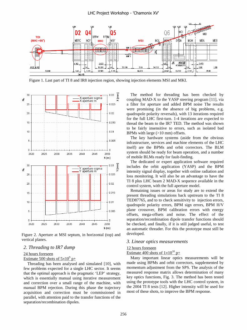
TDI(MKI +90�) MKI MSI
������
Figure 1. Last part of TI 8 and IR8 injection region, showing injection elements MSI and MKI.
Figure 2. Aperture at MSI septum, in horizontal (top) and vertical planes.
2. Threading to IR7 dump 24 hours foreseen Estimate 500 shots of 5×10⁹ p+
Threading has been analysed and simulated [10], with few problems expected for a single LHC sector. It seems that the optimal approach is the pragmatic ‘LEP’ strategy, which is essentially manual using iterative measurement and correction over a small range of the machine, with manual BPM rejection. During this phase the trajectory acquisition and correction must be commissioned in parallel, with attention paid to the transfer functions of the separation/recombination dipoles.
The method for threading has been checked by coupling MAD-X to the YASP steering program [11], via a filter for aperture and added BPM noise The results were promising (in the absence of big problems, e.g. quadrupole polarity reversals), with 13 iterations required for the full LHC first-turn. 1-4 iterations are expected to thread the beam to the IR7 TED. The method was shown to be fairly insensitive to errors, such as isolated bad BPMs with large (>10 mm) offsets.
The key hardware systems (aside from the obvious infrastructure, services and machine elements of the LHC itself) are the BPMs and orbit correctors. The BLM system should be ready for beam operation, and a number of mobile BLMs ready for fault-finding.
The dedicated or expert application software required includes the orbit application (YASP) and the BPM intensity signal display, together with online radiation and loss monitoring. It will also be an advantage to have the TI 8 plus LHC beam 2 MAD-X sequence available in the control system, with the full aperture model.
Remaining issues or areas for study are to extend the present threading simulations back upstream to the TI 8 TED87765, and to to check sensitivity to injection errors, quadrupole polarity errors, BPM sign errors, BPM H/V plane crossover, BPM calibration errors with energy offsets, mega-offsets and noise. The effect of the separation/recombination dipole transfer functions should be checked, and finally, if it is still judged useful, to test an automatic threader. For this the prototype must still be developed.
3. Linear optics measurements 12 hours foreseen Estimate 400 shots of 1×10¹⁰ p+
Many important linear optics measurements will be made using BPMs and orbit correctors, supplemented by momentum adjustment from the SPS. The analysis of the measured response matrix allows determination of many key optics functions, Fig. 3. The method has been tested using the prototype tools with the LHC control system, in the 2004 TI 8 tests [12]. Higher intensity will be used for most of these shots, to improve the BPM response.
LHC Project Workshop - 'Chamonix XV'
256
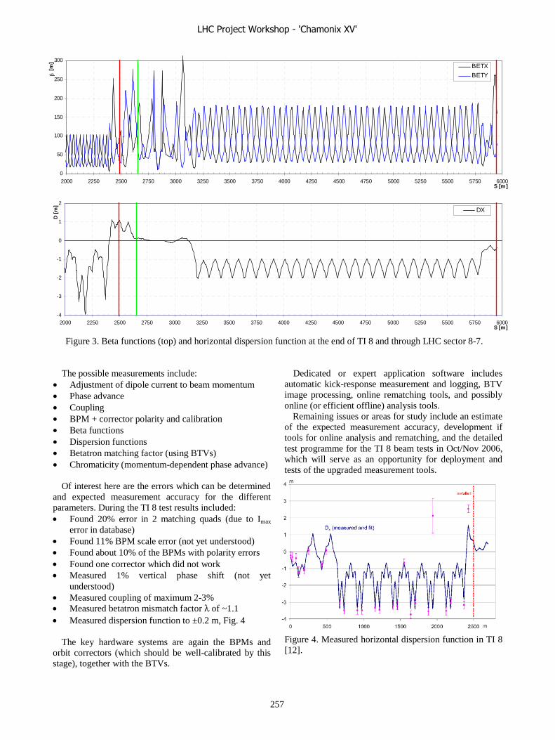
0
50
100
150
200
250
300
2000 2250 2500 2750 3000 3250 3500 3750 4000 4250 4500 4750 5000 5250 5500 5750 6000S [m]
β [
m]
BETX
BETY
-4
-3
-2
-1
0
1
2
2000 2250 2500 2750 3000 3250 3500 3750 4000 4250 4500 4750 5000 5250 5500 5750 6000S [m]
D [
m]
DX
Figure 3. Beta functions (top) and horizontal dispersion function at the end of TI 8 and through LHC sector 8-7.
The possible measurements include: • Adjustment of dipole current to beam momentum • Phase advance • Coupling • BPM + corrector polarity and calibration • Beta functions • Dispersion functions • Betatron matching factor (using BTVs) • Chromaticity (momentum-dependent phase advance)
Of interest here are the errors which can be determined and expected measurement accuracy for the different parameters. During the TI 8 test results included: • Found 20% error in 2 matching quads (due to Imax
error in database) • Found 11% BPM scale error (not yet understood) • Found about 10% of the BPMs with polarity errors • Found one corrector which did not work • Measured 1% vertical phase shift (not yet
understood) • Measured coupling of maximum 2-3% • Measured betatron mismatch factor λ of ~1.1 • Measured dispersion function to ±0.2 m, Fig. 4
The key hardware systems are again the BPMs and orbit correctors (which should be well-calibrated by this stage), together with the BTVs.
Dedicated or expert application software includes automatic kick-response measurement and logging, BTV image processing, online rematching tools, and possibly online (or efficient offline) analysis tools.
Remaining issues or areas for study include an estimate of the expected measurement accuracy, development if tools for online analysis and rematching, and the detailed test programme for the TI 8 beam tests in Oct/Nov 2006, which will serve as an opportunity for deployment and tests of the upgraded measurement tools.
Figure 4. Measured horizontal dispersion function in TI 8 [12].
LHC Project Workshop - 'Chamonix XV'
257

4. Commission Beam Loss Monitor system 6 hours foreseen Estimate 500 shots of 5×10⁹ p+
In addition to the BPMs, the other key distributed instrumentation system are the BLMs. These must be commissioned with beam, such that the system is up and running and recording losses. It is expected that there will be a lot of parasitic opportunity for commissioning the system during threading and first optics tests - prior calibration with a source means that many bugs will have been found, and that reasonable loss numbers can be expected quickly. During this commissioning, the acquisition and display of beam losses for as many monitors as possible is clearly required. Some crosstalk studies, Fig. 5, are also possible, as (in principle) the ‘beam 1’ monitors will be available. This BLM commissioning phase could probably be organised in parallel or in an interleaved fashion with the aperture measurements, since the requirements overlap to some extent.
The dedicated or expert application software required will be an effective BLM display program. The MCS utility [13] may also be required to adjust thresholds. The detailed general and local aperture models should be available.
Remaining issues or areas for study are to finalise the data exchange within the control system (for display, logging, PM, and threshold adjustment), how to make a meaningful BLM display (and whether this should be a prototype for the final LHC version, or a single-use application), and triggering for single-shot logging.
Figure 5. Simulated BLM response for LHC beam 1 and 2.
5. Aperture checks 24 hours foreseen Estimate 1100 shots of 5×10⁹ p+ with 1 μm εn
Although any major problems with the aperture will already have come to light by this stage, this measurement is aimed at a verification that the detailed physical aperture is as expected, particularly for known bottlenecks like the MSI, and also for the LHC arc. In a first iteration, it is planned to sequentially excite 2 correctors at approximately 90º phase difference to generate unclosed betatron oscillations, and to scan systematically over all phases, for both horizontal and vertical planes. The beam transmission will be measured and this will give a generic aperture envelope with little information about the local aperture. In a second iteration, π bumps will be produced to scan the aperture at well-defined locations, to check any local anomalies and to measure in specific regions. Clearly the region around LHCb must be treated with caution to avoid irradiation.
The momentum aperture of the LHC sector can be checked by measuring the transmission as a function of momentum offset, obtained by changing the SPS RF frequency. This will be limited by the TI 8 arc (which has a max |Dx| �������compared to 2 m in LHC), where the momentum aperture has been measured at ±0.003 [12], Fig. 6, about 50% of what is expected for the LHC arc. Measurement of the momentum aperture will therefore require rematching of TI 8 to accept such a large δp.
Fig. 7 illustrates the nomalised aperture at the end of TI 8 and in the LHC sector 7-8.
The key hardware systems are correctly functioning and calibrated correctors and BPMs. A subset at least of the latter should be equipped to provide beam intensity information. The BCTs at the end of TI 8 and in IR7 will be required. BLMs will be needed, especially in the event off a local problem to be investigated, where mobile BLMs could be useful.
Figure 6. Simulated and measured momentum acceptance for TI 8 [14].
LHC Project Workshop - 'Chamonix XV'
258
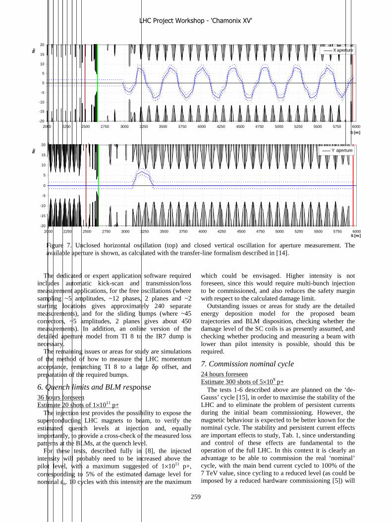
-20
-15
-10
-5
0
5
10
15
20
2000 2250 2500 2750 3000 3250 3500 3750 4000 4250 4500 4750 5000 5250 5500 5750 6000
S [m]
Nσ X aperture
-20
-15
-10
-5
0
5
10
15
20
2000 2250 2500 2750 3000 3250 3500 3750 4000 4250 4500 4750 5000 5250 5500 5750 6000S [m]
Nσ Y aperture
Figure 7. Unclosed horizontal oscillation (top) and closed vertical oscillation for aperture measurement. The available aperture is shown, as calculated with the transfer-line formalism described in [14].
The dedicated or expert application software required includes automatic kick-scan and transmission/loss measurement applications, for the free oscillations (where sampling ~5 amplitudes, ~12 phases, 2 planes and ~2 starting locations gives approximately 240 separate measurements), and for the sliding bumps (where ~45 correctors, ~5 amplitudes, 2 planes gives about 450 measurements). In addition, an online version of the detailed aperture model from TI 8 to the IR7 dump is necessary.
The remaining issues or areas for study are simulations of the method of how to measure the LHC momentum acceptance, rematching TI 8 to a large δp offset, and preparation of the required bumps.
6. Quench limits and BLM response 36 hours foreseen Estimate 20 shots of 1×10¹¹ p+
The injection test provides the possibility to expose the superconducting LHC magnets to beam, to verify the estimated quench levels at injection and, equally importantly, to provide a cross-check of the measured loss patterns at the BLMs, at the quench level.
For these tests, described fully in [8], the injected intensity will probably need to be increased above the pilot level, with a maximum suggested of 1×10¹¹ p+, corresponding to 5% of the estimated damage level for nominal εn. 10 cycles with this intensity are the maximum
which could be envisaged. Higher intensity is not foreseen, since this would require multi-bunch injection to be commissioned, and also reduces the safety margin with respect to the calculated damage limit.
Outstanding issues or areas for study are the detailed energy deposition model for the proposed beam trajectories and BLM disposition, checking whether the damage level of the SC coils is as presently assumed, and checking whether producing and measuring a beam with lower than pilot intensity is possible, should this be required.
7. Commission nominal cycle 24 hours foreseen Estimate 300 shots of 5×10⁹ p+
The tests 1-6 described above are planned on the ‘de-Gauss’ cycle [15], in order to maximise the stability of the LHC and to eliminate the problem of persistent currents during the initial beam commissioning. However, the magnetic behaviour is expected to be better known for the nominal cycle. The stability and persistent current effects are important effects to study, Tab. 1, since understanding and control of these effects are fundamental to the operation of the full LHC. In this context it is clearly an advantage to be able to commission the real ‘nominal’ cycle, with the main bend current cycled to 100% of the 7 TeV value, since cycling to a reduced level (as could be imposed by a reduced hardware commissioning [5]) will
LHC Project Workshop - 'Chamonix XV'
259

reduce the level of knowledge of the magnet cycle and also reduce proportionately the magnitude of the persistent current decay.
With the nominal cycle in place, the first series of injections and measurements should take place after waiting ~30 minutes, for full decay of persistent currents. Once this has been commissioned (i.e. beam injected, threaded and the trajectory corrected) and the first series of measurements made, the injection can be made immediately after recycling, to start to address the issues associated with persistent current decay.
Table 1. Effect of different cycles on persistent current effects (values quoted in units of 10-4).
1.7 ±0.4±1.4-3.7b3
Nominal cycle
Waiting 30’
De-Gauss
0.0 ±0.2±1.2-0.4a2
b2
a1
b1
Error
syst. rand
0.8 ±0.7±8.00.0
0.0 ±0.0±8.00.0
0.0 ±0.1±0.6-1.1
DecayRandomSystematic
1.7 ±0.4±1.4-3.7b3
Nominal cycle
Waiting 30’
De-Gauss
0.0 ±0.2±1.2-0.4a2
b2
a1
b1
Error
syst. rand
0.8 ±0.7±8.00.0
0.0 ±0.0±8.00.0
0.0 ±0.1±0.6-1.1
DecayRandomSystematic
8. Reproducibility and energy offset tests 36 hours foreseen Estimate 300 shots of 5×10⁹ p+, 100 shots of 3×10¹⁰ p+
The reproducibility of the LHC at injection for the ‘nominal’ cycle is an important input into the operational strategy, especially for injection, machine protection and collimation. With the single-pass techniques available, the measurements are expected to be able to resolve between 0.5-1 units of b1 and about 1 unit of b3, by trajectory response and measurement of the dispersion trajectory. The b1 is expected to decay by 1.5-2 units for the nominal cycle (but only by 0.7 units for a cycle which goes to 30% of the 7 TeV level). The random error given in Tab. 1 should not be affected by cycling to lower than the 7 TeV level. These measurements will be made initially after waiting 30’ for the persistent currents to decay, and then directly after recycling. The 24 hours foreseen will not allow very many LHC cycles – from this point of view it is clearly crucial to have the measurement and data-taking tools well prepared and usable from the start.
For some part of the measurements it may be necessary to use 2-3×10¹⁰ p+ per bunch, for improved BPM resolution.
9. Detailed field errors – high statistics 12 hours foreseen Estimate 200 shots of 1×10¹⁰ p+
The kick-response and trajectory analysis using LOCO [16] allows determination of the average a2, b2 and b3
field errors of the main bends, as shown in simulation in Fig. 8, and the b2 errors of the main focussing quadrupoles. The technique can also be extended to check multipole corrector polarity, by strong excitation of these circuits. This measurement requires the machine to be well understood regarding the linear optics, and good stability – it also needs the rms of the BPM noise and of the injection errors to be below 200 μm (corresponding to ~0.2 σ). This appears feasible based on the BPM responses from the TI 8 tests [12], from the measured 0.1 σ rms stability of the TI 8 line [17] and the expected random error of below 0.1 σ rms from the LHC injection system [18].
Figure 8. Effect on horizontal trajectory of b3 field errors of the main dipoles for 40 μrad horizontal (top) and vertical (bottom) kicks [16].
10. Commission machine protection subsystems 12 hours foreseen Estimate 1600 shots of 5×10⁹ p+
The machine protection at injection into the LHC relies on active and passive elements [6], including mobile collimators which must be set very accurately according to the beam axis and envelope. Setting up procedures rely on beam based alignment, and first ideas have already been tested for a single pass [19]. This technique may also be of interest for setting up the LHC machine collimators in inject and dump mode.
LHC Project Workshop - 'Chamonix XV'
260

In the injection test, the beam-based alignment of the TCDI and TDI jaws using a transmission measurement with a single pass will be tested, using 5×10⁹ p+ to limit the integrated losses given the high number of shots which will be required. Some shots of 3×10¹⁰ p+ may also be needed to measure accurately the beam axis. The LHC sequencer can also be tested, since the equipment must have an associated ‘operational state’ which is a function of the previous beam commissioning steps.
Clearly for these tests the collimator control system must be operational, and a high level applications to drive the elements through the setting up procedures.
11. Commission separation & crossing bumps 6 hours foreseen Estimate 100 shots of 5×10⁹ p+
Although the beam tests will start with the crossing and separation bumps switched off, it will be of interest to commission these in order to study the bump closure, induced dispersion, the aperture and possibly the measurement accuracy of the crossing angle. The bump amplitude can if required be limited to well below nominal, in order to avoid irradiation of this region – in any case, the LHCb spectrometer and compensation will remain switched off. Injecting onto the vertical separation bump will mean an adjustment of the trajectory at the injection point by about 0.2 mm and 3.5 μrad – it is also possible to inject onto an opposite polarity bump [20].
-0.01
-0.008
-0.006
-0.004
-0.002
0
0.002
0.004
0.006
0.008
0.01
2400 2500 2600 2700 2800 2900 3000 3100S [m]
x/y
[m]
XY
-20
-15
-10
-5
0
5
10
15
20
2400 2500 2600 2700 2800 2900 3000 3100
S [m]
Nσ
Y aperture
Figure 9. Crossing and separation bump in IR8 (top), together with the normalised aperture available in the vertical plane for nominal bump amplitude.
SUMMARY OF REQUIREMENTS, ISSUES AND TESTS
Requirements The injection test obviously relies on the installation
and hardware commissioning of a major part of the LHC equipment in the sectors 7-8 and 8-1, representing a large subset of the LHC accelerator systems. There are over 20 superconducting magnet types and around 120 circuits, with the injection elements and machine protection subsystems. The instrumentation essentials are the basic BDI systems, comprising the distributed BPM and BLM systems, together with individual BTVs and BCTs.
Regarding controls and software, an almost fully representative set of functionalities must be available. The minimum generic requirements for equipment control must be in place, together with data logging and diagnostics, plus some specific applications as detailed above. The magnet settings generation will need to be fully operational, with FiDeL interfaced to the LHC control system. Other requirements include the sequencer, single-shot injection logging, and online tools for matching and analysis.
Issues Many issues still remain to be solved, or fully worked
out after further study. These include the following aspects: • The ‘nominal’ cycle definition – whether this can be
to the 7 TeV current for the main bends or not, and the implications for the different proposed measurements.
• The expected accuracy of the magnetic model with the de-Gauss cycle.
• The LHC sequencer : whether this can be made as a full prototype, including injection sequencing from the SPS.
• Rollback for the controls system, to aid recovery from the different measurements and commissioning steps.
• The readiness of the collimator controls. • Emittance control for the tests – whether εn of 1 μm is
acceptable for all measurements, or needs to be larger e.g. for the quench tests.
• Verification of the damage levels of the superconducting coils.
• Intensity readback from some BPMS – which locations need to be instrumented in this way.
• Triggering and synchronisation of the single-shot logging
• Scope and feasibility of online matching and analysis tools.
• Whether multi-bunch injection should be commissioned.
Tests A summary table of the proposed tests is given in Tab. 2. This will be updated periodically [21].
Triplet R8
LHC Project Workshop - 'Chamonix XV'
261

Table 2. Breakdown of the proposed tests, with priority, time estimate, intensity and cycle [21]. Priority Time I Shots ��I Cycle Comments
h p+ p+
1End TI8, Injection Steering, commission BDI, timing
1 24 5E+09 500 2.5E+12 de-GaussTDI in, protecting LHCb
2Trajectory acquisition commissioning, trajectory correction, threading, energy matching
1 24 5E+09 500 2.5E+12 de-Gauss To IR7 beam dump
3Linear Optics from kick/trajectory, coupling, BPM polarity checks, corrector polarity checks
1 12 1E+10 400 4.0E+12 de-Gauss
4 Commission BLM system 1 6 5E+09 100 5.0E+11 de-GaussFirst to TDI, then to IR7 dump
Aperture limits, acceptance 1 18 5E+09 1000 5.0E+12 de-GaussOscillations, π bumps, BLMs, BCT
Momentum aperture 1 6 5E+09 100 5.0E+11 de-GaussMove energy of SPS beam
Commission multi-bunch injection ? 2 6 6E+10 50 3.0E+12 de-Gauss BDI acquisition, MKI
6 Determination of quench level - calibrate BLMs 2 36 1E+11 20 2.0E+12 de-GaussStart with pilot and
work slowly up
7Commission normal cycle - recheck dispersion, optics, aperture
2 24 5E+09 300 1.5E+12 Nominal Cycle & wait
Effects of magnetic cycle, variations during decay, reproducibility
2 24 1E+10 300 3.0E+12 Nominal 10 cycles
Energy offset versus time on FB 3 12 2E+10 100 2.0E+12 Nominal Cycle & repeat
9 Field errors (high statistics) 3 12 2E+10 200 4.0E+12 NominalCollect data, off-line analysis
Transfer line collimation studies - TCDI 3 6 5E+09 800 4.0E+12 NominalTDI in - mainly on to TCDI
Injection protection studies - TDI 4 6 5E+09 800 4.0E+12 NominalOn to TDI and IR7 dump
11IR bumps, aperture, separation, crossing angle bumps [LHCb?]
4 6 5E+09 100 5.0E+11 Nominal Careful in LHCb
TOTAL 222 5270 2.9E+13 On to TEDDAYS 9.3 6.5E+12 On to TDI
4.0E+12 On to TCDI
5
8
10
CONCLUSION The injection beam test will be a major step towards an
operational LHC. The test will verify the proper functioning of the fundamental BDI systems, with checks of the BPM resolution, cabling, polarity and offsets, BLM response and resolution, and BTV resolution. The tests will verify with certitude that the aperture is as expected in the critical injection region and also in the arc and around IP8. In addition to the BDI, other hardware will be commissioned with beam, including the main magnets, injection system, orbit correctors, timing and machine protection. The beam will sample all magnetic fields over 1/8 of the machine, which gives direct information about many aspects, including polarities, optics, key field errors to 1 unit, misalignments and corrector cabling. The test allows the deployment of control and correction procedures, via the beam threading, trajectory correction and bumps, and allows the magnetic model accuracy to be checked, providing data about the reproducibility of LHC cycle at injection and confirmation of the expected performance. The test also provides an opportunity to determine magnet quench levels and BLM response.
ACKNOWLEDGEMENT The direct and indirect contributions from many
colleagues are gratefully acknowledged, in particular from L.Bottura, B.Dehning, B.Jeanneret, L.Jensen, V.Kain, M.Lamont, V.Merten, R.Steinhagen and J.Wenninger.
REFERENCES [1] M.Lamont. “Sector Test: Overview, Motivation and
Scheduling”, Proceedings of the 2006 Chamonix Workshop on LHC Performance, 2006.
[2] L.Bottura, “Magnets”, Proceedings of the 2006 Chamonix Workshop on LHC Performance, 2006.
[3] L.Jensen, “Beam Instrumentation foreseen for the LHC sector test”, Proceedings of the 2006 Chamonix Workshop on LHC Performance, 2006.
[4] R.Lauckner, “Control Requirements”, Proceedings of the 2006 Chamonix Workshop on LHC Performance, 2006.
LHC Project Workshop - 'Chamonix XV'
262
[5] R.Saban “Hardware Commissioning”, Proceedings of the 2006 Chamonix Workshop on LHC Performance, 2006.
[6] V.Kain, “What is required to safely fill the LHC”, Proceedings of the 2006 Chamonix Workshop on LHC Performance, 2006.
[7] M.Lamont, “Field model deliverables for sector test and commissioning: when and what ?”, Proceedings of the 2006 Chamonix Workshop on LHC Performance, 2006.
[8] A.Koschik, “Magnet Quenches with Beam”, Proceedings of the 2006 Chamonix Workshop on LHC Performance, 2006.
[9] H.Vincke, “Radiation Issue”, Proceedings of the 2006 Chamonix Workshop on LHC Performance, 2006.
[10] A.Verdier, “First turn in LHC”, LHC Project Note 308, CERN, 2002.
[11] J.Wenninger, “LHC Threading””, minutes CERN AB LTC meeting June 2005.
[12] J.Wenninger et al., “Optics Studies of the LHC Beam Transfer Line TI 8”, Proceedings PAC’05 Particle Accelerator Conference, 2005.
[13] V.Kain et al., “Management of Critical Settings”, Functional Specification, to be published 2006.
[14] B.Goddard et all., “Aperture Studies of the SPS to LHC Transfer Lines”, Proceedings PAC’05 Particle Accelerator Conference, 2005.
[15] O.Brüning, “The Minimum Machine and the first 1000 turns (or so)”, Proceedings of the 2003 Chamonix Workshop on LHC Performance, 2003.
[16] J.Wenninger, “Determination of LHC Main Dipole Field Errors during a Sector Test using Trajectory Analysis”, LHC project note 314, CERN, 2003.
[17] J.Wenninger et al., “Beam Stability of the LHC Beam Transfer Line TI8”, Proceedings PAC’05 Particle Accelerator Conference, 2005.
[18] B.Goddard et al., “Aperture and delivery precision of the LHC injection system”, Proceedings EPAC ’04, European Particle Accelerator Conference 2004.
[19] V.Kain et al., “Beam Based Alignment of the LHC Transfer Line Collimators”, Proceedings PAC 2005 Particle Accelerator Conference, 2005.
[20] W.Herr, “The Solenoids and Dipole magnets of LHC experiments”, Proceedings of the 2006 Chamonix Workshop on LHC Performance, 2006.
[21] http://lhc-injection-test.web.cern.ch/
LHC Project Workshop - 'Chamonix XV'
263

Magnet Quenches with Beam
Alexander Koschik∗, CERN, Geneva, Switzerland
Abstract
The motivation for quenching magnets during the sectortest is revisited and presently assumed quench limits re-called. Which magnet(s) are planned to be used and the as-sociated BLM layout and local aperture layout are detailed.The required beam intensity/emittance/angle to reach thequench limit in the coil is estimated and how this is tobe achieved by steering beam into aperture. The currentknowledge from simulations is reviewed. Requirementsfrom further simulations, extra instruments, controls, ap-plications and logging are briefly enumerated.
MOTIVATION
Given the amount of stored energy of the LHC beam(s),2 × 22 MJ at injection and 2 × 346 MJ at top energy, it isapparent that a safe LHC operation is indispensable. There-fore two main tasks consist in
• protecting magnets against quenches and• protecting the whole machine against damage.
Here we will adhere to the first objective. Once safety isensured another main objective is desirable to achieve: op-erational efficiency. Getting the LHC back to stable beamconditions after an unexpected beam dump (e.g. as a con-sequence of a magnet quench) might take several hours.Likewise, an unnecessary forced beam dump causes also anon-negligible downtime and accordingly we would like to
• minimize the number of quenches and• minimize the number of unnecessary beam dumps.
This optimization problem can only be solved if
• we know the quench level• we have the ability to detect if this level is being
reached.
There are several systems in the LHC to guarantee a safeand efficient operation, but there is only one dedicated ac-tive protection system which enables us to detect whetherthe quench level is being reached or not: the Beam LossMonitor (BLM) system.
The BLMs detect losses outside the cryostat. If thelosses exceed a certain (yet to be determined) threshold abeam dump signal is triggered and the machine is protectedagainst possible magnet quenches and further damage. Inorder for this to work properly, the BLM system must becalibrated in terms of the quench level.
Estimates of quench levels depend on the model used forthe calculation and this is equally valid for the simulation
MagnetsBeam Loss
Monitors (BLM)
Quench Level Loss SignalCorrelation
Uncertainties Uncertainties
Test - Verify - Calibrate
Figure 1: Why to do the quench test with beam: Estab-lishing the correlation between BLM system and magnetquench behavior.
of the BLM response. The associated uncertainties are noteasy to quantify. Therefore a dedicated magnet quench testwith beam is proposed which would allow to
• verify and/or establish the “real-life” quench levels,• verify and/or establish the BLM response signal,• establish the threshold values, which is equal to estab-
lishing the correlation between quench level and BLMsignal ≡ calibration.
All together this is to ensure a safe and efficient LHCoperation, which includes the start-up/comissioning phase,hence increasing the operational efficiency and decreasingdowntime.
BEAM LOSS MONITOR (BLM) SYSTEM
The full description of the BLM system can be foundin [1, 2]. A look at the cold aperture limits at injection en-ergy immediately shows the most likely locations of beamlosses and accordingly the most probable locations of mag-net quenches. As a consequence the BLM layout has beenchosen in order to cover these regions. The cold aperturelimits at injection include:
• Triplet quadrupoles• Dispersion suppressor quadrupoles• Arc quadrupoles• (Main dipoles)
Fig. 2 shows the ARC BLM layout at the mainquadrupoles. There are 6 BLMs per quadrupole locationmounted in the horizontal plane, which are indicated asblue ( ) rectangles. The BLM signal shown is due topoint-like proton impact at different longitudinal positionsat an impact angle of 0.25 mrad. As can be seen, theshower of secondary particles is typically larger than about1 m.
LHC Project Workshop - 'Chamonix XV'
264

MB
SEX
T
BPM
OC
TU
MQ MCBH/V
DE
CA
MBx xx x
z=400
z=325z=200
z=−100z=0
z=−325
xx
z=300
x
BEAM 2
Figure 2: BLM layout and BLM signal depending on dif-ferent impact positions. By courtesy of L.Ponce.
In order to get the beam loss monitor signal for a spe-cific beam impact situation, these signals shown in Fig. 2have to be convoluted with the longitudinal beam profile.The exact loss pattern at a given location can be obtainedvia particle tracking using e.g. MAD-X. This is subject tofurther studies.
MAGNET QUENCH LEVELS
The expected quench levels that have also been used asa basic reference in the LHC design report are summarizedin [3]. In the following we repeat only the most importantkey points from this report.
The number of protons nq that is required to induce aquench in a super-conducting magnet is
nq =ΔQc
ε, (1)
where ΔQc is the amount of energy or heat per unit volumethat will raise the temperature to its critical value Tc. Theenergy density ε per proton has been obtained by CASIMand FLUKA simulations and is being discerned into peakand radial average, as well as local (per proton) and dis-tributed (per proton/m) depositions.
For transient losses (where duration of loss δt � τmetal,temperature decay time constant, see [3, Sec.4–5]) there isno temperature equalization between the inner and outeredge of the wire and in addition there is no heat transfer tothe helium. In this case the energy deposition is supposedto occur in the most exposed cable and the critical amountof heat ΔQc is given by the enthalpy reserve ΔHwire
ΔQc = ΔHwire and ε = εpeak . (2)
Depending on the loss pattern (local or distributed) the peakenergy deposition of one proton in the most exposed cableεpeak has been estimated to be
εpeak, local = 3.8 × 10⁻¹¹ J·cm−3 ,
εpeak, dist. = 3.8 × 10⁻¹¹ J·m·cm−3 .(3)
The enthalpy reserve of the SC wire at injection energyof 450 GeV has been estimated to be
ΔHwire = 38 mJ·cm−3 . (4)
Using these numbers (Eqs. 3–4) gives us finally the quenchlevel for transient losses at injection energy in number ofprotons (Eq. 1):
nq,450 GeV,fast =
{109 p locally ,
109 p/m distributed .(5)
This is the proton density of an impacting beam that is re-quired to cause a quench in the magnet coil. Already [3]states that these numbers should be used with caution,therefore we assume that Eq. 5 indicates the order of mag-nitude, but does not provide accurate numbers.
There are ongoing studies and refined simulations donein order to get more definite numbers for the quench levelswith beam [4, 5, 6]. Recent results are shown in Tab. 1,where the interesting numbers for transient losses at injec-tion energy are still preliminary results that need furtherinvestigations. From these numbers however, we concludethat the required proton density to cause a magnet quenchat injection energy in the case of fast losses is still in theorder of
nq,450 GeV,fast ≈ 109 p/m . (6)
MAGNET QUENCH TEST
The basic idea for this test is to steer the beam into asuper-conducting magnet and induce a quench.
The planning of the sector test currently foresees 36hfor performing the BLM calibration by quenching magnetswith beam. This time should be rather allocated towardsthe end of the sector test, after all basic checks have beencompleted successfully. It is apparent that such a test canonly be accomplished once that reliable, reproducible in-jection and beam conditions have been established.
Concerning the BLM calibration, a minimum of10 quenches shall the carried out. One part of the test couldconsist in quenching the same magnet several times withreproducible beam conditions. This would give some sta-tistical meaning to base the BLM calibration upon.
The recovery time after a beam induced quench is subjectto ongoing debates and accordingly there is a wide spec-trum of possible numbers. The assumptions range from15 min − 5 h. For magnets powered at low currents weadopt an optimistic–conservative approach and assume arecovery time τrecover of
τrecover ≈ 2 h,
LHC Project Workshop - 'Chamonix XV'
265
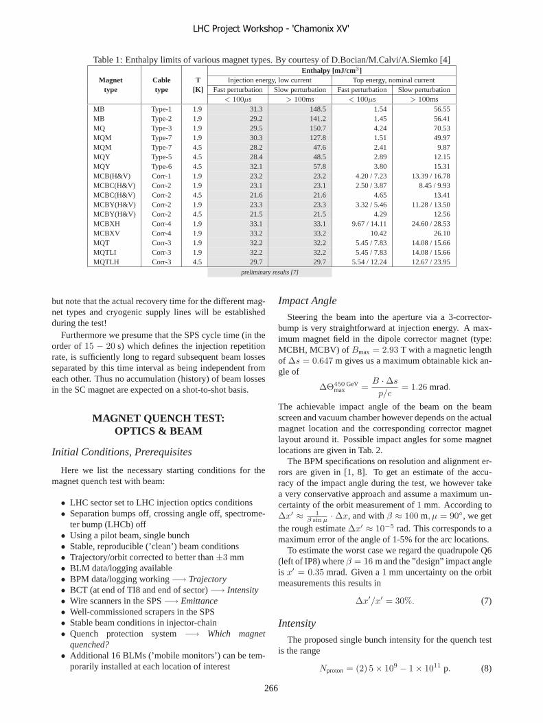
Table 1: Enthalpy limits of various magnet types. By courtesy of D.Bocian/M.Calvi/A.Siemko [4]
Magnettype
Cabletype
T[K]
Enthalpy [mJ/cm3]Injection energy, low current Top energy, nominal current
Fast perturbation Slow perturbation Fast perturbation Slow perturbation< 100µs > 100ms < 100µs > 100ms
MB Type-1 1.9 31.3 148.5 1.54 56.55MB Type-2 1.9 29.2 141.2 1.45 56.41MQ Type-3 1.9 29.5 150.7 4.24 70.53MQM Type-7 1.9 30.3 127.8 1.51 49.97MQM Type-7 4.5 28.2 47.6 2.41 9.87MQY Type-5 4.5 28.4 48.5 2.89 12.15MQY Type-6 4.5 32.1 57.8 3.80 15.31MCB(H&V) Corr-1 1.9 23.2 23.2 4.20 / 7.23 13.39 / 16.78MCBC(H&V) Corr-2 1.9 23.1 23.1 2.50 / 3.87 8.45 / 9.93MCBC(H&V) Corr-2 4.5 21.6 21.6 4.65 13.41MCBY(H&V) Corr-2 1.9 23.3 23.3 3.32 / 5.46 11.28 / 13.50MCBY(H&V) Corr-2 4.5 21.5 21.5 4.29 12.56MCBXH Corr-4 1.9 33.1 33.1 9.67 / 14.11 24.60 / 28.53MCBXV Corr-4 1.9 33.2 33.2 10.42 26.10MQT Corr-3 1.9 32.2 32.2 5.45 / 7.83 14.08 / 15.66MQTLI Corr-3 1.9 32.2 32.2 5.45 / 7.83 14.08 / 15.66MQTLH Corr-3 4.5 29.7 29.7 5.54 / 12.24 12.67 / 23.95
preliminary results [7]
but note that the actual recovery time for the different mag-net types and cryogenic supply lines will be establishedduring the test!
Furthermore we presume that the SPS cycle time (in theorder of 15 − 20 s) which defines the injection repetitionrate, is sufficiently long to regard subsequent beam lossesseparated by this time interval as being independent fromeach other. Thus no accumulation (history) of beam lossesin the SC magnet are expected on a shot-to-shot basis.
MAGNET QUENCH TEST:OPTICS & BEAM
Initial Conditions, Prerequisites
Here we list the necessary starting conditions for themagnet quench test with beam:
• LHC sector set to LHC injection optics conditions• Separation bumps off, crossing angle off, spectrome-
ter bump (LHCb) off• Using a pilot beam, single bunch• Stable, reproducible (’clean’) beam conditions• Trajectory/orbit corrected to better than ±3 mm• BLM data/logging available• BPM data/logging working −→ Trajectory• BCT (at end of TI8 and end of sector) −→ Intensity• Wire scanners in the SPS −→ Emittance• Well-commissioned scrapers in the SPS• Stable beam conditions in injector-chain• Quench protection system −→ Which magnet
quenched?• Additional 16 BLMs (’mobile monitors’) can be tem-
porarily installed at each location of interest
Impact Angle
Steering the beam into the aperture via a 3-corrector-bump is very straightforward at injection energy. A max-imum magnet field in the dipole corrector magnet (type:MCBH, MCBV) of Bmax = 2.93 T with a magnetic lengthof Δs = 0.647 m gives us a maximum obtainable kick an-gle of
ΔΘ450 GeVmax =
B · Δs
p/c= 1.26 mrad.
The achievable impact angle of the beam on the beamscreen and vacuum chamber however depends on the actualmagnet location and the corresponding corrector magnetlayout around it. Possible impact angles for some magnetlocations are given in Tab. 2.
The BPM specifications on resolution and alignment er-rors are given in [1, 8]. To get an estimate of the accu-racy of the impact angle during the test, we however takea very conservative approach and assume a maximum un-certainty of the orbit measurement of 1 mm. According toΔx′ ≈ 1
β sin μ · Δx, and with β ≈ 100 m, μ = 90◦, we getthe rough estimate Δx′ ≈ 10−5 rad. This corresponds to amaximum error of the angle of 1-5% for the arc locations.
To estimate the worst case we regard the quadrupole Q6(left of IP8) where β = 16 m and the ”design” impact angleis x′ = 0.35 mrad. Given a 1 mm uncertainty on the orbitmeasurements this results in
Δx′/x′ = 30%. (7)
Intensity
The proposed single bunch intensity for the quench testis the range
Nproton = (2) 5 × 10⁹ − 1 × 10¹¹ p. (8)
LHC Project Workshop - 'Chamonix XV'
266

A magnet will quench at a certain proton density impactingon it. During the test we will therefore vary the intensity ofthe beam in order to reach the expected quench level. Wewould start with a single bunch at the pilot beam inten-sity of 5 × 10⁹ p and then increase the intensity in steps of∼20% until the quench occurs. In a first iteration the upperlimit for the intensity would be set at 5 × 10¹⁰ p, which iswell below the expected damage level of 2 × 10¹² p [9].The absolute maximum would be a single bunch intensityof 1 × 10¹¹ p. The intensity can be reduced to a minimumof 2 × 10⁹ p if magnets quench already at the pilot bunchintensity, however less is not possible due to sensitivity andresolution restrictions of the LHC BPMs. In this case an al-ternative is also to go to smaller impact angles and decreasethe proton density by that.
The intensity variation can either be achieved by
• requesting different intensities from the PS Booster or• scraping the beam in the SPS.
The first solution has the advantage of getting a constantemittance for different intensities, but comes with the draw-back of being slow in the set-up. The second solution is ac-complished more rapidly, however the emittance changes.
The absolute intensity resolution of the BCTs is 5% ofthe pilot bunch intensity with a shot-to-shot fluctuation of0.2-0.5%. The accuracy of the intensity determination istherefore expected to be much better than 10%.
Emittance
The pilot bunch emittance for the sector test will be1μm·rad, whereas the nominal pilot bunch emittance will be3.5μm·rad. Both values are equally suited for the test, buta lower value is preferred as it reduces the impact lengthof the beam. In case we use scrapers in the SPS for theintensity variation, the expected range for the normalizedtransverse emittance is
εn = 0.5 − 3.5μm·rad. (9)
We assume that the emittance measurement in the SPS isaccurate to about 30%.
Impact Length
beam screen orvacuum chamber
reference orbit
l
S
�
beam
Figure 3: Definition of the 1σ-impact length, given by theimpact angle α ≈ z′ and the 1σ beam size s = ±1σ.
The impact length l, as depicted in Fig. 3 can be esti-mated by
l =s
sin z′=
2 ·√
ε · β + D2 · δ2
sin z′z = x|y, (10)
where s = ±σ is the 1σ-beam size, α ≈ z′ is the im-pact angle and ε, β,D, δ are the transverse emittance, theβ-function and dispersion function at the impact positionand the momentum spread respectively.
Table 2: Impact lengths l for two different magnet types.
β [m] D [m] x′
[mrad]δ
εn
[μm·rad] l [m]
MQM MQ.6L8.B2:16 0.1 0.35 0.5 10−3 1 1.0816 0.1 0.35 0.5 10−3 3.5 1.9716 0.1 0.35 1.5 10−3 1 1.3516 0.1 0.35 1.5 10−3 3.5 2.13
MB MB.C12R7.B2:135 1.65 1.23 0.5 10−3 1 1.60135 1.65 1.23 0.5 10−3 3.5 2.10135 1.65 1.23 1.5 10−3 1 4.12135 1.65 1.23 1.5 10−3 3.5 4.34
Tab. 2 shows some impact lengths depending on themagnet location and beam parameters. The length ismostly dominated by the impact angle, although momen-tum spread can also have a significant effect. The depen-dance on changes in emittance or β-function are less influ-ential. What is important for this test is the fact, that we canachieve very local impact with an impact length of ∼ 1 m.
To estimate the error on the impact length, we assumethat the emittance measurement is known with a resolutionof 30% and the momentum spread and the optics functionsto be known with an accuracy of 20%. Together with anuncertainty on the impact angle of 30% this gives us anuncertainty of the impact length (see Eq. 10) of
Δl/l = 35%. (11)
Test Procedure
Set optics (3-bump)
Vary intensity 5x10 9 - max. 1x10 11
+logging all relevant data (BPM, BLM, BCT, wire scanner, ...)
Magnet quench
Figure 4: Quench test
The test proce-dure is summarizedin Fig. 4 and inFig. 5. The idea isto set the optics tosteer the beam intothe magnet and then
only vary one parameter which is the intensity. This relieson only marginal fluctuations of the other beam and op-tics conditions form shot-to-shot. Recording of the relevantbeam parameters and optics parameters allow in the endto determine the impact length l and the impact position,which define the proton density (protons/m) nq = I/l thatcaused the magnet to quench, where I is the bunch inten-sity. A rough estimate on the accuracy that can be obtainedon this number, assumes 10% uncertainty on the intensityand the 35% uncertainty on the impact length from (11),
Δnq/nq = 36.5%. (12)
LHC Project Workshop - 'Chamonix XV'
267

Table 3: Magnet types to be used during quench test. Preliminary list as of Jan.2006
MagnetType
Temp.[K]
Quench Level[mJ/cm3]
What/Where Why
Main magnets
MQM 4.5 28.2 @ 0.1ms MQM(L).6L8.B2quadrupole Q6
• low quench level• aperture limit at injection• ”standalone” magnet• separate powering and cooling
MQTL 4.5 29.7 @ 0.1ms MQTLH.x6R7quadruploe Q6
• low quench level• strongly requested by collimation team• ”standalone” magnet• separate powering and cooling• Test at nominal current!
MQ 1.9 29.5 @ 0.1ms Main arc quadrupoles • low quench level• aperture limit at injection
MB 1.9 31.3 @ 0.1ms Arc dipoles• cover large fraction of the machine• cold aperture at injection limited in the arcs
(quadrupoles + dipoles)
Further candidatesMQY 4.5 32.1 @ 0.1ms Q4 low quench levelMQM/L 1.9 30.3 @ 0.1ms Q7/8/9/10 low quench levelMQT 1.9 32.2 @ 0.1ms Tuning quads low quench levelMCBX 1.9 33.1 @ 0.1ms low quench levelMCBY 1.9 33.2 @ 0.1ms low quench level
MCBH,MCBV
1.9 23.2 @ 0.1ms Orbit correctors • low quench level• may quench before main magnets
Beam Parameters Emittance Intensity Momentum spread
Optics Parameters -function Dispersion Trajectory/Orbit
Impact Length Impact Position
Proton density that causedquench in SC magnet
BLM signal
Determination ofquench level
Calibration
β
Figure 5: What we want to learn from the quench test.
MAGNET QUENCH TEST: WHICHMAGNETS?
One of the important questions for this test is: Whichmagnets are we going to use? As already described, onespecific magnet could be quenched more than once underreproducible conditions, therewith attaining a good BLMcalibration. Additionally such a test can provide infor-mation on the quench behavior of different magnet types.
Finally, some magnet locations are better than others interms of optics (corrector magnets nearby), cooling (sep-arate cryogenic supply) and powering (separate circuit).Tab. 3 gives a preliminary list of magnet candidates to-gether with some rationales why these types are of interest.
Q6
It should be noted that noquench attempt will be made atany location before or near IP8, be-cause of the requirement of keep-ing irradiation and activation at thelowest possible limit in the LHCbarea.
As can be seen from Tab. 3, themagnet MQTLH (Q6) right of IR7offers interesting features. In par-ticular it is the last magnet be-fore the temporary beam dump andtherefore can be tested and rampedto nominal current without any im-plications on the optics.
The figure to the left shows apossible 3-bump to test the quenchbehavior of the Q6 left of IP8(MQML.6L8.B2).
LHC Project Workshop - 'Chamonix XV'
268

CONCLUSIONS & FOLLOW-UP
We propose a well-defined and controlled magnetquench test with beam to establish
• the absolute quench levels,• the BLM threshold values,• knowledge of the relation between loss pattern,
quench level and BLM signal.
This test is essential for an early calibration of the BLMsystem and in fact is an integral part of the commissioningof the BLM system. Furthermore it is a very good test-runfor the quench protection system and the related machineprotection systems.
To fully profit from this measurement the optics solu-tions to steer the beam into the magnets should be refinedfurther and GEANT/FLUKA simulations should be car-ried out using the beam loss patterns from these particu-lar optics and layout of the impact situations during thequench test. A successful test will considerably improveour knowledge on the quench behavior of different magnettypes as required for reliable simulations.
ACKNOWLEDGMENTS
The help and valuable input from G.Arduini, D.Bocian,T.Bohl, H.Burkhardt, B.Dehning, B.Goddard, E.B.Holzer,J.M. Jowett, K.H.Mess, V.Kain, M.Lamont, L.Ponce,A.Siemko, R.van Weelderen and many others is gratefullyacknowledged.
REFERENCES
[1] O. Bruning, P. Collier, P. Lebrun, S. Myers, R. Ostojic,J. Poole, and P. Proudlock, editors. The LHC Design Report.CERN, Geneva, Switzerland, 2004. CERN-2004-003.
[2] J.B. Jeanneret and H. Burkhardt. Measurement of the beamlosses in the LHC rings. CERN EDMS Doc. LHC-BLM-ES-0001 v.2.0, EDMS Id: 328146, CERN, Geneva, Switzerland.
[3] J.B. Jeanneret, D. Leroy, L. Oberli, and T. Trenkler. Quenchlevels and transient beam losses in LHC magnets. LHCProject Report, 25 May 1996. CERN-LHC-PROJECT-REPORT-044, 16p.
[4] A. Siemko. Status of the LHC magnet quench level calcula-tions. Presented at the LTC meeting on 19 Oct 2005, 2005.
[5] A. Siemko and M. Calvi. Beam loss induced quench levels. InJ. Poole, editor, Proceedings of the 2nd LHC Project Work-shop - Chamonix XIV , 17–21 Jan 2005 , CERN, Geneva,Switzerland, pages 296–299. CERN-AB-2005-014, 320p.
[6] R. Bruce, S. Gilardoni, and J.M. Jowett. BFPP losses andquench limit for LHC magnets. LHC Project Note, 12 Jan2006. CERN-LHC-PROJECT-NOTE-379, 29p.
[7] D. Bocian. Private communication. To be published as LHCProject Report.
[8] J-P. Koutchouk. Measurement of the beam position in theLHC main rings. CERN EDMS Doc. LHC-BPM-ES-0004v.2, EDMS Id: 327557, CERN, Geneva, Switzerland.
[9] V. Kain. Damage levels: Comparison of experiment and sim-ulation. In J. Poole, editor, Proceedings of the 2nd LHCProject Workshop - Chamonix XIV , 17–21 Jan 2005 , CERN,Geneva, Switzerland, pages 299–302. CERN-AB-2005-014,320p.
LHC Project Workshop - 'Chamonix XV'
269

BEAM INSTRUMENTATION FORESEEN FOR THE LHC SECTOR TEST
Lars K. Jensen CERN, Geneva, Switzerland
Abstract
The state of installation and preparedness of the large distributed systems - BLMs and BPMs, and discrete instrumentation BCT and BTV is covered. The need and plans for other systems, BST for example, is also mentioned. The required controls infrastructure is described along with the proposed series of tests that will be performed to confirm readiness before the test itself. The proposed acquisition modes during the test are also discussed.
BEAM-POSITION MONITORS
Description The LHC ‘closed-orbit and bunch capture’ system that
works at the nominal bunch frequency 40MHz is described in several papers: Engineering specification [1] and an up-to-date design description [2]. A schematic of the tunnel electronics can be seen in figure 1.
Figure 1: overview of tunnel electronics Two types of BPMs will be used in the LHC:
A) Cold BPMs inside the cryostats B) Warm BPMs on dedicated supports
From the BPM electrodes (buttons or strip-lines depending on the BPM type), the beam induced signals are connected to the Wide-Band-Time-Normaliser (WBTN) over short (in the arcs) or long (in the LSSs and RRs) coaxial cables. At the output of the WBTN a short single-mode optical fibre (patch-cord) is used to connect to the optical fibre patch panel. A WorldFIP receiver module is used to control local settings for calibration generators used during the commissioning of the BPM system and a sensitivity switch during the running of the LHC.
Availability of equipment All cold BPM bodies are believed to be available
whereas the production of the warm BPM bodies and associated strip-lines has recently started in Russia (BINP). A close follow-up of the quality and availability of these will be required during the spring of 2006. The production of the special supports for the warm BPM bodies has started in Portugal and no problems are expected here. In the arcs starting from Q8, front-end crates as were used for the TI8 trajectory system will be distributed and installed by TS/IC. All necessary crates are available and can be installed as soon as the magnet interconnections are finished. The remaining equipment including what is needed for the acquisition (SR8 and SR7) has been ordered and will become available during spring 2006.
Installation A contract will be signed shortly allowing a team of
Russian collaborators to come to CERN starting June 2006. They should fit the common BPM and BLM front-end chassis to the crates and connect the WorldFIP cable and power cord to the tunnel equipment. In the LSSs and RRs where special crates are used, this work will be done by AB/BI. The installation of all front-end electronics and the connection of coaxial cables to the BPMs will also be done by AB/BI.
Commissioning The interested reader is invited to see [3] how AB/BI
intends to commission the BPM system. Cabling errors cannot be completely excluded. The recent TI8 experience from 2004 showed an error rate of approximately 5% [4]. The LHC BPM system will be much more complicated than TI8 as there are two BPMs per quadrupole (one for each beam) of which each measures in both planes, i.e. a total of eight coaxial cables instead of the two per quadrupole for TI8. A very thorough procedure will be put in place during installation to minimize these errors. It is believed that with the current trajectory software the identification of any remaining errors with beam should be straightforward. A short access to the LHC tunnel would be needed to correct these problems. AB/BI expects to be ready in time for the hardware commissioning period starting during the late summer of 2006.
Acquisition modes Two acquisition modes to acquire the beam trajectories
are proposed: A) Asynchronous, auto-triggered FIFO mechanism
that will always work if the intensity of the beam
BPM
WBTN
Fibre-patch
WorldFIP
220 V
WorldFIP Field-bus
Coax
LHC Project Workshop - 'Chamonix XV'
270
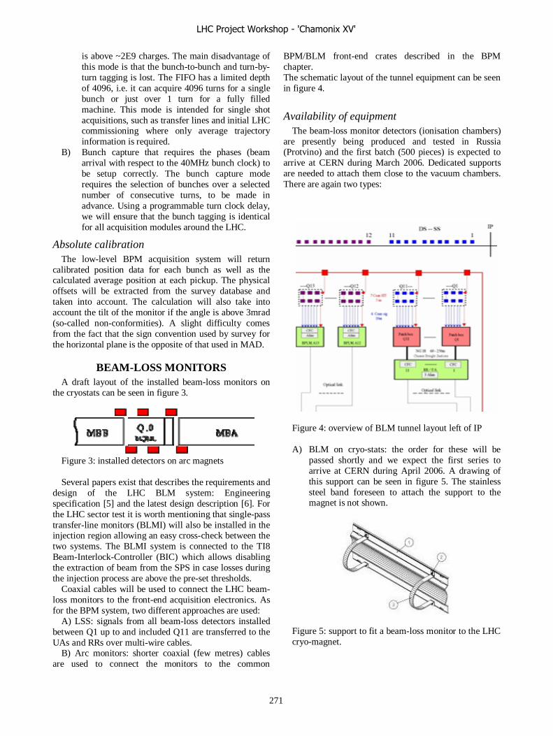
is above ~2E9 charges. The main disadvantage of this mode is that the bunch-to-bunch and turn-by-turn tagging is lost. The FIFO has a limited depth of 4096, i.e. it can acquire 4096 turns for a single bunch or just over 1 turn for a fully filled machine. This mode is intended for single shot acquisitions, such as transfer lines and initial LHC commissioning where only average trajectory information is required.
B) Bunch capture that requires the phases (beam arrival with respect to the 40MHz bunch clock) to be setup correctly. The bunch capture mode requires the selection of bunches over a selected number of consecutive turns, to be made in advance. Using a programmable turn clock delay, we will ensure that the bunch tagging is identical for all acquisition modules around the LHC.
Absolute calibration The low-level BPM acquisition system will return
calibrated position data for each bunch as well as the calculated average position at each pickup. The physical offsets will be extracted from the survey database and taken into account. The calculation will also take into account the tilt of the monitor if the angle is above 3mrad (so-called non-conformities). A slight difficulty comes from the fact that the sign convention used by survey for the horizontal plane is the opposite of that used in MAD.
BEAM-LOSS MONITORS A draft layout of the installed beam-loss monitors on
the cryostats can be seen in figure 3.
Figure 3: installed detectors on arc magnets Several papers exist that describes the requirements and
design of the LHC BLM system: Engineering specification [5] and the latest design description [6]. For the LHC sector test it is worth mentioning that single-pass transfer-line monitors (BLMI) will also be installed in the injection region allowing an easy cross-check between the two systems. The BLMI system is connected to the TI8 Beam-Interlock-Controller (BIC) which allows disabling the extraction of beam from the SPS in case losses during the injection process are above the pre-set thresholds.
Coaxial cables will be used to connect the LHC beam-loss monitors to the front-end acquisition electronics. As for the BPM system, two different approaches are used:
A) LSS: signals from all beam-loss detectors installed between Q1 up to and included Q11 are transferred to the UAs and RRs over multi-wire cables.
B) Arc monitors: shorter coaxial (few metres) cables are used to connect the monitors to the common
BPM/BLM front-end crates described in the BPM chapter. The schematic layout of the tunnel equipment can be seen in figure 4.
Availability of equipment The beam-loss monitor detectors (ionisation chambers)
are presently being produced and tested in Russia (Protvino) and the first batch (500 pieces) is expected to arrive at CERN during March 2006. Dedicated supports are needed to attach them close to the vacuum chambers. There are again two types:
Figure 4: overview of BLM tunnel layout left of IP A) BLM on cryo-stats: the order for these will be
passed shortly and we expect the first series to arrive at CERN during April 2006. A drawing of this support can be seen in figure 5. The stainless steel band foreseen to attach the support to the magnet is not shown.
Figure 5: support to fit a beam-loss monitor to the LHC cryo-magnet.
LHC Project Workshop - 'Chamonix XV'
271

B) BLM on special supports: the order for these supports will have to go though a market survey and we expect to the first series late spring also.
The market survey for the front-end electronics
modules CFCs (Current-to Frequency-Converter) has been finalised and the production will start shortly. We expect to have the first modules available during April 2006. The remaining equipment including what is needed for the acquisition of these signals in the surface buildings (SR7 and SR8) will also become available in time for hardware commissioning.
Installation As mentioned earlier, a team of Russian collaborators
will come to CERN during summer 2006. This team will install the entire BLM tunnel electronics (including in the LSS).
Commissioning The text in [3] along with E. B. Holzer and B.
Dehning’s papers from Chamonix 2006 give information on the commissioning of the BLM system. A battery will be connected to the coaxial cables immediately in front of the detector to validate the entire measurement chain (thus excluding the detectors themselves). AB/BI will request permission from SC/RP to use a weak radioactive source to verify the entire chain. We can this way exclude all cabling errors and detect and correct for all gain differences.
Acquisition modes AB/BI proposes to use two acquisition modes: A) A periodic update (1sec nominally) will become
vital when the LHC starts working with circulating beams. This mode would help verifying that the tools proposed by AB/CO (fixed-displays/logging etc) are capable of handling data at the requested rate (although for a limited number of devices in the beginning). It should be mentioned that this test can be done without beam in the LHC also.
B) A separate mode (on demand, triggered by external event) that would allow a fail-safe acquisition of losses linked to injection and possibly also for losses at extraction.
The main data returned by the LHC system for the
sector test is the contents of a so-called ‘logging buffer’. The values in this buffer will be the maximum value acquired since the last reset (read) of the value. A table summarizing the integration and refresh times can be found in figure 6.
BLM Moving Windows Refresh time
40 μs steps ms
40 μs steps ms
1 0.04 1 0.04 2 0.08 1 0.04 8 0.32 1 0.04 16 0.64 1 0.04 64 2.56 2 0.08
256 10.24 2 0.08 2048 81.92 64 2.56 8192 327.68 64 2.56
32768 1310.72 2048 81.92 131072 5242.88 2048 81.92 524288 20971.5 32768 1310.72 2097152 83886.1 32768 1310.72
Figure 6: the logging buffers with associated refresh times For the LHC sector test we propose to publish the contents of the logging buffer above around 100msec after each injection (here the values for the first 10 integration times have been updated locally).
BEAM-SIZE MEASUREMENT 6 new beam-size measurement devices are needed
during the LHC sector test. The complete list can be seen in figure 7.
Figure 7: the list of BTV devices for the sector test The CERN-wide BTV acquisition has been tested
successfully several times with beam, the latest being in LEIR. A description can be found here [7]. The acquisition systems for the devices at the end of TI8 and in the injection region have already been installed in UA87 whereas the images from the device at the end of the arc in front of Q6R7 will be acquired using a system in UJ76.
Availability of equipment The BTVI device at the end of TI8 is part of the
previous delivery from Russia and is therefore available and ready for installation. The three BTVSI devices are presently being fabricated at the same place as the BTVI and delivery is expected during spring 2006. The last two devices BTVSS and BTVST are being designed and produced at CERN. All other related equipment is available and ready to be installed.
BTVI.88119 (at septum entrance) BTVSS.A6R8.B2 (at exit of MSI) BTVSI.B5R8.B2 (at kicker entrance) BTVSI.A5R8.B2 (at kicker exit) BTVST.4R8.B2 (in front of the TDI) BTVSI.7R7.B2 (in front of Q6)
LHC Project Workshop - 'Chamonix XV'
272

Installation and commissioning AB/BI will install all the BTV devices in the LHC
tunnel and commission them according to a procedure put in place in since 2004.
Acquisition: The acquisition of the beam at injection will be
triggered by SPS extraction events as was tested during the 2004 TI8 tests. All levels of detail from the raw 3D image to the calculated horizontal and vertical sigma’s can be provided in the standard BTVI property [8].
BEAM-CURRENT MEASUREMENT A temporary Fast BCT device will be installed just
upstream of the beam-dump to acquire the beam intensity.
Availability of equipment AB/BI will install the device which was foreseen to be
installed at the end of the TI2 transfer-line during 2007 which means everything is already available.
Installation and commissioning AB/BI will install the BCT tank in the tunnel. What is
still missing is its exact location and 3D integration to allow a suitable support to be found or produced and cables to be pulled. The commissioning of the BCT is described here [4]. Two hardware modifications have been made since this kind of Fast BCT transformer was last tested with beam on the SPS: • Low bandwidth channel to acquire total intensity
(independent of the 40MHz phase setting) • Sensitivity switch to improve the resolution for low
intensity beams. The setting of this switch should be changed around a bunch intensity of 2E10 charges as the electronics will otherwise saturate.
We hope with these new measures to be able to give an absolute calibration and a resolution better than 10% on the LHC pilot bunch.
Acquisition: The acquisition of the beam-current information will be
armed (as in TI8) by means of SPS extraction events and triggered using fast extraction pre-pulses that normally are transmitted a few turns before the beam is extracted from the SPS. The values returned will include the integrated as well as the bunch intensities (when the 40MHz phase has been correctly setup).
CONTROLS INFRASTRUCTURE The list below presents what’s missing in terms of
controls infrastructure. 1) Ethernet installation in UJ76 and RR77 (IT/CS) 2) Timing (MTG) installation in SR7, UJ76 and
RR77 (AB/CO) 3) WIFI installation for local commissioning of
AB/BI equipment in SR8, SR7 and UJ76
The BPM system as earlier mentioned, relies on a working WorldFIP installation to function correctly. The AB/CO group is responsible for the hardware (so-called gateway PCs) and the software that was successfully tested during the TI8 tests.
Post-mortem A first attempt with beam in the LHC will be made to
test the post-mortem mechanism for BPM and BLM systems during the sector test. The signals for trigger and release will be transmitted using the Beam Synchronous Timing. The exact requirements for the BLM system are still to be discussed.
IN CASE OF PROBLEMS ‘EN ROUTE’ The BPM system working in auto-trigger mode will
identify the region in which most of the beam is lost (trigger level around 1E9 charges). With the expected resolution of the BLM system (around 5E7 protons) this should also help to identify aperture restrictions. A limited number of proto-type BPM intensity cards will be produced that could be used to identify intensity changes between chosen locations of ~10% (after correction for position variation).
CONCLUSIONS The LHC sector test with beam is an important
milestone for AB/BI. It will allow the large scale testing of the BPM and BLM instrumentation. We have identified nothing major preventing the LHC sector test taking place. Lots of equipment will become available during the spring of 2006 and we now need to finalize the procedures for test, installation and commissioning. It’s becoming clear that a close coordination will be needed both for hardware commissioning and for the software development.
REFERENCES [1] J. P. Koutchouk et al: “Measurement of the beam
position in the LHC main rings”, EDMS: 327557 [2] R. Jones et al: “The LHC Orbit and Trajectory
System” CERN-AB-2003-057-BDI [3] E.B. Holzer et al: Proceeding from Chamonix 2005 [4] L. Jensen: “The instrumentation of the TI8 SPS to
LHC transfer-line”, CERN-AB-2005-071 [5] J. B. Jeanneret et al, “On the measurement of the
beam losses in the LHC rings”, EDMS: 328146 [6] E. B. Holzer et al “Design of the Beam Loss
Monitoring System for the LHC Ring”, LHC-Project-Report-781
[7] E. Bravin et al: “A new TV beam observation system for CERN”, CERN-AB-2005-076
[8] A. Guerrero: “BTVI Software Specification”, EDMS: 485042
LHC Project Workshop - 'Chamonix XV'
273

MAGNETS
L. BotturaCERN, Geneva, Switzerland
Contribution not received
LHC Project Workshop - 'Chamonix XV'
274
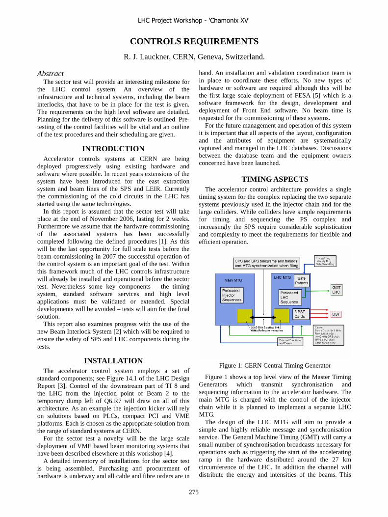
CONTROLS REQUIREMENTS
R. J. Lauckner, CERN, Geneva, Switzerland.
Abstract The sector test will provide an interesting milestone for
the LHC control system. An overview of the infrastructure and technical systems, including the beam interlocks, that have to be in place for the test is given. The requirements on the high level software are detailed. Planning for the delivery of this software is outlined. Pre-testing of the control facilities will be vital and an outline of the test procedures and their scheduling are given.
INTRODUCTION Accelerator controls systems at CERN are being
deployed progressively using existing hardware and software where possible. In recent years extensions of the system have been introduced for the east extraction system and beam lines of the SPS and LEIR. Currently the commissioning of the cold circuits in the LHC has started using the same technologies.
In this report is assumed that the sector test will take place at the end of November 2006, lasting for 2 weeks. Furthermore we assume that the hardware commissioning of the associated systems has been successfully completed following the defined procedures [1]. As this will be the last opportunity for full scale tests before the beam commissioning in 2007 the successful operation of the control system is an important goal of the test. Within this framework much of the LHC controls infrastructure will already be installed and operational before the sector test. Nevertheless some key components – the timing system, standard software services and high level applications must be validated or extended. Special developments will be avoided – tests will aim for the final solution.
This report also examines progress with the use of the new Beam Interlock System [2] which will be required to ensure the safety of SPS and LHC components during the tests.
INSTALLATION The accelerator control system employs a set of
standard components; see Figure 14.1 of the LHC Design Report [3]. Control of the downstream part of TI 8 and the LHC from the injection point of Beam 2 to the temporary dump left of Q6.R7 will draw on all of this architecture. As an example the injection kicker will rely on solutions based on PLCs, compact PCI and VME platforms. Each is chosen as the appropriate solution from the range of standard systems at CERN.
For the sector test a novelty will be the large scale deployment of VME based beam monitoring systems that have been described elsewhere at this workshop [4].
A detailed inventory of installations for the sector test is being assembled. Purchasing and procurement of hardware is underway and all cable and fibre orders are in
hand. An installation and validation coordination team is in place to coordinate these efforts. No new types of hardware or software are required although this will be the first large scale deployment of FESA [5] which is a software framework for the design, development and deployment of Front End software. No beam time is requested for the commissioning of these systems.
For the future management and operation of this system it is important that all aspects of the layout, configuration and the attributes of equipment are systematically captured and managed in the LHC databases. Discussions between the database team and the equipment owners concerned have been launched.
TIMING ASPECTS The accelerator control architecture provides a single
timing system for the complex replacing the two separate systems previously used in the injector chain and for the large colliders. While colliders have simple requirements for timing and sequencing the PS complex and increasingly the SPS require considerable sophistication and complexity to meet the requirements for flexible and efficient operation.
Figure 1: CERN Central Timing Generator
Figure 1 shows a top level view of the Master Timing Generators which transmit synchronisation and sequencing information to the accelerator hardware. The main MTG is charged with the control of the injector chain while it is planned to implement a separate LHC MTG.
The design of the LHC MTG will aim to provide a simple and highly reliable message and synchronisation service. The General Machine Timing (GMT) will carry a small number of synchronisation broadcasts necessary for operations such as triggering the start of the accelerating ramp in the hardware distributed around the 27 km circumference of the LHC. In addition the channel will distribute the energy and intensities of the beams. This
LHC Project Workshop - 'Chamonix XV'
275
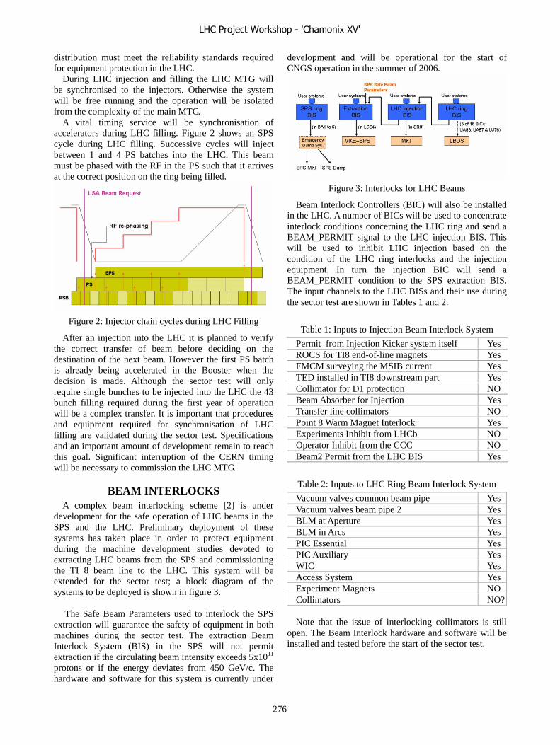
distribution must meet the reliability standards required for equipment protection in the LHC.
During LHC injection and filling the LHC MTG will be synchronised to the injectors. Otherwise the system will be free running and the operation will be isolated from the complexity of the main MTG.
A vital timing service will be synchronisation of accelerators during LHC filling. Figure 2 shows an SPS cycle during LHC filling. Successive cycles will inject between 1 and 4 PS batches into the LHC. This beam must be phased with the RF in the PS such that it arrives at the correct position on the ring being filled.
Figure 2: Injector chain cycles during LHC Filling
After an injection into the LHC it is planned to verify the correct transfer of beam before deciding on the destination of the next beam. However the first PS batch is already being accelerated in the Booster when the decision is made. Although the sector test will only require single bunches to be injected into the LHC the 43 bunch filling required during the first year of operation will be a complex transfer. It is important that procedures and equipment required for synchronisation of LHC filling are validated during the sector test. Specifications and an important amount of development remain to reach this goal. Significant interruption of the CERN timing will be necessary to commission the LHC MTG.
BEAM INTERLOCKS A complex beam interlocking scheme [2] is under
development for the safe operation of LHC beams in the SPS and the LHC. Preliminary deployment of these systems has taken place in order to protect equipment during the machine development studies devoted to extracting LHC beams from the SPS and commissioning the TI 8 beam line to the LHC. This system will be extended for the sector test; a block diagram of the systems to be deployed is shown in figure 3.
The Safe Beam Parameters used to interlock the SPS
extraction will guarantee the safety of equipment in both machines during the sector test. The extraction Beam Interlock System (BIS) in the SPS will not permit extraction if the circulating beam intensity exceeds 5x10¹¹ protons or if the energy deviates from 450 GeV/c. The hardware and software for this system is currently under
development and will be operational for the start of CNGS operation in the summer of 2006.
Figure 3: Interlocks for LHC Beams
Beam Interlock Controllers (BIC) will also be installed in the LHC. A number of BICs will be used to concentrate interlock conditions concerning the LHC ring and send a BEAM_PERMIT signal to the LHC injection BIS. This will be used to inhibit LHC injection based on the condition of the LHC ring interlocks and the injection equipment. In turn the injection BIC will send a BEAM_PERMIT condition to the SPS extraction BIS. The input channels to the LHC BISs and their use during the sector test are shown in Tables 1 and 2.
Table 1: Inputs to Injection Beam Interlock System
Permit from Injection Kicker system itself Yes ROCS for TI8 end-of-line magnets Yes FMCM surveying the MSIB current Yes TED installed in TI8 downstream part Yes Collimator for D1 protection NO Beam Absorber for Injection Yes Transfer line collimators NO Point 8 Warm Magnet Interlock Yes Experiments Inhibit from LHCb NO Operator Inhibit from the CCC NO Beam2 Permit from the LHC BIS Yes
Table 2: Inputs to LHC Ring Beam Interlock System
Vacuum valves common beam pipe Yes Vacuum valves beam pipe 2 Yes BLM at Aperture Yes BLM in Arcs Yes PIC Essential Yes PIC Auxiliary Yes WIC Yes Access System Yes Experiment Magnets NO Collimators NO? Note that the issue of interlocking collimators is still
open. The Beam Interlock hardware and software will be installed and tested before the start of the sector test.
LHC Project Workshop - 'Chamonix XV'
276

STANDARD SOFTWARE FACILTIES The capture and archival of information pertaining to
the correct operation and performance of the LHC will be a major challenge. It is foreseen to capture the data via a number of standard software facilities which are adapted to the nature of the information.
Alarms At the LHC alarms will be centralised by the LHC
Alarm Service (LASER). The role of LASER is to collect information pertaining to all faults that may impact on the commissioning and operation of the LHC. Some of the systems that shall provide alarms during the sector test are:
• Machine Protections Systems: − Interlocks, Collimators, Beam Loss, QPS
• Power Converters, • Injection Kicker, • Cryogenics:
− production, distribution and instruments, • Vacuum, • Control System, • Technical Services:
− including RAMSES and the access system.
Periodic Logging The LHC Logging System [6] manages a central
archive of data from the accelerator systems and in the future beam performance monitors. Data is collected periodically or on change, typically from processes with response times of around 1 second and upwards. Some of the data that will be required during the sector test are:
• Slow Machine Protection data: − absorber positions, QPS, PIC buffers …
• Vacuum pressures and valve positions, • Cryogenic Instruments, • Radiation Monitors (1 Hz), • RAMSES, • Technical Services.
Shot by Shot Logging Certain data will be collected pertaining to each
injection into the LHC. This is a special case of periodic logging. Some data will indeed be archived in the LHC Logging database but more complex data will be stored in SDDS [7] files. Some data that must be captured every injection are:
• Trajectories, • Beam Loss, • Beam TV, • Injected intensities, • Beam Interlocks • Magnet currents, • Radiation Monitors.
Post Mortem Transients When an asynchronous beam or power abort occurs in
the LHC transient information will be channel to one or more central Post Mortem servers. This information will be rigorously analysed to ensure no loss of redundancy or malfunctioning of the machine protection systems has occurred. During the sector test a magnet quench will lead to a post mortem trigger, generated from the machine interlocks and distributed via the timing system. Systems required to provide transient data are:
• Injection kicker, • Power Converters, • Beam Interlocks, • Quench Protection • BCT, • Beam Loss, • Beam Position, • Radiation Monitors (100 Hz), • Timing.
Fixed Displays The CCC will be equipped with permanent displays
providing the operator with a rapid overview of key LHC operational parameters. Details of the the displays required during the sector test are yet to be finalised but will include OTR screens and beam loss monitors.
These standard software facilities are all in operation
for operation of the injectors and LHC hardware commissioning. Nevertheless work is still required in many groups to secure the submission of the data needed during the sector test.
KEY HIGH LEVEL SOFTWARE The studies that are to be performed during the sector
test have already been defined in some detail [8]. From these the essential functionality required from the high level control software is being derived. Key facilities will be:
• Settings generation and trimming, • Trajectory control package, • Sequencer, • Kicker and beam display, • Collimator Control . Settings generation will draw on the field models of the
LHC magnets that are being developed. [9]. YASP is a sophisticated orbit package [10], already in use for the commissioning of the TT40 and TI 8 lines and elsewhere at CERN will provide the physics models for many of the proposed studies. Software for the automation of critical or repetitive series of controls actions is in use during hardware commissioning and development continues. Fine delays of the injection kicker will be adjusted using displays produced by the “OASIS” [12] package already used for SPS extractions. Some control of the TDI and TCDI collimators will also be required to follow the program. Development work in this area is critical.
LHC Project Workshop - 'Chamonix XV'
277
CONCLUSIONS The safety of equipment during the LHC sector test
will be assured by the interlocking of the SPS Extraction Kicker to be commissioned for CNGS operation in May.
The installation of the LHC control system hardware infrastructure and the specification and development of software is in hand. The sector test will be another progressive milestone for CERN Controls and the work to prepare and validate a number of control system components is an important guarantee for efficient LHC Beam and controls commissioning.
Priorities for controls validation during the sector test are the capture and management of beam performance data and the extension of the CERN timing and sequencing to the LHC.
REFERENCES [1] D, Bozzini et al, “General procedure for
commissioning the electrical circuits of a sector”, LHC-D-HCP-0001, 29th September 2004.
[2] B. Puccio, R. Schmidt, J. Wenninger, “Beam Interlocking Strategy between the LHC and its
Injector”, 10th ICALEPCS Int. Conf. on Accelerator & Large Expt. Physics Control Systems. Geneva, 10 - 14 Oct 2005
[3] Editorial Board O. Brüning et al, LHC Design Report, Vol. 1 chp. 14. CERN-2004-003, 4th June 2004.
[4] L. Jensen, “Beam Instrumentation foreseen for the LHC Sector Test”, these proceedings.
[5] FESA home page, http://cern.ch/project-fesa/ [6] R. Billen, M. Peryt, “The LHC Logging System”,
LHC-CL-ES-0001, 8th November 2002. [7] M. Borland, ``A Self-Describing File Protocol for
Simulation Integration and Shared Postprocessors,'' Proceedings of the 1995 Particle Accelerator Conference, May 1-5, 1995, Dallas, Texas.
[8] B. Godddard, “Proposed Tests with Beam”, these proceedings
[9] L. Bottura, “Magnets”, these proceedings. [10] J. Wenninger, private communication [11] L. Bojtar et al, “OASIS Status Report”, 10th
ICALEPCS Int. Conf. on Accelerator & Large Expt. Physics Control Systems. Geneva, 10 - 14 Oct 2005
LHC Project Workshop - 'Chamonix XV'
278

DISCUSSION: SECTOR TEST - BEAM
V. Kain, CERN, Geneva, Switzerland
SECTOR TEST: OVERVIEW, MOTIVATION AND SCHEDULING
(M.LAMONT)
Question: What is RF needed for during the Sector Test?
Answer: LHC RF will be needed for the timing.
PROPOSED TESTS WITH BEAM (B.GODDARD)
Question: Are system tests of the BIS foreseen?
Answer: Part of the system can and should be tested.
Question: How much shorter could the Sector Test be if only priority 1 tests were carried out?
Answer: It could be shorter by 2-3 days.
Question: Which procedures/ equipment are foreseen in case of unforeseen aperture limitations blocking the beam passage?
Answer: Mobile BLMs, the position reading of the position information from the BPMs (triggers above intensity of 2 � 109) and intensity reading from about 10 BPMs will be used in this case.
Comment: The control system (HW and SW) used for the TDI and the TCDI during the Sector Test should be the same as the one used for the TCS later on; no ad-hoc solutions should be used.
Comment: Online matching tools could improve operational efficiency and should be available.
Comment: No temporary solution for timing should be used; the final system should be deployed.
Comment: Changing the phase advance in the arc could be of interest for different measurements.
Comment: The Sector Test is important as check for the magnetic reference model.
Comment: Varying the emittance during the proposed quench tests could be envisaged.
MAGNET QUENCHES WITH BEAM (A.KOSCHIK)
Question: Could the MKI be used to kick the beam into superconducting magnets such as the triplet or the D1?
Answer: No, because of the constraint of “no” beam loss in the experimental insertion of LHC-b. In addition, by
then the TDI should be properly set up, such that any mis-kicked beam should end up on the diluter.
Question: Is it possible to check the protection level of the TCLI collimators against kicker failures?
Answer: The TCLIs will not be installed for the Sector Test and the MKI should not be used with other than nominal kick strength after the injection is set up due the LHC-b constraint.
Question: Could nominal current (corresponding to 7 TeV) be used in the stand alone quadrupole Q6 upstream of IP7 to lose the beam there?
Answer: This depends on the status of the hardware commissioning of Q6 at the time of the Sector Test.
Question: How can one deduce the energy deposition in the magnets causing the quench form the BLM measurement?
Answer: FLUKA simulations are used for the cross-calibration.
Comment: The effect on the quench behaviour of different temperatures in the case of stand alone magnets could be investigated.
Comment: The slides showed that the quench limit is in the order of 109 p+/m for the Sector Test Scenarios. The proposed intensities for the tests are of 5 � 109 to of 1� 1011 protons. The tests may need beam below pilot intensity, which might prove a problem for the instrumentation.
Comment: The post mortem system/analysis must be fully available for the quench tests.
Comment: The uncertainty on the BLM measurement is larger for BLMs attached to the cryostat where they can only capture the tails of the showers. Measuring in the forward direction would be more accurate.
Comment: The last Q6 before the dump could be equipped with BLMs in the forward direction.
Comment: The maximum beam intensity must be carefully chosen even it is below the assumed damage limit. Shock heating could lead to plastic deformations. In addition, the temperature limit in the coils is 200° C in order not to melt the insulation.
Comment: For safety reasons, an intensity of maximum 1010 protons should be envisaged as upper limit for the tests.
LHC Project Workshop - 'Chamonix XV'
279

BEAM INSTRUMENTATION FORESEEN FOR THE LHC SECTOR TEST
(L.JENSEN)
Comment: Inversions in the TI 8 BPMs lead to polarity errors. In the LHC the fact that all BPMs read back both H and V means that cable inversions could lead to more complicated cross-plane cabling errors.
Comment: There will not be any analogue signals from the LHC to be displayed with OASIS.
MAGNETS (L.BOTTURA)
Question: What are the predictions from simulations for beta beating?
Answer (S.Fartoukh): According to simulations for sector 7-8 beta beating of about 2 % is expected.
Comment: With the de-Gauss cycle the magnetic history of a superconducting magnet is erased and persistent currents are suppressed. However, the magnet ends up off the well-measured hysteresis curve – in a region with less confidence on the measurements.
Comment: The de-Gauss cycle is needed for the LHC start-up. Hence both the de-Gauss and the nominal cycle are worth testing during the Sector Test.
Comment: Priorities in terms of required circuits and level of commissioning have to be defined.
Comment: There might be little effect on the Sector Test if the circuits are only commissioned to 20 to 30% of the nominal current.
Comment: MAD-X online with an interface to FiDeL could be useful.
CONTROL REQUIREMENTS (R.LAUCKNER)
Comment: During the Sector Test, the energy will not be distributed to the BLMs and the MKI via SLP.
Comment: The extraction, transfer and injection interlocking will need (re-)commissioning with and without beam.
Comment: What is available in terms of fixed displays is not suitable for BLMs.
Comment: For the time being no data exchange with LHC-b is foreseen during the Sector Test. This point still needs clarification.
LHC Project Workshop - 'Chamonix XV'
280
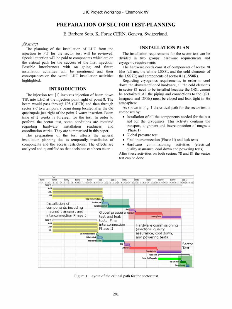
�������������� �������������
���������� ���������� ������ ������������
����������� �������� � ��� �� �������� � !"� ��# ���
��$�%��� � &�' �� ��� �%�� �� � ���� �� ������������%����������������������%#����� ���%�������� %����%�� ���� �� ��� (%%� � ��� ��� � ��$�%����& ���� ����������%� ���� � ���� ��� �(�(���� �������� �%������� ���� �� #������� ��� �����%� �)(��%� � ��� ������ !"� �� �������� �%������� ������������
������ ��������$�%����� �*+,������ ��$�%�������#���
�-. ���!"��������$�%�����������������.�������#�(�� �� ���(�� -&. /!"��0 ��� ���� ���(�� �%��.1'����#����2���#�(#��%������������34)(���(���$( ��������������'���#�� ���������#��#� � 5 ���6 � ��� ��� �� ��� �� �� -� ���� ������# ��� �%�� �� � #� %������ ��� ��)(������������� �������� �� �������� ������� ���%����������6 ����2��� (##����������� ������
��� ���������� � ��� �� � ����%� ��� ��������� �������� �������� �(� � ��#�����2 �� �������� �%#����� ��� ��� �%%� �� ���%��� � ��� ����%� �������2������)(�������� ������%� �� %��������6���
������������������ ����������)(���#��� ����� �%���� �%����
������� �� �� ��(� 7 �������� ��)(���#��� ���%�2����%��)(���#��� �
��������������� %� � ��%#����� � �%��'./��� �(�� ��% �������!��.!��� ��� %�� ���#��� ����!��'�0���%#����� � �%��.+/!��.�0�
��������� %�2����% ��)(���#��� �� ���� � %�����������#��������������� ������%�����#��� �� �%��.+��������� ��������%�( ����3�!%������ �%�������8��������������%���%��� ����3�!/#����� ���9�� 0#( ���%� ��������6�������"���# �����
8 ���������+���%����%����������� �%���� �� %#� ���27�� -� ���������������%#����� ������������� �
��� �� ��� %�2����% � ��� �%�����2 %����� ������� ��� �����#������ �����%���%����#����� /&�� �-0
�� �������� (���� ��� ����������%���%���/&�� �--0������6�� � �� "������� %##� ����� �%������� /���%���%��
)(����2� (���%� %���������������� � 08������� ��%������� ���� �%�� '.���.+��� �%���� �%��������
���(��+7!�2(�����%����%����������� �%���� �
LHC Project Workshop - 'Chamonix XV'
281

-� ��� ��� � ���� � ��� %����%�� ���� �� �������� � ���%#����� �����(���%������� ���%#��������#�������������5::4���*;,7
����� ��� 8�%7 3�! �� �������� ��� �� � ���� �� ���� ��� ��
����(��2� ��21#����� ���� ��� �����#��� �����%���%��� ��� ��%((# (�1 �%�� ���6 �� � ���������� ����2<�2�
�� !��.!7 %�21#����� ���� ��� �����#��� �����%���%��� ��� ��%((# (�1 �%�� ���6 �� � ���� �� ���� ��� �2 <�2� =�%((# ��� ���#�� ��(#������� ���� �� �� ������ ������� <�2 ���>(��� 9�������� ��%((# �%������� ��� ����� ��#����>��(��2�����>(�2�
�� !��'�7 �����2 �?���%��� ��� ���� %������� �� ������������� � �����������#<�� �#��<�2������%�������%������� �����������#����#��� � <�2 � >(��� ��21#����� ���� ��� �����#��� �����%���%��� ��� ��%((# (�1 �%�����6�� � ���������� ����2<�2�
��������� 8�%7 3�! �� � ���� ��� �� >��(��2� ��21#�����
���� ��� �����#��� �����%���%��� ��� ��%((# (�1 �%�����6�� � ���� ����2<�2�
�� !��+!73�!�� � ���� �����>��(��2���21#����� ���� ��� �����#��� �����%���%��� ��� ��%((# (�1 �%�����6�� � ���� ����28�����
�� !��.�7 3�! �� � ���� ��� �� ����(��2� ��21#����� ���� ��� �����#��� �����%���%��� �����%((# (�1 �%�����6�� � ���� ����2<�2�@��##����� ��� %���#��� ���� ��� ��� �� ������������ ����2 >(�2�=�%((#������# �� ��(#��������� ������ ������� <�2 ��� >(�2� 9�������� ��%((#�%������� �������#����>��(��2�����>(�2�������� ��� %���%��� ���� ��� �2 <�2� �����2�?���%����������%������� �� ����������� �� � �����������<�-�� � ���� ���#��>(�2�
8���� ��� � �%������� � ����� ���6 �� � ��� � ����������%���%��� ��� ���6 �� � ���� �� �����#�� �� ��%� �%���
���� �������� ����������������������
�#� ��%���%������ �����)(����������#����� ���%�(���� ��#�����2 �� �������� � %#����� ����%%� �� ���%����(����������� (� �
�������������������������-������ ��������#�(��������� � ��� ��������
�� ���� ��� ��9 ��# �-5 �� ��� �%�� '. ���� � 34�9(���������#����� �����9�������� ������/A���6 0��� �%�� '. ���� �� ��%6�� �� ���� ���� 9(���� ������������� ���������������� �������#����� � �%�� 4' ��� ������� ��� ������� ��������2 ������� ��� �(���� ���(�� �%��'.�
-� ���� � #���#��� ��� %� �)(��%� � �������#������� �����# ������ �%��� ��� ����� �(����7��� ���������� ��������(����������#���� �%6�����BC4A ������ �%��� ���� ������2�%���������� ���������������� ������������ ��������� ��(����� ��%����%������� ��������� �%��4'����������(�����
������������������������������ �������� ����%��� �� ���� ���� �� ��#�����2
�� ������7 �� �� �%�� 4' ��� �� �� �%�� '.�9(�������+'��2 ����������� ������ ��� ������������������#������#���%� ���
��� ���� � �%�� 4' � ���%�� �� ��(�� .::#���� ��# -&' ��� !��'! ��� ���� � ��� ��% /�����+.!'0���������%%� �����
9(���� ��� ����� ����� ��� ������ �%������� �������� ���� �����7 �� �������� � #����� �� �������� �%���#��� ��� �� �������� � 9D ��� 9; ��# �%��!��'!�8 �(��� � ����� �(���� �� ��� ��� ����(� ��� ���� �� �(�� �� �(���� ��� ��� �(����� � ��� �%�� �� � /;1A ���6 0� ��� ��(���� %#���%��� %1�%������� �(� ���� �� %�( � ������%��� ����%� �� ������������ �����������������
������������8���� ��� ���# �� � � �-. /����� �� ����0 ��� ����
��(�� �-. ���� ��%�#� � %������� ���� *5, ������?�#����2 �����6�"��%� ��� �%%� � �%�� .+���� �� ����%���� -� ���� �� ������ � ���#� �� ��� ���� ���� �#������������� ���(�� �%��.+������6����-�%���#��2�������%(����������������#��� �%������� ����%��� ��� ��� %� ��� ��� ���������� �� � � �%�� .+ � ���� � ��� #����� ���� ����
����������������#������������� ����%����%�����������������
���������������� 6�����2�� �!�����"���������#���%(������?������%������3�! ��� �������
�������%�������������������6 ��6� #����#�������������2�����%����#����������$���������%��� ���(%��� � ��� ��� ������� �%��� /���0
��� ��%��� ��� ���� ��(� �� 6 �� � �� ��������� � ��������
���#��������#��2 ���������������2����9�� ������ �%�� '.���.+ ���9��< ���9��C ��������������(���%6�������� ���������(���� � �����%� � �� ��� 9��8 ���� ���� ������ ����� �� � ���� /��(��+.���6 �����0����(��5 �� ���������������%����%������� ����%����(����� �����2 ��� �%��'.���%� �)(��%� ����9��8 ��2 ������� ������� ��� �����%���%��� /&�� � -0 � ������ � ������������� >(�� ��� ��� ��������� ��#� �� ��� �� � �����%������� � ���(%���
LHC Project Workshop - 'Chamonix XV'
282

���(��57����%�����9�� ����2����%����%������
8� ���� �(���� �%����������������� � ��
���������������� ������#����%������ ���� ������6��������D���;���6 *D,
�� �%�� .+ ��� 9��8 ����2 ���� ��� ����������%���%��� � �������E%���� ��� ��������������#� ���� ��� �� ��� ��#������ � ��� �����������%������� � ��� ��%���2 ���(%��� ��� # � %#��� �� %����� � (#� D���6 �� %� ��� ���� �#���#(#� D ���6 �� ������� �������� %##� ����� *D, ������%���%�� )(����2 � (���%� � !��.�� ��� ���� ���(�%�� �� ��� �����������2 � ��� 9��8 ����� D���6 ��2 ������D�;���6 �����������2����9��8&�.� ��� 9��88�+! � �������� ��)(���� ������#� �%���� ��������#�2�������5::4�
� ��������� �%�� �� �����%� ��� �� ��������� �%��4'���
!��'�� ���� ��� �����#��� �����%���%��� ��� ���6�� ��� �%��4'������%�%����������� ���������9D���9;�!��'�������%���#��� ��(��-&'������ �����(�������������� �%���� ��
����� ��� �� %����%�� %� �)(��%� �� ��� ��������� �������� �������� �(� � ��� �%�� �� �� "����� #��%������� ��%#�#�������%(������������# ���� ��% ���%1�%�����2�
��� �%�� �� � � ���� %���(��� �� ��� ��� � 5::4��6��� ��� �%%(��7 ��� � ��� 9�� ����2 � %����%�� ���#( � �� %#��� ���� ��� �%�� � �� � %� ��� �
�%�� .+ ��� � ������� �������� %##� ����� � ��� �%��'.���!��.������)(�������� %������� ��������������� ���(���� �� %���������� �� ���9��8 � �%��.+������D�;���6 ��������
������ ��*+, ����7FF��%1��$�%���1�� ������%����%�F��%1��$�%���1�� �*5, ��%���� �&���������1��������- (� "�=��%6�
����� ���%������ *D, ��%�� �� � &���������1"������� �##� �����
������� ����� ���%������ *;, !"� �� ��(%��� ��� �� �������� ������� �1
�������� ��� -� �������� �%���(�� !"�1&<1<�1:::A �����������
LHC Project Workshop - 'Chamonix XV'
283

GLOBAL HARDWARE STATUS FOR THE LHC SECTOR TEST
J.M. Jimenez, CERN, Geneva, Switzerland
Abstract
Starting from the TI 8 dump (TED) up to the end of the continuous cryostat in IR7, the availability in the tunnel of all components in the beam line e.g. the vacuum, cryogenic, collimation, protection devices, beam instrumentation and magnet systems are reviewed.
INTRODUCTION In this paper, the hardware availability date is defined
as the transport date as specified in the schedule for the LHC Sector test. This scenario assumes that all equipments are ready for transportation (magnets, DFBs, beam instrumentation…) and that the vacuum acceptance tests for components on the beam vacuum lines are completed before their transportation to the tunnel.
This review will not address the status of the about 320 items of the database nut will only address the critical equipment or equipment which availability was questioned.
The Sector test is part of the overall LHC installation i.e. the layout shall be identical to the one required in 2007 for the start up. All equipment expected to be available after the Sector test is considered as being on the critical path.
Prior to checking the hardware availabilities, the status of the 3D integration is shown.
LAYOUTS & MAJOR SYSTEMS
TI 8 downstream line - Last 120 m At the end of the TI8 transfer line, the injected beam
will arrive in the LHC main ring tunnel (IR8R – right side of IR8) and will pass very close to the DFBA, to the circulating beam vacuum chambers and to the Q6R8 quadrupole cryostat (Fig.1). Fig.2 shows examples of integration studies at the position of the collimators in TI 8 and near the Q6R8 quadrupole magnet.
TI 8 downstream Dump
DFBA IR8R
Q6R8
Injection SeptaInjection SeptaCirculating beamsCirculating beams Examples of tightIntegrations
Examples of tightIntegrations
The red trajectory of the beam does not means that the beamwill be late… but it just refers to the RED beam i.e. Beam 2
Fig.1: Layout of the last 120 metres of the TI 8 injection transfer line downstream the TI 8 dump.
Injected beamchamber near
Q6R8
Injectionsepta
TCDI collimatorsupstream the
injection septa
Injectionsepta
Injectionsepta
TCDI collimatorsupstream the
injection septa
TCDI collimatorsupstream the
injection septa
Circulating beamvacuum chambers
Injectedbeam
Circulating beamvacuum chambersCirculating beam
vacuum chambers
Injectedbeam
Injectedbeam
Fig.2: Example of the tight integration required in the TI 8 downstream part.
IR8R&L and IR7R After travelling in the TI 8 SPS to LHC transfer line,
the beam will be injected into the LHC between Q6R8 and Q5R8 quadrupoles, in the injection Septa (MSI). The last 40 meters of the TI 8 line downstream the TCDI collimators will be baked for vacuum compatibility with the ultra-high vacuum of the circulating beam.
The beams will pass through the Q5 cold quadrupole before being kicked to their final orbit by the injection kickers. Fig.3, 4 and 5 show the major equipments required for the room temperature parts, for the cryogenic system and for the cold magnets respectively from the injection into the LHC to the temporary beam dump to be installed in IR7R.
Beam2
TI 8 downstreampart - baked
Injection septum+ Instrumentation
Injection stopper+ Instrumentation
Injection kickers+ Instrumentation
Collimators(2007)
TED+ Instrumentation
Fig.3: Major equipments in the room temperature part of the Sector test (i.e. IR8L&R + IR7R).
LHC Project Workshop - 'Chamonix XV'
284
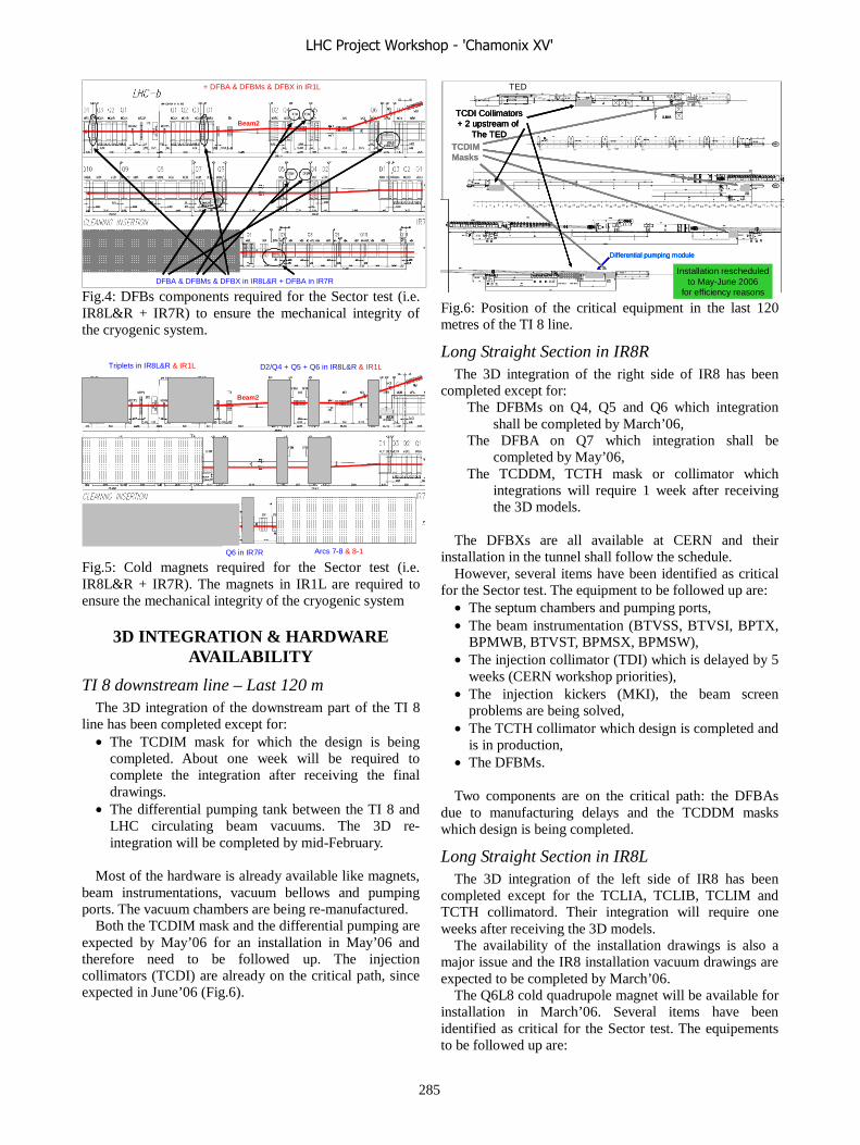
Beam2
DFBA & DFBMs & DFBX in IR8L&R + DFBA in IR7R
+ DFBA & DFBMs & DFBX in IR1L
Fig.4: DFBs components required for the Sector test (i.e. IR8L&R + IR7R) to ensure the mechanical integrity of the cryogenic system.
Beam2
Arcs 7-8 & 8-1
Triplets in IR8L&R & IR1L D2/Q4 + Q5 + Q6 in IR8L&R & IR1L
Q6 in IR7R Fig.5: Cold magnets required for the Sector test (i.e. IR8L&R + IR7R). The magnets in IR1L are required to ensure the mechanical integrity of the cryogenic system
3D INTEGRATION & HARDWARE AVAILABILITY
TI 8 downstream line – Last 120 m The 3D integration of the downstream part of the TI 8
line has been completed except for: • The TCDIM mask for which the design is being
completed. About one week will be required to complete the integration after receiving the final drawings.
• The differential pumping tank between the TI 8 and LHC circulating beam vacuums. The 3D re-integration will be completed by mid-February.
Most of the hardware is already available like magnets,
beam instrumentations, vacuum bellows and pumping ports. The vacuum chambers are being re-manufactured.
Both the TCDIM mask and the differential pumping are expected by May’06 for an installation in May’06 and therefore need to be followed up. The injection collimators (TCDI) are already on the critical path, since expected in June’06 (Fig.6).
Differential pumping moduleDifferential pumping moduleDifferential pumping module
TCDIMMasksTCDIMMasks
TCDI Collimators+ 2 upstream of
The TED
TCDI Collimators+ 2 upstream of
The TED
TCDI Collimators+ 2 upstream of
The TED
Installation rescheduledto May-June 2006
for efficiency reasons
TED
Fig.6: Position of the critical equipment in the last 120 metres of the TI 8 line.
Long Straight Section in IR8R The 3D integration of the right side of IR8 has been
completed except for: The DFBMs on Q4, Q5 and Q6 which integration
shall be completed by March’06, The DFBA on Q7 which integration shall be
completed by May’06, The TCDDM, TCTH mask or collimator which
integrations will require 1 week after receiving the 3D models.
The DFBXs are all available at CERN and their
installation in the tunnel shall follow the schedule. However, several items have been identified as critical
for the Sector test. The equipment to be followed up are: • The septum chambers and pumping ports, • The beam instrumentation (BTVSS, BTVSI, BPTX,
BPMWB, BTVST, BPMSX, BPMSW), • The injection collimator (TDI) which is delayed by 5
weeks (CERN workshop priorities), • The injection kickers (MKI), the beam screen
problems are being solved, • The TCTH collimator which design is completed and
is in production, • The DFBMs. Two components are on the critical path: the DFBAs
due to manufacturing delays and the TCDDM masks which design is being completed.
Long Straight Section in IR8L The 3D integration of the left side of IR8 has been
completed except for the TCLIA, TCLIB, TCLIM and TCTH collimatord. Their integration will require one weeks after receiving the 3D models.
The availability of the installation drawings is also a major issue and the IR8 installation vacuum drawings are expected to be completed by March’06.
The Q6L8 cold quadrupole magnet will be available for installation in March’06. Several items have been identified as critical for the Sector test. The equipements to be followed up are:
LHC Project Workshop - 'Chamonix XV'
285

• The beam instrumentation: BPMWB, BPMSX, BPMSW,
• The DFBMs and DFBA. The collimators TCLIA, TCLIB and TCTV are all on
the critical path even if they are all at a different design stage, completed for the TCLIB and being completed for the TCLIA and TCTV. The TCLIB is already launched in production.
The TCLIA and TCTV are not yet launched for manufacturing and these collimators could be pushed to the Phase 2.
Arc sector 8-7 The 3D integration of the 8-7 arc is fully completed and
no problems are expected with the dipole magnets. Some items need to be followed up:
• The QRL 7-8, the leak detections shall be completed, • Some quadrupoles need to be followed up: Q7R7,
Q8R7, Q9R7 and Q10R7. These magnets are expected to be available between week 10 and week 14.
Long Straight Section in IR7R The 3D integration of the right side of IR7 is half made
in particular for the DFBAN. This integration will be completed by March’06.
Some equipments need to be followed up: • The Q6R7 cold quadrupole magnet, • The BTVSI monitor (beam instrumentation), • The DFBA.
CONCLUSIONS A huge amount of work has been made to provide the
require equipment. However, to stay within the schedule, the installation must continue straight forward, all integration problems must have been solved not later than April’06. This strategy implies that the LHC baseline is fully consolidated. This consolidation requires the contribution of the equipment owners both at the stage of the first entry of the equipment parameters but also for the verification of the entered data.
Pressure shall be kept to complete the 3D integrations and the installation drawings required in particular by the Vacuum group for the detailed integration of the instrumentation ports and vacuum chambers.
The availability of the cold magnets, DFBMs and DFBA in IR1L for the Sector test shall be studied in detail and delayed equipments shall be confirmed as soon as possible to TS/IC in order to adapt whenever possible the installation schedule.
AKNOWLEDGEMENTS Many thanks to the colleagues from AB, TS and AT
Departments for their help in preparing this status review.
LHC Project Workshop - 'Chamonix XV'
286
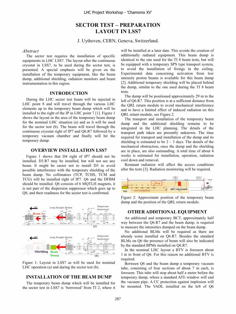
SECTOR TEST – PREPARATION LAYOUT IN LSS7
J. Uythoven, CERN, Geneva, Switzerland.
Abstract The sector test requires the installation of specific
equipments in LHC LSS7. The layout after the continuous cryostat in LSS7, to be used during the sector test, is presented. A special emphasis will be given on the installation of the temporary equipment, like the beam dump, additional shielding, radiation monitors and beam instrumentation in this region.
INTRODUCTION During the LHC sector test beam will be injected in
LHC point 8 and will travel through the various LHC elements up to the temporary beam dump which will be installed to the right of the IP in LHC point 7 [1]. Figure 1 shows the layout in the area of the temporary beam dump for the nominal LHC situation (a) and as it will be used for the sector test (b). The beam will travel through the continuous cryostat right of IP7 and Q6.R7 followed by a temporary vacuum chamber and finally will hit the temporary dump.
OVERVIEW INSTALLATION LSS7 Figure 1 shows that D4 right of IP7 should not be
installed. D3.R7 may be installed, but will not see any beam. It might be easier not to install D3 to avoid possible interference with the temporary shielding of the beam dump. No collimators (TCP, TCHS, TCM and TCG) will be installed right of IP7. Q6 and the DFBM should be installed. Q6 consists of 6 MQTLH magnets, it is not part of the dispersion suppressor which goes up to Q8, and their readiness for the sector test is confirmed.
Figure 1: Layout in LSS7 as will be used for nominal LHC operation (a) and during the sector test (b).
INSTALLATION OF THE BEAM DUMP The temporary beam dump which will be installed for
the sector test in LSS7 is ‘borrowed’ from TI 2, where it
will be installed at a later date. This avoids the creation of additionally radiated equipment. This beam dump is identical to the one used for the TI 8 beam tests, but will be equipped with a temporary SPS type transport system, to avoid the installation of fixings in the ceiling. Experimental data concerning activation from low intensity proton beams is available for this beam dump [2]. Additional temporary shielding will be placed behind the dump, similar to the one used during the TI 8 beam tests.
The dump will be positioned approximately 29 m to the left of Q6.R7. This position is at a sufficient distance from the QRL return module to avoid mechanical interference and to have a limited effect of induced radiation on this QRL return module, see Figure 2.
The transport and installation of the temporary beam dump and the additional shielding remains to be integrated in the LHC planning. The details of the transport path taken are presently unknown. The time required for transport and installation of the dump and its shielding is estimated to be 2 – 3 days. The details of the mechanical obstruction, once the dump and the shielding are in place, are also outstanding. A total time of about 4 weeks is estimated for installation, operation, radiation cool down and removal.
Remnant radiation will affect the access conditions after the tests [3]. Radiation monitoring will be required.
Figure 2: Approximate position of the temporary beam dump and the position of the QRL return module.
OTHER ADDITIONAL EQUIPMENT An additional and temporary BCT, approximately half
way between the Q6.R7 and the beam dump, is required to measure the intensities dumped on the beam dump.
No additional BLMs will be required as there are already some installed on Q6.R7. Besides the standard BLMs on Q6 the presence of beam will also be indicated by the standard BPMs installed on Q6.R7.
In the nominal LHC layout a BTV is foreseen about 1 m in front of Q6. For this reason no additional BTV is required.
Between Q6 and the beam dump a temporary vacuum tube, consisting of four sections of about 7 m each, is foreseen. This tube will stop about half a meter before the temporary dump, where a standard AlTi window will end the vacuum pipe. A CC protection against implosion will be mounted. The VADL installed on the left of Q6
Beam 2
Beam Dump
Shielding
Dispersion Suppressor
Long Straight Section IP7
(b)
Beam 2
Dispersion Suppressor
Long Straight Section IP7
(a)
QRL return module TED
LHC Project Workshop - 'Chamonix XV'
287

includes an ion pump plus penning and pirani gauges for the part to the left of the sector valve. As a result it will not be necessary to install any additional vacuum equipment or instrumentation on the temporary beam tubes.
ACCESS AND VENTILATION A temporary access door will be installed in the arc
towards point 6, about 800 m from IP7 [4]. Access to part of the sector 6 – 7 will not be possible at least one day before the test (for closing the zone), during the tests with beam and 2 – 3 days following the tests.
The collimation ventilation doors, foreseen to direct the radioactive air produced at the collimators, and the chicanes foreseen around the collimators should not be installed.
CONCLUSIONS The layout in LSS7 for the sector test will be identical
to the nominal situation up to and including Q6.R7. The additional equipment foreseen consists of the temporary beam dump and its shielding, about 29 m away from Q6.R7, a vacuum chamber between Q6 and the beam dump and a temporary BCT in the middle of this vacuum chamber. The transport of the temporary dump, the effect of its installation and radiation issues on the general planning need to be studied in more detail. A detailed layout drawing of LSS7 with the temporary installation will be made in the coming months.
ACKNOWLEDGEMENTS The contribution of Mike Lamont and the other people
involved in the preparations of the sector test are gratefully acknowledged.
REFERENCES
[1] M. Lamont, “Sector Test: Overview, Motivation and Scheduling”, these proceedings.
[2] J. Uythoven, “Experience with the TI 8 and TT40 Tests”, Proc. of the LHC Project Workshop Chamonix XIV, CERN, February 2005, pp. 164 – 167.
[3] H. Vincke, ”Sector Test- Preparation, Radiation Issues”, these proceedings.
[4] P. Ninin, ”Sector Test- Preparation, Temporary Access System”, these proceedings.
LHC Project Workshop - 'Chamonix XV'
288
SECTOR TEST – PREPARATION HARDWARE COMMISSIONING
R.Saban, CERN, Geneva, Switzerland.
Abstract The preparation for the injection tests of the equipment
described in the two previous presentations will be given in detail. The level of the commissioning of the equipment will depend on the time available between the cool down and the end of the injection test: this level can vary from the complete commissioning up to nominal current of all the circuits to the minimum current required for the injection test only for a limited number of circuits. The implications (organization of the work, coactivities with other sectors, etc.) of these scenarios will be described.
THE BASELINE The baseline for the commissioning of the two sectors
concerned by the sector test was already given in the Chamonix Workshop in 2004. Namely,
• Sectors 78 and 81 are completely installed before the injection test
• All the cryogenic subsectors of sectors 78 and 81 are at nominal temperature for the injection test
• All the circuits of sector 78 are commissioned for the injection test.
• All the circuits of sector 81 are not commissioned but only those required for the injection test.
It is worthwhile mentioning that the commissioning activity was intended as defined in the mandate of the Coordination for the Hardware Commissioning: all the equipment commissioned to nominal operating conditions of LHC.
The beam is threaded through the complete sector 78 up to and including Q6. Although, for sector 81 the beam is threaded only through the septa, Q5 until Q1, also the rest of the cold elements are required. In fact, in order to cool down even only one cryogenic sub sector of sector 81, all the connections to the QRL must either be made (SSSs or DFBs) or a temporary solution must be put in place in order to ensure the closure of the QRL and of the helium vessel (QRL and machine) as well as of the machine cryostat.
The conditions required for the sector test, as given in the web pages of the Sector Test with Beam Project[1], are listed below:
• TI8 operational • Injection region fully commissioned • Inner triplet, D1, D2, Q4, Q5 right of IP8
commissioned and cold • Inner triplet, D1, D2, Q4, Q5, Q6, Q7, dispersion
suppressor left of IP8 commissioned and cold • Arc 78 commissioned and cold (not all the arc
circuits are needed)
• Dispersion suppressor plus Q7 and Q6 right of IP7 cold
• Temporary dump region right of IP7
THE COMMISSIONING PROCEDURES For all the equipment required for the sector test, which
are detailed in the web pages of the Sector Test Project, the Hardware Commissioning Working Group had already prepared a set of standard commissioning procedures. These are described in documents [2,3,4,5,6] most of which were released after circulation for approval to the persons involved, departmental and project management; a few are in the last preparation phase.
For the superconducting electrical circuits, after the validation of the protection systems (see next section), the magnets are taken to different current levels.
At the minimum stand-by current of the power converter for each circuit, the protection functionalities of the powering interlock controllers and all its connected systems with current through the circuits is verified and the compatibility of the switch-on and switch-off processes of the converters with the sensitivity of the protection systems (namely QPS) are tested.
At each subsequent current level, (Injection level, 20%, 50%, 80% of Inominal and Inominal) the following points are checked/validated:
• the power converter current control loops • the protection mechanisms under real powering
conditions and with limited amount of energy in the circuits
• to quench-related procedures, e.g. cryogenic recovery procedures
• the sensitivity and compatibility during ramps of the systems susceptible to noise pick-up, couplings, etc
• a last check on the polarities of the circuits by verifying voltages across current leads (at low current using QPS signals)
After the tests listed above, at each current level, the circuit is commissioned to operate at that current level with compromising its integrity. Therefore the partial commissioning program described below was adopted.
THE NEW SCENARIO AND ITS IMPACT The conditions required for the test are slightly relaxed
with respect to the baseline conditions which were stated in the Chamonix Workshop in 2004. In fact, only 118 out of 210 are required for the Sector Test in sector 78 and 18 in sector 81. Furthermore, for some of the circuits the level at which these are powered is also relaxed.
It was argued that for all the equipment other than the one used for injection, since the injected beam will not be accelerated, it is not really necessary to power the circuits
LHC Project Workshop - 'Chamonix XV'
289

to nominal current. It was however requested to power the magnets up to 20% of nominal current in order to cycle the magnets and obtain similar conditions for every beam transfer.
This new scenario has a very big impact on the commissioning program. In fact, the standard procedures foresee a gradual powering of each circuit up to nominal current (even 12 kA for the main circuits) before the next circuit is taken for commissioning. Obviously, in the scenario proposed for the sector test the partial commissioning of the circuit interrupts this sequence and imposes a new overhead on the commissioning activity when it is restarted to complete the program for each circuit.
Nevertheless all the steps required to validate the protections systems, ensure electrical quality of the circuits and the associated equipment will not be impacted by the partial commissioning program: they will be carried-out completely. These tests are:
• The test of the power converters connected to the DC cables in short circuit, including controls for powering, ramp, monitoring
• The individual system tests of the Powering Interlock Control
• The individual system tests of the Quench Protection and Energy Extraction Systems
• Electrical Quality Assurance • Post-Mortem System tests • The interlock tests of each powering sub
sector prior and after connection of the power cables to the DFB leads
The powering of those circuits which are not needed at nominal current will only be carried out up to 20% of Inominal. This includes the main circuits which are the longest (10 days each) to commission.
The time required for the commissioning of the warm systems
The documentation describing the commissioning of this equipment (collimators, beam instrumentation, injection systems and the warm magnets), the numbers stated during the meetings of the Hardware Commissioning Working Group and in private discussions, indicate that the time required is 13 weeks after the installation of the equipment: this is independent of the cool down of the main cryostat. The last part (4-5 weeks) requires access restrictions to UA87 and RA87 before the high voltage tests of the kickers.
The time required for the partial commissioning of the superconducting electrical circuits
At the time of the commissioning of sectors 78 and 81, the teams foreseen for the commissioning of the LHC hardware across groups and departments will be available albeit not experienced. It is therefore foreseen to carry out this activity with four teams.
The first team would test the main circuits, a second team will be in charge of the separately powered
quadrupoles, and the 60-120 A circuits, while the third team will commission all the 600 A circuits and the separation dipoles; the fourth team will be dedicated to the two inner triplet assemblies on each side of Point 8.
The commissioning of these circuits requires the magnets to be cold and will therefore be carried-out after the electrical quality assurance of the circuits and the cool down of the sectors. The time required for these test cannot be reduced below five weeks. It is worthwhile mentioning that the DFBs (A,M and Xs) will be cooled down and powered for the first time during the commissioning of sectors 78 and 81. Previous experience at String 2, where two weeks were needed to tune the cool down of the DFBS, suggests that their commissioning will not go smoothly.
While this can be achieved for sector 78 in the schedule presented by E.Barbero-Soto, it is not clear how the electrical quality assurance, cool down and the commissioning of those circuits required for the injection test can be achieved in the time given (4 weeks). It was argued that speeding up the production of the DFBAs could liberate 4 weeks which could make the test feasible.
CONCLUSION It is clear that it takes substantially less time to partially
commission sectors 78 and 81 for the sector test alone. More detailed and ambitious studies could show that even more time can be saved. However equipment safety must not be jeopardized: the decision to take shortcuts is in the equipment groups who, alone, have the prerogative of equipment safety.
Partial commissioning causes a major disruption of the commissioning program since the sequence of the operations within the test of each sector is modified and some time will be required to restart the commissioning of each sector that was interrupted.
It must be noted that, if this scenario is adopted, at the end of this year it seems unlikely that even one sector will have been completely commissioned.
REFERENCES [1] http://lhc-injection-test.web.cern.ch/lhc-injection-
test/ [2] LHC-D-HCP-0001 v.1.0 General Procedure for the
Commissioning of the Electrical Circuits of a Sector. [3] LHC-MW-HCP-0002 v.1.0 General Procedure for
the Commissioning of the Warm Electrical Circuits. [4] LHC-D-HCP-0004 v.0.1 The Commissioning of the
Hardware in the LHC Sectors : The Commissioning of the Inner Triplet Region.
[5] LHC-I-HCP-0001 v.1.0 The Commissioning of the Hardware in the LHC Sectors: the Injection Systems in Points 2 and 8 with their Associated Instrumentation.
[6] LHC-D-HCP-0003 v.0.5 The Commissioning of the Hardware in the LHC Sectors : Powering of the Superconducting Circuits of a Powering Sub-Sector up to Nominal Current
LHC Project Workshop - 'Chamonix XV'
290
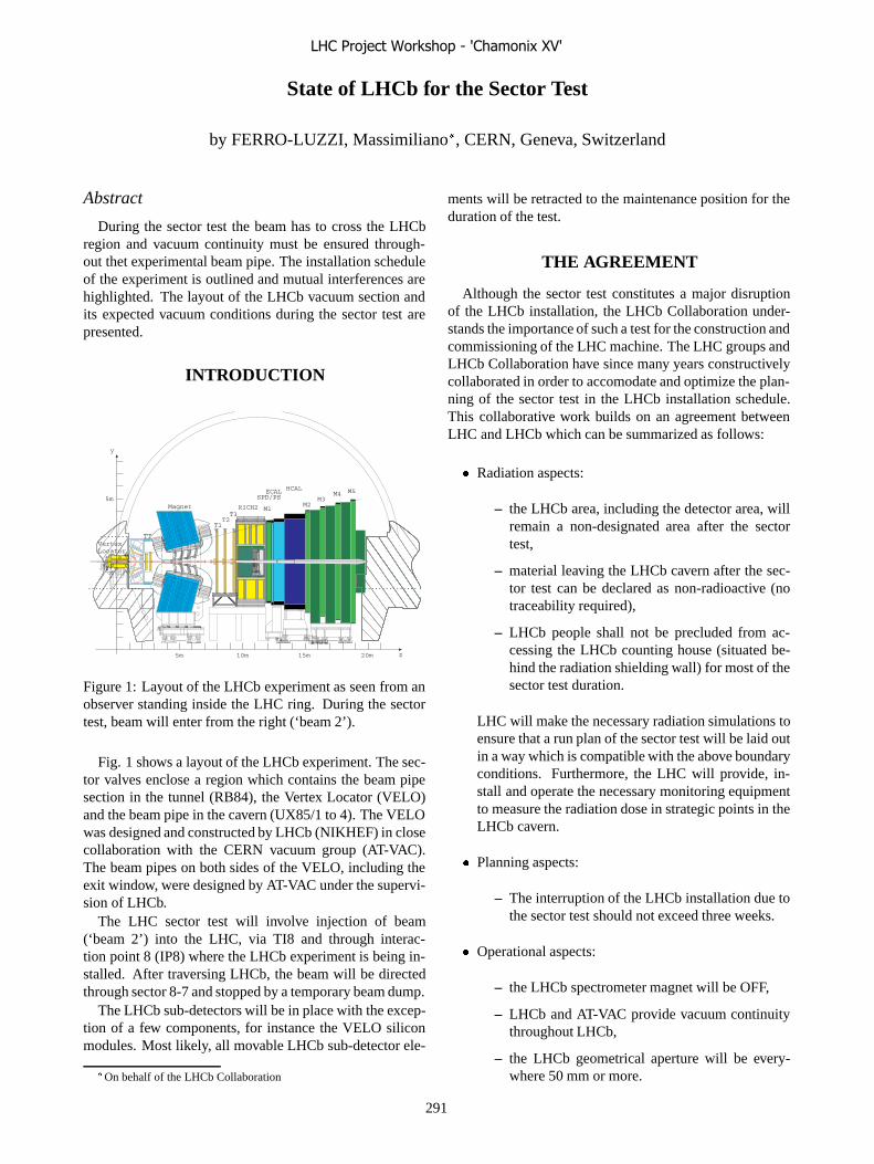
State of LHCb for the Sector Test
by FERRO-LUZZI, Massimiliano�, CERN, Geneva, Switzerland
Abstract
During the sector test the beam has to cross the LHCbregion and vacuum continuity must be ensured through-out thet experimental beam pipe. The installation scheduleof the experiment is outlined and mutual interferences arehighlighted. The layout of the LHCb vacuum section andits expected vacuum conditions during the sector test arepresented.
INTRODUCTION
M1
M3M2
M4 M5
RICH2
HCALECALSPD/PS
Magnet
z5m
y
5m
10m 15m 20m
TT
T1T2T3
VertexLocator
Figure 1: Layout of the LHCb experiment as seen from anobserver standing inside the LHC ring. During the sectortest, beam will enter from the right (‘beam 2’).
Fig. 1 shows a layout of the LHCb experiment. The sec-tor valves enclose a region which contains the beam pipesection in the tunnel (RB84), the Vertex Locator (VELO)and the beam pipe in the cavern (UX85/1 to 4). The VELOwas designed and constructed by LHCb (NIKHEF) in closecollaboration with the CERN vacuum group (AT-VAC).The beam pipes on both sides of the VELO, including theexit window, were designed by AT-VAC under the supervi-sion of LHCb.
The LHC sector test will involve injection of beam(‘beam 2’) into the LHC, via TI8 and through interac-tion point 8 (IP8) where the LHCb experiment is being in-stalled. After traversing LHCb, the beam will be directedthrough sector 8-7 and stopped by a temporary beam dump.
The LHCb sub-detectors will be in place with the excep-tion of a few components, for instance the VELO siliconmodules. Most likely, all movable LHCb sub-detector ele-
�On behalf of the LHCb Collaboration
ments will be retracted to the maintenance position for theduration of the test.
THE AGREEMENT
Although the sector test constitutes a major disruptionof the LHCb installation, the LHCb Collaboration under-stands the importance of such a test for the construction andcommissioning of the LHC machine. The LHC groups andLHCb Collaboration have since many years constructivelycollaborated in order to accomodate and optimize the plan-ning of the sector test in the LHCb installation schedule.This collaborative work builds on an agreement betweenLHC and LHCb which can be summarized as follows:
� Radiation aspects:
– the LHCb area, including the detector area, willremain a non-designated area after the sectortest,
– material leaving the LHCb cavern after the sec-tor test can be declared as non-radioactive (notraceability required),
– LHCb people shall not be precluded from ac-cessing the LHCb counting house (situated be-hind the radiation shielding wall) for most of thesector test duration.
LHC will make the necessary radiation simulations toensure that a run plan of the sector test will be laid outin a way which is compatible with the above boundaryconditions. Furthermore, the LHC will provide, in-stall and operate the necessary monitoring equipmentto measure the radiation dose in strategic points in theLHCb cavern.
� Planning aspects:
– The interruption of the LHCb installation due tothe sector test should not exceed three weeks.
� Operational aspects:
– the LHCb spectrometer magnet will be OFF,
– LHCb and AT-VAC provide vacuum continuitythroughout LHCb,
– the LHCb geometrical aperture will be every-where 50 mm or more.
LHC Project Workshop - 'Chamonix XV'
291

Figure 2: Layout of LHCb VELO vacuum system. Notethat, during the sector test, the detectors boxes will be inthe ‘open’ position, i.e. each moved out by 30 mm.
THE VERTEX LOCATOR
Description
Fig. 2 shows a view of the VELO vacuum system, whichconsists essentially of two volumes: the detector volume,which is pumped by turbodrag pumps, and the beam vol-ume, which is pumped by ion pumps. A 0.3 mm thinaluminium box surrounds each detector half and separatesthe detector vacuum from the beam vacuum. The maxi-mum pressure difference that this thin box can sustain be-fore plastic deformation is about 15 mbar. For this rea-son, a sophisticated gas injection and evacuation systemhas been designed, which allows venting and evacuatingthe volumes without ever reaching this critical pressure dif-ference. Furthemore, the detector halves can be moved inboth transverse directions by several millimeters. In orderto decouple the detectors from the vacuum vessel two largerectangular bellows are inserted between the detector sup-port and the flange on the vacuum vessel.
Some of the design goals of the vacuum system are
1. beam volume pressure ����� � ���� ���� (afterbake out),
2. detector volume pressure ������� � ���� ���� and
3. �� � ������ � �������� � ���� at all times.
More details, in particular about bake out temperatures,NEG compatibility and surface treatments, can be foundin the VELO Technical Design Report [1] and Ref. [2].
Construction
The VELO vacuum vessel was delivered to NIKHEF onApril 8, 2005 [2]. A prototype rectangular bellow was fab-ricated and stress-tested with 15000 movement cycles. Nodegradation of the bellow was observed. The final two
rectangular bellows were manufactured and installed in thevacuum vessel. The VELO vacuum and positioning sys-tems are now fully assembled, with the exception of thethin aluminium boxes which are still under fabrication. ThePLC-based control system of the VELO vacuum system iscomplete. The evacuation and venting procedure have beentested, exercised and fine tuned. The design criteria weremet, in particular the final beam vacuum pressure achievedafter bake out was ����� � � ���� ���� and the pres-sure difference �� never exceeded 3 mbar during evacua-tion and venting.
The effort is now shifting toward high-level control soft-ware developments (PVSS2) which should enable data ex-change between the VELO vacuum system (PLC) and bothLHCb and LHC SCADA systems. For more information,see Ref. [3].
The VELO vacuum vessel and vacuum system will beinstalled at IP8 in May 2006 and subsequently commis-sioned. The thin aluminium boxes will be installed not ear-lier than August 2006.
LHCB BEAM PIPE
Figure 3: Layout of LHCb beam pipe.
Fig. 3 shows a schematical layout of the LHCb beampipe throughout the LHCb spectrometer. The first sectionof the LHCb beam pipe in the cavern (UX85/1) consists ofa 2 mm thick aluminium window (83 cm in diameter, witha short beam pipe section and a bellow) which is weldedto a 1 mm thick beryllium pipe. A first prototype windowwas made and stress-tested. Bake-out was tested to �� �and the Helicoflex seal remained leak tight (the nominalbake-out temperature is ��� �, which also matches withthe maximum temperature specified by the seal manufac-turer). Five Helicoflex seals are in stock at CERN. A pres-sure test was made at 1.5 bar and a maximum displacementof 0.5 mm was observed. Two final windows have beenmachined and their geometry controlled. Vacuum tests arebeing performed.
LHC Project Workshop - 'Chamonix XV'
292

A first prototype of the UX85/1 beryllium beam pipesection was delivered to CERN. It passed all acceptancetests (leak tightness, thermal cycling, geometrical measure-ments). A NEG coating was applied. The beam pipe sec-tion was considered to be good enough for installation inLHCb. It is now ready for welding to the VELO window(which is foreseen for March).
The second section of beam pipe, labeled UX85/2, con-sists of beryllium. It was manufactured and delivered toCERN in February. Vacuum acceptance tests are under wayand NEG coating will follow. All the necessary tooling isready.
The third section, UX85/3, consists as well of berylliumand is being manufactured in Russia. Delivery has beendelayed to March.
The fourth and last section (UX85/4) is a stainless steelbeam pipe. It was delivered in January. The end cone wascopper coated on the inside. Acceptance tests are beingperformed and NEG coating will follow. All necessarytooling is available.
A few transition components between the UX85 beampipe sections are necessary to complete the LHCb vacuumchamber. The transition section (with bellow) betweenUX85/3 and UX85/4 is made of stainless steel and is be-ing manufactured (delivery expected in February). Thetransition between UX85/2 and UX85/3 consists of alu-minium and contains a bellow. Its design is being modifiedto improve reliability. The transition between UX85/1 andUX85/2 consists as well of aluminium with two bellowsconnected by a tube with flanges on the extremities. Partof the first fabricated series presented leaks on the bellowconvolutions. This was traced back to corrosive spittingscoming from the filling material used during the machin-ing process. This process is being improved to increase thereliability of the bellows. A new set of bellows is expectedbefore May.
The RB84 beam pipe section consists of standard LSScomponents and will be fabricated before June.
All beam pipe supports and installation tooling havebeen conceptually designed and detailing is being finished.Manufacturing is due to start in March and finish in April.
Finally, aluminium versions of the UX85/1, UX85/2 andUX85/3 beam pipe sections are being designed and will befabricated before June.
SCHEDULE AND SUMMARY
The VELO vacuum system is ready and its installationat IP8 due to start in May 2006. The thin aluminium boxesare under fabrication and will be installed later in the year.Most of the LHCb beam pipe sections and transition piecesare expected to be ready for the currently planned deploy-ment dates, i.e. from June to October 2006. In parallel,spare aluminium beam pipes are being designed and willbe fabricated before June and could be used for the sectortest in case any of the beryllium sections was to be late.
Concerning the global LHCb installation schedule, the
devices that are most coupled to this beam pipe installationare the RICH1 gas enclosure and exit window. Other de-vices which must be installed before the beam pipe are theTrigger Tracker support structure, the Outer Tracker mod-ules (on the inside of the LHC), the Inner Tracker supportand the Pre-Shower / Scintillator Pad Detector. All thesedevices are currently on schedule.
The first evacuation of the complete LHCb vacuum sec-tor is due to take place in October 2006. The bake outprocedure, which is an important step in the commission-ing of the LHCb experiment, is currently planned in Oc-tober 2006, although it is not required for the sector test.Discussions between AT-VAC and LHCb are ongoing todetermine the optimal date for this task. The interferencebetween neighbouring sectors by residual gas flow (whenthe sector valves are opened), as well as effects on the in-stallation and commissioning schedules, will be taken intoaccount.
ACKNOWLEDGEMENTS
I am particularly indebted to Delio Duarte Ramos (AT-VAC), Adriana Rossi (AT-VAC), Rolf Lindner (PH-LBD)and Gloria Corti (PH-LBD) for providing all the infor-mation concerning the LHCb beam pipe and installationschedule.
REFERENCES
[1] “LHCb VELO Technical Design Report”, P.R. Barbosa Mar-inho et al., CERN-LHCC-2001-011.
[2] Progress on the construction and testing of the VELOvacuum system, positioning system and mechanics can befollowed from the NIKHEF MT web site at the URLhttp://www.nikhef.nl/pub/departments/mt/projects/lhcb-vertex/ .
[3] The last VELO–AT-VAC meeting is documented underhttp://indico.cern.ch/conferenceDisplay.py?confId=a057358 .
LHC Project Workshop - 'Chamonix XV'
293

RADIATION PROTECTION ISSUES DURING THE TI8 AND SECTOR TESTS
H. Vincke, D. Forkel-Wirth, H. Menzel, CERN, Geneva, Switzerland
ABSTRACT
This paper discusses the radiation protection issues which will arise during the TI8 and the sector test. For both tests two main topics are discusses. The first point concentrates on assessments of the prompt radiation levels during the tests and the necessary access restrictions. The second point analyzes the consequences of the activation along the beam line and its surroundings which are caused by the beam losses at the beam line elements and the beam impact in the TED. For the sector test especially the impact for the LHCb area will be discussed in detail.
TI8 TESTS
Parameters used to estimate the radiological consequences of the tests
In the year 2006 two tests are scheduled. The planned intensities and the momentum of the beam used during the tests are listed in Table 1. Table 1: Beam intensities and momentum of the two TI8 tests. Beam
momentum Total beam intensity of the test
Duration
Test 1 (low intensity)
450 GeV/c 6E13 protons
48 h
Test 2 (high intensity)
450 GeV/c 4E14 protons
48 h
During the test the intensity of the single shots will reach one third of the maximum intensity which will be reached during the LHC operation. Figure 1 presents the simulation geometry of the TI8/LHC area as it was used in the calculations to asses the radiological consequences of the tests. Compared to the tests in 2004 the additional shielding which was located 2 meters downstream the TED and the 80 cm thick concrete shielding wall in UJ88 at the TI8 exit will not be installed anymore.
Figure 1: Beam line geometry used to simulate the TI8 tests. Access restrictions during the test caused by dose rate levels due to prompt radiation The access to areas where the accumulated dose integrated over the whole test period is higher than 3 uSv has to be blocked. 3 uSv is about one third of 10 uSv, which is considered as the so called “optimization limit”. If “non-radiation workers” in the LHC get a dose less than 10 uSv due to their work in the LHC per year, the working procedure is considered automatically as optimized. In 2006 three tests (two TI8 tests and one sector test) are planned to be carried out. The maximum possible dose per test is limited to 3 uSv. Therefore, non-radiation workers will not get a dose higher than 10 uSv by all tests performed. Figure 2 presents the accumulated dose contributions caused by the various particle types produced by the beam impact in the TED beam stopper. These pictures present correctly only the forward cascade. Due to limited CPU time the parts of the cascade pointing towards Point 1 were suppressed during the simulation procedure in order to save CPU time.
LHC Project Workshop - 'Chamonix XV'
294
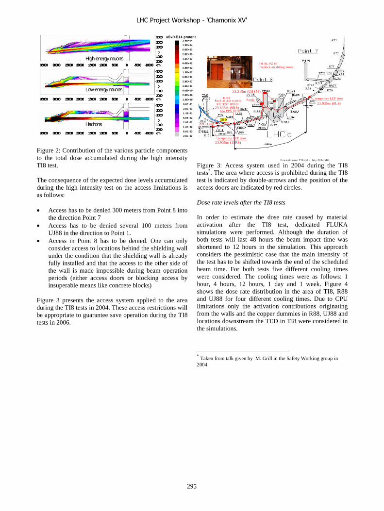
Extraction-test TI8.dsf / July.2004 MG
PM 85, PZ 85Interlock on sliding doors
TED
temporary LEP door
temporary LEP door
PPG 8270 new
60m
300 m
~600m23.935m (15R8)
23.635m (9R8)23.035m (8L8)
23.315m (US852)
PatchRack access system RXTEST 87820
UJ88
PPG TZ80
to CNGS
Figure 2: Contribution of the various particle components to the total dose accumulated during the high intensity TI8 test. The consequence of the expected dose levels accumulated during the high intensity test on the access limitations is as follows: • Access has to be denied 300 meters from Point 8 into
the direction Point 7 • Access has to be denied several 100 meters from
UJ88 in the direction to Point 1. • Access in Point 8 has to be denied. One can only
consider access to locations behind the shielding wall under the condition that the shielding wall is already fully installed and that the access to the other side of the wall is made impossible during beam operation periods (either access doors or blocking access by insuperable means like concrete blocks)
Figure 3 presents the access system applied to the area during the TI8 tests in 2004. These access restrictions will be appropriate to guarantee save operation during the TI8 tests in 2006.
Figure 3: Access system used in 2004 during the TI8 tests*. The area where access is prohibited during the TI8 test is indicated by double-arrows and the position of the access doors are indicated by red circles. Dose rate levels after the TI8 tests In order to estimate the dose rate caused by material activation after the TI8 test, dedicated FLUKA simulations were performed. Although the duration of both tests will last 48 hours the beam impact time was shortened to 12 hours in the simulation. This approach considers the pessimistic case that the main intensity of the test has to be shifted towards the end of the scheduled beam time. For both tests five different cooling times were considered. The cooling times were as follows: 1 hour, 4 hours, 12 hours, 1 day and 1 week. Figure 4 shows the dose rate distribution in the area of TI8, R88 and UJ88 for four different cooling times. Due to CPU limitations only the activation contributions originating from the walls and the copper dummies in R88, UJ88 and locations downstream the TED in TI8 were considered in the simulations. * Taken from talk given by M. Grill in the Safety Working group in
2004
uSv/4E14 protons
2.8E-03
6.0E-03
1.3E-02
2.8E-02
6.0E-02
1.3E-01
2.8E-01
6.0E-01
1.3E+00
2.8E+00
6.0E+00
1.3E+01
2.8E+01
6.0E+01
1.3E+02
2.8E+02
6.0E+02
1.3E+03
2.8E+03
6.0E+03
1.3E+04
2.8E+04uSv/4E14 protons
2.8E-03
6.0E-03
1.3E-02
2.8E-02
6.0E-02
1.3E-01
2.8E-01
6.0E-01
1.3E+00
2.8E+00
6.0E+00
1.3E+01
2.8E+01
6.0E+01
1.3E+02
2.8E+02
6.0E+02
1.3E+03
2.8E+03
6.0E+03
1.3E+04
2.8E+04
35000 30000 25000 20000 15000 10000 5000 0 -5000 -10000
-3000
-1000
010002000
-2000
cm
35000 30000 25000 20000 15000 10000 5000 0 -5000 -10000
-3000
-1000
010002000
-2000
cm
35000 30000 25000 20000 15000 10000 5000 0 -5000 -10000
-3000
-1000
01000
2000
-2000
cm
High-energy muons
Low-energy muons
Hadrons
35000 30000 25000 20000 15000 10000 5000 0 -5000 -10000
-3000
-1000
010002000
-2000
cm
35000 30000 25000 20000 15000 10000 5000 0 -5000 -10000
-3000
-1000
010002000
-2000
cm
35000 30000 25000 20000 15000 10000 5000 0 -5000 -10000
-3000
-1000
01000
2000
-2000
cm
35000 30000 25000 20000 15000 10000 5000 0 -5000 -10000
-3000
-1000
010002000
-2000
cm35000 30000 25000 20000 15000 10000 5000 0 -5000 -10000
-3000
-1000
010002000
-2000
cm35000 30000 25000 20000 15000 10000 5000 0 -5000 -10000
-3000
-1000
010002000
-2000
cm
35000 30000 25000 20000 15000 10000 5000 0 -5000 -10000
-3000
-1000
010002000
-2000
cm35000 30000 25000 20000 15000 10000 5000 0 -5000 -10000
-3000
-1000
010002000
-2000
cm35000 30000 25000 20000 15000 10000 5000 0 -5000 -10000
-3000
-1000
010002000
-2000
cm
35000 30000 25000 20000 15000 10000 5000 0 -5000 -10000
-3000
-1000
01000
2000
-2000
cm35000 30000 25000 20000 15000 10000 5000 0 -5000 -10000
-3000
-1000
01000
2000
-2000
cm35000 30000 25000 20000 15000 10000 5000 0 -5000 -10000
-3000
-1000
01000
2000
-2000
cm
High-energy muons
Low-energy muons
Hadrons
LHC Project Workshop - 'Chamonix XV'
295

Figure 4: Dose rate (average over an height of 2 m) after an irradiation of 4E14 (high Int.) and 6E13 protons respectively calculated for cooling times of 1(first picture), 12, 24 hours and 1 week (last picture).
After 1 hour of cooling after the high intensity TI8 test, the dose rate in the tunnel R88 adjacent to the TED and at the exit of the TI8 tunnel can be found to be in the range of 50 uSv/h. The main contribution to the radiation originates from Na-24 which is produced in concrete. This isotope decays with a half life of 15 hours. Therefore, the maximum dose rates in these areas declines within one day to a level of about 20 uSv/h. Within a week the radiation is further reduced to a dose rate of 0.1 uSv/h. Activation of the copper dummies In order to give first estimates concerning the activity produced during the tests in the two copper dummies, the consequences of a singular impact of 4E14 protons on the TED were calculated for a cooling time of 1 hour. The main specific activity in the copper dummies originates from Cu-64, which has a half life of 12.7 hours. The average specific activity in the dummy in R88 is 7E5 Bq/kg and the average specific activity found in the first 10 cm of the copper dummy in UJ88 is 1.9E7 Bq/kg. These values are clearly above the Swiss Exemption Limit for specific activity. Beside this isotope also several long lived isotopes like Mn-54 and Co-60 will be produced in the copper dummies. Activation of the TED cooling water For the simulation the TED was assumed to be cooled with dematerialized water. The impact of the proton beam causes production of tritium and Be-7 in the water circuit. However, the total radioactivity production caused by the test is below the limit above which the water is considered as radioactive. Consequences of the TI8 tests Already after the first TI8 test the areas UJ88 and R88 have to be declared as radiation areas. During the first two days (low intensity test) and the first week (high intensity test) respectively the area will be defined as controlled area. The consequence of that will be the following: • Access only with personal and active dosimeter • Job and dose planning is required during this time • Material which will be removed from the area has to
be radiologically controlled After this first period the area classification can be changed from “Controlled Area” into “Supervised Area”. This lowers the restrictions such that neither active dosimeter nor a job and dose planning is required when entering these areas. All calculations are based on the aforementioned conservative irradiation pattern during the test. In case the irradiation is equally distributed over the 48 hours which
1.5E-05
3.2E-05
7.0E-05
1.5E-04
3.2E-04
7.0E-04
1.5E-03
3.2E-03
7.0E-03
1.5E-02
3.2E-02
7.0E-02
1.5E-01
3.2E-01
7.0E-01
1.5E+00
3.2E+00
7.0E+00
1.5E+01
3.2E+01
7.0E+01
1.5E+02
High Int.
Low Int.
1.5E-05
3.2E-05
7.0E-05
1.5E-04
3.2E-04
7.0E-04
1.5E-03
3.2E-03
7.0E-03
1.5E-02
3.2E-02
7.0E-02
1.5E-01
3.2E-01
7.0E-01
1.5E+00
3.2E+00
7.0E+00
1.5E+01
3.2E+01
7.0E+01
1.5E+02
1.5E-05
3.2E-05
7.0E-05
1.5E-04
3.2E-04
7.0E-04
1.5E-03
3.2E-03
7.0E-03
1.5E-02
3.2E-02
7.0E-02
1.5E-01
3.2E-01
7.0E-01
1.5E+00
3.2E+00
7.0E+00
1.5E+01
3.2E+01
7.0E+01
1.5E+02
High Int.
Low Int.
uSv/h
LHC Project Workshop - 'Chamonix XV'
296

are foreseen for the test, the dose rate which will be seen at the first day of cooling will be significantly lower. Radiation Monitors used during and after the TI8 tests All access doors will be equipped with high-pressure ionization chambers (IG5) during the beam operation. These chambers will be in the interlock of the TI8 extraction. In case too high beam values will be measured during the operation the beam will be stopped. During and after the TI8 test air ionization chambers (PMI) will be installed in the area of the TED, in R88 and in UJ88 close to highly activated locations in order to measure the dose rate caused by activation. Along the whole TI8 beam line TL and High Level Dosimeters will be installed in order to measure the dose which is given to the material by the test operation.
SECTOR TEST This chapter studies the radiological consequences of the Sector Test in which 3E13 protons with a momentum of 450 GeV/c will be sent over the injection tunnel TI8 into the LHC tunnel to the TED beam stopper located at the beginning of Point 7. The main intensity of the single shots will be 5E9 protons and the highest intensity will go up to 1E11 protons per shot. The maximum loss rate expected during the test will be in the range of 1 %. A more likely loss ratio will be 10-4. For the sector test the same radiation assessment as for the TI8 test was performed. A prompt radiation levels during the test and the consequences originating from the activation were studied. Moreover, a closer look to the LHCb area in terms of possible activation of equipment was undertaken. The radiological requirements of the tests are as follows: During the test the prompt radiation should be kept within the limits applied on areas which can be accessed by non radiation workers. The area between Point 8 and 7 should be reclassified after the test to a non-designated area. Moreover, no radiological consequences for the LHCb area should arise from the test. In order to assess all consequences of the test FLUKA simulations were either performed or old calculation results were extrapolated by applying the new irradiation and geometry conditions.
Access restrictions during the test based on dose rate levels due to prompt radiation The access to areas where the accumulated dose integrated over the whole test period is higher than 3 uSv has to be blocked. 3 uSv is about one third of 10 uSv,
which is considered as the so called “optimization limit”. If “non-radiation workers” in the LHC get a dose less than 10 uSv due to their work in the LHC per year, the working procedure is considered automatically as optimized. In 2006 three tests (two TI8 tests and one sector test) are planned to be carried out. The maximum possible dose per test is limited to 3 uSv. Therefore, non-radiation workers will not get a dose higher than 10 uSv by all tests performed. The consequence of this restriction in accumulated dose can be concluded in terms of access constraints as follows: • Access has to be denied 1 km downstream the TED
beam stopper (into direction Point 6) • Access has to be denied several 100 meters from
UJ88 in the direction to Point 1. • Access in Point 8 has to be denied. One can only
consider access to locations behind the shielding wall under the condition that the shielding wall is already fully installed and that the access to the other side of the wall is made impossible during beam operation periods (either access doors or blocking access by insuperable means like concrete blocks)
Dose rate levels after the Sector Test After the Sector Test activation of the beam line elements and their surroundings will remain in the area. In the area of the TED the surrounding concrete walls, the beam line elements and the TED itself will contribute the most to the dose rate seen in the area. The dose rate seen after the test in the area will depend strongly on the irradiation pattern and on the cooling time after the irradiation. After the test it is planned to remove the TED in order to reclassify the area to a non designated area. In order to estimate the radiation levels after the test and to estimate the earliest moment at which it is save to remove the TED without taking too much dose, FLUKA simulations according the following parameters were performed: • The irradiation time was assumed to be 12 hours.
Although the test itself will last 14 days, this conservative assumption takes into account that beam line related problems might occur at the beginning of the test resulting in a shift of the main beam intensities towards the end of the test period.
• The total intensity was assumed to be 3E13 protons. • The dose rate after the test was calculated for cooling
times of 1 day, 4.5 days and 1 week. The simulation results are also supposed to predict whether it will be possible to reclassify the area after the test to a non designated area. Figure 5 presents the dose rate levels calculated for the aforementioned irradiation conditions for three different cooling times in the
LHC Project Workshop - 'Chamonix XV'
297
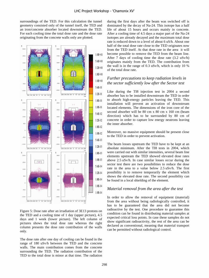
surroundings of the TED. For this calculation the tunnel geometry consisted only of the tunnel itself, the TED and an iron/concrete absorber located downstream the TED. For each cooling time the total dose rate and the dose rate originating from the concrete walls only are plotted. Figure 5: Dose rate after an irradiation of 3E13 protons on the TED and a cooling time of 1 day (upper picture), 4.5 days and 1 week (lower picture). The left column of pictures shows the total dose rate whereas the right column presents the dose rate contribution of the walls only. The dose rate after one day of cooling can be found in the range of 180 uSv/h between the TED and the concrete walls. The main contribution comes from the concrete surrounding the TED. The radiation contribution of the TED to the total dose is minor at that time. The radiation
during the first days after the beam was switched off is dominated by the decay of Na-24. This isotope has a half life of about 15 hours and occurs mainly in concrete. After a cooling time of 4.5 days a major part of the Na-24 isotopes are already decayed and the maximum total dose rate is reduced down to a level of about 6 uS/h. About one half of the total dose rate close to the TED originates now from the TED itself. At that dose rate in the area it will become possible to remove the TED from the beam line. After 7 days of cooling time the dose rate (3.2 uSv/h) originates mainly from the TED. The contribution from the wall is in the range of 0.3 uSv/h, which is only 10 % of the total dose rate.
Further precautions to keep radiation levels in the sector sufficiently low after the Sector test
Like during the TI8 injection test in 2004 a second absorber has to be installed downstream the TED in order to absorb high-energy particles leaving the TED. This installation will prevent an activation of downstream located elements. The dimensions of the iron core of the second absorber will be 80 cm x 80 cm x 160 cm (beam direction) which has to be surrounded by 80 cm of concrete in order to capture low energy neutrons leaving the inner absorber. Moreover, no massive equipment should be present close to the TED in order to prevent activation. The beam losses upstream the TED have to be kept at an absolute minimum. After the TI8 tests in 2004, which were carried out with similar intensities, several beam line elements upstream the TED showed elevated dose rates above 2.5 uSv/h. In case similar losses occur during the sector test there are two possibilities to reduce the dose rate in the area to a value below 2.5 uSv/h. The first possibility is to remove temporarily the element which shows the elevated dose rate. The second possibility can be found in a local shielding of the element.
Material removal from the area after the test
In order to allow the removal of equipment (material) from the area without being radiologically controlled, it has to be guaranteed that the area did not become radioactive by the test. One procedure to guarantee this condition can be found in distributing material samples at expected critical loss points. In case these samples do not show significant radioactivity, the rest of the area can be declared as conventional, meaning that material transport can be permitted without radiological control.
LHC Project Workshop - 'Chamonix XV'
298
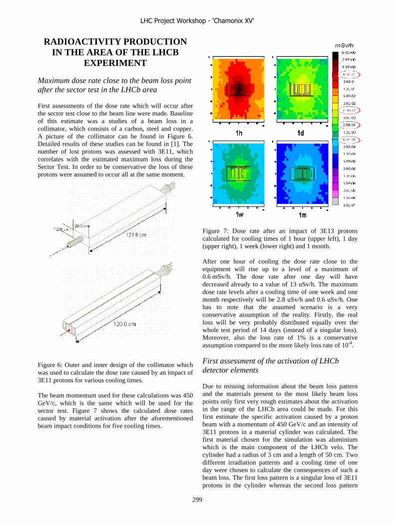
RADIOACTIVITY PRODUCTION IN THE AREA OF THE LHCB
EXPERIMENT
Maximum dose rate close to the beam loss point after the sector test in the LHCb area
First assessments of the dose rate which will occur after the sector test close to the beam line were made. Baseline of this estimate was a studies of a beam loss in a collimator, which consists of a carbon, steel and copper. A picture of the collimator can be found in Figure 6. Detailed results of these studies can be found in [1]. The number of lost protons was assessed with 3E11, which correlates with the estimated maximum loss during the Sector Test. In order to be conservative the loss of these protons were assumed to occur all at the same moment. Figure 6: Outer and inner design of the collimator which was used to calculate the dose rate caused by an impact of 3E11 protons for various cooling times. The beam momentum used for these calculations was 450 GeV/c, which is the same which will be used for the sector test. Figure 7 shows the calculated dose rates caused by material activation after the aforementioned beam impact conditions for five cooling times.
Figure 7: Dose rate after an impact of 3E13 protons calculated for cooling times of 1 hour (upper left), 1 day (upper right), 1 week (lower right) and 1 month. After one hour of cooling the dose rate close to the equipment will rise up to a level of a maximum of 0.6 mSv/h. The dose rate after one day will have decreased already to a value of 13 uSv/h. The maximum dose rate levels after a cooling time of one week and one month respectively will be 2.8 uSv/h and 0.6 uSv/h. One has to note that the assumed scenario is a very conservative assumption of the reality. Firstly, the real loss will be very probably distributed equally over the whole test period of 14 days (instead of a singular loss). Moreover, also the loss rate of 1% is a conservative assumption compared to the more likely loss rate of 10-4. First assessment of the activation of LHCb detector elements Due to missing information about the beam loss pattern and the materials present to the most likely beam loss points only first very rough estimates about the activation in the range of the LHCb area could be made. For this first estimate the specific activation caused by a proton beam with a momentum of 450 GeV/c and an intensity of 3E11 protons in a material cylinder was calculated. The first material chosen for the simulation was aluminium which is the main component of the LHCb velo. The cylinder had a radius of 3 cm and a length of 50 cm. Two different irradiation patterns and a cooling time of one day were chosen to calculate the consequences of such a beam loss. The first loss pattern is a singular loss of 3E11 protons in the cylinder whereas the second loss pattern
LHC Project Workshop - 'Chamonix XV'
299
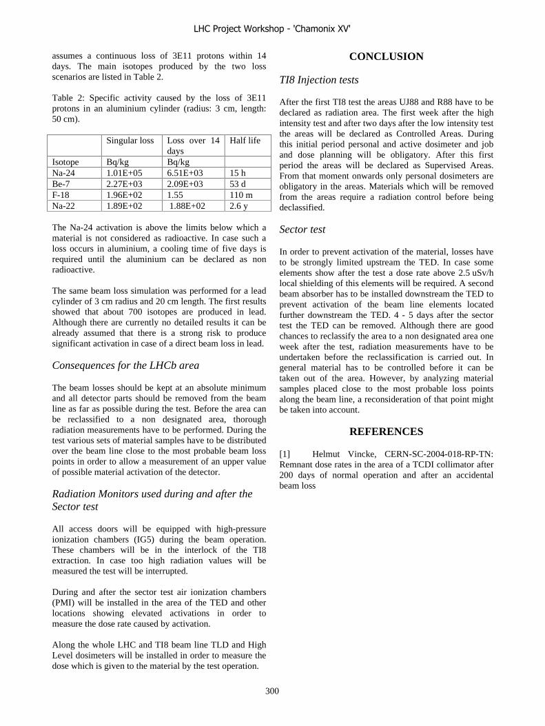
assumes a continuous loss of 3E11 protons within 14 days. The main isotopes produced by the two loss scenarios are listed in Table 2. Table 2: Specific activity caused by the loss of 3E11 protons in an aluminium cylinder (radius: 3 cm, length: 50 cm). Singular loss Loss over 14
days Half life
Isotope Bq/kg Bq/kg Na-24 1.01E+05 6.51E+03 15 h Be-7 2.27E+03 2.09E+03 53 d F-18 1.96E+02 1.55 110 m Na-22 1.89E+02 1.88E+02 2.6 y The Na-24 activation is above the limits below which a material is not considered as radioactive. In case such a loss occurs in aluminium, a cooling time of five days is required until the aluminium can be declared as non radioactive. The same beam loss simulation was performed for a lead cylinder of 3 cm radius and 20 cm length. The first results showed that about 700 isotopes are produced in lead. Although there are currently no detailed results it can be already assumed that there is a strong risk to produce significant activation in case of a direct beam loss in lead. Consequences for the LHCb area The beam losses should be kept at an absolute minimum and all detector parts should be removed from the beam line as far as possible during the test. Before the area can be reclassified to a non designated area, thorough radiation measurements have to be performed. During the test various sets of material samples have to be distributed over the beam line close to the most probable beam loss points in order to allow a measurement of an upper value of possible material activation of the detector. Radiation Monitors used during and after the Sector test All access doors will be equipped with high-pressure ionization chambers (IG5) during the beam operation. These chambers will be in the interlock of the TI8 extraction. In case too high radiation values will be measured the test will be interrupted. During and after the sector test air ionization chambers (PMI) will be installed in the area of the TED and other locations showing elevated activations in order to measure the dose rate caused by activation. Along the whole LHC and TI8 beam line TLD and High Level dosimeters will be installed in order to measure the dose which is given to the material by the test operation.
CONCLUSION TI8 Injection tests
After the first TI8 test the areas UJ88 and R88 have to be declared as radiation area. The first week after the high intensity test and after two days after the low intensity test the areas will be declared as Controlled Areas. During this initial period personal and active dosimeter and job and dose planning will be obligatory. After this first period the areas will be declared as Supervised Areas. From that moment onwards only personal dosimeters are obligatory in the areas. Materials which will be removed from the areas require a radiation control before being declassified. Sector test
In order to prevent activation of the material, losses have to be strongly limited upstream the TED. In case some elements show after the test a dose rate above 2.5 uSv/h local shielding of this elements will be required. A second beam absorber has to be installed downstream the TED to prevent activation of the beam line elements located further downstream the TED. 4 - 5 days after the sector test the TED can be removed. Although there are good chances to reclassify the area to a non designated area one week after the test, radiation measurements have to be undertaken before the reclassification is carried out. In general material has to be controlled before it can be taken out of the area. However, by analyzing material samples placed close to the most probable loss points along the beam line, a reconsideration of that point might be taken into account.
REFERENCES [1] Helmut Vincke, CERN-SC-2004-018-RP-TN: Remnant dose rates in the area of a TCDI collimator after 200 days of normal operation and after an accidental beam loss
LHC Project Workshop - 'Chamonix XV'
300

ACCES SYSTEMS DURING THE LHC INJECTION TESTS S. Grau, P. Ninin, T. Ladzinski, L. Scibile, CERN, Geneva, Switzerland
AbstractThe temporary access system required for the LHC
Injection Tests is described. Special hardware needed is listed as well as the software necessary to monitor the access. The procedures and limitations for accessing the zone are also described.
INTRODUCTIONDuring the LHC Injection Tests, the LHC Access
Systems shall protect the personnel against radiation hazard generated by the presence of the beam. Therefore, access doors must be interlocked to disable beam in case the safety conditions are violated.
The LHC Injection Tests represent a very important milestone for the LHC Access Systems [8]. This is a real scenario test for the LHC Access Control System (LACS)[5], for the LHC Access Safety System (LASS) [2] as well as for the access procedures [1].
This paper describes the configuration of the access systems during and after the tests, as well as the challenges in terms of planning and coordination to meet this milestone.
ACCESS EQUIPEMENT Access equipment to surface areas of Points 7 and 8
must be installed at their nominal location and be fully operational by the LHC Injection Tests. Access to machine areas of Point 8 will be possible through PM85 and access to LHCb through PZ85. Concerning Point 7, access will be done through PM76.
The same requirement is applicable for access equipment to underground areas around Points 7 and 8. The only exceptions are the two intersite doors of sectors 8-1 and 7-6 that will be temporally installed at several meters from their nominal position. The first one limits the access to the TI8 areas, the second one to the sector areas, during the tests. Access equipment installed in the underground areas is distributed over 18 patrol sectors, 5 in Point 7 and 13 in Point 8.
In particular for Point 8, a shielding wall between the experimental and the service areas shall be mounted to enable access to the service areas during the tests.
Access equipment shall also be deployed at the CCC. This concerns the man machine interfaces that will permit the operation and supervision of the LHC Access Systems, the external interfaces to alarm systems, the enrolment desks, the central servers, the database for authorisation and archiving, the audio and video controllers, and the maintenance and configuration workstations [2], [5].
The total number of equipment involved in these tests is presented in Table 1. This represents 20% of the LHC Access Systems infrastructure.
Access equipment LHC 7 LHC 8 CCC
Personnel Access 1 6
Material Access 1 5
Sector doors 8 11
End of Zone doors 2 13
Shielding walls 1 4 6
Racks 12 20 6
CCC computers 10
Patrol sectors 5 13
TOTAL 30 72 16Table 1: Access equipment for LHC Injection Tests
ACCESS INTERFACES For the LHC Injection Tests two interlock chains must
be connected to the LASS [3]. The first one, referred to as SPS Chain 3, prevents the beam from being transferred down the tunnel TI8. The second one, referred to as LHC Chain 8, prevents the beam from being injected to the LHC at Point 8. The integration of the above mentioned interlock chains to the LASS leads to the interfaces presented in Figure 1 and described below.
The LASS system is based on a safety PLC architecture and a redundant cable loop [4]. The PLC architecture consists of an Access Safety Central Controller located at the CCC that gathers and distributes safety information/commands from/to the Access Safety Local Controllers located at each site. The communication between the controllers is ensured by a redundant and dedicated transmission network (optical loop, copper cables). For the LHC Injection Tests, only the central controller and the LHC8 and LHC7 local controllers will be connected.
The Access Safety LHC8 Controller will interface the three Elements Importants de Sûreté (EIS) of LHC Chain 8: TED 87765, MBIAH 8783M and MSIB 8813M. The interlock with this equipment is done at the EIS control system level except for the MBIAH 8783M which is done also at the 18 KV level.
The Access Safety LHC7 Controller will not interface an EIS-beam. The circulating beam EIS of Point 7 will not be interlocked during the tests.
Both controllers of LHC7 and LHC8 will interface with the access equipment and evacuation systems of each site. The interface with the evacuation system is required to trigger the Beam Imminent Warning (BIW) sirens that indicate an imminent presence of the beam in each sector.
LHC Project Workshop - 'Chamonix XV'
301
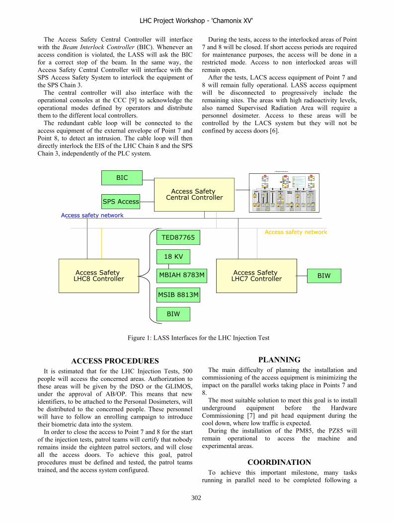
The Access Safety Central Controller will interface with the Beam Interlock Controller (BIC). Whenever an access condition is violated, the LASS will ask the BIC for a correct stop of the beam. In the same way, the Access Safety Central Controller will interface with the SPS Access Safety System to interlock the equipment of the SPS Chain 3.
The central controller will also interface with the operational consoles at the CCC [9] to acknowledge the operational modes defined by operators and distribute them to the different local controllers.
The redundant cable loop will be connected to the access equipment of the external envelope of Point 7 and Point 8, to detect an intrusion. The cable loop will then directly interlock the EIS of the LHC Chain 8 and the SPS Chain 3, independently of the PLC system.
ACCESS PROCEDURES It is estimated that for the LHC Injection Tests, 500
people will access the concerned areas. Authorization to these areas will be given by the DSO or the GLIMOS, under the approval of AB/OP. This means that new identifiers, to be attached to the Personal Dosimeters, will be distributed to the concerned people. These personnel will have to follow an enrolling campaign to introduce their biometric data into the system.
In order to close the access to Point 7 and 8 for the start of the injection tests, patrol teams will certify that nobody remains inside the eighteen patrol sectors, and will close all the access doors. To achieve this goal, patrol procedures must be defined and tested, the patrol teams trained, and the access system configured.
During the tests, access to the interlocked areas of Point 7 and 8 will be closed. If short access periods are required for maintenance purposes, the access will be done in a restricted mode. Access to non interlocked areas will remain open.
After the tests, LACS access equipment of Point 7 and 8 will remain fully operational. LASS access equipment will be disconnected to progressively include the remaining sites. The areas with high radioactivity levels, also named Supervised Radiation Area will require a personnel dosimeter. Access to these areas will be controlled by the LACS system but they will not be confined by access doors [6].
PLANNINGThe main difficulty of planning the installation and
commissioning of the access equipment is minimizing the impact on the parallel works taking place in Points 7 and 8.
The most suitable solution to meet this goal is to install underground equipment before the Hardware Commissioning [7] and pit head equipment during the cool down, where low traffic is expected.
During the installation of the PM85, the PZ85 will remain operational to access the machine and experimental areas.
COORDINATION To achieve this important milestone, many tasks
running in parallel need to be completed following a
Access Safety Central Controller
LASS operation mode selection
EIS-RF
ONOFF
R F
ON OFF
AC CESTUNNEL
POINT 1
ATLAS
ON OFF
A CCESTUNNEL
ON OFF
ACCESSERVICE
ON OFF
ACC ESEX PERIENCE
ON OFF
AC CESTUNNEL
ON OFF
A CCESSERVICE
ON OFF
AC CES RF
ON OFF
AC CESTUNNEL
ALICE
ON OFF
A CCESEXPERIENC E
ON OFF
A CCESSER VICE
ON OFF
AC CEST UNNE L
CMSON OFF
ACC ESEX PERIENCE
ON OFF
A CCEST UNNEL
ON OFF
A C CESS ERVICE
ON OFF
AC CESTUNNEL
ON OFF
ACC ESTUNNEL
LHC-BON OFF
AC CESEX PERIENC E
ON OFF
AC CESSER VIC E
Electr onsstoppers
ONOFF
Elect ron Sto.
ATLAS
YES NO
DE LEGATION
YES NO
DELEGAT ION
YES NO
DE LE GATION
YES NO
DELEGAT ION
YES NO
DELEGA TION
POINT 2 POINT 3 POINT 4 POINT 5 POINT 6 POINT 7 POINT 8
LHC
OK OK
EIS- a
ON OFF
ACCE S
Key release
ON
FA ISCEA U
OFF
EIS-f
Key r elease
Alarm eceaunent
FaisIm mi
DélaiD écroissance
R adiat ion18 18
Commande pour établir un mode (= reti rer un VETO)All umé = confirmation que le VETO est re tir é
Positio n sûr e de tous l es EIS (n on alime nté, fermé etc.)
Commande pour annuler un mode ( = mettr e un VETO)Allumé = confi rmati on que le VETO est mis
MODE Al lumé = Mode établiAucun VETO sur le gr oupe d’EIS cor respondant
Positio n non sûr e d’au moins un EIS (alimenté, ouvert, etc.)
Clignotement signalant un incident ou an omalie sur les EISor r espondant s (ex intr usion)c
OFF
ON
18 Compteur décr oissant
Clef en posi tion insér ée et ver rouil lée
EIS- a EIS -a EIS-a EIS-a EIS-a EIS-a EIS-a EIS- a EIS-a EIS-a EIS-a EIS- a EIS- a
EIS-a EIS- a EIS- a EIS-a EIS-a
ASB
TI2EIS- f
FA ISC EAU
Key release
OFF ON
ACCE S Point 2
Key release
OFFON
EIS- a
TI8EIS- f
FAISCEAU
Key r elea se
OFF ON
ACC ES P oint 8
Key release
OFFON
EIS-a
Access Safety LHC8 Controller
Access Safety LHC7 Controller
18 KV
TED87765
MBIAH 8783M
MSIB 8813M
BIW
BIW
BIC
SPS Access
Access safety network
Access safety network
Figure 1: LASS Interfaces for the LHC Injection Test
LHC Project Workshop - 'Chamonix XV'
302
specific order and in accordance with the LHC Installation and Commissioning schedule constraints.
In addition to the different project actors responsible for the achievement of individual tasks, the role of the Injection Tests Coordinator has been introduced. The objective of this project actor is to have a transversal view on the running tasks, identify critical or missing tasks, find out potential solutions and report to the project leader.
CONCLUSION During the LHC Injection Tests the LHC Access
Systems shall protect personnel against radiation hazard generated by the presence of the beam.
This is a very important milestone for the access systems. Installation and commissioning of access equipment and interfaces is scheduled and organized to achieve this goal, a goal that represents 20% of the LHC access systems infrastructure.
ACKNOWLEDGEMENTS This paper reflects the work of the LHC Access Project
team: J-F Juget, S. Di Luca, G. Roy, E. Sanchez-Corral, G. Smith, L. Hammouti, T. Riesco, N. Rama, M. Munoz.
REFERENCES [1] P. Ninin & all, LHC Access, Where do we stand,
LHC Project Workshop Chamonix XIV, January 2006.
[2] P. Ninin, T. Ladzinski, Spécification technique détaillée du système de sûreté d’accès, EDMS 571277.
[3] P. Ninin, F. Rodriguez, Description des interface avec les éléments de la machine, EDMS 456769.
[4] M. Munoz 4, Spécification technique de la voie câblée, EDMS 69585.
[5] L. Scibile & all, “Technical Specification for the Design, Supply, Installation and Maintenance of the LHC Access Control system, EDMS: 399737.
[6] H. Vincke, “Radiation Issue”, LHC Project Workshop Chamonix XIV, January 2006, Session 9.
[7] R. Saban, “ Hardware Commissioning”, LHC Project Workshop Chamonix XIV, January 2006, Session 9.
[8] M. Lamont, http://lhc-injection-test.web.cern.ch/lhc-injection-test/
[9] L. Hammouti, M. Munoz, Spécification du pupitre de contrôle du LHC, EDMS : 578789.
LHC Project Workshop - 'Chamonix XV'
303
DISCUSSION AND DECISIONS SESSION
J. Poole, CERN, Geneva, Switzerland
Steve Myers led this session which was used to dis-cuss various issues which had not been resolved during theworkshop, to prepare a list of items to be followed up dur-ing the year and to record the associated decisions.
MINIMUM WORKABLE LHC
Commissioning
During the discussion of the schedule for ions it wasnoted that it will be good practice to have an ion run be-fore a shutdown in the same way as this is done now for theSPS. The lower losses during the ion run allow the inducedactivity from proton running to decay before interventionsare made in the machine.
There had been some confusion regarding the meaningof bunch pile up number and it was explained that the num-ber refers to the absolute number of events per crossing. Itwas noted that it could be useful to run at a � � of 2m inorder to reduce bunch pile up.
It was reported from the experiments that if somebunches are displaced and to enable collisions in LHCb andthe crossing angle is zero, the other experiments will stillbe able to work.
The question was raised if the 75ns scheme was still nec-essary now that the electron cloud effect is not expected tobe a problem. It was agreed that this is an important stagefor operations but it will be verified by LHC-OP Commit-tee if there are further requirements for this scheme.
A recurring theme throughout the sessions was the man-agement of critical settings. Many parameters are ex-tremely sensitive because changing them in the wrong waycould cause serious damage to the accelerator and thereforeit is proposed that there is a management system which willensure their security. This system should be defined verysoon because it could have an influence on many other con-trol procedures.
The Machine Protection Working Group was asked tolook into the abort gap monitor.
It was noted that there will be an impact on backgroundin the experiments if some long straight sections are notbaked out. The experiments were asked to look into thisand see if it would be acceptable. The radiation protectionissues associated with the bakeout should also be taken intoaccount.
Machine Protection and Collimation
The vacuum group explained that for them the baselinewas to bake all room temperature components before beamcommissioning but if there are schedule problems or com-ponent delivery problems some bakeouts make be skipped.
If some sectors are not baked before the first run, they willbe done before the second year of operation.
The settings of the collimation system can be relaxedsomewhat during the early stages but it will be importantto know what the damage threshold is for 1�m emittancebeams. The influence of tertiary collimators on experimen-tal backgrounds needs to be evaluated for the early runs.The loss patterns also need to be recalculated for 2m � �.
During the discussion it was made clear that in the earlydays the sum signal from the beam pickups is a very use-ful parameter. The functionality to provide this parame-ter should be planned. Furthermore, it was noted that thisfunctionality is of little use once the other systems havebeen commissioned.
An operational scenario for the Beam Loss Monitorsneeds to be developed.
In order to avoid quenches, the abort gap needs to be keptclear of particles. Such particles can also interfere with thetune measurement.
There will be a formal set of procedures for the testingand acceptance of the machine protection systems. TheEiC will be responsible for machine protection during op-eration.
Providers Commitments
The presence of 50Hz lines on the tune spectrum couldbe a problem and some measurements should be made onthe closed orbit corrector power converters in order to ob-tain an estimate of the levels which might be expected.
The requirements from operations for access to the con-trol system by the standby services and security issues needto be specified as soon as possible.
It was noted that an algorithm exists for a �-beat cor-rection knob and this should be incorporated in the LSAsystem.
It was agreed that it would be preferable to have a smalloffset current in all of the MQTs.
The possibility of changing the beam screen to reducethe impact of polarity changes in LHCb should be followedup.
It will be essential to build and maintain an “as installed”database.
MAGNETIC REQUIREMENTS
Baseline measurements for the stand-alone quadrupolesneed to be discussed in the LTC.
MACHINE-EXPERIMENTS INTERFACE
It was noted that the primary objective is to accumulate10fb�� and changing optics and running conditions should
LHC Project Workshop - 'Chamonix XV'
304

not delay this goal but it was noted that it will probably benecessary to run at lower intensity (for example with ions)before a shutdown to allow induced radiation to decay.
A person from the accelerator side should be appointedto be responsible for experimental background optimisa-tion.
INSTALLATION
It was noted that magnet polarities should be verified be-fore installation in the tunnel.
IONS IN LHC
The early ion runs should be done with the same machineconfiguration as for protons.
It was noted that there is a long lead time for new ionspecies but the LINAC3 can be used for development andtherefore a full test stand need not be built.
It was agreed that the 14MHz RF system in LEIR shouldbe replaced by an 18MHz version and the existing systemwill be kept as a spare. A set of basic spares for LEIRshould be purchased.
It was noted again that a working collimation system forions has yet to be defined.
SECTOR TEST WITH BEAM
It was proposed that if the quench limit falls below 10�
protons, the beam intensity could be reduced by scrapingin the SPS.
It was agreed that the beam intensity during the testshould be limited to around ten times the quench limit inorder to be well away from the damage threshold.
It was agreed that an on-line machine model (MAD)should be prepared. This will be done by the ABP Groupin collaboration with M. Lamont.
Equipment groups need to prepare the data input for thepost mortem system.
Data exchange between machine and experiments duringthe sector test will be rudimentary and may be restricted totelephone communications.
It was agreed that there was little point in doing a par-tial test and there should be no short cuts taken in order tofacilitate the test.
There was strong support for cycling the magnets to100% of their maximum current from the magnet andpower groups. Cycling to 20% should only be consideredif it is the only way to make the test in time.
LHC Project Workshop - 'Chamonix XV'
305