The effect of pre-strain on the material behaviour and the Bauschinger effect in the bending of hot...
8
Materials Science and Engineering A 528 (2011) 3302–3309 Contents lists available at ScienceDirect Materials Science and Engineering A journal homepage: www.elsevier.com/locate/msea The effect of pre-strain on the material behaviour and the Bauschinger effect in the bending of hot rolled and aged steel E. Hemmerich a , B. Rolfe b , P.D. Hodgson a , M. Weiss a,∗ a Centre for Material and Fibre Innovation, Deakin University, Waurn Ponds, Pigdons Rd., Vic. 3217, Australia b School of Engineering, Deakin University, Waurn Ponds, Pigdons Rd., Vic. 3217, Australia article info Article history: Received 4 October 2010 Received in revised form 9 December 2010 Accepted 9 December 2010 Available online 15 December 2010 Keywords: Roll forming FEA Bending Bauschinger effect Sheet forming Aged steel Tension levelling abstract Compression and bend tests were performed on an annealed and aged carbon steel that had been pre- strained by different amounts. A bending model was developed to analyse the bending response of the material. While the bending test results agreed well with some of the material trends found in previous studies focusing on the Bauschinger effect, an overly high reduction of the bending yield with pre-strain was observed. Calculation of the moment curvature diagram for the pre-strained material based on the tensile and compression test data using the analytical model did not fit the experimental curve. In the control of yield phenomena by the industrial processes of temper rolling, skin passing, tension levelling and roller levelling, the effectiveness of the treatment is usually judged from tensile testing after treatment. However, the present work shows that where the yield phenomena have been removed by pre-processing, that the tensile test will not predict the subsequent bending behaviour and that the bending test may provide greater insight. This may have important consequences in the study of cold roll forming where shape defects in the product are believed to originate from small strain forward and reverse bending deformations that will be strongly affected by the Bauschinger and yield effects. © 2010 Elsevier B.V. All rights reserved. 1. Introduction In roll forming the overall amount of strain away from the bend is low and common shape defects, such as oil canning and edge waviness, are due to very low plastic strain differences [1]. The material behaviour close to yield is, therefore, critical for these forming processes and small changes in yield can affect the formed product. The steel types that are currently used in roll forming are often skin passed and/or roller levelled to eliminate upper and lower yield stress behaviour and yield point elongation [1,2], and to improve the surface quality [3] and flatness of the sheet [4]. Pre- vious studies focusing on the material behaviour in bending after skin passing have shown that, depending on the process condi- tions, temper rolling can lead to either an increase or a reduction in the yield stress [5]. The change in yield stress was related to the presence of residual stresses in the material and the Bauschinger effect. In tension levelling, the material is plastically pre-strained in tension [4]; if this is followed by bending, there will be a compres- ∗ Corresponding author at: Centre for Material and Fibre Innovation, Deakin University, Institute for Technology, Research & Innovation, Geelong Technology Precinct, Waurn Ponds, Pigdons Rd., Geelong, Vic. 3217, Australia. Tel.: +61 03 5227 3368; fax: +61 03 5227 1103. E-mail address: [email protected] (M. Weiss). sive deformation on one side of the sheet such that a reduction of the yield stress due to the Bauschinger effect is possible. It should be noted that these effects are not only specific to roll forming; stamped parts also suffer defects due to low strains (forming of hoods [6]) and Bauschinger effects (bending and unbending over die radii [7]). A previous study on the Bauschinger effect in steel by Wat- son and Brown [8] involved pre-straining steel samples in torsion followed by tension; they found that the work hardening rate in subsequent tension at low strain increased with pre-strain while at higher strains the work hardening rate approached that of the original flow curve. It was concluded that a high density of mobile dislocations exists after pre-straining and that these are rapidly immobilised in reverse deformation leading to the initially high hardening rate. In Watson and Brown’s study the Bauschinger stress, defined as the difference between the forward and the reverse flow stress, increased with pre-strain if ageing was prevented. This was later confirmed by Tan et al. [9] who also reported that in the case of ageing before reverse deformation, the Bauschinger effect is low and reduces with pre-strain. Gupta and Kodali [10] tested different steels in tension and compression and found that for all values of pre-strain the reduction of yield strength was higher in pre-compressed samples compared to those that were pre-strained in tension, while Li et al. [11] observed no influence of the deformation sequence on the Bauschinger effect. 0921-5093/$ – see front matter © 2010 Elsevier B.V. All rights reserved. doi:10.1016/j.msea.2010.12.035
Transcript of The effect of pre-strain on the material behaviour and the Bauschinger effect in the bending of hot...
Tt
Ea
b
a
ARRAA
KRFBBSAT
1
iwmfpaltvstipet
UPT
0d
Materials Science and Engineering A 528 (2011) 3302–3309
Contents lists available at ScienceDirect
Materials Science and Engineering A
journa l homepage: www.e lsev ier .com/ locate /msea
he effect of pre-strain on the material behaviour and the Bauschinger effect inhe bending of hot rolled and aged steel
. Hemmericha, B. Rolfeb, P.D. Hodgsona, M. Weissa,∗
Centre for Material and Fibre Innovation, Deakin University, Waurn Ponds, Pigdons Rd., Vic. 3217, AustraliaSchool of Engineering, Deakin University, Waurn Ponds, Pigdons Rd., Vic. 3217, Australia
r t i c l e i n f o
rticle history:eceived 4 October 2010eceived in revised form 9 December 2010ccepted 9 December 2010vailable online 15 December 2010
eywords:
a b s t r a c t
Compression and bend tests were performed on an annealed and aged carbon steel that had been pre-strained by different amounts. A bending model was developed to analyse the bending response of thematerial. While the bending test results agreed well with some of the material trends found in previousstudies focusing on the Bauschinger effect, an overly high reduction of the bending yield with pre-strainwas observed. Calculation of the moment curvature diagram for the pre-strained material based onthe tensile and compression test data using the analytical model did not fit the experimental curve.
oll formingEAendingauschinger effectheet formingged steelension levelling
In the control of yield phenomena by the industrial processes of temper rolling, skin passing, tensionlevelling and roller levelling, the effectiveness of the treatment is usually judged from tensile testingafter treatment. However, the present work shows that where the yield phenomena have been removedby pre-processing, that the tensile test will not predict the subsequent bending behaviour and that thebending test may provide greater insight. This may have important consequences in the study of coldroll forming where shape defects in the product are believed to originate from small strain forward andreverse bending deformations that will be strongly affected by the Bauschinger and yield effects.
. Introduction
In roll forming the overall amount of strain away from the bends low and common shape defects, such as oil canning and edge
aviness, are due to very low plastic strain differences [1]. Theaterial behaviour close to yield is, therefore, critical for these
orming processes and small changes in yield can affect the formedroduct. The steel types that are currently used in roll formingre often skin passed and/or roller levelled to eliminate upper andower yield stress behaviour and yield point elongation [1,2], ando improve the surface quality [3] and flatness of the sheet [4]. Pre-ious studies focusing on the material behaviour in bending afterkin passing have shown that, depending on the process condi-ions, temper rolling can lead to either an increase or a reduction
n the yield stress [5]. The change in yield stress was related to theresence of residual stresses in the material and the Bauschingerffect. In tension levelling, the material is plastically pre-strained inension [4]; if this is followed by bending, there will be a compres-∗ Corresponding author at: Centre for Material and Fibre Innovation, Deakinniversity, Institute for Technology, Research & Innovation, Geelong Technologyrecinct, Waurn Ponds, Pigdons Rd., Geelong, Vic. 3217, Australia.el.: +61 03 5227 3368; fax: +61 03 5227 1103.
E-mail address: [email protected] (M. Weiss).
921-5093/$ – see front matter © 2010 Elsevier B.V. All rights reserved.oi:10.1016/j.msea.2010.12.035
© 2010 Elsevier B.V. All rights reserved.
sive deformation on one side of the sheet such that a reduction ofthe yield stress due to the Bauschinger effect is possible. It shouldbe noted that these effects are not only specific to roll forming;stamped parts also suffer defects due to low strains (forming ofhoods [6]) and Bauschinger effects (bending and unbending overdie radii [7]).
A previous study on the Bauschinger effect in steel by Wat-son and Brown [8] involved pre-straining steel samples in torsionfollowed by tension; they found that the work hardening ratein subsequent tension at low strain increased with pre-strainwhile at higher strains the work hardening rate approached thatof the original flow curve. It was concluded that a high densityof mobile dislocations exists after pre-straining and that theseare rapidly immobilised in reverse deformation leading to theinitially high hardening rate. In Watson and Brown’s study theBauschinger stress, defined as the difference between the forwardand the reverse flow stress, increased with pre-strain if ageing wasprevented. This was later confirmed by Tan et al. [9] who alsoreported that in the case of ageing before reverse deformation,the Bauschinger effect is low and reduces with pre-strain. Gupta
and Kodali [10] tested different steels in tension and compressionand found that for all values of pre-strain the reduction of yieldstrength was higher in pre-compressed samples compared to thosethat were pre-strained in tension, while Li et al. [11] observed noinfluence of the deformation sequence on the Bauschinger effect.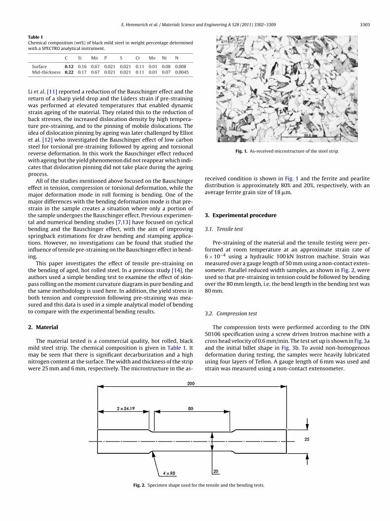
E. Hemmerich et al. / Materials Science and Engineering A 528 (2011) 3302–3309 3303
Table 1Chemical composition (wt%) of black mild steel in weight percentage determinedwith a SPECTRO analytical instrument.
Lrwsbtiesrwcp
emmsttbstii
taptbst
2
mmnw
C Si Mn P S Cr Mo Ni N
Surface 0.12 0.16 0.67 0.021 0.021 0.11 0.01 0.08 0.008Mid-thickness 0.22 0.17 0.67 0.021 0.021 0.11 0.01 0.07 0.0045
i et al. [11] reported a reduction of the Bauschinger effect and theeturn of a sharp yield drop and the Lüders strain if pre-strainingas performed at elevated temperatures that enabled dynamic
train ageing of the material. They related this to the reduction ofack stresses, the increased dislocation density by high tempera-ure pre-straining, and to the pinning of mobile dislocations. Thedea of dislocation pinning by ageing was later challenged by Elliott al. [12] who investigated the Bauschinger effect of low carbonteel for torsional pre-straining followed by ageing and torsionaleverse deformation. In this work the Bauschinger effect reducedith ageing but the yield phenomenon did not reappear which indi-
ates that dislocation pinning did not take place during the ageingrocess.
All of the studies mentioned above focused on the Bauschingerffect in tension, compression or torsional deformation, while theajor deformation mode in roll forming is bending. One of theajor differences with the bending deformation mode is that pre-
train in the sample creates a situation where only a portion ofhe sample undergoes the Bauschinger effect. Previous experimen-al and numerical bending studies [7,13] have focused on cyclicalending and the Bauschinger effect, with the aim of improvingpringback estimations for draw bending and stamping applica-ions. However, no investigations can be found that studied thenfluence of tensile pre-straining on the Bauschinger effect in bend-ng.
This paper investigates the effect of tensile pre-straining onhe bending of aged, hot rolled steel. In a previous study [14], theuthors used a simple bending test to examine the effect of skin-ass rolling on the moment curvature diagram in pure bending andhe same methodology is used here. In addition, the yield stress inoth tension and compression following pre-straining was mea-ured and this data is used in a simple analytical model of bendingo compare with the experimental bending results.
. Material
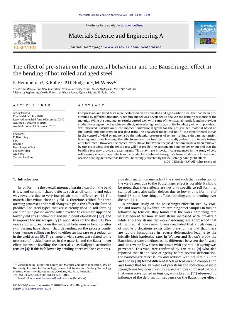
The material tested is a commercial quality, hot rolled, blackild steel strip. The chemical composition is given in Table 1. Itay be seen that there is significant decarburization and a high
itrogen content at the surface. The width and thickness of the stripere 25 mm and 6 mm, respectively. The microstructure in the as-
Fig. 2. Specimen shape used for the
Fig. 1. As-received microstructure of the steel strip.
received condition is shown in Fig. 1 and the ferrite and pearlitedistribution is approximately 80% and 20%, respectively, with anaverage ferrite grain size of 18 �m.
3. Experimental procedure
3.1. Tensile test
Pre-straining of the material and the tensile testing were per-formed at room temperature at an approximate strain rate of6 × 10−4 using a hydraulic 100 kN Instron machine. Strain wasmeasured over a gauge length of 50 mm using a non-contact exten-someter. Parallel reduced width samples, as shown in Fig. 2, wereused so that pre-straining in tension could be followed by bendingover the 80 mm length, i.e. the bend length in the bending test was80 mm.
3.2. Compression test
The compression tests were performed according to the DIN50106 specification using a screw driven Instron machine with across head velocity of 0.6 mm/min. The test set up is shown in Fig. 3aand the initial billet shape in Fig. 3b. To avoid non-homogenous
deformation during testing, the samples were heavily lubricatedusing four layers of Teflon. A gauge length of 6 mm was used andstrain was measured using a non-contact extensometer.tensile and the bending tests.

3304 E. Hemmerich et al. / Materials Science and Engineering A 528 (2011) 3302–3309
test (a
u
�
a
ε
wht
ε
a
�
Fig. 3. The experimental set-up of the compression
The compressive engineering stress and strain were calculatedsing the equations:
ce = 4F
�d20
(1)
nd
ce = h − ho
ho(2)
here the compression force is F, the initial diameter do, the sampleeight h, and the initial sample height ho. Those values were thenransformed into true stress strain data using the relations
ct = ln(1 + εcs) (3)
nd
ct = �ce(1 + εce). (4)
Fig. 4. Bend test set up (a) an
), sample dimensions (b) and sampling position (c).
3.3. Bending test
The bending test device is shown schematically in Fig. 4a. Thepin at A is inserted into a load cell in a standard tensile testingmachine. During a test, the load, F, and the displacement of point Aare recorded and the moment and curvature can be calculated. Thetest-piece is not subjected precisely to a pure moment as there is asmall axial force, F; the effect of this has been shown to be extremelysmall in the range of experimental conditions reported here [14].In these tests a clip-on curvature gauge was used to obtain a moreaccurate measure of curvature in the test-piece. This is illustratedin Fig. 4b which is self-explanatory and is fully described in [14].
All bending tests were taken to the same final curvature and themoment adjusted to a standardised value for a test strip width of
1 mm using the relation:Mstan = M
wNm/mm (5)
d curvature gauge (b).
E. Hemmerich et al. / Materials Science and Engineering A 528 (2011) 3302–3309 3305
FP
wM
3
dfiiaws
�
w
i
4
4
pct
Fs
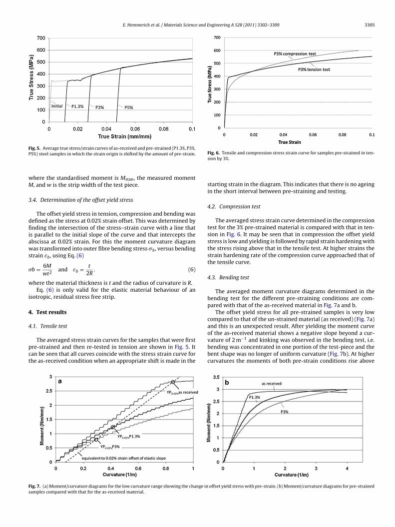
ig. 5. Average true stress/strain curves of as-received and pre-strained (P1.3%, P3%,5%) steel samples in which the strain origin is shifted by the amount of pre-strain.
here the standardised moment is Mstan, the measured moment, and w is the strip width of the test piece.
.4. Determination of the offset yield stress
The offset yield stress in tension, compression and bending wasefined as the stress at 0.02% strain offset. This was determined bynding the intersection of the stress–strain curve with a line that
s parallel to the initial slope of the curve and that intercepts thebscissa at 0.02% strain. For this the moment curvature diagramas transformed into outer fibre bending stress �b, versus bending
train εb, using Eq. (6)
b = 6M
wt2and εb = t
2R. (6)
here the material thickness is t and the radius of curvature is R.Eq. (6) is only valid for the elastic material behaviour of an
sotropic, residual stress free strip.
. Test results
.1. Tensile test
The averaged stress strain curves for the samples that were firstre-strained and then re-tested in tension are shown in Fig. 5. Itan be seen that all curves coincide with the stress strain curve forhe as-received condition when an appropriate shift is made in the
ig. 7. (a) Moment/curvature diagrams for the low curvature range showing the change inamples compared with that for the as-received material.
Fig. 6. Tensile and compression stress strain curve for samples pre-strained in ten-sion by 3%.
starting strain in the diagram. This indicates that there is no ageingin the short interval between pre-straining and testing.
4.2. Compression test
The averaged stress strain curve determined in the compressiontest for the 3% pre-strained material is compared with that in ten-sion in Fig. 6. It may be seen that in compression the offset yieldstress is low and yielding is followed by rapid strain hardening withthe stress rising above that in the tensile test. At higher strains thestrain hardening rate of the compression curve approached that ofthe tensile curve.
4.3. Bending test
The averaged moment curvature diagrams determined in thebending test for the different pre-straining conditions are com-pared with that of the as-received material in Fig. 7a and b.
The offset yield stress for all pre-strained samples is very lowcompared to that of the un-strained material (as received) (Fig. 7a)and this is an unexpected result. After yielding the moment curve
of the as-received material shows a negative slope beyond a cur-vature of 2 m−1 and kinking was observed in the bending test, i.e.bending was concentrated in one portion of the test-piece and thebent shape was no longer of uniform curvature (Fig. 7b). At highercurvatures the moments of both pre-strain conditions rise aboveoffset yield stress with pre-strain. (b) Moment/curvature diagrams for pre-strained
3 e and Engineering A 528 (2011) 3302–3309
th
4
trhTs
(cTs
eaiass
306 E. Hemmerich et al. / Materials Scienc
hat for the as-received material which might reflect overall strainardening during pre-straining.
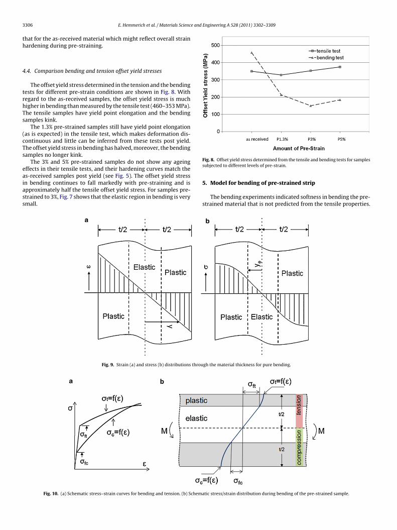
.4. Comparison bending and tension offset yield stresses
The offset yield stress determined in the tension and the bendingests for different pre-strain conditions are shown in Fig. 8. Withegard to the as-received samples, the offset yield stress is muchigher in bending than measured by the tensile test (460–353 MPa).he tensile samples have yield point elongation and the bendingamples kink.
The 1.3% pre-strained samples still have yield point elongationas is expected) in the tensile test, which makes deformation dis-ontinuous and little can be inferred from these tests post yield.he offset yield stress in bending has halved, moreover, the bendingamples no longer kink.
The 3% and 5% pre-strained samples do not show any ageingffects in their tensile tests, and their hardening curves match the
s-received samples post yield (see Fig. 5). The offset yield stressn bending continues to fall markedly with pre-straining and ispproximately half the tensile offset yield stress. For samples pre-trained to 3%, Fig. 7 shows that the elastic region in bending is verymall.Fig. 9. Strain (a) and stress (b) distributions throu
Fig. 10. (a) Schematic stress–strain curves for bending and tension. (b) Schema
Fig. 8. Offset yield stress determined from the tensile and bending tests for samplessubjected to different levels of pre-strain.
5. Model for bending of pre-strained strip
The bending experiments indicated softness in bending the pre-strained material that is not predicted from the tensile properties.
gh the material thickness for pure bending.
tic stress/strain distribution during bending of the pre-strained sample.
E. Hemmerich et al. / Materials Science and Engineering A 528 (2011) 3302–3309 3307
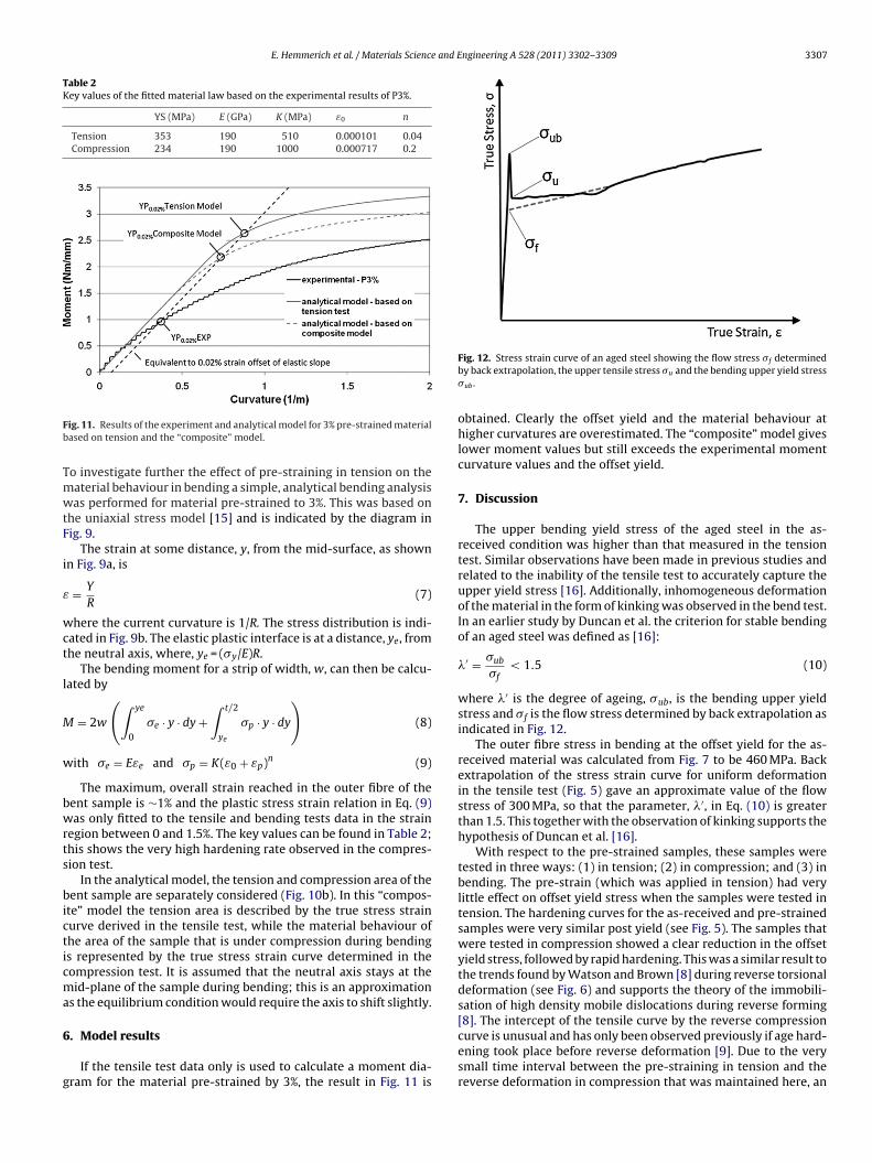
Table 2Key values of the fitted material law based on the experimental results of P3%.
YS (MPa) E (GPa) K (MPa) ε0 n
Tension 353 190 510 0.000101 0.04Compression 234 190 1000 0.000717 0.2
Fb
TmwtF
i
ε
wct
l
M
w
bwrts
bicticma
6
g
ig. 11. Results of the experiment and analytical model for 3% pre-strained materialased on tension and the “composite” model.
o investigate further the effect of pre-straining in tension on theaterial behaviour in bending a simple, analytical bending analysisas performed for material pre-strained to 3%. This was based on
he uniaxial stress model [15] and is indicated by the diagram inig. 9.
The strain at some distance, y, from the mid-surface, as shownn Fig. 9a, is
= Y
R(7)
here the current curvature is 1/R. The stress distribution is indi-ated in Fig. 9b. The elastic plastic interface is at a distance, ye, fromhe neutral axis, where, ye = (�y/E)R.
The bending moment for a strip of width, w, can then be calcu-ated by
= 2w
(∫ ye
0
�e · y · dy +∫ t/2
ye
�p · y · dy
)(8)
ith �e = Eεe and �p = K(ε0 + εp)n (9)
The maximum, overall strain reached in the outer fibre of theent sample is ∼1% and the plastic stress strain relation in Eq. (9)as only fitted to the tensile and bending tests data in the strain
egion between 0 and 1.5%. The key values can be found in Table 2;his shows the very high hardening rate observed in the compres-ion test.
In the analytical model, the tension and compression area of theent sample are separately considered (Fig. 10b). In this “compos-
te” model the tension area is described by the true stress strainurve derived in the tensile test, while the material behaviour ofhe area of the sample that is under compression during bendings represented by the true stress strain curve determined in theompression test. It is assumed that the neutral axis stays at theid-plane of the sample during bending; this is an approximation
s the equilibrium condition would require the axis to shift slightly.
. Model results
If the tensile test data only is used to calculate a moment dia-ram for the material pre-strained by 3%, the result in Fig. 11 is
Fig. 12. Stress strain curve of an aged steel showing the flow stress �f determinedby back extrapolation, the upper tensile stress �u and the bending upper yield stress�ub .
obtained. Clearly the offset yield and the material behaviour athigher curvatures are overestimated. The “composite” model giveslower moment values but still exceeds the experimental momentcurvature values and the offset yield.
7. Discussion
The upper bending yield stress of the aged steel in the as-received condition was higher than that measured in the tensiontest. Similar observations have been made in previous studies andrelated to the inability of the tensile test to accurately capture theupper yield stress [16]. Additionally, inhomogeneous deformationof the material in the form of kinking was observed in the bend test.In an earlier study by Duncan et al. the criterion for stable bendingof an aged steel was defined as [16]:
�′ = �ub
�f< 1.5 (10)
where �′ is the degree of ageing, �ub, is the bending upper yieldstress and �f is the flow stress determined by back extrapolation asindicated in Fig. 12.
The outer fibre stress in bending at the offset yield for the as-received material was calculated from Fig. 7 to be 460 MPa. Backextrapolation of the stress strain curve for uniform deformationin the tensile test (Fig. 5) gave an approximate value of the flowstress of 300 MPa, so that the parameter, �′, in Eq. (10) is greaterthan 1.5. This together with the observation of kinking supports thehypothesis of Duncan et al. [16].
With respect to the pre-strained samples, these samples weretested in three ways: (1) in tension; (2) in compression; and (3) inbending. The pre-strain (which was applied in tension) had verylittle effect on offset yield stress when the samples were tested intension. The hardening curves for the as-received and pre-strainedsamples were very similar post yield (see Fig. 5). The samples thatwere tested in compression showed a clear reduction in the offsetyield stress, followed by rapid hardening. This was a similar result tothe trends found by Watson and Brown [8] during reverse torsionaldeformation (see Fig. 6) and supports the theory of the immobili-sation of high density mobile dislocations during reverse forming
[8]. The intercept of the tensile curve by the reverse compressioncurve is unusual and has only been observed previously if age hard-ening took place before reverse deformation [9]. Due to the verysmall time interval between the pre-straining in tension and thereverse deformation in compression that was maintained here, an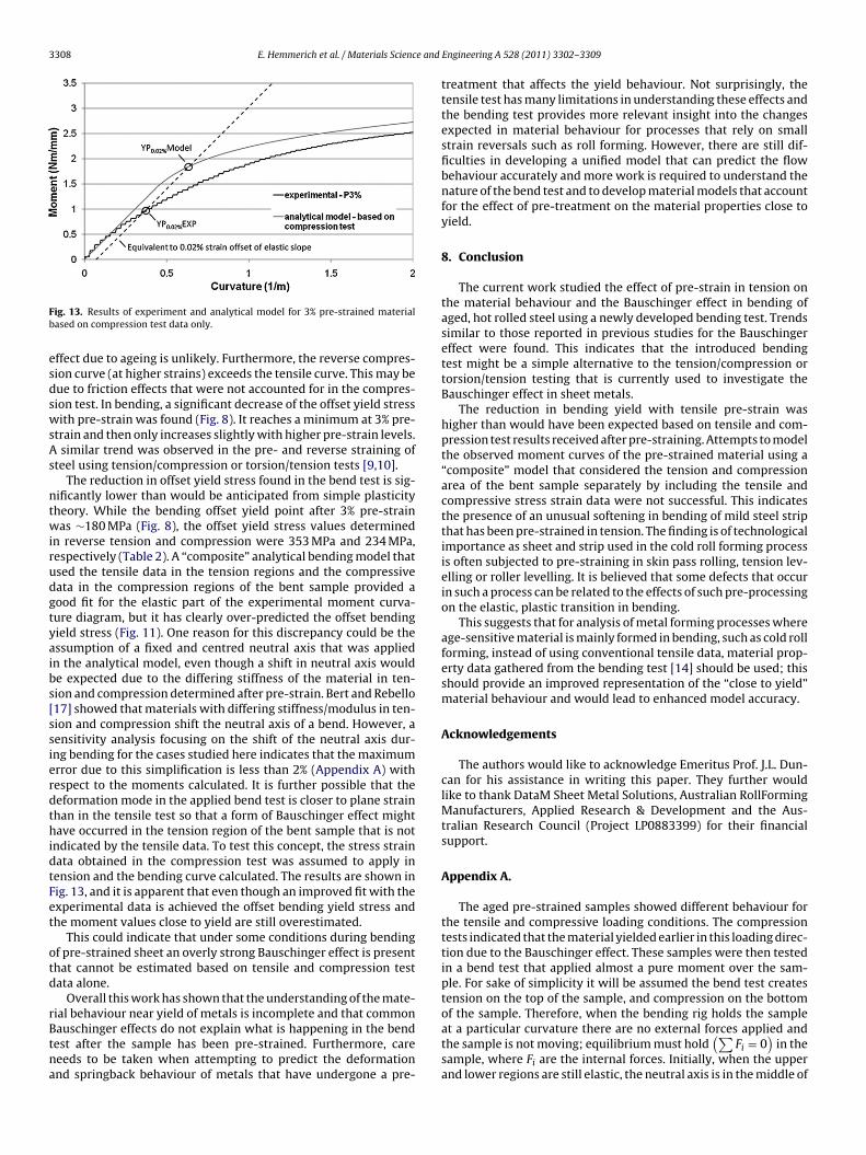
3308 E. Hemmerich et al. / Materials Science and
Fb
esdswsAs
ntwirudgtyaibs[ssierdthidtFet
otd
rBtna
ig. 13. Results of experiment and analytical model for 3% pre-strained materialased on compression test data only.
ffect due to ageing is unlikely. Furthermore, the reverse compres-ion curve (at higher strains) exceeds the tensile curve. This may beue to friction effects that were not accounted for in the compres-ion test. In bending, a significant decrease of the offset yield stressith pre-strain was found (Fig. 8). It reaches a minimum at 3% pre-
train and then only increases slightly with higher pre-strain levels.similar trend was observed in the pre- and reverse straining of
teel using tension/compression or torsion/tension tests [9,10].The reduction in offset yield stress found in the bend test is sig-
ificantly lower than would be anticipated from simple plasticityheory. While the bending offset yield point after 3% pre-strainas ∼180 MPa (Fig. 8), the offset yield stress values determined
n reverse tension and compression were 353 MPa and 234 MPa,espectively (Table 2). A “composite” analytical bending model thatsed the tensile data in the tension regions and the compressiveata in the compression regions of the bent sample provided aood fit for the elastic part of the experimental moment curva-ure diagram, but it has clearly over-predicted the offset bendingield stress (Fig. 11). One reason for this discrepancy could be thessumption of a fixed and centred neutral axis that was appliedn the analytical model, even though a shift in neutral axis woulde expected due to the differing stiffness of the material in ten-ion and compression determined after pre-strain. Bert and Rebello17] showed that materials with differing stiffness/modulus in ten-ion and compression shift the neutral axis of a bend. However, aensitivity analysis focusing on the shift of the neutral axis dur-ng bending for the cases studied here indicates that the maximumrror due to this simplification is less than 2% (Appendix A) withespect to the moments calculated. It is further possible that theeformation mode in the applied bend test is closer to plane strainhan in the tensile test so that a form of Bauschinger effect mightave occurred in the tension region of the bent sample that is not
ndicated by the tensile data. To test this concept, the stress strainata obtained in the compression test was assumed to apply inension and the bending curve calculated. The results are shown inig. 13, and it is apparent that even though an improved fit with thexperimental data is achieved the offset bending yield stress andhe moment values close to yield are still overestimated.
This could indicate that under some conditions during bendingf pre-strained sheet an overly strong Bauschinger effect is presenthat cannot be estimated based on tensile and compression testata alone.
Overall this work has shown that the understanding of the mate-
ial behaviour near yield of metals is incomplete and that commonauschinger effects do not explain what is happening in the bendest after the sample has been pre-strained. Furthermore, careeeds to be taken when attempting to predict the deformationnd springback behaviour of metals that have undergone a pre-Engineering A 528 (2011) 3302–3309
treatment that affects the yield behaviour. Not surprisingly, thetensile test has many limitations in understanding these effects andthe bending test provides more relevant insight into the changesexpected in material behaviour for processes that rely on smallstrain reversals such as roll forming. However, there are still dif-ficulties in developing a unified model that can predict the flowbehaviour accurately and more work is required to understand thenature of the bend test and to develop material models that accountfor the effect of pre-treatment on the material properties close toyield.
8. Conclusion
The current work studied the effect of pre-strain in tension onthe material behaviour and the Bauschinger effect in bending ofaged, hot rolled steel using a newly developed bending test. Trendssimilar to those reported in previous studies for the Bauschingereffect were found. This indicates that the introduced bendingtest might be a simple alternative to the tension/compression ortorsion/tension testing that is currently used to investigate theBauschinger effect in sheet metals.
The reduction in bending yield with tensile pre-strain washigher than would have been expected based on tensile and com-pression test results received after pre-straining. Attempts to modelthe observed moment curves of the pre-strained material using a“composite” model that considered the tension and compressionarea of the bent sample separately by including the tensile andcompressive stress strain data were not successful. This indicatesthe presence of an unusual softening in bending of mild steel stripthat has been pre-strained in tension. The finding is of technologicalimportance as sheet and strip used in the cold roll forming processis often subjected to pre-straining in skin pass rolling, tension lev-elling or roller levelling. It is believed that some defects that occurin such a process can be related to the effects of such pre-processingon the elastic, plastic transition in bending.
This suggests that for analysis of metal forming processes whereage-sensitive material is mainly formed in bending, such as cold rollforming, instead of using conventional tensile data, material prop-erty data gathered from the bending test [14] should be used; thisshould provide an improved representation of the “close to yield”material behaviour and would lead to enhanced model accuracy.
Acknowledgements
The authors would like to acknowledge Emeritus Prof. J.L. Dun-can for his assistance in writing this paper. They further wouldlike to thank DataM Sheet Metal Solutions, Australian RollFormingManufacturers, Applied Research & Development and the Aus-tralian Research Council (Project LP0883399) for their financialsupport.
Appendix A.
The aged pre-strained samples showed different behaviour forthe tensile and compressive loading conditions. The compressiontests indicated that the material yielded earlier in this loading direc-tion due to the Bauschinger effect. These samples were then testedin a bend test that applied almost a pure moment over the sam-ple. For sake of simplicity it will be assumed the bend test createstension on the top of the sample, and compression on the bottom
of the sample. Therefore, when the bending rig holds the sampleat a particular curvature there are no external forces applied andthe sample is not moving; equilibrium must hold(∑Fi = 0
)in the
sample, where Fi are the internal forces. Initially, when the upperand lower regions are still elastic, the neutral axis is in the middle of
E. Hemmerich et al. / Materials Science and E
Fw
tosmdtdarwTr
lra
ab
F
F
[[
[
[[
[Butterworth Heinemann, London, 2002.
[16] J. L. Duncan, M. Sue-Chu, X. J. Wang, Instability in plastic bending of thin sheetmetal, in: The International Conference on the Mechanical Behaviour of Mate-
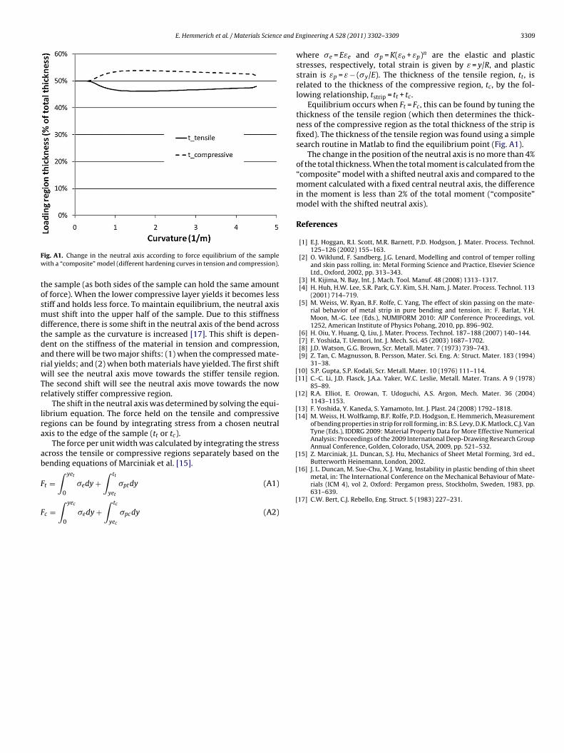
ig. A1. Change in the neutral axis according to force equilibrium of the sampleith a “composite” model (different hardening curves in tension and compression).
he sample (as both sides of the sample can hold the same amountf force). When the lower compressive layer yields it becomes lesstiff and holds less force. To maintain equilibrium, the neutral axisust shift into the upper half of the sample. Due to this stiffness
ifference, there is some shift in the neutral axis of the bend acrosshe sample as the curvature is increased [17]. This shift is depen-ent on the stiffness of the material in tension and compression,nd there will be two major shifts: (1) when the compressed mate-ial yields; and (2) when both materials have yielded. The first shiftill see the neutral axis move towards the stiffer tensile region.
he second shift will see the neutral axis move towards the nowelatively stiffer compressive region.
The shift in the neutral axis was determined by solving the equi-ibrium equation. The force held on the tensile and compressiveegions can be found by integrating stress from a chosen neutralxis to the edge of the sample (tt or tc).
The force per unit width was calculated by integrating the stresscross the tensile or compressive regions separately based on theending equations of Marciniak et al. [15].∫ yet
∫ tt
t =0
�edy +yet
�ptdy (A1)
c =∫ yec
0
�edy +∫ tc
yec
�pcdy (A2)
[
ngineering A 528 (2011) 3302–3309 3309
where �e = Eεe and �p = K(εo + εp)n are the elastic and plasticstresses, respectively, total strain is given by ε = y/R, and plasticstrain is εp = ε − (�y/E). The thickness of the tensile region, tt, isrelated to the thickness of the compressive region, tc, by the fol-lowing relationship, tstrip = tt + tc.
Equilibrium occurs when Ft = Fc, this can be found by tuning thethickness of the tensile region (which then determines the thick-ness of the compressive region as the total thickness of the strip isfixed). The thickness of the tensile region was found using a simplesearch routine in Matlab to find the equilibrium point (Fig. A1).
The change in the position of the neutral axis is no more than 4%of the total thickness. When the total moment is calculated from the“composite” model with a shifted neutral axis and compared to themoment calculated with a fixed central neutral axis, the differencein the moment is less than 2% of the total moment (“composite”model with the shifted neutral axis).
References
[1] E.J. Hoggan, R.I. Scott, M.R. Barnett, P.D. Hodgson, J. Mater. Process. Technol.125–126 (2002) 155–163.
[2] O. Wiklund, F. Sandberg, J.G. Lenard, Modelling and control of temper rollingand skin pass rolling, in: Metal Forming Science and Practice, Elsevier ScienceLtd., Oxford, 2002, pp. 313–343.
[3] H. Kijima, N. Bay, Int. J. Mach. Tool. Manuf. 48 (2008) 1313–1317.[4] H. Huh, H.W. Lee, S.R. Park, G.Y. Kim, S.H. Nam, J. Mater. Process. Technol. 113
(2001) 714–719.[5] M. Weiss, W. Ryan, B.F. Rolfe, C. Yang, The effect of skin passing on the mate-
rial behavior of metal strip in pure bending and tension, in: F. Barlat, Y.H.Moon, M.-G. Lee (Eds.), NUMIFORM 2010: AIP Conference Proceedings, vol.1252, American Institute of Physics Pohang, 2010, pp. 896–902.
[6] H. Oiu, Y. Huang, Q. Liu, J. Mater. Process. Technol. 187–188 (2007) 140–144.[7] F. Yoshida, T. Uemori, Int. J. Mech. Sci. 45 (2003) 1687–1702.[8] J.D. Watson, G.G. Brown, Scr. Metall. Mater. 7 (1973) 739–743.[9] Z. Tan, C. Magnusson, B. Persson, Mater. Sci. Eng. A: Struct. Mater. 183 (1994)
31–38.10] S.P. Gupta, S.P. Kodali, Scr. Metall. Mater. 10 (1976) 111–114.11] C.-C. Li, J.D. Flasck, J.A.a. Yaker, W.C. Leslie, Metall. Mater. Trans. A 9 (1978)
85–89.12] R.A. Elliot, E. Orowan, T. Udoguchi, A.S. Argon, Mech. Mater. 36 (2004)
1143–1153.13] F. Yoshida, Y. Kaneda, S. Yamamoto, Int. J. Plast. 24 (2008) 1792–1818.14] M. Weiss, H. Wolfkamp, B.F. Rolfe, P.D. Hodgson, E. Hemmerich, Measurement
of bending properties in strip for roll forming, in: B.S. Levy, D.K. Matlock, C.J. VanTyne (Eds.), IDDRG 2009: Material Property Data for More Effective NumericalAnalysis: Proceedings of the 2009 International Deep-Drawing Research GroupAnnual Conference, Golden, Colorado, USA, 2009, pp. 521–532.
15] Z. Marciniak, J.L. Duncan, S.J. Hu, Mechanics of Sheet Metal Forming, 3rd ed.,
rials (ICM 4), vol 2, Oxford: Pergamon press, Stockholm, Sweden, 1983, pp.631–639.
17] C.W. Bert, C.J. Rebello, Eng. Struct. 5 (1983) 227–231.