
The EcoKnight™ range - Luckins Live
52
1 The EcoKnight™ range High Efficiency Gas Fired Condensing Water Heaters Installation, Commissioning and Maintenance Instructions Models: EKW45CE EKW60CE EKW85CE EKW115CE EKW145CE EKW175CE EKW205CE EKW235CE INS0011 Issue No 9 | October 2013
-
Upload
khangminh22 -
Category
Documents
-
view
0 -
download
0
Transcript of The EcoKnight™ range - Luckins Live

1
The EcoKnight™ range High Efficiency Gas Fired Condensing Water Heaters
Installation, Commissioning and Maintenance
Instructions
Models:
EKW45CE
EKW60CE
EKW85CE
EKW115CE
EKW145CE
EKW175CE
EKW205CE
EKW235CE
INS0011 Issue No 9 | October 2013

2
Table of Contents 1.0 INTRODUCTION ................................................................................................................................................................................................... 4 2.0 PRINCIPAL PARTS ............................................................................................................................................................................................... 5 3.0 TECHNICAL DATA ................................................................................................................................................................................................ 9 4.0 GENERAL REQUIREMENTS ............................................................................................................................................................................. 11
4.1 RELATED DOCUMENTS ............................................................................................................................................................................. 11 5.0 WATER QUALITY ............................................................................................................................................................................................... 12 6.0 LOCATION ........................................................................................................................................................................................................... 12
6.1 PLANT ROOM REQUIREMENTS ................................................................................................................................................................ 12 6.2 GENERAL REQUIREMENTS ....................................................................................................................................................................... 12 6.3 CLEARANCES .............................................................................................................................................................................................. 13 6.4 CONDENSATE DRAIN ................................................................................................................................................................................. 13
7.0 GAS SUPPLY ...................................................................................................................................................................................................... 13 7.1 SERVICE PIPES ........................................................................................................................................................................................... 13 7.2 METERS ....................................................................................................................................................................................................... 13 7.3 GAS SUPPLY PIPES .................................................................................................................................................................................... 13 7.4 BOOSTED SUPPLIES .................................................................................................................................................................................. 13 7.5 PLANT-ROOM CONTROL VALVE ............................................................................................................................................................... 13 7.6 EQUIPMENT GAS SYSTEM LEAK CHECK ................................................................................................................................................ 14
8.0 FLUE SYSTEM .................................................................................................................................................................................................... 14 8.1 FLUE SYSTEM GENERAL REQUIREMENTS............................................................................................................................................. 15 8.2 APPROVED FLUE SYSTEM ........................................................................................................................................................................ 15 8.3 INSTALLATION PRECAUTIONS ................................................................................................................................................................. 15 8.4 MAXIMUM LENGTH ..................................................................................................................................................................................... 15 8.5 FLUE DISCHARGE ....................................................................................................................................................................................... 15 8.6 CONDENSATE DRAIN ................................................................................................................................................................................. 15 8.7 WATER HEATER CONNECTION ASSEMBLY ........................................................................................................................................... 16
8.7.1 EKW45CE – EKW60CE ......................................................................................................................................................................... 16 8.7.2 EKW85CE – EKW145CE ....................................................................................................................................................................... 18 8.7.3 EKW175CE ............................................................................................................................................................................................ 19 8.7.4 EKW205CE – EKW235CE ..................................................................................................................................................................... 20
8.8 FLUE TERMINAL INSTALLATION ............................................................................................................................................................... 21 8.8.1 TYPE B23 ................................................................................................................................................................................................ 21 8.8.2 TYPE C13 ................................................................................................................................................................................................ 21 8.8.3 TYPE C33 ................................................................................................................................................................................................ 22 8.8.4 TYPE C43 ................................................................................................................................................................................................ 23 8.8.5 TYPE C53 ................................................................................................................................................................................................ 23
8.9 FLUE TERMINAL GUARDING ..................................................................................................................................................................... 23 9.0 AIR SUPPLY ........................................................................................................................................................................................................ 24
9.1 COMBUSTION VENTILATION ..................................................................................................................................................................... 24 9.2 COOLING VENTILATION ............................................................................................................................................................................. 24
10.0 WATER CONNECTIONS .................................................................................................................................................................................... 25 10.1 GENERAL ..................................................................................................................................................................................................... 25 10.2 OPEN VENTED SYSTEM ARRANGEMENT ............................................................................................................................................... 25 10.3 UNVENTED SYSTEM ARRANGEMENT ..................................................................................................................................................... 25
10.3.1 EXPANSION VESSEL SIZING ........................................................................................................................................................ 26 10.4 DE-STRATIFICATION .................................................................................................................................................................................. 26 10.5 CIRCULATING PUMPS ................................................................................................................................................................................ 26 10.6 FLOW TEMPERATURE SENSOR ............................................................................................................................................................... 27
10.6.1 DRY-POCKET SENSOR ................................................................................................................................................................. 27 10.6.2 STRAP-ON SENSOR ...................................................................................................................................................................... 27 10.6.3 SENSOR WIRING ........................................................................................................................................................................... 27
11.0 ELECTRICAL SUPPLY ....................................................................................................................................................................................... 28 11.1 EXTERNAL CONTROLS .............................................................................................................................................................................. 28
11.1.1 REMOTE ENABLING ...................................................................................................................................................................... 28 11.2 HIGH VOLTAGE CONNECTOR STRIP ....................................................................................................................................................... 29 11.3 LOW VOLTAGE CONNECTOR STRIP ........................................................................................................................................................ 29 11.4 ELECTRICAL CONNECTIONS .................................................................................................................................................................... 31 11.5 FUSES .......................................................................................................................................................................................................... 31 11.6 ARC WELDING PRECAUTIONS.................................................................................................................................................................. 31 11.7 WIRING DIAGRAM ....................................................................................................................................................................................... 32 11.8 LADDER DIAGRAM ...................................................................................................................................................................................... 33
12.0 SMART SYSTEM CONTROL .............................................................................................................................................................................. 34 12.1 GENERAL ..................................................................................................................................................................................................... 34 12.2 SMART SYSTEM CONTROL PANEL .......................................................................................................................................................... 34 12.3 SEQUENCE OF OPERATION ...................................................................................................................................................................... 35 12.4 STATUS DISPLAY SCREENS ..................................................................................................................................................................... 36
13.0 COMMISSIONING AND TESTING ..................................................................................................................................................................... 38 13.1 ELECTRICAL INSTALLATION ..................................................................................................................................................................... 38 13.2 GAS INSTALLATION .................................................................................................................................................................................... 38 13.3 WATER CONNECTIONS.............................................................................................................................................................................. 38 13.4 COMMISSIONING THE EQUIPMENT ......................................................................................................................................................... 38
13.4.1 GENERAL CHECKS PRIOR TO LIGHTING ................................................................................................................................... 38 13.4.2 EQUIPMENT CHECKS PRIOR TO LIGHTING............................................................................................................................... 38 13.4.3 PROCEDURE FOR INITIAL LIGHTING .......................................................................................................................................... 39 13.4.4 GAS PRESSURE ADJUSTMENT AND COMBUSTION CHECKS ................................................................................................ 39

3
13.5 TEMPERATURE ADJUSTMENT PROCEDURE ......................................................................................................................................... 39 13.6 INSTALLATION NOISE ................................................................................................................................................................................ 40
14.0 LPG FUEL ............................................................................................................................................................................................................ 40 14.1 RELATED DOCUMENTS ............................................................................................................................................................................. 40 14.2 CONVERSION TO LPG ................................................................................................................................................................................ 40
14.2.1 EKW45CE – EKW85CE .................................................................................................................................................................. 41 14.2.2 EKW115CE ...................................................................................................................................................................................... 42 14.2.3 EKW145CE (BEFORE SERIAL NUMBER L09H10120786) ........................................................................................................... 43 14.2.4 EKW145CE (FROM SERIAL NUMBER L09H10120786) ............................................................................................................... 44 14.2.5 EKW175CE – EKW235CE .............................................................................................................................................................. 45
14.3 LPG COMMISSIONING AND TESTING ...................................................................................................................................................... 46 14.3.1 LPG PRESSURE ADJUSTMENT AND COMBUSTION CHECKS ................................................................................................. 46
15.0 MAINTENANCE ................................................................................................................................................................................................... 46 15.1 GENERAL ..................................................................................................................................................................................................... 46 15.2 MAINTENANCE SCHEDULE ....................................................................................................................................................................... 46 15.3 BURNER INSPECTION ................................................................................................................................................................................ 47 15.4 BURNER REMOVAL .................................................................................................................................................................................... 47 15.5 CLEANING THE HEAT EXCHANGER ......................................................................................................................................................... 47 15.6 DRAINING WATER HEATER SYSTEM ....................................................................................................................................................... 48 15.7 REMOVING SCALE AND SEDIMENT FROM THE STORAGE VESSEL ................................................................................................... 48 15.8 SACRIFICIAL ANODES: INSPECTION AND REPLACEMENT (STORAGE VESSELS)............................................................................ 48 15.9 REFILLING THE SYSTEM ........................................................................................................................................................................... 48 15.10 OTHER CHECKS ................................................................................................................................................................................... 49
15.10.1 RELIEF VALVE ................................................................................................................................................................................ 49 15.10.2 FLUE SYSTEM ................................................................................................................................................................................ 49 15.10.3 CONDENSATE NEUTRALISATION KIT ......................................................................................................................................... 49
16.0 SMART SYSTEM CONTROL SETTINGS .......................................................................................................................................................... 49 16.1 ENTERING THE INSTALLER CODE ........................................................................................................................................................... 49 16.2 MENU SET D FUNCTIONS .......................................................................................................................................................................... 50
16.2.1 RESET LAST 10 ERRORS ............................................................................................................................................................. 50 16.2.2 SERVICE MODE DELAY ................................................................................................................................................................ 50
16.3 MENU SET E WHR SETTINGS ................................................................................................................................................................... 50 16.3.1 TANK SETPOINT ............................................................................................................................................................................ 50
16.4 MENU SET H CONTROL MODES ............................................................................................................................................................... 50 16.4.1 CONTROL SOURCE ....................................................................................................................................................................... 50 16.4.2 CASCADE ADDRESS ..................................................................................................................................................................... 50 16.4.3 MAX CASCADE SETPOINT............................................................................................................................................................ 51 16.4.4 CASCADE OFFSET ........................................................................................................................................................................ 51 16.4.5 CASCADE OFF-ON DIFFERENTIAL .............................................................................................................................................. 51
16.5 MENU SET I CIRCULATION PUMPS .......................................................................................................................................................... 51 16.5.1 DHW PUMP DELAY ........................................................................................................................................................................ 51
16.6 MENU SET J SERVICE NOTIFICATION ..................................................................................................................................................... 51 16.6.1 SERVICE NOTIFICATION IN MONTHS ......................................................................................................................................... 51 16.6.2 SERVICE NOTIFICATION RUNNING HOURS .............................................................................................................................. 51 16.6.3 SERVICE NOTIFICATION BOILER CYCLES................................................................................................................................. 51 16.6.4 RESET SERVICE NOTIFICATION COUNTER .............................................................................................................................. 51
17.0 USER INSTRUCTIONS ....................................................................................................................................................................................... 51

4
1.0 INTRODUCTION
The Lochinvar EcoKnight™ range is a floor standing direct gas fired condensing water heater. The equipment comprises of stainless steel radial burner assembly and heat exchanger that permits fully condensing operation. EcoKnight™ water heaters should be used in conjunction with an appropriately sized storage vessel (available from Lochinvar Limited as an ancillary option)
The burner is initiated by a full electronic ignition sequence control that incorporates a spark ignition and a flame rectification device for supervision of the flame.
The output from the water heater is regulated by a variable speed combustion fan and gas/air ratio controls to maintain the correct combustion at all levels of modulation. This configuration allows modulation down to 20% of the rated output.
For the correct operation of the water heater, it is essential that a suitably sized, glanded construction pump is utilised to maintain a constant water flow rate through the heat exchanger.
This equipment is intended for use on Group H Natural Gas (2nd Family) and LPG propane (3rd Family). The information relating to propane firing is to be found in Section 14: LPG FUEL. This equipment MUST NOT use gas other than that for which it has been designed and adjusted.
This equipment must be installed by a competent person, registered with a H.S.E. approved body. All installations must conform to the relevant Gas Safety and Building Regulations. Health & Safety requirements must also be taken into account when installing any equipment. Failure to comply with the above may lead to prosecution.
If the equipment is to be connected to an unvented (pressurised) system, care must be taken to ensure all extra safety requirements are satisfied should a high or low-pressure condition occur in the system.
The equipment is designed for direct connection to a flue system.
Ancillary Options:
Primary Circulating Pump (EKW45CE & EKW60CE) Omega 3-80-2ZS
Primary Circulating Pump (EKW85CE) Omega 4-90-2ZS
Primary Circulating Pump (EKW115CE EKW145CE & EKW175CE) Omega 4-100-2ZS
Primary Circulating Pump (EKW205CE & EKW235CE) Omega 5-110-2ZS
Direct Storage Cylinder (297 litre) LST66
Direct Storage Cylinder (450 litre) LST100
Direct Storage Cylinder (747 litre) LST166
Direct Storage Cylinder (1155 litre) LST250
Unvented/Boosted Water System Kits Contact Lochinvar Limited
De-stratification Pump Kit WH9
Condensate Neutralisation Kit KIT2000
Pre-Fabricated Interconnecting Pipework Contact Lochinvar Limited
Flue System Components Contact Lochinvar Limited
5
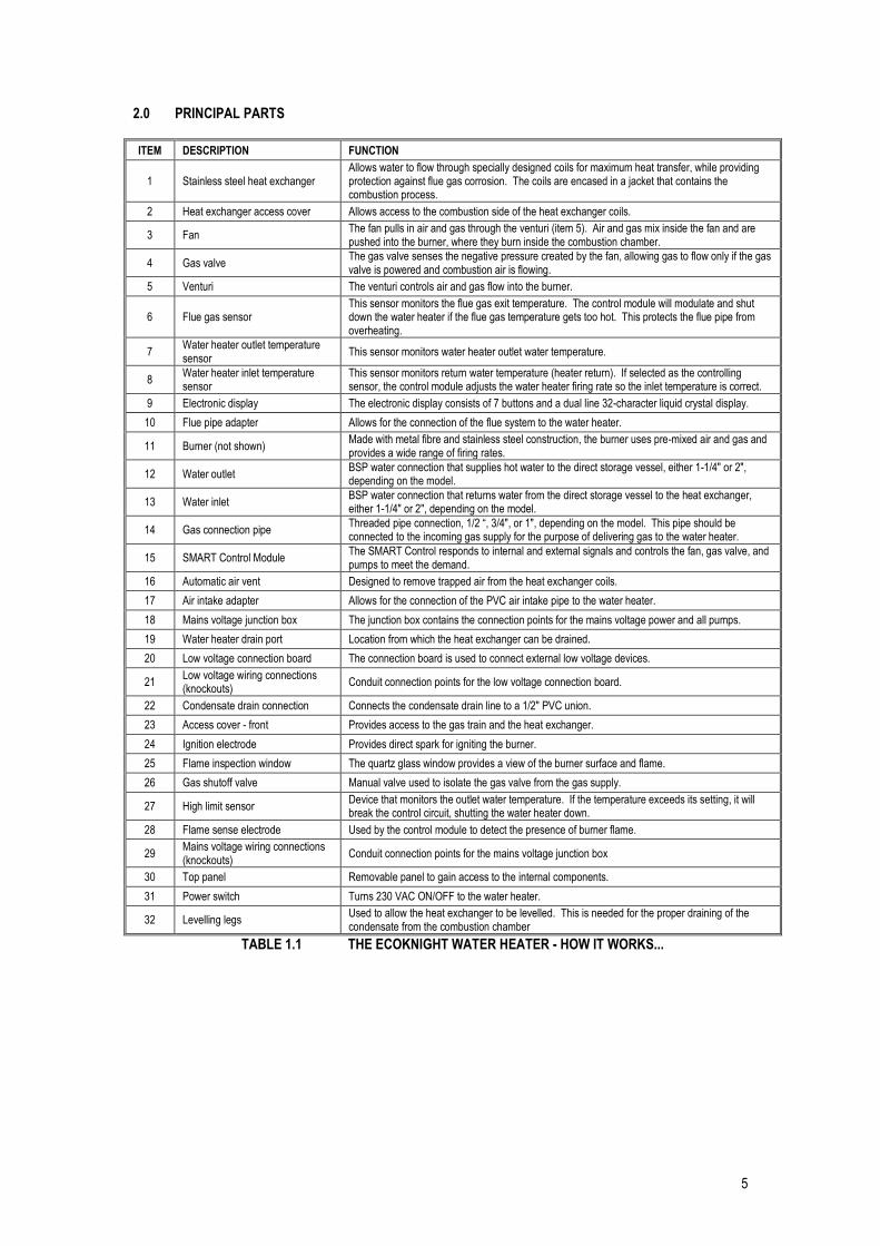
2.0 PRINCIPAL PARTS
ITEM DESCRIPTION FUNCTION
1 Stainless steel heat exchanger Allows water to flow through specially designed coils for maximum heat transfer, while providing protection against flue gas corrosion. The coils are encased in a jacket that contains the combustion process.
2 Heat exchanger access cover Allows access to the combustion side of the heat exchanger coils.
3 Fan The fan pulls in air and gas through the venturi (item 5). Air and gas mix inside the fan and are pushed into the burner, where they burn inside the combustion chamber.
4 Gas valve The gas valve senses the negative pressure created by the fan, allowing gas to flow only if the gas valve is powered and combustion air is flowing.
5 Venturi The venturi controls air and gas flow into the burner.
6 Flue gas sensor This sensor monitors the flue gas exit temperature. The control module will modulate and shut down the water heater if the flue gas temperature gets too hot. This protects the flue pipe from overheating.
7 Water heater outlet temperature sensor
This sensor monitors water heater outlet water temperature.
8 Water heater inlet temperature sensor
This sensor monitors return water temperature (heater return). If selected as the controlling sensor, the control module adjusts the water heater firing rate so the inlet temperature is correct.
9 Electronic display The electronic display consists of 7 buttons and a dual line 32-character liquid crystal display.
10 Flue pipe adapter Allows for the connection of the flue system to the water heater.
11 Burner (not shown) Made with metal fibre and stainless steel construction, the burner uses pre-mixed air and gas and provides a wide range of firing rates.
12 Water outlet BSP water connection that supplies hot water to the direct storage vessel, either 1-1/4" or 2", depending on the model.
13 Water inlet BSP water connection that returns water from the direct storage vessel to the heat exchanger, either 1-1/4" or 2", depending on the model.
14 Gas connection pipe Threaded pipe connection, 1/2 “, 3/4", or 1", depending on the model. This pipe should be connected to the incoming gas supply for the purpose of delivering gas to the water heater.
15 SMART Control Module The SMART Control responds to internal and external signals and controls the fan, gas valve, and pumps to meet the demand.
16 Automatic air vent Designed to remove trapped air from the heat exchanger coils.
17 Air intake adapter Allows for the connection of the PVC air intake pipe to the water heater.
18 Mains voltage junction box The junction box contains the connection points for the mains voltage power and all pumps.
19 Water heater drain port Location from which the heat exchanger can be drained.
20 Low voltage connection board The connection board is used to connect external low voltage devices.
21 Low voltage wiring connections (knockouts)
Conduit connection points for the low voltage connection board.
22 Condensate drain connection Connects the condensate drain line to a 1/2" PVC union.
23 Access cover - front Provides access to the gas train and the heat exchanger.
24 Ignition electrode Provides direct spark for igniting the burner.
25 Flame inspection window The quartz glass window provides a view of the burner surface and flame.
26 Gas shutoff valve Manual valve used to isolate the gas valve from the gas supply.
27 High limit sensor Device that monitors the outlet water temperature. If the temperature exceeds its setting, it will break the control circuit, shutting the water heater down.
28 Flame sense electrode Used by the control module to detect the presence of burner flame.
29 Mains voltage wiring connections (knockouts)
Conduit connection points for the mains voltage junction box
30 Top panel Removable panel to gain access to the internal components.
31 Power switch Turns 230 VAC ON/OFF to the water heater.
32 Levelling legs Used to allow the heat exchanger to be levelled. This is needed for the proper draining of the condensate from the combustion chamber
TABLE 1.1 THE ECOKNIGHT WATER HEATER - HOW IT WORKS...

6
FRONT VIEW MODELS EKW45CE – EKW60CE
LEFT SIDE (INSIDE UNIT) MODELS EKW45CE – EKW60CE
REAR VIEW MODELS EKW45CE – EKW60CE
RIGHT SIDE (INSIDE UNIT) MODELS EKW45CE – EKW60CE

7
REAR VIEW MODEL EKW85CE – EKW115CE
REAR VIEW MODEL EKW145CE
LEFT SIDE (INSIDE UNIT) MODEL EKW85CE – EKW115CE
LEFT SIDE (INSIDE UNIT) MODEL EKW145CE
8
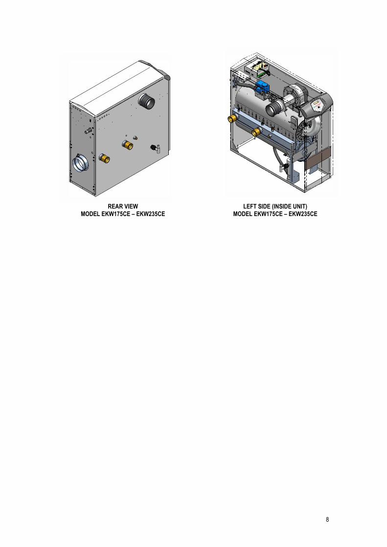
REAR VIEW MODEL EKW175CE – EKW235CE
LEFT SIDE (INSIDE UNIT) MODEL EKW175CE – EKW235CE

9
3.0 TECHNICAL DATA
Model Number EKW45CE EKW60CE EKW85CE EKW115CE EKW145CE EKW175CE EKW205CE EKW235CE
GENERAL DATA
Input (gross) – kW 44.0 61.5 83.5 116.9 146.5 175.8 205.2 234.5
Input (net) – kW 39.6 55.4 75.2 105.3 132.0 158.4 184.9 211.3
Recovery Rate (44° ΔT) – l/hr 806 1153 1567 2164 2768 3302 3865 4338
Recovery Rate (50° ΔT) – l/hr 709 1014 1379 1904 2436 2905 3401 3819
Heat generator seasonal efficiency – % 93.8 95.9 96.1 94.7 97.8 96.1 96.4 94.7
Shipping Weight – kg 75 79 102 129 138 154 168 184
NOX Class 5
GAS DATA – G20
Nominal gas inlet pressure – mbar 20
Maximum gas inlet pressure – mbar 25
Minimum gas inlet pressure – mbar 17.5
Gas flow rate – m3/hr 4.2 5.9 8.0 11.1 14.0 16.8 19.6 22.3
Flue gas mass rate – g/sec (@ 9.0% CO2)
16.0 22.3 30.4 42.5 53.2 63.9 74.6 85.2
Gas inlet connection size – “ BSP ½ ½ ¾ 1 1 1 1 1
GAS DATA – G31
Nominal gas inlet pressure – mbar 37
Maximum gas inlet pressure – mbar 45
Minimum gas inlet pressure – mbar 27
Gas flow rate – m3/hr 1.7 2.3 3.1 4.4 5.5 6.6 7.7 8.8
Flue gas mass rate – g/sec (@ 10.5% CO2)
16.7 23.2 31.6 44.2 55.4 66.6 77.6 88.8
Gas inlet connection size – “ BSP ½ ½ ¾ 1 1 1 1 1
WATER DATA
Water content – litres 4.9 6.4 9.1 12.9 15.9 15.9 18.9 21.6
Water connections (F & R) – “ BSP 1 ¼ 2
Max. water pressure (PMS) – bar 11.0
Min. water pressure – bar 0.5
Test pressure – bar 16.5
Maximum water temperature – C 80
FLUE DATA TYPE B23
Nominal flue diameter – mm 80 100 150
Maximum flue gas temp. – C 120
Maximum equivalent length – m 60
Equivalent length 90 bend – mm 1000 1500
Equivalent length 45 bend – mm 500 900
Flue gas temperature – C 70
Flue draught requirements – mbar -0.03 to -0.1
FLUE DATA TYPE C13 & C33
Nominal flue diameter – mm 80/125 100/150 150/220
Maximum flue gas temp. – C 120
Maximum equivalent length – m 30 13 30‡
Equivalent length 90 bend – mm 1000 1500
Equivalent length 45 bend – mm 500 900
FLUE DATA TYPE C43 & C53
Nominal flue diameter – mm 80 100 150
Average flue gas temp. – C (80/60 Flow/Return)
70
Maximum flue gas temp. – C 120
Maximum equivalent length – m 60*
Equivalent length 90 bend – mm 1000 1500
Equivalent length 45 bend – mm 500 900
TABLE 3.1 TECHNICAL DATA ‡ EKW175CE, EKW205 and EKW235CE use a concentric terminal only. The remainder of the flue system is to
be constructed from 150mm single wall components. * On twin pipe systems, the maximum equivalent length is the sum the air inlet components and the exhaust
components.

10
FIGURE 3.1 ENCLOSURE INSTALLATION CLEARANCES (mm)
FIGURE 3.2 PLANT-ROOM INSTALLATION CLEARANCES (mm)
400
400

11
4.0 GENERAL REQUIREMENTS The Lochinvar EcoKnight™ condensing water heater has been designed to operate trouble free for many years. These instructions should be followed closely to obtain the maximum usage and efficiency of the equipment. PLEASE read the instructions fully before installing or using the appliance.
4.1 RELATED DOCUMENTS It is law that all gas appliances are installed by competent persons, in accordance with The Gas Safety (Installation and Use) Regulations 1998. Failure to install appliances correctly could lead to prosecution. It is in your own interest, and that of safety, to ensure that this law is complied with. The installation of the equipment MUST be in accordance with the relevant requirements of the Gas Safety Regulations, Building Regulations, I.E.E. Regulations and the bylaws of the local water undertaking. The installation should also be in accordance with any relevant requirements of the local gas distributor and local authority. In addition the installation should follow the relevant guidance offered in the following documents. It is not practical to list all relevant information but emphasis is placed on the following documents, as failure to comply with the guidance given will almost certainly result in an unsatisfactory installation: BS EN 1858: 2003 Chimneys. Components. Concrete flue blocks BS 5440-1: 2008 Installation and maintenance of flues and ventilation for gas appliances of rated input
not exceeding 70kW net (1st, 2nd and 3rd family gases) Part 1: Specification for installation and maintenance of flues
BS 5440-2: 2009 Installation and maintenance of flues and ventilation for gas appliances of rated input not exceeding 70kW net (1st, 2nd and 3rd family gases) Part 2: Specification for installation and maintenance of ventilation for gas appliances
BS 6644: 2005 Specification for Installation of gas fired hot water boilers of rated inputs between 70kW + A1: 2008 (net) and 1.8MW (net) (2nd and 3rd family gasses) BS 6700: 1997 Design, installation, testing and maintenance of services supplying water for domestic
use within buildings and their curtilages BS 6880: 1988 Code of practice for low temperature hot water systems of output greater than 45kW Parts 1, 2 and 3 BS 7074: 1989 Application, selection and installation of expansion vessels and ancillary equipment for Parts 1and 2 sealed systems BS 7671: 2008 Requirements for electrical installations, I.E.E. wiring regulations seventeenth edition CP 342: Code of practice for centralised hot water supply-buildings other than dwellings Part 2 1974 IGE/UP/1: Installation pipework on industrial and commercial premises Edition 2 IGE/UP/2: Gas installation pipework, boosters and compressors on industrial and commercial Edition 2 premises IGE/UP/4: Commissioning of gas fired plant on industrial and commercial premises Edition 2 IGE/UP/10: Installation of flued gas appliances in industrial and commercial premises Edition 3 Gas Safety (Installation and Use) Regulations 1998 (England, Scotland & Wales)

12
CIBSE: Guide parts A, B and C H.S.E. guidance Automatically controlled steam and hot water boilers note PM5: Third edition of the 1956 Clean Air Act Memorandum on Chimney Heights Manufacturer's notes must not be taken in any way as overriding statutory obligations. 5.0 WATER QUALITY Water supply quality may adversely affect the efficiency and performance of water heaters and hot water systems. The situation can intensify where higher temperatures or demands exist. Water hardness should not exceed 205ppm CaCO3 and TDS (Total Dissolved Solids) of untreated water should not exceed 350ppm. If these values are exceeded, contact Lochinvar Limited for further guidance. 6.0 LOCATION
6.1 PLANT ROOM REQUIREMENTS The Lochinvar EcoKnight™ may only be installed in a room that complies with the appropriate ventilation requirements. The Lochinvar EcoKnight™ can be used as a type C13, C33, C43 or C53 appliance. Due to its room sealed design, ventilation allowances for combustion air are not necessary, provided the minimum clearances and service clearances as detailed in Figure 3.2 are observed. If the appliance is to be installed in a compartment or a hot environment, the minimum clearances detailed in Figure 3.1 should be observed. In addition to this, ventilation for cooling purposes must be fitted. For further guidance, please refer to Section 9: AIR SUPPLY or to BS5440-2 or BS6644 as appropriate. The Lochinvar EcoKnight™ can also be used as a type B23 appliance. If such a configuration is to be used, then appropriate ventilation for cooling and combustion must be provided. For further details, please refer to Section 9: AIR SUPPLY or to BS5440-2 or BS6644 as appropriate.
6.2 GENERAL REQUIREMENTS Corrosion of the heat exchanger coils and flue system may occur if air for combustion contains certain chemical vapours. Such corrosion may result in poor combustion and create a risk of asphyxiation. Aerosol propellants, cleaning solvents, refrigerator and air conditioning refrigerants, swimming pool chemicals, calcium and sodium chloride, waxes and process chemicals are corrosive. Products of this sort should not be stored near the water heater or outside by the air intake (if applicable). The fitting of this equipment in a situation where aerosols or other chemicals may be entrained into the combustion air will invalidate the warranty. The equipment must be installed on a level surface that is capable of adequately supporting its weight (when filled with water) and any ancillary equipment. The operation of the equipment must not cause the temperature of any combustible material in the vicinity of the equipment and its flue to exceed 65°C. If such a situation is unavoidable, appropriate insulation should be provided. Locate the equipment so that if the appliance or any connecting pipework should leak, water damage will not occur. When such locations cannot be avoided it is recommended that a suitable drain pan be installed under the equipment. The pan should be adequately drained but must not restrict the combustion or ventilation airflow.

13
6.3 CLEARANCES The location chosen for the equipment must permit the provision for a satisfactory flue system and, where necessary, an adequate air supply. The location must also provide adequate space for servicing and air circulation around each unit. This includes any electrical trunking laid across the floor and to the appliance. See Figure 3.1 & Figure 3.2 for dimensions/clearances. Further details regarding locations are given in BS5440 or BS6644 as appropriate.
6.4 CONDENSATE DRAIN The condensate drain is located on the left hand side of the water heater. It is fitted with a ½” PVC tee and union, this should be connected to an appropriate condensate drain, sloping continuously away from the water heater at an
angle of at least 3 (50mm per metre). The Water Resources Act requires that trade effluent is discharged to municipal sewers between pH 6.5 and 10.0. If it is determined that these levels cannot be achieved, an in-line condensate neutralisation kit is available from Lochinvar Limited. This unit is capable of neutralising 4000 litres of condensate to a pH of 7.0 before releasing it to a drain. 7.0 GAS SUPPLY The Lochinvar EcoKnight™ range is suitable for use on second and third family gasses 2H - G20 - 20mbar and 3P - G31 - 37mbar. Details relating to Natural Gas (2H) appear below; for details relating to Propane (3P) please refer to Section 14: LPG FUEL.
7.1 SERVICE PIPES The local gas distributor must be consulted at the installation planning stage in order to establish the availability of an adequate supply of gas. An existing service pipe must not be used without prior consultation with the local gas distributor.
7.2 METERS A new gas meter will be connected to the service pipe by the local gas distributor contractor. An existing gas meter should be checked, preferably by the gas distributor, to ensure that it is adequate to deal with the rate of gas supply required.
7.3 GAS SUPPLY PIPES Supply pipes must be fitted in accordance with IGE/UP/2. Pipework from the meter to the equipment must be of adequate size. The complete installation must be purged and tested as described in IGE/UP/1. Refer to Section 14: LPG FUEL for information on LPG pipework installation guidance.
7.4 BOOSTED SUPPLIES Where it is necessary to employ a gas pressure booster, the controls must include a low-pressure cut-off switch at the booster inlet. The local gas distributor must be consulted before a gas pressure booster is fitted. For details of how to connect a low-pressure cut-off switch, please refer to Section 11: ELECTRICAL SUPPLY
7.5 PLANT-ROOM CONTROL VALVE A manual valve for plant-room isolation must be fitted in the gas supply line. It must be clearly identified and readily accessible for operation, preferably by an exit.

14
7.6 EQUIPMENT GAS SYSTEM LEAK CHECK An approved gas inlet appliance isolating valve and union should be installed for each unit in a convenient and safe position and be clearly marked. Ensure that the gas inlet appliance isolating valve is in the OFF position. Although the equipment receives a gas leak check and gas train component integrity check prior to leaving the factory, transit and installation may cause disturbance to unions, fittings and components. During commissioning a further test for tightness should be carried out on the equipment gas pipework and components. Care must be taken not to allow leak detection fluid on or near any electrical parts or connections. 8.0 FLUE SYSTEM
FIGURE 8.1: FLUE TERMINAL POSITIONS
Location Description EKW45CE – EKW60CE EKW85CE – EKW235CE
A Directly below an opening, air brick, opening windows etc. 300 2000
B Above an opening, air brick, opening windows etc. 300 1000
C Horizontally to an opening, air brick, opening windows etc. 300 1000
D Below a gutter or sanitary pipework 75 75
E Below the eaves 200 200
F Below a balcony or car port roof 200 200
G From a vertical drain or soil pipe 150 150
H From an internal or external corner 300 300
I Above ground, roof or balcony level 300 300
J From a surface facing the terminal 600 1000
K From a terminal facing the terminal 1200 2000
L From an opening in the car port (e.g. door, window) into the dwelling
1200 1200
M Vertically from a terminal on the same wall 1500 1500
N Horizontally from a terminal on the same wall 300 600
P From a vertical structure on the roof 300 300
Q Above intersection with the roof 300 300
TABLE 8.1 FLUE TERMINAL MINIMUM DISTANCES

15
8.1 FLUE SYSTEM GENERAL REQUIREMENTS Detailed recommendations for the flue system are given in BS5440-1 for equipment of rated input not exceeding 70kW net, BS6644 for equipment above 70kW net and IGE/UP/10 for equipment of rated input above 54kW net. The following notes are intended to give general guidance only.
8.2 APPROVED FLUE SYSTEM The approved flue system is not suitable for use external to the building. If external routes cannot be avoided, a flue system manufacturer should be consulted to supply a suitable alternative. When used as a type C appliance, the approved, purpose designed adaptive flue system should be used. For further details, please contact Lochinvar Limited. When used as a Type B appliance, a suitable flue system constructed of Stainless Steel or Polypropylene with a
temperature rating in excess of 120C should be used. Aluminium flue pipe must not be used on this appliance as it may lead to premature failure of the heat exchanger and will invalidate the warranty.
8.3 INSTALLATION PRECAUTIONS
The approved flue system is rated to 120C max. To prevent the exhaust temperature exceeding this, the appliance is supplied with a flue gas temperature sensor. This must be fitted during the installation of the flue system. Failure to do so may lead to severe personal injury, death or substantial property damage.
The heater must not be operated unless the complete flue system is installed. This includes the water
heater connections, concentric adaptor (if required) flue pipes, air ducts (if required) and terminals. If discharging at low level, a suitable flue guard must be installed.
Due to the condensing nature of the water heater, long external runs should be avoided to prevent the
condensate freezing within the flue system.
During assembly precaution should be taken to ensure that the internal sealing ring is seated correctly.
Due to the close tolerances in the flue system, it may be necessary to use a twisting action to fit the joints together. No lubrication other than water should be used.
8.4 MAXIMUM LENGTH
Details of maximum flue lengths can be found in Table 3.1
8.5 FLUE DISCHARGE The flue system must ensure safe and efficient operation of the equipment to which it is attached, protect the combustion process from wind effects and disperse the products of combustion to open external air. The flue must terminate in a freely exposed position and be so situated as to prevent the products of combustion entering any opening in a building. Under certain operating and weather conditions, the EcoKnight™ heater may generate a plume at the terminal. Consideration should be given to the nuisance this may cause and the terminal should be sited accordingly. For further information on terminal locations, please refer to Figure 8.1 and Table 8.1.
8.6 CONDENSATE DRAIN
If the flue system rises at an angle of at least 3 (50mm per metre), no additional condensate drain will be required. Failure to provide an adequate rise in the flue system may lead to pooling of condensate which may lead to premature failure of the flue system.

16
8.7 WATER HEATER CONNECTION ASSEMBLY
8.7.1 EKW45CE – EKW60CE
FIGURE 8.2 FLUE CONNECTION DETAILS EKW45CE – EKW60CE
ITEM DESCRIPTION
1 Flue Gas Test Point
2 Concentric Adaptor
3 80mm Dia x 500mm Length
4 90 Elbow
5 Air Intake Transition
6 Intake Connection Reducer
7 Exhaust Transition
TABLE 8.2 FLUE CONNECTION DETAILS EKW45CE – EKW60CE
17
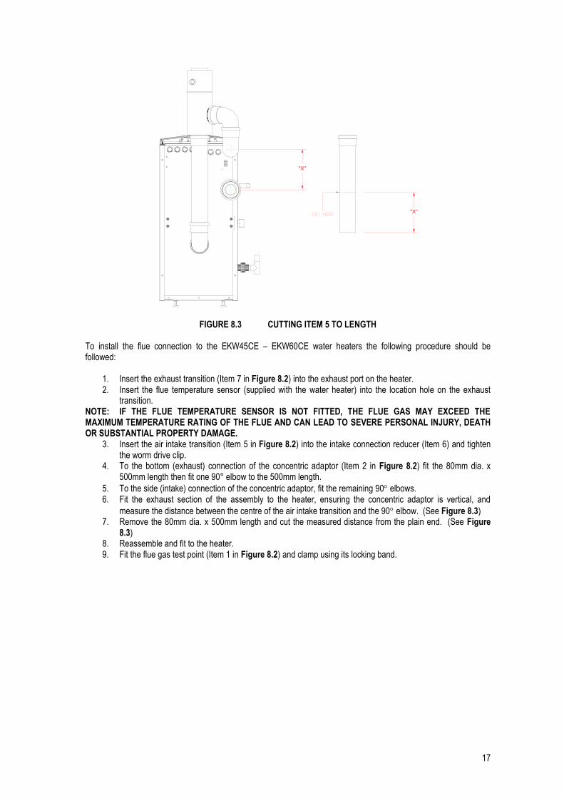
FIGURE 8.3 CUTTING ITEM 5 TO LENGTH To install the flue connection to the EKW45CE – EKW60CE water heaters the following procedure should be followed:
1. Insert the exhaust transition (Item 7 in Figure 8.2) into the exhaust port on the heater. 2. Insert the flue temperature sensor (supplied with the water heater) into the location hole on the exhaust
transition. NOTE: IF THE FLUE TEMPERATURE SENSOR IS NOT FITTED, THE FLUE GAS MAY EXCEED THE MAXIMUM TEMPERATURE RATING OF THE FLUE AND CAN LEAD TO SEVERE PERSONAL INJURY, DEATH OR SUBSTANTIAL PROPERTY DAMAGE.
3. Insert the air intake transition (Item 5 in Figure 8.2) into the intake connection reducer (Item 6) and tighten the worm drive clip.
4. To the bottom (exhaust) connection of the concentric adaptor (Item 2 in Figure 8.2) fit the 80mm dia. x 500mm length then fit one 90° elbow to the 500mm length.
5. To the side (intake) connection of the concentric adaptor, fit the remaining 90 elbows. 6. Fit the exhaust section of the assembly to the heater, ensuring the concentric adaptor is vertical, and
measure the distance between the centre of the air intake transition and the 90 elbow. (See Figure 8.3) 7. Remove the 80mm dia. x 500mm length and cut the measured distance from the plain end. (See Figure
8.3) 8. Reassemble and fit to the heater. 9. Fit the flue gas test point (Item 1 in Figure 8.2) and clamp using its locking band.
"X"
"X"

18
8.7.2 EKW85CE – EKW145CE
FIGURE 8.4 FLUE CONNECTION DETAILS EKW85CE – EKW145CE
ITEM DESCRIPTION
1 Flue Gas Test Point
2 Concentric Adaptor
3 100mm Dia x 500mm Length
4 90 Elbow
5 Exhaust Transition
6 Intake Connection
7 Air Intake Transition
TABLE 8.3 FLUE CONNECTION DETAILS EKW85CE – EKW145CE
FIGURE 8.5 CUTTING ITEM 3 (1) TO LENGTH
"X"
"X"

19
To install the flue connection to the EKW85CE – EKW145CE water heaters the following procedure should be followed:
1. Insert the exhaust transition (Item 6 in Figure 8.4) into the exhaust port on the heater. 2. Insert the flue temperature sensor (supplied with the water heater) into the location hole on the exhaust
transition. NOTE: IF THE FLUE TEMPERATURE SENSOR IS NOT FITTED, THE FLUE GAS MAY EXCEED THE MAXIMUM TEMPERATURE RATING OF THE FLUE AND CAN LEAD TO SEVERE PERSONAL INJURY, DEATH OR SUBSTANTIAL PROPERTY DAMAGE.
3. To the bottom (exhaust) connection of the concentric adaptor (Item 2 in Figure 8.4) fit one of the 100mm
dia. x 500 lengths (Item 3) followed by one of the 90 elbows (Item 4). 4. Offer the assembly to the heater, ensuring the concentric adaptor is vertical, and measure the distance
between the centre of the air intake connection and the concentric adaptor. (See Figure 8.5) 5. Remove the 100mm dia. x 500mm length and cut the measured distance from the plain end. (See Figure
8.5) 6. Insert the air intake transition (Item 7 in Figure 8.4) into the intake connection (Item 6) and tighten the worm
drive clip. 7. To the side (intake) connection of the concentric adaptor, fit one of the 100mm dia. x 500mm length
followed by one of the 90 elbows.
8. To the air intake transition, fit the final 90 elbow followed by the final 100mm dia. x 500mm length. Measure and cut the 100mm dia. x 500mm lengths to suit the installation.
9. Reassemble and fit to the heater. 10. Fit the flue gas test point (Item 1 in Figure 8.4) and clamp using its locking band.
8.7.3 EKW175CE
FIGURE 8.6 FLUE CONNECTION DETAILS EKW175CE
ITEM DESCRIPTION
1 Intake Connection
2 Air Intake Transition
3 130mm to 150mm Expander
4 100mm to 130mm Expander
5 90 Elbow
6 Exhaust Transition
TABLE 8.4 FLUE CONNECTION DETAILS EKW175CE
6
3
21
4
5

20
To install the flue connection to the EKW175CE water heater the following procedure should be followed:
1. Insert the exhaust transition (Item 6 in Figure 8.6) into the exhaust port on the heater. 2. Insert the flue temperature sensor (supplied with the water heater) into the location hole on the exhaust
transition. NOTE: IF THE FLUE TEMPERATURE SENSOR IS NOT FITTED, THE FLUE GAS MAY EXCEED THE MAXIMUM TEMPERATURE RATING OF THE FLUE AND CAN LEAD TO SEVERE PERSONAL INJURY, DEATH OR SUBSTANTIAL PROPERTY DAMAGE.
3. Insert the 90° elbow (Item 5 in Figure 8.6) in to the exhaust transition ensuring the socket is pointing upwards.
4. Insert the 100mm to 130mm expander (Item 4 in Figure 8.6) in to the 90° elbow. 5. Insert the 130mm to 150mm expander (Item 3 in Figure 8.6) in to the 100mm to 130mm expander. 6. Insert the air intake transition (Item 2 in Figure 8.6) into the intake connection (Item 1) and tighten the worm
drive clip.
8.7.4 EKW205CE – EKW235CE
FIGURE 8.7 FLUE CONNECTION DETAILS EKW205CE – EKW235CE
ITEM DESCRIPTION
1 Intake Connection
2 Air Intake Transition
3 Exhaust Transition
4 Flue Collar
TABLE 8.5 FLUE CONNECTION DETAILS EKW205CE – EKW235CE To install the flue connection to the EKW205CE – EKW235CE water heaters the following procedure should be followed:
1. Ensure that the flue collar (Item 4 in Figure 8.7) is correctly located in the appliance and that the flue temperature sensor (supplied with the water heater) is located in the grommet in the collar.
NOTE: IF THE FLUE TEMPERATURE SENSOR IS NOT FITTED, THE FLUE GAS MAY EXCEED THE MAXIMUM TEMPERATURE RATING OF THE FLUE AND CAN LEAD TO SEVERE PERSONAL INJURY, DEATH OR SUBSTANTIAL PROPERTY DAMAGE.
2. Insert the air intake transition (Item 2 in Figure 8.7) into the intake connection (Item 1) and tighten the worm drive clip.
3. Insert the exhaust transition (Item 3 in Figure 8.7) into the flue collar (Item 4) and secure with the worm drive clip.
2 3 41

21
8.8 FLUE TERMINAL INSTALLATION
8.8.1 TYPE B23 When the heater is installed as a Type B23 appliance, the flue system should be installed in accordance with the flue manufacturer’s specific instructions. A kit of components to facilitate conventional fluing of the appliance is available from Lochinvar Limited.
1. Insert the exhaust transition into the exhaust port of the heater. 2. Insert the flue temperature sensor into the location hole on the exhaust transition.
NOTE: IF THE FLUE TEMPERATURE SENSOR IS NOT FITTED, THE FLUE GAS MAY EXCEED THE MAXIMUM TEMPERATURE RATING OF THE FLUE AND CAN LEAD TO SEVERE PERSONAL INJURY, DEATH OR SUBSTANTIAL PROPERTY DAMAGE.
3. Insert the air intake into the intake connection and tighten the worm drive clip. 4. Insert the air inlet grill into the air inlet transition.
8.8.2 TYPE C13
When the heater is installed as a Type C13 appliance, the flue system should be installed as follows:
1. Determine the location of the flue terminal, taking into account minimum distances as detailed in Figure 8.1, Table 8.1 and the relevant British Standards.
2. Taking care to protect the appliance from debris and dust, drill a hole in the desired location. The diameter of the hole should be no more than 10mm greater than the diameter of the air supply pipe of the terminal.
3. Determine the required length of the terminal and cut as necessary. NOTE: When determining the required length for the flue terminal, the outer wall plate or rosette should be flush to
the wall. (See Figure 8.7) NOTE: Once cut; remove all burrs and sharp edges.
4. Insert the terminal into the drilled hole. The terminal section should be installed level or with a fall to outside (Max. 10mm per metre) to prevent the ingress of water.
NOTE: When inserting the terminal, ensure the air intake section is at the bottom. 5. Fill the void between the terminal and wall with water resistant sealant. 6. Fit the wall plates or rosette using appropriate fixings. 7. Fit the concentric adapter (EKW175CE – EKW235CE only) and clamp using its locking band. 8. Install the remainder of the flue system working progressively away from the water heater supporting the
pipes as necessary.
FIGURE 8.7 HORIZONTAL TERMINAL INSTALLATION

22
8.8.3 TYPE C33 When the heater is installed as a Type C33 appliance, the flue system should be installed as follows:
1. Confirm that the roof flashing is correct for the type of roof through which the terminal is to be installed. (See Figure 8.8)
2. Determine the desired location for the flue terminal, taking into account minimum distances as detailed in Figure 8.1, Table 8.1 and the relevant British Standards.
3. Taking care to protect the appliance from debris and dust, drill a hole in the desired location. The diameter of the hole should be no more than 10mm greater than the diameter of the air supply pipe of the terminal.
NOTE: The hole should be drilled from the outside to ensure that no damage is done to the roofing material. Extra care should be taken to ensure that the hole is drilled vertically.
4. Install the roof flashing and secure as appropriate. 5. Carefully insert the roof terminal through the roof flashing and hole in the roof.
NOTE: When inserting the roof terminal do not support or turn the terminal using the cap. 6. Ensure the terminal is vertical using a spirit level. 7. Fit the support bracket around the terminal and secure using appropriate fixings. Do not tighten the support
bracket 8. Fit the concentric adapter (EKW175CE – EKW235CE only) and clamp using its locking band. 9. Install the remainder of the flue system working progressively away from the water heater supporting the
pipes as necessary. 10. Once the flue system is fully installed, tighten the clamp to secure the terminal in place.
FIGURE 8.8 VERTICAL TERMINAL ROOF FLASHINGS FOR SYNTHETIC, FLAT AND TILED ROOFS
FIGURE 8.9 INSTALLING TERMINAL THROUGH ROOF FLASHING

23
8.8.4 TYPE C43 This appliance can operate on a U-Duct common flue system. The maximum lengths for the interconnecting flue can be found in Table 3.1. Concrete components of the U-Duct must meet the requirements of BS EN 1858
Model No. Mass Rate @ 100% (@ 9% CO2) (G20)
Mass Rate @ 23% (@ 9% CO2) (G20)
Mass Rate @ 100% (@ 10.5% CO2) (G31)
Mass Rate @ 23% (@ 10.5% CO2) (G31)
EKW45CE 16.0 3.7 16.7 3.8
EKW60CE 22.3 5.1 23.2 5.3
EKW85CE 30.4 7.0 31.6 7.3
EKW115CE 42.5 9.8 44.2 10.2
EKW145CE 53.2 12.2 55.4 12.7
EKW175CE 63.9 14.7 66.6 15.3
EKW205CE 74.6 17.1 77.6 17.9
EKW235CE 85.2 19.6 88.8 20.4
TABLE 8.6 FLUE GAS MASS RATES
8.8.5 TYPE C53 When installing the heater as a Type C53 appliance, it should be noted that the terminals must not be installed on opposite sides of the building. To install a Type C53 terminal or air inlet, the procedure for either a Type C13 (horizontal) or a Type C33 (vertical) terminal should be followed noting that the annular space of the terminal should be sealed off.
8.9 FLUE TERMINAL GUARDING If a horizontal flue terminal is to be fitted less than 2 metres from ground level or in a location where it can be touched from a window, door or balcony, a terminal guard must be fitted. For the EKW45CE – EKW145CE, use Lochinvar Part Number FTG0001 and for the EKW175CE – EKW235CE use Lochinvar Part Number FTG0002. For further information please contact Lochinvar Limited. The terminal guard is constructed from plastic-coated mild steel and is suitable for use on condensing appliances only. The guard should be installed centrally around the terminal ensuring a gap of at least 50mm between the guard and terminal is maintained.
24
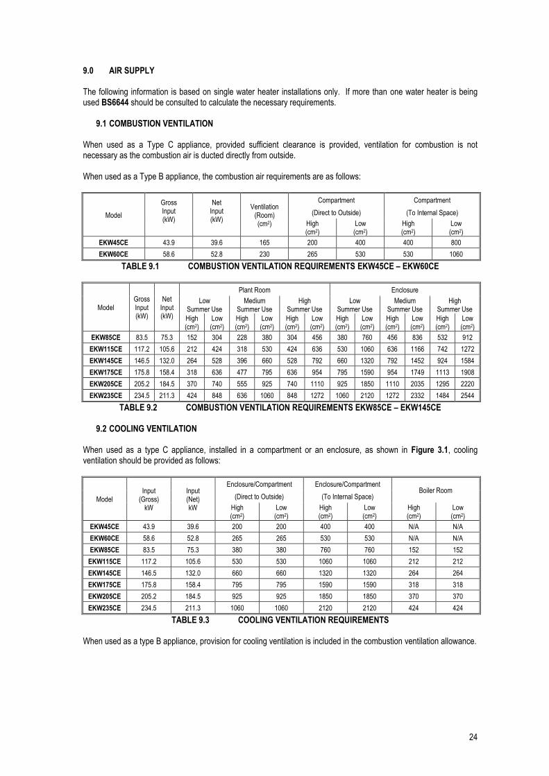
9.0 AIR SUPPLY The following information is based on single water heater installations only. If more than one water heater is being used BS6644 should be consulted to calculate the necessary requirements.
9.1 COMBUSTION VENTILATION When used as a Type C appliance, provided sufficient clearance is provided, ventilation for combustion is not necessary as the combustion air is ducted directly from outside. When used as a Type B appliance, the combustion air requirements are as follows:
Model
Gross Input (kW)
Net Input (kW)
Ventilation (Room) (cm2)
Compartment Compartment
(Direct to Outside) (To Internal Space)
High (cm2)
Low (cm2)
High (cm2)
Low (cm2)
EKW45CE 43.9 39.6 165 200 400 400 800
EKW60CE 58.6 52.8 230 265 530 530 1060
TABLE 9.1 COMBUSTION VENTILATION REQUIREMENTS EKW45CE – EKW60CE
Model Gross Input (kW)
Net Input (kW)
Plant Room Enclosure
Low Summer Use
Medium Summer Use
High Summer Use
Low Summer Use
Medium Summer Use
High Summer Use
High (cm2)
Low (cm2)
High (cm2)
Low (cm2)
High (cm2)
Low (cm2)
High (cm2)
Low (cm2)
High (cm2)
Low (cm2)
High (cm2)
Low (cm2)
EKW85CE 83.5 75.3 152 304 228 380 304 456 380 760 456 836 532 912
EKW115CE 117.2 105.6 212 424 318 530 424 636 530 1060 636 1166 742 1272
EKW145CE 146.5 132.0 264 528 396 660 528 792 660 1320 792 1452 924 1584
EKW175CE 175.8 158.4 318 636 477 795 636 954 795 1590 954 1749 1113 1908
EKW205CE 205.2 184.5 370 740 555 925 740 1110 925 1850 1110 2035 1295 2220
EKW235CE 234.5 211.3 424 848 636 1060 848 1272 1060 2120 1272 2332 1484 2544
TABLE 9.2 COMBUSTION VENTILATION REQUIREMENTS EKW85CE – EKW145CE
9.2 COOLING VENTILATION When used as a type C appliance, installed in a compartment or an enclosure, as shown in Figure 3.1, cooling ventilation should be provided as follows:
Model Input
(Gross) kW
Input (Net) kW
Enclosure/Compartment Enclosure/Compartment Boiler Room
(Direct to Outside) (To Internal Space)
High (cm2)
Low (cm2)
High (cm2)
Low (cm2)
High (cm2)
Low (cm2)
EKW45CE 43.9 39.6 200 200 400 400 N/A N/A
EKW60CE 58.6 52.8 265 265 530 530 N/A N/A
EKW85CE 83.5 75.3 380 380 760 760 152 152
EKW115CE 117.2 105.6 530 530 1060 1060 212 212
EKW145CE 146.5 132.0 660 660 1320 1320 264 264
EKW175CE 175.8 158.4 795 795 1590 1590 318 318
EKW205CE 205.2 184.5 925 925 1850 1850 370 370
EKW235CE 234.5 211.3 1060 1060 2120 2120 424 424
TABLE 9.3 COOLING VENTILATION REQUIREMENTS When used as a type B appliance, provision for cooling ventilation is included in the combustion ventilation allowance.

25
10.0 WATER CONNECTIONS
10.1 GENERAL Adaptors are required to convert the NPT (male) thread on the heat exchanger to BSP (female). These adaptors can be found in the packing carton. The BSP section of the adaptor is indicated with blue paint. EcoKnight™ water heaters require a minimum flow rate and should also be supplied with separate storage vessels. Suitably sized pumps and separate storage vessels are available from Lochinvar Limited as ancillary options. Note: Lochinvar Limited recommends the use of glanded pumps. Recommended pipework layouts are available for different water heater and storage vessel combinations. Please contact Lochinvar Limited for details. The requirements of minimum water flow are given in Table 10.2. Recommendations for the water circulation system are given in BS6644 and CP 342. The following notes are of particular importance. 1. When the unit is being utilised as a direct-fired water heater it is designed for use with a direct type storage
vessel. Contact Lochinvar Limited for help in sizing the storage vessel 2. Circulating pipework not forming part of the useful heating surface should be insulated. Cisterns, expansion
vessels and pipework situated in areas exposed to freezing conditions should also be insulated. 3. Drain valves must be located in accessible positions that will permit draining of the entire system including
the unit and the storage vessel. 4. Tapping sizes for connection to the water system are detailed in Table 3.1. 5. Ideally, individual valves should be fitted to each unit to enable isolation from the system. The arrangement
must comply with the requirements of BS6644.
10.2 OPEN VENTED SYSTEM ARRANGEMENT The Lochinvar EcoKnight™ can be used in an open vented arrangement provided that a vent pipe in accordance with CP342, BS6644 or BS6700 as appropriate is fitted. The minimum static head requirement for an open vented system is 0.5 bar.
10.3 UNVENTED SYSTEM ARRANGEMENT NOTE: IT IS STRONGLY RECOMMENDED THAT UNVENTED HOT WATER SYSTEMS BE
INSTALLED BY AN APPROVED INSTALLER. If the Lochinvar EcoKnight™ is to be used in an unvented arrangement, the system should follow the guidance given in BS6700 and must comply with The Building Regulations: Part G3. A kit of components that have been suitably sized for the unvented operation of the appliance is available from Lochinvar Limited. For further information, contact Lochinvar Limited.
26
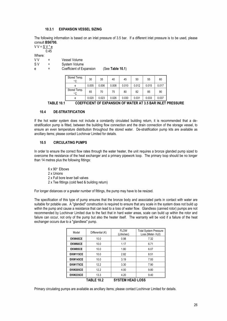
10.3.1 EXPANSION VESSEL SIZING The following information is based on an inlet pressure of 3.5 bar. If a different inlet pressure is to be used, please consult BS6700. V V = S V * e 0.45 Where: V V = Vessel Volume S V = System Volume e = Coefficient of Expansion (See Table 10.1)
Stored Temp.
C 30 35 40 45 50 55 60
e 0.005 0.006 0.008 0.010 0.012 0.015 0.017
Stored Temp.
C 65 70 75 80 82 85 90
e 0.020 0.023 0.026 0.030 0.031 0.033 0.037
TABLE 10.1 COEFFICIENT OF EXPANSION OF WATER AT 3.5 BAR INLET PRESSURE
10.4 DE-STRATIFICATION If the hot water system does not include a constantly circulated building return, it is recommended that a de-stratification pump is fitted, between the building flow connection and the drain connection of the storage vessel, to ensure an even temperature distribution throughout the stored water. De-stratification pump kits are available as ancillary items; please contact Lochinvar Limited for details.
10.5 CIRCULATING PUMPS In order to ensure the correct flow rates through the water heater, the unit requires a bronze glanded pump sized to overcome the resistance of the heat exchanger and a primary pipework loop. The primary loop should be no longer than 14 metres plus the following fittings:
6 x 90 Elbows 2 x Unions 2 x Full bore lever ball valves 2 x Tee fittings (cold feed & building return) For longer distances or a greater number of fittings, the pump may have to be resized. The specification of this type of pump ensures that the bronze body and associated parts in contact with water are suitable for potable use. A "glanded" construction is required to ensure that any scale in the system does not build up within the pump and cause a resistance that can lead to a loss of water flow. Glandless (canned rotor) pumps are not recommended by Lochinvar Limited due to the fact that in hard water areas, scale can build up within the rotor and failure can occur, not only of the pump but also the heater itself. The warranty will be void if a failure of the heat exchanger occurs due to a "glandless" pump.
Model Differential (K) FLOW
(Litre/sec) Total System Pressure
Loss (Meter- H20)
EKW45CE 10.0 0.98 7.32
EKW60CE 10.0 1.17 6.71
EKW85CE 10.0 1.80 6.07
EKW115CE 10.0 2.82 8.51
EKW145CE 10.0 3.19 7.93
EKW175CE 12.2 3.30 7.90
EKW205CE 12.2 4.00 9.80
EKW235CE 13.3 4.20 9.40
TABLE 10.2 SYSTEM HEAD LOSS Primary circulating pumps are available as ancillary items; please contact Lochinvar Limited for details.

27
10.6 FLOW TEMPERATURE SENSOR The EcoKnight water heater requires a temperature sensor to be installed in the primary flow pipework. On single water heater installations and multiple water heater installations that will not use the integral cascade manager, the sensor needs to be installed as close to the outlet of the appliance as possible. On cascaded installations, the sensor should be installed on the common flow pipework as close as possible to the junction where the individual water heater flows meet. The appliance is supplied with two sensors, from which only one should be chosen.
10.6.1 DRY-POCKET SENSOR A 6.35mm sensor and pocket are supplied in the fittings kit in the front cover of the appliance. Provision should be made to install this sensor in the flow pipework in the required location, ensuring that any reducing fittings used allow the pocket to by sufficiently immersed in the water flow to correctly register the temperature.
FIGURE 10.1 DRY-POCKET SENSOR INSTALLATION
10.6.2 STRAP-ON SENSOR
Where it is not possible to fit the dry-pocket sensor, the strap-on pipe sensor can be used. The sensor should be positioned on the primary pipework in the required location – ensuring the contact pad remains in place – and secured with the supplied tie.
FIGURE 10.2 STRAP-ON SENSOR INSTALLATION
10.6.3 SENSOR WIRING
For guidance on installing the wiring for the temperature sensor, please refer to Section 11.3: LOW VOLTAGE CONNECTION STRIP
SENSOR
DRY-POCKET
FITTINGS
TEE PIECE
HEAT EXCHANGER OUTLET
BARREL NIPPLE NPT/BSP CONVERTER
SENSOR
CABLE TIE
FLOW PIPE

28
11.0 ELECTRICAL SUPPLY Wiring external to the equipment must be installed in accordance with the I.E.E. Regulations and any local regulations that apply.
Model Normal Supply
Voltage External Fuse
Rating Power Consumption
EKW45CE
230V AC 50 Hz 1 PH
6.0 A
120 W
EKW60CE 144 W
EKW85CE 180 W
EKW115CE 180 W
EKW145CE 204 W
EKW175CE 322 W
EKW205CE 322 W
EKW235CE 322 W
TABLE 11.1 ELECTRICAL SUPPLY REQUIREMENTS
WARNING: THIS APPLIANCE MUST BE EARTHED A suitably competent person MUST check wiring. Normal supply required is 230 volts AC, single phase, 50 Hz. An isolator with a contact separation of at least 3mm in all poles should be sited close to the equipment and must only serve that equipment. The double pole switch must be readily accessible under all conditions.
11.1 EXTERNAL CONTROLS The Lochinvar EcoKnight™ is compatible with the following control and safety systems:
Building Management System (BMS) 0-10VDC analogue input Storage vessel thermostat (on/off type) Storage vessel sensor (modulating type) Internal sequencing control Gas pressure switch (e.g. gas booster under pressure/over pressure safety switch) Water flow proving device (e.g. differential pressure switch or flow switch) Auxiliary safety system proving switch (e.g. fan dilution system proving switch)
In addition to this, the Lochinvar EcoKnight™ can give the following signals:
Volt-free “burner on” (runtime) signal Volt-free “lock-out” (alarm) signal 24VAC auxiliary device enable signal (e.g. to start fan dilution system)
11.1.1 REMOTE ENABLING
If the appliance is to be enabled remotely, either by a building management control panel or time clock, a volt free contact should be used to interrupt the wiring between the flow temperature sensor and the low-voltage connection strip.

29
11.2 HIGH VOLTAGE CONNECTOR STRIP
FIGURE 11.1 HIGH VOLTAGE CONNECTION STRIP
CONNECTION NOTES
PRIMARY 230 VAC Live, Neutral and Earth connections for a primary circulation pump starter. NOTE: On all EcoKnight™ water heaters, the primary pump exceeds the maximum power output and therefore a suitable pump starter will be required.
DE-STRAT 230 VAC Live, Neutral and Earth connections for a system de-stratification pump. If the pump rating exceeds 190 watts, the Live and Neutral connections should be used to energise a suitable contactor.
RETURN 230 VAC Live, Neutral and Earth connections for a building return pump. If the pump rating exceeds 190 watts, the Live and Neutral connections should be used to energise a suitable contactor.
MAINS Connections for a 230V ~ 1 ph 50Hz power supply. NOTE: the power supply cable should be secured using the anchor supplied or an equivalent.
TABLE 11.2 HIGH VOLTAGE CONNECTION TERMINAL DETAILS
11.3 LOW VOLTAGE CONNECTOR STRIP
AUX. DEVICEPILOT SUPPLY
24VACGND
AUX. DEVICEPROVING
GAS PRESSURESWITCH
FLOWSWITCH
ALARMCONTACTS
RUNTIMECONTACTS
TANKSENSOR
SHIELD GROUND
0-10VDC EXTERNALGND CONTROL
TANK THERMOSTAT
A
B
SHIELD GROUND
SEQUENCING
LO
W W
AT
ER
CU
TO
FF
CN1
CN2
CN3
CN4
CN5
9
10
11
12
13
14
15
16
17
18
19
20
1521
22
1
2
3
4
5
6
7
8
FIGURE 11.2 LOW VOLTAGE CONNECTION STRIP
PRIMARY DE-STRAT RETURN
PUMP OUTPUTS 190 WATTS MAX
230V~50Hz
MAINS L N L N
L N LBL2313 REV B L N
30
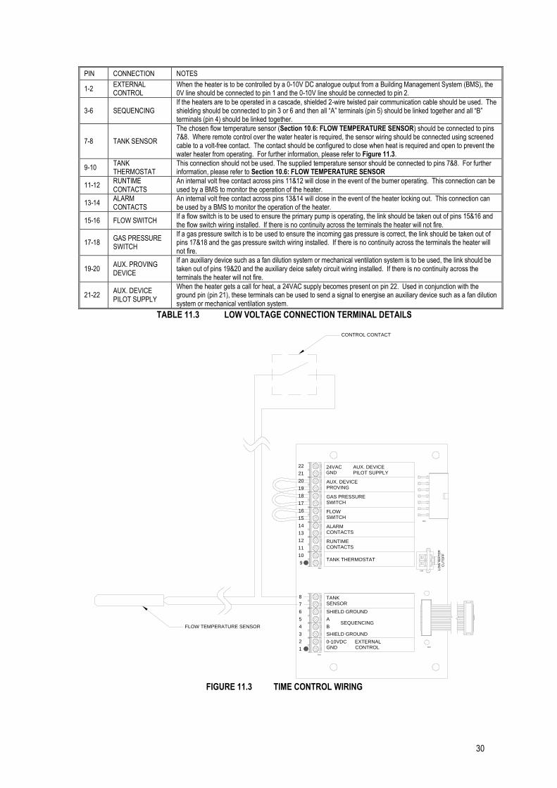
PIN CONNECTION NOTES
1-2 EXTERNAL CONTROL
When the heater is to be controlled by a 0-10V DC analogue output from a Building Management System (BMS), the 0V line should be connected to pin 1 and the 0-10V line should be connected to pin 2.
3-6 SEQUENCING If the heaters are to be operated in a cascade, shielded 2-wire twisted pair communication cable should be used. The shielding should be connected to pin 3 or 6 and then all “A” terminals (pin 5) should be linked together and all “B” terminals (pin 4) should be linked together.
7-8 TANK SENSOR
The chosen flow temperature sensor (Section 10.6: FLOW TEMPERATURE SENSOR) should be connected to pins 7&8. Where remote control over the water heater is required, the sensor wiring should be connected using screened cable to a volt-free contact. The contact should be configured to close when heat is required and open to prevent the water heater from operating. For further information, please refer to Figure 11.3.
9-10 TANK THERMOSTAT
This connection should not be used. The supplied temperature sensor should be connected to pins 7&8. For further information, please refer to Section 10.6: FLOW TEMPERATURE SENSOR
11-12 RUNTIME CONTACTS
An internal volt free contact across pins 11&12 will close in the event of the burner operating. This connection can be used by a BMS to monitor the operation of the heater.
13-14 ALARM CONTACTS
An internal volt free contact across pins 13&14 will close in the event of the heater locking out. This connection can be used by a BMS to monitor the operation of the heater.
15-16 FLOW SWITCH If a flow switch is to be used to ensure the primary pump is operating, the link should be taken out of pins 15&16 and the flow switch wiring installed. If there is no continuity across the terminals the heater will not fire.
17-18 GAS PRESSURE SWITCH
If a gas pressure switch is to be used to ensure the incoming gas pressure is correct, the link should be taken out of pins 17&18 and the gas pressure switch wiring installed. If there is no continuity across the terminals the heater will not fire.
19-20 AUX. PROVING DEVICE
If an auxiliary device such as a fan dilution system or mechanical ventilation system is to be used, the link should be taken out of pins 19&20 and the auxiliary deice safety circuit wiring installed. If there is no continuity across the terminals the heater will not fire.
21-22 AUX. DEVICE PILOT SUPPLY
When the heater gets a call for heat, a 24VAC supply becomes present on pin 22. Used in conjunction with the ground pin (pin 21), these terminals can be used to send a signal to energise an auxiliary device such as a fan dilution system or mechanical ventilation system.
TABLE 11.3 LOW VOLTAGE CONNECTION TERMINAL DETAILS
FIGURE 11.3 TIME CONTROL WIRING
AUX. DEVICEPILOT SUPPLY
24VACGND
AUX. DEVICEPROVING
GAS PRESSURESWITCH
FLOWSWITCH
ALARMCONTACTS
RUNTIMECONTACTS
TANKSENSOR
SHIELD GROUND
0-10VDC EXTERNALGND CONTROL
TANK THERMOSTAT
A
B
SHIELD GROUND
SEQUENCING
LO
W W
AT
ER
CU
TO
FF
CN1
CN2
CN3
CN4
CN5
9
10
11
12
13
14
15
16
17
18
19
20
21
22
1
2
3
4
5
6
7
8
FLOW TEMPERATURE SENSOR
CONTROL CONTACT
31
11.4 ELECTRICAL CONNECTIONS Access to the High Voltage and Low Voltage Connection Strips can be made by removing the appropriate knockouts on the back panel of the heater. All connections should be secured using an appropriate cord anchorage. One cord anchor is supplied with the heater for securing the mains supply to the unit. If additional controls and ancillaries are to be used, the appropriate knockout should be removed and an anchor such as RS Components part number 607-897 plus locking nut 607-910 should be fitted. If a knockout is removed by mistake, the resulting hole must be blocked with an appropriate anchor, plug or grommet to prevent accidental access to the live parts within the heater.
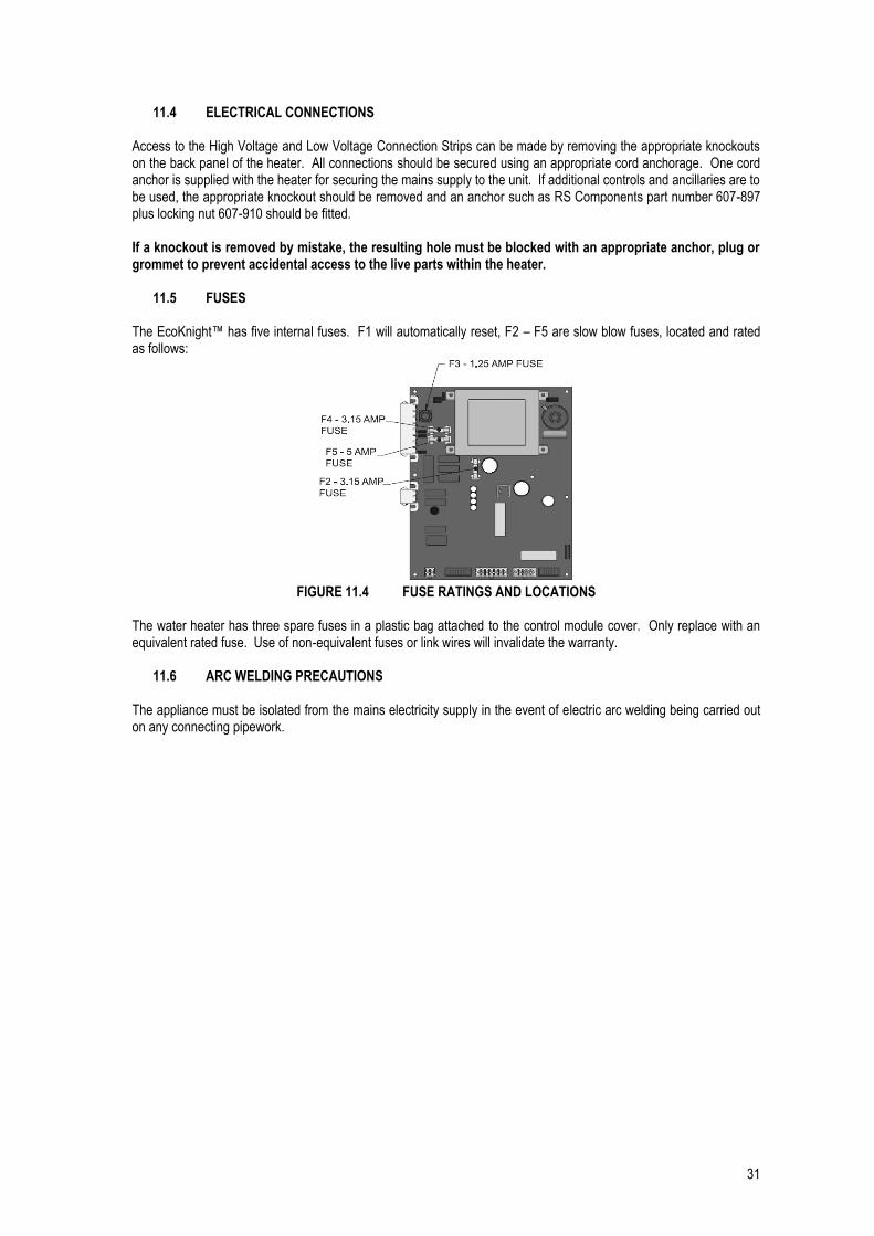
11.5 FUSES The EcoKnight™ has five internal fuses. F1 will automatically reset, F2 – F5 are slow blow fuses, located and rated as follows:
FIGURE 11.4 FUSE RATINGS AND LOCATIONS
The water heater has three spare fuses in a plastic bag attached to the control module cover. Only replace with an equivalent rated fuse. Use of non-equivalent fuses or link wires will invalidate the warranty.
11.6 ARC WELDING PRECAUTIONS The appliance must be isolated from the mains electricity supply in the event of electric arc welding being carried out on any connecting pipework.

32
11.7 WIRING DIAGRAM
diagrams to troubleshoot unit.3. Actual connector block locations may vary from those shown on diagrams. Refer to actual components for proper connector block locations when using
W R
VENTN.O.
230V SUPPLY
DE-STRATPUMP
RETURNPUMP
PRIMARYPUMP
TR1
COM
24 VAC
CN5-2
CN5-4
CN5-3
HIGH VOLTAGE SPARK LEADCAUTION
HI-LIMITAUTO RESET
CONTROLEXTERNAL
R
GY
BL
X6-6
X6-2
CN4-13
CN4-7
WX6-1CN4-5
THERMOSTATTANK
YX6-8CN4-8
SUPPLYPILOT
DEVICEAUX.
PR
PR
R
R
X3-2
X3-4
X3-3
X3-1
CONTACTSRUN-TIME
CONTACTSALARM
CN4-4
CN4-10
CN4-12
CN4-11
OR
BK
P
Y
BR
X6-10
X6-5
X6-4
X6-3
X6-9
CN4-2
CN4-3
CN4-9
CN4-1
CN4-6
CN5-1
CUT-OFF WATER
LOW
PROVING DEVICE
AUX.
SWITCHPRESSURE
GAS
SWITCHFLOW
Y
BK
SHIELD
SHIELD
BK
W
OR
X1-4
X1-6
X1-2
X1-5
X1-3
X4CN3
CONNECTION BOARD
B
ARS485
-
+0-10V
SENSORTANK
3 5421
S3
S1
S2
S4
BELL JUMPER
CN3
CN4
CN5
CN2
CN1
22
21
20
19
18
17
16
15
14
13
12
11
10
9
or ribbon cables can lead to operational problems which could result in non-repairable damage to the integrated controller or other components. minimum of 105°C. Exceptions: Replacement high voltage spark lead and ribbon cables must be purchased from the factory. Use of a non-approved spark lead 2. If any original equipment wire as supplied with the appliance must be replaced, it must be replaced with wire having same wire gauge (AWG) and rated for a 1. All wiring must be installed in accordance with I.E.E Regulations and any local regulations that apply.Notes:
1
2
3
4
5
6
7
8
CN4-14
INTERFACEPC
X3
HIGH VOLTAGE
LOW VOLTAGE230 VAC
X8
GY
OR
P
OR
PR
BL
GY
OR
P
OR
PR
BL
Y
W
R
BKX5-10
X5-4
X5-3
X5-11
X5-14
X5-7
X5-9
X5-2
X5-1
X5-8
DRAINBLOCKED
HI-LIMITMANUAL RESET
SENSORFLUE
SENSOROUTLET
SENSORINLET
G
W R
W
2 31
R G
BK
W
T
R
R
G
W/R
RODSPARK
RODFLAME
VALVEGAS
X1-7
X2-1
X2-2
VALVEVALVE
SOLENOID
X1-1
FAN
INTEGRATED CONTROL
X5-12
X5-6
X5-13
X5-5
X1-8
DISPLAY
BOX DEPICTSOPTIONAL ITEMS
JUNCTIONBOX
TERMINAL STRIP
OR
W
PR
BK
BR
W
W
W
L
N
ON/OFFSWITCH
L
GND
N
L
N
L
N
L
N
GND
GND
GND
GND
FIGURE 11.5 WIRING DIAGRAM

33
11.8 LADDER DIAGRAM
S3
S1
S2
S4
INTERFACEPC
11
12
13
14
8
7
6
5
4
3
2
X4-2CN3-2
1CONTROL
EXTERNAL
SHIELD
SHIELD
B
ARS485
-
+0-10V
SENSORTANK
X8
X4-5CN3-5
RIBBON CABLE
X3
X5-9
X5-2
X5-1
X5-8
X3-2
X3-4
X3-3
X3-1
CONTACTSRUN-TIME
CONTACTSALARM
CN4-4
CN4-10
CN4-12
CN4-11
CONTROLINTEGRATED
X4-10
X4-1
X4-3
X4-4
X4-6
X4-8
X4-7
X4-9
SENSORFLUE
SENSOROUTLET
SENSORINLET
CONNECTION BOARD
DISPLAY
CN3-10
CN3-1
CN3-3
CN3-4
CN3-6
CN3-8
CN3-7
CN3-9
RETURNRETURN
RETURN PUMPRELAY
DE-STRAT PUMPRELAY
PRIMARY PUMPRELAY
X1-2
X1-4
X1-3
STRIPPRIMARYPUMP
STRIP
DE-STRATPUMP "L"
PRIMARYPUMP "L"
PUMP "L"
DE-STRATPUMP
RETURNPUMP
DE-STRATPUMP "N"
PRIMARYPUMP "N"
PUMP "N"
TERMINAL TERMINAL
GND
GND
230VAC
TERMINAL STRIP230V SUPPLY "L"
NEUTRAL
TERMINAL STRIP230V SUPPLY "N"
GROUNDJUNCTION BOX
GND
9
2. See wiring diagram for additional notes. are connected or a fault condition is present. vary from those shown on diagrams depending upon whether utilities electricity) connected to the unit. As such, actual switch states may1. Where possible, switches are shown without utilities (gas, water orNOTES:
CN4-14
X6-2
X2-2
19
20
21
22
17
10
18
1615
HIGH VOLTAGE SPARK LEADCAUTION
HIGH VOLTAGE
LOW VOLTAGE230 VAC
CONTROLINTEGRATED
INTEGRATED CONTROL
RODSPARK
FLAME ROD
X1-7
TR1
1.25AF3
3.5A
F2
3.5A
F4
5A
5
4
2
1
X5-12
X5-6
X5-13
X5-5
RELAYGAS VALVE
GAS VALVE
X2-1
X5-4
X5-10
X5-3
X5-11
HI-LIMITAUTO RESET
SWITCHDRAIN
BLOCKED
X6-10CN4-2PROVING
AUX. DEVICE
24VAC
PILOT SUPPLYAUX. DEVICE
SWITCHPRESSUREHIGH GAS
SWITCHPRESSURELOW GAS
BOARDCONNECTION
X6-4 CN4-9X5-14HIGH LIMITMANUAL RESET
CONTROLINTEGRATED
X6-5
X6-1
X6-6
X6-9
CN4-3
CN4-5
CN4-13
CN4-6
BOARDCONNECTION
BOARDCONNECTION
THERMOSTATTANK
CN5-4
CN5-2
LWCO
CN5-3
BOARDCONNECTION
SWITCHFLOW
X1-8
BOXJUNCTION
CN5-1CN4-7 BOARD
CONNECTION
CN4-1
CN4-8
X6-7
X5-7
F5
X6-3
X6-8
X1-5
VLAVESOLENOID
VALVEVENT
JUNCTION BOX
FAN
3
21X1-1
RELAYBLOWER
X1-6
SWITCHON / OFF
24 VAC
230 VAC
OPTIONAL ITEMSBOX DEPICTS
FAN
FIGURE 11.6 LADDER DIAGRAM

34
12.0 SMART SYSTEM CONTROL
12.1 GENERAL The Lochinvar EcoKnight™ uses the SMART SYSTEM control interface. The control panel display give information on set-up, system status and diagnostic data in words rather than codes.
12.2 SMART SYSTEM CONTROL PANEL

35
12.3 SEQUENCE OF OPERATION
OPERATION DISPLAY 1. Upon a call for heat, the control turns on the appropriate
pumps. WHR: Standby
OUT: 61.4C (65)
2. The control connects 230 VAC to the fan. The fan does not run at this time.
If the unit is equipped with a flow switch or low water cut-off, it must close before the control powers up the fan.
If the unit is equipped with a manual reset high limit it must be closed before the control powers up the fan.
If the unit is equipped with a solenoid valve and/or a vent valve, they will be energized along with the fan.
If the unit is equipped with a gas pressure switch, it must close at this time.
If there is an auxiliary device connected to the unit, the unit will then provide 24 VAC to its enable relay. If the auxiliary device has a proving switch, it must close before the sequence continues.
WHR: Standby
OUT: 61.4C (65)
3. The control then starts a 10 second pre-purge cycle. WHR: PREPURGE
OUT: 61.5C (65)
4. Once the pre-purge cycle is complete, and the blocked drain and auto-reset high limit are closed, the control starts the 5-second trial for ignition by sending spark voltage to the ignition electrode and opening the gas valve.
WHR: IGNITION
OUT: 61.5C (65)
5. If the control does not detect flame by the end of the trial for ignition, the control performs a 10 second postpurge. On the EKW45CE to EKW115CE models, the control will perform another prepurge and will try to light the burner again. If the burner does not light after 4 trials, the control will lockout for 1 hour and then try another set of 4 trials. On the EKW145CE to EKW235CE models the unit will lockout until manually reset.
WHR: POSTPURGE, PREPURGE
OUT: 61.5C (65)
6. If the control detects a flame before the trial for ignition ends, it begins to modulate the burner in order to maintain the set point.
WHR: RUN 20% RATE
OUT: 62.6C (65)
7. Once the call for heat is satisfied, the control will turn off the burner. The fan will remain on for the 10-second post-purge cycle. The primary pump will continue to run for its respective pump delay time, and then turn off.
WHR: POSTPURGE
OUT: 64.5C (65))
8. Primary pump switches off. WHR: Standby
OUT: 64.8C (65)
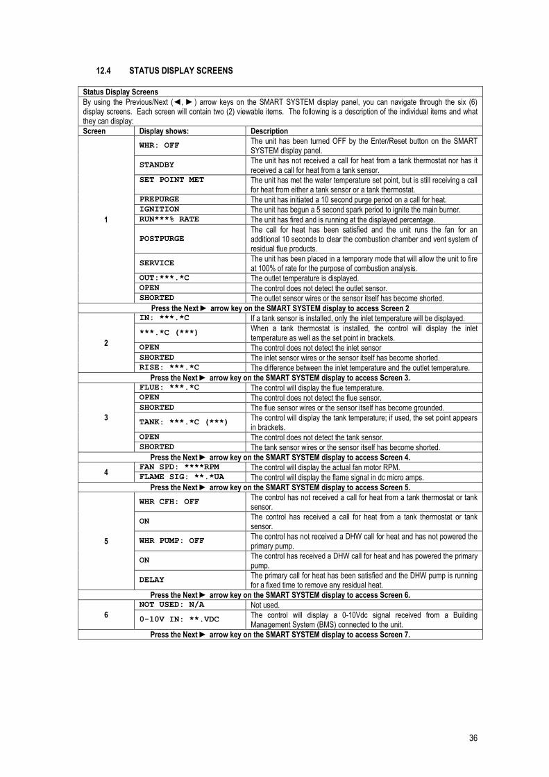
36
12.4 STATUS DISPLAY SCREENS Status Display Screens
By using the Previous/Next (◄, ►) arrow keys on the SMART SYSTEM display panel, you can navigate through the six (6) display screens. Each screen will contain two (2) viewable items. The following is a description of the individual items and what they can display:
Screen Display shows: Description
1
WHR: OFF The unit has been turned OFF by the Enter/Reset button on the SMART SYSTEM display panel.
STANDBY The unit has not received a call for heat from a tank thermostat nor has it received a call for heat from a tank sensor.
SET POINT MET
The unit has met the water temperature set point, but is still receiving a call for heat from either a tank sensor or a tank thermostat.
PREPURGE The unit has initiated a 10 second purge period on a call for heat. IGNITION The unit has begun a 5 second spark period to ignite the main burner. RUN***% RATE The unit has fired and is running at the displayed percentage.
POSTPURGE The call for heat has been satisfied and the unit runs the fan for an additional 10 seconds to clear the combustion chamber and vent system of residual flue products.
SERVICE The unit has been placed in a temporary mode that will allow the unit to fire at 100% of rate for the purpose of combustion analysis.
OUT:***.*C The outlet temperature is displayed. OPEN The control does not detect the outlet sensor. SHORTED The outlet sensor wires or the sensor itself has become shorted.
Press the Next ► arrow key on the SMART SYSTEM display to access Screen 2
2
IN: ***.*C If a tank sensor is installed, only the inlet temperature will be displayed.
***.*C (***) When a tank thermostat is installed, the control will display the inlet temperature as well as the set point in brackets.
OPEN The control does not detect the inlet sensor SHORTED The inlet sensor wires or the sensor itself has become shorted. RISE: ***.*C The difference between the inlet temperature and the outlet temperature.
Press the Next ► arrow key on the SMART SYSTEM display to access Screen 3.
3
FLUE: ***.*C The control will display the flue temperature. OPEN The control does not detect the flue sensor. SHORTED The flue sensor wires or the sensor itself has become grounded.
TANK: ***.*C (***) The control will display the tank temperature; if used, the set point appears in brackets.
OPEN The control does not detect the tank sensor. SHORTED The tank sensor wires or the sensor itself has become shorted.
Press the Next ► arrow key on the SMART SYSTEM display to access Screen 4.
4 FAN SPD: ****RPM The control will display the actual fan motor RPM. FLAME SIG: **.*UA The control will display the flame signal in dc micro amps.
Press the Next ► arrow key on the SMART SYSTEM display to access Screen 5.
5
WHR CFH: OFF The control has not received a call for heat from a tank thermostat or tank sensor.
ON The control has received a call for heat from a tank thermostat or tank sensor.
WHR PUMP: OFF The control has not received a DHW call for heat and has not powered the primary pump.
ON The control has received a DHW call for heat and has powered the primary pump.
DELAY The primary call for heat has been satisfied and the DHW pump is running for a fixed time to remove any residual heat.
Press the Next ► arrow key on the SMART SYSTEM display to access Screen 6.
6
NOT USED: N/A Not used.
0-10V IN: **.VDC The control will display a 0-10Vdc signal received from a Building Management System (BMS) connected to the unit.
Press the Next ► arrow key on the SMART SYSTEM display to access Screen 7.

37
7
Cas: Off The Master control has been turned off by the Enter/Reset button on the Smart System display.
Cas: Standby The Master water heater has not received a call for heat from a remote thermostat.
Cas: 61.4C (65) The Cascade is now active. The system temperature will be displayed. The Cascade set point will be displayed in brackets.
Cas: Setpoint Met The Cascade has met the water temperature set point, but is still receiving a call for heat from a tank sensor.
Cas: No Members The Master control could not detect any Member controls to participate in the Cascade.
PMP: Off The Master control has not received a call for heat from a tank sensor and has not powered the primary pump.
PMP: On The Master control has received a call for heat from a remote thermostat and has powered the system pump.
PMP: Delay The tank call for heat has been satisfied and the tank pump is running for a fixed time to remove any residual heat.
Press the Next ► arrow key on the SMART SYSTEM display to access Screen 8.
8
Cas Pow: ***% ***% The first percentage shows the firing rate that is being sent to the last water heater called on. The second percentage shows the total power available to the Cascade.
Present: 01234567
Example:
Present: 23----01
Shows the number of water heaters connected to the Cascade. The Master is designated as 0. Members will be designated 1 - 7. If a “-“ is used in place of a number, that water heater is either not connected, or in a lockout mode and not available for the Cascade. If the number is flashing, then that water heater is providing heat to the Cascade. As the lead water heater is changed from day to day, that water heater’s address will be shown first in the string of numbers. In the example, water heaters 0 - 3 are present and water heater 2 is the lead water heater.
Press the Next ► arrow key on the SMART SYSTEM display to roll back to Screen 1. At any point if you wish to access an earlier screen, press the Previous ◄ arrow key on the SMART SYSTEM display.

38
13.0 COMMISSIONING AND TESTING
13.1 ELECTRICAL INSTALLATION Notes on the requirements for electrical installation are provided in Section 11: ELECTRICAL SUPPLY. A schematic drawing of the control circuit is shown in Figure 11.5
13.2 GAS INSTALLATION For design see Section 7: GAS SUPPLY. See Section 2.0: PRINCIPAL PARTS for details on the position of the gas connection.
13.3 WATER CONNECTIONS For design see Section 10: WATER CONNECTIONS The system should be thoroughly flushed out with cold water without any circulating pump in position. Ensure all the valves are open. If a building return pump is to be fitted, it should be fitted before the system is filled and air locks cleared. Check the system for leaks and repair as necessary. If the system is configured in an unvented arrangement, check the expansion vessel cushion pressure.
13.4 COMMISSIONING THE EQUIPMENT
13.4.1 GENERAL CHECKS PRIOR TO LIGHTING A person deemed competent MUST be responsible for the commissioning of this equipment. Before attempting to commission any equipment, ensure that personnel involved are aware of what action is about to be taken and begin by making the following checks:
1. Flueway passages are clear. 2. Adequate ventilation exists in the plant room (if necessary) 3. The system is fully charged with water, ready to receive heat. All necessary valves are open and the
building return pump (if fitted) is circulating water. 4. The gas supply pipework is clear of any loose matter, tested for soundness and purged. 5. The condensate drain is installed correctly and the condensate trap is filled with water.
NOTE: If the condensate trap is not filled before use, products of combustion may escape and can lead to severe personal injury or death
13.4.2 EQUIPMENT CHECKS PRIOR TO LIGHTING This unit has been designed for a nominal gas inlet pressure of 20 mbar when used on natural gas. Information relating to propane firing can be found in Section 14: LPG FUEL
1. Gas supply is connected but turned to the “off” position. Any unions or fittings are correctly tightened, test points are closed and the flame sense electrode lead is connected correctly. Ensure the ceramic sheath around the flame sense electrode is not cracked or broken.
2. Ensure electricity supply is connected. 3. Check that the circulating pump is fully bled.

39
13.4.3 PROCEDURE FOR INITIAL LIGHTING IF THE UNIT IS TO OPERATE ON LPG REFER TO SECTION 14: LPG FUEL BEFORE PROCEEDING
1. Ensure that the gas inlet appliance isolating valve, provided by the installer, is in the “off” position. 2. Press the power rocker switch, positioned on the back of the appliance to bring the equipment on. 3. Press the Enter/Reset button on the SMART SYSTEM control panel to initiate the burner. 4. The combustion fan should ramp up to full speed to purge the combustion chamber and then drop back to
half rate in order to light. The spark generator should create a spark, visible through the burner sight glass. As the gas inlet appliance isolating valve is closed, the controls should go to a flame failure condition after four ignition attempts (EKW45CE – EKW115CE) or one ignition attempt (EKW145CE – EKW235CE). If the above occurs correctly, open the gas inlet appliance isolating valve and reset the unit by depressing the Enter/Reset button on the control panel.
5. The combustion fan will repeat the pre-purge procedure and attempt to light. Once a flame is established, the LCD display will change to display the rate at which it is firing.
6. Allow the system to reach temperature to check operation of the control sensors. 7. Once appliance shuts down, check that the main flame has extinguished.
13.4.4 GAS PRESSURE ADJUSTMENT AND COMBUSTION CHECKS
The Lochinvar EcoKnight™ series are supplied with a preset gas/air ratio inlet assembly. This must not be tampered with. Any attempt to adjust the gas valve or venturi will invalidate the warranty. Combustion figures should be as follows:
Model No. CO2 CO
EKW45CE 9.0% 0.5% <100 ppm
EKW60CE 9.0% 0.5% <100 ppm
EKW85CE 8.8% 0.5% <100 ppm
EKW115CE 8.8% 0.5% <100 ppm
EKW145CE 8.8% 0.5% <100 ppm
EKW175CE 9.0% 1.0% <100 ppm
EKW205CE 9.0% 1.0% <100 ppm
EKW235CE 9.0% 1.0% <100 ppm
TABLE 13.1 NATURAL GAS COMBUSTION FIGURES If the combustion figures are not within the range specified, contact Lochinvar Limited for further guidance. Combustion figures for Propane firing can be found in Section 14: LPG Fuel.
13.5 TEMPERATURE ADJUSTMENT PROCEDURE The setpoint can be adjusted using the Up and Down buttons on the Smart System control panel. Once the desired setpoint is displayed, the Enter/Reset button should be pressed to store the value. The setpoint should be adjusted to ensure that the water is stored at 60°C and distributed at 50°C within 1 (one) minute at all outlets. Care is needed to avoid much higher temperatures because of the risk of scalding. At 50°C the risk of scalding is small for most people, but the risk increases rapidly with higher temperatures and for longer exposure times. The risk to young children and to those with a sensory or mobility loss will be greater. Where a significant scalding risk has been identified, the use of thermostatic mixing valves on baths and showers should be considered to reduce temperature, these need to be placed as close to the point of use as possible.

40
13.6 INSTALLATION NOISE If care has been taken to follow the manufacturer’s instructions there should be no discernible noise from the equipment. The allied pump motor may have a level of sound that could lead to consideration for acoustic insulation, but care must be taken not to impede ventilation or airflow to the pump motor. 14.0 LPG FUEL NOTE! IT IS STRONGLY RECOMMENDED THAT, ON LPG INSTALLATIONS, GAS DETECTION EQUIPMENT IS FITTED. THIS EQUIPMENT SHOULD BE POSITIONED NEAR THE APPLIANCE AND AT LOW LEVEL. IT IS ALSO IMPORTANT THAT THE SPACE HOUSING THE APPLIANCE IS ADEQUATELY VENTILATED AT HIGH AND LOW LEVEL. THIS APPLIANCE MUST NOT BE LOCATED BELOW GROUND E.G. IN A CELLAR
14.1 RELATED DOCUMENTS In addition to those documents listed in Section 4.1: RELATED DOCUMENTS within the main body of the installer’s guide the gas installation should also comply with the guidance offered in the following documents. BS 5482-1: 2005 Code of practice for domestic butane and propane gas burning installations.
Part 1: Installations at permanent dwellings, residential park homes and commercial premises, with installation pipework sizes not exceeding dn25 for steel and dn28 for corrugated stainless steel or copper.
The operation of the EcoKnight™ range on LPG-Propane (3rd Family) 3P is similar to that on Natural Gas (2nd Family) 2H and the design and installation details described in the main body of the installer’s guide should be followed.
14.2 CONVERSION TO LPG This process must be carried out in the order stated. Failure to follow the following procedure may lead to non-warrantable damage to the water heater. The conversion MUST be carried out by a competent person certified for work on LPG fuel. In the event of any seal or gasket being broken it is essential that the seal or gasket be replaced. Contact Lochinvar Limited for replacement seals and gaskets.
Model Part No. Stamp Size
EKW45CE ORF2022 150 4.98 0.025
EKW60CE ORF2023 210 5.56 0.025
EKW85CE ORF2024 285 6.76 0.025
EKW115CE* ORF2025 7.2 7.20 0.02
EKW115CE* ORF20000 8 8.0 0.02
EKW145CE‡ ORF20003 9.5 9.5 0.02
EKW175CE ORF20002 10.2 10.2 1.0
EKW205CE ORF20002 10.2 10.2 1.0
EKW235CE ORF20002 10.2 10.2 1.0
TABLE 14.1 LPG ORIFICE MARKINGS * On EcoKnight™ EKW115CE water heaters with serial numbers prior to F09H10108102, use ORF2025. For EcoKnight™ water heaters with serial numbers after F09H10108102 use ORF20000 ‡ On EcoKnight™ EKW145CE water heaters with serial numbers before L09H10120786 an orifice conversion is not available. In this instance a LPG set gas valve, Lochinvar Part No. VAL2714 will be required.

41
If the water heater is already installed and operational, you must turn off the gas supply, turn off the power supply and allow the water heater to cool before proceeding. The conversion procedure is as follows:
14.2.1 EKW45CE – EKW85CE
1. Remove the top and front access covers from the unit (no tools required for removal). 2. Remove the impulse tube and wiring plug from the gas valve. 3. Remove the three cap-head screws securing the gas valve to the venturi (Figure 14.1). 4. Locate the propane orifice disk from the conversion kit bag. Verify that the stamping on the orifice disk is
correct for the water heater (see Table 14.1). Place the orifice into the black rubber grommet in the side of the gas valve ensuring the orifice and grommet are seated correctly (Figure 14.1).
5. Reposition the gas valve against the venturi and replace the cap-head screws (Figure 14.1) securing the valve to the venturi.
6. Refit the impulse tube and wiring plug to the gas valve. 7. After installation is complete, attach the propane conversion label (in the conversion kit bag) next to the
water heater rating plate. Attach the LPG warning label (in the conversion kit bag) to the appliance casing, next to the gas inlet pipework.
8. Replace the top and front access covers.
FIGURE 14.1 CONVERSION PROCEDURE EKW30CE – EKW85CE

42
14.2.2 EKW115CE
1. Remove the top and front access covers from the unit (no tools required for removal). 2. Remove the impulse tube and wiring plug from the gas valve. 3. Remove the three screws securing the venturi to the fan.
NOTE: When separating the venturi from the fan, take care not to damage the O-ring inside the fan (Figure 14.2). 4. Remove the four cap-head screws securing the gas valve to the venturi (Figure 14.2). 5. Locate the propane orifice disk from the conversion kit bag. Verify that the stamping on the orifice disk is
correct for the water heater (see Table 14.1). 6. Remove the existing orifice from the O-ring in the side of the gas valve and replace it with the orifice from
the kit. Position and secure the orifice in the valve as shown in Figure 14.2. 7. Reposition the gas valve against the venturi and replace the star-drive screws (Figure 14.2) securing the
valve to the venturi. 8. Inspect the O-ring inside the fan. Handle the O-ring with care, do not damage. Reposition the venturi
against the fan and replace the screws securing the venturi to the fan (Figure 14.2). 9. Refit the impulse tube and wiring plug to the gas valve. 10. After installation is complete, attach the propane conversion label (in the conversion kit bag) next to the
water heater rating plate. Attach the LPG warning label (in the conversion kit bag) to the appliance casing, next to the gas inlet pipework.
11. Replace the top and front access covers.
FIGURE 14.2 CONVERSION PROCEDURE EKW115CE

43
14.2.3 EKW145CE (BEFORE SERIAL NUMBER L09H10120786)
1. Remove the top and front access covers from the unit (no tools required for removal). 2. Disconnect the wiring plug from the gas valve. 3. Disconnect the impulse tube from the gas valve and venturi assembly and set aside, taking care not to kink
the tube. 4. Remove the 4 cap head screws securing the inlet flange then separate the flange from the valve. Inspect
the sealing ring and retain or replace as necessary. 5. Remove the 4 cap head screws securing the gas valve to the venturi supporting the valve at all times. 6. Separate the valve from the venturi, inspect the sealing gasket and retain or replace as necessary. 7. Fit the new valve using the reverse of the above procedure, ensuring the new or retained gaskets are
correctly seated. 8. After installation is complete, attach the propane conversion label (in the conversion kit bag) next to the
heater rating plate. Attach the LPG warning label (in the conversion kit bag) to the appliance casing, next to the gas inlet pipework.
9. Replace the top and front access covers.
FIGURE 14.3 CONVERSION PROCEDURE EKW145CE (BEFORE SERIAL NUMBER L09H10120786)

44
14.2.4 EKW145CE (FROM SERIAL NUMBER L09H10120786)
1. Remove the top and front access covers from the unit (no tools required for removal). 2. Remove the gas valve and manifold from the unit via the unions on each end (Figure 14.4). 3. Remove the three screws mounting the injector plate on the air shroud (Figure 14.4). 4. Remove the four screws securing the manifold adapter to the injector plate taking care not to damage the
O-ring. 5. Locate the propane orifice disk from the conversion kit bag. Verify that the stamping on the orifice disk is
correct for the heater (see Table 14.1). 6. Remove the existing orifice from the O-ring in the side of the injector plate and replace it with the orifice
from the kit. Position and secure the orifice in the injector plate as shown in Figure 14.4. 7. Reposition the manifold adapter to the injector plate and replace the four manifold adapter mounting
screws. Handle the O-ring with care, do not damage. 8. Reposition the injector plate to the air shroud and replace the three injector plate mounting screws. 9. After installation is complete, attach the propane conversion label (in the conversion kit bag) next to the
heater rating plate. Attach the LPG warning label (in the conversion kit bag) to the appliance casing, next to the gas inlet pipework.
10. Replace the top and front access covers.
FIGURE 14.4 CONVERSION PROCEDURE EKW145CE (FROM SERIAL NUMBER L09H10120786)

45
14.2.5 EKW175CE – EKW235CE
1. Remove the top and front access covers from the unit (no tools required for removal). 2. Remove the four screws and nuts that hold the adaptor flange to the inlet of the venturi. 3. Separate the flange and venturi ensuring the gasket is not damaged. 4. Locate the propane orifice disk from the conversion kit bag. Verify that the stamping on the orifice disk is
correct for the heater (see Table 14.1). 5. Fit the orifice plate ensuring its correct orientation (see DETAIL A of Figure 14.5) 6. Reinstall the four screws and nuts holding the adapter flange to the inlet of the venturi ensuring the correct
location of the gasket. 7. After installation is complete, attach the propane conversion label (in the conversion kit bag) next to the
heater rating plate. Attach the LPG warning label (in the conversion kit bag) to the appliance casing, next to the gas inlet pipework.
8. Replace the top and front access covers.
FIGURE 14.5 CONVERSION PROCEDURE EKW175CE – EKW235CE

46
14.3 LPG COMMISSIONING AND TESTING The commissioning procedure on LPG is similar to that when the heater is firing on Natural Gas. As such, the same procedure should be followed taking in to account the following information:
14.3.1 LPG PRESSURE ADJUSTMENT AND COMBUSTION CHECKS The Lochinvar EcoKnight™ series are supplied with a preset gas/air ratio inlet assembly. This must not be tampered with. Any attempt to adjust the gas valve or venturi will invalidate the warranty. Combustion figures should be as follows:
Model No. CO2 CO
EKW45CE 10.5% 0.5% <100 ppm
EKW60CE 10.5% 0.5% <100 ppm
EKW85CE 10.5% 0.5% <100 ppm
EKW115CE 10.5% 0.5% <100 ppm
EKW145CE 10.5% 0.5% <100 ppm
EKW175CE 10.0% 1.0% <100 ppm
EKW205CE 10.0% 1.0% <100 ppm
EKW235CE 10.0% 1.0% <100 ppm
TABLE 14.2 LPG COMBUSTION FIGURES If the combustion figures are not within the range specified, contact Lochinvar Limited for further guidance. 15.0 MAINTENANCE
15.1 GENERAL KEEP APPLIANCE AREA CLEAR AND FREE FROM COMBUSTIBLE MATERIALS AND FLAMMABLE VAPOURS AND LIQUIDS. A competent person should check and ensure that the flue, its support and terminal, the ventilation to the boiler house, safety valve, drain, pressure gauge etc. are in a serviceable and working condition and still comply with the relevant standards and codes of practice, as detailed in Section 4: GENERAL REQUIREMENTS. Servicing is recommended at intervals no greater than 12 months to ensure trouble free operation. Even if the maintenance schedule for the storage vessel is determined to be less than annually, it is important that all controls and safety features are checked for correct operation on an annual basis. Measuring flue gas CO2 and flue gas temperatures will give an indication of the state of the flue and burner. Results of the flue gas analysis should be compared with previously measured values to identify any changes in operational characteristics.
15.2 MAINTENANCE SCHEDULE The water heater has a built in function that reminds the user that routine maintenance is due. As a default, this is set to 12 months, 10,000 operational hours or 10,000 ignition cycles. Lochinvar Limited recommend that this be the maximum service interval however, in hard water areas it may be necessary to reduce this time period to ensure correct operation of the heater and associated equipment.

47
15.3 BURNER INSPECTION The heat exchanger has a sight glass for inspection of the flame picture. NOTE: If the appliance has been in recent operation, this area may be hot. Appropriate precautions should be taken to prevent personal injury. To check the flame picture at high and low fire, the following procedure should be followed:
1. Place the water heater into service mode. This is done by depressing the small recessed button below the Enter/Reset button for 5 seconds.
2. The heater should shut down and relight. 3. Depress the service button momentarily, this should ramp the water heater up to full rate. 4. Check the flame condition. 5. Depress the service button momentarily, this should ramp the water heater down to low rate. 6. Check the flame condition. 7. Press and hold the service button for 5 seconds to take the unit out of service mode.
15.4 BURNER REMOVAL
If it has been determined that the flame picture is unacceptable, the burner can be removed and cleaned using the following procedure:
1. Isolate the electrical and gas supplies to the heater. 2. Allow the boiler to cool down. 3. Disconnect the wiring connections to the ignition electrode. 4. Disconnect the power and control connection leads and earthing wire from the combustion fan. 5. Apply a suitable release oil to the 6 studs around the edge of burner door. 6. Remove the 6 retaining nuts around the edge of the burner door.
NOTE: Once loosened, the nuts should be removed by hand. If any of the nuts seize, the nut should gently be re-tightened and additional release oil used.
7. Withdraw the heat exchanger front plate and burner assembly from the heat exchanger complete with the combustion fan.
8. With the burner assembly away from the boiler, the burner can be gently cleaned with the brush attachment of a vacuum cleaner.
The reassembly procedure is the reverse of the above taking care to ensure that the for the heat exchanger front plate sealing gasket, the combustion fan connection gasket, the burner door insulation and the combustion chamber rear wall insulation are in good condition or are replaced as necessary. NOTE: PARTICULAR ATTENTION SHOULD BE PAID TO THE COMBUSTION CHAMBER REAR WALL
INSULATION. IF ANY DETERIORATION IN THE INSULATING MATERIAL IS NOTED, THE INSULATION PANEL MUST BE REPLACED.
15.5 CLEANING THE HEAT EXCHANGER
To clean the heat exchanger, the following procedure should be carried out:
1. Remove the burners as above. 2. Use a vacuum cleaner to remove any accumulation on the heating surfaces. 3. Inspect the heat exchanger to ensure that the 1 mm flueway is clear between all coils. 4. If any debris is still present, brush the heat exchanger with a non-metallic brush taking care not to damage
the insulation panel on the rear wall of the heat exchanger. NOTE: A kit of components to aid with cleaning the heat exchanger is available from Lochinvar Limited. For
models EKW45CE – EKW115CE use part number KIT30063, for models EKW145CE – EKW235CE use part number KIT30064.
NOTE: It is very important to inspect and remove all deposits from the heat exchanger. If all deposits cannot be removed from the heat exchanger, contact Lochinvar Limited for further guidance.
5. Once the heat exchanger has been brushed it should be rinsed with fresh water to remove all residues. 6. Remove the condensate water trap and clean out any debris.
48
7. Refit the condensate drain and fully recharge by pouring 1 litre of water through the heat exchanger coils. 8. Reinstall the burner. 9. Restart the heater as detailed in Section 13.4.3: PROCEDURE FOR INITIAL LIGHTING.
15.6 DRAINING WATER HEATER SYSTEM
The water heater must be drained if it is to be shut down and exposed to freezing temperatures. Maintenance and service procedures may also require draining the water heater.
1. Turn off the water heater electrical disconnect switch. 2. Connect a hose to the system drain valve. 3. Locate hose’s discharge in an area where hot water will not cause any damage or injury. 4. Close the cold-water inlet valve to water heater system. 5. Open a nearby hot water outlet to vent the system. 6. Open the drain valve. 7. If the water heater is being drained for an extended shutdown, it is suggested the drain valve be left
open during this period. NOTE: The heat exchanger cannot be completely drained of water without purging with compressed air at a
pressure of 1.0 bar.
15.7 REMOVING SCALE AND SEDIMENT FROM THE STORAGE VESSEL
1. Drain the water system. Refer to Section 15.6: DRAINING THE WATER HEATER SYSTEM. 2. Remove outer cover plate from the storage vessel casing. 3. Remove cover and gasket from cleanout opening. 4. Remove scale or sediment using care not to damage the lining of the vessel. 5. Inspect cleanout plate gasket and replace if necessary. 6. Install gasket and cleanout plate. Draw the plate up square by tightening the bolts evenly. 7. Once the system has been re-filled and a check for leaks carried out, the outer cover plate should be
re-fitted.
15.8 SACRIFICIAL ANODES: INSPECTION AND REPLACEMENT (STORAGE VESSELS) If the Correx non-sacrificial anode protection system is used, there is no requirement to check the condition of the anodes. The tank is protected against corrosion by means of two sacrificial anodes fitted in the front of the storage vessel. The rate at which the anodes are eroded is dependent on the quality of the water; therefore it is essential that the anodes are inspected at least once a year.
1. Drain the water heater system. Refer to Section 15.6: DRAINING THE WATER HEATER SYSTEM. 2. Remove the outer caps covering the anodes. 3. Remove each anode and inspect its condition. If the anode has reduced in size by more than 40% or if
the surface is severely pitted, the anode should be replaced. 4. When refitting the inspected or replaced anode, a suitable jointing compound should be applied to the
threads of the anode to prevent water leakage.
15.9 REFILLING THE SYSTEM
1. Close the drain valve. 2. Open a hot water fixture to allow air to escape. 3. Open the cold water supply to water heater and allow the tank to fill. 4. Follow the lighting instructions as detailed in Section 13.4.3: PROCEDURE FOR INITIAL LIGHTING. 5. Check for water leakage.

49
15.10 OTHER CHECKS
15.10.1 RELIEF VALVE At least once a year, the temperature and pressure relief valve and safety valve should be checked to ensure that they are in operating condition. To check each valve, lift the lever or turn the screw cap at the end of the valve several times. The valve should operate freely and seat properly. If water does not flow, remove and inspect for obstructions or corrosion. Replace with a new valve of the recommended size as necessary.
15.10.2 FLUE SYSTEM Examine the exhaust and air intake system at least once a year. Points of inspection are as follows:
1. Check for obstructions and/or deterioration of flue piping and terminal. Replace immediately where needed.
2. Check the terminal for any foreign material and remove as necessary 3. Check all flue system connections for leakage and reseal as required. 4. Check that ventilation grilles comply with current regulations.
15.10.3 CONDENSATE NEUTRALISATION KIT
If fitted the condensate neutralisation kit will require replacing after 12 months of operation. Please refer to the item specific instructions for further details. 16.0 SMART SYSTEM CONTROL SETTINGS
16.1 ENTERING THE INSTALLER CODE To access the user control the following procedure should be followed:
1. If the heater is operating, press the Enter/Reset button to turn the unit off. 2. Press and hold the Menu/Exit button for 5 seconds. At this point the display will change to show:
Enter Menu Code:
0000
3. Press the UP button 9 times. The display should now show: Enter Menu Code:
0009
4. Press the Previous button 2 times. The display should now show: Enter Menu Code:
0009
5. Press the Up button 3 times. The display should now show: Enter Menu Code:
0309
6. Press the Previous button. The display should now show: Enter Menu Code:
0309
7. Press the Up button 5 times. The display should now show: Enter Menu Code:
5309
8. Press the Enter/Reset button. The display should now show: Enter Menu Code:
INSTALLER CODE
In addition to menu sets A and C (as detailed in the User Guide) the installer has access to various other menus. By pressing the Up and Down buttons the various menu sets can be selected and then accessed using the Enter/Reset button.

50
16.2 MENU SET D FUNCTIONS
16.2.1 RESET LAST 10 ERRORS The last 10 errors logged can be cleared using this parameter. To carry out this function, the Enter/Reset button.
16.2.2 SERVICE MODE DELAY By pressing the pin button on the front of the display for five (5) seconds, the control will be placed in Service Mode. This will override all other heat demands. The Service Mode allows the installer to set the unit to either maximum firing rate or minimum firing rate for the purpose of combustion analysis. The delay sets the length of time the water heater will stay in the Service Mode if no keys have been pressed before going back to its original state. The time range of this parameter can be adjusted between 0 and 40 minutes using the Up and Down buttons. Once the desired time period has been set, the Enter/Reset button should be pressed to store the value. The default time delay is 20 minutes.
16.3 MENU SET E WHR SETTINGS
16.3.1 TANK SETPOINT When a DHW call for heat becomes active, the control will use the tank setpoint to determine the firing rate of the
water heater based on the actual water temperature. The desired temperature can be adjusted in ½ increments using the Up or Down buttons and the desired value stored by pressing the Enter/Reset button. The temperature
range of this parameter is 0C to 80C. The default value is 65C.
16.4 MENU SET H CONTROL MODES
16.4.1 CONTROL SOURCE The control source parameter selects the method used to control the modulation of the water heater. By using the Up and Down buttons and then pressing the Enter/Reset button, one of the following control modes can be selected: Thermostat: The control modulates the water heater based on the user set point and the temperature of the tank sensor when a tank thermostat is used, or the inlet sensor. BMS (Building Management System): The control modulates the water heater based on the 0 - 10 VDC signal delivered to the appropriate terminals on the connection board. When BMS is selected additional parameters for BMS operation may need to be adjusted. These can only be accessed using optional PC interface software. Cascade: The water heater is part of a group of water heaters sequenced together. The designated Master water heater determines the total output needed from the group based on the set point and controlling sensor reading. It assigns portions of this output to itself (Master) and the Member water heaters. When Cascade is selected, each water heater in the group requires a unique address (see below). The default control is Thermostat.
16.4.2 CASCADE ADDRESS The water heater designated, as the Master needs to be programmed with address 0. All the Member water heaters require addresses from 1 to 7, and the addresses must be different for each Member. The addresses can be in any order, regardless of the order in which the units are wired together. This parameter is adjustable by pressing the Up or Down buttons and then pressing the Enter/Reset button to store the assigned address. The tank sensor must be connected to the Master water heater. The default address is 1.

51
16.4.3 MAX CASCADE SETPOINT This setting is not used on the EcoKnight™ water heater.
16.4.4 CASCADE OFFSET This setting is not used on the EcoKnight™ water heater.
16.4.5 CASCADE OFF-ON DIFFERENTIAL This setting is not used on the EcoKnight™ water heater.
16.5 MENU SET I CIRCULATION PUMPS
16.5.1 DHW PUMP DELAY The DHW pump delay parameter sets the length of time the DHW (Primary) pump will run after a heater demand has been satisfied. The time range for this parameter is 0 minutes to 40 minutes and is adjustable (in 10 second steps) using the Up or Down buttons. Once the desired time setting has been selected, the Enter/Reset button should be pressed to store the value. The default pump delay is 30 seconds.
16.6 MENU SET J SERVICE NOTIFICATION
16.6.1 SERVICE NOTIFICATION IN MONTHS When the water heater control determines that a scheduled service is due based on days of installation, the water heater display will alternate the standard water heater display text with the message SERVICE DUE every 5 seconds. This parameter is adjustable in 1-month intervals using the Up or Down buttons and then stored by pressing the Enter/Reset button. The time range for this parameter is 0 months to 36 months. The default service interval is 12 months.
16.6.2 SERVICE NOTIFICATION RUNNING HOURS When the water heater control determines that a scheduled service is due based on the hours of actual operation, the water heater display will alternate the standard water heater display text with the message SERVICE DUE every 5 seconds. This parameter is adjustable in 500-hour intervals using the Up or Down buttons and then stored by pressing the Enter/Reset button. The time range for this parameter is 0 hours to 100,000 hours. The default time is 10,000 hours.
16.6.3 SERVICE NOTIFICATION BOILER CYCLES When the water heater control determines that a scheduled service is due based on the number of water heater cycles, the water heater display will alternate the standard water heater display text with the message SERVICE DUE every 5 seconds. This parameter is adjustable in 500 cycle intervals using the Up or Down buttons and then stored by pressing the Enter/Reset button. The range for this parameter is 0 cycles to 100,000 cycles. The default is 10,000 cycles.
16.6.4 RESET SERVICE NOTIFICATION COUNTER Once servicing has been completed, the service notification counter should be reset. Once the menu sub-section has been accessed, press the Enter/Reset button to reset the service notification counter. 17.0 USER INSTRUCTIONS Once the installation and commissioning is complete, the equipment owner or their representative should be made aware of the operation of the appliance and its safety devices. A practical demonstration should be given describing each functional step. Incorrect use may result in injury and will also invalidate the warranty. The installers guide should be handed over and kept in a safe place for easy reference. It is strongly recommended that the users read and understand the separate User and SMART SYSTEM Control Guide

52