The Cricket location-support system
12
6th ACM International Conference on Mobile Computing and Networking (ACM MOBICOM), Boston, MA, August 2000 (Slightly revised) The Cricket Location-Support System Nissanka B. Priyantha, Anit Chakraborty, and Hari Balakrishnan MIT Laboratory for Computer Science Cambridge, MA 02139 bodhi, achakra, hari @lcs.mit.edu Abstract This paper presents the design, implementation, and evaluation of Cricket, a location-support system for in-building, mobile, location- dependent applications. It allows applications running on mobile and static nodes to learn their physical location by using listeners that hear and analyze information from beacons spread throughout the building. Cricket is the result of several design goals, including user privacy, decentralized administration, network heterogeneity, and low cost. Rather than explicitly tracking user location, Cricket helps devices learn where they are and lets them decide whom to advertise this information to; it does not rely on any centralized management or control and there is no explicit coordination be- tween beacons; it provides information to devices regardless of their type of network connectivity; and each Cricket device is made from off-the-shelf components and costs less than U.S. $10. We describe the randomized algorithm used by beacons to transmit information, the use of concurrent radio and ultrasonic signals to infer distance, the listener inference algorithms to overcome multipath and inter- ference, and practical beacon configuration and positioning tech- niques that improve accuracy. Our experience with Cricket shows that several location-dependent applications such as in-building ac- tive maps and device control can be developed with little effort or manual configuration. 1 Introduction The emergence of network-enabled devices and the promise of ubiquitous network connectivity has made the development of per- vasive computing environments an attractive research goal. A com- pelling set of applications enabled by these technology trends are context-aware, location-dependent ones, which adapt their behav- ior and user interface to the current location in space, for which they need to know their physical location with some degree of accuracy. We have started seeing the commercial deployment of such appli- cations in outdoor settings (e.g., Hertz’s NeverLost navigator on This research was supported in part by NTT Corporation, DARPA (Grant No. MDA972-99-1-0014), and IBM. Permission to make digital or hard copies of all or part of this work for personal or classroom use is granted without fee provided that copies are not made or distributed for profit or commercial advan- tage, and that copies bear this notice and the full citation on the first page. Copyrights for components of this work owned by others than ACM must be honored. Abstracting with credit is permitted. To copy otherwise, to republish, to post on servers or to redistribute to lists, requires prior specific permission and/or a fee. MobiCom 2000 08/2000 Boston, MA c 2000 ACM rental cars [13]), where location information is obtained via wide- area technologies like the Global Positioning System (GPS) [11] or using the cellular infrastructure. We believe that the widespread deployment of location-dependent applications inside office build- ings and homes has the potential to fundamentally change the way we interact with our immediate environment, where computing ele- ments will be “ubiquitous” [20] or “pervasive” [9, 5]. In particular, our work will enable a new class of location-based applications and user interactions in the context of Project Oxygen at MIT [16]. The design and deployment of a system for obtaining location and spatial information in an indoor environment is a challenging task for several reasons, including the preservation of user privacy, ad- ministration and management overheads, system scalability, and the harsh nature of indoor wireless channels. The degree of privacy of- fered by the system is an important deployment consideration, since people often value their privacy highly. The administrative overhead to manage and maintain the hardware and software infrastructure must be minimal because of the potentially large number (possibly several thousands in a building) of devices and networked services that would be part of the system, and the communication protocols must be able to scale to a high spatial density of devices. Finally, in- door environments often contain substantial amounts of metal and other such reflective materials that affect the propagation of radio frequency (RF) signals in non-trivial ways, causing severe multi- path effects, dead-spots, noise, and interference. Our goal is to develop a system that allows applications running on user devices and service nodes to learn their physical location. Once this information is obtained, services advertise themselves to a resource discovery service such as the MIT Intentional Naming System (INS) [3], IETF Service Location Protocol [18], Berkeley Service Discovery Service [8], or Sun’s Jini discovery service [14]. User applications do not advertise themselves unless they want to be discovered by others; they learn about services in their vicin- ity via an active map that is sent from a map server application, and interact with services by constructing queries for services at a required location. By separating the processes of tracking ser- vices and obtaining location information, multiple resource discov- ery systems can be accommodated. By not tracking users and ser- vices, user-privacy concerns are adequately met. We emphasize that our goal is a location-support system, rather than a conventional location-tracking system that tracks and stores location information for services and users in a centrally maintained database. Over the past many months, we have designed and implemented Cricket, a location-support system for building-wide deployment in the context of Project Oxygen, and have conducted several experi- ments with it. We have integrated it with INS for resource discov- ery, and an active map application, which together enable location-
-
Upload
independent -
Category
Documents
-
view
3 -
download
0
Transcript of The Cricket location-support system
6th ACM International Conference on Mobile Computing and Networking (ACM MOBICOM), Boston, MA, August 2000(Slightly revised)
The Cricket Location-Support System
Nissanka B. Priyantha, Anit Chakraborty, and Hari BalakrishnanMIT Laboratory for Computer Science
Cambridge, MA 02139�bodhi, achakra, hari � @lcs.mit.edu
Abstract
This paper presents the design, implementation, and evaluation ofCricket, a location-support system for in-building, mobile, location-dependent applications. It allows applications running on mobileand static nodes to learn their physical location by using listenersthat hear and analyze information from beacons spread throughoutthe building. Cricket is the result of several design goals, includinguser privacy, decentralized administration, network heterogeneity,and low cost. Rather than explicitly tracking user location, Crickethelps devices learn where they are and lets them decide whom toadvertise this information to; it does not rely on any centralizedmanagement or control and there is no explicit coordination be-tween beacons; it provides information to devices regardless of theirtype of network connectivity; and each Cricket device is made fromoff-the-shelf components and costs less than U.S. $10. We describethe randomized algorithm used by beacons to transmit information,the use of concurrent radio and ultrasonic signals to infer distance,the listener inference algorithms to overcome multipath and inter-ference, and practical beacon configuration and positioning tech-niques that improve accuracy. Our experience with Cricket showsthat several location-dependent applications such as in-building ac-tive maps and device control can be developed with little effort ormanual configuration.
1 Introduction
The emergence of network-enabled devices and the promise ofubiquitous network connectivity has made the development of per-vasive computing environments an attractive research goal. A com-pelling set of applications enabled by these technology trends arecontext-aware, location-dependent ones, which adapt their behav-ior and user interface to the current location in space, for which theyneed to know their physical location with some degree of accuracy.We have started seeing the commercial deployment of such appli-cations in outdoor settings (e.g., Hertz’s NeverLost navigator on
This research was supported in part by NTT Corporation, DARPA(Grant No. MDA972-99-1-0014), and IBM.
Permission to make digital or hard copies of all or part of this workfor personal or classroom use is granted without fee provided thatcopies are not made or distributed for profit or commercial advan-tage, and that copies bear this notice and the full citation on the firstpage. Copyrights for components of this work owned by others thanACM must be honored. Abstracting with credit is permitted. To copyotherwise, to republish, to post on servers or to redistribute to lists,requires prior specific permission and/or a fee.
MobiCom 2000 08/2000 Boston, MA
c�
2000 ACM
rental cars [13]), where location information is obtained via wide-area technologies like the Global Positioning System (GPS) [11]or using the cellular infrastructure. We believe that the widespreaddeployment of location-dependent applications inside office build-ings and homes has the potential to fundamentally change the waywe interact with our immediate environment, where computing ele-ments will be “ubiquitous” [20] or “pervasive” [9, 5]. In particular,our work will enable a new class of location-based applications anduser interactions in the context of Project Oxygen at MIT [16].
The design and deployment of a system for obtaining location andspatial information in an indoor environment is a challenging taskfor several reasons, including the preservation of user privacy, ad-ministration and management overheads, system scalability, and theharsh nature of indoor wireless channels. The degree of privacy of-fered by the system is an important deployment consideration, sincepeople often value their privacy highly. The administrative overheadto manage and maintain the hardware and software infrastructuremust be minimal because of the potentially large number (possiblyseveral thousands in a building) of devices and networked servicesthat would be part of the system, and the communication protocolsmust be able to scale to a high spatial density of devices. Finally, in-door environments often contain substantial amounts of metal andother such reflective materials that affect the propagation of radiofrequency (RF) signals in non-trivial ways, causing severe multi-path effects, dead-spots, noise, and interference.
Our goal is to develop a system that allows applications runningon user devices and service nodes to learn their physical location.Once this information is obtained, services advertise themselves toa resource discovery service such as the MIT Intentional NamingSystem (INS) [3], IETF Service Location Protocol [18], BerkeleyService Discovery Service [8], or Sun’s Jini discovery service [14].User applications do not advertise themselves unless they want tobe discovered by others; they learn about services in their vicin-ity via an active map that is sent from a map server application,and interact with services by constructing queries for services ata required location. By separating the processes of tracking ser-vices and obtaining location information, multiple resource discov-ery systems can be accommodated. By not tracking users and ser-vices, user-privacy concerns are adequately met. We emphasize thatour goal is a location-support system, rather than a conventionallocation-tracking system that tracks and stores location informationfor services and users in a centrally maintained database.
Over the past many months, we have designed and implementedCricket, a location-support system for building-wide deployment inthe context of Project Oxygen, and have conducted several experi-ments with it. We have integrated it with INS for resource discov-ery, and an active map application, which together enable location-
dependent applications (and users) to discover and interact withservices. This paper describes our design goals (later in this sec-tion), system architecture and algorithms (Section 2), implementa-tion (Section 3), experimental results (Section 4), applications (Sec-tion 5), and a detailed comparison with previous location-trackingsystems (Section 6).
The design of Cricket was driven by the following specific goals,which followed from the nature of our applications and from de-ployment considerations:
� User privacy. Whenever a system for providing location in-formation to clients has been deployed in the past, the issueof user privacy has arisen. This is because many previous sys-tems were location tracking systems, where a database kepttrack of the locations of all the entities, including users in thesystem. To address this concern, we designed a location sup-port system, which allows clients to learn their location with-out centralized tracking in order to construct location-specificqueries for resources.
� Decentralized administration. Our goal is widespreadbuilding-wide deployment. We believe that it is not possibleto deploy and administer a system in a scalable way when allcontrol and management functions are centralized. Our de-sign is decentralized—the “owner” of a space in a building(e.g.,the occupant of a room) configures and installs a loca-tion beacon that announces the identity of that space (somecharacter string) and each beacon seamlessly integrates withthe rest of the system. Location receiver hardware, called alistener, is attached to every device of interest to a user. Lis-teners use an inference algorithm to determine the space inwhich they are currently located by listening to beacon an-nouncements. There is no need for a central entity to keeptrack of each individual component in the system.
� Network heterogeneity. A wide variety of network technolo-gies exist in most building environments. In our own labora-tory, devices and users connected over 10/100 Mbps Ethernet,three different types of indoor wireless LANs, cellular digitalpacket data (CDPD), infrared, public telephone, and power-line using X10 [21]. Independent of which technology theyuse to serve or gain access to information, many services andclients can benefit from learning their location in an automaticway, and we would like to accommodate them. In our design,we achieve this by decoupling the Cricket system from otherdata communication mechanisms.
� Cost. Achieving building-wide deployment requires cost-effective components. We use commercial, off-the-shelf, inex-pensive components in Cricket, setting and meeting the goalof less than U.S. $10 per location beacon and listener. Our de-sign involves no custom hardware and is small enough to fitin one’s palm.
� Room-sized granularity. Our goal is a system where spatialregions can be determined to within one or two square feet,so as to distinguish portions of rooms. This requires the abil-ity to demarcate and determine boundaries between regionscorresponding to different beacons.
Cricket uses a combination of RF and ultrasound to providea location-support service to users and applications. Wall- and
ceiling-mounted beacons are spread through the building, publish-ing location information on an RF signal. With each RF advertise-ment, the beacon transmits a concurrent ultrasonic pulse. The lis-teners receive these RF and ultrasonic signals, correlate them toeach other, estimate distances to the different beacons using the dif-ference in RF and ultrasonic signal propagation times, and there-fore infer the space they are currently in. We describe the details ofthe technologies, the system parameters and configuration, and thealgorithms and protocols used in Cricket. The beacons use a decen-tralized randomized transmission algorithm to minimize collisionsand interference amongst each other. The listeners implement a de-coding algorithm to overcome the effects of ultrasound multipathand RF interference. We investigate the performance of three de-coding algorithms and find that picking the location correspondingto the beacon with minimum statistical mode performs the best,maximizing the likelihood of making the correct choice. We alsodiscuss some practical deployment considerations when using ul-trasound hardware, and some location-dependent applications wehave developed using Cricket.
2 System architecture
Cricket uses beacons to disseminate information about a geo-graphic space to listeners. A beacon is a small device attached tosome location within the geographic space it advertises. Typically,it is obtained by the “owner” of the location (e.g., the occupant of aroom in an office or home, or a building administrator) and placedat an unobtrusive location like a ceiling or wall. Cricket does not at-tach any semantics to the space advertised by the beacon; any shortstring can be disseminated, such as the name of a server to contactto learn more about the space or a name resolver for the space todiscover resources. Cricket beacons are inexpensive and more thanone of them can be used in any space for fault-tolerance and bettercoverage.
To obtain information about a space, every mobile and static nodehas a listener attached to it. A listener is a small device that listens tomessages from beacons, and uses these messages to infer the spaceit is currently in. The listener provides an API to programs runningon the node that allow them to learn where they are, so that they canuse this information to appropriately advertise themselves and theirlocation to a resource discovery service.
The listener can be attached to both static and mobile nodes. Forexample, when a user attaches a new static service to the network(e.g., a printer), she does not need to configure it with a locationor other any attribute; all she does is attach a listener to it. Withina few seconds, the listener infers its current location from the setof beacons it hears, and informs the device software about this viathe API. This information can then be used in its own service ad-vertisements. When a mobile computer has a listener attached to it,the listener constantly listens to beacons to infer its location. As thecomputer (e.g., a hand-held computer carried by a person) movesin a building, the navigation software running on it uses the listenerAPI to update its current location. Then, by sending this informa-tion securely to a map server (for example), it can obtain updatesto the map displayed to the user. Furthermore, services appear asicons on the map that are a function of the user’s current location.The services themselves learn their location information using theirown listener devices, avoiding the need for any per-node configura-
tion.
The only configuration required in Cricket is setting the string fora space that is disseminated by a beacon. The specific string is afunction of the resource discovery protocol being used, and Cricketallows any one of several possibilities (in Section 5 we describe ourimplementation platform and integration with INS). Cricket alsoprovides a way by which the owner of a room can securely set andchange the space identifier that is sent in the advertisements. This isdone by sending a special message over the same RF channel thatis used for the advertisements, after authenticating the user via apassword. At this stage, we have chosen to allow this change onlyfrom within physical proximity of the room or location where thebeacon is located. This makes the system somewhat more securethan if we allowed this to be done from afar.
The boundaries between adjacent spaces can either be real, as in awall separating two rooms, or virtual, as in a non-physical partitionused to separate portions of a room. The precision of the systemis determined by how well the listener can detect the boundary be-tween two spaces, while the granularity of the system is the small-est possible size for a geographic space such that boundaries can bedetected with a high degree of precision. A third metric, accuracy isused to calibrate individual beacons and listeners; it is the degree towhich the distance from a beacon, estimated by a listener, matchesthe true distance. While our experiments show that the distance ac-curacy of our hardware is smaller than a few inches, what mattersis the precision and granularity of the system. These depend on thealgorithms and the placement of beacons across boundaries. Ourgoal is a system with a close-to-100% precision with a granularityof a few feet (a portion of a room).
The rest of this section describes the design of Cricket, focusing onthree fundamental issues: (i) mechanism for determining the loca-tion (the beacon-listener protocol), (ii) the listener algorithms andtechniques for handling beacon interference, and (iii) beacon con-figuration and positioning.
2.1 Determining the location
At the beginning we were hopeful that a purely RF-based sys-tem could be engineered and made to work well, providing lo-cation information at the granularity of a room, and ideally, por-tions of rooms. Our approach attempted to limit the coverage ofan RF transmitter to define the granularity of a geographic-space,and using received signal strength to infer best location. Despitemany weeks of experimentation and significant tuning, this did notyield satisfactory results [7]. This was mainly because RF propaga-tion within buildings deviates heavily from empirical mathematicalmodels (e.g., see also [6]), and in our environment, the correspond-ing signal behavior with our inexpensive, off-the-shelf radios wasnot reproducible across time.
We therefore decided to use a combination of RF and ultrasoundhardware to enable a listener to determine the distance to bea-cons, from which the closest beacon can be more unambiguouslyinferred. We achieve this by measuring the one-way propagationtime of the ultrasonic signals emitted by a beacon, taking advan-tage of the fact that the speed of sound in air (about 1.13 ft/ms atroom temperature) is much smaller than the speed of light (RF) inair. On each transmission, a beacon concurrently sends informationabout the space over RF, together with an ultrasonic pulse. When
the listener hears the RF signal, it uses the first few bits as traininginformation and then turns on its ultrasonic receiver. It then listensfor the ultrasonic pulse, which will usually arrive a short time later.The listener uses the time difference between the receipt of the firstbit of RF information and the ultrasonic signal to determine the dis-tance to the beacon. Of course, the value of the estimated distanceis not as important as the decision of which the closest beacon is.
The use of time-of-flight of signals to measure distance is not a newconcept. GPS uses the one-way delay of radio waves from satellitesto estimate distance, while radio-altimeters in aircrafts use the timefor an electromagnetic signal to reflect off the ground to determinealtitude. Collision avoidance mechanisms used in robotics [17] de-termine the distance to obstacles by measuring the time-of-flight ofan ultrasonic signal being bounced off them.
It is also possible to measure the distance using the relative veloc-ity of two signals. It is common practice to use the time elapsedbetween observing a lightning (electromagnetic waves) and accom-panied thunder (sound) to estimate the distance to the lightning.The Bat system (detailed in Section 6) uses this idea to determine amobile transmitter’s position in space, where an array of calibratedreceivers measure the time of flight of an ultrasonic signal emittedby a mobile transmitter in response to an RF signal from a basestation sent to the transmitter and all the receivers.
2.2 Reducing interference
While Cricket has the attractive property that its decentralized bea-con network is easy to configure and manage, it comes at the ab-sence of explicit coordination. There is no explicit scheduling orcoordination between the transmissions of different beacons thatmay be in close proximity, and listeners do not transmit any infor-mation to avoid compromising privacy. This lack of coordinationcan cause RF transmissions from different beacons to collide, andmay cause a listener to wrongly correlate the RF data of one bea-con with the ultrasonic signal of another, yielding false results. Fur-thermore, ultrasonic reception suffers from severe multipath effectscaused by reflections from walls and other objects, and these are or-ders of magnitude longer in time than RF multipath because of therelatively long propagation time for sound waves in air. In fact, thisis one of the reasons it is hard to modulate data on the ultrasonicsignal, which makes it a pure pulse. Thus, the listener’s task is togather various RF and ultrasound (US) samples, deduce and corre-late the
�RF,US � pairs that were sent concurrently by the different
beacons, and choose the space identifier sent from the pair with theclosest distance.
We decided not to implement a full-fledged carrier-sense-stylechannel-access protocol to avoid collisions in order to maintainsimplicity and reduce overall energy consumption. Instead, we han-dle the problem of collisions using randomization. Rather than us-ing a fixed or deterministic transmission schedule, beacon transmis-sion times are chosen randomly with a uniform distribution withinan interval � ��������� ms. Thus, the broadcasts of different beaconsare statistically independent, which avoids repeated synchroniza-tion and prevents persistent collisions. The choice of random in-terval is governed by the number of beacons we typically expectwill be within range of each other and the time it takes for thetransmitted information to reach the listeners, which depends onthe message size and link bandwidth. In our implementation, we
use an average frequency of four times per second distributed in� � ��� ��� ��� � ms. A smaller frequency increases the amount of time be-fore a statistically significant location inference can be made, whilea higher frequency increases the probability of collisions. We planto extend this technique to include a listening component that willallow each beacon to infer the number of beacons in its proximityand appropriately scale the beaconing frequency.
We minimize errors due to RF and ultrasonic interference amongbeacons by two methods: (i) proper selection of system parametersto reduce the chance of false correlations, and (ii) listener inferencealgorithms based on statistical analysis of correlated
�RF,US � sam-
ples.
2.2.1 System parameters
In addition to transmitting a string corresponding to the space, eachbeacon transmits a unique identifier. The combination of the loca-tion string and identifier is unique across the entire system. Thisallows the listener to correlate the RF and ultrasonic beacon signalscorrectly.
The raw line-of-sight range of our ultrasonic transmitter-receiverpair is around 50 feet, when both the transmitter and the receiver arefacing each other. However, by mounting the ultrasonic transmitterscarefully, as described in Section 3.3, we are able to reduce theeffective range to around 30 feet in the absence of any obstacles.The line-of-sight range of the RF transmitter-receiver pair is about80 feet, which drops to about 40 feet when there is an obstacle (e.g.,a wall). Since RF can travel farther than an ultrasonic transmissionand can also travel through certain obstacles, it is almost impossiblefor a listener to receive an ultrasonic signal without receiving thecorresponding RF signal.
We discovered that one way to reduce the occurrence of false cor-relations is to use a relatively sluggish RF data transmission rate!Instead, if we used a high-bandwidth RF channel, the data identify-ing a space would reach a listener before the ultrasound pulse wasdetected. I.e., if � is the size in bits of the message sent over the RFchannel with a transmission rate of � bits/s, and � is the maximumpropagation time for an ultrasonic signal in air between a beaconand a listener, a value of ��� ��� would mean that the ultrasonicsignal corresponding to a given RF message would arrive while the� message bits are still being received. Together with the fact thatthe range of our ultrasound is smaller than our RF, this establishesthat any potentially correlated ultrasound pulse must arrive whilean RF message is being received. In the absence of interfering bea-con transmissions, this check suffices to do the correct correlation.The specific parameters used in our implementation are describedin Section 3.
We now proceed to investigate the different interference scenariosthat are possible.
2.2.2 Interference scenarios
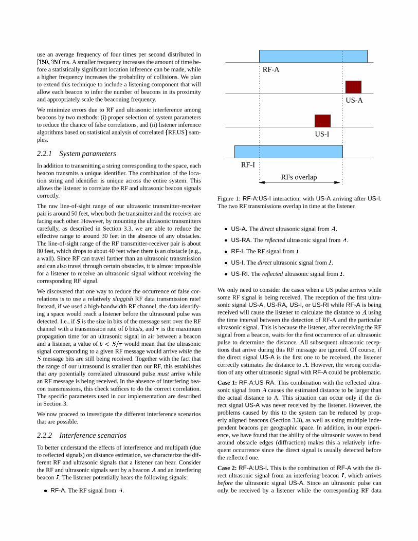
To better understand the effects of interference and multipath (dueto reflected signals) on distance estimation, we characterize the dif-ferent RF and ultrasonic signals that a listener can hear. Considerthe RF and ultrasonic signals sent by a beacon � and an interferingbeacon � . The listener potentially hears the following signals:
� RF-A. The RF signal from � .
US-I
US-A
RF-A
RF-I
RFs overlap
Figure 1: RF-A:US-I interaction, with US-A arriving after US-I.The two RF transmissions overlap in time at the listener.
� US-A. The direct ultrasonic signal from � .� US-RA. The reflected ultrasonic signal from � .� RF-I. The RF signal from � .� US-I. The direct ultrasonic signal from � .� US-RI. The reflected ultrasonic signal from � .
We only need to consider the cases when a US pulse arrives whilesome RF signal is being received. The reception of the first ultra-sonic signal US-A, US-RA, US-I, or US-RI while RF-A is beingreceived will cause the listener to calculate the distance to � usingthe time interval between the detection of RF-A and the particularultrasonic signal. This is because the listener, after receiving the RFsignal from a beacon, waits for the first occurrence of an ultrasonicpulse to determine the distance. All subsequent ultrasonic recep-tions that arrive during this RF message are ignored. Of course, ifthe direct signal US-A is the first one to be received, the listenercorrectly estimates the distance to � . However, the wrong correla-tion of any other ultrasonic signal with RF-A could be problematic.
Case 1: RF-A:US-RA. This combination with the reflected ultra-sonic signal from � causes the estimated distance to be larger thanthe actual distance to A. This situation can occur only if the di-rect signal US-A was never received by the listener. However, theproblems caused by this to the system can be reduced by prop-erly aligned beacons (Section 3.3), as well as using multiple inde-pendent beacons per geographic space. In addition, in our experi-ence, we have found that the ability of the ultrasonic waves to bendaround obstacle edges (diffraction) makes this a relatively infre-quent occurrence since the direct signal is usually detected beforethe reflected one.
Case 2: RF-A:US-I. This is the combination of RF-A with the di-rect ultrasonic signal from an interfering beacon � , which arrivesbefore the ultrasonic signal US-A. Since an ultrasonic pulse canonly be received by a listener while the corresponding RF data
packet is being received, RF-I should also be in transit to the lis-tener. Hence RF-A and RF-I should overlap at the listener as shownin Figure 1.
If RF-A and RF-I are comparable in signal strength, they will col-lide, causing the listener to ignore this event because both RF mes-sages will be corrupted. On the other hand, if the signal strength ofRF-I is substantially larger than RF-A, the two may not collide andthe listener will end up calculating the correct distance to beacon � .
The only situation that leads to a wrong distance estimate is whenthe signal strength of RF-I is much smaller than RF-A, causing thelistener to use the RF-A:US-I combination to determine the dis-tance to A. We reduce the chances of this event by using RF sig-nals with longer range than US signals. This generally ensures astrong RF reception whenever the corresponding ultrasonic signalis received (hence the receipt of US-I, in general ensures a strongRF-I).
Case 3. RF-A:US-RI. This occurs when a stray reflected signalfrom an interfering beacon � appears before US-A. As before, thiscan lead to wrong distance estimates as well.
Although cases 2 and 3 may lead to incorrect distance estimates,our use of randomization reduces the repeated calculation of wrongestimates. If there are a large number of beacons in close proximityto each other, there can be a non-negligible number of wrong dis-tance estimates at the receivers. At this point, we have engineeredour system to ensure that there are not more than five or six beaconsthat are within range of each other at any location.
In addition, listeners do not simply use the first sample pair they getto infer their best location. Rather, they collect multiple samplesand use an inference algorithm for this.
2.2.3 Beacon position inference
We develop and compare three simple algorithms to determinewhich the closest beacon is, overcoming the interference problemsof the previous section: Majority, MinMean, and MinMode. In ouranalysis of these algorithms, the distance estimate is rounded to thenearest ten inches and the data put into different bins accordingto how frequently they occur. This is done for each beacon sepa-rately. Furthermore, isolated stray samples are eliminated from theanalysis; a small threshold number of consistent values (two, in ourimplementation) are needed before the corresponding sample is in-cluded for analysis.
� Majority. This is the simplest algorithm, which pays no at-tention to the distance estimates and simply picks the beaconwith the highest frequency of occurrence in the data set. Thisalgorithm does not use ultrasonic signals for determining theclosest beacon, but as we find in our experiments, this doesnot perform well. We investigate this primarily for compari-son with the other algorithms.
� MinMean. Here, the listener calculates the mean distancefrom each unique beacon for the set of data points within thedata set. Then, it selects the beacon with the minimum meanas the closest one. The advantage of this algorithm is that itcan be computed with very little state, since a new sample up-dates the mean in a straightforward way. The problem withthis algorithm is that it is not immune to multipath effects that
Room A Room B
Beacon BBeacon A Listener
Figure 2: The nearest beacon to a listener may not be in the samegeographic space.
x
x
Location A
Location C
Location B
C.0
B.1
B.0 A.1
A.0
Beacons
Physical Boundary
x
x
x
Imaginary Boundary
Figure 3: Correct positioning of beacons.
cause the distance estimates to display modal behavior; wherecomputing a statistic like the mean (or median) is not reflec-tive of any actual beacon position.
� MinMode. Since the distance estimates often show significantmodal behavior due to reflections, our approach to obtaining ahighest-likelihood estimate is to compute the per-beacon sta-tistical modes over the past � samples (or time window). Foreach beacon, the listener then picks the distance correspond-ing to the mode of the distribution, and uses the beacon thathas the minimum distance value from among all the modes.We find that this is robust to stray signals and performs wellin both static and mobile cases.
Section 4 discusses the results of our experiments. We note thatthese are by no means the only possible algorithms, but these arerepresentative of the precision attainable with different degrees ofprocessing at the listeners.
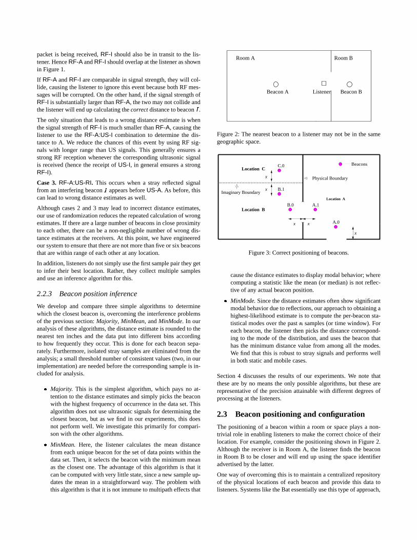
2.3 Beacon positioning and configuration
The positioning of a beacon within a room or space plays a non-trivial role in enabling listeners to make the correct choice of theirlocation. For example, consider the positioning shown in Figure 2.Although the receiver is in Room A, the listener finds the beaconin Room B to be closer and will end up using the space identifieradvertised by the latter.
One way of overcoming this is to maintain a centralized repositoryof the physical locations of each beacon and provide this data tolisteners. Systems like the Bat essentially use this type of approach,
where the central controller knows where each wall- or ceiling-mounted device is located, but it suffers from two problems thatmake it unsuitable for us. First, user-privacy is compromised be-cause a listener now needs to make active contact to learn whereit is (observe that in Cricket, a listener is completely passive). Sec-ond, it requires a centrally managed service, which does not suit ourautonomously managed environment particularly well.
Fortunately, there is a simple engineering solution to this problemthat preserves privacy and is decentralized. Whenever a beacon isplaced to demarcate a physical or virtual boundary corresponding toa different space, it must be placed at a fixed distance away from theboundary demarcating the two spaces. Figure 3 shows an exampleof this in a setting with both real and virtual boundaries. Such place-ment ensures that a listener rarely makes a wrong choice, unlesscaught within a small distance (1 foot in our current implementa-tion) from the boundary between two beacons advertising differentspaces. In this case, it is often equally valid to pick either beacon asthe closest.
3 Implementation
In this section, we describe the implementation of Cricket. We de-scribe the system parameters and hardware configuration, the APIprovided by the listener to applications running on the attachednode, and some deployment issues with ultrasonic hardware.
3.1 System parameters and hardware
The message size of a beacon RF transmission is 7 bytes long in ourimplementation, and the RF transmission rate of our radios is 1200bits/s. It therefore takes about 47 ms for the message to completelyreach a listener, during which time an ultrasonic pulse can travel atmost about 47 feet. The typical range of our RF radios is about 30feet in the building. No listener can therefore be farther away thanthis to detect which space it is in.
Cricket is implemented using inexpensive, off-the-shelf, simplehardware parts that cost less than U.S. $10 per beacon and listener.The beacon consists of a PIC micro-controller running at 10MHz,with 68 bytes of RAM and 1024 words of program memory. It usesa low-power SAW resonator-based RF transmitter and a single-chipRF receiver, both operating in the 418 MHz unlicensed band [10]with amplitude modulation. The final component is an ultrasonictransmitter operating at 40kHz. All of these are assembled on asmall board and mounted on a ceiling or high on a wall.
The listener is only slightly more complicated. It has an identicalmicro-controller, a single-chip RF receiver, and an ultrasonic re-ceiver with a single-chip tone-detector circuit, instead of the corre-sponding transmitters. It also has a TTL to RS-232 signal converterby which it interfaces to the host device, e.g., a laptop, hand-heldcomputer, or any other service like a printer, camera, television, etc.This interface uses the standard RS-232 protocol at 9600 bits/s.
We measured the power consumption of a beacon, since the peri-odic transmission of an RF signal and ultrasonic pulse will eventu-ally run the battery down. Although we did not explicitly design thehardware for low power consumption, we find that it is quite effi-cient, dissipating 15 mW of power during normal operation (whenit sends an RF and US signal every 250 ms on average). Currently,each Cricket beacon uses a single 9 Volt re-chargeable battery. We
Figure 4: The radiation pattern of an ultrasonic transmitter.
plan to use a solar cell with a backup re-chargeable battery in thefuture.
3.2 Listener API
A part of the software implemented for receiver nodes, called theLocationManager, runs on the host device that has the listener hard-ware attached to the serial port. The LocationManager listens on theserial port for any data coming from the listener hardware. In ourimplementation, the MinMode listener inference algorithm to an-alyze distance estimates is also implemented within the Location-Manager, since this provides greater flexibility. The listener sendsboth the location information and the measured distance to the cor-responding beacon, to the LocationManager for each valid RF re-ception.
Asynchronous to the reception of distance estimates and listenercomputations, applications running on the host device connect tothe LocationManager and retrieve current location information us-ing a datagram socket (UDP) interface. In fact, this allows for thepossibility of obtaining this information from a remote node else-where on the network, which might be useful for some applications.We have not yet taken advantage of this facility in our applications.
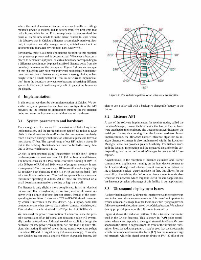
3.3 Ultrasound deployment issues
As described in Section 2, ultrasonic interference at the receiver canlead to incorrect distance measurements. It is therefore important toreduce ultrasonic leakage to other locations while trying to providefull coverage to the location served by a Cricket beacon. We achievethis by proper alignment of the ultrasonic transmitters.
Figure 4 shows the radiation pattern of the ultrasonic transmitterused in the Cricket beacons. This is shown in
��� ����� polar coordi-nates, where
�corresponds to the signal strength in dB and � corre-
sponds to the offset in degrees from the front of the ultrasonic trans-mitter. From the radiation pattern, it can be seen that the direction inwhich the ultrasound transmitter faces (
���) has the maximum sig-
nal strength, while the signal strength drops to 1% (-20 dB) of the
the ultrasonic
Beacon
Wall
Ceiling
Orientation of
transmitter
Circuit Board
Ultarsonictransmitter
45
Figure 5: Correct alignment of a Cricket ultrasonic transmitter.
maximum value at � � � � away from the� �
direction.
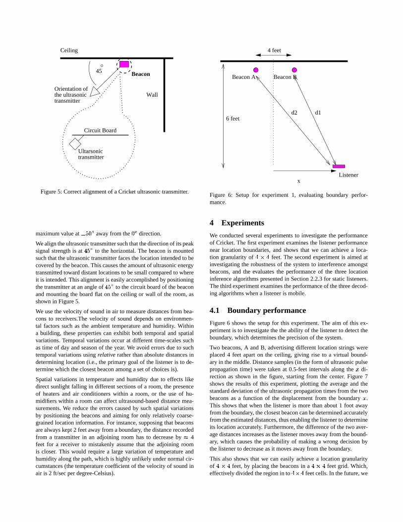
We align the ultrasonic transmitter such that the direction of its peaksignal strength is at � ��� to the horizontal. The beacon is mountedsuch that the ultrasonic transmitter faces the location intended to becovered by the beacon. This causes the amount of ultrasonic energytransmitted toward distant locations to be small compared to whereit is intended. This alignment is easily accomplished by positioningthe transmitter at an angle of � � � to the circuit board of the beaconand mounting the board flat on the ceiling or wall of the room, asshown in Figure 5.
We use the velocity of sound in air to measure distances from bea-cons to receivers.The velocity of sound depends on environmen-tal factors such as the ambient temperature and humidity. Withina building, these properties can exhibit both temporal and spatialvariations. Temporal variations occur at different time-scales suchas time of day and season of the year. We avoid errors due to suchtemporal variations using relative rather than absolute distances indetermining location (i.e., the primary goal of the listener is to de-termine which the closest beacon among a set of choices is).
Spatial variations in temperature and humidity due to effects likedirect sunlight falling in different sections of a room, the presenceof heaters and air conditioners within a room, or the use of hu-midifiers within a room can affect ultrasound-based distance mea-surements. We reduce the errors caused by such spatial variationsby positioning the beacons and aiming for only relatively coarse-grained location information. For instance, supposing that beaconsare always kept 2 feet away from a boundary, the distance recordedfrom a transmitter in an adjoining room has to decrease by � 4feet for a receiver to mistakenly assume that the adjoining roomis closer. This would require a large variation of temperature andhumidity along the path, which is highly unlikely under normal cir-cumstances (the temperature coefficient of the velocity of sound inair is 2 ft/sec per degree-Celsius).
4 feet
x
d1d2
Listener
Beacon A Beacon B
6 feet
Figure 6: Setup for experiment 1, evaluating boundary perfor-mance.
4 Experiments
We conducted several experiments to investigate the performanceof Cricket. The first experiment examines the listener performancenear location boundaries, and shows that we can achieve a loca-tion granularity of ����� feet. The second experiment is aimed atinvestigating the robustness of the system to interference amongstbeacons, and the evaluates the performance of the three locationinference algorithms presented in Section 2.2.3 for static listeners.The third experiment examines the performance of the three decod-ing algorithms when a listener is mobile.
4.1 Boundary performance
Figure 6 shows the setup for this experiment. The aim of this ex-periment is to investigate the the ability of the listener to detect theboundary, which determines the precision of the system.
Two beacons, A and B, advertising different location strings wereplaced 4 feet apart on the ceiling, giving rise to a virtual bound-ary in the middle. Distance samples (in the form of ultrasonic pulsepropagation time) were taken at 0.5-feet intervals along the � di-rection as shown in the figure, starting from the center. Figure 7shows the results of this experiment, plotting the average and thestandard deviation of the ultrasonic propagation times from the twobeacons as a function of the displacement from the boundary � .This shows that when the listener is more than about 1 foot awayfrom the boundary, the closest beacon can be determined accuratelyfrom the estimated distances, thus enabling the listener to determineits location accurately. Furthermore, the difference of the two aver-age distances increases as the listener moves away from the bound-ary, which causes the probability of making a wrong decision bythe listener to decrease as it moves away from the boundary.
This also shows that we can easily achieve a location granularityof ����� feet, by placing the beacons in a ����� feet grid. Which,effectively divided the region in to ��� feet cells. In the future, we
6
6.2
6.4
6.6
6.8
7
7.2
7.4
7.6
0 0.5 1 1.5 2 2.5 3 3.5
Ultr
ason
ic p
ropa
gatio
n tim
e (m
s)
Horizontal displacement (feet)
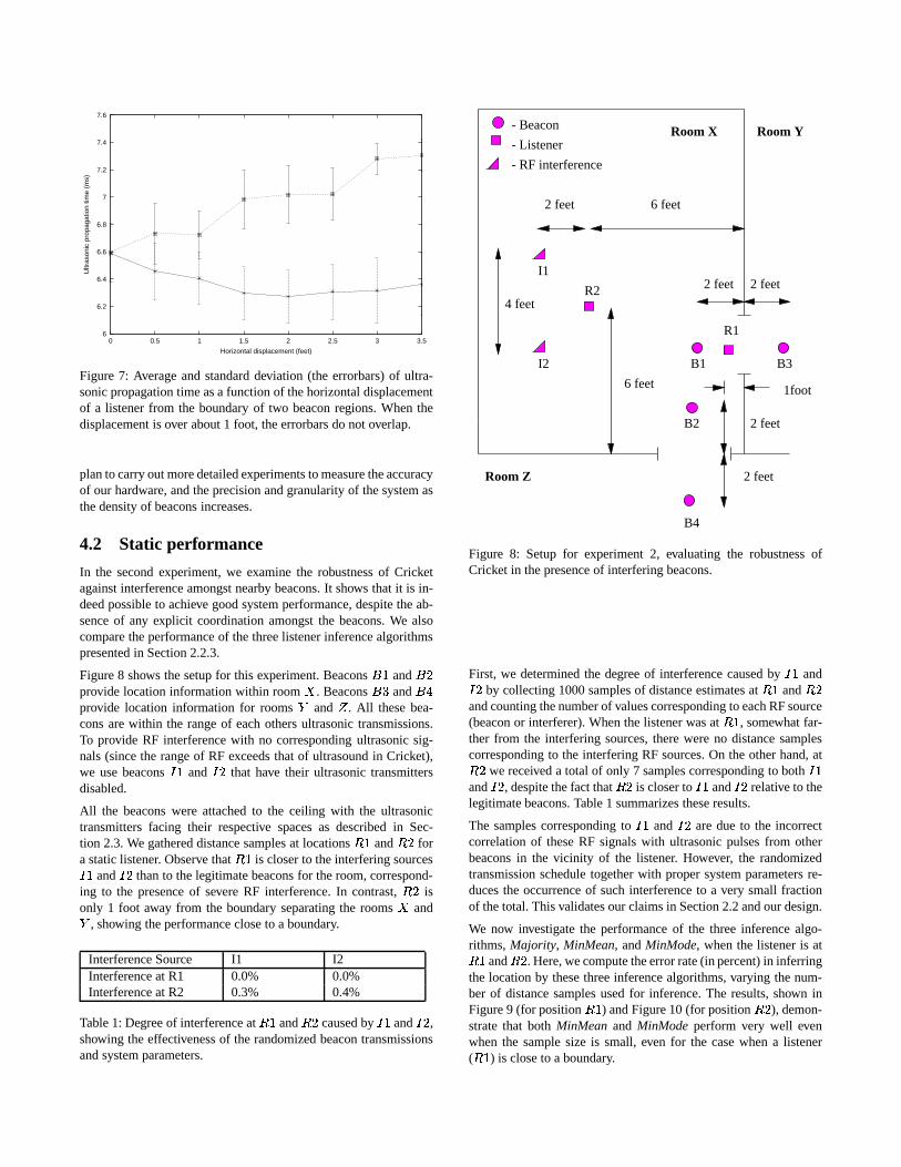
Figure 7: Average and standard deviation (the errorbars) of ultra-sonic propagation time as a function of the horizontal displacementof a listener from the boundary of two beacon regions. When thedisplacement is over about 1 foot, the errorbars do not overlap.
plan to carry out more detailed experiments to measure the accuracyof our hardware, and the precision and granularity of the system asthe density of beacons increases.
4.2 Static performance
In the second experiment, we examine the robustness of Cricketagainst interference amongst nearby beacons. It shows that it is in-deed possible to achieve good system performance, despite the ab-sence of any explicit coordination amongst the beacons. We alsocompare the performance of the three listener inference algorithmspresented in Section 2.2.3.
Figure 8 shows the setup for this experiment. Beacons � � and ��provide location information within room � . Beacons � � and ��provide location information for rooms � and � . All these bea-cons are within the range of each others ultrasonic transmissions.To provide RF interference with no corresponding ultrasonic sig-nals (since the range of RF exceeds that of ultrasound in Cricket),we use beacons � � and � that have their ultrasonic transmittersdisabled.
All the beacons were attached to the ceiling with the ultrasonictransmitters facing their respective spaces as described in Sec-tion 2.3. We gathered distance samples at locations ��� and � fora static listener. Observe that � � is closer to the interfering sources� � and � than to the legitimate beacons for the room, correspond-ing to the presence of severe RF interference. In contrast, � isonly 1 foot away from the boundary separating the rooms � and
� , showing the performance close to a boundary.
Interference Source I1 I2Interference at R1 0.0% 0.0%Interference at R2 0.3% 0.4%
Table 1: Degree of interference at ��� and � caused by � � and � ,showing the effectiveness of the randomized beacon transmissionsand system parameters.
4 feet
2 feet 2 feet
6 feet
I1
I2
2 feet
2 feet
B4
B2
6 feet 1foot
B1 B3
R1
R2
- Listener
- Beacon
- RF interference
2 feet
Room Z
Room X Room Y
Figure 8: Setup for experiment 2, evaluating the robustness ofCricket in the presence of interfering beacons.
First, we determined the degree of interference caused by � � and� by collecting 1000 samples of distance estimates at ��� and �and counting the number of values corresponding to each RF source(beacon or interferer). When the listener was at ��� , somewhat far-ther from the interfering sources, there were no distance samplescorresponding to the interfering RF sources. On the other hand, at� we received a total of only 7 samples corresponding to both � �and � , despite the fact that � is closer to � � and � relative to thelegitimate beacons. Table 1 summarizes these results.
The samples corresponding to � � and � are due to the incorrectcorrelation of these RF signals with ultrasonic pulses from otherbeacons in the vicinity of the listener. However, the randomizedtransmission schedule together with proper system parameters re-duces the occurrence of such interference to a very small fractionof the total. This validates our claims in Section 2.2 and our design.
We now investigate the performance of the three inference algo-rithms, Majority, MinMean, and MinMode, when the listener is at��� and � . Here, we compute the error rate (in percent) in inferringthe location by these three inference algorithms, varying the num-ber of distance samples used for inference. The results, shown inFigure 9 (for position ��� ) and Figure 10 (for position � ), demon-strate that both MinMean and MinMode perform very well evenwhen the sample size is small, even for the case when a listener( ��� ) is close to a boundary.
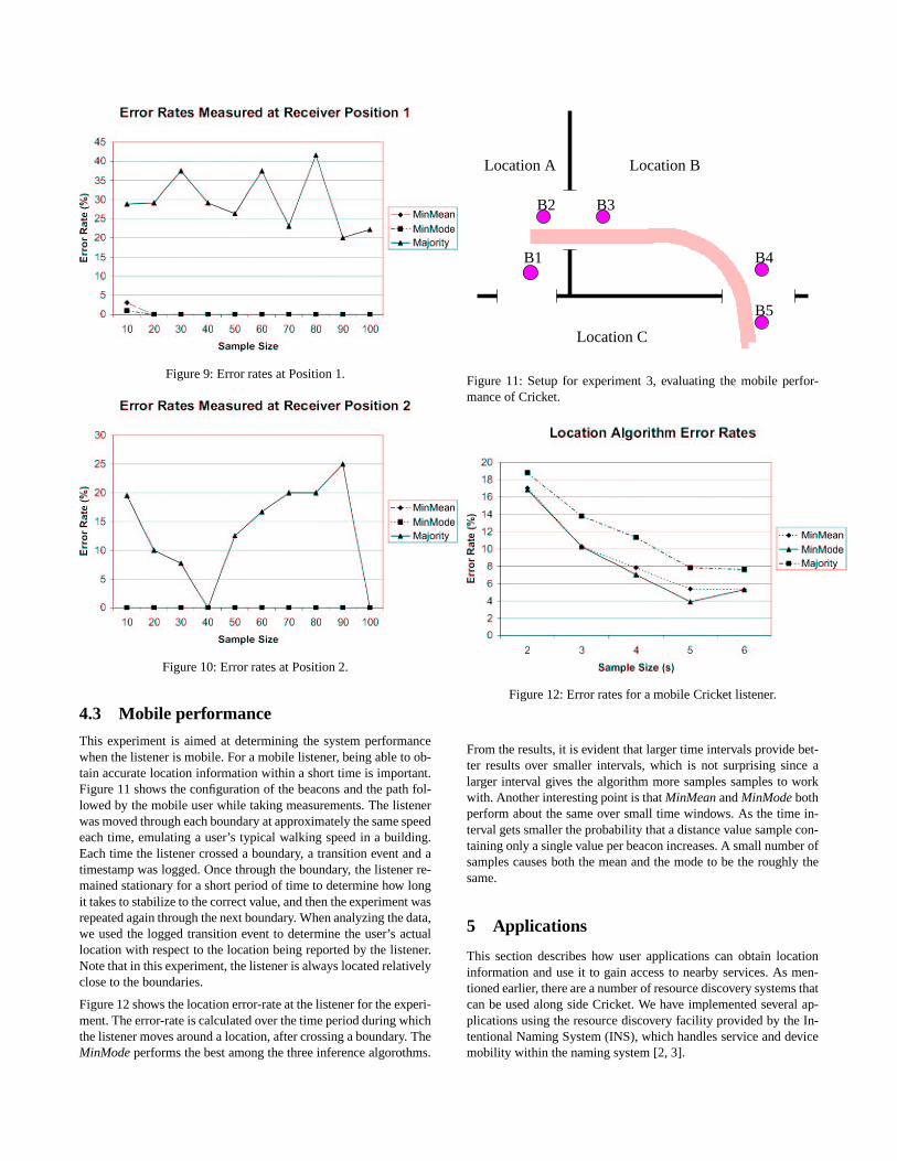
Figure 9: Error rates at Position 1.
Figure 10: Error rates at Position 2.
4.3 Mobile performance
This experiment is aimed at determining the system performancewhen the listener is mobile. For a mobile listener, being able to ob-tain accurate location information within a short time is important.Figure 11 shows the configuration of the beacons and the path fol-lowed by the mobile user while taking measurements. The listenerwas moved through each boundary at approximately the same speedeach time, emulating a user’s typical walking speed in a building.Each time the listener crossed a boundary, a transition event and atimestamp was logged. Once through the boundary, the listener re-mained stationary for a short period of time to determine how longit takes to stabilize to the correct value, and then the experiment wasrepeated again through the next boundary. When analyzing the data,we used the logged transition event to determine the user’s actuallocation with respect to the location being reported by the listener.Note that in this experiment, the listener is always located relativelyclose to the boundaries.
Figure 12 shows the location error-rate at the listener for the experi-ment. The error-rate is calculated over the time period during whichthe listener moves around a location, after crossing a boundary. TheMinMode performs the best among the three inference algorothms.
B1
B2 B3
B5
B4
Location A Location B
Location C
Figure 11: Setup for experiment 3, evaluating the mobile perfor-mance of Cricket.
Figure 12: Error rates for a mobile Cricket listener.
From the results, it is evident that larger time intervals provide bet-ter results over smaller intervals, which is not surprising since alarger interval gives the algorithm more samples samples to workwith. Another interesting point is that MinMean and MinMode bothperform about the same over small time windows. As the time in-terval gets smaller the probability that a distance value sample con-taining only a single value per beacon increases. A small number ofsamples causes both the mean and the mode to be the roughly thesame.
5 Applications
This section describes how user applications can obtain locationinformation and use it to gain access to nearby services. As men-tioned earlier, there are a number of resource discovery systems thatcan be used along side Cricket. We have implemented several ap-plications using the resource discovery facility provided by the In-tentional Naming System (INS), which handles service and devicemobility within the naming system [2, 3].
5.1 Using virtual spaces in INS
INS uses the concept of a virtual space (vspace), which is a col-lection of applications/services that can communicate with eachother [15]. Each vspace has a set of name resolvers that resolvename requests for entities in that vspace; each entity is describedusing an intentional name, which is a hierarchical collection ofapplication-defined attributes and values.
The overhead for creating a vspace in INS is small. For our location-dependent applications, we create a vspace for every location ofinterest (e.g., a room or a floor of a building) and identify it by astring. Each beacon advertises the name of the vspace of the cor-responding location, and each listener uses this name to bootstrapinto its environment by contacting INS and learning about the otherexisting services in that vspace.
Users and devices can also register their intentional names with thevspace for that location, which enables other entities in that vspaceto detect their presence. This way the user can easily determine allthe services that are located in their vspace. A user does not neces-sarily have to be limited to only one vspace at a time, and can selectarbitrary services to use. For example, one vspace can correspondto the set of printers in a building while another corresponds to theservices located on a specific floor. A user can determine the leastloaded printer by querying the printer vspace, or the physically-closest, least-loaded printer by querying the vspace representing theparticular floor of the building.
5.2 Floorplan
The Floorplan is an active map navigation utility that uses Cricketand a map server to present a location-dependent “active” map tothe user, highlighting her location on it as she moves. It also dis-plays the set of services that are located in the vicinity of the user,which are dynamically updated as the user moves. Floorplan loadsmap images from the map server, which also provides the valuesof
�� ��� � coordinate on the map corresponding to the user’s current
vspace position. As the user moves around the building, the listenerinfers its location and asks the map server to provide the location onthe map. Floorplan also learns about various services in the vspace,and contacts those services and downloads a small icon represent-ing each service. These icons are displayed on the map; when theuser clicks on an icon, Floorplan uses INS to download a controlscript or program for the application represented by that icon, andload the controls into a new window so the user can control the ap-plication. Figure 13 shows an active map displayed by Floorplan;we see that the user (represented by the dot) is in room 503. It alsodisplays four services it has found in the environment (space) :anMP3 service (represented by the speaker icon) in room 503, a TVservice (represented by the TV icon) in room 504, and two printers(represented by the printer icons) in room 517. Using this, a userwith no knowledge of her environment or software to control ser-vices within it can bootstrap herself with no manual configuration.
6 Related work
There are various solutions available today for device tracking andlocation discovery. For example, active and passive electromagneticand optical trackers are sometimes used for tracking and taggingobjects. Unfortunately, these tend to be expensive, and the perfor-
mance of electromagnetic trackers is affected by the presence ofmetallic objects in the environment. Furthermore, these productsdo not usually preserve user privacy.
The rest of this section discusses three systems that influenced var-ious aspects of Cricket, and compares their relative benefits andlimitations. Table 2 summarizes the following discussion.
6.1 The Bat system
In the BAT system, various objects within the system are tagged byattaching small wireless transmitters. The location of these trans-mitters are tracked by the system to build a location database ofthese objects [1, 12].
The system consists of a collection of mobile or fixed wirelesstransmitters, a matrix of receiver elements, and a central RF basestation. The wireless transmitter consists of an RF transceiver, sev-eral ultrasonic transmitters, an FPGA, and a microprocessor, andhas a unique ID associated with it. The receiver elements consistof an RF receiver, and an interface for a serial data network. Thereceiver elements are placed on the ceiling of the building, and areconnected together by a serial wire network to form a matrix. Thisnetwork is also connected to a computer, which does all the dataanalysis for tracking the transmitters.
The RF base station orchestrates the activity of transmitters by pe-riodically broadcasting messages addressed to each of them in turn.A transmitter, upon hearing a message addressed to it, sends outan ultrasound pulse. The receiver elements, which also receive theinitial RF signal from the base station, determine the time intervalbetween the receipt of the RF signal and the receipt of the corre-sponding ultrasonic signal, from which they estimate the distance tothe transmitter. These distances are then sent to the computer whichperforms the data analysis. By collecting enough distance readings,it is possible to determine the location of the transmitter with anaccuracy of a few centimeters, and these are keyed by transmitteraddress and stored in the location database.
Bat derives its accuracy from a tightly controlled and centralizedarchitecture that tracks users and objects. In contrast, Cricket ishighly decentralized and there is no central control of any aspectof the system, which preserves user privacy, is simpler, and reducesmanagement cost. The differences in design goals between Bat andCricket lead to radical differences in architecture, although the useof ultrasound and RF is common to both systems.
6.2 The Active Badge system
The Active Badge1 system was a predecessor to the Bat system, andtracks objects in an environment to store in a centralized locationdatabase [19]. Objects are tracked by attaching a badge, which pe-riodically transmits its unique ID using infrared transmitters. Fixedinfrared receivers pick up this information and relay it over a wirednetwork. The walls of the room act as a natural boundary to in-frared signals, thus enabling a receiver to identify badges within itsroom. A particular badge is associated with the fixed location of thereceiver that hears it.
Like the Bat system, the object tracking nature of Active Badge
1Active Badge is a registered trademark of Ing. C. Olivetti & C.,S.p.A.
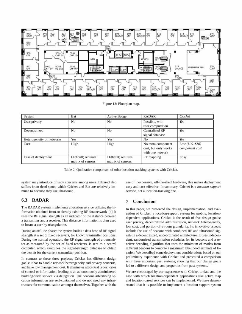
Figure 13: Floorplan map.
System Bat Active Badge RADAR Cricket
User privacy No No Possible, with Yesuser computation
Decentralized No No Centralized RF Yessignal database
Heterogeneity of networks Yes Yes No YesCost High High No extra component Low (U.S. $10)
cost, but only works component costwith one network
Ease of deployment Difficult; requires Difficult; requires RF mapping Easymatrix of sensors matrix of sensors
Table 2: Qualitative comparison of other location-tracking systems with Cricket.
system may introduce privacy concerns among users. Infrared alsosuffers from dead-spots, which Cricket and Bat are relatively im-mune to because they use ultrasound.
6.3 RADAR
The RADAR system implements a location service utilizing the in-formation obtained from an already existing RF data network [4]. Ituses the RF signal strength as an indicator of the distance betweena transmitter and a receiver. This distance information is then usedto locate a user by triangulation.
During an off-line phase; the system builds a data base of RF signalstrength at a set of fixed receivers, for known transmitter positions.During the normal operation, the RF signal strength of a transmit-ter as measured by the set of fixed receivers, is sent to a centralcomputer, which examines the signal-strength database to obtainthe best fit for the current transmitter position.
In contrast to these three projects, Cricket has different designgoals: it has to handle network heterogeneity and privacy concerns,and have low management cost. It eliminates all central repositoriesof control or information, leading to an autonomously administeredbuilding-wide service via delegation. The beacons advertising lo-cation information are self-contained and do not need any infras-tructure for communication amongst themselves. Together with the
use of inexpensive, off-the-shelf hardware, this makes deploymenteasy and cost-effective. In summary, Cricket is a location-supportservice, not a location-tracking one.
7 Conclusion
In this paper, we presented the design, implementation, and eval-uation of Cricket, a location-support system for mobile, location-dependent applications. Cricket is the result of five design goals:user privacy, decentralized administration, network heterogeneity,low cost, and portion-of-a-room granularity. Its innovative aspectsinclude the use of beacons with combined RF and ultrasound sig-nals in a decentralized, uncoordinated architecture. It uses indepen-dent, randomized transmission schedules for its beacons and a re-ceiver decoding algorithm that uses the minimum of modes fromdifferent beacons to compute a maximum likelihood estimate of lo-cation. We described some deployment considerations based on ourpreliminary experience with Cricket and presented a comparisonwith three important past systems, showing that our design goalsled to a different design and properties from past systems.
We are encouraged by our experience with Cricket to date and theease with which location-dependent applications like active mapand location-based services can be implemented. We have demon-strated that it is possible to implement a location-support system
that maintains user privacy and has no centralized control.
Acknowledgements
We thank William Adjie-Winoto, Dave Andersen, Steve Bauer,Dina Katabi, Jinyang Li, Rodrigo Rodrigues, Xiaowei Yang, andthe ACM MOBICOM reviewers for useful comments and sugges-tions that improved the quality of this paper.
References[1] A. HARTER AND A. HOPPER. A New Location Technique
for the Active Office. IEEE Personal Communications 4, 5(October 1997), 43–47.
[2] ADJIE-WINOTO, W. A Self-Configuring Resolver Architec-ture for Resource Discovery and Routing in Device Networks.Master’s thesis, Massachusetts Institute of Technology, May2000.
[3] ADJIE-WINOTO, W., SCHWARTZ, E. AND BALAKRISH-NAN, H. AND LILLEY, J. The design and implementationof an intentional naming system. In Proc. ACM Symposiumon Operating Systems Principles (Kiawah Island, SC, Dec.1999), pp. 186–201.
[4] BAHL, P., AND PADMANABHAN, V. RADAR: An In-Building RF-based User Location and Tracking System. InProc. IEEE INFOCOM (Tel-Aviv, Israel, Mar. 2000).
[5] BANAVAR, G., BECK, J., GLUZBERG, E., MUNSON, J.,SUSSMAN, J., AND ZUKOWSKI, D. An Application Modelfor Pervasive Computing. In Proc. 6th ACM MOBICOM Conf.(Boston, MA, Aug. 2000).
[6] BULUSU, N., HEIDEMANN, J., AND ESTRIN, D. GPS-less Low Cost Outdoor Localization For Very Small Devices.Tech. Rep. 00-729, Computer Science Department, Universityof Southern California, Apr. 2000.
[7] CHAKRABORTY, A. A Distributed Architecture for Mo-bile, Location-Dependent Applications. Master’s thesis, Mas-sachusetts Institute of Technology, May 2000.
[8] CZERWINSKI, S., ZHAO, B., HODES, T., JOSEPH, A., AND
KATZ, R. An Architecture for a Secure Service DiscoveryService. In Proc. 5th ACM MOBICOM Conf. (Seattle, WA,Aug. 1999), pp. 24–35.
[9] DERTOUZOS, M. The Future of Computing. Scientific Amer-ican (Aug. 1999). Available from http://www.sciam.com/1999/0899issue/0899dertouzos.html.
[10] FEDERAL COMMUNICATIONS COMMISION. Understandingthe FCC regulations for low-power, non-licensed transmitters,Feb. 1996.
[11] GETTING, I. The Global Positioning System. IEEE Spectrum30, 12 (December 1993), 36–47.
[12] HARTER, A., HOPPER, A., STEGGLES, P., WARD, A., AND
WEBSTER, P. The Anatomy of a Context-Aware Applica-tion. In Proc. 5th ACM MOBICOM Conf. (Seattle, WA, Aug.1999).
[13] Hertz Services: Hertz NeverLost. http://www.hertz.com/serv/us/prod_lost.html, 2000.
[14] Jini (TM). http://java.sun.com/products/jini/, 1998.
[15] LILLEY, J. Scalability in an Intentional Naming System. Mas-ter’s thesis, Massachusetts Institute of Technology, May 2000.
[16] Oxygen home page. http://oxygen.lcs.mit.edu/.
[17] Ultrasonics and robotics. http://www.seattlerobotics.org/encoder/may97/sonar2.html, May 1997.
[18] VEIZADES, J., GUTTMAN, E., PERKINS, C., AND KAPLAN,S. Service Location Protocol, June 1997. RFC 2165 (http://www.ietf.org/rfc/rfc2165.txt).
[19] WANT, R., HOPPER, A., FALCAO, V., AND GIBBONS, J.The Active Badge Location System. ACM Transactions onInformation Systems 10, 1 (January 1992), 91–102.
[20] WEISER, M. The computer for the 21st century. ScientificAmerican (September 1991).
[21] X-10 home page. http://www.x10.com/homepage.htm.