TENDER DOCUMENTS FOR - TPCODL : User Authentication
172
Page 1 of 172 TENDER DOCUMENTS FOR Re-construction and shifting of 33KV Line with UG Cable (CRRI-I & CRRI – II 33KV feeder) existing inside the premises of STP-II, Matgajpur of OISIP due to construction of Sewage treatment plant under CMC, Cuttack Under CDD No – II, Cuttack CENTRAL ELECTRICITY SUPPLY UTILITY OF ODISHA (CESU) OFFICE OF THE SUPERINTENDING ENGINEER ELECTRICAL CIRCLE, CUTTACK TELEPHONE: (0671) – 2324223 TENDER SPECIFICATION NO: 05 / 19-20
-
Upload
khangminh22 -
Category
Documents
-
view
1 -
download
0
Transcript of TENDER DOCUMENTS FOR - TPCODL : User Authentication

Page 1 of 172
TENDER DOCUMENTS FOR
Re-construction and shifting of 33KV Line with UG Cable (CRRI-I & CRRI – II
33KV feeder) existing inside the premises of STP-II, Matgajpur of OISIP due
to construction of Sewage treatment plant under CMC, Cuttack
Under CDD No – II, Cuttack
CENTRAL ELECTRICITY SUPPLY UTILITY OF ODISHA (CESU)
OFFICE OF THE SUPERINTENDING ENGINEER
ELECTRICAL CIRCLE, CUTTACK
TELEPHONE: (0671) – 2324223
TENDER SPECIFICATION NO: 05 / 19-20

Page 2 of 172
CENTRAL ELECTRICITY SUPPLY UTILITY OF ODISHA (CESU)
OFFICE OF THE SUPERINTENDING ENGINEER ELECTRICAL CIRCLE, CUTTACK
TELEPHONE: (0671) - 2324223
Tender Specification No : 05 /19-20
Tender Notice No. 668 dtd.13/02/2020
BIDDING DOCUMENTS

Page 3 of 172
CENTRAL ELECTRICITY SUPPLY UTILITY OF ODISHA (CESU)
OFFICE OF THE SUPERINTENDING ENGINEER ELECTRICAL CIRCLE, CUTTACK
TELEPHONE: (0671) - 2324223
TENDER NOTICE NO: 668 / Dtd.13/02/2020 for Re-construction and shifting of 33KV
Line with UG Cable (CRRI-I & CRRI – II 33KV feeder) existing inside the premises of STP-II,
Matgajpur of OISIP due to construction of Sewage treatment plant under CMC, Cuttack under
CDD No – II, Cuttack on partial turnkey basis.
CONTENTS SECTION No DESCRIPTION PAGE NO.
PART-I
SECTION-I : INVITATION FOR BIDS (IFB) 5-9
SECTION-II : GENERAL TERMS AND CONDITIONS OF 10-27 CONTRACT (GTCC)
SECTION-III : PRICE SCHEDULE FORMAT 28-33
SECTION-IV : BID PROPOSAL 34-39
ANEXURE-I : Bid Proposal Letter & Undertaking 40
ANNEXURE-II Declaration Form 41
ANNEXURE-III CPBG Format 42-44
ANNEXURE-IV Bank Guarantee for Advance Payment 45-47
ANNEXURE-V Power of Attorney for Joint Venture 48-49
ANNEXURE-VI Joint Venture Agreement 50-53
ANNEXURE-VII (A&B) Letter of Compliance 54-59
ANNEXURE-VIII Commercial Deviations 60
ANNEXURE-IX Technical Deviations 61
ANNEXURE-X Additional Information 62
ANNEXURE-XI Bought Out & Sub Contract 63
ANNEXURE-XII Work Completion Schedule 64
ANNEXURE-XIII Check List 65
ANNEXURE-XIV& XV Proforma for Indemnity Bond 66-71
ANNEXURE-XVI Self Declaration Form 72
SECTION-V : Technical Specification 73-173

Page 4 of 172
TENDER CALL NOTICE
CENTRAL ELECTRICITY SUPPLY UTILITY OF ODISHA (CESU)
OFFICE OF THE SUPERINTENDING ENGINEER ELECTRICAL CIRCLE, CUTTACK
TELEPHONE: (0671) - 2324223
Central Electricity Supply Utility of Odisha (CESU) invites bids from reputed firms to be
engaged as an Executor on turnkey basis in two-part bidding system for the following works
Brief Description of Work
Estimated Cost (In
Rs.)
Earnest Money Deposit
(In Rs.)
Last Date/ time for
Submission of bids
Date and time of
Opening of Bid
Non refundable cost of Bid
document in
1 2 3 4 5 6
Re-construction and shifting of 33KV Line with UG Cable (CRRI-I & CRRI – II 33KV feeder) existing inside the premises of STP-II, Matgajpur of OISIP due to construction of Sewage treatment plant under CMC, Cuttack under CDD No – II, Cuttack.
1,63,88,911/-
1,64,000/-
1.00PM of
02.03.2020
3.30PM of
02.03.2020
15,000/- +
1,800/- (12%
GST)
Downloading of tender documents starts from Date 17/02/2020
Pre-bid meeting will be held in the office chamber on Date 19/02/2020 at 11.30 A.M at
O/o Superintending Engineer, Electrical Circle, Cuttack.
For details please visit our web site : www. cescoorissa.com/ www.cesuodisha.com on or after
Date 17/02/2020.
The prospective bidders are requested to follow the above CESU website only time to
time for any Clarification/ Corrigendum/ Addendum against the referred Tender.
The authority reserves the right to accept or reject any or whole of the offers without
assigning any reason thereof.

Page 5 of 172
PART- I
SECTION – I
INVITATION FOR BIDS (IFB)

Page 6 of 172
1.0 CESU invites sealed tenders in two part bidding system from reputed Electrical
Contractors with required HT license, either in individual capacity or as part of a joint
venture agreement.
a) Consortium for carrying out various Electrical Installation works on ‘Partial
Turnkey’ basis in the jurisdiction of their respective licensed area under deposit
work. The bidder must fulfill all the qualifying requirements as specified in clause
2.0 stated below. The sealed envelopes shall be duly super scribed as “TENDER
NOTICE No: 05/19-20.
Brief Description of Work
Estimated Cost (In Rs.)
Earnest Money
Deposit (In
Rs.)
Last Date/ time for Submission
of bids
Date and time of Opening of
Bid
Non refundable cost of Bid
document in
1 2 3 4 5 6
Re-construction and shifting of 33KV Line with UG Cable (CRRI-I & CRRI – II 33KV feeder) existing inside the premises of STP-II, Matgajpur of OISIP due to construction of Sewage treatment plant under CMC, Cuttack under CDD No – II, Cuttack.
1,63,88,911/- 1,64,000/- 1.00PM of
02.03.2020
3.30PM of
02.03.2020
15,000/- +
1,800/- (12%
GST)
2.0 Bidders to be considered as eligible for the bid should meet the following Qualifications; Bidder must quote for the complete package.
Bidder should have installed and commissioned at least following quantum of works
as specified under the bid for which the bidder is submitting his bid during the last three
financial years preceding to the year of tender notification i.e. FY 2016-17, FY 2017-18 and
FY 2018-19. Bidder must enclose copies of the relevant Work Orders along with Client Certified
copies of Final Invoices and/or Performance Certificates duly signed by the competent authority
of the client and/or Final Inspection Certificate issued by Electrical Inspector in proof of having
executed the desired quantum works during the last three financial years.
Bidders must have experience of the following works:-
a) Construction of 6Pole/4Pole structure – 1No.
b) Construction of 11KV/33KV OH line -0.5Km
c) Laying of 11KV/33KV XLPE UG Cable through open trench method – 0.5Km .
d) Laying of 11KV/33KV XLPE UG Cable through HDD method– 50mtrs.

Page 7 of 172
a. Average Annual Turnover during the last three financial years preceding to
the year of tender notification should be equal to or more than the estimated
cost of the bid for which the bidder has submitted his bid. The bidder shall furnish
audited accounts for the last three years i.e. FY 2016-17, FY 2017-18 & FY 2018-19
evidencing their turnover requirement.
b. Bidder shall be financially sound and stable having liquid assets as stated in the enclosed
format and/or access to credit facility of not less than one fifth of estimated cost of
the Bid for which he has submitted the bid. Bidder shall furnish the documentary evidence
to establish the financial soundness. So, to access this, Bidders are required to
furnish liquid assets as on 31.01.2020 certified by their concerned Bank in
bank letter head only. (Ref Annexure- VII)
c. Two or more like minded contractor(s) and/or manufacturer(s) of electrical items, and /or
firms having above work experience which are under scope of supply & Erection of the
contractor as per this tender specification, may form a joint venture/ consortium, may Tie
up and make agreement amongst themselves and apply against this tender specification,
provided they qualify the criteria. However, the tie up partner showing their experience
should have valid HT electrical license. The sample format of joint venture / consortium
agreement is enclosed at Section – IV of this tender specification as Annexure - VI.
d. If the bidder is a joint venture / consortium, they shall comply the qualifying criteria as
follows:
At least one partner shall have the stipulated previous works experience for similar
quantity of completed works as stated in the qualifying criteria with valid electrical HT
license.
If the work experience of one partner is not meeting the entire qualifying criteria, the
item wise field experience of the other partner(s) specified in the scope of work shall be
added for qualifying the bid in total. However item wise fractional work experience shall
not be summed up for consideration for any single item of the scope.
The partner (lead or JV partner) showing their experience should have valid HT
electrical license.
However, the annual turnover and liquidity figures of all partners shall be added
together to determine the qualifying criteria in case of the joint venture / consortium
e. One of the partners shall be nominated as Lead Partner and the lead partner shall be
authorized to incur liabilities and receive instructions for and on behalf of all partners of the
joint venture / consortium and entire execution of the contract including receipt of payments
shall be done exclusively through the lead partner. This authorization shall be evidenced by
submitting by a Power of Attorney signed by legally authorized signatories of all partners.

Page 8 of 172
f. All partners of joint venture / consortium shall be liable jointly and severally for the
execution of contract in accordance with the contract terms and a copy of the agreement
entered into by the joint venture / consortium partners having such a provision shall be
submitted with the Bid. A statement to this effect shall be included in the authorization
mentioned as above as well as in the Bid form and in Contract form (in case of a successful
bid).
g. In addition to above the bidder should submit the following documents in part-I bid as
qualifying terms.
• Valid electrical HT license for electrical works.
• EPF & ESI registration
• PAN & GSTIN with registration certificate
h. The bidders who have earlier failed to execute the work order(s) of the CESU shall not be
eligible to participate in this tender.
i. CESU reserves the right to waive minor deviation, if they do not materially affect the
capacity of the bidder to perform the contract.
3.0 Bids specification document can be obtained from the office of the undersigned on payment
of Rs.15,000/- towards non-refundable cost of bid documents plus 12% GST (Total Rs.
16,800/-) through Cash / Bank (DD) drawn in favour of Superintending Engineer,
Electrical Circle CESU, Cuttack payable at “ Cuttack ” , during office hours.
4.0 The tender documents can also be downloaded from CESU websites www.cesuodisha.com.
In case tender papers are downloaded from these websites, then the bidder has to enclose a
Demand Draft drawn on any scheduled bank in favour of Superintending Engineer,
Electrical Circle CESU Cuttack payable at “Cuttack ”, covering the cost of bid
documents as stated above in a separate envelope with suitable superscription “Cost of Bid
Documents : Tender Notice Ref : 05/19-20 This envelope should accompany the Bid
Documents. Each and every documents / papers submitted by the bidder must be containing
page no and signed by the bidder with his company seal in each pages and certification in the
last page the total no’s of pages submitted by him.
5.0 The Bids shall be submitted and received in the office of the undersigned on all office
working days up to 1.00 P.M of Dt 02.03.2020 In the event the date of opening is a holiday,
the next working day shall be treated as the date of opening. A pre-bid meeting will be
held on Date 19.02.2020 at 11.30 A.M in the office chamber of Superintending Engineer,
Electrical Circle Cuttack for giving clarifications, if any, on the bid documents to the
prospective bidders who may choose to attend the meeting as detailed in the Bid
document.

Page 9 of 172
6.0 Part-I of the bid (Technical Bid) will be opened on Date 02.03.2020 at 3.30 P.M as
indicated above, in the presence of the authorized representatives of the Bidders. Further
the authorized representatives of the bidders have to produce/submit the authorization
letter, other wise he/she will not to be entertained in the room during the time of
opening of tender. Bidders shall depute only one representative to attend pre bid meeting
and tender opening if they wish to be represented. The undersigned reserves the right to
reject any or all tenders if the situations so warrants.
7.0 All correspondence with regard to the above shall be made to the following address :
O/O the Superintending Engineer
Electrical Circle, CESU, Cuttack
Ph – 0671-2324223

Page 10 of 172
SECTION – II
GENERAL TERMS AND CONDITIONS OF CONTRACT (GTCC)

Page 11 of 172
1.0 GENERAL: -
CESU hereinafter referred to as the “Purchaser” is desirous of execution for Re-construction
and shifting of 33KV Line with UG Cable (CRRI-I & CRRI – II 33KV feeder) existing
inside the premises of STP-II, Matgajpur of OISIP due to construction of Sewage treatment
plant under CMC, Cuttack under CDD No – II, Cuttack on partial turnkey basis as per the
Scope detailed in the Bid Documents.
2.0 SCOPE OF WORK: -
The scope shall include supply of all the materials & equipments and installation / erection /
commissioning & dismantling to complete the works.
2.01 THE DETAIL SCOPES OF THE WORK:
The detail scopes of work are available at Section – I (General), Technical Specification
of the Tender document.
DEFINITION OF TERMS
i. The ‘Contract’ means the agreement entered into between the Purchaser and the Contractor
as per the Contract Agreement signed by the parties, including all attachments and
appendices there to and all documents incorporated by reference therein.
ii. ‘Purchaser’ shall mean CESU and shall include its legal representatives, successors and
designated officers/Engineers.
iii. ‘Contractor’ shall mean the Bidder whose bid will be accepted by the Purchaser for the
award of the Works and shall include such successful Bidder’s legal representatives,
successors and permitted assigns.
iv. ‘Sub-Contractor’ shall mean the person named in the Contract for any part of the works or
any person to whom any part of the Contract has been sublet by the contractor with the
consent in writing of the Engineer and will include the legal representatives, successors and
permitted assigns of such person.
v. ‘Engineer in Charge’ shall mean the officer appointed in writing by the Purchaser to act as
Engineer from time to time for the purpose of the Contract.
vi. ‘Specifications’ shall mean the specifications and Bidding Document forming a part of the
Contract and such other schedules and drawings as may be mutually agreed upon.
vii. ‘Site’ shall mean and include the land and other places on, into or through which the works
and the related facilities are to be erected or installed and any adjacent land, paths, street or
reservoir which may be allocated or used by the Purchaser or Contractor in the performance
of the Contract.
viii. ‘Inspector’ shall mean the Purchaser or any person nominated by the Purchaser from time
to time, to inspect the equipment; stores or Works under the Contract and/or the duly
authorized representative of the Purchaser.
ix. ‘Notice of Award of Contract’/ ‘Letter of Award’ shall mean the official notice issued by
the Purchaser notifying the Contractor that his bid has been accepted.
x. ‘Date of Contract’ shall mean the date on which notice of Award of Contract/ Letter of

Page 12 of 172
Award has been issued.
xi. ‘Performance and Guarantee Tests’, shall mean all operational checks and tests required to
determine and demonstrate capacity, efficiency, and operating characteristics as specified in
the Contract Documents.
xii. The term ‘Final Acceptance’/ ‘Taking Over’ shall mean the Purchaser’s written acceptance of
the works performed under the Contract, after successful commissioning/ completion of
Performance and Guarantee Tests, as specified in the accompanying Technical Specifications
or otherwise agreed in the contract.
xiii. ‘Commercial Operation’ shall mean the condition of operation in which the complete
equipment covered under the Contract is officially declared by the Purchaser to be available
for continuous operation at different loads up to and including rated capacity. Such
declaration by the Purchaser, however, shall not relieve or prejudice the Contractor of any of
his obligations under the Contract.
xiv. Words imparting ‘Person’ shall include firms, companies, corporations and associations or
bodies of individuals, whether incorporated or not.
xv. Terms and expressions not herein defined shall have the same meaning as are assigned to
them in the Indian Sale of goods Act (1930), failing that in the Indian Contract Act (1872) and
failing that in the General Clauses Act (1897) including amendments thereof, if any.
xvi. In addition to the above the following definition shall also apply
a. ‘All equipment and materials’ to be supplied shall also mean ‘Goods’
b. ‘Constructed’ shall also mean erected and installed.
c. ‘Contract Performance Guarantee’ shall also mean ‘Contract Performance Security’.
4.0 SUBMISSION OF TENDER: -
Sealed tenders in Two parts, each complete in all respects in the manner hereinafter specified
are to be submitted to Superintending Engineer (Electrical), Electrical Circle CESU
Cuttack, Badambadi, Cuttack-12 on or before the date and time specified in the notice
inviting the tenders. Bids shall be submitted as per format provided in Section – III & IV. Bid
shall be submitted in double sealed envelopes superscripted on the covers the tender
specification number and the due date of opening of the bids on the right hand top side of the
envelop. On the left top side of the price bid original/ duplicate as is relevant shall be written.
The tenders are required to be submitted in Two Parts each in separate double sealed covers.
a. Part - I : Superscribed as “Technical and commercial bid ” shall contain EMD, Bid
Documents cost and Techno commercial documents.
b. Part - II, Superscribed as “Price Bid”. The Part - II should contain only Price bid
(both hard and Soft copy) of participation in duplicate in separate envelope.
Fax and Telegraphic tenders shall not be accepted.
Receipt of bids / revised bids after the cut off time and date as specified in the Tender
specification shall not be permitted and such bids shall be rejected outright. The Purchaser shall

Page 13 of 172
not be responsible for any delay in transit in post / courier etc. in this regard.
Regarding less quoting of price bid w.r.t tender estimated cost as per amendment of OPWD
code:
Additional Performance Security shall be obtained from the successful bidder who has quoted
less bid price/ rate than the estimated cost put to the tender. In such an event only the successful
bidder who has quoted less bid price shall have to furnish the exact amount of differential cost i.e.
estimated cost put to tender minus the quoted amount as Additional Performance Security in
shape of Demand draft / Term Deposit Receipt pledged in favour of Superintending
Engineer, Electrical Circle CESU Cuttack with validity same as the validity of CPBG for
this tender within 7 (Seven) days from issuance of letter on L1 bidder before placement of
work order, otherwise the bid shall be cancelled and security deposit (EMD) shall be
forfeited and other consequential action may be taken against the bidder.
This security amount shall be released only after expire of validity of CPBG as mentioned in
Clause 29.04 of GCC. The aforesaid amount shall not carry any interest payable to the bidder.
5.0 VALIDITY:-
The offer shall be valid for a period not less than Six months from the date of bid opening.
6.0 PRICE: -
Bidders are required to quote firm price as per the prescribed format enclosed in, Section –
VII of Bid Proposal Sheets. The quoted price shall be firm and inclusive of all taxes, duties,
freight & insurance and other levies, if any. CESU shall not be liable to pay anything extra over
and above the quoted price. However, any variation in taxes & duties shall be borne by the bidder
during the period of contract including extension period.
7.0 RECEIPT AND OPENING OF THE BID: -
Bids as described under clause 4.0 shall be received in the office of the Purchaser and
shall be opened on the scheduled date and time. The Purchaser’s authorized representatives
shall open bids in the presence of Bidders’ representatives on the date and time for opening of
bids as specified in the Invitation for Bid or in case any extension has been given thereto, on
the extended bid opening date and time notified.
Maximum one representative for each bidder shall be allowed to witness the opening of
bids. The representative must produce suitable authorization in this regard to be eligible to
witness the bid opening on behalf of the bidder. Bidders’ representatives who are present shall
sign in a register evidencing their attendance.
The Bidders’ names, bid prices, modifications, bid withdrawals and the presence or
absence of the requisite bid guarantee and such other details as the Purchaser, at its discretion,
may consider appropriate will be announced at the opening. No electronic recording devices

Page 14 of 172
will be permitted during bid opening.
Information relating to the examination, clarification, evaluation and comparison of
Bids and recommendations for the award of a contract shall not be disclosed to Bidders or any
other persons not officially concerned with such process. Any effort by a Bidder to influence
the Purchaser's processing of Bids or award decisions may result in the rejection of the Bidder's
Bid.
8.0 EVALUATION OF BIDS & AWARD OF CONTRACT:
To assist in the examination, evaluation and comparison of Bids, the Purchaser may, at
its discretion, ask the Bidder for a clarification of its Bid. All responses to requests for
clarification shall be in writing and no change in the price or substance of the Bid shall be
sought, offered or permitted.
Purchaser will examine the Bids to determine whether they are complete, whether any
computational errors have been made, whether required sureties have been furnished, whether
the documents have been properly signed, and whether the Bids are generally in order.
Arithmetical errors will be rectified on the following basis. If there is a discrepancy
between the unit price and the total price per item that is obtained by multiplying the unit price
and quantity, the unit price shall prevail and the total price per item will be corrected. If there is
a discrepancy between the Total Amount and the sum of the total price per item, the sum of the
total price per item shall prevail and the Total Amount will be corrected. In the event of
multiple unit supply rates for the same item is found, then the lowest quoted supply rate for the
same item shall be considered.
Prior to the detailed evaluation, Purchaser will determine the substantial responsiveness
of each Bid to the Bidding Documents including production capability and acceptable quality
of the Goods offered. A substantially responsive Bid is one, which conforms to all the terms
and conditions of the Bidding Documents without material deviation.
The Purchaser's evaluation of a Bid will take into account, in addition to the Bid price,
the following factors, in the manner and to the extent indicated in this Clause:
• Work Schedule
• Deviations from Bidding Documents
• Compliance of the criteria in Technical Bid
• If the quoted/evaluated rate of the bidder is less than 14.99% (without round off ) of
the tender estimated cost, then such a bid shall be rejected and tender shall be finalized
basing on merits of rest bids i.e. for Rs. 100 estimated cost lowest accepted quoted/
evaluated price is Rs. 85.01.
The Purchaser will award the Contract to the successful Bidder whose Bid has been
determined to be the lowest - evaluated responsive Bid based in the price quoted in the price
bid in their offered BOQ and services, when the lowest bidders is not ready and/or capable
to undertake the entire work envisaged, then the Purchaser may explore the possibility of

Page 15 of 172
the execution of works through other bidders if they are willing to execute at L1 rate.
Such exploration shall be carried out in a sequential order starting with L2 bidder then with
L3 bidder and so on.
9.0 EARNEST MONEY DEPOSIT (EMD):-
The Tender must be accompanied by Earnest Money Deposit (1% of the tendered
value) in shape of account payee Bank Draft drawn on any scheduled bank in favour of
Superintending Engineer, Electrical Circle CESU Cuttack, payable at Cuttack.
EMD shall be, as mentioned in the tender notice of the bid for which the bidder has
submitted the bid. Bids without EM deposit will be rejected out rightly.
No adjustment of any previous deposit or any amount payable from Purchaser shall be
entertained for EMD. EMD amount so submitted shall not carry any interest payable to the
bidder.
The Earnest Money so deposited shall be forfeited:
• if the Bidder:
Withdraws its bid during the period of bid validity specified by the Bidder in the Bid Form;
or
The successful Bidder, Fails to sign the Contract, or to execute minimum 10% of the work
order value which is not sufficient to cover CPBG amount.
The EMD of unsuccessful bidders shall be returned within 30 days from the date of
finalization of the order. The EMD of successful bidder shall be returned after acceptance
and approval of CPBG / deduction of CPBG amount in one stroke from 1st R.A bill.
10.0 PURCHASER’S RIGHT TO VARY QUANTITIES AT TIME OF AWARD:
CESU reserves the right to increase or decrease the quantity of goods/services specified in
the Schedule of Requirement during execution of Contract limiting to ±20% of Contract
price without any change in unit price ( as per the Price Schedule & Bills Of Materials) or
other terms and conditions. However, quantity of individual items required may vary
without any limitation.
11.0 INSPECTION AND TESTING:-
The Engineer-in-charge shall be entitled at all reasonable times during manufacture /
installation to inspect examine and test the materials at the contractor’s premises / erection
site about workmanship of the materials to be supplied under this contract. If the said

Page 16 of 172
materials are being manufactured in other premises, the contractor shall provide unhindered
clearance, giving full rights to the purchaser to inspect, examine and test as if the materials
were being manufactured in his premises. Such inspection / examination and testing shall
not relieve the contractor of his obligations to execute the contract by letter and spirit. The
contractor shall give the purchaser advance notice in writing of the Date and the Place at
which the materials will be ready for testing. The inspecting officer for the entire work shall
be the Purchaser representative for the concerned site. Inspection of all the materials will be
completed within maximum two lots. The contractor shall ensure that all the inspected
materials along with seal and intact at site and the same will be again cross checked and
certified in the presence of project in charge.
Before issuing of the purchase order to any manufacturer for purchase of materials by
the executants the GTP of all materials are to be submitted to CGM(Tech), CESU, BBSR after
due verification by EE(El) CDD-II, Cuttack/ EE(El) E& MR Division, Cuttack and SE(El) EC
Cuttack, for necessary approval at his end.
The contractor shall give the owner at least 15days prior advance notice in writing of
the Date and the Place at which the materials will be ready for testing as per the approved
GTP. The inspecting officer for the entire work shall be the Purchaser representative for the
concerned site.
Inspection of all the materials will be completed within maximum two lots. The
contractor shall submit the inspection call to Superintending Engineer (Elect), EC, Cuttack
which will be further forwarded to CGM(Tech) CESU, BBSR for deputation of officers for pre
dispatch inspection of the materials at the factory premises. The required DI shall be issued by
Superintending Engineer (Elect), EC, Cuttack after getting approval from CGM(Tech), CESU,
BBSR. On issue of dispatch clearance the contractor shall lift the materials. The contractor shall
ensure that all the inspected materials along with seal and intact and the same will be again cross
checked and certified in the presence of project in charge at the site.
11.1 INSPECTION OF COMPLETED WORK – The work after due completion under the
supervision of “The Engineer in Charge” shall be inspected by himself jointly with the
competent authority of Electrical Inspectorate, Govt. of Odisha. All arrangement for this
inspection shall be the responsibility of the Contractor. However, such Inspection and
Testing shall not relieve Contractor of his obligation to execute the contract by letter of
spirit. Any defects pointed out by the Electrical Inspector, shall be corrected or attended by
the bidder /subcontractor at his own cost.
12.0 COMPLETION AND COMPLETENESS OF THE EQUIPMENT :- Time being the
essence of the contract; the work shall be completed within 3 ( Three ) Months
maximum from the date of issue of work order including supply of all the materials,
erection, Testing, dismantling, Electrical inspection & commissioning.
The work shall be treated as complete item wise when one item shall be complete in all

Page 17 of 172
respects with all mountings, fixtures and standard accessories which are normally supplied
even though not specifically detailed in the specification. No extra payment shall be payable
for such mounting, fittings, fixtures and accessories which are needed for safe operations of
the equipment as required by applicable code of the country though this might not have
included in the contract.
All similar components and/or parts of similar equipment supplied shall be inter-
changeable with one another. Various equipments supplied under this contract shall be subject
to Purchaser’s approval.
Purchaser however reserves the right to re-schedule the completion period, if required.
13.0 REJECTION OF MATERIALS : -
In the event of the materials supplied by the contractor and/or the installation works are found
to be defective in quality and the workmanship is poor or otherwise not in conformity with the
requirements of the contract specification as per section-V (Technical specification),
Purchaser shall reject such materials / services and ask the contractor in writing to replace /
rectify the defects. The contractor on receipt of such notification shall rectify or replace the
defective materials and/or re-install the work already executed, free of cost to the Purchaser. If
the contactor fails to do so the Purchaser may at his option take the following actions which
could be on concurrent basis.
• Replace or rectify such defective materials and recover the extra cost so involved
plus 25% from the Contractor
• Terminate the contract for balance supply and erection with enforcement of penalty
as per contract.
• Acquire the defective materials at reduced price considered acceptable under the
circumstances.
• Forfeit the Contract Performance Bank Guarantee.
14.0 EXPERIENCE OF BIDDERS : -
The bidders are required to furnish information regarding their experience on the following
aspects as per format provided in Section – IV, Annexure VII (A) & (B):
i) Description of similar type of work executed during the last three FY years i.e. FY 2016-
17, FY 2017-18 & FY 2018-19 with the name(s) of the party(s) to whom / where supplies
/ erection were made.
ii) Work orders details (W.O No. and date only) executed during the last three years along
with Electrical inspection report copies and copies of user’s completion / performance
certificate.
Bids may not be considered if the past performance is found to be un-satisfactory.
15.0 DEVIATION FROM SPECIFICATION: -
The bidders are requested to study the specification and the attached drawings thoroughly

Page 18 of 172
before tendering so that if they make any deviations, the same are prominently brought on a
separate sheet under the headings “Deviations” as per formats provided under Section IV,
Annexure – VIII & IX. All such deviations to the technical & commercial terms of the
specification shall be indicated in a separate list as indicated above. In absence of such
deviation schedule, it will be presumed that the bidder has accepted all the conditions
stipulated in the tender specification, not withstanding any deviations mentioned elsewhere in
the Bid. However the acceptance of deviation is not binding on the Purchaser.
16.0 CONTRACTOR TO INFORM HIMSELF FULLY: -
The contractor shall examine the instructions, general conditions of the contract,
specifications and the schedule of quantity and delivery to satisfy himself as to all the terms
and conditions and circumstances affecting the contract price. He shall quote prices
according to his own judgment and shall understand that no additional cost except as quoted
shall only be considered.
17.0 PATENT RIGHT: -
The contractor shall indemnify the purchaser against all claims, actions, suits and
proceedings for the alleged infringement any patent design or copy right protected either in
country of origin or in India by the use of any equipment supplied by the contractor but such
indemnity shall not cover any use of the equipment other than for the purpose indicated by
or reasonable to be informed from the specification.
18.0 GUARANTEE PERIOD: -
The materials to be supplied by the contractor shall be guaranteed for satisfactory operation
against defects in design and workmanship for a period of 24 months from the date of
handing over the completed installations.
The above guarantee certificate shall be furnished in triplicate to the Purchaser for his
approval. Any defects noticed during the above period should be rectified by the Contractor
free of cost to the Utility provided such defects are due to faulty design, bad workmanship
or bad materials used on receipt of written notice from the Purchaser.
19.0 PENALTY FOR DELAY IN COMPLETION OF CONTRACT: -
If the contractor fails to complete the works by the scheduled period or any extension
granted thereby, the contractor shall be liable for deduction of penalty amounting to 0.5%
(half percent) of the contract price per week of un-finished works subject to the maximum
of 5% (five percent) of the total contract price and subject to force majeure conditions.
Penalty amount can be realized from the proceeds of the Contract Performance Bank
Guarantee, if the situation so warrants.
Extension of completion period could be with / without levy of penalty with the discretion
of purchaser.

Page 19 of 172
20.0 RIGHT OF WAY :
Right of way issues, if any, arising during execution of the works shall have no liability of
CESU. These issues shall be settled at the sole discretion of the Contractor with
compensation (if any). CESU shall however extend all possible help to the Contractor
including discussion with the local authorities for early resolution of these issues.
21.0 CONTRACTOR’S DEFAULT:
If the Contractor neglects to execute the works with due diligence and expedition or refuses
or neglects to comply with any reasonable order given to him, in writing by the Engineer in
connection with the works or contravenes the provisions or the contract, the Purchaser may
give notice in writing to the Contractor to make good the failure, neglect or contravention
complained of. Should the Contractor fail to comply with the notice within thirty (30) days
from the date of serving the notice, the Purchaser shall be at liberty to employ other
workmen and forthwith execute such part of the works as the contractor may have neglected
to do or if the Purchaser thinks fit, without prejudice to any other right, he may have under
the Contract to take the work wholly or in part out of the Contractor’s hands and re-contract
with any other person or persons to complete the works or any part thereof and in that event
the Purchaser shall have free use of all Contractor’s equipment that may have been at the
time on the Site in connection with the works without being responsible to the Contractor
for fair wear and tear thereof and to the exclusion of any right of the Contractor over the
same, and the Purchaser shall be entitled to retain and apply any balance which may
otherwise be due on the Contract by him to the Contractor, or such part thereof as may be
necessary, to the payment of the cost of executing the said part of works or of completing
the works as the case may be. If the cost of completing of works or executing part thereof as
aforesaid shall exceed the balance due to the Contractor, the Contractor shall pay such
excess. Such payment of excess amount shall be independent of the liquidated damages for
delay which the Contractor shall have to pay if the completion of works is delayed.
In addition, such action by the Purchaser as aforesaid shall not relieve the Contractor of his
liability to pay liquidated damages for delay in completion of works.
Such action by the Purchaser as aforesaid the termination of the Contract under this clause
shall not entitle the Contractor to reduce the value of the Contract Performance Guarantee
nor the time thereof. The Contract Performance Guarantee shall be valid for the full value
and for the full period of the Contract including guarantee.
22.0 TERMINATION OF CONTRACT ON PURCHASER’S INITIATIVE :
Purchaser reserves the right to terminate the Contract either in part or in full due to reasons
other than those mentioned under clause entitled ‘Contractor’s Default’. The Purchaser shall
in such an event give fifteen (15) days notice in writing to the Contractor of his decision to
do so.

Page 20 of 172
The Contractor upon receipt of such notice shall discontinue the work on the date and to
the extent specified in the notice, make all reasonable efforts to obtain cancellation of all
orders and Contracts to the extent they related to the work terminated and terms
satisfactory or the Purchaser, stop all further sub-contracting or purchasing activity related
to the work terminated, and assist Purchaser in maintenance, protection, and disposition of
the works acquired under the Contract by the Purchaser. In the event of such a termination
the Contractor shall be paid compensation, equitable and reasonable, dictated by the
circumstance prevalent at the time of termination.
If the Contractor is an individual or a proprietary concern and the individual or the
proprietor dies and if the Contractor is a partnership concern and one of the partners dies
then unless the Purchaser is satisfied that the legal representatives of the individual
Contractor or of the proprietor of the propriety concern and in the case of partnership, the
surviving partners, are capable of carrying out and in the case of partnership, the surviving
partners, are capable of carrying out and completing the Contract, the Purchaser shall be
entitled to cancel the Contract as to its incomplete part without being in any way liable to
payment of any compensation to the estate of deceased Contractor and /or to the surviving
partners of the Contractor’s firm on account of the cancellation of the contract. The
decision of the Purchaser that the legal representatives of the deceased Contractor or
surviving partners of the Contractor’s firm cannot carry out and complete the contract shall
be final and binding on the parties. In the event of such cancellation the Purchaser shall not
hold the estate of the deceased Contractor and/ or the surviving partners of the Contractor’s
firm liable to damages for not completing the Contract.
23.0 FORCE MAJEURE: -
The Contractor shall not be liable for any penalty for delay or for failure to perform the
contract for reasons of Force Majeure such as “acts of God, acts of the Public enemy, acts of
Govt., Fires, Flood, Epidemics, Quarantine restrictions, Strikes, Freight Embargos and
provided that the Contractor shall within ten (10) days from the beginning of such delay
notify the Purchaser in writing of the cause of delay. The Purchaser shall verify the facts and
grant extension as facts justify.
24.0 EXTENSION OF TIME: - If the delivery of the equipments / materials is delayed due to reasons beyond the control of
the Contractor, the Contractor shall immediately inform the Purchaser in writing of his claim
for an extension of time. The Purchaser on receipt of such notice may agree to extend the
contract period as may be reasonable but without prejudice to other terms & conditions of
the contract.
25.0 SAFETY PRECAUTIONS:-
The agency shall observe all applicable regulations regarding safety at the Site. Any
compensation due on account of any type of accident at site shall be to the contractor’s
account. The contractor should follows various safety provisions as provided under

Page 21 of 172
Regulation-3, Regulation-4 & Regulation-7 of CEA (Measures relating to safety & electric
supply) Regulation -2010 and Regulation -7 of CEA (Safety requirement for construction,
operation and maintenance of electrical plants and electrical lines) Regulation-2011. The
detail is annexed at Annexure- XVII.
26.0 STORE:-
Storing of materials from supply to erection shall be arranged by the contractor at his own
cost. No compensation shall be made by the Purchaser for any damage or loss of materials
during storing, transit transportation and at the time of erection.
27.0 INSURANCE: -
a) Contractor shall arrange adequate Transit-cum-storage-cum-erection policy of all the
materials including OSM materials and shall submit the copy of the same to the
Purchaser. The policy shall initially remain valid for a period of sixty days over & above
of the contractual guarantee period and shall be extended as required till handing over.
Contractor shall be responsible for lodging of claim with the insurer as well as for all
required follow up with the insurer for settlement of claim in case of loss/damage/theft of
material during transit/storage/erection till the completed works is handed over to the
Purchaser and is accepted by the authorized representative of the Purchaser in writing
and CESU shall have no liability regarding any damage or theft of OSM items (if any)
after handing over the materials to the contractor from the CESU store.
b) Contractor shall also arrange adequate cover for his employees / laborers engaged in the
works as well as arrange third party insurance cover to indemnify any possible
damages/accident to public at large not connected with the works process and shall
submit a copy of the same to the Engineer In Charge of the Project prior to starting of the
work. Any claim(s) pertaining to this shall be the responsibility of the Contractor.
The Contractor shall take out a comprehensive insurance policy under the Workman
Compensation Act 1923, to cover such workers, who will be engaged to undertake the jobs
covered under this Work and a copy of this insurance policy will be given to CESU and
Engineer-in-charge solely for their information, reference and records and Official use. The
Contractor shall ensure that such insurance policies are kept at all times valid.
c) The contractor shall undertake free replacement of the materials damaged or lost during
transit, which will be intimated by the Consignee within 30 days of receipt of the
materials at purchaser’s stores.
28.0 ENGINEER IN CHARGE & PROJECT CO-ORDINATOR :-
Concerned Executive Engineer, CDD-II, Cuttack of CESU shall be the Engineer
in charge for the Project. The Divisional Engineer, E&MR Division, Cuttack shall be
the project coordinator for the project. All inspection, supervision, erection, testing and
commissioning of the project shall be carried out in coordination with the Engineer in

Page 22 of 172
charge and the project co-coordinator. All drawings & GTPs should be submitted to CGM
(Tech) CESU Hqtr.BBSR, for approval prior to inspection.
29.0 CONTRACT PERFORMANCE BANK GUARANTEE:-
Within 30 days of issue of the Work Order, the Contractor shall submit Contract
Performance Bank Guarantee issued by a scheduled Bank, in favour of the Purchaser,
covering 10% of the total value of the work order.
In case of Joint Venture/ Consortium, performance bank guarantee shall be in the name
of lead partner @ of 10% of the contract price and additional @ 1% each by the Joint
venture partner(s) separately (or) single Bank Guarantee for ( Lead partner @ 10 % and each
JV partner @ 1%) mentioning the name and address of the Lead & JV partner, to be
submitted by lead partner from a Nationalized / Scheduled Bank encashable with the
Cuttack branch of the issuing bank, in favour of Central Electricity Supply Utility of Odisha,
Cuttack, in the prescribed proforma.
The said Bank Guarantee shall be prepared in the prescribed proforma as attached in
Section IV, Annexure - III. The Bank Guarantee furnished shall be executed on Non-judicial
Stamp paper worth of Rs 100/- (Rupees Hundred only), purchased in the name of the issuing
bank, as per the prevalent rules. The Bank Guarantee so provided shall be en-cashable on the
Cuttack branch of the issuing Bank.
The Contract Performance Bank Guarantee shall remain valid for a period not less than
90 days over and above the guarantee period, basing on stipulated completion period in the
W.O. towards security i.e. 30 (Thirty) months from the date of issue of the work order
and acceptance thereof, failing which the work order (W.O) shall be liable for cancellation
without any further notice with forfeiture of E.M.D. No interest shall be allowed by the
Purchaser on the above Performance Security Deposit submitted by the Bidder. The
Contract Performance Bank Guarantee may be extended for the delay period of completion
of work, if any. The advance BG & CPBG shall be submitted before Superintending
Engineer (Elect), Electrical Circle CESU Cuttack for necessary acceptance and approval
thereof.
30.0 TERMS OF PAYMENT: An advance of 10% (ten percent) of total lump sum contract price shall be paid as
Mobilization Advance, subject to the following.
1. Submission of Invoice for payment of advance.
2. Receipt and acceptance of unconditional irrevocable Contract Performance Bank
Guarantee in favour of Purchaser as mentioned in clause 29.00.
3. Receipt and acceptance of unconditional and irrevocable Advance Payment Bank
Guarantee in favour of Purchaser for an amount equivalent to the amount of advance
as per the prescribed format as provided in Section IV, Annexure - IV. The Bank
Guarantee so provided should be en-cashable on the Cuttack branch of the issuing Bank.
Advance bank guarantee shall be submitted for a period of 90 days over and above the

Page 23 of 172
schedule date of completion i.e. total for 6 (Six) months from date of issue of
WO. The advance bank guarantee may be extended further for a period of 3 months each
occasion, if the advance amount is not recovered fully.
4. Establishment of contractor site office and certification by the engineer that satisfactory
mobilization for erection exists (at least single/ part of the completed item of work).
5. All advance payment shall be interest bearing and recovery of advance along with the
interest component on the advance amount shall be as under:
The said mobilization Advance will be recovered/ adjusted towards payment of first
running bill while releasing 80% (Eighty percent) payment.
If any amount payable under the first running bill is not sufficient to cover the 10%
mobilization advance, the balance outstanding shall be recovered from the next payment
immediately falling due.
a. The amount of interest to be recovered from a particular bill shall be calculated
@10% per annum on the value of advance corresponding to the percentage of total
progressive payment being released. The period for which the interest is to be calculated
shall be reckoned from the date of release of the advance payment to the actual date of
release of the said progressive payment or the expiry of the stipulated time frame for
release of such progressive payment. If any amount payable under any interim bill is not
sufficient to cover all deduction to be made for interest on the advance payment and
other sums deductible there from, the balance outstanding shall be recovered from the
next payments immediately falling due.
80% (Eighty percent) of contract price on pro-rata basis along with taxes and
duties shall be paid progressively for each portion of proportionally completed items
(Supply and erection at site only) of work as per the agreed Bill of Materials within 30
days of submission of claim subject to certification by Purchaser’s Engineer-in-charge
on the basis of check points involved in such items of work. However, contractor
shall raise R/A bill with a copy of the comprehensive insurance policy as
per the Clause-27 on completion of at least 20 % of the total contract value
failing which bill shall not be processed.
Balance 20% (twenty percent) of contract price shall be paid after completion of
all works, envisaged under this project including any additions/alterations and on the
basis of the final amendment work order , testing & commissioning, return of dismantled
materials/ un-used free supply material, taking over certificate and entire stretch is fully
ready for commercial operation. The payments shall be subjected to clearance from
electrical inspectorate, Govt of Odisha.
Note : In case of joint venture/consortium the CPBG.s shall be in the name of joint venture/

Page 24 of 172
consortium covering all the partners including the Lead Partner. The amount shall be 10%
for lead partner and additional 1% by each of the J.V partners separately or single BG (Lead
partner @ 10 % and JV partner @ 1% ) mentioning the name and address of lead and JV
partner to be submitted by lead partner from a Nationalized / Scheduled Bank encashable
with the Cuttack branch of the issuing bank, in favour of Central Electricity Supply Utility
of Odisha, Cuttack, in the prescribed proforma.
31.0 PAYING OFFICER AND NODAL AUTHORITY:
The Superintending Engineer, Electrical Circle CESU, Cuttack, will be the paying
authority and the Nodal authority for the project. However The Executive Engineer, CDD II,
Cuttack will monitor the progress of the project jointly with the Sub-Divisional Engineer and
redress all the issues for smooth execution of the work in consultation with the concerned
Authorities and report fortnightly to the Superintending Engineer, Electrical Circle CESU
Cuttack. All drawings, GTP and type test reports to be submitted to CGM (Tech) through the
SE, EC, Cuttack for approval.
Apart from the above, The Superintending Engineer, Electrical Circle CESU
Cuttack, shall be the Paying Officer as mentioned below;
10% Mobilisation Advance
Note:- The said 10% Mobilisation Advance so paid shall be adjusted with interest against
the payment of 80% of 1st
R.A bill.
32.0 PURCHASER’S RIGHTS: -
The Purchaser reserves the right to accept any bid or reject any or all bids or cancel /
withdraw invitation of bid or to vary the quantity for placement of order without assigning
any reason to such decision. Such decision by the Purchaser shall bear no liability.
33.0 DISTINCT MARK ON EQUIPMENT AND MATERIALS:
All the equipments and materials required for the works shall have distinct mark of
Purchaser either by way of punching on metal part(s) and/or in built during casting and/or
painting as per common practice and/or as mutually agreed. This should be clearly visible in
day light in naked eye.
34.0 DISPUTE RESOLUTION AND JURISDICTION : -
a. Any Disputes arising out of this contract shall be referred to the CEO, CESU who shall decide the
case as sole Arbitrator.
b. For the purpose of dispute resolution, this agreement shall be governed by the provision of
Arbitration and Conciliation Act, 1996.
c. All disputes shall be subjected to exclusive jurisdiction of the Courts at Cuttack and the writ
jurisdiction of Hon’ble High Court of Odisha at Cuttack.
35.0 TRANSFER AND SUB-LETTING:-

Page 25 of 172
The Contractor shall not sublet, transfer, assign or otherwise part with the Contract or any
part thereof, either directly or indirectly, without prior written permission of the Purchaser.
36.0 FREE ISSUE OF MATERIALS (Owner Supply Materials / OSM ) BY CESU :-
The list of OSM materials (if any) as per the scope to be supplied by CESU are available in
Annexure-XVIII and Price Schedule. However, transportation cost of OSM materials from
any CESU Central store at Bhubaneswar/Choudwar to work site is to be borne by the
contractor. Rate should be quoted accordingly including transportation.
37.0 SUBMITTALS REQUIRED AFTER AWARD OF CONTRACT:-
Within 15 days of the effective date of contract the contractor shall provide three copies of
an outline program of production, inspection, testing, delivery, survey, erection, pre-
commissioning and commissioning in chart form. Included in the program will be the
detailed schedule of drawing to be submitted.
The bar chart & pert chart for each item of the work so as to complete the work in scheduled
period of, 3- months for the project shall be furnished by the contractor/Successful Bidder.
The periodic progress report as required by the purchaser shall be submitted by the
contractor as per the format prescribed by the Engineer in Charge.
38.0 DRAWINGS
Within 15 days of contract commencement the contractor shall submit, for approval to the
Superintending Engineer (Elect), Electrical Circle, Cuttack a schedule of the drawings to be
produced. The schedule shall also provide a program of drawing submission, for approval
by the Superintending Engineer (Elect). All drawings and design should be submitted to
CGM (Tech) within the period specified above through the SE, EC, Cuttack.
39.0 APPROVAL PROCEDURE OF SUB VENDORS & DRAWINGS OF BOUGHT OUT
MATERIALS
The contractor shall submit all drawings, documents and type test reports, QAP, Name of
Sub vendor, samples (as applicable) etc, to the engineer in charge within 15 days of award
of LOA for approval. If modifications to be made if such are deemed necessary, the
contractor has to resubmit them for approval without delaying the initial deliveries or
completion of the contract work.
Three copies of all drawings, GTP, QAP shall be submitted to CGM(Tech) CESU, BBSR
through SE, Cuttack for approval and three copies for any subsequent revision.
If the drawings will be as per the technical specifications, the competent authority of the
Purchaser will return the drawings & documents to the contractor marked with “Approved”
stamp.
40.0 TAKING OVER
Upon successful completion of all the tests to be performed at site on equipment / materials

Page 26 of 172
supplied and erected by the contractor, the Engineer-in-charge of the project shall issue to
the contractor a taking over certificate as a proof of the final acceptance of the equipment /
materials. Such certificate shall not be un-reasonably withheld nor will the engineer delay
the issuance thereof on account of minor omission or defects, which do not affect the
commercial operation and / or cause any serious to the equipment/material. Such certificate
shall, however, not relieve the contractor of any of his obligations which otherwise survive
by the terms & conditions of the contract after issuance of such certificate.
For the satisfaction of purchaser about quality, the purchaser shall have unreserved right for
arrangement of testing of equipment/ materials and the complete system independently by
self or any other agency chosen by the purchaser. The contractor is expected to agree and
extend necessary help during such test if necessary.
41.0 LATENT DEFECT WARRANTY
The period of latent defect warranty in terms of this bidding documents, shall be limited
to five (05) years from the date of completion of Guarantee period.
42.0 CLEARANCE OF SITE:
The Contractor’s shall from time to time during the progress of the Works clear away and
remove all surplus materials and rubbish disposal in an approved manner. On completion of
the work the Contractor shall remove all Contractors’ equipment and leave the whole of the
Site clean and in a workable condition, to the satisfaction of the CESU. The Contractor shall
obtain prior approval of the CESU to remove the surplus materials. The contractor should
rectify any damage occur during execution to its original position.
43.0 EMBOSSING / PUNCHING / CASTING / PAINTING
All major equipments and materials supplied /erected under this project shall bear distinct
mark of “ CESU, WO Order No. & Date” by a way of embossing / punching / casting etc.
This should be clearly visible to naked eye.
44.0 CESU may or may not take over any balance materials left in the project in their account. So the
contractor should procure the materials as per site condition.
45.0 Any terms & conditions not included above shall be abide by OPWD / CPWD / CVC codes /
guidelines.
DECLARATION
The contractor has to declare that, any other miscellaneous materials required as per site
condition to execute the work in complete manner which is not included in the price schedule,
has been taken into consideration during quoting the price for each scope. They understand
that, the quoted sub scope price shall be considered as inclusive of these extra required items.
Further, the contractor has to declare that, in the event of any deviation to scope of

Page 27 of 172
work, they will submit the rate analysis (both supply and erection), drawing (if required ) for
the additional items not included in the price schedule before execution of the deviated/extra
work beyond the original scope of the work to the satisfaction of CESU.

Page 28 of 172
SECTION – III
PRICE SCHEDULE FORMAT

Page 29 of 172
SCHEDULE OF QUANTITY & PRICE
Erection & Commissioning of Re-construction and shifting of 33KV Line with UG Cable (CRRI-I
& CRRI – II 33KV feeder) existing inside the premises of STP-II, Matgajpur of OISIP due to
construction of Sewage treatment plant under CMC, Cuttack under CDD No – II, Cuttack.
(Firms shall quote the unit rate and total rates including all taxes and Duties)
SCOPE OF WORK Unit Qnty. 6-POLE STRUCTURE
6-Pole Structure with 150 x 150 mm GI Joist 12 mtr long with
A.B. Switch (5Nos.) (33KV) No. 1
4-POLE STRUCTURE 4-Pole Structure with 150 x 150 mm GI Joist 12 mtr long with
Isolator (5Nos.) (33KV) No. 2
CONDUCTOR STRINGING Linking line in KM. 232mm² AAAC Ckt. KM. 0.233 XLPE UG CABLE 1Cx400mm² 33KV XLPE Cable Mtr. 6560 Cable Termination No. 16 Construction of RCC cable trench of internal width
1.5mtr. & internal height 1.5 mtr The RCC wall width shall be
200mm with covering of removable slab (Laying in two layer) Mtr. 740
Laying with HDD method with covering HDPE pipe Mtr. 30 Construction of loop chamber No. 4
Sl.
No. Particulars Unit Qty
Supply Erection
Total Unit Price
Total Price
Unit Price
Total Price
1 150x150 mm, 12 mtr long RS Joist (GI)
(34.6 Kg/ Mtr) Kg 5812.8
2
CC (1:4:8) for Pole 12Mtr. Long,
Padding-900x600x150mm.=0.081CuM
and Concreting 6'6"x2'x2'=26CFt.
=0.740CuM
CuM 11.494
3
C.C. (1:2:4) using 12mm. BHG metal &
Curing for Couping of support section
15"x15" (3.9CFt.) height 2'6" (1'6"
above GL & 1' below G.L.)
CuM 1.54
4 450x450x8 mm (GI) Base Plate Kg 182
5 33KV GI pin No 24
6 33KV Pin Insulator Polymer No 24
7 33KV Polymer Disc Insulator, 70KN, B
& S No 204 OSM
8 Single tension HW fitting for 232mm²
conductor (4 bolted) Set 51
9 125x65x6mm. GI Channel 11.9Kg./ Mtr. Kg 1975.4
10 100 x 50 x 6 mm GI channel 9.2Kg./
Mtr. Kg 876.24
11 65x65x6mm. GI Angle 5.8Kg./ Mtr. Kg 649.6
12 GI Pipe Earthing 40mm Dia, 3 htr long No 24
13 50x6mm. GI flat for earthing Kg 807.76 OSM
14 LA, 30KV-10KA No 24 OSM
15 GI Nut , Bolt & Washer of different Kg 192

Page 30 of 172
sizes
16 33 KV 1250 A ISOLATOR with
Polymer Post Insulator Set 10 OSM
17 Earthing of support coil type No 14 OSM
18 232mm² AAAC KM 0.7
19 4-bolted PG Clamp for 232mm²
Conductor No 80
20 Long barrel socket for 232mm²
conductor No 50
21 Black paint Ltr 7
22 GI Barbed wire anti climbing device
3Kg. Per support Kg 42
23 Danger Board No 14
UG Cable
1
Supply of 1Cx400mm², 33KV,
Alluminium, XLPE, Extruded type,
insulated screen, dry cured dry cooled,
armoured UG cable (ISI marked) with
high pressure testing
Mtr 6560
Erectio
n
rate not
to quote
Erection
rate not
to quote
2 Heat shrinkable cable end termination kit
for 1Cx400mm² Cable No 16
3
Heat shrinkable cable straight through
jointing kit for 1Cx400mm² 33KV
XLPE Cable
No 13
4 110mm. Dia HDPE pipe (PE80-PN8
Grade) Mtr 240
5 100mm. Dia Medium gauge GI Pipe
with rising of cable inside the pipe Mtr 160
6 Clamp for fixing of GI Pipe No 32
7 Assorted Size GI Nut and bolt Kg 20
8 Danger board No 24
9 GI Pipe Earthing 40 Dia, 3 mtr long No 25
10 50x6mm. G.I Flat Kg 3779.77 OSM
11
Excavation of earth pit, fixing of earth
electrode with supply of salt charcoal etc
and construction of brick masonry
chamber as per REC standard
No 25
12
Excavation of all type of soil and
construction of RCC cable trench( M15
grade i.e 1:2:4) of internal width 1.5 mtr
and internal height of 1.2 mtr. The RCC
trench should have RCC wall of 200 mm
and RCC base of 200 mm. The trench
should have intermediate RCC wall of
200 mm thick for separating both the
feeders. The trench should be covered by
removable RCC cover slab of 150 mm
thick. The trench should be filled by
river sand for protection of cable.
Mtr 740

Page 31 of 172
13
Excavation of all type of soil and
construction of RCC(M15 grade i.e
1:2:4) cable loop chamber of size 4mtr
x4 mtr x3 mtr height. The RCC chamber
should have RCC wall of 200 mm and
RCC base of 200 mm 200 mm with
removable RCC cover of 150 mm thick
with proper lifting arrangement. The
chamber should be filled by sand
including looping of cable.
No 4
14 Laying of cable in HDD method through
HDPE pipe in all type of soil with T&P Mtr 240
Supply
rate
not to
quote
Supply
rate not
to quote
15 Laying of single core HT cable in cable
trench Mtr 5920
Supply
rate
not to
quote
Supply
rate not
to quote
DISMANTLING
1
Dismantling of 4 no of towers with all
fitting and its conductor of length 5.6
Km and Transportation of all dismantled
materials to Central Store (Choudwar/
Bhubaneswar)
LS 1
2 Sundries for whole work LS 1
Total
Figure : Rupees………………………………………………………………………………………………………………
Please refer Detail price schedule format of the Bid proposal sheets enclosed with this
tender specification as Part-II, Section-VII.
Bidders will be permitted to only enter the item wise rates. No other modification shall be permitted.
Bidders are required to sign each and every page and enclose the same in the Price Bid envelope for the
package separately in Sealed Condition. One soft copy in CD shall also be submitted in the Price Bid.
(Signature of the Bidders)

Page 33 of 172
Note :
a) Unit rate is inclusive of all taxes and duties.
b) Any discrepancy in unit rate and amount, unit rate stands.
c) Any cell left blank shall be treated as inclusive.
d) In the event of multiple supply and erection price quoted for the same item the lowest quoted
supply and erection rate for the item shall be considered for evaluation.
e) Any other miscellaneous materials required as per site condition to execute the work in
complete manner which is not included in the above price schedule, has to be taken into
consideration during quoting the price for each scope. The quoted sub scope price is considered
to be inclusive of these extra required items
f) If the quoted/evaluated rate of the bidder is less than 14.99% (without round off ) of the tender
estimated cost, then such a bid shall be rejected and tender shall be finalized basing on merits of
rest bids i.e. for Rs. 100 estimated cost lowest accepted quoted/evaluated price is Rs. 85.01.
g) Regarding less quoting of price bid w.r.t tender estimated cost as per amendment of OPWD
code:
Additional Performance Security shall be obtained from the successful bidder who has quoted
less bid price/ rate than the estimated cost put to the tender. In such an event only the successful bidder
who has quoted less bid price shall have to furnish the exact amount of differential cost i.e. estimated
cost put to tender minus the quoted amount as Additional Performance Security in shape of Demand
draft / Term Deposit Receipt pledged in favour of CESU with validity same as the validity of CPBG for
this tender within 7 (Seven) days from issuance of letter on L1 bidder before placement of work order,
otherwise the bid shall be cancelled and security deposit (EMD) shall be forfeited and other
consequential action may be taken against the bidder.
This security amount shall be released only after expire of validity of CPBG as mentioned in
Clause 29.04 of GCC. The aforesaid amount shall not carry any interest payable to the bidder.
Transportation cost of OSM materials from any CESU central store to work site is to be borne
by the contractor. Rate should be quoted accordingly including transportation. Transportation means
transportation of OSM materials from CESU central store to divisional store to work site. The central
store means central store of CESU situated at Unit-8, Bhubaneswar / Choudwar, Cuttack.

Page 34 of 172
SECTION – IV
BID PROPOSAL

Page 35 of 172
ANNEXURE – I
BID PROPOSAL LETTER
Electrical Installation of Works under CENTRAL ELECTRICITY SUPPLY UTILITY OF ODISHA
Bidder’s Name and Address :
(in case of JV/Consortium, Name of JV/Consortium)
Bid Proposal Reference:
Person to be contacted:
Designation:
Telephone No. : E-mail : Fax No. :
To, Fax No:-
Name & Address of the Purchaser’s designated Officer
Dear Sir,
We the undersigned bidder have read and examined the detailed specification and bidding
documents for execution of various electrical installation works and do herewith submit our bid
for the following package:
Sl. No. Name of the Purchaser
Name of the Package Code
Division Reference
We declare the following:
1.0 PRICES AND VALIDITY :
All the prices and price components stated in our bid proposal are firm and not subject to any
price adjustment, in line with the bidding documents. All the prices and other terms and conditions of
this proposal are valid for a period of six months from the date of opening of the bids. We further
declare that prices stated in our proposal are in accordance with “Instructions to Bidders” of bidding
documents.
We do hereby confirm that our bid prices as quoted in attached Schedules include all import
duties and levies including license fees lawfully payable by us on imported items and other taxes,
duties and levies applicable on bought – out components, materials, equipment and other items and
confirm that any such taxes, duties and levies additionally payable shall be to our account.

Page 36 of 172
We confirm that the GST or any other similar taxes under the GST Act, as applicable, are
included in our quoted bid price and there shall not be any liability on this account to the Purchasers.
We understand that Purchasers shall, deduct such taxes at source as per the rules and issue TDS
Certificate to us.
We confirm that, in our Bid Price, we have considered service tax in line with lawful prevalent
practice.
Price components of various items are indicated in the B.O.Q. for the respective works.
We further declare that while quoting the price, the due credit under MODVAT scheme, re-
christened as CENVAT scheme, as per relevant Government policies wherever applicable, have been
taken into account.
We, having studied the bidding document in three volumes relating to taxes & duties and
hereby, declare that if any income tax, charge on income tax or any other corporate tax is attracted
under the law, we agree to pay the same.
We are aware that the Price schedules do not generally give a full description of the supplies to
be made and work to be performed under each item and we shall be deemed to have read the
Technical Specifications and other bidding documents and drawings to ascertain the full scope of
work included in each item while filling in the related and prices. We agree that the entered rates and
prices shall be deemed to include the full scope as aforesaid, including overheads and profits.
We understand that in the price schedule, if there is discrepancy between the unit price and
total price, the same shall be corrected as per relevant provisions.
We declare that prices for items left blank in the schedules will be deemed to have been
included in other items. The TOTAL for each schedule and the TOTAL of Grand summary shall be
deemed to be the total price for executing the facilities and sections thereof in complete accordance
with the contract, whether or not each item has been priced
2.0 CONSTRUCTION OF THE CONTRACT
2.01 We declare that we are making the offer on the basis of indivisible supply-cum- Erection contract on a single
source responsibility basis.
3.0 BID SECURITY( EMD)
We are enclosing DD no. dtd. Amounting to Rs. (Rupees only)
issued by Bank branch, payable on Cuttack towards Bid
Security against our above Bid. The Bid Security amount has been computed by adding
the Estimated Cost of the package no.s for which we are submitting our bid.
4.0 EQUIPMENT PERFORMANCE GURANTEE
We declare that the ratings and performance figures of the equipment to be furnished and
erected by us are guaranteed. The Guaranteed particulars of different equipments are enclosed along
with our bid.

Page 37 of 172
5.0 BID PRICING
We further declare that the prices stated in our proposal are in accordance with your
‘Instruction of Bidders of Conditions of Contract, Volume-1 of the bid documents.
6.0 PRICE ADJUSTMENT
We declare that all the prices and price components stated in our offer are on FIRM price basis.
7.0 QUALIFICATION
We confirm having submitted the Qualification Data in original plus one copy, as required by
you under clause 6.0 ‘Invitation for Bids’. Further we have filled in the information for qualification
requirements. In case you require any further information in this regard, we agree to furnished the
same in time
8.0 DEVIATIONS
We declare that the contract shall be executed strictly in a accordance with the specifications
and documents except for the variations and deviations all of which have been detailed out
exhaustively in the following schedules, irrespective of whatever has been stated to the contrary
anywhere else in our proposal.
a) Commercial Deviations Schedule
b) Cost of withdrawal of Deviations on Critical
c) Technical Deviation Schedule
We confirm that specified stipulation of following critical clauses are acceptable to us and
no deviations / exceptions are taken on any account whatsoever in the following clauses :
(a) Payment Terms :
(b) Bid Guarantee :
(c) Contract Performance Guarantee : (d) Liquidated Damages for delay :
(e) Prices and Price Adjustment :
(f) Guarantee / Warrantees :
8.03 Further, we agree that the additional conditions, deviations, if any, found in our bid proposal
documents other than those stated in attached Deviation Schedules, save that pertaining to
any rebates offered, shall not be given effect to.
9.0 ADDITIONAL INFORMATION
We have included with this proposal additional information listed. We further confirm
that such additional information does not imply any additional deviation beyond those
covered in appropriate schedules and in case of any contradiction between these additional
information and other provisions of Bid, the latter prevail.
10.0 GURANTEE DECLARATION
We guarantee that the equipment offered shall meet the rating and performance
requirements stipulated in this specification. The Guarantee Declaration which shall attract
levy of liquidated damages for non-performance is indicated in the relevant schedule.

Page 38 of 172
11.0 BOUGHT-OUT AND SUB-CONTRACTED ITEM
We are furnishing herewith at appropriate Schedule, the detail of all major item of
supply amounting to more than 10% of our Bid Price, which were propose subletting
giving detail of the name of sub-contractor/sub-vendor and quantity for each item.
12.0 WORK SCHEDULE
If this proposal is accepted by you, we agree to submit engineering data, provide
services and complete the entire work from time to time, in accordance with schedule
indicated in the proposal. We fully understand that the time schedule stipulated in this
proposal is the essence of the contract, if awarded. The completion schedule of the various
major key phases of the work is indicated in the designated schedule.
13.0 CONTRACT PERFORMANCE GUARANTEE
We further agree that if our Bid is accepted we shall provide an irrevocable Bank
guarantee towards Contract Performance Guarantee, of value equivalent to ten percent (10%)
of the Contract Price initially valid up to the end of ninety (90) days after the end of the
contract warranty period in the form of Bank Guarantee in your favour within 30 (thirty)
days from the date of ‘Notice of Award of Contract’ and enter into a formal agreement with
you immediately thereafter.
14.0 CHECK LIST
We have included a check list duly filled in Schedule. We understand that only this
check list, commercial and technical deviation will be read out during the part-I bid opening
before the bidders present.
(For Joint Venture/consortium only)
We, the Partners of joint venture/ consortium submitting their Bid, do agree and confirm
that in case of Award of the Contract on the joint venture, we shall be jointly and severally
responsible for the execution of the contract in accordance with contract terms and
conditions.
We, hereby declare that only the persons or firms interested in this proposal as principals are
named herein and that no other persons or firms other that those mentioned herein have any
interest in this proposal or in the contract to be entered into if we are awarded the contract,
and that this proposal is made without any connection with any other person, firm or party
likewise submitting a proposal and that this proposal is in all respect for and in good faith,
without collusion or fraud.

Page 39 of 172
Dated this ………………………..day of ………………………………20…..
Thanking you,
Yours faithfully,
(Signature of the Authorized Signatory)
Printed Name ……………………………
Designation ……………………………..
Common Seal off the company………..
(To be signed by lead partner case of Joint Venture) Signature of other partner (s) in
Case of Joint Venture)
Printed Name …………………
Designation …………………..
Date : ………………………….
Place :
(Written power of Attorney of all signatories of the bid to commit the Bidder must be
enclosed with the Bid. In case of joint venture, the written Power of Attorney of all
signatories from respective partners must be enclosed with the Bid.
Applicable case of a Bid from Joint Venture of Firms. Further, the Bid must be signed by each
partner of the Joint venture.

Page 40 of 172
ANNEXURE – I (A)
U N D E R T A K I N G
Under the scope of the tender specification No , We M/s do hereby
undertake to
u) Execute the Project covered under the above specification on Complete turnkey basis ( Supply
and Erection) and there shall be no deviation in any manner both for commercial & technical requirement as
stipulated in bid documents. We understand that our price offer shall not be considered if we are found
unsuitable in the minimum qualifying criteria.
Declare that, any other miscellaneous materials required as per site condition to execute the work
in complete manner which is not included in the price schedule, has been taken into consideration during
quoting the price for each scope. We understand that, the quoted sub scope price shall be considered as
inclusive of these extra required items.
Declare that, in the event of any deviation to scope of work we will submit the rate analysis (both
supply and erection), drawing (if required ) for the additional items not included in the price schedule before
execution of the deviated/extra work beyond the original scope of the work to the satisfaction of CESU.
( To be made in the company letter head)
Authorized Signatory and seal of the company

Page 41 of 172
ANNEXURE – II
DECLARATION FORM
To
Superintending Engineer (Elect.)
Electrical Circle CESU Cuttack
Sir,
Having examined the above specifications together with the Tender terms and conditions referred to
therein
1 – I / We the undersigned do hereby offer to supply the materials covered there on in complete
shape in all respects as per the rules entered in the attached contract schedule of prices in the tender.
2 – I / We do hereby under take to have the materials delivered within the time specified in the
tender.
3 – I / We do hereby guarantee the technical particulars given in the tender supported with necessary
reports from concerned authorities.
4 – I / We do hereby certify to have purchased a copy of the tender specifications by remitting Cash /
Demand draft & this has been duly acknowledged by you in your letter No…………Dt…………
5 – I / We do hereby agree to furnish the composite Bank Guarantee in the manner specified /
acceptable CESU& for the sum as applicable to me / us as per clause No.29 of Section -II of this
specification within thirty days of issue of Letter of intent / Purchase Order , in the event of purchase
order being decided in my / us favour , failing which I / We clearly understand that the said LOI /
P.O. shall be liable to be withdrawn by the purchaser
Signed this…………….Day of ................................ 20…
Yours faithfully
(Signature of Bidder with Seal of Company)
(This form should be duly filled up by the Bidder & submitted along with the original copy of the
Tender)
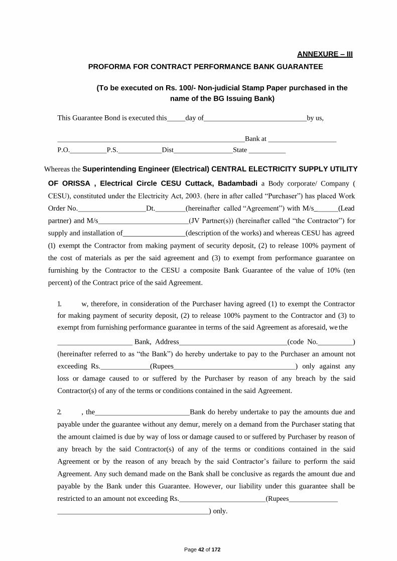
Page 42 of 172
ANNEXURE – III
PROFORMA FOR CONTRACT PERFORMANCE BANK GUARANTEE
(To be executed on Rs. 100/- Non-judicial Stamp Paper purchased in the
name of the BG Issuing Bank)
This Guarantee Bond is executed this day of by us,
Bank at
P.O. P.S. Dist State
Whereas the Superintending Engineer (Electrical) CENTRAL ELECTRICITY SUPPLY UTILITY
OF ORISSA , Electrical Circle CESU Cuttack, Badambadi a Body corporate/ Company (
CESU), constituted under the Electricity Act, 2003. (here in after called “Purchaser”) has placed Work
Order No. Dt. (hereinafter called “Agreement”) with M/s_ (Lead
partner) and M/s (JV Partner(s)) (hereinafter called “the Contractor”) for
supply and installation of (description of the works) and whereas CESU has agreed
(1) exempt the Contractor from making payment of security deposit, (2) to release 100% payment of
the cost of materials as per the said agreement and (3) to exempt from performance guarantee on
furnishing by the Contractor to the CESU a composite Bank Guarantee of the value of 10% (ten
percent) of the Contract price of the said Agreement.
1. w, therefore, in consideration of the Purchaser having agreed (1) to exempt the Contractor
for making payment of security deposit, (2) to release 100% payment to the Contractor and (3) to
exempt from furnishing performance guarantee in terms of the said Agreement as aforesaid, we the
Bank, Address (code No. )
(hereinafter referred to as “the Bank”) do hereby undertake to pay to the Purchaser an amount not
exceeding Rs. (Rupees ) only against any
loss or damage caused to or suffered by the Purchaser by reason of any breach by the said
Contractor(s) of any of the terms or conditions contained in the said Agreement.
2. , the Bank do hereby undertake to pay the amounts due and
payable under the guarantee without any demur, merely on a demand from the Purchaser stating that
the amount claimed is due by way of loss or damage caused to or suffered by Purchaser by reason of
any breach by the said Contractor(s) of any of the terms or conditions contained in the said
Agreement or by the reason of any breach by the said Contractor’s failure to perform the said
Agreement. Any such demand made on the Bank shall be conclusive as regards the amount due and
payable by the Bank under this Guarantee. However, our liability under this guarantee shall be
restricted to an amount not exceeding Rs. (Rupees
) only.

Page 43 of 172
3. , the Bank also undertake to pay to the Purchaser
any money so demanded not withstanding any dispute or dispute raised by the Contractor(s) in any
suit or proceeding instituted/ pending before any court or Tribunal relating thereto our liability under
this Agreement being absolute and irrevocable. The payment so made by us under this bond shall be
valid discharge of our liability for payment there under and the Contractor(s) shall have no claim
against us for making such payment.
4. We, the Bank further agree that the guarantee herein contain
shall remain in full force and effect during the period that would be taken for the performance of the
said Agreement and it shall continue to remain in force endorsable till all the dues of the Purchaser
under by virtue of the said Agreement have been fully paid and its claim satisfied or discharged or
till Purchaser certifies that the terms and conditions of the said Agreement have been fully and
properly carried out by the said Contractor(s) and accordingly discharge this guarantee and will not
be revoked by us during the validity of the guarantee period.
Unless a demand or claim under this guarantee is made on us or with our Cuttack branch at
(Name, address of the Cuttack branch and code No.) in writing on or
before (date) we shall be discharged from all liability under this guarantee
thereafter.
5. We, the Bank further agree that the Purchaser shall have the
fullest liberty without our consent and without affecting in any manner our obligations hereunder to
vary any of the terms and conditions of the said Agreement or to extend time of performance by the
said Contractor(s) and we shall not be relieved from our liability by reason of any such variation or
extension being granted to the said Contractor(s) or for any forbearance act or omission on part of
the Purchaser or any indulgence by the Purchaser to the said Contractor(s) or by any such matter or
thing whatsoever which under the law relating to sureties would but for this provisions have effect of
so relieving us.
6. The Guarantee will not be discharged due to change in the name, style and constitution of
the Bank and or Contractor(s).
7. We, the Bank lastly undertake not to revoke this Guarantee
during its currency except with the previous consent of the Purchaser in writing.
Dated the day of Two thousand .
Not withstanding anything contained herein above.
Our liability under this Bank Guarantee shall not exceed Rs. (Rupees
) only.
The Bank Guarantee shall be valid up to only.

Page 44 of 172
Our ...................................... branch at Cuttack (Name & Address of the Cuttack branch)
is liable to pay the guaranteed amount depending on the filing of claim and any part thereof under
this Bank Guarantee only and only if you serve upon us at our Cuttack branch a written claim or
demand and received by us at our Cuttack branch on or before Dt. otherwise bank shall
be discharged of all liabilities under this guarantee thereafter.
For
(indicate the name of the Bank )
N.B.:
(1) Name of the Contractor:
(Mention the name of JV partner(s), if any)
6. No. & date of the purchase order/ agreement:
7. Amount of P.O. :
8. Name of Materials :
9. Name of the Bank:
10. Amount of the Bank Guarantee:
11. Name, Address and Code No. of the Cuttack Branch of the Issuing Bank:
12. Validity period or date up to which the agreement is valid:
13. Signature of the Constituent Authority of the Bank with seal:
14. Name & addresses of the Witnesses with signature:
15. The Bank Guarantee shall be accepted only after getting confirmation from the respective Banks.

Page 45 of 172
ANNEXURE – IV
PROFORMA OF BANK GUARANTEE FOR ADVANCE PAYMENT
(To be stamped in accordance with Stamp Act)
(To be executed on Rs. 100/- Non-judicial Stamp Paper purchased in the
name of the BG Issuing Bank)
Ref............................ Bank Guarantee No.................
Date ............................
To
The Superintending Engineer (Electrical)
CENTRAL ELECTRICITY SUPPLY UTILITY OF ODISHA
Electrical Circle CESU, Cuttack
Dear Sir,
In consideration of CESU (hereinafter referred to as the ‘Purchaser’, which expression shall,
unless repugnant to the context or meaning thereof include its successors, administrators and
assigns) having awarded to M/s.................. (Lead partner) and
M/s (JV Partner(s)) (hereinafter referred to as the "Contractor”
which expression shall unless repugnant to the context or meaning thereof, include its
successors, administrators, executors and assigns), a Contract by issue of Purchaser’s Letter of
Award
No.................. dated ................... and the same having been acknowledged by the Contractor,
resulting in a Contract bearing No....................... dated .................. valued at ...................... for
.................................................................. (scope of work)................................... (hereinafter
called the 'Contract’) and the Purchaser having agreed to make an advance payment to the
Contractor for performance of the above Contract amounting ................................. (in words and
figures ) as an advance against Bank Guarantee to be furnished by the Contractor.
We,.................................................................................................................................
(Name of the Bank)
having its Head Office at .............................. (hereinafter referred to as the ‘Bank’, which
expression shall, unless repugnant to the context or meaning thereof , include its
successors, administrators, executors and assigns ) do hereby guarantee and undertake to
pay the Purchaser, immediately on demand any or, all monies payable by the Contractor to
the extent of ..................................... as aforesaid at any time upto ........ @ ...............
without any demur, reservation, contest, recourse or protest and / or without any reference to
the Contractor. Any such demand made by the Purchaser on the Bank shall be conclusive and
binding notwithstanding any difference between the Purchaser and the Contractor or
Page 46 of 172
any dispute pending before any Court, Tribunal, Arbitrator or any other authority. We
agree that the guarantee herein contained shall be irrevocable and shall continue to be
enforceable till the Purchaser discharges this guarantee.
The Purchaser shall have the fullest liberty without affecting in any way the liability of the
Bank under this guarantee, from time to time to vary the advance or to extend the time for
performance of the Contract by the Contractor. The Purchaser shall have the fullest liberty
without affecting this guarantee, to postpone from time to time the exercise of any powers.
Vested in them or of any right which they might have against the Contractor, and to exercise
the same at any time in any manner, and either to enforce or to forbear to enforce any
covenants, contained or implied, in the Contract between the Purchaser and the Contractor
or any other course or remedy or security available to the Purchaser. The Bank shall not be
released of its obligations under these presents by an exercise by the Purchaser of its liberty
with reference to the matters aforesaid or any of them or by reason of any other act or
forbearance or other acts of omission or commission on the part of the Purchaser or any
other indulgence shown by the Purchaser or by an other matter or thing, whatsoever, which
under law would, but for this provision have the effect of relieving the Bank.
Bank also agrees that the Purchaser at its option shall be entitled to enforce this Guarantee against
the Bank as a principal debtor, in the first instance without proceeding against the Contractor and
notwithstanding any security or other guarantee that the Purchaser may have in relation to the
Contractor'’ liabilities.
Notwithstanding anything contained hereinabove our liability under this guarantee is limited to
.................. and it shall remain in force upto and including ...........@ ............. and shall be extended
from time to time for such period (not exceeding one year ), as may be desired by M/s.
........................ on whose behalf this guarantee has been given.
The Guarantee will not be discharged due to change in the name, style and constitution of the Bank
and or Contractor(s).
All other contentions in B.G will safe guard the interest of <Purchaser>.
We, the Bank lastly undertake not to revoke this Guarantee during
its currency except with the previous consent of the <Purchaser> in writing.
Dated the day of Two thousand .
Not withstanding anything contained herein above.

Page 47 of 172
Our liability under this Bank Guarantee shall not exceed Rs. (Rupees
) only.
The Bank Guarantee shall be valid up to only.
Our ...................................... branch at Cuttack (Name & Address of the Cuttack branch)
is liable to pay the guaranteed amount depending on the filing of claim and any part thereof under
this Bank Guarantee only and only if you serve upon us at our Cuttack branch a written claim or
demand and received by us at our Cuttack branch on or before Dt.
be discharged of all liabilities under this guarantee thereafter.
For
otherwise bank shall
(indicate the name of the Bank )
Dated this .............. Day of ......... 20......... at ...............................................
WITNESS
.................................................. ......................................................................
(Signature) (Signature)
......................................................... .....................................................................
(Name) (Name)
.......................................................... ...........................................................................
(Official Address) (Designation with Bank Stamp)
Attorney as per
Power of Attorney No...................
Dated ...........................................
@ This date shall be ninety (90) days after the schedule date of completion of the Contract.
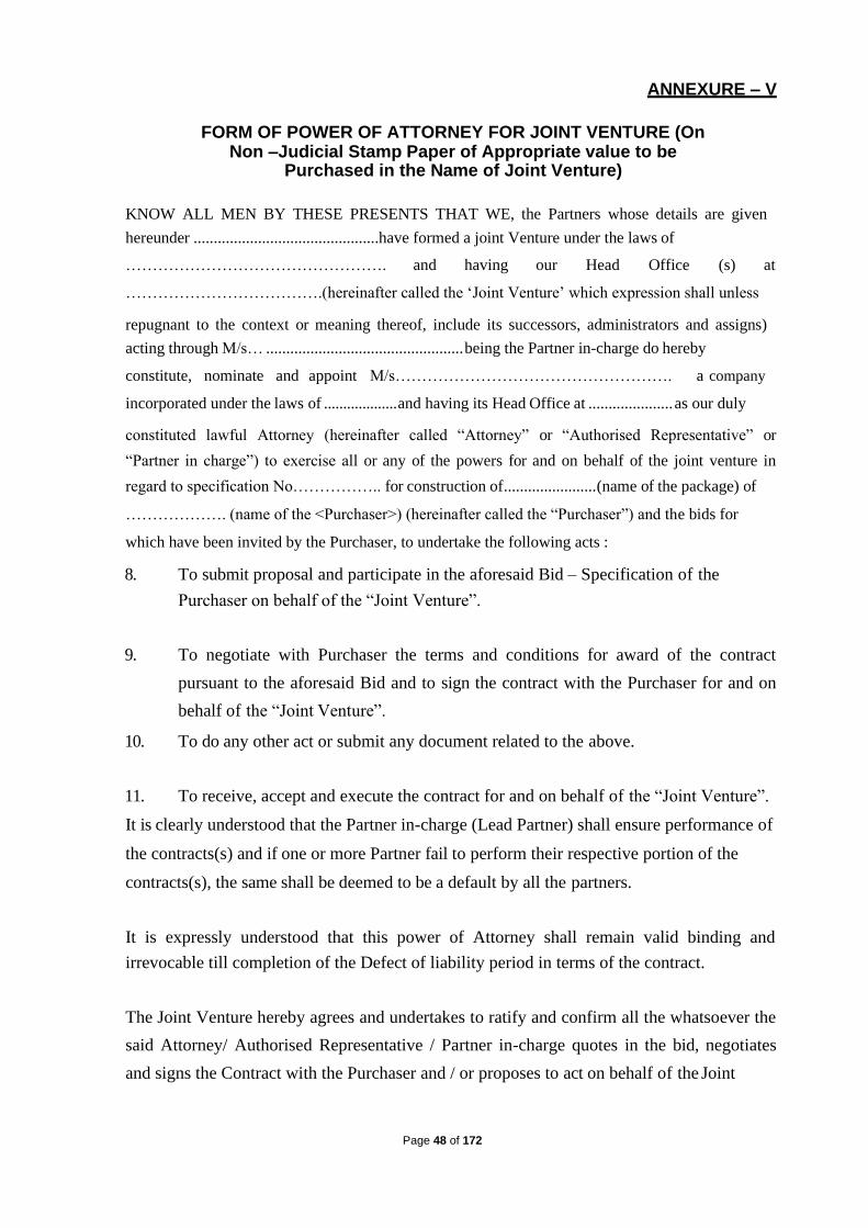
Page 48 of 172
ANNEXURE – V
FORM OF POWER OF ATTORNEY FOR JOINT VENTURE (On Non –Judicial Stamp Paper of Appropriate value to be
Purchased in the Name of Joint Venture)
KNOW ALL MEN BY THESE PRESENTS THAT WE, the Partners whose details are given
hereunder ..............................................have formed a joint Venture under the laws of
…………………………………………. and having our Head Office (s) at
……………………………….(hereinafter called the ‘Joint Venture’ which expression shall unless
repugnant to the context or meaning thereof, include its successors, administrators and assigns)
acting through M/s… ................................................. being the Partner in-charge do hereby
constitute, nominate and appoint M/s……………………………………………. a company
incorporated under the laws of ................... and having its Head Office at ..................... as our duly
constituted lawful Attorney (hereinafter called “Attorney” or “Authorised Representative” or
“Partner in charge”) to exercise all or any of the powers for and on behalf of the joint venture in
regard to specification No…………….. for construction of ....................... (name of the package) of
………………. (name of the <Purchaser>) (hereinafter called the “Purchaser”) and the bids for
which have been invited by the Purchaser, to undertake the following acts :
8. To submit proposal and participate in the aforesaid Bid – Specification of the
Purchaser on behalf of the “Joint Venture”.
9. To negotiate with Purchaser the terms and conditions for award of the contract
pursuant to the aforesaid Bid and to sign the contract with the Purchaser for and on
behalf of the “Joint Venture”.
10. To do any other act or submit any document related to the above.
11. To receive, accept and execute the contract for and on behalf of the “Joint Venture”.
It is clearly understood that the Partner in-charge (Lead Partner) shall ensure performance of
the contracts(s) and if one or more Partner fail to perform their respective portion of the
contracts(s), the same shall be deemed to be a default by all the partners.
It is expressly understood that this power of Attorney shall remain valid binding and
irrevocable till completion of the Defect of liability period in terms of the contract.
The Joint Venture hereby agrees and undertakes to ratify and confirm all the whatsoever the
said Attorney/ Authorised Representative / Partner in-charge quotes in the bid, negotiates
and signs the Contract with the Purchaser and / or proposes to act on behalf of the Joint

Page 49 of 172
Venture by virtue of this Power of Attorney and the same shall bind the Joint Venture as if
done by itself.
IN WITNESS THEREOF the Partners Constituting the Joint Venture as aforesaid have
executed these presents on this ………… day of .......... under the Common Seal (s) of their
Companies
for and on behalf of
the Partners of Joint Ventures
…………………………………
…………………………………
…………………………………
The Common Seal of the above Partners of the Joint Venture :
The Common Seal has been affixed there unto in the presence of :
WITNESS
12. Signature …………………………………
Name …………………………………
Designation …………………………………
Occupation …………………………………
13. Signature …………………………………...
Name ……………………………………….
Designation …………………………………
Occupation …………………………………

Page 50 of 172
ANNEXURE – VI
FORM OF JOINT VENTURE/ CONSORTIUM AGREEMENT
(To be executed on non-judicial stamp paper of appropriate value to be
purchased in the name of joint venture)
PROFORMA OF JOINT VENTURE AGREEMENT BETWEEN …………………………………
………………………. AND .................................................................................. FOR BID SPECIFICATION NO.
……………………………………………………………. OF (Purchaser).
THIS Joint Venture Agreement executed on this ……….. day of ....................... Two thousand and
……...… …………… between M/s. .......................................... a company incorporated under the
laws of ……….… …….……………. and having its Registered Office at …………….
…………….……………………...…. ……………. (hereinafter called the "Lead Partner" which
expression shall include its successors, executors and permitted assigns), M/s.
…………….…………….……………. a company incorporated under the laws of
…………….…………….……………. and having its Registered Office at …………….
……………. ……………. (hereinafter called the "Partner" which expression shall include its
successors, executors and permitted assigns) and M/s. .................................................................. a
company incorporated under the laws of ………………………………………….and having its
Registered Office at (hereinafter called the "Partner" which expression shall include its successors,
executors and permitted assigns) for the purpose of making a bid and entering into a contract (in case
of award) against the Specification No .................................................................. for Construction of
…………….……………. of (Purchaser)., a company incorporated under the ....................... having
its. Registered Office at .......................................................... (hereinafter called the "Purchaser). '
WHEREAS the Purchaser invited bids as per the above mentioned Specification for the design
manufacture, supply and erection, testing and commissioning of Equipment Materials stipulated in
the bidding documents under subject Package for
AND WHEREAS Annexure -A (Qualification Requirement of the Bidder), Section-SCC, Vol.-IA,
forming part of the bidding documents, stipulates that a Joint Venture of two or more qualified firms
as partners, meeting the requirement of Annexure-A, Section SCC as applicable may bid, provided
the Joint Venture fulfills all other requirements of Annexure-A, Section SCC and in such a case, the
BID shall be signed by all the partners so as to legally bind all the Partners of the Joint Venture, who
will be jointly and severally liable to perform the Contract and all obligations hereunder.

Page 51 of 172
The above clause further states that the Joint Venture agreement shall be attached to the bid and the
contract performance guarantee will be as per the format enclosed with the bidding document
without any restriction or liability for either party.
AND WHEREAS the bid has been submitted to the Purchaser vide proposal No dated by Lead
Partner based on the Joint Venture agreement between all the Partners under these presents and the
bid in accordance with the requirements of Annexure-A (Qualification Requirements of the Bidders),
Section -SCC has been signed by all the partners.
NOW THIS INDENTURE WITNESSETH AS UNDER:
In consideration of the above premises and agreements all the Partners to this Joint Venture do
hereby now agree as follows:
16. In consideration of the award of the Contract by the Purchaser to the Joint Venture partners, we, the
PartnerstotheJointVentureagreementdoherebyagreethatM/s
…………….…………….……………. shall act as Lead Partner and further declare and confirm that
we shall jointly and severally be bound unto the Purchaser for the successful performance of the
Contract and shall be fully responsible for the design, manufacture, supply, and successful
performance of the equipment in accordance with the Contract.
17. In case of any breach of the said Contract by the Lead Partner or other Partner(s) of the Joint Venture
agreement, the Partner(s) do hereby agree to be fully responsible for the successful performance of
the Contract .and to carry out all the obligations and responsibilities under the Contract in
accordance with the requirements of the Contract.
18. Further, if the Purchaser suffers any loss or damage on account of any breach in the Contract or any
shortfall in the performance of the equipment in meeting the performance guaranteed as per the
specification in terms of the Contract, the Partner(s) of these presents undertake to promptly make
good such loss or damages caused to the Purchaser, on its demand without any demur. It. shall not be
necessary or obligatory for the Purchaser to proceed against Lead Partner to these presents before
proceeding against or dealing with the other Partner(s).
19. The financial liability of the Partners of this Joint Venture agreement to the Purchaser, with respect
to any of the claims arising out of the performance of non- performance of the obligations set forth in
the said Joint Venture agreement, read in conjunction with the relevant conditions of the Contract
shall, however, not be limited in any way so as to restrict or limit the liabilities of any of the Partners
of the Joint Venture agreement.
20. It is expressly understood and agreed between the Partners to this Joint Venture agreement that the
responsibilities and obligations of each of the Partners shall be as delineated in Appendix-I (*To be
incorporated suitably by the Partners) to this agreement. It is further agreed by the Partners that the

Page 52 of 172
above sharing of responsibilities and obligations shall not in any way be a limitation of joint and
several responsibilities of the Partners under this Contract.
20. This Joint Venture agreement shall be construed and interpreted in accordance with the laws of India
and the courts of Delhi shall have the exclusive jurisdiction in all matters arising there under.
21. In case of an award of a Contract, We the Partners to the Joint Venture agreement do hereby agree
that we shall be jointly and severally responsible for furnishing a contract performance security from
a bank in favour of the Purchaser in the forms acceptable to purchaser for value of 10% of the
Contract Price in the currency/currencies of the Contract.
22. It is further agreed that the Joint Venture agreement shall be irrevocable and shall form an integral
part of the Contract, and shall continue to be enforceable till the Purchaser discharges the same. It
shall be effective from the date first mentioned above for all purposes and intents.
IN WITNESS WHEREOF. the Partners to the Joint Venture agreement have through their authorised
representatives executed these presents and affixed Common Seals of their companies, on the day,
month and year first mentioned above.
1. Common Seal …………….……………. of For Lead Partner
has been affixed in my/our presence
pursuant to the Board of Director's (Signature of authorised resolution
dated …………………….. representative)
Name... …………….…………….
Signature.. ………….……………. Designation
…………….…………….
Name .................................................................... Common Seal of the company
Designation…………….…………….…. …………….…………….…………….
2. Common Seal of ................................................................ For other Partners
has been affixed in my/our presence
pursuant to the Board of Director's (Signature of authorised
resolution dated representative)

Page 53 of 172
Name... …………….…………….
Signature.. ………….……………. Designation
…………….…………….
Name .................................................................... Common Seal of the company
Designation…………….…………….… …………….…………….………….
WITNESSES :
1. …………….…………….…………. 2.…………….…………….………….
(Signature) (Signature)
Name …………..…………….……… Name …………….…………….………….
…………….…………….……………
…………….…………….………….
(official address) (Official address)

Page 54 of 172
ANNEXURE – VII (A)
LETTER OF COMPLIANCE OF QUALIFYING REQUIREMENT
(In case of Bidder being a Single Firm)
To
The Superintending Engineer ( Electrical )
CENTRAL ELECTRICITY SUPPLY UTILITY OF ODISHA
Electrical Circle CESU, Cuttack
Dear Sir,
I/We ...................... (Name of Bidder) are submitting the bid as a single firm. In support of our
meeting the Qualifying requirements (QR) for bidders, stipulated in this tender specification, we
furnish herewith the details/documents etc. as follows.
Table – A : Previous Works Experience :
Qty Installed & Commissioned
Package Description
Sl. No.
FY
WO Ref
Documents provided
Quoted of Tender Name
Qty in proof of having
for Proposed Qty of
Installed executed the works
Works Client during the relevant
FY.
Table – B : Average Annual Turnover :
Package Quoted for
Annual Turnover Data
Estimated Cost (Rs. in Lakh)
of the Package Financial Year
Turnover
(Rs. in Lakh) (Rs. in Lakh)
2016-17
2017-18
2018-19
Total Estimated Cost of Average Turnover
the packages quoted for

Page 55 of 172
Table – C : Access to Credit Facility :
Package Quoted for
Estimated Cost
Credit Facility
of the Package Liquid Assets as on
(Rs. in Lakh) 31.01.2020
Description
(Rs. in Description
(Rs. in
Lakh) Lakh)
Cash at Bank
Un Utilized
Cash Credit
Balance
Short Term
Fixed Others (Pl
Deposits Specify)
One fifth of the total Total Liquid Total Credit
Estimated Cost. Assets Facility
Note- 1 : Continuation sheets, of like size and format, may be used as per Bidder’s requirements
and annexed to this Schedule.
2 : Bidder are required to furnish all the above data against their liquid assets from their concerned Bank as on 31.01.2020 in Bank letter head only.
I/We declare that we are fulfilling the qualifying requirements as per clause no. 2.0 of Section – I,
Invitation for Bids (IFB).
For & on behalf of ..................(Name of the Bidder).

Page 56 of 172
ANNEXURE – VII (B)
LETTER OF COMPLIANCE OF QUALIFYING REQUIREMENT
(In case of Bidder being a Joint Venture / Consortium Firm)
To
The Superintending Engineer (Electrical)
CENTRAL ELECTRICITY SUPPLY UTILITY OF ODISHA
Electrical Circle CESU Cuttack
Dear Sir,
I/We ...................... (Name of Bidder) are submitting the bid as a single firm. In support of our
meeting the Qualifying requirements (QR) for bidders, stipulated in this tender specification, we
furnish herewith the details/documents etc. as follows.
Name of the members of the JV / Consortium
1.
2.
3.
Table – A : Previous Works Experience : Name of the Member (any one member only)
Qty Installed & Commissioned
FY
WO Ref
Documents
Package Description provided in
Tender
proof of having Quoted of Proposed Sl. Name of Qty
Qty executed the for Works No. Client Installed
works during
the relevant
FY.

Page 57 of 172
Table – B : Average Annual Turnover : (All the members of JV/Consortium taken together)
Annual Turnover Annual Turnover
Total Annual
Turnover Estimate (Rs. in Lakh) (Rs. in Lakh) d Cost of (Rs. in Lakh)
Package the Name of 1
Name of 2
Name of 2
Quoted for Package Member Member Member
(Rs. in Financial
Turnover Financial
Turnover Financial
Turnover
Lakh) (Rs. in (Rs. in (Rs. in
Year Year Year Lakh) Lakh) Lakh)
2016-17 2016-17 2016-17
2017-18 2017-18 2017-18
2018-19 2018-19 2018-19
Total Total Total
Total Average
Estimated Turnover
Cost of the
packages
quoted for
Table – C : Access to Credit Facility : (All the members of JV/Consortium taken together)
Estimated
Liquid Assets as on 31.01.2020
Credit Facility Package Cost of the
Quoted for Package
(Rs. in Lakh)
Member 1 Member 1
Description (Rs. In Lakh) Description
(Rs. in
Lakh)
Cash at Bank
Un Utilized
Cash Credit
Balance
Short term Fixed Others (Pl
Deposits Specify)
Total Liquid Total Credit
Assets Facility
Liquid Assets as on 31.01.2020 Credit Facility
Member 2 Member 2
Description (Rs. In Lakh) Description
(Rs. in
Lakh)
Cash at Bank
Un Utilized
Cash Credit
Balance
Short term Fixed Others (Pl
Deposits Specify)
Total Liquid Total Credit
Assets Facility

Page 58 of 172
Liquid Assets as on 31.01.2020 Credit Facility
Total for JV 3 Total for JV 3
Description (Rs. In Lakh) Description
(Rs. in
Lakh)
Cash at Bank
Un Utilized
Cash Credit
Balance
Short term Fixed Others (Pl
Deposits Specify)
One fifth of
the total Total Liquid Total Credit
Estimated Assets Facility
Cost.
Note-1: Continuation sheets, of like size and format, may be used as per Bidder’s requirements and
annexed to this Schedule.
Note- 2 : Bidder are required to furnish all the above data against their liquid assets from their concerned Bank as on 31.01.2020 in Bank letter head only.
I/We declare that we are fulfilling the qualifying requirements as per clause no. 2.0 of Section – I,
Invitation for Bids (IFB).
For & on behalf of ..................(Name of the Bidder).
(All members of JV / Consortium should sign).
Details of qualification and experience of key personnel proposed for carrying out the works
Sl. Name of Degree/ Branch
Year Past Experience of
No Personnel Diploma
Passing
From
To
Responsibi
Name of Position lities/
Employer Held Relevant
experience
Date: (Signature) …………………..
Place: ( Printed Name) ……………….
(Designation) ………………….
(Common Seal) …………………

Page 59 of 172
Note: 1. Continuation sheets, of like size and format, may be used as per Bidder’s
requirements and annexed to this Schedule.
1 In case of Joint Venture, separate sheet for each partner of Joint
Venture should be used.
Details for sub-contracting elements amounting to more than 10% of bid price
Sl. No
Item Description
Qty. proposed to be bought-out/ Source of Supply Sub- contracted
1.
2.
3.
4.
5.
Date: (Signature) …………………..
Place: (Printed Name) ……………….
(Designation) …………………..
(Common Seal) …………………
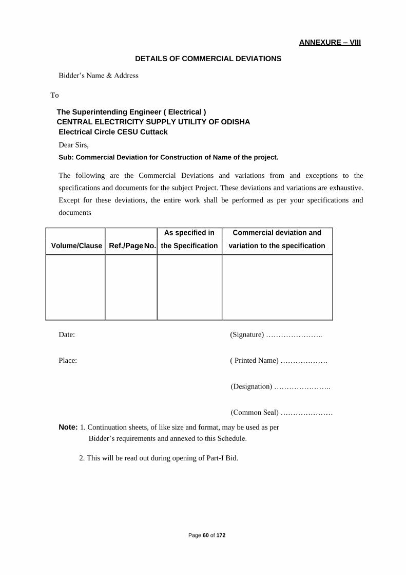
Page 60 of 172
ANNEXURE – VIII
DETAILS OF COMMERCIAL DEVIATIONS
Bidder’s Name & Address
To
The Superintending Engineer ( Electrical )
CENTRAL ELECTRICITY SUPPLY UTILITY OF ODISHA
Electrical Circle CESU Cuttack
Dear Sirs,
Sub: Commercial Deviation for Construction of Name of the project.
The following are the Commercial Deviations and variations from and exceptions to the
specifications and documents for the subject Project. These deviations and variations are exhaustive.
Except for these deviations, the entire work shall be performed as per your specifications and
documents
Volume/Clause
Ref./Page No.
As specified in Commercial deviation and
the Specification variation to the specification
Date: (Signature) …………………..
Place: ( Printed Name) ……………….
(Designation) …………………..
(Common Seal) …………………
Note: 1. Continuation sheets, of like size and format, may be used as per
Bidder’s requirements and annexed to this Schedule.
2. This will be read out during opening of Part-I Bid.

Page 61 of 172
ANNEXURE – IX
DETAILS TECHNICAL DEVIATIONS
To
The Superintending Engineer ( Electrical )
CENTRAL ELECTRICITY SUPPLY UTILITY OF ODISHA
Electrical Circle CESU Cuttack
Dear Sirs,
Sub: Technical Deviation for Construction of ........................ Name of the Project.
The following are the Technical Deviations and variations from and exceptions to the specifications
and documents for the subject package. These deviations and variations are exhaustive. Except for
these deviations, the entire work shall be performed as per your specifications and documents
Volume/Clause
Ref./Page No.
Technical deviation
As specified in the and variation to the
Specification / Relevant ISS specification
Date: (Signature) …………………..
Place: (Printed Name) ……………….
(Designation) …………………..
(Common Seal) …………………
Note: 1. Continuation sheets, of like size and format, may be used as per
Bidder’s requirements and annexed to this Schedule.
21. The deviations and variations, if any, shall be brought out
separately for each of the equipment.
22. This will be read out during opening of Part – I bid.
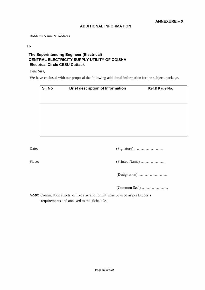
Page 62 of 172
Ref.& Page No. Brief description of Information Sl. No
ANNEXURE – X
ADDITIONAL INFORMATION
Bidder’s Name & Address
To
The Superintending Engineer (Electrical)
CENTRAL ELECTRICITY SUPPLY UTILITY OF ODISHA
Electrical Circle CESU Cuttack
Dear Sirs,
We have enclosed with our proposal the following additional information for the subject, package.
Date: (Signature) …………………..
Place: (Printed Name) ……………….
(Designation) …………………..
(Common Seal) …………………
Note: Continuation sheets, of like size and format, may be used as per Bidder’s
requirements and annexed to this Schedule.

Page 63 of 172
ANNEXURE – XI BOUGHT OUT & SUB CONTRACTED ITEMS
To
The Superintending Engineer (Electrical)
CENTRAL ELECTRICITY SUPPLY UTILITY OF ODISHA
Electrical Circle CESU Cuttack
Dear Sir,
We hereby furnish the details of the items/sub-assemblies to buy for the purpose of subject package
Date:
N.B. :- :- All the major materials having valid type test certificate from CPRI/ NABL accredited
labolatory/ Govt approved laboratory within 5 year from the date of tender notification will be
considered for the project.
(Signature of Bidder)
Place: Dt
1.150X150mm RS Joist 12mtr long
2. 232mm2 AAAC
3. 400mm2 single core 33KV XLPE cable
4. 33KV Pin Insulator (Polymer)
5. 33KV GI Pin
6. 33KV Polymer Disc Insulator, 70KN B&S
7. Single tension HW fittings for 232mm2 conductor
8. 30KV, 10KA LA
9. 33KV, 1250A Isolator with Polymer Post Insulator
Source of Supply Sl. No Item description

Page 64 of 172
ANNEXURE – XII WORK COMPLETION SCHEDULE
To
The Superintending Engineer ( Electrical )
CENTRAL ELECTRICITY SUPPLY UTILITY OF ODISHA
Electrical Circle CESU Cuttack
Dear Sir,
We hereby declare that, the work shall be completed within 3 (three) months from date of award of
contract as per following Work Completion Schedule which shall be followed by us
Sl. No Description of Work Period in Months( from the date of WO)
1 Completion of detailed engineering
2
Procurement of raw materials
3
Establishment of site office
4
Erection
(a) Commencement
(b) Completion
5
Testing & Pre-commissioning
(a) Commencement
(b) Completion
6
Commissioning
Date:
(Signature of bidder) …………………..
Place:

Page 65 of 172
ANNEXURE – XIII CHECK LIST
To
The Superintending Engineer ( Electrical ) CENTRAL ELECTRICITY SUPPLY UTILITY OF ODISHA
Electrical Circle CESU, Cuttack
Dear Sir,
Sl. Item Description Status of the Remarks No. Submission of
data
1 2 3 4
1. Bid Guarantee Yes /No If yes please give details No,
amount, validity & date of issue.
2. Qualifying Data Yes /No
3. Commercial Deviation Yes /No
4. Technical Deviation Yes /No
5. Cost of withdrawn of Yes /No
deviations
6. Bid validity Yes /No If yes state here the period.
7. Period of completion Yes/No If, yes please state here the period of
completion.
8. Additional information offered State here briefly by bidder
N.B.:- The contents of this schedule will be read out during opening of Part-I Bid.
………………………
Signature of Bidder
Date & Seal:
N.B :-
24. The bid guarantee one original shall be furnished in sealed envelope appropriately superscribed thereon.
25. All Schedules pertaining to prices (originals ) shall be furnished in a sealed envelope
duly superscribed thereon. Similarly one set of copies of such schedules shall be given in a separate sealed envelope ( these are not to be opened during opening of Part –I ).
26. All other schedules, one set original shall be submitted in sealed envelope (these are to
be opened during Part –I bid opening )
Date: (Signature) …………………..
Place:

Page 66 of 172
ANNEXURE – XIV
PROFORMA OF INDEMNITY BOND TO BE EXECUTED BY THE CONTRACTOR FOR THE EQUIPMENT HANDED OVER BY <PURCHASER> FOR PERFORMANCE OF ITS CONTRACT
(Entire Equipment consignment in one lot )
(On non-Judicial stamp paper of appropriate Value )
INDEMNITY BOND
THIS INDEMNITY BOND is made this ............. day of ...........20 .............. by ......................a
Company registered under the Companies Act, 1956/ Partnership Firm / Proprietary Concern having
its Registered Office at .........................(hereinafter called as ‘Contractor’ or “Obligor” which
expression shall include its successors and permitted assigns ) in favour of <Purchaser>, a <Company/
Body Corporate> incorporated under the <Companies Act, 1956 / Electricity Act-2003> having its
<Registered Office/ Head Office> at < Address> and its project at ..................... (hereinafter called
“<Purchaser>”Which expression shall include its successors and assigns ) :
WHEREAS <Purchaser> has awarded to the Contractor a Contract for ............... vide its Letter of
Award / Contract No.................... dated .................... and its Amendment No ...................... and
Amendment No.................. (applicable when amendments have been issued ) hereinafter called the
“Contract”) in terms of which <Purchaser> is required to handover various equipment to the
Contractor for execution of the Contract.
And WHERAS by virtue of Clause No .............. of the said Contract, the Contractor is required to
executive an Indemnity Bond in favour of <Purchaser> for the Equipment handed over to it by
<Purchaser> for the purpose of performance of the Contract / Erection portion of the Contract
(hereinafter called the “Equipment”)
NOW THEREFORE, This Indemnity Bond witness as follows :

Page 67 of 172
31. That in consideration of various equipment as mentioned in the Contract, valued at Rs... ................
(Rupees ....................................... ) handed over to the Contractor for the purpose of performance of
the Contract, the Contractor hereby undertakes to indemnify and shall keep <Purchaser>
indemnified, for the full value of the Equipment. The Contractor hereby acknowledges receipt of
the Equipment as per despatch title documents handed over to the Contractor duly endorsed in their
favour and detailed in the Schedule appended hereto. It is expressly understood by the Contractor
that handing over of the despatch title documents in respect of the said Equipment duly endorsed
by
<Purchaser> in favour of the Contractor shall be construed as handing over of the Equipment
purported to be covered by such title documents and the Contractor shall hold such Equipment is
trust as a Trustee for and on behalf of <PURCHASER> .
a) That the Contractor is obliged and shall remain absolutely responsible for the safe transit /
protection and custody of the Equipment at <PURCHASER> project Site against all risks,
whatsoever, till the Equipment are duly used / erected in accordance with the terms of the
Contract and the Plant / Package duly erected and commissioned in accordance with the terms
of the Contract, is taken over by <PURCHASER> . The Contractor undertakes to keep
<Purchaser> harmless against any loss or damage that may be caused to the Equipment.
The Contractor undertakes that the Equipment shall be used exclusively for the performance/
3. execution of the Contract strictly in accordance with its terms and conditions and no part of the
equipment shall be utilized for any other work or purpose whatsoever. It is clearly understood by
the Contractor that non-observance of the obligations under this Indemnity Bond by the
Contractor shall inter-alia constitute a criminal breach of trust on the part of the Contractor for all
intents and purpose including legal / penal consequences .
4. That <PURCHASER> is and shall remain the exclusive Owner of the Equipment free from all
encumbrances, charges or liens of any kind, whatsoever. The Equipment shall at all times be
open to inspection and checking by Engineer0in Charge / Engineer or other employees/agents
authorised by him in this regard. Further, <Purchaser> shall always be free at all times to take
possession of the Equipment in whatever form the Equipment may be, if in its opinion the
Equipment are likely to be endangered, mis-utilised or converted to uses other than those
specified in the Contract, by any acts of omission or commission on the part of the Contractor
binds himself and undertakes to comply with the direction of demand of <Purchaser> to return
the Equipment without any demur or reservation.

Page 68 of 172
5. That this indemnity Bond is irrevocable. If at any time any loss or damage occurs to the
Equipment or the same or any part thereof is misutilized in any manner whatsoever, then the
Contractor hereby agrees that the decision of the Engineer-in-Charge/Engineer of <Purchaser> as
to assessment of loss or damage to the Equipment shall be final and binding on the Contractor.
The Contractor binds itself and undertakes to replace the lost and/or damaged Equipment at its
own cost and/or shall pay the amount of loss of <Purchaser> without demur, reservation or
protest. This is without prejudice to any other right or remedy that may be available to
<Purchaser> against the Contractor under the Contract and under this Indemnity Bond.
6. NOW THE CONDITION of this Bond is that if the Contractor shall duly and punctually comply
with terms and conditions of this Bond to the satisfaction of <Purchaser>, THEN, the above
Bond shall be void, but otherwise, it shall remain in full force and virtue.
IN WITNESS WHEREOF, the Contractor has hereunto set its hand through its authorised representative under the common seal of the Company, the day, month and year first above mentioned.
SCHEDULE
Quantity
Particulars of Dispatch Title
Signature of
Particulars of Documents Value of the
Attorney
the Equipment
(authorised RR / GR / No. / Carrier
Equipment handed over Date of Bill of representative as
Lading a token of receipt
For an on behalf of M/s..............................................
WITNESS 1. 1. Signature ...................................... Signature .....................................
2. Name ........................................... Name ..........................................
3. Address........................................ Designation ................................
Authorised representative *
2. 1. Signature .....................................
2. Name .......................................... (Common Seal in case of Company)
Address .......................................
* Indemnity Bonds are to be executed by the authorised person and (i) in case of Contracting
Company under common seal of the Company or (ii) having the Power of Attorney issued under
common seal of the company with authority to execute Indemnity Bonds, (iii) In case of (ii), the
original Power of Attorney if it is specifically for this Contract or a Photostat copy of the Power of
Attorney if it is General Power of Attorney and such documents should be attached to Indemnity
Bond.
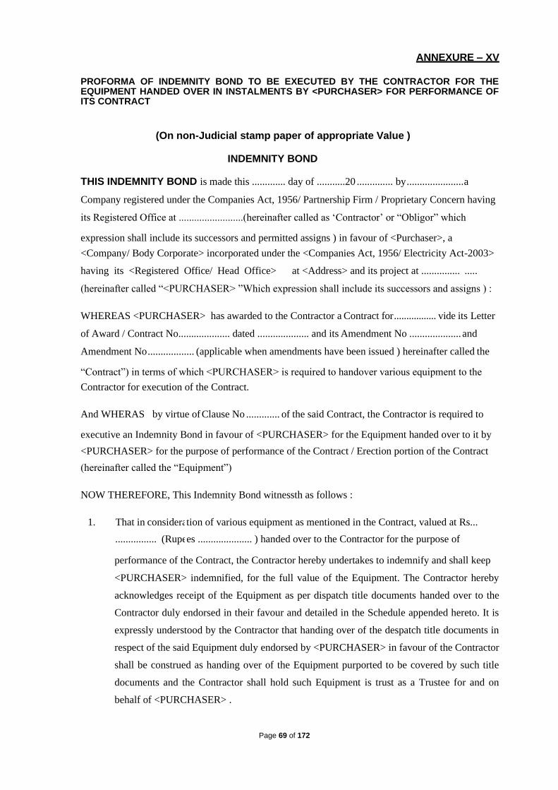
Page 69 of 172
ANNEXURE – XV
PROFORMA OF INDEMNITY BOND TO BE EXECUTED BY THE CONTRACTOR FOR THE EQUIPMENT HANDED OVER IN INSTALMENTS BY <PURCHASER> FOR PERFORMANCE OF ITS CONTRACT
(On non-Judicial stamp paper of appropriate Value )
INDEMNITY BOND
THIS INDEMNITY BOND is made this ............. day of ...........20 .............. by ...................... a
Company registered under the Companies Act, 1956/ Partnership Firm / Proprietary Concern having
its Registered Office at .........................(hereinafter called as ‘Contractor’ or “Obligor” which
expression shall include its successors and permitted assigns ) in favour of <Purchaser>, a
<Company/ Body Corporate> incorporated under the <Companies Act, 1956/ Electricity Act-2003>
having its <Registered Office/ Head Office> at <Address> and its project at ............... .....
(hereinafter called “<PURCHASER> ”Which expression shall include its successors and assigns ) :
WHEREAS <PURCHASER> has awarded to the Contractor a Contract for ................. vide its Letter
of Award / Contract No.................... dated .................... and its Amendment No .................... and
Amendment No .................. (applicable when amendments have been issued ) hereinafter called the
“Contract”) in terms of which <PURCHASER> is required to handover various equipment to the
Contractor for execution of the Contract.
And WHERAS by virtue of Clause No ............. of the said Contract, the Contractor is required to
executive an Indemnity Bond in favour of <PURCHASER> for the Equipment handed over to it by
<PURCHASER> for the purpose of performance of the Contract / Erection portion of the Contract
(hereinafter called the “Equipment”)
NOW THEREFORE, This Indemnity Bond witnessth as follows :
1. That in considera tion of various equipment as mentioned in the Contract, valued at Rs...
................ (Rupe es ..................... ) handed over to the Contractor for the purpose of
performance of the Contract, the Contractor hereby undertakes to indemnify and shall keep
<PURCHASER> indemnified, for the full value of the Equipment. The Contractor hereby
acknowledges receipt of the Equipment as per dispatch title documents handed over to the
Contractor duly endorsed in their favour and detailed in the Schedule appended hereto. It is
expressly understood by the Contractor that handing over of the despatch title documents in
respect of the said Equipment duly endorsed by <PURCHASER> in favour of the Contractor
shall be construed as handing over of the Equipment purported to be covered by such title
documents and the Contractor shall hold such Equipment is trust as a Trustee for and on
behalf of <PURCHASER> .

Page 70 of 172
• That the Contractor is obliged and shall remain absolutely responsible for the safe transit /
protection and custody of the Equipment at <PURCHASER> project Site against all risks,
whatsoever, till the Plant / Package duly erected and commissioned in accordance with the
terms of the Contract, is taken over by <PURCHASER> . The Contractor undertakes to
keep<PURCHASER> harmless against any loss or damage that may be caused to the
Equipment.
• The Contractor undertakes that the Equipment shall be used exclusively for the performance /
execution of the Contract strictly in accordance with its terms and conditions and no part of the
equipment shall be utilised for any other work or purpose, whatsoever. It is clearly understood
by the Contractor that non-observance of the obligations under this Indemnity Bond by the
Contractor shall inter-alia constitute a criminal breach of trust on the part of the Contractor for
all intents and purpose including legal / penal consequences.
• That <PURCHASER> is and shall remain the exclusive Owner of the Equipment free from all
encumbrances, charges or liens of any kind, whatsoever. The Equipment shall at all time be
open to inspection and checking by Engineer-in-Charge / Engineer or other employees / agents
authorized by him in this regard. Further , <PURCHASER> shall always be free at all times to
take possession of the Equipment in whatever from the Equipment may be, if in its opinion the
Equipment are likely to be endangered, mis-utilised or converted to use other than those
specified in the Contract, by any acts of omission or commission on the part of the Contractor
or any other person or on account of any reason, whatsoever, and the Contractor binds himself
and undertakes to comply with the directions of demand of <PURCHASER> to return the
equipment without any demur or reservation.
• That this Indemnity Bond in irrevocable. If at any time any loss or damage occurs to the
Equipment or the same or any part thereof is mis-utilized in any manner whatsoever, then the
Contractor hereby agrees that the decision of the Engineer-in-Charge / Engineer of
<PURCHASER> as to assessment of loss or damage to the Equipment shall be final and
binding on the contractor. The Contractor binds itself and undertakes to replace the lost and /
or damaged Equipment as its own cost and / or shall pay the amount of loss to
<PURCHASER> without any demur, reservation or protest. This is without prejudice to any
other right to remedy that may be available to <PURCHASER> against the Contractor under
the Contract and under this Indemnity Bond.
• NOW THE CONDITION of this Bond is that if the Contractor shall duly and punctually
comply with the terms and conditions of this Bond to the satisfaction of <PURCHASER> ,
then above Bond shall be void, but otherwise, it shall remain in full force and virtue.
IN WITNESS WHEREOF, the Contractor has hereunto set its hand through its authorized
representative under the common seal of the Company, the day, month and year first above
mentioned.

Page 71 of 172
SCHEDULE No. 1
Particulars of Quantity Particulars of Despatch Title Value of the Signature of
the Equipment Documents Equipment Attorney
handed over RR / GR / No. / Carrier (authorized
Date of Bill of representative as
Lading a token of receipt
(Please
number
subsequent
schedules )
For an on behalf of M/s..............................................
WITNESS
1. 1. Signature ...................................... Signature ....................................
.
2. Name ........................................... Name ..........................................
3. Address........................................ Designation ..............................

Page 72 of 172
ANNEXURE – XVI
SELF DECLARATION FORM
Name Of The Purchaser :………………………………
Tender No :……………………………………………….
Sir,
• I/We the undersigned do hereby declare that, I/We have never been blacklist and/or there
were no debarring actions against us for any default in supply of material/ equipments or in
the performance of the contract entrusted to us in any of the electricity utilities of India.
• In the event of any such information pertaining to the aforesaid matter found at any given
point of time either during the course of the contract or at the bidding stage, may bid/
contract shall be liable for truncation/ cancellation /termination without any notice at the sole
discretion of the purchaser.
Place :
Date :
Yours faithfully,
Signature of the bidder with seal.
( This form shall be duly filled-up and signed
by the bidder and submitted along with
the original copy of the bid).

Page 73 of 172
TENDER DOCUMENTS
FOR Re-construction and shifting of 33KV Line with UG Cable
(CRRI-I & CRRI – II 33KV feeder) existing inside the
premises of STP-II, Matgajpur of OISIP due to construction
of Sewage treatment plant under CMC, Cuttack under CDD
No – II, Cuttack on partial turnkey basis.
Volume – II
Technical Bid
Tender Specification No CESU / 05 /2019-20
CENTRAL ELECTRICITY SUPPLY UTILITY OF ORISSA (CESU)
OFFICE OF THE SUPERINTENDING ENGINEER (ELECT)
ELECTRICAL CIRCLE CUTTACK
PH – 0671-2324223

Page 74 of 172
CENTRAL ELECTRICITY SUPPLY UTILITY OF ODISHA
(CESU) OFFICE OF THE SUPERINTENDING ENGINEER (ELECT)
ELECTRICAL CIRCLE CUTTACK
TELEPHONE: (0671) - 2324223, FAX-0671-2310703
Email- [email protected]
BIDDING DOCUMENTS

Page 75 of 172
BID DOCUMENTS CONSIST OF THE FOLLOWING VOLUMES
VOLUME- I (COMMERCIAL REQUIREMENTS)
1. Section – I :-Invitation For Bids - IFB
2. Section – II :-General Terms and Conditions
of the Contract - GTCC
3. Section – III :-Price Schedule Format - PSF
4. Section – IV :-BID Proposal Letter - BPL
5. Section – V :-ANNEXURE - ANNEX
VOLUME-II (TECHNICAL REQUIREMENTS)
1. Section – I :-General
2. Section – II :- 33KV Conductor
3. Section – III :- R.S Joist Pole
4. Section – IV :- Insulators & hardware fittings
5. Section – V :- 33 kV Isolator with earth switch
6. Section – VI :- Lightning Arrestor
7. Section – VII :- 33kV UG Cable
8. Section – VIII :- HT cable joints and terminals
9. Section – IX :- Cable Laying Methodology
10. Section – X :- Proposed route map
VOLUME- III (BID PROPOSAL SHEETS)
1. PART – A :-PRICE SCHEDULE SHEETS
2. PART – B :-BILL OF QUANTITIES

Page 76 of 172
Section-I General

Page 77 of 172
1.0. INTRODUCTION:
The CENTRAL ELECTRICITY SUPPLY UTILITY OF ODISHA,
Hereinafter called CESU/OWNER is inviting Bids in respect of Total Partial Turnkey Package for Re-
construction and shifting of 33KV Line with UG Cable (CRRI-I & CRRI – II 33KV feeder) existing
inside the premises of STP-II, Matgajpur of OISIP due to construction of Sewage treatment plant
under CMC, Cuttack under CDD No – II, Cuttack, Testing and Commissioning as per the Scope
detailed in the Bid Documents.
2.0. NATURE OF WORK:
The work covered by this Specification is for Re-construction and shifting of 33KV Line with UG
Cable as specified herein and in the attached Schedules.
3.0. SCOPE:
Re-construction and shifting of 33KV Line with UG Cable. The work Involves:
a) Construction of 1no. 6pole structure with 12mtr. Long 150x150 RS Joist and AB Switch 5Nos.
b) Construction of 2nos. 4pole structure with 12mtr. Long 150x150 RS Joist and AB Switch 5Nos.
c) Construction of 0.233CKm 33KV linking line
d) Lying of 400mm2 single core cable 6560Mtr.
e) Cable termination 16Nos.
f) Construction of cable trench with inside space 1200mm. And wall width 250mm with covering of re-openable slab (Laying in two layer) – 740mtr.
g) Laying with HDD method with covering HDPE pipe – 30mtr.
h) Construction of loop chamber – 4nos.
Dismantle of Materials
I. Right of Way charges like crop compensation, tree cutting, making temporary road for
transportation, fixing of cable marker etc. during construction work – 6560 Mrt.
II. Dismantling of tower with all fitting – 4Nos.
III. Dismantling of Conductor and fittings from tower with earth wire – 5.6Km
IV. Transportation of dismantled materials to Central Store
4.0. Technical specifications for supply of materials: The supply of all the required materials on PARTLY TURN KEY is in the scope of the contractor.
The technical specifications for the major materials are mentioned in different sections of this
volume.
Methodology:
The complete procedures for the execution of the project are explained herewith in details.
SURVEY (detail & check, estimating of quantities & spotting of towers/ Poles).
Walk over survey, The odolite survey, profile survey (if required) shall have to be carried out to

Page 78 of 172
establish the route alignment by the contractor for new 33 KV lines. If the line is passing by any
Municipal / NAC areas, permission from local bodies / NH authority / State high way authority has
to be obtained prior to execution of work.
A. CHECK SURVEY
The contractor shall undertake the check survey during execution on the basis of the alignment
profile drawing and tower schedule approved by the concerned authority. During check survey,
minor changes due to RoW or any other unavoidable constraints, the contractor may have to
change the said alignment after obtaining prior approval from the authority.
B. GENERAL:
Preliminary route alignment in respect of the proposed 33KV transmission lines has been fixed by
CESU subject to alteration of places due to way leave or other unavoidable constraints. The Right
of way shall be solved by the contractor and all expenses there of shall be borne by him. However,
CESU shall render all helps in co-ordination with law and order department for solving the same.
Involvement of forest land should be restricted as far as possible.
Provisional quantities/numbers of different types of tower structures, Length cables, Conductors
etc have been estimated and indicated in the BOQ Schedule given. However final quantities for
work shall be as determined by the successful bidder, on completion of the detail survey,
preparation of route profile drawing and designing of the different items as elaborated in the
specification and scope of work.
The contractor shall undertake detailed survey on the basis of the tentative alignment fixed by
CESU. The said preliminary alignment may, however, change in the interest of economy to avoid
forest and hazards in work. While surveying the alternative route the following points shall be
taken care of by the contractor.
a. The line is as near as possible to the available roads in the area and the route is straight and short as far as possible.
b. Good farming areas, religious places, forest, civil and defense installations, aerodromes, public and private premises, ponds, tanks, lakes, gardens, and plantations are avoided as far as practicable.
c. The line should be far away from telecommunication lines as reasonably possible. Parallelism
with these lines shall be avoided as far as practicable.
d. Crossing with permanent objects are minimum but where unavoidable preferably at right angles.
Difficult and unsafe approaches are avoided.
i. The survey shall be conducted along the approved alignment only.
ii. For river crossing/ Crossing of drains : Taking levels at 25 meter interval on bank of river and at 50
meter interval at bed of river so far as to show the true profile of the ground and river bed
railway/road bridge, road The levels shall be taken at least 100 m. on either side of the crossing

Page 79 of 172
alignment. Both longitudinal and cross sectional shall be drawn preferably to a scale of 1:2000 at
horizontal and 1:200 vertical.
iii. Route of Cable shall be surveyed thoroughly and marked in the drawing for laying of cable in
HDD method.
After completing the detailed survey, the contractor shall submit the final profile and tower
schedule (with no. of stay or structure) and Cable layout for final approval of CESU. To
facilitate checking of the alignment, suitable reference marks shall be provided. For this
purpose, concrete pillars of suitable sizes shall be planted at all angle locations and suitable
wooden/iron pegs shall be driven firmly at the intermediate points. The contractor shall quote
his rate covering these involved jobs.
E. PROFILE PLOTTING AND TOWER SPOTTING:
With the help of sag template, final tower location shall be marked on the profiles and while
locating the tower on survey chart, the following shall be kept in mind:
SPAN
a. The span should be as near as possible to the basic design span so that the minimum
ground clearance should not less than 7.0 mts in cross country at maximum sag condition.
b. In urban areas minimum in every Half KM one angle tower (Cut point) has to be provided.
c. In other areas in every 1.5 KM one angle tower (Cut point) may be provided.
II. WAY-LEAVE AND TREE CUTTING
• Way-leave permission which may be required by the contractor shall be arranged at his cost.
While submitting final-survey report for approval, proposals for way-leave right of way shall be
submitted by the contractor. CESU may extend help to get the permission within a reasonable
time as mutually agreed upon for which due notice shall be given by the contractor in such a
way so that obtaining permission from appropriate authority do not hinder the continued and
smooth progress of the work.
• CESU shall not be held responsible for any claim on account of damage done by the contractor
or his personnel to trees, crops and other properties.
• The contractor shall take necessary precaution to avoid damage to any ripe and partially grown
crops and in the case of unavoidable damage, the CESU shall be informed and necessary
compensation shall be paid by the contractor.
• All the documents required for application to the statutory authorities must be prepared by the
contractor & submitted to the CESU for submission of the application towards approval of NH
authority, State authority etc. However, the responsibilities lie with the contractor to get the
clearance.
• Trimming of tree branches or cutting of a few trees en-route during survey is within the
scope of survey to be done by the contractor. Contractor shall arrange for necessary way-
leave and compensation in this regard. During erection of the line, compensation for tree

Page 80 of 172
cutting, damage caused to crops, actual cutting and falling of the tree including way-leave
permission for such route clearance shall be arranged by the contractor at his cost. The
contractor will identify the number of trees and detail of obstructions to be removed for
erection of the line and intimate CESU well in advance in case of any help. Other related works
like construction of temporary approach roads, etc. as required, shall be done by the contractor
and the same will lie within the scope of contractors work and such cost shall be considered to
be included in the rates quoted by him.
III. SUB-SOIL INVESTIGATION
(In case of river crossing locations/other locations where PILLING may be required)
To ascertain soil parameters in locations where higher tower will be required in order to get
adequate ground clearance (Either 220KV or 132 KV tower normally used in OPTCL) the
contractor shall carry out sub-soil investigation through reputed soil consultant as approved
by the CESU.
IV. TEST BORING • The boring shall be done at the major locations / crossing of special towers.
• The test boring through different layers of all kinds of soil shall have to be carried out by
the contractor through the approved soil consultant as briefed hereunder.
a. Method of boring, selection of sampling tubes, sampling, recording of boring,
protection, handling, leveling of samples shall be done as specified in IS: 1892/1977, if
any, after obtaining approval from the CESU. The contractor shall furnish in the soil
report in details, the equipment and method of boring actually adopted.
b. Depth of boring below ground level shall be normally 15 Mts to 25 Mts.,in river
crossing locations.
c. Undisturbed soil samples shall be obtained for the initial 4M depths at every 1.5M
interval and at change of strata. After these initial 4M depths, samples shall be
obtained preferably at every 3M or where there is a change of strata, or as advised by
the CESU.
d. In case collection of undisturbed samples becomes difficult/impossible detailed soil
testing on remolded soil samples is to be considered and reported in the soil report.
e. Standard penetration test as per IS: 2131 With latest amendment shall have to be
conducted in different strata and recorded properly.
f. The ground water table shall be recorded during boring operation and incorporated in
the bore log. If possible, the position of the water table just after monsoon period be
ascertained from local people and indicated in the report.

Page 81 of 172
W. LABORATORY TESTS OF SOIL SAMPLES
• The method and procedure of testing of soil sample to be followed shall be as per
relevant IS codes. Adequate volume of test samples shall be collected from site.
• Sample shall be properly sealed immediately after recovery as specified in relevant IS
code and transported carefully to laboratory for carrying out necessary laboratory tests
to find out the following parameters of every samples. Data and time of taking of the
sample shall be recorded in the test report.
a. Natural moisture content, Liquid limit, Plastic limit and Plasticity index.
b. Bulk, dry and buoyant density of soil.
c. Void ratio (e-long P curve shall be submitted)
d. Specific gravity.
e. Grain size distribution (Sieve analysis and hydrometer analysis)
f. Tri-axial and consolidation tests (consolidation undrained and consolidated drained as
and when application in table, graph and drawing.
g. Permeability tests
h. Chemical tests for both water and soil samples at different layers.
i. Evaluation of safe bearing capacity at different strata for square footings shall be done
for a maximum value of 25-mm. settlements.
j. At depths from 3M to 25 different strata.
k. Factor of safety shall be considered as 3 for evaluation of safe bearing capacity of soil.
l. Unconfined compression test for cohesive soil if encountered.
VI. REPORT ON SUB-SOIL INVESTIGATION • The contractor shall make analysis of soil samples as collected by him in the field and
approved by the CESU. A comprehensive report shall have to be prepared by him, finally
incorporating all the data collected in proper tabular forms or otherwise along with the
analysis.
• Recommendations shall include but not be limited to the following items (a) to (o)
a) Geological information of the region.
b) Past observations and historical data, if available, for the area or for other areas
with similar profile or for similar structures in the nearby area.
c) Procedure of investigations employed at field as well as laboratory test results.
d) Net safe bearing capacity and settlement computation for different types of
foundations for various widths and depths of tower and building.
e) Recommendations regarding stability of slopes, during excavations etc.

Page 82 of 172
f) Selection of foundation types for towers, transformers and buildings etc.
g) Bore hole and trial pit logs on standard proforma showing the depths, extent of
various soil strata etc.
h) A set of longitudinal and transverse profiles connecting various boreholes shall
be presented in order to give a clear picture of the site, how the soil/rock strata
are varying vertically and horizontally.
i) Modulus of sub grade reaction from plate load test for pressure ranging
up to 6 kg/cm². The recommended values shall include the effect of size, shape
and depth of foundations.
j) Deformation modulus from plate load test in various test depth/stratification.
k) Coefficient of earth pressure at rest.
l) Depth of ground water table and its effect on foundation design parameters.
m) Recommendations regarding stability of slopes, during shallow excavation etc.
n) Whether piles are necessary or not. If piles are necessary, recommendation of
depth, diameter and types of piles to be used.
o) Recommendations for the type of cement to be used and any treatment to the
underground concrete structure based on the chemical composition of soil and
sub-soil water.
Page 83 of 172
Section-II 33kV Conductors

Page 84 of 172
TECHNICAL SPECIFICATION FOR 33kV ACSR Panther Conductors
1.0 SCOPE
This section covers design, manufacture, testing before dispatch, packing, supply and delivery
F.O.R destination of kMs of "PANTHER" ACSR Conductor of size 30/7/3.00mm.
STANDARDS
The Conductor shall also comply in all respects with the IS:398 (Part-II) 1996 with latest
amendments unless otherwise stipulated in this specification or any other International
Standards which ensure equal or higher quality material.
The ACSR Conductor shall also conform to the following standards
Sr. Indian Title International
No. Standards Standards
1 IS : 209 Specification BS : 3436 for zinc
2 IS : 398 Part Specification IEC : 209 for aluminum BS :
I to V As 215 conductor for (Part-II)overhead relevant) Transmission purpose.
3 IS : 1778 Reels and BS : 1559 Drums for Bare
Conductors
4 IS : 1521 Method of Ten-ISO / R 89 site testing of
Steel wire.
5 IS : 2629 Recommended practice for Hot dip
galvanising of Iron and Steel.
6 IS : 2633 Method of Testing uniformity of coating of
zinc coated articles.
7 IS : 4826 Galvanised coating quoting on round steel ASTM A –
wire. 472 729
8 IS : 6745 Methods of determination of weight of zinc BS : 443 coating of zinc coated iron and steel articles.
9 IS : 8263 Method of radio Interference tests on high IEC:437 voltage Insulators NEMA : 107
10 IS : 1841 EC grade aluminium rod produced by rolling
(Second Revision) 6. IS : 5484EC grade aluminium rod produced by continuous
casting and rolling (first revision)
However, in an event where the supplier offers ACSR conductor conforming to standards
other than the above, then the salient points of comparison between the standards adopted
and the standards quoted herein shall be detailed in relevant schedule with an authenticated
English version of such standards referred to.

Page 85 of 172
GENERAL TECHNICAL REQUIREMENTS The General Technical Requirements are given in Clause-31.0. The Conductor shall conform to
these technical requirements.
MATERIALS/WORKMANSHIP
3.1.1 The material offered shall be of best quality and workmanship. The steel cored aluminium conductor strands shall consist of hard drawn aluminium wire manufactured from not less than 99.5% pure electrolytic aluminium rods of E.C. grade and copper content not exceeding 0.04%. They shall have the same properties and characteristics as prescribed in IEC:889- 1987. The steel wire shall be made from material produced either by the acid or basic open hearth process or by electric furnace process or basic oxygen process. Steel wire drawn from Bessemer Process shall not be used.
3.1.2 The steel wires shall be evenly and uniformly coated with electrolytic high grade, 99.95% purity zinc complying with the latest issue of IS-209 for zinc. The uniformity of zinccoating and the weight of coating shall be in accordance with standard specification and shall be tested and determined according to the latest IS-2633 or any other authoritative standard.
3.1.3 The steel strands shall be hot dip galvanized and shall have a minimum zinc coating of 250 gm/Sq.m after stranding. The coating shall be smooth, continuous, and of uniform thickness, free from imperfections and shall withstand minimum three dips after stranding in standard preece test. The steel strands shall be preformed and postformed in order to prevent spreading of strands in the event of cutting of composite core wire. The properties and characteristics of finished strands and individual wires shall be as prescribed in IEC:888-1987.
4.0 CONDUCTOR PARAMETERS
4.1 The Parameters of individual strands and composite steel cored aluminium conductor, shall be
in accordance with the standard specification values.
4.2 Creep in a conductor is attributed partly due to settlement of strands and partly due to non-
elastic elongation of metal when subjected to load. The manufacturer of conductor shall
furnish the amount of creep which will take place in 10, 20, 30, 40 and 50 years along with the
supporting calculations. The calculations should be based on everyday temperature of 32 ºC
and everyday tension of 25% of UTS of conductor of 33 KV Lines.
TOLERANCES
The tolerances on standard diameter of Aluminium and Steel wires shall be as detailed in
specific technical requirements.
The cross-section of any wire shall not depart from circularity by more than an amount
corresponding to the tolerance on the standard diameter.
The details of diameters, lay ratios of Aluminium and steel wires shall be in accordance with
the standard specification.
SURFACE CONDITIONS All aluminum and steel strands shall be smooth, and free from all imperfections, spills/and splits.
The finished conductor shall be smooth, compact, uniform and free from all imperfections including
spills and splits, die marks, scratches, abrasions, scuff marks, kinks (protrusion of wires), dents,
pressmarks, cut marks, wire cross-over, over-riding looseness, pressure and/or unusual bangle noise
on tapping, material inclusions, white rust, powder formation or black spots (on account of reaction
with trapped rain water etc.,), dirt, grit, etc. The surface of conductor shall be free from points, sharp
Page 86 of 172
edges, abrasions or other departures from smoothness or uniformity of surface contour that would
increase radio interference and corona losses. When subjected to tension upto 50% of the ultimate
strength of the conductor, the surface shall not depart from the cylindrical form nor any part of the
component parts or strands move relative to each other in such a way as to get out of place and
disturb the longitudinal smoothness of the conductor.
JOINTS IN WIRES
Aluminium wires
During stranding, no aluminium wire welds shall be made for the purpose of achieving the required
conductor length.
No joint shall be permitted in the individual aluminium wires in the outer most layer of the finished
Conductor. However, joints in the 12 Wire & 18 wire inner layer of the conductor are permitted but
these joints shall be made by the cold pressure butt welding and shall be such that no two such joints
shall be within 15 meters of each other in the complete stranded conductor.
Steel wires
There shall be no joints in finished steel wires forming the core of the steel reinforced aluminium
conductor.
STRANDING
The wires used in construction of the stranded conductor, shall, before stranding, satisfy all
requirements of IS-398 (Part-II)1996. In all constructions, the successive layers shall be stranded in
opposite directions. The wires in each layer shall be evenly and closely stranded round the underlying
wire or wires. The outer most layer of wires shall have a right hand lay. The lay ratio of the different
layers shall be within the limits as per standard specification.
PACKING
The conductor shall be supplied in non-returnable strong wooden drums provided with lagging of
adequate strength constructed to protect the conductor against any damage and Displacement
during transit, storage and subsequent handling and stringing operations in the field. The drums shall
generally conform to IS-1778-1980 and latest version except as otherwise specified hereinafter. The
conductor drums shall be adequate to wind one standard length of 2500 meters PANTHER ACSR
conductor.
The drums shall be suitable for wheel mounting and for letting off the conductor under a minimum
controlled tension of the order of 5KN. The conductor drums shall be provided with necessary
clamping arrangements so as to be suitable for tension stringing of power conductor.
The bidders should submit their drawings of the conductor drums along with the bid. After
placement of letter of intent the supplier shall submit four copies of fully dimensioned drawing of the
drum for purchaser's approval. After getting approval from the purchaser, supplier shall submit 30
more copies of the approved drawings for further distribution and field use at Board's end.

Page 87 of 172
All wooden components shall be manufactured out of seasoned soft wood free from defects that
may materially weaken the component parts of the drums. Preservative treatment for anti-
termite/anti fungus shall be applied to the entire drum with preservatives of a quality which is not
harmful to the conductor.
All flanges shall be 2-ply construction with 64 mm thickness. Each ply shall be nailed and clenched
together at approximately 90 degrees. Nails shall be driven from the inside face of the flange,
punched and then clenched on the outer face. Flange boards shall not be less than the nominal
thickness by more than 2 mm. There shall not be less than 2 nails per board in each circle.
The wooden battens used for making the barrel of the conductor shall be of segmental type. These
shall be nailed to the barrel supports with at least two nails. The battens shall be closely butted and
shall provide a round barrel with smooth external surface. The edges of the battens shall be rounded
or chamfered to avoid damage to the conductor.
Barrel studs shall be used for construction of drums. The flanges shall be holed and the barrel
supports slotted to receive them. The barrel studs shall be threaded over a length on either end,
sufficient to accommodate washers, spindle plates and nuts for fixing flanges at the required spacing.
Normally, the nuts on the studs shall stand protruded of the flanges. All the nails used on the inner
surface of the flanges and the drum barrel shall be countersunk. The ends of the barrel shall generally
be flushed with the top of the nuts.
The inner cheek of the flanges and drum barrel surface shall be painted with bitumin based paint.
Before reeling, card board or double corrugated or thick bituminised waterproof bamboo paper
shall be secured to the drum barrel and inside of flanges of the drum by means of a suitable
commercial adhesive material. The paper should be dried before use. Medium grade kraft paper shall
be used in between the layers of the conductor. After reeling the conductor the exposed surface of the
outer layer of conductor shall be wrapped with thin polythene sheet across the flanges to preserve the
conductor from dirt, grit and damage during transportation and handling and also to prevent ingress
of rain water during storage/transport.
9.11 A minimum space of 75 mm shall be provided between the inner surface of the external
protective lagging and outer layer of the conductor. Outside the protective lagging, there shall
be minimum of two binders consisting of hoop iron/galvanized steel wire. Each protective
lagging shall have two recesses to accommodate the binders.
9.12 Each batten shall be securely nailed across grains as far as possible to the flange edges with
at least 2 nails per end. The length of the nails shall not be less than twice the thickness of
the battens. The nail shall not protrude above the general surface and shall not have
Exposed sharp edges or allow the battens to be released due to corrosion.
9.13 The conductor ends shall be properly sealed and secured with the help of U-nails on one side
of the flanges.
9.14 Only one standard length of conductor shall be wound on each drum. The method of lagging

Page 88 of 172
to be employed shall be clearly stated in the tender.
9.15 As an alternative to wooden drum Bidder may also supply the conductors in non- returnable
painted steel drums. The painting shall conform to IS:9954-1981,reaffirmed in 1992. Wooden/
steel drum will be treated at par for evaluation purpose and accordingly the Bidder should
quote the package.
LABELLING AND MARKING
The drum number shall be branded or gauged or stencilled into the flange. An arrow shall be
marked on the sides of the drum, together with the words "Roll this way". Each drum shall have
the following information provided on the outside of the flange stencilled with indelible ink.
a. Manufacturer's name and address.
b. Contract/Specification number.
c. Size and type of conductor.
d. Net weight of the conductor.
e. Gross weight of the conductor and drum.
f. Length of the conductor.
g. Position of the conductor end.
h. Drum and lot number.
i. Name and address of the consignee.
j. Month and year of manufacture.
k. The drum may also be marked with standard specification as per which the conductor is manufactured.
11.1 STANDARD LENGTHS
The standard length of the conductor shall be 2500 metres. Bidder shall indicate the standard
length of the conductor to be offered by them. A tolerance of plus or minus 5% on the standard length
offered by the bidder shall be permitted. All lengths outside this limit of tolerance shall be treated as
random lengths.
Random lengths will be accepted provided no length is less than 70% of the standard length and
total quantity of such random length shall not be more than 10% of the total quantity order. When
one number random length has been manufactured at any time, five (5) more individual lengths, each
equivalent to the above random length with a tolerance of +/-5% shall also be manufactured and all
above six random lengths shall be dispatched in the same shipment. At any point, the cumulative
quantity supplied including such random lengths shall not be more than 12.5% of the total cumulative
quantity supplied including such random lengths. However, the last 20% of the quantity ordered shall
be supplied only in standard length as specified.
11.2 Bidder shall also indicate the maximum single length, above the standard length, he
can manufacture in the guaranteed technical particulars of offer. This is required for special stretches
like river crossing etc. The Purchaser reserves the right to place orders for the above lengths on the
Page 89 of 172
same terms and conditions applicable for the standard lengths during the pendency of the Contract.
12.0 QUALITY ASSURANCE PLAN A Quality Assurance Plan including customer hold points covering the manufacturing activities of
the material shall be required to be submitted by the tenderer to the purchaser along with the tender.
The Quality Assurance Plan after the same is found acceptable, will be approved by the purchaser.The
contractor shall follow the approved Quality Assurance Plan in true spirit. If desired by the purchaser,
he shall give access to all the documents and materials to satisfy the purchaser that the Quality
Assurance Plan is being properly followed.
TESTING
SELECTION OF TEST SAMPLES FOR TYPE TESTS The samples shall be taken from a continuous length of conductor and subjected to all the tests
specified in clause 14.
SELECTION OF TEST SAMPLES FOR ACCEPTANCE TESTS
Before dispatch from the works individual wire and finished steel cored aluminium conductor shall
be subjected to the tests as specified in IS:398 or any other authoritative standard. Sample for
individual wires for test shall be taken before stranding from outer ends of not less than ten per cent
of the spools in the case of aluminium wire and ten per cent of the wire coils in the case of steel
wires. If samples are taken after stranding, they shall be obtained by cutting 1.2 metres from the
outer ends of the finished conductor from not more than 10 per cent of the finished reels. The
routine tests shall be same as acceptance test and shall be carried out on each coil.
TESTS The following tests shall be carried out on a sample/samples of conductor.
Type Tests a) Visual examination b) Measurement of diameters of individual aluminium and steel wires.
c) Measurement of lay ratio of each layer
d) Breaking load test
e) Ductility test
f) Wrapping test
g) Resistance test on aluminium wires.
h) DC resistance Test on Composite Conductor.
i) Galvanizing test
j) Surface condition test.
k) Stress Strain test
l) Procedure qualification test on welded joint of Aluminium Strands.
NOTE :- The tenderer should submit type test certificates of a standard laboratory along with the
tender, failing which the tender is liable for rejection.

Page 90 of 172
Acceptance tests and Routine tests
a) Visual and dimensional check on drum.
b) Visual examination
c) Measurement of diameters of individual aluminium and steel wires.
d) Measurement of lay ratio of each layer
e) Breaking load test
f) Ductility test
g) Wrapping test
h) Resistance test on aluminium wires.
i) DC resistance Test on Composite Conductor.
j) Galvanizing test
Tests during Manufacture
The following tests during manufacture shall be carried out.
a) Chemical analysis of zinc used for galvanising,
b) Chemical analysis of aluminium used for making aluminium strands,
c) Chemical analysis of steel used for making steel strands,
Visual examination
The conductor shall be examined visually for good workmanship and general surface finish of
the conductor. The conductor drums shall be rewound in the presence of Board's Inspecting
Officer. The Inspector will initially check for Scratches, Joints etc., and that the conductor shall
generally conform to the requirements of the specifications/IS 398(Part-II)-1996.
Measurement of diameters of individual Aluminium and Steel Wires.
The diameters of individual Aluminium and Steel Wires shall be checked to ensure that they
conform to the requirements of this specification.
Measurement of lay-ratios
The lay-ratios of each layer of the conductor shall be measured and checked to ensure that
they conform to the requirements of this specification and IS:398 (Part- II)-1996.
Breaking load test
Breaking load test on complete conductor.
Circles perpendicular to the axis of the conductor shall be marked at two places on a sample of
conductor of minimum 5m length between fixing arrangement suitably fixed on a tensile
testing machine. The load shall be increased at a steady rate upto 50% of minimum specified

Page 91 of 172
UTS and held for one minute. The circles drawn shall not be distorted due to relative
movement of strands. Thereafter the load shall be increased at steady rate to 100% of UTS
and held for one minute. The Conductor sample shall not fail during this period. The applied
load shall then be increased until the failing load is reached and the value recorded.
Breaking load test on individual Aluminium and Galvanized steel wires.
This test shall be conducted on both Aluminium and Galvanized steel wires. The breaking load
of one specimen cut from each of the samples taken shall be determined by means of suitable
tensile testing machine. The load shall be applied gradually and the rate of separation of the
jaws of the testing machine shall be not less than 25 mm/min. and not greater than 100 mm. /
min. The ultimate breaking load of the specimens shall be not less than the values as per
standard specification.
Ductility Test
For the purpose of this test both torsion and elongation tests shall be carried out on
galvanized steel wires only.
Torsion Test
One specimen cut from each of the samples taken shall be gripped in two vices exactly 15 cms.
apart. One of the vices shall be made to revolve at a speed not exceeding one revolution per
second and the other shall be capable of moving longitudinally to allow for contraction or
expansion during testing. A small tensile load not exceeding 2 (two) percent of the breaking
load of the wire shall be applied to the samples during testing. The test shall be continued until
fracture occurs and the fracture shall show a smooth surface at right angles to the axis of the
wire. After fracture, the specimen shall be free from helical splits. The sample shall withstand a
number of twists equivalent to not less than 18 on length equal to 100 times the diameter.
When twisted after stranding the number of complete twists before fracture occurs shall be
not less than 16 on a length equal to 100 times the diameter of the wire. In case test sample
length is less or more than 100 times the stranded diameter of the strand, the minimum
number of twists will be proportioned to the length and if number comes in the fraction then it
will be rounded off to the next higher whole number. The fracture shall show a smooth surface
at right angles to the axis of the wire.
Elongation Test
The elongation of one specimen cut from each of the samples taken shall be determined. The
specimen shall be straightened by hand and an original gauge length of 200 mm. shall be
marked on the wire. A tensile load shall be applied as described in 1.1.4.6.2.1 and the
elongation shall be measured after the fractured ends have been fitted together. If the fracture
occurs outside the gauge marks, or within 25 mm. of either mark and the required elongation

Page 92 of 172
is not obtained, the test shall be disregarded and another test conducted. When tested before
stranding, the elongation shall be not less than 4 percent and when tested after stranding, the
elongation shall be not less than 3.5 percent.
Wrapping Test
This test shall be conducted on both Aluminium and Galvanised steel wires.
Aluminium wires
One specimen cut from each of the samples of aluminium wires shall be wrapped round a wire
of its own diameter to form a close helix of 8 turns. Six turns shall then be unwrapped and
closely wrapped in the same direction as before. The wire shall not break or show any crack.
Galvanized steel wires
One specimen cut from each of the samples of galvanized steel wire taken shall be wrapped
round a mandrel of diameter equal to 4 times the wire diameter to form a close helix of 8 turns.
Six turns shall then be unwrapped and again closely wrapped in the same direction as
before. The wire shall not break.
RESISTANCE TEST
IEC:889. The electrical resistance of one specimen of aluminum wire cut from each of the
samples taken shall be measured at ambient temperature. The measured resistance shall be
corrected to the value corresponding to 20 degrees C. by means of following formula.
1
R20 = RT------------------------
1+ alpha x (T-20) Where
R20 = Resistance corrected at 20 degrees C.
RT = Resistance measured at T degrees C.
alpha = Constant mass temperature coefficient of resistance 0.004.
T = Ambient temperature during measurement
This resistance calculated to 20 degrees C. shall be not more than the maximum value
specified in standard specification.
GALVANIZING TEST
This test shall be conducted on galvanized steel wires only. The uniformity of Zinc coating and
the weight of coating shall be in accordance with IS 4826-1979.
SURFACE CONDITION TEST
A sample of the finished conductor for use in 33 KV system having a minimum length of 5
meters with compression type dead end clamps compressed on both ends in such manner as to
permit the conductor to take its normal straight line shape, shall be subjected to a tension of 50
percent of the UTS of the conductor. The surface shall not depart from its cylindrical shape nor shall
the strands move relative to each other so as to get out of place or disturb the longitudinal

Page 93 of 172
smoothness of conductor. The measured diameter at any place shall be not less than the sum of the
minimum specified diameters of the individual aluminium and steel strands.
STRESS-STRAIN TEST
The test is contemplated only to collect the creep data of the conductor from the
manufacturer. A sample of conductor of minimum 10 meters length shall be suitably
compressed with dead end clamps.
15.0 TEST SET-UP
15.1 The test sample shall be supported in a trough over its full length and the trough adjusted so
that the conductor will not be lifted by more than 10mm under tension. This shall be
ascertained by actual measurement.
15.2 The distance between the clamp and the sleeve mouth shall be monitored with callipers during
the test to ensure that, after the test, it does not change by more than 1mm + 0.1mm from
the value before the test.
15.3 The conductor strain shall be evaluated from the measured displacements at the two ends of the
gauge length of the sample. The gauge reference targets shall be attached to the clamps
which lock the steel and aluminium wires together. Target plates may be used with
dial gauges or displacement transducers and care shall be taken to position the plates
perpendicular to the conductor. Twisting the conductor, lifting it and moving it from side-to-
side by the maximum amounts expected during the test should introduce no more than 0.3mm
error in the reading.
Test Loads for Complete Conductor
The loading conditions for repeated stress-strain tests for complete conductor shall be as
follows:
1KN load shall be applied initially to straighten the conductor. The load shall be removed after
straightening and then the strain gauges are to be set at zero tension.
For non-continuous stress-strain data, the strain readings at 1KN intervals at lower tensions
and 5 KN intervals above 30% of UTS shall be recorded.
The sample shall be reloaded to 30% of UTS and held for 1 hour. Readings are to be noted after
5, 10,15, 30, 45 and 60 minutes during the hold period. The load shall be released then after the
hold period.
The sample shall be reloaded to 50% of UTS and held for 1 hour. Readings are to be noted after
5, 10,15, 30, 45 and 60 minutes during the hold period. The load shall be released then after the
hold period.

Page 94 of 172
Reloading upto 70% of UTS shall be done and held for 1 hour. Readings are to be noted after 5,
10,15, 30, 45 and 60 minutes. The load shall be released.
Reloading upto 85% of UTS shall be done and held for 1 hour. Readings are to be noted after 5,
10, 15, 30, 45 and 60 minutes and the load shall be released then.
Tension shall be applied again and shall be increased uniformly until the actual breaking strength
is reached. Simultaneous readings of tension and elongation shall be recorded upto 90% of
UTS at the intervals.
Test Loads for steel core only
The loading conditions for repeated stress-strain tests for the steel core of ACSR shall be as
follows:
The test shall consist of successive applications of load applied in a manner similar to that for the
complete conductor at 30%, 50%, 70% and 85% of UTS.
The steel core shall be loaded until the elongation at the beginning of each hold period
corresponds to that obtained on the complete conductor at 30%, 50%, 70% and 85% of UTS
respectively.
18.0 Stress-strain curves
The design stress-strain curve shall be obtained by drawing a smooth curve through the 0.5
and 1 hour points at 30%,50% and 70% of UTS loadings. The presence of any aluminium slack
that can be related to any observed extrusion entering the span from the compression dead
ends shall be removed from the lower ends of the design curves. Both the laboratory and
standard stress-strain curves shall be submitted to the purchaser alongwith test results. The
stress-strain data obtained during the test shall be corrected to the standard temperature i.e.
20 deg.C.
19.0 DC RESISTANCE TEST ON COMPOSITE CONDUCTOR
On a conductor sample of minimum 5m length, two contact clamps shall be fixed with a pre-
determined bolt torque. The resistance of the sample shall be measured by a Kelvin double
bridge by placing the clamps initially zero metre and subsequently one metre apart. The test
shall be repeated at least five times and the average value recorded. The value obtained shall
be corrected to the value at 20 deg C as per clause no.12.8 of IS:398 (Part-II)-1982/1996.The
corrected resistance value at 20 deg.C shall conform to the requirements of this specification.
20.0 Procedure Qualification test on welded Aluminium Strands.
Two Aluminium wires shall be welded as per the approved quality plan and shall be subjected
to tensile load. The breaking strength of the welded joint of the wire shall not be less than the
guaranteed breaking strength of individual strands.

Page 95 of 172
21.0 Chemical Analysis of Aluminium and steel
Samples taken from the Aluminium and Steel ingots / coils/ strands shall be chemically/
Spectrographically analysed. The same shall be in conformity with the requirements stated in
this specification.
22.0 Chemical Analysis of zinc
Samples taken from the zinc ingots shall be chemically / spectrographically analysed.The same
shall be in conformity with the requirements stated in this specification.
23.0 Visual and Dimensional check on Drums
The drums shall be visually and dimensionally checked to ensure that they conform to the
requirements of this specification.
REJECTION AND RETEST
In case of failure in any type test, the supplier is either required to manufacture fresh sample lot
and repeat all the tests successfully once or repeat that particular type test three times
successfully on the sample selected from the already manufactured lot at his own expenses. In
case a fresh lot is manufactured for testing then the lot already manufactured shall be rejected.
If samples are taken for test after stranding and if any selected reel fails in the retest, the
manufacturer may test each and every reel and submit them for further inspection. All
rejected material shall be suitably marked and segregated.
5.0 CHECKING AND VERIFICATION OF LENGTH OF CONDUCTOR
The contractor should arrange for inspection by the representative of the purchaser specially
authorized for this purpose. At least 50% of the total number of drums of conductor subject to
minimum of two taken at random should be checked to ascertain the length of conductor.
Arrangements should be made available in the works of the manufacturer for transferring the
conductor from one reel to another at the same time measuring the length of the conductor so
transferred by means of a meter.
26.0 ADDITIONAL TESTS
The Owner reserves the right of having at his own expenses any other test(s) of reasonable
nature carried out at Bidder's premises, at site, or in any other standard Laboratory in addition
to the aforesaid type, acceptance and routine tests to satisfy himself that the materials comply
with the specifications.
TESTING EXPENSES
The breakup of the testing charges for the type tests specified shall be indicated separately.

Page 96 of 172
Bidder shall indicate the laboratories in which they propose to conduct the type test. They shall
ensure that adequate facilities are available in the laboratories and the tests can be completed
in these laboratories within the time schedule guaranteed by them.
The entire cost of testing for the acceptance and routine tests and tests during
manufacture specified herein shall be treated as included in the quoted unit price of the
conductor, except for the expenses of the inspector/Purchaser's representative.
In case of failure in any type test, if repeat type tests are required to be conducted then all the
expenses for deputation of Inspector/Purchaser's representative shall be deducted from the
contract price. Also if on receipt of the supplier's notice of testing, the Purchaser's
representative does not find 'plant' to be ready for testing, the expenses incurred by the
Purchaser for redeputation shall be deducted from contract price.
Test Reports
Copies of type test reports shall be furnished in at least six copies alongwith one original. One
copy will be returned duly certified by the Purchaser only after which the commercial
production of the material shall start.
Record of Routine test reports shall be maintained by the supplier at his works during
inspection by the Purchaser's representative.
Test certificates of Tests during manufacture shall be maintained by the supplier. These shall be
produced for verification as and when desired by the Purchaser.
29.0 Test Facilities
The following additional test facilities shall be available at the supplier's works:
b) Calibration of various testing and measuring equipment including tensile testing machine,
resistance measurement facilities, burette, thermometer, barometer,etc.
c) Standard resistance for calibration of resistance bridges.
d) Finished Conductor shall be checked for length verification and surface finish on separate
rewinding machine at reduced speed(variable from 8 to 16 meters per minute).The rewinding
facilities shall have appropriate clutch system and be free of vibrations, jerks etc with traverse
laying facilities.
INSPECTION
The Owner's representative shall, at all times, be entitled to have access to the works and all
places of manufacture where conductor shall be manufactured and the representative shall
have full facilities for unrestricted inspection of the Bidder's works, raw materials and process
of manufacture and conducting necessary tests as detailed herein.
The Bidder shall keep the Owner informed in advance of the time of starting and of the
progress of manufacture of conductor in its various stages so that arrangements can be made
for inspection.

Page 97 of 172
The contractor will intimate the purchaser about carrying out of the tests at least 15days in
advance of the scheduled date of tests during which the purchaser will arrange to depute his
representative/s to be present at the time of carrying out of the tests. Six (6) copies of the test
reports shall be submitted.
No material shall be dispatched from its point of manufacture before it has been satisfactorily
inspected and tested, Unless the inspection is waived off by the owner in writing. In the later
case also, the conductor shall be dispatched only after satisfactory testing for all tests specified
herein has been completed and approved by the owner.
The acceptance of any quantity of material shall in no way relieve the Bidder of any of his
responsibilities for meeting all requirements of the specification, and shall not prevent
subsequent rejection if such material is later found to be defective.
At least 50% of the total number of drums subject to minimum of two in any lot put up for
inspection, shall be selected at random to ascertain the length of conductor by the following
method:"At the works of the manufacturer of the conductor, the conductor shall be
transferred from one drum to another at the same time measuring its length with the help of a
graduated pulley and Cyclometer. The difference in the average length thus obtained and as
declared by the Bidder in the packing list shall be applied to all the drums if the conductor is
found short during checking".
31.0 SCHEDULE OF DEVIATIONS/VARIATIONS
If the tenderer has any exceptions to any of the clause/s laid down in this specification,
these should be clearly stated in the schedule of deviations / variations.
SPECIFIC TECHNICAL REQUIREMENTS
System Particulars
a) Line Voltage (kV) 33
b) Highest System Voltage (kV) 36
c) Number of Circuits 1
d) Frequency HZ 50
e) Neutraleffectively earthed
j) Short circuit level (KA) 31.8KA
TECHNICAL REQUIREMENTS
k) Conductor : Panther ACSR
l) IS applicable: IS-398 (part-II)1996 latest revision.
m) Wire diameter: Panther

Page 98 of 172
Aluminium (mm ) : 30/3.00 Steel(mm)
:
7/3.00
o) Number of strands:
Steel centre
1St steel layer 6 1St Aluminium layer 12
2nd Aluminium layer 18
o) Sectional Area of
:
212.1
Aluminium (sq. mm.)
p) Total Sectional : 261.5
q) Overall diameter (mm) : 21
r) Approximate weight : 974 (Kg./Km.)
s) Calculated D.C. resistance : 0.139 at 20 degrees C, maximum. (Ohms/km.)
t) Ultimate tensile strength : 89.67(KN)
v) Final modulas of elasticity: 80 (GN/sq.m)
w)Coefficient of Linear :17.8 expansion x 10-6 per º C
GURANTEED TECHNICAL PARTICULARS FOR ACSR PantherConductor
(To be submitted along with offer) 3. Maker's Name, Address & Country. :
4. a) Aluminium :
b) Steel wire :
c) Complete conductor :
CONDUCTOR :
8. Size & Code : 9. IS/International Standards applicable : 10. Wire diameter in m 16. Diameter of complete Conductor in mm :
17. Number of strands : Steel centre :
1St steel layer :
1St Aluminium layer :
2nd Aluminium layer :

Page 99 of 172
12. Sectional Area of Aluminium in mm2 :
13. Total Sectional Area in mm2 :
10. Overall diameter in mm :
11. Weight in kg :
14. Calculated D.C. resistance at 20 degrees C, maximum. :
15. Continuous current rating at 75 degree C (Enclose supporting calculations) :
21. Ultimate tensile strength, kg/kN :
22. Final modulus of elasticity :
23. Co-efficient of Linear expansion. :
24. Lay-Ratio Maximum
Minimum Steel core 6 wire
layer
Aluminium
1St layer
2nd layer
STRANDS
25. Technical particulars of Steel
Aluminium Aluminium and steel strands:
Diameter (mm) Standard : Maximum : Minimum :
Cross-sectional area of nominal diameter wire (sqmm) :
Weight in Kg./Km. :
Minimum breaking load in Kg/KN Before stranding :
After stranding:
e) Minimum ultimate tensile stress of strand (KG/Sq mm) :
f) Co-efficient of linear expansion :
23. D.C. Resistance at 20 degrees C in ohms/Km :
24. Zinc coating of steel wire in gms/m2:
a) Number of 1 minute dips. :
b) Minimum weight of Zinc Coating:
c) Process of Galvanizing :
d) Quality of Zinc :
25. Joints in strands a) Steel :
a) Aluminium :
b) Method of making joint :
c) Ultimate tensile strength of joint :
27. Maximum single length of conductor which can be manufactured in km :
28. Standard length of each piece in Km. :

Page 100 of 172
29. a) Tolerance if any on standard lengths :
b) Details of random lengths :
30. No. of standard length in one reel :
31. Type of Drums and IS applicable :
32. Dimensions of the Drum in cm. : (Drawing shall be enclosed)
33. Weight of the Drum in kg :
with conductor :
empty Drum with lagging :
32. Details of marking on conductor drum :
33. Whether the drums are suitable for use with tension stringing equipment. :
34. Standard according to which the conductor will be manufactured and tested :
a) Certification Mark if any :
b) Test certificate enclosed : Yes/No
35. Chemical composition of high carbon steel wire :
36. Initial & Final sag and Tension charts Furnished:
37. Stress/Strain data corresponding to different tensions, temperatures and time
furnished. :
38. Curves/tables of creep compensation corresponding to different tensions
temperatures furnished :
39. Other details if any :

Page 101 of 172
Section-III R.S.Joist Pole

Page 102 of 172
TECHNICAL SPECIFICATION OF 11 mtr, R.S Joist Pole
1.0 Scope Of Work:
This specification covers design, manufacture, testing and supply of 150x150mm RS Joist 11
Meter long designed for a working load of 306kg. The bidder should enclose Performance
Certificates from the above users, issued in favour of the Sub Vendor / manufacturer, as
proof of successful operation in field.
Sl. No. Size Purpose Supply Qty(Nos) Locations
1 11 Mtr DP 4 1. At Ransinghpur grid
2. At IOCL Depot
2 11 Mtr
4-Pole 4
At Janla S/s
Applicable Standards:
This specification covers the manufacturing, testing before dispatch and delivery of following
R.S Joists
150x150mmRS Joist
150 x 150 mm R.S. Joist length:-11mtr,30.6kg/mtr total weight MT
336.6kg
2.0 Standards:
The RS JOISTS shall comply with the requirements of latest issue of IS – 2062 Gr – A except
where specified otherwise.
3.0 Clamatic Conditions :
The climatic conditions at site under which the store shall operate satisfactory, are as follows
Maximum temperature of air in shade 45º c Maximum temperature of air in shade 0 c Maximum temperature of air in shade 50º c Maximum rain fall per annum 2000mm Maximum temperature of air in shade 45º c Maximum ambient temperature 45º c Maximum humidity 100% Av. No. of thunder storm days per annum 70% Av. No. of dust storm per annum 20 Av. Rain fall per annum 150mm
Rolled Steel Joists
The Rolled Steel joist (RSJ) support structures shall be fabricated from mild steel, grade A
and in lengths dictated by design parameters .The joists, may include, but shall not be limited
to the size i.e.150 X 150 mm;

Page 103 of 172
Dimensions and Properties
RSJ DESIGNATION 150 x 150 mm
ISHB
Length of Joist in Mtr with +100mm/- 11mtr
0% Tolerance
Weight kg/m with±2.5% Tolerance 30.6
Sectional Area (cm2) 39.00
Depth(D) of Section (mm) with 150.00
+3.0mm/ -2.0mm Tolerance as per IS
1852-1985
Width (B)of Flange (mm) with 150.00
±2.5mm Tolerance for116 x 100 mm
ISMB & ±4.0mm Tolerance for 150 x
150 mm ISHB IS 1852-1985
Thickness of Flange (Tf) (mm) 9.00
with±1.5mm Tolerance
Thickness of Web(Tw) (mm) 8.40
with±1.0mm Tolerance
Corner Radius of fillet or root (R1) (mm) 8.00
Corner Radius of Tow (R2) (mm) 4.00
Moment of Inertia
Ixx (cm4) Iyy (cm4) 1540.00
460.00
Radius of Gyration (cm) Rxx 6.29
Ryy 3.44
Flange Slope(α) in Degree 94.0
Tolerance in Dimension As perIS:1852
MECHANICAL PROPERTIES:
Tensile Test : Requirement as per IS:2062/
1999 Grade-A
Yeild Stress(MPa) Min250
Tensile Strength(MPa) Min410
Lo=(5.65√So)Elongation% Min23
Bend Test Shall not Crack
CHEMICAL PROPERTIES:
Chemical Composition Requirement as per IS:2062/ Permissible variation over the
1999 Grade-A Specified Limit,Percent,Max
Grade A -

Page 104 of 172
Chemical Name Fe-410W A -
Carbon(%Max.) 0.23 0.02
Manganese(%Max.) 1.5 0.05
Sulphur(%Max.) 0.050 0.005
Phosphorous(%Max.) 0.050 0.005
Silicon(%Max.) 0.40 0.03
Carbon Equivalent(%Max.) 0.42 -
Deoxidation Mode Semi-killed or killed -
Supply condition As rolled -
However, In case of any discrepancy between the above data & the relevant ISS, the values indicated in the IS shall prevail.
The Acceptance Tests shall be Carried out as per Relevant ISS.
5.2.150x150mm RS Joists:
RS Joists of Specific Weight 30.6kg/mtr with length of each type of pole being 11mtr pole
weighing 336.6Kg for specified number of poles with specified weight in MT as given in the
NIT table given above shall have to be supplied as per IS:2062;2006 Grade”A” ,
IS:808;1989/2001, IS1608:1995 & IS:12779-1989 and their latest amendment if any
complying the required Dimension, Weight, Chemical & Mechanical properties confirming to
the relevant IS, as per the Tolerrance given Below.
5.3.APPLICABLE TOLLERANCES :
2. Length of each pole = + 100mm / - 0 % As per relevant IS: 12779-1989
(with proportionate change in no of Poles)
3. Specific Weight of RS Joists = ±2.5% As per relevant IS: 1852/1985
4. Weight for whole lot of supply for all categories = ±3.0% As per relevant IS: 12779-1989
for both type of RS Joists.
EMBOSSING ON EACH R.S JOIST :
Following distinct non-erasable embossing is to be made on each R.S Joists .
a) Name & Logo of the
Manufacturer. b) B.I.S Logo(ISI
Mark) if applicable. c) Size of the
R.S Joist

Page 105 of 172
GUARANTEED TECHNICAL PARTICULARS FOR (RS JOISTS of sizes
150x150mm) (To be submitted along with offer)
Dimensions and Properties :
PARTICULARS 150 x 150 Manufacturer’s
mm ISHB Data
Length of Joist in Mtr with +100mm/-0% 11mtr
Tolerance
Weight kg/m with±2.5% Tolerance 30.6
Sectional Area (cm2) 39.00
Depth(D) of Section (mm) with +3.0mm/ - 150.00
2.0mm Tolerance as per IS 1852-1985
Width (B)of Flange (mm) with ±2.5mm 150.00
Tolerance for116 x 100 mm ISMB &
±4.0mm Tolerance for 150 x 150 mm
ISHB IS 1852-1985
ThicknessofFlange(Tf)(mm) 9.00
with±1.5mm Tolerance
Thickness of Web(Tw) (mm) with±1.0mm 8.40
Tolerance
Corner Radius of fillet or root (R1) (mm) 8.00
Corner Radius of Tow (R2) (mm) 4.00
Moment of Inertia
Ixx (cm4) 1540.00
Iyy (cm4) 460.00
Radius of Gyration (cm)
Rxx 6.29
Ryy 3.44
Modulus of Section 205
Zxx(cm3)
60.2 Zyy(cm3)
Flange Slope(α) in Degree 94.0
Tolerance in Dimension As per IS:1852
Distinct Non-Erasable Embossings to be a) Name & Logo of the Manufacturer.
made on each R.S. Joist b) B.I.S Logo(ISI Mark) if
applicable. c) Size

Page 106 of 172
Chemical Properties :
Tensile Test :
Requirement as per IS:2062/ 1999 Grade-A
Manufacturer’s Data
Yeild Stress(MPa) Min250
Tensile Strength(MPa) Min410
Lo=(5.65√So)Elongation% Min23
Bend Test Shall not Crack
Mechanical Properties :
Chemical Composition Requirement
as per IS:2062/1999
Grade-A
Permissible Manufacturer’s variation over the Data Specified
Limit,Percent,Max
Grade A -
Chemical Name Fe-410W A -
Carbon(%Max.) 0.23 0.02
Manganese(%Max.) 1.5 0.05
Sulphur(%Max.) 0.050 0.005
Phosphorous(%Max.) 0.050 0.005
Silicon(%Max.) 0.40 0.03
Carbon Equivalent(%Max.) 0.42 -
Deoxidation Mode Semi-killed - or killed
Supply condition As rolled -
However, In case of any discrepancy between the above data & the relevant ISS, the values indicated in the IS shall prevail.
The Acceptance Tests shall be Carried out as per Relevant ISS.
The RS Joists shall be manufactured confirming to the relevant IS with Manufacturer’s name/logo & B.I.S Logo if applicable embossed on it.

Page 107 of 172
Section-IV Insulators & Hardware fittings

Page 108 of 172
TECHNICAL SPECIFICATION OF 33 KV INSULATORS AND HARDWARE FITTINGS
This Specification covers design, engineering, manufacture, assembly, stage testing, inspection & testing before supply and delivery at site of the following:
33 KV Disc Insulator 33 KV Pin Insulator
1.0 Specific Parameters & Layout Conditions
Performance Guarantee
The equipment along with all accessories shall be capable of performing intended duties under specified conditions. The manufacturer shall guarantee the reliability and performance of the individual equipment as well as of the complete system as specified in the bid documents.
2.0 Design and Construction
The material shall conform in all respect to the relevant Indian standards with latest amendments indicated below :
Indian Standards Title
BIS:731/1976 Porcelain insulators for overhead power lines
with a nominal voltage greater than 1000V
BIS:2486(Part-1 to Metal fittings of insulators for overhead power lines
Part-4) with nominal voltage greater than 1000V
BIS:7935-1975 Porcelain insulators for overhead power lines
with a nominal voltage upto and including 1000V
REC SPEC : 3/1971 33 KV Porcelain insulators and fittings
REC SPEC : 21/1981 Guy Insulator (Stay Insulator)
3.0 General Requirements for 33 KV Pin and Disc Insulator
All insulators for 33KV shall conform to Type B of latest version of IS: 731. Insulator shall be as
per enclosed drawing. Pin insulator shall consist of a single piece of porcelain, intended to be
mounted rigidly on supporting structure by a pin, which passes up inside the insulator. The pin type
insulator shall have a top groove and shall be threaded to take mild steel pins. The profile of threads
shall be as per IS: 1445. The strain insulator shall be of Ball and Socket (B & S) type with details.
4.0 General requirement for Stay Insulators
These insulators shall generally comply with latest version of IS: 1445, REC Specification
No.4/1972 and fittings with IS: 7935-1975 or the latest version thereof.
Guy strain insulators shall conform to designation C as per IS: 5300.
5.0 Specific Requirements for Insulators
The insulators shall confirm to the following specific conditions of respective IS given in the table below :

Page 109 of 172
Insulator
Designation
Minimum mechanical Minimum
Creepage failing load
distance
33 KV
Pin Type –B of IS 731
10 KN 320 mm
Pin 10 KN 580 mm Type –B of IS 731
Disc 70 KN (for B & S type) 320 mm
Stay Type – C of IS
88 KN 57 mm 1445
Insulator Materials
Porcelain : The porcelain used in the manufacture of shells shall be sound, free from defects
thoroughly vitrified and smoothly glazed. It should not engage directly with hard metal.
Glaze :
The finished porcelain shall be glazed in brown colour. The glaze shall cover all exposed
parts of the insulator and shall have a good lustre, smooth surface and good performance
under the extreme weather conditions of a tropical climate. It shall not crack or chip by ageing
under the normal service conditions. The glaze shall have the same co-efficient of expansion
as if the porcelain body throughout the working temperature range. The insulator shall be so
designed that the stresses due to expansion and contraction in any part of the insulator shall
not lead to deterioration.
Cement :
Cement used in the manufacture of the insulator shall not cause fracture by expansion or
loosening by contraction. The cement shall not give rise to chemical reaction with metal
fittings and its thickness shall be as small and uniform as possible. Proper care shall be taken
to correctly centre and locate individual parts during cementing.
QUALITY ASSURANCE AND TESTING
Type Tests :
Reports of the following type tests conducted in any NABL accredited laboratory, shall
have to be submitted along with the bid.
a. Visual examination
b. Verification of dimensions c. Visible Discharge test (dry)
d. Impulse voltage withstand and flashover test(dry) e. Power frequency voltage withstands and flashover test (i) dry (ii)wet. f. Temperature Cycle test g. Mechanical failing Load Test (for pin insulator only) to be carried out as per procedure described at Sub-clause12.2.5 below h. 24 hour Mechanical Strength Test for Strain Insulator i. Puncture Test j. Porosity Test k. Galvanizing Test l. Electro-mechanical failing test (for Strain Insulator only) to be carried out. m. Thermal mechanical performance test (for Strain insulators only) to be carried out.
Note: Type test reports shall be submitted for acceptance which should not be more than five (05)
years old as on date of bid opening.

Page 110 of 172
Acceptance Tests:
The following tests shall be conducted at the works of the manufacturer on a suitable number of individual insulators.
Verification of dimensions
Temperature cycle test
Electro-mechanical failing test (for Strain Insulator only) to be carried out.
Puncture Test
Porosity Test
Galvanizing Test
Routine Test :
The manufacturer should have facilities to conduct following routine tests at their works.
a. Visual Inspection b. Mechanical routine test (for Strain Insulator only) c. Electrical routine test ( for Strain Insulator only) d. Hydraulic Internal Pressure on Shells ( for strain insulators only).
The bidder shall have to submit the list testing and measuring equipments along with bid documents.
Test during Manufacture :
On all components as applicable.
a. Chemical analysis of zinc used for Galvanizing
b. Chemical analysis, mechanical metallographic test and magnetic particle inspection for malleable castings.
c. Chemical analysis hardness tests and magnetic particle inspection for forgings. d. Hydraulic Internal Pressure tests on disc insulator shells as per relevant BIS Clause.
Hydraulic (For Disc Insulators Internal Pressure Test on Shells)
The test shall be carried out as per relevant BIS Clause.
Thermal Mechanical Performance Test (if applicable)
Thermal Mechanical Performance Test shall be performed in accordance with IEC-383-1-
1993 :
1. The applied mechanical load during this test shall be 70% of the rated
ectromechanical or mechanical value.
2. The acceptance criteria shall be:
a) X greater than or equal to R + 3S
Where, X Mean value of the individual mechanical failing load.
R Rated electro-mechanical/mechanical failing load S Standard deviation.

Page 111 of 172
The minimum sample size shall be taken as 20 for disc insulator units
The individual elect mechanical failing load shall beat least equal to the rate value. Also puncture shall not occur before the ultimate fracture.
Electromechanical/Mechanical Failing Load Test.
This test shall be performed in accordance of IEC 383 with the following acceptance.
X greater than or equal to R + 3S
Where,
X Mean value of the electro-mechanical/mechanical/failingload
RRated electro-mechanical/mechanical failing load
SStandard deviation.
The minimum sample size shall be taken as 20 for disc insulators units. However, for larger lot size, IEC 591 shall be applicable.
The individual electro-mechanical/mechanical failing load shall be at least equal to the rated value. Also electrical puncture shall not occur before the ultimate fracture.
Note: The purchaser had right to waive any type/special test if the supplier test report for such tests conducted on identical Insulators.
produces the
8.0 Packing and Marking
Each insulator shall be visibly and indelibly marked as following :
Name and Trademark of manufacturer
Month / Year of manufacturer
Minimum failing load in KN
Marking on porcelain shall be printed / engraved and shall be applied before firing.
All insulators shall be packed in strong seasoned wooden crates. The gross weight of the crates along with the material shall not normally exceed 200 Kg to avoid handling problem.
The packing shall be of sufficient strength to withstand rough handling during transit, storage at site and subsequent handling in the field.
Suitable cushioning, protective padding or spacers shall be provided to prevent damage or deformation during transit and handling.
All packing cases shall be marked legibly and correctly so as to ensure safe arrival at their
destination and to avoid the possibility of goods being lost or wrongly dispatched on account
of faulty packing and faulty or illegible markings. Each wooden case/crate shall have all the
markings stenciled on it in indelible ink.

Page 112 of 172
GURANTEED TECHNICAL PARTICULARS FOR
33KVDISCINSULATORS
(To be submitted along with offer)
Sl. Description Unit Bidder’s offer No.
1 Disc Diameter mm
2 Disc spacing mm
3 Creepage distance
(a) Total mm
(b) Protected mm
4 Combined electromechanical strength. Kgs.
5 Dry one minute power frequency Kv
6 Wet one minute power frequency Kv
7 Dry power frequency flashover. Kv
8 Wet power frequency flashover. Kv
9 Dry impulse withstand positive & Kv
negative. (Peak)
10 Impulse flashover 1 x 50 microsecond Kv
(Positive) (Peak)
11 Impulse flashover 1 x 50 microsecond Kv
(Negative) (Peak)
12 Power frequency puncture voltage Kv
13 High system voltage. Kv
14 Visible Discharge voltage. Kv
15 Weight/Unit. Kg.
16 Marking :-- Each insulator will be legibly marked to show the
following :
(a) Name of the Purchaser :--
(a) Name or trademark :--
(c) Month & year of manufactureing :--
(d) Minimum failing load.
PACKING: -- All insulators shall be packed suitably for easy but rough handling & acceptable for road transport. Where more than one insulator is packed in a crate, separator shall be fixed between the insulators to keep individual insulator in position without movement in the crate.

Page 113 of 172
GURANTEED TECHNICAL PARTICULARS FOR 33
KVPININSULATORS
(To be submitted along with offer)
Sl. Description Bidders offer No.
1 Normal working voltage
2 High system voltage.
3 Visible Discharge voltage dry PF.
4 1 Minute withstand voltage wet PF.
5 1 Minute withstand voltage.................
6 PF puncture withstand voltage.
7 Impulse withstand voltage :
8 Impulse flashover voltage :
9 Minimum failing load.
10 Minimum creepage distance.
11 Colour of glaze.
12 Weight per unit.
13 Size of insulator. (Height)
14 Material of thimble.
15 Steel head.
16 Standard.
17 Tolerance.
18 Marking :-- Each insulator will be legibly marked to show the following :
(a) Name of the Purchaser :-- IOCL
(a) Name or trademark :--
(c) Month & year of manufactureing :--
(d) Minimum failing load.
PACKING: -- All insulators shall be packed
rough handling & acceptable for road transp are packed in a crate, separator shall be fixed individual insulator in position
in wooden crates suitable for easy but
ort. Where more than one insulator between the insulators to keep

Page 114 of 172
DRAWINGS:
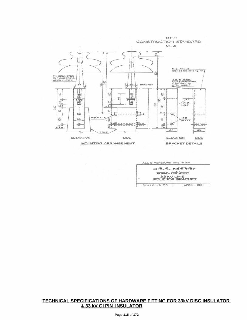
Page 115 of 172
TECHNICAL SPECIFICATIONS OF HARDWARE FITTING FOR 33kV DISC INSULATOR & 33 kV GI PIN INSULATOR

Page 116 of 172
9.1 SCOPE :
This Specification covers design, engineering, manufacture, assembly, stage testing,
inspection & testing before supply and delivery at site
Hardware fittings for 33 KV Disc Insulators
and 33 KV GI Pins.
9.2 APPLICABLE STANDARD :
I. Fittings for Disc insulators shall comply with the requirements of IS : 2486
and REC specification No. 3/1971, 4/1972.
II. 33 kV GI shall comply with the requirements of IS : 2486.
9.3 GENERAL REQUIREMENTS :
I. Fittings for Disc Insulators :
Cross arm strap confirming to IS 2486 (Part II)
Forged Steel ball eye for attaching the socket end of the Disc insulator to the cross
arm strap. Forging shall be made of steel as per IS : 2004 Grade 4. Aluminium alloy
thimble socket made out of permanent high strength aluminum alloy for attaching
the disc insulator at one end and for accommodating the loop of conductor (Panther
ACSR) at the other end. The thimble socket shall be attached to the disc insulator
with the help of locking pin as per the dimensions given in IS:2486 (Part II).
The tension hardware with four bolts strain hardware shall have minimum slip strength not less than 95% of the strength of respective conductor.
Failing load shall be minimum 70 KN.
II. 33 kV GI Pin :
The pins shall be of single piece obtained by the process of forging. They will not be
made by any process using more than one piece of material. The pin will have good
finish, free from flaws and other defects. The finish of the collar shall be such that a
sharp angle between the collar and the shank is avoided. All ferrous pins, nuts and
washers, except those made of stainless steel shall be galvanized by hot dip process.
Other fittings, i.,e flat washers and spring washers may be electro-galvalised as per
IS:2486. The threads of nuts, and toped holes, when cut after galvanization shall be
well oiled or greased.
The pins shall be as per relevant figure indicated in IS 2486 (part II) having stalk
length of 165 mm and shank length of 150 mm with minimum failing load of 10 KN
with small heads and shall match with the pin type insulators with cemented zinc
thimble having similar threads.
9.4 TESTS :
The hardware fittings and pin s shall be tested as per IS: 2486 (part-1):1993
Page 117 of 172
I. Type Test:
The bidder has to enclose the reports of the following type tests carried out in any govt. recognized laboratory along with the bid documents.
a) Checking of Threads on Heads
b) Galvanizing Test
c) Visual Examination
d) Mechanical Test.
II. Acceptance Tests:
Following tests shall be carried out at the works of the manufacturer before dispatch. a) Checking of Threads on Heads
b) Galvanizing Test
c) Visual Examination
d) Mechanical Test.
10.0 TECHNICAL SPECIFICATIONS OF NUTS & BOLTS
10.1 SCOPE:
This specification covers manufacture, testing and supply of ISI Marked bolts and nuts made
of black mild steel. All bolts and nuts shall have hexagonal heads, the heads being forged out
of solid truly concentric, and square with the shank, which must be perfectly straight. The half
thread GI nuts and bolts with 1 plane washer and 1 spring 1 washer completes 1 set. The
assorted sizes are as following :
Sl. No. Size Appx. Quantity (In Kg) 1 M 16 x 40 mm (Full Thread) As per actual 2 M 16 x 65 mm -do- 3 M 16 x 125 mm -do- 4 M 16 x 150 mm -do- 5 M 16 x 225 mm -do- 6 M 16 x 250 mm -do- 7 M 16 x 300 mm -do- 8 M 16 x 325 mm -do- 9 M 10 x 50 mm -do-
10.2 APPLICABLE STANDARDS
The Bolts & Nuts shall conform to IS: 6639 and galvanized as per IS: 1367 (Part-13)/ IS-
2629.
10.3 GENERAL REQUIREMENTS
a) Bolts upto M16 and having length up to 10 times the diameter of the bolt should be
manufactured by cold forging and thread rolling process to obtain good and
reliable mechanical properties and effective dimensional control. The shear
strength of bolt for 5.6 grade should be 310 MPA minimum as per IS-2427. Bolts
should be provided with washer face in accordance with IS: 1363 Part-I to ensure
proper bearing.

Page 118 of 172
b) Nuts should be double chamfered as per the requirement of IS: 1363 Part-III-1984.
The manufacturer should ensure that nuts should not be over tapped beyond 0.4
mm oversize on effective diameter for size up to M16
c) Fully threaded bolts shall not be used. The length of the bolt shall be such that the
threaded portion shall not extend into the place of contact of the component parts.
All bolts shall be threaded to take the full depth of the nuts and threaded enough
to permit the firm gripping of the component parts but no further. It shall be
ensured that the threaded portion of the bolt protruded not less than 3 mm and not
more than 8 mm when fully tightened. All nuts shall fit and tight to the point where
shank of the bolt connects to the head.
d) Flat washers and spring washers shall be provided wherever necessary and shall
be of positive lock type. Spring washers shall be electro-galvanized. The thickness
of washers shall conform to IS: 2016. The bidder shall furnish bolt schedules
giving thickness of components connected the nut and the washer and the length
of shank and the threaded portion of bolts and size of holes and any other special
details of this nature.
e) To obviate bending stress in bolt, it shall not connect aggregate thickness more
than three time its diameter. Bolts at the joints shall be so staggered that nuts may
be tightened with spanners without fouling.
f) To ensure effective in-process quality control it is essential that the manufacturer
should have all the testing facilities for tests like weight of zinc coating, shear
strength, other testing facilities etc, in-house. The agency should
also have proper Quality Assurance system which shall be in line with the
requirement of this specification and IS: 14000 services Quality System standard.
Fasteners of grade higher than 8.8 shall not to be used.
Raw Materials
MS round 16mm/12mm used shall be tested for quality as per IS: 2062 Gr.”A”.
The dimensions of the bolts & nuts and tolerances shall conform to IS: 1363 with their
latest amendments in all respect. The eccentricity and angular errors of various elements
shall be within specified limits as per IS: 1367/1967 with its latest amendments. The bolts
& nuts shall be free from forging and threading defects such as cuts, splits, burns, bulging,
taper, eccentricity, loose fill etc., which may affect their serviceability.
The bolt heads and nuts shall be chamfered on one face only and other face shall
be machined made. Mechanical property requirement of tester shall conform to IS:
1367 (Part- III)-1979 property class 4.6 for bolts and property class-5 for nuts as per IS:
1367 (Part-VI)-1980. The bolts and nuts shall be supplied in well- cleaned conditions and
suitably protected against corrosion in individual bags of 50kgs.
GALVANISING
It is required for galvanizing the Stay Clamps as following:

Page 119 of 172
a) All galvanizing shall be carried out by the hot dip process, in accordance with
Specification IS 2629. However, high tensile steel nuts, bolts and spring washer
shall be electro galvanized to Service Condition 4. The zinc coating shall be
smooth, continuous and uniform. It shall be free from acid spot and shall not scale,
blister or be removable by handling or packing. There shall be no impurities in the
zinc or additives to the galvanic bath which could have a detrimental effect on the
durability of the zinc coating.
b) Before picking, all welding, drilling, cutting, grinding and other finishing
operations must be completed and all grease, paints, varnish, oil, welding slag and
other foreign matter completely removed. All protuberances which would
affect the life of galvanizing shall also be removed.
c) The weight of zinc deposited shall be in accordance with that stated in Standard
IS 2629 and shall not less than 0.61kg/m² with a minimum thickness of 86 microns
for items of thickness more than 5mm, 0.46kg/m² (64 microns) for items of thickness
between 2mm and 5mm and 0.33kg/m² (47 microns) for items less than 2mm thick.
d) Parts shall not be galvanized if their shapes are such that the pickling solutions
cannot be removed with certainty or if galvanizing would be unsatisfactory or
if their mechanical strength would be reduced. Surfaces in contact with oil shall
not be galvanized unless they are subsequently coated with an oil resistant varnish or paint.
e) In the event of damage to the galvanizing the method used for repair shall be
subject to the approval of the Project Manager or that of his representative.
f) Repair of galvanizing on site will generally not be permitted.
g) The threads of all galvanized bolts and screwed rods shall be cleared of spelter by
spinning or brushing. A die shall not be used for cleaning the threads unless
specifically approved by the Project Manager. All nuts shall be galvanized. The
threads of nuts shall be cleaned with a tap and the threads oiled.
h) Partial immersion of the work shall not be permitted and the galvanizing tank must
therefore be sufficiently large to permit galvanizing to be carried out by one
immersion.
i) After galvanizing no drilling or welding shall be performed on the galvanized parts of
the equipment excepting that nuts may be threaded after galvanizing. To avoid the
formation of white rust galvanized materials shall be stacked during transport and
stored in such a manner as to permit adequate ventilation. Sodium dichromate
treatment shall be provided to avoid formation of white rust after hot dip
galvanization.
j) The galvanized steel shall be subjected to test as per IS-2633.
TESTS
Acceptance Tests
The bidder shall furnish test certificate from his own/recognized Govt. Laboratory giving

Page 120 of 172
the results of tests as per IS: 1367 (Part-III)-1979 & IS: 1367 (Part-VI) 1980 witnessed by
owners inspecting officer for each lot under inspection. The test certificate shall be in
respect of the following for all sizes of both bolts & nuts as applicable given below:-
a) Dimensional particulars (Sampling in accordance with IS: 2614 for both bolts & nuts
(tolerance as per drawing).
b) Tensile strength test on full size (for bolts minimum 400 N/ Sq. mm and for Nuts Proof Stress test Min 610 N/Sq.mm).
c) Power load test on full size bolts and M-12-51400 N for 15 Sec. d) Head soundness
tests for bolts (no fracture). e) Brinell hardness tests or Rockwell
Hardness or Vickers’s Hardness tests for bolts min. 114 and max. 209 or min.67 &
max. 95 or min.120 & max.220 respectively. For nuts Vicker’s Hardness min. 130 &
max. 302.
PRE-DESPATCH INSEPCTION
The bidder shall arrange to carryout acceptance tests in presence of owner’s inspecting
officer in his own laboratory. In case testing facilities are not available at his works he will
make necessary arrangements for carrying out these tests at a Govt. recognized lab at his
own expenses(s) and will provide all testing arrangement for Owner’s representative to
witness the tests.
MARKINGS
On the bolt head, there shall be identification marking of the manufacturer as well as
property class “4.6”. If possible property calls “5” shall be marked on Nuts also. Further
“ISI” mark shall be marked on Sunny Bags for proper identifications.
GURANTEED TECHNICAL PARTICULARS FOR
NUTS&BOLTS (To be submitted along with offer)
Sl. No. Particulars Bidder’s Offer
1 Length of Bolt (in MM)
2 Dia of Bolt (In MM)
3 Pitch of Thread (In MM)
4 Full Thread or Half Thread
5 Dimension of Head
6 Size & Thickness of Plain Washer
7 Size & Thickness of Spring Washer
8 Thickness of GI Coating
9 Weight of one complete set

Page 121 of 172
TECHNICAL SPECIFICATIONS OF DANGER BOARD
SCOPE:
This Specification covers manufacture, testing and supply to the owner’s stores of Danger
Notice Plates to be displayed in accordance with Rule no.35 of Indian Electricity Rules,
1956.
APPLICABLE STANDARDS
The danger Notice Plates shall comply with IS: 2551-1982 and REC Spec. No. 57/1993 or the latest version thereof.
DIMENSIONS
The size of Danger Notice shall be as following :
For display at 33 KV installations – 250 x 200mm
The corner of the plate shall be rounded off.
The locations of fixing holes as shown in Fig. 1 to 4 is provisional and can be modified to suit the requirement of the purchaser.
LETTERINGS
All letterings shall certainly spaced. The dimension of the letters, figures and their
respective position shall be as per standard. The size of letters in the words in each
languages and spacing earmarked for them.
LANGUAGES
Under Rule No.35 of Indian Electricity Rules, 1956, the owner of every medium high and
extra high voltage installation is required to affix permanently in a conspicuous position a
danger notice in Hindi or English and , in addition, in the local languages, with the sign of
skull and bones.
The type and sizes of lettering to be done in Odia is indicated in the specimen danger notice plates.
Adequate space has been provided in the specimen danger notice for having the letterings
in local languages for the equivalent of ‘Danger’: “33000” and “volts”.
MATERIAL AND FINISH
The plates shall be made from mild steel sheet of at least 1.6 mm thick and vitreous
enameled white, with letters, figures and conventional skull and cross bones in signal red
colour (refers IS:5-1978) on the front side. The rear side of the plate shall also be
enameled.
TESTS The following tests shall be carried out: Visual examination as per IS: 2551-1982.
Dimensional check as per IS:2551-1982.

Page 122 of 172
Test for weather proofness as per IS:8709-1977 (or its latest version)
MARKING Maker’s name and trade mark and the purchaser’s name shall be marked in such a manner and position on the plates that it does not interfere with the other information.
PACKING
The plates shall be packed in wooden crates suitable for rough handling and acceptable for rail/road transport.
GURANTEED TECHNICAL PARTICULARS FOR
DANGER BOARD
(To be submitted along with offer) Sl.
GENERAL TECHNICAL PARTICULARS Bidder’s Offer No
1 Size of the danger board
2Siz e of the letter
3Siz e of the Skull
4De tail of painting
5W hether detailed drawing is enclosed along
TECHNICAL SPECIFICATIONS OF BARBED WIRE
SCOPE :
The scope covers manufacture, testing and supply of two ply barbed wires as per IS : 278,1978.
MATERIALS :
The galvanised barbed wires, (Type A) shall be manufactured from hot dipped galvanised mild steel wire confirming to IS : 280, 1972. Diameter of line and point wire shall be 2.5 mm. Distance between the barbs shall be 75 mm.
COILING & PACKING :
Each reel of barbed wire shall be wound and fastened compactly and of weight of 50 Kg approximately.
TESTING :
Routine and Acceptance test will be carried out at the works of the manufacturer as per IS:278.

Page 123 of 172
GURANTEED TECHNICAL PARTICULARSFOR
BARBED WIRE (To be submitted along with offer)
Sl.
GENERAL TECHNICAL PARTICULARS Bidder’s Offer No. 1 Nominal diameter of line wire
2 Nominal diameter of point wire
3 Distance between the barbs
4 Tensile strength
A Min. N/mm²
B Max. N/mm²
5 Minimum breaking load (KN)
6 Type of coating Heavy/Medium/Light
7 Weight of Zinc coating (Gms/Sq. Mtr.) Min.
8 No. of dips the coating is able to withstand as 18 ± 20ºC
9 Chemical composition the MS Wire used shall not
A Sulphur 0.060%
B Phosphorous 0.065%

Page 124 of 172
Section-V 33kV Isolator

Page 125 of 172
TECHNICAL SPECIFICATION OF 33 KV AIR BREAK ISOLATOR
SCOPE This specification covers design, manufacture, testing and supply of. Manually operated 33 KV,
800 Amps Upright mounting type with manually operated with earth switch Isolators.
The isolator shall be of the manual operated type with earthing switches and shall complete
with all parts and accessories including insulator operating rods, mounting attachments,
necessary for their efficient operation.
1.04 It is not intent to specify completely herein, all details of the design and construction of
equipments, however the equipment shall confirm in all respect to high standards of
engineering mentioned in clause No. 4.0 design and workmanship and shall capable of
performing in continuous commercial operation up to the suppliers guarantee in a manner
acceptable to the purchaser, who will interpret the meanings of drawing and specification and
shall have the powers to reject any work or material which, in his judgment, is not in
accordance therewith. The equipment offered shall be complete with all components
necessary for its effective and trouble free operation along with associated equipments,
interlock, protection schemes, etc. Such components shall be deemed to be within the scope
of bidder's supply irrespective of whether those are specifically brought out in this
specification or not. All similar parts particularly removable ones shall be interchangeable.
2.00 LOCATION
The isolators are required to be provided at interconnection points of UG Cable on 4-Pole structure at Janla 33/11kV S/s.
SERVICE CONDITIONS:
The 33 kV triple pole air break isolators are intended to be used primarily for sectionalizing 33
kV UG cable portion of the line with 33 kV over head portion of the line.
3.03 ATMOSPHERIC CONDITIONS
Please refer to meteorological data furnished elsewhere in this document.
4.0 GOVERNING SPECIFICATION:
The isolator shall unless otherwise specified, generally conform the IS : 9921 (Part I to
IV) - 1985, which shall be applied in the manner altered, amended or supplemented
by this specification, the latest Indian Electricity Rules wherever applicable.
Any deviation from this specification offered to improvement performance, utility and
efficiency of equipment proposed by the bidder will be given due consideration,
provided full particular with justification thereof are furnished.
In the preparation of this specification, details have been taken from IEC 600 - 129
"alternating current disconnects (Isolators) and earthing switches", and IS 9921 (Part-I
to IV) "Specification for alternating current disconnects (isolators) and earthing
switches for voltages above 1000V ”.
Equipment meeting with the stipulations of equivalent IEC, ANSI, CSA, DIN standards which
ensure equal or better quality than the standards listed in Clause No. 4.05, shall also be
acceptable. In such case the bidder should submit along with this offer, two copies of such

Page 126 of 172
standards, in authentic English translation, if the language of the standard is other than English.
In case of dispute, the stipulations in English translation, submitted by the bidder shall prevail.
Further, in the event of conflict between the stipulations of the standard adopted be the bidder,
corresponding Indian Standard specification shall prevail.
In this specification reference has been made to the following Indian standard and other
specifications:
Standards
Sl Standards Particulars
No
1
IS : 9921-85 Part-I, II, III & IV)
Specification for alternating current Disconnects
(isolators) and earthing switches for voltages
above 1000V
2 IS: 2544-1973 & Porcelain post insulators for systems with
nominal voltage greater than 1000V IS : 5250-1970
3 IS : 7608 Phosphor bronze wires (for general engineering
purposes)
4 IS : 2108-1977 Black hard malleable iron castings
5 IS : 1570 Part - IQ- 1979
Carbon steel (unalloyed steels)
6 IS : 2071 (Part-I & ll)-1974 General definitions, test requirements & test
procedures
7 IEC: 600129 Alternating current disconnects (isolators) and
earthing switches
8 IS : 7906 (Part-Ill)-1975 Helical compression springs
9 IS: 5561 – 1970 Electric power connectors
10 IS: 5358-1969 Galvanizing of ferrous parts
11 IS : 2633 Method of testing conformity of coating of zinc
coated article

Page 127 of 172
RATING AND OTHER PARTICULARS
The isolators shall be designed for the following rating and other particulars:
Ratings & Other particulars
SI.No. Particulars 33KV
1
Type
Manually operated Double break, upright
mounting with the movement of the blade in a
horizontal plane suitable for outdoor installation
2 No. of poles (Phases) Three
3 Rated Voltage 36KV
4 Rated normal current 800A
5 Rated frequency 50 Hz
6 System neutral earthing effectively earthed…
7 Rated short time withstand
25 KA (rms for 3secs) current of main switch
8 Rated peak withstand current 2.5 times the rated short time withstand current
9
Rated 1.2/50 micro second
Impulse withstand voltage
(peak)
a) to earth 170 kV
b) across isolating distance 195 kV
10 Temperature rise Max.Temp deg.C
a) a. Copper contacts in air
i Silver faced Copper 105
ii Bare copper 75
b)
Terminal of isolator to be
connected to external
conductors by bolts
i Silver faced copper 105
ii Bare copper 90
c) Metal parts acting as springs The temperature shall not exceed a value, where
the elasticity of the materials is impaired. For pure copper the temp. limit is 75deg. C

Page 128 of 172
The isolator are required to be closed or interrupt the 33 kV line & UG cable line charging current.
Hence isolators should be capable of closing or interrupting a current of magnitude indicated in 5.01 (iv)
above.
5.04 CLEARANCE:
5.04.01 The clearance between live parts and ground structure shall not be less than those specified in the
IS – 10118, part – III, 1982. The length of break in full open position should be such that there is
absolutely, no possibility of arc over from the live parts to the de-energized parts on which any
maintenance work have to be done. The speed of opening or closing the switch shall be designed to
ensure that the arcing during the operation is reduced to the minimum.
6.0. GENERAL TECHNICAL REQUIREMENTS TYPE OF ISOLATORS:
The ISOLATORS shall be of three phase gang operated horizontal, double break type with turn and twist
type moving blades.
CURRENT DENSITY:
Current density, to be adopted, for all parts of isolator and terminal connector & shall not exceed the following limits.
a) Hollow tube sections – Copper - 2.0 A / Sq. mm
- Aluminium -1.25 A/Sq. mm
b) Other sections and terminal connectors
Copper - 1.6 A/Sq. mm
Aluminium- 1.0 A/Sq. mm
11 Safe duration of over load
a) 150 % of rated current 5 minutes
b) 120% of rated current 30 minutes
12 Minimum creep age
(mm)
distance 840
13 Rated
load
mechanical terminal
a) Straight load (Kgf) 35
b) Across load (Kgf) 13.26
14 Phase to Phase spacing for
installation(mm) 1500
15 Height of center line of terminal
pad above ground level (mm) 4000

Page 129 of 172
Designs & Drawings
The full particulars of design, manufacture, template and quality control devices developed for
manufacture of the equipments - offered in respect of the following items shall be furnished with drawings
and descriptions.
Sl Particulars No
1 Contacts, Material etc.,
2 Design of contact pressure.
3 Contacts support and fixing arrangement on insulators
4 Turn and twist mechanism, clamps, locks, etc.
5 Bearings, housing of bearing, bushes, etc.
6 Balancing of heights.
7 Coupling pipes, joints, connection adjustments.
8 Base plates.
9 Down pipe, guides joints.
10 Brass bushes and bearings at various joints
11 Operating mechanism, type of gear, size and thickness of box, degree of protection.
Gland plate, gland, etc.
12 Nuts, bolts and fasteners
TYPE AND CONSTRUCTION: The design of the isolators shall be such that the switch can be changed to right or left hand control
without excessive labour and with a minimum change of parts. The live parts shall be of non-rusting, non-
corroding metal. Current carrying parts shall be nonferrous. Bolts, screws and pins shall be provided with
lock washers, keys or other equipment locking facilities. Current carrying parts shall be made of copper
alloy or equivalent material. The switch shall not require lubrication of any part, at frequent intervals.
The isolator shall be suitable for mounting in upright position (with the blades moving in horizontal plane)
on steel / fabricated steel structures. The heights at which the isolators will be mounted along with phase to
phase dimensions are as per clause 5.00, Part - I. Any change in dimensions, will be intimated to
successful bidder. Necessary lengths of operating rod as required shall be supplied.
: OPERATING MECHANISM FOR MANUALLY OPERATED ISOLATOR:
a) Manual operating mechanism, gang operated through crank & reduction gear shall be provided
for main switch. b) The design of the operating mechanism shall be Such that minimum energy is required for operation
and one person shall be able to operate the switch without undue effort. The blades shall be in positive continuous control throughout tile entire cycle of operation. Suitable reduction gear to achieve above aspects may be provided, for main switch and shall close or open with about 20 revolutions of the crank.

Page 130 of 172
c) The operating pipes and rods shall be sufficiently rigid to maintain positive control without tension or
compression & there shall also be capable of withstanding all torsional and bending stresses due to
operation of the disconnecting switch. It shall not be possible, after final adjustment has been made for
any part of the mechanism to be displaced at any point in the travel sufficiently to allow improper
functioning of the switch, when the switch is opened or closed at any speed. All holes, ill crank,
linkages, etc., having moving pins, shall be drilled to accurate fit, so as to maintain the minimum
amount of slack and lost motion. The operating mechanism and its controls shall be so designed that
under no circumstances the switch blades travel is interrupted before it reaches the fully close or open
position. The operating mechanism shall be suitable to hold the main switch or earth switch in closed or
opened position to prevent operation by gravity, wind, short circuit, seismic acceleration, vibration,
shock, accidental touching etc.
6.06. CONTROL CABINET: The operating mechanism mid all accessories shall be enclosed in a weather, dust and vermin
proof cabinet. The control cabinet of each operating mechanism shall be made out of 12 SWG (2.64 mm
thick) steel sheet. or 10mm thick aluminum in the form plate or casting. Control cabinet shall be provided
with hinged doors along with padlocking arrangement. Sloping rain hood shall be provided to cover all
sides. 15 mm thick neoprene or better type gasket shall be provided to ensure degree of protection atleast
IP 55 as per S : 2147.
The motor operating mechanism / manually operating mechanism shall be mounted on the base
supporting structures or on a separate Support- structure at a height of 300 mm from the ground level.
Operating or lever for manual operation shall be at a convenient height of 1000mm above ground level for
easy operation. The unsupported length of the operating rod shall not. exceed 3 meters. Guide bearings
shall be provided at suitable intervals. All brackets angles or other members mid accessories necessary for
fixing the operating mechanism to switch supporting structure. and the bearing for operating rods shall be
supplied. Rust proof pins and bearings of the bronze bushing, ball or roller type shall be provided. All ball
and roller bearings shall be protected from weather by means of covers and grease retainers. Bearing
pressures shall be kept low to ensure long life.
GEAR:
The disconnect may be required to operate occasionally with considerably long idle intervals. Special
care shall be taken for selection of material for gear and lubrication of gears to meet these requirements. The
gears shall be made of bronze or any other better material and lubricated for life with graphite or better
quality non-draining or non-hardening grease. complete details of components, materials, self-lubricating
arrangement, grade of lubricant, details of jigs, fixtures and devices used for quality check shall be
furnished in the bid.
CONSTRUCTIONAL FEATURES:
FIXED AND MOVING CONTACTS:
a) The isolator shall have heavy-duty self-aligning high pressure - contacts of modem design. The contact shall
be made of high grade, high conductivity, and heat resisting material. The main contacts shall be made of hard drawn electrolytic copper and the surface shall be silver plated. Arcing contacts wherever provided shall close first and open last.
b) The isolators blades / arms shall be made preferably from tubular section of hard drawn electrolytic copper having suitable diameter and shell thickness, and the contact surface shall be heavily silver plated.
c) The surface of the contacts shall be liberally designed to withstand safely the-highest short circuit current of the system as specified in the clause 05.01 (vii) - (viii) of part - I.
d) The male and female contact assembly and blades shall ensure
i. Electro dynamic withstand ability during short circuit without any risk of repulsion of contacts.

Page 131 of 172
ii. Thermal with stand ability during short circuits. iii. Constant contact pressure even when the live parts of the insulators stacks are subjected
to tensile stresses the insulators stacks are subjected to tensile stresses due to linear expansion of connected bus - bars, flexible conductors either because of temperature variation or strong winds.
iv. Self - wiping action during closing and opening (preferably twisting type contacts). The surface shall be wiped during closing and opening operation to remove any film, oxide coating, etc. wiping action shall not cause scouring or abrasion of surfaces.
v. Self - wiping ensuring smooth closing of the switch. The temperature rise of the contacts and other current carrying parts shall not be more than 45 °C over an ambient air temperature of 45°C, while carrying the rated current continuously. The temperature rise due to passage of rated short-circuit current for a period of 3 seconds shall not cause an), annealing or welding of contacts.
e) Fixed guides shall be provided so that proper seating of contacts will be obtained by closing even when a blade is out of alignment by 2.5 min or less.
f) All movable pars which may be in the current path shall be shunted by flexible copper conductors to prevent breaking due to repeated bending.
g) Fabrication shall be made with suitable jig to avoid deviation during production. Details of size and shape of contact, springs, back plate, fixing arrangements, design of contact pressure, life of contacts, limit of temperature rise etc., shall be furnished along with the tender.
MOUNTING OF CONTACTS:
Fixed contacts shall be mounted on a block or channel welded to 10 mm thick M.S. plate with
holes for fixing on insulators. Slots shall be provided for marginal adjustment of height of contacts. The
contacts shall rest on a brass block and with initial tension. Suitable device shall be provided to prevent
dashing. Fabrication, welding etc. shall be done in suitable jig to avoid deviation during production.
TURN AND TWIST MECHANISM:
Turn and twist mechanism shall be provided with adequate locking to avoid opening or loosening by
wind, short circuit force etc., on moving blade. The springs shall be made out of stainless steel or phosphor
bronze or any other better material to have adequate strength and resilience and shall be encased with grease
to avoid exposure to rain. The clamps and plates be made out of at least 10 mm thick M.S. plate or flat.
Fasteners with unlock nuts shall be used wherever necessary. Vulnerable parts shall be fabricated by tubular
gas cutting and milling. The entire- mechanism shall be fabricated in suitable jig and template to avoid
deviations during production.
All lives parts shall be designed to have smooth surfaces without any sharp points, edges and
other corona producing surfaces so as to eliminate corona at specified extinction voltage or at 1.1 x rated
voltage, if extinction voltage is not specified.
FASTNERS:
Nuts, bolts and washers of M -16 and higher size shall be hot-dip galvanized. The bolts used on
tapped holes of insulators cap shall be galvanized by centrifuge process to avoid excess deposition of zinc
on threads. Nuts, bolts and washers of less than M -16 size shall be of stainless steel when used on live
parts and nickel plated brass in other parts.
BEARINGS
a) The design and construction of the various bearings should embody all the features required to
withstand the climatic conditions specified to ensure dependable and effective operation, even after
long period of in action. All bearings in the current path except those specially designed as high
pressure contact should be shunted by flexible copper housing having adequate cross section.
b) Rotating insulator shall be mounted on a housing with bearings. The housing shall be made of
gravity die cast metal with smooth surfaces and suitably machined for seating the bearings. Two

Page 132 of 172
nos. of bearings with adequate shaft diameter and distance between the bearings shall be provided
to avoid wobbling during operations. The bearings shall be of at least 75 mm internal diameter. The
bearings shall be of reputed make and lubricated for life. All other friction locations shall be provided
with suitable bearings or stainless or brass bushes. The bearings, bushes, joints, springs, etc., shall
be so designed that no lubrication shall be required during the service. Complete details of bearings,
bushes housing greasing, etc., shall be furnished with tender.
TANDEM AND DOWN PIPE:
a) The operating down pipe mid tandem pipe shall be of heavy duty GI pipe of the following sixes
(Bore dia) for different KV class i.Bore dia of tandem pipe ------- 32 mm.
ii. Bore dia of down operating pipe – 50 mm b) The outside diameter and thickness of pipe shall be as follows as per
table - 3 of IS : 1239 (Part - 1) 1990. Mild steel tubes. -
S1. Nominal outer dia outer dia Minimum
No. Bore in Maximum (mm) Minimum(mm) thickness
1. 32 42.9 42 4
2. 40 48.8 47.9 4
3. 50 60.8 59.7 4.5
Tandem pipe:
a) Two Nos. of tandem pipe shall be used for phase coupling of double break isolator. Base
plate of insulators for connection of tandem pipe shall be made out of one piece of at least 10
mm. thick MS plate. Bolt and shackle device shall be used to connect tandem pipe to the
base plate. Wherever unavoidable, sliding clamps may be used. These clamps shall be made
out of at least 10 mm thick MS plate with four(4) nos. of nuts and bolts. A grub screw shall be
provided for securing connection of tandem pipes.
b) The pipe shall be terminated into a suitable swivel or universal type joint between the insulator bottom bearing of the operating mechanism to take cares of marginal angular misalignment at site. All brackets, guides, etc., shall be mounted on the base of the isolator. Arrangement of mounting any guide, bracket, mechanism and the base shall not be accepted, for upright mounting type isolator.
6.15. BASE :
Each pole of the isolator shall be provided with hot dip galvanized rolled steel base provided
with holes for mounting bolts and designed for mounting on a steel structure. The bases shall
be rigid and self supporting and shall require the guying or cross bracing between phases
other than the supporting structure. The composite frame of the base shall be made of single
channel of 150 x 75 x 6 / 8 mm.
INSULATORS:
The isolator shall be provided with solid core insulators. a) These shall be of stacking type to be used.The dimensions and other parameters unless
otherwise specified shall generally conform to IS - 5350-Part-11 & IEC 273. b) The cylindrical type post insulators shall be of solid core type. Insulators of similar type shall be
interchangeable. The mechanical strength class for outdoor cylindrical post insulators shall be of strength class 6, corresponding mechanical strength in tension, compression and torsional shall

Page 133 of 172
be as per IS : 53550 Part - II. When operated at maximum system voltage, there shall be no electrical discharge. Shielding rings, if necessary shall be provided.
c) The parameters of the insulators required shall conform to IS : 0350 - Part - II - 1973 or IEC 273. d) The cylindrical post insulators shall consist of single unit only. e) The insulator shall be provided with a completely galvanized steel base designed for mounting
on the support. The base and mounting arrangement shall be such that the insulator shall be rigid and self supporting and no guying or cross bracing between phase shall be necessary. Porcelain of the insulator:
f) The porcelain used for the manufacture of the insulators shall be homogenous, free from laminations and other flaws or imperfections that might effect the mechanical or dielectric. quality and shall be thorough vitrified, tough and impervious to moisture. The glazing of the porcelain shall be uniform brown colour, with a smooth surface arranged to shade away rain water and free from blisters, burns and other similar defects. Insulators shall be inter-changeable.
g) The porcelain and metal parts shall be assembled in such a manner and with such materials that any differential thermal expansion between the metal and porcelain parts throughout the operating temperature range will not loosen the parts or electrical strength or rigidity. The assembly shall not have excessive concentration of electrical stress in any section or across leakage surfaces. The cement used shall not give rise to chemical reaction. with metal fittings. The insulator shall be suitable for water washing by rains or artificial means in service conditions. Further the insulators to be supplied shall be of high- quality and should not result in mismatch and misalignment of stacks during erection and operation.
h) Each cap shall be of a high grade cast iron or malleable steel casting or steel forging. Cap and base insulators shall be interchangeable with each other. The insulator shall conform to the requirement of the latest edition of IS : 2544,or any other equivalent standard. The bidder should furnish the characteristics of insulators.
6.16.03 All the ferrous metal part shall be hot dip galvanized smoothly as per IS: 3638 (as amended up to
date), IS : 2623 or any other equivalent authoritative standard. The material shall be galvanized
only after shop operations upon it have been completed. The metal parts for galvanization should
be thoroughly cleaned of any paint, grease, rust, scales or alkalies or any foreign deposit which are
likely to come in the way of galvanization process. The metal parts coating shall withstand
minimum four one minute dips in copper sulphate solution as per IEC - 168.
The insulator unit shall be assembled in a suitable jig to ensure correct positioning of the
top and bottom metal fittings relative to one another. The phases of the metal fitting shall be
parallel and at right angle to the axis of the insulator and corresponding holes in the top and bottom
metal fittings shall be in a vertical plane containing the axis of the insulator. It shall be sole
responsibility of the supplier to carry out thorough inspection and quality, checks on the insulators
at the insulator supplier works before offering the insulators for purchaser's inspection.
PADLOCKING DEVICE: The isolator shall be provided with padlocking device to permit locking of the isolator in both fully
open and fully closed positions.
EARTHING: The frame of each disconnect shall be provided with two reliable earthing terminals for connection
to the earthing conductor / flat so also clamping screw suitable for carrying specified short time current.
The diameter of clamping screw shall be at least 12 mm. The connecting point shall be marked with
earth symbol.
TERMINAL CONNECTORS a) The disconnecting switches shall be provided with high conductivity bimetallic terminal connectors
and suitable for Aluminium pipes (BS 1600 schedule 40) and 100 mm AAA conductors & 120 sqmm U.G.cable, the size of which will be indicated. to successful bidder. The connector shall be rigid in respect of AAA conductors & flexible for UG Cable connections. The terminal connectors shall be expansion type in respect of Aluminium pipes. The terminal connector shall conform to IS : 5561 1970.
b) Further the terminal connectors shall be suitable for both horizontal or vertical take off.

Page 134 of 172
c) For bimetallic type of connectors, necessary steps shall be taken by the manufacturers to ensure that there is no adverse effect on the connector and the connected equipment due to bimetallic action.
SUPPORTING STRUCTURE:
These galvanized support structures shall be fabricated as per the requirement.
ASSEMBLY
The disconnect shall be fully assembled at the works of the bidder. Typical operation shall be
carried out on each type of fully assembled disconnect to ascertain that all parts fit correctly and function
satisfactorily.
PAINTING, GALVANIZING AND CLIMATE PROOFING:
a) All interiors and exteriors of enclosures, cabinets mid other metal parts shall be thoroughly cleaned
to remove all rust scales, corrosions, grease and other adhering foreign matter and surfaces treated
by recognized phosphating (Eg. Seven tank phosphating sequence), After such preparation of
surfaces tow coats of zinc oxide primer shall be given by suitable stoving and air-drying, etc., before
final paint.
b) Colour of the final paint shall be of shade No. 631 of IS-5, i.e., epoxy light grey. The final painted
cubicle shall. present aesthetically pleasing appearance free from any dent of uneven surface Paint
inside the metallic housing shall be of anti - condensation type and the paint on outside surfaces
shall be suitable for outdoor installation.
c) All ferrous parts not suitable for painting such as structural steel, pipes, rods, levers, linkages, nuts
and bolts used in other than current path etc., and also supporting structures shall be hot dip
galvanized. Galvanization shall be done after completion of fabrication which shall be capable to
prevent corrosion in view of the severe climatic conditions.
d) Thickness of zinc coating shall not be less than 610 gm of zinc per sq. meter of surface. Zinc coating
shall be smooth clean and of uniform thickness and free from defect. Preparation of galvanizing and
the galvanizing itself shall not adversely effect the mechanical properties of the coated material, The
quality shall be established by tests per IS : 2633. Galvanizing of nuts and bolts shall be carried out
by centrifugal or suitable process so that the bolts will easily fit into the tapped holes / nuts.
e) All components shall be given adequate treatment of climate proofing as per IS : 3202 so as to
withstand corrosion and severe conditions.
TESTS :
Type tests :
a) The equipment offered, shall be fully type tested. The type test reports shall not be older than 5
years on the day of bid opening. The type tests are to conducted again if the reports are older than 5 years on the day of bid opening at no extra cost to owner.
b) During the type test the disconnect shall be mounted on its own support structure or equivalent support structure and installed with its own operating mechanism to make the type test
representative. Drawing of equivalent support structure if any and mounting arrangement made for type tests shall be furnished for purchaser's approval before conducting the type tests.
c) The type tests shall be conducted on the disconnect along with approved insulators and terminal connectors.
d) Mechanical endurance test shall be conducted on the main switch.
e) LIST OF TYPE TESTS:
List of type tests to be carried out as per IS : 9921 Part - VI 1985, are as given below.
i. Visual examination of components, ii. Dimensional verification of parts. iii. Assembly, interchangeability and verification of critical dimensions.

Page 135 of 172
iv. Measurement of resist-circuit of main circuit and earth circuit (before and after mechanical endurance test)
v. Temperature rise test (before and after mechanical endurance test) vi. Mechanical endurance test. vii. Short time withstand current and peak withstand current tests. viii. One minute power frequency voltage wet withstand tests across the isolating distances and to earth. ix. Standard lightning impulse voltage withstand tests on auxilia~3, and control circuits and auxiliary
switches. x. One minute power frequency, withstand voltage test on auxiliary and control circuits and auxiliary
switch. xi. Verification of operation during application of rated mechanical terminal loads. xii. Galvanization tests. xiii. Chemical composition of contact material, springs and fasteners and bushes. xiv Physical tests on
springs and fasteners and copper strip / tubes.
ACCEPTANCE AND ROUTING TESTS:
a) All acceptance and routine tests as stipulated in the relevant standards shall be carried out by the
supplier in presence of purchaser's representative. b) Mechanical operation tests (routine test) shall. be conducted on the complete disconnect (man
switch and earth switch) at supplier's works and a certified test report be furnished to the purchaser. Alternatively the bidder may offer to conduct this test at purchaser's sub- station in which case the purchaser shall make necessary arrangement to erect the disconnect at his sub-station site under supervision of bidders representatives for supervision shall not be borne by the purchaser.
c) The test report of power frequency voltage withstand test conducted on the insulator shall be furnished for purchaser's acceptance in lieu of conducting the power frequency (dry) test on main circuit (routine test).
d) LIST OF ROUTING TESTS: List. of routine test to be carried out as per IS : 9921, Part - IV - 1985 are as given below:
i. Visual examination of components.
ii. Assembly, interchangeability and verification of critical dimensions.
iii. One minute power frequency voltage dry withstand tests across the isolating distance and to earth.
iv. Measurement of resistance of isolator contacts and between terminals of the main circuits.
v. Power frequency voltage withstand tests on auxiliary and control circuits and auxiliary switches at 2 KV (RMS) for one minute.
vi. Mechanical operation tests.
SPECIAL TESTS
Special tests listed below shall be carried out in presence of purchaser's representative.
a) Test on insulators – Conforming to IS - 2544
b) Test on insulators – Conforming to IEC - 168
c) Test on terminal connecters – IS : 5561
d) Operation tests on operating mechanism - IS : 2623.
e) Test certificates and documents of the following items shall be furnished at the time of routine tests.
Chemical analysis of copper.
Bearings
Fasteners
Universal/ swivel joint coupling.
Insulators.
Gears

Page 136 of 172
8.00 INSPECTION
The inspection may be carried out by the purchaser at any stage of manufacture. The successful
bidder shall grant free access to the purchaser's representative at a reasonable time when the work
is in progress. Inspection and acceptance of any equipment under this specification by the
purchaser, shall not relieve the supplier of his obligation of furnishing equipment in accordance with
the specification and shall not prevent subsequent rejection if the equipment is found to be
defective. The supplier shall keep the purchaser informed in advance, about the manufacturing
programme so that arrangement can be made for inspection. The purchaser reserves the light to
insist for witnessing the acceptance / routine testing of the bought out items.
9.0. DOCUMENTATION:
All drawings shall conform to International Standard Organization (ISO) ' A ' series of drawing
sheet / Indian standards specification IS : 656. All drawings shall be in ink and suitable for
micro filming. All dimensions and data shall be in system international units.
LIST OF DRAWINGS AND DOCUMENTS:
The bidder shall furnish the following drawings along with his offer:
a) General outline and assembly drawings of the disconnect, operating mechanism, structure,
insulator and terminal connector.
b) Sectional views and descriptive details of items such as moving blades, contacts arms,
contact springs, contact support, turn and twist mechanism, bearing, housing of bearing,
bushes, balancing of heights, phase coupling pipes, base plate, operating shaft, guides,
swivel -joint operating mechanism and its components, etc.
a) Loading diagram.
b) Drawings with structure for the purpose of type test
c) Name plate
d) Schematic drawing
e) Type test reports in case the equipment has already been type tested
f) Test reports, literature, pamphlets of the bought out items and raw material.
INSTRUCTION MANUALS
The two copies of the erection, operation and maintenance manuals in English shall be supplied
one month prior to dispatch of the equipment. The manual shall be bound volume and shall contain all
drawings and information required for erection, Operation and maintenance of the disconnect including but
not limited to the following particulars.
a) Marked erection prints identify the component parts of the disconnect as shipped with -
assembly drawings. b) Detailed dimensions and description of all auxiliaries. c) Detailed views of the insulator stacks, metallics, operating mechanism, structure etc.
LIST OF MANUFACTURERS:
a) SWITCHGEAR & STRUCTURAL, b) MULAR, c) CGL , d) GR POWER , e) AREVA, f) SIEMENS
The bidders can only offer the above manufacturer’s equipments.

Page 137 of 172
Section-VI Lightning Arrestor

Page 138 of 172
TECHNICAL SPECIFICATION OF 33 KV LIGHTNING ARRESTOR
(VOLTAGE CLASS SURGE ARRESTORS)
The specification covers the design, manufacture, shop & laboratory testing before despatch, supply delivery of 33 KV, Station class heavy duty, gapless metal oxide Surge Arrestors, insulating base, clamps, complete fittings & accessories suitable for 33 KV transformers/feeders including arrester's electrode earthing.
1.0 STANDARDS
The design, manufacture and performance of Surge Arrestors shall comply with IS: 3070 Part-3
and other specific requirement stipulated in the specification Unless otherwise, specified, the equipment,
material and processes shall conform to the latest applicable Indian/International Standards as listed
hereunder:
IS: 2071-1993 (Part-1) : Methods of High Voltage Testing General Definitions &
Test Requirements.
IS: 2071-1974 (Part-2) : Test Procedures
IS: 2633-1986 : Methods for Testing uniformity of zinc coated Articles.
IS: 3070-1993 (Part-3) : Specification for surge arrestor for alternating current
system Metal-Oxide lightening Arrestors without gaps.
IS:4759-1996 : Specification for hot dip zinc coating on Structural Steel
and other allied products.
IS: 5621-1980 : Hollow Insulators for use in Electrical Equipment.
IS: 6209-1982 : Methods of Partial discharge measurement.
IS: 6745-1980 : Methods for determination of mass of zinc coating on
zinc coated iron and steel articles.
IEC:TC-37 : Test Procedures.
ANSI/IEEE-C.62.11(1982) : Metal Oxide, Surge Arrestor for A.C. Power Circuits.
IEE-99-4 : Surge Arrestors.
The equipment complying with any other internationally accepted standards shall also be considered if it
ensures performance equivalent to or superior to the India Standards.
GENERAL REQUIREMENT
The Metal Oxide gap less Surge Arrestor without any series or shunt gap shall be suitable for
protection of 33 KV power transformers, associated equipment and 33 KV lines from voltage surges resulting from natural disturbance like lightening as well as system disturbances.
The surge arrestor shall draw negligible current at operating voltage and at the same time offer least resistance during the flow of surge current.

Page 139 of 172
The surge arrestor shall consist of non-linear resistor elements placed in series and housed in electrical grade porcelain housing/silicon polymeric of specified creepage distance.
The assembly shall be hermetically sealed with suitable rubber gaskets with effective sealing system arrangement to prevent ingress of moisture.
The surge arrestor shall be provided with line suitable for ACSR 'Panther' Conductor for vertical and horizontal take off. The earth terminals shall be provided of suitable size. The groundside terminal of surge arrestor shall be connected with 50x6mm- galvanized strip, one end connected to the surge arrestor and second end to a separate ground electrode (Electrode type of earthing). The contractor shall also recommend the procedure which shall be followed in providing the ear thing/system to the Surge Arrestor.
The surge arrestor shall not operate under power frequency and temporary over voltage conditions but under surge conditions, the surge arrestor shall change over to the conducting mode.
2.7 Surge arrestor shall have a suitable pressure relief system to avoid damage to the porcelain / silicon polymeric housing and providing path for flow of rated fault currents in the event of arrestor failure.
The reference current of the arrestor shall be high enough to eliminate the influence of grading and stray capacitance on the measured reference voltage.
The surge arrestor shall be thermally stable and the contractor shall furnish a copy of thermal stability test with the bid.
The arrestors for 33 KV system shall be suitable for mounting on transformers as well as in the yard. The supplier shall furnish the drawing indicating the dimensions, weight etc. of the surge arrestors for the design of mounting brackets.
The arrestor shall be capable of handling terminal energy for high surges, external pollution and transient over voltage and have low losses at operating voltage.
ARRESTOR HOUSING
The arrestor housing shall be made up of porcelain/silicon polymeric housing and shall be
homogenous, free from laminations, cavities and other flaws of imperfections that might affect the
mechanical and dielectric quality. The housing shall be uniform brown colour, free from blisters, burrs and
other similar defects.
Arrestors shall be complete with insulating cases, fasteners for stacking units together and terminal
connectors.
The housing shall be so coordinated that external flashover shall not occur due to application of
any impulse or switching surge voltage upto the maximum design value for arrestor. The arrestors shall not
fail due to contamination. The 33 KV arrestors housing shall be designed for pressure relief class as given
in Technical Parameters of the specification. Sealed housing shall exhibit no measurable leakage.
TESTS
Test on Surge Arrestors: The Surge Arrestors offered shall be type tested not earlier than 5 years before the date of
opening of this tender. The surge arrestors shall be subjected to routine and acceptance tests in
accordance with IS: 3070(Part3)-1993. In addition, the suitability of the Surge Arrestors shall also be
established for the following:
* Residual voltage test
* Reference voltage test
* Leakage current at M.C.O.V.
* P.D. Test
* Sealing test
* Thermal stability test
* Aging and Energy capability test
* Watt loss test

Page 140 of 172
Each metal oxide block shall be tested for guaranteed specific energy capability in addition to
routine/acceptance test as per IEC/IS. The maximum residual voltages corresponding to nominal discharge current of 10KA for steep
current, impulse residual voltage test, lightning impulse protection level and switching impulse level shall generally conform to Annexure-K of IEC-99-4.
The bidder shall furnish the copies of the type tests and the characteristics curves between the residual voltage and nominal discharge current of the offered surge arrestor and power frequency voltage V/s time characteristic of the surge arrestor subsequent to impulse energy consumption as per clause 6.6 of IS: 3070 (Part-3) offered along with the bid.
The surge arrestors housing shall also be type tested and shall be subjected to routine and acceptance tests in accordance with IS: 2071.
Galvanization Test
All Ferrous parts exposed to atmospheric condition shall have passed the type test and be subjected to routine and acceptance test in accordance with IS: 2633 & IS: 6745.
NAME PLATE
The nameplate attached to the arrestors shall carry the following information: -
* Manufacturing Trade Mark * Year of Manufacture
* Rated Voltage
* Continuous Operation Voltage
* Pressure relief rated current
* Name of Client-
* Purchase Order Number along with date.
6.0 INSPECTION 6.1 All tests and inspection shall be made in the manufacturer’s work unless otherwise specifically agreed
upon by the manufacturer and purchaser at the time of placement of purchase order. The manufacturer shall afford to the inspector representing the purchaser, al reasonable facilities, without charge to satisfy him that the material being furnished is in accordance with these specifications. The purchaser reserves the right to get an component/material being used by the manufacturer of the Surge Arrestor tested from any recognized test house.
6.2 The inspection by the purchaser or his authorized representative shall not relieve the contractor of his obligation of furnishing equipment in accordance with the specifications.
DRAWING AND INSTRUCTION MANUALS
Within 15 days of receipt of the order, the successful tenderer shall furnish to the purchaser the
following drawings and literature for approval:
a. Outline dimensional drawings of Surge Arrestor and all accessories.
b. Assembly drawings and weights of main component parts.
c. Instructions manual
d. Drawing showing details of pressure relief value
e. Volt-time characteristics of surge arrestors.
f. Detailed dimensional drawing of porcelain housing / Silicon polymeric i.e. internal diameter, external diameter, thickness, height profile, creepage distance, dry arching distance etc.

Page 141 of 172
GURANTEED TECHNICAL PARTICULARSFOR
33KVLIGHTNING ARRESTOR
(To be submitted along with offer)
Sl. No. Particulars Bidder’s Offer
1. Name of manufacturer.
2. Type Designation
3. Model (Drawing No.)
4. Applicable Standard
5. No. of units per Arrestors
6. Rated Voltage
7. Nominal discharge current 8/20
micro second wave (KA)
8. Maximum continuous operating
Voltage
9. Insulation withstand voltage
power frequency.
10. Maximum Lightning Impulse
Residual voltage (8/20 micro
second wave
i) 5000 A KV Peak
ii) 10000 A KV Peak
iii) 20000 A KV Peak
11. Maximum steep current Impulse Residual voltage at 10 KA of micro
second front time.
12. Maximum Switching Impulse Residual voltage 50 x 100 micro
seconds at 500 Amps.
13. Current Impulse withstand capability.
i) Long duration discharge class.
ii) Minimum energy discharge
capability
14. Protective Ratio
15. High current impulse withstand value
(4 x10 Micro seconds)
16. Pressure relief class.
i) High current
ii) Low current
17. Reference current of the arresters
Ambient

Page 142 of 172
18. Current at M.C.O.V.
(Maximum Continuous
i) Resistive Current IR
ii) Capacitive voltage IC
19. Temporary over voltage capability
i) 0.1 second
ii) 1.0 Second
iii) 10.0 Second
iv) 100 second
20 a) Total Creepage Distance
b) Protected Creepage Distance
21. Over all dimensions
i) Height
ii) Diameter
22. Cantilever strength KG-M
23. Mounting flange dimensions
24 Minimum Clearance
i) Between Arrestors
ii) Arrestor and adjoining - objects

Page 143 of 172
Section-VII
33kV HT UG Cable

Page 144 of 172
TECHNICAL SPECIFICATIONS FOR 33kV XLPE INSULATED UNDERGROUND CABLES
SCOPE :
The scope of this specification covers the design, manufacture, stage inspection at works, inspection
and testing the finished cables 33kV aluminum conductor. Three Core 400 square millimeter and 300
square millimeter XLPE insulated screened, DRY CURED DRY COOLED Power cables for use with
effectively earthed urban distribution system at manufacturer’s works. One portion from Janla 33/11kV s/s to
IOCL depot Jatni is proposed for 3 core ,300 sqmm XLPE insulated Cable and the rest cable portion is
proposed for 3 core ,400 sqmm XLPE insulated as per the SLD given herewith.
RATED VOLTAGE
The rated voltage of the cable shall be 33000 Volts AC with the highest system voltage of 36000
Volts between phases of the effectively earthed three phase-distribution system.
APPLICABLE STANDARDS:
Unless otherwise stipulated in the specifications, the latest version of the following Standards shall be applicable.
a. IS 8130 – Conductors for Insulated electrical cables and flexible cords, H4 Grade Aluminium Conductor, Stranded compacted Circular.
b. IS 10810 (series) – Methods of tests for cables.
c. IS 10418 – Drums for electrical cables.
d. IS 7098 (Part 2) – Cross – linked Polyethylene Insulation for Cables.
e. IS 3975 – Specification for mild steel wires, strips and tapes for armoring of cables.
f. IS 5831 – Specification for PVC insulation sheath for electric cables. Dimensions of protective coverings of cables Part 1 – Elastomeric and thermoplastic insulated cables.
The Cables manufactured to any other Internal Standards like BSS, IEC or equivalent standards
not less stringent than Indian Standards are also acceptable. In such cases, the Bidders shall enclose a
copy of the equivalent international standard, in English language, along with the bid.
CLIMATIC CONDITIONS:
Maximum temperature of air in shade : 50 Degree C
Minimum temperature of air in shade : 15 Degree C
Maximum temperature of air in sun : 65 Degree C
Maximum humidity : 87%
Average No. of thunder storm days per annum : 50
Average No. of dust storm days per annum : 10
Maximum rainfall per annum : 3000 mm

Page 145 of 172
Average rainfall per annum : 925 mm
Limits of ambient temperature over a period of 24hours: 47Deg. C and 27Deg. C in summer and 30Deg. and 7.5Deg.C during winter
Maximum wind pressure : 260Kg/Sq.mm
Altitude : 1000M above MSL
PRINICPAL PARAMETERS:
The Power cable shall be 33 KV grade high conductivity stranded, compacted, aluminum
shaped conductor of flexibility grade-2, 3 core dry cured XLPE insulated, extruded inner PVC
sheathed, galvanized steel strip armored, with separate extruded PVC outer sheathed overall,
conforming generally to IS:7098 (Part-II/1985) or any latest amendment there of suitable for 33
KV / 11 KV 3 Phase 50 C/S earthed system.
CONDUCTOR: The cable conductor shall be made from stranded aluminum to form compact
shaped conductor having resistance within the limits specified in IS: 8130/1984 and any amendment
thereof. The wires shall be laid up together with a suitable right hand lay.
CONDUCTOR SHIELD: The conductor having a non-magnetic semi-conducting screen shall
ensure perfectly smooth profile and avoid stress concentration. This conductor screen shall be
extruded in the same operation as the insulation; the semi- conducting polymer shall be cross
linked.
INSULATION: The XLPE insulation should be suitable for specified 33 KV system voltages. The
curing process of XLPE insulation should be dry cured. The manufacturing process shall ensure that
insulations shall be free from voids. The insulation shall withstand mechanical and thermal stresses
under steady state and transient operating conditions. The extrusion method should give very
smooth interface between semi- conducting screen and insulation. The insulation of the cable shall
be high stranded quality, specified in IS:7098 (Part-II/1985).
INSULATION SHIELD: To confine electrical field to the insulation, non- magnetic semiconducting
shield shall be put over the insulation. The insulation shield shall be extruded in the same operation
as the conductor shield and the insulation by triple extrusion process. The XLPE insulation shield
should be strippable. Metallic screening shall be provided.
SHEATH: The sheath shall be suitable to withstand the site conditions and the desired
temperature. It should be of adequate thickness, consistent quality and free from all defects. The
PVC sheath shall be extruded as per IS: 7098 Part-II/1985.
ARMOUR: Armoring shall be applied over the inner sheath with singlegalvanized steel wire/strip
complying with the requirements of IS: 3975/1979. The dimensions of the galvanized wire/strip
shall be as specified in table 4 of the IS:7098/Part-II/1985. The armour wire/strips shall be
applied as closely as practicable. The direction of the lay of the armour shall be left hand. The
joints in armour wire/strip shall be made by brazing or welding and the surface irregularities
shall be removed. A joint in any wire/strip shall be at least 300mm from the nearest joint in any
Page 146 of 172
other armour wire/strip in the complete cable.
OUTER SHEATH: Extruded PVC outer sheath as per IS:5831/1984, shall be applied over
armouring with suitable additives to prevent attack by rodents and termites. Outer sheathing shall be
designed to offer high degree of mechanical protection and shall also be heat, oils, chemicals,
abrasion and weather resistant. Common acids, alkalis, saline solutions etc., shall not have adverse
effects on the PVC sheathing material used. The cable shall be suitable for laying in covered
trenches and/or buried underground to meet the outdoor application purposes.
Conductor Screening: Extruded, cross-linked, semi-conducting compound of 1.0mm
thickness for 33 KV
CONSTRUCTION:
The cable shall have suitable PVC fillers laid up with insulation cores to provide substantially
circular cross section before the inner sheath is applied. The fillers should be suitable for the
operating temperature of the cable and compatible with the insulating material.
All materials used in the manufacture of cable shall be new, unused and of finest quality. All
materials should comply with the applicable provisions of the tests of the specification, IS,
Indian Electricity Rules, Indian Electricity Act and any other applicable statutory provisions,
rules and regulations.
The PVC material used in the manufacture of cable should be of reputed manufacturer. No
recycling of the PVC is permissible. The purchaser reserves the right to ask for documentary
proof of the purchase of various materials to be used for the manufacture of cable and to check
that the conductor is complying with quality control.
Maximum Permissible emergency overload temp. at 25% overload to 100 hrs. per year or 500
hrs. in life of cable :1300C for 1 hour. Maximum Permissible short circuit temperature : 2500 C
for 1 hour.
7.0 CURRENT RATING:
The cables will have current ratings and derating factors as per relevant Indian Standards. The one
second short circuit current rating values shall be furnished and shall be subject to the purchaser’s
approval. The current ratings shall be based on maximum conductor temperature of 90Deg.C with
ambient site condition specified for continuous operating at the rated current. The Short circuit current
rating should be 28.2 KA for 1sec for 33 KV, 300 mm2 and 37.6 KA for 1 sec. for 33 KV, 400 mm2, XLPE
UG Cable.
8.0 OPERATION
Cables shall be capable of satisfactory operation, under a power supply system frequency variation
of plus or minus 3 Hz., voltage variation of plus or minus 10% and combined frequency voltage variation
of 10% (absolute sum). Cable shall be suitable for laying in ducts or burried under ground. Cable shall
have heat and moisture resistance properties. These shall be of type and design with proven record on
Distribution Net work services.
9.0 LENGTHS: The cables shall be supplied in standard drum lengths of 250Mtr. ±5% for 33 KV Cables.

Page 147 of 172
10.0 IDENTIFICATION: For identification of individual cores, colored tape of red, yellow and blue colors cores respectively shall be used on the on frequent intervals to identify phase conductor as per IS : 7098/ Part-II/1985.
MARKING ON THE DRUM: The following information either stenciled on the reel or drum or contained in a label
attached to it shall be carried by the cable.
Reference : IS:7098/Part-II
Manufacturers Name, Brand name or Trade mark
Type of cable and voltage grade
Number of cores
Nominal cross sectional area of conductor
Cable code
Length of cable on the reel or drum
Number of lengths on the reel or drum
Direction of rotation of drum (by means of arrow)
Approximate gross weight
Year of manufacture
The reel, drum, or label may be marked with IS Certification mark
ThePurchasedrum Ordershallbenumbermarkedand―Namedate.of Bayer – CESU, Orissa‖.
EMBOSSING ON THE OUTER SHEATH OF CABLE :
Each cable shall have the range of non-erasable distinct markings listed below legibly
printed on its outer sheath at one meter intervals.
ISI Mark with B.I.S License No. & ISS No. Applicable legibly
embossed on the insulation.
’ “ ”
Buyer s name : CESU, Odisha ’
Manufacturer Year of manufacture:sNamelastwithtwotrademarkdigitsareidentificationsufficient:.
Size of Cable
Rated voltage class:
Sequential marking of length.
The height of the printed lettering shall be not less than 20% of the
overall diameter of the conductor
11.0 TESTS
The following tests shall be carried out in accordance with IS:8130/1984, IS:3975/1979
(Armouring), IS:5831/1984, IS:10810 (Methods of test for cables), IS:7098/Part-II/1985.

Page 148 of 172
TYPE TESTS: The following shall constitute the type tests :
Tensile test (for aluminum) in accordance with IS:8130/1984. Wrapping test (for aluminum) in accordance
with IS:8130/1984. Conductor resistance tests (in accordance with IS:8130/1984)
Test for thickness of insulation and sheath (in accordance with IS:10810)
Physical test for insulation and sheath (in accordance with IS: 10810 and IS: 5831/1984).
Test for bleeding and blooming of pigments (in accordance with IS:5831/1984)
Insulation resistance test (in accordance with IS:5831/1984)
High voltage test (water immersion test) in accordance with IS:10810.
ACCEPTANCE TESTS: The following shall constitute the acceptance tests:
Tensile test (for aluminum) : IS:8130/1984
Wrapping test (for aluminum) : IS:8130/1984
Conductor resistance test : IS:8130/1984
Test for thickness of insulation : IS:5831/1970 & IS:10810
Insulation resistance test : IS:5831/1970 & IS:10810
Partial discharge test: IS: 7098/part-II/1985.
ROUTINE TESTS: The following shall constitute routine tests : Conductor resistance test (in
accordance with IS: 8130/1984) High voltage test or spark test (in accordance with IS: 10810)
12.0 INSPECTION
All acceptance tests shall be conducted at the time of inspection and inspection shall be made at
the place of manufacture unless and otherwise specifically agreed upon by the manufacturer and
purchaser at the time of purchase. The manufacturer shall afford the inspector representing the purchaser
all reasonable facilities, without charges to satisfy him that the material is being furnished in accordance
with the specification. The purchaser has the right to have the test carried out at his own cost by an
independent agency whenever there is dispute regarding the quality of supply.
13.0 PACKING
The cable shall be either wound on reels or drums, the packing shall be robust enough for rough
handling that is occasioned during transportation by Rail/Road.
14.0 GUARANTEED TECHNICAL PARTICULARS:
Guaranteed technical particulars of the cables to be furnished with the Bid are enclosed.
DRAWING & LITERATURE
The following shall be furnished along with the tender

Page 149 of 172
a) Cross sectional drawings of the cables, giving dimensional details for each size of cable.
b) An illustrated literature on the cable, giving technical technical information, on current ratings,
cable constants, short circuit ratings, derating factors, for different types of installation, packing
date, weights and other relevant information.
16.0 Schedule of Requirement, Desired deliveries and Prices
The schedule of requirement and desired deliveries etc. are indicated in the GTP.
17.0 INSTALLATION CONDITIONS
The cables are laid directly buried in ground, in the bores formed by horizontal boring method.
The Nominal depth of laying is up to 2000 mm (from top, of ground to centre of cable).However, in
trenchless horizontal bore method, the bore can go up to a depth of a maximum of 2 meter. Nature of soil
is heterogeneous, sandy, Soil resistivity varies between 18 to 100 ohmmeter and the Thermal resistivity is
around 1200 to 1500 C/ Cm/w. Only firm prices shall be quoted.
QUANTITY
Tenderer may quote the quantity that they can offer immediately within a month of the issue of purchase order and the minimum time required to supply the full quantity.
ISI CERTIFICATION: Tenderer having ISI certification marking will only be considered.
DRAWING & LITERATURE: The following shall be furnished along with the tender Cross sectional
drawings of the cables, giving dimensional details for each size of cable. An illustrated literature on the
cable, giving technical information, on current ratings, cable constants, short circuit ratings, de-rating
factors, for different types of installation, packing date, weights and other relevant information.
LIST OF MANUFACTURERS: a) NICO
b) GLUSTER
c) POLYCAP
d) DIMOND
e) FINOLEX
f) KEI
The bidders can only offer the above cable manufacturer’s equipments. However manufacturers other
than the above list may be considered based on their previous experience and approval of CESU.

Page 150 of 172
GURANTEED TECHNICAL PARTICULARS TO BE
FURNISHED BY THE BIDDER
1. CABLES a) Manufacturer b) Trade Name
2. Type of Cable 3. Applicable specification & Standards 4. Voltage Class 5. Whether suitable for extrusion technique is employed in the manufacture of conductor screen 6. Whether triple extrusion technique is employed in the manufacture of conductor screen 7. Permissible voltage and frequency variation for satisfactory operation 8. Continuous Current Rating for standard conditions indicated in specifications:
c) Air (450 C Ambient)
d) In Ground (350 C) e) In Duct f) In Trench
9. De-rating factors for various laying conditions 10. Conductor
a) Material b) Shape of conductor c) Nominal area of cross section d) Number of strands per core e) Diameter of Wire (before compacting and stranding) f) Diameter and size of conductor
11. Conductor Screening a) Type b) Material c) Nominal thickness d) Continuos working temperature e) Maximum allowable temperature at the termination of short circuit
12. Insulation a) Material b) Thickness of Insulation c) Thickness of Insulation between cores d) Thickness of Insulation between cores and inner sheath e) Tolerance of thickness in insulation f) Diameter of core over insulation
13. Specific Insulation Resistance at 900C 14. Process of curing 15. Whether XLPE Insulation filled or unfilled 16. Insulation Screening:
a) Material b) Thickness c) Thickness of semi conducting part d) Thickness of metallic part e) Size of copper tape f) Whether overlapping provided g) Current carrying capacity for continuous rating h) Current carrying capacity for short circuit rating for 1 minutes
i) Diameter of cable over screening j) Whether insulation screen is removable without the application of heat
17. Inner Sheath a) Material b) Extruded or wrapped c) Minimum thickness d) Diameter of cable over inner sheath

Page 151 of 172
18. Armouring: a) Material b) Type of Armouring c) Diameter of wire d) Whether galvanized e) Diameter of cable over Armouring f) Current carrying capacity of Armor
19. Outer Sheath: a) Material b) Minimum thickness of sheath c) Tolerance over thickness of sheath d) Overall diameter of cable
20. Scheme for identification of cable 21. Allowable/attainable maximum conductor temperature when carrying rated current continuously 22. Cable constants:
a) DC Resistance per core 200 C b) AC Resistance per core at operating temperature c) Reactance d) Capacitance
e) Insulation Resistance at 270C f) Loss tangent g) Dielectric constant – Maximum cable charging current at normal operating voltage
23. Factory Tests (Enumerate in detail for each type of cable)
24. Is the offered cable guaranteed to safely withstand continuous conductor temperature at 900C and
also safely withstand temperature upto 1300C for a duration of one hundred hours per year. 25. Are the offered Three core cable guaranteed to perform satisfactorily under installation conditions
specified? If ‘Yes’ furnish relevant calculations in support including the following data: a) Induced voltage in the Amour when a 500 mtr long cable is carrying current b) Induced voltage and the circulating current in the copper tape
TENDERER.

Page 152 of 172
Section-VIII HT cable joints and terminals

Page 153 of 172
TECHNICAL SPECIFICATIONS FOR HEAT SHRINKABLE CABLE JOINT KITS FOR CABLE TERMINATIONS AND JOINTS
GENERAL:
The term heat shrink refers to extruded or molded polymeric materials which are cross linked to develop
elastic memory and supplied in expanded or deformed size or shape. The manufacturer of kits besides
stating the properties of each component of the kit as indicated below and as per the detailed
specifications should also state the source of origin of each component viz; whether locally
manufactured or imported in raw material form and processed. The manufacturing activity carried out on
each component should be stated. Also, in case the kit is assembled with components imported from
two or more foreign suppliers, the manufacturers should give documentary proof supported by the
foreign manufacturers confirming that the kit assembled utilizing components of different suppliers are
guaranteed by them.
2.0 QUALIFYING EXPERIENCE:
2.1. The kits should have satisfactory performance record in India in excess of 5 years supported
with proof of customers having had satisfactory use of these kits in excess of 5 years.
3.0 HEAT SHRINKABLE MATERIAL:
The heat shrinkable material component used in the joint shall have been
produced in a systematic procedure as follows:
a) The required materials shall be mixed and extruded into the required shape and then cross-
linked by irradiation or any other appropriate chemical process. The components are then
warmed and stretched by a predetermined amount and allowed to cool in the extruded
shape. The cross-linking shall create a memory and when heated again, the same shall
come back to its original shape at which it was cross-linked. Heat shrinkable tubes can be
reduced to 30% of its expanded dimension by heating.
b) The volume resistivity of the sleeves shall be 108 ohm-cm and the dielectric constant of
around 15 to 30. The limiting temperature shall not be less than 100°C for longer duration
and 250°C for one minute.
4.0 TYPE TEST REPORTS:
The Joints and terminations should have been subjected to all the type tests and type test
reports not later than 5 years on the day of Bid opening shall be furnished for verification.
5.0 ELECTRICAL CLEARANCES:
The electrical clearances required for a Indoor/Outdoor termination and a straight through
joint is shall be as per standards
6.0 COMPRESSION TYPE TUBULAR TERMINAL ENDS:
The materials used in the terminals shall be Aluminum of grade 19501 conforming to IS
5082 - Specifications for wrought aluminum and aluminum alloys bars, rods, tubes and
sections for electrical purposes. The finish inside the barrel shall either be suitably
roughened throughout the crimping length of terminal end or provided with suitable grease

Page 154 of 172
based compound with abrasive action. Edges and corners shall be free from burrs and
sharp edges. The terminals shall meet the requirements of IS 8309 - Specification for
Compression type tubular terminal ends for aluminum conductors of insulated cables.
JOINT KITS:
The requirements contained in a typical joint Kit are as follows:
a) Heat shrinkable or push-on or Tapex or cold shrinkable type clear
insulating tubes
b) Stress control tubing where necessary
c) Ferrule insulating tubing for joints.
d) Conductive cable break outs for terminations, non tracking, erosion and
e) Weather resistant tubing both outer / inner
f) Non tracking erosions and weather resistant outdoor sheds in case of
terminations
g) High permittivity mastic wedge Insulating mastic.
h) Aluminum crimping lugs of ISI specification.
i) Tinned copper braids
j) Wrap around mechanical protection for joints.
k) Cleaning solvents, abrasive strips.
l) Plumbing metal.
m) Binding wire etc. adequate in quantity and dimensions to meet the
service and test conditions.
n) The kit shall contain a leaflet consisting of detailed installation instructions and shall be
properly packed with shelf life of over 3 years.
LIST OF MANUFACTURERS:
a) RECHEM
b) FRONTECH
c) 3M
The bidders can only offer the above manufacturer’s equipments.

Page 155 of 172
ANNEXURE - I
SPECIFICATIONS FOR MATERIAL PROPERTIES AND OTHER TECHNICAL REQUIREMENTS FOR HEAT SHRINKABLE CABLE TERMINATIONS AND JOINTS SUITABLE FOR 33 kV SCREENED CABLES/XLPE CABLES
1.0 GENERAL:
The term heat shrink refers to extruded or molded polymeric materials which are cross
linked to develop elastic memory and supplied in expanded or deformed size or shape. The
subsequent heating results in shrinking down to original size and shape. The manufacturer of
kits besides stating the properties of each component of the kit as indicated below and as per
the detailed specifications given in Enclosures-I(A), I(B) & I(C) should also state the source
of origin of each component viz; whether locally manufactured or imported in raw material
form and processed. The manufacturing activity carried out on each component should be
stated. Also, in case the kit is assembled with components imported from two or more foreign
suppliers, the manufacturers should give documentary proof supported by the foreign
manufacturers confirming that the kit assembled utilizing components of different suppliers
are guaranteed by them.
2.0 QUALIFYING EXPERIENCE:
The kits should have satisfactory performance record in India in excess of 5 years supported
with proof of customers having had satisfactory use of these kits in excess of 5 years.
3.0 PERFORMANCE TESTING AT CPRI, BANGALORE:
The successful contractor/bidder should undertake the testing of termination and jointing kits at
CPRI in the presence of CESU Engineers as per the performance type test sequence given below.
For this purpose, the kit shall be selected by CESU Engineers in the manufacturer’s premises and
sealed by the Engineer before taking it to CPRI, Bangalore.
Typical atmospheric conditions during the tests
Sl No Particulars Details
1
Amb. Temperature Maximum 450 C
Minimum 100 C
2 Atmospheric pressure 963 to 987 m. bar
3 Relative Humidity 50 – 90 %

Page 156 of 172
Test sequence
Sl No
Test Sequence Test
Voltage Test results shall be as
follows
1
Impact a wedge shaped weight of 4 kg having a 90⁰ angle with a
2 mm radius shall be dropped freely 6 times from a height of
2.0M. On to the sample. The drops shall be distributed over the
length of the joint and at right angles to the axis of the
joint,,,,,,,,,,,,,,,,,,,,,,,,,,,,,,,,,,,,,,,,,,,,,,,.(Electricity Council
Engg.C.81)
No visual damage
2 AC voltage withstand
1 min 35 kV Shall withstand
(IEC Pub 60) satisfactorily
3
Impulse voltage withstand test (IEC Pub 60 & 230)
10 positive and
10negative 1.2/50 micro seconds between each
conductor & the grounded sheathor
screen
Indoor -75 kV
-do-
utdoor95 kV
4
Load Cycling
63 cycles, 5 hrs heating, 3hrs
cooling conductor
temperature screened : 75⁰ C
15 kV
-do-
5
Thermal short circuit
1 Sec. symmetrical
-do- fault with sheath
temp. as per cable
Spec.
6 Load Cycling Repeat 15 kV -do-
7 A/C voltage withstand 4 hrs 24 kV -do-
8
Impulse voltage withstand
Repeat
Indoor -75 kV
-do-
Outdoor95 kV
9 D/C voltage withstand 30 Min. 48 kV -do-
10 Humidity indoor termination Conductivity 800
7.5 kV -do- S/Cm., 100 hrs
spray rate 0.41/Cu. M/h
11 Dynamic short circuit
63 kA -do- (VDE 0278)
12 Salt frog outdoor
224 Kg/m³ 7.5 kV -do- terminations

Page 157 of 172
ENCLOSURE – I (A)
MATERIAL SPECIFICATION FOR HEAT SHRINKABLE TUBING
Test
Requirement
Test Stress Ferrule
Inner
Method Non-Tracking Clear insulating Outer Control insulating
Tubing tubing tubing for
Tubing tubing Joint
Tensile ISO 37
8 N/mm² 14 N/mm² 10 N/mm² 12 N/mm² 14 MPa
Strength Min. Min. Min. Min. Min.
Ultimate
ISO 37
300 %
250 %
300 %
200 %
500 %
Elongation Min. Min. Min. Min. Min.
Accelerate
ISO 188
d Ageing
168 Hrs. at
120⁰C
-Tensile ISO 37 7.5 N/mm² 13 N/mm² 10 N/mm² 12 N/mm² 14 MPa
Strength Min. Min. Min. Min. Min. Min.
-
ISO 37
200 %
130 %
300 %
200 %
300 %
Ultimate Min. Min. Min. Min. Min.
Elongation
Thermal
IEC 216
110⁰ C
90⁰ C
105⁰ C
110⁰ C
120⁰ C
Endurance Min. Min. Min. Min. Min.
IEC 243
Wall Elec. - Wall Elec. Wall Elec. 100 Thkn. Strn. Thkn. Strn. Thkn. Strn. kV/CM
Electric
(Normal) KV/CM (Normal)KV/CM (Normal)KV/CM Min.
Strength
3.0 100 3.0 100 *1.3 100
mm. Min. mm. Min. mm. Min.
Volume IEC 93 1 × 10⁸ OHM- 5 × 10 ¹⁰ 1 × 10 ¹³ OHM- 1 × 10 ¹⁶ OHM- 1 × 10 ¹²
Resitivity CM Min. OHM-CM CM Min. CM Min. OHM-CM
Min. Min.
Dielectric
IEC 250
5.0
15.0
5.0
3.5
5.0
Max. Min. Max. Max. Max.

Page 158 of 172
No tracking
-
KA 3C
KA 1
erosion to top
Tracking surface or flame
failure after: and ASTM
1 HR at 2.5 kV erosion D2303
1 HR at 2.75 kV resistance
1 HR at 3.0 kV
20 Mins at
3.25kV
Water
ISO/R
1 % Max. AFT.
1 % Max.
1 % Max. AFT.
0.5 % Max. AFT.
0.2 % Max.
absorption 62 14 days at (23 ± AFT. 14 days 14 days at (23 ± 14 days at (23 ± AFT. 14
Procedu 2)⁰C at (23 ± 2)⁰C 2)⁰C 2)⁰ C days at (23
re A ± 2)⁰ C
Resistance
ISO
to liquids 1817
-
Transforme
r oil to VDE
0370
immersion
& days at
(23 ± 2)⁰C
-Tensile
ISO 37
5 N/mm²
13 N/mm²
7.5 N/mm²
-
14 MPa
Strength Min. Min. Min. Min.
-Ultimate
ISO 37
250 %
250 %
250 %
-
300 %
Elongation Min. Min. Min. Min.

Page 159 of 172
MATERIAL SPECIFICATION FOR HEAT SHRINKABLE MOULDED PARTS
Sl No
Test
Test Method
Requirement
Sheds Conductive Break-outs
1 Tensile Strength ISO 37 8 N/mm² 9 N/mm²
2 Ultimate Elongation ISO 37 300 % Minimum. 230%
3 Accelerated Ageing
ISO 188
168 Hrs. at 120ºC
4 Tensile Strength ISO 37 7.5 N/mm² Minimum. 9 N/mm²
Minimum.
5 Ultimate Elongation ISO 37 200 % 150 %
Minimum. Minimum.
6 Thermal Endurance IEC 216 110ºC 105ºC
Minimum. Minimum.
7
Electric Strength
IEC 243
Wall Elec. Thkn. -
Strn. (Normal) KV/CM
<3.0 100 mm. Minimum.
8 Volume Resistivity IEC 93 1 × 10 ¹³ OHM-CM Minimum. 200 OHM-CM Max.
9 Dielectric constant IEC 250 5.0 Maximum. -
10
ASTM D2303
No tracking erosion to top
-
surface or flame failure after:
Tracking and erosion 1 HR at 2.5 kV
resistance 1 HR at 2.75 kV
1 HR at 3.0 kV
20 Mins. at 3.25 kV
11 Water absorption ISO/R 62 Procedure A 1 % Max. AFTER. 14 days at 1 % Max. AFTER. 14
(23 ± 2)º C days at (23 ± 2)ºC
12 Resistance to liquids ISO 1817
13 Transformer oil to VDE 0370 immersion & days at (23 ± 2)º
C
14
Tensile Strength ISO 37 5 N/mm² Minimum. 7.5 N/mm²
Minimum.
Ultimate Elongation ISO 37 250 % 150 %
Minimum. Minimum.

Page 160 of 172
ENCLOSURE- I(C)
MATERIAL SPECIFICATION FOR HEAT SHRINKABLE ADHESIVE/SEALANTS
Test
Test Method Requirement
Black Insulator Mastic Sealant break-out and sheds
Softening
ASTM E28
(115 ± 10)⁰ C
Point
Electric
IEC 243
130 kV/CM Min.
80 kV/CM Min. Strength
Volume
IEC 93
1 × 10 ¹⁴ OHM-CM
resistivity
Min.
Water
ISO/R 62
1 % Max. AFT. 1 day 1 % Max. AFT. 1 day at
absorption Procedure A at (23 ± 2)⁰ C
(23 ± 2)⁰ C
Corrosive
No corrosion
effect 16 Hrs. ASTM
D2671
at 121⁰ C Method-B
Adhesive peel as detailed
-
strength in master
substrate 2/1 Spec.

Page 161 of 172
Below- 30⁰ C
NTR/ NTR 25N/25 mm Min.
NTR/ CON 20N/25 mm Min.
NTR/ AL 20N/25 mm Min.
NTR/ Pb 20N/25 mm Min.
T.E.R.T
-
No tracking erosion to top surface or
ASTM flame failure after : 1 HR
at 2.0 kV
D2303
1 HR at 2.5 kV
1 HR at 2.75 kV
1.00 Ordinary Soil:
ANNEXURE – I(D)
CLASSIFICATION OF SOIL STRATA
This shall comprise of vegetable or organic soil, turf, sand, sandy soil, silt, loam, clay, mud,
red earth, suede, peat, black cotton soil, soft shale, loose murrum, mud debris, concrete
below ground level, a mixture of all these and similar material which yields to the ordinary
application of pick, shovel, rake or other ordinary digging implement. Removal of gravel or
any other modular material having diameter in any one direction not exceeding 75 mm, such
occurring strata shall be deemed to be covered under this category.
Hard Soil:
This shall include :
1) Stiff heavy clay, hard shale or compact murrum requiring grifting tool or pick or
both and shovel closely applied.
2) Gravel, soft laterite, kankar and cobble stone having maximum diameter in any
one direction between 75 mm and 300 mm.
3) Soliding of road paths, etc., and hard core.
4) Macadam surfaces such as water bound and bitumen/tar bound.
5) Lime concrete, stone masonry in lime/cement mortar below ground level.
6) Soft conglomerate, where the stones may be detached from the matrix with picks.
7) Generally any material which requires the close application of picks or sacrifiers
to loosen and not affording resistance to digging greater than hardest of any soil
mentioned in item (1) to (6) above.

Page 162 of 172
8) Gravel, soft laterite, kankar and cobble stone having maximum diameter in any
one direction between 75 mm and 300 mm.
9) Soliding of road paths, etc., and hard core.
10) Macadam surfaces such as water bound and bitumen/tar bound.
11)Lime concrete, stone masonry in lime/cement mortar below ground level.
12)Soft conglomerate, where the stones may be detached from the matrix with picks.
13) Generally any material which requires the close application of picks or sacrifiers
to loosen and not affording resistance to digging greater than hardest of any soil
mentioned in item (1) to (6) above.
Ordinary Rock:
1) Ordinary rock comprising of lime stone, sand stone, hard laterite, fissured rock,
conglomerate or other soft or disintegrated rock which may be quarried or split with
crow bars.
2) Unreinforced cement concrete which may be broken up with crow bars or picks and
stone masonry in cement mortar below ground level.
3) Boulders which do not require blasting having maximum diameter in any direction of
more than 300 mm found lying loose on the surface or embedded in river bed, soil,
talus slope wash and terrace material of dissimilar origin.
NOTE : Hard laterite does not require blasting. It is to be classified
under ordinary rock which does not require blasting.
Hard Rock:
This shall comprise:
1) Any rock or cement concrete or RCC for the excavation of which the use of
mechanical plant or blasting is required.

Page 163 of 172
Section-XI Cable Laying Methodology

Page 164 of 172
GENERAL INFORMATION AND
SCOPE OF WORK FOR LAYING
UG CABLES

Page 165 of 172
CABLE LAYING
1.0. Notwithstanding anything stated in these specifications, CESU reserves the right to
assess the bidder’s capability to fulfill the scope of the bid, should the circumstances
warrant such assessment.
2.0. DESIGN – WORKMANSHIP AND INTERPRETATION OF CLAUSES :
The design and quality of goods supplied and the workmanship shall be in accordance with the
best engineering practice to ensure satisfactory performance of the system throughout the service life.
The goods and accessories offered shall be complete in all respects. Any material and / or
component thought not specifically stated in this specification but is necessary for trouble free and
successful operation shall be deemed to be included. All such components, accessories, etc., shall be
supplied at no extra cost.
The goods supplied shall be such that components, accessories of the same type shall be
interchangeable. Likewise similar or corresponding parts, components / accessories shall also be
interchangeable.
Wherever and whenever a material or article is specified or described by the name of a particular
brand, manufacturer, vendor, the specific item mentioned shall be understood as establishing type,
function, quality and not as limiting competition. However bidders may offer other similar components /
accessories provided they meet with the required standards, design, duties and performance.
Goods and accessories so offered shall conform to type test and shall also be subjected to
acceptance and routine tests in accordance with the requirements stipulated in this specification. The
CESU reserves the right for repeating any or all of the type tests to be conducted on the goods supplied.
STANDARDS
Except as modified by this specification all materials to be supplied shall conform to the requirements of
the latest editions of the following standards:
a) IS 1255 Code of practice for Installation and maintenance of power cables up to and
including 33 KV rating
b) IS 7098 (Part 2 ) Cross – linked Polyethylene PVC sheathed cables.
c) IEC 332 Tests on erected cables
d) IEC 1329 Allied steel, tubes, tubular and other rough iron fittings.
e) IEC 2629 Recommended practice for hot dip galvanizing of iron & steel.
f) ASTM-D : 2671 Standard method of testing heat shrinkable or push on Tapex or cold
type tubing for electrical use.
g) ASTM-D 3111 Flexibility determination of hot melt adhesives by mandrel bend test
method.
h) IEC 60 High Voltage test
i) IS 3043 Code of practice for Earthing
j) IS 8309 Compression type tubular terminals for aluminum conductors of insulated cable.
Page 166 of 172
DEVIATION IN SPECIFICATION:
All deviations in specification shall be brought out by the bidder and detailed clause by
clause in appropriate annexure form.
Deviations brought out elsewhere or in any other format will not be considered and are
liable for rejection. The CESU in such an event shall also deem that the bidder has conformed
to the clauses in this specification scrupulously.
Deviation in specification shall if possible be quoted with reference to standards. The
bidder shall then furnish an authentic English version of such standards.
LOCAL CONDITIONS :
It will be imperative on each bidder to fully inform himself of the local conditions and factors
which may have any effect on the execution of the supply and services covered under these
documents and specification.
It shall be understood and agreed that such factors will have been properly investigated and
considered in any bid that is submitted. The purchaser will entertain no claim for financial
adjustment to the contract awarded under these specifications and documents. No change in the
time schedule of the contract, or any financial adjustment arising thereof that are based on
incorrect information, or its effect on the cost of the contract to the bidder shall be permitted by the
Purchaser.
Bidders are advised to visit the various areas where the U.G. cables are access, road / drain /
footpath crossings to enable them to make proper costing and then quote accordingly.
DETAILS OF WORK :
a) The scope of work involves Supply and laying, testing and commissioning of 33KV, 3 Core,
400/300 Sq.mm XLPE UG cable. b) Laying of 3 core, 33 kV, 400 and 300 sqmm UG Cables by trenchless technology adopting
horizontal Boring (HDD) by machines with adequate drawing capacity. c) The contract will be on the turnkey basis and all the required materials as per specifications
are to be procured by the contractor himself. The specifications for the major equipment to be procured are as follows :
a) XLPE Cables of above size as per specifications enclosed.
b) Cable jointing termination and straight through kits as per specifications enclosed.
6.2. All the other materials like coarse and fine aggregate sand, joint markers, sealing,
route markers, cable support clamps, terminals and inline connectors, sealing
compounds etc., whether specifically mentioned or not in these specifications are
deemed to have been included in the scope of supply and installation. Similarly, the
contractor has to arrange for all the tools and plants required for the works at his own
cost.
SERVICE CONDITIONS : The cables are being laid in the Khurda district, Odisha, where temperature, humidity effect is
heavily experienced. The climatic conditions are prone to wide variations in ambient temperature, humidity etc., and
the accessories offered shall be suitable for installation under the above tropical conditions, where moderately hot and humid conditions conducive to dust, rust and fungi growth, prevail at site.
The underground cables are to be laid along NH-5, where other utility services like telephone and EHT lines are encountered.
Page 167 of 172
8.0. CLIMATIC CONDITIONS
Cuttack District is one of the oldest Districts of Odisha. It is an important city and District
headquarters.Cuttack, which lends its name to the District, is known as the business capital of
Odisha.The word Cuttack derives its name from the anglicized sanskrit word Kataka, which has two
meanings-one being military camp and the other being the seat of government, protected by the
army.Literally, it also means the fort, referring to the ancient Barabati Fort, around which the city
developed.This city takes pride in the fact that it had been the capital of Odisha, before its shifting to
Bhubaneswar, the new capital. Geographically, it is located at a latitude of 20 degree 03 to 20 degree
40 N and a longitude of 84 degree 58” to 86 degree 20 E. Cuttack city is flanked by Mahanadi river on
the north and Kathajodi river on the south. Covering a geographical area of 3932 sq kms, the District
is highly populated. The District experiences tropical climate, with the summer being hot and the
winter cold. The maximum temperature that this District experiences is well above 40 degree Celsius
(during summer) and the minimum is as low as 10 deg C (during winter). Summer generally lasts from
March to June and winter, from October to February. Rainfall is generally heavy during the monsoons,
which occur during the months of July and August. The average rainfall received is around 1892.55
mm in the District. South West monsoon is primarily responsible for the rainfall. With limited
industrialization, the people of this District depend upon agriculture as their main source of livelihood,
with about 76 percentage of the population being dependent on it. Agriculture in this District is
sustained by the numerous rivers and canals flowing through it. Rice, pulses, oil seeds, jute,
sugarcane, coconut and turmeric are the major crops grown here. This District is a major exporter of
cash crops, which in turn contributes immensely towards its economic growth. A number of reforms
have been implemented in this agricultural sector by the government. Example of some of these
reforms are broad basing of agriculture & allied sectors by bringing stake holders to a common
platform and empowering farmers’ organization & utilizing farmers’ input into programme planning and
resource allocations etc. Among other industries, the District has a rich tradition of handicraft and
cottage industries. The District is famous for its silver filigree works. Horn works, Patta Chitra, Dokra
Casting, Terra Cota, Wood Carving, Art Leather and Brass/Bell Metal works are also quite evolved
here. The District also generates substantial revenues from the exports of these handicraft products.
The presence of a number of handicraft cooperatives and handicraft training institutes gives a boost to
this handicraft industry. There are a number of other large and medium industries functioning in this
District as well. Some of the prominent among them are Indian Metals and Ferro Alloys (IMFA),
Paradeep Oxygen and Odisha Magnetics etc. The micro and small industries functioning here are
either chemical based, textile based, leather based or any other category based. The most important
aspect as regards the industrial growth of the District is the presence of 8 (eight) industrial estates.
Many enterprises are also in the pipeline, prominent among them being Odisha Cement Ltd, Tata
Power, Visa Power, Nilachal Power, Arati Steel etc. Secondary Board High School, Ravenshaw
University, SCB Medical College, Madhusudan Law College are some of the premier educational
institutions of the District. It has also a number of technical institutes like Bhubanananda Odisha
School of Engineering (BOSE), IPSAR, Institute of Textile Technology (ITT), National Law University
(NLU) etc. Central Rice Research Institute (CRRI), National Institute of Rehabilitation and Training
Page 168 of 172
(NIRTAR), Regional Spinal Injury Centre (RSIC) and Acharya Harihar Regional Cancer Research
Centre (AHRCRC) are the pioneer research institutes functioning here. Netaji Subash Chandra Bose,
Utkal Gourav Madhusudan Das, Karma Veera Gouri Shankar Ray, Dr. Radhanath Rath, Dr.
Harekrushna Mahatab, Biju patnaik, Pyarimohan Acharya are some of the prominent personalities this
District. As per 2011 Census, total population of the district is 2618708 which consists of 1339153
(Male) and 1279555 (Female). The population density of the district is 666 per Sq. Km. Out of total
population, 1993561 are literate (Male 1093224 and Female 900337). The Literacy Rate is 84
percent. Sex ratio of the district is 955 female per 1000 male.
COMPLIANCE WITH REGULATIONS :
All services carried out by the bidder / sub contractor shall be as per the requirements of the
I.E.Act-2003 & Indian electricity Rules – 1956, OERC and all other applicable statutory laws governing
the services in the state of Odisha Particular attention is drawn to the necessity of consulting the local
authorities and the administrative heads concerned with the operation and maintenance of roads, railways,
telegraph and telephone services, water supply and sewerage and other public utilities.
The CESU will assist in obtaining permission from civil authorities for boring in the Roads,
cutting roads. However the necessary charges shall be paid by the bidder sufficiently in advance.
CESU will also co-ordinate with the traffic police authorities for regulation of traffic during cutting of
roads.
INSPECTION BY ELECTRICAL INSPECTOR
All Electrical installations and equipments are to be inspected and approved by the Chief
Electrical Inspector to the Government of Odisha, before commissioning. The Contractor will
arrange for the payment of the necessary fees for inspection. Any defects pointed out by the
Electrical Inspector, shall be corrected or attended by the bidder /subcontractor at his own cost
and he shall pay, for subsequent inspection charges to the Electrical Inspector, for obtaining
approval.
INSTALLATION OF U.G. CABLES
Method Of UG Cable Laying : Laying 33 kV HT UG cables at a depth not more than 3 Mtrs, by
trenchless technology ,adopting horizontal boring using appropriate standard machines. Boring &
Drawing of cable including preparation at site
ROUTE PLANS: Tentative cable route plans will be furnished to the contractors, indicating the roads
road crossings, findings by excavating trial holes by the contractor / sub contractor. The work should be
taken upon only after CESU Engineers approve the final route. The CESU reserves the right to change,
alter deviate the route on technical reasons.
TRIAL PITS : The bidder shall excavate trial pits, for alignment purpose at appropriate distance apart
as warranted by the local conditions, keep a record of the findings and close the trial holes properly to
avoid hindrance / accidents to pedestrian traffic. The final route / alignment of the cables shall be

Page 169 of 172
decided based on the finding of the trial holes.
It is the responsibility of the bidder to maintain as far as possible the required statutory clearances
from other utility services.
Any damage caused, inadvertently to any utility services shall be the sole responsibility of the
contractor.
STATUTORY NOTICES AND WAY LEAVES
The Contractor shall arrange the necessary way leaves from the concerned public utility authorities
and CESU shall give the required assistance to the contractor in completing the project.
LAYING OF CABLES 33 kV H.T 3 core HT UG cables:
Laying 33 kV HT UG cables by trenchless technology by adopting horizontal boring at a depth
not more than 3 Mtrs using appropriate standard machines.
LAYING OUT THE CABLE :
33 V H.T 3 core HT UG cables:
The cable shall be pulled / drawn smoothly in the bored holes by the horizontal boring machine
itself. The excavated cable trench shall be drained of all water and bed surface shall be smooth,
uniform and fairly hard before laying out the cable. The cable shall be pulled in the trench only on
cable rollers spaced out at uniform intervals to prevent damage to cable. The laying out process shall
be smooth and steady, without subjecting the cable abnormal tension. The cable laid out shall be
smoothly and evenly transferred to the ground after providing sand cushion and shall never be
dropped. All the snake bends in the cable shall be straightened out.
Loop Cable : One complete loop of the cable has to be kept at each jointing point and termination
point.
FLAKING
Wherever it is not possible to lay of the entire cable drum length, the cable should be cut and
properly sealed and if it is necessary to remove the cable from the drum, it should be properly flaked.
Such cable lengths should be properly stored at site.
CABLES AND OVER BRIDGES :
Wherever the cable route crosses bridges the cable shall be laid in the ducts, if provided, by
removing and replacing the R.C.C. covers and filled with sand cushion. In the absence of the cable
ducts over bridges, the cable shall be laid in suitable size steel/G.I. pipes or as directed by the
engineer-In-charge and the pipe covered by cement concrete if necessary to protect from direct
sunrays.
CABLE CROSSING OPEN DRAINS WITH LONG SPAN :
Wherever the cable to cross open drains with a long span, the cable shall be laid in suitable size
G.I. pipe, properly jointed with suitable collars. The GI pipe shall be firmly supported on pillars,

Page 170 of 172
columns, or suitable support of R.C.C. foundation with stone masonry in cement mortar 1:4
Wherever the U.G. cable has to cross the sewerage or water supply line the U.G. cable has to be
taken below them maintaining adequate clearance. Further wherever the U.G. cable runs parallel to
the telephone cable a separation distance of at east 300-mm shall be maintained.
The cables shall be laid in stoneware pipe wherever the cable and trench crosses private roads,
gates, etc. In order to avoid inconvenience the stoneware pipe should be laid first after excavation
and excavated trench shall be back filled, compacted and surface properly redone to restore that
original condition.
CABLE AND JOINT MARKERS
Permanent means of indicating the positions of joints on site should be provided. During the
course of permanent reinstatement cable and joint markers, should be laid directly above the route of
the cable and the position of the joint respectively.
Wherever it is not possible to place the marker directly over the cable route or joint the marker should
be suitably placed near the cable route or joint on which the distance of the cable route or joint at right
angles to and parallel to the marker should be clearly indicated. The position of fixing the markers will be at
the discretion of the Engineer-In-charge.
JOINTING OF CABLES
GENERAL: It shall be noted that the U.G. cables are of XLPE insulation and needs special care
in jointing. The cable jointer and his assistant shall have experience in making joints / terminations.
Jointing work should commence as soon as two or three lengths of cables have been laid. All care
should be taken to protect the factory-plumbed cap/seal by laying the end solid in bitumen until such
time as the jointing is commenced. Jointing of cables in carriage ways, drives, under costly paving,
under concrete or asphalt surfaces and in proximity to telephone cables and water mains, should be
avoided whenever possible.
JOINT PITS: The joint pits should be sufficient dimensions as to allow jointers to work with as
much freedom of movement and comfort as cables proposed to be jointed. The sides of the pit should
be draped with tarpaulin sheet to prevent loose earth from falling on the joint during the course of
making. The pit should be well shored with timber, if necessary. An overlap of about 1.0 mtr of the
cables to be jointed may be kept, for allowance to adjust the position of the joint. When two or more
cables are laid together the joints shall be arranged to be staggered by 2 to 2.5 mtr.
SUMP PITS: When jointing cables in water logged ground or under monsoon conditions, a sump
pit should be excavated at one end of the joint pit in such a position so that the accumulating water
can be pumped or bailed out by buckets without causing interference to the jointing operation.
TENTS: A tent should be used in all circumstances wherever jointing work is carried out in the
open irrespective of the weather conditions. The tent should be so covered as to have only one
entrance and the back facing the direction of the wind. The tent cover should be properly weighted or
tied down on the sides.

Page 171 of 172
MEASUREMENT OF INSULATION RESISTANCE: Before jointing is commenced the insulation
resistance of both sections of the cable to be jointed should be checked by insulation resistance
testing instrument. An insulation resistance – testing instrument of 2.5/5 kV shall be used. The
Insulation Resistance values, between phases and phase to earth shall be recorded. The actual
jointing operation shall start only after the approval of the engineer in charge of works.
PRECAUTIONS BEFORE MAKING A JOINT OR CUTTING A CABLE.
The cable end seals should not be opened until all necessary precautions have been taken to
prevent circumstances arising out of rainy/inclement weather conditions, which might become
uncontrollable. The cable seals should be examined to ascertain if they are intact and also that the
cable ends are not damaged, if the seals are found broken or the lead sheath punctured, the cable
ends should not be jointed until after due examination and testing by the engineer-in-charge of the
works.
PRECAUTIONS TO BE TAKEN ON LIVE CABLES IN SERVICE
Sometimes it becomes necessary that a H.V. cable, which is in service, be cut for making a straight
joint with a new cable. In such cases work on joint should start only after the in service cable is properly
identified, isolated, discharged, tested and effectively earthed. Search coils interrupters or cable-identifying
instruments should be used for this purpose.
IDENTIFICATION NUMBERS / COLOURS AND PHASING : The cables should be laid and
jointed number to number or colour to colour shown on the core identifying marks and prevent cross
jointing. In all cases, the cables should be tested and phased out, and more particularly so when the
cable terminates at Ring Main Unit / Sub-station.
MAKING A JOINT: The Heat shrinkable joints used shall be conform to the specification vide
Annexe 2. Alternatively push-on or Tapex or cold shrinkable type can be used with the approval of
CESU. The contractor should furnish all the technical particulars of these joints and obtain approval
only in case they are found superior to the heat shrinkable joints. Epoxy based joints are not
permitted. Comprehensive jointing instructions obtained from the manufacturer of joint kits shall be
meticulously followed. The connection of the earth wires should be done using flexible bonds
connected to cable sheath using clips or soldering. Aluminum conductor strands shall be joined be
joined by mechanical compression method, using suitable die and sleeve with a good quality tool. The
joints shall conform to specification as per IS 13573-1992.
TRANSITION JOINTS: Wherever straight through joints will have to be made with existing
cables under the following conditions, the contractor shall arrange such type of joints and execute
them with skilled jointers.
(1) Between cables having two different types of insulation viz., paper and XLPE
(2) Between cables having two different types of conductor material, viz. copper and aluminum.
(3) Or a combination of the above
The transition joints shall conform to IS 13705 – Transition joints for cables for working voltages
Page 172 of 172
from 11 KV upto and including 33 KV – performance requirements and type tests.
CABLE TERMINATIONS: Cable terminations required are both indoor and outdoor type and
invariably be of heat shrinkable type conforming to the specifications vide Annexe 2. Alternatively
push-on or Tapex or cold shrinkable type can be used with the approval of CESU with appropriate
sheds for rainwater in case of outdoor terminations. All the technical particulars to establish the
superiority in the performance of these joints shall be furnished while seeking approval. The
terminations shall conform to specifications as per IS 13573 – 1992. The instructions furnished by the
manufacturer of termination boxes/kits should strictly be followed.
Whenever a cable raised from the trench to end in termination, to be finally connected to an
overhead line or transformer, the following instructions should be complied with –
(i) One coil to made and left in the ground for future needs
(ii) The rise of cable, immediately from the ground level should be enclosed in
suitable diameter GI pipe to height of 2 mt.
(iii) The balance portion of the cable should be neatly curved, in ‘S’ shape.
(iv) The cable and pipe should be properly fastened by using appropriate clamps
/support. The hardware of clamps shall be painted with red oxide and
enamel paint or galvanized.
(v) The lugs on the termination shall be compressed with a suitable compression
tool.
EARTHING AND BONDING
The metal sheath and Armour should be efficiently bonded and earthed at all terminals to earth
electrodes provided. The cross sectional area of the bond shall be such that the resistance of each bond
connection shall not exceed the combined resistance of an equal length of the metal sheath and Armour of
the cable.
TESTING AFTER LAYING AND JOINTING
All cables after laying and jointing works are completed should be tested systematically and
insulation and pressure tests should be made on all underground cables.
All test results should be recorded in tabular form in logbooks kept for the purpose
The cable cores should be tested for :-
(i) Continuity
(ii) Absence of cross phasing
(iii) Insulation resistance to earth; insulation resistance between conductors.
H.V. TESTS After the laying and jointing work is completed, a high voltage test should be applied to the
cable to ensure that the cable has not been damaged during or after the laying operations and there
is not defect in the joining
The high voltage tests should be as per IS 1255 or as per international standards. The H.V.
testing instruments shall be brought by the turn key contractor.
Page 173 of 172
TESTING AND RECORD OF CABLE CONSTANTS :
When the cable is ready, just before commissioning, the cable constants viz, the resistance,
capacitance and inductance of each conductor should be determined and recorded, along with
frequency at which the values of capacitance and inductance are determined.
GUARANTEE
All the cable joints / termination done by the contractor shall be guaranteed for 12 months from
the date of energisation of the complete cable. In the event of failure during the guarantee period,
the restoration work shall be done free of cost by the contractor within 24 hours of giving notice or
else the expenditure incurred by CESU to re-do the joint / termination will be recovered from the
performance guarantee amount held with the CESU.
CABLE RECORDS
Accurate neat plans / sketches, drawn to suitable scale (1 cm = 10M) should be prepared and
furnished by the contractor after the completion of each work.
All relevant information should be collected at site, during the progress of work and preserved
for preparation of drawings.
The following essential data should be incorporated on all drawings
a) Size, type of cable or cables.
b) Location of the cable in relation to prominent land mark property, Kerb-line etc.,
with depths.
c) The cross section showing where cables are laid in piper or ducts, giving their
sizes, type and depths.
d) Position and type of all joints
e) Location of other cables which run alongside or across the cable route.
f) Position and depths of all pipers, ducts, etc., which are met as obstruction to the
cable route.
g) Accurate lengths from joint to joint
f) Manufacturers name and drum number of the cable, between sections / joint to joint.
Two transparencies and six blue print copies of the cable records prepared as above shall be
given to the CESU’s engineer as a part of the contract as soon as the cable is charged.