Tender Documents City of Rossland Columbia Avenue ...
299
Set # ______________ Tender Documents March, 2012 City of Rossland Columbia Avenue Infrastructure Improvements Ref# COR 2012-01
-
Upload
khangminh22 -
Category
Documents
-
view
0 -
download
0
Transcript of Tender Documents City of Rossland Columbia Avenue ...
Set # ______________
Tender Documents
March, 2012
City of Rossland
Columbia Avenue Infrastructure Improvements Ref# COR 2012-01
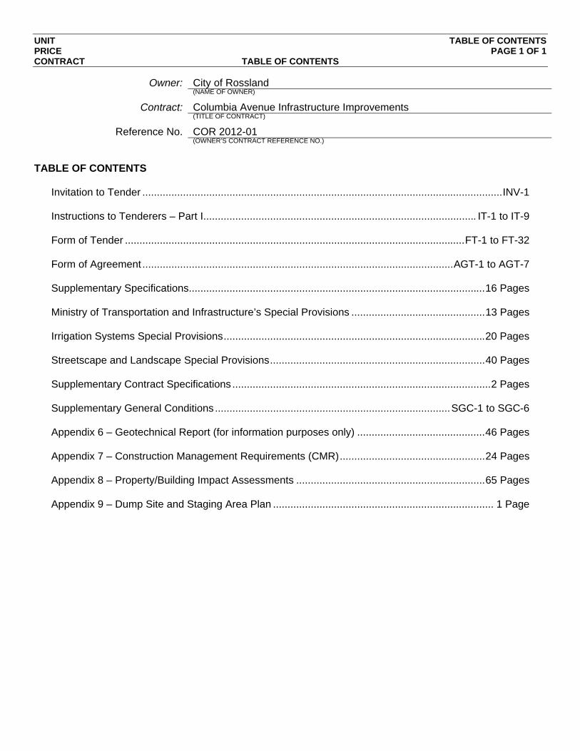
UNIT TABLE OF CONTENTS PRICE PAGE 1 OF 1 CONTRACT TABLE OF CONTENTS
Owner: City of Rossland (NAME OF OWNER)
Contract: Columbia Avenue Infrastructure Improvements (TITLE OF CONTRACT)
Reference No. COR 2012-01 (OWNER’S CONTRACT REFERENCE NO.)
TABLE OF CONTENTS
Invitation to Tender ............................................................................................................................ INV-1 Instructions to Tenderers – Part I.............................................................................................. IT-1 to IT-9 Form of Tender ..................................................................................................................... FT-1 to FT-32 Form of Agreement ........................................................................................................... AGT-1 to AGT-7 Supplementary Specifications...................................................................................................... 16 Pages Ministry of Transportation and Infrastructure’s Special Provisions .............................................. 13 Pages Irrigation Systems Special Provisions .......................................................................................... 20 Pages Streetscape and Landscape Special Provisions .......................................................................... 40 Pages Supplementary Contract Specifications ......................................................................................... 2 Pages Supplementary General Conditions ................................................................................. SGC-1 to SGC-6 Appendix 6 – Geotechnical Report (for information purposes only) ............................................ 46 Pages Appendix 7 – Construction Management Requirements (CMR) .................................................. 24 Pages Appendix 8 – Property/Building Impact Assessments ................................................................. 65 Pages Appendix 9 – Dump Site and Staging Area Plan ............................................................................ 1 Page

UNIT INVITATION TO TENDERERS PRICE PAGE 1 OF 1 CONTRACT INVITATION TO TENDERERS 2009
Owner: City of Rossland (NAME OF OWNER)
Contract: Columbia Avenue Infrastructure Improvements (TITLE OF CONTRACT)
Reference No. COR 2012-01 (OWNER’S CONTRACT REFERENCE NO.)
The Owner invites tenders for: The performance of infrastructure improvement work on Columbia Avenue
and Washington Street within the City of Rossland. The work includes supply and install by pipe bursting 435 lin.m. of HDPE drill sanitary sewer main and 245 lin.m. PVC DR35 sanitary sewer and storm main, XXXX lin.m. of C900 PVC watermain and appurtenances, XXX lin.m. of PVC irrigation main and apparatus. The work also includes XX sq.m. of full depth cold milling, XXX cu.m. of excavation, XXX tonnes of granular pavement structure, XXX tonnes of asphaltic pavement, XXX lin.m. of curb and gutter, XXX sq.m. of concrete sidewalk, streetlighting, landscaping and city scape features. (BRIEF DESCRIPTION OF THE WORK)
Contract Documents are available during normal
business hours at: City of Rossland and ISL Engineering and Land Services Ltd. Engineering Department 503, 4190 Lougheed Highway 1899 Columbia Avenue Burnaby, BC V5C 6A8 Rossland, BC V0G 1Y0 (LIST ADDRESSES FOR DOCUMENT PICKUP)
On payment of a non-refundable amount of $157.00 including HST payable to:
City of Rossland (NAME THAT CHEQUE SHOULD BE PAYABLE TO)
The Contract Documents are available for viewing at: City of Rossland and ISL Engineering and Land Services Ltd.
Engineering Department 503, 4190 Lougheed Highway 1899 Columbia Avenue Burnaby, BC V5C 6A8 Rossland, BC V0G 1Y0 (ADDRESS WHERE CONTRACT DOCUMENTS CAN BE VIEWED)
Tenders are scheduled to close: Tender Closing Time: 3:00pm local time (set by the City Hall clock)
Tender Closing Date: Tuesday, March 27, 2012
Address: City of Rossland
Engineering Department 1899 Columbia Avenue Rossland, BC V0G 1Y0 (ADDRESS WHERE TENDERS MUST BE SUBMITTED)
Name of Owner’s representative: Kevin Terness, P.Eng.
ISL Engineering and Land Services Ltd. [email protected] 604-629-2696 (PHONE)
UNIT TABLE OF CONTENTS PRICE IT – PART I PAGE 1 OF 2 CONTRACT INSTRUCTIONS TO TENDERERS PART I 2009
1.0 Introduction ........................................................................................................ IT – 1 2.0 Tender Documents ............................................................................................. IT – 1 3.0 Submission of Tenders ...................................................................................... IT – 2 4.0 Additional Instructions to Tenderers .......................................................... IT – 2 - 9
UNIT TABLE OF CONTENTS PRICE IT – PART I PAGE 2 OF 2 CONTRACT INSTRUCTIONS TO TENDERERS PART I 2009
THIS PAGE INTENTIONALLY LEFT BLANK

UNIT IT – PART I PRICE IT – PART I PAGE 1 OF 9 CONTRACT INSTRUCTIONS TO TENDERERS PART I 2009
(FOR USE WHEN UNIT PRICES FORM THE BASIS OF PAYMENT TO BE USED ONLY WITH THE GENERAL CONDITIONS AND OTHER STANDARD DOCUMENTS
OF THE UNIT PRICE MASTER MUNICIPAL CONSTRUCTION DOCUMENTS.)
(TO BE READ WITH “INSTRUCTIONS TO TENDERERS - PART II”
CONTAINED IN THE EDITION OF THE PUBLICATION “MASTER MUNICIPAL CONSTRUCTION DOCUMENTS” SPECIFIED IN ARTICLE 2.2 BELOW)
Owner: City of Rossland (NAME OF OWNER)
Contract: Columbia Avenue Infrastructure Improvements (TITLE OF CONTRACT)
Reference No. COR 2012-01 (OWNER’S CONTRACT REFERENCE NO.)
1.0 Introduction 1.1 The performance of infrastructure improvement work on Columbia Avenue and Washington Street within the City of Rossland. The work includes supply and install by pipe bursting 435 lin.m. of HDPE drill sanitary sewer main and 245 lin.m. PVC DR35 sanitary sewer and storm main, XXXX lin.m. of C900 PVC watermain and appurtenances, XXX lin.m. of PVC irrigation main and apparatus. The work also includes XX sq.m. of full depth cold milling, XXX cu.m. of excavation, XXX tonnes of granular pavement structure, XXX tonnes of asphaltic pavement, XXX lin.m. of curb and gutter, XXX sq.m. of concrete sidewalk, streetlighting, landscaping and city scape features.
(BRIEF DESCRIPTION OF THE WORK)
1.2 Direct all inquiries regarding the Contract, to: Kevin Terness, P.Eng. Contract Administrator (NAME AND POSITION OF INDIVIDUAL WHO WILL ANSWER INQUIRIS)
Address: ISL Engineering and Land Services Ltd. 503, 4190 Lougheed Highway Burnaby, BC V5C 6A8 Phone: 604-629-2696 Fax: 604-629-2698 Email: [email protected] 2.0 Tender
Documents 2.1 The tender documents which a tenderer should review to prepare a tender
consist of all of the Contract Documents listed in Schedule 1 entitled “Schedule of Contract Documents”. Schedule 1 is attached to the Agreement which is included as part of the tender package. The Contract Documents include the drawings listed in Schedule 2 to the Agreement, entitled “List of Contract Drawings”.
2.2 A portion of the Contract Documents are included by reference. Copies of
these documents have not been included with the tender package. These documents are the Instructions to Tenderers - Part II, General Conditions, Specifications and Standard Detail Drawings, and in the Standard Specifications for Highway Construction of the BC Ministry of Transportation Volume 1 and Volume 2 2012 Edition. They are those contained in the publication entitled “Master Municipal Construction Documents - General

UNIT IT – PART I PRICE IT – PART I PAGE 2 OF 9 CONTRACT INSTRUCTIONS TO TENDERERS PART I 2009
Conditions, Specifications and Standard Detail Drawings”. Refer to Schedule 1 to the Agreement or, if not specified in Schedule 1, then the applicable edition shall be the most recent edition as of the date of the Tender Closing Date. All sections of this publication are by reference included in the Contract Documents.
2.3 Any additional information made available to tenderers prior to the Tender
Closing Time by the Owner or representative of the Owner, such as as-built plans, which is not expressly included in Schedule 1 or Schedule 2 to the Agreement, is not included in the Contract Documents. Such additional information is made available only for the assistance of tenderers who must make their own judgment about its reliability, accuracy, completeness and relevance to the Contract, and neither the Owner nor any representative of the Owner gives any guarantee or representation that the additional information is reliable, accurate, complete or relevant. Appendix 6 is attached for information only.
3.0 Submission of
Tenders 3.1 Tenders must be submitted in a sealed envelope, marked on the outside with
the above Contract Title and Reference No., and must be received by the office of:
Mike Maturo, Manager Planning and Development Services (TITLE OF POSITION)
on or before Tender Closing Time: 3:00pm local time Tender Closing Date: Tuesday, March 27, 2012 at
Address: City of Rossland Engineering Department 1899 Columbia Avenue Rossland, BC V0G 1Y0 (ADDRESS WHERE TENDERS MUST BE SUBMITTED) Fax: 250-362-5451
3.2 Late tenders will not be accepted or considered, and will be returned
unopened. Closing time is determined by the clock in City Hall. 3.3 Depending on the available funds to complete the work program, the
scope of the work may be decreased due to budget constraints. The Owner reserves the right to reduce or remove items and scope based on available funds. No claims of lost overhead and profit can be made by the Contractor if scope is decreased due to funding constraints.
4.0 Additional
Instructions to Tenderers
4.1 Completing the Form of Tender The submitted Form of Tender must be legible, written in ink, or by typewriter and ALL ITEMS MUST BE BID, unless the Form of Tender specifically permits otherwise, with the price for every item and other extras clearly shown. Each page must be initialed by the Tenderer. The Tenderer shall be deemed to have satisfied himself as to the sufficiency of his tender for the work and of the unit and lump sum prices stated in the Form of Tender. These unit prices shall cover all his costs including overhead, profit

UNIT IT – PART I PRICE IT – PART I PAGE 3 OF 9 CONTRACT INSTRUCTIONS TO TENDERERS PART I 2009
and tax, except for the HST as explained in the following paragraphs of this section, for carrying out the works and his obligations under this Contract. This document contains one extra separate set of the Form of Tender. The Contractor shall complete and submit the separate set of the Form of Tender, in accordance with the Instructions to Tenderers and keep the remaining documents for record purposes. The "Amount" column shall be totaled in groups of items as shown and each total for a group of items shall be carried to the Summary Sheet for insertion in the appropriate place. The totals for all groups of items shall be added to give the Total Tender Price, Harmonized Sales Tax of 12% shall be calculated separately then added to arrive at the Total Tender Price including H.S.T.
Right to Accept or Reject Tenders
The City reserves the right to reject any or all tenders or to accept any tender should it be deemed in the interest of the City to do so. The lowest tender will not necessarily be accepted. For each item listed in the Form of Tender, there shall be a reasonable unit price. Under no conditions will an unbalanced tender be considered. The Contract Administrator will be the sole judge of such matters. Any tender considered to be unbalanced shall be rejected by the City. Without limiting the generality of the foregoing, any tender may be disqualified or rejected which is incomplete, obscure or irregular, which had erasures or corrections in the Form of Tender, in which prices are omitted or which has an insufficient or irregular Surety.
Additions and Deletions to Instructions to Tenderers: Part II
Deleted and revised measurement and payment sections from MMCD Volume II, Specifications refer to Supplementary Specifications contained within this document immediately following the Form of Agreement.
4.2 Par. # Title Action
5.2.2 Tender
Requirements - Cash, Bank Draft, Letter of Credit
Delete entire paragraph.
12.1 Amendment of
Tenders Change “hand, mail or fax” to “hand” and add “An amendment by email or fax will not be accepted.”
15.4 Award Insert the following clause:
“The lowest or any tender will not necessarily be accepted. Without limiting the generality of the foregoing, any tender which is incomplete,

UNIT IT – PART I PRICE IT – PART I PAGE 4 OF 9 CONTRACT INSTRUCTIONS TO TENDERERS PART I 2009
obscure or irregular may be rejected, any tender having erasures or corrections in the Form of Tender: Appendix 1, Schedule of Quantities & Prices may be rejected, any tender in which unit prices are omitted or in which unit prices are obviously unbalanced may be rejected, any tender accompanied by an insufficient bond may be rejected, any tender that has any deletions, alterations, or changes in the Contract Documents as listed in Schedule 1 and 2 of the Agreement may be rejected.”
Insert the following clause:
In exercising its discretion, the Owner will have regard to the information provided by the tenderer in the Appendices to the Form of Tender as described under IT 5.3, and may also have regard to any information obtained by the Owner in evaluation such tender information, any information obtained by the Owner from any other person, firm or corporation relating to their previous experience with the tenderer, as well as the Owner’s previous relevant experience, if any, with the tenderer. In exercising this discretion the Owner may consider, but it not limited to, the following criteria in addition to the Tender Price.
a) the proven experience of the tenderer, and any listed subcontractors to do the Work;
b) the tenderer’s ability to
complete the Work within the Preliminary Construction Schedule including timeliness in completing deficiency works;
c) the tenderer’s ability to work
effectively with the Owner, its consultants and representatives, and the public;
UNIT IT – PART I PRICE IT – PART I PAGE 5 OF 9 CONTRACT INSTRUCTIONS TO TENDERERS PART I 2009
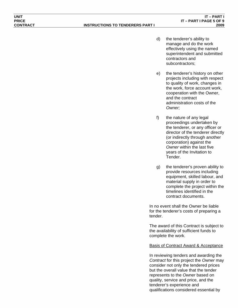
d) the tenderer’s ability to
manage and do the work effectively using the named superintendent and submitted contractors and subcontractors;
e) the tenderer’s history on other
projects including with respect to quality of work, changes in the work, force account work, cooperation with the Owner, and the contract administration costs of the Owner;
f) the nature of any legal
proceedings undertaken by the tenderer, or any officer or director of the tenderer directly (or indirectly through another corporation) against the Owner within the last five years of the Invitation to Tender.
g) the tenderer’s proven ability to
provide resources including equipment, skilled labour, and material supply in order to complete the project within the timelines identified in the contract documents.
In no event shall the Owner be liable for the tenderer’s costs of preparing a tender.
The award of this Contract is subject to
the availability of sufficient funds to complete the work.
Basis of Contract Award & Acceptance
In reviewing tenders and awarding the Contract for this project the Owner may consider not only the tendered prices but the overall value that the tender represents to the Owner based on quality, service and price, and the tenderer’s experience and qualifications considered essential by

UNIT IT – PART I PRICE IT – PART I PAGE 6 OF 9 CONTRACT INSTRUCTIONS TO TENDERERS PART I 2009
the Owner for the satisfactory completion of this type and size of project, including:
a) Bonding capability. b) Financial capability. c) Previous completed projects of this
type and/or size. d) Major projects currently being
undertaken by the tenderer. e) Key office and site personnel to be
assigned by the tenderer to this project.
f) Timeline for completion of the Work. g) The past experience of the Owner
and/or other project owners with respect to the tenderer’s performance in completing projects in a timely, efficient and satisfactory manner, the tenderer’s methods of doing business and the tenderer’s ability to establish and maintain a good working relationship with a project owner.
The Owner reserves the right to award
the Contract based on the above pre-requisites and to reject without further consideration, any tender which in its opinion, does not meet the criteria it considers essential for this project. The tenderer, by submitting a tender, agrees that it will not make a claim against the Owner, for whatever reason, relating to the tender, the tender documents, or the competitive tender process. The tenderer, by submitting a tender, waives any claim or recovery for loss of profits or any prospective damages whatsoever if no Contract is entered into with the tenderer.
UNIT IT – PART I PRICE IT – PART I PAGE 7 OF 9 CONTRACT INSTRUCTIONS TO TENDERERS PART I 2009
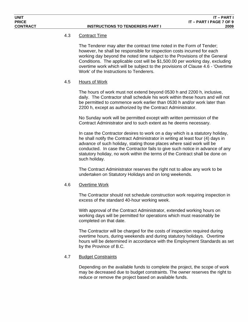
4.3 Contract Time The Tenderer may alter the contract time noted in the Form of Tender; however, he shall be responsible for inspection costs incurred for each working day beyond the noted time subject to the Provisions of the General Conditions. The applicable cost will be $1,500.00 per working day, excluding overtime work which will be subject to the provisions of Clause 4.6 - 'Overtime Work' of the Instructions to Tenderers.
4.5 Hours of Work
The hours of work must not extend beyond 0530 h and 2200 h, inclusive, daily. The Contractor shall schedule his work within these hours and will not be permitted to commence work earlier than 0530 h and/or work later than 2200 h, except as authorized by the Contract Administrator. No Sunday work will be permitted except with written permission of the Contract Administrator and to such extent as he deems necessary. In case the Contractor desires to work on a day which is a statutory holiday, he shall notify the Contract Administrator in writing at least four (4) days in advance of such holiday, stating those places where said work will be conducted. In case the Contractor fails to give such notice in advance of any statutory holiday, no work within the terms of the Contract shall be done on such holiday. The Contract Administrator reserves the right not to allow any work to be undertaken on Statutory Holidays and on long weekends.
4.6 Overtime Work
The Contractor should not schedule construction work requiring inspection in excess of the standard 40-hour working week. With approval of the Contract Administrator, extended working hours on working days will be permitted for operations which must reasonably be completed on that date. The Contractor will be charged for the costs of inspection required during overtime hours, during weekends and during statutory holidays. Overtime hours will be determined in accordance with the Employment Standards as set by the Province of B.C.
4.7 Budget Constraints
Depending on the available funds to complete the project, the scope of work may be decreased due to budget constraints. The owner reserves the right to reduce or remove the project based on available funds.

UNIT IT – PART I PRICE IT – PART I PAGE 8 OF 9 CONTRACT INSTRUCTIONS TO TENDERERS PART I 2009
4.8 Schedule The site work is expected to commence the week of April 23, 2012. It is anticipated that all electrical components will be ordered following notice to proceed.
4.9 Note that the MMCD (this Contract is based on the 2009 Platinum Edition)
must be purchased separately from: Support Services Unlimited 102, 211 Columbia Street Vancouver, BC V6A 2R5 ATTN: Donna Denham Phone: 604-481-0295
4.10 Availability of Relevant Publications
The Equipment Rental Rate Guide is available from: B.C. Road Builders and Heavy Construction Association 307, 8678 Greenwall Avenue Burnaby, BC V5J 3M6 Phone: 604-436-0220 Fax: 604-436-2627 All other Ministry of Transportation and Infrastructure General Reference Documents and other relevant publications can be obtained through Queen’s Printer at: Queen’s Printer Government Publication Services PO Box 9452, Stn Prov Govt Victoria, BC V8W 9V7 Or Phone toll free at: 1-800-663-6105 And can be accessed at: www.publications.gov.bc.ca If a relevant publication is not available from Queen’s Printer, please contact the Ministry Representative.
4.11 17.1 Optional Work
Change “Optional work” as defined in GC1.37, to “Optional Work”, as defined in GC 1.48. As identified in Section 4.7 Budget Constraints, some work identified in the Schedule of Quantities and Prices are to be bid as optional work.
UNIT IT – PART I PRICE IT – PART I PAGE 9 OF 9 CONTRACT INSTRUCTIONS TO TENDERERS PART I 2009
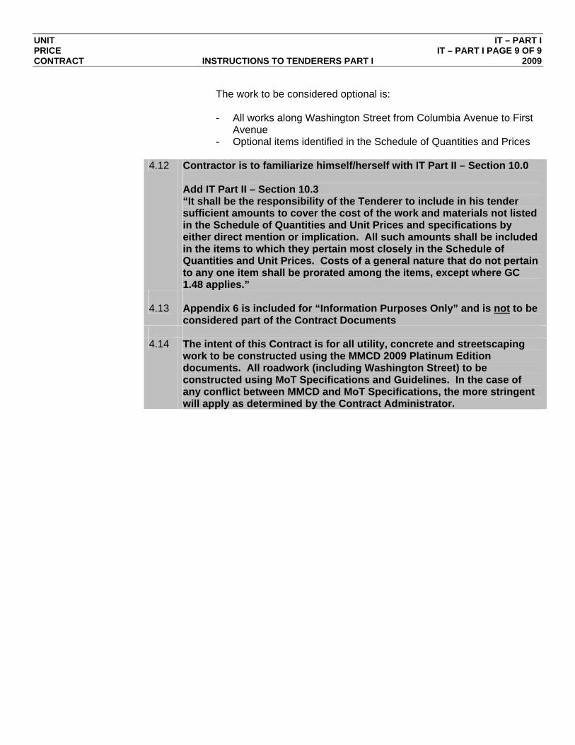
The work to be considered optional is: - All works along Washington Street from Columbia Avenue to First
Avenue - Optional items identified in the Schedule of Quantities and Prices
4.12 Contractor is to familiarize himself/herself with IT Part II – Section 10.0
Add IT Part II – Section 10.3 “It shall be the responsibility of the Tenderer to include in his tender sufficient amounts to cover the cost of the work and materials not listed in the Schedule of Quantities and Unit Prices and specifications by either direct mention or implication. All such amounts shall be included in the items to which they pertain most closely in the Schedule of Quantities and Unit Prices. Costs of a general nature that do not pertain to any one item shall be prorated among the items, except where GC 1.48 applies.”
4.13 Appendix 6 is included for “Information Purposes Only” and is not to be
considered part of the Contract Documents 4.14 The intent of this Contract is for all utility, concrete and streetscaping
work to be constructed using the MMCD 2009 Platinum Edition documents. All roadwork (including Washington Street) to be constructed using MoT Specifications and Guidelines. In the case of any conflict between MMCD and MoT Specifications, the more stringent will apply as determined by the Contract Administrator.
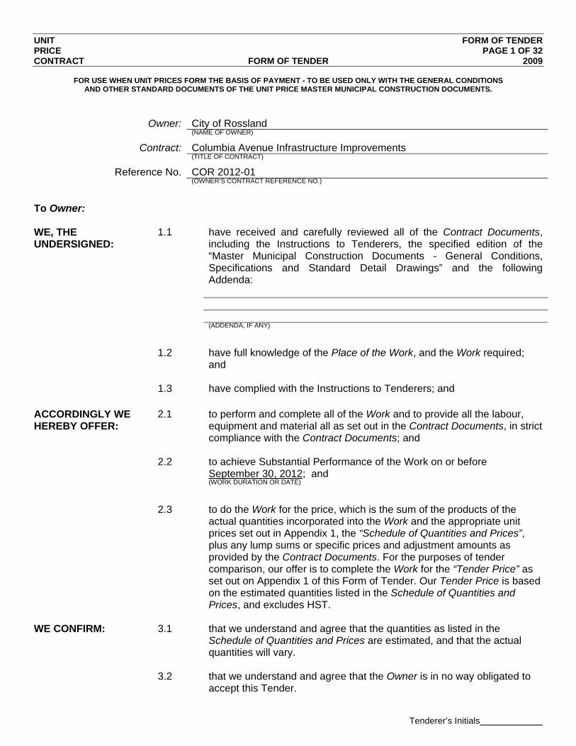
UNIT FORM OF TENDER PRICE PAGE 1 OF 32 CONTRACT FORM OF TENDER 2009
Tenderer’s Initials
FOR USE WHEN UNIT PRICES FORM THE BASIS OF PAYMENT - TO BE USED ONLY WITH THE GENERAL CONDITIONS AND OTHER STANDARD DOCUMENTS OF THE UNIT PRICE MASTER MUNICIPAL CONSTRUCTION DOCUMENTS.
Owner: City of Rossland (NAME OF OWNER)
Contract: Columbia Avenue Infrastructure Improvements (TITLE OF CONTRACT)
Reference No. COR 2012-01 (OWNER’S CONTRACT REFERENCE NO.)
To Owner: WE, THE UNDERSIGNED:
1.1 have received and carefully reviewed all of the Contract Documents, including the Instructions to Tenderers, the specified edition of the “Master Municipal Construction Documents - General Conditions, Specifications and Standard Detail Drawings” and the following Addenda:
(ADDENDA, IF ANY)
1.2 have full knowledge of the Place of the Work, and the Work required;
and 1.3 have complied with the Instructions to Tenderers; and
ACCORDINGLY WE HEREBY OFFER:
2.1 to perform and complete all of the Work and to provide all the labour, equipment and material all as set out in the Contract Documents, in strict compliance with the Contract Documents; and
2.2 to achieve Substantial Performance of the Work on or before
September 30, 2012; and (WORK DURATION OR DATE)
2.3 to do the Work for the price, which is the sum of the products of the
actual quantities incorporated into the Work and the appropriate unit prices set out in Appendix 1, the “Schedule of Quantities and Prices”, plus any lump sums or specific prices and adjustment amounts as provided by the Contract Documents. For the purposes of tender comparison, our offer is to complete the Work for the “Tender Price” as set out on Appendix 1 of this Form of Tender. Our Tender Price is based on the estimated quantities listed in the Schedule of Quantities and Prices, and excludes HST.
WE CONFIRM: 3.1 that we understand and agree that the quantities as listed in the
Schedule of Quantities and Prices are estimated, and that the actual quantities will vary.
3.2 that we understand and agree that the Owner is in no way obligated to
accept this Tender.

UNIT FORM OF TENDER PRICE PAGE 2 OF 32 CONTRACT FORM OF TENDER 2009
Tenderer’s Initials
WE CONFIRM: 4.1 that the following appendices are attached to and form a part of this tender:
4.1.1 the appendices as required by paragraph 5.3 of the Instructions to
Tenderers – Part II; and 4.1.2 the Bid Security as required by paragraph 5.2 of the Instructions to
Tenderers – Part II. WE AGREE: 5.1 that this tender will be irrevocable and open for acceptance by the
Owner for a period of 60 calendar days from the day following the Tender Closing Date and Time, even if the tender of another tenderer is accepted by the Owner. If within this period the Owner delivers a written notice (“Notice of Award”) by which the Owner accepts our tender we will:
5.1.1 within 10 Days of receipt of the written Notice of Award deliver to
the Owner: 1. a Performance Bond and a Labour and Material Payment Bond,
each in the amount of 50% of the Contract Price, covering the performance of the Work including the Contractor’s obligations during the Maintenance Period, issued by a surety licensed to carry on the business of suretyship in the province of British Columbia, and in a form acceptable to the Owner;
2. a Baseline Construction Schedule, as provided by GC 4.6.1;
3. a “clearance letter” indicating that the tenderer is in Worksafe BC compliance; and
4. a copy of the insurance policies as specified in GC 24 indicating
that all such insurance coverage is in place; and
5. MoT HOIII and ICBC APV47 or APV25OL and; 5.1.2 within 2 Days of receipt of written “Notice to Proceed”, or such
longer time as may be otherwise specified in the Notice to Proceed, commence the Work; and
5.1.3 sign the Contract Documents as required by GC 2.1.2. WE AGREE: 6.1 that, if we receive written Notice of Award of this Contract and, contrary
to paragraph 5 of this Form of Tender, we: 6.1.1 fail or refuse to deliver the documents as specified by paragraph
5.1.1 of this Form of Tender; or 6.1.2 fail or refuse to commence the Work as required by the Notice to
Proceed, then such failure or refusal will be deemed to be a refusal by us to enter into the Contract and the Owner may, on written notice to us, award the Contract to another party. We further agree that, as full compensation on account of damages

UNIT FORM OF TENDER PRICE PAGE 3 OF 32 CONTRACT FORM OF TENDER 2009
Tenderer’s Initials
suffered by the Owner because of such failure or refusal, the Bid Security shall be forfeited to the Owner, in an amount equal to the
lesser of: 6.1.3 the face value of the Bid Security; and 6.1.4 the amount by which our Tender Price is less than the amount for
which the Owner contracts with another party to perform the Work. OUR ADDRESS IS AS FOLLOWS:
Phone: Fax: Email: Attention: This Tender is executed this
_______ day of ______________________, 2012. Contractor: (FULL LEGAL NAME OF CORPORATION, PARTNERSHIP OR INDIVIDUAL)
(AUTHORIZED SIGNATORY)
(AUTHORIZED SIGNATORY)
Schedule of Quantities and Prices
MMCD Standard Specifications
Page 4
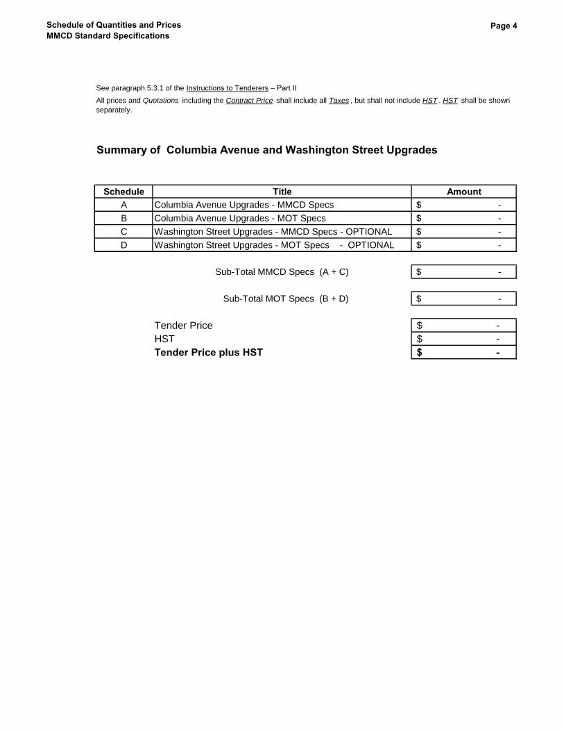
See paragraph 5.3.1 of the Instructions to Tenderers – Part II
Summary of Columbia Avenue and Washington Street Upgrades
Schedule Title Amount
A Columbia Avenue Upgrades - MMCD Specs -$
B Columbia Avenue Upgrades - MOT Specs -$
C Washington Street Upgrades - MMCD Specs - OPTIONAL -$
D Washington Street Upgrades - MOT Specs - OPTIONAL -$
Sub-Total MMCD Specs (A + C) -$
Sub-Total MOT Specs (B + D) -$
Tender Price -$
HST -$
Tender Price plus HST -$
All prices and Quotations including the Contract Price shall include all Taxes , but shall not include HST . HST shall be shown
separately.

Schedule of Quantities and Prices
MMCD Standard SpecificationsDiv Summary Sheet Page 5
Summary SheetSee paragraph 5.3.1 of the Instructions to Tenderers – Part II
Schedule A - Columbia Avenue Upgrades - MMCD Works
SCHEDULE OF QUANTITIES AND UNIT PRICES
Division Title Amount
Div 03 Concrete -$
Div 26 Electrical -$
Div 31 Earthwork -$
Div 32 Roads and Site Improvements -$
Div 33 Utilities -$
Schedule A Total -$
All prices and Quotations including the Contract Price shall include all Taxes , but shall
not include HST . HST shall be shown separately.
Summary Sheet
Schedule of Quantities and Prices
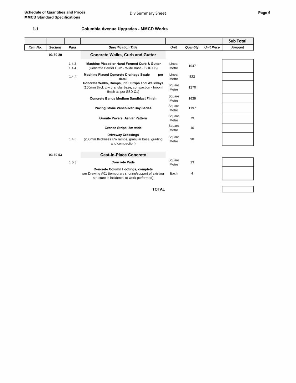
MMCD Standard SpecificationsDiv Summary Sheet Page 6
1.1 Columbia Avenue Upgrades - MMCD Works
Sub Total
Item No. Section Para Specification Title Unit Quantity Unit Price Amount
03 30 20 Concrete Walks, Curb and Gutter
1.4.3
1.4.4
Machine Placed or Hand Formed Curb & Gutter
(Concrete Barrier Curb - Wide Base - SDD C5)
Lineal
Metre1047
1.4.4 Machine Placed Concrete Drainage Swale per
detail
Lineal
Metre523
Concrete Walks, Ramps, Infill Strips and Walkways
(150mm thick c/w granular base, compaction - broom
finish as per SSD C1)
Square
Metre1270
Concrete Bands Medium Sandblast FinishSquare
Metre1639
Paving Stone Vancouver Bay SeriesSquare
Metre1197
Granite Pavers, Ashlar PatternSquare
Metre79
Granite Strips .3m wideSquare
Metre10
1.4.6
Driveway Crossings
(200mm thickness c/w ramps, granular base, grading
and compaction)
Square
Metre90
03 30 53 Cast-In-Place Concrete
1.5.3 Concrete PadsSquare
Metre13
Concrete Column Footings, complete
per Drawing A01 (temporary shoring/support of existing
structure is incidental to work performed)
Each 4
TOTAL

Schedule of Quantities and Prices
MMCD Standard SpecificationsDiv Summary Sheet Page 7
1.2 Columbia Avenue Upgrades - MMCD Works
26 Sub Total
Item No. Section Para Specification Title Unit Quantity Unit Price Amount
26 56 01 Roadway Lighting
1.9.1 Roadway LightingLump
Sum1
Telus Pre-ducting for Fiber Optics, complete per
detail
Lump
Sum1
TOTAL
Electrical

Schedule of Quantities and Prices
MMCD Standard SpecificationsDiv Summary Sheet Page 8
1.3 Columbia Avenue Upgrades - MMCD Works
31 Sub Total
Item No. Section Para Specification Title Unit Quantity Unit Price Amount
31 11 01 Clearing and Grubbing
1.4.2 Isolated Tree Clearing & Grubbing Each 31
31 11 41 Shrub and Tree Preservation
1.3.1Preservation of Existing Trees
Tree Protection Fence
Lineal
Metre130
Earthwork

Schedule of Quantities and Prices
MMCD Standard SpecificationsDiv Summary Sheet Page 9
31 23 01Excavating,Trenching and Backfilling
Underground Utility
1.10.3Overexcavating
including approved backfill OPTIONAL
Cubic
Metre200
31 23 17 Rock Removal
1.6.3 Mass Rock - Blasting PermittedCubic
Metre50
1.6.3 Trench Rock - Blasting PermittedCubic
Metre50
TOTAL
Schedule of Quantities and Prices
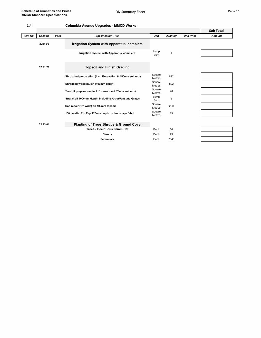
MMCD Standard SpecificationsDiv Summary Sheet Page 10
1.4 Columbia Avenue Upgrades - MMCD Works
32 Sub Total
Item No. Section Para Specification Title Unit Quantity Unit Price Amount
3284 00 Irrigation System with Apparatus, complete
Irrigation System with Apparatus, completeLump
Sum1
32 91 21 Topsoil and Finish Grading
Shrub bed preparation (incl. Excavation & 450mm soil mix)Square
Metres822
Shredded wood mulch (100mm depth)Square
Metres822
Tree pit preparation (incl. Excavation & 70mm soil mix)Square
Metres70
StrataCell 1000mm depth, including ArborVent and GratesLump
Sum1
Sod repair (1m wide) on 100mm topsoilSquare
Metres200
100mm dia. Rip Rap 120mm depth on landscape fabricSquare
Metres15
32 93 01 Planting of Trees,Shrubs & Ground Cover
Trees - Deciduous 60mm Cal Each 54
Shrubs Each 95
Perennials Each 2545
Roads and Site Improvements
Schedule of Quantities and Prices
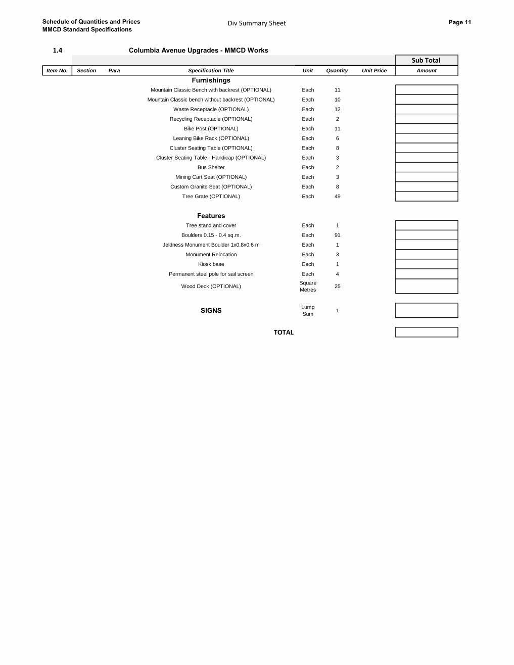
MMCD Standard SpecificationsDiv Summary Sheet Page 11
1.4 Columbia Avenue Upgrades - MMCD Works
32 Sub Total
Item No. Section Para Specification Title Unit Quantity Unit Price Amount
Roads and Site Improvements
Furnishings
Mountain Classic Bench with backrest (OPTIONAL) Each 11
Mountain Classic bench without backrest (OPTIONAL) Each 10
Waste Receptacle (OPTIONAL) Each 12
Recycling Receptacle (OPTIONAL) Each 2
Bike Post (OPTIONAL) Each 11
Leaning Bike Rack (OPTIONAL) Each 6
Cluster Seating Table (OPTIONAL) Each 8
Cluster Seating Table - Handicap (OPTIONAL) Each 3
Bus Shelter Each 2
Mining Cart Seat (OPTIONAL) Each 3
Custom Granite Seat (OPTIONAL) Each 8
Tree Grate (OPTIONAL) Each 49
Features
Tree stand and cover Each 1
Boulders 0.15 - 0.4 sq.m. Each 91
Jeldness Monument Boulder 1x0.8x0.6 m Each 1
Monument Relocation Each 3
Kiosk base Each 1
Permanent steel pole for sail screen Each 4
Wood Deck (OPTIONAL)Square
Metres25
SIGNSLump
Sum1
TOTAL

Schedule of Quantities and Prices
MMCD Standard SpecificationsDiv 33 - Utilities Page 12
1.5 Columbia Avenue Upgrades - MMCD Works
33 Sub Total
Item No. Section Para Specification Title Unit Quantity Unit Price Amount
33 01 30.2 Cleaning of Sewers
1.5.4 Root Cutting OPTIONAL Hours 16
33 05 23 Trenchless Sewer Pipe Bursting
1.7.1 Bypass PumpingLump
Sum1
1.7.2 Pipe Bursting 375mm HDPE DR11Lineal
Metres369.5
1.7.3 Pipe Bursting 250mm HDPE DR11Lineal
Metres67.8
1.7.3 Service Reconnection 150mm Each 18
1.7.4 HDPE pipe Connection to Manholes 375mm Each 3
1.7.4 HDPE pipe Connection to Manholes 250mm Each 2
33 05 24 Cured In Place Pipe Liners
1.9.1Mobilization / Demobilizaton Bypass Pumping
All Diameter Mains
Lump
Sum1
1.9.6CCTV Pipeline Pre- Installation Inspection
per 33 01 30.1n/c
1.9.7 Remove Intruding Connections OPTIONAL Each 5
1.9.8Sewer Lining
525mm pipe diameter
Lineal
Metres153
1.9.8Sewer Lining
450mm pipe diameter
Lineal
Metres103
1.9.8Sewer Lining
375mm pipe diameter
Lineal
Metres117
1.9.8Sewer Lining
300mm pipe diameter
Lineal
Metres77
1.9.9 Reinstate Sewer Connections Each 15
1.9.10 Connection Interface Sealing Each 15
33 11 01 Waterworks
Payment for watermain includes saw cutting,trench excavation,
disposal of surplus excavated material, bedding, supply and
installation of all pipe, bolts ,gaskets, test points, temporary caps,
temporary blow-offs, reverse acting thrust blocks, thrust blocks
and tie-rods, imported or approved native backfill as
specified,cleaning, pressure and leakage testing, flushing,
disinfection, colliform testing and surface restoration under
31 23 01.
1.8.1,
1.8.2
Watermain PVC C900 300mm diameter
Approved Native or Import Backfill
Lineal
Metres398
1.8.1,
1.8.2
Watermain PVC C900 200mm diameter
Approved Native or Import Backfill
Lineal
Metres85
1.8.1,
1.8.2
Watermain PVC C900 150mm diameter
Approved Native or Import Backfill
Lineal
Metres28
1.8.3 In-line Gate Valves 300mm FL-TYT Each 3
1.8.3 In-line Gate Valves 200mm FL-TYT Each 3
1.8.3 In-line Gate Valves 150mm FL-TYT Each 1
1.8.3Cross 300mmFL X 300mmFL X 300mmFL X
300mmFL DI CL350Each 1
1.8.3Tee 300mmFL X 300mmFL X 150mmFL
DI CL350 Each 1
1.8.3 Tee 300mmTYT X 300mmTYT X 150mmFL
DI CL350 Each 2
1.8.3Tee 300mmTYT X 300mmFL X 150mmFL
DI CL350 Each 2
1.8.3Tee 200mmFL X 200mmTYT X 300mmFL DI
CL350 Each 1
Utilities

Schedule of Quantities and Prices
MMCD Standard SpecificationsDiv 33 - Utilities Page 13
1.8.3Tee 200mmFL X 200mmTYT X 200mmFL DI
CL350 Each 1
1.8.3Bend 300mm diameter 45
Degree of Bend DI CL350Each
1.8.3Bend 200mm diameter 45
Degree of Bend DI CL350Each 8
1.8.3Bend 150mm diameter 45
Degree of Bend DI CL350Each 2
1.8.3Reducer 300mm X 200mm diameter
DI CL350Each 1
1.8.3Reducer 300mm X 150mm diameter
DI CL350Each 1
1.8.3 Permanent Cap 200mm diameter
DI CL350Each 4
1.8.3 Permanent Cap 150mm diameter
DI CL350Each 1
1.8.2
1.8.4
Water Service Connections
19mm diam Municipex
Standard Drawings W2a, W2b
Each 34
1.8.5Blow-Off Assembly
Standard Drawing W8Each 1
1.8.14SHydrant Assembly
TC-H105 CL250 Standard Drawing W4Each 4
1.8.13
Watermain Tie -In c/w
200mm PVC C900 to 200mm AC Coupler
Pipework by Contractor
Each 4
1.8.13
Watermain Tie -In c/w
150mm PVC C900 to 150mm CAL Coupler
Pipework by Contractor
Each 1
33 30 01 Sanitary Sewers
Payment for sanitary sewers includes saw cutting,trench
excavation, disposal of surplus excavated material, bedding,
supply and installation of all pipe, fittings and related material,
imported or approved native backfill as specified, cleaning,
flushing and testing and surface restoration under 31 23 01
1.6.1S
1.6.2S
Sewer Pipe PVC DR35 375mm diameter Approved
Native or Import Backfill Backfill
Lineal
Metres3.3
1.6.1S
1.6.2S
Sewer Pipe PVC DR35 300mm diameter Approved
Native or Import Backfill Backfill
Lineal
Metres18.8
1.6.1S
1.6.2S
Sewer Pipe PVC DR35 200mm diameter Approved
Native or Import Backfill Backfill
Lineal
Metres213
1.6.3Sanitary Service Connections - LONG
150mm diam PVC DR28 per Standard Drawings S8Each 19
1.6.3Sanitary Service Connections - SHORT
150mm diam PVC DR28 per Standard Drawings S8Each 18
1.6.4Sanitary Inspection Chamber
per Detail 7Each 37
Sanitary Services at Buildings Payment Item 1 Each 4
Sanitary Services at Buildings Payment Item 2 Each 2
Sanitary Services at Buildings Payment Item 3 Each 3
Sanitary Services at Buildings Payment Item 4 Each 13
Sanitary Services at Buildings Payment Item 5 Each 3
33 40 01 Storm Sewers
Payment for storm sewers includes saw cutting,trench excavation,
disposal of surplus excavated material, bedding, supply and
installation of all pipe, fittings and related material, imported or
approved native backfill as specified, cleaning, flushing and
testing and surface restoration under 31 23 01
1.6.1S
1.6.2S
Drainage Pipe Concrete C76-IV 600mm diameter,
Approved Native Backfill or Imported Backfill
Lineal
Metres25.3
1.6.1S
1.6.2S
Drainage Pipe Concrete C76-IV 525mm diameter,
Approved Native Backfill or Imported Backfill
Lineal
Metres17.8
1.6.1S
1.6.2S
Drainage Pipe PVC DR35 300mm diameter, Approved
Native Backfill or Imported Backfill
Lineal
Metres342.3

Schedule of Quantities and Prices
MMCD Standard SpecificationsDiv 33 - Utilities Page 14
1.6.3Drainage Service Connections - Long
150mm diam PVC DR28 per Standard Drawings S8 Each 5
1.6.3Drainage Service Connections - Short
150mm diam PVC DR28 per Standard Drawings S8Each 31
1.6.4Drainage Inspection Chamber
per Detail 7Each 36
1.6.5Catchbasin Lead
PVC DR35 200mm diameter
Lineal
Metres211
1.6.5Catchbasin Lead
PVC DR28 150mm diameter
Lineal
Metres100
1.6.6
Sub-surface Drain - 100mm PVC DR28 perforated pipe,
rounded 50mm minus drain rock and filter cloth
- tied into StrataCells or storm main/CB
Lineal
Metres1047
Storm Services at Buildings
Payment Item 1Each 3
Storm Services at Buildings
Payment Item 3Each 3
Storm Services at Buildings
Payment Item 4Each 12
Storm Services at Buildings Payment
Item 5Each 6
33 44 01 Manholes and Catchbasins
Payment for manhole base, lid, slab,adjustment rings,
frame, and cover includes all details shown on Standard
Drawings S1, S2, S3,S4 and S5 except for risers.
1.5.1.1Manhole 1500 diameter
base, lid, slab,cover and frameEach 1
1.5.1.1Manhole 1050 diameter
base, lid, slab,cover and frameEach 3
1.5.1.2Manhole Riser
1500mm diameter
Vertical
Metres10
1.5.1.2Manhole Riser
1200mm diameter
Vertical
Metres2.5
1.5.1.2Manhole Riser
1050mm diameter
Vertical
Metres9.4
1.5.1.5Extra over 1.5.1.1 for Outside Drop Type Manhole
Standard Drawing S3 200mm diameter Each 1
1.5.1.5Extra over 1.5.1.1 for Outside Drop Type Manhole
Standard Drawing S3 150mm diameter Each 2
1.5.1.6Add Manhole to Existing System - Overbuild c/w re-
benching 1500mm diameterEach 2
1.5.1.6Add Manhole to Existing System - Overbuild c/w re-
benching 1200mm diameterEach 1
1.5.1.6Add Manhole to Existing System - Overbuild c/w re-
benching 1050mm diameterEach 1
1.5.2Catchbasin Top Inlet
Standard Drawing S11Each 10
1.5.2Catchbasin Side Inlet
Detail 2Each 16
TOTAL

Schedule of Quantities and Prices
MMCD Standard SpecificationsDiv Summary Sheet Page 15
Summary SheetSee paragraph 5.3.1 of the Instructions to Tenderers – Part II
Schedule B - (Columbia Avenue) Hwy 3 / 22 Upgrades - MOT Works
SCHEDULE OF QUANTITIES AND UNIT PRICES
Section Title Amount
2.1 Columbia Avenue Upgrades - MOT Earthwork -$
2.2 Columbia Avenue Upgrades - MOT Roads and Site Improvements -$
TOTAL -$
All prices and Quotations including the Contract Price shall include all Taxes , but shall not include HST . HST shall be shown separately.
Summary Sheet
Schedule of Quantities and Prices
MMCD Standard SpecificationsDiv 31 - Earthwork Page 16
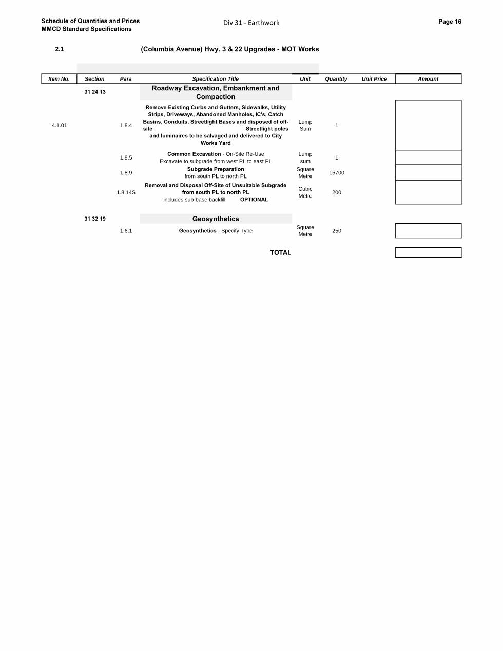
2.1 (Columbia Avenue) Hwy. 3 & 22 Upgrades - MOT Works
31
Item No. Section Para Specification Title Unit Quantity Unit Price Amount
31 24 13Roadway Excavation, Embankment and
Compaction
4.1.01 1.8.4
Remove Existing Curbs and Gutters, Sidewalks, Utility
Strips, Driveways, Abandoned Manholes, IC's, Catch
Basins, Conduits, Streetlight Bases and disposed of off-
site Streetlight poles
and luminaires to be salvaged and delivered to City
Works Yard
Lump
Sum1
1.8.5Common Excavation - On-Site Re-Use
Excavate to subgrade from west PL to east PL
Lump
sum1
1.8.9Subgrade Preparation
from south PL to north PL
Square
Metre15700
1.8.14S
Removal and Disposal Off-Site of Unsuitable Subgrade
from south PL to north PL
includes sub-base backfill OPTIONAL
Cubic
Metre200
31 32 19 Geosynthetics
1.6.1 Geosynthetics - Specify TypeSquare
Metre250
TOTAL
Earthwork

Schedule of Quantities and Prices
MMCD Standard SpecificationsDiv 32 - Roads and Site Improvements Page 17
2.2 (Columbia Avenue) Hwy. 3 & 22 Upgrades - MOT Works
32 Sub Total
Item No. Section Para Specification Title Unit Quantity Unit Price Amount
Provisional Sum for Site Modifications
2.2.01 SP 1.07 Provisional Sum for Site ModificationsProv.
Sum1
Mobilization
SP 1.01Initial Mobilization and Mobilizations as Required for
Construction Phasing
Lump
Sum1
32 01 16.7 Cold Milling
1.5.1
Cold Milling
full depth milling to maximum 150mm thickness of
existing asphalt road, including disposal within the City
of Rossland as directed by the Contractor Administrator Square
Metre
9815
1.5.1
Cold Milling
50mm surface mill and profilingof asphalt to 50mm
thickness of existing asphalt road, including disposal
within the City of Rossland as directed by the Contractor
Administrator
Square
Metre
2500
Select Granular Sub-Base
SP 1.05
75mm minus Select Granular Sub-Base
Variable Thickness for Roads and Curb and Gutter
(Back of curb +300mm)
Lump
Sum1
Well Graded Base Course
SP 1.05
25mm minus Well Graded Base Course
Variable Thickness for Roads and Curb and Gutter
(Back of curb +300mm)
Tonne 7100
Asphalt Tack Coat
SP 106.2 Supply and Spray Elmusified Penetrating Tack CoatSquare
Metre9750
Hot-Mix Asphalt Concrete Paving
SP 1.06.3/.4Asphalt Pavement - Lower Course - 50mm of Class
1, Medium MixTonne 1800
SP 1.06.3/.4Asphalt Pavement - Upper Course - 50mm of Class
1, Medium MixTonne 1200
Painted Pavement Markings
SP 1.06.6 Permanent Painted Pavement MarkingsLump
Sum1
SP 1.06.6 Permanent Thermoplastic Pavement MarkingsLump
Sum1
SP 1.04.1 Permanent Traffic Control Signs Each 15
TOTAL
Roads and Site Improvements
Schedule of Quantities and Prices
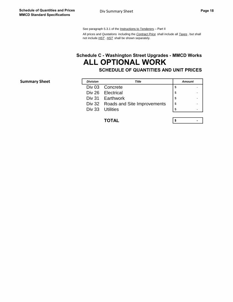
MMCD Standard SpecificationsDiv Summary Sheet Page 18
Summary SheetSee paragraph 5.3.1 of the Instructions to Tenderers – Part II
Schedule C - Washington Street Upgrades - MMCD Works
ALL OPTIONAL WORKSCHEDULE OF QUANTITIES AND UNIT PRICES
Division Title Amount
Div 03 Concrete -$
Div 26 Electrical -$
Div 31 Earthwork -$
Div 32 Roads and Site Improvements -$
Div 33 Utilities -$
TOTAL -$
All prices and Quotations including the Contract Price shall include all Taxes , but shall
not include HST . HST shall be shown separately.
Summary Sheet
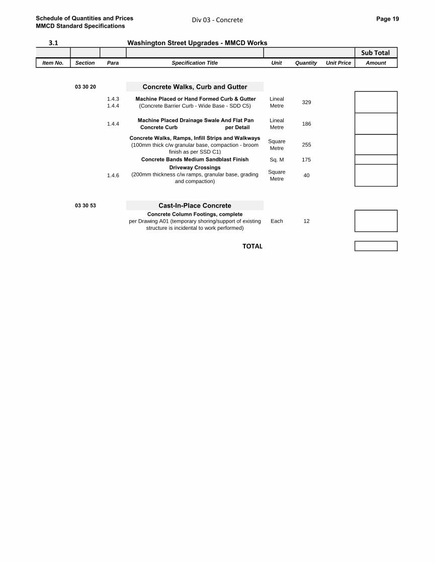
Schedule of Quantities and Prices
MMCD Standard SpecificationsDiv 03 - Concrete Page 19
3.1 Washington Street Upgrades - MMCD Works
Sub Total
Item No. Section Para Specification Title Unit Quantity Unit Price Amount
03 30 20 Concrete Walks, Curb and Gutter
1.4.3
1.4.4
Machine Placed or Hand Formed Curb & Gutter
(Concrete Barrier Curb - Wide Base - SDD C5)
Lineal
Metre329
1.4.4 Machine Placed Drainage Swale And Flat Pan
Concrete Curb per Detail
Lineal
Metre186
Concrete Walks, Ramps, Infill Strips and Walkways
(100mm thick c/w granular base, compaction - broom
finish as per SSD C1)
Square
Metre255
Concrete Bands Medium Sandblast Finish Sq. M 175
1.4.6
Driveway Crossings
(200mm thickness c/w ramps, granular base, grading
and compaction)
Square
Metre40
03 30 53 Cast-In-Place Concrete
Concrete Column Footings, complete
per Drawing A01 (temporary shoring/support of existing
structure is incidental to work performed)
Each 12
TOTAL

Schedule of Quantities and Prices
MMCD Standard SpecificationsDiv 26 - Electrical Page 20
3.2 Washington Street Upgrades - MMCD Works
26 Sub Total
Item No. Section Para Specification Title Unit Quantity Unit Price Amount
26 56 01 Roadway Lighting
1.9 Roadway LightingLump
Sum1
TOTAL
Electrical
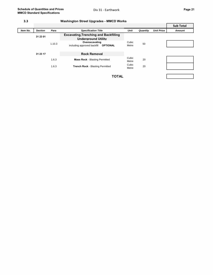
Schedule of Quantities and Prices
MMCD Standard SpecificationsDiv 31 - Earthwork Page 21
3.3 Washington Street Upgrades - MMCD Works
31 Sub Total
Item No. Section Para Specification Title Unit Quantity Unit Price Amount
31 23 01Excavating,Trenching and Backfilling
Underground Utility
1.10.3Overexcavating
including approved backfill OPTIONAL
Cubic
Metre50
31 23 17 Rock Removal
1.6.3 Mass Rock - Blasting PermittedCubic
Metre20
1.6.3 Trench Rock - Blasting PermittedCubic
Metre20
TOTAL
Earthwork
Schedule of Quantities and Prices
MMCD Standard SpecificationsDiv 32 - Roads and Site Improvements Page 22
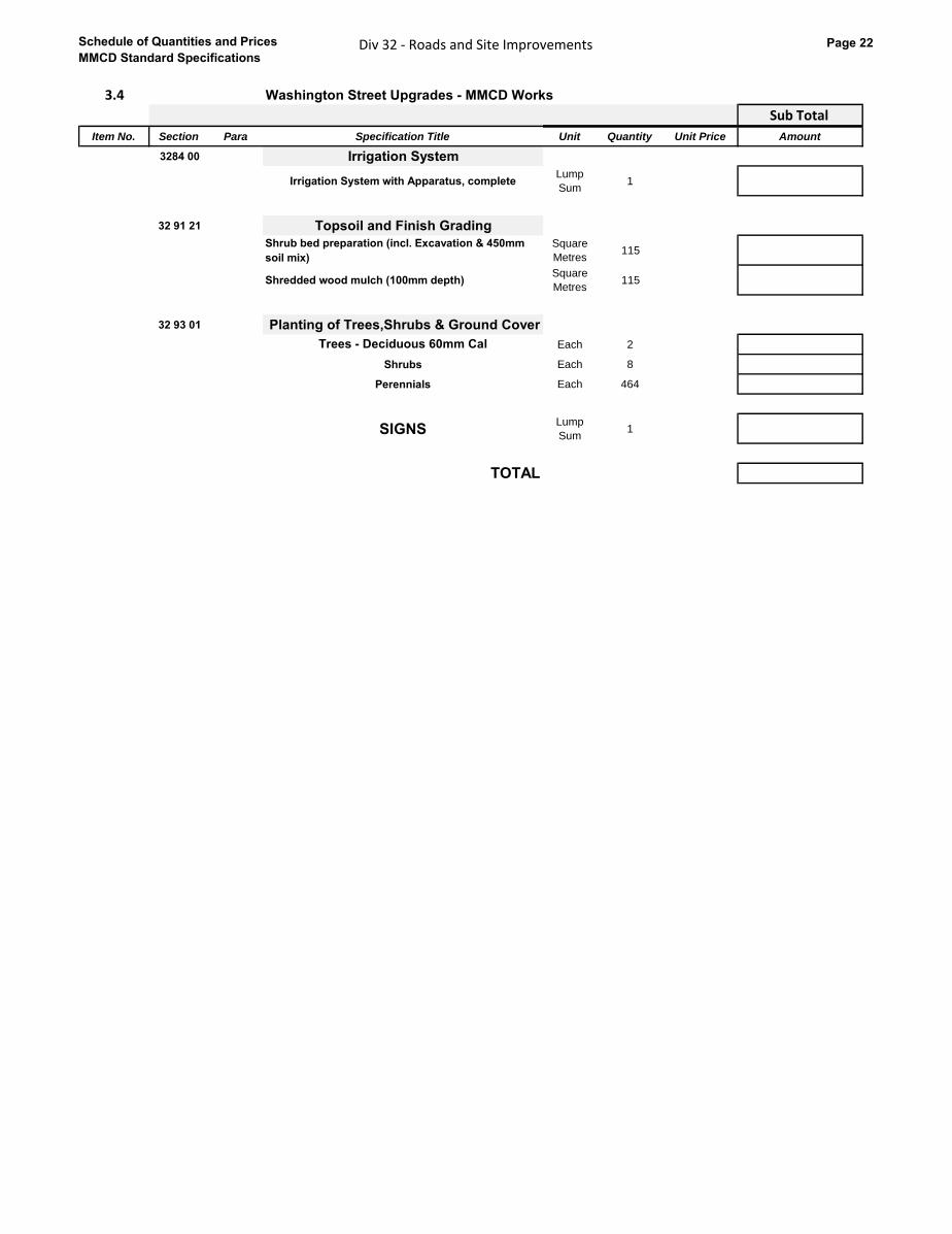
3.4 Washington Street Upgrades - MMCD Works
32 Sub Total
Item No. Section Para Specification Title Unit Quantity Unit Price Amount
3284 00 Irrigation System
Irrigation System with Apparatus, completeLump
Sum1
32 91 21 Topsoil and Finish Grading
Shrub bed preparation (incl. Excavation & 450mm
soil mix)
Square
Metres115
Shredded wood mulch (100mm depth)Square
Metres115
32 93 01 Planting of Trees,Shrubs & Ground Cover
Trees - Deciduous 60mm Cal Each 2
Shrubs Each 8
Perennials Each 464
SIGNSLump
Sum1
TOTAL
Roads and Site Improvements
Schedule of Quantities and Prices
MMCD Standard SpecificationsDiv 33 - Utilities Page 23
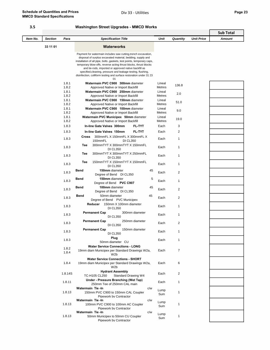
3.5 Washington Street Upgrades - MMCD Works
33 Sub Total
Item No. Section Para Specification Title Unit Quantity Unit Price Amount
33 11 01 Waterworks
Payment for watermain includes saw cutting,trench excavation,
disposal of surplus excavated material, bedding, supply and
installation of all pipe, bolts ,gaskets, test points, temporary caps,
temporary blow-offs, reverse acting thrust blocks, thrust blocks
and tie-rods, imported or approved native backfill as
specified,cleaning, pressure and leakage testing, flushing,
disinfection, colliform testing and surface restoration under 31 23
01
1.8.1
1.8.2
Watermain PVC C900 300mm diameter
Approved Native or Import Backfill
Lineal
Metres136.8
1.8.1
1.8.2
Watermain PVC C900 250mm diameter
Approved Native or Import Backfill
Lineal
Metres2.0
1.8.1
1.8.2
Watermain PVC C900 150mm diameter
Approved Native or Import Backfill
Lineal
Metres51.0
1.8.1
1.8.2
Watermain PVC C900 100mm diameter
Approved Native or Import Backfill
Lineal
Metres9.0
1.8.1
1.8.2
Watermain PVC Municipex 50mm diameter
Approved Native or Import Backfill
Lineal
Metres19.0
1.8.3 In-line Gate Valves 300mm FL-TYT Each 3
1.8.3 In-line Gate Valves 150mm FL-TYT Each 2
1.8.3Cross 300mmFL X 150mmFL X 300mmFL X
150mmFL DI CL350Each 1
1.8.3Tee 300mmTYT X 300mmTYT X 150mmFL
DI CL350 Each 1
1.8.3Tee 300mmTYT X 300mmTYT X 250mmFL
DI CL350 Each 1
1.8.3Tee 150mmTYT X 150mmTYT X 150mmFL
DI CL350 Each 1
1.8.3Bend 150mm diameter 45
Degree of Bend DI CL350Each 2
1.8.3Bend 150mm diameter 5
Degree of Bend PVC C907Each 1
1.8.3Bend 100mm diameter 45
Degree of Bend DI CL350Each 2
1.8.3Bend 50mm diameter 45
Degree of Bend PVC MunicipexEach 2
1.8.3Reducer 150mm X 100mm diameter
DI CL350Each 1
1.8.3Permanent Cap 300mm diameter
DI CL350Each 1
1.8.3Permanent Cap 250mm diameter
DI CL350Each 2
1.8.3Permanent Cap 150mm diameter
DI CL350Each 1
1.8.3Plug
50mm diameter CUEach 1
1.8.2
1.8.4
Water Service Connections - LONG
19mm diam Municipex per Standard Drawings W2a,
W2b
Each 7
1.8.4
Water Service Connections - SHORT
19mm diam Municipex per Standard Drawings W2a,
W2b
Each 6
1.8.14SHydrant Assembly
TC-H105 CL250 Standard Drawing W4Each 2
1.8.11Under - Pressure Branching (Wet Tap)
250mm Tee of 250mm CAL mainEach 1
1.8.13
Watermain Tie -In c/w
150mm PVC C900 to 150mm CAL Coupler
Pipework by Contractor
Lump
Sum1
1.8.13
Watermain Tie -In c/w
100mm PVC C900 to 100mm AC Coupler
Pipework by Contractor
Lump
Sum1
1.8.13
Watermain Tie -In c/w
50mm Municipex to 50mm CU Coupler
Pipework by Contractor
Lump
Sum1
Utilities

Schedule of Quantities and Prices
MMCD Standard SpecificationsDiv 33 - Utilities Page 24
33 30 01 Sanitary Sewers
Payment for sanitary sewers includes saw cutting,trench
excavation, disposal of surplus excavated material, bedding,
supply and installation of all pipe, fittings and related material,
imported or approved native backfill as specified, cleaning,
flushing and testing, and surface restoration under 31 23 01
1.6.1S
1.6.2S
Sewer Pipe PVC DR35 300mm diameter Approved
Native or Import Backfill Backfill
Lineal
Metres166
1.6.1S
1.6.2S
Sewer Pipe PVC DR35 200mm diameter Approved
Native or Import Backfill Backfill
Lineal
Metres26
1.6.3Sanitary Service Connections - LONG
150mm diam per Standard Drawings S7Each 8
1.6.3Sanitary Service Connections - SHORT
150mm diam per Standard Drawings S7Each 13
1.6.4Sanitary Inspection Chamber
per Detail 7Each 21
1.6.5Sanitary Inspection Chamber
MR12 cover c/w 300mm PVC DR35 standpipe
Lineal
Metres1
1.6.7Sanitary Tie -In 200mm diameter PVC DR35 Main into
existing 200mm diameter PVC sanitary sewerEach 1
Sanitary Services at Buildings Payment Item 3 Each 5
Sanitary Services at Buildings Payment Item 4 Each 6
33 40 01 Storm Sewers
Payment for storm sewers includes saw cutting,trench
excavation, disposal of surplus excavated material, bedding,
supply and installation of all pipe, fittings and related material,
imported or approved native backfill as specified, cleaning,
flushing and testing, and surface restoration under 31 23 01
Note
1.6.1,
1.6.2
Drainage Pipe Concrete C76-IV 525mm diameter,
Approved Native Backfill or Imported Backfill
Lineal
Metres31
1.6.1,
1.6.2
Drainage Pipe Concrete C76-IV 450mm diameter,
Approved Native Backfill or Imported Backfill
Lineal
Metres126
1.6.1,
1.6.2
Drainage Pipe Concrete C76-IV 300mm diameter,
Approved Native Backfill or Imported Backfill
Lineal
Metres11
1.6.3
Drainage Service Connections - LONG
PVC DR28 150mm diameter per Standard Drawings
S8
Each 8
1.6.3Drainage Service Connections - SHORT
150mm diam per Standard Drawings S8Each 13
1.6.4Drainage Inspection Chamber
per Detail 7Each 21
1.6.4Drainage Inspection Chamber
c/w 300mm PVC DR35 Stand Pipe and a MR12 CoverEach 1
1.6.5Catchbasin Lead
PVC DR 35 250mm diameter
Lineal
Metres9
1.6.5Catchbasin Lead
PVC DR 35 200mm diameter
Lineal
Metres13
1.6.5Catchbasin Lead
PVC DR 28 150mm diameter
Lineal
Metres8
1.6.5Lawn Drain Lead
PVC DR28 150mm diameter
Lineal
Metres4
1.6.6
Sub-surface Drain - 100mm PVC DR28 perforated
pipe, rounded 50mm minus drain rock and filter cloth -
tied into StrataCells or storm main
Lineal
Metres330
1.6.9Storm Tie -In 300mm diameter PVC DR35 storm main
into existing 300mm diameter "tile" storm sewerEach 1
Storm Services at Buildings
Payment Item 4Each 11
Schedule of Quantities and Prices
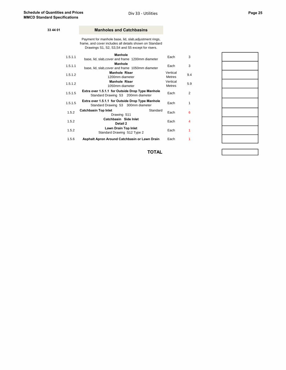
MMCD Standard SpecificationsDiv 33 - Utilities Page 25
33 44 01 Manholes and Catchbasins
Payment for manhole base, lid, slab,adjustment rings,
frame, and cover includes all details shown on Standard
Drawings S1, S2, S3,S4 and S5 except for risers.
1.5.1.1Manhole
base, lid, slab,cover and frame 1200mm diameterEach 3
1.5.1.1Manhole
base, lid, slab,cover and frame 1050mm diameterEach 3
1.5.1.2Manhole Riser
1200mm diameter
Vertical
Metres9.4
1.5.1.2Manhole Riser
1050mm diameter
Vertical
Metres5.9
1.5.1.5Extra over 1.5.1.1 for Outside Drop Type Manhole
Standard Drawing S3 200mm diameter Each 2
1.5.1.5Extra over 1.5.1.1 for Outside Drop Type Manhole
Standard Drawing S3 300mm diameter Each 1
1.5.2Catchbasin Top Inlet Standard
Drawing S11Each 6
1.5.2Catchbasin Side Inlet
Detail 2Each 4
1.5.2Lawn Drain Top Inlet
Standard Drawing S12 Type 2Each 1
1.5.6 Asphalt Apron Around Catchbasin or Lawn Drain Each 1
TOTAL

Schedule of Quantities and Prices
MMCD Standard SpecificationsDiv Summary Sheet Page 26
Summary SheetSee paragraph 5.3.1 of the Instructions to Tenderers – Part II
Schedule D - Washington Street Upgrades
ALL OPTIONAL WORKSCHEDULE OF QUANTITIES AND UNIT PRICES
Section Title Amount
4.1 Washington Street Upgrades - MOT Earthwork -$
4.2 Washington Street Upgrades - MOT Roads and Site Improvements -$
TOTAL -$
All prices and Quotations including the Contract Price shall include all Taxes , but shall not include HST . HST shall be shown
separately.
Summary Sheet
Schedule of Quantities and Prices
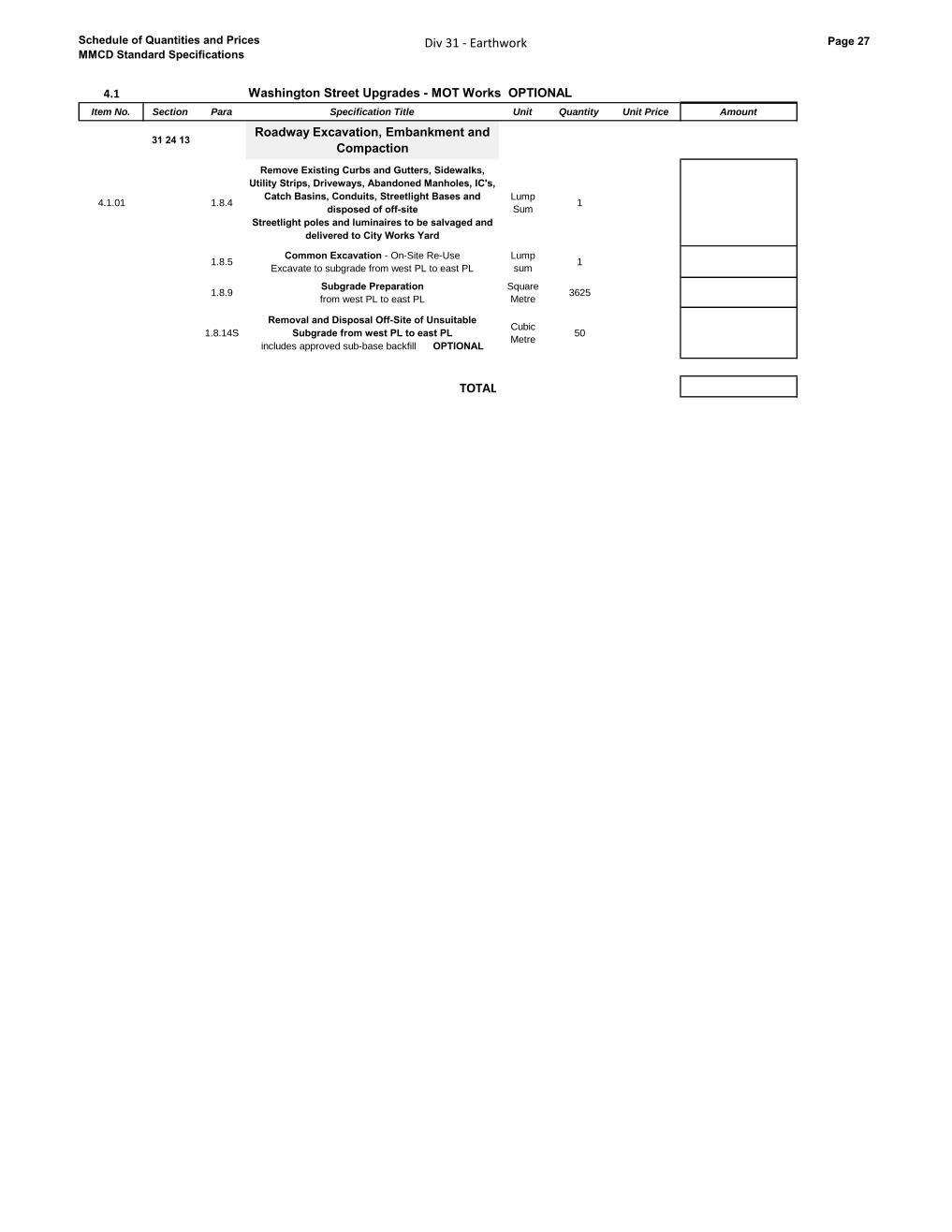
MMCD Standard SpecificationsDiv 31 - Earthwork Page 27
4.1 Washington Street Upgrades - MOT Works OPTIONAL
Item No. Section Para Specification Title Unit Quantity Unit Price Amount
31 24 13Roadway Excavation, Embankment and
Compaction
4.1.01 1.8.4
Remove Existing Curbs and Gutters, Sidewalks,
Utility Strips, Driveways, Abandoned Manholes, IC's,
Catch Basins, Conduits, Streetlight Bases and
disposed of off-site
Streetlight poles and luminaires to be salvaged and
delivered to City Works Yard
Lump
Sum1
1.8.5Common Excavation - On-Site Re-Use
Excavate to subgrade from west PL to east PL
Lump
sum1
1.8.9Subgrade Preparation
from west PL to east PL
Square
Metre3625
1.8.14S
Removal and Disposal Off-Site of Unsuitable
Subgrade from west PL to east PL
includes approved sub-base backfill OPTIONAL
Cubic
Metre50
TOTAL
Schedule of Quantities and Prices
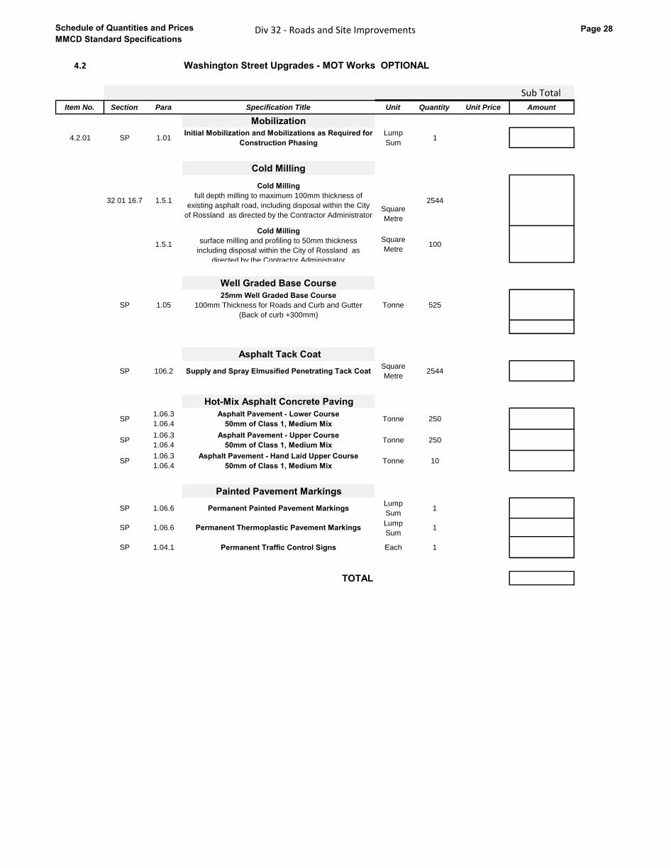
MMCD Standard SpecificationsDiv 32 - Roads and Site Improvements Page 28
4.2 Washington Street Upgrades - MOT Works OPTIONAL
32 Sub Total
Item No. Section Para Specification Title Unit Quantity Unit Price Amount
Mobilization
4.2.01 SP 1.01Initial Mobilization and Mobilizations as Required for
Construction Phasing
Lump
Sum1
Cold Milling
32 01 16.7 1.5.1
Cold Milling
full depth milling to maximum 100mm thickness of
existing asphalt road, including disposal within the City
of Rossland as directed by the Contractor Administrator Square
Metre
2544
1.5.1
Cold Milling
surface milling and profiling to 50mm thickness
including disposal within the City of Rossland as
directed by the Contractor Administrator
Square
Metre100
Well Graded Base Course
SP 1.05
25mm Well Graded Base Course
100mm Thickness for Roads and Curb and Gutter
(Back of curb +300mm)
Tonne 525
Asphalt Tack Coat
SP 106.2 Supply and Spray Elmusified Penetrating Tack CoatSquare
Metre2544
Hot-Mix Asphalt Concrete Paving
SP1.06.3
1.06.4
Asphalt Pavement - Lower Course
50mm of Class 1, Medium MixTonne 250
SP1.06.3
1.06.4
Asphalt Pavement - Upper Course
50mm of Class 1, Medium MixTonne 250
SP1.06.3
1.06.4
Asphalt Pavement - Hand Laid Upper Course
50mm of Class 1, Medium MixTonne 10
Painted Pavement Markings
SP 1.06.6 Permanent Painted Pavement MarkingsLump
Sum1
SP 1.06.6 Permanent Thermoplastic Pavement MarkingsLump
Sum1
SP 1.04.1 Permanent Traffic Control Signs Each 1
TOTAL
Roads and Site Improvements
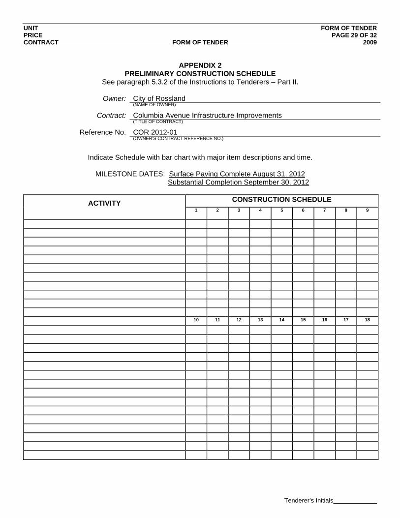
UNIT FORM OF TENDER PRICE PAGE 29 OF 32 CONTRACT FORM OF TENDER 2009
Tenderer’s Initials
APPENDIX 2
PRELIMINARY CONSTRUCTION SCHEDULE See paragraph 5.3.2 of the Instructions to Tenderers – Part II.
Owner: City of Rossland
(NAME OF OWNER)
Contract: Columbia Avenue Infrastructure Improvements (TITLE OF CONTRACT)
Reference No. COR 2012-01 (OWNER’S CONTRACT REFERENCE NO.)
Indicate Schedule with bar chart with major item descriptions and time.
MILESTONE DATES: Surface Paving Complete August 31, 2012
Substantial Completion September 30, 2012
ACTIVITY
CONSTRUCTION SCHEDULE 1 2 3 4 5 6 7 8 9
10 11 12 13 14 15 16 17 18

UNIT FORM OF TENDER PRICE PAGE 30 OF 32 CONTRACT FORM OF TENDER 2009
Tenderer’s Initials
APPENDIX 3
EXPERIENCE OF SUPERINTENDENT See paragraph 5.3.3 of the Instructions to Tenderers – Part II.
Owner: City of Rossland
(NAME OF OWNER)
Contract: Columbia Avenue Infrastructure Improvements (TITLE OF CONTRACT)
Reference No. COR 2012-01 (OWNER’S CONTRACT REFERENCE NO.)
Name:
Experience:
Dates: Project Name: Responsibility:
References:
Dates:
Project Name: Responsibility:
References:
Dates:
Project Name: Responsibility:
References:
Dates:
Project Name: Responsibility:
References:

UNIT FORM OF TENDER PRICE PAGE 31 OF 32 CONTRACT FORM OF TENDER 2009
Tenderer’s Initials
APPENDIX 4
COMPARABLE WORK EXPERIENCE See paragraph 5.3.4 of the Instructions to Tenderers – Part II.
Owner: City of Rossland
(NAME OF OWNER)
Contract: Columbia Avenue Infrastructure Improvements (TITLE OF CONTRACT)
Reference No. COR 2012-01 (OWNER’S CONTRACT REFERENCE NO.)
PROJECT
OWNER / CONTACT NAME
PHONE and FAX WORK
DESCRIPTION VALUE
($)
Owner / Contract
Phone ( ) Fax ( )
Owner / Contract
Phone ( ) Fax ( )
Owner / Contract
Phone ( ) Fax ( )
Owner / Contract
Phone ( ) Fax ( )
Owner / Contract
Phone ( ) Fax ( )
Owner / Contract
Phone ( ) Fax ( )
Owner / Contract
Phone ( ) Fax ( )
Owner / Contract
Phone ( ) Fax ( )
Owner / Contract
Phone ( ) Fax ( )
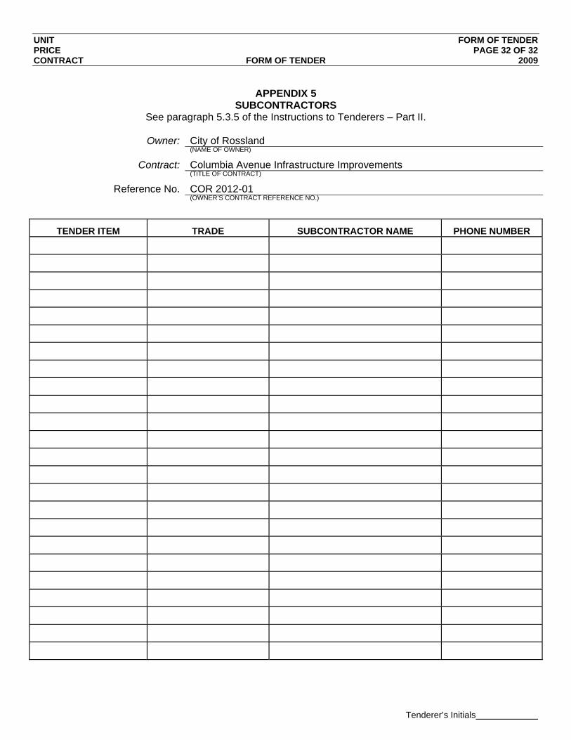
UNIT FORM OF TENDER PRICE PAGE 32 OF 32 CONTRACT FORM OF TENDER 2009
Tenderer’s Initials
APPENDIX 5
SUBCONTRACTORS See paragraph 5.3.5 of the Instructions to Tenderers – Part II.
Owner: City of Rossland
(NAME OF OWNER)
Contract: Columbia Avenue Infrastructure Improvements (TITLE OF CONTRACT)
Reference No. COR 2012-01 (OWNER’S CONTRACT REFERENCE NO.)
TENDER ITEM TRADE SUBCONTRACTOR NAME PHONE NUMBER
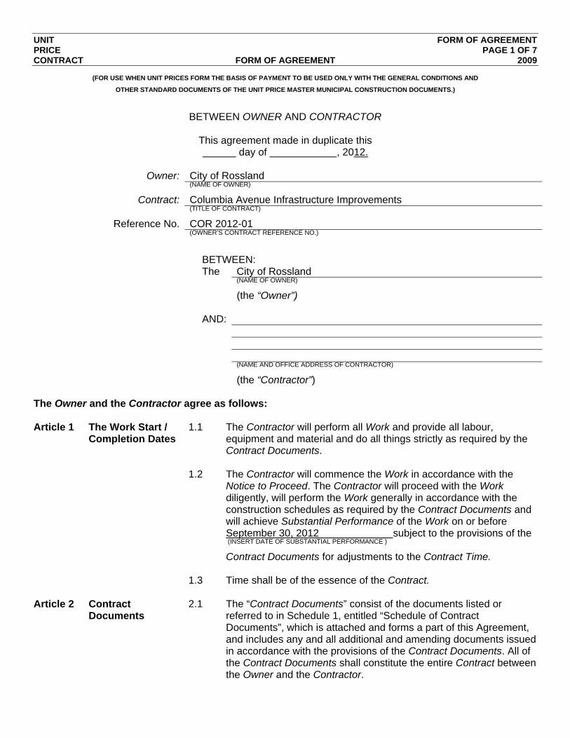
UNIT FORM OF AGREEMENT PRICE PAGE 1 OF 7 CONTRACT FORM OF AGREEMENT 2009
(FOR USE WHEN UNIT PRICES FORM THE BASIS OF PAYMENT TO BE USED ONLY WITH THE GENERAL CONDITIONS AND
OTHER STANDARD DOCUMENTS OF THE UNIT PRICE MASTER MUNICIPAL CONSTRUCTION DOCUMENTS.)
BETWEEN OWNER AND CONTRACTOR
This agreement made in duplicate this day of , 2012.
Owner: City of Rossland
(NAME OF OWNER)
Contract: Columbia Avenue Infrastructure Improvements (TITLE OF CONTRACT)
Reference No. COR 2012-01 (OWNER’S CONTRACT REFERENCE NO.)
BETWEEN: The City of Rossland (NAME OF OWNER)
(the “Owner”) AND: (NAME AND OFFICE ADDRESS OF CONTRACTOR)
(the “Contractor”) The Owner and the Contractor agree as follows: Article 1 The Work Start /
Completion Dates 1.1 The Contractor will perform all Work and provide all labour,
equipment and material and do all things strictly as required by the Contract Documents.
1.2 The Contractor will commence the Work in accordance with the
Notice to Proceed. The Contractor will proceed with the Work diligently, will perform the Work generally in accordance with the construction schedules as required by the Contract Documents and will achieve Substantial Performance of the Work on or before September 30, 2012 subject to the provisions of the (INSERT DATE OF SUBSTANTIAL PERFORMANCE )
Contract Documents for adjustments to the Contract Time. 1.3 Time shall be of the essence of the Contract. Article 2 Contract
Documents 2.1 The “Contract Documents” consist of the documents listed or
referred to in Schedule 1, entitled “Schedule of Contract Documents”, which is attached and forms a part of this Agreement, and includes any and all additional and amending documents issued in accordance with the provisions of the Contract Documents. All of the Contract Documents shall constitute the entire Contract between the Owner and the Contractor.
UNIT FORM OF AGREEMENT PRICE PAGE 2 OF 7 CONTRACT FORM OF AGREEMENT 2009
2.2 The Contract supersedes all prior negotiations, representations or agreements, whether written or oral, and the Contract may be amended only in strict accordance with the provisions of the Contract Documents.
Article 3 Contract Price 3.1 The price for the Work (“Contract Price”) shall be the sum in
Canadian dollars of the following 1.1.1 the product of the actual quantities of the items of Work listed
in the Schedule of Quantities and Prices which are incorporated into or made necessary by the Work and the unit prices listed in the Schedule of Quantities and Prices; plus
1.1.2 all lump sums, if any, as listed in the Schedule of Quantities
and Prices, for items relating to or incorporated into the Work; plus
1.1.3 any adjustments, including any payments owing on account
of Changes and agreed to Extra Work, approved in accordance with the provisions of the Contract Documents.
3.2 The Contract Price shall be the entire compensation owing to the
Contractor for the Work and this compensation shall cover and include all profit and all costs of supervision, labour, material, equipment, overhead, financing, and all other costs and expenses whatsoever incurred in performing the Work.
Article 4 Payment 4.1 Subject to applicable legislation and the provisions of the Contract
Documents, the Owner shall make payments to the Contractor. 4.2 If the Owner fails to make payments to the Contractor as they
become due in accordance with the terms of the Contract Documents then interest calculated at 2% per annum over the prime commercial lending rate of the Royal Bank of Canada on such unpaid amounts shall also become due and payable until payment. Such interest shall be calculated and added to any unpaid amounts monthly.
Article 5 Rights and
Remedies 5.1 The duties and obligations imposed by the Contract Documents and
the rights and remedies available thereunder shall be in addition to and not a limitation of any duties, obligations, rights and remedies otherwise imposed or available by law.
5.2 Except as specifically set out in the Contract Documents, no action
or failure to act by the Owner, Contract Administrator or Contractor shall constitute a waiver of any of the parties’ rights or duties afforded under the Contract, nor shall any such action or failure to act constitute an approval of or acquiescence in any breach under the Contract.
UNIT FORM OF AGREEMENT PRICE PAGE 3 OF 7 CONTRACT FORM OF AGREEMENT 2009
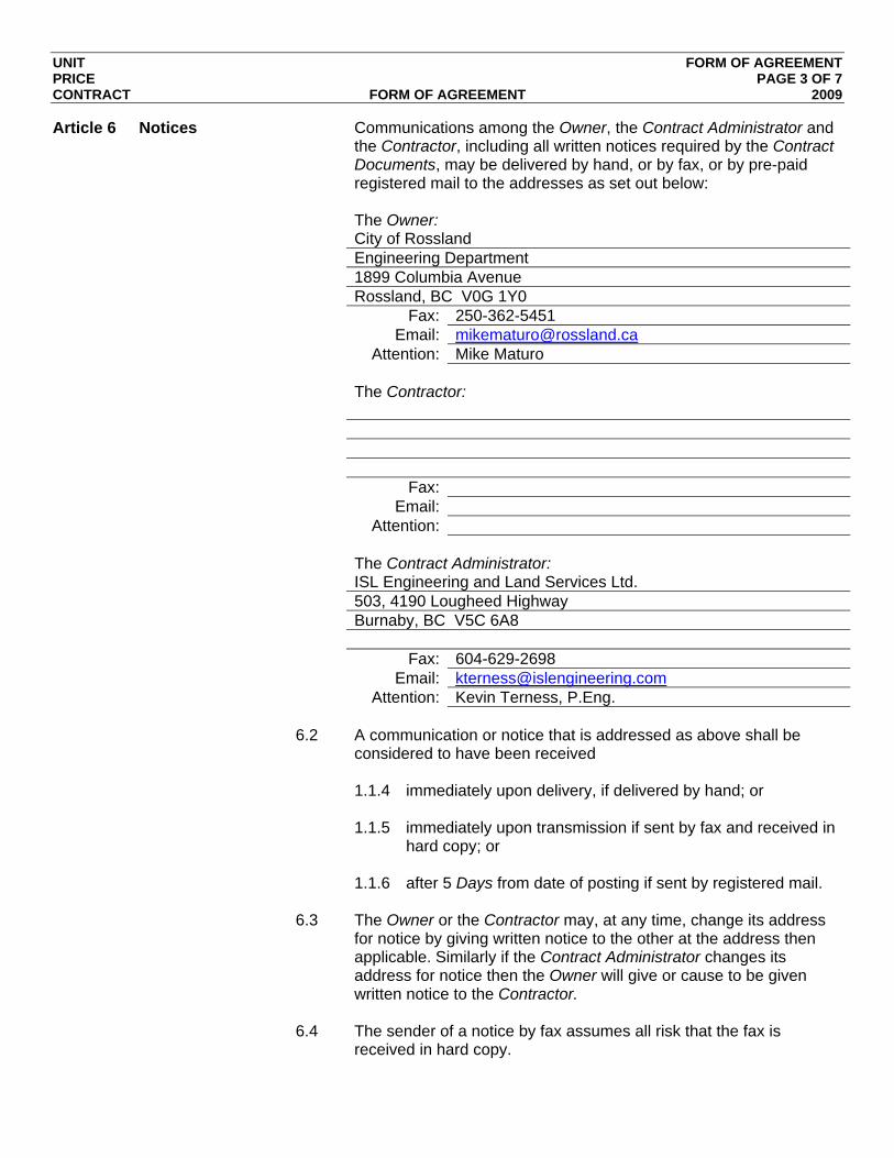
Article 6 Notices Communications among the Owner, the Contract Administrator and the Contractor, including all written notices required by the Contract Documents, may be delivered by hand, or by fax, or by pre-paid registered mail to the addresses as set out below:
The Owner: City of Rossland Engineering Department 1899 Columbia Avenue Rossland, BC V0G 1Y0 Fax: 250-362-5451 Email: [email protected] Attention: Mike Maturo The Contractor: Fax: Email: Attention: The Contract Administrator: ISL Engineering and Land Services Ltd. 503, 4190 Lougheed Highway Burnaby, BC V5C 6A8 Fax: 604-629-2698 Email: [email protected] Attention: Kevin Terness, P.Eng. 6.2 A communication or notice that is addressed as above shall be
considered to have been received 1.1.4 immediately upon delivery, if delivered by hand; or 1.1.5 immediately upon transmission if sent by fax and received in
hard copy; or 1.1.6 after 5 Days from date of posting if sent by registered mail. 6.3 The Owner or the Contractor may, at any time, change its address
for notice by giving written notice to the other at the address then applicable. Similarly if the Contract Administrator changes its address for notice then the Owner will give or cause to be given written notice to the Contractor.
6.4 The sender of a notice by fax assumes all risk that the fax is
received in hard copy.
UNIT FORM OF AGREEMENT PRICE PAGE 4 OF 7 CONTRACT FORM OF AGREEMENT 2009
Article 7 General 7.1 This Contract shall be construed according to the laws of British Columbia.
7.2 The Contractor shall not, without the express written consent of the
Owner, assign this Contract, or any portion of this Contract. 7.3 The headings included in the Contract Documents are for
convenience only and do not form part of this Contract and will not be used to interpret, define or limit the scope or intent of this Contract or any of the provisions of the Contract Documents.
7.4 A word in the Contract Documents in the singular includes the plural
and, in each case, vice versa. 7.5
This agreement shall ensure to the benefit of and be binding upon the parties and their successors, executors, administrators and assigns.
IN WITNESS WHEREOF the parties hereto have executed this Agreement
the day and year first written above. Contractor: (FULL LEGAL NAME OF CORPORATION, PARTNERSHIP OR INDIVIDUAL)
(AUTHORIZED SIGNATORY)
(AUTHORIZED SIGNATORY)
Owner: City of Rossland (FULL LEGAL NAME OF CORPORATION, PARTNERSHIP OR INDIVIDUAL)
(AUTHORIZED SIGNATORY)
(AUTHORIZED SIGNATORY)
UNIT FORM OF AGREEMENT PRICE PAGE 5 OF 7 CONTRACT FORM OF AGREEMENT 2009
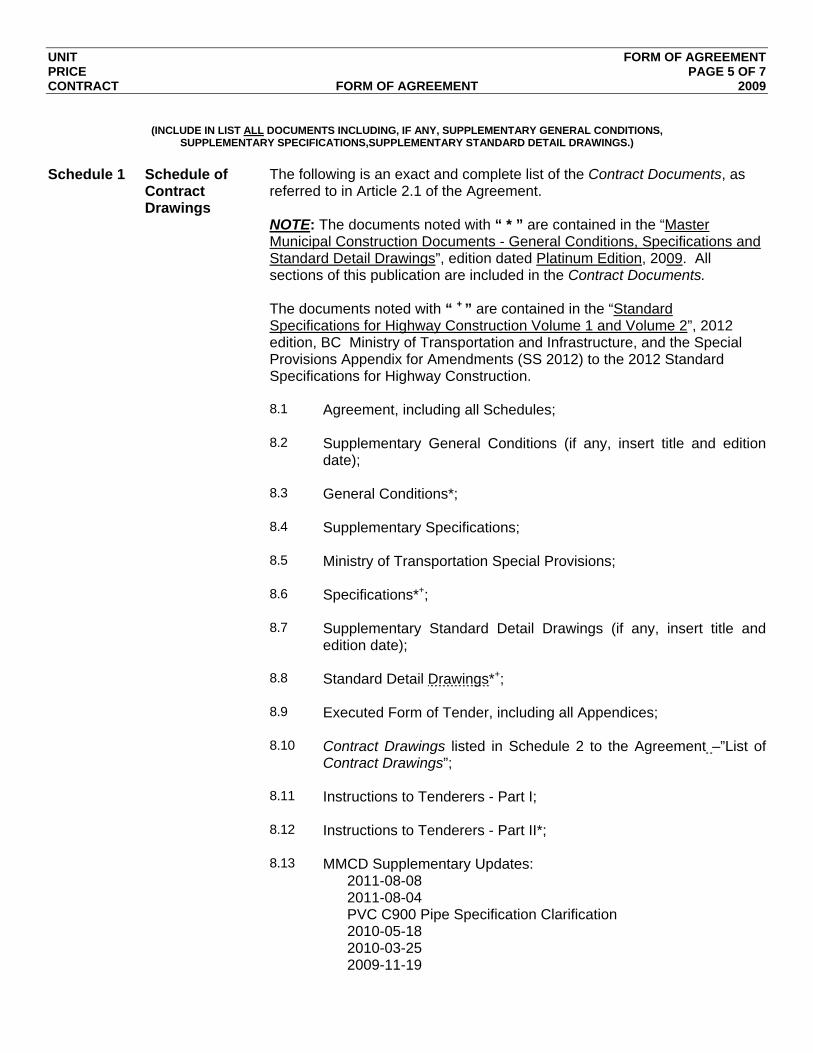
(INCLUDE IN LIST ALL DOCUMENTS INCLUDING, IF ANY, SUPPLEMENTARY GENERAL CONDITIONS,
SUPPLEMENTARY SPECIFICATIONS,SUPPLEMENTARY STANDARD DETAIL DRAWINGS.)
Schedule 1 Schedule of
Contract Drawings
The following is an exact and complete list of the Contract Documents, as referred to in Article 2.1 of the Agreement.
NOTE: The documents noted with “ * ” are contained in the “Master Municipal Construction Documents - General Conditions, Specifications and Standard Detail Drawings”, edition dated Platinum Edition, 2009. All sections of this publication are included in the Contract Documents.
The documents noted with “ + ” are contained in the “Standard Specifications for Highway Construction Volume 1 and Volume 2”, 2012 edition, BC Ministry of Transportation and Infrastructure, and the Special Provisions Appendix for Amendments (SS 2012) to the 2012 Standard Specifications for Highway Construction.
8.1 Agreement, including all Schedules; 8.2 Supplementary General Conditions (if any, insert title and edition
date); 8.3 General Conditions*; 8.4 Supplementary Specifications; 8.5 Ministry of Transportation Special Provisions; 8.6 Specifications*+; 8.7 Supplementary Standard Detail Drawings (if any, insert title and
edition date); 8.8 Standard Detail Drawings*+; 8.9 Executed Form of Tender, including all Appendices; 8.10 Contract Drawings listed in Schedule 2 to the Agreement –”List of
Contract Drawings”; 8.11 Instructions to Tenderers - Part I; 8.12 Instructions to Tenderers - Part II*; 8.13 MMCD Supplementary Updates:
2011-08-08 2011-08-04 PVC C900 Pipe Specification Clarification 2010-05-18 2010-03-25 2009-11-19

UNIT FORM OF AGREEMENT PRICE PAGE 6 OF 7 CONTRACT FORM OF AGREEMENT 2009
8.14 The following Addenda: (ADDENDA, IF ANY)

UNIT FORM OF AGREEMENT PRICE PAGE 7 OF 7 CONTRACT FORM OF AGREEMENT 2009
(COMPLETE LISTING OF ALL DRAWINGS, PLANS AND SKETCHES WHICH ARE TO FORM A PART OF THE CONTRACT,
OTHER THAN STANDARD DETAIL DRAWINGS AND SUPPLEMENTARY STANDARD DETAIL DRAWINGS.)
Schedule 2 List of Contract Drawings
TITLE DRAWING NO. DATE REVISION NO. REVISION DATE

Reference No.
These Supplementary Specifications must be read in conjunction with the Master Municipal Specifications contained in the Master Municipal Construction Documents, Volume II, Platinum Edition 2009.

SUPPLEMENTARY SECTION NDX CONTRACT INDEX PAGE 1 OF 1 SPECIFICATIONS 2012
SUPPLEMENTARY SPECIFICATIONS INDEX DIVISION 01 – GENERAL REQUIREMENTS 01010S General Information 01 33 01S Project Record Documents DIVISION 03 – CONCRETE 03 30 20 Concrete Walks, Curbs and Gutters DIVISION 31 – EARTHWORKS 31 23 01S Excavating, Trenching and Backfilling 31 24 13S Roadway Excavation, Embankment and Compaction DIVISION 33 – UTILITIES 33 01 30.1 CCTV Inspection of Pipelines 33 11 01 Waterworks 33 30 01 Sanitary Sewers 33 40 01S Storm Sewers 33 44 01S Manholes and Catchbasins

SUPPLEMENTARY GENERAL DIVISION 01S CONTRACT REQUIREMENTS PAGE 1 OF 7 SPECIFICATIONS 2012
1.0 Master Municipal
Construction Documents
.1 The Supplementary Specifications contained herein must be read in conjunction with the Master Municipal Specifications contained in the Master Municipal Construction Documents, Volume II (Platinum Edition 2009) and the Standard Specifications for Highway Construction Volume 1 and Volume 2, 2012 Edition, BC Ministry of Transportation and Infrastructure, as identified in the Instructions to Tender article 2.2.
2.0 Format and
Numbering System .1 The Supplementary Contract Specifications follow the same
format and numbering system as the Master Municipal Specifications, but is differentiated from it by having the letter “S” placed after the section number.
3.0 Construction Survey
Layout .1 The Contract Administrator will provide survey control CAD
files for this Contract. The Contractor shall be responsible for the detailed setting out of the work and recording all data required to compile record drawings. The Contractor will be responsible for the detailed survey of the site to execute construction.
.2 Payment for survey layout shall be considered incidental to
the work performed and no additional payment will be made to the contractor.
.3 All iron pins, wooden witness posts and survey monuments
disturbed by the Contractor shall be re-established by Registered British Columbia Land Surveyors, at the Contractor’s cost, and the appropriate authorities advised of the revised elevation and coordinates. Contractors are advised that the Contract Administrator will monitor construction to ensure that disturbed pins are replaced at the Contractor’s expense prior to completion of the Contract.
4.0 Description of Work .1 The work can be described as follows:
To address the aging of the downtown core and substandard infrastructure, the COR has planned a revitalization project for Columbia Avenue between Spokane Street and St. Paul Street and for Washington Street from Columbia Avenue to First Avenue. The objective is to bring the existing roadway up to a 20 year design life and improve the pedestrian friendliness of the downtown core. The work includes road rehabilitation, underground utility upgrading and sidewalk replacement and downtown core beautification.
SUPPLEMENTARY GENERAL DIVISION 01S CONTRACT REQUIREMENTS PAGE 2 OF 7 SPECIFICATIONS 2012
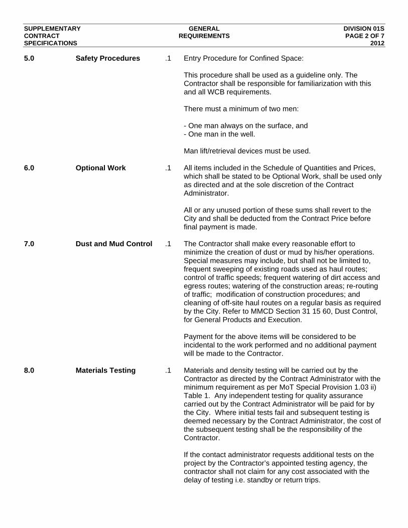
5.0 Safety Procedures .1 Entry Procedure for Confined Space: This procedure shall be used as a guideline only. The Contractor shall be responsible for familiarization with this and all WCB requirements. There must a minimum of two men: - One man always on the surface, and - One man in the well. Man lift/retrieval devices must be used.
6.0 Optional Work .1 All items included in the Schedule of Quantities and Prices,
which shall be stated to be Optional Work, shall be used only as directed and at the sole discretion of the Contract Administrator. All or any unused portion of these sums shall revert to the City and shall be deducted from the Contract Price before final payment is made.
7.0 Dust and Mud Control .1 The Contractor shall make every reasonable effort to
minimize the creation of dust or mud by his/her operations. Special measures may include, but shall not be limited to, frequent sweeping of existing roads used as haul routes; control of traffic speeds; frequent watering of dirt access and egress routes; watering of the construction areas; re-routing of traffic; modification of construction procedures; and cleaning of off-site haul routes on a regular basis as required by the City. Refer to MMCD Section 31 15 60, Dust Control, for General Products and Execution. Payment for the above items will be considered to be incidental to the work performed and no additional payment will be made to the Contractor.
8.0 Materials Testing .1 Materials and density testing will be carried out by the
Contractor as directed by the Contract Administrator with the minimum requirement as per MoT Special Provision 1.03 ii) Table 1. Any independent testing for quality assurance carried out by the Contract Administrator will be paid for by the City. Where initial tests fail and subsequent testing is deemed necessary by the Contract Administrator, the cost of the subsequent testing shall be the responsibility of the Contractor. If the contact administrator requests additional tests on the project by the Contractor’s appointed testing agency, the contractor shall not claim for any cost associated with the delay of testing i.e. standby or return trips.

SUPPLEMENTARY GENERAL DIVISION 01S CONTRACT REQUIREMENTS PAGE 3 OF 7 SPECIFICATIONS 2012
9.0 MoT Specification .1 The following list, at MMCD Specifications, should not be used for this Contract. The MoT Standard Specifications for Highway Construction , 2012 Edition, should be used in conjunction with the MoT Special Provisions: 01 55 00 Traffic Control, Vehicle Access and Parking 01 57 01 Environmental Protection 32 11 16.1 Granular Subbase 32 11 23 Granular Base 32 12 13.1 Asphalt Tack 32 12 13.2 Asphalt Primer 32 12 16 Hot Mix Asphalt Concrete Paving 32 17 23 Painted Pavement Markings
All reference to these specified within the MMCD Specifications will default to the MoT Standard Specifications.
10.0 Interfering Services .1 1. The Contractor shall, at his/her own expense, provide
for the uninterrupted flow of all watercourses, sewers, drains, and any other utility encountered during the work.
2. When other utility structures are encountered, the
Contractor shall support them to the satisfaction of the Contract Administrator, so as to protect them from damage. The Contractor shall, at his/her own expense, at once repair and make good any damage which may occur to any watermains, service or utility pipes, or facilities, or to any electrical conductor or telephone facility, or to any sidewalk or crosswalk as a result of this operation.
3. It is the Contractor’s responsibility, wherever
necessary, to determine the location of existing pipes, valves, or other underground structures. Wherever it is necessary to explore and excavate to determine the location of the existing underground structures, the Contractor shall do so at his/her own expense.
4. Where gas mains and/or service lines exist in the
vicinity of the proposed work, the Contractor shall consult the officers of the gas company prior to commencing operations and arrange for a mutually agreeable procedure for their protection.

SUPPLEMENTARY GENERAL DIVISION 01S CONTRACT REQUIREMENTS PAGE 4 OF 7 SPECIFICATIONS 2012
5. When existing utility poles conflict with the proposed works, the Contractor consult the appropriate utility provider prior to commencing operations and advise the Contract Administrator of the works to be undertaken. Costs associated with pole holding/support are incidental to the work.
11.0 Metric Units of
Measurement .1 All the units of measurement for payment in this Contract are
metric units as modified by the internationally agreed S.I. Units (System International). However, as the construction industry is not entirely converted to S.I. Units, some conversions will need to be made for purpose of month end and Final Progress Estimates. The following conversion factors will be used in this Contract: 1 ton = 0.907 tonnes 1 cubic yard = 0.765 cubic metres 1 foot = 0.3048 metres
12.0 Weigh Ticket Control .1 Items in the Schedule of Quantities and Prices measured by
weight will be paid for as stipulated in the appropriate section of the Specific Provisions or the Specifications of the Contract. In addition, the Contractor will adhere to the following conditions:
1. Payment will be made only for material completely incorporated into the works as witnessed by the Contract Administrator's representative.
2. Weigh tickets shall be received by the Contract
Administrator's representative immediately preceding the placement of the material in the works.
3. The Contractor is to arrange for material supply in
such a manner that weigh tickets can be collected and verified at specific locations on the project as arranged with and approved by the Contract Administrator.
4. The Contract Administrator shall have the right to
refuse approval of tickets received after the day of placement.
If the Contractor fails to meet any of these conditions, then the Contract Administrator shall have the right to refuse approval of weigh tickets presented.

SUPPLEMENTARY GENERAL DIVISION 01S CONTRACT REQUIREMENTS PAGE 5 OF 7 SPECIFICATIONS 2012
13.0 Disposal Site .1 The Contractor is responsible for the provision of all off-site disposal sites for waste materials that are to be removed from the construction sites in this Contract.
.2 The Contractor is responsible for all fees, permits and costs
associated with the off-site disposal of materials. .3 The City has available disposal sites for material acceptable
as embankment fill, as determined by the Contract Administrator. Disposal sites are shown on the site plan.
.4 The Contractor will place compact embankment material as
directed by the Contract Administrator. Payment for the above items will be considered incidental to the work performed and no additional payment will be made to the Contractor.
14.0 Permits from Outside
Agencies .1 The Contractor is responsible to obtain and pay for all permits
required from outside agencies. 15.0 Foreign Utility
Adjustments .1 The Contractor will be responsible for adjusting all foreign
utilities, unless noted otherwise on the drawings. All adjustments to foreign utilities must be completed to the satisfaction of the Utility Owner. The Contractor should note that certain Utility Owners may decide, after tender closing, to complete their own adjustments, if personnel are available. If the Utility Owner decides to complete their own adjustments, the Contractor will not be compensated for these utility adjustments but Contractor will coordinate the adjustments with the Utility Owner
16.0 Quality of Work .1 The Contractor shall provide a final product conforming to the
Contract Documents and the intent of the work. The work is to be accurate to the dimensional and tolerance requirements of the contract. Where no tolerances are specified in the Contract Documents, the standard of workmanship shall be in accordance with current industry best practices. Payment will be subject to adjustments based on quality assurance tests performed by the Contract Administrator. Any changes in the Work with respect to the location, grade, or line shall be approved in advance by the Contract Administrator. Failure to notify the Contract Administrator of changes in writing may result in rejection of Work.
17.0 Quality Control (QC)
by the Contractor .1 The Contractor is fully responsible for quality control of the
materials, production, and construction processes.

SUPPLEMENTARY GENERAL DIVISION 01S CONTRACT REQUIREMENTS PAGE 6 OF 7 SPECIFICATIONS 2012
Quality control tests shall be performed by the Contractor, at their own expense, to ensure that products meet the contract specifications. The Contractor shall be responsible for determining the frequency of Quality Control and method of sampling and testing to ensure that the materials produced and incorporated into the work, and the final product produced meet the specifications outlined in the specifications. The Contractor shall submit a Quality Control Plan (QCP) to the Contract Administrator for review at least two weeks prior to commencing work. The Contractor shall bear the cost of all consulting and testing services retained by him. (Relating to the Quality Control Plan and quality control testing.) The Contractor shall not use the City’s retained testing agency for QC work. Tests performed by the Contract Administrator under GC 4.12 will not be considered part of the Contractor’s quality control. Quality Assurance (QA) testing will be conducted by the Contract Administrator on the final product to ensure that the production and placement of Asphalt Concrete meets the specified requirements outlined in the Specifications and Supplemental Specifications.” With the exception of thickness and density derived from the QA coring, Appeal Testing to tests performed under GC4.12 will only be considered if Quality Control results can be presented that support an appeal. Failure by the Contractor to conduct adequate quality control testing during production and construction will negate the Contractor’s ability to appeal the quality assurance tests used for acceptance/rejection of the work. Under no circumstances will QC test results produced after completion of the Quality Assurance (QA) results be considered for appeal purposes. The Contractor may appeal the results of the Quality Assurance testing only once for a given deficiency at a given location. All costs associated with appeal testing are to be borne by the Contractor if Appeal testing supports QA testing. The Contractor shall serve notice of appeal test to the Engineer, in writing, within two working days of receipt of the Quality Assurance test results.” The Contract Administrator will arrange for an independent testing laboratory to perform the appeal testing. Personnel employed or testing laboratory retained by the Contractor for

SUPPLEMENTARY GENERAL DIVISION 01S CONTRACT REQUIREMENTS PAGE 7 OF 7 SPECIFICATIONS 2012
Quality Control testing on the project cannot be used for any appeal testing. If problems develop in the finished product following construction or during the warranty period, additional testing will be conducted on those areas to determine the cause and extent of the potential problem.
18.0 Inspection of work .1 The Contract Administrator and MOT will provide construction
review through inspections and material testing. The review will not relieve the Contractor from providing a product that meets the requirements of the Contract Documents.
END OF SECTION
SUPPLEMENTARY PROJECT SECTION 01 33 01S CONTRACT RECORD PAGE 1 OF 1 SPECIFICATIONS DOCUMENTS 2012
1.7S Recording Actual Site
Conditions .5S (add clause 1.7.5 as follows)
The Contractor will complete topographic site surveys using the project coordinate system and deliver an AutoCAD file with all of the final locations, elevations and inverts of the surface and underground works. The Contractor will keep one set of drawings on-site that will be marked up in red ink identifying all work completed and any changes made during the construction. This copy will be turned over to the Contract Administrator following completion of all works. The Contractor shall be responsible for the detailed setting out of the work and recording all data required to compile record drawings. Payment for recording data for record drawings shall be considered incidental to the work performed and no additional payment will be made to the contractor.
END OF SECTION
SUPPLEMENTARY CONCRETE WALKS, SECTION 03 30 20 CONTRACT CURBS AND PAGE 1 OF 1 SPECIFICATIONS GUTTERS 2012
1.4S Measurement and
Payment .6S Payment for driveway crossings including granular base
shown on Standard Detail Drawing C7 will be made on a square meter basis for each specified thickness.
.8S Delete this clause and replace with:
Adjustment of existing catchbasins and other utilities required for installation of curb and gutter and walks shall be considered incidental to the work performed and no additional payment will be made to the Contractor.
END OF SECTION
SUPPLEMENTARY EXCAVATING, SECTION 31 23 01S CONTRACT TRENCHING AND PAGE 1 OF 1 SPECIFICATIONS BACKFILLING 2012
1.10S Measurement and
Payment .2S Trench excavation by hand will be incidental to the work
performed and no additional payment will be made to the Contractor.
.8S Add:
Payment will be made per the Unit Bid Items in the Schedule of Units and Prices for the work performed.
END OF SECTION

SUPPLEMENTARY ROADWAY EXCAVATION, SECTION 31 24 13S CONTRACT EMBANKMENT AND PAGE 1 OF 1 SPECIFICATIONS COMPACTION 2012
1.8 Measurement and
Payment .5S 1. .4 Add:
Fully loaded truck volumes to be used for payment are: Tandem – 7cu.m ordinary material
– 4cu.m asphalt/concrete/pipe Triaxle – 8cu.m ordinary material
– 5cu.m asphalt/concrete/pipe Tandem and Pony – 11cu.m ordinary material
– 7.5cu.m asphalt/concrete/pipe Triaxle and Pony – 13cu.m ordinary material
– 9cu.m asphalt/concrete/pipe Tandem and Transfer – 19cu.m ordinary material
– 13cu.m asphalt/concrete/pipe Contractor to provide truck slips detailing location type of common excavation, time loaded and location of dump site. The slips are to be given to Contract Administrator by the end of shift or Contract Administrator can deny quantities subsequently submitted.
.6S Delete clause and replace with:
Payment for hauling to stockpile of excavated material as specified or as directed by Contract Administrator and will be based on truck volumes per 1.8.5.4. Add: Payment for the onsite re-use of stockpiled material as directed by the Contract Administrator will be based on truck volumes per 1.8.5.4S.
.14S Delete this clause and replace with:
Payment for removal of unsuitable materials will be as over-excavation with offsite disposal and backfill with 75mm minus select granular sub-base including finish grading, adjustment of moisture content and compaction as specified will be per the Unit Bid Item in the Schedule of Units and Prices.
END OF SECTION

SUPPLEMENTARY CCTV SECTION 33 01 30.1 CONTRACT INSPECTION OF PAGE 1 OF 1 SPECIFICATIONS PIPELINES 2012
1.6 .2S Delete this clause and replace with:
CCTV pipeline inspection shall be considered incidental to the work performed and no additional payment will be made to the Contractor.
END OF SECTION
SUPPLEMENTARY SECTION 33 11 01 CONTRACT WATERWORKS PAGE 1 OF 1 SPECIFICATIONS 2012
1.8 .1S Delete this clause and replace with:
Payment for watermain will be made separately for various sections of watermain consistent with pipe materials and diameters, and backfill requirements shown on Contract Drawings and described under individual payment items in the Schedule of Quantities and Prices.
.14S (add clause 1.8.14 as follows)
Payment for hydrants includes the hydrant body, lateral connections from mainline tee off watermain to hydrants, isolation valve at the mainline tee, bends if required and all other incidental work as shown on Standard Detail Drawings W4.
END OF SECTION
SUPPLEMENTARY SANITARY SECTION 33 30 01 CONTRACT SEWERS PAGE 1 OF 1 SPECIFICATIONS 2012
1.6 Measurement and
Payment .1S Payment for sanitary sewer will be made separately for
various sections of sanitary sewers consistent with pipe materials and diameters, and backfill requirements shown on Contract Drawings and described under individual payment items in Schedule of Quantities and Prices.
.2S Payment for sanitary sewer includes saw cutting pavement,
trench excavation, disposal of surplus excavated material, supply and installation of all pipe, fittings, and related materials, bedding, imported or approved native backfill as shown on Contract Drawings, cleaning and flushing, testing, (if applicable), all surface restoration as specified under Excavating, Trenching and Backfilling Section 31 23 01 – 3.6, and all other work and materials necessary to complete installation as shown on Contract Drawings and specified under this Section. Measurement for sanitary sewer will be made horizontally from manhole centerline to manhole centerline over surface after work has been completed.
.8S Payment for CCTV Inspection of Pipelines shall be
considered as incidental to the Work being performed under this Contract, and no separate payment will be made for this Work.
END OF SECTION
SUPPLEMENTARY STORM SECTION 33 40 01S CONTRACT SEWERS PAGE 1 OF 1 SPECIFICATIONS 2012
1.6 Measurement and
Payment .1S Payment for storm sewer will be made separately for various
sections of storm sewers consistent with pipe materials and diameters, and backfill requirements shown on Contract Drawings and described under individual payment items in Schedule of Quantities and Prices.
.2S Payment for storm sewer includes saw cutting pavement,
trench excavation, disposal of surplus excavated material, supply and installation of all pipe, fittings, and related materials, bedding, imported or approved native backfill as shown on Contract Drawings, cleaning and flushing, testing, (if applicable), all surface restoration as specified under Excavating, Trenching and Backfilling Section 31 23 01 – 3.6, and all other work and materials necessary to complete installation as shown on Contract Drawings and specified under this Section. Measurement for storm sewer will be made horizontally from manhole centerline to manhole centerline over surface after work has been completed.
.11S Payment for CCTV Inspection of Pipelines shall be
considered as incidental to the Work being performed under this Contract, and no separate payment will be made for this Work.
END OF SECTION
SUPPLEMENTARY MANHOLES SECTION 33 44 01S CONTRACT AND PAGE 1 OF 1 SPECIFICATIONS CATCHBASINS 2012
1.5 Measurement and
Payment .1S 1. Payment for manhole base, lid, slab, riser adjustment
rings, frame and cover includes all components shown on Standard Detail Drawings for manholes except riser. Payment includes dewatering, base preparation, all in-situ concrete work.
.6S Add:
Payment will be as hand placed asphalt actually incorporated into work based on weigh tickets provided to Contract Administrator as loads are delivered
2.1 Materials .11S Catchbasin leads to be minimum 150mm diameter of PVC
DR28. Add: Leads to side inlet catchbasins to be minimum 200mm diameter of PVC DR35.
END OF SECTION


SECTION NDX INDEX PAGE 1 OF 1 2011
MINISTRY OF TRANSPORTATION AND INFRASTRUCTURE’S SPECIAL PROVISIONS INDEX Section 1 Special Provisions
SPECIAL SECTION 1 PROVISIONS PAGE 1 OF 13 2012
1.01 Mobilization .1 Mobilization will be in accordance with SS 145.08
Payment for mobilization will be made at a Lump Sum Price bid and in accordance with SS 145.08.01.
1.02 Environmental
Protection .1 The Contractor is advised that he/she is responsible for all of
the necessary measures required to prevent the transportation of any silt or other deleterious material from the site into any fish bearing watercourses or their tributaries. All requirements of the Ministry of Environment, Lands and Parks, Fish and Wildlife Branch and Fisheries & Oceans Canada, with respect to air, earth and water pollution, must be strictly adhered to.
.2 Protection of the environment will be carried out according to
SS 165, and SS 165 will apply to the Contract in its entirety unless otherwise specified in these Special Provisions.
.3 Idle Reduction
The Ministry is taking initiatives to reduce greenhouse gas emissions from the Project and has identified reduced idling of construction vehicles and equipment as a reduction strategy. Further to SS 165.16.02, and 165.02.02, the Contractor’s Construction Environmental Management Plan shall include procedures outlining how drivers and equipment operators will be engaged in idle reduction practices. The Contractor is encouraged to develop innovative and practical methods to influence workers to participate in this program. The following are sample idle reduction strategies grouped within four areas of opportunity which may be applicable to the Project and that can be used as a basis for the Contractor to develop the Idle Reduction Plan: Location of staging areas to minimize impact of emissions:
Locate combustion engines away from sensitive receptors such as fresh air intakes, air conditioners, and windows.
Establish a staging zone for trucks that are waiting to load or unload material in the Contract area, away from sensitive receptors
Idling time restrictions: During periods of inactivity and while stopped within a queue formed under the direction of a traffic control person or device, idling of Contractor and Sub-Contractor off-road equipment shall be minimized and are not to exceed the following:
Motor vehicles and light diesel trucks - 1 minute; Heavy duty diesel vehicles - 5 minutes;
SPECIAL SECTION 1 PROVISIONS PAGE 2 OF 13 2012
Diesel Vehicles involved in construction Site passenger transportation - 10 minutes; and
Construction Equipment - exempt when actually employed at the Site for work intended.
Idling for more than the above times is permitted only under the following circumstances:
When the vehicle or equipment is forced to remain motionless because of other traffic conditions or mechanical difficulties over which the operator has no control;
To bring the vehicle or equipment to the manufacturer’s recommended operating temperature;
When the outdoor temperature is below 0°C or above +30°C and the operator or passengers are inside the vehicle, and there are no auxiliary power sources available to provide temperature control;
When it is necessary to operate auxiliary equipment that is located in or on the vehicle or equipment to accomplish the intended use of the vehicle or equipment (for example, cranes and cement mixers);
When the vehicle is detaching or exchanging a trailer; When the vehicle or equipment is being repaired or
engaged in repairing another vehicle, if idling is necessary for such repair;
When the vehicle or equipment is queued for inspection, if idling is necessary for such inspection;
For designated emergency vehicles or any vehicle or equipment assisting in police, fire or ambulance services; and/or
When defrosting or defogging windows. Idling shall end when fog, frost, or ice conditions have been eliminated.
Outreach and Communications:
The Contractor shall implement a system of education and training as part of Site orientation for all on-site staff and Sub-contractors.
The Contractor shall reinforce the idle reduction initiative via signage and during toolbox, health and safety, and Ministry meetings.
Idle Reduction Technologies: The Contractor is encouraged to utilize idle reduction technologies where appropriate and applicable. Some examples are available at: www.epa.gov/otag/retrofit/verif-list.htm
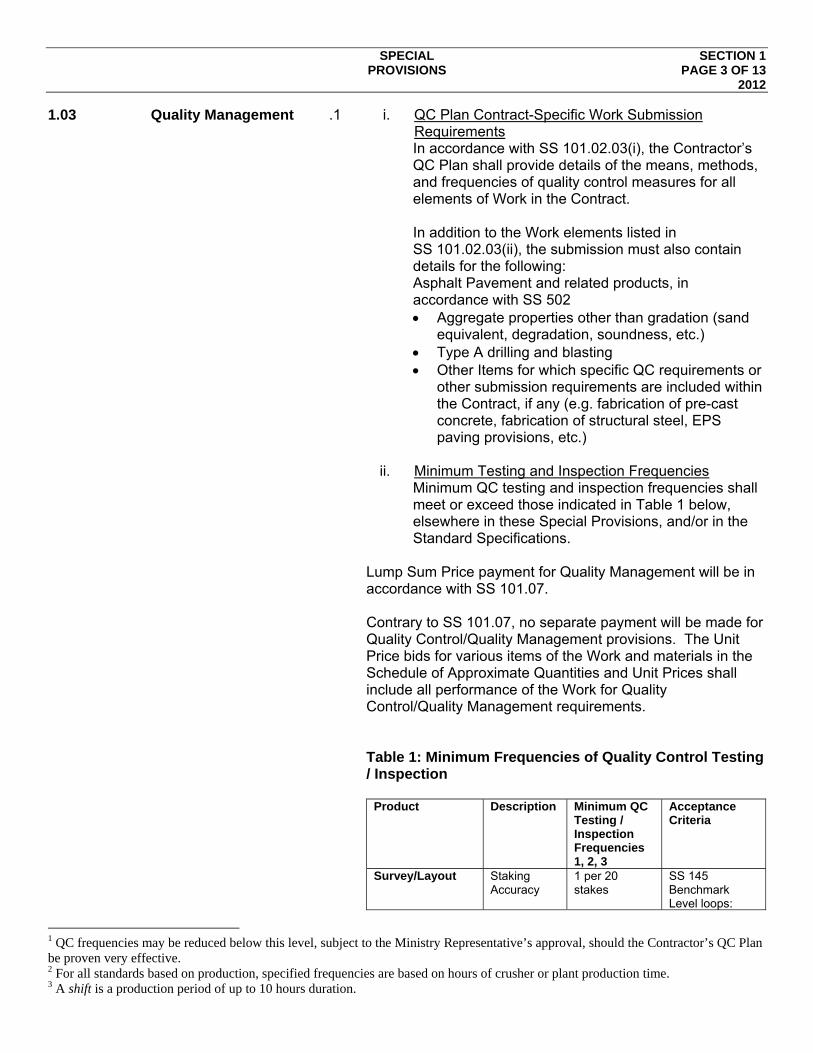
SPECIAL SECTION 1 PROVISIONS PAGE 3 OF 13 2012
1.03 Quality Management .1 i. QC Plan Contract-Specific Work Submission Requirements In accordance with SS 101.02.03(i), the Contractor’s QC Plan shall provide details of the means, methods, and frequencies of quality control measures for all elements of Work in the Contract. In addition to the Work elements listed in SS 101.02.03(ii), the submission must also contain details for the following: Asphalt Pavement and related products, in accordance with SS 502 Aggregate properties other than gradation (sand
equivalent, degradation, soundness, etc.) Type A drilling and blasting Other Items for which specific QC requirements or
other submission requirements are included within the Contract, if any (e.g. fabrication of pre-cast concrete, fabrication of structural steel, EPS paving provisions, etc.)
ii. Minimum Testing and Inspection Frequencies
Minimum QC testing and inspection frequencies shall meet or exceed those indicated in Table 1 below, elsewhere in these Special Provisions, and/or in the Standard Specifications.
Lump Sum Price payment for Quality Management will be in accordance with SS 101.07. Contrary to SS 101.07, no separate payment will be made for Quality Control/Quality Management provisions. The Unit Price bids for various items of the Work and materials in the Schedule of Approximate Quantities and Unit Prices shall include all performance of the Work for Quality Control/Quality Management requirements. Table 1: Minimum Frequencies of Quality Control Testing / Inspection
Product Description Minimum QC Testing / Inspection Frequencies 1, 2, 3
Acceptance Criteria
Survey/Layout Staking Accuracy
1 per 20 stakes
SS 145 Benchmark Level loops:
1 QC frequencies may be reduced below this level, subject to the Ministry Representative’s approval, should the Contractor’s QC Plan be proven very effective. 2 For all standards based on production, specified frequencies are based on hours of crusher or plant production time. 3 A shift is a production period of up to 10 hours duration.

SPECIAL SECTION 1 PROVISIONS PAGE 4 OF 13 2012
2nd order: ±0.008 m √km Layout level loops: 3rd order: ±0.024 m √km Control Line Traverse: 1:10,000.
TrafficControl / Management
On-going monitoring during active work, spot check after hours.
SS 194 & SPs
Concrete Roadside Barrier
Per SS 941 Materials and Concrete tests per SS 211, with all plastic concrete tests performed on each batch of concrete
Per SS 941
Bridge End Fill ASTM C 117, Sieve Analysis of Aggregates by Washing
1 per 750 m3 SS 201
Roadway Aggregate Quality (other than gradation and fracture)
ASTM D 2419 Sand Equivalent
1 per aggregate source
SS 202
D 6928 Micro Deval
1 per aggregate source
SS 202
ASTM C 88 Mg SO4 Soundness
1 per aggregate source, if Micro Deval fails
SS 202
SS 202 Appendix 2 - Petrographic Analysis Test
1 per source if the aggregate fails any of the above three tests
To the satisfaction of the Ministry Representative
Add’l test for High Fines Surfacing Aggregate
ASTM D 4318 Plastic Limit
1 per aggregate source
SS 202
During all Roadway Aggregate Production
ASTM C 136, Dry Sieve Analysis of Aggregates2
1 per hour per 300 t/hr or part thereof of production
SS 202 or SS 531
ASTM C 117, Sieve Analysis of Aggregates by Washing
1 per shift SS 202 or SS 531
SS 202 Appendix 1 -
1 for every second sample
SS 202 or SS 531
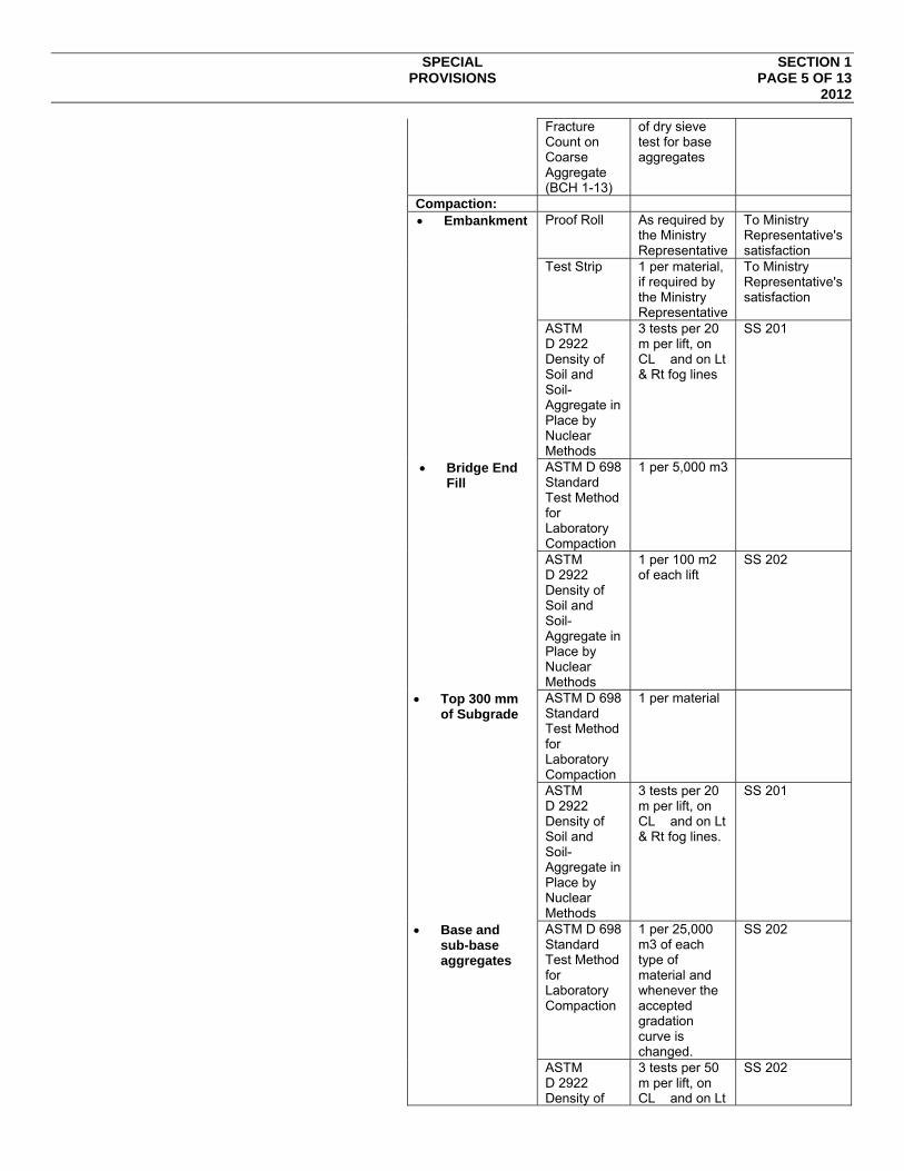
SPECIAL SECTION 1 PROVISIONS PAGE 5 OF 13 2012
Fracture Count on Coarse Aggregate (BCH 1-13)
of dry sieve test for base aggregates
Compaction: Embankment Proof Roll As required by
the Ministry Representative
To Ministry Representative's satisfaction
Test Strip 1 per material, if required by the Ministry Representative
To Ministry Representative's satisfaction
ASTM D 2922 Density of Soil and Soil-Aggregate in Place by Nuclear Methods
3 tests per 20 m per lift, on CL and on Lt & Rt fog lines
SS 201
Bridge End Fill
ASTM D 698 Standard Test Method for Laboratory Compaction
1 per 5,000 m3
ASTM D 2922 Density of Soil and Soil-Aggregate in Place by Nuclear Methods
1 per 100 m2 of each lift
SS 202
Top 300 mm of Subgrade
ASTM D 698 Standard Test Method for Laboratory Compaction
1 per material
ASTM D 2922 Density of Soil and Soil-Aggregate in Place by Nuclear Methods
3 tests per 20 m per lift, on CL and on Lt & Rt fog lines.
SS 201
Base and sub-base aggregates
ASTM D 698 Standard Test Method for Laboratory Compaction
1 per 25,000 m3 of each type of material and whenever the accepted gradation curve is changed.
SS 202
ASTM D 2922 Density of
3 tests per 50 m per lift, on CL and on Lt
SS 202
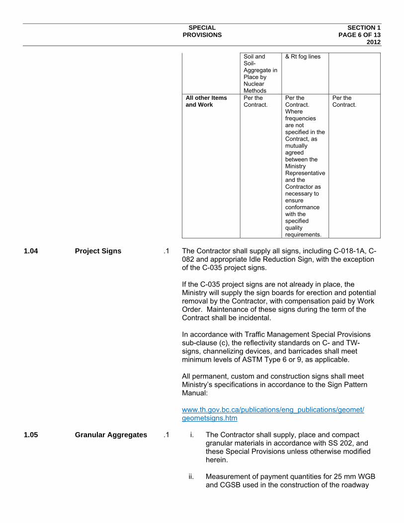
SPECIAL SECTION 1 PROVISIONS PAGE 6 OF 13 2012
Soil and Soil-Aggregate in Place by Nuclear Methods
& Rt fog lines
All other Items and Work
Per the Contract.
Per the Contract. Where frequencies are not specified in the Contract, as mutually agreed between the Ministry Representative and the Contractor as necessary to ensure conformance with the specified quality requirements.
Per the Contract.
1.04 Project Signs .1 The Contractor shall supply all signs, including C-018-1A, C-
082 and appropriate Idle Reduction Sign, with the exception of the C-035 project signs. If the C-035 project signs are not already in place, the Ministry will supply the sign boards for erection and potential removal by the Contractor, with compensation paid by Work Order. Maintenance of these signs during the term of the Contract shall be incidental. In accordance with Traffic Management Special Provisions sub-clause (c), the reflectivity standards on C- and TW- signs, channelizing devices, and barricades shall meet minimum levels of ASTM Type 6 or 9, as applicable. All permanent, custom and construction signs shall meet Ministry’s specifications in accordance to the Sign Pattern Manual: www.th.gov.bc.ca/publications/eng_publications/geomet/ geometsigns.htm
1.05 Granular Aggregates .1 i. The Contractor shall supply, place and compact
granular materials in accordance with SS 202, and these Special Provisions unless otherwise modified herein.
ii. Measurement of payment quantities for 25 mm WGB
and CGSB used in the construction of the roadway

SPECIAL SECTION 1 PROVISIONS PAGE 7 OF 13 2012
above sub-grade elevation will be based on design neat line quantities to be constructed, with no allowance for shrinkage or settlement.
Existing 25mm SGSB material that forms part of the existing pavement structure can be removed and stockpiles on-site as salvaged granular material at a location approved by the Contract Administrator. Following removal of Type “D” excavated material to the new lowered roadway sub-grade the salvaged granular material shall be placed and compacted as either 25 mm SGSB provided it meets the specified aggregate gradation as per Table 202-C.
No additional payment will be made for salvage of any 25 mm CGB or CGSB that is used in the works. Payment will be at unit price bid for the item where it was incorporated into the final works.
1.06 Paving .1 General
Asphalt Pavement shall meet the requirements of SS 502 unless otherwise stated in these Special Provisions. Asphalt Pavement shall meet the requirements of SS 502 for the applicable mix and the gradation shall meet the requirements of Table 502-C-1. Contrary to SS 502.35, all paving aggregate will be included in the payment for any and all Asphalt Pavement items. Contrary to Part F “Payment Adjustment” SS 502.50 no Payment Adjustments will apply. However, the Rejection limits shall apply as per SS 502. Generally, Asphalt Pavement in the travel lanes shall be paver laid in two lifts as follows:
Bottom Lift
Class 1 Medium Mix shall be used for the bottom lift. It shall be placed as shown in the Drawings or as directed by the Contract Administrator.
Top Lift
Class 1 Medium Mix shall be used for the top lift. It shall be placed as shown in the Drawings or as directed by the Contract Administrator.
Generally, Asphalt Pavement in the parking areas along the driving lanes shall be paver laid in two lifts as follows:

SPECIAL SECTION 1 PROVISIONS PAGE 8 OF 13 2012
Bottom and top Lift Class 1 Medium Mix shall be used. It shall be placed as shown in the Drawings or as directed by the Contract Administrator.
The Contractor shall supply a Ministry approved 120/150, Group “A”, Asphalt Cement meeting the requirements of the BC Standard Specifications 952 – Specification for Contractor Supply Asphalt and Paving Materials for Highway Use. Asphalt Plant Location and Operation The Contractor shall be entirely responsible for ensuring that the location and operation of any asphalt mixing plant used for the Work will meet all requirements of the Ministry of Environment (MoE), whether or not the plant is sited on lands under the jurisdiction of MoE or the City of Rossland.
.2 Supply and Spray Emulsified Penetrating Tack Coat
The Contractor shall supply Emulsified Penetrating tack coat that meets the requirements of SS 952. Only Emulsified Penetrating Tack Coat products listed under the category of “Emulsified Penetrating Tack Coat – Tack coat & Primers: in the current edition of the Ministry’s Recognized Products List (products may be from the “Proven”, “Tentative” or “Approved” categories) shall be used. Surfaces to be paved shall be tack coated, in accordance with the following requirements. Application shall be in accordance with SS 502 except as modified in the Special Provisions. Application shall be by pressure distributor. Emulsified Penetrating Tack Coat shall meet the requirements as described in SS 502.21. The Contractor shall exercise caution before spraying on the roadway to ensure absolutely no contamination may occur to any watercourse. This will mean not spraying when the weather forecast or visual assessment indicates the potential for rain. Further to SS 502.21.09 the Contractor shall take all measures to ensure that vehicles will not, at any time, have to drive on fresh tack coat. This will require that traffic control is in place prior to the spraying of tack coat. On two lane roads the entire width cannot be sprayed in one operation. Only one side can be sprayed at one time and the adjacent side cannot be sprayed until the tack coat has set up. The traffic control shall remain in place until the freshly sprayed surfaces have set up sufficiently to prevent any tracking of tack coat and to prevent any damage to vehicles. Any costs to remove prime/tack coat from surfaces or public vehicles shall be solely the responsibility of the Contractor to the satisfaction of the Contract Administrator.
SPECIAL SECTION 1 PROVISIONS PAGE 9 OF 13 2012
All paved surfaces shall be swept clean and tack coated at an application rate of 0.2 litres per square metre on existing pavement, 0.3 litres per square metre on milled surfaces, or such other rate as the Contract Administrator may direct. Tack coating will normally not be permitted more than 500 m in front of the paver and in no case for a greater distance than can be covered during the remainder of the shift. Payment will be made at the Unit Price bid for “Supply and Spray Emulsified Penetrating Tack Coat”.
.3 Payment for asphaltic concrete paving includes all
construction joint preparation, supply and placing of the asphaltic concrete, compaction, adjusting and cleaning frames, covers and lids of all castings affected. Measurement for asphaltic concrete paving for the specified design mixes for lower and upper courses will be for asphalt concrete actually incorporated into work based on weigh tickets provided to Contract Administrator as loads are delivered. All asphalt debris is to be power swept at the tie-ins, transfer areas and machine and truck clean up areas prior to leaving site on day of paving.
.4 Asphalt Pavement, Class 1 Medium Mix
Asphalt Pavement shall be Class 1 Medium Mix meeting all applicable requirements of SS 502. It shall generally be placed at 75 mm thickness or as shown on the drawings/plans or as directed by the Contract Administrator. Payment will be made at the Unit Price bid for “Asphalt Pavement, Class 1 Medium Mix” in Schedule B & D including the aggregates and Asphalt Cement 80/100 Group A.
.5 Extension of Time for Inclement Weather
The Contract Administrator may grant an Extension of Time under GC 44.01(c)(iv), as amended by Supplemental General Conditions (SGC), on account of inclement weather. Any such extension will be made solely at the Contract Administrator’s discretion, and, if made, will reflect the following conditions:
i. Where there is a delay for reasons of inclement weather, or conditions resulting from inclement weather, such delays will be considered when the Contractor cancels work for the shift based on forecasted inclement weather or when the Contractor works on the roadway surface less than half a normal working day for reasons of inclement weather. A normal working day shall comprise the average
SPECIAL SECTION 1 PROVISIONS PAGE 10 OF 13 2012
duration worked by the Contractor on the preceding five (5) uninterrupted working days or the first five planned days when the Contractor has not been able to achieve five uninterrupted working days where a single shift is observed.
ii. In the case of a Contractor employing multiple shifts,
once a total of eight (8) working hours is reached by adding the working hours from each shift, then it will have been deemed the Contractor has worked that day and there is no delay for reasons of inclement weather.
.6 Pavement Markings
i. Temporary Markings: The Contractor shall supply and place temporary line markings on newly constructed hard surfaces (pavement, hot-in-place recycled pavement, sealcoat, etc.) throughout the Project, in accordance with SS 194.22 and TCM 2.2.1, re-establishing centreline and all lane-dividing lines prior to being opened to traffic, and shall maintain such markings until the earlier of the Actual Completion Date or the date permanent markings have been placed. Temporary line markings are not required for lane edge lines (fog lines) unless otherwise directed for specific areas by the Contract Administrator.
Marking dimensions, spacing, colour, layout and other characteristics shall follow the recommendations of the TCM unless otherwise specified herein or approved by the Contract Administrator, and must be placed on each lift of pavement.
Temporary lines on the final surface shall be laid within 100 mm of the permanent line design location, so as to not detract from the permanent lines when laid. Centreline of undivided highway shall be marked throughout as “no passing” unless otherwise directed by the Contract Administrator.
The intent is that we do not want to encourage passing within a construction zone, but where sight distance is good (say 50% longer than normally required), the Contract Administrator should consider directing that the area be marked as “passing permitted.” This will be site and time specific decision.
For surfaces other than sealcoat, painted temporary lines are not permitted on the final surface.

SPECIAL SECTION 1 PROVISIONS PAGE 11 OF 13 2012
On sealcoated areas, temporary markings shall be placed as soon as excess aggregate has been removed. Contrary to the TCM, lines shall be painted on using rapid-drying, water-borne pavement paint, rather than temporary marking tape or “L” shaped flexible markers, and shall have an application of reflective glass bead applied prior to the paint drying.
In those areas where permanent markings have been applied prior to the Actual Completion Date, the Contractor shall remove the temporary pavement marking tape. Where the permanent marking has been sprayed on top of temporary tape, that piece of tape may be left in place.
These provisions represent a “best practice” and, although they do not represent consensus amongst stakeholders with opposing views, are to be used without change. Insert project-specific requirements with respect to style, spacing, etc. for tape or include provisions for painting of such lines.
ii. Permanent Marking Layout:
Prior to any work effecting existing pavement markings, the Contractor shall pick-up survey all key control points of existing markings at intersections, turn slots, exit tapers and similar features and, upon completion of the final hard surfacing, re-establish those points. Layout of centreline and lane line markings at other locations (e.g. between intersections) is not required.
Key control points are:
Intersections and Interchanges: Curvature points
(EC, BC, TS, SC, CS, ST) and any other points of deflection; all points as indicated on the “Typical Intersection Pavement Markings Control Points” (see Appendix) drawing and such additional points as may be required for more complex situations.
The Contractor shall, upon completion of the final hard surfacing, lay out all key control points throughout the Project, in accordance with the design Drawings.
For any portions of the Project where line marking designs are not included in the Contract, the Contract Administrator shall provide direction as to what

SPECIAL SECTION 1 PROVISIONS PAGE 12 OF 13 2012
specific services are required. Generally, such services will be laying out to a generic design or a pick-up survey of existing key control prior to disturbing the roadway in those areas and, upon completion of the final hard surfacing, re-establishing those points.
Key control points are as follows on all paint lines, including centreline, lane lines, islands, etc.:
Curvature points: EC, BC, TS, SC, CS, ST, and
any other points of deflection. Intersections and Interchanges: PI for design
control lines; curvature points (EC, BC, TS, SC, CS, ST) and any other points of deflection; all points as indicated on the “Typical Intersection Pavement Markings Control Points” (see Appendix) drawing and such additional points as may be required for more complex situations.
Intermediate points (on centreline only for undivided highway; one lane line for each direction on a divided highway): On tangents, curves and spirals, at maximum 100 m spacing.
Lane widening: Where the design incorporates pavement and lane widening designed into the curves and spirals to accommodate off-tracking of large vehicles, additional intermediate points shall be marked on centerline and all lane lanes at maximum 50 m spacing.
The remainder of language following is common to both Options B and C and only the last two paragraphs are used with Option A.
All layout markings shall be done with white or yellow centreline paint which will be clearly visible after exposure to all Site conditions for a minimum period of 2 months past the Actual Completion Date.
Key control points shall be marked at their design location within tolerances of ±50 mm transversely and ±100 mm longitudinally. Longitudinal tolerances for intermediate points, when required, are ±10 m.
iii. Payment
The Lump Sum Price bid for Pavement Marking shall include all costs and work necessary to provide temporary pavement markings and to layout key control points. The removal of temporary markings that replicate permanent line markings will be incidental to the work and no additional payment will be made.

SPECIAL SECTION 1 PROVISIONS PAGE 13 OF 13 2012
The removal of all other temporary markings will be considered incidental and no additional payment will be made.
1.07 Provisional Sum for
Site Modifications The Provisional Sum Item Schedule B Site Modification has
been included as a source of funds for payments for work as directed by the Contract Administrator. Payment for such work will be made at a negotiated rate or on a Force Account Basis from the Provisional Sum for Site Modifications. Possible items include:
1. Modification/change to the St. Paul/Columbia Avenue intersection
END OF SECTION


SECTION NDX INDEX PAGE 1 OF 1 2011
Section 32 32 84 00 Irrigation System
IRRIGATION SECTION 32 84 00 SYSTEM PAGE 1 OF 20 2012
1.01 Scope of Work .1 Supply and installation of backflow prevention devices, water
meter, sleeves, mainlines, lateral lines, control zone valves, dripline, micro-irrigation heads, controller enclosure, controller, and all related items necessary to provide a properly operating automatic irrigation system to distribute water in a way that adequately maintains the landscape while conserving and protecting water resources.
.2 Maintenance of the irrigation system. 1.02 Related Sections .1 Section 32 91 21—Topsoil and Finish Grading .2 Section 32 93 01—Trees, Shrubs, and Ornamentals .3 Division 22 —Plumbing .4 Division 26 —Electrical 1.03 Reference Standards .1 ASTM D1248 –High Density Polyethylene (HDPE) Pipe .2 ASTM D2241 -Poly (Vinyl Chloride) (PVC) Plastic Pipe
(SDR-PR). .3 ASTM D2564 -Solvent Cement for Poly (Vinyl Chloride)
(PVC) Plastic Pipe and Fittings. .4 CSA B137.0-12: Thermoplastic Pressure Piping 1.04 Quality Assurance .1 The trade contractor performing this work shall be a “Certified
Irrigation Contractor” having met the certification standards established by The Irrigation Industry Association of British Columbia or The Irrigation Association, and having experienced, trained and insured personnel qualified for the scope of work.
.2 The Contractor shall be certified in High-Density Polyethylene
Butt-Fusion as certified by the British Columbia Institute of Technology or approved equivalent.
.3 A written guarantee of the installed irrigation system shall be
provided to the Owner covering workmanship and materials for a minimum of one (1) years from the date of substantial completion. The contractor shall warranty maintenance on the system for a minimum of one (1) year.
1.05 Submittals .1 The Contractor shall submit evidence of project personnel
having certification in High-Density Polyethylene Butt-Fusion prior to commencing with the work.

IRRIGATION SECTION 32 84 00 SYSTEM PAGE 2 OF 20 2012
.2 The Contractor shall submit shop drawings, product literature, and specifications for approval by the Contract Administrator prior to construction.
.3 A suitably scaled as-built drawing shall be submitted,
preferably in AutoCAD 2008 or newer format. All components of the irrigation system shall be shown as installed, with clear measurements from an identifiable reference point to the location of the pump station, controller cabinet and its circuit breaker, master valve, mainline, sleeves, control zone valves, main water (cistern) connection, blow-out fittings, pipe drains, lateral end flush valves, soil moisture sensors and any other similar features. Show all other deviations from the irrigation design drawing provided to the Contractor.
.4 The as-built drawing shall be submitted prior to issue of
Substantial Completion. The Contractor shall maintain the as-built record drawing throughout the maintenance and warranty period and issue a revised As
.5 Operation and Maintenance Manuals
1.5.5.1 Prepare and deliver to the Owner within ten (10)
calendar days prior to completion of construction two (2) copies of the following information bound in 3-ring cover binders:
1.5.5.2 Index sheet stating Contractor's address and telephone number, list of equipment with name and addresses of local manufacturer's representatives.
1.5.5.3 Catalogs and parts sheets on every material and equipment installed under this Contract.
1.5.5.4 Guarantee statement. 1.5.5.5 Complete operating and maintenance instructions
on all major equipment. 1.5.5.6 Construction details from project. 1.5.5.7 Complete trouble-shooting guide to common
irrigation problems. 1.5.5.8 Winterization and spring start up procedures. 1.5.5.9 Chart of approximate watering times for spring,
summer, and fall showing the proposed run times for each zone relative to differing precipitation rates and water requirements, and a schedule of run times suggested for various weather conditions.
1.5.5.10 Maintenance materials to be furnished: 1.5.5.10.1 Two (2) sets of tools required for
removing, disassembling and adjusting each type of sprinkler and valve supplied on this project.
1.5.5.10.2 One (1) key for operation of gate valves and mainline drain valves

IRRIGATION SECTION 32 84 00 SYSTEM PAGE 3 OF 20 2012
1.5.5.10.3 One (1) quick coupler key and matching hose swivel for each type of quick coupling valve installed.
1.5.5.10.4 The above-mentioned equipment shall be turned over to the Owner at the conclusion of the project. Before final inspection can occur, evidence that the Owner has received material must be shown to the Contract Administrator
1.06 Test Reports and
permits .1 The Contractor shall submit to the Owner at Substantial
Completion the Electrical Permit and Plumbing Permit. .2 Submit to the Contract Administrator at Substantial
Completion the backflow device test report and meter registration. Submit at Final Acceptance the first annual backflow device test report.
.3 Provide to the Owner at Substantial Completion all applicable
permits and licenses required for this project. .4 Issuance of the Construction Completion Certificate will not
be granted unless the above documents and supplies are received.
1.07 Site Conditions .1 Verify the existence and location of all underground utilities
and services prior to commencement of the work. .2 Consult with the Contract Administrator to adjust the design,
if necessary, to suit existing site conditions and grades prior to commencement of the work.
.3 Protect from damage, existing landscape features, plant
material, structures, irrigation work in progress, and the work of other trades.
.4 Ensure that sequencing of this work is carried out in
coordination with the work of other trades. It is essential to coordinate the installation of sleeves under hard surfaces and irrigation piping through open tree soil trenches and Silva cells to ensure their installation is completed when the work area is accessible.
1.08 Substitutions .1 Where materials are specified by brand name and model
number, such specifications shall be deemed to facilitate a description of the materials and material quality and shall establish a standard for performance and quality against which proposed substitutes shall be evaluated.
IRRIGATION SECTION 32 84 00 SYSTEM PAGE 4 OF 20 2012
.2 Substitution requests shall not be considered unless submitted in writing with sufficient descriptive literature and product samples to permit product comparisons.
.3 All product substitutions shall be of equal or greater
performance, value and water efficiency than the original design. All proposed sprinkler substitutions must be accommodated with verifiable water efficiency performance data provided by the manufacturer or an independent industry source such as the Centre for Irrigation Technology (CIT), Fresno.
.4 Alternate materials shall match the specified materials in,
performance, flow, and pressure loss so as not to compromise the intent of the design.
.5 Alternate materials proposed shall be applied according to
their manufacturer’s specifications. .6 The written approval of the Contract Administrator is required
prior to the use of materials that are different from those shown in the design. Materials installed which have not been pre-approved by the Contract Administrator are subject to removal and replacement with approved materials at the Contractors expense.
1.09 Regulations .1 The Contractor shall be responsible for obtaining all permits
and licenses applicable to the work to be done and shall include costs for such permits and licenses in the tender prices.
.2 Ensure that there is compliance with the relevant codes and
regulations during the conduct of the work involved in the project.
1.10 Supervisor .1 At the time of tender, submit to the Owner, the name of the
Superintendent proposed, together with information regarding his qualifications and previous experience as a Superintendent on works of a similar size and character. The Superintendent must be acceptable to the Owner and Contract Administrator.
.2 The Superintendent shall devote his time exclusively to the
work of this Contract and shall remain on the job during normal working hours, and shall attend all site coordination and progress meetings.
.3 Do not change Superintendents during the progress of the
work, without prior written permission of the Owner. .4 Any employee of the Contractor or any Subcontractor who is
unsuitable, in the opinion of the Contract Administrator and/or
IRRIGATION SECTION 32 84 00 SYSTEM PAGE 5 OF 20 2012
the Owner shall be dismissed for all time from the work, upon direction from the Contract Administrator.
1.11 Notification of
Consultant .1 Report to the Contract Administrator, in writing, any
conditions or defects encountered on the site during or prior to construction upon which the work of this section depends and which may adversely affect its performance.
.2 Notify the Contract Administrator and obtain approvals for
inspection and testing of irrigation system as specified in this section. Provide the Contract Administrator and Owner minimum 48 hours notice prior to required inspections or meetings.
1.12 Measurement and
Payment .1 Payments will be on lump sum basis. Payment shall include
the supply and installation of all materials shown on the drawings, and all materials incidental to the completion of the work, and shall include all costs for the maintenance and guarantee of the system.
.2 Progress claims submitted by the Contractor shall be based
on the percentage of work completed at date of claim and approved by the Contract Administrator and Owner prior to payment.
.3 No payment shall be made for materials delivered and stored
onsite that have not been properly installed and tested. .4 The lump sum prices bid for supply shall include supplying,
delivering, loading, unloading and all allowances for handling, storage, breakage and waste. Payment will be made only for material actually installed and tested in the work.
2.1 Backflow Prevention
Device .1 The backflow prevention devices shall be as shown on
drawing. .2 All cross connections and backflow prevention devices shall
conform to the current standards as set out by the City of Rossland, Water Services Division.
.3 All cross connections and backflow prevention devices shall
be tested by a Certified Cross-Connection Control Specialist licensed to do the work in the Province of British Columbia.
2.2 High-Density
Polyethylene (HDPE) Pipe
.1 Material shall be listed by the Canadian Standards Association (CSA) and Plastic Pipe Institute (PPI) as a PE-3408/3608 resin with a hydrostatic design basis (HDB) of 1600 psi for water at 23°C. The material shall comply with ASTM D-1248 as a Type III Class C, Category 5, Grade P34 material and with ASTM D-3350 as a 345434C cell material.
IRRIGATION SECTION 32 84 00 SYSTEM PAGE 6 OF 20 2012
.2 Pipe pressure rating, sizing, and jointing methods shall be as per the drawings.
.3 Fittings for high-density polyethylene pipe shall be butt fusion
type for end-to-end joints. All fittings to be molded from same material as the HDPE pipe (minimum DR 17), ready for butt fusion. Sidewall fusion will not be permitted. Fittings and flange adaptors made by contractors or distributors are prohibited.
.4 The use of saddles along the mainline piping network is
prohibited during construction. 2.3 Polyvinylchloride
(PVC) Pipe .1 Polyvinylchloride pipe shall conform to CSA B137.3. All pipe
shall be in new condition, extruded from virgin materials and continuously and permanently marked with the manufacturers name, material, size, pressure rating and CSA approval.
.2 Series 200 shall be used in 25mm size pipe and Series 160
in 38mm and larger irrigation pipe. .3 Jointing methods: Solvent weld for 50mm diameter and
smaller size pipe. .4 Mainline fittings for PVC pipe shall be Schedule 80 PVC
suitable for solvent welding or threaded connections. Lateral fittings for PVC pipe shall be Schedule 40 PVC suitable for solvent welding or threaded connections.
.5 Threaded connections of PVC to metal shall have male
threads on the PVC and female threads on the metal. .6 PVC pipe cement and primer combination shall be as
recommended by the manufacturer to be suitable for the materials and application, when used as directed, and meet local codes.
.7 The use of saddles along the mainline piping network is
prohibited during construction. 2.4 Polyethylene Pipe –
Medium Density .1 Polyethylene pipe shall conform to CSA B137.3
.2 Pipe pressure rating, sizing, and jointing methods shall be as
per the drawings. .3 Fittings shall be Schedule 80 PVC insert fittings with
Stainless Steel T-Bolt clamps. 2.5 Valve Boxes .1 All valve boxes located in hard surfaces shall be made of
Polymer Concrete c/w Polymer Concrete Cover, as shown on drawings.

IRRIGATION SECTION 32 84 00 SYSTEM PAGE 7 OF 20 2012
.2 All valve boxes located in soft landscape shall be made of
heavy-duty UV resistant plastic, as shown on drawings. .3 Valve boxes shall be sized to allow minimum 100mm
between valves and minimum 100mm between valve and inside of valve box. Valve boxes shall be sized to allow minimum 100mm between bottom of box and bottom of valves and 100mm minimum between lid and top of valves. Provide valve box extensions where required.
.4 All valve boxes located in soft landscape shall have a locking
lid. .5 Valve boxes shall be installed with minimum 100mm depth
25mm diameter washed gravel at bottom of box. 2.6 Drip Zone Kits .1 Drip zone kit sizing shall be as shown on drawing. .2 Drip zone kits shall include one (1) Schedule 40 PVC ball
valve, inline pressure regulator and commercial inline screen with 150 mesh filter.
.3 The valve box shall contain maximum two (2) 25mm valves
per box. .4 The control zone valve shall be a normally closed 24 VAC
50/60 cycle solenoid globe pattern design. The valve pressure rating shall not be less than 200 psi. The valve shall have a flow rate of 0.1 - 40 gpm and pressure loss not to exceed: 3.7 psi.
.5 The valve body and bonnet shall be constructed of heavy-
duty glass-filled UV resistant nylon and have stainless steel studs and flange nuts; diaphragm shall be of nylon reinforced nitrile rubber. The valve shall have both internal and external manual open/close control (internal and external bleed) to manually open and close the valve without electrically energizing the solenoid. The valve’s internal bleed shall prevent flooding of the valve box. The valve shall have a flow control handle.
.6 The valves shall house a fully-encapsulated, one piece
solenoid. The solenoid shall have a captured plunger with a removable retainer for easy servicing and a leverage handle for easy turning. This 24 VAC 50/60 Hz solenoid shall open with 19.6 volt minimum at 200 psi (13, 80 bars).
.7 Drip zone kit shall have one (1) Schedule 80 PVC union per
control zone kit assembly.

IRRIGATION SECTION 32 84 00 SYSTEM PAGE 8 OF 20 2012
2.7 Micro-irrigation .1 Micro-irrigation components such as dripline, pressure compensating modules, air relief valves and lateral end flush valves shall be indicated by type, size and location on the drawings or details. Install according to the manufacturer's specifications.
.2 PC dripline shall be installed at a maximum depth of 50mm -
75mm below finished grade of top soil. Mulch or decorative rock is not considered finished grade.
2.8 Landscape Dripline .1 Landscape dripline shall be Pressure Compensating dripline
suitable for sub-surface installation. .2 The dripline shown on the drawings has 0.53gph pressure
compensating emitters, spaced every 450mm. Substitute dripline products must use pressure compensating emitters spaced every 450mm with flow rates in the range of 0.5gph to 0.6gph. The Contractor shall calculate and adjust the Watering Schedule accordingly.
.3 The flexible polyethylene tubing shall have factory installed,
pressure-compensating, inline emitters installed at distances and flow rates as indicated on drawings when inlet pressure is between 8 and 60 psi.
.4 Pressure compensation shall be accomplished through the
effective lengthening of the emitter flow path. This method of pressure compensation shall in no way reduce the size of the cross-sectional area of the emitter flow path. As a result, superior clog-resistance shall be achieved.
.5 The inline emitter’s cylindrical shape shall permit the welding
of the emitter to the inner circumference of the polyethylene tubing. This shall create a physical barrier that keeps the cover of the inline emitter securely in place making it impossible to dislodge the emitter cover, or the silicone wafer beneath it, when the polyethylene tubing is kinked. This, in turn, shall assure consistent flow from each inline emitter throughout the line.
.6 The inline emitter’s cylindrical shape shall provide surface
area for filtration throughout 360° of its outer circumference. This increased filtration surface area shall assure that the water that enters the inline emitter can always come from the upper half, or cleanest part of the flow path in the polyethylene tubing regardless of how the inline tubing lays on the ground. This shall make it unnecessary to install an automatic flush valve on the system to drain the inline tubing after each watering cycle thereby saving significant water during system operation.

IRRIGATION SECTION 32 84 00 SYSTEM PAGE 9 OF 20 2012
2.9 Controller Enclosure .1 The enclosure shall be the Hunter Plastic Pedestal as specified with the controller
.2 The enclosure shall be mounted on a concrete pad and
located in a shrub bed as per the drawings. .3 The enclosure shall include the irrigation controller,
miscellaneous electronic and communication components and main breaker.
.4 Install two (2) separate Grey PVC DB2 sweep ells for the
120Vac power supply and irrigation field wires. Conduit sizes are noted on drawings.
2.10 Two-Wire Controller .1 The controller shall be the Hunter ACC-99DPP. .2 Controller shall be mounted in the Plastic Pedestal
Enclosure. All wire connections will be done in the enclosure. .3 The automatic control system shall operate using a two-wire
path from controller to decoders installed at electronic control valves in field.
.4 The two-wire controller shall be capable of flow and rain
sensing. .5 Controller operates standard electric control valves. .6 Transformer Input; 120 / 230Vac, 50 / 60Hz, 2A max at 120V,
1A max at 230V. .7 Transformer Output; 24Vac, 4A at 120Vac
2.10.7.1 Decoder Line (path) output: 34V peak-to-peak 2.10.7.2 Decoder Power draw: 40 mA per active output 2.10.7.3 Solenoid capacity: 2 standard 24 VAC Hunter
solenoids per output within 150 ft. runs, up to 14 solenoids max simultaneous (includes dual P/MV outputs).
2.11 Controller –to-
Decoder-to-Valve Communications
.1 Communication between controller and the field decoders at the electric control valves shall be accomplished using the Hunter 14\2 IDWIRE.
.2 Field Decoders (either 1, 2, 4, or 6 station configuration with
ability to operate multiple solenoids per station) come pre-addressed.
.3 Decoder to solenoid: standard pair 18 AWG/1 mm to 150 ft.
(twisted improves surge resistance). .4 Programmable decoder station IDs (from controller panel).

IRRIGATION SECTION 32 84 00 SYSTEM PAGE 10 OF 20 2012
2.12 Flow Sensor .1 The flow sensor shall be an in-line type with a non-magnetic, spinning impeller (paddle wheel) as the only moving part. The electronics housing shall be glass-filled PPS. The impeller shall be glass-filled nylon or Tefzel with a UHMWPE or Tefzel sleeve bearing. The shaft material shall be tungsten carbide.
.2 The electronics housing shall have two ethylene propylene O-
Rings and shall be easily removed from the meter body. The sensor electronics will be potted in an epoxy compound designed for prolongs immersion.
.3 Electrical connections shall be 2 single conductor 18 AWG
leads 48 inches long. Insulation shall be direct burial “UF” type colored red for the positive lead and black for the negative lead.
.4 The sensor shall operate in line pressure up to 100 psi and
liquid temperatures up to 140° F, and operate in flows of 1 foot per second to 20 feet per second with linearity of ±1% and repeatability of ±1%. =
.5 The meter body shall be fabricated from Schedule 80 PVC
Tees with socket end connections and the diameter indicated on the final drawings.
2.13 Control Wire .1 Wires shall conform to the Canadian Electric Code and any
other regulatory conditions, which may govern this type of installation.
.2 Control wire shall be the Hunter 14\2 IDWIRE .3 Single conductor spare decoder wire shall be CSA approved
#14 AWG Blue. .4 Provide #14 AWG, 24VAC electric control wire(s) as required
(color, other than white, green, blue) or larger from controller to master valve location.
.5 All control wire installed shall use a Polyethylene outer jacket. .6 Install wires in neat, orderly fashion, between 4 o'clock and 8
o'clock position under irrigation pipes. Wire shall be placed consistently along one side of the pipe in the trench.
.7 A minimum loop of 600mm shall be left at each valve, at each
splice, at each change in direction, at every 152m of straight run, and at each controller for expansion and/or servicing.
.8 Wire splices shall only occur at electric control valves. Wire
splices shall be made with 3M DBR\Y connectors.
IRRIGATION SECTION 32 84 00 SYSTEM PAGE 11 OF 20 2012
2.14 Electrical Products .1 All electrical products shall be CSA approved and bear the CSA label. Alternatively, where a product does not bear the required CSA label, it shall be approved in writing, by the authority having jurisdiction.
.2 Wire conduit shall be Grey PVC DB2 non-metallic electric
conduit as shown on drawings. .3 Pull and Junction Boxes: to CSA C22.2 No.40-1973 (R1981),
sheet steel, screw-on or hinged covers. 2.15 Sensors and Surge
Protectors .1 Sensors shall be of the type, size, and location as shown on
the drawings. 2.16 Grounding and
Bonding .1 Primary grounding of the controller shall be accomplished
using the ground system utilized by the 120Vac source. .1 Secondary grounding will be accomplished through the use of
three (3) copper ground plates. Paige Electric manufactures copper ground plates (# 182201IC, 100mm x 915mm x 1.6mm) which shall be installed in the locations shown on the drawings.
.3 The Contractor shall ensure all electrical equipment is
connected to proper ground as per the manufacturer’s specifications.
2.17 Backflow Prevention
Devices .1 Double Check Valve Assembly: The term "Double Check
Valve Assembly" shall mean an assembly composed of two independently acting, approved check valves, including tightly closing shut-off valves with resilient seats, located at each end of the assembly and fitted with properly located test cocks as per CSA B64 series- 1976.
.2 The double check valve assembly and meter shall be
installed as per manufacturer’s specifications. .3 Backflow prevention units shall be of the size and type shown
on the drawings. Install backflow prevention units in accordance with all applicable codes and bylaws, with positive drainage and room for servicing.
2.18 Sleeving .1 Sleeving material and wire conduits proposed under concrete
or asphalt shall be coordinated prior to installation of the hard surfaces.
.2 SDR-35-PVC and Grey PVC DB2 conduit shall be used for
sleeving as shown on drawings. SDR-17.0 HDPE pipe can be used for sleeving where bends are required. Install with minimum 300mm cover under walkways and with minimum 600mm cover under driveways. Tape ends of sleeve to prevent filling with debris.

IRRIGATION SECTION 32 84 00 SYSTEM PAGE 12 OF 20 2012
.3 Diameter of sleeve shall be minimum twice the diameter of
the sum of the irrigations pipes passing through the sleeve. The size of the sleeving shall be measured in 50mm increments and noted on the as-built drawings.
2.19 Backfill Material .1 Native Excavated Material: Clean native excavated soil, free
from organic matter, stones larger than 25mm, building debris, and other foreign substances.
.2 Sand: Natural coarse sand. .3 Gravel: 19mm diameter crushed gravel. 2.20 Quick Couplers .1 Quick couplers shall be 25mm diameter one-piece brass
construction. .2 Supply and submit to the Owner one (1) swivel ell key
compatible with quick coupler. 2.21 Isolation Valves .1 Isolation valves shall be brass construction with non-rising
stems. Watts or Red & White equivalents. .2 The valve shall be rated for a working pressure of 250 psig
and be tested to 500 psig. 2.22 Miscellaneous
Components .1 Miscellaneous Components such as water meter, master
valve, drains, air relief valves, lateral flush valves, etc., shall be indicated by type, size and location on the drawings or details. Install according to the manufacturer's specifications.
.2 All components shall be installed in accordance to all
municipal and provincial bylaws and codes. 3.1 Recycling and
Protection of Existing Work
.1 Protect existing and proposed landscape features, elements, and sites from damage or contamination. Coordinate with the work of other trades to reduce waste, mixing of waste, soil compaction or erosion, overspray, or run-off from cleaning operations.
.2 Separate and recycle or reuse the following landscape
materials: nylon straps, wire, wood stakes, metal stakes, and plastic or cardboard packaging materials.
3.2 Layout .1 Stake out the location of all valves, piping and principal
fittings for approval by the Contract Administrator prior to construction. All staking and measurements shall be taken from permanent objects, buildings, or survey bench markers and not from objects such as turf boundaries, which are subject to change.

IRRIGATION SECTION 32 84 00 SYSTEM PAGE 13 OF 20 2012
.2 As staking progresses, all additions, changes, or equipment locations, shall be noted on the copy of the "working drawings" from which the "as-built" drawings will be prepared.
.3 Layout changes necessitated by unforeseen conflicts or
changes to the site conditions shall be approved in writing by the Contract Administrator.
3.3 Excavation .1 Keep excavations free of water. .2 Depths of sleeving and pipe shall be shall be as shown on
Drawing. .3 Bed trench with suitable material to the proper depth and
compact. The contractor shall repair any settlement of the trenches.
.4 Trenching, laying of pipe and backfilling shall be continuous
so that the amount of open trench at the end of each work day is minimized. Any open trench or other excavations shall be barricaded and marked with high visibility flagging tape.
3.4 Site Conditions .1 All scaled dimensions are approximate. The Contractor shall
check and verify all size dimensions and receive the Contract Administrators approval prior to proceeding with the work of this section.
.2 The contractor shall verify the existence and location of all
underground utilities prior to construction. .3 Coordinate installation or irrigation materials, including pipe,
so there shall be no interference with utilities or other construction or existing plant materials.
.4 An as-built record drawing will be constructed and updated
daily. The as-built record drawings will not only illustrate the Contractors progress, it will identify all changes to the design, irrigation / utility crossings, and the actual installed location of all irrigation components. The as-built record drawings will be made available upon request by the Owner or the Contract Administrator.
3.5 Pipe Laying and
Plowing .1 Lay the pipe in a straight line between fittings, placing it on
firm soil at all points in the trench. .2 Depths of sleeving to be a minimum of 300mm below finish
grade for paths and walkways and a minimum of 600mm below finish grade for parking lots and roads. Roads carrying heavy traffic such as tractor/trailer combinations on a regular basis shall require a road crossing to be installed.

IRRIGATION SECTION 32 84 00 SYSTEM PAGE 14 OF 20 2012
.3 Irrigation Lateral piping to be installed at a depth between 200mm and 300mm. Irrigation mainline piping shall be installed to a minimum depth of 300mm and a maximum depth of 750mm.
.4 Joints between plain end HDPE pipe and fittings shall be
made by butt fusion. The butt fusion procedures used shall be as per the pipe and fitting manufacturer’s specifications.
.5 HDPE pipe and fittings may be joined together or to other
materials by means of (a) flanged connections- flange adapters and backup rings, or (b) mechanical couplings designed for joining HDPE pipe or for joining HDPE pipe to another material.
.6 Upon request, the Contractor shall verify field fusion quality
by making and testing a trial fusion. The trial fusion shall be allowed to cool completely, then test straps shall be cut out and bent strap tested in accordance with ASTM D2657. If the bent strap test of the trial fusion fails at the joint, the field fusions represented by the trial fusion shall be rejected. The Contractor at his expense shall make all necessary corrections to equipment, set-up, operation and fusion procedure, and shall re-make the rejected fusions.
.7 Prevent dirt from entering exposed ends of pipe. Tape off or
Cap off all open ended pipe in trench. .8 All PVC solvent welding is to be done in accordance with
manufacturer’s recommendations with particular attention to cleanliness, air temperature, moisture, and curing time. Excess cement must be removed from all joints.
.9 The use of irrigation mainline saddles during construction is
prohibited. 3.6 Backfilling .1 Backfill excavated subgrade material in 150mm lifts, placing
and compacting with an approved device to minimum 85% S.P.D. until 150mm below finish grade. Compaction of trenches with trucks or machinery is not acceptable.
.2 Replace minimum 150mm depth finish grade topsoil to
elevations existing prior to commencement of work. .3 Contractor shall be careful to not mix subgrade and finish
grade topsoil in excavation or backfilling procedures. .4 Contractor shall verify by survey that finish grade is restored
to elevations and grading established prior to construction. 3.7 Water Line Flushing .1 Flush all irrigation mains in the presence of the Consultant to
remove all accumulation of dirt and other foreign materials.
IRRIGATION SECTION 32 84 00 SYSTEM PAGE 15 OF 20 2012
.2 Flush all laterals prior to installing dripline in accordance with
sprinkler manufacturer’s instructions to prevent clogging of dripline emitters.
3.8 Valves and Valve
Boxes .1 All valve boxes shall be installed flush with final grade. Locate
valves no closer than 300mm from walk edges, buildings and walls. Install valve boxes parallel or perpendicular to walkways.
.2 Valves shall be installed vertically and centered in the box so
as to be easily accessible for servicing. .3 Valve boxes shall be installed with adequate clearance above
the pipe and on a firm base so as not to contact the pipe with settlement or upon being depressed. Valve boxes shall be supported and able to support the weight of expected traffic.
.4 Install 0.05 m3 25 mm gravel in bottom of valve box. Provide
minimum 50mm clearance between bottom of valve and top of gravel. Depth of gravel shall be minimum 100mm.
.5 Quick coupler shall be installed at point of connection as
shown on the drawing. 3.9 Controller Enclosure .1 Install controller enclosure on a concrete pad as shown on
the drawings. Ensure Grey, DB2 non-metallic conduit is installed through concrete pad as shown on the drawings and extends 100mm past edge of concrete pad.
.2 Ensure manufacturer’s recommendation guidelines are
followed during installation. Use manufacturers bolt template to correctly locate enclosure mounting bolts during installation.
3.10 Two-Wire Controller .1 The controller shall be firmly mounted in the specified Plastic
Pedestal Enclosure. All wire connections shall be done in the Enclosure.
.2 Control wires shall be labeled and connected to the controller
in the sequence as shown on the drawing .3 A copy of the As-Built Irrigation Drawing reduced by 50% size
shall be laminated and permanently fastened inside the enclosure next to the controller.
.4 The Contractor shall ensure the controller is adequately
grounded to the main electrical panel. The Contractor shall also install a Paige Electric Copper Ground Plate at the controller location as shown on the drawings.

IRRIGATION SECTION 32 84 00 SYSTEM PAGE 16 OF 20 2012
.5 The Contractor shall program the controller with start and run times as per the irrigation schedule. The Contractor shall inform the Contract Administrator of any deviations in the irrigation schedule from the drawings and note the changes on the as-built drawing.
.6 The Contractor shall seasonally adjust the controller’s start
and run times as required to meet, but not exceed, the seasonal requirements of the plant materials. The Contractor shall maintain a log to record seasonal start and run times for each program and station. The Contractor shall submit a copy of the irrigation schedule log to the Contract Administrator at Final Acceptance.
3.11 Two-Wire Station
Field Decoders .1 The maximum wire length between controller and decoder
module is 10,000’ (3,050m). .2 Install the field decoder module on the side wall of the valve
box, 75mm off finished grade. Record the decoder module’s address numbers found on the side label and submit to the Contract Administrator. This address number identifies the station(s) that the decoder module controls. The Contractor shall input all decoder address’s into the satellite controller as per manufacturer’s recommendations.
.3 Secure the communication wires to the field decoder wires.
Connect the black communication wire to the black decoder module wire. Connect the remaining white communication wire to the white decoder module wire. Use 3M DBY\R for all wire connections.
.4 Connect the solenoid wires to the field decoder module’s
station wires. The station wires are color coded for easy identification. Connect the solid colored (red, green, orange or blue) station wire to the red/white solenoid wire. Connect the similar color station wire with black stripe to the black solenoid wire. Waterproof all wire connections.
3.12 Wire .1 All wiring shall be installed in accordance with local,
provincial and national electrical codes. .2 Two-wire cable shall be as shown on the plans. .3 Connect master valve and flow sensor wiring to controller
terminal strip as per manufacturers specifications. Label master valve, flow sensor and spare wiring at controller. Record wiring path on irrigation as-built drawings.
.4 Two-wire cable path shall not be looped back to controller
output circuit board. All wire paths from controller shall end at decoders in field. Two-wire cables not being used shall be capped with water proofed wire connector and left in last

IRRIGATION SECTION 32 84 00 SYSTEM PAGE 17 OF 20 2012
electric control valve box along mainline network. Leave 1200mm slack wire for future connections.
3.13 Grounding and
Bonding .1 The Irrigation Contractor shall connect all electronic irrigation
equipment to earth ground in accordance with the requirements of the Canadian Electrical Code (CEC.)
.2 The Contractor shall ensure the controller is adequately
grounded to earth as per manufacturer’s instructions. .3 The Contractor shall ensure all electrical equipment is
connected to proper ground as per the manufacturer’s specifications.
.4 Install at minimum, a 50mm conduit from controller cabinet
enclosure to soft landscape as shown on drawings for grounding wire. Connect the controller cabinet enclosure ground wire to the copper ground plate or copper clad rod wire. If the copper ground plate or copper clad rod is not pre-wired, use a 6 AWG bare copper wire.
.5 Bury the copper ground plate or copper clad rod in the soft
landscape next to the controller cabinet enclosure location as shown on drawings. Set it at the maximum depth that the ground wire would allow. Surround the copper ground plate with 50 lbs (2.68 Kg) of Earth contact material such as PowerSet® (Paige Electric, part number 1820058).
.6 The 6 AWG bare copper wire shall be connected to the
copper ground plate or copper clad rod using a CADWELD GR1161G “One-Shot” welding kit (Paige Electric Model No. 1820037) or approved permanent Exothermic welding process. Grounding clamps are prohibited.
.7 Copper clad grounding rod Exothermic welding process shall
be housed inside a #708 valve box for servicing access. .8 The use of salts, other soil additives to decrease ground
resistance within acceptable limits is not permitted. This is a temporary solution which may cause severe corrosion of the ground assembly.
3.14 Flow Sensor .1 For flow sensor, use Belden PE39, Paige 7072D cable or
equivalent. The cable shall be constructed of 19 AWG or larger copper conductors twisted into minimum three (3) pairs of varying lengths to prevent cross talk. Conductors shall be insulated with polyethylene with a working voltage of 350 Volts. The cable shall feature an 8mm aluminum-polyester shield and be finished with a black high-density polyethylene jacket.
IRRIGATION SECTION 32 84 00 SYSTEM PAGE 18 OF 20 2012
.2 Install and calibrate flow sensor as per manufacturers’ instructions.
.3 Installation location of flow meter shall ensure pipe has no
obstructions or disturbance (fittings, bends, elbows, tees, enlargements, reductions, etc.) of flow from 10 times pipe diameter upstream (supply) of flow controller and 5 times pipe diameter downstream (discharge) of flow controller.
3.15 Backflow Prevention
Device and Water Meter
.1 The backflow prevention device and water meter shall be installed as per the drawings and in accordance with the City of Rossland, Water Services Division.
.2 The DCVA shall be tested by a Certified Cross Connection
Specialist prior to system operation. Submit DCVA test report to Owner at Substantial Completion.
3.16 Clean Up .1 The job site shall be kept in a neat, clean and orderly
condition at all times during the irrigation installation. .2 All scrap and excess materials shall be regularly removed
from the site and not buried in trenches. 3.17 Inspections and
Testing .1 The Contractor shall provide the Contract Administrator with
minimum 48 hours notice prior to scheduled inspections. .2 Leave joints, fittings, valves and accessories exposed for
inspection by the Contract Administrator. .3 Test the backflow prevention device immediately after
installation and prior to operating system. Annually test the backflow prevention device until Final Acceptance Certification has been approved by the Owner.
3.18 Pressure and
Leakage Test .1 The Contractor shall request in writing the presence of the
Contract Administrator and Owner at least 48 hours in advance of testing.
.2 Test mainline prior to connection of any laterals and prior to
backfilling. .3 Fill pipe to be tested with water for a period of twenty four
(24) hours prior to performing test. Ensure all air has been expelled from the pipe being tested.
.4 Subject water pipe to hydrostatic pressure 50% greater than
operating pressure at lowest point of system or 90% of rated pipe capacity whichever is less for a period of two (2) hours to allow pipe time for expansion.
.5 Supply pumps, connections, gauges and required apparatus
for this test.
IRRIGATION SECTION 32 84 00 SYSTEM PAGE 19 OF 20 2012
.6 Reduce system pressure by 10% then begin test. .7 Test for 1 hour. .8 Apart from visual inspection, leakage test will consist of
monitoring drop from test pressure over a period of one (1) hour. Pipe installation will not be accepted when pressure drop is greater than 5% of test pressure.
.9 Replace defective material. .10 Contractor will supply water for testing. .11 Prevent water line from freezing. .12 Ensure minimum disruption to existing water supply during
testing. 3.19 Winterization .1 When the system is to be closed down for the winter season,
the Contractor shall completely drain and winterize the system with compressed air. The maximum compressor discharge pressure shall be 75 psi.
.2 The Contractor shall not leave drain valves or test cocks
open for the winter. 3.20 Spring Start-Up .1 In the following spring after Substantial Completion, the
Contractor shall set the system in operation by May 1 or as weather permits.
.2 The Contractor shall perform all maintenance and repair
procedures necessary to ensure system is completely functional and operating as designed.
.3 Replace and compact topsoil in trenches that settle. Reseed
or replace sod if necessary. 3.21 Maintenance .1 Train Owner’s maintenance personnel in operation and
maintenance of system. Provide Owner with manufacturer’s manuals, sprinkler repair tools and detailed instructions for winterization and spring start-up of system.
.2 Protect & maintain the entire irrigation system throughout the
entire Maintenance & Warranty Period. Include replacement of any defective materials, making all repairs due to faulty workmanship.
.3 The Maintenance Period shall be one (1) year following
award of the Substantial Completion Certificate.

IRRIGATION SECTION 32 84 00 SYSTEM PAGE 20 OF 20 2012
.4 The Contractor shall be responsible for conducting the winterization and spring start-up of system until the irrigation system is awarded the Final Acceptance Certificate
3.22 Final Acceptance .1 Irrigation system will be inspected by the Contract
Administrator and the Owner at the completion of the Maintenance Period.
.2 Where it is found that during the guarantee/maintenance
period, the irrigation system has been poorly maintained, or there has been a failure to rectify deficiencies within reasonable time, issuance of Final Acceptance may be withheld or the guarantee/maintenance period may be extended or made conditional upon completion of repairs or improvements, at the discretion of the Owner and the Contract Administrator.
END OF SECTION.

SECTION NDX INDEX PAGE 1 OF 1 2011
Sections 04 42 16 Stone Masonry Cladding 06 40 13.47 Exterior Architectural Woodwork 12 93 00.47 Site Furnishings 32 13 16.47 Concrete Finishes 32 14 13.47 Precast Unit Paving 32 15 20.04 Stones and Boulders 32 94 50 Unbranded Citygreen StrataCell Specifications
STONE MASONRY SECTION 04 42 16 CLADDING PAGE 1 OF 6 2012
1 General
1.1 SUMMARY
1.1.1 This Section includes requirements for supply and installation of cleaved and split faced stone masonry and includes the following:
1.1.1.1 Stone veneer and trims 1.1.1.2 Mortar 1.1.1.3 Ties, fastenings and anchors 1.1.1.4 Embedded flashings 1.1.1.5 Miscellaneous masonry accessories
1.2 RELATED REQUIREMENTS
1.2.1 Section 03300 – Cast-In-Place Concrete: Coordination with concrete substrate materials and other materials used with stone masonry veneer to prevent excessive efflorescence resulting from contact with cementitious materials.
1.2.2 Section 01340 – Submittals
1.2.3 Section 01150 – Measurement and Payment
1.3 REFERENCE STANDARDS
1.3.1 American Society for Testing of Materials (ASTM):
1.3.1.1 ASTM C97/C97M-09, Standard Test Methods for Absorption and Bulk Specific Gravity of Dimension Stone
1.3.1.2 ASTM C99/C99M-09, Standard Test Method for Modulus of Rupture of Dimension Stone
1.3.1.3 ASTM C170/C170M-09, Standard Test Method for Compressive Strength of Dimension Stone
1.3.1.4 ASTM C847-10, Standard Specification for Metal Lath
1.3.2 Canadian Standards Association (CSA):
1.3.2.1 CSA A179-04, Mortar and Grout for Unit Masonry 1.3.2.2 CSA A370-04, Connectors for Masonry 1.3.2.3 CSA A3000-08, Cementitious Materials Compendium
1.4 ADMINISTRATIVE REQUIREMENTS
1.4.1 Pre-Construction Meetings: Arrange a pre-construction meeting attended by the Contractor, Subcontractor’s representative and foreman for this project, the Consultant, materials suppliers, and other relevant personnel before commencement of work for this to discuss the following:
1.4.1.1 Confirmation of trowelled or tooled joints to exposed masonry faces 1.4.1.2 Confirmation of drainage and flashing materials 1.4.1.3 Location of sample panels 1.4.1.4 Review of hot and cold weather requirements 1.4.1.5 Confirmation of methods for controlling efflorescence during construction,
including providing covers to top of walls
STONE MASONRY SECTION 04 42 16 CLADDING PAGE 2 OF 6 2012
1.4.2 Coordination: Coordinate work of other Sections installed as a part of the work of this Section to maintain requirements for rain screen wall construction; stone cladding forms a part of an exterior rain screen and protective facing; construct assembly to allow for ventilation and drainage of the voids between the veneer and the substrate.
1.5 SUBMITTALS
1.5.1 Provide requested information in accordance with Section 01340 – Submittals
1.5.2 Action Submittals: Provide the following submittals before starting any work of this Section:
1.5.2.1 Product Data: Submit product data for each type of product specified. 1.5.2.2 Samples: Submit representative samples of stone materials indicating
expected range of colour variation.
1.5.3 Informational Submittals: Provide the following submittals when requested by the Consultant:
1.5.3.1 Site Quality Control Submittals: Submit detailed description of methods, materials, and equipment used to protect stone masonry cladding including the following: 1.5.3.1.1 Cold or hot weather requirements 1.5.3.1.2 Proposed stone cladding cleaning techniques
1.6 PROJECT CLOSEOUT SUBMISSIONS
1.6.1 Spare Parts: Submit manufacturer’s recommended maintenance cleaners formulated for use with anti-graffiti coating used on project.
1.7 QUALITY ASSURANCE
1.7.1 Qualifications: Provide proof of qualifications when requested by Consultant:
1.7.1.1 Stone Supplier: Obtain stone units of a uniform blend within the ranges accepted for these characteristics, through one source from a single quarry location for each product required.
1.7.1.2 Mortar Supplier: Obtain mortar ingredients of a uniform quality; including colour, from a single source of supply for each cementitious component and from one source or producer for each aggregate; select ingredients to reduce the potential for efflorescence.
1.7.1.3 Batch Plant: Consultant will permit use of pre-mixed mortar and grout batches provided that batch plant qualifications and mix designs are submitted prior to start of masonry work specified in this Section.

STONE MASONRY SECTION 04 42 16 CLADDING PAGE 3 OF 6 2012
1.7.2 Mock-ups: Construct mock-ups to verify selections made under sample submittals and to demonstrate aesthetic effects and set quality standards for materials and execution as follows:
1.7.2.1 Build mock-ups of typical wall areas installed on site as directed by Consultant: up to 5 m long portion of noise wall straddling a control joint; up to 10 m long portion of retaining wall 2, including both “dry stacked” and “flag stone” patterns including required joints; up to 5 m of retaining wall 3, including steel frames and “flag stone” masonry infill and abutting “dry stacked” masonry fields and required joints.
1.7.2.2 Include through wall flashing and drainage materials with a 300 mm length of flashing left exposed to view.
1.7.2.3 Protect reviewed mock-ups from construction activities until completion of work of this Section.
1.7.2.4 Mock-ups will be reviewed for: 1.7.2.4.1 Colour, texture, and blending of stone units 1.7.2.4.2 Relationship of mortar and sealant colours to stone unit colours 1.7.2.4.3 Tooling of joints 1.7.2.4.4 Aesthetic qualities of workmanship
1.7.2.5 Accepted mock-ups may become part of the completed Work if undisturbed at time of Substantial Performance.
1.7.2.6 Review and acceptance of mock-ups does not constitute acceptance of deviations from the Contract Documents contained in sample panels or mock-ups unless Consultant specifically notes such deviations in writing.
1.8 DELIVERY, STORAGE, AND HANDLING
1.8.1 Delivery and Acceptance Requirements: Deliver stone masonry to site using protective covers to prevent staining and soiling arising from transportation and weather; separated from cementitious materials, alkali sources and ground moisture; and do not permit stone to come into contact with oil or grease and as follows:
1.8.1.1 Deliver pre-blended, dry mortar mix in moisture resistant containers designed for lifting and emptying into dispensing silo; store dry mortar mix in delivery containers on elevated platforms, under cover, and in a dry location or in a metal dispensing silo with weatherproof cover.
1.8.2 Storage and Handling Requirements: Store stone units on elevated platforms in a dry location; stacked so that structural design loads of floor or pavement structures are not exceeded and as follows:
1.8.2.1 Cover tops and sides of stacks with waterproof sheeting securely tied to pallets if units are not stored in an enclosed location; do not wrap stones completely, ensure that air can circulate around stones.
1.8.2.2 Store cementitious materials on elevated platforms, under cover, and in a dry location; do not use cementitious materials that have become wet or damp.
1.8.2.3 Store aggregates where grading and other required characteristics can be maintained; store to prevent contamination by substances deleterious to performance and appearance.
1.8.2.4 Store masonry accessories; including metal items, to prevent corrosion and accumulation of dirt and oil.

STONE MASONRY SECTION 04 42 16 CLADDING PAGE 4 OF 6 2012
2 Products
2.1 MANUFACTURERS
2.1.1 Acceptable Materials Manufacturers: Subject to compliance with requirements specified in this Section.
2.2 MATERIALS
2.2.1 Rundle Stone: Sourced from local (Alberta) quarries and as follows:
2.2.1.1 Appearance: Dry Stacked Pattern - Random height coursed with 5 point split face and lengths ranging from 300 mm to 400 mm long; average thickness 100 mm 20 mm; jumper courses any shape; Flag Stone Pattern - Random sized with 5 point split face and diameters ranging from 200 mm to 600 mm; average thickness 100 mm 20 mm;
2.2.1.2 Colour: Dry Stacked Pattern - Black with no veins; Flag Stone Pattern - Brown with some veins and mottling of lighter and darker colours expected; variability in colour range is expected; mix units to provide random colouration with no concentrated variations between lightest and darkest stones within any one area of installation.
2.2.2 Cementitious Materials: In accordance with CSA A179, and as follows:
2.2.2.1 Cement Type: Normal portland cement in accordance with CSA A3000, Type GU.
2.2.2.2 Masonry Cement: In accordance with CSA A8. 2.2.2.3 Quick Lime: In accordance with ASTM A5. 2.2.2.4 Hydrated Lime: In accordance with ASTM C207; Type S or SA
2.2.3 Mortar Aggregates: In accordance with CSA A179, and as follows:
2.2.3.1 Use same brands of materials and source of aggregate for entire project. 2.2.3.2 Use washed aggregate consisting of natural sand or crushed stone for mortar
that is exposed to view.
2.2.4 Water: Potable in accordance with CSA A179.
2.2.5 Mortar Pigments: Natural and synthetic iron oxides and chromium oxides, compounded for use in mortar mixes; use only pigments with a record of satisfactory performance in masonry mortar:
2.2.5.1 Colour: Selected by Consultant to closely match stone masonry. 2.2.5.2 Acceptable Materials:
2.2.5.2.1 Bayferrox Iron Oxide Pigments 2.2.5.2.2 Davis Colors; True Tone Mortar Colors 2.2.5.2.3 Solomon Colors, SGS Mortar Colours
2.2.6 Self Furring Diamond Mesh Metal Lath: 1.8 kg/m2 diamond lath meeting requirements of ASTM C847; and hot dip galvanized to G60 coating designation in accordance with ASTM A653.
2.2.7 Corrugated Anchors: Corrugated anchors specifically manufactured for anchoring masonry to concrete; nominal 25 mm wide x length to permit 40 mm fold with 8 mm Ø fastening hole x 1.5 mm thickness; fabricated from Type 304 stainless steel in accordance with CSA A370.
STONE MASONRY SECTION 04 42 16 CLADDING PAGE 5 OF 6 2012
2.2.8 Fasteners: Self drilling, Type 304 stainless steel concrete screw; length required to penetrate concrete substrate a minimum 25 mm, and meeting requirements of CSA A370.
2.2.9 Ventilated Rainscreen Drainage Composite: High density polyethylene sheet, dimpled and grooved to provide drainage and ventilation on both sides of sheet, stabilized against oxidation and UV degradation; provide manufacturer recommended accessories and as follows:
2.2.9.1 Basis-of-Design Materials: Cosella-Dorken Delta-Dry
2.2.10 Flexible Flashing: Self adhering rubberized asphalt flashing; non-extruding composite flashing membrane compatible with air and vapour membrane; consisting of pliable, adhesive rubberized asphalt compound, bonded to a high density, cross laminated polyethylene film to produce an overall thickness of a minimum of 0.76 mm and specifically manufactured for use as a through wall flashing and damp course membrane, and as follows:
2.2.10.1 Acceptable Materials: 2.2.10.1.1 Bakor, Blueskin TWF 2.2.10.1.2 Grace Construction Products, Perm-A-Barrier 4000 Wall Flashing 2.2.10.1.3 Soprema, Sopraseal Stick 1100HT
2.2.11 Anti Graffiti Coatings: Non-sacrificial, fully breathable sealer that does not alter the look of the substrate to which it is being applied, specifically formulated to prevent graffiti from curing into stone masonry substrate pores:
2.2.11.1 Acceptable Materials: 2.2.11.1.1 Fabrikem Fabrishield PR Series 2.2.11.1.2 Graffiti Master, Acryli-Master 2.2.11.1.3 ProSoCo, Defacer Eraser Graffiti Barrier NS, with Protective Film
Hardener
2.3 MORTAR MIXES
2.3.1 Mortar for Stone Cladding, Trowel Ready (Wet Pre-Mix):
2.3.1.1 Batch and mix materials in accordance with CSA A179 Proportion Specification, at an acceptable batch plant; use hand mixing only if accepted in writing by the Consultant.
2.3.1.2 Provide Type N mortar for applications stated unless another type is specifically indicated on Drawings or needed to provide required compressive strength of masonry.
2.3.1.3 Select and proportion pigments with other ingredients to produce colour required; do not add pigments to coloured cement products, or use coloured cement products to match proportional pigments specified, and as follows: 2.3.1.3.1 Pigments shall not exceed 10% of portland cement by weight. 2.3.1.3.2 Pigments shall not exceed 5% of mortar cement by weight. 2.3.1.3.3 Mix to match Consultant's sample.
3 Execution
3.1 INSTALLATION
3.1.1 Build cavity to full thickness shown on Drawings.
STONE MASONRY SECTION 04 42 16 CLADDING PAGE 6 OF 6 2012
3.1.2 Cut lengths of stone masonry to suit course dimensions indicated on Drawings, and as follows:
3.1.2.1 Cut units with motor driven saws where cutting is required to provide a continuous pattern or to fit adjoining construction; mitre cut internal corners.
3.1.2.2 Split units with cold chisel and dress ends where split face returns for masonry are required; dress external corners for vertical return heads.
3.1.2.3 Install cut units with cut surfaces and cut edges concealed where possible; re-work split face edges to match face profile where end units are required; obtain Consultant’s acceptance where cut edges must be exposed.
3.1.3 Select and arrange units for exposed stone cladding to produce a uniform blend of colours and textures; mix units from several pallets or cubes as they are placed.
3.1.4 Bond Pattern for Exposed Masonry: Random offsets; semi-random coursing using patterns indicated on Drawings.
3.1.5 Stopping and Resuming Work: Stop work by racking back units in each course from those in course below, do not tooth; clean masonry surfaces that are to receive mortar, remove loose stone units and mortar, and wet stone before laying fresh masonry when resuming work.
3.1.6 Mortar Bedding and Jointing: Dry Stack Pattern - Lay stone units to provide the appearance of a dry stack installation with bed and head joints having no visible mortar lines on front face; Flag Stone Pattern - Lay stone with bed and head joints having visible mortar joints of 10mm to 25mm on front face; fully back butter stone and embed into diamond lath sufficient mortar to anchor into and around lath and corrugated anchors and as follows:
3.1.6.1 Set stone trim units in full bed of mortar; clean soiled surfaces with fibre brush and soap powder and rinse thoroughly with clear water; wet stone faces thoroughly before applying mortar.
3.1.6.2 Dry Stacked Pattern - Rake out exposed joints, mortar is used to embed around corrugated anchors to provide the appearance of a dry laid, open joint;
3.1.6.3 Colour mortar to approximate colour of stone face; support projecting stones until units above level of installation are set.
3.1.7 Control Joints: Install control and expansion joint materials in stone cladding as masonry progresses; tooth unbonded stone across joint, laid in a manner that allows materials to span control and expansion joints with provision for in-plane wall movement.
3.1.8 Flashing, Weep Holes and Vents: Install embedded flashing and weep holes in masonry at shelf angles, lintels, ledges, other obstructions to downward flow of water in wall and as follows:.
3.1.8.1 Place through wall flashing on sloping bed of mortar and cover with mortar where flashing is within mortar joint.
3.1.8.2 Extend flashing through veneer, across air space behind veneer, and up face of inner wythe or substrate a minimum of 200 mm; with upper edge lapped under membrane air and vapour retarder lapping a minimum of 100 mm.
3.1.9 Remove and replace stone units that are loose, chipped, broken, stained, or otherwise damaged or that do not match adjoining units; install new units to match adjoining units; install in fresh mortar, pointed to eliminate evidence of replacement.

STONE MASONRY SECTION 04 42 16 CLADDING PAGE 7 OF 6 2012
3.1.10 Anti-Graffiti Coatings: Apply in accordance with manufacturer’s written instructions.
3.2 CLEANING
3.2.1 Clean stone cladding as work progresses by dry brushing to remove mortar fins and smears before tooling joints.
3.2.2 After mortar is thoroughly set and cured, clean stone masonry in accordance with stone supplier's written instructions and using methods to diminish possibility of efflorescence bloom if not allowed to dry sufficiently.
3.2.3 Obtain Consultant's acceptance of sample cleaning before proceeding with cleaning of masonry.
END OF SECTION

EXTERIOR ARCHITECTURAL SECTION 06 40 13.47 WOODWORK PAGE 1 OF 3 2012
1 General
1.1 SUMMARY
1.1.1 This Section includes requirements for supply, finishing and installation of exterior architectural woodwork components.
1.2 REFERENCES
1.2.1 Architectural Woodwork Manufacturers Association of Canada (AWMAC):
1.2.1.1 Architectural Woodwork Standards (AWS), Edition 1, 2009
1.2.2 American Society for Testing and Materials (ASTM):
1.2.2.1 ASTM A123/A123M-09, Standard Specification for Zinc (Hot-Dipped Galvanized) Coatings on Iron and Steel Products
1.2.3 Canadian Standards Association (CSA):
1.2.3.1 CSA B111-74 (R2003), Wire Nails, Spikes and Staples 1.2.3.2 CSA O112 Series-M1977 (R2006), Standards for Wood Adhesives 1.2.3.3 CAN/CSA O141-05, Softwood Lumber
1.2.4 Environmental Choice Program (EPC):
1.2.4.1 CCD-046-95, Adhesives 1.2.4.2 CCD-047-05, Architectural Surface Coatings
1.3 SHOP DRAWINGS
1.3.1 Submit shop drawings in accordance with Section 01 33 00.00 - Submittal Procedures.
1.3.2 Indicate details of construction, profiles, jointing, fastening and other related details.
1.3.3 Indicate materials, thicknesses, finishes and hardware.
1.4 SAMPLES
1.4.1 Submit samples in accordance with Section 01 33 00.00 - Submittal Procedures.
1.4.2 Submit duplicate samples of Douglas Fir: sample size 19 x 140 mm or 500 mm long unless specified otherwise.
1.5 MOCK-UPS
1.5.1 Construct mock-ups in accordance with Section 01 45 00.00 - Quality Control.
1.5.2 Site prepare one bench assembly, complete with hardware and finishes, at designated location for review by the Consultant. Coordinate with granite boulder unit supply and installation.
1.5.3 Allow 48 hours for inspection of mock-up by Consultant before proceeding with this work.

EXTERIOR ARCHITECTURAL SECTION 06 40 13.47 WOODWORK PAGE 2 OF 3 2012
1.5.4 When accepted, mock-up will demonstrate minimum standard for this work. Mock-ups may remain as part of finished work.
1.6 DELIVERY, STORAGE, AND HANDLING
1.6.1 Deliver, handle, store and protect materials of this section in accordance with Section 01 61 00.00 - Common Product Requirements.
1.6.2 Protect wood against dampness and damage during and after delivery.
1.7 WASTE MANAGEMENT AND DISPOSAL
1.7.1 Separate and recycle packaging from transport and delivery of products to minimize construction waste to the maximum extent economically possible.
1.7.2 Separate wood waste in accordance with the place in designated areas in the following categories for recycling: Solid wood/softwood/hardwood, treated, painted, or contaminated wood.
1.7.3 Separate corrugated cardboard and place in designated areas for recycling.
1.7.4 Do not burn scrap at the project site.
1.7.5 Fold up metal banding, flatten, and place in designated area for recycling.
2 Products
2.1 MATERIALS
2.1.1 Douglas Fir having moisture content 15 % or less in accordance with following standards:
2.1.1.1 Material Standard: All Heart Grade, Surfaced 4 Sides (S4S), Eased 4 Edges (E4E) Even Lengths (EL) 8-10-12, Evenly Coloured with at least one Clear Face for exposed work; non-exposed faces will permit minimal wane and similar defects.
2.1.1.2 Construction Standard: AWS Premium Grade
2.1.2 Bolt, nut, washer, screw and pin type fasteners: Hot dip galvanized finish to ASTM A123.
3 Execution
3.1 FINISHING WOODWORK
3.1.1 Do architectural woodwork to AWS Quality Standards of the Architectural Woodwork Manufacturers Association of Canada, except where specified otherwise.
3.1.2 Position finished woodwork accurately, level, plumb straight.
3.1.3 Construct continuous members from pieces of longest practicable length.
3.1.4 Fasten and anchor all components securely.
3.2 CLEANING
3.2.1 Remove excess glue from surfaces and clean all outside surfaces.

EXTERIOR ARCHITECTURAL SECTION 06 40 13.47 WOODWORK PAGE 3 OF 3 2012
3.3 PROTECTION
3.3.1 Protect all exterior architectural woodwork from damage until substantial completion inspection.
END OF SECTION
SITE SECTION 12 93 00.47 FURNISHINGS PAGE 1 OF 6 2012
1 General
1.1 SUBMITTALS
1.1.1 Provide all submittals in accordance with the Project submittal procedures.
1.1.2 Submit manufacturer’s product data.
1.1.3 Submit shop drawings where requested.
1.1.4 Submit setting drawings, templates, and directions for installing anchor bolts and other anchorages.
1.1.5 Submit colour samples from manufacturer’s standard range of colours for selection and approval by the Consultant. Printed or electronically transmitted versions of the manufacturer’s product literature indicating available colour range shall not satisfy this requirement.
1.1.6 Warranty: Submit standard warranty information.
1.2 DELIVERY, STORAGE, AND HANDLING
1.2.1 Deliver to location as instructed by Contractor in manufacturer’s package showing no signs of damage to package or product.
1.2.2 Investigate delivered damaged packages and if product is damaged, Contractor to not accept and have product returned and replaced. Store boxed products on flat surface and protect from water exposure.
1.3 MEASUREMENT AND PAYMENT
1.3.1 Payment for furnishings will be made by separate items for each type of furnishing. Payment includes supply of all materials including tamper proof fasteners and concrete anchors, customization as identified, and complete installation as shown in the contract details or identified under manufactured items and manufactures installation instructions and specifications.
1.3.2 Payment for Custom Mining Cart Seat will be made on a lump sum basis per each cart location. Payment includes supply and install of all materials including carts and customization, handbrake mechanism, custom wood surfacing, and rail tracks as shown in the contract details or identified under manufactured items.
1.3.3 Payment for Custom Wood Benches will be made on a lump sum basis per each bench installation. Payment includes supply and install of all materials including carts including customization, handbrake mechanism, custom wood surfacing, and rail tracks as shown in the contract details or identified under manufactured items.
1.3.4 Payment for Custom Bus Shelter will be made on a lump sum basis per each shelter installation. Payment includes supply and install of all materials including wood timbers, concrete foundation, stone facade, brackets and fasteners and roofing as shown in the contract details or identified under manufactured items.
1.4 WARRANTY
1.4.1 At end of the contractual period for correction of defects in the work, transfer remainder of manufacturers’ standard warranty documents to the Owner.

SITE SECTION 12 93 00.47 FURNISHINGS PAGE 2 OF 6 2012 2 Products
2.1 MANUFACTURER
2.1.1 Bicycle Racks: Creative Pipe, Inc. P.O. Box 2458, Rancho Mirage, California 92270 Telephone (toll free): 1-800-644-8467 Fax: 760-340-5883 website: www.creativepipe.com
2.1.2 Benches, Picnic Tables, Litter and Recycle Containers: Wishbone Site Furnishings (Or accepted alternative) Local Supplier: Park N Play Design 6303A Bowness Road NW Calgary, AB T3B 0E4, Canada Contact (403) 208-0521 http://www.wishboneltd.com
2.1.3 Tree Grates and Frames: Trojan Industries (Or accepted alternative) 4900 - 54th Avenue S.E. CALGARY, ALBERTA T2C 2Y8 Contact: 403.269.6525 Email: [email protected] Website: http://www.trojanindustries.com/
2.1.4 Mining Cart: Company Name: The Nolan Company 1016 Ninth Street SW Canton, OH 44707 Contact: 800.297.1383 Email: [email protected] Website: http://www.nolancompany.com
2.1.5 Rail Tracks (Mining Cart):
2.2 MANUFACTURED ITEMS
2.2.1 Items not mentioned here, but shown on drawings: if the information shown appears to be incomplete or inconclusive, advise the Consultant prior to ordering these products.
2.2.2 See Drawing LT-1 Site Furnishing Schedule Quantities.
2.2.3 Bicycle Rack; Creative Pipe - Bicycle post bike rack model BP-F-P (or accepted alternative):
2.2.3.1 Vertical Post: 1.5" I.D. (1.9” O.D.) Schedule 40 steel pipe 2.2.3.2 Locking Loops & Bicycle Design: 3/8” laser cut steel plate 2.2.3.3 End Cap: Domed steel 2.2.3.4 Optional Flanged Surface Mount including concrete anchors

SITE SECTION 12 93 00.47 FURNISHINGS PAGE 3 OF 6 2012
2.2.3.5 TGIC polyester powder coated Litter Receptacles 2.2.3.5.1 Color: Black RAL XXXX
2.2.3.6 Contractor shall include Flush Finish Stainless Steel Mounting Hardware and removable stainless steel tamper proof fasteners.
2.2.4 Bicycle Rack; Creative Pipe - Leaning Bikes rack model LBR 4-F-P (or accepted
alternative)::
2.2.4.1 Fabrication: 1-inch ID, 0.179-inch wall, Schedule 80 steel pipe.Locking Loops & Bicycle Design: 3/8” laser cut steel plate
2.2.4.2 Optional Flanged Surface Mount including concrete anchors 2.2.4.3 TGIC polyester powder coated Litter Receptacles
2.2.4.3.1 Color: Black RAL XXXX 2.2.4.4 Contractor shall include Flush Finish Stainless Steel Mounting Hardware and
removable stainless steel tamper proof fasteners.
2.2.5 Bench A;
2.2.5.1 Wishbone Site Furnishings - Mountain Classic Park Bench with Back (or accepted alternative): Model: MCB-5
2.2.5.2 Installation: Surface mount 2.2.5.3 Ultraplast ™ Recycled Plastic Slats
2.2.5.3.1 Color: Sand 2.2.5.4 Durable Powder Coated Cast Aluminum Frame
2.2.5.4.1 Standard color: Semi-Gloss Black 2.2.5.5 Contractor shall include Flush Finish Stainless Steel Mounting Hardware and
removable stainless steel tamper proof fasteners.
2.2.6 Bench B; Wishbone Site Furnishings - Mountain Classic Straight Bench (or accepted alternative):
2.2.6.1 Model: MCSB-5 2.2.6.2 Installation: Surface mount 2.2.6.3 Ultraplast ™ Recycled Plastic Slats
2.2.6.3.1 Color: Sand 2.2.6.4 Durable Powder Coated Cast Aluminum Frame
2.2.6.4.1 Standard color: Semi-Gloss Black 2.2.6.5 Contractor shall include Flush Finish Stainless Steel Mounting Hardware and
removable stainless steel tamper proof fasteners.
2.2.7 Bear Resistant Waste Receptacle (or accepted alternative): Wishbone Site Furnishings - Modena Curved Top Receptacle.
2.2.7.1 Model No. MCTR-21/WFT-1 2.2.7.2 Dimensions: 546 mm width x 533 mm depth x 1077 mm height. 2.2.7.3 Internal Capacity: 30 gallons (113.5 litres). 2.2.7.4 Installation: Surface mount 2.2.7.5 Ultraplast ™ Recycled Plastic Slats
2.2.7.5.1 Color: Sand 2.2.7.6 Durable Powder Coated Cast Aluminum Frame
2.2.7.6.1 Standard color: Semi-Gloss Black
SITE SECTION 12 93 00.47 FURNISHINGS PAGE 4 OF 6 2012
2.2.7.7 Stainless Steel Hardware and Contractor shall include Flush Finish Stainless Steel Mounting Hardware and removable stainless steel tamper proof fasteners.
2.2.7.8 Including Optional Foot mechanism to open and close the folding front door and Locking Front Door
2.2.8 Recycle Container (or accepted alternative):Wishbone Site Furnishings - Modena
Curved Top Receptacle.
2.2.8.1 Model No. MCTR-21 2.2.8.2 Dimensions: 546 mm width x 533 mm depth x 1077 mm height. 2.2.8.3 Internal Capacity: 30 gallons (113.5 litres). 2.2.8.4 Installation: Surface mount 2.2.8.5 Ultraplast ™ Recycled Plastic Slats
2.2.8.5.1 Color: Sand 2.2.8.6 Durable Powder Coated Cast Aluminum Frame
2.2.8.6.1 Standard color: Semi-Gloss Black 2.2.8.7 Stainless Steel Hardware and Contractor shall include Flush Finish Stainless
Steel Mounting Hardware and removable stainless steel tamper proof fasteners.
2.2.8.8 Including optional Bottle and Can Recycler, Locking Front Door and Embossed Recycle symbol on wood slats (300mm size) all sides
2.2.8.9 Submit shop drawings of embossing for review and acceptance prior to manufacturing.
2.2.9 Picnic Table (Customized) (or accepted alternative):Wishbone Site Furnishings - Parker
Picnic Table
2.2.9.1 Model No. PKPT-6 2.2.9.2 Installation: Surface mount 2.2.9.3 Ultraplast ™ Recycled Plastic Slats
2.2.9.3.1 Color: Sand 2.2.9.4 Durable Powder Coated Cast Aluminum Frame
2.2.9.4.1 Standard color: Semi-Gloss Black 2.2.9.5 Contractor shall include Flush Finish Stainless Steel Mounting Hardware and
removable stainless steel tamper proof fasteners. 2.2.9.6 Customization includes filleted table top as illustrated on the Wishbone -
Avenue Picnic Table. 2.2.9.7 Submit shop drawings of modified table for review and acceptance prior to
manufacturing.
2.2.10 Accessible Picnic Table (Customized) (or accepted alternative):Wishbone Site Furnishings - Parker Picnic Table with handicap extension.
2.2.10.1 Model No. PKPT-76 2.2.10.2 Installation: Surface mount 2.2.10.3 Ultraplast ™ Recycled Plastic Slats
2.2.10.3.1 Color: Sand 2.2.10.4 Durable Powder Coated Cast Aluminum Frame
2.2.10.4.1 Standard color: Semi-Gloss Black 2.2.10.5 Contractor shall include Flush Finish Stainless Steel Mounting Hardware and
removable stainless steel tamper proof fasteners.
SITE SECTION 12 93 00.47 FURNISHINGS PAGE 5 OF 6 2012
2.2.10.6 Customization includes filleted table top as illustrated on the Wishbone - Avenue Picnic Table. 2.2.10.6.1 Submit shop drawings of modified table for review and acceptance
prior to manufacturing.
2.2.1 Tree Grate and galvanized Frame (or accepted alternative):Trojan Industries
2.2.1.1 Model Number: TF-48-S 2.2.1.2 Installation: Surface mount 2.2.1.3 Finish – Untreated 2.2.1.4 Includes galvanized frame Contract shall install the frame true and with top of
grate level with walking surface. No binding between the tree grate and frame is acceptable.
2.2.2 Mining Cart Seat with Tracks: The Nolan Company (or accepted alternative)
2.2.2.1 Model number: PC -10S 2.2.2.2 Submit shop drawings of modified bench for review and acceptance prior to
manufacturing.
2.2.2.3 Customization of the mining cart includes any addition of steel Rali Tracks:
2.2.3 Custom wood decking – see 06 40 13 Exterior Architectural Woodwork All surfaces
must be sanded smooth, Checking or cracking on seating surfaces is not acceptable.
2.2.3.1.1 Standard color: Semi-Gloss Black 2.2.3.1.2 Submit shop drawings of modified mining cart for review and
acceptance prior to manufacturing. 2.2.4 Custom Granite Bench
Granite Blocks 2.2.4.1 Installation: See detail XXXX 2.2.4.2 Custom Wood Seat XXX
3 Execution
3.1 VERIFICATION OF CONDITIONS
3.1.1 Verify that concrete surfaces are completed as per specified requirements and are ready to receive site furnishings.
3.2 INSTALLATION — GENERAL
3.2.1 Install all items, including items shown on the drawings but not mentioned specifically in this section, in accordance with manufacturer’s written directions. Complete field assembly of site furnishings where required.
3.2.2 Unless otherwise indicated, install site furnishings after landscaping and paving have been completed.
3.2.3 Mount all items in positions indicated, adjusting connection points as required to align materials of differing construction.
SITE SECTION 12 93 00.47 FURNISHINGS PAGE 6 OF 6 2012
3.2.4 Anchor furniture securely in place with tamper resistant fasteners.
3.2.5 Unless otherwise indicated, install site furnishings after landscaping and paving have been completed.
3.2.6 Install site furnishings level, plumb, true and positioned onsite as indicated on the contract documents.
3.2.7 Examine areas to receive benches. Notify landscape architect of conditions that would adversely affect installation or subsequent use. Do not begin installation until unacceptable conditions are corrected.
3.2.8 Layout finishing locations as indicated in the contract drawings. Final locations shall be approved on site by the landscape architect prior to installation.
3.3 PROTECTION
3.3.1 Protect all site furnishings immediately following installation from damage during construction period with temporary protective coverings approved the Consultant. Remove protective covering at the time of Substantial Completion.
3.4 CLEAN-UP
3.4.1 Remove excess material from site.
3.4.2 Keep roadway, walkway, and surrounding areas free of soil and debris as a result of work done under this section at the end of each working day or as directed by the Owner.
END OF SECTION
SITE SECTION 32 13 16.47 CONCRETE PAGE 1 OF 4 FINISHES 2012
1 General
1.1 RELATED SECTIONS
1.1.1 Section 03 53 53 — Cast-in-Place Concrete
1.1.2 Section 03 20 01 — Concrete Reinforcing
1.1.3 Section 03 30 20S — Concrete Sidewalks, Curbs and Gutters
1.2 SUMMARY
1.2.1 Work of this section includes finishing of site concrete flatwork.
1.3 SUBMITTALS
1.3.1 Make submittals in accordance with Section 01 33 00.00 – Submittal Procedures. Standard Documents Package.
1.4 QUALITY ASSURANCE
1.4.1 Comply with CSA A23.1/A23.2 and CSA A3000, including the following, unless modified by the requirements of the Contract Documents:
1.4.1.1 General requirements, including submittals, quality assurance, acceptance of structure, and protection of in-place concrete.
1.4.1.2 Formwork and form accessories.
1.4.1.3 Steel reinforcement and supports.
1.4.1.4 Concrete mixtures.
1.4.1.5 Handling, placing, and constructing concrete.
1.4.2 Formwork Quality: Concrete formwork finish is an important aesthetic criterion for this
project; only smooth, new materials shall be used to construct concrete forms where concrete will be visible to the public when forms are removed.
1.4.3 Do sandblasting in accordance with Master Painters Institute (MPI) “Abrasive Blasting Practices” March 1998.
1.5 SAMPLES
1.5.1 Prepare 600 x 600 mm samples of each finish, using same mix designs as will be used in the work, and showing tooled edge treatments, before flatwork is case.
1.5.2 Construct mockups and remainder of work to match approved samples.
1.5.3 Supply for review and approval by the Consultant; snap tie and snap tie plug products and plug manufacturer’s installation instructions.
SITE SECTION 32 13 16.47 CONCRETE PAGE 2 OF 4 FINISHES 2012
1.6 MOCK-UPS
1.6.1 Furnish all mock-ups in accordance with Section 01 45 00.00 – Quality Control – Standard Documents Package, and as follows.
1.6.2 Prepare one 10m x 10m section including all concrete finish types specified indicating tooling and finish at locations indicated on the drawings including the paving stones and Notify Owner and Consultant for approval after each mock-up has been completed. Accepted Mock-up shall form the basis for approval of remainder of work. Rejected mock-up shall be removed from site and a new mock-up prepared for approval.. Remove and dispose mock-up when directed by the Consultant. Approved mock-up may form a part of the work. Mock-ups are required for the following items:
1.6.2.1 Concrete patterns 1.6.2.2 Bull Float Finishes 1.6.2.3 Broomed Finishes 1.6.2.4 Sandblasted Finishes, if any. 1.6.2.5 Tooled concrete joints at flatwork constructon joints. 1.6.2.6 Sawn joints and their junctures with vertical surfaces.
2 Products
2.1 REINFORCEMENT
2.1.1 In accordance with the structural drawings and related specification sections.
2.2 FORMWORK
2.2.1 General:
2.2.1.1 Form Facing Panels for As-Cast Architecturally Exposed Concrete Finishes: Exterior grade plywood panels, non-absorptive, that will provide continuous, true, and smooth architectural concrete surfaces, MDO DFP Plywood having polyurethane coating at concrete face side and all perimeter edges.
2.2.1.1.1 Polyurethane Form Coating: Preco Form Cote or approved
equivalent.
2.3 SEALERS
2.3.1 Flatwork: Concrete sealer; non-saline, siloxane sealer.
3 Execution
3.1 EXAMINATION
3.1.1 Verify that site conditions are ready to receive work. Notify Consultant for additional instructions where air-entraining agents have been specified for concrete mix.
3.2 FORMWORK
3.2.1 Design, construct, erect, shore, brace, and maintain formwork according to CSA A23.1.
SITE SECTION 32 13 16.47 CONCRETE PAGE 3 OF 4 FINISHES 2012
3.3 FINISHING UNFORMED SURFACES
3.3.1 Finish exterior concrete flatwork true to line and sloped so that:
3.3.1.1 water drains from the surface without ponding; and
3.3.1.2 it is possible to place a steel straight edge, supported at the ends on 3 mm diameter rods 50 mm long, anywhere on the surface without the edge touching the concrete at any point between supports or allowing a 6 mm diameter steel ball to pass under the edge anywhere along it’s length.
3.3.2 Establish pour breaks and control joint locations. Work from centre of intersection and
work towards the four corners. Grade and hand screed concrete to correct levels.
3.3.3 After screeding, wood bull float to consolidate surface. Tool all edges with 3.8 mm diameter edge tool, trowel flat surfaces to remove impressions left by edge tooling. Do not use power trowels.
3.3.4 Finish concrete flatwork surfaces as follows and as indicated on the drawings:
3.3.4.1 Bull float finish: to conform with an approved mock-up. 3.3.4.2 Tined finish: to conform with an approved mock-up. 3.3.4.3 Broomed finish: to conform with an approved mock-up. 3.3.4.4 Sandblasted finish, if any: to conform with an approved mock-up.
3.3.5 Pressure wash completed installation 48 hours after sandblasting has been completed. Remove all residues of form release agents and sandblasting to leave natural concrete colouration.
3.4 CONCRETE JOINTS: SIDEWALKS AND WALKWAYS
3.4.1 Provide construction and isolation joints in accordance with Section 03 30 20S Concrete Sidewalks, Curbs and Gutters.
3.4.2 Accurately and neatly tool joints as indicated on drawings using a radiused edger or centerline tool, as per the Contract Drawings. Trowel out 65 mm flat plane from radius bead of edger or centreline tool.
3.4.3 Saw cut slabs in pattern where indicated on drawings. Complete saw cutting within 16 hours after placing concrete. Saw cut not less than 32 mm (1-1/4") deep.
3.4.3.1 Coordinate concrete walk joints with joints on concrete curbing, curb joints to match sidewalk jointing pattern.
3.4.3.2 At saw cut concrete bands, use a multi-bladed mechanical saw cutter to
provide a multi grooved, parallel saw cut pattern.
3.4.3.3 Provide 38-mm deep sawcut control joints at not less than 2000 mm on centers.
SITE SECTION 32 13 16.47 CONCRETE PAGE 4 OF 4 FINISHES 2012
3.4.3.4 Using a small radius saw or grinder, extend saw cuts to meet adjoining vertical surfaces, cutting to a depth not less than 10 mm,
3.4.3.5 Locate saw cuts with an accuracy of plus or minus 5 mm. Make them straight to
within 2 mm in any 10 m, and without any visible jogs or curvature.
3.4.3.6 Coordinate joint pattern and layout with Contract Drawings. Review with Consultant prior to first concrete placement. Submit proposed joint layout for Consultant’s review.
3.4.4 Remove all traces of sawing residue promptly.
3.5 COMPATIBILITY
3.5.1 Submit written declaration that components used are compatible and will not adversely affect adjacent materials.
3.6 SEALING
3.6.1 Seal all concrete surfaces of all exterior architectural concrete, patterned concrete and all walkway and other ornamental concrete with 2 coats of specified sealers. Apply sealers after completion of sandblasting and other finish requirements.
3.7 REPAIRS
3.7.1 Remove and replace concrete that does not comply with requirements in this Section.
END OF SECTION

PRECAST SECTION 32 14 13.47 UNIT PAGE 1 OF 3 PAVING 2012
1 General
1.1 RELATED SECTIONS
1.1.1 Section 31 23 13.47 – Subgrade Preparation.
1.1.2 Section 32 94 13.47 – Landscape Edging.
1.2 PROTECTION
1.2.1 Prevent damage to structures, landscaping, curbs, sidewalks, and other improvements.
1.2.2 Protect work in progress and completed work from construction traffic.
2 Products
2.1 MATERIALS
2.1.1 Maintenance edge pavers: “Vancouver Bay Natural” architectural sidewalk blocks, 406 x 406 x 45 mm as manufactured by Expocrete Concrete Products, #38, 53016 Hwy 60, Spruce Grove, Ab, T7X 3G7, Telephone: 962-4010, Fax: 962-3230, web: www.expocrete.com.
2.1.2 South Terrace Plaza Unit Pavers: Smooth Tilestone unit paver, 300 x 300 x 60 mm as manufactured by Expocrete Concrete Products, #38, 53016 Hwy 60, Spruce Grove, Ab, T7X 3G7, Telephone: 962-4010, Fax: 962-3230, web: www.expocrete.com.
2.1.3 South Terrace Plaza Traffic Bearing Pavers: SF “VS 5” unit paver, 300 x 300 x 100 mm as manufactured by Expocrete Concrete Products, #38, 53016 Hwy 60, Spruce Grove, Ab, T7X 3G7, Telephone: 962-4010, Fax: 962-3230, web: www.expocrete.com.
2.1.4 Bedding sand:
Sieve Size (mm) Percent Passing By Weight 9.5 100 4.75 95 - 100 2.36 80 - 100 1.18 50 - 85 0.600 25 - 60 0.300 10 - 30 0.150 5 - 15 0.75 0 - 10
2.1.5 Joint sand: Techni-Seal HP Polymeric Sand, colour Granite Grey, Product Code 141-848 (Techniseal, 1470 rue De Coulomb, Boucherville PQ, J4B 7K2, phone 800 363-7560, http://www.techniseal.com).
3 Execution
3.1 GRANULAR BASE COURSE
3.1.1 Construct the granular base in accordance with Section 31 23 13 and compact to within the following tolerances:
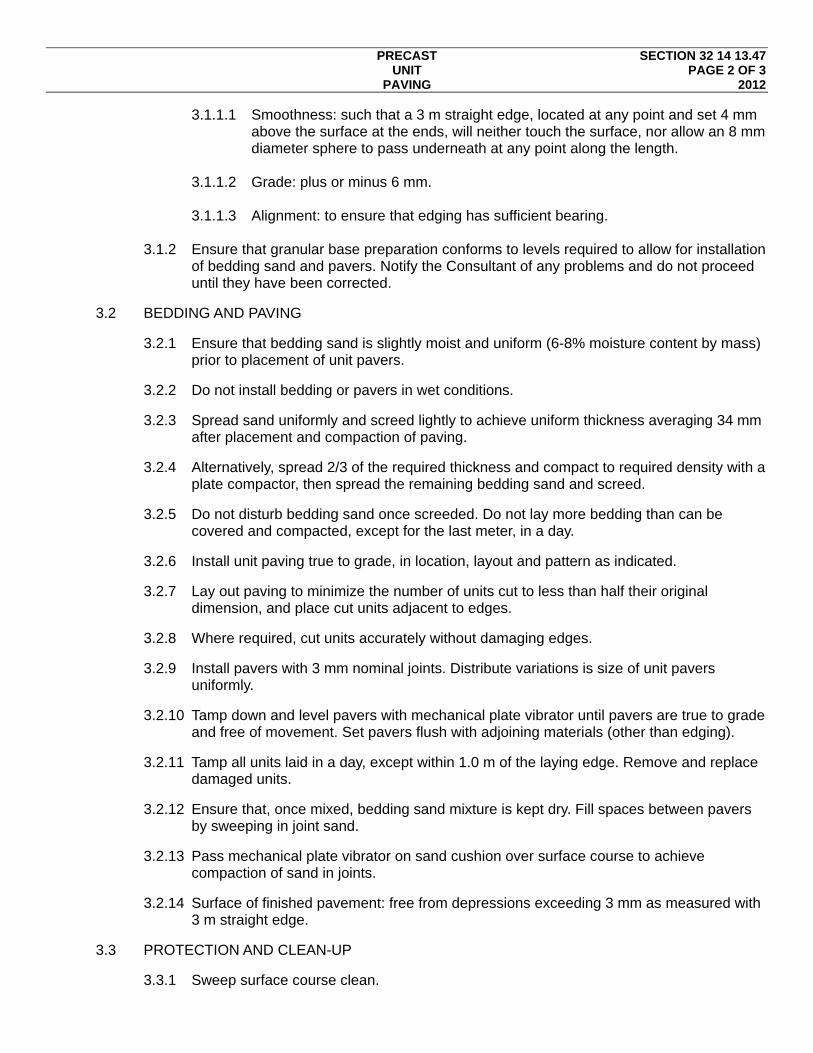
PRECAST SECTION 32 14 13.47 UNIT PAGE 2 OF 3 PAVING 2012
3.1.1.1 Smoothness: such that a 3 m straight edge, located at any point and set 4 mm above the surface at the ends, will neither touch the surface, nor allow an 8 mm diameter sphere to pass underneath at any point along the length.
3.1.1.2 Grade: plus or minus 6 mm.
3.1.1.3 Alignment: to ensure that edging has sufficient bearing.
3.1.2 Ensure that granular base preparation conforms to levels required to allow for installation
of bedding sand and pavers. Notify the Consultant of any problems and do not proceed until they have been corrected.
3.2 BEDDING AND PAVING
3.2.1 Ensure that bedding sand is slightly moist and uniform (6-8% moisture content by mass) prior to placement of unit pavers.
3.2.2 Do not install bedding or pavers in wet conditions.
3.2.3 Spread sand uniformly and screed lightly to achieve uniform thickness averaging 34 mm after placement and compaction of paving.
3.2.4 Alternatively, spread 2/3 of the required thickness and compact to required density with a plate compactor, then spread the remaining bedding sand and screed.
3.2.5 Do not disturb bedding sand once screeded. Do not lay more bedding than can be covered and compacted, except for the last meter, in a day.
3.2.6 Install unit paving true to grade, in location, layout and pattern as indicated.
3.2.7 Lay out paving to minimize the number of units cut to less than half their original dimension, and place cut units adjacent to edges.
3.2.8 Where required, cut units accurately without damaging edges.
3.2.9 Install pavers with 3 mm nominal joints. Distribute variations is size of unit pavers uniformly.
3.2.10 Tamp down and level pavers with mechanical plate vibrator until pavers are true to grade and free of movement. Set pavers flush with adjoining materials (other than edging).
3.2.11 Tamp all units laid in a day, except within 1.0 m of the laying edge. Remove and replace damaged units.
3.2.12 Ensure that, once mixed, bedding sand mixture is kept dry. Fill spaces between pavers by sweeping in joint sand.
3.2.13 Pass mechanical plate vibrator on sand cushion over surface course to achieve compaction of sand in joints.
3.2.14 Surface of finished pavement: free from depressions exceeding 3 mm as measured with 3 m straight edge.
3.3 PROTECTION AND CLEAN-UP
3.3.1 Sweep surface course clean.

PRECAST SECTION 32 14 13.47 UNIT PAGE 3 OF 3 PAVING 2012
3.3.2 Do not allow any traffic until after completed installation has been inspected and accepted by the Consultant.
END OF SECTION
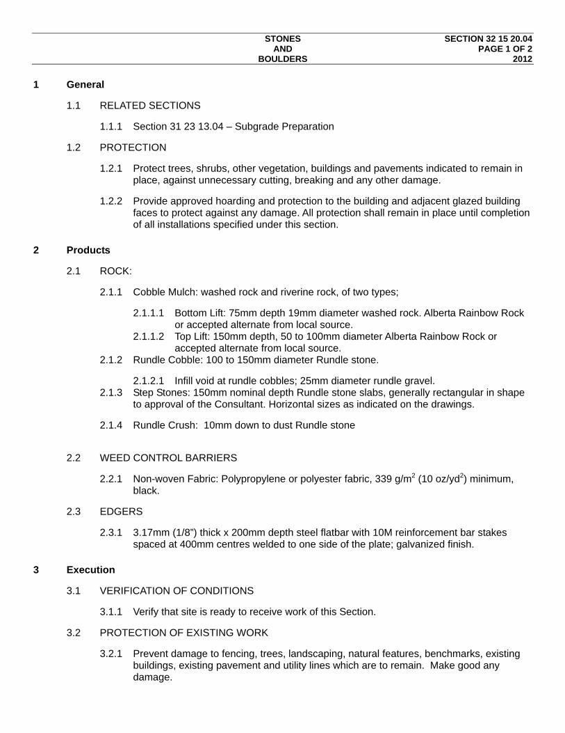
STONES SECTION 32 15 20.04 AND PAGE 1 OF 2 BOULDERS 2012
1 General
1.1 RELATED SECTIONS
1.1.1 Section 31 23 13.04 – Subgrade Preparation
1.2 PROTECTION
1.2.1 Protect trees, shrubs, other vegetation, buildings and pavements indicated to remain in place, against unnecessary cutting, breaking and any other damage.
1.2.2 Provide approved hoarding and protection to the building and adjacent glazed building faces to protect against any damage. All protection shall remain in place until completion of all installations specified under this section.
2 Products
2.1 ROCK:
2.1.1 Cobble Mulch: washed rock and riverine rock, of two types;
2.1.1.1 Bottom Lift: 75mm depth 19mm diameter washed rock. Alberta Rainbow Rock or accepted alternate from local source.
2.1.1.2 Top Lift: 150mm depth, 50 to 100mm diameter Alberta Rainbow Rock or accepted alternate from local source.
2.1.2 Rundle Cobble: 100 to 150mm diameter Rundle stone.
2.1.2.1 Infill void at rundle cobbles; 25mm diameter rundle gravel. 2.1.3 Step Stones: 150mm nominal depth Rundle stone slabs, generally rectangular in shape
to approval of the Consultant. Horizontal sizes as indicated on the drawings.
2.1.4 Rundle Crush: 10mm down to dust Rundle stone
2.2 WEED CONTROL BARRIERS
2.2.1 Non-woven Fabric: Polypropylene or polyester fabric, 339 g/m2 (10 oz/yd2) minimum, black.
2.3 EDGERS
2.3.1 3.17mm (1/8”) thick x 200mm depth steel flatbar with 10M reinforcement bar stakes spaced at 400mm centres welded to one side of the plate; galvanized finish.
3 Execution
3.1 VERIFICATION OF CONDITIONS
3.1.1 Verify that site is ready to receive work of this Section.
3.2 PROTECTION OF EXISTING WORK
3.2.1 Prevent damage to fencing, trees, landscaping, natural features, benchmarks, existing buildings, existing pavement and utility lines which are to remain. Make good any damage.

STONES SECTION 32 15 20.04 AND PAGE 2 OF 2 BOULDERS 2012
3.3 PREPARATION OF SUBGRADE
3.3.1 Locate utility lines before commencement of work and protect from damage.
3.3.2 Remove foreign material, undesirable plants, roots, stones in excess of 25 mm diameter, debris and soil contaminated with oil or gasoline, from site. Do not bury foreign material beneath areas to be landscaped.
3.3.3 Grade subgrade to eliminate uneven areas, low spots and ensure positive drainage from building face. Finish subgrades to depth shown on drawings.
3.3.4 Compact subgrades to minimum 95% Standard Proctor Density.
3.3.5 Install filter cloth on prepared subgrade to approval of the Consultant. Trim cloth exposed above the finish surface of rock materials.
3.4 STONE PLACEMENT
3.4.1 Place all rock materials to depths indicated on the drawings.
3.5 CLEANING
3.5.1 Broom clean all adjacent hard surfaces and finished boulder surfaces.
3.5.2 Remove all excess material and debris, including excavated material, from site.
3.5.3 Restore existing landscaped areas disturbed by boulder and rock installation in a manner acceptable to the Consultant.
END OF SECTION

UNBRANDED CITYGREEN STRATACELL SPECIFICATIONS 2012
Interconnected structural soil cell specification 1 12/5/2011
Structural Soil Cell Specification
The purpose of this specification is to inform landscape architects and installers of the detailed requirements for utilising interconnected structural soil cells effectively.
The structural soil cell is a highly engineered solution that enables street trees to flourish and prevents heaving of adjacent pavements and roads.
While the interconnected structural soil cells have very high strength capacity, the longevity of the pavement structure is contingent on all components being correctly installed in line with relevant design criteria.
The following Specification addresses each key step in the planning and installation processes.

UNBRANDED CITYGREEN STRATACELL SPECIFICATIONS 2012
Interconnected structural soil cell specification 2 12/5/2011
Table of Contents 1.0 Definitions ................................................................................................................... 1
2.0 Site Preliminaries ........................................................................................................ 2
2.01 Product Storage ..................................................................................................... 2
2.02 Services ................................................................................................................. 2
2.03 Tree Pit Layout ...................................................................................................... 2
2.04 Tree Pit Depths ...................................................................................................... 2
2.05 Soil Analysis .......................................................................................................... 2
3.0 Tree Pit Excavation and Drainage ............................................................................. 3
3.01 Excavation ............................................................................................................. 3
3.02 Reinforcing collar ................................................................................................... 3
3.03 Drainage ................................................................................................................ 3
3.04 Sub-base preparation ............................................................................................ 3
3.05 Installation of aggregate sub-base below interconnected structural soil cell matrix3
4.0 Matrix Installation and Soil Filling ............................................................................. 4
4.01 Interconnected structural soil cell assembly .......................................................... 4
4.02 Lateral pipes .......................................................................................................... 4
4.03 Vertical pipes ......................................................................................................... 4
4.04 Root/moisture barriers ........................................................................................... 4
4.05 Loading matrix with filler soil .................................................................................. 5
4.06 Geocomposite separation/reinforcement ............................................................... 5
5.0 Compaction and Pavement Layers ........................................................................... 6
5.01 Reinforcing collar ................................................................................................... 6
5.02 Tree pit opening ..................................................................................................... 6
5.03 Granular base course ............................................................................................ 6
6.0 Materials ...................................................................................................................... 7
6.01 Interconnected structural soil cell 60 Series .......................................................... 7
6.02 Interconnected structural soil cell 45 Series .......................................................... 7
6.03 Interconnected structural soil cell 30 Series .......................................................... 7
6.04 Geocomposite 3030 ............................................................................................... 7
6.05 Ribbed linear root barrier ....................................................................................... 8
6.06 Linear root/ moisture barrier .................................................................................. 9
6.07 Aeration pipes ...................................................................................................... 10
6.08 Filler soils ............................................................................................................. 10
6.09 Granular base course .......................................................................................... 11
7.0 Addendum ................................................................................................................. 12

UNBRANDED CITYGREEN STRATACELL SPECIFICATIONS 2012
Interconnected structural soil cell specification 3 12/5/2011
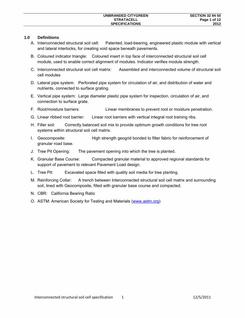
UNBRANDED CITYGREEN SECTION 32 94 50 STRATACELL Page 1 of 12 SPECIFICATIONS 2012
Interconnected structural soil cell specification 1 12/5/2011
1.0 Definitions A. Interconnected structural soil cell: Patented, load-bearing, engineered plastic module with vertical
and lateral interlocks, for creating void space beneath pavements.
B. Coloured indicator triangle: Coloured insert in top face of interconnected structural soil cell module, used to enable correct alignment of modules. Indicator verifies module strength.
C. Interconnected structural soil cell matrix: Assembled and interconnected volume of structural soil cell modules
D. Lateral pipe system: Perforated pipe system for circulation of air, and distribution of water and nutrients, connected to surface grating.
E. Vertical pipe system: Large diameter plastic pipe system for inspection, circulation of air, and connection to surface grate.
F. Root/moisture barriers: Linear membranes to prevent root or moisture penetration.
G. Linear ribbed root barrier: Linear root barriers with vertical integral root training ribs.
H. Filler soil: Correctly balanced soil mix to provide optimum growth conditions for tree root systems within structural soil cell matrix.
I. Geocomposite: High strength geogrid bonded to filter fabric for reinforcement of granular road base.
J. Tree Pit Opening: The pavement opening into which the tree is planted.
K. Granular Base Course: Compacted granular material to approved regional standards for support of pavement to relevant Pavement Load design.
L. Tree Pit: Excavated space filled with quality soil media for tree planting.
M. Reinforcing Collar: A trench between Interconnected structural soil cell matrix and surrounding soil, lined with Geocomposite, filled with granular base course and compacted.
N. CBR: California Bearing Ratio
O. ASTM: American Society for Testing and Materials (www.astm.org)
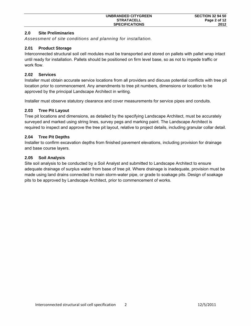
UNBRANDED CITYGREEN SECTION 32 94 50 STRATACELL Page 2 of 12 SPECIFICATIONS 2012
Interconnected structural soil cell specification 2 12/5/2011
2.0 Site Preliminaries Assessment of site conditions and planning for installation.
2.01 Product Storage Interconnected structural soil cell modules must be transported and stored on pallets with pallet wrap intact until ready for installation. Pallets should be positioned on firm level base, so as not to impede traffic or work flow.
2.02 Services Installer must obtain accurate service locations from all providers and discuss potential conflicts with tree pit location prior to commencement. Any amendments to tree pit numbers, dimensions or location to be approved by the principal Landscape Architect in writing.
Installer must observe statutory clearance and cover measurements for service pipes and conduits.
2.03 Tree Pit Layout Tree pit locations and dimensions, as detailed by the specifying Landscape Architect, must be accurately surveyed and marked using string lines, survey pegs and marking paint. The Landscape Architect is required to inspect and approve the tree pit layout, relative to project details, including granular collar detail.
2.04 Tree Pit Depths Installer to confirm excavation depths from finished pavement elevations, including provision for drainage and base course layers.
2.05 Soil Analysis Site soil analysis to be conducted by a Soil Analyst and submitted to Landscape Architect to ensure adequate drainage of surplus water from base of tree pit. Where drainage is inadequate, provision must be made using land drains connected to main storm-water pipe, or grade to soakage pits. Design of soakage pits to be approved by Landscape Architect, prior to commencement of works.

UNBRANDED CITYGREEN SECTION 32 94 50 STRATACELL Page 3 of 12 SPECIFICATIONS 2012
Interconnected structural soil cell specification 3 12/5/2011
3.0 Tree Pit Excavation and Drainage Excavating the pit, providing adequate drainage and meeting required load capacity at floor of tree pit.
3.01 Excavation Installer to excavate the tree pit accurately to the dimensions of the detailed plans, allowing 200mm (8”) additional clearance in length and width. Side walls of excavated pit to be clean, straight, and within 15° of vertical. Tree pit length, width and diagonals at base of pit to be measured to ensure that correct dimensions are being obtained (measurements shown on tree pit detail plus 200mm). Installer to confirm that correct depth has been provided, measuring from finished pavement level, including any drainage layers. Base of tree pit should be flat unless there is a drainage layer to be provided, in which case the subgrade surface must have a grade of 5%.
3.02 Reinforcing collar The top perimeter of the tree pit must be further excavated to a depth of 300mm (12”) and to a width of 200mm (10”), or a width sufficient to permit a narrow foot compacting plate (reinforcing collar) to be installed. Sides and base of this excavation must be clean and straight.
3.03 Drainage Positive drainage to main storm-water service from base of tree pit is mandatory if the design incorporates water harvesting and is strongly recommended if the site soil is not well drained. The base of the tree pit must be graded at 5% to the perforated collection pipe in trench. This collection pipe is to be wrapped in filter sock and connected to the storm-water system. A 100mm (4”) layer of clean aggregate is to be placed in base of tree pit and leveled.
3.04 Sub-base preparation Base of tree pit must be free of debris and level. Installer to check CBR of the subgrade below the proposed granular pavement layers to ensure it meets the applicable pavement design criteria. If the subgrade is fill confirm that it is compacted to a minimum of 95% of maximum dry density at optimum moisture content in accordance with ASTM D 698 Standard Proctor Method.
Compact the subgrade in natural ground with a minimum of three passes of a suitable vibrating compacting machine or apply other compaction forces as needed to achieve the required subgrade compaction rate. Apply additional compaction forces at optimum water levels.
If an aggregate drainage layer is specified cover top and sides of with a proprietary non-woven filter fabric to engineer specifications and ensure the sides of the drainage layer are compacted against the sides of the excavation to the density specified.
3.05 Installation of aggregate sub-base below interconnected structural soil cell matrix Install aggregate sub-base to the depths indicated in the drawings and compact to a minimum of 95% of maximum dry density at optimum moisture content, in accordance with ASTM D 698 Standard Proctor Method. Compact the subgrade with a minimum of three passes of a suitable vibrating machine or apply other compaction forces as needed to achieve the required subgrade compaction rate.
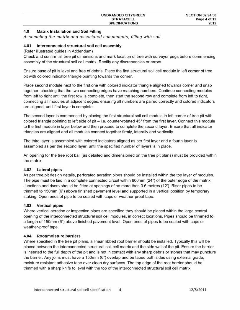
UNBRANDED CITYGREEN SECTION 32 94 50 STRATACELL Page 4 of 12 SPECIFICATIONS 2012
Interconnected structural soil cell specification 4 12/5/2011
4.0 Matrix Installation and Soil Filling Assembling the matrix and associated components, fill ing with soil.
4.01 Interconnected structural soil cell assembly (Refer illustrated guides in Addendum) Check and confirm all tree pit dimensions and mark location of tree with surveyor pegs before commencing assembly of the structural soil cell matrix. Rectify any discrepancies or errors.
Ensure base of pit is level and free of debris. Place the first structural soil cell module in left corner of tree pit with colored indicator triangle pointing towards the corner.
Place second module next to the first one with colored indicator triangle aligned towards corner and snap together, checking that the two connecting edges have matching numbers. Continue connecting modules from left to right until the first row is complete, then start the second row and complete from left to right, connecting all modules at adjacent edges, ensuring all numbers are paired correctly and colored indicators are aligned, until first layer is complete.
The second layer is commenced by placing the first structural soil cell module in left corner of tree pit with colored triangle pointing to left side of pit – i.e. counter-rotated 45° from the first layer. Connect this module to the first module in layer below and then proceed to complete the second layer. Ensure that all indicator triangles are aligned and all modules connect together firmly, laterally and vertically.
The third layer is assembled with colored indicators aligned as per first layer and a fourth layer is assembled as per the second layer, until the specified number of layers is in place.
An opening for the tree root ball (as detailed and dimensioned on the tree pit plans) must be provided within the matrix.
4.02 Lateral pipes As per tree pit design details, perforated aeration pipes should be installed within the top layer of modules. The pipe must be laid in a complete connected circuit within 600mm (24”) of the outer edge of the matrix. Junctions and risers should be fitted at spacings of no more than 3.6 metres (12’). Riser pipes to be trimmed to 150mm (6”) above finished pavement level and supported in a vertical position by temporary staking. Open ends of pipe to be sealed with caps or weather-proof tape.
4.03 Vertical pipes Where vertical aeration or inspection pipes are specified they should be placed within the large central opening of the interconnected structural soil cell modules, in correct locations. Pipes should be trimmed to a length of 150mm (6”) above finished pavement level. Open ends of pipes to be sealed with caps or weather-proof tape.
4.04 Root/moisture barriers Where specified in the tree pit plans, a linear ribbed root barrier should be installed. Typically this will be placed between the interconnected structural soil cell matrix and the side wall of the pit. Ensure the barrier is inserted to the full depth of the pit and is not in contact with any sharp debris or stones that may puncture the barrier. Any joins must have a 150mm (6”) overlap and be taped both sides using external grade, moisture resistant adhesive tape over clean dry surfaces. The top edge of the root barrier should be trimmed with a sharp knife to level with the top of the interconnected structural soil cell matrix.
UNBRANDED CITYGREEN SECTION 32 94 50 STRATACELL Page 5 of 12 SPECIFICATIONS 2012
Interconnected structural soil cell specification 5 12/5/2011
4.05 Loading matrix with filler soil Ensure that all required filler soil testing and certification is complete to the satisfaction of the Landscape Architect prior to loading into the tree pit.
When matrix is fully assembled, with all specified piping and barriers in place, the filler soil can be loaded into the matrix. Soil should be placed in the matrix using an excavator bucket and spread with rakes or shovels until the void spaces are filled. Ensure the outer trench for the reinforcing collar is kept clean and free of filler soil. Matrix is to be vibrated using plate vibration or needle vibration equipment in order to shake soil into all voids.
Continue loading dry soil, raking out and vibrating, until matrix is filled.
Should the filler soil constituents and moisture content not permit the voids to be fully filled, assemble the structural soil cell modules in layers and progressively fill, layer by layer.
Note: In some instances an air layer is detailed in the top of the matrix. In this case soil is loaded, spread and vibrated in smaller amounts, to ensure an even distribution of soil beneath the air layer.
4.06 Geocomposite separation/reinforcement The outer trench for provision of the reinforcing collar should be cleaned and all filler soil and debris removed. Place the geocomposite layer on the top of matrix and cut to length, ensuring that the material fully covers the top of the matrix, the upper side walls of the matrix, and the bottom of the adjacent trench for reinforcing collar. Any material joins must be straight, free of debris and over-lapped 150mm (6”). Pipe penetrations to be provided by means of two intersecting slits cut with a sharp knife to form a cross.

UNBRANDED CITYGREEN SECTION 32 94 50 STRATACELL Page 6 of 12 SPECIFICATIONS 2012
Interconnected structural soil cell specification 6 12/5/2011
5.0 Compaction and Pavement Layers Enclosing the tree pit and placing pavement layers, to comply with design loads.
5.01 Reinforcing collar Load the granular base course material into the base of the collar trench ensuring the geocomposite layer is not displaced from the base of the trench. Compact the granular material in 150mm (6”) lifts until the collar is level with the top of the matrix.
5.02 Tree pit opening Confirm the exact required position of the tree pit opening from project details and with reference to survey markers. Cut geocomposite layer and fold back to expose the tree pit opening. Position form-work to provide for poured concrete system, or other method as specified in project details.
Place linear ribbed root barrier within the tree pit opening with vertical ribs facing inwards. Ensure bottom edge of barrier is placed on the structural soil cell matrix and upper edge is at finished pavement level. Trim to suit with sharp knife. Ensure any joins are overlapped a minimum of 150mm (6”), are clean and dry and taped both sides with external grade, moisture resistant, adhesive tape.
5.03 Granular base course Load and spread granular base course material onto the geocomposite layer in an even depth of 100mm (4”). Compact this layer with a vibrating plate compactor with a mass of 1200kg – 1400kg/m² of base plate, to specified compaction levels. Continue building compacted granular layers to required levels including the reinforcing collar.
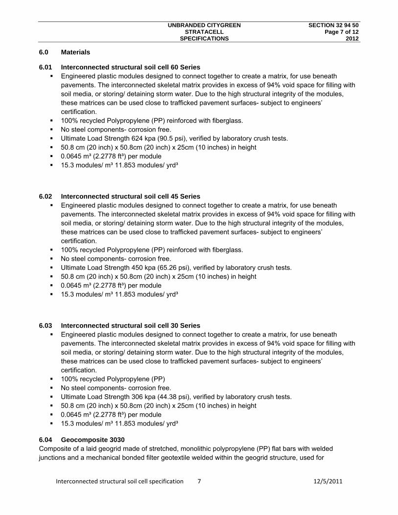
UNBRANDED CITYGREEN SECTION 32 94 50 STRATACELL Page 7 of 12 SPECIFICATIONS 2012
Interconnected structural soil cell specification 7 12/5/2011
6.0 Materials
6.01 Interconnected structural soil cell 60 Series Engineered plastic modules designed to connect together to create a matrix, for use beneath
pavements. The interconnected skeletal matrix provides in excess of 94% void space for filling with soil media, or storing/ detaining storm water. Due to the high structural integrity of the modules, these matrices can be used close to trafficked pavement surfaces- subject to engineers’ certification.
100% recycled Polypropylene (PP) reinforced with fiberglass. No steel components- corrosion free. Ultimate Load Strength 624 kpa (90.5 psi), verified by laboratory crush tests. 50.8 cm (20 inch) x 50.8cm (20 inch) x 25cm (10 inches) in height 0.0645 m³ (2.2778 ft³) per module 15.3 modules/ m³ 11.853 modules/ yrd³
6.02 Interconnected structural soil cell 45 Series Engineered plastic modules designed to connect together to create a matrix, for use beneath
pavements. The interconnected skeletal matrix provides in excess of 94% void space for filling with soil media, or storing/ detaining storm water. Due to the high structural integrity of the modules, these matrices can be used close to trafficked pavement surfaces- subject to engineers’ certification.
100% recycled Polypropylene (PP) reinforced with fiberglass. No steel components- corrosion free. Ultimate Load Strength 450 kpa (65.26 psi), verified by laboratory crush tests. 50.8 cm (20 inch) x 50.8cm (20 inch) x 25cm (10 inches) in height 0.0645 m³ (2.2778 ft³) per module 15.3 modules/ m³ 11.853 modules/ yrd³
6.03 Interconnected structural soil cell 30 Series Engineered plastic modules designed to connect together to create a matrix, for use beneath
pavements. The interconnected skeletal matrix provides in excess of 94% void space for filling with soil media, or storing/ detaining storm water. Due to the high structural integrity of the modules, these matrices can be used close to trafficked pavement surfaces- subject to engineers’ certification.
100% recycled Polypropylene (PP) No steel components- corrosion free. Ultimate Load Strength 306 kpa (44.38 psi), verified by laboratory crush tests. 50.8 cm (20 inch) x 50.8cm (20 inch) x 25cm (10 inches) in height 0.0645 m³ (2.2778 ft³) per module 15.3 modules/ m³ 11.853 modules/ yrd³
6.04 Geocomposite 3030 Composite of a laid geogrid made of stretched, monolithic polypropylene (PP) flat bars with welded junctions and a mechanical bonded filter geotextile welded within the geogrid structure, used for

UNBRANDED CITYGREEN SECTION 32 94 50 STRATACELL Page 8 of 12 SPECIFICATIONS 2012
Interconnected structural soil cell specification 8 12/5/2011
reinforcement in many fields of civil engineering including road construction, landfill and hydraulic engineering.
Property Test Method* Unit 30/30 Q1 151 GRK 3
Geogrid 30/30 Q1 Raw material - - Polypropylene (PP),
white Mass per unit area EN ISO 9864 g/m² 200 Max. tensile strength, md / cmd**
EN ISO 10319 kN/m ≥ 30/ ≥ 30
Elongation at nominal strength, md / cmd**
EN ISO 10319 % ≤8 / ≤8
Tensile strength at 2% elongation, md / cmd**
EN ISO 10319 kN/m 12 / 12
Tensile strength at 5% elongation, md / cmd**
EN ISO 10319 kN/m 24 / 24
Aperture size, md x cmd** - mm x mm Approx. 32 x 32 Production specific elongation
- % O
Geotextile 151 GRK 3 Raw material - - Polypropylene (PP),
whiteMass per unit area EN ISO 9864 g/m² ≥150 Max. tensile strength, md / cmd**
EN ISO 10319 kN/m 7.5 / 11.0
Elongation at max. tensile strength, md / cmd**
EN ISO 10319 % 40 / 30
Puncture force EN ISO 12236 N 1,670 Displacement at static puncture strength
EN ISO 12236 mm 30
Detector tested - - Yes Roll dimensions, width x length
- m x m 4.75 x 100
* based on, ** md = machine direction, cmd = cross machine direction
6.05 Ribbed linear root barrier
Linear root deflecting barriers to be used in proximity to tree root ball to protect all pavement layers. Vertical, integral ribs guide tree roots down into matrix beneath pavement.
Continuous rolls to minimize joins and possible penetration. Widths to suit application and pavement depth 100um thickness 100% High density Polyethylene. This resin meets FDA regulation 177.1520 for food packaging.
Nominal physical properties:
PROPERTY* ASTM D UNIT VALUE
Density 1505 g/cm³ 0.952
Melt Index 1238 g/10 min 0.35
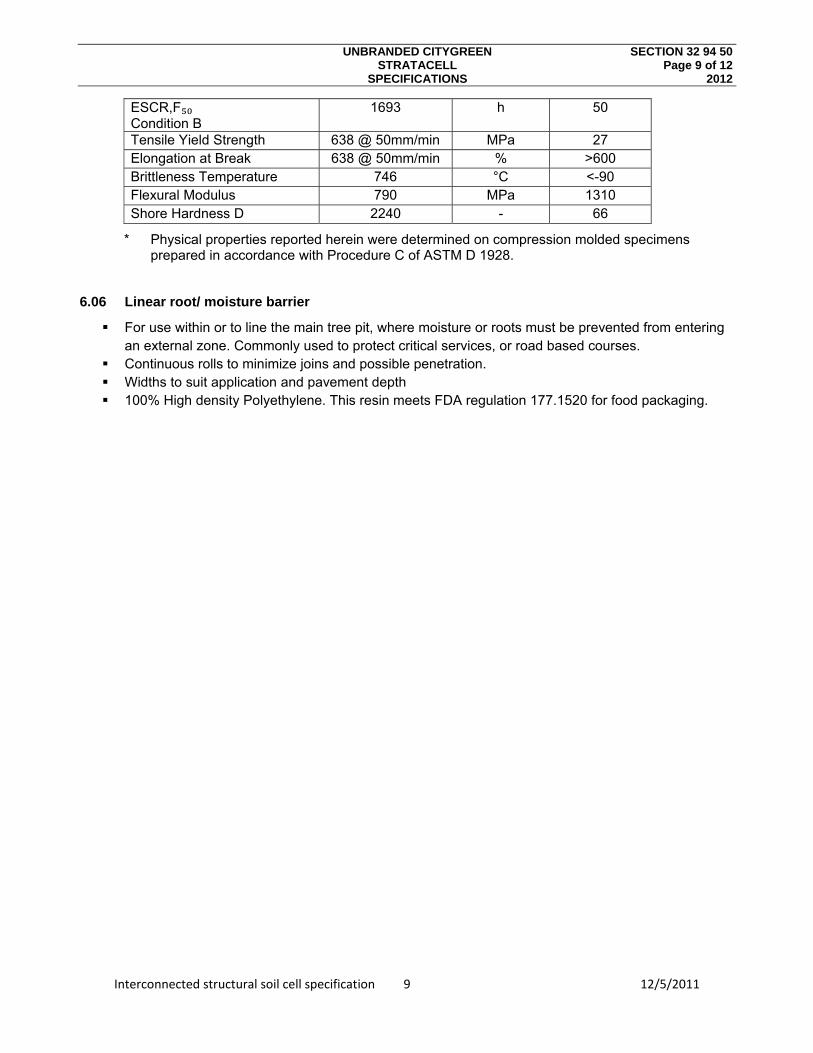
UNBRANDED CITYGREEN SECTION 32 94 50 STRATACELL Page 9 of 12 SPECIFICATIONS 2012
Interconnected structural soil cell specification 9 12/5/2011
ESCR,F₅₀ Condition B
1693 h 50
Tensile Yield Strength 638 @ 50mm/min MPa 27 Elongation at Break 638 @ 50mm/min % >600 Brittleness Temperature 746 °C <-90 Flexural Modulus 790 MPa 1310 Shore Hardness D 2240 - 66
* Physical properties reported herein were determined on compression molded specimens prepared in accordance with Procedure C of ASTM D 1928.
6.06 Linear root/ moisture barrier
For use within or to line the main tree pit, where moisture or roots must be prevented from entering an external zone. Commonly used to protect critical services, or road based courses.
Continuous rolls to minimize joins and possible penetration. Widths to suit application and pavement depth 100% High density Polyethylene. This resin meets FDA regulation 177.1520 for food packaging.
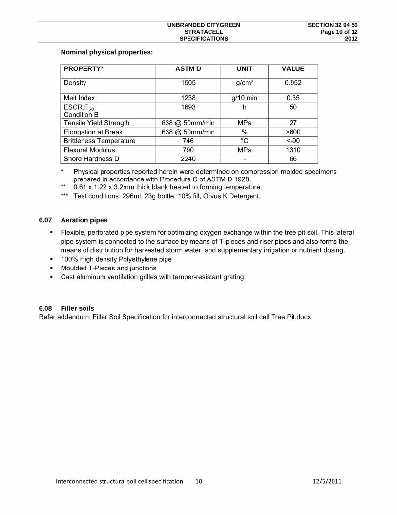
UNBRANDED CITYGREEN SECTION 32 94 50 STRATACELL Page 10 of 12 SPECIFICATIONS 2012
Interconnected structural soil cell specification 10 12/5/2011
Nominal physical properties:
PROPERTY* ASTM D UNIT VALUE
Density 1505 g/cm³ 0.952
Melt Index 1238 g/10 min 0.35 ESCR,F₅₀ Condition B
1693 h 50
Tensile Yield Strength 638 @ 50mm/min MPa 27 Elongation at Break 638 @ 50mm/min % ˃600 Brittleness Temperature 746 °C <-90 Flexural Modulus 790 MPa 1310 Shore Hardness D 2240 - 66
* Physical properties reported herein were determined on compression molded specimens prepared in accordance with Procedure C of ASTM D 1928.
** 0.61 x 1.22 x 3.2mm thick blank heated to forming temperature. *** Test conditions: 296ml, 23g bottle, 10% fill, Orvus K Detergent.
6.07 Aeration pipes
Flexible, perforated pipe system for optimizing oxygen exchange within the tree pit soil. This lateral pipe system is connected to the surface by means of T-pieces and riser pipes and also forms the means of distribution for harvested storm water, and supplementary irrigation or nutrient dosing.
100% High density Polyethylene pipe Moulded T-Pieces and junctions Cast aluminum ventilation grilles with tamper-resistant grating.
6.08 Filler soils Refer addendum: Filler Soil Specification for interconnected structural soil cell Tree Pit.docx
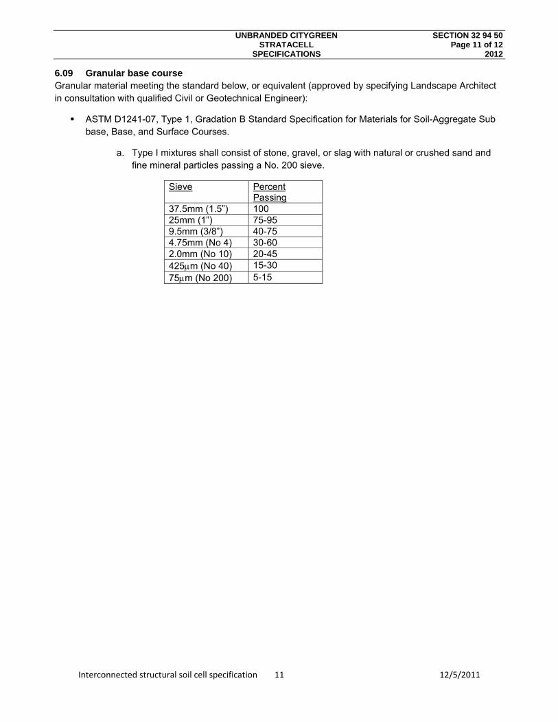
UNBRANDED CITYGREEN SECTION 32 94 50 STRATACELL Page 11 of 12 SPECIFICATIONS 2012
Interconnected structural soil cell specification 11 12/5/2011
6.09 Granular base course Granular material meeting the standard below, or equivalent (approved by specifying Landscape Architect in consultation with qualified Civil or Geotechnical Engineer):
ASTM D1241-07, Type 1, Gradation B Standard Specification for Materials for Soil-Aggregate Sub base, Base, and Surface Courses.
a. Type I mixtures shall consist of stone, gravel, or slag with natural or crushed sand and fine mineral particles passing a No. 200 sieve.
Sieve Percent Passing
37.5mm (1.5”) 100 25mm (1”) 75-95 9.5mm (3/8”) 40-75 4.75mm (No 4) 30-60 2.0mm (No 10) 20-45 425m (No 40) 15-30 75m (No 200) 5-15

UNBRANDED CITYGREEN SECTION 32 94 50 STRATACELL Page 12 of 12 SPECIFICATIONS 2012
Interconnected structural soil cell specification 12 12/5/2011
7.0 Addendum Interconnected structural soil cell Connection Procedure Layers 1 & 3.pdf Interconnected structural soil cell Connection Procedure Layers 2 & 4.pdf
Urban LEED Performance Assessment.pdf Filler Soil Specification for Interconnected structural soil cell Tree Pit.docx
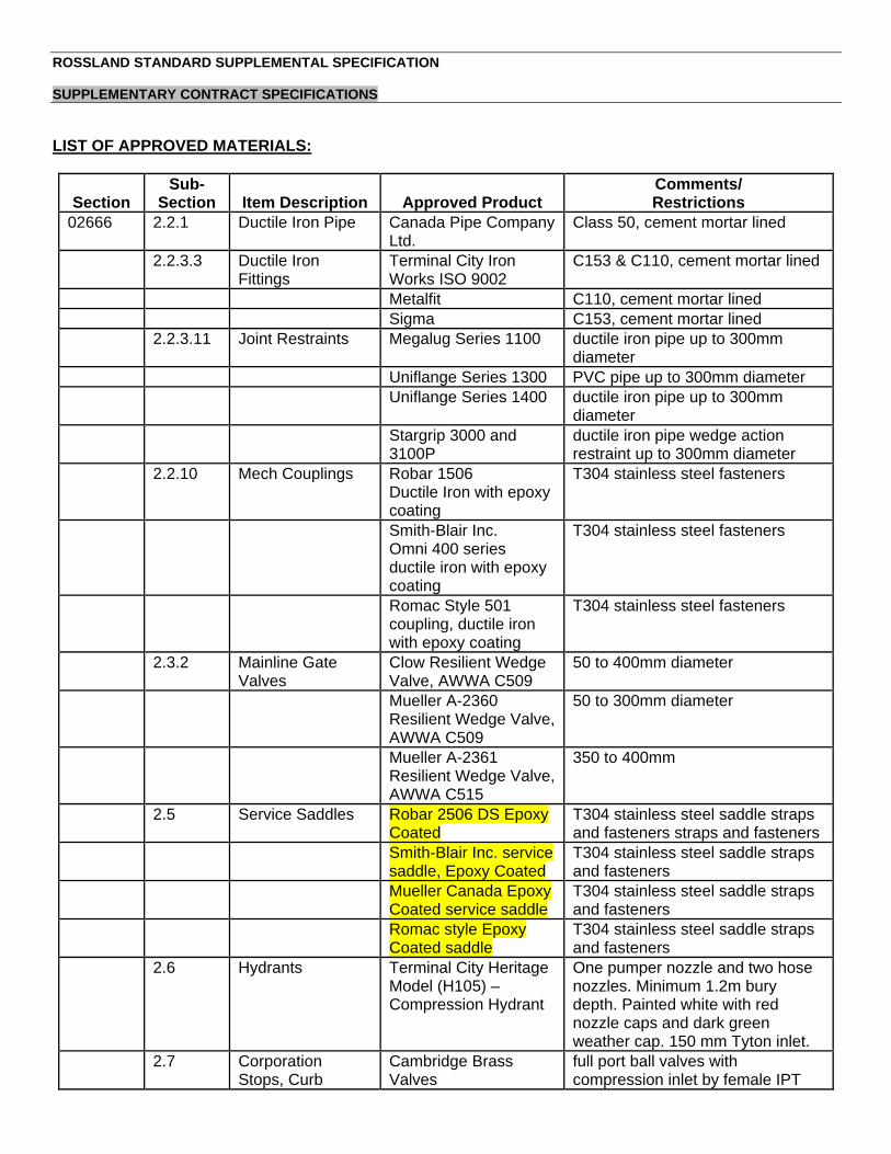
ROSSLAND STANDARD SUPPLEMENTAL SPECIFICATION SUPPLEMENTARY CONTRACT SPECIFICATIONS
LIST OF APPROVED MATERIALS:
Section Sub-
Section Item Description Approved Product Comments/ Restrictions
02666 2.2.1 Ductile Iron Pipe Canada Pipe Company Ltd.
Class 50, cement mortar lined
2.2.3.3 Ductile Iron Fittings
Terminal City Iron Works ISO 9002
C153 & C110, cement mortar lined
Metalfit C110, cement mortar lined Sigma C153, cement mortar lined 2.2.3.11 Joint Restraints Megalug Series 1100 ductile iron pipe up to 300mm
diameter Uniflange Series 1300 PVC pipe up to 300mm diameter Uniflange Series 1400 ductile iron pipe up to 300mm
diameter Stargrip 3000 and
3100P ductile iron pipe wedge action restraint up to 300mm diameter
2.2.10 Mech Couplings Robar 1506 Ductile Iron with epoxy coating
T304 stainless steel fasteners
Smith-Blair Inc. Omni 400 series ductile iron with epoxy coating
T304 stainless steel fasteners
Romac Style 501 coupling, ductile iron with epoxy coating
T304 stainless steel fasteners
2.3.2 Mainline Gate Valves
Clow Resilient Wedge Valve, AWWA C509
50 to 400mm diameter
Mueller A-2360 Resilient Wedge Valve, AWWA C509
50 to 300mm diameter
Mueller A-2361 Resilient Wedge Valve, AWWA C515
350 to 400mm
2.5 Service Saddles Robar 2506 DS Epoxy Coated
T304 stainless steel saddle straps and fasteners straps and fasteners
Smith-Blair Inc. service saddle, Epoxy Coated
T304 stainless steel saddle straps and fasteners
Mueller Canada Epoxy Coated service saddle
T304 stainless steel saddle straps and fasteners
Romac style Epoxy Coated saddle
T304 stainless steel saddle straps and fasteners
2.6 Hydrants Terminal City Heritage Model (H105) – Compression Hydrant
One pumper nozzle and two hose nozzles. Minimum 1.2m bury depth. Painted white with red nozzle caps and dark green weather cap. 150 mm Tyton inlet.
2.7 Corporation Stops, Curb
Cambridge Brass Valves
full port ball valves with compression inlet by female IPT

ROSSLAND STANDARD SUPPLEMENTAL SPECIFICATION SUPPLEMENTARY CONTRACT SPECIFICATIONS
Section Sub-
Section Item Description Approved Product Comments/ Restrictions
Stops, and Brass Fittings
outlet connections, 360 degree turn
2.7
Mueller 300 Ball Valves
full port ball valves with compression inlet by female IPT outlet connections, 360 degree turn
2.7 Cambridge Brass Ball Valves
full port ball valves with compression inlet by female IPT outlet connections, 360 degree turn
02725
2.1
Corporation Stops and Curb Stops - Insulating
Mueller 300 Insulated Ball Valves
Mueller N-35008 and Mueller N-35172-3
02725
2.1
Manhole and Catch Basin Frames and Covers - Cast Iron
Terminal City “ACS” cast in cover
02725 2.1 Dobney Foundry “DF” cast in cover 02725
2.1
Ductile Iron - Self Levelling Manhole Frame and Cover
Hanley Agencies Ltd. “SOLO 624 S”
“SOLO 600” and “EN 124 – D400” cast in cover
PVC Riser Rings IPEX - Lifesaver 02731 2.0 Sewer Couplings Generic one piece gasket and bushing, 300
series stainless steel clamps, with shear rings
PVC Sewer Pipe (PSM Type)
IPEX PVC Sewer Pipe 100 mm to 675 mm diameter, ring tite gasket
02731 2.0 Diamond Plastics PVC Sewer Pipe
100 mm to 375 mm diameter, Type PSM
2.2 Royal Pipe Co. PVC Sewer Pipe
100 mm to 675 mm diameter, gasketed

UNIT PRICE Supplementary General Conditions SGC – PAGE 1 CONTRACT MMCD VOLUME II (2009 PLATINUM EDITION) 2009
Owner: City of Rossland
(NAME OF OWNER)
Contract: Columbia Avenue Infrastructure Improvements (TITLE OF CONTRACT)
Reference No. COR 2012-01 (OWNER’S CONTRACT REFERENCE NO.)
General
Conditions # Paragraph # Title Action
3 .2 Authority Delete GC3.2.2 and replace with: “Nothing contained in the Contract Documents shall create any contractual relationship or other relationship recognized by law between the Contract Administrator and the Contractor, subcontractors, suppliers, or their agents, employees or other persons performing any of the Work.
3 3 Contract Administration
Delete GC3.3.5 and replace with: “The Owner shall provide the Contractor with three survey control points at the Place of the Work, and relative coordinates of the major portions of the Work. The Contract Administrator may conduct survey checks of the Work at his discretion. The Contractor shall provide a survey assistant, at the Contract Administrators request, for such survey checks. The Contractor shall protect and preserve such survey control points for so long as they are required for the Work and if any of them must be replaced because they are disturbed or destroyed by the Contractor, then the Contractor shall pay the costs of such replacement.”
4.3 .1 Protection of Work, Property and the Public
Add: Within the terms of this clause, the Contractor is responsible for the protection and maintenance of existing power and telephone poles during the term of the Contract.
.4 Delete GC 4.3.4 and replace with the following: Before commencing any Work at the Place of the Work, the Contractor shall be responsible to locate in three dimensions all underground utilities and structures indicated on the Contract Documents as being at the Place of the Work. The Contractor shall also be responsible to consult with all utility corporations that provide electricity, communication, gas or other utility services in the area of the Place of the Work, to locate in three dimensions all underground utilities for which they have records. The Contractor shall also locate in three dimensions any other utilities or underground structures that are reasonably apparent in an inspection of the Place of the Work.
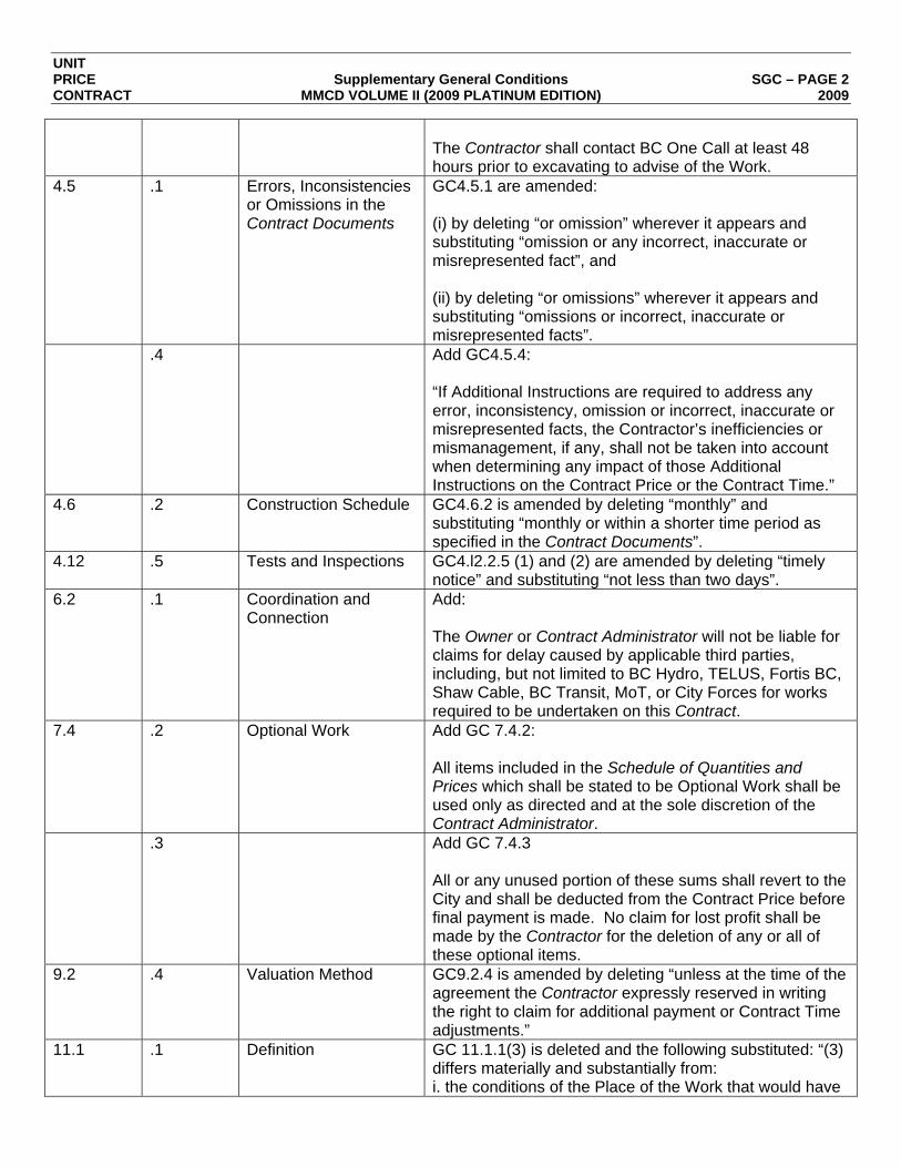
UNIT PRICE Supplementary General Conditions SGC – PAGE 2 CONTRACT MMCD VOLUME II (2009 PLATINUM EDITION) 2009
The Contractor shall contact BC One Call at least 48 hours prior to excavating to advise of the Work.
4.5 .1 Errors, Inconsistencies or Omissions in the Contract Documents
GC4.5.1 are amended: (i) by deleting “or omission” wherever it appears and substituting “omission or any incorrect, inaccurate or misrepresented fact”, and (ii) by deleting “or omissions” wherever it appears and substituting “omissions or incorrect, inaccurate or misrepresented facts”.
.4 Add GC4.5.4: “If Additional Instructions are required to address any error, inconsistency, omission or incorrect, inaccurate or misrepresented facts, the Contractor’s inefficiencies or mismanagement, if any, shall not be taken into account when determining any impact of those Additional Instructions on the Contract Price or the Contract Time.”
4.6 .2 Construction Schedule GC4.6.2 is amended by deleting “monthly” and substituting “monthly or within a shorter time period as specified in the Contract Documents”.
4.12 .5 Tests and Inspections GC4.l2.2.5 (1) and (2) are amended by deleting “timely notice” and substituting “not less than two days”.
6.2 .1 Coordination and Connection
Add: The Owner or Contract Administrator will not be liable for claims for delay caused by applicable third parties, including, but not limited to BC Hydro, TELUS, Fortis BC, Shaw Cable, BC Transit, MoT, or City Forces for works required to be undertaken on this Contract.
7.4 .2 Optional Work Add GC 7.4.2: All items included in the Schedule of Quantities and Prices which shall be stated to be Optional Work shall be used only as directed and at the sole discretion of the Contract Administrator.
.3 Add GC 7.4.3 All or any unused portion of these sums shall revert to the City and shall be deducted from the Contract Price before final payment is made. No claim for lost profit shall be made by the Contractor for the deletion of any or all of these optional items.
9.2 .4 Valuation Method GC9.2.4 is amended by deleting “unless at the time of the agreement the Contractor expressly reserved in writing the right to claim for additional payment or Contract Time adjustments.”
11.1 .1 Definition GC 11.1.1(3) is deleted and the following substituted: “(3) differs materially and substantially from: i. the conditions of the Place of the Work that would have
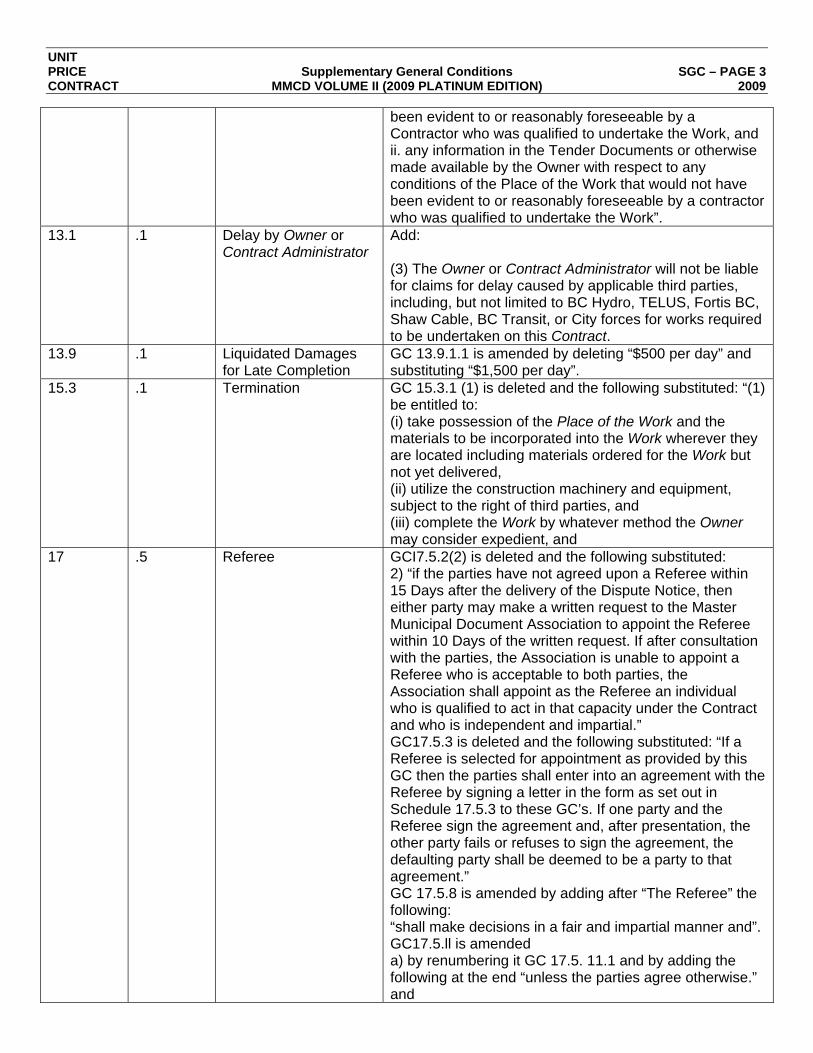
UNIT PRICE Supplementary General Conditions SGC – PAGE 3 CONTRACT MMCD VOLUME II (2009 PLATINUM EDITION) 2009
been evident to or reasonably foreseeable by a Contractor who was qualified to undertake the Work, and ii. any information in the Tender Documents or otherwise made available by the Owner with respect to any conditions of the Place of the Work that would not have been evident to or reasonably foreseeable by a contractor who was qualified to undertake the Work”.
13.1 .1 Delay by Owner or Contract Administrator
Add: (3) The Owner or Contract Administrator will not be liable for claims for delay caused by applicable third parties, including, but not limited to BC Hydro, TELUS, Fortis BC, Shaw Cable, BC Transit, or City forces for works required to be undertaken on this Contract.
13.9 .1 Liquidated Damages for Late Completion
GC 13.9.1.1 is amended by deleting “$500 per day” and substituting “$1,500 per day”.
15.3 .1 Termination GC 15.3.1 (1) is deleted and the following substituted: “(1) be entitled to: (i) take possession of the Place of the Work and the materials to be incorporated into the Work wherever they are located including materials ordered for the Work but not yet delivered, (ii) utilize the construction machinery and equipment, subject to the right of third parties, and (iii) complete the Work by whatever method the Owner may consider expedient, and
17 .5 Referee GCI7.5.2(2) is deleted and the following substituted: 2) “if the parties have not agreed upon a Referee within 15 Days after the delivery of the Dispute Notice, then either party may make a written request to the Master Municipal Document Association to appoint the Referee within 10 Days of the written request. If after consultation with the parties, the Association is unable to appoint a Referee who is acceptable to both parties, the Association shall appoint as the Referee an individual who is qualified to act in that capacity under the Contract and who is independent and impartial.” GC17.5.3 is deleted and the following substituted: “If a Referee is selected for appointment as provided by this GC then the parties shall enter into an agreement with the Referee by signing a letter in the form as set out in Schedule 17.5.3 to these GC’s. If one party and the Referee sign the agreement and, after presentation, the other party fails or refuses to sign the agreement, the defaulting party shall be deemed to be a party to that agreement.” GC 17.5.8 is amended by adding after “The Referee” the following: “shall make decisions in a fair and impartial manner and”. GC17.5.ll is amended a) by renumbering it GC 17.5. 11.1 and by adding the following at the end “unless the parties agree otherwise.” and

UNIT PRICE Supplementary General Conditions SGC – PAGE 4 CONTRACT MMCD VOLUME II (2009 PLATINUM EDITION) 2009
b) by adding the following: 17.5.11.2 Despite 17.5.1 1.1, on written application of a party, the Master Municipal Documents Association may revoke the appointment of the Referee if the Association is satisfied that the Referee is biased, unqualified to discharge the Referee’s duties, or has failed to diligently and conscientiously perform the Referee’s duties. A replacement Referee shall be selected for appointment as provided by this GC. GC17.5.l3 is amended by deleting “by either party, or both parties,” and substituting the following: “by both parties but not by one party.”
18.2 .1 Supporting Documentation
Add: The Contractor shall not work on the Site or deliver materials for which delivery slips submitted to the Owner are the basis of payment unless the Site Inspector is present. However, if the Contract Administrator deems these requirements inappropriate then this requirement may be waived.
18 .3 Delete GC 18.3.1 and replace with the following Except for items in the Schedule of Quantities and Prices which are identified as being “Supply Only” or items authorized under GC10. 1, payments shall not be made for materials or products purchased by the Contractor but not incorporated into the Work at the Place of the Work.
18.9 .1 Waiver of Claims GC18.9.1 is amended by deleting the last sentence and substituting the following: This waiver of claims shall include without limitation those claims that might arise from: 1) the negligence or breach of contract by the Owner, its employees, agents or officials, or 2) the negligence or wrongful acts of the Owner’s consultants or the Contract Administrator, but does not include claims made by the Contractor in writing prior to such application in accordance with the provisions of the Contract
.2 GC 18.9.2 is amended by deleting the last sentence “Documents and delivered to the Contract Administrator prior to date of Substantial Performance and still unsettled” and substituting the following: This waiver of claims shall include without limitation those claims that might arise from: 1) the negligence or breach of Contract by the Owner, its employees, agents’, or officials, or 2) the negligence or wrongful acts of the Owner’s consultants or Contract Administrator, but does not include claims made by the. Contractor in writing prior to such application in accordance with the provisions of the Contract Documents and delivered to the Contract Administrator and still unsettled.
19 Taxes, Duties and HST GC 19.0 is amended by deleting “GST” and substitute “HST”

UNIT PRICE Supplementary General Conditions SGC – PAGE 5 CONTRACT MMCD VOLUME II (2009 PLATINUM EDITION) 2009
19.1 .1 Taxes Delete GC 19.1.1 and replace with the following: The Contract Price and all unit prices, lump sum prices, and all other prices and Quotations shall include all taxes, customs duties and excise taxes, except for HST (collectively the “Taxes”) payable with respect to the performance of the Work. The Contractor shall be responsible to pay all Taxes.
20.4 .2 Environmental Laws GC2O.4 is amended by adding the following: 20.4.2 The Contractor shall indemnify the Owner for any costs, fines, expenses and penalties that the Owner is required to pay on account of the Contractor performing the Work in breach of any applicable Federal or Provincial or municipal environmental laws, regulations, or orders.
21 .2 Delete GC 2 1.2.1 and replace with the following As part of the Work the Contractor shall, to the extent reasonably possible, perform on behalf of the Owner the obligations which the Owner must undertake as “Prime Contractor” by virtue of the Workers’ Compensation Act and Regulations, or other statutes. The Contractor shall have a safety program acceptable to the Workers’ Compensation Board and shall ensure that all Workers’ Compensation Board safety rules and regulations are observed during performance of this contract, not only by the Contractor but by all sub-contractors, workers, material personnel and others engaged in the performance of this contract. The Contractor shall indemnify the City of Rossland and Province of B.C. and hold harmless the City of Rossland and Province of B.C. from all manner of claims, demand, costs, losses, penalties and proceedings arising out of or in any way related to unpaid Workers’ Compensation Board assessments owing from any person or corporation engaged in the performance of this contract, or arising out of or in any way related to the failure to observe safety rules, regulations and practices of the Workers’ Compensation Board, including penalties levied by the Workers’ Compensation Board.”
24 .1 Required Insurance In addition to the MMCD insurance requirements, the Contractor shall also comply with the following requirements of the City, which will take precedence: “The Contractor shall insure and keep insured while this contract is in force, with such companies and on such forms as are acceptable to the City, at the Contractor’s expense, Comprehensive General Liability Insurance covering premises and operations liability; Contractor’s Contingency Liability with respect to the operations of Subcontractor’s Completed Operations Liability, Contractual Liability and Non-Owned Automobile Liability Insurance. The limits of liability for Personal Injury and Property Damage combined shall be for not less than $5,000,000 each occurrence.
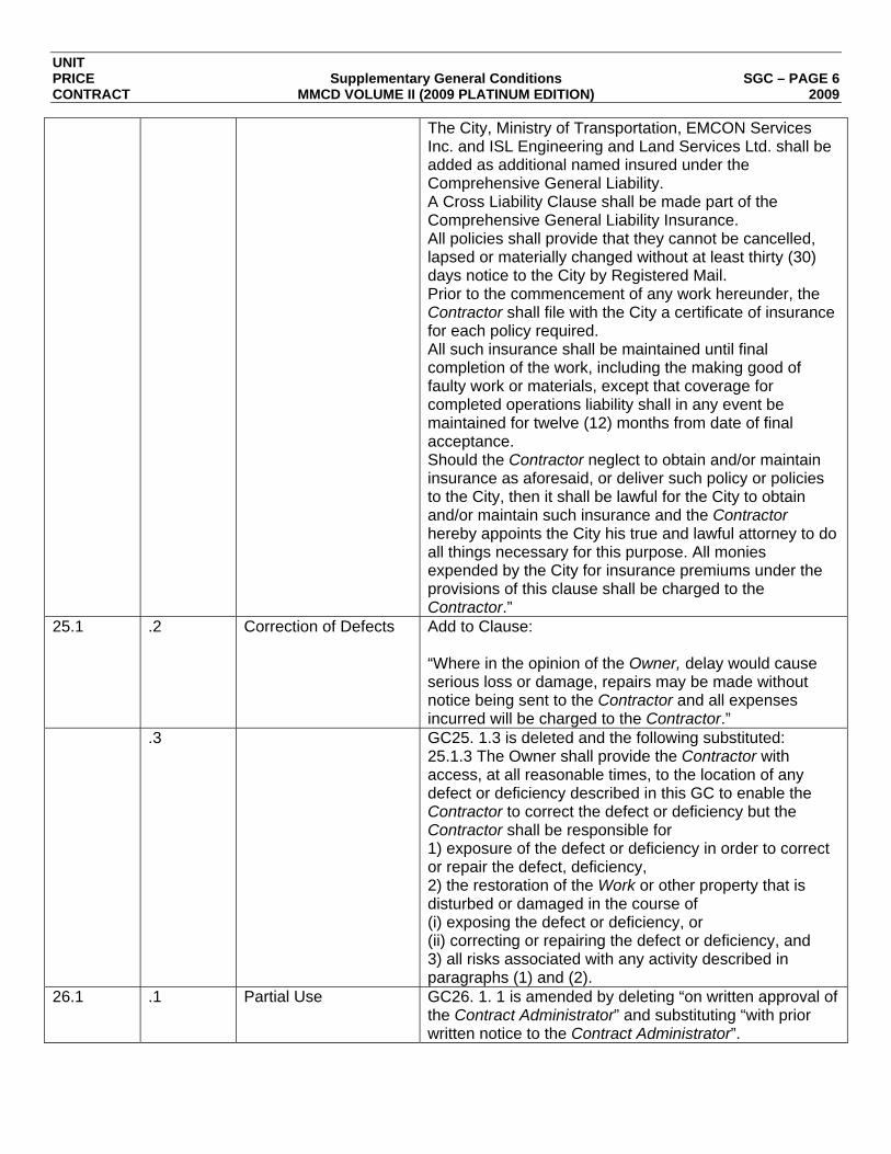
UNIT PRICE Supplementary General Conditions SGC – PAGE 6 CONTRACT MMCD VOLUME II (2009 PLATINUM EDITION) 2009
The City, Ministry of Transportation, EMCON Services Inc. and ISL Engineering and Land Services Ltd. shall be added as additional named insured under the Comprehensive General Liability. A Cross Liability Clause shall be made part of the Comprehensive General Liability Insurance. All policies shall provide that they cannot be cancelled, lapsed or materially changed without at least thirty (30) days notice to the City by Registered Mail. Prior to the commencement of any work hereunder, the Contractor shall file with the City a certificate of insurance for each policy required. All such insurance shall be maintained until final completion of the work, including the making good of faulty work or materials, except that coverage for completed operations liability shall in any event be maintained for twelve (12) months from date of final acceptance. Should the Contractor neglect to obtain and/or maintain insurance as aforesaid, or deliver such policy or policies to the City, then it shall be lawful for the City to obtain and/or maintain such insurance and the Contractor hereby appoints the City his true and lawful attorney to do all things necessary for this purpose. All monies expended by the City for insurance premiums under the provisions of this clause shall be charged to the Contractor.”
25.1 .2 Correction of Defects Add to Clause: “Where in the opinion of the Owner, delay would cause serious loss or damage, repairs may be made without notice being sent to the Contractor and all expenses incurred will be charged to the Contractor.”
.3 GC25. 1.3 is deleted and the following substituted: 25.1.3 The Owner shall provide the Contractor with access, at all reasonable times, to the location of any defect or deficiency described in this GC to enable the Contractor to correct the defect or deficiency but the Contractor shall be responsible for 1) exposure of the defect or deficiency in order to correct or repair the defect, deficiency, 2) the restoration of the Work or other property that is disturbed or damaged in the course of (i) exposing the defect or deficiency, or (ii) correcting or repairing the defect or deficiency, and 3) all risks associated with any activity described in paragraphs (1) and (2).
26.1 .1 Partial Use GC26. 1. 1 is amended by deleting “on written approval of the Contract Administrator” and substituting “with prior written notice to the Contract Administrator”.


Highway 3B/22 Columbia Avenue
Reconstruction Project
Geotechnical Investigation Report
Prepared for:
Tim Dyer
Regional Project Manager
5th Floor – 310 Ward Street
Nelson, BC V1L 5S4
Prepared by: Reviewed by:
Carolyn Turcotte, EIT Daryn Yonin, P.Eng.
Geotechnical Engineer-in-Training Geotechnical Engineer
Southern Interior Region Southern Interior Region
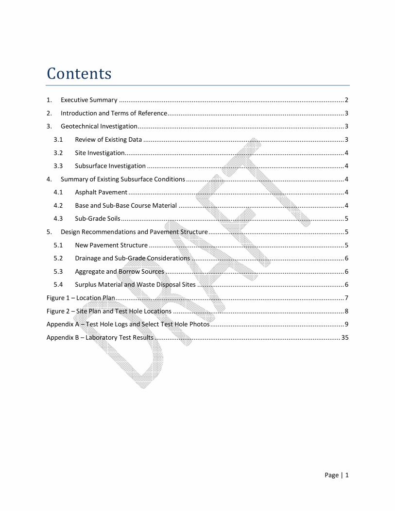
Page | 1
Contents
1. Executive Summary ......................................................................................................................... 2
2. Introduction and Terms of Reference............................................................................................... 3
3. Geotechnical Investigation............................................................................................................... 3
3.1 Review of Existing Data ............................................................................................................ 3
3.2 Site Investigation...................................................................................................................... 4
3.3 Subsurface Investigation .......................................................................................................... 4
4. Summary of Existing Subsurface Conditions ..................................................................................... 4
4.1 Asphalt Pavement .................................................................................................................... 4
4.2 Base and Sub-Base Course Material ......................................................................................... 4
4.3 Sub-Grade Soils ........................................................................................................................ 5
5. Design Recommendations and Pavement Structure ......................................................................... 5
5.1 New Pavement Structure ......................................................................................................... 5
5.2 Drainage and Sub-Grade Considerations .................................................................................. 6
5.3 Aggregate and Borrow Sources ................................................................................................ 6
5.4 Surplus Material and Waste Disposal Sites ............................................................................... 6
Figure 1 – Location Plan ........................................................................................................................... 7
Figure 2 – Site Plan and Test Hole Locations ............................................................................................ 8
Appendix A – Test Hole Logs and Select Test Hole Photos ........................................................................ 9
Appendix B – Laboratory Test Results .................................................................................................... 35

Page | 2
1. Executive Summary The Highway 3B/22 Columbia Avenue Reconstruction Project includes proposed improvements along
Highway 3B/22 (Columbia Avenue) for approximately 600 m from 100 m west of Spokane Street to St.
Paul Street and select improvements to Washington Street within the City of Rossland, BC.
Infrastructure improvements include replacing buried utilities on Columbia Avenue and Washington
Street coupled with select resurfacing of Washington Street which are to be funded by the City of
Rossland. It is understood that reconstruction of the highway pavement structure along Columbia
Avenue is to be covered by the BC Ministry of Transportation and Infrastructure (BC MoTI). This report
includes an assessment of the existing pavement on Columbia Avenue and subsurface ground conditions
then provides recommendations for a new pavement structure for Columbia Avenue between St. Paul
Street and Spokane Street.
The proposed reconstruction of Columbia Avenue between St. Paul Street and Spokane Street is largely
driven by the highway design requirements, including, lowering the elevation of the highway up to 300
mm. The existing pavement condition on Columbia Avenue is considered poor with extensive pavement
cracks and pot-holes. In compliance with the BC MoTI Pavement Structure Design Guidelines (draft
2011) and based on sub-grade conditions, the following pavement structure is recommended for the
highway: 125 mm Class 1 Hot Mix asphalt concrete, 300 mm of 25 mm Well Graded Base (WGB) course
and 300 mm of Select Granular Sub Base (SGSB) except between St. Paul Street and Queen Street where
the SGSB shall be 400 mm based on the identified weaker sub-grade.
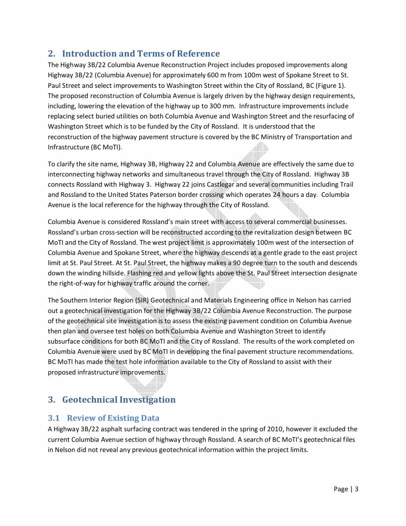
Page | 3
2. Introduction and Terms of Reference The Highway 3B/22 Columbia Avenue Reconstruction Project includes proposed improvements along
Highway 3B/22 (Columbia Avenue) for approximately 600 m from 100m west of Spokane Street to St.
Paul Street and select improvements to Washington Street within the City of Rossland, BC (Figure 1).
The proposed reconstruction of Columbia Avenue is largely driven by the highway design requirements,
including, lowering the elevation of the highway up to 300 mm. Infrastructure improvements include
replacing select buried utilities on both Columbia Avenue and Washington Street and the resurfacing of
Washington Street which is to be funded by the City of Rossland. It is understood that the
reconstruction of the highway pavement structure is covered by the BC Ministry of Transportation and
Infrastructure (BC MoTI).
To clarify the site name, Highway 3B, Highway 22 and Columbia Avenue are effectively the same due to
interconnecting highway networks and simultaneous travel through the City of Rossland. Highway 3B
connects Rossland with Highway 3. Highway 22 joins Castlegar and several communities including Trail
and Rossland to the United States Paterson border crossing which operates 24 hours a day. Columbia
Avenue is the local reference for the highway through the City of Rossland.
Columbia Avenue is considered Rossland’s main street with access to several commercial businesses.
Rossland’s urban cross-section will be reconstructed according to the revitalization design between BC
MoTI and the City of Rossland. The west project limit is approximately 100m west of the intersection of
Columbia Avenue and Spokane Street, where the highway descends at a gentle grade to the east project
limit at St. Paul Street. At St. Paul Street, the highway makes a 90 degree turn to the south and descends
down the winding hillside. Flashing red and yellow lights above the St. Paul Street intersection designate
the right-of-way for highway traffic around the corner.
The Southern Interior Region (SIR) Geotechnical and Materials Engineering office in Nelson has carried
out a geotechnical investigation for the Highway 3B/22 Columbia Avenue Reconstruction. The purpose
of the geotechnical site investigation is to assess the existing pavement condition on Columbia Avenue
then plan and oversee test holes on both Columbia Avenue and Washington Street to identify
subsurface conditions for both BC MoTI and the City of Rossland. The results of the work completed on
Columbia Avenue were used by BC MoTI in developing the final pavement structure recommendations.
BC MoTI has made the test hole information available to the City of Rossland to assist with their
proposed infrastructure improvements.
3. Geotechnical Investigation
3.1 Review of Existing Data
A Highway 3B/22 asphalt surfacing contract was tendered in the spring of 2010, however it excluded the
current Columbia Avenue section of highway through Rossland. A search of BC MoTI’s geotechnical files
in Nelson did not reveal any previous geotechnical information within the project limits.
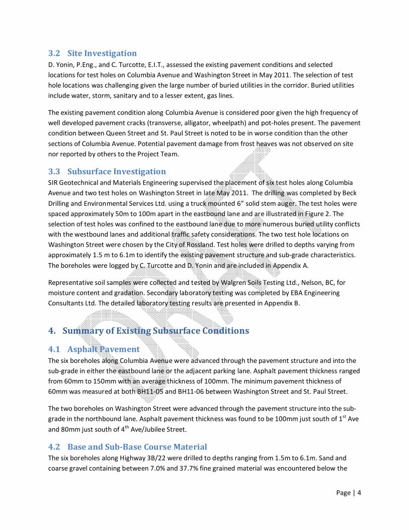
Page | 4
3.2 Site Investigation
D. Yonin, P.Eng., and C. Turcotte, E.I.T., assessed the existing pavement conditions and selected
locations for test holes on Columbia Avenue and Washington Street in May 2011. The selection of test
hole locations was challenging given the large number of buried utilities in the corridor. Buried utilities
include water, storm, sanitary and to a lesser extent, gas lines.
The existing pavement condition along Columbia Avenue is considered poor given the high frequency of
well developed pavement cracks (transverse, alligator, wheelpath) and pot-holes present. The pavement
condition between Queen Street and St. Paul Street is noted to be in worse condition than the other
sections of Columbia Avenue. Potential pavement damage from frost heaves was not observed on site
nor reported by others to the Project Team.
3.3 Subsurface Investigation
SIR Geotechnical and Materials Engineering supervised the placement of six test holes along Columbia
Avenue and two test holes on Washington Street in late May 2011. The drilling was completed by Beck
Drilling and Environmental Services Ltd. using a truck mounted 6” solid stem auger. The test holes were
spaced approximately 50m to 100m apart in the eastbound lane and are illustrated in Figure 2. The
selection of test holes was confined to the eastbound lane due to more numerous buried utility conflicts
with the westbound lanes and additional traffic safety considerations. The two test hole locations on
Washington Street were chosen by the City of Rossland. Test holes were drilled to depths varying from
approximately 1.5 m to 6.1m to identify the existing pavement structure and sub-grade characteristics.
The boreholes were logged by C. Turcotte and D. Yonin and are included in Appendix A.
Representative soil samples were collected and tested by Walgren Soils Testing Ltd., Nelson, BC, for
moisture content and gradation. Secondary laboratory testing was completed by EBA Engineering
Consultants Ltd. The detailed laboratory testing results are presented in Appendix B.
4. Summary of Existing Subsurface Conditions
4.1 Asphalt Pavement
The six boreholes along Columbia Avenue were advanced through the pavement structure and into the
sub-grade in either the eastbound lane or the adjacent parking lane. Asphalt pavement thickness ranged
from 60mm to 150mm with an average thickness of 100mm. The minimum pavement thickness of
60mm was measured at both BH11-05 and BH11-06 between Washington Street and St. Paul Street.
The two boreholes on Washington Street were advanced through the pavement structure into the sub-
grade in the northbound lane. Asphalt pavement thickness was found to be 100mm just south of 1st Ave
and 80mm just south of 4th Ave/Jubilee Street.
4.2 Base and Sub-Base Course Material
The six boreholes along Highway 3B/22 were drilled to depths ranging from 1.5m to 6.1m. Sand and
coarse gravel containing between 7.0% and 37.7% fine grained material was encountered below the
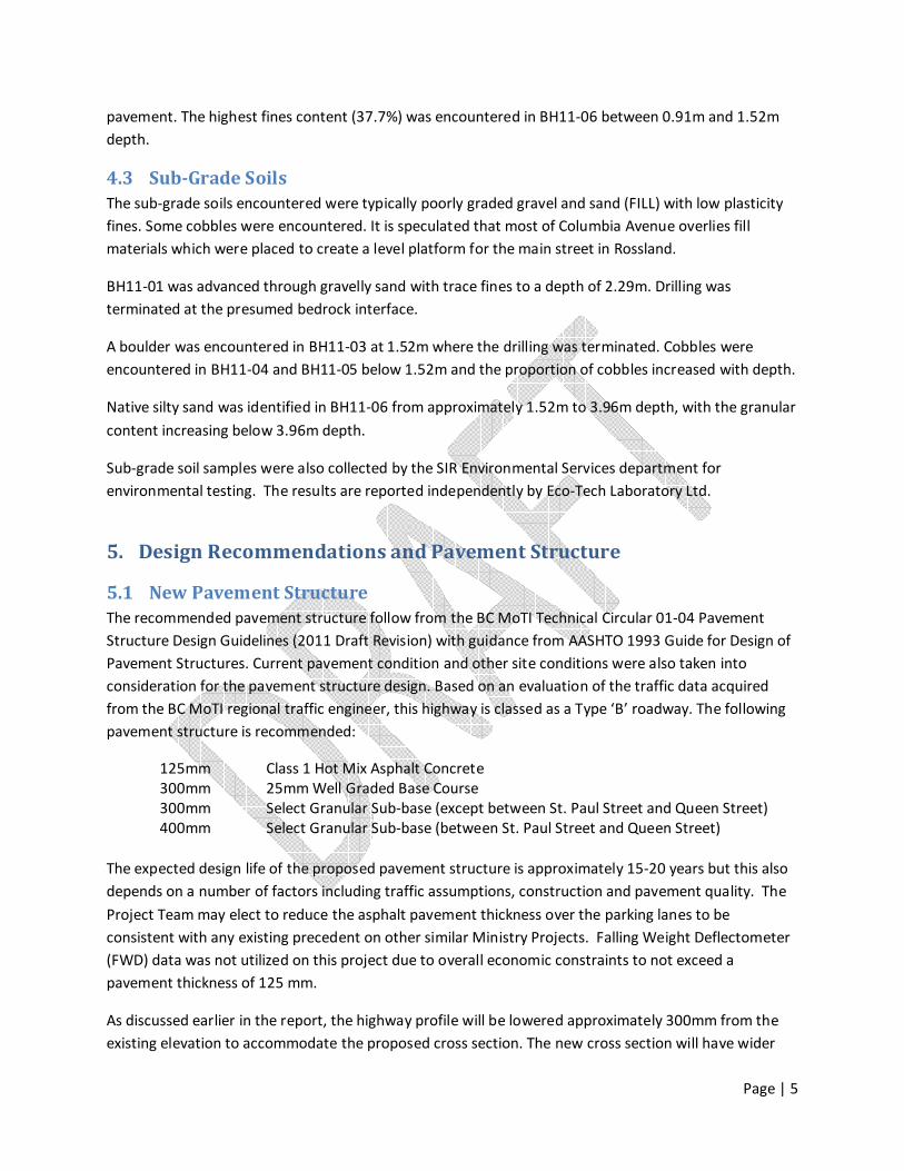
Page | 5
pavement. The highest fines content (37.7%) was encountered in BH11-06 between 0.91m and 1.52m
depth.
4.3 Sub-Grade Soils
The sub-grade soils encountered were typically poorly graded gravel and sand (FILL) with low plasticity
fines. Some cobbles were encountered. It is speculated that most of Columbia Avenue overlies fill
materials which were placed to create a level platform for the main street in Rossland.
BH11-01 was advanced through gravelly sand with trace fines to a depth of 2.29m. Drilling was
terminated at the presumed bedrock interface.
A boulder was encountered in BH11-03 at 1.52m where the drilling was terminated. Cobbles were
encountered in BH11-04 and BH11-05 below 1.52m and the proportion of cobbles increased with depth.
Native silty sand was identified in BH11-06 from approximately 1.52m to 3.96m depth, with the granular
content increasing below 3.96m depth.
Sub-grade soil samples were also collected by the SIR Environmental Services department for
environmental testing. The results are reported independently by Eco-Tech Laboratory Ltd.
5. Design Recommendations and Pavement Structure
5.1 New Pavement Structure
The recommended pavement structure follow from the BC MoTI Technical Circular 01-04 Pavement
Structure Design Guidelines (2011 Draft Revision) with guidance from AASHTO 1993 Guide for Design of
Pavement Structures. Current pavement condition and other site conditions were also taken into
consideration for the pavement structure design. Based on an evaluation of the traffic data acquired
from the BC MoTI regional traffic engineer, this highway is classed as a Type ‘B’ roadway. The following
pavement structure is recommended:
125mm Class 1 Hot Mix Asphalt Concrete
300mm 25mm Well Graded Base Course
300mm Select Granular Sub-base (except between St. Paul Street and Queen Street)
400mm Select Granular Sub-base (between St. Paul Street and Queen Street)
The expected design life of the proposed pavement structure is approximately 15-20 years but this also
depends on a number of factors including traffic assumptions, construction and pavement quality. The
Project Team may elect to reduce the asphalt pavement thickness over the parking lanes to be
consistent with any existing precedent on other similar Ministry Projects. Falling Weight Deflectometer
(FWD) data was not utilized on this project due to overall economic constraints to not exceed a
pavement thickness of 125 mm.
As discussed earlier in the report, the highway profile will be lowered approximately 300mm from the
existing elevation to accommodate the proposed cross section. The new cross section will have wider
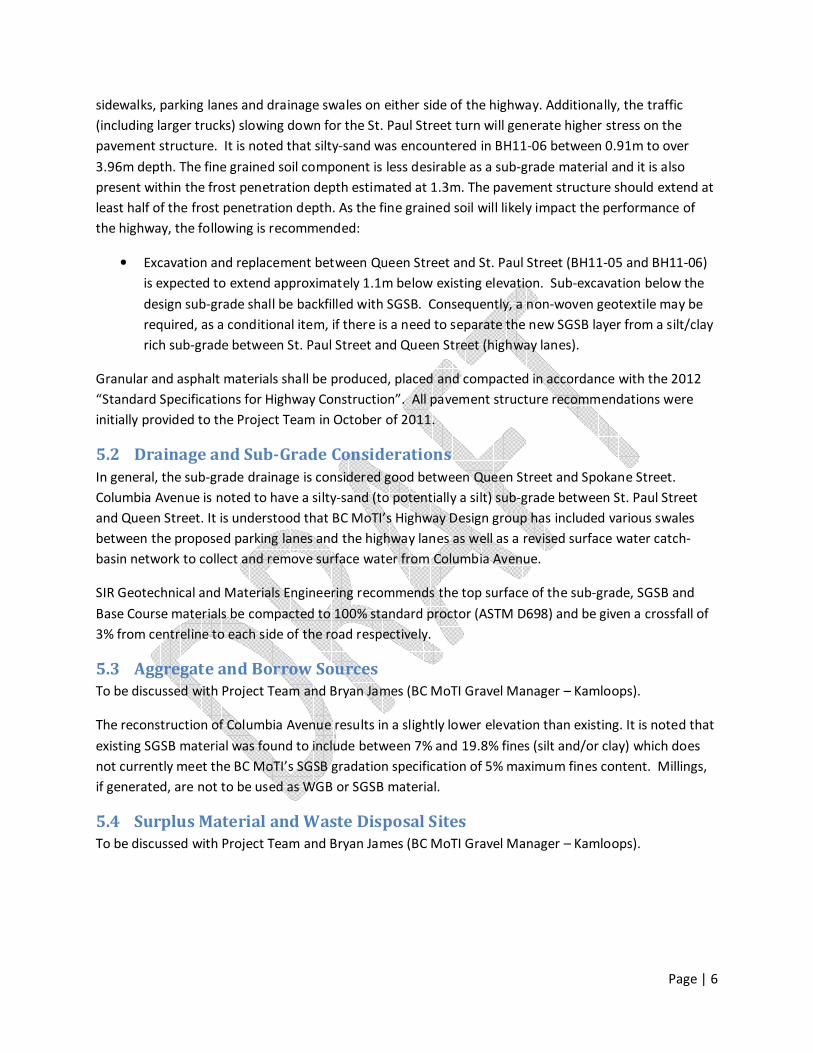
Page | 6
sidewalks, parking lanes and drainage swales on either side of the highway. Additionally, the traffic
(including larger trucks) slowing down for the St. Paul Street turn will generate higher stress on the
pavement structure. It is noted that silty-sand was encountered in BH11-06 between 0.91m to over
3.96m depth. The fine grained soil component is less desirable as a sub-grade material and it is also
present within the frost penetration depth estimated at 1.3m. The pavement structure should extend at
least half of the frost penetration depth. As the fine grained soil will likely impact the performance of
the highway, the following is recommended:
• Excavation and replacement between Queen Street and St. Paul Street (BH11-05 and BH11-06)
is expected to extend approximately 1.1m below existing elevation. Sub-excavation below the
design sub-grade shall be backfilled with SGSB. Consequently, a non-woven geotextile may be
required, as a conditional item, if there is a need to separate the new SGSB layer from a silt/clay
rich sub-grade between St. Paul Street and Queen Street (highway lanes).
Granular and asphalt materials shall be produced, placed and compacted in accordance with the 2012
“Standard Specifications for Highway Construction”. All pavement structure recommendations were
initially provided to the Project Team in October of 2011.
5.2 Drainage and Sub-Grade Considerations
In general, the sub-grade drainage is considered good between Queen Street and Spokane Street.
Columbia Avenue is noted to have a silty-sand (to potentially a silt) sub-grade between St. Paul Street
and Queen Street. It is understood that BC MoTI’s Highway Design group has included various swales
between the proposed parking lanes and the highway lanes as well as a revised surface water catch-
basin network to collect and remove surface water from Columbia Avenue.
SIR Geotechnical and Materials Engineering recommends the top surface of the sub-grade, SGSB and
Base Course materials be compacted to 100% standard proctor (ASTM D698) and be given a crossfall of
3% from centreline to each side of the road respectively.
5.3 Aggregate and Borrow Sources
To be discussed with Project Team and Bryan James (BC MoTI Gravel Manager – Kamloops).
The reconstruction of Columbia Avenue results in a slightly lower elevation than existing. It is noted that
existing SGSB material was found to include between 7% and 19.8% fines (silt and/or clay) which does
not currently meet the BC MoTI’s SGSB gradation specification of 5% maximum fines content. Millings,
if generated, are not to be used as WGB or SGSB material.
5.4 Surplus Material and Waste Disposal Sites
To be discussed with Project Team and Bryan James (BC MoTI Gravel Manager – Kamloops).
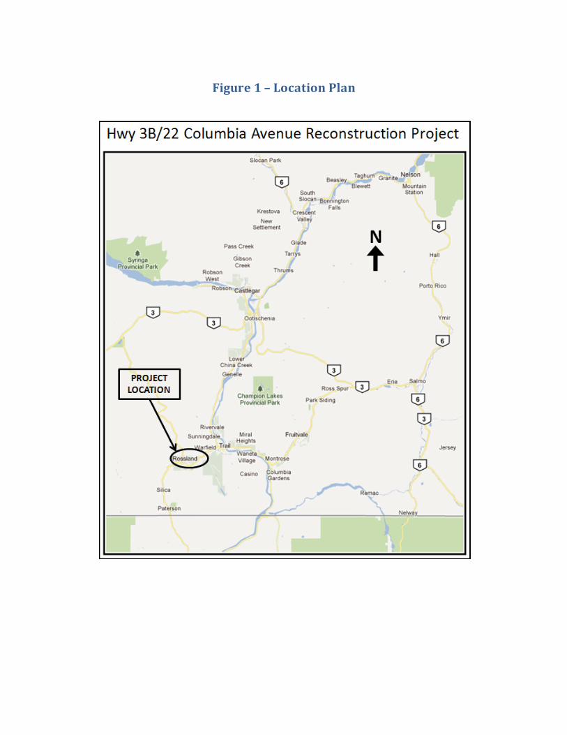
Figure 1 – Location Plan
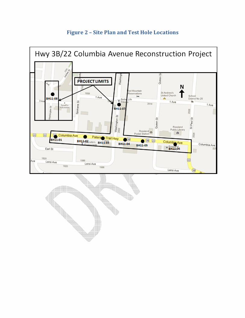
Figure 2 – Site Plan and Test Hole Locations

Appendix A – Test Hole Logs and Select Test Hole Photos

Ministry of Transportation and Infrastructure SUMMARY LOG Geotechnical and Test Hole No.
BH11 - 01
Project: Rossland Arterial GPS Coordinates: N-5436332.250 E-441306.122
Location: Hwy 3B/22; 110m west of Spokane St, EB Lane Elev. 1031.643m
Driller: Beck Drilling and Environmental Services Ltd. Inspector: CT/DY
Method: Solid stem auger Date: May 19/11
Gra
ve
l
Sa
nd
Fin
es
WL WP W
0.000.15 Asphalt pavement
0.46
1.00 G 19.0 74.0 7.0 4.8 SM1 SA#1 0.9 - 1.2m
1.52
G 3.4 SM1 SA#2 1.8 - 2.3m2.00
2.29
End of borehole: 2.29m
Note: Rock chip sample consistent with exposedrock face; No water table detected, drilling terminated at presumed bedrock interface
Shear Strength kPa Tests File No.
G - Grab U - Unconfined CompressionShear Strength kPa M - Mechanical Analysis
SS - Split Spoon Fv - Field Vane H - Hydrometer Prepared by:
ST - Shelby Tube Lv - Lab Vane C - Consolidation
PT - Piston Tube R - Remolded WL - Liquid Limit
W - Wash WP - Plastic Limit Sheet 1 of 1
W - Moisture Content
Sample Type
Materials Branch
Drilling, Well
installation, and
Blow Count
Details De
pth
(m
)
DC
PT
blo
ws/
0.3
m
Sa
mp
le T
yp
e
SP
T N
blo
ws/
0.3
m
Re
cov
ery
(m
) Gradation % Index Properties
Oth
er
Te
sts
CT
[Fill] Grey-brown, SAND,
gravelly, trace fines, dry to moist
[Fill] Grey-brown, SAND, some
gravel, trace fines, moist
[Fill] Grey-brown, SAND, trace
fines, dry to moist, sluffing 0.6m,
rock chip sample
Cla
ssif
ica
tio
n
Description
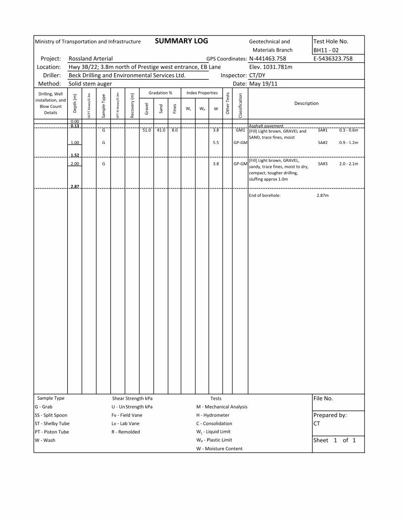
Ministry of Transportation and Infrastructure SUMMARY LOG Geotechnical and Test Hole No.
BH11 - 02
Project: Rossland Arterial GPS Coordinates: N-441463.758 E-5436323.758
Location: Hwy 3B/22; 3.8m north of Prestige west entrance, EB Lane Elev. 1031.781m
Driller: Beck Drilling and Environmental Services Ltd. Inspector: CT/DY
Method: Solid stem auger Date: May 19/11
Gra
ve
l
Sa
nd
Fin
es
WL WP W
0.000.13 Asphalt pavement
G 51.0 41.0 8.0 3.8 GM1 SA#1 0.3 - 0.6m
1.00 G 5.5 GP-GM SA#2 0.9 - 1.2m
1.52
2.00 G 3.8 GP-GM SA#3 2.0 - 2.1m
2.87
End of borehole: 2.87m
Shear Strength kPa Tests File No.
G - Grab U - Unconfined CompressionShear Strength kPa M - Mechanical Analysis
SS - Split Spoon Fv - Field Vane H - Hydrometer Prepared by:
ST - Shelby Tube Lv - Lab Vane C - Consolidation
PT - Piston Tube R - Remolded WL - Liquid Limit
W - Wash WP - Plastic Limit Sheet 1 of 1
W - Moisture Content
Sample Type
Materials Branch
Drilling, Well
installation, and
Blow Count
Details De
pth
(m
)
DC
PT
blo
ws/
0.3
m
Sa
mp
le T
yp
e
SP
T N
blo
ws/
0.3
m
Re
cov
ery
(m
) Gradation % Index Properties
Oth
er
Te
sts
CT
[Fill] Light brown, GRAVEL and
SAND, trace fines, moist
[Fill] Light brown, GRAVEL,
sandy, trace fines, moist to dry,
compact, tougher drilling,
sluffing approx 1.0m
Cla
ssif
ica
tio
n
Description
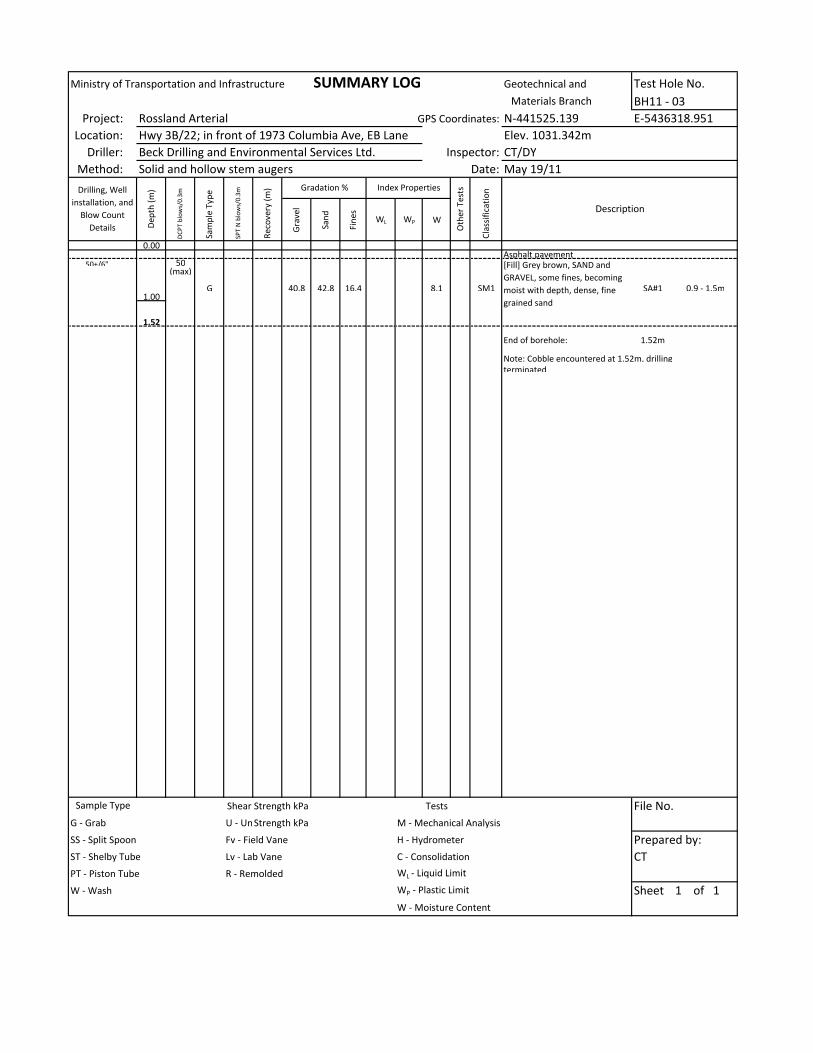
Ministry of Transportation and Infrastructure SUMMARY LOG Geotechnical and Test Hole No.
BH11 - 03
Project: Rossland Arterial GPS Coordinates: N-441525.139 E-5436318.951
Location: Hwy 3B/22; in front of 1973 Columbia Ave, EB Lane Elev. 1031.342m
Driller: Beck Drilling and Environmental Services Ltd. Inspector: CT/DY
Method: Solid and hollow stem augers Date: May 19/11
Gra
ve
l
Sa
nd
Fin
es
WL WP W
0.00Asphalt pavement
50+/6" 50(max)
G 40.8 42.8 16.4 8.1 SM1 SA#1 0.9 - 1.5m1.00
1.52
End of borehole: 1.52m
Note: Cobble encountered at 1.52m, drilling
terminated
Shear Strength kPa Tests File No.
G - Grab U - Unconfined CompressionShear Strength kPa M - Mechanical Analysis
SS - Split Spoon Fv - Field Vane H - Hydrometer Prepared by:
ST - Shelby Tube Lv - Lab Vane C - Consolidation
PT - Piston Tube R - Remolded WL - Liquid Limit
W - Wash WP - Plastic Limit Sheet 1 of 1
W - Moisture Content
Materials Branch
Drilling, Well
installation, and
Blow Count
Details De
pth
(m
)
DC
PT
blo
ws/
0.3
m
Sa
mp
le T
yp
e
SP
T N
blo
ws/
0.3
m
Re
cov
ery
(m
) Gradation % Index Properties
Oth
er
Te
sts
CT
[Fill] Grey brown, SAND and
GRAVEL, some fines, becoming
moist with depth, dense, fine
grained sand
Cla
ssif
ica
tio
n
Description
Sample Type

Ministry of Transportation and Infrastructure SUMMARY LOG Geotechnical and Test Hole No.
BH11 - 04
Project: Rossland Arterial GPS Coordinates: N-5436312.088 E-441563.049
Location: Hwy 3B/22; in front of Ferraro Foods, EB Lane Elev. 1030.949m
Driller: Beck Drilling and Environmental Services Ltd. Inspector: CT/DY
Method: Solid stem auger Date: May 19/11
Gra
ve
l
Sa
nd
Fin
es
WL WP W
0.000.08 Asphalt pavement
0.25
1.00G 37.2 53.4 9.4 10.7 SP-SM SA#1 1.1 - 1.4m
1.52
2.00
G 51.0 40.0 9.0 6.1 GM1 SA#2 2.6 - 2.9m
3.003.05
4.00
4.57
5.00
G 5.0 GP-GM SA#3 5.3 - 5.8m
6.006.10
End of borehole: 6.10m
Shear Strength kPa Tests File No.
G - Grab U - Unconfined CompressionShear Strength kPa M - Mechanical Analysis
SS - Split Spoon Fv - Field Vane H - Hydrometer Prepared by:
ST - Shelby Tube Lv - Lab Vane C - Consolidation
PT - Piston Tube R - Remolded WL - Liquid Limit
W - Wash WP - Plastic Limit Sheet 1 of 1
W - Moisture Content
Materials Branch
Drilling, Well
installation, and
Blow Count
Details De
pth
(m
)
DC
PT
blo
ws/
0.3
m
Sa
mp
le T
yp
e
SP
T N
blo
ws/
0.3
m
Re
cov
ery
(m
) Gradation % Index Properties
Oth
er
Te
sts
Cla
ssif
ica
tio
n
Description
Sample Type
CT
[Fill] Grey, SAND and GRAVEL,
moist, loose to compact
[Fill] Brownish grey, SAND and
GRAVEL, some fines, trace to
some cobbles, moist, loose to
compact, easier drilling, sluffing
0.5m, fine grained sand
[Fill] Brownish grey, GRAVEL and
SAND, some cobbles, trace silt,
moist, loose to compact, coarse
grained gravel
[Fill] Brownish-grey, SAND and
GRAVEL, cobbly increasing with
depth, trace fines, low recovery,
coarse grained gravel
[Fill] Brownish-grey, orange
mottling, SAND and GRAVEL,
cobbly increasing with depth,
trace silt, moist, compact, auger
difficult to remove, sluffing
approx 1.1m, coarse grained
gravel
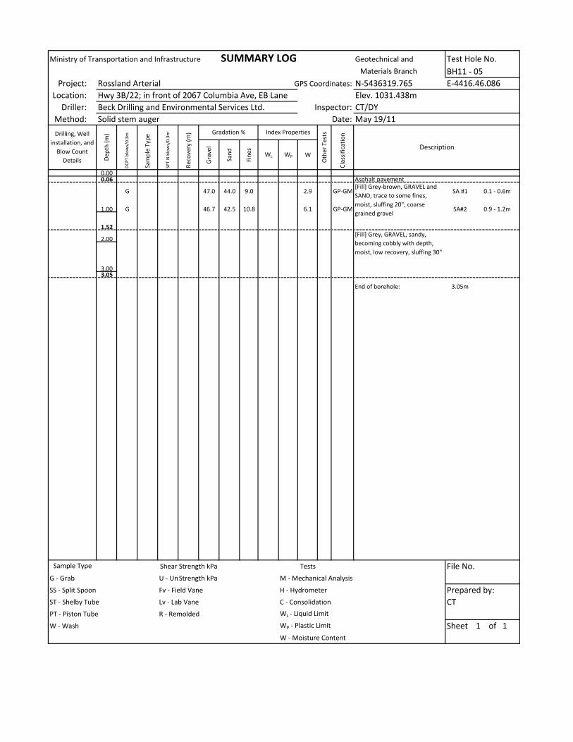
Ministry of Transportation and Infrastructure SUMMARY LOG Geotechnical and Test Hole No.
BH11 - 05
Project: Rossland Arterial GPS Coordinates: N-5436319.765 E-4416.46.086
Location: Hwy 3B/22; in front of 2067 Columbia Ave, EB Lane Elev. 1031.438m
Driller: Beck Drilling and Environmental Services Ltd. Inspector: CT/DY
Method: Solid stem auger Date: May 19/11
Gra
ve
l
Sa
nd
Fin
es
WL WP W
0.000.06 Asphalt pavement
G 47.0 44.0 9.0 2.9 GP-GM SA #1 0.1 - 0.6m
1.00 G 46.7 42.5 10.8 6.1 GP-GM SA#2 0.9 - 1.2m
1.52
2.00
3.003.05
End of borehole: 3.05m
Shear Strength kPa Tests File No.
G - Grab U - Unconfined CompressionShear Strength kPa M - Mechanical Analysis
SS - Split Spoon Fv - Field Vane H - Hydrometer Prepared by:
ST - Shelby Tube Lv - Lab Vane C - Consolidation
PT - Piston Tube R - Remolded WL - Liquid Limit
W - Wash WP - Plastic Limit Sheet 1 of 1
W - Moisture Content
Cla
ssif
ica
tio
n
Description
Materials Branch
Drilling, Well
installation, and
Blow Count
Details De
pth
(m
)
DC
PT
blo
ws/
0.3
m
Sa
mp
le T
yp
e
SP
T N
blo
ws/
0.3
m
Re
cov
ery
(m
) Gradation % Index Properties
Oth
er
Te
sts
Sample Type
CT
[Fill] Grey-brown, GRAVEL and
SAND, trace to some fines,
moist, sluffing 20", coarse
grained gravel
[Fill] Grey, GRAVEL, sandy,
becoming cobbly with depth,
moist, low recovery, sluffing 30"
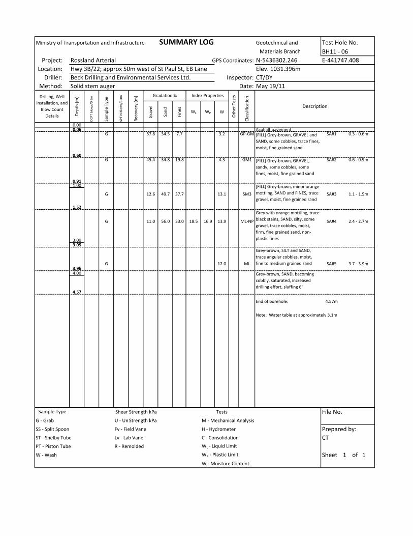
Ministry of Transportation and Infrastructure SUMMARY LOG Geotechnical and Test Hole No.
BH11 - 06
Project: Rossland Arterial GPS Coordinates: N-5436302.246 E-441747.408
Location: Hwy 3B/22; approx 50m west of St Paul St, EB Lane Elev. 1031.396m
Driller: Beck Drilling and Environmental Services Ltd. Inspector: CT/DY
Method: Solid stem auger Date: May 19/11
Gra
ve
l
Sa
nd
Fin
es
WL WP W
0.000.06 Asphalt pavement
G 57.8 34.5 7.7 3.2 GP-GM SA#1 0.3 - 0.6m
0.60
G 45.4 34.8 19.8 4.3 GM1 SA#2 0.6 - 0.9m
0.91
1.00
G 12.6 49.7 37.7 13.1 SM3 SA#3 1.1 - 1.5m
1.52
G 11.0 56.0 33.0 18.5 16.9 13.9 ML-NP SA#4 2.4 - 2.7m
3.003.05
G 12.0 ML SA#5 3.7 - 3.9m3.96
4.00
4.57
End of borehole: 4.57m
Note: Water table at approximately 3.1m
Shear Strength kPa Tests File No.
G - Grab U - Unconfined CompressionShear Strength kPa M - Mechanical Analysis
SS - Split Spoon Fv - Field Vane H - Hydrometer Prepared by:
ST - Shelby Tube Lv - Lab Vane C - Consolidation
PT - Piston Tube R - Remolded WL - Liquid Limit
W - Wash WP - Plastic Limit Sheet 1 of 1
W - Moisture Content
Sample Type
CT
Grey-brown, SAND, becoming
cobbly, saturated, increased
drilling effort, sluffing 6"
[FILL] Grey-brown, minor orange
mottling, SAND and FINES, trace
gravel, moist, fine grained sand
Grey with orange mottling, trace
black stains, SAND, silty, some
gravel, trace cobbles, moist,
firm, fine grained sand, non-
plastic fines
Grey-brown, SILT and SAND,
trace angular cobbles, moist,
fine to medium grained sand
[FILL] Grey-brown, GRAVEL and
SAND, some cobbles, trace fines,
moist, fine grained sand
[FILL] Grey-brown, GRAVEL,
sandy, some cobbles, some
fines, moist, fine grained sand
Materials Branch
Drilling, Well
installation, and
Blow Count
Details De
pth
(m
)
DC
PT
blo
ws/
0.3
m
Sa
mp
le T
yp
e
SP
T N
blo
ws/
0.3
m
Re
cov
ery
(m
) Gradation % Index Properties
Oth
er
Te
sts
Cla
ssif
ica
tio
n
Description

Ministry of Transportation and Infrastructure SUMMARY LOG Geotechnical and Test Hole No.
BH11 - 07
Project: Rossland Arterial GPS Coordinates: N-5436721.494 E-441570.466
Location: Washington St; In front of 2086 Washington St, NB Lane Elev. 1036.046m
Driller: Beck Drilling and Environmental Services Ltd. Inspector: CT/DY
Method: Solid and hollow stem augers Date: May 20/11
Gra
ve
l
Sa
nd
Fin
es
WL WP W
0.000.10 Asphalt pavement, top lift0.15 Asphalt pavement, bottom lift
39 G 38.0 50.0 12.0 5.9 SM1 SA#1 0.3 - 0.6
290.61 25
211.00
17 G 6.9 GP-GM SA#2 1.2 - 1.5
1.52 199
2.007
142.59
11 G 24.8 ML-NP SA#3 2.7 - 3.0m
3.00 143.20
2542 G 8.8 SM2 SA#4 3.6 - 3.9m
4.00 2019
4.57 3329 G 21.2 ML SA#5 4.8 - 5.1m
5.0029
5.49
40+/8" 40 G 26.0 CL-ML SA#6 5.5 - 5.8m(max)
6.006.10
End of borehole: 6.10m
Note: Water table at approximately 5.5m
Shear Strength kPa Tests File No.
G - Grab U - Unconfined CompressionShear Strength kPa M - Mechanical Analysis
SS - Split Spoon Fv - Field Vane H - Hydrometer Prepared by:
ST - Shelby Tube Lv - Lab Vane C - Consolidation
PT - Piston Tube R - Remolded WL - Liquid Limit
W - Wash WP - Plastic Limit Sheet 1 of 1
W - Moisture Content
Materials Branch
Drilling, Well
installation, and
Blow Count
Details De
pth
(m
)
DC
PT
blo
ws/
0.3
m
Sa
mp
le T
yp
e
SP
T N
blo
ws/
0.3
m
Re
cov
ery
(m
) Gradation % Index Properties
Oth
er
Te
sts
Cla
ssif
ica
tio
n
Description
Sample Type
[Fill?] Grey with orange
mottling, SILT, trace clay, very
moist to saturated, very stiff,
sluff to approximately 3.0m
CT
[Fill] Dark brown, SAND and
GRAVEL, some silt, dry to moist,
compact
[Fill] Dark brown, GRAVEL and
SAND, some silt, moist, compact
[Fill?] Dark brown, fine SAND,
gravelly, some cobbles, moist,
compact
[Fill?] Dark rusty brown, SILT,
some sand, some gravel, firm,
fine grained sand
[Fill?] Grey-brown, GRAVEL and
SAND, some cobbles, trace silt,
compact to dense
[Fill?] Grey, SAND, some silt,
trace gravel, very moist,
compact, fine grained sand
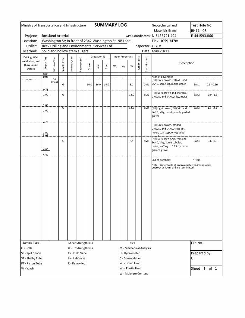
Ministry of Transportation and Infrastructure SUMMARY LOG Geotechnical and Test Hole No.
BH11 - 08
Project: Rossland Arterial GPS Coordinates: N-5436721.494 E-441593.866
Location: Washington St; In front of 2342 Washington St, NB Lane Elev. 1059.347m
Driller: Beck Drilling and Environmental Services Ltd. Inspector: CT/DY
Method: Solid and hollow stem augers Date: May 20/11
Gra
ve
l
Sa
nd
Fin
es
WL WP W
0.000.08 Asphalt pavement
70+/10" 70(max)
G 50.0 36.0 14.0 8.0 GM1 SA#1 0.3 - 0.6m
0.76
1.00 G 13.0 SM2 SA#2 0.9 - 1.3
1.68
G 12.6 SM4 SA#3 1.8 - 2.1 2.00
2.74
3.003.05
G 8.5 SM2 SA#4 3.6 - 3.9
4.00
4.42
End of borehole: 4.42m
Note: Water table at approximately 3.4m; possiblebedrock at 4.4m; drilling terminated
Shear Strength kPa Tests File No.
G - Grab U - Unconfined CompressionShear Strength kPa M - Mechanical Analysis
SS - Split Spoon Fv - Field Vane H - Hydrometer Prepared by:
ST - Shelby Tube Lv - Lab Vane C - Consolidation
PT - Piston Tube R - Remolded WL - Liquid Limit
W - Wash WP - Plastic Limit Sheet 1 of 1
W - Moisture Content
Cla
ssif
ica
tio
n
Description
Sample Type
Materials Branch
Drilling, Well
installation, and
Blow Count
Details De
pth
(m
)
DC
PT
blo
ws/
0.3
m
Sa
mp
le T
yp
e
SP
T N
blo
ws/
0.3
m
Re
cov
ery
(m
) Gradation % Index Properties
Oth
er
Te
sts
CT
[Fill] Grey-brown, GRAVEL and
SAND, some silt, moist, dense
[Fill] Dark brown and charcoal,
GRAVEL and SAND, silty, moist
[Fill] Light brown, GRAVEL and
SAND, silty, moist, poorly graded
gravel
[Fill] Grey-brown, graded
GRAVEL and SAND, trace silt,
moist, coarse/poorly graded
gravel[Fill] Dark brown, GRAVEL and
SAND, silty, some cobbles,
moist, sluffing to 0.15m, coarse
grained gravel

Borehole 11-01


Borehole 11-02

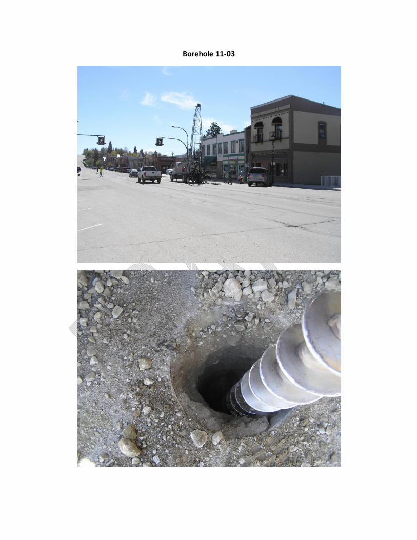
Borehole 11-03

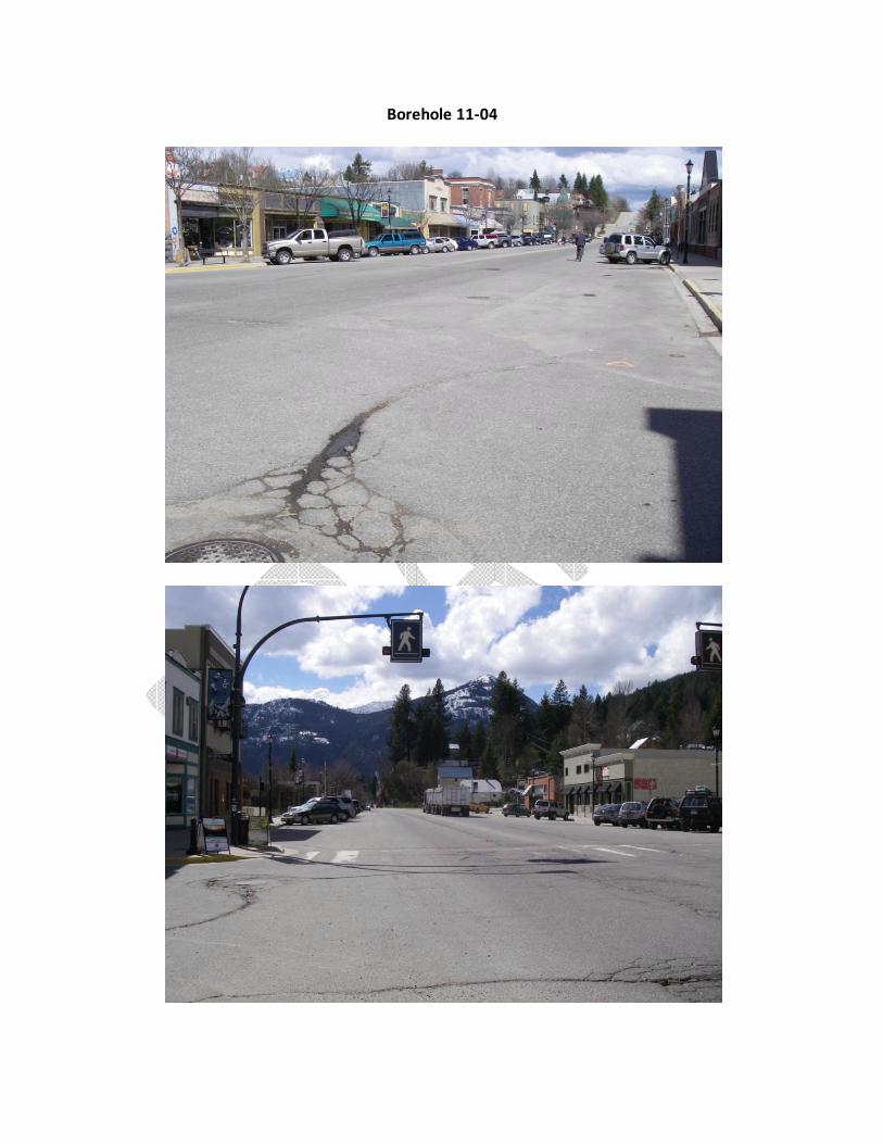
Borehole 11-04


Borehole 11-05

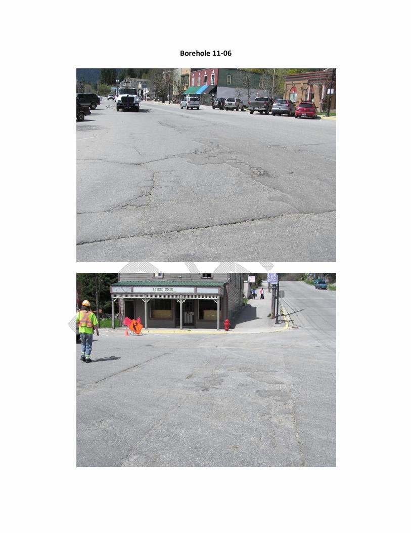
Borehole 11-06
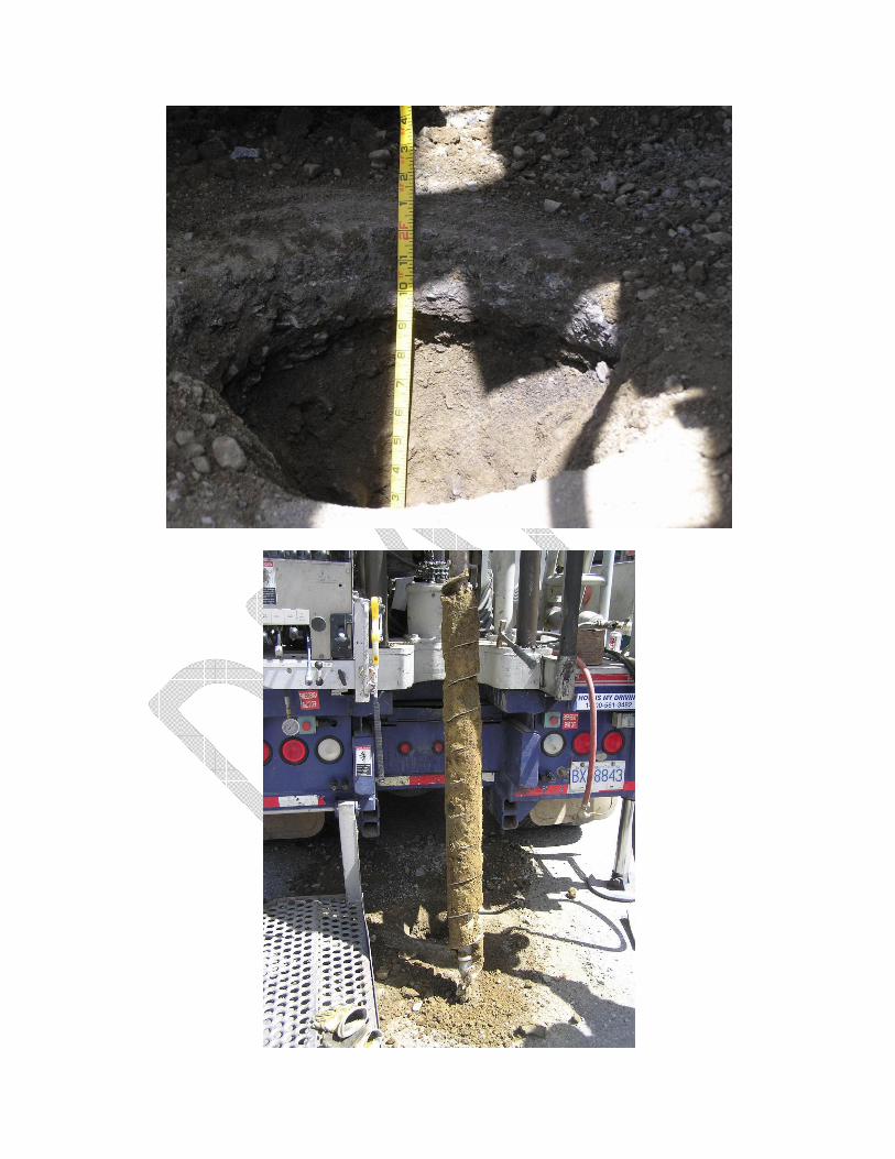
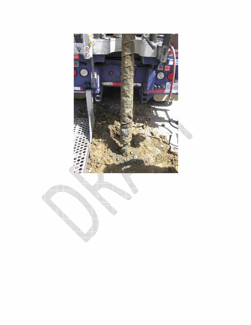

Borehole 11-07

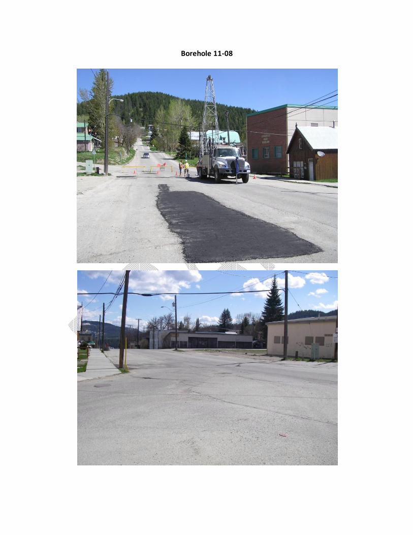
Borehole 11-08


Appendix B – Laboratory Test Results
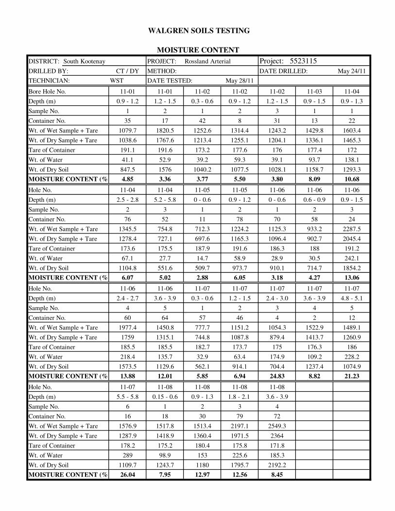
WALGREN SOILS TESTING
MOISTURE CONTENT
DISTRICT: South Kootenay PROJECT: Rossland Arterial Project: 5523115
DRILLED BY: CT / DY METHOD: DATE DRILLED: May 24/11
TECHNICIAN: WST DATE TESTED: May 28/11
Bore Hole No. 11-01 11-01 11-02 11-02 11-02 11-03 11-04
Depth (m) 0.9 - 1.2 1.2 - 1.5 0.3 - 0.6 0.9 - 1.2 1.2 - 1.5 0.9 - 1.5 0.9 - 1.3
Sample No. 1 2 1 2 3 1 1
Container No. 35 17 42 8 31 13 22
Wt. of Wet Sample + Tare 1079.7 1820.5 1252.6 1314.4 1243.2 1429.8 1603.4
Wt. of Dry Sample + Tare 1038.6 1767.6 1213.4 1255.1 1204.1 1336.1 1465.3
Tare of Container 191.1 191.6 173.2 177.6 176 177.4 172
Wt. of Water 41.1 52.9 39.2 59.3 39.1 93.7 138.1
Wt. of Dry Soil 847.5 1576 1040.2 1077.5 1028.1 1158.7 1293.3
MOISTURE CONTENT (%) 4.85 3.36 3.77 5.50 3.80 8.09 10.68
Hole No. 11-04 11-04 11-05 11-05 11-06 11-06 11-06
Depth (m) 2.5 - 2.8 5.2 - 5.8 0 - 0.6 0.9 - 1.2 0 - 0.6 0.6 - 0.9 0.9 - 1.5
Sample No. 2 3 1 2 1 2 3
Container No. 76 52 11 78 70 58 24
Wt. of Wet Sample + Tare 1345.5 754.8 712.3 1224.2 1125.3 933.2 2287.5
Wt. of Dry Sample + Tare 1278.4 727.1 697.6 1165.3 1096.4 902.7 2045.4
Tare of Container 173.6 175.5 187.9 191.6 186.3 188 191.2
Wt. of Water 67.1 27.7 14.7 58.9 28.9 30.5 242.1
Wt. of Dry Soil 1104.8 551.6 509.7 973.7 910.1 714.7 1854.2
MOISTURE CONTENT (%) 6.07 5.02 2.88 6.05 3.18 4.27 13.06
Hole No. 11-06 11-06 11-07 11-07 11-07 11-07 11-07
Depth (m) 2.4 - 2.7 3.6 - 3.9 0.3 - 0.6 1.2 - 1.5 2.4 - 3.0 3.6 - 3.9 4.8 - 5.1
Sample No. 4 5 1 2 3 4 5
Container No. 60 64 57 46 4 2 12
Wt. of Wet Sample + Tare 1977.4 1450.8 777.7 1151.2 1054.3 1522.9 1489.1
Wt. of Dry Sample + Tare 1759 1315.1 744.8 1087.8 879.4 1413.7 1260.9
Tare of Container 185.5 185.5 182.7 173.7 175 176.3 186
Wt. of Water 218.4 135.7 32.9 63.4 174.9 109.2 228.2
Wt. of Dry Soil 1573.5 1129.6 562.1 914.1 704.4 1237.4 1074.9
MOISTURE CONTENT (%) 13.88 12.01 5.85 6.94 24.83 8.82 21.23
Hole No. 11-07 11-08 11-08 11-08 11-08
Depth (m) 5.5 - 5.8 0.15 - 0.6 0.9 - 1.3 1.8 - 2.1 3.6 - 3.9
Sample No. 6 1 2 3 4
Container No. 16 18 30 79 72
Wt. of Wet Sample + Tare 1576.9 1517.8 1513.4 2197.1 2549.3
Wt. of Dry Sample + Tare 1287.9 1418.9 1360.4 1971.5 2364
Tare of Container 178.2 175.2 180.4 175.8 171.8
Wt. of Water 289 98.9 153 225.6 185.3
Wt. of Dry Soil 1109.7 1243.7 1180 1795.7 2192.2
MOISTURE CONTENT (%) 26.04 7.95 12.97 12.56 8.45

WALGREN SOILS TESTING
SOILS CLASSIFICATION
Project: Rossland Arterial Tested by: WST
District: South Kootenay Method: 0 Date Tested: May 28/11
Sampled by: CT / DY Date Sampled: May 24/11
FIELD DATA LAB DATA
SAMPLING DETAILS SOIL DESCRIPTION ATTERBERG LIMITS SOIL CLASSIFICATION
TEST HOLE SMPLE SAMPLE LAB VIS. MOIST. GRAVEL SAND FINES TOTAL SOIL SOIL
\STATION No. DEPTH (m) V.I. FIELD LAB Wt % Wt % Wt % WEIGHT LL PL PI M\C COLOUR CLASS.
11-01 1 0.9 - 1.2 SM1 Damp Damp 0.0 0.0 847.5 100.0 847.5 4.8 Lt. Brown
11-01 2 1.2 - 1.5 SM1 Damp Damp 0.0 0.0 1576.0 100.0 1576.0 3.4 Tan
11-02 1 0.3 - 0.6 SP-SM Damp Damp 0.0 0.0 1040.2 100.0 1040.2 3.8 Tan
11-02 2 0.9 - 1.2 GP-GM Damp Damp 0.0 0.0 1077.5 100.0 1077.5 5.5 Lt. Brown
11-02 3 1.2 - 1.5 GP-GM Damp Damp 0.0 0.0 1028.1 100.0 1028.1 3.8 Lt. Brown
11-03 1 0.9 - 1.5 GP-GM Damp Damp 473.0 40.8 495.5 42.8 190.2 16.4 1158.7 8.1 Lt. Brown
11-04 1 0.9 - 1.3 SM1 Wet Wet 480.9 37.2 690.2 53.4 122.2 9.4 1293.3 10.7 Brown
11-04 2 2.5 - 2.8 GM1 Damp Damp 0.0 0.0 1104.8 100.0 1104.8 6.1 Brown
11-04 3 5.2 - 5.8 GP-GM Damp Damp 0.0 0.0 551.6 100.0 551.6 5.0 Brown
11-05 1 0 - 0.6 GP-GM Damp Damp 0.0 0.0 509.7 100.0 509.7 2.9 Olve Brwn
11-05 2 0.9 - 1.2 GM1 Damp Damp 454.4 46.7 413.8 42.5 105.5 10.8 973.7 6.0 Lt. Brown
11-06 1 0 - 0.6 GP-GM Damp Damp 526.4 57.8 313.7 34.5 70.0 7.7 910.1 3.2 Lt. Brown
11-06 2 0.6 - 0.9 GM1 Damp Damp 324.2 45.4 248.8 34.8 141.7 19.8 714.7 4.3 Lt. Brown
11-06 3 0.9 - 1.5 SM2 Wet Wet 233.6 12.6 922.0 49.7 698.6 37.7 1854.2 13.1 Brown
11-06 4 2.4 - 2.7 ML Wet Wet 0.0 0.0 1573.5 100.0 1573.5 18.5 16.9 1.6 13.9 Olve Brwn
11-06 5 3.6 - 3.9 ML Wet Wet 0.0 0.0 1129.6 100.0 1129.6 12.0 Olve Brwn
11-07 1 0.3 - 0.6 GP-GM Damp Damp 0.0 0.0 562.1 100.0 562.1 5.9 Dk Brown
11-07 2 1.2 - 1.5 GP-GM Damp Damp 0.0 0.0 914.1 100.0 914.1 6.9 Dk Rd Brwn
11-07 3 2.4 - 3.0 ML-NP Wet Wet 0.0 0.0 704.4 100.0 704.4 24.8 Dk Rd Brwn
11-07 4 3.6 - 3.9 SM2 Damp Damp 0.0 0.0 1237.4 100.0 1237.4 8.8 Dk Brown
11-07 5 4.8 - 5.1 ML Wet Wet 0.0 0.0 1074.9 100.0 1074.9 21.2 Brown
11-07 6 5.5 - 5.8 CL-ML Wet Wet 0.0 0.0 1109.7 100.0 1109.7 26.0 Olve Brwn
11-08 1 0.15 - 0.6 SM1 Damp Damp 0.0 0.0 1243.7 100.0 1243.7 8.0 Vry Dk Brwn
11-08 2 0.9 - 1.3 SM2 Wet Wet 0.0 0.0 1180.0 100.0 1180.0 13.0 Dk Brown
11-08 3 1.8 - 2.1 SM4 Wet Wet 0.0 0.0 1795.7 100.0 1795.7 12.6 Olve Brwn
11-08 4 3.6 - 3.9 SM2 Wet Wet 0.0 0.0 2192.2 100.0 2192.2 8.5 Dk Brown
GP/GM
GP/GM
SM1
SP/SM
GM1
SM3
ML

WALGREN SOILS TESTING
ATTERBURG LIMITS
DISTRICT: South Kootenay PROJECT: Rossland Arterial Project # 5523115
STATION/T.H.: 11-06 SAMPLE No. 4 DEPTH: 2.4 - 2.7
TECHNICIAN: WST DATE TESTED: May 28/11
LIQUID LIMITS
Trial No. 1 2 3
No. of Blows 20 21 23
Container No. 1 2 3
Mass of Wet Sample + Tare 79.478 81.119 87.989
Mass of Dry Sample + Tare 75.887 76.655 83.169
Tare of Container 58.132 52.414 56.648
Mass of Water 3.591 4.464 4.82
Mass of Dry Soil 17.755 24.241 26.521
MOISTURE CONTENT (%) 20.225 18.415 18.174
LIQUID LIMIT 19.655 18.001 17.977
PLASTIC LIMIT
Trial No. 1
Container No. 4
Mass of Wet Sample + Tare 79.892
Mass of Dry Sample + Tare 77.488
Tare of Container 63.29
Mass of Water 2.404
Mass of Dry Soil 14.198
MOISTURE CONTENT (%) 16.932
NATURAL MOISTURE CONTENT (%): 13.88
AV LIQUID LIMIT: 18.544 PLASTICITY INDEX: 1.612
AV PLASTIC LIMIT: 16.932 LIQUIDITY INDEX: -1.893
SOIL CLASSIFICATION: ML 0-ORGANIC/1-INORGANIC: 1
0
10
20
30
40
50
60
0 10 20 30 40 50 60 70 80 90 100
PL
AS
TIC
ITY
IN
DE
X
LIQUID LIMIT
SOILS CLASSIFICATION CHART
CL CH
MH - OH
ML - OLCL-ML

Walgren Soils Testing
MECHANICAL ANALYSIS OF AGGREGATES
Project Rossland Arterial
Contract No. Description BH 11 - 03
Pit Name Location 3.5' - 5'
Material Bore Hole Source Sa # 1
Date Sampled May 19/11 By CT
Date Tested Aug. 11/11 By WST
MOISTURE DETERMINATION WASH TEST
Mass of Moist Sample g Mass of dry sample 1156 g
Mass of Dry Sample g Mass of Washed Sample 983.2 g
Loss of Moisture g Mass Lost(Passing 0.075mm) 172.8 g
% Moisture Passing 0.075mm on Dry Sieve 14.3 g
FRACTURE COUNT Total Passing 0.075mm 187.1 g
Sieve Size Mass Retained %Retained %Passing 75MM SGSB Mass Retained %Retained %Passing
75.0 100.0 100.0 0 0 100.0
50.0 75.0 100.0 0 0.0 100.0
37.5 56.0 100.0 0 0.0 100.0
25 32.0 100.0 112.6 9.7 90.3
19 15.0 100.0 48.7 4.2 86.0
12.50 7.0 100.0 100.5 8.7 77.4
9.5 0.0 100.0 74.5 6.4 70.9
4.75 0.0 100.0 136.7 11.8 59.1
2.36 0.0 100.0 110.8 9.6 49.5
1.18 0.0 100.0 90.9 7.9 41.6
0.60 0.0 100.0 75.3 6.5 35.1
0.30 0.0 15.0 77.1 6.7 28.5
0.15 0.0 10.0 78.5 6.8 21.7
0.075 0.0 5.0 63.3 5.5 16.2
PAN 187.1 16.2
TOTAL 1156
0
10
20
30
40
50
60
70
80
90
0.01 0.10 1.00 10.00 100.00
% P
AS
SIN
G
GRAIN SIZE(mm)
SIEVE ANALYSIS (WASH)

Walgren Soils Testing
MECHANICAL ANALYSIS OF AGGREGATES
Project Rossland Arterial
Contract No. Description BH 11 - 04
Pit Name Location 3.5' - 4.5'
Material Bore Hole Source Sa # 1
Date Sampled May 19/11 By CT
Date Tested Aug. 11/11 By WST
MOISTURE DETERMINATION WASH TEST
Mass of Moist Sample g Mass of dry sample 1284.6 g
Mass of Dry Sample g Mass of Washed Sample 1187.1 g
Loss of Moisture g Mass Lost(Passing 0.075mm) 97.5 g
% Moisture Passing 0.075mm on Dry Sieve 16 g
FRACTURE COUNT Total Passing 0.075mm 113.5 g
Sieve Size Mass Retained %Retained %Passing 75MM SGSB Mass Retained %Retained %Passing
75.0 100.0 100.0 0 0 100.0
50.0 75.0 100.0 0 0.0 100.0
37.5 56.0 100.0 0 0.0 100.0
25 32.0 100.0 36.5 2.8 97.2
19 15.0 100.0 108.6 8.5 88.7
12.50 7.0 100.0 104.2 8.1 80.6
9.5 0.0 100.0 80.1 6.2 74.4
4.75 0.0 100.0 151.5 11.8 62.6
2.36 0.0 100.0 113.8 8.9 53.7
1.18 0.0 100.0 229.8 17.9 35.8
0.60 0.0 100.0 96.2 7.5 28.3
0.30 0.0 15.0 98.2 7.6 20.7
0.15 0.0 10.0 85.7 6.7 14.0
0.075 0.0 5.0 66.5 5.2 8.8
PAN 113.5 8.8
TOTAL 1284.6
0
10
20
30
40
50
60
70
80
90
0.01 0.10 1.00 10.00 100.00
% P
AS
SIN
G
GRAIN SIZE(mm)
SIEVE ANALYSIS (WASH)

Walgren Soils Testing
MECHANICAL ANALYSIS OF AGGREGATES
Project Rossland Arterial
Contract No. Description BH 11 - 05
Pit Name Location 3' - 4'
Material Bore Hole Source Sa # 2
Date Sampled May 19/11 By CT
Date Tested Aug. 11/11 By WST
MOISTURE DETERMINATION WASH TEST
Mass of Moist Sample g Mass of dry sample 977.5 g
Mass of Dry Sample g Mass of Washed Sample 886.9 g
Loss of Moisture g Mass Lost(Passing 0.075mm) 90.6 g
% Moisture Passing 0.075mm on Dry Sieve 16.7 g
FRACTURE COUNT Total Passing 0.075mm 107.3 g
Sieve Size Mass Retained %Retained %Passing 75MM SGSB Mass Retained %Retained %Passing
75.0 100.0 100.0 0 0 100.0
50.0 75.0 100.0 0 0.0 100.0
37.5 56.0 100.0 0 0.0 100.0
25 32.0 100.0 144 14.7 85.3
19 15.0 100.0 28.8 2.9 82.3
12.50 7.0 100.0 89.2 9.1 73.2
9.5 0.0 100.0 63 6.4 66.8
4.75 0.0 100.0 159.4 16.3 50.4
2.36 0.0 100.0 117.5 12.0 38.4
1.18 0.0 100.0 74.3 7.6 30.8
0.60 0.0 100.0 48.3 4.9 25.9
0.30 0.0 15.0 45 4.6 21.3
0.15 0.0 10.0 51.7 5.3 16.0
0.075 0.0 5.0 49 5.0 11.0
PAN 107.3 11.0
TOTAL 977.5
0
10
20
30
40
50
60
70
80
90
0.01 0.10 1.00 10.00 100.00
% P
AS
SIN
G
GRAIN SIZE(mm)
SIEVE ANALYSIS (WASH)

Walgren Soils Testing
MECHANICAL ANALYSIS OF AGGREGATES
Project Rossland Arterial
Contract No. Description BH 11 - 06
Pit Name Location 1' - 2'
Material Bore Hole Source Sa # 1
Date Sampled May 19/11 By CT
Date Tested Aug. 11/11 By WST
MOISTURE DETERMINATION WASH TEST
Mass of Moist Sample g Mass of dry sample 911.5 g
Mass of Dry Sample g Mass of Washed Sample 848.3 g
Loss of Moisture g Mass Lost(Passing 0.075mm) 63.2 g
% Moisture Passing 0.075mm on Dry Sieve 8.2 g
FRACTURE COUNT Total Passing 0.075mm 71.4 g
Sieve Size Mass Retained %Retained %Passing 75MM SGSB Mass Retained %Retained %Passing
75.0 100.0 100.0 0 0 100.0
50.0 75.0 100.0 0 0.0 100.0
37.5 56.0 100.0 127 13.9 86.1
25 32.0 100.0 64.5 7.1 79.0
19 15.0 100.0 46.4 5.1 73.9
12.50 7.0 100.0 146.7 16.1 57.8
9.5 0.0 100.0 54.9 6.0 51.8
4.75 0.0 100.0 86.9 9.5 42.2
2.36 0.0 100.0 66.4 7.3 35.0
1.18 0.0 100.0 71.4 7.8 27.1
0.60 0.0 100.0 54.2 5.9 21.2
0.30 0.0 15.0 48.1 5.3 15.9
0.15 0.0 10.0 38.6 4.2 11.7
0.075 0.0 5.0 35 3.8 7.8
PAN 71.4 7.8
TOTAL 911.5
0
10
20
30
40
50
60
70
80
90
0.01 0.10 1.00 10.00 100.00
% P
AS
SIN
G
GRAIN SIZE(mm)
SIEVE ANALYSIS (WASH)
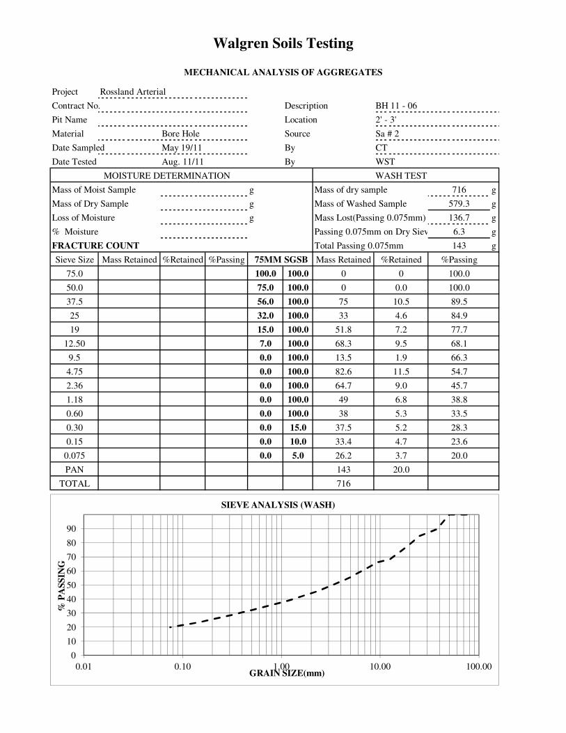
Walgren Soils Testing
MECHANICAL ANALYSIS OF AGGREGATES
Project Rossland Arterial
Contract No. Description BH 11 - 06
Pit Name Location 2' - 3'
Material Bore Hole Source Sa # 2
Date Sampled May 19/11 By CT
Date Tested Aug. 11/11 By WST
MOISTURE DETERMINATION WASH TEST
Mass of Moist Sample g Mass of dry sample 716 g
Mass of Dry Sample g Mass of Washed Sample 579.3 g
Loss of Moisture g Mass Lost(Passing 0.075mm) 136.7 g
% Moisture Passing 0.075mm on Dry Sieve 6.3 g
FRACTURE COUNT Total Passing 0.075mm 143 g
Sieve Size Mass Retained %Retained %Passing 75MM SGSB Mass Retained %Retained %Passing
75.0 100.0 100.0 0 0 100.0
50.0 75.0 100.0 0 0.0 100.0
37.5 56.0 100.0 75 10.5 89.5
25 32.0 100.0 33 4.6 84.9
19 15.0 100.0 51.8 7.2 77.7
12.50 7.0 100.0 68.3 9.5 68.1
9.5 0.0 100.0 13.5 1.9 66.3
4.75 0.0 100.0 82.6 11.5 54.7
2.36 0.0 100.0 64.7 9.0 45.7
1.18 0.0 100.0 49 6.8 38.8
0.60 0.0 100.0 38 5.3 33.5
0.30 0.0 15.0 37.5 5.2 28.3
0.15 0.0 10.0 33.4 4.7 23.6
0.075 0.0 5.0 26.2 3.7 20.0
PAN 143 20.0
TOTAL 716
0
10
20
30
40
50
60
70
80
90
0.01 0.10 1.00 10.00 100.00
% P
AS
SIN
G
GRAIN SIZE(mm)
SIEVE ANALYSIS (WASH)
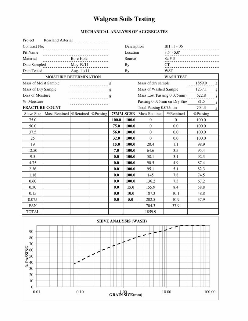
Walgren Soils Testing
MECHANICAL ANALYSIS OF AGGREGATES
Project Rossland Arterial
Contract No. Description BH 11 - 06
Pit Name Location 3.5' - 5.0'
Material Bore Hole Source Sa # 3
Date Sampled May 19/11 By CT
Date Tested Aug. 11/11 By WST
MOISTURE DETERMINATION WASH TEST
Mass of Moist Sample g Mass of dry sample 1859.9 g
Mass of Dry Sample g Mass of Washed Sample 1237.1 g
Loss of Moisture g Mass Lost(Passing 0.075mm) 622.8 g
% Moisture Passing 0.075mm on Dry Sieve 81.5 g
FRACTURE COUNT Total Passing 0.075mm 704.3 g
Sieve Size Mass Retained %Retained %Passing 75MM SGSB Mass Retained %Retained %Passing
75.0 100.0 100.0 0 0 100.0
50.0 75.0 100.0 0 0.0 100.0
37.5 56.0 100.0 0 0.0 100.0
25 32.0 100.0 0 0.0 100.0
19 15.0 100.0 20.4 1.1 98.9
12.50 7.0 100.0 64.6 3.5 95.4
9.5 0.0 100.0 58.1 3.1 92.3
4.75 0.0 100.0 90.5 4.9 87.4
2.36 0.0 100.0 95.1 5.1 82.3
1.18 0.0 100.0 145 7.8 74.5
0.60 0.0 100.0 136.2 7.3 67.2
0.30 0.0 15.0 155.9 8.4 58.8
0.15 0.0 10.0 187.3 10.1 48.8
0.075 0.0 5.0 202.5 10.9 37.9
PAN 704.3 37.9
TOTAL 1859.9
0
10
20
30
40
50
60
70
80
90
0.01 0.10 1.00 10.00 100.00
% P
AS
SIN
G
GRAIN SIZE(mm)
SIEVE ANALYSIS (WASH)

QUICK WASH TEST RESULT SUMMARY
Project No: KI 31 01 329.063 Sample No.: 5374 to 5380
Project: Rossland Arterial Project No. 5523115 Date Sampled: N/A
Client: BC Ministry of Transportation Sampled By: N/A
Date Tested: 3-Nov-I I
Attention: CarcynTurcotte Fax: N/A Tested By: SK
Email: Carolyn.turcottecqov.bc.ca Office: Kelowna
Description: Various borehole samples
Source: Provided by client
Sample Location: Rossland_Arterial Project
Supplier: Native
BH I Depth Sample No. Quick Wash Test Results
BHII-0I SAl5374 Sand (74%) Gravel (19%) Fines (7%)3 - 4’
BHII-02 SAl5375 Gravel (51%) Sand (41%) Fines (8%)I - 2’
BHI1-05 SAl5376 Gravel (47%) Sand (44%) Fines (9%)0 - 2’
BHII-04 SA25377 Gravel (51%) Sand (40%) Fines (9%)8.5 - 9.5’
BHI 1 -06 SA4 Sand (56%) Fines (33%) Gravel (11%)53788 - 9’ Atterberg Limits Test (ASTM 04318) Result: NON PLASTIC
BHII-07 SAl5379 Sand (50%) Gravel (38%) Fines (12%)
I - 2’
BHII-08 SAl5380 Gravel (50%) Sand (36%) Fines (14%)0.5 - 2’
Remarks:
Reviewed By:
_______________________
Data presented hereon is for the sole use of the stipulated client. EBA is not responsible, nor ran be held liable, for use made of this report by
any other party, with or settliout the knowledge of EBAThe testing services reported hereto have been performed by an EBA technician to
eecogntzed indttstsy standards, unless otherwtse noted. “in other warranty is made. These data do nor ittclude or represent any inrerpretation or
opmton of specification compliance or material suitability. Should engtneering interpretation be required, EI3A will provide it upon written reqursc A TETRA TECH COMPANY

City of Rossland Columbia Avenue Infrastructure Improvements
Construction Management Requirements (CMR) – Appendix 7
January, 2012
Table of Contents
Table of Contents
1.0 Rationale 1 1.1 Traffic Management Plan 1 1.2 Motor Vehicle Act Hours of Service 4 1.3 Traffic Management of Oversize Vehicle Loads 4
2.0 Project Overview 6 2.1 Project Description 6 2.2 Location 6 2.3 Methodology 6 2.4 Hours of Work 13
3.0 Traffic Control Implementation 15 3.1 Construction Staging – Columbia Avenue 15 3.2 Construction Staging – Washington Street 16 3.3 Transit 16 3.4 Truck Routes and Staging 16 3.5 Advanced Warning 17 3.6 Access to Businesses 17 3.7 Site Protection 17 3.8 Layout 17 3.9 Plan Updates and Modifications 18 3.10 Traffic Manager 18 3.11 Traffic Control Supervisor 18
4.0 Public Information Plan 20
5.0 Incident Management Plan 22 5.1 Notification 23 5.2 Emergency contact 23 5.3 Emergency Responder Access 23 5.4 Resuming Traffic 23 5.5 Incident Management Report 23 5.6 Contact Information 24

City of Rossland Columbia Avenue Infrastructure Improvements
Construction Management Requirements (CMR) – Appendix 7
January, 2012
Page 1
1.0 Rationale
This Construction Management Requirements (CMR) has been created as a guideline for construction works related to the Infrastructure Improvements in the City of Rossland (COR). The Contractors awarded the aforementioned works are responsible for reviewing this document, developing Traffic Management Plans (TMP’s) to suit the Contractor’s work program, and obtaining approvals from the Contract Administrator and any relevant agencies prior to construction works affecting traffic. The Construction Management Requirements (CMR) outlines traffic-related procedures and requirements for various phases of the project, including specific traffic control measures, procedures concerning public information, and responsibilities of key personnel. This document is designed in observation that the Contractor shall develop and implement their approved Traffic Control Plans in accordance with the following guidelines and standards:
MoT Traffic Management Guidelines for Work on Roadways (Category 4 specifications)
MoT Traffic Control Manual for Work on Roadways TAC Manual of Uniform Traffic Control Devices of Canada Ministry of Transportation’s Manual of Standard Traffic Signs and Pavement
Markings Ministry of Transportation Standard Specifications Section 194 TAC Geometric Design Guide for Canadian Roads BC Supplement to the TAC Geometric Design Guide.
The contractor’s independent Traffic Management Plans, and any related traffic control drawings will be required to have an engineering seal by a Professional Engineer licensed in the Province of British Columbia. During the tender phase, all questions should be directed through ISL Engineering and Land Services in writing and not through the individual agencies. This part of the project is part of the provincial highway network, and therefore, the following MoT traffic requirements will have to be followed: Traffic Management will comply with SS 194 except as specified below.
1.1 Traffic Management Plan
In accordance with SS 194.11, this Project is a Category 4 as defined in the Traffic Management Guidelines for Work on Roadways manual. The Traffic Management Plan requires the following documentation:
Traffic control plan Public information plan Incident management plan Implementation plan
City of Rossland Columbia Avenue Infrastructure Improvements
Construction Management Requirements (CMR) – Appendix 7
January, 2012
Page 2
For the convenience of the Contractor, a sample Traffic Control Plan template and the Traffic Management Guidelines for Work on Roadways Manual may be obtained from the Ministry website. The Contractor will ensure that all relevant factors, whether included on the sample sheet or not, are addressed prior to implementing each individual Traffic Control Plan.
1. Provisions for Traffic In accordance with SS 194.11, the following traffic engineering requirements must be incorporated into all traffic control plans unless otherwise approved by the Contract Administrator.
General a. A flashing arrow board is to be used at all lane drop locations. b. Where excavations are made adjacent to a traveled lane, causing a drop
off which is or could be hazardous to public traffic, the Contractor will either place CRB to separate the traffic from the hazard, or backfill the excavation and install Select Granular Sub-base shaped to eliminate the hazard prior to the end of each shift.
c. The Contractor will be required to provide two Portable Changeable Message Signs (PCMS), to be used to inform highway traffic of existing and anticipated conditions. PCMS and Changeable Message Signs (CMS) are to be used from April 1, 2012 to September 30, 2012 or Total Completion, whichever is later, and comply with SS 194.46. In addition, the Portable Changeable Message Signs shall be Precision Solar Controls, SMC full matrix (solar powered message centre) or equivalent. Portable Changeable Message Signs (PCMSs) shall be operated in accordance with Technical Circular T-16/06 http://www.th.gov.bc.ca/publications/Circulars/Current/T_Circ/2006/t16-06.pdf.
d. The Contractor shall supply and install the “Barrier Removed” (C-069 [http://www.th.gov.bc.ca/publications/eng_publications/signs/Construction_Signs.pdf]) signs in advance of construction zones on roadways where median and/or roadside barrier have been temporary removed. When used in advance of the construction zone, the C-069 sign may be tabbed with the C-139-Tu “FOR ____ km” sign that indicates the total distance covered by the construction project.
e. The Contractor shall supply and install the appropriate Idle Reduction Sign during daytime traffic stoppages at each stoppage zone or an approved alternative to discourage idling of engines. The P-081-Tb “Daylight Hours Only” tab shall be installed if traffic stoppages occur before or extend beyond daylight hours. Sign application and placement shall be in accordance with Technical Circular T-08/08 – Idle Reduction Signs, http://www.th.gov.bc.ca/publications/Circulars/Current/T_Circ/2008/t08-08.pdf. This is an initiative by the Ministry to reduce greenhouse gas emissions from the Project. These signs are to be included in the Contractor’s Traffic Management Plan and shown on Traffic Control Plans.

City of Rossland Columbia Avenue Infrastructure Improvements
Construction Management Requirements (CMR) – Appendix 7
January, 2012
Page 3
Speed Limits for Public Traffic and Safe Passage through the Work Use "Speed Limits for Public Traffic" only when construction of the Project will significantly affect traffic on the highway and the current regulatory speed limit exceeds 50 km/h. Where the Contract Administrator and District Manager, Transportation and Infrastructure consider it appropriate, a construction speed zone giving an overall reduction in speed limit may be granted, to a speed of not less than 30 km/h.
Route 22/3B Class of Roadway: Arterial
a. Minimum posted work zone speed limit: 50 km/h b. Minimum temporary construction zone speed limit: 30km/h c. Minimum number of lanes opened in each direction: One d. Detour Requirements will be in accordance with SS 194.27. The
minimum design requirements for any detours are specified as follows: i. design speed ii. design vehicle iii. use of active devices iv. number/types of lanes v. geometric details (i.e. lane widths, shoulder widths, min. tapers, vi. grades, min. radii etc.)
e. Provisions for Traffic during a seasonal shut down are to be in accordance with SS 194.29. The Site is to be left in a condition as specified below:
i. Site must be left in a safe and functional condition meeting the following criteria or as considered acceptable by the Ministry Representative.
ii. (insert the criteria) iii. Safety Apparel and Traffic Control Retro-Reflectivity Signs and
Devices f. The Contractor will be required to provide zero Speed Reader Boards for
use when flag persons/traffic control persons are controlling traffic. The deployment of the SRB’s with regards to application and placement shall be in accordance with the DRAFT Technical Circular Guidelines in Appendix on the Use of Speed Reader Boards (SRB) in Work Zones O:\CMB\RCS-Const\construc\Manual2008Restored\SpecProv\SpecProvAppendix\SPAmendments 2012\T-Circ - Speed Display Signs for Work Zones (Draft ver1_Jun 17_2011) (2).pdf
Payment In accordance with SS 194.61, Traffic Management is incidental to the Works and no payment will be made. The provision and removal of temporary pavement markings will be incidental to the works and no payment will be made.
2. The safety apparel and traffic control retro-reflectivity signs and devices
referenced in the Traffic Control Manual for Work on Roadways (TCM) have been revised as per Technical Circular T-09/05 http://www.th.gov.bc.ca/publications/Circulars/Current/T_Circ/2005/t09-05.pdf, and shall apply to all Work under this Contract.
City of Rossland Columbia Avenue Infrastructure Improvements
Construction Management Requirements (CMR) – Appendix 7
January, 2012
Page 4
1.2 Motor Vehicle Act Hours of Service
Solely for the purposes of the Motor Vehicle Act Regulations – Division 37, Part 3 Hours of Service, Section 37.11(h) the “site of the work” referenced therein shall include the Site and, subject to the approval in writing of the Contract Administrator, any of the following areas as the Contractor may explicitly request in writing as desired “Extensions to the site of the work”
a. any Contractor-provided pits, quarries, crusher or asphalt plant sites, and b. such highway rights-of-way for the entire distance from a Limit of Construction to
the property boundary of a Ministry- or Contactor-provided pit, quarry, crusher or asphalt plant site, up to a maximum cumulative length of thirty (30) km,
c. Where you can pre-determine the acceptability of having a haul route included within the Site, provide details below. It is recommended that the major routes around each Site and routes to established local aggregate sources/plant sites be assessed prior to Tender for every Contract.
Permitted:
1. e.g. Highway #xx southbound 2. e.g. Anywhere Road, up to 10 km from Highway #xx 3. all other routes
Not permitted:
1. e.g. Highway #yy 2. e.g. Anywhere Road, from Highway # to
1.3 Traffic Management of Oversize Vehicle Loads
The Contractor shall maintain the following minimum clearance envelope(s) through the construction site:
1. Highway 3B/22 – Minimum Width = 5 metres, Minimum Height = No Height Restrictions
The Contractor will notify the Provincial Highway Conditions Centre (PHCC) about clearance envelopes (including if there are no restrictions) that will be imposed on traffic passing through the construction site at least five business days before starting construction. The Contractor will further notify the Provincial Permit Centre about any subsequent changes to clearance envelopes. Notification shall occur at least five business days before any changes to clearance envelopes occur. The Contractor shall provide the following information in their notification to the Provincial Permit Centre:
Project name Project contact person and their contact information Project location Highway number Duration of the project Width restriction = (NONE, or if restricted, what dimensions are allowed, when in
effect, and for what duration) Height restriction = (NONE, or if restricted, what dimensions are allowed, when in
effect, and for what duration) A map indicating the closest alternative route around the clearance restriction
able to accommodate up to 4.8 m height and 5.0 m wide.
City of Rossland Columbia Avenue Infrastructure Improvements
Construction Management Requirements (CMR) – Appendix 7
January, 2012
Page 5
If construction requires a vertical clearance less than 5.0 metres or a narrowing of the existing horizontal clearance, the Contractor shall provide signage in accordance with the Ministry’s Manual of Standard Traffic Signs & Pavement Markings available at the following ULR: http://www.th.gov.bc.ca/publications/eng_publications/electrical/MoST_PM.pdf The Contractor shall cooperate with haulers of oversized load to facilitate the passage of these loads through the construction site whenever this can be reasonably accommodated by the Contractor. Contact: [email protected]

City of Rossland Columbia Avenue Infrastructure Improvements
Construction Management Requirements (CMR) – Appendix 7
January, 2012
Page 6
2.0 Project Overview
2.1 Project Description
To address the aging of the downtown core and substandard infrastructure, the COR has planned a revitalization project for Columbia Avenue between Spokane Street and St. Paul Street and for Washington Street from Columbia Avenue to First Avenue. The objective is to bring the existing roadway up to a 20 year design life and improve the pedestrian friendliness of the downtown core. The work includes road rehabilitation, underground utility upgrading and sidewalk replacement and downtown core beautification. Construction is scheduled for 2012-04 to 2012-09.
2.2 Location
2.2.1 Current Configuration
Columbia Avenue Columbia Avenue is a wide 2-lane urban highway in an east - west direction, with accesses to many retail and commercial developments along the corridor. Angle parking is permitted on Columbia Avenue. High traffic generators along Columbia Avenue include commercial development and a major commuting route connecting the City of Trail to Red Mountain and the U.S. border. Columbia Avenue is a primary link between the City of Trail and points west in B.C. Angle parking and parallel parking is permitted. BC Transit has a scheduled bus route on this corridor with three existing bus stops. The Construction zone will extend from just west of Spokane Street to the west to St. Paul Street to the east. Washington Street Washington Street is a two-lane urban collector running in the north - south direction, with accesses to commercial businesses and connects residential traffic from First Avenue to Columbia Avenue. Parallel parking is permitted. Washington Street is a BC Transit bus route. The Construction zone will extend from First Avenue to the north to Columbia Avenue to the south.
2.3 Methodology
To provide for parking in the downtown core, all proposed external parking lots are to be constructed to a gravel surface and parking designation put in place before parking is disrupted along Columbia Avenue. The external parking lots are to be capped with asphalt millings as soon as they become available. Single-lane, each direction, is to be maintained except with approval from the Contract Administrator. It is envisioned that the construction will be completed in five (5) phases. Activities for each phase and related traffic control measures as prescribed in the following charts:
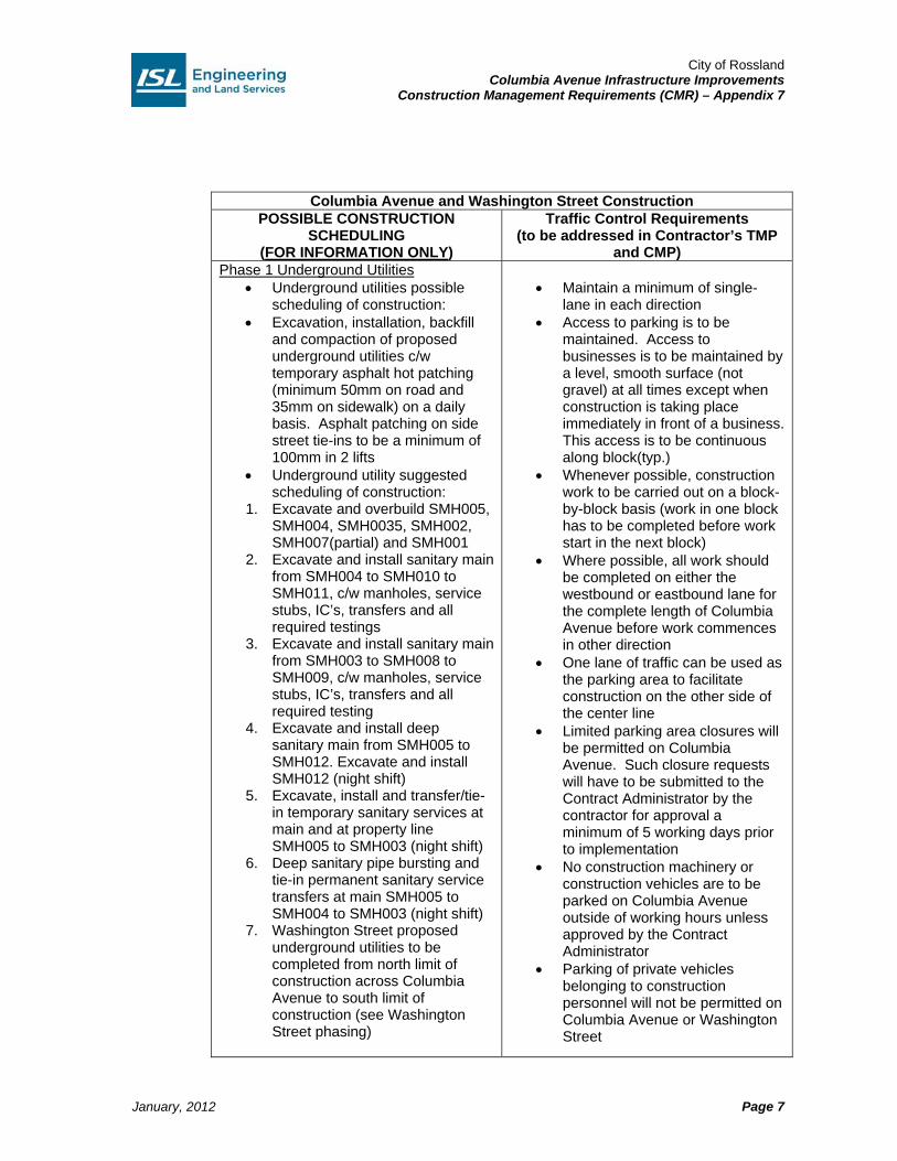
City of Rossland Columbia Avenue Infrastructure Improvements
Construction Management Requirements (CMR) – Appendix 7
January, 2012
Page 7
Columbia Avenue and Washington Street Construction POSSIBLE CONSTRUCTION
SCHEDULING (FOR INFORMATION ONLY)
Traffic Control Requirements (to be addressed in Contractor’s TMP
and CMP) Phase 1 Underground Utilities
Underground utilities possible scheduling of construction:
Excavation, installation, backfill and compaction of proposed underground utilities c/w temporary asphalt hot patching (minimum 50mm on road and 35mm on sidewalk) on a daily basis. Asphalt patching on side street tie-ins to be a minimum of 100mm in 2 lifts
Underground utility suggested scheduling of construction:
1. Excavate and overbuild SMH005, SMH004, SMH0035, SMH002, SMH007(partial) and SMH001
2. Excavate and install sanitary main from SMH004 to SMH010 to SMH011, c/w manholes, service stubs, IC’s, transfers and all required testings
3. Excavate and install sanitary main from SMH003 to SMH008 to SMH009, c/w manholes, service stubs, IC’s, transfers and all required testing
4. Excavate and install deep sanitary main from SMH005 to SMH012. Excavate and install SMH012 (night shift)
5. Excavate, install and transfer/tie-in temporary sanitary services at main and at property line SMH005 to SMH003 (night shift)
6. Deep sanitary pipe bursting and tie-in permanent sanitary service transfers at main SMH005 to SMH004 to SMH003 (night shift)
7. Washington Street proposed underground utilities to be completed from north limit of construction across Columbia Avenue to south limit of construction (see Washington Street phasing)
Maintain a minimum of single-
lane in each direction Access to parking is to be
maintained. Access to businesses is to be maintained by a level, smooth surface (not gravel) at all times except when construction is taking place immediately in front of a business. This access is to be continuous along block(typ.)
Whenever possible, construction work to be carried out on a block-by-block basis (work in one block has to be completed before work start in the next block)
Where possible, all work should be completed on either the westbound or eastbound lane for the complete length of Columbia Avenue before work commences in other direction
One lane of traffic can be used as the parking area to facilitate construction on the other side of the center line
Limited parking area closures will be permitted on Columbia Avenue. Such closure requests will have to be submitted to the Contract Administrator by the contractor for approval a minimum of 5 working days prior to implementation
No construction machinery or construction vehicles are to be parked on Columbia Avenue outside of working hours unless approved by the Contract Administrator
Parking of private vehicles belonging to construction personnel will not be permitted on Columbia Avenue or Washington Street
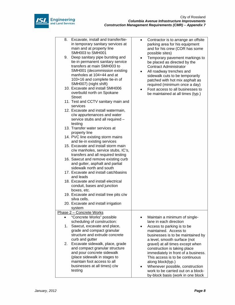
City of Rossland Columbia Avenue Infrastructure Improvements
Construction Management Requirements (CMR) – Appendix 7
January, 2012
Page 8
8. Excavate, install and transfer/tie-in temporary sanitary services at main and at property line SMH003 to SMH001
9. Deep sanitary pipe bursting and tie-in permanent sanitary service transfers at main SMH003 to SMH001 (decommission existing manholes at 104+44 and at 103+16 and complete tie-in of SMH007) (night shift)
10. Excavate and install SMH006 overbuild north on Spokane Street
11. Test and CCTV sanitary main and services
12. Excavate and install watermain, c/w appurtenances and water service stubs and all required – testing
13. Transfer water services at property line
14. PVC line existing storm mains and tie-in existing services
15. Excavate and install storm main c/w manholes, service stubs, IC’s, transfers and all required testing
16. Sawcut and remove existing curb and gutter, asphalt and partial sidewalk north and south
17. Excavate and install catchbasins and leads
18. Excavate and install electrical conduit, bases and junction boxes, etc.
19. Excavate and install tree pits c/w silva cells.
20. Excavate and install irrigation system
Contractor is to arrange an offsite parking area for his equipment and for his crew (COR has some possible sites)
Temporary pavement markings to be placed as directed by the Contract Administrator
All roadway trenches and sidewalk cuts to be temporarily patched with hot mix asphalt as required (minimum once a day)
Foot access to all businesses to be maintained at all times (typ.)
Phase 2 – Concrete Works “Concrete Works” possible
scheduling of construction: 1. Sawcut, excavate and place,
grade and compact granular structure and extrude concrete curb and gutter
2. Excavate sidewalk, place, grade and compact granular structure and pour concrete sidewalk (place sidewalk in stages to maintain foot access to all businesses at all times) c/w testing
Maintain a minimum of single-
lane in each direction Access to parking is to be
maintained. Access to businesses is to be maintained by a level, smooth surface (not gravel) at all times except when construction is taking place immediately in front of a business. This access is to be continuous along block(typ.)
Whenever possible, construction work to be carried out on a block-by-block basis (work in one block
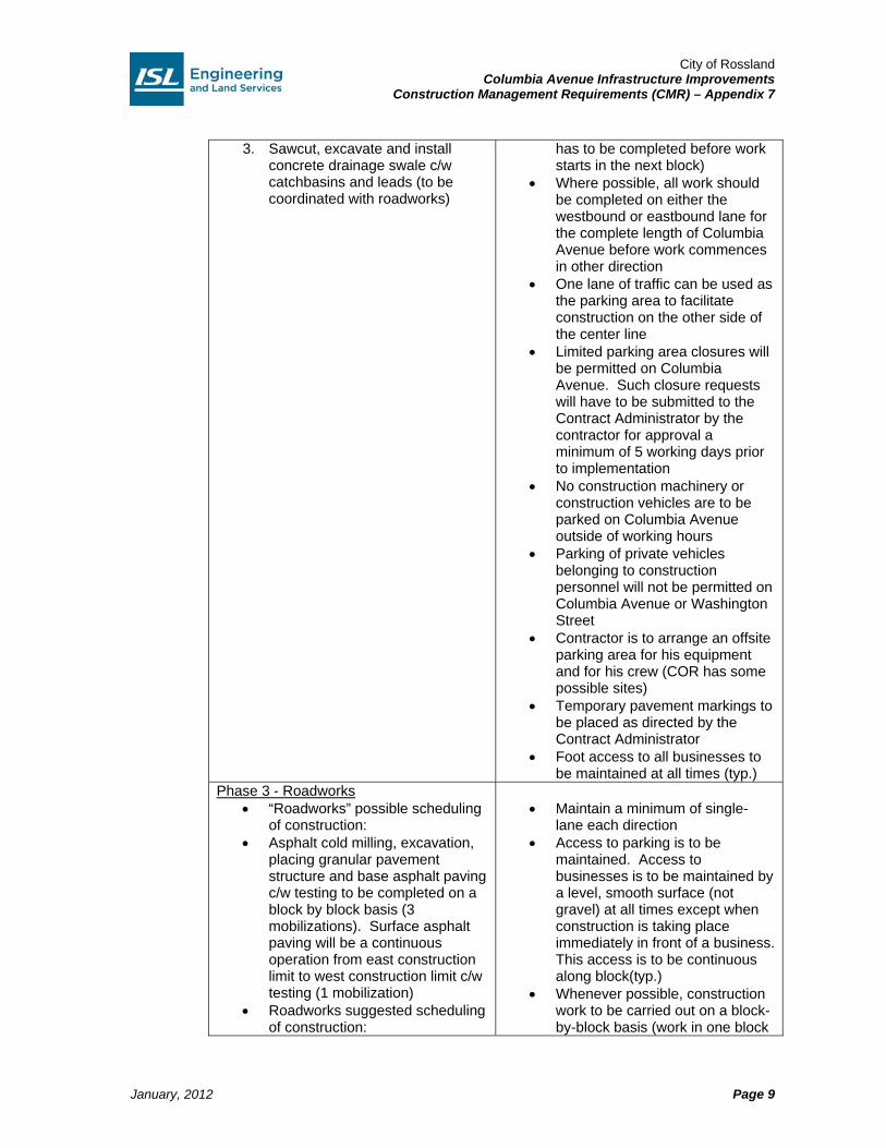
City of Rossland Columbia Avenue Infrastructure Improvements
Construction Management Requirements (CMR) – Appendix 7
January, 2012
Page 9
3. Sawcut, excavate and install concrete drainage swale c/w catchbasins and leads (to be coordinated with roadworks)
has to be completed before work starts in the next block)
Where possible, all work should be completed on either the westbound or eastbound lane for the complete length of Columbia Avenue before work commences in other direction
One lane of traffic can be used as the parking area to facilitate construction on the other side of the center line
Limited parking area closures will be permitted on Columbia Avenue. Such closure requests will have to be submitted to the Contract Administrator by the contractor for approval a minimum of 5 working days prior to implementation
No construction machinery or construction vehicles are to be parked on Columbia Avenue outside of working hours
Parking of private vehicles belonging to construction personnel will not be permitted on Columbia Avenue or Washington Street
Contractor is to arrange an offsite parking area for his equipment and for his crew (COR has some possible sites)
Temporary pavement markings to be placed as directed by the Contract Administrator
Foot access to all businesses to be maintained at all times (typ.)
Phase 3 - Roadworks “Roadworks” possible scheduling
of construction: Asphalt cold milling, excavation,
placing granular pavement structure and base asphalt paving c/w testing to be completed on a block by block basis (3 mobilizations). Surface asphalt paving will be a continuous operation from east construction limit to west construction limit c/w testing (1 mobilization)
Roadworks suggested scheduling of construction:
Maintain a minimum of single-
lane each direction Access to parking is to be
maintained. Access to businesses is to be maintained by a level, smooth surface (not gravel) at all times except when construction is taking place immediately in front of a business. This access is to be continuous along block(typ.)
Whenever possible, construction work to be carried out on a block-by-block basis (work in one block
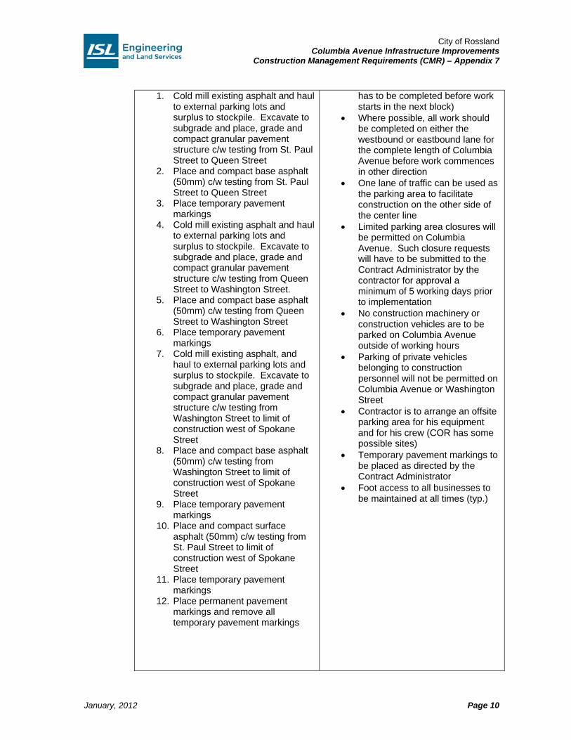
City of Rossland Columbia Avenue Infrastructure Improvements
Construction Management Requirements (CMR) – Appendix 7
January, 2012
Page 10
1. Cold mill existing asphalt and haul to external parking lots and surplus to stockpile. Excavate to subgrade and place, grade and compact granular pavement structure c/w testing from St. Paul Street to Queen Street
2. Place and compact base asphalt (50mm) c/w testing from St. Paul Street to Queen Street
3. Place temporary pavement markings
4. Cold mill existing asphalt and haul to external parking lots and surplus to stockpile. Excavate to subgrade and place, grade and compact granular pavement structure c/w testing from Queen Street to Washington Street.
5. Place and compact base asphalt (50mm) c/w testing from Queen Street to Washington Street
6. Place temporary pavement markings
7. Cold mill existing asphalt, and haul to external parking lots and surplus to stockpile. Excavate to subgrade and place, grade and compact granular pavement structure c/w testing from Washington Street to limit of construction west of Spokane Street
8. Place and compact base asphalt (50mm) c/w testing from Washington Street to limit of construction west of Spokane Street
9. Place temporary pavement markings
10. Place and compact surface asphalt (50mm) c/w testing from St. Paul Street to limit of construction west of Spokane Street
11. Place temporary pavement markings
12. Place permanent pavement markings and remove all temporary pavement markings
has to be completed before work starts in the next block)
Where possible, all work should be completed on either the westbound or eastbound lane for the complete length of Columbia Avenue before work commences in other direction
One lane of traffic can be used as the parking area to facilitate construction on the other side of the center line
Limited parking area closures will be permitted on Columbia Avenue. Such closure requests will have to be submitted to the Contract Administrator by the contractor for approval a minimum of 5 working days prior to implementation
No construction machinery or construction vehicles are to be parked on Columbia Avenue outside of working hours
Parking of private vehicles belonging to construction personnel will not be permitted on Columbia Avenue or Washington Street
Contractor is to arrange an offsite parking area for his equipment and for his crew (COR has some possible sites)
Temporary pavement markings to be placed as directed by the Contract Administrator
Foot access to all businesses to be maintained at all times (typ.)
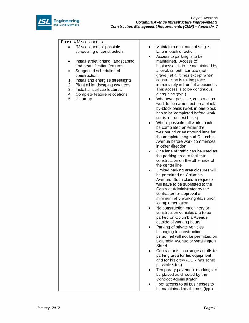
City of Rossland Columbia Avenue Infrastructure Improvements
Construction Management Requirements (CMR) – Appendix 7
January, 2012
Page 11
Phase 4 Miscellaneous “Miscellaneous” possible
scheduling of construction:
Install streetlighting, landscaping and beautification features
Suggested scheduling of construction:
1. Install and energize streetlights 2. Plant all landscaping c/w trees 3. Install all surface features 4. Complete feature relocations. 5. Clean-up
Maintain a minimum of single-
lane in each direction Access to parking is to be
maintained. Access to businesses is to be maintained by a level, smooth surface (not gravel) at all times except when construction is taking place immediately in front of a business. This access is to be continuous along block(typ.)
Whenever possible, construction work to be carried out on a block-by-block basis (work in one block has to be completed before work starts in the next block)
Where possible, all work should be completed on either the westbound or eastbound lane for the complete length of Columbia Avenue before work commences in other direction
One lane of traffic can be used as the parking area to facilitate construction on the other side of the center line
Limited parking area closures will be permitted on Columbia Avenue. Such closure requests will have to be submitted to the Contract Administrator by the contractor for approval a minimum of 5 working days prior to implementation
No construction machinery or construction vehicles are to be parked on Columbia Avenue outside of working hours
Parking of private vehicles belonging to construction personnel will not be permitted on Columbia Avenue or Washington Street
Contractor is to arrange an offsite parking area for his equipment and for his crew (COR has some possible sites)
Temporary pavement markings to be placed as directed by the Contract Administrator
Foot access to all businesses to be maintained at all times (typ.)

City of Rossland Columbia Avenue Infrastructure Improvements
Construction Management Requirements (CMR) – Appendix 7
January, 2012
Page 12
Phase 5 – Washington Street All works on Washington to be
constructed from Columbia Avenue north to construction limit. All works to be closely coordinated with construction on Columbia Avenue with regards to underground utility tie-ins and synchronization of surface operations
Underground utility – installation and tie-ins c/w all required testing
Possible schedule of Construction:
1. Excavate and install watermain, c/w appurtenances and water service stubs c/w testing
2. Transfer water services at property line
3. Excavate and install sanitary main c/w manholes, service stubs, IC’s and transfers c/w testing and CCTV
4. Excavate and install storm main c/w manholes, service stubs, IC’s, transfers, catch basins and leads c/w testing and CCTV
5. Concrete works – excavation and base preparation c/w testing
6. Place, grade and compact granular structure and extrude concrete curb and gutter
7. Excavate sidewalk, place, grade and compact granular structure
8. Excavate and install streetlighting conduit, tree pits and irrigation system
9. Pour concrete sidewalk (place sidewalk in stages to maintain foot access to all businesses at all times) c/w testing
Roadworks – Asphalt cold milling, excavation, placing granular pavement structure and asphalt paving c/w testing
10. Cold mill existing asphalt, excavate to subgrade and place, grade and compact granular pavement structure c/w testing
11. Place and compact base asphalt (50mm) c/w testing
12. Place temporary pavement markings
Minimum of single-lane
alternating during work hours (typ.)
Minimum of single-lane in each direction during non-working hours
Access to parking is to be maintained. Access to business is to be maintained by a level, smooth surface (not gravel) at all times except when construction is taking place immediately in front of a business. This access is to be continuous along block(typ.)
Whenever possible, construction work to be carried out on a block-by-block basis (work in one block has to be completed before work starts in the next block)
Where possible, all work should be completed on either the westbound or eastbound lane for the complete length of Columbia Avenue before work commences in other direction
No construction machinery or construction vehicles are to be parked on Washington Street outside of working hours
Parking of private vehicles belonging to construction personnel will not be permitted on Columbia Avenue or Washington Street
Contractor is to arrange an offsite parking area for his equipment and for his crew (COR has some possible sites)
Temporary pavement markings to be placed as required per the Contract Administrator
Foot access to all businesses to be maintained at all times (typ.)
All roadway trenches and sidewalk cuts to be temporarily patched with hot mix asphalt as required (minimum of once a day)
City of Rossland Columbia Avenue Infrastructure Improvements
Construction Management Requirements (CMR) – Appendix 7
January, 2012
Page 13
13. Place and compact surface asphalt (50mm) c/w testing
14. Place temporary pavement markings
15. Place permanent pavement markings and remove all temporary pavement markings
16. Miscellaneous – complete streetlighting, landscaping and beautification features.
17. Cleanup
The contractor shall review the “possible” staging plans and should conduct the work in the order listed below, unless otherwise approved by the Contract Administrator:
1. Phase 1 – Columbia Avenue underground utilities 2. Phase 2 – Columbia Avenue concrete works 3. Phase 3 – Columbia Avenue roadworks 4. Phase 4 – Columbia Avenue miscellaneous 5. Phase 5 – Washington Street improvements (optional works)
Phase 5 Washington Street work to be completed concurrently and in conjunction with work in phases 1 to 4.
2.4 Hours of Work
The hours of work shall be from 0530 h to 2200 h inclusive Monday to Sunday. The Contractor must schedule his work within these hours or obtain written authorization from the City of Rossland and the Contract Administrator to vary said hours. The City will allow extended hours as required for certain construction operations. Please note that all works to be completed outside the hours of work (2200 h to 0700 h) must be approved, with a noise variance issued, by the City prior to the construction taking place. The Contractor shall comply with all of the applicable bylaws of the City of Rossland which only permit activities creating a noise disturbance between 0700 h to 2200 h daily except Sundays and Statutory Holidays, which have total prohibitions or with the written approval of the City of Rossland and the Contract Administrator. No Work will be carried out at times outside of these hours of work without written approval of the City of Rossland and the Contract Administrator. If the Contractor wishes to work on a Sunday, on a long weekend or on a Statutory Holiday, he shall submit a written request to the Contract Administrator a minimum of 4 days in advance. The Contractor will commence the Work on the week of April 23, 2012 and achieve Substantial Performance of the Work on or before September 30, 2012, subject to the provisions of the Contract Documents for adjustments to the Contract Time. All work under this project is to be completed within the designated Contract Duration. The Contractor must provide sufficient resources in a continuous effort and presence to complete all the work within the allotted time.
City of Rossland Columbia Avenue Infrastructure Improvements
Construction Management Requirements (CMR) – Appendix 7
January, 2012
Page 14
The following lane closure restrictions shall apply: Columbia Avenue – West of Spokane Street to St. Paul Street
Daytime working hours - maintain two (2) lanes of traffic – 0700 h to 2200 h - maintain one (1) lane of traffic eastbound, one (1) lane of traffic westbound
Evenings & Nights – 2200 h to 0700 h (non-working hours) – maintain a minimum of single lane traffic in each direction and parking only required to businesses that are open during the evening and throughout the night.
All intersections shall be accommodated with full movements whenever possible. Left-turn restrictions may be permitted to better facilitate traffic flow along Columbia Avenue, as determined by the Contract Administrator. The contractor may be allowed to close one side of the road at a time and reduce traffic to single lane alternating during paving operations. Washington Street – Columbia Avenue to north limit of construction
Local Traffic Only Single lane alternating Access to businesses must be maintained Access to parking stalls must be maintained Work to be coordinated with Columbia Avenue work.
The Contractor shall review the Construction Management Requirements, suggested staging plan and take all other information included in the tender documents into account in the preparation and submission of the Tender. The contractor shall be aware that a TMP will require approval by the City of Rossland and the Contract Administrator before construction can begin. Costs to complete the works taking the above restrictions into consideration shall be included in the unit prices bid in the Schedule of Quantities and Prices.
City of Rossland Columbia Avenue Infrastructure Improvements
Construction Management Requirements (CMR) – Appendix 7
January, 2012
Page 15
3.0 Traffic Control Implementation
Traffic Control Plans for all phases are to be provided for the Contract Administrator’s review and approval prior to construction. The Contractor’s TMP / TCP’s submitted to the Contract Administrator for approval a minimum of two (2) weeks prior to implementation.
3.1 Construction Staging – Columbia Avenue
It is intended that Columbia Avenue maintains one lane of traffic in each direction 24 hours a day as specified in Section 2.0 of this document. Project Signs, external parking lots, as well as other signage, will be placed in advance of the work site to encourage residents to use alternate routes to minimize traffic volumes near the work zone. Columbia Avenue Phase 1 – Underground Utility Installation Clearing and grubbing, excavation, installation, backfill and compaction of proposed underground utilities c/w testing and temporary hot mix asphalt patching. It is intended that Columbia Avenue maintains one lane of traffic in each direction 24 hours a day. Traffic Control Plans for Phase 1 of construction are to be submitted and approved. Columbia Avenue Phase 2 – Concrete Work Excavation, installation, backfill and pouring of proposed concrete works c/w testing. It is intended that Columbia Avenue maintains one lane of traffic in each direction 24 hours a day. Traffic Control Plans for Phase 2 of construction are to be submitted and approved. Columbia Avenue Phase 3 – Roadworks Asphalt cold milling, excavation, placing granular pavement structure and base asphalt paving c/w testing to be completed on a block by block basis (3 mobilizations). Surface asphalt paving will be a continuous operation from east construction limit to west construction limit c/w testing (1 mobilization). It is intended that Columbia Avenue maintains one lane of traffic in each direction 24 hours a day. It is also intended that Columbia Avenue maintain a minimum of single-lane alternating during pavement operations. Traffic Control Plans for Phase 3 of construction are to be submitted and approved. Columbia Avenue Phase 4 – Miscellaneous Install streetlighting, landscaping and beautification features. Traffic Control Plans for Phase 4 of construction are to be submitted and approved. It is intended that Columbia Avenue maintains one lane of traffic in each direction 24 hours a day. Traffic Control Plans for Phase 4 of construction are to be submitted and approved.

City of Rossland Columbia Avenue Infrastructure Improvements
Construction Management Requirements (CMR) – Appendix 7
January, 2012
Page 16
3.2 Construction Staging – Washington Street
It is intended that Washington Street maintains at least one lane of traffic alternating as specified in section 2.0 of this document. Project Signs, as well as other signage, will be placed in advance of the work site to encourage residents to use alternate routes to minimize traffic volumes near the work zone.
Washington Street Improvement - Phase 5 (Optional) All works on Washington Street to be constructed from Columbia Avenue north to construction limit. All works on Washington Street to be constructed concurrently with construction works on Columbia Avenue. All works to be closely coordinated with construction on Columbia Avenue with regards to underground utility tie-ins and synchronization of surface operations. It is intended that Washington Street maintains at least one lane of traffic alternating during work hours and full road width, including parking stalls to be accessible during non-working hours. Traffic Control Plans for Washington Street are to be submitted and approved.
3.3 Transit
BC Transit will require coordination or the relocation of temporary bus stops to accommodate works. Bus stops located at:
Westbound – East side of Queen on Columbia Avenue Eastbound – East side of Spokane on Columbia Avenue Westbound – West side of Spokane on Columbia Avenue
3.4 Truck Routes and Staging
Operations of trucks and other heavy construction vehicles will be governed by COR Bylaws. Compliance includes, but not limited to, designated truck routes, vehicle sizes, load limits, and special permitting for oversize or overweight vehicles. Should it be necessary to bring in oversized vehicles, authorization by the City will be required. Contractor shall arrange for trucks and other heavy construction vehicles to “…..proceed on a Truck Route until reaching a point on the Truck Route closest to the destination; then…..continue along the shortest route possible to work site” for deliveries to site. Columbia Avenue Construction It is envisioned that trucks would access and egress from east or west end of site, depending on the side of Columbia Avenue having construction in progress. Barricades / Gates controlled by TCP(s) will be utilized to prevent public traffic from wandering into the work zone. Staging can be made along on Columbia Avenue within closed areas. Trucks would travel through the lane closure transition taper and proceed to the work zone on closed lanes.
City of Rossland Columbia Avenue Infrastructure Improvements
Construction Management Requirements (CMR) – Appendix 7
January, 2012
Page 17
All trucks are required to be equipped with flashing hazard lights for use when making any movement into or out of traffic. All truck drivers shall be instructed by the Contractor of procedures for access / egress of construction zones. Should material storage and / or excavation disposal sites be outside of work zones, the Contractor shall prepare a plan indicating their planned truck routes through the City.
3.5 Advanced Warning
Advanced information signs will be installed prior to major detour intersections. Changeable Message Signs must be in place 1 (one) week in advance of construction to notify the traveling public of the upcoming work and expected delays. The contractor is required to supply, locate and maintain a minimum of (2) two Changeable Message Signs (CMS) to be located in the following areas:
1. Eastbound on Columbia Avenue within COR limits west of Monita Street 2. Westbound on Highway 22/3B within COR limits east of bottom of hill
The exact locations are to be approved by the Contract Administrator. Messaging on the signs is to be adjusted as work progresses to provide appropriate information to traffic. The contractor is responsible for the removal of the signs at the completion of the work.
3.6 Access to Businesses
Communications with affected property owners will be managed by the Contract Administrator, from information provided by the Contractor, to inform the residents/owners of the planned work activities and to discuss alternate access for vehicles and pedestrian. The contractor is responsible to maintain all businesses access at all times. The contractor may provide temporary accesses and detour routes to the businesses if the affected businesses agree. All costs associated with temporary accesses shall be incidental and in writing at the contractor’s expense.
3.7 Site Protection
The Contractor is responsible to ensure the construction site is safe at all times for workers, pedestrians, bicycles and vehicle traffic. During non-working hours, the Contractor must ensure that the site has all potentially hazardous areas appropriately identified and protected, and also must provide appropriate signage, lighting, and markings for the direction of vehicle and pedestrian traffic, all to ensure the safety of the public.
3.8 Layout
The contractor is responsible for all temporary traffic control on the streets within this contract. The contractor will be responsible to provide a Traffic Management Plan (TMP) for approval (5) five working days prior to any lane closures taking place.
City of Rossland Columbia Avenue Infrastructure Improvements
Construction Management Requirements (CMR) – Appendix 7
January, 2012
Page 18
The TMP shall outline the approach to traffic management, show recognition and minimizations of risks, indicate signing locations, identify Traffic Control Persons (TCP) stations, and show lane shifting and proposed closures. The TMP is to be altered and resubmitted as required during the progress of the work The TMP will be adjusted and negotiated with all concerned parties.
3.9 Plan Updates and Modifications
The TMP is to be altered and resubmitted as required during the progress of the work. The TMP will be adjusted and negotiated with all concerned parties.
3.10 Traffic Manager
The Contractor shall assign a designated Traffic Manager. The Traffic Manager will have full authority over all of the traffic control personnel on site and be responsible for:
Ensuring compliance with Part 18 of the WCB’s Occupational Health and Safety Regulations regarding supervision of TCP’s at the work zone
Ensuring that emergency traffic control operations are carried out in accordance with the Incident Management Plan
Ensuring that daily traffic control logs and other documents are maintained. Monitoring traffic operations to determine the effectiveness of traffic control
measures Overseeing modifications to the Traffic Management Plan required by
construction schedule changes, accommodation of special events, or changes to sub plans
Ensuring that the Traffic Management Plan is up to date.
3.11 Traffic Control Supervisor
The Contractor shall assign a designated Traffic Control Supervisor, who will be responsible for implementing the Traffic Control Plans and for taking site-specific actions including incident response. Other responsibilities include:
Contacting emergency agencies and giving notice of the construction schedule and the resultant lane configuration
Notifying Traffic Manager of any incidents (if different persons) Directing the Incident Management Plan Finalizing traffic control measures with the Traffic Manager Directing the implementation of the Traffic Control Plans Maintaining an up-to-date contact list of emergency response agencies
The role of Traffic Control Supervisor will involve inspecting, reporting, and correcting traffic control devices being used on site. Procedures are generally as follows: Before Work Starts
Inspect and rectify all construction signs and traffic control devices and note any signs out of order or damaged during off hours.
Confirm the Traffic Management Plan for the day’s activities Assess effectiveness of signage and traffic control devices
City of Rossland Columbia Avenue Infrastructure Improvements
Construction Management Requirements (CMR) – Appendix 7
January, 2012
Page 19
During Work Hours
Periodically make inspections through the work site to check all signs and traffic control devices.
Conduct spot maintenance as required. Re-position signs as required and keep records of any changes. Ensure that all roadways utilized by the Contractor are kept clean and free of
dust and debris – coordinate clean road sweeping activities as required. Close Down (Each Day)
Conduct a final inspection at day’s end and allow time for maintenance works. Remove / Cover inappropriate signage (e.g. “Traffic Control Person Ahead” when
no TCP is present) Install traffic cones and tubular markers where required. Document details of inspection and note changes to traffic control layout. A copy
of the Traffic Control Daily Report can be found in MoT’s Traffic Management Guidelines For Work On Roadways.
Depending on scheduling and internal hierarchy of the Contractor, the Traffic Control Supervisor and Traffic Manager may be the same person, provided said person is qualified and will be have the capacity to perform for both roles over the duration of the project.
City of Rossland Columbia Avenue Infrastructure Improvements
Construction Management Requirements (CMR) – Appendix 7
January, 2012
Page 20
4.0 Public Information Plan
As the work site will be affecting adjacent business accesses and traffic along this major corridor, it is essential to establish clear communications with the public and ensure road users are aware of traffic pattern changes ahead of time. COR, Contract Administrator and the Contractor will work together to implement the Public Information Plan to provide information to road users and stakeholders regarding any traffic pattern changes. This Public Information Plan will be based on the Contractor’s traffic management plans and staging. Pre-Construction Meeting between COR, Contract Administrator and Contractor to establish communications. All emergency services, major user groups, and listed stakeholders will be notified of scheduled construction works and any changes in traffic configurations two (2) weeks prior to the start of work by the Contractor. For any unscheduled traffic delays, the emergency agencies will be advised immediately. During this time, all traffic control devices will be implemented in accordance with standards set out in the Traffic Control Manual for Work on Roadways, with modifications to suit local situations as deemed necessary by the Traffic Control Supervisor. The Contractor will notify COR immediately of any unexpected major delays. Details for the protocols will be as in the Incident Management Plan. Advanced Signage Project signs will be placed on Columbia Avenue at east and west limits, and other roads in the vicinity of the construction area prior to the commencement of construction and will remain for the duration of the project. Signage will accommodate both vehicle and non-vehicle traffic and carry project information including the expected duration of the project, the nature of the work, and contact information. COR will arrange for this signage. Construction Notices Written / E-mail / Fax notices will be delivered to emergency and public services, local businesses, and listed stakeholders in the vicinity of the construction area in advance of the implementation of any traffic control plan(s). Construction notices will include, but not limited to, a brief description of the work(s) taking place, scheduled start and completion dates, and related traffic control measures. COR will prepare and provide these letters to the contractor for distribution by the contractor. These letters will be based on information and sketches provided by the Contractor. COR Website The Contractor is to give advanced notice(s) for scheduled work(s) and traffic pattern changes to COR for updates on COR website.

City of Rossland Columbia Avenue Infrastructure Improvements
Construction Management Requirements (CMR) – Appendix 7
January, 2012
Page 21
Anticipated notification method and time as follows:
Contacts Pre-Construction Project Overview
Commencement of Project
Full Road Closure
Emergency Services 2 wks prior - in person (asap before project start)
Email Meeting - 2 weeks Fax NoC / E-mail 1 wk prior
City of Rossland Pre-construction Meeting & On-going
Email Email 2 weeks prior
Business / Neighbourhood Associations
2 wks prior - email Meeting Email 2 weeks prior
Local Owners / Businesses
2 wks prior - in person, flyer
Meeting Email 2 weeks prior
MOTI Email Email 2 weeks prior
Transit 2 wks prior - in person (asap before project start)
Email Email 2 weeks prior
Contacts Short Duration
Lane Closures Long Duration
Lane Shift Lane Shift /
No Stopping / Lane Width Reduction
Emergency Services min 2 wks prior Fax NoC 5 days prior
min 2 wks prior - Meeting - 2 weeks / Fax NoC 5 days prior
City of Rossland Email 5 days prior / Fax NoC 3 days prior
Email Email 2 weeks prior
Business / Neighbourhood Associations
5 days prior - email 5 days prior - email Email 2 weeks prior
Local Owners / Businesses
5 days prior - email 5 days prior - email Email 2 weeks prior
MOTI Email 5 days prior 5 days prior - email Email 2 weeks prior
Transit 5 days prior - email NoC 5 days prior
5 days prior - email Email 2 weeks prior
Contacts Stopping Restrictions Sidewalk Closure / Pedestrian Detour
Noise Variance Notifications
Emergency Services n/a n/a City of Rossland Email Email Application 5 days prior Pedestrians n/a Advisory Business / Neighbourhood Associations
5 days prior - email Advisory Advisory 48 hours prior
Local Owners / Businesses
5 days prior - email Advisory hand delivered flyer Advisory 48 hours prior
MOTI 5 days prior - email n/a n/a
Transit 5 days prior - email Meeting if affecting bus stops
n/a

City of Rossland Columbia Avenue Infrastructure Improvements
Construction Management Requirements (CMR) – Appendix 7
January, 2012
Page 22
5.0 Incident Management Plan
This Incident Management Plan aims to establish protocols to address scenes such as vehicle accidents, construction issues disrupting traffic, maintenance issues on the road, or other events that impedes traffic patterns prescribed by the original traffic plans and require field changes to traffic control measures to either maintain safe traffic access through the vicinity of the incident, or to close off traffic from a section of roadway that cannot be safely traversed. To ensure swift incident response, the Contractor shall make certain that all related personnel are familiar with incident management procedures and that resources needed for incident management are available. The Traffic Control Supervisor should be adaptive in responding to incidents and be able to coordinate incident management resources, including the use of materials from construction area as needed. Detection of Incidents: The Contractor's Traffic Control Supervisor will monitor the areas within and in the vicinity of the construction zone inclusive of areas under traffic control measures. If any construction crew detects and / or is responding to an incident, he / she will relay information to the Traffic Control Supervisor and any responding emergency services regarding the location of the incident, the number of people involved and their conditions, along with any issues such as chemical hazards, fire, or electrical hazards. Incident Response Procedures: As soon as an incident is detected, the Contractor and the Traffic Control Supervisor should be able to provide immediate incident response as well as notify various emergency contacts as needed. The Contractor shall have qualified traffic control person(s) to manage traffic control changes required until the incident is cleared. During an incident, the Traffic Control Supervisor will generally follow these procedures:
1. Notify the Traffic Manager of the incident (if different persons). 2. Assess severity and conditions. 3. Ensure emergency response agencies are contacted regarding the incident. 4. Based on the severity the incident and estimated duration until clean-up, modify
traffic control measures (as guided by MoT’s Traffic Control Manual for Work on Roadways) as safety requires. Remove equipment, materials, and any items that may interfere with incident management operations. Until the arrival of emergency response unit(s) and secure the area until the incident is cleared.
a. If incident requires traffic control modifications on major streets, advanced warning should be placed at next major intersections.
b. Whenever possible, maintain two-way traffic. 5. Ensure access for emergency response unit(s) to the incident. Direct / assist
emergency responders with placing equipment. 6. Monitor traffic flow until incident is cleared 7. Notify COR representatives. 8. After incident is concluded, survey incident area for damage to infrastructure and
traffic inventories. 9. Clear incident area and resume traffic flow. 10. Complete Incident Management Report.
City of Rossland Columbia Avenue Infrastructure Improvements
Construction Management Requirements (CMR) – Appendix 7
January, 2012
Page 23
5.1 Notification
Contractor’s Traffic Control Supervisor will notify COR of any incidents within or in the vicinity of the work zone and relay all relevant information. COR will be the official contact for local radio stations and other media outlets in providing traffic information as necessary.
5.2 Emergency contact
A draft list of emergency contacts has been developed for this project, as included in Section 4.0 of this Traffic Management Specification. COR will assist the Contractor with updating this list to ensure that the contact information is correct. The Contractor shall keep copies available at the site office and ensure that traffic management personnel have access to emergency contact information at all times.
5.3 Emergency Responder Access
The Traffic Control Supervisor should ensure that adequate parking is provided when emergency responders arrive at the incident scene. If possible, and without impeding emergency response operations, arrange parking space for emergency response vehicles in areas that are already closed off or in lanes that will be closed for incident response so as to avoid affecting road traffic. The Traffic Control Supervisor should also assist the emergency responders in setting up traffic control for the responders’ operations. The Traffic Control Supervisor will ensure that only vehicles required for emergency response operations have access to the incident site.
5.4 Resuming Traffic
As soon as an incident has concluded, the Contractor will clear the incident area of vehicles and debris and restore the traffic flow to normal or as planned in this traffic management plan. A survey should be conducted to determine if there was damage to the infrastructure in the vicinity of work zone. Should an incident cause significant damage to local infrastructure or traffic inventories, affected areas should be protected. The Contractor should inform COR representatives and coordinate with COR for repairs as needed.
5.5 Incident Management Report
After incidents, the Contractor shall prepare an Incident Management Reports providing the details about:
The time of incident occurring and clearing Location of the incident The nature of the incident, and whether or not incident is related to construction
activity Details regarding attendance by emergency services.
The BC MoT’s Traffic Management Guidelines for Work on Roadways contains a sample copy of an Incident Management Report. Copies of completed report(s) shall be submitted COR within 24 hours of clearing the incident. The Traffic Manager shall

City of Rossland Columbia Avenue Infrastructure Improvements
Construction Management Requirements (CMR) – Appendix 7
January, 2012
Page 24
investigation and review all incidents with the Traffic Control Supervisor (if different persons) and Site Superintendent.
5.6 Contact Information
City of Rossland Office Cell Fax
- - -
ISL Engineering and Land
Services Office Cell Fax
Contractor Office Cell
(Contractor Superintendent) (TBD) (TBD) (Contractor Safety Officer) (TBD) (TBD) Traffic Manager (Contractor selected) (TBD) (TBD) Traffic Control Supervisor (Contractor selected) (TBD) (TBD)
City of Rossland Office Cell
Traffic Operations (TBD) (TBD) Emergency No. (TBD) (TBD) Environmental (TBD) (TBD)
Ministry of Transportation and Infrastructure Office Cell
(TBD) (TBD) (TBD) (TBD) (TBD) (TBD)
Emergency / Public Services
Agency Emergency Non-
Emergency Ambulance 911 - Police – Traffic Division 911 ? Fire 911 -- BC Hydro 1-888-769-3766 - BC Hydro Transmission - 1-800-964-9376 Fortis BC - 1-888-224-2710 Telus / Telus Trouble Centre 611 1-888-811-2828 Street Lighting/Signals (After hours) -- - Streets/Utilities (After hours) -- - Provincial Emergency Preparedness (PEP) 1-800-663-3456 - Earthquake/Flood/Dangerous Goods Spill 1-800-663-3456 - Transit Supervisor (TBD) (TBD) School Administration (TBD) (TBD)

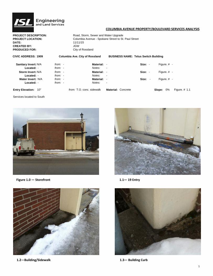
1
COLUMBIA AVENUE PROPERTY/BOULEVARD SERVICES ANALYSIS
PROJECT DESCRIPTION: Road, Storm, Sewer and Water Upgrade PROJECT LOCATION: Columbia Avenue - Spokane Street to St. Paul Street DATE: 11/11/15 CREATED BY: JGW PRODUCED FOR: City of Rossland
CIVIC ADDRESS: 1909 Columbia Ave. City of Rossland BUSINESS NAME: Telus Switch Building
Sanitary Invert: N/A from: - Material: - Size: - Figure. # - Located: - from: - Notes: -
Storm Invert: N/A from: - Material: - Size: - Figure. # - Located: - from: - Notes: -
Water Invert: N/A from: - Material: - Size: - Figure. # - Located: - from: - Notes: -
Entry Elevation: 10” from: T.O. conc. sidewalk Material: Concrete Slope: 0% Figure. # 1.1 Services located to South
Figure 1.0 — Storefront 1.1— 19 Entry
1.2—Building/Sidewalk 1.3— Building Curb

1
COLUMBIA AVENUE PROPERTY/BOULEVARD SERVICES ANALYSIS
PROJECT DESCRIPTION: Road, Storm, Sewer and Water Upgrade PROJECT LOCATION: Columbia Avenue - Spokane Street to St. Paul Street DATE: 11/11/15 CREATED BY: JGW PRODUCED FOR: City of Rossland
CIVIC ADDRESS: 1938 Columbia Ave. City of Rossland BUSINESS NAME: Mountain Haus Furniture (VACANT)
Sanitary Invert: Unknown from: U/S Subfloor Material: Unknown Size: Ø Figure. # Located: from: South West fdn. wall Notes:
Storm Invert: Unknown from: U/S Subfloor Material: Unknown Size: Ø Figure. # Located: from: South West fdn. wall Notes:
Water Invert: Unknown from: U/S Subfloor Material: Unknown Size: Ø Figure. # Located: from: South West fdn. wall Notes:
Entry Elevation: 2” from: T.O. conc. sidewalk Material: Concrete Pavers Slope: 1% Figure. # 2.1 General Notes: Crawlspace/basement accessible via.: Unaccessible—S.O.G; Bathrooms are located at North end of the building; Water Service comes in @ 8’-6” off East wall; Building is set back 5’-0” from sidewalk.
Figure 1.0—Facade Figure 1.1—Entry
Figure 1.2—Entry/Sidewalk

1
COLUMBIA AVENUE PROPERTY/BOULEVARD SERVICES ANALYSIS
PROJECT DESCRIPTION: Road, Storm, Sewer and Water Upgrade PROJECT LOCATION: Columbia Avenue - Spokane Street to St. Paul Street DATE: 11/11/15 CREATED BY: JGW PRODUCED FOR: City of Rossland
CIVIC ADDRESS: 19 Columbia Ave. City of Rossland BUSINESS NAME: Prestige Mountain Inn
Sanitary Invert: N/A from: - Material: - Size: - Figure. # - Located: - from: - Notes: -
Storm Invert: N/A from: - Material: - Size: - Figure. # - Located: - from: - Notes: -
Water Invert: N/A from: - Material: - Size: - Figure. # - Located: - from: - Notes: -
Entry Elevation: +/-4’-8” from: T.O. conc. sidewalk Material: Concrete Slope: - Figure. # 1.1, 1.2, 1.3 Services located to South
Figure 1.0 — Storefront 1.1— West Driveway
Figure 1.2— West Driveway/Parking Figure 1.3— East driveway @ sidewalk

2
COLUMBIA AVENUE PROPERTY/BOULEVARD SERVICES ANALYSIS
PROJECT DESCRIPTION: Road, Storm, Sewer and Water Upgrade PROJECT LOCATION: Columbia Avenue - Spokane Street to St. Paul Street DATE: 11/11/15 CREATED BY: JGW PRODUCED FOR: City of Rossland
CIVIC ADDRESS: 19 Columbia Ave. City of Rossland BUSINESS NAME: Prestige Mountain Inn
Sanitary Invert: N/A from: - Material: - Size: - Figure. # - Located: - from: - Notes: -
Storm Invert: N/A from: - Material: - Size: - Figure. # - Located: - from: - Notes: -
Water Invert: N/A from: - Material: - Size: - Figure. # - Located: - from: - Notes: -
Entry Elevation: Grade from: T.O. conc. sidewalk Material: Concrete Slope: 2% Figure. # 1.1 Services located to South
Figure 2.0 — Retaining wall @ Driveway East 2.1— East Driveway
Figure 2.2— Conference Room walkway
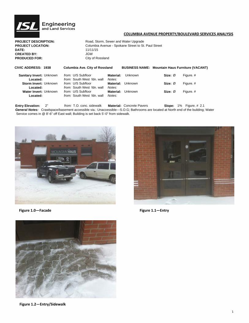
1
COLUMBIA AVENUE PROPERTY/BOULEVARD SERVICES ANALYSIS
PROJECT DESCRIPTION: Road, Storm, Sewer and Water Upgrade PROJECT LOCATION: Columbia Avenue - Spokane Street to St. Paul Street DATE: 11/11/15 CREATED BY: JGW PRODUCED FOR: City of Rossland
CIVIC ADDRESS: 1938 Columbia Ave. City of Rossland BUSINESS NAME: Mountain Haus Furniture (VACANT)
Sanitary Invert: Unknown from: U/S Subfloor Material: Unknown Size: Ø Figure. # Located: from: South West fdn. wall Notes:
Storm Invert: Unknown from: U/S Subfloor Material: Unknown Size: Ø Figure. # Located: from: South West fdn. wall Notes:
Water Invert: Unknown from: U/S Subfloor Material: Unknown Size: Ø Figure. # Located: from: South West fdn. wall Notes:
Entry Elevation: 2” from: T.O. conc. sidewalk Material: Concrete Pavers Slope: 1% Figure. # 2.1 General Notes: Crawlspace/basement accessible via.: Unaccessible—S.O.G; Bathrooms are located at North end of the building; Water Service comes in @ 8’-6” off East wall; Building is set back 5’-0” from sidewalk.
Figure 1.0—Facade Figure 1.1—Entry
Figure 1.2—Entry/Sidewalk
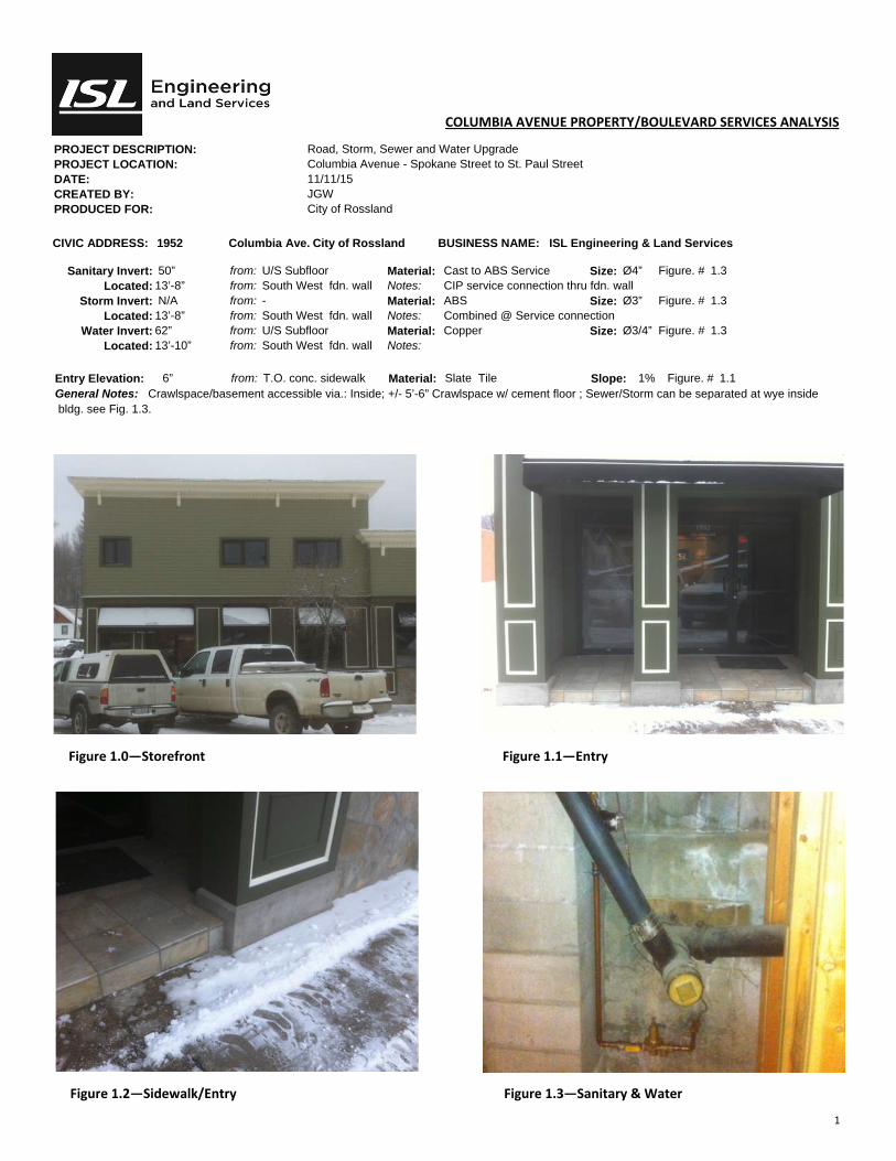
1
COLUMBIA AVENUE PROPERTY/BOULEVARD SERVICES ANALYSIS
PROJECT DESCRIPTION: Road, Storm, Sewer and Water Upgrade PROJECT LOCATION: Columbia Avenue - Spokane Street to St. Paul Street DATE: 11/11/15 CREATED BY: JGW PRODUCED FOR: City of Rossland
CIVIC ADDRESS: 1952 Columbia Ave. City of Rossland BUSINESS NAME: ISL Engineering & Land Services
Sanitary Invert: 50” from: U/S Subfloor Material: Cast to ABS Service Size: Ø4” Figure. # 1.3 Located: 13’-8” from: South West fdn. wall Notes: CIP service connection thru fdn. wall
Storm Invert: N/A from: - Material: ABS Size: Ø3” Figure. # 1.3 Located: 13’-8” from: South West fdn. wall Notes: Combined @ Service connection
Water Invert: 62” from: U/S Subfloor Material: Copper Size: Ø3/4” Figure. # 1.3 Located: 13’-10” from: South West fdn. wall Notes:
Entry Elevation: 6” from: T.O. conc. sidewalk Material: Slate Tile Slope: 1% Figure. # 1.1 General Notes: Crawlspace/basement accessible via.: Inside; +/- 5’-6” Crawlspace w/ cement floor ; Sewer/Storm can be separated at wye inside bldg. see Fig. 1.3.
Figure 1.0—Storefront Figure 1.1—Entry
Figure 1.2—Sidewalk/Entry Figure 1.3—Sanitary & Water
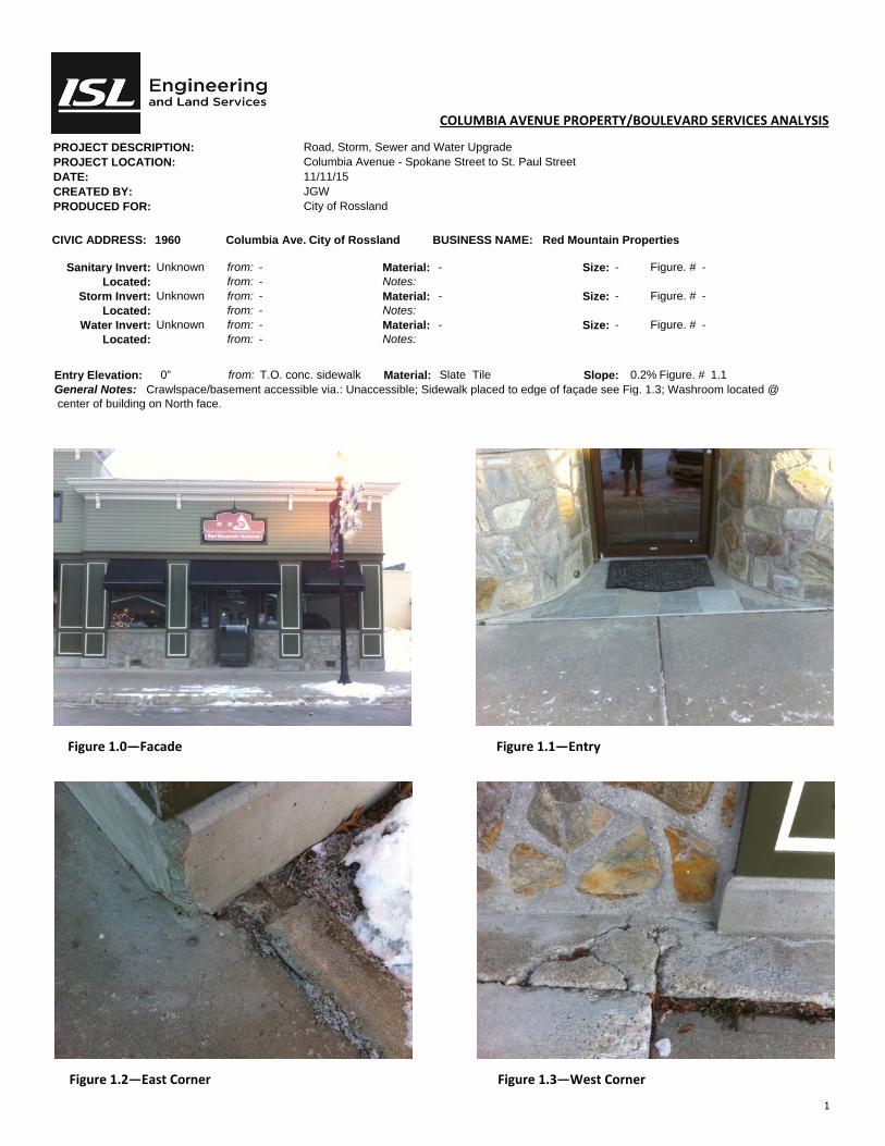
1
COLUMBIA AVENUE PROPERTY/BOULEVARD SERVICES ANALYSIS
PROJECT DESCRIPTION: Road, Storm, Sewer and Water Upgrade PROJECT LOCATION: Columbia Avenue - Spokane Street to St. Paul Street DATE: 11/11/15 CREATED BY: JGW PRODUCED FOR: City of Rossland
CIVIC ADDRESS: 1960 Columbia Ave. City of Rossland BUSINESS NAME: Red Mountain Properties
Sanitary Invert: Unknown from: - Material: - Size: - Figure. # - Located: from: - Notes:
Storm Invert: Unknown from: - Material: - Size: - Figure. # - Located: from: - Notes:
Water Invert: Unknown from: - Material: - Size: - Figure. # - Located: from: - Notes:
Entry Elevation: 0” from: T.O. conc. sidewalk Material: Slate Tile Slope: 0.2% Figure. # 1.1 General Notes: Crawlspace/basement accessible via.: Unaccessible; Sidewalk placed to edge of façade see Fig. 1.3; Washroom located @ center of building on North face.
Figure 1.0—Facade Figure 1.1—Entry
Figure 1.2—East Corner Figure 1.3—West Corner

1
COLUMBIA AVENUE PROPERTY/BOULEVARD SERVICES ANALYSIS
PROJECT DESCRIPTION: Road, Storm, Sewer and Water Upgrade PROJECT LOCATION: Columbia Avenue - Spokane Street to St. Paul Street DATE: 11/11/15 CREATED BY: JGW PRODUCED FOR: City of Rossland
CIVIC ADDRESS: 1973 Columbia Ave. City of Rossland BUSINESS NAME: Medical Associates
Sanitary Invert: N/A from: - Material: - Size: - Figure. # - Located: - from: - Notes: -
Storm Invert: N/A from: - Material: - Size: - Figure. # - Located: - from: - Notes: -
Water Invert: N/A from: - Material: - Size: - Figure. # - Located: - from: - Notes: -
Entry Elevation: 3” from: T.O. conc. sidewalk Material: Concrete Slope: N/A Figure. # 1.1 Services located to South
Figure 1.0 — Storefront 1.1 — Entry
1.2 — Entry
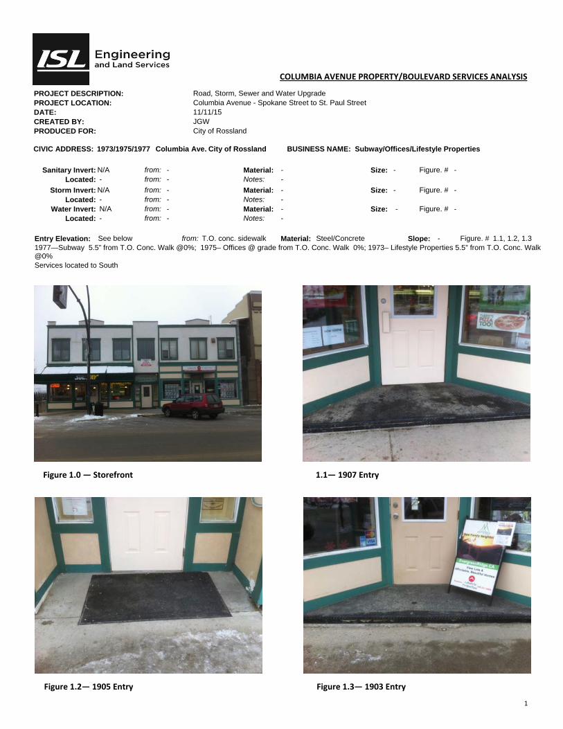
1
COLUMBIA AVENUE PROPERTY/BOULEVARD SERVICES ANALYSIS
PROJECT DESCRIPTION: Road, Storm, Sewer and Water Upgrade PROJECT LOCATION: Columbia Avenue - Spokane Street to St. Paul Street DATE: 11/11/15 CREATED BY: JGW PRODUCED FOR: City of Rossland
CIVIC ADDRESS: 1973/1975/1977 Columbia Ave. City of Rossland BUSINESS NAME: Subway/Offices/Lifestyle Properties
Sanitary Invert: N/A from: - Material: - Size: - Figure. # - Located: - from: - Notes: -
Storm Invert: N/A from: - Material: - Size: - Figure. # - Located: - from: - Notes: -
Water Invert: N/A from: - Material: - Size: - Figure. # - Located: - from: - Notes: -
Entry Elevation: See below from: T.O. conc. sidewalk Material: Steel/Concrete Slope: - Figure. # 1.1, 1.2, 1.3 1977—Subway 5.5” from T.O. Conc. Walk @0%; 1975– Offices @ grade from T.O. Conc. Walk 0%; 1973– Lifestyle Properties 5.5” from T.O. Conc. Walk @0% Services located to South
Figure 1.0 — Storefront 1.1— 1907 Entry
Figure 1.2— 1905 Entry Figure 1.3— 1903 Entry

1
COLUMBIA AVENUE PROPERTY/BOULEVARD SERVICES ANALYSIS
PROJECT DESCRIPTION: Road, Storm, Sewer and Water Upgrade PROJECT LOCATION: Columbia Avenue - Spokane Street to St. Paul Street DATE: 11/11/15 CREATED BY: JGW PRODUCED FOR: City of Rossland
CIVIC ADDRESS: 1990 Columbia Ave. City of Rossland BUSINESS NAME: Rossland PRO Hardware
Sanitary Invert: 23.5” from: U/S Subfloor Material: ABS to cast Service Size: Ø4” Figure. # 2.0 Located: 26’-6” from: West fdn. wall Notes: CIP service connection thru fdn. wall
Storm Invert: N/A from: - Material: - Size: Ø6” Figure. # - Located: - from: - Notes: -
Water Invert: 6’-4” from: U/S Subfloor Material: Steel Size: Ø2.5” Figure. # 2.2 & 3.3 Located: 58’-6” from: North fdn. wall Notes:
Entry Elevation: 3.25” from: T.O. conc. sidewalk Material: Concrete Pavers Slope: 2% Figure. # 1.1 General Notes: Crawlspace/basement accessible via.: Inside; +/- 8’ basement w/ cement floor - Sewer/Storm can be separated inside bldg.; 2 sanitary systems not in operation/connected to fixtures; Sub-grade openings & windows present - see drawing A02 for repair detail.
Figure 1.0—Storefront Figure 1.1—Entry
Figure 1.2—Tie to exst’g s/w Figure 1.3—Tie to exst’g s/w
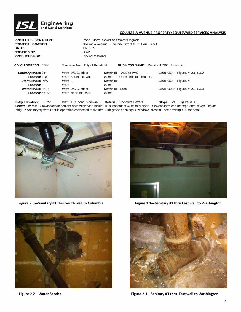
2
COLUMBIA AVENUE PROPERTY/BOULEVARD SERVICES ANALYSIS
PROJECT DESCRIPTION: Road, Storm, Sewer and Water Upgrade PROJECT LOCATION: Columbia Avenue - Spokane Street to St. Paul Street DATE: 11/11/15 CREATED BY: JGW PRODUCED FOR: City of Rossland
CIVIC ADDRESS: 1990 Columbia Ave. City of Rossland BUSINESS NAME: Rossland PRO Hardware
Sanitary Invert: 24” from: U/S Subfloor Material: ABS to PVC Size: Ø6” Figure. # 2.1 & 3.0 Located: 4’-8” from: South fdn. wall Notes: Unsealed hole thru fdn.
Storm Invert: N/A from: - Material: - Size: Ø6” Figure. # - Located: - from: - Notes: -
Water Invert: 6’-4” from: U/S Subfloor Material: Steel Size: Ø2.5” Figure. # 2.2 & 3.3 Located: 58’-6” from: North fdn. wall Notes:
Entry Elevation: 3.25” from: T.O. conc. sidewalk Material: Concrete Pavers Slope: 2% Figure. # 1.1 General Notes: Crawlspace/basement accessible via.: Inside; +/- 8’ basement w/ cement floor - Sewer/Storm can be separated at wye. Inside bldg.; 2 Sanitary systems not in operation/connected to fixtures; Sub-grade openings & windows present - see drawing A02 for detail.
Figure 2.0—Sanitary #1 thru South wall to Columbia Figure 2.1—Sanitary #2 thru East wall to Washington
Figure 2.2—Water Service Figure 2.3—Sanitary #3 thru East wall to Washington
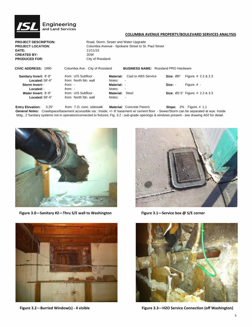
3
COLUMBIA AVENUE PROPERTY/BOULEVARD SERVICES ANALYSIS
PROJECT DESCRIPTION: Road, Storm, Sewer and Water Upgrade PROJECT LOCATION: Columbia Avenue - Spokane Street to St. Paul Street DATE: 11/11/15 CREATED BY: JGW PRODUCED FOR: City of Rossland
CIVIC ADDRESS: 1990 Columbia Ave. City of Rossland BUSINESS NAME: Rossland PRO Hardware
Sanitary Invert: 8’-8” from: U/S Subfloor Material: Cast to ABS Service Size: Ø6” Figure. # 2.2 & 2.3 Located: 58’-6” from: North fdn. wall Notes: -
Storm Invert: - from: - Material: - Size: - Figure. # - Located: - from: - Notes: -
Water Invert: 8’-8” from: U/S Subfloor Material: Steel Size: Ø2.5” Figure. # 2.2 & 3.3 Located: 58’-6” from: North fdn. wall Notes: -
Entry Elevation: 3.25” from: T.O. conc. sidewalk Material: Concrete Pavers Slope: 2% Figure. # 1.1 General Notes: Crawlspace/basement accessible via.: Inside; +/- 8’ basement w/ cement floor - Sewer/Storm can be separated at wye. Inside bldg.; 2 Sanitary systems not in operation/connected to fixtures; Fig. 3.2 -.sub-grade openings & windows present - see drawing A02 for detail.
Figure 3.0—Sanitary #2—Thru S/E wall to Washington Figure 3.1—Service box @ S/E corner
Figure 3.2—Burried Window(s) ‐ 4 visible Figure 3.3—H2O Service Connec on (off Washington)
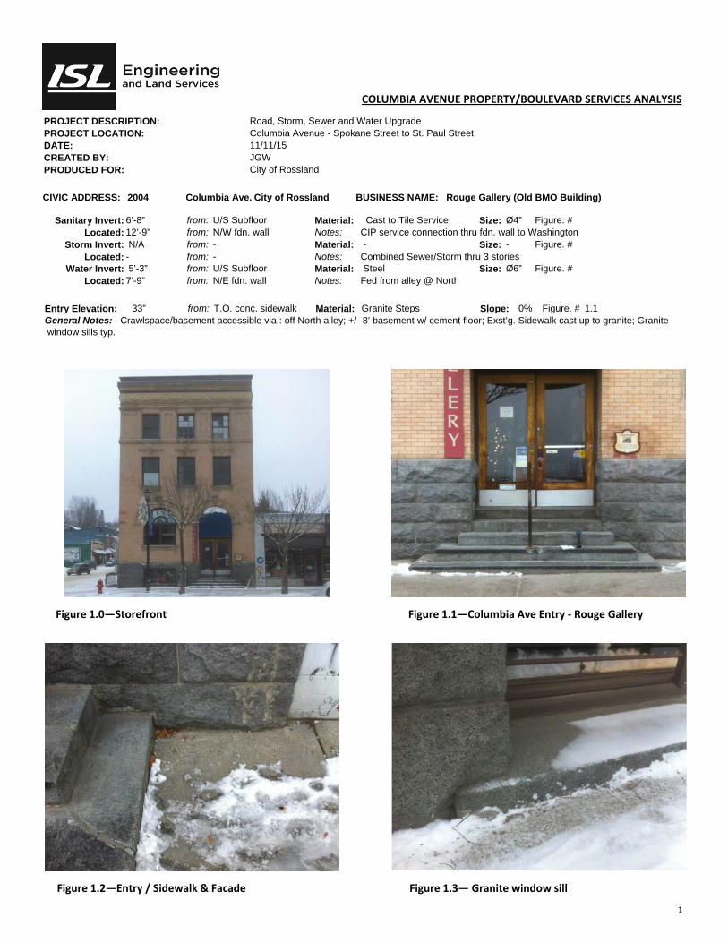
1
COLUMBIA AVENUE PROPERTY/BOULEVARD SERVICES ANALYSIS
PROJECT DESCRIPTION: Road, Storm, Sewer and Water Upgrade PROJECT LOCATION: Columbia Avenue - Spokane Street to St. Paul Street DATE: 11/11/15 CREATED BY: JGW PRODUCED FOR: City of Rossland
CIVIC ADDRESS: 2004 Columbia Ave. City of Rossland BUSINESS NAME: Rouge Gallery (Old BMO Building)
Sanitary Invert: 6’-8” from: U/S Subfloor Material: Cast to Tile Service Size: Ø4” Figure. # Located: 12’-9” from: N/W fdn. wall Notes: CIP service connection thru fdn. wall to Washington
Storm Invert: N/A from: - Material: - Size: - Figure. # Located: - from: - Notes: Combined Sewer/Storm thru 3 stories
Water Invert: 5’-3” from: U/S Subfloor Material: Steel Size: Ø6” Figure. # Located: 7’-9” from: N/E fdn. wall Notes: Fed from alley @ North
Entry Elevation: 33” from: T.O. conc. sidewalk Material: Granite Steps Slope: 0% Figure. # 1.1 General Notes: Crawlspace/basement accessible via.: off North alley; +/- 8’ basement w/ cement floor; Exst’g. Sidewalk cast up to granite; Granite window sills typ.
Figure 1.0—Storefront Figure 1.1—Columbia Ave Entry ‐ Rouge Gallery
Figure 1.2—Entry / Sidewalk & Facade Figure 1.3— Granite window sill

1
COLUMBIA AVENUE PROPERTY/BOULEVARD SERVICES ANALYSIS
PROJECT DESCRIPTION: Road, Storm, Sewer and Water Upgrade PROJECT LOCATION: Columbia Avenue - Spokane Street to St. Paul Street DATE: 11/11/15 CREATED BY: JGW PRODUCED FOR: City of Rossland
CIVIC ADDRESS: 2012 Columbia Ave. City of Rossland BUSINESS NAME: Main Stage Gallery
Sanitary Invert: - from: - Material: - Size: - Figure. # - Located: - from: - Notes: -
Storm Invert: - from: - Material: - Size: - Figure. # - Located: - from: - Notes: -
Water Invert: - from: - Material: - Size: - Figure. # - Located: - from: - Notes: -
Entry Elevation: 0.5” from: T.O. conc. sidewalk Material: Concrete Slope: 0.2% Figure. # 1.1
General Notes: Crawlspace/basement accessible via.: Inside; +/- 8’ basement w/ cement floor - Sewer not visible due to finished basement.
Figure 1.0—Storefront Figure 1.1—Entry
Figure 1.2— Entry Figure 1.3—Entry/Sidewalk
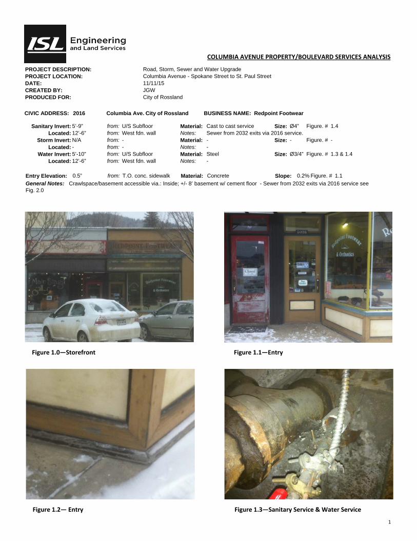
1
COLUMBIA AVENUE PROPERTY/BOULEVARD SERVICES ANALYSIS
PROJECT DESCRIPTION: Road, Storm, Sewer and Water Upgrade PROJECT LOCATION: Columbia Avenue - Spokane Street to St. Paul Street DATE: 11/11/15 CREATED BY: JGW PRODUCED FOR: City of Rossland
CIVIC ADDRESS: 2016 Columbia Ave. City of Rossland BUSINESS NAME: Redpoint Footwear
Sanitary Invert: 5’-9” from: U/S Subfloor Material: Cast to cast service Size: Ø4” Figure. # 1.4 Located: 12’-6” from: West fdn. wall Notes: Sewer from 2032 exits via 2016 service.
Storm Invert: N/A from: - Material: - Size: - Figure. # - Located: - from: - Notes: -
Water Invert: 5’-10” from: U/S Subfloor Material: Steel Size: Ø3/4” Figure. # 1.3 & 1.4 Located: 12’-6” from: West fdn. wall Notes: -
Entry Elevation: 0.5” from: T.O. conc. sidewalk Material: Concrete Slope: 0.2% Figure. # 1.1
General Notes: Crawlspace/basement accessible via.: Inside; +/- 8’ basement w/ cement floor - Sewer from 2032 exits via 2016 service see Fig. 2.0
Figure 1.0—Storefront Figure 1.1—Entry
Figure 1.2— Entry Figure 1.3—Sanitary Service & Water Service
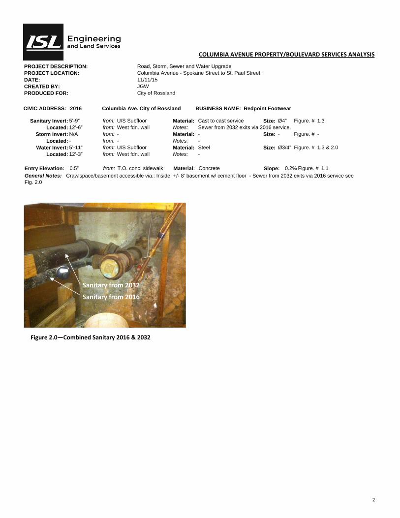
2
COLUMBIA AVENUE PROPERTY/BOULEVARD SERVICES ANALYSIS
PROJECT DESCRIPTION: Road, Storm, Sewer and Water Upgrade PROJECT LOCATION: Columbia Avenue - Spokane Street to St. Paul Street DATE: 11/11/15 CREATED BY: JGW PRODUCED FOR: City of Rossland
CIVIC ADDRESS: 2016 Columbia Ave. City of Rossland BUSINESS NAME: Redpoint Footwear
Sanitary Invert: 5’-9” from: U/S Subfloor Material: Cast to cast service Size: Ø4” Figure. # 1.3 Located: 12’-6” from: West fdn. wall Notes: Sewer from 2032 exits via 2016 service.
Storm Invert: N/A from: - Material: - Size: - Figure. # - Located: - from: - Notes: -
Water Invert: 5’-11” from: U/S Subfloor Material: Steel Size: Ø3/4” Figure. # 1.3 & 2.0 Located: 12’-3” from: West fdn. wall Notes: -
Entry Elevation: 0.5” from: T.O. conc. sidewalk Material: Concrete Slope: 0.2% Figure. # 1.1
General Notes: Crawlspace/basement accessible via.: Inside; +/- 8’ basement w/ cement floor - Sewer from 2032 exits via 2016 service see Fig. 2.0
Figure 2.0—Combined Sanitary 2016 & 2032
Sanitary from 2032
Sanitary from 2016

1
COLUMBIA AVENUE PROPERTY/BOULEVARD SERVICES ANALYSIS
PROJECT DESCRIPTION: Road, Storm, Sewer and Water Upgrade PROJECT LOCATION: Columbia Avenue - Spokane Street to St. Paul Street DATE: 11/11/15 CREATED BY: JGW PRODUCED FOR: City of Rossland
CIVIC ADDRESS: 2024 Columbia Ave. City of Rossland BUSINESS NAME: Best Food Mart
Sanitary Invert: - from: - Material: Cast to cast Size: Ø4” Figure. # 2.0; 2.1; 2.3 Located: - from: - Notes: See 2016 service info.
Storm Invert: N/A from: - Material: - Size: - Figure. # Located: - from: - Notes:
Water Invert: from: - Material: - Size: - Figure. # Located: from: - Notes:
Entry Elevation: Grade from: T.O. conc. sidewalk Material: Tile Slope: 0.1% Figure. # 1.1 Service connects to 2016 (Redpoint Footwear) in basement.
Figure 1.0—Sanitary #4—Thru East wall to Washington Figure 1.1—Entry
Figure 2.2—Entry / Sidewalk
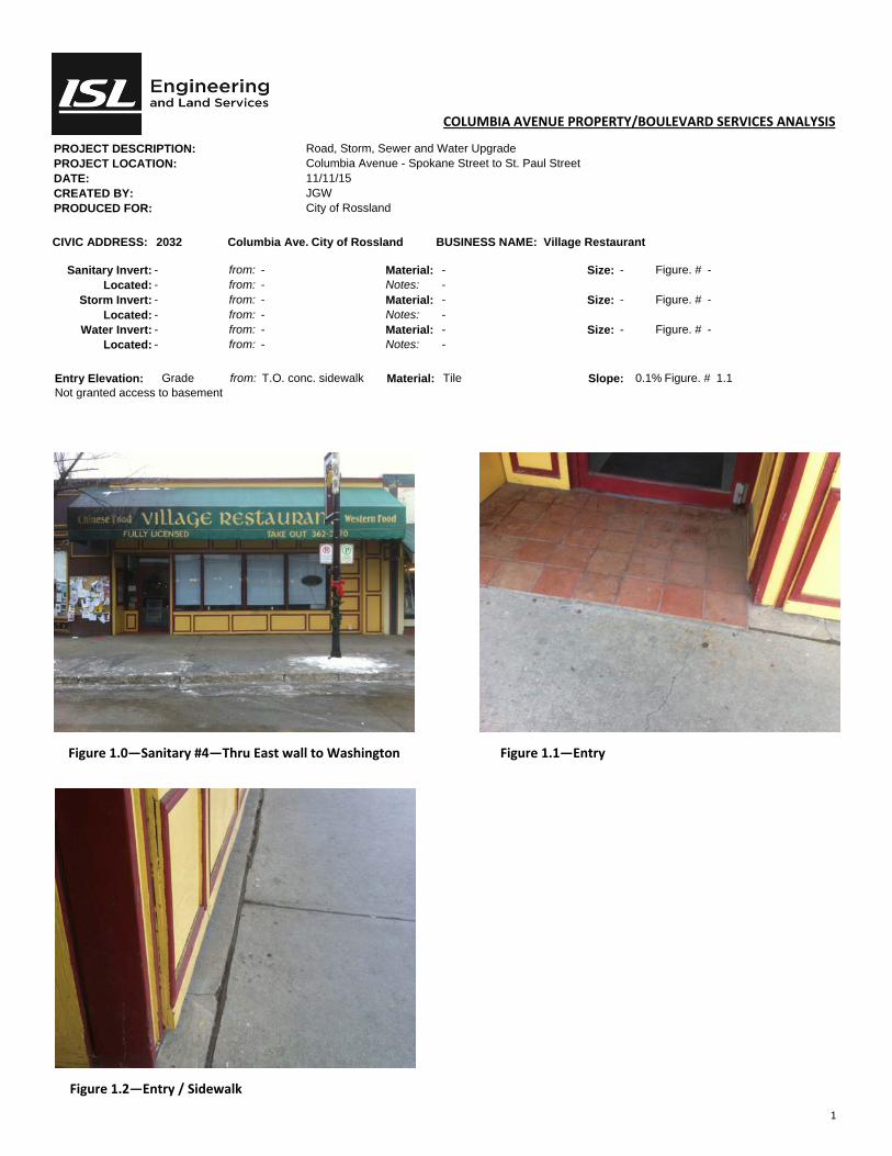
1
COLUMBIA AVENUE PROPERTY/BOULEVARD SERVICES ANALYSIS
PROJECT DESCRIPTION: Road, Storm, Sewer and Water Upgrade PROJECT LOCATION: Columbia Avenue - Spokane Street to St. Paul Street DATE: 11/11/15 CREATED BY: JGW PRODUCED FOR: City of Rossland
CIVIC ADDRESS: 2032 Columbia Ave. City of Rossland BUSINESS NAME: Village Restaurant
Sanitary Invert: - from: - Material: - Size: - Figure. # - Located: - from: - Notes: -
Storm Invert: - from: - Material: - Size: - Figure. # - Located: - from: - Notes: -
Water Invert: - from: - Material: - Size: - Figure. # - Located: - from: - Notes: -
Entry Elevation: Grade from: T.O. conc. sidewalk Material: Tile Slope: 0.1% Figure. # 1.1 Not granted access to basement
Figure 1.0—Sanitary #4—Thru East wall to Washington Figure 1.1—Entry
Figure 1.2—Entry / Sidewalk
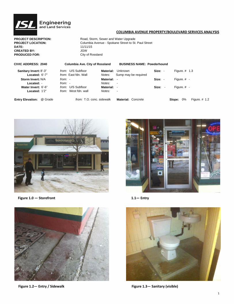
1
COLUMBIA AVENUE PROPERTY/BOULEVARD SERVICES ANALYSIS
PROJECT DESCRIPTION: Road, Storm, Sewer and Water Upgrade PROJECT LOCATION: Columbia Avenue - Spokane Street to St. Paul Street DATE: 11/11/15 CREATED BY: JGW PRODUCED FOR: City of Rossland
CIVIC ADDRESS: 2040 Columbia Ave. City of Rossland BUSINESS NAME: Powderhound
Sanitary Invert: 8’-3” from: U/S Subfloor Material: Unknown Size: - Figure. # 1.3 Located: 6’-7” from: East fdn. Wall Notes: Sump may be required
Storm Invert: N/A from: - Material: - Size: - Figure. # - Located: - from: - Notes: -
Water Invert: 6’-6” from: U/S Subfloor Material: - Size: - Figure. # - Located: 1’2” from: West fdn. wall Notes: -
Entry Elevation: @ Grade from: T.O. conc. sidewalk Material: Concrete Slope: 0% Figure. # 1.2
Figure 1.0 — Storefront 1.1— Entry
Figure 1.2— Entry / Sidewalk Figure 1.3— Sanitary (visible)
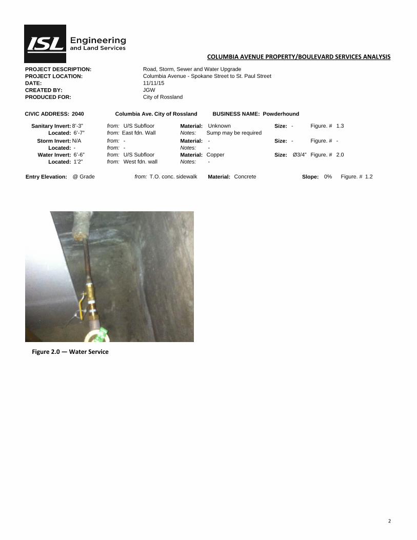
2
COLUMBIA AVENUE PROPERTY/BOULEVARD SERVICES ANALYSIS
PROJECT DESCRIPTION: Road, Storm, Sewer and Water Upgrade PROJECT LOCATION: Columbia Avenue - Spokane Street to St. Paul Street DATE: 11/11/15 CREATED BY: JGW PRODUCED FOR: City of Rossland
CIVIC ADDRESS: 2040 Columbia Ave. City of Rossland BUSINESS NAME: Powderhound
Sanitary Invert: 8’-3” from: U/S Subfloor Material: Unknown Size: - Figure. # 1.3 Located: 6’-7” from: East fdn. Wall Notes: Sump may be required
Storm Invert: N/A from: - Material: - Size: - Figure. # - Located: - from: - Notes: -
Water Invert: 6’-6” from: U/S Subfloor Material: Copper Size: Ø3/4” Figure. # 2.0 Located: 1’2” from: West fdn. wall Notes: -
Entry Elevation: @ Grade from: T.O. conc. sidewalk Material: Concrete Slope: 0% Figure. # 1.2
Figure 2.0 — Water Service
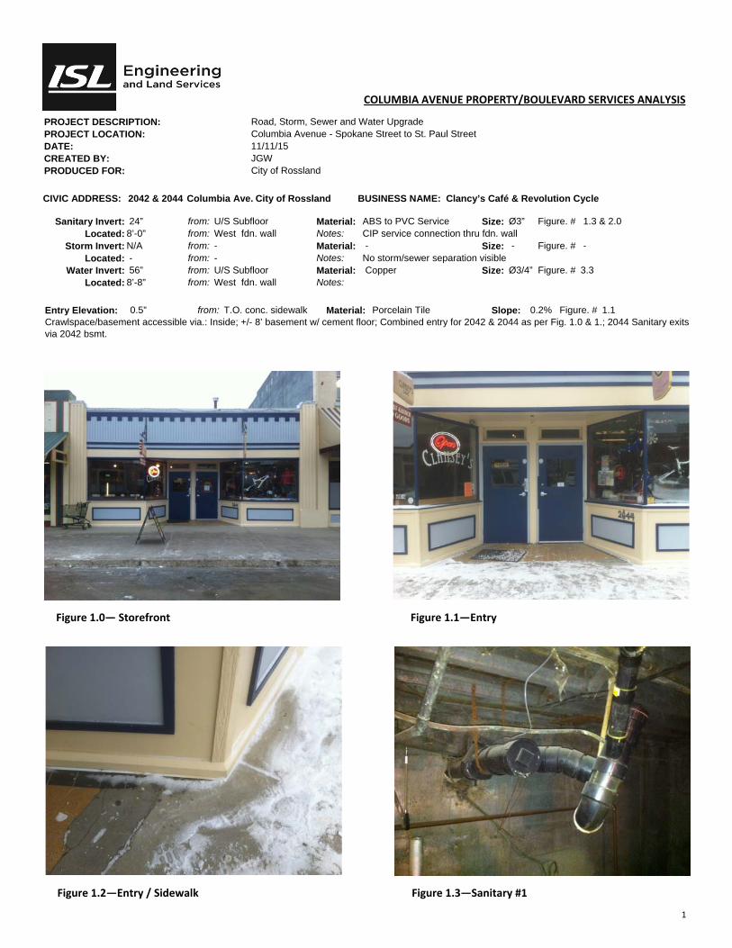
1
COLUMBIA AVENUE PROPERTY/BOULEVARD SERVICES ANALYSIS
PROJECT DESCRIPTION: Road, Storm, Sewer and Water Upgrade PROJECT LOCATION: Columbia Avenue - Spokane Street to St. Paul Street DATE: 11/11/15 CREATED BY: JGW PRODUCED FOR: City of Rossland
CIVIC ADDRESS: 2042 & 2044 Columbia Ave. City of Rossland BUSINESS NAME: Clancy’s Café & Revolution Cycle
Sanitary Invert: 24” from: U/S Subfloor Material: ABS to PVC Service Size: Ø3” Figure. # 1.3 & 2.0 Located: 8’-0” from: West fdn. wall Notes: CIP service connection thru fdn. wall
Storm Invert: N/A from: - Material: - Size: - Figure. # - Located: - from: - Notes: No storm/sewer separation visible
Water Invert: 56” from: U/S Subfloor Material: Copper Size: Ø3/4” Figure. # 3.3 Located: 8’-8” from: West fdn. wall Notes:
Entry Elevation: 0.5” from: T.O. conc. sidewalk Material: Porcelain Tile Slope: 0.2% Figure. # 1.1 Crawlspace/basement accessible via.: Inside; +/- 8’ basement w/ cement floor; Combined entry for 2042 & 2044 as per Fig. 1.0 & 1.; 2044 Sanitary exits via 2042 bsmt.
Figure 1.0— Storefront Figure 1.1—Entry
Figure 1.2—Entry / Sidewalk Figure 1.3—Sanitary #1

2
COLUMBIA AVENUE PROPERTY/BOULEVARD SERVICES ANALYSIS
PROJECT DESCRIPTION: Road, Storm, Sewer and Water Upgrade PROJECT LOCATION: Columbia Avenue - Spokane Street to St. Paul Street DATE: 11/11/15 CREATED BY: JGW PRODUCED FOR: City of Rossland
CIVIC ADDRESS: 2042 & 2044 Columbia Ave. City of Rossland BUSINESS NAME: Clancy’s Café & Revolution Cyle
Sanitary Invert: 7’-3” from: U/S Subfloor Material: ABS to Cast Size: Ø4” Figure. # 2.1; 2.2 Located: 4’-10” from: West fdn. wall Notes: Goes thru S.O.G @ 2’9” off South fdn wall
Storm Invert: - from: - Material: - Size: - Figure. # - Located: - from: - Notes: -
Water Invert: - from: - Material: - Size: - Figure. # - Located: - from: - Notes: -
Entry Elevation: 0.5” from: T.O. conc. sidewalk Material: Porcelain Tile Slope: 0.2% Figure. # 1.1 Crawlspace/basement accessible via.: Inside; +/- 8’ basement w/ cement floor; Combined entry for 2042 & 2044 as per Fig. 1.0 & 1.; 2044 Sanitary exits via 2042 bsmt.
Figure 2.0—Sanitary #1—Thru South wall. Figure 2.1—Sanitary #2—from 2042
Figure 2.2—Sanitary #2 Figure 2.3—Sanitary #3—from 2044

3
COLUMBIA AVENUE PROPERTY/BOULEVARD SERVICES ANALYSIS
PROJECT DESCRIPTION: Road, Storm, Sewer and Water Upgrade PROJECT LOCATION: Columbia Avenue - Spokane Street to St. Paul Street DATE: 11/11/15 CREATED BY: JGW PRODUCED FOR: City of Rossland
CIVIC ADDRESS: 2042 & 2044 Columbia Ave. City of Rossland BUSINESS NAME: Clancy’s Café & Revolution Cycle
Sanitary Invert: 7’-3” from: U/S Subfloor Material: Cast to ABS Service Size: Ø3” Figure. # 2.3, 3.0, 3.1 Located: 13’-9” from: South West fdn. wall Notes: Thru S.O.G @ 2’-0” of East wall (basement divider)
Storm Invert: N/A from: - Material: - Size: Ø3” Figure. # 3.2 Located: Mid Building from: - Notes: Possible storm leader from roof
Water Invert: 32” from: U/S Subfloor Material: Copper Size: Ø3/4” Figure. # 3.3 Located: from: South West fdn. wall Notes:
Entry Elevation: Grade from: T.O. conc. sidewalk Material: Concrete Slope: -0.5% Figure. # 1.1 Sanitary # 2 & 3 can be re-piped to suit new sanitary service. Sanitary # 4 is possible a RWL from the roof. Unable to determine.
Figure 3.0—Sanitary #3—from 2044 Columbia. Figure 3.1—Sanitary #3—from 2044 Columbia.
Figure 3.2—Sanitary #4 ‐ East wall @ mid‐point Figure 3.3—Water Service
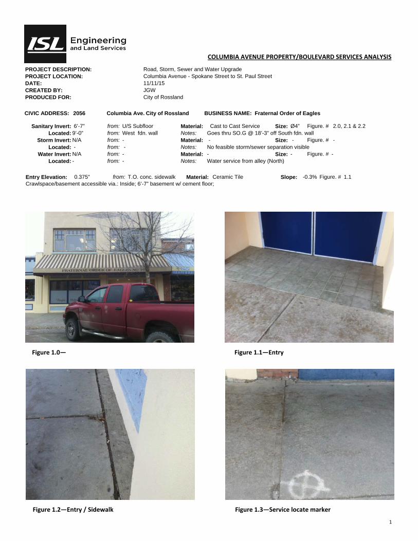
1
COLUMBIA AVENUE PROPERTY/BOULEVARD SERVICES ANALYSIS
PROJECT DESCRIPTION: Road, Storm, Sewer and Water Upgrade PROJECT LOCATION: Columbia Avenue - Spokane Street to St. Paul Street DATE: 11/11/15 CREATED BY: JGW PRODUCED FOR: City of Rossland
CIVIC ADDRESS: 2056 Columbia Ave. City of Rossland BUSINESS NAME: Fraternal Order of Eagles
Sanitary Invert: 6’-7” from: U/S Subfloor Material: Cast to Cast Service Size: Ø4” Figure. # 2.0, 2.1 & 2.2 Located: 9’-0” from: West fdn. wall Notes: Goes thru SO.G @ 18’-3” off South fdn. wall
Storm Invert: N/A from: - Material: - Size: - Figure. # - Located: - from: - Notes: No feasible storm/sewer separation visible
Water Invert: N/A from: - Material: - Size: - Figure. # - Located: - from: - Notes: Water service from alley (North)
Entry Elevation: 0.375” from: T.O. conc. sidewalk Material: Ceramic Tile Slope: -0.3% Figure. # 1.1 Crawlspace/basement accessible via.: Inside; 6’-7” basement w/ cement floor;
Figure 1.0— Figure 1.1—Entry
Figure 1.2—Entry / Sidewalk Figure 1.3—Service locate marker

2
COLUMBIA AVENUE PROPERTY/BOULEVARD SERVICES ANALYSIS
PROJECT DESCRIPTION: Road, Storm, Sewer and Water Upgrade PROJECT LOCATION: Columbia Avenue - Spokane Street to St. Paul Street DATE: 11/11/15 CREATED BY: JGW PRODUCED FOR: City of Rossland
CIVIC ADDRESS: 2056 Columbia Ave. City of Rossland BUSINESS NAME: Fraternal Order of Eagles
Sanitary Invert: 6’-7” from: U/S Subfloor Material: Cast to Cast Service Size: Ø4” Figure. # 2.0, 2.1 & 2.2 Located: 9’-0” from: West fdn. wall Notes: Goes thru SO.G @ 18’-3” off South fdn. wall
Storm Invert: N/A from: - Material: - Size: - Figure. # - Located: - from: - Notes: No feasible storm/sewer separation visible
Water Invert: N/A from: - Material: - Size: - Figure. # - Located: - from: - Notes: Water Service from alley (North)
Entry Elevation: 0.375” from: T.O. conc. sidewalk Material: Ceramic Tile Slope: -0.3% Figure. # 1.1 Crawlspace/basement accessible via.: Inside; 6’-7” basement w/ cement floor;
Figure 2.0— Sanitary @ S.O.G. Figure 2.1—Sanitary branch from North
Figure 2.2—Sanitary branch running North

1
COLUMBIA AVENUE PROPERTY/BOULEVARD SERVICES ANALYSIS
PROJECT DESCRIPTION: Road, Storm, Sewer and Water Upgrade PROJECT LOCATION: Columbia Avenue - Spokane Street to St. Paul Street DATE: 11/11/15 CREATED BY: JGW PRODUCED FOR: City of Rossland
CIVIC ADDRESS: 2060 Columbia Ave. City of Rossland BUSINESS NAME: Peoples Drug Mart
Sanitary Invert: 5’-9” from: U/S Subfloor Material: Cast to Cast Service Size: Ø4” Figure. # 2.0 Located: 2’-3” from: West fdn. wall Notes: Coal Shute in vicinity of service see dwg. A02 for detail.
Storm Invert: N/A from: - Material: - Size: - Figure. # - Located: - from: - Notes: No feasible storm/sewer separation visible
Water Invert: 38” from: U/S Subfloor Material: Copper Size: Ø1/2” Figure. # 2.2 Located: 12’ from: West fdn. wall Notes: -
Entry Elevation: Grade from: T.O. conc. sidewalk Material: Concrete Slope: 1% Figure. # 1.1 Crawlspace/basement accessible via.: Inside; +/- 8’ basement w/ dirt floor ; Sewer locate marker present; Water Service - curb stop visible in sidewalk.
Figure 1.0— Figure 1.1—Entry
Figure 1.2—Entry / Sidewalk Figure 1.3—Service locate marker

2
COLUMBIA AVENUE PROPERTY/BOULEVARD SERVICES ANALYSIS
PROJECT DESCRIPTION: Road, Storm, Sewer and Water Upgrade PROJECT LOCATION: Columbia Avenue - Spokane Street to St. Paul Street DATE: 11/11/15 CREATED BY: JGW PRODUCED FOR: City of Rossland
CIVIC ADDRESS: 2060 Columbia Ave. City of Rossland BUSINESS NAME: Peoples Drug Mart
Sanitary Invert: 5’-9” from: U/S Subfloor Material: Cast to Cast Service Size: Ø4” Figure. # 2.0 Located: 2’-3” from: West fdn. wall Notes: Coal Shute in vicinity of service see dwg. A02 for detail.
Storm Invert: N/A from: - Material: - Size: - Figure. # - Located: - from: - Notes: No feasible storm/sewer separation visible
Water Invert: 38” from: U/S Subfloor Material: Copper Size: Ø1/2” Figure. # 2.2 Located: 12’ from: West fdn. wall Notes: -
Entry Elevation: Grade from: T.O. conc. sidewalk Material: Concrete Slope: 1% Figure. # 1.1 Crawlspace/basement accessible via.: Inside; +/- 8’ basement w/ dirt floor ; Sewer locate marker present; Water Service - curb stop visible in sidewalk.
Figure 2.0 — Connec on to Service Figure 2.1— Tie to Service
Figure 2.2 — Water Service
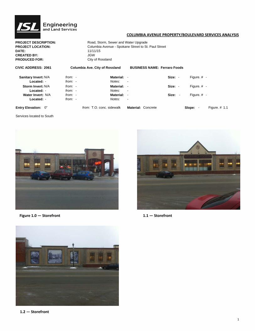
1
COLUMBIA AVENUE PROPERTY/BOULEVARD SERVICES ANALYSIS
PROJECT DESCRIPTION: Road, Storm, Sewer and Water Upgrade PROJECT LOCATION: Columbia Avenue - Spokane Street to St. Paul Street DATE: 11/11/15 CREATED BY: JGW PRODUCED FOR: City of Rossland
CIVIC ADDRESS: 2061 Columbia Ave. City of Rossland BUSINESS NAME: Ferraro Foods
Sanitary Invert: N/A from: - Material: - Size: - Figure. # - Located: - from: - Notes: -
Storm Invert: N/A from: - Material: - Size: - Figure. # - Located: - from: - Notes: -
Water Invert: N/A from: - Material: - Size: - Figure. # - Located: - from: - Notes: -
Entry Elevation: 0” from: T.O. conc. sidewalk Material: Concrete Slope: - Figure. # 1.1 Services located to South
Figure 1.0 — Storefront 1.1 — Storefront
1.2 — Storefront

1
COLUMBIA AVENUE PROPERTY/BOULEVARD SERVICES ANALYSIS
PROJECT DESCRIPTION: Road, Storm, Sewer and Water Upgrade PROJECT LOCATION: Columbia Avenue - Spokane Street to St. Paul Street DATE: 11/11/15 CREATED BY: JGW PRODUCED FOR: City of Rossland
CIVIC ADDRESS: 2065 Columbia Ave. City of Rossland BUSINESS NAME: BC Liquor Store
Sanitary Invert: N/A from: - Material: - Size: - Figure. # - Located: - from: - Notes: -
Storm Invert: N/A from: - Material: - Size: - Figure. # - Located: - from: - Notes: -
Water Invert: N/A from: - Material: - Size: - Figure. # - Located: - from: - Notes: -
Entry Elevation: Grade from: T.O. conc. sidewalk Material: Concrete Slope: 0.5% Figure. # 1.1 Services located to South
Figure 1.0 — Storefront 1.1— Entry
1
COLUMBIA AVENUE PROPERTY/BOULEVARD SERVICES ANALYSIS
PROJECT DESCRIPTION: Road, Storm, Sewer and Water Upgrade PROJECT LOCATION: Columbia Avenue - Spokane Street to St. Paul Street DATE: 11/11/15 CREATED BY: JGW PRODUCED FOR: City of Rossland
CIVIC ADDRESS: 2067 Columbia Ave. City of Rossland BUSINESS NAME: Out of the Cellar
Sanitary Invert: N/A from: - Material: - Size: - Figure. # - Located: - from: - Notes: -
Storm Invert: N/A from: - Material: - Size: - Figure. # - Located: - from: - Notes: -
Water Invert: N/A from: - Material: - Size: - Figure. # - Located: - from: - Notes: -
Entry Elevation: Grade from: T.O. conc. sidewalk Material: Concrete Slope: 0.5% Figure. # 1.1 Services located to South
Figure 1.0 — Storefront 1.1— Entry

1
COLUMBIA AVENUE PROPERTY/BOULEVARD SERVICES ANALYSIS
PROJECT DESCRIPTION: Road, Storm, Sewer and Water Upgrade PROJECT LOCATION: Columbia Avenue - Spokane Street to St. Paul Street DATE: 11/11/15 CREATED BY: JGW PRODUCED FOR: City of Rossland
CIVIC ADDRESS: 2070 & 2072 Columbia Ave. City of Rossland BUSINESS NAME: Bear Country kitchen & Jelly Bean Junction
Sanitary Invert: Flush from: U/S Subfloor Material: Cast & ABS Size: Ø2&3” Figure. # 2.1 Located: ~ 10’-0” from: North fdn. wall Notes: Sanitary appears to exit thru 2060 (Peoples Drug Mart)
Storm Invert: N/A from: - Material: - Size: - Figure. # - Located: - from: - Notes: No feasible storm/sewer separation visible
Water Invert: - from: - Material: - Size: - Figure. # - Located: Unknown from: - Notes: -
Entry Elevation: 2” from: T.O. conc. sidewalk Material: Concrete Slope: 1% Figure. # 1.1 Crawlspace/basement accessible via.: Inside; +/- 8’ basement w/ cement floor Bathroom is located @ North end of building in non– accessible crawlspace; Sanitary appears to exit thru 2060 (Peoples Drug Mart) but was not visible due to stock & records blocking the view; Sanitary could be re-piped & make proposed grade thru South foundation.
Figure 1.0 — Facade Figure 1.1 — Entry
Figure 1.2—Entry / Sidewalk Figure 1.3—Curb Stop in sidewalk
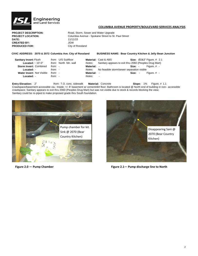
2
COLUMBIA AVENUE PROPERTY/BOULEVARD SERVICES ANALYSIS
PROJECT DESCRIPTION: Road, Storm, Sewer and Water Upgrade PROJECT LOCATION: Columbia Avenue - Spokane Street to St. Paul Street DATE: 11/11/15 CREATED BY: JGW PRODUCED FOR: City of Rossland
CIVIC ADDRESS: 2070 & 2072 Columbia Ave. City of Rossland BUSINESS NAME: Bear Country Kitchen & Jelly Bean Junction
Sanitary Invert: Flush from: U/S Subfloor Material: Cast & ABS Size: Ø2&3” Figure. # 2.1 Located: ~ 10’-0” from: North fdn. wall Notes: Sanitary appears to exit thru 2060 (Peoples Drug Mart)
Storm Invert: Combined from: - Material: - Size: - Figure. # - Located: - from: - Notes: No feasible storm/sewer separation visible
Water Invert: Not Visible from: - Material: - Size: - Figure. # - Located: - from: - Notes: -
Entry Elevation: 2” from: T.O. conc. sidewalk Material: Concrete Slope: 1% Figure. # 1.1 Crawlspace/basement accessible via.: Inside; +/- 8’ basement w/ cement/dirt floor; Bathroom is located @ North end of building in non– accessible crawlspace; Sanitary appears to exit thru 2060 (Peoples Drug Mart) but was not visible due to stock & records blocking the view; Sanitary could be re-piped & make proposed grade thru South foundation.
Figure 2.0 — Pump Chamber Figure 2.1— Pump discharge line to North
Pump chamber for kit.
Sink @ 2070 (Bear
Country Kitchen)
Disappearing Sani @
2070 (Bear Country
Kitchen)

1
COLUMBIA AVENUE PROPERTY/BOULEVARD SERVICES ANALYSIS
PROJECT DESCRIPTION: Road, Storm, Sewer and Water Upgrade PROJECT LOCATION: Columbia Avenue - Spokane Street to St. Paul Street DATE: 11/11/15 CREATED BY: JGW PRODUCED FOR: City of Rossland
CIVIC ADDRESS: 2071 Columbia Ave. City of Rossland BUSINESS NAME: Nelson & District Credit Union
Sanitary Invert: N/A from: - Material: - Size: - Figure. # - Located: - from: - Notes: -
Storm Invert: N/A from: - Material: - Size: - Figure. # - Located: - from: - Notes: -
Water Invert: N/A from: - Material: - Size: - Figure. # - Located: - from: - Notes: -
Entry Elevation: @ Grade from: T.O. conc. sidewalk Material: Concrete Slope: 0% Figure. # 1.1 Services located to South
Figure 1.0 — Storefront 1.1— Entry

1
COLUMBIA AVENUE PROPERTY/BOULEVARD SERVICES ANALYSIS
PROJECT DESCRIPTION: Road, Storm, Sewer and Water Upgrade PROJECT LOCATION: Columbia Avenue - Spokane Street to St. Paul Street DATE: 11/11/15 CREATED BY: JGW PRODUCED FOR: City of Rossland
CIVIC ADDRESS: 2076 & 2080 Columbia Ave. City of Rossland BUSINESS NAME: Mtn. Nugget Chocolate & RHC Insurance
Sanitary Invert: 3’-8” from: U/S Subfloor Material: Cast & ABS Size: Ø2&3” Figure. # 2.1 Located: 3’-0” from: West fdn. wall Notes: Sanitary exits thru coal shute see dwg. A02 for detail.
Storm Invert: N/A from: - Material: - Size: - Figure. # - Located: - from: - Notes: No storm/sewer separation visible
Water Invert: - from: - Material: - Size: - Figure. # - Located: - from: - Notes: -
Entry Elevation: Grade from: T.O. conc. sidewalk Material: Concrete Slope: 0% Figure. # 1.3 Crawlspace/basement accessible via.: Inside; +/- 8’ basement w/ cement floor; Storm system not present/visible; Water Service not visible.
Figure 1.0 — Facade Figure 1.1 — Entry
Figure 1.2—Entry / Sidewalk Figure 1.3—Sanitary/Service Connec on

1
COLUMBIA AVENUE PROPERTY/BOULEVARD SERVICES ANALYSIS
PROJECT DESCRIPTION: Road, Storm, Sewer and Water Upgrade PROJECT LOCATION: Columbia Avenue - Spokane Street to St. Paul Street DATE: 11/11/15 CREATED BY: JGW PRODUCED FOR: City of Rossland
CIVIC ADDRESS: 2096 Columbia Ave. City of Rossland BUSINESS NAME: Canada Post
Sanitary Invert: 3’-8” from: U/S Subfloor Material: Cast & ABS Size: Ø2&3” Figure. # 1.3, 2.0, 2.1 & 2.2 Located: 3’-0” from: West fdn. wall Notes: Sanitary exits thru coal shute
Storm Invert: Unknown from: - Material: - Size: - Figure. # 2.2 Located: - from: - Notes: Dye testing required to verify separation of storm & sanitary
Water Invert: 9’-3” from: U/S Subfloor Material: Copper Size: Ø1” Figure. # 2.3 Located: 18” from: West fdn. wall Notes: -
Entry Elevation: 63” above Grade from: T.O. conc. sidewalk Material: Concrete Slope: 0% Figure. # 1.1 Crawlspace/basement accessible via.: inside; +/- 9’ basement w/ cement floor; Entry—9 granite steps @ 7” rise (Fig. 1.1)
Figure 1.0 — Facade Figure 1.1 — Entry
Figure 1.2—Entry / Sidewalk Figure 1.3—Sanitary
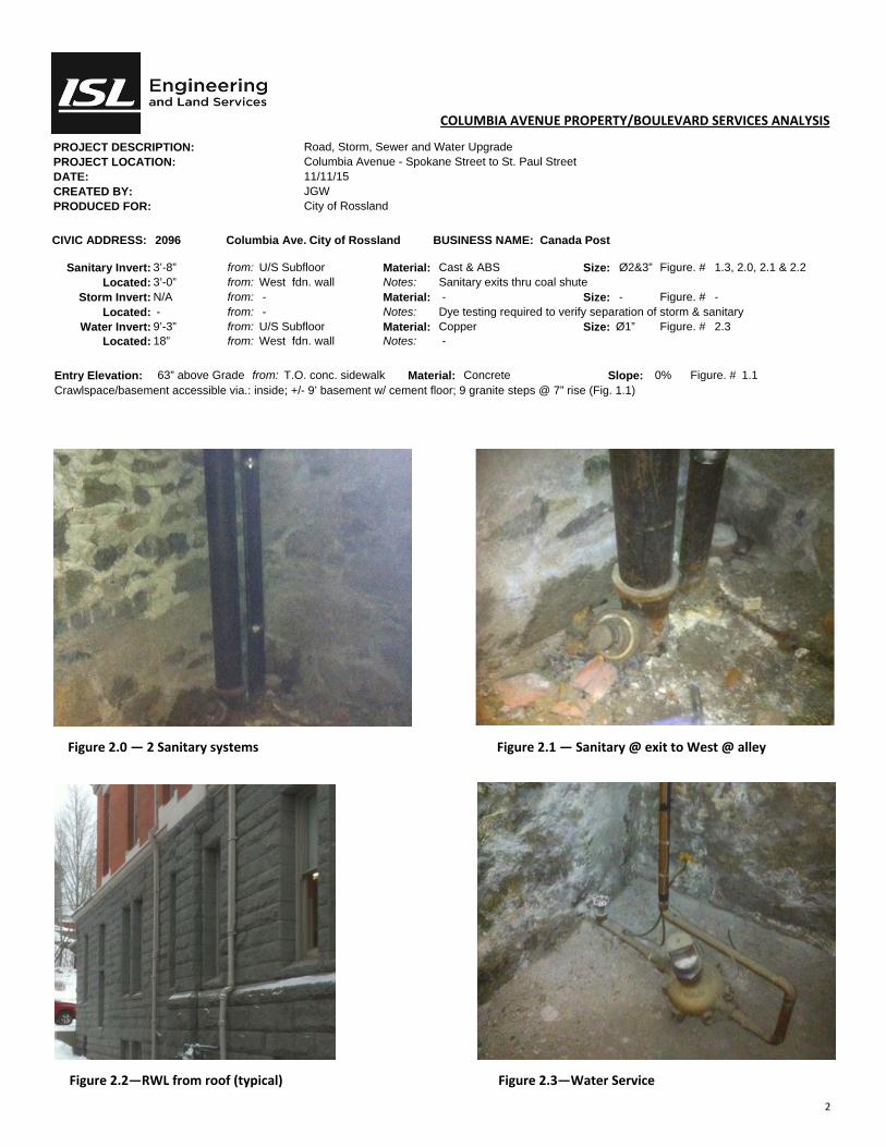
2
COLUMBIA AVENUE PROPERTY/BOULEVARD SERVICES ANALYSIS
PROJECT DESCRIPTION: Road, Storm, Sewer and Water Upgrade PROJECT LOCATION: Columbia Avenue - Spokane Street to St. Paul Street DATE: 11/11/15 CREATED BY: JGW PRODUCED FOR: City of Rossland
CIVIC ADDRESS: 2096 Columbia Ave. City of Rossland BUSINESS NAME: Canada Post
Sanitary Invert: 3’-8” from: U/S Subfloor Material: Cast & ABS Size: Ø2&3” Figure. # 1.3, 2.0, 2.1 & 2.2 Located: 3’-0” from: West fdn. wall Notes: Sanitary exits thru coal shute
Storm Invert: N/A from: - Material: - Size: - Figure. # - Located: - from: - Notes: Dye testing required to verify separation of storm & sanitary
Water Invert: 9’-3” from: U/S Subfloor Material: Copper Size: Ø1” Figure. # 2.3 Located: 18” from: West fdn. wall Notes: -
Entry Elevation: 63” above Grade from: T.O. conc. sidewalk Material: Concrete Slope: 0% Figure. # 1.1 Crawlspace/basement accessible via.: inside; +/- 9’ basement w/ cement floor; 9 granite steps @ 7” rise (Fig. 1.1)
Figure 2.0 — 2 Sanitary systems Figure 2.1 — Sanitary @ exit to West @ alley
Figure 2.2—RWL from roof (typical) Figure 2.3—Water Service
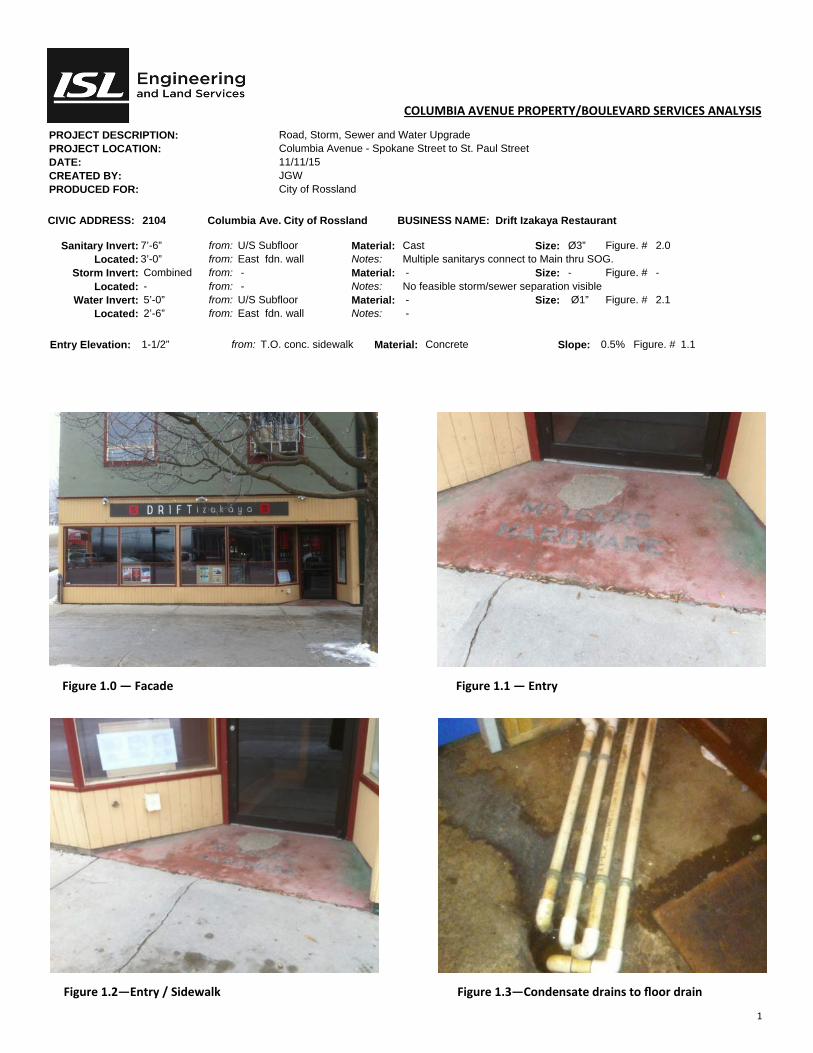
1
COLUMBIA AVENUE PROPERTY/BOULEVARD SERVICES ANALYSIS
PROJECT DESCRIPTION: Road, Storm, Sewer and Water Upgrade PROJECT LOCATION: Columbia Avenue - Spokane Street to St. Paul Street DATE: 11/11/15 CREATED BY: JGW PRODUCED FOR: City of Rossland
CIVIC ADDRESS: 2104 Columbia Ave. City of Rossland BUSINESS NAME: Drift Izakaya Restaurant
Sanitary Invert: 7’-6” from: U/S Subfloor Material: Cast Size: Ø3” Figure. # 2.0 Located: 3’-0” from: East fdn. wall Notes: Multiple sanitarys connect to Main thru SOG.
Storm Invert: Combined from: - Material: - Size: - Figure. # - Located: - from: - Notes: No feasible storm/sewer separation visible
Water Invert: 5’-0” from: U/S Subfloor Material: - Size: Ø1” Figure. # 2.1 Located: 2’-6” from: East fdn. wall Notes: -
Entry Elevation: 1-1/2” from: T.O. conc. sidewalk Material: Concrete Slope: 0.5% Figure. # 1.1
Figure 1.0 — Facade Figure 1.1 — Entry
Figure 1.2—Entry / Sidewalk Figure 1.3—Condensate drains to floor drain

2
COLUMBIA AVENUE PROPERTY/BOULEVARD SERVICES ANALYSIS
PROJECT DESCRIPTION: Road, Storm, Sewer and Water Upgrade PROJECT LOCATION: Columbia Avenue - Spokane Street to St. Paul Street DATE: 11/11/15 CREATED BY: JGW PRODUCED FOR: City of Rossland
CIVIC ADDRESS: 2104 Columbia Ave. City of Rossland BUSINESS NAME: Drift Izakaya Restaurant
Sanitary Invert: 7’-6” from: U/S Subfloor Material: Cast Size: Ø3” Figure. # 2.0 Located: 3’-0” from: East fdn. wall Notes: Multiple sanitarys connect to Main thru SOG.
Storm Invert: Combined from: - Material: - Size: - Figure. # - Located: - from: - Notes: No feasible storm/sewer separation visible
Water Invert: 5’-0” from: U/S Subfloor Material: - Size: Ø1” Figure. # 2.1 Located: 2’-6” from: East fdn. wall Notes: -
Entry Elevation: 1-1/2” from: T.O. conc. sidewalk Material: Concrete Slope: 0.5% Figure. # 1.1
Figure 2.0 — Sanitary thru SOG Figure 2.1 — H20 Supply
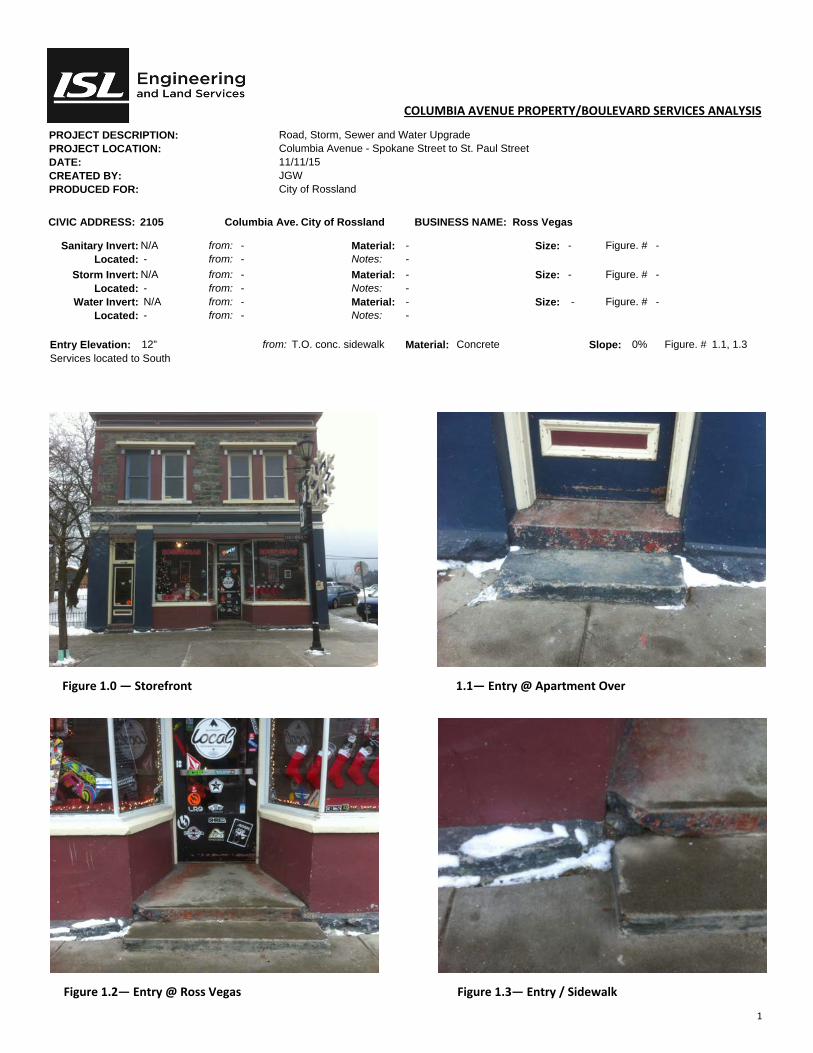
1
COLUMBIA AVENUE PROPERTY/BOULEVARD SERVICES ANALYSIS
PROJECT DESCRIPTION: Road, Storm, Sewer and Water Upgrade PROJECT LOCATION: Columbia Avenue - Spokane Street to St. Paul Street DATE: 11/11/15 CREATED BY: JGW PRODUCED FOR: City of Rossland
CIVIC ADDRESS: 2105 Columbia Ave. City of Rossland BUSINESS NAME: Ross Vegas
Sanitary Invert: N/A from: - Material: - Size: - Figure. # - Located: - from: - Notes: -
Storm Invert: N/A from: - Material: - Size: - Figure. # - Located: - from: - Notes: -
Water Invert: N/A from: - Material: - Size: - Figure. # - Located: - from: - Notes: -
Entry Elevation: 12” from: T.O. conc. sidewalk Material: Concrete Slope: 0% Figure. # 1.1, 1.3 Services located to South
Figure 1.0 — Storefront 1.1— Entry @ Apartment Over
Figure 1.2— Entry @ Ross Vegas Figure 1.3— Entry / Sidewalk

1
COLUMBIA AVENUE PROPERTY/BOULEVARD SERVICES ANALYSIS
PROJECT DESCRIPTION: Road, Storm, Sewer and Water Upgrade PROJECT LOCATION: Columbia Avenue - Spokane Street to St. Paul Street DATE: 11/11/15 CREATED BY: JGW PRODUCED FOR: City of Rossland
CIVIC ADDRESS: 2108/2110/2114 Columbia Ave. City of Rossland BUSINESS NAME: Natures Den/JC Griffiths Notary/Focus Eng.
Sanitary Invert: Unknown from: - Material: - Size: - Figure. # - Located: - from: - Notes: Unable to determine—no accesibility
Storm Invert: - from: - Material: - Size: - Figure. # - Located: - from: - Notes: -
Water Invert: - from: - Material: - Size: - Figure. # - Located: Unknown from: - Notes: -
Entry Elevation: @ Grade from: T.O. conc. sidewalk Material: Concrete Slope: 0% Figure. # 1.1
Figure 1.0 — Facade Figure 1.1 — Entry

1
COLUMBIA AVENUE PROPERTY/BOULEVARD SERVICES ANALYSIS
PROJECT DESCRIPTION: Road, Storm, Sewer and Water Upgrade PROJECT LOCATION: Columbia Avenue - Spokane Street to St. Paul Street DATE: 11/11/15 CREATED BY: JGW PRODUCED FOR: City of Rossland
CIVIC ADDRESS: 2116/2118/2132/2140
Columbia Ave. City of Rossland BUSINESS NAME: Sunshine Café/Delicious Baby Wear/Offices Over/LJ Vanderham Accounting/Century 21
Sanitary Invert: +/- 4’-0” from: U/S Subfloor Material: ABS to unknown Size: Ø4” Figure. # 2.1 Located: +/- 6’-0” from: West fdn. wall Notes: Sanitary accessible from crawlspace +/- 2’-6” H
Storm Invert: Combined from: - Material: - Size: - Figure. # - Located: - from: - Notes: No feasible storm/sewer separation visible
Water Invert: 4’-8” from: U/S Subfloor Material: Steel Size: Ø3/4” Figure. # 2.2 Located: Notes: Beneath entry to upper offices/suites
Entry Elevation: Varies—Flush to +1-1/4” from: T.O. conc. sidewalk Material: Concrete Slope: 0% Figure. # 1.2 & 1.3
Figure 1.0 — Storefront Figure 1.1 — Storefronts
Figure 1.2—Entry / Sidewalk Figure 1.3—Sanitary/Service Connec on

2
COLUMBIA AVENUE PROPERTY/BOULEVARD SERVICES ANALYSIS
PROJECT DESCRIPTION: Road, Storm, Sewer and Water Upgrade PROJECT LOCATION: Columbia Avenue - Spokane Street to St. Paul Street DATE: 11/11/15 CREATED BY: JGW PRODUCED FOR: City of Rossland
CIVIC ADDRESS: 2116/2118/2132/2140
Columbia Ave. City of Rossland BUSINESS NAME: Sunshine Café/Delicious Baby Wear/Offices Over/LJ Vanderham Accounting/Century 21
Sanitary Invert: +/- 4’-0” from: U/S Subfloor Material: ABS to unknown Size: Ø4” Figure. # 2.1 Located: +/- 6’-0” from: West fdn. wall Notes: Sanitary not accessible from crawlspace
Storm Invert: Combined from: - Material: - Size: - Figure. # - Located: - from: - Notes: No feasible storm/sewer separation visible
Water Invert: 4’-8” from: U/S Subfloor Material: Steel Size: Ø3/4” Figure. # 2.2 Located: Notes: Beneath entry to upper offices/suites
Entry Elevation: Varies—Flush to +1-1/4” from: T.O. conc. sidewalk Material: Concrete Slope: 0% Figure. # 1.2 & 1.3
Figure 2.0 — Sanitary service octopus to Sanitary main Figure 2.1 — Water Service
Sewer Main
Clean Out
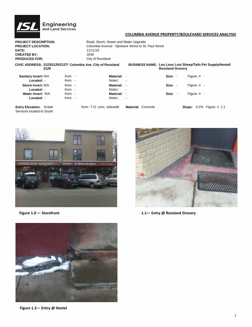
1
COLUMBIA AVENUE PROPERTY/BOULEVARD SERVICES ANALYSIS
PROJECT DESCRIPTION: Road, Storm, Sewer and Water Upgrade PROJECT LOCATION: Columbia Avenue - Spokane Street to St. Paul Street DATE: 11/11/15 CREATED BY: JGW PRODUCED FOR: City of Rossland
CIVIC ADDRESS: 2123/2125/2127/2129
Columbia Ave. City of Rossland BUSINESS NAME: Lou Lous Lost Sheep/Tails Pet Supply/Hostel/Rossland Grocery
Sanitary Invert: N/A from: - Material: - Size: - Figure. # - Located: - from: - Notes: -
Storm Invert: N/A from: - Material: - Size: - Figure. # - Located: - from: - Notes: -
Water Invert: N/A from: - Material: - Size: - Figure. # - Located: - from: - Notes: -
Entry Elevation: Grade from: T.O. conc. sidewalk Material: Concrete Slope: 0.2% Figure. # 1.1 Services located to South
Figure 1.0 — Storefront 1.1— Entry @ Rossland Grocery
Figure 1.2— Entry @ Hostel
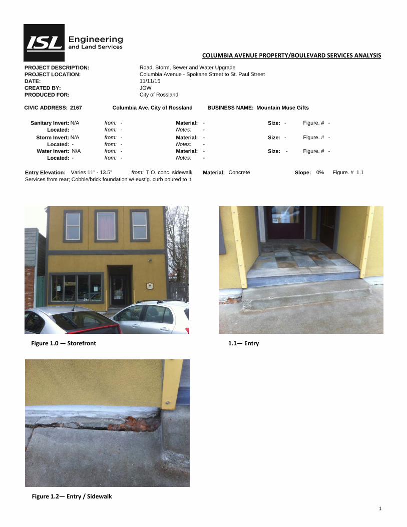
1
COLUMBIA AVENUE PROPERTY/BOULEVARD SERVICES ANALYSIS
PROJECT DESCRIPTION: Road, Storm, Sewer and Water Upgrade PROJECT LOCATION: Columbia Avenue - Spokane Street to St. Paul Street DATE: 11/11/15 CREATED BY: JGW PRODUCED FOR: City of Rossland
CIVIC ADDRESS: 2167 Columbia Ave. City of Rossland BUSINESS NAME: Mountain Muse Gifts
Sanitary Invert: N/A from: - Material: - Size: - Figure. # - Located: - from: - Notes: -
Storm Invert: N/A from: - Material: - Size: - Figure. # - Located: - from: - Notes: -
Water Invert: N/A from: - Material: - Size: - Figure. # - Located: - from: - Notes: -
Entry Elevation: Varies 11” - 13.5” from: T.O. conc. sidewalk Material: Concrete Slope: 0% Figure. # 1.1 Services from rear; Cobble/brick foundation w/ exst’g. curb poured to it.
Figure 1.0 — Storefront 1.1— Entry
Figure 1.2— Entry / Sidewalk

1
COLUMBIA AVENUE PROPERTY/BOULEVARD SERVICES ANALYSIS
PROJECT DESCRIPTION: Road, Storm, Sewer and Water Upgrade PROJECT LOCATION: Columbia Avenue - Spokane Street to St. Paul Street DATE: 11/11/15 CREATED BY: JGW PRODUCED FOR: City of Rossland
CIVIC ADDRESS: 2180 Columbia Ave. City of Rossland BUSINESS NAME: City of Rossland Public Library
Sanitary Invert: Unknown from: - Material: - Size: - Figure. # - Located: - from: - Notes: S.O.G.
Storm Invert: - from: - Material: - Size: - Figure. # - Located: - from: - Notes: -
Water Invert: - from: - Material: - Size: - Figure. # - Located: - from: - Notes: -
Entry Elevation: N/A from: T.O. conc. sidewalk Material: Concrete Slope: 0% Figure. # 1.0 Unable to determine Sanitary, Water & Storm invert & location due to distance from curb and S.O.G.
Figure 1.0 — Storefront
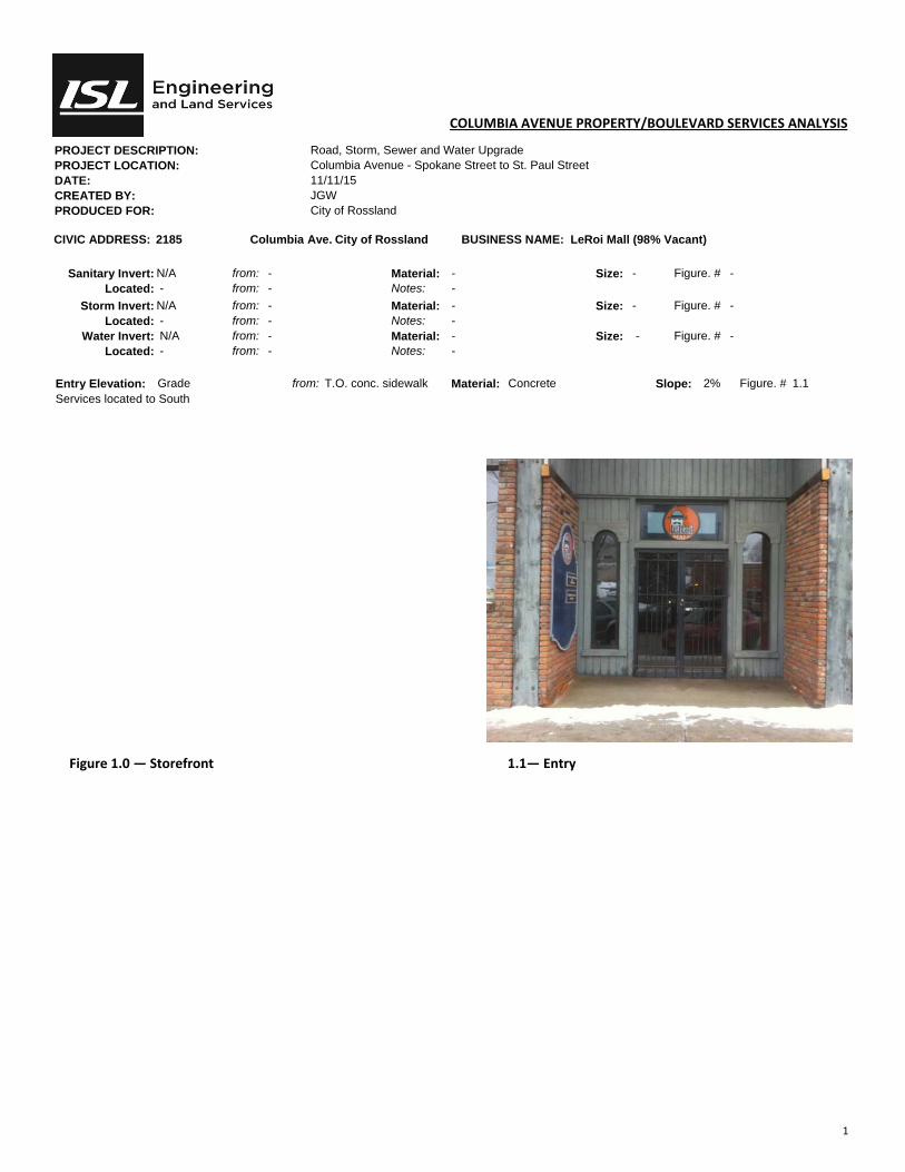
1
COLUMBIA AVENUE PROPERTY/BOULEVARD SERVICES ANALYSIS
PROJECT DESCRIPTION: Road, Storm, Sewer and Water Upgrade PROJECT LOCATION: Columbia Avenue - Spokane Street to St. Paul Street DATE: 11/11/15 CREATED BY: JGW PRODUCED FOR: City of Rossland
CIVIC ADDRESS: 2185 Columbia Ave. City of Rossland BUSINESS NAME: LeRoi Mall (98% Vacant)
Sanitary Invert: N/A from: - Material: - Size: - Figure. # - Located: - from: - Notes: -
Storm Invert: N/A from: - Material: - Size: - Figure. # - Located: - from: - Notes: -
Water Invert: N/A from: - Material: - Size: - Figure. # - Located: - from: - Notes: -
Entry Elevation: Grade from: T.O. conc. sidewalk Material: Concrete Slope: 2% Figure. # 1.1 Services located to South
Figure 1.0 — Storefront 1.1— Entry
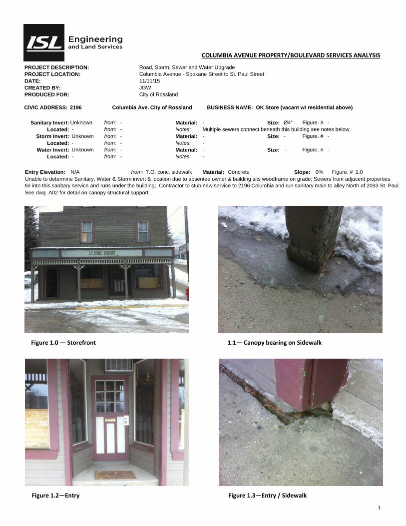
1
COLUMBIA AVENUE PROPERTY/BOULEVARD SERVICES ANALYSIS
PROJECT DESCRIPTION: Road, Storm, Sewer and Water Upgrade PROJECT LOCATION: Columbia Avenue - Spokane Street to St. Paul Street DATE: 11/11/15 CREATED BY: JGW PRODUCED FOR: City of Rossland
CIVIC ADDRESS: 2196 Columbia Ave. City of Rossland BUSINESS NAME: OK Store (vacant w/ residential above)
Sanitary Invert: Unknown from: - Material: - Size: Ø4” Figure. # - Located: - from: - Notes: Multiple sewers connect beneath this building see notes below.
Storm Invert: Unknown from: - Material: - Size: - Figure. # - Located: - from: - Notes: -
Water Invert: Unknown from: - Material: - Size: - Figure. # - Located: - from: - Notes: -
Entry Elevation: N/A from: T.O. conc. sidewalk Material: Concrete Slope: 0% Figure. # 1.0 Unable to determine Sanitary, Water & Storm invert & location due to absentee owner & building sits woodframe on grade; Sewers from adjacent properties tie into this sanitary service and runs under the building; Contractor to stub new service to 2196 Columbia and run sanitary main to alley North of 2033 St. Paul. See dwg. A02 for detail on canopy structural support.
Figure 1.0 — Storefront 1.1— Canopy bearing on Sidewalk
Figure 1.2—Entry Figure 1.3—Entry / Sidewalk

1
COLUMBIA AVENUE PROPERTY/BOULEVARD SERVICES ANALYSIS
PROJECT DESCRIPTION: Road, Storm, Sewer and Water Upgrade PROJECT LOCATION: Columbia Avenue - Spokane Street to St. Paul Street DATE: 11/11/15 CREATED BY: JGW PRODUCED FOR: City of Rossland
CIVIC ADDRESS: 2197 Columbia Ave. City of Rossland BUSINESS NAME: Medical Offices
Sanitary Invert: N/A from: - Material: - Size: - Figure. # - Located: - from: - Notes: -
Storm Invert: N/A from: - Material: - Size: - Figure. # - Located: - from: - Notes: -
Water Invert: N/A from: - Material: - Size: - Figure. # - Located: - from: - Notes: -
Entry Elevation: @ Grade from: T.O. conc. sidewalk Material: Concrete Slope: 0% Figure. # 1.1
Figure 1.0 — Storefront 1.1— Entries

1
COLUMBIA AVENUE PROPERTY/BOULEVARD SERVICES ANALYSIS
PROJECT DESCRIPTION: Road, Storm, Sewer and Water Upgrade PROJECT LOCATION: Washington Street - Columbia Avenue to First Avenue DATE: 11/11/15 CREATED BY: JGW PRODUCED FOR: City of Rossland
CIVIC ADDRESS: 2038 Washington St. City of Rossland BUSINESS NAME: Medical Aesthetic Office & Apartments over
Sanitary Invert: N/A from: - Material: - Size: - Figure. # - Located: - from: - Notes: Sanitary is combined with 2044 and not visible @ exit @ S/W corner of bldg.
Storm Invert: N/A from: - Material: - Size: - Figure. # - Located: - from: - Notes: -
Water Invert: 3’ from: u/s of subfloor Material: Ø6” Size: - Figure. # 3.2 Located: 5’6” from: North fdn. wall Notes: -
Entry Elevation: - from: - Material: - Slope: - Figure. # - 2038—Medical Esthetics 11.5” from T.O. conc. Sidewalk @ 0.1% Fig. 1.2; 2038—Apartment Entry 10” from T.O. conc. Sidewalk @ 0.1% Fig. 1.3;
Figure 1.0 — Storefront 1.1— Entries
1.2— Entries 1.3— Entries

2
COLUMBIA AVENUE PROPERTY/BOULEVARD SERVICES ANALYSIS
PROJECT DESCRIPTION: Road, Storm, Sewer and Water Upgrade PROJECT LOCATION: Washington Street - Columbia Avenue to First Avenue DATE: 11/11/15 CREATED BY: JGW PRODUCED FOR: City of Rossland
CIVIC ADDRESS: 2038 Washington St. City of Rossland BUSINESS NAME: Medical Aesthetic Office & Apartments over
Sanitary Invert: N/A from: - Material: - Size: - Figure. # - Located: - from: - Notes: Sanitary is combined with 2044 and not visible @ exit @ S/W corner of bldg.
Storm Invert: N/A from: - Material: - Size: - Figure. # - Located: - from: - Notes: -
Water Invert: 3’ from: u/s of subfloor Material: Ø6” Size: - Figure. # 3.2 Located: 5’6” from: North fdn. wall Notes: -
Entry Elevation: - from: - Material: - Slope: - Figure. # - 2038—Medical Esthetics 11.5” from T.O. conc. Sidewalk @ 0.1% Fig. 1.2; 2038—Apartment Entry 10” from T.O. conc. Sidewalk @ 0.1% Fig. 1.3;
Figure 2.0 — 2.1—
2.2— 2.3—

3
COLUMBIA AVENUE PROPERTY/BOULEVARD SERVICES ANALYSIS
PROJECT DESCRIPTION: Road, Storm, Sewer and Water Upgrade PROJECT LOCATION: Washington Street - Columbia Avenue to First Avenue DATE: 11/11/15 CREATED BY: JGW PRODUCED FOR: City of Rossland
CIVIC ADDRESS: 2038 Washington St. City of Rossland BUSINESS NAME: Medical Aesthetic Office & Apartments over
Sanitary Invert: N/A from: - Material: - Size: - Figure. # - Located: - from: - Notes: Sanitary is combined with 2044 and not visible @ exit @ S/W corner of bldg.
Storm Invert: N/A from: - Material: - Size: - Figure. # - Located: - from: - Notes: -
Water Invert: 3’ from: u/s of subfloor Material: Ø6” Size: - Figure. # 3.2 Located: 5’6” from: North fdn. wall Notes: -
Entry Elevation: - from: - Material: - Slope: - Figure. # - 2038—Medical Esthetics 11.5” from T.O. conc. Sidewalk @ 0.1% Fig. 1.2; 2038—Apartment Entry 10” from T.O. conc. Sidewalk @ 0.1% Fig. 1.3;
Figure 3.0—2044 Sewer service exi ng to 2038 3.1—Sprinkler Assembly
3.3 Water Service @ West fdn.
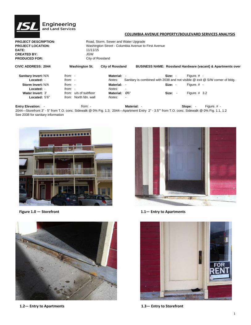
1
COLUMBIA AVENUE PROPERTY/BOULEVARD SERVICES ANALYSIS
PROJECT DESCRIPTION: Road, Storm, Sewer and Water Upgrade PROJECT LOCATION: Washington Street - Columbia Avenue to First Avenue DATE: 11/11/15 CREATED BY: JGW PRODUCED FOR: City of Rossland
CIVIC ADDRESS: 2044 Washington St. City of Rossland BUSINESS NAME: Rossland Hardware (vacant) & Apartments over
Sanitary Invert: N/A from: - Material: - Size: - Figure. # - Located: - from: - Notes: Sanitary is combined with 2038 and not visible @ exit @ S/W corner of bldg.
Storm Invert: N/A from: - Material: - Size: - Figure. # - Located: - from: - Notes: -
Water Invert: 3’ from: u/s of subfloor Material: Ø6” Size: - Figure. # 3.2 Located: 5’6” from: North fdn. wall Notes: -
Entry Elevation: - from: - Material: - Slope: - Figure. # - 2044—Storefront 3” - 5” from T.O. conc. Sidewalk @ 0% Fig. 1.3; 2044—Apartment Entry 2” - 3.5”” from T.O. conc. Sidewalk @ 0% Fig. 1.1, 1.2 See 2038 for sanitary information
Figure 1.0 — Storefront 1.1— Entry to Apartments
1.2— Entry to Apartments 1.3— Entry to Storefront

2
COLUMBIA AVENUE PROPERTY/BOULEVARD SERVICES ANALYSIS
PROJECT DESCRIPTION: Road, Storm, Sewer and Water Upgrade PROJECT LOCATION: Washington Street - Columbia Avenue to First Avenue DATE: 11/11/15 CREATED BY: JGW PRODUCED FOR: City of Rossland
CIVIC ADDRESS: 2038 Washington St. City of Rossland BUSINESS NAME: Medical Aesthetic Office & Apartments over
Sanitary Invert: N/A from: - Material: - Size: - Figure. # - Located: - from: - Notes: Sanitary is combined with 2044 and not visible @ exit @ S/W corner of bldg.
Storm Invert: N/A from: - Material: - Size: - Figure. # - Located: - from: - Notes: -
Water Invert: 3’ from: u/s of subfloor Material: Ø6” Size: - Figure. # 3.2 Located: 5’6” from: North fdn. wall Notes: -
Entry Elevation: - from: - Material: - Slope: - Figure. # - 2044—Storefront 3” - 5” from T.O. conc. Sidewalk @ 0% Fig. 1.3; 2044—Apartment Entry 2” - 3.5”” from T.O. conc. Sidewalk @ 0% Fig. 1.1, 1.2 See 2038 for sanitary information
Figure 2.0 — Sewer stack @ mid‐point of 2038 bsmt. 2.1— Sewer stack @ mid‐point of 2038 bsmt.
2.2— Sewer branch from 2044 2.3— Sewer from 2044 thru 2038
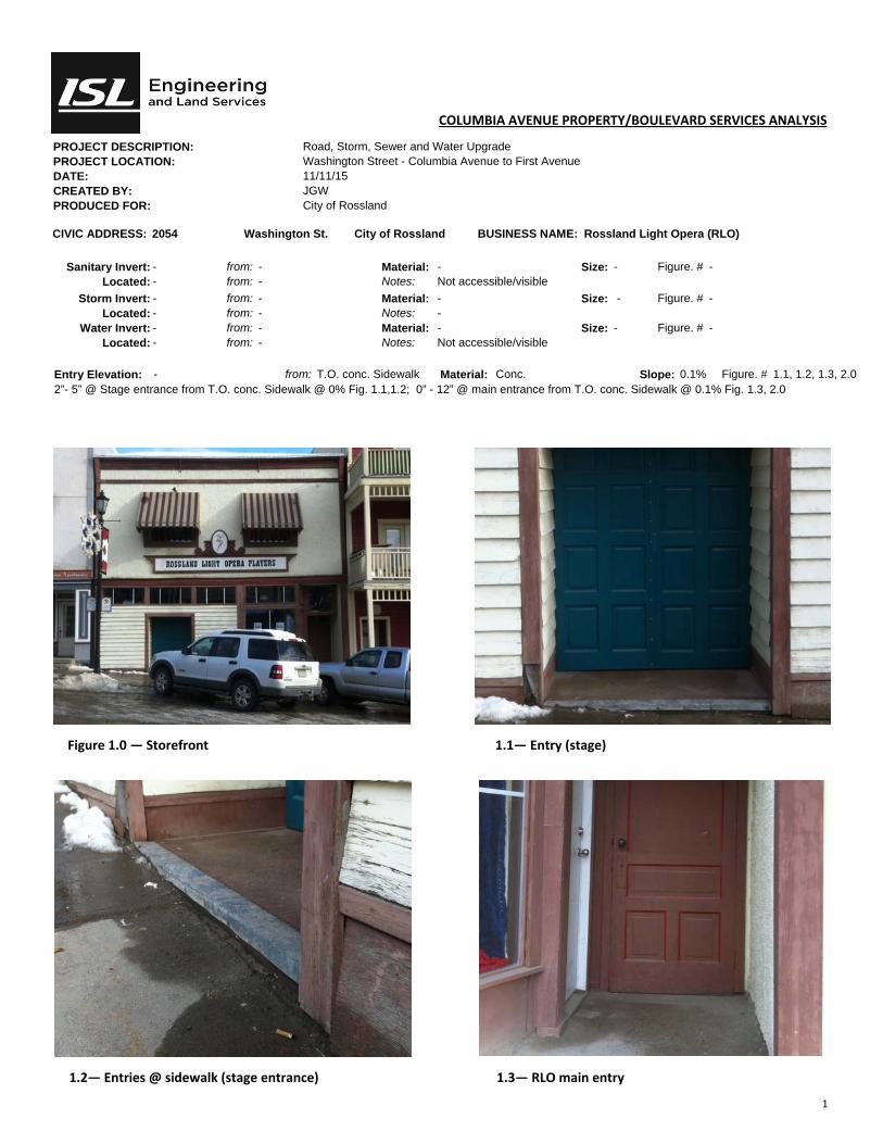
1
COLUMBIA AVENUE PROPERTY/BOULEVARD SERVICES ANALYSIS
PROJECT DESCRIPTION: Road, Storm, Sewer and Water Upgrade PROJECT LOCATION: Washington Street - Columbia Avenue to First Avenue DATE: 11/11/15 CREATED BY: JGW PRODUCED FOR: City of Rossland
CIVIC ADDRESS: 2054 Washington St. City of Rossland BUSINESS NAME: Rossland Light Opera (RLO)
Sanitary Invert: - from: - Material: - Size: - Figure. # - Located: - from: - Notes: Not accessible/visible
Storm Invert: - from: - Material: - Size: - Figure. # - Located: - from: - Notes: -
Water Invert: - from: - Material: - Size: - Figure. # - Located: - from: - Notes: Not accessible/visible
Entry Elevation: - from: T.O. conc. Sidewalk Material: Conc. Slope: 0.1% Figure. # 1.1, 1.2, 1.3, 2.0 2”- 5” @ Stage entrance from T.O. conc. Sidewalk @ 0% Fig. 1.1,1.2; 0” - 12” @ main entrance from T.O. conc. Sidewalk @ 0.1% Fig. 1.3, 2.0
Figure 1.0 — Storefront 1.1— Entry (stage)
1.2— Entries @ sidewalk (stage entrance) 1.3— RLO main entry
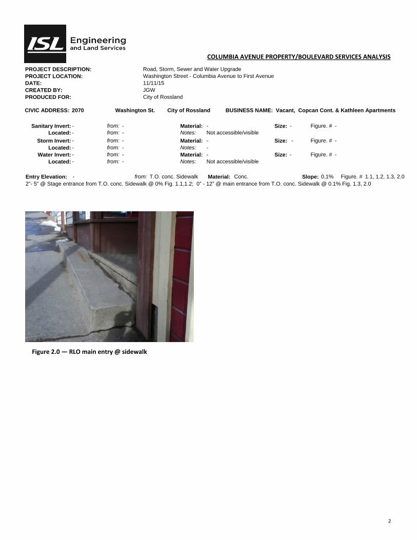
2
COLUMBIA AVENUE PROPERTY/BOULEVARD SERVICES ANALYSIS
PROJECT DESCRIPTION: Road, Storm, Sewer and Water Upgrade PROJECT LOCATION: Washington Street - Columbia Avenue to First Avenue DATE: 11/11/15 CREATED BY: JGW PRODUCED FOR: City of Rossland
CIVIC ADDRESS: 2070 Washington St. City of Rossland BUSINESS NAME: Vacant, Copcan Cont. & Kathleen Apartments
Sanitary Invert: - from: - Material: - Size: - Figure. # - Located: - from: - Notes: Not accessible/visible
Storm Invert: - from: - Material: - Size: - Figure. # - Located: - from: - Notes: -
Water Invert: - from: - Material: - Size: - Figure. # - Located: - from: - Notes: Not accessible/visible
Entry Elevation: - from: T.O. conc. Sidewalk Material: Conc. Slope: 0.1% Figure. # 1.1, 1.2, 1.3, 2.0 2”- 5” @ Stage entrance from T.O. conc. Sidewalk @ 0% Fig. 1.1,1.2; 0” - 12” @ main entrance from T.O. conc. Sidewalk @ 0.1% Fig. 1.3, 2.0
Figure 2.0 — RLO main entry @ sidewalk

1
COLUMBIA AVENUE PROPERTY/BOULEVARD SERVICES ANALYSIS
PROJECT DESCRIPTION: Road, Storm, Sewer and Water Upgrade PROJECT LOCATION: Washington Street - Columbia Avenue to First Avenue DATE: 11/11/15 CREATED BY: JGW PRODUCED FOR: City of Rossland
CIVIC ADDRESS: 2059 Washington St. City of Rossland BUSINESS NAME: Thrift Store
Sanitary Invert: 6’8” from: u/s subfloor Material: Cast Size: Ø3 Figure. # 1.3, 2.0, 2.1 Located: 7’6” from: South fdn. wall Notes: Sanitary runs along South perimeter of basement
Storm Invert: N/A from: - Material: - Size: - Figure. # - Located: - from: - Notes: -
Water Invert: 6’6” from: u/s subfloor Material: Copper Size: Ø1.5” Figure. # 2.1 Located: 6’8” from: South East fdn. Wall Notes: Ø1-1/2” reduced to Ø1/2” service in use only
Entry Elevation: 0”-6.5” from: T.O. conc. Sidewalk Material: Tile Slope: 0% Figure. # 1.1, 1.2
Figure 1.0 — Storefront 1.1— Entry
1.2— Entries @ sidewalk 1.3— North sewer stack
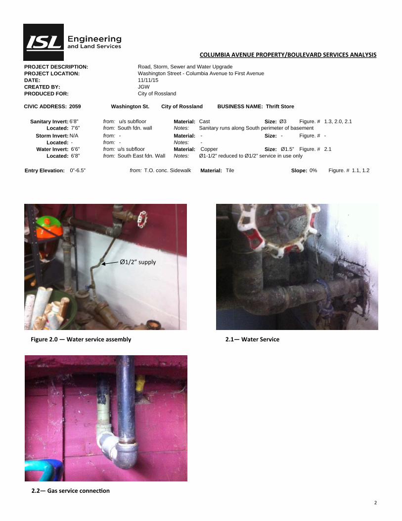
2
COLUMBIA AVENUE PROPERTY/BOULEVARD SERVICES ANALYSIS
PROJECT DESCRIPTION: Road, Storm, Sewer and Water Upgrade PROJECT LOCATION: Washington Street - Columbia Avenue to First Avenue DATE: 11/11/15 CREATED BY: JGW PRODUCED FOR: City of Rossland
CIVIC ADDRESS: 2059 Washington St. City of Rossland BUSINESS NAME: Thrift Store
Sanitary Invert: 6’8” from: u/s subfloor Material: Cast Size: Ø3 Figure. # 1.3, 2.0, 2.1 Located: 7’6” from: South fdn. wall Notes: Sanitary runs along South perimeter of basement
Storm Invert: N/A from: - Material: - Size: - Figure. # - Located: - from: - Notes: -
Water Invert: 6’6” from: u/s subfloor Material: Copper Size: Ø1.5” Figure. # 2.1 Located: 6’8” from: South East fdn. Wall Notes: Ø1-1/2” reduced to Ø1/2” service in use only
Entry Elevation: 0”-6.5” from: T.O. conc. Sidewalk Material: Tile Slope: 0% Figure. # 1.1, 1.2
Figure 2.0 — Water service assembly 2.1— Water Service
2.2— Gas service connec on
Ø1/2” supply
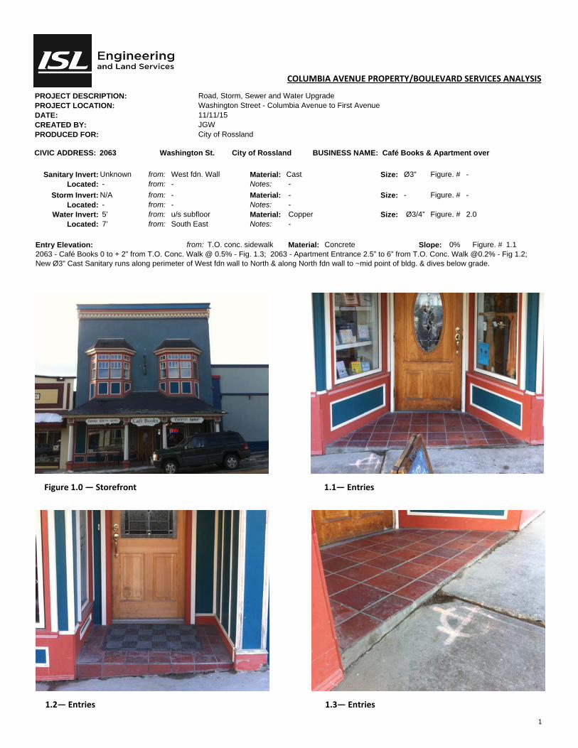
1
COLUMBIA AVENUE PROPERTY/BOULEVARD SERVICES ANALYSIS
PROJECT DESCRIPTION: Road, Storm, Sewer and Water Upgrade PROJECT LOCATION: Washington Street - Columbia Avenue to First Avenue DATE: 11/11/15 CREATED BY: JGW PRODUCED FOR: City of Rossland
CIVIC ADDRESS: 2063 Washington St. City of Rossland BUSINESS NAME: Café Books & Apartment over
Sanitary Invert: Unknown from: West fdn. Wall Material: Cast Size: Ø3” Figure. # - Located: - from: - Notes: -
Storm Invert: N/A from: - Material: - Size: - Figure. # - Located: - from: - Notes: -
Water Invert: 5’ from: u/s subfloor Material: Copper Size: Ø3/4” Figure. # 2.0 Located: 7’ from: South East Notes: -
Entry Elevation: from: T.O. conc. sidewalk Material: Concrete Slope: 0% Figure. # 1.1 2063 - Café Books 0 to + 2” from T.O. Conc. Walk @ 0.5% - Fig. 1.3; 2063 - Apartment Entrance 2.5” to 6” from T.O. Conc. Walk @0.2% - Fig 1.2; New Ø3” Cast Sanitary runs along perimeter of West fdn wall to North & along North fdn wall to ~mid point of bldg. & dives below grade.
Figure 1.0 — Storefront 1.1— Entries
1.2— Entries 1.3— Entries

2
COLUMBIA AVENUE PROPERTY/BOULEVARD SERVICES ANALYSIS
PROJECT DESCRIPTION: Road, Storm, Sewer and Water Upgrade PROJECT LOCATION: Washington Street - Columbia Avenue to First Avenue DATE: 11/11/15 CREATED BY: JGW PRODUCED FOR: City of Rossland
CIVIC ADDRESS: 2063 Washington St. City of Rossland BUSINESS NAME: Café Books & Apartment over
Sanitary Invert: Unknown from: West fdn. wall Material: Cast Size: Ø3” Figure. # - Located: along North from: - Notes:
Storm Invert: N/A from: - Material: - Size: - Figure. # - Located: - from: - Notes: -
Water Invert: 5’ from: u/s subfloor Material: Copper Size: Ø3/4” Figure. # 2.0 Located: 7’ from: South East Notes: -
Entry Elevation: - from: - Material: - Slope: - Figure. # - New Ø3” Cast Sanitary runs along perimeter of West fdn wall to North & along North fdn wall to ~mid point of bldg. & dives below grade.
Figure 2.0 — Water Service
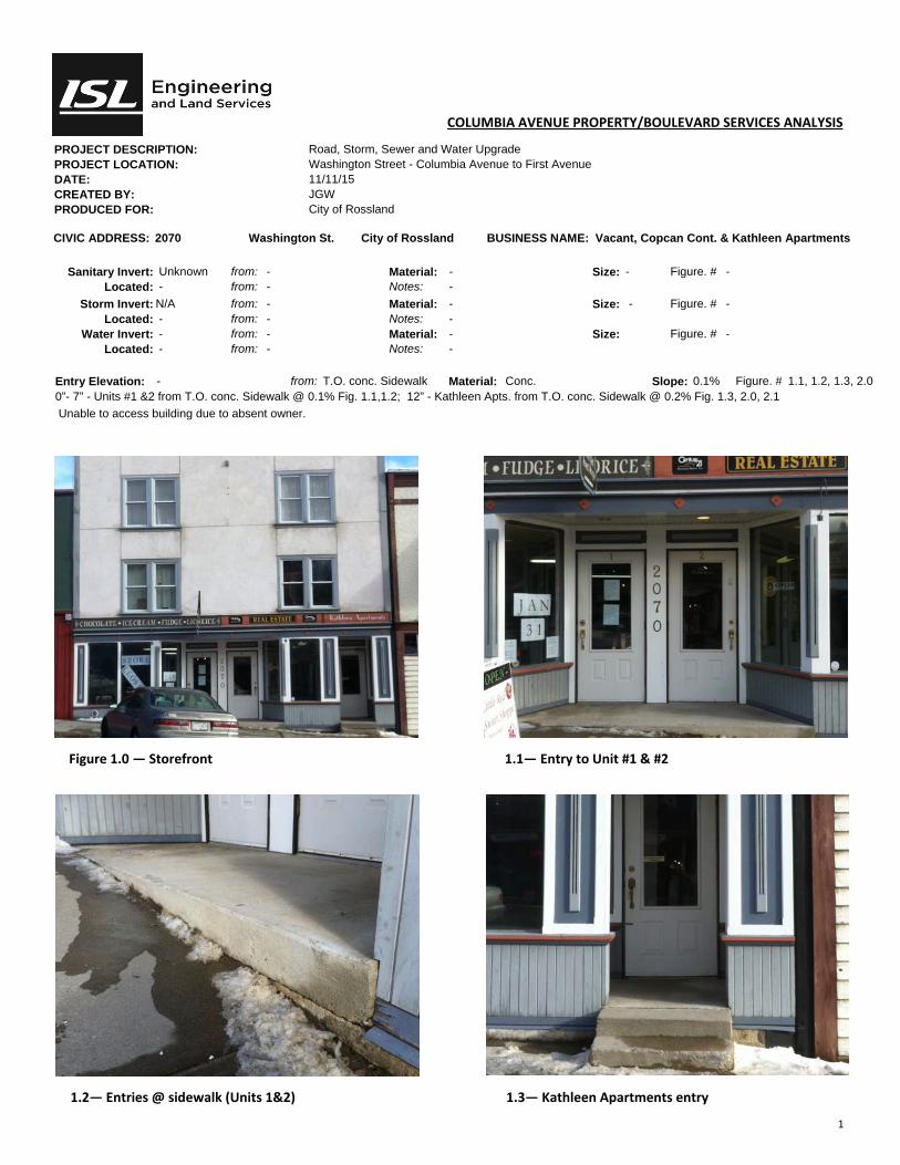
1
COLUMBIA AVENUE PROPERTY/BOULEVARD SERVICES ANALYSIS
PROJECT DESCRIPTION: Road, Storm, Sewer and Water Upgrade PROJECT LOCATION: Washington Street - Columbia Avenue to First Avenue DATE: 11/11/15 CREATED BY: JGW PRODUCED FOR: City of Rossland
CIVIC ADDRESS: 2070 Washington St. City of Rossland BUSINESS NAME: Vacant, Copcan Cont. & Kathleen Apartments
Sanitary Invert: Unknown from: - Material: - Size: - Figure. # - Located: - from: - Notes: -
Storm Invert: N/A from: - Material: - Size: - Figure. # - Located: - from: - Notes: -
Water Invert: - from: - Material: - Size: Figure. # - Located: - from: - Notes: -
Entry Elevation: - from: T.O. conc. Sidewalk Material: Conc. Slope: 0.1% Figure. # 1.1, 1.2, 1.3, 2.0 0”- 7” - Units #1 &2 from T.O. conc. Sidewalk @ 0.1% Fig. 1.1,1.2; 12” - Kathleen Apts. from T.O. conc. Sidewalk @ 0.2% Fig. 1.3, 2.0, 2.1
Unable to access building due to absent owner.
Figure 1.0 — Storefront 1.1— Entry to Unit #1 & #2
1.2— Entries @ sidewalk (Units 1&2) 1.3— Kathleen Apartments entry

2
COLUMBIA AVENUE PROPERTY/BOULEVARD SERVICES ANALYSIS
PROJECT DESCRIPTION: Road, Storm, Sewer and Water Upgrade PROJECT LOCATION: Washington Street - Columbia Avenue to First Avenue DATE: 11/11/15 CREATED BY: JGW PRODUCED FOR: City of Rossland
CIVIC ADDRESS: 2070 Washington St. City of Rossland BUSINESS NAME: Vacant, Copcan Cont. & Kathleen Apartments
Sanitary Invert: Unknown from: - Material: - Size: - Figure. # - Located: - from: - Notes: -
Storm Invert: N/A from: - Material: - Size: - Figure. # - Located: - from: - Notes: -
Water Invert: - from: - Material: - Size: Figure. # - Located: - from: - Notes: -
Entry Elevation: - from: T.O. conc. Sidewalk Material: Conc. Slope: 0.1% Figure. # 1.1, 1.2, 1.3, 2.0
0”- 7” - Units #1 &2 from T.O. conc. Sidewalk @ 0.1% Fig. 1.1,1.2; 12” - Kathleen Apts. from T.O. conc. Sidewalk @ 0.2% Fig. 1.3, 2.0, 2.1
Unable to access building due to absent owner.
Figure 2.0 — Kathleen Apartments entry 2.1— Tie to exst’g bldg.
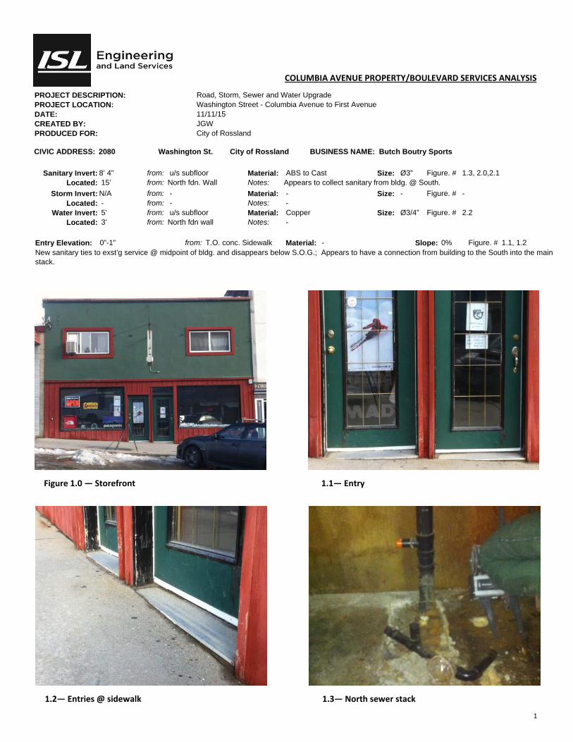
1
COLUMBIA AVENUE PROPERTY/BOULEVARD SERVICES ANALYSIS
PROJECT DESCRIPTION: Road, Storm, Sewer and Water Upgrade PROJECT LOCATION: Washington Street - Columbia Avenue to First Avenue DATE: 11/11/15 CREATED BY: JGW PRODUCED FOR: City of Rossland
CIVIC ADDRESS: 2080 Washington St. City of Rossland BUSINESS NAME: Butch Boutry Sports
Sanitary Invert: 8’ 4” from: u/s subfloor Material: ABS to Cast Size: Ø3” Figure. # 1.3, 2.0,2.1 Located: 15’ from: North fdn. Wall Notes: Appears to collect sanitary from bldg. @ South.
Storm Invert: N/A from: - Material: - Size: - Figure. # - Located: - from: - Notes: -
Water Invert: 5’ from: u/s subfloor Material: Copper Size: Ø3/4” Figure. # 2.2 Located: 3’ from: North fdn wall Notes: -
Entry Elevation: 0”-1” from: T.O. conc. Sidewalk Material: - Slope: 0% Figure. # 1.1, 1.2 New sanitary ties to exst’g service @ midpoint of bldg. and disappears below S.O.G.; Appears to have a connection from building to the South into the main stack.
Figure 1.0 — Storefront 1.1— Entry
1.2— Entries @ sidewalk 1.3— North sewer stack
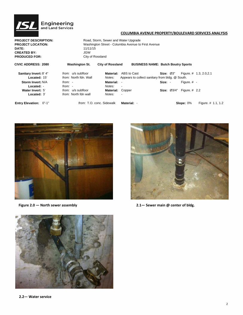
2
COLUMBIA AVENUE PROPERTY/BOULEVARD SERVICES ANALYSIS
PROJECT DESCRIPTION: Road, Storm, Sewer and Water Upgrade PROJECT LOCATION: Washington Street - Columbia Avenue to First Avenue DATE: 11/11/15 CREATED BY: JGW PRODUCED FOR: City of Rossland
CIVIC ADDRESS: 2080 Washington St. City of Rossland BUSINESS NAME: Butch Boutry Sports
Sanitary Invert: 8’ 4” from: u/s subfloor Material: ABS to Cast Size: Ø3” Figure. # 1.3, 2.0,2.1 Located: 15’ from: North fdn. Wall Notes: Appears to collect sanitary from bldg. @ South.
Storm Invert: N/A from: - Material: - Size: - Figure. # - Located: - from: - Notes: -
Water Invert: 5’ from: u/s subfloor Material: Copper Size: Ø3/4” Figure. # 2.2 Located: 3’ from: North fdn wall Notes: -
Entry Elevation: 0”-1” from: T.O. conc. Sidewalk Material: - Slope: 0% Figure. # 1.1, 1.2
Figure 2.0 — North sewer assembly 2.1— Sewer main @ center of bldg.
2.2— Water service

1
COLUMBIA AVENUE PROPERTY/BOULEVARD SERVICES ANALYSIS
PROJECT DESCRIPTION: Road, Storm, Sewer and Water Upgrade PROJECT LOCATION: Washington Street - Columbia Avenue to First Avenue DATE: 11/11/15 CREATED BY: JGW PRODUCED FOR: City of Rossland
CIVIC ADDRESS: 2081 Washington St. City of Rossland BUSINESS NAME: Rossland Legion
Sanitary Invert: Unknown from: - Material: - Size: - Figure. # - Located: - from: - Notes: Not visible—finished basement
Storm Invert: N/A from: - Material: - Size: - Figure. # - Located: - from: - Notes: -
Water Invert: N/A from: - Material: Copper Size: Ø3/4” Figure. # 2.2 Located: - from: - Notes: -
Entry Elevation: 0”-1” from: T.O. conc. Sidewalk Material: - Slope: 0% Figure. # 1.1, 1.2, 1.3 All services concealed—Finished basement
Figure 1.0 — Storefront 1.1— Entry
1.2— Entries @ sidewalk 1.3— North sewer stack
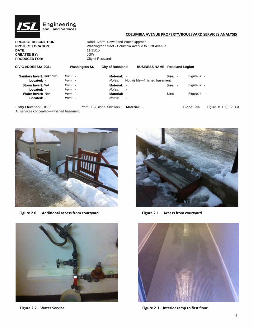
2
COLUMBIA AVENUE PROPERTY/BOULEVARD SERVICES ANALYSIS
PROJECT DESCRIPTION: Road, Storm, Sewer and Water Upgrade PROJECT LOCATION: Washington Street - Columbia Avenue to First Avenue DATE: 11/11/15 CREATED BY: JGW PRODUCED FOR: City of Rossland
CIVIC ADDRESS: 2081 Washington St. City of Rossland BUSINESS NAME: Rossland Legion
Sanitary Invert: Unknown from: - Material: - Size: - Figure. # - Located: - from: - Notes: Not visible—finished basement
Storm Invert: N/A from: - Material: - Size: - Figure. # - Located: - from: - Notes: -
Water Invert: N/A from: - Material: - Size: - Figure. # - Located: - from: - Notes: -
Entry Elevation: 0”-1” from: T.O. conc. Sidewalk Material: - Slope: 0% Figure. # 1.1, 1.2, 1.3 All services concealed—Finished basement
Figure 2.0 — Addi onal access from courtyard Figure 2.1— Access from courtyard
Figure 2.2—Water Service Figure 2.3—Interior ramp to first floor


COLUMBIA AVE
LEROI AVE
H
W
Y
3
B
KOOTENAY AVE
QU
EE
N S
T
SP
OK
AN
E S
T
WA
SH
IN
GT
ON
S
T
FIRST AVE
THOMPSON AVE
ST
. P
AU
L S
T
LEROI AVE
MO
NT
E C
RIS
TO
S
T
T
O
T
R
A
I
L
SECOND AVE
THIRD AVE
Appendix 9 - Dump Site and Staging Area Plan
jasonw
Cloud
jasonw
Text Box
INITIAL DUMP SITE