TEMPORARY REVISION 09-0042, D622W001 - Regulations ...
208
Aviation Safety Aircraft Certification Service Compliance & Airworthiness Division Seattle ACO Branch 2200 South 216 th Street Des Moines, WA 98198 June , 2021 In Reply Refer To: 784-21-7869 Mr. Amin Safee Manager, Regulatory Administration & Certification Boeing Commercial Airplanes SoCal Design Center 4000 N. Lakewood Blvd., M/C D800-0075 Long Beach, CA 90808-1700 Dear Mr. Safee: Subject: Federal Aviation Administration (FAA) Approval of an Alternative Method of Compliance (AMOC) to Airworthiness Directives (AD) 2008-11-13, 2012-07-06, 2014-09-09, 2015-17-13, 2016-11-07, 2016-11-16 and 2015-25-08 References: (1) Boeing letter DLD4-21-00060, dated March 16, 2021 (2) Boeing 777 Maintenance Planning Data (MPD) Document, Section 9, D622W001-9, dated February 2021 (Watermark Not FAA Approved 3/12/2021_02:14 PM) (3) Boeing 777 28-AWL-31 and 28-AWL-32 Revision Teflon Sleeve & Cushion Clamp Assessment, D340W105-23, dated February 26, 2021 The FAA received the reference (1) letter transmitting the reference (2) document for our review and approval. The reference (1) letter also requested approval of the reference (2) document as an alternative method of compliance (AMOC) to Airworthiness Directives (AD) 2008-11-13, 2012-07-06, 2014-09-09, 2015-17-13, 2016-11-07, 2016-11-16, and 2015-25-08. Planned AD 20-PAD-0044 was initiated to mandate the revision of the MPD Airworthiness Limitation (AWL) items 28-AWL-31 and 28-AWL-32, which are the subject of this submittal as identified in chapter D.1 FUEL SYSTEMS IGNITION PREVENTION of the reference (2) document; and revision of Boeing Alert Service Bulletin (SB) 777-57A-0050. The AWL items and SB are about having certain clamps and sleeves, as necessary, at certain wire bundle locations to support fuel tank safety analysis for Special Federal Aviation Regulation No. 88 (SFAR 88). The reference (3) document provides the background and substantiation for the changes in the MPD AWL items and SB as a result of a complete audit conducted on the wiring around the boundary of the fuel tanks. The audit finding resulted in an almost entire revision of AWL items 28-AWL-31 and 28-AWL-32. It identified missing wire bundle installation and incorrect locations; missing configuration
-
Upload
khangminh22 -
Category
Documents
-
view
1 -
download
0
Transcript of TEMPORARY REVISION 09-0042, D622W001 - Regulations ...

Aviation SafetyAircraft Certification ServiceCompliance & Airworthiness Division
Seattle ACO Branch2200 South 216th StreetDes Moines, WA 98198
June , 2021
In Reply Refer To: 784-21-7869
Mr. Amin SafeeManager, Regulatory Administration & Certification Boeing Commercial Airplanes SoCal Design Center 4000 N. Lakewood Blvd., M/C D800-0075 Long Beach, CA 90808-1700
Dear Mr. Safee:
Subject: Federal Aviation Administration (FAA) Approval of an Alternative Method of Compliance (AMOC) to Airworthiness Directives (AD) 2008-11-13,2012-07-06, 2014-09-09, 2015-17-13, 2016-11-07, 2016-11-16 and 2015-25-08
References: (1) Boeing letter DLD4-21-00060, dated March 16, 2021 (2) Boeing 777 Maintenance Planning Data (MPD) Document, Section 9,
D622W001-9, dated February 2021 (Watermark Not FAA Approved3/12/2021_02:14 PM)
(3) Boeing 777 28-AWL-31 and 28-AWL-32 Revision Teflon Sleeve &Cushion Clamp Assessment, D340W105-23, dated February 26, 2021
The FAA received the reference (1) letter transmitting the reference (2) document for our review and approval. The reference (1) letter also requested approval of the reference (2) document as an alternative method of compliance (AMOC) to Airworthiness Directives (AD) 2008-11-13, 2012-07-06, 2014-09-09, 2015-17-13, 2016-11-07, 2016-11-16, and 2015-25-08. Planned AD 20-PAD-0044 was initiated to mandate the revision of the MPD Airworthiness Limitation (AWL) items 28-AWL-31 and 28-AWL-32, which are the subject of this submittal as identified in chapter D.1 FUEL SYSTEMS IGNITION PREVENTION of the reference (2) document; and revision of Boeing Alert Service Bulletin (SB) 777-57A-0050. The AWL items and SB are about having certain clamps and sleeves, asnecessary, at certain wire bundle locations to support fuel tank safety analysis for SpecialFederal Aviation Regulation No. 88 (SFAR 88). The reference (3) document provides thebackground and substantiation for the changes in the MPD AWL items and SB as a result ofa complete audit conducted on the wiring around the boundary of the fuel tanks. The auditfinding resulted in an almost entire revision of AWL items 28-AWL-31 and 28-AWL-32. Itidentified missing wire bundle installation and incorrect locations; missing configuration

784-21-7869 2
features such as Teflon sleeve, cushion or plastic clamp, or ring post; and removal of unnecessary wire bundle locations. The reference (1) letter package also contains FAA Form 8100-9s signed by the appropriate engineering unit members (E-UMs) recommending approval of the reference (2) document. AD 2008-11-13 requires operators to revise their maintenance program by incorporating new AWLs for fuel tank systems and perform an initial inspection to phase in certain repetitive AWL inspections, and repair if necessary. That AD was issued to prevent the potential for ignition sources inside fuel tanks caused by latent failure, alterations, repairs, or maintenance actions. Paragraph (g) of AD 2008-11-13 requires incorporation of the information in certain subsections of Boeing document D622W001-9. Paragraph (h) of AD 2008-11-13 requires initial inspections in accordance with certain AWLs described in Boeing document D622W001-9. AD 2012-07-06 requires operators to revise their maintenance program to update structural inspection requirements. That AD was issued to detect and correct fatigue cracking of various principal structural elements (PSE), which could adversely affect the structural integrity of the airplanes. Paragraph (g)(1) of AD 2012-07-06 requires incorporation of the information in Subsection B of Boeing document D622W001-9 into the maintenance program. Paragraph (g)(2) of AD 2012-07-06 specifies the initial compliance time for the inspections based on the applicable inspection times provided in Subsection B of Boeing document D622W001-9. Paragraph (g)(3) of AD 2012-07-06 specifies requirements for reports specified in Boeing document D622W001-9. AD 2014-09-09 was issued to detect and correct failure of the engine fuel suction feed of the fuel system, which, in the event of total loss of the fuel boost pumps, could result in dual engine flameout, inability to restart the engines, and consequent forced landing of the airplane. Paragraph (g) of AD No. 2014-09-09 requires operators to revise their maintenance program to incorporate AWL 28-AWL-101 in Appendix 1 of the AD and specifies the initial compliance time for the inspection. AD 2015-17-13 requires repetitive functional checks of the forward strut drain line and doing corrective actions if necessary, and a one-time cleaning of certain forward strut drain lines. That AD was issued to detect and correct blockage of forward strut drain lines, which could cause flammable fluids to collect in the forward strut area and potentially cause an uncontrolled fire or cause failure of engine attachment structure and consequent airplane loss. Paragraph (g)(1) of AD 2015-17-13 requires repetitive functional checks for blockage of the forward strut drain line of the left and right struts and doing all applicable corrective actions. Paragraph (i) of AD 2015-17-13 provides optional terminating actions to terminate the repetitive functional checks required by paragraph (g)(1) of that AD at the modified area only. Paragraph (i)(5) of AD 2015-17-13 requires operators to revise their maintenance or inspection program to incorporate AWL No. 54-AWL-01 in Boeing document D622W001-9.

784-21-7869 3
AD 2016-11-07 requires certain actions, including installation of new forward strut drain lines, on the left and right struts. That AD was issued to prevent blockage of forward strut drain lines, which could cause flammable fluid to collect in the forward strut area and potentially cause an uncontrolled fire or cause failure of engine attachment structure and consequent airplane loss. Paragraph (g)(5) of AD 2016-11-07 requires operators to revise their maintenance or inspection program to incorporate AWL No. 54-AWL-01 in Boeing document D622W001-9. AD 2016-11-16 requires repetitive inspections of the thrust reverser inner wall and related corrective actions. That AD was issued to detect and correct a degraded thrust reverser inner wall. A degraded thrust reverser inner wall could lead to failure of the thrust reverser and adjacent components and their consequent separation from the airplane, which could result in a rejected takeoff and cause asymmetric thrust and consequent loss of the airplane during reverse thrust operation. Paragraph (n) of AD 2016-11-16 requires operators to revise their maintenance or inspection program to incorporate AWL No. 78-AWL-01 and AWL No. 78-AWL-02 in Boeing document D622W001-9. You are requesting approval of the reference (2) document as an AMOC to the ADs mentioned above since those ADs require the use of specific revisions of Boeing document D622W001-9 (Section 9 of the Boeing 777 MPD Document). The reference (1) letter states that the reference (2) document continues to identify the safety design features and provides satisfactory user instructions for maintaining the airplane. You consider the use of the reference (2) document, in place of specific revisions of Boeing document D622W001-9 required by the ADs, provides an acceptable level of safety. The reference (1) letter also requested approval of certain structural inspections defined in the reference (2) document as an AMOC to AD 2015-25-08. AD 2015-25-08 was issued to detect and correct fatigue cracking in the aft webs of the radial lap splices of the aft pressure bulkhead, which could result in reduced structural integrity of the airplane, decompression of the cabin, and collapse of the floor structure. Paragraph (g) of AD 2015-25-08 requires repetitive inspections for any cracking in the aft webs of the radial lap splices of the aft pressure bulkhead and doing corrective actions if necessary in accordance with Boeing Service Bulletin 777-53A0078, dated December 5, 2014. For a certain airplane, Boeing developed Supplemental Structural Inspection (SSI) number 53-80-I13-MRB1 to inspect specific areas where the AD mandated inspection cannot be performed due to structural repairs performed in those areas. You are requesting approval of the inspections in accordance with SSI number 53-80-I13-MRB1 defined in the reference (2) document as an AMOC to the inspections required by paragraph (g) of AD 2015-25-08 for those specific areas addressed by that SSI. The FAA previously approved the inspections in accordance with SSI number 53-80-I13-MRB1 defined in Revision November 2019 of Boeing Document D622W001-9 as an AMOC. That SSI task remains unchanged in the reference (2) document.

784-21-7869 4
We have reviewed the reference (2) document and agree that it provides the information necessary to perform inspections and maintain critical design features. We have determined that an acceptable level of safety would be maintained if the aircraft is maintained in accordance with the information included in the reference (2) document. The FAA approves the use of the reference (2) document as an AMOC to the use of the revisions of D622W001-9 cited in the following AD paragraphs when incorporating certain information into the maintenance or inspection program or performing initial AWL inspections as required by those AD paragraphs:
AD 2008-11-13, paragraphs (g) and (h) AD 2012-07-06, paragraph (g) AD 2015-17-13, paragraph (i)(5) AD 2016-11-07, paragraph (g)(5) AD 2016-11-16, paragraph (n)
It should be noted that the format of the reference (2) document has been changed when compared to some of the earlier revisions of Boeing document D622W001-9 mandated by the above ADs. For instance, Subsections D and E of earlier revisions were consolidated to Suincorporation of the AWL information in the reference (2) document that corresponds to the AWL information required by the above ADs for incorporation into the maintenance or inspection program. The FAA also approves the incorporation of AWL No. 28-AWL-101 defined in the reference (2) document into the maintenance program as an AMOC to the incorporation of AWL No. 28-AWL-101 defined in Appendix 1 of AD 2014-09-09 as required by paragraph (g) of AD 2014-09-09. For airplane line number 740, the FAA approves accomplishment of the inspections in accordance with Supplemental Structural Inspection (SSI) number 53-80-I13-MRB1 within the threshold and inspection intervals defined in the reference (2) document as an AMOC to accomplishment of the inspections within the compliance time and inspection intervals required by paragraph (g) of AD 2015-25-08 for the specific areas addressed by SSI number 53-80-I13-MRB1. In accordance with FAA Order 8110.103, the following conditions apply:
1. All provisions of ADs 2008-11-13, 2012-07-06, 2014-09-09, 2015-17-13, 2016-11-07, 2016-11-16, and 2015-25-08 that are not specifically referenced above remain fully applicable and must be complied with accordingly.
2. This approval is applicable only to Boeing Model 777-200, -200LR, -300, -300ER, and 777F series airplanes.
3. This FAA AMOC is transferable with the aircraft to other operators.

784-21-7869 5
4. Before using this AMOC, notify your appropriate principal inspector, or lacking a principal inspector, the manager of the local Flight Standards District Office/Certificate Holding District Office.
5. The preceding paragraph also applies to any applicable foreign-registered aircraft upon transfer of the aircraft to the U.S. registry if compliance with the AMOC has not been accomplished.
6. This AMOC only applies to the FAA ADs listed above. The FAA does not have the authority to approve this as an AMOC to any AD issued by another civil aviation authority (CAA). Approval of an AMOC to anothat CAA.
Should you have any questions, please contact this office or Mr. Kevin Nguyen at telephone number (206) 231-3555 or email at [email protected]. Sincerely, for Paul Bernado Acting Manager, Seattle ACO Branch, AIR-780 Compliance & Airworthiness Division Aircraft Certification Service

THIS PAGE INTENTIONALLY LEFT BLANK

777-200/200LR/300/300ER/777F MAINTENANCE PLANNING DATA
D622W001-9BOEING PROPRIETARY - Copyright (c) - Unpublished Work - See title page for details Page 9.0-1
EXPORT CONTROLLED - EAR ECCN: 9E991
777-200/200LR/300/300ER/777FMAINTENANCE PLANNING DATA (MPD) DOCUMENT
SECTION 9
AIRWORTHINESS LIMITATIONS (AWLs) AND CERTIFICATION MAINTENANCE REQUIREMENTS (CMRs)
D622W001-9
FEBRUARY 2021
COMPILED AND PUBLISHED BY:MAINTENANCE PROGRAMS ENGINEERING
BOEING COMMERCIAL AIRPLANE GROUPSEATTLE, WASHINGTON
FEB 2021

D622W001-9BOEING PROPRIETARY - Copyright (c) - Unpublished Work - See title page for details Page 9.0-2
EXPORT CONTROLLED - EAR ECCN: 9E991
777-200/200LR/300/300ER/777F MAINTENANCE PLANNING DATA
THIS PAGE INTENTIONALLY LEFT BLANK
BLANK

777-200/200LR/300/300ER/777F MAINTENANCE PLANNING DATA
D622W001-9BOEING PROPRIETARY - Copyright (c) - Unpublished Work - See title page for details Page 9.0-3
EXPORT CONTROLLED - EAR ECCN: 9E991
TABLE OF CONTENTS
REVISIONS .................................................................................................................................................................................................................................. 9.0-5
LIST OF EFFECTIVE PAGES .................................................................................................................................................................................................... 9.0-25
A. SCOPE................................................................................................................................................................................................................................... 9.0-27
B. AIRWORTHINESS LIMITATIONS – STRUCTURAL INSPECTIONS..................................................................................................................................... 9.0-28
C. AIRWORTHINESS LIMITATIONS – STRUCTURAL SAFE-LIFE LIMITS ............................................................................................................................ 9.0-124
D. AIRWORTHINESS LIMITATIONS – SYSTEMS ................................................................................................................................................................... 9.0-131
D.1 FUEL SYSTEMS IGNITION PREVENTION................................................................................................................................................................... 9.0-136
D.2 ENGINE SUCTION FEED SYSTEM.............................................................................................................................................................................. 9.0-178
D.3 NITROGEN GENERATION SYSTEM (NGS)................................................................................................................................................................. 9.0-180
D.4 PRATT AND WHITNEY FORWARD STRUT DRAIN LINE ............................................................................................................................................ 9.0-185
D.5 ROLLS ROYCE THRUST REVERSER THERMAL PROTECTION SYSTEM............................................................................................................... 9.0-187
E. CERTIFICATION MAINTENANCE REQUIREMENTS (CMRs)............................................................................................................................................ 9.0-190
F. CERTIFICATION MAINTENANCE REQUIREMENTS TASKS ............................................................................................................................................. 9.0-196
G. REPORTING UNCONTROLLABLE HIGH THRUST FAILURE CONDITIONS.................................................................................................................... 9.0-199
H. AWLS - STRUCTURAL LIMIT OF VALIDITY (LOV)............................................................................................................................................................. 9.0-201
I. AWLS - SYSTEMS................................................................................................................................................................................................................. 9.0-202
FEB 2021

D622W001-9BOEING PROPRIETARY - Copyright (c) - Unpublished Work - See title page for details Page 9.0-4
EXPORT CONTROLLED - EAR ECCN: 9E991
777-200/200LR/300/300ER/777F MAINTENANCE PLANNING DATA
THIS PAGE INTENTIONALLY LEFT BLANK
BLANK

777-200/200LR/300/300ER/777F MAINTENANCE PLANNING DATA
D622W001-9BOEING PROPRIETARY - Copyright (c) - Unpublished Work - See title page for details Page 9.0-5
EXPORT CONTROLLED - EAR ECCN: 9E991
REVISIONS
REVISION AND REVISION DESCRIPTION
APRIL 1995 (Original Release)
SEPTEMBER 1995 (Revision 1)
Added GE90 Fatigue RequirementsCMR 27-CMR-03 DeletedCMR 31-CMR-01 Wording ChangedCMR 78-CMR-01 RevisedCMR 78-CMR-02 Added
SEPTEMBER 1995 (Revision 2)
Replaced N/A with None – 15 PlacesAdded SSI 53-40-I01 (Side Mount Satcom)Added SSIs 57-53-I07, 57-53-I11, 57-53-I18, 57-53-I23, 57-53-I28 for Increased Gross Weight.Deleted SSI 57-53-I21 Duplicate Requirement
JANUARY 1996 (Revision 3)
Added four Fatigue Critical Items for Rolls-Royce Trent engine.
APRIL 1996 (Revision 4)
Added FAA to front pageRevised Flight Deck Stowage Compartment Latch wording.Revised Nose Landing Gear Life LimitCMR 78-CMR-02 Revised
AUGUST 1996 (Revision 5)
CMR 78-CMR-02 Revised
MARCH 1997 (Revision 6)
Added CMR 72-CMR-01 for inspection of the Step-Aside-Gearbox (SAGB) Housing and External Gearbox Lower Bevel Box (LBB) Housing for oil leakage and cracking.
Added CMR 72-CMR-02 for inspection of the Step-Aside-Gearbox (SAGB) Housing with fluorescent penetrant for evidence of cracking.
APRIL 1997 (Revision 7)
Added revised safe life limits for the 777-200/-200 IGW landing gear components based on fatigue test cycles completed to date.
FEB 2021
D622W001-9BOEING PROPRIETARY - Copyright (c) - Unpublished Work - See title page for details Page 9.0-6
EXPORT CONTROLLED - EAR ECCN: 9E991
777-200/200LR/300/300ER/777F MAINTENANCE PLANNING DATA
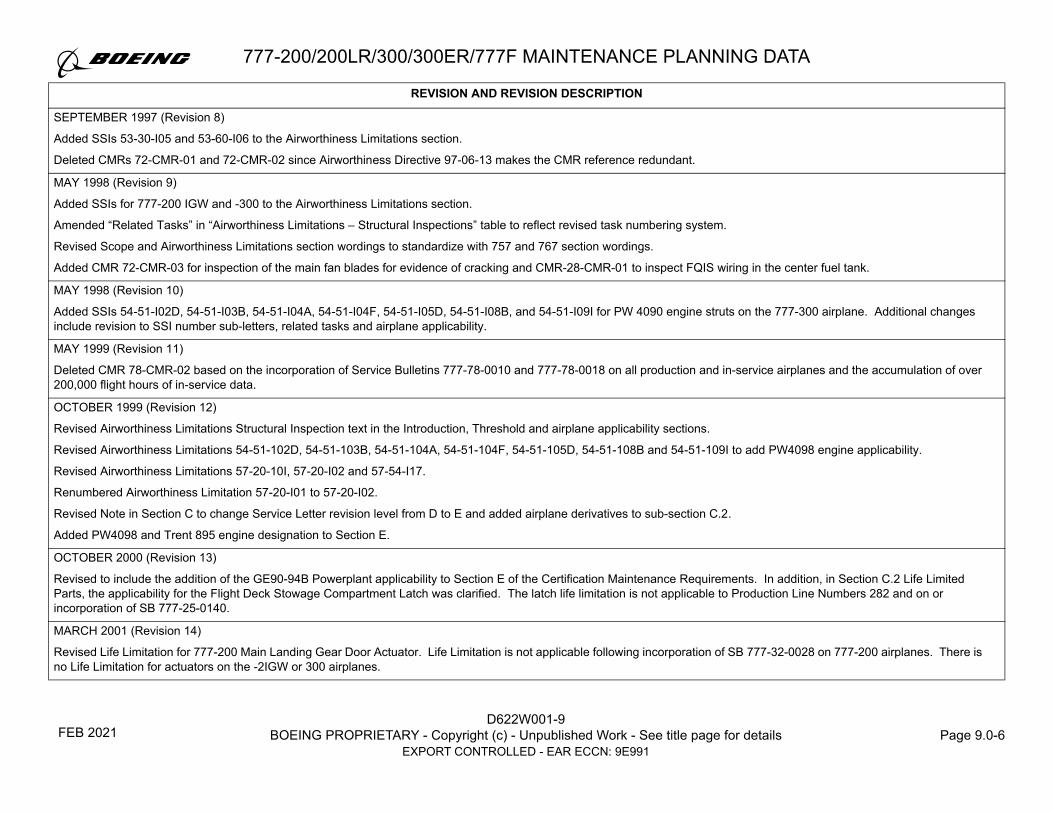
SEPTEMBER 1997 (Revision 8)
Added SSIs 53-30-I05 and 53-60-I06 to the Airworthiness Limitations section.
Deleted CMRs 72-CMR-01 and 72-CMR-02 since Airworthiness Directive 97-06-13 makes the CMR reference redundant.
MAY 1998 (Revision 9)
Added SSIs for 777-200 IGW and -300 to the Airworthiness Limitations section.
Amended “Related Tasks” in “Airworthiness Limitations – Structural Inspections” table to reflect revised task numbering system.
Revised Scope and Airworthiness Limitations section wordings to standardize with 757 and 767 section wordings.
Added CMR 72-CMR-03 for inspection of the main fan blades for evidence of cracking and CMR-28-CMR-01 to inspect FQIS wiring in the center fuel tank.
MAY 1998 (Revision 10)
Added SSIs 54-51-I02D, 54-51-I03B, 54-51-I04A, 54-51-I04F, 54-51-I05D, 54-51-I08B, and 54-51-I09I for PW 4090 engine struts on the 777-300 airplane. Additional changes include revision to SSI number sub-letters, related tasks and airplane applicability.
MAY 1999 (Revision 11)
Deleted CMR 78-CMR-02 based on the incorporation of Service Bulletins 777-78-0010 and 777-78-0018 on all production and in-service airplanes and the accumulation of over 200,000 flight hours of in-service data.
OCTOBER 1999 (Revision 12)
Revised Airworthiness Limitations Structural Inspection text in the Introduction, Threshold and airplane applicability sections.
Revised Airworthiness Limitations 54-51-102D, 54-51-103B, 54-51-104A, 54-51-104F, 54-51-105D, 54-51-108B and 54-51-109I to add PW4098 engine applicability.
Revised Airworthiness Limitations 57-20-10I, 57-20-I02 and 57-54-I17.
Renumbered Airworthiness Limitation 57-20-I01 to 57-20-I02.
Revised Note in Section C to change Service Letter revision level from D to E and added airplane derivatives to sub-section C.2.
Added PW4098 and Trent 895 engine designation to Section E.
OCTOBER 2000 (Revision 13)
Revised to include the addition of the GE90-94B Powerplant applicability to Section E of the Certification Maintenance Requirements. In addition, in Section C.2 Life Limited Parts, the applicability for the Flight Deck Stowage Compartment Latch was clarified. The latch life limitation is not applicable to Production Line Numbers 282 and on or incorporation of SB 777-25-0140.
MARCH 2001 (Revision 14)
Revised Life Limitation for 777-200 Main Landing Gear Door Actuator. Life Limitation is not applicable following incorporation of SB 777-32-0028 on 777-200 airplanes. There is no Life Limitation for actuators on the -2IGW or 300 airplanes.
REVISION AND REVISION DESCRIPTION
FEB 2021

777-200/200LR/300/300ER/777F MAINTENANCE PLANNING DATA
D622W001-9BOEING PROPRIETARY - Copyright (c) - Unpublished Work - See title page for details Page 9.0-7
EXPORT CONTROLLED - EAR ECCN: 9E991
JULY 2002 (Revision 15)
Added CMR 26-CMR-01 to inspect cargo fire bottles for leaks and apply Corrosion Inhibiting Compound to burst discs on fill fittings of cargo fire bottles.
SEPTEMBER 2002 (Revision 16)
Added CMR 52-CMR-01 applicable only to airplanes incorporating Boeing Service Bulletin 777-25-0216. This amended type certificate complies with the new 14 CFR 25.795 and the amended 14 CFR 25.772 as issued under Federal Register Docket No. FAA-2001-11032.
NOVEMBER 2002 (Revision 17)
Added Airworthiness Limitations 57-12-I02-1 and 57-12-I02-2 applicable to all airplanes L/N 423 and on due to design change.
Revised statement in preamble to airworthiness limitations that specifies roll back of any escalated baseline structural inspection intervals when reaching the AWL Threshold.
JANUARY 2003 (Revision 18)
Added L/N 427 and on applicability for 52-CMR-01.
JULY 2003 (Revision 19)
Added SSIs 54-51-I07-a, b, c for Rolls Royce aluminum aft strut bulkheads to the Airworthiness Limitations. These SSIs are applicable to 777-200ER (200IGW) Rolls Royce Struts, Production Line Numbers 447 and on.
NOVEMBER 2003 (Revision 20)
Added Section G which contains new airline operator reporting requirements for uncontrollable high thrust failure conditions or associated causal failures. This new section supports words added to the 777 Type Certificate Data Sheet stating occurrences of these subject failure conditions may endanger the safe operation of the airplane and hence are reportable under 121.703(c), 125.409 and 135.415. Section G contains a listing of these failures. Reference Exemption No. 7955 "Partial Exemption from 25.901(c) as it relates to uncontrollable high thrust.
Deleted the related task field from the Airworthiness Limitations – Structural Inspection listing to be common with other Boeing models.
Added an Applicability Note to clarify 26-CMR-01 requirement.
Added "applicable to airplanes with -2 bottles installed, Line Numbers 410 and on".
Revised the 777-200/2IGW/300 Nose Landing Gear Structural Safe Life limit from 37,200 landings to 77,500 landings as a result of completion of further fatigue testing on the nose landing gear.
Deleted reference to Service Letter 777-SL-32-001-E and added reference to Component Interchangeability Lists 161W0003 (Main Landing Gear) and 162W0002 (Nose Landing Gear) which provide a complete list of 777-200/-200 IGW/-300 landing gear related components subject to life limitations.
REVISION AND REVISION DESCRIPTION
FEB 2021

D622W001-9BOEING PROPRIETARY - Copyright (c) - Unpublished Work - See title page for details Page 9.0-8
EXPORT CONTROLLED - EAR ECCN: 9E991
777-200/200LR/300/300ER/777F MAINTENANCE PLANNING DATA
MARCH 2004 (Revision 21)
This revision includes changes to the format of the Airworthiness Limitations Structural Inspections table with more explicit airplane applicability information was added. “Flight length sensitive” AWLs were also identified in the new listing for the 777-300ER. Miscellaneous updates were made to non -300ER AWLs to correspond to the latest released SIPD information. Safe Life Limits for the Main Landing Gear, Main Landing Gear Support Fittings, and Nose Landing Gear were added for the 777-300ER. Specific safe life limits for the 777-300ER Nose Landing Gear Shock Strut components were also added. These components include; Upper Floating Piston, Upper Cylinder, Lower Cylinder, Metering Pin and Orifice Plate. This revision also includes the Life Limitation (2,000 cycles) for the 777-300ER Semi Lever Gear Hydraulic Strut (P/N 293W4201-2).
Paragraph “G” "Reporting Uncontrollable High Thrust Failure Conditions" was also revised for the 777-300ER.
Main landing gear door actuator life limitation applicability was clarified with the addition of a note. This addition thereby cancels Revision 14 of this document.
26-CMR-01: Revised Airplane Note to clarify applicability. CMR is not applicable to -3 Bottles.
JUNE 2004 (Revision 22)
Revised DTR number from 53-10-I02 to 53-10-I02A.
Added DTR 53-10-I02B and 53-10-I02C for rework structural provisions for Anti-Collision Light Installation.
JULY 2004 (Revision 23)
Revised 27-CMR-02 task interval from 100 FH to 250 FH based on the Primary Flight Control System (PFCS) Safety Analysis and service data reported by the airlines.
DECEMBER 2004 (Revision 24)
Added SSI 53-10-I02D applicable to airplanes L/N 501 and on.
Added Airworthiness Limitations SSIs 53-30-I01A, 53-30-I01B and 53-30-I01C that are applicable to airplanes with Connexion Next Generation Antenna installation incorporated in production.
JUNE 2005 (Revision 25)
Added SSI 57-53-I10 and 57-53-I11 applicable to all airplanes for the torque tube and inboard closeout rib fitting. The reason for the added SSIs is the damage tolerance category changed from a Category 2 to a Category 3.
DECEMBER 2005 (Revision 26)
Revised Airworthiness Limitations to add all Structural Significant Items (SSIs) for the 777-200LR. These changes support certification of the 777-200LR.
JANUARY 2006 (Revision 27)
Revised Airworthiness Limitations to add three new Structural Significant Items (SSIs) in the Structural Inspections Table to address a design change to the wing trailing edge flap support pins. Revised related DTR Check Form Titles to add applicability information for the existing flap pin design effective on L/N 504 and L/N 519.
FEBRUARY 2006 (Revision 28)
Added new Airworthiness Limitations Numbers 28-AWL-19 and 28-AWL-20 to address inspection and repair of the Motor Operated Valve Actuators.
REVISION AND REVISION DESCRIPTION
FEB 2021

777-200/200LR/300/300ER/777F MAINTENANCE PLANNING DATA
D622W001-9BOEING PROPRIETARY - Copyright (c) - Unpublished Work - See title page for details Page 9.0-9
EXPORT CONTROLLED - EAR ECCN: 9E991
MARCH 2006
Revised the Applicability Table in Section B to clarify engine applicability information. Revised the Applicability section of the table shown in Section G to update the GE90 applicability to include 110B.
Revised Fuel System Airworthiness Limitations to include paragraph (b) of the new standard introduced by § 25.981. Added 28-AWL-01 through 28-AWL-17 to the Airworthiness Limitations Table to satisfy SFAR 88 requirements.
Revised 26-CMR-01 Airplane Note to remove reference to line numbers, as the installation of a -2 bottle is not line number dependent.
Added text referencing the addition of Appendix L, “Post Threshold Intervals for Structures and Zonal Tasks”, to the MPD.
OCTOBER 2006
Revised CMR 52-CMR-01 interval from 4 years to 2250 days to reflect the improved reliability data for the Flight Deck Door Strike Assembly.
DECEMBER 2006
Revised applicability of fuel system airworthiness limitation number 28-AWL-20 to remove ITT actuator part number reference. The part number is listed in Service Bulletin 777-28A0034.
Revised Airworthiness Limitations – Systems section introduction to include revisions recommended by the Seattle FAA Flight Standards group.
JUNE 2007
Revised the Airworthiness Limitations – Structural Inspections table to update -200LR thresholds to cover new configuration.
SEPTEMBER 2007
Added a new fuel system Airworthiness Limitation number 28-AWL-18 to incorporate an operational check of Fuel Pump Ground Fault Interrupter (GFI).
Revised Section D. Airworthiness Limitations – Systems- Exceptional Short-Term Extensions to clarify notification requirements. Revised Section F. Certification Maintenance Requirements (CMRs) – Exception Short-Term Extensions to clarify notification requirements.
Revised Paragraph “I” to incorporate “Reporting Uncontrolled High Thrust Failure Conditions” per FAR 121.703 and FAR 135.415.
OCTOBER 2007
Revised Section C.1. Structural Safe Life Parts and associated Figures 3 and 4 as per the changes submitted by Landing Gear Structures Design Center, Boeing. These changes reflect the latest landing gear safe life limit information contained in the revised landing gear interchangeability drawings (a) Main Gear Interchangeability List 161W0003 Revision E, and (b) Nose Gear Interchangeability List 162W0002 Revision E.
Revised AWL 28-AWL-01 task description by removing "between reference to Sta 1035 to Sta 1045 and Zones 131 and 132" and adding "per Boeing AMM 28-11-00".
Revised 28-AWL-18 interval from 1 YR to 375 DYS be consistent with 777 Program usage parameters.
Revised Exceptional Short-Term Extensions for CMRs to clarify notification requirements for CMR 52-CMR-01.
Revised CMR 52-CMR-01 interval from 2250 days to 3375 days to reflect the improved reliability data for the Flight Deck Door Strike Assembly and related updates to the exceptional short-term extensions information.
REVISION AND REVISION DESCRIPTION
FEB 2021

D622W001-9BOEING PROPRIETARY - Copyright (c) - Unpublished Work - See title page for details Page 9.0-10
EXPORT CONTROLLED - EAR ECCN: 9E991
777-200/200LR/300/300ER/777F MAINTENANCE PLANNING DATA
DECEMBER 2007
Added new SSIs 28-00-I01A and 28-00-I01B that are applicable to 777-200LR aircraft with Auxiliary Fuel Tanks installed.
Revised Section C.2, Life Limited Parts, to include 777-200LR Optional Auxiliary Body Fuel Tanks. Revised Section D. Airworthiness Limitations – Systems by adding a note to clarify that the auxiliary fuel tank complies with CFR 25.981, Amendment 25-102.
Revised AWLs 28-AWL-11 through -14 and 18 to incorporate Auxiliary Fuel Tank information. Revised AWL 28-AWL-16 from "The following must be maintained during fuel tank access door installation" to "The following must be maintained during installation of the tank access doors located on the lower wing skin". Revised AWL 28-AWL-19 by adding additional AMM procedures.
Added new AWLs 28-AWL-21 through 28-AWL-26 to support 777-200LR aircraft with Auxiliary Fuel Tanks installed.
FEBRUARY 2008
Revised 28-AWL-03 to reflect the new maximum loop resistance values associated with the lightning protection of the unpressurized FQIS wire bundle installations so as to satisfy the Airworthiness Limitation Instructions required by SFAR 88. Also removed the joint resistance values based upon engineering review and operator maintenance practice.
NOVEMBER 2008
Revised Section B., Airworthiness Limitations – Structural Inspections, by adding information regarding Individual Airplane Specific Airworthiness Limitations for aircraft L/N 740.
JANUARY 2009
Revised the AIRWORTHINESS LIMITATIONS – STRUCTURAL INSPECTIONS Table to include references to the 777F, as well as additional, separate sections addressing threshold inspections for freighter and passenger aircraft.
Revised the Airworthiness Limitations to incorporate the 777F configuration.
Revised C. AIRWORTHINESS LIMITATIONS – STRUCTURAL SAFE LIFE LIMITS to include life limits for the 777F aircraft.
Revised G. PAGE FORMAT – CERTIFICATION MAINTENANCE REQUIREMENTS (CMRs) table to include applicability for the 777F aircraft.
Added the following CMR Tasks: 21-CMR-01, 27-CMR-05, 27-CMR-06, 27-CMR-07, 27-CMR-08, and 27-CMR-09.
Revised I. REPORTING UNCONTROLLABLE HIGH THRUST FAILURE CONDITIONS to incorporate 777F aircraft.
FEBRUARY 2009
Revised 28-AWL-02, 28-AWL-03, and 28-AWL-16 per the Approved Alternative Method of Compliance to Airworthiness Directive 2008-11-13.
Revised 28-AWL-01 – 05, 28-AWL-07 – 08, 28-AWL-10, 28-AWL-13 – 16, and 28-AWL-19 – 23 by adding updates to enhance clarity of the Airworthiness Limitations.
Revised Section F front matter by adding the Airworthiness Limitations – Nitrogen Generation System (NGS) requirements and by adding 47-AWL-01 – 47-AWL-06 NGS tasks.
JANUARY 2010
Revised the AIRWORTHINESS LIMITATIONS – STRUCTURAL INSPECTIONS Table to include updated inspection requirements for the 777-200/200LR/300/300ER aircraft as part of a planned re-assessment of the Supplemental Fatigue Inspection Program.
REVISION AND REVISION DESCRIPTION
FEB 2021

777-200/200LR/300/300ER/777F MAINTENANCE PLANNING DATA
D622W001-9BOEING PROPRIETARY - Copyright (c) - Unpublished Work - See title page for details Page 9.0-11
EXPORT CONTROLLED - EAR ECCN: 9E991
AUGUST 2010
Revised Paragraph F. Airworthiness Limitations – Nitrogen Generation Systems Tasks by updating the following text "CDCCLs" with "AWLs (ALIs and CDCCLs)", "design limitations", and "Final Flammability Rule, Paragraph III(F), Section 7, Paragraph M25.4(a)" to clarify the intent of the paragraph.
Revised 47-AWL-01 47-AWL-02, 47-AWL-03, 47-AWL-04, 47-AWL-05, 47-AWL-06, and 47-AWL-07 by updating the Applicability column to include airplanes that have incorporated Service Bulletin 777-47-0002.
Revised 47-AWL-01 and 47-AWL-05 by updating the Task Description to include instructions and a Note to clarify the procedure and parameters for the maintenance action.
Revised 47-AWL-02 by replacing the text "replaced and installed" with "replaced or reinstalled" to clarify the procedure and parameters for the maintenance action.
Revised 47-AWL-04 by replacing the text "per Boeing AMM 47-43-02" with "(refer to Boeing AMM 47-42-04)".
Added 47-AWL-07, an identification of the maintenance standard for the Nitrogen Generation System and notice of potential future compliance requirements associated with decreased aircraft descent rates.
JANUARY 2011
Added CMR Number 32-CMR-01, a 50 flight or 25 day cycle, whichever occurs later, lubrication task for the left and right Main Landing Gear truck beam and inner cylinder pivot joints. Applicable to airplanes Line Number 915 and on or airplanes incorporating Boeing Service Bulletin 777-32-0085.
JULY 2011
Revised 47-AWL-03 to incorporate NGS performance features to show compliance with 14 CFR 26.33.
FEBRUARY 2012
Revised the Life Limit for the 777-200LR Optional Auxiliary Body Fuel Tank from 1,800 Landings to 15,000 Cycles, due to results of continued fatigue testing.
Revised references to regulatory agencies, as needed, by adding “BASOO”, the acronym for the Boeing Aviation Safety Oversight Office.
Revised Section D by moving the first two paragraphs pertaining to Fuel System Ignition Prevention into the new subsection D.1. Revised the “FUEL SYSTEMS AIRWORTHINESS LIMITATIONS” heading to “INTRODUCTION”, and added information on FAA approved Airworthiness Limitations required under Title 14 CFR § 43.16 and § 91.403.
Revised “USE OF ALTERNATE TOOLS” heading in Section D to “USE OF ALTERNATE OR EQUIVALENT TOOLS, TEST EQUIPMENT OR MATERIALS"; revised requirements to include CMMs, and identified acceptable fuel tank sealants.
Revised the Exceptional Short-Term Extensions subparagraph, changing “fuel system AWL” to “system AWL” to accommodate the addition of 28-AWL-101 - Engine Suction Feed System. Revised “(e.g., a Principal Maintenance Inspector)” to “or a Principal Maintenance Inspector” and updated the Flight Standards Handbook reference from “8300.10” to “8900.1 FSIMS”.
Revised the Regulatory Agency Approval subparagraph by updating the requirements for operators not operating under the jurisdiction of the U.S. FAA.
Added new subparagraphs to Section D: "Definitions", to provide further clarification on accomplishment instructions, and "Supporting Documentation", to clarify that strict adherence to the methods, techniques and practices, as prescribed, is required to ensure the ALI or CDCCL is complied with.
(Continued on next page)
REVISION AND REVISION DESCRIPTION
FEB 2021

D622W001-9BOEING PROPRIETARY - Copyright (c) - Unpublished Work - See title page for details Page 9.0-12
EXPORT CONTROLLED - EAR ECCN: 9E991
777-200/200LR/300/300ER/777F MAINTENANCE PLANNING DATA
FEBRUARY 2012, Continued
Revised the table heading in Section D from “Airworthiness Limitations – Fuel Systems” to “AWLs - Fuel Tank Ignition Prevention”.
Revised certain AWLs by changing the word “per” in AWL references to “refer to”, as needed.
Revised 28-AWL-01 by adding an inspection of the wire sleeving, if installed, and added statement for SWPM repairs to ensure wires are not in contact with the surface of the Center Fuel Tank. Revised SWPM reference from 20-10 to 20-10-11 and 20-10-13, for further clarification.
Revised 28-AWL-03 by adding Step 1 for the loop resistance check between the receptacle and structure, added ohm values to Step 2, and Step 3 for restoring the electrical bond.
Revised 28-AWL-04 to clarify which design features must be maintained, dependent on the disruption of the ground path of each specified connector.
Revised 28-AWL-05, replacing "structure" with "front spar inside the tank" in Step 1, changing “first tube" to “fuel tube" in Steps 4 and 5, and adding “if the bonding jumper was disturbed” to Step 5 for clarification.
Revised 28-AWL-06 by adding critical design features for the hydraulic bulkhead fitting, heat exchanger, and non-heat exchanger hydraulic tubes due to the different hydraulic tube materials and types used.
Revised the Concern statement for 28-AWL-07 by deleting “during pump overhaul” to clarify that the potential for maintenance error is not limited to overhaul. Revised "Repair and overhaul" to "Maintenance" in the second paragraph to clarify the CDCCL intent.
Revised the Applicability for 28-AWL-08 by deleting “A market” for clarification. Replaced “phenolic washer” with “insulating washer” in Step 1 and revised Step 2 to identify the interface location for the fillet seal that must be maintained if the drain valve is removed or replaced.
Revised the Concern statement for 28-AWL-09 by adding a statement that electrical bonding of fitting and brackets and/or the cap sealing of fasteners, and fillet sealing of component interface will be necessary. Revised the second paragraph to clarify that any alteration, design change, or repair involving new penetrations requires approval by the Seattle FAA ACO or BASOO.
Revised the Concern statement for 28-AWL-10, replacing “jumpers” with “jumper” and added “Ground Fault Interrupter” for “GFI”. Added reference to AMMs 28-22-05 and 28-31-01. Revised “a bonding jumper” to “one bonding jumper” in Step 1, and added “across the bonding jumper” to Step 2 for clarification.
Revised the Concern statement for 28-AWL-11, replacing "EMI" with "EME" and deleting "outside of the tank". Added the definition/requirements for new wiring, and clarified the requirements for repaired/replaced wiring.
Revised 28-AWL-12 to clarify that the Auxiliary Tank Refuel Valve controlled by the AWL is the Solenoid Actuator Refuel Valve on the Center Wing Tank Rear Spar. Clarified the Aux Tank Refuel Valve requirement of this CDCCL is only applicable to 777 airplanes with the Aux Tank Refuel Valve installed. Revised Step 2 to clarify that the fillet seal is applied around the entire perimeter of the valve body.
Revised 28-AWL-13 by deleting the note for modifying/upgrading FQPU Part No. 0310KPU02 to eliminate redundancy, since the only CMMs that can be used for maintenance of the FQPU are already listed in the CDCCL.
Revised 28-AWL-14 by adding “water detector” to the Concern statement and replaced “Repair and overhaul” with “Maintenance of”, where applicable.
(Continued on next page)
REVISION AND REVISION DESCRIPTION
FEB 2021

777-200/200LR/300/300ER/777F MAINTENANCE PLANNING DATA
D622W001-9BOEING PROPRIETARY - Copyright (c) - Unpublished Work - See title page for details Page 9.0-13
EXPORT CONTROLLED - EAR ECCN: 9E991
FEBRUARY 2012, Continued
Revised 28-AWL-15 by changing Step 1.a.I. from "wire separation requirement of 0.125 in" to "wires not in contact with the structure". Further clarified the critical design features and precluded those already covered in 28-AWL-04.
Revised the title of 28-AWL-16 by replacing “Configuration” with “Lightning Protection” for clarification. Revised Step 1 to clarify which door positions are required to have the phenolic strip and added more critical design features to the AWL that are required to be maintained.
Revised 28-AWL-17 by adding “or GFIs” to the title, and clarified the steps required prior to resetting of GFIs and circuit breakers.
Revised the title of 28-AWL-18 by adding “and Ground Fault Protector (GFP)” and added GFP to the task, as needed, for further clarification.
Revised the title of 28-AWL-19 from “Lightning and Fault Current Protection – Motor Operated Valve (MOV) Actuator” to “Motor Operated Valve (MOV) Actuator – Lightning and Fault Current Protection”. Deleted SB 777-28A0059 from the Applicability due to the SB cancellation. Revised the AWL by separating the critical design feature requirements for MOV with adapter plate and MOV without adapter plate.
Revised the title of 28-AWL-20, replacing “Repair” with “Output Shaft Electrical Isolator” for clarification. Revised Applicability to “ALL/NOTE” and added the following Note for clarification: “Applies only to ITT actuators with Part Number MA20A2027 or MA30A1001”. Revised the second paragraph by adding “if the actuator was removed for bench testing or repair" to clarify the condition that requires a Dielectric Strength Test.
Revised 28-AWL-21 by adding an inspection of the wire sleeving, if installed, and adding requirement to ensure wires are not in contact with the surface of the auxiliary tank when repairing wires. Revised the SWPM reference from 20-10 to 20-10-11 and 20-10-13 for further clarification.
Revised the title of 28-AWL-23 to “Auxiliary Tank AC Fuel Pump Fault Current Bonding Path”. Replaced “path to structure” in the Concern statement with “path through the motor impeller assembly” and added “from the pump” to the end of the last sentence for clarification. The requirement for auxiliary tank installation/replacement was moved to new AWL 28-AWL-27. Revised Steps 2a and 2b to clarify the bonding resistance measurement location and value. Added Step 3 to ensure that fuel pump maintenance meets the requirements outlined in 28-AWL-07.
Revised 28-AWL-24 by adding “must be maintained” to the first paragraph, and “are installed” to Step 1 for clarification.
Revised 28-AWL-25, replacing “verify the following” with “the following must be maintained:”, and changed the numbering format of the listed items.
Added AWL 28-AWL-27 for the auxiliary fuel tank replacement or installation which was previously part of 28-AWL-23 to further clarify the bonding resistance values and the critical design features that must be maintained.
Added three new subsections to Section D: D.1 – Fuel Systems Ignition Prevention, D.2 – Engine Suction Feed System, and D.3 – Nitrogen Generation System (NGS).
Added new ALI, 28-AWL-101 - Engine Fuel Suction Feed Operational Test, that is required to protect against engine flameout during suction feed operations.
Added a new subheading for the table of AWLs – NGS Tasks in Section D.3.
Revised the heading for Section E, making it a subparagraph of Section D, then relettered the remaining headings accordingly.
REVISION AND REVISION DESCRIPTION
FEB 2021

D622W001-9BOEING PROPRIETARY - Copyright (c) - Unpublished Work - See title page for details Page 9.0-14
EXPORT CONTROLLED - EAR ECCN: 9E991
777-200/200LR/300/300ER/777F MAINTENANCE PLANNING DATA
MAY 2013
Added Section D.4 - Rolls Royce Thrust Reverser Thermal Protection System.
Added Airworthiness Limitation 78-AWL-01 for the Rolls Royce Thrust Reverser Thermal Protection System.
Added Airworthiness Limitation 78-AWL-02 for the Rolls Royce Thrust Reverser Inner Wall.
JUNE 2013
Added new CMR 25-CMR-01 to operationally check AMSAFE NexGen inflatable seat restraints, EMA Part Number 511959-XXX-XX.
MARCH 2014
Revised the document to define FAA Oversight Office and replaced all references of "Seattle FAA ACO or BASOO" with "FAA Oversight Office" throughout the entire document.
References to FAA regulations were changed to include "Title 14 CFR §" to accurately reflect FAA regulation citations throughout the document and for consistency.
Revised the subparagraph title "Airworthiness Limitations - Structural Inspections" to "Airworthiness Limitations" under Section A "Scope".
Revised Section D front matter with the following:
Moved the subparagraph "Regulatory Agency Approval", "AWL Revision Process" and “Accomplishment Instructions - General Information” to after the "Introduction" subparagraph.
Changed "per" to "in accordance with" throughout the entire Section D except for the "per" in the AWL 28-AWL-04 (Step 2), 28-AWL-15 (Step 2), 28-AWL-23 (Step 3), and 47-AWL-03. The word "per" in the AWL 28-AWL-04 (Step 2), 28-AWL-15 (Step 2), and 28-AWL-23 (Step 3) was changed to "as specified in". The word "per" in the AWL 47-AWL-03 was replaced with "as required by".
Revised "Accomplishment Instructions - General Information" subparagraph to provide clarification of the use of "in accordance with" and "refer to" verbiage when referencing other Instructions for Continued Airworthiness documents.
Revised the "Use of Alternate or Equivalent Tools, Test Equipment or Materials" subparagraph to delete the information on acceptable sealant type for fuel tank since the sealant type is defined in the "Definitions" subparagraph.
Revised "Definitions" subparagraph to define FAA Oversight Office.
Revised AWL 28-AWL-09 to provide clarification when a repair or alteration involving new or altered fuel tank penetrations requires FAA Oversight Office approval and when a repair or alteration does not require additional FAA Oversight Office approval. Added additional notation to require electrical bonding of fitting, brackets, cap sealing fasteners, and/or fillet sealing of component interface.
Added Section D.4 Pratt and Whitney Forward Strut Drain Line and new Airworthiness Limitation 54-AWL-01 to address potential clogging of the Pratt and Whitney Forward Strut Drain Line.
Renumbered Section D.4 Rolls Royce Thrust Reverser Thermal Protection System to Section D.5 to list AWLs in ATA sequence.
Revised "Exceptional Short-Term Extensions" under Section E to change Flight Standards Handbook from "8300.10" to "8900.1 FSIMS".
REVISION AND REVISION DESCRIPTION
FEB 2021

777-200/200LR/300/300ER/777F MAINTENANCE PLANNING DATA
D622W001-9BOEING PROPRIETARY - Copyright (c) - Unpublished Work - See title page for details Page 9.0-15
EXPORT CONTROLLED - EAR ECCN: 9E991
MAY 2014
Revised the Airworthiness Limitations - Structural Inspections section to clarify Front Matter and Table Notes.
Added Front Matter to the Airworthiness Limitations – Structural Inspections section to clarify 777 airplane designations.
Revised Front Matter in the Airworthiness Limitations – Structural Inspections section to clarify Removable Structural Components (RSC) requirements.
Added Maintenance Review Board Report (MRBR) Task references associated with structural items requiring excess sealant to be removed.
Revised the Excess Sealant inspection to the Wing Side of Body Splice Upper Surface (777 ALL) by providing an alternative inspection requirement.
Revised excess sealant removal Table Notes to clarify optional inspections and NDT Procedure references that may be used in lieu of sealant removal.
Revised the AMM procedure references for excess sealant removal and application.
Revised Flag Note (7) to Flag Note (8) in the Airworthiness Limitations - Structural Inspections table, since the NDT Procedures for the corresponding SSIs are accepted by the FAA and published in the NDT Manual, D634W301.
Revised 78-AWL-02 applicability to include Service Bulletin 777-78A0094 and P/N 315W5295-97/-98/-99/-100 and higher, and to clarify that this AWL applies to each thrust reverser half independently. Revised description for clarity and to correct color chip terminology.
OCTOBER 2014
Deleted the Boeing submittal signature column from the Revision Log to improve the layout and provide consistency across all Section 9/AWL/CMR/SCI documents. A submittal signature will no longer be included in the revision log; only the FAA BASOO approval date will be shown.
Revised CMR 25-CMR-01 interval from 285 DY to 375 DY based on updated System Safety Assessment.
DECEMBER 2014
Revised the definition of "Removed or Replaced” to include reinstallation of a component and added the definition for Maintenance, Fay Surface Bond, Fay Sealed Fay Surface Bond, Fillet Sealed Fay Surface Bond, and Cushion Clamp to the "Definitions" subparagraph in Section D front matter.
Revised 28-AWL-01 to meet new formatting requirements. Clarified specific SWPM references for wire assembly and installation, repair procedures, and seal fittings for repairing and replacement of wire.
Revised 28-AWL-02 to meet new formatting requirements and identify the critical design features that must be maintained. Added reference to Boeing AMMs 28-11-00 and 53-01-01 to provide access and inspection information to the area. Added SWPM references for wire assembly and installation, repair procedures, and seal fittings for accepted practices for repair and replacement of wires.
Revised 28-AWL-03 to add the name of the loop resistance tester manufacturer. Revised the value of the loop resistance from 0.054 ohm (54 milliohms) or less to 0.053 ohm (53 milliohms) or less for connector D28102P. Deleted Step 3 for restoring the bonds since it is covered in the AMM and does not meet the new AWL guidelines for critical design features.
Revised 28-AWL-04 to clarify the structure as the stiffener on the spar for Step 1.a.I.A and deleted Step 1.a.I.B for the torque requirement for the bonding jumper since it does not meet the AWL guidelines for critical design features. Added SWPM references for the accepted practices for bonding of the jumper and receptacle to the bracket and the electrical bonding processes.
(Continued on next page)
REVISION AND REVISION DESCRIPTION
FEB 2021

D622W001-9BOEING PROPRIETARY - Copyright (c) - Unpublished Work - See title page for details Page 9.0-16
EXPORT CONTROLLED - EAR ECCN: 9E991
777-200/200LR/300/300ER/777F MAINTENANCE PLANNING DATA
DECEMBER 2014, Continued
Revised 28-AWL-05 by deleting Steps 2 and 3 since they do not meet the AWL guidelines for critical design features. Added a step for fay sealed fay surface bond between the bulkhead fitting and front spar inside the tank.
Revised 28-AWL-06 to revise Step 1(b) (now is 1(a)) to change full bodied cap seals at the tank wall interface inside and outside the fuel tank to fillet seals at the tank wall interface on the outside of the fuel tank. Revised Step 2 to define critical design feature meeting the new AWL guidelines when the hydraulic heat exchanger is removed or replaced. Step 3, the electrical bonding resistance requirement for across the in-line fittings for non-heat exchanger hydraulic tube was expanded to include both the aluminum and titanium tubes and the different sizes of the tubes.
Revised 28-AWL-07 to change title from "AC and DC Pump Maintenance" to "AC and DC Fuel Pump Electrical/Mechanical Design". Separated and identified the specific CMM for the boost pump, override-jettison pump, and the APU supply fuel pump. Revised CMM revision level to reflect the first CMM revision that was FAA approved. Added clarification that the deviations from, temporary revisions, or Supplier Service Bulletin for these CMMs that have been approved by the FAA Oversight Office can be used for maintenance of these pumps. Added a notation that unless the specific portions of these CMMs are tagged as a CDCCL or ALI, the entire CMM must be followed precisely.
Revised 28-AWL-08 to change the applicability to all 777-200 since the AD 2006-05-08 compliance time has passed for incorporation of SB 777-28-0045. Revised AWL to meet the new formatting requirements.
Revised 28-AWL-09 by adding "(All Fuel Tanks)" to the title to clarify that the requirement is also applicable to the auxiliary fuel tank (if installed). Defined the acronyms for SRM and ODA.
Revised 28-AWL-10 title to clarify that the AWL is applicable to both AC and DC pumps. Added a requirement for the installation of a fay sealed fay surface bond for the bonding jumper terminals. Added electrical bonding requirements for DC pumps.
Revised 28-AWL-11 to clarify the definition of FQIS wiring on the airplane. Defined criteria for specific wiring that has low enough energy that is not affected by this AWL, allowing for the use of an LRU as a "Hot Short Protector", and clarified the requirement for wiring installed less than 2.0 inches from the FQIS wiring.
Revised 28-AWL-12 to separate requirements for center wing tank refuel valve and Auxiliary Fuel Tank Refuel Valve. Added a requirement for a fay surface bond between the valve body and the spar.
Revised 28-AWL-13 to separate and identify the specific CMM for the FQPU and the EFLI PDU. Revised the CMM revision level to reflect the first CMM revision level that was approved by the FAA. Also added clarification that the deviations from, temporary revisions, or Supplier Service Bulletin for these CMMs that have been approved by the FAA Oversight Office can be used for maintenance of these pumps. Added a notation that unless the specific portions of these CMM are tagged as a CDCCL or ALI, the entire CMM must be followed precisely.
Revised 28-AWL-14 to separate and identify the specific CMM for the FQIS Tank Units, densitometers, water detectors, and EFLI probe. Revised the CMM revision level to reflect the first CMM revision level that was approved by the FAA. Also added clarification that the deviations from, temporary revisions, or Supplier Service Bulletin for these CMMs that have been approved by the FAA Oversight Office can be used for maintenance of these pumps. Added a notation that unless the specific portions of these CMM are tagged as a CDCCL or ALI, the entire CMM must be followed precisely.
Revised 28-AWL-15 to specify that repair and overhaul of FQIS in-tank wire harness must be approved by FAA Oversight Office for on aircraft repair or follow GE Aviation CMM 28-47-61. Added critical design feature requirements for installation of the FQIS in-tank wire harness. Added requirements for airplane with auxiliary fuel tank (cell) installed.
(Continued on next page)
REVISION AND REVISION DESCRIPTION
FEB 2021

777-200/200LR/300/300ER/777F MAINTENANCE PLANNING DATA
D622W001-9BOEING PROPRIETARY - Copyright (c) - Unpublished Work - See title page for details Page 9.0-17
EXPORT CONTROLLED - EAR ECCN: 9E991
DECEMBER 2014, Continued
Revised 28-AWL-16 to add notation for the three types of fuel access doors for the 777 airplanes. Added clarification that when a gasket not meeting the requirements in Step 3(a) to 3(c) is used, the gasket must be replaced with a gasket meeting all the requirements in Step 3 within 30 days. Added clarification that the mesh gasket has to be vapor de-greased before using a different gasket filling material and prior to re-impregnating the knitted mesh gasket with grease or anti-corrosion compound when the new gasket is greater than five years old.
Revised 28-AWL-17 to revise the title to "Over-current and Arcing Protection Electrical Design Features - Fuel Pump Circuit Breakers or Electrical Load Control Unit (ELCU) and Ground Fault Interrupters (GFI)/Ground Fault Protector (GFP) (If Installed)" to better reflect the intent. Added ELCU as another component require compliance with this AWL. Added a requirement for an insulation resistance test to be completed for the fuel pump prior to resetting the circuit breaker, GF/GFP, or ELCU when no fault is found. Added reference to Boeing FIM 28-25 for the troubleshooting of DC pump.
Revised 28-AWL-18 to list the critical test requirement that must be verified for the operational check of the GFI/GFP for the Main Tank Boost Pump, Center Tank Override/Jettison Pump and Fuel Jettison Pump, and Auxiliary Fuel Tank Pump.
Revised 28-AWL-19 to meet the AWL guidelines for critical design features. Provided clarification on the applicable AMM procedure for the different type of motor operated valve. Added additional requirements for cap sealing the mounting bolts for the adapter plate inside the tank, bonding resistance requirement, and cap sealing of the bonding jumper terminal lugs. Added requirements for airplanes with auxiliary fuel tank (cell) installed. Added the air transfer valve/actuators part number that the AWL is not applicable to.
Revised 28-AWL-20 to meet the new formatting guidelines. Added new MOV Part Number MA30A1017 and the associated CMM 28-20-25.
Revised 28-AWL-21 to change the applicability from 4500 DY to 16,000 FC/3000 DY to be consistent with the same requirement for the wires over the center tank (28-AWL-01). Added reference to SWPM 20-10-22 for seal fittings. Deleted the repairing of the wiring since it does not meet the AWL guidelines. Reformatted and changed verbiage to meet the new AWL guidelines and to be consistent with 28-AWL-01.
Revised 28-AWL-22 to meet new formatting requirements and identify the critical design features that must be maintained. Added reference to Boeing AMMs 28-11-00 and 53-01-01 to provide access and inspection information to the area. Added SWPM references for wire assembly and installation, repair procedures, and seal fittings for accepted practices for repair and replacement of wires.
Revised 28-AWL-23 to clarify this AWL is also applicable during installation of the auxiliary fuel tank (cell). Deleted Step 3 for referencing the maintenance of the Auxiliary tank pump specified in 28-AWL-07 since it does not meet the AWL guidelines. Added requirement for installation of fay sealed fay surface bond for the bonding jumper terminals.
Revised 28-AWL-24 to meet the new formatting guidelines. Provided additional design feature clarification for the cargo liners, thermal insulation blankets, and the impact barrier.
Revised 28-AWL-25 by adding the correct AMM procedure reference. Deleted the requirement for the foil back fairing panels and added the electrical bonding requirements for the drain bulkhead union.
Revised 28-AWL-26 to list the critical test requirement that must be verified through an operational check of the auxiliary tank fuel pump uncommanded on/automatic shutoff circuit.
Revised 28-AWL-27 to meet the new formatting guidelines.
Added AWL 28-AWL-28 to require the inspection of the fillet seals and cap seals in the area where maintenance was performed inside the tank.
(Continued on next page)
REVISION AND REVISION DESCRIPTION
FEB 2021

D622W001-9BOEING PROPRIETARY - Copyright (c) - Unpublished Work - See title page for details Page 9.0-18
EXPORT CONTROLLED - EAR ECCN: 9E991
777-200/200LR/300/300ER/777F MAINTENANCE PLANNING DATA
DECEMBER 2014, Continued
Added AWL 28-AWL-29 to add requirements to prevent electrostatic energy to be transferred to the tank. Any alterations involving new or altered design features for static dissipation protection inside the fuel tanks will require FAA Oversight Office approval unless they are accomplished in accordance with Structural Repair Manual Procedures, Boeing Service Bulletins, and/or Boeing ODA approved repair/alterations instructions.
Added AWL 28-AWL-30 to provide relief when the requirements in AWL 28-AWL-17 Step 1(b) insulation resistance requirements of 5 megohms or greater in all power circuits is not met.
Added AWLs 28-AWL-31 and 28-AWL-32 for the inspection of the cushion clamps and teflon sleeving for out-of-tank wire bundles installed on specific brackets that are mounted directly on the fuel tanks.
Revised AWL 28-AWL-101 to meet the new formatting guidelines and clarified the engine parameters for the Rolls Royce engine. Added clarification that the engine suction feed operation step is with all boost pumps "OFF" for the associated tank.
Added "General Information" subparagraph to the front matter of Section D.3.
Revised 47-AWL-01 by deleting the requirement for electrical bonding resistance in Item 5. Added clarification for the requirement of the bulkhead fitting with integral honeycomb flame arrestor and the fillet sealed fay surface bond requirements.
Revised 47-AWL-02 to meet the new formatting guidelines and clarification.
Revised 47-AWL-03 by deleting the background information which has been moved to the NGS front matter section. Revised the verbiage to meet the new formatting guidelines.
Revised 47-AWL-04 to list the critical test requirement that must be verified for thermal switch test outlined in CMM 47-43-02. Added an option to replace the thermal switch instead of the testing outlined in CMM 47-43-02.
Revised 47-AWL-05 to list the critical test requirement that must be verified for the operational test of the cross vent check valve.
Revised 47-AWL-06 to change the testing requirement from a leakage check to a detail visual inspection of the NEA distribution line. Added critical requirement that must be verified for the detail visual inspection.
Revised 47-AWL-07 to change the title from "Industry Fleet Average Flammability Exposure" to "NGS On-Going Compliance Based on Industry Descent Times – Required Service Instructions" to better reflect the intent of the AWL. Also added clarification that the operator is required to implement the service instructions related to industry descent times within the compliance time stated in the service instructions.
Revised 78-AWL-01 by changing "DYS" to "DY" in the Interval column and reformatting the steps.
Revised 78-AWL-02 by changing "DYS" to "DY" in the Interval column.
JANUARY 2015
Added a new Section H. AWLs - Structural Limit of Validity (LOV) as required by Title 14 Code of Federal Regulations (CFR) Section 26.21 (Amendment 26-6).
REVISION AND REVISION DESCRIPTION
FEB 2021

777-200/200LR/300/300ER/777F MAINTENANCE PLANNING DATA
D622W001-9BOEING PROPRIETARY - Copyright (c) - Unpublished Work - See title page for details Page 9.0-19
EXPORT CONTROLLED - EAR ECCN: 9E991
NOVEMBER 2015
Revised 28-AWL-11 to revise the definition (first) paragraph to include the Auxiliary Fuel Tank (Cell) EFLI wiring and add the EFLI Processor Unit as an LRU. Replaced "FQIS" with "tank circuit or airplane interface circuit" in Steps 1 through 3 to reflect the intent to cover wiring from the LRU to the fuel tank penetration and wiring that terminates at the LRU and are not considered as tank circuit wiring as defined in the definition (first) paragraph.
Revised 28-AWL-16 to better reflect the applicability of the approved grease and anti-corrosion compound on machined impact resistant doors and added a step to include Mobilgrease 33 under approved grease or anti-corrosion compound. Deleted the additional requirement for the surge tank access door with vent scoop. Added requirements for removal and reinstallation or replacement of the pressure relief valve on the surge tank access door.
Revised 28-AWL-17 to delete "NOTE" in Step 1.b. to require the repetitive inspection in 28-AWL-30 or replace the pump. In addition, deleted 28-AWL-30 as the conditional requirement is difficult to track and comply by airline operators.
Revised 28-AWL-19 Step 1.c.III. to identify the electrical bonding resistance values between the actuator upper housing and the structure given the removal of the actuator, index plate, adapter plate, the actuator and index plate, or the removal of only the actuator prior to attachment of the bonding jumper and electrical connector. Added Step 1.d., 1e., 2, c. and 2.d. to define the critical design requirements for removal of the bonding jumper from the structure or the actuator. Sequenced Steps 2.a. and b. appropriately for when the APU valves (shut-off and isolation) and Jettison nozzle valve are removed and reinstalled or replaced, respectively. Added steps 2.c. to define critical design requirements for disconnection of the bonding jumper from Structure or Actuator for APU or Jettison Nozzle Valve. Revised and added step 3. C. to include verification of bonding jumper installation for Aux tank.
Deleted 28-AWL-30 as the conditional requirement is difficult to track and comply by airline operators.
Revised 78-AWL-01 applicability to include Service Bulletin 777-78A0094 and P/N 315W5295-97/-98/-99/-100 and higher, and to clarify that this AWL applies to each thrust reverser half independently.
Revised 27-CMR-02 interval from 250 Hrs to 500 Hrs based on updated System Safety Assessment.
Revised 29-CMR-03 interval from 6000 FH to 7500 FH after it has been shown that the escalation can be tolerated in Fault Tree Analysis (FTAs).
Revised 52-CMR-01 to change Airplane Note to clarify that the CMR is applicable to non-freighter airplanes from line number 427 and on, or airplanes that have incorporated Service Bulletin 777-25-0216.
JANUARY 2016
Per FAA request, deleted exceptions from Subsection B. AIRWORTHINESS LIMITATIONS - STRUCTURAL INSPECTIONS front matter regarding FAA Oversight Office's approval requirement of alternate inspections.
Revised Section H. AWLs - Structural Limit of Validity (LOV) to add applicability for the 777-200LR, 777-300ER, and 777F models.
REVISION AND REVISION DESCRIPTION
FEB 2021

D622W001-9BOEING PROPRIETARY - Copyright (c) - Unpublished Work - See title page for details Page 9.0-20
EXPORT CONTROLLED - EAR ECCN: 9E991
777-200/200LR/300/300ER/777F MAINTENANCE PLANNING DATA
DECEMBER 2016
Deleted the FAA Approval signature column from the Revision Log to improve the layout and provide consistency across all Section 9/AWL/CMR/SCI documents. Submittal signatures will no longer be included in the Revision Log.
Revised SSI 53-30-I06A to remove the operational limit that prevents 777-200/-300 airplane operation beyond the stated threshold. Validation of the applicable published inspection procedures for SSI 53-30-I06A was completed and revision to the inspection procedure was published in the NDT Manual, D634W301.
Revised SSI 53-40-I03A to remove the operational limit that prevents 777-200/-300 airplane operation beyond the stated threshold. Validation of the applicable published inspection procedures for SSI 53-40-I03A was completed and revision to the inspection procedure was published in the NDT Manual, D634W301.
Revised SSI 53-60-I07A to remove the operational limit that prevents 777-200/-300 airplane operation beyond the stated threshold. Validation of the applicable published inspection procedures for SSI 53-60-I07A was completed and revision to the inspection procedure was published in the NDT Manual, D634W301.
Revised SSI 53-70-I04A to remove the operational limit prevents 777-200/-300 airplane operation beyond the stated threshold. Validation of the applicable published inspection procedures for SSI 53-70-I04A was completed and revision to the inspection procedure was published in the NDT Manual, D634W301.
Revised 28-AWL-101 to provide adequate confirmation of a successful Engine Fuel Suction Feed Operational Test. Updated the Main Tank No. 1 and 2 Fuel Quantity requirement to ensure all engine feed couplings in the fuel tanks are exposed to atmospheric pressure during the test.
JULY 2017
Revised Section B., Airworthiness Limitations - Structural Inspections, by adding new SSI item 53-30-I08A, 777 L/N 1523, 1525 and On.
Revised Section B., Airworthiness Limitations - Structural Inspections, by adding new SSI item 53-30-I08B, 777 L/N 1523, 1525 and On.
Revised Section B., Airworthiness Limitations - Structural Inspections, Figure 1 to include the 777-300.
Revised Section B - “Individual Airplane Specific Airworthiness Limitation” for Line Number 740, SSI 53-80-I13-MRB1, related to Pressure-Bulkhead STA-2150 (NCR: N1780061195) to more clearly indicate the area requiring those special fatigue inspections. Changed table heading by deleting “Check Form” from the column header. Added a statement that prohibits expansion of the threshold value and specific table notes from the Airworthiness Limitations - Structures Inspections area are being added to the line number specific section to more clearly identify what notes were needed.
Revised Section B., Airworthiness Limitations - Structural Inspections, by adding information regarding Individual Airplane Specific Airworthiness Limitations for aircraft Line Number 1240.
Added individual airplane specific airworthiness limitations table notes.
Revised SSI 57-53-I18B, Number 3 and 6 Inboard Flap Support Forward Tension Link, for the 777-300 to correct the typographical error in the threshold. The threshold is now being corrected, restoring it to 40,000 cycles.
Revised SSI 57-12-I02-1 and additional form was added to provide specific line number and inspection procedure applicability.
Revised SSI 57-12-I02-2 and additional form was added to provide specific line number and inspection procedure applicability.
Revised SSI 54-51-I02S to change table note (7) to (8) for the 777-200/-200IGW, this inspection procedure was published in D634W301.
(Continued on next page)
REVISION AND REVISION DESCRIPTION
FEB 2021

777-200/200LR/300/300ER/777F MAINTENANCE PLANNING DATA
D622W001-9BOEING PROPRIETARY - Copyright (c) - Unpublished Work - See title page for details Page 9.0-21
EXPORT CONTROLLED - EAR ECCN: 9E991
JULY 2017, Continued
Revised SSI 54-51-I04A to change table note (7) to (8) for the 777-200IGW/ -300, this inspection procedure was published in D634W301.
Revised SSI 54-51-I07B to change table note (7) to (8) for the 777-300, this inspection procedure was published in D634W301.
Revised SSI 54-51-I07A,B to change table note (7) to (8) for the 777-200IGW/ -300, this inspection procedure was published in D634W301.
Revised SSI 54-51-I08B to change table note (7) to (8) for the 777-300, this inspection procedure was published in D634W301.
Revised SSI 57-20-I02D to change table note (7) to (8) for the 777-300, this inspection procedure was published in D634W301.
Revised SSI 57-20-I03A to change table note (7) to (8) for the 777-300, this inspection procedure was published in D634W301.
Revised SSI 57-54-I18A to change table note (7) to (8) for the 777-300, this inspection procedure was published in D634W301.
Revised SSI 53-30-I03 (L/N 1-218) to remove the operational limit that prevents 777-200/-200IGW/-300 airplane operation beyond the stated threshold. Validation of the applicable published inspection procedures for SSI 53-30-I03 was completed and revision to the inspection procedure was published in the NDT Manual, D634W301.
Revised SSI 54-51-I04D to remove the operational limit that prevents 777-200/-200IGW/-300 airplane operation beyond the stated threshold. Validation of the applicable published inspection procedures for SSI 54-51-I04D was completed and revision to the inspection procedure was published in the NDT Manual, D634W301.
Revised SSI 54-51-I04F to remove the operational limit that prevents 777-200/-200IGW/-300 airplane operation beyond the stated threshold. Validation of the applicable published inspection procedures for SSI 54-51-I04F was completed and revision to the inspection procedure was published in the NDT Manual, D634W301.
Revised SSI 57-10-I02B to remove the operational limit that prevents 777-200 airplane operation beyond the stated threshold. Validation of the applicable published inspection procedures for SSI 57-10-I02B was completed and revision to the inspection procedure was published in the NDT Manual, D634W301.
Revised SSI 57-20-I02D to remove the operational limit that prevents 777-200 airplane operation beyond the stated threshold. Validation of the applicable published inspection procedures for SSI 57-20-I02D was completed and revision to the inspection procedure was published in the NDT Manual, D634W301.
Revised Section C., Paragraph C.1 - Structural Safe-Life Parts, to fix a typographical error of the serial number for the Outer Cylinder part number 161W1110-3 to reflect the correct serial number 4JAW.
Revised the labeling of Figure 3 to Figure 5, Figure 4 to Figure 6, and Figure 5 to Figure 7 due to two new figures added.
REVISION AND REVISION DESCRIPTION
FEB 2021

D622W001-9BOEING PROPRIETARY - Copyright (c) - Unpublished Work - See title page for details Page 9.0-22
EXPORT CONTROLLED - EAR ECCN: 9E991
777-200/200LR/300/300ER/777F MAINTENANCE PLANNING DATA
SEPTEMBER 2018
Revised Section A., Scope, to add instructions regarding which revisions of the MPD Section 9 and DTR documents are applicable at the issuance of the Original Standard Airworthiness Certificate for each aircraft line number.
Revised AWL 28-AWL-13 to add supplier, Ontic (VU0J60), and to identify GE Aviation or Smiths as the suppliers of the respective CMMs.
Revised AWL 28-AWL-14 to identify GE Aviation or Smiths as the suppliers of the respective CMMs.
Revised AWL 28-AWL-15 to identify GE Aviation or Smiths as the suppliers of the respective CMMs.
Revised AWL 28-AWL-19 to clarify the method for measuring the bond resistance.
Revised AWL 28-AWL-31 to clarify wire harness applicability and locations of Teflon sleeving and wire bundle clamps.
Revised AWL 28-AWL-32 to add applicability note for airplanes L/N 504 and on and airplanes that have incorporated SB 777-57A0050 and clarified locations of Teflon sleeving and wire bundle clamps.
APRIL 2019
Revised Section A, Scope, to specify that the Airworthiness Limitations document must be used in its entirety at a specific revision level, and maintenance requirements and limitations from different revision levels shall not be combined.
Revised Section A., Scope, to add instructions regarding which revisions of the MPD Section 9 and DTR documents are applicable at the issuance of the Original Standard Airworthiness Certificate for each aircraft line number.
Revised Section B to add "Supplemental Structural Instructions" to add paragraphs which address special inspection requirements for operators that have incorporated SB 777-53-0084 or SB 777-53-0087.
Revised Section B to update the structural inspection results reporting instructions. The manager of the FAA Oversight Office, the Transport Airplane Directorate, and the FAA have been removed from the list of required recipients.
Revised SSI 53-30-I08A to remove table note (7) for 777-200/-200IGW/-300/-300ER/-200LR/777F.
Revised SSI 53-30-I08B to remove table note (7) for 777-200/-200IGW/-300/-300ER/-200LR/777F.
Revised SSI 57-12-I02-1 to reflect the addition of "Airplanes Without Underwing Longeron Doubler" to the DTR CHECK FORM TITLE column.
Revised SSI 57-12-I02-1 to reflect the addition of "Airplanes With Underwing Longeron Doubler" to the DTR CHECK FORM TITLE column.
Revised SSI 57-12-I02-2 to reflect the addition of "Airplanes Without Underwing Longeron Doubler" to the DTR CHECK FORM TITLE column.
Revised SSI 57-12-I02-2 to reflect the addition of "Airplanes With Underwing Longeron Doubler" to the DTR CHECK FORM TITLE column.
Revised Section C.2 Life-Limited Parts to reflect the addition of limits for 777-200LR/300ER/777F Main Landing Gear Outer Cylinder and P/N 161W2110-13 & 161W2110-14.
Revised Figure 5: 777-200LR/300ER/777F MLG Safe-Life Limits to reflect the addition of the life limit curve for outer cylinders as indicated in Section C.2.
Revised 28-AWL-19 to reflect the critical design feature for MOV actuator with bonding through the electrical isolator. The previous bonding requirements reflects additional bonding requirements needed for MOV actuator without an electrical isolator.
REVISION AND REVISION DESCRIPTION
FEB 2021

777-200/200LR/300/300ER/777F MAINTENANCE PLANNING DATA
D622W001-9BOEING PROPRIETARY - Copyright (c) - Unpublished Work - See title page for details Page 9.0-23
EXPORT CONTROLLED - EAR ECCN: 9E991
NOVEMBER 2019
Added new Section I, AWLs - SYSTEMS as a result of certification activities.
Added System Airworthiness Limitation No. 1 to include an operating limitation for airplanes with Rockwell Collins Multi-Mode Receiver (MMR) Model GLU-2100 with Operational Program Software (OPS) Part Numbers COL4E-0087-0001 or COL4D-0087-0002 installed.
DECEMBER 2019, TR 09-0038
This Temporary Revision is applicable to 777 Airplane Line Numbers 754 and 835 only.
Revised 28-AWL-31 "Cushion Clamps and Teflon Sleeving Installed on Out-of-Tank Wire Bundles Installed on Brackets that are Mounted Directly on the Fuel Tanks" for airplanes Line Numbers 754 and 835 only. Revised step 1.g. and step 1.h. to clarify that the configuration is applicable to airplanes that do not have Nitrogen Generation System (NGS) installed. Removed substeps of step 1.i.1) for the Center Tank and reserved the step number for future use. Added step 1.i.2)a) to reflect the configuration of L/N 754 and 835.
Revised 28-AWL-32 "Cushion Clamps and Teflon Sleeving Installed on Out-of-Tank Wire Bundles Installed on Brackets that are Mounted Directly on the Fuel Tanks" for airplanes Line Numbers 754 and 835 only. Revised step 1.g. and step 1.h. to clarify that the configuration is applicable to airplanes that do not have Nitrogen Generation System (NGS) installed. Removed substeps of step 1.i.1) for the Center Tank and reserved the step number for future use. Added step 1.i.2)a) to reflect the configuration of L/N 754 and 835.
FEBRUARY 2020, TR 09-0039 (Supersedes DECEMBER 2019, TR 09-0038)
This Temporary Revision is applicable to 777 Airplane Line Numbers 754, 835, 920, 927, 934, 941, 950, 956, 991, 1003, 1008, 1012, 1040, 1077, and 1089 only.
Revised 28-AWL-31 "Cushion Clamps and Teflon Sleeving Installed on Out-of-Tank Wire Bundles Installed on Brackets that are Mounted Directly on the Fuel Tanks" for airplanes Line Numbers 754, 835, 920, 927, 934, 941, 950, 956, 991, 1003, 1008, 1012, 1040, 1077, and 1089 only. Added "IRSS" to Step 1.c.1) in the first citing of Inboard Rear Spar Station. Revised Step 1.g. and Step 1.h. to clarify that the configuration is applicable to airplanes that do not have Nitrogen Generation System (NGS) installed. Removed sub-steps of Step 1.i.1) for the Center Tank and reserved the step number for future use. Revised Step 1.i.2) to include applicability for wire bundles with insulating ring posts. Added Steps 1.i.2)a) through n) to reflect the configuration of L/N 754, 835, 920, 927, 934, 941, 950, 956, 991, 1003, 1008, 1012, 1040, 1077, and 1089.
Revised 28-AWL-32 "Cushion Clamps and Teflon Sleeving Installed on Out-of-Tank Wire Bundles Installed on Brackets that are Mounted Directly on the Fuel Tanks" for airplanes Line Numbers 754, 835, 920, 927, 934, 941, 950, 956, 991, 1003, 1008, 1012, 1040, 1077, and 1089 only. Added "IRSS" to Step 1.c.1) in the first citing of Inboard Rear Spar Station. Revised Step 1.e.7) from "STA 1126" to "STA 1226". Revised Step 1.g. and Step 1.h. to clarify that the configuration is applicable to airplanes that do not have Nitrogen Generation System (NGS) installed. Removed sub-steps of Step 1.i.1) for the Center Tank and reserved the step number for future use. Revised Step 1.i.2) to include applicability for wire bundles with insulating ring posts. Added Steps 1.i.2)a) through n) to reflect the configuration of L/N 754, 835, 920, 927, 934, 941, 950, 956, 991, 1003, 1008, 1012, 1040, 1077, and 1089.
APRIL 2020, TR 09-0040
Added supplemental inspection information for Line Numbers 1667, 1671, 1675 and 1678, regarding removal of decorative decals.
NOVEMBER 2020, TR 09-0041
Added supplemental inspection information for Line Numbers 1683, 1687 and 1690, regarding removal of decorative decals.
REVISION AND REVISION DESCRIPTION
FEB 2021
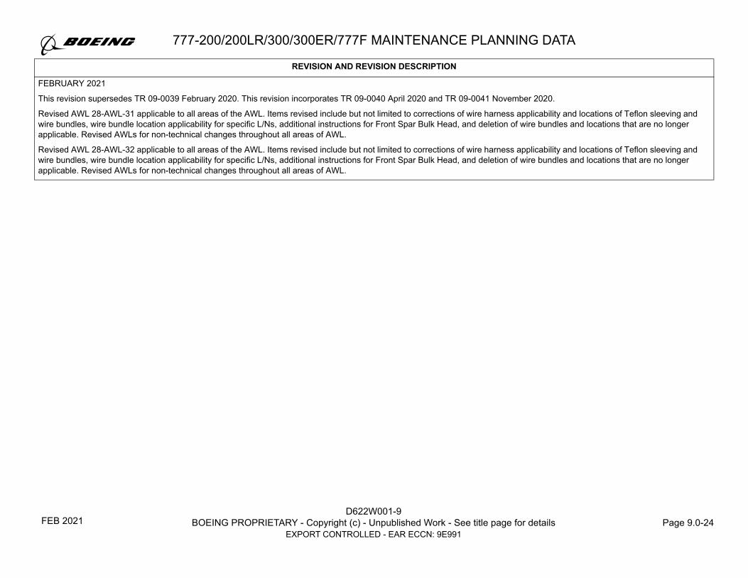
D622W001-9BOEING PROPRIETARY - Copyright (c) - Unpublished Work - See title page for details Page 9.0-24
EXPORT CONTROLLED - EAR ECCN: 9E991
777-200/200LR/300/300ER/777F MAINTENANCE PLANNING DATA
FEBRUARY 2021
This revision supersedes TR 09-0039 February 2020. This revision incorporates TR 09-0040 April 2020 and TR 09-0041 November 2020.
Revised AWL 28-AWL-31 applicable to all areas of the AWL. Items revised include but not limited to corrections of wire harness applicability and locations of Teflon sleeving and wire bundles, wire bundle location applicability for specific L/Ns, additional instructions for Front Spar Bulk Head, and deletion of wire bundles and locations that are no longer applicable. Revised AWLs for non-technical changes throughout all areas of AWL.
Revised AWL 28-AWL-32 applicable to all areas of the AWL. Items revised include but not limited to corrections of wire harness applicability and locations of Teflon sleeving and wire bundles, wire bundle location applicability for specific L/Ns, additional instructions for Front Spar Bulk Head, and deletion of wire bundles and locations that are no longer applicable. Revised AWLs for non-technical changes throughout all areas of AWL.
REVISION AND REVISION DESCRIPTION
FEB 2021

Section Page Date Section Page Date Section Page Date Section Page Date Section Page Date
D622W001-9BOEING PROPRIETARY - Copyright (c) - Unpublished Work - See title page for details Page 9.0-25
EXPORT CONTROLLED - EAR ECCN: 9E991
LIST OF EFFECTIVE PAGES777-200/200LR/300/300ER/777F MAINTENANCE PLANNING DATA
9.0 1 FEB 20219.0 2 BLANK9.0 3 FEB 20219.0 4 BLANK9.0 5 FEB 20219.0 6 FEB 20219.0 7 FEB 20219.0 8 FEB 20219.0 9 FEB 20219.0 10 FEB 20219.0 11 FEB 20219.0 12 FEB 20219.0 13 FEB 20219.0 14 FEB 20219.0 15 FEB 20219.0 16 FEB 20219.0 17 FEB 20219.0 18 FEB 20219.0 19 FEB 20219.0 20 FEB 20219.0 21 FEB 20219.0 22 FEB 20219.0 23 FEB 20219.0 24 FEB 20219.0 25 FEB 20219.0 26 FEB 20219.0 27 APR 20199.0 28 JAN 20169.0 29 MAY 20149.0 30 MAY 20149.0 31 JUL 20179.0 32 JUL 20179.0 33 MAY 20149.0 34 MAY 20149.0 35 APR 20199.0 36 MAY 20149.0 37 MAY 20149.0 38 MAY 20149.0 39 MAY 2014
9.0 40 MAY 20149.0 41 MAY 20149.0 42 MAY 20149.0 43 MAY 20149.0 44 MAY 20149.0 45 MAY 20149.0 46 JUL 20179.0 47 APR 20199.0 48 DEC 20169.0 49 MAY 20149.0 50 DEC 20169.0 51 MAY 20149.0 52 DEC 20169.0 53 MAY 20149.0 54 MAY 20149.0 55 JUL 20179.0 56 JUL 20179.0 57 MAY 20149.0 58 JUL 20179.0 59 MAY 20149.0 60 MAY 20149.0 61 MAY 20149.0 62 MAY 20149.0 63 MAY 20149.0 64 MAY 20149.0 65 MAY 20149.0 66 MAY 20149.0 67 MAY 20149.0 68 MAY 20149.0 69 MAY 20149.0 70 MAY 20149.0 71 MAY 20149.0 72 MAY 20149.0 73 JUL 20179.0 74 MAY 20149.0 75 MAY 20149.0 76 JUL 20179.0 77 MAY 20149.0 78 MAY 2014
9.0 79 MAY 20149.0 80 APR 20199.0 81 MAY 20149.0 82 MAY 20149.0 83 MAY 20149.0 84 MAY 20149.0 85 MAY 20149.0 86 MAY 20149.0 87 MAY 20149.0 88 MAY 20149.0 89 MAY 20149.0 90 MAY 20149.0 91 MAY 20149.0 92 MAY 20149.0 93 MAY 20149.0 94 MAY 20149.0 95 MAY 20149.0 96 MAY 20149.0 97 MAY 20149.0 98 JUL 20179.0 99 MAY 20149.0 100 MAY 20149.0 101 JUL 20179.0 102 MAY 20149.0 103 MAY 20149.0 104 MAY 20149.0 105 JUL 20179.0 106 MAY 20149.0 107 MAY 20149.0 108 MAY 20149.0 109 MAY 20149.0 110 MAY 20149.0 111 MAY 20149.0 112 JUL 20179.0 113 MAY 20149.0 114 MAY 20149.0 115 MAY 20149.0 116 JUL 20179.0 117 JUL 2017
9.0 118 APR 20209.0 119 APR 20209.0 120 NOV 20209.0 121 JUL 20179.0 122 JUL 20179.0 123 JUL 20179.0 124 JUL 20179.0 125 JUL 20179.0 126 APR 20199.0 127 JUL 20179.0 128 APR 20199.0 129 JUL 20179.0 130 JUL 20179.0 131 MAR 20149.0 132 MAR 20149.0 133 MAR 20149.0 134 DEC 20149.0 135 MAR 20149.0 136 FEB 20129.0 137 NOV 20159.0 138 NOV 20159.0 139 NOV 20159.0 140 NOV 20159.0 141 NOV 20159.0 142 NOV 20159.0 143 NOV 20159.0 144 NOV 20159.0 145 NOV 20159.0 146 NOV 20159.0 147 NOV 20159.0 148 NOV 20159.0 149 SEP 20189.0 150 SEP 20189.0 151 SEP 20189.0 152 NOV 20159.0 153 NOV 20159.0 154 NOV 20159.0 155 NOV 20159.0 156 NOV 2015
9.0 157 NOV 20159.0 158 NOV 20159.0 159 APR 20199.0 160 APR 20199.0 161 NOV 20159.0 162 NOV 20159.0 163 NOV 20159.0 164 NOV 20159.0 165 NOV 20159.0 166 FEB 20219.0 167 FEB 20219.0 168 FEB 20219.0 169 FEB 20219.0 170 FEB 20219.0 171 FEB 20219.0 172 FEB 20219.0 173 FEB 20219.0 174 FEB 20219.0 175 FEB 20219.0 176 FEB 20219.0 177 FEB 20219.0 178 FEB 20129.0 179 DEC 20169.0 180 DEC 20149.0 181 DEC 20149.0 182 DEC 20149.0 183 DEC 20149.0 184 DEC 20149.0 185 MAR 20149.0 186 MAR 20149.0 187 MAR 20149.0 188 NOV 20159.0 189 NOV 20159.0 190 MAR 20149.0 191 MAR 20149.0 192 MAR 20149.0 193 MAR 20149.0 194 MAR 20069.0 195 MAR 2014
FEB 2021

D622W001-9BOEING PROPRIETARY - Copyright (c) - Unpublished Work - See title page for details Page 9.0-26
EXPORT CONTROLLED - EAR ECCN: 9E991
LIST OF EFFECTIVE PAGES777-200/200LR/300/300ER/777F MAINTENANCE PLANNING DATA
Section Page Date Section Page Date Section Page Date Section Page Date Section Page Date9.0 196 NOV 20159.0 197 NOV 20159.0 198 NOV 20159.0 199 MAR 20149.0 200 MAR 20149.0 201 JAN 20169.0 202 NOV 2019
FEB 2021

777-200/200LR/300/300ER/777F MAINTENANCE PLANNING DATA
D622W001-9BOEING PROPRIETARY - Copyright (c) - Unpublished Work - See title page for details Page 9.0-27
EXPORT CONTROLLED - EAR ECCN: 9E991
A. SCOPE
The scheduled maintenance requirements described in this document result from Model 777 airplane certification activities with the U.S. Federal Aviation
Administration (FAA). Accordingly, this FAA approved Airworthiness Limitations and Certification Maintenance Requirements document is cross-
referenced in the Model 777 Type Certificate Data Sheet. These maintenance actions are mandatory.
These Airworthiness Limitations sections are FAA approved and specifies maintenance required under Title 14 Code of Federal Regulations (CFR)
§ 43.16 and § 91.403 unless an alternative program has been FAA Oversight Office approved. The Airworthiness Limitations document must be used in
its entirety at a specific revision level. Maintenance requirements and limitations from different revision levels shall not be combined.
Where used in this document, the term “FAA Oversight Office” is defined as the FAA office that currently has oversight responsibility for the type certificate
of the Boeing model 777. At the time of publication, the FAA office with oversight responsibility for the type certificate of the 777 is the FAA Boeing Aviation
Safety Oversight Office (BASOO).
For aircraft delivered after July 15, 2019, information regarding the effective revision of the MPD Section 9 document and the 777-200/200LR/300/300ER/
777F DTR Document (D622W001-DTR) at the time each aircraft line number was issued its Original Standard Airworthiness Certificate can be found in
MPD Section 9 and DTR Revision Effectivity Report letter MPE-RER-777-LNXXXX.
AIRWORTHINESS LIMITATIONS
The Airworthiness Limitations may only be revised with the approval of the FAA Oversight Office.
If the inspections cannot be accomplished due to repairs and/or modifications, an alternate inspection approved by the FAA Oversight Office must be
used.
CERTIFICATION MAINTENANCE REQUIREMENTS (CMRs)
These scheduled maintenance tasks may only be revised by the FAA Oversight Office. Principal Maintenance Inspectors (local regulatory authority) may
not change these requirements or the intervals associated with these requirements.
APR 2019

D622W001-9BOEING PROPRIETARY - Copyright (c) - Unpublished Work - See title page for details Page 9.0-28
EXPORT CONTROLLED - EAR ECCN: 9E991
777-200/200LR/300/300ER/777F MAINTENANCE PLANNING DATA
B. AIRWORTHINESS LIMITATIONS – STRUCTURAL INSPECTIONS
INTRODUCTION
The Structural Inspection Program approved in Section 3 of the 777 Maintenance Review Board (MRB) Report and contained in Section 2 of this MPD
describes an initial baseline structural maintenance program for all Structural Significant Items (SSIs). This program was developed in accordance with the
guidelines of MSG-3 and partially satisfies the requirements of Title 14 CFR § 25.571 by providing accidental and environmental damage detection
opportunity for all SSIs, and in some cases, fatigue damage detection opportunity until the supplemental inspection threshold is reached. The
supplemental structural inspections listed in this Section 9 "Airworthiness Limitations" are for those SSIs that do not receive adequate fatigue damage
detection opportunity from the initial baseline structural program that is listed in Section 2 and in Appendix L. The inspections shown in this section and
Appendix L are to be accomplished in conjunction with and not as a substitute for the existing structural maintenance program found in Section 2.
The supplemental structural inspection program uses the Damage Tolerance Rating (DTR) system to determine the inspections (and repeat intervals)
necessary to provide adequate fatigue damage detection. The DTR system defines a required DTR (a numerical value) that must be achieved for each
SSI. DTR Check Forms which define the inspection options and the required DTR are contained in Document D622W001-DTR.
The Airworthiness Limitations may only be revised with the approval of the FAA Oversight Office. If the inspections cannot be accomplished due to repairs
and/or modifications, an alternate inspection approved by the FAA Oversight Office must be used.
THRESHOLD (777-200/200LR/300/300ER Airplanes)
NOTE: In this section, "777-200" includes airplanes sometimes referred to as 777-200ER or 777-200IGW because those airplanes are certified as 777-200
airplanes per the applicable FAA Type Certificate.
The fatigue inspection requirements apply after accumulation of a certain number of flights (threshold). The initial fatigue inspections must be
accomplished within one repeat interval of the threshold for 777-200/200LR/300/300ER and must never exceed 44,000 flight cycles. “FLS” Group 1 items
must be within one inspection interval of the threshold and must never exceed the Group 2 limit in Figure 1. “FLS” Group 2 items must never exceed the
Group 2 limit in Figure 1. The threshold for each of the 777-200/200LR/300/300ER aircraft fatigue inspections is defined in the Structural Inspections
Table.
JAN 2016

777-200/200LR/300/300ER/777F MAINTENANCE PLANNING DATA
D622W001-9BOEING PROPRIETARY - Copyright (c) - Unpublished Work - See title page for details Page 9.0-29
EXPORT CONTROLLED - EAR ECCN: 9E991
When reaching a threshold of 40,000 flight cycles, all MPD 4,000 flight cycle (or higher) structural inspection repeat intervals must be no greater than those
shown in the MPD Section 2. This means that any operator, who has escalated the structures program by changing task intervals, must reduce the repeat
frequencies back to the MPD baseline structures program intervals before accumulating 40,000 flight cycles. The reason for this is that the Title 14 CFR
§ 25.571 damage tolerance evaluation takes credit for the baseline structures program. The Airworthiness Limitations listed in Section 9 cover structure
for which the required DTR is not met by the baseline structural inspections of Section 2. Any continued escalation beyond the MPD baseline structures
program may result in additional structure not meeting the required DTR which was the basis of certification.
In addition to the thresholds described above, a calendar threshold of 20 years applies unless an initial inspection of an FAA approved Corrosion
Prevention and Control Program (CPCP) has occurred, constituting CPCP implementation. The Corrosion Prevention and Control program identified within
the Structural Maintenance Program of the 777 Maintenance Review Board Report (D622W001-MRBR) is FAA approved and complies with this
requirement if it has been fully incorporated into the operator's maintenance program.
Additionally, some structures and zonal MPD items have been escalated by the Industry Steering Committee beyond the initial repeat interval considered at certification. The intervals listed in Appendix L correspond to the original task intervals used in determining the DTR which satisfies Title 14 CFR
§ 25.571. As a result, at 40,000 flight cycles, the items listed in Appendix L are required to be returned to the interval in that appendix, rather than what is listed in Sections 2 and 3. This is to be in compliance with the damage tolerance certification requirements.
The Structural Inspections Table defines the Inspection Implementation Threshold for the 777-200/200LR/300/300ER. Some items are sensitive to flight
length and are identified by FLS in the Threshold column of the Structural Inspections Table (See Figure 1). Flight Length Sensitive (FLS) Items require both flight hours and flight cycles to determine the Implementation Threshold. Refer to Figure 1 to determine the threshold for FLS Items.
For the 777-200/200LR/300/300ER, SSIs are also categorized as Group (1) or Group (2). Group 1 SSI Inspection Thresholds are limited to a maximum of 30,000 flight cycles and Group 2 SSI Inspection Thresholds are limited to a maximum of 40,000 flight cycles.
For those items which are not flight length sensitive, the lowest threshold shown in the Structural Inspections Table is 30,000 flights. Exceptions to this
requirement are: SSI 54-51-I02R, which has a threshold of 28,600 flights for the 777-200LR/300ER, and SSIs 28-00-I01A and 28-00-I01B have a threshold of 11,250 flights for the 777-200LR airplanes that have the optional auxiliary fuel tank installations. All other 777-200LR/300ER items which are not flight length sensitive have either a 30,000 flight threshold or 40,000 flight threshold depending upon whether the item is identified as Group 1 or Group 2. The
minimum threshold for those items which are identified as flight length sensitive must be determined from Figure 1, based upon the actual airplane utilization.
MAY 2014

D622W001-9BOEING PROPRIETARY - Copyright (c) - Unpublished Work - See title page for details Page 9.0-30
EXPORT CONTROLLED - EAR ECCN: 9E991
777-200/200LR/300/300ER/777F MAINTENANCE PLANNING DATA
Initial inspection (threshold) and intervals are measured in flight cycles or flight hours that a particular SSI detail has accumulated regardless of what the airframe as a whole has accumulated. Most SSI details have never been replaced and therefore have accumulated the same flight cycles and flight hours
as the airframe. Some SSI details are replaced, such as when installing Removable Structural Components (repairable/rotable/expendables) or installing used structural parts as a repair. In these cases the SSI details have accumulated flight cycles and flight hours that may be different than the airframe.
The operator must account for this in determining when inspections must be done.
Although intended for repairs, FAA AC 120-93 Appendix 7, provides a method for determining the age of a Removable Structural Component, which may be applied to the baseline structure.
Inspection thresholds for fastener locations where the terminating action has been accomplished per AD 2000-11-11 or AD 2005-10-17 can start from the
time when the terminating action was accomplished.
MAY 2014

777-200/200LR/300/300ER/777F MAINTENANCE PLANNING DATA
D622W001-9BOEING PROPRIETARY - Copyright (c) - Unpublished Work - See title page for details Page 9.0-31
EXPORT CONTROLLED - EAR ECCN: 9E991
FIGURE 1. FLIGHT LENGTH SENSITIVE (FLS) THRESHOLD CURVE (777-200/200LR/300/300ER ONLY)NOTE: In Figure 1 and the discussion of flight length sensitive threshold that immediately follows this note, "777-200" includes airplanes sometimes referred to
as 777-200ER or 777-200IGW since those airplanes are certified as 777-200 airplanes per the applicable FAA Type Certificate.
JUL 2017
D622W001-9BOEING PROPRIETARY - Copyright (c) - Unpublished Work - See title page for details Page 9.0-32
EXPORT CONTROLLED - EAR ECCN: 9E991
777-200/200LR/300/300ER/777F MAINTENANCE PLANNING DATA
USE OF FLIGHT LENGTH SENSITIVE THRESHOLD CURVE (777-200/200LR/300/300ER ONLY)
(For FLS Items only; all non-FLS SSIs have thresholds as listed in the Airworthiness Limitations Table)
1. Determine the FLS status and Group of the SSI (777-200/200LR/300/300ER) from the Airworthiness Limitations Table.
2. Determine the total number of flight cycles and flight hours experienced by the detail.
3. If the detail is FLS, locate the intersection of Flight Hours and Cycles on the graph.
4. If the point determined by Step 3 lies below the Threshold Curve for the group from Step 1, the detail has not reached the Inspection Threshold. If the
point is on the Threshold Curve for the specified group, then the Inspection Threshold has been reached. If the point is above or to the right of the
Threshold Curve for the specified group, then the Inspection Threshold has been exceeded.
THRESHOLD (777F Airplanes)
The fatigue inspection requirements apply after accumulation of a certain number of flights (threshold). The initial fatigue inspections must be
accomplished at the threshold defined in the Structural Inspections Table, or within an interval not to exceed 2,500 flight cycles beyond the threshold.
“FLS” Group 1 items must be within one inspection interval of the threshold and must never exceed the Group 2 limit in Figure 2. “FLS” Group 2 items
must never exceed the Group 2 limit in Figure 2. The threshold for 777F aircraft fatigue inspections is defined in the Structural Inspections Table.
When reaching a threshold of 25,000 flight cycles, all MPD 4,000 flight cycle (or higher) structural inspection repeat intervals must be no greater than those
shown in the MPD Section 2. This means that any operator, who has escalated the structures program by changing task intervals, must reduce the repeat
frequencies back to the MPD baseline structures program intervals before accumulating 25,000 flight cycles. The reason for this is that the Title 14 CFR
§ 25.571 damage tolerance evaluation takes credit for the baseline structures program. The Airworthiness Limitations listed in Section 9 cover structure
for which the required DTR is not met by the baseline structural inspections of Section 2. Any continued escalation beyond the MPD baseline structures
program may result in additional structure not meeting the required DTR which was the basis of certification.
In addition to the thresholds described above, a calendar threshold of 20 years applies unless an initial inspection of an FAA approved Corrosion
Prevention and Control Program (CPCP) has occurred, constituting CPCP implementation. The CPCP identified within the Structural Maintenance
Program of the 777 Maintenance Review Board Report (D622W001-MRBR) is FAA approved and complies with this requirement if it has been fully
incorporated into the operator’s maintenance program.
JUL 2017
777-200/200LR/300/300ER/777F MAINTENANCE PLANNING DATA
D622W001-9BOEING PROPRIETARY - Copyright (c) - Unpublished Work - See title page for details Page 9.0-33
EXPORT CONTROLLED - EAR ECCN: 9E991
Additionally, some structures and zonal MPD items have been escalated by the Industry Steering Committee beyond the initial repeat interval considered
at certification. The intervals listed in Appendix L correspond to the original task intervals used in determining the DTR which satisfies Title 14 CFR
§ 25.571. As a result, at 25,000 flight cycles, the items listed in Appendix L are required to be returned to the interval in that appendix, rather than what is
listed in Sections 2 and 3. This is to be in compliance with the damage tolerance certification requirements.
The Structural Inspections Table defines the Inspection Implementation Threshold for the 777F. Some items are sensitive to flight length and are identified
by FLS in the Threshold column of the Structural Inspections Table (See Figure 2). Flight Length Sensitive (FLS) Items require both flight hours and flight
cycles to determine the Implementation Threshold. Refer to Figure 2 to determine the threshold for FLS Items.
For the 777F, SSIs are also categorized as Group 1 or Group 2. Group 1 SSI Inspection Thresholds are limited to a maximum of 18,750 flight cycles and
Group 2 SSI Inspection Thresholds are limited to a maximum of 25,000 flight cycles.
For those items which are not flight length sensitive, the lowest threshold shown in the Structural Inspections Table is 18,750 flights. All other 777F items
which are not flight length sensitive have either a 18,750 flight threshold or 25,000 flight threshold depending upon whether the item is identified as
Group 1 or Group 2. The minimum threshold for those items which are identified as flight length sensitive must be determined from Figure 2, based upon
the actual airplane utilization.
Initial inspection (threshold) and intervals are measured in flight cycles or flight hours that a particular SSI detail has accumulated regardless of what the
airframe as a whole has accumulated. Most SSI details have never been replaced and therefore have accumulated the same flight cycles and flight hours
as the airframe. Some SSI details are replaced, such as when installing Removable Structural Components (repairable/rotable/expendables) or installing
used structural parts as a repair. In these cases the SSI details have accumulated flight cycles and flight hours that may be different than the airframe.
The operator must account for this in determining when inspections must be done.
Although intended for repairs, FAA AC 120-93 Appendix 7, provides a method for determining the age of a Removable Structural Component, which may
be applied to the baseline structure.
MAY 2014

D622W001-9BOEING PROPRIETARY - Copyright (c) - Unpublished Work - See title page for details Page 9.0-34
EXPORT CONTROLLED - EAR ECCN: 9E991
777-200/200LR/300/300ER/777F MAINTENANCE PLANNING DATA
FIGURE 2. FLIGHT LENGTH SENSITIVE (FLS) THRESHOLD CURVE (777F ONLY)USE OF FLIGHT LENGTH SENSITIVE THRESHOLD CURVE (777F ONLY)
(For FLS Items only; all non-FLS SSIs have thresholds as listed in the Airworthiness Limitations Table)1. Determine the FLS status and Group of the SSI (777F) from the Airworthiness Limitations Table.2. Determine the total number of flight cycles and flight hours experienced by the detail.3. If the detail is FLS, locate the intersection of Flight Hours and Cycles on the graph.4. If the point determined by Step 3 lies below the Threshold Curve for the group from Step 1, the detail has not reached the Inspection Threshold. If the
point is on the Threshold Curve for the specified group, then the Inspection Threshold has been reached. If the point is above or to the right of the Threshold Curve for the specified group, then the Inspection Threshold has been exceeded.
FLIGHT HOURS ( x 1,000)
Group 1 & 2Threshold Exceeded
Group 1 ThresholdExceeded
ÏÏÏÏÏÏÓÓÓÓÓÓ
ÏÏÏÏÏÏÏÏÏÏÏÏÏÏÏÏÏÏÏÏÏÏÏÏÏÏÏÏÏÏÏÏÏÏÏÏÏÏÏÏÏÏÏÏÏÏÏÏÏÏÏÏÏÏÏÏÏÏÏÏÏÏÏÏÏÏÏÏÏÏÏÏÏÏÏÏÏÏÏÏÏÏÏÏÏÏÏÏÏÏÏÏÏÏÏÏÏÏÏÏÏÏÏÏÏÏÏÏÏÏÏÏÏÏÏÏÏÏÏÏÏÏÏÏÏÏÏÏÏÏÏÏÏÏÏÏÏÏÏÏÏÏÏÏÏÏÏÏÏÏÏÏÏÏÏÏÏÏÏÏÏÏÏÏÏÏÏÏÏÏÏÏÏÏÏÏÏÏÏÏÏÏÏÏÏÏÏÏÏÏÏÏÏÏÏ
ÓÓÓÓÓÓÓÓÓÓÓÓÓÓÓÓÓÓÓÓÓÓÓÓÓÓÓÓÓÓÓÓÓÓÓÓÓÓÓÓÓÓÓÓÓÓÓÓÓÓÓÓÓÓÓÓÓÓÓÓÓÓÓÓÓÓÓÓÓÓÓÓÓÓÓÓÓÓÓÓÓÓÓÓÓÓÓÓÓÓÓÓÓÓÓÓÓÓÓÓÓÓÓÓÓÓÓÓÓÓÓÓÓÓÓÓÓÓÓÓÓÓÓÓÓÓÓÓÓÓÓÓÓÓÓÓÓÓÓÓÓÓÓÓÓÓÓÓÓÓÓÓÓÓÓÓÓÓÓÓÓÓÓÓÓÓÓÓÓÓÓÓÓÓÓÓÓÓÓÓÓÓÓÓÓÓÓÓÓÓÓÓÓÓÓÓÓÓÓÓÓÓÓÓÓÓÓÓÓÓÓÓÓÓÓÓÓÓÓÓÓÓÓÓÓÓÓÓÓÓÓÓÓÓÓÓÓÓÓÓÓÓÓÓÓÓÓÓÓÓÓÓÓÓÓÓÓÓÓÓÓÓÓÓÓÓÓÓÓÓÓÓÓÓÓÓÓÓÓÓÓÓÓÓÓÓÓÓÓÓÓÓÓÓÓÓÓÓÓÓÓÓÓÓÓÓ
5
10
15
20
25
30
FLIG
HT
CY
CL
ES
( x 1
,000
)
GROUP 1
GROUP 2
00 20 40 60 80 100 120 140 160
52.25 75
18.75
MAY 2014
777-200/200LR/300/300ER/777F MAINTENANCE PLANNING DATA
D622W001-9BOEING PROPRIETARY - Copyright (c) - Unpublished Work - See title page for details Page 9.0-35
EXPORT CONTROLLED - EAR ECCN: 9E991
REPEAT INSPECTION INTERVAL
A Repeat Interval for the Fatigue Inspection of an SSI is established from its respective Damage Tolerance Rating (DTR) Check Form. The DTR Check
Forms are the result of the damage tolerance assessment / evaluation documented during certification of the airplane. Revision to the required DTR
Check Form or the DTR Curve is not allowed without the prior approval from the FAA Oversight Office.
For -200/200LR/300ER/777F only: If the applicability/threshold box for the item includes a "< 7 Hrs" or "> 7 Hrs" designation, the average airplane hours
per flight should be calculated for the airplane and the repeat inspection interval should be based on the DTR Check Form with the corresponding
"< 7 Hrs" or "> 7 Hrs" label. If the current average hours per flight is longer than the prior average hours per flight, the current average hours per flight
should be used for determining which DTR Check Form should be utilized.
NOTE: In the paragraph immediately preceding this note, "777-200" includes airplanes sometimes referred to as 777-200ER or 777-200IGW since those airplanes are certified as 777-200 airplanes per the applicable FAA Type Certificate.
SUPPLEMENTAL STRUCTURAL INSPECTIONS
For operators that incorporate the underwing longeron retrofit given in SB 777-53-0084, supplemental structural inspections apply. After incorporation of
SB 777-53-0084, prior to returning the aircraft to service, the applicable post-retrofit supplemental inspections in SB 777-53-0084 shall be incorporated into
the aircraft maintenance program.
For operators that incorporate the underwing longeron retrofit given in SB 777-53-0087, supplemental structural inspections apply. After incorporation of
SB 777-53-0087, prior to returning the aircraft to service, the applicable post-retrofit supplemental inspections in SB 777-53-0087 shall be incorporated into
the aircraft maintenance program.
REPORTING RESULTS OF STRUCTURAL INSPECTIONS
All cracks found during these inspections shall be reported within ten (10) days after the airplane is returned to service to Boeing Commercial Airplanes
using the Discrepant Structure Report Form. Refer to D622W001-DTR for the required report form (any suitable alternative which contains the same
information may be used).
APR 2019

D622W001-9BOEING PROPRIETARY - Copyright (c) - Unpublished Work - See title page for details Page 9.0-36
EXPORT CONTROLLED - EAR ECCN: 9E991
777-200/200LR/300/300ER/777F MAINTENANCE PLANNING DATA
REMOVAL OF EXCESS SEALANT WHEN INSPECTING:
1. In areas where DTR Check Form (Section 9) visual inspection is prevented due to sealant, remove any fastener cap, fillet or brush sealant that extends
beyond 0.20" around the fastener at locations that are to be inspected. Remove any additional sealant which impairs visibility of the structure adjacent
to the fastener cap, fillet or brush sealant.
2. The following Structural Items require fastener cap, fillet or brush sealant that extends beyond 0.20" to be removed for baseline maintenance visual
inspections (MPD Section 2 and 3) at or prior to reaching the listed thresholds:
Principle Structural Element (PSE) Threshold
Installation Drawing Drawing Title Notes
Associated MRBR
Item Number (Reference Only)
Fuselage – Underwing Longeron (777 All)
P: 40,000 FC
F: 25,000 FC
140W9250 Underwing Longeron Instl
1. Fasteners on the Underwing Longeron common to the Fuselage Front Spar Bulkhead Outer Chord within 3 inches forward of the Wing Front Spar. In this area, also remove excess fillet seal at the free edge of the longeron that extends more than 0.25” from the fuselage skin surface.
2. Fasteners on the Underwing Longeron common to the Wing Lower Skin within 3 inches aft of the Fuselage Front Spar Bulkhead. In this area, also remove excess fillet seal at the free edge of the longeron that extends more than 0.25" from the lower wing skin surface.
NOTE: Does not require sealant removal inside the fuel tank.
53-545-0153-545-0253-830-00
Fuselage – Front Spar Side Frame Fitting (777 All)
P: 40,000 FC
F: 25,000 FC
110W1652 Front Spar Instl Integration – BBL 122.45
Fasteners on the Front Spar Side Frame Fitting within 6 inches above and below the Wing Upper Surface.
NOTE: Does not require sealant removal inside the fuel tank.
53-545-0153-545-0253-657-0057-604-00
MAY 2014

777-200/200LR/300/300ER/777F MAINTENANCE PLANNING DATA
D622W001-9BOEING PROPRIETARY - Copyright (c) - Unpublished Work - See title page for details Page 9.0-37
EXPORT CONTROLLED - EAR ECCN: 9E991
Fuselage – Rear Spar Side Frame Fitting (777 All)
P: 40,000 FC
F: 25,000 FC
110W1651 Rear Spar Instl Integration – BBL 122.45
Fasteners on the Rear Spar Side Frame Fitting within 6 inches above and below the Wing Upper Surface.
NOTE: Does not require sealant removal inside the fuel tank.
53-667-0053-668-0057-604-00
Engine Strut – Pratt and Whitney(777-200/200IGW/300)
P: 40,000 FC
F: 25,000 FC
311W3110 (Fwd)
311W3130 (Aft)
Spar Assy – Fwd Upper Nacelle/Strut
Strut Frame Assy – Aft
Fasteners on the LHS upper spar chords common to upper spar webs between NSTA 245.0 and 255.0 and between NSTA 319.0 and 333.0, except where spar chord is not visible.
54-510-0154-511-0154-518-0254-519-02
54-804-0154-806-0154-814-0254-816-02
Engine Strut – General Electric (777-200/200IGW)
P: 40,000 FC or 120,000 FH whichever
comes first.
F: 25,000 FC or 120,000 FH whichever comes first
311W1110 (Fwd)
311W1130 (Aft)
Spar Assy – Fwd Upper
Torque Box Assy – Aft
1. Fasteners on the RHS upper spar chord common to upper spar web between NSTA 213.5 and 230.0 and all fasteners on the RHS upper spar chord common to the forward engine mount bulkhead between NSTA 187.0 and 192.0, except where spar chord is not visible.
2. Fasteners on the LHS upper spar chords common to the bulkhead between NSTA 303.0 and 316.0, except where spar chord is not visible.
54-539-0154-540-0154-547-0254-548-02
54-824-0154-826-0154-834-0254-836-02
Engine Strut – Rolls Royce(777-200/200IGW/300)
P: 40,000 FC
F: 25,000 FC
311W5110 (Fwd) Spar Assy – Fwd Upper Fasteners on the upper spar chord common to forward engine mount bulkhead between NSTA 187.0 and 192.0, except where spar chord is not visible.
54-569-0154-570-0154-577-0254-578-02
54-844-0154-846-0154-854-0254-856-02
Principle Structural Element (PSE) Threshold
Installation Drawing Drawing Title Notes
Associated MRBR
Item Number (Reference Only)
MAY 2014

D622W001-9BOEING PROPRIETARY - Copyright (c) - Unpublished Work - See title page for details Page 9.0-38
EXPORT CONTROLLED - EAR ECCN: 9E991
777-200/200LR/300/300ER/777F MAINTENANCE PLANNING DATA
Horizontal Stabilizer – BL 0, Upper External Splice Plate (777 All)
P: 40,000 FC
F: 25,000 FC
182W7000 Splice Instl – Centerline, Horiz Stab
Fasteners on the Upper External Splice Plate common to the Rear Spar Terminal Fitting and Upper Rear Spar External Splice Fitting within 3 inches of BL 0.
55-501-00
Horizontal Stabilizer – BL 0, Upper Rear Spar External Splice Fitting (777 All)
P: 40,000 FC
F: 25,000 FC
182W7000 Splice Instl – Centerline, Horiz Stab
Fasteners on the Upper Rear Spar External Splice Fitting common to the Rear Spar Terminal Fitting and Upper External Splice Plate within 3 inches of BL 0.
55-501-00
Horizontal Stabilizer – BL 0, Rear Spar Terminal Fitting (777 All)
P: 40,000 FC
F: 25,000 FC
182W7500 Terminal Fitting Instl – Rear Spar, Horiz Stab
Fasteners on the Rear Spar Terminal Fitting common to the Upper Rear Spar External Splice Fitting and Upper External Splice Plate within 3 inches of BL 0.
55-540-0255-529-01
Principle Structural Element (PSE) Threshold
Installation Drawing Drawing Title Notes
Associated MRBR
Item Number (Reference Only)
MAY 2014

777-200/200LR/300/300ER/777F MAINTENANCE PLANNING DATA
D622W001-9BOEING PROPRIETARY - Copyright (c) - Unpublished Work - See title page for details Page 9.0-39
EXPORT CONTROLLED - EAR ECCN: 9E991
Wing – Side of Body Splice Upper Surface (777 All)
P: 40,000 FC or 120,000 FH whichever
comes first.F: 25,000 FC or
120,000 FH whichever comes first
110W1653 (Inboard)
Upper Panel Instl Integration – BBL 122.45
Outboard fastener row on the Rib Chord common to the upper skin panel within 2 inches of BBL 122.45.
Inspect the Rib Chord upper surface at the following locations:
1. At all field fasteners (fasteners that are not common to upper stringers or stub beams)
2. Between the forward fastener row common to Stringer 13 and the aft fastener row common to Stringer 14
3. Between the forward fastener row common to Stringer 19 and the aft fastener row common to Stringer 20
4. At one fastener location common to each vent stringer (Stringers 15, 17 and 21).
Cap seals and secondary fuel barrier do not need to be removed at the inspection locations above, provided that a minimum dimension of 0.70" is visible between adjacent cap seals in the forward-aft direction. If the minimum visible dimension of 0.70" is not met, cap seal and secondary fuel barrier removal is required or surface HFEC inspection can be performed per the Table Notes below.
NOTE: Does not require sealant removal inside the fuel tank.
57-602-00
Principle Structural Element (PSE) Threshold
Installation Drawing Drawing Title Notes
Associated MRBR
Item Number (Reference Only)
MAY 2014

D622W001-9BOEING PROPRIETARY - Copyright (c) - Unpublished Work - See title page for details Page 9.0-40
EXPORT CONTROLLED - EAR ECCN: 9E991
777-200/200LR/300/300ER/777F MAINTENANCE PLANNING DATA
Table Notes: P: = 777-200/200IGW/200LR/300/300ER (Passenger) airplanesF: = 777F (Freighter) airplanesAs an option to sealant removal: Perform surface HFEC inspection 360 degrees around the fastener per NDT Part 6, 51-00-17. Or if sealant does not extend beyond 0.50" from the fastener, perform surface HFEC inspection 360 degrees around the sealant around the fastener per NDT Part 6, 51-00-01 for aluminum parts, 51-00-05 for steel parts, or 51-00-06 for titanium parts.
NOTE: In the immediately preceding Table Notes, airplanes identified as "777-200IGW" are 777-200 airplanes that have been certified with a structure capability of MTW>547,000 lbs. This includes airplanes sometimes called "777-200ER" airplanes. All of these airplanes were certified as 777-200 series airplanes per the applicable FAA Type Certificate. 777-200LR airplanes are not included in the group of airplanes identified as 777-200 or 777-200IGW.
3. General Notes:
Refer to AMM 51-31-01 for general sealant removal and application.
Refer to AMM 28-11-00 for sealant (BMS 5-45) inside the fuel tank removal and application.
Refer to AMM 28-11-00 for secondary fuel barrier sealant (BMS 5-81, Type II) outside the fuel tank removal and application.
If sealant is removed inside the fuel tank for inspection, care must be taken to remove any sealant debris in the fuel tank.
Locations where sealant is removed for inspections must have the sealant restored to drawing or AMM requirements (and any applicable Service
Bulletins or repair instructions) after completion of the inspections. Sealant of fuel tank fasteners must comply with MPD Section 9, Parts D and E.
Wing – Side of Body Splice Upper Surface (777 All)
P: 40,000 FC or 120,000 FH whichever
comes first.F: 25,000 FC or
120,000 FH whichever comes first
112W3301 (Outboard)
Rib Chord Instl – Upper Panel, BBL 122.45
Inboard fastener row on the Rib Chord common to the upper skin panels outboard within 2 inches of BBL 122.45.
NOTE: Does not require sealant removal inside the fuel tank.
57-607-0157-620-02
Principle Structural Element (PSE) Threshold
Installation Drawing Drawing Title Notes
Associated MRBR
Item Number (Reference Only)
MAY 2014
777-200/200LR/300/300ER/777F MAINTENANCE PLANNING DATA
D622W001-9BOEING PROPRIETARY - Copyright (c) - Unpublished Work - See title page for details Page 9.0-41
EXPORT CONTROLLED - EAR ECCN: 9E991
SUPPLEMENTAL STRUCTURAL INSPECTION REQUIREMENTS
The table starting on the next page lists the Airworthiness Limitation supplemental structural inspection requirements. Each item is listed by SSI Number,
DTR Check Form Title, DTR Location, and Airplane Applicability/Threshold. There are corresponding DTR Check Forms in D622W001-DTR for each item
listed in the table. Where there is more than one listing for a given SSI Number, the DTR Check Form title and location is the unique identifier.
Airplane applicability is listed as shown below:
ALL = All 777 Airplanes
-200 = 777-200 up to or equal to 547,000 lbs.MTW
-300 = 777-300
-300ER = 777-300ER
-200IGW
=
777-200 IGW: Any 777-200 airplane certified for a structural capability greater than 547,000 lbs. MTW (also equates to777-200ER). This consists of all airplanes identified by Customer Variable Numbers (Manufacturer Block Number) WB001 through WB500 and WC001 through WC999. If needed, refer to the 777 Structural Repair Manual front matter Effective Aircraft “Manufacturer Block Number” to determine the associated Manufacturer Serial Numbers.
-200LR = 777-200LR (Longer Range)
777F = 777 Freighter
RR = Rolls Royce TRENT = TRENT 800 (875-17, 877-17, 884-17, 890-17, 892, 892B, 895)
PW = Pratt & Whitney PW4000 = PW4074, PW4077, PW4084, PW4090, PW4098
GE = General Electric GE90 = 75B/76B/85B/90B/94B/110B/115B
NOTE: C/L or L/N = Airplane Cumulative Line Number, where mentioned with DTR Check Form Title, identifies certain DTR Check Forms to specific airplane line numbers.
NOTE: “777” without any suffix means the form applies to all 777 airplanes.
MAY 2014

D622W001-9BOEING PROPRIETARY - Copyright (c) - Unpublished Work - See title page for details Page 9.0-42
EXPORT CONTROLLED - EAR ECCN: 9E991
777-200/200LR/300/300ER/777F MAINTENANCE PLANNING DATA
AIRWORTHINESS LIMITATIONS – STRUCTURAL INSPECTIONS
GROUP(4)
APPLICABILITY/THRESHOLDS(1,5,6)
SSI # (2) DTR CHECK FORM TITLE (3) DTR LOCATION -200 -200IGW -300 -300ER -200LR 777F
27-41-I01 Safety Rod, Horizontal Stabilizer Trim Actuator
Zone 310, Section 48 1 30,000 30,000 30,000 30,000 30,000
27-41-I01 Safety Rod, Horizontal Stabilizer Trim Actuator
Zone 310, Section 48 1 18,750
28-00-I01A Auxiliary Body Fuel Tanks Internal Corner Angles
Outer Angle around periphery of Forward Panel & Lower Side Panel Edges
1 11,250 (7)
28-00-I01B Auxiliary Body Fuel Tank Inner Skin At Fastener Holes of Panels Connecting to Diaphragms
1 11,250 (7)
52-10-I02 Passenger Doors Outer Skin and Structure
Outer Skin Between Handle and Window Cutouts
2 40,000 40,000 40,000 40,000 40,000 25,000
52-34-I03A Large Cargo Door Latch Support Frame Fittings
Latch Cam Support Fitting Lug Bore
2 40,000 (8)
40,000 (8)
40,000 (8)
40,000 (7)
40,000 (7)
25,000 (7)
52-34-I03B Large Cargo Door Latch Support Frame Fitting (135W1191)
Outer Chord 2 40,000 (8)
40,000 (8)
40,000 (8)
40,000 (7)
40,000 (7)
25,000 (7)
52-34-I05A Large Cargo Door Latch Frame Inner Chord
Splice to Latch Support Fitting 1 30,000 (8)
30,000 (8)
30,000 (8)
30,000 (7)
30,000 (7)
18,750 (7)
52-34-I05B Large Cargo Door Outer Skin at Attachment to Main Hinges
Outer Skin and Latch Frame Outer Chord
1 30,000 (8)
30,000 (8)
30,000 (8)
30,000 (7)
30,000 (7)
18,750 (7)
52-37-I03A Large Cargo Door Latch Support Frame Fittings
Latch Cam Support Fitting Lug Bore
2 40,000 (8)
40,000 (8)
40,000 (8)
40,000 (7)
40,000 (7)
25,000 (7)
52-37-I03B Large Cargo Door Latch Support Frame Fitting (135W1191)
Outer Chord 2 40,000 (8)
40,000 (8)
40,000 (8)
40,000 (7)
40,000 (7)
25,000 (7)
52-37-I05A Large Cargo Door Latch Frame Inner Chord
Splice to Latch Support Fitting 1 30,000 (8)
30,000 (8)
30,000 (8)
30,000 (7)
30,000 (7)
18,750 (7)
52-37-I05B Large Cargo Door Outer Skin at Attachment to Main Hinges
Outer Skin and Latch Frame Outer Chord
1 30,000 (8)
30,000 (8)
30,000 (8)
30,000 (7)
30,000 (7)
18,750 (7)
MAY 2014

777-200/200LR/300/300ER/777F MAINTENANCE PLANNING DATA
D622W001-9BOEING PROPRIETARY - Copyright (c) - Unpublished Work - See title page for details Page 9.0-43
EXPORT CONTROLLED - EAR ECCN: 9E991
52-38-I01 Main Deck Cargo Door – Main Latch Cam Assemblies
Main Rotary Cam Latch – Cam Shaft
1 18,750 (7)
52-38-I03A Main Deck Cargo Door – Latch Cam and Roller Support Fittings
Latch Cam Support Fitting Lug Bore
2 25,000 (7)
52-38-I03B Main Deck Cargo Door – Latch Cam and Roller Support Fittings
Latch Cam Support Fitting – Outer Chord
2 25,000 (7)
52-38-I05A Main Deck Cargo Door – Latch Cam and Roller Support Fittings
Latch Cam Support Fitting – Latch Frame Inner Chord Splice to Latch Support Fitting
1 18,750
52-38-I05B Main Deck Cargo Door – Skin and Door Structure
Outer Skin at Attachment to Main Hinges: Outer Skin and Latch Frame Outer Chord.
1 18,750
53-00-I01 Upper Lobe Skin Panels Entire Fuselage – Skin BS 132.5 to BS 2150 Above WL 200 Except Under Fairings
2 40,000 40,000 40,000 40,000 40,000
53-00-I02 Lower Lobe Skin Panels Entire Fuselage – Skin BS 132.5 to BS 2150 Below WL 200 Except Under Fairings
2 40,000 40,000 40,000 40,000 40,000
53-00-I03 Upper and Lower Lobe Skin Panels Sections 43, 46, 47 – Skin Under Fairings
2 30,000 30,000 30,000 30,000 30,000
53-10-I02A Crown Skin Antenna Installation – TCAS
Body Station 455.5 @ B.L. 0 2 40,000 (8)
40,000 (8)
40,000 (8)
40,000 (7)
40,000 (7)
25,000 (7)
53-10-I02B ACL Installation External Doubler Crown Skin STA 602, BL 0 Under Stringer
2 30,000 (8)
30,000 (8)
30,000 (8)
30,000 (7)
53-10-I02C ACL Installation External Doubler Crown Skin STA 602, BL 0 at Cutout
2 30,000 (8)
30,000 (8)
30,000 (8)
30,000 (7)
53-10-I02D Crown Skin Production ACL Installation
Crown Skin STA 602.5, BL 0 2 40,000 40,000 40,000 40,000 40,000 18,750
AIRWORTHINESS LIMITATIONS – STRUCTURAL INSPECTIONS
GROUP(4)
APPLICABILITY/THRESHOLDS(1,5,6)
SSI # (2) DTR CHECK FORM TITLE (3) DTR LOCATION -200 -200IGW -300 -300ER -200LR 777F
MAY 2014

D622W001-9BOEING PROPRIETARY - Copyright (c) - Unpublished Work - See title page for details Page 9.0-44
EXPORT CONTROLLED - EAR ECCN: 9E991
777-200/200LR/300/300ER/777F MAINTENANCE PLANNING DATA
53-10-I06 Ground Maneuver Camera Installation
Lower Lobe STA 604.06 @ BL 0 2 40,000 40,000
53-10-I07A Longitudinal Skin Lap Splices Inner Skin
Typical – All Section 41 Lap Splices
2 40,000 (8)
40,000 (8)
40,000 (8)
40,000 (7)
40,000 (7)
25,000 (7)
53-10-I07B Longitudinal Skin Lap Splices Outer Skin
Typical – All Section 41 Lap Splices
2 40,000 40,000 40,000 40,000 40,000 25,000
53-10-I09A Passenger Entry Door #1 – Cutout Upper Corner @ STA 332.5 and Lower Corner @ STA 382
2 40,000 (8)
40,000 (8)
40,000 (8)
40,000 (7)
40,000 (7)
25,000 (7)
53-10-I09B Passenger Entry Door #1 – Cutout Edge Frames @ STA 332.5 and STA 382
2 40,000 (8)
40,000 (8)
40,000 (8)
40,000 (7)
40,000 (7)
25,000 (7)
53-10-I09C Passenger Entry Door #1 – Cutout Bear Strap 2 40,000 (8)
40,000 (8)
40,000 (8)
40,000 (7)
40,000 (7)
25,000 (7)
53-10-I09D Passenger Entry Door #1 – Cutout Upper Sill
Sta 309.5 to Sta 357.25 2 40,000 (8)
40,000 (8)
40,000 (8)
40,000 (7)
40,000 (7)
25,000 (7)
53-10-I11A Forward Large Cargo Door – Cutout Upper Corner @ STA 501 2 40,000 (8)
40,000 (8)
40,000 (8)
40,000 (7)
40,000 (7)
25,000 (7)
53-10-I11B FWD Large Cargo Door – Cutout Outer Chord – Upper Sill
Body Station 592 to 613 1 30,000 (8)
30,000 (8)
30,000 (8)
30,000 (7)
30,000 (7)
18,750 (7)
53-10-I11C Forward Large Cargo Door – Cutout Upper Sill, STA 487 to STA 508 2 40,000 (8)
40,000 (8)
40,000 (8)
40,000 (7)
40,000 (7)
25,000 (7)
53-10-I11D Forward Large Cargo Door – Cutout Lower Sill, STA 592 to STA 634 2 40,000 (8)
40,000 (8)
40,000 (8)
40,000 (7)
40,000 (7)
25,000 (7)
53-10-I14 Forward Equipment Bay Access Hatch Cutout Structure
STA 143.5 to 172.5 Forward of NLG Well
2 40,000 (8)
40,000 (8)
40,000 (8)
40,000 (7)
40,000 (7)
25,000 (7)
53-10-I16 E/E Bay Access Hatch Cutout Structure
STA 360 to 382 Aft of NLG Well 2 40,000 (8)
40,000 (8)
40,000 (8)
40,000 (7)
40,000 (7)
25,000 (7)
53-10-I18 NO. 1 Crew Window Cutout Structure
Lower Window Sill, Left and Right 2 40,000 40,000 40,000 40,000 40,000 25,000
AIRWORTHINESS LIMITATIONS – STRUCTURAL INSPECTIONS
GROUP(4)
APPLICABILITY/THRESHOLDS(1,5,6)
SSI # (2) DTR CHECK FORM TITLE (3) DTR LOCATION -200 -200IGW -300 -300ER -200LR 777F
MAY 2014
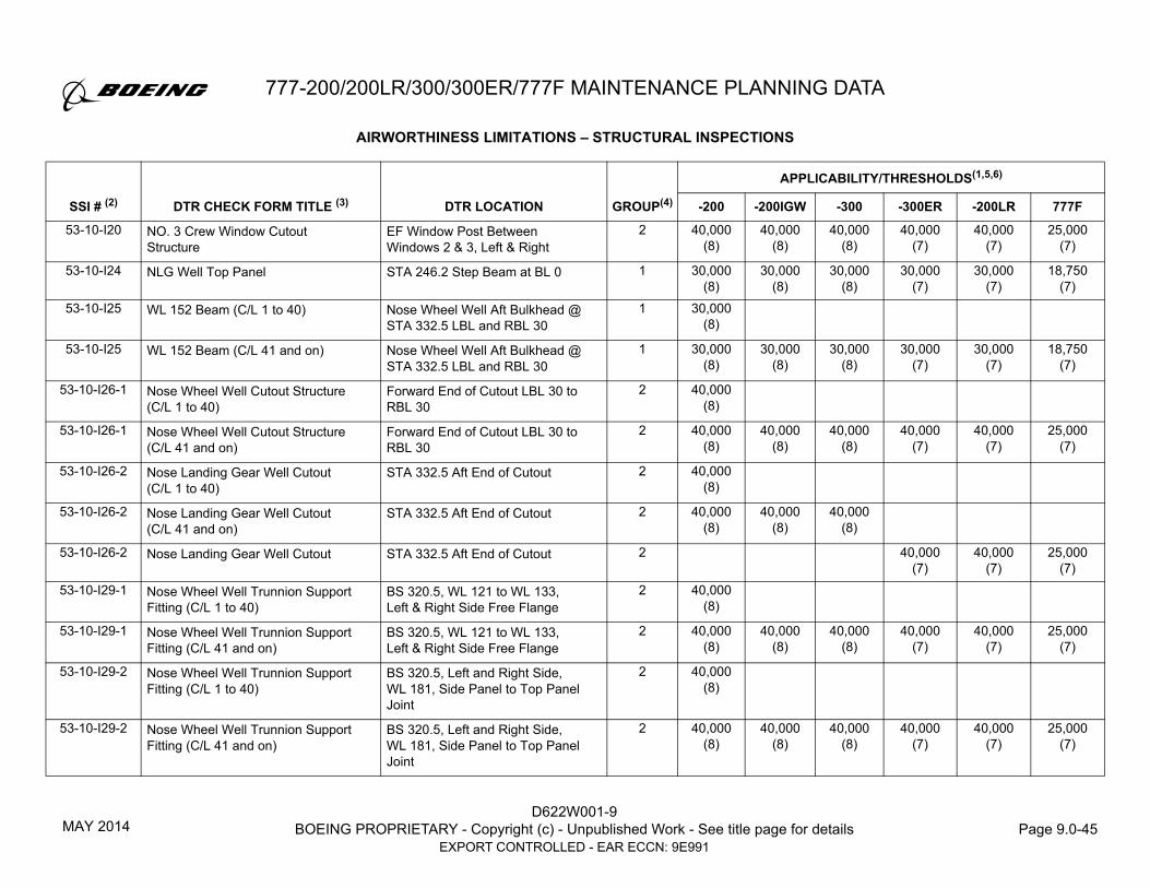
777-200/200LR/300/300ER/777F MAINTENANCE PLANNING DATA
D622W001-9BOEING PROPRIETARY - Copyright (c) - Unpublished Work - See title page for details Page 9.0-45
EXPORT CONTROLLED - EAR ECCN: 9E991
53-10-I20 NO. 3 Crew Window Cutout Structure
EF Window Post Between Windows 2 & 3, Left & Right
2 40,000 (8)
40,000 (8)
40,000 (8)
40,000 (7)
40,000 (7)
25,000 (7)
53-10-I24 NLG Well Top Panel STA 246.2 Step Beam at BL 0 1 30,000 (8)
30,000 (8)
30,000 (8)
30,000 (7)
30,000 (7)
18,750 (7)
53-10-I25 WL 152 Beam (C/L 1 to 40) Nose Wheel Well Aft Bulkhead @ STA 332.5 LBL and RBL 30
1 30,000 (8)
53-10-I25 WL 152 Beam (C/L 41 and on) Nose Wheel Well Aft Bulkhead @ STA 332.5 LBL and RBL 30
1 30,000 (8)
30,000 (8)
30,000 (8)
30,000 (7)
30,000 (7)
18,750 (7)
53-10-I26-1 Nose Wheel Well Cutout Structure(C/L 1 to 40)
Forward End of Cutout LBL 30 to RBL 30
2 40,000 (8)
53-10-I26-1 Nose Wheel Well Cutout Structure (C/L 41 and on)
Forward End of Cutout LBL 30 to RBL 30
2 40,000 (8)
40,000 (8)
40,000 (8)
40,000 (7)
40,000 (7)
25,000 (7)
53-10-I26-2 Nose Landing Gear Well Cutout (C/L 1 to 40)
STA 332.5 Aft End of Cutout 2 40,000 (8)
53-10-I26-2 Nose Landing Gear Well Cutout (C/L 41 and on)
STA 332.5 Aft End of Cutout 2 40,000 (8)
40,000 (8)
40,000 (8)
53-10-I26-2 Nose Landing Gear Well Cutout STA 332.5 Aft End of Cutout 2 40,000 (7)
40,000 (7)
25,000 (7)
53-10-I29-1 Nose Wheel Well Trunnion Support Fitting (C/L 1 to 40)
BS 320.5, WL 121 to WL 133, Left & Right Side Free Flange
2 40,000 (8)
53-10-I29-1 Nose Wheel Well Trunnion Support Fitting (C/L 41 and on)
BS 320.5, WL 121 to WL 133, Left & Right Side Free Flange
2 40,000 (8)
40,000 (8)
40,000 (8)
40,000 (7)
40,000 (7)
25,000 (7)
53-10-I29-2 Nose Wheel Well Trunnion Support Fitting (C/L 1 to 40)
BS 320.5, Left and Right Side, WL 181, Side Panel to Top Panel Joint
2 40,000 (8)
53-10-I29-2 Nose Wheel Well Trunnion Support Fitting (C/L 41 and on)
BS 320.5, Left and Right Side, WL 181, Side Panel to Top Panel Joint
2 40,000 (8)
40,000 (8)
40,000 (8)
40,000 (7)
40,000 (7)
25,000 (7)
AIRWORTHINESS LIMITATIONS – STRUCTURAL INSPECTIONS
GROUP(4)
APPLICABILITY/THRESHOLDS(1,5,6)
SSI # (2) DTR CHECK FORM TITLE (3) DTR LOCATION -200 -200IGW -300 -300ER -200LR 777F
MAY 2014

D622W001-9BOEING PROPRIETARY - Copyright (c) - Unpublished Work - See title page for details Page 9.0-46
EXPORT CONTROLLED - EAR ECCN: 9E991
777-200/200LR/300/300ER/777F MAINTENANCE PLANNING DATA
53-10-I30 NLG Drag Brace Fitting – Lug and Bushing Interface
STA 260, WL 173, RBL/LBL 30 1 30,000 (8)
30,000 (8)
30,000 (8)
30,000 (7)
30,000 (7)
18,750 (7)
53-30-I01A Crown Panel Skin/Stringer Cracking Under Radome
S-3L to S-3R, BS 755.5 to 846 2 40,000 40,000 40,000 40,000 40,000
53-30-I01B Longitudinal Skin Crack Under Radome
BS 755.5 to 846, S-3L to S-3R 2 30,000 30,000 30,000 30,000 30,000
53-30-I01C Longitudinal Skin Crack Under Antenna Attach Angle or Skin Lug Fittings
BS 755.5 to 846, BTWN S-3L and S-3R
2 40,000 (8)
40,000 (8)
40,000 (8)
40,000 (7)
40,000 (7)
53-30-I03 Fuselage Skin adjacent to Strakelet Attach Fitting (L/N 1-218)
STA 930 S-28 to S-30, STA 972 S-27 to S-29
2 30,000 30,000 30,000
53-30-I03 Fuselage Skin adjacent to Strakelet Attach Fitting (L/N 219 and on)
STA 930 S-28 to S-30, STA 972S-27 to S-29
2 40,000 (8)
40,000 (8)
40,000 (8)
40,000 (7)
40,000 (7)
25,000 (7)
53-30-I05-1 Fuselage Circumferential Skin/Stringer Splice, BS 1035 (L/N 75 – and on)
Bulkhead Outer Chord 1 30,000 (8)
30,000 (8)
30,000 (7)
18,750 (7)
53-30-I05-1 Fuselage Circumferential Skin/Stringer Splice
BS 1035, Bulkhead Outer Chord 1 30,000 (8)
30,000 (7)
53-30-I05-2 Fuselage Circumferential Skin/Stringer Splice, BS 1035 (L/N 75 – and on)
Stringer End Fasteners 2 40,000 (8)
40,000 (8)
40,000 (7)
25,000 (7)
53-30-I05-2 Fuselage Circumferential Skin/Stringer Splice
BS 1035, Stringer End Fasteners 2 40,000 (8)
40,000 (7)
53-30-I05-3 Fuselage Circumferential Skin/Stringer Splice, BS 1035 (L/N 75 – and on)
Paddle Fitting End Fasteners 2 40,000 (8)
40,000 (8)
40,000 (7)
25,000 (7)
53-30-I05-3 Fuselage Circumferential Skin/Stringer Splice
BS 1035, Paddle Fitting End Fasteners
2 40,000 (8)
40,000 (7)
AIRWORTHINESS LIMITATIONS – STRUCTURAL INSPECTIONS
GROUP(4)
APPLICABILITY/THRESHOLDS(1,5,6)
SSI # (2) DTR CHECK FORM TITLE (3) DTR LOCATION -200 -200IGW -300 -300ER -200LR 777F
JUL 2017

777-200/200LR/300/300ER/777F MAINTENANCE PLANNING DATA
D622W001-9BOEING PROPRIETARY - Copyright (c) - Unpublished Work - See title page for details Page 9.0-47
EXPORT CONTROLLED - EAR ECCN: 9E991
53-30-I06A Longitudinal Skin Lap Splices Inner Skin (L/N 1-422)
Section 43 Lap Splices at S-14 2 30,000 30,000 30,000
53-30-I06A Longitudinal Skin Lap Splices Inner Skin (L/N 423 and on)
Section 43 Lap Splices at S-14 2 40,000 (8)
40,000 (8)
40,000 (8)
40,000 (7)
40,000 (7)
25,000 (7)
53-30-I06A Longitudinal Skin Lap SplicesInner Skin
All Section 43 Lap Splices except S-14
2 40,000 (8)
40,000 (8)
40,000 (8)
40,000 (7)
40,000 (7)
25,000 (7)
53-30-I06B Longitudinal Skin Lap SplicesOuter Skin – Except Lower Row (S-45)
Typical – All Section 43 Lap Splices
2 40,000 40,000 40,000 40,000 40,000 25,000
53-30-I08A Underwing Longeron(L/N 1523, 1525 and on)
Underwing Longeron at Front Spar
1 FLS, See
Figure 1
FLS, See
Figure 1
FLS, See
Figure 1
FLS, See
Figure 1
FLS, See
Figure 1
FLS, See
Figure 2
53-30-I08B Fuselage Skin at Underwing Longeron Doubler(L/N 1523, 1525 and on)
STA 972 to STA 1035, Stringer S-34 to S-38
1 FLS, See
Figure 1
FLS, See
Figure 1
FLS, See
Figure 1
FLS, See
Figure 1
FLS, See
Figure 1
FLS, See
Figure 2
53-30-I12A Passenger Entry Door #2 – Cutout Upper Corner @ STA 739 and Lower Corner @ STA 788.5
2 40,000 (8)
40,000 (8)
40,000 (8)
40,000 (7)
40,000 (7)
53-30-I12B Passenger Entry Door #2 – Cutout Edge Frames @ STA 739 and STA 788.5
2 40,000 (8)
40,000 (8)
40,000 (8)
40,000 (7)
40,000 (7)
53-30-I12C Passenger Entry Door #2 – Cutout Bear strap 2 40,000 (8)
40,000 (8)
40,000 (8)
40,000 (7)
40,000 (7)
53-30-I12D Passenger Entry Door #2 – Cutout Upper Sill
Upper Sill, STA 718 to STA 755.5 2 40,000 (8)
40,000 (8)
40,000 (8)
40,000 (7)
40,000 (7)
53-30-I12E Passenger Entry Door #2 – Cutout Lower Main Sill, STA 772 to STA 804
2 40,000 (8)
40,000 (8)
40,000 (8)
40,000 (7)
40,000 (7)
53-30-I13 Passenger Entry Door #2 – Cutout Door Stop Backup Fitting
Fittings #7A & 8A, #1A & #2A, STA 788.5
2 40,000 (8)
40,000 (8)
40,000 (8)
40,000 (7)
40,000 (7)
53-40-I01 Satcom Antenna – Circumferential Cracking with Broken Stringer
STA 1077 to STA 1119 at Stringer 10 to 12
1 30,000 (8)
30,000 (8)
AIRWORTHINESS LIMITATIONS – STRUCTURAL INSPECTIONS
GROUP(4)
APPLICABILITY/THRESHOLDS(1,5,6)
SSI # (2) DTR CHECK FORM TITLE (3) DTR LOCATION -200 -200IGW -300 -300ER -200LR 777F
APR 2019

D622W001-9BOEING PROPRIETARY - Copyright (c) - Unpublished Work - See title page for details Page 9.0-48
EXPORT CONTROLLED - EAR ECCN: 9E991
777-200/200LR/300/300ER/777F MAINTENANCE PLANNING DATA
53-40-I01 Skin and Stringer at SATCOM antenna installation
STA 1077 to STA 1119 at Stringer 10 to 12
2 40,000
53-40-I01 Crown Panel, Skin and Stringer Section 44
At Skin to Stringer Fastener Locations
2 25,000 (7)
53-40-I03A Longitudinal Skin Lap Splices Inner Skin (L/N 1-450)
Section 44 Lap Splices at S-14 2 30,000 30,000 40,000 40,000 (7)
53-40-I03A Longitudinal Skin Lap Splices Inner Skin (L/N 451 and on)
Section 44 Lap Splices at S-14 2 40,000 (8)
40,000 (8)
40,000 (8)
40,000 (7)
40,000 (7)
25,000 (7)
53-40-I03A Longitudinal Skin Lap SplicesInner Skin
All Section 44 Lap Splices except at S-14
2 40,000 (8)
40,000 (8)
40,000 (8)
40,000 (7)
40,000 (7)
25,000 (7)
53-40-I03B Longitudinal Skin Lap SplicesOuter Skin
Typical – All Section 44 Lap Splices
2 40,000 40,000 40,000 40,000 40,000 25,000
53-40-I05 Front Spar Side Fitting Inner Chord Splice
BS 1035, Upper Crown Splice at Top Centerline and Stringer 21
2 40,000 (8)
40,000 (8)
40,000 (8)
40,000 (7)
40,000 (7)
25,000 (7)
53-40-I06-1 Rear Spar Side Fitting Inner Chord Splice
BS 1245, Ring Frame Splice at Stringer 12.5 and Stringer 21
2 40,000 (8)
40,000 (8)
40,000 (8)
40,000 (7)
40,000 (7)
25,000 (7)
53-40-I06-2 Rear Spar Side Fitting BS 1245, Inner Chord at Stringer 26
2 40,000 (8)
40,000 (8)
40,000 (8)
40,000 (7)
40,000 (7)
25,000 (7)
53-40-I06-3 Rear Spar Side Fitting at Seat Track Attachment
BS 1245 at Stringer 27, Fastener in Inner Chord
2 40,000 (8)
40,000 (8)
40,000 (8)
40,000 (7)
40,000 (7)
25,000 (7)
53-40-I07 Aft Wheel Well Bulkhead Inner Chord Splice
BS 1434, Upper Crown Slice at Top Centerline
2 40,000 (8)
40,000 (8)
40,000 (8)
40,000 (7)
40,000 (7)
25,000 (7)
53-40-I14A Passenger Entry Overwing Door #3 Cutout
Upper and Lower corners at STA 1154 and 1204
1 30,000 (8)
30,000 (7)
53-40-I14B Passenger Entry Overwing Door #3 Cutout
Edge Frame Inner Chord and Web at STA 1154.4 and 1204
2 40,000 (8)
40,000 (7)
53-40-I14C Passenger Entry Overwing Door #3 Cutout
Edge Frame Inner Chord at STA 1154.4 and 1204
2 40,000 (8)
40,000 (7)
AIRWORTHINESS LIMITATIONS – STRUCTURAL INSPECTIONS
GROUP(4)
APPLICABILITY/THRESHOLDS(1,5,6)
SSI # (2) DTR CHECK FORM TITLE (3) DTR LOCATION -200 -200IGW -300 -300ER -200LR 777F
DEC 2016

777-200/200LR/300/300ER/777F MAINTENANCE PLANNING DATA
D622W001-9BOEING PROPRIETARY - Copyright (c) - Unpublished Work - See title page for details Page 9.0-49
EXPORT CONTROLLED - EAR ECCN: 9E991
53-40-I14D Passenger Entry Overwing Door #3 Cutout
Edge Frame Straps at STA 1154.4 and 1204
2 40,000 (7)
40,000 (7)
53-40-I14E Passenger Entry Overwing Door #3 Cutout Upper Main Sill
Upper Main Sill, STA 1140 to 1180
2 40,000 (8)
40,000 (7)
53-50-I04-1 Aft Wheel Well Bulkhead Side Fitting Inner Chord Splice
BS 1434, Splice at Stringer 21 2 40,000 (8)
40,000 (8)
40,000 (8)
40,000 (7)
40,000 (7)
25,000 (7)
53-50-I04-2 Aft Wheel Well Bulkhead Side Fitting Outer Chord
BS 1434 From Stringer 28 to Stringer 45
2 40,000 (8)
40,000 (8)
40,000 (8)
40,000 (7)
40,000 (7)
25,000 (7)
53-50-I04-3 Aft Wheel Well Bulkhead Side Fitting Outer Chord
BS 1434 Lower Splice at Stringer 35 Strap and Outer Chord at Fasteners
2 40,000 (8)
40,000 (8)
40,000 (8)
40,000 (7)
40,000 (7)
25,000 (7)
53-50-I04-4 Aft Wheel Well Bulkhead Side Fitting Outer Chord
BS 1434 Lower Splice at Stringer 35 Outer Chord at Fasteners
1 30,000 (8)
30,000 (8)
30,000 (8)
30,000 (7)
30,000 (7)
18,750 (7)
53-50-I04-5 Aft Wheel Well Bulkhead Horizontal Stiffeners (L/N 1-33)
Horizontal Stiffeners at WL 109 through 153, LBL5 – RBL5
2 30,000 (8)
53-50-I04-5 Aft Wheel Well Bulkhead Horizontal Stiffeners (L/N 34 and on)
Horizontal Stiffeners at WL 109 through 153, LBL5 – RBL5
2 40,000 (8)
40,000 (8)
40,000 (8)
40,000 (7)
40,000 (7)
25,000 (7)
53-60-I01 Crown Panel, Skin and Stringer Section 46
At Skin to Stringer Fastener Locations
2 40,000 (8)
40,000 (8)
53-60-I01 Crown Panel, Skin and Stringer Section 46
At Skin to Stringer Fastener Locations
2 40,000 (7)
40,000 (7)
25,000 (7)
53-60-I06-1 Fuselage Circumferential Skin/Stringer Splice (L/N 75 – and on)
BS 1434, Bulkhead Outer Chord 1 30,000 (8)
30,000 (8)
30,000 (7)
53-60-I06-1 Fuselage Circumferential Skin/Stringer Splice
BS 1434, Bulkhead Outer Chord 1 30,000 (8)
30,000 (7)
53-60-I06-1 Fuselage Circumferential Skin/Stringer Splice
BS 1434, Bulkhead Outer Chord 1 18,750 (7)
AIRWORTHINESS LIMITATIONS – STRUCTURAL INSPECTIONS
GROUP(4)
APPLICABILITY/THRESHOLDS(1,5,6)
SSI # (2) DTR CHECK FORM TITLE (3) DTR LOCATION -200 -200IGW -300 -300ER -200LR 777F
MAY 2014

D622W001-9BOEING PROPRIETARY - Copyright (c) - Unpublished Work - See title page for details Page 9.0-50
EXPORT CONTROLLED - EAR ECCN: 9E991
777-200/200LR/300/300ER/777F MAINTENANCE PLANNING DATA
53-60-I06-2 Fuselage Circumferential Skin/Stringer Splice (L/N 75 – and on)
BS 1434, Stringer End Fasteners 2 40,000 (8)
40,000 (8)
40,000 (7)
53-60-I06-2 Fuselage Circumferential Skin/Stringer Splice
BS 1434, Stringer End Fasteners 2 40,000 (8)
40,000 (7)
53-60-I06-2 Fuselage Circumferential Skin/Stringer Splice
BS 1434, Stringer End Fasteners 2 25,000 (7)
53-60-I06-3 Fuselage Circumferential Skin/Stringer Splice (L/N 75 – and on)
BS 1434, Paddle Fitting End Fasteners
2 40,000 (8)
40,000 (8)
40,000 (7)
53-60-I06-3 Fuselage Circumferential Skin/Stringer Splice
BS 1434, Paddle Fitting End Fasteners
2 40,000 (8)
40,000 (7)
53-60-I06-3 Fuselage Circumferential Skin/Stringer Splice
BS 1434, Paddle Fitting End Fasteners
2 25,000 (7)
53-60-I07A Longitudinal Skin Lap Splices Inner Skin (L/N 1-422)
Section 46 Lap Splices at S-5 2 30,000 30,000 30,000
53-60-I07A Longitudinal Skin Lap Splices Inner Skin (L/N 423 and on)
Section 46 Lap Splices at S-5 2 40,000 (8)
40,000 (8)
40,000 (8)
40,000 (7)
40,000 (7)
25,000 (7)
53-60-I07A Longitudinal Skin Lap Splices Inner Skin
All Section 46 Lap Splices except at S-5
2 40,000 (8)
40,000 (8)
40,000 (8)
40,000 (7)
40,000 (7)
25,000 (7)
53-60-I07B Longitudinal Skin Lap SplicesOuter Skin
Typical – All Section 46 Lap Splices
2 40,000 40,000 40,000 40,000 40,000 25,000
53-60-I12A Passenger Entry Door #3 (-200)/#4 (-300) – Cutout
Section 46, Lower Corner @ STA 1497 and Upper Corner @ STA 1546.5
2 30,000 (8)
40,000 (8)
AIRWORTHINESS LIMITATIONS – STRUCTURAL INSPECTIONS
GROUP(4)
APPLICABILITY/THRESHOLDS(1,5,6)
SSI # (2) DTR CHECK FORM TITLE (3) DTR LOCATION -200 -200IGW -300 -300ER -200LR 777F
DEC 2016

777-200/200LR/300/300ER/777F MAINTENANCE PLANNING DATA
D622W001-9BOEING PROPRIETARY - Copyright (c) - Unpublished Work - See title page for details Page 9.0-51
EXPORT CONTROLLED - EAR ECCN: 9E991
53-60-I12A Passenger Entry Door #3 (-200IGW) Cutout
Section 46, Lower Corner @ STA 1497 and Upper Corner @ STA 1546.5
1 <= 7 Hrs, FLS, See
Figure 1 (8)
53-60-I12A Passenger Entry Door #3 (-200LR)/#4 (-300ER) – Cutout
Section 46, Lower Corner @ STA 1497 and Upper Corner @ STA 1546.5
2 <= 7 Hrs, FLS, See Figure 1
(7)
<= 7 Hrs, FLS, See Figure 1
(7)
53-60-I12A Passenger Entry Door #3 (-200IGW/200LR) / #4 (-300ER) Cutout
Section 46, Lower Corner @ STA 1497 and Upper Corner @ STA 1546.5
1 > 7 Hrs, FLS, See
Figure 1 (8)
> 7 Hrs, FLS, See Figure 1
(7)
> 7 Hrs, FLS, See Figure 1
(7)
53-60-I12B Passenger Entry Door #3 (-200)/#4 (-300) Cutout
Edge Frames @ STA 1497 and STA 1546.5
2 40,000 (8)
40,000 (8)
40,000 (8)
40,000 (7)
40,000 (7)
53-60-I12C Passenger Entry Door #3 (-200)/#4 (-300) Cutout
Bear Strap 2 40,000 (8)
40,000 (8)
40,000 (8)
40,000 (7)
40,000 (7)
53-60-I12D Passenger Entry Door #3 (-200)/#4 (-300) – Cutout
Upper Main Sill, STA 1540 to STA 1567
2 40,000 (8)
40,000 (8)
40,000 (8)
40,000 (7)
40,000 (7)
53-60-I12E Passenger Entry Door #3 (-200)/#4 (-300) – Cutout
Lower Main Sill, STA 1476 to STA 1513.5
2 40,000 (8)
40,000 (8)
40,000 (8)
40,000 (7)
40,000 (7)
53-60-I14A Small Cargo Door – Cutout Lower Main Sill
Body Station 1678.5 2 40,000 (8)
40,000 (8)
40,000 (8)
40,000 (7)
40,000 (7)
53-60-I14B Small Cargo Door – Cutout Upper Main Sill
Body Station 1740 to 1769 2 40,000 (8)
40,000 (8)
40,000 (8)
40,000 (7)
40,000 (7)
53-60-I14C Small Cargo Door – Cutout Inner Chord – Edge Frames – STA 1678.5 and STA 1754.5
Stringers at Door Stop Fittings 2 40,000 (8)
40,000 (8)
40,000 (8)
40,000 (7)
40,000 (7)
AIRWORTHINESS LIMITATIONS – STRUCTURAL INSPECTIONS
GROUP(4)
APPLICABILITY/THRESHOLDS(1,5,6)
SSI # (2) DTR CHECK FORM TITLE (3) DTR LOCATION -200 -200IGW -300 -300ER -200LR 777F
MAY 2014

D622W001-9BOEING PROPRIETARY - Copyright (c) - Unpublished Work - See title page for details Page 9.0-52
EXPORT CONTROLLED - EAR ECCN: 9E991
777-200/200LR/300/300ER/777F MAINTENANCE PLANNING DATA
53-60-I14D Small Cargo Door – Cutout Inner Chord – Edge Frames – STA 1678.5 and STA 1754.5
Stringers away from Door Stop Fittings
2 40,000 (8)
40,000 (8)
40,000 (8)
40,000 (7)
40,000 (7)
53-60-I14E Small Cargo Door – Cutout Outer Chord – Edge Frames – STA 1678.5 and STA 1754.5
Stringers at Backup Fittings 2 40,000 (8)
40,000 (8)
40,000 (8)
40,000 (7)
40,000 (7)
53-60-I14F Small Cargo Door – Cutout Bear Strap 2 40,000 (8)
40,000 (8)
40,000 (8)
40,000 (7)
40,000 (7)
53-60-I16A Aft Large Cargo Door – Cutout Upper Corner @ STA 1790 2 30,000 (8)
30,000 (8)
30,000 (8)
40,000 (7)
40,000 (7)
25,000 (7)
53-60-I16B Aft Large Cargo Door – Cutout Outer Chord – Upper Sill
Body Station 1683 to 1694 1 30,000 (8)
30,000 (8)
30,000 (8)
30,000 (7)
30,000 (7)
18,750 (7)
53-60-I16C Aft Large Cargo Door – Upper Main Sill
STA 1769 to STA 1811 2 40,000 (8)
40,000 (8)
40,000 (8)
40,000 (7)
40,000 (7)
25,000 (7)
53-60-I20A Main Deck Cargo Door – Cutout – Corners
Upper Corner, STA 1790 Upper Corner, STA 1637.5Lower Corner STA 1637.5
1 18,750 (7)
53-60-I20D Main Deck Cargo Door – Cutout Outer Chord Upper Sill
BS 1648 – 1673 & BS 1756 – 1780, S-6L
1 18,750 (7)
53-70-I01 Crown Panel, Skin and Stringer Section 47
At Skin to Stringer Fastener Locations
2 25,000 (7)
53-70-I04A Longitudinal Skin Lap SplicesInner Skin (L/N 1-422)
Section 47 Lap Splices at S-5 2 30,000 30,000 30,000
53-70-I04A Longitudinal Skin Lap SplicesInner Skin (L/N 423 and on)
Section 47 Lap Splices at S-5 2 40,000 (8)
40,000 (8)
40,000 (8)
40,000 (7)
40,000 (7)
25,000 (7)
53-70-I04A Longitudinal Skin Lap SplicesInner Skin
All Section 47 Lap Splices except at S-5
2 40,000 (8)
40,000 (8)
40,000 (8)
40,000 (7)
40,000 (7)
25,000 (7)
53-70-I04B Longitudinal Skin Lap SplicesOuter Skin
Typical – All Section 47 Lap Splices
2 40,000 40,000 40,000 40,000 40,000 25,000
AIRWORTHINESS LIMITATIONS – STRUCTURAL INSPECTIONS
GROUP(4)
APPLICABILITY/THRESHOLDS(1,5,6)
SSI # (2) DTR CHECK FORM TITLE (3) DTR LOCATION -200 -200IGW -300 -300ER -200LR 777F
DEC 2016

777-200/200LR/300/300ER/777F MAINTENANCE PLANNING DATA
D622W001-9BOEING PROPRIETARY - Copyright (c) - Unpublished Work - See title page for details Page 9.0-53
EXPORT CONTROLLED - EAR ECCN: 9E991
53-70-I07A Passenger Entry Door #4 (-200)/#5 (-300) – Cutout
Edge Frames @ STA 2017 and STA 2067
2 40,000 (8)
40,000 (8)
40,000 (8)
40,000 (7)
40,000 (7)
53-70-I07B Passenger Entry Door #4 (-200)/#5 (-300) – Cutout
Bear Strap 2 40,000 (8)
40,000 (8)
40,000 (8)
40,000 (7)
40,000 (7)
53-70-I07C Passenger Entry Door #4 (-200)/#5 (-300) – Cutout
Section 47, Upper Sill, STA 2050 to STA 2087
2 40,000 (8)
40,000 (8)
40,000 (8)
40,000 (7)
40,000 (7)
53-70-I07D Passenger Entry Door #4 (-200)/#5 (-300) – Cutout
Section 47, Lower Sill, STA 2000 to STA 2017
2 40,000 (8)
40,000 (8)
40,000 (8)
40,000 (7)
40,000 (7)
53-70-I09 Bulk Cargo Door – Cutout Edge Frames
STA 1895 from Stringer S-33R to S-40R, STA 1937 from Stringer S-33R to S-35R
2 40,000 (8)
40,000 (8)
40,000 (8)
40,000 (7)
40,000 (7)
25,000 (7)
53-80-I13A Pressure Bulkhead at STA 2150; Sec 48 Lap Splice (L/N 1-3)(5 of 12 Lap Splices)
Gore Lap Splices – Web Surface Hidden Crack Fastener Row at Stiffener
1 30,000 (8)
53-80-I13A Pressure Bulkhead at STA 2150; Sec 48 Lap Splice (L/N 1-422)
Gore Lap Splices – Web Surface Visible Crack Fastener Row at Stiffener
2 30,000 (8)
30,000 (8)
30,000 (8)
53-80-I13A Pressure Bulkhead at STA 2150; Sec 48 Lap Splice (L/N 423 and on)
Gore Lap Splices – Web Surface Visible Crack Fastener Row at Stiffener
2 40,000 (8)
40,000 (8)
40,000 (8)
40,000 (7)
40,000 (7)
25,000 (7)
53-80-I13B Pressure Bulkhead at STA 2150; Sec 48 Circumferential Crack in Web at Radial Stiffener
Entire Dome Between Super Tear Straps
2 40,000 40,000 40,000 40,000 40,000 25,000
53-80-I13C Pressure Bulkhead, STA 2150, Dome Web Attachment to Y-Ring (L/N 1-422)
Entire Dome Web Between Stiffeners
2 30,000 (8)
30,000 (8)
30,000 (8)
53-80-I13C Pressure Bulkhead, STA 2150, Dome Web Attachment to Y-Ring (L/N 423 and on)
Entire Dome Web Between Stiffeners
2 40,000 (8)
40,000 (8)
40,000 (8)
40,000 (7)
40,000 (7)
25,000 (7)
AIRWORTHINESS LIMITATIONS – STRUCTURAL INSPECTIONS
GROUP(4)
APPLICABILITY/THRESHOLDS(1,5,6)
SSI # (2) DTR CHECK FORM TITLE (3) DTR LOCATION -200 -200IGW -300 -300ER -200LR 777F
MAY 2014

D622W001-9BOEING PROPRIETARY - Copyright (c) - Unpublished Work - See title page for details Page 9.0-54
EXPORT CONTROLLED - EAR ECCN: 9E991
777-200/200LR/300/300ER/777F MAINTENANCE PLANNING DATA
53-80-I14A Stabilizer Pivot Bulkhead STA 2370 Vertical Stiffener at BL 36.5 2 40,000 (8)
40,000 (8)
40,000 (8)
40,000 (7)
40,000 (7)
25,000 (7)
53-80-I14B Stabilizer Pivot Bulkhead STA 2370 – Vertical Stiffeners
LH/RH Upper/Lower corner of cutout, BS 2370, LBL/RBL 15, WL 230/280
1 30,000 30,000 30,000 30,000 30,000 18,750
53-80-I15 Stabilizer Pivot Fitting Lug; Section 48
Station 2365 2 40,000 (8)
40,000 (8)
40,000 (8)
40,000 (7)
40,000 (7)
25,000 (7)
53-80-I17 Jackscrew Support Fitting Lug Section 48 Fin Support – Station 2245
2 40,000 (8)
40,000 (8)
40,000 (8)
40,000 (7)
40,000 (7)
25,000 (7)
54-51-I02A Aft Upper Spar Chord Splice (PW) Fasteners Common to the Chord, Splice and Side Skin from NSTA 298-308
1 30,000 (8)
30,000 (8)
30,000 (8)
54-51-I02D Strut Upper Spar (PW) Upper Spar Left and Right Sides From NSTA 245 – NSTA 292
1 30,000 (8)
54-51-I02D Strut Upper Spar (PW) Upper Spar Left and Right Sides From NSTA 245 – NSTA 292
1 30,000 (8)
54-51-I02D Strut Upper Spar (PW) Forward Chords between NSTA 245 and 292 Left and Right
1 30,000 (8)
54-51-I03B Strut Side Skin (PW) Cutout at NSTA 317 to NSTA 330 on Left and Right Side Skins
1 30,000 (8)
54-51-I03B Strut Side Skin (PW) Cutout at NSTA 317 to NSTA 330 on Left and Right Side Skins
1 <= 7 Hrs, FLS, See
Figure 1 (8)
AIRWORTHINESS LIMITATIONS – STRUCTURAL INSPECTIONS
GROUP(4)
APPLICABILITY/THRESHOLDS(1,5,6)
SSI # (2) DTR CHECK FORM TITLE (3) DTR LOCATION -200 -200IGW -300 -300ER -200LR 777F
MAY 2014

777-200/200LR/300/300ER/777F MAINTENANCE PLANNING DATA
D622W001-9BOEING PROPRIETARY - Copyright (c) - Unpublished Work - See title page for details Page 9.0-55
EXPORT CONTROLLED - EAR ECCN: 9E991
54-51-I03B Strut Side Skin (PW) Cutout at NSTA 317 to NSTA 330 on Left and Right Side Skins
1 > 7 Hrs, FLS, See
Figure 1 (8)
54-51-I03B Strut Side Skin (PW) Pressure Relief Door Cutout between NSTA 317 and 330
1 30,000 (8)
54-51-I04A Lower Spar Chord (PW) Spar Chord from NSTA 242 to NSTA 248
1 30,000 (8)
54-51-I04A Lower Spar Chord (PW) Spar Chord from NSTA 242 to NSTA 248
1 30,000 (8)
54-51-I04A Lower Spar (PW) Spar Chord from NSTA 242 to NSTA 248
1 30,000 (8)
54-51-I04D Lower Spar (PW) Fastener Locations on Lower Spar Common to Web and Chord, NSTA 261-281
1 30,000
54-51-I04D Lower Spar (PW) Fastener Locations on Lower Spar Common to Web and Chord, NSTA 261-281
1 30,000
54-51-I04D Lower Spar (PW) Fastener Locations on Lower Spar Common to Web and Chord, NSTA 261-281
1 30,000
54-51-I04F Lower Spar @ AEMB (PW) At Fasteners Common to Chord, Web, AEMB – Fwd and Aft of the Mount Attach Holes
1 30,000
54-51-I04F Lower Spar @ AEMB (PW) At Fasteners Common to Chord, Web, AEMB – Fwd and Aft of the Mount Attach Holes
1 30,000
AIRWORTHINESS LIMITATIONS – STRUCTURAL INSPECTIONS
GROUP(4)
APPLICABILITY/THRESHOLDS(1,5,6)
SSI # (2) DTR CHECK FORM TITLE (3) DTR LOCATION -200 -200IGW -300 -300ER -200LR 777F
JUL 2017

D622W001-9BOEING PROPRIETARY - Copyright (c) - Unpublished Work - See title page for details Page 9.0-56
EXPORT CONTROLLED - EAR ECCN: 9E991
777-200/200LR/300/300ER/777F MAINTENANCE PLANNING DATA
54-51-I04F Strut Lower Spar (PW) Spar Chord at Aft Engine Mount Bulkhead between NSTA 298 and 310
1 30,000
54-51-I05D Forward Engine Mount Bulkhead (PW)
Forward Flange @ 1.188 IN. Diameter GSE Holes, T = .45
1 30,000 (8)
54-51-I05D Forward Engine Mount Bulkhead (PW)
Forward Flange @ 1.188 IN. Diameter GSE Holes, T = .60
1 30,000 (8)
54-51-I05D Forward Engine Mount Bulkhead (PW)
Forward Flange at GSE Holes; T =.60
1 30,000 (8)
54-51-I05D Strut Forward Engine Mount Bulkhead Assembly (PW)
Front Flange at open GSE Holes 1 30,000 (8)
54-51-I08B Strut Aft Bulkhead (PW) At Fastener Common to the Aft Upper Spar Fitting, WL 153.46 to WL 164.99
1 30,000 (8)
54-51-I09I PW4090 and PW4098 Forward Engine Mount Assembly (PW)
Forward Mount Thrust Link 1 30,000
54-51-I02B Upper Spar Bay 3 (GE) Upper Spar Between NSTA 230 and NSTA 245
1 30,000 (8)
<= 7 Hrs, FLS, See
Figure 1 (8)
54-51-I02B Upper Spar Bay 3 (GE) Upper Spar Between NSTA 230 and NSTA 245
1 > 7 Hrs, FLS, See
Figure 1 (8)
54-51-I02E Strut Upper Spar Bay 5/6 at Cutout (GE)
Upper Spar in Bay 5/6 at Cutout NSTA 268 to NSTA 293
1 30,000 (8)
AIRWORTHINESS LIMITATIONS – STRUCTURAL INSPECTIONS
GROUP(4)
APPLICABILITY/THRESHOLDS(1,5,6)
SSI # (2) DTR CHECK FORM TITLE (3) DTR LOCATION -200 -200IGW -300 -300ER -200LR 777F
JUL 2017

777-200/200LR/300/300ER/777F MAINTENANCE PLANNING DATA
D622W001-9BOEING PROPRIETARY - Copyright (c) - Unpublished Work - See title page for details Page 9.0-57
EXPORT CONTROLLED - EAR ECCN: 9E991
54-51-I02E Strut Upper Spar Bay 5/6 at Cutout (GE)
Upper Spar in Bay 5/6 at Cutout NSTA 268 to NSTA 293
1 <= 7 Hrs, FLS, See
Figure 1 (8)
54-51-I02E Strut Upper Spar Bay 5/6 at Cutout (GE)
Upper Spar in Bay 5/6 at Cutout NSTA 268 to NSTA 293
1 > 7 Hrs, FLS, See
Figure 1 (8)
54-51-I02F Strut Upper Spar Bay 5 at Cutout (GE)
Side Skin in Bay 5 at Cutout NSTA 268 to NSTA 277
1 30,000 (8)
54-51-I02F Strut Upper Spar Bay 5 at Cutout (GE)
Side Skin in Bay 5 at Cutout NSTA 268 to NSTA 277
1 <= 7 Hrs, FLS, See
Figure 1 (8)
54-51-I02F Strut Upper Spar Bay 5 at Cutout (GE)
Side Skin in Bay 5 at Cutout NSTA 268 to NSTA 277
1 > 7 Hrs, FLS, See
Figure 1 (8)
54-51-I02T Strut Upper Spar Bay 6 at Cutout (GE)
Side Skin in Bay 6 at Cutout NSTA 283 to NSTA 293
1 30,000 (8)
54-51-I02T Strut Upper Spar Bay 6 at Cutout (GE)
Side Skin in Bay 6 at Cutout NSTA 283 to NSTA 293
1 <= 7 Hrs, FLS, See
Figure 1 (8)
AIRWORTHINESS LIMITATIONS – STRUCTURAL INSPECTIONS
GROUP(4)
APPLICABILITY/THRESHOLDS(1,5,6)
SSI # (2) DTR CHECK FORM TITLE (3) DTR LOCATION -200 -200IGW -300 -300ER -200LR 777F
MAY 2014

D622W001-9BOEING PROPRIETARY - Copyright (c) - Unpublished Work - See title page for details Page 9.0-58
EXPORT CONTROLLED - EAR ECCN: 9E991
777-200/200LR/300/300ER/777F MAINTENANCE PLANNING DATA
54-51-I02T Strut Upper Spar Bay 6 at Cutout (GE)
Side Skin in Bay 6 at Cutout NSTA 283 to NSTA 293
1 > 7 Hrs, FLS, See
Figure 1 (8)
54-51-I02R Upper Spar (GE) Fasteners Common to Upper Chord, Web, Frames, @ NSTA213/230/245/265/280/295
1 30,000 (8)
54-51-I02R Upper Spar (GE) Fasteners Common to Upper Chord, Web, Frames, @ NSTA213/230/245/265/280/295
1 30,000 (8)
54-51-I02S Upper Spar (GE) Fastener Common to the Upper Chord and Web Between Frames at NSTA 245 and NSTA 265
1 30,000 (8)
30,000 (8)
54-51-I03B Side Skin Cutout (GE) Side Skin Cutout, NSTA 310 to NSTA 325
1 30,000 (8)
<= 7 Hrs, FLS, See
Figure 1 (8)
54-51-I03B Side Skin Cutout (GE) Side Skin Cutout, NSTA 310 to NSTA 325
1 > 7 Hrs, FLS, See
Figure 1 (8)
54-51-I04A Lower Spar Bay 3 (GE) Bay 3 Fasteners Common to the Chord Between Frames at NSTA 230 and 245
1 30,000 (8)
AIRWORTHINESS LIMITATIONS – STRUCTURAL INSPECTIONS
GROUP(4)
APPLICABILITY/THRESHOLDS(1,5,6)
SSI # (2) DTR CHECK FORM TITLE (3) DTR LOCATION -200 -200IGW -300 -300ER -200LR 777F
JUL 2017

777-200/200LR/300/300ER/777F MAINTENANCE PLANNING DATA
D622W001-9BOEING PROPRIETARY - Copyright (c) - Unpublished Work - See title page for details Page 9.0-59
EXPORT CONTROLLED - EAR ECCN: 9E991
54-51-I04A Lower Spar Bay 3 (GE) Bay 3 Fasteners Common to the Chord Between Frames at NSTA 230 and 245
1 <= 7 Hrs, FLS, See
Figure 1 (8)
54-51-I04A Lower Spar Bay 3 (GE) Bay 3 Fasteners Common to the Chord Between Frames at NSTA 230 and 245
1 > 7 Hrs, FLS, See
Figure 1 (8)
54-51-I04B Lower Outboard Spar Chord at Aft Engine Mount Bulkhead (GE)
Lower Spar at Aft Engine Mount, NSTA 303 to NSTA 317
1 30,000 (8)
30,000 (8)
54-51-I04J Lower Spar @ Cutout (GE) Bay 2 Fasteners Common to the Chord and Web Between NSTA 212 and NSTA 230
1 30,000 (8)
30,000 (8)
54-51-I04M Lower Spar (GE) Frames NSTA 213, 230, 245, 265, 280, and 295, LH and RH Sides
1 30,000 (8)
54-51-I04M Lower Spar (GE) Frame NSTA 213, 230, 245, 265, 280, and 295, LH and RH Side
1 30,000 (8)
54-51-I05A Forward Engine Mount Bulkhead (GE)
Tension Fitting Gusset at NSTA 186.65
1 30,000 (8)
30,000 (8)
54-51-I01i Aft Upper Spar Fitting R4 (GE) Horizontal Flange First Fastener 1 > 7 Hrs, FLS, See Figure 1
> 7 Hrs, FLS, See Figure 1
54-51-I02a Strut Upper Spar Bay 2 (GE) RH Web/Chord/Skin Between NS 213-230
1 30,000 (7)
30,000 (7)
18,750 (7)
54-51-I02b Strut Upper Spar Bay 3 (GE) LH and RH Chord and Web, NSTA 232-240
1 30,000 (7)
30,000 (7)
AIRWORTHINESS LIMITATIONS – STRUCTURAL INSPECTIONS
GROUP(4)
APPLICABILITY/THRESHOLDS(1,5,6)
SSI # (2) DTR CHECK FORM TITLE (3) DTR LOCATION -200 -200IGW -300 -300ER -200LR 777F
MAY 2014
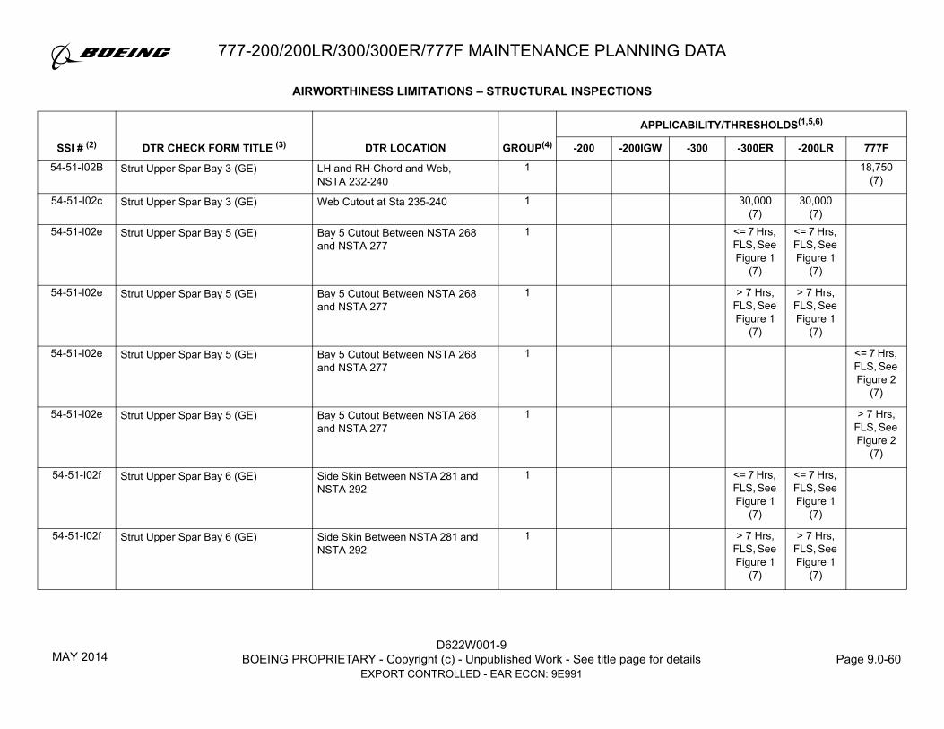
D622W001-9BOEING PROPRIETARY - Copyright (c) - Unpublished Work - See title page for details Page 9.0-60
EXPORT CONTROLLED - EAR ECCN: 9E991
777-200/200LR/300/300ER/777F MAINTENANCE PLANNING DATA
54-51-I02B Strut Upper Spar Bay 3 (GE) LH and RH Chord and Web, NSTA 232-240
1 18,750 (7)
54-51-I02c Strut Upper Spar Bay 3 (GE) Web Cutout at Sta 235-240 1 30,000 (7)
30,000 (7)
54-51-I02e Strut Upper Spar Bay 5 (GE) Bay 5 Cutout Between NSTA 268 and NSTA 277
1 <= 7 Hrs, FLS, See Figure 1
(7)
<= 7 Hrs, FLS, See Figure 1
(7)
54-51-I02e Strut Upper Spar Bay 5 (GE) Bay 5 Cutout Between NSTA 268 and NSTA 277
1 > 7 Hrs, FLS, See Figure 1
(7)
> 7 Hrs, FLS, See Figure 1
(7)
54-51-I02e Strut Upper Spar Bay 5 (GE) Bay 5 Cutout Between NSTA 268 and NSTA 277
1 <= 7 Hrs, FLS, See Figure 2
(7)
54-51-I02e Strut Upper Spar Bay 5 (GE) Bay 5 Cutout Between NSTA 268 and NSTA 277
1 > 7 Hrs, FLS, See Figure 2
(7)
54-51-I02f Strut Upper Spar Bay 6 (GE) Side Skin Between NSTA 281 and NSTA 292
1 <= 7 Hrs, FLS, See Figure 1
(7)
<= 7 Hrs, FLS, See Figure 1
(7)
54-51-I02f Strut Upper Spar Bay 6 (GE) Side Skin Between NSTA 281 and NSTA 292
1 > 7 Hrs, FLS, See Figure 1
(7)
> 7 Hrs, FLS, See Figure 1
(7)
AIRWORTHINESS LIMITATIONS – STRUCTURAL INSPECTIONS
GROUP(4)
APPLICABILITY/THRESHOLDS(1,5,6)
SSI # (2) DTR CHECK FORM TITLE (3) DTR LOCATION -200 -200IGW -300 -300ER -200LR 777F
MAY 2014

777-200/200LR/300/300ER/777F MAINTENANCE PLANNING DATA
D622W001-9BOEING PROPRIETARY - Copyright (c) - Unpublished Work - See title page for details Page 9.0-61
EXPORT CONTROLLED - EAR ECCN: 9E991
54-51-I02f RHS Upper Spar Bay 6 (GE) Side Skin Between NSTA 281 and NSTA 292
1 <= 7 Hrs, FLS, See Figure 2
(7)
54-51-I02f RHS Upper Spar Bay 6 (GE) Side Skin Between NSTA 281 and NSTA 292
1 > 7 Hrs, FLS, See Figure 2
(7)
54-51-I02i Strut Upper Spar (GE) Upper Chord Splice Between NSTA 305 and NSTA 315
1 30,000 (7)
30,000 (7)
54-51-I02i Strut Upper Spar (GE) Upper Chord Splice Between NSTA 305 and NSTA 315
1 FLS, See Figure 2
(7)
54-51-I02m Strut Upper Spar (GE) R3/R4 Fitting Inboard Flange 1 <= 7 Hrs, FLS, See Figure 1
(7)
<= 7 Hrs, FLS, See Figure 1
(7)
54-51-I02m Strut Upper Spar (GE) R3/R4 Fitting Inboard Flange 1 > 7 Hrs, FLS, See Figure 1
(7)
> 7 Hrs, FLS, See Figure 1
(7)
54-51-I02m Strut Aft Upper Spar (GE) R3/R4 Fitting Inboard Flange 1 <= 7 Hrs, FLS, See Figure 2
(7)
54-51-I02m Strut Aft Upper Spar (GE) R3/R4 Fitting Inboard Flange 1 > 7 Hrs, FLS, See Figure 2
(7)
AIRWORTHINESS LIMITATIONS – STRUCTURAL INSPECTIONS
GROUP(4)
APPLICABILITY/THRESHOLDS(1,5,6)
SSI # (2) DTR CHECK FORM TITLE (3) DTR LOCATION -200 -200IGW -300 -300ER -200LR 777F
MAY 2014

D622W001-9BOEING PROPRIETARY - Copyright (c) - Unpublished Work - See title page for details Page 9.0-62
EXPORT CONTROLLED - EAR ECCN: 9E991
777-200/200LR/300/300ER/777F MAINTENANCE PLANNING DATA
54-51-I02p Strut Upper Spar (GE) R1 Fitting Attachment NSTA 225 to NSTA 268
1 30,000 (7)
30,000 (7)
54-51-I02p Pylon R1/Web Interface (GE) R1 Fitting – NSTA 188 to NSTA 314
1 18,750 (7)
54-51-I02u Pylon R1/Web Interface (GE) R1 Fitting – NSTA 188 to NSTA 314
1 18,750(7)
54-51-I02v Pylon R1/Web Interface (GE) R1 Fitting – NSTA 188 to NSTA 314
1 18,750(7)
54-51-I02w Pylon R1/Web Interface (GE) R1 Fitting – NSTA 188 to NSTA 314
1 18,750(7)
54-51-I02r Upper Spar Assembly (GE) Upper Spar Common to Frames/Bulkheads
1 28,600 (7)
28,600 (7)
54-51-I02r Upper Spar Assembly (GE) Upper Spar Common to Frames/Bulkheads
1 18,750(7)
54-51-I02s Upper Spar Assembly (Bay 4) (GE) NSTA 245 to NSTA 264.6 1 <= 7 Hrs, FLS, See Figure 1
(7)
<= 7 Hrs, FLS, See Figure 1
(7)
54-51-I02s Upper Spar Assembly (Bay 4) (GE) NSTA 245 to NSTA 264.6 1 > 7 Hrs, FLS, See Figure 1
(7)
> 7 Hrs, FLS, See Figure 1
(7)
54-51-I02s Upper Spar Assembly (Bay 4) (GE) NSTA 245 to NSTA 265 1 18,750 (7)
54-51-I03a Side Skin Cutout, Bay 8 (GE) Cutout at Bay 8 1 <= 7 Hrs, FLS, See Figure 2
AIRWORTHINESS LIMITATIONS – STRUCTURAL INSPECTIONS
GROUP(4)
APPLICABILITY/THRESHOLDS(1,5,6)
SSI # (2) DTR CHECK FORM TITLE (3) DTR LOCATION -200 -200IGW -300 -300ER -200LR 777F
MAY 2014

777-200/200LR/300/300ER/777F MAINTENANCE PLANNING DATA
D622W001-9BOEING PROPRIETARY - Copyright (c) - Unpublished Work - See title page for details Page 9.0-63
EXPORT CONTROLLED - EAR ECCN: 9E991
54-51-I03b Side Skin Cutout, Bay 8 (GE) NSTA 310 to NSTA 325 1 <= 7 Hrs, FLS, See Figure 1
(7)
<= 7 Hrs, FLS, See Figure 1
(7)
54-51-I03b Side Skin Cutout, Bay 8 (GE) Cutout at Bay 8 1 <= 7 Hrs, FLS, See Figure 2
(7)
54-51-I03b Side Skin Cutout, Bay 8 (GE) Cutout at Bay 8 1 > 7 Hrs, FLS, See Figure 2
(7)
54-51-I03c Side Skin Cutout, Bay 8 (GE) NSTA 310 to NSTA 325 1 > 7 Hrs, FLS, See Figure 1
(7)
> 7 Hrs, FLS, See Figure 1
(7)
54-51-I03C Side Skin Cutout, Bay 8 (GE) Cutout at Bay 8 1 > 7 Hrs, FLS, See Figure 2
(7)
54-51-I03e Pylon Side Skin (GE) Side Skin Between NSTA 267 and NSTA 278
1 18,750 (7)
54-51-I03v Pylon Side Skin (GE) Side Skin Between NSTA 267 and NSTA 278
1 18,750 (7)
54-51-I03g Strut Side Skin Bay 4 (GE) NSTA 245 to NSTA 264.6 1 <= 7 Hrs, FLS, See Figure 1
<= 7 Hrs, FLS, See Figure 1
AIRWORTHINESS LIMITATIONS – STRUCTURAL INSPECTIONS
GROUP(4)
APPLICABILITY/THRESHOLDS(1,5,6)
SSI # (2) DTR CHECK FORM TITLE (3) DTR LOCATION -200 -200IGW -300 -300ER -200LR 777F
MAY 2014
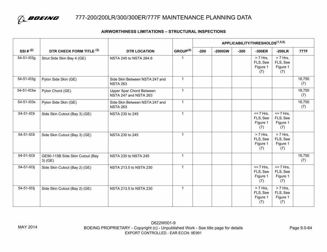
D622W001-9BOEING PROPRIETARY - Copyright (c) - Unpublished Work - See title page for details Page 9.0-64
EXPORT CONTROLLED - EAR ECCN: 9E991
777-200/200LR/300/300ER/777F MAINTENANCE PLANNING DATA
54-51-I03g Strut Side Skin Bay 4 (GE) NSTA 245 to NSTA 264.6 1 > 7 Hrs, FLS, See Figure 1
(7)
> 7 Hrs, FLS, See Figure 1
(7)
54-51-I03g Pylon Side Skin (GE) Side Skin Between NSTA 247 and NSTA 263
1 18,750 (7)
54-51-I03w Pylon Chord (GE) Upper Spar Chord Between NSTA 247 and NSTA 263
1 18,750 (7)
54-51-I03x Pylon Side Skin (GE) Side Skin Between NSTA 247 and NSTA 263
1 18,750 (7)
54-51-I03i Side Skin Cutout (Bay 3) (GE) NSTA 230 to 245 1 <= 7 Hrs, FLS, See Figure 1
(7)
<= 7 Hrs, FLS, See Figure 1
(7)
54-51-I03i Side Skin Cutout (Bay 3) (GE) NSTA 230 to 245 1 > 7 Hrs, FLS, See Figure 1
(7)
> 7 Hrs, FLS, See Figure 1
(7)
54-51-I03I GE90-115B Side Skin Cutout (Bay 3) (GE)
NSTA 230 to NSTA 245 1 18,750 (7)
54-51-I03j Side Skin Cutout (Bay 2) (GE) NSTA 213.5 to NSTA 230 1 <= 7 Hrs, FLS, See Figure 1
(7)
<= 7 Hrs, FLS, See Figure 1
(7)
54-51-I03j Side Skin Cutout (Bay 2) (GE) NSTA 213.5 to NSTA 230 1 > 7 Hrs, FLS, See Figure 1
(7)
> 7 Hrs, FLS, See Figure 1
(7)
AIRWORTHINESS LIMITATIONS – STRUCTURAL INSPECTIONS
GROUP(4)
APPLICABILITY/THRESHOLDS(1,5,6)
SSI # (2) DTR CHECK FORM TITLE (3) DTR LOCATION -200 -200IGW -300 -300ER -200LR 777F
MAY 2014

777-200/200LR/300/300ER/777F MAINTENANCE PLANNING DATA
D622W001-9BOEING PROPRIETARY - Copyright (c) - Unpublished Work - See title page for details Page 9.0-65
EXPORT CONTROLLED - EAR ECCN: 9E991
54-51-I03j Side Skin Cutout Bay 2 (GE) NSTA 213.5 to NSTA 230.0, Skin and Upper Spar Chord
1 <= 7 Hrs, FLS, See Figure 2
(7)
54-51-I03j Side Skin Cutout Bay 2 (GE) NSTA 213.5 to NSTA 230.0, Skin and Upper Spar Chord
1 > 7 Hrs, FLS, See Figure 2
(7)
54-51-I03k Side Skin Cutout (Bay 2) (GE) NSTA 213.5 to NSTA 230 1 <= 7 Hrs, FLS, See Figure 1
(7)
<= 7 Hrs, FLS, See Figure 1
(7)
54-51-I03k Side Skin Cutout Bay 2 (GE) NSTA 213.5 to NSTA 230.0, Skin and Upper Spar Chord
1 <= 7 Hrs, FLS, See Figure 2
(7)
54-51-I03k Side Skin Cutout Bay 2 (GE) NSTA 213.5 to NSTA 230.0, Skin and Upper Spar Chord
1 > 7 Hrs, FLS, See Figure 2
(7)
54-51-I03s Strut LH Side Skin Bay 4 (GE) NSTA 245 to NSTA 264.6, LHS 1 <= 7 Hrs, FLS, See Figure 1
(7)
<= 7 Hrs, FLS, See Figure 1
(7)
54-51-I03s Strut LH Side Skin Bay 4 (GE) NSTA 245 to NSTA 264.6, LHS 1 > 7 Hrs, FLS, See Figure 1
(7)
> 7 Hrs, FLS, See Figure 1
(7)
54-51-I03s Bay 4 Upper Spar (GE) LHS NSTA 245 to NSTA 264 1 18,750 (7)
AIRWORTHINESS LIMITATIONS – STRUCTURAL INSPECTIONS
GROUP(4)
APPLICABILITY/THRESHOLDS(1,5,6)
SSI # (2) DTR CHECK FORM TITLE (3) DTR LOCATION -200 -200IGW -300 -300ER -200LR 777F
MAY 2014

D622W001-9BOEING PROPRIETARY - Copyright (c) - Unpublished Work - See title page for details Page 9.0-66
EXPORT CONTROLLED - EAR ECCN: 9E991
777-200/200LR/300/300ER/777F MAINTENANCE PLANNING DATA
54-51-I04a Strut Lower Chord (GE) Bays 2 and 3 RH Chord/Web, NSTA at 213-245
1 <= 7 Hrs, FLS, See Figure 1
(7)
<= 7 Hrs, FLS, See Figure 1
(7)
54-51-I04a Strut Lower Chord (GE) Bays 2 and 3 RH Chord/Web, NSTA at 213-245
1 > 7 Hrs, FLS, See Figure 1
(7)
> 7 Hrs, FLS, See Figure 1
(7)
54-51-I04a Lower Spar Bay 3 (GE) Lower Spar Between NSTA 230 and 245
1 <= 7 Hrs, FLS, See Figure 2
(7)
54-51-I04a Lower Spar Bay 3 (GE) Lower Spar Between NSTA 230 and 245
1 > 7 Hrs, FLS, See Figure 2
(7)
54-51-I04b Strut Lower Chord Bay 3 (GE) LH Chord Between NSTA 230 and 245
1 > 7 Hrs, FLS, See Figure 1
> 7 Hrs, FLS, See Figure 1
54-51-I04b Strut Lower Chord Bay 3 (GE) LH Chord Between NSTA 230 and NSTA 245
1 <= 7 Hrs, FLS, See Figure 2
54-51-I04b Strut Lower Chord Bay 3 (GE) LH Chord Between NSTA 230 and NSTA 245
1 > 7 Hrs, FLS, See Figure 2
54-51-I04c Strut Lower Spar (GE) Bay 3 Lower Spar Web Cutout 1 <= 7 Hrs, FLS, See Figure 1
(7)
<= 7 Hrs, FLS, See Figure 1
(7)
AIRWORTHINESS LIMITATIONS – STRUCTURAL INSPECTIONS
GROUP(4)
APPLICABILITY/THRESHOLDS(1,5,6)
SSI # (2) DTR CHECK FORM TITLE (3) DTR LOCATION -200 -200IGW -300 -300ER -200LR 777F
MAY 2014

777-200/200LR/300/300ER/777F MAINTENANCE PLANNING DATA
D622W001-9BOEING PROPRIETARY - Copyright (c) - Unpublished Work - See title page for details Page 9.0-67
EXPORT CONTROLLED - EAR ECCN: 9E991
54-51-I04c Strut Lower Spar (GE) Bay 3 Lower Spar Web Cutout 1 > 7 Hrs, FLS, See Figure 1
(7)
> 7 Hrs, FLS, See Figure 1
(7)
54-51-I04d Strut Lower Spar (GE) Bays 5, 6 and 7 LH Chord/Web, NSTA 264-309
1 > 7 Hrs, FLS, See Figure 1
(7)
> 7 Hrs, FLS, See Figure 1
(7)
54-51-I04d Pylon Lower Spar (GE) LH Chord/Skin/Web Joint Between NSTA 266 and NSTA 278.5
1 FLS, See Figure 2
(7)
54-51-I04s Pylon Side Skin (GE) LH Chord/Skin/Web Joint Between NSTA 266 and NSTA 278.5
1 <= 7 Hrs, FLS, See Figure 2
(7)
54-51-I04s Pylon Side Skin (GE) LH Chord/Skin/Web Joint Between NSTA 266 and NSTA 278.5
1 > 7 Hrs, FLS, See Figure 2
(7)
54-51-I04e Pylon Lower Spar (GE) RH Chord/Skin/Web Joint Between NSTA 266 and NSTA 278.5
1 <= 7 Hrs, FLS, See Figure 2
(7)
54-51-I04e Pylon Lower Spar (GE) RH Chord/Skin/Web Joint Between NSTA 266 and NSTA 278.5
1 > 7 Hrs, FLS, See Figure 2
(7)
54-51-I04t Pylon Side Skin (GE) RH Chord/Skin/Web Joint Between NSTA 266 and NSTA 278.5
1 <= 7 Hrs, FLS, See Figure 2
(7)
AIRWORTHINESS LIMITATIONS – STRUCTURAL INSPECTIONS
GROUP(4)
APPLICABILITY/THRESHOLDS(1,5,6)
SSI # (2) DTR CHECK FORM TITLE (3) DTR LOCATION -200 -200IGW -300 -300ER -200LR 777F
MAY 2014

D622W001-9BOEING PROPRIETARY - Copyright (c) - Unpublished Work - See title page for details Page 9.0-68
EXPORT CONTROLLED - EAR ECCN: 9E991
777-200/200LR/300/300ER/777F MAINTENANCE PLANNING DATA
54-51-I04t Pylon Side Skin (GE) RH Chord/Skin/Web Joint Between NSTA 266 and NSTA 278.5
1 > 7 Hrs, FLS, See Figure 2
(7)
54-51-I04f Pylon Lower Spar (GE) Bay 5 Lwr Spar Web Cutout 1 <= 7 Hrs, FLS, See Figure 2
(7)
54-51-I04f Pylon Lower Spar (GE) Bay 5 Lwr Spar Web Cutout 1 > 7 Hrs, FLS, See Figure 2
(7)
54-51-I04g Strut Lower Spar (GE) Chord at Aft Engine Mount Bulkhead NSTA 303 to NSTA 317
1 30,000 (7)
30,000 (7)
18,750 (7)
54-51-I04h RHS Lower Spar Chord-Web-Skin Joint (GE)
Bay 2, STA 213 to STA 230 1 <= 7 Hrs, FLS, See Figure 2
(7)
54-51-I04h RHS Lower Spar Chord-Web-Skin Joint (GE)
Bay 2, STA 213 to STA 230 1 > 7 Hrs, FLS, See Figure 2
(7)
54-51-I04j Strut Lower Spar (GE) Bays 2 and 3 LH Chord NSTA 213-245
1 <= 7 Hrs, FLS, See Figure 1
<= 7 Hrs, FLS, See Figure 1
54-51-I04j Strut Lower Spar (GE) Bays 2 and 3 LH Chord NSTA 213-245
1 > 7 Hrs, FLS, See Figure 1
> 7 Hrs, FLS, See Figure 1
AIRWORTHINESS LIMITATIONS – STRUCTURAL INSPECTIONS
GROUP(4)
APPLICABILITY/THRESHOLDS(1,5,6)
SSI # (2) DTR CHECK FORM TITLE (3) DTR LOCATION -200 -200IGW -300 -300ER -200LR 777F
MAY 2014

777-200/200LR/300/300ER/777F MAINTENANCE PLANNING DATA
D622W001-9BOEING PROPRIETARY - Copyright (c) - Unpublished Work - See title page for details Page 9.0-69
EXPORT CONTROLLED - EAR ECCN: 9E991
54-51-I04j LHS Lower Spar Chord-web-skin Joint (GE)
Bay 2 1 <= 7 Hrs, FLS, See Figure 2
54-51-I04j LHS Lower Spar Chord-web-skin Joint (GE)
Bay 2 1 > 7 Hrs, FLS, See Figure 2
54-51-I04l Strut Lower Spar Bay 4 (GE) NSTA 245 to NSTA 264LHS and RHS Lower Spar
1 30,000 (7)
30,000 (7)
54-51-I04l Lower Spar Bay 4 (GE) NSTA 245 to NSTA 264LHS and RHS Lower Spar
1 <= 7 Hrs, FLS, See Figure 2
(7)
54-51-I04l Lower Spar Bay 4 (GE) NSTA 245 to NSTA 264LHS and RHS Lower Spar
1 > 7 Hrs, FLS, See Figure 2
(7)
54-51-I04u Lower Spar Bay 4 (GE) NSTA 245 to NSTA 264LHS and RHS Lower Spar
1 <= 7 Hrs, FLS, See Figure 2
(7)
54-51-I04u Lower Spar Bay 4 (GE) NSTA 245 to NSTA 264LHS and RHS Lower Spar
1 > 7 Hrs, FLS, See Figure 2
(7)
54-51-I04m Strut Lower Spar (GE) Chord STA at Bulkhead 1 <= 7 Hrs, FLS, See Figure 1
(7)
<= 7 Hrs, FLS, See Figure 1
(7)
<= 7 Hrs, FLS, See Figure 2
(7)
AIRWORTHINESS LIMITATIONS – STRUCTURAL INSPECTIONS
GROUP(4)
APPLICABILITY/THRESHOLDS(1,5,6)
SSI # (2) DTR CHECK FORM TITLE (3) DTR LOCATION -200 -200IGW -300 -300ER -200LR 777F
MAY 2014

D622W001-9BOEING PROPRIETARY - Copyright (c) - Unpublished Work - See title page for details Page 9.0-70
EXPORT CONTROLLED - EAR ECCN: 9E991
777-200/200LR/300/300ER/777F MAINTENANCE PLANNING DATA
54-51-I04m Strut Lower Spar (GE) Chord STA at Bulkhead 1 > 7 Hrs, FLS, See Figure 1
(7)
> 7 Hrs, FLS, See Figure 1
(7)
> 7 Hrs, FLS, See Figure 2
(7)
54-51-I04r Strut Lower Spar (GE) Bays 5, 6, and 7 NSTA 264-309 1 <= 7 Hrs, FLS, See Figure 1
(7)
<= 7 Hrs, FLS, See Figure 1
(7)
54-51-I04r Lower Spar Chords/Web Bays 6-7 (GE)
Lower Spar Chord Joint Between NSTA 280 and NSTA 308
1 <= 7 Hrs, FLS, See Figure 2
(7)
54-51-I04r Lower Spar Chords/Web Bays 6-7 (GE)
Lower Spar Chord Joint Between NSTA 280 and NSTA 308
1 > 7 Hrs, FLS, See Figure 2
(7)
54-51-I05a Strut Fwd Engine Mount Bulkhead (GE)
Gusset Edge 1 30,000 (7)
30,000 (7)
54-51-I05a Strut Fwd Engine Mount Bulkhead (GE)
Gusset Upper Edge 1 18,750 (7)
54-51-I05b Strut Fwd Engine Mount Bulkhead (GE)
Tension Fitting 1 30,000 (7)
30,000 (7)
54-51-I05b Fwd Engine Mount Bulkhead (GE) Tension Fitting 1 18,750
54-51-I06a Strut Mid Bulkhead STA 295 (GE) Flange 1 <= 7 Hrs, FLS, See Figure 1
(7)
<= 7 Hrs, FLS, See Figure 1
(7)
<= 7 Hrs, FLS, See Figure 2
(7)
AIRWORTHINESS LIMITATIONS – STRUCTURAL INSPECTIONS
GROUP(4)
APPLICABILITY/THRESHOLDS(1,5,6)
SSI # (2) DTR CHECK FORM TITLE (3) DTR LOCATION -200 -200IGW -300 -300ER -200LR 777F
MAY 2014

777-200/200LR/300/300ER/777F MAINTENANCE PLANNING DATA
D622W001-9BOEING PROPRIETARY - Copyright (c) - Unpublished Work - See title page for details Page 9.0-71
EXPORT CONTROLLED - EAR ECCN: 9E991
54-51-I06a Strut Mid Bulkhead STA 295 (GE) Flange 1 > 7 Hrs, FLS, See Figure 1
(7)
> 7 Hrs, FLS, See Figure 1
(7)
> 7 Hrs, FLS, See Figure 2
(7)
54-51-I06b Strut Mid Bulkhead STA 295 (GE) R1 Attachment Pad @ Bolt Hole 1 30,000 (7)
30,000 (7)
18,750 (7)
54-51-I07a Strut Aft Engine Mount Bulkhead (GE)
R1 Fitting Attachment 1 30,000 (7)
30,000 (7)
54-51-I07a Aft Engine Mount Bulkhead (GE) R1 Fitting Fastener Attachment 1 18,750 (7)
54-51-I07b Aft Engine Mount Bulkhead (GE) Engine Mount Tension Fitting 1 18,750
54-51-I07d Strut Aft Engine Mount Bulkhead (GE)
Cutout Flange 1 <= 7 Hrs, FLS, See Figure 1
(7)
<= 7 Hrs, FLS, See Figure 1
(7)
54-51-I07d Strut Aft Engine Mount Bulkhead (GE)
Cutout Flange 1 > 7 Hrs, FLS, See Figure 1
(7)
> 7 Hrs, FLS, See Figure 1
(7)
54-51-I07d Strut Aft Engine Mount Bulkhead (GE)
Cutout Flange 1 18,750 (7)
54-51-I08b Aft Strut Bulkhead (GE) Aft Bulkhead from NWL 147 to NWL 162
1 <= 7 Hrs, FLS, See Figure 2
(7)
54-51-I08b Aft Strut Bulkhead (GE) Aft Bulkhead from NWL 147 to NWL 162
1 > 7 Hrs, FLS, See Figure 2
(7)
AIRWORTHINESS LIMITATIONS – STRUCTURAL INSPECTIONS
GROUP(4)
APPLICABILITY/THRESHOLDS(1,5,6)
SSI # (2) DTR CHECK FORM TITLE (3) DTR LOCATION -200 -200IGW -300 -300ER -200LR 777F
MAY 2014

D622W001-9BOEING PROPRIETARY - Copyright (c) - Unpublished Work - See title page for details Page 9.0-72
EXPORT CONTROLLED - EAR ECCN: 9E991
777-200/200LR/300/300ER/777F MAINTENANCE PLANNING DATA
54-51-I08d Aft Strut Bulkhead (GE) Forward Upper Flange NSTA 325.33
1 <= 7 Hrs, FLS, See Figure 1
(7)
<= 7 Hrs, FLS, See Figure 1
(7)
54-51-I08d Aft Strut Bulkhead (GE) Forward Upper Flange NSTA 325.33
1 > 7 Hrs, FLS, See Figure 1
(7)
> 7 Hrs, FLS, See Figure 1
(7)
54-51-I08d Aft Strut Bulkhead (GE) Forward Upper Flange NSTA 325.33
1 18,750 (7)
54-51-I02A Upper Spar Chord (RR) Upper Spar Chord Splice Plate at NSTA 313 to NSTA 323
1 30,000 (8)
30,000 (8)
30,000 (8)
54-51-I02C Forward Upper Spar (RR) Upper Spar at Frame/Bulkheads 1 30,000 (8)
30,000 (8)
30,000 (8)
54-51-I02D Forward Upper Spar (RR) Fasteners Common to the Upper Chord and Web, NSTA 223 to NSTA 294, non-frame locations
1 30,000 (8)
30,000 (8)
30,000 (8)
54-51-I04A Lower Chord (RR) Lower Chord, Web at Aft Engine Mount Attachment Bolt Holes atNSTA 307.7, 309.9, 313.3, and 315.5
1 30,000 (8)
30,000 (8)
30,000 (8)
54-51-I04B Aft Lower Chord at Aft Engine Mount Bulkhead (RR)
Fasteners Common to Chord and Web under Engine Mount Fitting, NSTA 305 to NSTA 317
1 30,000 (8)
30,000 (8)
54-51-I04B Aft Lower Spar Chord Under Engine Mount Bulkhead (RR)
Fasteners Common to Chord and Web under Engine Mount Fitting, NSTA 305 to NSTA 317
1 30,000 (8)
54-51-I05A Forward Engine Mount Bulkhead (RR)
Fwd Engine Mount Bulkhead Tension Fitting End Pad
1 30,000 (8)
30,000 (8)
AIRWORTHINESS LIMITATIONS – STRUCTURAL INSPECTIONS
GROUP(4)
APPLICABILITY/THRESHOLDS(1,5,6)
SSI # (2) DTR CHECK FORM TITLE (3) DTR LOCATION -200 -200IGW -300 -300ER -200LR 777F
MAY 2014

777-200/200LR/300/300ER/777F MAINTENANCE PLANNING DATA
D622W001-9BOEING PROPRIETARY - Copyright (c) - Unpublished Work - See title page for details Page 9.0-73
EXPORT CONTROLLED - EAR ECCN: 9E991
54-51-I05A Forward Engine Mount Bulkhead (RR)
Fwd Engine Mount Bulkhead Tension Fitting End Pad
1 30,000 (8)
54-51-I06A Aft Engine Mount Bulkhead (RR) R1 Fitting Attach Tension Fitting 1 30,000 (8)
54-51-I06A Aft Engine Mount Bulkhead (RR) R1 Fitting Attach Tension Fitting 1 30,000 (8)
54-51-I06A Aft Engine Mount Bulkhead (RR) Upper Tension (Bathtub) Fitting End Pad
1 30,000 (8)
54-51-I07B Strut Aft Bulkhead (RR) At Fastener Common to the Aft Upper Spar Fitting WL 148.26 to WL 159.29
1 30,000 (8)
54-51-I07A,B Aluminum Aft Strut Bulkhead (RR) At Fasteners Common to the Aft Upper Spar from WL 148.26 to WL 159.29 and the Two Uppermost Fasteners Common to the R2 Fitting
1 30,000 (8)
54-51-I07A,B Aluminum Aft Strut Bulkhead (RR) At Fastener Common to the Aft Upper Spar from WL 148.26 to WL 159.29 and the Two Uppermost Fasteners Common to the R2 Fitting
1 30,000 (8)
54-51-I07C Aluminum Aft Strut Bulkhead (RR) Forward Upper Flange NSTA 344.00
1 <= 7 Hrs, FLS, See
Figure 1 (7)
AIRWORTHINESS LIMITATIONS – STRUCTURAL INSPECTIONS
GROUP(4)
APPLICABILITY/THRESHOLDS(1,5,6)
SSI # (2) DTR CHECK FORM TITLE (3) DTR LOCATION -200 -200IGW -300 -300ER -200LR 777F
JUL 2017

D622W001-9BOEING PROPRIETARY - Copyright (c) - Unpublished Work - See title page for details Page 9.0-74
EXPORT CONTROLLED - EAR ECCN: 9E991
777-200/200LR/300/300ER/777F MAINTENANCE PLANNING DATA
54-51-I07C Aluminum Aft Strut Bulkhead (RR) Forward Upper Flange NSTA 344.00
1 > 7 Hrs, FLS, See
Figure 1 (7)
54-51-I07C Aluminum Aft Strut Bulkhead (RR) Forward Upper Flange NSTA 344.00
1 30,000 (7)
55-12-I03 Upper Double Plus Chord Horizontal Stabilizer
BL 0.0 Skin/Stringer Splice 1 30,000 (8)
30,000 (8)
30,000 (8)
55-12-I03 Upper Double Plus Chord Horizontal Stabilizer
BL 0.0 Skin/Stringer Splice 1 30,000 (7)
30,000 (7)
55-12-I03 Upper Double Plus Chord Horizontal Stabilizer
BL 0.0 Skin/Stringer Splice 1 18,750 (7)
55-12-I07 Splice Fitting – F/S Upper Chord Horizontal Stabilizer
Inboard Jackscrew Attach Fastener at BL 4.2
1 30,000 (8)
30,000 (8)
30,000 (8)
55-12-I07 Splice Fitting – F/S Upper Chord Horizontal Stabilizer
Inboard Jackscrew Attach Fastener at BL 4.2
1 30,000 (7)
30,000 (7)
55-12-I07 Splice Fitting – F/S Upper Chord Horizontal Stabilizer
Inboard Jackscrew Attach Fastener at BL 4.2
1 18,750 (7)
55-17-I03A Pivot Fitting Lugs BL +/- 42 and Pivot Hinge Line 1 30,000 (8)
55-17-I03A Pivot Fitting Lugs BL +/- 42 and Pivot Hinge Line 1 30,000 (8)
55-17-I03A Pivot Fitting Lugs BL +/- 42 and Pivot Hinge Line 1 30,000 (8)
55-17-I03A Pivot Fitting Lugs BL +/- 42 and Pivot Hinge Line 1 30,000 (7)
30,000 (7)
55-17-I03A Pivot Fitting Lugs BL +/- 42 and Pivot Hinge Line 1 18,750 (7)
AIRWORTHINESS LIMITATIONS – STRUCTURAL INSPECTIONS
GROUP(4)
APPLICABILITY/THRESHOLDS(1,5,6)
SSI # (2) DTR CHECK FORM TITLE (3) DTR LOCATION -200 -200IGW -300 -300ER -200LR 777F
MAY 2014

777-200/200LR/300/300ER/777F MAINTENANCE PLANNING DATA
D622W001-9BOEING PROPRIETARY - Copyright (c) - Unpublished Work - See title page for details Page 9.0-75
EXPORT CONTROLLED - EAR ECCN: 9E991
55-17-I03B Pivot Fitting Straps (Both Pairs – Upper and Lower)
BL +/- 42, WL 246 and 263, BS 2365
1 30,000 (8)
30,000 (8)
30,000 (8)
30,000 (7)
30,000 (7)
55-17-I03B Pivot Fitting Straps Lower Strap BL +/- 42, WL 255, BS 2365 1 18,750 (7)
55-17-I03C Pivot Fitting Pins Outer Pin BL 42 and Pivot Hinge Line 1 30,000 (8)
55-17-I03C Pivot Fitting Pins Outer Pin BL 42 and Pivot Hinge Line 1 30,000 (8)
55-17-I03C Pivot Fitting Pins Outer Pin BL 42 and Pivot Hinge Line 1 30,000 (8)
55-17-I03C Pivot Fitting Pins Outer Pin BL 42 and Pivot Hinge Line 1 30,000 (7)
30,000 (7)
55-17-I03C Pivot Fitting Pins Outer Pin BL 42 and Pivot Hinge Line 1 18,750 (7)
55-18-I01 Jackscrew Fitting, Lugs Dwg. 182W7402
Back-to-Back Lugs BL +/- 5.0 WL 256.32
1 30,000 (8)
55-18-I01 Jackscrew Fitting, Lugs Dwg. 182W7402
Back-to-Back Lugs BL +/- 5.0 WL 256.32
1 30,000 (8)
55-18-I01 Jackscrew Fitting, Lugs Dwg. 182W7402
Back-to-Back Lugs BL +/- 5.0 WL 256.32
1 30,000 (8)
55-18-I01 Jackscrew Fitting, Lugs Dwg. 182W7402
Back-to-Back Lugs BL +/- 5.0 WL 256.32
1 30,000 (7)
30,000 (7)
55-18-I01 Jackscrew Fitting, Lugs Dwg. 182W7402
Back-to-Back Lugs BL +/- 5.0 WL 256.32
1 18,750 (7)
55-27-I03 Elevator Actuator Fitting 183W1312,L/N 718 and on, and all retrofitted airplanes
Upper Middle Flange 1 30,000 (8)
30,000 (8)
30,000 (8)
30,000 (7)
30,000 (7)
18,750 (7)
57-10-I02A SOB Splice, Lower Surface, T-Chord INBD and OBD Flanges of T-Chord
1 30,000 (8)
30,000 (8)
AIRWORTHINESS LIMITATIONS – STRUCTURAL INSPECTIONS
GROUP(4)
APPLICABILITY/THRESHOLDS(1,5,6)
SSI # (2) DTR CHECK FORM TITLE (3) DTR LOCATION -200 -200IGW -300 -300ER -200LR 777F
MAY 2014
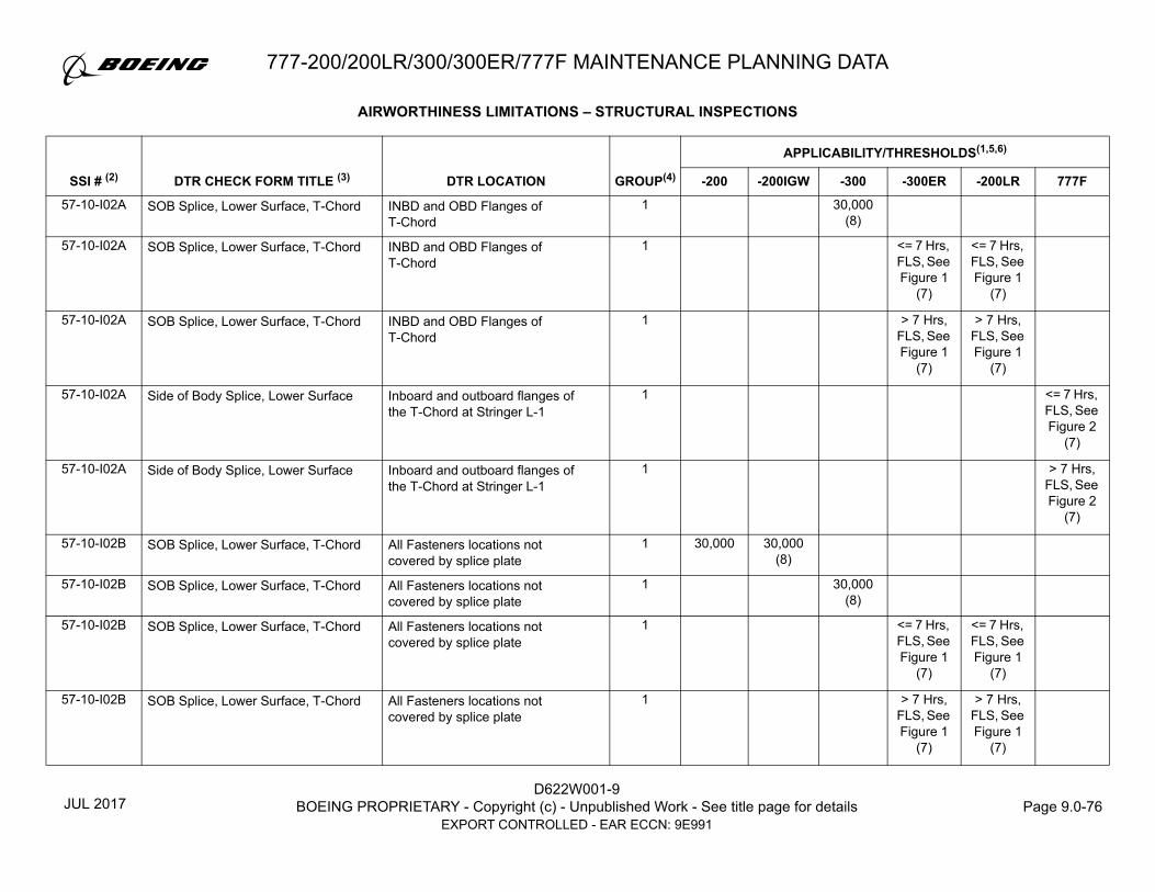
D622W001-9BOEING PROPRIETARY - Copyright (c) - Unpublished Work - See title page for details Page 9.0-76
EXPORT CONTROLLED - EAR ECCN: 9E991
777-200/200LR/300/300ER/777F MAINTENANCE PLANNING DATA
57-10-I02A SOB Splice, Lower Surface, T-Chord INBD and OBD Flanges of T-Chord
1 30,000 (8)
57-10-I02A SOB Splice, Lower Surface, T-Chord INBD and OBD Flanges of T-Chord
1 <= 7 Hrs, FLS, See Figure 1
(7)
<= 7 Hrs, FLS, See Figure 1
(7)
57-10-I02A SOB Splice, Lower Surface, T-Chord INBD and OBD Flanges of T-Chord
1 > 7 Hrs, FLS, See Figure 1
(7)
> 7 Hrs, FLS, See Figure 1
(7)
57-10-I02A Side of Body Splice, Lower Surface Inboard and outboard flanges of the T-Chord at Stringer L-1
1 <= 7 Hrs, FLS, See Figure 2
(7)
57-10-I02A Side of Body Splice, Lower Surface Inboard and outboard flanges of the T-Chord at Stringer L-1
1 > 7 Hrs, FLS, See Figure 2
(7)
57-10-I02B SOB Splice, Lower Surface, T-Chord All Fasteners locations not covered by splice plate
1 30,000 30,000 (8)
57-10-I02B SOB Splice, Lower Surface, T-Chord All Fasteners locations not covered by splice plate
1 30,000 (8)
57-10-I02B SOB Splice, Lower Surface, T-Chord All Fasteners locations not covered by splice plate
1 <= 7 Hrs, FLS, See Figure 1
(7)
<= 7 Hrs, FLS, See Figure 1
(7)
57-10-I02B SOB Splice, Lower Surface, T-Chord All Fasteners locations not covered by splice plate
1 > 7 Hrs, FLS, See Figure 1
(7)
> 7 Hrs, FLS, See Figure 1
(7)
AIRWORTHINESS LIMITATIONS – STRUCTURAL INSPECTIONS
GROUP(4)
APPLICABILITY/THRESHOLDS(1,5,6)
SSI # (2) DTR CHECK FORM TITLE (3) DTR LOCATION -200 -200IGW -300 -300ER -200LR 777F
JUL 2017

777-200/200LR/300/300ER/777F MAINTENANCE PLANNING DATA
D622W001-9BOEING PROPRIETARY - Copyright (c) - Unpublished Work - See title page for details Page 9.0-77
EXPORT CONTROLLED - EAR ECCN: 9E991
57-10-I02B Side of Body Splice, Lower Surface Inspect at all fastener locations not covered by the splice plate
1 <= 7 Hrs, FLS, See Figure 2
(7)
57-10-I02B Side of Body Splice, Lower Surface Inspect at all fastener locations not covered by the splice plate
1 > 7 Hrs, FLS, See Figure 2
(7)
57-10-I02C SOB Splice, Lower Surface, T-Chord INBD and OBD Flanges of T-chord @ Splice Plate (Str L1,L-10,L14,L-20 and L-23)
1 30,000 (8)
30,000 (8)
57-10-I02C SOB Splice, Lower Surface, T-Chord INBD and OBD Flanges of T-chord @ Splice Plate(Str L1,L-10,L14,L-20 and L-23)
1 30,000 (8)
57-10-I02C SOB Splice, Lower Surface, T-Chord INBD and OBD Flanges of T-chord @ Splice Plate (Str L1,L-10,L14,L-20 and L-23)
1 <= 7 Hrs, FLS, See Figure 1
(7)
<= 7 Hrs, FLS, See Figure 1
(7)
57-10-I02C SOB Splice, Lower Surface, T-Chord INBD and OBD Flanges of T-chord @ Splice Plate (Str L1,L-10,L14,L-20 and L-23)
1 > 7 Hrs, FLS, See Figure 1
(7)
> 7 Hrs, FLS, See Figure 1
(7)
57-10-I02C Side of Body Splice, Lower Surface Inboard and Outboard flanges of T-chord at splice plate locations (Str L1,L-10,L14,L-20 and L-23)
1 <= 7 Hrs, FLS, See Figure 2
(7)
57-10-I02C Side of Body Splice, Lower Surface Inboard and Outboard flanges of T-chord at splice plate locations (Str L1,L-10,L14,L-20 and L-23)
1 > 7 Hrs, FLS, See Figure 2
(7)
AIRWORTHINESS LIMITATIONS – STRUCTURAL INSPECTIONS
GROUP(4)
APPLICABILITY/THRESHOLDS(1,5,6)
SSI # (2) DTR CHECK FORM TITLE (3) DTR LOCATION -200 -200IGW -300 -300ER -200LR 777F
MAY 2014

D622W001-9BOEING PROPRIETARY - Copyright (c) - Unpublished Work - See title page for details Page 9.0-78
EXPORT CONTROLLED - EAR ECCN: 9E991
777-200/200LR/300/300ER/777F MAINTENANCE PLANNING DATA
57-10-I03A SOB Splice, Front Spar, Chord Upper and Lower Front Spar Chords (INBD and OBD of SOB rib)
1 30,000 (8)
<= 7 Hrs, FLS, See
Figure 1 (8)
57-10-I03A SOB Splice, Front Spar, Chord Upper and Lower Front Spar Chords (INBD and OBD of SOB rib)
1 > 7 Hrs, FLS, See
Figure 1 (8)
57-10-I03A SOB Splice, Front Spar, Chord Upper and Lower Front Spar Chords (INBD and OBD of SOB rib)
1 30,000 (8)
57-10-I03A SOB Splice, Front Spar, Chord Upper and Lower Front Spar Chords (INBD and OBD of SOB rib)
1 <= 7 Hrs, FLS, See Figure 1
(7)
<= 7 Hrs, FLS, See Figure 1
(7)
57-10-I03A SOB Splice, Front Spar, Chord Upper and Lower Front Spar Chords (INBD and OBD of SOB rib)
1 > 7 Hrs, FLS, See Figure 1
(7)
> 7 Hrs, FLS, See Figure 1
(7)
57-10-I03A Side of Body Splice, Front Spar Chords, Front Spar Lower and Upper Chords (Inboard and Outboard of SOB rib)
1 <= 7 Hrs, FLS, See Figure 2
(7)
57-10-I03A Side of Body Splice, Front Spar, Chord
Chords, Front Spar Lower and Upper Chords (Inboard and Outboard of SOB rib)
1 > 7 Hrs, FLS, See Figure 2
(7)
AIRWORTHINESS LIMITATIONS – STRUCTURAL INSPECTIONS
GROUP(4)
APPLICABILITY/THRESHOLDS(1,5,6)
SSI # (2) DTR CHECK FORM TITLE (3) DTR LOCATION -200 -200IGW -300 -300ER -200LR 777F
MAY 2014

777-200/200LR/300/300ER/777F MAINTENANCE PLANNING DATA
D622W001-9BOEING PROPRIETARY - Copyright (c) - Unpublished Work - See title page for details Page 9.0-79
EXPORT CONTROLLED - EAR ECCN: 9E991
57-10-I03B Side of Body Splice, Front Spar Skin, Front Spar Lower and Upper Chords (Inboard and Outboard of SOB rib)
1 <= 7 Hrs, FLS, See Figure 2
(7)
57-10-I03B Side of Body Splice, Front Spar Skin, Front Spar Lower and Upper Chords (Inboard and Outboard of SOB rib)
1 > 7 Hrs, FLS, See Figure 2
(7)
57-10-I04A SOB Splice, Rear Spar, Chord Upper and Lower Rear Spar Chords (INBD and OBD of SOB rib)
1 30,000 (8)
<= 7 Hrs, FLS, See
Figure 1 (8)
57-10-I04A SOB Splice, Rear Spar, Chord Upper and Lower Rear Spar Chords (INBD and OBD of SOB rib)
1 > 7 Hrs, FLS, See
Figure 1 (8)
57-10-I04A SOB Splice, Rear Spar, Chord Upper and Lower Rear Spar Chords (INBD and OBD of SOB rib)
1 30,000 (8)
57-10-I04A SOB Splice, Rear Spar, Chord Upper and Lower Rear Spar Chords (INBD and OBD of SOB rib)
1 <= 7 Hrs, FLS, See Figure 1
(7)
<= 7 Hrs, FLS, See Figure 1
(7)
57-10-I04A SOB Splice, Rear Spar, Chord Upper and Lower Rear Spar Chords (INBD and OBD of SOB rib)
1 > 7 Hrs, FLS, See Figure 1
(7)
> 7 Hrs, FLS, See Figure 1
(7)
AIRWORTHINESS LIMITATIONS – STRUCTURAL INSPECTIONS
GROUP(4)
APPLICABILITY/THRESHOLDS(1,5,6)
SSI # (2) DTR CHECK FORM TITLE (3) DTR LOCATION -200 -200IGW -300 -300ER -200LR 777F
MAY 2014

D622W001-9BOEING PROPRIETARY - Copyright (c) - Unpublished Work - See title page for details Page 9.0-80
EXPORT CONTROLLED - EAR ECCN: 9E991
777-200/200LR/300/300ER/777F MAINTENANCE PLANNING DATA
57-10-I04A Side of Body Splice, Rear Spar Chords, Rear Spar Lower and Upper Chords (Inboard and Outboard of SOB rib)
1 <= 7 Hrs, FLS, See Figure 2
(7)
57-10-I04A Side of Body Splice, Rear Spar Chords, Rear Spar Lower and Upper Chords (Inboard and Outboard of SOB rib)
1 > 7 Hrs, FLS, See Figure 2
(7)
57-10-I04B Side of Body Splice, Rear Spar Skin, Rear Spar Lower and Upper Chords (Inboard and Outboard of SOB rib)
1 <= 7 Hrs, FLS, See Figure 2
(7)
57-10-I04B Side of Body Splice, Rear Spar Skin, Rear Spar Lower and Upper Chords (Inboard and Outboard of SOB rib)
1 > 7 Hrs, FLS, See Figure 2
(7)
57-12-I02-1 Body Chord Inspection at Stringer 36 to 41 (Airplanes Without Underwing Longeron Doubler)
Front Spar Bulkhead, Station 1035, Stringer 36 to 41
1 30,000 (8)
30,000 (8)
30,000 (8)
30,000 (7)
30,000 (7)
18,750 (7)
57-12-I02-1 Body Chord Inspection at Stringer 36 to 41 (Airplanes With Underwing Longeron Doubler)
Front Spar Bulkhead, Station 1035, Stringer 36 to 41
1 30,000 (8)
30,000 (8)
30,000 (8)
30,000 (7)
30,000 (7)
18,750 (7)
57-12-I02-2 Body Chord Inspection at Splice Plate (Airplanes Without Underwing Longeron Doubler)
Front Spar Bulkhead, Station 1035 Stringer 38 to 39
1 30,000 (8)
30,000 (8)
30,000 (8)
30,000 (7)
30,000 (7)
18,750 (7)
57-12-I02-2 Body Chord Inspection at Splice Plate (Airplanes With Underwing Longeron Doubler)
Front Spar Bulkhead, Station 1035 Stringer 38 to 39
1 30,000 (8)
30,000 (8)
30,000 (8)
30,000 (7)
30,000 (7)
18,750 (7)
57-15-I01A Wing Center Section (WCS), Lower Panel Typical Stringer
Typical stringer on Lower Panel (WCS from SOB to SOB)
2 40,000 40,000
AIRWORTHINESS LIMITATIONS – STRUCTURAL INSPECTIONS
GROUP(4)
APPLICABILITY/THRESHOLDS(1,5,6)
SSI # (2) DTR CHECK FORM TITLE (3) DTR LOCATION -200 -200IGW -300 -300ER -200LR 777F
APR 2019

777-200/200LR/300/300ER/777F MAINTENANCE PLANNING DATA
D622W001-9BOEING PROPRIETARY - Copyright (c) - Unpublished Work - See title page for details Page 9.0-81
EXPORT CONTROLLED - EAR ECCN: 9E991
57-15-I01A Wing Center Section (WCS), Lower Panel Typical Stringer
Typical stringer on Lower Panel (WCS from SOB to SOB)
2 40,000
57-15-I01A Wing Center Section (WCS), Lower Panel Typical Stringer
Typical stringer on Lower Panel (WCS from SOB to SOB)
2 <= 7 Hrs, FLS, See Figure 1
(7)
<= 7 Hrs, FLS, See Figure 1
(7)
57-15-I01A Wing Center Section (WCS), Lower Panel Typical Stringer
Typical stringer on Lower Panel (WCS from SOB to SOB)
2 > 7 Hrs, FLS, See Figure 1
(7)
> 7 Hrs, FLS, See Figure 1
(7)
57-15-I01A Wing Center Section – Lower Panel – Typical Stringer
All WCS Lower Panel Typical Stringers from SOB to SOB
2 <= 7 Hrs, FLS, See Figure 2
(7)
57-15-I01A Wing Center Section – Lower Panel – Typical Stringer
All WCS Lower Panel Typical Stringers from SOB to SOB
2 > 7 hrs FLS, See Figure 2
57-15-I01B Wing Center Section (WCS), Lower Panel Splice Stringer
Splice stringer on Lower Panel (WCS @ L10,L14, L20 from SOB to SOB)
2 40,000 40,000 40,000
57-15-I01B Wing Center Section (WCS), Lower Panel Splice Stringer
Splice stringer on Lower Panel (WCS @ L10,L14, L20 from SOB to SOB)
2 <= 7 Hrs, FLS, See Figure 1
(7)
<= 7 Hrs, FLS, See Figure 1
(7)
57-15-I01B Wing Center Section – Lower Panel – Splice Stringer
All WCS Lower Panel Splice Stringers
2 <= 7 Hrs, FLS, See Figure 2
(7)
AIRWORTHINESS LIMITATIONS – STRUCTURAL INSPECTIONS
GROUP(4)
APPLICABILITY/THRESHOLDS(1,5,6)
SSI # (2) DTR CHECK FORM TITLE (3) DTR LOCATION -200 -200IGW -300 -300ER -200LR 777F
MAY 2014
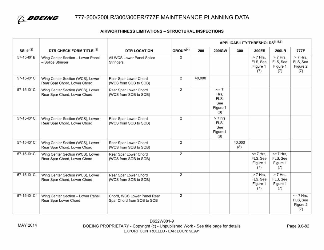
D622W001-9BOEING PROPRIETARY - Copyright (c) - Unpublished Work - See title page for details Page 9.0-82
EXPORT CONTROLLED - EAR ECCN: 9E991
777-200/200LR/300/300ER/777F MAINTENANCE PLANNING DATA
57-15-I01B Wing Center Section – Lower Panel – Splice Stringer
All WCS Lower Panel Splice Stringers
2 > 7 Hrs, FLS, See Figure 1
(7)
> 7 Hrs, FLS, See Figure 1
(7)
> 7 Hrs, FLS, See Figure 2
(7)
57-15-I01C Wing Center Section (WCS), Lower Rear Spar Chord, Lower Chord
Rear Spar Lower Chord (WCS from SOB to SOB)
2 40,000
57-15-I01C Wing Center Section (WCS), Lower Rear Spar Chord, Lower Chord
Rear Spar Lower Chord(WCS from SOB to SOB)
2 <= 7 Hrs, FLS, See
Figure 1 (8)
57-15-I01C Wing Center Section (WCS), Lower Rear Spar Chord, Lower Chord
Rear Spar Lower Chord (WCS from SOB to SOB)
2 > 7 hrs FLS, See
Figure 1 (8)
57-15-I01C Wing Center Section (WCS), Lower Rear Spar Chord, Lower Chord
Rear Spar Lower Chord(WCS from SOB to SOB)
2 40,000 (8)
57-15-I01C Wing Center Section (WCS), Lower Rear Spar Chord, Lower Chord
Rear Spar Lower Chord(WCS from SOB to SOB)
2 <= 7 Hrs, FLS, See Figure 1
(7)
<= 7 Hrs, FLS, See Figure 1
(7)
57-15-I01C Wing Center Section (WCS), Lower Rear Spar Chord, Lower Chord
Rear Spar Lower Chord (WCS from SOB to SOB)
2 > 7 Hrs, FLS, See Figure 1
(7)
> 7 Hrs, FLS, See Figure 1
(7)
57-15-I01C Wing Center Section – Lower Panel Rear Spar Lower Chord
Chord, WCS Lower Panel Rear Spar Chord from SOB to SOB
2 <= 7 Hrs, FLS, See Figure 2
(7)
AIRWORTHINESS LIMITATIONS – STRUCTURAL INSPECTIONS
GROUP(4)
APPLICABILITY/THRESHOLDS(1,5,6)
SSI # (2) DTR CHECK FORM TITLE (3) DTR LOCATION -200 -200IGW -300 -300ER -200LR 777F
MAY 2014

777-200/200LR/300/300ER/777F MAINTENANCE PLANNING DATA
D622W001-9BOEING PROPRIETARY - Copyright (c) - Unpublished Work - See title page for details Page 9.0-83
EXPORT CONTROLLED - EAR ECCN: 9E991
57-15-I01C Wing Center Section – Lower Panel Rear Spar Lower Chord
Chord, WCS Lower Panel Rear Spar Chord from SOB to SOB
2 > 7 Hrs, FLS, See Figure 2
(7)
57-15-I01D Wing Center Section (WCS), Lower Rear Spar Chord, Lower Skin
Rear Spar Lower Chord (WCS from SOB to SOB)
2 40,000
57-15-I01D Wing Center Section (WCS), Lower Rear Spar Chord, Lower Skin
Rear Spar Lower Chord (WCS from SOB to SOB)
2 <= 7 Hrs, FLS, See
Figure 157-15-I01D Wing Center Section (WCS), Lower
Rear Spar Chord, Lower SkinRear Spar Lower Chord(WCS from SOB to SOB)
2 > 7 hrs FLS, See
Figure 157-15-I01D Wing Center Section (WCS), Lower
Rear Spar Chord, Lower SkinRear Spar Lower Chord(WCS from SOB to SOB)
2 40,000 (8)
57-15-I01D Wing Center Section (WCS), Lower Rear Spar Chord, Lower Skin
Rear Spar Lower Chord(WCS from SOB to SOB)
2 <= 7 Hrs, FLS, See Figure 1
(7)
<= 7 Hrs, FLS, See Figure 1
(7)
57-15-I01D Wing Center Section (WCS), Lower Rear Spar Chord, Lower Skin
Rear Spar Lower Chord (WCS from SOB to SOB)
2 > 7 Hrs, FLS, See Figure 1
(7)
> 7 Hrs, FLS, See Figure 1
(7)
57-15-I01D Wing Center Section – Lower Panel Rear Spar Lower Chord
Skin, WCS Lower Panel Rear Spar Chord from SOB to SOB
2 <= 7 Hrs, FLS, See Figure 2
(7)
AIRWORTHINESS LIMITATIONS – STRUCTURAL INSPECTIONS
GROUP(4)
APPLICABILITY/THRESHOLDS(1,5,6)
SSI # (2) DTR CHECK FORM TITLE (3) DTR LOCATION -200 -200IGW -300 -300ER -200LR 777F
MAY 2014

D622W001-9BOEING PROPRIETARY - Copyright (c) - Unpublished Work - See title page for details Page 9.0-84
EXPORT CONTROLLED - EAR ECCN: 9E991
777-200/200LR/300/300ER/777F MAINTENANCE PLANNING DATA
57-15-I01D Wing Center Section – Lower Panel Rear Spar Lower Chord
Skin, WCS Lower Panel Rear Spar Chord from SOB to SOB
2 > 7 Hrs, FLS, See Figure 2
(7)
57-15-I01E Wing Center Section (WCS), Lower Panel Keel Beam Chord, Lower Skin
Lower Skin at Rear Spar Chord/Keel Attachment (LBL 15 to RBL 15)
1 30,000
57-15-I01E Wing Center Section (WCS), Lower Panel Keel Beam Chord, Lower Skin
Lower Skin at Rear Spar Chord/Keel Attachment (LBL 15 to RBL 15)
1 <= 7 Hrs, FLS, See
Figure 1 (8)
57-15-I01E Wing Center Section (WCS), Lower Panel Keel Beam Chord, Lower Skin
Lower Skin at Rear Spar Chord/Keel Attachment (LBL 15 to RBL 15)
1 > 7 Hrs, FLS, See
Figure 1 (8)
57-15-I01E Wing Center Section (WCS), Lower Panel Keel Beam Chord, Lower Skin
Lower Skin at Rear Spar Chord/Keel Attachment (LBL 15 to RBL 15)
1 30,000 (8)
57-15-I01E Wing Center Section (WCS), Lower Panel Keel Beam Chord, Lower Skin
Lower Skin at Rear Spar Chord/Keel Attachment (LBL 15 to RBL 15)
1 <= 7 Hrs, FLS, See Figure 1
(7)
<= 7 Hrs, FLS, See Figure 1
(7)
57-15-I01E Wing Center Section (WCS), Lower Panel Keel Beam Chord, Lower Skin
Lower Skin at Rear Spar Chord/Keel Attachment (LBL 15 to RBL 15)
1 > 7 Hrs, FLS, See Figure 1
(7)
> 7 Hrs, FLS, See Figure 1
(7)
AIRWORTHINESS LIMITATIONS – STRUCTURAL INSPECTIONS
GROUP(4)
APPLICABILITY/THRESHOLDS(1,5,6)
SSI # (2) DTR CHECK FORM TITLE (3) DTR LOCATION -200 -200IGW -300 -300ER -200LR 777F
MAY 2014
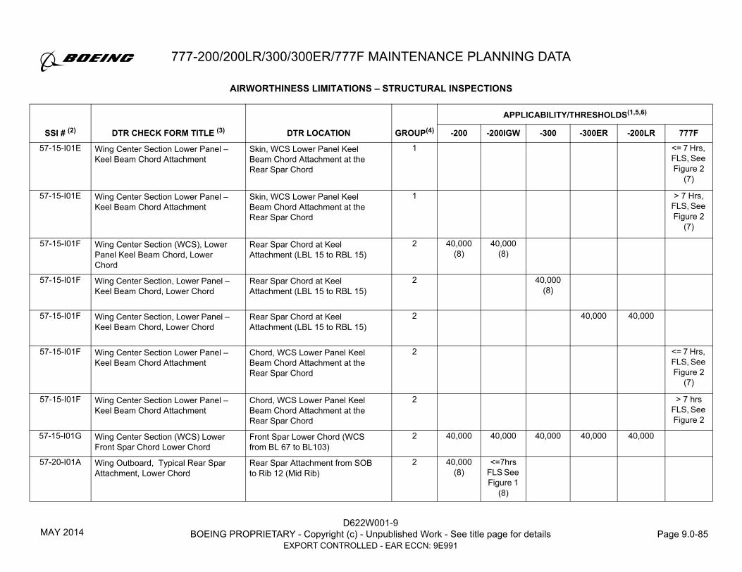
777-200/200LR/300/300ER/777F MAINTENANCE PLANNING DATA
D622W001-9BOEING PROPRIETARY - Copyright (c) - Unpublished Work - See title page for details Page 9.0-85
EXPORT CONTROLLED - EAR ECCN: 9E991
57-15-I01E Wing Center Section Lower Panel – Keel Beam Chord Attachment
Skin, WCS Lower Panel Keel Beam Chord Attachment at the Rear Spar Chord
1 <= 7 Hrs, FLS, See Figure 2
(7)
57-15-I01E Wing Center Section Lower Panel – Keel Beam Chord Attachment
Skin, WCS Lower Panel Keel Beam Chord Attachment at the Rear Spar Chord
1 > 7 Hrs, FLS, See Figure 2
(7)
57-15-I01F Wing Center Section (WCS), Lower Panel Keel Beam Chord, Lower Chord
Rear Spar Chord at Keel Attachment (LBL 15 to RBL 15)
2 40,000 (8)
40,000 (8)
57-15-I01F Wing Center Section, Lower Panel – Keel Beam Chord, Lower Chord
Rear Spar Chord at Keel Attachment (LBL 15 to RBL 15)
2 40,000 (8)
57-15-I01F Wing Center Section, Lower Panel – Keel Beam Chord, Lower Chord
Rear Spar Chord at Keel Attachment (LBL 15 to RBL 15)
2 40,000 40,000
57-15-I01F Wing Center Section Lower Panel – Keel Beam Chord Attachment
Chord, WCS Lower Panel Keel Beam Chord Attachment at the Rear Spar Chord
2 <= 7 Hrs, FLS, See Figure 2
(7)
57-15-I01F Wing Center Section Lower Panel – Keel Beam Chord Attachment
Chord, WCS Lower Panel Keel Beam Chord Attachment at the Rear Spar Chord
2 > 7 hrs FLS, See Figure 2
57-15-I01G Wing Center Section (WCS) Lower Front Spar Chord Lower Chord
Front Spar Lower Chord (WCS from BL 67 to BL103)
2 40,000 40,000 40,000 40,000 40,000
57-20-I01A Wing Outboard, Typical Rear Spar Attachment, Lower Chord
Rear Spar Attachment from SOB to Rib 12 (Mid Rib)
2 40,000 (8)
<=7hrs FLS See Figure 1
(8)
AIRWORTHINESS LIMITATIONS – STRUCTURAL INSPECTIONS
GROUP(4)
APPLICABILITY/THRESHOLDS(1,5,6)
SSI # (2) DTR CHECK FORM TITLE (3) DTR LOCATION -200 -200IGW -300 -300ER -200LR 777F
MAY 2014

D622W001-9BOEING PROPRIETARY - Copyright (c) - Unpublished Work - See title page for details Page 9.0-86
EXPORT CONTROLLED - EAR ECCN: 9E991
777-200/200LR/300/300ER/777F MAINTENANCE PLANNING DATA
57-20-I01A Wing Outboard, Typical Rear Spar Attachment, Lower Chord
Rear Spar Attachment from SOB to Rib 12 (Mid Rib)
2 >7hrs FLS See Figure 1
(8)57-20-I01A Wing Outboard, Typical Rear Spar
Attachment, Lower ChordRear Spar Attachment from SOB to Rib 12 (Mid Rib)
2 40,000 (8)
57-20-I01A Wing Outboard, Typical Rear Spar Attachment, Lower Chord
Rear Spar Attachment from SOB to Rib 15 (Mid Rib)
2 <= 7 Hrs, FLS, See Figure 1
(7)
<= 7 Hrs, FLS, See Figure 1
(7)
57-20-I01A Wing Outboard, Typical Rear Spar Attachment, Lower Chord
Rear Spar Attachment from SOB to Rib 15 (Mid Rib)
2 > 7 Hrs, FLS, See Figure 1
(7)
> 7 Hrs, FLS, See Figure 1
(7)
57-20-I01A Wing Outboard – Lower Panel Rear Spar Lower Chord
Chord, O/B Wing Lower Panel Rear Spar Chord from SOB to Rib 15 except at Ribpost locations
2 <= 7 Hrs, FLS, See Figure 2
(7)
57-20-I01A Wing Outboard – Lower Panel Rear Spar Lower Chord
Chord, O/B Wing Lower Panel Rear Spar Chord from SOB to Rib 15 except at Ribpost locations
2 > 7 Hrs, FLS, See Figure 2
(7)
57-20-I01B Wing Outboard, Typical Rear Spar Attachment, Lower Chord
Rear Spar Chord Attachment from Rib 15 to Wingtip (Mid Rib)
2 <= 7 Hrs, FLS, See Figure 1
<= 7 Hrs, FLS, See Figure 1
57-20-I01B Wing Outboard, Typical Rear Spar Attachment, Lower Chord
Rear Spar Chord Attachment from Rib 15 to Wingtip (Mid Rib)
2 > 7 Hrs, FLS, See Figure 1
(7)
> 7 Hrs, FLS, See Figure 1
(7)
AIRWORTHINESS LIMITATIONS – STRUCTURAL INSPECTIONS
GROUP(4)
APPLICABILITY/THRESHOLDS(1,5,6)
SSI # (2) DTR CHECK FORM TITLE (3) DTR LOCATION -200 -200IGW -300 -300ER -200LR 777F
MAY 2014

777-200/200LR/300/300ER/777F MAINTENANCE PLANNING DATA
D622W001-9BOEING PROPRIETARY - Copyright (c) - Unpublished Work - See title page for details Page 9.0-87
EXPORT CONTROLLED - EAR ECCN: 9E991
57-20-I01B Wing Outboard – Lower Panel Rear Spar Lower Chord
Chord, O/B Wing Lower Panel Rear Spar Chord from SOB to Rib 15 except at Ribpost locations
2 <= 7 Hrs, FLS, See Figure 2
57-20-I01B Wing Outboard – Lower Panel Rear Spar Lower Chord
Chord, O/B Wing Lower Panel Rear Spar Chord from SOB to Rib 15 except at Ribpost locations
2 > 7 Hrs, FLS, See Figure 2
(7)
57-20-I01C Wing Outboard, Typical Rear Spar Attachment, Lower Skin
Rear Spar Chord Attachment at Trailing Edge fairing locations
2 <= 7 Hrs, FLS, See Figure 1
(7)
<= 7 Hrs, FLS, See Figure 1
(7)
57-20-I01C Wing Outboard, Typical Rear Spar Attachment, Lower Skin
Rear Spar Chord Attachment at Trailing Edge fairing locations
2 > 7 Hrs, FLS, See Figure 1
(7)
> 7 Hrs, FLS, See Figure 1
(7)
57-20-I01C Wing Outboard – Lower Panel Rear Spar Lower Chord
Skin, O/B Wing Lower Panel Rear Spar Chord at the trailing edge fairing locations
2 <= 7 Hrs, FLS, See Figure 2
(7)
57-20-I01C Wing Outboard – Lower Panel Rear Spar Lower Chord
Skin, O/B Wing Lower Panel Rear Spar Chord at the trailing edge fairing locations
2 > 7 Hrs, FLS, See Figure 2
(7)
57-20-I01D Wing Outboard, Typical Splice Stringer
Stringer L10-L14 from SOB to Rib 36, L20 From Rib 8 to Rib 18
2 40,000 (8)
57-20-I01D Wing Outboard, Typical Splice Stringer
Stringer L10-L14 from SOB to Rib 36, L20 From Rib 8 to Rib 18
2 <= 7 Hrs, FLS, See
Figure 1
AIRWORTHINESS LIMITATIONS – STRUCTURAL INSPECTIONS
GROUP(4)
APPLICABILITY/THRESHOLDS(1,5,6)
SSI # (2) DTR CHECK FORM TITLE (3) DTR LOCATION -200 -200IGW -300 -300ER -200LR 777F
MAY 2014
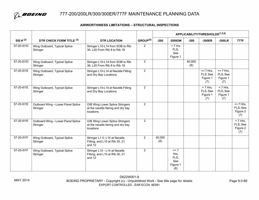
D622W001-9BOEING PROPRIETARY - Copyright (c) - Unpublished Work - See title page for details Page 9.0-88
EXPORT CONTROLLED - EAR ECCN: 9E991
777-200/200LR/300/300ER/777F MAINTENANCE PLANNING DATA
57-20-I01D Wing Outboard, Typical Splice Stringer
Stringer L10-L14 from SOB to Rib 36, L20 From Rib 8 to Rib 18
2 > 7 hrs FLS, See
Figure 157-20-I01D Wing Outboard, Typical Splice
StringerStringer L10-L14 from SOB to Rib 36, L20 From Rib 8 to Rib 18
2 40,000 (8)
57-20-I01E Wing Outboard, Typical Splice Stringer
Stringer L10-L14 at Nacelle Fitting and Dry Bay Locations
2 <= 7 Hrs, FLS, See Figure 1
(7)
<= 7 Hrs, FLS, See Figure 1
(7)
57-20-I01E Wing Outboard, Typical Splice Stringer
Stringer L10-L14 at Nacelle Fitting and Dry Bay Locations
2 > 7 Hrs, FLS, See Figure 1
(7)
> 7 Hrs, FLS, See Figure 1
(7)
57-20-I01E Outboard Wing – Lower Panel Splice Stringer
O/B Wing Lower Splice Stringers at the nacelle fairing and dry bay locations
2 <= 7 Hrs, FLS, See Figure 2
(7)
57-20-I01E Outboard Wing – Lower Panel Splice Stringer
O/B Wing Lower Splice Stringers at the nacelle fairing and dry bay locations
2 > 7 Hrs, FLS, See Figure 2
(7)
57-20-I01F Wing Outboard, Typical Splice Stringer
Stringer L1 0- L14 at Nacelle Fitting, and L10 at Rib 30, 21 and 12
2 40,000 (8)
57-20-I01F Wing Outboard, Typical Splice Stringer
Stringer L10 - L14 at Nacelle Fitting, and L10 at Rib 30, 21 and 12
2 <= 7 Hrs, FLS, See
Figure 1 (8)
AIRWORTHINESS LIMITATIONS – STRUCTURAL INSPECTIONS
GROUP(4)
APPLICABILITY/THRESHOLDS(1,5,6)
SSI # (2) DTR CHECK FORM TITLE (3) DTR LOCATION -200 -200IGW -300 -300ER -200LR 777F
MAY 2014

777-200/200LR/300/300ER/777F MAINTENANCE PLANNING DATA
D622W001-9BOEING PROPRIETARY - Copyright (c) - Unpublished Work - See title page for details Page 9.0-89
EXPORT CONTROLLED - EAR ECCN: 9E991
57-20-I01F Wing Outboard, Typical Splice Stringer
Stringer L10 - L14 at Nacelle Fitting, and L10 at Rib 30, 21 and 12
2 > 7 Hrs, FLS, See
Figure 1 (8)
57-20-I01G Wing Outboard, Lower Panel Rear Spar Chord, Lower Chord
Rear Spar Chord Attachment from SOB to Rib 12 at Rib Post
1 30,000 (8)
<= 7 Hrs, FLS, See
Figure 1 (8)
57-20-I01G Wing Outboard, Lower Panel Rear Spar Chord, Lower Chord
Rear Spar Chord Attachment from SOB to Rib 12 at Rib Post
1 > 7 Hrs, FLS, See
Figure 1 (8)
57-20-I01G Wing Outboard, Lower Panel Rear Spar Chord, Lower Chord
Rear Spar Chord Attachment from SOB to Rib 12 at Rib Post
1 30,000 (8)
57-20-I01G Wing Outboard, Lower Panel Rear Spar Chord, Lower Chord
Rear Spar Chord Attachment from SOB to Rib 15 at Rib Post
1 <= 7 Hrs, FLS, See Figure 1
(7)
<= 7 Hrs, FLS, See Figure 1
(7)
57-20-I01G Wing Outboard, Lower Panel Rear Spar Chord, Lower Chord
Rear Spar Chord Attachment from SOB to Rib 15 at Rib Post
1 > 7 Hrs, FLS, See Figure 1
(7)
> 7 Hrs, FLS, See Figure 1
(7)
57-20-I01G Wing Outboard, Lower Panel Rear Spar Lower Chord
O/B Wing Lower Panel Rear Spar Chord from Rib 15 to wingtip at all ribpost locations
1 <= 7 Hrs, FLS, See Figure 2
(7)
AIRWORTHINESS LIMITATIONS – STRUCTURAL INSPECTIONS
GROUP(4)
APPLICABILITY/THRESHOLDS(1,5,6)
SSI # (2) DTR CHECK FORM TITLE (3) DTR LOCATION -200 -200IGW -300 -300ER -200LR 777F
MAY 2014

D622W001-9BOEING PROPRIETARY - Copyright (c) - Unpublished Work - See title page for details Page 9.0-90
EXPORT CONTROLLED - EAR ECCN: 9E991
777-200/200LR/300/300ER/777F MAINTENANCE PLANNING DATA
57-20-I01G Wing Outboard, Lower Panel Rear Spar Lower Chord
O/B Wing Lower Panel Rear Spar Chord from Rib 15 to wingtip at all ribpost locations
1 > 7 Hrs, FLS, See Figure 2
(7)
57-20-I01H Wing Outboard, Lower Panel Rear Spar Chord, Lower Chord
Skin and Rear Spar Web Attachment from Rib 15 to Wingtip at Rib Post
1 <= 7 Hrs, FLS, See Figure 1
(7)
<= 7 Hrs, FLS, See Figure 1
(7)
57-20-I01H Wing Outboard, Lower Panel Rear Spar Chord, Lower Chord
Skin and Rear Spar Web Attachment from Rib 15 to Wingtip at Rib Post
1 > 7 Hrs, FLS, See Figure 1
(7)
> 7 Hrs, FLS, See Figure 1
(7)
57-20-I01H Wing Outboard, Lower Panel Front Spar Lower Chord
O/B Wing Lower Panel Front Spar Chord from Rib 15 to wingtip at all ribpost locations
1 18750 <= 7 Hrs
(7)
57-20-I01H Wing Outboard, Lower Panel Front Spar Lower Chord
O/B Wing Lower Panel Front Spar Chord from Rib 15 to wingtip at all ribpost locations
1 18750> 7 Hrs
(7)
57-20-I01J Wing Outboard, Lower Panel Front Spar Chord, Lower Chord
Skin to F/Spar Chord Attachment at Nacelle Fitting
1 30,000 (8)
30,000 (8)
57-20-I01J Wing Outboard, Lower Panel Front Spar Chord, Lower Chord
Skin to F/Spar Chord Attachment at Nacelle Fitting
1 30,000 (8)
57-20-I01J Wing Outboard, Lower Panel Front Spar Chord, Lower Chord
Skin to F/Spar Chord Attachment at Nacelle Fitting
1 <= 7 Hrs, FLS, See Figure 1
(7)
<= 7 Hrs, FLS, See Figure 1
(7)
57-20-I01J Wing Outboard, Lower Panel Front Spar Chord, Lower Chord
Skin to F/Spar Chord Attachment at Nacelle Fitting
1 > 7 Hrs, FLS, See Figure 1
(7)
> 7 Hrs, FLS, See Figure 1
(7)
AIRWORTHINESS LIMITATIONS – STRUCTURAL INSPECTIONS
GROUP(4)
APPLICABILITY/THRESHOLDS(1,5,6)
SSI # (2) DTR CHECK FORM TITLE (3) DTR LOCATION -200 -200IGW -300 -300ER -200LR 777F
MAY 2014

777-200/200LR/300/300ER/777F MAINTENANCE PLANNING DATA
D622W001-9BOEING PROPRIETARY - Copyright (c) - Unpublished Work - See title page for details Page 9.0-91
EXPORT CONTROLLED - EAR ECCN: 9E991
57-20-I01J Wing Outboard, Lower Panel Front Spar Lower Chord
Chord, O/B Wing Lower Panel Front Spar Chord at the nacelle fitting attachment locations
1 <= 7 Hrs, FLS, See Figure 2
(7)
57-20-I01J Wing Outboard, Lower Panel Front Spar Lower Chord
Chord, O/B Wing Lower Panel Front Spar Chord at the nacelle fitting attachment locations
1 > 7 Hrs, FLS, See Figure 2
(7)
57-20-I01K Wing Outboard, Lower Panel Front Spar Chord, Lower Skin
Skin to F/Spar Chord Attachment at Nacelle Fitting
1 <= 7 Hrs, FLS, See Figure 1
(7)
<= 7 Hrs, FLS, See Figure 1
(7)
57-20-I01K Wing Outboard, Lower Panel Front Spar Chord, Lower Skin
Skin to F/Spar Chord Attachment at Nacelle Fitting
1 > 7 Hrs, FLS, See Figure 1
(7)
> 7 Hrs, FLS, See Figure 1
(7)
57-20-I01K Wing Outboard, Lower Panel Front Spar Lower Chord
Skin, O/B Wing Lower Panel Front Spar Chord at the nacelle fitting attachment locations
1 <= 7 Hrs, FLS, See Figure 2
(7)
57-20-I01K Wing Outboard, Lower Panel Front Spar Lower Chord
Skin, O/B Wing Lower Panel Front Spar Chord at the nacelle fitting attachment locations
1 > 7 Hrs, FLS, See Figure 2
(7)
57-20-I01L1 Wing Outboard, Lower Panel Front Spar Chord, Lower Chord
Skin to F/Spar Chord Attachment from SOB to Wingtip except between Rib 30 to 44 and at Nacelle Fitting and Rib Post
2 <= 7 Hrs, FLS, See Figure 1
<= 7 Hrs, FLS, See Figure 1
AIRWORTHINESS LIMITATIONS – STRUCTURAL INSPECTIONS
GROUP(4)
APPLICABILITY/THRESHOLDS(1,5,6)
SSI # (2) DTR CHECK FORM TITLE (3) DTR LOCATION -200 -200IGW -300 -300ER -200LR 777F
MAY 2014

D622W001-9BOEING PROPRIETARY - Copyright (c) - Unpublished Work - See title page for details Page 9.0-92
EXPORT CONTROLLED - EAR ECCN: 9E991
777-200/200LR/300/300ER/777F MAINTENANCE PLANNING DATA
57-20-I01L2 Wing Outboard, Lower Panel Front Spar Chord, Lower Chord
Skin to F/Spar Chord Attachment from Rib 30 to Rib 44, except at Rib Post
2 <= 7 Hrs, FLS, See Figure 1
(7)
<= 7 Hrs, FLS, See Figure 1
(7)
57-20-I01L Wing Outboard, Lower Panel Front Spar Chord, Lower Chord
Skin to F/Spar Chord Attachment from SOB to Wingtip except at Nacelle Fitting Attachment and Rib Post
2 > 7 Hrs, FLS, See Figure 1
(7)
> 7 Hrs, FLS, See Figure 1
(7)
57-20-I01L Wing Outboard, Lower Panel Front Spar Lower Chord
Chord, O/B Wing Lower Panel Front Spar Chord from SOB to Wingtip except at ribpost locations
2 <= 7 Hrs, FLS, See Figure 2
57-20-I01L Wing Outboard, Lower Panel Front Spar Lower Chord
Chord, O/B Wing Lower Panel Front Spar Chord from SOB to Wingtip except at ribpost locations
2 > 7 Hrs, FLS, See Figure 2
(7)
57-20-I01M Wing Outboard, Lower Panel Front Spar Chord, Lower Chord
Skin to F/Spar Chord Attachment from SOB to Wingtip at all Rib Post
1 <= 7 Hrs, FLS, See Figure 1
(7)
<= 7 Hrs, FLS, See Figure 1
(7)
57-20-I01M Wing Outboard, Lower Panel Front Spar Chord, Lower Chord
Skin to F/Spar Chord Attachment from SOB to Wingtip at all Rib Post
1 > 7 Hrs, FLS, See Figure 1
(7)
> 7 Hrs, FLS, See Figure 1
(7)
57-20-I01M Wing Outboard, Lower Panel Front Spar Lower Chord
Chord, O/B Wing Lower Panel Front Spar Chord from SOB to Wingtip at all ribpost locations
1 <= 7 Hrs, FLS, See Figure 2
(7)
AIRWORTHINESS LIMITATIONS – STRUCTURAL INSPECTIONS
GROUP(4)
APPLICABILITY/THRESHOLDS(1,5,6)
SSI # (2) DTR CHECK FORM TITLE (3) DTR LOCATION -200 -200IGW -300 -300ER -200LR 777F
MAY 2014

777-200/200LR/300/300ER/777F MAINTENANCE PLANNING DATA
D622W001-9BOEING PROPRIETARY - Copyright (c) - Unpublished Work - See title page for details Page 9.0-93
EXPORT CONTROLLED - EAR ECCN: 9E991
57-20-I01M Wing Outboard, Lower Panel Front Spar Lower Chord
Chord, O/B Wing Lower Panel Front Spar Chord from SOB to Wingtip at all ribpost locations
1 > 7 Hrs, FLS, See Figure 2
(7)
57-20-I01N Wing Outboard, MLG Beam Support Fitting, Mid Rib, Lower Skin
Wing Skin Tab-Out btwn Ribs 11 and 12 at MLG Beam Support Fitting
2 40,000 (8)
40,000 (8)
57-20-I01N Wing Outboard, MLG Beam Support Fitting, Mid Rib, Lower Skin
Wing Skin Tab-Out btwn Ribs 11 and 12 at MLG Beam Support Fitting
2 40,000 (8)
57-20-I01N Wing Outboard, MLG Beam Support Fitting, Mid Rib, Lower Skin
Wing Skin Tab-Out btwn Ribs 11 and 12 at MLG Beam Support Fitting
2 <= 7 Hrs, FLS, See Figure 1
(7)
<= 7 Hrs, FLS, See Figure 1
(7)
57-20-I01N Wing Outboard, MLG Beam Support Fitting, Mid Rib, Lower Skin
Wing Skin Tab-Out btwn Ribs 11 and 12 at MLG Beam Support Fitting
2 > 7 Hrs, FLS, See Figure 1
(7)
> 7 Hrs, FLS, See Figure 1
(7)
57-20-I01N Lower Panel – MLG Beam Outboard Support Fitting Attachment
All fastener locations common to the O/B Wing Lower Panel Skin tab and the MLG Beam Outboard Support Fitting
2 <= 7 Hrs, FLS, See Figure 2
(7)
57-20-I01N Lower Panel – MLG Beam Outboard Support Fitting Attachment
All fastener locations common to the O/B Wing Lower Panel Skin tab and the MLG Beam Outboard Support Fitting
2 > 7 Hrs, FLS, See Figure 2
(7)
AIRWORTHINESS LIMITATIONS – STRUCTURAL INSPECTIONS
GROUP(4)
APPLICABILITY/THRESHOLDS(1,5,6)
SSI # (2) DTR CHECK FORM TITLE (3) DTR LOCATION -200 -200IGW -300 -300ER -200LR 777F
MAY 2014

D622W001-9BOEING PROPRIETARY - Copyright (c) - Unpublished Work - See title page for details Page 9.0-94
EXPORT CONTROLLED - EAR ECCN: 9E991
777-200/200LR/300/300ER/777F MAINTENANCE PLANNING DATA
57-20-I01P Wing Outboard, Typical Stringer Attachment at Nacelle FTG
Typical stringers at Nacelle Fitting locations
2 40,000 (8)
<= 7 Hrs, FLS, See
Figure 1 (8)
57-20-I01P Wing Outboard, Typical Stringer Attachment at Nacelle FTG
Typical stringers at Nacelle Fitting locations
2 > 7 Hrs, FLS, See
Figure 1 (8)
57-20-I01P Wing Outboard, Typical Stringer Attachment at Nacelle FTG
Typical stringers at Nacelle Fitting locations
2 40,000 (7)
57-20-I01P Wing Outboard, Typical Stringer Attachment at Nacelle FTG
Typical stringers at Nacelle Fitting locations
2 <= 7 Hrs, FLS, See Figure 1
(7)
<= 7 Hrs, FLS, See Figure 1
(7)
57-20-I01P Wing Outboard, Typical Stringer Attachment at Nacelle FTG
Typical stringers at Nacelle Fitting locations
2 > 7 Hrs, FLS, See Figure 1
(7)
> 7 Hrs, FLS, See Figure 1
(7)
57-20-I01P Outboard Wing – Lower Panel Typical Skin-Stringer Attachment
O/B Wing Lower Panel Typical Stringers at Nacelle Fairing Location
2 <= 7 Hrs, FLS, See Figure 2
(7)
57-20-I01P Outboard Wing – Lower Panel Typical Skin-Stringer Attachment
O/B Wing Lower Panel Typical Stringers at Nacelle Fairing Location
2 > 7 Hrs, FLS, See Figure 2
(7)
AIRWORTHINESS LIMITATIONS – STRUCTURAL INSPECTIONS
GROUP(4)
APPLICABILITY/THRESHOLDS(1,5,6)
SSI # (2) DTR CHECK FORM TITLE (3) DTR LOCATION -200 -200IGW -300 -300ER -200LR 777F
MAY 2014

777-200/200LR/300/300ER/777F MAINTENANCE PLANNING DATA
D622W001-9BOEING PROPRIETARY - Copyright (c) - Unpublished Work - See title page for details Page 9.0-95
EXPORT CONTROLLED - EAR ECCN: 9E991
57-20-I01Q Wing Outboard, Typical Rail Stringer at Access Door
Typical Rail Stringers at Access door from SOB to Wingtip except at Nacelle Fairing
2 40,000
57-20-I01Q Wing Outboard, Typical Rail Stringer at Access Door
Typical Rail Stringers at Access door from SOB to Wingtip except at Nacelle Fairing
2 > 7 hrs FLS, See Figure 1
> 7 hrs FLS, See Figure 1
57-20-I01Q Outboard Wing – Lower Panel Typical Attachment at Access Door/Hole
Stringer, O/B Wing Lower Panel Rail Stringer from SOB to Wingtip except at the nacelle fairing
2 <= 7 Hrs, FLS, See Figure 2
(7)
57-20-I01Q Outboard Wing – Lower Panel Typical Attachment at Access Door/Hole
Stringer, O/B Wing Lower Panel Rail Stringer from SOB to Wingtip except at the nacelle fairing
2 > 7 hrs FLS, See Figure 2
57-20-I01R Wing Outboard, Typical Rail Stringer at Access Door
Typical Rail Stringers at Access door at Nacelle Fairing
2 <= 7 Hrs, FLS, See Figure 1
(7)
<= 7 Hrs, FLS, See Figure 1
(7)
57-20-I01R Wing Outboard, Typical Rail Stringer at Access Door
Typical Rail Stringers at Access door at Nacelle Fairing
2 > 7 Hrs, FLS, See Figure 1
(7)
> 7 Hrs, FLS, See Figure 1
(7)
57-20-I01R Outboard Wing – Lower Panel Typical Attachment at Access Door/Hole
Stringer, O/B Wing Lower Panel Rail Stringer at the Nacelle Fairing
2 <= 7 Hrs, FLS, See Figure 2
(7)
57-20-I01R Outboard Wing – Lower Panel Typical Attachment at Access Door/Hole
Stringer, O/B Wing Lower Panel Rail Stringer at the Nacelle Fairing
2 > 7 Hrs, FLS, See Figure 2
(7)
AIRWORTHINESS LIMITATIONS – STRUCTURAL INSPECTIONS
GROUP(4)
APPLICABILITY/THRESHOLDS(1,5,6)
SSI # (2) DTR CHECK FORM TITLE (3) DTR LOCATION -200 -200IGW -300 -300ER -200LR 777F
MAY 2014

D622W001-9BOEING PROPRIETARY - Copyright (c) - Unpublished Work - See title page for details Page 9.0-96
EXPORT CONTROLLED - EAR ECCN: 9E991
777-200/200LR/300/300ER/777F MAINTENANCE PLANNING DATA
57-20-I01S Outboard Wing – Lower Panel Splice at Rib 46
Fastener locations (inboard and outboard of Rib 46) common to the Lower Rib Chord and Lower Rear Spar Chord
2 <= 7 Hrs, FLS, See Figure 1
(7)
<= 7 Hrs, FLS, See Figure 1
(7)
<= 7 Hrs, FLS, See Figure 2
(7)
57-20-I01S Outboard Wing – Lower Panel Splice at Rib 46
Fastener locations (inboard and outboard of Rib 46) common to the Lower Rib Chord and Lower Rear Spar Chord
2 > 7 Hrs, FLS, See Figure 1
(7)
> 7 Hrs, FLS, See Figure 1
(7)
> 7 Hrs, FLS, See Figure 2
(7)
57-20-I01T Outboard Wing – Lower Panel Splice at Rib 46
Fastener locations (inboard and outboard of Rib 46) common to the Lower Rib Chord and Paddle Fittings
1 <= 7 Hrs, FLS, See Figure 1
(7)
<= 7 Hrs, FLS, See Figure 1
(7)
<= 7 Hrs, FLS, See Figure 2
(7)
57-20-I01T Outboard Wing – Lower Panel Splice at Rib 46
Fastener locations (inboard and outboard of Rib 46) common to the Lower Rib Chord and Paddle Fittings
1 > 7 Hrs, FLS, See Figure 1
(7)
> 7 Hrs, FLS, See Figure 1
(7)
> 7 Hrs, FLS, See Figure 2
(7)
57-20-I02A Wing Outboard, Upper Panel, MLG Beam Support Fitting, Upper Skin
Fastener locations C/T Upper Panel Skin Tab and MLG Beam SPRT FTG
2 40,000 (8)
40,000 (8)
40,000 (8)
57-20-I02A Wing Outboard, Upper Panel, MLG Beam Support Fitting, Upper Skin
Fastener locations C/T Upper Panel Skin Tab and MLG Beam SPRT FTG
2 40,000 (7)
40,000 (7)
57-20-I02A Upper Panel – MLG Beam Outboard Support Fitting Attachment
Fastener locations common to the O/B Wing Upper panel Skin Tab and the MLG Beam Outboard Support Fitting
2 <= 7 Hrs, FLS, See Figure 2
(7)
57-20-I02A Upper Panel – MLG Beam Outboard Support Fitting Attachment
Fastener locations common to the O/B Wing Upper panel Skin Tab and the MLG Beam Outboard Support Fitting
2 > 7 Hrs, FLS, See Figure 2
(7)
AIRWORTHINESS LIMITATIONS – STRUCTURAL INSPECTIONS
GROUP(4)
APPLICABILITY/THRESHOLDS(1,5,6)
SSI # (2) DTR CHECK FORM TITLE (3) DTR LOCATION -200 -200IGW -300 -300ER -200LR 777F
MAY 2014

777-200/200LR/300/300ER/777F MAINTENANCE PLANNING DATA
D622W001-9BOEING PROPRIETARY - Copyright (c) - Unpublished Work - See title page for details Page 9.0-97
EXPORT CONTROLLED - EAR ECCN: 9E991
57-20-I02B Wing Outboard, Upper Panel, Front Spar Upper Chord
F/Spar Upper Chord from Rib 8 to Rib 11 (MidRib)
2 40,000 <= 7 Hrs, FLS, See
Figure 1
40,000
57-20-I02B Wing Outboard, Upper Panel, Front Spar Upper Chord
F/Spar Upper chords from SOB to Wingtip (MidRib)
2 > 7 Hrs, FLS, See
Figure 1
57-20-I02B Wing Outboard, Upper Panel, Front Spar Upper Chord
F/Spar Upper Chord from Rib 7 to Rib 11 (MidRib)
2 <= 7 Hrs, FLS, See Figure 1
<= 7 Hrs, FLS, See Figure 1
57-20-I02B Wing Outboard, Upper Panel, Front Spar Upper Chord
F/Spar Upper chords from SOB to Wingtip at Mid Rib except at F/Spar Splice between Rib 43 and Rib 44
2 > 7 Hrs, FLS, See Figure 1
(7)
> 7 Hrs, FLS, See Figure 1
(7)
57-20-I02B Wing Outboard – Upper Panel, Front Spar Upper Chord
O/B Wing Upper Panel Front Spar Chord from SOB to Wingtip except at Ribpost locations
2 > 7 Hrs, FLS, See Figure 2
(7)
57-20-I02C Wing Outboard, Upper Panel, Front Spar Upper Chord
Front Spar Upper chords from SOB to Wingtip at Rib Post Location
1 <= 7 Hrs, FLS, See Figure 1
(7)
<= 7 Hrs, FLS, See Figure 1
(7)
57-20-I02C Wing Outboard, Upper Panel, Front Spar Upper Chord
Front Spar Upper chords from SOB to Wingtip at Rib Post Location
1 > 7 Hrs, FLS, See Figure 1
(7)
> 7 Hrs, FLS, See Figure 1
(7)
AIRWORTHINESS LIMITATIONS – STRUCTURAL INSPECTIONS
GROUP(4)
APPLICABILITY/THRESHOLDS(1,5,6)
SSI # (2) DTR CHECK FORM TITLE (3) DTR LOCATION -200 -200IGW -300 -300ER -200LR 777F
MAY 2014

D622W001-9BOEING PROPRIETARY - Copyright (c) - Unpublished Work - See title page for details Page 9.0-98
EXPORT CONTROLLED - EAR ECCN: 9E991
777-200/200LR/300/300ER/777F MAINTENANCE PLANNING DATA
57-20-I02C Wing Outboard, Upper Panel, Front Spar Upper Chord
O/B Wing Upper Panel Front Spar Chord from SOB to Wingtip at all Ribpost Locations
1 <= 7 Hrs, FLS, See Figure 2
(7)
57-20-I02C Wing Outboard, Upper Panel, Front Spar Upper Chord
O/B Wing Upper Panel Front Spar Chord from SOB to Wingtip at all Ribpost Locations
1 > 7 Hrs, FLS, See Figure 2
(7)
57-20-I02D Wing Outboard, Upper Panel, Rear Spar Upper Chord
Rear Spar Upper Chord from SOB to Wingtip at Rib Post Location
1 30,000
57-20-I02D Wing Outboard, Upper Panel, Rear Spar Upper Chord
Rear Spar Upper Chord from SOB to Wingtip at Rib Post Location
1 <= 7 Hrs, FLS, See
Figure 1 (8)
57-20-I02D Wing Outboard, Upper Panel, Rear Spar Upper Chord
Rear Spar Upper Chord from SOB to Wingtip at Rib Post Location
1 > 7 Hrs, FLS, See
Figure 1 (8)
57-20-I02D Wing Outboard, Upper Panel, Rear Spar Upper Chord
Rear Spar Upper Chord from SOB to Wingtip at Rib Post Location
1 30,000 (8)
57-20-I02D Wing Outboard, Upper Panel, Rear Spar Upper Chord
Rear Spar Upper Chord from SOB to Wingtip at Rib Post Location
1 <= 7 Hrs, FLS, See Figure 1
(7)
<= 7 Hrs, FLS, See Figure 1
(7)
AIRWORTHINESS LIMITATIONS – STRUCTURAL INSPECTIONS
GROUP(4)
APPLICABILITY/THRESHOLDS(1,5,6)
SSI # (2) DTR CHECK FORM TITLE (3) DTR LOCATION -200 -200IGW -300 -300ER -200LR 777F
JUL 2017

D622W001-9BOEING PROPRIETARY - Copyright (c) - Unpublished Work - See title page for details Page 9.0-99
EXPORT CONTROLLED - EAR ECCN: 9E991
777-200/200LR/300/300ER/777F MAINTENANCE PLANNING DATA
57-20-I02D Wing Outboard, Upper Panel, Rear Spar Upper Chord
Rear Spar Upper Chord from SOB to Wingtip at Rib Post Location
1 > 7 Hrs, FLS, See Figure 1
(7)
> 7 Hrs, FLS, See Figure 1
(7)
57-20-I02D Wing Outboard, Upper Panel, Rear Spar Upper Chord
O/B Wing Upper Panel Rear Spar Chord from SOB to Wingtip at all Ribpost Locations
1 <= 7 Hrs, FLS, See Figure 2
(7)
57-20-I02D Wing Outboard, Upper Panel, Rear Spar Upper Chord
O/B Wing Upper Panel Rear Spar Chord from SOB to Wingtip at all Ribpost Locations
1 > 7 Hrs, FLS, See Figure 2
(7)
57-20-I02E Wing Outboard, Upper Panel, Rear Spar Upper Chord, Upper Skin
Rear Spar Upper Chord from Rib 8 to Rib 12
2 > 7 Hrs, FLS, See Figure 1
(7)
> 7 Hrs, FLS, See Figure 1
(7)
57-20-I02E Wing Outboard, Upper Panel, Rear Spar Upper Chord
O/B Wing Upper Panel Rear Spar Chord from Rib 8 to Rib 12 only
2 <= 7 Hrs, FLS, See Figure 2
57-20-I02E Wing Outboard, Upper Panel, Rear Spar Upper Chord
O/B Wing Upper Panel Rear Spar Chord from Rib 8 to Rib 12 only
2 > 7 Hrs, FLS, See Figure 2
(7)
57-20-I02F Wing Outboard, Upper Panel, Rear Spar Upper Chord
Rear Spar Upper Chord from Rib 8 to Rib 11 (Mid Rib)
2 40,000 <= 7 Hrs, FLS, See
Figure 1
40,000
AIRWORTHINESS LIMITATIONS – STRUCTURAL INSPECTIONS
GROUP(4)
APPLICABILITY/THRESHOLDS(1,5,6)
SSI # (2) DTR CHECK FORM TITLE (3) DTR LOCATION -200 -200IGW -300 -300ER -200LR 777F
MAY 2014

D622W001-9BOEING PROPRIETARY - Copyright (c) - Unpublished Work - See title page for details Page 9.0-100
EXPORT CONTROLLED - EAR ECCN: 9E991
777-200/200LR/300/300ER/777F MAINTENANCE PLANNING DATA
57-20-I02F Wing Outboard, Upper Panel, Rear Spar Upper Chord
Rear Spar Upper Chord from SOB to Wingtip (Mid Rib)
2 > 7 Hrs, FLS, See
Figure 1 57-20-I02F Wing Outboard, Upper Panel, Rear
Spar Upper ChordRear Spar Upper Chord from Rib 7 to Rib 11 (Mid Rib)
2 <= 7 Hrs, FLS, See Figure 1
<= 7 Hrs, FLS, See Figure 1
57-20-I02F Wing Outboard, Upper Panel, Rear Spar Upper Chord
Rear Spar Upper Chord from SOB to Wingtip (Mid Rib)
2 > 7 Hrs, FLS, See Figure 1
(7)
> 7 Hrs, FLS, See Figure 1
(7)
57-20-I02F Wing Outboard, Upper Panel, Rear Spar Upper Chord
O/B Wing Upper Panel Rear Spar Chord from SOB to Wingtip except at Ribpost
2 <= 7 Hrs, FLS, See Figure 2
(7)
57-20-I02F Wing Outboard, Upper Panel, Rear Spar Upper Chord
O/B Wing Upper Panel Rear Spar Chord from SOB to wingtip except at Ribpost
2 > 7 Hrs, FLS, See Figure 2
(7)
57-20-I02G Wing Outboard, Upper Skin Tab Upper Skin Tab at fastener locations C/T Skin and R1 Fitting
2 40,000 40,000 40,000
57-20-I02H Wing Outboard, Upper Skin Nacelle Attachment Tab
Upper Skin Tab at fastener locations C/T Skin and F/Spar Chord
2 40,000 (7)
40,000 (7)
57-20-I02H Upper Panel – Nacelle Attachment Tab
Fastener locations common to the O/B Wing Upper Panel Skin and Front Spar Upper Chord
2 <= 7 Hrs, FLS, See Figure 2
(7)
AIRWORTHINESS LIMITATIONS – STRUCTURAL INSPECTIONS
GROUP(4)
APPLICABILITY/THRESHOLDS(1,5,6)
SSI # (2) DTR CHECK FORM TITLE (3) DTR LOCATION -200 -200IGW -300 -300ER -200LR 777F
MAY 2014

D622W001-9BOEING PROPRIETARY - Copyright (c) - Unpublished Work - See title page for details Page 9.0-101
EXPORT CONTROLLED - EAR ECCN: 9E991
777-200/200LR/300/300ER/777F MAINTENANCE PLANNING DATA
57-20-I02H Upper Panel – Nacelle Attachment Tab
Fastener locations common to the O/B Wing Upper Panel Skin and Front Spar Upper Chord
2 > 7 Hrs, FLS, See Figure 2
(7)
57-20-I02J Wing Outboard, Upper Panel, Typical Splice Stringer
Upper Panel Splice Stringers @ U-10, U24 from Rib 3 to Rib 15
2 40,000 40,000 40,000 40,000 40,000
57-20-I03A Wing Outboard, Rear Spar Web at FWD Trunnion Fitting
All Fastener locations C/T Rear Spar Chords and FWD Trunnion SPRT Fitting btwn Ribs 7 and 8
1 30,000 (8)
30,000 (8)
57-20-I03A Wing Outboard, Rear Spar Web at FWD Trunnion Fitting
All Fastener locations C/T Rear Spar Chords and FWD Trunnion SPRT Fitting btwn Ribs 7 and 8
1 30,000 (8)
57-20-I03A Wing Outboard, Rear Spar Web at FWD Trunnion Fitting
All Fastener locations C/T Rear Spar Chords and FWD Trunnion SPRT Fitting btwn Ribs 7 and 8
1 <= 7 Hrs, FLS, See Figure 1
(7)
<= 7 Hrs, FLS, See Figure 1
(7)
57-20-I03A Wing Outboard, Rear Spar Web at FWD Trunnion Fitting
All Fastener locations C/T Rear Spar Chords and FWD Trunnion SPRT Fitting btwn Ribs 7 and 8
1 > 7 Hrs, FLS, See Figure 1
(7)
> 7 Hrs, FLS, See Figure 1
(7)
57-20-I03A Rear Spar Web at Fwd Trunnion Support Fitting attachment
Fasteners at the Lower Rear Spar Chord and the Upper Rear Spar Chord common to the Rear Spar Web between Ribs 7 and 8
1 <= 7 Hrs, FLS, See Figure 2
(7)
57-20-I03A Rear Spar Web at Fwd Trunnion Support Fitting attachment
Fasteners at the Lower Rear Spar Chord and the Upper Rear Spar Chord common to the Rear Spar Web between Ribs 7 and 8
1 > 7 Hrs, FLS, See Figure 2
(7)
AIRWORTHINESS LIMITATIONS – STRUCTURAL INSPECTIONS
GROUP(4)
APPLICABILITY/THRESHOLDS(1,5,6)
SSI # (2) DTR CHECK FORM TITLE (3) DTR LOCATION -200 -200IGW -300 -300ER -200LR 777F
JUL 2017

D622W001-9BOEING PROPRIETARY - Copyright (c) - Unpublished Work - See title page for details Page 9.0-102
EXPORT CONTROLLED - EAR ECCN: 9E991
777-200/200LR/300/300ER/777F MAINTENANCE PLANNING DATA
57-20-I04A Outboard Wing – Front Spar Splice between Ribs 43 and 44
Front Spar Splice between Ribs 43 and 44
1 <= 7 Hrs, FLS, See Figure 1
(7)
<= 7 Hrs, FLS, See Figure 1
(7)
<= 7 Hrs, FLS, See Figure 2
(7)
57-20-I04A Outboard Wing – Front Spar Splice between Ribs 43 and 44
Front Spar Splice between Ribs 43 and 44
1 > 7 Hrs, FLS, See Figure 1
(7)
> 7 Hrs, FLS, See Figure 1
(7)
> 7 Hrs, FLS, See Figure 2
(7)
57-20-I06A Wing Box Flap Support FTG, Shear Tie Ribs
All Fastener locations C/T Flap Support Back-up Fittings and Shear Tie Ribs 12, 21, 30
2 40,000 40,000
57-20-I06A Wing Box Flap Support Fitting at Shear Tie Rib #30
Fastener locations common to the Flap Support Back-up Fittings and Shear Tied Ribs
2 <= 7 Hrs, FLS, See Figure 2
57-20-I06A Wing Box Flap Support Fitting at Shear Tie Rib #30
Fastener locations common to the Flap Support Back-up Fittings and Shear Tied Ribs
2 > 7 hrs FLS, See Figure 2
57-20-I11 112W5093 Back-up Fitting Typical Rib #9
Wing Station 414.5 2 25,000
57-30-I01A Lower Panel- Wing Tip Splice at Rib 50
Tension Bolts at Rear Spar 1 30,000 30,000 18,750
57-30-I01B Lower Panel- Wing Tip Splice at Rib 50
Tension Bolts at Front Spar 1 30,000 30,000 18,750
57-30-I01C Lower Panel- Wing Tip Splice at Rib 50
Fitting Pad at Front Spar 1 30,000 (7)
30,000 (7)
18,750 (7)
57-30-I01D Lower Panel- Wing Tip Splice at Rib 50
Lower Skin Attachment at Rear Spar
2 40,000 (7)
40,000 (7)
25,000 (7)
57-53-I07A Inboard Main Flap Outboard Closeout Rib
Aft Access Hole 2 40,000 (8)
40,000 (8)
AIRWORTHINESS LIMITATIONS – STRUCTURAL INSPECTIONS
GROUP(4)
APPLICABILITY/THRESHOLDS(1,5,6)
SSI # (2) DTR CHECK FORM TITLE (3) DTR LOCATION -200 -200IGW -300 -300ER -200LR 777F
MAY 2014

777-200/200LR/300/300ER/777F MAINTENANCE PLANNING DATA
D622W001-9BOEING PROPRIETARY - Copyright (c) - Unpublished Work - See title page for details Page 9.0-103
EXPORT CONTROLLED - EAR ECCN: 9E991
57-53-I07A Inboard Main Flap Outboard Closeout Rib
Aft Access Hole 2 40,000 (8)
57-53-I07A Inboard Main Flap Outboard Closeout Rib
Aft Access Hole 2 40,000 (7)
40,000 (7)
57-53-I07A Inboard Main Flap Outboard Closeout Rib
Aft Access Hole 2 25,000 (7)
57-53-I07B Inboard Main Flap Outboard Ribs Aft Carrier Beam Attachments 2 40,000 (8)
40,000 (8)
40,000 (8)
57-53-I07B Inboard Main Flap Outboard Ribs Aft Carrier Beam Attachments 2 25,000
57-53-I10 Inboard Main Flap Torque Tube Cross-section just Outboard of Closeout Rib Splines
1 30,000 30,000 30,000 30,000 30,000
57-53-I10 Inboard Main Flap Torque Tube Cross-section just Outboard of Closeout Rib Splines
1 18,750 (7)
57-53-I11A Inboard Main Flap Inboard Closeout Rib
Section thru Lower Chord at Forward Track Support
1 30,000 (8)
57-53-I11A Inboard Main Flap Inboard Closeout Rib
Section thru Lower Chord at Forward Track Support
1 30,000 (8)
57-53-I11A Inboard Main Flap Inboard Closeout Rib
Section thru Lower Chord at Forward Track Support
1 30,000 (8)
57-53-I11A Inboard Main Flap Inboard Closeout Rib
Section thru Lower Chord at Forward Track Support
1 30,000 (7)
30,000 (7)
57-53-I11A Inboard Main Flap Inboard Closeout Rib
Section thru Lower Chord at Forward Track Support
1 18,750 (7)
57-53-I11B Inboard Main Flap Inboard Closeout Rib
Section through Torque Tube Access Hole
1 30,000 (8)
57-53-I11B Inboard Main Flap Inboard Closeout Rib
Section through Torque Tube Access Hole
1 30,000 (8)
AIRWORTHINESS LIMITATIONS – STRUCTURAL INSPECTIONS
GROUP(4)
APPLICABILITY/THRESHOLDS(1,5,6)
SSI # (2) DTR CHECK FORM TITLE (3) DTR LOCATION -200 -200IGW -300 -300ER -200LR 777F
MAY 2014

D622W001-9BOEING PROPRIETARY - Copyright (c) - Unpublished Work - See title page for details Page 9.0-104
EXPORT CONTROLLED - EAR ECCN: 9E991
777-200/200LR/300/300ER/777F MAINTENANCE PLANNING DATA
57-53-I11B Inboard Main Flap Inboard Closeout Rib
Section through Torque Tube Access Hole
1 30,000 (8)
57-53-I11B Inboard Main Flap Inboard Closeout Rib
Section through Torque Tube Access Hole
1 30,000 (7)
30,000 (7)
57-53-I11B Inboard Main Flap Inboard Closeout Rib
Section through Torque Tube Access Hole
1 18,750 (7)
57-53-I11C Inboard Main Flap Inboard Closeout Rib Fitting
Spline Region 1 30,000 30,000 30,000 30,000 30,000
57-53-I11C Inboard Main Flap Inboard Closeout Rib Fitting
Spline Region 1 18,750
57-53-I16A No. 3 (and No. 6) Inboard Flap Support Underwing Fitting
Lugs, Outer Lug 1 30,000 (8)
57-53-I16A No. 3 (and No. 6) Inboard Flap Support Underwing Fitting
Lugs, Outer Lug 1 30,000 (8)
57-53-I16A No. 3 (and No. 6) Inboard Flap Support Underwing Fitting
Lugs, Outer Lug 1 30,000 (8)
57-53-I16A No. 3 (and No. 6) Inboard Flap Support Underwing Fitting
Lugs, Outer Lug 1 30,000 (7)
30,000 (7)
18,750 (7)
57-53-I16B No. 3 (and No. 6) Inboard Flap Support Underwing Fitting
Lugs, Inner Lug 1 30,000 (8)
57-53-I16B No. 3 (and No. 6) Inboard Flap Support Underwing Fitting
Lugs, Inner Lug 1 30,000 (8)
57-53-I16B No. 3 (and No. 6) Inboard Flap Support Underwing Fitting
Lugs, Inner Lug 1 30,000 (8)
57-53-I16C No. 3 (and No. 6) Inboard Flap Support Underwing Fitting
Section at Aft Main Attach Bolt (Section C-C)
1 30,000 (8)
57-53-I16C No. 3 (and No. 6) Inboard Flap Support Underwing Fitting
Section at Aft Main Attach Bolt (Section C-C)
1 30,000 (8)
AIRWORTHINESS LIMITATIONS – STRUCTURAL INSPECTIONS
GROUP(4)
APPLICABILITY/THRESHOLDS(1,5,6)
SSI # (2) DTR CHECK FORM TITLE (3) DTR LOCATION -200 -200IGW -300 -300ER -200LR 777F
MAY 2014

777-200/200LR/300/300ER/777F MAINTENANCE PLANNING DATA
D622W001-9BOEING PROPRIETARY - Copyright (c) - Unpublished Work - See title page for details Page 9.0-105
EXPORT CONTROLLED - EAR ECCN: 9E991
57-53-I16C No. 3 (and No. 6) Inboard Flap Support Underwing Fitting
Section at Aft Main Attach Bolt (Section C-C)
1 30,000 (8)
57-53-I16C No. 3 (and No. 6) Inboard Flap Support Underwing Fitting
Section at Aft Main Attach Bolt (Section C-C)
1 30,000 (7)
30,000 (7)
18,750 (7)
57-53-I18A No. 3 (and No. 6) Inboard Flap Support Forward Tension Link
Aft Clevis Fillet, Inboard Lug 1 30,000 (8)
57-53-I18A No. 3 (and No. 6) Inboard Flap Support Forward Tension Link
Aft Clevis Fillet, Inboard Lug 1 30,000 (8)
57-53-I18B No. 3 (and No. 6) Inboard Flap Support Forward Tension Link
Center Section 2 40,000 (8)
57-53-I18B No. 3 (and No. 6) Inboard Flap Support Forward Tension Link
Center Section 2 40,000 (8)
57-53-I18B No. 3 (and No. 6) Inboard Flap Support Forward Tension Link
Center Section 2 40,000 (8)
57-53-I18B No. 3 (and No. 6) Inboard Flap Support Forward Tension Link
Center Section 2 40,000 (7)
40,000 (7)
25,000 (7)
57-53-I18C No. 3 (and No. 6) Inboard Flap Support Forward Tension Link
Lugs 2 30,000 (8)
57-53-I18C No. 3 (and No. 6) Inboard Flap Support Forward Tension Link
Lugs 2 30,000 (8)
57-53-I18C No. 3 (and No. 6) Inboard Flap Support Forward Tension Link
Lugs 2 30,000 (8)
57-53-I18C No. 3 (and No. 6) Inboard Flap Support Forward Tension Link
Lugs 2 30,000 (7)
30,000 (7)
25,000 (7)
57-53-I20A No. 3 (and No. 6) Inboard Flap Support Aft Tension Beam
Forward and Aft Lugs 2 40,000 (8)
57-53-I20A No. 3 (and No. 6) Inboard Flap Support Aft Tension Beam
Forward and Aft Lugs 2 40,000 (8)
AIRWORTHINESS LIMITATIONS – STRUCTURAL INSPECTIONS
GROUP(4)
APPLICABILITY/THRESHOLDS(1,5,6)
SSI # (2) DTR CHECK FORM TITLE (3) DTR LOCATION -200 -200IGW -300 -300ER -200LR 777F
JUL 2017

D622W001-9BOEING PROPRIETARY - Copyright (c) - Unpublished Work - See title page for details Page 9.0-106
EXPORT CONTROLLED - EAR ECCN: 9E991
777-200/200LR/300/300ER/777F MAINTENANCE PLANNING DATA
57-53-I20A No. 3 (and No. 6) Inboard Flap Support Aft Tension Beam
Forward and Aft Lugs 2 40,000 (8)
57-53-I20A No. 3 (and No. 6) Inboard Flap Support Aft Tension Beam
Forward and Aft Lugs 2 40,000 (7)
40,000 (7)
57-53-I20A No. 3 (and No. 6) Inboard Flap Support Aft Tension Beam
Aft Lug – Pin D (Forward and Aft Lugs)
2 25,000 (7)
57-53-I20B No. 3 (and No. 6) Inboard Flap Support Aft Tension Beam
General Section 2 40,000 (8)
57-53-I20B No. 3 (and No. 6) Inboard Flap Support Aft Tension Beam
General Section 2 40,000 (8)
57-53-I20B No. 3 (and No. 6) Inboard Flap Support Aft Tension Beam
General Section 2 40,000 (8)
57-53-I20B,C No. 3 (and No. 6) Inboard Flap Support Aft Tension Beam
General Section (includes area around compression rod attachment point)
2 40,000 (7)
40,000 (7)
57-53-I20C No. 3 (and No. 6) Inboard Flap Support Aft Tension Beam
Aft Section of Beam, area around compression rod attachment point
2 40,000 (8)
57-53-I20C No. 3 (and No. 6) Inboard Flap Support Aft Tension Beam
Aft Section of Beam, area around compression rod attachment point
2 40,000 (8)
57-53-I20C No. 3 (and No. 6) Inboard Flap Support Aft Tension Beam
Aft Section of Beam, area around compression rod attachment point
2 40,000 (8)
57-53-I20C No. 3 (and No. 6) Inboard Flap Support Aft Tension Beam
Aft Section of Beam 2 25,000 (7)
57-53-I21A No. 3 (and No. 6) Inboard Flap Support Pivot Link
Lug Cross-Sections 2 30,000 (8)
AIRWORTHINESS LIMITATIONS – STRUCTURAL INSPECTIONS
GROUP(4)
APPLICABILITY/THRESHOLDS(1,5,6)
SSI # (2) DTR CHECK FORM TITLE (3) DTR LOCATION -200 -200IGW -300 -300ER -200LR 777F
MAY 2014

777-200/200LR/300/300ER/777F MAINTENANCE PLANNING DATA
D622W001-9BOEING PROPRIETARY - Copyright (c) - Unpublished Work - See title page for details Page 9.0-107
EXPORT CONTROLLED - EAR ECCN: 9E991
57-53-I21A No. 3 (and No. 6) Inboard Flap Support Pivot Link
Lug Cross-Sections 2 30,000 (8)
57-53-I21A No. 3 (and No. 6) Inboard Flap Support Pivot Link
Lug Cross-Sections 2 30,000 (8)
57-53-I21A No. 3 (and No. 6) Inboard Flap Support Pivot Link
Lug Cross-Sections 2 30,000 (7)
30,000 (7)
25,000 (7)
57-53-I21B No. 3 (and No. 6) Inboard Flap Support Pivot Link
Center Section thru Fastener 1 30,000 (8)
57-53-I21B No. 3 (and No. 6) Inboard Flap Support Pivot Link
Center Section thru Fastener 1 30,000 (8)
57-53-I21B No. 3 (and No. 6) Inboard Flap Support Pivot Link
Center Section thru Fastener 1 30,000 (8)
57-53-I21B No. 3 (and No. 6) Inboard Flap Support Pivot Link
Center Section thru Fastener 1 30,000 (7)
30,000 (7)
18,750 (7)
57-53-I23 No. 3 (and No. 6) Inboard Flap Support Drive Arm Assembly
3rd Fastener Row from Forward Inboard Side
1 30,000 (8)
57-53-I23 No. 3 (and No. 6) Inboard Flap Support Drive Arm Assembly
3rd Fastener Row from Forward Inboard Side
1 30,000 (8)
57-53-I24A No. 3 (and No. 6) Inboard Flap Support Carrier Beam
Inboard Forward Arm 2 40,000 (8)
57-53-I24A No. 3 (and No. 6) Inboard Flap Support Carrier Beam
Inboard Forward Arm 2 40,000 (8)
57-53-I24A No. 3 (and No. 6) Inboard Flap Support Carrier Beam
Inboard Forward Arm 2 40,000 (8)
57-53-I24A No. 3 (and No. 6) Inboard Flap Support Carrier Beam
Inboard Forward Arm 2 40,000 (7)
40,000 (7)
18,750 (7)
57-53-I24B No. 3 (and No. 6) Inboard Flap Support Carrier Beam
Cross-Over Beam 1 30,000 (8)
AIRWORTHINESS LIMITATIONS – STRUCTURAL INSPECTIONS
GROUP(4)
APPLICABILITY/THRESHOLDS(1,5,6)
SSI # (2) DTR CHECK FORM TITLE (3) DTR LOCATION -200 -200IGW -300 -300ER -200LR 777F
MAY 2014

D622W001-9BOEING PROPRIETARY - Copyright (c) - Unpublished Work - See title page for details Page 9.0-108
EXPORT CONTROLLED - EAR ECCN: 9E991
777-200/200LR/300/300ER/777F MAINTENANCE PLANNING DATA
57-53-I24B No. 3 (and No. 6) Inboard Flap Support Carrier Beam
Cross-Over Beam 1 30,000 (8)
57-53-I24B No. 3 (and No. 6) Inboard Flap Support Carrier Beam
Cross-Over Beam 1 30,000 (8)
57-53-I24C No. 3 (and No. 6) Inboard Flap Support Carrier Beam
Flap Forward Attachment 1 30,000 (8)
57-53-I24C No. 3 (and No. 6) Inboard Flap Support Carrier Beam
Flap Forward Attachment 1 30,000 (8)
57-53-I24C No. 3 (and No. 6) Inboard Flap Support Carrier Beam
Flap Forward Attachment 1 30,000 (8)
57-53-I24C No. 3 (and No. 6) Inboard Flap Support Carrier Beam
Flap Forward Attachment 1 30,000 (7)
30,000 (7)
57-53-I24D No. 3 (and No. 6) Inboard Flap Support Carrier Beam
Flap Aft Attachment 1 30,000 (8)
57-53-I24D No. 3 (and No. 6) Inboard Flap Support Carrier Beam
Flap Aft Attachment 1 30,000 (8)
57-53-I24D No. 3 (and No. 6) Inboard Flap Support Carrier Beam
Flap Aft Attachment 1 30,000 (8)
57-53-I24D No.3 (and No. 6) Inboard Flap Support Carrier Beam
Flap Aft Attachment 1 30,000 (7)
30,000 (7)
57-53-I24F No. 3 (and No. 6 Inboard Flap Support Carrier Beam
'B' Point Lug 1 30,000 (8)
30,000 (8)
30,000 (8)
57-53-I24G No. 3 (and No. 6) Inboard Flap Support Carrier Beam
'C' Point Lug 1 30,000 (8)
30,000 (8)
57-53-I24G No. 3 (and No. 6) Inboard Flap Support Carrier Beam
'C' Point Lug 1 30,000 (8)
57-53-I24G No. 3 (and No. 6) Inboard Flap Support Carrier Beam
'C' Point Lug 1 30,000 (7)
30,000 (7)
AIRWORTHINESS LIMITATIONS – STRUCTURAL INSPECTIONS
GROUP(4)
APPLICABILITY/THRESHOLDS(1,5,6)
SSI # (2) DTR CHECK FORM TITLE (3) DTR LOCATION -200 -200IGW -300 -300ER -200LR 777F
MAY 2014

777-200/200LR/300/300ER/777F MAINTENANCE PLANNING DATA
D622W001-9BOEING PROPRIETARY - Copyright (c) - Unpublished Work - See title page for details Page 9.0-109
EXPORT CONTROLLED - EAR ECCN: 9E991
57-53-I24G No. 3 (and No. 6) Inboard Flap Support Carrier Beam
'C' Point Lug 1 18,750 (7)
57-53-I26A No. 3 (and No. 6) Inboard Flap Support 113W1027
Outer Pins A, B, and W 1 30,000 30,000 30,000 30,000 30,000 18,750
57-53-I26B No. 3 (and No. 6) Inboard Flap Support 113W1027
Outer Pins C, D, X, and Y 1 30,000 30,000 30,000 30,000 30,000 18,750
57-53-I27A No. 4 (and No. 5) Inboard Flap Support Drive Arm
Joint 'A' Pivot Hole 2 40,000 (8)
57-53-I27A No. 4 (and No. 5) Inboard Flap Support Drive Arm
Joint 'A' Pivot Hole 2 40,000 (8)
57-53-I27A No. 4 (and No. 5) Inboard Flap Support Drive Arm
Joint 'A' Pivot Hole 2 40,000 (8)
57-53-I27A No. 4 (and No. 5) Inboard Flap Support Drive Arm
Joint 'A' Pivot Hole 2 40,000 (7)
40,000 (7)
25,000 (7)
57-53-I27B No. 4 (and No. 5) Inboard Flap Support Drive Arm
'B' Point Lugs 2 40,000 (8)
40,000 (8)
57-53-I27B No. 4 (and No. 5) Inboard Flap Support Drive Arm
'B' Point Lugs 2 40,000 (8)
57-53-I27B No. 4 (and No. 5) Inboard Flap Support Drive Arm
'B' Point Lugs 2 40,000 (7)
40,000 (7)
25,000 (7)
57-53-I28A No. 4 (and No. 5) Inboard Flap Support Actuator Support Fitting
Outboard Beam at 9.88 inches Aft of Point 'A'
2 40,000 (8)
57-53-I28A No. 4 (and No. 5) Inboard Flap Support Actuator Support Fitting
Outboard Beam at 9.88 inches Aft of Point 'A'
2 40,000 (8)
57-53-I28A No. 4 (and No. 5) Inboard Flap Support Actuator Support Fitting
Outboard Beam at 9.88 inches Aft of Point 'A'
2 40,000 (8)
57-53-I28A No. 4 (and No. 5) Inboard Flap Support Actuator Support Fitting
Outboard Beam at 9.88 inches Aft of Point 'A'
2 40,000 (7)
40,000 (7)
25,000 (7)
AIRWORTHINESS LIMITATIONS – STRUCTURAL INSPECTIONS
GROUP(4)
APPLICABILITY/THRESHOLDS(1,5,6)
SSI # (2) DTR CHECK FORM TITLE (3) DTR LOCATION -200 -200IGW -300 -300ER -200LR 777F
MAY 2014

D622W001-9BOEING PROPRIETARY - Copyright (c) - Unpublished Work - See title page for details Page 9.0-110
EXPORT CONTROLLED - EAR ECCN: 9E991
777-200/200LR/300/300ER/777F MAINTENANCE PLANNING DATA
57-53-I28B No. 4 (and No. 5) Inboard Flap Support Actuator Support Fitting
Point 'A' Lugs 2 40,000 (8)
40,000 (8)
57-53-I28B No. 4 (and No. 5) Inboard Flap Support Actuator Support Fitting
Point 'A' Lugs 2 40,000 (8)
57-53-I28B No. 4 (and No. 5) Inboard Flap Support Actuator Support Fitting
Point 'A' Lugs 2 40,000 (7)
40,000 (7)
25,000 (7)
57-53-I29A No. 4 (and No. 5) Inboard Flap Support Carrier Beam
Section at Torque Tube Attachment Fitting
1 30,000 (8)
57-53-I29A No. 4 (and No. 5) Inboard Flap Support Carrier Beam
Section at Torque Tube Attachment Fitting
1 30,000 (8)
57-53-I29A No. 4 (and No. 5) Inboard Flap Support Carrier Beam
Section at Torque Tube Attachment Fitting
1 30,000 (8)
57-53-I29A No. 4 (and No. 5) Inboard Flap Support Carrier Beam
Section at Torque Tube Attachment Fitting
1 30,000 (7)
30,000 (7)
18,750 (7)
57-53-I29B No. 4 (and No. 5) Inboard Flap Support Pillow Block
Section at Aft Fasteners 1 30,000 (8)
57-53-I29B No. 4 (and No. 5) Inboard Flap Support Pillow Block
Section at Aft Fasteners 1 30,000 (8)
57-53-I29B No. 4 (and No. 5) Inboard Flap Support Pillow Block
Section at Aft Fasteners 1 30,000 (8)
57-53-I29B No. 4 (and No. 5) Inboard Flap Support Pillow Block
Section at Aft Fasteners 1 30,000 (7)
30,000 (7)
18,750 (7)
57-53-I33 No. 4 (and No. 5) Inboard Flap Support Pins
Inner and Outer Pin B 1 30,000 30,000 30,000 30,000 30,000 18,750
57-53-I34 No. 1 (and No. 8) Outboard Flap Support and No.2 (and No. 7) Outboard Flap Support
Underwing Fitting Inner and Outer Pins
1 30,000 (8)
30,000 (8)
30,000 (8)
30,000 (7)
30,000 (7)
AIRWORTHINESS LIMITATIONS – STRUCTURAL INSPECTIONS
GROUP(4)
APPLICABILITY/THRESHOLDS(1,5,6)
SSI # (2) DTR CHECK FORM TITLE (3) DTR LOCATION -200 -200IGW -300 -300ER -200LR 777F
MAY 2014
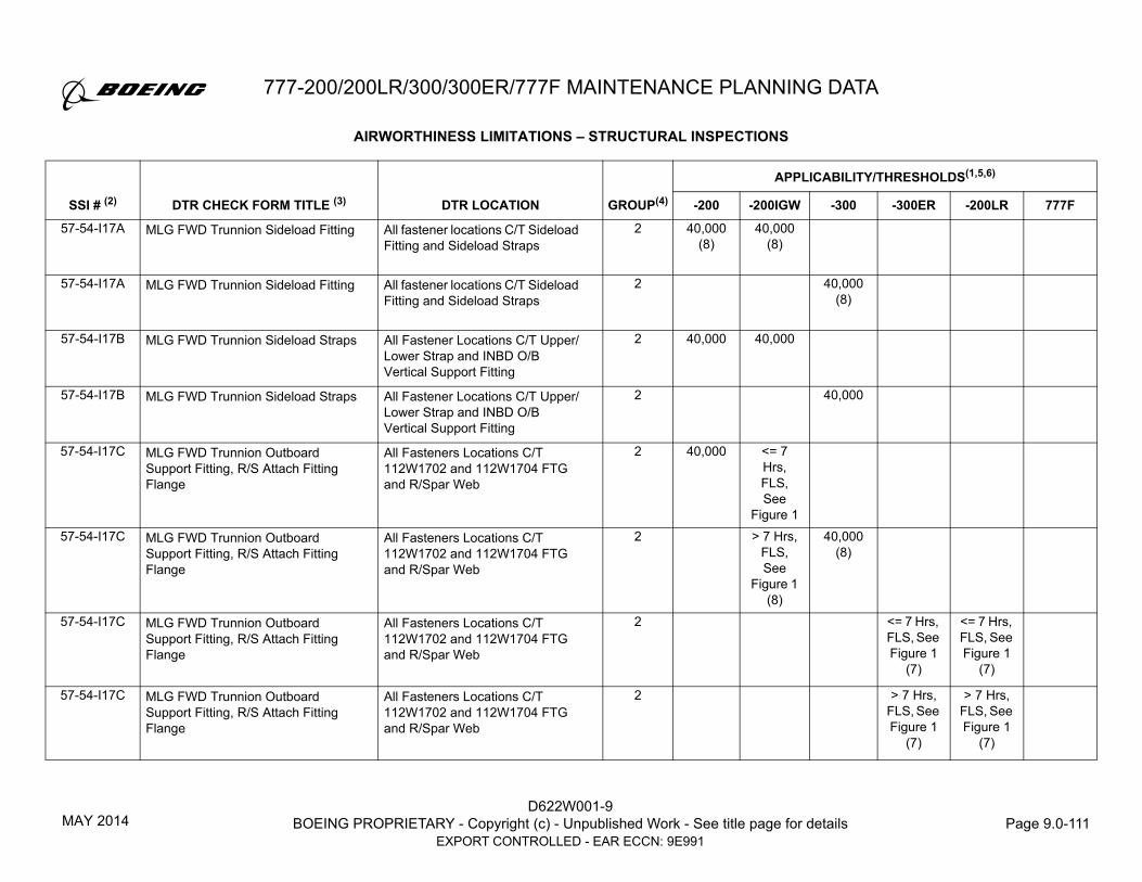
777-200/200LR/300/300ER/777F MAINTENANCE PLANNING DATA
D622W001-9BOEING PROPRIETARY - Copyright (c) - Unpublished Work - See title page for details Page 9.0-111
EXPORT CONTROLLED - EAR ECCN: 9E991
57-54-I17A MLG FWD Trunnion Sideload Fitting All fastener locations C/T Sideload Fitting and Sideload Straps
2 40,000 (8)
40,000 (8)
57-54-I17A MLG FWD Trunnion Sideload Fitting All fastener locations C/T Sideload Fitting and Sideload Straps
2 40,000 (8)
57-54-I17B MLG FWD Trunnion Sideload Straps All Fastener Locations C/T Upper/Lower Strap and INBD O/B Vertical Support Fitting
2 40,000 40,000
57-54-I17B MLG FWD Trunnion Sideload Straps All Fastener Locations C/T Upper/Lower Strap and INBD O/B Vertical Support Fitting
2 40,000
57-54-I17C MLG FWD Trunnion Outboard Support Fitting, R/S Attach Fitting Flange
All Fasteners Locations C/T 112W1702 and 112W1704 FTG and R/Spar Web
2 40,000 <= 7 Hrs, FLS, See
Figure 157-54-I17C MLG FWD Trunnion Outboard
Support Fitting, R/S Attach Fitting Flange
All Fasteners Locations C/T 112W1702 and 112W1704 FTG and R/Spar Web
2 > 7 Hrs, FLS, See
Figure 1 (8)
40,000 (8)
57-54-I17C MLG FWD Trunnion Outboard Support Fitting, R/S Attach Fitting Flange
All Fasteners Locations C/T 112W1702 and 112W1704 FTG and R/Spar Web
2 <= 7 Hrs, FLS, See Figure 1
(7)
<= 7 Hrs, FLS, See Figure 1
(7)
57-54-I17C MLG FWD Trunnion Outboard Support Fitting, R/S Attach Fitting Flange
All Fasteners Locations C/T 112W1702 and 112W1704 FTG and R/Spar Web
2 > 7 Hrs, FLS, See Figure 1
(7)
> 7 Hrs, FLS, See Figure 1
(7)
AIRWORTHINESS LIMITATIONS – STRUCTURAL INSPECTIONS
GROUP(4)
APPLICABILITY/THRESHOLDS(1,5,6)
SSI # (2) DTR CHECK FORM TITLE (3) DTR LOCATION -200 -200IGW -300 -300ER -200LR 777F
MAY 2014

D622W001-9BOEING PROPRIETARY - Copyright (c) - Unpublished Work - See title page for details Page 9.0-112
EXPORT CONTROLLED - EAR ECCN: 9E991
777-200/200LR/300/300ER/777F MAINTENANCE PLANNING DATA
57-54-I17C 112W1704, MLG FWD Trunnion Support Fitting
Section A-A, Spar Flange Crack 2 <= 7 Hrs, FLS, See Figure 2
(7)
57-54-I17C 112W1704, MLG FWD Trunnion Support Fitting
Section A-A, Spar Flange Crack 2 > 7 Hrs, FLS, See Figure 2
(7)
57-54-I18A MLG Beam OBD Support FTG, Lwr Skin Flange
All fastener holes locations C/T Lower flange and Lower Skin Panel
2 40,000 40,000
57-54-I18A MLG Beam OBD Support FTG, Lwr Skin Flange
All fastener holes locations C/T Lower flange and Lower Skin Panel
2 40,000 (8)
57-54-I18B MLG Beam OBD Support FTG, Fitting
Lower Horizontal Rib of MLG Beam Support Fitting @ Fastener Hole
2 40,000 (7)
40,000 (7)
57-54-I18B 112W1722, MLG Beam Outboard Support Fitting
Lower Horizontal Rib, Section A-A Lead crack at fastener hole
2 <= 7 Hrs, FLS, See Figure 2
(7)
57-54-I18B 112W1722, MLG Beam Outboard Support Fitting
Lower Horizontal Rib, Section A-A Lead crack at fastener hole
2 > 7 Hrs, FLS, See Figure 2
(7)
57-54-I18C MLG Beam OBD Support FTG, Fitting
Lower Horizontal Rib of MLG Beam Support Fitting @ Free Edge
2 40,000 (7)
40,000 (7)
AIRWORTHINESS LIMITATIONS – STRUCTURAL INSPECTIONS
GROUP(4)
APPLICABILITY/THRESHOLDS(1,5,6)
SSI # (2) DTR CHECK FORM TITLE (3) DTR LOCATION -200 -200IGW -300 -300ER -200LR 777F
JUL 2017

777-200/200LR/300/300ER/777F MAINTENANCE PLANNING DATA
D622W001-9BOEING PROPRIETARY - Copyright (c) - Unpublished Work - See title page for details Page 9.0-113
EXPORT CONTROLLED - EAR ECCN: 9E991
57-54-I18C 112W1722, MLG Beam Outboard Support Fitting
Lower Horizontal Rib, Section A-A Lead Crack at Free Edge
2 <= 7 Hrs, FLS, See Figure 2
57-54-I18C 112W1722, MLG Beam Outboard Support Fitting
Lower Horizontal Rib, Section A-A Lead Crack at Free Edge
2 > 7 hrs FLS, See
Fig 2 (7)
57-54-I19A MLG Drag Brace Support Fitting Section A-A Fitting Flange 2 40,000 (8)
40,000 (8)
57-54-I19A MLG Drag Brace Support Fitting Section A-A Fitting Flange 2 40,000 (8)
57-54-I19A MLG Drag Brace Support Fitting Section A-A Fitting Flange 2 40,000 (7)
40,000 (7)
57-54-I19A 112W1752, MLG Drag Brace Support Fitting
Section A-A Flange Crack 2 <= 7 Hrs, FLS, See Figure 2
(7)
57-54-I19A 112W1752, MLG Drag Brace Support Fitting
Section A-A Flange Crack 2 > 7 Hrs, FLS, See Figure 2
(7)
57-54-I19B MLG Drag Brace Support Fitting, Base of Fitting
Section A-A Fastener Locations C/T Base of fitting and Rear Spar Web
2 40,000 (8)
40,000 (8)
40,000 (8)
57-54-I19B MLG Drag Brace Support Fitting, Base of Fitting
Section A-A Fastener Locations C/T Base of fitting and Rear Spar Web
2 40,000 (7)
40,000 (7)
AIRWORTHINESS LIMITATIONS – STRUCTURAL INSPECTIONS
GROUP(4)
APPLICABILITY/THRESHOLDS(1,5,6)
SSI # (2) DTR CHECK FORM TITLE (3) DTR LOCATION -200 -200IGW -300 -300ER -200LR 777F
MAY 2014

D622W001-9BOEING PROPRIETARY - Copyright (c) - Unpublished Work - See title page for details Page 9.0-114
EXPORT CONTROLLED - EAR ECCN: 9E991
777-200/200LR/300/300ER/777F MAINTENANCE PLANNING DATA
57-54-I19B 112W1752, MLG Drag Brace Support Fitting
Section A-A Base Crack 2 <= 7 Hrs, FLS, See Figure 2
(7)
57-54-I19B 112W1752, MLG Drag Brace Support Fitting
Section A-A Base Crack 2 > 7 Hrs, FLS, See Figure 2
(7)
57-54-I19C MLG Drag Brace Internal Backup Fitting
Entire Fitting C/T SOB Rib and Rear Spar, including Stiffening Ribs
2 40,000
57-54-I19C MLG Drag Brace Internal Backup Fitting
Entire Fitting C/T SOB Rib and Rear Spar, including Stiffening Ribs
2 <= 7 Hrs, FLS, See Figure 1
<= 7 Hrs, FLS, See Figure 1
57-54-I19C MLG Drag Brace Internal Backup Fitting
Entire fitting c/t SOB Rib and Rear Spar, including Stiffening Ribs
2 > 7 hrs FLS, See Figure 1
> 7 hrs FLS, See Figure 1
57-54-I19C 112W1756, MLG Drag Brace Support Back-up Fitting
Section A-A, Lead Crack in Base 2 <= 7 Hrs, FLS, See Figure 2
57-54-I19C 112W1756, MLG Drag Brace Support Back-up Fitting
Section A-A, Lead Crack in Base 2 > 7 hrs FLS, See
Fig 2
57-54-I20 Retraction Actuator Support Fitting, Fitting Attach Flange
Rear Spar Attach Flange 2 40,000 40,000 40,000 25,000
AIRWORTHINESS LIMITATIONS – STRUCTURAL INSPECTIONS
GROUP(4)
APPLICABILITY/THRESHOLDS(1,5,6)
SSI # (2) DTR CHECK FORM TITLE (3) DTR LOCATION -200 -200IGW -300 -300ER -200LR 777F
MAY 2014

777-200/200LR/300/300ER/777F MAINTENANCE PLANNING DATA
D622W001-9BOEING PROPRIETARY - Copyright (c) - Unpublished Work - See title page for details Page 9.0-115
EXPORT CONTROLLED - EAR ECCN: 9E991
TABLE NOTES:
1. Blank entries in table indicate field is not applicable for that SSI/Check Form.
2. Multiple listings under a single SSI# are uniquely identified by Check Form Title, Location, and Model-Series Information. All inspections listed under a
single SSI# for a given model must be performed.
3. C/L or L/N in DTR Check Form title identifies certain forms as pertinent to specific airplane line numbers.
4. Group Number is provided to determine applicable plot in Figure 1 or 2 for items identified as "FLS”.
5. Figure 1 is applicable to all 777-200 models (including 777-200IGW) for items identified as "FLS”.
6. Thresholds that include "FLS" (e.g., "> 7 Hrs, FLS, See Figure 1 or Figure 2") are sensitive to flight length. All other values shown are in flight cycles.
7. No airplane may be operated beyond the stated threshold (or operational limit) until the applicable inspection procedures are validated, published in the
appropriate manual, and accepted by the FAA.
8. No airplane may be operated beyond the stated threshold requirements (or operational limit) unless it has been validated that the applicable published
inspection procedures can be accomplished and the inspection has been accomplished per the stated threshold requirements. If the applicable
published inspection procedure can not be accomplished, an alternative procedure must be used which the FAA has accepted for this inspection.
MAY 2014

D622W001-9BOEING PROPRIETARY - Copyright (c) - Unpublished Work - See title page for details Page 9.0-116
EXPORT CONTROLLED - EAR ECCN: 9E991
777-200/200LR/300/300ER/777F MAINTENANCE PLANNING DATA
INDIVIDUAL AIRPLANE SPECIFIC AIRWORTHINESS LIMITATIONS
PURPOSE
The purpose of this section is to identify additional or revised Supplemental Structures Airworthiness Limitation (AWL) Structural Inspection requirements
unique to a specific airplane serial number. Only those individual airplanes listed in this section have these additional or revised AWLs. These additional
or revised AWLs are due to differences in configuration as a result of Material Review Board actions.
The following table lists the additional supplemental Structures Inspection requirements for certain individual serial number airplanes. Each item is listed by Production Line/Serial Number, SSI Number, Inspection Figure, Location, Inspection Requirements and Threshold.
LINE NUMBER/SERIAL
NUMBER SSI NUMBER INSPECTION FIGURE LOCATION INSPECTION REQUIREMENTSTHRESHOLD
(1, 2, 3)
L/N 740S/N 37666
53-80-I13-MRB1 53-80-I13-N1780061195Aft Pressure Bulkhead Web Rework, Aft Side Doubler and Filler; Nonconformance Record NCR: N1780061195
STA 2190,WL 264,
BL LBL 27
1. Inspect the pressure bulkhead webs at all fasteners shown in the inspection figure from the forward side (except at radial stiffener) with MFEC per the 777 Non-Destructive Test (NDT) Manual, Part 6, 53-80-06 every 16,000 flight cycles. DETAILED inspect pressure bulkhead webs and radial stiffener from the forward side within the boundary shown in the inspection figure, every 16,000 flight cycles.
2. Inspect the NCR doubler at all fasteners shown in the inspection figure from the aft side with MFEC per the 777 NDT Manual, Part 6, 53-80-06 every 16,000 flight cycles. DETAILED inspect pressure bulkhead webs, doubler, filler and tear strap from the aft side within the boundary shown in the inspection figure, every 16,000 flight cycles.
3. All other Supplemental Inspections required for SSI 53-80-I13A in the preceding table and Service Bulletin 777-53A0078 must still be conducted except at the fastener locations common to the NCR doubler and filler.
30,000
JUL 2017

777-200/200LR/300/300ER/777F MAINTENANCE PLANNING DATA
D622W001-9BOEING PROPRIETARY - Copyright (c) - Unpublished Work - See title page for details Page 9.0-117
EXPORT CONTROLLED - EAR ECCN: 9E991
L/N 1240S/N 41759
57-20-I01G-MRB1 57-20-I01G-N1710245155
Outboard Wing Rear Spar Lower Chord Freeze Plug Rework;
NCR: N1710245155
Outbd Wing Lower Rear Spar Chord
at WSTA 414.5
(at Rib #9)
1. Inspect the rear spar lower chord in the area around the Rib Post #9 from the forward side (inside the fuel tank) with HFEC per the 777 Non-Destructive Test (NDT) Manual, Part 6, 51-00-01 every 16,000 flight cycles.
2. Inspect the rear spar lower chord from WSTA 412 - 417from the aft side (outside the fuel tank) in the gap betweenthe rear spar web and the wing lower panel with HFEC per the 777 NDT Manual, Part 6, 51-00-01 every 8,000 flight cycles.
3. Inspect the rear spar lower chord at fasteners common to Rib Post #9 with LFEC per the 777 NDT Manual, Part 6, 57-20-01 every 4,000 flight cycles. (4)
4. All other Supplemental Inspections required for SSI 57-20-I01G in the preceding table must still be conducted except at the fastener location common to the NCR freeze plug.
Group 1
<= 7 Hrs, FLS,
See Figure 1
(4)
L/N 1240S/N 41759
57-20-I01G-MRB1 57-20-I01G-N1710245155Outboard Wing Rear Spar Lower Chord Freeze Plug Rework;NCR: N1710245155
Outbd Wing Lower Rear Spar Chord
at WSTA 414.5
(at Rib #9)
1. Inspect the rear spar lower chord in the area around the Rib Post #9 from the forward side (inside the fuel tank) with HFEC per the 777 Non-Destructive Test (NDT) Manual, Part 6, 51-00-01 every 8,000 flight cycles.
2. Inspect the rear spar lower chord from WSTA 412 - 417from the aft side (outside the fuel tank) in the gap between the rear spar web and the wing lower panel with HFEC per the 777 NDT Manual, Part 6, 51-00-01 every 4,000 flight cycles.
3. Inspect the rear spar lower chord at fasteners common to Rib Post #9 with LFEC per the 777 NDT Manual, Part 6, 57-20-01 every 4,000 flight cycles. (4)
4. All other Supplemental Inspections required for SSI 57-20-I01G in the preceding table must still be conducted except at the fastener location common to the NCR freeze plug.
Group 1
> 7 Hrs, FLS,
See Figure 1
(4)
LINE NUMBER/SERIAL
NUMBER SSI NUMBER INSPECTION FIGURE LOCATION INSPECTION REQUIREMENTSTHRESHOLD
(1, 2, 3)
JUL 2017

D622W001-9BOEING PROPRIETARY - Copyright (c) - Unpublished Work - See title page for details Page 9.0-118
EXPORT CONTROLLED - EAR ECCN: 9E991
777-200/200LR/300/300ER/777F MAINTENANCE PLANNING DATA
L/N 1667S/N 66582
53-00-I01 N/A STA 390, 800,
WL 240, LHS
1. Prior to each inspection, remove the "oneworld" and ".Air wifi" decals in the inspection area (Ref. AMM 20-10-12 as needed).
2. Inspect SSI 53-00-I01 prior to threshold as given in D622W001-9.
3. Repeat inspections for SSI 53-00-I01 as given in D622W001-DTR
40,000 FC
L/N 1671S/N 66583
53-00-I01 N/A STA 390, 800,
WL 240, LHS
1. Prior to each inspection, remove the "oneworld" and ".Air wifi" decals in the inspection area (Ref. AMM 20-10-12 as needed).
2. Inspect SSI 53-00-I01 prior to threshold as given in D622W001-9.
3. Repeat inspections for SSI 53-00-I01 as given in D622W001-DTR
40,000 FC
L/N 1675S/N 66584
53-00-I01 N/A STA 390, 800,
WL 240, LHS
1. Prior to each inspection, remove the "oneworld" and ".Air wifi" decals in the inspection area (Ref. AMM 20-10-12 as needed).
2. Inspect SSI 53-00-I01 prior to threshold as given in D622W001-9.
3. Repeat inspections for SSI 53-00-I01 as given in D622W001-DTR
40,000 FC
L/N 1678S/N 66633
53-00-I01 N/A STA 390, 800,
WL 240, LHS
1. Prior to each inspection, remove the "oneworld" and ".Air wifi" decals in the inspection area (Ref. AMM 20-10-12 as needed).
2. Inspect SSI 53-00-I01 prior to threshold as given in D622W001-9.
3. Repeat inspections for SSI 53-00-I01 as given in D622W001-DTR
40,000 FC
LINE NUMBER/SERIAL
NUMBER SSI NUMBER INSPECTION FIGURE LOCATION INSPECTION REQUIREMENTSTHRESHOLD
(1, 2, 3)
APR 2020

777-200/200LR/300/300ER/777F MAINTENANCE PLANNING DATA
D622W001-9BOEING PROPRIETARY - Copyright (c) - Unpublished Work - See title page for details Page 9.0-119
EXPORT CONTROLLED - EAR ECCN: 9E991
L/N 1667S/N 66582
53-00-I02 N/A STA 1890,WL 180,
LHS
1. Prior to each inspection, remove the "Royal Mail" decal in the inspection area (Ref. AMM 20-10-12 as needed).
2. Inspect SSI 53-00-I02 prior to threshold as given in D622W001-9.
3. Repeat inspections for SSI 53-00-I02 as given in D622W001-DTR.
40,000 FC
L/N 1671S/N 66583
53-00-I02 N/A STA 1890,WL 180,
LHS
1. Prior to each inspection, remove the "Royal Mail" decal in the inspection area (Ref. AMM 20-10-12 as needed).
2. Inspect SSI 53-00-I02 prior to threshold as given in D622W001-9.
3. Repeat inspections for SSI 53-00-I02 as given in D622W001-DTR.
40,000 FC
L/N 1675S/N 66584
53-00-I02 N/A STA 1890,WL 180,
LHS
1. Prior to each inspection, remove the "Royal Mail" decal in the inspection area (Ref. AMM 20-10-12 as needed).
2. Inspect SSI 53-00-I02 prior to threshold as given in D622W001-9.
3. Repeat inspections for SSI 53-00-I02 as given in D622W001-DTR.
40,000 FC
L/N 1678S/N 66633
53-00-I02 N/A STA 1890,WL 180,
LHS
1. Prior to each inspection, remove the "Royal Mail" decal in the inspection area (Ref. AMM 20-10-12 as needed).
2. Inspect SSI 53-00-I02 prior to threshold as given in D622W001-9.
3. Repeat inspections for SSI 53-00-I02 as given in D622W001-DTR.
40,000 FC
LINE NUMBER/SERIAL
NUMBER SSI NUMBER INSPECTION FIGURE LOCATION INSPECTION REQUIREMENTSTHRESHOLD
(1, 2, 3)
APR 2020

D622W001-9BOEING PROPRIETARY - Copyright (c) - Unpublished Work - See title page for details Page 9.0-120
EXPORT CONTROLLED - EAR ECCN: 9E991
777-200/200LR/300/300ER/777F MAINTENANCE PLANNING DATA
L/N 1683S/N 66587
53-00-I01 N/A STA 390, 800,
WL 240, LHS
1. Prior to each inspection, remove the "Wi-Fi" decals in the inspection area (Ref. AMM 20-10-12 as needed).
2. Inspect SSI 53-00-I01 prior to threshold as given in D622W001-9.
3. Repeat inspections for SSI 53-00-I01 as given in D622W001-DTR
40,000 FC
L/N 1687S/N 66588
53-00-I01 N/A STA 390, 800,
WL 240, LHS
1. Prior to each inspection, remove the "Wi-Fi" decals in the inspection area (Ref. AMM 20-10-12 as needed).
2. Inspect SSI 53-00-I01 prior to threshold as given in D622W001-9.
3. Repeat inspections for SSI 53-00-I01 as given in D622W001-DTR
40,000 FC
L/N 1690S/N 66586
53-00-I01 N/A STA 390, 800,
WL 240, LHS
1. Prior to each inspection, remove the "Wi-Fi" decals in the inspection area (Ref. AMM 20-10-12 as needed).
2. Inspect SSI 53-00-I01 prior to threshold as given in D622W001-9.
3. Repeat inspections for SSI 53-00-I01 as given in D622W001-DTR
40,000 FC
LINE NUMBER/SERIAL
NUMBER SSI NUMBER INSPECTION FIGURE LOCATION INSPECTION REQUIREMENTSTHRESHOLD
(1, 2, 3)
NOV 2020

777-200/200LR/300/300ER/777F MAINTENANCE PLANNING DATA
D622W001-9BOEING PROPRIETARY - Copyright (c) - Unpublished Work - See title page for details Page 9.0-121
EXPORT CONTROLLED - EAR ECCN: 9E991
INDIVIDUAL AIRPLANE SPECIFIC AIRWORTHINESS LIMITATIONS TABLE NOTES:
1. Inspection must be accomplished at or before the stated threshold value.
2. Group Number is provided to determine applicable plot in Figure 1 or 2 for items identified as “FLS”.
3. Thresholds that include “FLS” (e.g., “ > 7 Hrs, FLS, See Figure 1 or Figure 2”) are sensitive to flight length. All other values shown are in flight cycles.
4. No airplane may be operated beyond the stated threshold (or operational limit) until the applicable inspection procedures are validated, published in the
appropriate manual, and accepted by the FAA.
JUL 2017

D622W001-9BOEING PROPRIETARY - Copyright (c) - Unpublished Work - See title page for details Page 9.0-122
EXPORT CONTROLLED - EAR ECCN: 9E991
777-200/200LR/300/300ER/777F MAINTENANCE PLANNING DATA
FIGURE 3. 53-80-I13-N1780061195 - Aft Pressure Bulkhead Web Rework, NCR N1780061195
53-80-I13-N1780061195
= MFEC Inspect the webs for cracks from the forward side per 777 NDT Manual, Part 6, 53-80-06.
= DETAILED Inspect the webs and radial stiffener for cracks from the forward side.
= MFEC Inspect the doubler for cracks from the aft side per 777 NDT Manual, Part 6, 53-80-06.
= DETAILED Inspect the webs, doubler, filler and tear strap for cracks from the aft side.
UP
INBD
View from Aft Side
JUL 2017

777-200/200LR/300/300ER/777F MAINTENANCE PLANNING DATA
D622W001-9BOEING PROPRIETARY - Copyright (c) - Unpublished Work - See title page for details Page 9.0-123
EXPORT CONTROLLED - EAR ECCN: 9E991
FIGURE 4. 57-20-I01G-N1710245155 - Outboard Wing Rear Spar Lower Chord Freeze Plug Rework, NCR N1710245155
Lower Skin
Rib #9Fitting
Rear SparChord
Rear SparWeb
Fastener withFreeze Plugs
View A A
Up
Aft
Aft
Inbd
Fastener with Freeze Plugs
Adjacent fasteners requiring inspection for SSI 57 20 I01G
Other fasteners (reference)
Rib #9Fitting
Rear SparChord
Lower Skin
A
A
In the reworked area, perform the following inspections:1) From direction 1, HFEC inspect the rear spar lower chord per the 777 NDT Manual
Part 6, 51 00 01. Use the lower chord edges, radius, Rib #9 fitting shear tie footand fastener collars on the vertical leg as a probe guide.
2) From direction 2, HFEC inspect the rear spar lower chord per the 777 NDT ManualPart 6, 51 00 01. Remove sealant as required. Use the rear spar web lower edgeas a probe guide.
3) From Direction 3, inspect the rear spar lower chord at the freeze plug fastenerlocation per 777 NDT Manual Part 6, 57 20 01.
4) Inspect the remaining 3 adjacent fastener locations as required for SSI 57 20 I01G.
JUL 2017

D622W001-9BOEING PROPRIETARY - Copyright (c) - Unpublished Work - See title page for details Page 9.0-124
EXPORT CONTROLLED - EAR ECCN: 9E991
777-200/200LR/300/300ER/777F MAINTENANCE PLANNING DATA
C. AIRWORTHINESS LIMITATIONS – STRUCTURAL SAFE-LIFE LIMITS
NOTE: In this section, airplanes identified as "777-200IGW" are 777-200 airplanes that have been certified for a structural capability of MTW>547,000 lbs. This includes airplanes sometimes called "777-200ER" airplanes. All of these airplanes were certified as 777-200 series airplanes per the applicable FAA Type Certificate. The airplanes identified as 777-200IGW airplanes in this section consist of all airplanes identified by Customer Variable Numbers (Manufacturer Block Numbers) WB001 through WB500 and WC001 through WC999. If needed, refer to the 777 Structural Repair Manual front matter Effective Aircraft “Manufacturer Block Number” to determine the associated Manufacturer Serial Numbers. 777-200LR airplanes are not included in the group of airplanes identified as 777-200 or 777-200IGW.
C.1 STRUCTURAL SAFE-LIFE PARTS
LANDING GEAR: See Note LANDING GEAR LIFE LIMIT:*
FAA EASA777-200/-200IGW/-300 Nose Landing Gear 77,500 46,500 Except: Inner Cylinder 73,300 44,000777-200/-200IGW/-300 Main Landing Gear, 86,200 51,700 Except: Outer Cylinder, 161W1110-3 S/N 5JHW and 161W1110-4 S/N 1JHW 12,857 7,714 Outer Cylinder, 161W1110-3 S/N 4JAW and 161W1110-4 S/N 6JAN 15,090 9,054 Outer Cylinder, 161W1110-3 S/N 1JJW and 161W1110-4 S/N 3JRW 15,677 9,406 Outer Cylinder, 161W1110-3, -4, -9, -10 16,666 10,000 Outer Cylinder, Other Part Numbers 66,600 40,000 Lower Drag Strut, 161W4003 and 161W4103 76,300 45,700 Upper Side Strut Spindle, 161W0100 83,300 50,000 Lower Actuator Attach Pin, 161W1020 83,300 50,000 Spacer Tube, 161W1159 83,300 50,000 Aft Trunnion Pin, 161W1301 83,300 50,000 Lower Side Strut Spindle, 161W1310 83,300 50,000777-200/-200IGW/-300 Main Landing Gear Support Structure 86,200 51,700 Except: Load Distribution Plate – Outboard Gear Beam Support 112W1725-1, -3, -4, -19, -21, -22 44,000 26,400 112W1725-7, -8, -9, -10 99,600 59,500 112W1725-13, -14, -15, -16 74,200 44,500
JUL 2017

777-200/200LR/300/300ER/777F MAINTENANCE PLANNING DATA
D622W001-9BOEING PROPRIETARY - Copyright (c) - Unpublished Work - See title page for details Page 9.0-125
EXPORT CONTROLLED - EAR ECCN: 9E991
NOTE: Component Interchangeability Lists 161W0003 (Main Landing Gear) and 162W0002 (Nose Landing Gear) provide complete listings of 777-200/200IGW/200LR/300/300ER/777F landing gear related components subject to life limitations.
Pin – Fuse, Outboard Gear Beam Support, 112W1728-3, -9 29,400 17,600 112W1728-4, -5 99,600 59,500
112W1728-7 74,200 44,500
Pin – Fuse Retract Actuator, 112W1769 28,181 16,908 Hanger Pin Details (Fwd & Aft), 115W1510 83,300 50,000 Pin – Stabilizer Brace, MLG Beam, 115W1671 83,300 50,000
* Shown in number of landings.
LANDING GEAR: LANDING GEAR LIFE LIMIT:
FAA EASA
777-200LR/300ER/777F Main Landing Gear Figure 5 (FAA & EASA)
777-200LR/300ER/777F Main Landing Gear Support Structure Figure 6 (FAA & EASA)
777-200LR/300ER/777F Nose Landing Gear Figure 7 (FAA & EASA)
JUL 2017

D622W001-9BOEING PROPRIETARY - Copyright (c) - Unpublished Work - See title page for details Page 9.0-126
EXPORT CONTROLLED - EAR ECCN: 9E991
777-200/200LR/300/300ER/777F MAINTENANCE PLANNING DATA
C.2 LIFE-LIMITED PARTS
NOTE: Component Interchangeability Lists 161W0003 (Main Landing Gear) and 162W0002 (Nose Landing Gear) provides a complete list of 777-200/200IGW/200LR/300/300ER/777F landing gear related components subject to life limitations.
COMPONENT: LIFE LIMIT:
777-200 Actuator Assembly – Door Main Landing Gear
NOTE: Life Limitation applies only to P/N 293W3702-5 actuators installed on 777-200 airplane Line Numbers 2-13, 15-17 and 19-29. Incorporation of SB 777-32-0028 (reference Service Letters 777-SL-32-006 and 777-SL-001-E) removes the life limit and re-identifies it as a -7 Actuator.
10,000 Landings
777-200/-200 IGW/-300 Flight Deck Side Stowage Compartment Latch – Captain & First Officer (if compartment is installed).
NOTE: Life Limitation is not Applicable Production Line Nos. 282 and on or following incorporation of SB 777-25-0140.365 Days Time In-Service
777-200LR Optional Auxiliary Body Fuel Tanks
NOTE: This limit is based on fatigue test cycles completed to date and this limit will be increased or removed after additional test cycles are completed.
15,000 Cycles
777-300ER Semi Lever Gear Hydraulic Strut (P/N 293W4201-2). 2,000 Landings
777-200LR/300ER/777F Main Landing Gear Outer Cylinder
NOTE: Life Limitation applies to P/N 161W2110-13 (LH) and 161W2110-14 (RH) Outer Cylinders with Serial Numbers:
161W2110-13: S/N WHM5001, WHM5002, WHM5003, WHM5007, WHM5017, WHM5021, WHM5023, WHM5033, WHM5039, WHM5041, WHM5045, WHM5047, WHM5053.
161W2110-14: S/N WHM5002, WHM5003, WHM5008, WHM5010, WHM5012, WHM5014, WHM5020, WHM5032, WHM5036, WHM5040, WHM5046, WHM5048, WHM5052.
Figure 5
APR 2019

777-200/200LR/300/300ER/777F MAINTENANCE PLANNING DATA
D622W001-9BOEING PROPRIETARY - Copyright (c) - Unpublished Work - See title page for details Page 9.0-127
EXPORT CONTROLLED - EAR ECCN: 9E991
Instructions for using Safe-Life Charts:
1. For each safe life component, determine the accumulated flight cycles and flight hours.
2. Enter the Safe-Life Limit Curve at the appropriate flight cycles and flight hours and locate the intersection.
3. If the point determined in Step 2 lies below the Safe-Life Limit Curve, the component has not reached the Safe-Life Limit. If the point is on, above, or to
the right of the Safe-Life Curve, then the Safe-Life Limit has been reached.
JUL 2017

D622W001-9BOEING PROPRIETARY - Copyright (c) - Unpublished Work - See title page for details Page 9.0-128
EXPORT CONTROLLED - EAR ECCN: 9E991
777-200/200LR/300/300ER/777F MAINTENANCE PLANNING DATA.
FIGURE 5. 777-200LR/300ER/777F MAIN LANDING GEAR SAFE-LIFE LIMITS
APR 2019

777-200/200LR/300/300ER/777F MAINTENANCE PLANNING DATA
D622W001-9BOEING PROPRIETARY - Copyright (c) - Unpublished Work - See title page for details Page 9.0-129
EXPORT CONTROLLED - EAR ECCN: 9E991
FIGURE 6. 777-200LR/300ER/777F MAIN LANDING GEAR SUPPORT FITTINGS SAFE-LIFE LIMITS
Main Landing Gear Support Fittings Safe-Life Limits
124.95, 83.30
320.00, 40.00
182.40, 121.60
129.30, 86.20
111.30, 74.20
0
20
40
60
80
100
120
140
0 50 100 150 200 250 300 350Flight Hours (x 1,000)
Flig
ht C
ycle
s (x
1,0
00)
All Other Components
Load Distribution PlateFuse Pin B
Upper and Lower Stabilizer Aft Pins Hanger Link Fwd and Aft Pins
Outboard Gear Beam Fuse Pin
Retract Actuator Fuse Pin(40K cycles for all Flight Hours)
JUL 2017

D622W001-9BOEING PROPRIETARY - Copyright (c) - Unpublished Work - See title page for details Page 9.0-130
EXPORT CONTROLLED - EAR ECCN: 9E991
777-200/200LR/300/300ER/777F MAINTENANCE PLANNING DATA
FIGURE 7. 777-200LR/300ER/777F NOSE LANDING GEAR SAFE-LIFE LIMITS
Nose Landing Gear Safe-Life Limits
348.00, 43.50
109.95, 73.30
116.25, 77.50
286.40, 35.80
66.00, 44.00
0
10
20
30
40
50
60
70
80
90
0 50 100 150 200 250 300 350 400Flight Hours (x 1,000)
Flig
ht C
ycle
s (x
1,0
00)
All Other Components
Inner Cylinder
777-300ER Upper Floating Piston,Upper Cylinder, Lower Cylinder,Metering Pin, and Orifice Plate
JUL 2017

777-200/200LR/300/300ER/777F MAINTENANCE PLANNING DATA
D622W001-9BOEING PROPRIETARY - Copyright (c) - Unpublished Work - See title page for details Page 9.0-131
EXPORT CONTROLLED - EAR ECCN: 9E991
D. AIRWORTHINESS LIMITATIONS – SYSTEMS
INTRODUCTION
The airplane systems maintenance requirements described in this AWL document result from various 777 airplane certification activities with the FAA. This
Airworthiness Limitations section is FAA-approved and specifies maintenance required under Title 14 CFR § 43.16 and § 91.403 of the Federal Aviation
Regulations, unless an alternative program has been FAA Oversight Office approved. The AWLs may only be revised with the approval of the FAA
Oversight Office. If the maintenance requirements cannot be accomplished due to repairs and/or modifications, an alternate inspection, acceptable to the
FAA Oversight Office, must be used.
An AWL may be an Airworthiness Limitation Instruction (ALI) or a Critical Design Configuration Control Limitation (CDCCL).
CDCCLs are a means of identifying certain design configuration features intended to preclude a fuel tank ignition source for the operational life of the
airplane as required under Special Federal Aviation Regulation No. 88 (SFAR 88) - Fuel Tank System Fault Tolerance Evaluation Requirements and Title
14 CFR § 25.981 - Fuel Tank Ignition Prevention. CDCCLs are mandatory and cannot be changed or deleted without the approval of the FAA Oversight
Office. A critical fuel tank ignition source prevention feature may exist in the fuel system and its related installation or in systems that, if a failure condition
were to develop, could interact with the fuel system in such a way that an unsafe condition would develop without this limitation. Strict adherence to
configuration, methods, techniques, and practices as prescribed is required to ensure compliance with the CDCCL. Any use of parts, methods, techniques
or practices not contained in the applicable CDCCL must be approved by the FAA Oversight Office. For each CDCCL, the word "maintenance" includes
maintaining any installation during alterations; therefore, adherence to the CDCCL is required during maintenance or alterations.
ALIs identify inspection tasks that must be done to maintain the design level of safety for the operational life of the airplane to prevent an unsafe condition.
ALIs are mandatory and cannot be changed or deleted without the approval of the FAA Oversight Office. Strict adherence to methods, techniques and
practices as prescribed is required to ensure the ALI is complied with. Any use of methods, techniques or practices not contained in these ALIs must be
approved by the FAA Oversight Office.
MAR 2014

D622W001-9BOEING PROPRIETARY - Copyright (c) - Unpublished Work - See title page for details Page 9.0-132
EXPORT CONTROLLED - EAR ECCN: 9E991
777-200/200LR/300/300ER/777F MAINTENANCE PLANNING DATA
REGULATORY AGENCY APPROVAL
Any deviations from the published AWL instructions included in this document require approval from the FAA Oversight Office. This applies to operators
under the U.S. FAA jurisdiction only and to airplanes registered in the U.S. Operators who are not under the U.S. FAA jurisdiction should obtain approval
from their own local regulatory agency for any deviations from the listed AWL instructions.
AWL REVISION PROCESS
In the event that an AWL is revised, Boeing will prepare a revision to this document that will be approved by the FAA Oversight Office. This revision will
then be forwarded to all 777 operators and the FAA Oversight Office.
ACCOMPLISHMENT INSTRUCTIONS – GENERAL INFORMATION
The listed AWLs may make reference to Instructions for Continued Airworthiness which are included in other Boeing documents.
• When a document is cited using the words "in accordance with" in an airworthiness limitation, the cited document (or document section) must be
followed to ensure that the critical design feature is maintained. Any deviation from the cited document requires FAA Oversight Office approval.
• When a document is cited using the words "refer to" in an airworthiness limitation, the cited document (or document section) represents one method of
complying with the airworthiness limitation. An alternative procedure may be developed by an operator in accordance with its procedures in its
maintenance program/manual.
For electrical bonding and grounding requirements, refer to the Boeing Standard Wiring Practices Manual (SWPM) 20-20.
MAR 2014

D622W001-9BOEING PROPRIETARY - Copyright (c) - Unpublished Work - See title page for details Page 9.0-133
EXPORT CONTROLLED - EAR ECCN: 9E991
777-200/200LR/300/300ER/777F MAINTENANCE PLANNING DATA
USE OF ALTERNATE OR EQUIVALENT TOOLS, TEST EQUIPMENT OR MATERIALS
For AWLs which require use of certain tools, test equipment or material, the use of alternate or equivalent tools, test equipment or materials requires prior
approval from the FAA Oversight Office.
The Component Maintenance Manuals (CMMs) listed in the AWLs as "in accordance with" and not "refer to" are currently FAA Oversight Office approved.
If the CMM allows the use of alternate or equivalent tools, test equipment or materials, use of an alternate or equivalent tool, test equipment or material
does not require further approval by the FAA Oversight Office.
EXCEPTIONAL SHORT-TERM EXTENSIONS
Since AWL intervals are based on estimations of the probability of an event, an exceptional short-term extension for each system AWL listed in this
document may be made without jeopardizing safety. The local regulatory authority or a Principal Maintenance Inspector must concur with any exceptional
short-term extensions before they take place using procedures established with the local regulatory authority in the operators' manuals. The "exceptional
short-term extension" process is applicable to AWL intervals. It should not be confused with the operators "short-term escalation" program for normal
maintenance tasks described in the operators' manuals and in the Flight Standards Handbook 8900.1 FSIMS.
The FAA Oversight Office have accepted that these exceptional short-term extensions may be granted without consultation with that office:
1. The term "exceptional short-term extension" is defined as an increase in a system AWL interval that may be needed to cover an uncontrollable or
unexpected situation. All AWLs listed in this section have been approved with an exceptional short-term extension of 30 days.
2. Repeated use of extensions, either on the same airplane or on similar airplanes in an operator's fleet, should not be used as a substitute for good
management practices. Exceptional short-term extensions must not be used for fleet AWL extensions.
3. After a system AWL has experienced an exceptional short-term extension, the AWL interval will revert back to its interval listed in this document. The
FAA Oversight Office must approve, prior to its use, any desired extension not explicitly listed above.
NOTE: This exceptional short-term extension listed above applies to airlines that fall under the U.S. FAA jurisdiction only. Operators who are not under the U.S. FAA jurisdiction should obtain interval extension approvals from the local regulatory agency.
MAR 2014

D622W001-9BOEING PROPRIETARY - Copyright (c) - Unpublished Work - See title page for details Page 9.0-134
EXPORT CONTROLLED - EAR ECCN: 9E991
777-200/200LR/300/300ER/777F MAINTENANCE PLANNING DATA
DEFINITIONS
Removed and Reinstalled or Replaced: Defined as removal and reinstalling or replacement of a component, including partial removals.
Disturbed: Defined as interference, movement or change to the arrangement or order of the referenced component.
New wiring: Defined as any alteration that installs wiring that is added to the airplane after initial Airplane Airworthiness Certificate issuance or after the
date that the MPD Section 9, D622W001-9, was first incorporated into an operator's maintenance program, whichever is later.
Sealant: Defined as sealant type BMS 5-45 or equivalent in accordance with SRM 51-20-05 for inside of fuel tank and sealant type BMS 5-95, or
equivalent, in accordance with SRM 51-20-05 for outside of the fuel tank.
FAA Oversight Office: Defined as the FAA office that currently has oversight responsibility for the type certificate of the Boeing Model 777 aircraft. At the
time of publication, the FAA Oversight Office is the FAA BASOO.
Maintenance: Defined as inspection, overhaul, repair, preservation, and the replacement of parts, but excludes preventive maintenance.
Fay Surface Bond: Defined as the mechanical joining of two conductive surfaces to provide an electrically conductive joint without sealing (Category 1
Electrical Fay Surface Bond, refer to Boeing SWPM 20-20-00).
Fay Sealed Fay Surface Bond: Defined as the mechanical joining of two conductive surfaces to provide an electrically conductive joint, with a layer of
sealant to one of the mating surfaces (Category 2 Electrical Fay Surface Bond, refer to Boeing SWPM 20-20-00).
Fillet Sealed Fay Surface Bond: Defined as the mechanical joining of two conductive surfaces to provide an electrically conductive joint, with a
continuous bead of sealant along the edges of the joint (Category 6 Electrical Fay Surface Bond, refer to Boeing SWPM 20-20-00).
Cushion Clamp: Defined as a clamp that has an electrical insulating cushion on the metal band which isolates the wire bundle from the conductive metal
part of the clamp when the clamp is closed.
DEC 2014

D622W001-9BOEING PROPRIETARY - Copyright (c) - Unpublished Work - See title page for details Page 9.0-135
EXPORT CONTROLLED - EAR ECCN: 9E991
777-200/200LR/300/300ER/777F MAINTENANCE PLANNING DATA
SUPPORTING DOCUMENTATION
Strict adherence to methods, techniques and practices as prescribed is required to ensure the ALI or CDCCL is complied with. Airlines must follow the
manufacturer's maintenance procedures when performing maintenance that has an effect on an ALI or CDCCL. If operators do not obey the procedures, it
can increase the risk of an unsafe condition. Any use of methods, techniques or practices not contained in these ALIs or CDCCLs must be approved by
the FAA Oversight Office.
PAGE FORMAT: SYSTEMS AIRWORTHINESS LIMITATIONS
COLUMN EXPLANATION
AWL NUMBER Each task is given a unique AWL Item Number. The first and second digits are the ATA Chapter Number.
TASK ALI = Airworthiness Limitation Instruction. These tasks are inspections that should be performed at the listed intervals.
CDCCL = Critical Design Configuration Control Limitation
INTERVAL Task frequencies are specified in terms of a usage parameter such as flight hours, cycles or calendar time.
APPLICABILITY Airplane model applicability.
DESCRIPTION Description of the task to be performed or critical design configurations aspects that cannot be changed without violating the intent of the design.
MAR 2014

D622W001-9BOEING PROPRIETARY - Copyright (c) - Unpublished Work - See title page for details Page 9.0-136
EXPORT CONTROLLED - EAR ECCN: 9E991
777-200/200LR/300/300ER/777F MAINTENANCE PLANNING DATA
D.1 FUEL SYSTEMS IGNITION PREVENTION
This section contains an FAA-approved program of scheduled inspections and design limitations for operators to incorporate into their maintenance
program for this type design to meet the standards and assumptions introduced by Title 14 CFR § 25.981 and Special Federal Aviation Regulation No. 88
(SFAR 88). SFAR 88 – Fuel Tank System Fault Tolerance Evaluation Requirements and Title 14 CFR § 25.981 – Fuel Tank Ignition Prevention require
maintenance instructions and control limitations for certain fuel tank critical design configurations.
NOTE: The auxiliary fuel tank installation has been shown to comply with Title 14 CFR § 25.981 at Amendment 25-102.
Paragraph 2(a) of SFAR 88 and Paragraph (b) of the standard introduced by Title 14 CFR § 25.981 (Amendment 25-102) requires certain design approval
holders of Type Certificates (TCs) and Supplemental Type Certificates (STCs) of large transport airplanes to conduct a safety review of the fuel tank
systems. The purpose of the safety review is to identify design features that may result in development of ignition sources in the fuel tank. Fuel system
AWLs are mandatory maintenance actions required to ensure that unsafe conditions identified by the SFAR 88 safety review do not occur or are not
introduced into the fuel tank system as a result of configuration changes, repairs, alterations, or deficiencies in the maintenance program throughout the
operational life of the airplane.
FEB 2012

D622W001-9BOEING PROPRIETARY - Copyright (c) - Unpublished Work - See title page for details Page 9.0-137
EXPORT CONTROLLED - EAR ECCN: 9E991
777-200/200LR/300/300ER/777F MAINTENANCE PLANNING DATA
AWLs – FUEL TANK IGNITION PREVENTION
AWLNUMBER TASK INTERVAL APPLICABILITY DESCRIPTION
28-AWL-01 ALI 16,000 FC/ 3,000 DY
NOTE
ALL External Wires Over Center Fuel Tank
Concern: Potential for wire chafing and arcing to Center Fuel Tank Upper Panel.
Perform a detailed inspection of the wire bundles routed over the center fuel tank and under the main deck floor boards to detect damaged wire bundles, damaged clamps, damaged sleeving (if installed), wire chafing, and that the wire bundle is not in contact with surface of the center fuel tank (refer to Boeing AMM 28-11-00).
NOTE: The Boeing Standard Wiring Practice Manual (SWPM) contains accepted practices for repair or replacement of existing wiring:
For assembly and installation, refer to Boeing SWPM 20-10-11. For repair procedures, refer to Boeing SWPM 20-10-13.For seal fittings, refer to Boeing SWPM 20-10-22.
INTERVAL NOTE: Whichever comes first.28-AWL-02 CDCCL N/A ALL External Wires Over Center Fuel Tank
Concern: Potential for wire chafing and arcing to Center Fuel Tank Upper Panel.
If any maintenance, preventative maintenance, or alteration is performed in the area under the main deck floor boards and over the Center Fuel Tank, verify the following (refer to Boeing AMM 28-11-00) in the affected areas where maintenance was performed:
1. Maintain existing (or newly approved) wire bundle routing, clamping and sleeving.
2. Wire bundles, clamps, and sleeving are not damaged.
3. Wires are not chafed.
4. Wire bundles are not in contact with the surface of the Center Fuel Tank.
NOTE: Boeing AMM 53-01-01 contains access information to these areas.
The Boeing Standard Wiring Practice Manual (SWPM) contains accepted practices for repair or replacement of existing wiring:For assembly and installation, refer to Boeing SWPM 20-10-11.For repair procedures, refer to Boeing SWPM 20-10-13.For seal fittings, refer to Boeing SWPM 20-10-22.
NOV 2015

D622W001-9BOEING PROPRIETARY - Copyright (c) - Unpublished Work - See title page for details Page 9.0-138
EXPORT CONTROLLED - EAR ECCN: 9E991
777-200/200LR/300/300ER/777F MAINTENANCE PLANNING DATA
28-AWL-03 ALI 16,000 FC/ 3,000 DY
NOTE
ALL Fuel Quantity Indicating System (FQIS) – Out of Tank Wiring Lightning Shield to Ground Termination
Concern: Potential for lightning-induced voltages on the FQIS wiring to enter the fuel tank.
Using a Loop Resistance Tester, BAE Systems Dallas Service Center (3X2T2), P/N 906-10246-2 or 906-10246-3, perform the following inspection to ensure the functional integrity of the FQIS wiring shield to ground termination (refer to Boeing AMM 05-55-54):
1. Measure the joint resistance of the FQIS receptacle to structure (spar) and verify resistance is 0.0030 ohm (3.0 milliohms) or less.
2. Measure and verify the resistance of the shield to ground termination for the following items:
a. The loop resistance is 0.040 ohm (40 milliohms) or less for Connector D28103P (Left Inboard Main Tank Rear Spar) Wire Bundle W8073.
b. The loop resistance is 0.053 ohm (53 milliohms) or less for Connector D28102P (Left Outboard Main Tank Rear Spar) Wire Bundle W8072.
c. The loop resistance is 0.040 ohm (40 milliohms) or less for Connector D28101P (Left Center Tank Front Spar) Wire Bundle W8010.
d. The loop resistance is 0.040 ohm (40 milliohms) or less for Connector D28201P (Right Center Tank Front Spar) Wire Bundle W8020.
e. The loop resistance is 0.053 ohm (53 milliohms) or less for Connector D28202P (Right Outboard Main Tank Rear Spar) Wire Bundle W8077.
f. The loop resistance is 0.040 ohm (40 milliohms) or less for Connector D28203P (Right Inboard Main Tank Rear Spar) Wire Bundle W8078.
INTERVAL NOTE: Whichever comes first.
AWLNUMBER TASK INTERVAL APPLICABILITY DESCRIPTION
NOV 2015

D622W001-9BOEING PROPRIETARY - Copyright (c) - Unpublished Work - See title page for details Page 9.0-139
EXPORT CONTROLLED - EAR ECCN: 9E991
777-200/200LR/300/300ER/777F MAINTENANCE PLANNING DATA
28-AWL-04 CDCCL N/A ALL FQIS – Out Tank Wiring Lightning Shield to Ground Termination
Concern: Potential for lightning-induced voltages on the FQIS wiring to enter the fuel tank.
1. If maintenance, preventative maintenance, or alteration is performed that disconnects the in-tank receptacle from the spar or opens an FQIS wire bundle shield to ground path, then perform the bond check for the type of ground path opened as listed below:
a. For the electrical joint between the plug's backshell and structure (spar) at the wing rear spar connectors D28102P, D28103P, D28202P and D28203P and the wing front spar connectors D28101P and D28201P, the following design features must be verified (applicable to all airplanes) (refer to Boeing AMM 28-41-05):
I. For the FQIS in-tank wiring spar receptacle:
A. A bonding jumper is installed between the FQIS spar receptacle's mounting bolt and a stiffener on the spar with the red end of the jumper attached to the spar stiffener.
B. After installation of the bonding jumper, the electrical bonding resistance between the FQIS in-tank wiring spar receptacle and the spar is 0.0030 ohm (3.0 milliohms) or less.
C. A cap seal is applied over both ends of the jumper terminal lugs.
II. For the out tank wire bundle plug to the FQIS in-tank wiring spar receptacle:
A. For the electrical joint between the out tank plug's backshell and in-tank wiring spar receptacle, the electrical bonding resistance is 0.0030 ohm (3.0 milliohms) or less.
b. Based on the installation, only one of the following configurations is applicable (refer to Boeing AMM 05-55-54):
I. Configuration 1 (airplanes with out of tank wire bundle with P connectors within the wheel well):
A. For the electrical joint between the connector backshell and primary structure within the wheel well for connectors D28113P, D28112P, D28212P and D28213P, and within the forward cargo for connectors D28211P and D28111P, the following design feature must be verified:
(1) The electrical bonding resistance between the connector backshell and primary structure is 0.0025 ohm (2.5 milliohms) or less.
(Continued on next page)
AWLNUMBER TASK INTERVAL APPLICABILITY DESCRIPTION
NOV 2015
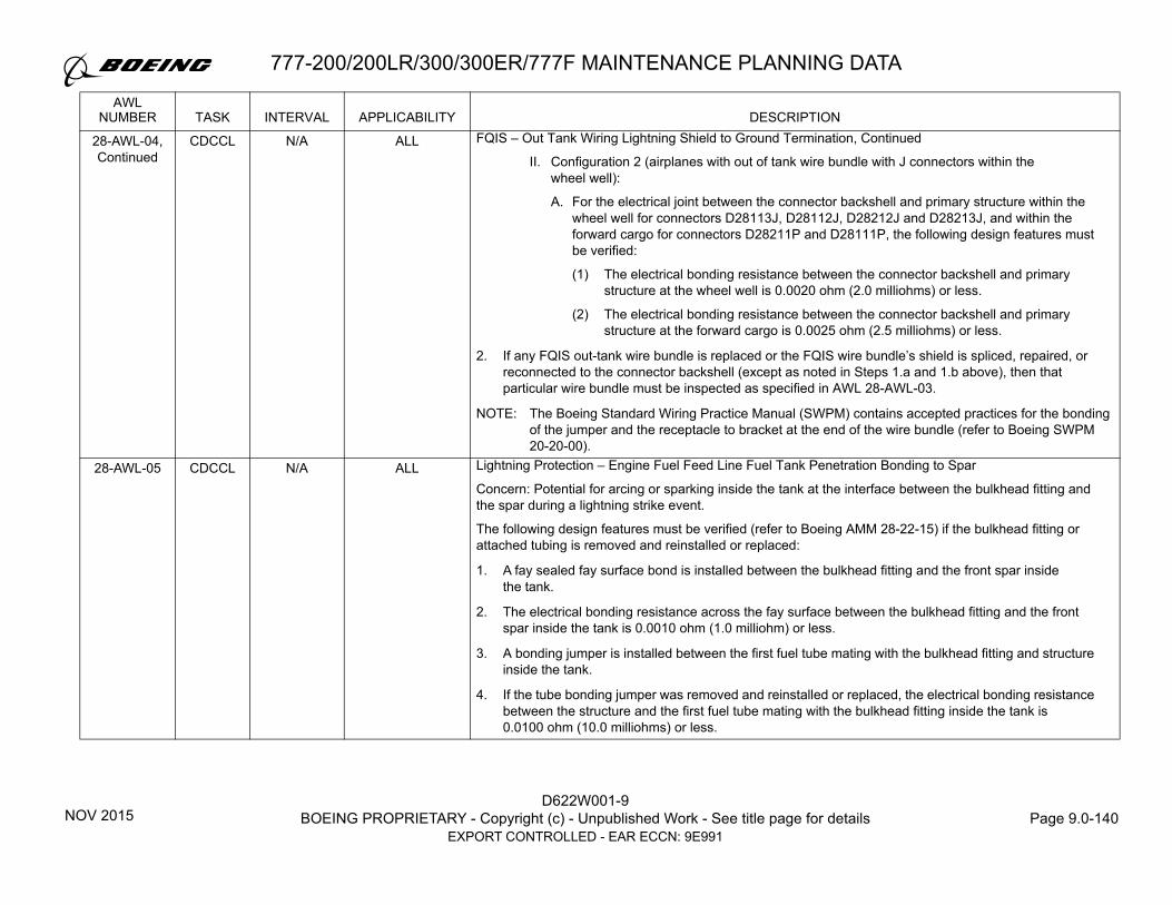
D622W001-9BOEING PROPRIETARY - Copyright (c) - Unpublished Work - See title page for details Page 9.0-140
EXPORT CONTROLLED - EAR ECCN: 9E991
777-200/200LR/300/300ER/777F MAINTENANCE PLANNING DATA
28-AWL-04,Continued
CDCCL N/A ALL FQIS – Out Tank Wiring Lightning Shield to Ground Termination, Continued
II. Configuration 2 (airplanes with out of tank wire bundle with J connectors within the wheel well):
A. For the electrical joint between the connector backshell and primary structure within the wheel well for connectors D28113J, D28112J, D28212J and D28213J, and within the forward cargo for connectors D28211P and D28111P, the following design features must be verified:
(1) The electrical bonding resistance between the connector backshell and primary structure at the wheel well is 0.0020 ohm (2.0 milliohms) or less.
(2) The electrical bonding resistance between the connector backshell and primary structure at the forward cargo is 0.0025 ohm (2.5 milliohms) or less.
2. If any FQIS out-tank wire bundle is replaced or the FQIS wire bundle’s shield is spliced, repaired, or reconnected to the connector backshell (except as noted in Steps 1.a and 1.b above), then that particular wire bundle must be inspected as specified in AWL 28-AWL-03.
NOTE: The Boeing Standard Wiring Practice Manual (SWPM) contains accepted practices for the bonding of the jumper and the receptacle to bracket at the end of the wire bundle (refer to Boeing SWPM 20-20-00).
28-AWL-05 CDCCL N/A ALL Lightning Protection – Engine Fuel Feed Line Fuel Tank Penetration Bonding to Spar
Concern: Potential for arcing or sparking inside the tank at the interface between the bulkhead fitting and the spar during a lightning strike event.
The following design features must be verified (refer to Boeing AMM 28-22-15) if the bulkhead fitting or attached tubing is removed and reinstalled or replaced:
1. A fay sealed fay surface bond is installed between the bulkhead fitting and the front spar inside the tank.
2. The electrical bonding resistance across the fay surface between the bulkhead fitting and the front spar inside the tank is 0.0010 ohm (1.0 milliohm) or less.
3. A bonding jumper is installed between the first fuel tube mating with the bulkhead fitting and structure inside the tank.
4. If the tube bonding jumper was removed and reinstalled or replaced, the electrical bonding resistance between the structure and the first fuel tube mating with the bulkhead fitting inside the tank is 0.0100 ohm (10.0 milliohms) or less.
AWLNUMBER TASK INTERVAL APPLICABILITY DESCRIPTION
NOV 2015

777-200/200LR/300/300ER/777F MAINTENANCE PLANNING DATA
D622W001-9BOEING PROPRIETARY - Copyright (c) - Unpublished Work - See title page for details Page 9.0-141
EXPORT CONTROLLED - EAR ECCN: 9E991
28-AWL-06 CDCCL N/A ALL Lightning Protection – Hydraulic Line Fuel Tank Penetration Bonding Paths
Concern: Potential for arcing or sparking inside the tank at the interface between the bulkhead fitting and the rear spar, the hydraulic bulkhead fitting and the heat exchanger, or any two tubes connected by a swaged sleeve during a lightning strike event.
1. If the bulkhead fitting is removed and reinstalled or replaced, the following design features must be verified (refer to Boeing AMM 29-11-55):
a. Fillet seals are applied at the fitting to the tank wall interface outside the fuel tank.b. The electrical bonding resistance between the bulkhead fitting and the rear spar is 0.0010 ohm
(1.0 milliohm) or less.c. The electrical bonding resistance between the hydraulic tube in the fuel tank and bulkhead fitting
in the fuel tank is 0.0040 ohm (4.0 milliohms) or less.
2. If the hydraulic heat exchanger is removed and reinstalled or replaced, the following design features must be verified (refer to Boeing AMM 29-11-60):
a. A bonding jumper is installed from the hydraulic heat exchanger to structure inside the tank.b. The electrical bonding resistance across the bonding jumper between the heat exchanger and
structure is 0.0025 ohm (2.5 milliohms) or less.c. The electrical bonding resistance between the heat exchanger and each hydraulic tube is
0.0040 ohm (4.0 milliohms) or less.
3. If a non-heat exchanger hydraulic tube in the Main Fuel Tank is removed and reinstalled or replaced, the following design features must be verified (refer to Boeing AMM 20-10-09):
a. The electrical bonding resistance across the in-line fittings (tube-to-tube):
I. If Aluminum, tubing sizes 3/8 inch to 1/2 inch (10 mm to 13 mm), the maximum resistance is 0.0015 ohm (1.5 milliohms).
II. If Aluminum, tubing sizes 5/8 inch to 1-1/4 inch (16 mm to 32 mm), the maximum resistance is 0.0010 ohm (1.0 milliohm).
III. If Titanium, tubing sizes 3/8 inch to 1/2 inch (10 mm to 13 mm), the maximum resistance is 0.0080 ohm (8.0 milliohms).
IV. If Titanium, tubing sizes 5/8 inch to 1-1/4 inch (16 mm to 32 mm), the maximum resistance is 0.0030 ohm (3.0 milliohms).
AWLNUMBER TASK INTERVAL APPLICABILITY DESCRIPTION
NOV 2015

D622W001-9BOEING PROPRIETARY - Copyright (c) - Unpublished Work - See title page for details Page 9.0-142
EXPORT CONTROLLED - EAR ECCN: 9E991
777-200/200LR/300/300ER/777F MAINTENANCE PLANNING DATA
28-AWL-07 CDCCL N/A ALL AC and DC Fuel Pump Electrical/Mechanical Design
Concern: Potential for maintenance error that could compromise ignition source prevention features.
Maintenance of Fuel Pumps must be done with the applicable CMM as follows:
1. Maintenance of the Main Tank Boost Pump and the Auxiliary Tank (Cell) Boost Pumps, if installed, must be in accordance with Eaton (VK2523) CMM 28-20-42 Revision 9, CMM 28-20-47 Revision 5, or later revisions of (or deviations from, or temporary revisions to, or Supplier Service Bulletin to) these CMMs that have been approved by the FAA Oversight Office.
2. Maintenance of the Center Wing Tank Override-Jettison Pump and Main Tank Jettison Pump must be in accordance with Eaton (VK2523) CMM 28-20-44 Revision 6, or later revisions of (or deviations from, or temporary revisions to, or Supplier Service Bulletin to) this CMM that have been approved by the FAA Oversight Office.
3. Maintenance of the APU Supply Fuel Pump must be in accordance with Eaton (VK2523) CMM 28-20-45 Revision 5 or later revisions of (or deviations from, or temporary revisions to, or Supplier Service Bulletin to) this CMM that have been approved by the FAA Oversight Office.
NOTE: Some CMM's have specific portions of the procedures tagged as a CDCCL or ALI, to identify them as items that must be followed precisely. If a CMM does not have specific items tagged as a CDCCL or ALI, then the entire CMM must be followed precisely.
28-AWL-08 CDCCL N/A 777-200 Center Wing Tank Sump Drain Valve
Concern: Potential for arcing or sparking inside the tank at the interface between the sump drain valve and the lower skin in the center wing tank during a lightning strike event.
If the center wing tank sump drain valve is removed and reinstalled or replaced, the following design features must be verified (refer to Boeing AMM 28-11-06):
1. The presence of an insulating washer at the sump drain valve inside the tank.
2. A fillet seal is applied at the interface between the jam nut and airplane structure inside the tank.
AWLNUMBER TASK INTERVAL APPLICABILITY DESCRIPTION
NOV 2015

777-200/200LR/300/300ER/777F MAINTENANCE PLANNING DATA
D622W001-9BOEING PROPRIETARY - Copyright (c) - Unpublished Work - See title page for details Page 9.0-143
EXPORT CONTROLLED - EAR ECCN: 9E991
28-AWL-09 CDCCL N/A ALL Lightning, Fault Current, or Hot Short Protection – Fuel Tank Penetrations (All Fuel Tanks)
Concern: Potential for arcing or sparking inside the tank at a conductive metal-to-ground structure interface as a result of electrical fault currents or lightning strike events due to insufficient bonding within the ground electrical path.
Any repair or alteration involving new or altered penetrations to the fuel tanks (such as a repair with fasteners, adding a bracket, bulkhead fitting or equipment, etc.) or change to the design features of the existing equipment penetrations (such as fuel measuring sticks, sump drain valves, fueling manifold, fuel temperature sensor, and motor operated fuel shutoff valve adapter plate) requires approval from the FAA Oversight Office.
However, no additional FAA Oversight Office approval is required if the repair or alteration is accomplished in accordance with:
1. Boeing Structural Repair Manual (SRM) procedures, and/or
2. Boeing Service Bulletins, and/or
3. Boeing Organization Designation Authorization (ODA) approved repair/alteration instructions;
where all the required procedures that relate to the new or altered fuel tank penetration include the statement, "These data have been reviewed by the Boeing ODA for fuel tank ignition prevention requirements, and no further approval from the FAA Oversight Office is required to satisfy the requirements of CDCCL 28-AWL-09 provided the repair or alteration is accomplished in accordance with these instructions.”
NOTE: Electrical bonding of fittings and brackets and/or cap sealing of fasteners and/or fillet sealing of component interface to structure inside and/or outside the fuel tank will be required.
AWLNUMBER TASK INTERVAL APPLICABILITY DESCRIPTION
NOV 2015

D622W001-9BOEING PROPRIETARY - Copyright (c) - Unpublished Work - See title page for details Page 9.0-144
EXPORT CONTROLLED - EAR ECCN: 9E991
777-200/200LR/300/300ER/777F MAINTENANCE PLANNING DATA
28-AWL-10 CDCCL N/A ALL AC and DC Fuel Pump Fault Current Bonding Jumper Installation, Main and Center Tank
Concern: Potential for fault current path through the pump housing to structure inside the tank. Electrical faults internal to the fuel pump motor-impeller are, by design, routed through the motor-impeller assembly to the bonding jumper on the front face of the motor-impeller assembly to structure outside the tank. The bonding jumper ensures that fault currents are conducted to structure outside the tank until the circuit breaker and/or Ground Fault Interrupter (GFI) and/or Ground Fault Protector (GFP) has had time to remove power from the pump.
If the pump is removed and reinstalled or replaced, the following design features must be verified (refer to Boeing AMMs 28-22-05, 28-22-06, 28-25-03, and 28-31-01):
1. A bonding jumper is installed between the pump motor-impeller and structure.
2. The bonding jumper is installed with a fay sealed fay surface bond between the pump motor-impeller and bonding jumper and a fay sealed fay surface bond between the bonding jumper and structure.
3. For AC pump, the electrical bonding resistance between the pump motor-impeller and the structure is 0.00025 ohm (0.25 milliohm) or less.
4. For DC pump, the electrical bonding resistance between the pump motor-impeller and the structure is 0.0005 ohm (0.5 milliohm) or less.
28-AWL-11 CDCCL N/A ALL Fuel Quantity Indicating System (FQIS) and Auxiliary Fuel Tank (Cell) Electronic Fuel Level Indication System (EFLI) – Out Tank Wiring Installation Separation Requirement
Concern: Potential for hot shorts and Electromagnetic Effects (EME)-induced voltages on the FQIS wiring or Auxiliary Fuel Tank (Cell) EFLI wiring to enter the tank.
Tank circuit wiring is identified as the FQIS or Auxiliary Fuel Tank (Cell) EFLI wiring from an LRU (shown to be an ignition source protection device - such as a Fuel Quantity Processor Unit (FQPU) or EFLI Processor Unit, qualified up to airplane 28VDC or 115VAC electrical power source) to the fuel tank structural penetration, typically at the spar connector. Airplane interface circuit wiring is identified as the wiring terminating at the LRU (such as a FQPU or EFLI Processor Unit) and not considered tank circuit wiring.
New wiring is defined as any new alteration that installs wiring after initial Airplane Airworthiness Certificate issuance or after the date 28-AWL-11 was first incorporated into an operator's maintenance program, whichever is later. Repair or replacement of existing wiring is not considered new wiring.
(Continued on next page)
AWLNUMBER TASK INTERVAL APPLICABILITY DESCRIPTION
NOV 2015

777-200/200LR/300/300ER/777F MAINTENANCE PLANNING DATA
D622W001-9BOEING PROPRIETARY - Copyright (c) - Unpublished Work - See title page for details Page 9.0-145
EXPORT CONTROLLED - EAR ECCN: 9E991
28-AWL-11,Continued
FQIS and Auxiliary Fuel Tank (Cell) EFLI – Out Tank Wiring Installation Separation Requirement, Continued
1. Repair or replacement of existing tank circuit or airplane interface circuit wiring must maintain its existing wire routing.
2. Routing and installation of any new wiring within 6.5 inches (165 mm) of the tank circuit or airplane interface circuit wiring must meet EITHER of the following requirements:
a. The new wiring installation has been found by the FAA to be compliant with Title 14 CFR Part 25, Section 25.981(a)(3) at Amendment 25-102 or later.
ORb. The new wiring must meet the following wire separation criteria:
I. For new wiring carrying data signals such as Coaxial, USB, or Ethernet wiring, the installation and separation requirements of the airplane Standard Wiring Practices Manual (SWPM) apply.
II. For airplanes with FQPU P/N 0320KPU01 that have new airplane interface circuit wiring up to airplane 28VDC electrical power source, the installation and separation requirements of the airplane SWPM apply.
III. For airplanes that do not have FQPU P/N 0320KPU01 and have new airplane interface circuit wiring up to airplane 115VAC electrical power source, the installation and separation requirements of the SWPM apply.
IV. For all other new wiring, use wire types BMS 13-48, BMS 13-60 or BMS 13-58 and a minimum separation of 2.0 inches (51 mm) or greater is required except as noted below:
A. For new wiring meeting any of the following criteria, the separation from tank circuit or airplane interface circuit wiring must meet the requirements from 2.b.IV.B to 2.b.IV.G.
(1) New wiring near tank circuit wiring.
(2) New wiring near airplane interface circuit wiring carrying greater than airplane 115VAC electrical power source.
(3) On airplanes with an FQPU processor with P/N 0320KPU01, new wiring near airplane interface circuit wiring carrying greater than airplane 28VDC electrical power source.
(Continued on next page)
AWLNUMBER TASK INTERVAL APPLICABILITY DESCRIPTION
NOV 2015

D622W001-9BOEING PROPRIETARY - Copyright (c) - Unpublished Work - See title page for details Page 9.0-146
EXPORT CONTROLLED - EAR ECCN: 9E991
777-200/200LR/300/300ER/777F MAINTENANCE PLANNING DATA
28-AWL-11,Continued
FQIS and Auxiliary Fuel Tank (Cell) EFLI – Out Tank Wiring Installation Separation Requirement, Continued
B. For new wiring installed with a separation between 2.0 inches (51 mm) and 0.5 inch (13 mm) from the tank circuit or airplane interface circuit wiring, and neither the tank circuit or airplane interface circuit wiring nor new wiring is EME shielded, the length of new wiring that is routed within the 2.0 inches (51 mm) from the tank circuit or airplane interface circuit wiring should not exceed 2.0 feet (0.6 m), either in the sum of the portions or total length.
C. For new wiring installed with a separation between 2.0 inches (51 mm) and 0.5 inch (13 mm) from the tank circuit or airplane interface circuit wiring, and either the tank circuit or airplane interface circuit wiring or new wiring is EME shielded, the length of new wiring that is routed within the 2.0 inches (51 mm) from the tank circuit or airplane interface circuit wiring should not exceed 34 feet (10.4 m), either in the sum of the portions or total length.
D. For new wiring installed in parallel to the tank circuit or airplane interface circuit wiring with a separation between 2.0 inches (51 mm) and 0.5 inch (13 mm), the following requirements also apply:
(1) Sleeve either the new wiring or the tank circuit or airplane interface circuit wire bundle with TFE-2X Standard wall (manufactured in accordance with MIL-I-23053). The sleeving must extend a minimum of 1.0 inch (25 mm) beyond the point where the separation is less than 2.0 inches (51 mm).
(2) Maintain a separation of no less than 0.5 inch (13 mm) from the tank circuit or airplane interface circuit wiring under any single failure of a support point.
E. For new wiring that crosses the tank circuit or airplane interface circuit wiring with a separation less than 2.0 inches (51 mm) and greater than 0.5 inch (13 mm) from the tank circuit or airplane interface circuit wiring, the following requirements also apply:
(1) Sleeve either the new wiring or the tank circuit or airplane interface circuit wire bundle with TFE-2X Standard wall (manufactured in accordance with MIL-I-23053). The sleeving must extend a minimum of 6.0 inches (152 mm) on either side of crossing point.
(2) Maintain a separation of no less than 0.5 inch (13 mm) from the tank circuit or airplane interface circuit wiring under any single failure of a support point.
(Continued on next page)
AWLNUMBER TASK INTERVAL APPLICABILITY DESCRIPTION
NOV 2015

777-200/200LR/300/300ER/777F MAINTENANCE PLANNING DATA
D622W001-9BOEING PROPRIETARY - Copyright (c) - Unpublished Work - See title page for details Page 9.0-147
EXPORT CONTROLLED - EAR ECCN: 9E991
28-AWL-11,Continued
FQIS and Auxiliary Fuel Tank (Cell) EFLI – Out Tank Wiring Installation Separation Requirement, Continued
F. For new wiring that crosses the tank circuit or airplane interface circuit wiring with a separation less than 0.5 inch (13 mm) from the tank circuit or airplane interface circuit wiring, the following requirements also apply:
(1) Sleeve both the new wiring and the tank circuit or airplane interface circuit wire bundle with TFE-2X Standard wall (manufactured in accordance with MIL-I-23053). The sleeving must extend a minimum of 6.0 inches (152 mm) on either side of the crossing point.
(2) Maintain a separation of no less than 0.25 inch (6 mm) from the tank circuit or airplane interface circuit wiring.
G. For new wiring routed within power panels in proximity of the tank circuit or airplane interface circuit wiring, the following requirements only apply:
(1) Sleeve and EME shield only the new wiring with TFE-2X Standard wall (manufactured in accordance with MIL-I-23053). New wiring can be routed together with the tank circuit or airplane interface circuit wiring. Do not route the new wiring via the same connector as the tank circuit or airplane interface circuit wiring.
3. Repair or replacement of existing wiring that is installed within 6.5 inches (165 mm) of the tank circuit or airplane interface circuit wiring must maintain its existing wire routing.
NOTE: Refer to the Boeing Wire Diagrams to identify FQIS wiring or Auxiliary Fuel Tank (Cell) EFLI wiring bundles.
NOTE: The following are accepted practices for repair or replacement of existing wiring:
For wire type substitutes, refer to Boeing SWPM 20-00-14.For wire assembly and installation, refer to Boeing SWPM 20-10-11.For repair procedures, refer to Boeing SWPM 20-10-13.
AWLNUMBER TASK INTERVAL APPLICABILITY DESCRIPTION
NOV 2015

D622W001-9BOEING PROPRIETARY - Copyright (c) - Unpublished Work - See title page for details Page 9.0-148
EXPORT CONTROLLED - EAR ECCN: 9E991
777-200/200LR/300/300ER/777F MAINTENANCE PLANNING DATA
28-AWL-12 CDCCL N/A ALL Center Wing Tank (CWT) Refuel Valve and Auxiliary Fuel Tank (Cell) Refuel Valve – Fault Current Bond
Concern: Potential for arcing inside the CWT following refuel valve maintenance.
1. If the CWT refuel valve is removed and reinstalled or replaced, the following design features must be verified (refer to Boeing AMM 28-21-02):
a. A fay surface bond is installed between the valve body and gasket and between the gasket and the rear spar inside the tank.
b. The electrical bonding resistance between the valve body and the rear spar inside the tank is 0.0025 ohm (2.5 milliohms) or less.
c. A fillet seal is applied around the entire perimeter of the valve body and gasket on the rear spar inside the tank.
2. For airplanes with Auxiliary Fuel Tank (Cell) installed, if the Auxiliary Fuel Tank (Cell) Refuel Valve (Solenoid Actuator located on CWT Rear Spar) is removed and reinstalled or replaced, the following design features must be verified (refer to Boeing AMM 28-21-21):
a. A fay surface bond is installed between the valve body and gasket and between the gasket and the rear spar inside the tank.
b. The electrical bonding resistance between the valve body and the rear spar inside the tank is 0.0025 ohm (2.5 milliohms) or less.
c. A fillet seal is applied around the entire perimeter of the valve body and gasket on the rear spar inside the tank.
AWLNUMBER TASK INTERVAL APPLICABILITY DESCRIPTION
NOV 2015

777-200/200LR/300/300ER/777F MAINTENANCE PLANNING DATA
D622W001-9BOEING PROPRIETARY - Copyright (c) - Unpublished Work - See title page for details Page 9.0-149
EXPORT CONTROLLED - EAR ECCN: 9E991
28-AWL-13 CDCCL N/A ALL FQIS – Fuel Quantity Processor Unit (FQPU) Repair and Auxiliary Fuel Tank (Cell) EFLI – Processor Display Unit (PDU) Repair
Concern: Potential for maintenance error during FQPU or Auxiliary Fuel Tank (Cell) EFLI PDU repair.
The FQPU and Auxiliary Fuel Tank (Cell) EFLI is designed to limit the levels of energy, voltage, current, and power allowed within the FQIS / EFLI circuit to intrinsically safe levels in order to preclude the potential of an ignition source within any fuel tank.
1. Maintenance of the FQPU must be in accordance with one of the following CMMs.
a. GE Aviation [identified as Smiths or GE Aviation in the respective CMM] (VK5294) CMM 28-47-69 Volume 1 Revision 5 and CMM 28-47-69 Volume 2 (IPC) Revision 2, CMM 28-47-65 Volume 1 Revision 5, and CMM 28-47-65 Volume 2 (IPC) Revision 4, or later revisions of (or deviation from, or temporary revisions to, or Supplier Service Bulletin to) these CMMs that have been approved by the FAA Oversight Office.
b. Ontic (VU0J60) CMM 28-47-69 Volume 1 Revision 9 and CMM 28-47-69 Volume 2 (IPC) Revision 4 or later revisions of (or deviation from, or temporary revisions to, or Supplier Service Bulletin to) these CMMs that have been approved by the FAA Oversight Office.
2. If auxiliary fuel tank (cell) is installed, maintenance of the EFLI PDU must be in accordance with Parker (V26055) CMM 28-41-81 Revision 1, or later revisions of (or deviation from, or temporary revisions to, or Supplier Service Bulletin to) this CMM that have been approved by the FAA Oversight Office.
NOTE: Some CMM's have specific portions of the procedures tagged as CDCCL or ALI, to identify them as items that must be followed precisely. If a CMM does not have specific items tagged as a CDCCL or ALI, then the entire CMM must be followed precisely.
AWLNUMBER TASK INTERVAL APPLICABILITY DESCRIPTION
SEP 2018

D622W001-9BOEING PROPRIETARY - Copyright (c) - Unpublished Work - See title page for details Page 9.0-150
EXPORT CONTROLLED - EAR ECCN: 9E991
777-200/200LR/300/300ER/777F MAINTENANCE PLANNING DATA
28-AWL-14 CDCCL N/A ALL FQIS and Auxiliary Fuel Tank (Cell) EFLI – In-Tank Hardware Design Features (FQIS Tank Units, Densitometers, Water Detector and Auxiliary Fuel Tank (Cell) EFLI Probes)
Concern: Potential for maintenance error during repair of in-tank hardware (FQIS tank units, densitometers, water detectors, and auxiliary fuel Tank (cell) EFLI probes). Arc gaps may develop that could result in an ignition source inside the fuel tank.
1. Maintenance of the FQIS Tank Units must be in accordance with GE Aviation [identified as Smiths or GE Aviation in the respective CMM] (VK5294)] CMM 28-47-58 Revision 8, CMM 28-47-71 Revision 5, or later revisions of (or deviations from, or temporary revisions to, or Supplier Service Bulletin to) these CMMs that have been approved by the FAA Oversight Office.
2. Maintenance of the FQIS Water Detectors must be in accordance with GE Aviation [identified as Smiths or GE Aviation in the respective CMM] (VK5294)] CMM 28-47-60 Revision 6 or later revisions of (or deviations from, or temporary revisions to, or Supplier Service Bulletin to) this CMM that have been approved by the FAA Oversight Office.
3. Maintenance of the FQIS Densitometers must be in accordance with GE Aviation [identified as Smiths in the respective CMM] (VK5294)] CMM 28-48-03 Revision 5 or later revisions of (or deviations from, or temporary revisions to, or Supplier Service Bulletin to) this CMM that have been approved by the FAA Oversight Office.
4. If auxiliary fuel tank (cell) is installed, maintenance of the EFLI probe must be in accordance with Parker (V26055) CMM 28-41-70 Revision 1 or later revisions of (or deviations from, or temporary revisions to, or Supplier Service Bulletin to) this CMM that have been approved by the FAA Oversight Office.
NOTE: Some CMM’s have specific portions of the procedures tagged as CDCCL or ALI to identify them as items that must be followed precisely. If a CMM does not have specific items tagged as a CDCCL or ALI, then the entire CMM must be followed precisely.
AWLNUMBER TASK INTERVAL APPLICABILITY DESCRIPTION
SEP 2018

777-200/200LR/300/300ER/777F MAINTENANCE PLANNING DATA
D622W001-9BOEING PROPRIETARY - Copyright (c) - Unpublished Work - See title page for details Page 9.0-151
EXPORT CONTROLLED - EAR ECCN: 9E991
28-AWL-15 CDCCL N/A ALL FQIS – In-Tank Wire Harness Protection Features – Wire Insulation and Separation from Tank Internal Structure
Concern: Potential for damage during repair or replacement of in-tank wire harness that may affect the design features for the wire insulation and the separation from tank structure. Arc gaps may develop that could result in an ignition source inside the fuel tank.
1. If any maintenance, preventative maintenance, alteration, or installation is performed on the FQIS In-Tank Wire Harness inside the main or center tanks, verify the following (refer to Boeing AMM 28-41-05):
a. Maintain existing (or newly approved) wire harness routing, clamping and sleeving. b. Wire harness, clamps, and sleeving are not damaged.c. Wires are not chafed.d. Wire harness clearance between wires and structure, accounting for slack in all directions, must
be a minimum of 0.125 inch (3.2 mm).
2. Maintenance of the FQIS In-Tank Wire Harness must be in accordance with the following:
a. Repair of the FQIS in-tank wire harness on aircraft must be approved by the FAA Oversight Office,
ORb. GE Aviation [identified as Smiths in the respective CMM] (VK5294)] CMM 28-47-61 Revision 7 or
later revisions of (or deviations from, or temporary revisions to, or Supplier Service Bulletin to) this CMM that has been approved by the FAA Oversight Office.
NOTE: Some CMM's have specific portions of the procedures tagged as CDCCL or ALI to identify them as items that must be followed precisely. If a CMM does not have specific items tagged as a CDCCL or ALI, then the entire CMM must be followed precisely.
(Continued on next page)
AWLNUMBER TASK INTERVAL APPLICABILITY DESCRIPTION
SEP 2018

D622W001-9BOEING PROPRIETARY - Copyright (c) - Unpublished Work - See title page for details Page 9.0-152
EXPORT CONTROLLED - EAR ECCN: 9E991
777-200/200LR/300/300ER/777F MAINTENANCE PLANNING DATA
28-AWL-15,Continued
FQIS – In-Tank Wire Harness Protection Features – Wire Insulation and Separation from Tank Internal Structure, Continued
3. For airplanes with Auxiliary Fuel Tank (Cell) installed, the following maintenance requirements are applicable:
a. If any maintenance, preventative maintenance, alteration, or installation is performed on the FQIS In-Tank Wire Harness inside the auxiliary fuel tank (cell), verify the following (refer to Boeing AMM 28-41-05):
I. Maintain existing (or newly approved) wire harness routing, clamping and sleeving.
II. Wire harness, clamps, and sleeving are not damaged.
III. Wires are not chafed.
IV. Wire harness clearance between wires and structure, accounting for slack in all directions, must be a minimum of 0.125 inch (3.2 mm).
b. If the auxiliary fuel tank (cell) is removed and replaced, verify the following (refer to Boeing AMM 28-14-01)) during installation of the auxiliary fuel tank (cell) (this step is not required for the installation of new auxiliary fuel tank (cell)):
I. Wire harness, clamps, and sleeving are not damaged.
II. Wires are not chafed.
III. Wire harness clearance between wires and structure, accounting for slack in all directions, must be a minimum of 0.125 inch (3.2 mm).
AWLNUMBER TASK INTERVAL APPLICABILITY DESCRIPTION
NOV 2015

777-200/200LR/300/300ER/777F MAINTENANCE PLANNING DATA
D622W001-9BOEING PROPRIETARY - Copyright (c) - Unpublished Work - See title page for details Page 9.0-153
EXPORT CONTROLLED - EAR ECCN: 9E991
28-AWL-16 CDCCL N/A ALL Fuel Tank Access Doors – Lightning Protection Electrical Design Features
Concern: Potential for arcing or sparking inside the tank at the interface between the door and the tank structure as a result of a direct strike or conducting currents through the wing skin.
The following design features must be verified during installation of fuel tank access doors located on the lower wing skin (refer to Boeing AMMs 28-11-01, 28-11-02, and 28-11-03):
NOTE: There are three types of doors: Standard, Impact-Resistant, and Machined Impact-Resistant, that have specific locations and other design features.
1. A phenolic strip is positioned around the outermost periphery of all doors that mate with the wing skin inside the tank, except for the impact-resistant door positions listed below:
a. 777-200/300: Door Positions 531AB, 631AB, 531BB, 631BB, 531CB, 631CB, 533AB, 633AB, 533BB, 633BB, 533CB, 633CB, 533DB, 633DB, 533EB, 633EB, 533FB, 633FB, 533GB, 633GB, 541AB, 641AB.
b. 777-200LR/300ER/F: Door Positions 533FB, 633FB, 533GB, 633GB, 541AB, 641AB.
2. No visible corrosion on the access door, clamp ring, and lower wing skin electrical faying surfaces.
3. A new knitted aluminum mesh gasket is installed. If a new gasket is not available, a used gasket meeting the following criteria may be installed:
a. No fastener holes are torn.b. The gasket is not elongated or out of shape.c. The gasket rubber seals around the inner and outer periphery must be a minimum of
0.015 inch (0.4 mm) thick.d. No more than 10% of strands in all three layers are broken through in any one area.
NOTE: A gasket that meets Item 3d but does not meet Items 3.a through 3.c criteria may be used for a maximum duration of 30 days and then must be replaced with a gasket that meets all the criteria listed above.
(Continued on next page)
AWLNUMBER TASK INTERVAL APPLICABILITY DESCRIPTION
NOV 2015

D622W001-9BOEING PROPRIETARY - Copyright (c) - Unpublished Work - See title page for details Page 9.0-154
EXPORT CONTROLLED - EAR ECCN: 9E991
777-200/200LR/300/300ER/777F MAINTENANCE PLANNING DATA
28-AWL-16,Continued
Fuel Tank Access Doors – Lightning Protection Electrical Design Features, Continued
4. Approved grease or anti-corrosion compound (listed in 4.a., 4.b. and 4.c.) is applied as necessary to ensure both sides of the knitted aluminum mesh gasket are filled. Do not mix grease or anti-corrosion compound types in the gasket and installation of the door (a thin layer of the same grease or anti-corrosion compound is applied to the wing skin surface common to the gasket prior to door installation).
a. Aeroshell 14 (applicable to all doors except for machined impact resistant doors on 777-300ER/200LR/F), or
b. Mobilgrease 33 (applicable to all doors except for machined impact resistant doors on 777-300ER/200LR/F), or
c. CorBan 27L (applicable to all doors including machined impact resistant doors on 777-300ER/200LR/F).
NOTE: If the new knitted aluminum mesh gasket is greater than five years old from manufacturing date, vapor de-grease and re-impregnate with 0.5-1 ounce (15 - 30 milliliters) of the approved grease or anti-corrosion compound to ensure both sides of the knitted aluminum mesh gasket are filled before installation.
5. A torque of 35 ±5 in-lb (4 ±1 N-m) is applied on the fasteners for all doors except for 777-300ER/200LR/F machined impact-resistant doors listed below:
a. 777-300ER/200LR/F: Machined Impact-Resistant Door Positions: 531AB, 631AB, 531BB, 631BB, 531CB, 631CB, 533AB, 633AB, 533BB, 633BB, 533CB, 633CB, 533DB, 633DB, 533EB, 633EB, a torque of 65 ± 5 in-lb (7 ±1 N-m) is applied on these fasteners.
6. If the pressure relief valve on the surge tank access door is removed and reinstalled or replaced, verify the following (refer to Boeing AMM 28-13-03).
a. A fillet sealed fay surface bond is installed between the valve body mounting flange and the door.b. The electrical bonding resistance between the valve and the door is 0.0100 ohm (10.0 milliohms)
or less.c. A fillet seal is installed between the valve body mounting flange and the door.
AWLNUMBER TASK INTERVAL APPLICABILITY DESCRIPTION
NOV 2015

777-200/200LR/300/300ER/777F MAINTENANCE PLANNING DATA
D622W001-9BOEING PROPRIETARY - Copyright (c) - Unpublished Work - See title page for details Page 9.0-155
EXPORT CONTROLLED - EAR ECCN: 9E991
28-AWL-17 CDCCL N/A ALL Over-current and Arcing Protection Electrical Design Features – Fuel Pump Circuit Breakers or Electrical Load Control Unit (ELCU) and Ground Fault Interrupters (GFI)/Ground Fault Protector (GFP) (If Installed)
Concern: Potential for high current heating, arcing or sparking inside the tank between fuel pumps and fuel pump housings and outside the tank between pump wiring and structure in flammable leakage zones.
Before resetting the circuit breaker(s), ELCU(s), or GFIs/GFPs, determine the fault(s) that resulted in circuit breaker, ELCU, or GFI/GFP tripping and the fault(s) are isolated and corrected prior to reset.
If no fault is found, then prior to resetting the circuit breaker, ELCU, or GFI/GFP, perform the following insulation resistance test between each power circuit and chassis/airplane ground using a megohmmeter that has 10 VDC and 500 VDC voltage supply options with a maximum short circuit current of 5 milliamperes (refer to Boeing AMM 28-22-00 for AC Fuel Pump and Boeing AMM 28-25-00 for DC Fuel Pump).
1. AC Fuel Pump:
a. Verify on the pump electrical connector that the resistance is 1 megohm or greater between each phase connector contact (three total) and ground contact with the megohmmeter set to 10 VDC.
b. Verify on the pump electrical connector that the resistance is 5 megohms or greater between each phase connector contact (three total) and ground contact with the megohmmeter set to 500 VDC.
2. DC Fuel Pump:
a. Verify on the pump electrical connector that the resistance is 1 megohm or greater between the power contact and ground contact with megohmmeter set to 10 VDC.
b. Verify on the pump electrical connector that the resistance is 1 megohm or greater between the power contact and ground contact with megohmmeter set to 500 VDC.
NOTE: The Boeing Fault Isolation Manual (FIM), contains accepted practices for troubleshooting airplane systems:
For AC Fuel Pump circuit breaker, ELCU and GFI/GFP troubleshooting, refer to Boeing FIM 28-22 and 28-31.For DC Fuel Pump circuit breaker troubleshooting, refer to Boeing FIM 28-25. For Aux Fuel Tank Fuel Pump GFI troubleshooting, refer to Boeing FIM 28-14.
AWLNUMBER TASK INTERVAL APPLICABILITY DESCRIPTION
NOV 2015

D622W001-9BOEING PROPRIETARY - Copyright (c) - Unpublished Work - See title page for details Page 9.0-156
EXPORT CONTROLLED - EAR ECCN: 9E991
777-200/200LR/300/300ER/777F MAINTENANCE PLANNING DATA
28-AWL-18 ALI 375 DY ALLNOTE
Over-Current and Arcing Protection Electrical Design Features Operation – AC Fuel Pump GFI and GFP
Concern: Potential for pump housing burn-through, either internal or external to the fuel tank, as a result of major arcing due to electrical failure (i.e., damaged electrical connector, stator windings or leadwire to housing/end cap shorting).
The GFI/GFP is designed to detect electrical faults and open the circuit prior to pump housing burn-through.
The following action is required in order to ensure continued functionality of each fuel pump GFI/GFP circuit (refer to Boeing AMM 28-22-00 for main, center and jettison or Boeing AMM 28-14-05 for auxiliary):
1. The Main Tank Fuel Boost Pump Ground Fault Interrupter – Operational Test (APPLICABILITY NOTE: (iii) and (iv)):
a. Verify that the pump does not operate when the white band on the RESET button is visible on the following relays:
I. L FWD GFI Control Relay K28121
II. L AFT GFI Control Relay K28123
III. R FWD GFI Control Relay K28241
IV. R AFT GFI Control Relay K28242
2. The following tests are applicable to ELMS 1 Configuration airplanes (APPLICABILITY NOTE: (ii) only):
a. The Center Fuel Tank Override/Jettison Pump Ground Fault Interrupter – Operational Test:
I. Verify that the amber PRESS light for the FUEL CENTER PUMPS L switch-light is on when the white band on the relay RESET button is visible for Left Override Pump GFI Control Relay K28253.
II. Verify that the amber PRESS light for the FUEL CENTER PUMPS R switch-light is on when the white band on the relay RESET button is visible for Right Override Pump GFI Control Relay K28254.
(Continued on next page)
AWLNUMBER TASK INTERVAL APPLICABILITY DESCRIPTION
NOV 2015

777-200/200LR/300/300ER/777F MAINTENANCE PLANNING DATA
D622W001-9BOEING PROPRIETARY - Copyright (c) - Unpublished Work - See title page for details Page 9.0-157
EXPORT CONTROLLED - EAR ECCN: 9E991
28-AWL-18,Continued
Over-Current and Arcing Protection Electrical Design Features Operation – AC Fuel Pump GFI and GFP, Continued
b. The Fuel Jettison Pump Ground Fault Interrupter – Operational Test:
I. Verify on the Fuel Management Maintenance Page that the COMMAND and STATUS indication for the L MAIN JET PUMP show as ON and NO PRESS respectively when the white band on the relay RESET button is visible for Left Override Pump GFI Control Relay K28247.
II. Verify on the Fuel Management Maintenance Page that the COMMAND and STATUS indication for the R MAIN JET PUMP show as ON and NO PRESS respectively when the white band on the relay RESET button is visible for Right Override Pump GFI Control Relay K28248.
3. The following tests are applicable to ELMS 2 Configuration airplanes (APPLICABILITY NOTE: (i) only):
a. The Center Fuel Tank Override/Jettison Pump Ground Fault Protection – Operational Test:
I. Verify that the center left override pump does not operate during the center left override pump test where the GFCI Tester, P/N J24014-24, has been used to insert the FAULT position, and the EICAS status message FUEL PUMP CENTER L shows on the EICAS display with the correlated maintenance message 28-11055 showing on the MAT.
II. Verify that the center right override pump does not operate during the center right override pump test where the GFCI Tester, P/N J24014-24, has been used to insert the FAULT position, and the EICAS status message FUEL PUMP CENTER R shows on the EICAS display with the correlated maintenance message 28-12039 showing on the MAT.
b. The Fuel Jettison Pump Ground Fault Protection – Operational Test:
I. Verify that the center left jettison pump does not operate during the center left jettison pump test where the GFCI Tester, P/N J24014-24, has been used to insert the FAULT position, and the EICAS status message FUEL JETT PUMP L and EICAS advisory message FUEL JETT MAIN show on the EICAS display with the correlated maintenance message 28-11056 showing on the MAT.
II. Verify that the center right jettison pump does not operate during the center right jettison pump test where the GFCI Tester, P/N J24014-24, has been used to insert the FAULT position, and the EICAS status message FUEL JETT PUMP R and EICAS advisory message FUEL JETT MAIN show on the EICAS display with the correlated maintenance message 28-12047 showing on the MAT.
(Continued on next page)
AWLNUMBER TASK INTERVAL APPLICABILITY DESCRIPTION
NOV 2015

D622W001-9BOEING PROPRIETARY - Copyright (c) - Unpublished Work - See title page for details Page 9.0-158
EXPORT CONTROLLED - EAR ECCN: 9E991
777-200/200LR/300/300ER/777F MAINTENANCE PLANNING DATA
28-AWL-18,Continued
Over-Current and Arcing Protection Electrical Design Features Operation – AC Fuel Pump GFI and GFP, Continued
4. The Auxiliary Fuel Tank (Cell) Pump Ground Fault Interrupter – Operational Test(APPLICABILITY NOTE: (v)):
a. Verify that the auxiliary fuel tank (cell) pump does not operate when the white band on the K28070 relay RESET button is visible.
APPLICABILITY NOTE:
i. (ELMS2) Center Tank Override/Jettison Pumps and Main Tank Jettison Pumps on airplanes with Line Number 423, 429, 454 and on.
ii. (ELMS1) Center Tank Override/Jettison Pumps and Main Tank Jettison Pumps on airplanes prior to Line Number 454, except 423 and 429, that have incorporated Service Bulletin 777-28A0037.
iii. All Main Tank Boost Pumps on airplanes with Line Number 662 and on.iv. All Main Tank Boost Pumps on airplanes prior to Line Number 662 that have incorporated Service
Bulletin 777-28A0038.v. Auxiliary Fuel Tank (Cell) Pumps on 777-200LRs only if equipped with Auxiliary Fuel Tank (Cell).
AWLNUMBER TASK INTERVAL APPLICABILITY DESCRIPTION
NOV 2015

777-200/200LR/300/300ER/777F MAINTENANCE PLANNING DATA
D622W001-9BOEING PROPRIETARY - Copyright (c) - Unpublished Work - See title page for details Page 9.0-159
EXPORT CONTROLLED - EAR ECCN: 9E991
28-AWL-19 CDCCL N/A Airplane Line Position 552
and on.
Airplanes that have incorporated
Service Bulletin777-28A0034.
Motor Operated Valve (MOV) Actuator – Lightning and Fault Current Protection Electrical Bond
Concern: Potential for arcing or sparking inside the fuel tank at a conductive metal-to-ground structure interface as a result of electrical fault.
1. For MOV Actuators that are mounted with an adapter plate, if the adapter plate is removed and reinstalled or replaced, the following design features must be verified (refer to the following Boeing AMMs: 28-14-12 (Auxiliary Tank Isolation Valve), 28-14-22 (Auxiliary Tank Refuel/Transfer Valve), 28-14-25 (Auxiliary Tank Fuel Transfer Valve), 28-14-44 (Auxiliary Tank Vent Valve), 28-21-24 (Auxiliary Tank No. 2 Refuel Isolation Valve), 28-22-01 (Fuel Spar Valve), 28-22-03 (Cross Feed Valve), 28-26-01 (Defuel Valve), 28-31-02 (Fuel Jettison Nozzle Valve for 777-300ER, -200LR, and 777F), 28-31-04 (Fuel Jettison Isolation Valve)).
a. A fillet sealed fay surface bond is installed between the adapter plate and the structure.b. Prior to installing the actuator, the electrical bonding resistance between the valve adapter plate
and the structure outside the tank is 0.0005 ohm (0.5 milliohm) or less.c. A fillet seal is installed between the adapter plate and structure.d. A cap seal is applied to each of the four adapter plate attach bolts inside the tank.
2. For MOV Actuators mounted without an adapter plate and using mounting bolts, if the valve is removed and reinstalled or replaced, the following design features must be verified (refer to Boeing AMMs 28-25-01 and 28-25-02 (APU Fuel Shutoff Valve), 28-25-04 and 28-25-05 (APU Fuel Isolation Valve)):
a. A fillet sealed fay surface bond is installed between the valve body mounting bolts and structure.b. A fillet seal is installed between the valve body mounting bolts and structure outside the tank.c. A fay sealed fay surface bond is installed between the actuator mounting feet and valve body
mounting bolts.d. Prior to attaching the bonding jumper to the actuator and with the electrical connector
disconnected, the electrical bonding resistance between the actuator mounting feet and the spar is 0.0050 ohm (5.0 milliohms) or less.
(Continued on next page)
AWLNUMBER TASK INTERVAL APPLICABILITY DESCRIPTION
APR 2019

D622W001-9BOEING PROPRIETARY - Copyright (c) - Unpublished Work - See title page for details Page 9.0-160
EXPORT CONTROLLED - EAR ECCN: 9E991
777-200/200LR/300/300ER/777F MAINTENANCE PLANNING DATA
28-AWL-19,Continued
Motor Operated Valve (MOV) Actuator – Lightning and Fault Current Protection, Continued
3. For 777-200/-300 airplane MOV Actuators that are mounted without adapter plate and is directly attached to the valve, if the valve is removed and reinstalled or replaced, the following design features must be verified (refer to Boeing AMMs 28-31-02 and 28-31-03 (Fuel Jettison Nozzle Valve):
a. A fillet sealed fay surface bond is installed between the valve body mounting flange and structure.b. Prior to installing the actuator, the electrical bonding resistance between the valve and the
structure is 0.0025 ohm (2.5 milliohms) or less.c. A fillet seal is installed between the valve body mounting flange and structure.d. A fay sealed fay surface bond is installed between the actuator mounting feet and the valve body.e. Prior to attaching the bonding jumper to the actuator and with the electrical connector
disconnected, the electrical bonding resistance between the actuator mounting feet and the structure is 0.0050 ohm (5.0 milliohms) or less.
4. For airplanes with auxiliary fuel tank (cell) installed, if the auxiliary fuel tank (cell) is removed and replaced, the following design features must be verified (refer to Boeing AMM 28-14-01) for the MOV Actuators (Auxiliary Tank Isolation Valve and the Auxiliary Tank Refuel/Transfer Valve) that are mounted on the auxiliary fuel tank (cell):
a. The MOV Actuator is installed on the auxiliary fuel tank (cell).b. A bonding jumper is installed between the actuator and structure.c. With the electrical connector disconnected, the electrical bonding resistance between the upper
actuator housing and the structure is 0.0025 ohm (2.5 milliohms) or less.
NOTE: Not applicable to the Air Transfer Valve/Actuator(s); Item Numbers V28010, V28011. The 777-200 covers the 777-200ER.
AWLNUMBER TASK INTERVAL APPLICABILITY DESCRIPTION
APR 2019
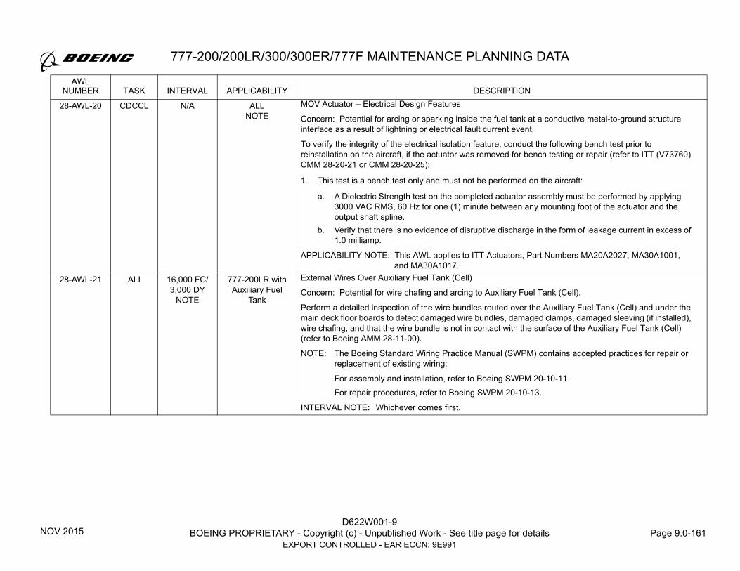
777-200/200LR/300/300ER/777F MAINTENANCE PLANNING DATA
D622W001-9BOEING PROPRIETARY - Copyright (c) - Unpublished Work - See title page for details Page 9.0-161
EXPORT CONTROLLED - EAR ECCN: 9E991
28-AWL-20 CDCCL N/A ALLNOTE
MOV Actuator – Electrical Design Features
Concern: Potential for arcing or sparking inside the fuel tank at a conductive metal-to-ground structure interface as a result of lightning or electrical fault current event.
To verify the integrity of the electrical isolation feature, conduct the following bench test prior to reinstallation on the aircraft, if the actuator was removed for bench testing or repair (refer to ITT (V73760) CMM 28-20-21 or CMM 28-20-25):
1. This test is a bench test only and must not be performed on the aircraft:
a. A Dielectric Strength test on the completed actuator assembly must be performed by applying 3000 VAC RMS, 60 Hz for one (1) minute between any mounting foot of the actuator and the output shaft spline.
b. Verify that there is no evidence of disruptive discharge in the form of leakage current in excess of 1.0 milliamp.
APPLICABILITY NOTE: This AWL applies to ITT Actuators, Part Numbers MA20A2027, MA30A1001, and MA30A1017.
28-AWL-21 ALI 16,000 FC/3,000 DY
NOTE
777-200LR with Auxiliary Fuel
Tank
External Wires Over Auxiliary Fuel Tank (Cell)
Concern: Potential for wire chafing and arcing to Auxiliary Fuel Tank (Cell).
Perform a detailed inspection of the wire bundles routed over the Auxiliary Fuel Tank (Cell) and under the main deck floor boards to detect damaged wire bundles, damaged clamps, damaged sleeving (if installed), wire chafing, and that the wire bundle is not in contact with the surface of the Auxiliary Fuel Tank (Cell) (refer to Boeing AMM 28-11-00).
NOTE: The Boeing Standard Wiring Practice Manual (SWPM) contains accepted practices for repair or replacement of existing wiring:
For assembly and installation, refer to Boeing SWPM 20-10-11.For repair procedures, refer to Boeing SWPM 20-10-13.
INTERVAL NOTE: Whichever comes first.
AWLNUMBER TASK INTERVAL APPLICABILITY DESCRIPTION
NOV 2015

D622W001-9BOEING PROPRIETARY - Copyright (c) - Unpublished Work - See title page for details Page 9.0-162
EXPORT CONTROLLED - EAR ECCN: 9E991
777-200/200LR/300/300ER/777F MAINTENANCE PLANNING DATA
28-AWL-22 CDCCL N/A 777-200LR with Auxiliary Fuel
Tank
External Wires Over Auxiliary Fuel Tank (Cell)
Concern: Potential for wire chafing or arcing to Auxiliary Fuel Tank (Cell).
If any maintenance, preventative maintenance, or alteration is performed in the area under the main deck floor boards and over the Auxiliary Fuel Tank (Cell), verify the following (refer to Boeing AMM 28-11-00) in the affected areas where maintenance was performed:
1. Maintain existing (or newly approved) wire bundle routing, clamping and sleeving.
2. Wire bundles, clamps, and sleeving (if installed) are not damaged.
3. Wires are not chafed.
4. Wire bundles are not in contact with the surface of the Auxiliary Fuel Tank (Cell).
NOTE: Boeing AMM 53-01-01 contains access information to this area.
The Boeing Standard Wiring Practice Manual (SWPM) contains accepted practices for repair or replacement of existing wiring.For assembly and installation, refer to Boeing SWPM 20-10-11. For repair procedures, refer to Boeing SWPM 20-10-13.
28-AWL-23 CDCCL N/A 777-200LR with Auxiliary Fuel
Tank
Auxiliary Fuel Tank (Cell) AC Fuel Pump Fault Current Bonding Path
Concern: Potential for fault current path through the motor-impeller assembly to the structure inside the tank (cell). Electrical faults internal to the fuel pump motor-impeller are, by design, routed through the motor-impeller assembly to the bonding jumpers on the front face of the motor-impeller assembly to the tank (cell) structure. The bonding jumpers ensure that fault currents are conducted to structure outside the tank (cell) until the circuit breaker and/or GFI has had time to remove power from the pump.
During auxiliary fuel tank (cell) pump replacement or auxiliary fuel tank (cell) installation (this AWL is not required for the installation of new auxiliary fuel tank (cell)), the following design features must be verified (refer to Boeing AMM 28-14-15 or 28-14-01):
1. A bonding jumper is installed between the pump motor-impeller and tank (cell) structure.
2. The bonding jumper is installed with a fay sealed fay surface bond between the pump motor-impeller and bonding jumper and a fay sealed fay surface bond between the bonding jumper and tank (cell) structure.
3. The electrical bonding resistance between the fuel pump motor-impeller and the tank (cell) structure is 0.0006 ohm (0.6 milliohm) or less.
AWLNUMBER TASK INTERVAL APPLICABILITY DESCRIPTION
NOV 2015

777-200/200LR/300/300ER/777F MAINTENANCE PLANNING DATA
D622W001-9BOEING PROPRIETARY - Copyright (c) - Unpublished Work - See title page for details Page 9.0-163
EXPORT CONTROLLED - EAR ECCN: 9E991
28-AWL-24 CDCCL N/A 777-200LR with Auxiliary Fuel
Tank
Auxiliary Fuel Tank (Cell) Thermal Protection Design Features
Concern: Potential for heating of the auxiliary tank (cell) structure as a result of a cargo fire event.
If any maintenance, preventative maintenance, or alteration is performed on or around the auxiliary tank (cell), the following must be verified (refer to Boeing AMM 28-14-00):
1. An Impact Barrier is installed on the aftmost auxiliary fuel tank (cell).
2. The Thermal Insulation Blanket is installed against the impact barrier.
3. Cargo Liners which separate the cargo compartment from the auxiliary fuel tank (cell) and cover the thermal blanket are installed.
28-AWL-25 CDCCL N/A 777-200LR with Auxiliary Fuel
Tank
Auxiliary Fuel Tank (Cell) Lightning Protection Design Features
Concern: Potential for arcing or sparking inside the tank (cell) at a conductive metal-to-ground structure interface as a result of lightning strike events to auxiliary fuel tank (cell) drains.
If any maintenance, preventative maintenance, or alteration is performed on or around the auxiliary fuel tank (cell) drain system, the following must be verified:
1. Low Pressure Teflon Lightning Safe Hoses are installed on the auxiliary fuel tank (cell) drain lines (Electrical Sump Drain Valve - Installation) (refer to Boeing AMM 28-14-52).
2. Forward and Aft Flame Arrestors are installed in auxiliary fuel tank (cell) drains (refer to Boeing AMM 28-14-54).
3. A fay sealed fay surface bond is installed between the drain bulkhead union and the structure (refer to Boeing AMM 28-14-52).
4. The electrical bonding resistance between the drain bulkhead union and the structure is 0.0025 ohm (2.5 milliohms) or less (refer to Boeing AMM 28-14-52).
28-AWL-26 ALI 375 DY 777-200LR with Auxiliary Fuel
Tank
Auxiliary Fuel Tank (Cell) AC Fuel Pump Uncommanded ON /Automatic Shutoff Circuit
Concern: Potential for failure of fuel pump power control circuit in the energized state allowing dry running of fuel pump with a potential ignition threat due to pump overheat or sparking.
The Pump Uncommanded ON/Automatic Shutoff Circuit provides redundant circuitry to remove power from the Auxiliary Fuel Tank (Cell) Pump if pump pressure is low for >15 seconds.
For installed Auxiliary Fuel Tank (Cell), operationally check the Auxiliary Fuel Tank (Cell) Pump Uncommanded ON/Automatic Shutoff Circuit (Bite Disable Relays) (refer to Boeing AMM 28-14-05) and verify the following:
1. Apply 28V DC (power supply) to pin 3 of connector D30324J and verify the circuit changes state to open at 15 +/- 2 seconds at pin 1 of connector D30324J.
AWLNUMBER TASK INTERVAL APPLICABILITY DESCRIPTION
NOV 2015

D622W001-9BOEING PROPRIETARY - Copyright (c) - Unpublished Work - See title page for details Page 9.0-164
EXPORT CONTROLLED - EAR ECCN: 9E991
777-200/200LR/300/300ER/777F MAINTENANCE PLANNING DATA
28-AWL-27 CDCCL N/A 777-200LR with Auxiliary Fuel
Tank
Auxiliary Fuel Tank (Cell) Replacement or Installation Electrical Bonding
Concern: Potential for fault current to the inside of the Auxiliary Fuel Tank (Cell). The tank (cell) contains bonding jumpers which provide a path from the tank (cell) to airplane structure. The bonding jumpers ensure that fault currents are conducted to structure outside the tank (cell).
The following design features must be verified during auxiliary tank (cell) bonding jumper replacement or installation of the Auxiliary Fuel Cell (refer to Boeing AMM 28-14-01):
1. The installation of a bonding jumper between the Auxiliary Fuel Tank (Cell) and the Stanchion.
2. The following electrical bonding resistances are verified:
a. On the right side of the tank (cell), the electrical bonding resistance between the auxiliary fuel tank (cell) and the stanchion is 0.0060 ohm (6.0 milliohms) or less.
b. The electrical bonding resistance between the stanchions and the structure is 0.0060 ohm (6.0 milliohms) or less.
28-AWL-28 CDCCL N/A ALL Lightning, Fault Current or Hot Short Protection Features – Fuel Tank Sealant Requirements (All Fuel Tanks)
Concern: Potential for arcing or sparking inside the tank at a conductive metal-to-ground structure interface as a result of electrical fault currents or lightning strike events due to insufficient bonding within the ground electrical path. Sealant damage or lack of proper adhesion could affect the fuel tank ignition prevention features.
If any maintenance, preventative maintenance, or alteration is performed inside the fuel tanks, verify the following in the affected areas (including the touchpoints during transit to and from the tank access point) where work is performed (refer to Boeing AMM 28-11-00):
1. Fillet seals around the periphery of the equipment interface with structure inside the tank are not damaged, such as peeling off or cracking.
2. Cap seals installed on fasteners and fittings inside the tank are not damaged, such as peeling off or cracking.
NOTE: Not all fasteners and fittings have cap seals. If fastener or fitting sealant is damaged, there will be residual evidence of a previously installed cap seal on fasteners and fittings in areas where installation is required.
NOTE: All repairs and alterations that involve fuel tank penetrations require compliance with AWL 28-AWL-09.
AWLNUMBER TASK INTERVAL APPLICABILITY DESCRIPTION
NOV 2015

777-200/200LR/300/300ER/777F MAINTENANCE PLANNING DATA
D622W001-9BOEING PROPRIETARY - Copyright (c) - Unpublished Work - See title page for details Page 9.0-165
EXPORT CONTROLLED - EAR ECCN: 9E991
28-AWL-29 CDCCL N/A ALL Static Dissipation Protection Design Features - In-Tank Material and Installation Changes (All Fuel Tanks)
Concern: Potential for electrostatic energy to be transferred to the tank during conditions such as airplane refueling. That electrostatic charge can accumulate on electrically isolated components or surfaces and then discharge to be a potential ignition source.
Any alteration or repair (does not include removal and replacement of existing parts) involving new or altered static dissipation protection design features inside the fuel tanks (such as alterations or repair that add fasteners, a bracket, a clamp, feed through fittings inside tank, or added equipment) or change to the design features of the existing equipment (such as the plumbing, paint, placards, clamps, location of isolated fasteners, fuel line bond jumpers, fuel line couplings) requires approval by the FAA Oversight Office.
However, no additional FAA Oversight Office approval is required if the alteration or repair is accomplished in accordance with:
1. Boeing Structural Repair Manual (SRM) procedures, and/or
2. Boeing Service Bulletins, and/or
3. Boeing Organization Designation Authorization (ODA) approved repair/alteration instructions;
where all the required procedures that relate to the new or altered static dissipation protection design features include the statement, "These data have been reviewed by the Boeing ODA for fuel tank ignition prevention requirements, and no further approval from the FAA Oversight Office is required to satisfy the requirements of CDCCL 28-AWL-29 provided the repair or alteration is accomplished in accordance with these instructions.”
28-AWL-30DELETED
ALI 500 FHNOTE
NOTE Over-Current and Arcing Protection Electrical Design Features - Fuel Pump Circuit Breakers or Ground Fault Interrupters (GFI)
AWLNUMBER TASK INTERVAL APPLICABILITY DESCRIPTION
NOV 2015

D622W001-9BOEING PROPRIETARY - Copyright (c) - Unpublished Work - See title page for details Page 9.0-166
EXPORT CONTROLLED - EAR ECCN: 9E991
777-200/200LR/300/300ER/777F MAINTENANCE PLANNING DATA
28-AWL-31 CDCCL N/A All Airplanes Line Number 504
and on.
Airplanes that have incorporated
Service Bulletin 777-57A0050.
Cushion Clamps and Teflon Sleeving Installed on Out-of-Tank Wire Bundles Installed on Brackets that are Mounted Directly on the Fuel Tanks
Concern: Potential for hot short induced voltages on out-of-tank wire bundle(s) to enter the fuel tank due to chafing and shorting to metal electrical brackets.
If maintenance, preventative maintenance, or alteration is performed on the following Out-of-Tank Wire Bundle(s) that are mounted directly on the fuel tanks at the locations listed in Step 1, the following design features in steps 2 to 4 must be verified for the affected wire bundles (refer to Boeing AMM 28-22-00) that maintenance was performed on.
1. The following are the applicable wire bundles and cushion clamp locations. If a plastic clamp (all locations) or a plastic ring-post (Center Tank Front Spar Bulkhead only) is used in any of these locations, steps 2 and 3 do not apply.
a. Left Wing Front Spar
I. Wire bundles W8100, W8101 located near Inboard Front Spar Stations (IFSS) 262 and 439
II. Wire bundles W8102, W8104, W8203, W8310, W8503, W8810, W8811 located near IFSS 262
III. Wire bundle W8850 located near IFSS 410
IV. Wire bundles W8143, W8145, W8247 located near IFSS 411 and 439
V. Wire bundles W8541, W8851 located near IFSS 411
VI. Wire bundle W8111 located near IFSS 262, 409, and 436 and Outboard Front Spar Stations (OFSS) 553, 578, 605, 635, 658, 684, 710, 740, 766, 816, 845, 871, 897, 923, 949, 1002, 1028, 1054 and 1080
VII. For 777-300ER, 777-200LR, and 777F airplanes, wire bundle W8111 located near OFSS 1106 and 1186
b. Right Wing Front Spar
I. Wire bundles W8200, W8201 located near Inboard Front Spar Stations (IFSS) 262 and 439
II. Wire bundles W8103, W8202, W8204, W8320, W8603, W8820, W8821 located near IFSS 262
III. Wire bundle W8860 located near IFSS 410
IV. Wire bundles W8147, W8243, W8245 located near IFSS 411 and 439
(Continued on next page)
AWLNUMBER TASK INTERVAL APPLICABILITY DESCRIPTION
FEB 2021

777-200/200LR/300/300ER/777F MAINTENANCE PLANNING DATA
D622W001-9BOEING PROPRIETARY - Copyright (c) - Unpublished Work - See title page for details Page 9.0-167
EXPORT CONTROLLED - EAR ECCN: 9E991
28-AWL-31,Continued
Cushion Clamps and Teflon Sleeving Installed on Out-of-Tank Wire Bundles Installed on Brackets that are Mounted Directly on the Fuel Tanks, Continued
V. Wire bundles W8641, W8861 located near IFSS 411
VI. Wire bundle W8211 located near IFSS 262, 410, and 436 and OFSS 553, 578, 605, 635, 658, 684, 710, 740, 766, 816, 845, 871, 897, 923, 949, 1002, 1028, 1054 and 1080
VII.For 777-300ER, 777-200LR, and 777F airplanes, wire bundle W8211 located near OFSS 1106 and 1186
c. Left Wing Rear Spar
I. Wire bundle W8171 located near Inboard Rear Spar Stations (IRSS) 268, 270, 272, 283, 293, 313, 422, 451, 522, 535
II. Wire bundle W8471 located near IRSS 273, 283, 293, and 313
III. Wire bundle W8271 located near IRSS 273, 283, 293, 313, and 396
d. Right Wing Rear Spar
I. Wire bundle W8272 located near IRSS 268, 270, 273, 283, 293, 313, 421, 451 (two brackets at this location), and 522
II. Wire bundle W8172 located near IRSS 273, 283, 293, 313, and 396
III. For 777-300 and 777-300ER airplanes, wire bundle W8164 located near IRSS 451
e. Left ECS Bay - Wire bundle W7112 located near the following locations.
I. Station (STA) 1209, Waterline (WL) 120, Left Buttock Line (LBL) 21
II. STA 1217, WL 120, LBL 33
III. STA 1217, WL 120, LBL 41
IV. STA 1217, WL 120, LBL 49
V. STA 1226, WL 120, LBL 56
VI. STA 1226, WL 120, LBL 64
VII.STA 1234, WL 122, LBL 68
(Continued on next page)
AWLNUMBER TASK INTERVAL APPLICABILITY DESCRIPTION
FEB 2021

D622W001-9BOEING PROPRIETARY - Copyright (c) - Unpublished Work - See title page for details Page 9.0-168
EXPORT CONTROLLED - EAR ECCN: 9E991
777-200/200LR/300/300ER/777F MAINTENANCE PLANNING DATA
28-AWL-31,Continued
Cushion Clamps and Teflon Sleeving Installed on Out-of-Tank Wire Bundles Installed on Brackets that are Mounted Directly on the Fuel Tanks, Continued
f. Right ECS Bay - For airplanes Line Number (L/N) 1-1270, wire bundle W7112 located near the following locations. For airplanes L/N 1271 and on, wire bundle W7221 located near the following locations.
I. STA 1043, WL 129, Right Buttock Line (RBL) 90
II. STA 1049, WL 126, RBL 83, 74, 62, 53, 44, 36, 27, and 18
III. STA 1217, WL 120, RBL 43
IV. STA 1233, WL 122, RBL 67
V. STA 1225, WL 121, RBL 64
VI. STA 1226, WL 120, RBL 56
VII.STA 1217, WL 120, RBL 51
VIII.STA 1217, WL 120, RBL 33
IX. STA 1209, WL 120, RBL 21
g. Left Forward Wing-to-Body Fairing
I. For airplanes without disconnect AW1031, wire bundles W8310, W8503, W8810, W8811 located near STA 1030, LBL 106, WL 135 and STA 1030, LBL 117, WL 141 and STA 1029, LBL 96, WL 130
II. For airplanes with disconnect AW1031, wire bundles W8350, W8553, W8870, W8841 located near STA 1029, LBL 96, WL 130
h. Right Forward Wing-to-Body Fairing
I. For airplanes without disconnect AW1032, wire bundles W8320, W8603, W8820, W8821 located near STA 1031, RBL 107, WL134 and STA 1031, RBL 117, WL 139 and STA 1029, RBL 96, WL 130
II. For airplanes with disconnect AW1032, wire bundles W8330, W8633, W8830, W8831 located near STA 1029, RBL 96, WL 130
III. For airplanes L/N 1-1270, wire bundle W7112 located near STA 1031, RBL 91, WL 132
IV. For airplanes L/N 1271 and on, wire bundle W7221 located near STA 1031, RBL 91, WL 132
(Continued on next page)
AWLNUMBER TASK INTERVAL APPLICABILITY DESCRIPTION
FEB 2021

777-200/200LR/300/300ER/777F MAINTENANCE PLANNING DATA
D622W001-9BOEING PROPRIETARY - Copyright (c) - Unpublished Work - See title page for details Page 9.0-169
EXPORT CONTROLLED - EAR ECCN: 9E991
28-AWL-31,Continued
Cushion Clamps and Teflon Sleeving Installed on Out-of-Tank Wire Bundles Installed on Brackets that are Mounted Directly on the Fuel Tanks, Continued
i. Front Spar Bulkhead (Center Tank)
I. For airplanes L/N 1 to 561
a. Wire bundles W8200, W8201 located near STA 1033, RBL 103, WL 185b. Wire bundles W5444, W5460 located near STA 1030, RBL 85, WL 196c. Wire bundles W5144, W5162, W5240, W5279 located near STA 1030, RBL 83, WL 196d. Wire bundles W5232, W5256 located near STA 1030, RBL 79, WL 197e. Wire bundles W5058, W5060, W5445, W5532 located near STA 1030, RBL 76, WL 197f. For 777-300 and 777-300ER airplanes, wire bundle W5213 located near STA 1030,
RBL 77, WL 196 and STA 1030, LBL 85, WL 196g. Wire bundles W5218, W5220, W5241, W5242, W5248, W5269 located near STA 1030,
RBL 30, WL 194h. Wire bundles W5232, W5273 located near STA 1030, RBL 28, WL 194i. For 777-200, 777-300, and 777-300ER airplanes, wire bundle W5164 (if installed) located
near STA 1030, LBL 15, WL 196j. Wire bundles W5443, W5461 located near STA 1030, LBL 76, WL 196k. Wire bundles W5140, W5149, W5172 located near STA 1030, LBL 78, WL 195l. Wire bundle W5141 located near STA 1030, LBL 83, WL 196m. Wire bundle W5167 located near STA 1030, LBL 21, WL 196n. Wire bundles W8100, W8101 located near STA 1033, LBL 103, WL 185
II. For 777-200, 777-200LR, 777-300, and 777-300ER airplanes, L/N 562 and on
a. Wire bundles W8200, W8201 located near STA 1033, RBL 103, WL 185b. Wire bundle W5246 located near STA 1030, RBL 85, WL 196c. Wire bundles W5146, W5229 located near STA 1030, RBL 83, WL 196d. Wire bundles W5050, W5660 located near STA 1030, RBL 78, WL 197e. Wire bundles W5048, W5455 located near STA 1030, RBL 76, WL 197f. Wire bundle W4635 (if installed) located near STA 1030, RBL 29, WL 196 and STA 1030,
LBL 29, WL 196
(Continued on next page)
AWLNUMBER TASK INTERVAL APPLICABILITY DESCRIPTION
FEB 2021

D622W001-9BOEING PROPRIETARY - Copyright (c) - Unpublished Work - See title page for details Page 9.0-170
EXPORT CONTROLLED - EAR ECCN: 9E991
777-200/200LR/300/300ER/777F MAINTENANCE PLANNING DATA
28-AWL-31,Continued
Cushion Clamps and Teflon Sleeving Installed on Out-of-Tank Wire Bundles Installed on Brackets that are Mounted Directly on the Fuel Tanks, Continued
g. Wire bundles W5228, W5244 (if installed), W5258 located near STA 1030, RBL 28, WL 196
h. Wire bundle W5552 located near STA 1030, RBL 22, WL 196i. Wire bundles W5223, W5251 located near STA 1030, LBL 14, WL 196j. Wire bundle W5263 located near STA 1030, LBL 15, WL 196k. Wire bundle W5453 located near STA 1030, LBL 76, WL 196l. Wire bundles W5159, W5182 located near STA 1030, LBL 78, WL 196m. Wire bundle W5143 (if installed) located near STA 1030, LBL 83, WL 197n. Wire bundles W8100, W8101 located near STA 1033, LBL 103, WL 184
III. For 777F airplanes, L/N 718 and on
a. Wire bundles W8100, W8101 located near STA 1033, LBL 103, WL 185b. Wire bundle W5015 located near STA 1030, LBL 36, WL 195c. For airplanes L/N 718 and 732, wire bundle W8194 located near STA 1030, LBL 15,
WL 195d. For airplanes L/N 752 and on, wire bundle W8194 located near STA 1030, LBL 21,
WL 195e. Wire bundles W5027, W5037, W5251, W5263 located near STA 1030, LBL 15, WL 195f. Wire bundle W5453 located near STA 1030, LBL 78, WL 195g. Wire bundles W5159, W5182 located near STA 1030, LBL 70, WL 195h. Wire bundle W5016 located near STA 1030, RBL 37, WL 195i. Wire bundles W5028, W5552 located near STA 1030, RBL 21, WL 194j. Wire bundles W5228, W5244, W5258 located near STA 1030, RBL 14, WL 194k. Wire bundles W5048, W5050, W5146, W5229, W5455, W8218 located near STA 1030,
RBL 79, WL 195l. Wire bundles W5246, W5660 located near STA 1030, RBL 71, WL 196m. Wire bundles W8200, W8201 located near STA 1033, RBL 103, WL 184
(Continued on next page)
AWLNUMBER TASK INTERVAL APPLICABILITY DESCRIPTION
FEB 2021

777-200/200LR/300/300ER/777F MAINTENANCE PLANNING DATA
D622W001-9BOEING PROPRIETARY - Copyright (c) - Unpublished Work - See title page for details Page 9.0-171
EXPORT CONTROLLED - EAR ECCN: 9E991
28-AWL-31,Continued
Cushion Clamps and Teflon Sleeving Installed on Out-of-Tank Wire Bundles Installed on Brackets that are Mounted Directly on the Fuel Tanks, Continued
j. Rear Spar Bulkhead (Center Tank)
I. Wire bundles W8171, W8173 located near STA 1244, LBL 104, WL 139
II. Wire bundle W8272 located near STA 1244, RBL 104, WL 139
2. Teflon, TFE-2X Standard Wall, sleeving is installed around the wire bundle and secured within the cushion clamp.
3. Teflon sleeving is not damaged.
4. Cushion clamp, plastic clamp, or plastic ring-post (as installed) is not damaged. For airplanes L/N 1671 and on, locations with an installed plastic clamp or plastic ring-post can only be replaced with a plastic clamp or a plastic ring-post, as applicable.
NOTE: The Boeing Standard Wiring Practices Manual (SWPM) 20-10-11 and 20-10-12 contains accepted practices for the replacement of the cushion clamp, plastic clamp, plastic ring-post, and Teflon sleeving.
NOTE: All repairs and alterations that involve fuel tank penetration require compliance with AWL 28-AWL-09.
AWLNUMBER TASK INTERVAL APPLICABILITY DESCRIPTION
FEB 2021

D622W001-9BOEING PROPRIETARY - Copyright (c) - Unpublished Work - See title page for details Page 9.0-172
EXPORT CONTROLLED - EAR ECCN: 9E991
777-200/200LR/300/300ER/777F MAINTENANCE PLANNING DATA
28-AWL-32 ALI 3,750 DY All Airplanes Line Number 504
and on.
Airplanes that have incorporated
Service Bulletin 777-57A0050
Cushion Clamps and Teflon Sleeving Installed on Out-of-Tank Wire Bundles Installed on Brackets that are Mounted Directly on the Fuel Tanks
Concern: Potential for hot short induced voltages on out-of-tank wire bundle(s) to enter the fuel tank due to chafing and shorting to metal electrical brackets.
Perform a detailed inspection of the out of tank wire bundles listed in Step 1 and verify the design features listed in steps 2 to 4 (refer to Boeing AMM 28-22-00).
1. The following are the applicable wire bundles and cushion clamp locations. If a plastic clamp (all locations) or a plastic ring-post (Center Tank Front Spar Bulkhead only) is used in any of these locations, steps 2 and 3 do not apply.
a. Left Wing Front Spar
I. Wire bundles W8100, W8101 located near Inboard Front Spar Stations (IFSS) 262 and 439
II. Wire bundles W8102, W8104, W8203, W8310, W8503, W8810, W8811 located near IFSS 262
III. Wire bundle W8850 located near IFSS 410
IV. Wire bundles W8143, W8145, W8247 located near IFSS 411 and 439
V. Wire bundles W8541, W8851 located near IFSS 411
VI. Wire bundle W8111 located near IFSS 262, 409, and 436 and Outboard Front Spar Stations (OFSS) 553, 578, 605, 635, 658, 684, 710, 740, 766, 816, 845, 871, 897, 923, 949, 1002, 1028, 1054 and 1080
VII.For 777-300ER, 777-200LR, and 777F airplanes, wire bundle W8111 located near OFSS 1106 and 1186
b. Right Wing Front Spar
I. Wire bundles W8200, W8201 located near Inboard Front Spar Stations (IFSS) 262 and 439
II. Wire bundles W8103, W8202, W8204, W8320, W8603, W8820, W8821 located near IFSS 262
III. Wire bundle W8860 located near IFSS 410
IV. Wire bundles W8147, W8243, W8245 located near IFSS 411 and 439
(Continued on next page)
AWLNUMBER TASK INTERVAL APPLICABILITY DESCRIPTION
FEB 2021

777-200/200LR/300/300ER/777F MAINTENANCE PLANNING DATA
D622W001-9BOEING PROPRIETARY - Copyright (c) - Unpublished Work - See title page for details Page 9.0-173
EXPORT CONTROLLED - EAR ECCN: 9E991
28-AWL-32,Continued
Cushion Clamps and Teflon Sleeving Installed on Out-of-Tank Wire Bundles Installed on Brackets that are Mounted Directly on the Fuel Tanks, Continued
V. Wire bundles W8641, W8861 located near IFSS 411
VI. Wire bundle W8211 located near IFSS 262, 410, and 436 and OFSS 553, 578, 605, 635, 658, 684, 710, 740, 766, 816, 845, 871, 897, 923, 949, 1002, 1028, 1054 and 1080
VII.For 777-300ER, 777-200LR, and 777F airplanes, wire bundle W8211 located near OFSS 1106 and 1186
c. Left Wing Rear Spar
I. Wire bundle W8171 located near Inboard Rear Spar Stations (IRSS) 268, 270, 272, 283, 293, 313, 422, 451, 522, 535
II. Wire bundle W8471 located near IRSS 273, 283, 293, and 313
III. Wire bundle W8271 located near IRSS 273, 283, 293, 313, and 396
d. Right Wing Rear Spar
I. Wire bundle W8272 located near IRSS 268, 270, 273, 283, 293, 313, 421, 451 (two brackets at this location), and 522
II. Wire bundle W8172 located near IRSS 273, 283, 293, 313, and 396
III. For 777-300 and 777-300ER airplanes, wire bundle W8164 located near IRSS 451
e. Left ECS Bay - Wire bundle W7112 located near the following locations.
I. Station (STA) 1209, Waterline (WL) 120, Left Buttock Line (LBL) 21
II. STA 1217, WL 120, LBL 33
III. STA 1217, WL 120, LBL 41
IV. STA 1217, WL 120, LBL 49
V. STA 1226, WL 120, LBL 56
VI. STA 1226, WL 120, LBL 64
VII.STA 1234, WL 122, LBL 68
(Continued on next page)
AWLNUMBER TASK INTERVAL APPLICABILITY DESCRIPTION
FEB 2021

D622W001-9BOEING PROPRIETARY - Copyright (c) - Unpublished Work - See title page for details Page 9.0-174
EXPORT CONTROLLED - EAR ECCN: 9E991
777-200/200LR/300/300ER/777F MAINTENANCE PLANNING DATA
28-AWL-32,Continued
Cushion Clamps and Teflon Sleeving Installed on Out-of-Tank Wire Bundles Installed on Brackets that are Mounted Directly on the Fuel Tanks, Continued
f. Right ECS Bay - For airplanes Line Number (L/N) 1-1270, wire bundle W7112 located near the following locations. For airplanes L/N 1271 and on, wire bundle W7221 located near the following locations.
I. STA 1043, WL 129, Right Buttock Line (RBL) 90
II. STA 1049, WL 126, RBL 83, 74, 62, 53, 44, 36, 27, and 18
III. STA 1217, WL 120, RBL 43
IV. STA 1233, WL 122, RBL 67
V. STA 1225, WL 121, RBL 64
VI. STA 1226, WL 120, RBL 56
VII.STA 1217, WL 120, RBL 51
VIII.STA 1217, WL 120, RBL 33
IX. STA 1209, WL 120, RBL 21
g. Left Forward Wing-to-Body Fairing
I. For airplanes without disconnect AW1031, wire bundles W8310, W8503, W8810, W8811 located near STA 1030, LBL 106, WL 135 and STA 1030, LBL 117, WL 141 and STA 1029, LBL 96, WL 130
II. For airplanes with disconnect AW1031, wire bundles W8350, W8553, W8870, W8841 located near STA 1029, LBL 96, WL 130
h. Right Forward Wing-to-Body Fairing
I. For airplanes without disconnect AW1032, wire bundles W8320, W8603, W8820, W8821 located near STA 1031, RBL 107, WL134 and STA 1031, RBL 117, WL 139 and STA 1029, RBL 96, WL 130
II. For airplanes with disconnect AW1032, wire bundles W8330, W8633, W8830, W8831 located near STA 1029, RBL 96, WL 130
III. For airplanes L/N 1-1270, wire bundle W7112 located near STA 1031, RBL 91, WL 132
IV. For airplanes L/N 1271 and on, wire bundle W7221 located near STA 1031, RBL 91, WL 132
(Continued on next page)
AWLNUMBER TASK INTERVAL APPLICABILITY DESCRIPTION
FEB 2021

777-200/200LR/300/300ER/777F MAINTENANCE PLANNING DATA
D622W001-9BOEING PROPRIETARY - Copyright (c) - Unpublished Work - See title page for details Page 9.0-175
EXPORT CONTROLLED - EAR ECCN: 9E991
28-AWL-32,Continued
Cushion Clamps and Teflon Sleeving Installed on Out-of-Tank Wire Bundles Installed on Brackets that are Mounted Directly on the Fuel Tanks, Continued
i. Front Spar Bulkhead (Center Tank)
I. For airplanes L/N 1 to 561
a. Wire bundles W8200, W8201 located near STA 1033, RBL 103, WL 185b. Wire bundles W5444, W5460 located near STA 1030, RBL 85, WL 196c. Wire bundles W5144, W5162, W5240, W5279 located near STA 1030, RBL 83, WL 196d. Wire bundles W5232, W5256 located near STA 1030, RBL 79, WL 197e. Wire bundles W5058, W5060, W5445, W5532 located near STA 1030, RBL 76, WL 197f. For 777-300 and 777-300ER airplanes, wire bundle W5213 located near STA 1030,
RBL 77, WL 196 and STA 1030, LBL 85, WL 196g. Wire bundles W5218, W5220, W5241, W5242, W5248, W5269 located near STA 1030,
RBL 30, WL 194h. Wire bundles W5232, W5273 located near STA 1030, RBL 28, WL 194i. For 777-200, 777-300, and 777-300ER airplanes, wire bundle W5164 (if installed) located
near STA 1030, LBL 15, WL 196j. Wire bundles W5443, W5461 located near STA 1030, LBL 76, WL 196k. Wire bundles W5140, W5149, W5172 located near STA 1030, LBL 78, WL 195l. Wire bundle W5141 located near STA 1030, LBL 83, WL 196m. Wire bundle W5167 located near STA 1030, LBL 21, WL 196n. Wire bundles W8100, W8101 located near STA 1033, LBL 103, WL 185
II. For 777-200, 777-200LR, 777-300, and 777-300ER airplanes, L/N 562 and on
a. Wire bundles W8200, W8201 located near STA 1033, RBL 103, WL 185b. Wire bundle W5246 located near STA 1030, RBL 85, WL 196c. Wire bundles W5146, W5229 located near STA 1030, RBL 83, WL 196d. Wire bundles W5050, W5660 located near STA 1030, RBL 78, WL 197e. Wire bundles W5048, W5455 located near STA 1030, RBL 76, WL 197f. Wire bundle W4635 (if installed) located near STA 1030, RBL 29, WL 196 and STA 1030,
LBL 29, WL 196
(Continued on next page)
AWLNUMBER TASK INTERVAL APPLICABILITY DESCRIPTION
FEB 2021

D622W001-9BOEING PROPRIETARY - Copyright (c) - Unpublished Work - See title page for details Page 9.0-176
EXPORT CONTROLLED - EAR ECCN: 9E991
777-200/200LR/300/300ER/777F MAINTENANCE PLANNING DATA
28-AWL-32,Continued
Cushion Clamps and Teflon Sleeving Installed on Out-of-Tank Wire Bundles Installed on Brackets that are Mounted Directly on the Fuel Tanks, Continued
g. Wire bundles W5228, W5244 (if installed), W5258 located near STA 1030, RBL 28, WL 196
h. Wire bundle W5552 located near STA 1030, RBL 22, WL 196i. Wire bundles W5223, W5251 located near STA 1030, LBL 14, WL 196j. Wire bundle W5263 located near STA 1030, LBL 15, WL 196k. Wire bundle W5453 located near STA 1030, LBL 76, WL 196l. Wire bundles W5159, W5182 located near STA 1030, LBL 78, WL 196m. Wire bundle W5143 (if installed) located near STA 1030, LBL 83, WL 197n. Wire bundles W8100, W8101 located near STA 1033, LBL 103, WL 184
III. For 777F airplanes, L/N 718 and on
a. Wire bundles W8100, W8101 located near STA 1033, LBL 103, WL 185b. Wire bundle W5015 located near STA 1030, LBL 36, WL 195c. For airplanes L/N 718 and 732, wire bundle W8194 located near STA 1030, LBL 15,
WL 195d. For airplanes L/N 752 and on, wire bundle W8194 located near STA 1030, LBL 21,
WL 195e. Wire bundles W5027, W5037, W5251, W5263 located near STA 1030, LBL 15, WL 195f. Wire bundle W5453 located near STA 1030, LBL 78, WL 195g. Wire bundles W5159, W5182 located near STA 1030, LBL 70, WL 195h. Wire bundle W5016 located near STA 1030, RBL 37, WL 195i. Wire bundles W5028, W5552 located near STA 1030, RBL 21, WL 194j. Wire bundles W5228, W5244, W5258 located near STA 1030, RBL 14, WL 194k. Wire bundles W5048, W5050, W5146, W5229, W5455, W8218 located near STA 1030,
RBL 79, WL 195l. Wire bundles W5246, W5660 located near STA 1030, RBL 71, WL 196m. Wire bundles W8200, W8201 located near STA 1033, RBL 103, WL 184
(Continued on next page)
AWLNUMBER TASK INTERVAL APPLICABILITY DESCRIPTION
FEB 2021

777-200/200LR/300/300ER/777F MAINTENANCE PLANNING DATA
D622W001-9BOEING PROPRIETARY - Copyright (c) - Unpublished Work - See title page for details Page 9.0-177
EXPORT CONTROLLED - EAR ECCN: 9E991
28-AWL-32,Continued
Cushion Clamps and Teflon Sleeving Installed on Out-of-Tank Wire Bundles Installed on Brackets that are Mounted Directly on the Fuel Tanks, Continued
j. Rear Spar Bulkhead (Center Tank)
I. Wire bundles W8171, W8173 located near STA 1244, LBL 104, WL 139
II. Wire bundle W8272 located near STA 1244, RBL 104, WL 139
2. Teflon, TFE-2X Standard Wall, sleeving is installed around the wire bundle and secured within the cushion clamp.
3. Teflon sleeving is not damaged.
4. Cushion clamp, plastic clamp, or plastic ring-post (as installed) is not damaged.
NOTE: The Boeing Standard Wiring Practices Manual (SWPM) 20-10-11 and 20-10-12 contains accepted practices for the replacement of the cushion clamp, plastic clamp, plastic ring-post, and Teflon sleeving.
NOTE: All repairs and alterations that involve fuel tank penetration require compliance with AWL 28-AWL-09.
AWLNUMBER TASK INTERVAL APPLICABILITY DESCRIPTION
FEB 2021

D622W001-9BOEING PROPRIETARY - Copyright (c) - Unpublished Work - See title page for details Page 9.0-178
EXPORT CONTROLLED - EAR ECCN: 9E991
777-200/200LR/300/300ER/777F MAINTENANCE PLANNING DATA
D.2 ENGINE SUCTION FEED SYSTEM
This section contains an FAA approved program of scheduled inspections for operators to incorporate into their maintenance program for this type design
to meet Title 14 CFR § 25.951.
The 777 Engine Fuel Feed System was type certificated as being compliant to Title 14 CFR § 25.951(b) when performing suction feed operations. The
Engine Suction Feed System AWL results from service experience of loss of fuel system suction feed capability due to air leaks in the engine fuel feed
system. The AWL is required maintenance needed to detect and correct failure of the engine fuel feed system to reduce the possibility of engine flameout
resulting from air ingestion into the engine fuel feed system during low fuel level operation with boost pumps inoperative.
The Engine Suction Feed System AWL is mandatory maintenance to ensure that the system retains the performance of the Engine Suction Feed required
by Title 14 CFR § 25.951(b) that arise due to air leaks in the engine fuel feed system do not result in flameout of both engines.
FEB 2012

777-200/200LR/300/300ER/777F MAINTENANCE PLANNING DATA
D622W001-9BOEING PROPRIETARY - Copyright (c) - Unpublished Work - See title page for details Page 9.0-179
EXPORT CONTROLLED - EAR ECCN: 9E991
AWLs – ENGINE SUCTION FEED SYSTEM
AWLNUMBER TASK INTERVAL APPLICABILITY DESCRIPTION
28-AWL-101 ALI 7,500 FH ALL Engine Fuel Suction Feed Operational Test
An Engine Fuel Suction Feed Operational Test must be accomplished successfully on each engine individually. This test is required in order to protect against engine flameout during suction feed operations, and must meet the following requirements (refer to Boeing AMM 28-22-00):
1. Each engine (fuel system) to be tested must meet the following Fuel Tank Quantity and Test Procedural Limitations listed below:
a. Fuel Tank Quantity – Engine No. 1:
I. The Center Tank Fuel Quantity must not exceed 5,000 lbs (2,200 kg).
II. The Main Tank No. 1 Fuel Quantity must be between 600 lbs – 800 lbs (200 kg – 300 kg).
NOTE: Excess fuel can be transferred to Main Tank No. 2.
b. Fuel Tank Quantity – Engine No. 2:
I. The Center Tank Fuel Quantity must not exceed 5,000 lbs (2,200 kg).
II. The Main Tank No. 2 Fuel Quantity must be between 600 lbs – 800 lbs (200 kg – 300 kg).
NOTE: Excess fuel can be transferred to Main Tank No. 1.
c. Test Procedural Limitations:
I. The Fuel Cross-Feed Valve must be CLOSED.
II. The APU Selector Switch must be OFF.
III. Idle Engine Warm-up time of minimum two minutes with Boost Pump(s) ON.
IV. Idle Engine Suction Feed (All Boost Pumps OFF for the associated tank) operation for a minimum of five minutes.
NOTE: APU may be used to start the engines provided the Fuel Tank Quantity and Test Procedural Limitations are met.
2. The test is considered a success if engine operation is maintained during the five-minute period and the following engine parameters do not decay relative to those observed with Boost Pump(s) ON.
a. Pratt & Whitney and General Electric Engine: N1, N2, and Fuel Flow.b. Rolls Royce Engine: N1, N2, N3, and Fuel Flow.
DEC 2016

D622W001-9BOEING PROPRIETARY - Copyright (c) - Unpublished Work - See title page for details Page 9.0-180
EXPORT CONTROLLED - EAR ECCN: 9E991
777-200/200LR/300/300ER/777F MAINTENANCE PLANNING DATA
D.3 NITROGEN GENERATION SYSTEM (NGS)
The following list of AWLs contains FAA approved scheduled inspections and design limitations for operators to incorporate into their maintenance
program for this type design to meet the requirements for the introduction of the Nitrogen Generation System (NGS). The FAA Final Flammability Rule,
E8-16084, requires maintenance instructions and control limitations for certain NGS critical design configurations. Title 14 CFR § 25.981(d) also requires
AWLs to preclude ignition sources inside the fuel tank that may be introduced by the addition of NGS.
E8-16084, Final Flammability Rule, Paragraph III(F), Section 7, Identification of Airworthiness Limitations: Paragraph M25.4(a) requires that if
Flammability Reduction Means (FRM) is used to comply with Paragraph M25.1, AWLs must be identified for all maintenance or inspection tasks required
to identify failures of components within the FRM that are needed to meet Paragraph M25.1. NGS AWLs are mandatory maintenance actions that ensure
that unsafe conditions that arise due to NGS failures do not occur or are not introduced into the airplane as a result of configuration changes, repairs,
alterations, or deficiencies in the NGS Maintenance Program throughout the operational life of the airplane.
See Section D for the definition of an ALI or CDCCL.
General Information
Three factors are required in order for a combustion event to occur; fuel vapors in the right concentration, oxygen in the right concentration, and an ignition
source. Ignition sources are addressed in Section D.1. Fuel vapors are addressed by minimizing the heat transferred to the fuel tanks. NGS addresses the
oxygen concentration. The NGS is designed to provide the proper level of nitrogen to the center wing tank in order to reduce the flammability exposure by
reducing the oxygen content of the ullage. The flammability exposure is also affected by the temperature of the fuel.
The following are critical design features of the airplane that, if altered, can negatively affect the performance of the NGS which in turn may increase the
center fuel tank flammability exposure beyond the limits of Title 14 CFR § 25.981 at Amendment 25-125, utilizing the equivalent level of safety finding
described in FAA Memorandum PS05-0177-P-2. Any alteration to these critical design features will require FAA Oversight Office approval.
1. Fuel Tank Venting: Transferring additional air (20.9% oxygen standard atmosphere) to the center fuel tank will dilute the nitrogen rich atmosphere
created by the NGS in the fuel tank. For example, some Auxiliary Fuel Tank installations transfer air to the center wing tank as part of venting and
fuel transfer.
DEC 2014

777-200/200LR/300/300ER/777F MAINTENANCE PLANNING DATA
D622W001-9BOEING PROPRIETARY - Copyright (c) - Unpublished Work - See title page for details Page 9.0-181
EXPORT CONTROLLED - EAR ECCN: 9E991
2. Bleed Air Pressure: NGS performance depends on bleed air pressure in the bleed air cross-over manifold supplied by the engines to reduce the
flammability of the center fuel tank. Any alteration that lowers the bleed pressure in the Environmental Control System (ECS) bleed air manifold will
reduce the effectiveness of the NGS. Examples include changes in engine bleed schedule, or installation of new systems that require bleed air
to operate.
3. Fuel Tank Temperature: Certification of the NGS depends on the inherent flammability of the center fuel tank without NGS installed. Center tank
flammability is a direct function of fuel tank temperature. Any additional heat sources around the tank, heat sources introduced into the tank (such as
warm fuel or new heat exchangers), or changes that would cause heat to be retained (such as installation of blankets adjacent to tank walls) could affect
fuel tank flammability in a negative manner.
NOTE: See Boeing AMM Chapter 28 for a description of the Fuel System. See Boeing AMM Chapter 47 for a description of the NGS.
DEC 2014
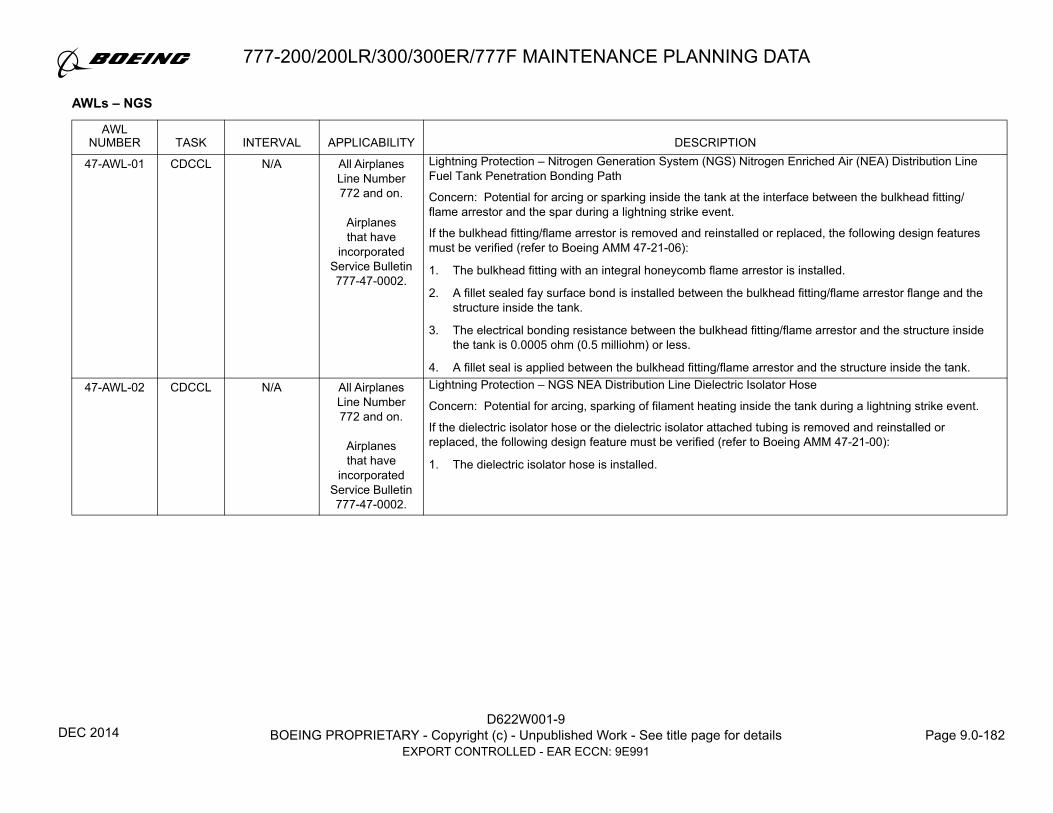
D622W001-9BOEING PROPRIETARY - Copyright (c) - Unpublished Work - See title page for details Page 9.0-182
EXPORT CONTROLLED - EAR ECCN: 9E991
777-200/200LR/300/300ER/777F MAINTENANCE PLANNING DATA
AWLs – NGS
AWLNUMBER TASK INTERVAL APPLICABILITY DESCRIPTION
47-AWL-01 CDCCL N/A All Airplanes Line Number 772 and on.
Airplanesthat have
incorporated Service Bulletin 777-47-0002.
Lightning Protection – Nitrogen Generation System (NGS) Nitrogen Enriched Air (NEA) Distribution Line Fuel Tank Penetration Bonding Path
Concern: Potential for arcing or sparking inside the tank at the interface between the bulkhead fitting/flame arrestor and the spar during a lightning strike event.
If the bulkhead fitting/flame arrestor is removed and reinstalled or replaced, the following design features must be verified (refer to Boeing AMM 47-21-06):
1. The bulkhead fitting with an integral honeycomb flame arrestor is installed.
2. A fillet sealed fay surface bond is installed between the bulkhead fitting/flame arrestor flange and the structure inside the tank.
3. The electrical bonding resistance between the bulkhead fitting/flame arrestor and the structure inside the tank is 0.0005 ohm (0.5 milliohm) or less.
4. A fillet seal is applied between the bulkhead fitting/flame arrestor and the structure inside the tank.47-AWL-02 CDCCL N/A All Airplanes
Line Number 772 and on.
Airplanesthat have
incorporated Service Bulletin 777-47-0002.
Lightning Protection – NGS NEA Distribution Line Dielectric Isolator Hose
Concern: Potential for arcing, sparking of filament heating inside the tank during a lightning strike event.
If the dielectric isolator hose or the dielectric isolator attached tubing is removed and reinstalled or replaced, the following design feature must be verified (refer to Boeing AMM 47-21-00):
1. The dielectric isolator hose is installed.
DEC 2014

777-200/200LR/300/300ER/777F MAINTENANCE PLANNING DATA
D622W001-9BOEING PROPRIETARY - Copyright (c) - Unpublished Work - See title page for details Page 9.0-183
EXPORT CONTROLLED - EAR ECCN: 9E991
47-AWL-03 CDCCL N/A All Airplanes Line Number 772 and on.
Airplanesthat have
incorporated Service Bulletin 777-47-0002.
NGS – Flammability Exposure and Performance
Concern: Airplane alterations may impact the performance of the NGS and hence the flammability of the Center Wing Fuel Tank.
Any alteration that affects performance of the NGS system, such as the following items 1 to 3 below, requires approval from the FAA Oversight Office.
1. Alteration that affects the vent system by adding air to the center tank, or
2. Alteration that reduces the available bleed pressure in the cross-over manifold during any phase of flight or ground operations, or
3. Alteration that adds any heat to the center wing fuel tank or increases heat retention of the center wing fuel tank (it does not include alterations to airplane fuselage paint color, or interior carpet or cabin furnishings).
47-AWL-04 ALI 108,000 FH All Airplanes Line Number 772 and on.
Airplanesthat have
incorporated Service Bulletin
777-47-0002
NGS – Thermal Switch
Concern: Latent Failure of the Thermal Switch removes a layer of protection against fuel tank ignition by hot bleed air.
Perform either of the following actions:
1. Replace with a new Thermal Switch (refer to Boeing AMM 47-42-04).
OR
2. Verify that the following bench tests have passed to ensure the integrity of the switch (refer to Honeywell (V70210) CMM 47-43-02):
NOTE: The following tests are bench test only and must not be performed on the aircraft:
a. Proof Temperature and Response Time Test:
I. Verify the time that thermal switch actuates is within 5 seconds when the thermal switch is immersed in an approximately 370o F (188o C) oil bath and there is no electrical cycling of the thermal switch.
b. Operating Test:
I. Verify that the thermal switch actuates within the range of 255o F and 275o F (124o C to 135o C) when the thermal switch is immersed in an oil bath.
AWLNUMBER TASK INTERVAL APPLICABILITY DESCRIPTION
DEC 2014

D622W001-9BOEING PROPRIETARY - Copyright (c) - Unpublished Work - See title page for details Page 9.0-184
EXPORT CONTROLLED - EAR ECCN: 9E991
777-200/200LR/300/300ER/777F MAINTENANCE PLANNING DATA
47-AWL-05 ALI 10,682 FH All Airplanes Line Number 772 and on.
Airplanesthat have
incorporated Service Bulletin 777-47-0002.
NGS – Cross Vent Check Valve
Concern: The cross vent check valve may fail open latently, allowing air to flow through the center tank, diluting the nitrogen rich environment created by the Nitrogen Generation System.
Perform an operational test of the cross vent check valve (refer to Boeing AMM 47-21-05) to ensure the cross vent check valve closes to prevent ambient air from entering the center tank.
1. Open the flapper valve of the cross vent check valve and verify that the flapper closes and seats into the valve body.
47-AWL-06 ALI 10,682 FH All Airplanes Line Number 772 and on.
Airplanesthat have
incorporated Service Bulletin 777-47-0002.
NGS – NEA Distribution Ducting Integrity
Concern: The NEA Distribution System ducting outside the fuel tank may fail latently allowing NEA to leak without reaching the fuel tank, resulting in the fuel tank not reaching required inert levels.
Perform a detailed visual inspection of the NEA distribution lines from the Air Separation Module (ASM) to the fuel tank front spar for damage and leaks (refer to Boeing AMM 47-21-00):
1. Verify that there are no loose clamps for the Nitrogen Enriched Air Distribution System (NEADS) couplings, drain line connection, or joints.
2. Verify that there are no disconnections for the NEADS couplings, drain line connection, or joints.
3. Verify that there are no damaged tubes from the ASM to the fuel tank front spar.47-AWL-07 CDCCL N/A All Airplanes
Line Number 772 and on.
Airplanesthat have
incorporated Service Bulletin 777-47-0002.
NGS Ongoing Compliance Based on Industry Descent Times – Required Service Instructions
Concern: NGS performance is dependent on industry descent times. Industry efforts to reduce descent time may result in NGS performance that does not meet FAA requirements.
Fleet Average flammability exposure for the fuel tanks with flammability reduction of this airplane type must be maintained in accordance with Title 14 CFR Part 25, Appendix M. Boeing will monitor U.S. descent statistics and, if necessary to maintain compliance, will publish service instructions.
If Boeing publishes such service instructions noted to maintain compliance with this CDCCL, this CDCCL requires either that operators implement these FAA-approved design changes or that operators implement other design changes or operational procedural changes approved by the FAA Oversight Office, within the compliance time stated in the service instructions, to maintain compliance with Title 14 CFR Part 25, Appendix M.
AWLNUMBER TASK INTERVAL APPLICABILITY DESCRIPTION
DEC 2014

777-200/200LR/300/300ER/777F MAINTENANCE PLANNING DATA
D622W001-9BOEING PROPRIETARY - Copyright (c) - Unpublished Work - See title page for details Page 9.0-185
EXPORT CONTROLLED - EAR ECCN: 9E991
D.4 PRATT AND WHITNEY FORWARD STRUT DRAIN LINE
This section contains an FAA approved program of Forward Strut Drain Line Scheduled inspections. Operators should incorporate these inspections into
their maintenance programs to meet Title 14 CFR § 25.901(b)(2) for those strut drains that are identified as applicable.
In revenue service, excessive temperatures combined with draining fluids have contributed to clogging of the forward strut drain line. Hydraulic fluid has
pooled in the strut flammable leakage zone, the left systems electrical bay, in the strut forward dry bay, and forward engine mount. The titanium engine
mount is susceptible to hydrogen embrittlement when exposed to hydraulic fluid. The addition of drain line insulation (see Service Bulletin 777-71-0055)
reduces the temperatures experienced by the drain lines minimizing the clogging of the drain such that periodic inspection will prevent clogging and pooled
flammable fluids between inspections.
The Forward Strut Drain Line functional check AWL is mandatory maintenance to ensure safe operation of the strut drainage system as required by
Title 14 CFR § 25.901(b)(2). The Forward Strut Drain Line functional check verifies the drain will be functional until the next scheduled inspection.
MAR 2014

D622W001-9BOEING PROPRIETARY - Copyright (c) - Unpublished Work - See title page for details Page 9.0-186
EXPORT CONTROLLED - EAR ECCN: 9E991
777-200/200LR/300/300ER/777F MAINTENANCE PLANNING DATA
AWLs – DRAIN LINE
AWLNUMBER TASK INTERVAL APPLICABILITY DESCRIPTION
54-AWL-01 ALI 2,000 FC/1,500 DY
NOTE
777 Airplanes Line Number 1118 and on with PW4000
engines
777 Airplanes Line Numbers1 through 1117 with PW4000
engines that have
incorporated Service Bulletin
777-71-0055
Forward Strut Drain Line
Concern: Potential for hydraulic fluid clogging the Forward Strut drain line causing subsequent clogging of the Left Systems Disconnect, Strut Forward Lower Spar Inlet and Forward Fire Seal Pan Inlet which could result in pooled flammable fluid in a flammable leakage zone which poses a potential fire hazard. Hydraulic Fluid can also back up into the strut forward dry bay and cause hydrogen embrittlement of the forward engine mount fittings that could cause cracks that lead to the loss of load carrying capability for the forward engine mount.
Perform a Forward Strut Drain Line Functional Check (refer to Boeing AMM 54-55-01) to ensure the drain has sufficient flow.
1. Apply 381oz (11.27 l) to 387 oz (11.44 l) of water into the strut disconnect box over a 45 to 90 second period.
2. Verify a minimum of 354 oz (10.47 l) is collected within two minutes after pouring water is complete.
3. If the flow requirement is not met, then additional checks are required to verify the following:
a. Verify that the three drain lines that connect to the Forward Strut drain line are cleared of blockage from the drain outlet to the following inlets: Left Systems Disconnect, Strut Forward Lower Spar Inlet and Forward Fire Seal Pan Inlet.
b. Verify that there is no evidence of hydraulic fluid contamination in the strut forward dry bay.
NOTE: Access is through 432AR or 442AR. The Boeing Service Bulletin 777-54-0028 contains accepted practices for inspection, cleaning and refinishing of the strut forward dry bay.
Interval Note: Whichever comes first.
MAR 2014

777-200/200LR/300/300ER/777F MAINTENANCE PLANNING DATA
D622W001-9BOEING PROPRIETARY - Copyright (c) - Unpublished Work - See title page for details Page 9.0-187
EXPORT CONTROLLED - EAR ECCN: 9E991
D.5 ROLLS ROYCE THRUST REVERSER THERMAL PROTECTION SYSTEM
This section contains an FAA approved program of Thrust Reverser (T/R) scheduled inspections. Operators should incorporate these inspections into
their maintenance program to meet Title 14 CFR § 25.901(b)(2) for those T/R configurations that are identified as applicable.
In revenue service, excessive temperatures have contributed to the failures of the 777 Rolls Royce T/R inner wall. The T/R Thermal Protection System
(TPS) limits the temperatures experienced by the inner wall minimizing new/additional thermal distress. The replacement of the inner wall together with
other design improvements (see SB 777-78-0082) eliminates the potential for additional thermal distress.
The Rolls Royce Thrust Reverser Inner Wall AWL is mandatory maintenance to ensure safe operation of the T/R installation as required by Title 14 CFR
§ 25.901(b)(2). The T/R TPS inspection verifies the proper functionality of the TPS. The Color Chip inspection demonstrates the inner wall has not been
exposed to excessive temperatures by checking for any discoloration of the engine side inner wall primer.
MAR 2014

D622W001-9BOEING PROPRIETARY - Copyright (c) - Unpublished Work - See title page for details Page 9.0-188
EXPORT CONTROLLED - EAR ECCN: 9E991
777-200/200LR/300/300ER/777F MAINTENANCE PLANNING DATA
AWLs – THRUST REVERSER TPS
AWLNUMBER TASK INTERVAL APPLICABILITY DESCRIPTION
78-AWL-01 ALI 1,125 DY/6000 FCNOTE
777 Airplaneswith Trent 800
engines.
NOTE
Thrust Reverser Thermal Protection System
Concern: Potential for latent failure of the thrust reverser inner wall thermal protection system that could result in thermal exposure which reduces the strength of the inner wall panel. Proper cooling and insulation protects against thermal damage.
Inspect (Detailed) the Thrust Reverser Thermal Protection System on both engines for the following (refer to Boeing AMM 78-31-07).
1. Prior to Insulation Blanket Removal:
a. The 4 upper and 4 lower cooling holes/bushings are blockage free (fan duct access)b. The insulation blankets are undamaged, securely attached, and clickbond covers are in place
2. After Insulation Blanket Removal:
a. The insulation blanket perimeter sealing foam is firmly attached and undamaged.b. For drag link fittings that have cooling tubes attached:
I. Air exit holes are blockage free.
II. A fillet seal exists between the cooling tubes and the drag link fitting.
III. For the left thrust reverser, a fillet seal exists around the base of the drag link fitting.
IV. For the right thrust reverser, a fillet seal exists between the land fitting flange and the exposed flanges of the drag link fittings.
c. The clickbond studs are present and firmly attached.
INTERVAL NOTE: Whichever comes first. Interval to be applied to each thrust reverser half independently.
APPLICABILITY NOTE:
1. For individual thrust reverser halves that have incorporated Service Bulletin 777-78-0071, or
2. For individual thrust reverser halves that have incorporated Service Bulletin 777-78-0082, or
3. For individual thrust reverser halves that have incorporated Service Bulletin 777-78A0094, or
4. For individual thrust reverser halves with thrust reverser, PN 315W5295-97/-98/-99/-100 and higher.
NOV 2015

777-200/200LR/300/300ER/777F MAINTENANCE PLANNING DATA
D622W001-9BOEING PROPRIETARY - Copyright (c) - Unpublished Work - See title page for details Page 9.0-189
EXPORT CONTROLLED - EAR ECCN: 9E991
78-AWL-02 ALI 1,125 DY/ 6000 FCNOTE
777 Airplanes with Trent 800
engines. NOTE
Thrust Reverser Inner Wall
Concern: Thermal protective system failures can result in the inner wall panel of the thrust reverser being exposed to high temperatures which can reduce the strength of the inner wall structure and lead to thermally induced damage such as disbonds and delaminations on the inner wall. Thermally damaged inner walls can collapse in flight.
Inspect (Detailed) the thrust reverser inner wall (refer to Boeing AMM 78-31-01), using the Color Chip Kit, P/N 315W5110-7, to ensure the inner wall has not been exposed to temperatures which could degrade its strength.
1. Verify that the thrust reverser inner wall primer color is not darker than the color chip standard (P/N 315W5110-5) from the Color Chip Kit, P/N 315W5110-7.
2. If the thrust reverser inner wall primer color appears darker than the color chip standard, perform a non-destructive test (refer to Boeing AMM 78-31-01) to ensure the composite inner wall structure has no disbonds or delaminations.
INTERVAL NOTE: Whichever comes first. Interval to be applied to each thrust reverser half independently.
APPLICABILITY NOTE:
1. For individual thrust reverser halves that have incorporated Service Bulletin 777-78-0082 Work Package 1 or Work Package 2, or
2. For individual thrust reverser halves that have incorporated Service Bulletin 777-78A0094 Work Package 3 or Work Package 4, or
3. For individual thrust reverser halves with thrust reverser, PN 315W5295-97/-98/-99/-100 and higher.
AWLNUMBER TASK INTERVAL APPLICABILITY DESCRIPTION
NOV 2015

D622W001-9BOEING PROPRIETARY - Copyright (c) - Unpublished Work - See title page for details Page 9.0-190
EXPORT CONTROLLED - EAR ECCN: 9E991
777-200/200LR/300/300ER/777F MAINTENANCE PLANNING DATA
E. CERTIFICATION MAINTENANCE REQUIREMENTS (CMRs)
SELECTION OF CMRs
In order to grant operators of the 777 airplane an opportunity to participate in the evaluation and selection of CMRs in an integrated process with MRB
tasks and intervals, a Certification Maintenance Coordination Committee (CMCC) was convened to review all of the 777 CMRs. The CMRs listed in this
document are the result of applying the CMCC process as described in AC 25-19.
CMR DEFINITION
As defined by AC 25-19, a CMR is a required periodic task, established during the design certification of the airplane as an operating limitation of the type
certificate. CMRs usually result from a formal, numerical analysis conducted to show compliance with catastrophic and hazardous failure conditions.
Additional notes concerning the definition of CMRs:
1. A CMR is intended to detect safety-significant latent (hidden) failures that would, in combination with one or more specific failures or events, result in a
hazardous or catastrophic failure condition.
2. It is important to note that CMRs are derived from a fundamentally different analysis process than the maintenance tasks and intervals that result from
the Maintenance Steering Group (MSG-3) Analysis associated with Maintenance Review Board (MRB) activities. MSG-3 Analysis activity produces
maintenance tasks that are performed for safety, operational, or economic reasons, involving both preventative maintenance tasks, which are performed
before failure occurs (and are intended to prevent failures), as well as failure-finding tasks. CMRs, on the other hand, are failure-finding tasks only, and
exist solely to limit the exposure to otherwise hidden failures. Although CMR tasks are failure-finding tasks, use of potential failure-finding tasks, such
as functional checks and inspections, may also be appropriate.
3. CMRs are designed to verify that a certain failure has or has not occurred, and do not provide any preventative maintenance function. CMRs “restart
the failure clock to zero” for latent failures by verifying that the item has not failed, or cause repair if it has failed. Because the exposure time to a latent
failure is a key element in the calculations used in a safety analysis performed to show compliance with Title 14 CFR § 25.1309, limiting the exposure
time will have a significant effect on the resultant overall failure probability of the system. The CMR Task Interval should be designated in terms of flight
hours, cycles, or calendar time, as appropriate.
MAR 2014

777-200/200LR/300/300ER/777F MAINTENANCE PLANNING DATA
D622W001-9BOEING PROPRIETARY - Copyright (c) - Unpublished Work - See title page for details Page 9.0-191
EXPORT CONTROLLED - EAR ECCN: 9E991
4. The type certification process assumes that the airplane will be maintained in a condition of airworthiness at least equal to its certified or properly altered
condition. The process described in AC 25-19 is not intended to establish normal maintenance tasks that should be defined through the MSG-3
Analysis process. Also, this process is not intended to establish CMRs for the purpose of providing supplemental margins of safety for concerns arising
late in the type design approval process.
5. CMRs should not be confused with required structural inspection programs that are developed by the type certificate applicant to meet the inspection
requirements for damage tolerance, as required by Title 14 CFR § 25.571 or § 25.1529, Appendix H25.4 (Airworthiness Limitations section). CMRs are
to be developed and administered separately from any structural inspection programs.
CMR TYPES
CMR Tasks are divided into two categories: One Star CMRs (*) and Two Star CMRs (**). They are defined as follows:
1. One Star CMRs (*) – The tasks and intervals specified are mandatory and cannot be changed, escalated, or deleted without the concurrence of the FAA
Oversight Office.
2. Two Star CMRs (**) – Task intervals may be adjusted in accordance with each operator’s approved escalation program or an approved reliability
program in a like manner for any MRB Report task, but may not be deleted without prior FAA Oversight Office approval.
ESCALATION OF TWO STAR CMRs (**)
All Two Star CMRs (**) can be managed and controlled the same as any MRB Report task; however, they can not be deleted from an operator’s program
without prior FAA Oversight Office approval. For operators with approved escalation practices or an approved reliability program, data collection and
analytical techniques are used to make adjustments to an operator’s maintenance program. It has been demonstrated that the management of a
maintenance program does not give rise to undue escalations; consequently, the escalation of Two Star CMR (**) intervals within an operator’s
maintenance program will be properly managed by the operator subject to local regulatory authority approval.
MAR 2014

D622W001-9BOEING PROPRIETARY - Copyright (c) - Unpublished Work - See title page for details Page 9.0-192
EXPORT CONTROLLED - EAR ECCN: 9E991
777-200/200LR/300/300ER/777F MAINTENANCE PLANNING DATA
EXCEPTIONAL SHORT-TERM EXTENSIONS
Since CMR intervals are based on statistical averages and reliability rates, an exceptional short-term extension of 10% for each CMR listed in this
document may be made, except as noted in Item 1, without jeopardizing safety. The local regulatory authority or a Principle Maintenance Inspector must
concur with any exceptional short-term extensions before they take place using procedures established with the local regulatory authority in the operators’
manuals. The “exceptional short-term extension” process is applicable to CMR intervals. It should not be confused with the operator’s short-term
escalation” program for normal maintenance tasks described in the operators’ manuals and in the Flight Standards Handbook 8900.1 FSIMS.
The FAA Oversight Office has accepted that these exceptional short-term extensions may be granted without consultation with that office:
1. The term “exceptional short-term extension” is defined as an increase in a CMR interval that may be needed to cover an uncontrollable or unexpected
situation. All CMRs listed in this section have been approved for an exceptional short-term extension of 10%, except as noted below:
• CMR 52-CMR-01, which has been approved for a short-term extension, is restricted to a maximum of 90 days.
2. Repeated use of extensions, either on the same airplane or on similar airplanes in an operator’s fleet, should not be used as a substitute for good
management practices. Exceptional short-term extensions must not be used for fleet CMR extensions.
3. After a CMR has experienced an exceptional short-term extension, the CMR interval will revert back to its interval listed in this document. The FAA
Oversight Office must approve, prior to its use, any desired extension not explicitly listed above.
NOTE: This exceptional short-term extension listed above applies to airlines that fall under the U.S. FAA jurisdiction only. Operators who are not under the U.S. FAA jurisdiction should obtain interval extension approvals from their local regulatory agency.
MAR 2014
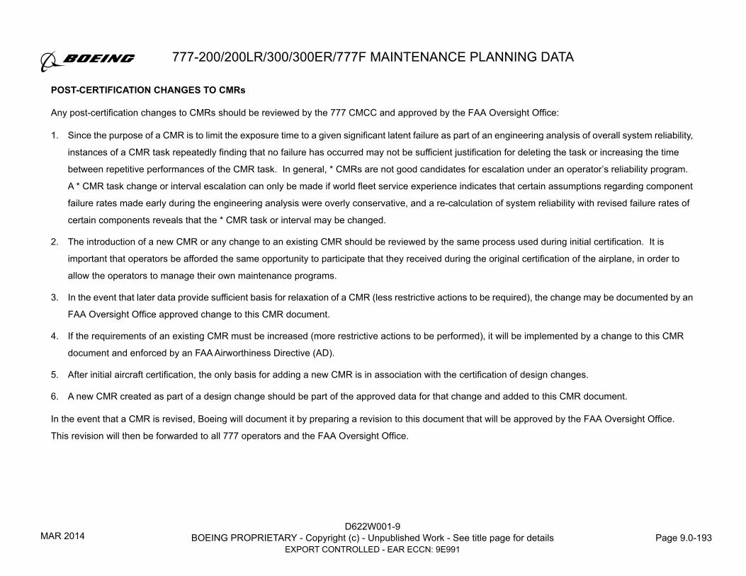
777-200/200LR/300/300ER/777F MAINTENANCE PLANNING DATA
D622W001-9BOEING PROPRIETARY - Copyright (c) - Unpublished Work - See title page for details Page 9.0-193
EXPORT CONTROLLED - EAR ECCN: 9E991
POST-CERTIFICATION CHANGES TO CMRs
Any post-certification changes to CMRs should be reviewed by the 777 CMCC and approved by the FAA Oversight Office:
1. Since the purpose of a CMR is to limit the exposure time to a given significant latent failure as part of an engineering analysis of overall system reliability,
instances of a CMR task repeatedly finding that no failure has occurred may not be sufficient justification for deleting the task or increasing the time
between repetitive performances of the CMR task. In general, * CMRs are not good candidates for escalation under an operator’s reliability program.
A * CMR task change or interval escalation can only be made if world fleet service experience indicates that certain assumptions regarding component
failure rates made early during the engineering analysis were overly conservative, and a re-calculation of system reliability with revised failure rates of
certain components reveals that the * CMR task or interval may be changed.
2. The introduction of a new CMR or any change to an existing CMR should be reviewed by the same process used during initial certification. It is
important that operators be afforded the same opportunity to participate that they received during the original certification of the airplane, in order to
allow the operators to manage their own maintenance programs.
3. In the event that later data provide sufficient basis for relaxation of a CMR (less restrictive actions to be required), the change may be documented by an
FAA Oversight Office approved change to this CMR document.
4. If the requirements of an existing CMR must be increased (more restrictive actions to be performed), it will be implemented by a change to this CMR
document and enforced by an FAA Airworthiness Directive (AD).
5. After initial aircraft certification, the only basis for adding a new CMR is in association with the certification of design changes.
6. A new CMR created as part of a design change should be part of the approved data for that change and added to this CMR document.
In the event that a CMR is revised, Boeing will document it by preparing a revision to this document that will be approved by the FAA Oversight Office.
This revision will then be forwarded to all 777 operators and the FAA Oversight Office.
MAR 2014

D622W001-9BOEING PROPRIETARY - Copyright (c) - Unpublished Work - See title page for details Page 9.0-194
EXPORT CONTROLLED - EAR ECCN: 9E991
777-200/200LR/300/300ER/777F MAINTENANCE PLANNING DATA
FIGURE 8. PAGE FORMAT CERTIFICATION MAINTENANCE REQUIREMENTS
MAR 2006

777-200/200LR/300/300ER/777F MAINTENANCE PLANNING DATA
D622W001-9BOEING PROPRIETARY - Copyright (c) - Unpublished Work - See title page for details Page 9.0-195
EXPORT CONTROLLED - EAR ECCN: 9E991
PAGE FORMAT – CMRs
COLUMN EXPLANATION
CMR ITEM NUMBER
Each task is given a unique CMR item number. The first character, if applicable, is the engine prefix:G = General Electric, N = Pratt & Whitney, and R = Rolls RoyceThe second and third digits are the ATA chapter number.
TYPE CMR TYPE
CMRs are categorized into one or two star CMRs based on whether or not they can be escalated by the operator without prior FAA Oversight Office approval.
* Cannot be escalated or deleted without prior FAA Oversight Office approval.
** Can be escalated based on the operator’s approved program for continued airworthiness based on continuous analysis and surveillance; however, these tasks cannot be deleted without prior FAA Oversight Office approval.
RELATED MRB ITEM NUMBER
This column is for the related MRB Item Number, if there is an applicable MRB Item Number. Not all CMRs have a one to one relationship to a MRB Item Number.
TASK MSG-3 TASK CATEGORIES
OP = OPERATIONAL CHECK A failure finding task to determine if an item is fulfilling its intended purposes. Does not require quantitative tolerances.
CMR INTERVAL
Task frequencies are specified in terms of a usage parameter such as flight hours, cycles or calendar time.
APPLICABILITY
APL ENG
Applicable Airplane Model and Engine.
AIRPLANEALL = All Airplanes300 = 777-300777F = 777 Freighter
ENGINEALL = All Engines4000 = PW4074, PW4077, PW4084, PW4090, PW4098GE90 = GE90 (75B/76B/85B/90B/94B/110B/115B)TRENT = TRENT 800 (875-17, 877-17, 884-17, 890-17, 892, 892B, 895)
TASK DESCRIPTION
Description of the task to be performed.
MAR 2014

D622W001-9BOEING PROPRIETARY - Copyright (c) - Unpublished Work - See title page for details Page 9.0-196
EXPORT CONTROLLED - EAR ECCN: 9E991
777-200/200LR/300/300ER/777F MAINTENANCE PLANNING DATA
F. CERTIFICATION MAINTENANCE REQUIREMENTS TASKS
CMRITEM
NUMBER
TYPE
RELATED MRB ITEM
NUMBER
TASK
CMR INTERVAL
APPLICABILITY777
CERTIFICATION MAINTENANCE REQUIREMENTS
APL ENG TASK DESCRIPTION
21-CMR-01 ** 21-33 OP 7500 Hrs 777F ALL Operationally check the manual and automatic activation of the Main Deck Alerting System.
25-CMR-01 * 25-056 OP 375 DY ALLNOTE
ALL Perform an operational check of the Inflatable Seat Restraint System.
AIRPLANE NOTE: If installed. Applicable to AMSAFE NexGen inflatable seat restraint installations, EMA P/N 511959-XXX-XX.
26-CMR-01 * --- IN 6000 Hrs or18 Mos,
whichever occurs first
ALLNOTE
ALL Inspect Cargo Fire Bottles, supplier Part Numbers 473474-2, 473475-2, 473854-2, and 473876-2, for leaks using a Halide Leak Detector. Apply Corrosion Inhibitor Compound to burst disc (inside fill fitting).
AIRPLANE NOTE: Applicable to airplanes with -2 bottles installed. (CMR is not applicable to -3 bottles).
27-CMR-01 * 27-140 OP 500 Hrs ALL ALL Operationally check PRIMARY FLIGHT CONTROL ACTUATION. Use hydraulics-on actuation confidence tests.
27-CMR-02 * 27-160 OP 500 Hrs ALL ALL Operationally check ACTUATOR CONTROL ELECTRONICS (ACE) MONITORING Functions of Flight Controls System (use ACE self-test).
27-CMR-04 * 27-360 OP 12000 Hrs ALL ALL Operationally check LE SLAT SKEW/LOSS CABLE SYSTEM.
27-CMR-05 * IN 5000 FC 777F ALL Conduct a visual inspection of the 24 Horizontal Stabilizer Trim Actuator (HSTA) Karon lined bushings and pins common to the Jackscrew Upper and Lower Gimbals, Section 48 and Section 82 Fittings. Inspect for Karon liner or pin wear/damage and liner delamination
27-CMR-06 * 12-002 LUB 5000 Hrs or 500 Dys
whichever comes first
777F ALL Lubricate the Elevator Power Control Units (PCUs) and Elevator Hinges.
27-CMR-07 * 12-004 LUB 5000 Hrs or 500 Dys
whichever comes first
777F ALL Lubricate the Rudder and Rudder Tab Hinge Bearings, Rudder Power Control Units (PCUs) Reaction Link Rod Ends and PCU Rod Ends.
NOV 2015

777-200/200LR/300/300ER/777F MAINTENANCE PLANNING DATA
D622W001-9BOEING PROPRIETARY - Copyright (c) - Unpublished Work - See title page for details Page 9.0-197
EXPORT CONTROLLED - EAR ECCN: 9E991
27-CMR-08 * 27-240 FC 12000 Hrs or 1125 Dys, whichever comes first
777F ALL Functionally Check Elevator Surface Freeplay.
27-CMR-09 * 27-430 FC 12000 Hrs or 1125 Dys, whichever comes first
777F ALL Functionally Check Rudder/Rudder Tab Surface Freeplay.
28-CMR-01 * --- IN 6000 Hrs 300 ALL Conduct a visual inspection of the center fuel tank FQIS wiring for damage or chafing.
29-CMR-01 * 29-030 FC 12000 Hrs ALL ALL Functionally check the GROSS INTERNAL LEAKAGE of the Main (Center) Hydraulic System.
29-CMR-02 * 29-130 OP 12000 Hrs ALL ALL Operationally check CENTER HYDRAULIC ISOLATION SYSTEM.
29-CMR-03 * 29-150 OP 7500 Hrs ALL ALL Operationally check RAT System (using RAT checkout module) and check RAT Auto and Manual Deployment Systems.
31-CMR-01 * 31-100 OP 24 HrsNOTE
ALL ALL Operationally check FIRE WARNING SYSTEM using the Fire/Overheat Test switch (if not checked by crew).
INTERVAL NOTE: Under exceptional operational circumstances the interval may be extended beyond 24 hours (elapsed clock hours) but not exceed 48 hours (clock time).
32-CMR-01 * 12-081 LUB 50 FC or 25 DYS,
whichever occurs later
NOTE ALL Lubricate the left and right Main Landing Gear truck beam and inner cylinder pivot joints.
AIRPLANE NOTE: Applicable to airplanes production line number 915 and on, or airplanes that have incorporated Service Bulletin 777-32-0085.
52-CMR-01 * --- DS 3375 Dys NOTE ALL Discard the Flight Deck Door Strike Assembly.
AIRPLANE NOTE: Applicable to non-freighter airplanes from line number 427 and on, or airplanes that have incorporated Service Bulletin 777-25-0216.
CMRITEM
NUMBER
TYPE
RELATED MRB ITEM
NUMBER
TASK
CMR INTERVAL
APPLICABILITY777
CERTIFICATION MAINTENANCE REQUIREMENTS
APL ENG TASK DESCRIPTION
NOV 2015

D622W001-9BOEING PROPRIETARY - Copyright (c) - Unpublished Work - See title page for details Page 9.0-198
EXPORT CONTROLLED - EAR ECCN: 9E991
777-200/200LR/300/300ER/777F MAINTENANCE PLANNING DATA
72-CMR-01DELETED
* --- IN 24 HrsNOTE
NOTE TRENTNOTE
Inspect (Detailed) STEP-ASIDE-GEARBOX (SAGB) HOUSING and EXTERNAL GEARBOX LOWER BEVEL BOX (LBB) HOUSING for evidence of oil leakage and cracking per RR Non-Modification Service Bulletin 72-C129, Issue 3. AD 97-06-13.
INTERVAL NOTE: Under exceptional operational circumstances the interval may be extended beyond 24 hours (clock time) but not to exceed 48 hours (clock time).
AIRPLANE NOTE: Applicable to all Increased Gross Weight 777-200 airplanes and to any 777-200 with Rolls-Royce Trent engines capable of the 892-17 thrust rating.
ENGINE NOTE: Applicable to all Rolls-Royce Trent engines capable of the 892-17 thrust rating and to all Trent engines installed on Increased Gross Weight 777-200’s.
72-CMR-02DELETED
* --- IN 10 Cyc NOTE TRENTNOTE
Inspect (Special Detailed) STEP-ASIDE-GEARBOX (SAGB) HOUSING with fluorescent penetrant for evidence of cracking per RR Non-Modification Service Bulletin 72-C129, Issue 3. AD 97-06-13.
AIRPLANE NOTE: Applicable to all Increased Gross Weight 777-200 airplanes and to any 777-200 with Rolls-Royce Trent engines capable of the 892-17 thrust rating.
ENGINE NOTE: Applicable to all Rolls-Royce Trent engines capable of the 892-17 thrust rating and to all Trent engines installed on Increased Gross Weight 777-200’s.
72-CMR-03 * --- IN 1000 CycNOTE
300 TRENT Inspect (Special Detailed) MAIN FAN BLADES with ultrasonic test for evidence of fan blade root cracking per Rolls-Royce Non-Modification Service Bulletin 72-C445, Rev. 1.
INTERVAL NOTE: Repeat inspections at 500 cycles.
78-CMR-01 * 78-02578-22078-365
OP 5000 Hrs ALL ALL Operationally check Thrust Reverser SYNC LOCK on left and right engine.
78-CMR-02DELETED
* 78-035 78-040
- NOTE ALL GE90 PRECOOLER INLET DUCT ASSEMBLY KISS SEAL
INTERVAL NOTE: For Part Number S315W134-2 and -11 inspect per Service Bulletin 777-78-0010, Revision 2.
All CMRs on this list may have a 10% exceptional short-term extension of the task interval for a specific airplane. For further explanation, see Section 9.D.
CMRITEM
NUMBER
TYPE
RELATED MRB ITEM
NUMBER
TASK
CMR INTERVAL
APPLICABILITY777
CERTIFICATION MAINTENANCE REQUIREMENTS
APL ENG TASK DESCRIPTION
NOV 2015

777-200/200LR/300/300ER/777F MAINTENANCE PLANNING DATA
D622W001-9BOEING PROPRIETARY - Copyright (c) - Unpublished Work - See title page for details Page 9.0-199
EXPORT CONTROLLED - EAR ECCN: 9E991
G. REPORTING UNCONTROLLABLE HIGH THRUST FAILURE CONDITIONS
Title 14 CFR § 121.703 and § 135.415 state that “each certificate holder shall report any failure, malfunction, or defect in an aircraft, system, component,
or powerplant that occurs or is detected at any time if, in its opinion, that failure, malfunction, or defect has endangered or may endanger the safe
operation of an aircraft”. Title 14 CFR § 125.409 also requires reporting of failures, malfunctions, or defects. In many cases a reportable failure or
malfunction will be obvious, but there are some failure modes related to uncontrolled high thrust that are reportable but may not be obvious. The following
information is provided, as required by FAA Exemption No. 7955, to assist the operators in identifying reportable malfunctions related to uncontrolled high
thrust.
The FAA has concluded that the loss of capability to control thrust due to a failure of the engine thrust control system may endanger the aircraft. This
includes any malfunctions having one or more of the following characteristics:
777-200 (777-200IGW or 777-200ER), 777-300
• Auto-acceleration or uncommanded thrust change to higher power
• Stuck thrust lever above idle power
• Inability to reduce thrust
777-300ER, 777-200LR, 777F
• Stuck thrust lever above idle power
• No response to thrust lever, with the cause being a mechanical failure in the thrust lever mechanism or resolver
• Although some or these incidents may not appear to be safety related, documenting the events is important to ensure the present level of safety is
maintained and/or to identify failure conditions that must be corrected.
MAR 2014
D622W001-9BOEING PROPRIETARY - Copyright (c) - Unpublished Work - See title page for details Page 9.0-200
EXPORT CONTROLLED - EAR ECCN: 9E991
777-200/200LR/300/300ER/777F MAINTENANCE PLANNING DATA
When filing a report of such an event with the FAA, the operator is requested to include in the description of the event one or more of the
following phrases:
• “thrust control”
• “no response to thrust lever”
• “auto-acceleration”
• “uncontrolled high thrust”
In addition, the following information should be included in the report:
• Event description
• Flight Crew action
• Maintenance action
• List of affected or removed components
Reports should be submitted to the local representative of the FAA Administrator that handles the appropriate reporting responsibility for Title 14 CFR
§ 121.703, 125.409, and 135.415. In addition to filing reports with the FAA, it is recommended that a copy be sent to Boeing and to the engine
manufacturer.
MAR 2014

777-200/200LR/300/300ER/777F MAINTENANCE PLANNING DATA
D622W001-9BOEING PROPRIETARY - Copyright (c) - Unpublished Work - See title page for details Page 9.0-201
EXPORT CONTROLLED - EAR ECCN: 9E991
H. AWLs - STRUCTURAL LIMIT OF VALIDITY (LOV)
This section provides the Limit of Validity (LOV) in accordance with the requirements of Title 14 CFR § 26.21 (Amendment 26-6). This regulation requires
the establishment of an airplane level limit of validity of the engineering data that supports the structural maintenance program that corresponds to the
period of time, stated as a number of total accumulated flight cycles or flight hours or both, during which it is demonstrated that widespread fatigue damage
will not occur in the airplane. The LOVs listed in the following table support operator compliance with Title 14 CFR Sections 121.1115 and 129.115.
LIMIT OF VALIDITY FOR THE 777-200/200LR/300/300ER/F
MODEL FLIGHT CYCLE LOV FLIGHT HOUR LOV
777-200 60,000 180,000
777-200LR 60,000 180,000
777-300 60,000 180,000
777-300ER 60,000 180,000
777F 37,500 180,000
Note:
Limit of Validity for the 777-200 applies to all 777-200 airplanes except the 777-200LR model.
Limit of Validity for the 777-300 applies to all 777-300 airplanes except the 777-300ER model.
JAN 2016

D622W001-9BOEING PROPRIETARY - Copyright (c) - Unpublished Work - See title page for details Page 9.0-202
EXPORT CONTROLLED - EAR ECCN: 9E991
777-200/200LR/300/300ER/777F MAINTENANCE PLANNING DATA
I. AWLs - SYSTEMS
These System Airworthiness Limitations are a result of Model 777 airplane certification activities with the U.S. FAA and are part of the Airworthiness
Limitations section of the Instructions for Continued Airworthiness. These maintenance actions are mandatory. These Airworthiness Limitations may only
be revised with the approval of the FAA Oversight Office.
SYSTEM AIRWORTHINESS LIMITATION NO. 1 - MULTI-MODE RECEIVER (MMR) OPERATING LIMITATION - 777-200/200LR/300/300ER/777F
AIRPLANES WITH COLLINS GLU-2100 MMR
Aircraft configured with Rockwell Collins Multi-Mode Receivers (MMRs) Model GLU-2100 (P/N 822-2532-100) with Operational Program Software (OPS)
P/N COL4E-0087-0001 or COL4D-0087-0002 will fail on June 11 2023 00:00:000 UTC. Failure will result in complete loss of all enabled MMR functions
including Global Positioning System (GPS) and Instrument Landing System (ILS). Airplanes with GLU-2100 MMR units with OPS P/N COL4E-0087-0001
or COL4D-0087-0002 cannot be operated past June 10 2023 00:00:000 UTC unless upgraded to new compliant software. Boeing will release service data
to allow retrofit of a software update to the GLU-2100 MMR prior to that date.
NOV 2019