
TECHNICAL DATA GHP and EHP hybrid Air Conditioner
151
OUTDOOR MODEL No. U-20GES3E5 U-10MES2E8 TECHNICAL DATA GHP and EHP hybrid Air Conditioner REFERENCE No. GTD-1805-02A Order No. SBPAC1805006CE
-
Upload
khangminh22 -
Category
Documents
-
view
5 -
download
0
Transcript of TECHNICAL DATA GHP and EHP hybrid Air Conditioner

OUTDOOR MODEL No.
U-20GES3E5U-10MES2E8
TECHNICAL DATA
GHP and EHP hybridAir Conditioner
REFERENCE No. GTD-1805-02A
Order No. SBPAC1805006CE

Contents
System Configuration ...................................................................A-1
Outdoor Unit .................................................................................B-1
Control-Related ............................................................................C-1
System Design .............................................................................D-1
Installation Work ...........................................................................E-1
Separately Sold Parts ..................................................................F-1
Periodic Inspection .......................................................................G-1

System Configuration
Contents
1. Type Configuration
(1) Outdoor unit ............................................................................................................ A-2
2. System Configuration
(1) SYSTEM 1: Multi-type indoor unit system............................................................... A-4(2) SYSTEM 2: Large-capacity multi-type indoor unit system ...................................... A-6(3) SYSTEM 3: System connected with multi-type indoor units and large-capacity
multi-type indoor units ........................................................................ A-6
(4)
(5)
SYSTEM 5: System including 100% Fresh Air duct function type indoor units....... A-6SYSTEM 7: Water heat exchanger units ................................................................ A-7
(2) Indoor unit ............................................................................................................... A-3
A-1

System Configuration 1. Type Configuration
(1) Outdoor Unit
U-20GES3E5 U-10MES2E8
A-2

System Configuration 1. Type Configuration
(2) Indoor unit
ClassType
22 28 36 45 56 60 73 90 106 140 160 224 280
4Way Cassette ○ ○ ○ ○○○○ ○○ ○ ○
2Way Cassette ○ ○ ○ ○ ○ ○
1Way Cassette ○ ○ ○ ○ ○
Variable Static Pressure Hide Away ○ ○ ○ ○ ○○○ ○ ○ ○ ○
Slim Variable Static Pressure Hide Away ○ ○ ○ ○ ○
Ceiling ○ ○ ○ ○ ○ ○
High Static Pressure Hide Away ○ ○
Wall Mounting ○ ○ ○ ○ ○ ○ ○
Floor Standing ○ ○ ○ ○ ○ ○
Concealed Floor Standing ○ ○ ○ ○ ○ ○
A-3

System Configuration 2. System Configuration
(1) SYSTEM 1: Multi-type indoor unit system
Piping set (sold separately) usage exampleFor the number of connectable indoor units, see the table on the next page.
1) Branch piping usage example (in the case of a W multi-system, the maximum number of outdoor units
is two)
Example 1 Example 2
Outdoor unit
Indoor units
Branch pipe
Outdoor unit
Indoor units
Branch pipe
Closed(pinch)weld(arranged on-site)
1m or less
Example 3 *Line branch method Example 4 *T-tee branch method
Outdoor unit
Indoor units
Outdoor unit
Indoor units
2 m or less
First branch
2) Header usage example
Outdoor unit
Indoor units
2 m or less
First branch
Two headers used
3) Combination of header and branch piping usage example
Example 1 Example 2
Outdoor unit
Indoor units
Branch pipe
Header
Outdoor unit
Indoor units
Branch pipe
Header
Note) There are four branches from a single header.To form five or more branches with the header method, connect two headers as shown in the figure.Branch piping cannot be placed after a header branch.
Note) All header piping openings are closed when shipping.Perform piping during expansion.
Note 1) Branch piping cannot be placed after a T-tee branch.
Note 2) When a commercial T-tee will be used, set the total length of the branch section to 2 m or less.
Note) Branch piping cannot be placed after a header branch.
A-4

System Configuration 2. System Configuration
<Connection range of indoor units>
Maximum number of indoor that can be connected(per system) : 48 units
Minimum capacity of indoor units that can be connected: Type 22 or greater
Connectable capacity : 50-130% outdoor units total capacity in the system
Outdoor temperature operation range
Cooling mode –10 to 43ºC DB
Heating mode –21 to 18ºC WB
A-5

System Configuration 2. System Configuration
(2) SYSTEM 2: Large-capacity multi-type indoor unit system
Multiple connections of different capacities are possible.
*The large-capacity multi-type indoor units are HIDE AWAY units (Type 224/280).
Connection capacity range of indoor units
Min : 50 % of the minimum outdoor unit capacityMax : 120 % of the total capacity of two outdoor units
(3) SYSTEM 3: System connected with multi-type indoor units and large-capacity multi-type indoor units
rarge-capacity multi-type indoor units can be connected with one multi-type indoor units in one system.
Connection capacity range of indoor units
(4) SYSTEM 5: System including 100% Fresh Air duct function type indoor units
Connections of different capacities are possible. Furthermore, it is also possible to connect multi-typeindoor units.Connect units to satisfy the following conditions.In either case, the maximum number of indoor unit connections is 24 units.1. In the case of 100% Fresh Air duct function type indoor units only, connect units to satisfy condition.2. In the case of 100% Fresh Air duct function type, and multi-type indoor units, connect units to satisfyconditions (1) and (2).
Condition (1)Connection capacity range of indoor unitsMin : 50 % of the minimum outdoor unit capacityMax : 100 % of the total capacity of two outdoor units
Condition (2)Connection ratio of 100 % Fresh Air duct function type indoor units:It must be 40 % or less of the total capacity of connected indoor units
Min : 50 % of the minimum outdoor unit capacityMax : 130 % of the total capacity of two outdoor units
A-6

System Configuration 2. System Configuration
(5) SYSTEM 7: Water heat exchanger units
Outdoor unit Water heat exchanger unit
Type 560 Type 500
Type 850 Type 710
Rap valve kit connections
In the case of SYSTEM 2 and SYSTEM 3, rap valve kit is necessary for HIDE AWAY units (Type 224/280).
In the case of SYSTEM 3, satisfy the following connection limit.• The total capacity of an indoor unit not equipped with rap valve kit shall be 16 kW or higher.
• W multi-systemThe total capacity of an indoor unit not equipped with rap valve kit shall be 50% or more of the largestoutdoor unit capacity.
In the case of SYSTEM 4 , rap valve kit is not necessary, but outdoor units must have “rap configured.
For combinations in which the connection capacity exceeds 100%, the performance of each indoor unitmust be lower than the prescribed value when all indoor units are operating.
Air conditioning may be reduced transiently due to the combination and operation condition of indoor units.
valve kit available”
A-7

Outdoor Unit
Contents
1. Gas Usage Conditions
(1) Usable Gas ............................................................................................................. B-2
(2) Gas Supply Pressure .............................................................................................. B-2
(3) Applicable Gas Type ............................................................................................... B-2
(4) Gas Maximum Flow Volume ................................................................................... B-2
(5) When using Propane .............................................................................................. B-3
2. Specifications......................................................................................................B-4
3. External Dimensions ...........................................................................................B-6
4. Wiring Diagram ...................................................................................................B-8
5. Performance Characteristics ..............................................................................B-10
6. Vibration Force
(1) Measurement Points ............................................................................................... B-28(2) Vibration Force ........................................................................................................ B-28
B-1
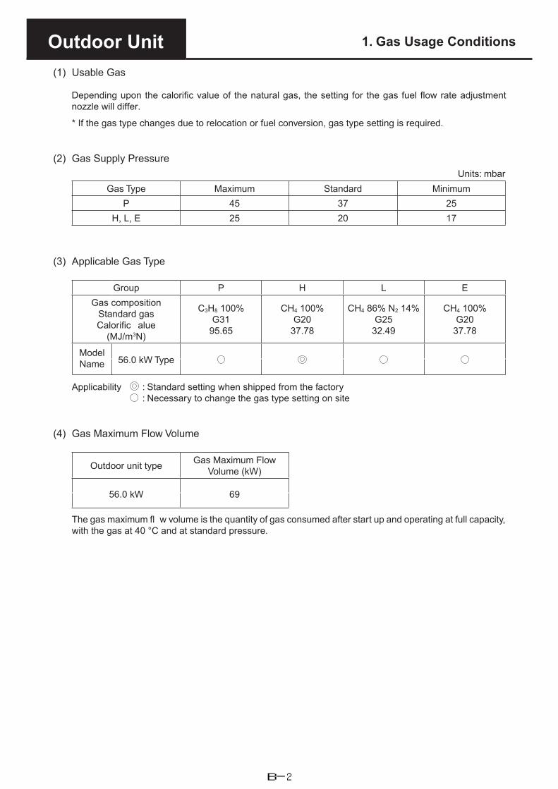
Outdoor Unit 1. Gas Usage Conditions
(1) Usable Gas
Depending upon the calorific value of the natural gas, the setting for the gas fuel flow rate adjustment nozzle will differ.
* If the gas type changes due to relocation or fuel conversion, gas type setting is required.
(2) Gas Supply PressureUnits: mbar
Gas Type Maximum Standard MinimumP 45 37 25
H, L, E 25 20 17
(3) Applicable Gas Type
Group P H L EGas composition
Standard gasCalorific alue
(MJ/m3N)
C3H8 100%G31
95.65
CH4 100%G20
37.78
CH4 86% N2 14%G25
32.49
CH4 100%G20
37.78
Model Name 56.0 kW Type
Applicability : Standard setting when shipped from the factory : Necessary to change the gas type setting on site
(4) Gas Maximum Flow Volume
Outdoor unit type Gas Maximum Flow Volume (kW)
56.0 kW 69
The gas maximum fl w volume is the quantity of gas consumed after start up and operating at full capacity, with the gas at 40 °C and at standard pressure.
B-2

Outdoor Unit 1. Gas Usage Conditions
(5) When using Propane
* When using Propane as the gas fuel, it is necessary to adjust the fuel adjustment valve and the gastype setting.
1) Fuel valve setting
�With the power supply breaker for the outdoor unit OFF① Move the lever of the P/N switch that is attached to the mixer
part of the engine to the position shown in the diagram. Turnit 180 degrees in the clockwise direction (there is a stopperprovided). Do not apply unnecessary force to turn it anyfurther.
② Attach the short-circuit connector supplied to the N/P switchCN013 on the outdoor unit’s control board.
* Switch the outdoor unit’s power breaker to ON.③ In the electrical equipment box, fix the "Gas type setting/
Adjustment Completed" label to the prescribed position forthe PL NAME.
2) Fuel Gas Type Setting
�Check that the fuel adjustment valve setting has been set before operating the outdoor control board.① Press the home key (SW004) for longer than one second and the menu item number will be displayed.
② Next, press the up (SW005)/down (SW006) key to set the menu item number to .③ After displaying , is displayed. When is displayed press the
set (SW007) key. The green LED (LED053) lights up, and the system address setting is displayed.(For example: )
④ Next operate the down (SW006)/up (SW005) key, to display the gas type setting. When the gas typesetting is displayed, press the set (SW007) key for longer than one second.Note: When setting the gas type, ** is displayed.(for ** enter 00-05)
⑤ A red LED (LED052) lights up, indicating that a forced setting is being carried out. In this condition, pressthe down (SW006)/up (SW005) key, and select the gas type.
The relationship between display and gas type is as shown in the following table.
↑ DOWN↓ UP
Status/settingdisplay Type of gas Status/setting
display Type of gas
Band P (LPG) No Use
No Use No Use
Band H/L (Natural Gas) No Use
No Use No Use
Band E (Natural Gas) No Use
No Use No Use
No Use Band LNG (Natural Gas)
No Use No Use
* When the H/L/E gas type is selected, the oil replacement time warning is not displayed.
⑥ After completing selection of gas type, press the set (SW007) key for longer than 1 second. The redLED (LED052) will be extinguished.
⑦ Press the home (SW004) key to complete the setting.
Note: When using propane, change the setting in accordance with the above procedure to
P Lever
H•L•E
B-3

Outdoor Unit 2. Specification
Model No. U-20GES3E5External dimensions (mm)
HeightWidthDepth
2,2551,650
1,000 (+80)
Weight (kg) 765
Performance (kW)
Cooling capacityHeating capacity (Standard)Heating capacity (low temp.)Hot Water (Cooling mode)
56.063.067.0
29.1 (@65°C outlet)(Note 7)
Generate electricity power source 220 / 230 / 240 V, 50 Hz, Single-phase
Electrical rating
CoolingRunning amperes (A)
Power input (kW)Power factor (%)
5.181.1294
HeatingRunning amperes (A)
Power input (kW)Power factor (%)
4.791.0595
Starting amperes (A) 30
Gas Type
Gas Band
PHLE
Propane gas (G31)Natural gas (G20)Natural gas (G25)Natural gas (G20)
Gas consumption (kW)
CoolingHeating (Standard)
52.151.1
Compressor
Cooling oil (L) (type)Crankcase heater (W)
4.4(FV68S)30
Paint color (Munsell code) Silky Shade (1Y8.5 / 0.5)
Engine
Displacement (L)Rated output (kW)
2.48812.4
Oil TypeQuantity (L)
Panasonic Genuine40
Starter motor 12 V DC, 2.0 kW
Starter type AC/DC conversion type DC starter
Engine cooling waterQuantity (L)
Concentration, Freezing temperature
21
50 V / V%, –35°C
Cooling water pump rated output (kW) 0.16
Refrigerant type, Quantity (kg) HFC [R410A] , 11.5
Air intakes All around
Air outlet TopPiping
Refrigerant gas (mm)
Refrigerant liquid (mm)
Fuel gasExhaust drain (mm)
Hot water supply in/out
ø28.58(brazed)(ø31.75) (Note 4)ø15.88(brazed)
(ø19.05) (Note 4)
Operating noise level dB(A) 80 / 58 (PWL/SPL)
Ventilation System
TypeAir flow rate (m3/min)
Rated output (kW)
Propeller fans (x2)420
0.70×2
Drain heater (W) 40
η s,c 211.8η s,h 143.2Design Pressure (HP/LP) (MPa) 3.80 / 2.50
Notes1. Cooling and heating capacities in the tables are determined under the test conditions of JIS B 8627.
Operating condition Cooling Heating (standard) Heating (low temp.)
Indoor air intake temp. 27°CDB/19°CWB 20°CDB 20°CDB/15°CWB or less
Outdoor air intake temp. 35°CDB 7°CDB/6°CWB 2°CDB/1°CWB
• Effective heating requires that the outdoor air intake temperature be at least –20°CDB or –21°CWB.2. Gas consumption is the total (high) calorific alue standard.3. Outdoor unit operating sound is measured 1 meter from the front and 1.5 meters above the floor (in an
anechoic environment). Actual installations may have larger values due to ambient noise and reflection.4. Values in parentheses ( ) for refrigerant gas and liquid types are those when the maximum piping length
exceeds 90 meters (equivalent length). (Reducers are available locally.)5. Specifications are subject to change without notic .6. Hot water heating capacity is applicable during cooling operation as in Note 1.7. The maximum water temperature that can be obtained is 65°C. Water heating performance and temperature
vary with the air conditioning load.Because the hot water heating system uses waste heat from the engine, which runs the air conditioning,its ability to heat water is not guaranteed.
Oil balance(mm) ø6.35R3/4 (Bolt, thread)
ø25 .Rubber hose (length: 350) Rp3/4 (Nut, thread)
B-4

Outdoor Unit 2. Specification
Notes1. Cooling and heating capacities in the tables are determined under the test conditions of JIS B 8616.
Operating condition Cooling Heating (standard) Heating (low temp.)
Indoor air intake temp. 27°CDB/19°CWB 20°CDB 20°CDB/15°CWB or less
Outdoor air intake temp. 35°CDB 7°CDB/6°CWB 2°CDB/1°CWB
• Effective heating requires that the outdoor air intake temperature be at least –20°CDB or –21°CWB.
2.
3.
4.
Outdoor unit operating sound is measured 1 meter from the front and 1.5 meters above the floor (in an anechoic environment). Actual installations may have larger values due to ambient noise and reflection. Values in parentheses ( ) for refrigerant gas and liquid types are those when the maximum piping length exceeds 90 meters (equivalent length). (Reducers are available locally.)Specifications are subject to change without notic .
HFC [R410A] , 5.6
Three sides(except the front side)
Top
Refrigerant type, Quantity (kg)
Air outletPiping
Refrigerant gas (mm)
Refrigerant liquid (mm)
ø22.22(brazed)(ø25.4) (Note 3)ø9.52 (brazed)(ø12.7) (Note 3)
ø6.35 Oil balance(mm)
Ventilation SystemType Propeller fans (x1)
2240.75
Air flow rate (m3/min) Rated output (kW)
275.4167.6
η s,cη s,hDesign Pressure (HP/LP) (MPa) 3.80 / 3.11
U-10MES2E8Model No.
External dimensions (mm)
HeightWidthDepth
1,842770
1,000
Weight (kg)
Performance (kW)
Cooling capacityHeating capacity
28.031.5
Generate electricity power source 380 / 400 / 415 V, 50 Hz, 3-phase
Electrical rating
Cooling10.26.4191
HeatingRunning amperes (A)
Power input (kW)Power factor (%)
10.56.6291
1Starting amperes (A)
Running amperes (A)Power input (kW)Power factor (%)
210
Air intakes
77 /56(PWL / SPL) Operating noise level dB(A)
B-5

Outdoor Unit 3. External Dimensions
2255(External)176
1650(External)
Front View
1024(min)1040(max)
(anchor pitch)
1000
325
(anchor pitch)
Top View
1412
10 12
1212
1000(External)
1080(frame width)
1050
(suspension holes)
Left Side View
111115
9
153
243
22
243
51353
143 (Knock out hole)100 (Rerigerant pipe)
213
326
42260
15080
(Hot water) 11150
182
Rear View
4
5 6
7
13 2
81718
1 32000
At least
550At least
950At least
100
At least
350
At least
550At least
950At least
100
At least
100
At least
350
At least
744
16
Right Side View
Front Side
Front Side
Rear Side
(refrigerant tubing)
Rear Side
(refrigerant tubing)
<Single-unit
installation>
<Multi-unit series installation>
Service Clearances for Installation
(Units:mm)
Free
Exte
rnal
dim
ensi
ons
U-2
0GES
3E5
draw
ing
Scal
eM
odel
Nam
e
B-6

Outdoor Unit 3. External Dimensions
unit: mm
ø19.051 Refrigerant tubing(gas tube)
brazed connection
Refrigerant tubing (liquid tube)Refrigerant tubing(balance tube)
flared connectionflared connection
8HPTypes of unit 10HP
ø9.522
ø6.35
ø22.22
ø9.52
ø6.353
4
5
6
7
8
9
10
11
Installation holes(8-15x21 elongated holes), anchor bolts M12 or larger
Refrigerant tubing port (front: knock-out hole)
Refrigerant tubing port (bottom: slit hole)
Electrical wiring port (front: ø60, ø29 knock-out hole - for conduit connection)Electrical wiring port (bottom: ø60, ø29 knock-out hole - for conduit connection)Pressure outlet port (for high pressure: ø7.94 Schrader-type connection)Pressure outlet port (for low pressure: ø7.94 Schrader-type connection)
Terminal plate for inter-unit control wiring and/or inter-outdoor unit control wiring
Terminal plate
12
A :B :C :
964 (Installation hole pitch) * The tubing is routed out from the front.730 (Installation hole pitch) * The tubing is routed out from the bottom.730 (Installation hole pitch)
According to the installation site, you may choose the setting position in the depth direction of the anchor bolt from "A", "B" or "C".
1-2. Dimensional DataU-10MES2E8
460 5 5
5
5
189(Width of space)
(Width of space)
79
6839
81
85 86
355220
55
219354
450489
552624
222
149
134
9274
56
322 34
8
a
1842
953
760
901
353583
618
9
10
12
75 75
11
E
D
8 6
12357
15 1823
4
1000
1000
C:7
30 B:7
30
A:9
6418740
770
15
Installation anchor hole8-15×21elongated holes
4
View Z
ø60 knock-
out hole
ø29 knock-
out hole
Enlarged view D
Installation hole8 - 15 x 21 elongated hole
Side view
Front view
Top view
Air intake
Air intake
Air intake
(Installation hole pitch)
Electrical component box
Installation fixing bracket Installation side
Enlarged view E
Position of refrigerant tube connection
Dimension of refrigerant tube connecting positionTypes of unit 8HP
a10HP
240 270
(par
t3
)(p
art
2)
(par
t1
)
Z
B-7

(1) U-20G S3E5
DC
MC
N083
12
3
12
3
12
3
12
3
12V
AC
N001
3P
( BLU
)
12
3
PS2
PS1
CN
049
6P
( RED
)
12
34
56
11
12
3
12
3
AU
H1
AU
H2
CN
031
7P
( BLK
)
+ -
DC
MC
N024
VG
01
VG
02
CN
041
OU
T-M
AIN
CN
026
3P
( WH
T)
7P
( WH
T)
6P
( WH
T)
63Q
3C
N038
3P
( RED
)
13
FB
VG
CN
101
3P
( BLK
)
12V
C
FC
CN
025
3P
( BLK
)
12
3
12V
AC
N021
3P
( BLU
)
12
3
13
57
13
57
13
57
12
34
56
IG1
IG2
CN
010
6P
( WH
T)
12
34
56
12
34
56
12
34
56
VG
01V
G02
PO
WER
SU
PP
LY
UN
ITC
ON
TR
OL
LIN
E
LO
AD
CB
LIN
E
Sta
rter
Moto
rP
ow
er
Supp
ly
OU
T-P
OW
CN
019
7P
( BLK
)
12
34
56
71
23
45
67
89
10
11
12
13
14
15
16
YEL
YEL
1 2 3 4
STR
CN
022
3P
( WH
T)
CT1
CN
063
3P
( YEL
)
1 31 3
AC
-IN
CN
002
3P
(WH
T)
1 2 3
52S
CN
028
3P
( YEL
)
12
34
12
34
RED
L
BLK
Fuel G
as V
alve
1,2
Fuel G
as B
ox
VG
01 : Inle
t Sid
eV
G02 : G
ove
rnor
Sid
e
YELWHT
CN
072
5P
( WH
T)
( BLU
)
12
34
5
12
34
5
12
34
5
M
CN
065
6P
( YEL
)
12
34
56
M
3P
( YEL
)
FM
3~
ji
hg
RS
UV
yz
g
zy
L1
CN
009
+
BLK
BLK
FG
TM
075
+
L2
CN
010
+
PP
LC
N084
+
12
34
56
12
12
BLK
L1
D1
ORG
YEL
WHT
WH
T
L2
C1
PNKYEL
N1
23
4TR
MB
LC
K(T
B1)
Ele
ctr
ical
Wirin
gD
iagr
am
12
B
B
A
DC12V
A
PNK
REDWHTBRNORGYELBLU
YELYEL
REDYELBLK
ORGBLKBRNORGBLKRED
ORGBLKPNKORGBLKYEL
REDWHTBRNORGYELBLU
REDBLKYELWHT
DC12V/0V
DC180V/0V
GND
GND
DC180V/0V
hi
j
B
B
A
DC12V
DC12V
A
DC
12V
/0V
PN
KC
N085
+D
C12V
/0V
AC
-IN
2C
N013
4P
( BLU
)
1 4
AC
11V
/0V
SIG
OC
1 3 1 3
1 3
CN
045
4P
( WH
T)SIG
C-M
CN
020
3P
( RED
)
AC
230V
/0V
AC
230V
/0V
AC
200V
/0V
52S
24
6
SB
A2
A1
13
5
BR
AN
CH
LIN
E
TR
MB
LC
K(T
B2)
Ext
ern
alO
pera
teP
um
pO
ut
put
5P
-6
( BLK
)6P
-3
( RED
)3P
-7
12
12
( YEL
)2P
-2
( WH
T)4P
-2
Exp
ansi
on
Val
ve
Fuel G
asA
djust
ment
Val
ve
(Engine)
Engi
ne O
ilP
ress
ure
SW
Sta
rter
(First
Cyl
inde
r)
(Second
Cyl
inde
r)
Cam
Angl
eSenso
r
Cra
nk
Angl
e S
enso
r
Thro
ttle
Val
ve(T
hird
Cyl
inde
r)
(Fore
th C
ylin
der)
32
1
32
1
CN
074
5P
( BLU
)
( BLK
)( B
LK)
12
34
5
12
34
5
12
34
5
M
B
B
A
DC12V
A
5P
-5C
oolin
g W
ater
3W
AY M
oto
r V
alve
CN
070
5P
( YEL
)
( RED
)
12
34
5
12
34
5
12
34
5
M
B
B
A
DC12V
A
B
B
A
DC12V
A
DC5V
B
B
A
DC12V
A
B
B
A
DC12V
A
63Q
2TH
-G
r1TH
-G
r2C
N021
3P
( RED
)
13
13
13
13
13
BLK
GR
N
BLK
GND
SIG
5P
-4
Lig
uid
Val
ve
REDBLKYELWHT
CN
069
5P
( GR
N)
( WH
T)
12
34
5
12
34
5
12
34
5
M
5P
-3
By-
Pas
sV
alve
FB
VG
CN
043
3P
( BLK
)
7P
( RED
)
( BLK
)( W
HT)
1P
-1
CN
001
5P
( BLK
)
12
34
5
Fan
Moto
r 1
WH
T
WH
T
WH
T
CL
DC12V/0V
TH
15
CN
040
13
t°
GR
Y
GND
SIGTH
15
VR
RC
N033
3P
( WH
T)
13AC200V/0V
AC200V/0V
OP
MC
N032
3P
( GR
N)
13DC90V/0V
63P
HFM
1P
.D.1
FM
2P
.D.2
CN
014
4P
( WH
T)
14AC200V/0V
Exp
ansi
on
Val
ve1-1
Exp
ansi
on
Val
ve1-2
( WH
T)
12
34
5
12
34
5
M
5P
-2
16P
( WH
T)C
N086
12
34
56
78
910
10P
( WH
T)C
N089
12
34
5
ORGREDYELBLKGRY
ORGREDYELBLKGRY
ORGREDYELBLKGRY
ORGREDYELBLKGRY
BRNWHTGRNGRYYEL
ORGREDYELBLKGRY
DC12V/0V
DC12V
DC12V/0V
DC12V/0V
DC12V
DC7V
BLU
RED
WHTWHTPNKPPL
REDWHTBLK
REDWHTBLKBRNORG
YEL
WHT
GRY
ORGBLK
WHT
PNK
REDBRNBLKREDORGBLK
BLKBLKRED
BLU
WHT
GRY
REDBLK
BLKBLK
ORG
BRN
RED
BLU
BLUBLU
REDYELBLKGRY
REDYELBLKGRY
REDYELBLKGRY
RED
RED
YEL
YEL
YEL
BLK
BLK
GRY
BRNWHTBLUGRY
GRY
ORG
ORG
ORG
ORG
ORG
WHT
WHTWHT
GRY
ORG
BRN
RED
GND
CN
006
3P
( BLK
)
12
3
REDWHTBLK
GRYPNK
BLUYEL
GRN/YELORG
REDWHTBLK
REDWHTBLK
GRYPNK
BLUYEL
ORG
BLKBLK
REDWHTBLK
BRN
BLUWHT
REDRED
BLKWHTREDWHT
RED
RED
BLK
BRN
WHT
WHT
BRN
WHT
WHT
BLU
BLU
BLK
BLK
RED
WHT
RED
BLKRED
GRY
DC12V/0V
DC12V/0V
DC12V/0V
12
34
5
M
5P
-1
( BLK
)
SIG
12V
CC
N006
3P
( BLK
)3P
( BLK
)
GND
DC12V
DC5V
GND
SIG
32
1
32
1
3P
-5
( BLK
)3P
-4
( BLK
)3P
-9
( GR
Y)3P
-10
( GR
Y)3P
-11
+G IG1
IB+
G IG2
IB
Refr
igera
nt
Low
Pre
ssure
Senso
r
Refr
igera
nt
Hig
h P
ress
ure
Senso
r
3P
( RED
)
CH
CN
035
13
3P
( OR
G)
Coolin
gW
ater
Pum
pM
oto
r
Refr
igera
nt
Hig
hP
resu
reSW
Clu
tch
Coil
Dra
inFilt
er
Heat
er
1
Dra
inFilt
er
Heat
er
2
AC
XF22-07050
MA
IN P
RIN
TED
CKT B
D A
SSY
PO
WER
PR
INTED
CKT B
D A
SSY
GND
DC12V
SIG
GND
DC12V
SIG
GND
DC12V
SIG
IG3
IG4
CN
011
6P
( BLK
)6P
( BLK
)
12
34
56
12
34
56
12
34
56
( BLU
)6P
-4
12
34
56
12
34
56
6P
-2
( GR
Y)3P
-12
( GR
Y)3P
-13
+G IG3
IB+
G IG4
IB
GND
DC12V
SIG
GND
DC12V
SIG
(RED
)
63Q
CN
012
13
Nam
eSym
bol
Hot
Wat
er
Inle
t Tem
pera
ture
Senso
r
TH
1C
om
press
or
Inle
t Tem
pera
ture
Senso
r
Com
press
or
Outlet
Tem
pera
ture
Senso
rTH
2
Cat
alys
t Tem
pera
ture
Senso
rTH
9
Hot
Wat
er
Outlet
Tem
pera
ture
Senso
rTH
10
Oil
Leve
l M
eas
ure
ment
Tem
pera
ture
Senso
rTH
11
TH
12
TH
14
TH
15
Heat
Exc
han
ger
Inle
t Tem
pera
ture
Senso
rTH
3
Coolin
g W
ater
Tem
pera
ture
Senso
rTH
6
Outd
oor
Tem
pera
ture
Senso
r
Exh
aust
Gas
Tem
pera
ture
Senso
r
TH
7
TH
8
Reac
tor
1L1
Reac
tor
2L2
Clu
tch C
oil
Tem
pera
ture
Senso
r 2
Clu
tch C
oil
Tem
pera
ture
Senso
r
Ignitio
n C
oil 1~
4IG
1~
4
Nam
eSym
bol
Circuit B
reak
er
Nois
e F
ilter
1
Nois
e F
ilter
2
Nois
e F
ilter
3
NF1
NF2
NF3
CB
C1
C2
Dio
de 1
D1
Dio
de 2
D2
Cap
acitor
1
Cap
acitor
2
Cap
acitor
3C
3
CN
073
5P
( RED
)
12
34
5
12
34
5
12
34
5
BRNWHTGRNGRYYEL
M
B
B
A
DC12V
DC12V
DC12V/0V
A
(BLK
)5P
-7
Hot
Wat
er
3W
AY M
oto
r V
alve
Oil
Byp
ass
Val
ve
CA
MC
N016
3P
( BR
N)
13
12
12
CN
066
3P
( RED
)
12
34
56
MSTR
REDWHTBRNORGYELBLU
BLUBRN
REDYELBLK
12
3
12
3
12
3
REDBLUBLK
(WH
T)3P
-6
( GR
N)
3P
-8
GND
DC12V
SIG
CR
AC
N015
3P
( WH
T)
REDBLUBLK
REDBLKWHTREDBLKWHT
REDBLKWHTREDBLKWHT
REDWHTBRNORGYELBLU
B
B
A
DC12V
DC12V
A
12
34
56
12
34
56
6P
-1
( RED
)( W
HT)
2P
-18
GND
DC5V/0VFG
LP
CN
040
3P
( GR
N)
FC
AC
200V
/0V
RED
RED
BP
V
FC SIG
PM
3~ PM
CN
023
3P
( RED
)
12
3
AC200V/0V
AC200V/0V
FM
3~
CN
005
5P
( BLK
)
12
34
51
23
4
Fan
Moto
r 2
CN
007
3P
( BLK
)
12
3
CL
11
( WH
T)1P
-2
CL2
CN
008
4P
( YEL
)
DC12V/0V
Clu
tch
Coil
2
CL2
12
12
( WH
T)2P
-3
Cra
nk
Cas
eH
eat
er
12
12
( GR
N)
2P
-4
( RED
)2P
-14t°
TH
8
12
12
t°
TH
7
( GR
Y)2P
-12t°
TH
6
12
12
SIG
GND
12
34
56
78
910
11
12
13
14
15
16
16P
( BLK
)C
N091
SIG
GND
SIG
GND
SIG
GND
SIG
GND
SIG
GND
SIG
GND
SIG
GND
SIG
GND
SIG
GND
SIG
GND
t°
TH
11
t°
TH
12
( RED
)2P
-11
( WH
T)2P
-10
( BLU
)2P
-9
( RED
)2P
-8
( BLK
)2P
-7
t°
TH
14
12
12
t°
TH
10
34
34
t°
TH
9
12
12
t°
TH
3
12
12
t°
TH
2
12
12
t°
TH
1
12
12
RTV
2C
N027
13
3P
( BLK
)
OR
VR
OB
VC
N017
13AC200V/0V
12
12
( WH
T)2P
-5
YEL
YEL
12
12
( RED
)2P
-15
RTV
1ED
HC
N004
3P
-3
12
3
12
3
( BLK
)3P
-2
( BLK
)2P
-17
BR
Ne
15
34
BR
Nf
WHT
WHT
Oil
Pum
p
OP
M
REDWHTBLK
12
3
12
3
( BLK
)3P
-1
N/P
CN
013
3P
( WH
T)
12
3
OU
T-R
AY
9P
( WH
T)C
N018
12
34
56
78
9
BRNWHTBLUGRYYEL
AC
OU
TC
N015
4P
( BLU
)
14
4-W
AY
Val
ve
20S
HESV
CN
016
3P
( RED
)
NF2
4 213
Nois
eFilt
er2
RED
GRN
WHT
BLK
RED
WHT
NF3
4
21
3
Nois
eFilt
er3
BRN
BLU
BRN
BLU
NF1
4 213
Nois
eFilt
er1
RED
GRN
RED
WHT
WHT
WH
T
VA
12
Var
isto
rTR
MB
LC
K(T
B4)
AL
Surg
eA
bsorb
er
WH
TR
ED
TR
MB
LC
K(T
B3)
BLU WHTWHTBRN
YELREDBLK B
RN
C2
C3
PNK
PNK
CT
BLK
RED
GRY
FC
BRN
LT BLU
GRN/YEL
YEL
YEL
feB
RN
BR
N
ba
ba
GRN/YEL
GRN/YEL
FC
FC
BLKBLK
BLKBLK
BLKBLK
(BLK
)4P
-1
12
12
BLKBLK
(BLK
)2P
-16
12
12
BLKBLK
(WH
T)2P
-13
12
12
BLKBLK
BLKBLK
BLKBLK
BLKBLK
REDRED
GRN
Fuel G
as L
Pre
ssure
SW
12
12
( WH
T)2P
-6
BR
NB
LU
BLK
D2
Oil
Recove
ryV
alve
Outdoor Unit 4. Wiring Diagram
B-8

��
�
�
��
��
��
��
��
��
�
�
��
Outdoor Unit 4. Wiring Diagram
(2)U-10MES2E8
B-9

Outdoor Unit 5. Performance Characteristics
①U-20GES3E5 [56.0 kW type]1) Cooling capacityCapacity ratio: 130% (Total capacity of indoor units: 72.8 kW) Cooling capacity characteristics (Unit: %)
Outdoor air
intake temp.
(°CDB)
Indoor air intake temp. (ºCWB)
16 18 19 20 22 24
(a) (b) (a) (b) (a) (b) (a) (b) (a) (b) (a) (b)
0 98.3 90.0 107.4 95.9 110.7 96.9 113.4 99.0 116.1 101.3 116.7 101.85 97.8 90.1 106.9 96.1 110.2 97.1 112.8 99.2 115.6 101.5 116.2 102.0
10 97.3 90.4 106.4 96.4 109.6 97.4 112.3 99.5 115.0 101.8 115.6 102.315 96.9 90.9 105.8 96.9 109.1 97.9 111.7 100.0 114.4 102.4 115.0 102.920 96.4 91.3 105.3 97.4 108.5 98.4 111.2 100.5 113.9 102.9 114.5 103.425 95.9 91.8 104.8 97.9 108.0 98.9 110.6 101.0 113.3 103.4 113.9 103.930 95.9 94.8 104.8 101.1 108.0 102.4 110.7 104.7 113.3 107.0 113.9 107.635 95.9 98.4 104.8 105.0 108.0 106.5 110.6 108.6 113.3 111.3 113.9 111.940 91.2 104.2 97.7 112.7 101.0 116.7 103.5 119.7 106.1 122.8 106.7 124.0
Capacity ratio: 100% (Total capacity of indoor units: 56.0 kW) Cooling capacity characteristics (Unit: %)
Outdoor air
intake temp.
(°CDB)
Indoor air intake temp. (ºCWB)
16 18 19 20 22 24
(a) (b) (a) (b) (a) (b) (a) (b) (a) (b) (a) (b)
0 91.0 84.5 99.4 90.1 102.5 91.0 105.0 92.9 107.5 95.2 108.1 95.65 90.6 84.6 98.9 90.2 102.0 91.2 104.4 93.1 107.0 95.4 107.6 95.8
10 90.1 84.9 98.5 90.5 101.5 91.5 103.9 93.4 106.5 95.6 107.1 96.115 89.7 85.3 98.0 91.0 101.0 92.0 103.4 93.9 105.9 96.1 106.6 96.620 89.2 85.8 97.5 91.4 100.5 92.4 102.9 94.3 105.4 96.6 106.0 97.125 88.8 86.2 97.0 91.9 100.0 92.9 102.4 94.8 104.9 97.1 105.5 97.630 88.8 89.0 97.0 94.9 100.0 96.1 102.5 98.3 104.9 100.5 105.5 101.135 88.8 92.4 97.0 98.6 100.0 100.0 102.4 102.0 104.9 104.5 105.5 105.140 84.5 97.8 90.4 105.8 93.6 109.5 95.9 112.4 98.2 115.4 98.9 116.5
Capacity ratio: 80% (Total capacity of indoor units: 44.8 kW) Cooling capacity characteristics (Unit: %)
Outdoor air
intake temp.
(°CDB)
Indoor air intake temp. (ºCWB)
16 18 19 20 22 24
(a) (b) (a) (b) (a) (b) (a) (b) (a) (b) (a) (b)
0 72.8 50.8 79.5 54.2 82.0 54.7 83.9 55.9 86.0 57.3 86.5 57.55 72.4 50.9 79.2 54.3 81.6 54.8 83.5 56.0 85.6 57.4 86.1 57.6
10 72.1 51.0 78.8 54.5 81.2 55.0 83.1 56.2 85.2 57.5 85.7 57.815 71.7 51.3 78.4 54.7 80.8 55.3 82.7 56.5 84.7 57.8 85.2 58.120 71.4 51.6 78.0 55.0 80.4 55.6 82.3 56.8 84.3 58.1 84.8 58.425 71.0 51.8 77.6 55.3 80.0 55.9 81.9 57.0 83.9 58.4 84.4 58.730 71.0 53.5 77.6 57.1 80.0 57.8 82.0 59.1 83.9 60.4 84.4 60.835 71.0 55.6 77.6 59.2 80.0 60.2 81.9 61.4 83.9 62.8 84.4 63.240 67.6 58.8 72.4 63.6 74.9 65.8 76.7 67.6 78.6 69.4 79.1 70.1
(a) Capacity(b) Gas consumption
B-10

Outdoor Unit 5. Performance Characteristics
[56.0 kW type]
Capacity ratio: 70% (Total capacity of indoor units: 39.2 kW) Cooling capacity characteristics (Unit: %)
Outdoor air
intake temp.
(°CDB)
Indoor air intake temp. (ºCWB)
16 18 19 20 22 24
(a) (b) (a) (b) (a) (b) (a) (b) (a) (b) (a) (b)
0 63.8 38.9 69.6 41.5 71.8 42.0 73.5 42.8 75.2 43.9 75.7 44.25 63.4 39.0 69.3 41.6 71.4 42.1 73.1 42.9 74.9 44.0 75.4 44.2
10 63.1 39.1 68.9 41.7 71.1 42.3 72.8 43.1 74.5 44.1 75.0 44.415 62.8 39.3 68.6 41.9 70.7 42.5 72.4 43.3 74.1 44.3 74.6 44.620 62.5 39.5 68.2 42.1 70.4 42.7 72.1 43.5 73.8 44.6 74.3 44.825 62.2 39.7 67.9 42.4 70.0 42.9 71.7 43.7 73.4 44.8 73.9 45.130 62.2 41.1 67.9 43.8 70.0 44.3 71.7 45.3 73.4 46.3 73.9 46.635 62.2 42.6 67.9 45.5 70.0 46.1 71.7 47.0 73.4 48.2 73.9 48.540 59.2 45.1 63.3 48.8 65.4 50.6 67.1 51.9 68.7 53.2 69.3 53.8
Capacity ratio: 60% (Total capacity of indoor units: 33.6 kW) Cooling capacity characteristics (Unit: %)
Outdoor air
intake temp.
(°CDB)
Indoor air intake temp. (ºCWB)
16 18 19 20 22 24
(a) (b) (a) (b) (a) (b) (a) (b) (a) (b) (a) (b)
0 54.6 28.7 59.7 30.7 61.5 31.0 62.9 31.6 64.5 32.4 64.9 32.65 54.4 28.8 59.4 30.7 61.2 31.1 62.6 31.6 64.2 32.5 64.6 32.6
10 54.1 28.9 59.1 30.8 60.9 31.2 62.3 31.7 63.8 32.6 64.2 32.715 53.8 29.0 58.8 31.0 60.6 31.3 62.0 31.9 63.5 32.7 63.9 32.920 53.6 29.2 58.5 31.1 60.3 31.5 61.7 32.1 63.2 32.9 63.6 33.125 53.3 29.3 58.2 31.3 60.0 31.6 61.4 32.2 62.9 33.1 63.3 33.230 53.3 30.3 58.2 32.3 60.0 32.7 61.5 33.4 62.9 34.1 63.3 34.435 53.3 31.5 58.2 33.6 60.0 34.1 61.4 34.7 62.9 35.6 63.3 35.740 50.7 33.2 54.3 36.0 56.1 37.3 57.5 38.3 58.9 39.2 59.3 39.6
Capacity ratio: 50% (Total capacity of indoor units: 28.0 kW) Cooling capacity characteristics (Unit: %)
Outdoor air
intake temp.
(°CDB)
Indoor air intake temp. (ºCWB)
16 18 19 20 22 24
(a) (b) (a) (b) (a) (b) (a) (b) (a) (b) (a) (b)
0 45.5 20.5 49.7 21.8 51.3 22.1 52.5 22.5 53.8 23.1 54.1 23.25 45.3 20.5 49.5 21.9 51.0 22.1 52.2 22.5 53.6 23.1 53.9 23.2
10 45.1 20.6 49.2 21.9 50.8 22.2 52.0 22.6 53.3 23.2 53.6 23.315 44.8 20.7 49.0 22.1 50.5 22.3 51.7 22.7 53.0 23.3 53.3 23.420 44.6 20.8 48.7 22.2 50.3 22.4 51.5 22.8 52.8 23.4 53.1 23.525 44.4 20.9 48.5 22.3 50.0 22.5 51.2 23.0 52.5 23.6 52.8 23.630 44.4 21.6 48.5 23.0 50.0 23.3 51.3 23.8 52.5 24.4 52.8 24.535 44.4 22.4 48.5 23.9 50.0 24.2 51.2 24.7 52.5 25.3 52.8 25.540 42.3 23.8 45.3 25.6 46.8 26.6 48.0 27.3 49.2 28.0 49.5 28.2
(a) Capacity(b) Gas consumption
B-11

Outdoor Unit 5. Performance Characteristics
[56.0 kW type]2) Heating capacityCapacity ratio: 130% (Total capacity of indoor units: 72.8 kW) Heating capacity characteristics (Unit: %)
Outdoor air intake temp.
(°CDB) (°CWB)
Indoor air intake temp. (ºCDB)16 18 20 22 24
(a) (b) (a) (b) (a) (b) (a) (b) (a) (b)-15 -15.6 62.8 92.6 69.5 102.5 76.2 112.3 76.8 113.2 77.4 114.1-10 -10.5 70.7 99.1 77.4 108.5 84.1 117.9 84.7 118.7 85.4 119.6-7 -7.6 75.9 99.9 82.6 109.2 89.3 118.5 89.9 119.4 90.6 120.42 1.2 91.7 101.9 110.8 105.1 120.0 105.8 121.1 106.4 122.67 6 100.9 102.8 107.6 109.2 114.3 115.6 115.0 115.9 115.6 115.8
10 8.8 100.9 100.7 107.6 107.0 114.3 113.2 115.0 113.5 115.6 113.515 13.7 100.9 97.2 107.6 103.3 114.3 115.0 109.6 115.6 109.620 15 100.9 96.3 107.6 102.3 114.3 115.0 108.6 115.6 108.6
Capacity ratio: 100% (Total capacity of indoor units: 56.0 kW) Heating capacity characteristics (Unit: %)
Outdoor air intake temp.
(°CDB) (°CWB)
Indoor air intake temp. (ºCDB)16 18 20 22 24
(a) (b) (a) (b) (a) (b) (a) (b) (a) (b)-15 -15.6 62.8 92.6 69.5 102.5 76.2 112.3 76.8 113.2 77.4 114.1-10 -10.5 70.7 99.1 77.4 108.5 84.1 117.9 81.9 114.9 79.3 112.5-7 -7.6 75.9 99.9 82.6 109.2 89.3 118.5 82.8 114.9 80.2 112.52 1.2 91.7 101.9 98.4 110.8 105.1 120.0 103.4 123.5 100.1 124.27 6 100.9 102.8 100.4 102.1 100.0 100.0 97.4 101.6 94.4 100.6
10 8.8 100.9 100.7 100.4 100.1 100.0 98.0 97.4 99.6 94.4 98.615 13.7 100.9 97.2 100.4 98.4 100.0 96.3 97.4 97.7 94.4 96.920 15 100.9 96.3 100.4 98.0 100.0 95.9 97.4 97.3 94.4 96.5
Capacity ratio: 80% (Total capacity of indoor units: 44.8 kW) Heating capacity characteristics (Unit: %)
Outdoor air intake temp.
(°CDB) (°CWB)
Indoor air intake temp. (ºCDB)16 18 20 22 24
(a) (b) (a) (b) (a) (b) (a) (b) (a) (b)-15 -15.6 62.8 92.6 62.0 89.3 61.7 88.8 59.4 85.5 56.8 81.5-10 -10.5 64.4 72.9 63.3 71.5 62.9 71.1 60.6 69.2 57.9 66.7-7 -7.6 65.1 72.9 64.0 71.6 63.6 71.1 61.3 69.2 58.6 66.72 1.2 87.5 77.2 86.1 74.6 85.6 73.2 82.5 73.9 78.8 73.17 6 81.8 61.0 80.3 60.0 80.0 58.8 77.9 59.7 75.5 59.5
10 8.8 81.8 59.8 80.3 58.9 80.0 57.6 77.9 58.5 75.5 58.115 13.7 81.8 58.6 80.3 57.9 80.0 56.6 77.9 57.6 75.5 57.020 15 81.8 58.4 80.3 57.7 80.0 56.4 77.9 57.3 75.5 56.8
(a) Capacity(b) Gas consumption
98.4
109.3108.3
B-12

Outdoor Unit 5. Performance Characteristics
[56.0 kW type]
Capacity ratio: 70% (Total capacity of indoor units: 39.2 kW) Heating capacity characteristics (Unit: %)
Outdoor air intake temp.
(°CDB) (°CWB)
Indoor air intake temp. (ºCDB)16 18 20 22 24
(a) (b) (a) (b) (a) (b) (a) (b) (a) (b)-15 -15.6 55.2 76.0 54.2 73.5 54.0 73.2 52.1 70.8 49.7 67.7-10 -10.5 56.2 64.9 55.3 63.7 55.1 63.5 53.1 61.8 50.7 59.5-7 -7.6 56.9 65.0 55.9 63.7 55.7 63.5 53.7 61.8 51.3 59.52 1.2 76.1 66.7 75.0 64.5 74.4 63.2 71.8 63.8 68.6 63.17 6 71.6 53.7 70.3 52.8 70.0 51.7 68.2 52.5 66.1 52.2
10 8.8 71.6 52.5 70.3 51.7 70.0 50.6 68.2 51.5 66.1 51.115 13.7 71.6 51.6 70.3 50.9 70.0 49.8 68.2 50.6 66.1 50.020 15 71.6 51.4 70.3 50.7 70.0 49.6 68.2 50.4 66.1 49.8
Capacity ratio: 60% (Total capacity of indoor units: 33.6 kW) Heating capacity characteristics (Unit: %)
Outdoor air intake temp.
(°CDB) (°CWB)
Indoor air intake temp. (ºCDB)16 18 20 22 24
(a) (b) (a) (b) (a) (b) (a) (b) (a) (b)-15 -15.6 47.3 60.0 46.4 58.5 46.2 58.2 44.5 56.4 42.7 54.4-10 -10.5 48.2 57.2 47.4 56.0 47.2 55.7 45.4 54.2 43.5 52.3-7 -7.6 48.8 57.2 47.9 56.1 47.7 55.8 45.9 54.2 44.0 52.32 1.2 65.5 56.9 64.5 55.0 64.2 54.1 61.8 54.4 59.2 53.87 6 61.4 46.3 60.2 45.4 60.0 44.6 58.4 45.3 56.6 44.9
10 8.8 61.4 45.3 60.2 44.6 60.0 43.6 58.4 44.3 56.6 43.915 13.7 61.4 44.6 60.2 43.9 60.0 42.9 58.4 43.6 56.6 43.020 15 61.4 44.4 60.2 43.7 60.0 42.8 58.4 43.4 56.6 42.8
Capacity ratio: 50% (Total capacity of indoor units: 28.0 kW) Heating capacity characteristics (Unit: %)
Outdoor air intake temp.
(°CDB) (°CWB)
Indoor air intake temp. (ºCDB)16 18 20 22 24
(a) (b) (a) (b) (a) (b) (a) (b) (a) (b)-15 -15.6 39.4 48.0 38.7 47.1 38.6 46.9 37.1 45.6 35.6 44.0-10 -10.5 40.1 48.2 39.4 47.3 39.3 47.1 37.9 45.8 36.3 44.2-7 -7.6 40.6 48.2 39.9 47.3 39.8 47.1 38.3 45.8 36.7 44.22 1.2 54.7 47.2 53.9 45.8 53.5 44.9 51.5 45.1 49.3 44.67 6 51.2 38.7 50.2 38.0 50.0 37.3 48.7 37.9 47.2 37.5
10 8.8 51.2 37.9 50.2 37.3 50.0 36.5 48.7 37.1 47.2 36.715 13.7 51.2 37.3 50.2 36.7 50.0 35.9 48.7 36.5 47.2 36.020 15 51.2 37.1 50.2 36.5 50.0 35.7 48.7 36.3 47.2 35.8
(a) Capacity(b) Gas consumption
B-13

Outdoor Unit 5. Performance Characteristics
Capacity Ratio 30-130% TC: Total capacity (kW), PI: Power input (kW)
Combination:Indoor/outdoorcapacity ratio
Outdoorair temp.
°CDB
Indoor air temp. : °CWB14.0 16.0 18.0 19.0 21.0 23.0 25.0
TC PI TC PI TC PI TC PI TC PI TC PI TC PIkW kW kW kW kW kW kW kW kW kW kW kW kW kW
130%
-10.0 24.3 2.88 29.1 3.45 30.1 3.58 30.1 3.58 34.1 4.05 38.1 4.53 42.1 5.00-5.0 24.3 2.88 29.1 3.46 30.1 3.58 30.1 3.58 34.1 4.06 38.1 4.53 42.1 5.010.0 24.3 2.88 29.1 3.46 30.1 3.58 30.1 3.58 34.1 4.06 38.1 4.54 42.1 5.015.0 24.3 2.89 29.1 3.47 30.1 3.59 30.1 3.59 34.1 4.07 38.1 4.55 42.1 5.02
10.0 24.3 2.90 29.1 3.47 30.1 3.60 30.1 3.60 34.1 4.09 38.1 4.58 42.1 5.0615.0 24.3 2.90 29.1 3.49 30.1 3.65 30.1 3.65 34.1 4.16 38.1 4.67 42.1 5.1620.0 24.3 2.97 29.1 3.60 30.1 3.83 30.1 3.83 34.1 4.39 38.1 5.14 42.1 5.9825.0 24.3 3.36 29.1 4.20 30.1 4.71 30.1 4.71 34.1 5.58 38.1 6.53 42.1 7.5530.0 24.3 4.23 29.1 5.26 30.1 5.85 30.1 5.85 34.1 6.89 38.1 8.02 41.7 8.9735.0 24.3 5.16 29.1 6.41 30.1 7.06 30.1 7.06 34.1 8.30 36.9 8.97 38.5 8.9740.0 24.3 6.17 29.1 7.64 30.1 8.38 30.1 8.38 32.6 8.97 34.0 8.97 35.5 8.9743.0 24.3 6.81 29.1 8.42 29.6 8.97 29.6 8.97 31.0 8.97 32.3 8.80 33.1 8.4146.0 24.0 6.84 24.2 6.84 24.2 6.84 24.2 6.84 25.0 6.58 26.0 6.39 27.2 6.2452.0 10.1 2.66 10.7 2.66 10.7 2.66 10.7 2.66 11.9 2.76 13.2 2.86 14.6 2.97
Combination:Indoor/outdoorcapacity ratio
Outdoorair temp.
°CDB
Indoor air temp. : °CWB14.0 16.0 18.0 19.0 21.0 23.0 25.0
TC PI TC PI TC PI TC PI TC PI TC PI TC PIkW kW kW kW kW kW kW kW kW kW kW kW kW kW
120%
-10.0 22.4 2.66 26.9 3.19 29.4 3.49 29.4 3.49 33.3 3.96 37.2 4.42 41.2 4.89-5.0 22.4 2.66 26.9 3.19 29.4 3.50 29.4 3.50 33.3 3.96 37.2 4.43 41.2 4.890.0 22.4 2.66 26.9 3.20 29.4 3.50 29.4 3.50 33.3 3.97 37.2 4.43 41.2 4.905.0 22.4 2.67 26.9 3.20 29.4 3.51 29.4 3.51 33.3 3.97 37.2 4.44 41.2 4.91
10.0 22.4 2.68 26.9 3.21 29.4 3.52 29.4 3.52 33.3 3.99 37.2 4.47 41.2 4.9415.0 22.4 2.68 26.9 3.23 29.4 3.56 29.4 3.56 33.3 4.06 37.2 4.56 41.2 5.0420.0 22.4 2.74 26.9 3.33 29.4 3.73 29.4 3.73 33.3 4.28 37.2 4.95 41.2 5.7525.0 22.4 3.11 26.9 3.87 29.4 4.56 29.4 4.56 33.3 5.39 37.2 6.30 41.2 7.2730.0 22.4 3.91 26.9 4.85 29.4 5.66 29.4 5.66 33.3 6.67 37.2 7.75 41.2 8.9035.0 22.4 4.76 26.9 5.90 29.4 6.84 29.4 6.84 33.3 8.04 36.6 8.97 38.1 8.9740.0 22.4 5.69 26.9 7.03 29.4 8.12 29.4 8.12 32.3 8.97 33.7 8.97 35.2 8.9743.0 22.4 6.28 26.9 7.75 29.4 8.94 29.4 8.94 30.8 8.97 32.1 8.86 32.9 8.4446.0 22.2 6.83 24.0 6.86 24.0 6.86 24.0 6.86 24.8 6.59 25.7 6.37 26.8 6.2152.0 9.4 2.62 10.3 2.62 10.5 2.62 10.5 2.62 11.6 2.70 12.9 2.80 14.2 2.89
Combination:Indoor/outdoorcapacity ratio
Outdoorair temp.
°CDB
Indoor air temp. : °CWB14.0 16.0 18.0 19.0 21.0 23.0 25.0
TC PI TC PI TC PI TC PI TC PI TC PI TC PIkW kW kW kW kW kW kW kW kW kW kW kW kW kW
110%
-10.0 20.5 2.44 24.6 2.93 28.7 3.41 28.7 3.41 32.5 3.86 36.4 4.32 40.2 4.77-5.0 20.5 2.44 24.6 2.93 28.7 3.41 28.7 3.41 32.5 3.87 36.4 4.32 40.2 4.780.0 20.5 2.44 24.6 2.93 28.7 3.42 28.7 3.42 32.5 3.87 36.4 4.33 40.2 4.785.0 20.5 2.45 24.6 2.94 28.7 3.42 28.7 3.42 32.5 3.88 36.4 4.33 40.2 4.79
10.0 20.5 2.45 24.6 2.94 28.7 3.43 28.7 3.43 32.5 3.89 36.4 4.36 40.2 4.8215.0 20.5 2.46 24.6 2.96 28.7 3.47 28.7 3.47 32.5 3.96 36.4 4.45 40.2 4.9220.0 20.5 2.51 24.6 3.05 28.7 3.63 28.7 3.63 32.5 4.16 36.4 4.76 40.2 5.5325.0 20.5 2.86 24.6 3.54 28.7 4.41 28.7 4.41 32.5 5.21 36.4 6.07 40.2 7.0030.0 20.5 3.59 24.6 4.44 28.7 5.48 28.7 5.48 32.5 6.44 36.4 7.48 40.2 8.5835.0 20.5 4.37 24.6 5.40 28.7 6.62 28.7 6.62 32.5 7.77 36.3 8.95 37.8 8.9740.0 20.5 5.22 24.6 6.43 28.7 7.87 28.7 7.87 32.1 8.97 33.5 8.97 34.9 8.9743.0 20.5 5.75 24.6 7.09 28.7 8.67 28.7 8.67 30.5 8.97 31.9 8.93 32.6 8.4846.0 20.3 6.26 23.9 6.89 23.9 6.89 23.9 6.89 24.6 6.60 25.5 6.36 26.5 6.1852.0 8.7 2.58 9.6 2.58 10.3 2.58 10.3 2.58 11.4 2.65 12.6 2.74 13.9 2.82
Combination:Indoor/outdoorcapacity ratio
Outdoorair temp.
°CDB
Indoor air temp. : °CWB14.0 16.0 18.0 19.0 21.0 23.0 25.0
TC PI TC PI TC PI TC PI TC PI TC PI TC PIkW kW kW kW kW kW kW kW kW kW kW kW kW kW
100%
-10.0 18.7 2.22 22.4 2.66 26.1 3.10 28.0 3.33 31.7 3.77 35.5 4.21 39.2 4.66-5.0 18.7 2.22 22.4 2.66 26.1 3.11 28.0 3.33 31.7 3.77 35.5 4.22 39.2 4.660.0 18.7 2.22 22.4 2.67 26.1 3.11 28.0 3.33 31.7 3.78 35.5 4.22 39.2 4.675.0 18.7 2.23 22.4 2.67 26.1 3.12 28.0 3.34 31.7 3.78 35.5 4.23 39.2 4.67
10.0 18.7 2.23 22.4 2.68 26.1 3.12 28.0 3.35 31.7 3.80 35.5 4.25 39.2 4.7015.0 18.7 2.24 22.4 2.69 26.1 3.15 28.0 3.38 31.7 3.86 35.5 4.33 39.2 4.8020.0 18.7 2.29 22.4 2.78 26.1 3.28 28.0 3.53 31.7 4.05 35.5 4.58 39.2 5.3125.0 18.7 2.61 22.4 3.22 26.1 3.90 28.0 4.26 31.7 5.02 35.5 5.85 39.2 6.7430.0 18.7 3.27 22.4 4.03 26.1 4.86 28.0 5.30 31.7 6.22 35.5 7.21 39.2 8.2735.0 18.7 3.98 22.4 4.90 26.1 5.89 28.0 6.41 31.7 7.51 35.5 8.68 37.5 8.9740.0 18.7 4.75 22.4 5.84 26.1 7.01 28.0 7.62 31.7 8.91 33.2 8.97 34.6 8.9743.0 18.7 5.23 22.4 6.43 26.1 7.72 28.0 8.39 30.3 8.97 31.7 8.97 32.4 8.5346.0 18.5 5.69 22.2 7.00 23.6 7.12 23.8 6.93 24.4 6.61 25.3 6.36 26.2 6.1652.0 8.1 2.44 8.8 2.46 9.6 2.51 10.1 2.54 11.1 2.60 12.2 2.68 13.5 2.76
* Use the ab ve table when choosing the model of outdoor unit.
②U-10MES2E8 (Cooling)1) Cooling capacity
B-14

Outdoor Unit 5. Performance Characteristics
Capacity Ratio 30-130% TC: Total capacity (kW), PI: Power input (kW)
Combination:Indoor/outdoorcapacity ratio
Outdoorair temp.
°CDB
Indoor air temp. : °CWB14.0 16.0 18.0 19.0 21.0 23.0 25.0
TC PI TC PI TC PI TC PI TC PI TC PI TC PIkW kW kW kW kW kW kW kW kW kW kW kW kW kW
90%
-10.0 16.8 2.00 20.2 2.40 23.5 2.79 25.2 2.99 28.6 3.39 31.9 3.79 35.3 4.19-5.0 16.8 2.00 20.2 2.40 23.5 2.80 25.2 3.00 28.6 3.40 31.9 3.80 35.3 4.200.0 16.8 2.00 20.2 2.40 23.5 2.80 25.2 3.00 28.6 3.40 31.9 3.80 35.3 4.205.0 16.8 2.01 20.2 2.41 23.5 2.81 25.2 3.01 28.6 3.41 31.9 3.81 35.3 4.21
10.0 16.8 2.01 20.2 2.41 23.5 2.81 25.2 3.01 28.6 3.41 31.9 3.82 35.3 4.2315.0 16.8 2.02 20.2 2.42 23.5 2.83 25.2 3.03 28.6 3.45 31.9 3.88 35.3 4.3020.0 16.8 2.05 20.2 2.48 23.5 2.92 25.2 3.14 28.6 3.60 31.9 4.06 35.3 4.5225.0 16.8 2.31 20.2 2.83 23.5 3.39 25.2 3.69 28.6 4.32 31.9 5.01 35.3 5.7430.0 16.8 2.90 20.2 3.55 23.5 4.24 25.2 4.61 28.6 5.38 31.9 6.21 35.3 7.0835.0 16.8 3.53 20.2 4.32 23.5 5.16 25.2 5.59 28.6 6.52 31.9 7.50 35.3 8.5340.0 16.8 4.21 20.2 5.14 23.5 6.14 25.2 6.66 28.6 7.74 31.9 8.89 33.4 8.9743.0 16.8 4.64 20.2 5.67 23.5 6.77 25.2 7.34 28.6 8.53 30.5 8.97 31.7 8.8646.0 16.6 5.05 20.0 6.17 23.3 7.36 23.4 7.14 23.9 6.74 24.4 6.41 25.1 6.1452.0 7.7 2.38 8.3 2.37 8.9 2.38 9.3 2.39 10.1 2.42 11.1 2.46 12.1 2.50
Combination:Indoor/outdoorcapacity ratio
Outdoorair temp.
°CDB
Indoor air temp. : °CWB14.0 16.0 18.0 19.0 21.0 23.0 25.0
TC PI TC PI TC PI TC PI TC PI TC PI TC PIkW kW kW kW kW kW kW kW kW kW kW kW kW kW
80%
-10.0 14.9 1.78 17.9 2.13 20.9 2.48 22.4 2.66 25.4 3.02 28.4 3.37 31.4 3.73-5.0 14.9 1.78 17.9 2.13 20.9 2.49 22.4 2.66 25.4 3.02 28.4 3.38 31.4 3.730.0 14.9 1.78 17.9 2.13 20.9 2.49 22.4 2.67 25.4 3.02 28.4 3.38 31.4 3.745.0 14.9 1.78 17.9 2.14 20.9 2.50 22.4 2.67 25.4 3.03 28.4 3.39 31.4 3.74
10.0 14.9 1.79 17.9 2.15 20.9 2.50 22.4 2.68 25.4 3.04 28.4 3.39 31.4 3.7515.0 14.9 1.80 17.9 2.15 20.9 2.51 22.4 2.69 25.4 3.06 28.4 3.43 31.4 3.8020.0 14.9 1.81 17.9 2.19 20.9 2.57 22.4 2.76 25.4 3.16 28.4 3.56 31.4 3.9725.0 14.9 2.00 17.9 2.46 20.9 2.92 22.4 3.17 25.4 3.68 28.4 4.23 31.4 4.8230.0 14.9 2.54 17.9 3.08 20.9 3.66 22.4 3.97 25.4 4.60 28.4 5.28 31.4 5.9935.0 14.9 3.10 17.9 3.76 20.9 4.46 22.4 4.82 25.4 5.59 28.4 6.39 31.4 7.2440.0 14.9 3.69 17.9 4.49 20.9 5.32 22.4 5.75 25.4 6.66 28.4 7.60 31.4 8.6043.0 14.9 4.07 17.9 4.95 20.9 5.87 22.4 6.34 25.4 7.34 28.4 8.38 30.5 8.9746.0 14.8 4.43 17.7 5.38 20.7 6.38 22.2 6.90 23.5 7.02 23.8 6.60 24.3 6.2552.0 7.4 2.34 7.8 2.29 8.4 2.27 8.6 2.27 9.3 2.26 10.0 2.27 10.8 2.29
Combination:Indoor/outdoorcapacity ratio
Outdoorair temp.
°CDB
Indoor air temp. : °CWB14.0 16.0 18.0 19.0 21.0 23.0 25.0
TC PI TC PI TC PI TC PI TC PI TC PI TC PIkW kW kW kW kW kW kW kW kW kW kW kW kW kW
70%
-10.0 13.1 1.55 15.7 1.86 18.3 2.17 19.6 2.33 22.2 2.64 24.8 2.95 27.4 3.26-5.0 13.1 1.56 15.7 1.87 18.3 2.18 19.6 2.33 22.2 2.64 24.8 2.95 27.4 3.260.0 13.1 1.56 15.7 1.87 18.3 2.18 19.6 2.34 22.2 2.65 24.8 2.96 27.4 3.275.0 13.1 1.56 15.7 1.87 18.3 2.18 19.6 2.34 22.2 2.65 24.8 2.96 27.4 3.27
10.0 13.1 1.57 15.7 1.88 18.3 2.19 19.6 2.35 22.2 2.66 24.8 2.97 27.4 3.2815.0 13.1 1.57 15.7 1.89 18.3 2.20 19.6 2.35 22.2 2.67 24.8 2.99 27.4 3.3120.0 13.1 1.58 15.7 1.90 18.3 2.23 19.6 2.40 22.2 2.73 24.8 3.08 27.4 3.4225.0 13.1 1.71 15.7 2.10 18.3 2.49 19.6 2.68 22.2 3.09 24.8 3.53 27.4 3.9930.0 13.1 2.21 15.7 2.65 18.3 3.12 19.6 3.37 22.2 3.88 24.8 4.42 27.4 4.9935.0 13.1 2.69 15.7 3.23 18.3 3.81 19.6 4.10 22.2 4.73 24.8 5.38 27.4 6.0640.0 13.1 3.20 15.7 3.86 18.3 4.55 19.6 4.90 22.2 5.64 24.8 6.41 27.4 7.2143.0 13.1 3.53 15.7 4.26 18.3 5.02 19.6 5.41 22.2 6.22 24.8 7.07 27.4 7.9546.0 12.9 3.84 15.5 4.63 18.1 5.46 19.4 5.89 22.0 6.77 23.4 7.00 23.7 6.5552.0 7.2 2.33 7.5 2.25 7.9 2.20 8.1 2.18 8.5 2.14 9.1 2.12 9.7 2.11
Combination:Indoor/outdoorcapacity ratio
Outdoorair temp.
°CDB
Indoor air temp. : °CWB14.0 16.0 18.0 19.0 21.0 23.0 25.0
TC PI TC PI TC PI TC PI TC PI TC PI TC PIkW kW kW kW kW kW kW kW kW kW kW kW kW kW
60%
-10.0 11.2 1.33 13.4 1.60 15.7 1.86 16.8 2.00 19.0 2.26 21.3 2.53 23.5 2.80-5.0 11.2 1.33 13.4 1.60 15.7 1.87 16.8 2.00 19.0 2.27 21.3 2.53 23.5 2.800.0 11.2 1.34 13.4 1.60 15.7 1.87 16.8 2.00 19.0 2.27 21.3 2.54 23.5 2.805.0 11.2 1.34 13.4 1.61 15.7 1.87 16.8 2.01 19.0 2.27 21.3 2.54 23.5 2.81
10.0 11.2 1.34 13.4 1.61 15.7 1.88 16.8 2.01 19.0 2.28 21.3 2.55 23.5 2.8115.0 11.2 1.35 13.4 1.62 15.7 1.89 16.8 2.02 19.0 2.29 21.3 2.55 23.5 2.8320.0 11.2 1.36 13.4 1.63 15.7 1.90 16.8 2.04 19.0 2.32 21.3 2.61 23.5 2.9025.0 11.2 1.43 13.4 1.75 15.7 2.07 16.8 2.23 19.0 2.57 21.3 2.89 23.5 3.2530.0 11.2 1.89 13.4 2.25 15.7 2.62 16.8 2.82 19.0 3.22 21.3 3.64 23.5 4.0835.0 11.2 2.30 13.4 2.74 15.7 3.20 16.8 3.43 19.0 3.93 21.3 4.44 23.5 4.9740.0 11.2 2.73 13.4 3.27 15.7 3.82 16.8 4.11 19.0 4.69 21.3 5.30 23.5 5.9343.0 11.2 3.01 13.4 3.60 15.7 4.22 16.8 4.53 19.0 5.18 21.3 5.85 23.5 6.5546.0 11.1 3.27 13.3 3.92 15.5 4.59 16.6 4.93 18.8 5.64 21.1 6.37 23.3 7.1352.0 7.0 2.35 7.2 2.25 7.5 2.16 7.6 2.12 7.9 2.06 8.3 2.01 8.7 1.97
* Use the ab ve table when choosing the model of outdoor unit.
U-10MES2E8 (Cooling)
B-15

Outdoor Unit 5. Performance Characteristics
Capacity Ratio 30-130% TC: Total capacity (kW), PI: Power input (kW)
Combination:Indoor/outdoorcapacity ratio
Outdoorair temp.
°CDB
Indoor air temp. : °CWB14.0 16.0 18.0 19.0 21.0 23.0 25.0
TC PI TC PI TC PI TC PI TC PI TC PI TC PIkW kW kW kW kW kW kW kW kW kW kW kW kW kW
50%
-10.0 9.3 1.11 11.2 1.33 13.1 1.55 14.0 1.67 15.9 1.89 17.7 2.11 19.6 2.33-5.0 9.3 1.11 11.2 1.33 13.1 1.56 14.0 1.67 15.9 1.89 17.7 2.11 19.6 2.330.0 9.3 1.11 11.2 1.34 13.1 1.56 14.0 1.67 15.9 1.89 17.7 2.11 19.6 2.345.0 9.3 1.12 11.2 1.34 13.1 1.56 14.0 1.67 15.9 1.90 17.7 2.12 19.6 2.34
10.0 9.3 1.12 11.2 1.34 13.1 1.57 14.0 1.68 15.9 1.90 17.7 2.12 19.6 2.3515.0 9.3 1.12 11.2 1.35 13.1 1.57 14.0 1.68 15.9 1.91 17.7 2.13 19.6 2.3520.0 9.3 1.13 11.2 1.36 13.1 1.58 14.0 1.69 15.9 1.92 17.7 2.15 19.6 2.3925.0 9.3 1.17 11.2 1.42 13.1 1.67 14.0 1.80 15.9 2.07 17.7 2.34 19.6 2.6030.0 9.3 1.60 11.2 1.87 13.1 2.16 14.0 2.31 15.9 2.61 17.7 2.93 19.6 3.2635.0 9.3 1.93 11.2 2.28 13.1 2.63 14.0 2.81 15.9 3.19 17.7 3.58 19.6 3.9840.0 9.3 2.29 11.2 2.71 13.1 3.14 14.0 3.36 15.9 3.82 17.7 4.28 19.6 4.7643.0 9.3 2.52 11.2 2.98 13.1 3.47 14.0 3.71 15.9 4.21 17.7 4.73 19.6 5.2646.0 9.2 2.73 11.1 3.24 12.9 3.77 13.9 4.04 15.7 4.58 17.6 5.15 19.4 5.7252.0 6.9 2.43 7.0 2.29 7.1 2.18 7.2 2.12 7.4 2.03 7.7 1.96 8.0 1.89
Combination:Indoor/outdoorcapacity ratio
Outdoorair temp.
°CDB
Indoor air temp. : °CWB14.0 16.0 18.0 19.0 21.0 23.0 25.0
TC PI TC PI TC PI TC PI TC PI TC PI TC PIkW kW kW kW kW kW kW kW kW kW kW kW kW kW
40%
-10.0 7.5 0.89 9.0 1.07 10.5 1.24 11.2 1.33 12.7 1.51 14.2 1.69 15.7 1.87-5.0 7.5 0.89 9.0 1.07 10.5 1.25 11.2 1.33 12.7 1.51 14.2 1.69 15.7 1.870.0 7.5 0.89 9.0 1.07 10.5 1.25 11.2 1.34 12.7 1.51 14.2 1.69 15.7 1.875.0 7.5 0.89 9.0 1.07 10.5 1.25 11.2 1.34 12.7 1.52 14.2 1.70 15.7 1.87
10.0 7.5 0.90 9.0 1.07 10.5 1.25 11.2 1.34 12.7 1.52 14.2 1.70 15.7 1.8815.0 7.5 0.90 9.0 1.08 10.5 1.26 11.2 1.35 12.7 1.53 14.2 1.71 15.7 1.8920.0 7.5 0.91 9.0 1.09 10.5 1.27 11.2 1.36 12.7 1.54 14.2 1.72 15.7 1.9025.0 7.5 0.92 9.0 1.11 10.5 1.30 11.2 1.40 12.7 1.60 14.2 1.81 15.7 2.0130.0 7.5 1.32 9.0 1.52 10.5 1.73 11.2 1.84 12.7 2.06 14.2 2.29 15.7 2.5235.0 7.5 1.58 9.0 1.84 10.5 2.11 11.2 2.24 12.7 2.52 14.2 2.80 15.7 3.0940.0 7.5 1.86 9.0 2.18 10.5 2.51 11.2 2.67 12.7 3.00 14.2 3.35 15.7 3.6943.0 7.5 2.04 9.0 2.40 10.5 2.76 11.2 2.94 12.7 3.31 14.2 3.69 15.7 4.0846.0 7.4 2.21 8.9 2.60 10.3 3.00 11.1 3.20 12.6 3.61 14.0 4.02 15.5 4.4452.0 6.0 2.21 6.9 2.42 6.9 2.27 7.0 2.21 7.1 2.08 7.2 1.98 7.4 1.88
Combination:Indoor/outdoorcapacity ratio
Outdoorair temp.
°CDB
Indoor air temp. : °CWB14.0 16.0 18.0 19.0 21.0 23.0 25.0
TC PI TC PI TC PI TC PI TC PI TC PI TC PIkW kW kW kW kW kW kW kW kW kW kW kW kW kW
30%
-10.0 5.6 0.67 6.7 0.80 7.8 0.93 8.4 1.00 9.5 1.13 10.6 1.27 11.8 1.40-5.0 5.6 0.67 6.7 0.80 7.8 0.94 8.4 1.00 9.5 1.14 10.6 1.27 11.8 1.400.0 5.6 0.67 6.7 0.80 7.8 0.94 8.4 1.00 9.5 1.14 10.6 1.27 11.8 1.405.0 5.6 0.67 6.7 0.80 7.8 0.94 8.4 1.00 9.5 1.14 10.6 1.27 11.8 1.41
10.0 5.6 0.67 6.7 0.81 7.8 0.94 8.4 1.01 9.5 1.14 10.6 1.28 11.8 1.4115.0 5.6 0.68 6.7 0.81 7.8 0.95 8.4 1.01 9.5 1.15 10.6 1.28 11.8 1.4220.0 5.6 0.68 6.7 0.82 7.8 0.95 8.4 1.02 9.5 1.16 10.6 1.29 11.8 1.4325.0 5.6 0.70 6.7 0.83 7.8 0.97 8.4 1.04 9.5 1.17 10.6 1.32 11.8 1.4630.0 5.6 1.06 6.7 1.20 7.8 1.35 8.4 1.42 9.5 1.57 10.6 1.72 11.8 1.8735.0 5.6 1.25 6.7 1.44 7.8 1.62 8.4 1.71 9.5 1.90 10.6 2.09 11.8 2.2840.0 5.6 1.46 6.7 1.69 7.8 1.91 8.4 2.03 9.5 2.26 10.6 2.49 11.8 2.7243.0 5.6 1.60 6.7 1.85 7.8 2.10 8.4 2.23 9.5 2.48 10.6 2.74 11.8 3.0146.0 5.5 1.72 6.7 2.00 7.8 2.28 8.3 2.42 9.4 2.70 10.5 2.98 11.6 3.2752.0 4.5 1.72 5.4 1.99 6.4 2.27 6.8 2.41 6.9 2.29 6.9 2.14 7.0 2.01
* Use the ab ve table when choosing the model of outdoor unit.
U-10MES2E8 (Cooling)
B-16

Outdoor Unit 5. Performance Characteristics
* Use the above table when choosing the model of outdoor unit.
Capacity Ratio 30-130% TC: Total capacity (kW), PI: Power input (kW)
Combination:Indoor/outdoorcapacity ratio
Outdoorair temp.
Indoor air temp. : °CDB16.0 17.0 19.0 20.0 23.0 25.0 30.0
TC PI TC PI TC PI TC PI TC PI TC PI TC PI°CDB °CWB kW kW kW kW kW kW kW kW kW kW kW kW kW kW
130%
-24.9 -25.0 15.9 6.92 15.5 6.82 14.6 6.62 14.2 6.51 12.9 6.13 12.0 5.84 9.7 4.99 -19.8 -20.0 18.5 7.13 18.0 7.03 17.1 6.79 16.6 6.67 15.1 6.26 14.1 5.95 11.3 5.05 -14.7 -15.0 21.3 7.43 20.8 7.31 19.7 7.05 19.2 6.91 17.5 6.46 16.3 6.13 13.2 5.17 -9.6 -10.0 24.6 7.86 24.0 7.73 22.8 7.44 22.2 7.29 20.3 6.80 19.0 6.44 15.5 5.41 -4.4 -5.0 28.5 8.50 27.8 8.35 26.5 8.02 25.8 7.84 23.6 7.24 22.1 6.87 18.0 5.73 -1.8 -2.5 30.7 8.75 30.0 8.60 28.5 8.29 27.8 8.11 25.5 7.54 23.8 7.12 19.4 5.92 0.8 0.0 33.0 8.93 32.2 8.78 30.7 8.44 29.9 8.26 27.4 7.66 25.6 7.23 20.9 5.99 2.8 2.0 34.9 9.04 34.1 8.88 32.5 8.53 31.6 8.34 29.0 7.73 27.2 7.28 21.3 5.71 6.0 5.0 38.1 9.18 37.2 9.02 35.1 8.51 33.9 8.17 30.1 7.19 27.6 6.56 21.3 5.05 7.0 6.0 38.9 9.09 37.6 8.76 35.1 8.11 33.9 7.79 30.1 6.86 27.6 6.26 21.3 4.83 8.6 7.5 38.9 8.40 37.6 8.10 35.1 7.51 33.9 7.22 30.1 6.37 27.6 5.83 21.3 4.52
11.2 10.0 38.9 7.31 37.6 7.05 35.1 6.56 33.9 6.31 30.1 5.60 27.6 5.14 21.3 4.03 16.4 15.0 38.9 5.35 37.6 5.19 35.1 4.87 33.9 4.71 30.1 4.24 27.6 3.93 21.3 3.16 24.0 18.0 38.9 5.02 37.6 4.87 35.1 4.57 33.9 4.43 30.1 3.98 27.6 3.69 21.3 2.95
Combination:Indoor/outdoorcapacity ratio
Outdoorair temp.
Indoor air temp. : °CDB16.0 17.0 19.0 20.0 23.0 25.0 30.0
TC PI TC PI TC PI TC PI TC PI TC PI TC PI°CDB °CWB kW kW kW kW kW kW kW kW kW kW kW kW kW kW
120%
-24.9 -25.0 15.8 6.84 15.4 6.75 14.6 6.54 14.2 6.43 12.9 6.06 12.0 5.78 9.6 4.94 -19.8 -20.0 18.4 7.05 18.0 6.95 17.0 6.72 16.5 6.59 15.0 6.19 14.0 5.88 11.3 5.00 -14.7 -15.0 21.3 7.35 20.7 7.23 19.7 6.98 19.1 6.84 17.4 6.39 16.3 6.07 13.2 5.12 -9.6 -10.0 24.6 7.79 24.0 7.66 22.8 7.38 22.2 7.23 20.3 6.74 18.9 6.38 15.4 5.36 -4.4 -5.0 28.5 8.43 27.8 8.28 26.5 7.96 25.8 7.79 23.6 7.22 22.1 6.79 18.0 5.68 -1.8 -2.5 30.7 8.65 30.0 8.51 28.5 8.19 27.8 8.02 25.4 7.46 23.8 7.05 19.3 5.86 0.8 0.0 33.0 8.82 32.2 8.66 30.7 8.33 29.8 8.15 27.3 7.57 25.5 7.14 20.8 5.93 2.8 2.0 34.9 8.92 34.1 8.76 32.5 8.41 31.6 8.23 28.9 7.63 27.0 7.14 20.8 5.49 6.0 5.0 38.0 9.02 36.8 8.70 34.3 8.06 33.1 7.75 29.4 6.85 27.0 6.26 20.8 4.85 7.0 6.0 38.0 8.57 36.8 8.27 34.3 7.67 33.1 7.38 29.4 6.53 27.0 5.98 20.8 4.65 8.6 7.5 38.0 7.92 36.8 7.64 34.3 7.10 33.1 6.84 29.4 6.06 27.0 5.56 20.8 4.35
11.2 10.0 38.0 6.87 36.8 6.65 34.3 6.20 33.1 5.98 29.4 5.33 27.0 4.91 20.8 3.88 16.4 15.0 38.0 5.02 36.8 4.87 34.3 4.59 33.1 4.45 29.4 4.02 27.0 3.74 20.8 3.04 24.0 18.0 38.0 4.91 36.8 4.77 34.3 4.48 33.1 4.33 29.4 3.90 27.0 3.61 20.8 2.89
Combination:Indoor/outdoorcapacity ratio
Outdoorair temp.
Indoor air temp. : °CDB16.0 17.0 19.0 20.0 23.0 25.0 30.0
TC PI TC PI TC PI TC PI TC PI TC PI TC PI°CDB °CWB kW kW kW kW kW kW kW kW kW kW kW kW kW kW
110%
-24.9 -25.0 15.8 6.76 15.4 6.67 14.5 6.47 14.1 6.36 12.8 5.99 11.9 5.71 9.6 4.88 -19.8 -20.0 18.4 6.98 17.9 6.87 17.0 6.64 16.5 6.52 15.0 6.12 13.9 5.82 11.2 4.94 -14.7 -15.0 21.2 7.28 20.7 7.16 19.6 6.91 19.1 6.77 17.4 6.33 16.2 6.00 13.1 5.07 -9.6 -10.0 24.5 7.73 23.9 7.59 22.7 7.31 22.1 7.16 20.2 6.68 18.9 6.32 15.3 5.31 -4.4 -5.0 28.5 8.34 27.8 8.20 26.4 7.90 25.7 7.73 23.5 7.17 22.0 6.76 17.9 5.63 -1.8 -2.5 30.7 8.54 29.9 8.40 28.5 8.10 27.7 7.93 25.4 7.38 23.7 6.97 19.3 5.80 0.8 0.0 33.0 8.70 32.2 8.55 30.6 8.22 29.8 8.05 27.3 7.47 25.5 7.05 20.3 5.70 2.8 2.0 34.9 8.80 34.1 8.64 32.4 8.30 31.6 8.12 28.7 7.46 26.3 6.82 20.3 5.28 6.0 5.0 37.1 8.50 35.9 8.21 33.5 7.63 32.3 7.35 28.7 6.52 26.3 5.98 20.3 4.67 7.0 6.0 37.1 8.08 35.9 7.80 33.5 7.26 32.3 6.99 28.7 6.21 26.3 5.71 20.3 4.47 8.6 7.5 37.1 7.45 35.9 7.20 33.5 6.72 32.3 6.48 28.7 5.77 26.3 5.31 20.3 4.18
11.2 10.0 37.1 6.46 35.9 6.26 33.5 5.86 32.3 5.66 28.7 5.07 26.3 4.68 20.3 3.73 16.4 15.0 37.1 4.80 35.9 4.66 33.5 4.38 32.3 4.24 28.7 3.82 26.3 3.57 20.3 2.92 24.0 18.0 37.1 4.80 35.9 4.66 33.5 4.38 32.3 4.24 28.7 3.82 26.3 3.54 20.3 2.83
Combination:Indoor/outdoorcapacity ratio
Outdoorair temp.
Indoor air temp. : °CDB16.0 17.0 19.0 20.0 23.0 25.0 30.0
TC PI TC PI TC PI TC PI TC PI TC PI TC PI°CDB °CWB kW kW kW kW kW kW kW kW kW kW kW kW kW kW
100%
-24.9 -25.0 15.7 6.68 15.3 6.59 14.5 6.39 14.1 6.29 12.8 5.92 11.9 5.65 9.5 4.83 -19.8 -20.0 18.3 6.90 17.9 6.79 16.9 6.57 16.4 6.45 14.9 6.05 13.9 5.75 11.2 4.89 -14.7 -15.0 21.2 7.21 20.7 7.09 19.6 6.84 19.0 6.70 17.3 6.26 16.2 5.94 13.0 5.02 -9.6 -10.0 24.5 7.66 23.9 7.53 22.7 7.24 22.1 7.10 20.2 6.61 18.8 6.26 15.3 5.26 -4.4 -5.0 28.4 8.25 27.8 8.12 26.4 7.82 25.7 7.66 23.5 7.12 21.9 6.71 17.8 5.56 -1.8 -2.5 30.6 8.44 29.9 8.30 28.4 8.00 27.7 7.83 25.3 7.29 23.6 6.88 19.2 5.73 0.8 0.0 33.0 8.59 32.2 8.44 30.6 8.11 29.7 7.94 27.2 7.38 25.4 6.96 19.8 5.48 2.8 2.0 34.9 8.68 34.1 8.52 32.4 8.19 31.5 8.01 28.0 7.10 25.7 6.51 19.8 5.07 6.0 5.0 36.2 8.01 35.0 7.74 32.7 7.22 31.5 6.96 28.0 6.20 25.7 5.70 19.8 4.47 7.0 6.0 36.2 7.60 35.0 7.35 32.7 6.87 31.5 6.62 28.0 5.90 25.7 5.43 19.8 4.29 8.6 7.5 36.2 7.00 35.0 6.78 32.7 6.34 31.5 6.12 28.0 5.48 25.7 5.05 19.8 4.01
11.2 10.0 36.2 6.06 35.0 5.88 32.7 5.52 31.5 5.34 28.0 4.81 25.7 4.46 19.8 3.58 16.4 15.0 36.2 4.70 35.0 4.56 32.7 4.29 31.5 4.15 28.0 3.74 25.7 3.46 19.8 2.79 24.0 18.0 36.2 4.70 35.0 4.56 32.7 4.29 31.5 4.15 28.0 3.74 25.7 3.46 19.8 2.77
2) U-10MES2E8 (Heating)
B-17

Outdoor Unit 5. Performance Characteristics
* Use the above table when choosing the model of outdoor unit.
Capacity Ratio 30-130% TC: Total capacity (kW), PI: Power input (kW)
Combination:Indoor/outdoorcapacity ratio
Outdoorair temp.
Indoor air temp. : °CDB16.0 17.0 19.0 20.0 23.0 25.0 30.0
TC PI TC PI TC PI TC PI TC PI TC PI TC PI°CDB °CWB kW kW kW kW kW kW kW kW kW kW kW kW kW kW
90%
-24.9 -25.0 15.5 6.37 15.1 6.29 14.3 6.10 13.8 6.00 12.5 5.66 11.6 5.40 9.3 4.62 -19.8 -20.0 18.1 6.60 17.6 6.50 16.7 6.28 16.2 6.17 14.7 5.79 13.6 5.51 10.9 4.68 -14.7 -15.0 21.0 6.92 20.5 6.81 19.4 6.57 18.8 6.43 17.1 6.01 15.9 5.71 12.8 4.82 -9.6 -10.0 24.4 7.42 23.8 7.27 22.5 6.99 21.9 6.85 19.9 6.38 18.6 6.04 15.0 5.07 -4.4 -5.0 28.3 7.86 27.7 7.74 26.2 7.47 25.5 7.32 23.2 6.83 21.7 6.47 17.5 5.40 -1.8 -2.5 30.5 8.00 29.8 7.87 28.3 7.59 27.5 7.44 25.0 6.93 23.1 6.46 17.9 5.11 0.8 0.0 32.6 8.00 31.5 7.76 29.4 7.28 28.4 7.05 25.2 6.33 23.1 5.86 17.9 4.66 2.8 2.0 32.6 7.29 31.5 7.08 29.4 6.66 28.4 6.45 25.2 5.80 23.1 5.41 17.9 4.37 6.0 5.0 32.6 6.32 31.5 6.17 29.4 5.87 28.4 5.71 25.2 5.21 23.1 4.84 17.9 3.88 7.0 6.0 32.6 6.20 31.5 6.03 29.4 5.67 28.4 5.50 25.2 4.97 23.1 4.61 17.9 3.72 8.6 7.5 32.6 5.70 31.5 5.54 29.4 5.23 28.4 5.08 25.2 4.60 23.1 4.29 17.9 3.48
11.2 10.0 32.6 4.90 31.5 4.78 29.4 4.54 28.4 4.42 25.2 4.04 23.1 3.78 17.9 3.11 16.4 15.0 32.6 4.27 31.5 4.15 29.4 3.90 28.4 3.78 25.2 3.41 23.1 3.16 17.9 2.54 24.0 18.0 32.6 4.27 31.5 4.15 29.4 3.90 28.4 3.78 25.2 3.41 23.1 3.16 17.9 2.54
Combination:Indoor/outdoorcapacity ratio
Outdoorair temp.
Indoor air temp. : °CDB16.0 17.0 19.0 20.0 23.0 25.0 30.0
TC PI TC PI TC PI TC PI TC PI TC PI TC PI°CDB °CWB kW kW kW kW kW kW kW kW kW kW kW kW kW kW
80%
-24.9 -25.0 15.3 6.10 14.9 6.02 14.1 5.84 13.6 5.74 12.3 5.42 11.4 5.17 9.1 4.44 -19.8 -20.0 17.9 6.34 17.4 6.24 16.5 6.03 16.0 5.92 14.4 5.55 13.4 5.28 10.7 4.50 -14.7 -15.0 20.8 6.68 20.3 6.57 19.2 6.33 18.6 6.20 16.9 5.79 15.7 5.49 12.5 4.64 -9.6 -10.0 24.3 7.17 23.6 7.06 22.4 6.80 21.7 6.65 19.7 6.17 18.4 5.83 14.7 4.89 -4.4 -5.0 28.3 7.48 27.5 7.37 26.1 7.12 25.2 6.93 22.4 6.29 20.5 5.85 15.9 4.71 -1.8 -2.5 28.9 7.00 28.0 6.82 26.1 6.46 25.2 6.27 22.4 5.71 20.5 5.32 15.9 4.34 0.8 0.0 28.9 6.25 28.0 6.09 26.1 5.81 25.2 5.67 22.4 5.21 20.5 4.88 15.9 4.01 2.8 2.0 28.9 5.76 28.0 5.64 26.1 5.39 25.2 5.26 22.4 4.85 20.5 4.55 15.9 3.75 6.0 5.0 28.9 5.11 28.0 5.01 26.1 4.80 25.2 4.69 22.4 4.33 20.5 4.06 15.9 3.33 7.0 6.0 28.9 4.98 28.0 4.86 26.1 4.63 25.2 4.50 22.4 4.13 20.5 3.87 15.9 3.19 8.6 7.5 28.9 4.56 28.0 4.46 26.1 4.26 25.2 4.15 22.4 3.83 20.5 3.60 15.9 2.99
11.2 10.0 28.9 3.90 28.0 3.83 26.1 3.68 25.2 3.60 22.4 3.35 20.5 3.17 15.9 2.67 16.4 15.0 28.9 3.85 28.0 3.74 26.1 3.52 25.2 3.41 22.4 3.08 20.5 2.86 15.9 2.31 24.0 18.0 28.9 3.85 28.0 3.74 26.1 3.52 25.2 3.41 22.4 3.08 20.5 2.86 15.9 2.31
Combination:Indoor/outdoorcapacity ratio
Outdoorair temp.
Indoor air temp. : °CDB16.0 17.0 19.0 20.0 23.0 25.0 30.0
TC PI TC PI TC PI TC PI TC PI TC PI TC PI°CDB °CWB kW kW kW kW kW kW kW kW kW kW kW kW kW kW
70%
-24.9 -25.0 15.2 5.90 14.8 5.82 13.9 5.65 13.5 5.55 12.2 5.24 11.3 5.00 8.9 4.30 -19.8 -20.0 17.8 6.15 17.4 6.05 16.4 5.85 15.9 5.74 14.3 5.38 13.3 5.12 10.5 4.36 -14.7 -15.0 20.8 6.51 20.3 6.40 19.1 6.16 18.5 6.04 16.8 5.64 15.6 5.35 12.4 4.52 -9.6 -10.0 24.3 6.94 23.7 6.84 22.4 6.62 21.7 6.49 19.6 6.03 18.0 5.60 13.9 4.52 -4.4 -5.0 25.3 6.06 24.5 5.93 22.9 5.67 22.1 5.54 19.6 5.12 18.0 4.82 13.9 3.99 -1.8 -2.5 25.3 5.51 24.5 5.41 22.9 5.20 22.1 5.08 19.6 4.71 18.0 4.44 13.9 3.70 0.8 0.0 25.3 5.01 24.5 4.92 22.9 4.73 22.1 4.63 19.6 4.31 18.0 4.07 13.9 3.40 2.8 2.0 25.3 4.62 24.5 4.54 22.9 4.38 22.1 4.29 19.6 4.00 18.0 3.79 13.9 3.18 6.0 5.0 25.3 4.06 24.5 4.00 22.9 3.87 22.1 3.80 19.6 3.55 18.0 3.37 13.9 2.83 7.0 6.0 25.3 3.92 24.5 3.86 22.9 3.71 22.1 3.63 19.6 3.39 18.0 3.21 13.9 2.71 8.6 7.5 25.3 3.58 24.5 3.53 22.9 3.41 22.1 3.34 19.6 3.13 18.0 2.98 13.9 2.54
11.2 10.0 25.3 3.42 24.5 3.32 22.9 3.13 22.1 3.04 19.6 2.75 18.0 2.62 13.9 2.27 16.4 15.0 25.3 3.42 24.5 3.32 22.9 3.13 22.1 3.04 19.6 2.75 18.0 2.55 13.9 2.07 24.0 18.0 25.3 3.42 24.5 3.32 22.9 3.13 22.1 3.04 19.6 2.75 18.0 2.55 13.9 2.07
Combination:Indoor/outdoorcapacity ratio
Outdoorair temp.
Indoor air temp. : °CDB16.0 17.0 19.0 20.0 23.0 25.0 30.0
TC PI TC PI TC PI TC PI TC PI TC PI TC PI°CDB °CWB kW kW kW kW kW kW kW kW kW kW kW kW kW kW
60%
-24.9 -25.0 15.4 5.85 15.0 5.76 14.1 5.59 13.6 5.49 12.3 5.18 11.3 4.95 9.0 4.25 -19.8 -20.0 18.1 6.11 17.6 6.01 16.6 5.80 16.0 5.69 14.5 5.34 13.4 5.08 10.6 4.32 -14.7 -15.0 21.2 6.51 20.6 6.36 19.4 6.14 18.8 6.01 16.8 5.55 15.4 5.19 11.9 4.27 -9.6 -10.0 21.7 5.71 21.0 5.61 19.6 5.40 18.9 5.29 16.8 4.92 15.4 4.64 11.9 3.84 -4.4 -5.0 21.7 4.83 21.0 4.75 19.6 4.59 18.9 4.50 16.8 4.21 15.4 3.99 11.9 3.36 -1.8 -2.5 21.7 4.39 21.0 4.33 19.6 4.19 18.9 4.11 16.8 3.86 15.4 3.66 11.9 3.10 0.8 0.0 21.7 3.97 21.0 3.92 19.6 3.80 18.9 3.74 16.8 3.52 15.4 3.35 11.9 2.86 2.8 2.0 21.7 3.64 21.0 3.60 19.6 3.50 18.9 3.45 16.8 3.26 15.4 3.11 11.9 2.67 6.0 5.0 21.7 3.18 21.0 3.15 19.6 3.07 18.9 3.03 16.8 2.87 15.4 2.75 11.9 2.36 7.0 6.0 21.7 3.03 21.0 3.00 19.6 2.92 18.9 2.88 16.8 2.73 15.4 2.62 11.9 2.27 8.6 7.5 21.7 2.99 21.0 2.91 19.6 2.75 18.9 2.66 16.8 2.53 15.4 2.43 11.9 2.13
11.2 10.0 21.7 2.99 21.0 2.91 19.6 2.75 18.9 2.66 16.8 2.42 15.4 2.25 11.9 1.91 16.4 15.0 21.7 2.99 21.0 2.91 19.6 2.75 18.9 2.66 16.8 2.42 15.4 2.25 11.9 1.84 24.0 18.0 21.7 2.99 21.0 2.91 19.6 2.75 18.9 2.66 16.8 2.42 15.4 2.25 11.9 1.84
U-10MES2E8 (Heating)
B-18

Outdoor Unit 5. Performance Characteristics
* Use the above table when choosing the model of outdoor unit.
Capacity Ratio 30-130% TC: Total capacity (kW), PI: Power input (kW)
Combination:Indoor/outdoorcapacity ratio
Outdoorair temp.
Indoor air temp. : °CDB16.0 17.0 19.0 20.0 23.0 25.0 30.0
TC PI TC PI TC PI TC PI TC PI TC PI TC PI°CDB °CWB kW kW kW kW kW kW kW kW kW kW kW kW kW kW
50%
-24.9 -25.0 16.2 6.03 15.7 5.94 14.7 5.76 14.3 5.66 12.8 5.33 11.8 5.09 9.3 4.37 -19.8 -20.0 18.1 5.96 17.5 5.84 16.3 5.59 15.8 5.46 14.0 5.05 12.8 4.77 9.9 3.98 -14.7 -15.0 18.1 5.28 17.5 5.19 16.3 5.00 15.8 4.89 14.0 4.50 12.8 4.23 9.9 3.53 -9.6 -10.0 18.1 4.52 17.5 4.46 16.3 4.32 15.8 4.24 14.0 3.98 12.8 3.78 9.9 3.21 -4.4 -5.0 18.1 3.79 17.5 3.75 16.3 3.65 15.8 3.59 14.0 3.39 12.8 3.24 9.9 2.78 -1.8 -2.5 18.1 3.44 17.5 3.40 16.3 3.32 15.8 3.27 14.0 3.10 12.8 2.97 9.9 2.56 0.8 0.0 18.1 3.09 17.5 3.07 16.3 3.00 15.8 2.96 14.0 2.82 12.8 2.71 9.9 2.36 2.8 2.0 18.1 2.83 17.5 2.81 16.3 2.76 15.8 2.73 14.0 2.61 12.8 2.51 9.9 2.20 6.0 5.0 18.1 2.57 17.5 2.50 16.3 2.38 15.8 2.36 14.0 2.27 12.8 2.20 9.9 1.94 7.0 6.0 18.1 2.57 17.5 2.50 16.3 2.36 15.8 2.29 14.0 2.16 12.8 2.10 9.9 1.87 8.6 7.5 18.1 2.57 17.5 2.50 16.3 2.36 15.8 2.29 14.0 2.09 12.8 1.95 9.9 1.76
11.2 10.0 18.1 2.57 17.5 2.50 16.3 2.36 15.8 2.29 14.0 2.09 12.8 1.95 9.9 1.61 16.4 15.0 18.1 2.57 17.5 2.50 16.3 2.36 15.8 2.29 14.0 2.09 12.8 1.95 9.9 1.61 24.0 18.0 18.1 2.57 17.5 2.50 16.3 2.36 15.8 2.29 14.0 2.09 12.8 1.95 9.9 1.61
Combination:Indoor/outdoorcapacity ratio
Outdoorair temp.
Indoor air temp. : °CDB16.0 17.0 19.0 20.0 23.0 25.0 30.0
TC PI TC PI TC PI TC PI TC PI TC PI TC PI°CDB °CWB kW kW kW kW kW kW kW kW kW kW kW kW kW kW
40%
-24.9 -25.0 14.5 5.20 14.0 5.11 13.1 4.92 12.6 4.83 11.2 4.52 10.3 4.29 7.9 3.65 -19.8 -20.0 14.5 4.60 14.0 4.54 13.1 4.36 12.6 4.27 11.2 3.97 10.3 3.76 7.9 3.18 -14.7 -15.0 14.5 4.08 14.0 4.03 13.1 3.91 12.6 3.84 11.2 3.60 10.3 3.39 7.9 2.85 -9.6 -10.0 14.5 3.48 14.0 3.44 13.1 3.36 12.6 3.31 11.2 3.13 10.3 3.00 7.9 2.59 -4.4 -5.0 14.5 2.90 14.0 2.88 13.1 2.82 12.6 2.79 11.2 2.66 10.3 2.56 7.9 2.24 -1.8 -2.5 14.5 2.62 14.0 2.61 13.1 2.56 12.6 2.54 11.2 2.44 10.3 2.35 7.9 2.07 0.8 0.0 14.5 2.35 14.0 2.34 13.1 2.31 12.6 2.30 11.2 2.22 10.3 2.14 7.9 1.90 2.8 2.0 14.5 2.14 14.0 2.12 13.1 2.10 12.6 2.09 11.2 2.03 10.3 1.97 7.9 1.77 6.0 5.0 14.5 2.14 14.0 2.09 13.1 1.98 12.6 1.92 11.2 1.76 10.3 1.72 7.9 1.57 7.0 6.0 14.5 2.14 14.0 2.09 13.1 1.98 12.6 1.92 11.2 1.76 10.3 1.65 7.9 1.51 8.6 7.5 14.5 2.14 14.0 2.09 13.1 1.98 12.6 1.92 11.2 1.76 10.3 1.65 7.9 1.43
11.2 10.0 14.5 2.14 14.0 2.09 13.1 1.98 12.6 1.92 11.2 1.76 10.3 1.65 7.9 1.37 16.4 15.0 14.5 2.14 14.0 2.09 13.1 1.98 12.6 1.92 11.2 1.76 10.3 1.65 7.9 1.37 24.0 18.0 14.5 2.14 14.0 2.09 13.1 1.98 12.6 1.92 11.2 1.76 10.3 1.65 7.9 1.37
Combination:Indoor/outdoorcapacity ratio
Outdoorair temp.
Indoor air temp. : °CDB16.0 17.0 19.0 20.0 23.0 25.0 30.0
TC PI TC PI TC PI TC PI TC PI TC PI TC PI
30%
-24.9 -25.0 10.9 3.86 10.5 3.80 9.8 3.67 9.5 3.60 8.4 3.39 7.7 3.23 6.0 2.78 -19.8 -20.0 10.9 3.48 10.5 3.42 9.8 3.28 9.5 3.22 8.4 3.01 7.7 2.86 6.0 2.45 -14.7 -15.0 10.9 3.01 10.5 2.97 9.8 2.90 9.5 2.86 8.4 2.72 7.7 2.60 6.0 2.21 -9.6 -10.0 10.9 2.56 10.5 2.54 9.8 2.49 9.5 2.47 8.4 2.36 7.7 2.27 6.0 2.00 -4.4 -5.0 10.9 2.13 10.5 2.12 9.8 2.10 9.5 2.08 8.4 2.01 7.7 1.95 6.0 1.74 -1.8 -2.5 10.9 1.90 10.5 1.90 9.8 1.89 9.5 1.88 8.4 1.82 7.7 1.77 6.0 1.60 0.8 0.0 10.9 1.72 10.5 1.68 9.8 1.68 9.5 1.68 8.4 1.65 7.7 1.61 6.0 1.47 2.8 2.0 10.9 1.72 10.5 1.68 9.8 1.59 9.5 1.55 8.4 1.51 7.7 1.48 6.0 1.37 6.0 5.0 10.9 1.72 10.5 1.68 9.8 1.59 9.5 1.55 8.4 1.43 7.7 1.35 6.0 1.23 7.0 6.0 10.9 1.72 10.5 1.68 9.8 1.59 9.5 1.55 8.4 1.43 7.7 1.35 6.0 1.19 8.6 7.5 10.9 1.72 10.5 1.68 9.8 1.59 9.5 1.55 8.4 1.43 7.7 1.35 6.0 1.14 11.2 10.0 10.9 1.72 10.5 1.68 9.8 1.59 9.5 1.55 8.4 1.43 7.7 1.35 6.0 1.14 16.4 15.0 10.9 1.72 10.5 1.68 9.8 1.59 9.5 1.55 8.4 1.43 7.7 1.35 6.0 1.14 24.0 18.0 10.9 1.72 10.5 1.68 9.8 1.59 9.5 1.55 8.4 1.43 7.7 1.35 6.0 1.14
U-10MES2E8 (Heating)
°CDB °CWB kW kW kW kW kW kW kW kW kW kW kW kW kW kW
B-19

Outdoor Unit 5. Performance Characteristics
The above table shows the characteristics of Part Load (Total capacity and Power input) while all connected indoor units are operating at 100% ratio indoor and outdoor capacity.
Part Load Ratio 30-100% TC: Total capacity (kW), PI: Power input (kW)
Combination:Indoor/outdoorcapacity ratio
:Part load ratio
Outdoorair temp.
°CDB
Indoor air temp. : °CWB14.0 16.0 18.0 19.0 21.0 23.0 25.0
TC PI TC PI TC PI TC PI TC PI TC PI TC PIkW kW kW kW kW kW kW kW kW kW kW kW kW kW
100% 100%
-10.0 18.7 1.77 22.4 2.13 26.1 2.48 28.0 2.66 31.7 3.01 35.5 3.37 39.2 3.72-5.0 18.7 1.77 22.4 2.13 26.1 2.48 28.0 2.66 31.7 3.02 35.5 3.37 39.2 3.720.0 18.7 1.78 22.4 2.13 26.1 2.49 28.0 2.67 31.7 3.02 35.5 3.38 39.2 3.735.0 18.7 1.78 22.4 2.14 26.1 2.50 28.0 2.67 31.7 3.03 35.5 3.39 39.2 3.75
10.0 18.7 1.79 22.4 2.15 26.1 2.51 28.0 2.70 31.7 3.07 35.5 3.45 39.2 3.8215.0 18.7 1.82 22.4 2.21 26.1 2.60 28.0 2.81 31.7 3.22 35.5 3.63 39.2 4.0220.0 18.7 2.03 22.4 2.50 26.1 3.02 28.0 3.30 31.7 3.91 35.5 4.58 39.2 5.3125.0 18.7 2.61 22.4 3.22 26.1 3.90 28.0 4.26 31.7 5.02 35.5 5.85 39.2 6.7430.0 18.7 3.27 22.4 4.03 26.1 4.86 28.0 5.30 31.7 6.22 35.5 7.21 39.2 8.2735.0 18.7 3.98 22.4 4.90 26.1 5.89 28.0 6.42 31.7 7.51 35.5 8.68 37.5 8.9740.0 18.7 4.75 22.4 5.84 26.1 7.01 28.0 7.62 31.7 8.91 33.2 8.97 34.6 8.9743.0 18.7 5.23 22.4 6.43 26.1 7.72 28.0 8.39 30.3 8.97 31.7 8.97 32.4 8.5346.0 18.5 5.69 22.2 7.00 23.6 7.12 23.8 6.93 24.4 6.61 25.3 6.36 26.2 6.1652.0 8.1 2.44 8.8 2.46 9.6 2.51 10.1 2.54 11.1 2.60 12.2 2.68 13.5 2.76
Combination:Indoor/outdoorcapacity ratio
:Part load ratio
Outdoorair temp.
°CDB
Indoor air temp. : °CWB14.0 16.0 18.0 19.0 21.0 23.0 25.0
TC PI TC PI TC PI TC PI TC PI TC PI TC PIkW kW kW kW kW kW kW kW kW kW kW kW kW kW
100% 90%
-10.0 16.8 1.43 20.2 1.80 23.5 2.15 25.2 2.32 28.6 2.67 31.9 3.00 35.3 3.33-5.0 16.8 1.43 20.2 1.80 23.5 2.15 25.2 2.33 28.6 2.67 31.9 3.01 35.3 3.330.0 16.8 1.44 20.2 1.80 23.5 2.16 25.2 2.33 28.6 2.68 31.9 3.01 35.3 3.345.0 16.8 1.44 20.2 1.81 23.5 2.17 25.2 2.34 28.6 2.68 31.9 3.02 35.3 3.35
10.0 16.8 1.45 20.2 1.82 23.5 2.17 25.2 2.35 28.6 2.70 31.9 3.04 35.3 3.3815.0 16.8 1.46 20.2 1.84 23.5 2.21 25.2 2.40 28.6 2.77 31.9 3.13 35.3 3.4920.0 16.8 1.58 20.2 2.01 23.5 2.43 25.2 2.63 28.6 3.03 31.9 3.49 35.3 3.9725.0 16.8 2.11 20.2 2.61 23.5 3.13 25.2 3.40 28.6 3.94 31.9 4.50 35.3 5.0830.0 16.8 2.73 20.2 3.33 23.5 3.95 25.2 4.26 28.6 4.90 31.9 5.55 35.3 6.2235.0 16.8 3.49 20.2 4.22 23.5 4.97 25.2 5.34 28.6 6.10 31.9 6.88 35.3 7.6940.0 16.8 4.17 20.2 5.01 23.5 5.86 25.2 6.29 28.6 7.17 31.9 8.08 34.6 8.9743.0 16.8 4.58 20.2 5.49 23.5 6.41 25.2 6.88 28.6 7.85 31.7 8.97 32.4 8.5346.0 16.8 4.91 20.2 5.96 23.5 7.05 23.8 6.93 24.4 6.61 25.3 6.36 26.2 6.1652.0 8.1 2.44 8.8 2.46 9.6 2.51 10.1 2.54 11.1 2.60 12.2 2.68 13.5 2.76
Combination:Indoor/outdoorcapacity ratio
:Part load ratio
Outdoorair temp.
°CDB
Indoor air temp. : °CWB14.0 16.0 18.0 19.0 21.0 23.0 25.0
TC PI TC PI TC PI TC PI TC PI TC PI TC PIkW kW kW kW kW kW kW kW kW kW kW kW kW kW
100% 80%
-10.0 14.9 1.23 17.9 1.56 20.9 1.88 22.4 2.04 25.4 2.35 28.4 2.65 31.4 2.95-5.0 14.9 1.23 17.9 1.56 20.9 1.88 22.4 2.04 25.4 2.35 28.4 2.66 31.4 2.960.0 14.9 1.23 17.9 1.56 20.9 1.89 22.4 2.04 25.4 2.36 28.4 2.66 31.4 2.965.0 14.9 1.24 17.9 1.57 20.9 1.89 22.4 2.05 25.4 2.36 28.4 2.67 31.4 2.97
10.0 14.9 1.24 17.9 1.58 20.9 1.90 22.4 2.06 25.4 2.37 28.4 2.67 31.4 2.9815.0 14.9 1.26 17.9 1.59 20.9 1.91 22.4 2.07 25.4 2.39 28.4 2.71 31.4 3.0220.0 14.9 1.30 17.9 1.66 20.9 2.01 22.4 2.18 25.4 2.52 28.4 2.85 31.4 3.1725.0 14.9 1.71 17.9 2.09 20.9 2.48 22.4 2.67 25.4 3.07 28.4 3.47 31.4 3.8730.0 14.9 2.25 17.9 2.72 20.9 3.19 22.4 3.43 25.4 3.91 28.4 4.39 31.4 4.8635.0 14.9 2.92 17.9 3.50 20.9 4.08 22.4 4.37 25.4 4.95 28.4 5.52 31.4 6.1040.0 14.9 3.52 17.9 4.20 20.9 4.87 22.4 5.20 25.4 5.86 28.4 6.53 31.4 7.2043.0 14.9 3.89 17.9 4.63 20.9 5.35 22.4 5.71 25.4 6.43 28.4 7.17 31.4 7.9146.0 14.9 4.15 17.9 4.97 20.9 5.80 22.4 6.23 24.4 6.61 25.3 6.36 26.2 6.1652.0 8.1 2.44 8.8 2.46 9.6 2.51 10.1 2.54 11.1 2.60 12.2 2.68 13.5 2.76
Combination:Indoor/outdoorcapacity ratio
:Part load ratio
Outdoorair temp.
°CDB
Indoor air temp. : °CWB14.0 16.0 18.0 19.0 21.0 23.0 25.0
TC PI TC PI TC PI TC PI TC PI TC PI TC PIkW kW kW kW kW kW kW kW kW kW kW kW kW kW
100% 70%
-10.0 13.1 1.02 15.7 1.31 18.3 1.60 19.6 1.74 22.2 2.02 24.8 2.30 27.4 2.56-5.0 13.1 1.02 15.7 1.31 18.3 1.60 19.6 1.74 22.2 2.02 24.8 2.30 27.4 2.570.0 13.1 1.02 15.7 1.32 18.3 1.61 19.6 1.75 22.2 2.03 24.8 2.30 27.4 2.575.0 13.1 1.03 15.7 1.32 18.3 1.61 19.6 1.75 22.2 2.03 24.8 2.31 27.4 2.58
10.0 13.1 1.03 15.7 1.33 18.3 1.62 19.6 1.76 22.2 2.04 24.8 2.31 27.4 2.5815.0 13.1 1.04 15.7 1.34 18.3 1.63 19.6 1.77 22.2 2.05 24.8 2.32 27.4 2.5920.0 13.1 1.06 15.7 1.36 18.3 1.66 19.6 1.80 22.2 2.09 24.8 2.38 27.4 2.6525.0 13.1 1.28 15.7 1.59 18.3 1.90 19.6 2.05 22.2 2.33 24.8 2.61 27.4 2.8930.0 13.1 1.81 15.7 2.17 18.3 2.51 19.6 2.69 22.2 3.02 24.8 3.36 27.4 3.6935.0 13.1 2.39 15.7 2.84 18.3 3.28 19.6 3.49 22.2 3.92 24.8 4.33 27.4 4.7340.0 13.1 2.92 15.7 3.45 18.3 3.96 19.6 4.21 22.2 4.70 24.8 5.19 27.4 5.6643.0 13.1 3.24 15.7 3.82 18.3 4.38 19.6 4.65 22.2 5.19 24.8 5.72 27.4 6.2446.0 13.1 3.47 15.7 4.08 18.3 4.70 19.6 5.02 22.2 5.64 24.8 6.04 26.2 6.1652.0 8.1 2.44 8.8 2.46 9.6 2.51 10.1 2.54 11.1 2.60 12.2 2.68 13.5 2.76
3) U-10MES2E8 (Cooling)
B-20

Outdoor Unit 5. Performance Characteristics
The above table shows the characteristics of Part Load (Total capacity and Power input) while all connected indoor units are operating at 100% ratio indoor and outdoor capacity.
Part Load Ratio 30-100% TC: Total capacity (kW), PI: Power input (kW)
Combination:Indoor/outdoorcapacity ratio
:Part load ratio
Outdoorair temp.
°CDB
Indoor air temp. : °CWB14.0 16.0 18.0 19.0 21.0 23.0 25.0
TC PI TC PI TC PI TC PI TC PI TC PI TC PIkW kW kW kW kW kW kW kW kW kW kW kW kW kW
100% 60%
-10.0 11.2 0.81 13.4 1.06 15.7 1.32 16.8 1.44 19.0 1.68 21.3 1.93 23.5 2.16-5.0 11.2 0.81 13.4 1.07 15.7 1.32 16.8 1.44 19.0 1.69 21.3 1.93 23.5 2.160.0 11.2 0.81 13.4 1.07 15.7 1.32 16.8 1.44 19.0 1.69 21.3 1.93 23.5 2.175.0 11.2 0.81 13.4 1.07 15.7 1.32 16.8 1.45 19.0 1.69 21.3 1.94 23.5 2.17
10.0 11.2 0.82 13.4 1.08 15.7 1.33 16.8 1.45 19.0 1.70 21.3 1.94 23.5 2.1815.0 11.2 0.83 13.4 1.08 15.7 1.34 16.8 1.46 19.0 1.71 21.3 1.95 23.5 2.1920.0 11.2 0.84 13.4 1.10 15.7 1.35 16.8 1.47 19.0 1.72 21.3 1.96 23.5 2.2025.0 11.2 0.91 13.4 1.17 15.7 1.43 16.8 1.55 19.0 1.80 21.3 2.04 23.5 2.2830.0 11.2 1.42 13.4 1.67 15.7 1.91 16.8 2.03 19.0 2.26 21.3 2.47 23.5 2.6835.0 11.2 1.91 13.4 2.24 15.7 2.55 16.8 2.71 19.0 3.00 21.3 3.28 23.5 3.5440.0 11.2 2.36 13.4 2.76 15.7 3.14 16.8 3.32 19.0 3.67 21.3 4.01 23.5 4.3343.0 11.2 2.63 13.4 3.08 15.7 3.50 16.8 3.70 19.0 4.08 21.3 4.45 23.5 4.8146.0 11.2 2.85 13.4 3.31 15.7 3.75 16.8 3.97 19.0 4.39 21.3 4.81 23.5 5.2252.0 8.1 2.44 8.8 2.46 9.6 2.51 10.1 2.54 11.1 2.60 12.2 2.68 13.5 2.76
Combination:Indoor/outdoorcapacity ratio
:Part load ratio
Outdoorair temp.
°CDB
Indoor air temp. : °CWB14.0 16.0 18.0 19.0 21.0 23.0 25.0
TC PI TC PI TC PI TC PI TC PI TC PI TC PIkW kW kW kW kW kW kW kW kW kW kW kW kW kW
100% 50%
-10.0 9.3 0.59 11.2 0.81 13.1 1.02 14.0 1.13 15.9 1.34 17.7 1.54 19.6 1.75-5.0 9.3 0.59 11.2 0.81 13.1 1.02 14.0 1.13 15.9 1.34 17.7 1.55 19.6 1.750.0 9.3 0.59 11.2 0.81 13.1 1.03 14.0 1.13 15.9 1.34 17.7 1.55 19.6 1.755.0 9.3 0.60 11.2 0.82 13.1 1.03 14.0 1.14 15.9 1.35 17.7 1.55 19.6 1.75
10.0 9.3 0.60 11.2 0.82 13.1 1.03 14.0 1.14 15.9 1.35 17.7 1.56 19.6 1.7615.0 9.3 0.61 11.2 0.82 13.1 1.04 14.0 1.15 15.9 1.36 17.7 1.56 19.6 1.7620.0 9.3 0.62 11.2 0.83 13.1 1.05 14.0 1.16 15.9 1.36 17.7 1.57 19.6 1.7725.0 9.3 0.63 11.2 0.85 13.1 1.07 14.0 1.17 15.9 1.38 17.7 1.59 19.6 1.7930.0 9.3 1.07 11.2 1.23 13.1 1.33 14.0 1.40 15.9 1.56 17.7 1.73 19.6 1.9135.0 9.3 1.47 11.2 1.70 13.1 1.91 14.0 2.01 15.9 2.19 17.7 2.36 19.6 2.5240.0 9.3 1.84 11.2 2.13 13.1 2.40 14.0 2.52 15.9 2.75 17.7 2.97 19.6 3.1743.0 9.3 2.07 11.2 2.39 13.1 2.69 14.0 2.83 15.9 3.10 17.7 3.34 19.6 3.5646.0 9.3 2.30 11.2 2.62 13.1 2.92 14.0 3.07 15.9 3.35 17.7 3.61 19.6 3.8552.0 8.1 2.44 8.8 2.46 9.6 2.51 10.1 2.54 11.1 2.60 12.2 2.68 13.5 2.76
Combination:Indoor/outdoorcapacity ratio
:Part load ratio
Outdoorair temp.
°CDB
Indoor air temp. : °CWB14.0 16.0 18.0 19.0 21.0 23.0 25.0
TC PI TC PI TC PI TC PI TC PI TC PI TC PIkW kW kW kW kW kW kW kW kW kW kW kW kW kW
100% 40%
-10.0 7.5 0.37 9.0 0.55 10.5 0.72 11.2 0.81 12.7 0.98 14.2 1.15 15.7 1.32-5.0 7.5 0.37 9.0 0.55 10.5 0.73 11.2 0.81 12.7 0.98 14.2 1.15 15.7 1.320.0 7.5 0.37 9.0 0.55 10.5 0.73 11.2 0.81 12.7 0.98 14.2 1.15 15.7 1.325.0 7.5 0.38 9.0 0.55 10.5 0.73 11.2 0.82 12.7 0.99 14.2 1.16 15.7 1.32
10.0 7.5 0.38 9.0 0.56 10.5 0.73 11.2 0.82 12.7 0.99 14.2 1.16 15.7 1.3315.0 7.5 0.38 9.0 0.56 10.5 0.74 11.2 0.82 12.7 0.99 14.2 1.16 15.7 1.3320.0 7.5 0.39 9.0 0.57 10.5 0.74 11.2 0.83 12.7 1.00 14.2 1.17 15.7 1.3425.0 7.5 0.40 9.0 0.58 10.5 0.76 11.2 0.84 12.7 1.01 14.2 1.18 15.7 1.3530.0 7.5 0.54 9.0 0.66 10.5 0.80 11.2 0.88 12.7 1.04 14.2 1.22 15.7 1.4035.0 7.5 1.07 9.0 1.22 10.5 1.35 11.2 1.41 12.7 1.51 14.2 1.64 15.7 1.8140.0 7.5 1.37 9.0 1.56 10.5 1.73 11.2 1.81 12.7 1.95 14.2 2.07 15.7 2.1743.0 7.5 1.55 9.0 1.77 10.5 1.97 11.2 2.06 12.7 2.22 14.2 2.37 15.7 2.4946.0 7.5 1.81 9.0 2.03 10.5 2.22 11.2 2.31 12.7 2.47 14.2 2.62 15.7 2.7552.0 7.5 2.16 8.8 2.46 9.6 2.51 10.1 2.54 11.1 2.60 12.2 2.68 13.5 2.76
Combination:Indoor/outdoorcapacity ratio
:Part load ratio
Outdoorair temp.
°CDB
Indoor air temp. : °CWB14.0 16.0 18.0 19.0 21.0 23.0 25.0
TC PI TC PI TC PI TC PI TC PI TC PI TC PIkW kW kW kW kW kW kW kW kW kW kW kW kW kW
100% 30%
-10.0 5.6 0.15 6.7 0.28 7.8 0.42 8.4 0.49 9.5 0.62 10.6 0.75 11.8 0.88-5.0 5.6 0.15 6.7 0.28 7.8 0.42 8.4 0.49 9.5 0.62 10.6 0.75 11.8 0.880.0 5.6 0.15 6.7 0.29 7.8 0.42 8.4 0.49 9.5 0.62 10.6 0.76 11.8 0.895.0 5.6 0.15 6.7 0.29 7.8 0.42 8.4 0.49 9.5 0.63 10.6 0.76 11.8 0.8910.0 5.6 0.15 6.7 0.29 7.8 0.43 8.4 0.49 9.5 0.63 10.6 0.76 11.8 0.8915.0 5.6 0.16 6.7 0.29 7.8 0.43 8.4 0.50 9.5 0.64 10.6 0.77 11.8 0.9020.0 5.6 0.16 6.7 0.30 7.8 0.43 8.4 0.50 9.5 0.64 10.6 0.78 11.8 0.9125.0 5.6 0.17 6.7 0.31 7.8 0.44 8.4 0.52 9.5 0.65 10.6 0.79 11.8 0.9230.0 5.6 0.20 6.7 0.33 7.8 0.46 8.4 0.54 9.5 0.69 10.6 0.85 11.8 1.0035.0 5.6 0.72 6.7 0.81 7.8 0.91 8.4 0.98 9.5 1.11 10.6 1.24 11.8 1.3640.0 5.6 0.94 6.7 1.06 7.8 1.16 8.4 1.20 9.5 1.27 10.6 1.32 11.8 1.3643.0 5.6 1.08 6.7 1.22 7.8 1.34 8.4 1.39 9.5 1.47 10.6 1.54 11.8 1.5946.0 5.6 1.38 6.7 1.51 7.8 1.62 8.4 1.67 9.5 1.76 10.6 1.83 11.8 1.8852.0 5.6 1.63 6.7 1.80 7.8 1.95 8.4 2.01 9.5 2.08 10.6 2.11 11.8 2.13
U-10MES2E8 (Cooling)
B-21

Outdoor Unit 5. Performance Characteristics
4) U-10MES2E8 (Heating)Part Load Ratio 30-100% TC: Total capacity (kW), PI: Power input (kW)
Combination:Indoor/outdoorcapacity ratio
:Part load ratio
Outdoorair temp.
Indoor air temp. : °CDB16.0 17.0 19.0 20.0 23.0 25.0 30.0
TC PI TC PI TC PI TC PI TC PI TC PI TC PI
100% 100%
kW kW°CDB °CWB kW kW kW kW kW kW kW kW kW kW kW kW-24.9 -25.0 24.6 8.49 24.0 8.34 22.7 8.01 22.1 7.85 20.1 7.30 18.8 6.89 15.2 5.76 -19.8 -20.0 25.7 8.66 25.1 8.50 23.8 8.17 23.2 7.99 21.1 7.43 19.7 7.01 16.0 5.85 -14.7 -15.0 27.4 8.92 26.8 8.75 25.4 8.40 24.7 8.22 22.6 7.62 21.1 7.19 17.1 5.99 -9.6 -10.0 29.7 9.27 29.0 9.12 27.6 8.74 26.8 8.54 24.5 7.91 22.9 7.45 18.6 6.18 -4.4 -5.0 31.5 9.27 31.1 9.27 30.4 9.18 29.6 8.95 27.0 8.28 25.3 7.79 19.8 6.15 -1.8 -2.5 32.8 9.27 32.4 9.27 31.6 9.27 31.2 9.26 28.0 8.32 25.7 7.61 19.8 5.89 0.8 0.0 34.4 9.27 34.0 9.27 32.7 9.08 31.5 8.73 28.0 7.72 25.7 7.07 19.8 5.48 2.8 2.0 36.2 9.26 35.0 8.94 32.7 8.32 31.5 8.01 28.0 7.10 25.7 6.51 19.8 5.07 6.0 5.0 36.2 8.01 35.0 7.74 32.7 7.22 31.5 6.96 28.0 6.20 25.7 5.70 19.8 4.47 7.0 6.0 36.2 7.60 35.0 7.35 32.7 6.87 31.5 6.62 28.0 5.90 25.7 5.43 19.8 4.29 8.6 7.5 36.2 7.00 35.0 6.78 32.7 6.34 31.5 6.12 28.0 5.48 25.7 5.05 19.8 4.01
11.2 10.0 36.2 6.06 35.0 5.88 32.7 5.52 31.5 5.34 28.0 4.81 25.7 4.46 19.8 3.58 16.4 15.0 36.2 4.41 35.0 4.31 32.7 4.09 31.5 3.98 28.0 3.64 25.7 3.40 19.8 2.79 24.0 18.0 36.2 3.93 35.0 3.82 32.7 3.60 31.5 3.48 28.0 3.15 25.7 2.92 19.8 2.36
Combination:Indoor/outdoorcapacity ratio
:Part load ratio
Outdoorair temp.
Indoor air temp. : °CDB16.0 17.0 19.0 20.0 23.0 25.0 30.0
TC PI TC PI TC PI TC PI TC PI TC PI TC PI
100% 90%
kW kW°CDB °CWB kW kW kW kW kW kW kW kW kW kW kW kW-24.9 -25.0 24.6 8.49 24.0 8.34 22.7 8.01 22.1 7.85 20.1 7.30 18.8 6.89 15.2 5.76 -19.8 -20.0 25.7 8.66 25.1 8.50 23.8 8.17 23.2 7.99 21.1 7.43 19.7 7.01 16.0 5.85 -14.7 -15.0 27.4 8.92 26.8 8.75 25.4 8.40 24.7 8.22 22.6 7.62 21.1 7.19 17.1 5.99 -9.6 -10.0 29.7 9.27 29.0 9.12 27.6 8.74 26.8 8.54 24.5 7.91 22.9 7.45 17.9 5.70 -4.4 -5.0 31.5 9.27 31.1 9.27 29.4 8.25 28.4 7.98 25.2 7.17 23.1 6.62 17.9 5.25 -1.8 -2.5 32.6 8.40 31.5 8.15 29.4 7.66 28.4 7.41 25.2 6.67 23.1 6.17 17.9 4.92 0.8 0.0 32.6 7.70 31.5 7.48 29.4 7.04 28.4 6.82 25.2 6.16 23.1 5.71 17.9 4.58 2.8 2.0 32.6 6.99 31.5 6.80 29.4 6.42 28.4 6.22 25.2 5.63 23.1 5.26 17.9 4.28 6.0 5.0 32.6 6.04 31.5 5.91 29.4 5.63 28.4 5.49 25.2 5.04 23.1 4.70 17.9 3.80 7.0 6.0 32.6 5.92 31.5 5.76 29.4 5.44 28.4 5.28 25.2 4.80 23.1 4.47 17.9 3.63 8.6 7.5 32.6 5.42 31.5 5.28 29.4 5.01 28.4 4.87 25.2 4.44 23.1 4.15 17.9 3.40
11.2 10.0 32.6 4.64 31.5 4.53 29.4 4.32 28.4 4.21 25.2 3.88 23.1 3.65 17.9 3.03 16.4 15.0 32.6 3.58 31.5 3.48 29.4 3.28 28.4 3.18 25.2 2.89 23.1 2.75 17.9 2.33 24.0 18.0 32.6 3.58 31.5 3.48 29.4 3.28 28.4 3.18 25.2 2.87 23.1 2.67 17.9 2.16
Combination:Indoor/outdoorcapacity ratio
:Part load ratio
Outdoorair temp.
Indoor air temp. : °CDB16.0 17.0 19.0 20.0 23.0 25.0 30.0
TC PI TC PI TC PI TC PI TC PI TC PI TC PI
100% 80%
kW kW°CDB °CWB kW kW kW kW kW kW kW kW kW kW kW kW-24.9 -25.0 24.6 8.49 24.0 8.34 22.7 8.01 22.1 7.85 20.1 7.30 18.8 6.89 15.2 5.76 -19.8 -20.0 25.7 8.66 25.1 8.50 23.8 8.17 23.2 7.99 21.1 7.43 19.7 7.01 15.9 5.85 -14.7 -15.0 27.4 8.92 26.8 8.75 25.4 8.40 24.7 8.22 22.4 7.62 20.5 6.45 15.9 5.17 -9.6 -10.0 28.9 7.89 28.0 7.70 26.1 7.29 25.2 7.09 22.4 6.46 20.5 6.02 15.9 4.88 -4.4 -5.0 28.9 6.90 28.0 6.74 26.1 6.41 25.2 6.24 22.4 5.71 20.5 5.35 15.9 4.37 -1.8 -2.5 28.9 6.35 28.0 6.21 26.1 5.92 25.2 5.77 22.4 5.31 20.5 4.98 15.9 4.13 0.8 0.0 28.9 5.78 28.0 5.65 26.1 5.43 25.2 5.31 22.4 4.93 20.5 4.65 15.9 3.87 2.8 2.0 28.9 5.30 28.0 5.22 26.1 5.02 25.2 4.92 22.4 4.57 20.5 4.32 15.9 3.61 6.0 5.0 28.9 4.67 28.0 4.60 26.1 4.44 25.2 4.35 22.4 4.07 20.5 3.84 15.9 3.20 7.0 6.0 28.9 4.54 28.0 4.45 26.1 4.27 25.2 4.17 22.4 3.87 20.5 3.65 15.9 3.06 8.6 7.5 28.9 4.13 28.0 4.06 26.1 3.91 25.2 3.83 22.4 3.57 20.5 3.38 15.9 2.86
11.2 10.0 28.9 3.50 28.0 3.45 26.1 3.35 25.2 3.29 22.4 3.10 20.5 2.96 15.9 2.55 16.4 15.0 28.9 3.24 28.0 3.15 26.1 2.96 25.2 2.87 22.4 2.60 20.5 2.42 15.9 1.97 24.0 18.0 28.9 3.24 28.0 3.15 26.1 2.96 25.2 2.87 22.4 2.60 20.5 2.42 15.9 1.97
Combination:Indoor/outdoorcapacity ratio
:Part load ratio
Outdoorair temp.
Indoor air temp. : °CDB16.0 17.0 19.0 20.0 23.0 25.0 30.0
TC PI TC PI TC PI TC PI TC PI TC PI TC PI
100% 70%
kW kW°CDB °CWB kW kW kW kW kW kW kW kW kW kW kW kW-24.9 -25.0 24.6 8.49 24.0 8.34 22.7 8.01 22.1 7.85 19.6 7.30 18.0 5.85 13.9 4.77 -19.8 -20.0 25.3 7.27 24.5 7.12 22.9 6.79 22.1 6.62 19.6 6.05 18.0 5.61 13.9 4.59 -14.7 -15.0 25.3 6.70 24.5 6.56 22.9 6.28 22.1 6.14 19.6 5.67 18.0 5.34 13.9 4.39 -9.6 -10.0 25.3 6.00 24.5 5.89 22.9 5.66 22.1 5.54 19.6 5.14 18.0 4.85 13.9 4.07 -4.4 -5.0 25.3 5.22 24.5 5.15 22.9 4.99 22.1 4.90 19.6 4.59 18.0 4.36 13.9 3.68 -1.8 -2.5 25.3 4.86 24.5 4.80 22.9 4.66 22.1 4.58 19.6 4.30 18.0 4.09 13.9 3.47 0.8 0.0 25.3 4.48 24.5 4.43 22.9 4.31 22.1 4.24 19.6 3.99 18.0 3.81 13.9 3.25 2.8 2.0 25.3 4.11 24.5 4.06 22.9 3.96 22.1 3.90 19.6 3.69 18.0 3.53 13.9 3.03 6.0 5.0 25.3 3.57 24.5 3.54 22.9 3.47 22.1 3.42 19.6 3.26 18.0 3.12 13.9 2.68 7.0 6.0 25.3 3.44 24.5 3.40 22.9 3.31 22.1 3.26 19.6 3.09 18.0 2.96 13.9 2.57 8.6 7.5 25.3 3.11 24.5 3.08 22.9 3.02 22.1 2.98 19.6 2.85 18.0 2.74 13.9 2.40
11.2 10.0 25.3 2.89 24.5 2.81 22.9 2.65 22.1 2.57 19.6 2.47 18.0 2.39 13.9 2.13 16.4 15.0 25.3 2.89 24.5 2.81 22.9 2.65 22.1 2.57 19.6 2.33 18.0 2.18 13.9 1.78 24.0 18.0 25.3 2.89 24.5 2.81 22.9 2.65 22.1 2.57 19.6 2.33 18.0 2.18 13.9 1.78
The above table shows the characteristics of Part Load (Total capacity and Power input) while all connected indoor units are operating at 100% ratio indoor and outdoor capacity.
B-22

Outdoor Unit 5. Performance Characteristics
Part Load Ratio 30-100% TC: Total capacity (kW), PI: Power input (kW)
Combination:Indoor/outdoorcapacity ratio
:Part load ratio
Outdoorair temp.
Indoor air temp. : °CDB16.0 17.0 19.0 20.0 23.0 25.0 30.0
TC PI TC PI TC PI TC PI TC PI TC PI TC PI
100% 60%
°CDB °CWB kW kW kW kW kW kW kW kW kW kW kW kW kW kW-24.9 -25.0 21.7 5.90 21.0 5.81 19.6 5.60 18.9 5.49 16.8 5.12 15.4 4.83 11.9 3.98 -19.8 -20.0 21.7 5.55 21.0 5.46 19.6 5.28 18.9 5.18 16.8 4.86 15.4 4.61 11.9 3.86 -14.7 -15.0 21.7 5.10 21.0 5.04 19.6 4.90 18.9 4.82 16.8 4.54 15.4 4.33 11.9 3.68 -9.6 -10.0 21.7 4.63 21.0 4.59 19.6 4.47 18.9 4.40 16.8 4.16 15.4 3.98 11.9 3.40 -4.4 -5.0 21.7 4.09 21.0 4.05 19.6 3.96 18.9 3.91 16.8 3.72 15.4 3.56 11.9 3.08 -1.8 -2.5 21.7 3.79 21.0 3.76 19.6 3.68 18.9 3.64 16.8 3.47 15.4 3.33 11.9 2.89 0.8 0.0 21.7 3.47 21.0 3.45 19.6 3.39 18.9 3.35 16.8 3.21 15.4 3.09 11.9 2.70 2.8 2.0 21.7 3.16 21.0 3.14 19.6 3.10 18.9 3.07 16.8 2.96 15.4 2.86 11.9 2.52 6.0 5.0 21.7 2.71 21.0 2.71 19.6 2.69 18.9 2.67 16.8 2.59 15.4 2.50 11.9 2.21 7.0 6.0 21.7 2.57 21.0 2.56 19.6 2.54 18.9 2.52 16.8 2.45 15.4 2.38 11.9 2.13 8.6 7.5 21.7 2.54 21.0 2.47 19.6 2.33 18.9 2.30 16.8 2.25 15.4 2.20 11.9 1.99 11.2 10.0 21.7 2.54 21.0 2.47 19.6 2.33 18.9 2.27 16.8 2.06 15.4 1.93 11.9 1.77 16.4 15.0 21.7 2.54 21.0 2.47 19.6 2.33 18.9 2.27 16.8 2.06 15.4 1.93 11.9 1.59 24.0 18.0 21.7 2.54 21.0 2.47 19.6 2.33 18.9 2.27 16.8 2.06 15.4 1.93 11.9 1.59
Combination:Indoor/outdoorcapacity ratio
:Part load ratio
Outdoorair temp.
Indoor air temp. : °CDB16.0 17.0 19.0 20.0 23.0 25.0 30.0
TC PI TC PI TC PI TC PI TC PI TC PI TC PI
100% 50%
°CDB °CWB kW kW kW kW kW kW kW kW kW kW kW kW kW kW-24.9 -25.0 18.1 4.55 17.5 4.51 16.3 4.40 15.8 4.33 14.0 4.11 12.8 3.93 9.9 3.29 -19.8 -20.0 18.1 4.32 17.5 4.27 16.3 4.18 15.8 4.12 14.0 3.91 12.8 3.75 9.9 3.22 -14.7 -15.0 18.1 4.00 17.5 3.97 16.3 3.89 15.8 3.84 14.0 3.66 12.8 3.51 9.9 3.04 -9.6 -10.0 18.1 3.62 17.5 3.60 16.3 3.53 15.8 3.49 14.0 3.35 12.8 3.22 9.9 2.81 -4.4 -5.0 18.1 3.17 17.5 3.16 16.3 3.12 15.8 3.09 14.0 2.98 12.8 2.88 9.9 2.54 -1.8 -2.5 18.1 2.93 17.5 2.92 16.3 2.89 15.8 2.87 14.0 2.77 12.8 2.69 9.9 2.38 0.8 0.0 18.1 2.67 17.5 2.67 16.3 2.65 15.8 2.64 14.0 2.56 12.8 2.49 9.9 2.23 2.8 2.0 18.1 2.41 17.5 2.42 16.3 2.42 15.8 2.41 14.0 2.36 12.8 2.30 9.9 2.07 6.0 5.0 18.1 2.19 17.5 2.13 16.3 2.06 15.8 2.06 14.0 2.03 12.8 1.99 9.9 1.81 7.0 6.0 18.1 2.19 17.5 2.13 16.3 2.02 15.8 1.96 14.0 1.92 12.8 1.89 9.9 1.75 8.6 7.5 18.1 2.19 17.5 2.13 16.3 2.02 15.8 1.96 14.0 1.79 12.8 1.75 9.9 1.64 11.2 10.0 18.1 2.19 17.5 2.13 16.3 2.02 15.8 1.96 14.0 1.79 12.8 1.68 9.9 1.47 16.4 15.0 18.1 2.19 17.5 2.13 16.3 2.02 15.8 1.96 14.0 1.79 12.8 1.68 9.9 1.40 24.0 18.0 18.1 2.19 17.5 2.13 16.3 2.02 15.8 1.96 14.0 1.79 12.8 1.68 9.9 1.40
Combination:Indoor/outdoorcapacity ratio
:Part load ratio
Outdoorair temp.
Indoor air temp. : °CDB16.0 17.0 19.0 20.0 23.0 25.0 30.0
TC PI TC PI TC PI TC PI TC PI TC PI TC PI
100% 40%
°CDB °CWB kW kW kW kW kW kW kW kW kW kW kW kW kW kW-24.9 -25.0 14.5 3.52 14.0 3.50 13.1 3.43 12.6 3.39 11.2 3.24 10.3 3.12 7.9 2.70 -19.8 -20.0 14.5 3.33 14.0 3.31 13.1 3.26 12.6 3.22 11.2 3.09 10.3 2.97 7.9 2.60 -14.7 -15.0 14.5 3.09 14.0 3.07 13.1 3.03 12.6 3.00 11.2 2.89 10.3 2.79 7.9 2.45 -9.6 -10.0 14.5 2.78 14.0 2.77 13.1 2.75 12.6 2.72 11.2 2.64 10.3 2.55 7.9 2.27 -4.4 -5.0 14.5 2.43 14.0 2.43 13.1 2.42 12.6 2.40 11.2 2.34 10.3 2.28 7.9 2.05 -1.8 -2.5 14.5 2.23 14.0 2.24 13.1 2.24 12.6 2.23 11.2 2.18 10.3 2.13 7.9 1.93 0.8 0.0 14.5 2.03 14.0 2.04 13.1 2.05 12.6 2.05 11.2 2.02 10.3 1.98 7.9 1.80 2.8 2.0 14.5 1.84 14.0 1.83 13.1 1.85 12.6 1.85 11.2 1.83 10.3 1.81 7.9 1.67 6.0 5.0 14.5 1.84 14.0 1.79 13.1 1.70 12.6 1.66 11.2 1.57 10.3 1.57 7.9 1.47 7.0 6.0 14.5 1.84 14.0 1.79 13.1 1.70 12.6 1.66 11.2 1.52 10.3 1.49 7.9 1.42 8.6 7.5 14.5 1.84 14.0 1.79 13.1 1.70 12.6 1.66 11.2 1.52 10.3 1.43 7.9 1.34 11.2 10.0 14.5 1.84 14.0 1.79 13.1 1.70 12.6 1.66 11.2 1.52 10.3 1.43 7.9 1.21 16.4 15.0 14.5 1.84 14.0 1.79 13.1 1.70 12.6 1.66 11.2 1.52 10.3 1.43 7.9 1.21 24.0 18.0 14.5 1.84 14.0 1.79 13.1 1.70 12.6 1.66 11.2 1.52 10.3 1.43 7.9 1.21
Combination:Indoor/outdoorcapacity ratio
:Part load ratio
Outdoorair temp.
Indoor air temp. : °CDB16.0 17.0 19.0 20.0 23.0 25.0 30.0
TC PI TC PI TC PI TC PI TC PI TC PI TC PI
100% 30%
°CDB °CWB kW kW kW kW kW kW kW kW kW kW kW kW kW kW-24.9 -25.0 10.9 2.63 10.5 2.61 9.8 2.58 9.5 2.56 8.4 2.46 7.7 2.38 6.0 2.10 -19.8 -20.0 10.9 2.48 10.5 2.48 9.8 2.45 9.5 2.43 8.4 2.35 7.7 2.27 6.0 2.02 -14.7 -15.0 10.9 2.30 10.5 2.30 9.8 2.28 9.5 2.26 8.4 2.20 7.7 2.13 6.0 1.91 -9.6 -10.0 10.9 2.08 10.5 2.08 9.8 2.07 9.5 2.06 8.4 2.01 7.7 1.96 6.0 1.77 -4.4 -5.0 10.9 1.81 10.5 1.81 9.8 1.81 9.5 1.81 8.4 1.78 7.7 1.75 6.0 1.60 -1.8 -2.5 10.9 1.65 10.5 1.65 9.8 1.67 9.5 1.67 8.4 1.65 7.7 1.63 6.0 1.50 0.8 0.0 10.9 1.49 10.5 1.49 9.8 1.51 9.5 1.52 8.4 1.52 7.7 1.50 6.0 1.41 2.8 2.0 10.9 1.49 10.5 1.45 9.8 1.39 9.5 1.37 8.4 1.39 7.7 1.38 6.0 1.31 6.0 5.0 10.9 1.49 10.5 1.45 9.8 1.39 9.5 1.35 8.4 1.25 7.7 1.21 6.0 1.17 7.0 6.0 10.9 1.49 10.5 1.45 9.8 1.39 9.5 1.35 8.4 1.25 7.7 1.18 6.0 1.13 8.6 7.5 10.9 1.49 10.5 1.45 9.8 1.39 9.5 1.35 8.4 1.25 7.7 1.18 6.0 1.07 11.2 10.0 10.9 1.49 10.5 1.45 9.8 1.39 9.5 1.35 8.4 1.25 7.7 1.18 6.0 1.01 16.4 15.0 10.9 1.49 10.5 1.45 9.8 1.39 9.5 1.35 8.4 1.25 7.7 1.18 6.0 1.01 24.0 18.0 10.9 1.49 10.5 1.45 9.8 1.39 9.5 1.35 8.4 1.25 7.7 1.18 6.0 1.01
The above table shows the characteristics of Part Load (Total capacity and Power input) while all connected indoor units are operating at 100% ratio indoor and outdoor capacity.
B-23
U-10MES2E8 (Heating)

Outdoor Unit
③ U-20GES3E5 + PAW-500WX2E5N (2)1) Cooling capacity
[When connected to the Water Heat Exchanger Unit]
Cooling capacity characteristics (Unit: kW)
Outdoor air
intake temp.
(°CDB)
Leaving water temp. (ºC)
5 7 10 12 14 15
(a) (b) (a) (b) (a) (b) (a) (b) (a) (b) (a) (b)
0 55.1 50.7 59.3 52.4 65.0 55.5 68.5 57.2 71.5 58.9 73.0 59.85 54.6 50.8 58.8 52.5 64.4 55.6 67.8 57.3 70.8 59.1 72.3 59.9
10 54.1 50.9 58.2 52.7 63.8 55.7 67.2 57.5 70.2 59.2 71.7 60.115 53.1 51.2 57.1 52.9 62.6 56.0 65.9 57.8 68.8 59.5 70.3 60.420 52.1 51.4 56.0 53.2 61.4 56.3 64.7 58.1 67.5 59.8 69.0 60.725 51.1 51.7 54.9 53.5 60.2 56.6 63.4 58.4 66.2 60.1 67.6 61.030 49.0 55.5 52.9 57.2 58.2 60.4 61.3 62.1 64.1 63.9 65.5 64.835 46.1 59.2 50.0 61.0 55.3 64.1 58.5 65.9 61.3 67.7 62.7 68.640 42.4 63.0 46.3 64.8 51.6 67.9 54.8 69.7 57.6 71.4 59.0 72.3
2) Heating capacityHeating capacity characteristics (Unit: kW)
Outdoor air intake temp.
(°CDB) (°CWB)
Indoor air intake temp. (ºCDB)35 40 45 50 55
(a) (b) (a) (b) (a) (b) (a) (b) (a) (b)2 1.2 60.9 57.2 60.4 59.0 60.0 60.9 57.8 64.2 56.8 68.07 6 60.9 51.2 60.4 54.1 60.0 56.9 57.8 61.2 56.8 64.610 8.8 66.7 53.1 65.4 56.3 64.3 58.7 61.7 62.9 - -15 13.7 73.8 56.2 72.3 59.5 71.1 61.7 67.5 65.7 - -20 15 75.3 56.9 73.8 60.3 72.6 62.6 68.7 66.6 - -
(a) Capacity(b) Gas consumption
3) Heating capacity at low ambient temperatureHeating capacity characteristics (Unit: kW)
Outdoor air intake temp.
(°CDB) (°CWB)
Indoor air intake temp. (ºCDB)35 40 45 50 55
(a) (b) (a) (b) (a) (b) (a) (b) (a) (b)-15 -15.6 46.3 57.4 47.5 59.2 48.5 60.9 50.0 63.6 51.5 68.1-10 -10.5 47.5 58.7 48.2 59.9 49.0 61.3 50.5 63.9 52.0 68.4-7 -7.6 48.2 59.4 48.6 60.2 49.3 61.5 50.8 64.2 52.3 68.7
3-1 Heating capacity in cold district modeHeating capacity characteristics (Unit: kW)
Outdoor air intake temp.
(°CDB) (°CWB)
Indoor air intake temp. (ºCDB)35 40 45 50 55
(a) (b) (a) (b) (a) (b) (a) (b) (a) (b)-15 -15.6 59.7 74.5 59.8 75.1 59.9 75.8 60.0 76.9 51.5 68.1-10 -10.5 61.1 75.9 61.2 76.5 61.3 77.1 61.4 78.1 52.0 68.4-7 -7.6 61.8 76.7 62.3 77.6 63.0 79.1 64.7 82.2 52.3 68.7
5. Performance Characteristics
B-24

Outdoor Unit 6. Vibration Force
(1) Measurement Points
(2) Vibration Force
Maximum vibration force at each frequency is measured over the whole range of engine rotation speedsand loads.
Maximum values while changing rotation rate from 500 to 2200 r/min.
1/3rd octaveFrequency (Hz) 3.15 4 5 6.3 8 10 12.5 16 20 25
Vibration force F (N) 0.385 0.035 1.587 2.087 11.3 35.48 49.49 12.25 109.4 95.28
Vibration force level 20log10 F -8.28 -29.21 4.01 6.39 21.06 31.00 33.89 21.76 40.78 39.58F0
F: Vibration Force (N)F0: 1N
31.5
40 50 63 80 100 125 160 200 250 315Compound
Value
124.5
115.3 374.5 309.7 311.9 274.2 659.2 291.4 747.3 572.1 231.7 1386.2
41.90
41.24 51.47 49.82 49.88 48.76 56.38 49.29 57.47 55.15 47.30 62.8
2)
Frequency (Hz) 8 10 12.5 16 20 25 31.5 40 50 63 80
Vibration force F (N) 0.11 0.16 0.46 0.18 1.09 1.71 1.30 2.33 7.87 2.32 2.99
28.434.4 27.3 25.6 23.4 23.5 19.7 16.8 16.6 12.9 11.1F FVibration force level 20log10 ―
0
U-10MES2E8
1)) U-20GES3E5
1/3rd octave
Maximum values while changing rotation rate from 500 to 2200 r/min.
B-25

Control-Related
Contents1. System Block Diagram .......................................................................................C-2
2. Remote Control Warning List(1) Remote Control Warning List (With Indoor Unit connected) ................................... C-3
3. Circuit Drawing ...................................................................................................C-8
C-1

Control-Related 1. System Block Diagram
Room
tem
pera
ture
senso
r
<Key-
SW
>
Ope
rate
/st
op
Chan
ge o
pera
tion
Tem
pera
ture
sett
ing
Hig
her
Tem
pera
ture
sett
ing
Low
er
Air s
peed
chan
ge
Sele
ct
unit
Sw
ing/
air
dire
tion
Tim
er
sett
ing
Tim
er
period
lncre
ase
Tim
er
period
Redu
ce
Set/
Dele
te
Energ
y sa
ving
Fllt
er
rese
t
insp
ection
Rai
se/lo
wer
Filt
er
Ventila
tion
<B
oar
d>
Rem
ote
contr
ol ad
dress
connecto
r
Liq
uid
cry
stal
dis
play
Indo
or
Unit
Outd
oor
Unit G
HP
Inle
t te
mpe
ratu
re s
enso
r
Outlet
tem
pera
ture
senso
r
<C
oil
tmpe
ratu
re s
enso
r>
Inle
t
Outlete
Flo
at S
WR
em
ote
contr
ol
cab
le
Fan
moto
r
Dra
in p
um
o
Hum
idifie
r
Dust
colle
oto
r
Ele
otr
om
agnetic v
alve
Fla
p m
oto
r
Conde
nsa
tion
Venila
tion
Ext
ern
al S
tart
/st
op
Ext
ern
al r
em
ote
contr
ol di
sabl
ed
alar
m s
ignal
Ope
ration m
onitor
sign
al
Engi
ne h
ydra
ulic
SW
Oil
float
SW
H leve
l
Outd
oor
Unit
USB
Indo
or
Unit
Hum
idity
senso
r
EC
ON
AV
Inan
oe
Outd
oor
Unit E
HP
INV
1_H
IC
Fan
moto
r 1H
IC
Heat
Exc
han
ge Inle
t va
lve
Sav
e v
alve
Oil
recove
ry v
alve
Byp
ass
valv
e
Accum
ula
tor
valv
e
Cra
nkc
ase h
eat
er
1
PIN SW
Indo
or/
Outd
oor
com
munic
atio
n
Heat
Exc
han
ger
1 m
eka
val
ve
Heat
Exc
han
ger
2 m
eka
val
ve
Heat
Exc
han
ger
4 m
eka
val
ve(S
C m
eka
val
ve)
Dis
char
ge t
em
p 1
Heat
Exc
han
ger
gas
1 t
em
p
Heat
Exc
han
ger
liquid
1 t
em
p
Heat
Exc
han
ger
gas
2 t
em
p
Heat
Exc
han
ger
liquid
2 t
em
p
outs
ide t
em
p
Suction t
em
p
A c
om
press
or
1 o
il te
mp
Inle
t te
mpe
ratu
re s
enso
r
Ove
rcoolin
g ga
s te
mp
Hig
h p
ress
ure
seneor
low
pre
ssure
seneor
INV
1 P
rim
ary
curr
ent
INV
1 S
econda
ry c
urr
ent
Com
mon h
igh p
ress
ure
SW
<Senso
r in
put>
Control board
Control board
Inte
rmedi
ate
Fan
lin
e p
rote
ction t
herm
ost
at
preve
ntion h
eat
er
Com
press
or
inls
t pr
ess
ure
Com
press
or
outlet
press
ure
Com
press
or
inle
t te
mp
Com
press
or
outlet
tem
p
Outd
oor
heat
exc
han
ger
inle
t te
mp
Outd
oor
heat
exc
han
ger
outlet
tem
p O
utd
oor
air
tem
p
Exh
aust
gas
tem
p
Coolin
g w
atse
r te
mp
Clu
tch c
oil
tem
p
(Hot
wat
er
outlet
tem
p)
Clu
tch c
oil
tem
p
Cra
nk
angl
e s
enso
rC
am a
ngl
e s
enso
r
Fuel ga
s L p
ress
ure
SW
Key
SW
s(4)
Slid
e S
Ws(
3)
N/P
check
SW
Oil
float
SW
L leve
l
Cold
wat
er
float
SW
MA
IN
PO
W
7 s
egm
ent
LED
outp
ut/
6 d
igits
LED
outp
ut(
4)
Cra
nk
cas
e h
eat
er
4-w
ay v
alve
Fuel ga
s va
lve 1
Engi
ne o
il su
pply
pum
p
Oil
supp
ly S
ole
noid
val
ve 1
,2
Dra
in filt
er
heat
or
Sta
rter
moto
r po
wer
supp
ly(C
oola
nt
heat
er)
Sta
rter
moto
r
Ignitio
n 1
,2,3
,4
Clu
tch
Exp
ansi
on v
alve
1,2
Liq
uid
Val
ve
3-w
ay m
oto
r va
lve
Thro
ttle
(ste
p m
oto
r)
Hot
wat
er
3-w
ay m
oto
r va
lve
Fuel ga
s ad
just
ment
valv
e
By-
pass
val
ve
Coolin
g w
alve
Fan
moto
r 1
Fan
moto
r 2
(Only
for
MD
L v
alev)
Coolin
g w
ater
pum
p
LED
outp
ut(
1)
Refr
igera
nt
H P
ress
ure
SW
Pow
er
supp
ly
Fuel ga
s va
lve 2
Indoor / Outdoor communication
Indoor / Outdoor communication
Indoor / Outdoor communication
Control board
Inte
llige
nt
contr
olle
r
Ope
rate
/st
op
Chan
ge o
pera
tion
Chan
ge w
ind
dire
ction
Energ
y sa
ving
sett
ing
<H
ybrid
function>
Hyb
rid
basi
c s
ett
ing
Outd
oor
unit s
ett
ing
Pricin
g
Indi
vidu
al o
pera
tion m
ap s
ett
ing
War
nin
g outp
ut
ALLO
N/O
FF inpu
t
Ope
ration m
onitor
outp
ut
Win
d sp
eed
chan
ge
Tem
p se
ttin
g
Concentr
atio
n/In
divi
dual
Weekl
y pr
ogr
am
War
nin
g di
spla
y
Ope
rating
tim
e
Holid
ay s
ett
ing
Dem
and
contr
ol
<O
pera
tion/di
spla
y>
Control board
<Ext
ern
al inpu
t / o
utp
ut>
Unit
Contr
ol
Lin
e
C-2
Multi-
contr
olle
r

Control-Related 2. Remote Control Warning List
(1) Remote Control Warning List (With Indoor Unit connected): Flashing : Lit : Off
Detection Item Warning Display
Wireless Remote Control Lamp Display
Device Checked
Engine protection device operation
Engine system faults
Engine oil pressure fault A01
Outdoor unit
Engine oil fault A02Engine over-rev fault A03Engine low-rev fault A04Ignition power fault A05Engine start failure A06Fuel gas valve fault A07Stalling A08High exhaust gas temperature A10Engine oil level fault A11Throttle failure A12Oil pressure switch fault A14Crank angle fault A23Cam angle fault A24Accidental fire ault A26
Starter system faultsStarter power output short circuited A15Starter lock A16CT fault (bad starter current detected) A17
Coolant system faults
Low coolant temperature A19High coolant temperature A20Coolant level fault A21Coolant pump overload A22
Clutch fault A25Catalyzer temperature fault (for only model with catalyzer) A27Generator fault (for only G-POWER and W Multi models) A28Converter fault (for only G-POWER and W Multi models) A29Fuel gas low pressure fault A30Remote control unit detected an abnormal signal from an indoor unit
Faulty remote control reception E01 Remote controllerFaulty remote control transmission E02
Faulty reception of (focused) remote control by indoor unit E03Indoor unit
Serial transm
ission faults, invalid settings
Invalid settingDuplicate indoor unit address setting E08
Multiple parent remote control settings E09 Remote controller
Faulty reception at indoor unit from signal output board E11 Indoor unitAutomatic address setting is in progress; automatic address setting start is prohibited E12 Outdoor unit
Faulty transmission from an indoor unit to remote control E13Indoor unit
Faulty group control wiring communication E18Faulty reception by an indoor unit from an outdoor unit E04
Indoor unitFaulty transmission from an indoor unit to an outdoor unit E05Faulty reception by an outdoor unit from an indoor unit E06
Outdoor unit
Faulty transmission from an outdoor unit to an indoor unit E07Automatic address warning
Too few units E15Too many units E16
No indoor unit E20Outdoor main controller board fault E21Outdoor main controller board sensor fault E22Faulty communications between outdoor units (for only W Multi model) E24Wrong guantity of outdoor units (for only W Multi model) E26Outdoor unit wrong tubing connection (for only W Multi model) E28Abnormal transmission within a unit E31
When the water heat exchanger unit is connected in the table above, please replace indoor unit with water heat exchanger unit for the alarm.
Note: Some items are not indicated, depending in model type.
U-20GES3E5
C-3

Control-Related 2. Remote Control Warning List
Detection Item Warning Display
Wireless Remote Control Lamp Display
Device Checked
Sensor faults
Indoor unit sensor faults
Indoor heat exchanger inlet temperature sensor fault (E1) F01
Indoor unit
Water heat exchanger refrigerant anti-icing sensor fault F02
Indoor heat exchanger outlet temperature sensor fault (E3) F03
Indoor unit intake temperature sensor fault F10Indoor unit blow out temperature sensor fault F11
Outdoor unit sensor faults
Compressor outlet temperature sensor fault F04
Outdoor unit
Outdoor heat exchanger inlet temperature sensor fault F06
Outdoor heat exchanger outlet temperature sensor fault F07
External air temperature sensor fault F08Compressor inlet temperature sensor fault F12Coolant temperature sensor fault F13Compressor inlet/outlet pressure sensor fault F16
Hot water outlet temperature sensor fault (for only hot water removal model) F17
Exhaust gas temperature sensor fault F18Clutch coil temperature sensor fault F20Clutch-2 coil temperature sensor fault F21Oil level sensor fault (for only W Multi model) H08
Compressor oil empty (for only W Multi model) H07
Indoor nonvolatile memory (EEPROM) fault (*1) F29 Indoor unit
Outdoor nonvolatile memory (EEPROM) fault F31 Outdoor unit
Invalid or missing setting
Incompatible outdoor/indoor unit (non-GHP equipment connected) L02Indoor unit
Multiple parent devices set for group control L03Indoor unit priority settings duplicated
Indoor unit priority L05Outdoor unit
Non-indoor unit priority L06Group control cable present for individual-control indoor unit L07
Indoor unitIndoor unit address not set L08Indoor unit capacity not set L09Duplicate system (outdoor unit) address setting L04
Outdoor unitOutdoor unit capacity not set L10Faulty indoor unit type setting L13Faulty indoor unit combination L15Wrong gas type setting L21
When the water heat exchanger unit is connected in the table above, please replace indoor unit with water heat exchanger unit for the alarm.
Note: Some items are not indicated, depending in model type.
C-4
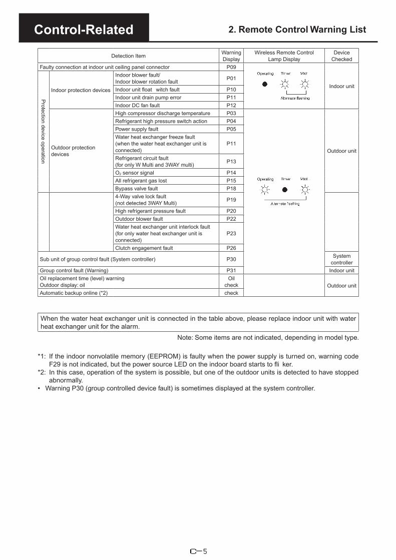
Control-Related 2. Remote Control Warning List
Detection Item Warning Display
Wireless Remote Control Lamp Display
Device Checked
Faulty connection at indoor unit ceiling panel connector P09
Indoor unit
Protection device operation
Indoor protection devices
Indoor blower fault/Indoor blower rotation fault P01
Indoor unit float witch fault P10Indoor unit drain pump error P11Indoor DC fan fault P12
Outdoor protection devices
High compressor discharge temperature P03
Outdoor unit
Refrigerant high pressure switch action P04Power supply fault P05Water heat exchanger freeze fault (when the water heat exchanger unit is connected)
P11
Refrigerant circuit fault (for only W Multi and 3WAY multi) P13
O2 sensor signal P14All refrigerant gas lost P15Bypass valve fault P184-Way valve lock fault (not detected 3WAY Multi) P19
High refrigerant pressure fault P20Outdoor blower fault P22Water heat exchanger unit interlock fault (for only water heat exchanger unit is connected)
P23
Clutch engagement fault P26
Sub unit of group control fault (System controller) P30 System controller
Group control fault (Warning) P31 Indoor unitOil replacement time (level) warning Outdoor display: oil
Oil check Outdoor unit
Automatic backup online (*2) check
When the water heat exchanger unit is connected in the table above, please replace indoor unit with water heat exchanger unit for the alarm.
Note: Some items are not indicated, depending in model type.
*1: If the indoor nonvolatile memory (EEPROM) is faulty when the power supply is turned on, warning codeF29 is not indicated, but the power source LED on the indoor board starts to fli ker.
*2: In this case, operation of the system is possible, but one of the outdoor units is detected to have stoppedabnormally.
• Warning P30 (group controlled device fault) is sometimes displayed at the system controller.
C-5

Control-Related 2. Remote Control Warning List
U-10MES2E8 ON: Blinking: OFF:
Possible cause of malfunction
Wired remote control display
Wireless remote controller receiver display
Ope
ratio
n
Tim
er
Stan
dby
for h
eatin
g
Serial communication errors Mis-setting
Remote controller is detecting error signal from indoor unit.
Error in receiving serial communication signal. (Signal from main indoor unit in case of group control) Outdoor system address, indoor unit address, or indoor unit address independent/main/sub unit setting has not been made. (Auto address is not completed.)Error in transmitting serial communication signal.
Indoor unit is detecting error signal from remote controller and system controller.Indoor unit is detecting error signal from outdoor unit.
••
•
<E01>
<E02><<E03>>
<<E09>>
<<L09>>
F05F06F07F08
E04
E08
<E06>Outdoor unit is detecting error signal from indoor unit.
Error in receiving serial communication signal.When turning on the power supply, the number of connected indoor units does not correspond to the number set. (Except R.C. address is “0.”)Group wiring failure of indoor units in the refrigerant system(occurring when remote controller is operated immediately after auto address setting)Error in receiving serial communication signal.There is an indoor unit which does not send signals when the power is ON.
••
Indoor unit address setting is duplicated.•Duplicated remote controller “main” setting.•
Indoor unit communication error of group control wiring.During auto. address setting, number of connected units does not correspond to number set.
Improper setting
Improper setting
Improper setting
Indoor unit
Auto address setting start is prohibited.AP pin (CN24) was short-circuited at time when auto address setting was started.Error of main indoor unit in receiving serial communication signal from sub indoor units.Number of connected indoor units is less than the number set.Number of connected indoor units is more than the number set.No indoor unit is connected during auto. address setting.Main outdoor unit is detecting error signal from sub outdoor unit.Duplicated outdoor unit address.Mismatch in “No. of outdoor units” setting.Error of sub outdoor unit in receiving serial communication signal from main outdoor unit.Outdoor unit serial communications failure.Communication error between the microcomputersConnected indoor unit is not a multi unit.Duplication of main indoor unit address setting in group control.Duplicated indoor unit priority (priority indoor unit).Duplicated indoor unit priority (non-priority indoor unit) and outdoor unit.Group control wiring is connected to individual control indoor unit.Indoor unit address is not set.Capacity code of indoor unit is not set.Duplication of outdoor R.C. address setting.
Capacity code of outdoor unit is not set.
E12
E18
E16E20
E15
E24E25
E29
E30E31
<L03>
L06
L08
L05
<<L02>>
L04
L17L18
L10
L07
Thermistor fault
Mismatch of outdoor unit type.4-way valve operation failureIndoor coil temp. sensor (E1)Indoor coil temp. sensor (E3)Indoor suction air (room) temp. sensor (TA)Indoor discharge air temp. sensor (BL)Comp. No. 1 discharge gas temp. sensor (DISCH1)Comp. No. 2 discharge gas temp. sensor (DISCH2)Outdoor No. 1 coil gas temp. sensor (EXG1)Outdoor No. 1 coil liquid temp. sensor (EXL1)Outdoor air temp. sensor (TO)
Continued
Operating lamp blinking
Heating ready lamp blinking
Operating lamp blinking
Heating ready lamp blinking
Operating and heating ready lamps blinking simultaneously
Operating and heating ready lamps blinking simultaneously
F04
<<F03>><<F10>><<F11>>
Operating and timer lamps blinking alternately
<<F01>>
E26
Thermistor fault Outdoor unit Operating and timer lamps blinkingalternately
C-6

Control-Related 2. Remote Control Warning List
ON: Blinking: OFF:
Possible cause of malfunction
Wired remote control display
Wireless remote controller receiver display
Ope
ratio
n
Tim
er
Stan
dby
for h
eatin
g
Thermistor fault Outdoor thermistor is eitheropen or damaged.
Activation ofprotectivedevice
Protective device in indoorunit is activated.
Protective device in outdoorunit is activated.
F12
F16F17
F24F23
F14
<<P09>>
<<P12>>
<<P10>><<P11>>
<<P01>>
P14
Compressor intake temp. sensor (SCT)Temp. sensor at refrigerant gas outlet of dual-tube (SCG)High pressure sensor failure. High pressure trouble.Low-pressure sensor failureOutdoor No. 2 coil gas temp. sensor (EXG2)Outdoor No. 2 coil liquid temp. sensor (EXL2)Thermal protector in indoor unit fan motor is activated.Improper wiring connections of ceiling panel.Float switch is activated.Faulty drain pump. Drain pump locked.Operation of protective function of fan inverter.O2 sensor (detects low oxygen level) activatedDischarge temperature error. (Comp. No. 1)High pressure switch is activated.Open phase.DC voltage charge failure (Comp. No. 1)Open phase.DC voltage charge failure (Comp. No. 2)Compressor No. 1 over secondary overcurrent.Discharge temperature error. (Comp. No. 2)Inverter for compressor No. 2 is unusual.High load alarmOutdoor unit fan motor 1 is unusual.Outdoor unit fan motor 2 is unusual.Compressor No. 2 over secondary overcurrent.Inverter for compressor No. 1 is unusual.When alarm message in other indoor units occurs in case of group control, unalarmed state of indoor units are inoperative.
Indoor unit communicationerror of group control wiring.
P04P03
P05P15
P20P19P17
P29
<P31>
P22P24P26
P16
Operating and timer lamps blinkingalternately
Timer and heat ready lamp blinking alternately
Operating and heat ready lamp blinking alternately
<< >> alarm indication: Does not affect the operation of other indoor units.< > alarm indication: In some cases may affect the operation of other indoor units.
(Disconnection, etc.)Abnormal device function
Compressor No. 1 HIC trip (HIC current or temperature).
EEPROM on indoor unit PCB failure
EEPROM on the main or sub outdoor unit PCB has failed.
Protective devicefor compressor is activated
Operating and timer lamp blinking simultaneously
Operating and timer lamp blinking simultaneously
Compressor No. 1 discharge temp. sensor disconnectedProtective device for Compressor No. 2 current trouble (overcurrent)compressor No. 2 is activated. Compressor No. 2 CT sensor disconnected or short circuit
Oil sensor fault.
Timer lamp blinking
Protective device for Compressor No. 1 current trouble (overcurrent)compressor No. 1 is activated. Compressor No. 1 CT sensor disconnected
H31
F29
F31
H11H13H15H06
07H
Compressor No. 2 discharge temp. sensor disconnectedAbnormal decrease of low-pressureLow oil alarm
H08H27
Comp. No. 1 oil sensorComp. No. 2 oil sensorCompressor No. 2 HIC trip (HIC current or temperature). H21
H0305H
H01
C-7

Control-Related 3. Circuit Drawing
C-8

Control-Related 3. Circuit Drawing
Balance tubeø6.35 flare connection
Gas tube8 HP: ø19.05 Brazing
connection10 HP: ø22.22 Brazing
8,10 HP:
12 HP:
connection12 HP: ø25.4 Brazing
connection
ø9.52 flare connectionø12.7 flare connection
Liquid tube
Electronic control valve
MOV4
SCG
Heat exchanger
Thermistor
Ex. Name
Filter
Closed
Schrader valve
For LP
For HP
Solenoid valve
Check valve
SAVE
DISCH
OIL
HPHigh pressure switch
High pressure sensor
Compressor
Capillary tube
Capillary tube
Acc
umul
ator
Low pressure sensor
Oil separator
INV
4-way valve
S
S
M
MM
LPS
HPS
S
S
MOV2
EXL2EXL1
EXG2EXG1
TO
MOV1
BPV
ACV
SCT
ORVR
▲○
Outdoor air temperature
sensor
Blank tubing
U-10MES2E8
C-9

System Design
Contents1.
2.
Operating temperature ranges for heating and cooling ......................................D-2
3.
4.
Effect of refrigerant pipe length on performance ................................................D-3
Sound-proofing measure(1) Installation location and sound-proofing measure ................................................. D-5(2) Attenuation of sound over distance ......................................................................... D-5(3) Sound attenuation by a noise barrier ...................................................................... D-6(4) Additional sound from reflection ............................................................................ D-7(5) Combining sounds .................................................................................................. D-7(6) Converting from octave band levels to overall A weighting .................................... D-8(7) Designing sound-proofing counte measures .......................................................... D-8(8) Sound-proofing calculation sheet ( xample) ........................................................... D-9
Center-of-gravity and earthquake resistance(1) Earthquake resistance calculations ........................................................................ D-10(2) Verifying the strength of foundation bolts during an earthquake ............................. D-10(3) Installation position and center of gravity ................................................................ D-19(4) Example anchor bolt calculation ............................................................................. D-20
D-1

System Design Cooling
40
30
20
10
40 30 20 10 0 -10 -20 50
24
13.5
Operating range for coolingIndoor relative humidity
45-85%
Indo
or in
take
air
wet
bul
b te
mpe
ratu
re
(WBºC)
Outdoor intake air dry bulb temperature (DBºC)
-10 43
Heating
31
18
Operating range for heating
(DBºC) -21
10
40
30
20
10
30 20 10 0 -10 -20 -30 40
Indo
or in
take
air
dry
bulb
tem
pera
ture
Outdoor intake air wet bulb temperature (WBºC)
Note 1 : The remote control temperature setting range is as shown in the table below. This is slightly different from the system operating temperature range.
Upper limit Lower limitCooling 30 18Heating 30 16
Note 2 : When heating starts (during warm-up), the system can operate even if the indoor temperature is below 10ºC.
Operating temperature rangesfor heating and cooling
1.
D-2

System Design 2. Effect of refrigerant pipe lengthon performance
Refrigerant piping length: 90m (equivalent length) or less
D-3

System Design 2. Effect of refrigerant pipe lengthon performance
Refrigerant piping length: Over 90m (equivalent length)
D-4

System Design 3. Sound-proofing measure
(1) Installation location and sound-proofing measureIf no suitable installation location is available and it is necessary to install in a confined location where there are houses, offices or other buildings nearby, it may be necessary to provide sound barrier walls, sound absorption chambers or other secondary sound-proofing measure .Secondary sound-proofing measure include• Attenuation over distance• Sound-proofing with noise bar iers• Sound-proofing using sound absorbing chamber• Sound-proofing y vibration isolation (anti-vibration pads, fl xible couplings, etc.)
The following criteria are from Tokyo Pollution Prevention Regulations.Criteria for everyday sound levels
Condition
Area type
Ordinary standards Special standards
Morning Daytime Evening NightNear schools and hospitals (approx. 50m)
Soundlevel
(phon)Time
Soundlevel
(phon)Time
Soundlevel
(phon)Time
Soundlevel
(phon)Time
Type 1 Residential and school areas, etc. 40
6 AM to8 AM
458 AM to7 PM
407 PM to11 PM
40
11 PM to
6 AM
Same as at left
Type 2Residential and undesignated areas
45 50 45 45
At least 5 phon lower than at
leftType 3
Commercial, light industrial, industrial areas
55 608 AM to8 PM
558 PM to11 PM
50
Type 4Shopping areas and specially designated areas
60 70 60 55
(2) Attenuation of sound over distanceThe figure at the right shows sound attenuation over distance. (Figure 1)Operating sound is measured 1m from its source.
Example. For a type 280 outdoor unit, the sound level in the 50-Hz range at 3m distance is specified as 56 dB(A). In Figure 1, follow the 3m distance line downwards to where it crosses the slope (a), and then horizontally to point (b) at the left to find the atte uation of 6.8 dB(A).Therefore, 56 – 6.8 = 49.2 dB(A)
D-5

System Design 3. Sound-proofing measure
(3) Sound attenuation by a noise barrierSound attenuation of an indoor unit at a reception point behind a noise barrier or building depends on the frequency and path length difference.
Ex. 2
?
d
B
A
Ex. 3
Ex. 1
Reception point?
d
BA
Soun
d ba
rrier
Outdoor unit
?
d
BA
Reception point
Build
ing
Outdoor unit
Reception pointBuilding
Outdoor unit
Figure 2. Diffraction attenuation
δ = path length differenceδ = (A+B) – d
The barrier should be located as close as possible to the outdoor unit (sound source). (Figure 3)(Be certain to preserve the required space for air intake and exhaust, service and maintenance.)
The barrier should be sufficiently higher than the top of the outdoor unit (Figure 3)(However, not more than 1m higher.)
The width of the barrier should be at least several times the height, on both sides of the center. Wherethis is not possible, the barrier should bend around the unit as shown in Figure 4.
?
B
A
Reception point
Soun
d ba
rrier
Outdoor unit
1 m or less
Effective area
As close as possible (while maintaining minimum clearances required for intake, exhaust and servicing of each unit)
Outdoor unit
Soun
d ba
rrier
At least several times the barrier height
At least several times the barrier height When adjoining
barriers, longer than this line.
Figure 3. Sound barrier Figure 4. Sound barrier
D-6
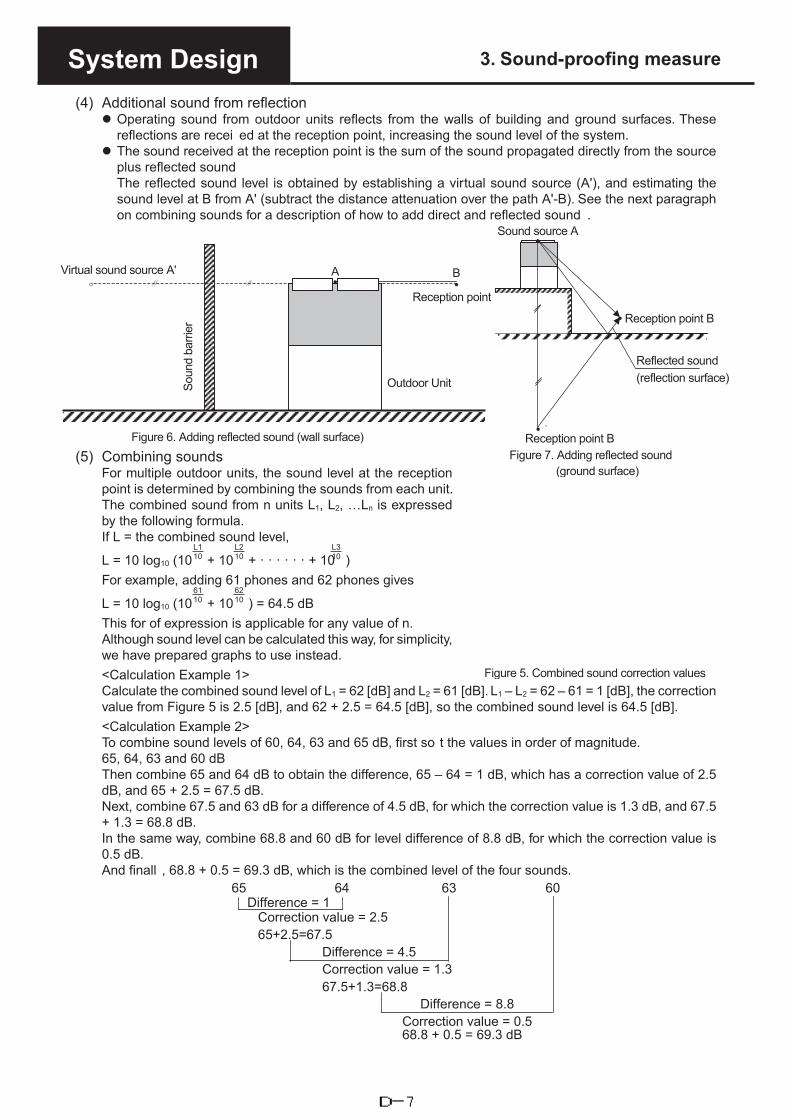
System Design 3. Sound-proofing measure
(4) Additional sound from reflection Operating sound from outdoor units reflects from the walls of building and ground surfaces. These
reflections are recei ed at the reception point, increasing the sound level of the system. The sound received at the reception point is the sum of the sound propagated directly from the source
plus reflected soundThe reflected sound level is obtained by establishing a virtual sound source (A'), and estimating the sound level at B from A' (subtract the distance attenuation over the path A'-B). See the next paragraph on combining sounds for a description of how to add direct and reflected sound .
(5) Combining soundsFor multiple outdoor units, the sound level at the reception point is determined by combining the sounds from each unit.The combined sound from n units L1, L2, …Ln is expressed by the following formula.If L = the combined sound level,
L = 10 log10 (10L110 + 10
L210 + · · · · · · + 10
L310 )
For example, adding 61 phones and 62 phones gives
L = 10 log10 (106110 + 10
6210 ) = 64.5 dB
This for of expression is applicable for any value of n.Although sound level can be calculated this way, for simplicity, we have prepared graphs to use instead.<Calculation Example 1>Calculate the combined sound level of L1 = 62 [dB] and L2 = 61 [dB]. L1 – L2 = 62 – 61 = 1 [dB], the correction value from Figure 5 is 2.5 [dB], and 62 + 2.5 = 64.5 [dB], so the combined sound level is 64.5 [dB].<Calculation Example 2>To combine sound levels of 60, 64, 63 and 65 dB, first so t the values in order of magnitude.65, 64, 63 and 60 dBThen combine 65 and 64 dB to obtain the difference, 65 – 64 = 1 dB, which has a correction value of 2.5 dB, and 65 + 2.5 = 67.5 dB.Next, combine 67.5 and 63 dB for a difference of 4.5 dB, for which the correction value is 1.3 dB, and 67.5 + 1.3 = 68.8 dB.In the same way, combine 68.8 and 60 dB for level difference of 8.8 dB, for which the correction value is 0.5 dB.And finall , 68.8 + 0.5 = 69.3 dB, which is the combined level of the four sounds.
65 64 63 60Difference = 1
Correction value = 2.5 65+2.5=67.5
Difference = 4.5Correction value = 1.3 67.5+1.3=68.8
Difference = 8.8Correction value = 0.568.8 + 0.5 = 69.3 dB
Figure 5. Combined sound correction values
BA
’
Outdoor Unit
Virtual sound source A'
Soun
d ba
rrier
Reception point
Sound source A
Reception point B
Reflected sound (reflection surface)
Reception point BFigure 7. Adding reflected sound
(ground surface)
Figure 6. Adding reflected sound (wall surface)
D-7
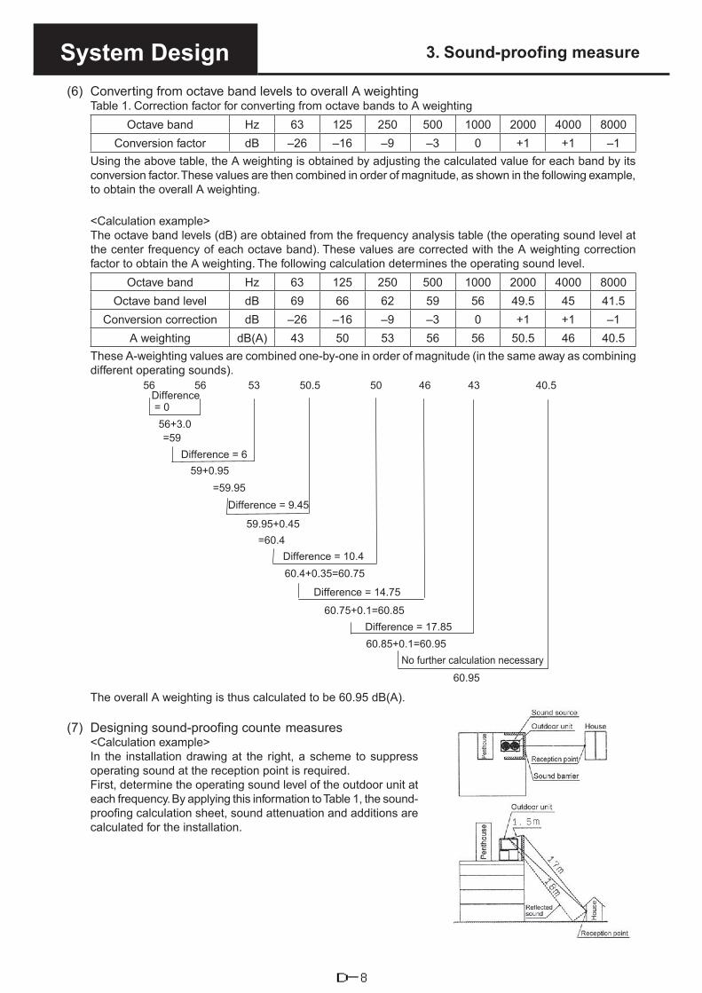
System Design 3. Sound-proofing measure
(6) Converting from octave band levels to overall A weightingTable 1. Correction factor for converting from octave bands to A weighting
Octave band Hz 63 125 250 500 1000 2000 4000 8000Conversion factor dB –26 –16 –9 –3 0 +1 +1 –1
Using the above table, the A weighting is obtained by adjusting the calculated value for each band by its conversion factor. These values are then combined in order of magnitude, as shown in the following example, to obtain the overall A weighting.
<Calculation example>The octave band levels (dB) are obtained from the frequency analysis table (the operating sound level at the center frequency of each octave band). These values are corrected with the A weighting correction factor to obtain the A weighting. The following calculation determines the operating sound level.
Octave band Hz 63 125 250 500 1000 2000 4000 8000Octave band level dB 69 66 62 59 56 49.5 45 41.5
Conversion correction dB –26 –16 –9 –3 0 +1 +1 –1A weighting dB(A) 43 50 53 56 56 50.5 46 40.5
These A-weighting values are combined one-by-one in order of magnitude (in the same away as combining different operating sounds).
56 56 53 50.5 50 46 43 40.5 Difference = 0
56+3.0=59
Difference = 6 59+0.95
=59.95Difference = 9.45
59.95+0.45=60.4
Difference = 10.460.4+0.35=60.75
Difference = 14.75
60.75+0.1=60.85Difference = 17.85
60.95
No further calculation necessary 60.85+0.1=60.95
The overall A weighting is thus calculated to be 60.95 dB(A).
(7) Designing sound-proofing counte measures<Calculation example>In the installation drawing at the right, a scheme to suppress operating sound at the reception point is required.First, determine the operating sound level of the outdoor unit at each frequency. By applying this information to Table 1, the sound-proofing calculation sheet, sound attenuation and additions are calculated for the installation.
D-8

System Design 3. Sound-proofing measure
Table 1. Sound-proofing calculation sheet (filled-in xample)Frequency Hz 63 125 250 500 1000 2000 4000 8000
1) Operating sound ofoutdoor unit dB
From the operating sound characteristics diagram in the outdoor unit manual
69 66 62 59 56 49.5 45 41.5
2) Distance attenuation dB From distance attenuationFrom Fig. 1, attenuation of unit operating sound = -22
3) Refraction attenuation dB Fig. 2, Refraction attenuation, sound path difference δ = A + B – d = 0.5–3.5 –5 –6.5 –9 –12 –15 –18 –21
4) Additional soundfrom reflections ( allsurface)
dBFig. 6, Additional sound due to reflections ( all)
By calculation or the simplified method, the maxi um value of the two combined sounds is +3
5) Additional sound fromreflections ( roundsurface)
dBFig. 7, Addition sound due to reflection ( round surface)
By calculation or the simplified method, the maxi um value of the two combined sounds is +3
6) Subtotals dB 49.5 45 39.5 34 28 18.5 11 4.57) Overall A-weighting
correction factors dB Conversion factors for A weighting–26 –16 –9 –3 0 +1 +1 –1
8) A weighting dB(A) 23.5 29 30.5 31 28 19.5 12 3.5
When the calculations of Table 1 are completed, the overall A weighting can be calculated.
31 30.5 29 28 23.5 Difference = 0.5
(31 + 2.7)33.7
Difference = 4.7(33.7 + 1.2)
34.9 35.95 30.0Difference = 6.9
(34.9+0.8) 35.7 Difference = 5.95
Difference = 12.2 (35.95+0.95) =36.935.7 + 0.25 = 35.95 dB
The overall A weighting at the reception point is calculated to be 35.95 dB(A). If the ambient noise (when the unit is not operating) is 30.0 dB(A), the combining these levels gives 36.9 dB(A).
(8) Sound-proofing calculation sheet ( xample)Frequency Hz 63 125 250 500 1000 2000 4000 8000
1) Operating sound ofoutdoor unit dB
From the operating sound characteristics diagram in the outdoor unit manual
2) Distance attenuation dB Distance attenuation Distance attenuation value =
3) Refraction attenuation dB Refraction attenuation, sound path difference δ = A + B – d, δ =
4) Additional soundfrom reflections ( allsurface)
dBAdditional sound due to reflections ( all)
By calculation or the simplified method, the maxi um value of the twocombined sounds is +3
5) Additional sound fromreflections ( roundsurface)
dBFig. 7, Addition sound due to reflection ( round surface)
By calculation or the simplified method, the maxi um value of the twocombined sounds is +3
6) Subtotals dB7) Overall A-weighting
correction factors dB Conversion factors for A weighting–26 –16 –9 –3 0 +1 +1 –1
8) A weighting dB(A)By completing the calculations in the above table, the overall A weighting at the reception point is obtained (calculate in order from the highest sound level).Once the overall A weighting has been calculated, combine with the ambient noise level to obtain to total sound level at the reception point.
D-9

System Design 4. Center-of-gravity and earthquake resistance
(1) Earthquake resistance calculationsSeveral earthquake-resistance ranks are used for carrying out earthquake-resistance calculations, as shown in the following table. Gas heat pump air conditioners are considered to be common use equipment.• Equipment earthquake-resistance ranks
Earthquake-resistance ranks and their meanings are as follows
Maintenance of operation
Horiz. design force (Horizontal seismic
coefficient
Strength calculation
Earthquake-resistance evaluation
Equ
ipm
ent E
arth
quak
e R
esis
tanc
e
Earthquake resistant type
Can be operated after inspection 1.5 G Design target
value
Strength calculation or verification test (Note 2),
and installation earthquake-resistance
Common use type
Can be operated after small-scale repairs
(Note 1)1.0 G As above Installation earthquake-
resistance evaluation (Note 3)
Small equipment As above 0.6 G As above As above
Notes1) Small-scale repairs are those that require up to two days to complete.2) Mainframe strength (static), fasteners for each component (bolts, etc.)3) Mounting bolt calculations, etc.* The table is from “Earthquake-resistant equipment specification criteria for package air conditioners and
water chillers” published by the Japan Refrigeration and Air Conditioning Industry Association.The above criteria are applicable to normal air conditioning equipment installed in buildings subject tonormal approval procedures under the Buildings Standard Law (e.g., less than 60m high)
(2) Verifying the strength of foundation bolts during an earthquake Calculation formulae and table of allowable stresses
• Design earthquake force1) The design earthquake force consists of a horizontal force and a vertical force, acting simultaneously
on the equipment through the center of gravity.2) The following formula gives the design earthquake force.
FH=KH · WFH : Design horizontal force (N) W : Equipment operating weight (N)
FV = 12
FH KH : Design horizontal quake magnitude FV : Design vertical force (N)(Japanese scale)
Equipment rank Design horiz. Magnitude KH (Japanese scale)
Notes1) “Earthquake resistant” refers to essential building
services2) “Common use type” refers to non-essential building
services3) Equipment with earthquake-resistant supports
incorporates stoppers to prevent amplification ofshaking due to resonance. In this case, shock-absorbent materials are placed between the stoppersand equipment so that the stoppers are not damagedor deformed by impact.
Earthquake resistant 1.5 G
Common use type 1.0 G
(Floor or pad mounting)
D-10

System Design 4. Center-of-gravity and earthquake resistance
In the diagram above,G : Position of center-of-gravity of equipmentW : Weight (N) of equipment aloneRb : Pull-out force of one mounting bolt (N)n : Total no. of mounting boltsnt : No. of mounting bolts on one side subject to tension
by toppling force (in the direction being considered)hG : Height of unit center-of-gravity above mounting
surface (mm)L : Bold span (mm) from direction of concern (L1 : End-on direction, L2 = Broadside direction)LG : Distance from center-of-bolt to center-of-gravity as
viewed from direction of concern (but LG ≤ /2 (mm))
Mounting bolt pull-out force
Rb= FH · hG - (W-FV) · LG
L · nt
Mounting bolt shear stress
τ= FH
n · A
Table of allowable stress on bolts Units (N/ mm2)
Bolt material Bolt diameterLong-term allowable stress Short-term allowable stressTension (ft) Shear (fs) Tension (ft) Shear (fs)
SS40040 mm or less 118 88 176 132More than 40 mm 108 80 162 121
SUS30440 mm or less 137 103 206 154More than 40 mm 126 94 188 141
Notes1) The values in the above table are derived from “Steel structure design criteria” published by the Architects
Institute of Japan.2) Use the value ft in the table if necessary to investigate bolt tensile stress.3) Strength of a bolt subject to simultaneous tension and shear can be checked as follows.
a) τ fs
b) σ ≤ the smaller of ft or fts, but fts = 1.4ft – 1.6τwhere, τ : Shear stress on bolt
σ : Tensile stress on bolt (σ = Rb/A)fs : Allowable stress on bolt with shear stress only (value from above table)ft : Allowable stress on bolt with tensile stress only (value from above table)fts : Allowable tensile stress on a bolt with simultaneous shear stress, but fts ≤ ft
4) The allowable tensile stresses in the above table are evaluated using the cross-sectional area of theminor diameter of the screw thread. However, when calculating for selection purposes, the cross-sectionalarea based upon the nominal diameter may be used.
5) If the threaded portion is subject to shear, then if using the cross-sectional area based upon the nominaldiameter, multiply the value of fs in the above table by 0.75.
FH : Design horizontal force (N) (FH =KH · W)FV : Design vertical force (N)
FV = 12
FH
A : Nominal cross-sectional area of one mounting bolt (mm2)
τ: Shear stress on bolt (N/ mm2)fts : Allowable tensile stress on a bolt with
simultaneous shear stress (N/ mm2) However, fts ≤ ftMounting bolt tensile stress
δ= Rb
A
Allowable tensile stress on a bolt with simultaneous shear stress
fts = 1.4ft - 1.6τ
D-11

System Design 4. Center-of-gravity and earthquake resistance(1
) Allo
wab
le p
ull-o
ut fo
rce
of e
mbe
dded
J- a
nd J
A-ty
pe b
olts
Inst
alla
tion
loca
tion:
a)
Sol
id fo
unda
tion
b)U
pper
sur
face
of n
orm
al fl
oor s
lac)
Botto
m s
urfa
ce o
f nor
mal
cei
ling
slab,
con
cret
e wa
ll sur
face
Sho
rt-te
rm a
llow
able
pul
l-out
load
of
a bo
lt is
obt
aine
d w
ith t
he
follo
win
g fo
rmul
ae. H
owev
er, i
f the
she
ar s
tress
on
the
bolt
exce
eds
44.1
N/m
m2 (
for S
S40
0), b
olt s
treng
th a
nd a
ssur
ance
that
allo
wab
le
tens
ile s
tress
is n
ot e
xcee
ded
mus
t be
verif
ied
Ta=6
π · L
2 · p
…
(a)
Whe
re,
Ta =
Anc
hor b
olt a
llow
able
sho
rt-te
rm p
ull-o
ut lo
ad (N
)L
= E
mbe
dded
leng
th o
f anc
hor b
olt (
mm
)H
owev
er, L
mus
t be
betw
een
60 a
nd 3
00p
= C
orre
ctio
n fa
ctor
for c
oncr
ete
desi
gn s
treng
th is
P =
1 6M
in
Fc 30, 0
.49
+ Fc 10
0F C
= C
oncr
ete
desi
gn c
hara
cter
istic
stre
ngth
(N/m
m2 )
(Nor
mal
ly, 1
7.6
N/m
m2 i
s us
ed.)
For b
olts
nea
r a c
orne
r or e
dge
of a
foun
datio
n, if
the
dist
ance
from
th
e ce
nter
of t
he b
olt t
o th
e ed
ge is
C ≤
L, t
he a
llow
able
sho
rt-te
rm
pull-
out l
oad
of th
e bo
lt is
giv
en b
y ei
ther
form
ula
(b) o
r (c)
bel
ow.
1)Fo
r L ≤
C +
h,
Ta=6
π · C
2 · p
…
(b)
2)Fo
r L >
C +
h,
Ta=6
π · (
L · h
)2 · p
…
(c)
Whe
re C
= th
e di
stan
ce fr
om th
e ed
ge o
f the
foun
datio
n to
the
cent
er o
f the
bol
t (m
m)
How
ever
, L
≥ C
≥ 4
d, a
nd1 2
C ≥
50
mm
h =
Foun
datio
n pa
d he
ight
(mm
)N
otes
1. L
sho
uld
be ≥
6d
(whe
re d
= n
omin
al a
ncho
r bol
t dia
met
er).
2. I
n th
e ab
ove
diag
ram
, is
appr
ox. 4
.5 d
for a
JIS
bol
t.3.
If t
ype
1 or
2 li
ghtw
eigh
t con
cret
e is
use
d, a
llow
10%
mar
gin.
Sho
rt-te
rm p
ull-o
ut lo
ad (N
)B
olt d
iam
eter
d
(nom
inal
)C
oncr
ete
thic
knes
s (m
m)
120
150
180
200
M 8
8820
8820
8820
8820
M10
1176
011
760
1176
011
760
M12
1176
011
760
1176
011
760
M16
-11
760
1176
011
760
M20
--
1176
011
760
M24
--
-11
760
Leng
th o
f bol
tem
bedd
ed, L
(mm
)10
0-d
130-
d16
0-d
180-
d
Not
es1.
The
se a
re s
hort-
term
allo
wab
le p
ull-o
ut lo
ads
for b
olts
em
bedd
edas
sho
wn
in th
e di
agra
m a
bove
.2.
The
conc
rete
des
ign
char
acte
ristic
stre
ngth
is ta
ken
to b
e F C
=17
.6 N
/mm
2 .3.
Whe
n th
e di
men
sion
s di
ffer
from
the
abo
ve d
iagr
am,
or if
the
conc
rete
des
ign
char
acte
ristic
stre
ngth
diff
ers,
then
the
pull-
out
load
can
be
calc
ulat
ed a
ccor
ding
with
the
form
ulae
for b
olts
in a
stro
ng fo
unda
tion,
at t
he le
ft. In
any
cas
e, th
e al
low
able
pul
l-out
load
on
one
bolt
mus
t not
exc
eed
11,7
60 N
.4.
It is
des
irabl
e th
at L
≥ 6
d. T
he c
ondi
tions
indi
cate
d by
“-” i
n th
eab
ove
tabl
e sh
ould
be
avoi
ded.
5. I
n th
e ab
ove
diag
ram
, is
appr
ox. 4
.5 d
for a
JIS
bol
t.6.
If t
ype
1 or
2 li
ghtw
eigh
t con
cret
e is
use
d, a
llow
10%
mar
gin.
Long
-term
allo
wab
le p
ull-o
ut lo
ad (N
)B
olt d
iam
eter
d (n
omin
al)
Con
cret
e th
ickn
ess
(mm
)12
015
018
020
0M
858
8058
8058
8058
80M
1078
4078
4078
4078
40M
1278
4078
4078
4078
40M
16-
7840
7840
7840
M20
--
7840
7840
M24
--
-78
40Le
ngth
of b
olt
embe
dded
, L (m
m)
100-
d13
0-d
160-
d18
0-d
Not
es1.
The
se a
re s
hort-
term
allo
wab
le p
ull-o
ut lo
ads
for b
olts
em
bedd
edas
sho
wn
in th
e di
agra
m a
bove
.2.
The
conc
rete
des
ign
char
acte
ristic
stre
ngth
is ta
ken
to b
e FC
=17
.6 N
/mm
2 .3.
Whe
n th
e di
men
sion
s di
ffer
from
the
abo
ve d
iagr
am,
or if
the
conc
rete
des
ign
char
acte
ristic
stre
ngth
diff
ers,
then
the
pull-
out
load
can
be
calc
ulat
ed a
ccor
ding
with
the
form
ulae
for b
olts
in a
stro
ng fo
unda
tion,
at t
he le
ft, a
nd d
ivid
e th
e re
sult
by 1
.5 to
obt
ain
the
allo
wab
le p
ull-o
ut lo
ad. I
n an
y ca
se, t
he a
llow
able
pul
l-out
load
on o
ne b
olt m
ust n
ot e
xcee
d 7,
840
N.
4.It
is d
esira
ble
that
L ≥
6d.
The
con
ditio
ns in
dica
ted
by “-
” in
the
abov
e ta
ble
shou
ld b
e av
oide
d.5.
In
the
abov
e di
agra
m, l
is a
ppro
x. 4
.5 d
for a
JIS
bol
t.6.
It is
nec
essa
ry t
o in
vest
igat
e th
e sh
ort-t
erm
pul
l-out
loa
d of
norm
al s
uppo
rts w
ith re
gard
to e
arth
quak
es w
hen
the
supp
orts
are
inst
alle
d in
the
botto
m o
f cei
ling
slab
s an
d on
con
cret
e w
alls
desi
gned
to s
uppo
rt he
avy
obje
cts.
For
this
sho
rt-te
rm p
ull-o
utlo
ad, s
ee It
em b
, “S
hort-
term
pul
l-out
load
s.”7.
If t
ype
1 or
2 li
ghtw
eigh
t con
cret
e is
use
d, a
llow
10%
mar
gin.
D-12

System Design 4. Center-of-gravity and earthquake resistance(2
) Allo
wab
le p
ull-o
ut lo
ad o
f em
bedd
ed L
- and
LA
-type
bol
tsIn
stal
latio
n lo
catio
n:
a) S
olid
foun
datio
nb)
Upp
er s
urfa
ce o
f nor
mal
floo
r sla
c)Bo
ttom
sur
face
of n
orm
al c
eilin
g sla
b, c
oncr
ete
wall s
urfa
ce
Sho
rt-te
rm a
llow
able
pul
l-out
load
of
a bo
lt is
obt
aine
d w
ith t
he
follo
win
g fo
rmul
ae. H
owev
er, i
f the
she
ar s
tress
on
the
bolt
exce
eds
44.1
N/m
m2 (
for S
S40
0), b
olt s
treng
th a
nd a
ssur
ance
that
allo
wab
le
tens
ile s
tress
is n
ot e
xcee
ded
mus
t be
verif
ied
Ta =
π ·
d ·
· fc
…(a
)W
here
,Ta
= A
ncho
r bol
t allo
wab
le s
hort-
term
pul
l-out
load
(N)
d =
Anc
hor b
olt n
omin
al d
iam
eter
(mm
)=
Em
bedd
ed le
ngth
of a
ncho
r bol
t (m
m).
(the
leng
th fr
om 2
0mm
bel
ow th
e su
rface
of t
he c
oncr
ete
foun
datio
n.)
fc =
sho
rt-te
rm a
llow
able
bon
d st
ress
in re
info
rced
con
cret
e
fc =
9 100 F
C
(fro
m “
Sta
ndar
d fo
r R
C s
truc
ture
s de
sign
,” pu
blis
hed
by t
he
Arc
hite
ctur
al In
stitu
te o
f Jap
an)
F C =
Con
cret
e de
sign
cha
ract
eris
tic s
treng
th (N
/mm
2 )(N
orm
ally,
17.
6 N
/mm
2 is
used
.)Fo
r an
chor
bol
ts p
ositi
oned
in th
e co
rner
or
near
the
edge
of t
he
foun
datio
n, t
he s
hort-
term
allo
wab
le p
ull-o
ut lo
ad s
hall
be t
aken
to
be
the
min
imum
of t
he v
alue
s fro
m fo
rmul
ae (b
) bel
ow, a
nd (a
).Ta
= 6
π ·
C2 ·
p
…(b
)W
here
C =
the
dist
ance
from
the
edge
of t
he fo
unda
tion
to th
e ce
nter
of
the
bolt
(mm
)
How
ever
, C ≥
4d,
and
C -
d 2 ≥
50
mm
p =
Cor
rect
ion
fact
or fo
r con
cret
e de
sign
stre
ngth
is
P =
1 6M
in
Fc 30, 0
.49
+ Fc 10
0N
otes
1. L
sho
uld
be ≥
6d
(whe
re d
= n
omin
al a
ncho
r bol
t dia
met
er).
2. I
f typ
e 1
or 2
ligh
twei
ght c
oncr
ete
is u
sed,
allo
w 1
0% m
argi
n.
Sho
rt-te
rm p
ull-o
ut lo
ad (N
)B
olt d
iam
eter
d (n
omin
al)
Con
cret
e th
ickn
ess
(mm
)12
015
018
020
0M
831
3643
1255
8663
70M
1039
2053
9069
5879
38M
1247
0465
6683
3095
06M
16-
8722
1117
211
760
M20
--
1176
011
760
M24
--
-11
760
Effe
ctiv
e em
bedd
ed
leng
th (
) (m
m)
8011
014
016
0
Not
es1.
The
se a
re s
hort-
term
allo
wab
le p
ull-o
ut lo
ads
for b
olts
em
bedd
edas
sho
wn
in th
e di
agra
m a
bove
.2.
The
conc
rete
des
ign
char
acte
ristic
stre
ngth
is ta
ken
to b
e F C
=17
.6 N
/mm
2 .3.
Whe
n th
e di
men
sion
s di
ffer
from
the
abo
ve d
iagr
am,
or if
the
conc
rete
des
ign
char
acte
ristic
stre
ngth
diff
ers,
then
the
pull-
out
load
can
be
calc
ulat
ed a
ccor
ding
with
the
form
ulae
for b
olts
in a
stro
ng fo
unda
tion,
at t
he le
ft. In
any
cas
e, th
e al
low
able
pul
l-out
load
on
one
bolt
mus
t not
exc
eed
11,7
60 N
.4.
It is
des
irabl
e th
at L
≥ 6
d. T
he c
ondi
tions
indi
cate
d by
“-” i
n th
eab
ove
tabl
e sh
ould
be
avoi
ded.
5. I
f typ
e 1
or 2
ligh
twei
ght c
oncr
ete
is u
sed,
allo
w 1
0% m
argi
n.
Long
-term
allo
wab
le p
ull-o
ut lo
ad (N
)B
olt d
iam
eter
d (n
omin
al)
Con
cret
e th
ickn
ess
(mm
)12
015
018
020
0M
820
5828
4237
2442
14M
1025
4835
2846
0652
92M
1231
3643
1254
8862
72M
16-
5782
7448
7840
M20
--
7840
7840
M24
--
-78
40E
ffect
ive
embe
dded
le
ngth
( ) (
mm
)80
110
140
160
Not
es1.
The
se a
re s
hort-
term
allo
wab
le p
ull-o
ut lo
ads
for b
olts
em
bedd
edas
sho
wn
in th
e di
agra
m a
bove
.2.
The
conc
rete
des
ign
char
acte
ristic
stre
ngth
is ta
ken
to b
e F C
=17
.6 N
/mm
2 .3.
Whe
n th
e di
men
sion
s di
ffer
from
the
abo
ve d
iagr
am,
or if
the
conc
rete
des
ign
char
acte
ristic
stre
ngth
diff
ers,
then
the
pull-
out
load
can
be
calc
ulat
ed a
ccor
ding
with
the
form
ulae
for b
olts
in a
stro
ng fo
unda
tion,
at t
he le
ft, a
nd d
ivid
e th
e re
sult
by 1
.5 to
obt
ain
the
allo
wab
le p
ull-o
ut lo
ad. I
n an
y ca
se, t
he a
llow
able
pul
l-out
load
on o
ne b
olt m
ust n
ot e
xcee
d 7,
840
N.
4.It
is d
esira
ble
that
L ≥
6d.
The
con
ditio
ns in
dica
ted
by “-
” in
the
abov
e ta
ble
shou
ld b
e av
oide
d.5.
It i
s ne
cess
ary
to in
vest
igat
e ite
m b
), th
e sh
ort-t
erm
pul
l-out
load
of n
orm
al s
uppo
rts w
ith re
gard
to e
arth
quak
es w
hen
the
supp
orts
are
inst
alle
d in
the
botto
m o
f cei
ling
slab
s an
d on
con
cret
e w
alls
desi
gned
to s
uppo
rt he
avy
obje
cts.
6. I
f typ
e 1
or 2
ligh
twei
ght c
oncr
ete
is u
sed,
allo
w 1
0% m
argi
n.
D-13

System Design 4. Center-of-gravity and earthquake resistance(3
) Allo
wab
le p
ull-o
ut lo
ad o
f em
bedd
ed b
olts
with
hea
dsIn
stal
latio
n lo
catio
n:
a) S
olid
foun
datio
nb)
Upp
er s
urfa
ce o
f nor
mal
floo
r sla
c)Bo
ttom
sur
face
of n
orm
al c
eilin
g sla
b, c
oncr
ete
wall s
urfa
ce
Sho
rt-te
rm a
llow
able
pul
l-out
load
of
a bo
lt is
obt
aine
d w
ith t
he
follo
win
g fo
rmul
ae. H
owev
er, i
f the
she
ar s
tress
on
the
bolt
exce
eds
44.1
N/m
m2 (
for S
S40
0), b
olt s
treng
th a
nd a
ssur
ance
that
allo
wab
le
tens
ile s
tress
is n
ot e
xcee
ded
mus
t be
verif
ied
Ta=6
π · L
(L+B
) · p
…
(a)
Whe
re,
Ta =
Anc
hor b
olt a
llow
able
sho
rt-te
rm p
ull-o
ut lo
ad (N
)d
= A
ncho
r bol
t nom
inal
dia
met
er (m
m)
B =
Min
imum
bol
t hea
d w
idth
(mm
), (d
ista
nce
acro
ss fl
atsi
des
of J
IS s
tand
ard
hex
bolt
head
)p
= C
orre
ctio
n fa
ctor
for c
oncr
ete
desi
gn s
treng
th is
P =
1 6M
in
Fc 30, 0
.49
+ Fc 10
0F C
= C
oncr
ete
desi
gn c
hara
cter
istic
stre
ngth
(N/m
m2 )
(Nor
mal
ly, 1
7.6
N/m
m2 i
s us
ed.)
For b
olts
nea
r a c
orne
r or e
dge
of a
foun
datio
n, if
the
dist
ance
from
th
e ce
nter
of t
he b
olt t
o th
e ed
ge is
C ≤
L +
B, t
he a
llow
able
sho
rt-te
rm
pull-
out l
oad
of th
e bo
lt is
giv
en b
y ei
ther
form
ula
(b) o
r (c)
bel
ow.
1)Fo
r L ≤
C +
h,
Ta=6
π · C
2 · p
…
(b)
2)Fo
r L >
C +
h,
Ta=6
π · C
2 · p
…
(c)
Whe
re C
= th
e di
stan
ce fr
om th
e ed
ge o
f the
foun
datio
n to
the
cent
er
of th
e bo
lt (m
m)
How
ever
, L
+ B
≥ C
, and
C -
d 2 ≥
50
mm
h =
Foun
datio
n pa
d he
ight
(mm
)N
otes
1. L
sho
uld
be ≥
6d
(whe
re d
= n
omin
al a
ncho
r bol
t dia
met
er).
2. T
hick
ness
H in
the
abov
e di
agra
m s
houl
d be
no
less
than
that
of
a JI
S s
tand
ard
hex
bolt
head
.3.
If t
ype
1 or
2 li
ghtw
eigh
t con
cret
e is
use
d, a
llow
10%
mar
gin.
Sho
rt-te
rm p
ull-o
ut lo
ad (N
)B
olt d
iam
eter
d (n
omin
al)
Con
cret
e th
ickn
ess
(mm
)B
olt s
ize
120
150
180
200
H (m
m)
B (m
m)
M 8
8820
8820
8820
8820
5513
M10
1176
011
760
1176
011
760
717
M12
1176
011
760
1176
011
760
819
M16
-11
760
1176
011
760
1024
M20
--
1176
011
760
1330
M24
--
-11
760
1536
Leng
th o
f bol
t em
bedd
ed, L
(m
m)
100-
H13
0-H
160-
H18
0-H
Not
es1.
The
tabl
e sh
ows
the
shor
t-ter
m p
ull-o
ut lo
ad fo
r bol
ts e
mbe
dded
in c
oncr
ete
of v
ario
us th
ickn
esse
s as
sho
wn
in th
e ab
ove
diag
ram
.2.
The
conc
rete
des
ign
char
acte
ristic
stre
ngth
is ta
ken
to b
e F C
=17
.6 N
/mm
2 .3.
Whe
n th
e di
men
sion
s di
ffer
from
the
abo
ve d
iagr
am,
or if
the
conc
rete
des
ign
char
acte
ristic
stre
ngth
diff
ers,
then
the
pull-
out
load
can
be
calc
ulat
ed a
ccor
ding
with
the
form
ulae
for b
olts
in a
st
rong
foun
datio
n, a
t the
left.
In a
ny c
ase,
the
allo
wab
le p
ull-o
ut
load
on
one
bolt
mus
t not
exc
eed
11,7
60 N
.4.
It is
des
irabl
e th
at L
≥ 6
d. T
he c
ondi
tions
indi
cate
d by
“-” i
n th
eab
ove
tabl
e sh
ould
be
avoi
ded.
5.D
imen
sion
s B
and
H in
the
abo
ve d
iagr
am a
re t
he d
ista
nce
acro
ss th
e fla
tsid
es o
f the
hea
d an
d th
e th
ickn
ess
of th
e he
ad,
resp
ectiv
ely,
for J
IS s
tand
ard
hex
bolt.
6. I
f typ
e 1
or 2
ligh
twei
ght c
oncr
ete
is u
sed,
allo
w 1
0% m
argi
n.
Long
-term
allo
wab
le p
ull-o
ut lo
ad (N
)B
olt d
iam
eter
d (n
omin
al)
Con
cret
e th
ickn
ess
(mm
)B
olt s
ize
120
150
180
200
H (m
m)
B (m
m)
M 8
5880
5880
5880
5880
5513
M10
7840
7840
7840
7840
717
M12
7840
7840
7840
7840
819
M16
-78
4078
4078
4010
24M
20-
-78
4078
4013
30M
24-
--
7840
1536
Leng
th o
f bol
t em
bedd
ed, L
(m
m)
100-
H13
0-H
160-
H18
0-H
Not
es1.
The
se a
re s
hort-
term
allo
wab
le p
ull-o
ut lo
ads
for b
olts
em
bedd
edas
sho
wn
in th
e di
agra
m a
bove
.2.
The
conc
rete
des
ign
char
acte
ristic
stre
ngth
is ta
ken
to b
e F C
=17
.6 N
/mm
2 .3.
Whe
n th
e di
men
sion
s di
ffer
from
the
abo
ve d
iagr
am,
or if
the
conc
rete
des
ign
char
acte
ristic
stre
ngth
diff
ers,
then
the
pull-
out
load
can
be
calc
ulat
ed a
ccor
ding
with
the
form
ulae
for b
olts
in a
st
rong
foun
datio
n, a
t the
left,
and
div
ide
the
resu
lt by
1.5
to o
btai
n th
e al
low
able
pul
l-out
load
. In
any
case
, the
allo
wab
le p
ull-o
ut lo
ad
on o
ne b
olt m
ust n
ot e
xcee
d 7,
840
N.
4.It
is d
esira
ble
that
L ≥
6d.
The
con
ditio
ns in
dica
ted
by “-
” in
the
abov
e ta
ble
shou
ld b
e av
oide
d.5.
It is
nec
essa
ry t
o in
vest
igat
e th
e sh
ort-t
erm
pul
l-out
loa
d of
norm
al s
uppo
rts w
ith re
gard
to e
arth
quak
es w
hen
the
supp
orts
ar
e in
stal
led
in th
e bo
ttom
of c
eilin
g sl
abs
and
on c
oncr
ete
wal
ls
desi
gned
to s
uppo
rt he
avy
obje
cts.
For
this
sho
rt-te
rm p
ull-o
ut
load
, see
Item
b, “
Sho
rt-te
rm p
ull-o
ut lo
ads.”
6. I
f typ
e 1
or 2
ligh
twei
ght c
oncr
ete
is u
sed,
allo
w 1
0% m
argi
n.
D-14

System Design 4. Center-of-gravity and earthquake resistance(4
) Allo
wab
le p
ull-o
ut lo
ad o
f J- a
nd J
A-ty
pe b
olts
and
hea
ded
bolts
in b
oxou
ts(B
oxou
t tec
hniq
ues
are
not a
pplic
able
to th
e un
ders
ide
of c
eilin
g sl
abs
or c
oncr
ete
wal
l sur
face
s)In
stal
latio
n lo
catio
n:
a) S
olid
foun
datio
nb)
Upp
er s
urfa
ce o
f nor
mal
floo
r sla
c) Bo
ttom
surfa
ce of
norm
al ce
iling s
lab, c
oncre
te wa
ll sur
face
Sho
rt-te
rm a
llow
able
pul
l-out
load
of a
bol
t is
obta
ined
with
the
follo
win
g fo
rmul
ae.
How
ever
, if t
he s
hear
stre
ss o
n th
e bo
lt ex
ceed
s 44
.1 N
/mm
2 (fo
r SS
400)
, bol
t stre
ngth
and
as
sura
nce
that
allo
wab
le te
nsile
stre
ss is
not
exc
eede
d m
ust b
e ve
rifie
dFo
r FC
1 ≤ F
C2
Ta =
F C1
80 π
· L
· W
…(a
)
For F
C1 >
FC
2 (e.
g., i
n no
n-sh
rink
mor
tar)
Ta =
F C2
80 π
· L
· W
…(a
)
Whe
re,
Ta =
Anc
hor b
olt a
llow
able
sho
rt-te
rm p
ull-o
ut lo
ad (N
)L
= E
mbe
dded
leng
th o
f anc
hor b
olt (
mm
)F C
1 = C
hara
cter
istic
des
ign
stre
ngth
of b
ackf
ill m
ota
r (N
/mm
2 )F C
2 = C
hara
cter
istic
des
ign
stre
ngth
of s
urro
undi
ng c
oncr
ete
(N/m
m2 )
Nor
mal
ly, F
C1 =
11.
8 N
/mm
2 and
FC
2 = 1
7.6
N/m
m2 a
re u
sed.
W =
Wid
th o
f anc
hor b
olt b
oxou
t (be
twee
n 10
0mm
and
150
mm
).U
se th
e sm
alle
st d
imen
sion
for r
ecta
ngul
ar s
hape
s. H
owev
er, t
he in
tern
al s
urfa
ces
of th
e bo
x in
sert
mus
t be
suffi
cien
tly ro
ughe
ned
For a
ncho
r bol
ts p
ositio
ned
in th
e co
rner
or n
ear t
he e
dge
of th
e fo
unda
tion,
the
shor
t-ter
m a
llowa
ble
pull-
out l
oad
shal
l be
take
n to
be
eith
er o
f the
val
ues
from
form
ulae
(c) a
nd (d
) or (
e) a
nd (f
) bel
ow.
1)Fo
r FC
1 ≤ F
C2 a
nd L
≤ h
,Ta
= F C
1
80 π
· L
· W A 10
…(c
)
2)Fo
r FC
1 ≤ F
C2 a
nd L
> h
,Ta
= F C
1
80π
· L ·
W (
L - h
+ A 10
h )
…(d
)
3)Fo
r FC
1 > F
C2 a
nd L
≤ h
,Ta
= F C
2
80π
· L ·
W A 10
…(e
)
4)Fo
r FC
1 > F
C2 a
nd L
> h
,Ta
= F C
2
80π
· L ·
W (
L - h
+ A 10
h )
…(f)
Whe
re,
h =
Foun
datio
n pa
d he
ight
(mm
)A
= D
ista
nce
from
edg
e of
anc
hor b
oxou
t to
edge
of f
ound
atio
n pa
d (m
m)
Not
es
1. L
sho
uld
be ≥
6d
(whe
re d
= n
omin
al a
ncho
r bol
t dia
met
er).
2. I
f typ
e 1
or 2
ligh
twei
ght c
oncr
ete
is u
sed,
allo
w 1
0% m
argi
n.
Sho
rt-te
rm p
ull-o
ut lo
ad (N
)B
olt d
iam
eter
d (n
omin
al)
Con
cret
e th
ickn
ess
(mm
)12
015
018
020
0M
831
3645
0854
8862
72M
1031
3645
0854
8862
72M
12-
4508
5488
6272
M16
--
5488
6272
M20
--
5488
6272
M24
--
--
Leng
th o
f bol
tem
bedd
ed, L
(mm
)80
-d11
0-d
140-
d16
0-d
Not
es1.
The
se a
re s
hort-
term
allo
wab
le p
ull-o
ut lo
ads
for b
olts
embe
dded
as
show
n in
the
diag
ram
abo
ve, w
ith F
C1 =
11.8
N/m
m2 ,
F C2 =
17.
6 N
/mm
2 , an
d W
= 1
00 m
m.
2. W
hen
the
dim
ensi
ons
diffe
r fro
m th
e ab
ove
diag
ram
,or
if th
e co
ncre
te d
esig
n ch
arac
teris
tic s
treng
th d
iffer
s,th
en th
e pu
ll-ou
t loa
d ca
n be
cal
cula
ted
acco
rdin
g w
ithth
e fo
rmul
ae fo
r bol
ts in
a s
trong
foun
datio
n, a
t the
left.
In a
ny c
ase,
the
allo
wab
le p
ull-o
ut lo
ad o
f on
e bo
ltm
ust n
ot e
xcee
d 11
,760
N.
3. I
t is
desi
rabl
e th
at L
≥ 6
d. T
he c
ondi
tions
indi
cate
d by
“-” i
n th
e ab
ove
tabl
e sh
ould
be
avoi
ded.
4. T
he a
bove
tabl
e ca
n be
use
d fo
r box
out w
idth
s up
to15
0 m
m.
5. I
f typ
e 1
or 2
ligh
twei
ght c
oncr
ete
is u
sed,
allo
w 1
0%m
argi
n.
Long
-term
allo
wab
le p
ull-o
ut lo
ad (N
)B
olt d
iam
eter
d (n
omin
al)
Con
cret
e th
ickn
ess
(mm
)12
015
018
020
0M
848
0267
6282
3288
20M
1048
0267
6282
3294
08M
12-
6762
8232
9408
M16
--
8232
9408
M20
--
8232
9408
M24
--
-94
08Le
ngth
of b
olt
embe
dded
, L (m
m)
80-d
110-
d14
0-d
160-
d
Not
es1.
The
se a
re s
hort-
term
allo
wab
le p
ull-o
ut lo
ads
for b
olts
embe
dded
as
show
n in
the
diag
ram
abo
ve, w
ith F
C1 =
20.6
N/m
m2 ,
F C2 =
17.
6 N
/mm
2 , an
d W
= 1
00 m
m.
2. W
hen
the
dim
ensi
ons
diffe
r fro
m th
e ab
ove
diag
ram
,or
if th
e co
ncre
te d
esig
n ch
arac
teris
tic s
treng
th d
iffer
s,th
en th
e pu
ll-ou
t loa
d ca
n be
cal
cula
ted
acco
rdin
g w
ithth
e fo
rmul
ae fo
r bol
ts in
a s
trong
foun
datio
n, a
t the
left.
In a
ny c
ase,
the
allo
wab
le p
ull-o
ut lo
ad o
n on
e bo
ltm
ust n
ot e
xcee
d 11
,760
N.
3. I
t is
desi
rabl
e th
at L
≥ 6
d. T
he c
ondi
tions
indi
cate
d by
“-” i
n th
e ab
ove
tabl
e sh
ould
be
avoi
ded.
4. T
he a
bove
tabl
e ca
n be
use
d fo
r box
out w
idth
s up
to15
0 m
m.
5. I
f typ
e 1
or 2
ligh
twei
ght c
oncr
ete
is u
sed,
allo
w 1
0%m
argi
n.
D-15

System Design 4. Center-of-gravity and earthquake resistance(5
) Allo
wab
le p
ull-o
ut lo
ad o
f em
bedd
ed L
- and
LA
-type
bol
ts in
box
outs
(Box
out t
echn
ique
s ar
e no
t app
licab
le to
the
unde
rsid
e of
cei
ling
slab
s or
con
cret
e w
all s
urfa
ces)
Inst
alla
tion
loca
tion:
a)
Sol
id fo
unda
tion
b)U
pper
sur
face
of n
orm
al fl
oor s
lac)
Botto
m su
rface
of no
rmal
ceilin
g slab
, con
crete
wall s
urfac
e
The
shor
t-ter
m a
llowa
ble
pull-
out l
oad
of a
bol
t is
the
smal
ler o
f the
val
ue o
btai
ned
from
form
ula
(a)
in it
em (2
) or t
he fo
llowi
ng fo
rmul
ae. H
owev
er, i
f the
pul
l-out
load
on
the
bolt
exce
eds
14.7
N/m
m2 (
for
SS40
0), b
olt s
treng
th a
nd a
ssur
ance
that
allo
wabl
e te
nsile
stre
ss is
not
exc
eede
d m
ust b
e ve
rifie
dFo
r FC
1 ≤ F
C2
Ta =
F C1
80 π
· L
· W
…(a
)
For F
C1 >
FC
2 (e.
g., i
n no
n-sh
rink
mor
tar)
Ta =
F C2
80 π
· L
· W
…(b
)
Whe
re,
Ta =
Anc
hor b
olt a
llow
able
sho
rt-te
rm p
ull-o
ut lo
ad (N
)L
= E
mbe
dded
leng
th o
f anc
hor b
olt (
mm
)F C
1 = C
hara
cter
istic
des
ign
stre
ngth
of b
ackf
ill m
ota
r (N
/mm
2 )F C
2 = C
hara
cter
istic
des
ign
stre
ngth
of s
urro
undi
ng c
oncr
ete
(N/m
m2 )
Nor
mal
ly, F
C1 =
11.
8 N
/mm
2 and
FC
2 = 1
7.6
N/m
m2 a
re u
sed.
W =
Wid
th o
f anc
hor b
olt b
oxou
t (be
twee
n 10
0mm
and
150
mm
).U
se th
e sm
alle
st d
imen
sion
for r
ecta
ngul
ar s
hape
s. H
owev
er, t
he in
tern
al s
urfa
ces
of th
e bo
x in
sert
mus
t be
suffi
cien
tly ro
ughe
ned
For a
ncho
r bolt
s pos
itione
d in
the
corn
er o
r nea
r the
edg
e of
the
foun
datio
n, th
e sh
ort-t
erm
allo
wable
pull
-out
loa
d sh
all b
e ta
ken
to b
e eit
her o
f the
value
s fro
m fo
rmula
e (a
) in
item
(2),
and
(c) a
nd (d
) or (
e) a
nd (f
) belo
w.1)
For F
C1 ≤
FC
2 and
L ≤
h,
Ta =
F C1
80 π
· L
· W A 10
…(c
)
2)Fo
r FC
1 ≤ F
C2 a
nd L
> h
,Ta
= F C
1
80π
· L ·
W (
L - h
+ A 10
h )
…(d
)
3)Fo
r FC
1 > F
C2 a
nd L
≤ h
,Ta
= F C
2
80π
· L ·
W A 10
…(e
)
4)Fo
r FC
1 > F
C2 a
nd L
> h
,Ta
= F C
2
80π
· L ·
W (
L - h
+ A 10
h )
…(f)
Whe
re,
h =
Foun
datio
n pa
d he
ight
(mm
) A :
A =
Dis
tanc
e fro
m e
dge
of a
ncho
r box
out t
o ed
ge o
f fo
unda
tion
pad
(mm
), an
d A
is g
reat
er th
an 1
00 m
m, b
ut n
ot m
ore
than
150
mm
Not
es
1. L
sho
uld
be ≥
6d
(whe
re d
= n
omin
al a
ncho
r bol
t dia
met
er).
2. I
f typ
e 1
or 2
ligh
twei
ght c
oncr
ete
is u
sed,
allo
w 1
0% m
argi
n.
Sho
rt-te
rm p
ull-o
ut lo
ad (N
)B
olt d
iam
eter
d (n
omin
al)
Con
cret
e th
ickn
ess
(mm
)12
015
018
020
0M
815
6823
5231
3637
24M
1019
6029
4039
2046
06M
12-
3528
4704
5586
M16
--
5488
6272
M20
--
5488
6272
M24
--
-62
72Le
ngth
of b
olt
embe
dded
, L (m
m)
80-d
110-
d14
0-d
160-
d
Effe
ctive
leng
th o
f bol
t em
bedd
ed, (
) (m
m)
6090
120
140
Not
es1.
The
se a
re s
hort-
term
allo
wab
le p
ull-o
ut lo
ads
for b
olts
embe
dded
as
show
n in
the
diag
ram
abo
ve, w
ith F
C1 =
11.8
N/m
m2 ,
F C2 =
17.
6 N
/mm
2 , an
d W
= 1
00 m
m.
2. W
hen
the
dim
ensi
ons
diffe
r fro
m th
e ab
ove
diag
ram
,or
if th
e co
ncre
te d
esig
n ch
arac
teris
tic s
treng
th d
iffer
s,th
en th
e pu
ll-ou
t loa
d ca
n be
cal
cula
ted
acco
rdin
g w
ithth
e fo
rmul
ae fo
r bol
ts in
a s
trong
foun
datio
n, a
t the
left.
In
any
cas
e, th
e al
low
able
pul
l-out
load
on
one
bolt
mus
t not
exc
eed
11,7
60 N
.3.
It i
s de
sira
ble
that
L ≥
6d.
The
con
ditio
ns in
dica
ted
by“-
” in
the
abov
e ta
ble
shou
ld b
e av
oide
d.4.
The
abo
ve ta
ble
can
be u
sed
for b
oxou
t wid
ths
up to
150
mm
.5.
If t
ype
1 or
2 li
ghtw
eigh
t con
cret
e is
use
d, a
llow
10%
mar
gin.
Long
-term
allo
wab
le p
ull-o
ut lo
ad (N
)B
olt d
iam
eter
d (n
omin
al)
Con
cret
e th
ickn
ess
(mm
)12
015
018
020
0M
823
5235
2847
0455
86M
1029
4044
1059
7869
58M
12-
5292
7154
8330
M16
--
8232
9408
M20
--
8232
9408
M24
--
-94
08Le
ngth
of b
olt
embe
dded
, L (m
m)
80-d
110-
d14
0-d
160-
d
Effe
ctive
leng
th o
f bol
t em
bedd
ed, (
) (m
m)
6090
120
140
Not
es1.
The
se a
re s
hort-
term
allo
wab
le p
ull-o
ut lo
ads
for b
olts
embe
dded
as
show
n in
the
diag
ram
abo
ve, w
ith F
C1 =
20.6
N/m
m2 ,
F C2 =
17.
6 N
/mm
2 , an
d W
= 1
00 m
m.
2. W
hen
the
dim
ensi
ons
diffe
r fro
m th
e ab
ove
diag
ram
,or
if th
e co
ncre
te d
esig
n ch
arac
teris
tic s
treng
th d
iffer
s,th
en th
e pu
ll-ou
t loa
d ca
n be
cal
cula
ted
acco
rdin
g w
ithth
e fo
rmul
ae fo
r bol
ts in
a s
trong
foun
datio
n, a
t the
left.
In a
ny c
ase,
the
allo
wab
le p
ull-o
ut lo
ad o
n on
e bo
ltm
ust n
ot e
xcee
d 11
,760
N.
3. I
t is
desi
rabl
e th
at L
≥ 6
d. T
he c
ondi
tions
indi
cate
d by
“-” i
n th
e ab
ove
tabl
e sh
ould
be
avoi
ded.
4. T
he a
bove
tabl
e ca
n be
use
d fo
r box
out w
idth
s up
to15
0 m
m.
5. I
f typ
e 1
or 2
ligh
twei
ght c
oncr
ete
is u
sed,
allo
w 1
0%m
argi
n.
D-16
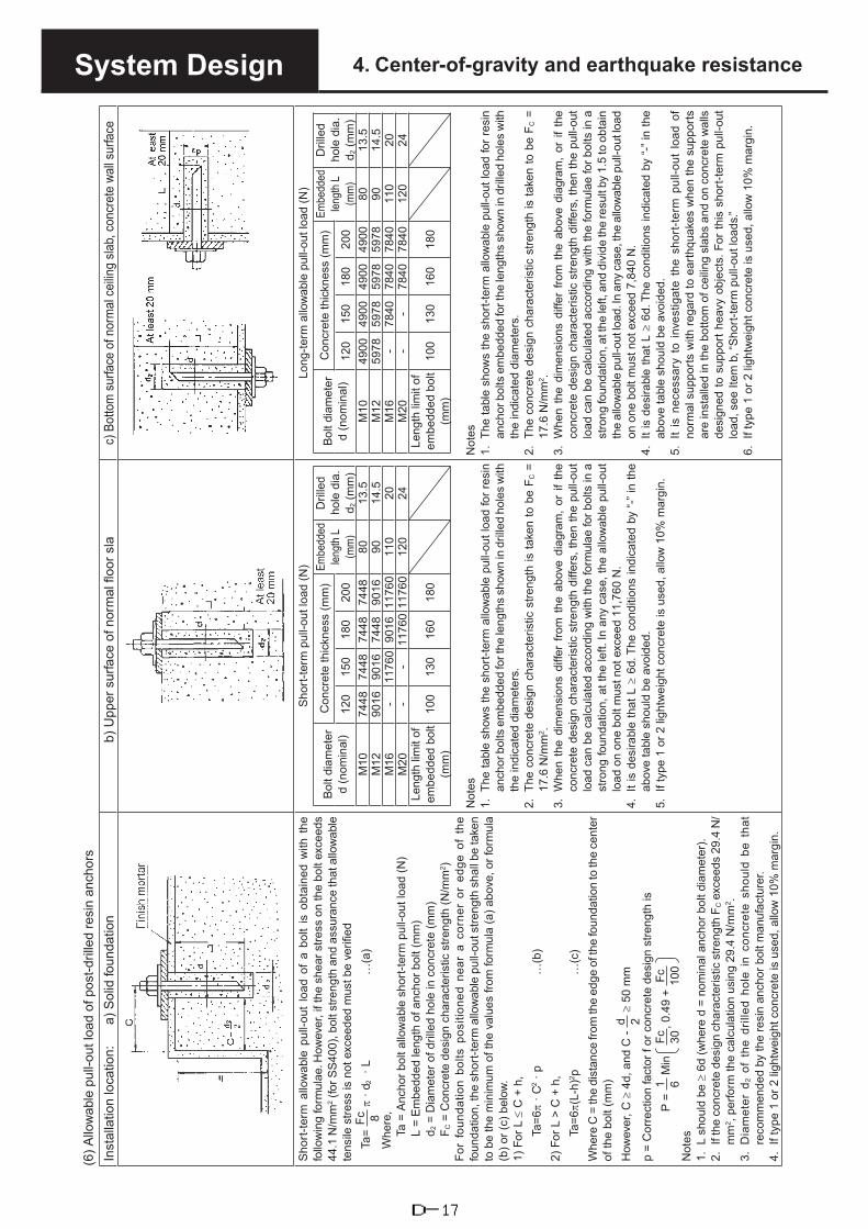
System Design 4. Center-of-gravity and earthquake resistance(6
) Allo
wab
le p
ull-o
ut lo
ad o
f pos
t-dril
led
resi
n an
chor
sIn
stal
latio
n lo
catio
n:
a) S
olid
foun
datio
nb)
Upp
er s
urfa
ce o
f nor
mal
floo
r sla
c)Bo
ttom
sur
face
of n
orm
al c
eilin
g sla
b, c
oncr
ete
wall s
urfa
ce
Sho
rt-te
rm a
llow
able
pul
l-out
load
of
a bo
lt is
obt
aine
d w
ith t
he
follo
win
g fo
rmul
ae. H
owev
er, i
f the
she
ar s
tress
on
the
bolt
exce
eds
44.1
N/m
m2 (
for S
S40
0), b
olt s
treng
th a
nd a
ssur
ance
that
allo
wab
le
tens
ile s
tress
is n
ot e
xcee
ded
mus
t be
verif
ied
Ta=
Fc 8 π
· d 2
· L
…
(a)
Whe
re,
Ta =
Anc
hor b
olt a
llow
able
sho
rt-te
rm p
ull-o
ut lo
ad (N
)L
= E
mbe
dded
leng
th o
f anc
hor b
olt (
mm
)d 2
= D
iam
eter
of d
rille
d ho
le in
con
cret
e (m
m)
F C =
Con
cret
e de
sign
cha
ract
eris
tic s
treng
th (N
/mm
2 )Fo
r fo
unda
tion
bolts
pos
ition
ed n
ear
a co
rner
or
edge
of
the
foun
datio
n, th
e sh
ort-t
erm
allo
wab
le p
ull-o
ut s
treng
th s
hall
be ta
ken
to b
e th
e m
inim
um o
f the
val
ues
from
form
ula
(a) a
bove
, or f
orm
ula
(b) o
r (c)
bel
ow.
1)Fo
r L ≤
C +
h,
Ta=6
π · C
2 · p
…
(b)
2)Fo
r L >
C +
h,
Ta=6
π(L-
h)2 p
…
(c)
Whe
re C
= th
e di
stan
ce fr
om th
e ed
ge o
f the
foun
datio
n to
the
cent
er
of th
e bo
lt (m
m)
How
ever
, C ≥
4d,
and
C -
d 2 ≥
50
mm
p =
Cor
rect
ion
fact
or f
or c
oncr
ete
desi
gn s
treng
th is
P =
1 6 M
in
Fc 30, 0
.49
+ Fc 10
0N
otes
1. L
sho
uld
be ≥
6d
(whe
re d
= n
omin
al a
ncho
r bol
t dia
met
er).
2. I
f the
con
cret
e de
sign
cha
ract
eris
tic s
treng
th F
C e
xcee
ds 2
9.4
N/
mm
2 , pe
rform
the
calc
ulat
ion
usin
g 29
.4 N
/mm
2 .3.
Dia
met
er d
2 of
the
dril
led
hole
in
conc
rete
sho
uld
be t
hat
reco
mm
ende
d by
the
resi
n an
chor
bol
t man
ufac
ture
r.4.
If t
ype
1 or
2 li
ghtw
eigh
t con
cret
e is
use
d, a
llow
10%
mar
gin.
Sho
rt-te
rm p
ull-o
ut lo
ad (N
)
Bol
t dia
met
erd
(nom
inal
)C
oncr
ete
thic
knes
s (m
m)
Embe
dded
len
gth
L (m
m)
Dril
led
hole
dia
. d 2
(mm
)12
015
018
020
0M
1074
4874
4874
4874
4880
13.5
M12
9016
9016
7448
9016
9014
.5M
16-
1176
090
1611
760
110
20M
20-
-11
760
1176
012
024
Leng
th li
mit
of
embe
dded
bol
t (m
m)
100
130
160
180
Not
es1.
The
tabl
e sh
ows
the
shor
t-ter
m a
llow
able
pul
l-out
load
for r
esin
anch
or b
olts
em
bedd
ed fo
r the
leng
ths
show
n in
dril
led
hole
s w
ithth
e in
dica
ted
diam
eter
s.2.
The
conc
rete
des
ign
char
acte
ristic
stre
ngth
is ta
ken
to b
e F C
=17
.6 N
/mm
2 .3.
Whe
n th
e di
men
sion
s di
ffer
from
the
abo
ve d
iagr
am,
or if
the
conc
rete
des
ign
char
acte
ristic
stre
ngth
diff
ers,
then
the
pull-
out
load
can
be
calc
ulat
ed a
ccor
ding
with
the
form
ulae
for b
olts
in a
stro
ng fo
unda
tion,
at t
he le
ft. In
any
cas
e, th
e al
low
able
pul
l-out
load
on
one
bolt
mus
t not
exc
eed
11,7
60 N
.4.
It is
des
irabl
e th
at L
≥ 6
d. T
he c
ondi
tions
indi
cate
d by
“-” i
n th
eab
ove
tabl
e sh
ould
be
avoi
ded.
5. I
f typ
e 1
or 2
ligh
twei
ght c
oncr
ete
is u
sed,
allo
w 1
0% m
argi
n.
Long
-term
allo
wab
le p
ull-o
ut lo
ad (N
)
Bol
t dia
met
erd
(nom
inal
)C
oncr
ete
thic
knes
s (m
m)
Embe
dded
len
gth
L (m
m)
Dril
led
hole
dia
. d 2
(mm
)12
015
018
020
0M
1049
0049
0049
0049
0080
13.5
M12
5978
5978
5978
5978
9014
.5M
16-
7840
7840
7840
110
20M
20-
-78
4078
4012
024
Leng
th li
mit
of
embe
dded
bol
t (m
m)
100
130
160
180
Not
es1.
The
tabl
e sh
ows
the
shor
t-ter
m a
llow
able
pul
l-out
load
for r
esin
anch
or b
olts
em
bedd
ed fo
r the
leng
ths
show
n in
dril
led
hole
s w
ithth
e in
dica
ted
diam
eter
s.2.
The
conc
rete
des
ign
char
acte
ristic
stre
ngth
is ta
ken
to b
e F C
=17
.6 N
/mm
2 .3.
Whe
n th
e di
men
sion
s di
ffer
from
the
abo
ve d
iagr
am,
or if
the
conc
rete
des
ign
char
acte
ristic
stre
ngth
diff
ers,
then
the
pull-
out
load
can
be
calc
ulat
ed a
ccor
ding
with
the
form
ulae
for b
olts
in a
stro
ng fo
unda
tion,
at t
he le
ft, a
nd d
ivid
e th
e re
sult
by 1
.5 to
obt
ain
the
allo
wab
le p
ull-o
ut lo
ad. I
n an
y ca
se, t
he a
llow
able
pul
l-out
load
on o
ne b
olt m
ust n
ot e
xcee
d 7,
840
N.
4.It
is d
esira
ble
that
L ≥
6d.
The
con
ditio
ns in
dica
ted
by “-
” in
the
abov
e ta
ble
shou
ld b
e av
oide
d.5.
It is
nec
essa
ry t
o in
vest
igat
e th
e sh
ort-t
erm
pul
l-out
loa
d of
norm
al s
uppo
rts w
ith re
gard
to e
arth
quak
es w
hen
the
supp
orts
are
inst
alle
d in
the
botto
m o
f cei
ling
slab
s an
d on
con
cret
e w
alls
desi
gned
to s
uppo
rt he
avy
obje
cts.
For
this
sho
rt-te
rm p
ull-o
utlo
ad, s
ee It
em b
, “S
hort-
term
pul
l-out
load
s.”6.
If t
ype
1 or
2 li
ghtw
eigh
t con
cret
e is
use
d, a
llow
10%
mar
gin.
D-17

System Design 4. Center-of-gravity and earthquake resistance(7
) Allo
wab
le p
ull-o
ut lo
ad fo
r pos
t-ins
talle
d sc
rew
-type
mec
hani
cal a
ncho
r bol
tsIn
stal
latio
n lo
catio
n:
a) S
olid
foun
datio
nb)
Upp
er s
urfa
ce o
f nor
mal
floo
r sla
c)Bo
ttom
sur
face
of n
orm
al c
eilin
g sla
b, c
oncr
ete
wall s
urfa
ce
Sho
rt-te
rm a
llow
able
pul
l-out
load
of
a bo
lt is
obt
aine
d w
ith t
he
follo
win
g fo
rmul
ae. H
owev
er, i
f the
she
ar s
tress
on
the
bolt
exce
eds
44.1
N/m
m2 (
for S
S40
0), b
olt s
treng
th a
nd a
ssur
ance
that
allo
wab
le
tens
ile s
tress
is n
ot e
xcee
ded
mus
t be
verif
ied
Ta=
6π ·
L2 · p
…
(a)
Whe
re,
Ta =
Anc
hor b
olt a
llow
able
sho
rt-te
rm p
ull-o
ut lo
ad (N
)L
= E
mbe
dded
leng
th o
f anc
hor b
olt (
mm
)(M
ay b
e ta
ken
to b
e th
e de
pth
of th
e dr
illed
hol
e.)
P =
Cor
rect
ion
fact
or fo
r con
cret
e de
sign
stre
ngth
is
P =
1 6M
in
Fc 30, 0
.49
+ Fc 10
0F C
= C
oncr
ete
desi
gn c
hara
cter
istic
stre
ngth
(N/m
m2)
(Nor
mal
ly, 1
7.6
N/m
m2
is u
sed.
)Fo
r bol
ts n
ear a
cor
ner o
r edg
e of
a fo
unda
tion,
if th
e di
stan
ce fr
om
the
cent
er o
f the
bol
t to
the
edge
is C
≤ L
, the
allo
wab
le s
hort-
term
pu
ll-ou
t loa
d of
the
bolt
is g
iven
by
form
ula
(b) b
elow
.Ta
= 6π
· C
2 · p
…
(b)
Whe
re C
= th
e di
stan
ce fr
om th
e ed
ge o
f the
foun
datio
n to
the
cent
er
of th
e bo
lt (m
m)
How
ever
, C ≥
4d,
and
C -
d 2 ≥
50
mm
Not
e 1.
If
type
1 o
r 2 lig
htw
eigh
t con
cret
e is
use
d, a
llow
10%
mar
gin.
Sho
rt-te
rm p
ull-o
ut lo
ad (N
)B
olt d
iam
eter
d (n
omin
al)
Con
cret
e th
ickn
ess
(mm
)E
mbe
dded
le
ngth
L (m
m)
120
150
180
200
M8
2940
2940
2940
2940
40M
1037
2437
2437
2437
2445
M12
6566
6566
6566
6566
60M
1690
1690
1690
1690
1670
M20
1176
011
760
1176
011
760
90M
2411
760
1176
011
760
1176
010
0Le
ngth
lim
it of
em
bedd
ed b
olt
(mm
)
100
or
less
120
or
less
160
or
less
180
or
less
Not
es1.
The
abo
ve ta
ble
show
s th
e sh
ort-t
erm
allo
wab
le p
ull-o
ut lo
ad fo
ran
chor
bol
ts e
mbe
dded
for t
he le
ngth
s sh
own.
2.Th
e co
ncre
te d
esig
n ch
arac
teris
tic s
treng
th is
take
n to
be
FC =
17.6
N/m
m2 .
3.W
hen
the
dim
ensi
ons
diffe
r fro
m t
he a
bove
dia
gram
, or
if t
heco
ncre
te d
esig
n ch
arac
teris
tic s
treng
th d
iffer
s, th
en th
e pu
ll-ou
tlo
ad c
an b
e ca
lcul
ated
acc
ordi
ng w
ith th
e fo
rmul
ae fo
r bol
ts in
ast
rong
foun
datio
n, a
t the
left.
In a
ny c
ase,
the
allo
wab
le p
ull-o
utlo
ad o
n on
e bo
lt m
ust n
ot e
xcee
d 11
,760
N.
4. D
o no
t use
bol
ts w
ith a
n em
bedd
ed le
ngth
less
than
that
sho
wn
in th
e rig
htm
ost c
olum
n.5.
If t
ype
1 or
2 li
ghtw
eigh
t con
cret
e is
use
d, a
llow
10%
mar
gin.
Long
-term
allo
wab
le p
ull-o
ut lo
ad (N
)B
olt d
iam
eter
d (n
omin
al)
Con
cret
e th
ickn
ess
(mm
)E
mbe
dded
le
ngth
L (m
m)
120
150
180
200
M8
1960
1960
1960
1960
40M
1024
5024
5024
5024
5045
M12
4410
4410
4410
4410
60M
1659
7859
7859
7859
7870
M20
7840
7840
7840
7840
90M
2478
4078
4078
4078
4010
0Le
ngth
lim
it of
em
bedd
ed b
olt
(mm
)
100
or
less
120
or
less
160
or
less
180
or
less
Not
es1.
The
abo
ve ta
ble
show
s th
e sh
ort-t
erm
allo
wab
le p
ull-o
ut lo
ad fo
ran
chor
bol
ts e
mbe
dded
for t
he le
ngth
s sh
own.
2.Th
e co
ncre
te d
esig
n ch
arac
teris
tic s
treng
th is
take
n to
be
F C =
17.6
N/m
m2 .
3.W
hen
the
dim
ensi
ons
diffe
r fro
m t
he a
bove
dia
gram
, or
if t
heco
ncre
te d
esig
n ch
arac
teris
tic s
treng
th d
iffer
s, th
en th
e pu
ll-ou
tlo
ad c
an b
e ca
lcul
ated
acc
ordi
ng w
ith th
e fo
rmul
ae fo
r bol
ts in
ast
rong
foun
datio
n, a
t the
left,
and
div
ide
the
resu
lt by
1.5
to o
btai
nth
e al
low
able
pul
l-out
load
. In
any
case
, the
allo
wab
le p
ull-o
ut lo
adon
one
bol
t mus
t not
exc
eed
7,84
0 N
.4.
Do
not u
se b
olts
with
an
embe
dded
leng
th le
ss th
an th
at s
how
nin
the
right
mos
t col
umn.
5.It
is n
eces
sary
to
inve
stig
ate
the
shor
t-ter
m p
ull-o
ut l
oad
ofno
rmal
sup
ports
with
rega
rd to
ear
thqu
akes
whe
n th
e su
ppor
tsar
e in
stal
led
in th
e bo
ttom
of c
eilin
g sl
abs
and
on c
oncr
ete
wal
lsde
sign
ed to
sup
port
heav
y ob
ject
s. F
or th
is s
hort-
term
pul
l-out
load
, see
Item
b, “
Sho
rt-te
rm p
ull-o
ut lo
ads.”
6. I
f typ
e 1
or 2
ligh
twei
ght c
oncr
ete
is u
sed,
allo
w 1
0% m
argi
n.
D-18

System Design 4. Center-of-gravity and earthquake resistance
(3) Installation position and center of gravityFor 2-WAY Type Outdoor Unit1) Position of center-of-gravity
LG2
hG
L2
LG2´LG1
hG
L1
LG1́
Broadside (front view) End-on (side view)
Outdoor unit type
Position of mounting points
Position of center-of-gravity Unit Weight (kg)
L1 L2 LG1 LG1´ LG2 LG2´ hG W
56.0 kW 1,000 1,040 523 477 492 548 761 765
For earthquake-resistant design, compare LG1 and LG1', and LG2 and LG2', and use the smallest value.
2) Mounting pad (foundation) size Unit: mm
A (mm) B (mm) C (mm)
20GES3E5
Installation on ground 1,700 or more
1,170 or more
120 or more
Installation on roof
Without vibration-resistant frame
1,850 or more 2,000
or more140 or moreWith vibration-resistant
frame2,000
or moreNote: The foundation is either a solid pad, or directly on the floor sla .
3) Size and type of anchor boltsi) All anchor bolts are M12.ii) Use one of the following types of anchor bolts.
Embedded-type: L-type, LA-type, headed bolts, J-type, JA-typeBoxout-compatible: L, LA, headed, J or JA (however, base dimension C must be at least 180 mm),post-drilled resin anchors or post-installed male-threaded mechanical anchor bolts.Female screw anchors provide insufficient pull-out strength, so cannot be used
A
B
C
D-19

System Design 4. Center-of-gravity and earthquake resistance
(4) Example anchor bolt calculation
Earthquake-resistance evaluation of Model U-20GES3E5
1) The earthquake-resistance type is “Common use,” so design horizontal earthquake factor KH is 1.0 G.(KH = 1.0 for rooftop installations, and 0.4 for ground installations.)
2) Refer to paragraph (3) on the previous page for the equipment center-of-gravity position.3) Anchor bolts
Number of bolts = 4Bolt diameter M12 (12 mm)Note: If calculations give unacceptable results, change conditions and recalculate.
Example of evaluation using calculations
(1) Anchor bolt conditions
1) Total no. of bolts (N) N = 4 current models have four bolts
2) Bolt diameter (D) D = 12 mm for M12 bolts
3) Bolt cross-sectional area (A) A = πD2 / 4 = 113 mm2
4) Bolts on one side (end-on direction, n1) n1 = 2 current models have two bolts
(broadside direction, n2) n2 = 2 current models have two bolts
5) The installation method is for “embedded J or JA type bolts,” on a 15-cm-thick slabAnchor bolt allowable short-term tensile load (Ta) Ta = 11,760 N(The installation method may also be selected after completing calculations.)
(2) Calculation
1) Design horizontal seismic magnitude (KH) KH = 1.0 Installation location: KH roof : 1.0ground : 0.4
2) Operating load (W) W = 7,497 N(= operating mass × 9.8)
3) Horizontal earthquake force (FH) FH = KH · W = 7,497 N
4) Height of center-of-gravity (hG) hG = 761 mm
5) Vertical earthquake force (FV) FV = FH / 2 = 3,749 N
6) Distance from center-of-gravity to boltEnd-on direction (LG1) LG1 = 477 mm
Broadside direction (LG2) LG2 = 492 mm
D-20

System Design 4. Center-of-gravity and earthquake resistance
7) Bolt spanEnd-on direction (L1) L1 = 1,000 mm
Broadside direction (L2) L2 = 1,040 mm
8) Actual strength of anchor boltsShort-term allowable tensile stress (ft) ft = 176 N/mm2 for SS400, ft = 176
Short-term allowable shear stress (fs) fs = 99 N/mm2 for SS400, fs = 132 x 0.75
9) Pull-out load on one boltEnd-on direction (Rb1) Rb1 = FH · hG – (W – FV) LG1
L1 · n1 = 1,959 N
Broadside direction (Rb2) Rb2 = FH · hG – (W – FV) LG2
L2 · n2 = 1,856 N
10) Anchor bolt shear stress ( ) τ = FH
N · A = 16.6 N/mm2
11) Mounting bolt tensile stressEnd-on direction (σ1) σ1 = Rb1
A = 17.3 N/mm2
Broadside direction (σ2) σ2 = Rb2
A = 16.4 N/mm2
12) Allowable tensile stress on a bolt subject to both tensile and shear stresses (fts)
fts =1.4 · ft – 1.6τ = 218.4 N/mm2
(3) Judgment
1) Tensile loadEnd-on direction, if Rb1 < Ta OK Rb1 = 1,959 < Ta = 11,760
Broadside direction, if Rb2 < Ta OK Rb2 = 1,856 < Ta = 11,760
2) Shear stressifτ< fs, OK τ = 16.6 < fs = 99
3) Tensile stressEnd-on direction: if σ1 < ft < ft = 176
OK σ1 = 17.3 σ1<fts < fts = 218.4
Broadside direction: if σ2 < ft < ft = 176OK σ2 = 16.4
σ2<fts < fts = 218.4
D-21

Installation Work
Contents
1.Procedures and Technical Pointsfor System Installation ...............................................E-2
2.Air ConditionerINSTALLATION INSTRUCTIONS ..........................................................E-35
3.Procedures and Technical Pointsfor Electrical Wiring Work (Outdoors) ........................E-69
E-1

1.Procedures and Technical Pointsfor System InstallationInstallation Work
IMPORTANT!Read Before StartingThis air conditioning system meets strict safety andoperating standard. As the installer or service person,it is an important part of your job to install or servicethe system so it operates safety and efficiently.For safe installation and trouble-free operation,you must:• Carefully read this instruction booklet before beginning.• Follow each installation or repair step exactly as shown.• Observe all local, state, and national installation codes.• Pay close attention to all warning and caution notices
given in this manual.• After the work is completed, be sure to provide the
user with a user manual and a brief explanation of theoperating procedures.
This symbol refers to a hazard or unsafe practice which can result in severe personal injury or death.
This symbol refers to a hazard or unsafe practice which can result in personal injury or product or property damage.
If Necessary, Get HelpThese instructions are all you need for most installation sites and maintenance conditions. If you require help for a special problem, contact our sales/service outlet or your certified dealer for additional instructions.In Case of Improper InstallationThe manufacturer shall in no way be responsible for improper installation or maintenance service, including failure to follow the instructions in this document.
WARNING
CAUTION
SPECIAL PRECAUTIONS When WiringELECTRICAL SHOCK CAN CAUSE SEVERE PERSONAL INJURY OR DEATH. ONLY A QUALIFIED, EXPERIENCED ELECTRICIAN SHOULD ATTEMPT TO WIRE THIS SYSTEM.
• Do not supply power to the unit allwiring and tubing are completed or reconnected and checked.
• Highly dangerous electrical voltageare used in this system. Carefullyrefer to the wiring diagram andthese instructions when wiring.Improper connections andinadequate grounding can causeaccidental injury or death.
• The unit must be connectedto the earth according to localelectrical code.
• Connect all wiring tightly. Loose wiringmay cause overheating at connectionpoints and a possible fire hazard.
E-2

1.Procedures and Technical Pointsfor System InstallationInstallation Work
When Transporting
Be careful when picking up and moving the indoor and outdoor units. Get a partner to help, and bend your knees when lifting to reduce strain on your back. Sharp edges or thin aluminum fins on the air conditioner can cut your fingers.
When Installing...
...In a Ceiling or WallMake sure the ceiling/wall is strong enough to hold the unit’s weight. It may be necessary to construct a strong wood or metal frame to provide added support.
...In a RoomProperty insulate any tubing run inside a room to prevent “sweating” that can cause dripping and water damage to walls and floors.
...In Moist or Uneven LocationsUse a raised concrete pad or concrete blocks to provide a solid, level foundation for the outdoor unit. This prevents water damage and abnormal vibration.
...In an Area with High WindsSecurely anchor the outdoor unit down with bolts and a metal frame. Provide a suitable air baffle.
...In a Snowy Area (for Heat Pump-type Systems)Install the outdoor unit on a raised platform that is higher than drifting snow. Provide snow vents.
When Connecting Refrigerant Tubing
• Use the flare method forconnecting tubing.
• Apply refrigerant lubricant to thematching surfaces of the flare andunion tubes before connectingthem, then tighten the nut witha torque wrench for a leak-freeconnection.
• Check carefully for leaks beforestarting the test run.
When Servicing
• Turn the power OFF at the mainpower box (mains) before openingthe unit to check or repair electricalparts and wiring.
• Keep your fingers and clothingaway from any moving parts.
• Clean up the site after you finish,remembering to check that nometal scraps or bits of wiring havebeen left inside the unit beingserviced.
Gas Supply Pressure
Gas Supply Pressure(mbar) Gas Supply Pressure(mbar)
G20, G25(Natural Gas)
Min. Normal Max. G31(LPG)
Min. Normal Max.17 20 25 25 37 45
Others
CAUTION
• Ventilate any enclosed areas wheninstalling or testing the refrigerationsystem. Escaped refrigerant gas,on contact with fire or heat, canproduce dangerously toxic gas.
• Confirm upon completinginstallation that no refrigerant gasis leaking. If escaped gas comesin contact with a stove, gas waterheater, electric room heater orother heat source, it can producedangerously toxic gas.
NOTICE • The English text is the original instructions. Other languages are translation of the originalinstructions.
E-3

1.Procedures and Technical Pointsfor System InstallationInstallation Work
SAFETY PRECAUTIONS
WARNING
• Be sure to arrange installation from the dealer where the system waspurchased or using a professional installer. If you attempt to perform thework yourself, and do so incorrectly, there is danger of poisoning causedby exhaust gases entering the building, as well as danger of water leakage,electric shock and fire.
• Installation work must be performed correctly, in accordance with theinstructions listed here. Hazards from incorrect installation includedangerous exhaust gas buildup, water leakage, electric shock and fire.
• Check the type of engine fuel used. If the wrong type of gas is used, theengine can suffer combustion problems, and there is danger of poisoningcaused by exhaust gases.
• Ventilate the area in case refrigerant gas leaks during installation work.If refrigerant gas comes into contact with flame during the tube brazingprocess, toxic gas will be produced.
• When installation work is completed, check that there is no refrigerant gasleakage.If refrigerant gas leaks into the room and contacts the flame of a fan heater,stove, burner, or other device, toxic gases will be produced.
• Never use (top up or replace) any refrigerant other than the specifiedrefrigerant (noted on the nameplate).Doing so may cause a rupture in or breakdown of the device, or personalinjury.
• When installing or moving the indoor and outdoor units, do not allowrefrigerants other than the one specified (written on the label on the unit) orair to enter the unit’s refrigeration cycle.
• Always use nitrogen for the airtightness test. (Do not use oxygen-basedgases.)
• Never modify or repair the system yourself.• Be sure to use a refrigerant recovery machine when recovering refrigerant
for relocation or repairs. It cannot be recovered into an outdoor unit.Recovering refrigerant into an outdoor unit may result in serious accidentssuch as rupturing and injury.
CAUTION
• When handling refrigerant gas, do not come in contact with the gas directly.Doing so may result in frostbite.
Important Information Regarding the Refrigerant UsedThis product contains fluorinated greenhouse gases. Do not vent gases into the atmosphere.Refrigerant type: R410AGWP(1) value: 2088(1) GWP = global warming potentialPeriodical inspections for refrigerant leaks may be required depending on European or local legislation. Please contact your local dealer for more information.
E-4

1.Procedures and Technical Pointsfor System InstallationInstallation Work
CHARACTERISTICS AND REQUESTS
ABOUT YOUR GAS HEAT PUMP AIR CONDITIONERThe gas heat pump air conditioner (GHP) uses gas as the fuel to drive the compressor.As it uses gas engine, there are various characteristics.• As the unit does not easily frost, defrosting operations are infrequent even on very cold days, allowing the
unit to provide stable and continuous heating.• As the electric power consumption is about 1 kW, this leads to be less received power equipment.However, as with a car engine, periodical inspections by a specialist are for efficient use needed for a comfortable operation. Make sure you have these periodical inspections.
ENSURE YOU SIGN UP FOR A REGULAR CHECK UP CONTRACTIn order to have a comfortable operation of GHP for a long period, periodical inspections are necessary.Conduct yearly inspections supported by a specialist.What will happen if you do not have periodical inspections.1. The engine oil will deteriorate, causing a malfunction.2. The air cleaner element will be clog up, causing carbon monoxide and occasional reduction of
performance.REQUESTSOnce signed up for a periodical inspection, a specialist will call on depending on the length of time the unit has been in use. After a fixed period of in use hours, the remote controller will display “Oil Inspection”. At this time we would appreciate you contacting your dealer or service center for a check up.GUARANTEE PERIODThe guarantee period is ONE year after the date of a successful test operation and the product delivery.However, the engine itself and periodical replaced parts are guaranteed for ONE year after a successful test operation and the product delivery or 2000 hours in operation whichever comes earlier.
CHANGING ENGINE OILPeriodically change engine oil and oil filter.If you forget to change engine oil or use a non-specified oil, it may have a bad effect on the engine and be the cause of trouble.* Engine oil (Genuine oil
MAXIMUM GAS FLOW RATE AND NOX VALUEThe unit’s maximum gas flow rate and NOX value are as follows.• Maximum gas flow rate: 98 kW• Year emission (Hs) of NOX: 220 mg/kWh (COMMISSION REGULATION (EU) 2016/2281)
INGCOOL AND HEATING ABLE OPER TEMPERATURE RANGE
In order to use the air conditioner correctly, operate under the following conditions.If you operate the equipment at temperature for a long period of time, the protective components will engage and the equipment will become inoperable.
Coo
ling
Mod
e
Outdoor Temperature ≥ Approx. -10°C, ≤ 43°C
Indoor Temperature ≥ Approx. 18°C, ≤ 32°C
Room Humidity≤ Approx. 80%In the rainy season or when the air humidity is high, using the air conditioner for a long time may result in frost on the surface of the equipment and fog may be discharged from the air discharge.
Hea
ting
Mod
e Outdoor Temperature ≥ Approx. -20°C, ≤ 24°C
Indoor Temperature ≤ Approx. 27°C
E-5

1.Procedures and Technical Pointsfor System InstallationInstallation Work
1. SELECTING THE INSTALLATION LOCATION(1) Install the gas heat pump air conditioner (GHP) so that it satisfies all local regulations and government
safety codes, as well as installation standards and service guidelines for industrial gas devices.(2) Choose a suitable installation location (with adequate space for servicing), as below.
WARNING
• Install the GHP outdoor unit in a location where exhaust gases will not enter the building’s air intake orexhaust vents or windows, and will not enter the building through tubes or vents that lead inside thebuilding. There is danger of poisoning if exhaust gases enter the building.
• Install the GHP outdoor unit outdoors, in a location open to the air, so that there is no accumulation of exhaustgases.There is danger of the gases entering the building and causing poisoning.
• The exhaust gases must be open to the air in a location where they will not adversely affect the surroundings.There is danger of exhaust gases entering the building and causing poisoning. (Be certain not to allowexhaust gases to be discharged into a drainage basin, gutter, or similar location.)
• Install the outdoor unit securely in a location that can fully bear the weight of the unit.There is danger of gas leakage or injury if the outdoor unit tips over or falls.
CAUTION
• When installing outdoor units, bear in mind the need of space for maintenance. Check with Fig. 1 andmake sure there is enough space.If you fail to ensure enough space, it may result in injury from falling while performing maintenance work.
• If the outdoor unit is installed on a roof or other elevated location, install a permanent ladder, handrails,and other necessary items in the passageway leading up to the unit, and install a fence, handrails, orsimilar structure around the outdoor unit. If such protections are not installed, an injury from fallingwhile working may result.
• Be sure to stand on a stable surface when installing the outdoor unit on an elevated base or location,and avoid using stepladders.
• Leave the distances shown in Fig. 2 between the GHP outdoor unit and any flammable materials.There is danger of fire if these distances are insufficient.
• Do not install the outdoor unit in a location where flammable gases may be generated, flow, accumulateor leak, or in a location where volatile substances are handled or stored. There may be danger of fire orexplosion if the unit is installed in such a location.
• Install the outdoor unit in a location where exhaust gases and fan air will not harm plants or animals.The exhaust gases and fan air may adversely affect plants and animals.
• Avoid installation near locations such as parking lots and flowerbeds where damage from clinging dustand particles may occur. If installation in such locations is unavoidable, be sure to put a covering on theoutdoor unit or take other measures to protect it.
In addition to heeding the WARNING and CAUTION notes, avoid installation in locations where the unit will beexposed to the following:• excessive dust • fumes from organic solvents• excessively salty air, such as near the sea • high fluctuations in power voltage• sulfuric gases, such as near hot springs • electromagnetic interference from other devices• excessive water, vapors, or oil fumes (ex: from machines)
In order to improve heat exchange, install the outdoor unit in a location that is well ventilated. Providemaintenance space and separation from flammable materials as per Figs. 1 and 2.If installing in a poorly ventilated location, or if installing multiple outdoor units, ensure sufficient space to preventshort circuits.
Do not do any wiring or tubing within 30 cm of the front panel of U-10MES2E8, because this space is needed asa servicing space for the compressor.
Ensure a base height of 100 mm or more to ensure that drainage water does not accumulate and freeze aroundthe bottom of the unit.
E-6

1.Procedures and Technical Pointsfor System InstallationInstallation Work
Over 35 cm Over 95 cm
Example of installation of GHP units
Example of installation of GHP and U-10MES2E8 units
Example of installation of U-10MES2E8 units (when 3 sides are open and only 1 side is shuttered)
Over 95 cm
Over 5 cm
Over 5 cm
Over 30 cm*
Over 35 cm* Over 35 cm*
** Over 50 cm
*** Over 6 cm
Make a walk-in space behind the unit to erase maintenance and servicing*** When setting the anchor bolt to position “B” or “C”, make the space between the unit and the wall more than 25 mm for
installation operation.*** When setting the anchor bolt to position “B” or “C”, make the space between the outdoor units more than 180 mm for
installation operation.
Over 2 m
Over 10 cm
Over 10 cm
Over 10 cmOver 10 cm
Front side Front side Front side Rear side
Over 10 cmOver 10 cm Over 10 cmOver 10 cm
Over 10 cm
Refrigerant tubing side Over 55 cm
Over 55 cm
Over 55 cm
Over 95 cm
Over 95 cm
Over 95 cm
Over 95 cm
Fig. 1 Maintenance Space
Fig. 2 Required distance from flammable materials
Over 15 cm
Over 1 cm
Over 15 cm
(Top view) (Front view)
Over 1 cmOver 60 cm
E-7

1.Procedures and Technical Pointsfor System InstallationInstallation Work
(3) In snowy regions, be sure to install a snow-protection hood and enclosure.Even in regions that do not have heavy snowfall, install a snow-protection roof (such as a snow hood) if the unit is installed in a location where snow may build up and fall from the building’s roof or other surface onto the unit. (Install the hood so that the coolant supply opening at the top of the GHP unit can be used.)
(4) Take care that operating noise and exhaust do not disturb neighboring buildings or homes.In particular, install so that noise-related local environmental standards, if any, are satisfied at the border with a neighboring dwelling.
(5) Because this air conditioner may affect other electrical devices with noise, give due consideration when installing air conditioner units (both indoors and outdoors) at enough distance (at least 3 m) from the main unit of TVs, radios, stereos, intercoms, PCs, word processors, telephones, etc., as well as their antenna cables, signal wires, power cords, etc.
(6) Select an installation location so that the length of refrigerant tubing is within the ranges shown in the table below.
Warnings (Same for All Models)*Always use R410A branch tubes (sold separately) when running branching tubes.1.. arnings about using branch tubes ( ) and header tubes sold separately will come packaged with the
parts sold separately, so be sure to refer to those materials.
2.. When using T-tee branch tube
2 m or less), the main tubing must be either level or vertical. The openings
rees) L3<2mraised angle from the ground when Indoor
the main tubing is level. The openings Indoor Closed weldcan be set at any angle when the main Outdoor
tubing is vertical, but be sure to curve Fig. 3 Main tube (horizontal) Fig. 4 Main tube (vertical)a portion of the connected tubing upward. Always close weld the end point of the T-tee tubing. In addition, pay special attention to the insertion dimensions for each connected tube so that refrigerant flow is not blocked at the T-tee branches. Be sure to use only standard T-tees.
3.. Do not use f the shelf Y-joints ( ) for liquid tubes (branch tubes (made on site)).
Table 1-1 System limitationsOutdoor unit type U-10MES2E8 + U-20GES3E5
Equivalent Horsepower 30
Ratio of capacity for indoor unit to outdoor units
Min: Across the system, a minimum outdoor unit capacity of 50%Max: Total capacity of 130% with 2 outdoor units
Minimum capacity of indoor units that can be connected Type 22 or greater (equivalent to 0.8 horsepower)
Maximum number of indoor units that can be connected (per system) 48
Any angle
Closed weld
Indoor
Indoor
(provided by installer) (only with L3 at OutdoorIndoor
Level line
of each branch tube must be at a Raised angle(15 to 30 deg
E-8

1.Procedures and Technical Pointsfor System InstallationInstallation Work
Table 1-2 Ranges for refrigerant tubing length and installation height differenceCategory Symbol Description Tubing length (m)
Allowable tubing length
L1 Max. allowable tubing length ≤170 (equivalent length 200)
DL=(L2-L4) Difference between longest and shortest tubing lengths after the No. 1 branch (first branching point) ≤70
LM Max. length for main tube (tube with widest diameter) 7≤LM≤120
ℓ1, ℓ2...ℓn Max. length for each tube branch ≤30
L5 Distance between outdoor units ≤7
Lb Max. length for balance tube ≤10
Allowable height difference
H1 Max. height difference between indoor and outdoor units
If outdoor unit is above ≤50
If outdoor unit is below ≤35 (*1)
H2 ≤α (*2)
H3
Max. height difference between indoor units
Max. height difference between outdoor units 1
Allowable length for branched tubing (header branch)
L3 Max. length between first T-tee branch (provided by installer) and the closed tube end ≤2
(*1) If cooling mode is expected to be used when the external temperature is 10°C or below, the maximum length is 30 m.
(*2) The max/min permissible height between indoor units (α) is found by the difference ( L) between the maximum length and the minimum length from the first branch.α=35- L/2 (however, 0≤α≤15)
The grouping of tubes that connect the outdoor units to the indoor units is referred to as the “main tubing.”
When the maximum tubing length is more than 90 m (equivalent length), upgrade the tube size 1 rank for both the liquid and gas tubes of the main tubing.The prescribed performance cannot be guaranteed if the wrong size is selected.
If the total amount of refrigerant (Required additional refrigerant charge + Quantity of refrigerant chargewhen shipped) exceeds 80 kg, reduce the amount to 80 kg or less by changing the refrigerant tubing route.
Table 1-3 Outdoor tubing/main tubing size *1, *2
Outdoor/main tubing Outdoor tubing Main tubing
Outdoor unit (gross) capacity (kW) 28 56 85
Gas tube (mm) Ø22.22 Ø28.58 Ø31.75 (Ø38.1)
Liquid tube (mm) Ø9.52 Ø15.88 Ø19.05 (Ø22.22)
*1 If there are plans for future expansion, choose plumbing sizes according to the total capacity after suchexpansion. However, if tube size is stepped up 3 levels, expansion is not possible.
*2 If the maximum tube length exceeds 90 m (or equivalent length), use the figure in parentheses ( ) tosize the main tubing, along with those of the liquid and gas tubes.
Table 1-4 Main tube size after branching *1, *2
When indoor unit(s) are connected Main tube after branching
Post-branching indoor unit capacity (kW)*3
– 5. – 16. – 22. 28.– – 16. – 28. 35.– – 45. – 71. – 101. – 10.5 – 221.0
Gas tube (mm)
Ø12.7 Ø15.88 Ø19.05 Ø22.22 Ø15.88 Ø22.22 (Ø25.4)
Ø25.4 (Ø28.58)
Ø28.58 (Ø31.75)Ø31.75 (Ø38.1)
Ø38.1 (Ø44.45)
Liquid tube (mm)
Ø9.52 Ø9.52 (Ø12.7) Ø12.7 (Ø15.88)Ø15.88
(Ø19.05)Ø19.05 (Ø22.22) Ø22.22
*1 Select a diameter for the main tubing after a branch that is no larger than that of the header.(In cases where the main tubing after a branch would have to be larger than the header tubing, select tubing of the same size, and never exceed the header size.)
*2 If the maximum tube length exceeds 90 m (or equivalent length), use the figure in parentheses ( ) to sizethe main tube after branching, along with those of the liquid and gas tubes.
*3 “–* *” in the table above means “** kW or less”.
E-9

1.Procedures and Technical Pointsfor System InstallationInstallation Work
Fig. 5 Length of Refrigerant Tubing
Table 1-5 Branch/Header Tube SelectionUse the following branch tubing sets or tubing sets for branching the system’s main tube and indoor unit tubing.
Capacity after branch
Branch tube size (*1)
Gas tube (mm) Liquid tube (mm)
Branch tube number
Branch tubingCZ-P160BK2 CZ-P680PJ(BK)2 CZ-P1350PJ(BK)2
Over 72.8 kW Ø31.75 Ø19.05 ― ― ●
Over 45.0 kW to 72.8 kW Ø28.58 Ø15.88 ― ● ●
Over 35.5 kW to 45.0 kW Ø28.58 Ø12.7 ― ● ●
Over 28.0 kW to 35.5 kW Ø25.4 Ø12.7 ― ● ●
Over 16.0 kW to 28.0 kW Ø22.22 Ø9.52 ― ● ●
Over 5.6 kW to 16.0 kW Ø15.88 Ø9.52 ● ●(*3) ●(*3)
5.6 kW or below Ø12.7 (*2) Ø9.52 ● ●(*3) ●(*3)
(*1) Make a selection so as not to exceed the main tubing size.(*2) Even when 5.6 kW or below, make the gas tube diameter Ø15.88 if 2 or more indoor units are connected after
branching.(*3) As the tube diameter for the supplied reducer does not match, another reducer must be provided by the installer.
Table 1-6 Tubes Connecting Outdoor Units and Indoor UnitsOutdoor Units
Tubing connecting to outdoor units (L5) Unit type U-10MES2E8 U-20GES3E5
Tube sizeGas tube (mm) Ø22.22 Ø28.58
Liquid tube (mm) Ø9.52 Ø15.88
Indoor UnitsTubing
connecting to indoor units
(ℓA to ℓB)
Unit type 22 28 36 45 56 60 73 90 106 140 160 224 280
Tube sizeGas tube (mm) Ø12.7 Ø15.88 Ø19.05 Ø22.22
Ø9.52 Liquid tube (mm) Ø6.35
Note: Keep the maximum length between ℓ1 to ℓn within 30 m.
1 2 3
54 6 7 n
H3
L5 L1L5LM
LB LC LD LE
LH
LG
L4
LA
LF
L3
L2
H2
H1
Lb
ℓ
ℓ ℓ ℓ
ℓ ℓ ℓ ℓ
1. LM: Main tube with largest tubing diameter (includes LA and all post-branch main tubes that are identical in size to LA) ≤ 120 m.2. Select the sizes for post-branching main tubes after LM (LB, LC, ...) based on the post-branching capacity.3. The sizes for the indoor unit connection tubing (ℓ1 to ℓn) depend on the tubing diameter for the indoor unit.
When T-tee branch tubing is used (header branch method)
40 cm or less
40 cm or less
Used for expansionSymbols
Branch tube (purchased separately)Ball valve (purchased separately)T-tee (provided by installer)Closed (pinch) weld
No.1 branchBalance tube
Maximum height differential of indoor units after final branchIf exceeding the 4 m of height between indoor units after a final branch cannot be helped, split the difference between rise and fall (2:1).
4 m or less (within α) More than 4 m
(within α)
2X m or more
X m
Four meters is the maximum height differential between indoor units after the last branch.
E-10
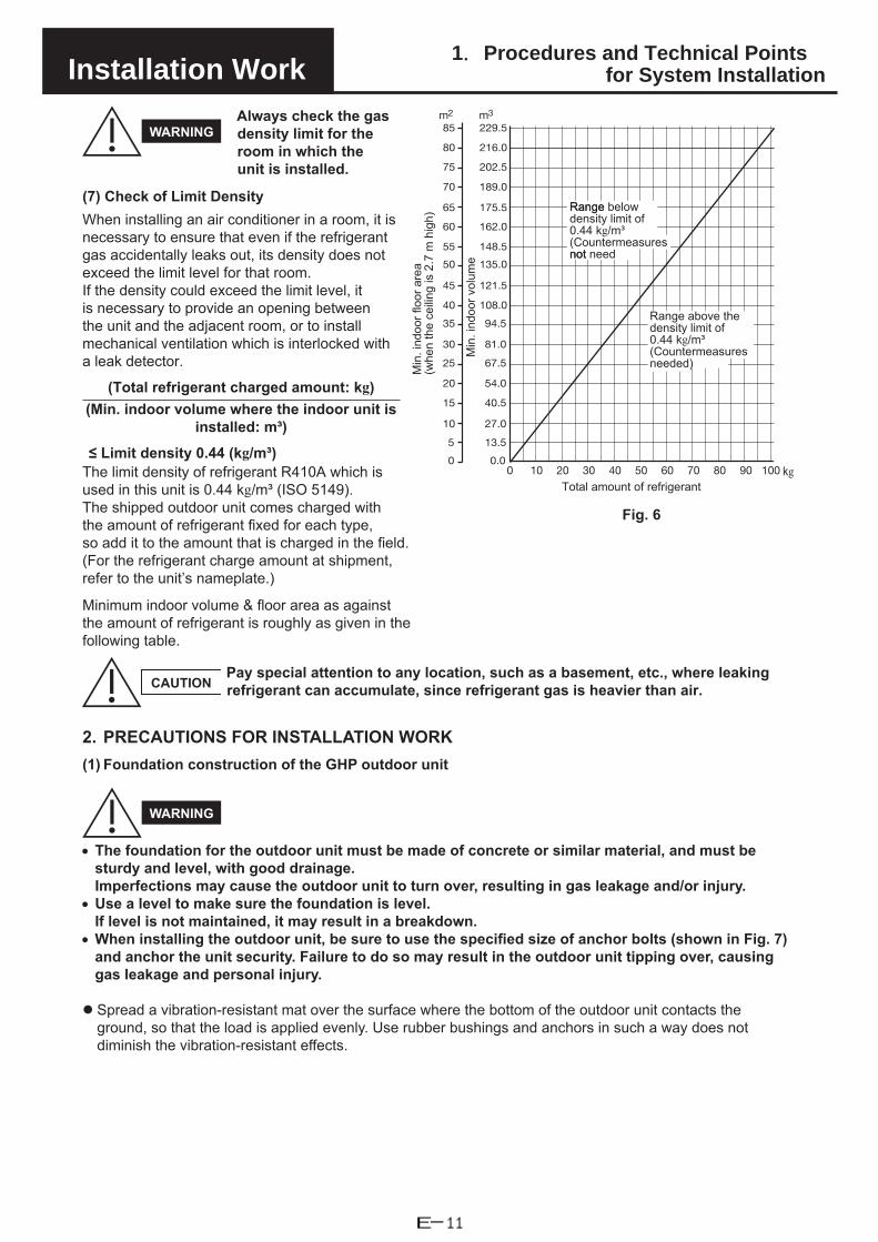
1.Procedures and Technical Pointsfor System InstallationInstallation Work
WARNINGAlways check the gas density limit for the room in which the unit is installed.
(7) Check of Limit DensityWhen installing an air conditioner in a room, it is necessary to ensure that even if the refrigerant gas accidentally leaks out, its density does not exceed the limit level for that room. If the density could exceed the limit level, it is necessary to provide an opening between the unit and the adjacent room, or to install mechanical ventilation which is interlocked with a leak detector.
(Total refrigerant charged amount: kg)(Min. indoor volume where the indoor unit is
installed: m³)
≤ Limit density 0.44 (kg/m³)The limit density of refrigerant R410A which is used in this unit is 0.44 kg/m³ (ISO 5149).The shipped outdoor unit comes charged with the amount of refrigerant fixed for each type, so add it to the amount that is charged in the field. (For the refrigerant charge amount at shipment, refer to the unit’s nameplate.)
Minimum indoor volume & floor area as against the amount of refrigerant is roughly as given in the following table.
CAUTIONPay special attention to any location, such as a basement, etc., where leaking refrigerant can accumulate, since refrigerant gas is heavier than air.
2. PRECAUTIONS FOR INSTALLATION WORK(1) Foundation construction of the GHP outdoor unit
WARNING
• The foundation for the outdoor unit must be made of concrete or similar material, and must besturdy and level, with good drainage.Imperfections may cause the outdoor unit to turn over, resulting in gas leakage and/or injury.
• Use a level to make sure the foundation is level.If level is not maintained, it may result in a breakdown.
• When installing the outdoor unit, be sure to use the specified size of anchor bolts (shown in Fig. 7)and anchor the unit security. Failure to do so may result in the outdoor unit tipping over, causinggas leakage and personal injury.
Spread a vibration-resistant mat over the surface where the bottom of the outdoor unit contacts theground, so that the load is applied evenly. Use rubber bushings and anchors in such a way does notdiminish the vibration-resistant effects.
20100 30 40 60 70 80 90 10050
m2 m3
40.5
54.0
27.0
13.5
0.0
67.5
81.0
94.5
108.0
121.5
135.0
148.5
162.0
175.5
189.0
202.5
216.0
15
10
5
0
20
25
30
35
40
45
50
55
60
65
70
75
80
229.585
kgTotal amount of refrigerant
Range belowRangedensity limit of 0.44 kg/m³(Countermeasures notnot need
Range above the density limit of 0.44 kg/m³(Countermeasures needed)
Min
. ind
oor v
olum
e
Min
. ind
oor f
loor
are
a(w
hen
the
ceili
ng is
2.7
m h
igh)
Fig. 6
E-11

1.Procedures and Technical Pointsfor System InstallationInstallation Work
Fig. 7 Foundation diagram of the GHP outdoor unit (mat foundation)Unit: mm
Foundation
Vibration-resistant mat
M12 anchor bolt
Table 2a (mm) b (mm) c (mm) d (mm) e (mm) f (mm)
56.0 kW
Installation on ground 1,700 or more
1,170 or more
1,000 1,040 1,450
120 or more
Installation on roof
Without vibration-resistant frame 1,850 or more
2,000 or more
140 or moreWith vibration-resistant frame (single type) 2,000 or
moreWith vibration-resistant frame (interlocking type) 1,850
Unit: mm
Be sure to take the following steps to prevent shifting of the foundation.A mat foundation that is simply placed on a floor slab (A-a type) must be of the dimensions shown in theTable 3 or larger in order to prevent shifting of the foundation in case of earthquake. If the mat foundationis smaller than these dimensions, take steps such as connecting the foundation and the building structurewith reinforcing bars, in accordance with building utilities earthquake-resistant design and constructionguidelines.Foundation types A-b, A-c, A-d, and A-e are provided as examples.
Use one of the following types of anchors. Use bolts of size M12 or larger for all bolts.1. Embedded-type: L-type, LA-type, headed bolts, J-type, JA-type2. Blockout-type: L-type, LA-type, headed bolts, J-type, JA-type (Make dimension “f” of the foundation
180 mm or more.)3. Plastic anchor4. External-thread type mechanical anchor
CAUTION: Do not use an internal-thread type mechanical anchor.
Fig. 8Unit: mmCondensate drain port
Fuel gas inletR3/4 external thread (male)
Exhaust drain port
E-12
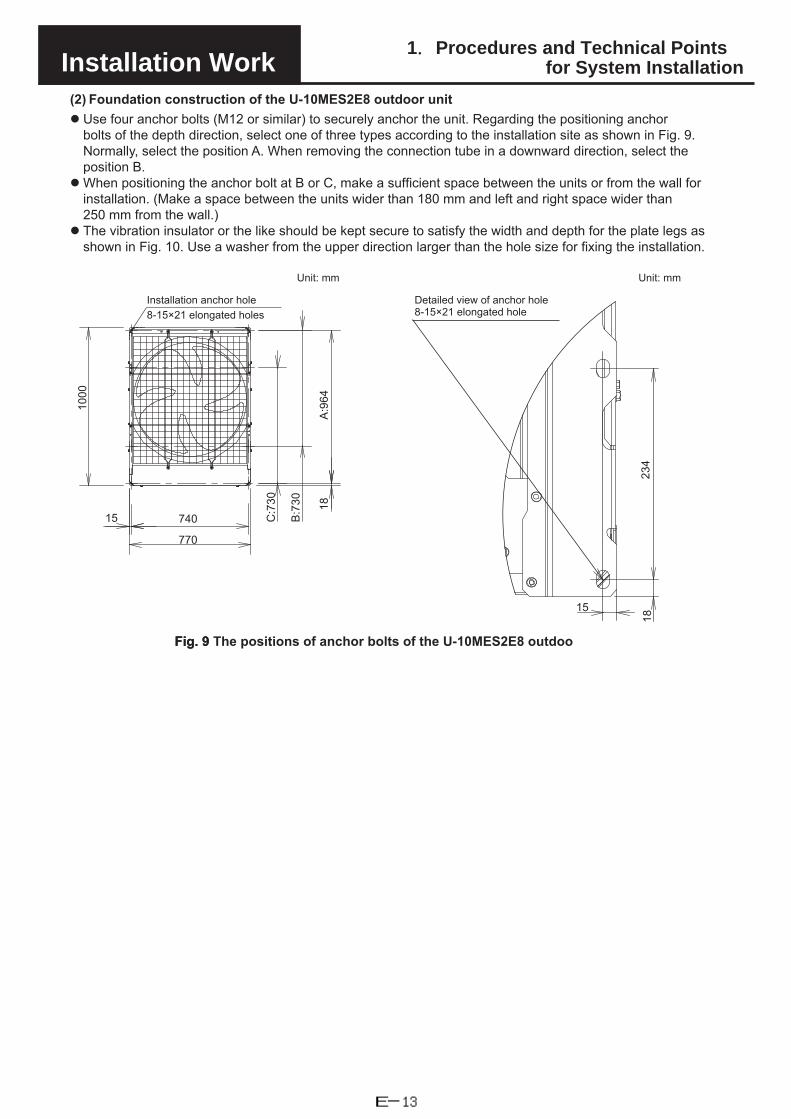
1.Procedures and Technical Pointsfor System InstallationInstallation Work
(2) Foundation construction of the U-10MES2E8 outdoor unit Use four anchor bolts (M12 or similar) to securely anchor the unit. Regarding the positioning anchor
bolts of the depth direction, select one of three types according to the installation site as shown in Fig. 9. Normally, select the position A. When removing the connection tube in a downward direction, select the position B.
When positioning the anchor bolt at B or C, make a sufficient space between the units or from the wall forinstallation. (Make a space between the units wider than 180 mm and left and right space wider than 250 mm from the wall.)
The vibration insulator or the like should be kept secure to satisfy the width and depth for the plate legs asshown in Fig. 10. Use a washer from the upper direction larger than the hole size for fixing the installation.
740
770
15
1000
C:730
B:730
A:964
18
Installation anchor hole8-15×21 elongated holes
Unit: mm Unit: mm
15
18234
Detailed view of anchor hole 8-15×21 elongated hole
Fig. 9Fig. 9 The positions of anchor bolts of the U-10MES2E8 outdoo
E-13

1.Procedures and Technical Pointsfor System InstallationInstallation Work
1575*
≥100
100*
*100
≥100
≥100
Unit: mm
Unit: mm
Unit: mm
• vibration insulator position when setting anchor bolt at position B. Below shows
• Below shows vibration insulator position when setting anchor bolt at Below shows
Plate leg (right)
DD
D D
Plate leg (left)
Vibration insulator
Electrical wiring port (bottom)
Tubing port (bottom)
Plate leg (right)
A:964
Inst
alla
tion
hole
pitc
h
D D
EE
Tubing port (bottom)
Electrical wiring port (bottom)
Vibration insulator
Plate leg (left)
B:730
Inst
alla
tion
hole
pitc
h
EE
D D
C:730
Tubing port (bottom)
Electrical wiring port (bottom)
insulatorVibration
Plate leg (left) Plate leg (right)
Inst
alla
tion
hole
pitc
h
Unit: mm
Unit: mm
Unit: mm
NOTE: Proceed with the work following the
Detailed view of D
Plate legs (left, right)
Anchor bolts
Washer
Base
Vibration insulator
Detailed view of E
Detailed view of D
Anchor bolts
Base
Vibration insulator
Plate legs (left, right)
Anchor bolts
Washer
Base
Vibration insulator
WasherPlate legs (left, right)
• Below shows vibration insulator position when setting anchor bolt at position A.
dimensions showing the asterisk.
Fig. 10 Vibration insulator position of the U-10MES2E8 outdoor unit
E-14

1.Procedures and Technical Pointsfor System InstallationInstallation Work
(3) Fuel piping work of the GHP outdoor unitAs needed, attach devices 2, 3 or 5 to the outdoor unit external fuel gas pipe. (Fig. 11-1)1 Flexible gas hose 2 Pressure release tap 3 Strainer 4 Master valve 5 Pipe bracketA main valve must be installed for servicing the fuel gas tube.
CAUTION
• Use a reinforced gas hose or a low-pressure gas hose with fuelgas joint bracket between the fuel gas pipe master valve and theoutdoor unit. In addition, avoid excess pressure or shock to theoutdoor unit’s fuel gas inlet by taking measures such as makingthe pipe path leading up to the gas hose as short as possible.Otherwise, there is danger of fire resulting from fuel gas leakage.
• If necessary, install pipe brackets in the fuel gas pipe path toreduce the risk of pressure or shock to the pipe path. In particular,take sufficient precautions when installing near roads. There is adanger of fire or explosion resulting from fuel gas leakage.* In regions with heavy snowfall, take precautions to protect the
fuel gas pipe path from snow damage (Fig. 11-2).• After installation work is completed, check that there is no gas
leakage from the fuel gas pipe/hose path. There is danger of fireresulting from fuel gas leakage.
• To ensure safety in case of a gas leak, make sure that airflowsurrounding the outdoor unit is sufficient and gas will notaccumulate.Accumulation of gas may result in fire or explosion.
Fig. 11-1 Fuel Pipe Structure Diagram
Fuel gas pipe
Fig. 11-2 Fuel pipe protection example
Protective cover
(4) Exhaust drain pipe work of the GHP outdoor unitAttach the included exhaust drain hose to the exhaust drain port (Fig. 8) and follow the precautions below in performing plumbing work.● The exhaust drain hose comes packaged on the reverse side of the electrical box panel of the outdoor unit.
WARNING
• If connecting the outdoor unit’s exhaust drain to a covered drainage basin or gutter, or drainingmultiple outdoor units to the same location, be sure to configure the pipes (as shown in Fig. 12) sothat exhaust gases are discharged into open air. (Make sure that the opening in the receiving drainpipe is at least 60.5 mm in nominal diameter.) Exhaust gases flowing into the building or indoor/outdoor units may result in poisoning or corrosion of the unit.
• If a pipe is used for outdoor unit exhaust draining, do not use the same pipe for other purposes(condensate draining for outdoor units, indoor unit draining, etc.). Exhaust gases flowing into thebuilding or indoor/outdoor units may result in poisoning or corrosion of the unit.
CAUTION
• If installing the outdoor unit on a roof, extend the exhaust drain pipe to the water drain (as shown in Fig. 13).PROHIBITED: Do not install the drain pipes so they drain directly onto concrete surfaces,
waterproof sheets, or metal roofing.Doing so may result in discoloring of concrete and metal surfaces, damage to waterproof sheets, holes, and other damage.
● Fasten the exhaust drain hose (included) with a hose clamp.If the exhaust drain hose leaks, it may cause corrosion to the equipment.
● When installing the exhaust drain hose (included) and plumbing the exhaust drain water tube, take care thatit is not blocked from bending/smashing the exhaust drain hose.If the exhaust drain hose is blocked, it will result in poor engine combustion and may lead to an equipment breakdown.
E-15

1.Procedures and Technical Pointsfor System InstallationInstallation Work
Slope the drain pipe at a gradient of 1/50 or more, and do not taper the pipe diameter (Fig. 12, 13). Inaddition, do not create any traps or peaks in the pipe.
If connecting multiple outdoor units to a single exhaust drain pipe, be sure to prevent exhaust gases fromflowing backward by allowing the gases to discharge into open air where the drain hose enters the drainpipe (with the drain pipe opening at least 60.5 mm in nominal diameter). Exhaust gases flowing back into theoutdoor units while they are stopped may result in starting failures, engine stalls, corrosion of the unit, andother problems. In addition, take measures to prevent drain water from splattering in locations where wind isstrong.
In cold regions where the exhaust drain pipe is likely to freeze, wrap heat tape or take other measures toprevent freezing.
Use PVC or stainless steel tubing for the exhaust drain pipe. As condensed water drips from the unit, be sure to install it in a location with good drainage. (Tubing for
the condensate drain port (Fig. 8) is not necessary, but follow the above precautions if tubing is installed.)* Condensed water from the refrigerant tubing inside the unit is released through the condensate drain
port. Condensed water from the heat exchanger and water that gets inside the unit is released throughthe drainage ports located at the center of either side panel.Route the tubing so that the exhaust gas from the drain hose does not enter any windows or ventilationports of the building.
Fig. 12 Draining the exhaust into a drainage basin
Fig. 13 Draining the exhaust into a water drain (roof)
Exhaust drain pipe
Drainage basin
Exhaust drain hose
Open to air(opening at least 60.5 mm in nominal diameter)
Downward slope of 1/50 or more
Exhaust drain pipe
Water drain
Exhaust drain hose
Open to air(opening at least 60.5 mm in nominal diameter)
Downward slope of 1/50 or more
3. INSTALLATION PROCEDURE
3-1. Anchoring the outdoor unit
3-1-1. Anchoring the GHP outdoor unitTransporting the outdoor unit by hoist:
For hoisting, pass the rope over the hoistingbrackets on the unit vase at 4 locations. (Fig. 14)
Insert wood separators as protective shieldingwhen using the hoist to prevent the outer casingfrom being scratched or deformed by the rope.Be sure not to touch or apply pressure on tubeconnectors. (Fig. 14)
When hoisting with a crane, the crane hookposition must be 1 m or more above the unit.
Fig. 14
Over 1 m
Tube connectors Rear view Side view
Rope
Wood shielding
• Do not lay the outdoor unit on its side during transportation.This can damage the devices and result in malfunction.
CAUTION
E-16

1.Procedures and Technical Pointsfor System InstallationInstallation Work
3-1-2. Anchoring the U-10MES2E8 outdoor unitWhen transporting the unit, have it delivered as close to the installation site as possible without unpacking.Use a hook for suspending the unit as shown in Fig. 15.
CAUTION
When hoisting the outdoor unit, pass lifting belts through the left and right holes of the bottom plate asshown in the following figures. Use two lengths of lifting belt 7.5 meters long or longer.
Hang the lifting belt at an oblique angle of the four corners of the bottom plate. If it is hung at other areas,the lifting belt becomes loose and the outdoor unit will be damaged or you may be injured.
Use protective panels or padding at all locations where the lifting belt contacts the outer casing or otherparts to prevent scratching. In particular, use protective material (Such as cloth or cardboard) to preventthe edges of the top panel from being scratched.
A
Lifting belt
Detailed drawing A
Protective cardboard or cloth
Fan guard
These are not lifting holes.
Fig. 15
E-17

1.Procedures and Technical Pointsfor System InstallationInstallation Work
3-2. Preparing and installing the tubing
Material: Phosphorous deoxidized copper seamless tubing (C1220T)
Tubing size: Choose tubing sizes according to tables 1-3, 1-4, 1-6.
Use tube with thickness as per Table 3.
Table 3Tubing size (mm)
Exterior diameter Wall thickness TypeØ6.35 T0.8
OØ9.52 T0.8Ø12.7 T0.8Ø15.88 T1.0Ø19.05 T1.0
1/2 H or H
Ø22.22 T1.0Ø25.4 T1.0Ø28.58 T1.0Ø31.75 T1.1Ø38.1 T1.35
Ø44.45 over T1.55
After cutting the tube, be sure to remove all burrs and finish tubing ends to thecorrect surface. (The same must be done for branch tubes (purchased separately).)When bending tubes, be sure the bend radius is at least 4 times the outer diameter
of the tube.When cutting or bending tubes, be careful not to cause any pinching or blockage of
the tube.Fig. 16
CAUTION• Prevent foreign substances such as dirt or water from entering the tube by
sealing the end of the tubes with either a cap or with tape.Otherwise, this can damage the devices and result in malfunction.
E-18

1.Procedures and Technical Pointsfor System InstallationInstallation Work
3-3. Connecting the refrigerant tubing
3-3-1. Connecting the refrigerant tubing to the GHP outdoor unit1. Remove the tube fastening rubber on the gas and liquid tubes from the pipe connection panel.2. Open the knockout hole for the balance tube.3. Connect the gas and liquid tubes and perform brazing.4. Connect the balance tube and make a flare connection. (Tightening torque: 16±2N·m)5. Reattach the gas tube, liquid tube, balance tube fastening panel, and fastening rubber as they were
originally. The balance tube fastening rubber comes packaged on the reverse side of the rear panel of theGHP outdoor unit.
Tube connection panelKnockout hole
Gas tube fastening rubber
Liquid tube fastening rubber
Gas tube
Rear panelLiquid tube
Balance tube
Gas tube
Balance tube
Liquid tube
Pressure reducing valve
Nitr
ogen
Fig. 17
CAUTION
Be sure to perform the following before brazing.• The rubber that fastens the tubes is damaged easily by heat. Be sure to remove it before brazing.• Cool the tubes with wet cloths or other materials to prevent the value inside the machine from being
damaged by the brazing heat.• Be sure to replace the contents of the tube with nitrogen to prevent the formation of an oxide film. (Oxygen,
carbon dioxide or refrigerant may not be used.)• Do not use commercially available oxide film agents (antioxidants). They can adversely affect the
refrigerant and the refrigeration oil, and can cause malfunctions.• If using flare connections (for the indoor connectors or other part), apply refrigeration oil to the flared part.
E-19

1.Procedures and Technical Pointsfor System InstallationInstallation Work
3-3-2. Connecting the refrigerant tubing to the U-10MES2E8 outdoor unit1. The tubing can be routed out either from the front or from the bottom. The connecting valve is contained
inside the unit. Therefore, remove the front panel as shown in Fig. 18.(1) If the tubing is routed out from the front, cut out the slit part ( ).(2) If the tubing is routed out from the bottom, use cutting pliers or a similar tool to cut out the tubing outlet slit
(part indicated by ) from the tubing cover.
Front
Bottom
Remove 8 panel screws from front panel.
Tubing cover
Tubing cover
Remove 3 screws.
If the tubing is routed out from the bottom, use cutting pliers or a similar tool to cut out the shaded area.
Cut out the shaded area in the direction of the arrow.
Fig. 18
E-20
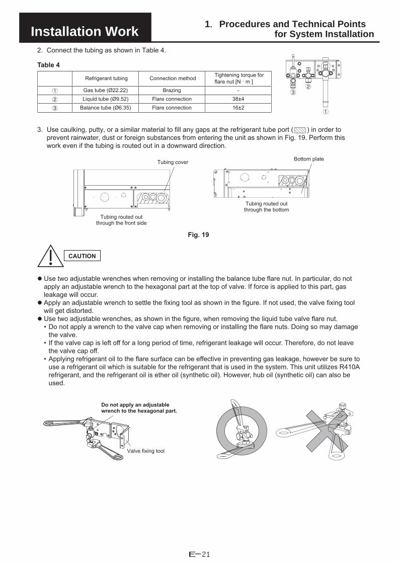
1.Procedures and Technical Pointsfor System InstallationInstallation Work
2. Connect the tubing as shown in Table 4.
Table 4
Refrigerant tubing Connection method Tightening torque for flare nut [N · m ]
1 Gas tube (Ø22.22) Brazing -
2 Liquid tube (Ø9.52) Flare connection 38±4
3 Balance tube (Ø6.35) Flare connection 16±2
3. Use caulking, putty, or a similar material to fill any gaps at the refrigerant tube port ( ) in order toprevent rainwater, dust or foreign substances from entering the unit as shown in Fig. 19. Perform thiswork even if the tubing is routed out in a downward direction.
Tubing cover
Tubing routed out through the front side
Bottom plate
Tubing routed out through the bottom
Fig. 19
CAUTION
Use two adjustable wrenches when removing or installing the balance tube flare nut. In particular, do notapply an adjustable wrench to the hexagonal part at the top of valve. If force is applied to this part, gasleakage will occur.
Apply an adjustable wrench to settle the fixing tool as shown in the figure. If not used, the valve fixing toolwill get distorted.
Use two adjustable wrenches, as shown in the figure, when removing the liquid tube valve flare nut.• Do not apply a wrench to the valve cap when removing or installing the flare nuts. Doing so may damage
the valve.• If the valve cap is left off for a long period of time, refrigerant leakage will occur. Therefore, do not leave
the valve cap off.• Applying refrigerant oil to the flare surface can be effective in preventing gas leakage, however be sure to
use a refrigerant oil which is suitable for the refrigerant that is used in the system. This unit utilizes R410Arefrigerant, and the refrigerant oil is ether oil (synthetic oil). However, hub oil (synthetic oil) can also beused.
Do not apply an adjustablewrench to the hexagonal part.
Valve fixing tool
1
32
E-21

1.Procedures and Technical Pointsfor System InstallationInstallation Work
3-4. Tubing airtightness test and vacuum application
An airtightness test is required for gas heat pump air conditioner as part of industry installation guidelines. Follow the procedure below to perform the test and confirm there is no leakage from any connections.
Connect the manifold gauge to service ports - on the gas tube, liquid tube and balance tube. Then connectthe nitrogen tank, vacuum pump, and other items as shown in Fig. 20.
Connect an R410A control valve (Schrader valve) at the service port for the shut-off valve.If an R410A control valve (Schrader valve) is not connected, it may cause a frost burn due to refrigerant leaking when the charge hose is removed.
Use nitrogen to raise the pressure to the airtightness test pressure (3.8 MPaG) and confirm that there is no leakage. Refrigerant leakage can cause suffocation and injury to nearby persons.
CAUTION
Container for adding compressor oil
Pressure reducing valve
Pressure gauge
Siphon tube
Weight scaleVacuum pump
Liquid tube
Balance tube
Gas tube
Refringerant container R410A
Nitr
ogen
Fig. 20
When checking for air/vacuum tightness, do so at all service ports at the same time. (With all the valves tothe outdoor units closed.)Always use nitrogen when performing air tightness checks.(Oxygen, carbon dioxide or refrigerant may not be used)When performing air tightness checks on the tubes between indoor/outdoor units, we recommend doing soon the tubes independently, prior to connecting outdoor units.
After the airtightness test is completed, apply vacuum of 667 Pa (-755 mmHg, 5 Torr) or below to theindoor unit and tubing.
Do not leave for a long period of time after the vacuum state has been reached.
There is a check valve at each service port.
E-22

1.Procedures and Technical Pointsfor System InstallationInstallation Work
3-5. Compressor oil charge• Add compressor oil (FV68S) when vacuuming.• Insert compressor oil (FV68S) from the gas tube side that was mounted for vacuuming, and perform
vacuuming from the liquid tube side.• After adding the specified amount of oil, close the valve on the gas tube side, and continue vacuuming.
Table 5
Type Added compressor oil (FV68S) amount (kg)
U-10MES2E8 (28.0 kW) 0.0U-20GES3E5 (56.0 kW) 3.1
• Perform before turning on the power of the indoor and outdoor units.The expansion valve of the indoor unit will be closed.
• If the power is already turned on, perform Test Run Settings “V open” ( ) in Test Run item 13 before adding the compressor oil.
3-6. Refrigerant chargeCalculation of amount of additional refrigerant charge• Table 7 shows the refrigerant charge at factory shipping time. Additional refrigerant must be added
according to the size and length of the tubing. If a water heat exchanger unit is installed, provide an additional refrigerant charge for the connecting line portion. (Use the values in Table 6 to calculate liquid tube size and length.)
Table 6 Quantity of additional refrigerant charge Table 7
Liquid tube size (mm) Additional charge quantity per meter (g/m) Type Quantity of refrigerant
charge when shipped (kg)Ø6.35 26 U-10MES2E8 (28.0 kW) 5.6Ø9.52 56 U-20GES3E5 (56.0 kW) 11.5Ø12.7 128Ø15.88 185Ø19.05 259Ø22.22 366
Required additional refrigerant charge (kg) =[456 × (A) + 366 × (B) + 259 × (C) + 185 × (D) + 128 × (E) + 56 × (F) + 26 × (G)] × 0.001 + Unit additional charge amount (H)
(A) = total length in meters of 25.4 mm diameter liquid tubing(B) = total length in meters of 22.22 mm diameter liquid tubing(C) = total length in meters of 19.05 mm diameter liquid tubing(D) = total length in meters of 15.88 mm diameter liquid tubing(E) = total length in meters of 12.7 mm diameter liquid tubing(F) = total length in meters of 9.52 mm diameter liquid tubing(G) = total length in meters of 6.35 mm diameter liquid tubing(H) = Unit additional charge amount (Table 8)
• If the total amount of refrigerant (Required additional refrigerant charge + Quantity of refrigerant chargewhen shipped) exceeds 80 kg, reduce the amount to 80 kg or less by changing the refrigerant tubing route.
• Be careful to charge accurately according to refrigerant weight.• Charging procedure
Evacuate the system, close the gauge manifold at the gas tube side to ensure that no refrigerant enters thegas tube side, then charge the system with liquid refrigerant at the liquid tube side. While charging, keep allvalves fully closed. The compressor can be damaged if liquid refrigerant is added at the gas tube side.
• If the system does not accept the predetermined quantity of refrigerant, fully open all valves and run thesystem (either heating or cooling). While the system is running, gradually add refrigerant at the low pressureside by slightly opening the valve on the cylinder just enough so that the liquid refrigerant is gasified as it issucked into the system. (This step is normally only needed when commissioning the system.)All outdoor unit valves should be fully open.
• When charging is completed, fully open all valves.• Avoid liquid back-flow when charging with R410A refrigerant by adding small amounts at a time.
Table 8
Type Unit additional charge amount (kg)
U-10MES2E8 (28.0 kW) 5.5
U-20GES3E5 (56.0 kW) 3.5
E-23

1.Procedures and Technical Pointsfor System InstallationInstallation Work
Thermal insulation (120°C or higher heat resistance)
Control cable
Gas tube
Duct (or similar) tape(for waterproofing)
Thermal insulation
Liquid tube
Fig. 21
3-7. Insulating the Refrigerant Tubing
Tubing Insulation● Standard selection of insulation material
Under the environment of the high temperature and high humidity, the surface of the insulation material is easy to become condensation. This will result in leakage and dew drop. Refer to the chart shown below when selecting the insulation material. In case that the ambient temperature and relative humidity are placed above the line of the insulation thickness, the condensation may occasionally make a dew drop on the surface of the insulation material. In this case, select the better insulation efficiency.
* However, since the condition will be differentdue to the sort of the insulation material and the environmental condition of the installation place, see the chart shown below as a reference when making a selection.
Standard selection of tubing insulation
Sort of insulation material Polyethylene heat resisting material
Upper limits of usage temperature Gas tubing : 120 °C or aboveOther tubing : 80 °C or above
Calculating condition
Thermal conductivity of insulation material 0.043 W/(m · K) (Average temperature 23 °C)
Refrigerant temperature 2 °C
• When charging with additional refrigerant, use liquid only.• R410A cylinders are colored gray with a pink top.• Check whether a siphon tube is present (indicated on the label at the
top of the cylinder).• Depending on refrigerant and system pressure, conventional
refrigerant (R22, R407C) equipment may or may not be compatiblewith R410A equipment, so care is needed.In particular, the gauge manifold used must be specifically designedfor R410A.
• Be sure to check the limiting density.• Refer to the section “4. OPENING THE SHUT-OFF VALVES” (→ page 25)
when the instructions call for fully opening all valves.
R410A cylinder
Pink
Siphon tube Liquid refrigerant
4010 20 30 40 50
50
60
70
80
90
100
0401 20 30 40 50 4010 20 30 40 50
50
60
70
80
90
100
50
60
70
80
90
100o6.35 o9.52 o12.7
Ambient temperature [°C] Ambient temperature [°C] Ambient temperature [°C]
Thickness 30mm Thickness
30mmThickness 30mm
Thickness 20mm
Thickness 20mm
Thickness 20mm
Thickness 10mm
Thickness 10mm Thickness
10mm
Am
bien
t rel
ativ
e hu
mid
ity [%
]
Am
bien
t rel
ativ
e hu
mid
ity [%
]
Am
bien
t rel
ativ
e hu
mid
ity [%
]
E-24

1.Procedures and Technical Pointsfor System InstallationInstallation Work
Sealer
Vinyl clampsFlare nut
o38.1 o41.28
4010 20 30 40 50 10 20 30 40 50
50
60
70
80
90
100
40
50
60
70
80
90
100 100
90
80
70
60
50
4010 20 30 40 50
o44.45
100
90
80
70
60
50
4010 20 30 40 50
o50.8Ambient temperature [°C]
Ambient temperature [°C]
Ambient temperature [°C]
Thickness 30mm
Thickness 30mm
Thickness 30mm
Thickness 20mm
Thickness 20mm
Thickness
Thickness 10mm
Thickness 10mm
Thickness 10mm
Am
bien
t rel
ativ
e hu
mid
ity [%
]A
mbi
ent r
elat
ive
hum
idity
[%]
Am
bien
t rel
ativ
e hu
mid
ity [%
]
Ambient temperature [°C]
20mm
Thickness 10mm
Am
bien
t rel
ativ
e hu
mid
ity [%
]
0401 20 30 40 50
4010 20 30 40 50
0401 20 30 40 50
4010 20 30 40 50 0
401 20 30 40 50
4010 20 30 40 50
50
60
70
80
90
100
50
60
70
80
90
100
50
60
70
80
90
100
50
60
70
80
90
100
50
60
70
80
90
100
50
60
70
80
90
100
o15.88
o25.4
o19.05
o28.58
o22.22
o31.75
Ambient temperature [°C] Ambient temperature [°C] Ambient temperature [°C]
Thickness 30mm
Thickness 30mm
Thickness 30mm
Thickness 20mm
Thickness 20mm
Thickness 20mm
Thickness 10mm
Thickness 10mm
Thickness 10mm
Am
bien
t rel
ativ
e hu
mid
ity [%
]
Am
bien
t rel
ativ
e hu
mid
ity [%
]
Am
bien
t rel
ativ
e hu
mid
ity [%
]
E-25
Thickness
Thickness 30mm
20mm

1.Procedures and Technical Pointsfor System InstallationInstallation Work
4. OPENING THE SHUT-OFF VALVES
1. Remove the cap.
2. Slowly and securely turn the tab to the left(counterclockwise) 90 degrees.The valve is fully open when the tab hasbeen rotated 90 degrees (when it contactsthe stopper). Do not forcefully attempt toturn the tab past this point.The gas tube shut-off valve of theU-10MES2E8 outdoor unit is fully openedby turning it fully to the left, using ahexagonal wrench (8 mm across faces).The liquid tube shut-off valve is fullyopened by turning it fully to the left, using ahexagonal wrench (4 mm across faces).
Be sure to open the shut-off valve all the way.
Gas tube, Liquid tube
Ball valves are used for the shut-off valves on the outdoor units. Each can be opened and closed by rotating the tab 90 degrees.Follow the procedure below to securely open the valves. Rotate the tab 90 degrees.
Fully closed Fully open
Fully closed Fully open
Balance tube
Fig. 22 Rotating the Tab3. Reattach and tighten the cap.
Table 9Unit type Tube Cap tightening torque [N · m]
U-20GES3E5Gas
LiquidBalance
30±330±3
22.5±2.5
U-10MES2E8Gas
LiquidBalance
50±324.5±3.922.5±2.5
5. HOT WATER PIPING WORK OF THE GHP OUTDOOR UNITPrecautions on Hot Water Piping Work
CAUTION
• The allowable pressure for the hot water piping in the outdoor unit is 0.7 MPa.• Attach water release valves and air release valves to the hot water piping at the appropriate locations. If air
becomes mixed with the fluid in the pipe, this could result in noise, corrosion, or reduced performance.• Use a hot water circulation rate in the range from 35ℓ/min to 51ℓ/min.
If a circulation rate outside this range is used, this could result in a breakdown or air blockage in the pipedue to corrosion or freezing of the heat exchanger.
• Be sure to fully perform the heat-retention work for DHW piping.Failure to provide adequate heat retention will result in heat loss. This could also result in damage due tofreezing during periods of extreme cold.
• Attach the pump for DHW to the inlet piping side for DHW.• For the DHW piping, select pipes with a connection port diameter of 27.2 mm or larger, and pay careful
attention to the flow rate. Route the piping by minimizing bends and pipe resistance, and use union jointsand similar parts near the outdoor unit so that the outdoor unit can be easily separated.
• Attach a strainer (80 mesh or higher) to the outdoor unit inlet pipe for protecting the DHW heat exchangerin the outdoor unit. Also attach valves before and after the strainer and at the outlet pipe for maintenanceand servicing.
• Attach a temperature gauge and pressure gauge to the piping. These are needed for conducting checks ofthe operation status and for maintenance.
E-26

1.Procedures and Technical Pointsfor System InstallationInstallation Work
• During test operation, attach a water temperature gauge and flow rate adjustment valve to the water pipingto enable adjusting of the hot water flow rate while watching the water temperature gauge. Also, do nottouch the adjustment valve once adjustment is complete.
• Attach pipe support fittings to the DHW pipes at appropriate locations so that no excessive loads areapplied to the outdoor unit.
• Select the pump for DHW based on the water pressure loss characteristics shown in the table below .
0 35 40 45 50 55 60 650 12.5 16.3 19.7 24.6 29.7 34.8 40.6
0
10
20
30
40
50
30 35 40 45 50 55 60
Pres
sure
loss
[kPa
]
Circulation rate [ℓ/min]
Fig. 23 Characteristic of Hot water pressure loss
Hot Water Pipe Cleaning and Air Bleeding• Be sure to always perform cleaning of the pipe system for removing dust, cutting debris, and other objects
inside the pipes and removing flux debris inside the pipes which can cause deterioration of antifreeze solution and generation of gel compounds.
CAUTION
Be sure to fully bleed the air. If any air remains in the pipes, water will not flow, and the pipes cannot be cleaned.
Antifreeze Solution and Rust Prevention
CAUTION
• Failure to use antifreeze solution can cause damage to the surrounding devices and pipes due to freezingand rust.
• Antifreeze solution is injected to preventing freezing of the circulating water of this system. Be sure to injectpure antifreeze solution for preventing rust and freezing.
• Set this antifreeze solution to a concentration of 35% to 55% for fully realizing the solution's freezingprevention and rust prevention effects. Dilute using tap water (treated water) that meets the water qualitystandards.
• Use a concentration for the antifreeze solution that is 10°C lower than the annual minimum outdoortemperature.Table 10 Antifreeze solution performance table
Concentration (by volume) 35% 40% 45% 50% 55%Specific gravity (20°C) 1.056 1.063 1.071 1.078 1.085Freezing temperature -20°C -24°C -30°C -35°C -42°C
6. AFTER INSTALLATION IS COMPLETEDRecord the actual length of refrigerant tubing and the amount of refrigerant charge.
With the GHP outdoor unit, the “label for showing the actual length of refrigerant tubing and the amountof refrigerant charged” is provided. Enter the details in the designated spaces, and apply the label to theinside of the electrical box panel, at the top.
This will be needed for subsequent maintenance.Be sure to enter this information and apply the label.
E-27

1.Procedures and Technical Pointsfor System InstallationInstallation Work
7. ENGINE REPLACEMENT PATHWAYDuring installation, consider the engine external dimensions listed at right and ensure that there is a
sufficient pathway for moving the engine.This pathway will be required should the engine need to be replaced.Table 11
Engine external dimensions (mm)Package weight (kg)
Width Depth Height670 (810) 640 (760) 650 (700) 170
* Figures in parentheses are the external dimensions of the wood shipping crate
8. USING A VIBRATION-RESISTANT FRAMEA vibration-reduction frame must be used if the unit is installed in locations where noise and vibration can
be a problem, such as on rooftops above living spaces or conference rooms. If a vibration-resistant frameis used, be sure to install steady braces or other support, and take measures to prevent applying excessiveforce to the refrigerant tubing.
Refer to the instruction manual supplied with the vibration-resistant frame when installing the frame.
(1) When Using Singular Frames
When anchoring the refrigerant tubing, be sure to set the tubing anchor for each outdoor unit at least 1.5 maway from the respective unit (as shown in Fig. 24-1).
When installing a ball valve, be sure to install them within area B. (Installation in area A is prohibited.)
Ball valve (provided by installer)
Ball valve (provided by installer)
Liquid tube (narrow)
Gas tube (wide)(At least 1.5 m)
(At least 1.5 m)
Tubing anchor
Tubing anchor
Fig. 24-1
Liquid tube
Tubing anchor
Gas tube
Fig. 24-2
When using single-type vibration-resistant frames, never install tubing in the manner shown at the right. Doing so puts excessive weight on the entire tubing installation and may result tube damage.
CAUTION
E-28

1.Procedures and Technical Pointsfor System InstallationInstallation Work
9.SUPPLEMENT(1)Attention on handling refrigerant piping
In GHP and EHP outdoor unit, the direction of the connection port of the refrigerant pipe is different, so handling the refrigerant piping as follows depending on the orientation of unit installation.
GHP: Piping connection port is on the rear side (The logo is on rear side panel)
EHP: Piping connection port is on the front side (The logo is on front side panel)
●When aligning the front of the outdoor unit (when not using vibration resistant frame)
refrigerant piping direction: right refrigerant piping direction: left
EHP right side
EHP left side
● Do not piping in front of the GHP unit. It will interfere with maintenance.
●Piping and wiring within 300 mm of the EHP unit will interfere with maintenance.
● In the case of passing refrigerant piping of EHP between GHP unit and EHP unit, leave a gap of 200mmor more for piping racking.
●When aligning piping takeout direction (when not using vibration resistant frame)
refrigerant piping direction: right refrigerant piping direction: left
EHP right side
EHP left side
●Piping and wiring within 300 mm of the EHP unit will interfere with maintenance.
GHP
EHP
GHP EHP
GHP
EHP
300mm or more
300mm or more 300mm or more
200mm or more 200mm or more
300mm or more
front front front front
front front front front
GHP EHP
front rear
rear front
front rear
rear front
E-29

1.Procedures and Technical Pointsfor System InstallationInstallation Work
●When using vibration resistant frame※For GHP only when using the vibration resistant frame (EHP is a vibration resistant mat) or when using the
vibration resistant frame for both GHP and EHP, please follow the following.
The piping junction of GHP and EHP should be located 1.5 m or more away from the refrigerant piping outlet of GHP, and fix the GHP refrigerant piping at a distance of 1.5 m or more for GHP outdoor unit. Tubing anchor and pipe branch within 1.5 m cause piping damage due to vibration.
refrigerant piping direction: right refrigerant piping direction: left
EHP right side
EHP left side
● Do not piping in front of the GHP unit. It will interfere with maintenance.
●Piping and wiring within 300 mm of the EHP unit will interfere with maintenance.
●In the case of passing refrigerant piping of EHP between GHP unit and EHP unit, leave a gap of 200 mm ormore for piping racking.
300mm or more
1.5m or more
1.5m or more
GHP EHP
300mm or more 1.5m or more
1.5m or more
1.5m or more
300mm or more
1.5m or more
200mm or more200mm or more
GHP EHP
300mm or more
1.5m or more
1.5m or more
Tubing anchor
Pipe branch
front rear
rear front
front front
E-30

1.Procedures and Technical Pointsfor System InstallationInstallation Work
(2) Points regarding branch pipe work
• CZ-P160BK2
1. Accompanying PartsCheck the contents of your distribution joint kit.
2. Distribution Joint Kits (with insulation)
Parts Kit 1 Parts Kit 2
• Size of connection point on each part (Shown are inside diameters of tubing)
Size Part A Part B Part C Part D Part Emm Ø19.05 Ø15.88 Ø12.7 Ø9.52 Ø6.35Inch 3/4 5/8 1/2 3/8 1/4
3. Making Branch Connections• For branching tubes, install 150mm or larger (including reducer) straight tubing up to the point where
the tube branches (or after the point where the tubes join together).• Using a tube cutter, cut the joints at the diameter required to match the outside diameter of the tubing
you are connecting. (This is usually done at the installation site.) The tube diameter depends on thetotal capacity of the indoor unit.Note that you do not have to cut the joints if it already matches the tubing end size. For size selectionof the tube diameter, refer to the installation instructions provided with the outdoor unit.
NoteAvoid forceful cutting that may harm the shape of the joints or tubing. (Inserting the tubing will not be possible if the tube shape is not proper.)
• Cut off as far away from stopper as possible.• After cutting the joints, be sure to remove burrs on the inside
of the joints. (If the joints have been squashed or dented badly,reshaped them using a tube spreader.)
• Make sure there is no dirt or other foreign substances insidethe distribution joint.
• The distribution joint can be either horizontal or vertical. Inthe case of horizontal, the L-shaped tubing must be slantedslightly upward (15° to 30°).
• When brazing, replace air inside the tube with nitrogen gas to prevent copper oxide from forming.• To insulate the distribution joint, use the supplied tubing insulation.
(If using insulation other than that supplied, make sure that its heat resistance is 120°C or higher.)• For additional details, refer to the installation instructions provided with the outdoor unit.
• When brazing a pipe E to thereducer of which middle pipe innerdimension is D as shown abovechart, cut the middle pipe as longas possible as that the pipe E canbe inserted.
E-31

1.Procedures and Technical Pointsfor System InstallationInstallation Work
• CZ-P680BK2
1. Accompanying PartsCheck the contents of your distribution joint kit.
2. Distribution Joint Kits (with insulation)Parts Kit 1 Parts Kit 2
• Size of connection point on each part (Shown are inside diameters of tubing)Size Part A Part B Part C Part D Part E Part F Part G Part Hmm Ø28.58 Ø25.4 Ø22.22 Ø19.05 Ø15.88 Ø12.7 Ø9.52 Ø6.35Inch 1-1/8 1 7/8 3/4 5/8 1/2 3/8 1/4
3. Making Branch Connections• For branching tubes, install 150mm or larger (including reducer) straight tubing up to the point where
the tube branches (or after the point where the tubes join together).• Using a tube cutter, cut the joints at the diameter required to match the outside diameter of the tubing
you are connecting. (This is usually done at the installation site.) The tube diameter depends on thetotal capacity of the indoor unit.Note that you do not have to cut the joints if it already matches the tubing end size. For size selectionof the tube diameter, refer to the installation instructions provided with the outdoor unit.
NoteAvoid forceful cutting that may harm the shape of the joints or tubing. (Inserting the tubing will not be possible if the tube shape is not proper.)
• Cut off as far away from stopper as possible.• After cutting the joints, be sure to remove burrs on the inside
of the joints. (If the joints have been squashed or dented badly,reshaped them using a tube spreader.)
• Make sure there is no dirt or other foreign substances inside the distribution joint.• The distribution joint can be either horizontal or vertical. In the case of horizontal, the L-shaped tubing
must be slanted slightly upward (15° to 30°).
• When brazing, replace air inside the tube with nitrogen gas to prevent copper oxide from forming.• To insulate the distribution joint, use the supplied tubing insulation.
(If using insulation other than that supplied, make sure that its heat resistance is 120°C or higher.)• For additional details, refer to the installation instructions provided with the outdoor unit.
Part Name Parts Kit 1 Parts Kit 2Distribution Joints 1 1
Insulations 1 1Reducing Joints 5 3
E-32

Installation Work• CZ-P1350BK2
1. Accompanying PartsCheck the contents of your distribution joint kit.
2. Distribution Joint Kits (with insulation)Parts Kit 1 Parts Kit 2
• Size of connection point on each part (Shown are inside diameters of tubing)Size Part A Part B Part C Part D Part E Part F Part G Part H Part I Part Jmm Ø38.1 Ø31.75 Ø28.58 Ø25.4 Ø22.22 Ø19.05 Ø15.88 Ø12.7 Ø9.52 Ø6.35Inch 1-1/2 1-1/4 1-1/8 1 7/8 3/4 5/8 1/2 3/8 1/4
3. Making Branch Connections• For branching tubes, install 150mm or larger (including reducer) straight tubing up to the point where
the tube branches (or after the point where the tubes join together).• Using a tube cutter, cut the joints at the diameter required to match the outside diameter of the tubing
you are connecting. (This is usually done at the installation site.) The tube diameter depends on thetotal capacity of the indoor unit.Note that you do not have to cut the joints if it already matches the tubing end size. For size selectionof the tube diameter, refer to the installation instructions provided with the outdoor unit.
NoteAvoid forceful cutting that may harm the shape of the joints or tubing. (Inserting the tubing will not be possible if the tube shape is not proper.)
• Cut off as far away from stopper as possible.• After cutting the joints, be sure to remove burrs
on the inside of the joints. (If the joints have beensquashed or dented badly, reshaped them usinga tube spreader.)
• Make sure there is no dirt or other foreignsubstances inside the distribution joint.
• When brazing, replace air inside the tube with nitrogen gas to prevent copper oxide from forming.• To insulate the distribution joint, use the supplied tubing insulation.
(If using insulation other than that supplied, make sure that its heat resistance is 120°C or higher.)• For additional details, refer to the installation instructions provided with the outdoor unit.
Part Name Parts Kit 1 Parts Kit 2Distribution Joints 1 1
Insulations 1 1Reducing Joints 7 4
1.Procedures and Technical Pointsfor System Installation
E-33

Example:
A
C B C D E D E
E
G
E
H
HG
GH
B
B
CDE
FF
F
175
135
110
97
114
72
Table 2 Size of connection point on each part (Shown are inside diameters of tubing)
Size Part A Part B Part C Part D Part E Part F Part G Part H
mm ø31.75 ø28.58 ø25.4 ø22.22 ø19.05 ø15.88 ø12.7 ø9.52
Example:
A AB
E F
F
H
F
I
I H
HI
GG
GB
B
175
135
110
97
C
C
D
D
114
72
E
F
* If the tube diameter is more than ø38.1, use field-supply reducer.
Table 3 Size of connection point on each part (Shown are inside diameters of tubing)
Size Part A Part B Part C Part D Part E Part F Part G Part H Part I
mm ø38.1 ø31.75 ø28.58 ø25.4 ø22.22 ø19.05 ø15.88 ø12.7 ø9.52
Unit: mm
Unit: mm
Distribution Joint
Reducing JointsInsulation
Distribution Joint
Reducing Joints
Insulation
Distribution Joint
Reducing Joints
Insulation
Distribution Joint
Reducing Joints
Insulation
Gas tube
Gas tube
Liquid tube
Liquid tube
Installation Work 1.Procedures and Technical Pointsfor System Installation
•
•
CZ-P680P
CZ-P1350P
E-34

2.INSTALLATION INSTRUCTIONSAir ConditionerInstallation Work
Model No.
Outdoor Units
Type Outdoor Unit TypeRated Capacity
10 HP
MES2 2WAY System U-10MES2E8
• o be connecting Indoor Unit
Indoor Units
Type Indoor Unit TypeRated Capacity
22 28 36 45 56 60D1 1-Way Cassette S-28MD1E5 S-36MD1E5 S-45MD1E5 S-56MD1E5
L1 2-Way Cassette S-22ML1E5 S-28ML1E5 S-36ML1E5 S-45ML1E5 S-56ML1E5
U2 4-Way Cassette S-22MU2E5A S-28MU2E5A S-36MU2E5A S-45MU2E5A S-56MU2E5A S-60MU2E5A
Y2 4-Way Cassette 60 × 60 S-22MY2E5A S-28MY2E5A S-36MY2E5A S-45MY2E5A S-56MY2E5A
K2 Wall-Mounted S-22MK2E5A S-28MK2E5A S-36MK2E5A S-45MK2E5A S-56MK2E5A
T2 Ceiling S-36MT2E5A S-45MT2E5A S-56MT2E5A
F2 Low Silhouette Ducted S-22MF2E5A S-28MF2E5A S-36MF2E5A S-45MF2E5A S-56MF2E5A S-60MF2E5A
M1 Slim Low Static Ducted S-22MM1E5A S-28MM1E5A S-36MM1E5A S-45MM1E5A S-56MM1E5A
P1 Floor Standing S-22MP1E5 S-28MP1E5 S-36MP1E5 S-45MP1E5 S-56MP1E5
R1 Concealed Floor Standing S-22MR1E5 S-28MR1E5 S-36MR1E5 S-45MR1E5 S-56MR1E5
Type Indoor Unit TypeRated Capacity
71 / 73 90 106 140 160D1 1-Way Cassette S-73MD1E5
L1 2-Way Cassette S-73ML1E5
U2 4-Way Cassette S-73MU2E5A S-90MU2E5A S-106MU2E5A S-140MU2E5A S-160MU2E5A
K2 Wall-Mounted S-73MK2E5A S-106MK2E5A
T2 Ceiling S-73MT2E5A S-106MT2E5A S-140MT2E5A
F2 Low Silhouette Ducted S-73MF2E5A S-90MF2E5A S-106MF2E5A S-140MF2E5A S-160MF2E5A
P1 Floor Standing S-71MP1E5
R1 Concealed Floor Standing S-71MR1E5
Type Indoor Unit TypeRated Capacity224 280
E2 High Static Pressure Ducted S-224ME2E5 S-280ME2E5
Read through the Installation Instructions before you proceed with the installation. In particular, you will need to read under the “ IMPORTANT ! ” section at the top of the page.
The manuals “Procedures and Technical points for System Installation”, “Procedures and Technical Points for Electrical Wiring Work (Outdoors)” and “Procedures and Technical Points for Test Run” are also attached for the U-20GES3E5 outdoor unit. Be sure to read this manual in conjunction with these service manuals.
E-35

2.INSTALLATION INSTRUCTIONSAir ConditionerInstallation Work
IMPORTANT!Please Read Before StartingThis air conditioner must be installed by the sales dealer or installer.This information is provided for use only by authorized persons.
For safe installation and trouble-free operation, you must:● Carefully read this instruction booklet before beginning.● Follow each installation or repair step exactly as shown.● This air conditioner shall be installed in accordance with
National Wiring Regulations.● This product is intended for professional use.
Permission from the power supplier is required wheninstalling the U-10MES2E8 outdoor units that areconnected to a 16 A distribution network.
● The product meets the technical requirements ofEN/IEC 61000-3-3.
● Pay close attention to all warning and caution noticesgiven in this manual.
WARNING
This symbol refers to a hazard or unsafe practice which can result in severe personal injury or death.
CAUTION
This symbol refers to a hazard or unsafe practice which can result in personal injury or product or property damage.
If Necessary, Get HelpThese instructions are all you need for most installation sites and maintenance conditions. If you require help for a special problem, contact our sales/service outlet or your certified dealer for additional instructions.
In Case of Improper InstallationThe manufacturer shall in no way be responsible for improper installation or maintenance service, including failure to follow the instructions in this document.
SPECIAL PRECAUTIONS
WARNING When Wiring
ELECTRICAL SHOCK CAN CAUSE SEVERE PERSONAL INJURY OR DEATH. ONLY A QUALIFIED, EXPERIENCED ELECTRICIAN SHOULD ATTEMPT TO WIRE THIS SYSTEM.
• Do not supply power to the unit untilall wiring and tubing are completed orreconnected and checked.
• Highly dangerous electrical voltages areused in this system. Carefully refer to the wiring diagram and these instructionswhen wiring. Improper connectionsand inadequate grounding can causeaccidental injury or death.
• Connect all wiring tightly. Loose wiringmay cause overheating at connectionpoints and a possible fire hazard.
• Provide a power outlet to be usedexclusively for each unit.
• ELCB must be incorporated in thefixed wiring. Circuit breaker must beincorporated in the fixed wiring inaccordance with the wiring regulations.
Circuit breaker
U-10MES2E8 25 A
• Provide a power outlet exclusively foreach unit, and full disconnection meanshaving a contact separation by 3 mmin all poles must be incorporated in thefixed wiring in accordance with the wiringrules.
• To prevent possible hazards frominsulation failure, the unit must begrounded.
• This equipment is strongly recommendedto be installed with Earth LeakageCircuit Breaker (ELCB) or ResidualCurrent Device (RCD). Otherwise, it maycause electrical shock and fire in caseof equipment breakdown or insulationbreakdown.
E-36

2.INSTALLATION INSTRUCTIONSAir ConditionerInstallation Work
When Connecting Refrigerant TubingPay particular attention to refrigerant leakages.
WARNING
• When performing piping work,do not mix air except forspecified refrigerant (R410A)in refrigeration cycle. It causescapacity down, and risk ofexplosion and injury due to hightension inside the refrigerantcycle.
• If the refrigerant comes in contactwith a flame, it produces a toxicgas.
• Do not add or replace refrigerantother than specified type. It maycause product damage, burst andinjury, etc.
• Ventilate the room immediately, in theevent that is refrigerant gas leaks duringthe installation. Be careful not to allowcontact of the refrigerant gas with aflame as this will cause the generationof toxic gas.
• Keep all tubing runs as short aspossible.
• Apply refrigerant lubricant to thematching surfaces of the flare and uniontubes before connecting them, thentighten the nut with a torque wrench fora leak-free connection.
• Check carefully for leaks before startingthe test run.
• Do not leak refrigerant while piping workfor an installation or re-installation, andwhile repairing refrigeration parts.Handle liquid refrigerant carefully as itmay cause frostbite.
When Transporting
• It may need two or more people to carryout the installation work.
• Be careful when picking up and movingthe indoor and outdoor units. Get apartner to help, and bend your kneeswhen lifting to reduce strain on yourback. Sharp edges or thin aluminumfins on the air conditioner can cut yourfingers.
When Installing…
Select an installation location which is rigid and strong enough to support or hold the unit, and select a location for easy maintenance.…In a RoomProperly insulate any tubing run inside a room to prevent “sweating” that can cause dripping and water damage to walls and floors.
CAUTIONKeep the fire alarm and the air outlet at least 1.5 m away from the unit.
…In Moist or Uneven LocationsUse a raised concrete pad or concrete blocks to provide a solid, level foundation for the outdoor unit. This prevents water damage and abnormal vibration.
…In an Area with High WindsSecurely anchor the outdoor unit down with bolts and a metal frame. Provide a suitable air baffle.
…In a Snowy Area (for Heat Pump-type Systems)Install the outdoor unit on a raised platform that is higher than drifting snow. Provide snow vents.
E-37

2.INSTALLATION INSTRUCTIONSAir ConditionerInstallation Work
When Servicing
• Turn the power OFF at the mainpower box (mains), wait at least 10minutes until it is discharged, thenopen the unit to check or repairelectrical parts and wiring.
• Keep your fingers and clothing away fromany moving parts.
• Clean up the site after you finish,remembering to check that no metalscraps or bits of wiring have been leftinside the unit.
WARNING• This product must not be
modified or disassembled underany circumstances. Modified ordisassembled unit may cause fire,electric shock or injury.
• Do not clean inside the indoor andoutdoor units by users. Engageauthorized dealer or specialist forcleaning.
• In case of malfunction of thisappliance, do not repair by yourself.Contact to the sales dealer orservice dealer for a repair anddisposal.
CAUTION• Ventilate any enclosed areas when
installing or testing the refrigerationsystem. Leaked refrigerant gas,on contact with fire or heat, canproduce dangerously toxic gas.
• Confirm after installation that norefrigerant gas is leaking. If the gascomes in contact with a burningstove, gas water heater, electricroom heater or other heat source,it can cause the generation of toxicgas.
Others
When disposal of the product, comply with national regulations.
CAUTION
• Do not touch the air inlet orthe sharp aluminum fins of theoutdoor unit. You may getinjured.
• Do not sit or step on the unit,you may fall down accidentally.
• Do not stick any object into theFAN CASE.You may be injured and the unitmay be damaged.
NOTICEThe English text is the original instructions. Other languages are translations of the original instructions.
E-38

2.INSTALLATION INSTRUCTIONSAir ConditionerInstallation Work
2. The standards for minimum room volume are as follows.
(1) No partition (shaded portion)
(2) When there is an effective opening with the adjacent room for ventilation of leaking refrigerant gas (opening without a door, or an opening 0.15% or larger than the respective floor spaces at the top or bottom of the door).
(3) If an indoor unit is installed in each partitioned room and the refrigerant tubing is interconnected, the smallest room of course becomes the object. But when mechanical ventilation is installed interlocked with a gas leakage detector in the smallest room where the density limit is exceeded, the volume of the next smallest room becomes the object.
3. The minimum indoor floor space compared with theamount of refrigerant is roughly as follows: (When theceiling is 2.7 m high)
20100 30 40 60 70 80 90 10050
m2 m3
40.5
54.0
27.0
13.5
0.0
67.5
81.0
94.5
108.0
121.5
135.0
148.5
162.0
175.5
189.0
202.5
216.0
15
10
5
0
20
25
30
35
40
45
50
55
60
65
70
75
80
229.585
kgTotal amount of refrigerant
Range below the density limit of 0.44 kg/m³(Countermeasures notnot need
angeRange aboveRdensity limit of 0.44 kg/m³(Countermeasures needed)
Min
. ind
oor
volu
me
Min
. ind
oor
floor
are
a(w
hen
the
ceili
ng is
2.7
m h
igh)
Check of Density LimitCheck the amount of refrigerant in the system and floor space of the room according to the legislation on refrigerant drainage. If there is no applicable legislation, follow the standards described below.
The room in which the air conditioner is to be installed requires a design that in the event of refrigerant gas leaking out, its density will not exceed a set limit.
The refrigerant (R410A), which is used in the air conditioner, is safe, without the toxicity or combustibility of ammonia, and is not restricted by laws imposed to protect the ozone layer. However, since it contains more than air, it poses the risk of suffocation if its density should rise excessively. Suffocation from leakage of refrigerant is almost non-existent. With the recent increase in the number of high density buildings, however, the installation of multi air conditioner systems is on the increase because of the need for effective use of floor space, individual control, energy conservation by curtailing heat and carrying power, etc. Most importantly, the multi air conditioner system is able to replenish a large amount of refrigerant compared to conventional individual air conditioners. If a single unit of the multi air conditioner system is to be installed in a small room, select a suitable model and installation procedure so that if the refrigerant accidentally leaks out, its density does not reach the limit (and in the event of an emergency, measures can be made before injury can occur).In a room where the density may exceed the limit, create an opening with adjacent rooms, or install mechanical ventilation combined with a gas leak detection device. The density is as given below.
Total amount of refrigerant (kg)
Min. volume of the indoor unit installed room (m3)
< Density limit (kg/m3)
The density limit of refrigerant which is used in multi air conditioners is 0.44 kg/m3 (ISO 5149).
NOTE
1. If there are 2 or more refrigerating systems in a singlerefrigerating device, the amount of refrigerant should be ascharged in each independent device.
For the amount of charge in this example:
The possible amount of leaked refrigerant gas in rooms A, B and C is 10 kg.The possible amount of leaked refrigerant gas in rooms D, E and F is 15 kg.
e.g., charge.amount (10 kg)
Indoor unit
Outdoor unit
e.e.g., chargamount (15 kg)
Room A Room B Room C Room D Room E Room F
Outdoor unit
Refrigerant tubing
Indoor unit
Mechanical ventilation device – Gas leak detector
Refrigerant tubing
Outdoor unit
Indoor unitVery small room
Small room
Medium room
Large room
E-39

2.INSTALLATION INSTRUCTIONSAir ConditionerInstallation Work
Precautions for Installation Using New Refrigerant1.. Care regarding tubi
1-1. Process tubing● Material: Use seamless phosphorous deoxidized copper tube for refrigeration. Wall thickness shall comply with the applicable
legislation. The minimal wall thickness must be in accordance with the table below. For tubes of ø22.22 or larger, use the material oftemper 1/2H or H (Hard copper tube). Do not bend the hard copper tube.
● Tubing size: Be sure to use the sizes indicated in the table below.
● Use a tube cutter when cutting the tubing, and be sure to remove any flash. This also applies to distribution joints (optional).
● When bending tubing, use a bending radius that is 4 times the outer diameter of the tubing or larger.
CAUTIONUse sufficient care in handling the tubing. Seal the tubing ends with caps or tape to prevent dirt, moisture, or other foreign substances from entering. These substances can result in system malfunction.
Unit: mm
Material Temper - O (Soft copper tube)
Copper tubeOuter diameter 6.35 9.52 12.7 15.88 19.05
Wall thickness 0.8 0.8 0.8 1.0 1.2
Unit: mm
Material Temper - 1/2 H, H (Hard copper tube)
Copper tubeOuter diameter 22.22 25.4 28.58 31.75 38.1 41.28 44.45
Wall thickness 1.0 1.0 1.0 1.1 over 1.35 over 1.45 over 1.55
1-2. Prevent impurities including water, dust and oxide from entering the tubing. Impurities can cause R410A refrigerant deterioration and compressor defects. Due to the features of the refrigerant and refrigerating machine oil, the prevention of water and other impurities becomes more important than ever.
2. Be sure to recharge the refrigerant only in liquid form.
2-1. Since R410A is a non-azeotrope, recharging the refrigerant in gas form can lower performance and cause defects in the unit.
2-2. Since refrigerant composition changes and performance decreases when gas leaks, collect the remaining refrigerant and recharge the required total amount of new refrigerant after fixing the leak.
3. Different tools required
3-1. Tool specifications have been changed due to the characteristics of R410A.
Some tools for R22- and R407C-type refrigerant systems cannot be used.
Item New tool?R407C tools compatible with R410A?
RemarksManifold gauge
Manifold gauge Yes No Types of refrigerant, refrigerating machine oil, and pressure gauge are different.
Charge hose Yes No To resist higher pressure, material must be changed.
Vacuum pump Yes Yes Use a conventional vacuum pump if it is equipped with a check valve. If it has no check valve, purchase and attach a vacuum pump adapter.
Leak detector Yes No Leak detectors for CFC and HCFC that react to chlorine do not function because R410A contains no chlorine. Leak detectors for HFC134a can be used for R410A.
Vacuum pump
OutletInlet
Flaring oil Yes No For systems that use R22, apply mineral oil (Suniso oil) to the flare nuts on the tubing to prevent refrigerant leakage. For machines that use R407C or R410A, apply synthetic oil (ether oil) to the flare nuts.
* Using tools for R22 and R407C and new tools for R410A toge her can cause defects.
3-2. Use R410A exclusive cylinder only.Single-outlet valve (with siphon tube) Liquid refrigerant should be recharged with the cylinder standing on end as shown.
Valve
Liquid
E-40

2.INSTALLATION INSTRUCTIONSAir ConditionerInstallation Work
4
5 67
This product contains fluorinated greenhouse gases.CO2 equivalent amount is shown in “CO2 eq.”
1 2
1 000
“CO2 eq.”1 +( ) x 2 3
11 kg
2 2kg
1 2 3kg
8ton
R410AGWP : 2088 3
Important Information Regarding The Refrigerant UsedThis product contains fluorinated greenhouse gases. Do not vent gases into the atmosphere.
Refrigerant type: R410A
GWP(1)
value: 2088(1)
GWP = global warming potential
Periodical inspections for refrigerant leaks may be required depending on European or local legislation.Please contact your local dealer for more information.
Please fill in with indelible ink,
■ 1: the factory refrigerant charge of the product
■ 2: the additional refrigerant amount charged in the field
■ 1 + 2: the total refrigerant charge
■ (1 + 2) x 3/1000: CO2 equivalent in tons; multiply the total refrigerant charge by GWP value, then divided by 1000.
on the refrigerant charge label supplied with the product.
The filled out label must be adhered in the proximity of the product charging port (e.g. onto the inside of the service cover).
1.. Factory refrigerant charge of the product: see unit nam plate. Additional refrigerant amount charged in the fie2.
3.. Total refrigerant char. Contains fluorinated greenhouse gas4.
5.. Outdoor un6.. Refrigerant cylinder and manifold for chargi7.. GWP (global warming potential) of the refrigerant used in his product8.. 2 equivalent of fluorinated greenhouse gases contained in this product
* English text printed on this label is original. Eaclanguage label will be sealed on this original text.
E-41

2.INSTALLATION INSTRUCTIONSAir ConditionerInstallation Work
1. GENERALThis booklet briefly outlines where and how to install the air conditioning system. Please read over the entire set of instructions for the outdoor unit and make sure all accessory parts listed are with the system before beginning.
1-1. Tools Required for Installation (not supplied)1. Flathead screwdriver
2. Phillips head screwdriver
3. Knife or wire stripper
4. Tape measure
5. Carpenter’s level
6. Sabre saw or keyhole saw
7. Hacksaw
8. Core bits
9. Hammer
10. Drill
11. Tube cutter
12. Tube flaring tool
13. Torque wrench
14. Adjustable wrench
15. Reamer (for deburring)
16. Hexagonal wrench (4 mm and 5 mm)
17. Pliers
18. Cutting pliers
1-2. Accessories Supplied with Outdoor Unit
1-3. Type of Copper Tube and Insulation MaterialIf you wish to purchase these materials separately from a local source, you will need:
1. Deoxidized annealed copper tube for refrigerant tubing.
2. Foamed polyethylene insulation for copper tubes asrequired to precise length of tubing. See the section“5-3. Insulating the Refrigerant Tubing” for details.
3. Use insulated copper wire for field wiring. Wire size varieswith the total length of wiring.See the section “4. ELECTRICAL WIRING” for details.
CAUTION
Check local electrical codes and regulations before obtaining wire. Also, check any specified instructions or limitations.
1-4. Additional Materials Required for Installation1. Refrigeration (armored) tape
2. Insulated staples or clamps for connecting wire(See your local codes.)
3. Putty
4. Refrigeration tubing lubricant
5. Clamps or saddles to secure refrigerant tubing
6. Scale for weighingTable 1 Outdoor Unit
Part Name FigureQ’ty
10 HP
Connectiontubing(mm)
Outer diameterø28.58
Inner diameterø25.4
0
OperatingInstructions 1
InstallationInstructions 1
E-42

2.INSTALLATION INSTRUCTIONSAir ConditionerInstallation Work
WARNINGAlways check the gas density limit for the room in which the unit is installed.
1-5. Check of Limit Density
When installing an air conditioner in a room, it is necessary to ensure that even if the refrigerant gas accidentally leaks out, its density does not exceed the limit level for that room. If the density could exceed the limit level, it is necessary to provide an opening between the unit and the adjacent room, or to install mechanical ventilation which is interlocked with a leak detector.
(Total refrigerant charged amount: kg)
(Min. indoor volume where the indoor unit is installed: m³)
≤ Limit density 0.44 (kg/m³)
The limit density of refrigerant R410A which is used in this unit is 0.44 kg/m³ (ISO 5149).The shipped outdoor unit comes charged with the amount of refrigerant fixed for each type, so add it to the amount that is charged in the field. (For the refrigerant charge amount at shipment, refer to the unit’s nameplate.)
Minimum indoor volume & floor area as against the amount of refrigerant is roughly as given in the following table.
CAUTIONPay special attention to any location, such as a basement, etc., where leaking refrigerant can accumulate, since refrigerant gas is heavier than air.
20100 30 40 60 70 80 90 10050
m2 m3
40.5
54.0
27.0
13.5
0.0
67.5
81.0
94.5
108.0
121.5
135.0
148.5
162.0
175.5
189.0
202.5
216.0
15
10
5
0
20
25
30
35
40
45
50
55
60
65
70
75
80
229.585
kgTotal amount of refrigerant
Range below the density limit of 0.44 kg/m³(Countermeasures notnot need
angeRange aboveRdensity limit of 0.44 kg/m³(Countermeasures needed)
Min
. ind
oor
volu
me
Min
. ind
oor
floor
are
a(w
hen
the
ceili
ng is
2.7
m h
igh)
E-43

2.INSTALLATION INSTRUCTIONSAir ConditionerInstallation Work
1-6. Installing Distribution Joint(1) Refer to “HOW TO ATTACH DISTRIBUTION JOINT” enclosed with the optional distribution joint kit
(CZ-P680PJ2, CZ-P1350PJ2, CZ-P160BK2, CZ-P680BK2, CZ-P1350BK2).
● When connecting a branch tubing to the indoor unit directly, it is necessary for each branch tubing to install at a positive angle withrespect to horizontal in order to prevent accumulation of refrigerant oil in stopped units. See the below chart.
Branch tubing system Restricted Not restricted
A
B
How to install branch tubing
When connecting branch tubing to indoor unit directlyWhen not connecting
branch tubing to indoor unit directly
Gas tubeLiquid tube Gas & liquid tubes
When connecting to A When connecting to B
Horizontal
AD
B
15~90°
Straight tubing length over
200mm
Arrow view D
15~90°
15~30°
Straight tubing length over
200mm
(Branch tubing angle)
Horizontal
StraightStraight tubingover 200mm
or
0~30°(Branch tubing
angle)
Horizontal
Ver
tical
Upw
ard
VerticalVertical
Vertical Vertical
Dow
nwar
d
15~90°
Vertical
Straight tubing length over 200mm
15~90°
Straight tubing length over 200mm
Vertical
Vertical Vertical
Header branch system (Main tubing is horizontal.) ● Be sure to solidly weld shut the T-joint end (marked by X inthe figure). In addition, pay attention to the insertion depth ofeach connected tube so that the flow of refrigerant within theT-joint is not impeded.
Be sure to use a commercial available T-joint.
● When using the header joint system, do not make furtherbranches in the tubing.
● Do not use the header joint system on the outdoor unit side.
Outdoor
Indoor
Indoor
Indoor(From 1st branch to tip of solidly welded part)
Horizontal line
Install at a positive angle(15~30°)
Horizontal line
Install at a positive angle(15~30°)
Solidly welded shut (X)
E-44

2.INSTALLATION INSTRUCTIONSAir ConditionerInstallation Work
1-7. Optional Distribution Joint KitsSee the installation instructions packaged with the distribution joint kit for the installation procedure.
■ Tubing size (with thermal insulation)
. CZ-P680P1.
Example:
A
C B C D E D E
E
G
E
H
HG
GH
B
B
CDE
FF
F
175
135
110
97
114
72
Table 2 Size of connection point on each part (Shown are inside diameters of tubing)
Size Part A Part B Part C Part D Part E Part F Part G Part H
mm ø31.75 ø28.58 ø25.4 ø22.22 ø19.05 ø15.88 ø12.7 ø9.52
. CZ-P1350P2.
Example:
A AB
E F
F
H
F
I
I H
HI
GG
GB
B
175
135
110
97
C
C
D
D
114
72
E
F
* If the tube diameter is more than ø38.1, use field-supply reducer.
Table 3 Size of connection point on each part (Shown are inside diameters of tubing)
Size Part A Part B Part C Part D Part E Part F Part G Part H Part I
mm ø38.1 ø31.75 ø28.58 ø25.4 ø22.22 ø19.05 ø15.88 ø12.7 ø9.52
Unit: mm
Unit: mm
Distribution Joint
Reducing JointsInsulation
Distribution Joint
Reducing Joints
Insulation
Distribution Joint
Reducing Joints
Insulation
Distribution Joint
Reducing Joints
Insulation
Gas tube
Gas tube
Liquid tube
Liquid tube
E-45

2.INSTALLATION INSTRUCTIONSAir ConditionerInstallation Work
. CZ-P160B3.Example:
11097
11097
7272BA D
B
B C
C
C D EA
DE
C
C
Table 4 Size of connection point on each part (Shown are inside diameters of tubing)
Size Part A Part B Part C Part D Part E
mm ø19.05 ø15.88 ø12.7 ø9.52 ø6.35
4.. CZ-P680B
Example:
175135
11097
EE
G F
FGH
BCD
EF
EB C DFGHD C B
E F 114
72A
A
A
Insulation
Table 5 Size of connection point on each part (Shown are inside diameters of tubing)
Size Part A Part B Part C Part D Part E Part F Part G Part H
mm ø28.58 ø25.4 ø22.22 ø19.05 ø15.88 ø12.7 ø9.52 ø6.35
. CZ-P1350B5.Example:
175135
11097
HIJ
CD
EF
GH
114
72GF F
HG
GBA
D CB
B
A
C D
*If the tube diameter is more than ø38.1, use field-supply reducer. If the tube diameter is more than ø19.05, use field-supplyreducer.
Table 6 Size of connection point on each part (Shown are inside diameters of tubing)
Size Part A Part B Part C Part D Part E Part F Part G Part H Part I Part J
mm ø38.1 ø31.75 ø28.58 ø25.4 ø22.22 ø19.05 ø15.88 ø12.7 ø9.52 ø6.35
Unit: mm
Unit: mm
Unit: mm
Distribution Joint
Insulation Distribution JointInsulation
Distribution Joint
Reducing Joints
Distribution Joint
Reducing JointsInsulation
Distribution Joint
Reducing JointsInsulation
Distribution Joint
Reducing Joints
Insulation
Gas tube
Gas tube
Liquid tube
Gas tube Liquid tube
Liquid tube
E-46

2.INSTALLATION INSTRUCTIONSAir ConditionerInstallation Work
CAUTION Be sure to check the limit density for the room in which the indoor unit is installed.
Checking of limit density
Density limit is determined on the basis of the size of a room using an indoor unit of minimum capacity.For instance, when an indoor unit is used in a room (floor area 15 m2 × ceiling height 2.7 m = room volume 40.5 m3), the graph at right shows that the maximum overall refrigerant charge amount of limit density (0.44 kg/m3) that is not required to install a ventilation fan should be calculated as follows.
Due to the room volume,
Maximum overall refrigerant charge amount
= (room volume) × (limit density)
= 40.5 (m3) × 0.44 (kg/m3)
= 17.82 kg
Overall refrigerant charge amount for this system is 67.621 (kg). The formula for the minimum room volume should be determined as follows.
Required minimum room volume
= (overall refrigerant charge amount) ÷ (limit density)
= 67.621 (kg) ÷ 0.44 (kg/m3)
= 153.68 (m3)
Required minimum floor area
= (minimum room volume) ÷ (ceiling height)
= 153.68 (m3) ÷ 2.7 (m)
= 56.9 (m2)
Therefore an opening for ventilation is required.
< Formula for computation >
Overall refrigerant charge amount for the air conditioner: kg(Minimum room volume for indoor unit: m3)
67.621 (kg)=
40.5 (m³)= 1.67 (kg/m3) > 0.44 (kg/m³)
Accordingly, it is necessary to install a ventilation fan for this room.
20100 30 40 60 70 80 90 10050
m2 m3
40.5
54.0
27.0
13.5
0.0
67.5
81.0
94.5
108.0
121.5
135.0
148.5
162.0
175.5
189.0
202.5
216.0
15
10
5
0
20
25
30
35
40
45
50
55
60
65
70
75
80
229.585
kgTotal amount of refrigerant
Range below the density limit of 0.44 kg/m³(Countermeasures
ot neednotn
angeRange aboveRdensity limit of 0.44 kg/m³(Countermeasures needed)
Min
. ind
oor
volu
me
Min
. ind
oor
floor
are
a(w
hen
the
ceili
ng is
2.7
m h
igh)
E-47
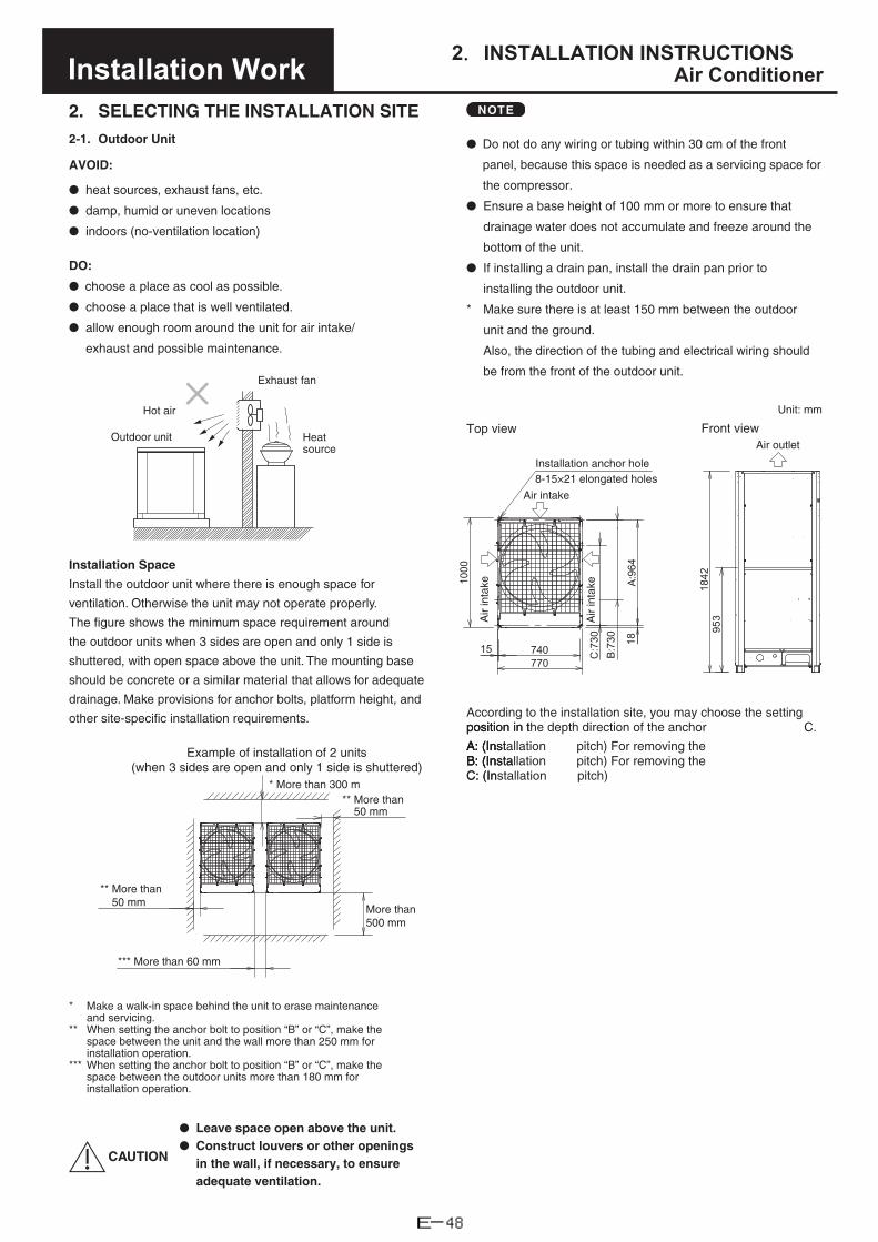
2.INSTALLATION INSTRUCTIONSAir ConditionerInstallation Work
2. SELECTING THE INSTALLATION SITE2-1. Outdoor Unit
AVOID:
● heat sources, exhaust fans, etc.
● damp, humid or uneven locations
● indoors (no-ventilation location)
DO:
● choose a place as cool as possible.
● choose a place that is well ventilated.
● allow enough room around the unit for air intake/
exhaust and possible maintenance.
Installation Space
Install the outdoor unit where there is enough space for
ventilation. Otherwise the unit may not operate properly.
The figure shows the minimum space requirement around
the outdoor units when 3 sides are open and only 1 side is
shuttered, with open space above the unit. The mounting base
should be concrete or a similar material that allows for adequate
drainage. Make provisions for anchor bolts, platform height, and
other site-specific installation requirements.
Example of installation of 2 units (when 3 sides are open and only 1 side is shuttered)
More than 300 m*** More than
50 mm
More than 500 mm
** More than50 mm
*** More than 60 mm
* Make a walk-in space behind the unit to erase maintenanceand servicing.
** When setting the anchor bolt to position “B” or “C”, make the space between the unit and the wall more than 250 mm forinstallation operation.
*** When setting the anchor bolt to position “B” or “C”, make the space between the outdoor units more than 180 mm forinstallation operation.
CAUTION
● Leave space open above the unit.● Construct louvers or other openings
in the wall, if necessary, to ensureadequate ventilation.
Hot air
Exhaust fan
Heat source
Outdoor unit
1000
C:7
30B
:730
A:9
64
1842
953
18
740770
15
Installation anchor hole
Top view Front view
Unit: mm
8-15×21 elongated holes
Air intake
Air outlet
According to the installation site, you may choose the setting ositosition the depth direction of the anchorposition in pp in t C.
: (IAA: (InstallationA: (I: (Inst: (IBB: (InstallationB: (Insta: (I
C: (InstallationC: (I
n pitch) For removing theAn pitch) For removing theBn pitch)
Air
inta
ke
Air
inta
ke
NOTE
● Do not do any wiring or tubing within 30 cm of the front
panel, because this space is needed as a servicing space for
the compressor.
● Ensure a base height of 100 mm or more to ensure that
drainage water does not accumulate and freeze around the
bottom of the unit.
● If installing a drain pan, install the drain pan prior to
installing the outdoor unit.
* Make sure there is at least 150 mm between the outdoor
unit and the ground.
Also, the direction of the tubing and electrical wiring should
be from the front of the outdoor unit.
E-48

2.INSTALLATION INSTRUCTIONSAir ConditionerInstallation Work
2-2. Shield for Horizontal Exhaust DischargeIt is necessary to install an air-discharge chamber (field supply) to direct exhaust from the fan horizontally if it is difficult to provide a minimum space of 2 m between the air-discharge outlet and a nearby obstacle.
CAUTION
InIn regIn regions withn regioIn reIutdoor unit shououtdooroutdooutdooroutoolid, rasolid, solisolid, raisesolid,s
vents.
AVOID
DO
ithoutWithout snow-proofW(Without platform)
r vents WithWith snow-p(High(High plat
Fallen snow
nstalI UnitI the OutdoornsI2-3. Installing ca aw canw snow
nstalling can lem, snow-
nts shentse unite theIn locations where wind-blownproof vents should be fitted ton xposure to the wind should be avoided as much as possible.
The following problems may occur if proper countermeasures are not taken:● The fan in the outdoor unit may stop running, causing the
unit to be damaged.● There may be no air flow.● The tubing may freeze and burst.● The condenser pressure may drop because of strong wind,
and the indoor unit may freeze.
2-4. Precautions When Installing in Heavy Snow Areas
a) The platform should be higher than the maximum snowdepth.
b) The 2 anchoring feet of the outdoor unit should be used forthe platform, and the platform should be installed beneaththe air-intake side of the outdoor unit.
c) The platform foundation must be solid and the unit must besecured with anchor bolts.
d) When installing on a roof subject to strong wind,countermeasures must be taken to prevent the unit frombeing overturned.
2-5. Dimensions of Wind Ducting Reference diagram for air-discharge chamber (field supply)
For further details, see the section “SUPPLEMENT”.
2-6. Dimensions of Snow Ducting Reference diagram for snow-proof vents (field supply)
For further details, see the section “SUPPLEMENT”.
E-49

2.INSTALLATION INSTRUCTIONSAir ConditionerInstallation Work
3. HOW TO INSTALL THE OUTDOOR UNIT3-1. TransportingWhen transporting the unit, have it delivered as close to the installation site as possible without unpacking.Use a hook for suspending the unit respectively according to the type of model.
A
Lifting belt
Detailed drawing A
Protective cardboard or cloth
Fan guard
These are not lifting holes.
CAUTION
● When hoisting the outdoor unit, pass lifting belts throughthe left and right holes of the bottom plate as shown in thefollowing figures. Use two lengths of lifting belt 7.5 meterslong or longer.
● Hang the lifting belt at an oblique angle of the four cornersof the bottom plate. If it is hung at other areas, the lifting beltbecomes loose and the outdoor unit will be damaged or youmay be injured.
● Use protective panels or padding at all locations where thelifting belt contacts the outer casing or other parts to preventscratching. In particular, use protective material (such ascloth or cardboard) to prevent the edges of the top panelfrom being scratched.
E-50

2.INSTALLATION INSTRUCTIONSAir ConditionerInstallation Work
3-2. Installing the Outdoor Unit(1) Use four anchor bolts (M12 or similar) to securely anchor
the unit. Regarding the positioning anchor bolts of the
depth direction, select one of three types according to the
installation site as shown in the following figures.
Normally, select the position A. When removing the connection
tube in a downward direction, select the position B.
740
770
15
1000
C:7
30
B:7
30
A:9
6418
Installation anchor hole
8-15×21 elongated holes
Unit: mm
(2) When only using a single outdoor unit, see the figure below.
15
1823
4
Detailed view of anchor hole Unit: mm8-15×21 elongated hole
In case of the combination with different units, see the
section “SUPPLEMENT”.
* When positioning the anchor bolt at B or C, make a
sufficient space between the units or from the wall for
installation. (Make a space between the units wider than
180mm and left and right space wider than 250mm from
the wall.)
(3) The vibration insulator or the like should be kept secure to
satisfy the width and depth for the plate legs. Use a washer
from the upper direction larger than the hole size for fixing
the installation.
E-51

2.INSTALLATION INSTRUCTIONSAir ConditionerInstallation Work
1575*
≥100
100*
*100
≥100
≥100
Unit: mm
Unit: mm
Unit: mm
• Below showsBelow shows vibration position when setting anchor bolt at position B.
• Below shows vibration insulator position when setting anchor bolt at position C.
Plate leg (right)
DD
D D
Plate leg (left)
Vibration insulator
Electrical wiring port (bottom)
Tubing port (bottom)
Plate leg (right)
A:9
64In
stal
latio
n ho
le p
itch
D D
EE
Tubing port (bottom)
Electrical wiring (bottom)port
insulatorVibration
Plate leg (left)
B:7
30In
stal
latio
n ho
le p
itch
EE
D D
C:7
30
Tubing port (bottom)
Electrical wiring (bottom)port
Vibration insulator
Plate leg (left) Plate leg (right)
Inst
alla
tion
hole
pitc
h
Unit: mm
Unit: mm
Unit: mm
NOTE: Proceed with the work following the dimensions showing the asterisk.
Detailed view of D
Plate legs (left, right)
Anchor bolts
Washer
Base
Vibration insulator
Detailed view of E
Detailed view of D
Anchor bolts
Base
Vibration insulator
Plate legs (left, right)
Anchor bolts
Washer
Base
Vibration insulator
WasherPlate legs (left, right)
• Below shows vibration insulator position when setting anchor bolt at position A.
E-52

2.INSTALLATION INSTRUCTIONSAir ConditionerInstallation Work
3-3. Routing the Tubing● The tubing can be routed out either from the front or from the bottom.● The connecting valve is contained inside the unit. Therefore, remove the front panel.(1) If the tubing is routed out from the front, cut out the slit part ( ).● Be careful not to damage the tubing cover.(2) If the tubing is routed out from the bottom, use cutting pliers or a similar tool to cut out the tubing outlet slit (part indicated by )
from the tubing cover.● Be careful not to damage the tubing cover.
Front
Bottom
Remove 8 panel screws from front panel.
Tubing cover
Tubing cover
Remove 3 screws.
If the tubing is routed out from the bottom, use cutting pliers or a similar tool to cut out the shaded area.
Cut out the shaded area in the direction of the arrow.
E-53

2.INSTALLATION INSTRUCTIONSAir ConditionerInstallation Work
3-4. Prepare the Tubing● Material: Use seamless phosphorous deoxidized copper
tube for refrigeration. Wall thickness shall comply with theapplicable legislation. The minimal wall thickness must bein accordance with the table below. For tubes of ø22.22 orlarger, use the material of temper 1/2H or H (Hard coppertube). Do not bend the hard copper tube.
● Tubing sizeUse the tubing size indicated in the table below.
● When cutting the tubing, use a tube cutter, and be sure toremove any burrs.The same applies to distribution tubing (optional).
● When bending the tubes, bend each tube using a radiusthat is at least 4 times the outer diameter of the tube. Whenbending, use sufficient care to avoid crushing or damagingthe tube.
● For flaring, use a flare tool, and be sure that flaring isperformed correctly.
CAUTION
Use sufficient caution during preparation of the tubing.
Seal the tube ends by means of caps or taping to prevent
dust, moisture, or other foreign substances from entering
the tubes.
Refrigerant tubing
Tubing size (mm)
Material Temper - O (Soft copper tube)
Material Temper - 1/2 H, H (Hard copper tube)
Outer dia. Thickness Outer dia. Thickness
ø6.35 t0.8 ø22.22 t1.0
ø9.52 t0.8 ø25.4 t1.0
ø12.7 t0.8 ø28.58 t1.0
ø15.88 t1.0 ø31.75 t1.1
ø19.05 t1.2 ø38.1 over t1.35
ø41.28 over t1.45
ø44.45 over t1.55
3-5. Connect the Tubing● When operating the refrigerant tube installation in the
field, do not apply the flame of welding to the surroundingsheet-metal parts. If necessary, use a wet rag to preventoverheating of the heat exchanger.
● Except for the 16 HP model, do not use the suppliedconnector tubing.
Refrigerant tubing
Connection method
Supplied parts used?
1 Gas tube Brazing No
2 Liquid tube Flare connection No
3 Balance tube Flare connection No
Refrigerant tube port
● Use caulking, putty, or a similar material to fill any gaps atthe refrigerant tube port ( ) in order to prevent rainwater, dust or foreign substances from entering the unit.
* Perform this work even if the tubing is routed out in adownward direction.
Tubing cover
Bottom plate
Tubing routed outthrough the front side
Tubing routed out through the bottom
1
32
E-54

2.INSTALLATION INSTRUCTIONSAir ConditionerInstallation Work
Use two adjustable wrenches, as shown in the figure, when removing the liquid tube valve flare nut.1. Do not apply a wrench to the valve cap when removing or
installing the flare nuts. Doing so may damage the valve.2. If the valve cap is left off for a long period of time, refrigerant
leakage will occur. Therefore, do not leave the valve cap off.3. Applying refrigerant oil to the flare surface can be effective in
preventing gas leakage, however be sure to use a refrigerantoil which is suitable for the refrigerant that is used in thesystem. This unit utilizes R410A refrigerant, and the refrigerant oil isether oil (synthetic oil). However, hub oil (synthetic oil) canalso be used.
1. Be sure to use nitrogenOxygen, CO2, and CFC must not be used.
2.. Use a pressure-reducing valve on the nitrogen tan3. Do not use agents intended to prevent the formation of oxide
film. They will adversely affect the refrigeration oil, and maycause equipment failure.
4. The balance tube is not used if only 1 outdoor unit isinstalled. Use the unit in the same conditions as when it wasshipped from the factory.
● Precautions for brazingBe sure to replace the air inside the tube with nitrogen toprevent oxide film from forming during the brazing process.Be sure to use a damp cloth or other means to cool the valveunit during brazing.
● Tighten each cap as specified below.
Tightening torque for each cap
Cap tightening torqueUnit 10 HP
Liquid tube
Valve capN · m 20.6 ~ 28.4
{kgf · cm} {206 ~ 284}
Service port capN · m 10.7 ~ 14.7
{kgf · cm} {107 ~ 147}
Flare nutN · m 34 ~ 42
{kgf · cm} {340 ~ 420}
Gas tube
Valve capN · m 47 ~ 53
{kgf · cm} {470 ~ 530}
Service port capN · m 10 ~ 12
{kgf · cm} {100 ~ 120}
Balance tube
Valve capN · m 20 ~ 25
{kgf · cm} {200 ~ 250}
Service port capN · m 9 ~ 11
{kgf · cm} {90 ~ 110}
Flare nutN · m 14 ~ 18
{kgf · cm} {140 ~ 180}
Work methodWork methodField-supply tube Remote valve
Brazing locations TapingPressure-reducingPressure-reducing valve (regulator)valve (regulator)
Nitrogen
Do not apply an adjustable to the hexagonal part.wrench
Use two adjustable wrenches when removing or installing the balance tube flare nut.In particular, do not apply an adjustable wrench to the hexagonal part at the top of the valve.If force is applied to this part, gas leakage will occur.Apply an adjustable wrench to settle the fixing tool as shown in the figure. If not used, the valve fixing tool will get distorted.
Valve fixing tool
CAUTION
HP: horsepower
Valve cap (width 14mm)
Service port cap (width 17mm)
Service port cap (width 17mm) Valve cap
(width 19mm)
Gas tube
Valve cap (width 27mm)
Service port cap (width 17mm)
Flare nut (ø6.35)
Flare nut (ø9.52)
Balance tube
Liquid tube
E-55
2.INSTALLATION INSTRUCTIONSAir ConditionerInstallation Work
4. ELECTRICAL WIRING
4-1. General Precautions on Wiring
(1) Before wiring, confirm the rated voltage of the unit as shown on its nameplate, then carry out the wiring closely following the wiring diagram.
WARNING
(2) This equipment is strongly recommended to be installed with Earth Leakage Circuit Breaker (ELCB) or Residual Current Device (RCD). Otherwise, it may cause electrical shock and fire in case of equipment breakdown or insulation breakdown.Earth Leakage Circuit Breaker (ELCB) must be incorporated in the fixed wiring in accordance with the wiring regulations. The Earth Leakage Circuit Breaker (ELCB) must be an approved circuit capacity, having a contact separation in all poles.
(3) To prevent possible hazards from insulation failure, the unit must be grounded.
(4) Each wiring connection must be done in accordance with the wiring system diagram. Wrong wiring may cause the unit to misoperate or become damaged.
(5) Do not allow wiring to touch the refrigerant tubing, compressor, or any moving parts of the fan.
(6) Unauthorized changes in the internal wiring can be very dangerous. The manufacturer will accept no responsibility for any damage or misoperation that occurs as a result of such unauthorized changes.
(7) Regulations on wire diameters differ from locality to locality. For field wiring rules, please refer to your LOCAL ELECTRICAL CODES before beginning. You must ensure that installation complies with all relevant rules and regulations.
(8) To prevent malfunction of the air conditioner caused by electrical noise, care must be taken when wiring as follows:
● The remote control wiring and the inter-unit controlwiring should be wired apart from the inter-unit powerwiring.
● Use shielded wires for inter-unit control wiring betweenunits and ground the shield on both sides.
(9) If the power supply cord of this appliance is damaged, it must be replaced by a repair shop appointed by the manufacturer, because special purpose tools are required.
(10) Use a waterproof conduit for outdoor unit wiring to avoid damaging the wire and to prevent accumulation of liquid inside the unit.
4-2. Recommended Wire Length and Wire Diameter for Power Supply System
Outdoor unit
(A) Power supply Time delay fuse orcircuit capacityWire size Max. length
U-10MES2E8 4 mm² 54 m 25 A
or
(A) Power supply Time delay fuse orcircuit capacityWire size Max. length
6 mm² 81 m 30 A
Indoor unit
Type(B) Power supply Time delay fuse
or circuit capacity
Type(B) Power supply Time delay fuse
or circuit capacityMinimum 2 mm² 2.5 mm² Minimum 2 mm² 2.5 mm²
K2 Max. 150 m — 15 A D1 — Max. 130 m 10 – 16 A
Y2 Max. 130 m — 15 A L1 — Max. 130 m 10 – 16 A
K1 — Max. 150 m 10 – 16 A M1 — Max. 130 m 10 – 16 A
U1 — Max. 130 m 10 – 16 A P1 — Max. 130 m 10 – 16 A
F2 — Max. 130 m 10 – 16 A R1 — Max. 130 m 10 – 16 A
T2 — Max. 130 m 10 – 16 A E2 — Max. 30 m 10 – 16 A
Control wiring
(C) Inter-unit (between outdoor and indoor units) control wiring
0.75 mm² (AWG #18)Use shielded wiring*
Max. 1,000 m
(D) Remote control wiring
0.75 mm² (AWG #18)
Max. 500 m
NOTE * With ring-type wire terminal
(E) Control wiring for group control
0.75 mm² (AWG #18)
Max. 200 m (Total)
E-56

2.INSTALLATION INSTRUCTIONSAir ConditionerInstallation Work
4-3. Wiring System Diagram
NOTE
(1) See the section “4-2. Recommended Wire Length and Wire Diameter for Power Supply System” for the explanation of “A”, “B”, “C”, “D” and “E” in the above diagram.
(2) The basic connection diagram of the indoor unit shows the 6P terminal board, so the terminal boards in your equipment may differ from the diagram.
(3) Refrigerant Circuit (R.C.) address should be set before turning the power on.
(4) Regarding the R.C. address setting, it can be executed by remote controller automatically. See the section “7-3. Auto Address Setting”.
U2
U1
R2
R1
L
N
R2
R1
R2
R1
R2
R1
2
1
2
1
U2
U1
L
N
U2
U1
L
N
U2
U1
L
N
2
1
2
1
2
1
D
E
C
B
LN
LN
LN
LN
2
1
B
B
B
C
D
D
C
LN
A L1L2L3N
C
C
L
N
L1
L2
L3
N
3
4
U1
U2
1
2
WHT BLK
WHT BLK
WHT BLK
Power supply220-230-240V ~ 50-60 Hz
Power supply220-230-240V ~ 50-60 Hz
Power supply220-230-240V ~ 50-60 Hz
Power supply220-230-240V ~ 50-60 Hz
Remote controller
Remote controller
Remote controller
Power supply220/230/240V ~ 50 Hz
Power supply380-400-415V 3N ~ 50 Hz
Outdoor unit U-20GES3E5
Outdoor unit U-10MES2E8
Indoor unit (No. 1)
Indoor unit (No. 2)
Indoor unit (No. 3)
Indoor unit (No. n)
Group control:
U1 U2
N
4P terminal board
4P terminal board
L1 L2 L3Power supply
Type MES2
Inter-unit control wiring
( : Functional earthing)
E-57

2.INSTALLATION INSTRUCTIONSAir ConditionerInstallation Work
CAUTION
(1) When linking outdoor units in a network, see the section “ATTENTION!”.
(2) Do not install the inter-unit control wiring in a way that forms a loop.
(3) Do not install the inter-unit control wiring such as star branch wiring. Star branch wiring causes mis-address setting.
(4) If branching the inter-unit control wiring, the number of branch points should be 16 or fewer.
Outdoor unit
Central Controller
Outdoor unit
Indoor unit Indoor unit Indoor unit
Indoor unit Indoor unit Indoor unit
Indoor unit Indoor unit Indoor unit
Mor
e th
an 2
m r
equi
red
Outdoor unit Branch point
Outdoor unit
Outdoor unit
Indoor unit
Indoor unit Indoor unit
Indoor unit Indoor unit
Branch point
Indoor unit Indoor unit Indoor unit Indoor unit
Outdoor unit Outdoor unitProhibited
Prohibited
NO
E-58

2.INSTALLATION INSTRUCTIONSAir ConditionerInstallation Work
(5) Use shielded wires for inter-unit control wiring (C) and ground the shield on both sides, otherwise misoperation from noise may occur. Connect wiring as shown in the section “4-3. Wiring System Diagram.”
How to Connect Wiring to Terminal
■ For stranded wiring
(1) Cut the wire end with cutting pliers, then strip the insulation to expose the stranded wiring about 10 mm and tightly twist the wire ends.
Stranded wire
Ring pressure terminal
Str
ip 1
0 m
m
(2) Using a Phillipsscrew(s) on the
head screwdriver, remove the terminal terminal board.
sing a ring con(3) Using a ring connector fastener or pliers,Uach stripped wire end with a ring presseach strippede
pressure terminal, and replace and tighten (4) Place the ringthe removed terminal screw using a screwdriver.
Screw and Special washer
Ring pressure terminal
Terminal board
Ring pressure terminal
ScrewSpecial washer
Wire
Wire
(6) • Connecting cable between indoor unit and outdoor unit shall be approved polychloroprene sheathed 5 or 3 *1.5 mm2 flexible cord. Type designation 60245 IEC57 (H05RN-F, GP85PCP etc.) or heavier cord.
• F or H07RN-F which conformrating Use the standard power supply cables for Europe (such as H05RN-F or H07RN-F whichrating specifications) or use the cables based on IEC standard. (60245 IEC57, 60245
WARNINGLoose wiring may cause the terminal to overheat or result in unit malfunction. A fire hazard may also exist. Therefore, ensure that all wiring is tightly connected.
to Terminal” When connecting each power wire to the terminal, follow the instructions on “How to Connect Wiringand fasten the wire securely with the fixing screw of the terminal board.
■ Examples of shield wires
emove cable coat nR(1) Remove cable coat notRemove ca
carefullyU(2) Unbraid the braided shieldnbrUnbraid the tightlyunbraided u shield wirenbraidedunbraided shield wires
ires by coirwwires vering them with airesw by covering themwinsulation tape around them.
nsul ShieldShielInsulationI
(3) Remove coat of signal wire.
8 mm
Insulation tape ShieldShiel
signalAttach ring pre the(4) Attach ring pressure terminals to (2).shield wires insulated in Step
■ Earth wire for power supplyThe earth wire should be longer than the other lead wires for electrical safety.
Shielded wire
earthing)(Functional earthing) (Functional
E-59

2.INSTALLATION INSTRUCTIONSAir ConditionerInstallation Work
Use this screw when connecting to ground for the inter-unit control wiring.( : Functional earthing)
Use this screw when connecting to ground for the inter-unit control wiring.( : Functional earthing)
Power supplyInter-unit control wiring
Power supply Inter-unit control wiring
EarthEarth
■ Wiring sample
Torque values of power supply terminal board: 2.2N·m±0.05N·m {22 kgf·cm ±0.5 kgf·cm}
Torque value of communication terminal board: 1.3N·m±0.1N·m {13 kgf·cm ±1 kgf·cm}
ATTENTION: Comply with the torque values.If tightening over torque values, the screw will be damaged.
ATTENTION: Apply an adjustable wrench to the valve vertically not to damage the P.C.board.
NOTE
• Fix the wires with the clamper to the wiring fixture plates (2 locations) and do not allow them to touch the refrigerant tubing andcompressor.
• Use a waterproof conduit for outdoor unit wiring to avoid damaging the wire and to prevent accumulation of liquid inside the unit.
Electrical wiring port
Unit front Unit bottom
E-60

2.INSTALLATION INSTRUCTIONSAir ConditionerInstallation Work
NOTE
downward and be sure that henWhen reaming, hold the tubeWno copper scraps fall into theno cop
(3) Remove the flare nut fromemove the flare nut from the theRon the copper tube.
(4) Make a flare at the end of copper tubeMake a flare at the
Flare nut
Flare tool
Coppertubing
NOTE
A good flare should have the following characteristics:● Inside surface is glossy and smooth● Edge is smooth● Tapered sides are of uniform length
5. HOW TO PROCESS TUBINGThe liquid tubing side is connected by a flare nut, and the gas tubing side is connected by brazing.
5-1. Connecting the Refrigerant Tubing
Use of the Flaring MethodMany of conventional split system air conditioners employ the flaring method to connect refrigerant tubes which run between indoor and outdoor units. In this method, the copper tubes are flared at each end and connected with flare nuts.
Flaring Procedure with a Flare Tool(1) Cut the copper tube to the required length with a tube
cutter. It is recommended to cut approx. 30 – 50 cm longer than the tubing length you estimate.
(2) Remove burrs at the end of the copper tube with a tube reamer or a similar tool. This process is important and should be done carefully to make a good flare. Be sure to keep any contaminants (moisture, dirt, metal filings, etc.) from entering the tubing.
Deburring
Before After
Copper tubing
Reamer
E-61

2.INSTALLATION INSTRUCTIONSAir ConditionerInstallation Work
Caution Before Connecting Tubes Tightly
(1) Apply a sealing cap or water-proof tape to prevent dust or water from entering the tubes before they are used.
(2) Be sure to apply refrigerant lubricant (ether oil) to the inside of the flare nut before making piping connections. This is effective for reducing gas leaks.
Apply refrigerant lubricant.
the unionF(3) For proper connection, align then screw instraight with each other,
or proper connection the flare nut lightly at
first to obtain a smooth match.
Flare nut
●
Union
liquid tube usingA connect it to thet
djust the shape ohe installation sit
Adjust the shape of thethe installation site andvalve using a flare.
Cautions During Brazing
● eplace air inside the tube with niReplace air insideReplRcopper oxide film from forming during the brazing process. (Oxygen, carbon dioxide and Freon are not acceptable.)
● Do not allow the tubing to get too hot during brazing.The nitrogen gas inside the tubing may overheat,causing refrigerant system valves to become damaged.Therefore allow the tubing to cool when brazing.
● Use a reducing valve for the nitrogen cylinder.
● Do not use agents intended to prevent the formationof oxide film. These agents adversely affect therefrigerant and refrigerant oil, and may cause damageor malfunctions.
5-2. Connecting Tubing BetweenConnecting Tubing BeUnits
(1) Tightly connect the indoor-side refrigerant tubing extended from the wall with the outdoor-side tubing.
theT(2) To fasten the flare nuts, applyo fasten the flare nuts, ap
● hen removing the flare nWhen removing thehen W emoviWWhen rr when tightenin afteror when tightenoor when tightening them
to use a torque wrench at ando use a t
Torque wrench
SpannerIndoor unit
Outdoor unit
If the flare nuts are over-tightened, the flare may be damaged, which could result refrigerant leakage and cause in injury or asphyxiation to room occupants.
● For the flare nuts at tubing connections, be sure to use theflare nuts that were supplied with the unit, or else flare nuts forR410A (type 2). The refrigerant tubing that is used must be ofthe correct wall thickness as shown in the following table.
Tube diameter Tightening torque,approximate Tube thickness
ø6.35 (1/4")14 – 18 N · m{140 – 180 kgf · cm}
0.8 mm
ø9.52 (3/8")34 – 42 N · m{340 – 420 kgf · cm}
0.8 mm
ø12.7 (1/2")49 – 61 N · m{490 – 610 kgf · cm}
0.8 mm
ø15.88 (5/8")68 – 82 N · m{680 – 820 kgf · cm}
1.0 mm
ø19.05 (3/4")100 – 120 N · m{1000 – 1200 kgf · cm}
1.2 mm
Because the pressure is approximately 1.6 times higher than conventional refrigerant pressure, the use of ordinary flare nuts (type 1) or thin-walled tubes may result in tube rupture, injury, or asphyxiation caused by refrigerant leakage.
● In order to prevent damage to the flare caused by over-tightening of the flare nuts, use the table above as a guidewhen tightening.
● When tightening the flare nut on the liquid tube, use anadjustable wrench with a nominal handle length of 200 mm.
E-62

2.INSTALLATION INSTRUCTIONSAir ConditionerInstallation Work
5-3. Insulating the Refrigerant Tubing
Tubing Insulation● Standard Selection of Insulation Material
Under the environment of the high temperature and highhumidity, the surface of the insulation material is easy tobecome condensation. This will result in leakage and dewdrop. Refer to the chart shown below when selecting theinsulation material. In case that the ambient temperature andrelative humidity are placed above the line of the insulationthickness, the condensation may occasionally make a dewdrop on the surface of the insulation material. In this case,select the better insulation efficiency.* However, since the condition will be different due to the
sort of the insulation material and the environmentalcondition of the installation place, see the chart shownbelow as a reference when making a selection.
Standard Selection of Tubing Insulation
Sort of insulation materialPolyethylene heat resistingmaterial
Upper limits of usage temperature
Gas tubing : 120 °C or aboveOther tubing : 80 °C or above
Calculating condition
Thermal conductivityof insulation material
0.043 W/(m · K)(Average temperature 23 °C)
Refrigerant temperature 2 °C
Two tubes arranged together
Three tubes arranged together
4010 20 30 40 50
50
60
70
80
90
100
040
1 20 30 40 50
040
1 20 30 40 50
4010 20 30 40 50
4010 20 30 40 50
040
1 20 30 40 50 040
1 20 30 40 50
4010 20 30 40 50
4010 20 30 40 50
50
60
70
80
90
100
50
60
70
80
90
100
50
60
70
80
90
100
50
60
70
80
90
100
50
60
70
80
90
100
50
60
70
80
90
100
50
60
70
80
90
100
50
60
70
80
90
100o6.35
o15.88
o25.4
o19.05
o28.58
o22.22
o31.75
o9.52 o12.7
Liquid tube Gas tube
Cosmetic (finishing) tape
Gas tube
Liquid tube
Insulation
Ambient temperature [°C]
Ambient temperature [°C]
Ambient temperature [°C] Ambient temperature [°C] Ambient temperature [°C]
Ambient temperature [°C] Ambient temperature [°C]
Ambient temperature [°C] Ambient temperature [°C]
Thickness 30mm
Thickness 30mm
Thickness 30mm
Thickness 30mm
Thickness 30mm
Thickness 30mm
Thickness 30mm
Thickness 30mm
Thickness 30mm
Thickness 20mm
Thickness 20mm
Thickness 20mm
Thickness 20mm
Thickness 20mm
Thickness 20mm
Thickness 20mm
Thickness 20mm
Thickness 20mm
Thickness 10mm
Thickness 10mm
Thickness 10mm
Thickness 10mm
Thickness 10mm
Thickness 10mm
Thickness 10mm
Thickness 10mm
Thickness 10mm
Balance tube
Insulation
Am
bien
t rel
ativ
e hu
mid
ity [%
]A
mbi
ent r
elat
ive
hum
idity
[%]
Am
bien
t rel
ativ
e hu
mid
ity [%
]
Am
bien
t rel
ativ
e hu
mid
ity [%
]
Am
bien
t rel
ativ
e hu
mid
ity [%
]
Am
bien
t rel
ativ
e hu
mid
ity [%
]
Am
bien
t rel
ativ
e hu
mid
ity [%
]
Am
bien
t rel
ativ
e hu
mid
ity [%
]
Am
bien
t rel
ativ
e hu
mid
ity [%
]
E-63

2.INSTALLATION INSTRUCTIONSAir ConditionerInstallation Work
CAUTION
If the exterior of the outdoor unit valves has been finished with a square duct covering, make sure you allow sufficient space to use the valves and to allow the panels to be attached and removed.
Taping the flare nuts
Wind the white insulation tape around the flare nuts at the gas tube connections. Then cover up the tubing connections with the flare insulator, and fill the gap at the union with the supplied black insulation tape. Finally, fasten the insulator at both ends with the supplied vinyl clamps.
o38.1 o41.28
4010 20 30 40 50 10 20 30 40 50
50
60
70
80
90
100
40
50
60
70
80
90
100
Ambient temperature [°C] Ambient temperature [°C]
Thickness 30mm
Thickness 30mm
Thickness 20mm
Thickness 20mm
Thickness 10mm
Thickness 10mm
Am
bien
t rel
ativ
e hu
mid
ity [%
]
Am
bien
t rel
ativ
e hu
mid
ity [%
]
Sealer
Flare insulator
Tube insulator
Vinyl clampsFlare nut
Unit side insulator
Refrigerant tubing and insulator
Drain pipe and insulator Drain insulator and clamp
Packing clamp
Small hose band
The procedure used for installing the insulator for both gas and liquid tubes is the same.
Seal
Flare insulator
Vinyl clamp
Insulation tape
Insulation tape (white)
100
90
80
70
60
50
4010 20 30 40 50
o44.45
Ambient temperature [°C]
Thickness 30mm
Thickness 20mm
Thickness 10mm
Am
bien
t rel
ativ
e hu
mid
ity [%
]
Never grasp the drain or refrigerant connecting outlets when moving the unit.
Insulation material
The material used for insulation must have good insulation characteristics, be easy to use, be age resistant, and must not easily absorb moisture.
Be sure to use the heat-resistant insulator corresponding to the gas tube of 120 °C or above and other tubes of 80 °C or above.
CAUTION
After a tube has been insulated, never try to bend it into a narrow curve because it can cause the tube to break or crack.
E-64

2.INSTALLATION INSTRUCTIONSAir ConditionerInstallation Work
5-4. Taping the Tubes(1) At this time, the refrigerant tubes (and electrical wiring if
local codes permit) should be taped together with armoring tape in 1 bundle. To prevent the condensation from overflowing the drain pan, keep the drain hose separate from the refrigerant tubing.
(2) Wrap the armoring tape from the bottom of the outdoor unit to the top of the tubing where it enters the wall. As you wrap the tubing, overlap half of each previous tape turn.
(3) Clamp the tubing bundle to the wall, using 1 clamp approx. each meter.
Insulated tubes Drain hose
Clamp
NOTE
Do not wind the armoring tape too tightly since this will decrease the heat insulation effect. Also ensure that the condensation drain hose splits away from the bundle and drips clear of the unit and the tubing.
5-5. Finishing the InstallationAfter finishing insulating and taping over the tubing, use sealing putty to seal off the hole in the wall to prevent rain and draft from entering.
Apply putty here
Tubing
Communication line
E-65

2.INSTALLATION INSTRUCTIONSAir ConditionerInstallation Work
6. AIR PURGINGAir and moisture in the refrigerant system may have undesirable effects as indicated below.
● pressure in the system rises
● operating current rises
● cooling (or heating) efficiency drops
● moisture in the refrigerant circuit may freeze and blockcapillary tubing
● water may lead to corrosion of parts in the refrigerantsystem
Therefore, the indoor unit and tubing between the indoor and outdoor unit must be leak tested and evacuated to remove any noncondensables and moisture from the system.
■ Air Purging with a Vacuum Pump (for Test Run)Preparation
Check that each tube (both liquid and gas tubes) between the indoor and outdoor units have been properly connected and all wiring for the test run has been completed. Remove the valve caps from both the gas and liquid service valves on the outdoor unit. Note that both liquid and gas tube service valves on the outdoor unit are kept closed at this stage.
Leak test(1) With the service valves on the outdoor unit closed, remove
the 1/4 in. flare nut and its bonnet on the gas tube service valve. (Save for reuse.)
(2) Attach a manifold valve (with pressure gauges) and dry nitrogen gas cylinder to this service port with charge hoses.
CAUTIONUse a manifold valve for air purging. If it is not available, use a stop valve for this purpose. The “Lo” knob of the manifold valve must always be kept closed.
(3) Pressurize the system to no more than 3.80 MPa with dry nitrogen gas and close the cylinder valve when the gauge reading reaches 3.80 MPa. Then, test for leaks with liquid soap.
CAUTION
To avoid nitrogen entering the refrigerant system in a liquid state, the top of the cylinder must be higher than the bottom when you pressurize the system. Usually, the cylinder is used in a vertical standing position.
Lo Hi
Manifold gauge
Vacuum pumpOutletInlet
Manifold valve
Pressuregauge
Charge hose
Cylinder valve
Gas tube
Open
Open
Open
Close
Close
Close
Outdoor unit
Liquid tube
Balance tube
Nitrogen gas cylinder (In vertical standing position)
E-66

Installation Work 2.INSTALLATION INSTRUCTIONSAir Conditioner
(4) Do a leak test of all joints of the tubing (both indoor and outdoor) and both gas and liquid service valves. Bubbles indicate a leak. Wipe off the soap with a clean cloth after a leak test.
(5) After the system is found to be free of leaks, relieve the nitrogen pressure by loosening the charge hose connector at the nitrogen cylinder. When the system pressure is reduced to normal, disconnect the hose from the cylinder.
Evacuation(1) Attach the charge hose end described in the preceding
steps to the vacuum pump to evacuate the tubing and indoor unit. Confirm that the “Lo” knob of the manifold valve is open. Then, run the vacuum pump. The operation time for evacuation varies with the tubing length and capacity of the pump. The following table shows the amount of time for evacuation:
Required time for evacuationwhen 30 gal/min. vacuum pump is used
If tubing length is less than 15 m
If tubing length is longer than 15 m
45 min. or more 90 min. or more
NOTE
The required time in the above table is calculated based on the assumption that the ideal (or target) vacuum condition is less than –101 kPa {–755 mmHg, 5 Torr}.
(2) When the desired vacuum is reached, close the “Lo” knob of the manifold valve and turn off the vacuum pump. Please confirm that the gauge pressure is under –101 kPa {–755 mmHg, 5 Torr} after 4 to 5 minutes of vacuum pump operation.
Lo Hi
Manifold valve
Vacuumgauge
Vacuum pump
Gas tube
Open
Open
Open
Close
Close
Close
Outdoor unitLiquid tube
Balancetube
E-67

Installation Work 2.INSTALLATION INSTRUCTIONSAir Conditioner
CAUTIONUse a cylinder designed for use with R410A respectively.
Charging additional refrigerant
● Charging additional refrigerant using the liquid tube servicevalve.
● Use a balance to measure the refrigerant accurately.
● If the additional refrigerant charge amount cannot becharged at once, charge the remaining refrigerant in liquidform by using the gas tube service valve with the system incooling operation mode at the time of test run.
Finishing the job(1) With a hex wrench, turn the liquid tube service valve stem
counter-clockwise to fully open the valve.
(2) Turn the gas tube service valve stem counter-clockwise to fully open the valve.
CAUTION
To avoid gas from leaking when removing the charge hose, make sure the stem of the gas tube is turned all the way out (“BACK SEAT” position).
(3) Loosen the charge hose connected to the gas tube service port (1/4 in.) slightly to release the pressure, then remove the hose.
(4) Replace the 1/4 in. flare nut and its bonnet on the gas tube service port and fasten the flare nut securely with an adjustable wrench or box wrench. This process is very important to prevent gas from leaking from the system.
(5) Replace the valve caps at both gas and liquid service valves and fasten them securely.
This completes air purging with a vacuum pump. The air conditioner is now ready for a test run.
Manifold valve
Pressuregauge Lo Hi
Valve
Liquid
R410A
Gas tube
Gas tube
Open
Open
Open
Open
Open
Close
Close
Close
Close
Close
Close
Close
Outdoor unit
Outdoor unitLiquid tube
Liquid tube
Balance tube
Balance tube
E-68

3.Procedures and Technical Pointsfor Electrical Wiring WorkInstallation Work
SAFETY PRECAUTIONSWARNING
•Be sure to arrange installation from the dealer where the system waspurchased or using a professional installer. Electric shock or fire may resultif an inexperienced person performs any installation or warning proceduresincorrectly.
•Only a qualified electrician shall connect this system, in accordance with theinstructions given in “Engineering Standard Related to Electrical Equipment,”“Building Wiring Regulations,” “Procedures and Technical Points for ElectricalWiring Work (Outdoors)” and “INSTALLATION INSTRUCTIONS.” Electric shockor fire may result if electrical work is not correctly done.
Important Information Regarding the Refrigerant UsedThis product contains fluorinated greenhouse gases. Do not vent gases into the atmosphere.Refrigerant type: R410AGWP(1) value: 2088(1) GWP = global warming potentialPeriodical inspections for refrigerant leaks may be required depending on European or local legislation. Please contact your local dealer for more information.
E-69

3.Procedures and Technical Pointsfor Electrical Wiring WorkInstallation Work
ELECTRICAL WIRING REQUIREMENTS(a) Precautions regarding electrical wiring
WARNING
• Use a dedicated branch circuit for the power wiring. Do not share the branchcircuit with any other electrical devices. Doing so may result in secondary damageoccurring if the breaker is tripped.
• Use the specified power cables (type and wiring diameter) for the electricalconnections, and connect the cables securely. Run and fasten the cablessecurely so that external forces or pressure placed on the cables will not betransmitted to their connection terminals. Overheating or fire may result ifconnections or attachment are not secure.
CAUTION
• For each device, install an overcurrent breaker of the designated capacity. If thewrong breaker is installed, there is danger of fire resulting from overheating orshort circuit.
• For each device, install an earth leakage circuit breaker of the designatedcapacity. (U-20GES3E5 Earth leakage circuit breaker rating: 30 mA, 0.1 s or less)(U-10MES2E8 Earth leakage circuit breaker rating: 30 mA, 0.1 s or less) If an earth leakage circuit breaker is not installed, there is danger of electric shockor fire.
• Protective Earthing of the electrical installation shall comply with thenational and local wiring/installation requirements.
• This air conditioner shall be installed in accordance with National Wiring Regulations.• The product meets the technical requirements of EN/IEC 61000-3-3.• Provide a power outlet exclusively for each unit, and full disconnection means having a contact separation
by 3 mm in all poles must be incorporated in the fixed wiring in accordance with the wiring rules.• This device includes an inverter. Use an earth leakage circuit breaker that is suitable for use with an inverter.• Fasten power cables and indoor/outdoor control cables inside the outdoor unit with wiring clamps. Be sure
that they do not come in contact with any of the following:(1) Engines, motors, fan blades, and other moving or high-temperature devices or fixtures(2) Refrigerant tubing, pressure release tubes, or other parts of the refrigerant circuit(3) Installation brackets or other sharp parts
• Use signal cables for the communications cables (remote controller cables and indoor/outdoor control cables)which are identifiable as different from the power cables. In addition, do not run the communications cablesparallel to the power cables.
• Run the A/C power cables and communications cables at least 3 meters distant from any units, antennas, controlcables, or power cables of televisions, radios, stereos, intercoms, computers, word processors, and similar devices.If they are less than 3 meters away, electrical noise interference may occur.
• This product is intended for professional use. Permission from the power supplier is required when installingthe U-10MES2E8 outdoor unit that are connected to a 16A distribution network.
Set the voltage of the GHP outdoor unit prior to a testrun.
Set the unit to the voltage that matches the power supply where it is installed.Select the voltage setting from 220V, 230V or 240V.
Setting the Voltage of the GHP outdoor unitWhen making the voltage setting, make sure the electricity is off at the power source.Set the voltage by rewiring the red wire that connects (TB3) and (52S) at the top of the starter motor power supply inside the electrical box, as shown in the diagram.
Relationship Between TB3 & VoltageVoltage Terminal No.220 V #4230 V #5240 V #6
220V 230V 240V
1 2 3 4 5 6
52S
Rewire the red wire to match the power supply at the installation site.
TRM BLCK (TB3)
REDBLU
Starter Motor Power Supply
BRN
YEL BLK
RED
BLU
Fig. 1
E-70

3.Procedures and Technical Pointsfor Electrical Wiring WorkInstallation Work
Connection examples for indoor/outdoor control cables Note: indicates a branch point.1. Bus network (up to 16 branch points) (Fig. 2)
Branch points should generally be made from outdoor units.
Outdoor unitU-20GES3E5
Outdoor unitU-10MES2E8
System controller
Outdoor unit
Outdoor unit
Remote controller
Remote controller
No remote controller Group control
No remote controller
At least 2 m apart
Indoor unit
Indoor unit
Indoor unit
Indoor unit
Indoor unit
Indoor unit
Indoor unit
Indoor unit
Indoor unit
Remote controller
Fig. 2
2. Cable that is not considered a branch (Fig. 3)One of the indoor cables is split in this example.
*
Outdoor unitU-20GES3E5
Outdoor unitU-10MES2E8
System controller
Outdoor unit
Remote controller
**If this portion is 1 m or lessit is not considered a branch.
No remote controller
Indoor unit
Indoor unit
Indoor unit
Indoor unit
Indoor unit
Indoor unit
Remote controller
Fig. 3
E-71

3.Procedures and Technical Pointsfor Electrical Wiring WorkInstallation Work
3. Bus network that may exceed 17 branch points (Fig. 4)If the number of branch points will exceed 17, reduce the number of branch points by linking 2 refrigeranttubing systems within a single wiring system, for example.
Outdoor unitU-20GES3E5
Outdoor unitU-10MES2E8
System controller
Outdoor unit 2
Outdoor unit 3
Outdoor unit 4
Outdoor unit 5
Example of reducing branches of outdoor units 2 and 4
Remote controller
Remote controller
Remote controller
Remote controller
Remote controllerNo remote controller
Group control
No remote controller Group control
No remote controller
No remote controller
Indoor unit
Indoor unit
Indoor unit
Indoor unit
Indoor unit
Indoor unit
Indoor unit
Indoor unit
Indoor unit
Indoor unit
Indoor unit
Indoor unit
Indoor unit
Indoor unit
Indoor unit
Fig. 4
4. PROHIBITED: Star networks (Fig. 5)
Outdoor unitMust be fewer than four lines
Indoor unit
Indoor unit
Indoor unit
Indoor unit
System controller
Fig. 5
E-72

3.Procedures and Technical Pointsfor Electrical Wiring WorkInstallation Work
5. PROHIBITED: Sub-branches (Fig. 6)Do not branch cables that have already been branched.
System controller
Outdoor unit
Outdoor unit
Outdoor unit
Remote controller
Remote controller
Indoor unit
Indoor unit
Indoor unit
Indoor unit
Indoor unit
Indoor unit
Indoor unit
Indoor unit
Indoor unit
Indoor unit
Indoor unit
No remote controller
No remote controllerGroup control
No remote controllerGroup controlRemote controller
Fig. 6
6. PROHIBITED: Loop configurations (Fig. 7)Do not loop the entire network or any part of the network as shown.
System controller
Outdoor unit
Outdoor unit
Outdoor unit
Remote controller
Remote controller
Indoor unit
Indoor unit
Indoor unit
Indoor unit
Indoor unit
Indoor unit
Indoor unit
Indoor unit
Indoor unit
No remote controller
No remote controllerGroup control
Note: � indicates the looped portion.
Remote controller
Fig. 7
E-73

3.Procedures and Technical Pointsfor Electrical Wiring WorkInstallation Work
*
**
U1U212
L1L2L3
Earth leakage circuit breaker
Earth leakage circuit breaker
380-400-415V 3N ~ 50Hz
220/230/240V ~ 50Hz
Earth leakage circuit breaker
Earth leakage circuit breaker
Earth leakage circuit breaker
Earth leakage circuit breaker
Outdoor power cable
Outdoor power cable
Indoor/outdoor control cable
Indoor/outdoor control cable
Indoor power cable
Remote controller
White Black White Black White Black White Black
(purchased separately)
(purchased separately)
(purchased separately)
(purchased separately)
Remote controller Remote controller Remote controller
Indoor unit1
Indoor unit2
Indoor unit3
Indoor unit4Outdoor
unitU-20GES3E5
Outdoor unit
U-10MES2E8
220-230-240V ~ 50-60Hz
220-230-240V ~ 50-60Hz
220-230-240V ~ 50-60Hz
220-230-240V ~ 50-60Hz
(c) Electrical Wiring System Diagram For electrical wiring construction, refer to the Electrical wiring system diagram (Fig. 9) and the electrical diagram attached to the indoor unit.
Fig. 9 Electrical Wiring System Diagram
* When connecting indoor/outdoor control cables, no more than two cablesshould be connected to a single terminal section on the terminal board. If youneed to connect a third or forth cable, connect the cables to 3 and 4 on theterminal board.
** Do not connect any cables to 1 and 2 on the terminal board of the U-10MES2E8 outdoor unit.
CAUTION
Use shielded wires for inter-unit control wiring and ground theshield on both sides, otherwise misoperation from noise mayoccur. Connect wiring as shown in the section “(c) ElectricalWiring System Diagram.”
WARNINGLoose wiring may cause the terminal to overheat or result in unit malfunction. A fire hazard may also exist. Therefore, ensure that all wiring is tightly connected.
When connecting each power wire to the terminal, follow the instructions on “How to Connect Wiring to Terminal” and fasten the wire securely with the fixing screw of the terminal board.
Shielded wire
(Functional earthing) (Functional earthing)
Fig. 10
( : Functional earthing)
E-74

3.Procedures and Technical Pointsfor Electrical Wiring WorkInstallation Work
How to Connect Wiring to Terminal
■ For stranded wiring
(1) Cut the wire end with cutting pliers, then strip the insulation to expose the stranded wiring about 10 mm and tightly twist the wire ends.
Stranded wire
Ring pressure terminal
Stri
p 10
mm
(2) Using a Phillips head screwdriver, remove the terminal screw(s) on the terminal board.
(3) Using a ring connector fastener or pliers, securely a ring pressure clamp each stripped wire end with
terminal.(4) Place the ring pressure terminal, and replace
and tighten the removed terminal screw using a screwdriver.
Screw and Special washer
Ring pressure terminal
Terminal board
Ring pressure terminal
ScrewSpecial washer
Wire
Wire
■ Examples of shieldExamp
not to scratch braided (1) Remove cable coatshield.
igFig.F
(2) Unbraid the braided carefull shieldd y and twisthe unbrtthe unbraidedhe unt shieldthe unbraid
wires byInsulate Insulate th oran insulation tubn insulaa
Insulate the shieldan insulation tubearound them.
Insulation tape Shield mesh
Fig.Fig
(3) Remove coat ofat of sat re.
8 mm
Insulation tape ShieldShiel
terminals to the signal
Fig. 15
(4) Attach ring pressure wires insulatedwires and the shield in Step (2).
Fig. 16
■ Earth wire for power supplyThe earth wire should be longer than the other lead wires for electrical safety.
Fig. 11
12Fig.
E-75

3.Procedures and Technical Pointsfor Electrical Wiring WorkInstallation Work
Wiring sample of the GHP outdoor unit
Torque values of power supply wiring:2.7N·m±0.1N·m {27 kgf·cm ±1 kgf·cm}
Torque value of communication wiring: 1.3N·m±0.1N·m {13 kgf·cm ±1 kgf·cm}
ATTENTION:Comply with the torque values. If tightening over torque values, the screw will be damaged.
Fig. 17
Use this screw when connecting to ground for the inter-unit control wiring. ( : Functional earthing)
Use this screw when connecting to ground for the inter-unit control wiring. ( : Functional earthing)
Torque values of power supply terminal board:2.2N·m±0.05N·m {22 kgf·cm ±0.5 kgf·cm}
Torque value of communication terminal board: 1.3N·m±0.1N·m {13 kgf·cm ±1 kgf·cm}
ATTENTION: Comply with the torque values. If tightening over torque values, the screw will be damaged.
ATTENTION: Apply an adjustable wrench to the valve vertically not to damage the P.C.board.
Power supplyInter-unit control wiring
Earth
Power supply Inter-unit control wiring
Earth
Fig. 18
Wiring sample of the U-10MES2E8 outdoor unit
Earth
Use this screw when connecting to groundfor the Inter-unit control wiring. ( : Functional earthing)
Power supply wiring Inter-unit control wiring
E-76
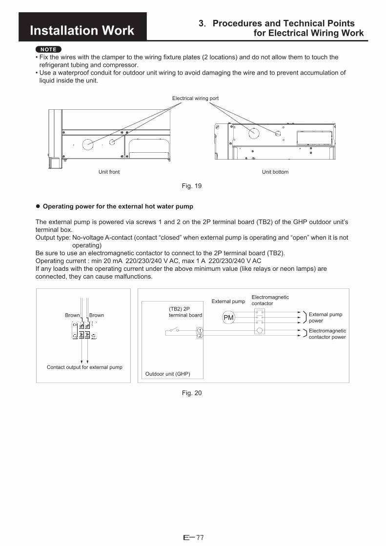
3.Procedures and Technical Pointsfor Electrical Wiring WorkInstallation Work
NOTE
• Fix the wires with the clamper to the wiring fixture plates (2 locations) and do not allow them to touch therefrigerant tubing and compressor.
• Use a waterproof conduit for outdoor unit wiring to avoid damaging the wire and to prevent accumulation ofliquid inside the unit.
Electrical wiring port
Unit front Unit bottom
Fig. 19
Operating power for the external hot water pump
The external pump is powered via screws 1 and 2 on the 2P terminal board (TB2) of the GHP outdoor unit’s terminal box.Output type: No-voltage A-contact (contact “closed” when external pump is operating and “open” when it is not
operating)Be sure to use an electromagnetic contactor to connect to the 2P terminal board (TB2).Operating current : min 20 mA 220/230/240 V AC, max 1 A 220/230/240 V AC If any loads with the operating current under the above minimum value (like relays or neon lamps) are connected, they can cause malfunctions.
12
PM
Outdoor unit (GHP)
External pump
Brown
Contact output for external pump
(TB2) 2P terminal board
Electromagnetic contactor
External pump power
Electromagnetic contactor power
Brown
Fig. 20
E-77

Separately Sold Parts
Contents1. Outdoor unit related parts
(1) Exhaust extension kit (CZ-PEX560S) ..................................................................... F-2
F-1

Separately Sold Parts 1. Outdoor unit related parts
(1) Exhaust extension kit (CZ-PEX560S)
(1) External dimension diagram
Figure 1
(2) Limitations when the exhaust pipe is extendedObserve the following limits when carrying out exhaust pipe extension work.Limitations during installation work Limit valueOutdoor air temperature -5°C or moreExtension of exhaust pipe 5 m and 4 bends or lessSlope of the exhaust pipe Gradient of 3/100 or more (upward)
(3) Installing the exhaust extension kit1) Disassemble the adaptor for the exhaust extension
a) Open the box, and check that it contains the following parts.Exhaust extension adaptor and exhaust top assembly x 1O-ring (P-70) x 1Instruction manual x 1
b) Fully insert the exhaust top all the way into the exhaust extension adapter once.c) Pull out the exhaust top in the direction of the arrow while pressing the stopper on the exhaust
extension adapter.
Figure 2
2) Remove the cap and exhaust top (standard parts)a) Remove the cap (M5 screw) attached to the top of the outdoor unit.b) Remove the exhaust top (M4 screws x 2) in the same way while taking care to not to dislodge
the exhaust pipe. (The exhaust top can be removed easily if you use lubricant and turn it duringremoval.) The two M4 screws will be reused, so take care not to lose them.
c) Remove the existing O-ring from the exhaust pipe and attach the supplied O-ring.The edge of the exhaust pipe is sharp, so be careful not to injure yourself when you performthis step.
Figure 3
F-2

Separately Sold Parts 1. Outdoor unit related parts
3) Attach the adapter for the exhaust extensiona) Insert the exhaust extension adaptor in the direction of the arrow. (The adaptor can be inserted
easily if you use lubricant.)b) Use the two M4 screws removed in Step 2) b to fix the exhaust extension adaptor to the outdoor
unit top panel.
Figure 4
4) Attach the exhaust topa) Be sure to attach the supplied exhaust top to the very end of the pipe.b) Connect the exhaust top and KP pipe by sufficiently inserting the exhaust top until the male
side connector warning mark (red line). Refer to Figure 6. A clicking sound will be heard whenthe top is connected properly.
c) Be sure to attach the exhaust top vertically as shown in Figure 5.
Figure 5
Figure 6
F-3

Separately Sold Parts 1. Outdoor unit related parts
Cautions regarding installation work• Cautions regarding connecting the KP pipe
1) When connecting the KP pipe, sufficiently insert the top until the warning mark (red line) on themale connector side becomes hidden. A clicking sound will be heard when the top is connectedproperly. Refer to Figure 6.
2) Never cut the KP pipe. If size adjustment is necessary, use a slide pipe.3) For other points regarding the KP pipe, follow the instructions provided by the manufacturer.
• Method of securing the exhaust pipe1) To secure the exhaust pipe, attach the fittings (support legs and split halves) on site, and use the
bolts/screws of the unit top plate to secure the pipe. Refer to the example in Figure 7.2) Secure the exhaust gas pipe extending from the main body of the unit to an external wall or the
like using the fittings very 1.5 to 2.0 m.3) The length from the exhaust extension pipe final securing edge is limited to 500 mm or less. Refer
to Figure 7.
Figure 7
• Separation distance of the exhaust pipeThe separation distance (mm) of the exhaust pipe from building parts finished with combustible material,flame retardant mate ial, or quasi-noncombustible material shall be as shown in Figure 8.
Figure 8 (Space part)
F-4

Separately Sold Parts 1. Outdoor unit related parts
• Separation distance of the exhaust topThe separation distance (mm) of the exhaust pipe opening from building parts finished witcombustible material, flame retardant material, or quasi-noncombustible material shall be as shownin Figure 9.
Figure 9 (Separation distance around the exhaust top)
<Reference> The dimensions within the parentheses are the distances for the case where a heat-proof board is installed and building parts are effectively finished with non-combustible materials.
• Precautions for when using an anti-vibration frame1) An exhaust extension can also be attached when an anti-vibration platform is used.2) If the exhaust pipe extension is 500 mm or less and installed vertically, then there is no need to
secure the exhaust extension.3) In other cases, secure the exhaust extension using, for instance, the fittings and the bolts/screws
of the unit top plate.4) Refer to the example in Figure 7.
• Precautions for when installing a blow out extension duct1) If a blow out extension duct is installed, there are cases when it is difficult to use a leg support
fitting and other fittings because of the shape to the duct. In such a case, use wire or other suitablemeans and the bolts/screws of the duct and unit top plate to secure the blow out extension.
2) For an example of using a leg support fitting, re er to Figure 10.
Figure 10
F-5
Periodic Inspection
Contents1. Periodic inspection items and intervals
(1) Test run ................................................................................................................... G-2(2) Warranty period ....................................................................................................... G-2(3) Periodic inspection items outside the warranty period ............................................ G-2
2. Periodic replacement parts .................................................................................G-4
G-1
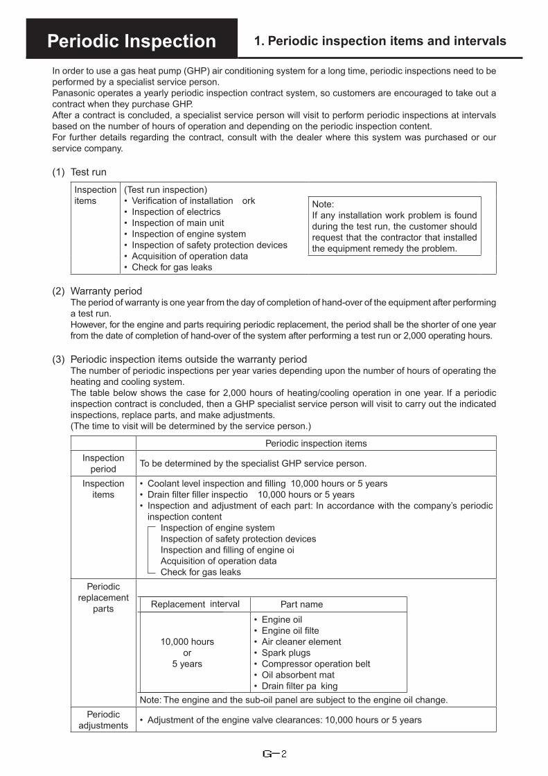
Periodic Inspection 1. Periodic inspection items and intervals
In order to use a gas heat pump (GHP) air conditioning system for a long time, periodic inspections need to be performed by a specialist service person.Panasonic operates a yearly periodic inspection contract system, so customers are encouraged to take out a contract when they purchase GHP.After a contract is concluded, a specialist service person will visit to perform periodic inspections at intervals based on the number of hours of operation and depending on the periodic inspection content.For further details regarding the contract, consult with the dealer where this system was purchased or our service company.
(1) Test run
Inspection items
(Test run inspection)• Verification of installation ork• Inspection of electrics• Inspection of main unit• Inspection of engine system• Inspection of safety protection devices• Acquisition of operation data• Check for gas leaks
Note:If any installation work problem is found during the test run, the customer should request that the contractor that installed the equipment remedy the problem.
(2) Warranty periodThe period of warranty is one year from the day of completion of hand-over of the equipment after performing a test run.However, for the engine and parts requiring periodic replacement, the period shall be the shorter of one year from the date of completion of hand-over of the system after performing a test run or 2,000 operating hours.
(3) Periodic inspection items outside the warranty periodThe number of periodic inspections per year varies depending upon the number of hours of operating the heating and cooling system.The table below shows the case for 2,000 hours of heating/cooling operation in one year. If a periodic inspection contract is concluded, then a GHP specialist service person will visit to carry out the indicated inspections, replace parts, and make adjustments.(The time to visit will be determined by the service person.)
Periodic inspection itemsInspection
period To be determined by the specialist GHP service person.
Inspection items
• Coolant level inspection and filling 10,000 hours or 5 years• Drain filter filler inspectio 10,000 hours or 5 years• Inspection and adjustment of each part: In accordance with the company’s periodic
inspection contentInspection of engine systemInspection of safety protection devicesInspection and filling of engine oiAcquisition of operation dataCheck for gas leaks
Periodic replacement
parts Replacement interval Part name
10,000 hoursor
5 years
• Engine oil• Engine oil filte• Air cleaner element• Spark plugs• Compressor operation belt• Oil absorbent mat• Drain filter pa king
Note: The engine and the sub-oil panel are subject to the engine oil change.Periodic
adjustments • Adjustment of the engine valve clearances: 10,000 hours or 5 years
G-2

Periodic Inspection 1. Periodic inspection items and intervals
A charge is made for periodic inspection.Note: The periodic replacement period is calculated on the basis of 2,000 operating hours per year, and
13 years of use.If it becomes necessary to replace parts other than the periodic replacement parts above, there will be a charge separate from the periodic inspection contract charge.
Note: Garbage and dust sticking to the heat exchanger fans of the indoor unit and outdoor unit may result in reduced performance or a failure.Therefore, it is recommended that you consult with the dealer where the system was purchased or with a specialist service company, and have garbage removed from the heat exchangers, and the heat exchangers cleaned. (A charge will be made for this service.)
G-3

Periodic Inspection 2. Periodic replacement parts
U-20GES3E5Replacement rank
(Replacement time) Part code Part name Quantity
C-5(10,000 hours or5 years)
CZ-PSLF3 Oil filte 1CZ-PSAF1 Air cleaner element 1CZ-PSPG1 Spark plugs 4CZ-PSVB6 Compressor operation belt 1CZ-PSLS5 Oil absorbent mat 0.5CZ-PSDF1 Drain filter pa king 1
C-10(20,000 hours or10 years)
CZ-PSLF3 Oil filte 1CZ-PSAF1 Air cleaner element 1CZ-PSPG1 Spark plugs 4CZ-PSVB6 Compressor operation belt 1CZ-PSLS5 Oil absorbent mat 0.5CZ-PSDF1 Drain filter pa king 1
G-4