
Taxonomy, technology and applications of smart objects
20
Inf Syst Front (2011) 13:281–300 DOI 10.1007/s10796-009-9218-4 Taxonomy, technology and applications of smart objects Tomás Sánchez López · Damith Chinthana Ranasinghe · Bela Patkai · Duncan McFarlane Published online: 5 August 2009 © Springer Science + Business Media, LLC 2009 Abstract Deployment of embedded technologies is in- creasingly being examined in industrial supply chains as a means for improving efficiency through greater control over purchase orders, inventory and product related information. Central to this development has been the advent of technologies such as bar codes, Radio Frequency Identification (RFID) systems, and wireless sensors which when attached to a product, form part of the product’s embedded systems infra- structure. The increasing integration of these technolo- gies dramatically contributes to the evolving notion of a “smart product”, a product which is capable of incorporating itself into both physical and information environments. The future of this revolution in objects equipped with smart embedded technologies is one in which objects can not only identify themselves, but can also sense and store their condition, communicate This work was partly funded as part of the BRIDGE project by the European Commission within the Sixth Framework Programme (2002-2006) IP Nr. IST-FP6-033546. T. Sánchez López (B ) · B. Patkai · D. McFarlane Engineering Department, Institute for Manufacturing, University of Cambridge, 16 Mill Lane, Cambridge CB2 1RX, UK e-mail: [email protected] B. Patkai e-mail: [email protected] D. McFarlane e-mail: [email protected] D. C. Ranasinghe The School of Computer Science, The University of Adelaide, Adelaide, South Australia, 5005, Australia e-mail: [email protected] with other objects and distributed infrastructures, and take decisions related to managing their life cycle. The object can essentially “plug” itself into a compatible systems infrastructure owned by different partners in a supply chain. However, as in any development process that will involve more than one end user, the estab- lishment of a common foundation and understanding is essential for interoperability, efficient communica- tion among involved parties and for developing novel applications. In this paper, we contribute to creating that common ground by providing a characterization to aid the specification and construction of “smart objects” and their underlying technologies. Further- more, our work provides an extensive set of examples and potential applications of different categories of smart objects. Keywords Smart object · Intelligent product · RFID · Sensors · Classification 1 Introduction It is easy to observe in our civilization that our original human motivation for building machines that substitute for physical work and help get rid of drudgery, was extended in the information age by a desire to replicate human intelligence and substitute the intellectual work of humans by machines. Consequently, we are moving towards ridding ourselves of “intellectual drudgery” and improving quality of human life. This development is enabled by recent advances in microelectronics, ubiquitous computing and wire- less communication technologies, while its integration with machines and physical objects (e.g. mechatronics)
Transcript of Taxonomy, technology and applications of smart objects
Inf Syst Front (2011) 13:281–300DOI 10.1007/s10796-009-9218-4
Taxonomy, technology and applications of smart objects
Tomás Sánchez López · Damith Chinthana Ranasinghe ·Bela Patkai · Duncan McFarlane
Published online: 5 August 2009© Springer Science + Business Media, LLC 2009
Abstract Deployment of embedded technologies is in-creasingly being examined in industrial supply chainsas a means for improving efficiency through greatercontrol over purchase orders, inventory and productrelated information. Central to this development hasbeen the advent of technologies such as bar codes,Radio Frequency Identification (RFID) systems, andwireless sensors which when attached to a product,form part of the product’s embedded systems infra-structure. The increasing integration of these technolo-gies dramatically contributes to the evolving notionof a “smart product”, a product which is capable ofincorporating itself into both physical and informationenvironments. The future of this revolution in objectsequipped with smart embedded technologies is one inwhich objects can not only identify themselves, butcan also sense and store their condition, communicate
This work was partly funded as part of the BRIDGE projectby the European Commission within the Sixth FrameworkProgramme (2002-2006) IP Nr. IST-FP6-033546.
T. Sánchez López (B) · B. Patkai · D. McFarlaneEngineering Department, Institute for Manufacturing,University of Cambridge, 16 Mill Lane,Cambridge CB2 1RX, UKe-mail: [email protected]
B. Patkaie-mail: [email protected]
D. McFarlanee-mail: [email protected]
D. C. RanasingheThe School of Computer Science,The University of Adelaide, Adelaide,South Australia, 5005, Australiae-mail: [email protected]
with other objects and distributed infrastructures, andtake decisions related to managing their life cycle. Theobject can essentially “plug” itself into a compatiblesystems infrastructure owned by different partners in asupply chain. However, as in any development processthat will involve more than one end user, the estab-lishment of a common foundation and understandingis essential for interoperability, efficient communica-tion among involved parties and for developing novelapplications. In this paper, we contribute to creatingthat common ground by providing a characterizationto aid the specification and construction of “smartobjects” and their underlying technologies. Further-more, our work provides an extensive set of examplesand potential applications of different categories ofsmart objects.
Keywords Smart object · Intelligent product · RFID ·Sensors · Classification
1 Introduction
It is easy to observe in our civilization that our originalhuman motivation for building machines that substitutefor physical work and help get rid of drudgery, wasextended in the information age by a desire to replicatehuman intelligence and substitute the intellectual workof humans by machines. Consequently, we are movingtowards ridding ourselves of “intellectual drudgery”and improving quality of human life.
This development is enabled by recent advancesin microelectronics, ubiquitous computing and wire-less communication technologies, while its integrationwith machines and physical objects (e.g. mechatronics)
282 Inf Syst Front (2011) 13:281–300
is ongoing and promises many new potentially dis-ruptive developments in product and service design.The availability of affordable computers, communica-tion networks, software development tools, wirelesscommunication technologies, RFID technology, minia-turised sensors and actuators has allowed the user-centered development of technologically advancedproducts that can store data, identify themselves andeven make decisions about themselves. These latterproducts have often been referred to as “smart prod-ucts”, “intelligent products” or “smart objects”.
While striving to integrate the aforementioned tech-nologies, another tendency of “disintegration” that ismotivated by the rapidly growing complexity of thesesystems can be observed. Distributed systems, controltheory and decision theory all aim at keeping complex-ity at a manageable level to ensure reliable operationand robustness.
In 2002, Wong et al. introduced the notion of the“intelligent product”, a conceptual model for the prop-erties associated with a physical product if it were toachieve some elements of behaviour associated withan intelligent being (Wong et al. 2002). This papertakes that notion further and into more concrete termsas we seek to provide a specification for an objectequipped with suitable “smart” technologies to achievea comprehensive set of intelligent properties directlyon the product. In essence this would enable, for in-stance, a product moving through the supply chain tonot only represent a physical commodity for deliverybut a key part of the information infrastructure of thesame supply chain. We refer to these objects equippedwith embedded smart technologies as “smart objects”.Smart objects are envisioned to be a key element inthe future for product life cycle management systemsin which products (objects) themselves interact withorganizational information systems and participate indecision making to make the overall system more ef-ficient. To achieve this goal, objects need to provideinformation related to themselves and the environmentthat surrounds them, and make decisions by commu-nicating and cooperating with other objects and withinformation infrastructures that support the system.
The smart object paradigm is a significant shift fromtraditional methods of product management comput-ing. In this new way of asset information management(AIM), there is a move towards object centric com-puting, in which objects themselves take over varioustasks that were formerly the responsibility of the systeminfrastructure. Therefore smarter objects provide theability to move decisions closer to the point of theinformation origin, and enable user and object centricapplications previously considered impossible.
Although the realization of this paradigm can gen-erate significant business value through more accurate,complete, timely and multi-dimensional information,there are many challenges that need to be addressed.Many of these issues are technology-related, such aswhich technologies are most suitable to provide theobjects with the new “abilities”, or which is the best wayto organize the information at an infrastructure leveland combine it with existent architectures. However,there is also a fundamental problem that should beaddressed prior to attempting any further prototyping;the characterization of smart objects, or how should wedescribe their features in order to provide a commonground for further development. Without a commonunderstanding of capabilities and features of smart ob-jects, we risk slowing down not only design, develop-ment and deployment processes but development ofnovel applications.
The objectives of this paper are, first, to brieflyreview existing classifications, key technologies, appli-cations and requirements for a specification of smartobjects. Secondly, to classify smart objects in a simplebut useful way, and provide examples of smart objectsin the context of this classification. Finally, we will alsoprovide a prototype implementation as the basis of asmart object test environment.
The paper is organized as follows. Section 2 de-scribes existing attempts to classify concepts relatedto smart objects. Section 3 summarizes the benefits ofa smart object characterization. Section 4 details ourclassification scheme and shows examples of smart ob-jects with various capabilities, and Section 5 introducesthe technologies that are relevant to the developmentof smart objects, while. Section 6 analyzes the mostpromising applications for smart objects, and Section 7describes a prototype based on this technology. Finally,Sections 8 and 9 conclude the paper with a discussionand conclusions, respectively.
2 Related work
In general, the concept of augmenting objects withcapabilities that will make them “smart” in some senseis very broadly studied and spans over numerous areasof research. Some areas, such as asset life cycle manage-ment, are directly focused on the creation of businessvalue. Others, such as context-aware systems, are notinterested in influencing the revenue streams that arealready in place, but rather in creating new products.
In this section we will overview, not all the areas thatmay profit from the smart object concept, but all thoseclassification attempts that are related to our work.
Inf Syst Front (2011) 13:281–300 283
Sections 5 and 6 will also provide some insight intoother related areas, the former by analyzing technolo-gies that would be required to build smart objects andthe later by reviewing present and future applicationsthat could benefit from developments in smart objects.
Though classification schemes for smart objects andrelated paradigms are generally missing, there are someassociated concepts that can help to develop a newtaxonomy, such as:
1. RFID tag classes 1–5: this is a technology basedclassification and is limited to RFID tags and read-ers (Section 2.1).
2. RFID-based sensor integration: Based on indus-trial needs obtained through interviews, pilots andcase studies. The main objective of this work is tohelp the adoption of RFID and sensor integrationtechnologies by providing a tool that assess the bestintegration strategies (Section 2.2)
3. Intelligent products: manufacturing/supply chainapplication oriented classification, mainly consider-ing life cycle data management. We consider thisthe most useful of all classifications and provides abasis for our current specification (Section 2.3)
While these classification schemes are inadequate todescribe smart objects in full, they provide a capability-oriented classification that is the basis for our specifica-tion. We will elaborate these existing classifications inthe following sections.
2.1 RFID tag classification
The Auto-ID Center (Auto-ID Labs since 2003) hasclassified RFID tags in order to improve their design,development and use. This classification (EPCglobal2007) has become very popular since its specification,and is currently well-known in manufacturing and sup-ply chain applications.
The specification defines the following classes:
• Class 1: Passive tags with minimum functionality(read/write memory, unique identity code).
• Class 2: Passive tags with additional functionalities,such as enhanced security features.
• Class 3: Semi-passive tags. A battery is used topower the logic portion of the circuit and providesimproved read range compared to Class 1 and Class2 tags. Added capabilities such as sensors may alsobe included.
• Class 4: Active tags. A battery is also used to powertransmissions as well as operate the tag. Likelyto have additional functionality such as tamper-
detection and sensors. They may also communicatedirectly with other Class-4 tags.
• Class 5: Readers. Have enough power to activateother tags and are generally connected to back-endnetworks.
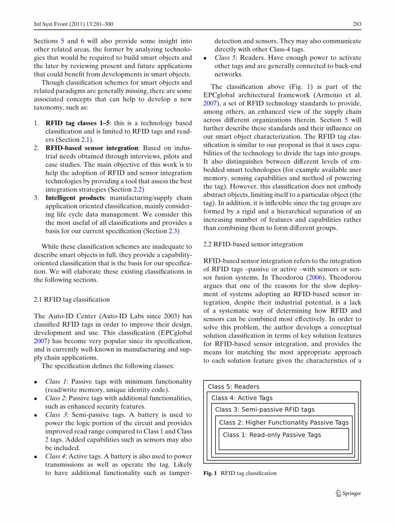
The classification above (Fig. 1) is part of theEPCglobal architectural framework (Armenio et al.2007), a set of RFID technology standards to provide,among others, an enhanced view of the supply chainacross different organizations therein. Section 5 willfurther describe these standards and their influence onour smart object characterization. The RFID tag clas-sification is similar to our proposal in that it uses capa-bilities of the technology to divide the tags into groups.It also distinguishes between different levels of em-bedded smart technologies (for example available usermemory, sensing capabilities and method of poweringthe tag). However, this classification does not embodyabstract objects, limiting itself to a particular object (thetag). In addition, it is inflexible since the tag groups areformed by a rigid and a hierarchical separation of anincreasing number of features and capabilities ratherthan combining them to form different groups.
2.2 RFID-based sensor integration
RFID-based sensor integration refers to the integrationof RFID tags –passive or active –with sensors or sen-sor fusion systems. In Theodorou (2006), Theodorouargues that one of the reasons for the slow deploy-ment of systems adopting an RFID-based sensor in-tegration, despite their industrial potential, is a lackof a systematic way of determining how RFID andsensors can be combined most effectively. In order tosolve this problem, the author develops a conceptualsolution classification in terms of key solution featuresfor RFID-based sensor integration, and provides themeans for matching the most appropriate approachto each solution feature given the characteristics of a
Fig. 1 RFID tag classification
284 Inf Syst Front (2011) 13:281–300
certain target application. Both the solution featuresand the application characteristics were based on a setof responses obtained from direct personal interviewswith industrial leaders, examination of pilots and casestudies.
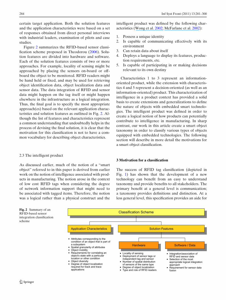
Figure 2 summarizes the RFID-based sensor classi-fication scheme proposed in Theodorou (2006). Solu-tion features are divided into hardware and software.Each of the solution features consists of two or moreapproaches. For example, locality of sensing might beapproached by placing the sensors on-board or off-board the object to be monitored. RFID readers mightbe hand held or fixed, and may be used for retrievingobject identification data, object localization data andsensor data. The data integration of RFID and sensordata might happen on the tag itself or might happenelsewhere in the infrastructure as a logical integration.Thus, the final goal is to specify the most appropriateapproach(es) based on the relevant application charac-teristics and solution features as outlined in Fig. 2. Al-though the list of features and characteristics representa common understanding that undoubtedly helps in theprocess of devising the final solution, it is clear that themotivation for this classification is not to have a com-mon vocabulary for describing object characteristics.
2.3 The intelligent product
As discussed earlier, much of the notion of a “smartobject” referred to in this paper is derived from earlierwork on the notion of intelligence associated with prod-ucts in manufacturing. The notion arose in the contextof low cost RFID tags when considering the degreeof network information support that might need tobe associated with tagged items. Therefore, the notionwas a logical rather than a physical construct and the
intelligent product was defined by the following char-acteristics (Wong et al. 2002; McFarlane et al. 2002):
1. Possess a unique identity2. Is capable of communicating effectively with its
environment3. Can retain data about itself4. Deploys a language to display its features, produc-
tion requirements, etc.5. Is capable of participating in or making decisions
relevant to its own destiny
Characteristics 1 to 3 represent an information-oriented product, while the extension with characteris-tics 4 and 5 represent a decision-oriented (as well as aninformation-oriented) product. This characterization ofintelligence in a product context has provided a solidbasis to create extensions and generalizations to definethe nature of objects with embedded smart technolo-gies. The intelligent product was defined in order tocreate a logical notion of how products can potentiallycontribute to intelligence in manufacturing. In sharpcontrast, our work in this article create a smart objecttaxonomy in order to classify various types of objectsequipped with embedded technologies. The followingsection will describe in more detail the motivations fora smart object classification.
3 Motivation for a classification
The success of RFID tag classification (depicted inFig. 1) has shown that the development of a newtechnology can benefit from an easy to understandtaxonomy and provide benefits to all stakeholders. Theprimary benefit at a general level is communication;a taxonomy provides definitions and distinction. At aless general level, this specification provides an aide for
Fig. 2 Summary of anRFID-based sensorintegration classificationscheme
Inf Syst Front (2011) 13:281–300 285
implementing a clearly defined set of technologies andrelated standards. These technologies, as discussed inSection 5, are specially valuable in the context of theEPCglobal standards.
The challenge of this specification is to find such anabstraction and grouping of smart object features thatcan become useful in the long term. Abstraction offeatures is less difficult than grouping because unlikeRFID features, smart object capabilities are not implic-itly inherited from lower classes. For example, Class 3RFID tags have all the Class 2 functionality and Class 4tags inherit all Class 1–3 functionality (it is easily visiblein Fig. 1).
Furthermore, smart objects may be used in a num-ber of industry sectors with considerably overlappingrequirements. This overlap provides the rationale forspecifying, designing and developing smart objects witha generic applicability. Applications in areas such asretail, logistics or vehicle health management show themost potential. A more detailed description on presentand future applications will be given in Section 6.
4 Smart object model
The term smart is a synonym of clever and intelligent,i.e. having the ability to make informed decisions on thebasis of some available information for one’s own ben-efit. In case of humans this is easily understandable, butin case of objects, we are using the method of analogyto transfer the idea of “smartness” or “intelligence” tophysical objects and products.
A “smart object” is any object or product that is –byway of embedded technologies –aware of its environ-ment and state, and it may have the ability to makeits own decisions about itself and its uses, communicatestate information, and achieve actuation under its owncontrol. Hence, a smart object possesses two or moreof the characteristics described below. Here, it is con-venient to use a simple letter coding for key features ofsmart objects. In our abstract feature model for smartobjects we formulate the characteristics for the smartobjects as:
• “I” for identity and the storage of any other rele-vant data
• “S” for sensing its physical condition and its situ-ated environment
• “A” for actuation of internal or external devices• “D” for decision making and participation in con-
trolling other devices or systems• “N” for networking to reach and receive informa-
tion through a wired or wireless network (predom-
inantly wireless, as wiring or connectors violate theindependence of smart objects)
The features listed are always optional, and variouscombinations of them can constitute a smart object.The degree or level of smartness can be noted by acombination of the letters I-S-A-D-N, e.g. “IS-Smart”object refers to an object that has identity, can storedata relevant to itself and has one or more sensors tosense its physical condition and its surrounding envi-ronment. Furthermore, it can be said that an objectwhich is composed of smart objects is also a smartobject, and that its intelligence is naturally a combina-tion of all its constituent smart objects. Section 7 willexemplify this fact by describing a washing machinewhich is composed of several smart objects with differ-ent characteristics.
The “I-S-A-D-N” specification does not aim toimpose a constraining view on smart objects or termi-nology, but forms a working description of the char-acteristic functionality of smart objects. A numberingof classes or categories or levels may be consideredin the future along with the letter notation. Note thatcombinations of the four letters include codings that arenot likely to be realistic. For example, an “N-smart”object needs to have a unique identity (at least witha local scope) to network with other objects, hence itmust be, at a minimum, “IN-smart”. Currently foreseenunrealistic smart objects are: D, N, SD, DN, SN, AD,AN, SDN, ADN, ASDN.
The following sections describe in detail each oneof the “I-S-A-D-N” characteristics. For each, a defin-ition and several simple examples are given. Finally,we provide a number of complex examples to clarifyinteractions among various characteristics.
4.1 “I” for identity and data
Definition An object that possesses a unique identity–in a relevant context –and/or has on-object data stor-age capability is an I-Smart object. Optionally these twobasic features may be extended by access control andother security services. Also, plug-and-play functional-ity requires a smart object to have an identity and on-board data storage capability.
Example An etched serial number on a car part, aserialized bar code on a can of food, a contact memorybutton with a serial number on a container or a Class 1passive RFID tag on a prescribed medication are allI-smart.
286 Inf Syst Front (2011) 13:281–300
4.2 “S” for sensing
Definition An “S-Smart” object is able to obtain andprovide a mechanism for the retrieval of physical infor-mation relevant to itself. Additionally, on-board stor-age capabilities for sensor data may also be supported.
Example Sensing is most likely to be combined withother smart features, but it can also be provided as astandalone feature. An example of a standalone “S”feature is an object with a temperature sensor andan LCD screen. End users can observe the temper-ature of the object and make decisions themselves.Alternatively, the “S” function can be substituted withnetworking –N-Smart functionality –whereby conditiondata are obtained from sources that are other than on-board sensors. In this case the object is not S-smart, aspart of the functionality is shifted to the environmentthat surrounds it.
4.3 “A” for actuation
Definition An “A-Smart” object is able to send ac-tuation commands to other devices. Actuators neednot be part of the smart object. An actuation may betriggered by a decision made by the object itself (wherethe property “D” is also necessary), by a programmaticsource or by an external source.
Example The “A” functionality is also most probablycombined with other functions. A fire detection devicethat fires an audio alarm on breaching a smoke particlethreshold is SAD-smart. On the contrary, a manualalarm switch is an A-Smart object.
4.4 “D” for decision
Definition A “D-Smart” object is able to make deci-sions relevant to its own destiny on the basis of avail-able information. One of the possible decisions mayinvolve some kind of actuation and in special cases itcan also have a “control” function: the capability toissue control signals to external objects or systems. Thisfunction is unlikely to exist on its own, i.e. without othersmartness functionality.
Example A motorcar engine with a sensor can de-cide if oil has to be changed and display a message:“CHANGE OIL”. This requires at least SAD-Smartfunctionality. An example of a D-Smart object is aclutch that can decide at the end of its life cycle, at atime when it is on an automated disassembly line, if
it should be recycled or disposed, and choose its routebased on its end of life decision.
4.5 “N” for networking
Definition An “N-Smart” object is able to use wiredor wireless communications to improve the quality ofits other smart functionalities. In general, networkedobjects require a unique identity with a local or globalscope to be able to communicate bi-directionally withina network. The networking functionality is essentialin many applications, for example in forwarding dataamong objects to reach a remote data collector such asan RFID reader or a base station in a wireless sensornetwork.
Example A condition monitored container can collectsensor data about its contents by using SN-smart itemsplaced in the container with temperature sensors. Whenthe cargo moves into the container, the items can com-municate their condition data through the container’swireless connection to end users. Also, if an object inthe same container does not have its own sensor, itcan network with another SN-smart object with therequired sensing capability to obtain the necessary data.This way the N-smartness can compliment many of theother capabilities of smart objects.
The following section will consider the state of theart for enabling levels of intelligence identified priorto considering novel applications of the smart objectsparadigm.
5 Key enabling technologies
In this section, the relevance of some enabling tech-nologies and components for building smart objects arediscussed in the context of our specification.
5.1 RFID technology
The most basic property of smart objects is that theycan uniquely identify themselves (automated self iden-tification). Although there are many technologies andstandards for unique identification, RFID is perhapsone of the most well known and certainly the mostrelevant for our purpose. Radio Frequency Identifi-cation (RFID) is a general term used for systemsthat transfer a unique identification code using radiosignals. Recently, however, RFID is associated, notonly with the ID transmission itself, but also with the
Inf Syst Front (2011) 13:281–300 287
infrastructure that allows for RFID based informationto be transformed into services (Section 5.3).
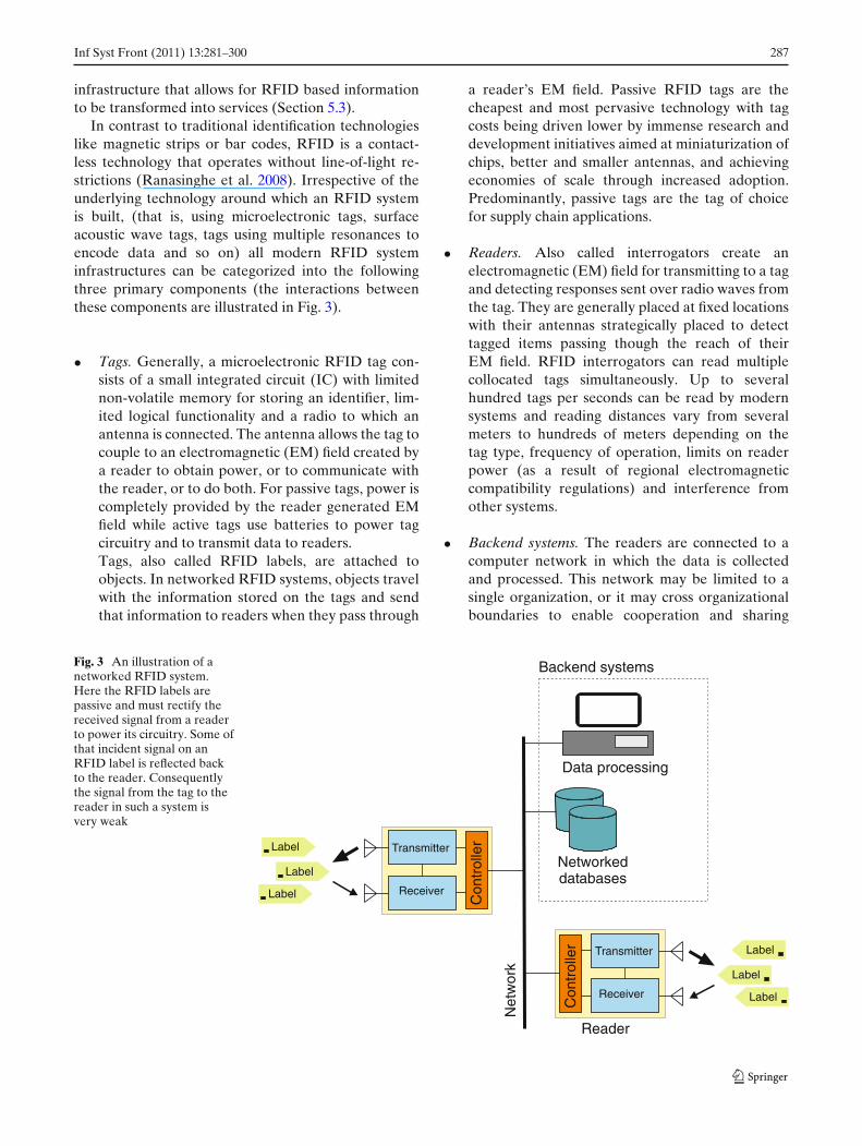
In contrast to traditional identification technologieslike magnetic strips or bar codes, RFID is a contact-less technology that operates without line-of-light re-strictions (Ranasinghe et al. 2008). Irrespective of theunderlying technology around which an RFID systemis built, (that is, using microelectronic tags, surfaceacoustic wave tags, tags using multiple resonances toencode data and so on) all modern RFID systeminfrastructures can be categorized into the followingthree primary components (the interactions betweenthese components are illustrated in Fig. 3).
• Tags. Generally, a microelectronic RFID tag con-sists of a small integrated circuit (IC) with limitednon-volatile memory for storing an identifier, lim-ited logical functionality and a radio to which anantenna is connected. The antenna allows the tag tocouple to an electromagnetic (EM) field created bya reader to obtain power, or to communicate withthe reader, or to do both. For passive tags, power iscompletely provided by the reader generated EMfield while active tags use batteries to power tagcircuitry and to transmit data to readers.Tags, also called RFID labels, are attached toobjects. In networked RFID systems, objects travelwith the information stored on the tags and sendthat information to readers when they pass through
a reader’s EM field. Passive RFID tags are thecheapest and most pervasive technology with tagcosts being driven lower by immense research anddevelopment initiatives aimed at miniaturization ofchips, better and smaller antennas, and achievingeconomies of scale through increased adoption.Predominantly, passive tags are the tag of choicefor supply chain applications.
• Readers. Also called interrogators create anelectromagnetic (EM) field for transmitting to a tagand detecting responses sent over radio waves fromthe tag. They are generally placed at fixed locationswith their antennas strategically placed to detecttagged items passing though the reach of theirEM field. RFID interrogators can read multiplecollocated tags simultaneously. Up to severalhundred tags per seconds can be read by modernsystems and reading distances vary from severalmeters to hundreds of meters depending on thetag type, frequency of operation, limits on readerpower (as a result of regional electromagneticcompatibility regulations) and interference fromother systems.
• Backend systems. The readers are connected to acomputer network in which the data is collectedand processed. This network may be limited to asingle organization, or it may cross organizationalboundaries to enable cooperation and sharing
Fig. 3 An illustration of anetworked RFID system.Here the RFID labels arepassive and must rectify thereceived signal from a readerto power its circuitry. Some ofthat incident signal on anRFID label is reflected backto the reader. Consequentlythe signal from the tag to thereader in such a system isvery weak
Transmitter
Transmitter
Receiver
Receiver
Con
trol
ler
Con
trol
ler
Reader
Label
Label
Label
Label
Label
Label
Networkeddatabases
Net
wor
k
Data processing
Backend systems
288 Inf Syst Front (2011) 13:281–300
between business partners (e.g. manufacturers,warehouses and retailers).
Due to their wireless capabilities, RFID tagged ob-jects are potentially capable of offering their identi-fication in a fully automated environment. Thus, theadvantages of RFID systems for object tracking andmanagement, as compared to traditional identificationmethods such as the bar code, are many. Unlike theoptical bar code, RFID tags do not require line ofsight for operation. Furthermore, bar codes need tobe read manually and one at a time, however, RFIDinterrogators can read multiple collocated tags simul-taneously. The collocation reading ratio can reach upto several hundred tags per seconds with proper anti-collision techniques. Also, since RFID tags store theiridentification code in small memory chips, they arecapable of storing more information than just serialnumbers, leaving the door open for additional productdata or other applications.
Today’s RFID technology is founded on the Elec-tronic Product Code (EPC) unique object numberingstandard. The EPC, described in the EPCglobal’s TagData Standard (EPCglobal 2005), is an identificationscheme designed to support the needs of various indus-tries by accommodating both existing and new codingschemes.
EPCglobal’s set of RFID specifications have becomede-facto industry standards for RFID system imple-mentations. There are many companies that providecommercial solutions based on these standards, includ-ing hardware (such as tags and readers) and softwareand system integration. Although EPCglobal specifica-tions are still under development, they are supportedby industry and international research bodies. They arewithout a doubt the most promising set of technologystandards for truly interoperable, complete and globalRFID systems.
5.2 Sensor technology
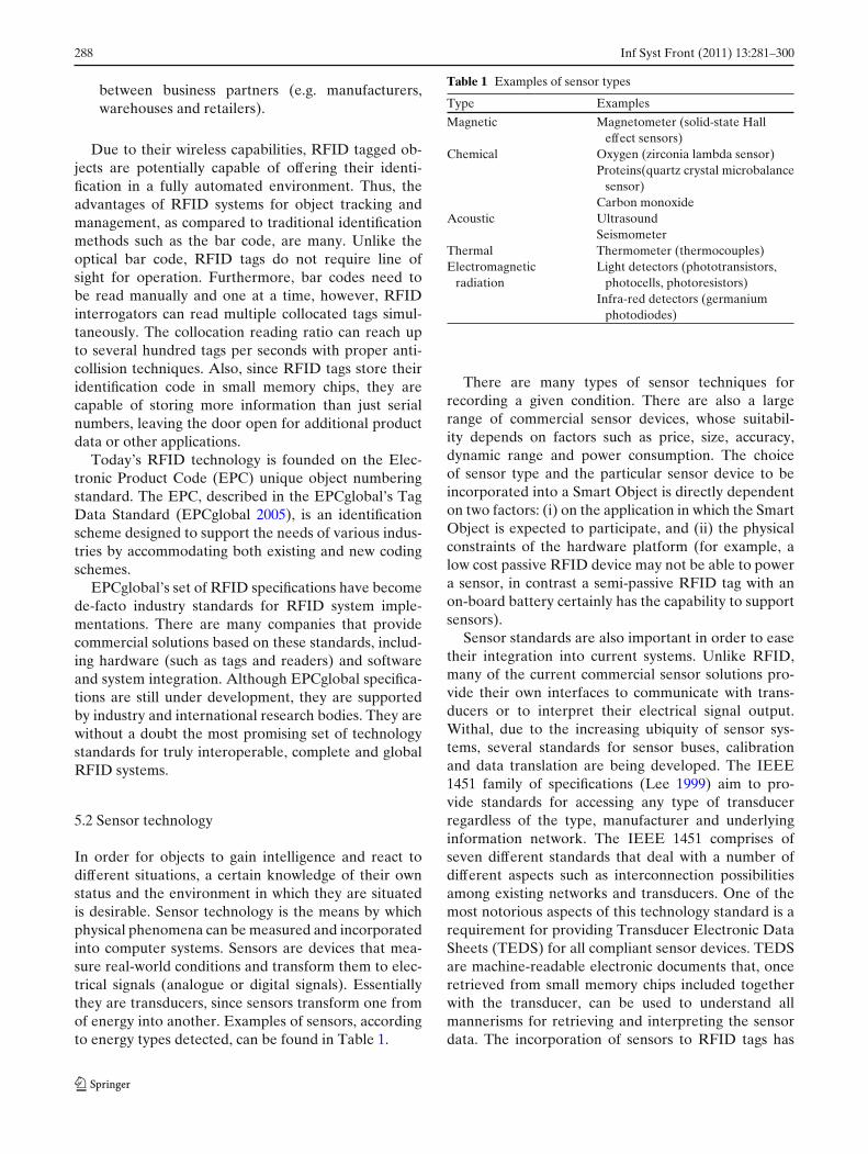
In order for objects to gain intelligence and react todifferent situations, a certain knowledge of their ownstatus and the environment in which they are situatedis desirable. Sensor technology is the means by whichphysical phenomena can be measured and incorporatedinto computer systems. Sensors are devices that mea-sure real-world conditions and transform them to elec-trical signals (analogue or digital signals). Essentiallythey are transducers, since sensors transform one fromof energy into another. Examples of sensors, accordingto energy types detected, can be found in Table 1.
Table 1 Examples of sensor types
Type Examples
Magnetic Magnetometer (solid-state Halleffect sensors)
Chemical Oxygen (zirconia lambda sensor)Proteins(quartz crystal microbalance
sensor)Carbon monoxide
Acoustic UltrasoundSeismometer
Thermal Thermometer (thermocouples)Electromagnetic Light detectors (phototransistors,
radiation photocells, photoresistors)Infra-red detectors (germanium
photodiodes)
There are many types of sensor techniques forrecording a given condition. There are also a largerange of commercial sensor devices, whose suitabil-ity depends on factors such as price, size, accuracy,dynamic range and power consumption. The choiceof sensor type and the particular sensor device to beincorporated into a Smart Object is directly dependenton two factors: (i) on the application in which the SmartObject is expected to participate, and (ii) the physicalconstraints of the hardware platform (for example, alow cost passive RFID device may not be able to powera sensor, in contrast a semi-passive RFID tag with anon-board battery certainly has the capability to supportsensors).
Sensor standards are also important in order to easetheir integration into current systems. Unlike RFID,many of the current commercial sensor solutions pro-vide their own interfaces to communicate with trans-ducers or to interpret their electrical signal output.Withal, due to the increasing ubiquity of sensor sys-tems, several standards for sensor buses, calibrationand data translation are being developed. The IEEE1451 family of specifications (Lee 1999) aim to pro-vide standards for accessing any type of transducerregardless of the type, manufacturer and underlyinginformation network. The IEEE 1451 comprises ofseven different standards that deal with a number ofdifferent aspects such as interconnection possibilitiesamong existing networks and transducers. One of themost notorious aspects of this technology standard is arequirement for providing Transducer Electronic DataSheets (TEDS) for all compliant sensor devices. TEDSare machine-readable electronic documents that, onceretrieved from small memory chips included togetherwith the transducer, can be used to understand allmannerisms for retrieving and interpreting the sensordata. The incorporation of sensors to RFID tags has
Inf Syst Front (2011) 13:281–300 289
also been studied by the ISO/IEC group (InternationalOrganization for Standardization/International Elec-trotechnical Commission). The current working drafts(ISO/ICE 2006, 2007), part of which involves a tagdata structure and an air interface protocol, are largelyconsistent with the IEEE 1451 standardisation efforts.
5.2.1 Wireless sensor networks
Sensor transducers are usually connected to computersystems (embedded or not) that control them and usetheir data output. Networking the systems that operatesensor devices is a very valuable feature for informationsharing and control.
A popular solution and an area of research for net-working sensor systems are Wireless Sensor Networks(WSNs). WSNs strive to develop systems of reducedsize, low power, long range, low cost wireless deviceswith computation and sensing capabilities. WirelessSensor Networks are gaining increasing popularity dueto a rapidly increasing applications domain and increas-ingly tight integration of embedded modules (receiverand transmitter module, microcontroller and sensortechnologies) coupled with declining costs. The abilityof WSNs to form ad-hoc networks and perform dataprocessing represents a significant improvement overtraditional sensor networks.
The basic purpose of Wireless Sensor Network ap-plications is to provide monitoring of a target envi-ronment. WSNs have many applications which posedifferent technical issues. Environmental monitoring,disaster prevention, health care, smart spaces and mil-itary applications are among their most popular appli-cations (refer to Section 6.4).
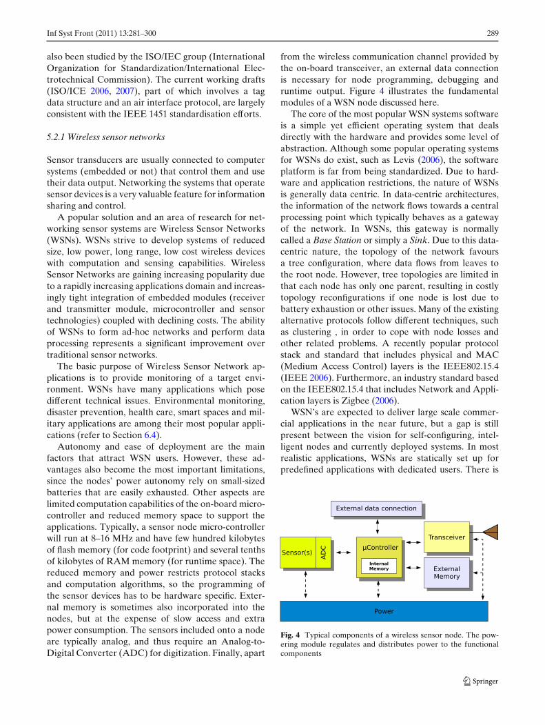
Autonomy and ease of deployment are the mainfactors that attract WSN users. However, these ad-vantages also become the most important limitations,since the nodes’ power autonomy rely on small-sizedbatteries that are easily exhausted. Other aspects arelimited computation capabilities of the on-board micro-controller and reduced memory space to support theapplications. Typically, a sensor node micro-controllerwill run at 8–16 MHz and have few hundred kilobytesof flash memory (for code footprint) and several tenthsof kilobytes of RAM memory (for runtime space). Thereduced memory and power restricts protocol stacksand computation algorithms, so the programming ofthe sensor devices has to be hardware specific. Exter-nal memory is sometimes also incorporated into thenodes, but at the expense of slow access and extrapower consumption. The sensors included onto a nodeare typically analog, and thus require an Analog-to-Digital Converter (ADC) for digitization. Finally, apart
from the wireless communication channel provided bythe on-board transceiver, an external data connectionis necessary for node programming, debugging andruntime output. Figure 4 illustrates the fundamentalmodules of a WSN node discussed here.
The core of the most popular WSN systems softwareis a simple yet efficient operating system that dealsdirectly with the hardware and provides some level ofabstraction. Although some popular operating systemsfor WSNs do exist, such as Levis (2006), the softwareplatform is far from being standardized. Due to hard-ware and application restrictions, the nature of WSNsis generally data centric. In data-centric architectures,the information of the network flows towards a centralprocessing point which typically behaves as a gatewayof the network. In WSNs, this gateway is normallycalled a Base Station or simply a Sink. Due to this data-centric nature, the topology of the network favoursa tree configuration, where data flows from leaves tothe root node. However, tree topologies are limited inthat each node has only one parent, resulting in costlytopology reconfigurations if one node is lost due tobattery exhaustion or other issues. Many of the existingalternative protocols follow different techniques, suchas clustering , in order to cope with node losses andother related problems. A recently popular protocolstack and standard that includes physical and MAC(Medium Access Control) layers is the IEEE802.15.4(IEEE 2006). Furthermore, an industry standard basedon the IEEE802.15.4 that includes Network and Appli-cation layers is Zigbee (2006).
WSN’s are expected to deliver large scale commer-cial applications in the near future, but a gap is stillpresent between the vision for self-configuring, intel-ligent nodes and currently deployed systems. In mostrealistic applications, WSNs are statically set up forpredefined applications with dedicated users. There is
Fig. 4 Typical components of a wireless sensor node. The pow-ering module regulates and distributes power to the functionalcomponents
290 Inf Syst Front (2011) 13:281–300
little intelligence adopted for those applications be-cause it is difficult to model many of the WSN issuesin a real environment. Moreover, many WSNs are im-plemented as a disjoint network for dedicated servicesin the local (edge) domain. Thus, most research effortson WSNs fall into developing an effective in-networkdata aggregation mechanism with limited resources,while connection to infrastructure networks is hardlyconsidered. Nevertheless, the ability to create smart-ness by installing off-the-shelf wireless sensor nodesmust be considered, and together with other similartechnologies such as sensor enabled RFID tags, WSNscould become one of the key technologies to realizetruly Smart Objects.
5.3 Information infrastructure
In order to support applications that transforms ob-jects into an actual intelligent system, both sensor andidentification information must be collected, filteredand stored for further processing. If the smart objectapplication that we are creating must extend beyondthe local domain, a suitable mechanism for sharing thedata among various players must also be implemented.Considering that an object’s condition information canvary over time and may need to be updated regularlywith applications, our ideal architecture may be com-plex and difficult to realize if it is designed from basicbuilding blocks.
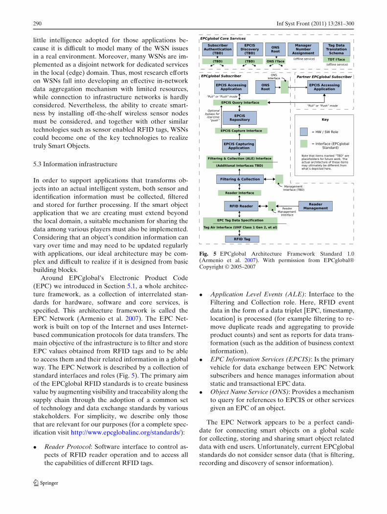
Around EPCglobal’s Electronic Product Code(EPC) we introduced in Section 5.1, a whole architec-ture framework, as a collection of interrelated stan-dards for hardware, software and core services, isspecified. This architecture framework is called theEPC Network (Armenio et al. 2007). The EPC Net-work is built on top of the Internet and uses Internet-based communication protocols for data transfers. Themain objective of the infrastructure is to filter and storeEPC values obtained from RFID tags and to be ableto access them and their related information in a globalway. The EPC Network is described by a collection ofstandard interfaces and roles (Fig. 5). The primary aimof the EPCglobal RFID standards is to create businessvalue by augmenting visibility and traceability along thesupply chain through the adoption of a common setof technology and data exchange standards by variousstakeholders. For simplicity, we describe only thosethat are relevant for our purposes (for a complete spec-ification visit http://www.epcglobalinc.org/standards/):
• Reader Protocol: Software interface to control as-pects of RFID reader operation and to access allthe capabilities of different RFID tags.
Fig. 5 EPCglobal Architecture Framework Standard 1.0(Armenio et al. 2007). With permission from EPCglobal®Copyright © 2005–2007
• Application Level Events (ALE): Interface to theFiltering and Collection role. Here, RFID eventdata in the form of a data triplet [EPC, timestamp,location] is processed (for example filtering to re-move duplicate reads and aggregating to provideproduct counts) and sent as reports for data trans-formation (such as the addition of business contextinformation).
• EPC Information Services (EPCIS): Is the primaryvehicle for data exchange between EPC Networksubscribers and hence manages information aboutstatic and transactional EPC data.
• Object Name Service (ONS): Provides a mechanismto query for references to EPCIS or other servicesgiven an EPC of an object.
The EPC Network appears to be a perfect candi-date for connecting smart objects on a global scalefor collecting, storing and sharing smart object relateddata with end users. Unfortunately, current EPCglobalstandards do not consider sensor data (that is filtering,recording and discovery of sensor information).
Inf Syst Front (2011) 13:281–300 291
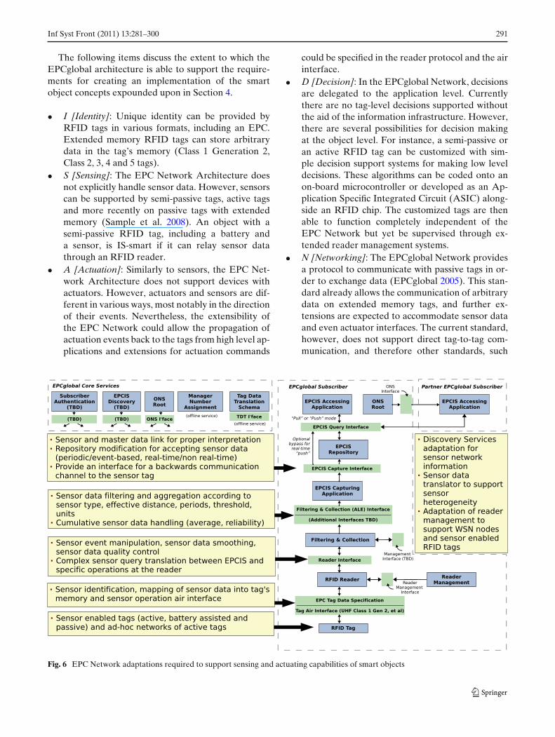
The following items discuss the extent to which theEPCglobal architecture is able to support the require-ments for creating an implementation of the smartobject concepts expounded upon in Section 4.
• I [Identity]: Unique identity can be provided byRFID tags in various formats, including an EPC.Extended memory RFID tags can store arbitrarydata in the tag’s memory (Class 1 Generation 2,Class 2, 3, 4 and 5 tags).
• S [Sensing]: The EPC Network Architecture doesnot explicitly handle sensor data. However, sensorscan be supported by semi-passive tags, active tagsand more recently on passive tags with extendedmemory (Sample et al. 2008). An object with asemi-passive RFID tag, including a battery anda sensor, is IS-smart if it can relay sensor datathrough an RFID reader.
• A [Actuation]: Similarly to sensors, the EPC Net-work Architecture does not support devices withactuators. However, actuators and sensors are dif-ferent in various ways, most notably in the directionof their events. Nevertheless, the extensibility ofthe EPC Network could allow the propagation ofactuation events back to the tags from high level ap-plications and extensions for actuation commands
could be specified in the reader protocol and the airinterface.
• D [Decision]: In the EPCglobal Network, decisionsare delegated to the application level. Currentlythere are no tag-level decisions supported withoutthe aid of the information infrastructure. However,there are several possibilities for decision makingat the object level. For instance, a semi-passive oran active RFID tag can be customized with sim-ple decision support systems for making low leveldecisions. These algorithms can be coded onto anon-board microcontroller or developed as an Ap-plication Specific Integrated Circuit (ASIC) along-side an RFID chip. The customized tags are thenable to function completely independent of theEPC Network but yet be supervised through ex-tended reader management systems.
• N [Networking]: The EPCglobal Network providesa protocol to communicate with passive tags in or-der to exchange data (EPCglobal 2005). This stan-dard already allows the communication of arbitrarydata on extended memory tags, and further ex-tensions are expected to accommodate sensor dataand even actuator interfaces. The current standard,however, does not support direct tag-to-tag com-munication, and therefore other standards, such
Fig. 6 EPC Network adaptations required to support sensing and actuating capabilities of smart objects
292 Inf Syst Front (2011) 13:281–300
as the aforementioned IEEE 802.15.4 and ZigBee,could be considered in the future.
Overall, the EPCglobal standards were designed tobe extensible and flexible. An eventual consequence ofsensor enabled RFID tags is the need for specifyingextensions to the various interfaces of the EPCglobalarchitecture framework. Figure 6 presents an abstractview of how the different roles and interfaces of theEPC Network would have to be broadened to supportsensing and actuation capabilities of the smart objectmodel.
6 Applications
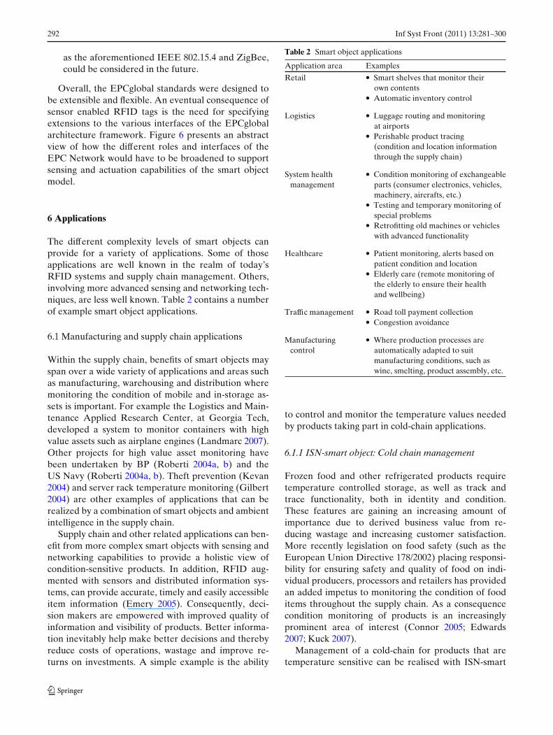
The different complexity levels of smart objects canprovide for a variety of applications. Some of thoseapplications are well known in the realm of today’sRFID systems and supply chain management. Others,involving more advanced sensing and networking tech-niques, are less well known. Table 2 contains a numberof example smart object applications.
6.1 Manufacturing and supply chain applications
Within the supply chain, benefits of smart objects mayspan over a wide variety of applications and areas suchas manufacturing, warehousing and distribution wheremonitoring the condition of mobile and in-storage as-sets is important. For example the Logistics and Main-tenance Applied Research Center, at Georgia Tech,developed a system to monitor containers with highvalue assets such as airplane engines (Landmarc 2007).Other projects for high value asset monitoring havebeen undertaken by BP (Roberti 2004a, b) and theUS Navy (Roberti 2004a, b). Theft prevention (Kevan2004) and server rack temperature monitoring (Gilbert2004) are other examples of applications that can berealized by a combination of smart objects and ambientintelligence in the supply chain.
Supply chain and other related applications can ben-efit from more complex smart objects with sensing andnetworking capabilities to provide a holistic view ofcondition-sensitive products. In addition, RFID aug-mented with sensors and distributed information sys-tems, can provide accurate, timely and easily accessibleitem information (Emery 2005). Consequently, deci-sion makers are empowered with improved quality ofinformation and visibility of products. Better informa-tion inevitably help make better decisions and therebyreduce costs of operations, wastage and improve re-turns on investments. A simple example is the ability
Table 2 Smart object applications
Application area Examples
Retail • Smart shelves that monitor theirown contents
• Automatic inventory control
Logistics • Luggage routing and monitoringat airports
• Perishable product tracing(condition and location informationthrough the supply chain)
System health • Condition monitoring of exchangeablemanagement parts (consumer electronics, vehicles,
machinery, aircrafts, etc.)• Testing and temporary monitoring of
special problems• Retrofitting old machines or vehicles
with advanced functionality
Healthcare • Patient monitoring, alerts based onpatient condition and location
• Elderly care (remote monitoring ofthe elderly to ensure their healthand wellbeing)
Traffic management • Road toll payment collection• Congestion avoidance
Manufacturing • Where production processes arecontrol automatically adapted to suit
manufacturing conditions, such aswine, smelting, product assembly, etc.
to control and monitor the temperature values neededby products taking part in cold-chain applications.
6.1.1 ISN-smart object: Cold chain management
Frozen food and other refrigerated products requiretemperature controlled storage, as well as track andtrace functionality, both in identity and condition.These features are gaining an increasing amount ofimportance due to derived business value from re-ducing wastage and increasing customer satisfaction.More recently legislation on food safety (such as theEuropean Union Directive 178/2002) placing responsi-bility for ensuring safety and quality of food on indi-vidual producers, processors and retailers has providedan added impetus to monitoring the condition of fooditems throughout the supply chain. As a consequencecondition monitoring of products is an increasinglyprominent area of interest (Connor 2005; Edwards2007; Kuck 2007).
Management of a cold-chain for products that aretemperature sensitive can be realised with ISN-smart
Inf Syst Front (2011) 13:281–300 293
objects based on sensor enabled RFID tags. For exam-ple semi-passive (Class 3) or active (Class 4) tags withan on-board temperature sensor, preferably –and mostlikely –a digital temperature sensors since they are self-calibrating and require no special conditioning circuits,are suitable candidates. Possibly additional sensors, on-tag or installed in the warehouse, can monitor otherconditions such as humidity, light exposure, pressure orinclination.
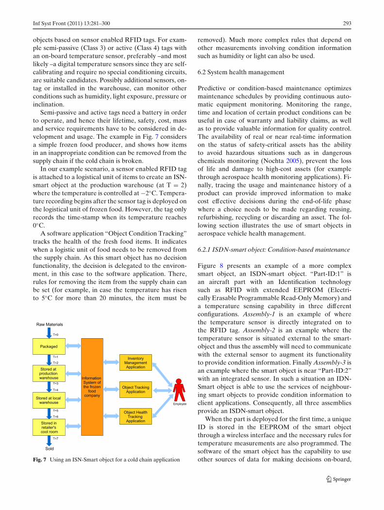
Semi-passive and active tags need a battery in orderto operate, and hence their lifetime, safety, cost, massand service requirements have to be considered in de-velopment and usage. The example in Fig. 7 considersa simple frozen food producer, and shows how itemsin an inappropriate condition can be removed from thesupply chain if the cold chain is broken.
In our example scenario, a sensor enabled RFID tagis attached to a logistical unit of items to create an ISN-smart object at the production warehouse (at T = 2)where the temperature is controlled at −2◦C. Tempera-ture recording begins after the sensor tag is deployed onthe logistical unit of frozen food. However, the tag onlyrecords the time-stamp when its temperature reaches0◦C.
A software application “Object Condition Tracking”tracks the health of the fresh food items. It indicateswhen a logistic unit of food needs to be removed fromthe supply chain. As this smart object has no decisionfunctionality, the decision is delegated to the environ-ment, in this case to the software application. There,rules for removing the item from the supply chain canbe set (for example, in case the temperature has risento 5◦C for more than 20 minutes, the item must be
Fig. 7 Using an ISN-Smart object for a cold chain application
removed). Much more complex rules that depend onother measurements involving condition informationsuch as humidity or light can also be used.
6.2 System health management
Predictive or condition-based maintenance optimizesmaintenance schedules by providing continuous auto-matic equipment monitoring. Monitoring the range,time and location of certain product conditions can beuseful in case of warranty and liability claims, as wellas to provide valuable information for quality control.The availability of real or near real-time informationon the status of safety-critical assets has the abilityto avoid hazardous situations such as in dangerouschemicals monitoring (Nochta 2005), prevent the lossof life and damage to high-cost assets (for examplethrough aerospace health monitoring applications). Fi-nally, tracing the usage and maintenance history of aproduct can provide improved information to makecost effective decisions during the end-of-life phasewhere a choice needs to be made regarding reusing,refurbishing, recycling or discarding an asset. The fol-lowing section illustrates the use of smart objects inaerospace vehicle health management.
6.2.1 ISDN-smart object: Condition-based maintenance
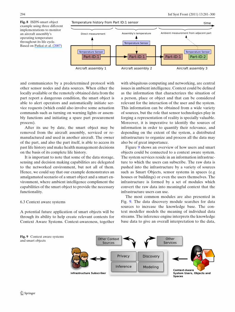
Figure 8 presents an example of a more complexsmart object, an ISDN-smart object. “Part-ID:1” isan aircraft part with an Identification technologysuch as RFID with extended EEPROM (Electri-cally Erasable Programmable Read-Only Memory) anda temperature sensing capability in three differentconfigurations. Assembly-1 is an example of wherethe temperature sensor is directly integrated on tothe RFID tag. Assembly-2 is an example where thetemperature sensor is situated external to the smart-object and thus the assembly will need to communicatewith the external sensor to augment its functionalityto provide condition information. Finally Assembly-3 isan example where the smart object is near “Part-ID:2”with an integrated sensor. In such a situation an IDN-Smart object is able to use the services of neighbour-ing smart objects to provide condition information toclient applications. Consequently, all three assembliesprovide an ISDN-smart object.
When the part is deployed for the first time, a uniqueID is stored in the EEPROM of the smart objectthrough a wireless interface and the necessary rules fortemperature measurements are also programmed. Thesoftware of the smart object has the capability to useother sources of data for making decisions on-board,
294 Inf Syst Front (2011) 13:281–300
Fig. 8 ISDN-smart objectexample using three differentimplementations to monitoran aircraft assembly’soperating temperaturethroughout its life cycle.Based on Patkai et al. (2007)
and communicates by a predetermined protocol withother sensor nodes and data sources. When either thelocally available or the remotely obtained data from thepart report a dangerous condition, the smart object isable to alert operators and automatically initiate ser-vice requests (which could also involve some actuationcommands such as turning on warning lights or assem-bly functions and initiating a spare part procurementprocess).
After its use by date, the smart object may beremoved from the aircraft assembly, serviced or re-manufactured and used in another aircraft. The ownerof the part, and also the part itself, is able to access itspast life history and make health management decisionson the basis of its complete life history.
It is important to note that some of the data storage,sensing and decision making capabilities are delegatedto the networked environment, but not all of them.Hence, we could say that our example demonstrates anamalgamated scenario of a smart object and a smart en-vironment, where ambient intelligence compliment thecapabilities of the smart object to provide the necessaryfunctionality.
6.3 Context aware systems
A potential future application of smart objects will bethrough its ability to help create relevant contexts forContext Aware Systems. Context-awareness, together
with ubiquitous computing and networking, are centralissues in ambient intelligence. Context could be definedas the information that characterizes the situation ofa person, place or object and that can be consideredrelevant for the interaction of the user and the system.This information can be obtained from a wide varietyof sources, but the role that sensor technologies play inforging a representation of reality is specially valuable.Moreover, it is imperative to identify the sources ofinformation in order to quantify their relevance, anddepending on the extent of the system, a distributedinfrastructure to organize and process all the data mayalso be of great importance.
Figure 9 shows an overview of how users and smartobjects could be connected to a context aware system.The system services reside in an information infrastruc-ture to which the users can subscribe. The raw data ispushed into the infrastructure by a variety of sourcessuch as Smart Objects, sensor systems in spaces (e.ghouses or buildings) or even the users themselves. Theinfrastructure is formed by a set of modules whichconvert the raw data into meaningful context that theinfrastructure users can use.
The most common modules are also presented inFig. 9. The data discovery module searches for datasources to increase the knowledge base. The con-text modeller models the meaning of individual datastreams. The inference engine interprets the knowledgebase data to give an overall interpretation to the data,
Fig. 9 Context aware systemsand smart objects
Inf Syst Front (2011) 13:281–300 295
thus building the context. The privacy module filtersdata sources according to the privacy policy. Other datasources such as historical information can be used toinfer a more accurate context. Finally, the beneficiariesfrom the context aware system might also be third-partyservices not directly associated with the subscribers.Note that by building a modular system, any sourcesof context information and other modules can also beplugged into the context-aware system, while the userbenefits from the enhanced flow of information in atransparent way.
6.4 Other applications
RFID tags and the standards that support them areforeseen to augment in complexity and functionalitieswith time (Mitsugi et al. 2007). Currently RFID tech-nological maturity is around passive RFID tags andincreasing innovation is driving the development ofcommercial solutions based on battery assisted andactive tags (Ruhanen et al. 2008). Although WSNsand RFID have always been considered as separatetechnologies, and hence they have followed separateresearch paths, the evolution of RFID technology,standards and applications is aligning RFID on an in-evitable path of convergence with WSNs at some pointin the future. As these technological paths converge itis probably more appropriate to consider applicationsas smart object applications as opposed to RFID orWSN applications. WSNs could be seen, thus, as thetechnology to power smart objects with sensing andactive networking capabilities. For all these reasons, weconsider that in the near future, applications tradition-ally related to WSNs will form a subset of smart objectapplications.
Environment monitoring is perhaps the most pop-ular application of WSNs and the one that has beenreported more often. For example, sensor nodes couldbe deployed in greenhouses, farm buildings and cropsin order to monitor animals and plants in real-time(Yoo et al. 2007). Forests, building and other areascould be protected from fires by deploying a networkof nodes that can warn firefighting authorities if a fire
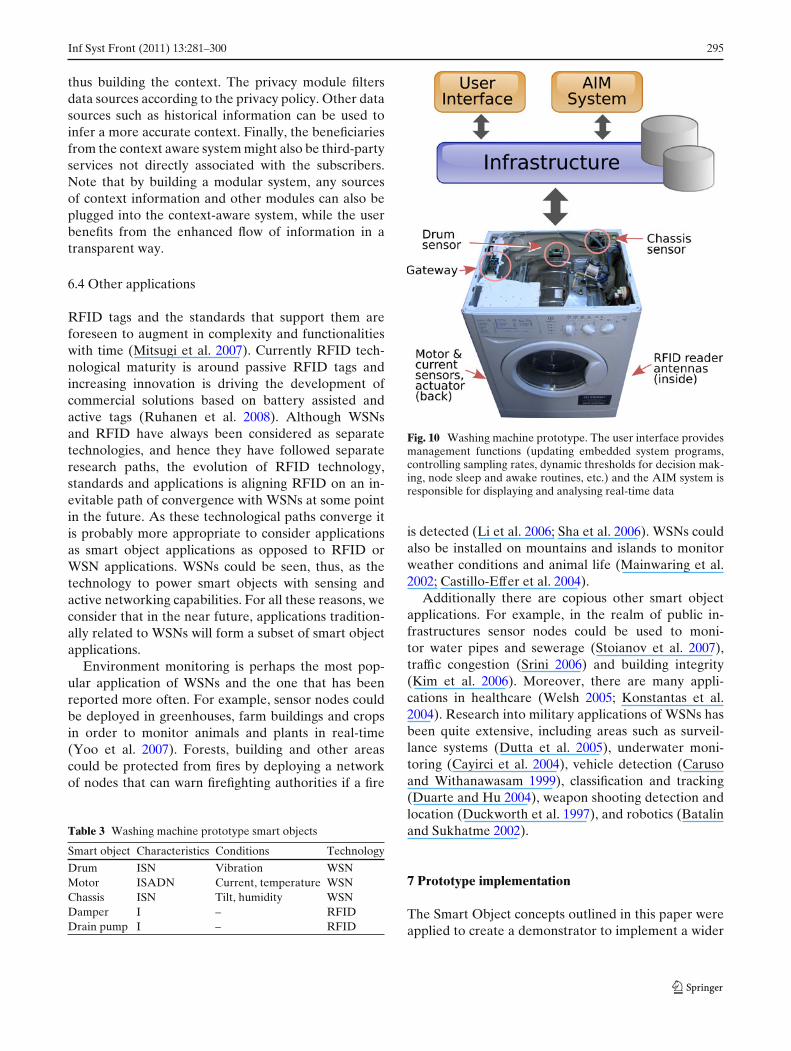
Table 3 Washing machine prototype smart objects
Smart object Characteristics Conditions Technology
Drum ISN Vibration WSNMotor ISADN Current, temperature WSNChassis ISN Tilt, humidity WSNDamper I – RFIDDrain pump I – RFID
Fig. 10 Washing machine prototype. The user interface providesmanagement functions (updating embedded system programs,controlling sampling rates, dynamic thresholds for decision mak-ing, node sleep and awake routines, etc.) and the AIM system isresponsible for displaying and analysing real-time data
is detected (Li et al. 2006; Sha et al. 2006). WSNs couldalso be installed on mountains and islands to monitorweather conditions and animal life (Mainwaring et al.2002; Castillo-Effer et al. 2004).
Additionally there are copious other smart objectapplications. For example, in the realm of public in-frastructures sensor nodes could be used to moni-tor water pipes and sewerage (Stoianov et al. 2007),traffic congestion (Srini 2006) and building integrity(Kim et al. 2006). Moreover, there are many appli-cations in healthcare (Welsh 2005; Konstantas et al.2004). Research into military applications of WSNs hasbeen quite extensive, including areas such as surveil-lance systems (Dutta et al. 2005), underwater moni-toring (Cayirci et al. 2004), vehicle detection (Carusoand Withanawasam 1999), classification and tracking(Duarte and Hu 2004), weapon shooting detection andlocation (Duckworth et al. 1997), and robotics (Batalinand Sukhatme 2002).
7 Prototype implementation
The Smart Object concepts outlined in this paper wereapplied to create a demonstrator to implement a wider
296 Inf Syst Front (2011) 13:281–300
Fig. 11 High-level software architecture. Smart objects based onWSNs provide both ID and sensor data streams while I-smartobjects developed with passive RFID technology provide IDstreams. These two different data streams are integrated at theapplication level to provide a comprehensive set of services toclients based on a miscellany of smart objects with various com-binations of features implemented using a variety of technologies
system that employed Smart Objects to provide anAsset Information Management (AIM) system. Theexperimental platform is composed of a number of
washing machine components. These components forma network of Smart Objects. The system was designedto exhibit and use various characteristics of the SmartObject model. Primarily, the sensing capabilities wereutilized to perform condition monitoring of themselves,in real-time. The network of objects communicate in-formation about its current health status. This informa-tion is used by client applications to predict the failureof those objects based on comparisons with historicaland expected state information of particular compo-nents. Subsequently, predicted failures trigger decisionssuch as automatic part ordering, preventive shut downand assisting repair tasks.
The smart object classification aided the clear spec-ification of requirements and considerably simplifiedthe technology selection process. The taxonomy wasespecially important in the prototype specification dis-cussions. The smart object paradigm also simplifiedthe development effort across collaborating partners aseach component was modelled as an intelligent entitywith clearly defined capabilities.
The smart objects were implemented using WirelessSensor Network (WSN) and RFID technology. Thesensor nodes were programmed to provide the de-sired characteristics of the Smart Objects and suitablesensors, both on board sensor nodes and external tothe node, provided the required perceptors for objectstatus, such as its temperature or current consumption.The implementation uses the sensor nodes to monitorfive different conditions in three different Smart Ob-jects. Table 3 lists them together with their associatedclassification, a summary of sensing capabilities andtechnologies employed to build the prototypes. A gate-way (base station) node was installed to relay the sensordata from the WSN to the software infrastructure.
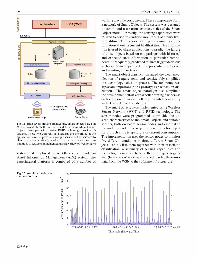
Fig. 12 Acceleration data inthe time domain
2008-07-16 00:29:18.359 2008-07-16 00:34:29.265 2008-07-16 00:39:46.5620
100
200
300
400
500
600
700
x-ax
isA
ccel
erat
ion
(9.8
10-3
ms-
2)
Timescale (Date and Time)
Inf Syst Front (2011) 13:281–300 297
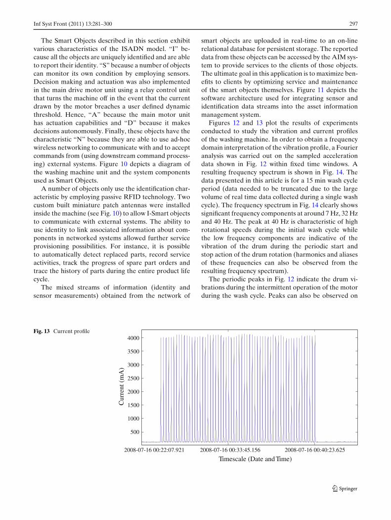
The Smart Objects described in this section exhibitvarious characteristics of the ISADN model. “I” be-cause all the objects are uniquely identified and are ableto report their identity. “S” because a number of objectscan monitor its own condition by employing sensors.Decision making and actuation was also implementedin the main drive motor unit using a relay control unitthat turns the machine off in the event that the currentdrawn by the motor breaches a user defined dynamicthreshold. Hence, “A” because the main motor unithas actuation capabilities and “D” because it makesdecisions autonomously. Finally, these objects have thecharacteristic “N” because they are able to use ad-hocwireless networking to communicate with and to acceptcommands from (using downstream command process-ing) external systems. Figure 10 depicts a diagram ofthe washing machine unit and the system componentsused as Smart Objects.
A number of objects only use the identification char-acteristic by employing passive RFID technology. Twocustom built miniature patch antennas were installedinside the machine (see Fig. 10) to allow I-Smart objectsto communicate with external systems. The ability touse identity to link associated information about com-ponents in networked systems allowed further serviceprovisioning possibilities. For instance, it is possibleto automatically detect replaced parts, record serviceactivities, track the progress of spare part orders andtrace the history of parts during the entire product lifecycle.
The mixed streams of information (identity andsensor measurements) obtained from the network of
smart objects are uploaded in real-time to an on-linerelational database for persistent storage. The reporteddata from these objects can be accessed by the AIM sys-tem to provide services to the clients of those objects.The ultimate goal in this application is to maximize ben-efits to clients by optimizing service and maintenanceof the smart objects themselves. Figure 11 depicts thesoftware architecture used for integrating sensor andidentification data streams into the asset informationmanagement system.
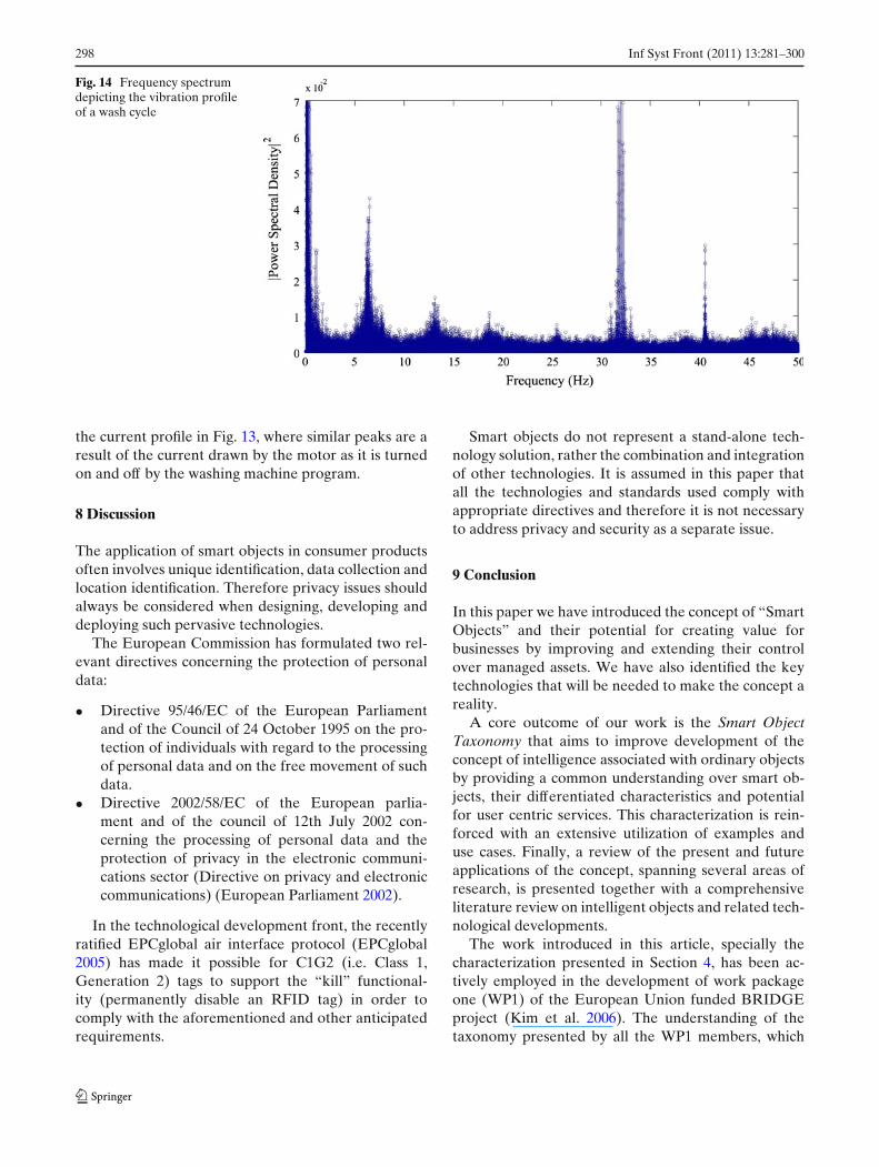
Figures 12 and 13 plot the results of experimentsconducted to study the vibration and current profilesof the washing machine. In order to obtain a frequencydomain interpretation of the vibration profile, a Fourieranalysis was carried out on the sampled accelerationdata shown in Fig. 12 within fixed time windows. Aresulting frequency spectrum is shown in Fig. 14. Thedata presented in this article is for a 15 min wash cycleperiod (data needed to be truncated due to the largevolume of real time data collected during a single washcycle). The frequency spectrum in Fig. 14 clearly showssignificant frequency components at around 7 Hz, 32 Hzand 40 Hz. The peak at 40 Hz is characteristic of highrotational speeds during the initial wash cycle whilethe low frequency components are indicative of thevibration of the drum during the periodic start andstop action of the drum rotation (harmonics and aliasesof these frequencies can also be observed from theresulting frequency spectrum).
The periodic peaks in Fig. 12 indicate the drum vi-brations during the intermittent operation of the motorduring the wash cycle. Peaks can also be observed on
Fig. 13 Current profile
2008-07-16 00:22:07.921 2008-07-16 00:33:45.156 2008-07-16 00:40:23.625
500
1000
1500
2000
2500
3000
3500
4000
Timescale (Date and Time)
Cur
rent
(m
A)
298 Inf Syst Front (2011) 13:281–300
Fig. 14 Frequency spectrumdepicting the vibration profileof a wash cycle
the current profile in Fig. 13, where similar peaks are aresult of the current drawn by the motor as it is turnedon and off by the washing machine program.
8 Discussion
The application of smart objects in consumer productsoften involves unique identification, data collection andlocation identification. Therefore privacy issues shouldalways be considered when designing, developing anddeploying such pervasive technologies.
The European Commission has formulated two rel-evant directives concerning the protection of personaldata:
• Directive 95/46/EC of the European Parliamentand of the Council of 24 October 1995 on the pro-tection of individuals with regard to the processingof personal data and on the free movement of suchdata.
• Directive 2002/58/EC of the European parlia-ment and of the council of 12th July 2002 con-cerning the processing of personal data and theprotection of privacy in the electronic communi-cations sector (Directive on privacy and electroniccommunications) (European Parliament 2002).
In the technological development front, the recentlyratified EPCglobal air interface protocol (EPCglobal2005) has made it possible for C1G2 (i.e. Class 1,Generation 2) tags to support the “kill” functional-ity (permanently disable an RFID tag) in order tocomply with the aforementioned and other anticipatedrequirements.
Smart objects do not represent a stand-alone tech-nology solution, rather the combination and integrationof other technologies. It is assumed in this paper thatall the technologies and standards used comply withappropriate directives and therefore it is not necessaryto address privacy and security as a separate issue.
9 Conclusion
In this paper we have introduced the concept of “SmartObjects” and their potential for creating value forbusinesses by improving and extending their controlover managed assets. We have also identified the keytechnologies that will be needed to make the concept areality.
A core outcome of our work is the Smart ObjectTaxonomy that aims to improve development of theconcept of intelligence associated with ordinary objectsby providing a common understanding over smart ob-jects, their differentiated characteristics and potentialfor user centric services. This characterization is rein-forced with an extensive utilization of examples anduse cases. Finally, a review of the present and futureapplications of the concept, spanning several areas ofresearch, is presented together with a comprehensiveliterature review on intelligent objects and related tech-nological developments.
The work introduced in this article, specially thecharacterization presented in Section 4, has been ac-tively employed in the development of work packageone (WP1) of the European Union funded BRIDGEproject (Kim et al. 2006). The understanding of thetaxonomy presented by all the WP1 members, which
Inf Syst Front (2011) 13:281–300 299
includes a total of nine companies and institutions, wasfundamental to prototyping and developing various de-liverables and demonstrators.
In Section 7 we also unfolded a prototype based onthe concepts described in the paper to illustrate oursmart object taxonomy in the context of a real lifeapplication.
References
Armenio, F., et al. (2007). The EPC global architecture frame-work, resource document. EPCglobal, http://www.epcglobalinc.org/standards/architecture/architecture_1_2-framework-20070910.pdf. Accessed 9 March 2009.
Batalin, M. A., & Sukhatme, G. S. (2002). Sensor coverage usingmobile robots and stationary nodes. In Proceedings of scal-ability and traffic control in IP networks 2002, 31 July 2002(Vol. 4868, pp. 269–276). Boston, USA.
Caruso, M. J., & Withanawasam, L. S. (1999). Vehicle detec-tion and compass applications using AMR magnetic sensors.Resource document, Honeywell technical documentation.www.magneticsensors.com/datasheets/amr.pdf. Accessed 9March 2009.
Castillo-Effer, M., Quintela, D. H., Moreno, W., Jordan, R., &Westhoff, W. (2004). Wireless sensor networks for flash-flood alerting. In Proceedings of the fifth IEEE interna-tional caracas conference on devices, circuits and systems,3–5 November 2004 (pp. 142–146). Punta Cana, DominicanRepublic.
Cayirci, E., Tezcan, H., Dogan, Y., & Coskun, V. (2004). Wire-less sensor networks for underwater surveillance systems.Elsevier Journal on Ad-hoc Networks, 4(4), 431–446.
Connor, C. O. (2005). Growers sow the seeds of success.Resource document. RFID journal online. http://www.rfidjournal.com/article/articleview/1513/. Accessed 30 October2008.
Duarte, M., & Hu, Y.-H. (2004). Vehicle classification in distrib-uted sensor networks. Journal of Parallel and DistributedComputing, 64(7), 826–838.
Duckworth, G. L., Gilbert, D. C., & Barger, J. E. (1997). Acousticcounter-sniper system. In: Proceedings of SPIE internationalsymposium on enabling technologies for law enforcement andsecurity, 19 November (p. 262). Boston, USA.
Dutta, P., Grimmer, M., Arora, A., Bibyk, S., & Culler, D. (2005).Design of a wireless sensor network platform for detectingrare, random, and ephemeral events. In: Proceedings of the4th international symposium on information processing insensor networks, 25–27 April (Article no. 70). Los Angeles,USA.
Edwards, J. (2007). Cold chain heats up RFID adoption.Resource document. RFID journal online. http://www.rfidjournal.com/magazine/article/3243/6/417/. Accessed 30October 2007.
Emery, K. (2005). Distributed eventing architecture: RFID andsensors in a supply chain. MPhil thesis, MIT University.
EPCglobal Inc (2005). Class 1 generation 2 UHF air interfaceprotocol standard version 1.0.9: ‘Gen 2’. Resource docu-ment. EPCglobal. http://www.epcglobalinc.org/standards/uhfc1g2/uhfc1g2_1_2_0-standard-20080511.pdf. Accessed 9March 2009.
EPCglobal Inc (2005). EPCTM tag data standards. Resource do-cument. EPCglobal. http://www.epcglobalinc.org/standards/tds/tds_1_4-standard-20080611.pdf. Accessed 9 March 2009.
EPCglobal Inc (2007). EPCglobal tag class definitions. Resourcedocument. EPCglobal. http://www.epcglobalinc.org/standards/TagClassDefinitions_1_0-whitepaper-20071101.pdf. Accessed9 March 2009.
European Parliament (2002). Regulation (EC) No. 178/2002 ofthe European Parliament and of the Council. Official Jour-nal of the European Communities, L31/1L31/24.
Gilbert, A. (2004). HP developing ‘smart rack’ to ease data centerwork. Resource document. CNET news. http://news.cnet.com/HP-developing-smart-rack-to-ease-data-center-work/2100-1012_3-5432481.html. Accessed 30 October 2008.
IEEE Standard for Information Technology—Telecommuni-cations and Information Exchange Between Systems—Local and Metropolitan Area Networks (2006). 802.15.4,specific requirements Part 15.4: Wireless medium accesscontrol (MAC) and physical layer (PHY) specificationsfor low-rate wireless personal area networks (WPANs). Re-source document. IEEE Computer Society. http://standards.ieee.org/getieee802/download/802.15.4-2006.pdf. Accessed 9March 2009.
ISO/ICE (2006). Information technology –radio frequency iden-tification (RFID) for item management application proto-col: Encoding and processing rules for sensors and batteries.Technical document draft, ISO/ IEC WD 24753.
ISO/IEC (2007). Information technology –radio frequency identi-fication for item management—part6: Parameters for air in-terface communications at 860MHz to 960MHz. Technicaldocument, Working draft, ISO/ IEC WD 18000-6REV1.
Kevan, T. (2004). Theft and terror threats push sensors intosupply chain. Resource document. Frontline Solutions.http://www.sensitech.com/PDFs/coldchain_info/Frontline_Solutions.pdf. Accessed 30 October 2008.
Kim, S., Pakzad, S., Culler, D., Demmel, J., Fenves, G., Glaser, S.,et al. (2006). Wireless sensor networks for structural healthmonitoring. In Proceedings of the 4th international confer-ence on embedded networked sensor systems, 31 October–3 November 2006 (pp. 4270-428). Boulder, USA.
Konstantas, D., van Halteren, A. T., Bults, R. G. A., Wac, K. E.,Jones, V. M., & Widya, I. A. (2004). Body area networksfor ambulant patient monitoring over next generation pub-lic wireless networks. In Thirteenth IST mobile and wire-less communications summit, 27–30 June 2004 (pp. 181–185).Lyon, France.
Kuck, M. (2007). The chill-on project: Novel technologiesfor a safe and transparent food supply. Resource online.http://www.chill-on.com/. Accessed 30 October 2008.
LandMarc Research Center (2007). Integrated sensor radiofrequency identification (ISRFID). http://landmarc.gtri.gatech.edu. Accessed 15 April 2007.
Lee, K. (1999). A synopsis of the IEEE P1451- standardsfor smart transducer communication. Resource document.National Institute of Standards and Technology. ieee1451.nist.gov/1451synosis-599F.pdf. Accessed 9 March 2009.
Levis, P. (2006). TinyOS 2.0 overview. Resource document.http://www.tinyos.net/tinyos-2.x/doc/html/overview.html. Ac-cessed 20 October 2008.
Li, G-H., Zhao, J., & Wang Z. (2006). Research on forest firedetection based on wireless sensor network. In Proceedingsof the WCICA 2006, 21–23 June 2006 (275–279). DalianChina.
Mainwaring, A., Polastre, J., Szewczyk, R., Culler, D., &Anderson, J. (2002). Wireless sensor networks for habitat
300 Inf Syst Front (2011) 13:281–300
monitoring. In Proceedings of the WSNA’02, 28 September2002 (pp. 88–97). Atlanta, Georgia.
McFarlane, D. C., Sarma, S. E., Chirn, J. L., Wong, C. Y., &Ashton, K. (2002). The intelligent product in manufacturingcontrol. Journal of EAIA, 54–64.
Mitsugi, J., Inaba, T., Patkai, B., Theodorou, L., Sung, J., SanchezLopez, T., et al. (2007). Architecture development for sensorintegration in the EPCglobal network. Auto-ID Labs WhitePaper, White Paper Series 2007.
Nochta, Z., Oertel, N., & Spiess, P. (2005). Relocatableservices and service classification scheme. Resourcedocument. Project CoVIs. http://www.cobis-online.de/files/Deliverable_D101.pdf. Accessed 9 March 2009.
Patkai, B., Theodorou, L., McFarlane, D., & Schmidt, K. (2007).Requirements for RFID-based sensor integration inlanding gear monitoring—a case study. Technical report,AerospaceID Technologies Programme, University ofCambridge.
Ranasinghe, D. C., & Cole, P. H. (2008). Networked RFID sys-tems. In Networked RFID systems and lightweight cryptog-raphy: Raising barriers to product counterfeiting (pp. 45–58).Berlin: Springer.
Roberti, M. (2004a). BP leads the way on sensors. Resourcedocument. RFID journal online. http://www.rfidjournal.com/article/view/1216/1/2. Accessed 9 March 2009.
Roberti, M. (2004b). Navy revs up RFID sensors. Resourcedocument. RFID journal online. http://www.rfidjournal.com/article/view/990/1/1. Accessed 9 March 2009.
Ruhanen, A., et al. (2008). Sensor-enabled RFID tag handbook.Resource document. BRIDGE project. http://www.bridge-project.eu/data/File/BRIDGE_WP01_RFID_tag_handbook.pdf. Accessed 9 March 2009.
Sample, A. P., Yeager, D. J., Powledge, P. S., Mamishev, A. V.,& Smith, J. R. (2008). Design of an RFID-basedbattery-free programmable sensing platform. IEEE Trans-actions on Instrumentation and Measurement, 57(11),2608–2615.
Sha, K., Shi, K., & Watkins, O. (2006). Using wireless sensornetworks for fire rescue applications: Requirements andchallenges. In Proceedings of the 6th IEEE internationalconference on electro/information technology, 7–10 May(pp. 239–244). East Lansing, USA.
Srini, V. P. (2006). A vision for supporting autonomous nav-igation in urban environments. IEEE Computer, 39(12),68–77.
Stoianov, I., Nachman, L., Madden, S., & Tokmouline T. (2007).PIPENET A wireless sensor network for pipeline monitor-ing. In Proceedings of the information processing in sen-sor networks 2007, 25–27 April (pp. 264-273). Cambridge,USA.
Theodorou, S. (2006). A classification approach for RFID-based sensor integration. A thesis for the degree of Master
of Philosophy, Hughes Hall, Department of Engineering,University of Cambridge.
Welsh, M. (2005). CodeBlue: A wireless sensor network formedical care and disaster response. Resource document.http://www.eecs.harvard.edu/∼mdw/talks/ucsd-codeblue.pdf.Accessed October 30 2008.
Wong, C. Y., McFarlane, D., Zaharudin, A. H., & Agarwal, V.(2002). The intelligent product driven supply chain. In Pro-ceedings of the IEEE international conference on systems,man and cybernetics, 6–9 October (Vol. 4, 6 p.).
Yoo, S., Kim, J., Kim, T., Ahn, S., Sung, J., & Kim, D. (2007).A2S: Automated Agriculture system based on WSN. In Pro-ceedings of the ISCE2007, 20–23 Jun (pp. 628–633). Dallas,Texas.
ZigBee Alliance (2006). ZigBee specification. Technical docu-ment 05347r13.
Tomás Sánchez López is a Research Associate at theDistribution Information and Automation Laboratory, Univer-sity of Cambridge. His research interests focus on how to providesensor functionalities within the current RFID standards and in-formation architectures. Sánchez López has a Ph.D in ComputerScience from KAIST, South Korea, and is actively involved inthe activities of the Auto-ID lab Cambridge. Contact him [email protected].
Damith C. Ranasinghe is the associate director of theAuto-ID Lab at the University of Adelaide. His researchinterests are on RFID and sensor data management, light-weight security and agent based systems Ranasinghe has a PhDfrom the University of Adelaide, Australia. Contact him [email protected].
Bela Patkai has engineering degrees from Hungary (BUTE),the UK (NTU) and a PhD in Agent-based Modeling of ComplexProduction Networks from Finland (TUT). At the Auto-ID Labof Cambridge University he had been working on the integrationof sensors and RFID in aerospace applications. You can contacthim at [email protected].
Duncan McFarlane is Professor of Service and Support En-gineering at the Cambridge University Engineering Depart-ment, and head of the Centre for Distributed Informational andAutomation Laboratory. His research work is focused in the ar-eas of distributed industrial automation, reconfigurable systems,RFID integration and the role of automation and informationsolutions in supporting service environments. Contact him [email protected].