Table of Contents - Kitsap County
746
-
Upload
khangminh22 -
Category
Documents
-
view
1 -
download
0
Transcript of Table of Contents - Kitsap County

RIDGETOP BLVD NW IMPROVEMENTS PROJECT PHASE 2
BACK OF COVER

i RIDGETOP BLVD NW IMPROVEMENTS PROJECT PHASE 2
Table of Contents CALL FOR BIDS............................................................................................................. 1
PROPOSAL .................................................................................................................... 5
BID BOND .................................................................................................................... 21
BIDDER RESPONSIBILITY STATEMENT ................................................................... 23
CERTIFICATION OF COMPLIANCE WITH WAGE PAYMENT STATUTES ............... 25
NON-COLLUSION DECLARATION FORM ................................................................. 27
SUBCONTRACTOR LIST ............................................................................................ 29
PROPOSAL FOR INCORPORATING RECYCLED MATERIALS INTO THE PROJECT ...................................................................................................................................... 31
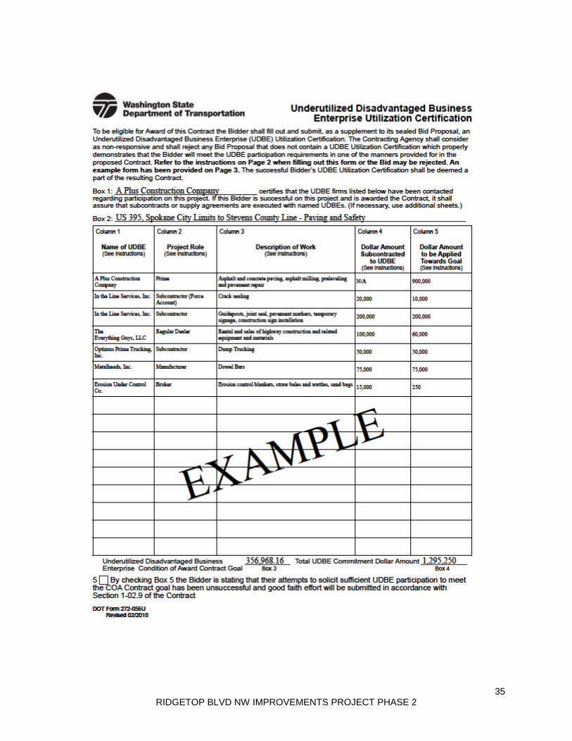
UDBE UTILIZATION CERTIFICATION ........................................................................ 33
UDBE WRITTEN CONFIRMATION DOCUMENT ........................................................ 37
LOCAL AGENCY CERTIFICATION FOR FEDERAL-AID CONTRACTS .................... 39
AGREEMENT ............................................................................................................... 41
PUBLIC WORKS PAYMENT BOND ............................................................................ 47
PERFORMANCE BOND ............................................................................................... 49
AMENDMENTS TO THE STANDARD SPECIFICATIONS .......................................... 51
SPECIAL PROVISIONS .............................................................................................. 1-1
DIVISION 1 GENERAL REQUIREMENTS .................................................................. 1-2
1-01 DEFINITIONS AND TERMS ......................................................................... 1-2
1-01.3 Definitions ........................................................................................... 1-2
1-02 BID PROCEDURES AND CONDITIONS ..................................................... 1-4
1-02.1 Prequalification of Bidders ................................................................ 1-4 1-02.2 Plans and Specifications ................................................................... 1-4 1-02.4 Examination of Plans, Specifications and Site of Work .................. 1-5 1-02.5 Proposal Forms .................................................................................. 1-5 1-02.6 Preparation of Proposal ..................................................................... 1-6 1-02.7 Bid Deposit ......................................................................................... 1-7 1-02.9 Delivery of Proposal ............................................................................ 1-8 1-02.10 Withdrawing, Revising, or Supplementing Proposal .................... 1-8 1-02.13 Irregular Proposals........................................................................... 1-9 1-02.14 Disqualification of Bidders ............................................................ 1-10 1-02.15 Pre Award Information ................................................................... 1-14

ii RIDGETOP BLVD NW IMPROVEMENTS PROJECT PHASE 2
1-03 AWARD AND EXECUTION OF CONTRACT ............................................. 1-14
1-03.1 Consideration of Bids ...................................................................... 1-14 1-03.3 Execution of Contract ...................................................................... 1-15 1-03.4 Contract Bond .................................................................................. 1-15 1-03.7 Judicial Review ................................................................................. 1-17
1-04 SCOPE OF WORK ..................................................................................... 1-17
1-04.2 Coordination of Contract Documents, Plans, Special Provisions, Specifications, and Addenda ........................................................................ 1-17
1-05 CONTROL OF WORK ................................................................................ 1-17
1-05.3 Working Drawings ............................................................................ 1-17 1-05.4 Conformity With and Deviations From Plans and Stakes ............... 1-23 1-05.7 Removal of Defective and Unauthorized Work .............................. 1-28 1-05.11 Final Inspection .............................................................................. 1-28 1-05.13 Superintendents, Labor and Equipment of Contractor ............... 1-30 1-05.14 Cooperation With Other Contractors ............................................ 1-30 1-05.15 Method of Serving Notices ............................................................ 1-31 1-05.16 Water and Power ............................................................................ 1-31 1-05.17 Project Management Communications – Provided at no cost to Contractor ...................................................................................................... 1-31 1-05.18 Record Drawings ............................................................................ 1-35
1-06 CONTROL OF MATERIAL ......................................................................... 1-37
1-06.1 Approval of Materials Prior to Use .................................................. 1-38 1-06.6 Recycled Materials ........................................................................... 1-38
1-07 Legal Relations and Responsibilities to the Public ............................... 1-39
1-07.1 Laws to be Observed ....................................................................... 1-39 1-07.2 State Sales Tax ................................................................................. 1-40 1-07.6 Permits and Licenses ....................................................................... 1-41 1-07.9 Wages ................................................................................................ 1-42 1-07.11 Requirements for Nondiscrimination ............................................ 1-43 1-07.12 Federal Agency Inspection ............................................................ 1-74 1-07.17 Utilities and Similar Facilities ........................................................ 1-74 1-07.18 Public Liability and Property Damage Insurance ........................ 1-76 1-07.23 Public Convenience and Safety .................................................... 1-80 1-07.24 Rights of Way .................................................................................. 1-81
1-08 PROSECUTION AND PROGRESS ............................................................ 1-82
1-08.0 Preliminary Matters .......................................................................... 1-82 1-08.1 Subcontracting .................................................................................. 1-84
iii RIDGETOP BLVD NW IMPROVEMENTS PROJECT PHASE 2
1-08.4 Prosecution of Work ........................................................................ 1-85 1-08.5 Time for Completion .......................................................................... 1-86 1-08.9 Liquidated Damages ........................................................................ 1-87
1-09 MEASUREMENT AND PAYMENT ............................................................. 1-87
1-09.2 Weighing Equipment ........................................................................ 1-87 1-09.6 Force Account .................................................................................. 1-88 1-09.9 Payments .......................................................................................... 1-88 1-09.13 Claims Resolution .......................................................................... 1-90
1-10 TEMPORARY TRAFFIC CONTROL .......................................................... 1-90
1-10.2 Traffic Control Management ............................................................ 1-90 1-10.4 Measurement .................................................................................... 1-91
DIVISION 2 EARTHWORK .......................................................................................... 2-1
2-01 CLEARING, GRUBBING, AND ROADSIDE CLEANUP .............................. 2-1
2-01.1 Description .......................................................................................... 2-1 2-01.2 Disposal of Usable Material and Debris ........................................... 2-1 2-01.3 Construction Requirements .............................................................. 2-1
2-02 REMOVAL OF STRUCTURES AND OBSTRUCTIONS .............................. 2-1
2-02.1 Description .......................................................................................... 2-1 2-02.3 Construction Requirements .............................................................. 2-2 2-02.4 Measurement ...................................................................................... 2-5 2-02.5 Payment .............................................................................................. 2-5
2-03 ROADWAY EXCAVATION AND EMBANKMENT ....................................... 2-6
2-03.1 Description .......................................................................................... 2-6 2-03.2 Materials .............................................................................................. 2-6 2-03.3 Construction Requirements .............................................................. 2-6 2-03.4 Measurement ...................................................................................... 2-7 2-03.5 Payment .............................................................................................. 2-9
2-07 WATERING ................................................................................................ 2-10
2-07.4 Measurement .................................................................................... 2-10
2-09 STRUCTURE EXCAVATION ..................................................................... 2-10
2-09.3 Construction Requirements ............................................................ 2-10 2-09.4 Measurement .................................................................................... 2-11 2-09.5 Payment ............................................................................................ 2-11
DIVISION 4 BASES ..................................................................................................... 4-1
4-04 BALLAST AND CRUSHED SURFACING ................................................... 4-1

iv RIDGETOP BLVD NW IMPROVEMENTS PROJECT PHASE 2
4-04.3 Construction Requirements .............................................................. 4-1 DIVISION 5 SURFACE TREATMENTS AND PAVEMENTS ....................................... 5-1
5-03 TEMPORARY ROAD ................................................................................... 5-1
5-03.1 Description ........................................................................................... 5-1 5-03.2 Materials ............................................................................................... 5-1 5-03.3 Construction Requirements ............................................................... 5-1 5-03.4 Measurement ....................................................................................... 5-1 5-03.5 Payment ............................................................................................... 5-1
5-04 HOT MIX ASPHALT ..................................................................................... 5-1
5-04.1 Description ........................................................................................... 5-1 5-04.2 Materials ............................................................................................... 5-2 5-04.3 Construction Requirements ............................................................... 5-5 5-04.4 Measurement ..................................................................................... 5-32 5-04.5 Payment ............................................................................................. 5-32
5-05 CEMENT CONCRETE PAVEMENT ........................................................... 5-35
5-05 CEMENT CONCRETE PAVEMENT ........................................................... 5-35
5-05.1 Description .......................................................................................... 5-35 5-05.2 Materials .............................................................................................. 5-35 5-05.3 Construction Requirements .............................................................. 5-36 5-05.4 Measurement ...................................................................................... 5-39 5-05.5 Payment .............................................................................................. 5-39
DIVISION 7 DRAINAGE STRUCTURES, STORM SEWERS, SANITARY SEWERS, WATER MAINS, AND CONDUITS .............................................................................. 7-1
7-04 STORM SEWERS .......................................................................................... 7-1
7-04.1 Description .......................................................................................... 7-1 7-04.2 Materials .............................................................................................. 7-1 7-04.5 Payment .............................................................................................. 7-1
7-05 MANHOLES, INLETS, CATCH BASINS, AND DRYWELLS ....................... 7-2
7-05.1 Description .......................................................................................... 7-2 7-05.2 Materials .............................................................................................. 7-2 7-05.4 Measurement ...................................................................................... 7-2 7-05.5 Payment .............................................................................................. 7-2
7-08 GENERAL PIPE INSTALLATION REQUIREMENTS .................................. 7-3
7-08.3 Construction Requirements .............................................................. 7-3 7-08.4 Measurement ...................................................................................... 7-4 7-08.5 Payment .............................................................................................. 7-5

v RIDGETOP BLVD NW IMPROVEMENTS PROJECT PHASE 2
7-12 VALVES FOR WATER MAINS ...................................................................... 7-5
7-12.1 Description ............................................................................................ 7-5
7-12.3 Construction Requirements ................................................................ 7-5
7-12.4 Measurement ........................................................................................ 7-5
7-12.5 Payment ................................................................................................ 7-6
DIVISION 8 MISCELLANEOUS CONSTRUCTION ..................................................... 8-1
8-01 EROSION AND WATER POLLUTION CONTROL ...................................... 8-1
8-01.1 Description .......................................................................................... 8-1
8-01.3 Construction Requirements .............................................................. 8-1
8-01.4 Measurement ...................................................................................... 8-4
8-01.5 Payment .............................................................................................. 8-4
8-02 ROADSIDE RESTORATION ........................................................................ 8-4
8-02.5 Payment .............................................................................................. 8-4
8-04 CURBS, GUTTERS, AND SPILLWAYS ...................................................... 8-5
8-04.1 Description .......................................................................................... 8-5
8-04.2 Materials .............................................................................................. 8-5
8-04.4 Measurement ...................................................................................... 8-5
8-04.5 Payment .............................................................................................. 8-5
8-14 CEMENT CONCRETE SIDEWALKS .......................................................... 8-6
8-14.1 Description .......................................................................................... 8-6
8-14.4 Measurement ...................................................................................... 8-7
8-14.5 Payment .............................................................................................. 8-8
8-20 ILLUMINATION, TRAFFIC SIGNAL SYSTEMS, INTELLIGENT TRANSPORTATION SYSTEMS AND ELECTRICAL ............................................ 8-8
8-20.1 Description .......................................................................................... 8-8
8-20.2 Materials ............................................................................................ 8-10 8-20.3 Construction Requirements .............................................................. 8-11
8-20.4 Measurement .................................................................................... 8-15
8-20.5 Payment ............................................................................................ 8-16
8-21 PERMANENT SIGNING ............................................................................ 8-17
8-21.3 Construction Requirements ............................................................ 8-17
8-21.4 Measurement .................................................................................... 8-17
8-21.5 Payment ............................................................................................ 8-17
8-23 TEMPORARY PAVEMENT MARKINGS ................................................... 8-18
8-23.3 Construction Requirements ............................................................ 8-18
8-23.5 Payment ............................................................................................ 8-18

vi RIDGETOP BLVD NW IMPROVEMENTS PROJECT PHASE 2
8-24 ROCK AND GRAVITY BLOCK WALL AND GABION CRIBBING ........... 8-18
8-24.1 Description ........................................................................................ 8-18
8-24.2 Materials ............................................................................................ 8-18
8-24.3 Construction Requirements ............................................................ 8-19
8-24.5 Payment ............................................................................................ 8-19
8-26 FIELD OFFICE BUILDING ......................................................................... 8-19
8-26.1 Description ........................................................................................ 8-19
8-26.3 Construction Requirements ............................................................ 8-19
8-26.5 Payment ............................................................................................ 8-20
8-27 BIORETENTION CELL .............................................................................. 8-20
8-27.1 Description .......................................................................................... 8-20
8-27.2 Materials .............................................................................................. 8-21
8-27.3 Construction Requirements .............................................................. 8-21
8-27.4 Measurement ...................................................................................... 8-27
8-27.5 Payment .............................................................................................. 8-27
DIVISION 9 MATERIALS ............................................................................................. 9-1
9-03 AGGREGATES ............................................................................................ 9-1
9-03.14 Borrow ............................................................................................... 9-1
9-03.21 Recycled Materials ........................................................................... 9-2
9-05 DRAINAGE STRUCTURES AND CULVERTS ............................................ 9-2
9-05.15 Metal Casings ................................................................................... 9-2
9-14 EROSION CONTROL AND ROADSIDE PLANTING ................................... 9-3
9-14.1 Soil ....................................................................................................... 9-3
9-14.4 Mulch and Amendments ...................................................................... 9-3
9-14.8 Bioretention Soil Media (BSM) ........................................................ 9-3
9-28 SIGNING MATERIALS AND FABRICATION ............................................. 9-5
9-28.10 Street Name Signs ............................................................................. 9-5
9-29 Illumination, Signal, Electrical ................................................................... 9-5
9-29.1 Conduit, Innerduct and Outerduct .................................................... 9-6
9-29.2 Junction Boxes, Cable Vaults, and Pull Boxes ................................ 9-6
9-29.3 Fiber Optic Cable, Electrical Conductors, and Cable ...................... 9-6
9-29.6 Light and Signal Standards ............................................................... 9-7
9-29.7 Luminaire Fusing and Electrical Connections at Light Standard Bases, Cantilever Bases, and Sign Bridge Bases ........................................ 9-7
9-29.10 Luminaires ........................................................................................ 9-8
9-29.12 Electrical Splice Materials ............................................................... 9-8

vii RIDGETOP BLVD NW IMPROVEMENTS PROJECT PHASE 2
9-29.15 Flashing Beacon Control ................................................................. 9-8 9-29.24 Service Cabinets .............................................................................. 9-9
9-33 Construction Geosynthetic ...................................................................... 9-10
9-33.2 Geosynthetic Properties .................................................................. 9-10 Standard Plans ...........................................................................................................S-1
ATTACHMENTS
WASHINGTON STATE PREVAILING WAGE RATES, STATE BENEFIT CODE KEY AND SUPPLEMENTAL (L&I STATEMENT) FEDERAL PREVAILING RATES FEDERAL CONTRACT PROVISIONS (FHWA 1273), W/ AMENDMENT
CENTRAL KITSAP SCHOOL DISTRICT START/END TIMES
KITSAP TRANSIT RIDGETOP BUS SERVICE AND STOPS
GEOTECHNICAL REPORT
POTHOLING INFORMATION
DOE SRF INSERT

viii RIDGETOP BLVD NW IMPROVEMENTS PROJECT PHASE 2
THIS PAGE INTENTIONALLY LEFT BLANK

1 RIDGETOP BLVD NW IMPROVEMENTS PROJECT PHASE 2
CALL FOR BIDS
KITSAP COUNTY DEPARTMENT OF PUBLIC WORKS COUNTY ROAD PROJECT NO. 1593 / STORMWATER DIVISION NO. 97003139
RIDGETOP BLVD NW
IMPROVEMENTS PROJECT PHASE 2
BID OPENING: DATE: July 30, 2019 TIME: 11:00 AM
Sealed bids for the project designated above will be received by Kitsap County Department of Public Works before the time and date indicated above, at which time they will be opened and publicly read aloud. Bids will be received in person or by private carrier (UPS, Federal Express, etc.) at:
Kitsap County Department of Public Works Third floor Reception Desk 507 Austin Avenue Port Orchard, Washington
Bids delivered by US Postal Service shall be addressed to:
Kitsap County Department of Public Works 614 Division Street, MS-26 Port Orchard, Washington 98366-4699
Prospective bidders are hereby notified that they are solely responsible for ensuring timely delivery of their bid to the place of bid opening. All bid proposals shall be accompanied by a bid proposal surety bond made payable to Kitsap County Department of Public Works in an amount equal to five percent (5%) of the amount of such bid proposal. Should the successful Bidder fail to enter into such contract and furnish satisfactory performance and payment bonds within the time stated in the Special Provisions, the bid proposal bond shall be forfeited to Kitsap County Department of Public Works. Each proposal or bid shall be completely sealed in a separate envelope, properly addressed as stated above, with the name and address of the bidder and the name of the project plainly written on the outside of the envelope. A complete bid proposal shall include the following:
1. Proposal Form 2. Bid Bond 3. Bidder Responsibility Statement

2 RIDGETOP BLVD NW IMPROVEMENTS PROJECT PHASE 2
4. Certification of Compliance with Wage Payment Statutes 5. Non-Collusion Affidavit 6. Subcontractor List 7. Proposal for Incorporating Recycled Materials into the Project 8. Underutilized Disadvantaged Business Enterprise Utilization Certification 9. Underutilized Disadvantaged Business Enterprise Written Conformation
Document 10. Local Agency Certification for Federal Aid Contracts
All of the above items must be complete in all respects, including signatures (notarized where required). Bidder shall acknowledge receipt of all addendums in the spaces provided. The successful Bidder will be required to submit a photocopy of their current Washington State Contractors Registration. Failure to include all items may be cause for the bid to be considered irregular and thereby rejected. Bids or proposals received after the time set for the opening of bids will not be considered. Bidders are notified that all bids are likely to be rejected if the lowest responsible bid received exceeds the Engineer's estimate by an unreasonable amount. Kitsap County reserves the right to award the bid in a manner and on a basis which will best serve the County, taking into consideration the Bidder Responsibility Statement included with the bids and the requirements of the WSDOT/APWA Standard Specifications and the Contract Provisions. The award of the contract, if made, shall be made to the responsible Bidder submitting the lowest responsive bid, based upon the total sum of the extension of unit prices for the bid items. It is anticipated that this project will be funded in part by the Washington State Department of Ecology. Neither the State of Washington nor any of its departments or employees are, or shall be, a party to any contract or any subcontract resulting from this solicitation for bids. DESCRIPTION OF WORK This contract provides for the road and stormwater improvements for approximately 3500 linear feet on Ridgetop Boulevard NW from Quail Run Drive NW to NW Pinnacle Ct located in central Kitsap County. The work proposed consists of Preparation, Excavation, Grading, Bioretention cells, Storm Sewer, Surfacing, Asphalt Concrete Pavement, Erosion Control and Planting, Traffic Safety and Control and related work. The engineer’s estimate ranges from $3,000,000 to $3,800,000.The following is applicable to federal aid projects:

3 RIDGETOP BLVD NW IMPROVEMENTS PROJECT PHASE 2
The Kitsap County Board of Commissioners accordance with Title VI of the Civil Rights Act of 1964, 78 Stat. 252, 42 USC 2000d to 2000d-4 and Title 49, Code of Federal Regulations, Department of Transportation, Subtitle A, Office of the Secretary, Part 21, Nondiscrimination in Federally-Assisted Programs of the Department of Transportation issued pursuant to such Act, hereby notifies all bidders that it will affirmatively ensure that in any contract entered into pursuant to this advertisement, disadvantaged business enterprises as defined at 49 CFR Part 26 will be afforded full opportunity to submit bids in response to this invitation and will not be discriminated against on the grounds of race, color, national origin, or sex in consideration for an award.
OBTAINING PLANS AND CONTRACT PROVISIONS: Electronic copies of the Plans and Contract Provisions in PDF format are available on the internet through Kitsap County’s website, Department of Public Works, Road Projects Open for Bid, located at https://spf.kitsapgov.com/pw/Pages/Current-Road-Projects-Open-For-Bid.aspx. Paper copies of the Contract Plans and Provisions for the proposed work may be obtained from the Kitsap County Department of Public Works at 507 Austin Avenue, 3rd floor Reception Desk, Port Orchard, Washington for a non-refundable fee of $35.00 for each set plus $5.00 to cover postage and handling if mailing is requested. To order these Contract Documents, please call 360-337-5777 or email at [email protected]. Plans and Contract Provisions will not be shipped until the fee is received. To obtain a Bid Proposal Package at no cost or to be added to the Plan Holder List, please call 360-337-5777 or email at [email protected]. CONTACT PERSON Any prospective Bidder having questions or desire an explanation or interpretation of the Bid Documents are requested to contact Gunnar Fridriksson, Project Manager, at 360-337-4689, or [email protected].
KITSAP COUNTY BOARD OF COMMISSIONERS

4 RIDGETOP BLVD NW IMPROVEMENTS PROJECT PHASE 2
THIS PAGE INTENTIONALLY LEFT BLANK

5 RIDGETOP BLVD NW IMPROVEMENTS PROJECT PHASE 2
PROPOSAL
KITSAP COUNTY DEPARTMENT OF PUBLIC WORKS COUNTY ROAD PROJECT NO. 1593 / STORMWATER DIVISION NO. 97003139
RIDGETOP BLVD NW
IMPROVEMENTS PROJECT PHASE 2 The Honorable Board of Commissioners Kitsap County 614 Division Street Port Orchard, Washington 98366 1. Pursuant to and in compliance with your Advertisement for Bids and the other
documents relating thereto, the undersigned Bidder, having familiarized themselves with the terms of the project related to those items herein bid, being aware of the local conditions affecting the performance of a Contract covering the items bid, having knowledge of the cost of the work at the place where the work is to be done, having familiarized themselves with the Contract Documents, hereby proposes and agrees to perform the work and/or to furnish the equipment, and to furnish any and all of the labor, materials, tools, expendable equipment and all utility and transportation services necessary to perform a Contract covering any or all of those items herein bid and to complete in a workmanlike manner all work covered by said Contract in connection with the Owner's Improvement Project, for an amount computed upon the basis of the quantity of work actually performed at the following bid prices:
NOTE: UNIT PRICES FOR ALL ITEMS, ALL EXTENSIONS, AND THE TOTAL AMOUNT OF BID MUST BE SHOWN. All prices shall be in legible figures (not words) written in ink or typed. The proposal shall include: A unit price for each item (omitting digits more than four places to the right of the decimal point); an extension for each unit price (omitting digits more than two places to the right of the decimal point); the total Contract price (the sum of all extensions).

6 RIDGETOP BLVD NW IMPROVEMENTS PROJECT PHASE 2
COST CODE (a guide to locate Bid Item information – the Contracting Agency does not warrant its accuracy): The Cost Code for each Bid Item consists of the WSDOT/APWA Standard Specifications division number, the section number and the item number, in that order. An example is shown below:
Kitsap County-specific Cost Codes are noted with “KC” at the end. Project-specific Bid Items are noted with “KC (CRP#)”. Bid Items that have options (e.g. Plant Selection or Beam Guardrail Anchor Type X) are designated as such. Examples are shown below:
01-04-7728 WSDOT Standard Bid Item 01-07-0010KC Kitsap County Standard Bid Item 05-05-6711KC (1593) Project-specific Bid Item 08-02-6550-AC WSDOT Standard Bid Item with option 08-11-6760-16 WSDOT Standard Bid Item with option (e.g. specific pipe size)

7 RIDGETOP BLVD NW IMPROVEMENTS PROJECT PHASE 2
NO. COST CODE
ITEM QTY UNIT UNIT COST AMOUNT
1 01-04-7728 MINOR CHANGE 45000 CALC $ 1.00 $ 45,000.00
2 01-05-0004KC
RECORD DRAWINGS (MINIMUM BID $5,000) 1 L.S.
3 01-07-0010KC
PROTECTION & SUPPORT OF EXISTING UTILITIES
1 L.S.
4 01-07-7725
REIMBURSEMENT FOR THIRD PARTY DAMAGE
5 EST. $ 1.00 $ 5.00
5 01-07-7736 SPCC PLAN 1 L.S.
6 01-08-7003
TYPE B PROGRESS SCHEDULE 1 L.S.
7 01-09-0001 MOBILIZATION 1 L.S.
8 01-09-7715KC
FORCE ACCOUNT POT-HOLE UTILITY CROSSING
5000 EST. $ 1.00 $ 5,000.00
9 01-10-6971
PROJECT TEMPORARY TRAFFIC CONTROL
1 L.S.

8 RIDGETOP BLVD NW IMPROVEMENTS PROJECT PHASE 2
10 01-10-6982
CONSTRUCTION SIGNS CLASS A 200 S.F.
11 02-01-0025
CLEARING AND GRUBBING (ACRE) 4.3 ACRE
12 02-01-7480 ROADSIDE CLEANUP 1 EST. $ 14,000.00 $ 14,000.00
13 02-02-0050
REMOVAL OF STRUCTURES AND OBSTRUCTIONS
1 L.S.
14 02-02-0079KC
SAW CUT ASPHALT CONCRETE PAVEMENT
3388 L.F.
15 02-02-0100
REMOVING CEMENT CONC. SIDEWALK 3486 S.Y.
16 02-02-0108
REMOVING CEMENT CONC. CURB AND GUTTER
271 L.F.
17 02-02-0110
REMOVING CEMENT CONC. CURB 9485 L.F.
18 02-02-0120
REMOVING ASPHALT CONC. PAVEMENT 16190 S.Y.
19 02-03-0310
ROADWAY EXCAVATION INCL. HAUL
3800 C.Y.

9 RIDGETOP BLVD NW IMPROVEMENTS PROJECT PHASE 2
20 02-03-0350
UNSUITABLE FOUNDATION EXCAVATION INCL. HAUL
100 C.Y.
21 02-03-0413KC
SPECIAL BORROW INCL. HAUL - EMBANKMENT
2010 TON
22 02-03-0414KC
SPECIAL BORROW INCL. HAUL - STORM 6860 C.Y.
23 02-03-0470
EMBANKMENT COMPACTION 2890 C.Y.
24 02-07-7018 WATER 180 MGAL
25 02-09-4006
STRUCTURE EXCAVATION CLASS A INCL. HAUL
485 C.Y.
26 02-09-7008KC
SHORING OR EXTRA EXCAVATION CLASS B (L.S.)
1 L.S.
27 02-09-7014
GRAVEL BACKFILL FOR DRAIN 330 C.Y.
28 02-11-7490
TRIMMING AND CLEANUP 1 L.S.
29 04-04-5100
CRUSHED SURFACING BASE COURSE (TON)
5500 TON

10 RIDGETOP BLVD NW IMPROVEMENTS PROJECT PHASE 2
30 04-04-5120
CRUSHED SURFACING TOP COURSE (TON)
2070 TON
31 05-03-
5657KC (1593)
TEMPORARY ROAD 1 L.S.
32 05-04-5767
HMA CL. 1/2 IN. PG 58H-22 3020 TON
33 05-05-
6711KC (1593)
RED PIGMENTED CEMENT CONCRETE PAVEMENT
1250 S.Y.
34 07-01-1160
UNDERDRAIN PIPE 6 IN. DIAM. 1414 L.F.
35 07-04-3151
TESTING STORM SEWER PIPE 3506 L.F.
36 07-04-3251KC
DUCTILE IRON STORM SEWER PIPE 12 IN. DIAM.
892 L.F.
37 07-04-3602
CORRUGATED POLYETHYLENE STORM SEWER PIPE 12 IN. DIAM.
1786 L.F.
38 07-04-3607
CORRUGATED POLYETHYLENE STORM SEWER PIPE 18 IN. DIAM.
474 L.F.
39 07-04-3608
CORRUGATED POLYETHYLENE STORM SEWER PIPE 24 IN. DIAM.
414 L.F.

11 RIDGETOP BLVD NW IMPROVEMENTS PROJECT PHASE 2
40 07-05-1046 CONCRETE INLET 1 EACH
41 07-05-3080 ADJUST MANHOLE 2 EACH
42 07-05-3091
CATCH BASIN TYPE 1 39 EACH
43 07-05-3105
CATCH BASIN TYPE 2 48 IN. DIAM. 11 EACH
44 07-05-3106
CATCH BASIN TYPE 2 54 IN. DIAM. 1 EACH
45 07-05-3109
CATCH BASIN TYPE 2 60 IN. DIAM. 1 EACH
46 07-05-3111KC
BEEHIVE GRATE FOR CATCH BASIN 5 EACH
47 07-05-3112KC
ROUNDABOUT TRUCK APRON CURB INLET FRAME AND GRATE
1 EACH
48 07-05-9605
CONNECTION TO DRAINAGE STRUCTURE
3 EACH
49 07-05-9606KC
CONNECT CATCH BASIN TO EXISTING PIPE
5 EACH

12 RIDGETOP BLVD NW IMPROVEMENTS PROJECT PHASE 2
50 07-12-6243 ADJUST VALVE BOX 7 EACH
51 08-01-6422
SEEDING AND MULCHING 1.1 ACRE
52 08-01-6489KC
NPDES CONSTRUCTION STORMWATER GENERAL PERMIT
1 L.S.
53 08-01-6490KC
EROSION/WATER POLLUTION CONTROL (L.S.)
1 L.S.
54
08-02-6550-AUU
(1593)
PLANT SELECTION BEAR BERRY (ARCTOSTAPHYLOS UVA-URSI)
8405 EACH
55
08-02-6550-BTCP (1593)
PLANT SELECTION CRIMSON PYGMY BARBERRY (BERBIS THUNBERGII 'CRIMSON PYGMY')
2922 EACH
56
08-02-6550-
CH (1593)
PLANT SELECTION WHITE ROCK ROSE (CISTUS X HYBRIDUS)
966 EACH
57 08-02-6550-CO
PLANT SELECTION SLOUGH SEDGE (CAREX OBNUPTA)
680 EACH
58
08-02-6550-CSK
(1593)
PLANT SELECTION (DWARF RED TWIG DOGWOOD (CORNUS SERICEA 'KELSEYII')
835 EACH
59
08-02-6550-EDKR (1593)
PLANT SELECTION KRAMER'S ROTE HEATH (ERICA X DARLEYENSIS 'KRAMER'S ROTE')
3020 EACH

13 RIDGETOP BLVD NW IMPROVEMENTS PROJECT PHASE 2
60
08-02-6550-EVM
(1593)
PLANT SELECTION MRS. DF MAXWELL HEATH (ERICA VAGANS 'MRS. DF MAXWELL')
2808 EACH
61 08-02-6550-ID
PLANT SELECTION DOUGLAS IRIS (IRIS DOUGLAS)
680 EACH
62 08-02-6550-JP
PLANT SELECTION SPREADING RUSH (JUNCUS PATENS)
680 EACH
63 08-02-6550-JT
PLANT SELECTION SLENDER RUSH (JUNCUS TENUIS)
680 EACH
64 08-02-
6550-LP (1593)
PLANT SELECTION (BOXLEAF HONEYSUCKLE (LONICERA PILEATA)
2778 EACH
65
08-02-6550-PAH
(1593)
PLANT SELECTION HAMELN FOUNTAIN GRASS (PENNISETUM ALOPECUROIDES 'HAMELN')
3005 EACH
66
08-02-6550-
VD (1593)
PLANT SELECTION DAVID'S VIBURNUM (VIBURNUM DAVIDII)
969 EACH
67 08-04-6699
ROUNDABOUT CEMENT CONCRETE CURB AND GUTTER
850 L.F.
68 08-04-6700
CEMENT CONC. TRAFFIC CURB AND GUTTER
13562 L.F.
69 08-04-6701
CEMENT CONC. TRAFFIC CURB 315 L.F.

14 RIDGETOP BLVD NW IMPROVEMENTS PROJECT PHASE 2
70 08-04-6706
DUAL-FACED CEMENT CONC. TRAFFIC CURB
58 L.F.
71 08-04-6707
CEMENT CONC. PEDESTRIAN CURB 328 L.F.
72 08-04-6708
ROUNDABOUT CENTRAL ISLAND CEMENT CONCRETE CURB
213 L.F.
73 08-04-6709
ROUNDABOUT TRUCK APRON CEM. CONC. CURB AND GUTTER
680 L.F.
74 08-04-6710KC
CEMENT CONC. CURB TRANSITION 6 EACH
75 08-04-
6712KC (1593)
CEMENT CONC. DEPRESSED CURB INLET
11 EACH
76 08-06-7059-1
CEMENT CONC. DRIVEWAY ENTRANCE TYPE 1
106 S.Y.
77 08-12-7088
COATED CHAIN LINK FENCE TYPE 4 61 L.F.
78 08-14-7054
DETECTABLE WARNING SURFACE 1000 S.F.
79 08-14-7055
CEMENT CONC. SIDEWALK 6302 S.Y.
15 RIDGETOP BLVD NW IMPROVEMENTS PROJECT PHASE 2
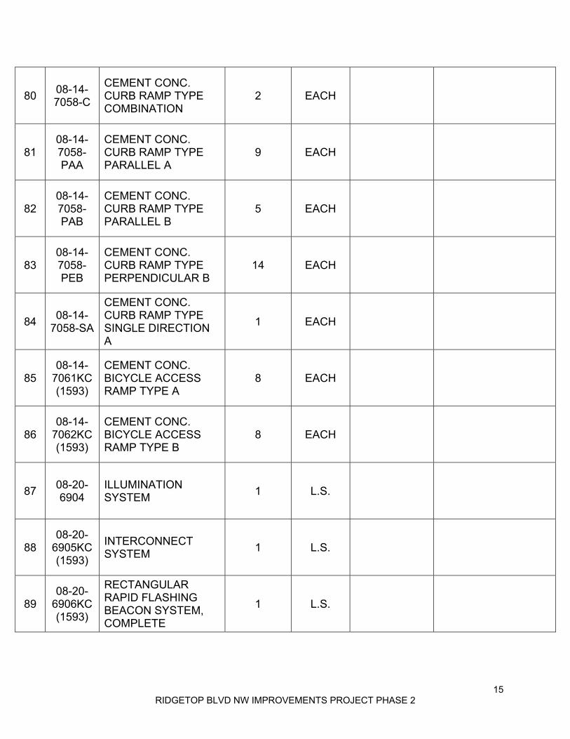
80 08-14-7058-C
CEMENT CONC. CURB RAMP TYPE COMBINATION
2 EACH
81 08-14-7058-PAA
CEMENT CONC. CURB RAMP TYPE PARALLEL A
9 EACH
82 08-14-7058-PAB
CEMENT CONC. CURB RAMP TYPE PARALLEL B
5 EACH
83 08-14-7058-PEB
CEMENT CONC. CURB RAMP TYPE PERPENDICULAR B
14 EACH
84 08-14-7058-SA
CEMENT CONC. CURB RAMP TYPE SINGLE DIRECTION A
1 EACH
85 08-14-
7061KC (1593)
CEMENT CONC. BICYCLE ACCESS RAMP TYPE A
8 EACH
86 08-14-
7062KC (1593)
CEMENT CONC. BICYCLE ACCESS RAMP TYPE B
8 EACH
87 08-20-6904
ILLUMINATION SYSTEM 1 L.S.
88 08-20-
6905KC (1593)
INTERCONNECT SYSTEM 1 L.S.
89 08-20-
6906KC (1593)
RECTANGULAR RAPID FLASHING BEACON SYSTEM, COMPLETE
1 L.S.

16 RIDGETOP BLVD NW IMPROVEMENTS PROJECT PHASE 2
90 08-21-6890
PERMANENT SIGNING 1 L.S.
91 08-22-6806 PAINT LINE 3897 L.F.
92 08-22-6807 PLASTIC LINE 784 L.F.
93 08-22-6828
PLASTIC WIDE LANE LINE 282 L.F.
94 08-22-6847
PLASTIC WIDE DOTTED ENTRY LINE 505 L.F.
95 08-22-6857
PLASTIC CROSSWALK LINE 1026 S.F.
96 08-22-9238
PLASTIC YIELD LINE SYMBOL 73 EACH
97 08-24-7164
GRAVITY BLOCK WALL 903 S.F.
98 08-24-7165KC
MODULAR BLOCK WALL 237 S.F.
99 08-26-7500
FIELD OFFICE BUILDING 1 L.S.

17 RIDGETOP BLVD NW IMPROVEMENTS PROJECT PHASE 2
100 08-27-
1030KC (1593)
DITCH EXCAVATION INCL. HAUL FOR BIORETENTION CELL
3190 C.Y.
101 08-27-
1087KC (1593)
ROCK PROTECTION PAD 14 EACH
102 08-27-1177KC INSPECTION PORT 8 EACH
103 08-27-
6410KC (1593)
BIORETENTION SOIL MEDIA 1080 C.Y.
104 08-27-
6463KC (1593)
CHECK DAM 20 L.F.
105 08-27-
6465KC (1593)
TRENCH DAM 5 EACH
106 08-27-
6482KC (1593)
COARSE COMPOST (ACRE) 0.3 ACRE
107 08-27-
6580KC (1593)
PATHWAY BARK 1.8 ACRE
TOTAL CONTRACT COST $

18 RIDGETOP BLVD NW IMPROVEMENTS PROJECT PHASE 2
2. BIDDER SHALL INCLUDE SALES TAX IN THE LUMP SUM AND UNIT PRICE BID ITEMS in accordance with Section 1-07.2(1) of Special Provisions. 3. The undersigned Bidder hereby proposes and agrees to commence work under this Contract, if awarded to them, in accordance with Sections 1-08.4 and 1-08.5 of the Special Provisions. They further agree to complete the contract within 140 working days. 4. The agreed liquidated damage to the Owner shall be in accordance with Liquidated Damages as described in the Standard Specifications, Amendments thereto, and Special Provisions. 5. The Owner reserves the right to delete all or any portions of the work as outlined in the Contract Documents. 6. The required bid security in the amount of five percent (5%) of the total bid is hereto attached. 7. It is understood that the Contractor is responsible for obtaining and completing all required government forms. 8. Receipt of the following Addenda to the Contract Document is hereby acknowledged.
ADDENDUM # DATE OF RECEIPT OF ADDENDUM
SIGNED ACKNOWLEDGMENT
1 2 3 4 5 6 (Note: Failure to acknowledge receipt of the Addenda may be considered an irregularity in the proposal).
9. Notice of Acceptance of this bid or requests for additional information should be addressed to the undersigned at the address stated below and unless otherwise notified in writing, this address shall be used by the successful bidder during the life of the Contract for all official notices. 10. By signing this Proposal, the Bidder certifies that they have read and understand all of the terms and Conditions of the Contract Plans, Standard Specifications, the Amendments there to, and these Special Provisions, and agrees to comply with them.

19 RIDGETOP BLVD NW IMPROVEMENTS PROJECT PHASE 2
Date:
Proper Name of Bidder (Type or Print):
By (Signature):
Name and Title (Type or Print Name and Title of Signatory):
Street Address:
City, State and Zip Code:
Telephone Number with Area Code:
Fax Number with Area Code:
Mailing Address, if different from above:

20 RIDGETOP BLVD NW IMPROVEMENTS PROJECT PHASE 2
THIS PAGE INTENTIONALLY LEFT BLANK
21 RIDGETOP BLVD NW IMPROVEMENTS PROJECT PHASE 2
BID BOND
KNOW ALL MEN BY THESE PRESENTS, that we, the undersigned, as Principal, and as Surety, are hereby held and firmly bound unto Kitsap County Department of Public Works as Owner in the penal sum of for payment of which, well and truly to be made, we hereby jointly and severally bind ourselves, successors and assigns. Signed this day of , 2019. The Condition of the above obligation is such that whereas the Principal has submitted To Kitsap County Department of Public Works, a certain BID, attached hereto and made a part hereof to enter a contract in writing, for the NOW, THEREFORE, (a) If said BID be rejected, or (b) If said Bid shall be accepted and the Principal shall execute and deliver a contract in the
Form of Contract attachment hereto (properly completed in accordance with said BID) and shall furnish a BOND for faithful performance of said contract, and for the payment of all persons performing labor and furnishing materials in connection therewith, and shall in all other respects perform the agreement created by the acceptance of said BID, then this obligation shall be void, otherwise the same shall remain in force and effect; it being expressly understood and agreed that the liability of the Surety for any and all claims hereunder shall, in no event exceed the penal amount of this obligation as herein stated.
The Surety, for value received, hereby stipulates and agrees that the obligations of said Surety and its BOND shall be in no way impaired or affected by any extension of the time within which the OWNER may accept such BID; and said Surety does hereby waive notice of any such extension. IN WITNESS WHEREOF, the Principal and the Surety have hereunto set their hands and seals, and such of them as are Corporations have set their Corporation seals to be hereto affixed and these presents to be signed by their proper officers, the day and year first set forth above. Principal Surety By:

22 RIDGETOP BLVD NW IMPROVEMENTS PROJECT PHASE 2
THIS PAGE INTENTIONALLY LEFT BLANK
23 RIDGETOP BLVD NW IMPROVEMENTS PROJECT PHASE 2
BIDDER RESPONSIBILITY STATEMENT
Each Bidder shall prepare and submit the following information with their bid. By signing the signature page of the Proposal, the Bidder affirms that the following information is true and correct. Name of Bidder:
Business Address:
A) MANDATORY BIDDER RESPONSIBILITY CRITERIA (RCW 39.04.350) 1. Washington State Contractors License Number:
Effective Date:
2. State of Washington Unified Business Identifier (UBI) No.:
3. Do you have industrial insurance (workers’ compensation) coverage for your employees working in Washington as required by Title 51 RCW?
Yes: No: Not Applicable:
4. Washington State Employment Security Department number as required by Title 51 RCW.
Number: Not Applicable:
5. Washington State Department of Revenue state excise tax registration number as required by Title 82 RCW.
Number: Not Applicable:
6. Have you ever been disqualified from bidding on any public works contract under RCW 39.06.010 or 39.12.065(3)?
Yes: No:
B) SUPPLEMENTAL BIDDER RESPONSIBILITY CRITERIA (SPECIAL PROVISIONS SECTION 1-02.14) 1. Do you own delinquent taxes to the State of Washington Department of Revenue?
Yes: No:
2. Are you currently debarred or suspended from bidding by the Federal government?
Yes: No:
3. Does your standard subcontract form include the subcontract responsibility language
required by RCW 39.06.020?
Yes: No:

24 RIDGETOP BLVD NW IMPROVEMENTS PROJECT PHASE 2
4. Do you have any established procedure which your company utilizes to validate the responsibility of each of your subcontractors and any sub-tier contractors?
Yes: No:
5. Do you have any record of prevailing wage violations in the last 5 years as determined by
the Washington State Department of Labor and Industries?
Yes: No:
6. Have you had any claims against retainage or payment bonds for public works projects in
the last 3 years?
Yes: No:
7. Has your company or its owners been convicted of a crime involving bidding on a public
works contract in the last 5 years?
Yes: No:
8. Has your company had any public works contract terminated for cause or terminated for
default by a government agency in the last 5 years?
Yes: No:
9. Has your company had any lawsuits with judgments entered against the company in the
last 5 years?
Yes: No:

25 RIDGETOP BLVD NW IMPROVEMENTS PROJECT PHASE 2
This form must be submitted with the Bid Proposal or as a Supplement to the Bid no later than
24 hours after the time for delivery of the Bid Proposal, as provided for in Section 1-02.9 of the Contract Provisions.
CERTIFICATION OF COMPLIANCE WITH WAGE PAYMENT STATUTES
The bidder hereby certifies that, within the three-year period immediately preceding the bid solicitation date July 9, 2019, the bidder is not a “willful” violator, as defined in RCW 49.48.082, of any provision of chapters 49.46, 49.48, or 49.52 RCW, as determined by a final and binding citation and notice of assessment issued by the Department of Labor and Industries or through a civil judgment entered by a court of limited or general jurisdiction. I certify under penalty of perjury under the laws of the State of Washington that the foregoing is true and correct.
Bidder’s Business Name
Signature of Authorized Official*
Printed Name
Title
Date
City
State
Check One:
Sole Proprietorship ☐ Partnership ☐ Joint Venture ☐ Corporation ☐ State of Incorporation, or if not a corporation, State where business entity was formed:
If a co-partnership, give firm name under which business is transacted:
* If a corporation, proposal must be executed in the corporate name by the president or vice-president (or any other corporate officer accompanied by evidence of authority to sign). If a co-partnership, proposal must be executed by a partner.

26 RIDGETOP BLVD NW IMPROVEMENTS PROJECT PHASE 2
THIS PAGE INTENTIONALLY LEFT BLANK
27 RIDGETOP BLVD NW IMPROVEMENTS PROJECT PHASE 2
NON-COLLUSION DECLARATION FORM

28 RIDGETOP BLVD NW IMPROVEMENTS PROJECT PHASE 2
THIS PAGE INTENTIONALLY LEFT BLANK

29 RIDGETOP BLVD NW IMPROVEMENTS PROJECT PHASE 2
SUBCONTRACTOR LIST

30 RIDGETOP BLVD NW IMPROVEMENTS PROJECT PHASE 2
THIS PAGE INTENTIONALLY LEFT BLANK

31 RIDGETOP BLVD NW IMPROVEMENTS PROJECT PHASE 2
PROPOSAL FOR INCORPORATING RECYCLED MATERIALS INTO THE PROJECT

32 RIDGETOP BLVD NW IMPROVEMENTS PROJECT PHASE 2
THIS PAGE INTENTIONALLY LEFT BLANK

33 RIDGETOP BLVD NW IMPROVEMENTS PROJECT PHASE 2
UDBE UTILIZATION CERTIFICATION
34 RIDGETOP BLVD NW IMPROVEMENTS PROJECT PHASE 2
35 RIDGETOP BLVD NW IMPROVEMENTS PROJECT PHASE 2

36 RIDGETOP BLVD NW IMPROVEMENTS PROJECT PHASE 2
THIS PAGE INTENTIONALLY LEFT BLANK

37 RIDGETOP BLVD NW IMPROVEMENTS PROJECT PHASE 2
UDBE WRITTEN CONFIRMATION DOCUMENT

38 RIDGETOP BLVD NW IMPROVEMENTS PROJECT PHASE 2
THIS PAGE INTENTIONALLY LEFT BLANK
39 RIDGETOP BLVD NW IMPROVEMENTS PROJECT PHASE 2
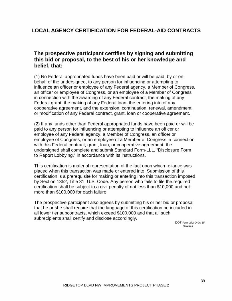
LOCAL AGENCY CERTIFICATION FOR FEDERAL-AID CONTRACTS
The prospective participant certifies by signing and submitting this bid or proposal, to the best of his or her knowledge and belief, that:
(1) No Federal appropriated funds have been paid or will be paid, by or on behalf of the undersigned, to any person for influencing or attempting to influence an officer or employee of any Federal agency, a Member of Congress, an officer or employee of Congress, or an employee of a Member of Congress in connection with the awarding of any Federal contract, the making of any Federal grant, the making of any Federal loan, the entering into of any cooperative agreement, and the extension, continuation, renewal, amendment, or modification of any Federal contract, grant, loan or cooperative agreement. (2) If any funds other than Federal appropriated funds have been paid or will be paid to any person for influencing or attempting to influence an officer or employee of any Federal agency, a Member of Congress, an officer or employee of Congress, or an employee of a Member of Congress in connection with this Federal contract, grant, loan, or cooperative agreement, the undersigned shall complete and submit Standard Form-LLL, “Disclosure Form to Report Lobbying,” in accordance with its instructions. This certification is material representation of the fact upon which reliance was placed when this transaction was made or entered into. Submission of this certification is a prerequisite for making or entering into this transaction imposed by Section 1352, Title 31, U.S. Code. Any person who fails to file the required certification shall be subject to a civil penalty of not less than $10,000 and not more than $100,000 for each failure. The prospective participant also agrees by submitting his or her bid or proposal that he or she shall require that the language of this certification be included in all lower tier subcontracts, which exceed $100,000 and that all such subrecipients shall certify and disclose accordingly.
DOT Form 272-040A EF 07/2011

40 RIDGETOP BLVD NW IMPROVEMENTS PROJECT PHASE 2
THIS PAGE INTENTIONALLY LEFT BLANK

41 RIDGETOP BLVD NW IMPROVEMENTS PROJECT PHASE 2
AGREEMENT
This Agreement, made and entered into this day of , 2019 by and between Kitsap County, through the BOARD OF COUNTY COMMISSIONERS of Kitsap County, State of Washington, hereinafter referred to as the “COUNTY”, and, , a general Contractor licensed by the State of Washington, for themselves, their heirs, executors, administrators, successors, and assigns, hereinafter referred to as the “CONTRACTOR.” RECITALS: WHEREAS, the COUNTY desires to provide road and stormwater improvements for approximately 3500 linear feet on Ridgetop Boulevard NW from Quail Run Drive NW to NW Pinnacle Ct, in Commissioner District 1: WHEREAS, the CONTRACTOR has been selected by competitive bid as the “responsible bidder with the lowest responsive bid,” as defined under RCW 39.04.010; NOW THEREFORE, in consideration of the mutual benefits and covenants contained herein, the COUNTY and the CONTRACTOR mutually agree as follows: CONTRACT DOCUMENTS: This Agreement hereby incorporates the recitals and the Contract Documents, which documents are incorporated herein by reference. The Contract Documents shall include, but shall not be limited to, the Contract Provisions for “RIDGETOP BLVD NW IMPROVEMENTS PROJECT PHASE 2”, Call for Bids, Contractors accepted Bid Proposal, the General and Special Provisions, Contract Plans and Drawings, Addenda, applicable Bonds, and the 2018 WSDOT/APWA Standard Specifications for Road, Bridge, and Municipal Construction, hereinafter referred to as the “Standard Specifications”, any amendments to the Standard Specifications, and this Agreement. 1) DESCRIPTION OF WORK: This contract provides for the road and stormwater improvements for approximately 3500 linear feet on Ridgetop Boulevard NW from Quail Run Drive NW to NW Pinnacle Ct located in central Kitsap County. The work proposed consists of Preparation, Excavation, Grading, Bioretention cells, Storm Sewer, Surfacing, Asphalt Concrete Pavement, Erosion Control and Planting, Traffic Safety and Control and related work. The CONTRACTOR shall furnish all of the materials, supplies, tools, equipment, labor, and other services necessary for the construction and completion of the project described herein, in accordance with the Contract Documents. 2) BINDING EFFECT: The covenants and conditions contained in this Agreement shall apply to and bind the parties, heirs, legal representatives and assigns of the parties.

42 RIDGETOP BLVD NW IMPROVEMENTS PROJECT PHASE 2
3) TIME IS OF THE ESSENCE: The CONTRACTOR agrees to work promptly and to fully complete the work within the time limits as described in the Contract Documents. Failure to complete within the allowed time limit will subject the CONTRACTOR to Liquidated Damages, as described in Section 1-08.9, Liquidated Damages, of the Contract Documents. 4) TIME FOR COMPLETION: The work to be performed under this Agreement shall commence and complete in accordance with Sections 1-08.4, Notice to Proceed and Prosecution of Work, and 1-08.5, Time for Completion, of the Contract Documents and Physically Completion of the work shall be achieved within 140 WORKING DAYS, unless Contract Time is extended otherwise in accordance with the Contract Documents. 5) COMPENSATION: The COUNTY agrees to pay the CONTRACTOR for the work described and completed according to the Contract Documents the sum of [spell out the amount in words and in numbers] ,$ . This sum shall include state sales tax. 6) INDEPENDENT CONTRACTOR: The CONTRACTOR shall perform the services under this Agreement as an independent CONTRACTOR and not as an agent, employee or servant of the COUNTY. The parties agree that the CONTRACTOR is not entitled to any benefits or rights enjoyed by employees of the COUNTY. CONTRACTOR shall comply with all laws regarding workers’ compensation. 7) DISCRIMINATION AND AMERICANS WITH DISABILITIES ACT (ADA): The CONTRACTOR agrees to comply with all provisions of the Americans with Disabilities Act and all regulations interpreting or enforcing said Act. The CONTRACTOR agrees to comply with all Federal, State and County laws and regulations in effect pertaining to non-discrimination. Violation of this section may be treated as a breach of this Agreement. 8) LIABILITY FOR NEGLIGENCE: The CONTRACTOR shall be liable for any additional expenses incurred by the COUNTY as a result of carelessness or negligence on the part of the CONTRACTOR, the CONTRACTOR’s agents, or the CONTRACTOR’s employees. The CONTRACTOR agrees that the COUNTY may deduct such additional costs on its own behalf from monies due, or to become due, to the CONTRACTOR. 9) TERMINATION: This Agreement may be terminated by the officials or agents of the COUNTY authorized to contract for or supervise the execution of such work in accordance with Section 1-08.10 of the Standard Specifications.

43 RIDGETOP BLVD NW IMPROVEMENTS PROJECT PHASE 2
10) MODIFICATION There shall be no modification of this Agreement, except in writing, executed with the same formalities as this Agreement. Change Orders totaling less than 10% of the total contract amount may be executed by the Director of Public Works or their authorized agent. Change Orders that exceed 10% of the total contract amount shall be valid provided they are executed by the Chair of the Board of County Commissioners or their authorized agent. 11) HOLD HARMLESS: The CONTRACTOR shall indemnify and hold harmless the COUNTY and its officers and employees from, and shall process and defend at its own expense, all claims, demands or suits at law or equity arising in whole or in part from the CONTRACTOR’s performance of any of its obligations under this Agreement; provided that nothing herein shall require the CONTRACTOR to indemnify the COUNTY against and hold harmless the COUNTY from claims, demands, or suits based upon the sole negligence of the COUNTY, its agents, officers, and employees; and provided further that if claims or suits are caused by or result from the concurrent negligence of (a) the CONTACTOR or CONTRACTOR’s agents or employees, and (b) the COUNTY or COUNTY’s agents, officers, or employees, this indemnity provision shall be valid and enforceable only to the extent of the CONTRACTOR’s negligence or the negligence of the CONTRACTOR’s agents or employees. The CONTRACTOR expressly assumes potential liability for actions brought by the CONTRACTOR’s own employees against the COUNTY; and, solely for the purpose of this indemnification and defense, the CONTRACTOR specifically waives any immunity under the state industrial insurance law, Title 51 RCW. The CONTRACTOR recognizes that this waiver was specifically entered into pursuant to the provisions of RCW 4.24.115 and was subject of mutual negotiation. 12) INSURANCE REQUIREMENTS: Section 1-07.18 of the Special Provisions shall govern this Agreement. 13) VENUE AND CHOICE OF LAW: Any action at law, suit in equity, or other judicial proceeding for the enforcement of this contract or any provisions thereof shall be instituted as provided for in RCW 36.01.050. It is mutually understood and agreed that this Agreement shall be governed by the laws of the State of Washington, both as to interpretation and performance. 14) INTEGRATION CLAUSE: This instrument embodies the entire agreement of the parties. There are no promises, terms, conditions or obligations other than those contained herein; and this Agreement shall supersede all previous communications, representations or agreements, either verbal or written, between parties.

44 RIDGETOP BLVD NW IMPROVEMENTS PROJECT PHASE 2
15) AUTHORIZATION: Each party signing below warrants to the other party, that they have the full power and authority to execute this Agreement on behalf of the party for whom they sign. 16) COMPLIANCE WITH LAWS: The CONTRACTOR shall comply with all applicable federal, state and local laws, rules and regulations in performing this Agreement. 17) SEVERABILITY: a. If a court of competent jurisdiction holds any part, term or provision of this Agreement to be illegal, or invalid in whole or in part, the validity of the remaining provisions shall not be affected, and the parties rights and obligations shall be construed and enforced as if the Contract did not contain the particular provision held to be invalid. b. If it should appear that any provision of this Agreement is in conflict with any statutory provision of the United States or State of Washington, said provision which may conflict therewith shall be deemed inoperative and null and void insofar as it may be in conflict therewith, and shall be deemed modified to conform to such statutory provision. 18) CONFLICTS PROVISION: In the event language in this Contract conflicts with the requirements in the Standard Specifications, the language in the Contract controls. 19) RIGHTS and REMEDIES: No action or failure to act by the COUNTY shall constitute a waiver of a right or duty afforded the COUNTY under the Contract Documents, nor shall such action or failure to act constitute approval of an acquiescence in a breach therein, except as may be specifically agreed in writing. 20) THIRD-PARTY AGREEMENTS: The Contract Documents shall not be construed to create a contractual relationship of any kind between the COUNTY and any Subcontractor or any persons other than the COUNTY and the CONTRACTOR. 21) RECORDS RETENTION: The wage, payroll, bid and cost records of the CONTRACTOR and its Subcontractors, and all records subject to audit in accordance with the Standard Specifications shall be retained for a period of not less than six (6) years after the date of Final Acceptance of the Contract Documents. 22) CONTRACT BOND: Payment and performance bonds for this project have been issued by , Surety Company of Street address: City: Telephone: Contact Person:

45 RIDGETOP BLVD NW IMPROVEMENTS PROJECT PHASE 2
in the amount of . IN WITNESS WHEREOF, the said CONTRACTOR has executed this instrument, and the said Board of County Commissioners of aforesaid COUNTY pursuant to resolution duly adopted has caused this instrument to be executed by and in the name of said Board by its Chair, duly attested by its Clerk, the day and year first above written, and the seal of said Board to be hereunto affixed on the date this instrument first above written. CONTRACTOR
BOARD OF COUNTY COMMISSIONERS KITSAP COUNTY, WASHINGTON
BY
TITLE
EDWARD E. WOLFE, Chair
CHARLOTTE GARRIDO, Commissioner
ROBERT GELDER, Commissioner
Foregoing contract approved and ratified:
ATTEST
DANA DANIELS, Clerk of the Board

46 RIDGETOP BLVD NW IMPROVEMENTS PROJECT PHASE 2
THIS PAGE INTENTIONALLY LEFT BLANK
47 RIDGETOP BLVD NW IMPROVEMENTS PROJECT PHASE 2
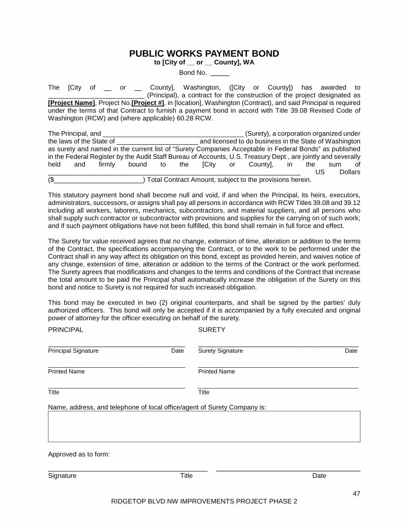
PUBLIC WORKS PAYMENT BOND to [City of __ or __ County], WA
Bond No.
The [City of __ or __ County], Washington, ([City or County]) has awarded to __________________________ (Principal), a contract for the construction of the project designated as [Project Name], Project No.[Project #], in [location], Washington (Contract), and said Principal is required under the terms of that Contract to furnish a payment bond in accord with Title 39.08 Revised Code of Washington (RCW) and (where applicable) 60.28 RCW. The Principal, and ______________________________________ (Surety), a corporation organized under the laws of the State of ______________________ and licensed to do business in the State of Washington as surety and named in the current list of “Surety Companies Acceptable in Federal Bonds” as published in the Federal Register by the Audit Staff Bureau of Accounts, U.S. Treasury Dept., are jointly and severally held and firmly bound to the [City or County], in the sum of ____________________________________________________________________ US Dollars ($________________________) Total Contract Amount, subject to the provisions herein. This statutory payment bond shall become null and void, if and when the Principal, its heirs, executors, administrators, successors, or assigns shall pay all persons in accordance with RCW Titles 39.08 and 39.12 including all workers, laborers, mechanics, subcontractors, and material suppliers, and all persons who shall supply such contractor or subcontractor with provisions and supplies for the carrying on of such work; and if such payment obligations have not been fulfilled, this bond shall remain in full force and effect. The Surety for value received agrees that no change, extension of time, alteration or addition to the terms of the Contract, the specifications accompanying the Contract, or to the work to be performed under the Contract shall in any way affect its obligation on this bond, except as provided herein, and waives notice of any change, extension of time, alteration or addition to the terms of the Contract or the work performed. The Surety agrees that modifications and changes to the terms and conditions of the Contract that increase the total amount to be paid the Principal shall automatically increase the obligation of the Surety on this bond and notice to Surety is not required for such increased obligation. This bond may be executed in two (2) original counterparts, and shall be signed by the parties’ duly authorized officers. This bond will only be accepted if it is accompanied by a fully executed and original power of attorney for the officer executing on behalf of the surety.
PRINCIPAL SURETY _________________________________________ ________________________________________________ Principal Signature Date Surety Signature Date _________________________________________ ________________________________________________ Printed Name Printed Name _________________________________________ ________________________________________________ Title Title Name, address, and telephone of local office/agent of Surety Company is:
Approved as to form:
___________________________________________ Signature Title Date

48 RIDGETOP BLVD NW IMPROVEMENTS PROJECT PHASE 2
THIS PAGE INTENTIONALLY LEFT BLANK

49 RIDGETOP BLVD NW IMPROVEMENTS PROJECT PHASE 2
PERFORMANCE BOND to [City of __ or __ County], WA
Bond No. The [City of __ or __ County], Washington, ([City or County]) has awarded to __________________________ (Principal), a contract for the construction of the project designated as [Project Name], Project No.[Project #], in [location], Washington (Contract), and said Principal is required to furnish a bond for performance of all obligations under the Contract. The Principal, and ______________________________________ (Surety), a corporation organized under the laws of the State of ______________________ and licensed to do business in the State of Washington as surety and named in the current list of “Surety Companies Acceptable in Federal Bonds” as published in the Federal Register by the Audit Staff Bureau of Accounts, U.S. Treasury Dept., are jointly and severally held and firmly bound to the [City or County], in the sum of ____________________________________________________________________ US Dollars ($________________________) Total Contract Amount, subject to the provisions herein. This statutory performance bond shall become null and void, if and when the Principal, its heirs, executors, administrators, successors, or assigns shall well and faithfully perform all of the Principal’s obligations under the Contract and fulfill all the terms and conditions of all duly authorized modifications, additions, and changes to said Contract that may hereafter be made, at the time and in the manner therein specified; and if such performance obligations have not been fulfilled, this bond shall remain in full force and effect. The Surety for value received agrees that no change, extension of time, alteration or addition to the terms of the Contract, the specifications accompanying the Contract, or to the work to be performed under the Contract shall in any way affect its obligation on this bond, and waives notice of any change, extension of time, alteration or addition to the terms of the Contract or the work performed. The Surety agrees that modifications and changes to the terms and conditions of the Contract that increase the total amount to be paid the Principal shall automatically increase the obligation of the Surety on this bond and notice to Surety is not required for such increased obligation. This bond may be executed in two (2) original counterparts, and shall be signed by the parties’ duly authorized officers. This bond will only be accepted if it is accompanied by a fully executed and original power of attorney for the officer executing on behalf of the surety.
PRINCIPAL SURETY _________________________________________ ________________________________________________ Principal Signature Date Surety Signature Date _________________________________________ ________________________________________________ Printed Name Printed Name _________________________________________ ________________________________________________ Title Title Name, address, and telephone of local office/agent of Surety Company is:
Approved as to form:
___________________________________________ Signature Title Date

50 RIDGETOP BLVD NW IMPROVEMENTS PROJECT PHASE 2
THIS PAGE INTENTIONALLY LEFT BLANK

51 RIDGETOP BLVD NW IMPROVEMENTS PROJECT PHASE 2
AMENDMENTS TO THE STANDARD SPECIFICATIONS
INTRODUCTION The following Amendments and Special Provisions shall be used in conjunction with the 2018 Standard Specifications for Road, Bridge, and Municipal Construction.
AMENDMENTS TO THE STANDARD SPECIFICATIONS The following Amendments to the Standard Specifications are made a part of this contract and supersede any conflicting provisions of the Standard Specifications. For informational purposes, the date following each Amendment title indicates the implementation date of the Amendment or the latest date of revision. Each Amendment contains all current revisions to the applicable section of the Standard Specifications and may include references which do not apply to this particular project. Section 1-01, Definitions and Terms August 6, 2018 1-01.3 Definitions The following new term and definition is inserted before the definition for “Shoulder”:
Sensitive Area – Natural features, which may be previously altered by human activity, that are present on or adjacent to the project location and protected, managed, or regulated by local, tribal, state, or federal agencies.
The following new term and definition is inserted after the definition for “Working Drawings”:
WSDOT Form – Forms developed and maintained by WSDOT that are required or available for use on a project. These forms can be downloaded from the forms catalogue at:
http://wsdot.wa.gov/forms/pdfForms.html Section 1-02, Bid Procedures and Conditions June 3, 2019 1-02.4(1) General This section is supplemented with the following:
Prospective Bidders are advised that the Contracting Agency may include a partially completed Washington State Department of Ecology (Ecology) Transfer of Coverage (Ecology Form ECY 020-87a) for the Construction Stormwater General Permit (CSWGP) as part of the Bid Documents. When the Contracting Agency requires the transfer of coverage of the CSWGP to the Contractor, an informational copy of the Transfer of Coverage and the associated CSWGP will be included in the appendices. As a condition of Section 1-03.3, the Contractor is required to
52 RIDGETOP BLVD NW IMPROVEMENTS PROJECT PHASE 2
complete sections I, III, and VIII of the Transfer of Coverage and return the form to the Contracting Agency. The Contracting Agency is responsible for compliance with the CSWGP until the end of day that the Contract is executed. Beginning on the day after the Contract is executed, the Contractor shall assume complete legal responsibility for compliance with the CSWGP and full implementation of all conditions of the CSWGP as they apply to the Contract Work.
1-02.5 Proposal Forms The first sentence of the first paragraph is revised to read:
At the request of a Bidder, the Contracting Agency will provide a physical Proposal Form for any project on which the Bidder is eligible to Bid.
1-02.6 Preparation of Proposal Item number 1 of the second paragraph is revised to read:
1. A unit price for each item (omitting digits more than two places to the right of the decimal point),
In the third sentence of the fourth paragraph, “WSDOT Form 422-031” is revised to read “WSDOT Form 422-031U”. The following new paragraph is inserted before the last paragraph:
The Bidder shall submit with their Bid a completed Contractor Certification Wage Law Compliance form (WSDOT Form 272-009). Failure to return this certification as part of the Bid Proposal package will make this Bid Nonresponsive and ineligible for Award. A Contractor Certification of Wage Law Compliance form is included in the Proposal Forms.
1-02.13 Irregular Proposals Item 1(h) is revised to read:
h. The Bidder fails to submit Underutilized Disadvantaged Business Enterprise Good Faith Effort documentation, if applicable, as required in Section 1-02.6, or if the documentation that is submitted fails to demonstrate that a Good Faith Effort to meet the Condition of Award was made;
Item 1(i) is revised to read the following three items:
i. The Bidder fails to submit a UDBE Bid Item Breakdown form, if applicable, as required in Section 1-02.6, or if the documentation that is submitted fails to meet the requirements of the Special Provisions;

53 RIDGETOP BLVD NW IMPROVEMENTS PROJECT PHASE 2
j. The Bidder fails to submit UDBE Trucking Credit Forms, if applicable, as required in Section 1-02.6, or if the documentation that is submitted fails to meet the requirements of the Special Provisions; or
k. The Bid Proposal does not constitute a definite and unqualified offer to meet
the material terms of the Bid invitation. Section 1-03, Award and Execution of Contract January 2, 2018 1-03.3 Execution of Contract The first paragraph is revised to read:
Within 20 calendar days after the Award date, the successful Bidder shall return the signed Contracting Agency-prepared Contract, an insurance certification as required by Section 1-07.18, a satisfactory bond as required by law and Section 1-03.4, the Transfer of Coverage form for the Construction Stormwater General Permit with sections I, III, and VIII completed when provided, and shall be registered as a contractor in the state of Washington.
1-03.5 Failure to Execute Contract The first sentence is revised to read:
Failure to return the insurance certification and bond with the signed Contract as required in Section 1-03.3, or failure to provide Disadvantaged, Minority or Women’s Business Enterprise information if required in the Contract, or failure or refusal to sign the Contract, or failure to register as a contractor in the state of Washington, or failure to return the completed Transfer of Coverage for the Construction Stormwater General Permit to the Contracting Agency when provided shall result in forfeiture of the proposal bond or deposit of this Bidder.
Section 1-05, Control of Work August 6, 2018 1-05.5 Vacant This section, including title, is revised to read:
1-05.5 Tolerances Geometrical tolerances shall be measured from the points, lines, and surfaces defined in Contract documents. A plus (+) tolerance increases the amount or dimension to which it applies, or raises a deviation from level. A minus (-) tolerance decreases the amount or dimension to which it applies, or lowers a deviation from level. Where only one signed tolerance is specified (+ or -), there is no specified tolerance in the opposing direction. Tolerances shall not be cumulative. The most restrictive tolerance shall control.

54 RIDGETOP BLVD NW IMPROVEMENTS PROJECT PHASE 2
Tolerances shall not extend the Work beyond the Right of Way or other legal boundaries identified in the Contract documents. If application of tolerances causes the extension of the Work beyond the Right of Way or legal boundaries, the tolerance shall be reduced for that specific instance. Tolerances shall not violate other Contract requirements. If application of tolerances causes the Work to violate other Contract requirements, the tolerance shall be reduced for that specific instance. If application of tolerances causes conflicts with other components or aspects of the Work, the tolerance shall be reduced for that specific instance.
1-05.9 Equipment The following new paragraph is inserted before the first paragraph:
Prior to mobilizing equipment on site, the Contractor shall thoroughly remove all loose dirt and vegetative debris from drive mechanisms, wheels, tires, tracks, buckets and undercarriage. The Engineer will reject equipment from the site until it returns clean.
This section is supplemented with the following:
Upon completion of the Work, the Contractor shall completely remove all loose dirt and vegetative debris from equipment before removing it from the job site.
Section 1-06, Control of Material January 7, 2019 1-06.1(3) Aggregate Source Approval (ASA) Database This section is supplemented with the following:
Regardless of status of the source, whether listed or not listed in the ASA database the source owner may be asked to provide testing results for toxicity in accordance with Section 9-03.21(1).
1-06.2(2)D Quality Level Analysis This section is supplemented with the following new subsection:
1-06.2(2)D5 Quality Level Calculation – HMA Compaction The procedures for determining the quality level and pay factor for HMA compaction are as follows:
1. Determine the arithmetic mean, Xm, for compaction of the lot:
nxX m
∑=
Where:

55 RIDGETOP BLVD NW IMPROVEMENTS PROJECT PHASE 2
x = individual compaction test values for each sublot in the lot. ∑x = summation of individual compaction test values n = total number test values
2. Compute the sample standard deviation, “S”, for each constituent:
( )( )
21
22
1
−∑−∑
=nn
xxnS
Where: ∑x2 = summation of the squares of individual compaction test values (∑x)2 = summation of the individual compaction test values squared
3. Compute the lower quality index (QL):
SLSLXQ m
L−
=
Where: LSL = 92.0
4. Determine PL (the percent within the lower Specification limit which
corresponds to a given QL) from Table 1. For negative values of QL, PL is equal to 100 minus the table PL. If the value of QL does not correspond exactly to a figure in the table, use the next higher value.
5. Determine the quality level (the total percent within Specification limits):
Quality Level = PL 6. Using the quality level from step 5, determine the composite pay factor
(CPF) from Table 2. 7. If the CPF determined from step 6 is 1.00 or greater: use that CPF for the
compaction lot; however, the maximum HMA compaction CPF using an LSL = 92.0 shall be 1.05.
8. If the CPF from step 6 is not 1.00 or greater: repeat steps 3 through 6 using
an LSL = 91.5. The value thus determined shall be the HMA compaction CPF for that lot; however, the maximum HMA compaction CPF using an LSL = 91.5 shall be 1.00.
1-06.2(2)D1 Quality Level Analysis The following new sentence is inserted after the first sentence:
56 RIDGETOP BLVD NW IMPROVEMENTS PROJECT PHASE 2
The quality level calculations for HMA compaction are completed using the formulas in Section 1-06.2(2)D5.
1-06.2(2)D4 Quality Level Calculation The first paragraph (excluding the numbered list) is revised to read:
The procedures for determining the quality level and pay factors for a material, other than HMA compaction, are as follows:
1-06.6 Recycled Materials The first three sentences of the second paragraph are revised to read:
The Contractor shall submit a Recycled Material Utilization Plan on WSDOT Form 350-075A within 30 calendar days after the Contract is executed. The plan shall provide the Contractor’s anticipated usage of recycled concrete aggregates for meeting the requirements of these Specifications. The quantity of recycled concrete aggregate will be provided in tons and as a percentage of the Plan quantity for eligible material listed in Section 9-03.21(1)E Table on Maximum Allowable percent (By Weight) of Recycled Material.
The last paragraph is revised to read:
Within 30 calendar days after Physical Completion, the Contractor shall report the quantity of recycled concrete aggregates that were utilized in the construction of the project for each eligible item listed in Section 9-03.21(1)E. The Contractor’s report shall be provided on WSDOT Form 350-075A, Recycled Materials Reporting.
1-06.6(1)A General Item 1(a) in the second paragraph is revised to read:
a. The estimated costs for the Work for each material with 25 percent recycled concrete aggregate. The cost estimate shall include for each material a documented price quote from the supplier with the lowest total cost for the Work.
Section 1-07, Legal Relations and Responsibilities to the Public April 1, 2019 1-07.5 Environmental Regulations This section is supplemented with the following new subsections:
1-07.5(5) U.S. Army Corps of Engineers When temporary fills are permitted, the Contractor shall remove fills in their entirety and the affected areas returned to pre-construction elevations.
57 RIDGETOP BLVD NW IMPROVEMENTS PROJECT PHASE 2
If a U.S. Army Corps of Engineers permit is noted in Section 1-07.6 of the Special Provisions, the Contractor shall retain a copy of the permit or the verification letter (in the case of a Nationwide Permit) on the worksite for the life of the Contract. The Contractor shall provide copies of the permit or verification letter to all subcontractors involved with the authorized work prior to their commencement of any work in waters of the U.S. 1-07.5(6) U.S. Fish/Wildlife Services and National Marine Fisheries Service The Contracting Agency will provide fish exclusion and handling services if the Work dictates. However, if the Contractor discovers any fish stranded by the project and a Contracting Agency biologist is not available, they shall immediately release the fish into a flowing stream or open water.
1-07.5(1) General The first sentence is deleted and replaced with the following:
No Work shall occur within areas under the jurisdiction of resource agencies unless authorized in the Contract.
The third paragraph is deleted. 1-07.5(2) State Department of Fish and Wildlife This section is revised to read:
In doing the Work, the Contractor shall:
1. Not degrade water in a way that would harm fish, wildlife, or their habitat. 2. Not place materials below or remove them from the ordinary high water line
except as may be specified in the Contract. 3. Not allow equipment to enter waters of the State except as specified in the
Contract. 4. Revegetate in accordance with the Plans, unless the Special Provisions
permit otherwise. 5. Prevent any fish-threatening silt buildup on the bed or bottom of any body
of water. 6. Ensure continuous stream flow downstream of the Work area. 7. Dispose of any project debris by removal, burning, or placement above
high-water flows.
58 RIDGETOP BLVD NW IMPROVEMENTS PROJECT PHASE 2
8. Immediately notify the Engineer and stop all work causing impacts, if at any time, as a result of project activities, fish are observed in distress or a fish kill occurs.
If the Work in (1) through (3) above differs little from what the Contract requires, the Contracting Agency will measure and pay for it at unit Contract prices. But if Contract items do not cover those areas, the Contracting Agency will pay pursuant to Section 1-09.4. Work in (4) through (8) above shall be incidental to Contract pay items.
1-07.5(3) State Department of Ecology This section is revised to read:
In doing the Work, the Contractor shall:
1. Comply with Washington State Water Quality Standards. 2. Perform Work in such a manner that all materials and substances not
specifically identified in the Contract documents to be placed in the water do not enter waters of the State, including wetlands. These include, but are not limited to, petroleum products, hydraulic fluid, fresh concrete, concrete wastewater, process wastewater, slurry materials and waste from shaft drilling, sediments, sediment-laden water, chemicals, paint, solvents, or other toxic or deleterious materials.
3. Use equipment that is free of external petroleum-based products. 4. Remove accumulations of soil and debris from drive mechanisms (wheels,
tracks, tires) and undercarriage of equipment prior to using equipment below the ordinary high water line.
5. Clean loose dirt and debris from all materials placed below the ordinary
high water line. No materials shall be placed below the ordinary high water line without the Engineer’s concurrence.
6. When a violation of the Construction Stormwater General Permit (CSWGP)
occurs, immediately notify the Engineer and fill out WSDOT Form 422-011, Contractor ECAP Report, and submit the form to the Engineer within 48 hours of the violation.
7. Once Physical Completion has been given, prepare a Notice of Termination
(Ecology Form ECY 020-87) and submit the Notice of Termination electronically to the Engineer in a PDF format a minimum of 7 calendar days prior to submitting the Notice of Termination to Ecology.

59 RIDGETOP BLVD NW IMPROVEMENTS PROJECT PHASE 2
8. Transfer the CSWGP coverage to the Contracting Agency when Physical Completion has been given and the Engineer has determined that the project site is not stabilized from erosion.
9. Submit copies of all correspondence with Ecology electronically to the
Engineer in a PDF format within four calendar days. 1-07.5(4) Air Quality This section is revised to read:
The Contractor shall comply with all regional clean air authority and/or State Department of Ecology rules and regulations. The air quality permit process may include additional State Environment Policy Act (SEPA) requirements. Contractors shall contact the appropriate regional air pollution control authority well in advance of beginning Work. When the Work includes demolition or renovation of any existing facility or structure that contains Asbestos Containing Material (ACM) and/or Presumed Asbestos-Containing Material (PACM), the Contractor shall comply with the National Emission Standards for Hazardous Air Pollutants (NESHAP). Any requirements included in Federal and State regulations regarding air quality that applies to the “owner or operator” shall be the responsibility of the Contractor.
1-07.7(1) General The first sentence of the third paragraph is revised to read:
When the Contractor moves equipment or materials on or over Structures, culverts or pipes, the Contractor may operate equipment with only the load-limit restrictions in Section 1-07.7(2).
The first sentence of the last paragraph is revised to read:
Unit prices shall cover all costs for operating over Structures, culverts and pipes. 1-07.9(1) General The last sentence of the sixth paragraph is revised to read:
Generally, the Contractor initiates the request by preparing standard form 1444 Request for Authorization of Additional Classification and Rate, available at https://www.dol.gov/whd/recovery/dbsurvey/conformance.htm, and submitting it to the Engineer for further action.
1-07.9(2) Posting Notices The second sentence of the first paragraph (up until the colon) is revised to read:

60 RIDGETOP BLVD NW IMPROVEMENTS PROJECT PHASE 2
The Contractor shall ensure the most current edition of the following are posted:
The revision dates are deleted from all items in the numbered list. The following new items are inserted after item number 1:
2. Mandatory Supplement to EEOC P/E-1 published by US Department of Labor. Post for projects with federal-aid funding.
3. Pay Transparency Nondiscrimination Provision published by US
Department of Labor. Post for projects with federal-aid funding. Item number 2 through 12 are renumbered to 4 through 14, respectively. 1-07.11(2) Contractual Requirements In this section, “creed” is revised to read “religion”. Item numbers 1 through 9 are revised to read 2 through 10, respectively. After the preceding Amendment is applied, the following new item number 1 is inserted:
1. The Contractor shall maintain a Work site that is free of harassment, humiliation, fear, hostility and intimidation at all times. Behaviors that violate this requirement include but are not limited to:
a. Persistent conduct that is offensive and unwelcome. b. Conduct that is considered to be hazing. c. Jokes about race, gender, or sexuality that are offensive. d. Unwelcome, unwanted, rude or offensive conduct or advances of a sexual
nature which interferes with a person’s ability to perform their job or creates an intimidating, hostile, or offensive work environment.
e. Language or conduct that is offensive, threatening, intimidating or hostile
based on race, gender, or sexual orientation. f. Repeating rumors about individuals in the Work Site that are considered to
be harassing or harmful to the individual’s reputation. 1-07.11(5) Sanctions This section is supplemented with the following:
61 RIDGETOP BLVD NW IMPROVEMENTS PROJECT PHASE 2
Immediately upon the Engineer’s request, the Contractor shall remove from the Work site any employee engaging in behaviors that promote harassment, humiliation, fear or intimidation including but not limited to those described in these specifications.
1-07.11(6) Incorporation of Provisions The first sentence is revised to read:
The Contractor shall include the provisions of Section 1-07.11(2) Contractual Requirements (1) through (5) and the Section 1-07.11(5) Sanctions in every subcontract including procurement of materials and leases of equipment.
1-07.15(1) Spill Prevention, Control, and Countermeasures Plan The last sentence of the first paragraph is revised to read:
An SPCC Plan template and guidance information is available at http://www.wsdot.wa.gov/environment/technical/disciplines/hazardous-materials/spill-prevent-report.
1-07.16(2)A Wetland and Sensitive Area Protection The first sentence of the first paragraph is revised to read:
Existing wetland and other sensitive areas, where shown in the Plans or designated by the Engineer, shall be saved and protected through the life of the Contract.
1-07.18 Public Liability and Property Damage Insurance Item number 1 is supplemented with the following new sentence:
This policy shall be kept in force from the execution date of the Contract until the Physical Completion Date.
Section 1-08, Prosecution and Progress January 7, 2019 1-08.1 Subcontracting The first sentence of the seventh paragraph is revised to read:
All Work that is not performed by the Contractor will be considered as subcontracting except: (1) purchase of sand, gravel, crushed stone, crushed slag, batched concrete aggregates, ready-mix concrete, off-site fabricated structural steel, other off-site fabricated items, and any other materials supplied by established and recognized commercial plants; or (2) delivery of these materials to the Work site in vehicles owned or operated by such plants or by recognized independent or commercial hauling companies hired by those commercial plants.
The following new paragraph is inserted after the seventh paragraph:

62 RIDGETOP BLVD NW IMPROVEMENTS PROJECT PHASE 2
The Contractor shall not use businesses (material suppliers, vendors, subcontractors, etc.) with federal purchasing exclusions. Businesses with exclusions are identified using the System for Award Management web page at www.SAM.gov.
1-08.5 Time for Completion Item number 2 of the sixth paragraph is supplemented with the following:
f. A copy of the Notice of Termination sent to the Washington State Department of Ecology (Ecology); the elapse of 30 calendar days from the date of receipt of the Notice of Termination by Ecology; and no rejection of the Notice of Termination by Ecology. This requirement will not apply if the Construction Stormwater General Permit is transferred back to the Contracting Agency in accordance with Section 8-01.3(16).
1-08.7 Maintenance During Suspension The fifth paragraph is revised to read:
The Contractor shall protect and maintain all other Work in areas not used by traffic. All costs associated with protecting and maintaining such Work shall be the responsibility of the Contractor.
Section 1-09, Measurement and Payment August 6, 2018 1-09.2(1) General Requirements for Weighing Equipment The last paragraph is supplemented with the following:
When requested by the Engineer, the Contractor’s representative shall collect the tickets throughout the day and provide them to the Engineer’s designated receiver, not later than the end of shift, for reconciliation. Tickets for loads not verified as delivered will receive no pay.
1-09.2(2) Specific Requirements for Batching Scales The last sentence of the first paragraph is revised to read:
Batching scales used for concrete or hot mix asphalt shall not be used for batching other materials.
1-09.10 Payment for Surplus Processed Materials The following sentence is inserted after the first sentence of the second paragraph:
For Hot Mix Asphalt, the Plan quantity and quantity used will be adjusted for the quantity of Asphalt and quantity of RAP or other materials incorporated into the mix.
63 RIDGETOP BLVD NW IMPROVEMENTS PROJECT PHASE 2
Section 2-01, Clearing, Grubbing, and Roadside Cleanup April 1, 2019 2-01.2(3) Disposal Method No. 3 – Chipping Item number 2 of the first paragraph is revised to read:
2. Chips shall be disposed outside of sensitive areas, and in areas that aren’t in conflict with permanent Work.
Section 2-02, Removal of Structures and Obstructions April 2, 2018 2-02.3(3) Removal of Pavement, Sidewalks, Curbs, and Gutters In item number 3 of the first paragraph, the second sentence is revised to read:
For concrete pavement removal, a second vertical full depth relief saw cut offset 12 to 18 inches from and parallel to the initial saw cut is also required, unless the Engineer allows otherwise.
Section 2-03, Roadway Excavation and Embankment April 1, 2019 2-03.3(14)F Displacement of Unsuitable Foundation Materials This section, including title, is revised to read:
2-03.3(14)F Vacant Section 2-09, Structure Excavation April 1, 2019 2-09.2 Materials In the first paragraph, the references to “Portland Cement” and “Aggregates for Portland Cement Concrete” are revised to read:
Cement 9-01 Fine Aggregate for Concrete 9-03.1(2)
2-09.3(3)B Excavation Using Open Pits – Extra Excavation The last two paragraphs are deleted and replaced with the following:
The excavation height (Ht) shall be calculated within a vertical plane as the difference between the lowest elevation in the excavation and the highest elevation of the ground surface immediately adjacent to the excavation. Pavement thickness and other surface treatments existing at the time of the excavation shall be included in the height calculation. Submittals and Design Requirements Excavations 4-feet and less in height do not require design and submittals. The Contractor shall provide a safe work environment and shall execute the work in a manner that does not damage adjacent pavements, utilities, or structures. If the
64 RIDGETOP BLVD NW IMPROVEMENTS PROJECT PHASE 2
Engineer determines the Contractor’s work may potentially affect adjacent traffic, pavements, utilities, or structures, the Engineer may request a Type 1 Working Drawing from the Contractor. The Contractor shall explain in the Type 1 Working Drawing how the Engineer’s concerns will be addressed, why infrastructure will not be damaged by the work, and how worker safety will be preserved. For excavations that have soil types and slope geometries defined in WAC 296-155 part N and are between 4-feet and 20-feet in height, the Contractor shall submit Type 2 Working Drawings. Required submittal elements include, at a minimum, the following:
1. A plan view showing the limits of the excavation and its relationship to traffic, structures, utilities and other pertinent project elements. If the stability of the excavation requires no-load zones or equipment setback distances, those shall be shown on the plan view.
2. A typical or controlling cross section showing the proposed excavation,
original ground line, and locations of traffic, existing structures, utilities, site constraints, surcharge loads, or other conditions that could affect the stability of the slope. If the stability of the excavation requires no-load zones or equipment setback distances, those shall be shown in cross section.
3. A summary clearly describing subsurface conditions, soil type for WAC
296-155 part N, and groundwater conditions, sequencing considerations, and governing assumptions.
Where WAC 296-155 part N requires an engineer’s design, the Contractor shall submit Type 2E Working Drawings. Required submittal elements include, at a minimum, the three items above and the following additional items:
4. Supporting calculations for the design of the excavation, the soil and
material properties selected for design, and the justification for the selection for those properties, in accordance with the WSDOT Geotechnical Design Manual M 46-03.
5. Safety factors, or load and resistance factors used, and justification for their
selection, in accordance with the WSDOT Geotechnical Design Manual M 46-03, and referenced AASHTO design manuals.
6. A monitoring plan to evaluate the excavation performance throughout its
design life. 7. Any supplemental subsurface explorations made by the Contractor to meet
the requirements for geotechnical design of excavation slopes, in accordance with the WSDOT Geotechnical Design Manual M 46-03.

65 RIDGETOP BLVD NW IMPROVEMENTS PROJECT PHASE 2
2-09.3(3)D Shoring and Cofferdams The first sentence of the sixth paragraph is revised to read:
Structural shoring and cofferdams shall be designed for conditions stated in this Section using methods shown in Division I Section 5 of the AASHTO Standard Specifications for Highway Bridges Seventeenth Edition – 2002 for allowable stress design, or the AASHTO LRFD Bridge Design Specifications for load and resistance factor design.
Section 3-01, Production from Quarry and Pit Sites April 2, 2018 3-01.1 Description The first paragraph is revised to read:
This Work shall consist of manufacturing and producing crushed and screened aggregates including pit run aggregates of the kind, quality, and grading specified for use in the construction of concrete, hot mix asphalt, crushed surfacing, maintenance rock, ballast, gravel base, gravel backfill, gravel borrow, riprap, and bituminous surface treatments of all descriptions.
Section 4-04, Ballast and Crushed Surfacing April 2, 2018 4-04.3(5) Shaping and Compaction This section is supplemented with the following new paragraph:
When using 100% Recycled Concrete Aggregate, the Contractor may submit a written request to use a test point evaluation for compaction acceptance testing in lieu of compacting to 95% of the standard density as determined by the requirements of Section 2-03.3(14)D. The test point evaluation shall be performed in accordance with SOP 738.
Section 5-01, Cement Concrete Pavement Rehabilitation January 7, 2019 5-01.2 Materials The reference for Concrete Patching Material is revised to read:
Concrete Patching Material, Grout, and Mortar 9-20.1 5-01.3(1)A1 Concrete Patching Materials In this section, each reference to “9-20” is revised to read “9-20.1”. 5-01.3(4) Replace Cement Concrete Panel This section’s content is deleted and replaced with the following new subsections:

66 RIDGETOP BLVD NW IMPROVEMENTS PROJECT PHASE 2
5-01.3(4)A General Curing, cold weather work, concrete pavement construction in adjacent lines, and protection of pavement shall meet the requirements of Section 5-05.3(13) through Section 5-05.3(15). The Contractor, at no cost to the Contracting Agency, shall repair any damage to existing pavement caused by the Contractor’s operations. 5-01.3(4)B Sawing and Dimensional Requirements Concrete slabs to be replaced as shown in the Plans or staked by the Engineer shall be at least 6.0 feet long and full width of an existing pavement panel. The portion of the panel to remain in place shall have a minimum dimension of 6 feet in length and full panel width; otherwise the entire panel shall be removed and replaced. There shall be no new joints closer than 3.0 feet to an existing transverse joint or crack. A vertical full depth saw cut is required along all longitudinal joints and at transverse locations and, unless the Engineer allows otherwise, an additional vertical full depth relief saw cut located 12 to 18 inches from and parallel to the initial longitudinal and transverse saw cut locations is also required. Removal of existing cement concrete pavement shall not cause damage to adjacent slabs that are to remain in place. In areas that will be ground, slab replacements shall be performed prior to pavement grinding. Side forms shall meet the requirements of Section 5-05.3(7)B whenever a sawed full depth vertical face cannot be maintained. 5-01.3(4)C Dowel Bars and Tie Bars For the half of a dowel bar or tie bar placed in fresh concrete, comply with the requirements of Section 5-05. For the half of a dowel bar or tie bar placed in hardened concrete, comply with the Standard Plans and the following. After drilling, secure dowel bars and tie bars into the existing pavement with either an epoxy bonding agent Type I or IV as specified in Section 9-26.1, or a grout Type 2 for non-shrink applications as specified in Section 9-20.3. Dowel bars shall be placed at the mid depth of the concrete slab, centered over the transverse joint, and parallel to the centerline and to the roadway surface, within the tolerances in the table below. Dowel bars may be adjusted to avoid contact with existing dowel bars in the transverse joint at bridge approach slabs or existing panels provided the adjusted dowel bars meet the tolerances below. Tie bars shall be placed at the mid depth of the concrete slab, centered over the joint, perpendicular to centerline, and parallel to the roadway surface, within the tolerances in the table below. The horizontal position of tie bars may be adjusted to avoid contact with existing tie bars in the longitudinal joint where panel replacement takes place, provided the adjusted tie bars meet the tolerances below.

67 RIDGETOP BLVD NW IMPROVEMENTS PROJECT PHASE 2
Placement Tolerances Dowel Bars Tie Bars Vertical: Center of Bar to Center of Slab Depth
± 1.00 inch max ± 1.00 inch max
Dowel Bar Centered Over the Transverse Joint
± 1.00 inch max N/A
Tie Bar Centered Over the Longitudinal Joint
N/A ± 1.00 inch max
Parallel to Centerline Over the Length of the Dowel Bar
± 0.50 inch max N/A
Perpendicular to Longitudinal Joint Over the Length of the Tie Bar
N/A ± 1.00 inch max
Parallel to Roadway Surface Over the Length of the Bar
± 0.50 inch max ± 1.00 inch max
Dowel bars and tie bars shall be placed according to the Standard Plan when multiple panels are placed. Panels shall be cast separately from the bridge approach slab. Dowel bars to be drilled into existing concrete or at a new transverse contraction joint shall have a parting compound, such as curing compound, grease, or other Engineer accepted equal, applied to them prior to placement. Clean the drilled holes in accordance with the epoxy or grout manufacturer’s instructions. Holes shall be clean and dry at the time of placing the epoxy, or grout and tie bars. Completely fill the void between the tie bar and the outer limits of the drilled hole with epoxy or grout. Use retention rings to prevent leakage of the epoxy or grout and support the tie bar to prevent movement until the epoxy or grout has cured the minimum time recommended by the manufacturer. 5-01.3(4)D Foundation Preparation The Contractor shall smooth the surfacing below the removed panel and compact it to the satisfaction of the Engineer. Crushed surfacing base course, or hot mix asphalt may be needed to bring the surfacing to grade prior to placing the new concrete. If the material under the removed panel is uncompactable and the Engineer requires it, the Contractor shall excavate the Subgrade 2 feet, place a soil stabilization construction geotextile meeting the requirements of Section 9-33, and backfill with crushed surfacing base course. This Work may include:
1. Furnishing and hauling crushed surfacing base course to the project site. 2. Excavating uncompactable material. 3. Furnishing and placing a soil stabilization construction geotextile.
68 RIDGETOP BLVD NW IMPROVEMENTS PROJECT PHASE 2
4. Backfilling and compacting crushed surfacing base course. 5. Removing, hauling and restocking any unused crushed surfacing base
course. 5-01.3(4)E Concrete Finishing Grade control shall be the responsibility of the Contractor. All panels shall be struck off level with the adjacent panels and floated to a smooth surface. Final finish texturing shall meet the requirements of Section 5-05.3(11). In areas where the Plans do not require grinding, the surface smoothness will be measured with a 10-foot straightedge by the Engineer in accordance with Section 5-05.3(12). If the replacement panel is located in an area that will be ground as part of concrete pavement grinding in accordance with Section 5-01.3(9), the surface smoothness shall be measured, by the Contractor, in conjunction with the smoothness measurement done in accordance with Section 5-01.3(10). 5-01.3(4)F Joints All transverse and longitudinal joints shall be sawed and sealed in accordance with Section 5-05.3(8). The Contractor may use a hand pushed single blade saw for sawing joints. 5-01.3(4)G Cracked Panels Replacement panels that crack shall be repaired as specified in Section 5-05.3(22) at no cost to the Contracting Agency. When repairing replacement panels that have cracked, epoxy-coated dowel bars meeting the requirements of Section 9-07.5(1) may be substituted for the corrosion resistant dowel bars specified. 5-01.3(4)H Opening to Traffic Opening to traffic shall meet the requirements of Section 5-05.3(17).
5-01.3(5) Partial Depth Spall Repair The second sentence of the third paragraph is revised to read:
All sandblasting residue shall be removed. 5-01.3(7) Sealing Existing Concrete Random Cracks The second sentence of the second paragraph is revised to read:
Immediately prior to sealing, the cracks shall be clean. 5-01.3(8) Sealing Existing Longitudinal and Transverse Joint The first sentence of the fifth paragraph is revised to read:

69 RIDGETOP BLVD NW IMPROVEMENTS PROJECT PHASE 2
Immediately prior to sealing, the cracks shall be clean.
5-01.3(10) Pavement Smoothness This section is revised to read:
Pavement surface smoothness for cement concrete pavement grinding on this project will include International Roughness Index (IRI) testing. Ride quality will be evaluated using the Mean Roughness Index (MRI) calculated by averaging the IRI data for the left and right wheel path within the section. Smoothness Testing Equipment and Operator Certification Use an inertial profiler and operator that meet the requirements of Section 5-05.3(3)E. Surface Smoothness Operate the inertial profiler in accordance with AASHTO R 57. Collect two longitudinal traces, one in each wheel path. Collect the control profile at locations designated in Table 2 prior to any pavement rehabilitation Work on the areas to be tested. Collect an acceptance profile at locations designated in Table 2 after completion of all cement concrete pavement grinding on the project. Profiles shall be collected in a continuous pass including areas excluded from pay adjustments. Provide notice to the Engineer a minimum of seven calendar days prior to testing.
Table 2 Locations Requiring MRI Testing
Travel lanes where cement concrete grinding is shown in the plans
Control profile
Additional locations designated by the Engineer Control profile
Travel lanes with completed cement concrete pavement grinding
Acceptance profile
Bridges, approach panels and 0.02 miles before and after bridges and approach panels and other excluded areas within lanes requiring testing
Control and acceptance profile
Ramps, Shoulders and Tapers Do not test
Within 30 calendar days after the Contractor’s testing, the Engineer may perform verification testing. If the verification testing shows a difference in MRI greater than the 10 percent, the following resolution process will be followed:
70 RIDGETOP BLVD NW IMPROVEMENTS PROJECT PHASE 2
1. The profiles, equipment and procedures will be evaluated to determine the cause of the difference.
2. If the cause of the discrepancy cannot be resolved the pavement shall be
retested with both profilers at a mutually agreed time. The two profilers will test the section within 30 minutes of each other. If the retest shows a difference in MRI equal or greater than the percentages shown in Table 2 of AASHTO R 54 the Engineer’s test results will be used for pavement smoothness acceptance.
The Contractor shall evaluate profiles for acceptance or corrective action using the current version of ProVAL and provide the results including the profile data in unfiltered electronic Engineering Research Division (ERD) file format to the Engineer within 3 calendar days of completing each days profile testing. If the profile data files are created using an export option in the manufacturer’s software where filter settings can be specified, use the filter settings that were used to create data files for certification. Analyze the entire profile. Exclude areas listed in Table 3.
Table 3 Areas Excluded from MRI Acceptance Requirements
Location Exclude Beginning and end of grinding Pavement within 0.02 mile
Bridges and approach slabs
The bridge and approach slab and 0.02 mile from the
ends of the bridge or approach slab
Defects in the existing roadway identified by the Contractor that adversely affect the MRI such as dips, depressions and wheel path longitudinal joints.1
0.01-mile section containing the defect and the 0.01-mile section following the section
with the defect.
1The presence of defects is subject to verification by the Engineer
Report the MRI results in inches per mile for each 0.01-mile section and each 0.10-mile section. Do not truncate 0.10-mile sections for areas excluded from MRI acceptance requirements. MRI requirements will not apply to 0.10-mile sections with more than three 0.01 mile-sections excluded. MRI requirements for the individual 0.01-mile sections shall still apply. The Engineer will verify the analysis. The MRI for each 0.10 mile of ground lane will comply with the following:

71 RIDGETOP BLVD NW IMPROVEMENTS PROJECT PHASE 2
Control Profile MRI per 0.10 Mile
Maximum MRI of Acceptance Profile per 0.10
Mile ≤130 inches/mile 78 inches/mile >130 inches/mile 0.6 x Control Profile MRI
The MRI for each 0.01 mile of the completed cement concrete grinding shall not exceed 160 inches/mile. All Work is subject to parallel and transverse 10-foot straightedge requirements, corrective work and disincentive adjustments. Surface smoothness of travel lanes including areas subject to MRI testing shall not vary more than ⅛ inch from the lower edge of a 10-foot straightedge placed on the surface parallel to the centerline. The smoothness perpendicular to the centerline will be measured with a 10-foot straightedge within the lanes. There shall be not vertical elevation difference of more than a ¼ inch between lanes. Pavement that does not meet these requirements will be subject to corrective Work. All corrective Work shall be completed at no additional expense, including traffic control, to the Contracting Agency. Pavement shall be repaired by one or more of the following methods:
1. Diamond grinding. 2. By other method accepted by the Engineer.
Repair areas shall be re-profiled to ensure they no longer require corrective Work. With concurrence of the Engineer, a 10-foot straight edge may be used in place of the inertial profiler. If correction of the roadway as listed above either will not or does not produce satisfactory results as to smoothness or serviceability the Engineer may accept the completed pavement and a credit will be calculated in accordance with Section 5-01.5. Under these circumstances, the decision whether to accept the completed pavement or to require corrective work as described above shall be vested entirely in the Engineer.
5-01.5 Payment This section is supplemented with the following:
“Grinding Smoothness Compliance Adjustment”, by calculation. Grinding Smoothness Compliance Adjustments will be based on the requirements in Section 5-01.3(10) and the following calculations:

72 RIDGETOP BLVD NW IMPROVEMENTS PROJECT PHASE 2
A smoothness compliance adjustment will be calculated in the sum of minus $100 for each and every section of single traffic lane 0.01 mile in length and $1,000 for each and every section of single traffic lane 0.10 mile in length that does not meet the requirements in Section 5-01.3(10) after corrective Work.
Section 5-02, Bituminous Surface Treatment April 1, 2019 5-02.3(5) Application of Aggregates The first sentence of the eleventh paragraph is revised to read:
The Contractor shall use a pickup broom in all curbed areas, on all bridges, within city limits, within sensitive areas, and where shown in the Plans both before the application of emulsified asphalt and during the final brooming operation.
Section 5-04, Hot Mix Asphalt April 1, 2019 5-04.1 Description The last sentence of the first paragraph is revised to read:
The manufacture of HMA may include additives or processes that reduce the optimum mixing temperature (Warm Mix Asphalt) or serve as a compaction aid in accordance with these Specifications.
5-04.2 Materials The reference to “Warm Mix Asphalt Additive” is revised to read “HMA Additive”. 5-04.2(1) How to Get an HMA Mix Design on the QPL The last bullet in the first paragraph is revised to read:
• Do not include HMA additives that reduce the optimum mixing temperature or serve as a compaction aid when developing a mix design or submitting a mix design for QPL evaluation. The use of HMA additives is not part of the process for obtaining approval for listing a mix design on the QPL. Refer to Section 5-04.2(2)B.
In the table, “WSDOT Standard Practice QC-8” is revised to read “WSDOT Standard Practice QC-8 located in the WSDOT Materials Manual M 46-01”. 5-04.2(1)C Mix Design Resubmittal for QPL Approval Item number 3 of the first paragraph is revised to read:
3. Changes in modifiers used in the asphalt binder. 5-04.2(2)B Using Warm Mix Asphalt Processes This section, including title, is revised to read:

73 RIDGETOP BLVD NW IMPROVEMENTS PROJECT PHASE 2
5-04.2(2)B Using HMA Additives The Contractor may, at the Contractor’s discretion, elect to use additives that reduce the optimum mixing temperature or serve as a compaction aid for producing HMA. Additives include organic additives, chemical additives and foaming processes. The use of Additives is subject to the following:
• Do not use additives that reduce the mixing temperature in accordance with Section 5-04.3(6) in the production of High RAP/Any RAS mixtures.
• Before using additives, obtain the Engineer’s approval using WSDOT Form
350-076 to describe the proposed additive and process.
5-04.3(3)A Mixing Plant Item number 5 of the first paragraph is revised to read:
5. Provide HMA sampling equipment that complies with FOP for AASHTO T 168:
• Use a mechanical sampling device accepted by the Engineer, or • Platforms or devices to enable sampling from the truck transport without
entering the truck transport for sampling HMA. 5-04.3(4) Preparation of Existing Paved Surfaces The first sentence of the fourth paragraph is revised to read:
Unless otherwise allowed by the Engineer, use cationic emulsified asphalt CSS-1, CSS-1h, or Performance Graded (PG) asphalt for tack coat.
5-04.3(6) Mixing The first paragraph is revised to read:
The asphalt supplier shall introduce recycling agent and anti-stripping additive, in the amount designated on the QPL for the mix design, into the asphalt binder prior to shipment to the asphalt mixing plant.
The seventh paragraph is revised to read: Upon discharge from the mixer, ensure that the temperature of the HMA does not exceed the optimum mixing temperature shown on the accepted Mix Design Report by more than 25°F, or as allowed by the Engineer. When an additive is included in the manufacture of HMA, do not heat the additive (at any stage of production including in binder storage tanks) to a temperature higher than the maximum recommended by the manufacturer of the additive.
5-04.3(7) Spreading and Finishing The last row of the table is revised to read:
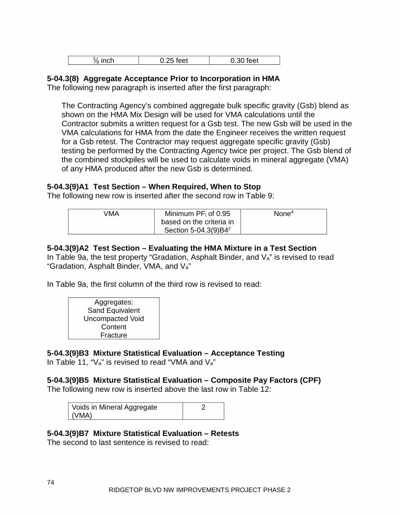
74 RIDGETOP BLVD NW IMPROVEMENTS PROJECT PHASE 2
3⁄8 inch 0.25 feet 0.30 feet
5-04.3(8) Aggregate Acceptance Prior to Incorporation in HMA The following new paragraph is inserted after the first paragraph:
The Contracting Agency’s combined aggregate bulk specific gravity (Gsb) blend as shown on the HMA Mix Design will be used for VMA calculations until the Contractor submits a written request for a Gsb test. The new Gsb will be used in the VMA calculations for HMA from the date the Engineer receives the written request for a Gsb retest. The Contractor may request aggregate specific gravity (Gsb) testing be performed by the Contracting Agency twice per project. The Gsb blend of the combined stockpiles will be used to calculate voids in mineral aggregate (VMA) of any HMA produced after the new Gsb is determined.
5-04.3(9)A1 Test Section – When Required, When to Stop The following new row is inserted after the second row in Table 9:
VMA Minimum PFi of 0.95 based on the criteria in Section 5-04.3(9)B42
None4
5-04.3(9)A2 Test Section – Evaluating the HMA Mixture in a Test Section In Table 9a, the test property “Gradation, Asphalt Binder, and Va” is revised to read “Gradation, Asphalt Binder, VMA, and Va” In Table 9a, the first column of the third row is revised to read:
Aggregates: Sand Equivalent
Uncompacted Void Content Fracture
5-04.3(9)B3 Mixture Statistical Evaluation – Acceptance Testing In Table 11, “Va” is revised to read “VMA and Va” 5-04.3(9)B5 Mixture Statistical Evaluation – Composite Pay Factors (CPF) The following new row is inserted above the last row in Table 12:
Voids in Mineral Aggregate (VMA)
2
5-04.3(9)B7 Mixture Statistical Evaluation – Retests The second to last sentence is revised to read:
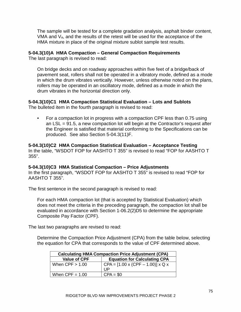
75 RIDGETOP BLVD NW IMPROVEMENTS PROJECT PHASE 2
The sample will be tested for a complete gradation analysis, asphalt binder content, VMA and Va, and the results of the retest will be used for the acceptance of the HMA mixture in place of the original mixture sublot sample test results.
5-04.3(10)A HMA Compaction – General Compaction Requirements The last paragraph is revised to read:
On bridge decks and on roadway approaches within five feet of a bridge/back of pavement seat, rollers shall not be operated in a vibratory mode, defined as a mode in which the drum vibrates vertically. However, unless otherwise noted on the plans, rollers may be operated in an oscillatory mode, defined as a mode in which the drum vibrates in the horizontal direction only.
5-04.3(10)C1 HMA Compaction Statistical Evaluation – Lots and Sublots The bulleted item in the fourth paragraph is revised to read:
• For a compaction lot in progress with a compaction CPF less than 0.75 using an LSL = 91.5, a new compaction lot will begin at the Contractor’s request after the Engineer is satisfied that material conforming to the Specifications can be produced. See also Section 5-04.3(11)F.
5-04.3(10)C2 HMA Compaction Statistical Evaluation – Acceptance Testing In the table, “WSDOT FOP for AASHTO T 355” is revised to read “FOP for AASHTO T 355”. 5-04.3(10)C3 HMA Statistical Compaction – Price Adjustments In the first paragraph, “WSDOT FOP for AASHTO T 355” is revised to read “FOP for AASHTO T 355”. The first sentence in the second paragraph is revised to read:
For each HMA compaction lot (that is accepted by Statistical Evaluation) which does not meet the criteria in the preceding paragraph, the compaction lot shall be evaluated in accordance with Section 1-06.2(2)D5 to determine the appropriate Composite Pay Factor (CPF).
The last two paragraphs are revised to read:
Determine the Compaction Price Adjustment (CPA) from the table below, selecting the equation for CPA that corresponds to the value of CPF determined above.
Calculating HMA Compaction Price Adjustment (CPA) Value of CPF Equation for Calculating CPA
When CPF > 1.00 CPA = [1.00 x (CPF – 1.00)] x Q x UP
When CPF = 1.00 CPA = $0

76 RIDGETOP BLVD NW IMPROVEMENTS PROJECT PHASE 2
When CPF < 1.0 CPA = [0.60 x (CPF – 1.00)] x Q x UP
Where CPA = Compaction Price Adjustment for the compaction lot ($) CPF = Composite Pay Factor for the compaction lot (maximum is 1.05) Q = Quantity in the compaction lot (tons) UP = Unit price of the HMA in the compaction lot ($/ton)
5-04.3(10)C4 HMA Statistical Compaction – Requests for Retesting The first sentence is revised to read:
For a compaction sublot that has been tested with a nuclear density gauge that did not meet the minimum of 91.5 percent of the theoretical maximum density in a compaction lot with a CPF below 1.00 and thus subject to a price reduction or rejection, the Contractor may request that a core, taken at the same location as the nuclear density test, be used for determination of the relative density of the compaction sublot.
5-04.3(13) Surface Smoothness The second to last paragraph is revised to read:
When concrete pavement is to be placed on HMA, the surface tolerance of the HMA shall be such that no surface elevation lies above the Plan grade minus the specified Plan depth of concrete pavement. Prior to placing the concrete pavement, bring any such irregularities to the required tolerance by grinding or other means allowed by the Engineer.
5-04.5 Payment The paragraph following the Bid item “Crack Sealing-LF”, per linear foot is revised to read:
The unit Contract price per linear foot for “Crack Sealing-LF” shall be full payment for all costs incurred to perform the Work described in Section 5-04.3(4)A.
Section 5-05, Cement Concrete Pavement April 1, 2019 5-05.1 Description In the first paragraph, “portland cement concrete” is revised to read “cement concrete”. 5-05.2 Materials In the first paragraph, the reference to “Portland Cement” is revised to read:
Cement 9-01

77 RIDGETOP BLVD NW IMPROVEMENTS PROJECT PHASE 2
In the first paragraph, the section reference for Concrete Patching Material is revised to read “9-20.1”. The second paragraph is revised to read:
Cementitious materials are considered to be the following: portland cement, blended hydraulic cement, fly ash, ground granulated blast furnace slag and microsilica fume.
5-05.3(1) Concrete Mix Design for Paving The table title in item number 4 is revised to read Concrete Batch Weights. In item 4a, “Portland Cement” is revised to read “Cement”. 5-05.3(3)E Smoothness Testing Equipment This section is revised to read:
Inertial profilers shall meet all requirements of AASHTO M 328 and be certified in accordance with AASHTO R 56 within the preceding 12 months. The inertial profiler operator shall be certified as required by AASHTO R 56 within three years preceding profile measurement. Equipment or operator certification by other states or a profiler certification facility will be accepted provided the certification meets the requirements of AASHTO R 56. Documentation verifying certification by another state shall be submitted to the Engineer a minimum of 14 calendar days prior to profile measurement. Equipment certification documentation shall include the information required by part 8.5 and 8.6 of AASHTO R 56. Operator documentation shall include a statement from the certifying state that indicates the operator is certified to operate the inertial profiler to be used on the project. The decision whether another state’s certification meets the requirements of AASHTO R 56 shall be vested entirely in the Engineer.
5-05.3(4) Measuring and Batching Materials Item number 2 is revised to read:
2. Batching Materials – On all projects requiring more than 2,500 cubic yards of concrete for paving, the batching plant shall be equipped to proportion aggregates and cement by weight by means of automatic and interlocked proportioning devices of accepted type.
5-05.3(4)A Acceptance of Portland Cement Concrete Pavement This section’s title is revised to read:

78 RIDGETOP BLVD NW IMPROVEMENTS PROJECT PHASE 2
Acceptance of Portland Cement or Blended Hydraulic Cement Concrete Pavement
The first sentence is revised to read:
Acceptance of portland cement or blended hydraulic cement concrete pavement shall be as provided under statistical or nonstatistical acceptance.
5-05.3(7) Placing, Spreading, and Compacting Concrete This section’s content is deleted. 5-05.3(10) Tie Bars and Corrosion Resistant Dowel Bars The first sentence of the last paragraph is revised to read:
The tie bar holes shall be clean before grouting. 5-05.3(12) Surface Smoothness This section is revised to read:
Pavement surface smoothness for this project will include International Roughness Index (IRI) testing. The Contractor shall perform IRI testing on each through lane, climbing lane, and passing lane, greater than 0.25 mile in length and these lanes will be subject to incentive/disincentive adjustments. Ride quality will be evaluated using the Mean Roughness Index (MRI) calculated by averaging the IRI data for the left and right wheel path within the section. Ramps, shoulders and tapers will not be included in MRI testing for pavement smoothness and will not be subject to incentive adjustments. All Work is subject to parallel and transverse 10-foot straightedge requirements, corrective work and disincentive adjustments. Operate the inertial profiler in accordance with AASHTO R 57. Collect two longitudinal traces, one in each wheel path. Collect profile data after completion of all concrete paving on the project in a continuous pass including areas excluded from pay adjustments. Provide notice to the Engineer a minimum of seven calendar days prior to testing. Within 30 calendar days after the Contractor’s testing, the Engineer may perform verification testing. If the verification testing shows a difference in MRI greater than the percentages shown in Table 2 of AASHTO R 54 the following resolution process will be followed:
1. The profiles, equipment and procedures will be evaluated to determine the cause of the difference.

79 RIDGETOP BLVD NW IMPROVEMENTS PROJECT PHASE 2
2. If the cause of the discrepancy cannot be resolved the pavement shall be retested with both profilers at a mutually agreed time. The two profilers will test the section within 30 minutes of each other. If the retest shows a difference in MRI equal or greater than the percentages shown in Table 2 of AASHTO R 54 the Engineer’s test results will be used to establish pay adjustments.
Surface smoothness of travel lanes not subject to MRI testing will be measured with a 10-foot straightedge no later than 5:00 p.m. of the day following the placing of the concrete. The completed surface of the wearing course shall not vary more than ⅛ inch from the lower edge of a 10-foot straightedge placed on the surface parallel to the centerline. Smoothness perpendicular to the centerline will be measured with a 10-foot straightedge across all lanes with the same cross slope, including shoulders when composed of cement concrete pavement. The overlapping 10-foot straightedge measurement shall be discontinued at a point 6 inches from the most extreme outside edge of the finished cement concrete pavement. The completed surface of the wearing course shall not vary more than ¼ inch from the lower edge of a 10-foot straightedge placed on the surface perpendicular to the centerline. Any deviations in excess of the above tolerances shall be corrected. The Contractor shall evaluate profiles for acceptance, incentive payments, disincentive payments, or corrective action using the current version of ProVAL and provide the results including the profile data in unfiltered electronic Engineering Research Division (ERD) file format to the Engineer within 2 calendar days of completing testing each section of pavement. If the profile data files are created using an export option in the manufacturer’s software where filter settings can be specified, use the filter settings that were used to create data files for certification. Analyze the entire profile. Exclude any areas specifically identified in the Contract. Exclude from the analysis the first 100 feet after the start of the paving operations and last 100 feet prior to the end of the paving operation, the first 100 feet on either side of bridge Structures and bridge approach slab. Report the MRI results in inches per mile for each 52.8 foot section and horizontal distance measurements in project stationing to the nearest foot. Include pay adjustments in the results. The Engineer will verify the analysis. Corrective work for pavement smoothness may be taken by the Contractor prior to MRI testing. After completion of the MRI testing the Contractor shall measure the smoothness of each 52.8-foot section with an MRI greater than 125 inches per mile with a 10-foot straightedge within 14 calendar days or as allowed by the Engineer. The Contractor shall identify all locations that require corrective work and provide the straight edge measurements at each location that exceeds the allowable limit to the Engineer. If all measurements in a 52.8-foot section comply with smoothness requirements, the Contractor shall provide the maximum measurement to the Engineer and a statement that corrective work is not required. Unless allowed by
80 RIDGETOP BLVD NW IMPROVEMENTS PROJECT PHASE 2
the Engineer, corrective work shall be taken by the Contractor for pavement identified by the Contractor or Engineer that does not meet the following requirements:
1. The completed surface shall be of uniform texture, smooth, uniform as to crown and grade, and free from defects of all kinds.
2. The completed surface shall not vary more than ⅛ inch from the lower
edge of a 10-foot straightedge placed on the surface parallel to the centerline.
3. The completed surface shall vary not more than ¼ inch in 10 feet from the
rate of transverse slope shown in the Plans. All corrective work shall be completed at no additional expense, including traffic control, to the Contracting Agency. Corrective work shall not begin until the concrete has reached its design strength unless allowed by the Engineer. Pavement shall be repaired by one or more of the following methods:
1. Diamond grinding; repairs shall not reduce pavement thickness by more than ¼ inch less than the thickness shown in the Plans. When required by the Engineer, the Contractor shall verify the thickness of the concrete pavement by coring. Thickness reduction due to corrective work will not be included in thickness measurements for calculating the Thickness Deficiency in Section 5-05.5(1)A.
2. Removal and replacement of the cement concrete pavement. 3. By other method allowed by the Engineer.
For repairs following MRI testing the repaired area shall be checked by the Contractor with a 10-foot straightedge to ensure it no longer requires corrective work. With concurrence of the Engineer an inertial profiler may be used in place of the 10-foot straight edge. If correction of the roadway as listed above either will not or does not produce satisfactory results as to smoothness or serviceability the Engineer may accept the completed pavement and a credit will be calculated in accordance with Section 5-05.5. The credit will be in addition to the price adjustment for MRI. Under these circumstances, the decision whether to accept the completed pavement or to require corrective work as described above shall be vested entirely in the Engineer.
5-05.3(22) Repair of Defective Pavement Slabs The last sentence of the fourth paragraph is revised to read:
All sandblasting residue shall be removed.
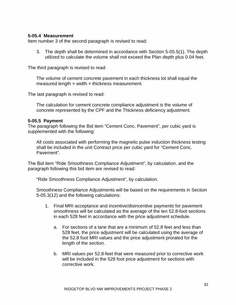
81 RIDGETOP BLVD NW IMPROVEMENTS PROJECT PHASE 2
5-05.4 Measurement Item number 3 of the second paragraph is revised to read:
3. The depth shall be determined in accordance with Section 5-05.5(1). The depth utilized to calculate the volume shall not exceed the Plan depth plus 0.04 feet.
The third paragraph is revised to read:
The volume of cement concrete pavement in each thickness lot shall equal the measured length × width × thickness measurement.
The last paragraph is revised to read:
The calculation for cement concrete compliance adjustment is the volume of concrete represented by the CPF and the Thickness deficiency adjustment.
5-05.5 Payment The paragraph following the Bid item “Cement Conc. Pavement”, per cubic yard is supplemented with the following:
All costs associated with performing the magnetic pulse induction thickness testing shall be included in the unit Contract price per cubic yard for “Cement Conc. Pavement”.
The Bid item “Ride Smoothness Compliance Adjustment”, by calculation, and the paragraph following this bid item are revised to read:
“Ride Smoothness Compliance Adjustment”, by calculation. Smoothness Compliance Adjustments will be based on the requirements in Section 5-05.3(12) and the following calculations:
1. Final MRI acceptance and incentive/disincentive payments for pavement smoothness will be calculated as the average of the ten 52.8-foot sections in each 528 feet in accordance with the price adjustment schedule.
a. For sections of a lane that are a minimum of 52.8 feet and less than
528 feet, the price adjustment will be calculated using the average of the 52.8 foot MRI values and the price adjustment prorated for the length of the section.
b. MRI values per 52.8-feet that were measured prior to corrective work
will be included in the 528 foot price adjustment for sections with corrective work.

82 RIDGETOP BLVD NW IMPROVEMENTS PROJECT PHASE 2
2. In addition to the price adjustment for MRI a smoothness compliance adjustment will be calculated in the sum of minus $1000.00 for each and every section of single traffic lane 52.8 feet in length in that does not meet the 10-foot straight edge requirements in Section 5-05.3(12) after corrective Work.
Price Adjustment Schedule MRI for each 528 ft.
section Pay Adjustment
Schedule in. / mi. $ / 0.10 mi.
< 30 2400 30 2400 31 2320 32 2240 33 2160 34 2080 35 2000 36 1920 37 1840 38 1760 39 1680 40 1600 41 1520 42 1440 43 1360 44 1280 45 1200 46 1120 47 1040 48 960 49 880 50 800 51 720 52 640 53 560 54 480 55 400 56 320 57 240 58 160 59 80 60 0 61 0 62 0 63 0 64 0 65 0 66 0 67 0
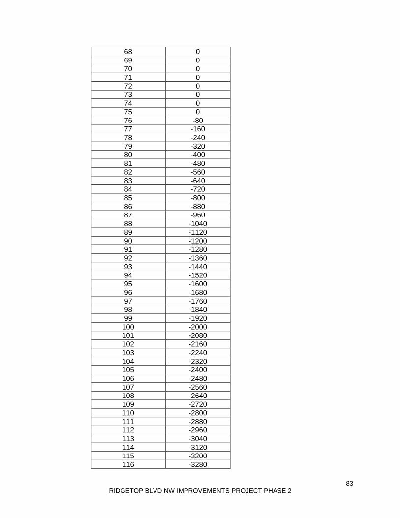
83 RIDGETOP BLVD NW IMPROVEMENTS PROJECT PHASE 2
68 0 69 0 70 0 71 0 72 0 73 0 74 0 75 0 76 -80 77 -160 78 -240 79 -320 80 -400 81 -480 82 -560 83 -640 84 -720 85 -800 86 -880 87 -960 88 -1040 89 -1120 90 -1200 91 -1280 92 -1360 93 -1440 94 -1520 95 -1600 96 -1680 97 -1760 98 -1840 99 -1920
100 -2000 101 -2080 102 -2160 103 -2240 104 -2320 105 -2400 106 -2480 107 -2560 108 -2640 109 -2720 110 -2800 111 -2880 112 -2960 113 -3040 114 -3120 115 -3200 116 -3280

84 RIDGETOP BLVD NW IMPROVEMENTS PROJECT PHASE 2
117 -3360 118 -3440 119 -3520 120 -3600 121 -3680 122 -3760 123 -3840 124 -3920 ≥125 -4000
The bid item “Portland Cement Concrete Compliance Adjustment”, by calculation, and the paragraph following this bid item are revised to read:
“Cement Concrete Compliance Adjustment”, by calculation. Payment for “Cement Concrete Compliance Adjustment” will be calculated by multiplying the unit Contract price for the cement concrete pavement, times the volume for adjustment, times the percent of adjustment determined from the calculated CPF and the Deficiency Adjustment listed in Section 5-05.5(1)A.
5-05.5(1) Pavement Thickness This section is revised to read:
Cement concrete pavement shall be constructed in accordance with the thickness requirements in the Plans and Specifications. Tolerances allowed for Subgrade construction and other provisions, which may affect thickness, shall not be construed to modify such thickness requirements. Thickness measurements in each lane paved shall comply with the following:
Thickness Testing of Cement Concrete Pavement Thickness Lot Size 15 panels maximum
Thickness test location determined by
Engineer will select testing locations in accordance with WSDOT TM 716 method B.
Sample method AASHTO T 359
Sample preparation performed by Contractor provides, places, and secures disks in the presence of the Engineer1
Measurement method AASHTO T 359 Thickness measurement performed by
Contractor, in the presence of the Engineer2
1Reflectors shall be located at within 0.5 feet of the center of the panel. The Contractor shall supply a sufficient number of 300 mm-diameter round reflectors meeting the requirements of AASHTO T 359 to accomplish the required testing. 2The Contractor shall provide all equipment and materials needed to perform the testing.
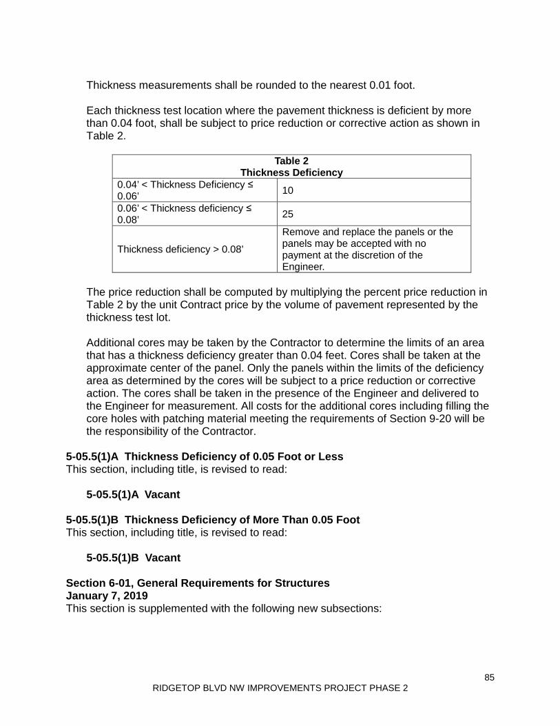
85 RIDGETOP BLVD NW IMPROVEMENTS PROJECT PHASE 2
Thickness measurements shall be rounded to the nearest 0.01 foot. Each thickness test location where the pavement thickness is deficient by more than 0.04 foot, shall be subject to price reduction or corrective action as shown in Table 2.
Table 2 Thickness Deficiency
0.04’ < Thickness Deficiency ≤ 0.06’ 10
0.06’ < Thickness deficiency ≤ 0.08’ 25
Thickness deficiency > 0.08’
Remove and replace the panels or the panels may be accepted with no payment at the discretion of the Engineer.
The price reduction shall be computed by multiplying the percent price reduction in Table 2 by the unit Contract price by the volume of pavement represented by the thickness test lot. Additional cores may be taken by the Contractor to determine the limits of an area that has a thickness deficiency greater than 0.04 feet. Cores shall be taken at the approximate center of the panel. Only the panels within the limits of the deficiency area as determined by the cores will be subject to a price reduction or corrective action. The cores shall be taken in the presence of the Engineer and delivered to the Engineer for measurement. All costs for the additional cores including filling the core holes with patching material meeting the requirements of Section 9-20 will be the responsibility of the Contractor.
5-05.5(1)A Thickness Deficiency of 0.05 Foot or Less This section, including title, is revised to read:
5-05.5(1)A Vacant 5-05.5(1)B Thickness Deficiency of More Than 0.05 Foot This section, including title, is revised to read:
5-05.5(1)B Vacant Section 6-01, General Requirements for Structures January 7, 2019 This section is supplemented with the following new subsections:

86 RIDGETOP BLVD NW IMPROVEMENTS PROJECT PHASE 2
6-01.16 Repair of Defective Work 6-01.16(1) General When using repair procedures that are described elsewhere in the Contract Documents, the Working Drawing submittal requirements of this Section shall not apply to those repairs unless noted otherwise. Repair procedures for defective Work shall be submitted as Type 2 Working Drawings. Type 2E Working Drawings shall be submitted when required by the Engineer. As an alternative to submitting Type 2 or 2E Working Drawings, defective Work within the limits of applicability of a pre-approved repair procedure may be repaired using that procedure. Repairs using a pre-approved repair procedure shall be submitted as a Type 1 Working Drawing. Pre-approved repair procedures shall consist of the following:
• The procedures listed in Section 6-01.16(2) • For precast concrete, repair procedures in the annual plant approval
process documents that have been approved for use by the Contracting Agency.
All Working Drawings for repair procedures shall include:
• A description of the defective Work including location, extent and
pictures • Materials to be used in the repair. Repairs using manufactured
products shall include written manufacturer recommendations for intended uses of the product, surface preparation, mixing, aggregate extension (if applicable), ambient and surface temperature limits, placement methods, finishing and curing.
• Construction procedures • Plan details of the area to be repaired • Calculations for Type 2E Working Drawings
Material manufacturer’s instructions and recommendations shall supersede any conflicting requirements in pre-approved repair procedures. The Engineer shall be notified prior to performing any repair procedure and shall be given an opportunity to inspect the repair work being performed.

87 RIDGETOP BLVD NW IMPROVEMENTS PROJECT PHASE 2
6-01.16(2) Pre-Approved Repair Procedures 6-01.16(2)A Concrete Spalls and Poor Consolidation (Rock Pockets, Honeycombs, Voids, etc.) This repair shall be limited to the following areas:
• Areas that are not on top Roadway surfaces (with or without an overlay) including but not limited to concrete bridge decks, bridge approach slabs or cement concrete pavement
• Areas that are not underwater • Areas that are not on precast barrier, except for the bottom 4
inches (but not to exceed 1 inch above blockouts) • Areas that do not affect structural adequacy as determined by the
Engineer. The repair procedure is as follows:
1. Remove all loose and unsound concrete. Impact breakers shall not exceed 15 pounds in weight when removing concrete adjacent to reinforcement or other embedments and shall not exceed 30 pounds in weight otherwise. Operate impact breakers at angles less than 45 degrees as measured from the surface of the concrete to the tool and moving away from the edge of the defective Work. Concrete shall be completely removed from exposed surfaces of existing steel reinforcing bars. If half or more of the circumference of any steel reinforcing bar is exposed, if the reinforcing bar is loose or if the bond to existing concrete is poor then concrete shall be removed at least ¾ inch behind the reinforcing bar. Do not damage any existing reinforcement. Stop work and allow the Engineer to inspect the repair area after removing all loose and unsound concrete. Submit a modified repair procedure when required by the Engineer.
2. Square the edges of the repair area by cutting an edge
perpendicular to the concrete surface around the repair area. The geometry of the repair perimeter shall minimize the edge length and shall be rectangular with perpendicular edges, avoiding reentrant corners. The depth of the cut shall be a minimum of ¾ inch, but shall be reduced if necessary to avoid damaging any reinforcement. For repairs on vertical surfaces, the top edge shall slope up toward the front at a 1-vertical-to-3-horizontal slope.
3. Remove concrete within the repair area to a depth at least
matching the cut depth at the edges. Large variations in the depth

88 RIDGETOP BLVD NW IMPROVEMENTS PROJECT PHASE 2
of removal within short distances shall be avoided. Roughen the concrete surface. The concrete surface should be roughened to at least Concrete Surface Profile (CSP) 5 in accordance with ICRI Guideline No. 310.2R, unless a different CSP is recommended by the patching material manufacturer.
4. Inspect the concrete repair surface for delaminations, debonding,
microcracking and voids using hammer tapping or a chain drag. Remove any additional loose or unsound concrete in accordance with steps 1 through 3.
5. Select a patching material in accordance with Section 9-20.2 that
is appropriate for the repair location and thickness. The concrete patching material shall be pumpable or self-consolidating as required for the type of placement that suits the repair. The patching material shall have a minimum compressive strength at least equal to the specified compressive strength of the concrete.
6. Prepare the concrete surface and reinforcing steel in accordance
with the patching material manufacturer’s recommendations. At a minimum, clean the concrete surfaces (including perimeter edges) and reinforcing steel using oil-free abrasive blasting or high-pressure (minimum 5,000 psi) water blasting. All dirt, dust, loose particles, rust, laitance, oil, film, microcracked/bruised concrete or foreign material of any sort shall be removed. Damage to the epoxy coating on steel reinforcing bars shall be repaired in accordance with Section 6-02.3(24)H.
7. Construct forms if necessary, such as for patching vertical or
overhead surfaces or where patching extends to the edge or corner of a placement.
8. When recommended by the patching material manufacturer,
saturate the concrete in the repair area and remove any free water at the concrete surface to obtain a saturated surface dry (SSD) substrate. When recommended by the patching material manufacturer, apply a primer, scrub coat or bonding agent to the existing surfaces. Epoxy bonding agents, if used, shall be Type II or Type V in accordance with Section 9-26.1.
9. Place and consolidate the patching material in accordance with the
manufacturer’s recommendations. Work the material firmly into all surfaces of the repair area with sufficient pressure to achieve proper bond to the concrete.
89 RIDGETOP BLVD NW IMPROVEMENTS PROJECT PHASE 2
10. The patching material shall be textured, cured and finished in accordance with the patching material manufacturer’s recommendations and/or the requirements for the repaired component. Protect the newly placed patch from vibration in accordance with Section 6-02.3(6)D.
11. When the completed repair does not match the existing concrete
color and will be visible to the public, a sand and cement mixture that is color matched to the existing concrete shall be rubbed, brushed, or applied to the surface of the patching material and the concrete.
6-01.10 Utilities Supported by or Attached to Bridges In the third paragraph, “Federal Standard 595” is revised to read “SAE AMS Standard 595”. 6-01.12 Final Cleanup The second sentence of the first paragraph is revised to read:
Structure decks shall be clean. The second paragraph is deleted. Section 6-02, Concrete Structures April 1, 2019 6-02.1 Description The first sentence is revised to read:
This Work consists of the construction of all Structures (and their parts) made of portland cement or blended hydraulic cement concrete with or without reinforcement, including bridge approach slabs.
6-02.2 Materials In the first paragraph, the references to “Portland Cement” and “Aggregates for Portland Cement Concrete” are revised to read:
Cement 9-01 Aggregates for Concrete 9-03.1
The reference to metakaolin is deleted. 6-02.3(2) Proportioning Materials The second paragraph is revised to read:
Unless otherwise specified, the Contractor shall use Type I or II portland cement or blended hydraulic cement in all concrete as defined in Section 9-01.2(1).

90 RIDGETOP BLVD NW IMPROVEMENTS PROJECT PHASE 2
The last sentence of the fifth paragraph is revised to read:
With the Engineer’s written concurrence, microsilica fume may be used in all classifications of Class 4000, Class 3000, and commercial concrete and is limited to a maximum of 10 percent of the cementitious material.
6-02.3(2)A Contractor Mix Design The last sentence of the last paragraph is revised to read:
For all other concrete, air content shall be a minimum of 4.5 percent and a maximum of 7.5 percent for all concrete placed above the finished ground line unless noted otherwise.
6-02.3(2)A1 Contractor Mix Design for Concrete Class 4000D Item number 5 of the first paragraph is deleted. Item number 6 of the first paragraph (after the preceding Amendment is applied) is renumbered to 5. 6-02.3(2)B Commercial Concrete The second paragraph is revised to read:
Where concrete Class 3000 is specified for items such as, culvert headwalls, plugging culverts, concrete pipe collars, pipe anchors, monument cases, Type PPB, PS, I, FB and RM signal standards, pedestals, cabinet bases, guardrail anchors, fence post footings, sidewalks, concrete curbs, curbs and gutters, and gutters, the Contractor may use commercial concrete. If commercial concrete is used for sidewalks, concrete curbs, curbs and gutters, and gutters, it shall have a minimum cementitious material content of 564 pounds per cubic yard of concrete, shall be air entrained, and the tolerances of Section 6-02.3(5)C shall apply.
6-02.3(4) Ready-Mix Concrete The first sentence of the first paragraph is revised to read:
All concrete, except lean concrete, shall be batched in a prequalified manual, semi-automatic, or automatic plant as described in Section 6-02.3(4)A.
6-02.3(4)D Temperature and Time For Placement The following is inserted after the first sentence of the first paragraph:
The upper temperature limit for placement for Class 4000D concrete may be increased to a maximum of 80°F if allowed by the Engineer.
6-02.3(5)C Conformance to Mix Design Item number 1 of the second paragraph is revised to read:
91 RIDGETOP BLVD NW IMPROVEMENTS PROJECT PHASE 2
1. Cement weight plus 5 percent or minus 1 percent of that specified in the
mix design. 6-02.3(6)A1 Hot Weather Protection The first paragraph is revised to read:
The Contractor shall provide concrete within the specified temperature limits. Cooling of the coarse aggregate piles by sprinkling with water is permitted provided the moisture content is monitored, the mixing water is adjusted for the free water in the aggregate and the coarse aggregate is removed from at least 1 foot above the bottom of the pile. Sprinkling of fine aggregate piles with water is not allowed. Refrigerating mixing water or replacing all or part of the mixing water with crushed ice is permitted, provided the ice is completely melted by placing time.
The second sentence of the second paragraph is revised to read:
These surfaces include forms, reinforcing steel, steel beam flanges, and any others that touch the concrete.
6-02.3(7) Vacant This section, including title, is revised to read:
6-02.3(7) Tolerances Unless noted otherwise, concrete construction tolerances shall be in accordance with this section. Tolerances in this section do not apply to cement concrete pavement. Horizontal deviation of roadway crown points, cross-slope break points, and curb, barrier or railing edges from alignment or work line: ±1.0 inch Deviation from plane: ±0.5 inch in 10 feet Deviation from plane for roadway surfaces: ±0.25 inch in 10 feet Deviation from plumb or specified batter: ±0.5 inch in 10 feet, but not to exceed a total of ±1.5 inches Vertical deviation from profile grade for roadway surfaces: ±1 inch Vertical deviation of top surfaces (except roadway surfaces): ±0.75 inch Thickness of bridge decks and other structural slabs not at grade: ±0.25 inch
92 RIDGETOP BLVD NW IMPROVEMENTS PROJECT PHASE 2
Length, width and thickness of elements such as columns, beams, crossbeams, diaphragms, corbels, piers, abutments and walls, including dimensions to construction joints in initial placements: +0.5 inch, -0.25 inch Length, width and thickness of spread footing foundations: +2 inches, -0.5 inch Horizontal location of the as-placed edge of spread footing foundations: The greater of ±2% of the horizontal dimension of the foundation perpendicular to the edge and ±0.5 inch. However, the tolerance shall not exceed ±2 inches. Location of opening, insert or embedded item at concrete surface: ±0.5 inch Cross-sectional dimensions of opening: ±0.5 inch Bridge deck, bridge approach slab, and bridge traffic barrier expansion joint gaps with a specified temperature range, measured at a stable temperature: ±0.25 inch Horizontal deviation of centerline of bearing pad, oak block or other bearing assembly: ±0.125 inch Horizontal deviation of centerline of supported element from centerline of bearing pad, oak block or other bearing assembly ±0.25 inch Vertical deviation of top of bearing pad, oak block or other bearing assembly: ±0.125 inch
6-02.3(10)C Finishing Equipment The first paragraph is revised to read:
The finishing machine shall be self-propelled and be capable of forward and reverse movement under positive control. The finishing machine shall be equipped with augers and a rotating cylindrical single or double drum screed. The finishing machine shall have the necessary adjustments to produce the required cross section, line, and grade. The finishing machine shall be capable of raising the screeds, augers, and any other parts of the finishing mechanical operation to clear the screeded surface, and returning to the specified grade under positive control. Unless otherwise allowed by the Engineer, a finishing machine manufacturer technical representative shall be on site to assist the first use of the machine on the Contract.
The first sentence of the second paragraph is revised to read:
For bridge deck widening of 20 feet or less, and for bridge approach slabs, or where jobsite conditions do not allow the use of the conventional configuration finishing machines, or modified conventional machines as described above; the Contractor

93 RIDGETOP BLVD NW IMPROVEMENTS PROJECT PHASE 2
may submit a Type 2 Working Drawing proposing the use of a hand-operated motorized power screed such as a “Texas” or “Bunyan” screed.
6-02.3(10)D4 Monitoring Bridge Deck Concrete Temperature After Placement This section, including title, is revised to read:
6-02.3(10)D4 Vacant 6-02.3(10)D5 Bridge Deck Concrete Finishing and Texturing In the third subparagraph of the first paragraph, the last sentence is revised to read:
The Contractor shall texture the bridge deck surface to within 3-inches minimum and 24-inches maximum of the edge of concrete at expansion joints, within 1-foot minimum and 2-feet maximum of the curb line, and within 3-inches minimum and 9-inches maximum of the perimeter of bridge drain assemblies.
6-02.3(10)F Bridge Approach Slab Orientation and Anchors The second to last paragraph is revised to read:
The compression seal shall be a 2½ inch wide gland and shall conform to Section 9-04.1(4).
The last paragraph is deleted. 6-02.3(13)A Strip Seal Expansion Joint System In item number 3 of the third paragraph, “Federal Standard 595” is revised to read “SAE AMS Standard 595”. 6-02.3(13)B Compression Seal Expansion Joint System The first paragraph is revised to read:
Compression seal glands shall conform to Section 9-04.1(4) and be sized as shown in the Plans.
6-02.3(14)C Pigmented Sealer for Concrete Surfaces This section is supplemented with the following new paragraph:
Pigmented Sealer Materials shall be a product listed in the current WSDOT Qualified Products List (QPL). If the pigmented sealer material is not listed in the current WSDOT QPL, a sample shall be submitted to the State Materials Laboratory in Tumwater for evaluation and acceptance in accordance with Section 9-08.3.
6-02.3(20) Grout for Anchor Bolts and Bridge Bearings The second, third and fourth paragraphs are revised to read:

94 RIDGETOP BLVD NW IMPROVEMENTS PROJECT PHASE 2
Grout shall be a workable mix with a viscosity that is suitable for the intended application. Grout shall not be placed outside of the manufacturer recommended range of thickness. The Contractor shall receive concurrence from the Engineer before using the grout. Field grout cubes and cylinders shall be fabricated and tested in accordance with Section 9-20.3 when requested by the Engineer, but not less than once per bridge pier or once per day. Before placing grout, the substrate on which it is to be placed shall be prepared as recommended by the manufacturer to ensure proper bonding. The grout shall be cured as recommended by the manufacturer. The grout may be loaded when a minimum of 4,000 psi compressive strength is attained.
The fifth paragraph is deleted. 6-02.3(23) Opening to Traffic This section is supplemented with the following new paragraph:
After curing bridge approach slabs in accordance with Section 6-02.3(11), the bridge approach slabs may be opened to traffic when a minimum compressive strength of 2,500 psi is achieved.
6-02.3(24)C Placing and Fastening This section is revised to read:
The Contractor shall position reinforcing steel as the Plans require and shall ensure that the steel is set within specified tolerances. Adjustments to reinforcing details outside of specified tolerances to avoid interferences and for other purposes are acceptable when approved by the Engineer. When spacing between bars is 1 foot or more, they shall be tied at all intersections. When spacing is less than 1 foot, every other intersection shall be tied. If the Plans require bundled bars, they shall be tied together with wires at least every 6 feet. All epoxy-coated bars in the top mat of the bridge deck shall be tied at all intersections, however they may be tied at alternate intersections when spacing is less than 1 foot in each direction and they are supported by continuous supports meeting all other requirements of supports for epoxy-coated bars. Other epoxy-coated bars shall also be tied at all intersections, but shall be tied at alternate intersections when spacing is less than 1 foot in each direction. Wire used for tying epoxy-coated reinforcing steel shall be plastic coated. Tack welding is not permitted on reinforcing steel. Abrupt bends in the steel are permitted only when one steel member bends around another. Vertical stirrups shall pass around main reinforcement or be firmly attached to it.

95 RIDGETOP BLVD NW IMPROVEMENTS PROJECT PHASE 2
For slip-formed concrete, the reinforcing steel bars shall be tied at all intersections and cross braced to keep the cage from moving during concrete placement. Cross bracing shall be with additional reinforcing steel. Cross bracing shall be placed both longitudinally and transversely. After reinforcing steel bars are placed in a traffic or pedestrian barrier and prior to slip-form concrete placement, the Contractor shall check clearances and reinforcing steel bar placement. This check shall be accomplished by using a template or by operating the slip-form machine over the entire length of the traffic or pedestrian barrier. All clearance and reinforcing steel bar placement deficiencies shall be corrected by the Contractor before slip-form concrete placement.
Precast concrete supports (or other accepted devices) shall be used to maintain the concrete coverage required by the Plans. The precast concrete supports shall:
1. Have a bearing surface measuring not greater than 2 inches in either
dimension, and 2. Have a compressive strength equal to or greater than that of the concrete in
which they are embedded.
In slabs, each precast concrete support shall have either: (1) a grooved top that will hold the reinforcing bar in place, or (2) an embedded wire that protrudes and is tied to the reinforcing steel. If this wire is used around epoxy-coated bars, it shall be coated with plastic.
Precast concrete supports may be accepted based on a Manufacturer’s Certificate of Compliance.
In lieu of precast concrete supports, the Contractor may use metal or all-plastic supports to hold uncoated bars. Any surface of a metal support that will not be covered by at least ½ inch of concrete shall be one of the following:
1. Hot-dip galvanized after fabrication in keeping with AASHTO M232 Class D;
2. Coated with plastic firmly bonded to the metal. This plastic shall be at least
3⁄32 inch thick where it touches the form and shall not react chemically with the concrete when tested in the State Materials Laboratory. The plastic shall not shatter or crack at or above -5°F and shall not deform enough to expose the metal at or below 200°F; or
3. Stainless steel that meet the requirements of ASTM A493, Type 302.
Stainless steel chair supports are not required to be galvanized or plastic coated.
96 RIDGETOP BLVD NW IMPROVEMENTS PROJECT PHASE 2
In lieu of precast concrete supports, epoxy-coated reinforcing bars may be supported by one of the following:
1. Metal supports coated entirely with a dielectric material such as epoxy or plastic,
2. Other epoxy-coated reinforcing bars, or 3. All-plastic supports.
Damaged coatings on metal bar supports shall be repaired prior to placing concrete. All-plastic supports shall be lightweight, non-porous, and chemically inert in concrete. All-plastic supports shall have rounded seatings, shall not deform under load during normal temperatures, and shall not shatter or crack under impact loading in cold weather. All-plastic supports shall be placed at spacings greater than 1 foot along the bar and shall have at least 25 percent of their gross place area perforated to compensate for the difference in the coefficient of thermal expansion between plastic and concrete. The shape and configuration of all-plastic supports shall permit complete concrete consolidation in and around the support. A “mat” is two adjacent and perpendicular layers of reinforcing steel. In bridge decks, top and bottom mats shall be supported adequately enough to hold both in their proper positions. If bar supports directly support, or are directly supported on No. 4 bars, they shall be spaced at not more than 3-foot intervals (or not more than 4-foot intervals for bars No. 5 and larger). Wire ties to girder stirrups shall not be considered as supports. To provide a rigid mat, the Contractor shall add other supports and tie wires to the top mat as needed. Unless noted otherwise, the minimum concrete cover for main reinforcing bars shall be:
3 inches to a concrete surface deposited against earth without intervening forms.
2½ inches to the top surface of a concrete bridge deck or bridge approach slab. 2 inches to a concrete surface when not specified otherwise in this section or in the Contract documents. 1½ inches to a concrete barrier or curb surface.
Except for top cover in bridge decks and bridge approach slabs, minimum concrete cover to ties and stirrups may be reduced by ½ inch but shall not be less than 1

97 RIDGETOP BLVD NW IMPROVEMENTS PROJECT PHASE 2
inch. Minimum concrete cover shall also be provided to the outermost part of mechanical splices and headed steel reinforcing bars. Reinforcing steel bar location, concrete cover and clearance shall not vary more than the following tolerances from what is specified in the Contract documents:
Reinforcing bar location for members 12 inches or less in thickness: ±0.25 inch Reinforcing bar location for members greater than 12 inches in thickness: ±0.375 inch Reinforcing bar location for bars placed at equal spacing within a plane: the greater of either ±1 inch or ±1 bar diameter within the plane. The total number of bars shall not be fewer than that specified. The clearance between reinforcement shall not be less than the greater of the bar diameter or 1 inch for unbundled bars. For bundled bars, the clearance between bundles shall not be less than the greater of 1 inch or a bar diameter derived from the equivalent total area of all bars in the bundle. Longitudinal location of bends and ends of bars: ±1 inch Embedded length of bars and length of bar lap splices:
No. 3 through No. 11: -1 inch No. 14 through No. 18: -2 inches
Concrete cover measured perpendicular to concrete surface (except for the top surface of bridge decks, bridge approach slabs and other roadway surfaces): ±0.25 inch Concrete cover measured perpendicular to concrete surface for the top surface of bridge decks, bridge approach slabs and other roadway surfaces: +0.25 inch, -0 inch
Before placing any concrete, the Contractor shall:
1. Clean all mortar from reinforcement, and 2. Obtain the Engineer’s permission to place concrete after the Engineer has
inspected the placement of the reinforcing steel. (Any concrete placed without the Engineer’s permission shall be rejected and removed.)
6-02.3(25)H Finishing The last paragraph is revised to read:
98 RIDGETOP BLVD NW IMPROVEMENTS PROJECT PHASE 2
The Contractor may repair defects in prestressed concrete girders in accordance with Section 6-01.16.
6-02.3(25)I Fabrication Tolerances Item number 12 of the first paragraph is revised to read:
12. Stirrup Projection from Top of Girder:
Wide flange thin deck and slab girders: ± ½ inch All other girders: ± ¾ inch
6-02.3(27) Concrete for Precast Units The last sentence of the first paragraph is revised to read:
Type III portland cement or blended hydraulic cement is permitted to be used in precast concrete units.
6-02.3(28)B Casting In the second paragraph, the reference to Section 6-02.3(25)B is revised to read Section 6-02.3(25)C. 6-02.3(28)D Contractors Control Strength In the first paragraph, “WSDOT FOP for AASHTO T 23” is revised to read “FOP for AASHTO T 23”. 6-02.3(28)E Finishing This section is supplemented with the following:
The Contractor may repair defects in precast panels in accordance with Section 6-01.16.
Section 6-03, Steel Structures January 7, 2019 6-03.2 Materials In the first paragraph, the material reference for Paints is revised to read:
Paints and Related Materials 9-08 6-03.3(25)A3 Ultrasonic Inspection The first paragraph (up until the colon) is revised to read:
Complete penetration groove welds on plates 5/16 inch and thicker in the following welded assemblies or Structures shall be 100 percent ultrasonically inspected:

99 RIDGETOP BLVD NW IMPROVEMENTS PROJECT PHASE 2
6-03.3(33) Bolted Connections The first paragraph is supplemented with the following:
After final tightening of the fastener components, the threads of the bolts shall at a minimum be flush with the end of the nut.
The following is inserted after the third sentence of the fourth paragraph:
When galvanized bolts are specified, tension-control galvanized bolts are not permitted.
Section 6-05, Piling January 2, 2018 6-05.3(9)A Pile Driving Equipment Approval The fourth sentence of the second paragraph is revised to read:
For prestressed concrete piles, the allowable driving stress in kips per square inch shall be 0.095 ∙ �𝑓𝑓′𝑐𝑐 plus prestress in tension, and 0.85f’c minus prestress in compression, where f’c is the concrete compressive strength in kips per square inch.
Section 6-07, Painting January 7, 2019 6-07.1 Description The first sentence is revised to read:
This work consists of containment, surface preparation, shielding adjacent areas from work, testing and disposing of debris, furnishing and applying paint, and cleaning up after painting is completed.
6-07.2 Materials The material reference for Paint is revised to read:
Paint and Related Materials 9-08 6-07.3(1)A Work Force Qualifications for Shop Application of Paint This section is supplemented with the following new sentence:
The work force may be accepted based on the approved facility. 6-07.3(1)B Work Force Qualifications for Field Application of Paint The first two paragraphs are revised to read:
The Contractor preparing the surface and applying the paint shall be certified under SSPC‑QP 1 or NACE International Institute Contractor Accreditation Program (NIICAP) AS 1.

100 RIDGETOP BLVD NW IMPROVEMENTS PROJECT PHASE 2
The Contractor removing and otherwise disturbing existing paint containing lead and other hazardous materials shall be certified under SSPC-QP 2, Category A or NIICAP AS 2.
The third paragraph (up until the colon) is revised to read:
In lieu of the above SSPC or NIICAP certifications, the Contractor performing the specified work shall complete both of the following actions:
Item number 2 of the third paragraph is revised to read:
2. The Contractor’s quality control inspector(s) for the project shall be NACE-certified CIP Level 3 or SSPC Protective Coating Inspector (PCI) Level 3.
6-07.3(2) Submittals The first paragraph is supplemented with the following:
Each component of the plan shall identify the specification section it represents. 6-07.3(2)B Contractor’s Quality Control Program Submittal Component The numbered list in the first paragraph is revised to read:
1. Description of the inspection procedures, tools, techniques and the acceptance criteria for all phases of work.
2. Procedure for implementation of corrective action for non-conformance work. 3. The paint system manufacturer’s recommended methods of preventing defects. 4. The Contractor’s frequency of quality control inspection for each phase of work. 5. Example of each completed form(s) of the daily quality control report used to
document the inspection work and tests performed by the Contractor’s quality control personnel.
6-07.3(2)C Paint System Manufacturer and Paint System Information Submittal Component Item number 1 is revised to read:
1. Product data sheets and Safety Data Sheets (SDS) on the paint materials, paint preparation, and paint application, as specified by the paint manufacturer, including:
a. All application instructions, including the mixing and thinning directions.
101 RIDGETOP BLVD NW IMPROVEMENTS PROJECT PHASE 2
b. Recommended spray nozzles and pressures. c. Minimum and maximum drying time between coats. d. Restrictions on temperature and humidity. e. Repair procedures for shop and field applied coatings. f. Maximum dry film thickness for each coat. g. Minimum wet film thickness for each coat to achieve the specified minimum
dry film thickness. 6-07.3(2)D Hazardous Waste Containment, Collection, Testing, and Disposal Submittal Component The first paragraph (up until the colon) is revised to read:
The hazardous waste containment, collection, testing, and disposal shall meet all Federal and State requirements, and the submittal component of the painting plan shall include the following:
6-07.3(2)E Cleaning and Surface Preparation Submittal Component Item 1(b) of the first paragraph is revised to read::
b. Type, manufacturer, and brand of abrasive blast material and all associated additives, including Safety Data Sheets (SDS).
6-07.3(3)B Quality Control and Quality Assurance for Field Application of Paint The last sentence of the first paragraph (excluding the numbered list) is revised to read:
The Contractor’s quality control operations shall include a minimum monitoring and documenting the following for each working day:
Item number 1 in the fourth paragraph is revised to read:
1. Environmental conditions for painting in accordance with ASTM E 337. Item number 4 in the fourth paragraph is revised to read:
4. Pictorial of surface preparation guides in accordance with SSPC-VIS 1, 3, 4, and 5.
Item number 5 in the fourth paragraph is revised to read:
5. Surface profile by Keanne-Tator comparator in accordance with ASTM D 4417 and SSPC PA17.

102 RIDGETOP BLVD NW IMPROVEMENTS PROJECT PHASE 2
6-07.3(4) Paint System Manufacturer’s Technical Representative This section is revised to read:
The paint system manufacturer’s representative shall be present at the jobsite for the pre-painting conference and for the first day of paint application, and shall be available to the Contractor and Contracting Agency for consultation for the full project duration.
6-07.3(5) Pre-Painting Conference The second paragraph is revised to read:
If the Contractor’s key personnel change between any work operations, an additional conference shall be held if requested by the Engineer.
6-07.3(6)A Paint Containers In item number 2 of the first paragraph, “Federal Standard 595” is revised to read “SAE AMS Standard 595”. 6-07.3(6)B Paint Storage Item number 2 of the second paragraph is revised to read:
2. The Contractor shall monitor and document daily the paint material storage facility with a high-low recording thermometer device.
6-07.3(7) Paint Sampling and Testing The first two paragraphs are revised to read:
The Contractor shall provide the Engineer 1 quart of each paint representing each lot. Samples shall be accompanied with a Safety Data Sheet. If the quantity of paint required for each component of the paint system for the entire project is 20 gallons or less, then the paint system components will be accepted as specified in Section 9-08.1(7).
6-07.3(8)A Paint Film Thickness Measurement Gages The first paragraph is revised to read:
Paint dry film thickness measurements shall be performed with either a Type 1 pull-off gage or a Type 2 electronic gage as specified in SSPC Paint Application Specification No. 2, Procedure for Determining Conformance to Dry Coating Thickness Requirements.
6-07.3(9) Painting New Steel Structures The last sentence of the second paragraph is revised to read:

103 RIDGETOP BLVD NW IMPROVEMENTS PROJECT PHASE 2
Welded shear connectors are not required to painted. The last paragraph is revised to read:
Temporary attachments or supports for scaffolding, containment or forms shall not damage the paint system.
6-07.3(9)A Paint System The first paragraph is revised to read:
The paint system applied to new steel surfaces shall consist of the following:
Option 1 (component based paint system):
Primer Coat – Inorganic Zinc Rich 9-08.1(2)C Intermediate Coat – Moisture Cured Polyurethane 9-08.1(2)G Intermediate Stripe Coat – Moisture Cured Polyurethane 9-08.1(2)G Top Coat – Moisture Cured Polyurethane 9-08.1(2)H
Option 2 (performance based paint system):
Primer Coat – Inorganic Zinc Rich 9-08.1(2)M Intermediate Coat – Epoxy 9-08.1(2)M Intermediate Stripe Coat – Epoxy 9-08.1(2)M Top Coat – Polyurethane 9-08.1(2)M
The following new paragraph is inserted after the first paragraph:
Paints and related materials shall be products listed in the current WSDOT Qualified Products List (QPL). Component based paint systems shall be listed on the QPL in the applicable sections of Section 9-08. Performance based systems shall be listed on the current Northeast Protective Coatings Committee (NEPCOAT) Qualified Products List “A” as listed on the WSDOT QPL in Section 9-08.1(2)M. If the paint and related materials for the component based system is not listed in the current WSDOT QPL, a sample shall be submitted to the State Materials Laboratory in Tumwater for evaluation and acceptance in accordance with Section 9-08.
6-07.3(9)C Mixing and Thinning Paint This section is revised to read:
The Contractor shall thoroughly mix paint in accordance with the manufacturer’s written recommendations and by mechanical means to ensure a uniform and lump free composition. Paint shall not be mixed by means of air stream bubbling or boxing. Paint shall be mixed in the original containers and mixing shall continue until all pigment or metallic powder is in suspension. Care shall be taken to ensure that the solid material that has settled to the bottom of the container is thoroughly

104 RIDGETOP BLVD NW IMPROVEMENTS PROJECT PHASE 2
dispersed. After mixing, the Contractor shall inspect the paint for uniformity and to ensure that no unmixed pigment or lumps are present. Catalysts, curing agents, hardeners, initiators, or dry metallic powders that are packaged separately may be added to the base paint in accordance with the paint manufacturer’s written recommendations and only after the paint is thoroughly mixed to achieve a uniform mixture with all particles wetted. The Contractor shall then add the proper volume of curing agent to the correct volume of base and mix thoroughly. The mixture shall be used within the pot life specified by the manufacturer. Unused portions shall be discarded at the end of each work day. Accelerants are not permitted except as allowed by the Engineer. The Contractor shall not add additional thinner at the application site except as allowed by the Engineer. The amount and type of thinner, if allowed, shall conform to the manufacturer’s specifications. If recommended by the manufacturer and allowed by the Engineer, a measuring cup shall be used for the addition of thinner to any paint with graduations in ounces. No un-measured addition of thinner to paint will be allowed. Any paint found to be thinned by unacceptable methods will be rejected. When recommended by the manufacturer, the Contractor shall constantly agitate paint during application by use of paint pots equipped with mechanical agitators. The Contractor shall strain all paint after mixing to remove undesirable matter, but without removing the pigment or metallic powder. Paint shall be stored and mixed in a secure, contained location to eliminate the potential for spills into State waters and onto the ground and highway surfaces.
6-07.3(9)D Coating Thickness This section is revised to read:
Dry film thickness shall be measured in accordance with SSPC Paint Application Specification No. 2, Procedure for Determining Conformance to Dry Coating Thickness Requirements. The minimum dry film thickness of the primer coat shall not be less than 2.5 mils. The minimum dry film thickness of each coat (combination of intermediate and intermediate stripe, and top) shall be not less than 3.0 mils. The dry film thickness of each coat shall not be thicker than the paint manufacturer’s recommended maximum thickness. The minimum wet film thickness of each coat shall be specified by the paint manufacturer to achieve the minimum dry film thickness.

105 RIDGETOP BLVD NW IMPROVEMENTS PROJECT PHASE 2
Film thickness, wet and dry, will be measured by gages conforming to Section 6-07.3(8)A. Wet measurements will be taken immediately after the paint is applied in accordance with ASTM D4414. Dry measurements will be taken after the coating is dry and hard in accordance with SSPC Paint Application Specification No. 2. Each painter shall be equipped with wet film thickness gages and shall be responsible for performing frequent checks of the paint film thickness throughout application. Coating thickness measurements may be made by the Engineer after the application of each coat and before the application of the succeeding coat. In addition, the Engineer may inspect for uniform and complete coverage and appearance. One hundred percent of all thickness measurements shall meet or exceed the minimum wet film thickness. In areas where wet film thickness measurements are impractical, dry film thickness measurements may be made. If a question arises about an individual coat’s thickness or coverage, it may be verified by the use of a Tooke gage in accordance with ASTM D4138. If the specified number of coats does not produce a combined dry film thickness of at least the sum of the thicknesses required per coat, if an individual coat does not meet the minimum thickness, or if visual inspection shows incomplete coverage, the coating system will be rejected and the Contractor shall discontinue painting and surface preparation operations and shall submit a Type 2 Working Drawing of the repair proposal. The repair proposal shall include documentation demonstrating the cause of the less-than-minimum thickness, along with physical test results, as necessary, and modifications to Work methods to prevent similar results. The Contractor shall not resume painting or surface preparation operations until receiving the Engineer’s acceptance of the completed repair.
6-07.3(9)E Surface Temperature Requirements Prior to Application of Paint This section, including title, is revised to read:
6-07.3(9)E Environmental Condition Requirements Prior to Application of Paint Paint shall be applied only during periods when:
1. Air and steel temperatures are in accordance with the paint manufacturer’s recommendations but in no case less than 35°F nor greater than 115°F.
2. Steel surface temperature is a minimum of 5°F above the dew point. 3. Steel surface is not wet.

106 RIDGETOP BLVD NW IMPROVEMENTS PROJECT PHASE 2
4. Relative humidity is within the manufacturer’s recommended range. 5. The anticipated ambient temperature will remain above 35°F or the
manufacturer’s minimum temperature, whichever is greater, during the paint drying and curing period.
Application will not be allowed if conditions are not favorable for proper application and performance of the paint. Paint shall not be applied when weather conditions are unfavorable to proper curing. If a paint system manufacturer’s recommendations allow for application of a paint under environmental conditions other than those specified, the Contractor shall submit a Type 2 Working Drawing consisting of a letter from the paint manufacturer specifying the environmental conditions under which the paint can be applied. Application of paint under environmental conditions other than those specified in this section will not be allowed without the Engineer’s concurrence.
6-07.3(9)F Shop Surface Cleaning and Preparation The last sentence is revised to read:
The entire steel surface to be painted, including surfaces specified in Section 6-07.3(9)G to receive a mist coat of primer, shall be cleaned to a near white condition in accordance with SSPC-SP 10, Near-white Metal Blast Cleaning, and shall be in this condition immediately prior to paint application.
6-07.3(9)G Application of Shop Primer Coat The first paragraph is supplemented with the following:
Repairs of the shop primer coat shall be prepared in accordance with the painting plan. Shop primer coat repair paint shall be selected from the approved component based or performance based paint system in accordance with Section 6-07.3(10)H.
6-07.3(9)H Containment for Field Coating This section is revised to read:
The Contractor shall use a containment system in accordance with Section 6-07.3(10)A for surface preparation and prime coating of all uncoated areas remaining, including bolts, nuts, washers, and splice plates. During painting operations of the intermediate, stripe and top coats the Contractor shall furnish, install, and maintain drip tarps below the areas to be painted to contain all spilled paint, buckets, brushes, and other deleterious material, and prevent such materials from reaching the environment below or adjacent to the structure being painted. Drip tarps shall be absorbent material and hung to minimize puddling. The Contractor shall evaluate the project-specific conditions to determine

107 RIDGETOP BLVD NW IMPROVEMENTS PROJECT PHASE 2
the specific type and extent of containment needed to control the paint emissions and shall submit a containment plan in accordance with Section 6-07.3(2).
6-07.3(9)I Application of Field Coatings This section is revised to read:
An on-site supervisor shall be present for each work shift at the bridge site. Upon completion of erection Work, all uncoated or damaged areas remaining, including bolts, nuts, washers, and splice plates, shall be prepared in accordance with Section 6-07.3(9)F, followed by a field primer coat of a zinc-rich primer and final coats of paint selected from the approved component or performance based paint system in accordance with Section 6-07.3(10)H. . The intermediate, intermediate stripe, and top coats shall be applied in accordance with the manufacturer’s written recommendations. Upon completion of erection Work, welds for steel column jackets may be prepared in accordance with SSPC-SP 15, Commercial Grade Power Tool Cleaning. The minimum drying time between coats shall be as shown in the product data sheets, but not less than 12 hours. The Contractor shall determine whether the paint has cured sufficiently for proper application of succeeding coats. The maximum time between intermediate and top coats shall be in accordance with the manufacturer’s written recommendations. If the maximum time between coats is exceeded, all newly coated surfaces shall be prepared to SSPC-SP 7, Brush-off Blast Cleaning, and shall be repainted with the same paint that was cleaned, at no additional cost to the Contracting Agency. Each coat shall be applied in a uniform layer, completely covering the preceding coat. The Contractor shall correct runs, sags, skips, or other deficiencies before application of succeeding coats. Such corrective work may require re-cleaning, application of additional paint, or other means as determined by the Engineer, at no additional cost to the Contracting Agency. Dry film thickness measurements will be made in accordance with Section 6-07.3(9)D. All paint damage that occurs shall be repaired in accordance with the manufacturer’s written recommendations. On bare areas or areas of insufficient primer thickness, the repair shall include field-applied zinc-rich primer and the final coats of paint selected from the approved component or performance based paint system in accordance with Section 6-07.3(10)H. On areas where the primer is at least equal to the minimum required dry film thickness, the repair shall include the application of the final two coats of the paint system. All paint repair operations shall

108 RIDGETOP BLVD NW IMPROVEMENTS PROJECT PHASE 2
be performed by the Contractor at no additional cost or time to the Contracting Agency.
6-07.3(10)A Containment The first sentence of the third paragraph is revised to read:
Emissions shall be assessed by Visible Emission Observations (Method A) in SSPC Technology Update No. 7, Conducting Ambient Air, Soil, and Water Sampling of Surface Preparation and Paint Disturbance Activities, Section 6.2 and shall be limited to the Level A Acceptance Criteria Option Level 0 Emissions standard.
6-07.3(10)D Surface Preparation Prior to Overcoat Painting The first paragraph is revised to read:
The Contractor shall remove any visible oil, grease, and road tar in accordance with SSPC-SP 1, Solvent Cleaning.
The second paragraph is revised to read:
Following any preparation by SSPC-SP1, all steel surfaces to be painted shall be prepared in accordance with SSPC-SP 7, Brush-off Blast Cleaning. Surfaces inaccessible to brush-off blast shall be prepared in accordance with SSPC-SP 3, Power Tool Cleaning, as allowed by the Engineer.
The first sentence of the third paragraph is revised to read:
Following brush-off blast cleaning, the Contractor shall perform spot abrasive blast cleaning in accordance with SSPC-SP 6, Commercial Blast Cleaning.
The second to last sentence of the third paragraph is revised to read:
For small areas, as allowed by the Engineer, the Contractor may substitute cleaning in accordance with SSPC-SP 15, Commercial Grade Power Tool Cleaning.
6-07.3(10)G Treatment of Pack and Rust Gaps The second paragraph is revised to read:
Pack rust forming a gap between steel surfaces of ⅟16 to ¼ inch shall be cleaned to a depth of at least one half of the gap width. The gaps shall be cleaned and prepared in accordance with SSPC-SP6. The cleaned gap shall be treated with rust penetrating sealer, prime coated, and then caulked to form a watertight seal along the top edge and the two sides of the steel pieces involved, using the rust penetrating sealer and caulk as accepted by the Engineer. The bottom edge or lowest edge of the steel pieces involved shall not be caulked.
The third paragraph is supplemented with the following:
109 RIDGETOP BLVD NW IMPROVEMENTS PROJECT PHASE 2
Caulk shall be a single-component urethane sealant conforming to Section 9-08.7.
The fifth paragraph is revised to read:
At locations where gaps between steel surfaces exceed ¼ inch, the Contractor shall clean and prepare the gap in accordance SSPC-SP6, apply the rust penetrating sealer, apply the prime coat, and then fill the gap with foam backer rod material as accepted by the Engineer. The foam backer rod material shall be of sufficient diameter to fill the crevice or gap. The Contractor shall apply caulk over the foam backer rod material to form a watertight seal.
This section is supplemented with the following new paragraph:
Caulk and backer rod, if needed, shall be placed prior to applying the top coat. The Contractor, with the concurrence of the Engineer, may apply the rust penetrating sealer after application of the prime coat provided the primer is removed in the areas to be sealed. The areas to be sealed shall be re-cleaned and re-prepared in accordance with SSPC-SP6.
6-07.3(10)H Paint System The first paragraph is revised to read:
The paint system applied to existing steel surfaces shall consist of the following five-coat system:
Option 1 (component based system):
Primer Coat – Zinc-filled Moisture Cured Polyurethane 9-08.1(2)F Primer Stripe Coat - Moisture Cured Polyurethane 9-08.1(2)F Intermediate Coat - Moisture Cured Polyurethane 9-08.1(2)G Intermediate Stripe Coat - Moisture Cured Polyurethane 9-08.1(2)G Top Coat - Moisture Cured Polyurethane 9-08.1(2)H
Option 2 (performance based system):
Primer Coat – Zinc-rich Epoxy 9-08.1(2)N Primer Stripe Coat – Epoxy 9-08.1(2)N Intermediate Coat – Epoxy 9-08.1(2)N Intermediate Stripe Coat – Epoxy 9-08.1(2)N Top Coat – Polyurethane 9-08.1(2)N
The following new paragraph is inserted after the first paragraph:
Paints and related materials shall be a product listed in the current WSDOT Qualified Products List (QPL). Component based paint systems shall be listed on
110 RIDGETOP BLVD NW IMPROVEMENTS PROJECT PHASE 2
the QPL in the applicable sections of Section 9-08. Performance based systems shall be listed on the current Northeast Protective Coatings Committee (NEPCOAT) Qualified Products List “B” as listed on the WSDOT QPL in Section 9-08.1(2)N. If the paint and related material for the component based system is not listed in the current WSDOT QPL, a sample shall be submitted to the State Materials Laboratory in Tumwater for evaluation and acceptance in accordance with Section 9-08.
6-07.3(10)J Mixing and Thinning Paint This section is revised to read:
Mixing and thinning paint shall be in accordance with Section 6-07.3(9)C. 6-07.3(10)K Coating Thickness This section is revised to read:
Coating thickness shall be in accordance with Section 6-07.3(9)D except the minimum dry film thickness of each coat (combination of primer and primer stripe, combination of intermediate and intermediate stripe, and top) shall not be less than 3.0 mils.
6-07.3(10)L Environmental Condition Requirements Prior to Application of Paint This section is revised to read:
Environmental conditions shall be in accordance with Section 6-07.3(9)E. 6-07.3(10)M Steel Surface Condition Requirements Prior to Application of Paint The third paragraph is revised to read:
Edges of existing paint shall be feathered in accordance with SSPC-PA 1, Shop, Field, and Maintenance Coating of Metals, Note 15.20.
6-07.3(10)N Field Coating Application Methods The third sentence is revised to read:
The Contractor may apply stripe coat paint using spray or brush but shall follow spray application using a brush to ensure complete coverage around structural geometric irregularities and to push the paint into gaps between existing steel surfaces and around rivets and bolts.
6-07.3(10)O Applying Field Coatings The second to last paragraph is revised to read:
Each application of primer, primer stripe, intermediate, intermediate stripe, and top coat shall be considered as separately applied coats. The Contractor shall not use a preceding or subsequent coat to remedy a deficiency in another coat. The

111 RIDGETOP BLVD NW IMPROVEMENTS PROJECT PHASE 2
Contractor shall apply the top coat to at least the minimum specified top coat thickness, to provide a uniform appearance and consistent finish coverage.
6-07.3(10)P Field Coating Repair The second sentence is revised to read:
Repair areas shall be cleaned of all damaged paint and the system reapplied using all coats typical to the paint system and shall meet the minimum coating thickness.
6-07.3(11)A Painting of Galvanized Surfaces This section is revised to read:
All galvanized surfaces receiving paint shall be prepared for painting in accordance with the ASTM D 6386. The method of preparation shall be brush-off in accordance with SSPC-SP16 Brush-Off Blast Cleaning of Coated and Uncoated Galvanized Steel, Stainless Steels, and Non-Ferrous Metals or as otherwise allowed by the Engineer. The Contractor shall not begin painting until receiving the Engineer’s acceptance of the prepared galvanized surface. For galvanized bolts used for replacement of deteriorated existing rivets, the Contractor, with the concurrence of the Engineer and after successful demonstration testing, may prepare galvanized surfaces in accordance with SSPC-SP1 followed by SSPC-SP2, Hand Tool Cleaning or SSPC-SP3, Power Tool Cleaning. The demonstration testing shall include adhesion testing of the first coat of paint over galvanized bolts, nuts, and washers or a representative galvanized surface. Adhesion testing shall be performed in accordance with ASTM D 4541 for 600 psi minimum adhesion. A minimum of 3 successful tests shall be performed on the galvanized surface prepared and painted using the same methods and materials to be used on the galvanized bolts, nuts and washers in the field.
6-07.3(11)A2 Paint Coat Materials This section is revised to read:
The Contractor shall paint the dry surface as follows:
1. The first coat over a galvanized surface shall be an epoxy polyamide conforming to Section 9-08.1(2)E . In the case of galvanized bolts used for replacement of deteriorated existing rivets and for small surface areas less than or equal to one square foot, an intermediate moisture cured polyurethane conforming to Section 9-08.1(2)G may be used as a first coat. In both cases the first coat shall be compatible with galvanizing and as recommended by the top coat manufacturer.
2. The second coat shall be a top coat moisture cured aliphatic polyurethane
conforming to Section 9-08.1(2)H or a top coat polyurethane conforming to Section 6-07.3(10)H Option 2 NEPCOAT performance based paint
112 RIDGETOP BLVD NW IMPROVEMENTS PROJECT PHASE 2
specification compatible with the first coat as recommended by the manufacturer.
Each coat shall be dry before the next coat is applied. All coats applied in the shop shall be dried hard before shipment.
6-07.3(11)B Powder Coating of Galvanized Surfaces This section is revised to read:
Powder coating of galvanized surfaces shall consist of the following coats:
1. The first coat shall be an epoxy powder primer coat conforming to Section 9-08.2.
2. The second coat shall be a polyester finish coat conforming to Section 9-
08.2. 6-07.3(11)B3 Galvanized Surface Cleaning and Preparation The first three paragraphs are revised to read:
Galvanized surfaces receiving the powder coating shall be cleaned and prepared for coating in accordance with ASTM D 7803, and the project-specific powder coating plan. Assemblies conforming to the ASTM D 7803 definition for newly galvanized steel shall receive surface smoothing and surface cleaning in accordance with ASTM D 7803, Section 5, and surface preparation in accordance with ASTM D 7803, Section 5.1.3. Assemblies conforming to the ASTM D 7803 definition for partially weathered galvanized steel shall be checked and prepared in accordance with ASTM D 7803, Section 6, before then receiving surface smoothing and surface cleaning in accordance with ASTM D 7803, Section 5, and surface preparation in accordance with ASTM D 7803, Section 5.1.3.
The fourth paragraph (up until the colon) is revised to read:
Assemblies conforming to the ASTM D 7803 definition for weathered galvanized steel shall be prepared in accordance with ASTM D 7803, Section 7 before then receiving surface smoothing and surface cleaning in accordance with ASTM D 7803, Section 5, and surface preparation in accordance with ASTM D 7803, Section 5.3 except as follows:
6-07.3(11)B5 Testing Item number 4 in the first paragraph is revised to read:

113 RIDGETOP BLVD NW IMPROVEMENTS PROJECT PHASE 2
4. Adhesion testing in accordance with ASTM D 4541 for 600 psi minimum adhesion for the complete two-component system.
The second sentence of the fourth paragraph is revised to read:
Rejected assemblies shall be repaired or recoated by the Contractor, at no additional expense to the Contracting Agency, in accordance with the powder coating manufacturer’s recommendation as detailed in the project-specific powder coating plan, until the assemblies satisfy the acceptance testing requirements.
6-07.3(12) Painting Ferry Terminal Structures This section is revised to read:
Painting of ferry terminal Structures shall be in accordance with Section 6-07.3 as supplemented below.
This section is supplemented with the following new subsections:
6-07.3(12)A Painting New Steel Ferry Terminal Structures Painting of new steel Structures shall be in accordance with Section 6-07.3(9) except that all coatings (primer, intermediate, intermediate stripe, and top) shall be applied in the shop with the following exceptions:
1. Steel surfaces to be field welded. 2. Steel surfaces to be greased. 3. The length of piles designated in the Plans not requiring painting.
The minimum drying time between coats shall be as shown in the product data sheets, but not less than 12 hours. The Contractor shall determine whether the paint has cured sufficiently for proper application of succeeding coats.
6-07.3(12)A1 Paint Systems Paint systems for Structural Steel, which includes vehicle transfer spans and towers, pedestrian overhead loading structures and towers, upland structural steel and other elements as designated in the Special Provisions shall be as specified in Section 6-07.3(9)A. Paint systems for Piling, Landing Aids and Life Ladders shall be as specified in the Special Provisions. 6-07.3(12)A2 Paint Color Paint colors shall be as specified in the Special Provisions.

114 RIDGETOP BLVD NW IMPROVEMENTS PROJECT PHASE 2
6-07.3(12)A3 Coating Thickness Coating thicknesses shall be as specified in the Special Provisions. 6-07.3(12)A4 Application of Field Coatings An on-site supervisor shall be present for each work shift at the project site. Upon completion of erection Work, all uncoated or damaged areas remaining, including bolts, nuts, washers, splice plates, and field welds shall be prepared in accordance with SSPC-SP 1, Solvent Cleaning, followed by SSPC-SP 11, Power Tool Cleaning to Bare Metal. Surface preparation shall be measured according to SSPC-VIS 3. SSPC-SP 11 shall be performed for a minimum distance of 1 inch from the uncoated or damaged area. In addition, intact shop-applied coating surrounding the area shall be abraded or sanded for a distance of 6 inches out from the properly prepared clean/bare metal areas to provide adequate roughness for application of field coatings. All sanding dust and contamination shall be removed prior to application of field coatings. Field applied paint for Structural Steel shall conform to Section 6-07.3(10)H, as applicable. Field applied paint for Piling, Landing Aids and Life Ladders shall be as specified in the Special Provisions. For areas above the tidal zone, the minimum drying time between coats shall be as shown in the product data sheets, but not less than 12 hours. For areas within the tidal zone, the minimum drying time between coats shall be as recommended by the paint system manufacturer. The Contractor shall determine whether the paint has cured sufficiently for proper application of succeeding coats. The maximum time between intermediate and top coats shall be in accordance with the manufacturer’s written recommendations. If the maximum time between coats is exceeded, all newly coated surfaces shall be prepared to SSPC-SP 3, Power Tool Cleaning, and shall be repainted with the same paint that was cleaned, at no additional cost to the Contracting Agency. Each coat shall be applied in a uniform layer, completely covering the preceding coat. The Contractor shall correct runs, sags, skips, or other deficiencies before application of succeeding coats. Such corrective work may require re-cleaning, application of additional paint, or other means as determined by the Engineer, at no additional cost to the Contracting Agency. Surface preparation for underwater locations shall consist of removing all dirt, oil, grease, loose paint, loose rust, and marine growth from the area that is to be repaired. The sound paint surrounding the damaged area shall be roughened to meet the requirements of the manufacturer. Paint for underwater applications shall be as specified in the Special Provisions and shall be applied in accordance with the manufacturer’s recommendations.

115 RIDGETOP BLVD NW IMPROVEMENTS PROJECT PHASE 2
6-07.3(12)B Painting Existing Steel Ferry Terminal Structures Painting of existing steel structures shall be in accordance with Section 6-07.3(10) as supplemented by the following.
6-07.3(12)B1 Containment Containment for full removal shall be in accordance with Section 6-07.3(10)A. Containment for overcoat systems shall be in accordance with all applicable Permits as required in the Special Provisions. Prior to cleaning the Contractor shall enclose all exposed electrical and mechanical equipment to seal out dust, water, and paint. Non-metallic surfaces shall not be abrasive blasted or painted. Unless otherwise specified, the following metallic surfaces shall not be painted and shall be protected from abrasive blasting and painting:
1. Galvanized and stainless steel surfaces not previously painted, 2. Non-skid surfaces, 3. Unpainted intentionally greased surfaces, 4. Equipment labels, identification plates, tags, etc., 5. Fire and emergency containers or boxes, 6. Mechanical hardware such as hoist sheaves, hydraulic cylinders, gear
boxes, wire rope, etc. The Contractor shall submit a Type 2 Working Drawing consisting of materials and equipment used to shield components specified to not be cleaned and painted. The Contractor shall shut off the power prior to working around electrical equipment. The Contractor shall follow the lock-out/tag-out safety provisions of the WAC 296-803 and all other applicable safety standards. 6-07.3(12)B2 Surface Preparation For applications above high water and within the tidal zone, surface preparation for overcoat painting shall be in accordance with SSPC-SP 1, Solvent Cleaning, followed by SSPC-SP 3, Power Tool Cleaning. Use of wire brushes is not allowed. After SP 3 cleaning has been completed all surfaces exhibiting coating failure down to the steel substrate, and those exhibiting visible corrosion, shall be prepared down to clean bare steel in accordance with SSPC-SP 15, Commercial Grade Power Tool Cleaning. Surface preparation shall be measured according to SSPC-VIS 3. SSPC-SP 15 shall be performed for a minimum distance of 1 inch from the area exhibiting failure or visible corrosion.

116 RIDGETOP BLVD NW IMPROVEMENTS PROJECT PHASE 2
In addition, intact shop-applied coating surrounding the repair area shall be abraded or sanded for a distance of 6 inches out from the properly prepared clean/bare metal areas to provide adequate roughness for application of repair coatings. All sanding dust and contamination shall be removed prior to application of repair coatings. Surface preparation for full paint removal shall be in accordance with Section 6-07.3(10)E except SSPC-SP 11 will be permitted as detailed in the Contractor’s painting plan and as allowed by the Engineer. Surface preparation for underwater locations shall consist of removing all dirt, oil, grease, loose paint, loose rust, and marine growth from the area that is to be repaired. The sound paint surrounding the damaged area shall be roughened as required by the coating manufacturer. Removed marine growth may be released to state waters provided the marine growth is not mixed with contaminants (paint, oil, rust, etc.) and it shall not accumulate on the sea bed. All marine growth containing contaminants shall be collected for proper disposal. Surface preparation for the underside of bridge decks (consisting of either a steel grid system of main bars or tees and a light gauge metal form, in-filled with concrete or a corrugated light gauge metal form, infilled with concrete) shall be in accordance with SSPC-SP 2, Hand Tool Cleaning or SSPC-SP 3, Power Tool Cleaning with the intent of not causing further damage to the light gauge metal form. Following removal of any pack rust and corroded sections from the underside of the bridge deck, cleaning and flushing to remove salts and prior to applying the primer coat, the Contractor shall seal the entire underside of the deck system with rust-penetrating sealer. Damage to galvanized metal forms and/or grids shall be repaired in accordance with ASTM A 780, with the preferred method of repair using paints containing zinc dust. 6-07.3(12)B3 Paint Systems Paints systems for Structural Steel, which includes vehicle transfer spans and towers, pedestrian overhead loading structures and towers, upland structural steel and other elements as designated in the Special Provisions shall be as specified in Section 6-07.3(10)H. Paint systems for Piling, Landing Aids, Life Ladders, underside of vehicle transfer span bridge decks, non-skid surface treated areas, and anti-graffiti coatings shall be as specified in the Special Provisions. 6-07.3(12)B4 Paint Color Paint colors shall be as specified in the Special Provisions. 6-07.3(12)B5 Coating Thickness Coating thicknesses shall be as specified in the Special Provisions.

117 RIDGETOP BLVD NW IMPROVEMENTS PROJECT PHASE 2
6-07.3(12)B6 Application of Field Coatings Application of field coatings shall be in accordance with Section 6-07.3(10)O and Section 6-07.3(12)A2 except for the following:
1. All coatings applied in the field shall be applied using a brush or roller. Spray application methods may be used if allowed by the Engineer.
2. Applied coatings shall not be immersed until the coating has been
cured as required by the coating manufacturer. 3. Non-skid surface treatment products shall be applied in accordance
with the manufacturer’s recommendations. 4. Anti-graffiti coatings shall be applied in one coat following application of
the top coat, where specified in the Plans. 6-07.3(14)B Reference Standards The second standard reference (to SSPC CS 23.00), and its accompanying title, is revised to read:
SSPC CS 23.00 Specification for the Application of Thermal Spray Coatings (Metallizing) of Aluminum, Zinc, and Their Alloys and Composites for the Corrosion Protection of Steel
Section 6-08, Bituminous Surfacing on Structure Decks January 7, 2019 6-08.3(7)A Concrete Deck Preparation The first sentence of the first paragraph is revised to read:
The Contractor, with the Engineer, shall inspect the exposed concrete deck to establish the extent of bridge deck repair in accordance with Section 6-09.3(6).
6-08.3(8)A Structure Deck Preparation The second sentence of the last paragraph is revised to read:
Prior to applying the primer or sheet membrane, all dust and loose material shall be removed from the Structure Deck.
Section 6-09, Modified Concrete Overlays January 7, 2019 6-09.3 Construction Requirements This section is supplemented with the following new subsection:

118 RIDGETOP BLVD NW IMPROVEMENTS PROJECT PHASE 2
6-09.3(15) Sealing and Texturing Concrete Overlay After the requirements for checking for bond have been met, all joints and visible cracks shall be filled and sealed with a high molecular weight methacrylate resin (HMWM). Cracks 1⁄16 inch and greater in width shall receive two applications of HMWM. Immediately following the application of HMWM, the wetted surface shall be coated with sand for abrasive finish. After all cracks have been filled and sealed and the HMWM resin has cured, the concrete overlay surface shall receive a longitudinally sawn texture in accordance with Section 6-02.3(10)D5. Traffic shall not be permitted on the finished concrete until it has reached a minimum compressive strength of 3,000 psi as verified by rebound number determined in accordance with ASTM C805 and the longitudinally sawn texture is completed.
6-09.3(1)B Rotary Milling Machines This section is revised to read:
Rotary milling machines used to remove an upper layer of existing concrete overlay, when present, shall have a maximum operating weight of 50,000 pounds and conform to Section 6-08.3(5)B.
6-09.3(1)C Hydro-Demolition Machines The first sentence of this section is revised to read:
Hydro-demolition machines shall consist of filtering and pumping units operating in conjunction with a remote-controlled robotic device, using high-velocity water jets to remove sound concrete to the nominal scarification depth shown in the Plans with a single pass of the machine, and with the simultaneous removal of deteriorated concrete.
6-09.3(1)D Shot Blasting Machines This section, including title, is revised to read:
6-09.3(1)D Vacant 6-09.3(1)E Air Compressor This section is revised to read:
Air compressors shall be equipped with oil traps to eliminate oil from being blown onto the bridge deck.
6-09.3(1)J Finishing Machine This section is revised to read:
119 RIDGETOP BLVD NW IMPROVEMENTS PROJECT PHASE 2
The finishing machine shall meet the requirements of Section 6-02.3(10) and the following requirements:
The finishing machine shall be equipped with augers, followed by an oscillating, vibrating screed, vibrating roller tamper, or a vibrating pan, followed by a rotating cylindrical double drum screed. The vibrating screed, roller tamper or pan shall be of sufficient length and width to properly consolidate the mixture. The vibrating frequency of the vibrating screed, roller tamper or pan shall be variable with positive control.
6-09.3(2) Submittals Item number 1 and 2 are revised to read:
1. A Type 1 Working Drawing consisting of catalog cuts and operating parameters of the hydro-demolition machine selected by the Contractor for use in this project to scarify concrete surfaces.
2. A Type 1 Working Drawing consisting of catalog cuts, operating parameters,
axle loads, and axle spacing of the rotary milling machine (if used to remove an upper layer of existing concrete overlay when present).
The first sentence of item number 3 is revised to read:
A Type 2 Working Drawing of the Runoff Water Disposal Plan. 6-09.3(5)A General The first sentence of the fourth paragraph is revised to read:
All areas of the deck that are inaccessible to the selected scarifying machine shall be scarified to remove the concrete surface matrix to a maximum nominal scarification depth shown in the Plans by a method acceptable to the Engineer.
This section is supplemented with the following:
Concrete process water generated by scarifying concrete surface and removing existing concrete overlay operations shall be contained, collected, and disposed of in accordance with Section 5-01.3(11) and Section 6-09.3(5)C, and the Section 6-09.3(2) Runoff Water Disposal Plan.
6-09.3(5)B Testing of Hydro-Demolition and Shot Blasting Machines This section’s title is revised to read:
Testing of Hydro-Demolition Machines The second paragraph is revised to read:
120 RIDGETOP BLVD NW IMPROVEMENTS PROJECT PHASE 2
In the “sound” area of concrete, the equipment shall be programmed to remove concrete to the nominal scarification depth shown in the Plans with a single pass of the machine.
6-09.3(5)D Shot Blasting This section, including title, is revised to read:
6-09.3(5)D Vacant 6-09.3(5)E Rotomilling This section, including title, is revised to read:
6-09.3(5)E Removing Existing Concrete Overlay Layer by Rotomilling When the Contractor elects to remove the upper layer of existing concrete overlay, when present, by rotomilling prior to final scarifying, the entire concrete surface of the bridge deck shall be milled to remove the surface matrix to the depth specified in the Plans with a tolerance as specified in Section 6-08.3(5)B. The operating parameters of the rotary milling machine shall be monitored in order to prevent the unnecessary removal of concrete below the specified removal depth.
6-09.3(6) Further Deck Preparation The first paragraph is revised to read::
Once the lane or strip being overlaid has been cleaned of debris from scarifying, the Contractor, with the Engineer, shall perform a visual inspection of the scarified surface. The Contractor shall mark those areas of the existing bridge deck that are authorized by the Engineer for further deck preparation by the Contractor.
Item number 4 of the second paragraph is deleted. The first sentence of the third paragraph is deleted. 6-09.3(6)A Equipment for Further Deck Preparation This section is revised to read:
Further deck preparation shall be performed using either power driven hand tools conforming to Section 6-09.3(1)A, or hydro-demolition machines conforming to Section 6-09.3(1)C.
6-09.3(6)B Deck Repair Preparation The second paragraph is deleted. The last sentence of the second paragraph (after the preceding Amendment is applied) is revised to read:
121 RIDGETOP BLVD NW IMPROVEMENTS PROJECT PHASE 2
In no case shall the depth of a sawn vertical cut exceed ¾ inch or to the top of the top steel reinforcing bars, whichever is less.
The first sentence of the third to last paragraph is revised to read:
Where existing steel reinforcing bars inside deck repair areas show deterioration greater than 20-percent section loss, the Contractor shall furnish and place steel reinforcing bars alongside the deteriorated bars in accordance with the details shown in the Standard Plans.
The last paragraph is deleted. 6-09.3(7) Surface Preparation for Concrete Overlay The first seven paragraphs are deleted and replaced with the following:
Following the completion of any required further deck preparation the entire lane or strip being overlaid shall be cleaned to be free from oil and grease, rust and other foreign material that may still be present. These materials shall be removed by detergent-cleaning or other method accepted by the Engineer followed by sandblasting. After detergent cleaning and sandblasting is completed, the entire lane or strip being overlaid shall be cleaned in final preparation for placing concrete. Hand tool chipping, sandblasting and cleaning in areas adjacent to a lane or strip being cleaned in final preparation for placing concrete shall be discontinued when final preparation is begun. Scarifying and hand tool chipping shall remain suspended until the concrete has been placed and the requirement for curing time has been satisfied. Sandblasting and cleaning shall remain suspended for the first 24 hours of curing time after the completion of concrete placing. Scarification, and removal of the upper layer of concrete overlay when present, may proceed during the final cleaning and overlay placement phases of the Work on adjacent portions of the Structure so long as the scarification and concrete overlay removal operations are confined to areas which are a minimum of 100 feet away from the defined limits of the final cleaning or overlay placement in progress. If the scarification and concrete overlay removal impedes or interferes in any way with the final cleaning or overlay placement as determined by the Engineer, the scarification and concrete overlay removal Work shall be terminated immediately and the scarification and concrete overlay removal equipment removed sufficiently away from the area being prepared or overlaid to eliminate the conflict. If the grade is such that water and contaminants from the scarification and concrete overlay removal operation will flow into the area being prepared or overlaid, the scarification and concrete overlay removal operation shall be terminated and shall remain suspended for the first 24 hours of curing time after the completion of concrete placement.

122 RIDGETOP BLVD NW IMPROVEMENTS PROJECT PHASE 2
6-09.3(11) Placing Concrete Overlay The first sentence of item number 3 in the fourth paragraph is revised to read:
Concrete shall not be placed when the temperature of the concrete surface is less than 45°F or greater than 75°F, and wind velocity at the construction site is in excess of 10 mph.
6-09.3(12) Finishing Concrete Overlay The third paragraph is deleted. The last paragraph is deleted. 6-09.3(13) Curing Concrete Overlay The first sentence of the first paragraph is revised to read:
As the finishing operation progresses, the concrete shall be immediately covered with a single layer of clean, new or used, wet burlap.
The last sentence of the second paragraph is deleted. The following two new paragraphs are inserted after the second paragraph:
As an alternative to the application of burlap and fog spraying described above, the Contractor may propose a curing system using proprietary curing blankets specifically manufactured for bridge deck curing. The Contractor shall submit a Type 2 Working Drawing consisting of details of the proprietary curing blanket system, including product literature and details of how the system is to be installed and maintained. The wet curing regimen as described shall remain in place for a minimum of 42-hours.
The last paragraph is deleted. 6-09.3(14) Checking for Bond The first sentence of the first paragraph is revised to read:
After the requirements for curing have been met, the entire overlaid surface shall be sounded by the Contractor, in a manner accepted by and in the presence of the Engineer, to ensure total bond of the concrete to the bridge deck.
The last sentence of the first paragraph is deleted. The second paragraph is deleted.

123 RIDGETOP BLVD NW IMPROVEMENTS PROJECT PHASE 2
Section 6-10, Concrete Barrier August 6, 2018 6-10.2 Materials In the first paragraph, the reference to “Portland Cement” is revised to read:
Cement 9-01 6-10.3(6) Placing Concrete Barrier The first two sentences of the first paragraph are revised to read:
Precast concrete barriers Type 2, Type 4, Type F, precast single slope barrier, and transitions shall rest on a paved foundation shaped to a uniform grade and section. The foundation surface for precast concrete barriers Type 2, Type 4, Type F, precast single slope barrier, and transitions shall meet this test for uniformity: When a 10-foot straightedge is placed on the surface parallel to the centerline for the barrier, the surface shall not vary more than ¼ inch from the lower edge of the straightedge.
Section 6-11, Reinforced Concrete Walls April 2, 2018 6-11.2 Materials In the first paragraph, the reference to “Aggregates for Portland Cement Concrete” is revised to read:
Aggregates for Concrete 9-03.1 Section 6-12, Noise Barrier Walls August 6, 2018 6-12.2 Materials In the first paragraph, the reference to “Aggregates for Portland Cement Concrete” is revised to read:
Aggregates for Concrete 9-03.1 The first paragraph is supplemented with the following new material reference:
Noise Barrier Wall Access Door 9-06.17 6-12.3(9) Access Doors and Concrete Landing Pads The second paragraph is deleted and replaced with the following:
All frame and door surfaces, except stainless steel surfaces, shall be painted in accordance with Section 6-07.3(9). Primer shall be applied to all non-stainless steel surfaces. All primer coated exposed metal surfaces shall be field painted with the remaining Section 6-07.3(9)A paint system coats. The top coat, when dry, shall match the color specified in the Plans or Special Provisions.

124 RIDGETOP BLVD NW IMPROVEMENTS PROJECT PHASE 2
This section is supplemented with the following:
Access door deadbolt locks shall be capable of accepting a Best CX series core. The Contractor shall furnish and install a spring-loaded construction core lock with each lock. The Engineer will furnish the permanent Best CX series core for the Contractor to install at the conclusion of the project.
Section 6-13, Structural Earth Walls August 6, 2018 6-13.2 Materials In the first paragraph, the reference to “Aggregates for Portland Cement Concrete” is revised to read:
Aggregates for Concrete 9-03.1 6-13.3(4) Precast Concrete Facing Panel and Concrete Block Fabrication Item number 1 of the sixth paragraph is revised to read:
1. Vertical dimensions shall be ± 1⁄16 inch of the Plan dimension, and the rear height shall not exceed the front height.
Item number 3 of the sixth paragraph is revised to read:
3. All other dimensions shall be ± ¼ inch of the Plan dimension. Section 6-14, Geosynthetic Retaining Walls April 2, 2018 6-14.2 Materials In the first paragraph, the references to “Portland Cement” and “Aggregates for Portland Cement Concrete” are revised to read:
Cement 9-01 Aggregates for Concrete 9-03.1
Section 6-15, Soil Nail Walls January 7, 2019 6-15.3(7) Shotcrete Facing The last paragraph is supplemented with the following:
After final tightening of the nut, the threads of the soil nail shall at a minimum be flush with the end of the nut.

125 RIDGETOP BLVD NW IMPROVEMENTS PROJECT PHASE 2
Section 6-16, Soldier Pile and Soldier Pile Tieback Walls April 2, 2018 6-16.2 Materials In the first paragraph, the reference to “Aggregates for Portland Cement Concrete” is revised to read:
Aggregates for Concrete 9-03.1 Section 6-18, Shotcrete Facing April 1, 2019 6-18.2 Materials The reference to metakaolin is deleted. 6-18.3(3) Testing In the last sentence of the first paragraph, “AASHTO T 24” is revised to read “ASTM C1604”. 6-18.3(3)B Production Testing In the last sentence, “AASHTO T 24” is revised to read “ASTM C1604”. 6-18.3(4) Qualifications of Contractor’s Personnel In the last sentence of the second paragraph, “AASHTO T 24” is revised to read “ASTM C1604”. Section 6-19, Shafts January 7, 2019 6-19.2 Materials In the first paragraph, the references to “Portland Cement” and “Aggregates for Portland Cement Concrete” are revised to read:
Cement 9-01 Aggregates for Concrete 9-03.1
6-19.3(1)A Shaft Construction Tolerances The last paragraph is supplemented with the following:
The elevation of the top of the reinforcing cage for drilled shafts shall be within +6 inches and -3 inches from the elevation shown in the Plans.
6-19.3(2)D Nondestructive QA Testing Organization and Personnel Item number 4 in the first paragraph is revised to read:
4. Personnel preparing test reports shall be a Professional Engineer, licensed under Title 18 RCW, State of Washington, and shall seal the report in accordance with WAC 196-23-020.
126 RIDGETOP BLVD NW IMPROVEMENTS PROJECT PHASE 2
6-19.3(3)C Conduct of Shaft Casing Installation and Removal and Shaft Excavation Operations The first paragraph is supplemented with the following:
In no case shall shaft excavation and casing placement extend below the bottom of shaft excavation as shown in the Plans.
6-19.3(6)E Thermal Wire and Thermal Access Point (TAPS) The third sentence of the third paragraph is revised to read:
The thermal wire shall extend from the bottom of the reinforcement cage to the top of the shaft, with a minimum of 5-feet of slack wire provided above the top of shaft.
The following new sentence is inserted after the third sentence of the third paragraph:
All thermal wires in a shaft shall be equal lengths. 6-19.3(9)D Nondestructive QA Testing Results Submittal The last sentence of the first paragraph is revised to read:
Results shall be a Type 2E Working Drawing presented in a written report. Section 7-02, Culverts April 2, 2018 7-02.2 Materials In the first paragraph, the references to “Portland Cement” and “Aggregates for Portland Cement Concrete” are revised to read:
Cement 9-01 Aggregates for Concrete 9-03.1
7-02.3(6)A4 Excavation and Bedding Preparation The first sentence of the third paragraph is revised to read:
The bedding course shall be a 6-inch minimum thickness layer of culvert bedding material, defined as granular material either conforming to Section 9-03.12(3) or to AASHTO Grading No. 57 as specified in Section 9-03.1(4)C.
Section 7-05, Manholes, Inlets, Catch Basins, and Drywells August 6, 2018 7-05.3 Construction Requirements The fourth sentence of the third paragraph is deleted.

127 RIDGETOP BLVD NW IMPROVEMENTS PROJECT PHASE 2
Section 7-08, General Pipe Installation Requirements April 2, 2018 7-08.3(3) Backfilling The fifth sentence of the fourth paragraph is revised to read:
All compaction shall be in accordance with the Compaction Control Test of Section 2-03.3(14)D except in the case that 100% Recycled Concrete Aggregate is used.
The following new sentences are inserted after the fifth sentence of the fourth paragraph:
When 100% Recycled Concrete Aggregate is used, the Contractor may submit a written request to use a test point evaluation for compaction acceptance. Test Point evaluation shall be performed in accordance with SOP 738.
Section 8-01, Erosion Control and Water Pollution Control April 1, 2019 8-01.1 Description This section is revised to read:
This Work consists of furnishing, installing, maintaining, removing and disposing of best management practices (BMPs), as defined in the Washington Administrative Code (WAC) 173-201A, to manage erosion and water quality in accordance with these Specifications and as shown in the Plans or as designated by the Engineer. The Contracting Agency may have a National Pollution Discharge Elimination System Construction Stormwater General Permit (CSWGP) as identified in the Contract Special Provisions. The Contracting Agency may or may not transfer coverage of the CSWGP to the Contractor when a CSWGP has been obtained. The Contracting Agency may not have a CSWGP for the project but may have another water quality related permit as identified in the Contract Special Provisions or the Contracting Agency may not have water quality related permits but the project is subject to applicable laws for the Work. Section 8-01 covers all of these conditions.
This section is supplemented with the following new subsection:
8-01.1(1) Definitions 1. pH Affected Stormwater
a. Stormwater contacting green concrete (concrete that has set/stiffen but is still curing), recycled concrete, or engineered soils (as defined in the Construction Stormwater General Permit (CSWGP)) as a natural process
b. pH monitoring shall be performed in accordance with the CSWGP, or
Water Quality Standards (WQS in accordance with WAC 173-201A (surface) or 173-200C (ground)) when the CSWGP does not apply

128 RIDGETOP BLVD NW IMPROVEMENTS PROJECT PHASE 2
c. May be neutralized and discharged to surface waters or infiltrated
2. pH Affected Non-Stormwater
a. Conditionally authorized in accordance with CSWGP Special Condition S.1.C., uncontaminated water contacting green concrete, recycled concrete, or engineered soils (as defined in the CSWGP)
b. Shall not be categorized as cementitious wastewater/concrete wastewater,
as defined below c. Shall be managed and treated in accordance with the CSWGP, or WQS
when the CSWGP does not apply d. pH adjustment and dechlorination may be necessary, as specified in the
CSWGP or in accordance with WQS when the CSWGP does not apply e. May be neutralized, treated, and discharged to surface waters in
accordance with the CSWGP, with the exception of water-only shaft drilling slurry. Water-only shaft drilling slurry may be treated, neutralized, and infiltrated but not discharged to surface waters (Refer to Special Conditions S1.C. Authorized Discharges and S1.d Prohibited Discharges of the CSWGP)
3. Cementitious Wastewater/Concrete Wastewater
a. Any water that comes into contact with fine cementitious particles or slurry; any water used in the production, placement and/or clean-up of cementitious products; any water used to cut, grind, wash, or otherwise modify cementitious products
b. When any water, including stormwater, commingles with cementitious
wastewater/concrete wastewater, the resulting water is considered cementitious wastewater/concrete wastewater and shall be managed to prevent discharge to waters of the State, including ground water
c. CSWGP Examples include: water used for or resulting from concrete
truck/mixer/pumper/tool/chute rinsing or washing, concrete saw cutting and surfacing (sawing, coring, grinding, roughening, hydro-demolition, bridge and road surfacing)
d. Cannot be neutralized and discharged or infiltrated
8-01.2 Materials The first paragraph is revised to read:

129 RIDGETOP BLVD NW IMPROVEMENTS PROJECT PHASE 2
Materials shall meet the requirements of the following sections:
Corrugated Polyethylene Drain Pipe 9-05.1(6) Quarry Spalls and Permeable Ballast 9-13 Erosion Control and Roadside Planting 9-14 Construction Geotextile 9-33
The second paragraph is deleted. 8-01.3(1) General This section is revised to read:
Adaptive management shall be employed throughout the duration of the project for the implementation of erosion and water pollution control permit requirements for the current condition of the project site. The adaptive management includes the selection and utilization of BMPs, scheduling of activities, prohibiting unacceptable practices, implementing maintenance procedures, and other managerial practices that when used singularly or in combination, prevent or reduce the release of pollutants to waters of the State. The adaptive management shall use the means and methods identified in this section and means and methods identified in the Washington State Department of Transportation’s Temporary Erosion and Sediment Control Manual or the Washington State Department of Ecology’s Stormwater Management Manuals for construction stormwater. The Contractor shall install a high visibility fence along the lines shown in the Plans or as instructed by the Engineer. Throughout the life of the project, the Contractor shall preserve and protect the delineated preservation area, acting immediately to repair or restore any high visibility fencing damaged or removed. All discharges to surface waters shall comply with surface water quality standards as defined in Washington Administrative Code (WAC) Chapter 173-201A. All discharges to groundwater shall comply with groundwater quality standards WAC Chapter 173-200. The Contractor shall comply with the CSWGP when the project is covered by the CSWGP. Work, at a minimum, shall include the implementation of:
1. Sediment control measures prior to ground disturbing activities to ensure all discharges from construction areas receive treatment prior to discharging from the site.
2. Flow control measures to prevent erosive flows from developing.

130 RIDGETOP BLVD NW IMPROVEMENTS PROJECT PHASE 2
3. Water management strategies and pollution prevention measures to prevent contamination of waters that will be discharged to surface waters or the ground.
4. Erosion control measures to stabilize erodible earth not being worked. 5. Maintenance of BMPs to ensure continued compliant performance. 6. Immediate corrective action if evidence suggests construction activity is not
in compliance. Evidence includes sampling data, olfactory or visual evidence such as the presence of suspended sediment, turbidity, discoloration, or oil sheen in discharges.
To the degree possible, the Contractor shall coordinate this Work with permanent drainage and roadside restoration Work the Contract requires. Clearing, grubbing, excavation, borrow, or fill within the Right of Way shall never expose more erodible earth than as listed below:
Western Washington (West of the Cascade
Mountain Crest)
Eastern Washington (East of the Cascade
Mountain Crest) May 1 through September 30 17 Acres April 1 through
October 31 17 Acres
October 1 through April
30 5 Acres
November 1 through March
31 5 Acres
The Engineer may increase or decrease the limits based on project conditions. Erodible earth is defined as any surface where soils, grindings, or other materials may be capable of being displaced and transported by rain, wind, or surface water runoff. Erodible earth not being worked, whether at final grade or not, shall be covered within the specified time period (see the table below), using BMPs for erosion control.
Western Washington (West of the Cascade
Mountain Crest)
Eastern Washington (East of the Cascade
Mountain Crest) October 1
through April 30
2 days maximum
October 1 through June
30
5 days maximum
May 1 to September 30
7 days maximum
November 1 through March
31
10 days maximum

131 RIDGETOP BLVD NW IMPROVEMENTS PROJECT PHASE 2
When applicable, the Contractor shall be responsible for all Work required for compliance with the CSWGP including annual permit fees. If the Engineer, under Section 1-08.6, orders the Work suspended, the Contractor shall continue to comply with this division during the suspension.
8-01.3(1)A Submittals This section’s content is deleted. This section is supplemented with the following new subsection:
8-01.3(1)A1 Temporary Erosion and Sediment Control Plan Temporary Erosion and Sediment Control (TESC) Plans consist of a narrative section and plan sheets that meets the Washington State Department of Ecology’s Stormwater Pollution Prevention Plan (SWPPP) requirement in the CSWGP. For projects that do not require a CSWGP but have the potential to discharge to surface waters of the state, an abbreviated TESC plan shall be used, which may consist of a narrative and/or plan sheets and shall demonstrate compliance with applicable codes, ordinances and regulations, including the water quality standards for surface waters; Chapter 173-201A of the Washington Administrative Code (WAC) and water quality standards for groundwaters in accordance with Chapter 173-200 WAC. The Contractor shall either adopt the TESC Plan in the Contract or develop a new TESC Plan. If the Contractor adopts the TESC Plan in scenarios in which the CSWGP is transferred to the Contractor, the Contractor shall modify the TESC Plan to match the Contractor’s schedule, method of construction, and to include all areas that will be used to directly support construction activity such as equipment staging yards, material storage areas, or borrow areas. TESC Plans shall include all high visibility fence shown in the Plans. All TESC Plans shall meet the requirements of the current edition of the WSDOT Temporary Erosion and Sediment Control Manual M 3109 and be adaptively managed throughout construction based on site inspections and required sampling to maintain compliance with the CSWGP, or WQS when no CSWGP applies. The Contractor shall develop a schedule for implementation of the TESC work and incorporate it into the Contractor’s progress schedule. The Contractor shall submit their TESC Plan (either the adopted plan or new plan) as Type 2 Working Drawings. At the request of the Engineer, updated TESC Plans shall be submitted as Type 1 Working Drawings.
8-01.3(1)B Erosion and Sediment Control (ESC) Lead This section is revised to read:
The Contractor shall identify the ESC Lead at the preconstruction discussions and in the TESC Plan. The ESC Lead shall have, for the life of the Contract, a current
132 RIDGETOP BLVD NW IMPROVEMENTS PROJECT PHASE 2
Certificate of Training in Construction Site Erosion and Sediment Control from a course approved by the Washington State Department of Ecology. The ESC Lead must be onsite or on call at all times throughout construction. The ESC Lead shall be listed on the Emergency Contact List required under Section 1-05.13(1). The ESC Lead shall implement the TESC Plan. Implementation shall include, but is not limited to:
1. Installing, adaptively managing, and maintaining temporary erosion and sediment control BMPs to assure continued performance of their intended function. Damaged or inadequate BMPs shall be corrected immediately.
2. Updating the TESC Plan to reflect current field conditions. 3. Discharge sampling and submitting Discharge Monitoring Reports (DMRs)
to the Washington State Department of Ecology in accordance with the CSWGP.
4. Develop and maintain the Site Log Book as defined in the CSWGP. When
the Site Log Book or portion thereof is electronically developed, the electronic documentation must be accessible onsite. As a part of the Site Log Book, the Contractor shall develop and maintain a tracking table to show that identified TESC compliance issues are fully resolved within 10 calendar days. The table shall include the date an issue was identified, a description of how it was resolved, and the date the issue was fully resolved.
The ESC Lead shall also inspect all areas disturbed by construction activities, all on-site erosion and sediment control BMPs, and all stormwater discharge points at least once every calendar week and within 24-hours of runoff events in which stormwater discharges from the site. Inspections of temporarily stabilized, inactive sites may be reduced to once every calendar month. The Washington State Department of Ecology’s Erosion and Sediment Control Site Inspection Form, located at https://ecology.wa.gov/Regulations-Permits/Permits-certifications/Stormwater-general-permits/Construction-stormwater-permit, shall be completed for each inspection and a copy shall be submitted to the Engineer no later than the end of the next working day following the inspection.
8-01.3(1)C Water Management This section is supplemented with the following new subsections:
8-01.3(1)C5 Water Management for In-Water Work Below Ordinary High Water Mark (OHWM) Work over surface waters of the state (defined in WAC 173-201A-010) or below the OHWM (defined in RCW 90.58.030) shall comply with water quality standards for surface waters of the State of Washington.
133 RIDGETOP BLVD NW IMPROVEMENTS PROJECT PHASE 2
8-01.3(1)C6 Environmentally Acceptable Hydraulic Fluid All equipment containing hydraulic fluid that extends from a bridge deck over surface waters of the state or below the OHWM, shall be equipped with a biodegradable hydraulic fluid. The fluid shall achieve either a Pw1 Environmental Persistence Classification stated in ASTM D6046 (≥60% biodegradation in 28 days) or equivalent standard. Alternatively, hydraulic fluid that meets International Organization for Standardization (ISO 15380), the European Union Ecolabel, or equivalent certification will also be accepted. The Contractor shall submit a Type 1 Working Drawing consisting of a manufacturer catalog cut of the hydraulic fluid used. The designation of biodegradable hydraulic fluid does not mean fluid spills are acceptable. The Contractor shall respond to spills to land or water in accordance with the Contract, the associated SPCC Plan, and all applicable local, state, and federal regulations. 8-01.3(1)C7 Turbidity Curtain All Work for the turbidity curtain shall be in accordance with the manufacturer’s recommendations for the site conditions. Removal procedures shall be developed and used to minimize silt release and disturbance of silt. The Contractor shall submit a Type 2 Working Drawing, detailing product information, installation and removal procedures, equipment and workforce needs, maintenance plans, and emergency repair/replacement plans. Turbidity curtain materials, installation, and maintenance shall be sufficient to comply with water quality standards. The Contractor shall notify the Engineer 10 days in advance of removing the turbidity curtain. All components of the turbidity curtain shall be removed from the project.
8-01.3(1)C1 Disposal of Dewatering Water This section is revised to read:
When uncontaminated groundwater is encountered in an excavation on a project it may be infiltrated within vegetated areas of the right of way not designated as Sensitive Areas or incorporated into an existing stormwater conveyance system at a rate that will not cause erosion or flooding in any receiving surface water. Alternatively, the Contractor may pursue independent disposal and treatment alternatives that do not use the stormwater conveyance system provided it is in compliance with the applicable WACs and permits.
134 RIDGETOP BLVD NW IMPROVEMENTS PROJECT PHASE 2
8-01.3(1)C2 Process Wastewater This section is revised to read:
Wastewater generated on-site as a byproduct of a construction process shall not be discharged to surface waters of the State. Some sources of process wastewater may be infiltrated in accordance with the CSWGP. Some sources of process wastewater may be disposed via independent disposal and treatment alternatives in compliance with the applicable WACs and permits.
8-01.3(1)C3 Shaft Drilling Slurry Wastewater This section is revised to read:
Wastewater generated on-site during shaft drilling activity shall be managed and disposed of in accordance with the requirements below. No shaft drilling slurry wastewater shall be discharged to surface waters of the State. Neither the sediment nor liquid portions of the shaft drilling slurry wastewater shall be contaminated, as detectable by visible or olfactory indication (e.g., chemical sheen or smell).
1. Water-only shaft drilling slurry or water slurry with accepted flocculants may be infiltrated on-site. Flocculants used shall meet the requirements of Section 9-14.5(1) or shall be chitosan products listed as General Use Level Designation (GULD) on the Washington State Department of Ecology’s stormwater treatment technologies webpage for construction treatment. Infiltration is permitted if the following requirements are met:
a. Wastewater shall have a pH of 6.5 – 8.5 prior to discharge. b. The amount of flocculant added to the slurry shall be kept to the
minimum needed to adequately settle out solids. The flocculant shall be thoroughly mixed into the slurry.
c. The slurry removed from the shaft shall be contained in a leak proof
cell or tank for a minimum of 3 hours. d. The infiltration rate shall be reduced if needed to prevent wastewater
from leaving the infiltration location. The infiltration site shall be monitored regularly during infiltration activity. All wastewater discharged to the ground shall fully infiltrate and discharges shall stop before the end of each work day.
e. Drilling spoils and settled sediments remaining in the containment cell
or tank shall be disposed of in accordance with Section 6-19.3(4)F. f. Infiltration locations shall be in upland areas at least 150 feet away
from surface waters, wells, on-site sewage systems, aquifer sensitive recharge areas, sole source aquifers, well head protection areas, and

135 RIDGETOP BLVD NW IMPROVEMENTS PROJECT PHASE 2
shall be marked on the plan sheets before the infiltration activity begins.
g. Prior to infiltration, the Contractor shall submit a Shaft Drilling Slurry
Wastewater Management and Infiltration Plan as a Type 2 Working Drawing. This Plan shall be kept on-site, adapted if needed to meet the construction requirements, and updated to reflect what is being done in the field. The Working Drawing shall include, at a minimum, the following information:
i. Plan sheet showing the proposed infiltration location and all
surface waters, wells, on-site sewage systems, aquifer-sensitive recharge areas, sole source aquifers, and well-head protection areas within 150 feet.
ii. The proposed elevation of soil surface receiving the wastewater for
infiltration and the anticipated phreatic surface (i.e., saturated soil). iii. The source of the water used to produce the slurry. iv. The estimated total volume of wastewater to be infiltrated. v. The accepted flocculant to be used (if any). vi. The controls or methods used to prevent surface wastewater runoff
from leaving the infiltration location. vii. The strategy for removing slurry wastewater from the shaft and
containing the slurry wastewater once it has been removed from the shaft.
viii. The strategy for monitoring infiltration activity and adapting
methods to ensure compliance. ix. A contingency plan that can be implemented immediately if it
becomes evident that the controls in place or methods being used are not adequate.
x. The strategy for cleaning up the infiltration location after the
infiltration activity is done. Cleanup shall include stabilizing any loose sediment on the surface within the infiltration area generated as a byproduct of suspended solids in the infiltrated wastewater or soil disturbance associated with BMP placement and removal.
2. Shaft drilling mineral slurry, synthetic slurry, or slurry with polymer additives
not allowed for infiltration shall be contained and disposed of by the

136 RIDGETOP BLVD NW IMPROVEMENTS PROJECT PHASE 2
Contractor at an accepted disposal facility in accordance with Section 2-03.3(7)C. Spoils that have come into contact with mineral slurry shall be disposed of in accordance with Section 6-19.3(4)F.
8-01.3(1)C4 Management of Off-Site Water This section is revised to read:
Prior to clearing and grubbing, the Contractor shall intercept all sources of off-site surface water and overland flow that will run-on to the project. Off-site surface water run-on shall be diverted through or around the project in a way that does not introduce construction related pollution. It shall be diverted to its preconstruction discharge location in a manner that does not increase preconstruction flow rate and velocity and protects contiguous properties and waterways from erosion. The Contractor shall submit a Type 2 Working Drawing consisting of the method for performing this Work.
8-01.3(1)E Detention/Retention Pond Construction This section is revised to read:
Permanent or temporary ponds shall be constructed before beginning other grading and excavation Work in the area that drains into that pond. Detention/retention ponds may be constructed concurrently with grading and excavation when allowed by the Engineer. Temporary conveyances shall be installed concurrently with grading in accordance with the TESC Plan so that newly graded areas drain to the pond as they are exposed.
8-01.3(2) Seeding, Fertilizing, and Mulching This section’s title is revised to read:
8-01.3(2) Temporary Seeding and Mulching 8-01.3(2)A Preparation for Application This section is revised to read:
A cleated roller, crawler tractor, or similar equipment, which forms longitudinal depressions at least 2 inches deep shall be used for compaction and preparation of the surface to be seeded. The entire area shall be uniformly covered with longitudinal depressions formed perpendicular to the natural flow of water on the slope. The soil shall be conditioned with sufficient water so the longitudinal depressions remain in the soil surface until completion of the seeding.
8-01.3(2)A1 Seeding This section is deleted in its entirety. 8-01.3(2)A2 Temporary Seeding This section is deleted in its entirety.

137 RIDGETOP BLVD NW IMPROVEMENTS PROJECT PHASE 2
8-01.3(2)B Seeding and Fertilizing This section, including title, is revised to read:
8-01.3(2)B Temporary Seeding Temporary grass seed shall be a commercially prepared mix, made up of low growing grass species that will grow without irrigation at the project location, and accepted by the Engineer. The application rate shall be two pounds per 1000 square feet. The Contractor shall notify the Engineer not less than 24 hours in advance of any seeding operation and shall not begin the Work until areas prepared or designated for seeding have been accepted. Following the Engineer’s acceptance, seeding of the accepted slopes shall begin immediately. Temporary seeding may be sown at any time allowed by the Engineer. Temporary seeding shall be sown by one of the following methods:
1. A hydro seeder that utilizes water as the carrying agent, and maintains continuous agitation through paddle blades. It shall have an operating capacity sufficient to agitate, suspend, and mix into a homogeneous slurry the specified amount of seed and water or other material. Distribution and discharge lines shall be large enough to prevent stoppage and shall be equipped with a set of hydraulic discharge spray nozzles that will provide a uniform distribution of the slurry.
2. Blower equipment with an adjustable disseminating device capable of
maintaining a constant, measured rate of material discharge that will ensure an even distribution of seed at the rates specified.
3. Power-drawn drills or seeders. 4. Areas in which the above methods are impractical may be seeded by hand
methods. When seeding by hand, the seed shall be incorporated into the top ¼ inch of soil by hand raking or other method that is allowed by the Engineer. Seed applied using a hydroseeder shall have a tracer added to visibly aid uniform application. This tracer shall not be harmful to plant, aquatic, or animal life. If Short-Term Mulch is used as a tracer, the application rate shall not exceed 250 pounds per acre. Seed and fertilizer may be applied in one application provided that the fertilizer is placed in the hydroseeder tank no more than 1 hour prior to application.
138 RIDGETOP BLVD NW IMPROVEMENTS PROJECT PHASE 2
8-01.3(2)D Mulching This section, including title, is revised to read:
8-01.3(2)D Temporary Mulching Temporary mulch shall be straw, wood strand, or HECP mulch and shall be used for the purpose of erosion control by protecting bare soil surface from particle displacement. Mulch shall not be applied below the anticipated water level of ditch slopes, pond bottoms, and stream banks. HECP mulch shall not be used within the Ordinary High Water Mark. Non-HECP mulches applied below the anticipated water level shall be removed or anchored down so that it cannot move or float, at no additional expense to the Contracting Agency. Straw or wood strand mulch shall be applied at a rate to achieve at least 95 percent visual blockage of the soil surface. Short Term Mulch shall be hydraulically applied at the rate of 2500 pounds per acre and may be applied in one lift. Moderate Term Mulch and Long Term Mulch shall be hydraulically applied at the rate of 3500 pounds per acre with no more than 2000 pounds applied in any single lift. Mulch sprayed on signs or sign Structures shall be removed the same day. Areas not accessible by mulching equipment shall be mulched by accepted hand methods.
8-01.3(2)F Dates for Application of Final Seed, Fertilizer, and Mulch This section is deleted in its entirety. 8-01.3(2)G Protection and Care of Seeded Areas This section is deleted in its entirety. 8-01.3(2)H Inspection This section is deleted in its entirety. 8-01.3(2)I Mowing This section is deleted in its entirety. 8-01.3(3) Placing Biodegradable Erosion Control Blanket This section’s title is revised to read:
8-01.3(3) Placing Erosion Control Blanket The first sentence of the first paragraph is revised to read:

139 RIDGETOP BLVD NW IMPROVEMENTS PROJECT PHASE 2
Erosion Control Blankets are used as an erosion prevention device and to enhance the establishment of vegetation.
The second paragraph is revised to read:
When used to enhance the establishment of seeded areas, seeding and fertilizing shall be done prior to blanket installation.
8-01.3(4) Placing Compost Blanket This section is revised to read:
Compost blankets are used for erosion control. Compost blanket shall be only be placed on ground surfaces that are steeper than 3-foot horizontal and 1-foot vertical though steeper slopes shall be broken by wattles or compost socks placed according to the Standard Plans. Compost shall be placed to a depth of 3 inches over bare soil. An organic tackifier shall be placed over the entire composted area when dry or windy conditions are present or expected. The tackifier shall be applied immediately after the application of compost to prevent compost from leaving the composted area. Medium compost shall be used for the compost blanket. Compost may serve the purpose of soil amendment as specified in Section 8-02.3(6).
8-01.3(5) Plastic Covering The first paragraph is revised to read:
Erosion Control – Plastic coverings used to temporarily cover stockpiled materials, slopes or bare soils shall be installed and maintained in a way that prevents water from intruding under the plastic and prevents the plastic cover from being damaged by wind. Plastic coverings shall be placed with at least a 12-inch overlap of all seams and be a minimum of 6 mils thick. Use soil stabilization and energy dissipation BMPs to minimize the erosive energy flows coming off sloped areas of plastic (e.g., toe of slope). When feasible, prevent the clean runoff from plastic from hitting bare soil. Direct flows from plastic to stabilized outlet areas.
8-01.3(7) Stabilized Construction Entrance The first paragraph is revised to read:
Temporary stabilized construction entrance shall be constructed in accordance with the Standard Plans, prior to construction vehicles entering the roadway from locations that generate sediment track out on the roadway. Material used for stabilized construction entrance shall be free of extraneous materials that may cause or contribute to track out.
8-01.3(8) Street Cleaning This section is revised to read:

140 RIDGETOP BLVD NW IMPROVEMENTS PROJECT PHASE 2
Self-propelled pickup street sweepers shall be used to remove and collect dirt and other debris from the Roadway. The street sweeper shall effectively collect these materials and prevent them from being washed or blown off the Roadway or into waters of the State. Street sweepers shall not generate fugitive dust and shall be designed and operated in compliance with applicable air quality standards. Material collected by the street sweeper shall be disposed of in accordance with Section 2-03.3(7)C. When allowed by the Engineer, power broom sweepers may be used in non-sensitive areas. The broom sweeper shall sweep dirt and other debris from the roadway into the work area. The swept material shall be prevented from entering or washing into waters of the State. Street washing with water will require the concurrence of the Engineer.
8-01.3(12) Compost Socks The first two sentences of the first paragraph are revised to read:
Compost socks are used to disperse flow and sediment. Compost socks shall be installed as soon as construction will allow but before flow conditions create erosive flows or discharges from the site. Compost socks shall be installed prior to any mulching or compost placement.
8-01.3(13) Temporary Curb The last two sentences of the second paragraph are revised to read:
Temporary curbs shall be a minimum of 4 inches in height. Temporary curb shall be installed so that ponding does not occur in the adjacent roadway.
8-01.3(14) Temporary Pipe Slope Drain The third and fourth paragraphs are revised to read:
The pipe fittings shall be water tight and the pipe secured to the slope with metal posts, wood stakes, or sand bags. The water shall be discharged to a stabilized conveyance, sediment trap, stormwater pond, rock splash pad, or vegetated strip, in a manner to prevent erosion and maintain water quality compliance.
The last paragraph is deleted. 8-01.3(15) Maintenance This section is revised to read:

141 RIDGETOP BLVD NW IMPROVEMENTS PROJECT PHASE 2
Erosion and sediment control BMPs shall be maintained or adaptively managed as required by the CSWGP until the Engineer determines they are no longer needed. When deficiencies in functional performance are identified, the deficiencies shall be rectified immediately. The BMPs shall be inspected on the schedule outlined in Section 8-01.3(1)B for damage and sediment deposits. Damage to or undercutting of BMPs shall be repaired immediately. In areas where the Contractor’s activities have compromised the erosion control functions of the existing grasses, the Contractor shall overseed at no additional cost to the Contracting Agency. The quarry spalls of construction entrances shall be refreshed, replaced, or screened to maintain voids between the spalls for collecting mud and dirt. Unless otherwise specified, when the depth of accumulated sediment and debris reaches approximately ⅓ the height of the BMP the deposits shall be removed. Debris or contaminated sediment shall be disposed of in accordance with Section 2-03.3(7)C. Clean sediments may be stabilized on-site using BMPs as allowed by the Engineer.
8-01.3(16) Removal This section is revised to read:
The Contractor shall remove all temporary BMPs, all associated hardware and associated accumulated sediment deposition from the project limits prior to Physical Completion unless otherwise allowed by the Engineer. When the temporary BMP materials are made of natural plant fibers unaltered by synthetic materials the Engineer may allow leaving the BMP in place. The Contractor shall remove BMPs and associated hardware in a way that minimizes soil disturbance. The Contractor shall permanently stabilize all bare and disturbed soil after removal of BMPs. If the installation and use of the erosion control BMPs have compacted or otherwise rendered the soil inhospitable to plant growth, such as construction entrances, the Contractor shall take measures to rehabilitate the soil to facilitate plant growth. This may include, but is not limited to, ripping the soil, incorporating soil amendments, or seeding with the specified seed. At the request of the Contractor and at the sole discretion of the Engineer the CSWGP may be transferred back to the Contracting Agency. Approval of the Transfer of Coverage request will require the following:
1. All other Work required for Contract Completion has been completed.

142 RIDGETOP BLVD NW IMPROVEMENTS PROJECT PHASE 2
2. All Work required for compliance with the CSWGP has been completed to the maximum extent possible. This includes removal of BMPs that are no longer needed and the site has undergone all Stabilization identified for meeting the requirements of Final Stabilization in the CSWGP.
3. An Equitable Adjustment change order for the cost of Work that has not
been completed by the Contractor. 4. Submittal of the Washington State Department of Ecology Transfer of
Coverage form (Ecology form ECY 020-87a) to the Engineer. If the Engineer approves the transfer of coverage back to the Contracting Agency, the requirement in Section 1-07.5(3) for the Contractor’s submittal of the Notice of Termination form to the Washington State Department of Ecology will not apply.
8-01.4 Measurement This section’s content is deleted and replaced with the following new subsections:
8-01.4(1) Lump Sum Bid for Project (No Unit Items) When the Bid Proposal contains the item “Erosion Control and Water Pollution Prevention” there will be no measurement of unit or force account items for Work defined in Section 8-01 except as described in Sections 8-01.4(3) and 8-01.4(4). Also, except as described in Section 8-01.4(3), all of Sections 8-01.4(2) and 8-01.5(2) are deleted. 8-01.4(2) Item Bids When the Proposal does not contain the items “Erosion Control and Water Pollution Prevention”, Section 8-01.4(1) and 8-01.5(1) are deleted and the Bid Proposal will contain some or all of the following items measured as noted.
ESC lead will be measured per day for each day that an inspection is made and a report is filed. Erosion control blanket and plastic covering will be measured by the square yard along the ground slope line of surface area covered and accepted. Turbidity curtains will be measured by the linear foot along the ground line of the installed curtain. Check dams will be measured per linear foot one time only along the ground line of the completed check dam. No additional measurement will be made for check dams that are required to be rehabilitated or replaced due to wear. Stabilized construction entrances will be measured by the square yard by ground slope measurement for each entrance constructed.
143 RIDGETOP BLVD NW IMPROVEMENTS PROJECT PHASE 2
Tire wash facilities will be measured per each for each tire wash installed. Street cleaning will be measured by the hour for the actual time spent cleaning pavement, refilling with water, dumping and transport to and from cleaning locations within the project limits, as authorized by the Engineer. Time to mobilize the equipment to or from the project limits on which street cleaning is required will not be measured. Inlet protections will be measured per each for each initial installation at a drainage structure. Silt fence, gravel filter, compost berms, and wood chip berms will be measured by the linear foot along the ground line of the completed barrier. Wattles and compost socks will be measured by the linear foot. Temporary curbs will be measured by the linear foot along the ground line of the completed installation. Temporary pipe slope drains will be measured by the linear foot along the flow line of the pipe. Coir logs will be measured by the linear foot along the ground line of the completed installation. Outlet protections will be measured per each initial installation at an outlet location. Temporary seeding, temporary mulching, and tackifiers will be measured by the acre by ground slope measurement. Compost blanket will be measured by the square yard by ground slope surface area covered and accepted.
8-01.4(3) Reinstating Unit Items with Lump Sum Erosion Control and Water Pollution Prevention The Contract Provisions may establish the project as lump sum, in accordance with Section 8-01.4(1) and also include one or more of the items included above in Section 8-01.4(2). When that occurs, the corresponding measurement provision in Section 8-01.4(2) is not deleted and the Work under that item will be measured as specified. 8-01.4(4) Items not included with Lump Sum Erosion Control and Water Pollution Prevention Compost blanket will be measured by the square yard by ground slope surface area covered and accepted.

144 RIDGETOP BLVD NW IMPROVEMENTS PROJECT PHASE 2
Temporary mulch will be measured by the acre by ground slope surface area covered and accepted. High visibility fence will be measured by the linear foot along the ground line of the completed fence.
8-01.5 Payment This section’s content is deleted and replaced with the following new subsections:
8-01.5(1) Lump Sum Bid for Project (No Unit Items) Payment will be made for the following Bid item when it is included in the Proposal:
“Erosion Control and Water Pollution Prevention”, lump sum. The lump sum Contract price for “Erosion Control and Water Pollution Prevention” shall be full pay to perform the Work as described in Section 8-01 except for costs compensated by Bid Proposal items inserted through Contract Provisions as described in Section 8-01.4(2). Progress payments for the lump sum item “Erosion Control and Water Pollution Prevention” will be made as follows:
1. The Contracting Agency will pay 15 percent of the bid amount for the initial set up for the item. Initial set up includes the following:
a. Acceptance of the TESC Plan provided by the Contracting Agency
or submittal of a new TESC Plan, b. Submittal of a schedule for the installation of the BMPs, and c. Identifying water quality sampling locations.
2. 70 percent of the bid amount will be paid in accordance with Section 1-
09.9. 3. Once the project is physically complete and copies of the all reports
submitted to the Washington State Department of Ecology have been submitted to the Engineer, and, if applicable, transference of the CSWGP back to the Contracting Agency is complete, the remaining 15 percent of the bid amount shall be paid in accordance with Section 1-09.9.
8-01.5(2) Item Bids “ESC Lead”, per day. “Turbidity Curtain”, per linear foot.

145 RIDGETOP BLVD NW IMPROVEMENTS PROJECT PHASE 2
“Erosion Control Blanket”, per square yard. “Plastic Covering”, per square yard. “Check Dam”, per linear foot. “Inlet Protection”, per each. “Gravel Filter Berm”, per linear foot. “Stabilized Construction Entrance”, per square yard. “Street Cleaning”, per hour. “Silt Fence”, per linear foot. “Wood Chip Berm”, per linear foot. “Compost Berm”, per linear foot. “Wattle”, per linear foot. “Compost Sock”, per linear foot. “Coir Log”, per linear foot. “Temporary Curb”, per linear foot. “Temporary Pipe Slope Drain”, per linear foot. “Temporary Seeding”, per acre. “Temporary Mulching”, per acre. “Compost Blanket”, per square yard. “Outlet Protection”, per each. “Tackifier”, per acre. “Erosion/Water Pollution Control”, by force account as provided in Section 1-09.6. Maintenance and removal of erosion and water pollution control devices including removal and disposal of sediment, stabilization and rehabilitation of soil disturbed by these activities, and any additional Work deemed necessary by the Engineer to

146 RIDGETOP BLVD NW IMPROVEMENTS PROJECT PHASE 2
control erosion and water pollution will be paid by force account in accordance with Section 1-09.6. To provide a common Proposal for all Bidders, the Contracting Agency has entered an amount in the Proposal to become a part of the Contractor’s total Bid. 8-01.5(3) Reinstating Unit Items with Lump Sum Erosion Control and Water Pollution Prevention The Contract may establish the project as lump sum, in accordance with Section 8-01.4(1) and also reinstate the measurement of one or more of the items described in Section 8-01.4(2), except for Erosion/Water Pollution Control, by force account. When that occurs, the corresponding payment provision in Section 8-01.5(2) is not deleted and the Work under that item will be paid as specified. 8-01.5(4) Items not included with Lump Sum Erosion Control and Water Pollution Prevention Payment will be made for the following Bid item when it is included in the Proposal:
“High Visibility Fence”, per linear foot. Section 8-02, Roadside Restoration April 1, 2019 This section, including all subsections, is revised to read:
8-02.1 Description This Work consists of preserving, maintaining, establishing and augmenting vegetation on the roadsides and within mitigation or sundry site areas. It includes vegetation preservation, weed and pest control, furnishing and placing topsoil, compost, and soil amendments, and furnishing and planting seed, sod and plants of all forms and container types. It includes performing plant establishment activities and soil bioengineering. Work shall be performed in accordance with these Specifications and as shown in the Plans or as designated by the Engineer. Trees, whips, shrubs, ground covers, cuttings, live stakes, live poles, live branches, rhizomes, tubers, rootstock, and seedlings will hereinafter be referred to collectively as “plants” or “plant material”. Grass, wildflowers, and other plant materials installed in seed form will hereinafter be referred to collectively as “seed”. 8-02.2 Materials Materials shall meet the requirements of the following sections:
Erosion Control and Roadside Planting 9-14 Water 9-25.2
Botanical identification and nomenclature of plant materials shall be based on descriptions by Hitchcock and Cronquist in “Flora of the Pacific Northwest”.

147 RIDGETOP BLVD NW IMPROVEMENTS PROJECT PHASE 2
Botanical identification and nomenclature of plant material not found in "Flora" shall be based on Bailey in “Hortus Third” or superseding editions and amendments or as referenced in the Plans. 8-02.3 Construction Requirements
8-02.3(1) Responsibility During Construction The Contractor shall prepare, install, and ensure adequate and proper care of all roadside seeded, planted, and lawn areas on the project until all plant establishment periods required by the Contract are complete or until Physical Completion of the project, whichever is last. Adequate and proper care shall include, but is not limited to, keeping all plant material in a healthy, growing condition by watering, pruning, and other actions deemed necessary for plant health. This Work shall include keeping the project area free from insect infestation, weeds or unwanted vegetation, litter, and other debris along with retaining the finished grades and mulch in a neat uniform condition. Existing desirable vegetation shall be saved and protected unless removal is required by the Contract or allowed by the Engineer. The Contractor shall have sole responsibility for the maintenance and appearance of the roadside restoration. 8-02.3(2) Work Plans Three Work Plan submittals exist under this Section:
1. Roadside Work Plan: This plan is required when Work will disturb the roadside beyond 20 feet from the pavement or where trees or native vegetation will be removed, the Contractor shall submit a Type 2 Working Drawing.
2. Weed and Pest Control Plan: This plan is required when the proposal
contains the item "Weed and Pest Control," and prior to application of any chemicals or weed control activities, the Contractor shall submit a Type 2 Working Drawing.
3. Plant Establishment Plan: This plan is required when the proposal
contains the item "PSIPE__", and prior to completion of Initial Planting, the Contractor shall submit a Type 2 Working Drawing.
8-02.3(2)A Roadside Work Plan The Roadside Work Plan shall define the expected impacts to the roadside and restoration resulting from Work necessary to meet all Contract requirements. The Contractor shall define how the roadside restoration Work included in the Contract will be phased and coordinated with project

148 RIDGETOP BLVD NW IMPROVEMENTS PROJECT PHASE 2
Work such as earthwork, staging, access, erosion and water pollution control, irrigation, etc. The Roadside Work Plan shall include the following:
1. Limiting impacts to roadsides:
a. Limits of Work including locations of staging or parking. b. Means and methods for vegetation protection (in accordance
with Section 1-07.16(2)). c. Locations outside of clearing limits where vegetation shall be
removed to provide access routes or other needs to accomplish the Work.
d. Plans for removal, preservation and stockpile of topsoil or
other native materials, if outside of clearing and grubbing limits and within the project limits.
2. Roadside Restoration:
a. Plan for propagation and procurement of plants, ground preparation for planting, and installation of plants.
b. Means and methods to limit soil compaction where seeding
and planting are to occur, such as steel plates, hog fuel access roads, wood mats for sensitive areas (including removal) and decompaction for unavoidable impacts.
c. Plan and timing to incorporate or remove erosion control
items. 3. Lawn Installation:
a. Schedule for lawn installation work. b. Establishment and maintenance of lawns.
8-02.3(2)B Weed and Pest Control Plan The Weed and Pest Control Plan shall describe all weed and pest control needs for the project. The plan shall be prepared and signed by a licensed Commercial Pest Control Operator or Consultant. The plan for control of weeds and pests on the Contract in accordance with Section 8-02.3(3) shall include the following:

149 RIDGETOP BLVD NW IMPROVEMENTS PROJECT PHASE 2
1. Names of plan preparer and pesticide operators, including contact information. The Contractor shall furnish the Engineer evidence that all operators are licensed with appropriate endorsements, and that the pesticide used is registered for use by the Washington State Department of Agriculture.
2. Means and methods of weed control, including mechanical and/or
chemical. 3. Schedule for weed control including re-entry times for pesticide
application by pesticide type. 4. Proposed pesticide use in accordance with Section 8-02.3(3)A:
name, application rate, and Safety Data Sheets of all proposed pesticides. Include a copy of the current product label for each pesticide to be used.
5. Plan to ensure worker safety until pesticide re-entry periods are
met. 8-02.3(2)C Plant Establishment Plan The Plant Establishment Plan shall describe activities necessary to ensure continued health and vigor of planted and seeded areas in accordance with the requirements of Sections 8-02.3(12) and 8-02.3(13). Should the plan become unworkable at any time during the first-year plant establishment, the Contractor shall submit a revised plan prior to proceeding with further Work. The Plant Establishment Plan shall include:
1. Proposed scheduling of joint inspection meetings, activities, materials, equipment to be utilized for the first-year plant establishment.
2. Proposed adaptive management activities to ensure successful
establishment of seeded, sodded, and planted areas. 3. A contact person. 4. Management of the irrigation system, when applicable.
8-02.3(3) Weed and Pest Control The Contractor shall control weed and pest species within the project limits using integrated pest management principles consisting of mechanical, biological, and chemical controls that are outlined in the Weed and Pest Control Plan or as designated by the Engineer. Controlling weeds consists of killing and removing weeds by chemical, mechanical, and hand methods.

150 RIDGETOP BLVD NW IMPROVEMENTS PROJECT PHASE 2
8-02.3(3)A Chemical Pesticides Chemical pesticides include, but are not restricted to, any substance or mixture of substances intended for preventing, destroying, repelling or mitigating any pest, including but not limited to, insecticides, herbicides, fungicides, adjuvants, and additives, including plant regulators, defoliants and desiccants. The Contractor shall apply chemical pesticides in accordance with the label recommendations, the Washington State Department of Ecology, local sensitive area ordinances, and Washington State Department of Agriculture laws and regulations. Only those pesticides listed in the table Herbicides Approved for Use on WSDOT Rights of Way and accepted as part of the Weed and Pest Control Plan or by written authorization from the Engineer may be used (www.wsdot.wa.gov/maintenance/roadside/herbicide_use.htm). The applicator shall be licensed by the State of Washington as a Commercial Applicator or Commercial Operator, with additional endorsements as required by the Special Provisions or the proposed weed control plan. All chemical pesticides shall be delivered to the job site in the original containers, or if pre-mixed off-site, a certification of the components and formulation from the supplier is required. The licensed applicator or operator shall complete WSDOT Form 540-509, Commercial Pesticide Application Record, each day the pesticide is applied and furnish a copy to the Engineer by the following business day. The Contractor shall ensure confinement of the chemicals within the designated areas. The use of spray chemical pesticides shall require the use of anti-drift and activating agents and a spray pattern indicator unless otherwise allowed by the Engineer. The Contractor shall assume all responsibility for rendering any area unsatisfactory for planting by reason of chemical application. Damage to adjacent areas, either on or off the Highway Right of Way, shall be repaired to the satisfaction of the Engineer or the property owner at no additional cost to the Contracting Agency. 8-02.3(3)B Planting and Lawn Area Weed Control Planting and lawn area weed control consists of controlling weeds and pests in planted and lawn areas shown in the Plans. This Work is included in the bid items for planting and lawn installation. All planting and lawn areas shall be prepared so that they are weed and debris free at the time of planting and until completion of the project. The planting areas shall include the entire ground surface, regardless of cover, areas around plants, and those areas shown in the Plans.
151 RIDGETOP BLVD NW IMPROVEMENTS PROJECT PHASE 2
Within planting or lawn areas, all species that are not shown in the Plans are unwanted and shall be controlled unless specifically allowed by the Engineer to remain. Grass growing within the mulch ring of a plant, including grass applied in accordance with Sections 8-01.3(2)A1, 8-02.3(9) or 8-02.3(10), shall be considered a weed and shall be controlled on the project in accordance with the weed and pest control plan. All applications of post-emergent herbicides shall be made while green and growing tissue is present. Residual herbicides shall not be used where rhizomatous species or perennial species are indicated. Should unwanted vegetation reach the flowering and seed stage in violation of these Specifications, the Contractor shall physically remove and bag the seed heads prior to seed dispersion. All physically removed vegetation and seed heads shall be disposed of off-site at no cost to the Contracting Agency. 8-02.3(3)C Project Area Weed and Pest Control The Contractor shall control weeds not otherwise covered in accordance with Section 8-02.3(3)B, in all areas within the project limits, including erosion control seeding areas and vegetation preservation areas, as designated by the Engineer. When the Bid Item “Project Area Weed and Pest Control” is included in the Contract, the Contractor shall also control all weeds specified as noxious by the Washington State Department of Agriculture, the local Weed District, or the County Noxious Weed Control Board outside of planting areas within the project limits.
8-02.3(4) Topsoil Topsoil shall not be worked or placed when the ground or topsoil is frozen, or excessively wet. The Contractor shall protect topsoil stockpiled for project use to prevent erosion and weed growth. Weed growth on topsoil stockpile sites shall be immediately eliminated in accordance with the accepted Weed and Pest Control Plan and Section 8-02.3(3)C. The subsoil where topsoil is to be placed shall be tilled to a depth of 1 foot or as specified in the Special Provisions or the Plans. Topsoil of the type specified shall be evenly spread over the specified areas to the depth shown in the Plans or as otherwise ordered by the Engineer. Topsoil depths greater than 6 inches shall be placed in lifts no more than 6 inches in depth. The first lift of topsoil shall be incorporated with sub-soil to a depth of 8 inches and subsequent lifts

152 RIDGETOP BLVD NW IMPROVEMENTS PROJECT PHASE 2
placed and lightly tamped between lifts. After the topsoil has been spread, all large clods, hard lumps, and rocks 2 inches in diameter and larger, and litter shall be raked up, removed, and disposed.
8-02.3(4)A Topsoil Type A Topsoil Type A shall be as specified in the Special Provisions. The Contractor shall submit a certification by the supplier that the contents of the Topsoil meet the requirements in the Special Provisions. 8-02.3(4)B Topsoil Type B Topsoil Type B shall be naturally occurring topsoil taken from within the project limits and shall meet the requirements of Section 9-14.1(2). Topsoil Type B shall be taken from areas shown in the Plans to the designated depth and stockpiled at locations that will not interfere with the construction of the project, and outside of sensitive areas, as allowed by the Engineer. A minimum of two weeks prior to excavation of Topsoil Type B, the Contractor shall pre-treat the vegetation on the designated Topsoil Type B areas according to the Weed and Pest Control Plan. Areas beyond the slope stakes shall be disturbed as little as possible in the above operations and under no circumstances shall Topsoil Type B be stockpiled within 10 feet of any existing tree or vegetation area designated to be saved and protected. The Contractor shall protect topsoil stockpile from weed infestation. The Contractor shall set aside sufficient material to satisfy the needs of the project. Upon completion of topsoil placement, the Contractor shall dispose of remaining stockpiled Topsoil Type B not required for use on the project at no additional expense to the Contracting Agency in accordance with Section 2-03.3(7)C. Should a shortage of Topsoil Type B occur, and the Contractor has wasted or otherwise disposed of topsoil material, the Contractor shall furnish Topsoil Type A or C at no additional expense to the Contracting Agency. 8-02.3(4)C Topsoil Type C Topsoil Type C shall be naturally occurring topsoil obtained from a source provided by the Contractor outside of the Contracting Agency-owned Right of Way. Topsoil Type C shall meet the requirements of Sections 8-02.3(4)B and 9-14.1(3). The Contractor shall not begin removal of Topsoil Type C from the proposed source until the material has been allowed for use by the Engineer.

153 RIDGETOP BLVD NW IMPROVEMENTS PROJECT PHASE 2
8-02.3(5) Roadside Seeding, Lawn and Planting Area Preparation This Work includes preparing worked areas for the installation of all types of permanent erosion control planting. Work shall be conducted so the flow lines in drainage channels are maintained. Material displaced by the Contractor’s operations that interferes with drainage shall be removed from the channel and disposed of as allowed by the Engineer.
8-02.3(5)A Seeding Area Preparation The Contractor shall prepare roadside seeding areas as follows:
1. Remove all excess material, debris, stumps, and rocks greater than 3 inches in diameter from areas to be seeded. Dispose of removed materials offsite.
2. Prepare roadside seeding area to a weed free and bare condition. 3. Bring area to uniform grade and install topsoil, soil amendments, or
compost as specified. Any slopes 3(H) to 1(V) or steeper shall not be tilled unless otherwise specified.
4. Compact to provide a reasonably firm but friable seedbed; tractor
walk to uniformly cover the surface with longitudinal depressions at least 2 inches deep formed perpendicular to the natural flow of water on the slope. Condition the soil with sufficient water so the longitudinal depressions remain in the soil surface until completion of the seeding.
5. Seed and mulch within 2 days of preparation.
8-02.3(5)B Lawn Area Preparation The Contractor shall prepare lawn areas as follows:
1. Prepare lawn area to a weed free and bare condition in accordance with Section 8-02.3(3)B.
2. Remove excess material, stumps, wood or rocks over 3 inches in
diameter and remove from site. 3. Bring area to uniform grade and install topsoil or soil amendments
in accordance with Section 8-02.3(4) and 8-02.3(6). 4. Till to an 8-inch depth, rake to a smooth even grade without low
areas that trap water, and compact with a 50-pound roller. The finished grade of the soil shall be 1 inch below the top of all curbs, junction and valve boxes, walks, driveways, and other Structures.
154 RIDGETOP BLVD NW IMPROVEMENTS PROJECT PHASE 2
5. Seed or sod the area within two days of preparation. 8-02.3(5)C Planting Area Preparation The Contractor shall prepare planting areas as follows:
1. Prepare planting area to a weed free and bare condition in accordance with Section 8-02.3(3)B.
2. Decompact soil to a depth of 18 inches where construction
activities have taken place or where native soils are compacted. 3. Return soil to uniform grade even with surrounding areas, leaving
no holes or mounds over 3 inches in depth or height. 4. Remove excess material, stumps, wood or rocks over 3 inches in
diameter and remove from site. 5. Apply compost or other amendments as indicated in the plans and
in accordance with Section 8-02.3(6). 6. Cultivate amendments to a depth of 12 inches to provide a
reasonably firm but friable planting area. Do not till any slopes 3(H) to 1(V) or steeper.
7. Return soil to a uniform finished grade, 1 inch, or the specified
depth of mulch plus 1 inch, below walks, curbs, junction and valve boxes, catch basins, and driveways, unless otherwise specified.
8. Begin planting and mulching the area within two days of final
preparation.
8-02.3(6) Soil Amendments The Contractor shall place soil amendments of the type, quality, and quantities specified where shown in the Plans or as specified in the Special Provisions. Areas receiving soil amendments shall be bare soil or vegetation free prior to application. All soil amendments shall be installed as shown in the Plans within 30 calendar days after delivery to the project site.
8-02.3(6)A Compost Compost used for soil amendments shall be Fine Compost unless otherwise designated in the Plans. When compost blanket is used for temporary erosion control, the compost blanket may be incorporated into the soil immediately prior to planting when used as compost soil amendment. The area shall be prepared in accordance with Section 8-02.3(5) prior to placing compost.

155 RIDGETOP BLVD NW IMPROVEMENTS PROJECT PHASE 2
8-02.3(6)B Fertilizers The Contractor shall apply fertilizer in the form, mixture, and rate specified in the Special Provisions or as directed by the Engineer. Application procedures shall be in accordance with the manufacturer’s recommendations unless otherwise specified in the Special Provisions. The Contractor shall submit a guaranteed fertilizer analysis label for the selected product a minimum of one week prior to application for acceptance. Following the Engineer’s acceptance, fertilizing of the accepted ground or vegetated surfaces shall begin immediately. In seeding and lawn areas to be fertilized, the fertilizer shall be applied concurrently with the seed. When fertilizer is hydraulically applied, the fertilizer shall be suitable for application with seeding as specified in Section 8-02.3(9)C. If hydroseeding, the fertilizer shall be placed in the hydroseeder tank no more than 1 hour prior to application. Fertilizers for planting areas shall be applied concurrently with compost and applied prior to incorporation, unless tablet form fertilizer is specified. Where tablet form fertilizer is specified, fertilizer shall be applied concurrently with plant installation. Fertilizer sprayed on signs or sign structures shall be removed the same day. Areas not accessible by fertilizing equipment shall be fertilized by allowed hand methods. Second Application: A second application of fertilizer shall be applied as specified in the Special Provisions at the locations designated in the Plans. The fertilizer shall be applied during the months of March, April, or May of the following year after the initial seeding, planting, or lawn installation. The fertilizer shall be dry granular pellets or pearls and applied in accordance with the manufacturer’s recommendations or as specified in the Special Provisions.
8-02.3(7) Layout of Planting, Lawn and Seeding Areas The Contractor shall lay out and prepare planting and lawn areas and receive the Engineer’s acceptance of layout and preparation prior to any installation activities. The Contractor shall stake the location of all trees larger than 1-inch caliper and the perimeter of all planting areas for acceptance by the Engineer prior to any installation activities. The Contractor shall locate all trees to be planted in mowable grass areas a minimum of 10 feet from the edge of planting areas, other trees, fence lines, and bottom of ditches unless otherwise specified.

156 RIDGETOP BLVD NW IMPROVEMENTS PROJECT PHASE 2
Tree locations shown in the Plans shall be considered approximate unless shown with stationing and offset distance. In irrigated areas, trees shall be located so their trunk is a minimum of ⅓ of the spray radius away from the nearest sprinkler head. Unless otherwise shown, planting areas located adjacent to Roadways shall begin 6 feet from the edge of shoulder on roadway fills and begin 5 feet up on the back slope from the bottom on roadway cut sections. Plants within planting areas shall be located such that mature branching pattern will not block sight distance, signs, or other traffic-related devices. No trees shall be placed where the mature canopy will grow to within 10 feet of existing power lines. Where roadside ditches are present, planting areas shall begin 5 feet from the centerline of the ditch unless shown otherwise in the Plans. 8-02.3(8) Planting
8-02.3(8)A Dates and Conditions for Planting No plant material shall be planted until it has been inspected and accepted for planting by the Engineer. Rejected material shall be removed from the project site immediately. All plants for the project or a sufficient quantity to plant 1-acre of the site, whichever is less, shall be received on site prior to the Engineer beginning inspection of the plants. Under no circumstances will planting be permitted during unsuitable soil or weather conditions as determined by the Engineer. Unsuitable conditions may include frozen soil, freezing weather, saturated soil, standing water, high winds, heavy rains, and high water levels. The ground shall be moist at the time of planting. All planting shall be accomplished during the following periods:
1. Non-Irrigated Plant Material Western Washington (West of the Cascade Mountain Crest) – October 1 to March 1. Eastern Washington (East of the Cascade Mountain Crest) – October 1 to November 15.
2. Irrigated Plant Material In irrigated areas, plant material shall not be installed until the irrigation system is fully operational and accepted by the Engineer. Trees and shrubs may be planted in irrigated areas during the non-irrigated planting window before the irrigation system is functional with the written concurrence of the Engineer only if the irrigation system is guaranteed to be operational prior to the end of the non-irrigated planting window.

157 RIDGETOP BLVD NW IMPROVEMENTS PROJECT PHASE 2
8-02.3(8)B Plant Installation The Contractor shall handle plant material in the following manner:
1. Root systems shall be kept covered and damp at all times. Plant material shall be kept in containers until the time of planting.
2. Roots shall not be bunched, curled, twisted, or unreasonably bent
when placed in the planting hole. Bare root plant material shall be dormant at the time of harvesting and planting. The root systems of all bare root plant material shall be dipped in a slurry immediately prior to planting.
3. Plant material supplied in wrapped balls shall not be removed from
the wrapping until the time of planting at the planting location. The root system of balled plant material shall be moist at the time of planting. Root balls shall be loosened prior to planting. All burlap, baskets, string, wire and other such materials shall be removed from the hole when planting balled plants.
4. Plant cutting material shall be dormant at the time of cutting and
planting. All cuttings shall be installed immediately if buds begin to swell.
5. Plants shall be placed with the crown at the finished grade. In their
final position, plants shall have their top true root (not adventitious root) no more than 1 inch below the soil surface, no matter where that root was located in the original root ball or container. The backfill material, including container and root ball soil, shall be thoroughly watered on the same day that planting occurs regardless of season.
When installing plants, the Contractor shall dig planting holes three times the diameter of the container or root ball size. Any glazed surface of the planting hole shall be roughened prior to planting. 8-02.3(8)C Pruning, Staking, Guying, and Wrapping Plants shall be pruned at the time of planting, only to remove minor broken or damaged twigs, branches or roots. Pruning shall be performed with a sharp tool and shall be done in such a manner as to retain or to encourage natural growth characteristics of the plants. All other pruning shall be performed only after the plants have been in the ground at least 1 year and when plants are dormant. Trees shall only be staked when so noted in the Plans. Each tree shall be staked or guyed before completion of the backfilling in accordance with the details shown in the Plans.

158 RIDGETOP BLVD NW IMPROVEMENTS PROJECT PHASE 2
Trees shall be wrapped when so noted in the Plans.
8-02.3(9) Seeding, Fertilizing, and Mulching For all seed, the Contractor shall furnish the following documentation to the Engineer:
1. The state or provincial seed dealer license and endorsements. 2. Copies of Washington State Department of Agriculture (WSDA) test
results on each lot of seed. Test results shall be within six months prior to the date of application.
8-02.3(9)A Dates for Application of Seed Unless otherwise allowed by the Engineer, the Contractor shall apply seed for permanent erosion control during the following periods:
Western Washington1 (West of the Cascade
Mountain Crest)
Eastern Washington (East of the Cascade
Mountain Crest) March 1 through May 15
September 1 through October 1
October 1 through November 15
1Seeding may be allowed outside these dates when allowed by the Engineer.
All roadway excavation and embankment ground surfaces that are completed to final grades shall be prepared and seeded during the first available seeding window. When environmental conditions are not conducive to satisfactory results, the Engineer may suspend the seeding Work until such time that the desired results are likely to be obtained. If seeding is suspended, temporary erosion control methods according to Section 8-01 shall be used to protect the bare soil until seeding conditions improve. 8-02.3(9)B Seeding and Fertilizing The Contractor shall prepare the seeding area in accordance with Section 8-02.3(5)A and apply seed at the rate and mix specified in the Special Provisions. The Contractor shall notify the Engineer within 5 days in advance of any seeding operation and shall not begin the Work until areas prepared or designated for seeding have been accepted. Following the Engineer’s acceptance, seeding of the accepted ground surfaces shall begin immediately. Seeding shall not be done during windy weather or when the ground is frozen, or excessively wet.
159 RIDGETOP BLVD NW IMPROVEMENTS PROJECT PHASE 2
When seeding by hand, the seed shall be incorporated into the top ¼ inch of soil by hand raking or other method that is allowed by the Engineer. Seed applied as a separate operation using a hydroseeder shall have a tracer added to visibly aid uniform application. The tracer shall be HECP Short-Term Mulch applied at a rate of 200 to 250 pounds per acre and the tracer shall carry the measured specified seeding rate. 8-02.3(9)C Seeding with Fertilizers and Mulches When the Proposal includes any variation of seeding, fertilizing, and without mulching, the seed and fertilizer shall be applied in one application followed by mulching. West of the Cascade Mountains, seed, fertilizer, and mulch may be completely applied in one application. East of the Cascades, seeding, fertilizing, and mulching shall not be applied as a single application unless allowed by the Engineer in writing prior to application. The fertilizing and mulching shall meet the requirements of Sections 8-02.3(6) and 8-02.3(11). 8-02.3(9)D Inspection Seeded areas will be inspected upon completion of seeding, fertilizing, and mulching. The Work in any area will not be measured for payment until a uniform distribution of the materials is accomplished at the specified rate. Areas that have not received a uniform application of seed, fertilizer, and mulch at the specified rate, as determined by the Engineer, shall be re-seeded, re-fertilized, or re-mulched prior to payment for seeding within a designated area. 8-02.3(9)E Protection and Care of Seeded Areas The Contractor shall install and establish a stable and weed free stand of grass as specified within all designated permanent seeding areas. A stable stand of grass shall meet the following requirements:
1. A dense and uniform canopy cover, 70% for Western Washington and 50% for Eastern Washington, of specified species covers all seeded areas after 3 months of active growth following germination during the growing season. Canopy cover is defined as the cover of living and vigorous grass blades, leaves, and shoots of specified species. Volunteer species, weeds, woody plants, or other undesirable vegetation shall not factor into the canopy cover. Growth and establishment may require supplemental irrigation to meet cover requirements.
2. Stand health is evident by vigorously growing planted species
having a uniform rich-green appearance and with no dead patches or major gaps of growth. A stand of grass that displays rusting,

160 RIDGETOP BLVD NW IMPROVEMENTS PROJECT PHASE 2
wilting, stunted growth, disease, yellowing or browning of leaves, or bare patches does not meet the stand health requirement.
3. The Contractor shall establish a stable stand of grass free of all
weeds, non-specified grasses, and other undesirable vegetation. Weed control shall be in accordance with the Weed and Pest Control Plan and occur on a monthly basis during the establishment period and through the life of the Contract.
4. Remove all trash, rocks, construction debris, and other
obstructions that may be detrimental to the continued establishment of future seeding.
In addition to the requirements of Section 1-07.13(1), restoration of eroded areas including clean up, removal, and proper disposal of eroded material, filling and raking of eroded areas with Topsoil Type A or fine compost, and re-application of the specified seed, fertilizer, and mulch shall occur at no additional cost to the Contracting Agency.
8-02.3(10) Lawn Installation
8-02.3(10)A Dates and Conditions for Lawn Installation In irrigated areas, lawn installation shall not begin until the irrigation system is fully operational. Unless otherwise allowed by the Engineer, seeded lawn installation shall be performed during the following time periods at the location shown:
Western Washington (West of the Cascade
Mountain Crest)
Eastern Washington (East of the Cascade
Mountain Crest) March 1 through May 15
September 1 through October 1 October 1 through November
15 When irrigation system is
operational March 1 through October 1
When irrigation system is operational
March 1 through November 1
8-02.3(10)B Lawn Seeding and Sodding The Contractor shall prepare the lawn area in accordance with Section 8-02.3(5) and apply seed at the mix and rate of application as specified in the Special Provisions. The Contractor shall have the option of sodding in lieu of seeding for lawn installation at no additional expense to the Contracting Agency. Seeding in lieu of sodding will not be allowed. Seed placed by hand shall be raked into the soil. Following raking, the seeded soil shall be rolled with a smooth 50-pound roller. Sod strips shall
161 RIDGETOP BLVD NW IMPROVEMENTS PROJECT PHASE 2
be placed within 48 hours of being cut. Placement shall be without voids and have the end joints staggered. Following placement, the sod shall be rolled with a smooth roller to establish contact with the soil. Barriers shall be erected, with warning signs where necessary, to preclude pedestrian traffic access to the newly placed lawn during the establishment period. 8-02.3(10)C Lawn Establishment Lawn establishment shall consist of caring for all new lawn areas within the limits of the project. The lawn establishment period shall begin immediately after the lawn seeding or sodding has been accepted by the Engineer and shall extend to the end of four mowings or 20 working days whichever is longer. The mowings shall be done in accordance with Section 8-02.3(10)D. During the lawn establishment period, the Contractor shall ensure the continuing healthy growth of the turf. This care shall include keeping the project in a presentable condition including, but not limited to, removal of litter, mowing, trimming, removal of grass clippings, edging, fertilization, insecticide and fungicide applications, weed control, watering, repairing the irrigation system, and repair and reseeding all damaged areas. Temporary barriers shall be removed only when directed by the Engineer. All Work performed under lawn establishment shall comply with established turf management practices. Acceptance of lawn planting as specified will be based on a uniform stand of grass and a uniform grade at the time of final inspection. The Contractor shall recultivate, re-grade, reseed, and refertilize areas that are bare or have a poor stand of grass or not having a uniform grade through any cause before final inspection at no additional cost to the Contracting Agency. 8-02.3(10)D Lawn Mowing Lawn mowing shall begin immediately after the lawn establishment period has been accepted by the Engineer and shall extend to the end of the Contract or the first-year plant establishment, whichever is last. The Contractor shall accomplish the following minimum requirements:
1. Mow, trim, and edge as often as conditions dictate, at a minimum, once per week between April and September. Maximum height of lawn shall not exceed 3 inches. The cutting height shall be 2
162 RIDGETOP BLVD NW IMPROVEMENTS PROJECT PHASE 2
inches. Cuttings, trimmings, and edgings shall be disposed of off the project site. When the Engineer allows the use of a mulching mower, trimmings may be left in place.
2. Water as often as conditions dictate depending on weather and
soil conditions. 3. Provide fertilizer, weed control, water, and other measures as
necessary to establish and maintain a healthy stand of grass.
8-02.3(11) Mulch Mulches associated with seeding and planting shall be of the type specified in the Special Provisions or as indicated in the Plans. The Contractor shall evenly apply mulch at the rates indicated in the Plans. Mulches shall not be placed below the anticipated water level of ditch slopes, pond bank slopes, and stream banks, or in areas of standing or flowing water.
8-02.3(11)A Mulch for Seeding Areas The Contractor shall furnish and evenly apply Hydraulically Applied Erosion Control Product (HECP) Long Term Mulch at the rates indicated and in accordance with the Manufacturer’s specifications unless otherwise specified. HECP Long Term Mulch shall be hydraulically applied at the rate of 3500 pounds per acre with no more than 2000 pounds applied in any single lift. HECP mulch shall not be used within the Ordinary High Water Mark. Mulch sprayed on signs or sign Structures shall be removed the same day. Areas not accessible by mulching equipment shall be mulched by accepted hand methods. HECP Long Term Mulch may be applied with seed and fertilizer west of the summit of the Cascade Range. East of the summit of the Cascade Range, seed and fertilizer shall be applied in a single application followed by the application of mulch. 8-02.3(11)B Bark or Woodchip Mulch The Contractor shall apply bark or wood chip mulch of the type and depth specified where shown in the Plans or as specified in the Special Provisions. The Contractor shall complete final grading and placement/incorporation of soil amendments within the planting area prior to placement of mulch. Areas receiving bark mulch shall be bare soil or vegetation free before
163 RIDGETOP BLVD NW IMPROVEMENTS PROJECT PHASE 2
application, except where trees and other plants are specifically identified in the Plans or designated by the Engineer to be saved and protected. Bark or wood chip mulch shall be placed to a uniform non-compacted depth of 3 inches over all planting areas unless otherwise specified. Mulch shall be feathered to the base of the plant and 1 inch below the top of junction and valve boxes, curbs, and pavement edges. Any contamination of the mulch due to the Contractor’s operations shall be corrected to its former condition at no additional cost to the Contracting Agency. Mulch placed to a thickness greater than specified shall be at no additional cost to the Contracting Agency. The Contractor shall keep plant material crowns, runners, and branches free of mulch at all times. 8-02.3(11)C Bark or Woodchip Mulch Rings The Contractor shall apply mulch rings around plants installed within existing vegetation areas or within seeded areas as shown in the Plans. Bark or wood chip mulch rings shall be applied to the surface of vegetation free amended soil in the isolated plant locations where shown in the Plans or as specified in the Special Provisions. Bark or wood chip mulch shall be placed to a uniform non-compacted depth of 3 inches to a radius of 2 feet around all plants within interplanted plant locations.
8-02.3(12) Completion of Initial Planting Upon completion of the initial planting within a designated area, the Engineer will make an inspection of all planting areas. The Engineer will notify the Contractor, in writing, of any replacements or corrective action necessary to meet the plant installation requirements. The Contractor shall replace all plants and associated materials rejected or missing and correct unsatisfactory conditions. Completion of the initial planting within a designated area includes the following conditions:
1. 100 percent of each of the plant material categories are installed as shown in the Plans.
2. Planting Area is cleaned up. 3. Repairs are completed, including but not limited to, full operation of the
irrigation system. 4. Mulch coverage is complete.

164 RIDGETOP BLVD NW IMPROVEMENTS PROJECT PHASE 2
5. All weeds are controlled. 8-02.3(13) Plant Establishment Plant establishment consists of caring for all plants and planting areas within the project limits. The provisions of Sections 1-07.13(2) and 1-07.13(3) do not apply to this Section. When the Proposal includes the bid item PSIPE____ (Plant Selection Including Plant Establishment), that bid item includes one year of plant establishment Work. The first year of plant establishment shall begin immediately upon written notification from the Engineer of the completion of initial planting for the project. The first-year plant establishment period shall be a minimum of one calendar year. The one calendar year shall be extended an amount equal to any periods where the Contractor does not comply with the plant establishment requirements and plan. During the first-year plant establishment period, the Contractor shall perform all Work necessary to ensure the resumption and continued growth of the transplanted material. This Work shall include, but is not limited to, applying water, removing foreign, dead, or rejected plant material, maintaining all planting areas in a weed-free condition, and replacing all unsatisfactory plant material planted under the Contract. If plants are stolen or damaged by the acts of others, the Contracting Agency will pay invoice cost only for the replacement plants with no mark-up and the Contractor will be responsible for the labor to install the replacement plants. Other weed control within the project limits but outside of planting, lawn, or seeding areas shall be as specified in Section 8-02.3(3)C. During the first year of plant establishment, the Contractor shall meet monthly or at an agreed upon schedule with the Engineer for the purpose of joint inspection of the planting material. The Contractor shall correct all unsatisfactory conditions identified by the Engineer within a 10-day period immediately following the inspection. If plant replacement is required, the Contractor shall, within the 10-day period, submit a plan and schedule for the plant procurement and replacement to occur during the planting period as designated in Section 8-02.3(8). At the end of the plant establishment period, plants that do not show normal growth shall be replaced and all staking and guying that remain on the project shall be removed unless otherwise allowed by the Engineer. All automatic irrigation systems shall be operated fully automatic during the plant establishment period and until final acceptance of the Contract. Payment for water used to water in plants, or hand watering of plant material or lawn areas unless otherwise specified, is the responsibility of the Contractor during the first-year plant establishment period.

165 RIDGETOP BLVD NW IMPROVEMENTS PROJECT PHASE 2
Subsequent year plant establishment periods shall begin immediately at the completion of the preceding year’s plant establishment period. Each subsequent plant establishment period shall be one full calendar year in duration. During the plant establishment period(s) after the first year plant establishment, the Work necessary for the continued healthy and vigorous growth of all plants material shall be performed as directed by the Engineer. Payment for water used to water plants during the subsequent year(s) of plant establishment will be paid under the plant establishment item. 8-02.3(14) Plant Replacement The Contractor shall be responsible for growing or arrange to provide sufficient plants for replacement of all plant material rejected through first-year plant establishment. All replacement plant material shall be inspected and accepted by the Engineer prior to installation. All rejected plant material shall be replaced with acceptable plants meeting the specifications and installed according to the requirements of this Section at dates allowed by the Engineer. All replacement plants shall be of the same species as the plants they replace and meet the requirements of Section 9-14.8 unless otherwise allowed by the Engineer. Plants may vary in size reflecting one season of growth should the Contractor elect to hold plant material under nursery conditions for an additional year to serve as replacement plants. Replacement plant material larger than specified in the Plans shall meet the applicable section requirements of the ASNS for container class, ball size, spread, and branching characteristics. 8-02.3(15) Bioengineering Bioengineering consists of using plant materials for the purpose of streambank or earthen slope construction and surface stabilization. This Work may include installing woody plant cuttings in various forms as well as part of streambank or earthen slope construction.
8-02.3(15)A Fascines Live fascines shall be constructed of live and dead cuttings bundled together with a diameter of 8 to 18 inches. Live cuttings shall be the species shown in the Plans. Dead branches may be cuttings from any woody, non-invasive plant native to the project area. Dead branches may be placed within the live fascine and on the side exposed to the air. Live branches shall be placed in contact with the soil along their entire length. Each live fascine must contain a minimum of eight live branches. Dead branches shall constitute no more than 40 percent of the total fascine content.

166 RIDGETOP BLVD NW IMPROVEMENTS PROJECT PHASE 2
The total length of each live fascine shall be a minimum of 5 feet. Branches shall be bundled into log-like forms and bound with biodegradable twine spaced at 1-foot intervals along the entire length of the live fascine. Live fascines shall be installed horizontally in a trench whose depth shall be ½ the diameter of the live fascine. Secure the live fascine with live stakes 3 feet in length and ¾ inch in diameter placed at 18-inch intervals. A minimum of three live stakes shall be used per fascine. The live stakes shall be driven through the live fascine vertically into the slope. The ends of live fascines shall be woven together so that no gap remains between the two sections of the live fascine. Prior to being covered with soil, the fascine shall be thoroughly watered. Once the fascine is covered with 6 inches of soil, the soil covering the fascine shall be thoroughly watered. When used to remedy erosion areas, live fascines shall extend a minimum of two feet beyond the visible area of erosion and soil disturbance. The locations for live fascines and live stake rows shall be identified in the field for review and acceptance by the Engineer. The Engineer may require adjustment of fascine locations prior to installation in order to best accomplish the intended functions. Plant replacement during plant establishment for “PSIPE Live Fascine” will be required for any section void of live shoots for a length of 3 feet or more. Replacement shall consist of installing live stakes, spaced 1 foot apart above the fascine within the area void of live shoots. Live stakes shall be of the same species as the live fascine and shall have a minimum length of 3 feet and a minimum diameter of ¾ inch. The requirements of Section 8-02.3(8) apply to PSIPE Live Fascine. 8-02.3(15)B Brush Mattress Live brush mattress shall be constructed of live branch cuttings, live poles, jute rope and topsoil. The live cuttings and live poles shall be from the plant species designated in the Plans. Live branch cuttings shall be placed with the cut ends oriented down slope as shown in the Plans. Cuttings shall overlap from side to side and from top to bottom as each layer is constructed. The live branches in each succeeding upper layer shall overlap the adjacent lower layer by a minimum of 6 inches. A maximum of 20 percent of the branches may be dead branches, but the live branches shall be distributed evenly to provide even rooting and growth over the entire area of the brush mattress. The Contractor shall anchor the live brush mattress to the slope using stakes and jute rope as shown in the Plans. Initially, the stakes shall be installed to protrude above the live brush mattress. The Contractor shall attach the jute rope to the stakes and tighten the rope by tamping the
167 RIDGETOP BLVD NW IMPROVEMENTS PROJECT PHASE 2
stakes further into the bank, pulling the live brush mattress tight against the soil surface. The Contractor shall cover the live brush mattress with sufficient stockpiled topsoil to ensure good soil contact with the live plant material. Plant replacement during plant establishment for “PSIPE Live Brush Mattress” will be required for any section void of live shoots for an area of 25 square feet or more. Replacement shall consist of installing live stakes, spaced 3 feet apart in a triangular pattern within the area void of live shoots. Live stakes shall be of the same species as the live brush mattress and shall have a minimum length of 3 feet and a minimum diameter of ¾ inch. The requirements of Section 8-02.3(8) apply to PSIPE Brush Mattress. 8-02.3(15)C Brush Layer Brush layers shall be constructed of live branch cuttings, randomly mixed, from the plant species listed under the brush layer heading in the Plans. The number of branches required will vary depending on the average branch diameter and layer thickness. Brush layers shall be placed in a trench dug at a 45 degree incline into the slope or stream bank. Two-thirds to three-fourths of the length of the live branches shall be buried. Soil shall be firmly tamped in place. Succeeding layers shall be spaced as detailed in the Plans. Brush layer placed in stream banks shall be angled downstream. Brush layers may include plant establishment when designated as PSIPE Brush Layer. Plant replacement for PSIPE Brush Layer will be required for each section void of live shoots for a continuous distance of 3 feet or more. The requirements of Section 8-02.3(8) apply to PSIPE Brush Layer.
8-02.3(16) Roadside Maintenance Under Construction When the Contract includes the item, Roadside Maintenance Under Construction, this Work includes roadside mowing and ditch maintenance, and noxious weed control outside of planting areas according to Section 8-02.3(3)C.
8-02.3(16)A Roadside Mowing The Contractor shall mow designated roadside grass areas to the limits designated by the Engineer. Roadside mowing is limited to slopes not steeper than 3(H) to 1(V). The Contractor shall mow according to the following requirements:
1. Trim around traffic equipment, structures, planting areas, or other features extending above ground preceding or simultaneously with each mowing.

168 RIDGETOP BLVD NW IMPROVEMENTS PROJECT PHASE 2
2. Maintain grass between 4 and 12 inches in height. 3. Operate mowing equipment with suitable guards to prevent
throwing rocks or debris onto the traveled way or off of the Contracting Agency property. Power driven equipment shall not cause ruts, deformation, and compaction of the vegetated soil.
4. Removing clippings is required on the traveled way, shoulders,
walkways, or Structures. 5. Restore soil rutting to a smooth and even grade at the direction of
the Engineer. 8-02.3(16)B Ditch Maintenance The Contractor shall maintain drainage for the duration of the Contract according to the following requirements:
1. Maintain flow lines in drainage channels and roadside ditches. 2. Cutting or trimming vegetation within drainage channels to
maintain positive flow. 3. Remove dirt and debris from inside of culverts or any drainage
area where runoff has allowed accumulations and re-seed for erosion control.
4. Restore channels to previous operational condition.
8-02.4 Measurement Topsoil, bark or woodchip mulch and soil amendments will be measured by the acre or the square yard along the grade and slope of the area covered immediately after placement. Weed control pre-treatment of topsoil areas, excavation, and stockpiling are included in the bid item “Topsoil Type ___. Bark or woodchip mulch rings will be measured per each. Compost will be measured by the acre or the square yard along the grade and slope of the area covered immediately after application. Seeding, fertilizing, and mulching will be measured by the acre or the square yard by ground slope measurement or through the use of design data. Seeding and fertilizing by hand will be measured by the square yard. No adjustment in area size will be made for the vegetation free zone around each plant.
169 RIDGETOP BLVD NW IMPROVEMENTS PROJECT PHASE 2
Seeded lawn, sod installation, and lawn mowing will be measured along the ground slope and computed in square yards of actual lawn completed, established, and accepted. Plant selection will be measured per each. PSIPE __ (Plant Selection Including Plant Establishment) will be measured per each. Live Pole will be measured per each. Live Stake Row will be measured by the linear foot along the ground slope line. The pay quantities for plant materials will be determined by count of the number of satisfactory plants in each category accepted by the Engineer. Fascine and PSIPE live fascine will be measured by the linear foot along the ground slope line. Brush mattress and PSIPE live brush mattress will be measured by the surface square yard along the ground slope line. Brush layer and PSIPE brush layer will be measured by the linear foot along the ground slope line. Water will be measured in accordance with Section 2-07.4. Measurement will be made of only that water hauled in tank trucks or similar equipment.
8-02.5 Payment Payment will be made for each of the following listed Bid items that are included in the Proposal:
“Project Area Weed and Pest Control” will be paid in accordance with Section 1-09.6. For the purpose of providing a common Proposal for all Bidders, the Contracting Agency entered an amount for “Project Area Weed and Pest Control” in the Proposal to become a part of the total Bid by the Contractor. Payment under this item will be made only when the Work is not already covered by other items. “Topsoil Type ____”, per acre. The unit Contract price per acre for “Topsoil Type ____” shall be full payment for all costs for the specified Work. “Fine Compost ”, per acre or per square yard. “Medium Compost”, per acre or per square yard.
170 RIDGETOP BLVD NW IMPROVEMENTS PROJECT PHASE 2
“Coarse Compost”, per acre or per square yard. The unit Contract price per acre for “Fine Compost”, “Medium Compost” or “Coarse Compost” shall be full pay for furnishing and spreading the compost onto the existing soil. “Soil Amendment”, per acre. The unit Contract price per acre for “Soil Amendment” shall be full pay for furnishing and incorporating the soil amendment into the existing soil. “Plant Selection ___”, per each. The unit Contract price for “Plant Selection ___”, per each shall be full pay for all Work to perform the work as specified within the planting area prior to planting for weed control, planting area preparation and installation of plants with initial watering. As the plants that do not include plant establishment are obtained, propagated, and grown, partial payments will be made as follows:
Payment of 15 percent of the unit Contract price per each when the plant materials have been contracted, propagated, and are growing under nursery conditions. The Contractor shall provide the Engineer with certification that the plant material has been procured or contracted for delivery to the project for planting within the time limits of the project. The certification shall state the location, quantity, and size of all material. Payment will be increased to 100 percent of the unit Contract price per each for contracted plant material at the completion of the initial planting. All partial payments shall be limited to the actual number of healthy vigorous plants that meet the stage requirements, limited to plan quantity. Previous partial payments made for materials rejected or missing will be deducted from future payments due the Contractor.
“PSIPE ___”, per each. The unit Contract price for “PSIPE ___”, per each, shall be full pay for all Work necessary to perform as specified within the planting area for weed control and planting area preparation, planting, cleanup, and water necessary to complete planting operations as specified to the end of first year plant establishment. As the plants that include plant establishment are obtained, propagated, and grown, partial payments will be made as follows after inspection by the Engineer:
Payment of 5 percent of the unit Contract price, per each, when the plant materials have been contracted, propagated, and are growing under nursery conditions. The Contractor shall provide the Engineer with

171 RIDGETOP BLVD NW IMPROVEMENTS PROJECT PHASE 2
certification that the plant material has been procured or contracted for delivery to the project for planting within the time limits of the project. The certification shall state the location, quantity, and size of all material. Payment will be increased to 15 percent of the unit Contract price, per each, upon completion of the initial weed control and planting area preparation Work. Payment will be increased to 60 percent of the unit Contract price per each for the contracted plant material in a designated unit area when planted. Payment will be increased to 70 percent of the unit Contract price per each for contracted plant material at the completion of the initial planting. Payment will be increased to the appropriate percentage upon reaching the following plant establishment milestones:
June 30th 80 percent September 30th 90 percent Completion of first-year plant establishment or after all 100 percent replacement plants have been installed, whichever is later.
Plant establishment milestones are achieved when planting areas meet conditions described in Section 8-02.3(13).
“Seeding, Fertilizing and Mulching”, per acre. “Seeding and Fertilizing”, per acre or per square yard. “Seeding and Fertilizing by Hand”, per square yard. “Second Application of Fertilizer”, per acre. “Seeding and Mulching”, per acre. “Seeded Lawn Installation”, per square yard. “Sod Installation”, per square yard. “Lawn Mowing”, per square yard. The unit Contract price per square yard for “Seeded Lawn Installation” or “Sod Installation” shall be full pay for all costs necessary to prepare the area, plant or sod the lawn, erect barriers, control weeds, and establish lawn areas and for furnishing all labor, tools, equipment, and materials necessary to complete the
172 RIDGETOP BLVD NW IMPROVEMENTS PROJECT PHASE 2
Work as specified and shall be paid in the following sequence for healthy, vigorous lawn:
Completion of Lawn Planting 60 percent of individual areas Mid Lawn Establishment (after two mowings) 85 percent of individual areas Completion of Lawn Establishment 100 percent of individual areas (after four mowings)
“Plant Establishment Year ____” will be paid in accordance with Section 1-09.6. For the purpose of providing a common Proposal for all Bidders, the Contracting Agency entered an amount for “Plant Establishment - ___ Year” in the Proposal to become a part of the total Bid by the Contractor. “Live Pole”, per each. “Live Stake Row”, per linear foot. “Bark or Wood Chip Mulch”, per acre. “Bark or Wood Chip Mulch Rings”, per each. The unit Contract price per acre for “Bark or Wood Chip Mulch” shall be full pay for furnishing and spreading the mulch onto the existing soil. “Fascine” and “PSIPE Live Fascine”, per linear foot. “Brush Mattress” and “PSIPE Live Brush Mattress”, per square yard. “Brush Layer” and “PSIPE Brush Layer”, per linear foot. When PSIPE is included with Fascine, Brush Mattress, or Brush Layer, the payment schedule for PSIPE ____ will apply. “Roadside Maintenance under Construction” will be paid in accordance with Section 1-09.6. For the purpose of providing a common Proposal for all Bidders, the Contracting Agency has entered an amount for “Roadside Maintenance Under Construction” in the Proposal to become a part of the total Bid by the Contractor. “Water”, per M Gal.
Section 8-04, Curbs, Gutters, and Spillways April 2, 2018 8-04.2 Materials In the first paragraph, the reference to “Portland Cement” is revised to read:

173 RIDGETOP BLVD NW IMPROVEMENTS PROJECT PHASE 2
Cement 9-01
8-04.3(1) Cement Concrete Curbs, Gutters, and Spillways The first paragraph is supplemented with the following:
Roundabout truck apron cement concrete curb and gutter shall be constructed with air entrained concrete Class 4000 conforming to the requirements of Section 6-02.
Section 8-06, Cement Concrete Driveway Entrances April 2, 2018 8-06.2 Materials In the first paragraph, the reference to “Portland Cement” is revised to read:
Cement 9-01 8-06.3 Construction Requirements The first paragraph is revised to read:
Cement concrete driveway approaches shall be constructed with air entrained concrete Class 4000 conforming to the requirements of Section 6-02 or Portland Cement or Blended Hydraulic Cement Concrete Pavement conforming to the requirements of Section 5-05.
Section 8-07, Precast Traffic Curb April 2, 2018 8-07.3(1) Installing Curbs The first sentence of the first paragraph is revised to read:
The curb shall be firmly bedded for its entire length and breadth on a mortar bed conforming to Section 9-20.4(3) composed of one part Portland cement or blended hydraulic cement and two parts sand.
The fourth paragraph is revised to read:
All joints between adjacent pieces of curb except joints for expansion and/or drainage as designated by the Engineer shall be filled with mortar composed of one part Portland cement or blended hydraulic cement and two parts sand.
Section 8-09, Raised Pavement Markers April 1, 2019 8-09.5 Payment The last paragraph is revised to read:
The unit Contract price per hundred for “Raised Pavement Marker Type 1”, “Raised Pavement Marker Type 2”, “Raised Pavement Marker Type 3______ In.”, and

174 RIDGETOP BLVD NW IMPROVEMENTS PROJECT PHASE 2
“Recessed Pavement Marker” shall be full pay for furnishing and installing the markers in accordance with these Specifications.
Section 8-11, Guardrail April 1, 2019 8-11.3(1)A Erection of Posts The first sentence of the first paragraph is revised to read:
Posts shall be set to the true line and grade of the Highway after the grade is in place and compaction is completed.
8-11.3(1)C Terminal and Anchor Installation The first paragraph is revised to read:
All excavation and backfilling required for installation of anchors shall be performed in accordance with Section 2-09, except that the costs thereof shall be included in the unit Contract price for the anchor installed.
The first sentence of the second to last paragraph is revised to read:
Assembly and installation of Beam Guardrail Non-flared Terminals for Type 31 guardrail shall be supervised at all times by a manufacturer’s representative, or an installer who has been trained and certified by the manufacturer.
The last paragraph is revised to read:
Beam Guardrail Non-flared Terminals for Type 31 guardrail shall meet the crash test and evaluation criteria in the Manual for Assessing Safety Hardware (MASH).
8-11.4 Measurement The third paragraph is revised to read:
Measurement of beam guardrail _____ terminal will be per each for the completed terminal.
The fourth paragraph is revised to read:
Measurement of beam guardrail Type 31 buried terminal Type 2 will be per linear foot for the completed terminal.
The sixth paragraph is revised to read:
Measurement of beam guardrail anchor Type 10 will be per each for the completed anchor, including the attachment of the anchor to the guardrail.
175 RIDGETOP BLVD NW IMPROVEMENTS PROJECT PHASE 2
8-11.5 Payment The Bid item “Beam Guardrail Anchor Type ___”, per each is revised to read “Beam Guardrail Anchor Type 10”, per each. The Bid item “Beam Guardrail Buried Terminal Type 1”, per each is deleted from this section. The Bid item “Beam Guardrail Buried Terminal Type 2”, per linear foot and the following paragraph are revised to read:
“Beam Guardrail Type 31 Buried Terminal Type 2”, per linear foot. The unit Contract price per linear foot for “Beam Guardrail Type 31 Buried Terminal Type 2” shall be full payment for all costs to obtain and provide materials and perform the Work as described in Section 8-11.3(1)C.
Section 8-14, Cement Concrete Sidewalks April 2, 2018 8-14.2 Materials In the first paragraph, the reference to “Portland Cement” is revised to read:
Cement 9-01 In the second paragraph, each reference to “Federal Standard 595” is revised to read “SAE AMS Standard 595”. Section 8-16, Concrete Slope Protection April 2, 2018 8-16.2 Materials In the first paragraph, the last two material references are revised to read:
Poured Portland Cement or Blended Hydraulic Cement Concrete Slope Protection 9-13.5(2) Pneumatically Placed Portland Cement or Blended Hydraulic Cement Concrete Slope Protection 9-13.5(3)
Section 8-17, Impact Attenuator Systems January 7, 2019 8-17.3 Construction Requirements This section is supplemented with the following:
Permanent impact attenuators shall meet the crash test and evaluation criteria of the Manual for Assessing Safety Hardware (MASH), except as otherwise noted in the Plans or Special Provisions.
176 RIDGETOP BLVD NW IMPROVEMENTS PROJECT PHASE 2
Section 8-20, Illumination, Traffic Signal Systems, Intelligent Transportation Systems, and Electrical August 6, 2018 8-20.1(1) Regulations and Code The last paragraph is revised to read:
Persons performing electrical Work shall be certified in accordance with and supervised as required by RCW 19.28.161. Proof of certification shall be worn at all times in accordance with WAC 296-46B-942. Persons failing to meet these certification requirements may not perform any electrical work, and shall stop any active electrical work, until their certification is provided and worn in accordance with this Section.
8-20.2(2) Equipment List and Drawings This section is renumbered:
8-20.2(1) Equipment List and Drawings 8-20.3(4) Foundations The second sentence of the first paragraph is revised to read:
Concrete for Type II, III, IV, V, and CCTV signal standards and light standard foundations shall be Class 4000P and does not require air entrainment.
8-20.3(5)A General The last two sentences of the last paragraph is deleted. This section is supplemented with the following:
All conduits shall include a pull tape with the equipment grounding conductor. The pull tape shall be attached to the conduit near the end bell or grounded end bushing, or to duct plugs or caps if present, at both ends of the conduit.
8-20.3(8) Wiring The seventeenth paragraph is supplemented with the following:
Pulling tape shall meet the requirements of Section 9-29.1(10). Pull string may not be used.
8-20.3(14)C Induction Loop Vehicle Detectors Item number 2 is deleted. Item numbers 3 through 12 are renumbered to 2 through 11, respectively.

177 RIDGETOP BLVD NW IMPROVEMENTS PROJECT PHASE 2
Section 8-21, Permanent Signing January 7 2019 8-21.3(5) Sign Relocation The second sentence of the first paragraph is revised to read:
Where the existing sign Structure is mounted on concrete pedestals, the Contractor shall remove the pedestal to a minimum of 2 feet below finished grade and backfill the remaining hole with material similar to that surrounding the hole.
8-21.3(9)F Foundations Item number 3 of the twelfth paragraph is supplemented with the following new sentence:
Class 4000P concrete for roadside sign structures does not require air entrainment. Section 8-22, Pavement Marking January 7, 2019 8-22.3(2) Preparation of Roadway Surfaces The second paragraph is revised to read:
Remove all other contaminants from pavement surfaces that may adversely affect the installation of new pavement marking.
8-22.3(3)F Application Thickness The second to last sentence of the last paragraph is revised to read:
After grinding, clean the groove. Section 9-00, Definitions and Tests January 7, 2019 9-00.4 Sieves for Testing Purposes This section is revised to read:
Test sieves shall be made of either: (1) woven wire cloth conforming to ASTM E11, or (2) square-hole, perforated plates conforming to ASTM E323.
9-00.7 Galvanized Hardware, AASHTO M 232 The first sentence is revised to read:
An acceptable alternate to hot-dip galvanizing in accordance with AASHTO M 232 will be zinc coatings mechanically deposited in accordance with ASTM B695, providing the minimum thickness of zinc coating is not less than that specified in AASHTO M 232, and the process will not produce hydrogen embrittlement in the base metal.

178 RIDGETOP BLVD NW IMPROVEMENTS PROJECT PHASE 2
Section 9-02, Bituminous Materials January 7, 2019 9-02.1 Asphalt Material, General The second paragraph is revised to read:
The Asphalt Supplier of Performance Graded (PG) asphalt binder and emulsified asphalt shall have a Quality Control Plan (QCP) in accordance with WSDOT QC 2 “Standard Practice for Asphalt Suppliers That Certify Performance Graded and Emulsified Asphalts”. The Asphalt Supplier’s QCP shall be submitted and receive the acceptance of the WSDOT State Materials Laboratory. Once accepted, any change to the QCP will require a new QCP to be submitted for acceptance. The Asphalt Supplier of PG asphalt binder and emulsified asphalt shall certify through the Bill of Lading that the PG asphalt binder or emulsified asphalt meets the Specification requirements of the Contract.
9-02.1(4) Performance Graded Asphalt Binder (PGAB) This section’s title is revised to read:
Performance Graded (PG) Asphalt Binder The first paragraph is revised to read:
PG asphalt binder meeting the requirements of AASHTO M 332 Table 1 of the grades specified in the Contract shall be used in the production of HMA. For HMA with greater than 20 percent RAP by total weight of HMA, or any amount of RAS, the new asphalt binder, recycling agent and recovered asphalt (RAP and/or RAS) when blended in the proportions of the mix design shall meet the PG asphalt binder requirements of AASHTO M 332 Table 1 for the grade of asphalt binder specified by the Contract.
The second paragraph, including the table, is revised to read:
In addition to AASHTO M 332 Table 1 specification requirements, PG asphalt binders shall meet the following requirements:
Additional Requirements by Performance Grade (PG) Asphalt Binders
Property
Test Method
PG58S-22
PG58H-22
PG58V-22
PG64S-28
PG64H-28
PG64V-28
RTFO Residu
e: Averag
e Percent Recove
AASHTO T 3501
30% Min.
20% Min.
25% Min.
30% Min.

179 RIDGETOP BLVD NW IMPROVEMENTS PROJECT PHASE 2
ry @ 3.2 kPa 1Specimen conditioned in accordance with AASHTO T 240 – RTFO.
The third paragraph is revised to read:
The RTFO Jnrdiff and the PAV direct tension specifications of AASHTO M 332 are not required.
9-02.1(6) Cationic Emulsified Asphalt This section is revised to read:
Cationic Emulsified Asphalt meeting the requirements of AASHTO M 208 Table 1 of the grades specified in the Contract shall be used.
9-02.5 Warm Mix Asphalt (WMA) Additive This section, including title, is revised to read:
9-02.5 HMA Additive Additives for HMA shall be accepted by the Engineer.
Section 9-03, Aggregates January 7, 2019 9-03.1 Aggregates for Portland Cement Concrete This section’s title is revised to read:
Aggregates for Concrete 9-03.1(1) General Requirements The first two sentences of the first paragraph are revised to read:
Concrete aggregates shall be manufactured from ledge rock, talus, or sand and gravel in accordance with the provisions of Section 3-01. Reclaimed aggregate may be used if it complies with the specifications for concrete.
The second paragraph (up until the colon) is revised to read:
Aggregates for concrete shall meet the following test requirements: The second sentence of the second to last paragraph is revised to read:
The Contractor shall submit test results according to ASTM C1567 through the Engineer to the State Materials Laboratory that demonstrate that the proposed fly ash when used with the proposed aggregates and cement will control the potential expansion to 0.20 percent or less before the fly ash and aggregate sources may be used in concrete.

180 RIDGETOP BLVD NW IMPROVEMENTS PROJECT PHASE 2
9-03.1(2) Fine Aggregate for Portland Cement Concrete This section’s title is revised to read:
Fine Aggregate for Concrete 9-03.1(4) Coarse Aggregate for Portland Cement Concrete This section’s title is revised to read:
Coarse Aggregate for Concrete 9-03.1(4)C Grading The first paragraph (up until the colon) is revised to read:
Coarse aggregate for concrete when separated by means of laboratory sieves shall conform to one or more of the following gradings as called for elsewhere in these Specifications, Special Provisions, or in the Plans:
9-03.1(5) Combined Aggregate Gradation for Portland Cement Concrete This section’s title is revised to read:
Combined Aggregate Gradation for Concrete 9-03.1(5)B Grading In the last paragraph, “WSDOT FOP for WAQTC/AASHTO T 27/T 11” is revised to read “FOP for WAQTC/AASHTO T 27/T 11”. 9-03.2 Aggregate for Job-Mixed Portland Cement Mortar This section’s title is revised to read:
Aggregate for Job-Mixed Portland Cement or Blended Hydraulic Cement Mortar
The first sentence of the first paragraph is revised to read:
Fine aggregate for portland cement or blended hydraulic cement mortar shall consist of sand or other inert materials, or combinations thereof, accepted by the Engineer, having hard, strong, durable particles free from adherent coating.
9-03.4(1) General Requirements The first paragraph (up until the colon) is revised to read:
Aggregate for bituminous surface treatment shall be manufactured from ledge rock, talus, or gravel, in accordance with Section 3-01. Aggregates for Bituminous Surface Treatment shall meet the following test requirements:

181 RIDGETOP BLVD NW IMPROVEMENTS PROJECT PHASE 2
9-03.8(1) General Requirements The first paragraph (up until the colon) is revised to read:
Aggregates for Hot Mix Asphalt shall meet the following test requirements: 9-03.8(2) HMA Test Requirements The two tables in the second paragraph are replaced with the following three tables:
Mix Criteria HMA Class
3⁄8 inch ½ inch ¾ inch 1 inch Min. Max. Min. Max. Min. Max. Min. Max.
Voids in Mineral Aggregate (VMA), % 15.0 14.0 13.0 12.0
Voids Filled With Asphalt (VFA), % ESAL’s (millions) VFA < 0.3 70 80 70 80 70 80 67 80 0.3 to < 3 65 78 65 78 65 78 65 78 ≥ 3 73 76 65 75 65 75 65 75 Dust/Asphalt Ratio 0.6 1.6 0.6 1.6 0.6 1.6 0.6 1.6
Test Method ESAL’s (millions) Number of Passes
Hamburg Wheel-Track Testing, FOP for AASHTO T 324 Minimum Number of Passes with no Stripping Inflection Point and Maximum Rut Depth of 10mm
< 0.3 10,000
0.3 to < 3 12,500
≥ 3 15,000 Indirect Tensile (IDT) Strength (psi) of Bituminous Materials FOP for ASTM D6931
175 Maximum
ESAL’s
(millions) N initial N design N maximum
% Gmm < 0.3 ≤ 91.5 96.0 ≤ 98.0
0.3 to < 3 ≤ 90.5 96.0 ≤ 98.0 ≥ 3 ≤ 89.0 96.0 ≤ 98.0
Gyratory Compaction (number of gyrations)
< 0.3 6 50 75 0.3 to < 3 7 75 115
> 3 8 100 160
9-03.8(7) HMA Tolerances and Adjustments In the table in item number 1, the fifth row is revised to read:
Asphalt binder -0.4% to 0.5% ±0.7%
In the table in item number 1, the following new row is inserted before the last row:
Voids in Mineral Aggregate, VMA
-1.0%

182 RIDGETOP BLVD NW IMPROVEMENTS PROJECT PHASE 2
9-03.9(1) Ballast The second paragraph (up until the colon) is revised to read:
Aggregates for ballast shall meet the following test requirements: 9-03.14(4) Gravel Borrow for Structural Earth Wall The second sentence of the first paragraph is revised to read:
The material shall be substantially free of shale or other soft, poor durability particles, and shall not contain recycled materials, such as glass, shredded tires, concrete rubble, or asphaltic concrete rubble.
9-03.21(1)B Recycled Concrete Aggregate Approval and Acceptance The first sentence of the second paragraph is revised to read:
Recycled concrete aggregate may be used as coarse aggregate or blended with coarse aggregate for Commercial Concrete, Class 3000 concrete, or Cement Concrete Pavement.
Item number 4 of the second paragraph is revised to read:
4. For Cement Concrete Pavement mix designs using recycled concrete aggregates, the Contractor shall submit evidence that ASR mitigating measures control expansion in accordance with Section 9-03.1(1).
This section is supplemented with the following new subsection:
9-03.21(1)B1 Recycled Concrete Aggregate Approval and Acceptance Recycled concrete aggregate may be approved through a three tiered system that consists of the following:
Tier 1 Approval Requirements Approval of the Reclamation Facility is not
required. Acceptance Requirements Certification of toxicity characteristics in
accordance with Section 9-03.21(1). Field acceptance testing in accordance with Section 3-04.
Approved to provide the following Aggregate Materials: 9-03.10 Aggregate for Gravel Base 9-03.12(1)B Gravel Backfill for Foundations Class B 9-03.12(2) Gravel Backfill for Walls 9-03.12(3) Gravel Backfill for Pipe Zone Bedding 9-03.14(1) Gravel Borrow 9-03.14(2) Select Borrow 9-03.14(2) Select Borrow (greater than 3 feet below subgrade and side slope) 9-03.14(3) Common Borrow
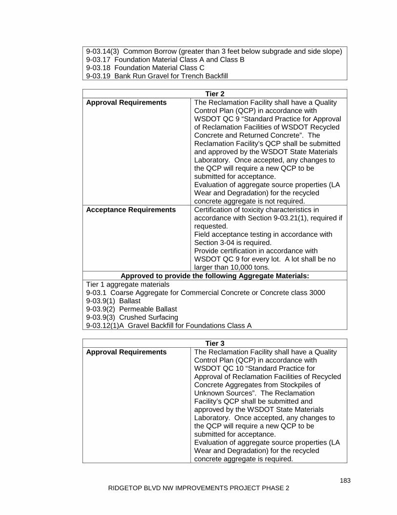
183 RIDGETOP BLVD NW IMPROVEMENTS PROJECT PHASE 2
9-03.14(3) Common Borrow (greater than 3 feet below subgrade and side slope) 9-03.17 Foundation Material Class A and Class B 9-03.18 Foundation Material Class C 9-03.19 Bank Run Gravel for Trench Backfill
Tier 2
Approval Requirements The Reclamation Facility shall have a Quality Control Plan (QCP) in accordance with WSDOT QC 9 “Standard Practice for Approval of Reclamation Facilities of WSDOT Recycled Concrete and Returned Concrete”. The Reclamation Facility’s QCP shall be submitted and approved by the WSDOT State Materials Laboratory. Once accepted, any changes to the QCP will require a new QCP to be submitted for acceptance. Evaluation of aggregate source properties (LA Wear and Degradation) for the recycled concrete aggregate is not required.
Acceptance Requirements Certification of toxicity characteristics in accordance with Section 9-03.21(1), required if requested. Field acceptance testing in accordance with Section 3-04 is required. Provide certification in accordance with WSDOT QC 9 for every lot. A lot shall be no larger than 10,000 tons.
Approved to provide the following Aggregate Materials: Tier 1 aggregate materials 9-03.1 Coarse Aggregate for Commercial Concrete or Concrete class 3000 9-03.9(1) Ballast 9-03.9(2) Permeable Ballast 9-03.9(3) Crushed Surfacing 9-03.12(1)A Gravel Backfill for Foundations Class A
Tier 3
Approval Requirements The Reclamation Facility shall have a Quality Control Plan (QCP) in accordance with WSDOT QC 10 “Standard Practice for Approval of Reclamation Facilities of Recycled Concrete Aggregates from Stockpiles of Unknown Sources”. The Reclamation Facility’s QCP shall be submitted and approved by the WSDOT State Materials Laboratory. Once accepted, any changes to the QCP will require a new QCP to be submitted for acceptance. Evaluation of aggregate source properties (LA Wear and Degradation) for the recycled concrete aggregate is required.
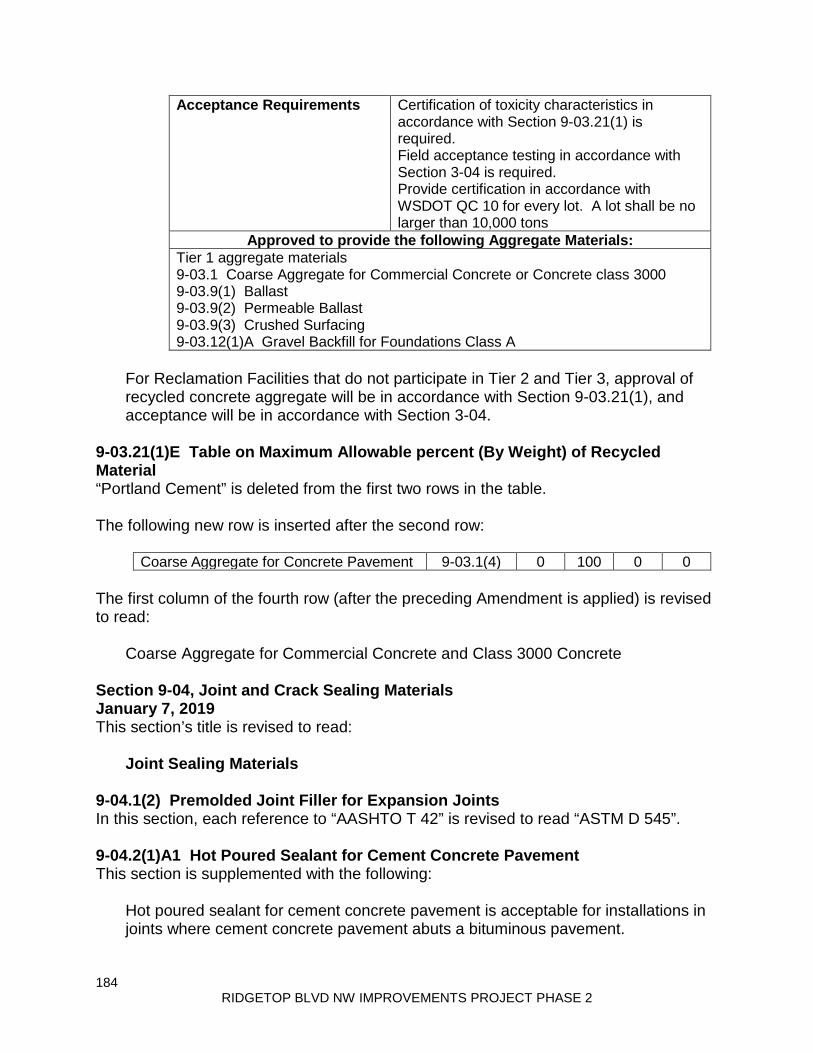
184 RIDGETOP BLVD NW IMPROVEMENTS PROJECT PHASE 2
Acceptance Requirements Certification of toxicity characteristics in accordance with Section 9-03.21(1) is required. Field acceptance testing in accordance with Section 3-04 is required. Provide certification in accordance with WSDOT QC 10 for every lot. A lot shall be no larger than 10,000 tons
Approved to provide the following Aggregate Materials: Tier 1 aggregate materials 9-03.1 Coarse Aggregate for Commercial Concrete or Concrete class 3000 9-03.9(1) Ballast 9-03.9(2) Permeable Ballast 9-03.9(3) Crushed Surfacing 9-03.12(1)A Gravel Backfill for Foundations Class A
For Reclamation Facilities that do not participate in Tier 2 and Tier 3, approval of recycled concrete aggregate will be in accordance with Section 9-03.21(1), and acceptance will be in accordance with Section 3-04.
9-03.21(1)E Table on Maximum Allowable percent (By Weight) of Recycled Material “Portland Cement” is deleted from the first two rows in the table. The following new row is inserted after the second row:
Coarse Aggregate for Concrete Pavement 9-03.1(4) 0 100 0 0 The first column of the fourth row (after the preceding Amendment is applied) is revised to read:
Coarse Aggregate for Commercial Concrete and Class 3000 Concrete Section 9-04, Joint and Crack Sealing Materials January 7, 2019 This section’s title is revised to read:
Joint Sealing Materials 9-04.1(2) Premolded Joint Filler for Expansion Joints In this section, each reference to “AASHTO T 42” is revised to read “ASTM D 545”. 9-04.2(1)A1 Hot Poured Sealant for Cement Concrete Pavement This section is supplemented with the following:
Hot poured sealant for cement concrete pavement is acceptable for installations in joints where cement concrete pavement abuts a bituminous pavement.

185 RIDGETOP BLVD NW IMPROVEMENTS PROJECT PHASE 2
9-04.2(1)A2 Hot Poured Sealant for Bituminous Pavement This section is supplemented with the following:
Hot poured sealant for bituminous pavement is acceptable for installations in joints where cement concrete pavement abuts a bituminous pavement.
9-04.2(1)B Sand Slurry for Bituminous Pavement Item number 2 of the first paragraph is revised to read:
2. Two percent portland cement or blended hydraulic cement, and 9-04.3 Joint Mortar The first paragraph is revised to read:
Mortar for hand mortared joints shall conform to Section 9-20.4(3) and consist of one part portland cement or blended hydraulic cement, three parts fine sand, and sufficient water to allow proper workability.
9-04.5 Flexible Plastic Gaskets In the table, the Test Method value for Specific Gravity at 77°F is revised to read “ASTM D71”. In the table, the Test Method value for Flash Point COC, F is revised to read “ASTM D93 REV A”. In the table, the Test Method value for Volatile Matter is revised to read “ASTM D6”. Section 9-05, Drainage Structures and Culverts January 7, 2019 9-05.3(1)A End Design and Joints The second sentence of the first paragraph is revised to read:
The joints and gasket material shall meet the requirements of ASTM C990. 9-05.3(1)C Age at Shipment The last sentence of the first paragraph is revised to read:
Unless it is tested and accepted at an earlier age, it shall not be considered ready for shipment sooner than 28 days after manufacture when made with Type II portland cement or blended hydraulic cement, nor sooner than 7 days when made with Type III portland cement.
9-05.7(3) Concrete Storm Sewer Pipe Joints The second sentence is revised to read:
The joints and gasket material shall meet the requirements of ASTM C990.

186 RIDGETOP BLVD NW IMPROVEMENTS PROJECT PHASE 2
9-05.7(4)A Hydrostatic Pressure on Pipes in Straight Alignment The first sentence is revised to read:
Hydrostatic pressure tests on pipes in straight alignment shall be made in accordance with the procedure outlined in Section 10 of ASTM C990, except that they shall be performed on an assembly consisting of not less than three nor more than five pipe sections selected from stock by the Engineer and assembled in accordance with standard installation instructions issued by the manufacturer.
9-05.24(1) Polypropylene Culvert Pipe and Storm Sewer Pipe This section is revised to read:
Polypropylene culvert and storm sewer pipe shall conform to the following requirements:
1. For dual wall pipe sizes up to 60 inches: ASTM F2881 or AASHTO M 330, Type S or Type D.
2. For double or triple wall pipe sizes up to 60 inches: ASTM F2764. 3. Fittings shall be factory welded, injection molded, or PVC.
9-05.24(2) Polypropylene Sanitary Sewer Pipe This section is revised to read:
Polypropylene sanitary sewer pipe shall conform to the following requirements:
1. For pipe sizes up to 60 inches: ASTM F2764. 2. Fittings shall be factory welded, injection molded, or PVC.
Section 9-06, Structural Steel and Related Materials January 7, 2019 9-06.5 Bolts This section’s title is revised to read:
Bolts and Rods 9-06.5(4) Anchor Bolts This section, including title, is revised to read:
9-06.5(4) Anchor Bolts and Anchor Rods Anchor bolts and anchor rods shall meet the requirements of ASTM F1554 and, unless otherwise specified, shall be Grade 105 and shall conform to Supplemental Requirements S2, S3, and S4.
187 RIDGETOP BLVD NW IMPROVEMENTS PROJECT PHASE 2
Nuts for ASTM F1554 Grade 105 black anchor bolts and anchor rods shall conform to ASTM A563, Grade D or DH. Nuts for ASTM F1554 Grade 105 galvanized anchor bolts and anchor rods shall conform to either ASTM A563, Grade DH, or AASHTO M292, Grade 2H, and shall conform to the overtapping, lubrication, and rotational testing requirements in Section 9-06.5(3). Nuts for ASTM F1554 Grade 36 or 55 black or galvanized anchor bolts and anchor rods shall conform to ASTM A563, Grade A or DH. Washers shall conform to ASTM F436. The bolts and rods shall be tested by the manufacturer in accordance with the requirements of the pertinent Specification and as specified in these Specifications. Anchor bolts, anchor rods, nuts, and washers shall be inspected prior to shipping to the project site. The Contractor shall submit to the Engineer for acceptance a Manufacturer’s Certificate of Compliance for the anchor bolts, anchor rods, nuts, and washers, as defined in Section 1-06.3. If the Engineer deems it appropriate, the Contractor shall provide a sample of the anchor bolt, anchor rod, nut, and washer for testing. All bolts, rods, nuts, and washers shall be marked and identified as required in the pertinent Specification.
9-06.15 Welded Shear Connectors The third paragraph is revised to read:
Mechanical properties shall be determined in accordance with AASHTO T 244.
9-06.17 Vacant This section, including title, is revised to read:
9-06.17 Noise Barrier Wall Access Door Access door frames shall be formed of 14-gauge steel to the size and dimensions shown in the Plans. The access door frame head and jamb members shall be mitered, securely welded, and ground smooth. Each head shall have two anchors and each jamb shall have three anchors. The hinges shall be reinforced with ¼-inch by 12-inch plate, width equal to the full inside width of the frame. Access doors shall be full flush 1-¾-inch thick seamless doors with a polystyrene core. Door faces shall be constructed with smooth seamless 14-gauge roller-levered, cold-rolled steel sheet conforming to ASTM A 792 Type SS, Grade 33 minimum, Coating Designation AZ55 minimum. The vertical edges shall be neat interlocked hemmed edge seam. The top and bottom of the door shall be enclosed with 14-gauge channels. Mortise and reinforcement for locks and hinges shall be 10-gauge steel. Welded top cap shall be ground and filled for exterior applications. The bottom channel shall have weep holes.
188 RIDGETOP BLVD NW IMPROVEMENTS PROJECT PHASE 2
Each access door shall have three hinges. Access door hinges shall be ASTM A 276 Type 316 stainless steel, 4-½-inches square, with stainless steel ball bearing and non-removable pins. Each access door shall have two pull plates. The pull plates shall be ASTM A 240 Type 316 stainless steel, with a grip handle of one-inch diameter and 8 to 10-inches in length. The door assembly shall be fabricated and assembled as a complete unit including all hardware specified prior to shipment.
9-06.18 Metal Bridge Railing The second sentence of the first paragraph is revised to read:
Steel used for metal railings, when galvanized after fabrication in accordance with AASHTO M111, shall have a controlled silicon content of either 0.00 to 0.06 percent or 0.15 to 0.25 percent.
Section 9-07, Reinforcing Steel January 7, 2019 9-07.5(1) Epoxy-Coated Dowel Bars (for Cement Concrete Rehabilitation) This section (including title) is revised to read:
9-07.5(1) Dowel Bars for Cement Concrete Pavement Rehabilitation Dowel bars for Cement Concrete Pavement Rehabilitation shall be 1½ inch outside diameter plain round steel bars or tubular bars 18 inches in length and meet the requirements of one of the following dowel bar types:
1. Epoxy-coated dowel bars shall be round plain steel bars of the dimensions shown in the Standard Plans. They shall conform to AASHTO M31, Grade 60 or ASTM A615, Grade 60 and shall be coated in accordance with ASTM A1078 Type 2 coating, except that the bars may be cut to length after being coated. Cut ends shall be coated in accordance with ASTM A1078 with a patching material that is compatible with the coating, inert in concrete and recommended by the coating manufacturer. The thickness of the epoxy coating shall be 10 mils plus or minus 2 mils. The Contractor shall furnish a written certification that properly identifies the coating material, the number of each batch of coating material used, quantity represented, date of manufacture, name and address of manufacturer, and a statement that the supplied coating material meets the requirements of ASTM A1078 Type 2 coating. Patching material, compatible with the coating material and inert in concrete and recommended by the manufacturer shall be supplied with each shipment for field repairs by the Contractor.
2. ASTM A513 steel tubes made from Grade 60 Carbon Steel Tube with a
1.625 inch outside diameter and a 0.120 inch wall thickness. Both the
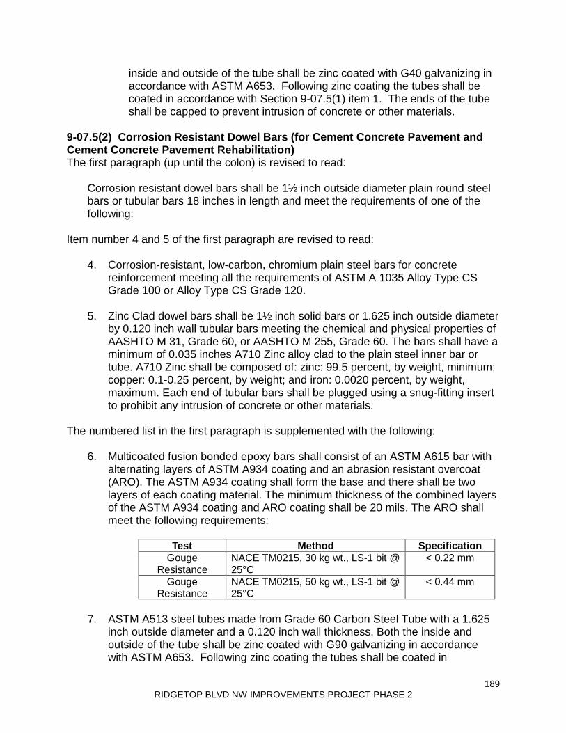
189 RIDGETOP BLVD NW IMPROVEMENTS PROJECT PHASE 2
inside and outside of the tube shall be zinc coated with G40 galvanizing in accordance with ASTM A653. Following zinc coating the tubes shall be coated in accordance with Section 9-07.5(1) item 1. The ends of the tube shall be capped to prevent intrusion of concrete or other materials.
9-07.5(2) Corrosion Resistant Dowel Bars (for Cement Concrete Pavement and Cement Concrete Pavement Rehabilitation) The first paragraph (up until the colon) is revised to read:
Corrosion resistant dowel bars shall be 1½ inch outside diameter plain round steel bars or tubular bars 18 inches in length and meet the requirements of one of the following:
Item number 4 and 5 of the first paragraph are revised to read:
4. Corrosion-resistant, low-carbon, chromium plain steel bars for concrete reinforcement meeting all the requirements of ASTM A 1035 Alloy Type CS Grade 100 or Alloy Type CS Grade 120.
5. Zinc Clad dowel bars shall be 1½ inch solid bars or 1.625 inch outside diameter
by 0.120 inch wall tubular bars meeting the chemical and physical properties of AASHTO M 31, Grade 60, or AASHTO M 255, Grade 60. The bars shall have a minimum of 0.035 inches A710 Zinc alloy clad to the plain steel inner bar or tube. A710 Zinc shall be composed of: zinc: 99.5 percent, by weight, minimum; copper: 0.1-0.25 percent, by weight; and iron: 0.0020 percent, by weight, maximum. Each end of tubular bars shall be plugged using a snug-fitting insert to prohibit any intrusion of concrete or other materials.
The numbered list in the first paragraph is supplemented with the following:
6. Multicoated fusion bonded epoxy bars shall consist of an ASTM A615 bar with alternating layers of ASTM A934 coating and an abrasion resistant overcoat (ARO). The ASTM A934 coating shall form the base and there shall be two layers of each coating material. The minimum thickness of the combined layers of the ASTM A934 coating and ARO coating shall be 20 mils. The ARO shall meet the following requirements:
Test Method Specification
Gouge Resistance
NACE TM0215, 30 kg wt., LS-1 bit @ 25°C
< 0.22 mm
Gouge Resistance
NACE TM0215, 50 kg wt., LS-1 bit @ 25°C
< 0.44 mm
7. ASTM A513 steel tubes made from Grade 60 Carbon Steel Tube with a 1.625
inch outside diameter and a 0.120 inch wall thickness. Both the inside and outside of the tube shall be zinc coated with G90 galvanizing in accordance with ASTM A653. Following zinc coating the tubes shall be coated in

190 RIDGETOP BLVD NW IMPROVEMENTS PROJECT PHASE 2
accordance with Section 9-07.5(1) item 1. The ends of the tube shall be capped to prevent intrusion of concrete or other materials.
The last paragraph is revised to read:
Stainless Steel Clad and Stainless Steel Tube Dowel bar ends shall be sealed with a patching material (primer and finish coat) used for patching epoxy-coated reinforcing steel as required in Section 9-07.3, item 6.
9-07.7 Wire Mesh This section is supplemented with the following:
Welded wire manufacturers shall participate in the NTPEP Audit Program for Reinforcing Steel (rebar) Manufacturers and shall be listed on the NTPEP audit program website displaying that they are NTPEP compliant.
Section 9-08, Paints and Related Materials January 7, 2019 9-08.1(1) Description The first sentence is revised to read:
Paint used for highway and bridge structure applications shall be made from materials meeting the requirements of the applicable Federal and State Paint Specifications, Department of Defense (DOD), American Society of Testing of Materials (ASTM), and The Society for Protective Coatings (SSPC) specifications in effect at time of manufacture.
9-08.1(2) Paint Types This section is supplemented with the following new subsections:
9-08.1(2)M NEPCOAT Qualified Products List A Qualified products used shall be part of a NEPCOAT system supplied by the same manufacturer. 9-08.1(2)N NEPCOAT Qualified Products List B Qualified products used shall be part of a NEPCOAT system supplied by the same manufacturer.
9-08.1(2)D Organic Zinc-Rich Primer This section, including title, is revised to read:
Vacant 9-08.1(2)E Epoxy Polyamide This section is revised to read:

191 RIDGETOP BLVD NW IMPROVEMENTS PROJECT PHASE 2
Epoxy polyamide shall be a two-component system conforming to MIL-DTL-24441 or SSPC Coating Standard No. 42.
9-08.1(2)H Top Coat, Single-Component, Moisture-Cured Polyurethane This section is revised to read:
Vehicle Type: Moisture-cured aliphatic polyurethane. Color and Gloss: Meet the SAE AMS Standard 595 Color as specified in the
table below. The Top Coat shall meet the following requirements:
The resin shall be an aliphatic urethane. Minimum-volume solids 50 percent. The top coat shall be semi-gloss.
Color Semi-Gloss Washington Gray 26357 Mt. Baker Gray 26134 Mt. St. Helens Gray 26306 Cascade Green 24158
9-08.1(2)I Rust-Penetrating Sealer This section is revised to read:
Rust-penetrating sealer shall be a two-component, chemically-cured, 100 percent solids epoxy.
9-08.1(2)J Black Enamel This section is revised to read:
The enamel shall conform to Federal Specification MIL PRF 24635E Type II Class 2.
9-08.1(2)K Orange Equipment Enamel The first paragraph is revised to read:
The enamel shall be an alkyd gloss enamel conforming to Federal Specification MIL-PRF-24635E Type II Class 1. The color, when dry, shall match that of SAE AMS Standard 595, color number 12246.
9-08.1(2)L Exterior Acrylic Latex Paint-White The first paragraph is revised to read:
192 RIDGETOP BLVD NW IMPROVEMENTS PROJECT PHASE 2
This paint shall conform to Federal Specification MIL-PRF-24635E Type II Class 1, 2 or 3.
9-08.1(7) Acceptance This section is revised to read:
For projects with moisture-cured polyurethane quantities less than 20 gallons, acceptance will be by the Manufacturer’s Certificate of Compliance. For projects with moisture-cured polyurethane quantities greater than 20 gallons, the product shall be listed in the current WSDOT Qualified Products List (QPL). If the lot number is listed on the QPL, it may be accepted without additional testing. If the lot number is not listed on the QPL, a 1 quart sample shall be submitted to the State Materials Laboratory for testing and acceptance. For all other paint types, acceptance will be based on visual inspection.
9-08.1(8) Standard Colors In the first paragraph, the reference to “Federal Standard 595” is revised to read “SAE AMS Standard 595”. The second paragraph is revised to read:
Unless otherwise specified, all top or finish coats shall be semi-gloss, with the paint falling within the range of 35 to 70 on the 60-degree gloss meter.
9-08.2 Powder Coating Materials for Coating Galvanized Surfaces The last paragraph is revised to read:
Repair materials shall be as recommended by the powder coating manufacturer and as specified in the Contractor’s powder coating plan as accepted by the Engineer.
9-08.3 Pigmented Sealer Materials for Coating of Concrete Surfaces This section, including title, is revised to read:
9-08.3 Concrete Surface Treatments 9-08.3(1) Pigmented Sealer Materials The pigmented sealer shall be a semi-opaque, colored toner containing only methyl methacrylate-ethyl acrylate copolymer resins, toning pigments suspended in solution at all times by a chemical suspension agent, and solvent. Toning pigments shall be laminar silicates, titanium dioxide, and inorganic oxides only. There shall be no settling or color variation. Tinting shall occur at the factory at the time of manufacture and placement in containers, prior to initial shipment. Use of vegetable or marine oils, paraffin materials, stearates, or organic pigments in any part of coating formulation will not be permitted. The

193 RIDGETOP BLVD NW IMPROVEMENTS PROJECT PHASE 2
color of pigmented sealer shall be as specified by the Contracting Agency. The Contractor shall submit a 1-quart wet sample, a drawdown color sample, and spectrophotometer or colorimeter readings taken in accordance with ASTM D2244, for each batch and corresponding standard color card. The calculated Delta E shall not exceed 1.5 from the Commission Internationale de l’Eclairage (CIELAB) when measured at 10 degrees Standard Observer and Illuminant D 65. The 1-quart wet sample shall be submitted in the manufacturer’s labeled container with product number, batch number, and size of batch. The companion drawdown color sample shall be labeled with the product number, batch number, and size of batch. The Contractor shall submit the specified samples and readings to the Engineer at least 14 calendar days prior to the scheduled application of the sealer. The Contractor shall not begin applying pigmented sealer until receiving the Engineer’s written approval of the pigmented sealer color samples. 9-08.3(2) Exposed Aggregate Concrete Coatings and Sealers
9-08.3(2)A Retardant Coating Retardant coating shall exhibit the following properties:
1. Retards the set of the surface mortar of the concrete without preventing the concrete to reach the specified 28 day compressive strength.
2. Leaves the aggregate with its original color and luster, and firmly
embedded in the concrete matrix. 3. Allows the removal of the surface mortar in accordance with the
methods specified in Section 6-02.3(14)E without the use of acidic washing compounds.
4. Allows for uniform removal of the surface mortar.
If the Contractor proposes use of a retardant coating that is not listed in the current WSDOT QPL, the Contractor shall submit a Type 2 Working Drawing consisting of a one quart product sample from a current lot along with supporting product information, Safety Data Sheet, and a Manufacturer’s Certificate of Compliance stating that the product conforms to the above performance requirements. 9-08.3(2)B Clear Sealer The sealer for concrete surfaces with exposed aggregate finish shall be a clear, non-gloss, penetrating sealer of either a silane, siloxane, or silicone based formulation.

194 RIDGETOP BLVD NW IMPROVEMENTS PROJECT PHASE 2
9-08.3(3) Permeon Treatment Permeon treatment shall be a product of known consistent performance in producing the SAE AMS Standard 595 Color No. 30219 target color hue established by WSDOT, either selected from the WSDOT Qualified Products List (QPL), or an equivalent product accepted by the Engineer. For acceptance of products not listed in the current WSDOT QPL, the Contractor shall submit Type 3 Working Drawings consisting of a one quart product sample from a current lot, supporting product information and a Safety Data Sheet.
Section 9-13, Riprap, Quarry Spalls, Slope Protection, and Rock for Erosion and Scour Protection and Rock Walls April 2, 2018 9-13.1(1) General The last paragraph is revised to read:
Riprap and quarry spalls shall be free from segregation, seams, cracks, and other defects tending to destroy its resistance to weather and shall meet the following test requirements:
9-13.5 Concrete Slope Protection This section is revised to read:
Concrete slope protection shall consist of reinforced portland cement or blended hydraulic cement concrete poured or pneumatically placed upon the slope with a rustication joint pattern or semi-open concrete masonry units placed upon the slope closely adjoining each other.
9-13.5(2) Poured Portland Cement Concrete Slope Protection This section’s title is revised to read:
Poured Portland Cement or Blended Hydraulic Cement Concrete Slope Protection
9-13.5(3) Pneumatically Placed Portland Cement Concrete Slope Protection This section’s title is revised to read:
Pneumatically Placed Portland Cement or Blended Hydraulic Cement Concrete Slope Protection
The first paragraph is revised to read:
Cement – This material shall be portland cement or blended hydraulic cement as specified in Section 9-01.
9-13.7(1) Rock for Rock Walls and Chinking Material The first paragraph (up until the colon) is revised to read:

195 RIDGETOP BLVD NW IMPROVEMENTS PROJECT PHASE 2
Rock for rock walls and chinking material shall be hard, sound and durable material, free from seams, cracks, and other defects tending to destroy its resistance to weather, and shall meet the following test requirements:
Section 9-14, Erosion Control and Roadside Planting August 6, 2018 9-14.4(2) Hydraulically Applied Erosion Control Products (HECPs) In Table 1, the last four rows are deleted. 9-14.4(2)A Long-Term Mulch The first paragraph is supplemented with the following:
Products containing cellulose fiber produced from paper or paper components will not be accepted.
Table 2 is supplemented with the following new rows:
Water Holding Capacity ASTM D 7367 800 percent minimum Organic Matter Content AASHTO T 267 90 percent minimum Seed Germination Enhancement
ASTM D 7322 Long Term 420 percent minimum
9-14.4(2)B Moderate-Term Mulch This section is revised to read:
Within 48 hours of application, the Moderate-Term Mulch shall bond with the soil surface to create a continuous, absorbent, flexible, erosion-resistant blanket. Moderate-Term Mulch shall effectively perform the intended erosion control function in accordance with Section 8-01.3(1) for a minimum of 3 months, or until temporary vegetation has been established, whichever comes first. Moderate-Term Mulch shall not be used in conjunction with permanent seeding.
9-14.4(2)C Short-Term Mulch This section is revised to read:
Short-Term Mulch shall effectively perform the intended erosion control function in accordance with Section 8-01.3(1) for a minimum of 2 months, or until temporary vegetation has been established, whichever comes first. Short-Term Mulch shall not be used in conjunction with permanent seeding.

196 RIDGETOP BLVD NW IMPROVEMENTS PROJECT PHASE 2
Section 9-16, Fence and Guardrail August 6, 2018 9-16.3(1) Rail Element The last sentence of the first paragraph is revised to read:
All rail elements shall be formed from 12-gage steel except for thrie beam reducer sections, reduced length thrie beam rail elements, thrie beams used for bridge rail retrofits, and Design F end sections, which shall be formed from 10-gage steel.
9-16.3(5) Anchors The last paragraph is revised to read:
Cement grout shall conform to Section 9-20.3(4) and consist of one part portland cement or blended hydraulic cement and two parts sand.
Section 9-18, Precast Traffic Curb April 2, 2018 9-18.1(1) Aggregates and Proportioning Item number 1 of the first paragraph is revised to read:
1. Portland cement or blended hydraulic cement shall conform to the requirements of Section 9-01 except that it may be Type I portland cement conforming to AASHTO M 85.
Section 9-20, Concrete Patching Material, Grout, and Mortar April 1, 2019 9-20.1 Patching Material This section, including title, is revised to read:
9-20.1 Patching Material for Cement Concrete Pavement Concrete patching material shall be prepackaged mortar extended with aggregate. The amount of aggregate for extension shall conform to the manufacturer’s recommendation. Patching mortar and patching mortar extended with aggregate shall contain cementitious material and conform to Sections 9-20.1(1) and 9-20.1(2). The Manufacturer shall use the services of a laboratory that has an equipment calibration verification system and a technician training and evaluation process in accordance with AASHTO R 18 to perform all tests specified in Section 9-20.1.
9-20.1(1) Patching Mortar Patching mortar shall conform to the following requirements:
Compressive Strength ASTM Test Method Specification
at 3 hours C 39 Minimum 3,000 psi at 24 hours C 39 Minimum 5,000 psi
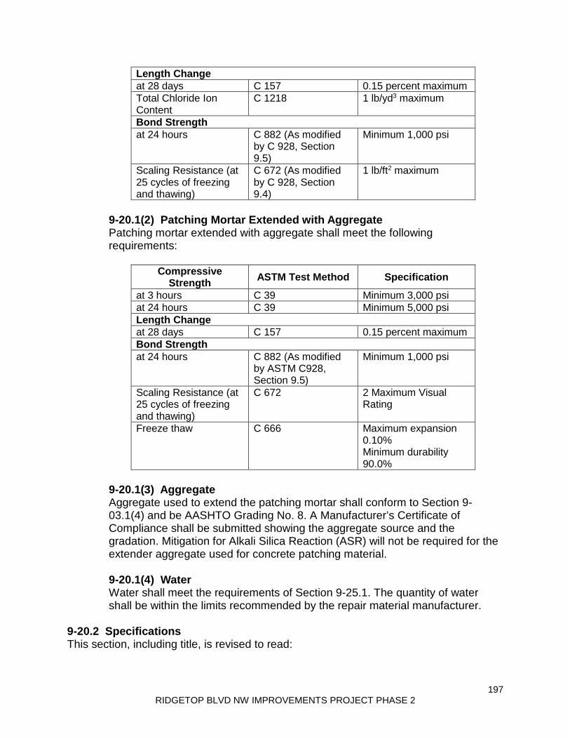
197 RIDGETOP BLVD NW IMPROVEMENTS PROJECT PHASE 2
Length Change at 28 days C 157 0.15 percent maximum Total Chloride Ion Content
C 1218 1 lb/yd3 maximum
Bond Strength at 24 hours C 882 (As modified
by C 928, Section 9.5)
Minimum 1,000 psi
Scaling Resistance (at 25 cycles of freezing and thawing)
C 672 (As modified by C 928, Section 9.4)
1 lb/ft2 maximum
9-20.1(2) Patching Mortar Extended with Aggregate Patching mortar extended with aggregate shall meet the following requirements:
Compressive Strength ASTM Test Method Specification
at 3 hours C 39 Minimum 3,000 psi at 24 hours C 39 Minimum 5,000 psi Length Change at 28 days C 157 0.15 percent maximum Bond Strength at 24 hours C 882 (As modified
by ASTM C928, Section 9.5)
Minimum 1,000 psi
Scaling Resistance (at 25 cycles of freezing and thawing)
C 672 2 Maximum Visual Rating
Freeze thaw C 666 Maximum expansion 0.10% Minimum durability 90.0%
9-20.1(3) Aggregate Aggregate used to extend the patching mortar shall conform to Section 9-03.1(4) and be AASHTO Grading No. 8. A Manufacturer’s Certificate of Compliance shall be submitted showing the aggregate source and the gradation. Mitigation for Alkali Silica Reaction (ASR) will not be required for the extender aggregate used for concrete patching material. 9-20.1(4) Water Water shall meet the requirements of Section 9-25.1. The quantity of water shall be within the limits recommended by the repair material manufacturer.
9-20.2 Specifications This section, including title, is revised to read:

198 RIDGETOP BLVD NW IMPROVEMENTS PROJECT PHASE 2
9-20.2 Patching Material for Concrete Structure Repair Concrete patching material shall be a prepackaged mixture of portland or blended hydraulic cement, aggregate, and admixtures. Fly ash, ground granulated blast furnace slag and microsilica fume may be used. The concrete patching material may be shrinkage compensated. The concrete patching material shall also meet the following requirements:
• Compressive strength of 6000 psi or higher at 28 days in accordance with AASHTO T 22 (ASTM C 39), unless noted otherwise
• Bond strength of 250 psi or higher at 28 days or less in accordance with
ASTM C 1583 or ICRI 210.3R • Shrinkage shall be 0.05 percent (500 microstrain) or lower at 28 days in
accordance with AASHTO T 160 (ASTM C 157) as modified by ICRI 320.3R
• Permeability shall be 2,000 coulombs or lower at 28 days in accordance
with AASHTO T 277 (ASTM C 1202) • Freeze-thaw resistance shall have a durability factor of 90 percent or higher
after a minimum of 300 cycles in accordance with AASHTO T 161 Procedure A (ASTM C 666)
• Soluble chloride ion limits in Section 6-02.3(2) shall be satisfied
9-20.2(1) Patching Mortar This section, including title, is deleted in its entirety. 9-20.2(2) Patching Mortar Extended with Aggregate This section, including title, is deleted in its entirety. 9-20.3(3) Grout Type 3 for Unconfined Bearing Pad Applications This section’s title is revised to read:
Grout Type 3 for Unconfined Applications This section is revised to read:
Grout Type 3 shall be a prepackaged material that does not include expansive admixtures meeting the following requirements:
• Compressive strength shall be 4000 psi or higher at 28 days in accordance with AASHTO T 22 (ASTM C 39) for grout extended with coarse aggregate or AASHTO T 106 (ASTM C109) otherwise.

199 RIDGETOP BLVD NW IMPROVEMENTS PROJECT PHASE 2
• Bond strength shall meet one of the following:
◦ 250 psi or higher at 28 days or less in accordance with ASTM C1583. ◦ 2000 psi or higher at 28 days or less in accordance with ASTM C882.
The following modification to ASTM C882 is acceptable: use Type 3 Grout in lieu of epoxy resin base bonding system and freshly mixed portland-cement mortar in the procedure for testing Type II and V systems.
• Drying shrinkage shall be 0.08 percent (800 microstrain) or lower at 28
days in accordance with AASHTO T 160 (ASTM C157). The following modification to AASHTO T 160 is acceptable: use a standard specimen size of 3 x 3 x 11-¼ inches.
9-20.5 Bridge Deck Repair Material Item number 3 of the first paragraph is revised to read:
3. Permeability of less than 2,000 coulombs at 28-days or more in accordance with AASHTO T 277.
Section 9-21, Raised Pavement Markers (RPM) January 2, 2018 9-21.2 Raised Pavement Markers Type 2 This section’s content is deleted. 9-21.2(1) Physical Properties This section, including title, is revised to read:
9-21.2(1) Standard Raised Pavement Markers Type 2 The marker housing shall contain reflective faces as shown in the Plans to reflect incident light from either a single or opposite directions and meet the requirements of ASTM D 4280 including Flexural strength requirements.
9-21.2(2) Optical Requirements This section, including title, is revised to read:
9-21.2(2) Abrasion Resistant Raised Markers Type 2 Abrasion Resistant Raised Markers Type 2 shall comply with Section 9-21.2(1) and meet the requirements of ASTM D 4280 with the following additional requirement: The coefficient of luminous intensity of the markers shall be measured after subjecting the entire lens surface to the test described in ASTM D 4280 Section 9.5 using a sand drop apparatus. After the exposure described above, retroreflected values shall not be less than 0.5 times a nominal unblemished sample.

200 RIDGETOP BLVD NW IMPROVEMENTS PROJECT PHASE 2
9-21.2(3) Strength Requirements This section is deleted in its entirety. Section 9-23, Concrete Curing Materials and Admixtures April 1, 2019 9-23.12 Natural Pozzolan This section is revised to read:
Natural Pozzolans shall be ground Pumice and shall conform to the requirements of AASHTO M295 Class N, including supplementary optional chemical requirements as set forth in Table 2.
9-23.13 Blended Supplementary Cementitious Material The second sentence is revised to read:
Blended SCMs shall be limited to binary or ternary blends of fly ash, ground granulated blast furnace slag and microsilica fume.
The second to last sentence is deleted. Section 9-26, Epoxy Resins January 7, 2019 9-26.1(1) General The following new sentence is inserted after the first sentence of the first paragraph:
For pre-packaged cartridge kits, the epoxy bonding agent shall meet the requirements of ASTM C881 when mixed according to manufacturer instructions, utilizing the manufacturer’s mixing nozzle.
9-26.1(2) Packaging and Marking The first sentence of the first paragraph is revised to read:
The components of the epoxy system furnished under these Specifications shall be supplied in separate containers or pre-packaged cartridge kits that are non-reactive with the materials contained.
The second paragraph is revised to read:
Separate containers shall be marked by permanent marking that identify the formulator, “Component A” (contains the Epoxy Resin) and “Component B” (Contains the Curing Agent), type, grade, class, lot or batch number, mixing instructions and the quantity contained in pounds or gallons as defined by these Specifications.
The following new paragraph is inserted after the second paragraph:

201 RIDGETOP BLVD NW IMPROVEMENTS PROJECT PHASE 2
Pre-packaged cartridge kits shall be marked by permanent marking that identify the formulator, type, grade, class, lot or batch number, mixing instructions and the quantity contained in ounces or milliliters as defined by these Specifications.
Section 9-28, Signing Materials and Fabrication April 1, 2019 9-28.2 Manufacturer’s Identification and Date The second sentence is revised to read:
In addition, the width and height dimension, in inches, the Contract number, and the number of the sign as it appears in the Plans shall be placed using 3-inch series C black letters on the back of destination, distance, and large special signs.
9-28.10 Vacant This section, including title, is revised to read:
9-28.10 Digital Printing Transparent and opaque durable inks used in digital printed sign messages shall be as recommended by the manufacturer. When properly applied, digital printed colors shall have a warranty life of the base retroreflective sign sheeting. Digital applied colors shall present a smooth surface, free from foreign material, and all messages and borders shall be clear and sharp. Digital printed signs shall conform to 70% of the retroreflective minimum values established for its type and color. Digitally printed signs shall meet the daytime color and luminance, and nighttime color requirements of ASTM D 4956. No variations in color or overlapping of colors will be permitted. Digital printed permanent traffic signs shall have an integrated engineered match component clear protective overlay recommended by the sheeting manufacturer applied to the entire face of the sign. On Temporary construction/maintenance signs printed with black ink only, the protective overlay film is optional, as long as the finished sign has a warranty of a minimum of three years from sign sheeting manufacturer. All digital printed traffic control signs shall be an integrated engineered match component system. The integrated engineered match component system shall consist of retroreflective sheeting, durable ink(s), and clear overlay film all from the same manufacturer applied to aluminum substrate conforming to Section 9-28.8. The sign fabricator shall use an approved integrated engineered match component system as listed on the Qualified Products List (QPL). Each approved digital printer shall only use the compatible retroreflective sign sheeting manufacturer’s engineered match component system products. Each retroreflective sign sheeting manufacturer/integrated engineered match component system listed on the QPL shall certify a department approved sign fabricator is approved to operate their compatible digital printer. The sign fabricator shall re-certify annually with the retroreflective sign manufacturer to ensure their

202 RIDGETOP BLVD NW IMPROVEMENTS PROJECT PHASE 2
digital printer is still meeting manufacturer’s specifications for traffic control signs. Documentation of each re-certification shall be submitted to the QPL Engineer annually.
9-28.11 Hardware The last paragraph is revised to read:
All steel parts shall be galvanized in accordance with AASHTO M111. Steel bolts and related connecting hardware shall be galvanized in accordance with ASTM F 2329.
9-28.14(2) Steel Structures and Posts The first sentence of the third paragraph is revised to read:
Anchor rods for sign bridge and cantilever sign structure foundations shall conform to Section 9-06.5(4), including Supplemental Requirement S4 tested at -20°F.
In the second sentence of the fourth paragraph, “AASHTO M232” is revised to read “ASTM F 2329”. The first sentence of the fifth paragraph is revised to read:
Except as otherwise noted, steel used for sign structures and posts shall have a controlled silicon content of either 0.00 to 0.06 percent or 0.15 to 0.25 percent.
The last sentence of the last paragraph is revised to read:
If such modifications are contemplated, the Contractor shall submit a Type 2 Working Drawing of the proposed modifications.
Section 9-29, Illumination, Signal, Electrical April 1, 2019 9-29.1 Conduit, Innerduct, and Outerduct This section is supplemented with the following new subsections:
9-29.1(10) Pull Tape Pull tape shall be pre-lubricated polyester pulling tape. The pull tape shall have a minimum width of ½-inch and a minimum tensile strength of 500 pounds. Pull tape may have measurement marks.
9-29.1(11) Foam Conduit Sealant Foam conduit sealant shall be self-expanding waterproof foam designed to prevent both water and pest intrusion. The foam shall be designed for use in and around electrical equipment, including both insulated and bare conductors.

203 RIDGETOP BLVD NW IMPROVEMENTS PROJECT PHASE 2
9-29.2(1) Junction Boxes The first paragraph is revised to read:
For the purposes of this Specification concrete is defined as portland cement or blended hydraulic cement concrete and non-concrete is all others.
9-29.2(1)A2 Non-Concrete Junction Boxes The first paragraph is revised to read:
Material for the non-concrete junction boxes shall be of a quality that will provide for a similar life expectancy as portland cement or blended hydraulic cement concrete in a direct burial application.
9-29.2(2)A Standard Duty Cable Vaults and Pull Boxes In the table in the last paragraph, the fourth, fifth and sixth rows are revised to read:
Slip Resistant Lid ASTM A36 steel Frame ASTM A36 steel Slip Resistant Frame ASTM A36 steel
9-29.3(2)A1 Single Conductor Current Carrying This second sentence is revised to read:
Insulation shall be XLP (cross-linked polyethylene) or EPR (Ethylene Propylene Rubber), Type USE (Underground Service Entrance) or USE-2, and rated for 600-volts or higher.
9-29.6 Light and Signal Standards In the first sentence of the third paragraph, “AASHTO M232” is revised to read “ASTM F 2329”. Item number 2 of the last paragraph is revised to read:
2. The steel light and signal standard fabricator’s shop drawing submittal, including supporting design calculations, submitted as a Type 2E Working Drawing in accordance with Section 8-20.2(1) and the Special Provisions.
9-29.6(1) Steel Light and Signal Standards In the second paragraph, “AASHTO M232” is revised to read “ASTM F 2329”. The first sentence of the last paragraph is revised to read:
Steel used for light and signal standards shall have a controlled silicon content of either 0.00 to 0.06 percent or 0.15 to 0.25 percent.
9-29.6(5) Foundation Hardware In the last paragraph, “AASHTO M232” is revised to read “ASTM F 2329”.

204 RIDGETOP BLVD NW IMPROVEMENTS PROJECT PHASE 2
9-29.10(1) Conventional Roadway Luminaires This section is revised to read:
All conventional roadway luminaires shall meet 3G vibration requirements as described in ANSI C136.31. All luminaires shall have housings fabricated from aluminum. The housing shall be painted flat gray, SAE AMS Standard 595 color chip No. 26280, unless otherwise specified in the Contract. Painted housings shall withstand a 1,000 hour salt spray test as specified in ASTM B117. Each housing shall include a four bolt slip-fitter mount capable of accepting a nominal 2” tenon and adjustable within +/- 5 degrees of the axis of the tenon. The clamping bracket(s) and the cap screws shall not bottom out on the housing bosses when adjusted within the +/- 5 degree range. No part of the slipfitter mounting brackets on the luminaires shall develop a permanent set in excess of 0.2 inch when the cap screws used for mounting are tightened to a torque of 32 foot-pounds. Each luminaire shall include leveling reference points for both transverse and longitudinal adjustment. All luminaires shall include shorting caps when shipped. The caps shall be removed and provided to the Contracting Agency when an alternate control device is required to be installed in the photocell socket. House side shields shall be included when required by the Contract. Order codes shall be modified to the minimum extent necessary to include the option for house side shields.
This section is supplemented with the following new subsections:
9-29.10(1)A High Pressure Sodium (HPS) Conventional Roadway Luminaires HPS conventional roadway luminaires shall meet the following requirements:
1. General shape shall be “cobrahead” style, with flat glass lens and full cutoff optics.
2. Light pattern distribution shall be IES Type III. 3. The reflector of all luminaires shall be of a snap-in design or secured with
screws. The reflector shall be polished aluminum or prismatic borosilicate glass.
4. Flat lenses shall be formed from heat resistant, high-impact, molded
borosilicate or tempered glass. 5. The lens shall be mounted in a doorframe assembly, which shall be hinged
to the luminaire and secured in the closed position to the luminaire by

205 RIDGETOP BLVD NW IMPROVEMENTS PROJECT PHASE 2
means of an automatic latch. The lens and doorframe assembly, when closed, shall exert pressure against a gasket seat. The lens shall not allow any light output above 90 degrees nadir. Gaskets shall be composed of material capable of withstanding the temperatures involved and shall be securely held in place.
6. The ballast shall be mounted on a separate exterior door, which shall be
hinged to the luminaire and secured in the closed position to the luminaire housing by means of an automatic type of latch (a combination hex/slot stainless steel screw fastener may supplement the automatic-type latch).
7. Each luminaire shall be capable of accepting a 150, 200, 250, 310, or 400
watt lamp complete and associated ballast. Lamps shall mount horizontally.
9-29.10(1)B Light Emitting Diode (LED) Conventional Roadway Luminaires LED Conventional Roadway Luminaires are divided into classes based on their equivalent High Pressure Sodium (HPS) luminaires. Current classes are 200W, 250W, 310W, and 400W. LED luminaires are required to be pre-approved in order to verify their photometric output. To be considered for pre-approval, LED luminaires must meet the requirements of this section. LED luminaires shall include a removable access door, with tool-less entry, for access to electronic components and the terminal block. The access door shall be removable, but include positive retention such that it can hang freely without disconnecting from the luminaire housing. LED drivers may be mounted either to the interior of the luminaire housing or to the removable door itself. LED drivers shall be removable for user replacement. All internal modular components shall be connected by means of mechanical plug and socket type quick disconnects. Wire nuts may not be used for any purpose. All external electrical connections to the luminaire shall be made through the terminal block. LED luminaires shall include a 7-pin NEMA photocell receptacle. The LED driver(s) shall be dimmable from ten volts to zero volts. LED output shall have a Correlated Color Temperature (CCT) of 4000K nominal (4000-4300K) and a Color Rendering Index (CRI) of 70 or greater. LED output shall be a minimum of 85% at 75,000 hours at 25 degrees Celsius. LED luminaires shall be available for 120V, 240V, and 480V supply voltages. Voltages refer to the supply voltages to the luminaires present in the field. LED power usage shall not exceed the following maximum values for the applicable wattage class:
Class Max. Wattage 200W 110W 250W 165W

206 RIDGETOP BLVD NW IMPROVEMENTS PROJECT PHASE 2
310W 210W 400W 275W
Only one brand of LED conventional roadway luminaire may be used on a Contract. They do not necessarily have to be the same brand as any high-mast, underdeck, or wall-mount luminaires when those types of luminaires are specified in the Contract. LED luminaires shall include a standard 10 year manufacturer warranty. The list of pre-approved LED Conventional Roadway Luminaires is available at http://www.wsdot.wa.gov/Design/Traffic/ledluminaires.htm.
9-29.10(2) Decorative Luminaires This section, including title, is revised to read:
9-29.10(2) Vacant 9-29.12 Electrical Splice Materials This section is supplemented with the following new subsections:
9-29.12(3) Splice Enclosures 9-29.12(3)A Heat Shrink Splice Enclosure Heat shrink splice enclosures shall be medium or heavy wall cross-linked polyolefin, meeting the requirements of AMS-DTL-23053/15, with thermoplastic adhesive sealant. Heat shrink splices used for “wye” connections require rubber electrical mastic tape. 9-29.12(3)B Molded Splice Enclosure Molded splice enclosures shall use epoxy resin in a clear rigid plastic mold. The material used shall be compatible with the insulation material of the insulated conductor or cable. The component materials of the resin insulation shall be packaged ready for convenient mixing without removing from the package.
9-29.12(4) Re-Enterable Splice Enclosure Re-enterable splice enclosures shall use either dielectric grease or a flexible resin contained in a two-piece plastic mold. The mold shall either snap together or use stainless steel hose clamps. 9-29.12(5) Vinyl Electrical Tape for Splices Vinyl electrical tape in splicing applications shall meet the requirements of MIL-I-24391C.
9-29.12(1) Illumination Circuit Splices This section is revised to read:
Underground illumination circuit splices shall be solderless crimped connections capable of securely joining the wires, both mechanically and electrically, as defined

207 RIDGETOP BLVD NW IMPROVEMENTS PROJECT PHASE 2
in Section 8-20.3(8). Aerial illumination splices shall be solderless crimp connectors or split bolt vice-type connectors.
9-29.12(1)A Heat Shrink Splice Enclosure This section is deleted in its entirety. 9-29.12(1)B Molded Splice Enclosure This section is deleted in its entirety. 9-29.12(2) Traffic Signal Splice Material This section is revised to read:
Induction loop splices and magnetometer splices shall use an uninsulated barrel-type crimped connector capable of being soldered.
9-29.13(10)D Cabinets for Type 170E and 2070 Controllers The first sentence of item number 4 is revised to read:
A disposable paper filter element with dimensions of 12” × 16” × 1” shall be provided in lieu of a metal filter.
Item number 6 is revised to read:
6. LED light strips shall be provided for cabinet lighting, powered from the Equipment breaker on the Power Distribution Assembly. Each LED light strip shall be approximately 12 inches long, have a minimum output of 320 lumens, and have a color temperature of 4100K (cool white) or higher. There shall be three light strips for each rack within the cabinet. Lighting shall be ceiling mounted – rack mounted lighting is not permitted. Light strips shall be installed in the locations shown in the Standard Plans. Lighting shall not interfere with the proper operation of any other ceiling mounted equipment. All lighting fixtures above a rack shall energize automatically when either door to that respective rack is opened. Each door switch shall be labeled “Light”.
Item number 7 is revised to read:
7. Rack mounted equipment shall be as shown in the Standard Plans. The cabinet shall use PDA #2LX and Output File #1LX. Where an Auxiliary Output File is required, Output File #2LX shall also be included.
This section is supplemented with the following new item:
9. The PCB connectors for Field Terminal Blocks FT1 through FT6 on Output Files #1LX and #2LX shall be capable of accepting minimum 14 AWG field wiring, have a pitch of 5.08 mm, and use screw flange type locking to secure the plug and socket connection. The sockets on the Field Terminal Panel shall

208 RIDGETOP BLVD NW IMPROVEMENTS PROJECT PHASE 2
be secured to the panel such that unplugging a connector will not result in the socket moving or separating from the panel.
9-29.13(11) Traffic Data Accumulator and Ramp Meters Item number 2 is revised to read:
2. Rack mounted equipment shall be as shown in the Standard Plans. Item number 3 is revised to read:
3. PDA #3LX shall be furnished with three Model 200 Load Switches installed. PDA #3LX shall be modified to include a second Model 430 transfer relay, mounted on the rear of the PDA and wired as shown in the Standard Plans.
9-29.13(12) ITS Cabinet This section’s title is revised to read:
Type 331L ITS Cabinet The first paragraph (excluding the numbered list) is revised to read:
Basic ITS cabinets shall be Model 331L Cabinets, unless otherwise specified in the Contract. Type 331L Cabinets shall be constructed in accordance with the TEES, with the following modifications:
Item number 6 of the first paragraph is revised to read:
6. LED light strips shall be provided for cabinet lighting, powered from the Equipment breaker on the Power Distribution Assembly. Each LED light strip shall be approximately 12 inches long, have a minimum output of 320 lumens, and have a color temperature of 4100K (cool white) or higher. There shall be three light strips for each rack within the cabinet. Lighting shall be ceiling mounted – rack mounted lighting is not permitted. Light strips shall be installed in the locations shown in the Standard Plans. Lighting shall not interfere with the proper operation of any other ceiling mounted equipment. All lighting fixtures above a rack shall energize automatically when either door to that respective rack is opened. Each door switch shall be labeled “Light”.
9-29.16(2)E Painting Signal Heads In the first sentence, “Federal Standard 595” is revised to read “SAE AMS Standard 595”. 9-29.17 Signal Head Mounting Brackets and Fittings In the first paragraph, item number 2 under Stainless Steel is revised to read:
2. Bands or cables for Type N mount.

209 RIDGETOP BLVD NW IMPROVEMENTS PROJECT PHASE 2
9-29.20 Pedestrian Signals In item 2C of the second paragraph, “Federal Standard 595” is revised to read “SAE AMS Standard 595”. 9-29.24 Service Cabinets The third sentence of item number 6 is revised to read:
The dead front cover shall have cutouts for the entire breaker array, with blank covers where no circuit breakers are installed.
Item number 8 is revised to read:
8. Lighting contactors shall meet the requirements of Section 9-29.24(2). The last sentence of item number 10 is revised to read:
Dead front panels shall prevent access to any exposed, live components, and shall cover all equipment except for circuit breakers (including blank covers), the photocell test/bypass switch, and the GFCI receptacle.
9-29.24(2) Electrical Circuit Breakers and Contactors This section is revised to read:
All circuit breakers shall be bolt-on type, with the RMS-symmetrical interrupting capacity described in this Section. Circuit breakers for 120/240/277 volt circuits shall be rated at 240 or 277 volts, as applicable, with an interrupting capacity of not less than 10,000 amperes. Circuit breakers for 480 volt circuits shall be rated at 480 volts, and shall have an interrupting capacity of not less than 14,000 amperes. Lighting contactors shall be rated for tungsten or ballasted (such as sodium vapor, mercury vapor, metal halide, and fluorescent) lamp loads. Contactors for 120/240/277 volt circuits shall be rated at 240 volts maximum line to line voltage, or 277 volts maximum line to neutral voltage, as applicable. Contactors for 480 volt circuits shall be rated at 480 volt maximum line to line voltage.
Section 9-33, Construction Geosynthetic August 6, 2018 9-33.4(1) Geosynthetic Material Approval The second sentence of the first paragraph is revised to read:
If the geosynthetics material is not listed in the current WSDOT QPL, a Manufacturer’s Certificate of Compliance including Certified Test Reports of each proposed geosynthetic shall be submitted to the State Materials Laboratory in Tumwater for evaluation.

210 RIDGETOP BLVD NW IMPROVEMENTS PROJECT PHASE 2
The last paragraph is revised to read:
Geosynthetics used as reinforcement in permanent geosynthetic retaining walls, reinforced slopes, reinforced embankments, and other geosynthetic reinforcement applications require proof of compliance with the National Transportation Product Evaluation Program (NTPEP) in accordance with AASHTO Standard Practice R 69, Standard Practice for Determination of Long-Term Strength for Geosynthetic Reinforcement.
Section 9-34, Pavement Marking Material January 7, 2019 9-34.2(2) Color The first sentence is revised to read:
Paint draw-downs shall be prepared according to ASTM D823. Each reference to “Federal Standard 595” is revised to read “SAE AMS Standard 595”. 9-34.2(3) Prohibited Materials This section is revised to read:
Traffic paint shall not contain mercury, lead, chromium, diarylide pigments, toluene, chlorinated solvents, hydrolysable chlorine derivatives, ethylene-based glycol ethers and their acetates, nor any other EPA hazardous waste material over the regulatory levels in accordance with CFR 40 Part 261.24.
9-34.2(5) Low VOC Waterborne Paint The heading “Standard Waterborne Paint” is supplemented with “Type 1 and 2”. The heading “High-Build Waterborne Paint” is supplemented with “Type 4”. The heading “Cold Weather Waterborne Paint” is supplemented with “Type 5”. In the row beginning with “° @90°F”, each minimum value is revised to read “60”. In the row beginning with “Fineness of Grind, (Hegman Scale)”, each minimum value is revised to read “3”. The last four rows are replaced with the following:
Vehicle Composition
ASTM D 2621
100% acrylic emulsion
100% cross-linking acrylic4
100% acrylic emulsion
Freeze-Thaw Stability, KU
ASTM D 2243 and D 562
@ 5 cycles show no coagulation or change in viscosity greater than ± 10 KU
@ 5 cycles show no coagulation or change in viscosity greater than ± 10 KU
@ 3 cycles show no coagulation or change in viscosity greater than ± 10 KU

211 RIDGETOP BLVD NW IMPROVEMENTS PROJECT PHASE 2
Heat Stability ASTM D 5622
± 10 KU from the initial viscosity
± 10 KU from the initial viscosity
± 10 KU from the initial Viscosity
Low Temperature Film Formation
ASTM D 28053
No Cracks* No Cracks
Cold Flexibility5 ASTM D522
Pass at 0.5 in mandrel*
Test Deck Durability6
ASTM D913
≥70% paint retention in wheel track*
Mud Cracking (See note 7)
No Cracks No Cracks
After the preceding Amendments are applied, the following new column is inserted after the “Standard Waterborne Paint Type 1 and 2” column:
Semi-Durable Waterborne
Paint Type 3 White Yellow
Min. Max. Min. Max. Within ± 0.3 of qualification
sample
80 95 80 95 60 60 77 77 65 65
43 43 1.25 1.25
3 3 0.98 0.96 88 50
100° 100° 9.5 9.5
10 10 100% acrylic emulsion @ 5 cycles show no
coagulation or change in viscosity greater than ± 10 KU
± 10 KU from the initial viscosity
No Cracks Pass at 0.25 in mandrel
≥70% paint retention in wheel track
No Cracks The footnotes are supplemented with the following:
212 RIDGETOP BLVD NW IMPROVEMENTS PROJECT PHASE 2
4Cross-linking acrylic shall meet the requirements of federal specification TT-P-1952F Section 3.1.1. 5Cold Flexibility: The paint shall be applied to an aluminum panel at a wet film thickness of 15 mils and allowed to dry under ambient conditions (50±10% RH and 72±5 ˚F) for 24 hours. A cylindrical mandrel apparatus (in accordance with ASTM D522 method B) shall be put in a 40°F refrigerator when the paint is drawn down. After 24 hours, the aluminum panel with dry paint shall be put in the 40°F refrigerator with the mandrel apparatus for 2 hours. After 2 hours, the panel and test apparatus shall be removed and immediately tested to according to ASTM D522 to evaluate cold flexibility. Paint must show no evidence of cracking, chipping or flaking when bent 180 degrees over a mandrel bar of specified diameter. 6NTPEP test deck, or a test deck conforming to ASTM D713, shall be conducted for a minimum of six months with the following additional requirements: it shall be applied at 15 wet mils to a test deck that is located at 40N latitude or higher with at least 10,000 ADT and which was applied during the months of September through November. 7Paint is applied to an approximately 4”x12” aluminum panel using a drawdown bar with a 50 mil gap. The coated panel is allowed to dry under ambient conditions (50±10% RH and 72±5 ˚F) for 24 hours. Visual evaluation of the dry film shall reveal no cracks.
9-34.3 Plastic In the first sentence of the last paragraph, “Federal Standard 595” is revised to read “SAE AMS Standard 595”. 9-34.3(2) Type B – Pre-Formed Fused Thermoplastic In the last two paragraphs, each reference to “Federal Standard 595” is revised to read “SAE AMS Standard 595”. 9-34.3(4) Type D – Liquid Cold Applied Methyl Methacrylate The Test Method value for Adhesion to PCC or HMA, psi is revised to read “ASTM D45411”. 9-34.4 Glass Beads for Pavement Marking Materials In the Test Method column of the table titled Metal Concentration Limits, “EPA 3052 SW-846 6010C” is revised to read “EPA 3052 SW-846 6010D”. 9-34.5(1) Temporary Pavement Marking Tape – Short Duration This section, including title, is revised to read:

213 RIDGETOP BLVD NW IMPROVEMENTS PROJECT PHASE 2
9-34.5(1) Temporary Pavement Marking Tape – Short Duration (Removable) Temporary pavement marking tape for short duration (usage is for up to two months) shall conform to ASTM D4592 Type I except that black tape, black mask tape and the black portion of the contrast removable tape, shall be non-reflective.
9-34.5(2) Temporary Pavement Marking Tape – Long Duration This section’s title is revised to read:
Temporary Pavement Marking Tape – Long Duration (Non-Removable) The first sentence is revised to read:
Temporary pavement marking tape for long duration (usage is for greater than two months and less than one year) shall conform to ASTM D4592 Type II.
ASTM E2176 is deleted from the second sentence. 9-34.7(1) Requirements The first paragraph is revised to read:
Field performance evaluation is required for low VOC solvent-based paint per Section 9-34.2(4), Type A – liquid hot applied thermoplastic per Section 9-34.3(1), Type B – preformed fused thermoplastic per Section 9-34.3(2), Type C – cold applied preformed tape per Section 9-34.3(3), and Type D – liquid applied methyl methacrylate per Section 9-34.3(4).
The last paragraph is deleted. 9-34.7(1)C Auto No-Track Time The first paragraph is revised to read:
Auto No-Track Time will only be required for low VOC solvent-based paint in accordance with Section 9-34.2(4).
The second and third sentences of the second paragraph are deleted.

214 RIDGETOP BLVD NW IMPROVEMENTS PROJECT PHASE 2
THIS PAGE INTENTIONALLY LEFT BLANK

1-1 RIDGETOP BLVD NW IMPROVEMENTS PROJECT PHASE 2
1
SPECIAL PROVISIONS
(August 14, 2013 APWA GSP) The work on this project shall be accomplished in accordance with the Standard Specifications for Road, Bridge and Municipal Construction, 2018 edition, as issued by the Washington State Department of Transportation (WSDOT) and the American Public Works Association (APWA), Washington State Chapter (hereafter “Standard Specifications”). The Standard Specifications, as modified or supplemented by the Amendments to the Standard Specifications and these Special Provisions, all of which are made a part of the Contract Documents, shall govern all of the Work. These Special Provisions are made up of both General Special Provisions (GSPs) from various sources, which may have project-specific fill-ins; and project-specific Special Provisions. Each Provision either supplements, modifies, or replaces the comparable Standard Specification, or is a new Provision. The deletion, amendment, alteration, or addition to any subsection or portion of the Standard Specifications is meant to pertain only to that particular portion of the section, and in no way should it be interpreted that the balance of the section does not apply. The project-specific Special Provisions are not labeled as such. The GSPs are labeled under the headers of each GSP, with the effective date of the GSP and its source. For example:
(March 8, 2013 APWA GSP) (April 1, 2013 WSDOT GSP) (May 3, 2017 KC GSP)
Also incorporated into the Contract Documents by reference are:
• Manual on Uniform Traffic Control Devices for Streets and Highways, currently adopted edition, with Washington State modifications, if any
• Standard Plans for Road, Bridge and Municipal Construction, WSDOT/APWA, current edition
• 2012 Stormwater Management Manual for Western Washington, Volumes (1-5) Department of Ecology, as amended in 2014.
Contractor shall obtain copies of these publications, at Contractor’s own expense.

1-2 RIDGETOP BLVD NW IMPROVEMENTS PROJECT PHASE 2
DIVISION 1 GENERAL REQUIREMENTS
Description of Work (March 13, 1995 WSDOT GSP) Ridgetop Boulevard Phase 2 On Ridgetop Boulevard from Quail Run Drive to Tower View Court the project will add a bike lane, sidewalk extensions, reconstruction of the storm water system, and repaving for the existing roadway. 1-01 DEFINITIONS AND TERMS 1-01.3 Definitions (January 4, 2016 APWA GSP) Delete the heading Completion Dates and the three paragraphs that follow it, and replace them with the following: Dates
Bid Opening Date The date on which the Contracting Agency publicly opens and reads the Bids. Award Date The date of the formal decision of the Contracting Agency to accept the lowest responsible and responsive Bidder for the Work. Contract Execution Date The date the Contracting Agency officially binds the Agency to the Contract. Notice to Proceed Date The date stated in the Notice to Proceed on which the Contract time begins. Substantial Completion Date The day the Engineer determines the Contracting Agency has full and unrestricted use and benefit of the facilities, both from the operational and safety standpoint, any remaining traffic disruptions will be rare and brief, and only minor incidental work, replacement of temporary substitute facilities, plant establishment periods, or correction or repair remains for the Physical Completion of the total Contract. Physical Completion Date The day all of the Work is physically completed on the project. All documentation required by the Contract and required by law does not necessarily need to be furnished by the Contractor by this date.

1-3 RIDGETOP BLVD NW IMPROVEMENTS PROJECT PHASE 2
Completion Date The day all the Work specified in the Contract is completed and all the obligations of the Contractor under the contract are fulfilled by the Contractor. All documentation required by the Contract and required by law must be furnished by the Contractor before establishment of this date. Final Acceptance Date The date on which the Contracting Agency accepts the Work as complete.
Supplement this section with the following:
All references in the Standard Specifications, Amendments, or WSDOT General Special Provisions, to the terms “Department of Transportation”, “Washington State Transportation Commission”, “Commission”, “Secretary of Transportation”, “Secretary”, “Headquarters”, and “State Treasurer” shall be revised to read “Contracting Agency”. All references to the terms “State” or “state” shall be revised to read “Contracting Agency” unless the reference is to an administrative agency of the State of Washington, a State statute or regulation, or the context reasonably indicates otherwise. All references to “State Materials Laboratory” shall be revised to read “Contracting Agency designated location”. All references to “final contract voucher certification” shall be interpreted to mean the Contracting Agency form(s) by which final payment is authorized, and final completion and acceptance granted.
Additive A supplemental unit of work or group of bid items, identified separately in the Bid Proposal, which may, at the discretion of the Contracting Agency, be awarded in addition to the base bid.
Alternate One of two or more units of work or groups of bid items, identified separately in the Bid Proposal, from which the Contracting Agency may make a choice between different methods or material of construction for performing the same work.
Business Day A business day is any day from Monday through Friday except holidays as listed in Section 1-08.5.
Contract Bond The definition in the Standard Specifications for “Contract Bond” applies to whatever bond form(s) are required by the Contract Documents, which may be a combination of a Payment Bond and a Performance Bond.
1-4 RIDGETOP BLVD NW IMPROVEMENTS PROJECT PHASE 2
Contract Documents See definition for “Contract”. Contract Time The period of time established by the terms and conditions of the Contract within which the Work must be physically completed.
Notice of Award The written notice from the Contracting Agency to the successful Bidder signifying the Contracting Agency’s acceptance of the Bid Proposal.
Notice to Proceed The written notice from the Contracting Agency or Engineer to the Contractor authorizing and directing the Contractor to proceed with the Work and establishing the date on which the Contract time begins.
Traffic Both vehicular and non-vehicular traffic, such as pedestrians, bicyclists, wheelchairs, and equestrian traffic.
1-02 BID PROCEDURES AND CONDITIONS 1-02.1 Prequalification of Bidders Delete this section and replace it with the following:
1-02.1 Qualifications of Bidder (January 24, 2011 APWA GSP)
Before award of a public works contract, a bidder must meet at least the minimum qualifications of RCW 39.04.350(1) to be considered a responsible bidder and qualified to be awarded a public works project.
1-02.2 Plans and Specifications (June 27, 2011 APWA GSP) Delete this section and replace it with the following:
Information as to where Bid Documents can be obtained or reviewed can be found in the Call for Bids (Advertisement for Bids) for the work. After award of the contract, plans and specifications will be issued to the Contractor at no cost as detailed below:

1-5 RIDGETOP BLVD NW IMPROVEMENTS PROJECT PHASE 2
To Prime Contractor No. of Sets Basis of Distribution
Reduced Plans (11” x 17”) 5 Furnished automatically upon award.
Large Plans (22” x 34”) 5 Furnished automatically upon award.
Contract Provisions 5 Furnished automatically upon award.
Additional plans and Contract Provisions may be obtained by the Contractor from the source stated in the Call for Bids, at the Contractor’s own expense.
1-02.4 Examination of Plans, Specifications and Site of Work 1-02.4(1) General (August 15, 2016 APWA GSP Option B) The first sentence of the last paragraph is revised to read:
Any prospective Bidder desiring an explanation or interpretation of the Bid Documents, shall request the explanation or interpretation in writing by close of business 5 business days preceding the bid opening to allow a written reply to reach all prospective Bidders before the submission of their Bids.
Supplement this section with the following:
(April 30, 2019 KC GSP) It is anticipated that this project will be funded in part by the Washington State Department of Ecology. Neither the State of Washington nor any of its departments or employees are, or shall be, a party to this contract or any subcontract.
1-02.4(2) Subsurface Information (March 8, 2013 APWA GSP) The second sentence in the first paragraph is revised to read:
The Summary of Geotechnical Conditions and the boring logs, if and when included as an appendix to the Special Provisions, shall be considered as part of the Contract.
1-02.5 Proposal Forms (July 31, 2017 APWA GSP) Delete this section and replace it with the following:

1-6 RIDGETOP BLVD NW IMPROVEMENTS PROJECT PHASE 2
The Proposal Form will identify the project and its location and describe the work. It will also list estimated quantities, units of measurement, the items of work, and the materials to be furnished at the unit bid prices. The bidder shall complete spaces on the proposal form that call for, but are not limited to, unit prices; extensions; summations; the total bid amount; signatures; date; and, where applicable, retail sales taxes and acknowledgment of addenda; the bidder’s name, address, telephone number, and signature; the bidder’s UDBE/DBE/M/WBE commitment, if applicable; a State of Washington Contractor’s Registration Number; and a Business License Number, if applicable. Bids shall be completed by typing or shall be printed in ink by hand, preferably in black ink. The required certifications are included as part of the Proposal Form.
The Contracting Agency reserves the right to arrange the proposal forms with alternates and additives, if such be to the advantage of the Contracting Agency. The bidder shall bid on all alternates and additives set forth in the Proposal Form unless otherwise specified.
1-02.6 Preparation of Proposal (July 11, 2018 APWA GSP) Supplement the second paragraph with the following:
4. If a minimum bid amount has been established for any item, the unit or lump sum price must equal or exceed the minimum amount stated.
5. Any correction to a bid made by interlineation, alteration, or erasure, shall be
initialed by the signer of the bid. Delete the last two paragraphs, and replace them with the following:
If no Subcontractor is listed, the Bidder acknowledges that it does not intend to use any Subcontractor to perform those items of work. The Bidder shall submit with their Bid a completed Contractor Certification Wage Law Compliance form, provided by the Contracting Agency. Failure to return this certification as part of the Bid Proposal package will make this Bid Nonresponsive and ineligible for Award. A Contractor Certification of Wage Law Compliance form is included in the Proposal Forms. The Bidder shall make no stipulation on the Bid Form, nor qualify the bid in any manner. A bid by a corporation shall be executed in the corporate name, by the president or a vice president (or other corporate officer accompanied by evidence of authority to sign).
1-7 RIDGETOP BLVD NW IMPROVEMENTS PROJECT PHASE 2
A bid by a partnership shall be executed in the partnership name and signed by a partner. A copy of the partnership agreement shall be submitted with the Bid Form if any UDBE requirements are to be satisfied through such an agreement.
A bid by a joint venture shall be executed in the joint venture name and signed by a member of the joint venture. A copy of the joint venture agreement shall be submitted with the Bid Form if any UDBE requirements are to be satisfied through such an agreement.
(August 2, 2004 WSDOT GSP OPT15) The fifth and sixth paragraphs of Section 1-02.6 are deleted. Add the following new section:
1-02.6(1) Recycled Materials Proposal (January 4, 2016 APWA GSP) The Bidder shall submit with the Bid, its proposal for incorporating recycled materials into the project, using the form provided in the Contract Provisions.
1-02.7 Bid Deposit (March 8, 2013 APWA GSP) Supplement this section with the following:
Bid bonds shall contain the following:
1. Contracting Agency-assigned number for the project; 2. Name of the project; 3. The Contracting Agency named as obligee; 4. The amount of the bid bond stated either as a dollar figure or as a percentage
which represents five percent of the maximum bid amount that could be awarded;
5. Signature of the bidder’s officer empowered to sign official statements. The signature of the person authorized to submit the bid should agree with the signature on the bond, and the title of the person must accompany the said signature;
6. The signature of the surety’s officer empowered to sign the bond and the power of attorney.
If so stated in the Contract Provisions, bidder must use the bond form included in the Contract Provisions.
If so stated in the Contract Provisions, cash will not be accepted for a bid deposit.

1-8 RIDGETOP BLVD NW IMPROVEMENTS PROJECT PHASE 2
1-02.9 Delivery of Proposal (May 17, 2018 APWA GSP, Option A) Delete this section and replace it with the following:
Each Proposal shall be submitted in a sealed envelope, with the RIDGETOP BLVD NW IMPROVEMENTS PROJECT PHASE 2 and Project Number as stated in the Call for Bids clearly marked on the outside of the envelope, or as otherwise required in the Bid Documents, to ensure proper handling and delivery.
To be considered responsive on a FHWA-funded project, the Bidder may be required to submit the following items, as required by Section 1-02.6:
• UDBE Written Confirmation Document from each UDBE firm listed on the
Bidder’s completed UDBE Utilization Certification (WSDOT 272-056U)
• Good Faith Effort (GFE) Documentation
These documents, if applicable, shall be received either with the Bid Proposal or as a supplement to the Bid. These documents shall be received no later than 24 hours (not including Saturdays, Sundays and Holidays) after the time for delivery of the Bid Proposal.
If submitted after the Bid Proposal is due, the document(s) must be submitted in a sealed envelope labeled the same as for the Proposal, with “Supplemental Information” added. All other information required to be submitted with the Bid Proposal must be submitted with the Bid Proposal itself, at the time stated in the Call for Bids.
The Contracting Agency will not open or consider any Bid Proposal that is received after the time specified in the Call for Bids for receipt of Bid Proposals or received in a location other than that specified in the Call for Bids. The Contracting Agency will not open or consider any “Supplemental Information” (UDBE confirmations, or GFE documentation) that is received after the time specified above or received in a location other than that specified in the Call for Bids.
1-02.10 Withdrawing, Revising, or Supplementing Proposal (July 23, 2015 APWA GSP) Delete this section, and replace it with the following:
After submitting a physical Bid Proposal to the Contracting Agency, the Bidder may withdraw, revise, or supplement it if:
1. The Bidder submits a written request signed by an authorized person and
physically delivers it to the place designated for receipt of Bid Proposals, and
1-9 RIDGETOP BLVD NW IMPROVEMENTS PROJECT PHASE 2
2. The Contracting Agency receives the request before the time set for receipt of Bid Proposals, and
3. The revised or supplemented Bid Proposal (if any) is received by the Contracting Agency before the time set for receipt of Bid Proposals.
If the Bidder’s request to withdraw, revise, or supplement its Bid Proposal is received before the time set for receipt of Bid Proposals, the Contracting Agency will return the unopened Proposal package to the Bidder. The Bidder must then submit the revised or supplemented package in its entirety. If the Bidder does not submit a revised or supplemented package, then its bid shall be considered withdrawn. Late revised or supplemented Bid Proposals or late withdrawal requests will be date recorded by the Contracting Agency and returned unopened. Mailed, emailed, or faxed requests to withdraw, revise, or supplement a Bid Proposal are not acceptable.
1-02.13 Irregular Proposals (June 20, 2017 APWA GSP) Delete this section and replace it with the following:
1. A Proposal will be considered irregular and will be rejected if: a. The Bidder is not prequalified when so required; b. The authorized Proposal form furnished by the Contracting Agency is not
used or is altered; c. The completed Proposal form contains any unauthorized additions,
deletions, alternate Bids, or conditions; d. The Bidder adds provisions reserving the right to reject or accept the
award, or enter into the Contract; e. A price per unit cannot be determined from the Bid Proposal; f. The Proposal form is not properly executed; g. The Bidder fails to submit or properly complete a Subcontractor list, if
applicable, as required in Section 1-02.6; h. The Bidder fails to submit or properly complete an Underutilized
Disadvantaged Business Enterprise Certification, if applicable, as required in Section 1-02.6;
i. The Bidder fails to submit written confirmation from each UDBE firm listed on the Bidder’s completed UDBE Utilization Certification that they are in agreement with the bidder’s UDBE participation commitment, if applicable, as required in Section 1-02.6, or if the written confirmation that is submitted fails to meet the requirements of the Special Provisions;
j. The Bidder fails to submit UDBE Good Faith Effort documentation, if applicable, as required in Section 1-02.6, or if the documentation that is

1-10 RIDGETOP BLVD NW IMPROVEMENTS PROJECT PHASE 2
submitted fails to demonstrate that a Good Faith Effort to meet the Condition of Award was made;
k. The Bid Proposal does not constitute a definite and unqualified offer to meet the material terms of the Bid invitation; or
l. More than one Proposal is submitted for the same project from a Bidder under the same or different names.
2. A Proposal may be considered irregular and may be rejected if:
a. The Proposal does not include a unit price for every Bid item; b. Any of the unit prices are excessively unbalanced (either above or below
the amount of a reasonable Bid) to the potential detriment of the Contracting Agency;
c. Receipt of Addenda is not acknowledged; d. A member of a joint venture or partnership and the joint venture or
partnership submit Proposals for the same project (in such an instance, both Bids may be rejected); or
e. If Proposal form entries are not made in ink.
1-02.14 Disqualification of Bidders (May 17, 2018 APWA GSP, Option B) Delete this section and replace it with the following:
A Bidder will be deemed not responsible if the Bidder does not meet the mandatory bidder responsibility criteria in RCW 39.04.350(1), as amended; or does not meet Supplemental Criteria 1-7 listed in this Section. The Contracting Agency will verify that the Bidder meets the mandatory bidder responsibility criteria in RCW 39.04.350(1), and Supplemental Criteria 1-2. Evidence that the Bidder meets Supplemental Criteria 3-7 shall be provided by the Bidder as stated later in this Section. 1. Delinquent State Taxes
A. Criterion: The Bidder shall not currently be debarred or suspended by the Federal government.
B. Documentation: The Bidder, if and when required as detailed below, shall sign a statement (on a form to be provided by the Contracting Agency) that the Bidder does not owe delinquent taxes to the Washington State Department of Revenue, or if delinquent taxes are owed to the Washington State Department of Revenue, the Bidder must submit a written payment plan approved by the Department of Revenue, to the Contracting Agency by the deadline listed below.
1-11 RIDGETOP BLVD NW IMPROVEMENTS PROJECT PHASE 2
2. Federal Debarment
A. Criterion: The Bidder shall not currently be debarred or suspended by the Federal government.
B. Documentation: The Bidder shall not be listed as having an “active
exclusion” on the U.S. government’s “System for Award Management” database (www.sam.gov).
3. Subcontractor Responsibility
A. Criterion: The Bidder’s standard subcontract form shall include the subcontractor responsibility language required by RCW 39.06.020, and the Bidder shall have an established procedure which it utilizes to validate the responsibility of each of its subcontractors. The Bidder’s subcontract form shall also include a requirement that each of its subcontractors shall have and document a similar procedure to determine whether the sub-tier subcontractors with whom it contracts are also “responsible” subcontractors as defined by RCW 39.06.020.
B. Documentation: The Bidder, if and when required as detailed below, shall
submit a copy of its standard subcontract form for review by the Contracting Agency, and a written description of its procedure for validating the responsibility of subcontractors with which it contracts.
4. Claims Against Retainage and Bonds
A. Criterion: The Bidder shall not have a record of excessive claims filed against the retainage or payment bonds for public works projects in the three years prior to the bid submittal date, that demonstrate a lack of effective management by the Bidder of making timely and appropriate payments to its subcontractors, suppliers, and workers, unless there are extenuating circumstances and such circumstances are deemed acceptable to the Contracting Agency.
B. Documentation: The Bidder, if and when required as detailed below, shall
submit a list of the public works projects completed in the three years prior to the bid submittal date that have had claims against retainage and bonds and include for each project the following information:
• Name of project • The owner and contact information for the owner; • A list of claims filed against the retainage and/or payment bond for any
of the projects listed; • A written explanation of the circumstances surrounding each claim and
the ultimate resolution of the claim.

1-12 RIDGETOP BLVD NW IMPROVEMENTS PROJECT PHASE 2
5. Public Bidding Crime
A. Criterion: The Bidder and/or its owners shall not have been convicted of a crime involving bidding on a public works contract in the five years prior to the bid submittal date.
B. Documentation: The Bidder, if and when required as detailed below, shall
sign a statement (on a form to be provided by the Contracting Agency) that the Bidder and/or its owners have not been convicted of a crime involving bidding on a public works contract.
6. Termination for Cause / Termination for Default
A. Criterion: The Bidder shall not have had any public works contract terminated for cause or terminated for default by a government agency in the five years prior to the bid submittal date, unless there are extenuating circumstances and such circumstances are deemed acceptable to the Contracting Agency.
B. Documentation: The Bidder, if and when required as detailed below, shall
sign a statement (on a form to be provided by the Contracting Agency) that the Bidder has not had any public works contract terminated for cause or terminated for default by a government agency in the five years prior to the bid submittal date; or if Bidder was terminated, describe the circumstances.
7. Lawsuits
A. Criterion: The Bidder shall not have lawsuits with judgments entered against the Bidder in the five years prior to the bid submittal date that demonstrate a pattern of failing to meet the terms of contracts, unless there are extenuating circumstances and such circumstances are deemed acceptable to the Contracting Agency
B. Documentation: The Bidder, if and when required as detailed below, shall
sign a statement (on a form to be provided by the Contracting Agency) that the Bidder has not had any lawsuits with judgments entered against the Bidder in the five years prior to the bid submittal date that demonstrate a pattern of failing to meet the terms of contracts, or shall submit a list of all lawsuits with judgments entered against the Bidder in the five years prior to the bid submittal date, along with a written explanation of the circumstances surrounding each such lawsuit. The Contracting Agency shall evaluate these explanations to determine whether the lawsuits demonstrate a pattern of failing to meet of terms of construction related contracts

1-13 RIDGETOP BLVD NW IMPROVEMENTS PROJECT PHASE 2
As evidence that the Bidder meets the Supplemental Criteria stated above, the apparent low Bidder must submit to the Contracting Agency by 12:00 P.M. (noon) of the second business day following the bid submittal deadline, a written statement verifying that the Bidder meets the supplemental criteria together with supporting documentation (sufficient in the sole judgment of the Contracting Agency) demonstrating compliance with the Supplemental Criteria. The Contracting Agency reserves the right to request further documentation as needed from the low Bidder and documentation from other Bidders as well to assess Bidder responsibility and compliance with all bidder responsibility criteria. The Contracting Agency also reserves the right to obtain information from third-parties and independent sources of information concerning a Bidder’s compliance with the mandatory and supplemental criteria, and to use that information in their evaluation. The Contracting Agency may consider mitigating factors in determining whether the Bidder complies with the requirements of the supplemental criteria. The basis for evaluation of Bidder compliance with these mandatory and supplemental criteria shall include any documents or facts obtained by Contracting Agency (whether from the Bidder or third parties) including but not limited to: (i) financial, historical, or operational data from the Bidder; (ii) information obtained directly by the Contracting Agency from others for whom the Bidder has worked, or other public agencies or private enterprises; and (iii) any additional information obtained by the Contracting Agency which is believed to be relevant to the matter. If the Contracting Agency determines the Bidder does not meet the bidder responsibility criteria above and is therefore not a responsible Bidder, the Contracting Agency shall notify the Bidder in writing, with the reasons for its determination. If the Bidder disagrees with this determination, it may appeal the determination within two (2) business days of the Contracting Agency’s determination by presenting its appeal and any additional information to the Contracting Agency. The Contracting Agency will consider the appeal and any additional information before issuing its final determination. If the final determination affirms that the Bidder is not responsible, the Contracting Agency will not execute a contract with any other Bidder until at least two business days after the Bidder determined to be not responsible has received the Contracting Agency’s final determination. Request to Change Supplemental Bidder Responsibility Criteria Prior To Bid: Bidders with concerns about the relevancy or restrictiveness of the Supplemental Bidder Responsibility Criteria may make or submit requests to the Contracting Agency to modify the criteria. Such requests shall be in writing, describe the nature of the concerns, and propose specific modifications to the criteria. Bidders shall submit such requests to the Contracting Agency no later than five (5) business days prior to the bid submittal deadline and address the request to the Project Engineer or such other person designated by the Contracting Agency in the Bid Documents.
1-14 RIDGETOP BLVD NW IMPROVEMENTS PROJECT PHASE 2
1-02.15 Pre Award Information (August 14, 2013 APWA GSP) Revise this section to read:
Before awarding any contract, the Contracting Agency may require one or more of these items or actions of the apparent lowest responsible bidder:
1. A complete statement of the origin, composition, and manufacture of any or all
materials to be used, 2. Samples of these materials for quality and fitness tests, 3. A progress schedule (in a form the Contracting Agency requires) showing the
order of and time required for the various phases of the work, 4. A breakdown of costs assigned to any bid item, 5. Attendance at a conference with the Engineer or representatives of the Engineer, 6. Obtain, and furnish a copy of, a business license to do business in the city or
county where the work is located. 7. Any other information or action taken that is deemed necessary to ensure that
the bidder is the lowest responsible bidder. 1-03 AWARD AND EXECUTION OF CONTRACT 1-03.1 Consideration of Bids (January 23, 2006 APWA GSP) Revise the first paragraph to read:
After opening and reading proposals, the Contracting Agency will check them for correctness of extensions of the prices per unit and the total price. If a discrepancy exists between the price per unit and the extended amount of any bid item, the price per unit will control. If a minimum bid amount has been established for any item and the bidder’s unit or lump sum price is less than the minimum specified amount, the Contracting Agency will unilaterally revise the unit or lump sum price, to the minimum specified amount and recalculate the extension. The total of extensions, corrected where necessary, including sales taxes where applicable and such additives and/or alternates as selected by the Contracting Agency, will be used by the Contracting Agency for award purposes and to fix the Awarded Contract Price amount and the amount of the contract bond.
1-03.1(1) Identical Bid Totals (January 4, 2016 APWA GSP) Revise this section to read:

1-15 RIDGETOP BLVD NW IMPROVEMENTS PROJECT PHASE 2
After opening Bids, if two or more lowest responsive Bid totals are exactly equal, then the tie-breaker will be the Bidder with an equal lowest bid, that proposed to use the highest percentage of recycled materials in the Project, per the form submitted with the Bid Proposal. If those percentages are also exactly equal, then the tie-breaker will be determined by drawing as follows: Two or more slips of paper will be marked as follows: one marked “Winner” and the other(s) marked “unsuccessful”. The slips will be folded to make the marking unseen. The slips will be placed inside a box. One authorized representative of each Bidder shall draw a slip from the box. Bidders shall draw in alphabetic order by the name of the firm as registered with the Washington State Department of Licensing. The slips shall be unfolded and the firm with the slip marked “Winner” will be determined to be the successful Bidder and eligible for Award of the Contract. Only those Bidders who submitted a Bid total that is exactly equal to the lowest responsive Bid, and with a proposed recycled materials percentage that is exactly equal to the highest proposed recycled materials amount, are eligible to draw.
1-03.3 Execution of Contract (October 1, 2005 APWA GSP) Revise this section to read:
Copies of the Contract Provisions, including the unsigned Form of Contract, will be available for signature by the successful bidder on the first business day following award. The number of copies to be executed by the Contractor will be determined by the Contracting Agency. Within 10 calendar days after the award date, the successful bidder shall return the signed Contracting Agency-prepared contract, an insurance certification as required by Section 1-07.18, and a satisfactory bond as required by law and Section 1-03.4. Before execution of the contract by the Contracting Agency, the successful bidder shall provide any pre-award information the Contracting Agency may require under Section 1-02.15. Until the Contracting Agency executes a contract, no proposal shall bind the Contracting Agency, nor shall any work begin within the project limits or within Contracting Agency-furnished sites. The Contractor shall bear all risks for any work begun outside such areas and for any materials ordered before the contract is executed by the Contracting Agency. If the bidder experiences circumstances beyond their control that prevents return of the contract documents within the calendar days after the award date stated above, the Contracting Agency may grant up to a maximum of 10 additional calendar days for return of the documents, provided the Contracting Agency deems the circumstances warrant it.
1-03.4 Contract Bond (July 23, 2015 APWA GSP)
1-16 RIDGETOP BLVD NW IMPROVEMENTS PROJECT PHASE 2
Delete the first paragraph and replace it with the following:
The successful bidder shall provide executed payment and performance bond(s) for the full contract amount. The bond may be a combined payment and performance bond; or be separate payment and performance bonds. In the case of separate payment and performance bonds, each shall be for the full contract amount. The bond(s) shall:
1. Be on Contracting Agency-furnished form(s); 2. Be signed by an approved surety (or sureties) that:
a. Is registered with the Washington State Insurance Commissioner, and
b. Appears on the current Authorized Insurance List in the State of Washington published by the Office of the Insurance Commissioner,
3. Guarantee that the Contractor will perform and comply with all obligations, duties, and conditions under the Contract, including but not limited to the duty and obligation to indemnify, defend, and protect the Contracting Agency against all losses and claims related directly or indirectly from any failure:
a. Of the Contractor (or any of the employees, subcontractors, or lower tier subcontractors of the Contractor) to faithfully perform and comply with all contract obligations, conditions, and duties, or
b. Of the Contractor (or the subcontractors or lower tier subcontractors of the Contractor) to pay all laborers, mechanics, subcontractors, lower tier subcontractors, material person, or any other person who provides supplies or provisions for carrying out the work;
4. Be conditioned upon the payment of taxes, increases, and penalties incurred on the project under titles 50, 51, and 82 RCW; and
5. Be accompanied by a power of attorney for the Surety’s officer empowered to sign the bond; and
6. Be signed by an officer of the Contractor empowered to sign official statements (sole proprietor or partner). If the Contractor is a corporation, the bond(s) must be signed by the president or vice president, unless accompanied by written proof of the authority of the individual signing the bond(s) to bind the corporation (i.e., corporate resolution, power of attorney, or a letter to such effect signed by the president or vice president).
1-17 RIDGETOP BLVD NW IMPROVEMENTS PROJECT PHASE 2
1-03.7 Judicial Review (November 30, 2018 APWA GSP) Revise this section to read:
Any decision made by the Contracting Agency regarding the Award and execution of the Contract or Bid rejection shall be conclusive subject to the scope of judicial review permitted under Washington Law. Such review, if any, shall be timely filed in the Superior Court of the county where the Contracting Agency headquarters is located, provided that where an action is asserted against a county, RCW 36.01.050 shall control venue and jurisdiction.
1-04 SCOPE OF WORK 1-04.2 Coordination of Contract Documents, Plans, Special Provisions, Specifications, and Addenda (March 13, 2012 APWA GSP) Revise the second paragraph to read:
Any inconsistency in the parts of the contract shall be resolved by following this order of precedence (e.g., 1 presiding over 2, 2 over 3, 3 over 4, and so forth):
1. Addenda, 2. Proposal Form, 3. Special Provisions, 4. Contract Plans, 5. Amendments to the Standard Specifications, 6. Standard Specifications, 7. Contracting Agency’s Standard Plans or Details (if any), and 8. WSDOT Standard Plans for Road, Bridge, and Municipal Construction.
1-05 CONTROL OF WORK 1-05.3 Working Drawings Supplement this section with the following:
(May 2, 2019 KC GSP) 1-05.3(1) Submittals The Contractor shall not install materials or equipment, which requires submittals, until reviewed by the Contracting Agency. Late submissions by the Contractor shall not be cause for time extension.

1-18 RIDGETOP BLVD NW IMPROVEMENTS PROJECT PHASE 2
Submittals shall be made per Submittal Number and Revision assigned by the Contracting Agency’s project management software, rather than per material. The Contractor shall be responsible for ensuring that each submittal includes cut sheets and/or other information for all pertinent materials necessary to complete the work for each Submittal Number. It is understood that producing submittals for each Submittal Number may require multiple submittals of common materials that are associated with more than one Submittal Number. The Contractor shall also be responsible for producing submittals that may only be associated with a Specification Section, not a particular Submittal Number. The Contractor shall submit electronic copies of each submittal required by the Contract Documents through the Contracting Agency’s project management software, (see Special Provisions Section 1-05.17), unless otherwise required elsewhere in the Contract Provisions. This includes, but is not limited to:
• Working Drawings • Product Data • Samples • Reports • Material Submittals (Ref. 1-06) • Progress Schedules (Ref. 1-08.3) • Guarantees (Ref. 1-05.10)
Physical samples shall be delivered with a hardcopy transmittal of the Procore® submittal.
The Engineer will return reviewed submittals through the Procore® web-based project management software for the Contractor’s use. 1-05.3(2) Submittal Schedule In conformance with section 1-08.3, the progress schedule shall be submitted and reviewed prior to commencing any work. No delay claim shall be entertained for Contractor’s failure to comply. No claim will be allowed for damages or extension of time resulting from rejection of a submittal or the requirement of resubmittals as outlined by this section. The Engineer’s review will be completed as quickly as possible but may require up to ten (10) working days from the date the submittals or resubmittals are received until they are sent to the Contractor. If more than ten (10) working days are required for the Engineer’s review of any individual submittal or resubmittal, an extension of time will be considered in accordance with Section 1-08.8. 1-05.3(3) Submittal Procedures

1-19 RIDGETOP BLVD NW IMPROVEMENTS PROJECT PHASE 2
Contractor submittals shall be in accordance with the following: The Contractor shall thoroughly review each submittal for dimensions, quantities, and details of the material or item shown. The Contractor shall review each submittal and note any errors, omissions, or deviations with the Contract Documents. The Contractor shall accept full responsibility for the completeness of each submittal. Each submittal shall have a unique number assigned to it (via the Contracting Agency’s project management software). On each page, indicate the page number, and total number of pages in each submittal. Each submittal shall indicate the following:
1. The intended use of the item in the work; 2. Clearly indicate only applicable items on any catalog cut sheets; 3. The current revision, issue number, and data shall be indicated on all
drawings and other descriptive data. 4. Description of Submittal. 5. Related Specification Section and/or plan sheet. 6. Each material submittal shall clearly indicate the name and address of all
suppliers, processors, distributors, and/or producers from which the Contractor directly purchased each material.
When submitting product data, the Contractor shall modify drawings to delete any information not applicable to the project and add information that is applicable to the project. The Contractor shall mark copies of printed material to clearly identify the pertinent materials, products or models. Samples submitted shall be of sufficient size and quantity to clearly illustrate functional characteristics of product or material and full range of colors available. Field samples and mock-ups, where required, shall be erected at the project site where directed by the Engineer. The Contractor shall notify the Engineer, in writing at time of submission, of deviations in submittals from requirements of the contract documents. The Contracting Agency shall not be responsible for delays in reviewing submittals not submitted in accordance with these specifications. Review or approval of Working Drawings shall neither confer upon the Contracting Agency nor relieve the Contractor of any responsibility for the accuracy of the drawings or their conformity with the Contract. The Contractor shall bear all risk and all costs of any Work delays caused by rejection or non-approval of Working Drawings.

1-20 RIDGETOP BLVD NW IMPROVEMENTS PROJECT PHASE 2
1-05.3(4) Engineer’s Review of Submittals The Engineer’s review of drawings and data submitted by the Contractor will cover only general conformity with the Contract drawings and specifications. The Engineer’s review of submittals shall not relieve the Contractor from responsibility for errors, omissions, deviations, or responsibility for compliance with the Contract documents. Review of a separate item does not constitute review of an assembly in which the item functions. When the submittal or resubmittal is marked “APPROVED”, “APPROVED AS NOTED”, “REVIEWED & FILED” AND “CONDITIONALLY APPROVED” no resubmittal is required. When the submittal is marked “REVIEWED WITH COMMENTS” the Contractor shall comply with any comments on the return submittal. 1-05.3(5) Resubmittals When a submittal is marked “REVISE AND RESUBMIT” or “REJECTED,” the Contractor shall make the corrections as noted and instructed by the Engineer and resubmit via the Contracting Agency’s project management software. The Contractor shall not install material or equipment that has received a review status of “REVISE AND RESUBMIT” or REJECTED”. When corrected copies are resubmitted, the Contractor shall in writing direct specific attention to all revisions and shall list separately any revision made other than those called for by the Engineer on previous submittals. The Contracting Agency’s project management software will assign the resubmittal number of the original submittal followed by a revision number (1, 2, etc.) to indicate the sequence of the resubmittal. Each submittal shall have a unique number assigned to it (via the Contracting Agency’s project management software). The Contractor shall revise returned submittals as required and resubmit until final review is obtained. Any associated progress delay due to the Contractor’s need to revise and resubmit is the Contractor’s sole responsibility. The Contractor shall verify that all exceptions previously noted by the Engineer have been accounted for. 1-05.3(6) Record Drawings The Contractor shall submit Project Record Drawings in accordance with the following:

1-21 RIDGETOP BLVD NW IMPROVEMENTS PROJECT PHASE 2
Record drawings refer to those documents maintained and annotated by the Contractor during construction and is defined as, a neatly and legibly marked set of Contract drawings showing any changes made to the original details of work. The Contractor shall maintain drawings in good condition; protect from deterioration and keep in a clean, dry, and secure location. The Project Record Drawings shall not be used for construction purposes. The Contractor shall provide to the County, access to Project Record Drawings at all times during normal working hours. Record Drawings shall be updated on a continuous basis. The Contractor shall bring the up-to-date drawings to a monthly “Record Drawing Review” meeting where the Engineer will verify the maintenance of the Project Record Drawings as part of the condition precedent to approving the monthly progress payment disbursement process. The Contractor shall certify on the Record Drawings that said drawings are an accurate depiction of built conditions. The Contractor shall submit final Record Drawings to the Contracting Agency upon completion of all Work. Contracting Agency acceptance of the Record Drawings is one of the requirements for achieving Physical Completion. A. Project Record Drawings:
Do not permanently conceal any work until required information has been recorded. Mark drawings to show the actual installation where the installation varies from the work as originally shown on the Contract drawings or indicated in the Contract specifications. Give particular attention to information on concealed elements that would be difficult to measure and record at a later date.
1. Changes and information shall be clearly drawn, described and shown
technically correct. 2. Mark drawings with red erasable pencil. 3. Record data as soon as possible after obtaining it. 4. Mark any new information. 5. Keep accurate measurements of horizontal and vertical locations of
underground services and utilities. 6. Mark any changes made where installation varies from that shown
originally, such as, in materials, equipment, locations, alignments, elevations, and any other dimensions of the work.
7. For any work not demolished, abated, or salvaged, cross out and appropriately annotate “Not Complete”.
8. Indicate revisions to drawings with a “cloud” drawn around the revision and note date the revision(s) was made.

1-22 RIDGETOP BLVD NW IMPROVEMENTS PROJECT PHASE 2
9. Note Request For Change (RFC), Request For Information (RFI), and similar identification, where applicable.
B. Format:
Identify and date each print; include the designation “PROJECT RECORD DRAWINGS” in a prominent location.
1. Prints: Organize Record Drawings into manageable sets. Include
identification on cover sheets. 2. Identify cover sheets as follows:
• Specification No. • Project Name • Date • “RECORD DRAWINGS” • Name of Engineer • Name of Contractor
3. Electronic Copies: Scan full-size (dimension size: 22x34) Project Record Drawings and submit, on a CD-R, in pdf format.
The lump sum Contract price for “Record Drawings” shall be full pay for all costs associated with, including but not limited to, documenting, revising, updating, maintaining, and submitting Project Record Drawings at the completion of all Work. Payment for this item will be made on a prorated monthly basis for work completed in accordance with this section up to 75% of the lump sum bid. The final 25% of the lump sum item will be paid upon submittal and acceptance of the completed Record Drawings set prepared in conformance with these Special Provisions.
A minimum bid amount has been entered in the Bid Proposal for this item. The Contractor must bid at least that amount. 1-05.3(7) Clarifications Clarifications of the Contract intent shall be submitted via a Request for Information (RFI) using the Contracting Agency’s project management software as described in Section 1-05.17 of the Special Provisions. The Contractor shall provide a clear and concise clarification question, specific project document reference such as plan detail number or specification number, proposed solution to the clarification question, and provide any supporting documentation necessary to understand the clarification question. Request for Information responses provided by the Contracting Agency shall be incorporated into the Record Drawings, if resulting in a change to the Contract Plans.

1-23 RIDGETOP BLVD NW IMPROVEMENTS PROJECT PHASE 2
Request for Information responses provided by the Contracting Agency shall not be construed to be a change to the Contract Documents.
1-05.4 Conformity With and Deviations From Plans and Stakes Delete the fourth through seventh paragraph of this section and add the following new subsection:
(May 2, 2019 KC GSP) 1-05.4(1) Contracting Agency Provided Construction Staking
1-05.4(1)A General
As used in this Section 1-05.4, the words, “stake,” “mark,” “marker,” or “monument” will be deemed to include any kind of survey marking, whether or not set by the Contracting Agency. 1-05.4(1)B Control Stakes The Engineer will supply construction stakes and marks establishing lines, slopes and grades in accordance with this Section of these Special Provisions. The Contractor shall assume full responsibility for detailed dimensions, elevations, and excavation slopes measured from these Engineer furnished stakes and marks. Any claim by the Contractor for extra compensation by reason of alterations or reconstruction work allegedly due to error in the Engineer’s line and grade will not be allowed unless the original control points set by the Engineer still exist, or unless the Contractor can provide other satisfactory substantiating evidence to prove the error was caused by incorrect Engineer furnished survey data. Three consecutive points set on line or grade shall be the minimum points used to determine any variation from a straight line or grade. Any such variation shall, upon discovery, be reported to the Engineer. The Contractor shall provide a work site clear of equipment, stockpiles and obstructions which has been prepared and maintained to permit construction staking to proceed in a safe and orderly manner. The Engineer will stake a finite amount of work in a single day in accordance with Section 1-05.4(1)C of these Special Provisions. Stakes that constitute reference points for all construction work will be conspicuously marked with an appropriate color of flagging tape. It will be the responsibility of the Contractor to inform its employees and subcontractors of the importance and necessity to preserve the stakes. 1-05.4(1)C Survey Requests

1-24 RIDGETOP BLVD NW IMPROVEMENTS PROJECT PHASE 2
It shall be the Contractor’s responsibility to properly schedule survey work and coordinate staking requests with construction activities. The Engineer may be reasonably expected to stake any one of the following items, in the quantity shown, in a single day:
Roadway grading +/-1500 lineal feet of centerline Storm or sanitary sewer Approximately 8-10 structures Water main +/-1500 lineal feet of pipe Curb and gutter +/-1300 lineal feet (one side only) Base and top course +/-1000 lineal feet of centerline Slope staking +/-800-1200 lineal feet (top and toe) Illumination/signalization Approximately 15-20 structures
Actual quantities may vary based on the complexity of the project, line of sight considerations, traffic interference, properly prepared work site, and other items that could affect production. The Contractor shall be aware that length does not always translate directly into stationing. For example, a survey request for storm sewer pipe from Station 3+00 to 8+00 is 500 lineal feet in length. There may be 1000 lineal feet, or more, of storm sewer pipe, if the pipe is placed on both sides of the roadway and interconnected. The Contractor shall provide staking requests at least three (3) working days before the Engineer needs to begin the staking operation. If the work site is obstructed so that survey work cannot be done, a new survey request shall be submitted by the Contractor so that the survey work can be rescheduled once the site is properly prepared. An additional 3 working days may be required to complete the rescheduled work. The Contractor shall work to preserve stakes and marks set by the Engineer. The Contracting Agency will deduct from payments due the Contractor all costs to replace such stakes, marks, and monuments carelessly or willfully damaged or destroyed by the Contractor's operation. A new survey request shall be submitted by the Contractor to replace the damaged or destroyed stakes. An additional 3 working days may be required to complete the request. If the removal of a control stake or monument is required by the construction operations of the Contractor or its subcontractors, and advance notice of at least three (3) working days is given to the Engineer, the Engineer will reference, remove, and later replace the stakes at no cost to the Contractor.

1-25 RIDGETOP BLVD NW IMPROVEMENTS PROJECT PHASE 2
1-05.4(1)D Staking Services The Contractor shall determine appropriate construction stake offset distances to prevent damage to stakes by its construction equipment. The Engineer shall furnish to the Contractor, one time only, all principal lines, grades and measurements the Engineer deems necessary for completion of the work. These shall generally consist of one initial set of:
1. Cut or fill stakes for establishing grade and embankments, 2. Curb or gutter grade stakes, 3. Centerline finish grade stakes for pavement sections wider than 25
feet as set forth in Section 1-05.5(5), subsection 2, and 4. Offset points to establish line and grade for underground utilities such
as water, sewers, storm drains, illumination and signalization. No intermediate stakes shall be provided between curb grade and centerline stakes. Roadway and Utility Surveys The County will furnish the following stakes and reference marks:
• Clearing Limits - One set of clearing limit stakes will be set at approximately 50-foot stations or as needed.
• Rough Grading - One set of rough grade stakes will be set along the construction centerline of streets at 50-foot stations as required. (If superelevations require intermediate stakes along vertical curves, the County will provide staking at closer intervals.) One set of primary cut and fill stakes will be set for site work. One set of secondary final grade cut and fill stakes will be set where deemed applicable as determined by the Engineer.
• Storm Sewers - Two cut or fill stakes for each inlet, catch basin or manhole will be set at appropriate offsets to the center of the structure. After installation and backfill, inverts will be checked for correctness.
• Sanitary Sewers - Two cut or fill stakes for each manhole or cleanout location will be set at appropriate offsets to the center of the structure. After installation and backfill, inverts will be checked for correctness.
• Water Main - One set of line stakes will be furnished for water mains at 50-foot stations. Additionally, two reference stakes for each valve, hydrant, tee and angle point location will be set concurrently with these line stakes.

1-26 RIDGETOP BLVD NW IMPROVEMENTS PROJECT PHASE 2
• Staking for Embankments - Catch points and one-line stake will be set in those cases where the vertical difference in elevation from the construction centerline to the toe or top of a cut or fill slope exceeds 3 feet. In all other areas, stakes shall be set at an appropriate offset to the street centerline to allow for the preservation of said offsets through the rough grading phase. In both cases the stakes shall be clearly marked with appropriate information necessary to complete the rough grading phase.
• Curb and Gutters - One set of curb and gutter stakes shall be set at an appropriate offset at 25-foot intervals, beginning and end points of curves and curb returns, wheelchair ramps, driveways, and sufficient mid-curve points to establish proper alignment.
• Base and Top Course - One set of final construction centerline grade hubs will be set for each course, at not less than 50-foot stations. No intermediate stakes shall be provided unless superelevations require them. In those circumstances, one grade hub left and right of construction centerline at the transition stations will be set at an appropriate offset to centerline not less than 25-foot stations.
• Adjacent or Adjoining Wetlands - One set of stakes delineating adjacent wetland perimeters will be set at 25 to 50-foot stations as required.
• Illumination and Traffic Signals System - One set of stakes for luminaires and traffic signal pole foundations will be set as required. One set of stakes for vaults, junction boxes, and conduits will be set, only if curb and gutter is not in place at the time of the survey request. If curb and gutter is in place, staking for vaults, junction boxes, and conduits will be provided at an additional expense to the Contractor.
When deemed appropriate by the Engineer, cut sheets will be supplied for curb, storm, sanitary sewer and water lines. Cuts or fills may be marked on the surveyed points but should not be relied on as accurate until a completed cut sheet is supplied. The Contractor is responsible for staking all other items deemed necessary to construct the project per the Plans and Specifications. All costs associated with Contractor staking shall be incidental to the Work and be included in the Contract unit prices. Structure Survey The Engineer is responsible for setting all alignment stakes, slope stakes, and grades necessary for the construction of bridges, noise walls, and retaining walls. The Contractor shall maintain stakes set for construction and maintain the necessary lines and grades. The survey work by the Engineer will include but not be limited to the following:
1-27 RIDGETOP BLVD NW IMPROVEMENTS PROJECT PHASE 2
• Establish, by placing hubs and/or marked stakes, the location with offsets of foundation shafts and piles.
• Establish offsets to footing centerline of bearing for structure excavation.
• Establish offsets to footing centerline of bearing for footing forms.
• Establish wing wall, retaining wall, and noise wall horizontal alignment.
• Establish retaining wall top of wall profile grade.
• Establish elevation benchmarks for all substructure formwork.
• Check elevations at top of footing concrete line inside footing formwork immediately prior to concrete placement.
• Check column location and pier centerline of bearing at top of footing immediately prior to concrete placement.
• Establish location and plumbness of column forms and monitor column plumbness during concrete placement.
• Establish pier cap and crossbeam top and bottom elevations and centerline of bearing.
• Check pier cap and crossbeam top and bottom elevations and centerline of bearing prior to and during concrete placement.
• Establish grout pad locations and elevations.
• Establish structure bearing locations and elevations, including locations of anchor bolt assemblies.
• Establish box girder bottom slab grades and locations.
• Establish girder and/or web wall profiles and locations.
• Establish diaphragm locations and centerline of bearing.
• Establish roadway slab alignment, grades and provide dimensions from top of girder to top of roadway slab. Set elevations for deck paving machine rails.
• Establish traffic barrier and curb profile.
• Profile all girders prior to the placement of any deadload or construction live load that may affect the girder's profile.
1-05.4(1)E Monuments The Contractor shall work to preserve the existing monumentation as provided in RCW 58.09.130 and WAC 332-120. The Contractor shall notify the Engineer immediately if it becomes apparent that a survey marker will be disturbed due to

1-28 RIDGETOP BLVD NW IMPROVEMENTS PROJECT PHASE 2
construction. The Contractor shall allow ample time for the Engineer to acquire adequate information so that the monument may be replaced in its original position after construction.
1-05.7 Removal of Defective and Unauthorized Work (October 1, 2005 APWA GSP) Supplement this section with the following:
If the Contractor fails to remedy defective or unauthorized work within the time specified in a written notice from the Engineer or fails to perform any part of the work required by the Contract Documents, the Engineer may correct and remedy such work as may be identified in the written notice, with Contracting Agency forces or by such other means as the Contracting Agency may deem necessary. If the Contractor fails to comply with a written order to remedy what the Engineer determines to be an emergency situation, the Engineer may have the defective and unauthorized work corrected immediately, have the rejected work removed and replaced, or have work the Contractor refuses to perform completed by using Contracting Agency or other forces. An emergency situation is any situation when, in the opinion of the Engineer, a delay in its remedy could be potentially unsafe, or might cause serious risk of loss or damage to the public. Direct or indirect costs incurred by the Contracting Agency attributable to correcting and remedying defective or unauthorized work, or work the Contractor failed or refused to perform, shall be paid by the Contractor. Payment will be deducted by the Engineer from monies due, or to become due, the Contractor. Such direct and indirect costs shall include in particular, but without limitation, compensation for additional professional services required, and costs for repair and replacement of work of others destroyed or damaged by correction, removal, or replacement of the Contractor’s unauthorized work . No adjustment in contract time or compensation will be allowed because of the delay in the performance of the work attributable to the exercise of the Contracting Agency’s rights provided by this Section. The rights exercised under the provisions of this section shall not diminish the Contracting Agency’s right to pursue any other avenue for additional remedy or damages with respect to the Contractor’s failure to perform the work as required.
1-05.11 Final Inspection Delete this section and replace it with the following:
1-05.11 Final Inspections and Operational Testing (October 1, 2005 APWA GSP)

1-29 RIDGETOP BLVD NW IMPROVEMENTS PROJECT PHASE 2
1-05.11(1) Substantial Completion Date When the Contractor considers the work to be substantially complete, the Contractor shall so notify the Engineer and request the Engineer establish the Substantial Completion Date. The Contractor’s request shall list the specific items of work that remain to be completed in order to reach physical completion. The Engineer will schedule an inspection of the work with the Contractor to determine the status of completion. The Engineer may also establish the Substantial Completion Date unilaterally. If, after this inspection, the Engineer concurs with the Contractor that the work is substantially complete and ready for its intended use, the Engineer, by written notice to the Contractor, will set the Substantial Completion Date. If, after this inspection the Engineer does not consider the work substantially complete and ready for its intended use, the Engineer will, by written notice, so notify the Contractor giving the reasons therefor. Upon receipt of written notice concurring in or denying substantial completion, whichever is applicable, the Contractor shall pursue vigorously, diligently and without unauthorized interruption, the work necessary to reach Substantial and Physical Completion. The Contractor shall provide the Engineer with a revised schedule indicating when the Contractor expects to reach substantial and physical completion of the work. The above process shall be repeated until the Engineer establishes the Substantial Completion Date and the Contractor considers the work physically complete and ready for final inspection. 1-05.11(2) Final Inspection and Physical Completion Date When the Contractor considers the work physically complete and ready for final inspection, the Contractor by written notice, shall request the Engineer to schedule a final inspection. The Engineer will set a date for final inspection. The Engineer and the Contractor will then make a final inspection and the Engineer will notify the Contractor in writing of all particulars in which the final inspection reveals the work incomplete or unacceptable. The Contractor shall immediately take such corrective measures as are necessary to remedy the listed deficiencies. Corrective work shall be pursued vigorously, diligently, and without interruption until physical completion of the listed deficiencies. This process will continue until the Engineer is satisfied the listed deficiencies have been corrected. If action to correct the listed deficiencies is not initiated within 7 days after receipt of the written notice listing the deficiencies, the Engineer may, upon written notice to the Contractor, take whatever steps are necessary to correct those deficiencies pursuant to Section 1-05.7.

1-30 RIDGETOP BLVD NW IMPROVEMENTS PROJECT PHASE 2
The Contractor will not be allowed an extension of contract time because of a delay in the performance of the work attributable to the exercise of the Engineer’s right hereunder. Upon correction of all deficiencies, the Engineer will notify the Contractor and the Contracting Agency, in writing, of the date upon which the work was considered physically complete. That date shall constitute the Physical Completion Date of the contract but shall not imply acceptance of the work or that all the obligations of the Contractor under the contract have been fulfilled. 1-05.11(3) Operational Testing It is the intent of the Contracting Agency to have at the Physical Completion Date a complete and operable system. Therefore, when the work involves the installation of machinery or other mechanical equipment; street lighting, electrical distribution or signal systems; irrigation systems; buildings; or other similar work it may be desirable for the Engineer to have the Contractor operate and test the work for a period of time after final inspection but prior to the physical completion date. Whenever items of work are listed in the Contract Provisions for operational testing they shall be fully tested under operating conditions for the time period specified to ensure their acceptability prior to the Physical Completion Date. During and following the test period, the Contractor shall correct any items of workmanship, materials, or equipment which prove faulty, or that are not in first class operating condition. Equipment, electrical controls, meters, or other devices and equipment to be tested during this period shall be tested under the observation of the Engineer, so that the Engineer may determine their suitability for the purpose for which they were installed. The Physical Completion Date cannot be established until testing and corrections have been completed to the satisfaction of the Engineer. The costs for power, gas, labor, material, supplies, and everything else needed to successfully complete operational testing, shall be included in the unit contract prices related to the system being tested, unless specifically set forth otherwise in the proposal. Operational and test periods, when required by the Engineer, shall not affect a manufacturer’s guaranties or warranties furnished under the terms of the contract.
1-05.13 Superintendents, Labor and Equipment of Contractor (August 14, 2013 APWA GSP) Delete the sixth and seventh paragraphs of this section. 1-05.14 Cooperation With Other Contractors Supplement this section with the following:

1-31 RIDGETOP BLVD NW IMPROVEMENTS PROJECT PHASE 2
Other Contracts Or Other Work (March 13, 1995 WSDOT GSP) It is anticipated that the following work adjacent to or within the limits of this project will be performed by others during the course of this project and will require coordination of the work:
Relocation of existing power, telephone, cable and water facilities by their owners. The Contractor will also attend one public open house meeting with the Engineer to present their schedule to the public and discuss the coordination of their work with the community.
1-05.15 Method of Serving Notices (March 25, 2009 APWA GSP) Revise the second paragraph to read:
All correspondence from the Contractor shall be directed to the Project Engineer. All correspondence from the Contractor constituting any notification, notice of protest, notice of dispute, or other correspondence constituting notification required to be furnished under the Contract, must be in paper format, hand delivered or sent via mail delivery service to the Project Engineer's office. Electronic copies such as e-mails or electronically delivered copies of correspondence will not constitute such notice and will not comply with the requirements of the Contract.
Add the following new section:
1-05.16 Water and Power (October 1, 2005 APWA GSP) The Contractor shall make necessary arrangements and shall bear the costs for power and water necessary for the performance of the work, unless the contract includes power and water as a pay item.
Add the following new section:
1-05.17 Project Management Communications – Provided at no cost to Contractor (May 2, 2019 KC GSP)
1-05.17(1) Summary
The Contractor shall use the communications tool and protocols included in the Contracting Agency’s project management software during this project. The use of

1-32 RIDGETOP BLVD NW IMPROVEMENTS PROJECT PHASE 2
project management communications as herein described does not replace or change any contractual responsibilities of the participants. A valid email address, electronic and computer equipment, and internet connections are the responsibility of each project participant. The Contracting Agency will set up the user account. Nothing in this specification or the subsequent communications supersedes the parties’ obligations and rights for copyright or document ownership as established by the Contract Documents. The use of CAD files, processes or design information distributed in this system is intended only for the project specified herein. 1-05.17(2) Training & Support The Contracting Agency will host an information and training session for Contractor staff in use of the Contracting Agency’s project management software at a time to be schedule after contract award. Companies may also use online videos, support articles, online chat and phone support provided by the Contracting Agency’s project management software at no cost. 1-05.17(3) Project Archive The archive will be available to the Contractor at no cost. The archive set will contain only documents that the Contractor has access to during construction. All legal rights in any discovery process are retained. Archive material shall be ordered through the Contracting Agency. 1-05.17(4) Authorized Users Access to the Contracting Agency’s project management software will be by individuals who have been authorized to use it by the Engineer.
1. The Contracting Agency will provide the Contractor with at least five (5)
access accounts for the duration of the project. The sharing of user accounts is prohibited.
2. Contractor shall provide Engineer with list of Authorized users including valid email addresses following award of the Contract and scheduling of Contracting Agency provided training.
3. Authorized users will be contacted via e-mail with log-in information. 4. Individuals shall be responsible for the proper use of their passwords and
access to data as agents of the Contractor. 5. Only entities with a direct Contract with the Contracting Agency will be
allowed to have read/write access (Authorized user) to the software. Read access may be provided to others, if beneficial to the project, including subcontractors and utility providers.

1-33 RIDGETOP BLVD NW IMPROVEMENTS PROJECT PHASE 2
1-05.17(5) Communications
The use of fax, email and courier communication for this project is discouraged in favor of using the Contracting Agency’s project management software to send messages. Communication functions are as follows:
1. Document Integrity and Revisions:
a. Documents, comments, drawings and other data posted to the system remain a permanent component of the project. The originator, time and date are recorded for each document submitted to the system. Submitting a new document or record with a unique ID, originator, and time stamp is the method used to make modifications or corrections.
b. The system identifies revised or superseded documents and their predecessors.
c. Server or Client-side software enhancements during the life of the project will not alter or restrict the content of data published by the system. System upgrades will not affect access to older documents or software.
2. Document Security: The system provides a method for communication of documents. Documents allow security group assignment to respect the contractual parties’ communication with the exception that the Contracting Agency Administrative Users have access to everything. DO NOT POST PRIVATE OR CONFIDENTIAL ITEMS IN THE DATABASE.
3. Document Integration: Documents of various types are able to be logically related to one another. For example, requests for information (RFIs), inspector’s daily field reports (IDRs), supplemental sketches and photographs can be referenced as related records.
4. Reporting: The system is capable of generating reports for work in progress, and logs for each document type. Summary reports generated by the system are available for project members and are subject to each user’s security settings.
5. Notifications and Distribution: Document distribution to project members may be accomplished both within the Contracting Agency’s project management software and via email depending on user settings. Project document distribution to parties outside of the project communication system may be accomplished by secure email of outgoing documents and attachments, readable by a standard email client.
6. Except for paper documents which require original signatures and large format documents (greater than 11 x 17 inches), all other documents shall be submitted by transmission in electronic form into the Contracting Agency’s project management software by Authorized users.
a. Large format documents may be transmitted by hardcopy and electronically via the Contracting Agency’s project management

1-34 RIDGETOP BLVD NW IMPROVEMENTS PROJECT PHASE 2
software as otherwise agreed, or as otherwise noted in the specifications.
b. Document Types that shall be transmitted via the Contracting Agency’s project management software include, but are not limited to: i. Request for Information (RFI) ii. Change Order (CO) iii. Submittals iv. Transmittals, including record of documents and materials delivered
in hard copy v. Meeting Minutes/Notes vi. Application for Payments vii. Review Comments viii. Inspector’s Daily Field Reports (IDR) ix. Construction Photographs x. Drawings xi. Supplemental Sketches xii. Schedules xiii. Specifications
1-05.17(6) Record Keeping
1. The Contracting Agency and their representatives and the Contractor shall
respond to electronic documents received from the Contracting Agency’s project management software and consider them as if received in paper document form.
2. The Contracting Agency and their representatives and the Contractor reserve the right to reply or respond through the Contracting Agency’s project management software to documents actually received in paper document form.
3. The following are examples of paper documents which will require an original signature:
1. Contract 2. Change Orders 3. Application & Certificates for Payment 4. Force Account and Protested Force Account forms 5. Correspondence by the Contractor constituting notification per Section 1-
05.15 of the Special Provisions.
1-05.17(7) Minimum Equipment Requirements
In addition to other requirements specified in this Section, the Contractor shall be responsible for providing suitable tools and internet access to utilize the Contracting

1-35 RIDGETOP BLVD NW IMPROVEMENTS PROJECT PHASE 2
Agency’s project management software. Contact the Contracting Agency for equipment requirements and support. No separate payment will be made for the use of the Contracting Agency’s project management software, as this will be considered incidental to the Contract. All costs incurred to carry out the requirements of utilizing and maintaining the Contracting Agency’s project management software, including but not limited to, labor, training, equipment, and required tools are the sole responsibility of the Contractor.
Add the following new section:
1-05.18 Record Drawings (March 8, 2013 APWA GSP) The Contractor shall maintain one set of full size plans for Record Drawings, updated with clear and accurate red-lined field revisions on a daily basis, and within 2 business days after receipt of information that a change in Work has occurred. The Contractor shall not conceal any work until the required information is recorded. This Record Drawing set shall be used for this purpose alone, shall be kept separate from other Plan sheets, and shall be clearly marked as Record Drawings. These Record Drawings shall be kept on site at the Contractor’s field office and shall be available for review by the Contracting Agency at all times. The Contractor shall bring the Record Drawings to each progress meeting for review. The preparation and upkeep of the Record Drawings is to be the assigned responsibility of a single, experienced, and qualified individual. The quality of the Record Drawings, in terms of accuracy, clarity, and completeness, is to be adequate to allow the Contracting Agency to modify the computer-aided drafting (CAD) Contract Drawings to produce a complete set of Record Drawings for the Contracting Agency without further investigative effort by the Contracting Agency. The Record Drawing markups shall document all changes in the Work, both concealed and visible. Items that must be shown on the markups include but are not limited to:
• Actual dimensions, arrangement, and materials used when different than
shown in the Plans. • Changes made by Change Order or Field Order. • Changes made by the Contractor. • Accurate locations of storm sewer, sanitary sewer, water mains and other
water appurtenances, structures, conduits, light standards, vaults, width of roadways, sidewalks, landscaping areas, building footprints, channelization and pavement markings, etc. Include pipe invert elevations, top of castings (manholes, inlets, etc.).

1-36 RIDGETOP BLVD NW IMPROVEMENTS PROJECT PHASE 2
If the Contract calls for the Contracting Agency to do all surveying and staking, the Contracting Agency will provide the elevations at the tolerances the Contracting Agency requires for the Record Drawings. When the Contract calls for the Contractor to do the surveying/staking, the applicable tolerance limits include, but are not limited to the following:
Vertical Horizontal As-built sanitary & storm invert and grate elevations
± 0.01 foot ± 0.01 foot
As-built monumentation ±0.001 foot ±0.001 foot As-built waterlines, inverts, valves, hydrants
± 0.10 foot ± 0.10 foot
As-built ponds/swales/water features ± 0.10 foot ± 0.10 foot As-built buildings (fin. Floor elev.) ± 0.01 foot ± 0.10 foot As-built gas lines, power, TV, Tel, Com
± 0.10 foot ± 0.10 foot
As-built signs, signals, etc. N/A ± 0.10 foot Making Entries on the Record Drawings:
• Use erasable colored pencil (not ink) for all markings on the Record
Drawings, conforming to the following color code: • Additions - Red • Deletions - Green • Comments - Blue • Dimensions- Graphite • Provide the applicable reference for all entries, such as the change order
number, the request for information (RFI) number, or the approved shop drawing number.
• Date all entries. • Clearly identify all items in the entry with notes similar to those in the Contract
Drawings (such as pipe symbols, centerline elevations, materials, pipe joint abbreviations, etc.).
The Contractor shall certify on the Record Drawings that said drawings are an accurate depiction of built conditions, and in conformance with the requirements detailed above. The Contractor shall submit final Record Drawings to the Contracting Agency. Contracting Agency acceptance of the Record Drawings is one of the requirements for achieving Physical Completion.

1-37 RIDGETOP BLVD NW IMPROVEMENTS PROJECT PHASE 2
Payment will be made for the following bid item:
Record Drawings (Minimum Bid $ 5000.00)
Lump Sum
Payment for this item will be made on a prorated monthly basis for work completed in accordance with this section up to 75% of the lump sum bid. The final 25% of the lump sum item will be paid upon submittal and approval of the completed Record Drawings set prepared in conformance with these Special Provisions. A minimum bid amount has been entered in the Bid Proposal for this item. The Contractor must bid at least that amount.
1-06 CONTROL OF MATERIAL Supplement this section with the following:
Buy America (August 6, 2012 WSDOT GSP, Option 1(A)) In accordance with Buy America requirements contained in 23 CFR 635.410, the major quantities of steel and iron construction material that is permanently incorporated into the project shall consist of American-made materials only. Buy America does not apply to temporary steel items, e.g., temporary sheet piling, temporary bridges, steel scaffolding and falsework. Minor amounts of foreign steel and iron may be utilized in this project provided the cost of the foreign material used does not exceed one-tenth of one percent of the total contract cost or $2,500.00, whichever is greater. American-made material is defined as material having all manufacturing processes occurring domestically. To further define the coverage, a domestic product is a manufactured steel material that was produced in one of the 50 States, the District of Columbia, Puerto Rico, or in the territories and possessions of the United States. If domestically produced steel billets or iron ingots are exported outside of the area of coverage, as defined above, for any manufacturing process then the resulting product does not conform to the Buy America requirements. Additionally, products manufactured domestically from foreign source steel billets or iron ingots do not conform to the Buy America requirements because the initial melting and mixing of alloys to create the material occurred in a foreign country. Manufacturing begins with the initial melting and mixing, and continues through the coating stage. Any process which modifies the chemical content, the physical size or shape, or the final finish is considered a manufacturing process. The processes include rolling, extruding, machining, bending, grinding, drilling, welding, and coating. The action of applying a coating to steel or iron is deemed a manufacturing
1-38 RIDGETOP BLVD NW IMPROVEMENTS PROJECT PHASE 2
process. Coating includes epoxy coating, galvanizing, aluminizing, painting, and any other coating that protects or enhances the value of steel or iron. Any process from the original reduction from ore to the finished product constitutes a manufacturing process for iron. Due to a nationwide waiver, Buy America does not apply to raw materials (iron ore and alloys), scrap (recycled steel or iron), and pig iron or processed, pelletized, and reduced iron ore. The following are considered to be steel manufacturing processes:
1. Production of steel by any of the following processes:
a. Open hearth furnace.
b. Basic oxygen.
c. Electric furnace.
d. Direct reduction.
2. Rolling, heat treating, and any other similar processing.
3. Fabrication of the products.
a. Spinning wire into cable or strand.
b. Corrugating and rolling into culverts.
c. Shop fabrication.
A certification of materials origin will be required for any items comprised of, or containing, steel or iron construction materials prior to such items being incorporated into the permanent work. The certification shall be on DOT Form 350-109EF provided by the Engineer, or such other form the Contractor chooses, provided it contains the same information as DOT Form 350-109EF. (******) The Contracting Agency has specified patented/proprietary items, some of which contain foreign steel and/or iron. The Contractor shall be made aware that the total value of the foreign steel associated with patented/proprietary items is ***$48.00*** and will apply toward the minor amounts of foreign steel and iron allowed herein.
1-06.1 Approval of Materials Prior to Use 1-06.1(4) Fabrication Inspection Expense (June 27, 2011 APWA GSP)
Delete this section in its entirety. 1-06.6 Recycled Materials (January 4, 2016 APWA GSP)

1-39 RIDGETOP BLVD NW IMPROVEMENTS PROJECT PHASE 2
Delete this section, including its subsections, and replace it with the following:
The Contractor shall make their best effort to utilize recycled materials in the construction of the project. Approval of such material use shall be as detailed elsewhere in the Standard Specifications. Prior to Physical Completion the Contractor shall report the quantity of recycled materials that were utilized in the construction of the project for each of the items listed in Section 9-03.21. The report shall include hot mix asphalt, recycled concrete aggregate, recycled glass, steel furnace slag and other recycled materials (e.g. utilization of on-site material and aggregates from concrete returned to the supplier). The Contractor’s report shall be provided on DOT form 350-075 Recycled Materials Reporting.
1-07 LEGAL RELATIONS AND RESPONSIBILITIES TO THE PUBLIC 1-07.1 Laws to be Observed (October 1, 2005 APWA GSP) Supplement this section with the following:
In cases of conflict between different safety regulations, the more stringent regulation shall apply. The Washington State Department of Labor and Industries shall be the sole and paramount administrative agency responsible for the administration of the provisions of the Washington Industrial Safety and Health Act of 1973 (WISHA). The Contractor shall maintain at the project site office, or other well-known place at the project site, all articles necessary for providing first aid to the injured. The Contractor shall establish, publish, and make known to all employees, procedures for ensuring immediate removal to a hospital, or doctor’s care, persons, including employees, who may have been injured on the project site. Employees should not be permitted to work on the project site before the Contractor has established and made known procedures for removal of injured persons to a hospital or a doctor’s care. The Contractor shall have sole responsibility for the safety, efficiency, and adequacy of the Contractor’s plant, appliances, and methods, and for any damage or injury resulting from their failure, or improper maintenance, use, or operation. The Contractor shall be solely and completely responsible for the conditions of the project site, including safety for all persons and property in the performance of the work. This requirement shall apply continuously, and not be limited to normal working hours. The required or implied duty of the Engineer to conduct construction review of the Contractor’s performance does not, and shall not, be intended to

1-40 RIDGETOP BLVD NW IMPROVEMENTS PROJECT PHASE 2
include review and adequacy of the Contractor’s safety measures in, on, or near the project site.
1-07.2 State Taxes Delete this section, including its sub-sections, in its entirety and replace it with the following:
1-07.2 State Sales Tax (June 27, 2011 APWA GSP)
The Washington State Department of Revenue has issued special rules on the State sales tax. Sections 1-07.2(1) through 1-07.2(3) are meant to clarify those rules. The Contractor should contact the Washington State Department of Revenue for answers to questions in this area. The Contracting Agency will not adjust its payment if the Contractor bases a bid on a misunderstood tax liability. The Contractor shall include all Contractor-paid taxes in the unit bid prices or other contract amounts. In some cases, however, state retail sales tax will not be included. Section 1-07.2(2) describes this exception. The Contracting Agency will pay the retained percentage (or release the Contract Bond if a FHWA-funded Project) only if the Contractor has obtained from the Washington State Department of Revenue a certificate showing that all contract-related taxes have been paid (RCW 60.28.051). The Contracting Agency may deduct from its payments to the Contractor any amount the Contractor may owe the Washington State Department of Revenue, whether the amount owed relates to this contract or not. Any amount so deducted will be paid into the proper State fund.
1-07.2(1) State Sales Tax — Rule 171 WAC 458-20-171, and its related rules, apply to building, repairing, or improving streets, roads, etc., which are owned by a municipal corporation, or political subdivision of the state, or by the United States, and which are used primarily for foot or vehicular traffic. This includes storm or combined sewer systems within and included as a part of the street or road drainage system and power lines when such are part of the roadway lighting system. For work performed in such cases, the Contractor shall include Washington State Retail Sales Taxes in the various unit bid item prices, or other contract amounts, including those that the Contractor pays on the purchase of the materials, equipment, or supplies used or consumed in doing the work. 1-07.2(2) State Sales Tax — Rule 170 WAC 458-20-170, and its related rules, apply to the constructing and repairing of new or existing buildings, or other structures, upon real property. This includes, but is not limited to, the construction of streets, roads, highways, etc., owned by the

1-41 RIDGETOP BLVD NW IMPROVEMENTS PROJECT PHASE 2
state of Washington; water mains and their appurtenances; sanitary sewers and sewage disposal systems unless such sewers and disposal systems are within, and a part of, a street or road drainage system; telephone, telegraph, electrical power distribution lines, or other conduits or lines in or above streets or roads, unless such power lines become a part of a street or road lighting system; and installing or attaching of any article of tangible personal property in or to real property, whether or not such personal property becomes a part of the realty by virtue of installation.
For work performed in such cases, the Contractor shall collect from the Contracting Agency, retail sales tax on the full contract price. The Contracting Agency will automatically add this sales tax to each payment to the Contractor. For this reason, the Contractor shall not include the retail sales tax in the unit bid item prices, or in any other contract amount subject to Rule 170, with the following exception. Exception: The Contracting Agency will not add in sales tax for a payment the Contractor or a subcontractor makes on the purchase or rental of tools, machinery, equipment, or consumable supplies not integrated into the project. Such sales taxes shall be included in the unit bid item prices or in any other contract amount.
1-07.2(3) Services The Contractor shall not collect retail sales tax from the Contracting Agency on any contract wholly for professional or other services (as defined in Washington State Department of Revenue Rules 138 and 244).
1-07.6 Permits and Licenses (January 2, 2018 WSDOT GSP) Supplement this section with the following:
The Contracting Agency has obtained the below-listed permit(s) for this project. A copy of the permit(s) is attached as an appendix for informational purposes. Copies of these permits, including a copy of the Transfer of Coverage form, when applicable, are required to be onsite at all times. Contact with the permitting agencies, concerning the below-listed permit(s), shall be made through the Engineer with the exception of the Construction Stormwater General Permit coverage is transferred to the Contractor, direct communication with the Department of Ecology is allowed. The Contractor shall be responsible for obtaining Ecology’s approval for any Work requiring additional approvals (e.g. Request for Chemical Treatment Form). The Contractor shall obtain additional permits as necessary. All costs to obtain and comply with additional permits shall be included in the applicable Bid items for the Work involved.
Washington State Dept of Ecology NPDES Construction Permit

1-42 RIDGETOP BLVD NW IMPROVEMENTS PROJECT PHASE 2
1-07.9 Wages 1-07.9(1) General Supplement this section with the following:
(January 9, 2019 WSDOT GSP, Option 1) The Federal wage rates incorporated in this contract have been established by the Secretary of Labor under United States Department of Labor General Decision No. WA190001. The State rates incorporated in this contract are applicable to all construction activities associated with this contract. (April 2, 2007 WSDOT GSP, Option 4) Application of Wage Rates for the Occupation of Landscape Construction State prevailing wage rates for public works contracts are included in this contract and show a separate listing for the occupation:
Landscape Construction, which includes several different occupation descriptions such as: Irrigation and Landscape Plumbers, Irrigation and Landscape Power Equipment Operators, and Landscaping or Planting Laborers.
In addition, federal wage rates that are included in this contract may also include occupation descriptions in Federal Occupational groups for work also specifically identified with landscaping such as:
Laborers with the occupation description, Landscaping or Planting, or Power Equipment Operators with the occupation description, Mulch Seeding Operator.
If Federal wage rates include one or more rates specified as applicable to landscaping work, then Federal wage rates for all occupation descriptions, specific or general, must be considered and compared with corresponding State wage rates. The higher wage rate, either State or Federal, becomes the minimum wage rate for the work performed in that occupation. Contractors are responsible for determining the appropriate crafts necessary to perform the contract work. If a classification considered necessary for performance of the work is missing from the Federal Wage Determination applicable to the contract, the Contractor shall initiate a request for approval of a proposed wage and benefit rate. The Contractor shall prepare and submit Standard Form 1444, Request for Authorization of Additional Classification and Wage Rate available at http://www.wdol.gov/docs/sf1444.pdf, and submit the
1-43 RIDGETOP BLVD NW IMPROVEMENTS PROJECT PHASE 2
completed form to the Project Engineer’s office. The presence of a classification wage on the Washington State Prevailing Wage Rates For Public Works Contracts does not exempt the use of form 1444 for the purpose of determining a federal classification wage rate.
1-07.11 Requirements for Nondiscrimination Supplement this section with the following:
(April 2, 2018 WSDOT GSP, Option 1) Requirement for Affirmative Action to Ensure Equal Employment Opportunity (Executive Order 11246)
1. The Contractor's attention is called to the Equal Opportunity Clause and the
Standard Federal Equal Employment Opportunity Construction Contract Specifications set forth herein.
2. The goals and timetables for minority and female participation set by the Office
of Federal Contract Compliance Programs, expressed in percentage terms for the Contractor's aggregate work force in each construction craft and in each trade on all construction work in the covered area, are as follows:
Women - Statewide
Timetable Goal
Until further notice 6.9% Minorities - by Standard Metropolitan Statistical Area (SMSA) Spokane, WA:
SMSA Counties: Spokane, WA 2.8
WA Spokane. Non-SMSA Counties 3.0
WA Adams; WA Asotin; WA Columbia; WA Ferry; WA Garfield; WA Lincoln, WA Pend Oreille; WA Stevens; WA Whitman.
Richland, WA
SMSA Counties: Richland Kennewick, WA 5.4
WA Benton; WA Franklin. Non-SMSA Counties 3.6
WA Walla Walla.

1-44 RIDGETOP BLVD NW IMPROVEMENTS PROJECT PHASE 2
Yakima, WA: SMSA Counties:
Yakima, WA 9.7 WA Yakima.
Non-SMSA Counties 7.2 WA Chelan; WA Douglas; WA Grant; WA Kittitas; WA Okanogan.
Seattle, WA:
SMSA Counties: Seattle Everett, WA 7.2
WA King; WA Snohomish. Tacoma, WA 6.2
WA Pierce. Non-SMSA Counties 6.1
WA Clallam; WA Grays Harbor; WA Island; WA Jefferson; WA Kitsap; WA Lewis; WA Mason; WA Pacific; WA San Juan; WA Skagit; WA Thurston; WA Whatcom.
Portland, OR:
SMSA Counties: Portland, OR-WA 4.5
WA Clark. Non-SMSA Counties 3.8
WA Cowlitz; WA Klickitat; WA Skamania; WA Wahkiakum. These goals are applicable to each nonexempt Contractor’s total on-site construction workforce, regardless of whether or not part of that workforce is performing work on a Federal, or federally assisted project, contract, or subcontract until further notice. Compliance with these goals and time tables is enforced by the Office of Federal Contract compliance Programs. The Contractor's compliance with the Executive Order and the regulations in 41 CFR Part 60-4 shall be based on its implementation of the Equal Opportunity Clause, specific affirmative action obligations required by the specifications set forth in 41 CFR 60-4.3(a), and its efforts to meet the goals. The hours of minority and female employment and training must be substantially uniform throughout the length of the contract, in each construction craft and in each trade, and the Contractor shall make a good faith effort to employ minorities and women evenly on each of its projects. The transfer of minority or female employees or trainees from Contractor to Contractor or from project to project for the sole purpose of meeting the Contractor's goal shall be a violation of the contract, the Executive Order and the regulations in 41 CFR Part 60-4. Compliance with the goals will be measured against the total work hours performed.
1-45 RIDGETOP BLVD NW IMPROVEMENTS PROJECT PHASE 2
3. The Contractor shall provide written notification to the Office of Federal Contract Compliance Programs (OFCCP) within 10 working days of award of any construction subcontract in excess of $10,000 or more that are Federally funded, at any tier for construction work under the contract resulting from this solicitation. The notification shall list the name, address and telephone number of the Subcontractor; employer identification number of the Subcontractor; estimated dollar amount of the subcontract; estimated starting and completion dates of the subcontract; and the geographical area in which the contract is to be performed. The notification shall be sent to:
U.S. Department of Labor Office of Federal Contract Compliance Programs Pacific Region Attn: Regional Director San Francisco Federal Building 90 – 7th Street, Suite 18-300 San Francisco, CA 94103(415) 625-7800 Phone (415) 625-7799 Fax
Additional information may be found at the U.S. Department of Labor website: https://www.dol.gov/ofccp/regs/compliance/preaward/cnstnote.htm
4. As used in this Notice, and in the contract resulting from this solicitation, the
Covered Area is as designated herein. Standard Federal Equal Employment Opportunity Construction Contract Specifications (Executive Order 11246) 1. As used in these specifications:
a. Covered Area means the geographical area described in the solicitation from which this contract resulted;
b. Director means Director, Office of Federal Contract Compliance
Programs, United States Department of Labor, or any person to whom the Director delegates authority;
c. Employer Identification Number means the Federal Social Security
number used on the Employer's Quarterly Federal Tax Return, U. S. Treasury Department Form 941;
d. Minority includes:
(1) Black, a person having origins in any of the Black Racial Groups of Africa.

1-46 RIDGETOP BLVD NW IMPROVEMENTS PROJECT PHASE 2
(2) Hispanic, a fluent Spanish speaking, Spanish surnamed person of Mexican, Puerto Rican, Cuban, Central American, South American, or other Spanish origin.
(3) Asian or Pacific Islander, a person having origins in any of the
original peoples of the Pacific rim or the Pacific Islands, the Hawaiian Islands and Samoa.
(4) American Indian or Alaskan Native, a person having origins in
any of the original peoples of North America, and who maintain cultural identification through tribal affiliation or community recognition.
2. Whenever the Contractor, or any Subcontractor at any tier, subcontracts a
portion of the work involving any construction trade, it shall physically include in each subcontract in excess of $10,000 the provisions of these specifications and the Notice which contains the applicable goals for minority and female participation and which is set forth in the solicitations from which this contract resulted.
3. If the Contractor is participating (pursuant to 41 CFR 60-4.5) in a Hometown
Plan approved by the U.S. Department of Labor in the covered area either individually or through an association, its affirmative action obligations on all work in the Plan area (including goals and timetables) shall be in accordance with that Plan for those trades which have unions participating in the Plan. Contractors must be able to demonstrate their participation in and compliance with the provisions of any such Hometown Plan. Each Contractor or Subcontractor participating in an approved Plan is individually required to comply with its obligations under the EEO clause, and to make a good faith effort to achieve each goal under the Plan in each trade in which it has employees. The overall good faith performance by other Contractors or Subcontractors toward a goal in an approved Plan does not excuse any covered Contractor's or Subcontractor's failure to take good faith effort to achieve the Plan goals and timetables.
4. The Contractor shall implement the specific affirmative action standards
provided in paragraphs 7a through 7p of this Special Provision. The goals set forth in the solicitation from which this contract resulted are expressed as percentages of the total hours of employment and training of minority and female utilization the Contractor should reasonably be able to achieve in each construction trade in which it has employees in the covered area. Covered construction contractors performing construction work in geographical areas where they do not have a Federal or federally assisted construction contract shall apply the minority and female goals established for the geographical area where the work is being performed. The Contractor is expected to make

1-47 RIDGETOP BLVD NW IMPROVEMENTS PROJECT PHASE 2
substantially uniform progress in meeting its goals in each craft during the period specified.
5. Neither the provisions of any collective bargaining agreement, nor the failure by
a union with whom the Contractor has a collective bargaining agreement, to refer either minorities or women shall excuse the Contractor's obligations under these specifications, Executive Order 11246, or the regulations promulgated pursuant thereto.
6. In order for the nonworking training hours of apprentices and trainees to be
counted in meeting the goals, such apprentices and trainees must be employed by the Contractor during the training period, and the Contractor must have made a commitment to employ the apprentices and trainees at the completion of their training, subject to the availability of employment opportunities. Trainees must be trained pursuant to training programs approved by the U.S. Department of Labor.
7. The Contractor shall take specific affirmative actions to ensure equal
employment opportunity. The evaluation of the Contractor's compliance with these specifications shall be based upon its effort to achieve maximum results from its action. The Contractor shall document these efforts fully, and shall implement affirmative action steps at least as extensive as the following:
a. Ensure and maintain a working environment free of harassment,
intimidation, and coercion at all sites, and in all facilities at which the Contractor's employees are assigned to work. The Contractor, where possible, will assign two or more women to each construction project. The Contractor shall specifically ensure that all foremen, superintendents, and other on-site supervisory personnel are aware of and carry out the Contractor's obligation to maintain such a working environment, with specific attention to minority or female individuals working at such sites or in such facilities.
b. Establish and maintain a current list of minority and female recruitment
sources, provide written notification to minority and female recruitment sources and to community organizations when the Contractor or its unions have employment opportunities available, and maintain a record of the organizations' responses.
c. Maintain a current file of the names, addresses and telephone numbers
of each minority and female off-the-street applicant and minority or female referral from a union, a recruitment source or community organization and of what action was taken with respect to each such individual. If such individual was sent to the union hiring hall for referral and was not referred back to the Contractor by the union or, if referred, not employed by the Contractor, this shall be documented in

1-48 RIDGETOP BLVD NW IMPROVEMENTS PROJECT PHASE 2
the file with the reason therefor, along with whatever additional actions the Contractor may have taken.
d. Provide immediate written notification to the Director when the union or
unions with which the Contractor has a collective bargaining agreement has not referred to the Contractor a minority person or woman sent by the Contractor, or when the Contractor has other information that the union referral process has impeded the Contractor's efforts to meet its obligations.
e. Develop on-the-job training opportunity and/or participate in training
programs for the area which expressly include minorities and women, including upgrading programs and apprenticeship and trainee programs relevant to the Contractor's employment needs, especially those programs funded or approved by the U.S. Department of Labor. The Contractor shall provide notice of these programs to the sources compiled under 7b above.
f. Disseminate the Contractor's EEO policy by providing notice of the
policy to unions and training programs and requesting their cooperation in assisting the Contractor in meeting its EEO obligations; by including it in any policy manual and collective bargaining agreement; by publicizing it in the company newspaper, annual report, etc.; by specific review of the policy with all management personnel and with all minority and female employees at least once a year; and by posting the company EEO policy on bulletin boards accessible to all employees at each location where construction work is performed.
g. Review, at least annually, the company's EEO policy and affirmative
action obligations under these specifications with all employees having any responsibility for hiring, assignment, layoff, termination or other employment decisions including specific review of these items with on-site supervisory personnel such as Superintendents, General Foremen, etc., prior to the initiation of construction work at any job site. A written record shall be made and maintained identifying the time and place of these meetings, persons attending, subject matter discussed, and disposition of the subject matter.
h. Disseminate the Contractor's EEO policy externally by including it in
any advertising in the news media, specifically including minority and female news media, and providing written notification to and discussing the Contractor's EEO policy with other Contractors and Subcontractors with whom the Contractor does or anticipates doing business.
i. Direct its recruitment efforts, both oral and written to minority, female
and community organizations, to schools with minority and female

1-49 RIDGETOP BLVD NW IMPROVEMENTS PROJECT PHASE 2
students and to minority and female recruitment and training organizations serving the Contractor's recruitment area and employment needs. Not later than one month prior to the date for the acceptance of applications for apprenticeship or other training by any recruitment source, the Contractor shall send written notification to organizations such as the above, describing the openings, screening procedures, and tests to be used in the selection process.
j. Encourage present minority and female employees to recruit other
minority persons and women and where reasonable, provide after school, summer and vacation employment to minority and female youth both on the site and in other areas of a Contractor's work force.
k. Validate all tests and other selection requirements where there is an
obligation to do so under 41 CFR Part 60-3. l. Conduct, at least annually, an inventory and evaluation of all minority
and female personnel for promotional opportunities and encourage these employees to seek or to prepare for, through appropriate training, etc., such opportunities.
m. Ensure that seniority practices, job classifications, work assignments
and other personnel practices, do not have a discriminatory effect by continually monitoring all personnel and employment related activities to ensure that the EEO policy and the Contractor's obligations under these specifications are being carried out.
n. Ensure that all facilities and company activities are nonsegregated
except that separate or single-user toilet and necessary changing facilities shall be provided to assure privacy between the sexes.
o. Document and maintain a record of all solicitations of offers for
subcontracts from minority and female construction contractors and suppliers, including circulation of solicitations to minority and female contractor associations and other business associations.
p. Conduct a review, at least annually, of all supervisors' adherence to
and performance under the Contractor's EEO policies and affirmative action obligations.
8. Contractors are encouraged to participate in voluntary associations which
assist in fulfilling one or more of their affirmative action obligations (7a through 7p). The efforts of a contractor association, joint contractor-union, contractor-community, or other similar group of which the Contractor is a member and participant, may be asserted as fulfilling any one or more of the obligations under 7a through 7p of this Special Provision provided that the Contractor

1-50 RIDGETOP BLVD NW IMPROVEMENTS PROJECT PHASE 2
actively participates in the group, makes every effort to assure that the group has a positive impact on the employment of minorities and women in the industry, ensure that the concrete benefits of the program are reflected in the Contractor's minority and female work-force participation, makes a good faith effort to meet its individual goals and timetables, and can provide access to documentation which demonstrate the effectiveness of actions taken on behalf of the Contractor. The obligation to comply, however, is the Contractor's and failure of such a group to fulfill an obligation shall not be a defense for the Contractor's noncompliance.
9. A single goal for minorities and a separate single goal for women have been
established. The Contractor, however, is required to provide equal employment opportunity and to take affirmative action for all minority groups, both male and female, and all women, both minority and non-minority. Consequently, the Contractor may be in violation of the Executive Order if a particular group is employed in substantially disparate manner (for example, even though the Contractor has achieved its goals for women generally, the Contractor may be in violation of the Executive Order if a specific minority group of women is underutilized).
10. The Contractor shall not use the goals and timetables or affirmative action
standards to discriminate against any person because of race, color, religion, sex, or national origin.
11. The Contractor shall not enter into any subcontract with any person or firm
debarred from Government contracts pursuant to Executive Order 11246. 12. The Contractor shall carry out such sanctions and penalties for violation of
these specifications and of the Equal Opportunity Clause, including suspensions, terminations and cancellations of existing subcontracts as may be imposed or ordered pursuant to Executive Order 11246, as amended, and its implementing regulations by the Office of Federal Contract Compliance Programs. Any Contractor who fails to carry out such sanctions and penalties shall be in violation of these specifications and Executive Order 11246, as amended.
13. The Contractor, in fulfilling its obligations under these specifications, shall
implement specific affirmative action steps, at least as extensive as those standards prescribed in paragraph 7 of this Special Provision, so as to achieve maximum results from its efforts to ensure equal employment opportunity. If the Contractor fails to comply with the requirements of the Executive Order, the implementing regulations, or these specifications, the Director shall proceed in accordance with 41 CFR 60-4.8.
14. The Contractor shall designate a responsible official to monitor all employment
related activity to ensure that the company EEO policy is being carried out, to
1-51 RIDGETOP BLVD NW IMPROVEMENTS PROJECT PHASE 2
submit reports relating to the provisions hereof as may be required by the government and to keep records. Records shall at least include, for each employee, their name, address, telephone numbers, construction trade, union affiliation if any, employee identification number when assigned, social security number, race, sex, status (e.g., mechanic, apprentice, trainee, helper, or laborer), dates of changes in status, hours worked per week in the indicated trade, rate of pay, and locations at which the work was performed. Records shall be maintained in an easily understandable and retrievable form; however, to the degree that existing records satisfy this requirement, the Contractors will not be required to maintain separate records.
15. Nothing herein provided shall be construed as a limitation upon the application
of other laws which establish different standards of compliance or upon the application of requirements for the hiring of local or other area residents (e.g., those under the Public Works Employment Act of 1977 and the Community Development Block Grant Program).
16. Additional assistance for Federal Construction Contractors on contracts
administered by Washington State Department of Transportation or by Local Agencies may be found at:
Washington State Dept. of Transportation Office of Equal Opportunity PO Box 47314 310 Maple Park Ave. SE Olympia WA 98504-7314 Ph: 360-705-7090 Fax: 360-705-6801 http://www.wsdot.wa.gov/equalopportunity/default.htm
(April 3, 2018 WSDOT GSP, Option 3) Disadvantaged Business Enterprise Participation The Disadvantaged Business Enterprise (DBE) requirements of 49 CFR Part 26 and USDOT’s official interpretations (i.e., Questions & Answers) apply to this Contract. Demonstrating compliance with these Specifications is a Condition of Award (COA) of this Contract. Failure to comply with the requirements of this Specification may result in your Bid being found to be nonresponsive resulting in rejection or other sanctions as provided by Contract.
DBE Abbreviations and Definitions
Broker – A business firm that provides a bona fide service, such as professional, technical, consultant or managerial services and assistance in the procurement of essential personnel, facilities, equipment, materials, or

1-52 RIDGETOP BLVD NW IMPROVEMENTS PROJECT PHASE 2
supplies required for the performance of the Contract; or, persons/companies who arrange or expedite transactions. Certified Business Description – Specific descriptions of work the DBE is certified to perform, as identified in the Certified Firm Directory, under the Vendor Information page. Certified Firm Directory – A database of all Minority, Women, and Disadvantaged Business Enterprises, including those identified as a UDBE, currently certified by Washington State. The on-line Directory is available to Contractors for their use in identifying and soliciting interest from DBE firms. The database is located under the Firm Certification section of the Diversity Management and Compliance System web page at: https://omwbe.diversitycompliance.com. Commercially Useful Function (CUF) – 49 CFR 26.55(c)(1) defines commercially useful function as: “A DBE performs a commercially useful function when it is responsible for execution of the work of the contract and is carrying out its responsibilities by actually performing, managing, and supervising the work involved. To perform a commercially useful function, the DBE must also be responsible, with respect to materials and supplies used on the contract, for negotiating price, determining quality and quantity, ordering the material, and installing (where applicable) and paying for the material itself. To determine whether a DBE is performing a commercially useful function, you must evaluate the amount of work subcontracted, industry practices, whether the amount the firm is to be paid under the contract is commensurate with the work it is actually performing and the DBE credit claimed for its performance of the work, and other relevant factors.” Contract – For this Special Provision only, this definition supplements Section 1-01.3. 49 CFR 26.5 defines contract as: “… a legally binding relationship obligating a seller to furnish supplies or services (including, but not limited to, construction and professional services) and the buyer to pay for them. For purposes of this part, a lease is considered to be a contract.” Disadvantaged Business Enterprise (DBE) – A business firm certified by the Washington State Office of Minority and Women’s Business Enterprises, as meeting the criteria outlined in 49 CFR 26 regarding DBE certification. A Underutilized Disadvantaged Business Enterprise (UDBE) firm is a subset of DBE. Force Account Work – Work measured and paid in accordance with Section 1-09.6.

1-53 RIDGETOP BLVD NW IMPROVEMENTS PROJECT PHASE 2
Good Faith Efforts – Efforts to achieve the UDBE COA Goal or other requirements of this part which, by their scope, intensity, and appropriateness to the objective, can reasonably be expected to fulfill the program requirement. Manufacturer (DBE) – A DBE firm that operates or maintains a factory or establishment that produces on the premises the materials, supplies, articles, or equipment required under the Contract. A DBE Manufacturer shall produce finished goods or products from raw or unfinished material or purchase and substantially alters goods and materials to make them suitable for construction use before reselling them. Regular Dealer (DBE) – A DBE firm that owns, operates, or maintains a store, warehouse, or other establishment in which the materials or supplies required for the performance of a Contract are bought, kept in stock, and regularly sold to the public in the usual course of business. To be a Regular Dealer, the DBE firm must be an established regular business that engages in as its principal business and in its own name the purchase and sale of the products in question. A Regular Dealer in such items as steel, cement, gravel, stone, and petroleum products need not own, operate or maintain a place of business if it both owns and operates distribution equipment for the products. Any supplementing of regular dealers’ own distribution equipment shall be by long-term formal lease agreements and not on an ad-hoc basis. Brokers, packagers, manufacturers’ representatives, or other persons who arrange or expedite transactions shall not be regarded as Regular Dealers within the meaning of this definition. Underutilized Disadvantaged Business Enterprise (UDBE) – A DBE Firm that is underutilized based on WSDOT’s Disparity Study. All UDBEs are DBEs. UDBE Commitment – The dollar amount the Contractor indicates they will be subcontracting to be applied towards the UDBE Condition of Award Goal as shown on the UDBE Utilization Certification Form for each UDBE Subcontractor. This UDBE Commitment amount will be incorporated into the Contract and shall be considered a Contract requirement. Any changes to the UDBE Commitment require the Engineer’s approval. UDBE Condition of Award (COA) Goal – An assigned numerical amount specified as a percentage of the Contract. Initially, this is the minimum amount that the Bidder must commit to by submission of the Utilization Certification Form and/or by Good Faith Effort (GFE). This is also the minimum required amount of UDBE participation specified as a percentage of the final Contract amount inclusive of all change orders.
UDBE COA Goal

1-54 RIDGETOP BLVD NW IMPROVEMENTS PROJECT PHASE 2
The Contracting Agency has established a UDBE COA Goal for this Contract in the amount of: 10%
DBE Eligibility/Selection of DBEs In order to determine the distinct element(s) of work for which a DBE is certified, Contractors should refer to the Certified Business Description. The Contractor shall not use NAICS codes on the UDBE Utilization Certification. Crediting DBE Participation Subcontractors proposed as COA must be certified prior to the due date for bids on the Contract. All non-COA DBE Subcontractors shall be certified before the subcontract on which they are participating is executed.
Be advised that although a firm is listed in the Certified Firm Directory, there are cases where the listed firm is in a temporary suspension status. The Contractor shall review the OMWBE Suspended DBE Firms list. A DBE firm that is included on this list may not enter into new contracts that count towards participation. DBE participation is only credited upon payment to the DBE. The following are some definitions of what may be counted as DBE participation.
DBE Prime Contractor Only take credit for that portion of the total dollar value of the Contract equal to the distinct, clearly defined portion of the Work that the DBE Prime Contractor performs with its own forces and is certified to perform. DBE Subcontractor Only take credit for that portion of the total dollar value of the subcontract that is equal to the distinct, clearly defined portion of the Work that the DBE performs with its own forces. The value of work performed by the DBE includes the cost of supplies and materials purchased by the DBE and equipment leased by the DBE, for its work on the contract. Supplies, materials or equipment obtained by a DBE that are not utilized or incorporated in the contract work by the DBE will not be eligible for DBE credit. The supplies, materials, and equipment purchased or leased from the Contractor or its affiliate, including any Contractor’s resources available to DBE subcontractors at no cost, shall not be credited. DBE credit will not be given in instances where the equipment lease includes the operator. The DBE is expected to operate the equipment used in the performance of its work under the contract with its own forces. Situations where equipment is leased and used by the DBE, but payment is deducted from the Contractor’s payment to the DBE is not allowed.

1-55 RIDGETOP BLVD NW IMPROVEMENTS PROJECT PHASE 2
When the subcontractor is part of a UDBE Commitment, the following apply:
1. If a UDBE subcontracts a portion of the Work of its contract to
another firm, the value of the subcontracted Work may be counted toward the UDBE COA Goal only if the Lower-Tier Subcontractor is also a UDBE.
2. Work subcontracted to a Lower-Tier Subcontractor that is a DBE, but not a UDBE, may be counted as DBE race-neutral participation but not counted toward the UDBE COA Goal.
3. Work subcontracted to a non-DBE does not count towards the UDBE COA Goal nor DBE participation.
DBE Subcontract and Lower Tier Subcontract Documents There must be a subcontract agreement that complies with 49 CFR Part 26 and fully describes the distinct elements of Work committed to be performed by the DBE. The subcontract agreement shall incorporate requirements of the primary Contract. Subcontract agreements of all tiers, including lease agreements shall be readily available at the project site for the Engineer’s review. DBE Service Provider The value of fees or commissions charged by a DBE Broker, a DBE behaving in a manner of a Broker, or another service provider for providing a bona fide service, such as professional, technical, consultant, managerial services, or for providing bonds or insurance specifically required for the performance of the contract will only be credited as DBE participation, if the fee/commission is determined by the Contracting Agency to be reasonable and the firm has performed a CUF. Force Account Work When the Contractor elects to utilize force account Work to meet the UDBE COA Goal, as demonstrated by listing this force account Work on the UDBE Utilization Certification Form, for the purposes of meeting UDBE COA Goal, only 50% of the Proposal amount shall be credited toward the Contractors Commitment to meet the UDBE COA Goal. One hundred percent of the actual amounts paid to the DBE for the force account Work shall be credited towards UDBE COA Goal or DBE participation.

1-56 RIDGETOP BLVD NW IMPROVEMENTS PROJECT PHASE 2
Temporary Traffic Control If the DBE firm is being utilized in the capacity of only “Flagging”, the DBE firm must provide a Traffic Control Supervisor (TCS) and flagger, which are under the direct control of the DBE. The DBE firm shall also provide all flagging equipment (e.g. paddles, hard hats, and vests). If the DBE firm is being utilized in the capacity of “Traffic Control Services”, the DBE firm must provide a TCS, flaggers, and traffic control items (e.g., cones, barrels, signs, etc.) and be in total control of all items in implementing the traffic control for the project. In addition, if the DBE firm utilizes the Contractor’s equipment, such as Transportable Attenuators and Portable Changeable Message Signs (PCMS) no DBE credit can be taken for supplying and operating the items. Trucking DBE trucking firm participation may only be credited as DBE participation for the value of the hauling services, not for the materials being hauled unless the trucking firm is also certified as a supplier. In situations where the DBE’s work is priced per ton, the value of the hauling service must be calculated separately from the value of the materials in order to determine DBE credit for hauling The DBE trucking firm must own and operate at least one licensed, insured and operational truck on the contract. The truck must be of the type that is necessary to perform the hauling duties required under the contract. The DBE receives credit for the value of the transportation services it provides on the Contract using trucks it owns or leases, licenses, insures, and operates with drivers it employs. The DBE may lease additional trucks from another DBE firm. The trucking Work subcontracted to any non-DBE trucking firm will not receive credit for Work done on the project. The DBE may lease trucks from a non-DBE truck leasing company, but can only receive credit towards DBE participation if the DBE uses its own employees as drivers. DBE credit for a truck broker is limited to the fee/commission that the DBE receives for arranging transportation services. Truck registration and lease agreements shall be readily available at the project site for the Engineer review. When Trucking is a UDBE Commitment, the following apply:
1. If the trucking firm is a UDBE, participation may count towards the UDBE COA Goal.

1-57 RIDGETOP BLVD NW IMPROVEMENTS PROJECT PHASE 2
2. The Work that a UDBE trucking firm performs with trucks it leases
from other certified UDBE trucking firms qualify for 100% credit towards the UDBE COA Goal.
3. The UDBE may lease trucks from a non-UDBE truck leasing company, but can only receive credit towards UDBE participation if the UDBE uses its own employees as drivers.
DBE Manufacturer and DBE Regular Dealer One hundred percent (100%) of the cost of the manufactured product obtained from a DBE manufacturer can count as DBE participation. If the DBE manufacturer is a UDBE, participation may count towards the UDBE COA Goal. Sixty percent (60%) of the cost of materials or supplies purchased from a DBE Regular Dealer may be credited as DBE Participation. If the role of the DBE Regular Dealer is determined to be that of a pass-through, then no DBE credit will be given for its services. If the role of the DBE Regular Dealer is determined to be that of a Broker, then DBE credit shall be limited to the fee or commission it receives for its services. Regular Dealer status and the amount of credit is determined on a Contract-by-Contract basis. If the DBE regular dealer is a UDBE, participation may count towards the UDBE COA Goal. Regular Dealer DBE firms, including UDBEs must be approved before being used on a project. The WSDOT Approved Regular Dealer list published on WSDOT’s Office of Equal Opportunity (OEO) web site must include the specific project for which approval is being requested. For purposes of the UDBE COA Goal participation, the Regular Dealer must submit the Regular Dealer Status Request form a minimum of five days prior to bid opening. Purchase of materials or supplies from a DBE which is neither a manufacturer nor a regular dealer, (i.e. Broker) only the fees or commissions charged for assistance in the procurement of the materials and supplies, or fees or transportation charges for the delivery of materials or supplies required on a job site, can count as DBE participation provided the fees are not excessive as compared with fees customarily allowed for similar services. Documentation will be required to support the fee/commission charged by the DBE. The cost of the materials and supplies themselves cannot be counted toward as DBE participation. Note: Requests to be listed as a Regular Dealer will only be processed if
the requesting firm is a material supplier certified by the Office of

1-58 RIDGETOP BLVD NW IMPROVEMENTS PROJECT PHASE 2
Minority and Women’s Business Enterprises in a NAICS code that falls within the 42XXXX NAICS Wholesale code section.
Underutilized Disadvantaged Business Enterprise Utilization The requirements of this section apply to projects with a UDBE COA Goal. To be eligible for award of the Contract, the Bidder shall properly complete and submit an Underutilized Disadvantaged Business Enterprise (UDBE) Utilization Certification with the Bidder’s sealed Bid Proposal, as specified in Section 1-02.9 Delivery of Proposal. The Bidder’s UDBE Utilization Certification must clearly demonstrate how the Bidder intends to meet the UDBE COA Goal. A UDBE Utilization Certification (WSDOT Form 272-056U) is included in the Proposal package for this purpose as well as instructions on how to properly fill out the form. The Bidder is advised that the items listed below when listed in the Utilization Certification must have their amounts reduced to the percentages shown and those reduced amounts will be the amount applied towards meeting the UDBE COA Goal.
• Force account at 50% • Regular dealer at 60%
In the event of arithmetic errors in completing the UDBE Utilization Certification, the amount listed to be applied towards the UDBE COA Goal for each UDBE shall govern and the UDBE total amount shall be adjusted accordingly. Note: The Contracting Agency shall consider as non-responsive and shall
reject any Bid Proposal submitted that does not contain a UDBE Utilization Certification Form that accurately demonstrates how the Bidder intends to meet the UDBE COA Goal.
Underutilized Disadvantaged Business Enterprise Written Confirmation Document(s) The requirements of this section apply to projects with a UDBE COA Goal. The Bidder shall submit an Underutilized Disadvantaged Business Enterprise (UDBE) Written Confirmation Document (completed and signed by the UDBE) for each UDBE firm listed in the Bidder’s completed UDBE Utilization Certification submitted with the Bid. Failure to do so will result in the associated participation being disallowed, which may cause the Bid to be determined to be nonresponsive resulting in Bid rejection. The Confirmation Documents provide confirmation from the UDBEs that they are participating in the Contract as provided in the Contractor’s Commitment. The Confirmation Documents must be consistent with the Utilization Certification.
1-59 RIDGETOP BLVD NW IMPROVEMENTS PROJECT PHASE 2
A UDBE Written Confirmation Document (WSDOT Form 422-031U) is included in the Proposal package for this purpose. The form(s) shall be received as specified in the special provisions for Section 1-02.9 Delivery of Proposal. It is prohibited for the Bidder to require a UDBE to submit a Written Confirmation Document with any part of the form left blank. Should the Contracting Agency determine that an incomplete Written Confirmation Document was signed by a UDBE, the validity of the document comes into question. The associated UDBE participation may not receive credit. Selection of Successful Bidder/Good Faith Efforts (GFE) The requirements of this section apply to projects with a UDBE COA Goal. The successful Bidder shall be selected on the basis of having submitted the lowest responsive Bid, which demonstrates a good faith effort to achieve the UDBE COA Goal. The Contracting Agency, at any time during the selection process, may request a breakdown of the bid items and amounts that are counted towards the overall contract goal for any of the UDBEs listed on the UDBE Utilization Certification. Achieving the UDBE COA Goal may be accomplished in one of two ways:
1. By meeting the UDBE COA Goal Submission of the UDBE Utilization Certification and supporting UDBE Written Confirmation Document(s) showing the Bidder has obtained enough UDBE participation to meet or exceed the UDBE COA Goal.
2. By documentation that the Bidder made adequate GFE to meet the
UDBE COA Goal The Bidder may demonstrate a GFE in whole or part through GFE documentation ONLY IN THE EVENT a Bidder’s efforts to solicit sufficient UDBE participation have been unsuccessful. The Bidder must supply GFE documentation in addition to the UDBE Utilization Certification, and supporting UDBE Written Confirmation Document(s).
Note: In the case where a Bidder is awarded the contract based on
demonstrating adequate GFE, the advertised UDBE COA Goal will not be reduced. The Bidder shall demonstrate a GFE during the life of the Contract to attain the advertised UDBE COA Goal.
GFE documentation shall be submitted as specified in Section 1-02.9. The Contracting Agency will review the GFE documentation and will determine if the Bidder made an adequate good faith effort.

1-60 RIDGETOP BLVD NW IMPROVEMENTS PROJECT PHASE 2
Good Faith Effort (GFE) Documentation GFE is evaluated when:
1. Determining award of a Contract that has COA goal,
2. When a COA UDBE is terminated and substitution is required, and
3. Prior to Physical Completion when determining whether the Contractor has satisfied its UDBE commitments.
49 CFR Part 26, Appendix A is intended as general guidance and does not, in itself, demonstrate adequate good faith efforts. The following is a list of types of actions, which would be considered as part of the Bidder’s GFE to achieve UDBE participation. It is not intended to be a mandatory checklist, nor is it intended to be exclusive or exhaustive. Other factors or types of efforts may be relevant in appropriate cases.
1. Soliciting through all reasonable and available means (e.g. attendance at pre-bid meetings, advertising and/or written notices) the interest of all certified UDBEs who have the capability to perform the Work of the Contract. The Bidder must solicit this interest within sufficient time to allow the UDBEs to respond to the solicitation. The Bidder must determine with certainty if the UDBEs are interested by taking appropriate steps to follow up initial solicitations.
2. Selecting portions of the Work to be performed by UDBEs in order to
increase the likelihood that the UDBE COA Goal will be achieved. This includes, where appropriate, breaking out contract Work items into economically feasible units to facilitate UDBE participation, even when the Contractor might otherwise prefer to perform these Work items with its own forces.
3. Providing interested UDBEs with adequate information about the
Plans, Specifications, and requirements of the Contract in a timely manner to assist them in responding to a solicitation. a. Negotiating in good faith with interested UDBEs. It is the Bidder’s
responsibility to make a portion of the Work available to UDBE subcontractors and suppliers and to select those portions of the Work or material needs consistent with the available UDBE subcontractors and suppliers, so as to facilitate UDBE participation. Evidence of such negotiation includes the names, addresses, and telephone numbers of UDBEs that were considered; a description of the information provided regarding the Plans and Specifications for the Work selected for subcontracting;

1-61 RIDGETOP BLVD NW IMPROVEMENTS PROJECT PHASE 2
and evidence as to why additional agreements could not be reached for UDBEs to perform the Work.
b. A Bidder using good business judgment would consider a number
of factors in negotiating with subcontractors, including DBE subcontractors, and would take a firm’s price and capabilities as well as the UDBE COA Goal into consideration. However, the fact that there may be some additional costs involved in finding and using UDBEs is not in itself sufficient reason for a Bidder’s failure to meet the UDBE COA Goal, as long as such costs are reasonable. Also, the ability or desire of a Contractor to perform the Work of a Contract with its own organization does not relieve the Bidder of the responsibility to make Good Faith Efforts. Contractors are not, however, required to accept higher quotes from UDBEs if the price difference is excessive or unreasonable.
4. Not rejecting UDBEs as being unqualified without sound reasons
based on a thorough investigation of their capabilities. The Contractor’s standing within its industry, membership in specific groups, organizations, or associations and political or social affiliations (for example union vs. non-union employee status) are not legitimate causes for the rejection or non-solicitation of bids in the Contractor’s efforts to meet the UDBE COA Goal.
5. Making efforts to assist interested UDBEs in obtaining bonding, lines of
credit, or insurance as required by the recipient or Contractor. 6. Making efforts to assist interested UDBEs in obtaining necessary
equipment, supplies, materials, or related assistance or services. 7. Effectively using the services of available minority/women community
organizations; minority/women contractors’ groups; local, State, and Federal minority/women business assistance offices; and other organizations as allowed on a case-by-case basis to provide assistance in the recruitment and placement of UDBEs.
8. Documentation of GFE must include copies of each UDBE and non-
DBE subcontractor quotes submitted to the Bidder when a non-DBE subcontractor is selected over a UDBE for Work on the Contract. (ref. updated DBE regulations – 26.53(b)(2)(vi) & App. A)
Administrative Reconsideration of GFE Documentation A Bidder has the right to request reconsideration if the GFE documentation submitted with their Bid was determined to be inadequate.

1-62 RIDGETOP BLVD NW IMPROVEMENTS PROJECT PHASE 2
• The Bidder must request within 48 hours of notification of being nonresponsive or forfeit the right to reconsideration.
• The reconsideration decision on the adequacy of the Bidder’s GFE
documentation shall be made by an official who did not take part in the original determination.
• Only original GFE documentation submitted as a supplement to the Bid
shall be considered. The Bidder shall not introduce new documentation at the reconsideration hearing.
• The Bidder shall have the opportunity to meet in person with the official
for the purpose of setting forth the Bidder’s position as to why the GFE documentation demonstrates a sufficient effort.
• The reconsideration official shall provide the Bidder with a written
decision on reconsideration within five working days of the hearing explaining the basis for their finding.
Procedures between Award and Execution After Award and prior to Execution, the Contractor shall provide the additional information described below. Failure to comply shall result in the forfeiture of the Bidder’s Proposal bond or deposit.
1. A UDBE Bid Item Breakdown is required which shall contain the following information for all UDBEs as shown on the UDBE Utilization Certification:
a. Correct business name, federal employee identification number (if
available), and mailing address. b. List of all Bid items assigned to each UDBE with a clear description
of Work to be performed for each Bid item and the dollar value of the Work to be performed by the UDBE.
c. Description of partial items (if any) to be sublet to each UDBE
specifying the Work committed under each item to be performed and including the dollar value of the UDBE portion.
d. Total amounts shown for each UDBE shall match the amount
shown on the UDBE Utilization Certification. A UDBE Bid Item Breakdown that does not conform to the UDBE Utilization Certification or that demonstrates a different amount of UDBE participation than that included in the UDBE Utilization Certification will be returned for correction.

1-63 RIDGETOP BLVD NW IMPROVEMENTS PROJECT PHASE 2
2. A list of all firms who submitted a bid or quote in attempt to participate in this project whether they were successful or not. Include the business name and mailing address.
Note: The firms identified by the Contractor may be contacted by the Contracting Agency to solicit general information as follows: age of the firm and average of its gross annual receipts over the past three-years.
Procedures after Execution Commercially Useful Function (CUF) The Contractor may only take credit for the payments made for Work performed by a DBE that is determined to be performing a CUF. Payment must be commensurate with the work actually performed by the DBE. This applies to all DBEs performing Work on a project, whether or not the DBEs are COA, if the Contractor wants to receive credit for their participation. The Engineer will conduct CUF reviews to ascertain whether DBEs are performing a CUF. A DBE performs a CUF when it is carrying out its responsibilities of its contract by actually performing, managing, and supervising the Work involved. The DBE must be responsible for negotiating price; determining quality and quantity; ordering the material, installing (where applicable); and paying for the material itself. If a DBE does not perform “all” of these functions on a furnish-and-install contract, it has not performed a CUF and the cost of materials cannot be counted toward UDBE COA Goal. Leasing of equipment from a leasing company is allowed. However, leasing/purchasing equipment from the Contractor is not allowed. Lease agreements shall be readily available for review by the Engineer. In order for a DBE traffic control company to be considered to be performing a CUF, the DBE must be in control of its work inclusive of supervision. The DBE shall employ a Traffic Control Supervisor who is directly involved in the management and supervision of the traffic control employees and services. The DBE does not perform a CUF if its role is limited to that of an extra participant in a transaction, contract, or project through which the funds are passed in order to obtain the appearance of DBE participation. The following are some of the factors that the Engineer will use in determining whether a DBE trucking company is performing a CUF:
• The DBE shall be responsible for the management and supervision
of the entire trucking operation for which it is responsible on the contract. The owner demonstrates business related knowledge, shows up on site and is determined to be actively running the business.

1-64 RIDGETOP BLVD NW IMPROVEMENTS PROJECT PHASE 2
• The DBE shall with its own workforce, operate at least one fully licensed, insured, and operational truck used on the Contract. The drivers of the trucks owned and leased by the DBE must be exclusively employed by the DBE and reflected on the DBE’s payroll.
• Lease agreements for trucks shall indicate that the DBE has
exclusive use of and control over the truck(s). This does not preclude the leased truck from working for others provided it is with the consent of the DBE and the lease provides the DBE absolute priority for use of the leased truck.
• Leased trucks shall display the name and identification number of
the DBE.
UDBE Utilization Plan The UDBE Bid Item Breakdown is the initial plan for Bid Item work committed to UDBE firms. At any time between Execution and Physical Completion, if the Contractor identifies a change in the plan, an update to the Bid Item Breakdown shall be submitted to the Engineer within 7 calendar days of the proposed change for review and acceptance. Plan updates shall not make changes to the Commitment or the UDBE Utilization Certification. Joint Checking A joint check is a check between a Subcontractor and the Contractor to the supplier of materials/supplies. The check is issued by the Contractor as payer to the Subcontractor and the material supplier jointly for items to be incorporated into the project. The DBE must release the check to the supplier, while the Contractor acts solely as the guarantor. A joint check agreement must be approved by the Engineer and requested by the DBE involved using the DBE Joint Check Request Form (form # 272-053) prior to its use. The form must accompany the DBE Joint Check Agreement between the parties involved, including the conditions of the arrangement and expected use of the joint checks. The approval to use joint checks and the use will be closely monitored by the Engineer. To receive DBE credit for performing a CUF with respect to obtaining materials and supplies, a DBE must “be responsible for negotiating price, determining quality and quantity, ordering the material, installing and paying for the material itself.” The Contractor shall submit DBE Joint Check Request Form for the Engineer approval prior to using a joint check. Material costs paid by the Contractor directly to the material supplier are not allowed. If proper procedures are not followed or the Engineer determines that

1-65 RIDGETOP BLVD NW IMPROVEMENTS PROJECT PHASE 2
the arrangement results in lack of independence for the DBE involved, no DBE credit will be given for the DBE’s participation as it relates to the material cost. Prompt Payment Prompt payment to all subcontractors shall be in accordance with Section 1-08.1. Prompt payment requirements apply to progress payments as well as return of retainage. Reporting The Contractor and all subcontractors/suppliers/service providers that utilize DBEs to perform work on the project, shall maintain appropriate records that will enable the Engineer to verify DBE participation throughout the life of the project. Refer to Section 1-08.1 for additional reporting requirements associated with this contract. Changes in COA Work Committed to UDBE The Contractor shall utilize the COA UDBEs to perform the work and supply the materials for which each is committed unless approved by the Engineer. The Contractor shall not be entitled to any payment for work or material completed by the Contractor or subcontractors that was committed to be completed by the COA UDBEs. Owner Initiated Changes Where the Engineer makes changes that result in changes to Work that was committed to a COA UDBE. The Contractor may be directed to substitute for the Work in such instances. Contractor Initiated Changes The Contractor cannot reduce the amount of work committed to a COA UDBE without good cause. Reducing UDBE Commitment is viewed as partial UDBE termination, and therefore subject to the termination procedures below. Original Quantity Underruns In the event that Work committed to a UDBE firm as part of the COA underruns the original planned quantities the Contractor may be required to substitute other remaining Work to another UDBE. Contractor Proposed DBE Substitutions Requests to substitute a COA UDBE must be for good cause (see UDBE termination process below), and requires prior written approval of the Engineer. After receiving a termination with good cause approval, the Contractor may only replace a UDBE with another certified UDBE. When any changes between Contract Award and Execution result in a substitution of COA UDBE, the substitute UDBE shall be certified prior to the bid opening on the Contract.

1-66 RIDGETOP BLVD NW IMPROVEMENTS PROJECT PHASE 2
UDBE Termination Termination of a COA UDBE (or an approved substitute UDBE) is only allowed in whole or in part with prior written approval of the Engineer. If the Contractor terminates a COA UDBE without the written approval of the Engineer, the Contractor shall not be entitled to credit towards the UDBE COA Goal for any payment for work or material performed/supplied by the COA UDBE. In addition, sanctions may apply as described elsewhere in this specification. The Contractor must have good cause to terminate a COA UDBE. Good cause typically includes situations where the UDBE Subcontractor is unable or unwilling to perform the work of its subcontract. Good cause may exist if:
• The UDBE fails or refuses to execute a written contract. • The UDBE fails or refuses to perform the Work of its subcontract in
a way consistent with normal industry standards. • The UDBE fails or refuses to meet the Contractor’s reasonable
nondiscriminatory bond requirements. • The UDBE becomes bankrupt, insolvent, or exhibits credit
unworthiness. • The UDBE is ineligible to work on public works projects because of
suspension and debarment proceedings pursuant to federal law or applicable State law.
• The UDBE voluntarily withdraws from the project, and provides
written notice of its withdrawal. • The UDBE’s work is deemed unsatisfactory by the Engineer and
not in compliance with the Contract. • The UDBE’s owner dies or becomes disabled with the result that
the UDBE is unable to complete its Work on the Contract. Good cause does not exist if: • The Contractor seeks to terminate a COA UDBE so that the
Contractor can self-perform the Work.

1-67 RIDGETOP BLVD NW IMPROVEMENTS PROJECT PHASE 2
• The Contractor seeks to terminate a COA UDBE so the Contractor can substitute another DBE contractor or non-DBE contractor after Contract Award.
• The failure or refusal of the COA UDBE to perform its Work on the
subcontract results from the bad faith or discriminatory action of the Contractor (e.g., the failure of the Contractor to make timely payments or the unnecessary placing of obstacles in the path of the UDBE’s Work).
Prior to requesting termination, the Contractor shall give notice in writing to the UDBE with a copy to the Engineer of its intent to request to terminate UDBE Work and the reasons for doing so. The UDBE shall have five (5) days to respond to the Contractor’s notice. The UDBE’s response shall either support the termination or advise the Engineer and the Contractor of the reasons it objects to the termination of its subcontract. When a COA UDBE is terminated, or fails to complete its work on the Contract for any reason, the Contractor shall substitute with another UDBE or provide documentation of GFE. A plan to achieve the COA UDBE Commitment shall be submitted to the Engineer within 2 days of the approval of termination or the Contract shall be suspended until such time the substitution plan is submitted.
Decertification When a DBE is “decertified” from the DBE program during the course of the Contract, the participation of that DBE shall continue to count as DBE participation as long as the subcontract with the DBE was executed prior to the decertification notice. The Contractor is obligated to substitute when a DBE does not have an executed subcontract agreement at the time of decertification.
Consequences of Non-Compliance Breach of Contract Each contract with a Contractor (and each subcontract the Contractor signs with a Subcontractor) must include the following assurance clause: The Contractor, subrecipient, or Subcontractor shall not discriminate on the basis of race, color, national origin, or sex in the performance of this contract. The Contractor shall carry out applicable requirements of 49 CFR Part 26 in the award and administration of DOT-assisted contracts. Failure by the Contractor to carry out these requirements is a material breach of this Contract, which may result in the termination of this Contract or such other remedy as the recipient deems appropriate, which may include, but is not limited to:
(1) Withholding monthly progress payments;

1-68 RIDGETOP BLVD NW IMPROVEMENTS PROJECT PHASE 2
(2) Assessing sanctions; (3) Liquidated damages; and/or (4) Disqualifying the Contractor from future bidding as non-
responsible.
Notice If the Contractor or any Subcontractor, Consultant, Regular Dealer, or service provider is deemed to be in non-compliance, the Contractor will be informed in writing, by certified mail by the Engineer that sanctions will be imposed for failure to meet the UDBE COA Commitment and/or submit documentation of good faith efforts. The notice will state the specific sanctions to be imposed which may include impacting a Contractor or other entity’s ability to participate in future contracts. Sanctions If it is determined that the Contractor’s failure to meet all or part of the UDBE COA Commitment is due to the Contractor’s inadequate good faith efforts throughout the life of the Contract, including failure to submit timely, required Good Faith Efforts information and documentation, the Contractor may be required to pay DBE penalty equal to the amount of the unmet Commitment, in addition to the sanctions outlined in Section 1-07.11(5). Payment Compensation for all costs involved with complying with the conditions of this Specification and any other associated DBE requirements is included in payment for the associated Contract items of Work, except otherwise provided in the Specifications.
(April 3, 2017 WSDOT GSP, Option 4) Special Training Provisions
General Requirements The Contractor’s equal employment opportunity, affirmative action program shall include the requirements set forth below. The Contractor shall provide on-the-job training aimed at developing trainees to journeyman status in the trades involved. The number of training hours shall be *** 800 ***. Trainees shall not be assigned less than 400 hours. The Contractor may elect to accomplish training as part of the work of a subcontractor, however, the Prime Contractor shall retain the responsibility for complying with these Special Provisions. The Contractor shall also ensure that this training provision is made applicable to any subcontract that includes training.

1-69 RIDGETOP BLVD NW IMPROVEMENTS PROJECT PHASE 2
Trainee Approval The Federal government requires Contracting Agencies to include these training provisions as a condition attached to the receipt of Federal highway funding. The Federal government has determined that the training and promotion of members of certain minority groups and women is a primary objective of this training provision. The Contractor shall make every effort to enroll minority groups and women trainees to the extent such persons are available within a reasonable recruitment area. This training provision is not intended and shall not be used to discriminate against any applicant for training, whether that person is a minority, woman or otherwise. A non-minority male trainee or apprentice may be approved provided the following requirements are met:
1. The Contractor is otherwise in compliance with the contract’s Equal
Employment Opportunity and On-the-Job Training requirements and provides documentation of the efforts taken to fill the specific training position with either minorities or females
2. or, if not otherwise in compliance, furnishes evidence of his/her
systematic and direct recruitment efforts in regard to the position in question and in promoting the enrollment and/or employment of minorities and females in the craft which the proposed trainee is to be trained
3. and the Contractor has made a good faith effort towards recruiting of
minorities and women. As a minimum this good faith effort shall consist of the following:
• Distribution of written notices of available employment
opportunities with the Contractor and enrollment opportunities with its unions. Distribution should include but not be limited to; minority and female recruitment sources and minority and female community organizations;
• Records documenting the Contractor’s efforts and the outcome
of those efforts, to employ minority and female applicants and/or refer them to unions;
• Records reflecting the Contractor’s efforts in participating in
developing minority and female on-the-job training opportunities, including upgrading programs and apprenticeship opportunities;
• Distribution of written notices to unions and training programs
disseminating the Contractor’s EEO policy and requesting cooperation in achieving EEO and OJT obligations.

1-70 RIDGETOP BLVD NW IMPROVEMENTS PROJECT PHASE 2
No employee shall be employed as a trainee in any classification in which the employee has successfully completed a training course leading to journeyman status or in which the employee has been employed as a journeyman. The Contractor’s records shall document the methods for determining the trainee’s status and findings in each case. When feasible, 25 percent of apprentices or trainees in each occupation shall be in their first year of apprenticeship or training. For the purpose of this specification, acceptable training programs are those employing trainees/apprentices registered with the following:
1. Washington State Department of Labor & Industries — State
Apprenticeship Training Council (SATC) approved apprenticeship agreement:
a. Pursuant to RCW 49.04.060, an apprenticeship agreement
shall be;
i. an individual written agreement between an employer and apprentice
ii. a written agreement between (an employer or an association of employers) and an organization of employees describing conditions of employment for apprentices
iii. a written statement describing conditions of employment for apprentices in a plant where there is no bona fide employee organization.
All such agreements shall conform to the basic standards and other provisions of RCW Chapter 49.
2. Apprentices must be registered with U.S. Department of Labor —
Apprenticeship Training, Employer, and Labor Services (ATELS) approved program.
Or
3. Trainees participating in a non-ATELS/SATC program, which has been approved by the contracting agency for the specific project.
4. For assistance in locating trainee candidates, the Contractor may call
WSDOT's OJT Support Services Technical Advisor at (360) 704-6314.

1-71 RIDGETOP BLVD NW IMPROVEMENTS PROJECT PHASE 2
Obligation to Provide Information Upon starting a new trainee, the Contractor shall furnish the trainee a copy of the approved program the Contractor will follow in providing the training. Upon completion of the training, the Contractor shall provide the Contracting Agency with a certification showing the type and length of training satisfactorily completed by each trainee.
Training Program Approval The Training Program shall meet the following requirements:
1. The Training Program (DOT Form 272-049) must be submitted to the
Engineer for approval prior to commencing contract work and shall be resubmitted when modifications to the program occur.
2. The minimum length and type of training for each classification will be
as established in the training program as approved by the Contracting Agency.
3. The Training Program shall contain the trades proposed for training,
the number of trainees, the hours assigned to the trade and the estimated beginning work date for each trainee.
4. Unless otherwise specified, Training Programs will be approved if the
proposed number of training hours equals the training hours required by contract and the trainees are not assigned less than 400 hours each.
5. After approval of the training program, information concerning each
individual trainee and good faith effort documentation shall be submitted on (DOT Form 272-050.)
6. In King County, laborer trainees or apprentices will not be approved on
contracts containing less than 2000 training hours as specified in this Section. In King County, no more than twenty percent (20%) of hours proposed for trainees or apprentices shall be in the laborer classification when the contract contains 2000 or more hours of training as specified in this Section. Trainees shall not be assigned less than 400 hours.
7. Flagging programs will not be approved. Other programs that include
flagging training will only be approved if the flagging portion is limited to an orientation of not more than 20 hours.
8. It is the intention of these provisions that training is to be provided in
the construction crafts rather than clerk-typists or secretarial-type positions. Training is permissible in lower level management positions such as office engineers, estimators, timekeepers, etc., where the

1-72 RIDGETOP BLVD NW IMPROVEMENTS PROJECT PHASE 2
training is oriented toward construction applications. Some off-site training is permissible as long as the training is an integral part of an approved training program.
9. It is normally expected that a trainee will begin training on the project
as soon as feasible after start of work, utilizing the skill involved and remain on the project as long as training opportunities exist in the work classification or upon completion of the training program. It is not required that all trainees be on board for the entire length of the contract. The number trained shall be determined on the basis of the total number enrolled on the contract for a significant period.
10. Wage Progressions: Trainees will be paid at least the applicable ratios
or wage progressions shown in the apprenticeship standards published by the Washington State Department of Labor and Industries. In the event that no training program has been established by the Department of Labor and Industries, the trainee shall be paid in accordance with the provisions of RCW 39.12.021 which reads as follows:
Apprentice workmen employed upon public works projects for whom an apprenticeship agreement has been registered and approved with the State Apprenticeship Council pursuant to RCW 49.04, must be paid at least the prevailing hourly rate for an apprentice of that trade. Any workman for whom an apprenticeship agreement has not been registered and approved by the State Apprenticeship Council shall be considered to be a fully qualified journeyman, and, therefore, shall be paid at the prevailing hourly rate for journeymen.
Compliance In the event that the Contractor is unable to accomplish the required training hours but can demonstrate a good faith effort to meet the requirements as specified, then the Contracting Agency will adjust the training goals accordingly.
Requirements for Non ATELS/SATC Approved Training Programs Contractors who are not affiliated with a program approved by ATELS or SATC may have their training program approved provided that the program is submitted for approval on DOT Form 272-049, and the following standards are addressed and incorporated in the Contractor’s program:
• The program establishes minimum qualifications for persons entering
the training program. • The program shall outline the work processes in which the trainee will
receive supervised work experience and training on-the-job and the

1-73 RIDGETOP BLVD NW IMPROVEMENTS PROJECT PHASE 2
allocation of the approximate time to be spent in each major process. The program shall include the method for recording and reporting the training completed shall be stated.
• The program shall include a numeric ratio of trainees to journeymen
consistent with proper supervision, training, safety, and continuity of employment. The ratio language shall be specific and clear as to application in terms of job site and workforce during normal operations (normally considered to fall between 1:10 and 1:4).
• The terms of training shall be stated in hours. The number of hours
required for completion to journeyman status shall be comparable to the apprenticeship hours established for that craft by the SATC. The following are examples of programs that are currently approved:
CRAFT HOURS Laborer 4,000 Ironworker 6,000 Carpenter 5,200-8,000 Construction Electrician 8,000 Operating Engineer 6,000-8,000 Cement Mason 5,400 Teamster 2,100
• The method to be used for recording and reporting the training
completed shall be stated.
Measurement The Contractor may request that the total number of “training” hours for the contract be increased subject to approval by the Contracting Agency. This reimbursement will be made even though the Contractor receives additional training program funds from other sources, provided such other sources do not prohibit other reimbursement. Reimbursement to the Contractor for off-site training as indicated previously may only be made when the Contractor does one or more of the following and the trainees are concurrently employed on a Federal-aid project:
• contributes to the cost of the training, • provides the instruction to the trainee, • pays the trainee’s wages during the off- site training period.
Reimbursement will be made upon receipt of a certified invoice that shows the related payroll number, the name of trainee, total hours trained under the program, previously paid hours under the contract, hours due this estimate, and dollar amount due this estimate. The certified invoice shall show a statement indicating the Contractor’s effort to enroll minorities and women when a new

1-74 RIDGETOP BLVD NW IMPROVEMENTS PROJECT PHASE 2
enrollment occurs. If a trainee is participating in a SATC/ATELS approved apprenticeship program, a copy of the certificate showing apprenticeship registration must accompany the first invoice on which the individual appears. Reimbursement for training occurring prior to approval of the training program will be allowed if the Contractor verbally notifies the Engineer of this occurrence at the time the apprentice/trainee commences work. A trainee/apprentice, regardless of craft, must have worked on the contract for at least 20 hours to be eligible for reimbursement.
Payment The Contractor will be reimbursed under the item “Training” per hour for each hour of training for each employee
1-07.12 Federal Agency Inspection Supplement this section with the following:
Required Federal Aid Provisions (January 25, 2016 WSDOT GSP) The Required Contract Provisions Federal Aid Construction Contracts (FHWA 1273) Revised May 1, 2012 and the amendments thereto supersede any conflicting provisions of the Standard Specifications and are made a part of this Contract; provided, however, that if any of the provisions of FHWA 1273, as amended, are less restrictive than Washington State Law, then the Washington State Law shall prevail. The provisions of FHWA 1273, as amended, included in this Contract require that the Contractor insert the FHWA 1273 and amendments thereto in each Subcontract, together with the wage rates which are part of the FHWA 1273, as amended. Also, a clause shall be included in each Subcontract requiring the Subcontractors to insert the FHWA 1273 and amendments thereto in any lower tier Subcontracts, together with the wage rates. The Contractor shall also ensure that this section, REQUIRED FEDERAL AID PROVISIONS, is inserted in each Subcontract for Subcontractors and lower tier Subcontractors. For this purpose, upon request to the Project Engineer, the Contractor will be provided with extra copies of the FHWA 1273, the amendments thereto, the applicable wage rates, and this Special Provision.
1-07.17 Utilities and Similar Facilities Supplement this section with the following:
(April 2, 2007 WSDOT GSP)

1-75 RIDGETOP BLVD NW IMPROVEMENTS PROJECT PHASE 2
Locations and dimensions shown in the Plans for existing facilities are in accordance with available information obtained without uncovering, measuring, or other verification. Public and private utilities, or their Contractors, will furnish all work necessary to adjust, relocate, replace, or construct their facilities unless otherwise provided for in the Plans or these Special Provisions. Such adjustment, relocation, replacement, or construction will be done during the prosecution of the work for this project. It is anticipated that utility adjustment, relocation, replacement or construction within the project limits will be completed as follows:
Relocation or adjustment of existing power, telephone, cable television, water and fiber optic communications cable facilities.
The Contractor shall attend a mandatory utility preconstruction meeting with the Engineer, all affected Subcontractors, and all utility owners and their Contractors prior to beginning onsite work. The following addresses and telephone numbers of utility companies or their Contractors that will be adjusting, relocating, replacing or constructing utilities within the project limits are supplied for the Contractor's use:
Cascade Natural Gas CenturyLink PO Box 539 611 6th Street, Bsmt Bremerton, WA 98337 Bremerton, WA 98337 Contact: Kendall Youngblood Contact: Royce Klein Telephone: (360) 405-4230 Telephone: (360) 478-5930 Mobile: (360) 633-6614 Kitsap County Public Works Puget Sound Energy Sewer Utility Division 6522 Kitsap Way 614 Division Street Bremerton, WA 98312 Port Orchard, WA 98366 Contact: Jeremy Paz Contact: Stella Vakarcs Telephone: (360) 333-7056 Telephone: (360) 337-5777 Silverdale Water District Wave Broadband 5300 NW Newberry Hill Road 4519 SE Mile Hill Drive Silverdale, WA 98383 Port Orchard, WA 98366 Contact: Nolan Corpuz Contact: Ron McGehee Telephone: (360) 447-3521 Telephone:(360)871-5618ext. 1734 Comcast Convergence 1225 Sylvan Way 900 Sheridan Road #108 Bremerton, WA 98310 Bremerton, WA 98310 Contact: Jim LeCompte Contact: John Stockwell

1-76 RIDGETOP BLVD NW IMPROVEMENTS PROJECT PHASE 2
Telephone: (360) 896-5688 Telephone: (360) 373-2137
1-07.18 Public Liability and Property Damage Insurance Delete this section in its entirety, and replace it with the following:
1-07.18 Insurance (January 4, 2016 APWA GSP)
1-07.18(1) General Requirements A. The Contractor shall procure and maintain the insurance described in all
subsections of section 1-07.18 of these Special Provisions, from insurers with a current A. M. Best rating of not less than A-: VII and licensed to do business in the State of Washington. The Contracting Agency reserves the right to approve or reject the insurance provided, based on the insurer’s financial condition.
B. The Contractor shall keep this insurance in force without interruption from the commencement of the Contractor’s Work through the term of the Contract and for thirty (30) days after the Physical Completion date, unless otherwise indicated below.
C. If any insurance policy is written on a claims made form, its retroactive date, and that of all subsequent renewals, shall be no later than the effective date of this Contract. The policy shall state that coverage is claims made, and state the retroactive date. Claims-made form coverage shall be maintained by the Contractor for a minimum of 36 months following the Completion Date or earlier termination of this Contract, and the Contractor shall annually provide the Contracting Agency with proof of renewal. If renewal of the claims made form of coverage becomes unavailable, or economically prohibitive, the Contractor shall purchase an extended reporting period (“tail”) or execute another form of guarantee acceptable to the Contracting Agency to assure financial responsibility for liability for services performed.
D. The Contractor’s Automobile Liability, Commercial General Liability and Excess or Umbrella Liability insurance policies shall be primary and non-contributory insurance as respects the Contracting Agency’s insurance, self-insurance, or self-insured pool coverage. Any insurance, self-insurance, or self-insured pool coverage maintained by the Contracting Agency shall be excess of the Contractor’s insurance and shall not contribute with it.
E. Contractor shall provide the Contracting Agency and all additional insureds with written notice of any policy cancellation, within two business days of their receipt of such notice.
F. The Contractor shall not begin work under the Contract until the required insurance has been obtained and approved by the Contracting Agency
G. Failure on the part of the Contractor to maintain the insurance as required shall constitute a material breach of contract, upon which the Contracting Agency may, after giving five business days’ notice to the Contractor to correct the breach,

1-77 RIDGETOP BLVD NW IMPROVEMENTS PROJECT PHASE 2
immediately terminate the Contract or, at its discretion, procure or renew such insurance and pay any and all premiums in connection therewith, with any sums so expended to be repaid to the Contracting Agency on demand, or at the sole discretion of the Contracting Agency, offset against funds due the Contractor from the Contracting Agency.
H. All costs for insurance shall be incidental to and included in the unit or lump sum prices of the Contract and no additional payment will be made.
1-07.18(2) Additional Insured All insurance policies, with the exception of Workers Compensation, and of Professional Liability and Builder’s Risk (if required by this Contract) shall name the following listed entities as additional insured(s) using the forms or endorsements required herein:
• the Contracting Agency and its officers, elected officials, employees, agents, and volunteers
The above-listed entities shall be additional insured(s) for the full available limits of liability maintained by the Contractor, irrespective of whether such limits maintained by the Contractor are greater than those required by this Contract, and irrespective of whether the Certificate of Insurance provided by the Contractor pursuant to 1-07.18(4) describes limits lower than those maintained by the Contractor. For Commercial General Liability insurance coverage, the required additional insured endorsements shall be at least as broad as ISO forms CG 20 10 10 01 for ongoing operations and CG 20 37 10 01 for completed operations.
1-07.18(3) Subcontractors The Contractor shall cause each Subcontractor of every tier to provide insurance coverage that complies with all applicable requirements of the Contractor-provided insurance as set forth herein, except the Contractor shall have sole responsibility for determining the limits of coverage required to be obtained by Subcontractors. The Contractor shall ensure that all Subcontractors of every tier add all entities listed in 1-07.18(2) as additional insureds, and provide proof of such on the policies as required by that section as detailed in 1-07.18(2) using an endorsement as least as broad as ISO CG 20 10 10 01 for ongoing operations and CG 20 37 10 01 for completed operations.
Upon request by the Contracting Agency, the Contractor shall forward to the Contracting Agency evidence of insurance and copies of the additional insured endorsements of each Subcontractor of every tier as required in 1-07.18(4) Verification of Coverage.
1-78 RIDGETOP BLVD NW IMPROVEMENTS PROJECT PHASE 2
1-07.18(4) Verification of Coverage The Contractor shall deliver to the Contracting Agency a Certificate(s) of Insurance and endorsements for each policy of insurance meeting the requirements set forth herein when the Contractor delivers the signed Contract for the work. Failure of Contracting Agency to demand such verification of coverage with these insurance requirements or failure of Contracting Agency to identify a deficiency from the insurance documentation provided shall not be construed as a waiver of Contractor’s obligation to maintain such insurance. Verification of coverage shall include: 1. An ACORD certificate or a form determined by the Contracting Agency to be
equivalent. 2. Copies of all endorsements naming Contracting Agency and all other entities
listed in 1-07.18(2) as additional insured(s), showing the policy number. The Contractor may submit a copy of any blanket additional insured clause from its policies instead of a separate endorsement.
3. Any other amendatory endorsements to show the coverage required herein. 4. A notation of coverage enhancements on the Certificate of Insurance shall not
satisfy these requirements – actual endorsements must be submitted. Upon request by the Contracting Agency, the Contractor shall forward to the Contracting Agency a full and certified copy of the insurance policy(s). If Builders Risk insurance is required on this Project, a full and certified copy of that policy is required when the Contractor delivers the signed Contract for the work. 1-07.18(5) Coverages and Limits The insurance shall provide the minimum coverages and limits set forth below. Contractor’s maintenance of insurance, its scope of coverage, and limits as required herein shall not be construed to limit the liability of the Contractor to the coverage provided by such insurance, or otherwise limit the Contracting Agency’s recourse to any remedy available at law or in equity. All deductibles and self-insured retentions must be disclosed and are subject to approval by the Contracting Agency. The cost of any claim payments falling within the deductible or self-insured retention shall be the responsibility of the Contractor. In the event an additional insured incurs a liability subject to any policy’s deductibles or self-insured retention, said deductibles or self-insured retention shall be the responsibility of the Contractor.
1-07.18(5)A Commercial General Liability Commercial General Liability insurance shall be written on coverage forms at least as broad as ISO occurrence form CG 00 01, including but not limited to liability arising from premises, operations, stop gap liability, independent contractors,

1-79 RIDGETOP BLVD NW IMPROVEMENTS PROJECT PHASE 2
products-completed operations, personal and advertising injury, and liability assumed under an insured contract. There shall be no exclusion for liability arising from explosion, collapse or underground property damage. The Commercial General Liability insurance shall be endorsed to provide a per project general aggregate limit, using ISO form CG 25 03 05 09 or an equivalent endorsement. Contractor shall maintain Commercial General Liability Insurance arising out of the Contractor’s completed operations for at least three years following Substantial Completion of the Work.
Such policy must provide the following minimum limits:
$1,000,000 Each Occurrence $2,000,000 General Aggregate $2,000,000 Products & Completed Operations Aggregate $1,000,000 Personal & Advertising Injury each offence $1,000,000 Stop Gap / Employers’ Liability each accident
1-07.18(5)B Automobile Liability Automobile Liability shall cover owned, non-owned, hired, and leased vehicles; and shall be written on a coverage form at least as broad as ISO form CA 00 01. If the work involves the transport of pollutants, the automobile liability policy shall include MCS 90 and CA 99 48 endorsements.
Such policy must provide the following minimum limit:
$1,000,000 Combined single limit each accident 1-07.18(5)C Workers’ Compensation The Contractor shall comply with Workers’ Compensation coverage as required by the Industrial Insurance laws of the State of Washington.
Add the following section:
(April 30, 2019 KC GSP) 1-07.18(5)D THIRD PARTY BENEFICIARY
All parties agree that the State of Washington shall be, and is hereby named as an express third-party beneficiary of the contract, with full rights as such.

1-80 RIDGETOP BLVD NW IMPROVEMENTS PROJECT PHASE 2
1-07.23 Public Convenience and Safety 1-07.23(1) Construction Under Traffic Supplement this section with the following:
(January 2, 2012 WSDOT GSP, Option 2) Work Zone Clear Zone The Work Zone Clear Zone (WZCZ) applies during working and nonworking hours. The WZCZ applies only to temporary roadside objects introduced by the Contractor’s operations and does not apply to preexisting conditions or permanent Work. Those work operations that are actively in progress shall be in accordance with adopted and approved Traffic Control Plans, and other contract requirements. During nonworking hours equipment or materials shall not be within the WZCZ unless they are protected by permanent guardrail or temporary concrete barrier. The use of temporary concrete barrier shall be permitted only if the Engineer approves the installation and location. During actual hours of work, unless protected as described above, only materials absolutely necessary to construction shall be within the WZCZ and only construction vehicles absolutely necessary to construction shall be allowed within the WZCZ or allowed to stop or park on the shoulder of the roadway. The Contractor's nonessential vehicles and employees private vehicles shall not be permitted to park within the WZCZ at any time unless protected as described above. Deviation from the above requirements shall not occur unless the Contractor has requested the deviation in writing and the Engineer has provided written approval. Minimum WZCZ distances are measured from the edge of traveled way and will be determined as follows:
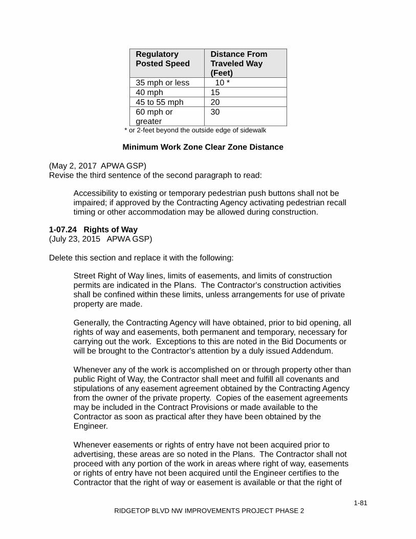
1-81 RIDGETOP BLVD NW IMPROVEMENTS PROJECT PHASE 2
Regulatory Posted Speed
Distance From Traveled Way (Feet)
35 mph or less 10 * 40 mph 15 45 to 55 mph 20 60 mph or greater
30
* or 2-feet beyond the outside edge of sidewalk
Minimum Work Zone Clear Zone Distance (May 2, 2017 APWA GSP) Revise the third sentence of the second paragraph to read:
Accessibility to existing or temporary pedestrian push buttons shall not be impaired; if approved by the Contracting Agency activating pedestrian recall timing or other accommodation may be allowed during construction.
1-07.24 Rights of Way (July 23, 2015 APWA GSP) Delete this section and replace it with the following:
Street Right of Way lines, limits of easements, and limits of construction permits are indicated in the Plans. The Contractor’s construction activities shall be confined within these limits, unless arrangements for use of private property are made. Generally, the Contracting Agency will have obtained, prior to bid opening, all rights of way and easements, both permanent and temporary, necessary for carrying out the work. Exceptions to this are noted in the Bid Documents or will be brought to the Contractor’s attention by a duly issued Addendum. Whenever any of the work is accomplished on or through property other than public Right of Way, the Contractor shall meet and fulfill all covenants and stipulations of any easement agreement obtained by the Contracting Agency from the owner of the private property. Copies of the easement agreements may be included in the Contract Provisions or made available to the Contractor as soon as practical after they have been obtained by the Engineer. Whenever easements or rights of entry have not been acquired prior to advertising, these areas are so noted in the Plans. The Contractor shall not proceed with any portion of the work in areas where right of way, easements or rights of entry have not been acquired until the Engineer certifies to the Contractor that the right of way or easement is available or that the right of

1-82 RIDGETOP BLVD NW IMPROVEMENTS PROJECT PHASE 2
entry has been received. If the Contractor is delayed due to acts of omission on the part of the Contracting Agency in obtaining easements, rights of entry or right of way, the Contractor will be entitled to an extension of time. The Contractor agrees that such delay shall not be a breach of contract. Each property owner shall be given 48 hours’ notice prior to entry by the Contractor. This includes entry onto easements and private property where private improvements must be adjusted. The Contractor shall be responsible for providing, without expense or liability to the Contracting Agency, any additional land and access thereto that the Contractor may desire for temporary construction facilities, storage of materials, or other Contractor needs. However, before using any private property, whether adjoining the work or not, the Contractor shall file with the Engineer a written permission of the private property owner, and, upon vacating the premises, a written release from the property owner of each property disturbed or otherwise interfered with by reasons of construction pursued under this contract. The statement shall be signed by the private property owner, or proper authority acting for the owner of the private property affected, stating that permission has been granted to use the property and all necessary permits have been obtained or, in the case of a release, that the restoration of the property has been satisfactorily accomplished. The statement shall include the parcel number, address, and date of signature. Written releases must be filed with the Engineer before the Completion Date will be established.
1-08 PROSECUTION AND PROGRESS Add the following new section:
1-08.0 Preliminary Matters (May 25, 2006 APWA GSP)
Add the following new section:
1-08.0(1) Preconstruction Conference (October 10, 2008 APWA GSP) Prior to the Contractor beginning the work, a preconstruction conference will be held between the Contractor, the Engineer and such other interested parties as may be invited. The purpose of the preconstruction conference will be: 1. To review the initial progress schedule; 2. To establish a working understanding among the various parties associated or
affected by the work; 3. To establish and review procedures for progress payment, notifications,
approvals, submittals, etc.;

1-83 RIDGETOP BLVD NW IMPROVEMENTS PROJECT PHASE 2
4. To establish normal working hours for the work; 5. To review safety standards and traffic control; and 6. To discuss such other related items as may be pertinent to the work. The Contractor shall prepare and submit at the preconstruction conference the following: 1. A breakdown of all lump sum items; 2. A preliminary schedule of working drawing submittals; and 3. A list of material sources for approval if applicable.
Add the following new section:
1-08.0(2) Hours of Work (December 8, 2014 APWA GSP)
Except in the case of emergency or unless otherwise approved by the Engineer, the normal working hours for the Contract shall be any consecutive 8-hour period between 7:00 a.m. and 6:00 p.m. Monday through Friday, exclusive of a lunch break. If the Contractor desires different than the normal working hours stated above, the request must be submitted in writing prior to the preconstruction conference, subject to the provisions below. The working hours for the Contract shall be established at or prior to the preconstruction conference.
All working hours and days are also subject to local permit and ordinance conditions (such as noise ordinances). If the Contractor wishes to deviate from the established working hours, the Contractor shall submit a written request to the Engineer for consideration. This request shall state what hours are being requested, and why. Requests shall be submitted for review no later than 2 working days prior to the day(s) the Contractor is requesting to change the hours. If the Contracting Agency approves such a deviation, such approval may be subject to certain other conditions, which will be detailed in writing. For example:
1. On non-Federal aid projects, requiring the Contractor to reimburse the Contracting Agency for the costs in excess of straight-time costs for Contracting Agency representatives who worked during such times. (The Engineer may require designated representatives to be present during the work. Representatives who may be deemed necessary by the Engineer include, but are not limited to: survey crews; personnel from the Contracting Agency’s material testing lab; inspectors; and other Contracting Agency employees or third party consultants when, in the opinion of the Engineer, such work necessitates their presence.)

1-84 RIDGETOP BLVD NW IMPROVEMENTS PROJECT PHASE 2
2. Considering the work performed on Saturdays, Sundays, and holidays as working days with regard to the contract time.
3. Considering multiple work shifts as multiple working days with respect to contract time even though the multiple shifts occur in a single 24-hour period.
4. If a 4-10 work schedule is requested and approved the non-working day for the week will be charged as a working day.
5. If Davis Bacon wage rates apply to this Contract, all requirements must be met and recorded properly on certified payroll
1-08.1 Subcontracting
Supplement this section with the following:
(October 12, 1998 WSDOT GSP) Prior to any subcontractor or lower tier subcontractor beginning work, the Contractor shall submit to the Engineer a certification (WSDOT Form 420-004 EF) that a written agreement between the Contractor and the subcontractor or between the subcontractor and any lower tier subcontractor has been executed. This certification shall also guarantee that these subcontract agreements include all the documents required by the Special Provision Federal Agency Inspection. A Subcontractor or lower tier Subcontractor will not be permitted to perform any work under the contract until the following documents have been completed and submitted to the Engineer:
1. Request to Sublet Work (Form 421-012 EF), and 2. Contractor and Subcontractor or Lower Tier Subcontractor Certification for
Federal-aid Projects (Form 420-004 EF).
The Contractor's records pertaining to the requirements of this Special Provision shall be open to inspection or audit by representatives of the Contracting Agency during the life of the contract and for a period of not less than three years after the date of acceptance of the contract. The Contractor shall retain these records for that period. The Contractor shall also guarantee that these records of all Subcontractors and lower tier Subcontractors shall be available and open to similar inspection or audit for the same time period.
Revise the eighth paragraph to read:
(November 30, 2018 APWA GSP, Option A) The Contractor shall certify to the actual amount received from the Contracting Agency and amounts paid to all firms that were used as Subcontractors, lower tier subcontractors, manufacturers, regular dealers, or service providers on the

1-85 RIDGETOP BLVD NW IMPROVEMENTS PROJECT PHASE 2
Contract. This includes all Disadvantaged, Minority, Small, Veteran or Women’s Business Enterprise firms. This Certification shall be submitted to the Engineer on a monthly basis each month between Execution of the Contract and Physical Completion of the Contract using the application available at: https://wsdot.diversitycompliance.com. A monthly report shall be submitted for every month between Execution of the Contract and Physical Completion regardless of whether payments were made or work occurred.
1-08.3(2)B Type B Progress Schedule (March 13, 2012 APWA GSP) Revise the first paragraph to read:
The Contractor shall submit a preliminary Type B Progress Schedule at or prior to the preconstruction conference. The preliminary Type B Progress Schedule shall comply with all of these requirements and the requirements of Section 1-08.3(1), except that it may be limited to only those activities occurring within the first 60-working days of the project.
Revise the first sentence of the second paragraph to read:
The Contractor shall submit one copy of a Type B Progress Schedule depicting the entire project no later than 21-calendar days after the preconstruction conference.
1-08.4 Prosecution of Work Delete this section and replace it with the following:
1-08.4 Notice to Proceed and Prosecution of Work (July 23, 2015 APWA GSP) Notice to Proceed will be given after the contract has been executed and the contract bond and evidence of insurance have been approved and filed by the Contracting Agency. The Contractor shall not commence with the work until the Notice to Proceed has been given by the Engineer. The Contractor shall commence construction activities on the project site within ten days of the Notice to Proceed Date, unless otherwise approved in writing. The Contractor shall diligently pursue the work to the physical completion date within the time specified in the contract. Voluntary shutdown or slowing of operations by the Contractor shall not relieve the Contractor of the responsibility to complete the work within the time(s) specified in the contract. When shown in the Plans, the first order of work shall be the installation of high visibility fencing to delineate all areas for protection or restoration, as described in the Contract. Installation of high visibility fencing adjacent to the roadway shall occur after the placement of all necessary signs and traffic control devices in accordance with 1-10.1(2). Upon construction of the fencing, the Contractor shall request the

1-86 RIDGETOP BLVD NW IMPROVEMENTS PROJECT PHASE 2
Engineer to inspect the fence. No other work shall be performed on the site until the Contracting Agency has accepted the installation of high visibility fencing, as described in the Contract.
1-08.5 Time for Completion (November 30, 2018 APWA GSP, Option A) Revise the third and fourth paragraphs to read:
Contract time shall begin on the first working day following the Notice to Proceed Date. Each working day shall be charged to the contract as it occurs, until the contract work is physically complete. If substantial completion has been granted and all the authorized working days have been used, charging of working days will cease. Each week the Engineer will provide the Contractor a statement that shows the number of working days: (1) charged to the contract the week before; (2) specified for the physical completion of the contract; and (3) remaining for the physical completion of the contract. The statement will also show the nonworking days and any partial or whole day the Engineer declares as unworkable. Within 10 calendar days after the date of each statement, the Contractor shall file a written protest of any alleged discrepancies in it. To be considered by the Engineer, the protest shall be in sufficient detail to enable the Engineer to ascertain the basis and amount of time disputed. By not filing such detailed protest in that period, the Contractor shall be deemed as having accepted the statement as correct. If the Contractor is approved to work 10 hours a day and 4 days a week (a 4-10 schedule) and the fifth day of the week in which a 4-10 shift is worked would ordinarily be charged as a working day then the fifth day of that week will be charged as a working day whether or not the Contractor works on that day.
Revise the sixth paragraph to read:
The Engineer will give the Contractor written notice of the completion date of the contract after all the Contractor’s obligations under the contract have been performed by the Contractor. The following events must occur before the Completion Date can be established: 1. The physical work on the project must be complete; and 2. The Contractor must furnish all documentation required by the contract and
required by law, to allow the Contracting Agency to process final acceptance of the contract. The following documents must be received by the Project Engineer prior to establishing a completion date:
a. Certified Payrolls (per Section 1-07.9(5)). b. Material Acceptance Certification Documents c. Monthly Reports of Amounts Credited as DBE Participation, as required by
the Contract Provisions.

1-87 RIDGETOP BLVD NW IMPROVEMENTS PROJECT PHASE 2
d. Final Contract Voucher Certification e. Copies of the approved “Affidavit of Prevailing Wages Paid” for the Contractor
and all Subcontractors f. A copy of the Notice of Termination sent to the Washington State Department
of Ecology (Ecology); the elapse of 30 calendar days from the date of receipt of the Notice of Termination by Ecology; and no rejection of the Notice of Termination by Ecology. This requirement will not apply if the Construction Stormwater General Permit is transferred back to the Contracting Agency in accordance with Section 8-01.3(16).
g. Property owner releases per Section 1-07.24 Supplement this section with the following:
(March 13, 1995 WSDOT GSP, OPT7) This project shall be physically completed within 140 working days.
1-08.9 Liquidated Damages (August 14, 2013 APWA GSP) Revise the fourth paragraph to read:
When the Contract Work has progressed to Substantial Completion as defined in the Contract, the Engineer may determine that the work is Substantially Complete. The Engineer will notify the Contractor in writing of the Substantial Completion Date. For overruns in Contract time occurring after the date so established, the formula for liquidated damages shown above will not apply. For overruns in Contract time occurring after the Substantial Completion Date, liquidated damages shall be assessed on the basis of direct engineering and related costs assignable to the project until the actual Physical Completion Date of all the Contract Work. The Contractor shall complete the remaining Work as promptly as possible. Upon request by the Project Engineer, the Contractor shall furnish a written schedule for completing the physical Work on the Contract.
1-09 MEASUREMENT AND PAYMENT 1-09.2 Weighing Equipment
1-09.2(1) General Requirements for Weighing Equipment (July 23, 2015 APWA GSP, Option 2) Revise item 4 of the fifth paragraph to read:
4. Test results and scale weight records for each day’s hauling operations are
provided to the Engineer daily. Reporting shall utilize WSDOT form 422-027, Scaleman’s Daily Report, unless the printed ticket contains the same information

1-88 RIDGETOP BLVD NW IMPROVEMENTS PROJECT PHASE 2
that is on the Scaleman’s Daily Report Form. The scale operator must provide AM and/or PM tare weights for each truck on the printed ticket.
1-09.2(5) Measurement (May 2, 2017 APWA GSP) Revise the first paragraph to read:
Scale Verification Checks – At the Engineer’s discretion, the Engineer may perform verification checks on the accuracy of each batch, hopper, or platform scale used in weighing contract items of Work.
1-09.6 Force Account (October 10, 2008 APWA GSP) Supplement this section with the following:
The Contracting Agency has estimated and included in the Proposal, dollar amounts for all items to be paid per force account, only to provide a common proposal for Bidders. All such dollar amounts are to become a part of Contractor's total bid. However, the Contracting Agency does not warrant expressly or by implication, that the actual amount of work will correspond with those estimates. Payment will be made on the basis of the amount of work actually authorized by Engineer.
1-09.9 Payments (March 13, 2012 APWA GSP) Delete the first four paragraphs and replace them with the following:
The basis of payment will be the actual quantities of Work performed according to the Contract and as specified for payment. The Contractor shall submit a breakdown of the cost of lump sum bid items at the Preconstruction Conference, to enable the Project Engineer to determine the Work performed on a monthly basis. A breakdown is not required for lump sum items that include a basis for incremental payments as part of the respective Specification. Absent a lump sum breakdown, the Project Engineer will make a determination based on information available. The Project Engineer’s determination of the cost of work shall be final. Progress payments for completed work and material on hand will be based upon progress estimates prepared by the Engineer. A progress estimate cutoff date will be established at the preconstruction conference. The initial progress estimate will be made not later than 30 days after the Contractor commences the work, and successive progress estimates will be made every month

1-89 RIDGETOP BLVD NW IMPROVEMENTS PROJECT PHASE 2
thereafter until the Completion Date. Progress estimates made during progress of the work are tentative, and made only for the purpose of determining progress payments. The progress estimates are subject to change at any time prior to the calculation of the final payment.
The value of the progress estimate will be the sum of the following:
1. Unit Price Items in the Bid Form — the approximate quantity of acceptable units of work completed multiplied by the unit price.
2. Lump Sum Items in the Bid Form — based on the approved Contractor’s lump sum breakdown for that item, or absent such a breakdown, based on the Engineer’s determination.
3. Materials on Hand — 100 percent of invoiced cost of material delivered to Job site or other storage area approved by the Engineer.
4. Change Orders — entitlement for approved extra cost or completed extra work as determined by the Engineer.
Progress payments will be made in accordance with the progress estimate less:
1. Retainage per Section 1-09.9(1), on non FHWA-funded projects; 2. The amount of progress payments previously made; and 3. Funds withheld by the Contracting Agency for disbursement in accordance
with the Contract Documents. Progress payments for work performed shall not be evidence of acceptable performance or an admission by the Contracting Agency that any work has been satisfactorily completed. The determination of payments under the contract will be final in accordance with Section 1-05.1.
Retainage
Section 1-09.9(1) content and title is deleted and replaced with the following:
(June 27, 2011 WSDOT GSP) Vacant
1-09.11(3) Time Limitation and Jurisdiction (November 30, 2018 APWA GSP) Revise this section to read:
For the convenience of the parties to the Contract it is mutually agreed by the parties that any claims or causes of action which the Contractor has against the Contracting Agency arising from the Contract shall be brought within 180 calendar days from the date of final acceptance (Section 1-05.12) of the Contract by the

1-90 RIDGETOP BLVD NW IMPROVEMENTS PROJECT PHASE 2
Contracting Agency; and it is further agreed that any such claims or causes of action shall be brought only in the Superior Court of the county where the Contracting Agency headquarters is located, provided that where an action is asserted against a county, RCW 36.01.050 shall control venue and jurisdiction. The parties understand and agree that the Contractor’s failure to bring suit within the time period provided, shall be a complete bar to any such claims or causes of action. It is further mutually agreed by the parties that when any claims or causes of action which the Contractor asserts against the Contracting Agency arising from the Contract are filed with the Contracting Agency or initiated in court, the Contractor shall permit the Contracting Agency to have timely access to any records deemed necessary by the Contracting Agency to assist in evaluating the claims or action.
1-09.13 Claims Resolution 1-09.13(3)A Administration of Arbitration (November 30, 2018 APWA GSP) Revise the third paragraph to read:
The Contracting Agency and the Contractor mutually agree to be bound by the decision of the arbitrator, and judgment upon the award rendered by the arbitrator may be entered in the Superior Court of the county in which the Contracting Agency’s headquarters is located, provided that where claims subject to arbitration are asserted against a county, RCW 36.01.050 shall control venue and jurisdiction of the Superior Court. The decision of the arbitrator and the specific basis for the decision shall be in writing. The arbitrator shall use the Contract as a basis for decisions.
1-10 TEMPORARY TRAFFIC CONTROL 1-10.2 Traffic Control Management 1-10.2(1) General Supplement this section with the following:
(January 3, 2017 WSDOT GSP, OPT1) Only training with WSDOT TCS card and WSDOT training curriculum is recognized in the State of Washington. The Traffic Control Supervisor shall be certified by one of the following:
The Northwest Laborers-Employers Training Trust 27055 Ohio Ave. Kingston, WA 98346 (360) 297-3035
1-91 RIDGETOP BLVD NW IMPROVEMENTS PROJECT PHASE 2
Evergreen Safety Council 12545 135th Ave. NE Kirkland, WA 98034-8709 1-800-521-0778
The American Traffic Safety Services Association 15 Riverside Parkway, Suite 100 Fredericksburg, Virginia 22406-1022 Training Dept. Toll Free (877) 642-4637 Phone: (540) 368-1701
1-10.4 Measurement
1-10.4(3) Reinstating Unit Items With Lump Sum Traffic Control Supplement this section with the following:
(August 2, 2004 WSDOT GSP) The bid proposal contains the item “Project Temporary Traffic Control,” lump sum and the additional temporary traffic control items listed below. The provisions of Section 1-10.4(1), Section 1-10.4(3), and Section 1-10.5(3) shall apply.
“Construction Signs, Class A”, per square foot.

1-92 RIDGETOP BLVD NW IMPROVEMENTS PROJECT PHASE 2
THIS PAGE INTENTIONALLY LEFT BLANK
2-1 RIDGETOP BLVD NW IMPROVEMENTS PROJECT PHASE 2
2
DIVISION 2 EARTHWORK
2-01 CLEARING, GRUBBING, AND ROADSIDE CLEANUP 2-01.1 Description Supplement this section with the following:
(March 13, 1995 WSDOT GSP OPT1) Clearing and grubbing on this project shall be performed within the following limits:
Clearing and grubbing limits are defined as the Right of Way (ROW) limits, unless otherwise noted in the Plans. All trees within the clearing limits shall be removed and disposed of, unless otherwise noted in the Plans.
2-01.2 Disposal of Usable Material and Debris Supplement this section with the following:
The Contractor shall use Disposal Method No. 2 per Section 2-01.2(2) of the Standard Specifications.
2-01.3 Construction Requirements 2-01.3(4) Roadside Cleanup Supplement this section with the following:
6. Existing pedestrian sidewalk that is to remain shall be cleared of dirt, debris, and vegetation up to 2 feet behind the existing back of walk.
2-02 REMOVAL OF STRUCTURES AND OBSTRUCTIONS 2-02.1 Description Supplement this section with the following:
This Work shall also include removal and disposal of existing signs and posts as shown in the Plans.
Removing Asphalt Concrete Pavement Where shown in the Plans or where designated by the Engineer the existing asphalt concrete pavement shall be removed and promptly removed from the project site. Saw Cut Asphalt Concrete Pavement

2-2 RIDGETOP BLVD NW IMPROVEMENTS PROJECT PHASE 2
Saw Cut Asphalt Concrete Pavement Where shown in the plans or where designated by the Engineer, the Contractor shall saw cut the asphalt concrete pavement prior to removal of any pavement.
2-02.3 Construction Requirements 2-02.3(1) Removal of Bridges, Box Culverts, and Other Drainage Structures Supplement this section with the following:
The table below list drainage structures and pipes included in the removal and disposal. Drainage Structures: Catch Basin Type Station Offset Type 2 STA 41+47 1.00' LT Type 1 STA 41+47 35.00' RT Type 1 STA 44+82 35.00' RT Type 1 STA 50+58 33.00' LF Type 1 STA 50+58 34.00' RT Type 2 STA 52+60 14.00 LT Type 1 STA 52+60 34.00 RT Type 1 STA 52+60 34.00' LT Type 1 STA 52+72 2.00' RT Type 1 STA 52+98 56.00' LT Type 1 STA 53+44 56.00' LT Type 1 STA 54+23 18.00' LT Type 1 STA 54+62 34.00' RT Type 1 STA 54+77 18.00' LT Type 2 STA 55+24 44.00' RT Type 2 STA 55+24 0' Type 2 STA 55+24 33.00' LT Type 1 STA 56+82 33.00' LT Type 2 STA 57+45 0' Type 1 STA 57+45 33.00' LT Type 1 STA 57+94 18.00' RT Type 1 STA 58+68 54.00' LT Type 1 STA 59+32 58.00' LT Type 1 STA 59+44 2.00' LT Type 1 STA 59+62 32.00' LT Type 1 STA 59+62 50.00' LT Type 2 STA 59+62 15.00' RT

2-3 RIDGETOP BLVD NW IMPROVEMENTS PROJECT PHASE 2
Type 1 STA 61+68 36.00' RT Type 2 STA 62+15 0' Type 1 STA 62+15 32.00' RT Type 1 STA 62+15 32.00' LT Type 1 STA 64+03 20.00' LT Type 1 STA 65+52 1.00' LT Type 2 STA 65+65 15.00' RT Type 1 STA 65+70 32.00' LT Type 1 STA 67+95 32.00' LT Type 1 STA 70+24 32.00' LT Type 1 STA 70+94 20.00' RT Type 1 STA 71+83 55.00' LT Type 1 STA 72+23 55.00' LT Type 1 STA 72+44 3.00' LT Type 2 STA 72+56 15.00' RT Type 1 STA 72+56 33.00' LT Type 1 STA 72+78 34.00' RT
TOTAL STRUCTURES = 44
Drainage Pipes: Length of Pipe Pipe Type Start Station, Offset End Station, Offset 36 LF 12" CMP STA 41+47, 1.00' LT STA 41+47, 35.00' RT 10 LF unknown STA 41+47, 1.00' LT STA 41+57, 2.00' LT 320 LF 12" CMP STA 41+47, 1.00' LT STA 44+80, 35.00' RT 67 LF 12" CMP STA 50+58, 33.00' LT STA 50+58, 34.00' RT 202 LF 12" CMP STA 52+60, 35.00' RT STA 52+60, 35.00' RT 48 LF 12" CMP STA 52+60, 35.00' RT STA 52+60, 14.00' LT 34 LF 12" CMP STA 52+60, 35.00' RT STA 52+72, 2.00' RT 20 LF 12" CMP STA 52+60, 14.00' LT STA 52+60, 34.00' LT 44 LF 12" CMP STA 52+60, 34.00' LT STA 52+98, 56.00' LT 46 LF 12" CMP STA 52+98, 56.00' LT STA 53+44, 56.00' LT 260 LF 12" CMP STA 52+60, 13.00' LT STA 55+24, at 0' LT' 54 LF 12" CMP STA 54+23, 18.00' LT STA 54+77, 18.00' LT 30 LF 12" CMP STA 54+65, 44.00' LT STA 54+77, 18.00' LT 60 LF 12" CMP STA 54+62, 44.00' RT STA 55+24, 44.00' RT 35 LF 22" CMP STA 54+96, 50.00' RT STA 55+24, 44.00' RT 33 LF 22" CMP STA 55+24, 0' STA 55+24, 33.00' RT 32 LF 12" CMP STA 55+24, 0' STA 55+24, 32.00' LT 48 LF 12" CMP STA 54+77, 18.00' LT STA 55+24, 33.00' LT 15 LF unknown STA 55+24, 33.00' LT STA 55+38, 33.00' LT

2-4 RIDGETOP BLVD NW IMPROVEMENTS PROJECT PHASE 2
220 LF 24" CMP STA 55+24, 0' STA 57+45, 0' 60 LF 12" CMP STA 56+82, 33.00' LT STA 57+45, 33.00' LT 33 LF 12" CMP STA 57+45, 0' LT STA 57+45, 33.00' LT 10 LF 12" CMP STA 57+45, 33.00' LT STA 57+45,41.00' LT 52 LF 12" CMP STA 57+45, 0' STA 57+94, 18.00' RT 218 LF 18" CMP STA 57+45, 0' STA 59+62, 15.00' RT 64 LF 12" CMP/12" ADS STA 58+68, 54.00' LT STA 59+32, 58.00'LT 27 LF 12" ADS STA 59+32, 54.00' LT STA 59+62, 50.00' LT 25 LF 12" CMP STA 59+46, 2.00' LT STA 59+62, 15.00' RT 66 LF 12" CMP STA 59+32, 0' STA 59+32, 50.00' LT 255 LF 15" CMP STA 59+62, 15.00' RT STA 62+15, 0' 46 LF 12" CMP STA 61+69, 33.00' RT STA 62+15, 33.00' RT 33 LF 12" CMP STA 62+15, 0' STA 62+15, 33.00' LT 15 LF 12" CMP STA 62+15, 33.00' LT STA 62+15, 48.00' LT 33 LF 12" CMP STA 62+15, 0' RT STA 62+15, 33.00' RT 34 LF 12" CMP STA 63+72, 4.00 RT STA 64+03, 18.00' RT 350 LF 15" CMP STA 62+15, 0' STA 65+65, 15.00' RT 22 LF 12" CMP STA 65+52, 1.00' LT STA 65+65, 15.00' RT 48 LF 12" CMP STA 65+70, 15.00' RT STA 65+70, 32.00' LT 30 LF 12" CMP STA 65+70, 32.00' LT STA 65+70, 62.00' LT 97 LF 12" CMP STA 67+02, 1.00' RT STA 67+95, 32.00' LT 16 LF 12" CMP STA 67+95, 32.00' LT STA 67+96.98, 48.00' LT 60 LF 12" CMP STA 69+74, 0' LT STA 70+24, 32.00' LT 20 LF 12" CMP STA 70+24, 32.00' LT STA 70+25.83, 52.00' LT 34 LF 12" CMP STA 70+68, 2.00' LT STA 70+96, 20.00' RT 136 LF 12" CMP STA 71+20, 10.00' LT STA 72+56, 15.00' RT 40 LF 12" DI STA 71+83, 55.00' LT STA 72+23, 55.00' LT 40 LF 12" CMP STA 72+23, 55.00' LT STA 72+56, 33.00' LT 45 LF 12" CMP STA 72+56, 33.00' LT STA 72+56, 12.00' RT 20 LF 12" CMP STA 72+44, 3.00' LT STA 72+56, 15.00' RT 30 LF 12" CMP STA 72+56, 15.00' RT STA 72+78, 34.00' RT
TOTAL LENGTH OF PIPE = 3,573 LF
2-02.3(3) Removal of Pavement, Sidewalks, Curbs and Gutters Supplemented this section with the following:
(September 8, 1997 WSDOT GSP, OPT1) Pavement Thickness The approximate thickness of the existing asphalt pavement has not been observed. It shall be the Bidder’s responsibility to observe existing conditions and base their bid accordingly.

2-5 RIDGETOP BLVD NW IMPROVEMENTS PROJECT PHASE 2
Saw Cut Asphalt Concrete Pavement The equipment and procedures used to make the vertical cut shall be approved by the Engineer. The Contractor shall make a vertical saw cut to delineate the areas of pavement to be removed from those areas of pavement to remain. The removed pavement shall become the property of the Contractor and shall be promptly removed from the project. Damage caused to portions of the pavement to remain, due to the Contractor’s operations, shall be repaired by the contractor at no expense to the Contracting Agency.
2-02.4 Measurement Supplement this section with the following:
Removing Cement Conc. Sidewalk will be measured by the square yard. Removing Asphalt Conc. Pavement will be measured by the square yard. Saw Cut Asphalt Concrete Pavement will be measured by the lineal foot of saw cut actually completed. Removing Cement Conc. Curb will be measured per lineal foot of cement concrete curb removed.
2-02.5 Payment Revise the first two paragraphs with the following:
Payment shall be made for the following Bid item when it is included in the Proposal:
“Removal of Structures and Obstructions”, lump sum.
All pavements, sidewalks, curbs, or gutters and any other improvements, lying within an excavation area for removal of the existing structures or piping are inclusive to the bid item. This includes the additional asphalt removal required for roadway patching in accordance with Kitsap County Standards.
Supplement this section with the following:
“Removing Cement Conc. Sidewalk”, per square yard. “Removing Asphalt Conc. Pavement”, per square yard.

2-6 RIDGETOP BLVD NW IMPROVEMENTS PROJECT PHASE 2
The unit Contract price, per square yard, shown on the proposal for Removing Asphalt Conc. Pavement and Removing Cement Conc. Sidewalk shall be full compensation for all costs incurred for all tools, labor, materials and equipment necessary to complete the work. “Saw Cut Asphalt Concrete Pavement”, per linear foot.
The unit Contract price, per linear foot, shown on the proposal for Saw Cut Asphalt Concrete Pavement shall be full compensation for all costs incurred for all tools, labor, materials, and equipment necessary to complete the work.
“Removing Cement Conc. Curb”, per lineal foot.
The unit Contract price, per lineal foot, shown on the proposal for Removing Cement Conc. Curb shall be full compensation for all costs incurred for all tools, labor, materials and equipment necessary to complete the work.
2-03 ROADWAY EXCAVATION AND EMBANKMENT 2-03.1 Description Supplement this section with the following:
This work shall include the excavating, hauling and placing of Special Borrow to construct embankments to subgrade elevations which is defined as the bottom of the crushed surfacing and for backfill of trenches resulting from removal and installation of storm sewer.
This work shall include the re-grading of existing approach to meet the new roadway pavement constructed for this project as shown in the Plans. Approach is defined as a connection providing private vehicular access to and from the County road system.
2-03.2 Vacant
Revise this section including the title to read as follows:
2-03.2 Materials
Special Borrow shall meet the requirements of Section 9-03.14(5) of these Special Provisions.
2-03.3 Construction Requirements 2-03.3(7) Disposal of Surplus Material
2-7 RIDGETOP BLVD NW IMPROVEMENTS PROJECT PHASE 2
Delete this section and replace with the following:
A waste site has not been provided by the Contracting Agency for the disposal of excess materials and construction debris. The Contractor shall be solely responsible for the loading, hauling and disposing of all surplus material and construction debris in a manner complying with all local, state and federal statutes and regulations.
2-03.3(13) Borrow Supplement this section with the following:
The Contractor must provide the Engineer with written notice at least 24 hours before hauling and placing backfill materials from off-site locations. This notice is essential in scheduling inspection personnel and item quantity ticket takers. Failure by the Contractor to begin hauling and placing materials at the agreed time may result in a penalty equal to the standby cost incurred by the County. The penalty will be calculated and deducted from the item being hauled.
2-03.3(14) Embankment Construction Supplement this section with the following:
2-03.3(14)N Special Borrow including Haul
Where shown in the Plans or as directed by the Engineer, the Contractor shall use Special Borrow including Haul meeting the requirements of Section 9-03.14(5) of these Special Provisions to:
1. Build embankments.
2. Backfill excavation of unsuitable foundation materials.
3. Backfill trenches when select backfill material is required in accordance with Section 2-09 or Section 7-08 of these Special Provisions.
Special Borrow shall be compacted according to Section 2-03.3(14)C, Method B, and 2-03.3(14)D.
2-03.3(14)O Approach Excavation and Embankment Compaction
The contractor shall grade each approach to the lines and grades established by the Engineer and as shown in the Plans. All fills shall be compacted in accordance with Section 2-03.3(14)C, Method B. Excess material and debris shall be removed from the site by the Contractor.
2-03.4 Measurement

2-8 RIDGETOP BLVD NW IMPROVEMENTS PROJECT PHASE 2
Supplement this section with the following:
Special Borrow Incl. Haul - Embankment will be measured by the ton, when used to build embankments.
Special Borrow Incl. Haul - Storm will be neat line measured per cubic yard when used in backfill of trenches for removal and installation of storm sewer. The neat line measurement will be based on the horizontal trench limits as defined in Section 2-09.4 of the Standard Specifications and the vertical limits as defined by the top of Pipe Zone bedding to bottom of restoration materials (crushed surfacing or top soils).
Structure Excavation Class B and Structure Excavation Class B Including Haul will be measured in accordance with Section 2-09.4 of these Special Provisions.
Special Borrow used as trench backfill shall be measured as described in Section 7-08 of these Special Provisions.
Unsuitable Roadway Foundation Excavation Incl. Haul will be measured by the cubic yard in place for material actually removed. Because the amount of such excavation is unknown, a quantity has been estimated based on field observation to provide a common Bid base. The unit price submitted shall be used for all such excavation. Material that must be excavated to construct the improvements to the lines and grades shown on the Plans, regardless of the nature of the material, shall not be considered as unsuitable foundation excavation. Additional material excavated as directed by the Engineer to provide a stable subgrade for the pavement section or structural fill, shall be measured as “Unsuitable Foundation Excavation Incl. Haul”.
Excavation required for this project will not be measured for separate payment. All excavation shall be included in and incidental to other, pertinent Bid Items in the Proposal.
No separate measurement for payment will be made for compaction. All costs associated with compaction shall be included with the other various unit Bid prices in the Proposal.
No separate measurement for payment will be made for disposal of surplus materials. All costs associated with this work shall be included with the other various Bid Items in the Proposal.
Computation of Excavation and Embankment Quantities
Only one determination of the original ground elevation will be made on this project. Measurement for Roadway Excavation including Haul and Embankment Compaction will be based on the original ground elevation recorded previous to

2-9 RIDGETOP BLVD NW IMPROVEMENTS PROJECT PHASE 2
the award of this contract minus a factor to account for the removal of organic material during clearing and grubbing. It is anticipated that depth of removal of organic material during clearing and grubbing for this project will vary and a factor of minus 6 inches will be used to determine ground elevation after clearing and grubbing. Control stakes will be set during construction to provide the Contractor with all essential information for the construction of excavation and embankments.
If discrepancies are discovered in the ground elevations which will materially affect the quantities of earthwork, the original computations of earthwork quantities will be adjusted accordingly.
Earthwork quantities will be computed, either manually or by means of electronic data processing equipment, by use of the average end area method or by the finite element analysis method utilizing digital terrain modeling techniques.
2-03.5 Payment Supplement this section with the following:
“Special Borrow Including Haul - Embankment”, per ton.
The unit Contract price per ton for “Special Borrow Including Haul - Embankment” shall be full compensation for all costs incurred for furnishing, building embankments, compacting, loading, hauling and placing the material.
“Special Borrow Including Haul - Storm”, per cubic yard.
The unit Contract price per cubic yard for “Special Borrow Including Haul – Storm” shall be full compensation for all costs incurred for furnishing, compacting, loading, hauling and placing the material.
“Unsuitable Foundation Excavation Incl. Haul”, per cubic yard.
The unit Bid price in the Proposal for “Unsuitable Roadway Foundation Excavation Incl. Haul” shall be full compensation for the costs of all labor, tools, equipment, and materials necessary or incidental to remove, load, haul, and dispose of the unsuitable material offsite at a Contractor-obtained legal disposal site. The unit bid price shall also include all costs associated with furnishing, installing, hauling, placing, and compacting the material specified to replace the unsuitable material, including geotextile and backfill materials.
All cost to perform all other Work associated with this Section 2-03 Roadway Excavation and Embankment shall be included with the other various Bid Items in the Proposal and no separate payment will be made.
2-10 RIDGETOP BLVD NW IMPROVEMENTS PROJECT PHASE 2
All costs involved in the loading, hauling and the disposal of all surplus material and construction debris shall be included in the bid prices of the items shown on the proposal and no further payment will be made.
For the purpose of providing a common proposal for all bidders, the Contracting Agency has entered an amount in the proposal to become part of the total bid by the Contractor. Payment for “HMA Road Approach” is as specified in 5-04 in these Special Provisions.
2-07 WATERING 2-07.4 Measurement Supplement this section with the following:
The unit of measure M Gallon shown in the proposal for water indicates 1,000 gallons. The unit bid price entered in the Proposal by the bidder shall be for each 1,000 gallons.
2-09 STRUCTURE EXCAVATION 2-09.3 Construction Requirements 2-09.3(1)A Staking, Cross-Sectioning and Inspecting Supplement this section by adding the following two paragraphs at the end:
At least 24 hours prior to commencing any excavation, the Contractor shall expose by pot-holing existing underground telephone cables, gas mains, sewer mains, water mains or any other underground utility shown in the Plans that crosses the location of the new structure to be installed under this contract. Excavation immediately adjacent to the existing utilities shall be by hand methods in compliance with Washington State requirements. When directed by the Engineer, the Contractor shall expose by pot-holing crossings of new pipe and utilities not shown in the Plans.
2-09.3(1)C Removal of Unstable Base Material Revise this section to read:
When the material at the bottom of an excavation is not stable enough to support the Structure, the Contractor shall excavate below grade and replace the unstable material with special borrow.

2-11 RIDGETOP BLVD NW IMPROVEMENTS PROJECT PHASE 2
Special borrow shall meet the requirements of Section 9-03.14(5) of these Special Provisions. It shall be placed in layers not more than 6 inches thick with each layer compacted to 95 percent of the maximum density determined by the Compaction Control Test, Section 2-03.3(14)D.
2-09.4 Measurement Delete paragraphs 1 through 6 of this section and replace them with the following:
No measurement will be made for Structure Excavation Class B or Structure Excavation Class B including Haul. All costs for such excavation shall be included in the unit contract price shown in the proposal for the item to be installed.
Delete the second sentence of the ninth paragraph and replace it with the following:
No unit of measurement shall apply to the lump sum bid item Shoring or Extra Excavation Class B.
Delete the third, fourth and fifth sentences of the ninth paragraph.
2-09.5 Payment In the first paragraph delete all references to “Structure Excavation Class B” and “Structure Excavation Class B including Haul”. Insert the following at the end of the paragraph:
All costs for Structure Excavation Class B or Structure Excavation Class B including Haul shall be included in the unit price for the item to be installed and no further payment will be made.
Revise the first sentence of the third paragraph to read:
If the Engineer orders the Contractor to excavate below the elevations shown in the Plans, the excavation will be paid for as Unsuitable Foundation Excavation including Haul per cubic yard in accordance with Section 2-09 of these Special Provisions.
Delete the ninth, tenth and eleventh paragraph and replace them with the following:
"Shoring or Extra Excavation Class B", lump sum. The lump sum Contract price for Shoring or Extra Excavation Class B shall be full pay for all excavation, backfill, compaction and other Work required when extra excavation is used in lieu of constructing shoring. If select backfill is required for backfilling within the limits of the Structure Excavation, it shall also be required as backfill material for the extra excavation at the Contractor’s expense.

2-12 RIDGETOP BLVD NW IMPROVEMENTS PROJECT PHASE 2
THIS PAGE INTENTIONALLY LEFT BLANK

4-1 RIDGETOP BLVD NW IMPROVEMENTS PROJECT PHASE 2
3 4
DIVISION 4 BASES
4-04 BALLAST AND CRUSHED SURFACING 4-04.3 Construction Requirements 4-04.3(7) Miscellaneous Requirements Supplement this section with the following:
The Contractor must provide the Engineer with written notice at least 24 hours before hauling and placing surfacing materials from off-site locations. This notice is essential in scheduling inspection personnel and item quantity ticket takers. Failure by the Contractor to begin hauling and placing materials at the agreed time may result in a penalty equal to the standby cost incurred by the County. The penalty will be calculated and deducted from the item being
4-2 RIDGETOP BLVD NW IMPROVEMENTS PROJECT PHASE 2
THIS PAGE INTENTIONALLY LEFT BLANK

5-1 RIDGETOP BLVD NW IMPROVEMENTS PROJECT PHASE 2
5
DIVISION 5 SURFACE TREATMENTS AND PAVEMENTS
Add the following new section:
5-03 TEMPORARY ROAD
5-03.1 Description
This Work shall consist of constructing, maintaining, and removing the temporary road in accordance with the Standard Specifications and these Special Provisions to the lines, grades, thicknesses, and typical cross-sections shown in the Plans.
5-03.2 Materials
Materials shall meet the requirements of Section 5-04.2 in these Special Provisions.
5-03.3 Construction Requirements
Construction shall meet the requirements of Section 5-04.3 in these Special Provisions and as shown in the Plans.
5-03.4 Measurement
No unit of measurement shall apply to the lump sum bid item Temporary Road.
5-03.5 Payment “Temporary Road”, per lump sum. The unit contract price per lump sum for “Temporary Road” shall be full pay for all costs to complete the Work as specified on the Plans, including excavation, grading, paving, striping, maintaining, and removing the Temporary Road.
5-04 HOT MIX ASPHALT
(July 18, 2018 APWA GSP) Delete Section 5-04 and amendments, Hot Mix Asphalt and replace it with the following:
5-04.1 Description
This Work shall consist of providing and placing one or more layers of plant-mixed hot mix asphalt (HMA) on a prepared foundation or base in accordance with these Specifications and the lines, grades, thicknesses, and typical cross-sections shown in the Plans. The manufacture of HMA may include warm mix

5-2 RIDGETOP BLVD NW IMPROVEMENTS PROJECT PHASE 2
asphalt (WMA) processes in accordance with these Specifications. WMA processes include organic additives, chemical additives, and foaming.
HMA shall be composed of asphalt binder and mineral materials as may be required, mixed in the proportions specified to provide a homogeneous, stable, and workable mixture.
5-04.2 Materials
Materials shall meet the requirements of the following sections:
Asphalt Binder 9-02.1(4)
Cationic Emulsified Asphalt 9-02.1(6)
Anti-Stripping Additive 9-02.4
HMA Additive 9-02.5
Aggregates 9-03.8
Recycled Asphalt Pavement 9-03.8(3)B
Mineral Filler 9-03.8(5)
Recycled Material 9-03.21
Portland Cement 9-01
Sand 9-03.1(2)
(As noted in 5-04.3(5)C for crack sealing)
Joint Sealant 9-04.2
Foam Backer Rod 9-04.2(3)A
The Contract documents may establish that the various mineral materials required for the manufacture of HMA will be furnished in whole or in part by the Contracting Agency. If the documents do not establish the furnishing of any of these mineral materials by the Contracting Agency, the Contractor shall be required to furnish such materials in the amounts required for the designated mix. Mineral materials include coarse and fine aggregates, and mineral filler.
The Contractor may choose to utilize recycled asphalt pavement (RAP) in the production of HMA. The RAP may be from pavements removed under the Contract, if any, or pavement material from an existing stockpile.
5-3 RIDGETOP BLVD NW IMPROVEMENTS PROJECT PHASE 2
The Contractor may use up to 20 percent RAP by total weight of HMA with no additional sampling or testing of the RAP. The RAP shall be sampled and tested at a frequency of one sample for every 1,000 tons produced and not less than ten samples per project. The asphalt content and gradation test data shall be reported to the Contracting Agency when submitting the mix design for approval on the QPL. The Contractor shall include the RAP as part of the mix design as defined in these Specifications.
The grade of asphalt binder shall be as required by the Contract. Blending of asphalt binder from different sources is not permitted.
The Contractor may only use warm mix asphalt (WMA) processes in the production of HMA with 20 percent or less RAP by total weight of HMA. The Contractor shall submit to the Engineer for approval the process that is proposed and how it will be used in the manufacture of HMA.
Production of aggregates shall comply with the requirements of Section 3-01.
Preparation of stockpile site, the stockpiling of aggregates, and the removal of aggregates from stockpiles shall comply with the requirements of Section 3-02.
5-04.2(1) How to Get an HMA Mix Design on the QPL
If the contractor wishes to submit a mix design for inclusion in the Qualified Products List (QPL), please follow the WSDOT process outlined in Standard Specification 5-04.2(1).
5-04.2(1)A Vacant
5-04.2(2) Mix Design – Obtaining Project Approval
No paving shall begin prior to the approval of the mix design by the Engineer.
Nonstatistical evaluation will be used for all HMA not designated as Commercial HMA in the contract documents.
Commercial evaluation will be used for Commercial HMA and for other classes of HMA in the following applications: sidewalks, road approaches, ditches, slopes, paths, trails, gores, prelevel, and pavement repair. Other nonstructural applications of HMA accepted by commercial evaluation shall be as approved by the Project Engineer. Sampling and testing of HMA accepted by commercial evaluation will be at the option of the Project Engineer. The Proposal quantity of HMA that is accepted by commercial evaluation will be excluded from the quantities used in the determination of nonstatistical evaluation.
Nonstatistical Mix Design. Fifteen days prior to the first day of paving the contractor shall provide one of the following mix design verification certifications for Contracting Agency review;

5-4 RIDGETOP BLVD NW IMPROVEMENTS PROJECT PHASE 2
• The WSDOT Mix Design Evaluation Report from the current WSDOT QPL, or one of the mix design verification certifications listed below.
• The proposed HMA mix design on WSDOT Form 350-042 with the seal and certification (stamp & sig-nature) of a valid licensed Washington State Professional Engineer.
• The Mix Design Report for the proposed HMA mix design developed by a qualified City or County laboratory that is within one year of the approval date.**
The mix design shall be performed by a lab accredited by a national authority such as Laboratory Accreditation Bureau, L-A-B for Construction Materials Testing, The Construction Materials Engineering Council (CMEC’s) ISO 17025 or AASHTO Accreditation Program (AAP) and shall supply evidence of participation in the AASHTO: resource proficiency sample program.
Mix designs for HMA accepted by Nonstatistical evaluation shall;
• Have the aggregate structure and asphalt binder content determined in accordance with WSDOT Standard Operating Procedure 732 and meet the requirements of Sections 9-03.8(2), except that Hamburg testing for ruts and stripping are at the discretion of the Engineer, and 9-03.8(6).
• Have anti-strip requirements, if any, for the proposed mix design determined in accordance with AASHTO T 283 or T 324, or based on historic anti-strip and aggregate source compatibility from previous WSDOT lab testing.
At the discretion of the Engineer, agencies may accept verified mix designs older than 12 months from the original verification date with a certification from the Contractor that the materials and sources are the same as those shown on the original mix design.
Commercial Evaluation Approval of a mix design for “Commercial Evaluation” will be based on a review of the Contractor’s submittal of WSDOT Form 350-042 (For commercial mixes, AASHTO T 324 evaluation is not required) or a Mix Design from the current WSDOT QPL or from one of the processes allowed by this section. Testing of the HMA by the Contracting Agency for mix design approval is not required.
For the Bid Item Commercial HMA, the Contractor shall select a class of HMA and design level of Equivalent Single Axle Loads (ESAL’s) appropriate for the required use.

5-5 RIDGETOP BLVD NW IMPROVEMENTS PROJECT PHASE 2
5-04.2(2)B Using Warm Mix Asphalt Processes
The Contractor may elect to use additives that reduce the optimum mixing temperature or serve as a compaction aid for producing HMA. Additives include organic additives, chemical additives and foaming processes. The use of Additives is subject to the following:
• Do not use additives that reduce the mixing temperature more than allowed in Section 5-04.3(6) in the production of mixtures.
• Before using additives, obtain the Engineer’s approval using WSDOT Form 350-076 to describe the proposed additive and process.
5-04.3 Construction Requirements
5-04.3(1) Weather Limitations
Do not place HMA for wearing course on any Traveled Way beginning October 1st through March 31st of the following year without written concurrence from the Engineer.
Do not place HMA on any wet surface, or when the average surface temperatures are less than those specified below, or when weather conditions otherwise prevent the proper handling or finishing of the HMA.
Minimum Surface Temperature for Paving
Compacted Thickness (Feet) Wearing Course Other Courses
Less than 0.10 55◦F 45◦F
0.10 to .20 45◦F 35◦F
More than 0.20 35◦F 35◦F
5-04.3(2) Paving Under Traffic
When the Roadway being paved is open to traffic, the requirements of this Section shall apply.
The Contractor shall keep intersections open to traffic at all times except when paving the intersection or paving across the intersection. During such time, and provided that there has been an advance warning to the public, the intersection may be closed for the minimum time required to place and compact the mixture. In hot weather, the Engineer may require the application of water to the

5-6 RIDGETOP BLVD NW IMPROVEMENTS PROJECT PHASE 2
pavement to accelerate the finish rolling of the pavement and to shorten the time required before reopening to traffic.
Before closing an intersection, advance warning signs shall be placed and signs shall also be placed marking the detour or alternate route.
During paving operations, temporary pavement markings shall be maintained throughout the project. Temporary pavement markings shall be installed on the Roadway prior to opening to traffic. Temporary pavement markings shall be in accordance with Section 8-23.
All costs in connection with performing the Work in accordance with these requirements, except the cost of temporary pavement markings, shall be included in the unit Contract prices for the various Bid items involved in the Contract.
5-04.3(3) Equipment
5-04.3(3)A Mixing Plant
Plants used for the preparation of HMA shall conform to the following requirements:
1. Equipment for Preparation of Asphalt Binder – Tanks for the storage of asphalt binder shall be equipped to heat and hold the material at the required temperatures. The heating shall be accomplished by steam coils, electricity, or other approved means so that no flame shall be in contact with the storage tank. The circulating system for the asphalt binder shall be designed to ensure proper and continuous circulation during the operating period. A valve for the purpose of sampling the asphalt binder shall be placed in either the storage tank or in the supply line to the mixer.
2. Thermometric Equipment – An armored thermometer, capable of detecting temperature ranges expected in the HMA mix, shall be fixed in the asphalt binder feed line at a location near the charging valve at the mixer unit. The thermometer location shall be convenient and safe for access by Inspectors. The plant shall also be equipped with an approved dial-scale thermometer, a mercury actuated thermometer, an electric pyrometer, or another approved thermometric instrument placed at the discharge chute of the drier to automatically register or indicate the temperature of the heated aggregates. This device shall be in full view of the plant operator.
3. Heating of Asphalt Binder – The temperature of the asphalt binder shall not exceed the maximum recommended by the asphalt binder manufacturer nor shall it be below the minimum temperature required to maintain the asphalt binder in a homogeneous state. The asphalt binder shall be heated in a manner that will avoid local variations in heating. The

5-7 RIDGETOP BLVD NW IMPROVEMENTS PROJECT PHASE 2
heating method shall provide a continuous supply of asphalt binder to the mixer at a uniform average temperature with no individual variations exceeding 25°F. Also, when a WMA additive is included in the asphalt binder, the temperature of the asphalt binder shall not exceed the maximum recommended by the manufacturer of the WMA additive.
4. Sampling and Testing of Mineral Materials – The HMA plant shall be equipped with a mechanical sampler for the sampling of the mineral materials. The mechanical sampler shall meet the requirements of Section 1-05.6 for the crushing and screening operation. The Contractor shall provide for the setup and operation of the field testing facilities of the Contracting Agency as provided for in Section 3-01.2(2).
5. Sampling HMA – The HMA plant shall provide for sampling HMA by one of the following methods:
a. A mechanical sampling device attached to the HMA plant.
b. Platforms or devices to enable sampling from the hauling vehicle without entering the hauling vehicle.
5-04.3(3)B Hauling Equipment
Trucks used for hauling HMA shall have tight, clean, smooth metal beds and shall have a cover of canvas or other suitable material of sufficient size to protect the mixture from adverse weather. Whenever the weather conditions during the work shift include, or are forecast to include, precipitation or an air temperature less than 45°F or when time from loading to unloading exceeds 30 minutes, the cover shall be securely attached to protect the HMA.
The contractor shall provide an environmentally benign means to prevent the HMA mixture from adhering to the hauling equipment. Excess release agent shall be drained prior to filling hauling equipment with HMA. Petroleum derivatives or other coating material that contaminate or alter the characteristics of the HMA shall not be used. For live bed trucks, the conveyer shall be in operation during the process of applying the release agent.
5-04.3(3)C Pavers
HMA pavers shall be self-contained, power-propelled units, provided with an internally heated vibratory screed and shall be capable of spreading and finishing courses of HMA plant mix material in lane widths required by the paving section shown in the Plans.
The HMA paver shall be in good condition and shall have the most current equipment available from the manufacturer for the prevention of segregation of the HMA mixture installed, in good condition, and in working order. The

5-8 RIDGETOP BLVD NW IMPROVEMENTS PROJECT PHASE 2
equipment certification shall list the make, model, and year of the paver and any equipment that has been retrofitted.
The screed shall be operated in accordance with the manufacturer’s recommendations and shall effectively produce a finished surface of the required evenness and texture without tearing, shoving, segregating, or gouging the mixture. A copy of the manufacturer’s recommendations shall be provided upon request by the Contracting Agency. Extensions will be allowed provided they produce the same results, including ride, density, and surface texture as obtained by the primary screed. Extensions without augers and an internally heated vibratory screed shall not be used in the Traveled Way.
When specified in the Contract, reference lines for vertical control will be required. Lines shall be placed on both outer edges of the Traveled Way of each Roadway. Horizontal control utilizing the reference line will be permitted. The grade and slope for intermediate lanes shall be controlled automatically from reference lines or by means of a mat referencing device and a slope control device. When the finish of the grade prepared for paving is superior to the established tolerances and when, in the opinion of the Engineer, further improvement to the line, grade, cross-section, and smoothness can best be achieved without the use of the reference line, a mat referencing device may be substituted for the reference line. Substitution of the device will be subject to the continued approval of the Engineer. A joint matcher may be used subject to the approval of the Engineer. The reference line may be removed after the completion of the first course of HMA when approved by the Engineer. Whenever the Engineer determines that any of these methods are failing to provide the necessary vertical control, the reference lines will be reinstalled by the Contractor.
The Contractor shall furnish and install all pins, brackets, tensioning devices, wire, and accessories necessary for satisfactory operation of the automatic control equipment.
If the paving machine in use is not providing the required finish, the Engineer may suspend Work as allowed by Section 1-08.6. Any cleaning or solvent type liquids spilled on the pavement shall be thoroughly removed before paving proceeds.
5-04.3(3)D Material Transfer Device or Material Transfer Vehicle
A Material Transfer Device/Vehicle (MTD/V) shall only be used with the Engineer’s approval, unless other-wise required by the contract.
Where an MTD/V is required by the contract, the Engineer may approve paving without an MTD/V, at the request of the Contractor. The Engineer will determine if an equitable adjustment in cost or time is due.
5-9 RIDGETOP BLVD NW IMPROVEMENTS PROJECT PHASE 2
When used, the MTD/V shall mix the HMA after delivery by the hauling equipment and prior to laydown by the paving machine. Mixing of the HMA shall be sufficient to obtain a uniform temperature throughout the mixture. If a windrow elevator is used, the length of the windrow may be limited in urban areas or through intersections, at the discretion of the Engineer.
To be approved for use, an MTV:
1. Shall be self-propelled vehicle, separate from the hauling vehicle or paver.
2. Shall not be connected to the hauling vehicle or paver.
3. May accept HMA directly from the haul vehicle or pick up HMA from a windrow.
4. Shall mix the HMA after delivery by the hauling equipment and prior to placement into the paving machine.
5. Shall mix the HMA sufficiently to obtain a uniform temperature throughout the mixture.
To be approved for use, an MTD:
1. Shall be positively connected to the paver.
2. May accept HMA directly from the haul vehicle or pick up HMA from a windrow.
3. Shall mix the HMA after delivery by the hauling equipment and prior to placement into the paving machine.
4. Shall mix the HMA sufficiently to obtain a uniform temperature throughout the mixture.
5-04.3(3)E Rollers
Rollers shall be of the steel wheel, vibratory, oscillatory, or pneumatic tire type, in good condition and capable of reversing without backlash. Operation of the roller shall be in accordance with the manufacturer’s recommendations. When ordered by the Engineer for any roller planned for use on the project, the Contractor shall provide a copy of the manufacturer’s recommendation for the use of that roller for compaction of HMA. The number and weight of rollers shall be sufficient to compact the mixture in compliance with the requirements of Section 5-04.3(10). The use of equipment that results in crushing of the aggregate will not be permitted. Rollers producing pickup, washboard, uneven compaction of the surface, displacement of the mixture or other undesirable results shall not be used.

5-10 RIDGETOP BLVD NW IMPROVEMENTS PROJECT PHASE 2
5-04.3(4) Preparation of Existing Paved Surfaces
When the surface of the existing pavement or old base is irregular, the Contractor shall bring it to a uniform grade and cross-section as shown on the Plans or approved by the Engineer.
Preleveling of uneven or broken surfaces over which HMA is to be placed may be accomplished by using an asphalt paver, a motor patrol grader, or by hand raking, as approved by the Engineer.
Compaction of preleveling HMA shall be to the satisfaction of the Engineer and may require the use of small steel wheel rollers, plate compactors, or pneumatic rollers to avoid bridging across preleveled areas by the compaction equipment. Equipment used for the compaction of preleveling HMA shall be approved by the Engineer.
Before construction of HMA on an existing paved surface, the entire surface of the pavement shall be clean. All fatty asphalt patches, grease drippings, and other objectionable matter shall be entirely removed from the existing pavement. All pavements or bituminous surfaces shall be thoroughly cleaned of dust, soil, pavement grindings, and other foreign matter. All holes and small depressions shall be filled with an appropriate class of HMA. The surface of the patched area shall be leveled and compacted thoroughly. Prior to the application of tack coat, or paving, the condition of the surface shall be approved by the Engineer.
A tack coat of asphalt shall be applied to all paved surfaces on which any course of HMA is to be placed or abutted; except that tack coat may be omitted from clean, newly paved surfaces at the discretion of the Engineer. Tack coat shall be uniformly applied to cover the existing pavement with a thin film of residual asphalt free of streaks and bare spots at a rate between 0.02 and 0.10 gallons per square yard of retained asphalt. The rate of application shall be approved by the Engineer. A heavy application of tack coat shall be applied to all joints. For Roadways open to traffic, the application of tack coat shall be limited to surfaces that will be paved during the same working shift. The spreading equipment shall be equipped with a thermometer to indicate the temperature of the tack coat material.
Equipment shall not operate on tacked surfaces until the tack has broken and cured. If the Contractor’s operation damages the tack coat it shall be repaired prior to placement of the HMA.
The tack coat shall be CSS-1, or CSS-1h emulsified asphalt. The CSS-1 and CSS-1h emulsified asphalt may be diluted once with water at a rate not to exceed one-part water to one part emulsified asphalt. The tack coat shall have sufficient temperature such that it may be applied uniformly at the specified rate of application and shall not exceed the maximum temperature recommended by the emulsified asphalt manufacturer.

5-11 RIDGETOP BLVD NW IMPROVEMENTS PROJECT PHASE 2
5-04.3(4)A Crack Sealing
5-04.3(4)A1 General
When the Proposal includes a pay item for crack sealing, seal all cracks ¼ inch in width and greater.
Cleaning: Ensure that cracks are thoroughly clean, dry and free of all loose and foreign material when filling with crack sealant material. Use a hot compressed air lance to dry and warm the pavement surfaces within the crack immediately prior to filling a crack with the sealant material. Do not overheat pavement. Do not use direct flame dryers. Routing cracks is not required.
Sand Slurry: For cracks that are to be filled with sand slurry, thoroughly mix the components and pour the mixture into the cracks until full. Add additional CSS-1 cationic emulsified asphalt to the sand slurry as needed for workability to ensure the mixture will completely fill the cracks. Strike off the sand slurry flush with the existing pavement surface and allow the mixture to cure. Top off cracks that were not completely filled with additional sand slurry. Do not place the HMA overlay until the slurry has fully cured.
The sand slurry shall consist of approximately 20 percent CSS-1 emulsified asphalt, approximately 2 percent portland cement, water (if required), and the remainder clean Class 1 or 2 fine aggregate per section 9-03.1(2). The components shall be thoroughly mixed and then poured into the cracks and joints until full. The following day, any cracks or joints that are not completely filled shall be topped off with additional sand slurry. After the sand slurry is placed, the filler shall be struck off flush with the existing pavement surface and allowed to cure. The HMA overlay shall not be placed until the slurry has fully cured. The requirements of Section 1-06 will not apply to the portland cement and sand used in the sand slurry.
In areas where HMA will be placed, use sand slurry to fill the cracks.
In areas where HMA will not be placed, fill the cracks as follows:
1. Cracks ¼ inch to 1 inch in width - fill with hot poured sealant.
2. Cracks greater than 1 inch in width – fill with sand slurry.
Hot Poured Sealant: For cracks that are to be filled with hot poured sealant, apply the material in accordance with these requirements and the manufacturer’s recommendations. Furnish a Type 1 Working Drawing of the manufacturer’s product information and recommendations to the Engineer prior to the start of work, including the manufacturer’s recommended heating time and temperatures, allowable storage time and temperatures after initial heating, allowable reheating criteria, and application temperature range. Confine hot poured sealant material within the crack. Clean any overflow of sealant from the pavement surface. If, in
5-12 RIDGETOP BLVD NW IMPROVEMENTS PROJECT PHASE 2
the opinion of the Engineer, the Contractor’s method of sealing the cracks with hot poured sealant results in an excessive amount of material on the pavement surface, stop and correct the operation to eliminate the excess material.
5-04.3(4)A2 Crack Sealing Areas Prior to Paving
In areas where HMA will be placed, use sand slurry to fill the cracks.
5-04.3(4)A3 Crack Sealing Areas Not to be Paved
In areas where HMA will not be placed, fill the cracks as follows: A. Cracks ¼ inch to 1 inch in width - fill with hot poured sealant. B. Cracks greater than 1 inch in width – fill with sand slurry.
5-04.3(4)B Vacant
5-04.3(4)C Pavement Repair
The Contractor shall excavate pavement repair areas and shall backfill these with HMA in accordance with the details shown in the Plans and as marked in the field. The Contractor shall conduct the excavation operations in a manner that will protect the pavement that is to remain. Pavement not designated to be removed that is damaged as a result of the Contractor’s operations shall be repaired by the Contractor to the satisfaction of the Engineer at no cost to the Contracting Agency. The Contractor shall excavate only within one lane at a time unless approved otherwise by the Engineer. The Contractor shall not excavate more area than can be completely finished during the same shift, unless approved by the Engineer.
Unless otherwise shown in the Plans or determined by the Engineer, excavate to a depth of 1.0 feet. The Engineer will make the final determination of the excavation depth required. The minimum width of any pavement repair area shall be 40 inches unless shown otherwise in the Plans. Before any excavation, the existing pavement shall be sawcut or shall be removed by a pavement grinder. Excavated materials will become the property of the Contractor and shall be disposed of in a Contractor-provided site off the Right of Way or used in accordance with Sections 2-02.3(3) or 9-03.21.
Asphalt for tack coat shall be required as specified in Section 5-04.3(4). A heavy application of tack coat shall be applied to all surfaces of existing pavement in the pavement repair area.
Placement of the HMA backfill shall be accomplished in lifts not to exceed 0.35-foot compacted depth. Lifts that exceed 0.35-foot of compacted depth may be accomplished with the approval of the Engineer. Each lift shall be thoroughly compacted by a mechanical tamper or a roller.

5-13 RIDGETOP BLVD NW IMPROVEMENTS PROJECT PHASE 2
5-04.3(5) Producing/Stockpiling Aggregates and RAP
Aggregates and RAP shall be stockpiled according to the requirements of Section 3-02. Sufficient storage space shall be provided for each size of aggregate and RAP. Materials shall be removed from stockpile(s) in a manner to ensure minimal segregation when being moved to the HMA plant for processing into the final mixture. Different aggregate sizes shall be kept separated until they have been delivered to the HMA plant.
5-04.3(5)A Vacant
5-04.3(6) Mixing
After the required amount of mineral materials, asphalt binder, recycling agent and anti-stripping additives have been introduced into the mixer the HMA shall be mixed until complete and uniform coating of the particles and thorough distribution of the asphalt binder throughout the mineral materials is ensured.
When discharged, the temperature of the HMA shall not exceed the optimum mixing temperature by more than 25°F as shown on the reference mix design report or as approved by the Engineer. Also, when a WMA additive is included in the manufacture of HMA, the discharge temperature of the HMA shall not exceed the maximum recommended by the manufacturer of the WMA additive. A maximum water content of 2 percent in the mix, at discharge, will be allowed providing the water causes no problems with handling, stripping, or flushing. If the water in the HMA causes any of these problems, the moisture content shall be reduced as directed by the Engineer.
Storing or holding of the HMA in approved storage facilities will be permitted with approval of the Engineer, but in no event shall the HMA be held for more than 24 hours. HMA held for more than 24 hours after mixing shall be rejected. Rejected HMA shall be disposed of by the Contractor at no expense to the Contracting Agency. The storage facility shall have an accessible device located at the top of the cone or about the third point. The device shall indicate the amount of material in storage. No HMA shall be accepted from the storage facility when the HMA in storage is below the top of the cone of the storage facility, except as the storage facility is being emptied at the end of the working shift.
Recycled asphalt pavement (RAP) utilized in the production of HMA shall be sized prior to entering the mixer so that a uniform and thoroughly mixed HMA is produced. If there is evidence of the recycled asphalt pavement not breaking down during the heating and mixing of the HMA, the Contractor shall immediately suspend the use of the RAP until changes have been approved by the Engineer. After the required amount of mineral materials, RAP, new asphalt binder and asphalt rejuvenator have been introduced into the mixer the HMA shall be mixed until complete and uniform coating of the particles and thorough distribution of the asphalt binder throughout the mineral materials, and RAP is ensured.
5-14 RIDGETOP BLVD NW IMPROVEMENTS PROJECT PHASE 2
5-04.3(7) Spreading and Finishing
The mixture shall be laid upon an approved surface, spread, and struck off to the grade and elevation established. HMA pavers complying with Section 5-04.3(3) shall be used to distribute the mixture. Unless otherwise directed by the Engineer, the nominal compacted depth of any layer of any course shall not exceed the following:
HMA Class 1” 0.35 feet
HMA Class ¾” and HMA Class ½”
wearing course 0.30 feet
other courses 0.35 feet
HMA Class ⅜” 0.15 feet
On areas where irregularities or unavoidable obstacles make the use of mechanical spreading and finishing equipment impractical, the paving may be done with other equipment or by hand.
When more than one JMF is being utilized to produce HMA, the material produced for each JMF shall be placed by separate spreading and compacting equipment. The intermingling of HMA produced from more than one JMF is prohibited. Each strip of HMA placed during a work shift shall conform to a single JMF established for the class of HMA specified unless there is a need to make an adjustment in the JMF.
5-04.3(8) Aggregate Acceptance Prior to Incorporation in HMA
For HMA accepted by nonstatistical evaluation the aggregate properties of sand equivalent, uncompacted void content and fracture will be evaluated in accordance with Section 3-04. Sampling and testing of aggregates for HMA accepted by commercial evaluation will be at the option of the Engineer.
5-04.3(9) HMA Mixture Acceptance
Acceptance of HMA shall be as provided under nonstatistical, or commercial evaluation.
Nonstatistical evaluation will be used for the acceptance of HMA unless Commercial Evaluation is specified.
Commercial evaluation will be used for Commercial HMA and for other classes of HMA in the following applications: sidewalks, road approaches, ditches, slopes, paths, trails, gores, prelevel, temporary pavement, and pavement repair. Other nonstructural applications of HMA accepted by commercial evaluation shall be as

5-15 RIDGETOP BLVD NW IMPROVEMENTS PROJECT PHASE 2
approved by the Engineer. Sampling and testing of HMA accepted by commercial evaluation will be at the option of the Engineer.
The mix design will be the initial JMF for the class of HMA. The Contractor may request a change in the JMF. Any adjustments to the JMF will require the approval of the Engineer and may be made in accordance with this section.
HMA Tolerances and Adjustments
1. Job Mix Formula Tolerances – The constituents of the mixture at the time of acceptance shall be within tolerance. The tolerance limits will be established as follows:
For Asphalt Binder and Air Voids (Va), the acceptance limits are determined by adding the tolerances below to the approved JMF values. These values will also be the Upper Specification Limit (USL) and Lower Specification Limit (LSL) required in Section 1-06.2(2)D2
Property Non-Statistical Evaluation Commercial Evaluation
Asphalt Binder +/- 0.5% +/- 0.7% Air Voids, Va 2.5% min. and 5.5% max N/A
For Aggregates in the mixture:
a. First, determine preliminary upper and lower acceptance limits by applying the following tolerances to the approved JMF.
Aggregate Percent Passing
Non-Statistical Evaluation
Commercial Evaluation
1”, ¾”, ½”, and 3/8” sieves +/- 6% +/- 8% No. 4 sieve +/-6% +/- 8% No. 8 Sieve +/- 6% +/-8% No. 200 sieve +/- 2.0% +/- 3.0%
b. Second, adjust the preliminary upper and lower acceptance limits determined from step (a) the minimum amount necessary so that none of the aggregate properties are outside the control points in Section 9-03.8(6). The resulting values will be the upper and lower acceptance limits for aggregates, as well as the USL and LSL required in Section 1-06.2(2)D2.
2. Job Mix Formula Adjustments – An adjustment to the aggregate gradation or asphalt binder content of the JMF requires approval of the Engineer. Adjustments to the JMF will only be considered if the change produces material of equal or better quality and may require the development of a new mix design if the adjustment exceeds the amounts listed below.
5-16 RIDGETOP BLVD NW IMPROVEMENTS PROJECT PHASE 2
a. Aggregates –2 percent for the aggregate passing the 1½″, 1″, ¾″, ½″, ⅜″, and the No. 4 sieves, 1 percent for aggregate passing the No. 8 sieve, and 0.5 percent for the aggregate passing the No. 200 sieve. The adjusted JMF shall be within the range of the control points in Section 9-03.8(6).
b. Asphalt Binder Content – The Engineer may order or approve changes to asphalt binder content. The maximum adjustment from the approved mix design for the asphalt binder content shall be 0.3 percent
5-04.3(9)A Vacant
5-04.3(9)B Vacant
5-04.3(9)C Mixture Acceptance – Nonstatistical Evaluation
HMA mixture which is accepted by Nonstatistical Evaluation will be evaluated by the Contracting Agency by dividing the HMA tonnage into lots.
5-04.3(9)C1 Mixture Nonstatistical Evaluation – Lots and Sublots
A lot is represented by randomly selected samples of the same mix design that will be tested for acceptance. A lot is defined as the total quantity of material or work produced for each Job Mix Formula placed. Only one lot per JMF is expected. A sublot shall be equal to one day’s production or 800 tons, whichever is less except that the final sublot will be a minimum of 400 tons and may be increased to 1200 tons.
All of the test results obtained from the acceptance samples from a given lot shall be evaluated collectively. If the Contractor requests a change to the JMF that is approved, the material produced after the change will be evaluated on the basis of the new JMF for the remaining sublots in the current lot and for acceptance of subsequent lots. For a lot in progress with a CPF less than 0.75, a new lot will begin at the Contractor’s request after the Engineer is satisfied that material conforming to the Specifications can be produced.
Sampling and testing for evaluation shall be performed on the frequency of one sample per sublot.
5-04.3(9)C2 Mixture Nonstatistical Evaluation Sampling
Samples for acceptance testing shall be obtained by the Contractor when ordered by the Engineer. The Contractor shall sample the HMA mixture in the presence of the Engineer and in accordance with AASH-TO T 168. A minimum of
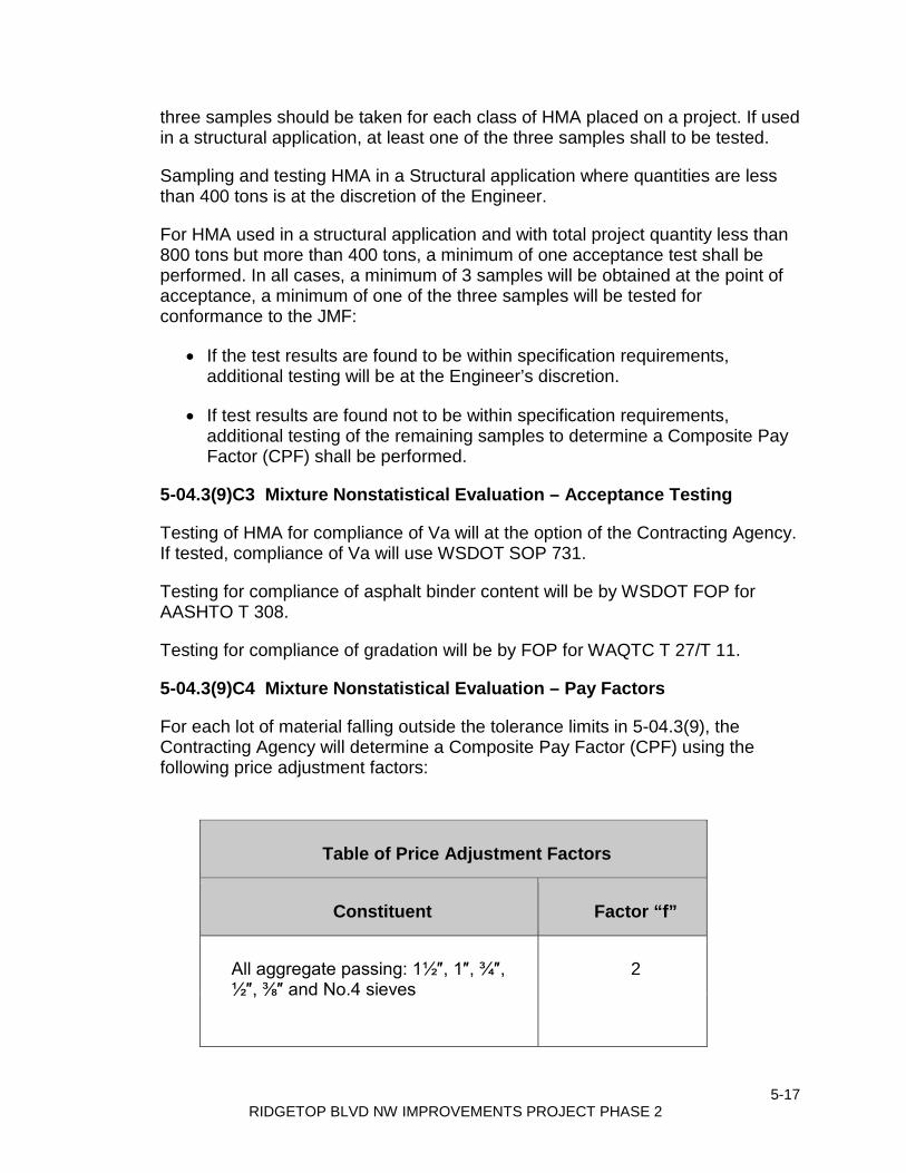
5-17 RIDGETOP BLVD NW IMPROVEMENTS PROJECT PHASE 2
three samples should be taken for each class of HMA placed on a project. If used in a structural application, at least one of the three samples shall to be tested.
Sampling and testing HMA in a Structural application where quantities are less than 400 tons is at the discretion of the Engineer.
For HMA used in a structural application and with total project quantity less than 800 tons but more than 400 tons, a minimum of one acceptance test shall be performed. In all cases, a minimum of 3 samples will be obtained at the point of acceptance, a minimum of one of the three samples will be tested for conformance to the JMF:
• If the test results are found to be within specification requirements, additional testing will be at the Engineer’s discretion.
• If test results are found not to be within specification requirements, additional testing of the remaining samples to determine a Composite Pay Factor (CPF) shall be performed.
5-04.3(9)C3 Mixture Nonstatistical Evaluation – Acceptance Testing
Testing of HMA for compliance of Va will at the option of the Contracting Agency. If tested, compliance of Va will use WSDOT SOP 731.
Testing for compliance of asphalt binder content will be by WSDOT FOP for AASHTO T 308.
Testing for compliance of gradation will be by FOP for WAQTC T 27/T 11.
5-04.3(9)C4 Mixture Nonstatistical Evaluation – Pay Factors
For each lot of material falling outside the tolerance limits in 5-04.3(9), the Contracting Agency will determine a Composite Pay Factor (CPF) using the following price adjustment factors:
Table of Price Adjustment Factors
Constituent Factor “f”
All aggregate passing: 1½″, 1″, ¾″, ½″, ⅜″ and No.4 sieves
2

5-18 RIDGETOP BLVD NW IMPROVEMENTS PROJECT PHASE 2
All aggregate passing No. 8 sieve 15
All aggregate passing No. 200 sieve 20
Asphalt binder 40
Air Voids (Va) (where applicable) 20
Each lot of HMA produced under Nonstatistical Evaluation and having all constituents falling within the tolerance limits of the job mix formula shall be accepted at the unit Contract price with no further evaluation. When one or more constituents fall outside the nonstatistical tolerance limits in the Job Mix Formula shown in Table of Price Adjustment Factors, the lot shall be evaluated in accordance with Section 1-06.2 to determine the appropriated CPF. The nonstatistical tolerance limits will be used in the calculation of the CPF and the maximum CPF shall be 1.00. When less than three sublots exist, backup samples of the existing sublots or samples from the Roadway shall be tested to provide a minimum of three sets of results for evaluation.
5-04.3(9)C5 Vacant
5-04.3(9)C6 Mixture Nonstatistical Evaluation – Price Adjustments
For each lot of HMA mix produced under Nonstatistical Evaluation when the calculated CPF is less than 1.00, a Nonconforming Mix Factor (NCMF) will be determined. The NCMF equals the algebraic difference of CPF minus 1.00 multiplied by 60 percent. The total job mix compliance price adjustment will be calculated as the product of the NCMF, the quantity of HMA in the lot in tons, and the unit Contract price per ton of mix.
If a constituent is not measured in accordance with these Specifications, its individual pay factor will be considered 1.00 in calculating the Composite Pay Factor (CPF).
5-04.3(9)C7 Mixture Nonstatistical Evaluation - Retests
The Contractor may request a sublot be retested. To request a retest, the Contractor shall submit a written request within 7 calendar days after the specific test results have been received. A split of the original acceptance sample will be retested. The split of the sample will not be tested with the same tester that ran the original acceptance test. The sample will be tested for a complete gradation analysis, asphalt binder content, and, at the option of the agency, Va. The results of the retest will be used for the acceptance of the HMA in place of the original

5-19 RIDGETOP BLVD NW IMPROVEMENTS PROJECT PHASE 2
sublot sample test results. The cost of testing will be deducted from any monies due or that may come due the Contractor under the Contract at the rate of $500 per sample.
5-04.3 (9)D Mixture Acceptance – Commercial Evaluation
If sampled and tested, HMA produced under Commercial Evaluation and having all constituents falling within the tolerance limits of the job mix formula shall be accepted at the unit Contract price with no further evaluation. When one or more constituents fall outside the commercial tolerance limits in the Job Mix Formula shown in 5-04.3(9), the lot shall be evaluated in accordance with Section 1-06.2 to determine the appropriate CPF. The commercial tolerance limits will be used in the calculation of the CPF and the maximum CPF shall be 1.00. When less than three sublots exist, backup samples of the existing sublots or samples from the street shall be tested to provide a minimum of three sets of results for evaluation.
For each lot of HMA mix produced and tested under Commercial Evaluation when the calculated CPF is less than 1.00, a Nonconforming Mix Factor (NCMF) will be determined. The NCMF equals the algebraic difference of CPF minus 1.00 multiplied by 60 percent. The Job Mix Compliance Price Adjustment will be calculated as the product of the NCMF, the quantity of HMA in the lot in tons, and the unit Contract price per ton of mix.
If a constituent is not measured in accordance with these Specifications, its individual pay factor will be considered 1.00 in calculating the Composite Pay Factor (CPF).
5-04.3(10) HMA Compaction Acceptance
HMA mixture accepted by nonstatistical evaluation that is used in traffic lanes, including lanes for intersections, ramps, truck climbing, weaving, and speed change, and having a specified compacted course thickness greater than 0.10-foot, shall be compacted to a specified level of relative density. The specified level of relative density shall be a Composite Pay Factor (CPF) of not less than 0.75 when evaluated in accordance with Section 1-06.2, using a LSL of 92.0 (minimum of 92 percent of the maximum density). The maximum density shall be determined by WSDOT FOP for AASHTO T 729. The specified level of density attained will be determined by the evaluation of the density of the pavement. The density of the pavement shall be determined in accordance with WSDOT FOP for WAQTC TM 8, except that gauge correlation will be at the discretion of the Engineer, when using the nuclear density gauge and WSDOT SOP 736 when using cores to determine density.
Tests for the determination of the pavement density will be taken in accordance with the required procedures for measurement by a nuclear density gauge or roadway cores after completion of the finish rolling.
5-20 RIDGETOP BLVD NW IMPROVEMENTS PROJECT PHASE 2
If the Contracting Agency uses a nuclear density gauge to determine density the test procedures FOP for WAQTC TM 8 and WSDOT SOP T 729 will be used on the day the mix is placed and prior to opening to traffic.
Roadway cores for density may be obtained by either the Contracting Agency or the Contractor in accordance with WSDOT SOP 734. The core diameter shall be 4-inches minimum, unless otherwise approved by the Engineer. Roadway cores will be tested by the Contracting Agency in accordance with WSDOT FOP for AASHTO T 166.
If the Contract includes the Bid item “Roadway Core” the cores shall be obtained by the Contractor in the presence of the Engineer on the same day the mix is placed and at locations designated by the Engineer. If the Contract does not include the Bid item “Roadway Core” the Contracting Agency will obtain the cores.
For a lot in progress with a CPF less than 0.75, a new lot will begin at the Contractor’s request after the Engineer is satisfied that material conforming to the Specifications can be produced.
HMA mixture accepted by commercial evaluation and HMA constructed under conditions other than those listed above shall be compacted on the basis of a test point evaluation of the compaction train. The test point evaluation shall be performed in accordance with instructions from the Engineer. The number of passes with an approved compaction train, required to attain the maximum test point density, shall be used on all subsequent paving.
HMA for preleveling shall be thoroughly compacted. HMA that is used for preleveling wheel rutting shall be compacted with a pneumatic tire roller unless otherwise approved by the Engineer.
Test Results
For a sublot that has been tested with a nuclear density gauge that did not meet the minimum of 92 percent of the reference maximum density in a compaction lot with a CPF below 1.00 and thus subject to a price reduction or rejection, the Contractor may request that a core be used for determination of the relative density of the sublot. The relative density of the core will replace the relative density determined by the nuclear density gauge for the sublot and will be used for calculation of the CPF and acceptance of HMA compaction lot.
When cores are taken by the Contracting Agency at the request of the Contractor, they shall be requested by noon of the next workday after the test results for the sublot have been provided or made available to the Contractor. Core locations shall be outside of wheel paths and as determined by the Engineer. Traffic control shall be provided by the Contractor as requested by the Engineer. Failure by the Contractor to provide the requested traffic control will result in forfeiture of the request for cores. When the CPF for the lot based on the

5-21 RIDGETOP BLVD NW IMPROVEMENTS PROJECT PHASE 2
results of the HMA cores is less than 1.00, the cost for the coring will be deducted from any monies due or that may become due the Contractor under the Contract at the rate of $200 per core and the Contractor shall pay for the cost of the traffic control.
5-04.3(10)A HMA Compaction – General Compaction Requirements
Compaction shall take place when the mixture is in the proper condition so that no undue displacement, cracking, or shoving occurs. Areas inaccessible to large compaction equipment shall be compacted by other mechanical means. Any HMA that becomes loose, broken, contaminated, shows an excess or deficiency of asphalt, or is in any way defective, shall be removed and replaced with new hot mix that shall be immediately compacted to conform to the surrounding area.
The type of rollers to be used and their relative position in the compaction sequence shall generally be the Contractor’s option, provided the specified densities are attained. Unless the Engineer has approved otherwise, rollers shall only be operated in the static mode when the internal temperature of the mix is less than 175°F. Regardless of mix temperature, a roller shall not be operated in a mode that results in checking or cracking of the mat. Rollers shall only be operated in static mode on bridge decks.
5-04.3(10)B HMA Compaction – Cyclic Density
Low cyclic density areas are defined as spots or streaks in the pavement that are less than 90 percent of the theoretical maximum density. At the Engineer’s discretion, the Engineer may evaluate the HMA pavement for low cyclic density, and when doing so will follow WSDOT SOP 733. A $500 Cyclic Density Price Adjustment will be assessed for any 500-foot section with two or more density readings below 90 percent of the theoretical maximum density.
5-04.3(10)C Vacant
5-04.3(10)D HMA Nonstatistical Compaction
5-04.3(10)D1 HMA Nonstatistical Compaction – Lots and Sublots
HMA compaction which is accepted by nonstatistical evaluation will be based on acceptance testing performed by the Contracting Agency dividing the project into compaction lots.
A lot is represented by randomly selected samples of the same mix design that will be tested for acceptance. A lot is defined as the total quantity of material or work produced for each Job Mix Formula placed. Only one lot per JMF is expected. A sublot shall be equal to one day’s production or 400 tons, whichever is less except that the final sublot will be a minimum of 200 tons and may be increased to 800 tons. Testing for compaction will be at the rate of 5 tests per sublot per WSDOT T 738.

5-22 RIDGETOP BLVD NW IMPROVEMENTS PROJECT PHASE 2
The sublot locations within each density lot will be determined by the Engineer. For a lot in progress with a CPF less than 0.75, a new lot will begin at the Contractor’s request after the Engineer is satisfied that material conforming to the Specifications can be produced.
HMA mixture accepted by commercial evaluation and HMA constructed under conditions other than those listed above shall be compacted on the basis of a test point evaluation of the compaction train. The test point evaluation shall be performed in accordance with instructions from the Engineer. The number of passes with an approved compaction train, required to attain the maximum test point density, shall be used on all subsequent paving.
HMA for preleveling shall be thoroughly compacted. HMA that is used to prelevel wheel ruts shall be compacted with a pneumatic tire roller unless otherwise approved by the Engineer.
5-04.3(10)D2 HMA Compaction Nonstatistical Evaluation – Acceptance Testing
The location of the HMA compaction acceptance tests will be randomly selected by the Engineer from within each sublot, with one test per sublot.
5-04.3(10)D3 HMA Nonstatistical Compaction – Price Adjustments
For each compaction lot with one or two sublots, having all sublots attain a relative density that is 92 percent of the reference maximum density the HMA shall be accepted at the unit Contract price with no further evaluation. When a sublot does not attain a relative density that is 92 percent of the reference maximum density, the lot shall be evaluated in accordance with Section 1-06.2 to determine the appropriate CPF. The maximum CPF shall be 1.00, however, lots with a calculated CPF in excess of 1.00 will be used to offset lots with CPF values below 1.00 but greater than 0.90. Lots with CPF lower than 0.90 will be evaluated for compliance per 5-04.3(11). Additional testing by either a nuclear moisture-density gauge or cores will be completed as required to provide a minimum of three tests for evaluation.
For compaction below the required 92% a Non-Conforming Compaction Factor (NCCF) will be determined. The NCCF equals the algebraic difference of CPF minus 1.00 multiplied by 40 percent. The Compaction Price Adjustment will be calculated as the product of CPF, the quantity of HMA in the compaction control lot in tons, and the unit Contract price per ton of mix.
5-04.3(11) Reject Work
5-04.3(11)A Reject Work General
Work that is defective or does not conform to Contract requirements shall be rejected. The Contractor may propose, in writing, alternatives to removal and

5-23 RIDGETOP BLVD NW IMPROVEMENTS PROJECT PHASE 2
replacement of rejected material. Acceptability of such alternative proposals will be determined at the sole discretion of the Engineer. HMA that has been rejected is subject to the requirements in Section 1-06.2(2) and this specification, and the Contractor shall submit a corrective action proposal to the Engineer for approval.
5-04.3(11)B Rejection by Contractor
The Contractor may, prior to sampling, elect to remove any defective material and replace it with new material. Any such new material will be sampled, tested, and evaluated for acceptance.
5-04.3(11)C Rejection Without Testing (Mixture or Compaction)
The Engineer may, without sampling, reject any batch, load, or section of Roadway that appears defective. Material rejected before placement shall not be incorporated into the pavement. Any rejected section of Roadway shall be removed.
No payment will be made for the rejected materials or the removal of the materials unless the Contractor requests that the rejected material be tested. If the Contractor elects to have the rejected material tested, a minimum of three representative samples will be obtained and tested. Acceptance of rejected material will be based on conformance with the nonstatistical acceptance Specification. If the CPF for the rejected material is less than 0.75, no payment will be made for the rejected material; in addition, the cost of sampling and testing shall be borne by the Contractor. If the CPF is greater than or equal to 0.75, the cost of sampling and testing will be borne by the Contracting Agency. If the material is rejected before placement and the CPF is greater than or equal to 0.75, compensation for the rejected material will be at a CPF of 0.75. If rejection occurs after placement and the CPF is greater than or equal to 0.75, compensation for the rejected material will be at the calculated CPF with an addition of 25 percent of the unit Contract price added for the cost of removal and disposal.
5-04.3(11)D Rejection - A Partial Sublot
In addition to the random acceptance sampling and testing, the Engineer may also isolate from a normal sublot any material that is suspected of being defective in relative density, gradation or asphalt binder content. Such isolated material will not include an original sample location. A minimum of three random samples of the suspect material will be obtained and tested. The material will then be statistically evaluated as an independent lot in accordance with Section 1-06.2(2).
5-04.3(11)E Rejection - An Entire Sublot
An entire sublot that is suspected of being defective may be rejected. When a sublot is rejected a minimum of two additional random samples from this sublot

5-24 RIDGETOP BLVD NW IMPROVEMENTS PROJECT PHASE 2
will be obtained. These additional samples and the original sublot will be evaluated as an independent lot in accordance with Section 1-06.2(2).
5-04.3(11)F Rejection - A Lot in Progress
The Contractor shall shut down operations and shall not resume HMA placement until such time as the Engineer is satisfied that material conforming to the Specifications can be produced:
1. When the Composite Pay Factor (CPF) of a lot in progress drops below 1.00 and the Contractor is taking no corrective action, or
2. When the Pay Factor (PF) for any constituent of a lot in progress drops below 0.95 and the Contractor is taking no corrective action, or
3. When either the PFi for any constituent or the CPF of a lot in progress is less than 0.75.
5-04.3(11)G Rejection - An Entire Lot (Mixture or Compaction)
An entire lot with a CPF of less than 0.75 will be rejected.
5-04.3(12) Joints
5-04.3(12)A HMA Joints
5-04.3(12)A1 Transverse Joints
The Contractor shall conduct operations such that the placing of the top or wearing course is a continuous operation or as close to continuous as possible. Unscheduled transverse joints will be allowed, and the roller may pass over the unprotected end of the freshly laid mixture only when the placement of the course must be discontinued for such a length of time that the mixture will cool below compaction temperature. When the Work is resumed, the previously compacted mixture shall be cut back to produce a slightly beveled edge for the full thickness of the course.
A temporary wedge of HMA constructed on a 20H:1V shall be constructed where a transverse joint as a result of paving or planing is open to traffic. The HMA in the temporary wedge shall be separated from the permanent HMA by strips of heavy wrapping paper or other methods approved by the Engineer. The wrapping paper shall be removed and the joint trimmed to a slightly beveled edge for the full thickness of the course prior to resumption of paving.
The material that is cut away shall be wasted and new mix shall be laid against the cut. Rollers or tamping irons shall be used to seal the joint.
5-04.3(12)A2 Longitudinal Joints

5-25 RIDGETOP BLVD NW IMPROVEMENTS PROJECT PHASE 2
The longitudinal joint in any one course shall be offset from the course immediately below by not more than 6 inches nor less than 2 inches. All longitudinal joints constructed in the wearing course shall be located at a lane line or an edge line of the Traveled Way. A notched wedge joint shall be constructed along all longitudinal joints in the wearing surface of new HMA unless otherwise approved by the Engineer. The notched wedge joint shall have a vertical edge of not less than the maximum aggregate size or more than ½ of the compacted lift thickness and then taper down on a slope not steeper than 4H:1V. The sloped portion of the HMA notched wedge joint shall be uniformly compacted.
5-04.3(12)B Bridge Paving Joint Seals
5-04.3(12)B1 HMA Sawcut and Seal
Prior to placing HMA on the bridge deck, establish sawcut alignment points at both ends of the bridge paving joint seals to be placed at the bridge ends, and at interior joints within the bridge deck when and where shown in the Plans. Establish the sawcut alignment points in a manner that they remain functional for use in aligning the sawcut after placing the overlay.
Submit a Type 1 Working Drawing consisting of the sealant manufacturer’s application procedure.
Construct the bridge paving joint seal as specified ion the Plans and in accordance with the detail shown in the Standard Plans. Construct the sawcut in accordance with the detail shown in the Standard Plan. Con-struct the sawcut in accordance with Section 5-05.3(8)B and the manufacturer’s application procedure.
5-04.3(12)B2 Paved Panel Joint Seal
Construct the paved panel joint seal in accordance with the requirements specified in section 5-04.3(12)B1 and the following requirement:
1. Clean and seal the existing joint between concrete panels in accordance with Section 5-01.3(8) and the details shown in the Standard Plans.
5-04.3(13) Surface Smoothness
The completed surface of all courses shall be of uniform texture, smooth, uniform as to crown and grade, and free from defects of all kinds. The completed surface of the wearing course shall not vary more than ⅛ inch from the lower edge of a 10-foot straightedge placed on the surface parallel to the centerline. The transverse slope of the completed surface of the wearing course shall vary not more than ¼ inch in 10 feet from the rate of transverse slope shown in the Plans.

5-26 RIDGETOP BLVD NW IMPROVEMENTS PROJECT PHASE 2
When deviations in excess of the above tolerances are found that result from a high place in the HMA, the pavement surface shall be corrected by one of the following methods:
1. Removal of material from high places by grinding with an approved grinding machine, or
2. Removal and replacement of the wearing course of HMA, or
3. By other method approved by the Engineer.
Correction of defects shall be carried out until there are no deviations anywhere greater than the allowable tolerances.
Deviations in excess of the above tolerances that result from a low place in the HMA and deviations resulting from a high place where corrective action, in the opinion of the Engineer, will not produce satisfactory results will be accepted with a price adjustment. The Engineer shall deduct from monies due or that may become due to the Contractor the sum of $500.00 for each and every section of single traffic lane 100 feet in length in which any excessive deviations described above are found.
When utility appurtenances such as manhole covers and valve boxes are located in the traveled way, the utility appurtenances shall be adjusted to the finished grade prior to paving. This requirement may be waived when requested by the Contractor, at the discretion of the Engineer or when the adjustment details provided in the project plan or specifications call for utility appurtenance adjustments after the completion of paving.
Utility appurtenance adjustment discussions will be included in the Pre-Paving planning (5-04.3(14)B3). Submit a written request to waive this requirement to the Engineer prior to the start of paving.
5-04.3(14) Planing (Milling) Bituminous Pavement
The planning plan must be approved by the Engineer and a pre planning meeting must be held prior to the start of any planing. See Section 5-04.3(14)B2 for information on planning submittals.
Locations of existing surfacing to be planed are as shown in the Drawings.
Where planing an existing pavement is specified in the Contract, the Contractor must remove existing surfacing material and to reshape the surface to remove irregularities. The finished product must be a prepared surface acceptable for receiving an HMA overlay.
Use the cold milling method for planing unless otherwise specified in the Contract. Do not use the planer on the final wearing course of new HMA.

5-27 RIDGETOP BLVD NW IMPROVEMENTS PROJECT PHASE 2
Conduct planing operations in a manner that does not tear, break, burn, or otherwise damage the surface which is to remain. The finished planed surface must be slightly grooved or roughened and must be free from gouges, deep grooves, ridges, or other imperfections. The Contractor must repair any damage to the sur-face by the Contractor’s planing equipment, using an Engineer approved method.
Repair or replace any metal castings and other surface improvements damaged by planing, as deter-mined by the Engineer.
A tapered wedge cut must be planed longitudinally along curb lines sufficient to provide a minimum of 4 inches of curb reveal after placement and compaction of the final wearing course. The dimensions of the wedge must be as shown on the Drawings or as specified by the Engineer.
A tapered wedge cut must also be made at transitions to adjoining pavement surfaces (meet lines) where butt joints are shown on the Drawings. Cut butt joints in a straight line with vertical faces 2 inches or more in height, producing a smooth transition to the existing adjoining pavement.
After planing is complete, planed surfaces must be swept, cleaned, and if required by the Contract, patched and preleveled.
The Engineer may direct additional depth planing. Before performing this additional depth planing, the Contractor must conduct a hidden metal in pavement detection survey as specified in Section 5-04.3(14)A.
5-04.3(14)A Pre-Planing Metal Detection Check
Before starting planing of pavements, and before any additional depth planing required by the Engineer, the Contractor must conduct a physical survey of existing pavement to be planed with equipment that can identify hidden metal objects.
Should such metal be identified, promptly notify the Engineer.
See Section 1-07.16(1) regarding the protection of survey monumentation that may be hidden in pavement.
The Contractor is solely responsible for any damage to equipment resulting from the Contractor’s failure to conduct a pre-planing metal detection survey, or from the Contractor’s failure to notify the Engineer of any hidden metal that is detected.

5-28 RIDGETOP BLVD NW IMPROVEMENTS PROJECT PHASE 2
5-04.3(14)B Paving and Planing Under Traffic
5-04.3(14)B1 General
In addition, the requirements of Section 1-07.23 and the traffic controls required in Section 1-10, and unless the Contract specifies otherwise, or the Engineer approves, the Contractor must comply with the following:
1. Intersections:
a. Keep intersections open to traffic at all times, except when paving or planing operations through an intersection requires closure. Such closure must be kept to the minimum time required to place and compact the HMA mixture, or plane as appropriate. For paving, schedule such closure to individual lanes or portions thereof that allows the traffic volumes and schedule of traffic volumes required in the approved traffic control plan. Schedule work so that adjacent intersections are not impacted at the same time and comply with the traffic control restrictions required by the Traffic Engineer. Each individual intersection closure or partial closure, must be addressed in the traffic control plan, which must be submitted to and accepted by the Engineer, see Section 1-10.2(2).
b. When planing or paving and related construction must occur in an intersection, consider scheduling and sequencing such work into quarters of the intersection, or half or more of an intersection with side street detours. Be prepared to sequence the work to individual lanes or portions thereof.
c. Should closure of the intersection in its entirety be necessary, and no trolley service is impacted, keep such closure to the minimum time required to place and compact the HMA mixture, plane, remove asphalt, tack coat, and as needed.
d. Any work in an intersection requires advance warning in both signage and a number of Working Days advance notice as determined by the Engineer, to alert traffic and emergency services of the intersection closure or partial closure.
e. Allow new compacted HMA asphalt to cool to ambient temperature before any traffic is allowed on it. Traffic is not allowed on newly placed asphalt until approval has been obtained from the Engineer.
2. Temporary centerline marking, post-paving temporary marking, temporary stop bars, and maintaining temporary pavement marking must comply with Section 8-23.
3. Permanent pavement marking must comply with Section 8-22.
5-29 RIDGETOP BLVD NW IMPROVEMENTS PROJECT PHASE 2
5-04.3(14)B2 Submittals – Planing Plan and HMA Paving Plan
The Contractor must submit a separate planing plan and a separate paving plan to the Engineer at least 5 Working Days in advance of each operation’s activity start date. These plans must show how the moving operation and traffic control are coordinated, as they will be discussed at the pre-planing briefing and pre-paving briefing. When requested by the Engineer, the Contractor must provide each operation’s traffic control plan on 24 x 36 inch or larger size Shop Drawings with a scale showing both the area of operation and sufficient detail of traffic beyond the area of operation where detour traffic may be required. The scale on the Shop Drawings is 1 inch = 20 feet, which may be changed if the Engineer agrees sufficient detail is shown.
The planing operation and the paving operation include, but are not limited to, metal detection, removal of asphalt and temporary asphalt of any kind, tack coat and drying, staging of supply trucks, paving trains, rolling, scheduling, and as may be discussed at the briefing.
When intersections will be partially or totally blocked, provide adequately sized and noticeable signage alerting traffic of closures to come, a minimum 2 Working Days in advance. The traffic control plan must show where peace officers will be stationed when signalization is or may be, countermanded, and show areas where flaggers are proposed.
At a minimum, the planing and the paving plan must include:
1. A copy of the accepted traffic control plan, see Section 1-10.2(2), detailing each day’s traffic control as it relates to the specific requirements of that day’s planing and paving. Briefly describe the sequencing of traffic control consistent with the proposed planing and paving sequence, and scheduling of placement of temporary pavement markings and channelizing devices after each day’s planing, and paving.
2. A copy of each intersection’s traffic control plan.
3. Haul routes from Supplier facilities, and locations of temporary parking and staging areas, including return routes. Describe the complete round trip as it relates to the sequencing of paving operations.
4. Names and locations of HMA Supplier facilities to be used.
5. List of all equipment to be used for paving.
6. List of personnel and associated job classification assigned to each piece of paving equipment.
7. Description (geometric or narrative) of the scheduled sequence of planing and of paving and intended area of planing and of paving for each day’s

5-30 RIDGETOP BLVD NW IMPROVEMENTS PROJECT PHASE 2
work, must include the directions of proposed planing and of proposed paving, sequence of adjacent lane paving, sequence of skipped lane paving, intersection planing and paving scheduling and sequencing, and proposed notifications and coordination to be timely made. The plan must show HMA joints relative to the final pavement marking lane lines.
8. Names, job titles, and contact information for field, office, and plant supervisory personnel.
9. A copy of the approved Mix Designs.
10. Tonnage of HMA to be placed each day.
11. Approximate times and days for starting and ending daily operations.
5-04.3(14)B3 Pre-Paving and Pre-Planing Briefing
At least 2 Working Days before the first paving operation and the first planing operation, or as scheduled by the Engineer for future paving and planing operations to ensure the Contractor has adequately prepared for notifying and coordinating as required in the Contract, the Contractor must be prepared to discuss that day’s operations as they relate to other entities and to public safety and convenience, including driveway and business access, garbage truck operations, Metro transit operations and working around energized overhead wires, school and nursing home and hospital and other accesses, other contractors who may be operating in the area, pedestrian and bicycle traffic, and emergency services. The Contractor, and Subcontractors that may be part of that day’s operations, must meet with the Engineer and discuss the proposed operation as it relates to the submitted planing plan and paving plan, approved traffic control plan, and public convenience and safety. Such discussion includes, but is not limited to:
1. General for both Paving Plan and for Planing Plan:
a. The actual times of starting and ending daily operations.
b. In intersections, how to break up the intersection, and address traffic control and signalization for that operation, including use of peace officers.
c. The sequencing and scheduling of paving operations and of planing operations, as applicable, as it relates to traffic control, to public convenience and safety, and to other con-tractors who may operate in the Project Site.
d. Notifications required of Contractor activities and coordinating with other entities and the public as necessary.

5-31 RIDGETOP BLVD NW IMPROVEMENTS PROJECT PHASE 2
e. Description of the sequencing of installation and types of temporary pavement markings as it relates to planning and to paving.
f. Description of the sequencing of installation of, and the removal of, temporary pavement patch material around exposed castings and as may be needed
g. Description of procedures and equipment to identify hidden metal in the pavement, such as survey monumentation, monitoring wells, street car rail, and castings, before planning, see Section 5-04.3(14)B2.
h. Description of how flaggers will be coordinated with the planing, paving, and related operations.
i. Description of sequencing of traffic controls for the process of rigid pavement base repairs.
j. Other items the Engineer deems necessary to address.
2. Paving – additional topics:
a. When to start applying tack and coordinating with paving.
b. Types of equipment and numbers of each type equipment to be used. If more pieces of equipment than personnel are proposed, describe the sequencing of the personnel operating the types of equipment. Discuss the continuance of operator personnel for each type equipment as it relates to meeting Specification requirements.
c. Number of JMFs to be placed, and if more than one JMF how the Contractor will ensure different JMFs are distinguished, how pavers and MTVs are distinguished if more than one JMF is being placed at the time, and how pavers and MTVs are cleaned so that one JMF does not adversely influence the other JMF.
d. Description of contingency plans for that day’s operations such as equipment breakdown, rain out, and Supplier shutdown of operations.
e. Number of sublots to be placed, sequencing of density testing, and other sampling and testing.
5-04.3(15) Sealing Pavement Surfaces
Apply a fog seal where shown in the plans. Construct the fog seal in accordance with Section 5-02.3. Unless otherwise approved by the Engineer, apply the fog seal prior to opening to traffic.

5-32 RIDGETOP BLVD NW IMPROVEMENTS PROJECT PHASE 2
5-04.3(16) HMA Road Approaches
HMA approaches shall be constructed at the locations shown in the Plans or where staked by the Engineer. The Work shall be performed in accordance with Section 5-04.
5-04.4 Measurement
HMA Cl. ___ PG ___, HMA for ___ Cl. ___ PG ___, and Commercial HMA will be measured by the ton in accordance with Section 1-09.2, with no deduction being made for the weight of asphalt binder, mineral filler, or any other component of the mixture. If the Contractor elects to remove and replace mix as allowed by Section 5-04.3(11), the material removed will not be measured.
Roadway cores will be measured per each for the number of cores taken.
Preparation of untreated roadway will be measured by the mile once along the centerline of the main line Roadway. No additional measurement will be made for ramps, Auxiliary Lanes, service roads, Frontage Roads, or Shoulders. Measurement will be to the nearest 0.01 mile.
Soil residual herbicide will be measured by the mile for the stated width to the nearest 0.01 mile or by the square yard, whichever is designated in the Proposal.
Pavement repair excavation will be measured by the square yard of surface marked prior to excavation.
Asphalt for prime coat will be measured by the ton in accordance with Section 1-09.2.
Prime coat aggregate will be measured by the cubic yard, truck measure, or by the ton, whichever is designated in the Proposal.
Asphalt for fog seal will be measured by the ton, as provided in Section 5-02.4.
Longitudinal joint seals between the HMA and cement concrete pavement will be measured by the linear foot along the line and slope of the completed joint seal.
Planing bituminous pavement will be measured by the square yard.
Temporary pavement marking will be measured by the linear foot as provided in Section 8-23.4.
Water will be measured by the M gallon as provided in Section 2-07.4.
5-04.5 Payment

5-33 RIDGETOP BLVD NW IMPROVEMENTS PROJECT PHASE 2
Payment will be made for each of the following Bid items that are included in the Proposal:
“HMA Cl. ___ PG ___”, per ton.
“HMA for Approach Cl. ___ PG ___”, per ton.
“HMA for Preleveling Cl. ___ PG ___”, per ton.
“HMA for Pavement Repair Cl. ___ PG ___”, per ton.
“Commercial HMA”, per ton.
The unit Contract price per ton for “HMA Cl. ___ PG ___”, “HMA for Approach Cl. ___ PG ___”, “HMA for Preleveling Cl. ___ PG ___”, “HMA for Pavement Repair Cl. ___ PG ___”, and “Commercial HMA” shall be full compensation for all costs, including anti-stripping additive, incurred to carry out the requirements of Section 5-04 except for those costs included in other items which are included in this Subsection and which are included in the Proposal.
“Preparation of Untreated Roadway”, per mile.
The unit Contract price per mile for “Preparation of Untreated Roadway” shall be full pay for all Work described under 5-04.3(4) , with the exception, however, that all costs involved in patching the Roadway prior to placement of HMA shall be included in the unit Contract price per ton for “HMA Cl. ___ PG ___” which was used for patching. If the Proposal does not include a Bid item for “Preparation of Untreated Roadway”, the Roadway shall be prepared as specified, but the Work shall be included in the Contract prices of the other items of Work.
“Preparation of Existing Paved Surfaces”, per mile.
The unit Contract Price for “Preparation of Existing Paved Surfaces” shall be full pay for all Work described under Section 5-04.3(4) with the exception, however, that all costs involved in patching the Roadway prior to placement of HMA shall be included in the unit Contract price per ton for “HMA Cl. ___ PG ___” which was used for patching. If the Proposal does not include a Bid item for “Preparation of Untreated Roadway”, the Roadway shall be prepared as specified, but the Work shall be included in the Contract prices of the other items of Work.
“Crack Sealing”, by force account.
“Crack Sealing” will be paid for by force account as specified in Section 1-09.6. For the purpose of providing a common Proposal for all Bidders, the Contracting Agency has entered an amount in the Proposal to become a part of the total Bid by the Contractor.
5-34 RIDGETOP BLVD NW IMPROVEMENTS PROJECT PHASE 2
“Pavement Repair Excavation Incl. Haul”, per square yard.
The unit Contract price per square yard for “Pavement Repair Excavation Incl. Haul” shall be full payment for all costs incurred to perform the Work described in Section 5-04.3(4) with the exception, however, that all costs involved in the placement of HMA shall be included in the unit Contract price per ton for “HMA for Pavement Repair Cl. ___ PG ___”, per ton.
“Asphalt for Prime Coat”, per ton.
The unit Contract price per ton for “Asphalt for Prime Coat” shall be full payment for all costs incurred to obtain, provide and install the material in accordance with Section 5-04.3(4).
“Prime Coat Agg.”, per cubic yard, or per ton.
The unit Contract price per cubic yard or per ton for “Prime Coat Agg.” shall be full pay for furnishing, loading, and hauling aggregate to the place of deposit and spreading the aggregate in the quantities required by the Engineer.
“Asphalt for Fog Seal”, per ton.
Payment for “Asphalt for Fog Seal” is described in Section 5-02.5.
“Longitudinal Joint Seal”, per linear foot.
The unit Contract price per linear foot for “Longitudinal Joint Seal” shall be full payment for all costs incurred to perform the Work described in Section 5-04.3(12).
“Planing Bituminous Pavement”, per square yard.
The unit Contract price per square yard for “Planing Bituminous Pavement” shall be full payment for all costs incurred to perform the Work described in Section 5-04.3(14).
“Temporary Pavement Marking”, per linear foot.
Payment for “Temporary Pavement Marking” is described in Section 8-23.5.
“Water”, per M gallon.
Payment for “Water” is described in Section 2-07.5.
“Job Mix Compliance Price Adjustment”, by calculation.
“Job Mix Compliance Price Adjustment” will be calculated and paid for as described in Section 5-04.3(9)C6.

5-35 RIDGETOP BLVD NW IMPROVEMENTS PROJECT PHASE 2
“Compaction Price Adjustment”, by calculation.
“Compaction Price Adjustment” will be calculated and paid for as described in Section 5-04.3(10)D3.
“Roadway Core”, per each.
The Contractor’s costs for all other Work associated with the coring (e.g., traffic control) shall be incidental and included within the unit Bid price per each and no additional payments will be made.
“Cyclic Density Price Adjustment”, by calculation.
“Cyclic Density Price Adjustment” will be calculated and paid for as described in Section 5-04.3(10)B.
5-05 CEMENT CONCRETE PAVEMENT
5-05 CEMENT CONCRETE PAVEMENT 5-05.1 Description Supplement this section with the following:
This work shall also consist of constructing Red Pigmented Cement Concrete Pavement where shown in the Plans, in conformity with the lines, grades, thicknesses, and typical cross-sections shown in the Plans.
5-05.2 Materials Supplement this section with the following:
Red Pigmented Cement Concrete Pavement shall be stamped Type II Gray Portland Cement with integral color additive and shall be a uniform “Red River Clay” or similar color.
Integral color additives for the Red Pigmented Cement Concrete Pavement shall contain pure concentrated mineral pigments, containing no fillers, adulterants or admixtures, specially processed for mixing into concrete and complying with ASTM C979. Calcium chloride shall not be permitted in the mix. Integral color liquid dose rate shall be 2.32 lbs per 94 lb sack of cement. Integral color powder dose rate shall be 1.5 lbs per 94 lb sack of cement. The stamped impression shall be a “Running Bond Brick” pattern made from an interlocking stamp pattern. The surface texture shall be that of new, unused brick with straight edges and square corners.
5-36 RIDGETOP BLVD NW IMPROVEMENTS PROJECT PHASE 2
Red Pigmented Cement Concrete Pavement shall be cured and sealed with a curing compound and sealer to be approved by the color additive manufacturer for use with colored concrete and shall comply with ASTM C309. Curing compound and sealer shall be water-based, non-flammable, low gloss, non-yellowing, non-clouding and wear resistant. Compound and sealer shall protect against water damage, oil and common stains, formulated for exterior use.
5-05.3 Construction Requirements Supplement this section with the following:
Red Pigmented Cement Concrete Pavement shall consist of integrally colored concrete pavement with the stamped pattern as described in Section 5-05.2 of these Special Provisions. The final layout of Red Pigmented Cement Concrete Pavement shall be determined in the field and approved by the Engineer. Qualified and competent workers shall have a minimum five (5) years of work experience for same paving type installation and placement of concrete. Asphalt mastic joint fillers shall be 3/8” x full depth of concrete and of the same material as that used in the curb with matching expansion joint locations. Expansion joints, architectural score joint and decorative stamped finish shall be provided as described in Section 5-05.2 of these Special Provisions and in locations as approved by the Engineer. Submittal The Contractor shall submit a Joint Layout Plan to the Engineer for approval at least five (5) working days prior to the commencement of any pavement construction. Transverse and longitudinal joints shall be contraction or through joints (including construction joints).
Mock Up Prior to start of pavement work the Contractor shall provide at least one 5’x5’ sample, as described herein, including the integral color and stamping. The mock up sample shall be approved by the Engineer prior to the start of work. The final approved sample shall be the standard for the balance of the rest of the work installed and shall be protected from damage until final acceptance and approval of all Red Pigmented Cement Concrete Pavement.

5-37 RIDGETOP BLVD NW IMPROVEMENTS PROJECT PHASE 2
The mock up sample(s) provided by the Contractor for the Engineer’s approval shall be included in the unit bid price for “Red Pigmented Cement Concrete Pavement” per Section 5-05.5 of these Special Provisions.
5-05.3(1) Concrete Mix Design for Paving Supplement this section with the following:
The submittal for the concrete mix design shall provide the following: the date, the amount of materials (i.e. cement, sand, aggregates, water) used, the type and amount of each admixture and the designated 28-day compressive strength specific to the mix design being submitted. The design compressive strength shall be a minimum of 4,000 psi.
5-05.3(4) Measuring and Batching Materials 5-05.3(4)A Acceptance of Portland Cement Concrete Pavement Delete the first, second, third and fourth paragraphs. This section is supplemented with the following:
Acceptance of concrete will be on a non-statistical acceptance only. 5-05.3(8) Joints Supplement the second paragraph with the following:
When new pavement abuts an existing pavement, the locations of the joints in the new pavement shall match with the joints in the existing pavement unless otherwise shown on the plans.
The faces of all joints shall be constructed perpendicular to the surface of the cement concrete pavement.
5-05.3(8)D Isolation Joints Supplement this section with the following:
The joint alignment shall be at right angles to the Pavement Structure centerline unless otherwise specified in the Contract.
Isolation joints shall be constructed with pre-molded material, 3/8-inch in thickness and conform to Section 9-04.1(2) Pre-molded Joint Filler for Expansion Joints and as shown on the Standard Details in these Specifications.

5-38 RIDGETOP BLVD NW IMPROVEMENTS PROJECT PHASE 2
The joint material shall be held accurately in place during the placing and finishing of the concrete by a bulkhead, a holder, metal cap or any other approved method. The joint shall be perpendicular to the paved surface and the holder shall be in place long enough to prevent sagging of the joint material.
A wood filler strip or metal cap shall be placed on the top of the pre-molded joint filler to form the groove, and shall remain in place until after the finishing and the concrete is sufficiently set to resist sloughing in the groove. The joint filler shall be stapled together at the ends to preserve continuity.
Immediately after removal of side forms, the edges of the pavement shall be carefully inspected and wherever the joint filler is not fully exposed, the concrete shall be chipped down until the edge of the filler is fully exposed for the entire depth.
Add the following new subsection:
5-05.3(8)E Sealing Through Joints
After the pavement is cured and before carrying any traffic, the space left by the removal of the wood filler strip or the metal cap above the top of the expansion joint filler strip shall be thoroughly cleaned of all loose material. The groove shall be completely free of any projecting concrete from the sides and the groove shall be continuous across the slab to each edge. It shall then be filled level with the pavement surface with joint sealant meeting the requirements of Section 9-04.2 Joint Sealants.
The joint sealant material shall be “black” color and heated and placed in accordance with the manufacturer’s instructions. Burned material will be rejected. The through joint groove shall be dry at the time of pouring the sealing compound.
5-05.3(10) Tie Bars and Corrosion Resistant Dowel Bars Supplement this section with the following:
Placement of tie bars and dowel bars shall be in accordance with the WSDOT Standard Plan A-40.10-03.
5-05.3(13) Curing 5-05.3(13)A Curing Compound Supplement this section with the following:
Liquid membrane – forming concrete curing compounds shall not be used on concrete sidewalks nor other concrete surfaces designed for non-traffic use unless approved by the Project Engineer.

5-39 RIDGETOP BLVD NW IMPROVEMENTS PROJECT PHASE 2
5-05.3(14) Cold Weather Work Supplement this section with the following:
The following additional requirements for placing concrete shall be in effect from November 1 to April 1:
• Engineer shall be notified at least 24 hours prior to placement of concrete.
• All concrete placement shall be completed no later than 2:00 p.m. each day.
• Where forms have been placed and the subgrade has been subjected to frost, no concrete shall be placed until the ground is completely thawed. At that time, the forms shall be adjusted and subgrade repaired as determined by the Engineer.
5-05.4 Measurement Supplement this section with the following:
“Red Pigmented Cement Concrete Pavement” shall be measured per square yard surface area of colored, stamped and finished cement concrete pavement, completed and accepted. No separate measurement will be made for the required mock-up(s).
5-05.5 Payment Supplement this section with the following: “Red Pigmented Cement Concrete Pavement”, per square yard.
The unit Contract price per square yard for “Red Pigmented Cement Concrete Pavement” shall include all labor, materials, and equipment necessary including but not limited to concrete, color, dowels, tie-bars, wire mesh, saw cutting, mock-up(s), decorative stamping, sealant, and sealing joints as noted in the Plans.

5-40 RIDGETOP BLVD NW IMPROVEMENTS PROJECT PHASE 2
THIS PAGE INTENTIONALLY LEFT BLANK

7-1 RIDGETOP BLVD NW IMPROVEMENTS PROJECT PHASE 2
6 7
DIVISION 7 DRAINAGE STRUCTURES, STORM SEWERS, SANITARY SEWERS, WATER MAINS, AND CONDUITS
7-04 STORM SEWERS
7-04.1 Description Add the following new section:
7-04.3(1)F Television Inspection
Following the air testing, Contracting Agency reserves the right to inspect the pipe using a TV camera and measuring equipment. Contracting Agency will be responsible for this inspection. The costs incurred in making the initial inspection shall be borne by Contracting Agency. Contractor shall provide two weeks advance notice and accommodate and allow up to five (5) days for this inspection to be made.
Any departure from that normally achieved with good construction practices such as pipeline misalignment (vertical or horizontal) will be deemed a deficiency. Pipe shall be excavated, the joint repaired, and the bedding and backfill re-compacted and replaced as necessary. The maximum allowable pipe deflection will be five (5.0) percent (in either horizontal or vertical). The pipe’s internal diameter will be based on the inside dimensions and reasonable tolerances obtained from the pipe manufacturer. Pipe that is misaligned or exceeds the allowable deflection shall be excavated and the bedding and backfill re-compacted and replaced as necessary. Contractor shall bear the cost of correcting such deficiencies as well as the costs of any TV inspections that are required to verify the deficiency has been corrected.
7-04.2 Materials Supplement this section with the following:
Ductile Iron Storm Sewer Pipe shall meet the requirements of Section 9-05.13.
7-04.5 Payment Supplement this section with the following:
“Ductile Iron Storm Sewer Pipe 12 In. Diam.”, per linear foot.
The unit contract price per linear foot for “Ductile Iron Storm Sewer Pipe 12 In. Diam.” shall be full pay to furnish and install the ductile iron pipe as detailed on the plans, including excavation, all parts and fittings, trench backfill, and foundation material.
7-2 RIDGETOP BLVD NW IMPROVEMENTS PROJECT PHASE 2
For a pipe to structure connection, this includes but is not limited to excavation, removal of the existing pipe, and additional alteration of the existing structure, making a water-tight connection, special backfill, and compaction.
7-05 MANHOLES, INLETS, CATCH BASINS, AND DRYWELLS
7-05.1 Description Supplement this section with the following:
This work shall include providing and installing all new frames, grates, and covers.
7-05.2 Materials Supplement this section with the following:
Catch basin grates and covers shall have the words “KITSAP COUNTY” cast into the top surface and shall be the bolt down and locking type as shown in the Plans.
Beehive Grate for Catch Basin shall conform to the detail shown in the Plans. Roundabout Truck Apron Curb Inlet Frame and Grate shall conform to the detail shown in the Plans. Streambed cobbles, 4-inch minus, hand-placed around the catch basin shall conform to the details as shown in the Plans and meet the requirements of Section 9-03.11(2) of the Standard Specifications.
7-05.4 Measurement Supplement this section with the following:
Beehive Grate for Catch Basin shall be measured by each frame and grate installed. Roundabout Truck Apron Curb Inlet Frame and Grate shall be measured by each frame and grate installed. Connection to Drainage Structure shall be measured per each connection completed.
7-05.5 Payment Revise the second paragraph as follows:

7-3 RIDGETOP BLVD NW IMPROVEMENTS PROJECT PHASE 2
All costs associated with furnishing and installing gravel backfill for bedding manholes, inlets and catch basins, including any needed CDF, polyethylene plastic sheeting, or other materials as shown on the plans, shall be included in the unit Contract price for the item installed.
Supplement this section with the following: “Beehive Grate for Catch Basin”, per each.
The unit Contract price per each for “Beehive Grate for Catch Basin” shall be full pay for all costs to complete the Work as specified in the Plans, including furnishing and hand-placing streambed cobbles and for all incidentals required to complete the Work as shown on the Plans.
“Roundabout Truck Apron Curb Inlet Frame and Grate”, per each.
The unit Contract price per each for “Roundabout Truck Apron Curb Inlet Frame and Grate” shall be full pay for all costs and incidentals required to complete the Work as shown in the Plans.
“Connection to Drainage Structure”, per each.
The unit Contract price per each for “Connection to Drainage Structure” shall be full compensation for all costs to complete the Work, including excavation, pipe bedding, backfill, and connections to structures needed to complete the connection as shown in the Plans. “Connect Catch Basin to Existing Pipe”, per each. The unit contract price per each for “Connect Catch Basin to Existing Pipe” shall be full pay to furnish and install the connection as noted or detailed on the plans.
For a pipe to structure connection, this includes but is not limited to excavation, removal of the existing pipe, and additional alteration of the existing structure, making a water-tight connection, special backfill, and compaction.
7-08 GENERAL PIPE INSTALLATION REQUIREMENTS 7-08.3 Construction Requirements 7-08.3(1) Excavation and Preparation of Trenches Supplement this section with the following:
Pot-hole Existing Utility
Description

7-4 RIDGETOP BLVD NW IMPROVEMENTS PROJECT PHASE 2
At least 24 hours prior to commencing installation of any pipe, the Contractor shall expose by pot-holing existing underground telephone cables, gas mains, sewer mains or services, water mains or services or any other underground utility shown in the Plans that crosses the route of any new pipe to be installed under this Contract. Excavation immediately adjacent to the existing utilities shall be by hand methods in compliance with Washington State requirements. When directed by the Engineer, the Contractor shall expose by pot-holing crossings of new pipe and utilities not shown in the Plans.
7-08.3(1)A Trenches Revise the sixth paragraph to read as follows:
When, after excavating to the foundation level, the material remaining in the trench bottom is determined to be unsuitable by the Engineer, the excavation shall be continued to such additional depth and width as required by the Engineer. Unsuitable foundation materials shall be disposed of at an approved site. The trench foundation shall be backfilled to the bottom of the pipe zone with Special Borrow Including Haul and compacted to form a uniformly dense, unyielding foundation.
7-08.4 Measurement Delete the fourth paragraph and replace it with the following:
Structure Excavation Class B and Structure Excavation Class B Including Haul will not be measured in accordance with Section 2-09.4 of these Special Provisions.
Revise the last paragraph to read as follows:
Shoring or Extra Excavation Class B will not be measured in accordance with Section 2-09.4 of these Special Provisions.
Supplement this section with the following:
Pot-holing of existing utilities shown in the Plan crossing the route of new pipe shall be incidental to the item being installed. All costs for such work shall be included in the unit Contract price shown on the Proposal for the item to be installed and not further payment will be made. Pot-holing of utilities not shown in the Plans as crossing the route of the new pipe will be measure by force account in accordance with Section 1-09.6 of these Special Provisions.
7-5 RIDGETOP BLVD NW IMPROVEMENTS PROJECT PHASE 2
7-08.5 Payment Delete the fifth and sixth paragraph. Revise the seventh paragraph to read as follows:
“Shoring or Extra Excavation Class B”, lump sum. Supplement this section with the following:
“Unsuitable Foundation Excavation Including Haul”, per cubic yard. No payment will be made for pot-holing of existing utilities in the Plans as crossing the route of the new pipe. “Pot-hole Utility Crossing”, per force account. Payment will be made for the bid item “Pot-hole Utility Crossing”, per force account, as provided in Section 1-09.6 for exposing any utility crossing the new pipe or drainage structure that is not shown in the Plans. To provide a common proposal for all Bidders, the Contracting Agency has entered an amount in the Proposal to become a part of the Contractor’s total bid.
7-12 VALVES FOR WATER MAINS
7-12.1 Description Supplement this section with the following:
This work shall include the adjustment of water valve boxes to the finished grade of the new pavement.
7-12.3 Construction Requirements Supplement this section with the following:
The installation or removal of extension sleeves to adjust the valve box to finished grade shall be included in the work.
7-12.4 Measurement Supplement this section with the following:
The measurement of adjust water valve box will be by each valve adjusted.

7-6 RIDGETOP BLVD NW IMPROVEMENTS PROJECT PHASE 2
7-12.5 Payment Supplement this section with the following:
“Adjust Valve Box”, per each.
8-1 RIDGETOP BLVD NW IMPROVEMENTS PROJECT PHASE 2
8
DIVISION 8 MISCELLANEOUS CONSTRUCTION
8-01 EROSION AND WATER POLLUTION CONTROL 8-01.1 Description Supplement this section with the following:
Kitsap County has applied for a Washington State Department of Ecology NPDES Construction Stormwater General Permit for this project. The County anticipates the permit to be issued prior to the start of construction. The Contractor shall assume and include in the bid full compliance and administration with the requirements of the General Permit for this Project. This work shall include the preparation and implementation of a Temporary Erosion and Sedimentation Control (TESC) Plan by the Contractor for this contract.
8-01.3 Construction Requirements 8-01.3(1) General Delete and replace the first paragraph in this section with the following:
The Contractor shall install a high visibility fence along ***those sections of Ridgetop Boulevard where there is no existing fencing along the adjacent properties through the construction site*** or as instructed by the Engineer.
8-01.3(1)A Submittals This section is revised with the following:
The Contractor shall be responsible for the preparation of a Temporary Erosion and Sediment Control (TESC) Plan for the Contract and shall submit this TESC Plan to the Engineer 5 days prior to the preconstruction conference.
A TESC Plan consists of a narrative section and plan sheets that meets Ecology’s Stormwater Pollution Prevention Plan (SWPPP) requirement in the CSWGP. When the Contracting Agency has developed a TESC Plan for a Contract the narrative is included in the appendix to the Special Provisions and the TESC plan sheets are included in the Contract Plans. The Contracting Agency TESC plan will not include off-site areas used to directly support construction activity.

8-2 RIDGETOP BLVD NW IMPROVEMENTS PROJECT PHASE 2
A Stormwater Pollution Prevention Plan (SWPPP) shall be prepared by the Contractor and submitted for approval by the Engineer. The plan shall consist of the Contractor’s complete strategy to meet the requirements of the CSWGP. The SWPPP shall include and modify as necessary the TESC Plan drawings if provided as part of the Contact Plans. The Contractor shall prepare, review and modify the SWPPP as necessary to be consistent with the actual work schedule, sequencing, and construction methods that will be used on the project. The SWPPP shall document all the erosion and sediment control Best Management Practices (BMPs) proposed, whether permanent or temporary. The plan shall document installation procedures, materials, scheduling, and maintenance procedures for each erosion and sediment control BMP. The Contractor shall submit the SWPPP for the Engineer’s approval before any work begins. The Contractor shall allow at least five working days for the Engineer’s review of the initial SWPPP or any revisions to the modified SWPPP. Failure to approve all or part of any such plan shall not make the Contracting Agency liable to the Contractor for any work delays. The Contractor may not begin work without an approved Contractor’s SWPPP.
Contractor TESC Plans shall include all high visibility fence delineation shown on the Contracting Agency Contract Plans. All TESC Plans shall meet the requirements of the current edition of the WSDOT Temporary Erosion and Sediment Control Manual M 3109 and be adapted as needed throughout construction based on site inspections and discharge samples to maintain compliance with the CSWGP. The Contractor shall develop a schedule for implementation of the TESC work and incorporate it into the Contractor’s progress schedule.
The Contractor shall submit their TESC Plan and implementation schedule as Type 2 Working Drawings. At the request of the Engineer, updated TESC Plans shall be submitted as Type 1 Working Drawings.
8-01.3(2) Seeding, Fertilizing and Mulching 8-01.3(2)B Seeding and Fertilizing Supplement this section with the following:
Seed: Grass seed, of the following composition, proportion, and quality shall be applied at the rate of 80 pounds per acre on all areas requiring roadside seeding within the project:
Kind and Variety of % By Minimum % Minimum % Seed in Mixture Weight Pure Seed Germination Chewing Fescue 40 39.2 90 Colonial Bentgrass 10 9.8 85 (Var.Astoria)

8-3 RIDGETOP BLVD NW IMPROVEMENTS PROJECT PHASE 2
Perennial Rye 40 39.2 90 White Dutch Clover 10 9.8 90 Weed Seed 0.5 % maximum Inert and Other Crop 1.5 % maximum TOTAL 100.00 % 8-01.3(2)B3 Fertilizer Supplement this section with the following:
Application of Fertilizer The Contractor shall apply sufficient quantities of fertilizer to supply the following amounts of nutrients:
Total Nitrogen as N - 135 pounds per acre. Available Phosphoric Acid as P205 - 60 pounds per acre. Soluble Potash as K20 - 60 pounds per acre.
The fertilizer formulation and application rate shall be approved by the Engineer before use.
8-01.3(2)D Mulch Supplement this section with the following:
Mulch for Erosion Control Seeding:
Mulch shall be Short Term Mulch applied at a rate of 2500 pounds per acre.
8-01.3(16) Removal (January 5, 2015, WSDOT GSP) The first paragraph of Section 8-01.3(16) is revised to read:
The Contractor shall remove all temporary BMP’s and all associated hardware from the project limits prior to Physical Completion unless otherwise approved by the Engineer. At the request of the Contractor and at the sole discretion of the Engineer the CSWGP may be transferred back to the Contracting Agency. Approval of the Transfer of Coverage request will require the following:
1. All other Work required for Contract Completion has been completed.
2. All Work required for compliance with the CSWGP has been completed to the maximum extent possible. This includes removal of BMPs that are no longer needed and the site has undergone all Stabilization identified for meeting the requirements of Final Stabilization in the CSWGP.

8-4 RIDGETOP BLVD NW IMPROVEMENTS PROJECT PHASE 2
3. An Equitable Adjustment change order for the cost of Work that has not been completed by the Contractor.
4. Submittal of the Washington State Department of Ecology Transfer of Coverage form (Ecology form ECY 020-87a) to the Engineer.
If the Engineer approves the Transfer of Coverage back to the Contracting Agency the requirement in Section 1-07.5(3) for the Contractor’s submittal of the Notice of Termination form to Ecology will not apply.
8-01.4 Measurement Supplement this section with the following:
No specific unit of measurement will apply to the Lump Sum Bid Item “NPDES Construction Stormwater General Permit”.
8-01.5 Payment
Supplement this section with the following:
“Erosion / Water Pollution Control”, lump sum. The lump sum Contract price for Erosion/Water Pollution Control shall be full pay for all labor, tools, equipment, and materials for the installation, maintenance, and removal of erosion and water pollution control measures including the preparation and implementation of the TESC Plan. “NPDES Construction Stormwater General Permit”, per Lump Sum. The lump sum contract price for “NPDES Construction Stormwater General Permit” shall be full pay for the SWPPP documentation and CESCL and their responsibilities including but not limited to, sampling, monitoring, reporting, coordinating, inspecting, fees and any other expenses, materials and labor (pertinent to their responsibilities) necessary to fully comply with the requirements of the permit and terminate it upon completion of the project.
8-02 ROADSIDE RESTORATION 8-02.5 Payment Delete the seventh through twelfth paragraphs of this section and replaced with the following:
Payment for PSIPE (Plant Species Including Plant Establishment) shall be as follows:

8-5 RIDGETOP BLVD NW IMPROVEMENTS PROJECT PHASE 2
90% of contract price at completion of planting 10% of contract price at physical completion of project.
Contractor is notified that prepayment for the plant establishment period is for the convenience of both the Contracting Agency and the Contractor in that it allows for close out of the contract and payment of any retained funds prior to the completion of the one year plant establishment period. The provisions of Section 8-02.3(13), Plant Establishment, shall still apply. If the Contractor fails to perform any work described in the Plant Establishment Plan, including weeding, watering or plant species replacement, the Contracting Agency will cause the work to be completed and invoice the Contractor for all costs.
8-04 CURBS, GUTTERS, AND SPILLWAYS 8-04.1 Description Supplement this section with the following:
This work shall also include the construction of Cement Conc. Depressed Curb Inlets and Cement Conc. Curb Transitions as shown on the Plans.
8-04.2 Materials Supplement this section with the following:
Streambed cobbles, 4-inch minus, hand-placed around the curb inlet shall conform to the details as shown in the Plans and meet the requirements of Section 9-03.11(2) of the Standard Specifications.
8-04.3(1) Cement Concrete Curbs, Gutters, and Spillways Supplement this section with the following:
These requirements shall include the construction of Cement Conc. Depressed Curb Inlets and Cement Conc. Curb Transitions.
8-04.4 Measurement Supplement this section with the following:
Cement Conc. Curb Transitions will be measured per each. Cement Conc. Depressed Curb Inlet will be measured per each.
8-04.5 Payment
Supplement this section with the following:

8-6 RIDGETOP BLVD NW IMPROVEMENTS PROJECT PHASE 2
“Cement Conc. Curb Transition”, per each.
The unit contract price for “Cement Conc. Curb Transition” shall be full compensation for all labor, tools, equipment, and materials necessary or incidental to construction and finishing of the concrete curb transition in accordance with the Plans. “Cement Conc. Depressed Curb Inlet”, per each.
The unit contract price for “Cement Conc. Depressed Curb Inlet” shall be full compensation for all labor, tools, equipment, and materials necessary or incidental to construction and finishing of the concrete check dam at the inlet in accordance with the Plans.
All costs associated with furnishing and hand-placing streambed cobbles as shown on the Plans shall be included in the unit Contract price for the item installed.
8-14 CEMENT CONCRETE SIDEWALKS 8-14.1 Description Supplement this section with the following:
This Work shall include the installation of bicycle access ramps in accordance with details as shown in the Plans and these Specifications and in conformity to lines and grades shown in the plans or as established by the Engineer. The Contractor shall receive approval of the Engineer for the line and grade of the sidewalk and curb/bike ramps being installed prior to pouring the concrete. The Contractor shall have the subgrade prepared and formwork in place at least 24 hours prior to pouring concrete. The Engineer shall review the line and grades of the sidewalk/ramps and make minor adjustments as necessary. Minor adjustments shall be considered as changes to the Plan elevations or offsets of 3 inches or less. The work to revise the lines, formwork and subgrade for minor adjustments shall be considered incidental to the bid. If the lines and formwork are not in conformance with the Plans all adjustments, regardless of size, shall be at the sole expense of the Contractor. Adjustments to the lines and grades shall not constitute a basis for claims for additional contract time or expenses.
The sidewalk cross slope shall be not be greater than 1.5% measured perpendicular to the direction of travel. Any sidewalk installed at a cross slope greater than 2% without prior approval of Engineer shall be removed and replaced at the Contractor’s expense.

8-7 RIDGETOP BLVD NW IMPROVEMENTS PROJECT PHASE 2
This work shall also include constructing a bus stop shelter pad and bus stop access pad in accordance with details as shown in the Plans and these Specifications and in conformity to lines and grades shown in the plans or as established by the Engineer.
8-14.3(3) Placing and Finishing Concrete Revise the third paragraph to read:
Full depth expansion joints shall be constructed with a maximum spacing of 10 feet, and as detailed in the Plans. Expansion joints shall be placed between pedestrian ramps, driveways and match curb and gutter expansion joint spacing. The Contractor shall also place expansion joints as indicated in the Contract Documents. Curb ramps shall be of the type specified in the Plans. Bicycle access ramps shall be built as shown in the Plans.
8-14.3(4) Curing The second sentence is revised to read:
Curing shall be in accordance with Section 5-05.3(13) of the Standard Specifications.
Add the following new section:
8-14.3(6) Cold Weather Work
The following additional requirements for placing concrete shall be in effect from November 1 to April 1 unless approved by the Engineer:
• The Engineer shall be notified at least 24 hours prior to placement of concrete.
• All concrete placement shall be completed no later than 2:00 p.m. each day.
• Where forms have been placed and the subgrade has been subjected to frost, no concrete shall be placed until the ground is completely thawed. At the time, the forms shall be adjusted, and subgrade repaired as determined by the Engineer.
8-14.4 Measurement Supplement this section with the following:
8-8 RIDGETOP BLVD NW IMPROVEMENTS PROJECT PHASE 2
Cement Conc. Bicycle Access Ramp will be measured per each for the complete ramp installed. Bus stop shelter pad and bus stop access pad will be measured by the square yard of finished surface.
8-14.5 Payment Supplement this section with the following:
“Cement Conc. Bicycle Access Ramp Type ___”, per each. The unit contract price for “Cement Conc. Bicycle Access Ramp Type ___”, shall be full compensation for all labor, tools, equipment, and materials necessary or incidental to construction and finishing of the concrete bike ramp in accordance with the Plans. “Cement Conc. Sidewalk, per square yard. The unit contract price for “Cement Conc. Sidewalk” shall be full compensation for all labor, tools, equipment, and materials necessary or incidental to construction and finishing of the sidewalks, bus stop shelter pads, and bus stop access pads in accordance with the plans.
8-20 ILLUMINATION, TRAFFIC SIGNAL SYSTEMS, INTELLIGENT TRANSPORTATION SYSTEMS AND ELECTRICAL
8-20.1 Description Supplement this section with the following:
The work includes furnishing all materials and performing all work necessary for the following:
1. Modify the existing illumination, 2. Installation of conduit and junction boxes for future fiber optic interconnect
as shown in the Contract Plans and 3. Installation of an illumination system and all appurtenances at the
following intersections and as shown in the Contract Plans:
• Ridgetop Blvd NW, Ridgepoint Drive NW, and Quail Run Drive NW • Ridgetop Blvd NW, NW Timber Shadow Court, and NW Tahoe
Lane • Ridgetop Blvd NW and NW Thornwood Circle • Ridgetop Blvd NW, NW Tower View Circle, and NW Pinnacle Court
8-9 RIDGETOP BLVD NW IMPROVEMENTS PROJECT PHASE 2
Equipment to be installed is located by station and offset on the plans. These locations may be adjusted in the field by the Engineer, if necessary, to interface with other improvements or existing conditions. Relocation and upgrades to existing luminaire poles and bases shall be coordinated with Puget Sound Energy (PSE). Existing luminaires shall be keep in operation as long as possible.
All work shall be performed as shown in the Plans in accordance with applicable Standard Specifications and Standard Plans included herein and the following Special Provisions. Work shall include the supply, testing, and installation of all traffic signal and illumination hardware including the communication cable and interface system, and when specified, the modification and/or removal of such an existing system.
The work includes, but shall not be limited to, the following:
1. Electrical services, enclosures, connections, and bases 2. Foundations 3. Junction boxes 4. Conduit and wire 5. Luminaires 6. Luminaire poles and bases
8-20.1(1) Regulations and Code Supplement this section with the following:
All electrical equipment shall conform to the Standards of the National Electrical Manufacturer’s Association (NEMA). In addition to the requirements of these Specifications, the Plans and Special Provisions, all material and work shall conform to the requirements of the National Electrical Code; Laws, Rules and Regulations for Installing Electric Wires and Equipment, of the Department of Labor and Industries, State of Washington; the American Society for Testing and Materials (ASTM); the American Standards Association (ASA); American National Standards Institute (ANSI); Standard Specifications for Roads, Bridge and Municipal Construction (Standard Specifications); Standard Plans for Road, Bridge and Municipal Construction (Standard Plans); and any requirements of Puget Sound Energy that may apply. It shall be the Contractor’s responsibility to determine these requirements and to coordinate all inspections. Prior to start of work, all necessary licenses, permits, and approvals shall be obtained by the Contractor. The Contractor shall comply with all laws, ordinances, rules, orders, and regulations relating to the performance of the work, the protection of adjacent property, and the maintenance of all other facilities. The Contractor will be required to comply with all the provisions of these

8-10 RIDGETOP BLVD NW IMPROVEMENTS PROJECT PHASE 2
instruments and shall save and hold Kitsap County harmless from any damage that may be incurred as a result of the Contractor’s failure to comply with all the terms of these permits.
8-20.2 Materials Supplement this section with the following:
General All materials for the completion of the illumination work shall be furnished and installed by the Contractor as a part of this Contract.
8-20.2(1) Equipment List and Drawings Supplement this section with the following:
All equipment shall be approved for use in writing by the Engineer prior to ordering the equipment.
Materials not approved by the Engineer will not be permitted on the jobsite.
All illumination materials for review shall be incorporated in a single submittal.
The following equipment has been pre-approved for use: Service Cabinet Tesco Pad Mount Type III AF 26-000 Anodized Aluminum Metered Service
(March 13, 1995 WSDOT GSP) Pole base to light source distances (H1) for lighting standards with pre-approved plans shall be as noted in the Plans. Pole base to light source distances (H1) for lighting standards without pre-approved plans will be furnished by the Engineer as part of the final approved shop drawings, prior to fabrication. Approval of shop drawings may require up to 30 calendar days from the date the Engineer receives the drawings until they are returned to the Contractor. The actual time required for approval is dependent upon the completeness and appropriateness of the drawings as submitted. Any deficiencies will require additional time for approval based on the degree of the deficiency and the additional review time required. If the shop drawings are returned to the Contractor to correct deficiencies, an additional 30 calendar days may be required for the approval process. If more than 30 calendar days are required for routine approval of shop drawings that are completed and accurate,

8-11 RIDGETOP BLVD NW IMPROVEMENTS PROJECT PHASE 2
the Contractor will be granted an extension of time equal to the additional review time.
8-20.3 Construction Requirements 8-20.3(1) General Supplement this section with the following: Product Handling
All equipment shall be handled and protected so as to prevent damage. Damaged equipment, if any, shall be repaired or replaced by the Contractor to the satisfaction of the Engineer at no additional cost to the Owner.
Delivery to the County All spare equipment, equipment requiring testing, and salvaged equipment shall be delivered to: Kitsap County Signal Shop Public Works Annex 8600 SW Imperial Way Bremerton, WA 98312 Contact: Daren Miller Telephone: 360.337.5777, ext. 5710
The Contractor shall provide notice a minimum of five working days prior to delivery of any materials.
8-20.3(2) Excavating and Backfilling Supplement this section with the following:
Underground utilities of record are shown on the construction plans insofar as information is available. These, however, are shown for convenience only and the Owner assumes no responsibility for improper locations or failure to show utility locations on the construction plans.
At least 24 hours prior to commencing installation of any illumination equipment, the Contractor shall expose by pot-holing existing underground telephone cables, gas mains, sewer mains, water mains or any other underground utility shown in the Plans that crosses the route of the new illumination equipment to be installed under this contract. Excavation immediately adjacent to the existing utilities shall be by hand methods in compliance with Washington State requirements.
The Contractor shall be entirely responsible for coordination with the utility companies and arranging for the movement or adjustment, either temporary or permanent, of their facilities within the project limits.

8-12 RIDGETOP BLVD NW IMPROVEMENTS PROJECT PHASE 2
If a conflict is identified, the Contractor shall contact the Engineer. The Contractor and Owner shall locate alternative locations for poles, cabinet, or junction boxes. The Contractor shall get approval from the Engineer prior to installation. The Contractor may consider changing depth or alignment of conduit to avoid utility conflicts.
Before beginning any excavation work for foundations, vaults, junction boxes or conduit runs, the contractor shall confirm that the location proposed on the Contract Plans does not conflict with utility location markings placed on the surface by the various utility companies. If a conflict is identified, the following process shall be used to resolve the conflict:
1. Contact the Engineer and determine if there is an alternative location for the foundation, junction box, vault or conduit trench.
2. If an adequate alternate location is not obvious for the underground work, select a location that may be acceptable and pothole to determine the exact location of other utilities. Potholing must be approved by the Engineer.
3. If an adequate alternate alignment still cannot be identified following potholing operations, the pothole area should be restored and work in the area should stop until a new design can be developed.
The Contractor shall not attempt to adjust the location of an existing utility unless specifically agreed to by the utility owner.
All conduit will be installed by open trench unless otherwise approved by the Engineer.
Where the trench is located under the roadway or shoulder, all backfill shall consist of crushed surfacing top course meeting the requirements of Section 9-03.9(3) of the Standard Specifications. Backfill for all other trenches may consist of suitable native material from the excavation if approved by the engineer; otherwise, backfill shall be the same as specified for trenches under the roadway.
All backfill shall be mechanically compacted by a power-operated mechanical tamper or other mechanical compaction device approved by the Engineer. All trenches to be restored shall be compacted as specified in Section 2-03.3(14) C, Method C, of the Standard Specifications. The temporary restoration of conduit trenches shall be as directed by the Engineer. All costs for temporary trench restoration shall be included in the lump sum bid item and no additional measurement shall be made.

8-13 RIDGETOP BLVD NW IMPROVEMENTS PROJECT PHASE 2
8-20.3(4) Foundations Supplement this section with the following:
Each concrete foundation shall be constructed in a single pour. Foundations for cabinets shall be as shown in the Plans. Anchor bolts shall be positioned horizontally and vertically prior to final set of the concrete. All concrete on the anchor bolts shall be immediately removed following pouring of the foundation. Conduits shall be temporarily capped during the pour to prevent concrete from entering.
The void between the foundation and the pole flange shall be no larger than 4 inches and shall be completely filled around the conduit(s) with dry pack mortar and neatly troweled. A ½ inch diameter, plastic drain pipe shall be install in all structures to provide drainage from the pole base. The plastic drain pipe shall be neatly trimmed flush with the surfaces. Illumination poles shall be installed such that the base is at the same elevation as the edge of the pavement or top of curb or wedge curb when curb is present. All foundations installed in the sidewalk or ramp area shall be poured to the bottom of the sidewalk or ramp. The sidewalk or ramp shall be installed in a separate pour. All foundations installed at the back of the sidewalk shall be poured to the elevation of the back of sidewalk. All foundations not in sidewalk or ramp areas shall be poured to the elevation of the adjacent ground and shall have a 4-inch thick cement concrete square collar formed around the top of the foundation. Some locations may require a small block wall due to a cut or fill to accommodate the foundation.
8-20.3(5) Conduit Supplement this section with the following:
Each conduit run shall contain a minimum 200-pound breaking strength pull string, which shall be tied off at both ends.
All conduit installed underground shall have polyethylene underground hazard marking tape, 6 inches wide, red, legend "Caution-Electric Line Buried Below," placed approximately 12 inches above the conduit.
Conduit meeting the requirements of Section 9-29.1 of the Standard Specifications shall be used at the following locations:
8-14 RIDGETOP BLVD NW IMPROVEMENTS PROJECT PHASE 2
1. Hot-dip galvanized rigid metal conduit.
a. All conduit installed above ground. b. All conduit between the service cabinet and the service pole or
vault. c. All conduit between the nearest junction box and a pole or cabinet
foundation. d. All conduit 90° bends.
2. Schedule 80 rigid PVC. a. All conduit under roadways or shoulders.
3. Schedule 40 rigid PVC.
a. All other locations except as noted above. 8-20.3(6) Junction Boxes, Cable Vaults, and Pull Boxes Supplement this section with the following:
All junction boxes placed out of the sidewalk area shall have a 2-inch thick cement concrete collar constructed around the box. The collar shall extend 4 inches out from the box, except where the box is located at the back of sidewalk in which case the collar shall abut and be flush with the back of sidewalk.
8-20.3(8) Wiring Supplement this section with the following:
The unfused service wires between the Puget Sound Energy transformer pole and the service cabinet shall be labeled "Unfused Service" at all terminal ends.
Wire marking sleeves shall be permanent, non-adhesive, printable heat shrink, full-circle design of white polyvinyl chloride.
8-20.3(9) Bonding, Grounding Supplement this section with the following:
Contractor shall provide and install bonding and grounding wires as described in Standard Specifications and the National Electric Code for any modified existing junction boxes that are not properly bonded/grounded. For the purposes of this section, a box shall be considered “modified” if new cables (including current-carrying conductors and/or low-voltage cables) are installed.
8-20.3(10) Service, Transformer, Intelligent Transportation System (ITS) Cabinets Supplement this section with the following:
8-15 RIDGETOP BLVD NW IMPROVEMENTS PROJECT PHASE 2
The County has completed an electrical service connection with Puget Sound Energy and made arrangements for new electrical service connections. The Contractor shall coordinate with PSE to schedule the service connections, meter installations, and all required inspections.
8-20.3(11) Field Test Supplement this section with the following:
A 48 hour test burn of the illumination system must be completed before acceptance of the lighting system.
8-20.3(13) Illumination Systems 8-20.3(13)C Luminaires Supplement this section with the following:
All luminaires shall be provided with markers for positive identification of light source type and wattage. Markers shall conform to ANSI C136.15-2011 “American National Standard for Roadway and Area Lighting Equipment – Luminaire Field Identification”.
8-20.4 Measurement Supplement this section with the following:
Measurement for “Illumination System”, “Interconnect System”, and “Rectangular Rapid Flashing Beacon System, complete” will be by lump sum. The lump sum measurement will include furnishing and installing all components associated with the illumination, interconnect, and rectangular rapid flashing beacon systems including removal of existing systems and modifications required at the existing signal as shown in the Contract Plans. Coordination of service connections with Puget Sound Energy and any necessary permits and fees associated with the service connections shall be considered incidental to the bid items included herein and no additional compensation will be made. All potholing associated with the bid items herein shall be considered included in the bid items included herein and no additional compensation will be made. Use of a vacuum truck for excavation, including potholing, shall be considered included in the bid items included herein and no additional compensation will be made.

8-16 RIDGETOP BLVD NW IMPROVEMENTS PROJECT PHASE 2
Adjustment of junction boxes to final grade (including any interim adjustment to facilitate construction staging) shall be incidental and included in the bid items included herein and no additional compensation will be made. Restoration of facilities destroyed or damaged during construction shall be considered incidental to the bid items included herein and no additional compensation will be made.
8-20.5 Payment Supplement this section with the following:
The lump sum Contract price for "Illumination System" shall be full pay for the construction of the complete illumination system as described and as shown in the Plans. “Illumination System”, lump sum. The lump sum price for “Illumination System” shall be for the total of all items for complete illumination system. All items and labor necessary to supply, install, and test the: luminaire poles and arms, LED luminaires, foundations, conduit, wiring, junction boxes, connections with existing service cabinet, conduit and junction boxes, adjusting junction boxes to grade, excavation, backfilling, cut or fill block walls, directional boring, restoring facilities destroyed or damaged during construction, removing existing luminaire poles, luminaires, foundations and associated equipment, salvaging existing materials, removal of existing conduit, testing, as-built plans and all other components necessary to make a complete system shall be included within the lump sum measurement. All painting of components shall be considered incidental to the lump sum measurement. “Interconnect System”, lump sum.
The lump sum price for "Interconnect System" shall be measured per lump sum for the total of all items. All items and labor necessary to supply, install, and test the conduit, junction boxes, connections with existing conduit, pull boxes, pull rope, restoring facilities destroyed or damaged during construction, salvaging existing materials, as-built plans and all other components necessary to install infrastructure, including conduit and pull boxes, for future Interconnect System shall be included within the lump sum measurement. Conduit for the Interconnect System shall be installed in the trench and no additional payment will be made for excavation or backfill associated with the interconnect system. “Rectangular Rapid Flashing Beacon System, complete”, lump sum.

8-17 RIDGETOP BLVD NW IMPROVEMENTS PROJECT PHASE 2
The lump sum price for “Rectangular Rapid Flashing Beacon System, complete” shall be measured per lump sum for the total of all items. All items and labor necessary to supply, install, and test the Rectangular Rapid Flashing Beacon system, restore facilities destroyed or damaged during construction, salvage existing materials, as-built plans and all other components necessary to complete the Work shall be included within the lump sum measurement.
8-21 PERMANENT SIGNING 8-21.3 Construction Requirements Supplement this section with the following:
Existing signs, as shown in the Plans where in conflict with proposed improvements, shall be temporarily removed and reinstalled in their original locations or permanently removed and replaced with new signs as indicated in the Plans. All existing signs noted for reinstallation shall be protected during construction and reinstalled in their original condition.
Signs noted for reinstallation that become damaged as a result of construction for this project shall be replaced at the Contractor’s expense. Any damage to signs not noted for removal as a result of construction activities shall also be replaced at the Contractor’s expense.
Since regulatory signs must remain visible to traffic and pedestrians at all times, temporary placement of regulatory signs may be necessary by portable sign stand or other means. Temporary regulatory signs shall be placed as close to the original sign’s location as practicable. All regulatory sign placement, whether temporary or permanent, shall follow the requirements of the Manual on Uniform Traffic Control Devices (MUTCD), latest version.
8-21.4 Measurement Supplement this section with the following:
There is no unit of measure shall apply to the lump sum Bid Item Permanent Signing.
8-21.5 Payment Supplement this section with the following:
“Permanent Signing”, lump sum. The lump sum price in the Proposal shall be full compensation for all labor, tools, equipment, and materials necessary to removing the existing signing; temporarily

8-18 RIDGETOP BLVD NW IMPROVEMENTS PROJECT PHASE 2
reinstalling signs to accommodate construction activities; and all new signs posts and foundations as required per the Plans.
8-23 TEMPORARY PAVEMENT MARKINGS 8-23.3 Construction Requirements Supplement this section with the following:
The Contractor shall furnish, install, maintain, and remove all temporary pavement markings required by the approved traffic control plan and as necessary to successfully complete the Work.
8-23.5 Payment Supplement this section with the following:
All costs for installation, inspection, maintenance, and removal of temporary pavement markings shall be considered incidental and included in the lump sum Bid Item “Project Temporary Traffic Control”.
8-24 ROCK AND GRAVITY BLOCK WALL AND GABION CRIBBING 8-24.1 Description Supplement this section with the following:
This Work shall consist of furnishing and installing precast gravity and modular block walls in accordance with the Plans, Special Provisions and the Standard Specifications.
8-24.2 Materials
Supplement this section with the following:
Gravel Backfill for Walls 9-03.12(2)
Gravel Backfill for Drains 9-03.12(4)
Perforated Corrugated Polyethylene Underdrain Pipe 9-05.2(7)
Construction Geotextile for Underground Drainage 9-33.2(1)
Precast block walls shall be a standard grey ledgestone face finish as manufactured by Redi-Rock, Keystone, ReCon, or approved equal by the Engineer.

8-19 RIDGETOP BLVD NW IMPROVEMENTS PROJECT PHASE 2
8-24.3 Construction Requirements Supplement this section with the following:
The block walls shall be installed in accordance to the block manufacturer‘s specifications and recommendation. Contractor shall submit one (1) electronic copy of working drawings and design calculations for the gravity block wall sealed by a Professional Engineer registered in the State of Washington for review and written concurrence by the Engineer. The Engineer will have 10 calendar days for plan review.
8-24.5 Payment Supplement this section with the following:
“Gravity Block Wall”, per square foot.
The unit Contract price per square foot for “Gravity Block Wall” shall be full compensation for all equipment, labor, and materials required including but not limited to CSBC leveling pad, underdrain pipe and connection to storm drain system, gravel backfill for walls, gravel backfill for drains, geotextile, structural excavation, disposal of excavated materials, and precast blocks.
“Modular Block Wall”, per square foot.
The unit Contract price per square foot for “Modular Block Wall” shall be full compensation for all equipment, labor, and materials required including but not limited to concrete block, CSTC leveling pad, underdrain pipe and connection to storm drain system, gravel backfill for walls, structural excavation, disposal of excavated materials, and precast blocks.
Add the following new section:
8-26 FIELD OFFICE BUILDING (August 7, 2017 WSDOT GSP) 8-26.1 Description
This work shall consist of furnishing and setting-up a temporary office building for the sole use of the Contracting Agency. 8-26.3 Construction Requirements
The building shall be set-up, at the location designated by the Engineer, within the first 10 working days, unless the Engineer has approved a different schedule.

8-20 RIDGETOP BLVD NW IMPROVEMENTS PROJECT PHASE 2
The building shall be weather-tight, installed plumb and level, and provided with the following as a minimum:
1. 240 square feet of floor space 2. Above ground floor 3. Heat 4. Electric lights 5. Telephone 6. Adequate windows 7. Six square feet of shelving 8. Plan table: 3 feet 6 inches deep by 6 feet wide by 3 feet 3 inches high 9. Drafting stool 10. Conference table: 4 foot by 8 foot 11. Four chairs 12. Cylinder door lock and six keys 13. Sanitary facilities (unless existing facilities are available)
The building shall remain the property of the Contractor and removed from the site upon physical completion of the contract, or when designated by the Engineer. 8-26.5 Payment
Payment will be made for the following bid item when included in the proposal:
"Field Office Building", lump sum. The lump sum contract price for "Field Office Building" shall be full pay for furnishing, installing, maintaining, and removing the facility, including all costs associated with all required utility hook-ups and disconnects, and monthly utility charges for all utilities except telephone. The monthly telephone costs will be paid by the Contracting Agency.
Add the following new section:
8-27 BIORETENTION CELL
8-27.1 Description
This work shall include supplying and placing the Bioretention Soil Media for the bioretention cell and the construction thereof. It shall include all grading, scarifying, mixing and tilling necessary to prepare the cells and place the bioretention soil media per plans. The work typically includes:
1. Excavation of swale to subgrade; scarifying the soil to a min. depth per plans.

8-21 RIDGETOP BLVD NW IMPROVEMENTS PROJECT PHASE 2
2. Placement of gravel backfill for drains, underdrain pipe, inspection ports, bioretention soil media, and compost.
3. Installation of Check Dams where shown on plans. 4. Planting the plants; and 5. Protection of the bioretention cell(s) from siltation and sediments from
runoff during construction and until the project site is stabilized. 6. Furnishing and constructing Rock Protection Pad.
8-27.2 Materials
Materials for Rock Protection Pad shall conform to the details shown in the Plans.
Streambed Cobbles, 4-inch and 8-inch 9-03.11(2)
Gravel Backfill for Pipe Zone Bedding 9-03.12(3)
PVC Drain Pipe 9-05.1(5)
Seed 9-14.2
Pathway Bark 9-14.4(3)a Special Provision
Coarse Compost 9-14.4(8)
Bioretention Soil Media 9-14.8 Special Provision
HDPE Liner 9-33.2(4) Special Provision
8-27.3 Construction Requirements
8-27.3(1) Responsibility during Construction
Bioretention Cell Excavation Requirements Ditch excavation shall be classified, measured, and paid for in accordance with Section 2-03 of the Standard Specifications. Excavation of the bioretention cells to final configuration shall not begin until exposed areas contributing to the cells have been stabilized or flow temporarily diverted away from bioretention cell. No heavy equipment shall be driven on, stored, or used within the limits of the bioretention cells once excavation of the bioretention cell has started. Excavation of the cells shall be from the roadway side of the cells. The native soils within the bioretention cell footprint shall not be compacted. Placement of the Bioretention Soil Media shall immediately follow the excavation of the cells in accordance with Section 8-27.3 of these Special Provisions.

8-22 RIDGETOP BLVD NW IMPROVEMENTS PROJECT PHASE 2
The Bioretention Soil Media shall be protected from all additional moisture at the supplier, during transport and at the work site until it is placed in the cell area. Soil placement and compaction will not be allowed when the ground is saturated or frozen, or when the weather is too wet, as determined by the Engineer. Placement of the Bioretention Soil Media shall occur as soon as practical following the excavation of the bioretention cell. No heavy equipment shall be used within the limits of the cell for placement of the Bioretention Soil Media. Any debris or sediment which has entered the cell shall be removed prior to placing the Bioretention Soil Media. Scarify the bottom and sides subgrade soil (to the water line) a minimum of 3-inches deep where slopes allow. The soil mix shall be placed in loose lifts and lightly compacted in 6-inch lifts utilizing hand rollers or other methods approved by the Engineer.
8-27.3(2) Bioretention Soil Media
8-27.3(2)A Submittals
At least 10 Working Days prior to placement of the Bioretention Soil Media, the Contractor shall submit to the Engineer the following in accordance with Section 1-05.3 of these Special Provisions:
1. Grain size analysis results of the Mineral Aggregate for the Bioretention Media (Section 9-14.1(10)) performed by an independent laboratory in accordance with ASTM D 422, Standard Test Method for Particle Size Analysis of Soils;
2. All Quality analysis results for the fine compost for the Bioretention Soil Media performed in accordance with STA standards, as specified in Section 9-14.4(8); In addition, the fine compost should have a Carbon to Nitrogen Ratio (TMECC 05.02A which uses 04.01 “organic Carbon” and 04.02D “total Nitrogen by Oxidation) (C:N) of less than 25:1, unless specified by the Engineer.
3. Compost should only come from organic feed stocks as defined in WAC 173-350 as “wood waste”, “yard debris”, or “preconsumer vegetable waste”. ”Post-consumer food waste”, or “preconsumer animal-based waste” are not allowed. The contractor shall provide a list of feedstock sources by percentage in the final compost product.
8-23 RIDGETOP BLVD NW IMPROVEMENTS PROJECT PHASE 2
4. The following information:
a. The Manufacturer’s Certificate(s) of Compliance per Standard Specification Section 1-06.3 accompanying the test results from the Supplier of the Bioretention Media, and/or (if different) the Suppliers of the mineral aggregate and compost components, including their name(s) and address(es);
b. A description of the equipment and methods to mix the mineral aggregate and compost to produce the Bioretention Soil Media;
c. The ratio of mineral aggregate to fine compost mix used in the BSM.
d. Methods and equipment to be used to achieve compaction of the BSM.
5. The following information from the compost supplier:
a. A copy of the solid waste handling permit issued to the manufacturer by the Jurisdictional Health Department in accordance with WAC 173-350 (Minimum Functional Standards for Solid Waste Handling).
b. The Contractor shall verify in writing and provide lab analyses that the material complies with the processes, testing, and standards specified in WAC 173-350 and these Specifications. An independent Seal of Testing Assurance (STA) Program certified laboratory shall perform the analyses
c. A copy of the manufacturer’s Seal of Testing Assurance STA certification as issued by the U.S. Composting Council.
8-27.3(2)B Grading and Placement
Grading and placement for the bioretention cells shall be performed as follows:
1. The Contractor shall construct the bioretention cell during the dry months to make sure that the swale is in place and stabilized prior to the wet season. If the bioretention cell is constructed during wet weather, the contractor shall bypass all stormwater discharge from entering the bioretention cell until the bioretention cell is completed, planted, and stabilized, as determined by the Engineer. The contractor shall bypass the stormwater during construction of the Bioretention Cell at their own expense. The contractor shall not install the bioretention soil media over standing water or saturated soils.
8-24 RIDGETOP BLVD NW IMPROVEMENTS PROJECT PHASE 2
2. No heavy equipment shall operate within the swale or earth berm perimeter once bioretention cell excavation has begun, including during excavation, backfilling, tree pit preparation, mulching, or planting. At the locations shown on the Drawings, bioretention cells shall be excavated to accommodate the placing of Bioretention Soil Media and, if applicable, gravel reservoir, and underdrain as shown on the Drawings. The Contractor shall provide the Engineer the opportunity to inspect the excavation 24-hours prior to placement of any material or subgrade soil scarification.
3. The Contractor shall scarify the surface of the prepared subgrade to a minimum depth of 3 inches prior to placement of Bioretention Media or gravel reservoir, if applicable.
4. After excavation to subgrade, if any sediment laden runoff has entered the cell, the sediment deposition shall be removed & hauled by over-excavating the cell in minimum 3-inch layers, until all sediments are removed as approved by the Engineer. The excavated material shall be replaced with Bioretention Soil Media or gravel backfill for drains as directed by the Engineer, at the Contractor’s expense.
5. If applicable, after placement of gravel backfill for drains reservoir, if any sediment laden runoff has entered the bioretention cell, the sediment deposition shall be removed by excavating gravel reservoir in the bioretention cell in minimum 3-inch layers (until approved by the Engineer) and replacing it with clean gravel backfill for drains per the plans, at the Contractor’s expense.
6. The Contractor shall place Bioretention Soil Media loosely upon a prepared subgrade, or upon gravel reservoir with or without an underdrain per plans. The BSM is to be installed as specified in accordance with these Specifications and in conformity with the lines, grades, depth, and typical cross-section shown in the Drawings or as established by the Engineer.
7. The Contractor shall compact the Bioretention Soil Media to a maximum relative compaction of 85 percent of modified maximum dry density (ASTM D 1557) using methods that will not over compact the BSM or native soils underneath.
8. Prior to seeding or planting, the Contractor shall notify the Engineer to inspect the bioretention cell. If any sediment laden runoff has entered the cell, the Contractor shall remove the top silt laded layer of Bioretention Soil Media and replace with new Bioretention Soil Media per design, at the Contractor’s expense. If silt and sediments have also entered the rock gallery under the BSM, the contractor shall remove the silt-laden rock
8-25 RIDGETOP BLVD NW IMPROVEMENTS PROJECT PHASE 2
material and replace with new or re-screened rock material at the Contractor’s expense.
9. An additional layer of compost and/or mulch may be required, per the plans.
10. Contractor shall be responsible protecting the bioretention cell until the vegetation and site are fully stabilized. Contractor shall be responsible for protecting the stabilized bioretention cell from sedimentation until the remainder of the site is stabilized and cleaned up. The stormwater conveyance shall not be allowed to discharge stormwater to the bioretention cell until it passes inspection by the Engineer.
No Materials or substances shall be mixed or dumped within the bioretention landscape planting area that may be harmful to plant growth or prove a hindrance to the planting or maintenance operations.
The finished elevation of the top of the bioretention cell shall be a minimum of two (2) inch below walks, curbs, pavements and driveways, unless otherwise specified or detailed on the plans. Upon completion of finish grading work, all excess Material shall be removed from the project site and disposed of accordingly.
8-27.3(2)C Placement
The Contractor shall not place the Bioretention Soil Media until the project site draining to the bioretention area has been stabilized, native soils scarified per plans, the BSM passes visual inspection by the Engineer, and authorization is given by Engineer to place the BSM.
Bioretention Soil Media shall be protected from all sources of additional moisture at the Supplier’s site, in covered conveyance, and at the project site until incorporated into the Work.
Soil placement and consolidation shall not occur when the Bioretention Soil Media is excessively wet as determined by the Engineer. There should be no visible free water in the material.
Mixing or placing Bioretention Soil Media shall not be allowed if the native soils receiving Bioretention Soil Media is frozen, excessively wet or saturated.
The Contractor shall not place Bioretention Soil Media until the Media delivery ticket(s) have been reviewed and accepted by the Engineer. At first delivery of Bioretention Media, and for deliveries thereafter as determined by the Engineer, the Contractor will make available to the Engineer:

8-26 RIDGETOP BLVD NW IMPROVEMENTS PROJECT PHASE 2
1. The Manufacturer’s Certificate(s) of Compliance and test results described in 8- 02.3(17) Submittals for comparison with the delivery tickets to verify the Suppliers.
2. Access to the delivered Bioretention Soil Media, before placement, to make a grab sample to verify that it is homogeneously mixed and matches the submitted sample.
The Engineer may stop the Bioretention Soil Media delivery and placement if the Engineer determines that the delivered Bioretention Soil Media mix does not appear to match the submittals or comes from a different source, and require sampling and testing of the delivered soil, before authorizing the Bioretention Soil Media placement.
Place the Bioretention Soil Media specified for landscape areas loosely. Do not allow uncontrolled runoff from adjacent impervious areas to enter swales. Repeat until final depth is achieved.
After placement of Bioretention Soil Media, and before planting or placing coarse compost, the Contractor shall notify the Engineer at least five (5) Working days in advance, so that the Engineer can perform compaction and final infiltration testing.
Rake soil to final grade, swale shall be consolidated or compacted as specified above, and approved by Engineer prior to planting.
8-27.3(2)D Acceptance
Upon final placement of the Bioretention Soil Media and prior to planting and placement of coarse compost, the owner may perform compaction and in-place infiltration testing to determine final acceptance of the Bioretention Media. The Bioretention cells shall provide a minimum infiltration rate of 3.0 inches/hour and a maximum of 12.0 inches/hour. Three separate infiltration tests may be conducted back-to-back on each facility. The bioretention cell will not be accepted if it exhibits an infiltration rate of less than 3.0 inches/hour on any of the three tests.
Upon completion of the final testing no mechanized or heavy equipment will be allowed within the bioretention cell. All areas which fail the infiltration testing shall be retested after the Contractor removes and replaces the Bioretention Soil Media at the Contractors expense after the Contractor addresses deficiencies in the construction methods and/or materials. If equipment enters the bioretention cells after the owner provided infiltration testing, the area shall be retested at the Contractor’s expense.
8-27 RIDGETOP BLVD NW IMPROVEMENTS PROJECT PHASE 2
8-27.4 Measurement
Ditch Excavation including Haul for Bioretention Cell will be measured by the cubic yard per Section 2-03.4 of the Standard Specifications.
Rock Protection Pad will be measured by each pad constructed.
Inspection Port will be measured per each port installed.
Bioretention Soil Media will be measured by the cubic yard as measured by neat line measurement.
Check Dams will be measured per each.
Coarse Compost will be measured per acre along the grade and slope of the area covered immediately after application.
Pathway Bark will be measured per acre along the grade and slope of the area covered immediately after application.
8-27.5 Payment
“Ditch Excavation including Haul for Bioretention Cell” per cubic yard.
The unit Contract price per cubic yard for “Ditch Excavation including Haul for Bioretention Cell” shall be full compensation for all costs incurred for excavating, loading, placing, or otherwise disposing of the material.
“Rock Protection Pad”, each.
The unit contract price per each for “Rock Protection Pad, per each, shall be full pay for all costs to complete the Work as specified on the Plans, including furnishing and hand-placing streambed cobbles and for all incidentals required to complete the Work as shown on the Plans.
“Inspection Port”, per each.
The unit contract price per each for “Inspection Port” shall be full pay for all costs to complete the Work as specified on the Plans, including excavation, furnishing and installing cleanout, pipe, pipe bedding and for all incidentals required to complete the Work as shown in the Plans.
“Bioretention Soil Media”, per cubic yard.
The unit contract price for “Bioretention Soil Media” shall be full compensation for all labor, tools, equipment, scarifying, and material necessary or incidental to
8-28 RIDGETOP BLVD NW IMPROVEMENTS PROJECT PHASE 2
procuring, testing, hauling, preparing, mixing, placing, compacting, and grading of the material.
“Check Dams”, per each.
The unit contract price per each for “Check Dams” shall be full pay for all costs to complete the Work as specified on the Plans, including furnishing and hand-placing streambed cobbles, HDPE liner, and for all incidentals required to complete the Work as shown on the Plans.
“Coarse Compost”, per acre.
“Pathway Bark”, per acre.
The unit Contract price per acre for “Coarse Compost” and “Pathway Bark” shall be full pay for furnishing and spreading the material.
All costs involved in the loading, hauling, and the disposal of all surplus material and construction debris shall be included in the bid prices of the items shown on the proposal and no further payment will be made.
Add the following new section: 8-28 Protection and Support of Existing Utilities (January 2, 2018 KC GSP) Description The Contractor shall provide support and protection of all existing utility facilities crossing the work area during construction. All utilities shall remain fully operational throughout the life of this Contract. The Contractor shall be responsible for coordinating with the Engineer and the utility owners for the relocation of the utilities, or the erection of temporary support for them. The Contractor shall be responsible for the erection of all temporary support and temporary relocation necessary to complete the work. The Contractor shall “pot hole” and expose the existing underground utilities crossing the route of the new improvements. Excavation immediately adjacent to the existing conduits shall be made by hand methods in compliance with Washington State requirements. Payment
Payment will be made in accordance with Section 1-04.1 for the following bid item included on the proposal:
“Protection and Support of Existing Utilities”, lump sum.

8-29 RIDGETOP BLVD NW IMPROVEMENTS PROJECT PHASE 2
The lump sum Contract price for “Protection and Support of Existing Utilities” shall be full pay for all labor, tools, materials and equipment necessary to complete the work and for any costs incurred by the Contractor due to the loss of work efficiency as a result of the requirement to work adjacent to the relocated or temporarily supported utilities.

8-30 RIDGETOP BLVD NW IMPROVEMENTS PROJECT PHASE 2
THIS PAGE INTENTIONALLY LEFT BLANK

9-1 RIDGETOP BLVD NW IMPROVEMENTS PROJECT PHASE 2
9
DIVISION 9 MATERIALS
9-03 AGGREGATES 9-03.8(2) HMA Test Requirements Supplement this section with the following:
ESAL’s The number of ESAL’s for the design and acceptance of the HMA shall be in the range of more than 300,000 to less than 3 million.
9-03.8(7) HMA Tolerances and Adjustments Supplement this section with the following:
Item 1 is deleted and replaced with:
1. Job Mix Formula Tolerances. After the JMF is determined as required in 5-04.3(7)A, the constituents of the mixture at the time of acceptance shall conform to the following tolerances:
Nonstatistical Evaluation
Commercial Evaluation
Aggregate, percent passing 1”, ¾”, ½” and ⅜” sieves ±6.0% ±8.0% U.S. No. 4 sieve ±6.0% ±8.0% U.S. No. 8 sieve ±6.0% ±8.0% U.S. No. 200 sieve ±2.0% ±3.0% Asphalt Binder ±0.5% ±0.7% Air Voids 2.5% Minimum and 5.5% Maximum
9-03.14 Borrow
Add the following new section:
9-03.14(5) Special Borrow Material for special borrow shall consist of granular material, either naturally occurring or processed, and shall meet the following requirements for grading and quality:

9-2 RIDGETOP BLVD NW IMPROVEMENTS PROJECT PHASE 2
Screen Size Percent Passing 3" 100 1.5" 70 - 100 3/4" 50 - 85 #4 30 - 60 #40 8 - 24 #200 3 - 10 Sand Equivalent 35 Min.
9-03.21 Recycled Materials
Supplement this section with the following:
The Contracting Agency encourages bidders to use recycled materials to the maximum extent feasible.
9-05 DRAINAGE STRUCTURES AND CULVERTS
9-05.15 Metal Casings
9-05.15(1) Manhole Ring and Cover
Revise this section with the following:
All covers shall be interchangeable within the dimensions shown on the Drawings. All mating surfaces shall be machine finished to ensure a non-rocking fit. Sanitary sewer manholes frames and covers shall have the words "KITSAP SEWER" cast into the top surface of the cover and shall be the bolt down and locking type and size as shown on the Drawings. Covers shall contain integral heavy-duty cam locks with ¼" round neoprene gaskets. Cam lock wrench shall only be removable when the cover is in the locked position. Subject to compliance with the contract documents the following manufacturers are acceptable:
1. EJ Group, Inc.
2. Neenah Foundry.
3. Deeter Foundry.
4. Olympic Foundry.
5. Approved Equal, shall be determined based on requirements within this section, materials specifications, and conformity with the dimensions and custom logo design provided on the Kitsap County Standard Details.

9-3 RIDGETOP BLVD NW IMPROVEMENTS PROJECT PHASE 2
9-14 EROSION CONTROL AND ROADSIDE PLANTING
9-14.1 Soil Add the following new section:
9-14.1(4) Mineral Aggregate for Top Soil Type A Mineral aggregate for Top Soil Type A shall meet the following gradation:
Sieve Size Percent Passing 1 inch 100 No. 4 60 - 100 No. 10 40 - 100 No. 40 15 - 50 No. 200 2 – 5
9-14.4 Mulch and Amendments
Add the following new section:
9-14.4(3)a Pathway Bark
Pathway Bark shall be long and shredded Douglas Fir or other conifers species. It shall not contain resin tannin, or other compounds in quantities that would bet detrimental to plan life. Bark from deciduous trees, sawdust or construction debris shall not be used. Pathway Bark shall conform to the following gradation:
Sieve Size Percent Passing 2 inch 95-100 #4 0-30
Add the following new section:
9-14.8 Bioretention Soil Media (BSM)
The Contractor shall use the standard BSM mix shown below.
1. Fine compost to mineral aggregate ratio:
60 -65 percent mineral aggregate, 35-40 percent fine compost by volume.
2. BSM Mineral aggregate shall meet the gradation, coefficient of uniformity, and coefficient of curve below:
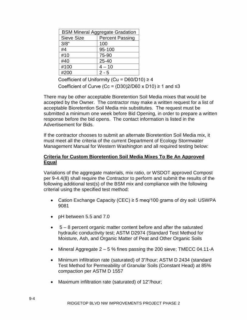
9-4 RIDGETOP BLVD NW IMPROVEMENTS PROJECT PHASE 2
BSM Mineral Aggregate Gradation Sieve Size Percent Passing 3/8” 100 #4 95-100 #10 75-90 #40 25-40 #100 4 – 10 #200 2 - 5
Coefficient of Uniformity (Cu = D60/D10) ≥ 4 Coefficient of Curve (Cc = (D30)2/D60 x D10) ≥ 1 and ≤3
There may be other acceptable Bioretention Soil Media mixes that would be accepted by the Owner. The contractor may make a written request for a list of acceptable Bioretention Soil Media mix substitutes. The request must be submitted a minimum one week before Bid Opening, in order to prepare a written response before the bid opens. The contact information is listed in the Advertisement for Bids.
If the contractor chooses to submit an alternate Bioretention Soil Media mix, it must meet all the criteria of the current Department of Ecology Stormwater Management Manual for Western Washington and all required testing below:
Criteria for Custom Bioretention Soil Media Mixes To Be An Approved Equal
Variations of the aggregate materials, mix ratio, or WSDOT approved Compost per 9-4.4(8) shall require the Contractor to perform and submit the results of the following additional test(s) of the BSM mix and compliance with the following criterial using the specified test method:
• Cation Exchange Capacity (CEC) ≥ 5 meq/100 grams of dry soil: USWPA 9081
• pH between 5.5 and 7.0
• 5 – 8 percent organic matter content before and after the saturated hydraulic conductivity test; ASTM D2974 (Standard Test Method for Moisture, Ash, and Organic Matter of Peat and Other Organic Soils
• Mineral Aggregate 2 – 5 % fines passing the 200 sieve; TMECC 04.11-A
• Minimum infiltration rate (saturated) of 3”/hour; ASTM D 2434 (standard Test Method for Permeability of Granular Soils (Constant Head) at 85% compaction per ASTM D 1557
• Maximum infiltration rate (saturated) of 12”/hour;

9-5 RIDGETOP BLVD NW IMPROVEMENTS PROJECT PHASE 2
If compost is used in creating the custom mix, it must meet all the specifications listed above for compost except the gradation specification must indicate the minimum percent passing for a range of similar particle sizes. 9-28 SIGNING MATERIALS AND FABRICATION
Add the following new section:
9-28.10 Street Name Signs
Street name signs mounted on posts shall conform to the Standard Specifications, these Special Provisions, the Manual on Uniform Traffic Control Devices for Streets and Highways, and as shown on the Plans.
1. Letters shall be white with a green background. 2. The font shall be Highway E modified. 3. Letter size shall be a combination of upper and lower case:
• First letter of word shall be upper case o 4” on roads posted 25 mph or less o 6” on roads 30 mph and greater
• Lower case letters shall be three-quarters (3/4) of the size of the upper case.
• Prefix or suffix is 2”. • The type of road (i.e. St, Dr, Ave, etc.) shall be 3” upper case
and 2.25” lower case. 4. Blank size shall be determined by the letter height and name length. 5. Sheeting shall be high intensity prismatic and retroreflective. 6. Sign borders may be omitted from the street name signs. 7. Square tubular steel posts shall be used for sign mounting as shown on
the Kitsap County Road Standard Detail, Figure 5-1, Type ST-2 Sign Support.
9-29 ILLUMINATION, SIGNAL, ELECTRICAL Supplement this section with the following:
General All bolts, nuts, washers, and other fasteners shall be stainless steel unless otherwise specified herein. Where applicable, all materials, equipment, and installation procedures shall conform to the current requirements and standards of the State of Washington Department of Labor and Industries.
9-6 RIDGETOP BLVD NW IMPROVEMENTS PROJECT PHASE 2
9-29.1 Conduit, Innerduct and Outerduct Supplement this section with the following:
The type of conduit to be used at specific locations is noted in Section 8-20.3(5) of these Special Provisions.
9-29.2 Junction Boxes, Cable Vaults, and Pull Boxes 9-29.2(1) Junction Boxes Supplement this section with the following:
Junction boxes shall conform to the latest WSDOT Standard Plans for locking junction boxes of the type specified. Junction boxes shall be marked for their use in accordance with the following schedule:
System Type Legend Illumination LT Interconnect Only COMM
Junction boxes shall have galvanized metallic lids. All frames and lids shall be hot-dip galvanized. All junction boxes placed in the sidewalk area shall have a non-slip surface on the lid meeting the requirements of WSDOT Certification for slip resistant applications for utility boxes, frames and other similar appurtenances meeting a static coefficient of friction (COF) of 0.6 for pedestrian access routes (PAR’s) in accordance with testing procedures ASTM F-1679, ASTM C-1028 and ASTM F-1667.
9-29.2(2) Cable Vaults and Pull Boxes 9-29.2(2)A Standard Duty Cable Vaults and Pull Boxes Supplement this section with the following:
Pull Boxes shall be 24” x 36” Stackable Assembly with 2-piece cover .
9-29.3 Fiber Optic Cable, Electrical Conductors, and Cable Supplement this section with the following:

9-7 RIDGETOP BLVD NW IMPROVEMENTS PROJECT PHASE 2
Chemically cross-linked polyethylene type USE shall be used for insulation of conductors in raceways. No alternate will be allowed.
9-29.6 Light and Signal Standards Supplement this section with the following:
(January 7, 2019 WSDOT GSP) Light Standards with Type 1 Luminaire Arms Lighting standards shall be fabricated in conformance with the methods and materials specified on the pre-approved Plans listed below, provided the following requirements have been satisfied:
(a) Light source to pole base distance (H1) shall be as noted in the Plans. Verification of H1 distances by the Engineer, prior to fabrication, is not required. Fabrication tolerance shall be 6 inches.
(b) All other requirements of the Special Provisions have been satisfied. Pre-Approved Plan Fabricator Mounting Hgt. Drawing No. Valmont Ind. Inc. 30', 35’, 40' & 50' DB01164 Rev. B Sheets 1, 2, 3, 4 & 5 of 5 Drawing No. Ameron Pole 20',25’,30’,35’,40’, WA15LT3721 Rev. A Prod. Div. 45’ & 50' Sheet 1 and 2 of 2
9-29.7 Luminaire Fusing and Electrical Connections at Light Standard Bases, Cantilever Bases, and Sign Bridge Bases Supplement this section with the following: Luminaire fusing shall conform to Standard Specification Section 9-29.7. Fuses
shall be Bussman Type FNM, Reliance MEN, Gould Shawmut TRM or approved equivalent and shall be 10 amps.
Fuse connectors shall be installed at every pole base containing a luminaire.
Every conductor above ground potential shall be served by a quick-disconnect fused connector. Every conductor at ground potential shall be serviced by a single pin connector. Fuse connectors shall be per Standard Specification Section 9-29.7.
The fuse holders shall be readily accessible from the pole hand hole base and
have 18 inches of slack in the conductors.

9-8 RIDGETOP BLVD NW IMPROVEMENTS PROJECT PHASE 2
9-29.10 Luminaires 9-29.10(1) Conventional Roadway Luminaires Supplement this section with the following:
Conventional highway luminaires shall be light emitting diode (LED) and shall be 310 watt equivalent, LEOTEK model number GC2-80F-MV-NW-2-GY-700, or approved equivalent.
9-29.12 Electrical Splice Materials 9-29.12(1) Illumination Circuit Splices Supplement this section with the following:
All splices for the illumination circuit shall be made in the junction box employing an epoxy resin the splice kit as specified in the Standard Specifications.
9-29.15 Flashing Beacon Control Supplement this section with the following:
Rapid Flashing Beacons Rapid Flashing Beacon (RFB) indications shall comply with the dimensional, operational, and flash pattern requirements of Federal Highway Administration (FHWA) Interim Approval 21 (IA-21, Conditions 4, 5, and 6, excluding Condition 5f; https://mutcd.fhwa.dot.gov/resources/interim_approval/ia21/index.htm). RFB systems shall be capable of providing, at a minimum, the following two-channel flashing patterns: 1. NEMA Standard 50-50:
• Channel one is ON and channel two is OFF for 0.5 seconds. • Channel one is OFF and channel two is ON for 0.5 seconds. (Cycle repeats; the total flashing pattern cycle length is 1.00 second.)
2. RFB “WW+S” Pattern (IA-21 Condition 5b):
• Channel one is ON and channel two is OFF for 0.05 seconds. • Both channels are OFF for 0.05 seconds. • Channel one is OFF and channel two is ON for 0.05 seconds. • Both channels are OFF for 0.05 seconds. • Channel one is ON and channel two is OFF for 0.05 seconds. • Both channels are OFF for 0.05 seconds.

9-9 RIDGETOP BLVD NW IMPROVEMENTS PROJECT PHASE 2
• Channel one is OFF and channel two is ON for 0.05 seconds. • Both channels are OFF for 0.05 seconds. • Both channels are ON for 0.05 seconds. • Both channels are OFF for 0.05 seconds. • Both channels are ON for 0.05 seconds. • Both channels are OFF for 0.25 seconds. (Cycle repeats; the total flashing pattern cycle length is 0.80 seconds.)
The flashing pattern shall be user-selectable in the field. RFB system pushbuttons shall not include tactile arrows, speech messages, or vibrotactile indications. RFB system pushbuttons shall use a 9” x 12” R10-25 sign. The R10-25 sign may include integral yellow warning lights.
9-29.24 Service Cabinets Supplement this section with the following:
12. Enclosure shall be 12.5 inches wide by 50 inches high by 7.3 inches deep and shall meet EUSERC requirements.
13. Exterior shall be fabricated from 0.125 inch aluminum, shall be anodized and have continuous welded seams. Interior shall be fabricated from 14 gauge cold rolled steel painted white.
14. Outer door shall be fully framed, side hinged with swaged close tolerance sides for flush fit. It shall be provided with a top drip lip, closed cell neoprene flange compressed gaskets and fitted with a keyed lock.
15. Enclosure shall have a full length dead front with a stainless steel hinge, ¼ turn latch and knurled knobs. Dead front shall be hinged on the same side as exterior door and open a minimum of 100 degrees.
16. UL 508 industrial control panel labels for service entrance equipment shall be provided.
17. Pull section with removable step. Removable backpan shall be mounted on 4 welded ¼ inch studs.
18. Circuit breakers shall be mounted in a vertical position with handle up for "On" and handle down for "Off". Circuit breakers shall be of cable-in cable-out type. No "Bolt-On" or "Plug-In" circuit breakers will be allowed.
19. Enclosure shall be completely pre-wired at the factory. Wiring shall be to NEMA IIB standards showing external connections and external equipment.
20. All bussing shall be UL approved copper THHN cable bussing, fully rated. 21. The function of all circuit breakers, switches and other components shall
be identified by laminated engraved plastic nameplates with minimum ¼

9-10 RIDGETOP BLVD NW IMPROVEMENTS PROJECT PHASE 2
inch high letters and fastened with minimum of two #4 - 40 stainless steel machine screws.
22. Wiring schematics will be Computer Aided Drafting and include all external equipment and connections per NEMA IIB. As-built factory drawings shall be enclosed in clear plastic and held inside the outer door by welded hooks.
Manufacturer will be required to furnish independent laboratory certification of metal preparation and finish and to confirm that the overall product meets these specifications. If the contracting agency desires to witness this testing, all costs shall be paid by the contractor.
Service enclosure shall be Tesco Pad Mount Type III AF 26-000 Anodized Aluminum Metered Service or an approved equivalent. 9-33 CONSTRUCTION GEOSYNTHETIC 9-33.2 Geosynthetic Properties Add the following new section:
9-33.2(4) HDPE Liner The HDPE liner shall be a minimum of 20 mil thickness and meet the following specifications.
Dispersion only applies to near spherical agglomerates.9 of 10 views shall be Category 1or 2. No more than 1view from Category 3.549.
PROPERTY TEST METHOD TEST VALUE Thickness, mil (mm)
Nominal Lowest individual Reading
Density, g/cm3 Carbon Black Content, % Carbon Black Dispersion Tensile Properties: (each direction)
Strength at Yield, lb/in (kN/m) Strength at Break, lb/in (kN/m) Elongation at Yield,% Elongation at Break, %
Tear Resistance, lb(N) Puncture Resistance,lb(N) Notched Constant Tensile
ASTME D 5199
ASTM D 1505 ASME C 1603,
modified ASTM D 5596 ASTME D 6693 Type IV,2 ipm
(1.3"gauge length) (2.0"gauge length)
ASTM D 1004 ASTM D 4833 ASTM D 5397,
20 (0.51) 18 (0.45)
0.94 2.0
Note 1
42 (7) 76 (12)
12 500
13 (57) 36 (158)
400 100

S-1 RIDGETOP BLVD NW IMPROVEMENTS PROJECT PHASE 2
(April 1, 2019) Standard Plans The State of Washington Standard Plans for Road, Bridge and Municipal Construction M21-01 transmitted under Publications Transmittal No. PT 16-048, effective August 6, 2018 is made a part of this contract. The Standard Plans are revised as follows: A-40.10 Section View, PCCP to HMA Longitudinal Joint, callout, was – “Sawed Groove ~ Width 3/16” (IN) MIN. to 5/16” (IN) MAX. ~ Depth 1” (IN) MIN. ~ see Std. Spec. 5-04.3(12)B” is revised to read; “Sawed Groove ~ Width 3/16” (IN) MIN. to 5/16” (IN) MAX. ~ Depth 1” (IN) MIN. ~ see Std. Spec. Section 5-04.3(12)A2” Section View, Transverse Contraction Joint, dimension, was – “D/4” is revised to read: “D/3 to D/4” A-50.10 Sheet 2 of 2, Plan, with Single Slope Barrier, reference C-14a is revised to C-70.10 A-50.20 Sheet 2 of 2, Plan, with Anchored Barrier, reference C-14a is revised to C-70.10 A-50.30 Sheet 2 of 2, Plan (top), reference C-14a is revised to C-70.1 B-10.60 DELETED B-82.20 DELETED B-90.40 Valve Detail - DELETED C-1b STEEL POST Detail on page 2: The upper callout is changed from “3/4” (IN) DIAM. HOLE (TYP.)” to “3/4” (IN) OR 13/16” (IN) DIAM. HOLE (TYP.)” C-2C CASE 9A (typical of 2 callouts): The dimensions were “3’-0” MIN. ~ TO FACE OF GUARDRAIL”. are now revised to read “5’-0” MIN ~ TO FACE OF GUARDRAIL”. C-4b DELETED

S-2 RIDGETOP BLVD NW IMPROVEMENTS PROJECT PHASE 2
C-4e DELETED C-4f Sheet 1, BULLNOSE GRADING PLAN: Slopes shall be not steeper than 10H:1V for the bullnose guardrail system including slopes into the guardrail face to 1 foot behind the guardrail post. Sheet 2, POST 1R & 1L, 2R & 2L, 3R TO 8R and 3L TO 8L, 9R TO 12 R and 9L TO 12L elevation view details: Slopes into the guardrail face to 1 foot behind the guardrail post shall not be steeper than 10H:1V. Sheet 3, SECTION B, callout – was: “THE NUT SHALL BE ASTM A563D STEEL, AND GALVANIZED ACCORDING TO STANDARD SPEC. 9-16.3(3).” Is revised to read: ”THE NUT SHALL BE ASTM A307 STEEL, AND GALVANIZED ACCORDING TO STANDARD SPEC. 9-16.3(3).” C-20.10 STEEL POST Detail: The upper callout is changed from “1/4” (IN) DIAM. HOLE FOR ANTI-ROTATION 16d NAIL (TYP.)” to “1/4” (IN) OR 13/16” (IN) DIAM. HOLE FOR ANTI-ROTATION 16d NAIL (TYP.)” The lower callout is changed from “3/4” (IN) DIAM. HOLE FOR BUTTON HEAD BOLT (TYP.)” to “3/4” (IN) OR 13/16” (IN) DIAM. HOLE FOR BUTTON HEAD BOLT (TYP.)” C-20.14 CASE 3-31: The dimension was “5’-0” MIN” from the back of guardrail to the center of railroad signal support is now revised to “5’-0” MIN” from face of guardrail to the front edge of the railroad signal support. Note 3, was – “The slope from the edge of the shoulder into the face of the guardrail cannot exceed 10H : 1V when the face of the guardrail is less than 12’ – 0” from the edge of the shoulder.” is revised to read: “The slope from the edge of the shoulder into the face of the guardrail cannot be steeper than 10H : 1V when the face of the guardrail is less than 12’ – 0” from the edge of the shoulder. The slope from the edge of the shoulder into the face of the guardrail cannot be steeper than 6H : 1V when the guardrail is 12’ – 0” or more from the edge of the shoulder.” C-20.18 ALL CASES: The dimensions were “3’-0” MIN” from the face of guardrail to the front edge of the fixed feature are now revised to “5’-0” MIN” from the face of guardrail to the front edge of the fixed feature. Note 1, was – “The slope from the edge of the shoulder into the face of the guardrail should not exceed 10H : 1V when the guardrail is within 12’ – 0” from the edge of the shoulder.” Is revised to read: “The slope from the edge of the shoulder into the face of the guardrail should not be steeper than 10H : 1V when the guardrail is less than 12’ –

S-3 RIDGETOP BLVD NW IMPROVEMENTS PROJECT PHASE 2
0” from the edge of the shoulder. The slope from the edge of the shoulder into the face of the guardrail should not be steeper than 6H : 1V when the guardrail is 12’ – 0” or more from the edge of shoulder.” C-20.41 BOX CULVERT POST, ELEVATION VIEW Detail: The upper callout is changed from “3/4” (IN) DIAM. HOLE” to “3/4” (IN) OR 13/16” (IN) DIAM. HOLE” C-20.45 STEEL POST Detail: The upper callout is changed from “1/4” (IN) DIAM. HOLE FOR ANTI-ROTATION 16d NAIL (TYP.)” to “1/4” (IN) OR 13/16” (IN) DIAM. HOLE FOR ANTI-ROTATION 16d NAIL (TYP.)” The lower callout is changed from “3/4” (IN) DIAM. HOLE FOR BUTTON HEAD BOLT (TYP.) ~ SEE DETAIL AT RIGHT” to “3/4” (IN) OR 13/16” (IN) DIAM. HOLE FOR BUTTON HEAD BOLT (TYP.) ~ SEE DETAIL AT RIGHT” C-22.14 DELETED C-22.16 Note 3, formula, was: “Elevation G = (Elevation S – D x (0.1) + 31” is revised to read: “Elevation G = (Elevation S – D x (0.1) + 31/12” C-22.40 PLAN VIEW, MSKT-SP-MGS (TL-3) SHOWN: The dimension was “4’-0” MIN” from the face of the terminal to the edge of the widened embankment is now revised to “4’-0” MIN” from the back of the terminal post to the edge of the widened embankment. Elevation View, MSKT-SP-MGS (TL-3), dimension, MSKT-SP-MGS (TL-3) SYSTEM LENGTH = 50’ – 0” , dimension is revised to read: 46’ – 101/2” Elevation View, SOFTSTOP (TL-3), dimension, SOFTSTOP (TL-3) SYSTEM LENGTH = 50’ – 9 1/2”, dimension is revised to read: 50’ – 10 1/2” Note 6, was – “…a maximum taper of 25.4 : 1 or flatter is allowed over the system length of 50’ – 9 ½” with a maximum…” is revised to read: “…a maximum taper of 25.44 : 1 or flatter is allowed over the system length of 50’ – 10 ½” with a maximum…” C-22.45 PLAN VIEW, MSKT-SP-MGS (TL-2) SHOWN: The dimension was “4’-0” MIN” from the face of the terminal to the edge of the widened embankment is now revised to “4’-0” MIN” from the back of the terminal post to the edge of the widened embankment. Elevation View, MSKT-SP-MGS (TL-2), dimension, MSKT-SP-MGS (TL-2) SYSTEM LENGTH = 25’ – 0”, dimension is revised to read 34’ – 4 1/2”

S-4 RIDGETOP BLVD NW IMPROVEMENTS PROJECT PHASE 2
Elevation View, SOFTSTOP (TL-2), dimension, SOFTSTOP (TL-2) SYSTEM LENGTH = 38’ – 3 1/2”, dimension is revised to read 38’ – 4 1/2” Note 6, was – “…flare of 38.29 : 1 or flatter is allowed over the system length of 38’ – 3 ½” with a maximum…” is revised to read: “…flare of 38.38 : 1 or flatter is allowed over the system length of 38’ – 4 ½” with a maximum…” C-25.26 Elevation View, TYPE 23: The guardrail height dimension was 2’-8” from the top of the thrie beam to the top of the bridge curb is now revised to 2’-8” from the top of the thrie beam to the top of the ground line. C-25.80 Plan View, callout, was – “12” (IN) BLOCKOUT” is revised to read; “12” (IN) or 8” (IN) BLOCKOUT (12” (IN) SHOWN)” Elevation View, add labels to posts (below view); beginning at left side of view – Label Posts as follows; POST 1, POST 2 through POST 6”. General Notes, add Note 6. Note reads as follows; “6. Post 1 shall use an 8 inch blockout, and posts 2 through post 6 shall use 12 inch or 8 inch blockouts.” C-40.14 DELETED C-90.10 DELETED D-10.10 Wall Type 1 may be used if no traffic barrier is attached on top of the wall. Walls with traffic barriers attached on top of the wall are considered non-standard and shall be designed in accordance with the current WSDOT Bridge Design Manual (BDM) and the revisions stated in the 11/3/15 Bridge Design memorandum. D-10.15 Wall Type 2 may be used if no traffic barrier is attached on top of the wall. Walls with traffic barriers attached on top of the wall are considered non-standard and shall be designed in accordance with the current WSDOT BDM and the revisions stated in the 11/3/15 Bridge Design memorandum. D-10.20 Wall Type 3 may be used in all cases. The last sentence of Note 6 on Wall Type 3 shall be revised to read: The seismic design of these walls has been completed using a site adjusted (effective) peak ground acceleration of 0.32g. D-10.25 Wall Type 4 may be used in all cases. The last sentence of Note 6 on Wall Type 4 shall
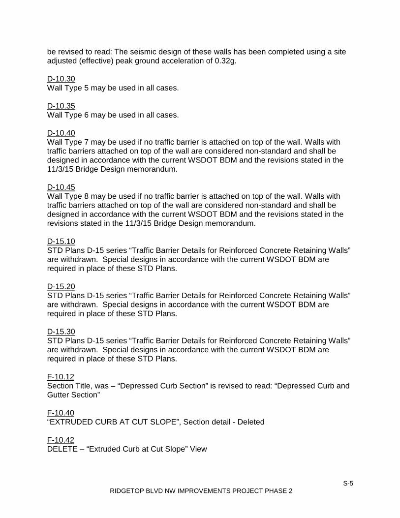
S-5 RIDGETOP BLVD NW IMPROVEMENTS PROJECT PHASE 2
be revised to read: The seismic design of these walls has been completed using a site adjusted (effective) peak ground acceleration of 0.32g. D-10.30 Wall Type 5 may be used in all cases. D-10.35 Wall Type 6 may be used in all cases. D-10.40 Wall Type 7 may be used if no traffic barrier is attached on top of the wall. Walls with traffic barriers attached on top of the wall are considered non-standard and shall be designed in accordance with the current WSDOT BDM and the revisions stated in the 11/3/15 Bridge Design memorandum. D-10.45 Wall Type 8 may be used if no traffic barrier is attached on top of the wall. Walls with traffic barriers attached on top of the wall are considered non-standard and shall be designed in accordance with the current WSDOT BDM and the revisions stated in the revisions stated in the 11/3/15 Bridge Design memorandum. D-15.10 STD Plans D-15 series “Traffic Barrier Details for Reinforced Concrete Retaining Walls” are withdrawn. Special designs in accordance with the current WSDOT BDM are required in place of these STD Plans. D-15.20 STD Plans D-15 series “Traffic Barrier Details for Reinforced Concrete Retaining Walls” are withdrawn. Special designs in accordance with the current WSDOT BDM are required in place of these STD Plans. D-15.30 STD Plans D-15 series “Traffic Barrier Details for Reinforced Concrete Retaining Walls” are withdrawn. Special designs in accordance with the current WSDOT BDM are required in place of these STD Plans. F-10.12 Section Title, was – “Depressed Curb Section” is revised to read: “Depressed Curb and Gutter Section” F-10.40 “EXTRUDED CURB AT CUT SLOPE”, Section detail - Deleted F-10.42 DELETE – “Extruded Curb at Cut Slope” View

S-6 RIDGETOP BLVD NW IMPROVEMENTS PROJECT PHASE 2
H-70.20 Sheet 2, Spacing Detail, Mailbox Support Type 1, reference to Standard Plan I-70.10 is revised to H-70.10 I-30.30 8” Diameter Wattle Spacing Table, lower left corner, was –“Slope:1H : 1V, Maximum Spacing:10’ – 0”” is revised to read: “Slope:1H : 1V, Maximum Spacing:8’ – 0””. J-10.21 Note 18, was – “When service cabinet is installed within right of way fence, see Standard Plan J-10.22 for details.” Is revised to read; “When service cabinet is installed within right of way fence, or the meter base is mounted on the exterior of the cabinet, see Standard Plan J-10.22 for details.” J-10.22 Key Note 1, was – “Meter base per serving utility requirements~ as a minimum, the meter base shall be safety socket box with factory-installed test bypass facility that meets the requirements of EUSERC drawing 305.” Is revised to read; “Meter base per serving utility requirements~ as a minimum, the meter base shall be safety socket box with factory-installed test bypass facility that meets the requirements of EUSERC drawing 305. When the utility requires meter base to be mounted on the side or back of the service cabinet, the meter base enclosure shall be fabricated from type 304 stainless steel.” Key Note 4, “Test with (SPDT Snap Action, Positive close 15 Amp – 120/277 volt “T” rated). Is revised to read: “Test Switch (SPDT snap action, positive close 15 amp – 120/277 volt “T” rated).” Key Note 14, was – “Hinged dead front with ¼ turn fasteners or slide latch.” Is revised to read; “Hinged dead front with ¼ turn fasteners or slide latch. ~ Dead front panel bolts shall not extend into the vertical limits of the breaker array(s).” Key Note 15, was – “Cabinet Main Bonding Jumper. Buss shall be 4 lug tinned copper. See Cabinet Main bonding Jumper detail, Standard Plan J-3b.“ is revised to read; “Cabinet Main Bonding Jumper Assembly ~ Buss shall be 4 lug tinned copper ~ See Standard Plan J-10.20 for Cabinet Main Bonding Jumper Assembly details.” Note 1, was – “…socket box mounting detail, see Standard Plan J-3b.” is revised to read to read: “…socket box mounting detail, see Standard Plan J-10.20.” Note 6, was – “…See door hinge detail, Standard Plan J-3b.” is revised to read: “…See door hinge detail, Standard Plan J-10.20.” J-20.10 Add Note 5, “5. One accessible pedestrian signal assembly per pedestrian pushbutton post.” J-20.11 Sheet 2, Foundation Detail, Elevation, callout – “Type 1 Signal Pole” is revised to read: “Type PS or Type 1 Signal Pole” Sheet 2, Foundation Detail, Elevation, add note below Title, “(Type 1 Signal Pole

S-7 RIDGETOP BLVD NW IMPROVEMENTS PROJECT PHASE 2
Shown)” Add Note 6, “6. One accessible pedestrian signal assembly per pedestrian pushbutton post.” J-20.26 Add Note 1, “1. One accessible pedestrian pushbutton station per pedestrian pushbutton post.” J-20.16 View A, callout, was – LOCK NIPPLE, is revised to read; CHASE NIPPLE J-21.10 Sheet 1, Elevation View, Round Concrete Foundation Detail, callout – “ANCHOR BOLTS ~ ¾” (IN) x 30” (IN) FULL THREAD ~ THREE REQ’D. PER ASSEMBLY” IS REVISED TO READ: “ANCHOR BOLTS ~ ¾” (IN) x 30” (IN) FULL THREAD ~ FOUR REQ’D. PER ASSEMBLY” Sheet 1 of 2, Elevation view (Round), add dimension depicting the distance from the top of the foundation to find 2 #4 reinforcing bar shown, to read; 3” CLR.. Delete “(TYP.)” from the 2 ½” CLR. dimension, depicting the distance from the bottom of the foundation to find 2 # 4 reinf. Bar. Sheet 1 of 2, Elevation view (Square), add dimension depicting the distance from the top of the foundation to find 1 #4 reinforcing bar shown, to read; 3” CLR. Delete “(TYP.)” from the 2 ½” CLR. dimension, depicting the distance from the bottom of the foundation to find 1 # 4 reinf. Bar. Sheet 2 of 2, Elevation view (Round), add dimension depicting the distance from the top of the foundation to find 2 #4 reinforcing bar shown, to read; 3” CLR. Delete “(TYP.)” from the 2 ½” CLR. dimension, depicting the distance from the bottom of the foundation to find 2 # 4 reinf. Bar. Sheet 2 of 2, Elevation view (Square), add dimension depicting the distance from the top of the foundation to find 1 #4 reinforcing bar shown, to read; 3” CLR. Delete “(TYP.)” from the 2 ½” CLR. dimension, depicting the distance from the bottom of the foundation to find 1 # 4 reinf. Bar. Detail F, callout, “Heavy Hex Clamping Bolt (TYP.) ~ 3/4” (IN) Diam. Torque Clamping Bolts (see Note 3)” is revised to read; “Heavy Hex Clamping Bolt (TYP.) ~ 3/4” (IN) Diam. Torque Clamping Bolts (see Note 1)” Detail F, callout, “3/4” (IN) x 2’ – 6” Anchor Bolt (TYP.) ~ Four Required (See Note 4)” is revised to read; “3/4” (IN) x 2’ – 6” Anchor Bolt (TYP.) ~ Three Required (See Note 2)” J-21.15 Partial View, callout, was – LOCK NIPPLE ~ 1 ½” DIAM., is revised to read; CHASE NIPPLE ~ 1 ½” (IN) DIAM. J-21.16 Detail A, callout, was – LOCKNIPPLE, is revised to read; CHASE NIPPLE
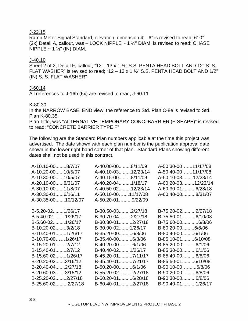
S-8 RIDGETOP BLVD NW IMPROVEMENTS PROJECT PHASE 2
J-22.15 Ramp Meter Signal Standard, elevation, dimension 4’ - 6” is revised to read; 6’-0” (2x) Detail A, callout, was – LOCK NIPPLE ~ 1 ½” DIAM. is revised to read; CHASE NIPPLE ~ 1 ½” (IN) DIAM. J-40.10 Sheet 2 of 2, Detail F, callout, “12 – 13 x 1 ½” S.S. PENTA HEAD BOLT AND 12” S. S. FLAT WASHER” is revised to read; “12 – 13 x 1 ½” S.S. PENTA HEAD BOLT AND 1/2” (IN) S. S. FLAT WASHER” J-60.14 All references to J-16b (6x) are revised to read; J-60.11 K-80.30 In the NARROW BASE, END view, the reference to Std. Plan C-8e is revised to Std. Plan K-80.35 Plan Title, was “ALTERNATIVE TEMPORARY CONC. BARRIER (F-SHAPE)” is revised to read: “CONCRETE BARRIER TYPE F” The following are the Standard Plan numbers applicable at the time this project was advertised. The date shown with each plan number is the publication approval date shown in the lower right-hand corner of that plan. Standard Plans showing different dates shall not be used in this contract. A-10.10-00........8/7/07 A-40.00-00.........8/11/09 A-50.30-00…....11/17/08 A-10.20-00......10/5/07 A-40.10-03.........12/23/14 A-50.40-00…....11/17/08 A-10.30-00......10/5/07 A-40.15-00.........8/11/09 A-60.10-03........12/23/14 A-20.10-00......8/31/07 A-40.20-04.........1/18/17 A-60.20-03.........12/23/14 A-30.10-00......11/8/07 A-40.50-02.........12/23/14 A-60.30-01..........6/28/18 A-30.30-01......6/16/11 A-50.10-00…....11/17/08 A-60.40-00..........8/31/07 A-30.35-00.......10/12/07 A-50.20-01…......9/22/09
B-5.20-02........1/26/17 B-30.50-03.........2/27/18 B-75.20-02..........2/27/18 B-5.40-02.........1/26/17 B-30.70-04.........2/27/18 B-75.50-01..........6/10/08 B-5.60-02.........1/26/17 B-30.80-01..........2/27/18 B-75.60-00............6/8/06 B-10.20-02........3/2/18 B-30.90-02........1/26/17 B-80.20-00.........6/8/06 B-10.40-01........1/26/17 B-35.20-00..........6/8/06 B-80.40-00.........6/1/06 B-10.70-00……1/26/17 B-35.40-00..........6/8/06 B-85.10-01.........6/10/08 B-15.20-01........2/7/12 B-40.20-00..........6/1/06 B-85.20-00..........6/1/06 B-15.40-01........2/7/12 B-40.40-02........1/26/17 B-85.30-00..........6/1/06 B-15.60-02........1/26/17 B-45.20-01..........7/11/17 B-85.40-00..........6/8/06 B-20.20-02.......3/16/12 B-45.40-01..........7/21/17 B-85.50-01.........6/10/08 B-20.40-04.......2/27/18 B-50.20-00..........6/1/06 B-90.10-00….......6/8/06 B-20.60-03.......3/15/12 B-55.20-02..........2/27/18 B-90.20-00..........6/8/06 B-25.20-02........2/27/18 B-60.20-01..........6/28/18 B-90.30-00..........6/8/06 B-25.60-02.........2/27/18 B-60.40-01..........2/27/18 B-90.40-01..........1/26/17

S-9 RIDGETOP BLVD NW IMPROVEMENTS PROJECT PHASE 2
B-30.10-03.........2/27/18 B-65.20-01..........4/26/12 B-90.50-00..........6/8/06 B-30.15-00……..2/27/18 B-65.40-00..........6/1/06 B-95.20-01..........2/3/09 B-30.20-04.........2/27/18 B-70.20-00..........6/1/06 B-95.40-01..........6/28/18 B-30.30-03.........2/27/18 B-70.60-01..........1/26/17 B-30.40-03..........2/27/18
C-1....................6/28/18 C-20.15-02..........6/11/14 C-40.18-03........7/21/17 C-1a.................7/14/15 C-20.18-02..........6/11/14 C-70.10-01........6/17/14 C-1b...................7/14/15 C-20.19-02..........6/11/14 C-75.10-01........6/11/14 C-1d................10/31/03 C-20.40-06..........7/21/17 C-75.20-01........6/11/14 C-2c..................6/21/06 C-20.41-01..........7/14/15 C-75.30-01........6/11/14 C-4f...................7/2/12 C-20.42-05..........7/14/15 C-80.10-01........6/11/14 C-6a................10/14/09 C-20.45.01...........7/2/12 C-80.20-01........6/11/14 C-7.....................6/16/11 C-22.16-06........7/21/17 C-80.30-01........6/11/14 C-7a...................6/16/11 C-22.40-06........7/21/17 C-80.40-01........6/11/14 C-8.....................2/10/09 C-22.45-03........7/21/17 C-80.50-00........4/8/12 C-8a...................7/25/97 C-23.60-04........7/21/17 C-85.10-00........4/8/12 C-8b....................2/29/16 C.24.10-01........6/11/14 C-85.11-00........4/8/12 C-8e....................2/21/07 C-25.20-06........7/14/15 C-85.14-01........6/11/14 C-8f.....................6/30/04 C-25.22-05........7/14/15 C-85.15-01........6/30/14 C-16a.................7/21/17 C-25.26-03........7/14/15 C-85.16-01........6/17/14 C-20.10-04.........7/21/17 C-25.30-00…….6/28/18 C-85-18-01........6/11/14 C-20.11-00……..7/21/17 C-25.80-04........7/15/16 C-85.20-01........6/11/14 C-20.14-03..........6/11/14 C-40.16-02........7/2/12
D-2.04-00........11/10/05 D-2.48-00........11/10/05 D-3.17-02……5/9/16 D-2.06-01........1/6/09 D-2.64-01........1/6/09 D-4.................12/11/98 D-2.08-00........11/10/05 D-2.66-00........11/10/05 D-6...................6/19/98 D-2.14-00........11/10/05 D-2.68-00........11/10/05 D-10.10-01......12/2/08 D-2.16-00........11/10/05 D-2.80-00........11/10/05 D-10.15-01......12/2/08 D-2.18-00........11/10/05 D-2.82-00........11/10/05 D-10.20-00.........7/8/08 D-2.20-00........11/10/05 D-2.84-00........11/10/05 D-10.25-00.........7/8/08 D-2.32-00........11/10/05 D-2.86-00........11/10/05 D-10.30-00.........7/8/08 D-2.34-01........1/6/09 D-2.88-00........11/10/05 D-10.35-00.........7/8/08 D-2.36-03........6/11/14 D-2.92-00........11/10/05 D-10.40-01......12/2/08 D-2.42-00........11/10/05 D-3.09-00........5/17/12 D-10.45-01......12/2/08 D-2.44-00........11/10/05 D-3.10-01……5/29/13 D-15.10-01......12/2/08 D-2.60-00........11/10/05 D-3.11-03……6/11/14 D-15.20-03........5/9/16 D-2.62-00........11/10/05 D-3.15-02……6/10/13 D-15.30-01......12/02/08 D-2.46-01........6/11/14 D-3.16-02……5/29/13
E-1....................2/21/07 E-4....................8/27/03 E-2....................5/29/98 E-4a..................8/27/03
F-10.12-03.......6/11/14 F-10.62-02........4/22/14 F-40.15-03........6/29/16 F-10.16-00.......12/20/06 F-10.64-03........4/22/14 F-40.16-03........6/29/16

S-10 RIDGETOP BLVD NW IMPROVEMENTS PROJECT PHASE 2
F-10.18-01.........7/11/17 F-30.10-03........6/11/14 F-45.10-02........7/15/16 F-10.40-03...........6/29/16 F-40.12-03........6/29/16 F-80.10-04........7/15/16 F-10.42-00.........1/23/07 F-40.14-03........6/29/16
G-10.10-00........9/20/07 G-25.10-04.......6/10/13 G-90.10-03……7/11/17 G-20.10-02........6/23/15 G-30.10-04.......6/23/15 G-90.11-00……4/28/16 G-22.10-04..........6/28/18 G-50.10-03.......6/28/18 G-90.20-05……7/11/17 G-24.10-00......11/8/07 G-60.10-04.......6/28/18 G-90.30-04……7/11/17 G-24.20-01......2/7/12 G-60.20-02.......6/18/15 G-90.40-02……4/28/16 G-24.30-02......6/28/18 G-60.30-02.......6/18/15 G-95.10-02........6/28/18 G-24.40-07.....6/28/18 G-70.10-03.......6/18/15 G-95.20-03........6/28/18 G-24.50-04.....7/11/17 G-70.20-04.......7/21/17 G-95.30-03........6/28/18 G-24.60-05.....6/28/18 G-70.30-04.......7/21/17
H-10.10-00..........7/3/08 H-32.10-00.......9/20/07 H-70.10-01......2/7/12 H-10.15-00..........7/3/08 H-60.10-01.........7/3/08 H-70.20-01......2/16/12 H-30.10-00......10/12/07 H-60.20-01.........7/3/08 H-70.30-02......2/7/12
I-10.10-01.........8/11/09 I-30.20-00.........9/20/07 I-40.20-00.........9/20/07 I-30.10-02.........3/22/13 I-30.30-01.........6/10/13 I-50.20-01..........6/10/13 I-30.15-02.........3/22/13 I-30.40-01.......6/10/13 I-60.10-01..........6/10/13 I-30.16-00.........3/22/13 I-30.60-01.........3/7/18 I-60.20-01..........6/10/13 I-30.17-00.........3/22/13 I-40.10-00.........9/20/07 I-80.10-02..........7/15/16
J-10..................7/18/97 J-28.22-00.......8/07/07 J-50.25-00…….6/3/11 J-10.10-03……6/3/15 J-28.24-01.......6/3/15 J-50.30-00…….6/3/11 J-10.15-01........6/11/14 J-28.26-01......12/02/08 J-60.05-01…….7/21/16 J-10.16-00……6/3/15 J-28.30-03......6/11/14 J-60.11-00…....5/20/13 J-10.17-00……6/3/15 J-28.40-02......6/11/14 J-60.12-00…....5/20/13 J-10.18-00……6/3/15 J-28.42-01.......6/11/14 J-60.13-00…....6/16/10 J-10.20-01……6/1/16 J-28.43-01.......6/28/18 J-60.14-00……6/16/10 J-10.21-00……6/3/15 J-28.45-03.......7/21/16 J-75.10-02……7/10/15 J-10.22-00........5/29/13 J-28.50-03.......7/21/16 J-75.20-01……7/10/15 J-10.25-00……7/11/17 J-28.60-02.......7/21/16 J-75.30-02…….7/10/15 J-12.15-00……6/28/18 J-28.70-03.......7/21/17 J-75.40-02……6/1/16 J-12.16-00……6/28/18 J-29.10-01.......7/21/16 J-75.41-01……6/29/16 J-15.10-01........6/11/14 J-29.15-01.......7/21/16 J-75.45-02……6/1/16 J-15.15-02……7/10/15 J-29.16-02.......7/21/16 J-80.10-00……6/28/18 J-20.10-03........6/30/14 J-30.10-00…...6/18/15 J-80.15-00……6/28/18 J-20.11-02........6/30/14 J-40.05-00……7/21/16 J-81.10-00……6/28/18 J-20.15-03........6/30/14 J-40.10-04…...4/28/16 J-86.10-00……6/28/18 J-20.16-02........6/30/14 J-40.20-03…...4/28/16 J-90.10-03…….6/28/18 J-20.20-02........5/20/13 J-40.30-04……4/28/16 J-90.20-03…….6/28/18 J-20.26-01........7/12/12 J-40.35-01……5/29/13 J-90.21-02……6/28/18 J-21.10-04......6/30/14 J-40.36-02……7/21/17 J-90.50-00……6/28/18 J-21.15-01......6/10/13 J-40.37-02……7/21/17
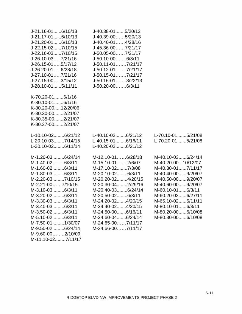
S-11 RIDGETOP BLVD NW IMPROVEMENTS PROJECT PHASE 2
J-21.16-01......6/10/13 J-40.38-01.......5/20/13 J-21.17-01......6/10/13 J-40.39-00……5/20/13 J-21.20-01......6/10/13 J-40.40-01……4/28/16 J-22.15-02......7/10/15 J-45.36-00……7/21/17 J-22.16-03......7/10/15 J-50.05-00……7/21/17 J-26.10-03…..7/21/16 J-50.10-00…….6/3/11 J-26.15-01…..5/17/12 J-50.11-01…….7/21/17 J-26.20-01…..6/28/18 J-50.12-01…….7/21/17 J-27.10-01…..7/21/16 J-50.15-01…….7/21/17 J-27.15-00…..3/15/12 J-50.16-01…….3/22/13 J-28.10-01......5/11/11 J-50.20-00…….6/3/11
K-70.20-01.......6/1/16 K-80.10-01.......6/1/16 K-80.20-00.....12/20/06 K-80.30-00.......2/21/07 K-80.35-00.......2/21/07 K-80.37-00.......2/21/07
L-10.10-02........6/21/12 L-40.10-02........6/21/12 L-70.10-01.......5/21/08 L-20.10-03........7/14/15 L-40.15-01........6/16/11 L-70.20-01.......5/21/08 L-30.10-02........6/11/14 L-40.20-02........6/21/12
M-1.20-03.........6/24/14 M-12.10-01……6/28/18 M-40.10-03......6/24/14 M-1.40-02.........6/3/11 M-15.10-01........2/6/07 M-40.20-00...10/12/07 M-1.60-02.........6/3/11 M-17.10-02........7/3/08 M-40.30-01......7/11/17 M-1.80-03.........6/3/11 M-20.10-02........6/3/11 M-40.40-00......9/20/07 M-2.20-03.........7/10/15 M-20.20-02........4/20/15 M-40.50-00......9/20/07 M-2.21-00……7/10/15 M-20.30-04........2/29/16 M-40.60-00......9/20/07 M-3.10-03.........6/3/11 M-20.40-03........6/24/14 M-60.10-01......6/3/11 M-3.20-02.........6/3/11 M-20.50-02........6/3/11 M-60.20-02......6/27/11 M-3.30-03.........6/3/11 M-24.20-02.......4/20/15 M-65.10-02......5/11/11 M-3.40-03.........6/3/11 M-24.40-02.......4/20/15 M-80.10-01......6/3/11 M-3.50-02.........6/3/11 M-24.50-00.......6/16/11 M-80.20-00......6/10/08 M-5.10-02.........6/3/11 M-24.60-04.......6/24/14 M-80.30-00......6/10/08 M-7.50-01.........1/30/07 M-24.65-00……7/11/17 M-9.50-02.........6/24/14 M-24.66-00……7/11/17 M-9.60-00……..2/10/09 M-11.10-02........7/11/17

S-12 RIDGETOP BLVD NW IMPROVEMENTS PROJECT PHASE 2
THIS PAGE INTENTIONALLY LEFT BLANK

RIDGETOP BLVD NW IMPROVEMENTS PROJECT PHASE 2
ATTACHMENTS

RIDGETOP BLVD NW IMPROVEMENTS PROJECT PHASE 2
THIS PAGE INTENTIONALLY LEFT BLANK

State of Washington Department of Labor & Industries
Prevailing Wage Section - Telephone 360-902-5335 PO Box 44540, Olympia, WA 98504-4540
Washington State Prevailing Wage The PREVAILING WAGES listed here include both the hourly wage rate and the hourly rate of fringe benefits. On public works projects, worker's wage and benefit rates must add to
not less than this total. A brief description of overtime calculation requirements are provided on the Benefit Code Key.
Prevailing wage rates which have been published On: 2/1/2019 and will be effective from: 3/3/2019
County Trade Job Classification Wage Holiday Overtime NoteKitsap Asbestos Abatement
WorkersJourney Level $46.57 5D 1H
Kitsap Boilermakers Journey Level $66.54 5N 1CKitsap Brick Mason Journey Level $57.32 5A 1MKitsap Brick Mason Pointer-Caulker-Cleaner $57.32 5A 1MKitsap Building Service Employees Janitor $12.00 1Kitsap Building Service Employees Shampooer $12.00 1Kitsap Building Service Employees Waxer $12.00 1Kitsap Building Service Employees Window Cleaner $13.22 1Kitsap Cabinet Makers (In Shop) Journey Level $23.72 1Kitsap Carpenters Acoustical Worker $60.04 5D 4CKitsap Carpenters Bridge, Dock And Wharf
Carpenters$60.04 5D 4C
Kitsap Carpenters Carpenter $60.04 5D 4CKitsap Carpenters Carpenters on Stationary
Tools$60.17 5D 4C
Kitsap Carpenters Creosoted Material $60.14 5D 4CKitsap Carpenters Floor Finisher $60.04 5D 4CKitsap Carpenters Floor Layer $60.04 5D 4CKitsap Carpenters Scaffold Erector $60.04 5D 4CKitsap Cement Masons Journey Level $60.07 7A 4UKitsap Divers & Tenders Bell/Vehicle or
Submersible Operator (Not Under Pressure)
$113.60 5D 4C
Kitsap Divers & Tenders Dive Supervisor/Master $76.33 5D 4CKitsap Divers & Tenders Diver $113.60 5D 4C 8VKitsap Divers & Tenders Diver On Standby $71.33 5D 4CKitsap Divers & Tenders Diver Tender $64.71 5D 4CKitsap Divers & Tenders Manifold Operator $64.71 5D 4CKitsap Divers & Tenders $69.71 5D 4C
Page 1 of 21
6/27/2019https://fortress.wa.gov/lni/wagelookup/wageupdatepublication.aspx?PubCtlId=149
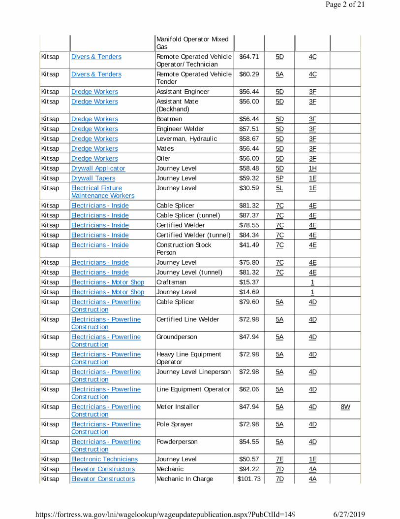
Manifold Operator Mixed Gas
Kitsap Divers & Tenders Remote Operated Vehicle Operator/Technician
$64.71 5D 4C
Kitsap Divers & Tenders Remote Operated Vehicle Tender
$60.29 5A 4C
Kitsap Dredge Workers Assistant Engineer $56.44 5D 3FKitsap Dredge Workers Assistant Mate
(Deckhand)$56.00 5D 3F
Kitsap Dredge Workers Boatmen $56.44 5D 3FKitsap Dredge Workers Engineer Welder $57.51 5D 3FKitsap Dredge Workers Leverman, Hydraulic $58.67 5D 3FKitsap Dredge Workers Mates $56.44 5D 3FKitsap Dredge Workers Oiler $56.00 5D 3FKitsap Drywall Applicator Journey Level $58.48 5D 1HKitsap Drywall Tapers Journey Level $59.32 5P 1EKitsap Electrical Fixture
Maintenance WorkersJourney Level $30.59 5L 1E
Kitsap Electricians - Inside Cable Splicer $81.32 7C 4EKitsap Electricians - Inside Cable Splicer (tunnel) $87.37 7C 4EKitsap Electricians - Inside Certified Welder $78.55 7C 4EKitsap Electricians - Inside Certified Welder (tunnel) $84.34 7C 4EKitsap Electricians - Inside Construction Stock
Person$41.49 7C 4E
Kitsap Electricians - Inside Journey Level $75.80 7C 4EKitsap Electricians - Inside Journey Level (tunnel) $81.32 7C 4EKitsap Electricians - Motor Shop Craftsman $15.37 1Kitsap Electricians - Motor Shop Journey Level $14.69 1Kitsap Electricians - Powerline
ConstructionCable Splicer $79.60 5A 4D
Kitsap Electricians - Powerline Construction
Certified Line Welder $72.98 5A 4D
Kitsap Electricians - Powerline Construction
Groundperson $47.94 5A 4D
Kitsap Electricians - Powerline Construction
Heavy Line Equipment Operator
$72.98 5A 4D
Kitsap Electricians - Powerline Construction
Journey Level Lineperson $72.98 5A 4D
Kitsap Electricians - Powerline Construction
Line Equipment Operator $62.06 5A 4D
Kitsap Electricians - Powerline Construction
Meter Installer $47.94 5A 4D 8W
Kitsap Electricians - Powerline Construction
Pole Sprayer $72.98 5A 4D
Kitsap Electricians - Powerline Construction
Powderperson $54.55 5A 4D
Kitsap Electronic Technicians Journey Level $50.57 7E 1EKitsap Elevator Constructors Mechanic $94.22 7D 4AKitsap Elevator Constructors Mechanic In Charge $101.73 7D 4A
Page 2 of 21
6/27/2019https://fortress.wa.gov/lni/wagelookup/wageupdatepublication.aspx?PubCtlId=149

Kitsap Fabricated Precast Concrete Products
Journey Level $13.50 1
Kitsap Fabricated Precast Concrete Products
Journey Level - In-Factory Work Only
$13.50 1
Kitsap Fence Erectors Fence Erector $41.45 7A 3IKitsap Fence Erectors Fence Laborer $41.45 7A 3IKitsap Flaggers Journey Level $41.45 7A 3IKitsap Glaziers Journey Level $64.56 7L 1YKitsap Heat & Frost Insulators And
Asbestos WorkersJourneyman $73.58 5J 4H
Kitsap Heating Equipment Mechanics
Journey Level $82.51 7F 1E
Kitsap Hod Carriers & Mason Tenders
Journey Level $50.42 7A 3I
Kitsap Industrial Power Vacuum Cleaner
Journey Level $29.89 1
Kitsap Inland Boatmen Boat Operator $61.41 5B 1KKitsap Inland Boatmen Cook $56.48 5B 1KKitsap Inland Boatmen Deckhand $57.48 5B 1KKitsap Inland Boatmen Deckhand Engineer $58.81 5B 1KKitsap Inland Boatmen Launch Operator $58.89 5B 1KKitsap Inland Boatmen Mate $57.31 5B 1KKitsap Inspection/Cleaning/Sealing
Of Sewer & Water Systems By Remote Control
Cleaner Operator, Foamer Operator
$12.00 1
Kitsap Inspection/Cleaning/Sealing Of Sewer & Water Systems By Remote Control
Grout Truck Operator $12.00 1
Kitsap Inspection/Cleaning/Sealing Of Sewer & Water Systems By Remote Control
Head Operator $12.78 1
Kitsap Inspection/Cleaning/Sealing Of Sewer & Water Systems By Remote Control
Tv Truck Operator $24.17 1
Kitsap Insulation Applicators Journey Level $60.04 5D 4CKitsap Ironworkers Journeyman $69.28 7N 1OKitsap Laborers Air, Gas Or Electric
Vibrating Screed$48.90 7A 3I
Kitsap Laborers Airtrac Drill Operator $50.42 7A 3IKitsap Laborers Ballast Regular Machine $48.90 7A 3IKitsap Laborers Batch Weighman $41.45 7A 3IKitsap Laborers Brick Pavers $48.90 7A 3IKitsap Laborers Brush Cutter $48.90 7A 3IKitsap Laborers Brush Hog Feeder $48.90 7A 3IKitsap Laborers Burner $48.90 7A 3IKitsap Laborers Caisson Worker $50.42 7A 3IKitsap Laborers Carpenter Tender $48.90 7A 3IKitsap Laborers Caulker $48.90 7A 3I
Page 3 of 21
6/27/2019https://fortress.wa.gov/lni/wagelookup/wageupdatepublication.aspx?PubCtlId=149

Kitsap Laborers Cement Dumper-paving $49.81 7A 3IKitsap Laborers Cement Finisher Tender $48.90 7A 3IKitsap Laborers Change House Or Dry
Shack$48.90 7A 3I
Kitsap Laborers Chipping Gun (under 30 Lbs.)
$48.90 7A 3I
Kitsap Laborers Chipping Gun(30 Lbs. And Over)
$49.81 7A 3I
Kitsap Laborers Choker Setter $48.90 7A 3IKitsap Laborers Chuck Tender $48.90 7A 3IKitsap Laborers Clary Power Spreader $49.81 7A 3IKitsap Laborers Clean-up Laborer $48.90 7A 3IKitsap Laborers Concrete Dumper/chute
Operator$49.81 7A 3I
Kitsap Laborers Concrete Form Stripper $48.90 7A 3IKitsap Laborers Concrete Placement Crew $49.81 7A 3IKitsap Laborers Concrete Saw
Operator/core Driller$49.81 7A 3I
Kitsap Laborers Crusher Feeder $41.45 7A 3IKitsap Laborers Curing Laborer $48.90 7A 3IKitsap Laborers Demolition: Wrecking &
Moving (incl. Charred Material)
$48.90 7A 3I
Kitsap Laborers Ditch Digger $48.90 7A 3IKitsap Laborers Diver $50.42 7A 3IKitsap Laborers Drill Operator
(hydraulic,diamond)$49.81 7A 3I
Kitsap Laborers Dry Stack Walls $48.90 7A 3IKitsap Laborers Dump Person $48.90 7A 3IKitsap Laborers Epoxy Technician $48.90 7A 3IKitsap Laborers Erosion Control Worker $48.90 7A 3IKitsap Laborers Faller & Bucker Chain
Saw$49.81 7A 3I
Kitsap Laborers Fine Graders $48.90 7A 3IKitsap Laborers Firewatch $41.45 7A 3IKitsap Laborers Form Setter $48.90 7A 3IKitsap Laborers Gabian Basket Builders $48.90 7A 3IKitsap Laborers General Laborer $48.90 7A 3IKitsap Laborers Grade Checker & Transit
Person$50.42 7A 3I
Kitsap Laborers Grinders $48.90 7A 3IKitsap Laborers Grout Machine Tender $48.90 7A 3IKitsap Laborers Groutmen (pressure)
including Post Tension Beams
$49.81 7A 3I
Kitsap Laborers Guardrail Erector $48.90 7A 3IKitsap Laborers Hazardous Waste Worker
(level A)$50.42 7A 3I
Page 4 of 21
6/27/2019https://fortress.wa.gov/lni/wagelookup/wageupdatepublication.aspx?PubCtlId=149

Kitsap Laborers Hazardous Waste Worker (level B)
$49.81 7A 3I
Kitsap Laborers Hazardous Waste Worker (level C)
$48.90 7A 3I
Kitsap Laborers High Scaler $50.42 7A 3IKitsap Laborers Jackhammer $49.81 7A 3IKitsap Laborers Laserbeam Operator $49.81 7A 3IKitsap Laborers Maintenance Person $48.90 7A 3IKitsap Laborers Manhole Builder-mudman $49.81 7A 3IKitsap Laborers Material Yard Person $48.90 7A 3IKitsap Laborers Motorman-dinky
Locomotive$49.81 7A 3I
Kitsap Laborers Nozzleman (concrete Pump, Green Cutter When Using Combination Of High Pressure Air & Water On Concrete & Rock, Sandblast, Gunite, Shotcrete, Water Bla
$49.81 7A 3I
Kitsap Laborers Pavement Breaker $49.81 7A 3IKitsap Laborers Pilot Car $41.45 7A 3IKitsap Laborers Pipe Layer Lead $50.42 7A 3IKitsap Laborers Pipe Layer/tailor $49.81 7A 3IKitsap Laborers Pipe Pot Tender $49.81 7A 3IKitsap Laborers Pipe Reliner $49.81 7A 3IKitsap Laborers Pipe Wrapper $49.81 7A 3IKitsap Laborers Pot Tender $48.90 7A 3IKitsap Laborers Powderman $50.42 7A 3IKitsap Laborers Powderman's Helper $48.90 7A 3IKitsap Laborers Power Jacks $49.81 7A 3IKitsap Laborers Railroad Spike Puller -
Power$49.81 7A 3I
Kitsap Laborers Raker - Asphalt $50.42 7A 3IKitsap Laborers Re-timberman $50.42 7A 3IKitsap Laborers Remote Equipment
Operator$49.81 7A 3I
Kitsap Laborers Rigger/signal Person $49.81 7A 3IKitsap Laborers Rip Rap Person $48.90 7A 3IKitsap Laborers Rivet Buster $49.81 7A 3IKitsap Laborers Rodder $49.81 7A 3IKitsap Laborers Scaffold Erector $48.90 7A 3IKitsap Laborers Scale Person $48.90 7A 3IKitsap Laborers Sloper (over 20") $49.81 7A 3IKitsap Laborers Sloper Sprayer $48.90 7A 3IKitsap Laborers Spreader (concrete) $49.81 7A 3IKitsap Laborers Stake Hopper $48.90 7A 3IKitsap Laborers Stock Piler $48.90 7A 3IKitsap Laborers $49.81 7A 3I
Page 5 of 21
6/27/2019https://fortress.wa.gov/lni/wagelookup/wageupdatepublication.aspx?PubCtlId=149
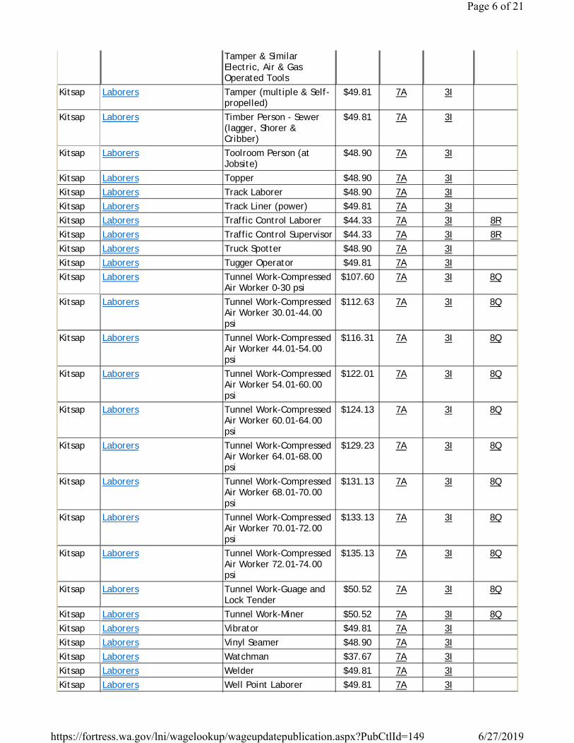
Tamper & Similar Electric, Air & Gas Operated Tools
Kitsap Laborers Tamper (multiple & Self-propelled)
$49.81 7A 3I
Kitsap Laborers Timber Person - Sewer (lagger, Shorer & Cribber)
$49.81 7A 3I
Kitsap Laborers Toolroom Person (at Jobsite)
$48.90 7A 3I
Kitsap Laborers Topper $48.90 7A 3IKitsap Laborers Track Laborer $48.90 7A 3IKitsap Laborers Track Liner (power) $49.81 7A 3IKitsap Laborers Traffic Control Laborer $44.33 7A 3I 8RKitsap Laborers Traffic Control Supervisor $44.33 7A 3I 8RKitsap Laborers Truck Spotter $48.90 7A 3IKitsap Laborers Tugger Operator $49.81 7A 3IKitsap Laborers Tunnel Work-Compressed
Air Worker 0-30 psi$107.60 7A 3I 8Q
Kitsap Laborers Tunnel Work-Compressed Air Worker 30.01-44.00 psi
$112.63 7A 3I 8Q
Kitsap Laborers Tunnel Work-Compressed Air Worker 44.01-54.00 psi
$116.31 7A 3I 8Q
Kitsap Laborers Tunnel Work-Compressed Air Worker 54.01-60.00 psi
$122.01 7A 3I 8Q
Kitsap Laborers Tunnel Work-Compressed Air Worker 60.01-64.00 psi
$124.13 7A 3I 8Q
Kitsap Laborers Tunnel Work-Compressed Air Worker 64.01-68.00 psi
$129.23 7A 3I 8Q
Kitsap Laborers Tunnel Work-Compressed Air Worker 68.01-70.00 psi
$131.13 7A 3I 8Q
Kitsap Laborers Tunnel Work-Compressed Air Worker 70.01-72.00 psi
$133.13 7A 3I 8Q
Kitsap Laborers Tunnel Work-Compressed Air Worker 72.01-74.00 psi
$135.13 7A 3I 8Q
Kitsap Laborers Tunnel Work-Guage and Lock Tender
$50.52 7A 3I 8Q
Kitsap Laborers Tunnel Work-Miner $50.52 7A 3I 8QKitsap Laborers Vibrator $49.81 7A 3IKitsap Laborers Vinyl Seamer $48.90 7A 3IKitsap Laborers Watchman $37.67 7A 3IKitsap Laborers Welder $49.81 7A 3IKitsap Laborers Well Point Laborer $49.81 7A 3I
Page 6 of 21
6/27/2019https://fortress.wa.gov/lni/wagelookup/wageupdatepublication.aspx?PubCtlId=149
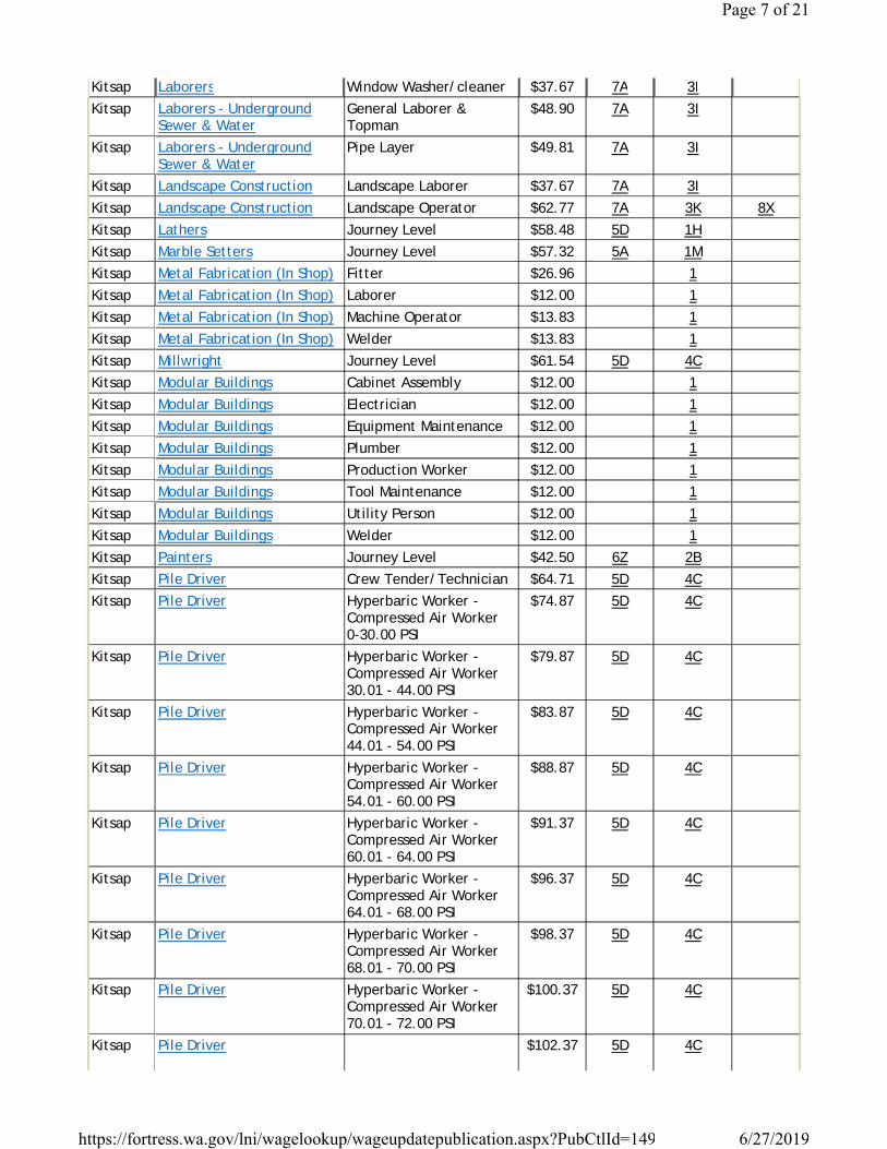
Kitsap Laborers Window Washer/cleaner $37.67 7A 3IKitsap Laborers - Underground
Sewer & WaterGeneral Laborer & Topman
$48.90 7A 3I
Kitsap Laborers - Underground Sewer & Water
Pipe Layer $49.81 7A 3I
Kitsap Landscape Construction Landscape Laborer $37.67 7A 3IKitsap Landscape Construction Landscape Operator $62.77 7A 3K 8XKitsap Lathers Journey Level $58.48 5D 1HKitsap Marble Setters Journey Level $57.32 5A 1MKitsap Metal Fabrication (In Shop) Fitter $26.96 1Kitsap Metal Fabrication (In Shop) Laborer $12.00 1Kitsap Metal Fabrication (In Shop) Machine Operator $13.83 1Kitsap Metal Fabrication (In Shop) Welder $13.83 1Kitsap Millwright Journey Level $61.54 5D 4CKitsap Modular Buildings Cabinet Assembly $12.00 1Kitsap Modular Buildings Electrician $12.00 1Kitsap Modular Buildings Equipment Maintenance $12.00 1Kitsap Modular Buildings Plumber $12.00 1Kitsap Modular Buildings Production Worker $12.00 1Kitsap Modular Buildings Tool Maintenance $12.00 1Kitsap Modular Buildings Utility Person $12.00 1Kitsap Modular Buildings Welder $12.00 1Kitsap Painters Journey Level $42.50 6Z 2BKitsap Pile Driver Crew Tender/Technician $64.71 5D 4CKitsap Pile Driver Hyperbaric Worker -
Compressed Air Worker 0-30.00 PSI
$74.87 5D 4C
Kitsap Pile Driver Hyperbaric Worker - Compressed Air Worker 30.01 - 44.00 PSI
$79.87 5D 4C
Kitsap Pile Driver Hyperbaric Worker - Compressed Air Worker 44.01 - 54.00 PSI
$83.87 5D 4C
Kitsap Pile Driver Hyperbaric Worker - Compressed Air Worker 54.01 - 60.00 PSI
$88.87 5D 4C
Kitsap Pile Driver Hyperbaric Worker - Compressed Air Worker 60.01 - 64.00 PSI
$91.37 5D 4C
Kitsap Pile Driver Hyperbaric Worker - Compressed Air Worker 64.01 - 68.00 PSI
$96.37 5D 4C
Kitsap Pile Driver Hyperbaric Worker - Compressed Air Worker 68.01 - 70.00 PSI
$98.37 5D 4C
Kitsap Pile Driver Hyperbaric Worker - Compressed Air Worker 70.01 - 72.00 PSI
$100.37 5D 4C
Kitsap Pile Driver $102.37 5D 4C
Page 7 of 21
6/27/2019https://fortress.wa.gov/lni/wagelookup/wageupdatepublication.aspx?PubCtlId=149

Hyperbaric Worker - Compressed Air Worker 72.01 - 74.00 PSI
Kitsap Pile Driver Journey Level $60.29 5D 4CKitsap Pile Driver Manifold Operator (LST) $69.71 5D 4CKitsap Plasterers Journey Level $56.54 7Q 1RKitsap Playground & Park
Equipment InstallersJourney Level $12.00 1
Kitsap Plumbers & Pipefitters Journey Level $71.42 5A 1GKitsap Power Equipment Operators Asphalt Plant Operators $63.83 7A 3K 8XKitsap Power Equipment Operators Assistant Engineer $60.04 7A 3K 8XKitsap Power Equipment Operators Barrier Machine (zipper) $63.27 7A 3K 8XKitsap Power Equipment Operators Batch Plant Operator:
concrete$63.27 7A 3K 8X
Kitsap Power Equipment Operators Bobcat $60.04 7A 3K 8XKitsap Power Equipment Operators Brokk - Remote
Demolition Equipment$60.04 7A 3K 8X
Kitsap Power Equipment Operators Brooms $60.04 7A 3K 8XKitsap Power Equipment Operators Bump Cutter $63.27 7A 3K 8XKitsap Power Equipment Operators Cableways $63.83 7A 3K 8XKitsap Power Equipment Operators Chipper $63.27 7A 3K 8XKitsap Power Equipment Operators Compressor $60.04 7A 3K 8XKitsap Power Equipment Operators Concrete Finish Machine -
Laser Screed$60.04 7A 3K 8X
Kitsap Power Equipment Operators Concrete Pump - Mounted Or Trailer High Pressure Line Pump, Pump High Pressure
$62.77 7A 3K 8X
Kitsap Power Equipment Operators Concrete Pump: Truck Mount With Boom Attachment Over 42 M
$63.83 7A 3K 8X
Kitsap Power Equipment Operators Concrete Pump: Truck Mount With Boom Attachment Up To 42m
$63.27 7A 3K 8X
Kitsap Power Equipment Operators Conveyors $62.77 7A 3K 8XKitsap Power Equipment Operators Cranes friction: 200 tons
and over$65.77 7A 3K 8X
Kitsap Power Equipment Operators Cranes: 100 tons through 199 tons, or 150’ of boom (including jib with attachments)
$64.47 7A 3K 8X
Kitsap Power Equipment Operators Cranes: 20 Tons Through 44 Tons With Attachments
$63.27 7A 3K 8X
Kitsap Power Equipment Operators Cranes: 200 tons- 299 tons, or 250’ of boom including jib with attachments
$65.13 7A 3K 8X
Kitsap Power Equipment Operators Cranes: 300 tons and over or 300’ of boom including jib with attachments
$65.77 7A 3K 8X
Page 8 of 21
6/27/2019https://fortress.wa.gov/lni/wagelookup/wageupdatepublication.aspx?PubCtlId=149

Kitsap Power Equipment Operators Cranes: 45 Tons Through 99 Tons, Under 150' Of Boom (including Jib With Attachments)
$63.83 7A 3K 8X
Kitsap Power Equipment Operators Cranes: A-frame - 10 Tons And Under
$60.04 7A 3K 8X
Kitsap Power Equipment Operators Cranes: Friction cranes through 199 tons
$65.13 7A 3K 8X
Kitsap Power Equipment Operators Cranes: through 19 tons with attachments, A-frame over 10 tons
$62.77 7A 3K 8X
Kitsap Power Equipment Operators Crusher $63.27 7A 3K 8XKitsap Power Equipment Operators Deck Engineer/Deck
Winches (power)$63.27 7A 3K 8X
Kitsap Power Equipment Operators Derricks, On Building Work
$63.83 7A 3K 8X
Kitsap Power Equipment Operators Dozers D-9 & Under $62.77 7A 3K 8XKitsap Power Equipment Operators Drill Oilers: Auger Type,
Truck Or Crane Mount$62.77 7A 3K 8X
Kitsap Power Equipment Operators Drilling Machine $64.47 7A 3K 8XKitsap Power Equipment Operators Elevator And Man-lift:
Permanent And Shaft Type
$60.04 7A 3K 8X
Kitsap Power Equipment Operators Finishing Machine, Bidwell And Gamaco & Similar Equipment
$63.27 7A 3K 8X
Kitsap Power Equipment Operators Forklift: 3000 Lbs And Over With Attachments
$62.77 7A 3K 8X
Kitsap Power Equipment Operators Forklifts: Under 3000 Lbs. With Attachments
$60.04 7A 3K 8X
Kitsap Power Equipment Operators Grade Engineer: Using Blue Prints, Cut Sheets, Etc
$63.27 7A 3K 8X
Kitsap Power Equipment Operators Gradechecker/Stakeman $60.04 7A 3K 8XKitsap Power Equipment Operators Guardrail Punch $63.27 7A 3K 8XKitsap Power Equipment Operators Hard Tail End Dump
Articulating Off- Road Equipment 45 Yards. & Over
$63.83 7A 3K 8X
Kitsap Power Equipment Operators Hard Tail End Dump Articulating Off-road Equipment Under 45 Yards
$63.27 7A 3K 8X
Kitsap Power Equipment Operators Horizontal/Directional Drill Locator
$62.77 7A 3K 8X
Kitsap Power Equipment Operators Horizontal/Directional Drill Operator
$63.27 7A 3K 8X
Kitsap Power Equipment Operators Hydralifts/Boom Trucks Over 10 Tons
$62.77 7A 3K 8X
Kitsap Power Equipment Operators Hydralifts/Boom Trucks, 10 Tons And Under
$60.04 7A 3K 8X
Kitsap Power Equipment Operators $64.47 7A 3K 8X
Page 9 of 21
6/27/2019https://fortress.wa.gov/lni/wagelookup/wageupdatepublication.aspx?PubCtlId=149

Loader, Overhead 8 Yards. & Over
Kitsap Power Equipment Operators Loader, Overhead, 6 Yards. But Not Including 8 Yards
$63.83 7A 3K 8X
Kitsap Power Equipment Operators Loaders, Overhead Under 6 Yards
$63.27 7A 3K 8X
Kitsap Power Equipment Operators Loaders, Plant Feed $63.27 7A 3K 8XKitsap Power Equipment Operators Loaders: Elevating Type
Belt$62.77 7A 3K 8X
Kitsap Power Equipment Operators Locomotives, All $63.27 7A 3K 8XKitsap Power Equipment Operators Material Transfer Device $63.27 7A 3K 8XKitsap Power Equipment Operators Mechanics, All (leadmen -
$0.50 Per Hour Over Mechanic)
$64.47 7A 3K 8X
Kitsap Power Equipment Operators Motor Patrol Graders $63.83 7A 3K 8XKitsap Power Equipment Operators Mucking Machine, Mole,
Tunnel Drill, Boring, Road Header And/or Shield
$63.83 7A 3K 8X
Kitsap Power Equipment Operators Oil Distributors, Blower Distribution & Mulch Seeding Operator
$60.04 7A 3K 8X
Kitsap Power Equipment Operators Outside Hoists (Elevators And Manlifts), Air Tuggers, Strato
$62.77 7A 3K 8X
Kitsap Power Equipment Operators Overhead, Bridge Type Crane: 20 Tons Through 44 Tons
$63.27 7A 3K 8X
Kitsap Power Equipment Operators Overhead, Bridge Type: 100 Tons And Over
$64.47 7A 3K 8X
Kitsap Power Equipment Operators Overhead, Bridge Type: 45 Tons Through 99 Tons
$63.83 7A 3K 8X
Kitsap Power Equipment Operators Pavement Breaker $60.04 7A 3K 8XKitsap Power Equipment Operators Pile Driver (other Than
Crane Mount)$63.27 7A 3K 8X
Kitsap Power Equipment Operators Plant Oiler - Asphalt, Crusher
$62.77 7A 3K 8X
Kitsap Power Equipment Operators Posthole Digger, Mechanical
$60.04 7A 3K 8X
Kitsap Power Equipment Operators Power Plant $60.04 7A 3K 8XKitsap Power Equipment Operators Pumps - Water $60.04 7A 3K 8XKitsap Power Equipment Operators Quad 9, Hd 41, D10 And
Over$63.83 7A 3K 8X
Kitsap Power Equipment Operators Quick Tower - No Cab, Under 100 Feet In Height Based To Boom
$60.04 7A 3K 8X
Kitsap Power Equipment Operators Remote Control Operator On Rubber Tired Earth Moving Equipment
$63.83 7A 3K 8X
Kitsap Power Equipment Operators Rigger and Bellman $60.04 7A 3K 8XKitsap Power Equipment Operators $62.77 7A 3K 8X
Page 10 of 21
6/27/2019https://fortress.wa.gov/lni/wagelookup/wageupdatepublication.aspx?PubCtlId=149

Rigger/Signal Person, Bellman (Certified)
Kitsap Power Equipment Operators Rollagon $63.83 7A 3K 8XKitsap Power Equipment Operators Roller, Other Than Plant
Mix$60.04 7A 3K 8X
Kitsap Power Equipment Operators Roller, Plant Mix Or Multi-lift Materials
$62.77 7A 3K 8X
Kitsap Power Equipment Operators Roto-mill, Roto-grinder $63.27 7A 3K 8XKitsap Power Equipment Operators Saws - Concrete $62.77 7A 3K 8XKitsap Power Equipment Operators Scraper, Self Propelled
Under 45 Yards$63.27 7A 3K 8X
Kitsap Power Equipment Operators Scrapers - Concrete & Carry All
$62.77 7A 3K 8X
Kitsap Power Equipment Operators Scrapers, Self-propelled: 45 Yards And Over
$63.83 7A 3K 8X
Kitsap Power Equipment Operators Service Engineers - Equipment
$62.77 7A 3K 8X
Kitsap Power Equipment Operators Shotcrete/Gunite Equipment
$60.04 7A 3K 8X
Kitsap Power Equipment Operators Shovel , Excavator, Backhoe, Tractors Under 15 Metric Tons
$62.77 7A 3K 8X
Kitsap Power Equipment Operators Shovel, Excavator, Backhoe: Over 30 Metric Tons To 50 Metric Tons
$63.83 7A 3K 8X
Kitsap Power Equipment Operators Shovel, Excavator, Backhoes, Tractors: 15 To 30 Metric Tons
$63.27 7A 3K 8X
Kitsap Power Equipment Operators Shovel, Excavator, Backhoes: Over 50 Metric Tons To 90 Metric Tons
$64.47 7A 3K 8X
Kitsap Power Equipment Operators Shovel, Excavator, Backhoes: Over 90 Metric Tons
$65.13 7A 3K 8X
Kitsap Power Equipment Operators Slipform Pavers $63.83 7A 3K 8XKitsap Power Equipment Operators Spreader, Topsider &
Screedman$63.83 7A 3K 8X
Kitsap Power Equipment Operators Subgrader Trimmer $63.27 7A 3K 8XKitsap Power Equipment Operators Tower Bucket Elevators $62.77 7A 3K 8XKitsap Power Equipment Operators Tower Crane Up To 175'
In Height Base To Boom$64.47 7A 3K 8X
Kitsap Power Equipment Operators Tower Crane: over 175’ through 250’ in height, base to boom
$65.13 7A 3K 8X
Kitsap Power Equipment Operators Tower Cranes: over 250’ in height from base to boom
$65.77 7A 3K 8X
Kitsap Power Equipment Operators Transporters, All Track Or Truck Type
$63.83 7A 3K 8X
Kitsap Power Equipment Operators Trenching Machines $62.77 7A 3K 8XKitsap Power Equipment Operators $63.27 7A 3K 8X
Page 11 of 21
6/27/2019https://fortress.wa.gov/lni/wagelookup/wageupdatepublication.aspx?PubCtlId=149

Truck Crane Oiler/driver - 100 Tons And Over
Kitsap Power Equipment Operators Truck Crane Oiler/Driver Under 100 Tons
$62.77 7A 3K 8X
Kitsap Power Equipment Operators Truck Mount Portable Conveyor
$63.27 7A 3K 8X
Kitsap Power Equipment Operators Welder $63.83 7A 3K 8XKitsap Power Equipment Operators Wheel Tractors, Farmall
Type$60.04 7A 3K 8X
Kitsap Power Equipment Operators Yo Yo Pay Dozer $63.27 7A 3K 8XKitsap Power Equipment
Operators- Underground Sewer & Water
Asphalt Plant Operators $63.83 7A 3K 8X
Kitsap Power Equipment Operators- Underground Sewer & Water
Assistant Engineer $60.04 7A 3K 8X
Kitsap Power Equipment Operators- Underground Sewer & Water
Barrier Machine (zipper) $63.27 7A 3K 8X
Kitsap Power Equipment Operators- Underground Sewer & Water
Batch Plant Operator, Concrete
$63.27 7A 3K 8X
Kitsap Power Equipment Operators- Underground Sewer & Water
Bobcat $60.04 7A 3K 8X
Kitsap Power Equipment Operators- Underground Sewer & Water
Brokk - Remote Demolition Equipment
$60.04 7A 3K 8X
Kitsap Power Equipment Operators- Underground Sewer & Water
Brooms $60.04 7A 3K 8X
Kitsap Power Equipment Operators- Underground Sewer & Water
Bump Cutter $63.27 7A 3K 8X
Kitsap Power Equipment Operators- Underground Sewer & Water
Cableways $63.83 7A 3K 8X
Kitsap Power Equipment Operators- Underground Sewer & Water
Chipper $63.27 7A 3K 8X
Kitsap Power Equipment Operators- Underground Sewer & Water
Compressor $60.04 7A 3K 8X
Kitsap Power Equipment Operators- Underground Sewer & Water
Concrete Finish Machine - Laser Screed
$60.04 7A 3K 8X
Kitsap Power Equipment Operators- Underground Sewer & Water
Concrete Pump - Mounted Or Trailer High Pressure Line Pump, Pump High Pressure
$62.77 7A 3K 8X
Kitsap Power Equipment Operators- Underground Sewer & Water
Concrete Pump: Truck Mount With Boom Attachment Over 42 M
$63.83 7A 3K 8X
Page 12 of 21
6/27/2019https://fortress.wa.gov/lni/wagelookup/wageupdatepublication.aspx?PubCtlId=149

Kitsap Power Equipment Operators- Underground Sewer & Water
Concrete Pump: Truck Mount With Boom Attachment Up To 42m
$63.27 7A 3K 8X
Kitsap Power Equipment Operators- Underground Sewer & Water
Conveyors $62.77 7A 3K 8X
Kitsap Power Equipment Operators- Underground Sewer & Water
Cranes friction: 200 tons and over
$65.77 7A 3K 8X
Kitsap Power Equipment Operators- Underground Sewer & Water
Cranes: 100 tons through 199 tons, or 150’ of boom (including jib with attachments)
$64.47 7A 3K 8X
Kitsap Power Equipment Operators- Underground Sewer & Water
Cranes: 20 Tons Through 44 Tons With Attachments
$63.27 7A 3K 8X
Kitsap Power Equipment Operators- Underground Sewer & Water
Cranes: 200 tons- 299 tons, or 250’ of boom including jib with attachments
$65.13 7A 3K 8X
Kitsap Power Equipment Operators- Underground Sewer & Water
Cranes: 300 tons and over or 300’ of boom including jib with attachments
$65.77 7A 3K 8X
Kitsap Power Equipment Operators- Underground Sewer & Water
Cranes: 45 Tons Through 99 Tons, Under 150' Of Boom (including Jib With Attachments)
$63.83 7A 3K 8X
Kitsap Power Equipment Operators- Underground Sewer & Water
Cranes: A-frame - 10 Tons And Under
$60.04 7A 3K 8X
Kitsap Power Equipment Operators- Underground Sewer & Water
Cranes: Friction cranes through 199 tons
$65.13 7A 3K 8X
Kitsap Power Equipment Operators- Underground Sewer & Water
Cranes: through 19 tons with attachments, A-frame over 10 tons
$62.77 7A 3K 8X
Kitsap Power Equipment Operators- Underground Sewer & Water
Crusher $63.27 7A 3K 8X
Kitsap Power Equipment Operators- Underground Sewer & Water
Deck Engineer/Deck Winches (power)
$63.27 7A 3K 8X
Kitsap Power Equipment Operators- Underground Sewer & Water
Derricks, On Building Work
$63.83 7A 3K 8X
Kitsap Power Equipment Operators- Underground Sewer & Water
Dozers D-9 & Under $62.77 7A 3K 8X
Kitsap Power Equipment Operators- Underground Sewer & Water
Drill Oilers: Auger Type, Truck Or Crane Mount
$62.77 7A 3K 8X
Kitsap Power Equipment Operators- Underground Sewer & Water
Drilling Machine $64.47 7A 3K 8X
Page 13 of 21
6/27/2019https://fortress.wa.gov/lni/wagelookup/wageupdatepublication.aspx?PubCtlId=149

Kitsap Power Equipment Operators- Underground Sewer & Water
Elevator And Man-lift: Permanent And Shaft Type
$60.04 7A 3K 8X
Kitsap Power Equipment Operators- Underground Sewer & Water
Finishing Machine, Bidwell And Gamaco & Similar Equipment
$63.27 7A 3K 8X
Kitsap Power Equipment Operators- Underground Sewer & Water
Forklift: 3000 Lbs And Over With Attachments
$62.77 7A 3K 8X
Kitsap Power Equipment Operators- Underground Sewer & Water
Forklifts: Under 3000 Lbs. With Attachments
$60.04 7A 3K 8X
Kitsap Power Equipment Operators- Underground Sewer & Water
Grade Engineer: Using Blue Prints, Cut Sheets, Etc
$63.27 7A 3K 8X
Kitsap Power Equipment Operators- Underground Sewer & Water
Gradechecker/Stakeman $60.04 7A 3K 8X
Kitsap Power Equipment Operators- Underground Sewer & Water
Guardrail Punch $63.27 7A 3K 8X
Kitsap Power Equipment Operators- Underground Sewer & Water
Hard Tail End Dump Articulating Off- Road Equipment 45 Yards. & Over
$63.83 7A 3K 8X
Kitsap Power Equipment Operators- Underground Sewer & Water
Hard Tail End Dump Articulating Off-road Equipment Under 45 Yards
$63.27 7A 3K 8X
Kitsap Power Equipment Operators- Underground Sewer & Water
Horizontal/Directional Drill Locator
$62.77 7A 3K 8X
Kitsap Power Equipment Operators- Underground Sewer & Water
Horizontal/Directional Drill Operator
$63.27 7A 3K 8X
Kitsap Power Equipment Operators- Underground Sewer & Water
Hydralifts/Boom Trucks Over 10 Tons
$62.77 7A 3K 8X
Kitsap Power Equipment Operators- Underground Sewer & Water
Hydralifts/Boom Trucks, 10 Tons And Under
$60.04 7A 3K 8X
Kitsap Power Equipment Operators- Underground Sewer & Water
Loader, Overhead 8 Yards. & Over
$64.47 7A 3K 8X
Kitsap Power Equipment Operators- Underground Sewer & Water
Loader, Overhead, 6 Yards. But Not Including 8 Yards
$63.83 7A 3K 8X
Kitsap Power Equipment Operators- Underground Sewer & Water
Loaders, Overhead Under 6 Yards
$63.27 7A 3K 8X
Kitsap Power Equipment Operators- Underground Sewer & Water
Loaders, Plant Feed $63.27 7A 3K 8X
Page 14 of 21
6/27/2019https://fortress.wa.gov/lni/wagelookup/wageupdatepublication.aspx?PubCtlId=149
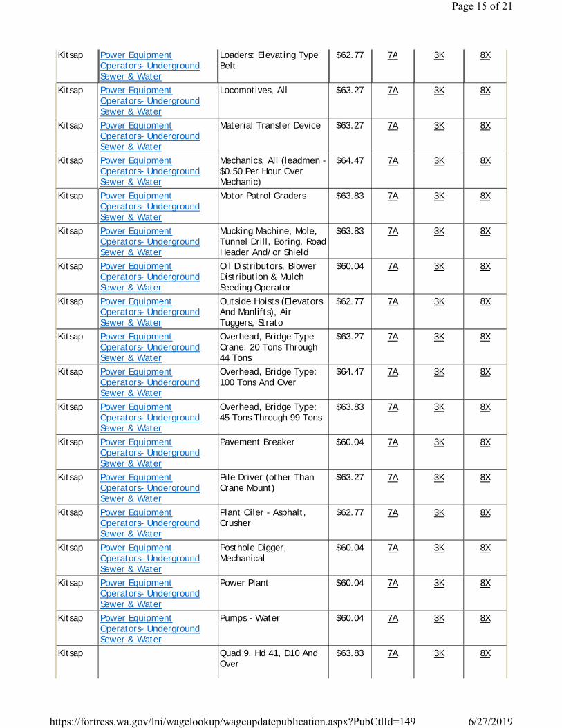
Kitsap Power Equipment Operators- Underground Sewer & Water
Loaders: Elevating Type Belt
$62.77 7A 3K 8X
Kitsap Power Equipment Operators- Underground Sewer & Water
Locomotives, All $63.27 7A 3K 8X
Kitsap Power Equipment Operators- Underground Sewer & Water
Material Transfer Device $63.27 7A 3K 8X
Kitsap Power Equipment Operators- Underground Sewer & Water
Mechanics, All (leadmen - $0.50 Per Hour Over Mechanic)
$64.47 7A 3K 8X
Kitsap Power Equipment Operators- Underground Sewer & Water
Motor Patrol Graders $63.83 7A 3K 8X
Kitsap Power Equipment Operators- Underground Sewer & Water
Mucking Machine, Mole, Tunnel Drill, Boring, Road Header And/or Shield
$63.83 7A 3K 8X
Kitsap Power Equipment Operators- Underground Sewer & Water
Oil Distributors, Blower Distribution & Mulch Seeding Operator
$60.04 7A 3K 8X
Kitsap Power Equipment Operators- Underground Sewer & Water
Outside Hoists (Elevators And Manlifts), Air Tuggers, Strato
$62.77 7A 3K 8X
Kitsap Power Equipment Operators- Underground Sewer & Water
Overhead, Bridge Type Crane: 20 Tons Through 44 Tons
$63.27 7A 3K 8X
Kitsap Power Equipment Operators- Underground Sewer & Water
Overhead, Bridge Type: 100 Tons And Over
$64.47 7A 3K 8X
Kitsap Power Equipment Operators- Underground Sewer & Water
Overhead, Bridge Type: 45 Tons Through 99 Tons
$63.83 7A 3K 8X
Kitsap Power Equipment Operators- Underground Sewer & Water
Pavement Breaker $60.04 7A 3K 8X
Kitsap Power Equipment Operators- Underground Sewer & Water
Pile Driver (other Than Crane Mount)
$63.27 7A 3K 8X
Kitsap Power Equipment Operators- Underground Sewer & Water
Plant Oiler - Asphalt, Crusher
$62.77 7A 3K 8X
Kitsap Power Equipment Operators- Underground Sewer & Water
Posthole Digger, Mechanical
$60.04 7A 3K 8X
Kitsap Power Equipment Operators- Underground Sewer & Water
Power Plant $60.04 7A 3K 8X
Kitsap Power Equipment Operators- Underground Sewer & Water
Pumps - Water $60.04 7A 3K 8X
Kitsap Quad 9, Hd 41, D10 And Over
$63.83 7A 3K 8X
Page 15 of 21
6/27/2019https://fortress.wa.gov/lni/wagelookup/wageupdatepublication.aspx?PubCtlId=149

Power Equipment Operators- Underground Sewer & Water
Kitsap Power Equipment Operators- Underground Sewer & Water
Quick Tower - No Cab, Under 100 Feet In Height Based To Boom
$60.04 7A 3K 8X
Kitsap Power Equipment Operators- Underground Sewer & Water
Remote Control Operator On Rubber Tired Earth Moving Equipment
$63.83 7A 3K 8X
Kitsap Power Equipment Operators- Underground Sewer & Water
Rigger and Bellman $60.04 7A 3K 8X
Kitsap Power Equipment Operators- Underground Sewer & Water
Rigger/Signal Person, Bellman (Certified)
$62.77 7A 3K 8X
Kitsap Power Equipment Operators- Underground Sewer & Water
Rollagon $63.83 7A 3K 8X
Kitsap Power Equipment Operators- Underground Sewer & Water
Roller, Other Than Plant Mix
$60.04 7A 3K 8X
Kitsap Power Equipment Operators- Underground Sewer & Water
Roller, Plant Mix Or Multi-lift Materials
$62.77 7A 3K 8X
Kitsap Power Equipment Operators- Underground Sewer & Water
Roto-mill, Roto-grinder $63.27 7A 3K 8X
Kitsap Power Equipment Operators- Underground Sewer & Water
Saws - Concrete $62.77 7A 3K 8X
Kitsap Power Equipment Operators- Underground Sewer & Water
Scraper, Self Propelled Under 45 Yards
$63.27 7A 3K 8X
Kitsap Power Equipment Operators- Underground Sewer & Water
Scrapers - Concrete & Carry All
$62.77 7A 3K 8X
Kitsap Power Equipment Operators- Underground Sewer & Water
Scrapers, Self-propelled: 45 Yards And Over
$63.83 7A 3K 8X
Kitsap Power Equipment Operators- Underground Sewer & Water
Service Engineers - Equipment
$62.77 7A 3K 8X
Kitsap Power Equipment Operators- Underground Sewer & Water
Shotcrete/Gunite Equipment
$60.04 7A 3K 8X
Kitsap Power Equipment Operators- Underground Sewer & Water
Shovel , Excavator, Backhoe, Tractors Under 15 Metric Tons
$62.77 7A 3K 8X
Kitsap Power Equipment Operators- Underground Sewer & Water
Shovel, Excavator, Backhoe: Over 30 Metric Tons To 50 Metric Tons
$63.83 7A 3K 8X
Kitsap $63.27 7A 3K 8X
Page 16 of 21
6/27/2019https://fortress.wa.gov/lni/wagelookup/wageupdatepublication.aspx?PubCtlId=149

Power Equipment Operators- Underground Sewer & Water
Shovel, Excavator, Backhoes, Tractors: 15 To 30 Metric Tons
Kitsap Power Equipment Operators- Underground Sewer & Water
Shovel, Excavator, Backhoes: Over 50 Metric Tons To 90 Metric Tons
$64.47 7A 3K 8X
Kitsap Power Equipment Operators- Underground Sewer & Water
Shovel, Excavator, Backhoes: Over 90 Metric Tons
$65.13 7A 3K 8X
Kitsap Power Equipment Operators- Underground Sewer & Water
Slipform Pavers $63.83 7A 3K 8X
Kitsap Power Equipment Operators- Underground Sewer & Water
Spreader, Topsider & Screedman
$63.83 7A 3K 8X
Kitsap Power Equipment Operators- Underground Sewer & Water
Subgrader Trimmer $63.27 7A 3K 8X
Kitsap Power Equipment Operators- Underground Sewer & Water
Tower Bucket Elevators $62.77 7A 3K 8X
Kitsap Power Equipment Operators- Underground Sewer & Water
Tower Crane Up To 175' In Height Base To Boom
$64.47 7A 3K 8X
Kitsap Power Equipment Operators- Underground Sewer & Water
Tower Crane: over 175’ through 250’ in height, base to boom
$65.13 7A 3K 8X
Kitsap Power Equipment Operators- Underground Sewer & Water
Tower Cranes: over 250’ in height from base to boom
$65.77 7A 3K 8X
Kitsap Power Equipment Operators- Underground Sewer & Water
Transporters, All Track Or Truck Type
$63.83 7A 3K 8X
Kitsap Power Equipment Operators- Underground Sewer & Water
Trenching Machines $62.77 7A 3K 8X
Kitsap Power Equipment Operators- Underground Sewer & Water
Truck Crane Oiler/driver - 100 Tons And Over
$63.27 7A 3K 8X
Kitsap Power Equipment Operators- Underground Sewer & Water
Truck Crane Oiler/Driver Under 100 Tons
$62.77 7A 3K 8X
Kitsap Power Equipment Operators- Underground Sewer & Water
Truck Mount Portable Conveyor
$63.27 7A 3K 8X
Kitsap Power Equipment Operators- Underground Sewer & Water
Welder $63.83 7A 3K 8X
Kitsap Power Equipment Operators- Underground Sewer & Water
Wheel Tractors, Farmall Type
$60.04 7A 3K 8X
Kitsap Yo Yo Pay Dozer $63.27 7A 3K 8X
Page 17 of 21
6/27/2019https://fortress.wa.gov/lni/wagelookup/wageupdatepublication.aspx?PubCtlId=149

Power Equipment Operators- Underground Sewer & Water
Kitsap Power Line Clearance Tree Trimmers
Journey Level In Charge $49.96 5A 4A
Kitsap Power Line Clearance Tree Trimmers
Spray Person $47.37 5A 4A
Kitsap Power Line Clearance Tree Trimmers
Tree Equipment Operator $49.96 5A 4A
Kitsap Power Line Clearance Tree Trimmers
Tree Trimmer $44.57 5A 4A
Kitsap Power Line Clearance Tree Trimmers
Tree Trimmer Groundperson
$33.60 5A 4A
Kitsap Refrigeration & Air Conditioning Mechanics
Journey Level $70.71 5A 1G
Kitsap Residential Brick Mason Journey Level $57.32 5A 1MKitsap Residential Carpenters Journey Level $45.05 5D 4CKitsap Residential Cement Masons Journey Level $60.07 7A 4UKitsap Residential Drywall
ApplicatorsJourney Level $45.05 5D 4C
Kitsap Residential Drywall Tapers Journey Level $45.19 5P 1EKitsap Residential Electricians Journey Level $39.81 5Q 2OKitsap Residential Glaziers Journey Level $43.00 7L 1HKitsap Residential Insulation
ApplicatorsJourney Level $45.05 5D 4C
Kitsap Residential Laborers Journey Level $36.68 7A 1HKitsap Residential Marble Setters Journey Level $57.32 5A 1MKitsap Residential Painters Journey Level $42.50 6Z 2BKitsap Residential Plumbers &
PipefittersJourney Level $44.34 5A 1G
Kitsap Residential Refrigeration & Air Conditioning Mechanics
Journey Level $41.01 5A 1G
Kitsap Residential Sheet Metal Workers
Journey Level (Field or Shop)
$50.01 7F 1R
Kitsap Residential Soft Floor Layers
Journey Level $49.43 5A 3J
Kitsap Residential Sprinkler Fitters (Fire Protection)
Journey Level $48.18 5C 2R
Kitsap Residential Stone Masons Journey Level $57.32 5A 1MKitsap Residential Terrazzo
WorkersJourney Level $52.61 5A 1M
Kitsap Residential Terrazzo/Tile Finishers
Journey Level $43.44 5A 1B
Kitsap Residential Tile Setters Journey Level $52.61 5A 1MKitsap Roofers Journey Level $51.52 5A 3HKitsap Roofers Using Irritable Bituminous
Materials$54.52 5A 3H
Kitsap Sheet Metal Workers Journey Level (Field or Shop)
$82.51 7F 1E
Kitsap Shipbuilding & Ship Repair $36.36 7V 1
Page 18 of 21
6/27/2019https://fortress.wa.gov/lni/wagelookup/wageupdatepublication.aspx?PubCtlId=149
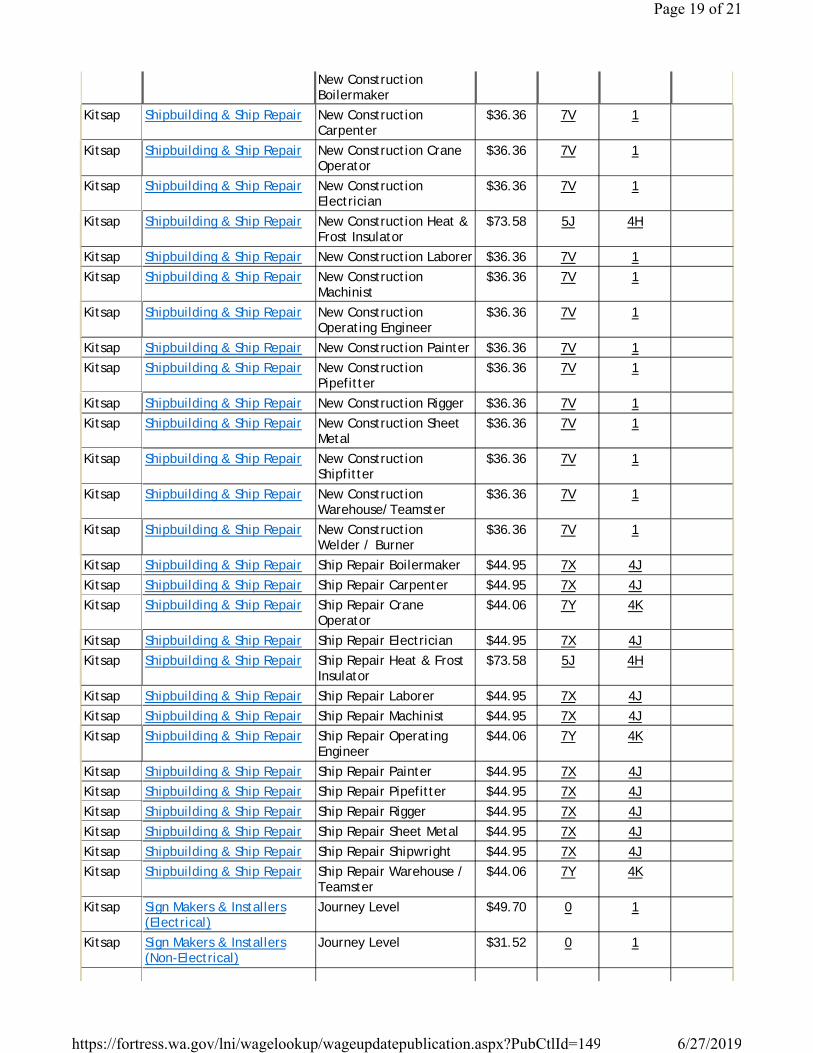
New Construction Boilermaker
Kitsap Shipbuilding & Ship Repair New Construction Carpenter
$36.36 7V 1
Kitsap Shipbuilding & Ship Repair New Construction Crane Operator
$36.36 7V 1
Kitsap Shipbuilding & Ship Repair New Construction Electrician
$36.36 7V 1
Kitsap Shipbuilding & Ship Repair New Construction Heat & Frost Insulator
$73.58 5J 4H
Kitsap Shipbuilding & Ship Repair New Construction Laborer $36.36 7V 1Kitsap Shipbuilding & Ship Repair New Construction
Machinist$36.36 7V 1
Kitsap Shipbuilding & Ship Repair New Construction Operating Engineer
$36.36 7V 1
Kitsap Shipbuilding & Ship Repair New Construction Painter $36.36 7V 1Kitsap Shipbuilding & Ship Repair New Construction
Pipefitter$36.36 7V 1
Kitsap Shipbuilding & Ship Repair New Construction Rigger $36.36 7V 1Kitsap Shipbuilding & Ship Repair New Construction Sheet
Metal$36.36 7V 1
Kitsap Shipbuilding & Ship Repair New Construction Shipfitter
$36.36 7V 1
Kitsap Shipbuilding & Ship Repair New Construction Warehouse/Teamster
$36.36 7V 1
Kitsap Shipbuilding & Ship Repair New Construction Welder / Burner
$36.36 7V 1
Kitsap Shipbuilding & Ship Repair Ship Repair Boilermaker $44.95 7X 4JKitsap Shipbuilding & Ship Repair Ship Repair Carpenter $44.95 7X 4JKitsap Shipbuilding & Ship Repair Ship Repair Crane
Operator$44.06 7Y 4K
Kitsap Shipbuilding & Ship Repair Ship Repair Electrician $44.95 7X 4JKitsap Shipbuilding & Ship Repair Ship Repair Heat & Frost
Insulator$73.58 5J 4H
Kitsap Shipbuilding & Ship Repair Ship Repair Laborer $44.95 7X 4JKitsap Shipbuilding & Ship Repair Ship Repair Machinist $44.95 7X 4JKitsap Shipbuilding & Ship Repair Ship Repair Operating
Engineer$44.06 7Y 4K
Kitsap Shipbuilding & Ship Repair Ship Repair Painter $44.95 7X 4JKitsap Shipbuilding & Ship Repair Ship Repair Pipefitter $44.95 7X 4JKitsap Shipbuilding & Ship Repair Ship Repair Rigger $44.95 7X 4JKitsap Shipbuilding & Ship Repair Ship Repair Sheet Metal $44.95 7X 4JKitsap Shipbuilding & Ship Repair Ship Repair Shipwright $44.95 7X 4JKitsap Shipbuilding & Ship Repair Ship Repair Warehouse /
Teamster$44.06 7Y 4K
Kitsap Sign Makers & Installers (Electrical)
Journey Level $49.70 0 1
Kitsap Sign Makers & Installers (Non-Electrical)
Journey Level $31.52 0 1
Page 19 of 21
6/27/2019https://fortress.wa.gov/lni/wagelookup/wageupdatepublication.aspx?PubCtlId=149
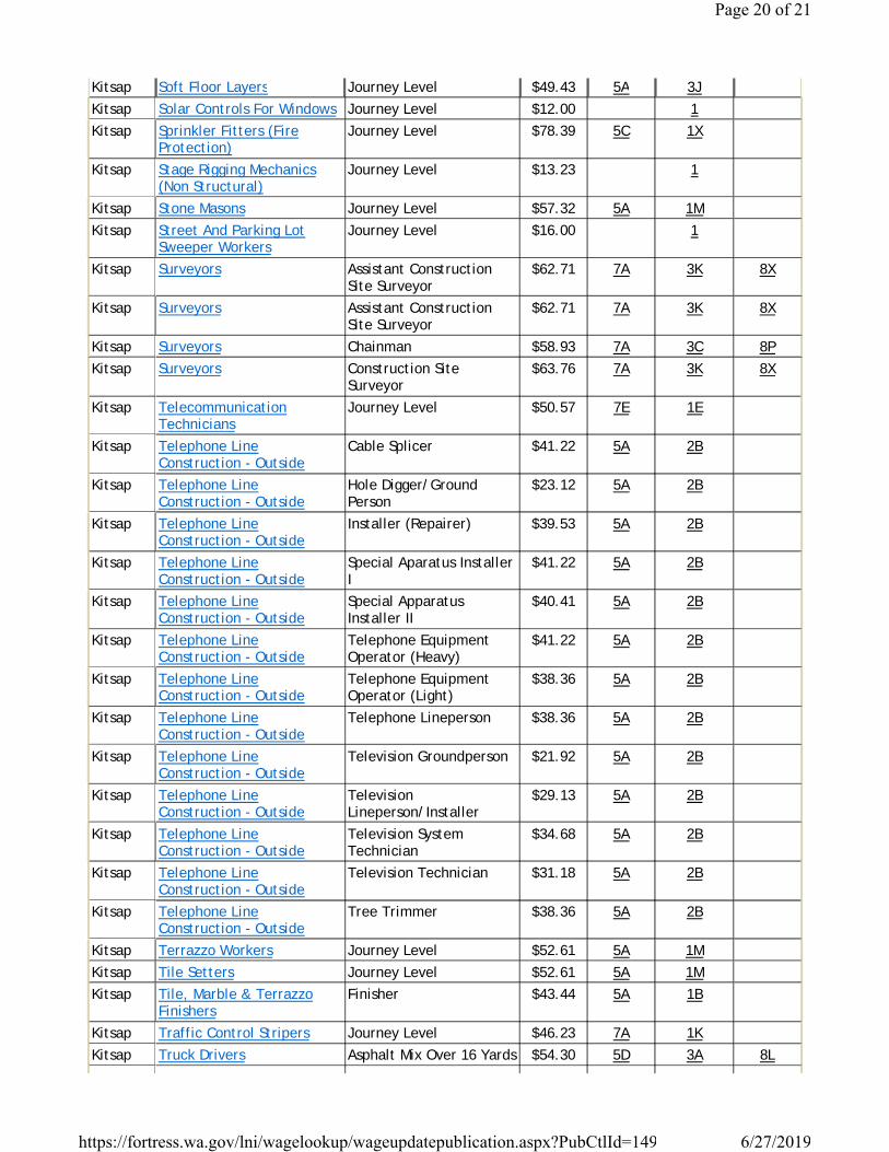
Kitsap Soft Floor Layers Journey Level $49.43 5A 3JKitsap Solar Controls For Windows Journey Level $12.00 1Kitsap Sprinkler Fitters (Fire
Protection)Journey Level $78.39 5C 1X
Kitsap Stage Rigging Mechanics (Non Structural)
Journey Level $13.23 1
Kitsap Stone Masons Journey Level $57.32 5A 1MKitsap Street And Parking Lot
Sweeper WorkersJourney Level $16.00 1
Kitsap Surveyors Assistant Construction Site Surveyor
$62.71 7A 3K 8X
Kitsap Surveyors Assistant Construction Site Surveyor
$62.71 7A 3K 8X
Kitsap Surveyors Chainman $58.93 7A 3C 8PKitsap Surveyors Construction Site
Surveyor$63.76 7A 3K 8X
Kitsap Telecommunication Technicians
Journey Level $50.57 7E 1E
Kitsap Telephone Line Construction - Outside
Cable Splicer $41.22 5A 2B
Kitsap Telephone Line Construction - Outside
Hole Digger/Ground Person
$23.12 5A 2B
Kitsap Telephone Line Construction - Outside
Installer (Repairer) $39.53 5A 2B
Kitsap Telephone Line Construction - Outside
Special Aparatus Installer I
$41.22 5A 2B
Kitsap Telephone Line Construction - Outside
Special Apparatus Installer II
$40.41 5A 2B
Kitsap Telephone Line Construction - Outside
Telephone Equipment Operator (Heavy)
$41.22 5A 2B
Kitsap Telephone Line Construction - Outside
Telephone Equipment Operator (Light)
$38.36 5A 2B
Kitsap Telephone Line Construction - Outside
Telephone Lineperson $38.36 5A 2B
Kitsap Telephone Line Construction - Outside
Television Groundperson $21.92 5A 2B
Kitsap Telephone Line Construction - Outside
Television Lineperson/Installer
$29.13 5A 2B
Kitsap Telephone Line Construction - Outside
Television System Technician
$34.68 5A 2B
Kitsap Telephone Line Construction - Outside
Television Technician $31.18 5A 2B
Kitsap Telephone Line Construction - Outside
Tree Trimmer $38.36 5A 2B
Kitsap Terrazzo Workers Journey Level $52.61 5A 1MKitsap Tile Setters Journey Level $52.61 5A 1MKitsap Tile, Marble & Terrazzo
FinishersFinisher $43.44 5A 1B
Kitsap Traffic Control Stripers Journey Level $46.23 7A 1KKitsap Truck Drivers Asphalt Mix Over 16 Yards $54.30 5D 3A 8L
Page 20 of 21
6/27/2019https://fortress.wa.gov/lni/wagelookup/wageupdatepublication.aspx?PubCtlId=149

Kitsap Truck Drivers Asphalt Mix To 16 Yards $53.46 5D 3A 8LKitsap Truck Drivers Dump Truck $53.46 5D 3A 8LKitsap Truck Drivers Dump Truck & Trailer $54.30 5D 3A 8LKitsap Truck Drivers Other Trucks $54.30 5D 3A 8LKitsap Truck Drivers - Ready Mix Journey Level $20.79 1Kitsap Well Drillers & Irrigation
Pump InstallersIrrigation Pump Installer $13.17 1
Kitsap Well Drillers & Irrigation Pump Installers
Oiler $14.08 1
Kitsap Well Drillers & Irrigation Pump Installers
Well Driller $14.40 1
Page 21 of 21
6/27/2019https://fortress.wa.gov/lni/wagelookup/wageupdatepublication.aspx?PubCtlId=149

RIDGETOP BLVD NW IMPROVEMENTS PROJECT PHASE 2
THIS PAGE INTENTIONALLY LEFT BLANK

Benefit Code Key – Effective 3/3/2019 thru 8/30/2019
1
************************************************************************************************************
Overtime Codes
Overtime calculations are based on the hourly rate actually paid to the worker. On public works projects, the hourly rate
must be not less than the prevailing rate of wage minus the hourly rate of the cost of fringe benefits actually provided for
the worker.
1. ALL HOURS WORKED IN EXCESS OF EIGHT (8) HOURS PER DAY OR FORTY (40) HOURS PER WEEK SHALL BE
PAID AT ONE AND ONE-HALF TIMES THE HOURLY RATE OF WAGE.
B. All hours worked on Saturdays shall be paid at one and one-half times the hourly rate of wage. All hours worked on
Sundays and holidays shall be paid at double the hourly rate of wage.
C. The first two (2) hours after eight (8) regular hours Monday through Friday and the first ten (10) hours on Saturday
shall be paid at one and one-half times the hourly rate of wage. All other overtime hours and all hours worked on
Sundays and holidays shall be paid at double the hourly rate of wage.
D. The first two (2) hours before or after a five-eight (8) hour workweek day or a four-ten (10) hour workweek day and
the first eight (8) hours worked the next day after either workweek shall be paid at one and one-half times the hourly
rate of wage. All additional hours worked and all worked on Sundays and holidays shall be paid at double the hourly
rate of wage.
E. The first two (2) hours after eight (8) regular hours Monday through Friday and the first eight (8) hours on Saturday
shall be paid at one and one-half times the hourly rate of wage. All other hours worked Monday through Saturday,
and all hours worked on Sundays and holidays shall be paid at double the hourly rate of wage.
F. The first two (2) hours after eight (8) regular hours Monday through Friday and the first ten (10) hours on Saturday
shall be paid at one and one-half times the hourly rate of wage. All other overtime hours worked, except Labor Day,
shall be paid at double the hourly rate of wage. All hours worked on Labor Day shall be paid at three times the hourly
rate of wage.
G. The first ten (10) hours worked on Saturdays and the first ten (10) hours worked on a fifth calendar weekday in a four-
ten hour schedule, shall be paid at one and one-half times the hourly rate of wage. All hours worked in excess of ten
(10) hours per day Monday through Saturday and all hours worked on Sundays and holidays shall be paid at double
the hourly rate of wage.
H. All hours worked on Saturdays (except makeup days if work is lost due to inclement weather conditions or equipment
breakdown) shall be paid at one and one-half times the hourly rate of wage. All hours worked Monday through
Saturday over twelve (12) hours and all hours worked on Sundays and holidays shall be paid at double the hourly rate
of wage.
I. All hours worked on Sundays and holidays shall also be paid at double the hourly rate of wage.
J. The first two (2) hours after eight (8) regular hours Monday through Friday and the first ten (10) hours on Saturday
shall be paid at one and one-half times the hourly rate of wage. All hours worked over ten (10) hours Monday through
Saturday, Sundays and holidays shall be paid at double the hourly rate of wage.
K. All hours worked on Saturdays and Sundays shall be paid at one and one-half times the hourly rate of wage. All hours
worked on holidays shall be paid at double the hourly rate of wage.
M. All hours worked on Saturdays (except makeup days if work is lost due to inclement weather conditions) shall be paid
at one and one-half times the hourly rate of wage. All hours worked on Sundays and holidays shall be paid at double
the hourly rate of wage.
N. All hours worked on Saturdays (except makeup days) shall be paid at one and one-half times the hourly rate of wage.
All hours worked on Sundays and holidays shall be paid at double the hourly rate of wage.
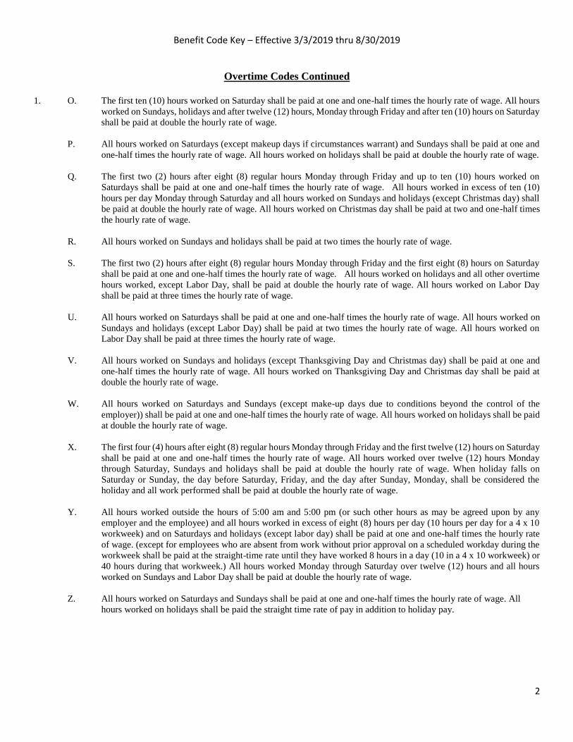
Benefit Code Key – Effective 3/3/2019 thru 8/30/2019
2
Overtime Codes Continued
1. O. The first ten (10) hours worked on Saturday shall be paid at one and one-half times the hourly rate of wage. All hours
worked on Sundays, holidays and after twelve (12) hours, Monday through Friday and after ten (10) hours on Saturday
shall be paid at double the hourly rate of wage.
P. All hours worked on Saturdays (except makeup days if circumstances warrant) and Sundays shall be paid at one and
one-half times the hourly rate of wage. All hours worked on holidays shall be paid at double the hourly rate of wage.
Q. The first two (2) hours after eight (8) regular hours Monday through Friday and up to ten (10) hours worked on
Saturdays shall be paid at one and one-half times the hourly rate of wage. All hours worked in excess of ten (10)
hours per day Monday through Saturday and all hours worked on Sundays and holidays (except Christmas day) shall
be paid at double the hourly rate of wage. All hours worked on Christmas day shall be paid at two and one-half times
the hourly rate of wage.
R. All hours worked on Sundays and holidays shall be paid at two times the hourly rate of wage.
S. The first two (2) hours after eight (8) regular hours Monday through Friday and the first eight (8) hours on Saturday
shall be paid at one and one-half times the hourly rate of wage. All hours worked on holidays and all other overtime
hours worked, except Labor Day, shall be paid at double the hourly rate of wage. All hours worked on Labor Day
shall be paid at three times the hourly rate of wage.
U. All hours worked on Saturdays shall be paid at one and one-half times the hourly rate of wage. All hours worked on
Sundays and holidays (except Labor Day) shall be paid at two times the hourly rate of wage. All hours worked on
Labor Day shall be paid at three times the hourly rate of wage.
V. All hours worked on Sundays and holidays (except Thanksgiving Day and Christmas day) shall be paid at one and
one-half times the hourly rate of wage. All hours worked on Thanksgiving Day and Christmas day shall be paid at
double the hourly rate of wage.
W. All hours worked on Saturdays and Sundays (except make-up days due to conditions beyond the control of the
employer)) shall be paid at one and one-half times the hourly rate of wage. All hours worked on holidays shall be paid
at double the hourly rate of wage.
X. The first four (4) hours after eight (8) regular hours Monday through Friday and the first twelve (12) hours on Saturday
shall be paid at one and one-half times the hourly rate of wage. All hours worked over twelve (12) hours Monday
through Saturday, Sundays and holidays shall be paid at double the hourly rate of wage. When holiday falls on
Saturday or Sunday, the day before Saturday, Friday, and the day after Sunday, Monday, shall be considered the
holiday and all work performed shall be paid at double the hourly rate of wage.
Y. All hours worked outside the hours of 5:00 am and 5:00 pm (or such other hours as may be agreed upon by any
employer and the employee) and all hours worked in excess of eight (8) hours per day (10 hours per day for a 4 x 10
workweek) and on Saturdays and holidays (except labor day) shall be paid at one and one-half times the hourly rate
of wage. (except for employees who are absent from work without prior approval on a scheduled workday during the
workweek shall be paid at the straight-time rate until they have worked 8 hours in a day (10 in a 4 x 10 workweek) or
40 hours during that workweek.) All hours worked Monday through Saturday over twelve (12) hours and all hours
worked on Sundays and Labor Day shall be paid at double the hourly rate of wage.
Z. All hours worked on Saturdays and Sundays shall be paid at one and one-half times the hourly rate of wage. All
hours worked on holidays shall be paid the straight time rate of pay in addition to holiday pay.
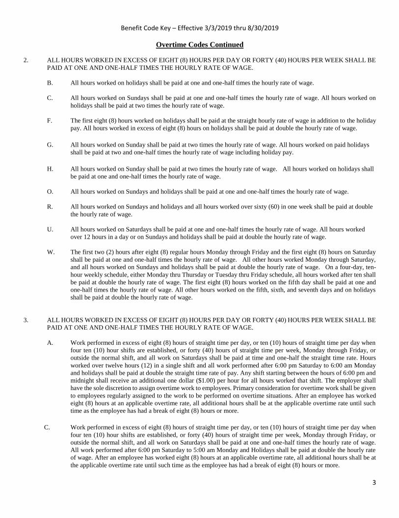
Benefit Code Key – Effective 3/3/2019 thru 8/30/2019
3
Overtime Codes Continued
2. ALL HOURS WORKED IN EXCESS OF EIGHT (8) HOURS PER DAY OR FORTY (40) HOURS PER WEEK SHALL BE
PAID AT ONE AND ONE-HALF TIMES THE HOURLY RATE OF WAGE.
B. All hours worked on holidays shall be paid at one and one-half times the hourly rate of wage.
C. All hours worked on Sundays shall be paid at one and one-half times the hourly rate of wage. All hours worked on
holidays shall be paid at two times the hourly rate of wage.
F. The first eight (8) hours worked on holidays shall be paid at the straight hourly rate of wage in addition to the holiday
pay. All hours worked in excess of eight (8) hours on holidays shall be paid at double the hourly rate of wage.
G. All hours worked on Sunday shall be paid at two times the hourly rate of wage. All hours worked on paid holidays
shall be paid at two and one-half times the hourly rate of wage including holiday pay.
H. All hours worked on Sunday shall be paid at two times the hourly rate of wage. All hours worked on holidays shall
be paid at one and one-half times the hourly rate of wage.
O. All hours worked on Sundays and holidays shall be paid at one and one-half times the hourly rate of wage.
R. All hours worked on Sundays and holidays and all hours worked over sixty (60) in one week shall be paid at double
the hourly rate of wage.
U. All hours worked on Saturdays shall be paid at one and one-half times the hourly rate of wage. All hours worked
over 12 hours in a day or on Sundays and holidays shall be paid at double the hourly rate of wage.
W. The first two (2) hours after eight (8) regular hours Monday through Friday and the first eight (8) hours on Saturday
shall be paid at one and one-half times the hourly rate of wage. All other hours worked Monday through Saturday,
and all hours worked on Sundays and holidays shall be paid at double the hourly rate of wage. On a four-day, ten-
hour weekly schedule, either Monday thru Thursday or Tuesday thru Friday schedule, all hours worked after ten shall
be paid at double the hourly rate of wage. The first eight (8) hours worked on the fifth day shall be paid at one and
one-half times the hourly rate of wage. All other hours worked on the fifth, sixth, and seventh days and on holidays
shall be paid at double the hourly rate of wage.
3. ALL HOURS WORKED IN EXCESS OF EIGHT (8) HOURS PER DAY OR FORTY (40) HOURS PER WEEK SHALL BE
PAID AT ONE AND ONE-HALF TIMES THE HOURLY RATE OF WAGE.
A. Work performed in excess of eight (8) hours of straight time per day, or ten (10) hours of straight time per day when
four ten (10) hour shifts are established, or forty (40) hours of straight time per week, Monday through Friday, or
outside the normal shift, and all work on Saturdays shall be paid at time and one-half the straight time rate. Hours
worked over twelve hours (12) in a single shift and all work performed after 6:00 pm Saturday to 6:00 am Monday
and holidays shall be paid at double the straight time rate of pay. Any shift starting between the hours of 6:00 pm and
midnight shall receive an additional one dollar ($1.00) per hour for all hours worked that shift. The employer shall
have the sole discretion to assign overtime work to employees. Primary consideration for overtime work shall be given
to employees regularly assigned to the work to be performed on overtime situations. After an employee has worked
eight (8) hours at an applicable overtime rate, all additional hours shall be at the applicable overtime rate until such
time as the employee has had a break of eight (8) hours or more.
C. Work performed in excess of eight (8) hours of straight time per day, or ten (10) hours of straight time per day when
four ten (10) hour shifts are established, or forty (40) hours of straight time per week, Monday through Friday, or
outside the normal shift, and all work on Saturdays shall be paid at one and one-half times the hourly rate of wage.
All work performed after 6:00 pm Saturday to 5:00 am Monday and Holidays shall be paid at double the hourly rate
of wage. After an employee has worked eight (8) hours at an applicable overtime rate, all additional hours shall be at
the applicable overtime rate until such time as the employee has had a break of eight (8) hours or more.

Benefit Code Key – Effective 3/3/2019 thru 8/30/2019
4
Overtime Codes Continued
3. E. All hours worked Sundays and holidays shall be paid at double the hourly rate of wage. Each week, once 40 hours of
straight time work is achieved, then any hours worked over 10 hours per day Monday through Saturday shall be paid
at double the hourly wage rate.
F. All hours worked on Saturday shall be paid at one and one-half times the hourly rate of wage. All hours worked on
Sunday shall be paid at two times the hourly rate of wage. All hours worked on paid holidays shall be paid at two and
one-half times the hourly rate of wage including holiday pay.
H. All work performed on Sundays between March 16th and October 14th and all Holidays shall be compensated for at
two (2) times the regular rate of pay. Work performed on Sundays between October 15th and March 15th shall be
compensated at one and one half (1-1/2) times the regular rate of pay.
I. All hours worked on Saturdays shall be paid at one and one-half times the hourly rate of wage. In the event the job is
down due to weather conditions during a five day work week (Monday through Friday,) or a four day-ten hour work
week (Tuesday through Friday,) then Saturday may be worked as a voluntary make-up day at the straight time rate.
However, Saturday shall not be utilized as a make-up day when a holiday falls on Friday. All hours worked Monday
through Saturday over twelve (12) hours and all hours worked on Sundays and holidays shall be paid at double the
hourly rate of wage.
J. All hours worked between the hours of 10:00 pm and 5:00 am, Monday through Friday, and all hours worked on
Saturdays shall be paid at a one and one-half times the hourly rate of wage. All hours worked on Sundays and holidays
shall be paid at double the hourly rate of wage.
K. Work performed in excess of eight (8) hours of straight time per day, or ten (10) hours of straight time per day when
four ten (10) hour shifts are established, or forty (40) hours of straight time per week, Monday through Friday, or
outside the normal 5 am to 6pm shift, and all work on Saturdays shall be paid at one and one-half times the hourly
rate of wage. All work performed after 6:00 pm Saturday to 5:00 am Monday and Holidays, and all hours worked in
excess of twelve (12) hours in a single shift shall be paid at double the hourly rate of wage.
After an employee has worked eight (8) hours at an applicable overtime rate, all additional hours shall be at the
applicable overtime rate until such time as the employee has had a break of eight (8) hours or more. When an employee
returns to work without at least eight (8) hours time off since their previous shift, all such time shall be a continuation
of shift and paid at the applicable overtime rate until he/she shall have the eight (8) hours rest period.
4. ALL HOURS WORKED IN EXCESS OF EIGHT (8) HOURS PER DAY OR FORTY (40) HOURS PER WEEK SHALL BE
PAID AT ONE AND ONE-HALF TIMES THE HOURLY RATE OF WAGE.
A. All hours worked in excess of eight (8) hours per day or forty (40) hours per week shall be paid at double the hourly
rate of wage. All hours worked on Saturdays, Sundays and holidays shall be paid at double the hourly rate of wage.
B. All hours worked over twelve (12) hours per day and all hours worked on holidays shall be paid at double the hourly
rate of wage.
C. On Monday through Friday, the first four (4) hours of overtime after eight (8) hours of straight time work shall be
paid at one and one half (1-1/2) times the straight time rate of pay, unless a four (4) day ten (10) hour workweek has
been established. On a four (4) day ten (10) hour workweek scheduled Monday through Thursday, or Tuesday
through Friday, the first two (2) hours of overtime after ten (10) hours of straight time work shall be paid at one and
one half (1-1/2) times the straight time rate of pay. On Saturday, the first twelve (12) hours of work shall be paid at
one and one half (1-1/2) times the straight time rate of pay, except that if the job is down on Monday through Friday
due to weather conditions or other conditions outside the control of the employer, the first ten (10) hours on Saturday
may be worked at the straight time rate of pay. All hours worked over twelve (12) hours in a day and all hours worked
on Sunday and Holidays shall be paid at two (2) times the straight time rate of pay.

Benefit Code Key – Effective 3/3/2019 thru 8/30/2019
5
Overtime Codes Continued
4. D. All hours worked in excess of eight (8) hours per day or forty (40) hours per week shall be paid at double the hourly
rate of wage. All hours worked on Saturday, Sundays and holidays shall be paid at double the hourly rate of pay. Rates
include all members of the assigned crew.
EXCEPTION:
On all multipole structures and steel transmission lines, switching stations, regulating, capacitor stations, generating
plants, industrial plants, associated installations and substations, except those substations whose primary function is
to feed a distribution system, will be paid overtime under the following rates:
The first two (2) hours after eight (8) regular hours Monday through Friday of overtime on a regular workday, shall
be paid at one and one-half times the hourly rate of wage. All hours in excess of ten (10) hours will be at two (2) times
the hourly rate of wage. The first eight (8) hours worked on Saturday will be paid at one and one-half (1-1/2) times
the hourly rate of wage. All hours worked in excess of eight (8) hours on Saturday, and all hours worked on Sundays
and holidays will be at the double the hourly rate of wage.
All overtime eligible hours performed on the above described work that is energized, shall be paid at the double the
hourly rate of wage.
E. The first two (2) hours after eight (8) regular hours Monday through Friday and the first eight (8) hours on Saturday
shall be paid at one and one-half times the hourly rate of wage. All other hours worked Monday through Saturday,
and all hours worked on Sundays and holidays shall be paid at double the hourly rate of wage.
On a four-day, ten-hour weekly schedule, either Monday thru Thursday or Tuesday thru Friday schedule, all hours
worked after ten shall be paid at double the hourly rate of wage. The Monday or Friday not utilized in the normal four-
day, ten hour work week, and Saturday shall be paid at one and one half (1½) times the regular shift rate for the first
eight (8) hours. All other hours worked Monday through Saturday, and all hours worked on Sundays and holidays
shall be paid at double the hourly rate of wage.
F. All hours worked between the hours of 6:00 pm and 6:00 am, Monday through Saturday, shall be paid at a premium
rate of 20% over the hourly rate of wage. All hours worked on Sundays shall be paid at one and one-half times the
hourly rate of wage. All hours worked on holidays shall be paid at double the hourly rate of wage.
G. All hours worked on Saturdays shall be paid at one and one-half times the hourly rate of wage. All hours worked
Monday through Saturday over twelve (12) hours and all hours worked on Sundays and holidays shall be paid at
double the hourly rate of wage.
H. The first two (2) hours after eight (8) regular hours Monday through Friday and the first eight (8) hours on Saturday
shall be paid at one and one-half times the hourly rate of wage. All other overtime hours worked, except Labor Day,
and all hours on Sunday shall be paid at double the hourly rate of wage. All hours worked on Labor Day shall be paid
at three times the hourly rate of wage.
I. The First eight (8) hours worked on Saturdays shall be paid at one and one-half times the hourly rate of wage. All
hours worked in excess of eight (8) per day on Saturdays shall be paid at double the hourly rate of wage. All hours
worked on Sundays and holidays shall be paid at double the hourly rate of wage.
J. The first eight (8) hours worked on a Saturday shall be paid at one and one-half times the hourly rate of wage. All
hours worked in excess of eight (8) hours on a Saturday shall be paid at double the hourly rate of wage. All hours
worked over twelve (12) in a day, and all hours worked on Sundays and Holidays shall be paid at double the hourly
rate of wage.
K. All hours worked on a Saturday shall be paid at one and one-half times the hourly rate of wage, so long as Saturday
is the sixth consecutive day worked. All hours worked over twelve (12) in a day Monday through Saturday, and all
hours worked on Sundays and Holidays shall be paid at double the hourly rate of wage.
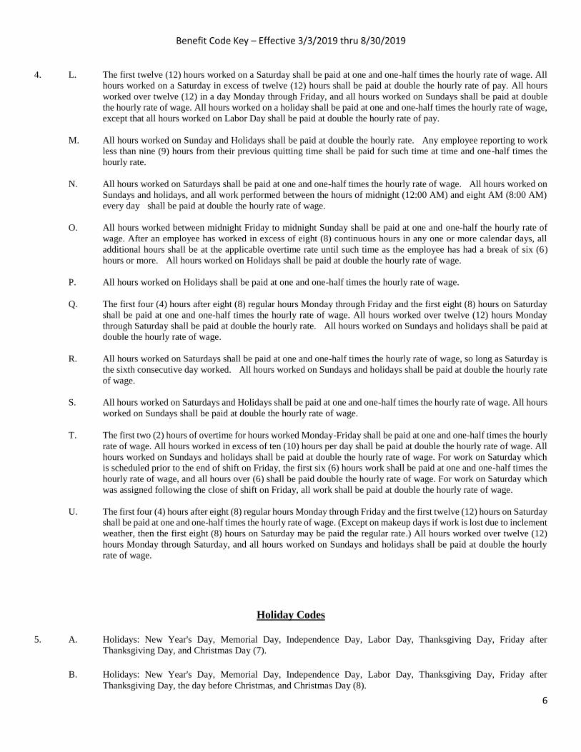
Benefit Code Key – Effective 3/3/2019 thru 8/30/2019
6
4. L. The first twelve (12) hours worked on a Saturday shall be paid at one and one-half times the hourly rate of wage. All
hours worked on a Saturday in excess of twelve (12) hours shall be paid at double the hourly rate of pay. All hours
worked over twelve (12) in a day Monday through Friday, and all hours worked on Sundays shall be paid at double
the hourly rate of wage. All hours worked on a holiday shall be paid at one and one-half times the hourly rate of wage,
except that all hours worked on Labor Day shall be paid at double the hourly rate of pay.
M. All hours worked on Sunday and Holidays shall be paid at double the hourly rate. Any employee reporting to work
less than nine (9) hours from their previous quitting time shall be paid for such time at time and one-half times the
hourly rate.
N. All hours worked on Saturdays shall be paid at one and one-half times the hourly rate of wage. All hours worked on
Sundays and holidays, and all work performed between the hours of midnight (12:00 AM) and eight AM (8:00 AM)
every day shall be paid at double the hourly rate of wage.
O. All hours worked between midnight Friday to midnight Sunday shall be paid at one and one-half the hourly rate of
wage. After an employee has worked in excess of eight (8) continuous hours in any one or more calendar days, all
additional hours shall be at the applicable overtime rate until such time as the employee has had a break of six (6)
hours or more. All hours worked on Holidays shall be paid at double the hourly rate of wage.
P. All hours worked on Holidays shall be paid at one and one-half times the hourly rate of wage.
Q. The first four (4) hours after eight (8) regular hours Monday through Friday and the first eight (8) hours on Saturday
shall be paid at one and one-half times the hourly rate of wage. All hours worked over twelve (12) hours Monday
through Saturday shall be paid at double the hourly rate. All hours worked on Sundays and holidays shall be paid at
double the hourly rate of wage.
R. All hours worked on Saturdays shall be paid at one and one-half times the hourly rate of wage, so long as Saturday is
the sixth consecutive day worked. All hours worked on Sundays and holidays shall be paid at double the hourly rate
of wage.
S. All hours worked on Saturdays and Holidays shall be paid at one and one-half times the hourly rate of wage. All hours
worked on Sundays shall be paid at double the hourly rate of wage.
T. The first two (2) hours of overtime for hours worked Monday-Friday shall be paid at one and one-half times the hourly
rate of wage. All hours worked in excess of ten (10) hours per day shall be paid at double the hourly rate of wage. All
hours worked on Sundays and holidays shall be paid at double the hourly rate of wage. For work on Saturday which
is scheduled prior to the end of shift on Friday, the first six (6) hours work shall be paid at one and one-half times the
hourly rate of wage, and all hours over (6) shall be paid double the hourly rate of wage. For work on Saturday which
was assigned following the close of shift on Friday, all work shall be paid at double the hourly rate of wage.
U. The first four (4) hours after eight (8) regular hours Monday through Friday and the first twelve (12) hours on Saturday
shall be paid at one and one-half times the hourly rate of wage. (Except on makeup days if work is lost due to inclement
weather, then the first eight (8) hours on Saturday may be paid the regular rate.) All hours worked over twelve (12)
hours Monday through Saturday, and all hours worked on Sundays and holidays shall be paid at double the hourly
rate of wage.
Holiday Codes
5. A. Holidays: New Year's Day, Memorial Day, Independence Day, Labor Day, Thanksgiving Day, Friday after
Thanksgiving Day, and Christmas Day (7).
B. Holidays: New Year's Day, Memorial Day, Independence Day, Labor Day, Thanksgiving Day, Friday after
Thanksgiving Day, the day before Christmas, and Christmas Day (8).

Benefit Code Key – Effective 3/3/2019 thru 8/30/2019
7
Holiday Codes Continued
5. C. Holidays: New Year's Day, Presidents’ Day, Memorial Day, Independence Day, Labor Day, Thanksgiving Day, the
Friday after Thanksgiving Day, And Christmas Day (8).
D. Holidays: New Year's Day, Memorial Day, Independence Day, Labor Day, Thanksgiving Day, the Friday and
Saturday after Thanksgiving Day, And Christmas Day (8).
H. Holidays: New Year's Day, Memorial Day, Independence Day, Thanksgiving Day, the Day after Thanksgiving Day,
And Christmas (6).
I. Holidays: New Year's Day, Memorial Day, Independence Day, Labor Day, Thanksgiving Day, and Christmas Day
(6).
J. Holidays: New Year's Day, Memorial Day, Independence Day, Thanksgiving Day, Friday after Thanksgiving Day,
Christmas Eve Day, And Christmas Day (7).
K. Holidays: New Year’s Day, Presidents’ Day, Memorial Day, Independence Day, Labor Day, Thanksgiving Day,
Friday After Thanksgiving Day, The Day Before Christmas, And Christmas Day (9).
L. Holidays: New Year’s Day, Martin Luther King Jr. Day, Memorial Day, Independence Day, Labor Day, Thanksgiving
Day, Friday after Thanksgiving Day, And Christmas Day (8).
N. Holidays: New Year's Day, Presidents’ Day, Memorial Day, Independence Day, Labor Day, Veterans' Day,
Thanksgiving Day, The Friday After Thanksgiving Day, And Christmas Day (9).
P. Holidays: New Year's Day, Memorial Day, Independence Day, Labor Day, Thanksgiving Day, Friday And Saturday
After Thanksgiving Day, The Day Before Christmas, And Christmas Day (9). If A Holiday Falls On Sunday, The
Following Monday Shall Be Considered As A Holiday.
Q. Paid Holidays: New Year's Day, Memorial Day, Independence Day, Labor Day, Thanksgiving Day, and Christmas
Day (6).
R. Paid Holidays: New Year's Day, Memorial Day, Independence Day, Labor Day, Thanksgiving Day, Day After
Thanksgiving Day, One-Half Day Before Christmas Day, And Christmas Day. (7 1/2).
S. Paid Holidays: New Year's Day, Presidents’ Day, Memorial Day, Independence Day, Labor Day, Thanksgiving Day,
And Christmas Day (7).
T. Paid Holidays: New Year's Day, Washington’s Birthday, Memorial Day, Independence Day, Labor Day,
Thanksgiving Day, The Friday After Thanksgiving Day, Christmas Day, And The Day Before Or After Christmas (9).
Z. Holidays: New Year's Day, Memorial Day, Independence Day, Labor Day, Veterans Day, Thanksgiving Day, the
Friday after Thanksgiving Day, And Christmas Day (8).
6. A. Paid Holidays: New Year’s Day, Presidents’ Day, Memorial Day, Independence Day, Labor Day, Thanksgiving Day,
the Friday after Thanksgiving Day, And Christmas Day (8).
E. Paid Holidays: New Year's Day, Day Before Or After New Year's Day, Presidents Day, Memorial Day,
Independence Day, Labor Day, Thanksgiving Day, the Friday after Thanksgiving Day, Christmas Day, and a Half-
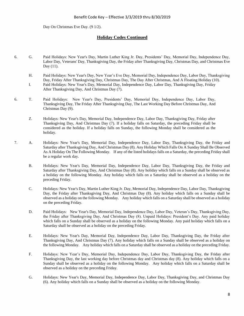
Benefit Code Key – Effective 3/3/2019 thru 8/30/2019
8
Day On Christmas Eve Day. (9 1/2).
Holiday Codes Continued
6. G. Paid Holidays: New Year's Day, Martin Luther King Jr. Day, Presidents’ Day, Memorial Day, Independence Day,
Labor Day, Veterans' Day, Thanksgiving Day, the Friday after Thanksgiving Day, Christmas Day, and Christmas Eve
Day (11).
H. Paid Holidays: New Year's Day, New Year’s Eve Day, Memorial Day, Independence Day, Labor Day, Thanksgiving
Day, Friday After Thanksgiving Day, Christmas Day, The Day After Christmas, And A Floating Holiday (10).
I. Paid Holidays: New Year's Day, Memorial Day, Independence Day, Labor Day, Thanksgiving Day, Friday
After Thanksgiving Day, And Christmas Day (7).
6. T. Paid Holidays: New Year's Day, Presidents’ Day, Memorial Day, Independence Day, Labor Day,
Thanksgiving Day, The Friday After Thanksgiving Day, The Last Working Day Before Christmas Day, And
Christmas Day (9).
Z. Holidays: New Year's Day, Memorial Day, Independence Day, Labor Day, Thanksgiving Day, Friday after
Thanksgiving Day, And Christmas Day (7). If a holiday falls on Saturday, the preceding Friday shall be
considered as the holiday. If a holiday falls on Sunday, the following Monday shall be considered as the
holiday.
7. A. Holidays: New Year's Day, Memorial Day, Independence Day, Labor Day, Thanksgiving Day, the Friday and
Saturday after Thanksgiving Day, And Christmas Day (8). Any Holiday Which Falls On A Sunday Shall Be Observed
As A Holiday On The Following Monday. If any of the listed holidays falls on a Saturday, the preceding Friday shall
be a regular work day.
B. Holidays: New Year's Day, Memorial Day, Independence Day, Labor Day, Thanksgiving Day, the Friday and
Saturday after Thanksgiving Day, And Christmas Day (8). Any holiday which falls on a Sunday shall be observed as
a holiday on the following Monday. Any holiday which falls on a Saturday shall be observed as a holiday on the
preceding Friday.
C. Holidays: New Year's Day, Martin Luther King Jr. Day, Memorial Day, Independence Day, Labor Day, Thanksgiving
Day, the Friday after Thanksgiving Day, And Christmas Day (8). Any holiday which falls on a Sunday shall be
observed as a holiday on the following Monday. Any holiday which falls on a Saturday shall be observed as a holiday
on the preceding Friday.
D. Paid Holidays: New Year's Day, Memorial Day, Independence Day, Labor Day, Veteran’s Day, Thanksgiving Day,
the Friday after Thanksgiving Day, And Christmas Day (8). Unpaid Holidays: President’s Day. Any paid holiday
which falls on a Sunday shall be observed as a holiday on the following Monday. Any paid holiday which falls on a
Saturday shall be observed as a holiday on the preceding Friday.
E. Holidays: New Year's Day, Memorial Day, Independence Day, Labor Day, Thanksgiving Day, the Friday after
Thanksgiving Day, And Christmas Day (7). Any holiday which falls on a Sunday shall be observed as a holiday on
the following Monday. Any holiday which falls on a Saturday shall be observed as a holiday on the preceding Friday.
F. Holidays: New Year’s Day, Memorial Day, Independence Day, Labor Day, Thanksgiving Day, the Friday after
Thanksgiving Day, the last working day before Christmas day and Christmas day (8). Any holiday which falls on a
Sunday shall be observed as a holiday on the following Monday. Any holiday which falls on a Saturday shall be
observed as a holiday on the preceding Friday.
G. Holidays: New Year's Day, Memorial Day, Independence Day, Labor Day, Thanksgiving Day, and Christmas Day
(6). Any holiday which falls on a Sunday shall be observed as a holiday on the following Monday.

Benefit Code Key – Effective 3/3/2019 thru 8/30/2019
9
Holiday Codes Continued
7. H. Holidays: New Year's Day, Martin Luther King Jr. Day, Independence Day, Memorial Day, Labor Day, Thanksgiving
Day, the Friday after Thanksgiving Day, the Last Working Day before Christmas Day and Christmas Day (9). Any
holiday which falls on a Sunday shall be observed as a holiday on the following Monday. Any holiday which falls on
a Saturday shall be observed as a holiday on the preceding Friday.
I. Holidays: New Year's Day, President’s Day, Independence Day, Memorial Day, Labor Day, Thanksgiving Day, The
Friday After Thanksgiving Day, The Day Before Christmas Day And Christmas Day (9). Any holiday which falls on
a Sunday shall be observed as a holiday on the following Monday. Any holiday which falls on a Saturday shall be
observed as a holiday on the preceding Friday.
J. Holidays: New Year's Day, Independence Day, Memorial Day, Labor Day, Thanksgiving Day and Christmas Day (6).
Any holiday which falls on a Sunday shall be observed as a holiday on the following Monday. Any holiday which
falls on a Saturday shall be observed as a holiday on the preceding Friday.
K. Holidays: New Year's Day, Memorial Day, Independence Day, Thanksgiving Day, the Friday and Saturday after
Thanksgiving Day, And Christmas Day (8). Any holiday which falls on a Sunday shall be observed as a holiday on
the following Monday. Any holiday which falls on a Saturday shall be observed as a holiday on the preceding Friday.
L. Holidays: New Year's Day, Memorial Day, Labor Day, Independence Day, Thanksgiving Day, the Last Work Day
before Christmas Day, And Christmas Day (7). Any holiday which falls on a Sunday shall be observed as a holiday
on the following Monday. Any holiday which falls on a Saturday shall be observed as a holiday on the preceding
Friday.
M. Paid Holidays: New Year's Day, The Day after or before New Year’s Day, President’s Day, Memorial Day,
Independence Day, Labor Day, Thanksgiving Day, the Friday after Thanksgiving Day, Christmas Day, And the Day
after or before Christmas Day (10). Any holiday which falls on a Sunday shall be observed as a holiday on the
following Monday. Any holiday which falls on a Saturday shall be observed as a holiday on the preceding Friday.
N. Holidays: New Year's Day, Memorial Day, Independence Day, Labor Day, Thanksgiving Day, the Friday after
Thanksgiving Day, And Christmas Day (7). Any holiday which falls on a Sunday shall be observed as a holiday on
the following Monday. When Christmas falls on a Saturday, the preceding Friday shall be observed as a holiday.
P. Holidays: New Year's Day, Memorial Day, Independence Day, Labor Day, Thanksgiving Day, Friday after
Thanksgiving Day, And Christmas Day (7). Any holiday which falls on a Sunday shall be observed as a holiday on
the following Monday.
Q. Holidays: New Year's Day, Memorial Day, Independence Day, Labor Day, Thanksgiving Day, the Friday after
Thanksgiving Day, the Last Working Day before Christmas Day and Christmas Day (8). Any holiday which falls on
a Sunday shall be observed as a holiday on the following Monday. If any of the listed holidays falls on a Saturday, the
preceding Friday shall be a regular work day.
R. Paid Holidays: New Year's Day, the day after or before New Year’s Day, President’s Day, Memorial Day,
Independence Day, Labor Day, Thanksgiving Day, the Friday after Thanksgiving Day, Christmas Day, and the day
after or before Christmas Day (10). If any of the listed holidays fall on Saturday, the preceding Friday shall be observed
as the holiday. If any of the listed holidays falls on a Sunday, the day observed by the Nation shall be considered a
holiday and compensated accordingly.
S. Paid Holidays: New Year's Day, Memorial Day, Independence Day, Labor Day, Thanksgiving Day, Friday after
Thanksgiving Day, Christmas Day, the Day after Christmas, and A Floating Holiday (9). If any of the listed holidays
falls on a Sunday, the day observed by the Nation shall be considered a holiday and compensated accordingly.

Benefit Code Key – Effective 3/3/2019 thru 8/30/2019
10
Holiday Codes Continued
7. T. Paid Holidays: New Year's Day, the Day after or before New Year’s Day, President’s Day, Memorial Day,
Independence Day, Labor Day, Thanksgiving Day, the Friday after Thanksgiving Day, Christmas Day, and The Day
after or before Christmas Day. (10). If any of the listed holidays falls on a Sunday, the day observed by the Nation
shall be considered a holiday and compensated accordingly. Any holiday which falls on a Saturday shall be observed
as a holiday on the preceding Friday.
V. Holidays: New Year's Day, President’s Birthday, Memorial Day, Independence Day, Labor Day, Thanksgiving Day,
the Friday after Thanksgiving Day, Christmas Day, the day before or after Christmas, and the day before or after New
Year’s Day. If any of the above listed holidays falls on a Sunday, the day observed by the Nation shall be considered
a holiday and compensated accordingly.
W. Holidays: New Year's Day, Day After New Year’s, Memorial Day, Independence Day, Labor Day, Thanksgiving
Day, the Friday after Thanksgiving Day, Christmas Eve Day, Christmas Day, the day after Christmas, the day before
New Year’s Day, and a Floating Holiday.
X. Holidays: New Year's Day, Day before or after New Year’s Day, Presidents’ Day, Memorial Day, Independence Day,
Labor Day, Thanksgiving Day, the Friday after Thanksgiving Day, Christmas Day, and the day before or after
Christmas day. If a holiday falls on a Saturday or on a Friday that is the normal day off, then the holiday will be taken
on the last normal workday. If the holiday falls on a Monday that is the normal day off or on a Sunday, then the holiday
will be taken on the next normal workday.
Y. Holidays: New Year's Day, Presidents’ Day, Memorial Day, Independence Day, Labor Day, Thanksgiving Day, the
Friday after Thanksgiving Day, and Christmas Day. (8) If the holiday falls on a Sunday, then the day observed by the
federal government shall be considered a holiday and compensated accordingly.
Z. Holidays: New Year's Day, President’s Day, Independence Day, Memorial Day, Labor Day, Thanksgiving Day, The
Friday After Thanksgiving Day, And Christmas Day (8). Any holiday which falls on a Sunday shall be observed as a
holiday on the following Monday. Any holiday which falls on a Saturday shall be observed as a holiday on the
preceding Friday.
15. A. Holidays: New Year's Day, Memorial Day, Independence Day, Labor Day, Thanksgiving Day, the Friday after
Thanksgiving Day, the day before Christmas Day and Christmas Day. (8) Any holiday which falls on a Sunday shall
be observed as a holiday on the following Monday.
B. Holidays: New Year's Day, Martin Luther King Jr. Day, President’s Day, Memorial Day, Independence Day, Labor
Day, Veteran’s Day, Thanksgiving Day, and Christmas Day. (9)
C. Holidays: New Year's Day, Memorial Day, Independence Day, Labor Day, Thanksgiving Day, the Friday after
Thanksgiving Day, the day before Christmas Day and Christmas Day. (8)
D Holidays: New Year's Day, Presidents' Day, Memorial Day, Independence Day, Labor Day, Thanksgiving Day, Friday
after Thanksgiving Day, Christmas Day, and the day after Christmas.
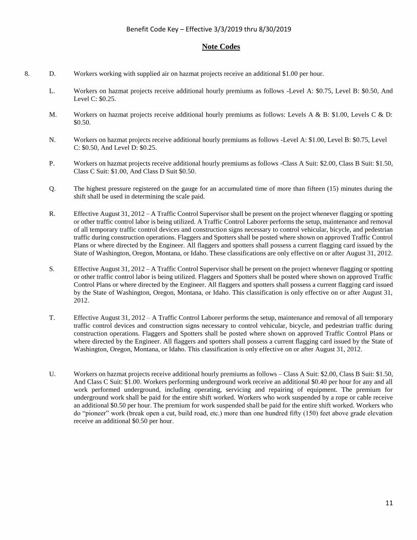
Benefit Code Key – Effective 3/3/2019 thru 8/30/2019
11
Note Codes
8. D. Workers working with supplied air on hazmat projects receive an additional $1.00 per hour.
L. Workers on hazmat projects receive additional hourly premiums as follows -Level A: $0.75, Level B: $0.50, And
Level C: $0.25.
M. Workers on hazmat projects receive additional hourly premiums as follows: Levels A & B: $1.00, Levels C & D:
$0.50.
N. Workers on hazmat projects receive additional hourly premiums as follows -Level A: $1.00, Level B: $0.75, Level
C: $0.50, And Level D: $0.25.
P. Workers on hazmat projects receive additional hourly premiums as follows -Class A Suit: $2.00, Class B Suit: $1.50,
Class C Suit: $1.00, And Class D Suit $0.50.
Q. The highest pressure registered on the gauge for an accumulated time of more than fifteen (15) minutes during the
shift shall be used in determining the scale paid.
R. Effective August 31, 2012 – A Traffic Control Supervisor shall be present on the project whenever flagging or spotting
or other traffic control labor is being utilized. A Traffic Control Laborer performs the setup, maintenance and removal
of all temporary traffic control devices and construction signs necessary to control vehicular, bicycle, and pedestrian
traffic during construction operations. Flaggers and Spotters shall be posted where shown on approved Traffic Control
Plans or where directed by the Engineer. All flaggers and spotters shall possess a current flagging card issued by the
State of Washington, Oregon, Montana, or Idaho. These classifications are only effective on or after August 31, 2012.
S. Effective August 31, 2012 – A Traffic Control Supervisor shall be present on the project whenever flagging or spotting
or other traffic control labor is being utilized. Flaggers and Spotters shall be posted where shown on approved Traffic
Control Plans or where directed by the Engineer. All flaggers and spotters shall possess a current flagging card issued
by the State of Washington, Oregon, Montana, or Idaho. This classification is only effective on or after August 31,
2012. T. Effective August 31, 2012 – A Traffic Control Laborer performs the setup, maintenance and removal of all temporary
traffic control devices and construction signs necessary to control vehicular, bicycle, and pedestrian traffic during
construction operations. Flaggers and Spotters shall be posted where shown on approved Traffic Control Plans or
where directed by the Engineer. All flaggers and spotters shall possess a current flagging card issued by the State of
Washington, Oregon, Montana, or Idaho. This classification is only effective on or after August 31, 2012.
U. Workers on hazmat projects receive additional hourly premiums as follows – Class A Suit: $2.00, Class B Suit: $1.50,
And Class C Suit: $1.00. Workers performing underground work receive an additional $0.40 per hour for any and all
work performed underground, including operating, servicing and repairing of equipment. The premium for
underground work shall be paid for the entire shift worked. Workers who work suspended by a rope or cable receive
an additional $0.50 per hour. The premium for work suspended shall be paid for the entire shift worked. Workers who
do “pioneer” work (break open a cut, build road, etc.) more than one hundred fifty (150) feet above grade elevation
receive an additional $0.50 per hour.

Benefit Code Key – Effective 3/3/2019 thru 8/30/2019
12
Note Codes Continued
8. V. In addition to the hourly wage and fringe benefits, the following depth and enclosure premiums shall be paid. The
premiums are to be calculated for the maximum depth and distance into an enclosure that a diver reaches in a day.
The premiums are to be paid one time for the day and are not used in calculating overtime pay.
Depth premiums apply to depths of fifty feet or more. Over 50' to 100' - $2.00 per foot for each foot over 50 feet. Over
101' to 150' - $3.00 per foot for each foot over 101 feet. Over 151' to 220' - $4.00 per foot for each foot over 220 feet.
Over 221' - $5.00 per foot for each foot over 221 feet.
Enclosure premiums apply when divers enter enclosures (such as pipes or tunnels) where there is no vertical ascent
and is measured by the distance travelled from the entrance. 25’ to 300’ - $1.00 per foot from entrance. 300’ to 600’
- $1.50 per foot beginning at 300’. Over 600’ - $2.00 per foot beginning at 600’.
W. Meter Installers work on single phase 120/240V self-contained residential meters. The Lineman/Groundmen rates
would apply to meters not fitting this description.
X. Workers on hazmat projects receive additional hourly premiums as follows - Class A Suit: $2.00, Class B Suit:
$1.50, Class C Suit: $1.00, and Class D Suit: $0.50. Special Shift Premium: Basic hourly rate plus $2.00 per hour.
When due to conditions beyond the control of the Employer or when an owner (not acting as the contractor), a
government agency or the contract specifications requires that work can only be performed outside the normal 5 am
to 6pm shift, then the special shift premium will be applied to the basic hourly rate. When an employee works on a
special shift, they shall be paid a special shift premium for each hour worked unless they are in OT or Double-time
status. (For example, the special shift premium does not waive the overtime requirements for work performed on
Saturday or Sunday.)
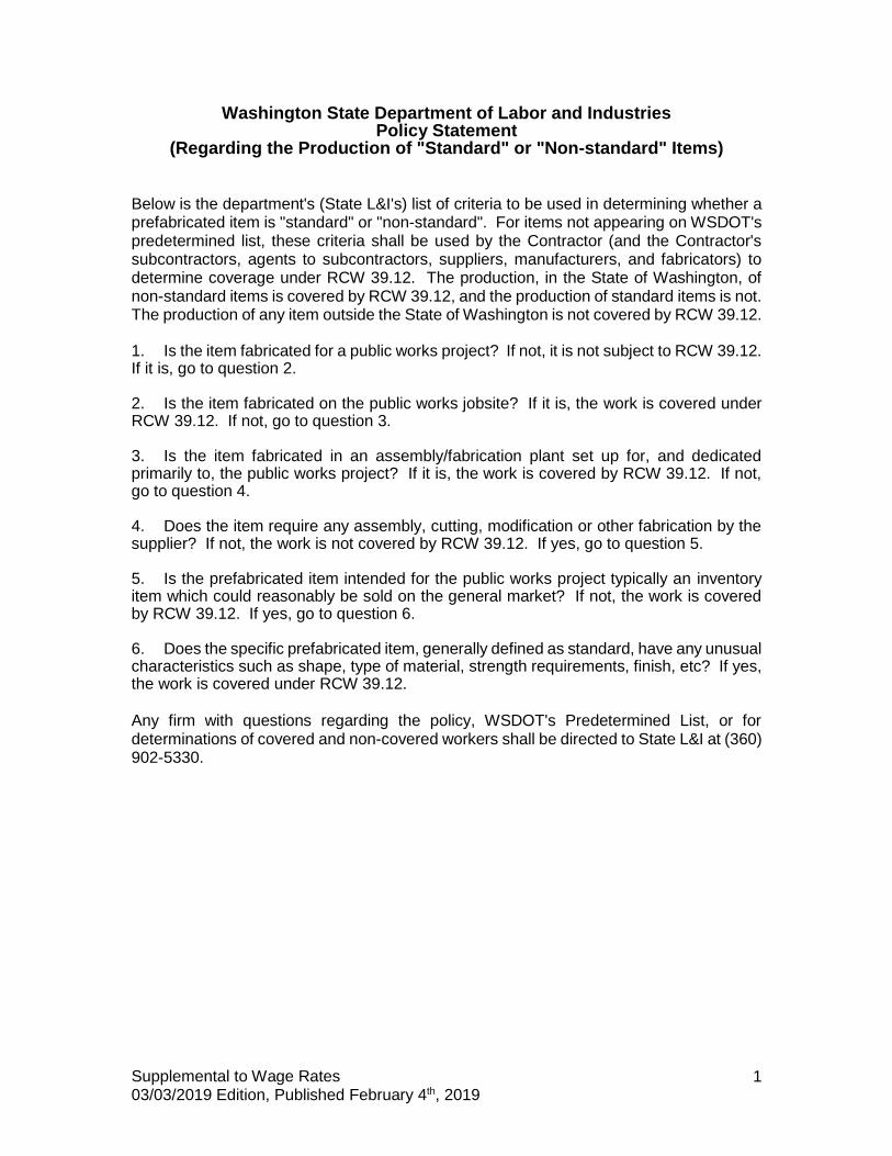
Supplemental to Wage Rates 03/03/2019 Edition, Published February 4th, 2019
1
Washington State Department of Labor and Industries Policy Statement
(Regarding the Production of "Standard" or "Non-standard" Items)
Below is the department's (State L&I's) list of criteria to be used in determining whether a prefabricated item is "standard" or "non-standard". For items not appearing on WSDOT's predetermined list, these criteria shall be used by the Contractor (and the Contractor's subcontractors, agents to subcontractors, suppliers, manufacturers, and fabricators) to determine coverage under RCW 39.12. The production, in the State of Washington, of non-standard items is covered by RCW 39.12, and the production of standard items is not. The production of any item outside the State of Washington is not covered by RCW 39.12. 1. Is the item fabricated for a public works project? If not, it is not subject to RCW 39.12. If it is, go to question 2. 2. Is the item fabricated on the public works jobsite? If it is, the work is covered under RCW 39.12. If not, go to question 3. 3. Is the item fabricated in an assembly/fabrication plant set up for, and dedicated primarily to, the public works project? If it is, the work is covered by RCW 39.12. If not, go to question 4. 4. Does the item require any assembly, cutting, modification or other fabrication by the supplier? If not, the work is not covered by RCW 39.12. If yes, go to question 5. 5. Is the prefabricated item intended for the public works project typically an inventory item which could reasonably be sold on the general market? If not, the work is covered by RCW 39.12. If yes, go to question 6. 6. Does the specific prefabricated item, generally defined as standard, have any unusual characteristics such as shape, type of material, strength requirements, finish, etc? If yes, the work is covered under RCW 39.12. Any firm with questions regarding the policy, WSDOT's Predetermined List, or for determinations of covered and non-covered workers shall be directed to State L&I at (360) 902-5330.
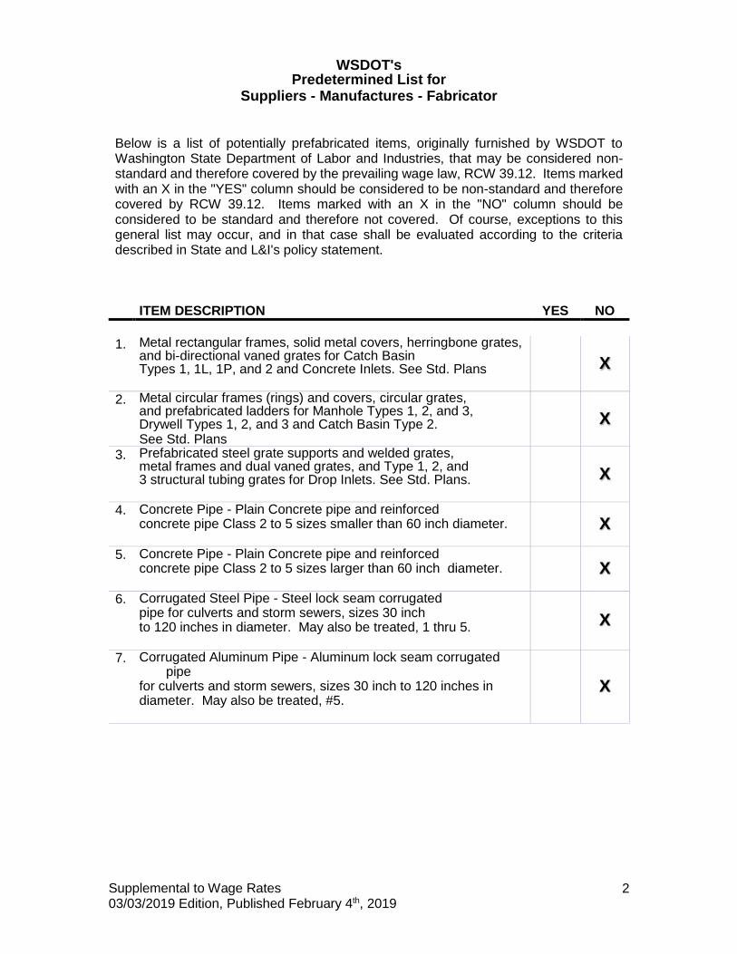
WSDOT's
Predetermined List for Suppliers - Manufactures - Fabricator
Supplemental to Wage Rates 03/03/2019 Edition, Published February 4th, 2019
2
Below is a list of potentially prefabricated items, originally furnished by WSDOT to Washington State Department of Labor and Industries, that may be considered non-standard and therefore covered by the prevailing wage law, RCW 39.12. Items marked with an X in the "YES" column should be considered to be non-standard and therefore covered by RCW 39.12. Items marked with an X in the "NO" column should be considered to be standard and therefore not covered. Of course, exceptions to this general list may occur, and in that case shall be evaluated according to the criteria described in State and L&I's policy statement. ITEM DESCRIPTION YES NO
1. Metal rectangular frames, solid metal covers, herringbone grates,
and bi-directional vaned grates for Catch Basin Types 1, 1L, 1P, and 2 and Concrete Inlets. See Std. Plans
X
2. Metal circular frames (rings) and covers, circular grates, and prefabricated ladders for Manhole Types 1, 2, and 3, Drywell Types 1, 2, and 3 and Catch Basin Type 2. See Std. Plans
X
3. Prefabricated steel grate supports and welded grates, metal frames and dual vaned grates, and Type 1, 2, and 3 structural tubing grates for Drop Inlets. See Std. Plans.
X
4. Concrete Pipe - Plain Concrete pipe and reinforced concrete pipe Class 2 to 5 sizes smaller than 60 inch diameter.
X
5. Concrete Pipe - Plain Concrete pipe and reinforced concrete pipe Class 2 to 5 sizes larger than 60 inch diameter.
X
6. Corrugated Steel Pipe - Steel lock seam corrugated pipe for culverts and storm sewers, sizes 30 inch to 120 inches in diameter. May also be treated, 1 thru 5.
X
7. Corrugated Aluminum Pipe - Aluminum lock seam corrugated pipe
for culverts and storm sewers, sizes 30 inch to 120 inches in diameter. May also be treated, #5.
X

Supplemental to Wage Rates 03/03/2019 Edition, Published February 4th, 2019
3
ITEM DESCRIPTION YES NO
8. Anchor Bolts & Nuts - Anchor Bolts and Nuts, for
mounting sign structures, luminaries and other items, shall be made from commercial bolt stock. See Contract Plans and Std. Plans for size and material type.
X
9. Aluminum Pedestrian Handrail - Pedestrian handrail conforming to the type and material specifications set forth in
the contract plans. Welding of aluminum shall be in accordance with Section 9-28.14(3).
X
10. Major Structural Steel Fabrication - Fabrication of major steel items such as trusses, beams, girders, etc., for bridges.
X
11. Minor Structural Steel Fabrication - Fabrication of minor steel Items such as special hangers, brackets, access doors for structures, access ladders for irrigation boxes, bridge expansion joint systems, etc., involving welding, cutting, punching and/or boring of holes. See Contact Plans for item description and
shop drawings.
X
12. Aluminum Bridge Railing Type BP - Metal bridge railing conforming to the type and material specifications set forth in the Contract Plans. Welding of aluminum shall be in accordance with Section 9-28.14(3).
X
13. Concrete Piling--Precast-Prestressed concrete piling for use as 55
and 70 ton concrete piling. Concrete to conform to Section 9-19.1 of Std. Spec..
X
14. Precast Manhole Types 1, 2, and 3 with cones, adjustment sections and flat top slabs. See Std. Plans.
X
15. Precast Drywell Types 1, 2, and with cones and adjustment
Sections. See Std. Plans.
X
16. Precast Catch Basin - Catch Basin type 1, 1L, 1P, and 2 With adjustment sections. See Std. Plans.
X

Supplemental to Wage Rates 03/03/2019 Edition, Published February 4th, 2019
4
ITEM DESCRIPTION YES NO
17. Precast Concrete Inlet - with adjustment sections,
See Std. Plans
X
18. Precast Drop Inlet Type 1 and 2 with metal grate supports. See Std. Plans.
X
19. Precast Grate Inlet Type 2 with extension and top units. See Std. Plans
X
20. Metal frames, vaned grates, and hoods for Combination Inlets. See Std. Plans
X
21. Precast Concrete Utility Vaults - Precast Concrete utility vaults of
various sizes. Used for in ground storage of utility facilities and controls. See Contract Plans for size and construction requirements. Shop drawings are to be provided for approval prior to casting
X
22. Vault Risers - For use with Valve Vaults and Utilities X
Vaults.
X
23. Valve Vault - For use with underground utilities. See Contract Plans for details.
X
24. Precast Concrete Barrier - Precast Concrete Barrier for use as new barrier or may also be used as Temporary Concrete Barrier. Only new state approved barrier may be used as permanent barrier.
X
25. Reinforced Earth Wall Panels – Reinforced Earth Wall Panels in size and shape as shown in the Plans. Fabrication plant has annual approval for methods and materials to be used. See Shop Drawing. Fabrication at other locations may be approved, after facilities inspection, contact HQ. Lab.
X
26. Precast Concrete Walls - Precast Concrete Walls - tilt-up wall panel in size and shape as shown in Plans. Fabrication plant has annual approval for methods and materials to be used
X

Supplemental to Wage Rates 03/03/2019 Edition, Published February 4th, 2019
5
ITEM DESCRIPTION YES NO
27. Precast Railroad Crossings - Concrete Crossing Structure
Slabs. X
28. 12, 18 and 26 inch Standard Precast Prestressed Girder – Standard Precast Prestressed Girder for use in structures. Fabricator plant has annual approval of methods and materials
to be used. Shop Drawing to be provided for approval prior to casting girders. See Std. Spec. Section 6-02.3(25)A
X
29. Prestressed Concrete Girder Series 4-14 - Prestressed Concrete Girders for use in structures. Fabricator plant has annual
approval of methods and materials to be used. Shop Drawing to be provided for approval prior to casting girders. See Std. Spec. Section 6-02.3(25)A .
X
30. Prestressed Tri-Beam Girder - Prestressed Tri-Beam Girders for use in structures. Fabricator plant has annual approval of methods and materials to be used. Shop Drawing to be
provided for approval prior to casting girders. See Std. Spec. Section 6-02.3(25)A
X
31. Prestressed Precast Hollow-Core Slab – Precast Prestressed Hollow-core slab for use in structures. Fabricator plant has
annual approval of methods and materials to be used. Shop Drawing to be provided for approval prior to casting girders. See Std. Spec. Section 6-02.3(25)A.
X
32. Prestressed-Bulb Tee Girder - Bulb Tee Prestressed Girder for use in structures. Fabricator plant has annual approval of methods and materials to be used. Shop Drawing to be
provided for approval prior to casting girders. See Std. Spec. Section 6-02.3(25)A
X
33. Monument Case and Cover See Std. Plan.
X

Supplemental to Wage Rates 03/03/2019 Edition, Published February 4th, 2019
6
ITEM DESCRIPTION YES NO
34. Cantilever Sign Structure - Cantilever Sign Structure
fabricated from steel tubing meeting AASHTO-M-183. See Std. Plans, and Contract Plans for details. The steel structure shall be galvanized after fabrication in accordance with AASHTO-M-111.
X
35. Mono-tube Sign Structures - Mono-tube Sign Bridge fabricated to details shown in the Plans. Shop drawings for approval are required prior to fabrication.
X
36. Steel Sign Bridges - Steel Sign Bridges fabricated from steel tubing meeting AASHTO-M-138 for Aluminum Alloys. See Std. Plans, and Contract Plans for details. The steel
structure shall be galvanized after fabrication in accordance with AASHTO-M-111.
X
37. Steel Sign Post - Fabricated Steel Sign Posts as detailed in Std Plans. Shop drawings for approval are to be provided prior to fabrication
X
38. Light Standard-Prestressed - Spun, prestressed, hollow concrete poles.
X
39. Light Standards - Lighting Standards for use on highway illumination systems, poles to be fabricated to conform with methods and materials as specified on Std. Plans. See Specia Provisions for pre-approved drawings.
X
40. Traffic Signal Standards - Traffic Signal Standards for use on highway and/or street signal systems. Standards to be
fabricated to conform with methods and material as specified on Std.
Plans. See Special Provisions for pre-approved drawings
X
41. Precast Concrete Sloped Mountable Curb (Single and DualFaced) See Std. Plans.
X

Supplemental to Wage Rates 03/03/2019 Edition, Published February 4th, 2019
7
ITEM DESCRIPTION YES NO
42. Traffic Signs - Prior to approval of a Fabricator of Traffic Signs,
the sources of the following materials must be submitted and approved for reflective sheeting, legend material, and
aluminum sheeting. NOTE: *** Fabrication inspection required. Only signs tagged "Fabrication Approved" by WSDOT Sign Fabrication Inspector to be installed
X X
Custom Message
Std Signing
Message
43. Cutting & bending reinforcing steel
X
44. Guardrail components X X Custom
End Sec Standard
Sec
45. Aggregates/Concrete mixes
Covered by WAC 296-127-018
46. Asphalt
Covered by WAC 296-127-018
47. Fiber fabrics
X
48. Electrical wiring/components
X
49. treated or untreated timber pile
X
50. Girder pads (elastomeric bearing)
X
51. Standard Dimension lumber
X
52. Irrigation components X

Supplemental to Wage Rates 03/03/2019 Edition, Published February 4th, 2019
8
ITEM DESCRIPTION YES NO
53. Fencing materials
X
54. Guide Posts
X
55. Traffic Buttons
X
56. Epoxy
X
57. Cribbing
X
58. Water distribution materials
X
59. Steel "H" piles
X
60. Steel pipe for concrete pile casings
X
61. Steel pile tips, standard
X
62. Steel pile tips, custom X
Prefabricated items specifically produced for public works projects that are prefabricated in a county other than the county wherein the public works project is to be completed, the wage for the offsite prefabrication shall be the applicable prevailing wage for the county in which the actual prefabrication takes place. It is the manufacturer of the prefabricated product to verify that the correct county wage rates are applied to work they perform. See RCW 39.12.010 (The definition of "locality" in RCW 39.12.010(2) contains the phrase "wherein the physical work is being performed." The department interprets this phrase to mean the actual work site.

Supplemental to Wage Rates 03/03/2019 Edition, Published February 4th, 2019
9
WSDOT's List of State Occupations not applicable to Heavy and Highway Construction Projects
This project is subject to the state hourly minimum rates for wages and fringe benefits in the contract provisions, as provided by the state Department of Labor and Industries. The following list of occupations, is comprised of those occupations that are not normally used in the construction of heavy and highway projects. When considering job classifications for use and / or payment when bidding on, or building heavy and highway construction projects for, or administered by WSDOT, these Occupations will be excepted from the included "Washington State Prevailing Wage Rates For Public Work Contracts" documents.
Building Service Employees Electrical Fixture Maintenance Workers Electricians - Motor Shop Heating Equipment Mechanics Industrial Engine and Machine Mechanics Industrial Power Vacuum Cleaners Inspection, Cleaning, Sealing of Water Systems by Remote Control Laborers - Underground Sewer & Water Machinists (Hydroelectric Site Work) Modular Buildings Playground & Park Equipment Installers Power Equipment Operators - Underground Sewer & Water Residential *** ALL ASSOCIATED RATES *** Sign Makers and Installers (Non-Electrical) Sign Makers and Installers (Electrical) Stage Rigging Mechanics (Non Structural)
The following occupations may be used only as outlined in the preceding text concerning "WSDOT's list for Suppliers - Manufacturers - Fabricators"
Fabricated Precast Concrete Products Metal Fabrication (In Shop)
Definitions for the Scope of Work for prevailing wages may be found at the Washington State Department of Labor and Industries web site and in WAC Chapter 296-127.

Supplemental to Wage Rates 03/03/2019 Edition, Published February 4th, 2019
10
Washington State Department of Labor and Industries Policy Statements
(Regarding Production and Delivery of Gravel, Concrete, Asphalt, etc.)
WAC 296-127-018 Agency filings affecting this section
Coverage and exemptions of workers involved in the production and delivery of gravel, concrete, asphalt, or similar materials. (1) The materials covered under this section include but are not limited to: Sand, gravel, crushed rock, concrete, asphalt, or other similar materials. (2) All workers, regardless of by whom employed, are subject to the provisions of chapter 39.12 RCW when they perform any or all of the following functions: (a) They deliver or discharge any of the above-listed materials to a public works project site: (i) At one or more point(s) directly upon the location where the material will be incorporated into the project; or (ii) At multiple points at the project; or (iii) Adjacent to the location and coordinated with the incorporation of those materials. (b) They wait at or near a public works project site to perform any tasks subject to this section of the rule. (c) They remove any materials from a public works construction site pursuant to contract requirements or specifications (e.g., excavated materials, materials from demolished structures, clean-up materials, etc.). (d) They work in a materials production facility (e.g., batch plant, borrow pit, rock quarry, etc.,) which is established for a public works project for the specific, but not necessarily exclusive, purpose of supplying materials for the project. (e) They deliver concrete to a public works site regardless of the method of incorporation. (f) They assist or participate in the incorporation of any materials into the public works project.

Supplemental to Wage Rates 03/03/2019 Edition, Published February 4th, 2019
11
(3) All travel time that relates to the work covered under subsection (2) of this section requires the payment of prevailing wages. Travel time includes time spent waiting to load, loading, transporting, waiting to unload, and delivering materials. Travel time would include all time spent in travel in support of a public works project whether the vehicle is empty or full. For example, travel time spent returning to a supply source to obtain another load of material for use on a public works site or returning to the public works site to obtain another load of excavated material is time spent in travel that is subject to prevailing wage. Travel to a supply source, including travel from a public works site, to obtain materials for use on a private project would not be travel subject to the prevailing wage. (4) Workers are not subject to the provisions of chapter 39.12 RCW when they deliver materials to a stockpile. (a) A "stockpile" is defined as materials delivered to a pile located away from the site of incorporation such that the stockpiled materials must be physically moved from the stockpile and transported to another location on the project site in order to be incorporated into the project. (b) A stockpile does not include any of the functions described in subsection (2)(a) through (f) of this section; nor does a stockpile include materials delivered or distributed to multiple locations upon the project site; nor does a stockpile include materials dumped at the place of incorporation, or adjacent to the location and coordinated with the incorporation. (5) The applicable prevailing wage rate shall be determined by the locality in which the work is performed. Workers subject to subsection (2)(d) of this section, who produce such materials at an off-site facility shall be paid the applicable prevailing wage rates for the county in which the off-site facility is located. Workers subject to subsection (2) of this section, who deliver such materials to a public works project site shall be paid the applicable prevailing wage rates for the county in which the public works project is located. [Statutory Authority: Chapter 39.12 RCW, RCW 43.22.051 and 43.22.270. 08-24-101, § 296-127-018, filed 12/2/08, effective 1/2/09. Statutory Authority: Chapters 39.04 and 39.12 RCW and RCW 43.22.270. 92-01-104 and 92-08-101, § 296-127-018, filed 12/18/91 and 4/1/92, effective 8/31/92.]

RIDGETOP BLVD NW IMPROVEMENTS PROJECT PHASE 2
THIS PAGE INTENTIONALLY LEFT BLANK

1 | P a g e WA190001 Modification 5 Federal Wage Determinations for Highway Construction
"General Decision Number: WA20190001 06/14/2019
Superseded General Decision Number: WA20180001
State: Washington
Construction Type: Highway
Counties: Washington Statewide.
HIGHWAY (Excludes D.O.E. Hanford Site in Benton and Franklin
Counties)
Note: Under Executive Order (EO) 13658, an hourly minimum wage
of $10.60 for calendar year 2019 applies to all contracts
subject to the Davis-Bacon Act for which the contract is
awarded (and any solicitation was issued) on or after January
1, 2015. If this contract is covered by the EO, the contractor
must pay all workers in any classification listed on this wage
determination at least $10.60 per hour (or the applicable wage
rate listed on this wage determination, if it is higher) for
all hours spent performing on the contract in calendar year
2019. If this contract is covered by the EO and a
classification considered necessary for performance of work on
the contract does not appear on this wage determination, the
contractor must pay workers in that classification at least the
wage rate determined through the conformance process set forth
in 29 CFR 5.5(a)(1)(ii) (or the EO minimum wage rate,if it is
higher than the conformed wage rate). The EO minimum wage rate
will be adjusted annually. Please note that this EO applies to
the above-mentioned types of contracts entered into by the
federal government that are subject to the Davis-Bacon Act
itself, but it does not apply to contracts subject only to the
Davis-Bacon Related Acts, including those set forth at 29 CFR
5.1(a)(2)-(60). Additional information on contractor
requirements and worker protections under the EO is available
at www.dol.gov/whd/govcontracts.
Modification Number Publication Date
0 01/04/2019
1 01/18/2019
2 02/15/2019
3 05/03/2019
4 05/24/2019
5 06/14/2019

2 | P a g e WA190001 Modification 5 Federal Wage Determinations for Highway Construction
CARP0001-008 06/01/2018
ADAMS, ASOTIN, BENTON, CHELAN, COLUMBIA, DOUGLAS, FERRY,
FRANKLIN, GARFIELD, GRANT, KITTITAS, LINCOLN, OKANOGAN, PEND
OREILLE, SPOKANE, STEVENS, WALLA WALLA, WHITMAN, and YAKIMA
Counties
Rates Fringes
CARPENTER
GROUP 1.....................$ 33.40 16.40
GROUP 2.....................$ 45.42 18.83
GROUP 3.....................$ 34.52 16.40
GROUP 4.....................$ 34.52 16.40
GROUP 5.....................$ 77.52 16.40
GROUP 6.....................$ 37.76 16.40
GROUP 7.....................$ 38.76 16.40
GROUP 8.....................$ 35.52 16.40
GROUP 9.....................$ 41.76 16.40
CARPENTER & DIVER CLASSIFICATIONS:
GROUP 1: Carpenter
GROUP 2: Millwright, Machine Erector
GROUP 3: Piledriver - includes driving, pulling, cutting,
placing collars, setting, welding, or creosote treated
material, on all piling
GROUP 4: Bridge, Dock, and Wharf carpenters
GROUP 5: Diver Wet
GROUP 6: Diver Tender, Manifold Operator, ROV Operator
GROUP 7: Diver Standby
GROUP 8: Assistant Diver Tender, ROV Tender/Technician
GROUP 9: Manifold Operator-Mixed Gas
ZONE PAY:
ZONE 1 0-60 MILES FREE
ZONE 2 61-100 $4.00/PER HOUR
ZONE 3 OVER 100 MILES $6.00/PER HOUR
DISPATCH POINTS:
CARPENTERS/MILLWRIGHTS: PASCO (515 N Neel Street) or Main
Post Office of established residence of employee (Whichever
is closest to the worksite).
CARPENTERS/PILEDRIVER: SPOKANE (127 E. AUGUSTA AVE.) or Main
Post Office of established residence of employee (Whichever
is closest to the worksite).

3 | P a g e WA190001 Modification 5 Federal Wage Determinations for Highway Construction
CARPENTERS: WENATCHEE (27 N. CHELAN) or Main Post Office of
established residence of employee (Whichever is closest to
the worksite).
CARPENTERS: COEUR D' ALENE (1839 N. GOVERNMENT WAY) or Main
Post Office of established residence of employee (Whichever
is closest to the worksite).
CARPENTERS: MOSCOW (306 N. JACKSON) or Main Post Office of
established residence of employee (Whichever is closest to
the worksite).
DEPTH PAY FOR DIVERS BELOW WATER SURFACE:
50-100 feet $2.00 per foot
101-150 feet $3.00 per foot
151-220 feet $4.00 per foot
221 feet and deeper $5.00 per foot
PREMIUM PAY FOR DIVING IN ENCLOSURES WITH NO VERTICAL ASCENT:
0-25 feet Free
26-300 feet $1.00 per Foot
SATURATION DIVING:
The standby rate applies until saturation starts. The
saturation diving rate applies when divers are under
pressure continuously until work task and decompression are
complete. the diver rate shall be paid for all saturation
hours.
WORK IN COMBINATION OF CLASSIFICATIONS:
Employees working in any combination of classifications
within the diving crew (except dive supervisor) in a shift
are paid in the classification with the highest rate for
that shift.
HAZMAT PROJECTS:
Anyone working on a HAZMAT job (task), where HAZMAT
certification is required, shall be compensated at a
premium, in addition to the classification working in as
follows:
LEVEL D + $.25 per hour - This is the lowest level of
protection. No respirator is used and skin protection is
minimal.
LEVEL C + $.50 per hour - This level uses an air purifying
respirator or additional protective clothing.
LEVEL B + $.75 per hour - Uses same respirator protection as
Level A. Supplied air line is provided in conjunction with
a chemical ""splash suit"".
LEVEL A +$1.00 per hour - This level utilizes a fully
encapsulated suit with a self-contained breathing apparatus
or a supplied air line.

4 | P a g e WA190001 Modification 5 Federal Wage Determinations for Highway Construction
----------------------------------------------------------------
CARP0003-006 06/01/2018
SOUTHWEST WASHINGTON: CLARK, COWLITZ, KLICKITAT,
LEWIS(Piledriver only), PACIFIC (South of a straight line made
by extending the north boundary line of Wahkiakum County west
to Willapa Bay to the Pacific Ocean), SKAMANIA, and WAHKIAKUM
Counties.
Rates Fringes
Carpenters:
CARPENTERS..................$ 37.64 16.83
DIVERS TENDERS..............$ 43.73 16.83
DIVERS......................$ 87.73 16.83
DRYWALL.....................$ 37.64 16.83
MILLWRIGHTS.................$ 38.17 16.83
PILEDRIVERS.................$ 38.71 16.83
DEPTH PAY:
50 TO 100 FEET $1.00 PER FOOT OVER 50 FEET
101 TO 150 FEET $1.50 PER FOOT OVER 101 FEET
151 TO 200 FEET $2.00 PER FOOT OVER 151 FEET
Zone Differential (Add up Zone 1 rates):
Zone 2 - $0.85
Zone 3 - 1.25
Zone 4 - 1.70
Zone 5 - 2.00
Zone 6 - 3.00
BASEPOINTS: ASTORIA, LONGVIEW, PORTLAND, THE DALLES, AND
VANCOUVER, (NOTE: All dispatches for Washington State
Counties: Cowlitz, Wahkiakum and Pacific shall be from
Longview Local #1707 and mileage shall be computed from
that point.)
ZONE 1: Projects located within 30 miles of the respective
city hall of the above mentioned cities
ZONE 2: Projects located more than 30 miles and less than 40
miles of the respective city of the above mentioned cities
ZONE 3: Projects located more than 40 miles and less than 50
miles of the respective city of the above mentioned cities
ZONE 4: Projects located more than 50 miles and less than 60
miles of the respective city of the above mentioned cities.
ZONE 5: Projects located more than 60 miles and less than 70
miles of the respective city of the above mentioned cities
ZONE 6: Projects located more than 70 miles of the respected
city of the above mentioned cities
----------------------------------------------------------------

5 | P a g e WA190001 Modification 5 Federal Wage Determinations for Highway Construction
CARP0770-003 06/01/2018
Rates Fringes
CARPENTER
CENTRAL WASHINGTON:
CHELAN, DOUGLAS (WEST OF THE 120TH MERIDIAN),KITTITAS, OKANOGAN (WEST
OF THE 120TH MERIDIAN) AND YAKIMA COUNTIES
CARPENTERS ON CREOSOTE
MATERIAL...................$ 29.15 13.93
CARPENTERS.................$ 29.05 13.93
DIVERS TENDER..............$ 48.59 16.12
DIVERS.....................$ 97.43 16.12
MILLWRIGHT AND MACHINE
ERECTORS...................$ 45.42 16.12
PILEDRIVER, DRIVING,
PULLING, CUTTING, PLACING
COLLARS, SETTING, WELDING
OR CRESOTE TREATED
MATERIAL, ALL PILING.......$ 44.17 13.93
(HOURLY ZONE PAY: WESTERN AND CENTRAL WASHINGTON - ALL
CLASSIFICATIONS EXCEPT MILLWRIGHTS AND PILEDRIVERS
Hourly Zone Pay shall be paid on jobs located outside of the
free zone computed from the city center of the following
listed cities:
Seattle Olympia Bellingham
Auburn Bremerton Anacortes
Renton Shelton Yakima
Aberdeen-Hoquiam Tacoma Wenatchee
Ellensburg Everett Port Angeles
Centralia Mount Vernon Sunnyside
Chelan Pt. Townsend
Zone Pay:
0 -25 radius miles Free
26-35 radius miles $1.00/hour
36-45 radius miles $1.15/hour
46-55 radius miles $1.35/hour
Over 55 radius miles $1.55/hour
(HOURLY ZONE PAY: WESTERN AND CENTRAL WASHINGTON - MILLWRIGHT
AND PILEDRIVER ONLY)
Hourly Zone Pay shall be computed from Seattle Union Hall,
Tacoma City center, and Everett City center
Zone Pay:
0 -25 radius miles Free
26-45 radius miles $ .70/hour
Over 45 radius miles $1.50/hour
----------------------------------------------------------------

6 | P a g e WA190001 Modification 5 Federal Wage Determinations for Highway Construction
CARP0770-006 06/01/2018
Rates Fringes
CARPENTER
WESTERN WASHINGTON: CLALLAM, GRAYS HARBOR, ISLAND, JEFFERSON, KING,
KITSAP, LEWIS (excludes piledrivers only), MASON, PACIFIC (North of a
straight line made by extending the north boundary line of Wahkiakum
County west to the Pacific Ocean), PIERCE, SAN JUAN, SKAGIT, SNOHOMISH,
THURSTON AND WHATCOM COUNTIES
BRIDGE CARPENTERS..........$ 43.92 16.12
CARPENTERS ON CREOSOTE
MATERIAL...................$ 44.02 16.12
CARPENTERS.................$ 43.92 16.12
DIVERS TENDER..............$ 48.59 16.12
DIVERS.....................$ 97.48 16.12
MILLWRIGHT AND MACHINE
ERECTORS...................$ 45.42 16.12
PILEDRIVER, DRIVING,
PULLING, CUTTING, PLACING
COLLARS, SETTING, WELDING
OR CRESOTE TREATED
MATERIAL, ALL PILING.......$ 44.17 16.12
(HOURLY ZONE PAY: WESTERN AND CENTRAL WASHINGTON - ALL
CLASSIFICATIONS EXCEPT MILLWRIGHTS AND PILEDRIVERS
Hourly Zone Pay shall be paid on jobs located outside of the
free zone computed from the city center of the following
listed cities:
Seattle Olympia Bellingham
Auburn Bremerton Anacortes
Renton Shelton Yakima
Aberdeen-Hoquiam Tacoma Wenatchee
Ellensburg Everett Port Angeles
Centralia Mount Vernon Sunnyside
Chelan Pt. Townsend
Zone Pay:
0 -25 radius miles Free
26-35 radius miles $1.00/hour
36-45 radius miles $1.15/hour
46-55 radius miles $1.35/hour
Over 55 radius miles $1.55/hour
(HOURLY ZONE PAY: WESTERN AND CENTRAL WASHINGTON - MILLWRIGHT
AND PILEDRIVER ONLY)
Hourly Zone Pay shall be computed from Seattle Union Hall,
Tacoma City center, and Everett City center
Zone Pay:
0 -25 radius miles Free
26-45 radius miles $ .70/hour
Over 45 radius miles $1.50/hour

7 | P a g e WA190001 Modification 5 Federal Wage Determinations for Highway Construction
----------------------------------------------------------------
ELEC0046-001 02/04/2019
CALLAM, JEFFERSON, KING AND KITSAP COUNTIES
Rates Fringes
CABLE SPLICER....................$ 58.84 22.48
ELECTRICIAN......................$ 53.49 22.31
----------------------------------------------------------------
ELEC0048-003 01/01/2019
CLARK, KLICKITAT AND SKAMANIA COUNTIES
Rates Fringes
CABLE SPLICER....................$ 44.22 21.50
ELECTRICIAN......................$ 44.85 23.57
HOURLY ZONE PAY:
Hourly Zone Pay shall be paid on jobs located outside of the
free zone computed from the city center of the following
listed cities:
Portland, The Dalles, Hood River, Tillamook, Seaside and
Astoria
Zone Pay:
Zone 1: 31-50 miles $1.50/hour
Zone 2: 51-70 miles $3.50/hour
Zone 3: 71-90 miles $5.50/hour
Zone 4: Beyond 90 miles $9.00/hour
*These are not miles driven. Zones are based on Delorrne
Street Atlas USA 2006 plus.
----------------------------------------------------------------
ELEC0048-029 01/01/2019
COWLITZ AND WAHKIAKUM COUNTY
Rates Fringes
CABLE SPLICER....................$ 44.22 21.50
ELECTRICIAN......................$ 44.85 23.57
----------------------------------------------------------------
ELEC0073-001 01/01/2019
ADAMS, FERRY, LINCOLN, PEND OREILLE, SPOKANE, STEVENS, WHITMAN
COUNTIES
Rates Fringes
CABLE SPLICER....................$ 34.10 16.68
ELECTRICIAN......................$ 34.30 18.88
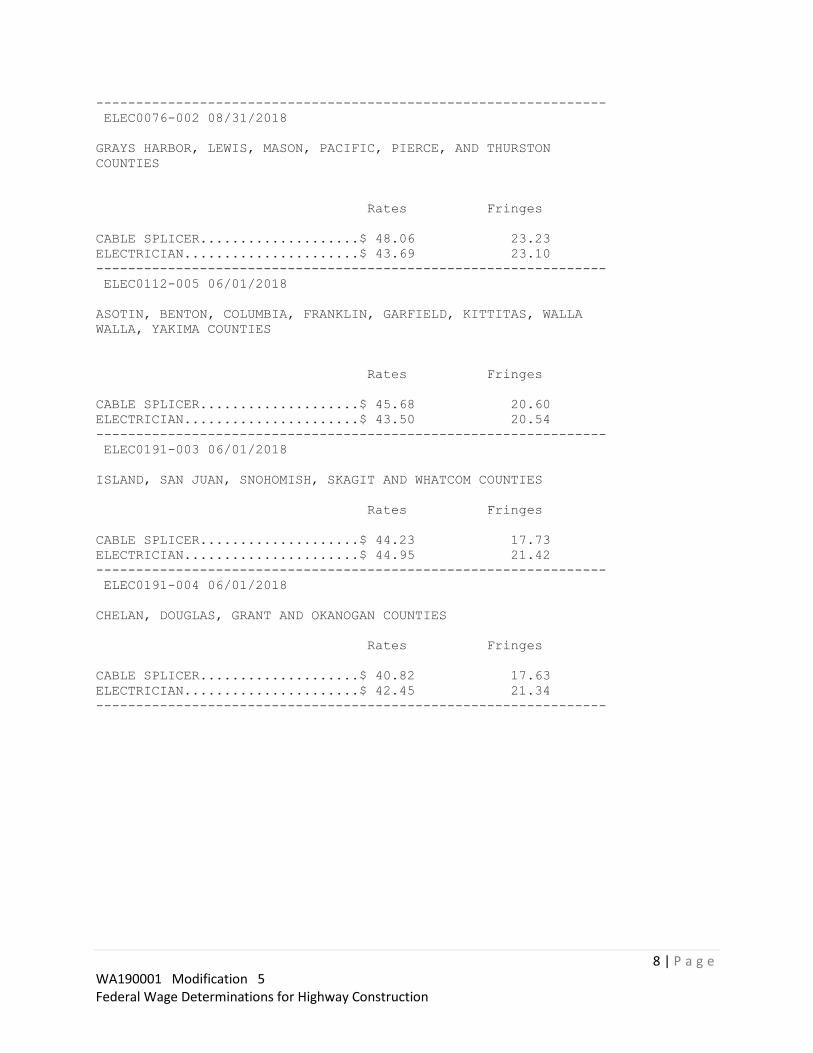
8 | P a g e WA190001 Modification 5 Federal Wage Determinations for Highway Construction
----------------------------------------------------------------
ELEC0076-002 08/31/2018
GRAYS HARBOR, LEWIS, MASON, PACIFIC, PIERCE, AND THURSTON
COUNTIES
Rates Fringes
CABLE SPLICER....................$ 48.06 23.23
ELECTRICIAN......................$ 43.69 23.10
----------------------------------------------------------------
ELEC0112-005 06/01/2018
ASOTIN, BENTON, COLUMBIA, FRANKLIN, GARFIELD, KITTITAS, WALLA
WALLA, YAKIMA COUNTIES
Rates Fringes
CABLE SPLICER....................$ 45.68 20.60
ELECTRICIAN......................$ 43.50 20.54
----------------------------------------------------------------
ELEC0191-003 06/01/2018
ISLAND, SAN JUAN, SNOHOMISH, SKAGIT AND WHATCOM COUNTIES
Rates Fringes
CABLE SPLICER....................$ 44.23 17.73
ELECTRICIAN......................$ 44.95 21.42
----------------------------------------------------------------
ELEC0191-004 06/01/2018
CHELAN, DOUGLAS, GRANT AND OKANOGAN COUNTIES
Rates Fringes
CABLE SPLICER....................$ 40.82 17.63
ELECTRICIAN......................$ 42.45 21.34
----------------------------------------------------------------

9 | P a g e WA190001 Modification 5 Federal Wage Determinations for Highway Construction
ENGI0302-003 06/01/2018
CHELAN (WEST OF THE 120TH MERIDIAN), CLALLAM, DOUGLAS (WEST OF
THE 120TH MERIDIAN), GRAYS HARBOR, ISLAND, JEFFERSON, KING,
KITSAP, KITTITAS, MASON, OKANOGAN (WEST OF THE 120TH MERIDIAN),
SAN JUNA, SKAGIT, SNOHOMISH, WHATCOM AND YAKIMA (WEST OF THE
120TH MERIDIAN) COUNTIES
Zone 1 (0-25 radius miles):
Rates Fringes
POWER EQUIPMENT OPERATOR
Group 1A...................$ 44.44 19.97
Group 1AA..................$ 45.09 19.97
Group 1AAA.................$ 45.73 19.97
Group 1.....................$ 43.79 19.97
Group 2.....................$ 43.23 19.97
Group 3.....................$ 42.74 19.97
Group 4.....................$ 40.01 19.97
Zone Differential (Add to Zone 1 rates):
Zone 2 (26-45 radius miles) - $1.00
Zone 3 (Over 45 radius miles) - $1.30
BASEPOINTS: Aberdeen, Bellingham, Bremerton, Everett, Kent,
Mount Vernon, Port Angeles, Port Townsend, Seattle,
Shelton, Wenatchee, Yakima
POWER EQUIPMENT OPERATORS CLASSIFICATIONS
GROUP 1AAA - Cranes-over 300 tons, or 300 ft of boom
(including jib with attachments)
GROUP 1AA - Cranes 200 to 300 tons, or 250 ft of boom
(including jib with attachments); Tower crane over 175 ft
in height, base to boom
GROUP 1A - Cranes, 100 tons thru 199 tons, or 150 ft of boom
(including jib with attachments); Crane-overhead, bridge
type, 100 tons and over; Tower crane up to 175 ft in height
base to boom; Loaders-overhead, 8 yards and over; Shovels,
excavator, backhoes-6 yards and over with attachments
GROUP 1 - Cableway; Cranes 45 tons thru 99 tons, under 150 ft
of boom (including jib with attachments); Crane-overhead,
bridge type, 45 tons thru 99 tons; Derricks on building
work; Excavator, shovel, backhoes over 3 yards and under 6
yards; Hard tail end dump articulating off-road equipment
45 yards and over; Loader- overhead 6 yards to, but not
including 8 yards; Mucking machine, mole, tunnel, drill
and/or shield; Quad 9, HD 41, D-10; Remote control operator
on rubber tired earth moving equipment; Rollagon;
Scrapers-self propelled 45 yards and over; Slipform pavers;
Transporters, all truck or track type

10 | P a g e WA190001 Modification 5 Federal Wage Determinations for Highway Construction
GROUP 2 - Barrier machine (zipper); Batch Plant Operaor-
Concrete; Bump Cutter; Cranes, 20 tons thru 44 tons with
attachments; Crane-overhead, bridge type-20 tons through 44
tons; Chipper; Concrete Pump-truck mount with boom
attachment; Crusher; Deck Engineer/Deck Winches (power);
Drilling machine; Excavator, shovel, backhoe-3yards and
under; Finishing Machine, Bidwell, Gamaco and similar
equipment; Guardrail punch; Horizontal/directional drill
operator; Loaders-overhead under 6 yards; Loaders-plant
feed; Locomotives-all; Mechanics-all; Mixers-asphalt plant;
Motor patrol graders-finishing; Piledriver (other than
crane mount); Roto-mill,roto-grinder; Screedman, spreader,
topside operator-Blaw Knox, Cedar Rapids, Jaeger,
Caterpillar, Barbar Green; Scraper-self propelled, hard
tail end dump, articulating off-road equipment-under 45
yards; Subgrade trimmer; Tractors, backhoes-over 75 hp;
Transfer material service machine-shuttle buggy, blaw
knox-roadtec; Truck crane oiler/driver-100 tons and over;
Truck Mount portable conveyor; Yo Yo Pay dozer
GROUP 3 - Conveyors; Cranes-thru 19 tons with attachments;
A-frame crane over 10 tons; Drill oilers-auger type, truck
or crane mount; Dozers-D-9 and under; Forklift-3000 lbs.
and over with attachments; Horizontal/directional drill
locator; Outside hoists-(elevators and manlifts), air
tuggers, strato tower bucket elevators; Hydralifts/boom
trucks over 10 tons; Loader-elevating type, belt; Motor
patrol grader-nonfinishing; Plant oiler- asphalt, crusher;
Pumps-concrete; Roller, plant mix or multi-lift materials;
Saws-concrete; Scrpers-concrete and carry-all; Service
engineer-equipment; Trenching machines; Truck Crane
Oiler/Driver under 100 tons; Tractors, backhoe 75 hp and
under
GROUP 4 - Assistant Engineer; Bobcat; Brooms; Compressor;
Concrete finish mahine-laser screed; Cranes-A frame-10 tons
and under; Elevator and Manlift-permanent or shaft type;
Gradechecker, Stakehop; Forklifts under 3000 lbs. with
attachments; Hydralifts/boom trucks, 10 tons and under; Oil
distributors, blower distribution and mulch seeding
operator; Pavement breaker; Posthole digger, mechanical;
Power plant; Pumps, water; Rigger and Bellman; Roller-other
than plant mix; Wheel Tractors, farmall type;
Shotcrete/gunite equipment operator

11 | P a g e WA190001 Modification 5 Federal Wage Determinations for Highway Construction
HANDLING OF HAZARDOUS WASTE MATERIALS:
Personnel in all craft classifications subject to working
inside a federally designated hazardous perimeter shall be
elgible for compensation in accordance with the following
group schedule relative to the level of hazardous waste as
outlined in the specific hazardous waste project site
safety plan.
H-1 Base wage rate when on a hazardous waste site when not
outfitted with protective clothing
H-2 Class ""C"" Suit - Base wage rate plus $ .25 per hour.
H-3 Class ""B"" Suit - Base wage rate plus $ .50 per hour.
H-4 Class ""A"" Suit - Base wage rate plus $ .75 per hour.
----------------------------------------------------------------
ENGI0370-002 06/01/2018
ADAMS, ASOTIN, BENTON, CHELAN (EAST OF THE 120TH MERIDIAN),
COLUMBIA, DOUGLAS (EAST OF THE 120TH MERIDIAN), FERRY,
FRANKLIN, GARFIELD, GRANT, LINCOLN, OKANOGAN (EAST OF THE 120TH
MERIDIAN), PEND OREILLE, SPOKANE, STEVENS, WALLA WALLA, WHITMAN
AND YAKIMA (EAST OF THE 120TH MERIDIAN) COUNTIES
ZONE 1:
Rates Fringes
POWER EQUIPMENT OPERATOR
GROUP 1.....................$ 27.51 15.95
GROUP 2.....................$ 27.83 15.95
GROUP 3.....................$ 28.44 15.95
GROUP 4.....................$ 28.60 15.95
GROUP 5.....................$ 28.76 15.95
GROUP 6.....................$ 29.04 15.95
GROUP 7.....................$ 29.31 15.95
GROUP 8.....................$ 30.41 15.95
ZONE DIFFERENTIAL (Add to Zone 1 rate): Zone 2 - $2.00
Zone 1: Within 45 mile radius of Spokane, Pasco, Washington;
Lewiston, Idaho
Zone 2: Outside 45 mile radius of Spokane, Pasco,
Washington; Lewiston, Idaho
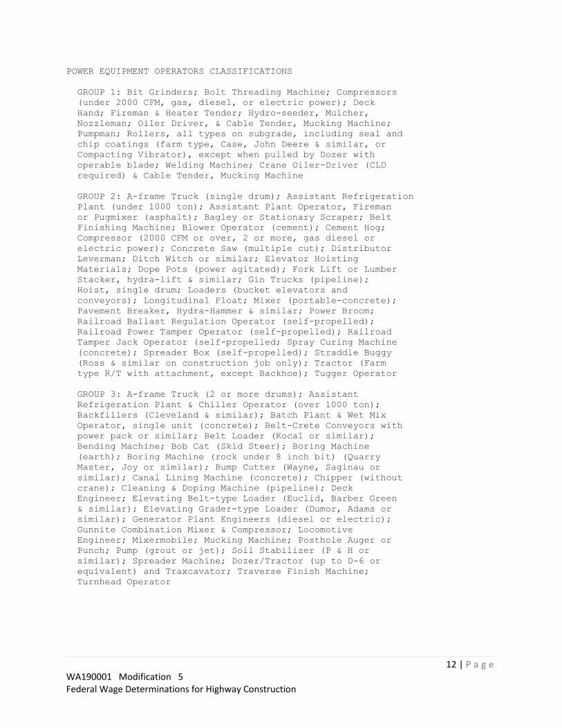
12 | P a g e WA190001 Modification 5 Federal Wage Determinations for Highway Construction
POWER EQUIPMENT OPERATORS CLASSIFICATIONS
GROUP 1: Bit Grinders; Bolt Threading Machine; Compressors
(under 2000 CFM, gas, diesel, or electric power); Deck
Hand; Fireman & Heater Tender; Hydro-seeder, Mulcher,
Nozzleman; Oiler Driver, & Cable Tender, Mucking Machine;
Pumpman; Rollers, all types on subgrade, including seal and
chip coatings (farm type, Case, John Deere & similar, or
Compacting Vibrator), except when pulled by Dozer with
operable blade; Welding Machine; Crane Oiler-Driver (CLD
required) & Cable Tender, Mucking Machine
GROUP 2: A-frame Truck (single drum); Assistant Refrigeration
Plant (under 1000 ton); Assistant Plant Operator, Fireman
or Pugmixer (asphalt); Bagley or Stationary Scraper; Belt
Finishing Machine; Blower Operator (cement); Cement Hog;
Compressor (2000 CFM or over, 2 or more, gas diesel or
electric power); Concrete Saw (multiple cut); Distributor
Leverman; Ditch Witch or similar; Elevator Hoisting
Materials; Dope Pots (power agitated); Fork Lift or Lumber
Stacker, hydra-lift & similar; Gin Trucks (pipeline);
Hoist, single drum; Loaders (bucket elevators and
conveyors); Longitudinal Float; Mixer (portable-concrete);
Pavement Breaker, Hydra-Hammer & similar; Power Broom;
Railroad Ballast Regulation Operator (self-propelled);
Railroad Power Tamper Operator (self-propelled); Railroad
Tamper Jack Operator (self-propelled; Spray Curing Machine
(concrete); Spreader Box (self-propelled); Straddle Buggy
(Ross & similar on construction job only); Tractor (Farm
type R/T with attachment, except Backhoe); Tugger Operator
GROUP 3: A-frame Truck (2 or more drums); Assistant
Refrigeration Plant & Chiller Operator (over 1000 ton);
Backfillers (Cleveland & similar); Batch Plant & Wet Mix
Operator, single unit (concrete); Belt-Crete Conveyors with
power pack or similar; Belt Loader (Kocal or similar);
Bending Machine; Bob Cat (Skid Steer); Boring Machine
(earth); Boring Machine (rock under 8 inch bit) (Quarry
Master, Joy or similar); Bump Cutter (Wayne, Saginau or
similar); Canal Lining Machine (concrete); Chipper (without
crane); Cleaning & Doping Machine (pipeline); Deck
Engineer; Elevating Belt-type Loader (Euclid, Barber Green
& similar); Elevating Grader-type Loader (Dumor, Adams or
similar); Generator Plant Engineers (diesel or electric);
Gunnite Combination Mixer & Compressor; Locomotive
Engineer; Mixermobile; Mucking Machine; Posthole Auger or
Punch; Pump (grout or jet); Soil Stabilizer (P & H or
similar); Spreader Machine; Dozer/Tractor (up to D-6 or
equivalent) and Traxcavator; Traverse Finish Machine;
Turnhead Operator

13 | P a g e WA190001 Modification 5 Federal Wage Determinations for Highway Construction
GROUP 4: Concrete Pumps (squeeze-crete, flow-crete, pump-
crete, Whitman & similar); Curb Extruder (asphalt or
concrete); Drills (churn, core, calyx or diamond);
Equipment Serviceman; Greaser & Oiler; Hoist (2 or more
drums or Tower Hoist); Loaders (overhead & front-end, under
4 yds. R/T); Refrigeration Plant Engineer (under 1000 ton);
Rubber-tired Skidders (R/T with or without attachments);
Surface Heater & Plant Machine; Trenching Machines (under 7
ft. depth capacity); Turnhead (with re-screening); Vacuum
Drill (reverse circulation drill under 8 inch bit)
GROUP 5: Backhoe (under 45,000 gw); Backhoe & Hoe Ram (under
3/4 yd.); Carrydeck & Boom Truck (under 25 tons); Cranes
(25 tons & under), all attachments including clamshell,
dragline; Derricks & Stifflegs (under 65 tons); Drilling
Equipment(8 inch bit & over) (Robbins, reverse circulation
& similar); Hoe Ram; Piledriving Engineers; Paving (dual
drum); Railroad Track Liner Operaotr (self-propelled);
Refrigeration Plant Engineer (1000 tons & over); Signalman
(Whirleys, Highline Hammerheads or similar); Grade Checker
GROUP 6: Asphalt Plant Operator; Automatic Subgrader (Ditches
& Trimmers)(Autograde, ABC, R.A. Hansen & similar on grade
wire); Backhoe (45,000 gw and over to 110,000 gw); Backhoes
& Hoe Ram (3/4 yd. to 3 yd.); Batch Plant (over 4 units);
Batch & Wet Mix Operator (multiple units, 2 & incl. 4);
Blade Operator (motor patrol & attachments); Cable
Controller (dispatcher); Compactor (self-propelled with
blade); Concrete Pump Boom Truck; Concrete Slip Form Paver;
Cranes (over 25 tons, to and including 45 tons), all
attachments including clamshell, dragline; Crusher, Grizzle
& Screening Plant Operator; Dozer, 834 R/T & similar; Drill
Doctor; Loader Operator (front-end & overhead, 4 yds. incl.
8 yds.); Multiple Dozer Units with single blade; Paving
Machine (asphalt and concrete); Quad-Track or similar
equipment; Rollerman (finishing asphalt pavement); Roto
Mill (pavement grinder); Scrapers, all, rubber-tired;
Screed Operator; Shovel(under 3 yds.); Trenching Machines
(7 ft. depth & over); Tug Boat Operator Vactor guzzler,
super sucker; Lime Batch Tank Operator (REcycle Train);
Lime Brain Operator (Recycle Train); Mobile Crusher
Operator (Recycle Train)

14 | P a g e WA190001 Modification 5 Federal Wage Determinations for Highway Construction
GROUP 7: Backhoe (over 110,000 gw); Backhoes & Hoe Ram (3 yds
& over); Blade (finish & bluetop) Automatic, CMI, ABC,
Finish Athey & Huber & similar when used as automatic;
Cableway Operators; Concrete Cleaning/Decontamination
machine operator; Cranes (over 45 tons to but not including
85 tons), all attachments including clamshell and dragine;
Derricks & Stiffleys (65 tons & over); Elevating Belt
(Holland type); Heavy equipment robotics operator; Loader
(360 degrees revolving Koehring Scooper or similar);
Loaders (overhead & front-end, over 8 yds. to 10 yds.);
Rubber-tired Scrapers (multiple engine with three or more
scrapers); Shovels (3 yds. & over); Whirleys & Hammerheads,
ALL; H.D. Mechanic; H.D. Welder; Hydraulic Platform
Trailers (Goldhofer, Shaurerly andSimilar); Ultra High
Pressure Wateriet Cutting Tool System Operator (30,000
psi); Vacuum Blasting Machine Operator
GROUP 8: Cranes (85 tons and over, and all climbing,
overhead,rail and tower), all attachments including
clamshell, dragline; Loaders (overhead and front-end, 10
yards and over); Helicopter Pilot
BOOM PAY: (All Cranes, Including Tower)
180 ft to 250 ft $ .50 over scale
Over 250 ft $ .80 over scale
NOTE:
In computing the length of the boom on Tower Cranes, they
shall be measured from the base of the Tower to the point
of the boom.
HAZMAT:
Anyone working on HAZMAT jobs, working with supplied air
shall receive $1.00 an hour above classification.
----------------------------------------------------------------
ENGI0612-001 09/28/2018
PIERCE County
ON PROJECTS DESCRIBED IN FOOTNOTE A BELOW, THE RATE FOR EACH
GROUP SHALL BE 90% OF THE BASE RATE PLUS FULL FRINGE BENEFITS.
ON ALL OTHER WORK, THE FOLLOWING RATES APPLY.
Zone 1 (0-25 radius miles):
Rates Fringes
POWER EQUIPMENT OPERATOR
GROUP 1A...................$ 44.44 19.97
GROUP 1AA..................$ 45.09 19.97
GROUP 1AAA.................$ 45.73 19.97
GROUP 1.....................$ 43.79 19.97
GROUP 2.....................$ 43.23 19.97
GROUP 3.....................$ 42.74 19.97
GROUP 4.....................$ 40.01 19.97

15 | P a g e WA190001 Modification 5 Federal Wage Determinations for Highway Construction
Zone Differential (Add to Zone 1 rates):
Zone 2 (26-45 radius miles) = $1.00
Zone 3 (Over 45 radius miles) - $1.30
BASEPOINTS: CENTRALIA, OLYMPIA, TACOMA
POWER EQUIPMENT OPERATORS CLASSIFICATIONS
GROUP 1 AAA - Cranes-over 300 tons or 300 ft of boom
(including jib with attachments)
GROUP 1AA - Cranes- 200 tonsto 300 tons, or 250 ft of boom
(including jib with attachments; Tower crane over 175 ft in
height, bas to boom
GROUP 1A - Cranes, 100 tons thru 199 tons, or 150 ft of boom
(including jib with attachments); Crane-overhead, bridge
type, 100 tons and over; Tower crane up to 175 ft in height
base to boom; Loaders-overhead, 8 yards and over; Shovels,
excavator, backhoes-6 yards and over with attachments
GROUP 1 - Cableway; Cranes 45 tons thru 99 tons under 150 ft
of boom (including jib with attachments); Crane-overhead,
bridge type, 45 tons thru 99 tons; Derricks on building
work; Excavator, shovel, backhoes over 3 yards and under 6
yards; Hard tail end dump articulating off-road equipment
45 yards and over; Loader- overhead, 6 yards to, but not
including, 8 yards; Mucking machine, mole, tunnel, drill
and/or shield; Quad 9 HD 41, D-10; Remote control operator
on rubber tired earth moving equipment; Rollagon; Scrapers-
self-propelled 45 yards and over; Slipform pavers;
Transporters, all track or truck type
GROUP 2 - Barrier machine (zipper); Batch Plant Operator-
concrete; Bump Cutter; Cranes, 20 tons thru 44 tons with
attachments; Crane-Overhead, bridge type, 20 tons through
44 tons; Chipper; Concrete pump-truck mount with boom
attachment; Crusher; Deck engineer/deck winches (power);
Drilling machine; Excavator, shovel, backhoe-3 yards and
under; Finishing machine, Bidwell, Gamaco and similar
equipment; Guardrail punch; Loaders, overhead under 6
yards; Loaders-plant feed; Locomotives-all; Mechanics- all;
Mixers, asphalt plant; Motor patrol graders, finishing;
Piledriver (other than crane mount); Roto-mill, roto-
grinder; Screedman, spreader, topside operator-Blaw Knox,
Cedar Rapids, Jaeger, Caterpillar, Barbar Green;
Scraper-self- propelled, hard tail end dump, articulating
off-road equipment- under 45 yards; Subgrader trimmer;
Tractors, backhoe over 75 hp; Transfer material service
machine-shuttle buggy, Blaw Knox- Roadtec; Truck Crane
oiler/driver-100 tons and over; Truck Mount Portable
Conveyor; Yo Yo pay
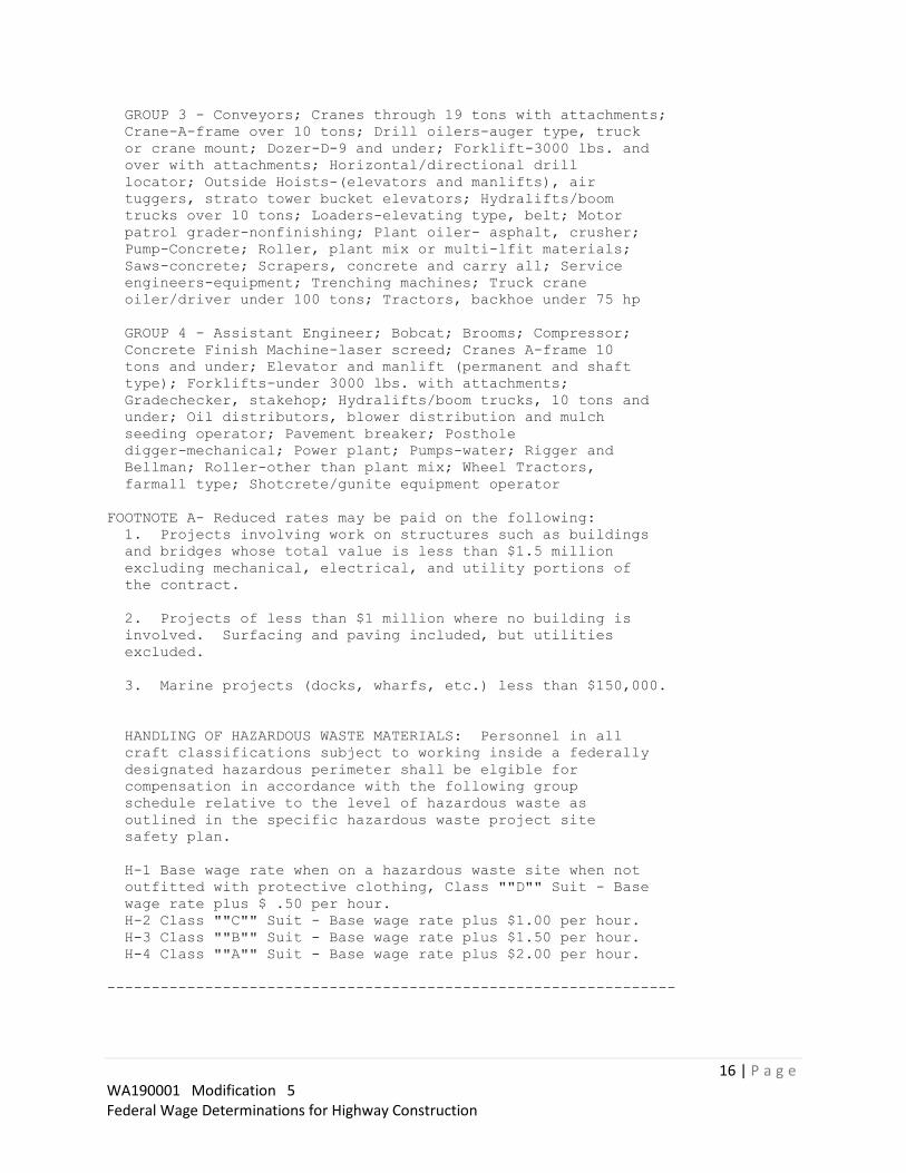
16 | P a g e WA190001 Modification 5 Federal Wage Determinations for Highway Construction
GROUP 3 - Conveyors; Cranes through 19 tons with attachments;
Crane-A-frame over 10 tons; Drill oilers-auger type, truck
or crane mount; Dozer-D-9 and under; Forklift-3000 lbs. and
over with attachments; Horizontal/directional drill
locator; Outside Hoists-(elevators and manlifts), air
tuggers, strato tower bucket elevators; Hydralifts/boom
trucks over 10 tons; Loaders-elevating type, belt; Motor
patrol grader-nonfinishing; Plant oiler- asphalt, crusher;
Pump-Concrete; Roller, plant mix or multi-lfit materials;
Saws-concrete; Scrapers, concrete and carry all; Service
engineers-equipment; Trenching machines; Truck crane
oiler/driver under 100 tons; Tractors, backhoe under 75 hp
GROUP 4 - Assistant Engineer; Bobcat; Brooms; Compressor;
Concrete Finish Machine-laser screed; Cranes A-frame 10
tons and under; Elevator and manlift (permanent and shaft
type); Forklifts-under 3000 lbs. with attachments;
Gradechecker, stakehop; Hydralifts/boom trucks, 10 tons and
under; Oil distributors, blower distribution and mulch
seeding operator; Pavement breaker; Posthole
digger-mechanical; Power plant; Pumps-water; Rigger and
Bellman; Roller-other than plant mix; Wheel Tractors,
farmall type; Shotcrete/gunite equipment operator
FOOTNOTE A- Reduced rates may be paid on the following:
1. Projects involving work on structures such as buildings
and bridges whose total value is less than $1.5 million
excluding mechanical, electrical, and utility portions of
the contract.
2. Projects of less than $1 million where no building is
involved. Surfacing and paving included, but utilities
excluded.
3. Marine projects (docks, wharfs, etc.) less than $150,000.
HANDLING OF HAZARDOUS WASTE MATERIALS: Personnel in all
craft classifications subject to working inside a federally
designated hazardous perimeter shall be elgible for
compensation in accordance with the following group
schedule relative to the level of hazardous waste as
outlined in the specific hazardous waste project site
safety plan.
H-1 Base wage rate when on a hazardous waste site when not
outfitted with protective clothing, Class ""D"" Suit - Base
wage rate plus $ .50 per hour.
H-2 Class ""C"" Suit - Base wage rate plus $1.00 per hour.
H-3 Class ""B"" Suit - Base wage rate plus $1.50 per hour.
H-4 Class ""A"" Suit - Base wage rate plus $2.00 per hour.
----------------------------------------------------------------

17 | P a g e WA190001 Modification 5 Federal Wage Determinations for Highway Construction
ENGI0612-012 09/28/2018
LEWIS, PACIFIC (portion lying north of a parallel line
extending west from the northern boundary of Wahkaikum County
to the sea) AND THURSTON COUNTIES
ON PROJECTS DESCRIBED IN FOOTNOTE A BELOW, THE RATE FOR EACH
GROUP SHALL BE 90% OF THE BASE RATE PLUS FULL FRINGE BENEFITS.
ON ALL OTHER WORK, THE FOLLOWING RATES APPLY.
Zone 1 (0-25 radius miles):
Rates Fringes
POWER EQUIPMENT OPERATOR
GROUP 1A...................$ 44.44 19.97
GROUP 1AA..................$ 45.09 19.97
GROUP 1AAA.................$ 45.73 19.97
GROUP 1.....................$ 43.79 19.97
GROUP 2.....................$ 43.23 19.97
GROUP 3.....................$ 42.74 19.97
GROUP 4.....................$ 40.01 19.97
Zone Differential (Add to Zone 1 rates):
Zone 2 (26-45 radius miles) = $1.00
Zone 3 (Over 45 radius miles) - $1.30
BASEPOINTS: CENTRALIA, OLYMPIA, TACOMA
POWER EQUIPMENT OPERATORS CLASSIFICATIONS
GROUP 1 AAA - Cranes-over 300 tons or 300 ft of boom
(including jib with attachments)
GROUP 1AA - Cranes- 200 tonsto 300 tons, or 250 ft of boom
(including jib with attachments; Tower crane over 175 ft in
height, bas to boom
GROUP 1A - Cranes, 100 tons thru 199 tons, or 150 ft of boom
(including jib with attachments); Crane-overhead, bridge
type, 100 tons and over; Tower crane up to 175 ft in height
base to boom; Loaders-overhead, 8 yards and over; Shovels,
excavator, backhoes-6 yards and over with attachments
GROUP 1 - Cableway; Cranes 45 tons thru 99 tons under 150 ft
of boom (including jib with attachments); Crane-overhead,
bridge type, 45 tons thru 99 tons; Derricks on building
work; Excavator, shovel, backhoes over 3 yards and under 6
yards; Hard tail end dump articulating off-road equipment
45 yards and over; Loader- overhead, 6 yards to, but not
including, 8 yards; Mucking machine, mole, tunnel, drill
and/or shield; Quad 9 HD 41, D-10; Remote control operator
on rubber tired earth moving equipment; Rollagon; Scrapers-
self-propelled 45 yards and over; Slipform pavers;
Transporters, all track or truck type

18 | P a g e WA190001 Modification 5 Federal Wage Determinations for Highway Construction
GROUP 2 - Barrier machine (zipper); Batch Plant Operator-
concrete; Bump Cutter; Cranes, 20 tons thru 44 tons with
attachments; Crane-Overhead, bridge type, 20 tons through
44 tons; Chipper; Concrete pump-truck mount with boom
attachment; Crusher; Deck engineer/deck winches (power);
Drilling machine; Excavator, shovel, backhoe-3 yards and
under; Finishing machine, Bidwell, Gamaco and similar
equipment; Guardrail punch; Loaders, overhead under 6
yards; Loaders-plant feed; Locomotives-all; Mechanics- all;
Mixers, asphalt plant; Motor patrol graders, finishing;
Piledriver (other than crane mount); Roto-mill, roto-
grinder; Screedman, spreader, topside operator-Blaw Knox,
Cedar Rapids, Jaeger, Caterpillar, Barbar Green;
Scraper-self- propelled, hard tail end dump, articulating
off-road equipment- under 45 yards; Subgrader trimmer;
Tractors, backhoe over 75 hp; Transfer material service
machine-shuttle buggy, Blaw Knox- Roadtec; Truck Crane
oiler/driver-100 tons and over; Truck Mount Portable
Conveyor; Yo Yo pay
GROUP 3 - Conveyors; Cranes through 19 tons with attachments;
Crane-A-frame over 10 tons; Drill oilers-auger type, truck
or crane mount; Dozer-D-9 and under; Forklift-3000 lbs. and
over with attachments; Horizontal/directional drill
locator; Outside Hoists-(elevators and manlifts), air
tuggers, strato tower bucket elevators; Hydralifts/boom
trucks over 10 tons; Loaders-elevating type, belt; Motor
patrol grader-nonfinishing; Plant oiler- asphalt, crusher;
Pump-Concrete; Roller, plant mix or multi-lfit materials;
Saws-concrete; Scrapers, concrete and carry all; Service
engineers-equipment; Trenching machines; Truck crane
oiler/driver under 100 tons; Tractors, backhoe under 75 hp
GROUP 4 - Assistant Engineer; Bobcat; Brooms; Compressor;
Concrete Finish Machine-laser screed; Cranes A-frame 10
tons and under; Elevator and manlift (permanent and shaft
type); Forklifts-under 3000 lbs. with attachments;
Gradechecker, stakehop; Hydralifts/boom trucks, 10 tons and
under; Oil distributors, blower distribution and mulch
seeding operator; Pavement breaker; Posthole
digger-mechanical; Power plant; Pumps-water; Rigger and
Bellman; Roller-other than plant mix; Wheel Tractors,
farmall type; Shotcrete/gunite equipment operator
FOOTNOTE A- Reduced rates may be paid on the following:
1. Projects involving work on structures such as buildings
and bridges whose total value is less than $1.5 million
excluding mechanical, electrical, and utility portions of
the contract.
2. Projects of less than $1 million where no building is
involved. Surfacing and paving included, but utilities
excluded.
3. Marine projects (docks, wharfs, etc.) less than $150,000.

19 | P a g e WA190001 Modification 5 Federal Wage Determinations for Highway Construction
HANDLING OF HAZARDOUS WASTE MATERIALS: Personnel in all
craft classifications subject to working inside a federally
designated hazardous perimeter shall be elgible for
compensation in accordance with the following group
schedule relative to the level of hazardous waste as
outlined in the specific hazardous waste project site
safety plan.
H-1 Base wage rate when on a hazardous waste site when not
outfitted with protective clothing, Class ""D"" Suit - Base
wage rate plus $ .50 per hour.
H-2 Class ""C"" Suit - Base wage rate plus $1.00 per hour.
H-3 Class ""B"" Suit - Base wage rate plus $1.50 per hour.
H-4 Class ""A"" Suit - Base wage rate plus $2.00 per hour.
----------------------------------------------------------------
ENGI0701-002 01/01/2018
CLARK, COWLITZ, KLICKKITAT, PACIFIC (SOUTH), SKAMANIA, AND
WAHKIAKUM COUNTIES
POWER RQUIPMENT OPERATORS: ZONE 1
Rates Fringes
POWER EQUIPMENT OPERATOR
GROUP 1.....................$ 41.65 14.35
GROUP 1A....................$ 43.73 14.35
GROUP 1B....................$ 45.82 14.35
GROUP 2.....................$ 39.74 14.35
GROUP 3.....................$ 38.59 14.35
GROUP 4.....................$ 37.51 14.35
GROUP 5.....................$ 36.27 14.35
GROUP 6.....................$ 33.05 14.35
Zone Differential (add to Zone 1 rates):
Zone 2 - $3.00
Zone 3 - $6.00
For the following metropolitan counties: MULTNOMAH;
CLACKAMAS; MARION; WASHINGTON; YAMHILL; AND COLUMBIA;
CLARK; AND COWLITZ COUNTY, WASHINGTON WITH MODIFICATIONS AS
INDICATED:
All jobs or projects located in Multnomah, Clackamas and
Marion Counties, West of the western boundary of Mt. Hood
National Forest and West of Mile Post 30 on Interstate 84
and West of Mile Post 30 on State Highway 26 and West of
Mile Post 30 on Highway 22 and all jobs or projects located
in Yamhill County, Washington County and Columbia County
and all jobs or porjects located in Clark & Cowlitz County,
Washington except that portion of Cowlitz County in the Mt.
St. Helens ""Blast Zone"" shall receive Zone I pay for all
classifications.
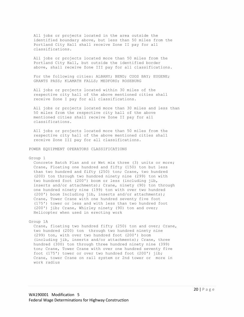
20 | P a g e WA190001 Modification 5 Federal Wage Determinations for Highway Construction
All jobs or projects located in the area outside the
identified boundary above, but less than 50 miles from the
Portland City Hall shall receive Zone II pay for all
classifications.
All jobs or projects located more than 50 miles from the
Portland City Hall, but outside the identified border
above, shall receive Zone III pay for all classifications.
For the following cities: ALBANY; BEND; COOS BAY; EUGENE;
GRANTS PASS; KLAMATH FALLS; MEDFORD; ROSEBURG
All jobs or projects located within 30 miles of the
respective city hall of the above mentioned cities shall
receive Zone I pay for all classifications.
All jobs or projects located more than 30 miles and less than
50 miles from the respective city hall of the above
mentioned cities shall receive Zone II pay for all
classifications.
All jobs or projects located more than 50 miles from the
respective city hall of the above mentioned cities shall
receive Zone III pay for all classifications.
POWER EQUIPMENT OPERATORS CLASSIFICATIONS
Group 1
Concrete Batch Plan and or Wet mix three (3) units or more;
Crane, Floating one hundred and fifty (150) ton but less
than two hundred and fifty (250) ton; Crane, two hundred
(200) ton through two hundred ninety nine (299) ton with
two hundred foot (200') boom or less (including jib,
inserts and/or attachments); Crane, ninety (90) ton through
one hundred ninety nine (199) ton with over two hundred
(200') boom Including jib, inserts and/or attachments);
Crane, Tower Crane with one hundred seventy five foot
(175') tower or less and with less than two hundred foot
(200') jib; Crane, Whirley ninety (90) ton and over;
Helicopter when used in erecting work
Group 1A
Crane, floating two hundred fifty (250) ton and over; Crane,
two hundred (200) ton through two hundred ninety nine
(299) ton, with over two hundred foot (200') boom
(including jib, inserts and/or attachments); Crane, three
hundred (300) ton through three hundred ninety nine (399)
ton; Crane, Tower Crane with over one hundred seventy five
foot (175') tower or over two hundred foot (200') jib;
Crane, tower Crane on rail system or 2nd tower or more in
work radius

21 | P a g e WA190001 Modification 5 Federal Wage Determinations for Highway Construction
Group 1B
Crane, three hundred (300) ton through three hundred ninety
nine (399) ton, with over two hundred foot (200') boom
(including jib, inserts and/or attachments); Floating
crane, three hundred fifty (350) ton and over; Crane, four
hundred (400) ton and over
Group 2
Asphalt Plant (any type); Asphalt Roto-Mill, pavement
profiler eight foot (8') lateral cut and over; Auto Grader
or ""Trimmer""; Blade, Robotic; Bulldozer, Robotic Equipment
(any type); Bulldozer, over one hundred twenty thousand
(120,000) lbs. and above; Concrete Batch Plant and/or Wet
Mix one (1) and two (2) drum; Concrete Diamond Head
Profiler; Canal Trimmer; Concrete, Automatic Slip Form
Paver (Assistant to the Operator required); Crane, Boom
Truck fifty (50) ton and with over one hundred fifty foot
(150') boom and over; Crane, Floating (derrick barge)
thirty (30) ton but less than one hundred fifty (150) ton;
Crane, Cableway twenty-five (25) ton and over; Crane,
Floating Clamshell three (3) cu. Yds. And over; Crane,
ninety (90) ton through one hundred ninety nine (199) ton
up to and including two hundred foot (200') of boom
(including jib inserts and/or attachments); Crane, fifty
(50) ton through eighty nine (89) ton with over one hundred
fifty foot (150') boom (including jib inserts and/or
attachments); Crane, Whirley under ninety (90) ton; Crusher
Plant; Excavator over one hundred thirty thousand (130,000)
lbs.; Loader one hundred twenty thousand (120,000) lbs. and
above; Remote Controlled Earth Moving Equipment; Shovel,
Dragline, Clamshell, five (5) cu. Yds. And over; Underwater
Equipment remote or otherwise, when used in construction
work; Wheel Excavator any size
Group 3
Bulldozer, over seventy thousand (70,000) lbs. up to and
including one hundred twenty thousand (120,000) lbs.;
Crane, Boom Truck fifty (50) ton and over with less than
one hundred fifty foot (150') boom; Crane, fifty (50) ton
through eighty nine (89) ton with one hundred fifty foot
(150') boom or less (including jib inserts and/or
attachments); Crane, Shovel, Dragline or Clamshell three
(3) cu. yds. but less than five (5) cu. Yds.; Excavator
over eighty thousand (80,000) lbs. through one hundred
thirty thousand (130,000) lbs.; Loader sixty thousand
(60,000) lbs. and less than one hundred twenty thousand
(120,000) lbs.

22 | P a g e WA190001 Modification 5 Federal Wage Determinations for Highway Construction
Group 4
Asphalt, Screed; Asphalt Paver; Asphalt Roto-Mill, pavement
profiler, under eight foot (8') lateral cut; Asphalt,
Material Transfer Vehicle Operator; Back Filling Machine;
Backhoe, Robotic, track and wheel type up to and including
twenty thousand (20,000) lbs. with any attachments; Blade
(any type); Boatman; Boring Machine; Bulldozer over twenty
thousand (20,000) lbs. and more than one hundred (100)
horse up to seventy thousand (70,000) lbs.; Cable-Plow (any
type); Cableway up to twenty five (25) ton; Cat Drill (John
Henry); Chippers; Compactor, multi-engine; Compactor,
Robotic; Compactor with blade self-propelled; Concrete,
Breaker; Concrete, Grout Plant; Concrete, Mixer Mobile;
Concrete, Paving Road Mixer; Concrete, Reinforced Tank
Banding Machine; Crane, Boom Truck twenty (20) ton and
under fifty (50) ton; Crane, Bridge Locomotive, Gantry and
Overhead; Crane, Carry Deck; Crane, Chicago Boom and
similar types; Crane, Derrick Operator, under one hundred
(100) ton; Crane, Floating Clamshell, Dragline, etc.
Operator, under three (3) cu. yds. Or less than thirty (30)
ton; Crane, under fifty (50) ton; Crane, Quick Tower under
one hundred foot (100') in height and less than one hundred
fifty foot (150') jib (on rail included); Diesel-Electric
Engineer (Plant or Floating); Directional Drill over twenty
thousand (20,000) lbs. pullback; Drill Cat Operator; Drill
Doctor and/or Bit Grinder; Driller, Percussion, Diamond,
Core, Cable, Rotary and similar type; Excavator Operator
over twenty thousand (20,000) lbs. through eighty thousand
(80,000) lbs.; Generator Operator; Grade-all; Guardrail
Machines, i.e. punch, auger, etc.; Hammer Operator
(Piledriver); Hoist, stiff leg, guy derrick or similar
type, fifty (50) ton and over; Hoist, two (2) drums or
more; Hydro Axe (loader mounted or similar type); Jack
Operator, Elevating Barges, Barge Operator, self-unloading;
Loader Operator, front end and overhead, twenty five
thousand (25,000) lbs. and less than sixty thousand
(60,000) lbs.; Log Skidders; Piledriver Operator (not crane
type); Pipe, Bending, Cleaning, Doping and Wrapping
Machines; Rail, Ballast Tamper Multi-Purpose; Rubber-tired
Dozers and Pushers; Scraper, all types; Side-Boom; Skip
Loader, Drag Box; Strump Grinder (loader mounted or similar
type); Surface Heater and Planer; Tractor, rubber-tired,
over fifty (50) HP Flywheel; Trenching Machine three foot
(3') depth and deeper; Tub Grinder (used for wood debris);
Tunnel Boring Machine Mechanic; Tunnel, Mucking Machine;
Ultra High Pressure Water Jet Cutting Tool System Operator;
Vacuum Blasting Machine Operator; Water pulls, Water wagons

23 | P a g e WA190001 Modification 5 Federal Wage Determinations for Highway Construction
Group 5
Asphalt, Extrusion Machine; Asphalt, Roller (any asphalt
mix); Asphalt, Roto-Mill pavement profiler ground man;
Bulldozer, twenty thousand (20,000) lbs. or less, or one
hundred (100) horse or less; Cement Pump; Chip Spreading
Machine; Churn Drill and Earth Boring Machine; Compactor,
self-propelled without blade; Compressor, (any power) one
thousand two hundred fifty (1,250) cu. ft. and over, total
capacity; Concrete, Batch Plant Quality control; Concrete,
Combination Mixer and compressor operator, gunite work;
Concrete, Curb Machine, Mechanical Berm, Curb and/or Curb
and Gutter; Concrete, Finishing Machine; Concrete, Grouting
Machine; Concrete, Internal Full Slab Vibrator Operator;
Concrete, Joint Machine; Concrete, Mixer single drum, any
capacity; Concrete, Paving Machine eight foot (8') or less;
Concrete, Planer; Concrete, Pump; Concrete, Pump Truck;
Concrete, Pumpcrete Operator (any type); Concrete, Slip
Form Pumps, power driven hydraulic lifting device for
concrete forms; Conveyored Material Hauler; Crane, Boom
Truck under twenty (20) tons; Crane, Boom Type lifting
device, five (5) ton capacity or less; Drill, Directional
type less than twenty thousand (20,000) lbs. pullback; Fork
Lift, over ten (10) ton or Robotic; Helicopter Hoist; Hoist
Operator, single drum; Hydraulic Backhoe track type up to
and including twenty thousand (20,000) lbs.; Hydraulic
Backhoe wheel type (any make); Laser Screed; Loaders,
rubber-tired type, less than twenty five thousand (25,000)
lbs.; Pavement Grinder and/or Grooving Machine (riding
type); Pipe, cast in place Pipe Laying Machine; Pulva-Mixer
or similar types; Pump Operator, more than five (5) pumps
(any size); Rail, Ballast Compactor, Regulator, or Tamper
machines; Service Oiler (Greaser); Sweeper Self-Propelled;
Tractor, Rubber-Tired, fifty (50) HP flywheel and under;
Trenching Machine Operator, maximum digging capacity three
foot (3') depth; Tunnel, Locomotive, Dinkey; Tunnel, Power
Jumbo setting slip forms, etc.
Group 6
Asphalt, Pugmill (any type); Asphalt, Raker; Asphalt, Truck
Mounted Asphalt Spreader, with Screed; Auger Oiler;
Boatman; Bobcat, skid steed (less than one (1) yard);
Broom, self-propelled; Compressor Operator (any power)
under 1,250 cu. ft. total capacity; Concrete Curing Machine
(riding type); Concrete Saw; Conveyor Operator or
Assistant; Crane, Tugger; Crusher Feederman; Crusher Oiler;
Deckhand; Drill, Directional Locator; Fork Lift; Grade
Checker; Guardrail Punch Oiler; Hydrographic Seeder
Machine, straw, pulp or seed; Hydrostatic Pump Operator;
Mixer Box (CTB, dry batch, etc.); Oiler; Plant Oiler; Pump
(any power); Rail, Brakeman, Switchman, Motorman; Rail,
Tamping Machine, mechanical, self-propelled; Rigger; Roller
grading (not asphalt); Truck, Crane Oiler-Driver
----------------------------------------------------------------

24 | P a g e WA190001 Modification 5 Federal Wage Determinations for Highway Construction
IRON0014-005 07/01/2018
ADAMS, ASOTIN, BENTON, COLUMBIA, DOUGLAS, FERRY, FRANKLIN,
GARFIELD, GRANT, LINCOLN, OKANOGAN, PEND ORIELLE, SPOKANE,
STEVENS, WALLA WALLA AND WHITMAN COUNTIES
Rates Fringes
IRONWORKER.......................$ 33.18 27.82
----------------------------------------------------------------
IRON0029-002 05/01/2018
CLARK, COWLITZ, KLICKITAT, PACIFIC, SKAMANIA, AND WAHKAIKUM
COUNTIES
Rates Fringes
IRONWORKER.......................$ 37.00 27.87
----------------------------------------------------------------
IRON0086-002 07/01/2018
YAKIMA, KITTITAS AND CHELAN COUNTIES
Rates Fringes
IRONWORKER.......................$ 33.18 27.82
----------------------------------------------------------------
IRON0086-004 07/01/2018
CLALLAM, GRAYS HARBOR, ISLAND, JEFFERSON, KING, KITSAP, LEWIS,
MASON, PIERCE, SKAGIT, SNOHOMISH, THURSTON, AND WHATCOM COUNTIES
Rates Fringes
IRONWORKER.......................$ 40.81 28.22
----------------------------------------------------------------

25 | P a g e WA190001 Modification 5 Federal Wage Determinations for Highway Construction
LABO0238-004 06/01/2018
PASCO AREA: ADAMS, BENTON, COLUMBIA,DOUGLAS (East of 120th
Meridian), FERRY, FRANKLIN, GRANT, OKANOGAN, WALLA WALLA
SPOKANE AREA: ASOTIN, GARFIELD, LINCOLN, PEND OREILLE, SPOKANE,
STEVENS & WHITMAN COUNTIES
Rates Fringes
LABORER (PASCO)
GROUP 1.....................$ 24.84 12.35
GROUP 2.....................$ 26.94 12.35
GROUP 3.....................$ 27.21 12.35
GROUP 4.....................$ 27.48 12.35
GROUP 5.....................$ 27.76 12.35
LABORER (SPOKANE)
GROUP 1.....................$ 24.74 12.45
GROUP 2.....................$ 26.84 12.45
GROUP 3.....................$ 27.11 12.45
GROUP 4.....................$ 27.38 12.45
GROUP 5.....................$ 27.66 12.45
Zone Differential (Add to Zone 1 rate): $2.00
BASE POINTS: Spokane, Pasco, Lewiston
Zone 1: 0-45 radius miles from the main post office.
Zone 2: 45 radius miles and over from the main post office.
LABORERS CLASSIFICATIONS
GROUP 1: Flagman; Landscape Laborer; Scaleman; Traffic
Control Maintenance Laborer (to include erection and
maintenance of barricades, signs and relief of flagperson);
Window Washer/Cleaner (detail cleanup, such as, but not
limited to cleaning floors, ceilings, walls, windows, etc.
prior to final acceptance by the owner)
GROUP 2: Asbestos Abatement Worker; Brush Hog Feeder;
Carpenter Tender; Cement Handler; Clean-up Laborer;
Concrete Crewman (to include stripping of forms, hand
operating jacks on slip form construction, application of
concrete curing compounds, pumpcrete machine, signaling,
handling the nozzle of squeezcrete or similar machine,6
inches and smaller); Confined Space Attendant; Concrete
Signalman; Crusher Feeder; Demolition (to include clean-up,
burning, loading, wrecking and salvage of all material);
Dumpman; Fence Erector; Firewatch; Form Cleaning Machine
Feeder, Stacker; General Laborer; Grout Machine Header
Tender; Guard Rail (to include guard rails, guide and
reference posts, sign posts, and right-of-way markers);
Hazardous Waste Worker, Level D (no respirator is used and
skin protection is minimal); Miner, Class ""A"" (to include
all bull gang, concrete crewman, dumpman and pumpcrete

26 | P a g e WA190001 Modification 5 Federal Wage Determinations for Highway Construction
crewman, including distributing pipe, assembly & dismantle,
and nipper); Nipper; Riprap Man; Sandblast Tailhoseman;
Scaffold Erector (wood or steel); Stake Jumper; Structural
Mover (to include separating foundation, preparation,
cribbing, shoring, jacking and unloading of structures);
Tailhoseman (water nozzle); Timber Bucker and Faller (by
hand); Track Laborer (RR); Truck Loader; Well-Point Man;
All Other Work Classifications Not Specially Listed Shall
Be Classified As General Laborer
GROUP 3: Asphalt Roller, walking; Cement Finisher Tender;
Concrete Saw, walking; Demolition Torch; Dope Pot Firemen,
non-mechanical; Driller Tender (when required to move and
position machine); Form Setter, Paving; Grade Checker using
level; Hazardous Waste Worker, Level C (uses a chemical
""splash suit"" and air purifying respirator); Jackhammer
Operator; Miner, Class ""B"" (to include brakeman, finisher,
vibrator, form setter); Nozzleman (to include squeeze and
flo-crete nozzle); Nozzleman, water, air or steam; Pavement
Breaker (under 90 lbs.); Pipelayer, corrugated metal
culvert; Pipelayer, multi- plate; Pot Tender; Power Buggy
Operator; Power Tool Operator, gas, electric, pneumatic;
Railroad Equipment, power driven, except dual mobile power
spiker or puller; Railroad Power Spiker or Puller, dual
mobile; Rodder and Spreader; Tamper (to include operation
of Barco, Essex and similar tampers); Trencher, Shawnee;
Tugger Operator; Wagon Drills; Water Pipe Liner;
Wheelbarrow (power driven)
GROUP 4: Air and Hydraulic Track Drill; Aspahlt Raker;Brush
Machine (to include horizontal construction joint cleanup
brush machine, power propelled); Caisson Worker, free air;
Chain Saw Operator and Faller; Concrete Stack (to include
laborers when laborers working on free standing concrete
stacks for smoke or fume control above 40 feet high);
Gunite (to include operation of machine and nozzle);
Hazardous Waste Worker, Level B (uses same respirator
protection as Level A. A supplied air line is provided in
conjunction with a chemical ""splash suit""); High Scaler;
Laser Beam Operator (to include grade checker and elevation
control); Miner, Class C (to include miner, nozzleman for
concrete, laser beam operator and rigger on tunnels);
Monitor Operator (air track or similar mounting); Mortar
Mixer; Nozzleman (to include jet blasting nozzleman, over
1,200 lbs., jet blast machine power propelled, sandblast
nozzle); Pavement Breaker (90 lbs. and over); Pipelayer (to
include working topman, caulker, collarman, jointer,
mortarman, rigger, jacker, shorer, valve or meter
installer); Pipewrapper; Plasterer Tender; Vibrators (all)
GROUP 5 - Drills with Dual Masts; Hazardous Waste Worker,
Level A (utilizes a fully encapsulated suit with a
self-contained breathing apparatus or a supplied air line);
Miner Class ""D"", (to include raise and shaft miner, laser
beam operator on riases and shafts)

27 | P a g e WA190001 Modification 5 Federal Wage Determinations for Highway Construction
----------------------------------------------------------------
LABO0238-006 06/01/2018
COUNTIES EAST OF THE 120TH MERIDIAN: ADAMS, ASOTIN, BENTON,
CHELAN, COLUMBIA, DOUGLAS, FERRY, FRANKLIN, GARFIELD, GRANT,
LINCOLN, OKANOGAN, PEND OREILLE, STEVENS, SPOKANE, WALLA WALLA,
WHITMAN
Rates Fringes
Hod Carrier......................$ 27.75 12.25
----------------------------------------------------------------
LABO0242-003 06/01/2018
KING COUNTY
Rates Fringes
LABORER
GROUP 1.....................$ 26.05 11.49
GROUP 2.....................$ 29.83 11.49
GROUP 3.....................$ 37.27 11.49
GROUP 4.....................$ 38.19 11.49
GROUP 5.....................$ 38.80 11.49
BASE POINTS: BELLINGHAM, MT. VERNON, EVERETT, SEATTLE, KENT,
TACOMA, OLYMPIA, CENTRALIA, ABERDEEN, SHELTON, PT.
TOWNSEND, PT. ANGELES, AND BREMERTON
ZONE 1 - Projects within 25 radius miles of the respective
city hall
ZONE 2 - More than 25 but less than 45 radius miles from the
respective city hall
ZONE 3 - More than 45 radius miles from the respective city
hall
ZONE DIFFERENTIAL (ADD TO ZONE 1 RATES):
ZONE 2 - $1.00
ZONE 3 - $1.30
BASE POINTS: CHELAN, SUNNYSIDE, WENATCHEE, AND YAKIMA
ZONE 1 - Projects within 25 radius miles of the respective
city hall
ZONE 2 - More than 25 radius miles from the respective city
hall
ZONE DIFFERENTIAL (ADD TO ZONE 1 RATES):
ZONE 2 - $2.25
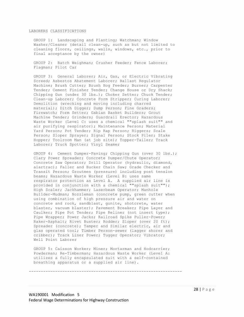
28 | P a g e WA190001 Modification 5 Federal Wage Determinations for Highway Construction
LABORERS CLASSIFICATIONS
GROUP 1: Landscaping and Planting; Watchman; Window
Washer/Cleaner (detail clean-up, such as but not limited to
cleaning floors, ceilings, walls, windows, etc., prior to
final acceptance by the owner)
GROUP 2: Batch Weighman; Crusher Feeder; Fence Laborer;
Flagman; Pilot Car
GROUP 3: General Laborer; Air, Gas, or Electric Vibrating
Screed; Asbestos Abatement Laborer; Ballast Regulator
Machine; Brush Cutter; Brush Hog Feeder; Burner; Carpenter
Tender; Cement Finisher Tender; Change House or Dry Shack;
Chipping Gun (under 30 lbs.); Choker Setter; Chuck Tender;
Clean-up Laborer; Concrete Form Stripper; Curing Laborer;
Demolition (wrecking and moving including charred
material); Ditch Digger; Dump Person; Fine Graders;
Firewatch; Form Setter; Gabian Basket Builders; Grout
Machine Tender; Grinders; Guardrail Erector; Hazardous
Waste Worker (Level C: uses a chemical ""splash suit"" and
air purifying respirator); Maintenance Person; Material
Yard Person; Pot Tender; Rip Rap Person; Riggers; Scale
Person; Sloper Sprayer; Signal Person; Stock Piler; Stake
Hopper; Toolroom Man (at job site); Topper-Tailer; Track
Laborer; Truck Spotter; Vinyl Seamer
GROUP 4: Cement Dumper-Paving; Chipping Gun (over 30 lbs.);
Clary Power Spreader; Concrete Dumper/Chute Operator;
Concrete Saw Operator; Drill Operator (hydraulic, diamond,
aiartrac); Faller and Bucker Chain Saw; Grade Checker and
Transit Person; Groutmen (pressure) including post tension
beams; Hazardous Waste Worker (Level B: uses same
respirator protection as Level A. A supplied air line is
provided in conjunction with a chemical ""splash suit"");
High Scaler; Jackhammer; Laserbeam Operator; Manhole
Builder-Mudman; Nozzleman (concrete pump, green cutter when
using combination of high pressure air and water on
concrete and rock, sandblast, gunite, shotcrete, water
blaster, vacuum blaster); Pavement Breaker; Pipe Layer and
Caulker; Pipe Pot Tender; Pipe Reliner (not insert type);
Pipe Wrapper; Power Jacks; Railroad Spike Puller-Power;
Raker-Asphalt; Rivet Buster; Rodder; Sloper (over 20 ft);
Spreader (concrete); Tamper and Similar electric, air and
glas operated tool; Timber Person-sewer (lagger shorer and
cribber); Track Liner Power; Tugger Operator; Vibrator;
Well Point Laborer
GROUP 5: Caisson Worker; Miner; Mortarman and Hodcarrier;
Powderman; Re-Timberman; Hazardous Waste Worker (Level A:
utilizes a fully encapsulated suit with a self-contained
breathing apparatus or a supplied air line).
----------------------------------------------------------------
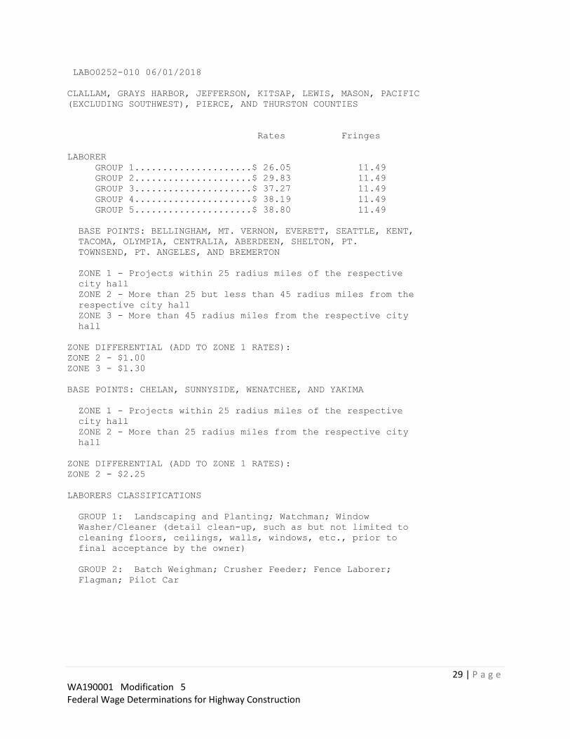
29 | P a g e WA190001 Modification 5 Federal Wage Determinations for Highway Construction
LABO0252-010 06/01/2018
CLALLAM, GRAYS HARBOR, JEFFERSON, KITSAP, LEWIS, MASON, PACIFIC
(EXCLUDING SOUTHWEST), PIERCE, AND THURSTON COUNTIES
Rates Fringes
LABORER
GROUP 1.....................$ 26.05 11.49
GROUP 2.....................$ 29.83 11.49
GROUP 3.....................$ 37.27 11.49
GROUP 4.....................$ 38.19 11.49
GROUP 5.....................$ 38.80 11.49
BASE POINTS: BELLINGHAM, MT. VERNON, EVERETT, SEATTLE, KENT,
TACOMA, OLYMPIA, CENTRALIA, ABERDEEN, SHELTON, PT.
TOWNSEND, PT. ANGELES, AND BREMERTON
ZONE 1 - Projects within 25 radius miles of the respective
city hall
ZONE 2 - More than 25 but less than 45 radius miles from the
respective city hall
ZONE 3 - More than 45 radius miles from the respective city
hall
ZONE DIFFERENTIAL (ADD TO ZONE 1 RATES):
ZONE 2 - $1.00
ZONE 3 - $1.30
BASE POINTS: CHELAN, SUNNYSIDE, WENATCHEE, AND YAKIMA
ZONE 1 - Projects within 25 radius miles of the respective
city hall
ZONE 2 - More than 25 radius miles from the respective city
hall
ZONE DIFFERENTIAL (ADD TO ZONE 1 RATES):
ZONE 2 - $2.25
LABORERS CLASSIFICATIONS
GROUP 1: Landscaping and Planting; Watchman; Window
Washer/Cleaner (detail clean-up, such as but not limited to
cleaning floors, ceilings, walls, windows, etc., prior to
final acceptance by the owner)
GROUP 2: Batch Weighman; Crusher Feeder; Fence Laborer;
Flagman; Pilot Car

30 | P a g e WA190001 Modification 5 Federal Wage Determinations for Highway Construction
GROUP 3: General Laborer; Air, Gas, or Electric Vibrating
Screed; Asbestos Abatement Laborer; Ballast Regulator
Machine; Brush Cutter; Brush Hog Feeder; Burner; Carpenter
Tender; Cement Finisher Tender; Change House or Dry Shack;
Chipping Gun (under 30 lbs.); Choker Setter; Chuck Tender;
Clean-up Laborer; Concrete Form Stripper; Curing Laborer;
Demolition (wrecking and moving including charred
material); Ditch Digger; Dump Person; Fine Graders;
Firewatch; Form Setter; Gabian Basket Builders; Grout
Machine Tender; Grinders; Guardrail Erector; Hazardous
Waste Worker (Level C: uses a chemical ""splash suit"" and
air purifying respirator); Maintenance Person; Material
Yard Person; Pot Tender; Rip Rap Person; Riggers; Scale
Person; Sloper Sprayer; Signal Person; Stock Piler; Stake
Hopper; Toolroom Man (at job site); Topper-Tailer; Track
Laborer; Truck Spotter; Vinyl Seamer
GROUP 4: Cement Dumper-Paving; Chipping Gun (over 30 lbs.);
Clary Power Spreader; Concrete Dumper/Chute Operator;
Concrete Saw Operator; Drill Operator (hydraulic, diamond,
aiartrac); Faller and Bucker Chain Saw; Grade Checker and
Transit Person; Groutmen (pressure) including post tension
beams; Hazardous Waste Worker (Level B: uses same
respirator protection as Level A. A supplied air line is
provided in conjunction with a chemical ""splash suit"");
High Scaler; Jackhammer; Laserbeam Operator; Manhole
Builder-Mudman; Nozzleman (concrete pump, green cutter when
using combination of high pressure air and water on
concrete and rock, sandblast, gunite, shotcrete, water
blaster, vacuum blaster); Pavement Breaker; Pipe Layer and
Caulker; Pipe Pot Tender; Pipe Reliner (not insert type);
Pipe Wrapper; Power Jacks; Railroad Spike Puller-Power;
Raker-Asphalt; Rivet Buster; Rodder; Sloper (over 20 ft);
Spreader (concrete); Tamper and Similar electric, air and
glas operated tool; Timber Person-sewer (lagger shorer and
cribber); Track Liner Power; Tugger Operator; Vibrator;
Well Point Laborer
GROUP 5: Caisson Worker; Miner; Mortarman and Hodcarrier;
Powderman; Re-Timberman; Hazardous Waste Worker (Level A:
utilizes a fully encapsulated suit with a self-contained
breathing apparatus or a supplied air line).
----------------------------------------------------------------
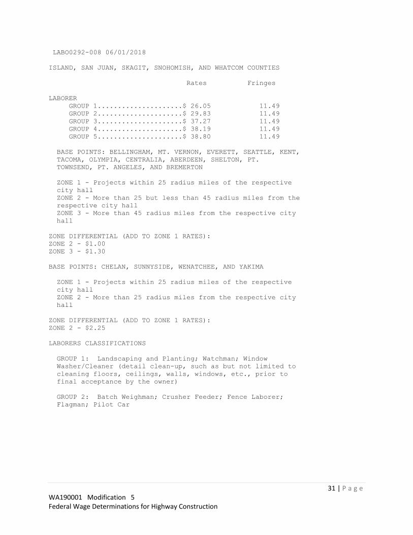
31 | P a g e WA190001 Modification 5 Federal Wage Determinations for Highway Construction
LABO0292-008 06/01/2018
ISLAND, SAN JUAN, SKAGIT, SNOHOMISH, AND WHATCOM COUNTIES
Rates Fringes
LABORER
GROUP 1.....................$ 26.05 11.49
GROUP 2.....................$ 29.83 11.49
GROUP 3.....................$ 37.27 11.49
GROUP 4.....................$ 38.19 11.49
GROUP 5.....................$ 38.80 11.49
BASE POINTS: BELLINGHAM, MT. VERNON, EVERETT, SEATTLE, KENT,
TACOMA, OLYMPIA, CENTRALIA, ABERDEEN, SHELTON, PT.
TOWNSEND, PT. ANGELES, AND BREMERTON
ZONE 1 - Projects within 25 radius miles of the respective
city hall
ZONE 2 - More than 25 but less than 45 radius miles from the
respective city hall
ZONE 3 - More than 45 radius miles from the respective city
hall
ZONE DIFFERENTIAL (ADD TO ZONE 1 RATES):
ZONE 2 - $1.00
ZONE 3 - $1.30
BASE POINTS: CHELAN, SUNNYSIDE, WENATCHEE, AND YAKIMA
ZONE 1 - Projects within 25 radius miles of the respective
city hall
ZONE 2 - More than 25 radius miles from the respective city
hall
ZONE DIFFERENTIAL (ADD TO ZONE 1 RATES):
ZONE 2 - $2.25
LABORERS CLASSIFICATIONS
GROUP 1: Landscaping and Planting; Watchman; Window
Washer/Cleaner (detail clean-up, such as but not limited to
cleaning floors, ceilings, walls, windows, etc., prior to
final acceptance by the owner)
GROUP 2: Batch Weighman; Crusher Feeder; Fence Laborer;
Flagman; Pilot Car

32 | P a g e WA190001 Modification 5 Federal Wage Determinations for Highway Construction
GROUP 3: General Laborer; Air, Gas, or Electric Vibrating
Screed; Asbestos Abatement Laborer; Ballast Regulator
Machine; Brush Cutter; Brush Hog Feeder; Burner; Carpenter
Tender; Cement Finisher Tender; Change House or Dry Shack;
Chipping Gun (under 30 lbs.); Choker Setter; Chuck Tender;
Clean-up Laborer; Concrete Form Stripper; Curing Laborer;
Demolition (wrecking and moving including charred
material); Ditch Digger; Dump Person; Fine Graders;
Firewatch; Form Setter; Gabian Basket Builders; Grout
Machine Tender; Grinders; Guardrail Erector; Hazardous
Waste Worker (Level C: uses a chemical ""splash suit"" and
air purifying respirator); Maintenance Person; Material
Yard Person; Pot Tender; Rip Rap Person; Riggers; Scale
Person; Sloper Sprayer; Signal Person; Stock Piler; Stake
Hopper; Toolroom Man (at job site); Topper-Tailer; Track
Laborer; Truck Spotter; Vinyl Seamer
GROUP 4: Cement Dumper-Paving; Chipping Gun (over 30 lbs.);
Clary Power Spreader; Concrete Dumper/Chute Operator;
Concrete Saw Operator; Drill Operator (hydraulic, diamond,
aiartrac); Faller and Bucker Chain Saw; Grade Checker and
Transit Person; Groutmen (pressure) including post tension
beams; Hazardous Waste Worker (Level B: uses same
respirator protection as Level A. A supplied air line is
provided in conjunction with a chemical ""splash suit"");
High Scaler; Jackhammer; Laserbeam Operator; Manhole
Builder-Mudman; Nozzleman (concrete pump, green cutter when
using combination of high pressure air and water on
concrete and rock, sandblast, gunite, shotcrete, water
blaster, vacuum blaster); Pavement Breaker; Pipe Layer and
Caulker; Pipe Pot Tender; Pipe Reliner (not insert type);
Pipe Wrapper; Power Jacks; Railroad Spike Puller-Power;
Raker-Asphalt; Rivet Buster; Rodder; Sloper (over 20 ft);
Spreader (concrete); Tamper and Similar electric, air and
glas operated tool; Timber Person-sewer (lagger shorer and
cribber); Track Liner Power; Tugger Operator; Vibrator;
Well Point Laborer
GROUP 5: Caisson Worker; Miner; Mortarman and Hodcarrier;
Powderman; Re-Timberman; Hazardous Waste Worker (Level A:
utilizes a fully encapsulated suit with a self-contained
breathing apparatus or a supplied air line).
----------------------------------------------------------------
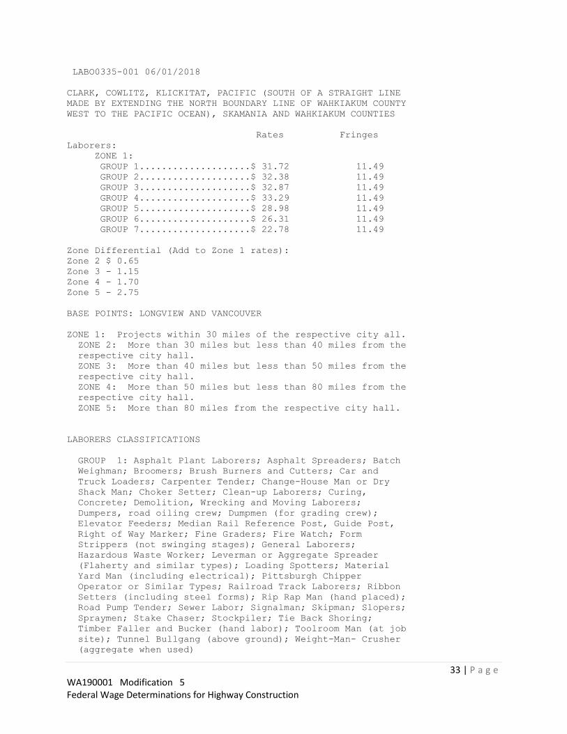
33 | P a g e WA190001 Modification 5 Federal Wage Determinations for Highway Construction
LABO0335-001 06/01/2018
CLARK, COWLITZ, KLICKITAT, PACIFIC (SOUTH OF A STRAIGHT LINE
MADE BY EXTENDING THE NORTH BOUNDARY LINE OF WAHKIAKUM COUNTY
WEST TO THE PACIFIC OCEAN), SKAMANIA AND WAHKIAKUM COUNTIES
Rates Fringes
Laborers:
ZONE 1:
GROUP 1....................$ 31.72 11.49
GROUP 2....................$ 32.38 11.49
GROUP 3....................$ 32.87 11.49
GROUP 4....................$ 33.29 11.49
GROUP 5....................$ 28.98 11.49
GROUP 6....................$ 26.31 11.49
GROUP 7....................$ 22.78 11.49
Zone Differential (Add to Zone 1 rates):
Zone 2 $ 0.65
Zone 3 - 1.15
Zone 4 - 1.70
Zone 5 - 2.75
BASE POINTS: LONGVIEW AND VANCOUVER
ZONE 1: Projects within 30 miles of the respective city all.
ZONE 2: More than 30 miles but less than 40 miles from the
respective city hall.
ZONE 3: More than 40 miles but less than 50 miles from the
respective city hall.
ZONE 4: More than 50 miles but less than 80 miles from the
respective city hall.
ZONE 5: More than 80 miles from the respective city hall.
LABORERS CLASSIFICATIONS
GROUP 1: Asphalt Plant Laborers; Asphalt Spreaders; Batch
Weighman; Broomers; Brush Burners and Cutters; Car and
Truck Loaders; Carpenter Tender; Change-House Man or Dry
Shack Man; Choker Setter; Clean-up Laborers; Curing,
Concrete; Demolition, Wrecking and Moving Laborers;
Dumpers, road oiling crew; Dumpmen (for grading crew);
Elevator Feeders; Median Rail Reference Post, Guide Post,
Right of Way Marker; Fine Graders; Fire Watch; Form
Strippers (not swinging stages); General Laborers;
Hazardous Waste Worker; Leverman or Aggregate Spreader
(Flaherty and similar types); Loading Spotters; Material
Yard Man (including electrical); Pittsburgh Chipper
Operator or Similar Types; Railroad Track Laborers; Ribbon
Setters (including steel forms); Rip Rap Man (hand placed);
Road Pump Tender; Sewer Labor; Signalman; Skipman; Slopers;
Spraymen; Stake Chaser; Stockpiler; Tie Back Shoring;
Timber Faller and Bucker (hand labor); Toolroom Man (at job
site); Tunnel Bullgang (above ground); Weight-Man- Crusher
(aggregate when used)

34 | P a g e WA190001 Modification 5 Federal Wage Determinations for Highway Construction
GROUP 2: Applicator (including pot power tender for same),
applying protective material by hand or nozzle on utility
lines or storage tanks on project; Brush Cutters (power
saw); Burners; Choker Splicer; Clary Power Spreader and
similar types; Clean- up Nozzleman-Green Cutter (concrete,
rock, etc.); Concrete Power Buggyman; Concrete Laborer;
Crusher Feeder; Demolition and Wrecking Charred Materials;
Gunite Nozzleman Tender; Gunite or Sand Blasting Pot
Tender; Handlers or Mixers of all Materials of an
irritating nature (including cement and lime); Tool
Operators (includes but not limited to: Dry Pack Machine;
Jackhammer; Chipping Guns; Paving Breakers); Pipe Doping
and Wrapping; Post Hole Digger, air, gas or electric;
Vibrating Screed; Tampers; Sand Blasting (Wet);
Stake-Setter; Tunnel-Muckers, Brakemen, Concrete Crew,
Bullgang (underground)
GROUP 3: Asbestos Removal; Bit Grinder; Drill Doctor; Drill
Operators, air tracks, cat drills, wagon drills,
rubber-mounted drills, and other similar types including at
crusher plants; Gunite Nozzleman; High Scalers, Strippers
and Drillers (covers work in swinging stages, chairs or
belts, under extreme conditions unusual to normal drilling,
blasting, barring-down, or sloping and stripping); Manhole
Builder; Powdermen; Concrete Saw Operator; Pwdermen; Power
Saw Operators (Bucking and Falling); Pumpcrete Nozzlemen;
Sand Blasting (Dry); Sewer Timberman; Track Liners, Anchor
Machines, Ballast Regulators, Multiple Tampers, Power
Jacks, Tugger Operator; Tunnel-Chuck Tenders, Nippers and
Timbermen; Vibrator; Water Blaster
GROUP 4: Asphalt Raker; Concrete Saw Operator (walls);
Concrete Nozzelman; Grade Checker; Pipelayer; Laser Beam
(pipelaying)-applicable when employee assigned to move, set
up, align; Laser Beam; Tunnel Miners; Motorman-Dinky
Locomotive-Tunnel; Powderman-Tunnel; Shield Operator-Tunnel
GROUP 5: Traffic Flaggers
GROUP 6: Fence Builders
GROUP 7: Landscaping or Planting Laborers
----------------------------------------------------------------
LABO0335-019 06/01/2018
Rates Fringes
Hod Carrier......................$ 31.72 11.49
----------------------------------------------------------------

35 | P a g e WA190001 Modification 5 Federal Wage Determinations for Highway Construction
LABO0348-003 06/01/2018
CHELAN, DOUGLAS (W OF 12TH MERIDIAN), KITTITAS, AND YAKIMA
COUNTIES
Rates Fringes
LABORER
GROUP 1.....................$ 22.23 11.49
GROUP 2.....................$ 25.48 11.49
GROUP 3.....................$ 27.89 11.49
GROUP 4.....................$ 28.56 11.49
GROUP 5.....................$ 29.04 11.49
BASE POINTS: BELLINGHAM, MT. VERNON, EVERETT, SEATTLE, KENT,
TACOMA, OLYMPIA, CENTRALIA, ABERDEEN, SHELTON, PT.
TOWNSEND, PT. ANGELES, AND BREMERTON
ZONE 1 - Projects within 25 radius miles of the respective
city hall
ZONE 2 - More than 25 but less than 45 radius miles from the
respective city hall
ZONE 3 - More than 45 radius miles from the respective city
hall
ZONE DIFFERENTIAL (ADD TO ZONE 1 RATES):
ZONE 2 - $1.00
ZONE 3 - $1.30
BASE POINTS: CHELAN, SUNNYSIDE, WENATCHEE, AND YAKIMA
ZONE 1 - Projects within 25 radius miles of the respective
city hall
ZONE 2 - More than 25 radius miles from the respective city
hall
ZONE DIFFERENTIAL (ADD TO ZONE 1 RATES):
ZONE 2 - $2.25
LABORERS CLASSIFICATIONS
GROUP 1: Landscaping and Planting; Watchman; Window
Washer/Cleaner (detail clean-up, such as but not limited to
cleaning floors, ceilings, walls, windows, etc., prior to
final acceptance by the owner)
GROUP 2: Batch Weighman; Crusher Feeder; Fence Laborer;
Flagman; Pilot Car

36 | P a g e WA190001 Modification 5 Federal Wage Determinations for Highway Construction
GROUP 3: General Laborer; Air, Gas, or Electric Vibrating
Screed; Asbestos Abatement Laborer; Ballast Regulator
Machine; Brush Cutter; Brush Hog Feeder; Burner; Carpenter
Tender; Cement Finisher Tender; Change House or Dry Shack;
Chipping Gun (under 30 lbs.); Choker Setter; Chuck Tender;
Clean-up Laborer; Concrete Form Stripper; Curing Laborer;
Demolition (wrecking and moving including charred
material); Ditch Digger; Dump Person; Fine Graders;
Firewatch; Form Setter; Gabian Basket Builders; Grout
Machine Tender; Grinders; Guardrail Erector; Hazardous
Waste Worker (Level C: uses a chemical ""splash suit"" and
air purifying respirator); Maintenance Person; Material
Yard Person; Pot Tender; Rip Rap Person; Riggers; Scale
Person; Sloper Sprayer; Signal Person; Stock Piler; Stake
Hopper; Toolroom Man (at job site); Topper-Tailer; Track
Laborer; Truck Spotter; Vinyl Seamer
GROUP 4: Cement Dumper-Paving; Chipping Gun (over 30 lbs.);
Clary Power Spreader; Concrete Dumper/Chute Operator;
Concrete Saw Operator; Drill Operator (hydraulic, diamond,
aiartrac); Faller and Bucker Chain Saw; Grade Checker and
Transit Person; Groutmen (pressure) including post tension
beams; Hazardous Waste Worker (Level B: uses same
respirator protection as Level A. A supplied air line is
provided in conjunction with a chemical ""splash suit"");
High Scaler; Jackhammer; Laserbeam Operator; Manhole
Builder-Mudman; Nozzleman (concrete pump, green cutter when
using combination of high pressure air and water on
concrete and rock, sandblast, gunite, shotcrete, water
blaster, vacuum blaster); Pavement Breaker; Pipe Layer and
Caulker; Pipe Pot Tender; Pipe Reliner (not insert type);
Pipe Wrapper; Power Jacks; Railroad Spike Puller-Power;
Raker-Asphalt; Rivet Buster; Rodder; Sloper (over 20 ft);
Spreader (concrete); Tamper and Similar electric, air and
glas operated tool; Timber Person-sewer (lagger shorer and
cribber); Track Liner Power; Tugger Operator; Vibrator;
Well Point Laborer
GROUP 5: Caisson Worker; Miner; Mortarman and Hodcarrier;
Powderman; Re-Timberman; Hazardous Waste Worker (Level A:
utilizes a fully encapsulated suit with a self-contained
breathing apparatus or a supplied air line).
----------------------------------------------------------------

37 | P a g e WA190001 Modification 5 Federal Wage Determinations for Highway Construction
PAIN0005-002 07/01/2018
STATEWIDE EXCEPT CLARK, COWLITZ, KLICKITAT, PACIFIC (SOUTH),
SKAMANIA, AND WAHKIAKUM COUNTIES
Rates Fringes
Painters:
STRIPERS....................$ 30.50 15.73
----------------------------------------------------------------
PAIN0005-004 03/01/2009
CLALLAM, GRAYS HARBOR, ISLAND, JEFFERSON, KING, KITSAP, LEWIS,
MASON, PIERCE, SAN JUAN, SKAGIT, SNOHOMISH, THURSTON AND
WHATCOM COUNTIES
Rates Fringes
PAINTER..........................$ 20.82 7.44
----------------------------------------------------------------
* PAIN0005-006 07/01/2018
ADAMS, ASOTIN; BENTON AND FRANKLIN (EXCEPT HANFORD SITE);
CHELAN, COLUMBIA, DOUGLAS, FERRY, GARFIELD, GRANT, KITTITAS,
LINCOLN, OKANOGAN, PEND OREILLE, SPOKANE, STEVENS, WALLA WALLA,
WHITMAN AND YAKIMA COUNTIES
Rates Fringes
PAINTER
Application of Cold Tar
Products, Epoxies, Polyure
thanes, Acids, Radiation
Resistant Material, Water
and Sandblasting............$ 30.19 11.71
Over 30'/Swing Stage Work..$ 22.20 7.98
Brush, Roller, Striping,
Steam-cleaning and Spray....$ 22.94 11.61
Lead Abatement, Asbestos
Abatement...................$ 21.50 7.98
*$.70 shall be paid over and above the basic wage rates
listed for work on swing stages and high work of over 30
feet.
----------------------------------------------------------------
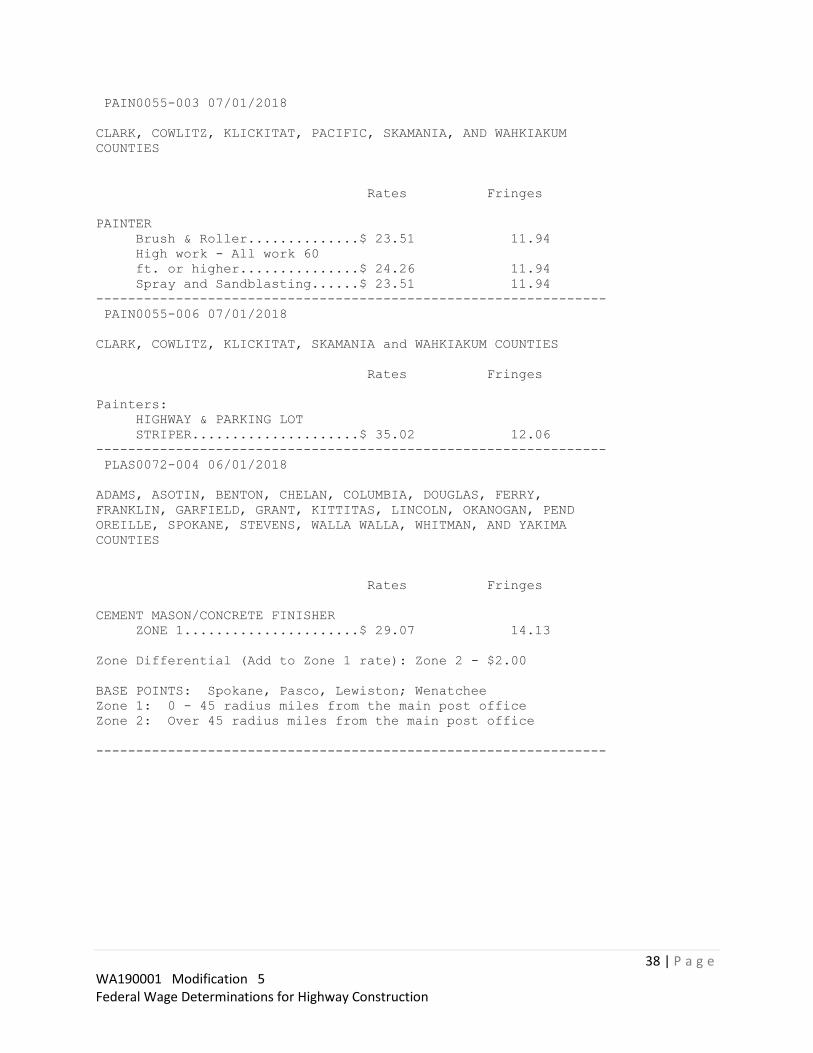
38 | P a g e WA190001 Modification 5 Federal Wage Determinations for Highway Construction
PAIN0055-003 07/01/2018
CLARK, COWLITZ, KLICKITAT, PACIFIC, SKAMANIA, AND WAHKIAKUM
COUNTIES
Rates Fringes
PAINTER
Brush & Roller..............$ 23.51 11.94
High work - All work 60
ft. or higher...............$ 24.26 11.94
Spray and Sandblasting......$ 23.51 11.94
----------------------------------------------------------------
PAIN0055-006 07/01/2018
CLARK, COWLITZ, KLICKITAT, SKAMANIA and WAHKIAKUM COUNTIES
Rates Fringes
Painters:
HIGHWAY & PARKING LOT
STRIPER.....................$ 35.02 12.06
----------------------------------------------------------------
PLAS0072-004 06/01/2018
ADAMS, ASOTIN, BENTON, CHELAN, COLUMBIA, DOUGLAS, FERRY,
FRANKLIN, GARFIELD, GRANT, KITTITAS, LINCOLN, OKANOGAN, PEND
OREILLE, SPOKANE, STEVENS, WALLA WALLA, WHITMAN, AND YAKIMA
COUNTIES
Rates Fringes
CEMENT MASON/CONCRETE FINISHER
ZONE 1......................$ 29.07 14.13
Zone Differential (Add to Zone 1 rate): Zone 2 - $2.00
BASE POINTS: Spokane, Pasco, Lewiston; Wenatchee
Zone 1: 0 - 45 radius miles from the main post office
Zone 2: Over 45 radius miles from the main post office
----------------------------------------------------------------

39 | P a g e WA190001 Modification 5 Federal Wage Determinations for Highway Construction
* PLAS0528-001 06/01/2019
CLALLAM, COWLITZ, GRAYS HARBOR, ISLAND, JEFFERSON, KING,
KITSAP, LEWIS, MASON, PACIFIC, PIERCE, SAN JUAN, SKAGIT,
SNOHOMISH, THURSTON, WAHKIAKUM AND WHATCOM COUNTIES
Rates Fringes
CEMENT MASON
CEMENT MASON................$ 44.43 18.04
COMPOSITION, TROWEL
MACHINE, GRINDER, POWER
TOOLS, GUNNITE NOZZLE.......$ 44.93 18.04
TROWELING MACHINE OPERATOR
ON COMPOSITION..............$ 44.93 18.04
TROWLING MACHINE OPERATOR
ON COMPOSITION..............$ 43.13 17.44
----------------------------------------------------------------
PLAS0555-002 06/01/2017
CLARK, KLICKITAT AND SKAMANIA COUNTIES
ZONE 1:
Rates Fringes
CEMENT MASON
CEMENT MASONS DOING BOTH
COMPOSITION/POWER
MACHINERY AND
SUSPENDED/HANGING SCAFFOLD..$ 32.87 17.62
CEMENT MASONS ON
SUSPENDED, SWINGING AND/OR
HANGING SCAFFOLD............$ 32.87 17.62
CEMENT MASONS...............$ 31.50 17.62
COMPOSITION WORKERS AND
POWER MACHINERY OPERATORS...$ 32.19 17.62
Zone Differential (Add To Zone 1 Rates):
Zone 2 - $0.65
Zone 3 - 1.15
Zone 4 - 1.70
Zone 5 - 3.00
BASE POINTS: BEND, CORVALLIS, EUGENE, MEDFORD, PORTLAND,
SALEM, THE DALLES, VANCOUVER
ZONE 1: Projects within 30 miles of the respective city hall
ZONE 2: More than 30 miles but less than 40 miles from the
respective city hall.
ZONE 3: More than 40 miles but less than 50 miles from the
respective city hall.
ZONE 4: More than 50 miles but less than 80 miles from the
respective city hall.
ZONE 5: More than 80 miles from the respective city hall

40 | P a g e WA190001 Modification 5 Federal Wage Determinations for Highway Construction
----------------------------------------------------------------
TEAM0037-002 06/01/2018
CLARK, COWLITZ, KLICKITAT, PACIFIC (South of a straight line
made by extending the north boundary line of Wahkiakum County
west to the Pacific Ocean), SKAMANIA, AND WAHKIAKUM COUNTIES
Rates Fringes
Truck drivers:
ZONE 1
GROUP 1....................$ 28.52 14.62
GROUP 2....................$ 28.64 14.62
GROUP 3....................$ 28.78 14.62
GROUP 4....................$ 29.05 14.62
GROUP 5....................$ 29.27 14.62
GROUP 6....................$ 29.45 14.62
GROUP 7....................$ 29.65 14.62
Zone Differential (Add to Zone 1 Rates):
Zone 2 - $0.65
Zone 3 - 1.15
Zone 4 - 1.70
Zone 5 - 2.75
BASE POINTS: ASTORIA, THE DALLES, LONGVIEW AND VANCOUVER
ZONE 1: Projects within 30 miles of the respective city
hall.
ZONE 2: More than 30 miles but less than 40 miles from the
respective city hall.
ZONE 3: More than 40 miles but less than 50 miles from the
respective city hall.
ZONE 4: More than 50 miles but less than 80 miles from the
respective city hall.
ZONE 5: More than 80 miles from the respective city hall.
TRUCK DRIVERS CLASSIFICATIONS
GROUP 1: A Frame or Hydra lifrt truck w/load bearing
surface; Articulated Dump Truck; Battery Rebuilders; Bus or
Manhaul Driver; Concrete Buggies (power operated); Concrete
Pump Truck; Dump Trucks, side, end and bottom dumps,
including Semi Trucks and Trains or combinations there of:
up to and including 10 cu. yds.; Lift Jitneys, Fork Lifts
(all sizes in loading, unloading and transporting material
on job site); Loader and/or Leverman on Concrete Dry Batch
Plant (manually operated); Pilot Car; Pickup Truck; Solo
Flat Bed and misc. Body Trucks, 0-10 tons; Truck Tender;
Truck Mechanic Tender; Water Wagons (rated capacity) up to
3,000 gallons; Transit Mix and Wet or Dry Mix - 5 cu. yds.
and under; Lubrication Man, Fuel Truck Driver, Tireman,
Wash Rack, Steam Cleaner or combinations; Team Driver;
Slurry Truck Driver or Leverman; Tireman

41 | P a g e WA190001 Modification 5 Federal Wage Determinations for Highway Construction
GROUP 2: Boom Truck/Hydra-lift or Retracting Crane;
Challenger; Dumpsters or similar equipment all sizes; Dump
Trucks/Articulated Dumps 6 cu to 10 cu.; Flaherty Spreader
Driver or Leverman; Lowbed Equipment, Flat Bed Semi-trailer
or doubles transporting equipment or wet or dry materials;
Lumber Carrier, Driver-Straddle Carrier (used in loading,
unloading and transporting of materials on job site); Oil
Distributor Driver or Leverman; Transit mix and wet or dry
mix trcuks: over 5 cu. yds. and including 7 cu. yds.;
Vacuum Trucks; Water truck/Wagons (rated capacity) over
3,000 to 5,000 gallons
GROUP 3: Ammonia Nitrate Distributor Driver; Dump trucks,
side, end and bottom dumps, including Semi Trucks and
Trains or combinations thereof: over 10 cu. yds. and
including 30 cu. yds. includes Articulated Dump Trucks;
Self-Propelled Street Sweeper; Transit mix and wet or dry
mix truck: over 7 cu yds. and including 11 cu yds.; Truck
Mechanic-Welder-Body Repairman; Utility and Clean-up Truck;
Water Wagons (rated capacity) over 5,000 to 10,000 gallons
GROUP 4: Asphalt Burner; Dump Trucks, side, end and bottom
cumps, including Semi-Trucks and Trains or combinations
thereof: over 30 cu. yds. and including 50 cu. yds.
includes Articulated Dump Trucks; Fire Guard; Transit Mix
and Wet or Dry Mix Trucks, over 11 cu. yds. and including
15 cu. yds.; Water Wagon (rated capacity) over 10,000
gallons to 15,000 gallons
GROUP 5: Composite Crewman; Dump Trucks, side, end and
bottom dumps, including Semi Trucks and Trains or
combinations thereof: over 50 cu. yds. and including 60 cu.
yds. includes Articulated Dump Trucks
GROUP 6: Bulk Cement Spreader w/o Auger; Dry Pre-Batch
concrete Mix Trucks; Dump trucks, side, end and bottom
dumps, including Semi Trucks and Trains of combinations
thereof: over 60 cu. yds. and including 80 cu. yds., and
includes Articulated Dump Trucks; Skid Truck
GROUP 7: Dump Trucks, side, end and bottom dumps, including
Semi Trucks and Trains or combinations thereof: over 80 cu.
yds. and including 100 cu. yds., includes Articulated Dump
Trucks; Industrial Lift Truck (mechanical tailgate)
----------------------------------------------------------------

42 | P a g e WA190001 Modification 5 Federal Wage Determinations for Highway Construction
TEAM0174-001 01/01/2018
CLALLAM, GRAYS HARBOR, ISLAND, JEFFERSON, KING, KITSAP, LEWIS,
MASON, PACIFIC (North of a straight line made by extending the
north boundary line of Wahkiakum County west to the Pacific
Ocean), PIERCE, SAN JUAN, SKAGIT, SNOHOMISH, THURSTON AND
WHATCOM COUNTIES
Rates Fringes
Truck drivers:
ZONE A:
GROUP 1:...................$ 35.63 18.67
GROUP 2:...................$ 34.79 18.67
GROUP 3:...................$ 31.98 18.67
GROUP 4:...................$ 27.01 18.67
GROUP 5:...................$ 35.18 18.67
ZONE B (25-45 miles from center of listed cities*): Add $.70
per hour to Zone A rates.
ZONE C (over 45 miles from centr of listed cities*): Add
$1.00 per hour to Zone A rates.
*Zone pay will be calculated from the city center of the
following listed cities:
BELLINGHAM CENTRALIA RAYMOND OLYMPIA
EVERETT SHELTON ANACORTES BELLEVUE
SEATTLE PORT ANGELES MT. VERNON KENT
TACOMA PORT TOWNSEND ABERDEEN BREMERTON
TRUCK DRIVERS CLASSIFICATIONS
GROUP 1 - ""A-frame or Hydralift"" trucks and Boom trucks or
similar equipment when ""A"" frame or ""Hydralift"" and Boom
truck or similar equipment is used; Buggymobile; Bulk
Cement Tanker; Dumpsters and similar equipment,
Tournorockers, Tournowagon, Tournotrailer, Cat DW series,
Terra Cobra, Le Tourneau, Westinghouse, Athye Wagon, Euclid
Two and Four-Wheeled power tractor with trailer and similar
top-loaded equipment transporting material: Dump Trucks,
side, end and bottom dump, including semi-trucks and trains
or combinations thereof with 16 yards to 30 yards capacity:
Over 30 yards $.15 per hour additional for each 10 yard
increment; Explosive Truck (field mix) and similar
equipment; Hyster Operators (handling bulk loose
aggregates); Lowbed and Heavy Duty Trailer; Road Oil
Distributor Driver; Spreader, Flaherty Transit mix used
exclusively in heavy construction; Water Wagon and Tank
Truck-3,000 gallons and over capacity

43 | P a g e WA190001 Modification 5 Federal Wage Determinations for Highway Construction
GROUP 2 - Bulllifts, or similar equipment used in loading or
unloading trucks, transporting materials on job site;
Dumpsters, and similar equipment, Tournorockers,
Tournowagon, Turnotrailer, Cat. D.W. Series, Terra Cobra,
Le Tourneau, Westinghouse, Athye wagon, Euclid two and
four-wheeled power tractor with trailer and similar
top-loaded equipment transporting material: Dump trucks,
side, end and bottom dump, including semi-trucks and trains
or combinations thereof with less than 16 yards capacity;
Flatbed (Dual Rear Axle); Grease Truck, Fuel Truck,
Greaser, Battery Service Man and/or Tire Service Man;
Leverman and loader at bunkers and batch plants; Oil tank
transport; Scissor truck; Slurry Truck; Sno-Go and similar
equipment; Swampers; Straddler Carrier (Ross, Hyster) and
similar equipment; Team Driver; Tractor (small,
rubber-tired)(when used within Teamster jurisdiction);
Vacuum truck; Water Wagon and Tank trucks-less than 3,000
gallons capacity; Winch Truck; Wrecker, Tow truck and
similar equipment
GROUP 3 - Flatbed (single rear axle); Pickup Sweeper; Pickup
Truck. (Adjust Group 3 upward by $2.00 per hour for onsite
work only)
GROUP 4 - Escort or Pilot Car
GROUP 5 - Mechanic
HAZMAT PROJECTS
Anyone working on a HAZMAT job, where HAZMAT certification is
required, shall be compensated as a premium, in addition to
the classification working in as follows:
LEVEL C: +$.25 per hour - This level uses an air purifying
respirator or additional protective clothing.
LEVEL B: +$.50 per hour - Uses same respirator protection as
Level A. Supplied air line is provided in conjunction with
a chemical ""splash suit.""
LEVEL A: +$.75 per hour - This level utilizes a fully-
encapsulated suit with a self-contained breathing apparatus
or a supplied air line.
----------------------------------------------------------------

44 | P a g e WA190001 Modification 5 Federal Wage Determinations for Highway Construction
TEAM0690-004 01/01/2019
ADAMS, ASOTIN, BENTON, CHELAN, COLUMBIA, DOUGLAS, FERRY,
FRANKLIN, GARFIELD, GRANT KITTITAS, LINCOLN, OKANOGAN, PEND
OREILLE, SPOKANE, STEVENS, WALLA WALLA, WHITMAN AND YAKIMA
COUNTIES
Rates Fringes
Truck drivers: (AREA 1:
SPOKANE ZONE CENTER: Adams, Chelan, Douglas, Ferry, Grant, Kittitas, Lincoln,
Okanogan, Pen Oreille, Spokane, Stevens, and Whitman Counties
AREA 1: LEWISTON ZONE CENTER: Asotin, Columbia, and Garfield Counties
AREA 2: PASCO ZONE CENTER: Benton, Franklin, Walla Walla and Yakima Counties)
AREA 1:
GROUP 1....................$ 23.91 17.40
GROUP 2....................$ 26.18 17.40
GROUP 3....................$ 26.68 17.40
GROUP 4....................$ 27.01 17.40
GROUP 5....................$ 27.12 17.40
GROUP 6....................$ 27.29 17.40
GROUP 7....................$ 27.82 17.40
GROUP 8....................$ 28.18 17.40
AREA 2:
GROUP 1....................$ 26.05 17.40
GROUP 2....................$ 28.69 17.40
GROUP 3....................$ 28.80 17.40
GROUP 4....................$ 29.13 17.40
GROUP 5....................$ 29.24 17.40
GROUP 6....................$ 29.24 17.40
GROUP 7....................$ 29.78 17.40
GROUP 8....................$ 30.10 17.40
Zone Differential (Add to Zone 1 rate: Zone 1 + $2.00)
BASE POINTS: Spokane, Pasco, Lewiston
Zone 1: 0-45 radius miles from the main post office.
Zone 2: Outside 45 radius miles from the main post office
TRUCK DRIVERS CLASSIFICATIONS
GROUP 1: Escort Driver or Pilot Car; Employee Haul; Power
Boat Hauling Employees or Material
GROUP 2: Fish Truck; Flat Bed Truck; Fork Lift (3000 lbs. and
under); Leverperson (loading trucks at bunkers); Trailer
Mounted Hydro Seeder and Mulcher; Seeder & Mulcher;
Stationary Fuel Operator; Tractor (small, rubber-tired,
pulling trailer or similar equipment)

45 | P a g e WA190001 Modification 5 Federal Wage Determinations for Highway Construction
GROUP 3: Auto Crane (2000 lbs. capacity); Buggy Mobile &
Similar; Bulk Cement Tanks & Spreader; Dumptor (6 yds. &
under); Flat Bed Truck with Hydraullic System; Fork Lift
(3001-16,000 lbs.); Fuel Truck Driver, Steamcleaner &
Washer; Power Operated Sweeper; Rubber-tired Tunnel Jumbo;
Scissors Truck; Slurry Truck Driver; Straddle Carrier
(Ross, Hyster, & similar); Tireperson; Transit Mixers &
Truck Hauling Concrete (3 yd. to & including 6 yds.);
Trucks, side, end, bottom & articulated end dump (3 yards
to and including 6 yds.); Warehouseperson (to include
shipping & receiving); Wrecker & Tow Truck
GROUP 4: A-Frame; Burner, Cutter, & Welder; Service Greaser;
Trucks, side, end, bottom & articulated end dump (over 6
yards to and including 12 yds.); Truck Mounted Hydro
Seeder; Warehouseperson; Water Tank truck (0-8,000 gallons)
GROUP 5: Dumptor (over 6 yds.); Lowboy (50 tons & under);
Self- loading Roll Off; Semi-Truck & Trailer; Tractor with
Steer Trailer; Transit Mixers and Trucks Hauling Concrete
(over 6 yds. to and including 10 yds.); Trucks, side, end,
bottom and end dump (over 12 yds. to & including 20 yds.);
Truck-Mounted Crane (with load bearing surface either
mounted or pulled, up to 14 ton); Vacuum Truck (super
sucker, guzzler, etc.)
GROUP 6: Flaherty Spreader Box Driver; Flowboys; Fork Lift
(over 16,000 lbs.); Dumps (Semi-end); Mechanic (Field);
Semi- end Dumps; Transfer Truck & Trailer; Transit Mixers &
Trucks Hauling Concrete (over 10 yds. to & including 20
yds.); Trucks, side, end, bottom and articulated end dump
(over 20 yds. to & including 40 yds.); Truck and Pup;
Tournarocker, DWs & similar with 2 or more 4 wheel-power
tractor with trailer, gallonage or yardage scale, whichever
is greater Water Tank Truck (8,001- 14,000 gallons);
Lowboy(over 50 tons)
GROUP 7: Oil Distributor Driver; Stringer Truck (cable
oeprated trailer); Transit Mixers & Trucks Hauling Concrete
(over 20 yds.); Truck, side, end, bottom end dump (over 40
yds. to & including 100 yds.); Truck Mounted Crane (with
load bearing surface either mounted or pulled (16 through
25 tons);
GROUP 8: Prime Movers and Stinger Truck; Trucks, side, end,
bottom and articulated end dump (over 100 yds.); Helicopter
Pilot Hauling Employees or Materials
Footnote A - Anyone working on a HAZMAT job, where HAZMAT
certification is required, shall be compensated as a
premium, in additon to the classification working in as
follows:
LEVEL C-D: - $.50 PER HOUR (This is the lowest level of
protection. This level may use an air purifying respirator
or additional protective clothing.
46 | P a g e WA190001 Modification 5 Federal Wage Determinations for Highway Construction
LEVEL A-B: - $1.00 PER HOUR (Uses supplied air is conjunction
with a chemical spash suit or fully encapsulated suit with
a self-contained breathing apparatus.
Employees shall be paid Hazmat pay in increments of four(4)
and eight(8) hours.
NOTE:
Trucks Pulling Equipment Trailers: shall receive $.15/hour
over applicable truck rate
----------------------------------------------------------------
WELDERS - Receive rate prescribed for craft performing
operation to which welding is incidental.
================================================================
Note: Executive Order (EO) 13706, Establishing Paid Sick Leave
for Federal Contractors applies to all contracts subject to the
Davis-Bacon Act for which the contract is awarded (and any
solicitation was issued) on or after January 1, 2017. If this
contract is covered by the EO, the contractor must provide
employees with 1 hour of paid sick leave for every 30 hours
they work, up to 56 hours of paid sick leave each year.
Employees must be permitted to use paid sick leave for their
own illness, injury or other health-related needs, including
preventive care; to assist a family member (or person who is
like family to the employee) who is ill, injured, or has other
health-related needs, including preventive care; or for reasons
resulting from, or to assist a family member (or person who is
like family to the employee) who is a victim of, domestic
violence, sexual assault, or stalking. Additional information
on contractor requirements and worker protections under the EO
is available at www.dol.gov/whd/govcontracts.
Unlisted classifications needed for work not included within
the scope of the classifications listed may be added after
award only as provided in the labor standards contract clauses
(29CFR 5.5 (a) (1) (ii)).
----------------------------------------------------------------

47 | P a g e WA190001 Modification 5 Federal Wage Determinations for Highway Construction
The body of each wage determination lists the classification
and wage rates that have been found to be prevailing for the
cited type(s) of construction in the area covered by the wage
determination. The classifications are listed in alphabetical
order of ""identifiers"" that indicate whether the particular
rate is a union rate (current union negotiated rate for local),
a survey rate (weighted average rate) or a union average rate
(weighted union average rate).
Union Rate Identifiers
A four letter classification abbreviation identifier enclosed
in dotted lines beginning with characters other than ""SU"" or
""UAVG"" denotes that the union classification and rate were
prevailing for that classification in the survey. Example:
PLUM0198-005 07/01/2014. PLUM is an abbreviation identifier of
the union which prevailed in the survey for this
classification, which in this example would be Plumbers. 0198
indicates the local union number or district council number
where applicable, i.e., Plumbers Local 0198. The next number,
005 in the example, is an internal number used in processing
the wage determination. 07/01/2014 is the effective date of the
most current negotiated rate, which in this example is July 1,
2014.
Union prevailing wage rates are updated to reflect all rate
changes in the collective bargaining agreement (CBA) governing
this classification and rate.
Survey Rate Identifiers
Classifications listed under the ""SU"" identifier indicate that
no one rate prevailed for this classification in the survey and
the published rate is derived by computing a weighted average
rate based on all the rates reported in the survey for that
classification. As this weighted average rate includes all
rates reported in the survey, it may include both union and
non-union rates. Example: SULA2012-007 5/13/2014. SU indicates
the rates are survey rates based on a weighted average
calculation of rates and are not majority rates. LA indicates
the State of Louisiana. 2012 is the year of survey on which
these classifications and rates are based. The next number, 007
in the example, is an internal number used in producing the
wage determination. 5/13/2014 indicates the survey completion
date for the classifications and rates under that identifier.
Survey wage rates are not updated and remain in effect until a
new survey is conducted.
48 | P a g e WA190001 Modification 5 Federal Wage Determinations for Highway Construction
Union Average Rate Identifiers
Classification(s) listed under the UAVG identifier indicate
that no single majority rate prevailed for those
classifications; however, 100% of the data reported for the
classifications was union data. EXAMPLE: UAVG-OH-0010
08/29/2014. UAVG indicates that the rate is a weighted union
average rate. OH indicates the state. The next number, 0010 in
the example, is an internal number used in producing the wage
determination. 08/29/2014 indicates the survey completion date
for the classifications and rates under that identifier.
A UAVG rate will be updated once a year, usually in January of
each year, to reflect a weighted average of the current
negotiated/CBA rate of the union locals from which the rate is
based.
----------------------------------------------------------------
WAGE DETERMINATION APPEALS PROCESS
1.) Has there been an initial decision in the matter? This can
be:
* an existing published wage determination
* a survey underlying a wage determination
* a Wage and Hour Division letter setting forth a position on
a wage determination matter
* a conformance (additional classification and rate) ruling
On survey related matters, initial contact, including requests
for summaries of surveys, should be with the Wage and Hour
Regional Office for the area in which the survey was conducted
because those Regional Offices have responsibility for the
Davis-Bacon survey program. If the response from this initial
contact is not satisfactory, then the process described in 2.)
and 3.) should be followed.
With regard to any other matter not yet ripe for the formal
process described here, initial contact should be with the
Branch of Construction Wage Determinations. Write to:
Branch of Construction Wage Determinations
Wage and Hour Division
U.S. Department of Labor
200 Constitution Avenue, N.W.
Washington, DC 20210

49 | P a g e WA190001 Modification 5 Federal Wage Determinations for Highway Construction
2.) If the answer to the question in 1.) is yes, then an
interested party (those affected by the action) can request
review and reconsideration from the Wage and Hour Administrator
(See 29 CFR Part 1.8 and 29 CFR Part 7). Write to:
Wage and Hour Administrator
U.S. Department of Labor
200 Constitution Avenue, N.W.
Washington, DC 20210
The request should be accompanied by a full statement of the
interested party's position and by any information (wage
payment data, project description, area practice material,
etc.) that the requestor considers relevant to the issue.
3.) If the decision of the Administrator is not favorable, an
interested party may appeal directly to the Administrative
Review Board (formerly the Wage Appeals Board). Write to:
Administrative Review Board
U.S. Department of Labor
200 Constitution Avenue, N.W.
Washington, DC 20210
4.) All decisions by the Administrative Review Board are final.
================================================================
END OF GENERAL DECISION"

RIDGETOP BLVD NW IMPROVEMENTS PROJECT PHASE 2
THIS PAGE INTENTIONALLY LEFT BLANK
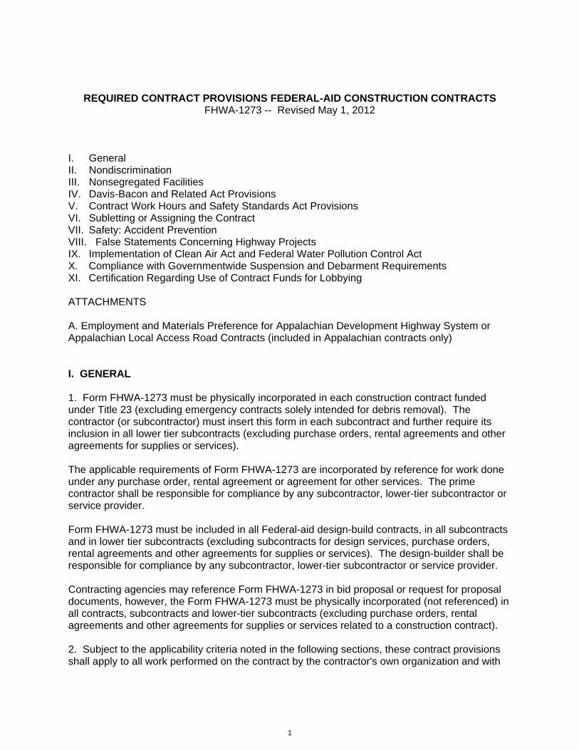
1
REQUIRED CONTRACT PROVISIONS FEDERAL-AID CONSTRUCTION CONTRACTS FHWA-1273 -- Revised May 1, 2012
I. General II. Nondiscrimination III. Nonsegregated Facilities IV. Davis-Bacon and Related Act Provisions V. Contract Work Hours and Safety Standards Act Provisions VI. Subletting or Assigning the Contract VII. Safety: Accident Prevention VIII. False Statements Concerning Highway Projects IX. Implementation of Clean Air Act and Federal Water Pollution Control Act X. Compliance with Governmentwide Suspension and Debarment Requirements XI. Certification Regarding Use of Contract Funds for Lobbying ATTACHMENTS A. Employment and Materials Preference for Appalachian Development Highway System or Appalachian Local Access Road Contracts (included in Appalachian contracts only) I. GENERAL 1. Form FHWA-1273 must be physically incorporated in each construction contract funded under Title 23 (excluding emergency contracts solely intended for debris removal). The contractor (or subcontractor) must insert this form in each subcontract and further require its inclusion in all lower tier subcontracts (excluding purchase orders, rental agreements and other agreements for supplies or services). The applicable requirements of Form FHWA-1273 are incorporated by reference for work done under any purchase order, rental agreement or agreement for other services. The prime contractor shall be responsible for compliance by any subcontractor, lower-tier subcontractor or service provider. Form FHWA-1273 must be included in all Federal-aid design-build contracts, in all subcontracts and in lower tier subcontracts (excluding subcontracts for design services, purchase orders, rental agreements and other agreements for supplies or services). The design-builder shall be responsible for compliance by any subcontractor, lower-tier subcontractor or service provider. Contracting agencies may reference Form FHWA-1273 in bid proposal or request for proposal documents, however, the Form FHWA-1273 must be physically incorporated (not referenced) in all contracts, subcontracts and lower-tier subcontracts (excluding purchase orders, rental agreements and other agreements for supplies or services related to a construction contract). 2. Subject to the applicability criteria noted in the following sections, these contract provisions shall apply to all work performed on the contract by the contractor's own organization and with

2
the assistance of workers under the contractor's immediate superintendence and to all work performed on the contract by piecework, station work, or by subcontract. 3. A breach of any of the stipulations contained in these Required Contract Provisions may be sufficient grounds for withholding of progress payments, withholding of final payment, termination of the contract, suspension / debarment or any other action determined to be appropriate by the contracting agency and FHWA. 4. Selection of Labor: During the performance of this contract, the contractor shall not use convict labor for any purpose within the limits of a construction project on a Federal-aid highway unless it is labor performed by convicts who are on parole, supervised release, or probation. The term Federal-aid highway does not include roadways functionally classified as local roads or rural minor collectors. II. NONDISCRIMINATION The provisions of this section related to 23 CFR Part 230 are applicable to all Federal-aid construction contracts and to all related construction subcontracts of $10,000 or more. The provisions of 23 CFR Part 230 are not applicable to material supply, engineering, or architectural service contracts. In addition, the contractor and all subcontractors must comply with the following policies: Executive Order 11246, 41 CFR 60, 29 CFR 1625-1627, Title 23 USC Section 140, the Rehabilitation Act of 1973, as amended (29 USC 794), Title VI of the Civil Rights Act of 1964, as amended, and related regulations including 49 CFR Parts 21, 26 and 27; and 23 CFR Parts 200, 230, and 633. The contractor and all subcontractors must comply with: the requirements of the Equal Opportunity Clause in 41 CFR 60-1.4(b) and, for all construction contracts exceeding $10,000, the Standard Federal Equal Employment Opportunity Construction Contract Specifications in 41 CFR 60-4.3. Note: The U.S. Department of Labor has exclusive authority to determine compliance with Executive Order 11246 and the policies of the Secretary of Labor including 41 CFR 60, and 29 CFR 1625-1627. The contracting agency and the FHWA have the authority and the responsibility to ensure compliance with Title 23 USC Section 140, the Rehabilitation Act of 1973, as amended (29 USC 794), and Title VI of the Civil Rights Act of 1964, as amended, and related regulations including 49 CFR Parts 21, 26 and 27; and 23 CFR Parts 200, 230, and 633. The following provision is adopted from 23 CFR 230, Appendix A, with appropriate revisions to conform to the U.S. Department of Labor (US DOL) and FHWA requirements. 1. Equal Employment Opportunity: Equal employment opportunity (EEO) requirements not to discriminate and to take affirmative action to assure equal opportunity as set forth under laws, executive orders, rules, regulations (28 CFR 35, 29 CFR 1630, 29 CFR 1625-1627, 41 CFR 60 and 49 CFR 27) and orders of the Secretary of Labor as modified by the provisions prescribed herein, and imposed pursuant to 23 U.S.C. 140 shall constitute the EEO and specific affirmative action standards for the contractor's project activities under this contract. The provisions of the Americans with Disabilities Act of 1990 (42 U.S.C. 12101 et seq.) set forth under 28 CFR 35 and 29 CFR 1630 are incorporated by reference in this contract. In the execution of this

3
contract, the contractor agrees to comply with the following minimum specific requirement activities of EEO:
a. The contractor will work with the contracting agency and the Federal Government to ensure that it has made every good faith effort to provide equal opportunity with respect to all of its terms and conditions of employment and in their review of activities under the contract. b. The contractor will accept as its operating policy the following statement:
"It is the policy of this Company to assure that applicants are employed, and that employees are treated during employment, without regard to their race, religion, sex, color, national origin, age or disability. Such action shall include: employment, upgrading, demotion, or transfer; recruitment or recruitment advertising; layoff or termination; rates of pay or other forms of compensation; and selection for training, including apprenticeship, pre-apprenticeship, and/or on-the-job training."
2. EEO Officer: The contractor will designate and make known to the contracting officers an EEO Officer who will have the responsibility for and must be capable of effectively administering and promoting an active EEO program and who must be assigned adequate authority and responsibility to do so. 3. Dissemination of Policy: All members of the contractor's staff who are authorized to hire, supervise, promote, and discharge employees, or who recommend such action, or who are substantially involved in such action, will be made fully cognizant of, and will implement, the contractor's EEO policy and contractual responsibilities to provide EEO in each grade and classification of employment. To ensure that the above agreement will be met, the following actions will be taken as a minimum:
a. Periodic meetings of supervisory and personnel office employees will be conducted before the start of work and then not less often than once every six months, at which time the contractor's EEO policy and its implementation will be reviewed and explained. The meetings will be conducted by the EEO Officer.
b. All new supervisory or personnel office employees will be given a thorough indoctrination by the EEO Officer, covering all major aspects of the contractor's EEO obligations within thirty days following their reporting for duty with the contractor.
c. All personnel who are engaged in direct recruitment for the project will be instructed by the EEO Officer in the contractor's procedures for locating and hiring minorities and women.
d. Notices and posters setting forth the contractor's EEO policy will be placed in areas readily accessible to employees, applicants for employment and potential employees.
e. The contractor's EEO policy and the procedures to implement such policy will be brought to the attention of employees by means of meetings, employee handbooks, or other appropriate means. 4. Recruitment: When advertising for employees, the contractor will include in all advertisements for employees the notation: "An Equal Opportunity Employer." All such advertisements will be placed in publications having a large circulation among minorities and women in the area from which the project work force would normally be derived.

4
a. The contractor will, unless precluded by a valid bargaining agreement, conduct systematic
and direct recruitment through public and private employee referral sources likely to yield qualified minorities and women. To meet this requirement, the contractor will identify sources of potential minority group employees, and establish with such identified sources procedures whereby minority and women applicants may be referred to the contractor for employment consideration.
b. In the event the contractor has a valid bargaining agreement providing for exclusive hiring hall referrals, the contractor is expected to observe the provisions of that agreement to the extent that the system meets the contractor's compliance with EEO contract provisions. Where implementation of such an agreement has the effect of discriminating against minorities or women, or obligates the contractor to do the same, such implementation violates Federal nondiscrimination provisions.
c. The contractor will encourage its present employees to refer minorities and women as applicants for employment. Information and procedures with regard to referring such applicants will be discussed with employees. 5. Personnel Actions: Wages, working conditions, and employee benefits shall be established and administered, and personnel actions of every type, including hiring, upgrading, promotion, transfer, demotion, layoff, and termination, shall be taken without regard to race, color, religion, sex, national origin, age or disability. The following procedures shall be followed:
a. The contractor will conduct periodic inspections of project sites to insure that working conditions and employee facilities do not indicate discriminatory treatment of project site personnel.
b. The contractor will periodically evaluate the spread of wages paid within each classification to determine any evidence of discriminatory wage practices.
c. The contractor will periodically review selected personnel actions in depth to determine whether there is evidence of discrimination. Where evidence is found, the contractor will promptly take corrective action. If the review indicates that the discrimination may extend beyond the actions reviewed, such corrective action shall include all affected persons.
d. The contractor will promptly investigate all complaints of alleged discrimination made to the contractor in connection with its obligations under this contract, will attempt to resolve such complaints, and will take appropriate corrective action within a reasonable time. If the investigation indicates that the discrimination may affect persons other than the complainant, such corrective action shall include such other persons. Upon completion of each investigation, the contractor will inform every complainant of all of their avenues of appeal. 6. Training and Promotion:
a. The contractor will assist in locating, qualifying, and increasing the skills of minorities and women who are applicants for employment or current employees. Such efforts should be aimed at developing full journey level status employees in the type of trade or job classification involved.

5
b. Consistent with the contractor's work force requirements and as permissible under Federal and State regulations, the contractor shall make full use of training programs, i.e., apprenticeship, and on-the-job training programs for the geographical area of contract performance. In the event a special provision for training is provided under this contract, this subparagraph will be superseded as indicated in the special provision. The contracting agency may reserve training positions for persons who receive welfare assistance in accordance with 23 U.S.C. 140(a).
c. The contractor will advise employees and applicants for employment of available training programs and entrance requirements for each.
d. The contractor will periodically review the training and promotion potential of employees who are minorities and women and will encourage eligible employees to apply for such training and promotion. 7. Unions: If the contractor relies in whole or in part upon unions as a source of employees, the contractor will use good faith efforts to obtain the cooperation of such unions to increase opportunities for minorities and women. Actions by the contractor, either directly or through a contractor's association acting as agent, will include the procedures set forth below:
a. The contractor will use good faith efforts to develop, in cooperation with the unions, joint training programs aimed toward qualifying more minorities and women for membership in the unions and increasing the skills of minorities and women so that they may qualify for higher paying employment.
b. The contractor will use good faith efforts to incorporate an EEO clause into each union agreement to the end that such union will be contractually bound to refer applicants without regard to their race, color, religion, sex, national origin, age or disability.
c. The contractor is to obtain information as to the referral practices and policies of the labor union except that to the extent such information is within the exclusive possession of the labor union and such labor union refuses to furnish such information to the contractor, the contractor shall so certify to the contracting agency and shall set forth what efforts have been made to obtain such information.
d. In the event the union is unable to provide the contractor with a reasonable flow of referrals within the time limit set forth in the collective bargaining agreement, the contractor will, through independent recruitment efforts, fill the employment vacancies without regard to race, color, religion, sex, national origin, age or disability; making full efforts to obtain qualified and/or qualifiable minorities and women. The failure of a union to provide sufficient referrals (even though it is obligated to provide exclusive referrals under the terms of a collective bargaining agreement) does not relieve the contractor from the requirements of this paragraph. In the event the union referral practice prevents the contractor from meeting the obligations pursuant to Executive Order 11246, as amended, and these special provisions, such contractor shall immediately notify the contracting agency. 8. Reasonable Accommodation for Applicants / Employees with Disabilities: The contractor must be familiar with the requirements for and comply with the Americans with Disabilities Act and all rules and regulations established there under. Employers must provide reasonable accommodation in all employment activities unless to do so would cause an undue hardship.
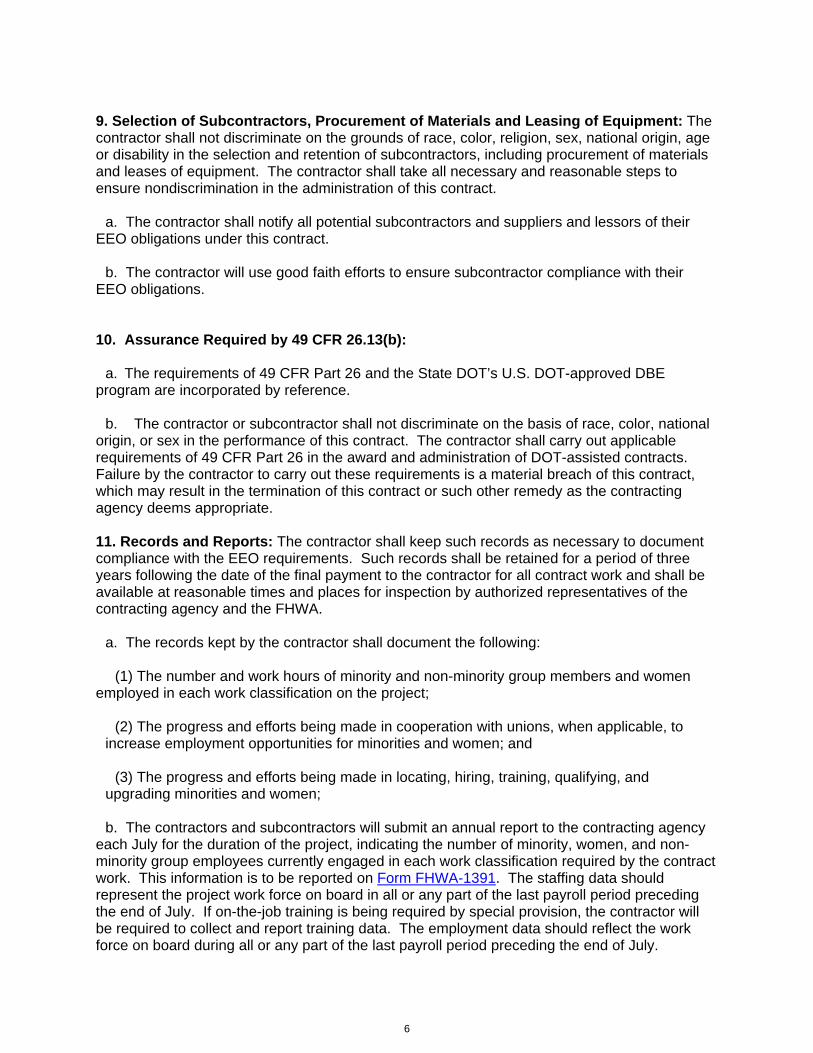
6
9. Selection of Subcontractors, Procurement of Materials and Leasing of Equipment: The contractor shall not discriminate on the grounds of race, color, religion, sex, national origin, age or disability in the selection and retention of subcontractors, including procurement of materials and leases of equipment. The contractor shall take all necessary and reasonable steps to ensure nondiscrimination in the administration of this contract.
a. The contractor shall notify all potential subcontractors and suppliers and lessors of their EEO obligations under this contract.
b. The contractor will use good faith efforts to ensure subcontractor compliance with their EEO obligations. 10. Assurance Required by 49 CFR 26.13(b):
a. The requirements of 49 CFR Part 26 and the State DOT’s U.S. DOT-approved DBE program are incorporated by reference.
b. The contractor or subcontractor shall not discriminate on the basis of race, color, national origin, or sex in the performance of this contract. The contractor shall carry out applicable requirements of 49 CFR Part 26 in the award and administration of DOT-assisted contracts. Failure by the contractor to carry out these requirements is a material breach of this contract, which may result in the termination of this contract or such other remedy as the contracting agency deems appropriate. 11. Records and Reports: The contractor shall keep such records as necessary to document compliance with the EEO requirements. Such records shall be retained for a period of three years following the date of the final payment to the contractor for all contract work and shall be available at reasonable times and places for inspection by authorized representatives of the contracting agency and the FHWA.
a. The records kept by the contractor shall document the following: (1) The number and work hours of minority and non-minority group members and women employed in each work classification on the project;
(2) The progress and efforts being made in cooperation with unions, when applicable, to increase employment opportunities for minorities and women; and
(3) The progress and efforts being made in locating, hiring, training, qualifying, and
upgrading minorities and women;
b. The contractors and subcontractors will submit an annual report to the contracting agency each July for the duration of the project, indicating the number of minority, women, and non-minority group employees currently engaged in each work classification required by the contract work. This information is to be reported on Form FHWA-1391. The staffing data should represent the project work force on board in all or any part of the last payroll period preceding the end of July. If on-the-job training is being required by special provision, the contractor will be required to collect and report training data. The employment data should reflect the work force on board during all or any part of the last payroll period preceding the end of July.

7
III. NONSEGREGATED FACILITIES This provision is applicable to all Federal-aid construction contracts and to all related construction subcontracts of $10,000 or more. The contractor must ensure that facilities provided for employees are provided in such a manner that segregation on the basis of race, color, religion, sex, or national origin cannot result. The contractor may neither require such segregated use by written or oral policies nor tolerate such use by employee custom. The contractor's obligation extends further to ensure that its employees are not assigned to perform their services at any location, under the contractor's control, where the facilities are segregated. The term "facilities" includes waiting rooms, work areas, restaurants and other eating areas, time clocks, restrooms, washrooms, locker rooms, and other storage or dressing areas, parking lots, drinking fountains, recreation or entertainment areas, transportation, and housing provided for employees. The contractor shall provide separate or single-user restrooms and necessary dressing or sleeping areas to assure privacy between sexes. IV. DAVIS-BACON AND RELATED ACT PROVISIONS
This section is applicable to all Federal-aid construction projects exceeding $2,000 and to all related subcontracts and lower-tier subcontracts (regardless of subcontract size). The requirements apply to all projects located within the right-of-way of a roadway that is functionally classified as Federal-aid highway. This excludes roadways functionally classified as local roads or rural minor collectors, which are exempt. Contracting agencies may elect to apply these requirements to other projects.
The following provisions are from the U.S. Department of Labor regulations in 29 CFR 5.5 “Contract provisions and related matters” with minor revisions to conform to the FHWA-1273 format and FHWA program requirements.
1. Minimum wages
a. All laborers and mechanics employed or working upon the site of the work, will be paid unconditionally and not less often than once a week, and without subsequent deduction or rebate on any account (except such payroll deductions as are permitted by regulations issued by the Secretary of Labor under the Copeland Act (29 CFR part 3)), the full amount of wages and bona fide fringe benefits (or cash equivalents thereof) due at time of payment computed at rates not less than those contained in the wage determination of the Secretary of Labor which is attached hereto and made a part hereof, regardless of any contractual relationship which may be alleged to exist between the contractor and such laborers and mechanics.
Contributions made or costs reasonably anticipated for bona fide fringe benefits under section 1(b)(2) of the Davis-Bacon Act on behalf of laborers or mechanics are considered wages paid to such laborers or mechanics, subject to the provisions of paragraph 1.d. of this section; also, regular contributions made or costs incurred for more than a weekly period (but not less often than quarterly) under plans, funds, or programs which cover the particular weekly period, are deemed to be constructively made or incurred during such weekly period. Such laborers and

8
mechanics shall be paid the appropriate wage rate and fringe benefits on the wage determination for the classification of work actually performed, without regard to skill, except as provided in 29 CFR 5.5(a)(4). Laborers or mechanics performing work in more than one classification may be compensated at the rate specified for each classification for the time actually worked therein: Provided, That the employer's payroll records accurately set forth the time spent in each classification in which work is performed. The wage determination (including any additional classification and wage rates conformed under paragraph 1.b. of this section) and the Davis-Bacon poster (WH–1321) shall be posted at all times by the contractor and its subcontractors at the site of the work in a prominent and accessible place where it can be easily seen by the workers.
b. (1) The contracting officer shall require that any class of laborers or mechanics, including helpers, which is not listed in the wage determination and which is to be employed under the contract shall be classified in conformance with the wage determination. The contracting officer shall approve an additional classification and wage rate and fringe benefits therefore only when the following criteria have been met:
(i) The work to be performed by the classification requested is not performed by a classification in the wage determination; and
(ii) The classification is utilized in the area by the construction industry; and
(iii) The proposed wage rate, including any bona fide fringe benefits, bears a reasonable relationship to the wage rates contained in the wage determination.
(2) If the contractor and the laborers and mechanics to be employed in the classification (if known), or their representatives, and the contracting officer agree on the classification and wage rate (including the amount designated for fringe benefits where appropriate), a report of the action taken shall be sent by the contracting officer to the Administrator of the Wage and Hour Division, Employment Standards Administration, U.S. Department of Labor, Washington, DC 20210. The Administrator, or an authorized representative, will approve, modify, or disapprove every additional classification action within 30 days of receipt and so advise the contracting officer or will notify the contracting officer within the 30-day period that additional time is necessary.
(3) In the event the contractor, the laborers or mechanics to be employed in the classification or their representatives, and the contracting officer do not agree on the proposed classification and wage rate (including the amount designated for fringe benefits, where appropriate), the contracting officer shall refer the questions, including the views of all interested parties and the recommendation of the contracting officer, to the Wage and Hour Administrator for determination. The Wage and Hour Administrator, or an authorized representative, will issue a determination within 30 days of receipt and so advise the contracting officer or will notify the contracting officer within the 30-day period that additional time is necessary.
(4) The wage rate (including fringe benefits where appropriate) determined pursuant to paragraphs 1.b.(2) or 1.b.(3) of this section, shall be paid to all workers performing work in the classification under this contract from the first day on which work is performed in the classification.

9
c. Whenever the minimum wage rate prescribed in the contract for a class of laborers or mechanics includes a fringe benefit which is not expressed as an hourly rate, the contractor shall either pay the benefit as stated in the wage determination or shall pay another bona fide fringe benefit or an hourly cash equivalent thereof.
d. If the contractor does not make payments to a trustee or other third person, the contractor may consider as part of the wages of any laborer or mechanic the amount of any costs reasonably anticipated in providing bona fide fringe benefits under a plan or program, Provided, That the Secretary of Labor has found, upon the written request of the contractor, that the applicable standards of the Davis-Bacon Act have been met. The Secretary of Labor may require the contractor to set aside in a separate account assets for the meeting of obligations under the plan or program.
2. Withholding
The contracting agency shall upon its own action or upon written request of an authorized representative of the Department of Labor, withhold or cause to be withheld from the contractor under this contract, or any other Federal contract with the same prime contractor, or any other federally-assisted contract subject to Davis-Bacon prevailing wage requirements, which is held by the same prime contractor, so much of the accrued payments or advances as may be considered necessary to pay laborers and mechanics, including apprentices, trainees, and helpers, employed by the contractor or any subcontractor the full amount of wages required by the contract. In the event of failure to pay any laborer or mechanic, including any apprentice, trainee, or helper, employed or working on the site of the work, all or part of the wages required by the contract, the contracting agency may, after written notice to the contractor, take such action as may be necessary to cause the suspension of any further payment, advance, or guarantee of funds until such violations have ceased.
3. Payrolls and basic records
a. Payrolls and basic records relating thereto shall be maintained by the contractor during the course of the work and preserved for a period of three years thereafter for all laborers and mechanics working at the site of the work. Such records shall contain the name, address, and social security number of each such worker, his or her correct classification, hourly rates of wages paid (including rates of contributions or costs anticipated for bona fide fringe benefits or cash equivalents thereof of the types described in section 1(b)(2)(B) of the Davis-Bacon Act), daily and weekly number of hours worked, deductions made and actual wages paid. Whenever the Secretary of Labor has found under 29 CFR 5.5(a)(1)(iv) that the wages of any laborer or mechanic include the amount of any costs reasonably anticipated in providing benefits under a plan or program described in section 1(b)(2)(B) of the Davis-Bacon Act, the contractor shall maintain records which show that the commitment to provide such benefits is enforceable, that the plan or program is financially responsible, and that the plan or program has been communicated in writing to the laborers or mechanics affected, and records which show the costs anticipated or the actual cost incurred in providing such benefits. Contractors employing apprentices or trainees under approved programs shall maintain written evidence of the registration of apprenticeship programs and certification of trainee programs, the registration of the apprentices and trainees, and the ratios and wage rates prescribed in the applicable programs.

10
b. (1) The contractor shall submit weekly for each week in which any contract work is performed a copy of all payrolls to the contracting agency. The payrolls submitted shall set out accurately and completely all of the information required to be maintained under 29 CFR 5.5(a)(3)(i), except that full social security numbers and home addresses shall not be included on weekly transmittals. Instead the payrolls shall only need to include an individually identifying number for each employee ( e.g. , the last four digits of the employee's social security number). The required weekly payroll information may be submitted in any form desired. Optional Form WH–347 is available for this purpose from the Wage and Hour Division Web site at http://www.dol.gov/esa/whd/forms/wh347instr.htm or its successor site. The prime contractor is responsible for the submission of copies of payrolls by all subcontractors. Contractors and subcontractors shall maintain the full social security number and current address of each covered worker, and shall provide them upon request to the contracting agency for transmission to the State DOT, the FHWA or the Wage and Hour Division of the Department of Labor for purposes of an investigation or audit of compliance with prevailing wage requirements. It is not a violation of this section for a prime contractor to require a subcontractor to provide addresses and social security numbers to the prime contractor for its own records, without weekly submission to the contracting agency..
(2) Each payroll submitted shall be accompanied by a “Statement of Compliance,” signed by the contractor or subcontractor or his or her agent who pays or supervises the payment of the persons employed under the contract and shall certify the following:
(i) That the payroll for the payroll period contains the information required to be provided under §5.5 (a)(3)(ii) of Regulations, 29 CFR part 5, the appropriate information is being maintained under §5.5 (a)(3)(i) of Regulations, 29 CFR part 5, and that such information is correct and complete;
(ii) That each laborer or mechanic (including each helper, apprentice, and trainee) employed on the contract during the payroll period has been paid the full weekly wages earned, without rebate, either directly or indirectly, and that no deductions have been made either directly or indirectly from the full wages earned, other than permissible deductions as set forth in Regulations, 29 CFR part 3;
(iii) That each laborer or mechanic has been paid not less than the applicable wage rates and fringe benefits or cash equivalents for the classification of work performed, as specified in the applicable wage determination incorporated into the contract.
(3) The weekly submission of a properly executed certification set forth on the reverse side of Optional Form WH–347 shall satisfy the requirement for submission of the “Statement of Compliance” required by paragraph 3.b.(2) of this section.
(4) The falsification of any of the above certifications may subject the contractor or subcontractor to civil or criminal prosecution under section 1001 of title 18 and section 231 of title 31 of the United States Code.
c. The contractor or subcontractor shall make the records required under paragraph 3.a. of this section available for inspection, copying, or transcription by authorized representatives of the contracting agency, the State DOT, the FHWA, or the Department of Labor, and shall permit such representatives to interview employees during working hours on the job. If the contractor or subcontractor fails to submit the required records or to make them available, the FHWA may,
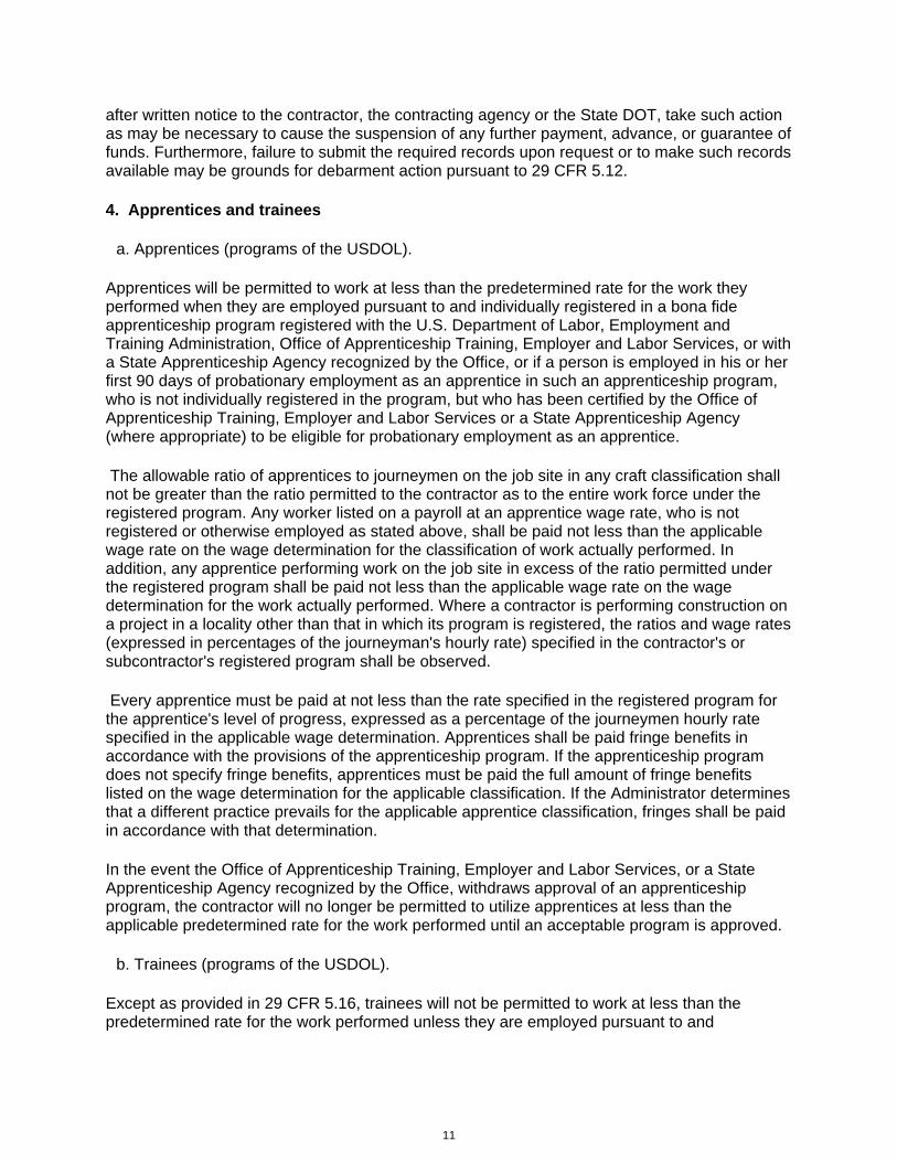
11
after written notice to the contractor, the contracting agency or the State DOT, take such action as may be necessary to cause the suspension of any further payment, advance, or guarantee of funds. Furthermore, failure to submit the required records upon request or to make such records available may be grounds for debarment action pursuant to 29 CFR 5.12.
4. Apprentices and trainees
a. Apprentices (programs of the USDOL).
Apprentices will be permitted to work at less than the predetermined rate for the work they performed when they are employed pursuant to and individually registered in a bona fide apprenticeship program registered with the U.S. Department of Labor, Employment and Training Administration, Office of Apprenticeship Training, Employer and Labor Services, or with a State Apprenticeship Agency recognized by the Office, or if a person is employed in his or her first 90 days of probationary employment as an apprentice in such an apprenticeship program, who is not individually registered in the program, but who has been certified by the Office of Apprenticeship Training, Employer and Labor Services or a State Apprenticeship Agency (where appropriate) to be eligible for probationary employment as an apprentice.
The allowable ratio of apprentices to journeymen on the job site in any craft classification shall not be greater than the ratio permitted to the contractor as to the entire work force under the registered program. Any worker listed on a payroll at an apprentice wage rate, who is not registered or otherwise employed as stated above, shall be paid not less than the applicable wage rate on the wage determination for the classification of work actually performed. In addition, any apprentice performing work on the job site in excess of the ratio permitted under the registered program shall be paid not less than the applicable wage rate on the wage determination for the work actually performed. Where a contractor is performing construction on a project in a locality other than that in which its program is registered, the ratios and wage rates (expressed in percentages of the journeyman's hourly rate) specified in the contractor's or subcontractor's registered program shall be observed.
Every apprentice must be paid at not less than the rate specified in the registered program for the apprentice's level of progress, expressed as a percentage of the journeymen hourly rate specified in the applicable wage determination. Apprentices shall be paid fringe benefits in accordance with the provisions of the apprenticeship program. If the apprenticeship program does not specify fringe benefits, apprentices must be paid the full amount of fringe benefits listed on the wage determination for the applicable classification. If the Administrator determines that a different practice prevails for the applicable apprentice classification, fringes shall be paid in accordance with that determination.
In the event the Office of Apprenticeship Training, Employer and Labor Services, or a State Apprenticeship Agency recognized by the Office, withdraws approval of an apprenticeship program, the contractor will no longer be permitted to utilize apprentices at less than the applicable predetermined rate for the work performed until an acceptable program is approved.
b. Trainees (programs of the USDOL).
Except as provided in 29 CFR 5.16, trainees will not be permitted to work at less than the predetermined rate for the work performed unless they are employed pursuant to and

12
individually registered in a program which has received prior approval, evidenced by formal certification by the U.S. Department of Labor, Employment and Training Administration.
The ratio of trainees to journeymen on the job site shall not be greater than permitted under the plan approved by the Employment and Training Administration.
Every trainee must be paid at not less than the rate specified in the approved program for the trainee's level of progress, expressed as a percentage of the journeyman hourly rate specified in the applicable wage determination. Trainees shall be paid fringe benefits in accordance with the provisions of the trainee program. If the trainee program does not mention fringe benefits, trainees shall be paid the full amount of fringe benefits listed on the wage determination unless the Administrator of the Wage and Hour Division determines that there is an apprenticeship program associated with the corresponding journeyman wage rate on the wage determination which provides for less than full fringe benefits for apprentices. Any employee listed on the payroll at a trainee rate who is not registered and participating in a training plan approved by the Employment and Training Administration shall be paid not less than the applicable wage rate on the wage determination for the classification of work actually performed. In addition, any trainee performing work on the job site in excess of the ratio permitted under the registered program shall be paid not less than the applicable wage rate on the wage determination for the work actually performed.
In the event the Employment and Training Administration withdraws approval of a training program, the contractor will no longer be permitted to utilize trainees at less than the applicable predetermined rate for the work performed until an acceptable program is approved.
c. Equal employment opportunity. The utilization of apprentices, trainees and journeymen under this part shall be in conformity with the equal employment opportunity requirements of Executive Order 11246, as amended, and 29 CFR part 30.
d. Apprentices and Trainees (programs of the U.S. DOT).
Apprentices and trainees working under apprenticeship and skill training programs which have been certified by the Secretary of Transportation as promoting EEO in connection with Federal-aid highway construction programs are not subject to the requirements of paragraph 4 of this Section IV. The straight time hourly wage rates for apprentices and trainees under such programs will be established by the particular programs. The ratio of apprentices and trainees to journeymen shall not be greater than permitted by the terms of the particular program.
5. Compliance with Copeland Act requirements. The contractor shall comply with the requirements of 29 CFR part 3, which are incorporated by reference in this contract.
6. Subcontracts. The contractor or subcontractor shall insert Form FHWA-1273 in any subcontracts and also require the subcontractors to include Form FHWA-1273 in any lower tier subcontracts. The prime contractor shall be responsible for the compliance by any subcontractor or lower tier subcontractor with all the contract clauses in 29 CFR 5.5.
7. Contract termination: debarment. A breach of the contract clauses in 29 CFR 5.5 may be grounds for termination of the contract, and for debarment as a contractor and a subcontractor as provided in 29 CFR 5.12.

13
8. Compliance with Davis-Bacon and Related Act requirements. All rulings and interpretations of the Davis-Bacon and Related Acts contained in 29 CFR parts 1, 3, and 5 are herein incorporated by reference in this contract.
9. Disputes concerning labor standards. Disputes arising out of the labor standards provisions of this contract shall not be subject to the general disputes clause of this contract. Such disputes shall be resolved in accordance with the procedures of the Department of Labor set forth in 29 CFR parts 5, 6, and 7. Disputes within the meaning of this clause include disputes between the contractor (or any of its subcontractors) and the contracting agency, the U.S. Department of Labor, or the employees or their representatives.
10. Certification of eligibility.
a. By entering into this contract, the contractor certifies that neither it (nor he or she) nor any person or firm who has an interest in the contractor's firm is a person or firm ineligible to be awarded Government contracts by virtue of section 3(a) of the Davis-Bacon Act or 29 CFR 5.12(a)(1).
b. No part of this contract shall be subcontracted to any person or firm ineligible for award of a Government contract by virtue of section 3(a) of the Davis-Bacon Act or 29 CFR 5.12(a)(1).
c. The penalty for making false statements is prescribed in the U.S. Criminal Code, 18 U.S.C. 1001.
V. CONTRACT WORK HOURS AND SAFETY STANDARDS ACT
The following clauses apply to any Federal-aid construction contract in an amount in excess of $100,000 and subject to the overtime provisions of the Contract Work Hours and Safety Standards Act. These clauses shall be inserted in addition to the clauses required by 29 CFR 5.5(a) or 29 CFR 4.6. As used in this paragraph, the terms laborers and mechanics include watchmen and guards.
1. Overtime requirements. No contractor or subcontractor contracting for any part of the contract work which may require or involve the employment of laborers or mechanics shall require or permit any such laborer or mechanic in any workweek in which he or she is employed on such work to work in excess of forty hours in such workweek unless such laborer or mechanic receives compensation at a rate not less than one and one-half times the basic rate of pay for all hours worked in excess of forty hours in such workweek.
2. Violation; liability for unpaid wages; liquidated damages. In the event of any violation of the clause set forth in paragraph (1.) of this section, the contractor and any subcontractor responsible therefor shall be liable for the unpaid wages. In addition, such contractor and subcontractor shall be liable to the United States (in the case of work done under contract for the District of Columbia or a territory, to such District or to such territory), for liquidated damages. Such liquidated damages shall be computed with respect to each individual laborer or mechanic, including watchmen and guards, employed in violation of the clause set forth in paragraph (1.) of this section, in the sum of $10 for each calendar day on which such individual

14
was required or permitted to work in excess of the standard workweek of forty hours without payment of the overtime wages required by the clause set forth in paragraph (1.) of this section.
3. Withholding for unpaid wages and liquidated damages. The FHWA or the contacting agency shall upon its own action or upon written request of an authorized representative of the Department of Labor withhold or cause to be withheld, from any moneys payable on account of work performed by the contractor or subcontractor under any such contract or any other Federal contract with the same prime contractor, or any other federally-assisted contract subject to the Contract Work Hours and Safety Standards Act, which is held by the same prime contractor, such sums as may be determined to be necessary to satisfy any liabilities of such contractor or subcontractor for unpaid wages and liquidated damages as provided in the clause set forth in paragraph (2.) of this section.
4. Subcontracts. The contractor or subcontractor shall insert in any subcontracts the clauses set forth in paragraph (1.) through (4.) of this section and also a clause requiring the subcontractors to include these clauses in any lower tier subcontracts. The prime contractor shall be responsible for compliance by any subcontractor or lower tier subcontractor with the clauses set forth in paragraphs (1.) through (4.) of this section.
VI. SUBLETTING OR ASSIGNING THE CONTRACT This provision is applicable to all Federal-aid construction contracts on the National Highway System. 1. The contractor shall perform with its own organization contract work amounting to not less than 30 percent (or a greater percentage if specified elsewhere in the contract) of the total original contract price, excluding any specialty items designated by the contracting agency. Specialty items may be performed by subcontract and the amount of any such specialty items performed may be deducted from the total original contract price before computing the amount of work required to be performed by the contractor's own organization (23 CFR 635.116).
a. The term “perform work with its own organization” refers to workers employed or leased by the prime contractor, and equipment owned or rented by the prime contractor, with or without operators. Such term does not include employees or equipment of a subcontractor or lower tier subcontractor, agents of the prime contractor, or any other assignees. The term may include payments for the costs of hiring leased employees from an employee leasing firm meeting all relevant Federal and State regulatory requirements. Leased employees may only be included in this term if the prime contractor meets all of the following conditions: (1) the prime contractor maintains control over the supervision of the day-to-day activities of the leased employees;
(2) the prime contractor remains responsible for the quality of the work of the leased employees;
(3) the prime contractor retains all power to accept or exclude individual employees from work on the project; and

15
(4) the prime contractor remains ultimately responsible for the payment of predetermined minimum wages, the submission of payrolls, statements of compliance and all other Federal regulatory requirements.
b. "Specialty Items" shall be construed to be limited to work that requires highly specialized
knowledge, abilities, or equipment not ordinarily available in the type of contracting organizations qualified and expected to bid or propose on the contract as a whole and in general are to be limited to minor components of the overall contract. 2. The contract amount upon which the requirements set forth in paragraph (1) of Section VI is computed includes the cost of material and manufactured products which are to be purchased or produced by the contractor under the contract provisions. 3. The contractor shall furnish (a) a competent superintendent or supervisor who is employed by the firm, has full authority to direct performance of the work in accordance with the contract requirements, and is in charge of all construction operations (regardless of who performs the work) and (b) such other of its own organizational resources (supervision, management, and engineering services) as the contracting officer determines is necessary to assure the performance of the contract. 4. No portion of the contract shall be sublet, assigned or otherwise disposed of except with the written consent of the contracting officer, or authorized representative, and such consent when given shall not be construed to relieve the contractor of any responsibility for the fulfillment of the contract. Written consent will be given only after the contracting agency has assured that each subcontract is evidenced in writing and that it contains all pertinent provisions and requirements of the prime contract. 5. The 30% self-performance requirement of paragraph (1) is not applicable to design-build contracts; however, contracting agencies may establish their own self-performance requirements. VII. SAFETY: ACCIDENT PREVENTION This provision is applicable to all Federal-aid construction contracts and to all related subcontracts. 1. In the performance of this contract the contractor shall comply with all applicable Federal, State, and local laws governing safety, health, and sanitation (23 CFR 635). The contractor shall provide all safeguards, safety devices and protective equipment and take any other needed actions as it determines, or as the contracting officer may determine, to be reasonably necessary to protect the life and health of employees on the job and the safety of the public and to protect property in connection with the performance of the work covered by the contract. 2. It is a condition of this contract, and shall be made a condition of each subcontract, which the contractor enters into pursuant to this contract, that the contractor and any subcontractor shall not permit any employee, in performance of the contract, to work in surroundings or under conditions which are unsanitary, hazardous or dangerous to his/her health or safety, as determined under construction safety and health standards (29 CFR 1926) promulgated by the Secretary of Labor, in accordance with Section 107 of the Contract Work Hours and Safety Standards Act (40 U.S.C. 3704).

16
3. Pursuant to 29 CFR 1926.3, it is a condition of this contract that the Secretary of Labor or authorized representative thereof, shall have right of entry to any site of contract performance to inspect or investigate the matter of compliance with the construction safety and health standards and to carry out the duties of the Secretary under Section 107 of the Contract Work Hours and Safety Standards Act (40 U.S.C.3704). VIII. FALSE STATEMENTS CONCERNING HIGHWAY PROJECTS This provision is applicable to all Federal-aid construction contracts and to all related subcontracts. In order to assure high quality and durable construction in conformity with approved plans and specifications and a high degree of reliability on statements and representations made by engineers, contractors, suppliers, and workers on Federal-aid highway projects, it is essential that all persons concerned with the project perform their functions as carefully, thoroughly, and honestly as possible. Willful falsification, distortion, or misrepresentation with respect to any facts related to the project is a violation of Federal law. To prevent any misunderstanding regarding the seriousness of these and similar acts, Form FHWA-1022 shall be posted on each Federal-aid highway project (23 CFR 635) in one or more places where it is readily available to all persons concerned with the project: 18 U.S.C. 1020 reads as follows: "Whoever, being an officer, agent, or employee of the United States, or of any State or Territory, or whoever, whether a person, association, firm, or corporation, knowingly makes any false statement, false representation, or false report as to the character, quality, quantity, or cost of the material used or to be used, or the quantity or quality of the work performed or to be performed, or the cost thereof in connection with the submission of plans, maps, specifications, contracts, or costs of construction on any highway or related project submitted for approval to the Secretary of Transportation; or Whoever knowingly makes any false statement, false representation, false report or false claim with respect to the character, quality, quantity, or cost of any work performed or to be performed, or materials furnished or to be furnished, in connection with the construction of any highway or related project approved by the Secretary of Transportation; or Whoever knowingly makes any false statement or false representation as to material fact in any statement, certificate, or report submitted pursuant to provisions of the Federal-aid Roads Act approved July 1, 1916, (39 Stat. 355), as amended and supplemented; Shall be fined under this title or imprisoned not more than 5 years or both." IX. IMPLEMENTATION OF CLEAN AIR ACT AND FEDERAL WATER POLLUTION CONTROL ACT This provision is applicable to all Federal-aid construction contracts and to all related subcontracts.

17
By submission of this bid/proposal or the execution of this contract, or subcontract, as appropriate, the bidder, proposer, Federal-aid construction contractor, or subcontractor, as appropriate, will be deemed to have stipulated as follows: 1. That any person who is or will be utilized in the performance of this contract is not prohibited from receiving an award due to a violation of Section 508 of the Clean Water Act or Section 306 of the Clean Air Act. 2. That the contractor agrees to include or cause to be included the requirements of paragraph (1) of this Section X in every subcontract, and further agrees to take such action as the contracting agency may direct as a means of enforcing such requirements. X. CERTIFICATION REGARDING DEBARMENT, SUSPENSION, INELIGIBILITY AND VOLUNTARY EXCLUSION This provision is applicable to all Federal-aid construction contracts, design-build contracts, subcontracts, lower-tier subcontracts, purchase orders, lease agreements, consultant contracts or any other covered transaction requiring FHWA approval or that is estimated to cost $25,000 or more – as defined in 2 CFR Parts 180 and 1200. 1. Instructions for Certification – First Tier Participants: a. By signing and submitting this proposal, the prospective first tier participant is providing the certification set out below. b. The inability of a person to provide the certification set out below will not necessarily result in denial of participation in this covered transaction. The prospective first tier participant shall submit an explanation of why it cannot provide the certification set out below. The certification or explanation will be considered in connection with the department or agency's determination whether to enter into this transaction. However, failure of the prospective first tier participant to furnish a certification or an explanation shall disqualify such a person from participation in this transaction. c. The certification in this clause is a material representation of fact upon which reliance was placed when the contracting agency determined to enter into this transaction. If it is later determined that the prospective participant knowingly rendered an erroneous certification, in addition to other remedies available to the Federal Government, the contracting agency may terminate this transaction for cause of default. d. The prospective first tier participant shall provide immediate written notice to the contracting agency to whom this proposal is submitted if any time the prospective first tier participant learns that its certification was erroneous when submitted or has become erroneous by reason of changed circumstances. e. The terms "covered transaction," "debarred," "suspended," "ineligible," "participant," "person," "principal," and "voluntarily excluded," as used in this clause, are defined in 2 CFR Parts 180 and 1200. “First Tier Covered Transactions” refers to any covered transaction between a grantee or subgrantee of Federal funds and a participant (such as the prime or

18
general contract). “Lower Tier Covered Transactions” refers to any covered transaction under a First Tier Covered Transaction (such as subcontracts). “First Tier Participant” refers to the participant who has entered into a covered transaction with a grantee or subgrantee of Federal funds (such as the prime or general contractor). “Lower Tier Participant” refers any participant who has entered into a covered transaction with a First Tier Participant or other Lower Tier Participants (such as subcontractors and suppliers). f. The prospective first tier participant agrees by submitting this proposal that, should the proposed covered transaction be entered into, it shall not knowingly enter into any lower tier covered transaction with a person who is debarred, suspended, declared ineligible, or voluntarily excluded from participation in this covered transaction, unless authorized by the department or agency entering into this transaction. g. The prospective first tier participant further agrees by submitting this proposal that it will include the clause titled "Certification Regarding Debarment, Suspension, Ineligibility and Voluntary Exclusion-Lower Tier Covered Transactions," provided by the department or contracting agency, entering into this covered transaction, without modification, in all lower tier covered transactions and in all solicitations for lower tier covered transactions exceeding the $25,000 threshold. h. A participant in a covered transaction may rely upon a certification of a prospective participant in a lower tier covered transaction that is not debarred, suspended, ineligible, or voluntarily excluded from the covered transaction, unless it knows that the certification is erroneous. A participant is responsible for ensuring that its principals are not suspended, debarred, or otherwise ineligible to participate in covered transactions. To verify the eligibility of its principals, as well as the eligibility of any lower tier prospective participants, each participant may, but is not required to, check the Excluded Parties List System website (https://www.epls.gov/), which is compiled by the General Services Administration. i. Nothing contained in the foregoing shall be construed to require the establishment of a system of records in order to render in good faith the certification required by this clause. The knowledge and information of the prospective participant is not required to exceed that which is normally possessed by a prudent person in the ordinary course of business dealings. j. Except for transactions authorized under paragraph (f) of these instructions, if a participant in a covered transaction knowingly enters into a lower tier covered transaction with a person who is suspended, debarred, ineligible, or voluntarily excluded from participation in this transaction, in addition to other remedies available to the Federal Government, the department or agency may terminate this transaction for cause or default. * * * * * 2. Certification Regarding Debarment, Suspension, Ineligibility and Voluntary Exclusion – First Tier Participants: a. The prospective first tier participant certifies to the best of its knowledge and belief, that it and its principals: (1) Are not presently debarred, suspended, proposed for debarment, declared ineligible, or voluntarily excluded from participating in covered transactions by any Federal department or agency;

19
(2) Have not within a three-year period preceding this proposal been convicted of or had a civil judgment rendered against them for commission of fraud or a criminal offense in connection with obtaining, attempting to obtain, or performing a public (Federal, State or local) transaction or contract under a public transaction; violation of Federal or State antitrust statutes or commission of embezzlement, theft, forgery, bribery, falsification or destruction of records, making false statements, or receiving stolen property; (3) Are not presently indicted for or otherwise criminally or civilly charged by a governmental entity (Federal, State or local) with commission of any of the offenses enumerated in paragraph (a)(2) of this certification; and (4) Have not within a three-year period preceding this application/proposal had one or more public transactions (Federal, State or local) terminated for cause or default. b. Where the prospective participant is unable to certify to any of the statements in this certification, such prospective participant shall attach an explanation to this proposal. 2. Instructions for Certification - Lower Tier Participants: (Applicable to all subcontracts, purchase orders and other lower tier transactions requiring prior FHWA approval or estimated to cost $25,000 or more - 2 CFR Parts 180 and 1200) a. By signing and submitting this proposal, the prospective lower tier is providing the certification set out below. b. The certification in this clause is a material representation of fact upon which reliance was placed when this transaction was entered into. If it is later determined that the prospective lower tier participant knowingly rendered an erroneous certification, in addition to other remedies available to the Federal Government, the department, or agency with which this transaction originated may pursue available remedies, including suspension and/or debarment. c. The prospective lower tier participant shall provide immediate written notice to the person to which this proposal is submitted if at any time the prospective lower tier participant learns that its certification was erroneous by reason of changed circumstances. d. The terms "covered transaction," "debarred," "suspended," "ineligible," "participant," "person," "principal," and "voluntarily excluded," as used in this clause, are defined in 2 CFR Parts 180 and 1200. You may contact the person to which this proposal is submitted for assistance in obtaining a copy of those regulations. “First Tier Covered Transactions” refers to any covered transaction between a grantee or subgrantee of Federal funds and a participant (such as the prime or general contract). “Lower Tier Covered Transactions” refers to any covered transaction under a First Tier Covered Transaction (such as subcontracts). “First Tier Participant” refers to the participant who has entered into a covered transaction with a grantee or subgrantee of Federal funds (such as the prime or general contractor). “Lower Tier Participant” refers any participant who has entered into a covered transaction with a First Tier Participant or other Lower Tier Participants (such as subcontractors and suppliers). e. The prospective lower tier participant agrees by submitting this proposal that, should the proposed covered transaction be entered into, it shall not knowingly enter into any lower tier covered transaction with a person who is debarred, suspended, declared ineligible, or

20
voluntarily excluded from participation in this covered transaction, unless authorized by the department or agency with which this transaction originated. f. The prospective lower tier participant further agrees by submitting this proposal that it will include this clause titled "Certification Regarding Debarment, Suspension, Ineligibility and Voluntary Exclusion-Lower Tier Covered Transaction," without modification, in all lower tier covered transactions and in all solicitations for lower tier covered transactions exceeding the $25,000 threshold. g. A participant in a covered transaction may rely upon a certification of a prospective participant in a lower tier covered transaction that is not debarred, suspended, ineligible, or voluntarily excluded from the covered transaction, unless it knows that the certification is erroneous. A participant is responsible for ensuring that its principals are not suspended, debarred, or otherwise ineligible to participate in covered transactions. To verify the eligibility of its principals, as well as the eligibility of any lower tier prospective participants, each participant may, but is not required to, check the Excluded Parties List System website (https://www.epls.gov/), which is compiled by the General Services Administration. h. Nothing contained in the foregoing shall be construed to require establishment of a system of records in order to render in good faith the certification required by this clause. The knowledge and information of participant is not required to exceed that which is normally possessed by a prudent person in the ordinary course of business dealings. i. Except for transactions authorized under paragraph e of these instructions, if a participant in a covered transaction knowingly enters into a lower tier covered transaction with a person who is suspended, debarred, ineligible, or voluntarily excluded from participation in this transaction, in addition to other remedies available to the Federal Government, the department or agency with which this transaction originated may pursue available remedies, including suspension and/or debarment. * * * * * Certification Regarding Debarment, Suspension, Ineligibility and Voluntary Exclusion--Lower Tier Participants: 1. The prospective lower tier participant certifies, by submission of this proposal, that neither it nor its principals is presently debarred, suspended, proposed for debarment, declared ineligible, or voluntarily excluded from participating in covered transactions by any Federal department or agency. 2. Where the prospective lower tier participant is unable to certify to any of the statements in this certification, such prospective participant shall attach an explanation to this proposal. * * * * *

21
XI. CERTIFICATION REGARDING USE OF CONTRACT FUNDS FOR LOBBYING This provision is applicable to all Federal-aid construction contracts and to all related subcontracts which exceed $100,000 (49 CFR 20). 1. The prospective participant certifies, by signing and submitting this bid or proposal, to the best of his or her knowledge and belief, that: a. No Federal appropriated funds have been paid or will be paid, by or on behalf of the undersigned, to any person for influencing or attempting to influence an officer or employee of any Federal agency, a Member of Congress, an officer or employee of Congress, or an employee of a Member of Congress in connection with the awarding of any Federal contract, the making of any Federal grant, the making of any Federal loan, the entering into of any cooperative agreement, and the extension, continuation, renewal, amendment, or modification of any Federal contract, grant, loan, or cooperative agreement. b. If any funds other than Federal appropriated funds have been paid or will be paid to any person for influencing or attempting to influence an officer or employee of any Federal agency, a Member of Congress, an officer or employee of Congress, or an employee of a Member of Congress in connection with this Federal contract, grant, loan, or cooperative agreement, the undersigned shall complete and submit Standard Form-LLL, "Disclosure Form to Report Lobbying," in accordance with its instructions. 2. This certification is a material representation of fact upon which reliance was placed when this transaction was made or entered into. Submission of this certification is a prerequisite for making or entering into this transaction imposed by 31 U.S.C. 1352. Any person who fails to file the required certification shall be subject to a civil penalty of not less than $10,000 and not more than $100,000 for each such failure. 3. The prospective participant also agrees by submitting its bid or proposal that the participant shall require that the language of this certification be included in all lower tier subcontracts, which exceed $100,000 and that all such recipients shall certify and disclose accordingly.

22
ATTACHMENT A - EMPLOYMENT AND MATERIALS PREFERENCE FOR APPALACHIAN DEVELOPMENT HIGHWAY SYSTEM OR APPALACHIAN LOCAL ACCESS ROAD CONTRACTS This provision is applicable to all Federal-aid projects funded under the Appalachian Regional Development Act of 1965. 1. During the performance of this contract, the contractor undertaking to do work which is, or reasonably may be, done as on-site work, shall give preference to qualified persons who regularly reside in the labor area as designated by the DOL wherein the contract work is situated, or the subregion, or the Appalachian counties of the State wherein the contract work is situated, except: a. To the extent that qualified persons regularly residing in the area are not available. b. For the reasonable needs of the contractor to employ supervisory or specially experienced personnel necessary to assure an efficient execution of the contract work. c. For the obligation of the contractor to offer employment to present or former employees as the result of a lawful collective bargaining contract, provided that the number of nonresident persons employed under this subparagraph (1c) shall not exceed 20 percent of the total number of employees employed by the contractor on the contract work, except as provided in subparagraph (4) below. 2. The contractor shall place a job order with the State Employment Service indicating (a) the classifications of the laborers, mechanics and other employees required to perform the contract work, (b) the number of employees required in each classification, (c) the date on which the participant estimates such employees will be required, and (d) any other pertinent information required by the State Employment Service to complete the job order form. The job order may be placed with the State Employment Service in writing or by telephone. If during the course of the contract work, the information submitted by the contractor in the original job order is substantially modified, the participant shall promptly notify the State Employment Service. 3. The contractor shall give full consideration to all qualified job applicants referred to him by the State Employment Service. The contractor is not required to grant employment to any job applicants who, in his opinion, are not qualified to perform the classification of work required. 4. If, within one week following the placing of a job order by the contractor with the State Employment Service, the State Employment Service is unable to refer any qualified job applicants to the contractor, or less than the number requested, the State Employment Service will forward a certificate to the contractor indicating the unavailability of applicants. Such certificate shall be made a part of the contractor's permanent project records. Upon receipt of this certificate, the contractor may employ persons who do not normally reside in the labor area to fill positions covered by the certificate, notwithstanding the provisions of subparagraph (1c) above. 5. The provisions of 23 CFR 633.207(e) allow the contracting agency to provide a contractual preference for the use of mineral resource materials native to the Appalachian region. 6. The contractor shall include the provisions of Sections 1 through 4 of this Attachment A in every subcontract for work which is, or reasonably may be, done as on-site work.

Amendment to Form FHWA 1273 Revised January 25, 2016
AMENDMENT REQUIRED CONTRACT PROVISIONS (Exclusive of Appalachian Contracts)
FEDERAL-AID CONSTRUCTION CONTRACTS The Federal–Aid provisions are supplemented with the following: XII. Cargo Preference Act 1. U.S. Department of Transportation Federal Highway Administration memorandum dated
December 11, 2015 requires that all federal-aid highway programs awarded after February 15, 2016 must comply with the Cargo Preference Act and its regulation of 46 CFR 381.7 (a)-(b).

RIDGETOP BLVD NW IMPROVEMENTS PROJECT PHASE 2
THIS PAGE INTENTIONALLY LEFT BLANK
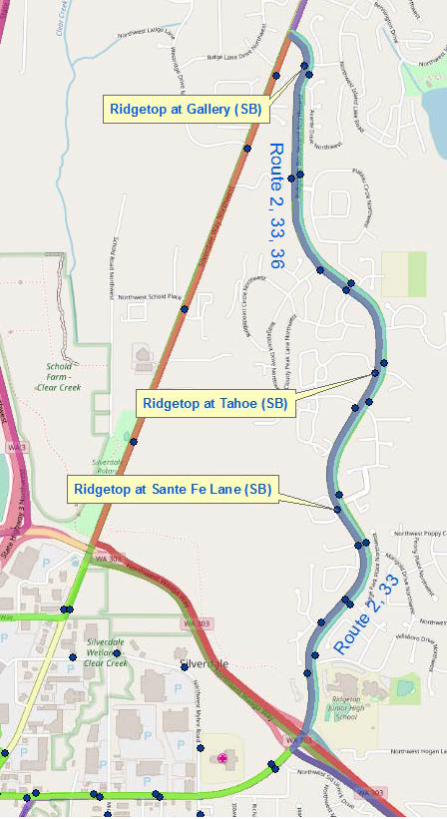

RIDGETOP BLVD NW IMPROVEMENTS PROJECT PHASE 2
THIS PAGE INTENTIONALLY LEFT BLANK


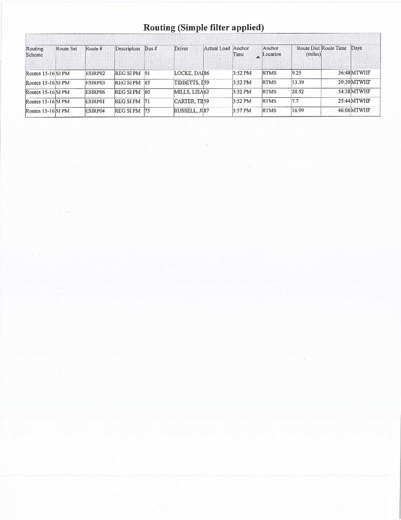


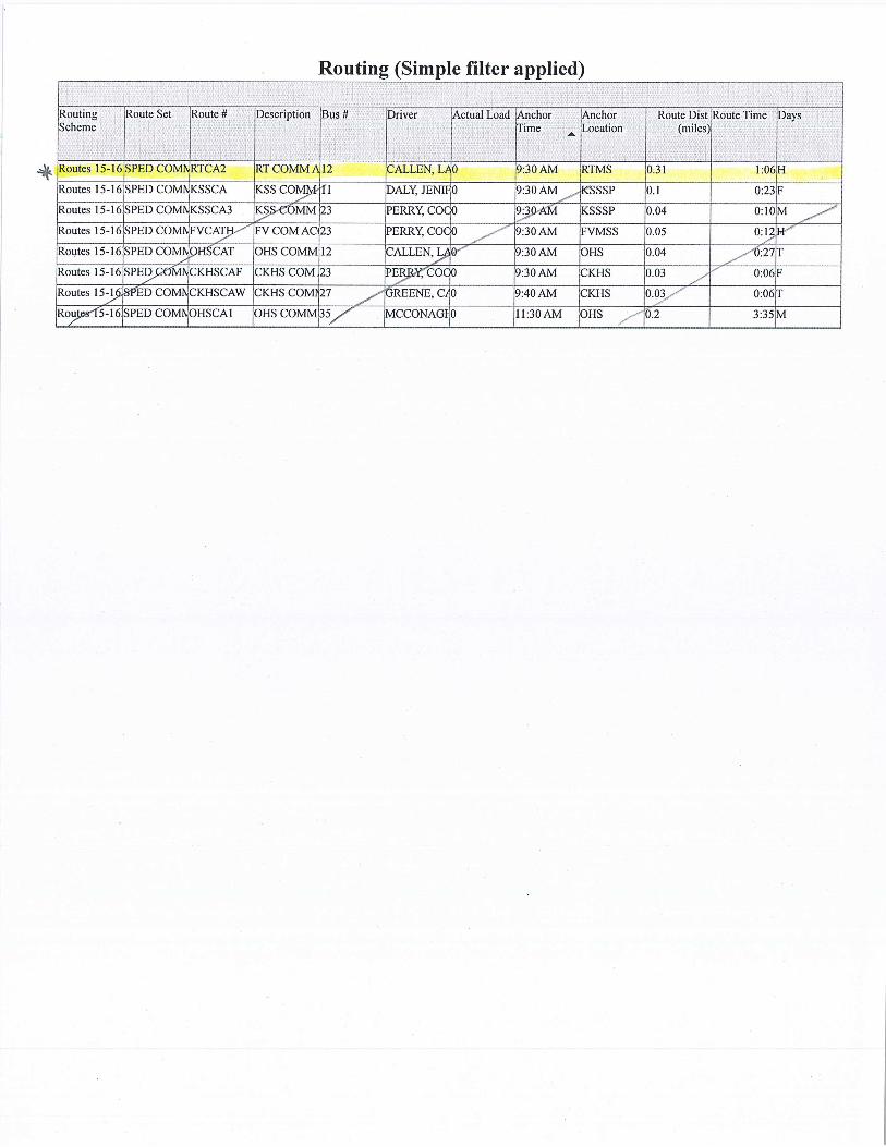

RIDGETOP BLVD NW IMPROVEMENTS PROJECT PHASE 2
THIS PAGE INTENTIONALLY LEFT BLANK

WWW.KINDREDHYDRO.COM
INFILTRATION TESTING AND ASSESSMENT RIDGETOP BOULEVARD GREEN STORMWATER PROJECT, SILVERDALE, WASHINGTON Prepared for: Kitsap County
Project No. KIT-14-1 October 15, 2014 Kindred Hydro, Inc.
J. Scott Kindred, PE [email protected]
https://netorg82711-my.sharepoint.com/personal/scottk_kindredhydro_com/Documents/Projects/Ridgetop/Report Drafts/Ridgetop PIT Testing Report.docx
7204 91st Avenue SE • Mercer Island, WA 98040 206-660-5417


KINDRED HYDRO, INC.
Contents
1 Introduction ................................................................................................. 1 1.1 Previous Studies ......................................................................................... 1
2 Explorations and Testing ............................................................................ 3 2.1 Testpit Explorations .................................................................................... 3 2.2 Borehole Explorations ................................................................................ 3 2.3 Grainsize Analyses ..................................................................................... 4 2.4 Pilot Infiltration Testing (PIT) ...................................................................... 4 2.5 Borehole Infiltration Testing ........................................................................ 5
3 Summary of Results .................................................................................... 7 3.1 Stratigraphy ................................................................................................ 7 3.2 Groundwater ............................................................................................... 8 3.3 Shallow Infiltration Test Results .................................................................. 8 3.4 Deep Borehole Infiltration Test Results ...................................................... 9
4 Recommendations .................................................................................... 11 4.1 General Design Considerations ................................................................ 11 4.2 Design Infiltration Rates............................................................................ 12 4.3 Estimated Deep Drain Capacity ................................................................ 13 4.4 Subsurface Uncertainty and Risk Management ........................................ 14 4.5 Construction Management ........................................................................ 15
5 Limitations ................................................................................................. 16
6 References ................................................................................................. 17
List of Tables 1 Summary of Shallow Infiltration PIT Testing Results
2 Conditions Encountered in Borehole Explorations and Borehole Infiltration Test Results
PROJECT NO. KIT-14-1 OCTOBER 15, 2014 i
KINDRED HYDRO, INC.
List of Figures 1 Vicinity Map
2 Ridgetop Boulevard Explorations Northernmost Extent
3 Ridgetop Boulevard Explorations Northern Central Extent
4 Ridgetop Boulevard Explorations Southern Central Extent
5 Ridgetop Boulevard Explorations Southernmost Extent
6 Infiltration Recommendations
List of Appendices A Subsurface Exploration Methodology and Exploration Logs
B Grainsize Analyses
C Pilot Infiltration Testing and Infiltration Rate Analyses
D Borehole Infiltration Testing and Hydraulic Conductivity Analyses
E Estimate of Deep Infiltration Drain Capacity
PROJECT NO. KIT-14-1 OCTOBER 15, 2014 ii

KINDRED HYDRO, INC.
1 Introduction This report summarizes the procedures and results of Kindred Hydro, Inc.’s (Kindred Hydro’s) subsurface exploration and infiltration testing program along Ridgetop Boulevard between Silverdale Way NW and NW Waaga Way in Silverdale, Washington. The information provided by this program regarding hydrogeology and infiltration feasibility will be used to support design of the proposed stormwater retrofit that is part of Kitsap County’s Ridgetop Boulevard Green Street Project (Project).
In order to support design and construction of the stormwater retrofit, Kitsap County contracted Kindred Hydro to observe explorations to characterize subsurface soils, conduct Pilot Infiltration Testing (PIT) in testpit explorations, and conduct borehole infiltration tests in 2 deep borings. Information gathered through these activities will be used to:
• Determine the appropriate size for bioretention facilities that rely on shallow infiltration based on shallow infiltration testing results;
• Identify areas where shallow dug drains can improve the effective infiltration rate for bioretention facilities that rely on shallow infiltration;
• Identify areas where deep infiltration is more cost effective based on subsurface conditions; and
• Determine the number and depth of deep infiltration drains, if determined to be cost effective.
1.1 Previous Studies Previous subsurface explorations and borehole infiltration testing were conducted in February 2014 and provided preliminary information regarding infiltration feasibility along Ridgetop Boulevard. The results of these assessments are documented in a technical memorandum dated March 26, 2014 (Aspect, 2014) and summarized below:
• Ten vactor explorations were completed along the proposed Project alignment. The locations of the vactor explorations, identified as “V-“, are shown in Figures 1 through 5.
• Vashon-age advance outwash soils (advance outwash), generally suitable for infiltration, were encountered near the ground surface in the northern portion of the Project area (north of NW Tower View Circle/NW Pinnacle Court).
• Explorations in the southern portion of the Project area encountered Vashon-age glacial till (glacial till), which generally has low permeability and is less suitable for infiltration.
PROJECT NO. KIT-14-1 OCTOBER 15, 2014 1

KINDRED HYDRO, INC.
• Borehole infiltration testing was conducted to estimate the permeability of the soil. These tests provided a range of hydraulic conductivity (K) values for the different soils observed in the Project area, as summarized below:
o Advance Outwash: 1.2 to 11 inches/hour;
o Glacial Till: 0.22 to 0.83 inches/hour; and
o Fill: 0.62 to 3.6 inches/hour.
• Based on these testing results and assuming a correction factor of 0.5, the following design infiltration rates were recommended for preliminary design:
o Advance Outwash: 1.6 inches/hour;
o Glacial Till: 0.2 inches/hour; and
o Fill: 0.9 inches/hour.
PROJECT NO. KIT-14-1 OCTOBER 15, 2014 2

KINDRED HYDRO, INC.
2 Explorations and Testing This section summarizes the field program conducted for this assessment, including testpit explorations, drilled borehole explorations, grainsize analyses, shallow infiltration using the PIT procedure, and borehole infiltration testing in the 2 deep boreholes.
2.1 Testpit Explorations Testpit explorations were conducted between August 7 and September 2, 2014, by Kitsap County Surface and Stormwater Management (SSWM) personnel using a county-owned, rubber-tired backhoe. Details of the testpit methodology are provided in Appendix A. The approximate locations of the testpit explorations are shown in Figures 1 through 5. A staff member from Kindred Hydro was present throughout the field exploration program to observe the testpit excavations, conduct soil sampling, and to prepare descriptive logs of the exploration. As discussed in Section 2.3, soil samples were collected from most of the testpits for grainsize analysis. Shallow infiltration tests were conducted in most of the testpit locations, as reported in Section 2.4.
Descriptive logs of the completed explorations are provided in Appendix A and a summary of conditions encountered in the testpits is provided in Table A-1. Exploration ground surface elevations were estimated from LiDAR data (Puget Sound LiDAR Consortium, 2004). As shown in Table A-1, exploration locations range in elevation from 246 to 416 feet.
Fill soils underlain by either native advance outwash or glacial till soils were encountered in most of the testpits. Testpit IT-21 was initially located in a utility trench and a stormwater pipe was encountered and broken at a depth of 4.5 feet. The pipe was repaired by Kitsap County personnel that day. A new testpit was excavated several feet away to facilitate observations of native soil and these conditions are reported in the testpit log for IT-21. Testpit IT-22 started in fill soils and excavation with the backhoe was stopped at 7 feet due to concerns that it was located above a utility pipe. The Kitsap County crew mobilized a vactor truck to the site and verified that a sewer pipe was located at a depth of 11 feet. The pipe was not broken by the vactor truck.
2.2 Borehole Explorations Kindred Hydro observed the drilling of 2 boreholes (B-101 and B-102) in August 2014. Locations of the boreholes are shown in Figure 5 and well logs are provided in Appendix A. The wells were installed by Holt Services Inc. using a track-mounted Roto-Sonic coring rig. Details of the drilling methodology are provided in Appendix A. The Roto-Sonic coring rig provides a 4-inch-diameter relatively continuous core of the penetrated materials. The continuous core provides superior lithologic information compared with alternative drilling methodologies. The core was observed and logged by a Kindred Hydro staff member and the observations are documented in the borehole logs provided in Appendix A. Table A-1 summarizes the conditions encountered in the boreholes.
PROJECT NO. KIT-14-1 OCTOBER 15, 2014 3

KINDRED HYDRO, INC.
The boreholes were completed as temporary test wells to facilitate borehole infiltration testing and estimate the hydraulic conductivity, as discussed in Section 2.5.
2.3 Grainsize Analyses Selected soil samples were submitted to Phoenix Soil Research for grainsize analyses in accordance with ASTM D422, Standard Test Method of Particle-Size Analysis of Soils. The purpose of this testing was to document the textural compositions range of the soil types observed in the explorations. The soil laboratory reports are provided in Appendix B and the results are summarized in Table B-1. Grainsize analyses from the previous subsurface sampling (Aspect, 2014) are also summarized in Table B-1. Unified Soils Classification System designations in Table B-1 were determined in general accordance with ASTM D-2487, Standard Practice for Classification of Soils for Engineering Purposes (Unified Soil Classification System).
2.4 Pilot Infiltration Testing (PIT) Shallow infiltration testing was conducted in the testpits to allow estimation of the infiltration capacity of potential shallow infiltration receptor horizons. Testing was conducted in general accordance with the Small-Scale PIT methodology described in the Washington State Department of Ecology (Ecology) Stormwater Manual (2012). These tests were conducted in the following manner:
1. A rubber-tired backhoe was used to excavate a testpit to the desired test depth. The dimensions of the testpit were approximately 2 to 3 feet wide and 6 to 10 feet long.
2. A piezometer was placed in the testpit to allow monitoring of the water level in the testpit. The piezometer was constructed of 1-inch diameter polyvinyl chloride (PVC) pipe connected with slip unions (not glued). Slots were hand-cut in the bottom 12 inches of the piezometer and a cap was placed on the bottom of the PVC pipe.
3. A transducer was placed in the bottom of piezometer and the water pressure and temperature was measured at 1 minute intervals.
4. Water was delivered to the testpit using a hose from a water truck. The water was allowed to gravity drain into the excavation and the flow rate ranged from approximately 20 to 35 gallons/minute depending on the elevation of the water level in the truck and variations in how the hose was laid out.
5. After the testpit was filled to a depth of 12 to 24 inches, the water was turned off. The wetted area of the pit during the test was measured.
6. In addition to the transducer data, the depth to water was manually measured during the test using either a stadia rod placed in the bottom of the testpit or using a water level probe to measure the depth to water in the piezometer.
7. If necessary, the testpit was refilled with water when the water level dropped approximately 6 and 12 inches. Some of the tests required refilling multiple times.
PROJECT NO. KIT-14-1 OCTOBER 15, 2014 4

KINDRED HYDRO, INC.
8. After testing was complete, the piezometer was removed from the testpit. 9. If the testpit was less than 10 feet deep, it was over-excavated to observe soil
and groundwater conditions below the test horizon. Soil conditions and seepage were documented.
10. The testpit was backfilled with excavated material and compacted with a backhoe bucket.
Deviations from Standard Small-Scale PIT Methodology The test procedure used for this program differed from the standard Small-Scale PIT methodology in a number of elements. These differences and justification for the differences are:
1. A rubber hose without a splash plate was used to convey water rather than a rigid hose with a splash plate. In Kindred Hydro’s experience, minor erosion of the testpit bottom does not significantly affect the results since the eroded solids are loose and un-compacted when they settle out.
2. The pre-soak period was generally in the 3 to 6 hour range rather than 6 hours due to time constraints. In all cases, the tests demonstrated that they reached steady state by the end of the tests and longer tests would not have provided different results.
3. Rather than conducting steady-state tests, the testpits were filled 1 to 11 times and only the falling head rates at the end of the tests were used to estimate the infiltration rate. In Kindred Hydro’s experience, the steady-state portions of the test can significantly overestimate the infiltration rate due to horizontal flow out of the sidewalls. The falling-head portion of the test when the water level is lowest tends to provide the most accurate estimate of the infiltration rate.
The PIT results are discussed in Section 3.3.
2.5 Borehole Infiltration Testing Borehole infiltration tests were conducted in B-101 and B-102 to provide an indication of saturated hydraulic conductivity (K) of the advance outwash. These tests were conducted in the following manner:
1. A 2-inch diameter piezometer was placed in the borehole. The piezometer was constructed using 2-inch diameter solid PVC pipe attached to 20 feet of manufactured slotted pipe with a cap on the bottom. In B-102, the annular space was left open to ensure that the piezometer could be removed after the test. However, the native soils caved around the casing during the test, making it difficult to estimate the effective diameter of the borehole. To prevent this caving in B-101, the annular space in B-101 was backfilled with 10-20 Colorado silica sand to maintain the borehole diameter. The piezometer was easily removed after testing.
2. A transducer was placed in the bottom of borehole and the water pressure and temperature was measured at 1 minute intervals.
3. The borehole was filled with water. The flow rate and depth to water was manually measured during the test, as described below:
PROJECT NO. KIT-14-1 OCTOBER 15, 2014 5

KINDRED HYDRO, INC.
i. The flow rate was estimated by measuring the amount of time to fill a container of known volume (a 5-gallon bucket in this case).
ii. The depth to water was measured from the top of casing using a water-level probe.
4. The constant head tests were conducted until the water level reached steady state for a given flow rate. After turning off the water, the transducer was left in the borehole to measure water levels until the borehole was dry or almost dry.
5. After testing was complete, the piezometer was removed from the borehole and the borehole was abandoned using bentonite chips.
PROJECT NO. KIT-14-1 OCTOBER 15, 2014 6

KINDRED HYDRO, INC.
3 Summary of Results
3.1 Stratigraphy The locations of the explorations for this field program and the previous field program are shown in Figure 1, with expanded views in Figures 2 through 5. The stratigraphy encountered in the explorations is described below:
• Fill: Fill soils were encountered in many of the explorations to depths as deep as 11 feet. In general, these fill soils were primarily silty to slightly silty sand with various amounts of gravel and cobbles, although it occasionally included other soils types, such as sandy silt and gravelly sand. In general, the fill is loose to medium dense. Permeability can range from low to moderate, depending on silt content and the degree of compaction.
• Vashon Glacial Till: In general, glacial till was deposited beneath the advancing glacier and generally consists of a well-graded mixture of silt, sand, and gravel with little or no bedding. Since it was subsequently consolidated by the weight of the glacier, it tends to be very dense. Glacial till is typically less than 40 feet thick within the Puget Sound area and is often less than 15 feet thick. The relatively high percentage of silt-sized material in the soil matrix results in relatively low permeability.
Vashon-age glacial till was encountered beneath the fill or at the ground surface in all the explorations south of Ridgepoint Drive NW (V-8 and south). The glacial till was predominately silty to slightly silty sand with variable amounts of gravel and cobbles. The entire thickness of the glacial till was penetrated at 3 locations:
o V-8 near the center of the Project with a depth of 5 feet; and
o B-101 and B-102 near the southern end of the project with depths of 19 and 31 feet respectively.
• Vashon Advance Outwash: In general, advance outwash was deposited by flowing water in front of the advancing glacier and was subsequently consolidated by the weight of the glacier. Bedding is often observed and it can range from predominately fine-grained sand and silt deposited in low-energy environments (pools or floodplains) to clean sand and gravel deposited in fast-moving streams. Permeability is generally moderate to high, although it can be low in the silt deposits.
Vashon-age advance outwash was encountered near the ground surface north of Ridgepoint Drive NW (IT-34 and north). Advance outwash was also encountered beneath 5 feet of glacial till in V-8 (near Ridgepoint Drive NW), beneath 19 feet of glacial till in B-101, and beneath 31 feet of glacial till in B-102. The advance outwash observed in the explorations was predominately slightly-silty fine sand with trace to little gravel or slightly gravelly sand with
PROJECT NO. KIT-14-1 OCTOBER 15, 2014 7
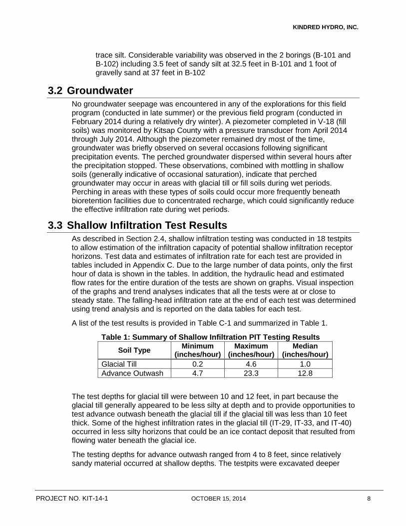
KINDRED HYDRO, INC.
trace silt. Considerable variability was observed in the 2 borings (B-101 and B-102) including 3.5 feet of sandy silt at 32.5 feet in B-101 and 1 foot of gravelly sand at 37 feet in B-102
3.2 Groundwater No groundwater seepage was encountered in any of the explorations for this field program (conducted in late summer) or the previous field program (conducted in February 2014 during a relatively dry winter). A piezometer completed in V-18 (fill soils) was monitored by Kitsap County with a pressure transducer from April 2014 through July 2014. Although the piezometer remained dry most of the time, groundwater was briefly observed on several occasions following significant precipitation events. The perched groundwater dispersed within several hours after the precipitation stopped. These observations, combined with mottling in shallow soils (generally indicative of occasional saturation), indicate that perched groundwater may occur in areas with glacial till or fill soils during wet periods. Perching in areas with these types of soils could occur more frequently beneath bioretention facilities due to concentrated recharge, which could significantly reduce the effective infiltration rate during wet periods.
3.3 Shallow Infiltration Test Results As described in Section 2.4, shallow infiltration testing was conducted in 18 testpits to allow estimation of the infiltration capacity of potential shallow infiltration receptor horizons. Test data and estimates of infiltration rate for each test are provided in tables included in Appendix C. Due to the large number of data points, only the first hour of data is shown in the tables. In addition, the hydraulic head and estimated flow rates for the entire duration of the tests are shown on graphs. Visual inspection of the graphs and trend analyses indicates that all the tests were at or close to steady state. The falling-head infiltration rate at the end of each test was determined using trend analysis and is reported on the data tables for each test.
A list of the test results is provided in Table C-1 and summarized in Table 1.
Table 1: Summary of Shallow Infiltration PIT Testing Results Soil Type Minimum
(inches/hour) Maximum
(inches/hour) Median
(inches/hour) Glacial Till 0.2 4.6 1.0 Advance Outwash 4.7 23.3 12.8
The test depths for glacial till were between 10 and 12 feet, in part because the glacial till generally appeared to be less silty at depth and to provide opportunities to test advance outwash beneath the glacial till if the glacial till was less than 10 feet thick. Some of the highest infiltration rates in the glacial till (IT-29, IT-33, and IT-40) occurred in less silty horizons that could be an ice contact deposit that resulted from flowing water beneath the glacial ice.
The testing depths for advance outwash ranged from 4 to 8 feet, since relatively sandy material occurred at shallow depths. The testpits were excavated deeper
PROJECT NO. KIT-14-1 OCTOBER 15, 2014 8
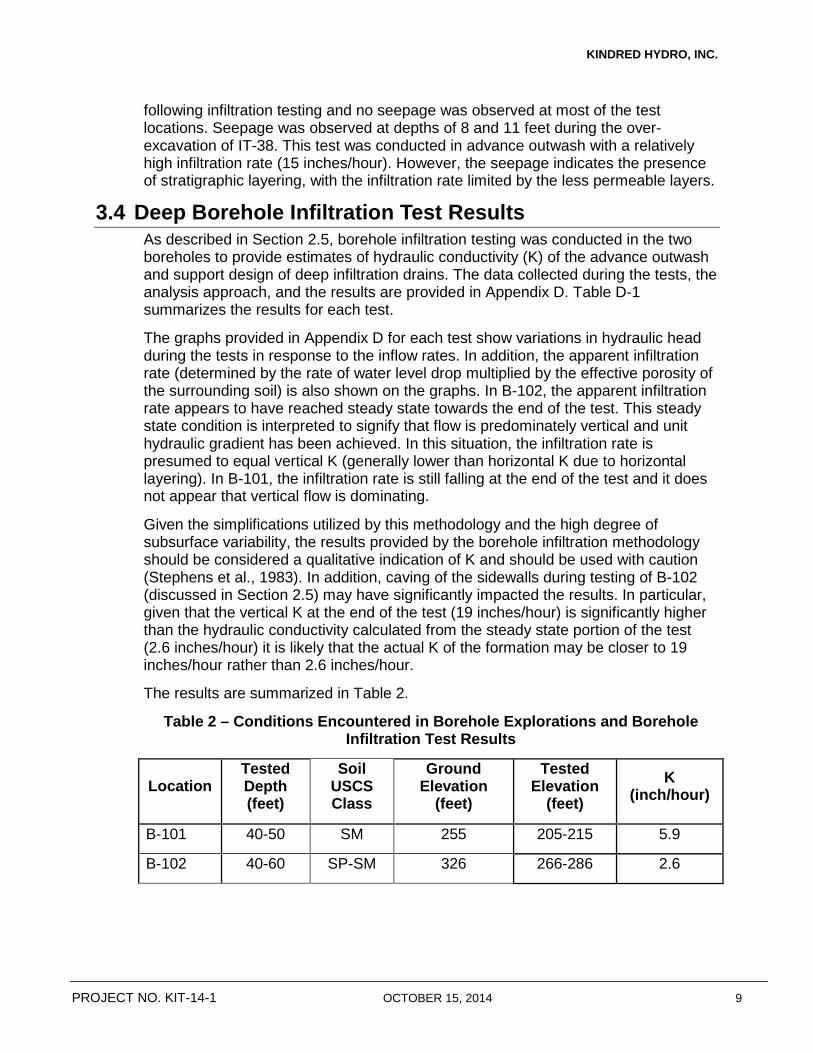
KINDRED HYDRO, INC.
following infiltration testing and no seepage was observed at most of the test locations. Seepage was observed at depths of 8 and 11 feet during the over-excavation of IT-38. This test was conducted in advance outwash with a relatively high infiltration rate (15 inches/hour). However, the seepage indicates the presence of stratigraphic layering, with the infiltration rate limited by the less permeable layers.
3.4 Deep Borehole Infiltration Test Results As described in Section 2.5, borehole infiltration testing was conducted in the two boreholes to provide estimates of hydraulic conductivity (K) of the advance outwash and support design of deep infiltration drains. The data collected during the tests, the analysis approach, and the results are provided in Appendix D. Table D-1 summarizes the results for each test.
The graphs provided in Appendix D for each test show variations in hydraulic head during the tests in response to the inflow rates. In addition, the apparent infiltration rate (determined by the rate of water level drop multiplied by the effective porosity of the surrounding soil) is also shown on the graphs. In B-102, the apparent infiltration rate appears to have reached steady state towards the end of the test. This steady state condition is interpreted to signify that flow is predominately vertical and unit hydraulic gradient has been achieved. In this situation, the infiltration rate is presumed to equal vertical K (generally lower than horizontal K due to horizontal layering). In B-101, the infiltration rate is still falling at the end of the test and it does not appear that vertical flow is dominating.
Given the simplifications utilized by this methodology and the high degree of subsurface variability, the results provided by the borehole infiltration methodology should be considered a qualitative indication of K and should be used with caution (Stephens et al., 1983). In addition, caving of the sidewalls during testing of B-102 (discussed in Section 2.5) may have significantly impacted the results. In particular, given that the vertical K at the end of the test (19 inches/hour) is significantly higher than the hydraulic conductivity calculated from the steady state portion of the test (2.6 inches/hour) it is likely that the actual K of the formation may be closer to 19 inches/hour rather than 2.6 inches/hour.
The results are summarized in Table 2.
Table 2 – Conditions Encountered in Borehole Explorations and Borehole Infiltration Test Results
Location Tested Depth (feet)
Soil USCS Class
Ground Elevation
(feet)
Tested Elevation
(feet) K
(inch/hour)
B-101 40-50 SM 255 205-215 5.9
B-102 40-60 SP-SM 326 266-286 2.6
PROJECT NO. KIT-14-1 OCTOBER 15, 2014 9
KINDRED HYDRO, INC.
These K values are generally lower that the advance outwash infiltration rates measured in the PIT tests (median of 12.8 inches/hour). The difference can be attributed to higher silt content in the soil horizons within the tested intervals for B-101 and B-102.
PROJECT NO. KIT-14-1 OCTOBER 15, 2014 10

KINDRED HYDRO, INC.
4 Recommendations
4.1 General Design Considerations General design considerations for this Project are discussed below.
1. Shallow infiltration is cost effective in areas with advance outwash near the ground surface. In general, stormwater facilities that infiltrate into advance outwash will provide significantly greater infiltration and will be more cost effective than those that infiltrate into fill or glacial till soils. As discussed in Section 3.1, advance outwash was encountered near the ground surface in the northern portion of the Project and these areas are likely suitable for shallow infiltration.
2. Dug drains are recommended in bioretention cells that rely on shallow infiltration. Infiltration testing in the advance outwash indicated a range of infiltration rates and considerable variability at different depths. In order to increase the potential to intersect more permeable layers and maximize the infiltration capacity, Kindred Hydro recommends constructing bioretention facilities with dug drains that reach a depth of at least 10 feet below the base of the bioretention cell excavation. These drains should have a cross-sectional area of at least 15 square feet and can be constructed with an excavator. They should be backfilled with clean pea gravel (less than 2 percent passing the #200 sieve) or clean sandy gravel (containing less than 5 percent passing the #100 sieve). If pea gravel is used, the dug drains should be capped with 6 inches of filter sand to minimize migration of fine material into the gravel. The filter sand is not necessary if a sandy gravel that meets the filter criteria for bioretention soil is used to backfill the drains.
3. Deep Infiltration using drilled drains is expected to be cost effective in areas underlain by glacial till. As discussed in Section 3.1, the central and southern portions of the Project area are underlain by glacial till and advance outwash was not encountered within 10 to 12 feet of the ground surface. Advance outwash was encountered in the 2 boreholes at depths of 19 and 31 feet in the southern portion of the Project. Due to the relatively low permeability of the glacial till and the potential for shallow groundwater mounding in these areas, it is expected that deep infiltration drains will be more cost effective than shallow infiltration in the central and southern areas of the Project. However, additional deep boreholes are recommended in the central portion of the project to verify the thickness of the glacial till and characterize the infiltration capacity of the advance outwash.
4. Deep drains can be constructed using standard well installation techniques. The deep drains can be constructed using an air-rotary drilling rig typically used for installation of water wells. The screen should be placed below the glacial till in the advance outwash and should not extend within 5 feet of the water table. The bioretention facilities would be constructed with underdrains beneath the bioretention soil that convey the treated stormwater
PROJECT NO. KIT-14-1 OCTOBER 15, 2014 11

KINDRED HYDRO, INC.
to the deep drains for infiltration into the advance outwash. The anticipated infiltration capacity of the deep drains is discussed in Section 4.3. Based on the size of the catchment area and the desired level of flow control, it may be necessary to connect multiple deep drains in series to provide sufficient capacity. Deep drains should be spaced at least 25 feet apart to minimize potential interference and loss of capacity.
5. Deep drains will require permitting as underground injection control (UIC) wells. Deep drains will require permitting under Washington State’s UIC Program for stormwater injection. In general, drilled drains can be permitted using the presumptive approach as long as the stormwater is treated with bioretention before discharge to the drains. Typically, permitting using the presumptive approach requires registration of the wells and a description of the treatment process and drain construction details and is relatively straight-forward.
6. Bioretention facilities that intersect permeable utility trench backfill should be lined. Several explorations (IT-21 and IT-22) intersected trench backfill material. If concentrated flows of infiltration stormwater were to enter pipe bedding material, this could result in adverse impacts (e.g., erosion of the pipe bedding material or excessive seepage along the path of the utility). Although the trench backfill material was relatively silty, it was also relatively loose and could be relatively permeable. For this reason, we recommend lining the bioretention facility excavation using one of the following approaches:
a. Over-excavating 1 foot of trench backfill material and replacing with low-permeability material compacted to a firm and unyielding condition. Silty sand or sandy silt (generally classified as SM) should be suitable as long as it contains more than 20 percent passing the #200 sieve and less than 10 percent retained on the #4 sieve. Based on grainsize analyses (presented in Appendix B), some of the native material meets these criteria. The material should be placed at close to optimum moisture condition and the compaction observed by a qualified geotechnical inspector.
b. Compacting the trench backfill material in place and lining the excavation with 30-mil PVC liner (or equivalent) placed in accordance with the manufacturer’s specifications.
4.2 Design Infiltration Rates Design infiltration rates for shallow infiltration have been estimated for each of the explorations locations shown in Figure 6. In general, these design infiltration rates were estimated using the following guidelines:
• Multiplying the measured infiltration rates from either PIT or borehole infiltration tests by a factor of safety of 0.5 for advance outwash and 0.3 for locations underlain by glacial till. A more conservative factor of safety was
PROJECT NO. KIT-14-1 OCTOBER 15, 2014 12
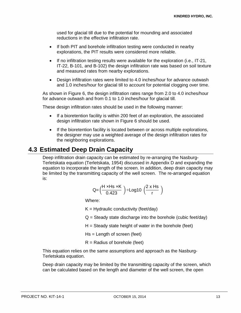
KINDRED HYDRO, INC.
used for glacial till due to the potential for mounding and associated reductions in the effective infiltration rate.
• If both PIT and borehole infiltration testing were conducted in nearby explorations, the PIT results were considered more reliable.
• If no infiltration testing results were available for the exploration (i.e., IT-21, IT-22, B-101, and B-102) the design infiltration rate was based on soil texture and measured rates from nearby explorations.
• Design infiltration rates were limited to 4.0 inches/hour for advance outwash and 1.0 inches/hour for glacial till to account for potential clogging over time.
As shown in Figure 6, the design infiltration rates range from 2.0 to 4.0 inches/hour for advance outwash and from 0.1 to 1.0 inches/hour for glacial till.
These design infiltration rates should be used in the following manner:
• If a bioretention facility is within 200 feet of an exploration, the associated design infiltration rate shown in Figure 6 should be used.
• If the bioretention facility is located between or across multiple explorations, the designer may use a weighted average of the design infiltration rates for the neighboring explorations.
4.3 Estimated Deep Drain Capacity Deep infiltration drain capacity can be estimated by re-arranging the Nasburg-Terletskata equation (Terletskata, 1954) discussed in Appendix D and expanding the equation to incorporate the length of the screen. In addition, deep drain capacity may be limited by the transmitting capacity of the well screen. The re-arranged equation is:
Q= �H ×Hs ×K
0.423 �÷Log10 �2 x Hs
r �
Where:
K = Hydraulic conductivity (feet/day)
Q = Steady state discharge into the borehole (cubic feet/day)
H = Steady state height of water in the borehole (feet)
Hs = Length of screen (feet)
R = Radius of borehole (feet)
This equation relies on the same assumptions and approach as the Nasburg-Terletskata equation.
Deep drain capacity may be limited by the transmitting capacity of the screen, which can be calculated based on the length and diameter of the well screen, the open
PROJECT NO. KIT-14-1 OCTOBER 15, 2014 13

KINDRED HYDRO, INC.
area of the screen, and the maximum velocity of water through a screen (generally assumed to be 0.1 ft/sec).
Results are shown in Table E-1 (Appendix E) for conditions observed in both B-101 and B-102 given a variety of different drain configurations. The results range from 46 to 274 gallons/minute for B-101 conditions and from 12 to 103 gallons/minute for B-102. None of the scenarios are limited by the well screen capacity.
B-101 capacities are higher than B-102 because of higher hydraulic conductivity in B-101 and less depth to the advance outwash (which allows use of a longer screen for the same depth of well). Assuming a well depth of 80 feet, a well diameter of 6 inches, and a telescoping stainless steel screen, the estimated capacity is 0.54 cubic feet/second (243 gallons/minute) for a drain at B-101 and 0.20 cubic feet/second (91 gallons/minutes) for a drain at B-102.
As discussed in Section 4.4, we recommend testing each drain following construction to determine capacity. The number of drains for each bioretention facility can be adjusted during construction based on these test results and the target flow capacity for the facility. This adaptive approach has been used on previous projects with success and allows for a less conservative approach during design combined with an appropriate contingency in the cost estimate if conditions are less favorable than expected. Kindred Hydro can work with the County during design to develop suitable assumptions for deep drain capacity.
4.4 Subsurface Uncertainty and Risk Management As illustrated in the exploration logs and testing results, subsurface conditions are highly variable. In addition, conditions observed in explorations may not be representative of conditions between the explorations. Encountering unexpected subsurface conditions during construction is a frequent cause of cost overruns and project delays and, generally, a major contributor to project risk. Although additional explorations and testing can help to reduce uncertainty regarding subsurface conditions, the budget for subsurface characterization needs to be a reasonable percentage of the total project cost.
Given this uncertainty regarding subsurface conditions and associated project risks, we recommend implementing the following risk-management practices during design and construction:
• Utilize design infiltration rates that incorporate reasonable factors of safety, as discussed in section 4.2.
• Identify and evaluate various failure mechanisms and provide redundant design elements to mitigate and reduce adverse impacts (e.g., overflow conveyance if maximum design flows are exceeded).
• Develop a bid package that clearly describes material specifications, installation procedures, testing requirements, and the potential for design changes due to unexpected subsurface conditions. Ideally, the bid package
PROJECT NO. KIT-14-1 OCTOBER 15, 2014 14

KINDRED HYDRO, INC.
specifies unit prices for dug and drilled drains to account for changes to the number and depth of drains. The plans should include locations for additional deep drains, if necessary, based on testing results.
• During construction, all bioretention excavations should be observed by a member of Kindred Hydro’s staff to determine if subsurface conditions are consistent with expectations. If conditions are different than expected, it may be possible to modify the facility configuration to ensure that project objectives are met. For example, if glacial till is encountered in an area where advance outwash is expected, it may be possible to penetrate the glacial till with deeper dug drains.
• For bioretention facilities that rely on shallow infiltration, conduct a full-scale infiltration test after excavating the facility and before placing the bioretention soil to verify that the design infiltration rates can be achieved. If design infiltration rates are not met, it may be possible to modify the facility configuration to ensure that project objectives are met (e.g., expanding the facility footprint or adding additional dug drains).
• All deep drains should be tested following construction to determine capacity. If the drain capacity differs from expectations, the number of drains associated with the facility can be modified to minimize costs while meeting design flow rates.
• Conduct infiltration testing of the bioretention soil to verify that the infiltration capacity meets design expectations.
4.5 Construction Management Construction of bioretention facilities and deep drilled drains is a relatively new practice for most contractors. Care must be taken to protect the infiltration capabilities of bioretention facilities and drilled deep drains during construction. In particular, stormwater runoff during construction must be managed carefully to ensure that infiltration facilities are not contaminated with silt.
The bid documents should clearly state the contractor’s responsibility to maintain the infiltration capacity of the facilities during construction. In addition, Kindred hydro recommends careful pre-qualification of the contractor before project award, clear communications of the special requirements of the bioretention elements of the project before and during construction, and oversight by qualified professionals during construction to maximize project success.
PROJECT NO. KIT-14-1 OCTOBER 15, 2014 15

KINDRED HYDRO, INC.
5 Limitations Work for this project was performed and this report prepared in accordance with generally accepted professional practices for the nature and conditions of work completed in the same or similar localities, at the time the work was performed. It is intended for the exclusive use of Kitsap County for specific application to the referenced matter. No other warranty, expressed or implied, is made.
PROJECT NO. KIT-14-1 OCTOBER 15, 2014 16

KINDRED HYDRO, INC.
6 References Aspect Consulting LLC (Aspect), 2014. Technical Memorandum: Results of Subsurface
Explorations and Infiltration Testing and Preliminary Recommendations, Ridgetop Boulevard Green Street Project, Silverdale, Washington, March 26, 2014.
Puget Sound LiDAR Consortium, 2004. LiDAR Bare Earth ASCII Data: Seattle, Washington, http://rocky2.ess.washington.edu/data/raster/lidar/lidardata/ index.htm#DEMs_and_geo-referenced_topographic).
Stephens, D.B., S. Tyler, K. Lambert, D. Watson, R. Rabold, R. Knowlton, E. Byers, S. Yztes, and S.P. Newman, 1983. In Situ Determination of Hydraulic Conductivity in the Vadose Zone Using Borehole Infiltration Tests, New Mexico Water Resources Institute and United States Department of Interior Office of Water Research and Technology.
Terletskata, N.M., 1954. Determination of Permeability in Dry Soils, Hydroelectric Waterworks, No. 2, February, Moscow.
Washington State Department of Ecology (Ecology), 2012. Stormwater Management Manual for Western Washington.
PROJECT NO. KIT-14-1 OCTOBER 15, 2014 17


!H
!H
"J
"J
"J
"J
!H
"J
!H
"J
"J
"J
!H
"J
"J!H
"J
"J!H
"J
"J!H
"J
#0
"J
"J!H
"J
"J
#0!H
"J
!H
FIGURE 2 EXTENT
FIGURE 3 EXTENT
FIGURE 4 EXTENT
FIGURE 5 EXTENT
V-1 (Advance Outwash)
V-3 (Advance Outwash)
IT-38 (6ft of fill over Advance Outwash)
IT-37 (4.5ft of fill over Advance Outwash)
IT-36 (4.5ft of fill over Advance Outwash)
IT-35 (6ft of fill over Advance Outwash)V-5 (Advance Outwash)
IT-34 (Advance Outwash)
V-8 (5ft of Glacial Till over Advance Outwash)IT-33 (Glacial Till)
IT-32 (11ft of fill over Glacial Till)
IT-31 (6ft of fill over Glacial Till)V-11 (Glacial Till)
IT-30 (Glacial Till)
IT-29 (Glacial Till)V-13 (Glacial Till)
IT-28 (Glacial Till)
IT-27 (8.5ft of fill over Glacial Till)V-10 (7ft fill over Glacial Till )
IT-26 (Glacial Till)
IT-40 (6ft of fill over Glacial Till)V-15 (Fill)
IT-25 (Glacial Till)
B-102 (31ft of Glacial Till over Advance Outwash)IT-24 (Glacial Till)
IT-23 (6ft of fill over Glacial Till)V-18 (Fill)
IT-22 (Fill)
IT-41 (Glacial Till)B-101 (19ft of Glacial Till over Advance Outwash) V-20 (Glacial Till)
IT-21 (Glacial Till)
IT-39 (Advance Outwash)
1Figure No.Project Number
09/24/14KIT-1-14
Vicinity MapRidgetop Boulevard NW Green Street Project
Silverdale, WA
Service Layer Credits: Source: Esri, DigitalGlobe, GeoEye, i-cubed, Earthstar Geographics, CNES/Airbus DS, USDA, USGS, AEX, Getmapping, Aerogrid, IGN, IGP, swisstopo, and the GIS User Community
¯0 800 1,600
Feet
#0 Drilled Borehole
"J Testpit Exploration (Geologic Unit)
!H Vactor Exploration (Geologic Unit)
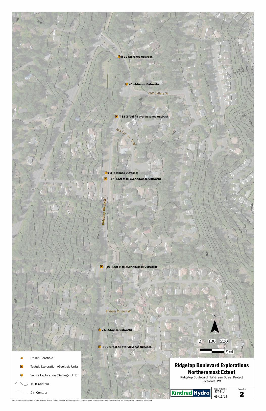
!H
!H
"J
"J
"J
"J
!H
!H
NW Gallery St
Plateau Circle NW
Ava nte Dr N W
Ridge
top Bl
vd NW
240
250
260
270
280
290
300
310
320
330
340
350
360
370
290 290
300310320330340350360
370
380
300
310320330
410
400
390
420
310
320
410
400
380
260
390
360
V-1 (Advance Outwash)
V-3 (Advance Outwash)
IT-38 (6ft of fill over Advance Outwash)
IT-37 (4.5ft of fill over Advance Outwash)
IT-36 (4.5ft of fill over Advance Outwash)
IT-35 (6ft of fill over Advance Outwash)
V-5 (Advance Outwash)
IT-39 (Advance Outwash)
2Figure No.Project Number
09/19/14KIT-1-14
Ridgetop Boulevard ExplorationsNorthernmost Extent
Ridgetop Boulevard NW Green Street ProjectSilverdale, WA
Service Layer Credits: Source: Esri, DigitalGlobe, GeoEye, i-cubed, Earthstar Geographics, CNES/Airbus DS, USDA, USGS, AEX, Getmapping, Aerogrid, IGN, IGP, swisstopo, and the GIS User Community
¯0 100 200
Feet#0 Drilled Borehole
"J Testpit Exploration (Geologic Unit)
!H Vactor Exploration (Geologic Unit)
10 ft Contour
2 ft Contour

"J
"J
!H
"J
"J
"J
!H
"J
"J
!H
NW Pinnacle Ct
NW Tower View Cir
NW Thornwood Cir
NW Timber Shadow Ct
NW Tahoe Ln
Ridgepoint Drive NW
Quail R un Dr N W
Ridgetop Blvd NW
Ridgepoint Dr. NW
330340350
360
370
380
290300310320
310320
390
280
270
280290
300310320
320
300310
280
420
350 360370
380
420
420
390
290
320
420
310
410
410
400
420420
IT-35 (6ft of fill over Advance Outwash)
IT-34 (Advance Outwash)
V-8 (5ft of Glacial Till over Advance Outwash)
IT-33 (Glacial Till)
IT-32 (11ft of fill over Glacial Till)
IT-31 (6ft of fill over Glacial Till)
V-11 (Glacial Till)
IT-30 (Glacial Till)
IT-29 (Glacial Till)
V-13 (Glacial Till)
3Figure No.Project Number
09/22/14KIT-1-14
Ridgetop Boulevard ExplorationsNorthern Central Extent
Ridgetop Boulevard NW Green Street ProjectSilverdale, WA
Service Layer Credits: Source: Esri, DigitalGlobe, GeoEye, i-cubed, Earthstar Geographics, CNES/Airbus DS, USDA, USGS, AEX, Getmapping, Aerogrid, IGN, IGP, swisstopo, and the GIS User Community
¯0 100 200
Feet#0 Drilled Borehole
"J Testpit Exploration (Geologic Unit)
!H Vactor Exploration (Geologic Unit)
10 ft Contour
2 ft Contour
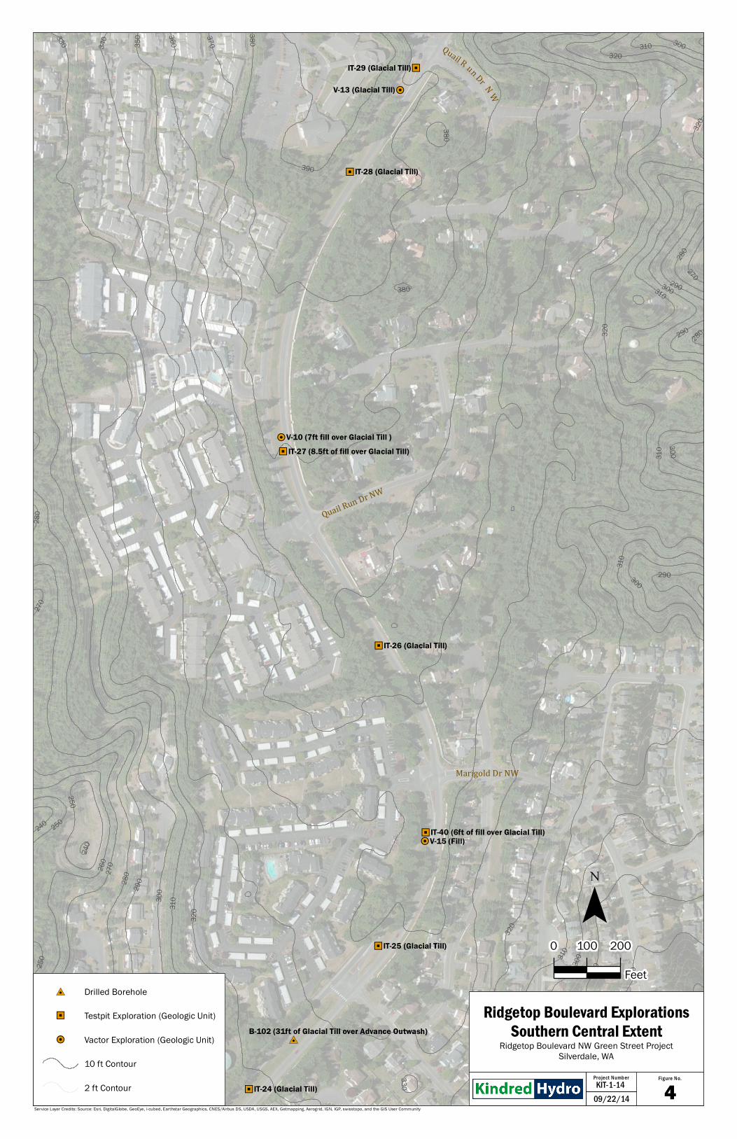
"J
!H
"J
"J
!H
"J
"J!H
"J
#0
"J
Ridgepoint Drive
Quail R un Dr N W
Marigold Dr NW
Quail Run Dr NW
260
270
280
290
300
310
320
250
390
380370
360350
340330
270
28029030
0310
320
280
240
250
270
290300310
320
300310320
290
290
280
280
240 250
380
300
310
380
300310
320
330
IT-29 (Glacial Till)
V-13 (Glacial Till)
IT-28 (Glacial Till)
IT-27 (8.5ft of fill over Glacial Till)V-10 (7ft fill over Glacial Till )
IT-26 (Glacial Till)
IT-40 (6ft of fill over Glacial Till)V-15 (Fill)
IT-25 (Glacial Till)
B-102 (31ft of Glacial Till over Advance Outwash)
IT-24 (Glacial Till) 4Figure No.Project Number
09/22/14KIT-1-14
Ridgetop Boulevard ExplorationsSouthern Central Extent
Ridgetop Boulevard NW Green Street ProjectSilverdale, WA
Service Layer Credits: Source: Esri, DigitalGlobe, GeoEye, i-cubed, Earthstar Geographics, CNES/Airbus DS, USDA, USGS, AEX, Getmapping, Aerogrid, IGN, IGP, swisstopo, and the GIS User Community
¯0 100 200
Feet#0 Drilled Borehole
"J Testpit Exploration (Geologic Unit)
!H Vactor Exploration (Geologic Unit)
10 ft Contour
2 ft Contour

"J!H
"J
#0
"J
"J!H
"J
"J
#0!H
"J
Marigold Dr NW
NW Derryfield Dr
Boardwalk Pl NW
Hillsboro Dr NW
350
340
33032031030
0290
220
230
240 250
260 270
330
230
240250
260
270
240
250200
220
220
230
220
210
200
210
210
220
290
280
230
240
280
280
220
280220
280
IT-40 (6ft of fill over Glacial Till)V-15 (Fill)
IT-25 (Glacial Till)
B-102 (31ft of Glacial Till over Advance Outwash)
IT-24 (Glacial Till)
IT-23 (6ft of fill over Glacial Till)V-18 (Fill)
IT-22 (Fill)
IT-41 (Glacial Till)
B-101 (19ft of Glacial Till over Advance Outwash)V-20 (Glacial Till)
IT-21 (Glacial Till)
5Figure No.Project Number
09/19/14KIT-1-14
Ridgetop Boulevard ExplorationsSouthernmost Extent
Ridgetop Boulevard NW Green Street ProjectSilverdale, WA
Service Layer Credits: Source: Esri, DigitalGlobe, GeoEye, i-cubed, Earthstar Geographics, CNES/Airbus DS, USDA, USGS, AEX, Getmapping, Aerogrid, IGN, IGP, swisstopo, and the GIS User Community
¯0 100 200
Feet#0 Drilled Borehole
"J Testpit Exploration (Geologic Unit)
!H Vactor Exploration (Geologic Unit)
10 ft Contour
2 ft Contour

!H
!H
"J
"J
"J
"J
!H
"J
!H
"J
"J
"J
!H
"J
"J!H
"J
"J!H
"J
"J!H
"J
#0
"J
"J!H
"J
"J
#0!H
"J
!H
FIGURE 2 EXTENT
FIGURE 3 EXTENT
FIGURE 4 EXTENT
FIGURE 5 EXTENT
V-1 (Shallow--4.0 inches/hour)
V-3 (Shallow--2.5 inches/hour)
IT-38 (Shallow--4.0 inches/hour)
IT-37 (Shallow--2.5 inches/hour)
IT-36 (Shallow--4.0 inches/hour)
IT-35 (Shallow--2.0 inches/hour)V-5 (Shallow--2.0 inches/hour)
IT-34 (Shallow--4.0 inches/hour)
V-8 (Shallow--0.8 inches/hour or drilled drain)IT-33 (Shallow--0.8 inches/hour or drilled drain)
IT-32 (Shallow--0.4 inches/hour or drilled drain)
IT-31 (Shallow--0.1 inches/hour or drilled drain)V-11 (Shallow--0.1 inches/hour or drilled drain)
IT-30 (Shallow--1.0 inch/hour or drilled drain)
IT-29 (Shallow--1.0 inch/hour or drilled drain)V-13 (Shallow--1.0 inch/hour or drilled drain)
IT-28 (Shallow--0.4 inches/hour or drilled drain)
IT-27 (Shallow--0.4 inches/hour or drilled drain)V-10 (Shallow--0.4 inches/hour or drilled drain)
IT-26 (Shallow--0.4 inches/hour or drilled drain)
IT-40 (Shallow--1.0 inch/hour or drilled drain)V-15 (Shallow--1.0 inch/hour or drilled drain)
IT-25 (Shallow--0.8 inches/hour or drilled drain)
B-102 (Shallow--0.3 inches/hour or drilled drain)IT-24 (Shallow--0.3 inches/hour or drilled drain)
IT-23 (Shallow--0.4 inches/hour or drilled drain)V-18 (Shallow--0.4 inches/hour or drilled drain)
IT-22 (Lined with drilled drain)
IT-41 (Shallow--0.1 inches/hour or drilled drain)B-101 (Shallow--0.1 inches/hour or drilled drain)
V-20 (Shallow--0.1 inches/hour or drilled drain)IT-21 (Lined with drilled drain)
IT-39 (Shallow--4.0 inches/hour)
6Figure No.Project Number
09/24/14KIT-1-14
Infiltration RecommendationsRidgetop Boulevard NW Green Street Project
Silverdale, WA
Service Layer Credits: Source: Esri, DigitalGlobe, GeoEye, i-cubed, Earthstar Geographics, CNES/Airbus DS, USDA, USGS, AEX, Getmapping, Aerogrid, IGN, IGP, swisstopo, and the GIS User Community
¯0 800 1,600
Feet
#0 Drilled Borehole
"J Testpit Exploration
!H Vactor Exploration
APPENDIX A
Subsurface Exploration Methodology and Exploration Logs

A. Subsurface Exploration Methodology and Exploration Logs A.1. Utility Locate and Soil Description
The proposed testpit and borehole locations were marked in the field and utility locates were called in at least 1 week before excavation began. Several locations were adjusted based on the location of nearby utilities and Cascade Natural Gas was called in to observe excavation for 2 testpits that were within 10 feet of a gas line.
A staff member from Kindred Hydro was present throughout the field exploration program to observe the testpit excavations and borehole drilling, conduct soil sampling, and prepare descriptive logs of the exploration. Soils were classified in general accordance with ASTM D-2488, Standard Practice for Description and Identification of Soils (Visual-Manual Procedure, and ASTM D-2487, Standard Practice for Classification of Soils for Engineering Purposes (Unified Soil Classification System). The exploration logs represent our interpretation of the contents of the field logs. The stratigraphic contacts shown on the individual summary logs represent the approximate boundaries between soil types; actual transitions may be more gradual. The subsurface conditions depicted are only for the specific date and locations reported, and therefore, are not necessarily representative of other locations and times.
A.2. Testpit Explorations Testpit explorations were excavated using a rubber-tired backhoe and crew provided by Kitsap County. The approximate locations of the testpit explorations are shown on Figures 1 through 5 in the main body of the report. Descriptive logs of the completed explorations and a key to the symbols and terms used in the logs are found in this appendix.
A.3. Drilled Boreholes Boreholes were drilled using a track-mounted Roto-Sonic coring rig. The Roto-Sonic coring rig drills a 6-inch-diameter borehole and provides a 4-inch-diameter relatively continuous core of the penetrated materials. The continuous core provides superior lithologic information compared with alternative drilling methodologies. The boreholes were abandoned using bentonite chips following drilling and testing. The approximate locations of the boreholes are shown on Figures 1 and 5 in the main body of the report. Descriptive logs of the completed explorations and a key to the symbols and terms used in the logs are provided in this appendix.
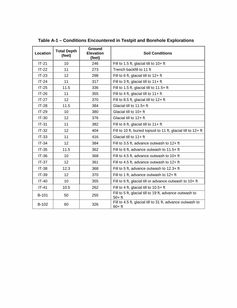
Table A-1 – Conditions Encountered in Testpit and Borehole Explorations
Location Total Depth (feet)
Ground Elevation
(feet) Soil Conditions
IT-21 10 246 Fill to 1.5 ft, glacial till to 10+ ft IT-22 11 273 Trench backfill to 11 ft IT-23 12 298 Fill to 6 ft, glacial till to 12+ ft IT-24 11 317 Fill to 3 ft, glacial till to 11+ ft IT-25 11.5 336 Fill to 1.5 ft, glacial till to 11.5+ ft IT-26 11 355 Fill to 4 ft, glacial till to 11+ ft IT-27 12 370 Fill to 8.5 ft, glacial till to 12+ ft IT-28 11.5 384 Glacial till to 11.5+ ft IT-29 10 380 Glacial till to 10+ ft IT-30 12 376 Glacial till to 12+ ft IT-31 11 382 Fill to 6 ft, glacial till to 11+ ft IT-32 12 404 Fill to 10 ft, buried topsoil to 11 ft, glacial till to 12+ ft IT-33 11 416 Glacial till to 11+ ft IT-34 12 384 Fill to 3.5 ft, advance outwash to 12+ ft IT-35 11.5 362 Fill to 6 ft, advance outwash to 11.5+ ft IT-36 10 368 Fill to 4.5 ft, advance outwash to 10+ ft IT-37 12 361 Fill to 4.5 ft, advance outwash to 12+ ft IT-38 12.3 368 Fill to 5 ft, advance outwash to 12.3+ ft IT-39 12 370 Fill to 1 ft, advance outwash to 12+ ft IT-40 10 355 Fill to 6 ft, glacial till or advance outwash to 10+ ft IT-41 10.5 262 Fill to 4 ft, glacial till to 10.5+ ft
B-101 50 255 Fill to 5 ft, glacial till to 19 ft, advance outwash to 50+ ft
B-102 60 326 Fill to 4.5 ft, glacial till to 31 ft, advance outwash to 60+ ft


Kindred Hydro, Inc.
246 (est. from topo)
Exploration Method: Rubber tired backhoe
Depth (ft)
Elev (ft)
Sample Type/I.D. Water
USCS Class
SM
SM
SM
GrabBOH @ 10 ft
13 233
Test Pit Log: IT-21 Project Name: Ridgetop BoulevardProject #: KIT-14-1Location: Silverdale, WA Depth to Water (ft BGS): None
Ground Surface Elevation:
Glacial Till (1.5 to BOH)
Contractor: Kitsap County Crew Start/Finish Date: September 2, 2014Logged by: Scott Kindred
Sampling Method: Grab
DescriptionSod (0-0.5 ft)
loose, dry, gray, silty SAND, with trace to few gravel and trace organics Fill (0.5-1.5 ft)
1 245 medium dense, dry to slightly moist, brown, silty SAND with few to little gravel, well graded
7 239
2 244 dense, slightly moist, gray, silty SAND with little gravel and trace cobble
3 243
4 242
- Initial excavation was in fill soils to 4.5 feet and uncovered an 18-inch diameter storm sewer (corregated steel pipe) at 4.5 ft.
5 241
6 240
8 238
9 237
10 236
11 235
12 234

Kindred Hydro, Inc.
273 (est. from topo)
Exploration Method: Rubber tired backhoe
Depth (ft)
Elev (ft)
Sample Type/I.D. Water
USCS Class
SM
-less silt
- stop digging at 7 feet to check for utilities- use vactor truck to excavate deeper
-pea gravel
-sanitary sewer pipe at 11 ftBOH @ 11.0 ft
No infiltration test
13 260
11 262
12 261
8 265
9 264
10 263
6 267
7 266
3 270
4 269
5 268
Crushed Base Rock (0.5-1.0 ft)1 272
2 271
Fill (1.0-11.0 ft)loose to medium dense, slightly moist, brown, silty SAND with few gravel
Asphalt (0-0.5 ft)
Test Pit Log: IT-22 Project Name: Ridgetop BoulevardProject #: KIT-14-1 Ground Surface Elevation: Location: Silverdale, WA Depth to Water (ft BGS): NoneContractor: Kitsap County Crew Start/Finish Date: August 28, 2014
Logged by: Scott KindredSampling Method: Grab
Description

Kindred Hydro, Inc.
298 (est. from topo)
Exploration Method: Rubber tired backhoe
Depth (ft)
Elev (ft)
Sample Type/I.D. Water
USCS Class
SM
SM
- changes to brown with orange mottling
-changes to dense and gray with occational mottling
-less silt
SM
Grab -infiltration test at 12.0 ftBOH @ 12.0 ft
13 285
11 287
12 286
8 290
9 289
10 288
3 295
Glacial Till (3.0 to BOH)
very dense, slightly moist, gray, silty SAND with few gravel and trace cobble
4 294
5 293
6 292
7 291
2 296
Contractor: Kitsap County Crew Start/Finish Date: August 27, 2014Logged by: Scott Kindred
Sampling Method: Grab
DescriptionSod (0-0.5 ft)
loose, dry, gray, silty SAND, with trace to few gravel and trace organics Fill (0.5-6.0 ft)
1 297 medium dense, dry to slightly moist, gray, silty SAND with little gravel and occational organics
Test Pit Log: IT-23 Project Name: Ridgetop BoulevardProject #: KIT-14-1 Ground Surface Elevation: Location: Silverdale, WA Depth to Water (ft BGS): None
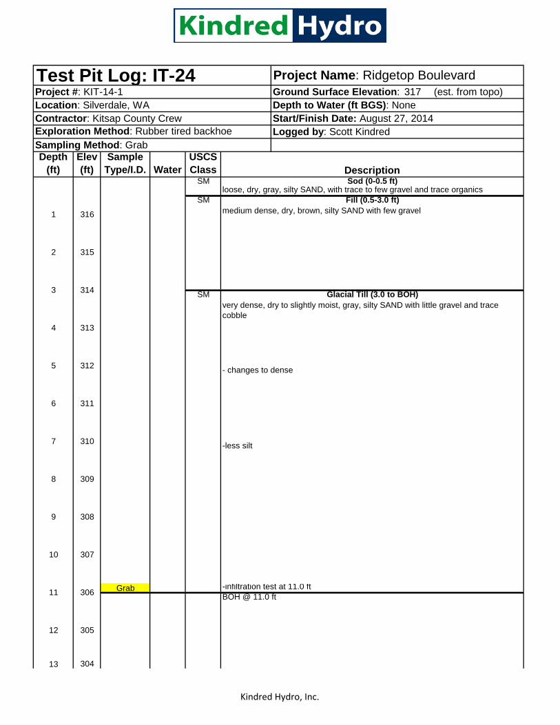
Kindred Hydro, Inc.
317 (est. from topo)
Exploration Method: Rubber tired backhoe
Depth (ft)
Elev (ft)
Sample Type/I.D. Water
USCS Class
SM
SM
SM
- changes to dense
-less silt
Grab -infiltration test at 11.0 ftBOH @ 11.0 ft
13 304
12 305
9 308
10 307
11 306
6 311
7 310
8 309
5 312
loose, dry, gray, silty SAND, with trace to few gravel and trace organics Fill (0.5-3.0 ft)
1 316 medium dense, dry, brown, silty SAND with few gravel
2 315
3 314
4 313
Glacial Till (3.0 to BOH)very dense, dry to slightly moist, gray, silty SAND with little gravel and trace cobble
Sod (0-0.5 ft)
Test Pit Log: IT-24 Project Name: Ridgetop BoulevardProject #: KIT-14-1 Ground Surface Elevation: Location: Silverdale, WA Depth to Water (ft BGS): NoneContractor: Kitsap County Crew Start/Finish Date: August 27, 2014
Logged by: Scott KindredSampling Method: Grab
Description
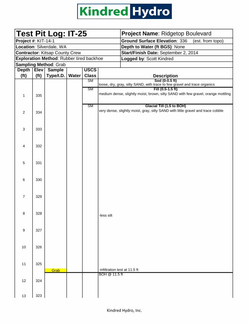
Kindred Hydro, Inc.
336 (est. from topo)
Exploration Method: Rubber tired backhoe
Depth (ft)
Elev (ft)
Sample Type/I.D. Water
USCS Class
SM
SM
SM
-less silt
Grab -infiltration test at 11.5 ftBOH @ 11.5 ft
13 323
12 324
9 327
10 326
11 325
6 330
7 329
8 328
5 331
loose, dry, gray, silty SAND, with trace to few gravel and trace organics Fill (0.5-1.5 ft)
1 335 medium dense, slightly moist, brown, silty SAND with few gravel, orange mottling
2 334
3 333
4 332
Glacial Till (1.5 to BOH)very dense, slightly moist, gray, silty SAND with little gravel and trace cobble
Sod (0-0.5 ft)
Test Pit Log: IT-25 Project Name: Ridgetop BoulevardProject #: KIT-14-1 Ground Surface Elevation: Location: Silverdale, WA Depth to Water (ft BGS): NoneContractor: Kitsap County Crew Start/Finish Date: September 2, 2014
Logged by: Scott KindredSampling Method: Grab
Description

Kindred Hydro, Inc.
355 (est. from topo)
Exploration Method: Rubber tired backhoe
Depth (ft)
Elev (ft)
Sample Type/I.D. Water
USCS Class
SM
SM
-changes to dense and gray
-rootsSM
-less silt
Grab -infiltration test at 11.0 ftBOH @ 11.0 ft
13 342
11 344
12 343
Glacial Till (4.0 to BOH)
9 346
dense, slightly moist, gray, silty SAND with little gravel and trace cobble
10 345
6 349
7 348
8 347
3 352
4 351
5 350
2 353
Contractor: Kitsap County Crew Start/Finish Date: August 26, 2014Logged by: Scott Kindred
Sampling Method: Grab
DescriptionSod (0-0.5 ft)
loose, dry, gray, silty SAND, with trace to few gravel and trace organics Fill (0.5-4.0 ft)
1 354 medium dense, slightly moist, brown, silty SAND with few gravel
Test Pit Log: IT-26 Project Name: Ridgetop BoulevardProject #: KIT-14-1 Ground Surface Elevation: Location: Silverdale, WA Depth to Water (ft BGS): None

Kindred Hydro, Inc.
370 (est. from topo)
Exploration Method: Rubber tired backhoe
Depth (ft)
Elev (ft)
Sample Type/I.D. Water
USCS Class
SM
SM
-changes to dense and blue-gray
- roots at 3 ft
- changes to brown with organic rich layer with wood and roots at 6 ft
-organics at 8 ft
SM
Grab -infiltration test at 12.0 ftBOH @ 12.0 ft
13 357
Glacial Till (8.5 to BOH)dense, slightly moist, gray, silty SAND with few gravel and trace cobble
12 358
9 361
10 360
11 359
6 364
7 363
8 362
3 367
4 366
5 365
2 368
Contractor: Kitsap County Crew Start/Finish Date: August 26, 2014Logged by: Scott Kindred
Sampling Method: Grab
DescriptionSod (0-0.5 ft)
loose, dry, gray, silty SAND, with trace to few gravel and trace organics Fill (0.5-8.5 ft)
1 369 medium dense, slightly moist, brown, silty SAND with few gravel
Test Pit Log: IT-27 Project Name: Ridgetop BoulevardProject #: KIT-14-1 Ground Surface Elevation: Location: Silverdale, WA Depth to Water (ft BGS): None

Kindred Hydro, Inc.
384 (est. from topo)
Exploration Method: Rubber tired backhoe
Depth (ft)
Elev (ft)
Sample Type/I.D. Water
USCS Class
SM
SM
-less silt
Grab -infiltration test at 11.5 ftBOH @ 11.5 ft
13 371
12 372
9 375
10 374
11 373
6 378
7 377
8 376
3 381
4 380
5 379
2 382
Contractor: Kitsap County Crew Start/Finish Date: August 25, 2014Logged by: Scott Kindred
Sampling Method: Grab
DescriptionSod (0-0.5 ft)
loose, dry, gray, silty SAND, with trace to few gravel and trace organics Glacial Till (0.5 to BOH)
1 383 dense, slightly moist, gray, silty SAND with little gravel and trace cobble
Test Pit Log: IT-28 Project Name: Ridgetop BoulevardProject #: KIT-14-1 Ground Surface Elevation: Location: Silverdale, WA Depth to Water (ft BGS): None

Kindred Hydro, Inc.
380 (est. from topo)
Exploration Method: Rubber tired backhoe
Depth (ft)
Elev (ft)
Sample Type/I.D. Water
USCS Class
SM
SM
SP-SM
Grab
-infiltration test at 10 ftBOH @ 10 ft
13 367
12 368
9 371
10 370
11 369
6 374
7 373
8 372
3 377
4 376
5 375
loose, dry, gray, silty SAND, with trace to few gravel and trace organics Glacial Till (0.5 to BOH)
1 379 dense, slightly moist, gray, silty SAND with little gravel and trace cobble and boulder
slightly silty SAND with little gravel
Test Pit Log: IT-29 Project Name: Ridgetop BoulevardProject #: KIT-14-1 Ground Surface Elevation: Location: Silverdale, WA Depth to Water (ft BGS): None
2 378
Contractor: Kitsap County Crew Start/Finish Date: August 25, 2014Logged by: Scott Kindred
Sampling Method: Grab
DescriptionSod (0-0.5 ft)
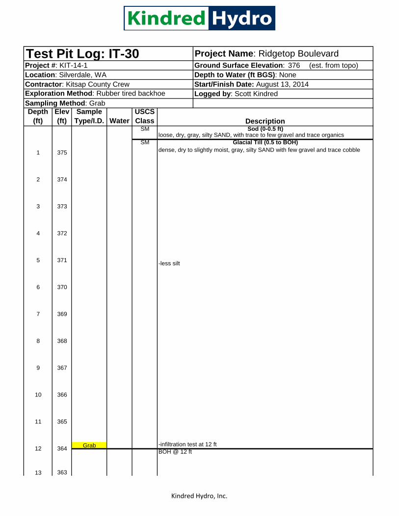
Kindred Hydro, Inc.
376 (est. from topo)
Exploration Method: Rubber tired backhoe
Depth (ft)
Elev (ft)
Sample Type/I.D. Water
USCS Class
SM
SM
-less silt
Grab -infiltration test at 12 ftBOH @ 12 ft
13 363
11 365
12 364
8 368
9 367
10 366
6 370
Glacial Till (0.5 to BOH)dense, dry to slightly moist, gray, silty SAND with few gravel and trace cobble
7 369
3 373
4 372
5 371
loose, dry, gray, silty SAND, with trace to few gravel and trace organics
1 375
2 374
Sod (0-0.5 ft)
Test Pit Log: IT-30 Project Name: Ridgetop BoulevardProject #: KIT-14-1 Ground Surface Elevation: Location: Silverdale, WA Depth to Water (ft BGS): NoneContractor: Kitsap County Crew Start/Finish Date: August 13, 2014
Logged by: Scott KindredSampling Method: Grab
Description

Kindred Hydro, Inc.
382 (est. from topo)
Exploration Method: Rubber tired backhoe
Depth (ft)
Elev (ft)
Sample Type/I.D. Water
USCS Class
SM
SM
-changed to red-brown
SM
Grab -infiltration test at 11 ftBOH @ 11 ft
13 369
11 371
12 370
8 374
9 373
10 372
2 380
dense, slightly moist, gray, silty SAND with few gravel and trace cobble
3 379
4 378
Glacial Till (6.0 to BOH)
5 377
6 376
7 375
loose, dry, gray, silty SAND, with trace to few gravel and trace organics Fill (0.5-6.0 ft)
1 381 medium dense, dry to slightly moist, brown, silty SAND with few gravel
Sod (0-0.5 ft)
Test Pit Log: IT-31 Project Name: Ridgetop BoulevardProject #: KIT-14-1 Ground Surface Elevation: Location: Silverdale, WA Depth to Water (ft BGS): NoneContractor: Kitsap County Crew Start/Finish Date: August 13, 2014
Logged by: Scott KindredSampling Method: Grab
Description

Kindred Hydro, Inc.
404 (est. from topo)
Exploration Method: Rubber tired backhoe
Depth (ft)
Elev (ft)
Sample Type/I.D. Water
USCS Class
SM
SM
-changes to medium dense, less silt
-loose, organics and orange mottling
-3.5-10 ft occasional organics and roots
SM
SM
BOH @ 12 ft
No infiltration test13 391
Buried Topsoil (10.0 to 11.0)medium dense, slightly moist, gray, silty SAND, black organics from 10 to 10.5 ft
Glacial Till (11.0 to BOH)dense, moist, gray, silty SAND with few gravel
12 392
9 395
10 394
11 393
6 398
7 397
8 396
3 401
4 400
5 399
loose, dry, gray, silty SAND, with trace to few gravel and trace organics Fill (0.5 to 10)
1 403
2 402
dense, slightly moist, gray, silty SAND with few gravel
Sod (0-0.5 ft)
Test Pit Log: IT-32 Project Name: Ridgetop BoulevardProject #: KIT-14-1 Ground Surface Elevation: Location: Silverdale, WA Depth to Water (ft BGS): NoneContractor: Kitsap County Crew Start/Finish Date: August 13, 2014
Logged by: Scott KindredSampling Method: Grab
Description

Kindred Hydro, Inc.
416 (est. from topo)
Exploration Method: Rubber tired backhoe
Depth (ft)
Elev (ft)
Sample Type/I.D. Water
USCS Class
SM
SM
SP-SM slightly silty SAND with little gravel
Grab Infiltration test at 11 feet.BOH @ 11 ft
13 403
11 405
12 404
8 408
9 407
10 406
5 411
6 410
7 409
4 412
loose, dry, gray, silty SAND, with trace to few gravel and trace organics
1 415
Glacial Till (0.5 to BOH)
2 414
dense, dry to slightly moist, gray, silty SAND with little gravel and trace cobble
3 413
Sod (0-0.5 ft)
Test Pit Log: IT-33 Project Name: Ridgetop BoulevardProject #: KIT-14-1 Ground Surface Elevation: Location: Silverdale, WA Depth to Water (ft BGS): NoneContractor: Kitsap County Crew Start/Finish Date: August 12, 2014
Logged by: Scott KindredSampling Method: Grab
Description

Kindred Hydro, Inc.
384 (est. from topo)
Depth (ft)
Elev (ft)
Sample Type/I.D. Water
USCS Class
SM
SM
SP-SM
Grab
BOH @ 12 ft
13 371
11 373
12 372
8 376 Infiltration test at 8 feet, continue digging after test is complete, no seepage
9 375
10 374
7 377
2 382
3 381
4 380
5 379
6 378
Advance Outwash (3.5-BOH)medium dense, slightly moist, gray, slightly silty, fine to medium SAND with trace gravel
DescriptionSod (0-0.5 ft)
loose, dry, gray, silty SAND, with trace to little gravel and trace organics Fill (0.5-3.5 ft)
1 383 loose, dry to slightly moist, tan brown, silty SAND with few gravel
Contractor: Kitsap County Crew Start/Finish Date: August 12, 2014Exploration Method: Rubber tired backhoe Logged by: Scott KindredSampling Method: Grab
Test Pit Log: IT-34 Project Name: Ridgetop BoulevardProject #: KIT-14-1 Ground Surface Elevation: Location: Silverdale, WA Depth to Water (ft BGS): None

Kindred Hydro, Inc.
362 (est. from topo)
Depth (ft)
Elev (ft)
Sample Type/I.D. Water
USCS Class
SM
SM
-changes to dense, olive grey
SP-SM
Grab
BOH @ 11.5 ft
13 349
medium dense, dry to slightly moist, tan brown, silty SAND with few gravel
- changed to brown with orange mottling, slightly silty SAND with few gravel
11 351
12 350
354
9 353
10 352
Infiltration test at 8 feet, continue digging after test is complete, no seepage
2 360
3 359
4 358
Advance Outwash (6.0-BOH)
5 357
medium dense to dense, dry to slightly moist, gray, slightly silty, fine to medium SAND with trace gravel
6 356
7 355
8
DescriptionSod (0-0.5 ft)
loose, dry, gray, silty SAND, with trace to little gravel and trace organics Fill (0.5-6 ft)
1 361
Contractor: Kitsap County Crew Start/Finish Date: August 11, 2014Exploration Method: Rubber tired backhoe Logged by: Scott KindredSampling Method: Grab
Test Pit Log: IT-35 Project Name: Ridgetop BoulevardProject #: KIT-14-1 Ground Surface Elevation: Location: Silverdale, WA Depth to Water (ft BGS): None

Kindred Hydro, Inc.
368 (est. from topo)
Depth (ft)
Elev (ft)
Sample Type/I.D. Water
USCS Class
SM
SM
- mottling 3-4 ft
-changes to dense silty SAND
SP-SM
Grab
BOH @ 10 ft
13 355
Test Pit Log: IT-36 Project Name: Ridgetop BoulevardProject #: KIT-14-1Location: Silverdale, WA Depth to Water (ft BGS): None
Ground Surface Elevation:
Contractor: Kitsap County Crew Start/Finish Date: August 11, 2014Exploration Method: Rubber tired backhoe Logged by: Scott KindredSampling Method: Grab
DescriptionSod (0-0.5 ft)
loose, dry, gray, silty SAND, with trace to little gravel and trace organics Fill (0.5-4.5 ft)
1 367 medium dense, dry to slightly moist, gray, slightly silty SAND with few gravel
2 366
3 365
4 364
9 359
Advance Outwash (4.5-BOH)5 363 medium dense to dense, dry to slightly moist, gray, slightly silty, fine to medium
SAND with trace gravel
6 362 Infiltration test at 6 feet, continue digging after test is complete, no seepage
7 361
8 360
10 358
11 357
12 356

Kindred Hydro, Inc.
361 (est. from topo)
Depth (ft)
Elev (ft)
Sample Type/I.D. Water
USCS Class
SM
SM
-changes to dense silty sand
SP
-mottled silty layers from 4.5 to 6 feet
Grab
BOH @ 12 ft
13 348
Test Pit Log: IT-37 Project Name: Ridgetop BoulevardProject #: KIT-14-1Location: Silverdale, WA Depth to Water (ft BGS): None
Ground Surface Elevation:
Contractor: Kitsap County Crew Start/Finish Date: August 11, 2014Exploration Method: Rubber tired backhoe Logged by: Scott KindredSampling Method: Grab
DescriptionSod (0-0.5 ft)
loose, dry, gray, silty SAND, with trace to little gravel and trace organics Fill (0.5-4.5 ft)
1 360 loose to medium dense to dense, slightly moist, gray, slightly silty SAND with few
2 359
3 358
4 357
5 356
6 355
7 354
Infiltration test at 6.5 feet, continue digging after test is complete, no seepage
8 353
10 351
9 352
11 350
12 349
Advance Outwash (4.5-BOH)medium dense to dense, slightly moist, gray, fine to medium SAND with trace-few gravel and trace silt

Kindred Hydro, Inc.
368 (est. from topo)
Depth (ft)
Elev (ft)
Sample Type/I.D. Water
USCS Class
SM
SM
-changes to dense
SP
Grab
BOH @ 12.3 ft
13 355
Test Pit Log: IT-38 Project Name: Ridgetop BoulevardProject #: KIT-14-1Location: Silverdale, WA Depth to Water (ft BGS): None
Ground Surface Elevation:
Contractor: Kitsap County Crew Start/Finish Date: August 7, 2014Exploration Method: Rubber tired backhoe Logged by: Scott KindredSampling Method: Grab
DescriptionSod (0-0.5 ft)
loose, dry, gray, silty SAND, with trace to little gravel and trace organics Fill (0.5-5 ft)
1 367 loose to medium dense, slightly moist, gray, silty SAND with few gravel
2 366
3 365
4 364
5 363
6 362
7 361
8 360
9 359
10 358
11 357
12 356
Infiltration test at 7.5 feet, continue digging after test is complete, seepage at 8 and 11 feet BGS
Advance Outwash (5.0-BOH)medium dense to dense, slightly moist, gray, slightly gravelly, fine to medium SAND with trace silt
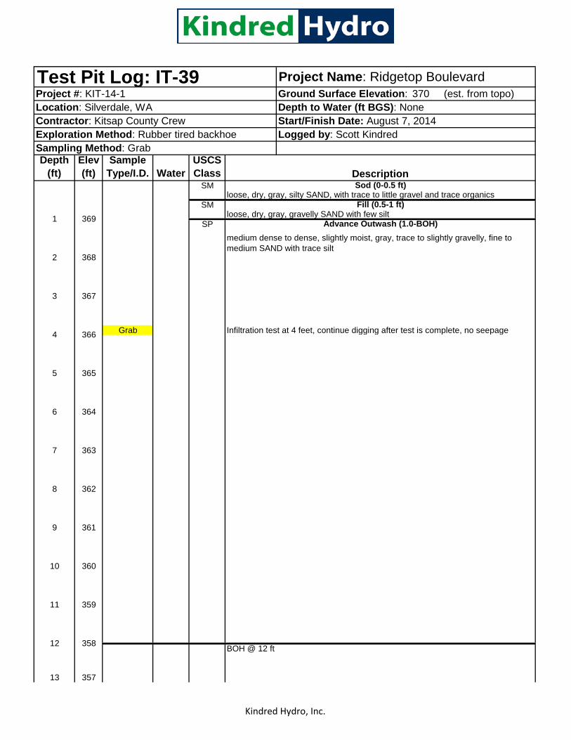
Kindred Hydro, Inc.
370 (est. from topo)
Depth (ft)
Elev (ft)
Sample Type/I.D. Water
USCS Class
SM
SM
SP
Grab Infiltration test at 4 feet, continue digging after test is complete, no seepage
BOH @ 12 ft
13 357
11
10 360
Sampling Method: Grab
loose, dry, gray, silty SAND, with trace to little gravel and trace organics
6
7
369
368
367
364
363
1
2
5
medium dense to dense, slightly moist, gray, trace to slightly gravelly, fine to medium SAND with trace silt
3
4
359
12 358
8 362
9 361
366
365
Test Pit Log: IT-39
loose, dry, gray, gravelly SAND with few siltAdvance Outwash (1.0-BOH)
Exploration Method: Rubber tired backhoe
Project Name: Ridgetop Boulevard
Logged by: Scott Kindred
Ground Surface Elevation: Project #: KIT-14-1Location: Silverdale, WAContractor: Kitsap County Crew
Depth to Water (ft BGS): NoneStart/Finish Date: August 7, 2014
DescriptionSod (0-0.5 ft)
Fill (0.5-1 ft)

Kindred Hydro, Inc.
355 (est. from topo)
Exploration Method: Rubber tired backhoe
Depth (ft)
Elev (ft)
Sample Type/I.D. Water
USCS Class
SM
SM
SP-SM
-infiltration test at 10.0 ftBOH @ 10.0 ft
13 342
12 343
9 346
10 345
11 344
6 349
7 348
8 347
dense, slightly moist, gray, slightly silty SAND with few gravel and trace cobble
5 350
loose, dry, gray, silty SAND, with trace to few gravel and trace organics Fill (0.5-6.0 ft)
1 354 medium dense, slightly moist, brown, slightly silty SAND with few gravel
2 353
Com
posi
te
3 352
4 351
Glacial Till or Silty Advance Outwash (6.0 to BOH)
Sod (0-0.5 ft)
Test Pit Log: IT-40 Project Name: Ridgetop BoulevardProject #: KIT-14-1 Ground Surface Elevation: Location: Silverdale, WA Depth to Water (ft BGS): NoneContractor: Kitsap County Crew Start/Finish Date: August 26, 2014
Logged by: Scott KindredSampling Method: Grab
Description

Kindred Hydro, Inc.
262 (est. from topo)
Exploration Method: Rubber tired backhoe
Depth (ft)
Elev (ft)
Sample Type/I.D. Water
USCS Class
SM
SM
SM
Grab -infiltration test at 10.5 ftBOH @ 10.5 ft
13 249
11 251
12 250
8 254
9 253
10 252
6 256
7 255
2 260
dense, slightly moist, gray, silty SAND with few gravel and trace cobble
3 259
4 258 Glacial Till (4.0 to BOH)
5 257
loose, dry, gray, silty SAND, with trace to few gravel and trace organics Fill (0.5-4.0 ft)
1 261 medium dense, dry to slightly moist, brown, silty SAND, with inclined lenses of sandy SILT and medium SAND
Sod (0-0.5 ft)
Test Pit Log: IT-41 Project Name: Ridgetop BoulevardProject #: KIT-14-1 Ground Surface Elevation: Location: Silverdale, WA Depth to Water (ft BGS): NoneContractor: Kitsap County Crew Start/Finish Date: September 2, 2014
Logged by: Scott KindredSampling Method: Grab
Description

Kindred Hydro, Inc. Page 23 of 31
255 (est. from topo)
Exploration Method: Track Mounted Sonic Rig
Depth (ft)
Elev (ft)
Sample Type/I.D. Water
USCS Class
SM
SM
SM
13 242
medium dense to dense, slightly moist, gray, silty SAND with few gravel and trace cobble
247
12 243
Boring Log: B-101 Project Name: Ridgetop BoulevardProject #: KIT-14-1 Ground Surface Elevation: Location: Silverdale, WA Depth to Water (ft BGS): None
3 252
4 251
loose, dry, tan-brown, silty SAND, with trace to little gravel and trace organics Fill (0.5-5.0 ft)
1 254 loose to medium dense, dry to slightly moist, gray, silty SAND with few gravel
2 253
Contractor: Holt Services Inc. Start/Finish Date: August 15, 2014Logged by: Scott Kindred
Sampling Method: Grab samples from 4-inch core
DescriptionSod
Glacial Till (5.0-19 ft)5 250
9 246
10 245
11 244
6 249
7 248
8

Kindred Hydro, Inc. Page 24 of 31
255 (est. from topo)Boring Log: B-101 Project Name: Ridgetop BoulevardProject #: KIT-14-1 Ground Surface Elevation: Depth
(ft)Elev (ft)
Sample Type/I.D. Water
USCS Class
SM
SP
SW-SM
- slightly siltier 14-17 feet
dense, slightrly moist, gray, medium SAND, trace gravel
slightly silty SAND, trace gravel with layers of silty SAND
gravelly SAND, few silt
Advance Outwash (19.0-BOH)
26 229
27 228
23 232
24 231
25 230
20 235
21 234
22 233
17 238
18 237
19 236
14 241
15 240
16 239
DescriptionGlacial Till (cont.)
- 6-inch layer of medium sand at 13 ft
SM-SM/SP

Kindred Hydro, Inc. Page 25 of 31
255 (est. from topo)Boring Log: B-101 Project Name: Ridgetop BoulevardProject #: KIT-14-1 Ground Surface Elevation: Depth
(ft)Elev (ft)
Sample Type/I.D. Water
USCS Class
SW
SW-GW
Grab
SP
ML
SM
sandy SILT, trace gravel
medium SAND
42 213
39 216
40 215
41 214
36 219
37 218
38 217
33 222
34 221
35 220
31 224
32 223
28 227
-changes to very-gravelly SAND with trace silt
29 226
30 225
Descriptionslightly gravelly medium to coarse SAND
slightly silty fine sand transitioning to fine-medium sand, trace silt
silty fine SAND with trace silt and occational gravel/cobble
SP/SM-SP

Kindred Hydro, Inc. Page 26 of 31
255 (est. from topo)Boring Log: B-101 Project Name: Ridgetop BoulevardProject #: KIT-14-1 Ground Surface Elevation: Depth
(ft)Elev (ft) Water
BOH @ 50 ft
55 200
56 199
57 198
210
52 203
53 202
54 201
49 206
50 205
51 204
Com
posi
te
46 209
47 208
48 207
43 212
44 211
45

Kindred Hydro, Inc. Page 27 of 31
326 (est. from topo)
Exploration Method: Track Mounted Sonic Rig
Depth (ft)
Elev (ft)
Sample Type/I.D. Water
USCS Class
SM
SM
-changes to medium dense, moist, gray, few gravel
SM
13 313
4 322
5 321
Glacial Till (4.5-31 ft)dense, slightly moist, gray, slightly silty to silty SAND with few gravel and trace cobble
9 317
10 316
6 320
7 319
8 318
Project Name: Ridgetop BoulevardProject #: KIT-14-1Location: Silverdale, WA Depth to Water (ft BGS): NoneContractor: Holt Services Inc. Start/Finish Date: August 14, 2014
Ground Surface Elevation:
3 323
1 325 loose to medium dense, dry to slightly moist, brown, silty SAND with trace gravel and organics
2 324
Logged by: Scott KindredSampling Method: Grab samples from 4-inch core
DescriptionSod
loose, dry, tan-brown, silty SAND, with trace to little gravel and trace organics Fill (0.5-4.5 ft)
12 314
11 315
Boring Log: B-102

Kindred Hydro, Inc. Page 28 of 31
326 (est. from topo)Project Name: Ridgetop Boulevard
Project #: KIT-14-1 Ground Surface Elevation: Boring Log: B-102Depth
(ft)Elev (ft)
Sample Type/I.D. Water
USCS Class
SM
15 311
16 310
DescriptionGlacial Till (cont.)
20 306
21 305
22 304
17 309
18 308
19 307
14 312
26 300
27 299
23 303
24 302
25 301

Kindred Hydro, Inc. Page 29 of 31
326 (est. from topo)Project Name: Ridgetop Boulevard
Project #: KIT-14-1 Ground Surface Elevation: Boring Log: B-102Depth
(ft)Elev (ft)
Sample Type/I.D. Water
USCS Class
SM
SP
- changed to trace gravel
SW
SP
SP-SM
gravelly SAND, trace silt
medium SAND, trace to few gravel
slightly silty fine-medium SAND with trace gravel
DescriptionGlacial Till (cont.)
30 296
31 295
32 294
28 298
29 297
Advance Outwash (31.0-BOH)dense, moist, gray, slightly silty fine to medium SAND with layers of very silty sand
36 290
37 289
38 288
33 293
34 292
35 291
42 284
39 287
40 286
41 285
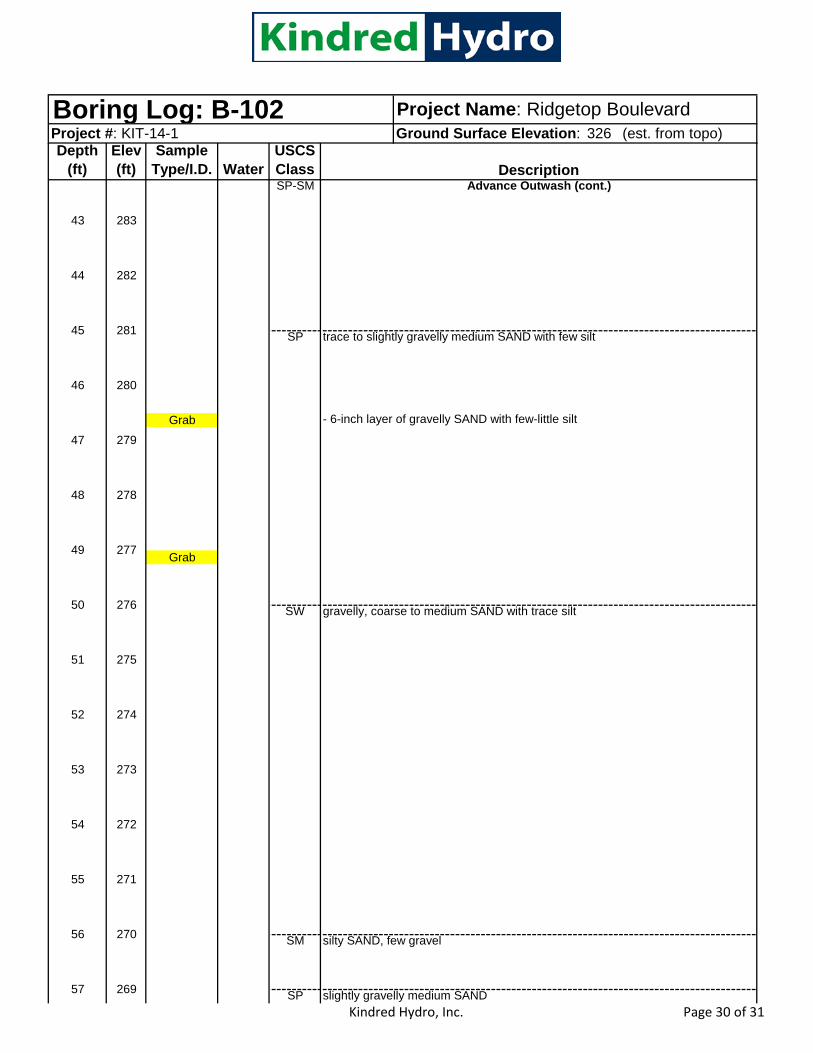
Kindred Hydro, Inc. Page 30 of 31
326 (est. from topo)Project Name: Ridgetop Boulevard
Project #: KIT-14-1 Ground Surface Elevation: Boring Log: B-102Depth
(ft)Elev (ft)
Sample Type/I.D. Water
USCS ClassSP-SM
SP
Grab - 6-inch layer of gravelly SAND with few-little silt
Grab
SW
SM
SP
trace to slightly gravelly medium SAND with few silt
gravelly, coarse to medium SAND with trace silt
slightly gravelly medium SAND
silty SAND, few gravel
279
43 283
44 282
Advance Outwash (cont.)
54 272
Description
55 271
56 270
51 275
52 274
53 273
48 278
49 277
50 276
45 281
46 280
47
57 269

Kindred Hydro, Inc. Page 31 of 31
326 (est. from topo)Project Name: Ridgetop Boulevard
Project #: KIT-14-1 Ground Surface Elevation: Boring Log: B-102Depth
(ft)Elev (ft)
Sample Type/I.D. Water
USCS Class
SP
SM
BOH @ 60 ft
Advance Outwash (cont.)
slighly silty SAND with trace gravel
61 265
62 264
58 268
59 267
72 254
Description
69 257
70 256
71 255
66 260
67 259
68 258
63 263
64 262
65 261
60 266

APPENDIX B
Grainsize Analyses
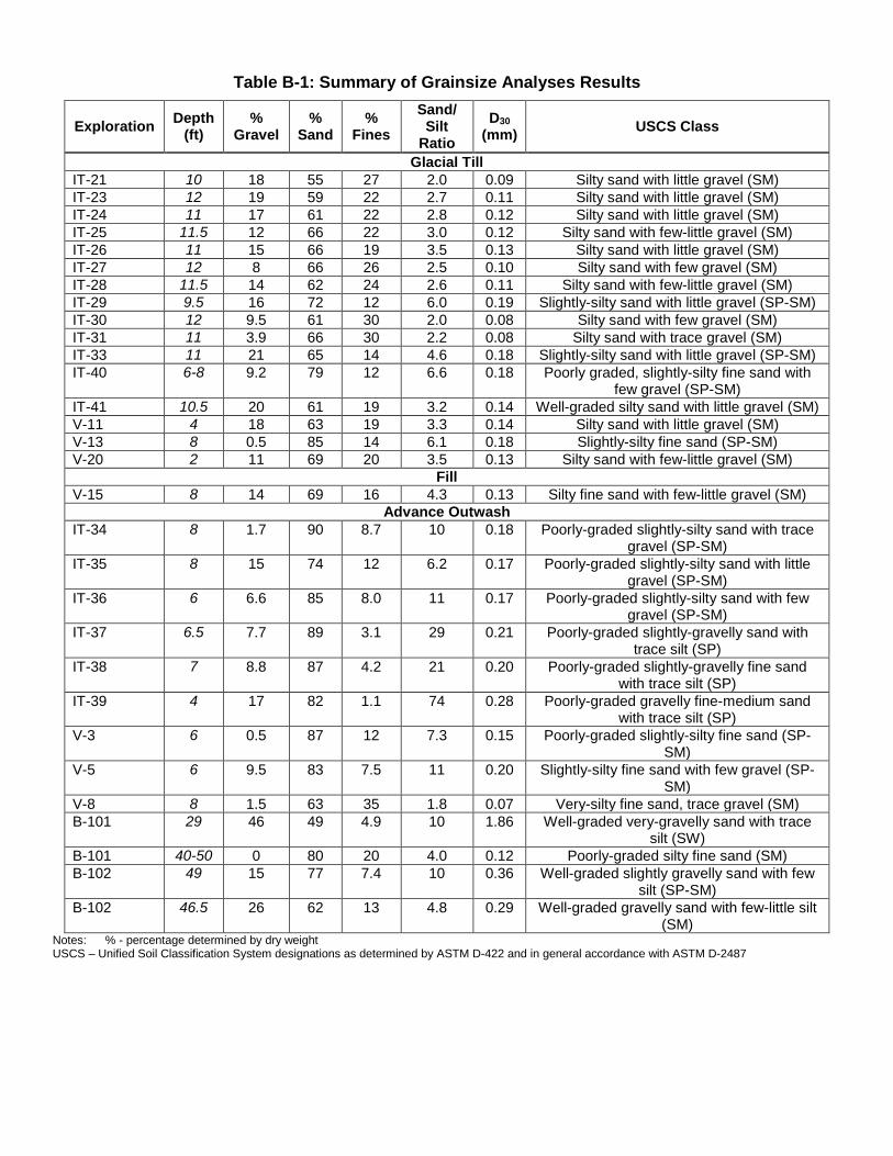
Table B-1: Summary of Grainsize Analyses Results
Exploration Depth (ft)
% Gravel
% Sand
% Fines
Sand/ Silt
Ratio D30
(mm) USCS Class
Glacial Till IT-21 10 18 55 27 2.0 0.09 Silty sand with little gravel (SM) IT-23 12 19 59 22 2.7 0.11 Silty sand with little gravel (SM) IT-24 11 17 61 22 2.8 0.12 Silty sand with little gravel (SM) IT-25 11.5 12 66 22 3.0 0.12 Silty sand with few-little gravel (SM) IT-26 11 15 66 19 3.5 0.13 Silty sand with little gravel (SM) IT-27 12 8 66 26 2.5 0.10 Silty sand with few gravel (SM) IT-28 11.5 14 62 24 2.6 0.11 Silty sand with few-little gravel (SM) IT-29 9.5 16 72 12 6.0 0.19 Slightly-silty sand with little gravel (SP-SM) IT-30 12 9.5 61 30 2.0 0.08 Silty sand with few gravel (SM) IT-31 11 3.9 66 30 2.2 0.08 Silty sand with trace gravel (SM) IT-33 11 21 65 14 4.6 0.18 Slightly-silty sand with little gravel (SP-SM) IT-40 6-8 9.2 79 12 6.6 0.18 Poorly graded, slightly-silty fine sand with
few gravel (SP-SM) IT-41 10.5 20 61 19 3.2 0.14 Well-graded silty sand with little gravel (SM) V-11 4 18 63 19 3.3 0.14 Silty sand with little gravel (SM) V-13 8 0.5 85 14 6.1 0.18 Slightly-silty fine sand (SP-SM) V-20 2 11 69 20 3.5 0.13 Silty sand with few-little gravel (SM)
Fill V-15 8 14 69 16 4.3 0.13 Silty fine sand with few-little gravel (SM)
Advance Outwash IT-34 8 1.7 90 8.7 10 0.18 Poorly-graded slightly-silty sand with trace
gravel (SP-SM) IT-35 8 15 74 12 6.2 0.17 Poorly-graded slightly-silty sand with little
gravel (SP-SM) IT-36 6 6.6 85 8.0 11 0.17 Poorly-graded slightly-silty sand with few
gravel (SP-SM) IT-37 6.5 7.7 89 3.1 29 0.21 Poorly-graded slightly-gravelly sand with
trace silt (SP) IT-38 7 8.8 87 4.2 21 0.20 Poorly-graded slightly-gravelly fine sand
with trace silt (SP) IT-39 4 17 82 1.1 74 0.28 Poorly-graded gravelly fine-medium sand
with trace silt (SP) V-3 6 0.5 87 12 7.3 0.15 Poorly-graded slightly-silty fine sand (SP-
SM) V-5 6 9.5 83 7.5 11 0.20 Slightly-silty fine sand with few gravel (SP-
SM) V-8 8 1.5 63 35 1.8 0.07 Very-silty fine sand, trace gravel (SM) B-101 29 46 49 4.9 10 1.86 Well-graded very-gravelly sand with trace
silt (SW) B-101 40-50 0 80 20 4.0 0.12 Poorly-graded silty fine sand (SM) B-102 49 15 77 7.4 10 0.36 Well-graded slightly gravelly sand with few
silt (SP-SM) B-102 46.5 26 62 13 4.8 0.29 Well-graded gravelly sand with few-little silt
(SM) Notes: % - percentage determined by dry weight USCS – Unified Soil Classification System designations as determined by ASTM D-422 and in general accordance with ASTM D-2487
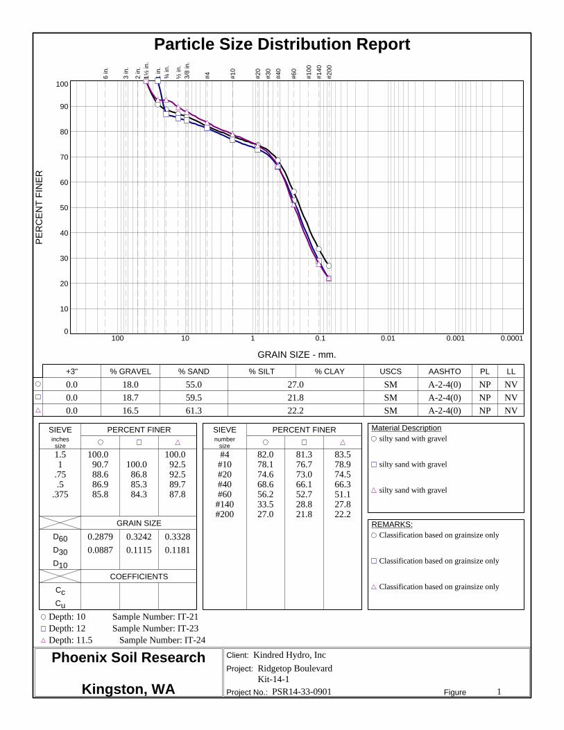
Phoenix Soil Research
Kingston, WA
silty sand with gravel
silty sand with gravel
silty sand with gravel
Classification based on grainsize only
Classification based on grainsize only
Classification based on grainsize only
inches numbersize size
0.0 18.0 55.0 27.0 SM A-2-4(0) NP NV0.0 18.7 59.5 21.8 SM A-2-4(0) NP NV0.0 16.5 61.3 22.2 SM A-2-4(0) NP NV
1.51
.75.5
.375
100.090.788.686.985.8
100.086.885.384.3
100.092.592.589.787.8
#4#10#20#40#60
#140#200
82.078.174.668.656.233.527.0
81.376.773.066.152.728.821.8
83.578.974.566.351.127.822.2
0.2879 0.3242 0.33280.0887 0.1115 0.1181
Depth: 10 Sample Number: IT-21Depth: 12 Sample Number: IT-23Depth: 11.5 Sample Number: IT-24
Kindred Hydro, IncRidgetop BoulevardKit-14-1
PSR14-33-0901 1
+3" % GRAVEL % SAND % SILT % CLAY USCS AASHTO PL LL
SIEVE PERCENT FINER SIEVE PERCENT FINER Material Description
GRAIN SIZE REMARKS:D60D30D10
COEFFICIENTSCcCu
Client:
Project:
Project No.: Figure
PER
CEN
T FI
NER
0
10
20
30
40
50
60
70
80
90
100
GRAIN SIZE - mm.
0.00010.0010.010.1110100
6 in
.
3 in
.
2 in
.1½
in.
1 in
.¾
in.
½ in
.3/
8 in
.
#4 #10
#20
#30
#40
#60
#100
#140
#200
Particle Size Distribution Report

Phoenix Soil Research
Kingston, WA
silty sand
silty sand with gravel
silty sand
Classification based on grainsize only
Classification based on grainsize only
Classification based on grainsize only
inches numbersize size
0.0 11.9 66.0 22.1 SM A-2-4(0) NP NV0.0 15.1 65.5 19.4 SM A-2-4(0) NP NV0.0 8.5 65.7 25.8 SM A-2-4(0) NP NV
.75.5
.375
100.096.693.3
100.093.590.1
100.098.396.6
#4#10#20#40#60
#140#200
88.183.179.371.854.928.122.1
84.980.176.268.050.324.719.4
91.584.880.171.655.431.625.8
0.2881 0.3263 0.28660.1154 0.1340 0.0973
Depth: 11.5 Sample Number: IT-25Depth: 11 Sample Number: IT-26Depth: 12 Sample Number: IT-27
Kindred Hydro, IncRidgetop BoulevardKit-14-1
PSR14-33-0901 2
+3" % GRAVEL % SAND % SILT % CLAY USCS AASHTO PL LL
SIEVE PERCENT FINER SIEVE PERCENT FINER Material Description
GRAIN SIZE REMARKS:D60D30D10
COEFFICIENTSCcCu
Client:
Project:
Project No.: Figure
PER
CEN
T FI
NER
0
10
20
30
40
50
60
70
80
90
100
GRAIN SIZE - mm.
0.00010.0010.010.1110100
6 in
.
3 in
.
2 in
.1½
in.
1 in
.¾
in.
½ in
.3/
8 in
.
#4 #10
#20
#30
#40
#60
#100
#140
#200
Particle Size Distribution Report

Phoenix Soil Research
Kingston, WA
silty sand
poorly graded sand with silt and gravel
silty sand
Classification based on grainsize only
Classification based on grainsize only
Classification based on grainsize only
inches numbersize size
0.0 14.4 61.7 23.9 SM A-2-4(0) NP NV0.0 16.4 71.6 12.0 SP-SM A-2-4(0) NP NV0.0 9.5 60.7 29.8 SM A-2-4(0) NP NV
.75.5
.375
100.094.290.7
100.089.588.9
100.097.894.6
#4#10#20#40#60
#140#200
85.680.075.366.951.829.623.9
83.678.372.661.540.215.712.0
90.587.784.577.462.336.129.8
0.3265 0.4059 0.23380.1083 0.1905 0.0757
Depth: 11.5 Sample Number: IT-28Depth: 9.5 Sample Number: IT-29Depth: 12 Sample Number: IT-30
Kindred Hydro, IncRidgetop BoulevardKit-14-1
PSR14-33-0901 3
+3" % GRAVEL % SAND % SILT % CLAY USCS AASHTO PL LL
SIEVE PERCENT FINER SIEVE PERCENT FINER Material Description
GRAIN SIZE REMARKS:D60D30D10
COEFFICIENTSCcCu
Client:
Project:
Project No.: Figure
PER
CEN
T FI
NER
0
10
20
30
40
50
60
70
80
90
100
GRAIN SIZE - mm.
0.00010.0010.010.1110100
6 in
.
3 in
.
2 in
.1½
in.
1 in
.¾
in.
½ in
.3/
8 in
.
#4 #10
#20
#30
#40
#60
#100
#140
#200
Particle Size Distribution Report

Phoenix Soil Research
Kingston, WA
silty sand
silty sand with gravel
poorly graded sand with silt
Classification based on grainsize only
Classification based on grainsize only
Classification based on grainsize only
inches numbersize size
0.0 3.9 66.5 29.6 SM A-2-4(0) NP NV0.0 21.5 64.9 13.6 SM A-2-4(0) NP NV0.0 1.7 89.6 8.7 SP-SM A-3 NP NV
1.51
.75.5
.375100.0
99.0
100.087.587.584.483.4
100.099.1
#4#10#20#40#60
#140#200
96.193.189.281.062.636.129.6
78.573.868.959.041.118.113.6
98.396.794.081.849.112.7
8.7
0.2331 0.4412 0.29480.0766 0.1777 0.1778
0.0871
1.233.39
Depth: 11 Sample Number: IT-31Depth: 11 Sample Number: IT-33Depth: 8 Sample Number: IT-34
Kindred Hydro, IncRidgetop BoulevardKit-14-1
PSR14-33-0901 4
+3" % GRAVEL % SAND % SILT % CLAY USCS AASHTO PL LL
SIEVE PERCENT FINER SIEVE PERCENT FINER Material Description
GRAIN SIZE REMARKS:D60D30D10
COEFFICIENTSCcCu
Client:
Project:
Project No.: Figure
PER
CEN
T FI
NER
0
10
20
30
40
50
60
70
80
90
100
GRAIN SIZE - mm.
0.00010.0010.010.1110100
6 in
.
3 in
.
2 in
.1½
in.
1 in
.¾
in.
½ in
.3/
8 in
.
#4 #10
#20
#30
#40
#60
#100
#140
#200
Particle Size Distribution Report
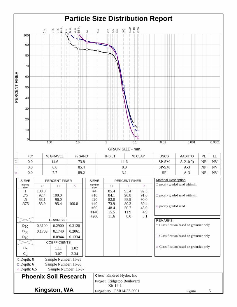
Phoenix Soil Research
Kingston, WA
poorly graded sand with silt
poorly graded sand with silt
poorly graded sand
Classification based on grainsize only
Classification based on grainsize only
Classification based on grainsize only
inches numbersize size
0.0 14.6 73.8 11.6 SP-SM A-2-4(0) NP NV0.0 6.6 85.4 8.0 SP-SM A-3 NP NV0.0 7.7 89.2 3.1 SP A-3 NP NV
1.75.5
.375
100.092.488.185.9
100.096.095.4 100.0
#4#10#20#40#60
#140#200
85.484.182.073.948.415.511.6
93.490.888.980.350.711.9
8.0
92.391.690.080.443.0
4.93.1
0.3109 0.2900 0.31200.1703 0.1740 0.2061
0.0944 0.1334
1.11 1.023.07 2.34
Depth: 8 Sample Number: IT-35Depth: 6 Sample Number: IT-36Depth: 6.5 Sample Number: IT-37
Kindred Hydro, IncRidgetop BoulevardKit-14-1
PSR14-33-0901 5
+3" % GRAVEL % SAND % SILT % CLAY USCS AASHTO PL LL
SIEVE PERCENT FINER SIEVE PERCENT FINER Material Description
GRAIN SIZE REMARKS:D60D30D10
COEFFICIENTSCcCu
Client:
Project:
Project No.: Figure
PER
CEN
T FI
NER
0
10
20
30
40
50
60
70
80
90
100
GRAIN SIZE - mm.
0.00010.0010.010.1110100
6 in
.
3 in
.
2 in
.1½
in.
1 in
.¾
in.
½ in
.3/
8 in
.
#4 #10
#20
#30
#40
#60
#100
#140
#200
Particle Size Distribution Report

Phoenix Soil Research
Kingston, WA
poorly graded sand
poorly graded sand with gravel
silty sand
Classification based on grainsize only
Classification based on grainsize only
Classification based on grainsize only
inches numbersize size
0.0 8.8 87.0 4.2 SP A-3 NP NV0.0 17.4 81.5 1.1 SP A-3 NP NV0.0 9.2 78.6 12.2 SM A-2-4(0) NP NV
.75.5
.375
100.096.194.2
100.091.789.2
100.096.295.3
#4#10#20#40#60
#140#200
91.288.184.771.843.8
7.04.2
82.676.068.853.723.7
2.31.1
90.887.383.973.547.215.912.2
0.3316 0.5022 0.31700.1952 0.2804 0.17250.1211 0.1755
0.95 0.892.74 2.86
Depth: 7 Sample Number: IT-38Depth: 4 Sample Number: IT-39Depth: 6-8 Sample Number: IT-40
Kindred Hydro, IncRidgetop BoulevardKit-14-1
PSR14-33-0901 6
+3" % GRAVEL % SAND % SILT % CLAY USCS AASHTO PL LL
SIEVE PERCENT FINER SIEVE PERCENT FINER Material Description
GRAIN SIZE REMARKS:D60D30D10
COEFFICIENTSCcCu
Client:
Project:
Project No.: Figure
PER
CEN
T FI
NER
0
10
20
30
40
50
60
70
80
90
100
GRAIN SIZE - mm.
0.00010.0010.010.1110100
6 in
.
3 in
.
2 in
.1½
in.
1 in
.¾
in.
½ in
.3/
8 in
.
#4 #10
#20
#30
#40
#60
#100
#140
#200
Particle Size Distribution Report

Phoenix Soil Research
Kingston, WA
silty sand with gravel
well-graded sand with gravel
silty sand
Classification based on grainsize only
Classification based on grainsize only
Classification based on grainsize only
inches numbersize size
0.0 19.7 61.2 19.1 SM A-2-4(0) NP NV0.0 46.5 48.6 4.9 SW A-1-a NP NV0.0 0.0 80.3 19.7 SM A-2-4(0) NP NV
1.51
.75.5
.375
100.093.190.887.585.3
100.092.386.879.272.6
#4#10#20#40#60
#140#200
80.373.267.959.645.524.219.1
53.531.517.811.3
8.05.74.9
100.099.298.794.673.126.919.7
0.4341 5.9767 0.20010.1402 1.8561 0.1154
0.3540
1.6316.88
Depth: 10.5 Sample Number: IT-41Depth: 29 Sample Number: B-101Depth: 40-50 Sample Number: B-101
Kindred Hydro, IncRidgetop BoulevardKit-14-1
PSR14-33-0901 7
+3" % GRAVEL % SAND % SILT % CLAY USCS AASHTO PL LL
SIEVE PERCENT FINER SIEVE PERCENT FINER Material Description
GRAIN SIZE REMARKS:D60D30D10
COEFFICIENTSCcCu
Client:
Project:
Project No.: Figure
PER
CEN
T FI
NER
0
10
20
30
40
50
60
70
80
90
100
GRAIN SIZE - mm.
0.00010.0010.010.1110100
6 in
.
3 in
.
2 in
.1½
in.
1 in
.¾
in.
½ in
.3/
8 in
.
#4 #10
#20
#30
#40
#60
#100
#140
#200
Particle Size Distribution Report

Phoenix Soil Research
Kingston, WA
poorly graded sand with silt and gravel
silty sand with gravel
Classification based on grainsize only
Classification based on grainsize only
inches numbersize size
0.0 15.4 77.2 7.4 SP-SM A-1-b NP NV0.0 25.6 61.7 12.7 SM A-1-b NP NV
1.75.5
.375
100.095.793.891.7
100.090.187.283.0
#4#10#20#40#60
#140#200
84.675.562.736.617.8
8.87.4
74.463.554.240.326.215.212.7
0.7761 1.41630.3611 0.29180.1407
1.195.52
Depth: 49 Sample Number: B-102Depth: 46.5 Sample Number: B-102
Kindred Hydro, IncRidgetop BoulevardKit-14-1
PSR14-33-0901 8
+3" % GRAVEL % SAND % SILT % CLAY USCS AASHTO PL LL
SIEVE PERCENT FINER SIEVE PERCENT FINER Material Description
GRAIN SIZE REMARKS:D60D30D10
COEFFICIENTSCcCu
Client:
Project:
Project No.: Figure
PER
CEN
T FI
NER
0
10
20
30
40
50
60
70
80
90
100
GRAIN SIZE - mm.
0.00010.0010.010.1110100
6 in
.
3 in
.
2 in
.1½
in.
1 in
.¾
in.
½ in
.3/
8 in
.
#4 #10
#20
#30
#40
#60
#100
#140
#200
Particle Size Distribution Report

APPENDIX C
Pilot Infiltration Testing and Infiltration Rate Analyses

Table C-1: Summary of Pilot Infiltration Testing
Kindred Hydro, Inc.9/16/14Ridgetop PIT Infiltration Testing.xlsx
Table C-1: Summary of Pilot Infiltration Testing Page 1 of 37
Location Depth (ft) Soil Type Total Test Volume (gal)
Sand/Silt Ratio D30
USCS Class
Infiltration Rate (inch/hr)
IT_23 12.0 Glacial till 200 2.7 0.11 SM 1.0IT_24 11.5 Glacial till 154 2.8 0.12 SM 0.7IT_25 11.5 Glacial till 320 3.0 0.12 SM 2.2IT_26 11.0 Glacial till 230 3.5 0.13 SM 0.9IT_27 12.0 Glacial till 174 2.5 0.1 SM 0.8IT_28 11.5 Glacial till 150 2.6 0.11 SM 0.8IT_29 10.0 Glacial till 94 6.0 0.19 SP-SM 1.8IT_30 12.0 Glacial till 150 2.0 0.08 SM 4.3IT_31 11.0 Glacial till 117 2.2 0.08 SM 0.2IT_33 11.0 Glacial till 258 4.6 0.18 SP-SM 1.6IT_34 8.0 Advance Outwash 1106 10 0.18 SP-SM 11.4IT_35 8.0 Advance Outwash 375 6.2 0.17 SP-SM 4.7IT_36 6.0 Advance Outwash 1035 11 0.17 SP-SM 14.1IT_37 6.5 Advance Outwash 700 29 0.21 SP 5.0IT_38 7.5 Advance Outwash 1024 21 0.2 SP 15.4IT_39 4.0 Advance Outwash 1215 74 0.28 SP 23.3IT_40 10.0 Glacial till 300 6.6 0.18 SP-SM 4.6IT_41 10.5 Glacial till 128 3.2 0.14 SM 0.4
Minimum Maximum Median0.2 4.6 1.04.7 23.3 12.8
Soil TypeGlacial Till
Advance Outwash
Results Summary by Soil Type (inch/hr)

Enter data in yellow cells.Project: Ridgetop Pit Depth: 12.0 Porosity: 100% Soil Type:Project No: KIT-14-1 Test Date: Effective Width 2.0 Volume/ft (gal/ft): 104.7 200 1.04Location: IT-23 27-Aug-14 Effective Length 7 Standing Water: dry Looks Back Looks back Forward
Time Time into Test (min)
Meter Flow Rate (gpm)
Totalizer reading (gal)
Total Inflow (gal) Staff Gauge (ft) Stage (ft)
Rate of WL Change (in/hr)
Storage Rate (gpm)
Corrected Outflow (gpm)
Infiltration Rate (in./hr) Comments
11:05 0.0 0 0.0211:06 1.0 15 15 0.05 24.5 3.6 2.011:07 2.0 15 30 0.18 89.3 13.0 -2.211:08 3.0 15 45 0.34 118.1 17.2 -0.911:09 4.0 0 45 0.49 109.4 15.9 1.211:10 5.0 0 45 0.48 -7.9 -1.2 1.011:11 6.0 0 45 0.47 -7.2 -1.0 1.011:12 7.0 0 45 0.46 -7.2 -1.0 1.011:13 8.0 0 45 0.45 -7.2 -1.0 0.011:14 9.0 5 50 0.45 0.0 0.0 0.911:15 10.0 10 60 0.49 28.1 4.1 -1.411:16 11.0 10 70 0.60 78.5 11.4 -1.311:17 12.0 10 80 0.71 77.8 11.3 -1.311:18 13.0 10 90 0.82 77.8 11.3 -0.411:19 14.0 10 100 0.92 71.3 10.4 -1.311:20 15.0 10 110 1.02 77.8 11.3 -0.311:21 16.0 10 120 1.12 70.6 10.3 0.911:22 17.0 10 130 1.21 62.6 9.1 -0.311:23 18.0 10 140 1.31 70.6 10.3 0.911:24 19.0 10 150 1.39 62.6 9.1 -1.211:25 20.0 10 160 1.50 77.0 11.2 1.611:26 21.0 10 170 1.58 57.6 8.4 0.611:27 22.0 10 180 1.67 64.8 9.4 1.711:28 23.0 10 190 1.75 56.9 8.3 0.611:29 24.0 10 200 1.84 64.8 9.4 2.811:30 25.0 0 200 1.91 49.7 7.2 0.011:31 26.0 0 200 1.91 0.0 0.0 1.0 7.211:32 27.0 0 200 1.90 -7.2 -1.0 1.0 7.211:33 28.0 0 200 1.89 -7.2 -1.0 0.0 0.011:34 29.0 0 200 1.89 0.0 0.0 1.2 7.911:35 30.0 0 200 1.88 -7.9 -1.2 -0.1 -0.711:36 31.0 0 200 1.88 0.7 0.1 1.0 7.211:37 32.0 0 200 1.87 -7.2 -1.0 0.0 0.011:38 33.0 0 200 1.87 0.0 0.0 0.0 0.011:39 34.0 0 200 1.87 0.0 0.0 1.0 7.211:40 35.0 0 200 1.86 -7.2 -1.0 0.0 0.011:41 36.0 0 200 1.86 0.0 0.0 0.0 0.011:42 37.0 0 200 1.86 0.0 0.0 1.0 7.211:43 38.0 0 200 1.85 -7.2 -1.0 0.0 0.011:44 39.0 0 200 1.85 0.0 0.0 1.0 7.211:45 40.0 0 200 1.84 -7.2 -1.0 0.0 0.011:46 41.0 0 200 1.84 0.0 0.0 0.0 0.011:47 42.0 0 200 1.84 0.0 0.0 1.0 7.211:48 43.0 0 200 1.83 -7.2 -1.0 0.0 0.011:49 44.0 0 200 1.83 0.0 0.0 -0.1 -0.711:50 45.0 0 200 1.83 0.7 0.1 1.2 7.911:51 46.0 0 200 1.82 -7.9 -1.2 0.0 0.011:52 47.0 0 200 1.82 0.0 0.0 0.1 0.711:53 48.0 0 200 1.82 -0.7 -0.1 1.2 7.911:54 49.0 0 200 1.81 -7.9 -1.2 -0.6 -4.311:55 50.0 0 200 1.81 4.3 0.6 0.9 6.511:56 51.0 0 200 1.80 -6.5 -0.9 0.0 0.011:57 52.0 0 200 1.80 0.0 0.0 0.0 0.011:58 53.0 0 200 1.80 0.0 0.0 1.0 7.211:59 54.0 0 200 1.79 -7.2 -1.0 0.1 0.712:00 55.0 0 200 1.79 -0.7 -0.1 0.0 0.012:01 56.0 0 200 1.79 0.0 0.0 0.0 0.012:02 57.0 0 200 1.79 0.0 0.0 0.0 0.012:03 58.0 0 200 1.79 0.0 0.0 1.0 7.212:04 59.0 0 200 1.78 -7.2 -1.0 -0.1 -0.7 Average:
Estimated Rate:
Glacial tillTotal Flow (gal):

0
5
10
15
20
25
30
35
0.0
0.5
1.0
1.5
2.0
2.5
0 20 40 60 80 100 120 140 160 180 200
Flow
Rat
e (g
pm)
Stag
e (fe
et)
Elapsed Time (minutes)
RidgetopIT-23 Infiltration Testing

Enter data in yellow cells.Project: Ridgetop Pit Depth: 11.5 Porosity: 100% Soil Type:Project No: KIT-14-1 Test Date: Effective Width 2.0 Volume/ft (gal/ft): 104.7 154 0.67Location: IT-24 27-Aug-14 Effective Length 7 Standing Water: dry Looks Back Looks back Forward
Time Time into Test (min)
Meter Flow Rate (gpm)
Totalizer reading (gal)
Total Inflow (gal) Staff Gauge (ft) Stage (ft)
Rate of WL Change (in/hr)
Storage Rate (gpm)
Corrected Outflow (gpm)
Infiltration Rate (in./hr) Comments
9:31 0.0 0 Total Flow: 154 -0.059:32 1.0 12 12 0.25 213.8 31.1 -5.59:33 2.0 12 24 0.42 120.2 17.5 -1.49:34 3.0 12 36 0.55 92.2 13.4 -1.19:35 4.0 12 48 0.67 90.0 13.1 0.69:36 5.0 12 60 0.78 78.5 11.4 -0.69:37 6.0 12 72 0.90 86.4 12.6 1.49:38 7.0 12 84 1.00 72.7 10.6 0.59:39 8.0 12 96 1.11 79.2 11.5 3.49:40 9.0 12 108 1.19 59.0 8.6 0.39:41 10.0 12 120 1.30 80.6 11.7 2.59:42 11.0 12 132 1.40 65.5 9.5 2.49:43 12.0 12 144 1.49 66.2 9.6 2.59:44 13.0 10 154 1.58 65.5 9.5 3.59:45 14.0 0 154 1.64 44.6 6.5 -1.09:46 15.0 0 154 1.65 7.2 1.0 0.9 6.59:47 16.0 0 154 1.64 -6.5 -0.9 0.0 0.09:48 17.0 0 154 1.64 0.0 0.0 0.0 0.09:49 18.0 0 154 1.64 0.0 0.0 1.4 9.49:50 19.0 0 154 1.63 -9.4 -1.4 -0.1 -0.79:51 20.0 0 154 1.63 0.7 0.1 0.0 0.09:52 21.0 0 154 1.63 0.0 0.0 0.0 0.09:53 22.0 0 154 1.63 0.0 0.0 0.0 0.09:54 23.0 0 154 1.63 0.0 0.0 1.3 8.69:55 24.0 0 154 1.62 -8.6 -1.3 0.0 0.09:56 25.0 0 154 1.62 0.0 0.0 0.0 0.09:57 26.0 0 154 1.62 0.0 0.0 0.0 0.09:58 27.0 0 154 1.62 0.0 0.0 0.0 0.09:59 28.0 0 154 1.62 0.0 0.0 -0.1 -0.7
10:00 29.0 0 154 1.62 0.7 0.1 0.9 6.510:01 30.0 0 154 1.61 -6.5 -0.9 0.0 0.010:02 31.0 0 154 1.61 0.0 0.0 -0.1 -0.710:03 32.0 0 154 1.61 0.7 0.1 1.0 7.210:04 33.0 0 154 1.60 -7.2 -1.0 0.2 1.410:05 34.0 0 154 1.60 -1.4 -0.2 -1.0 -7.210:06 35.0 0 154 1.61 7.2 1.0 1.0 7.210:07 36.0 0 154 1.60 -7.2 -1.0 0.1 0.710:08 37.0 0 154 1.60 -0.7 -0.1 0.0 0.010:09 38.0 0 154 1.60 0.0 0.0 0.9 6.510:10 39.0 0 154 1.59 -6.5 -0.9 0.0 0.010:11 40.0 0 154 1.59 0.0 0.0 -0.1 -0.710:12 41.0 0 154 1.59 0.7 0.1 1.0 7.210:13 42.0 0 154 1.58 -7.2 -1.0 0.0 0.010:14 43.0 0 154 1.58 0.0 0.0 0.2 1.410:15 44.0 0 154 1.58 -1.4 -0.2 -1.0 -7.210:16 45.0 0 154 1.59 7.2 1.0 0.0 0.010:17 46.0 0 154 1.59 0.0 0.0 1.0 7.210:18 47.0 0 154 1.58 -7.2 -1.0 -1.0 -7.210:19 48.0 0 154 1.59 7.2 1.0 0.9 6.510:20 49.0 0 154 1.58 -6.5 -0.9 0.0 0.010:21 50.0 0 154 1.58 0.0 0.0 0.0 0.010:22 51.0 0 154 1.58 0.0 0.0 -0.1 -0.710:23 52.0 0 154 1.58 0.7 0.1 1.0 7.210:24 53.0 0 154 1.57 -7.2 -1.0 0.2 1.410:25 54.0 0 154 1.57 -1.4 -0.2 0.0 0.010:26 55.0 0 154 1.57 0.0 0.0 0.0 0.010:27 56.0 0 154 1.57 0.0 0.0 -0.1 -0.710:28 57.0 0 154 1.57 0.7 0.1 1.0 7.210:29 58.0 0 154 1.56 -7.2 -1.0 -0.7 -5.010:30 59.0 0 154 1.57 5.0 0.7 1.0 7.2 Average:
Estimated Rate:
Glacial tillTotal Flow (gal):
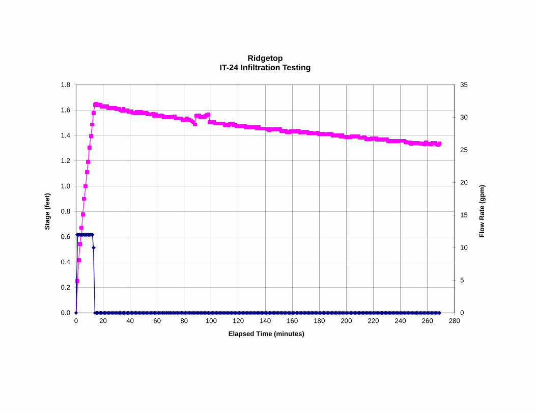
0
5
10
15
20
25
30
35
0.0
0.2
0.4
0.6
0.8
1.0
1.2
1.4
1.6
1.8
0 20 40 60 80 100 120 140 160 180 200 220 240 260 280
Flow
Rat
e (g
pm)
Stag
e (fe
et)
Elapsed Time (minutes)
RidgetopIT-24 Infiltration Testing

Enter data in yellow cells.Project: Ridgetop Pit Depth: 11.5 Porosity: 100% Soil Type:Project No: KIT-14-1 Test Date: Effective Width 2.0 Volume/ft (gal/ft): 89.8 320 2.16Location: IT-25 2-Sep-14 Effective Length 6 Standing Water: dry Looks Back Looks back Forward
Time Time into Test (min)
Meter Flow Rate (gpm)
Totalizer reading (gal)
Total Inflow (gal) Staff Gauge (ft) Stage (ft)
Rate of WL Change (in/hr)
Storage Rate (gpm)
Corrected Outflow (gpm)
Infiltration Rate (in./hr) Comments
10:11 0.0 0 Total Flow: 320 0.0010:12 1.0 20 20 0.02 15.1 1.9 18.110:13 2.0 20 40 0.04 15.1 1.9 -13.710:14 3.0 20 60 0.41 270.0 33.7 6.910:15 4.0 20 80 0.56 105.1 13.1 -3.010:16 5.0 20 100 0.82 184.3 23.0 -0.410:17 6.0 20 120 1.04 163.4 20.4 2.310:18 7.0 20 140 1.24 141.8 17.7 3.110:19 8.0 20 160 1.43 135.4 16.9 5.510:20 9.0 20 180 1.59 116.6 14.5 4.910:21 10.0 20 200 1.76 121.0 15.1 4.110:22 11.0 20 220 1.94 127.4 15.9 6.710:23 12.0 20 240 2.08 106.6 13.3 1.510:24 13.0 0 240 2.29 148.3 18.5 3.610:25 14.0 0 240 2.25 -28.8 -3.6 1.9 15.110:26 15.0 0 240 2.23 -15.1 -1.9 0.9 7.210:27 16.0 0 240 2.22 -7.2 -0.9 0.9 7.210:28 17.0 0 240 2.21 -7.2 -0.9 1.0 7.910:29 18.0 0 240 2.20 -7.9 -1.0 1.3 10.110:30 19.0 0 240 2.18 -10.1 -1.3 0.1 0.710:31 20.0 0 240 2.18 -0.7 -0.1 0.9 7.210:32 21.0 0 240 2.17 -7.2 -0.9 0.9 7.210:33 22.0 0 240 2.16 -7.2 -0.9 1.0 7.910:34 23.0 0 240 2.15 -7.9 -1.0 0.4 3.610:35 24.0 0 240 2.15 -3.6 -0.4 0.9 7.210:36 25.0 0 240 2.14 -7.2 -0.9 0.9 7.2 Average:10:37 26.0 0 240 2.13 -7.2 -0.9 0.8 6.5 7.310:38 27.0 0 240 2.12 -6.5 -0.8 0.0 0.010:39 28.0 0 240 2.12 0.0 0.0 1.2 9.410:40 29.0 0 240 2.10 -9.4 -1.2 0.8 6.510:41 30.0 0 240 2.10 -6.5 -0.8 1.0 7.910:42 31.0 0 240 2.08 -7.9 -1.0 0.0 0.010:43 32.0 0 240 2.08 0.0 0.0 0.9 7.210:44 33.0 0 240 2.07 -7.2 -0.9 -0.2 -1.410:45 34.0 0 240 2.08 1.4 0.2 0.9 7.210:46 35.0 0 240 2.07 -7.2 -0.9 0.0 0.010:47 36.0 0 240 2.07 0.0 0.0 0.9 7.210:48 37.0 0 240 2.06 -7.2 -0.9 0.9 7.210:49 38.0 0 240 2.05 -7.2 -0.9 -0.1 -0.710:50 39.0 0 240 2.05 0.7 0.1 0.9 7.210:51 40.0 0 240 2.04 -7.2 -0.9 0.0 0.010:52 41.0 0 240 2.04 0.0 0.0 0.8 6.510:53 42.0 0 240 2.03 -6.5 -0.8 1.0 7.910:54 43.0 0 240 2.02 -7.9 -1.0 0.8 6.510:55 44.0 0 240 2.01 -6.5 -0.8 0.2 1.410:56 45.0 0 240 2.01 -1.4 -0.2 1.0 7.910:57 46.0 0 240 2.00 -7.9 -1.0 1.1 8.610:58 47.0 0 240 1.98 -8.6 -1.1 1.0 7.910:59 48.0 0 240 1.97 -7.9 -1.0 -1.2 -9.411:00 49.0 0 240 1.99 9.4 1.2 1.0 7.911:01 50.0 0 240 1.97 -7.9 -1.0 0.1 0.711:02 51.0 0 240 1.97 -0.7 -0.1 0.1 0.711:03 52.0 0 240 1.97 -0.7 -0.1 0.9 7.211:04 53.0 0 240 1.96 -7.2 -0.9 -0.9 -7.211:05 54.0 0 240 1.97 7.2 0.9 0.9 7.211:06 55.0 0 240 1.96 -7.2 -0.9 0.0 0.011:07 56.0 0 240 1.96 0.0 0.0 0.8 6.511:08 57.0 0 240 1.95 -6.5 -0.8 0.0 0.011:09 58.0 0 240 1.95 0.0 0.0 0.3 2.211:10 59.0 0 240 1.95 -2.2 -0.3 0.8 6.5
Estimated Rate:
Glacial tillTotal Flow (gal):

0
5
10
15
20
25
30
35
0.0
0.5
1.0
1.5
2.0
2.5
0 20 40 60 80 100 120 140 160 180 200 220 240 260 280 300
Flow
Rat
e (g
pm)
Stag
e (fe
et)
Elapsed Time (minutes)
RidgetopIT-25 Infiltration Testing

Enter data in yellow cells.Project: Ridgetop Pit Depth: 11.0 Porosity: 100% Soil Type:Project No: KIT-14-1 Test Date: Effective Width 2.0 Volume/ft (gal/ft): 104.7 230 0.89Location: IT-26 26-Aug-14 Effective Length 7 Standing Water: dry Looks Back Looks back Forward
Time Time into Test (min)
Meter Flow Rate (gpm)
Totalizer reading (gal)
Total Inflow (gal) Staff Gauge (ft) Stage (ft)
Rate of WL Change (in/hr)
Storage Rate (gpm)
Corrected Outflow (gpm)
Infiltration Rate (in./hr) Comments
9:49 0.0 0 Total Flow: 230 0.019:50 1.0 25 25 0.42 293.0 42.6 -5.99:51 2.0 25 50 0.71 212.4 30.9 1.39:52 3.0 25 75 0.94 162.7 23.7 4.49:53 4.0 25 100 1.14 141.8 20.6 6.59:54 5.0 25 125 1.31 127.4 18.5 7.49:55 6.0 25 150 1.48 121.0 17.6 8.69:56 7.0 25 175 1.64 113.0 16.4 8.59:57 8.0 25 200 1.80 113.8 16.5 10.79:58 9.0 25 225 1.93 98.6 14.3 10.59:59 10.0 5 230 2.07 99.4 14.5 -0.1 -0.9
10:00 11.0 0 230 2.12 35.3 5.1 0.9 6.510:01 12.0 0 230 2.11 -6.5 -0.9 0.0 0.010:02 13.0 0 230 2.11 0.0 0.0 1.0 7.210:03 14.0 0 230 2.10 -7.2 -1.0 0.0 0.010:04 15.0 0 230 2.10 0.0 0.0 -0.1 -0.710:05 16.0 0 230 2.10 0.7 0.1 1.0 7.210:06 17.0 0 230 2.09 -7.2 -1.0 0.1 0.710:07 18.0 0 230 2.09 -0.7 -0.1 1.0 7.210:08 19.0 0 230 2.08 -7.2 -1.0 0.1 0.710:09 20.0 0 230 2.08 -0.7 -0.1 -0.5 -3.610:10 21.0 0 230 2.09 3.6 0.5 1.0 7.210:11 22.0 0 230 2.08 -7.2 -1.0 0.0 0.010:12 23.0 0 230 2.08 0.0 0.0 0.0 0.010:13 24.0 0 230 2.08 0.0 0.0 0.9 6.510:14 25.0 0 230 2.07 -6.5 -0.9 0.0 0.0 Average:10:15 26.0 0 230 2.07 0.0 0.0 0.0 0.0 2.210:16 27.0 0 230 2.07 0.0 0.0 0.0 0.010:17 28.0 0 230 2.07 0.0 0.0 0.0 0.010:18 29.0 0 230 2.07 0.0 0.0 0.0 0.010:19 30.0 0 230 2.07 0.0 0.0 1.0 7.210:20 31.0 0 230 2.06 -7.2 -1.0 0.4 2.910:21 32.0 0 230 2.05 -2.9 -0.4 0.4 2.910:22 33.0 0 230 2.05 -2.9 -0.4 1.5 10.110:23 34.0 0 230 2.03 -10.1 -1.5 0.4 2.910:24 35.0 0 230 2.03 -2.9 -0.4 -3.7 -25.210:25 36.0 0 230 2.07 25.2 3.7 0.1 0.710:26 37.0 0 230 2.06 -0.7 -0.1 0.2 1.410:27 38.0 0 230 2.06 -1.4 -0.2 1.3 8.610:28 39.0 0 230 2.05 -8.6 -1.3 0.1 0.710:29 40.0 0 230 2.05 -0.7 -0.1 -1.6 -10.810:30 41.0 0 230 2.06 10.8 1.6 0.0 0.010:31 42.0 0 230 2.06 0.0 0.0 0.0 0.010:32 43.0 0 230 2.06 0.0 0.0 0.0 0.010:33 44.0 0 230 2.06 0.0 0.0 0.1 0.710:34 45.0 0 230 2.06 -0.7 -0.1 0.8 5.810:35 46.0 0 230 2.06 -5.8 -0.8 -0.1 -0.710:36 47.0 0 230 2.06 0.7 0.1 -0.2 -1.410:37 48.0 0 230 2.06 1.4 0.2 0.9 6.510:38 49.0 0 230 2.05 -6.5 -0.9 -0.1 -0.710:39 50.0 0 230 2.05 0.7 0.1 1.3 8.610:40 51.0 0 230 2.04 -8.6 -1.3 0.0 0.010:41 52.0 0 230 2.04 0.0 0.0 0.9 6.510:42 53.0 0 230 2.03 -6.5 -0.9 -0.1 -0.710:43 54.0 0 230 2.03 0.7 0.1 -0.1 -0.710:44 55.0 0 230 2.03 0.7 0.1 0.8 5.810:45 56.0 0 230 2.02 -5.8 -0.8 -0.1 -0.710:46 57.0 0 230 2.02 0.7 0.1 0.0 0.010:47 58.0 0 230 2.02 0.0 0.0 0.8 5.810:48 59.0 0 230 2.02 -5.8 -0.8 -1.0 -7.2 Average:
Estimated Rate:
Glacial tillTotal Flow (gal):

0
5
10
15
20
25
30
35
0.0
0.5
1.0
1.5
2.0
2.5
0 20 40 60 80 100 120 140 160 180 200 220 240 260
Flow
Rat
e (g
pm)
Stag
e (fe
et)
Elapsed Time (minutes)
RidgetopIT-26 Infiltration Testing

Enter data in yellow cells.Project: Ridgetop Pit Depth: 12.0 Porosity: 100% Soil Type:Project No: KIT-14-1 Test Date: Effective Width 2.0 Volume/ft (gal/ft): 104.7 174 0.84Location: IT-27 26-Aug-14 Effective Length 7 Standing Water: dry Looks Back Looks back Forward
Time Time into Test (min)
Meter Flow Rate (gpm)
Totalizer reading (gal)
Total Inflow (gal) Staff Gauge (ft) Stage (ft)
Rate of WL Change (in/hr)
Storage Rate (gpm)
Corrected Outflow (gpm)
Infiltration Rate (in./hr) Comments
8:52 0.0 0 Total Flow: 174 -0.038:53 1.0 32 32 0.02 36.0 5.2 0.98:54 2.0 32 64 0.32 213.8 31.1 -1.98:55 3.0 25 89 0.64 233.3 33.9 -0.98:56 4.0 20 109 0.89 177.8 25.9 -0.68:57 5.0 20 129 1.09 141.8 20.6 1.48:58 6.0 20 149 1.26 128.2 18.6 3.38:59 7.0 15 164 1.42 114.5 16.7 0.39:00 8.0 10 174 1.56 100.8 14.7 0.6 4.09:01 9.0 0 174 1.65 64.8 9.4 0.8 5.89:02 10.0 0 174 1.64 -5.8 -0.8 -0.1 -0.79:03 11.0 0 174 1.65 0.7 0.1 0.8 5.89:04 12.0 0 174 1.64 -5.8 -0.8 1.5 10.19:05 13.0 0 174 1.62 -10.1 -1.5 1.0 7.29:06 14.0 0 174 1.61 -7.2 -1.0 -0.1 -0.79:07 15.0 0 174 1.61 0.7 0.1 0.0 0.09:08 16.0 0 174 1.61 0.0 0.0 -0.1 -0.79:09 17.0 0 174 1.62 0.7 0.1 0.4 2.99:10 18.0 0 174 1.61 -2.9 -0.4 0.9 6.59:11 19.0 0 174 1.60 -6.5 -0.9 0.1 0.79:12 20.0 0 174 1.60 -0.7 -0.1 0.0 0.09:13 21.0 0 174 1.60 0.0 0.0 1.0 7.29:14 22.0 0 174 1.59 -7.2 -1.0 -0.3 -2.29:15 23.0 0 174 1.59 2.2 0.3 -1.0 -7.29:16 24.0 0 174 1.60 7.2 1.0 0.9 6.59:17 25.0 0 174 1.60 -6.5 -0.9 0.0 0.0 Average:9:18 26.0 0 174 1.60 0.0 0.0 -0.1 -0.7 2.39:19 27.0 0 174 1.60 0.7 0.1 0.4 2.99:20 28.0 0 174 1.59 -2.9 -0.4 0.0 0.09:21 29.0 0 174 1.59 0.0 0.0 0.0 0.09:22 30.0 0 174 1.59 0.0 0.0 0.0 0.09:23 31.0 0 174 1.59 0.0 0.0 1.0 7.29:24 32.0 0 174 1.58 -7.2 -1.0 0.0 0.09:25 33.0 0 174 1.58 0.0 0.0 0.0 0.09:26 34.0 0 174 1.58 0.0 0.0 0.1 0.79:27 35.0 0 174 1.58 -0.7 -0.1 0.1 0.79:28 36.0 0 174 1.58 -0.7 -0.1 0.0 0.09:29 37.0 0 174 1.58 0.0 0.0 -0.5 -3.69:30 38.0 0 174 1.59 3.6 0.5 1.0 7.29:31 39.0 0 174 1.58 -7.2 -1.0 0.0 0.09:32 40.0 0 174 1.58 0.0 0.0 0.0 0.09:33 41.0 0 174 1.58 0.0 0.0 0.0 0.09:34 42.0 0 174 1.58 0.0 0.0 0.9 6.59:35 43.0 0 174 1.57 -6.5 -0.9 0.0 0.09:36 44.0 0 174 1.57 0.0 0.0 0.0 0.09:37 45.0 0 174 1.57 0.0 0.0 0.0 0.09:38 46.0 0 174 1.57 0.0 0.0 0.0 0.09:39 47.0 0 174 1.57 0.0 0.0 1.0 7.29:40 48.0 0 174 1.56 -7.2 -1.0 0.0 0.09:41 49.0 0 174 1.56 0.0 0.0 0.1 0.79:42 50.0 0 174 1.56 -0.7 -0.1 0.0 0.09:43 51.0 0 174 1.56 0.0 0.0 0.0 0.09:44 52.0 0 174 1.56 0.0 0.0 -0.2 -1.49:45 53.0 0 174 1.56 1.4 0.2 0.0 0.09:46 54.0 0 174 1.56 0.0 0.0 1.0 7.29:47 55.0 0 174 1.55 -7.2 -1.0 0.0 0.09:48 56.0 0 174 1.55 0.0 0.0 0.0 0.09:49 57.0 0 174 1.55 0.0 0.0 -0.3 -2.29:50 58.0 0 174 1.55 2.2 0.3 0.0 0.09:51 59.0 0 174 1.55 0.0 0.0 0.0 0.0 Average:
Estimated Rate:
Glacial tillTotal Flow (gal):

0
5
10
15
20
25
30
35
0.0
0.2
0.4
0.6
0.8
1.0
1.2
1.4
1.6
1.8
0 20 40 60 80 100 120 140 160 180 200 220 240 260 280
Flow
Rat
e (g
pm)
Stag
e (fe
et)
Elapsed Time (minutes)
RidgetopIT-27 Infiltration Testing

Enter data in yellow cells.Project: Ridgetop Pit Depth: 11.5 Porosity: 100% Soil Type:Project No: KIT-14-1 Test Date: Effective Width 2.0 Volume/ft (gal/ft): 104.7 150 0.80Location: IT-28 25-Aug-14 Effective Length 7 Standing Water: dry Looks Back Looks back Forward
Time Time into Test (min)
Meter Flow Rate (gpm)
Totalizer reading (gal)
Total Inflow (gal) Staff Gauge (ft) Stage (ft)
Rate of WL Change (in/hr)
Storage Rate (gpm)
Corrected Outflow (gpm)
Infiltration Rate (in./hr) Comments
11:22 0.0 0 Total Flow: 150 -0.0111:23 1.0 30 30 0.19 148.3 21.6 -1.911:24 2.0 30 60 0.50 219.6 31.9 5.411:25 3.0 30 90 0.73 169.2 24.6 2.211:26 4.0 30 120 1.00 190.8 27.8 6.111:27 5.0 20 140 1.23 164.2 23.9 0.411:28 6.0 10 150 1.41 134.6 19.6 1.711:29 7.0 0 150 1.49 56.9 8.3 0.511:30 8.0 0 150 1.49 -3.6 -0.5 0.8 5.811:31 9.0 0 150 1.48 -5.8 -0.8 0.0 0.011:32 10.0 0 150 1.48 0.0 0.0 0.9 6.511:33 11.0 0 150 1.47 -6.5 -0.9 0.0 0.011:34 12.0 0 150 1.47 0.0 0.0 1.5 10.111:35 13.0 0 150 1.46 -10.1 -1.5 0.1 0.711:36 14.0 0 150 1.45 -0.7 -0.1 0.1 0.711:37 15.0 0 150 1.45 -0.7 -0.1 1.2 7.911:38 16.0 0 150 1.44 -7.9 -1.2 0.1 0.711:39 17.0 0 150 1.44 -0.7 -0.1 -0.9 -6.511:40 18.0 0 150 1.45 6.5 0.9 0.1 0.711:41 19.0 0 150 1.45 -0.7 -0.1 1.0 7.211:42 20.0 0 150 1.44 -7.2 -1.0 0.0 0.011:43 21.0 0 150 1.44 0.0 0.0 0.1 0.711:44 22.0 0 150 1.44 -0.7 -0.1 -0.3 -2.211:45 23.0 0 150 1.44 2.2 0.3 0.9 6.511:46 24.0 0 150 1.43 -6.5 -0.9 0.0 0.011:47 25.0 0 150 1.43 0.0 0.0 0.1 0.7 Average:11:48 26.0 0 150 1.43 -0.7 -0.1 1.0 7.2 2.511:49 27.0 0 150 1.42 -7.2 -1.0 -0.4 -2.911:50 28.0 0 150 1.43 2.9 0.4 0.1 0.711:51 29.0 0 150 1.42 -0.7 -0.1 1.0 7.211:52 30.0 0 150 1.41 -7.2 -1.0 0.0 0.011:53 31.0 0 150 1.41 0.0 0.0 0.0 0.011:54 32.0 0 150 1.41 0.0 0.0 0.9 6.511:55 33.0 0 150 1.41 -6.5 -0.9 0.0 0.011:56 34.0 0 150 1.41 0.0 0.0 0.1 0.711:57 35.0 0 150 1.40 -0.7 -0.1 0.0 0.011:58 36.0 0 150 1.40 0.0 0.0 1.2 7.911:59 37.0 0 150 1.39 -7.9 -1.2 -0.5 -3.612:00 38.0 0 150 1.40 3.6 0.5 -0.1 -0.712:01 39.0 0 150 1.40 0.7 0.1 -0.1 -0.712:02 40.0 0 150 1.40 0.7 0.1 -0.1 -0.712:03 41.0 0 150 1.40 0.7 0.1 -0.1 -0.712:04 42.0 0 150 1.40 0.7 0.1 1.9 13.012:05 43.0 0 150 1.38 -13.0 -1.9 0.1 0.712:06 44.0 0 150 1.38 -0.7 -0.1 0.1 0.712:07 45.0 0 150 1.38 -0.7 -0.1 0.1 0.712:08 46.0 0 150 1.38 -0.7 -0.1 1.0 7.212:09 47.0 0 150 1.37 -7.2 -1.0 -0.7 -5.012:10 48.0 0 150 1.38 5.0 0.7 0.0 0.012:11 49.0 0 150 1.38 0.0 0.0 -0.1 -0.712:12 50.0 0 150 1.38 0.7 0.1 0.0 0.012:13 51.0 0 150 1.38 0.0 0.0 0.9 6.512:14 52.0 0 150 1.37 -6.5 -0.9 0.3 2.212:15 53.0 0 150 1.37 -2.2 -0.3 0.0 0.012:16 54.0 0 150 1.37 0.0 0.0 0.1 0.712:17 55.0 0 150 1.37 -0.7 -0.1 1.0 7.212:18 56.0 0 150 1.36 -7.2 -1.0 0.1 0.712:19 57.0 0 150 1.36 -0.7 -0.1 -0.4 -2.912:20 58.0 0 150 1.36 2.9 0.4 0.0 0.012:21 59.0 0 150 1.36 0.0 0.0 1.0 7.2 Average:
Estimated Rate:
Glacial tillTotal Flow (gal):
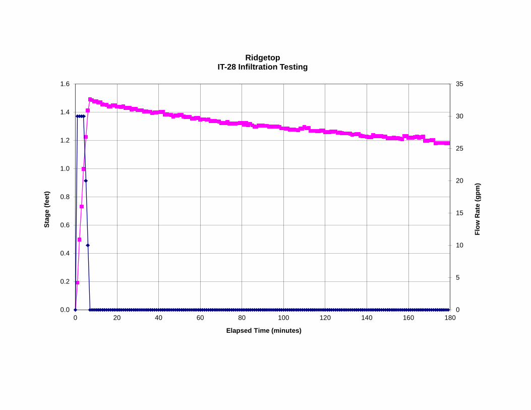
0
5
10
15
20
25
30
35
0.0
0.2
0.4
0.6
0.8
1.0
1.2
1.4
1.6
0 20 40 60 80 100 120 140 160 180
Flow
Rat
e (g
pm)
Stag
e (fe
et)
Elapsed Time (minutes)
RidgetopIT-28 Infiltration Testing

Enter data in yellow cells.Project: Ridgetop Pit Depth: 10.0 Porosity: 100% Soil Type:Project No: KIT-14-1 Test Date: Effective Width 2.0 Volume/ft (gal/ft): 104.7 94 1.76Location: IT-29 25-Aug-14 Effective Length 7 Standing Water: dry Looks Back Looks back Forward
Time Time into Test (min)
Meter Flow Rate (gpm)
Totalizer reading (gal)
Total Inflow (gal) Staff Gauge (ft) Stage (ft)
Rate of WL Change (in/hr)
Storage Rate (gpm)
Corrected Outflow (gpm)
Infiltration Rate (in./hr) Comments
10:11 0.0 0 Total Flow: 94 -0.0610:12 1.0 15 15 0.82 630.7 91.7 3.710:13 2.0 15 30 0.93 77.8 11.3 3.710:14 3.0 15 45 1.03 77.8 11.3 7.810:15 4.0 0 45 1.10 49.7 7.2 0.910:16 5.0 0 45 1.09 -6.5 -0.9 0.710:17 6.0 0 45 1.09 -5.0 -0.7 2.0 13.710:18 7.0 0 45 1.07 -13.7 -2.0 0.9 6.510:19 8.0 0 45 1.06 -6.5 -0.9 2.2 15.110:20 9.0 0 45 1.04 -15.1 -2.2 0.9 6.510:21 10.0 0 45 1.03 -6.5 -0.9 -0.1 -0.710:22 11.0 0 45 1.03 0.7 0.1 1.9 13.010:23 12.0 0 45 1.01 -13.0 -1.9 -0.1 -0.710:24 13.0 0 45 1.01 0.7 0.1 2.0 13.710:25 14.0 0 45 0.99 -13.7 -2.0 0.9 6.510:26 15.0 0 45 0.99 -6.5 -0.9 -0.1 -0.710:27 16.0 0 45 0.99 0.7 0.1 0.8 5.810:28 17.0 0 45 0.98 -5.8 -0.8 -0.1 -0.710:29 18.0 0 45 0.98 0.7 0.1 2.1 14.410:30 19.0 0 45 0.96 -14.4 -2.1 1.0 7.210:31 20.0 0 45 0.95 -7.2 -1.0 0.0 0.010:32 21.0 0 45 0.95 0.0 0.0 1.0 7.210:33 22.0 0 45 0.94 -7.2 -1.0 0.9 6.510:34 23.0 0 45 0.93 -6.5 -0.9 -0.1 -0.710:35 24.0 0 45 0.93 0.7 0.1 -0.3 -2.210:36 25.0 0 45 0.93 2.2 0.3 0.8 5.8 Average:10:37 26.0 0 45 0.93 -5.8 -0.8 -0.3 -2.2 5.010:38 27.0 0 45 0.93 2.2 0.3 0.8 5.810:39 28.0 0 45 0.92 -5.8 -0.8 2.3 15.810:40 29.0 0 45 0.90 -15.8 -2.3 -0.1 -0.710:41 30.0 0 45 0.90 0.7 0.1 1.0 7.210:42 31.0 0 45 0.89 -7.2 -1.0 -0.1 -0.710:43 32.0 0 45 0.89 0.7 0.1 0.9 6.510:44 33.0 0 45 0.88 -6.5 -0.9 0.8 5.810:45 34.0 0 45 0.87 -5.8 -0.8 1.2 7.910:46 35.0 0 45 0.86 -7.9 -1.2 0.1 0.710:47 36.0 0 45 0.86 -0.7 -0.1 1.3 8.610:48 37.0 0 45 0.85 -8.6 -1.3 0.1 0.710:49 38.0 0 45 0.85 -0.7 -0.1 -0.4 -2.910:50 39.0 0 45 0.85 2.9 0.4 0.1 0.710:51 40.0 0 45 0.85 -0.7 -0.1 0.0 0.010:52 41.0 0 45 0.85 0.0 0.0 1.0 7.210:53 42.0 0 45 0.84 -7.2 -1.0 0.1 0.710:54 43.0 0 45 0.84 -0.7 -0.1 -0.3 -2.210:55 44.0 0 45 0.84 2.2 0.3 1.0 7.210:56 45.0 0 45 0.83 -7.2 -1.0 0.1 0.710:57 46.0 0 45 0.83 -0.7 -0.1 0.0 0.010:58 47.0 0 45 0.83 0.0 0.0 1.2 7.910:59 48.0 0 45 0.82 -7.9 -1.2 -0.4 -2.911:00 49.0 0 45 0.83 2.9 0.4 0.0 0.011:01 50.0 0 45 0.83 0.0 0.0 1.0 7.211:02 51.0 0 45 0.82 -7.2 -1.0 0.0 0.011:03 52.0 0 45 0.82 0.0 0.0 0.9 6.511:04 53.0 0 45 0.81 -6.5 -0.9 0.0 0.011:05 54.0 0 45 0.81 0.0 0.0 0.0 0.011:06 55.0 0 45 0.81 0.0 0.0 0.9 6.511:07 56.0 0 45 0.80 -6.5 -0.9 0.0 0.011:08 57.0 0 45 0.80 0.0 0.0 0.0 0.011:09 58.0 0 45 0.80 0.0 0.0 1.3 8.611:10 59.0 0 45 0.79 -8.6 -1.3 0.0 0.0 Average:
Estimated Rate:
Glacial tillTotal Flow (gal):

0
5
10
15
20
25
30
35
0.0
0.2
0.4
0.6
0.8
1.0
1.2
0 20 40 60 80 100 120 140 160 180 200 220 240
Flow
Rat
e (g
pm)
Stag
e (fe
et)
Elapsed Time (minutes)
RidgetopIT-29 Infiltration Testing

Enter data in yellow cells.Project: Ridgetop Pit Depth: 12.0 Porosity: 100% Soil Type:Project No: KIT-14-1 Test Date: Effective Width 2.0 Volume/ft (gal/ft): 82.3 150 4.3Location: IT-30 13-Aug-14 Effective Length 5.5 Standing Water: dry Looks Back Looks back Forward
Time Time into Test (min)
Meter Flow Rate (gpm)
Totalizer reading (gal)
Total Inflow (gal) Staff Gauge (ft) Stage (ft)
Rate of WL Change (in/hr)
Storage Rate (gpm)
Corrected Outflow (gpm)
Infiltration Rate (in./hr) Comments
11:32 0.0 0 Total Flow: 150 -0.0911:33 1.0 0 0 1.89 1,424.2 162.7 0.811:34 2.0 0 0 1.88 -7.2 -0.8 1.111:35 3.0 0 0 1.87 -9.4 -1.1 0.711:36 4.0 0 0 1.86 -6.5 -0.7 0.711:37 5.0 0 0 1.85 -5.8 -0.7 0.711:38 6.0 0 0 1.84 -6.5 -0.7 0.7 5.811:39 7.0 0 0 1.84 -5.8 -0.7 1.8 15.811:40 8.0 0 0 1.81 -15.8 -1.8 0.8 7.211:41 9.0 0 0 1.80 -7.2 -0.8 0.0 0.011:42 10.0 0 0 1.80 0.0 0.0 1.6 13.711:43 11.0 0 0 1.78 -13.7 -1.6 0.0 0.011:44 12.0 0 0 1.78 0.0 0.0 0.8 7.211:45 13.0 0 0 1.77 -7.2 -0.8 0.8 7.211:46 14.0 0 0 1.76 -7.2 -0.8 -0.1 -0.711:47 15.0 0 0 1.77 0.7 0.1 0.8 7.211:48 16.0 0 0 1.76 -7.2 -0.8 0.8 7.211:49 17.0 0 0 1.75 -7.2 -0.8 0.1 0.711:50 18.0 0 0 1.74 -0.7 -0.1 0.8 7.211:51 19.0 0 0 1.73 -7.2 -0.8 -0.8 -7.211:52 20.0 0 0 1.74 7.2 0.8 1.6 14.411:53 21.0 0 0 1.72 -14.4 -1.6 0.8 7.211:54 22.0 0 0 1.71 -7.2 -0.8 0.7 6.511:55 23.0 0 0 1.71 -6.5 -0.7 0.8 7.211:56 24.0 0 0 1.70 -7.2 -0.8 0.1 0.711:57 25.0 0 0 1.69 -0.7 -0.1 0.9 7.9 Average:11:58 26.0 0 0 1.68 -7.9 -0.9 0.0 0.0 5.511:59 27.0 0 0 1.68 0.0 0.0 0.4 3.612:00 28.0 0 0 1.68 -3.6 -0.4 0.8 7.212:01 29.0 0 0 1.67 -7.2 -0.8 0.1 0.712:02 30.0 0 0 1.67 -0.7 -0.1 0.7 6.512:03 31.0 0 0 1.66 -6.5 -0.7 0.9 7.912:04 32.0 0 0 1.65 -7.9 -0.9 -0.3 -2.912:05 33.0 0 0 1.65 2.9 0.3 0.7 6.512:06 34.0 0 0 1.64 -6.5 -0.7 0.0 0.012:07 35.0 0 0 1.64 0.0 0.0 0.7 6.512:08 36.0 0 0 1.63 -6.5 -0.7 0.7 6.512:09 37.0 0 0 1.62 -6.5 -0.7 1.3 11.512:10 38.0 0 0 1.61 -11.5 -1.3 0.7 5.812:11 39.0 0 0 1.60 -5.8 -0.7 0.0 0.012:12 40.0 0 0 1.60 0.0 0.0 0.8 7.212:13 41.0 0 0 1.59 -7.2 -0.8 0.7 6.512:14 42.0 0 0 1.58 -6.5 -0.7 0.3 2.912:15 43.0 0 0 1.58 -2.9 -0.3 0.8 7.212:16 44.0 0 0 1.57 -7.2 -0.8 0.1 0.712:17 45.0 0 0 1.57 -0.7 -0.1 0.8 7.212:18 46.0 0 0 1.56 -7.2 -0.8 0.8 7.212:19 47.0 0 0 1.55 -7.2 -0.8 -0.1 -0.712:20 48.0 0 0 1.55 0.7 0.1 0.8 7.212:21 49.0 0 0 1.54 -7.2 -0.8 0.7 6.512:22 50.0 0 0 1.53 -6.5 -0.7 0.0 0.012:23 51.0 0 0 1.53 0.0 0.0 0.8 7.212:24 52.0 0 0 1.52 -7.2 -0.8 0.0 0.012:25 53.0 0 0 1.52 0.0 0.0 0.7 6.512:26 54.0 0 0 1.51 -6.5 -0.7 0.8 7.212:27 55.0 0 0 1.50 -7.2 -0.8 -0.1 -0.712:28 56.0 0 0 1.50 0.7 0.1 0.7 6.512:29 57.0 0 0 1.49 -6.5 -0.7 0.6 5.012:30 58.0 0 0 1.48 -5.0 -0.6 0.7 6.512:31 59.0 0 0 1.48 -6.5 -0.7 0.0 0.0 Average:
Estimated Rate:
Glacial tillTotal Flow (gal):

0
5
10
15
20
25
30
35
0.0
0.2
0.4
0.6
0.8
1.0
1.2
1.4
1.6
1.8
2.0
0 20 40 60 80 100 120 140 160
Flow
Rat
e (g
pm)
Stag
e (fe
et)
Elapsed Time (minutes)
RidgetopIT-30 Infiltration Testing

Enter data in yellow cells.Project: Ridgetop Pit Depth: 11.0 Porosity: 100% Soil Type:Project No: KIT-14-1 Test Date: Effective Width 2.0 Volume/ft (gal/ft): 104.7 117 0.21Location: IT-31 13-Aug-14 Effective Length 7 Standing Water: dry Looks Back Looks back Forward
Time Time into Test (min)
Meter Flow Rate (gpm)
Totalizer reading (gal)
Total Inflow (gal) Staff Gauge (ft) Stage (ft)
Rate of WL Change (in/hr)
Storage Rate (gpm)
Corrected Outflow (gpm)
Infiltration Rate (in./hr) Comments
10:01 0.0 0 Total Flow: 117 -0.0310:02 1.0 35 35 0.25 199.4 29.0 -6.210:03 2.0 35 70 0.65 283.0 41.2 -0.210:04 3.0 31 101 0.98 241.9 35.2 0.610:05 4.0 16 117 1.27 208.8 30.4 0.410:06 5.0 0 117 1.42 107.3 15.6 -1.010:07 6.0 0 117 1.43 7.2 1.0 0.9 6.510:08 7.0 0 117 1.42 -6.5 -0.9 0.0 0.010:09 8.0 0 117 1.42 0.0 0.0 0.4 2.910:10 9.0 0 117 1.42 -2.9 -0.4 -0.1 -0.710:11 10.0 0 117 1.42 0.7 0.1 0.0 0.010:12 11.0 0 117 1.42 0.0 0.0 0.0 0.010:13 12.0 0 117 1.42 0.0 0.0 -0.1 -0.710:14 13.0 0 117 1.42 0.7 0.1 1.4 9.410:15 14.0 0 117 1.41 -9.4 -1.4 0.0 0.010:16 15.0 0 117 1.41 0.0 0.0 0.0 0.010:17 16.0 0 117 1.41 0.0 0.0 -0.1 -0.710:18 17.0 0 117 1.41 0.7 0.1 0.0 0.010:19 18.0 0 117 1.41 0.0 0.0 0.2 1.410:20 19.0 0 117 1.41 -1.4 -0.2 -0.1 -0.710:21 20.0 0 117 1.41 0.7 0.1 0.0 0.010:22 21.0 0 117 1.41 0.0 0.0 0.0 0.010:23 22.0 0 117 1.41 0.0 0.0 0.0 0.010:24 23.0 0 117 1.41 0.0 0.0 0.3 2.210:25 24.0 0 117 1.40 -2.2 -0.3 -0.1 -0.710:26 25.0 0 117 1.40 0.7 0.1 0.0 0.0 Average:10:27 26.0 0 117 1.40 0.0 0.0 0.0 0.0 0.610:28 27.0 0 117 1.40 0.0 0.0 0.0 0.010:29 28.0 0 117 1.40 0.0 0.0 0.1 0.710:30 29.0 0 117 1.40 -0.7 -0.1 1.0 7.210:31 30.0 0 117 1.39 -7.2 -1.0 -1.2 -7.910:32 31.0 0 117 1.40 7.9 1.2 1.0 7.210:33 32.0 0 117 1.39 -7.2 -1.0 0.0 0.010:34 33.0 0 117 1.39 0.0 0.0 0.3 2.210:35 34.0 0 117 1.39 -2.2 -0.3 -1.0 -7.210:36 35.0 0 117 1.40 7.2 1.0 0.9 6.510:37 36.0 0 117 1.39 -6.5 -0.9 0.0 0.010:38 37.0 0 117 1.39 0.0 0.0 0.0 0.010:39 38.0 0 117 1.39 0.0 0.0 0.3 2.210:40 39.0 0 117 1.39 -2.2 -0.3 -1.0 -7.210:41 40.0 0 117 1.40 7.2 1.0 0.9 6.510:42 41.0 0 117 1.39 -6.5 -0.9 0.0 0.010:43 42.0 0 117 1.39 0.0 0.0 0.0 0.010:44 43.0 0 117 1.39 0.0 0.0 0.2 1.410:45 44.0 0 117 1.39 -1.4 -0.2 0.0 0.010:46 45.0 0 117 1.39 0.0 0.0 0.0 0.010:47 46.0 0 117 1.39 0.0 0.0 -0.1 -0.710:48 47.0 0 117 1.39 0.7 0.1 0.0 0.010:49 48.0 0 117 1.39 0.0 0.0 0.3 2.210:50 49.0 0 117 1.39 -2.2 -0.3 0.0 0.010:51 50.0 0 117 1.39 0.0 0.0 -0.1 -0.710:52 51.0 0 117 1.39 0.7 0.1 0.0 0.010:53 52.0 0 117 1.39 0.0 0.0 0.0 0.010:54 53.0 0 117 1.39 0.0 0.0 0.2 1.410:55 54.0 0 117 1.39 -1.4 -0.2 -0.1 -0.710:56 55.0 0 117 1.39 0.7 0.1 0.0 0.010:57 56.0 0 117 1.39 0.0 0.0 -0.1 -0.710:58 57.0 0 117 1.39 0.7 0.1 -0.1 -0.710:59 58.0 0 117 1.39 0.7 0.1 0.7 5.011:00 59.0 0 117 1.38 -5.0 -0.7 0.0 0.0 Average:
Estimated Rate:
Glacial tillTotal Flow (gal):

0
5
10
15
20
25
30
35
0.0
0.2
0.4
0.6
0.8
1.0
1.2
1.4
1.6
0 20 40 60 80 100 120 140 160 180 200 220
Flow
Rat
e (g
pm)
Stag
e (fe
et)
Elapsed Time (minutes)
RidgetopIT-31 Infiltration Testing

Enter data in yellow cells.Project: Ridgetop Pit Depth: 11.0 Porosity: 100% Soil Type:Project No: KIT-14-1 Test Date: Effective Width 2.0 Volume/ft (gal/ft): 127.2 258 1.6Location: IT-33 12-Aug-14 Effective Length 8.5 Standing Water: dry Looks Back Looks back Forward
Time Time into Test (min)
Meter Flow Rate (gpm)
Totalizer reading (gal)
Total Inflow (gal) Staff Gauge (ft) Stage (ft)
Rate of WL Change (in/hr)
Storage Rate (gpm)
Corrected Outflow (gpm)
Infiltration Rate (in./hr) Comments
10:37 0.0 0 Total Flow: 258 -0.0610:38 1.0 30 30 0.11 119.5 21.1 -3.610:39 2.0 30 60 0.37 190.1 33.6 -1.210:40 3.0 28 88 0.62 176.4 31.2 1.610:41 4.0 28 116 0.83 149.8 26.4 2.710:42 5.0 28 144 1.03 143.3 25.3 2.710:43 6.0 26 170 1.22 143.3 25.3 2.010:44 7.0 26 196 1.41 136.1 24.0 5.710:45 8.0 26 222 1.57 115.2 20.3 2.010:46 9.0 26 248 1.76 136.1 24.0 3.010:47 10.0 10 258 1.94 130.3 23.0 1.110:48 11.0 0 258 2.01 50.4 8.9 0.810:49 12.0 0 258 2.01 -4.3 -0.8 5.510:50 13.0 0 258 1.96 -31.0 -5.5 1.1 6.510:51 14.0 0 258 1.96 -6.5 -1.1 2.5 14.410:52 15.0 0 258 1.94 -14.4 -2.5 1.0 5.810:53 16.0 0 258 1.93 -5.8 -1.0 1.1 6.510:54 17.0 0 258 1.92 -6.5 -1.1 2.2 12.210:55 18.0 0 258 1.90 -12.2 -2.2 1.3 7.210:56 19.0 0 258 1.89 -7.2 -1.3 1.3 7.210:57 20.0 0 258 1.88 -7.2 -1.3 1.4 7.910:58 21.0 0 258 1.87 -7.9 -1.4 1.3 7.210:59 22.0 0 258 1.86 -7.2 -1.3 0.8 4.311:00 23.0 0 258 1.85 -4.3 -0.8 1.3 7.211:01 24.0 0 258 1.84 -7.2 -1.3 1.4 7.911:02 25.0 0 258 1.83 -7.9 -1.4 1.4 7.9 Average:11:03 26.0 0 258 1.82 -7.9 -1.4 1.3 7.2 7.811:04 27.0 0 258 1.81 -7.2 -1.3 0.6 3.611:05 28.0 0 258 1.81 -3.6 -0.6 0.0 0.011:06 29.0 0 258 1.81 0.0 0.0 1.0 5.811:07 30.0 0 258 1.80 -5.8 -1.0 0.0 0.011:08 31.0 0 258 1.80 0.0 0.0 1.3 7.211:09 32.0 0 258 1.79 -7.2 -1.3 1.7 9.411:10 33.0 0 258 1.78 -9.4 -1.7 0.0 0.011:11 34.0 0 258 1.78 0.0 0.0 1.3 7.211:12 35.0 0 258 1.77 -7.2 -1.3 -0.1 -0.711:13 36.0 0 258 1.77 0.7 0.1 1.3 7.211:14 37.0 0 258 1.76 -7.2 -1.3 1.5 8.611:15 38.0 0 258 1.75 -8.6 -1.5 0.1 0.711:16 39.0 0 258 1.74 -0.7 -0.1 1.1 6.511:17 40.0 0 258 1.74 -6.5 -1.1 1.4 7.911:18 41.0 0 258 1.72 -7.9 -1.4 0.0 0.011:19 42.0 0 258 1.72 0.0 0.0 0.8 4.311:20 43.0 0 258 1.72 -4.3 -0.8 0.0 0.011:21 44.0 0 258 1.72 0.0 0.0 1.3 7.211:22 45.0 0 258 1.71 -7.2 -1.3 -0.1 -0.711:23 46.0 0 258 1.71 0.7 0.1 1.3 7.211:24 47.0 0 258 1.70 -7.2 -1.3 0.4 2.211:25 48.0 0 258 1.70 -2.2 -0.4 1.3 7.211:26 49.0 0 258 1.69 -7.2 -1.3 0.0 0.011:27 50.0 0 258 1.69 0.0 0.0 1.3 7.211:28 51.0 0 258 1.68 -7.2 -1.3 0.0 0.011:29 52.0 0 258 1.68 0.0 0.0 1.3 7.211:30 53.0 0 258 1.67 -7.2 -1.3 0.1 0.711:31 54.0 0 258 1.67 -0.7 -0.1 1.3 7.2 Average:11:32 55.0 0 258 1.66 -7.2 -1.3 0.1 0.7 4.111:33 56.0 0 258 1.65 -0.7 -0.1 1.4 7.911:34 57.0 0 258 1.64 -7.9 -1.4 0.5 2.911:35 58.0 0 258 1.64 -2.9 -0.5 0.1 0.711:36 59.0 0 258 1.64 -0.7 -0.1 0.1 0.7
Estimated Rate:
Glacial tillTotal Flow (gal):
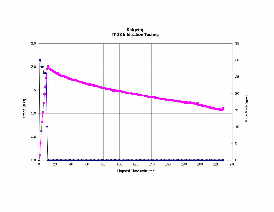
0
5
10
15
20
25
30
35
0.0
0.5
1.0
1.5
2.0
2.5
0 20 40 60 80 100 120 140 160 180 200 220 240
Flow
Rat
e (g
pm)
Stag
e (fe
et)
Elapsed Time (minutes)
RidgetopIT-33 Infiltration Testing

Enter data in yellow cells.Project: Ridgetop Pit Depth: 8.0 Porosity: 100% Soil Type:Project No: KIT-14-1 Test Date: Effective Width 3.0 Volume/ft (gal/ft): 202.0 1,106 11.4Location: IT-34 12-Aug-14 Effective Length 9 Standing Water: dry Looks Back Looks back Forward
Time Time into Test (min)
Meter Flow Rate (gpm)
Totalizer reading (gal)
Total Inflow (gal) Staff Gauge (ft) Stage (ft)
Rate of WL Change (in/hr)
Storage Rate (gpm)
Corrected Outflow (gpm)
Infiltration Rate (in./hr) Comments
9:04 0.0 0 Total Flow: 1,106 -0.049:05 1.0 33 33 0.10 100.8 28.3 7.19:06 2.0 33 66 0.23 92.2 25.9 1.19:07 3.0 33 99 0.39 113.8 31.9 3.19:08 4.0 33 132 0.54 106.6 29.9 5.19:09 5.0 33 165 0.68 99.4 27.9 6.79:10 6.0 30 195 0.81 93.6 26.3 5.49:11 7.0 30 225 0.93 87.8 24.6 7.49:12 8.0 0 225 1.04 80.6 22.6 11.19:13 9.0 0 225 0.98 -39.6 -11.1 11.1 39.69:14 10.0 0 225 0.93 -39.6 -11.1 -3.29:15 11.0 0 225 0.95 11.5 3.2 8.3 29.59:16 12.0 0 225 0.90 -29.5 -8.3 6.3 22.39:17 13.0 0 225 0.87 -22.3 -6.3 8.3 29.59:18 14.0 0 225 0.83 -29.5 -8.3 6.5 23.09:19 15.0 0 225 0.80 -23.0 -6.5 2.0 7.29:20 16.0 0 225 0.79 -7.2 -2.0 5.9 20.99:21 17.0 0 225 0.76 -20.9 -5.9 5.9 20.99:22 18.0 0 225 0.73 -20.9 -5.9 3.8 13.79:23 19.0 0 225 0.71 -13.7 -3.8 7.7 27.49:24 20.0 0 225 0.68 -27.4 -7.7 5.7 20.29:25 21.0 0 225 0.65 -20.2 -5.7 5.9 20.99:26 22.0 0 225 0.62 -20.9 -5.9 6.1 21.69:27 23.0 0 225 0.59 -21.6 -6.1 4.2 15.19:28 24.0 0 225 0.57 -15.1 -4.2 5.9 20.99:29 25.0 0 225 0.54 -20.9 -5.9 3.2 11.5 Average:9:30 26.0 0 225 0.52 -11.5 -3.2 5.9 20.9 209:31 27.0 15 240 0.49 -20.9 -5.9 5.19:32 28.0 33 273 0.54 35.3 9.9 1.39:33 29.0 33 306 0.70 113.0 31.7 3.19:34 30.0 33 339 0.85 106.6 29.9 3.19:35 31.0 10 349 1.00 106.6 29.9 6.09:36 32.0 0 349 1.02 14.4 4.0 3.69:37 33.0 0 349 1.00 -13.0 -3.6 5.9 20.99:38 34.0 0 349 0.97 -20.9 -5.9 5.7 20.29:39 35.0 0 349 0.94 -20.2 -5.7 6.1 21.69:40 36.0 0 349 0.91 -21.6 -6.1 6.3 22.39:41 37.0 0 349 0.88 -22.3 -6.3 3.8 13.79:42 38.0 0 349 0.86 -13.7 -3.8 6.1 21.69:43 39.0 0 349 0.83 -21.6 -6.1 5.9 20.99:44 40.0 0 349 0.80 -20.9 -5.9 3.4 12.29:45 41.0 0 349 0.78 -12.2 -3.4 3.8 13.79:46 42.0 0 349 0.77 -13.7 -3.8 5.7 20.29:47 43.0 0 349 0.74 -20.2 -5.7 3.8 13.79:48 44.0 0 349 0.72 -13.7 -3.8 4.0 14.49:49 45.0 0 349 0.70 -14.4 -4.0 5.3 18.79:50 46.0 0 349 0.67 -18.7 -5.3 3.8 13.79:51 47.0 0 349 0.65 -13.7 -3.8 3.8 13.79:52 48.0 0 349 0.63 -13.7 -3.8 3.8 13.79:53 49.0 0 349 0.62 -13.7 -3.8 3.8 13.79:54 50.0 0 349 0.60 -13.7 -3.8 7.5 26.69:55 51.0 0 349 0.56 -26.6 -7.5 3.8 13.79:56 52.0 0 349 0.54 -13.7 -3.8 4.0 14.49:57 53.0 0 349 0.52 -14.4 -4.0 4.0 14.49:58 54.0 0 349 0.50 -14.4 -4.0 3.8 13.7 Average:9:59 55.0 0 349 0.48 -13.7 -3.8 3.8 13.7 15
10:00 56.0 33 382 0.46 -13.7 -3.8 -2.510:01 57.0 33 415 0.64 126.7 35.5 3.110:02 58.0 33 448 0.79 106.6 29.9 3.310:03 59.0 33 481 0.93 105.8 29.7 3.1
Estimated Rate:
Advance OutwashTotal Flow (gal):

0
5
10
15
20
25
30
35
0.0
0.2
0.4
0.6
0.8
1.0
1.2
0 20 40 60 80 100 120 140 160 180 200 220 240 260 280
Flow
Rat
e (g
pm)
Stag
e (fe
et)
Elapsed Time (minutes)
RidgetopIT-34 Infiltration Testing
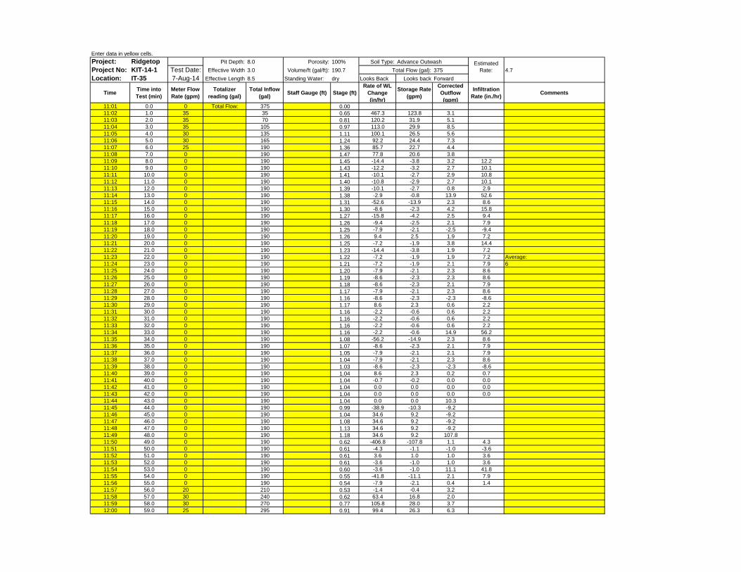
Enter data in yellow cells.Project: Ridgetop Pit Depth: 8.0 Porosity: 100% Soil Type:Project No: KIT-14-1 Test Date: Effective Width 3.0 Volume/ft (gal/ft): 190.7 375 4.7Location: IT-35 7-Aug-14 Effective Length 8.5 Standing Water: dry Looks Back Looks back Forward
Time Time into Test (min)
Meter Flow Rate (gpm)
Totalizer reading (gal)
Total Inflow (gal) Staff Gauge (ft) Stage (ft)
Rate of WL Change (in/hr)
Storage Rate (gpm)
Corrected Outflow (gpm)
Infiltration Rate (in./hr) Comments
11:01 0.0 0 Total Flow: 375 0.0011:02 1.0 35 35 0.65 467.3 123.8 3.111:03 2.0 35 70 0.81 120.2 31.9 5.111:04 3.0 35 105 0.97 113.0 29.9 8.511:05 4.0 30 135 1.11 100.1 26.5 5.611:06 5.0 30 165 1.24 92.2 24.4 7.311:07 6.0 25 190 1.36 85.7 22.7 4.411:08 7.0 0 190 1.47 77.8 20.6 3.811:09 8.0 0 190 1.45 -14.4 -3.8 3.2 12.211:10 9.0 0 190 1.43 -12.2 -3.2 2.7 10.111:11 10.0 0 190 1.41 -10.1 -2.7 2.9 10.811:12 11.0 0 190 1.40 -10.8 -2.9 2.7 10.111:13 12.0 0 190 1.39 -10.1 -2.7 0.8 2.911:14 13.0 0 190 1.38 -2.9 -0.8 13.9 52.611:15 14.0 0 190 1.31 -52.6 -13.9 2.3 8.611:16 15.0 0 190 1.30 -8.6 -2.3 4.2 15.811:17 16.0 0 190 1.27 -15.8 -4.2 2.5 9.411:18 17.0 0 190 1.26 -9.4 -2.5 2.1 7.911:19 18.0 0 190 1.25 -7.9 -2.1 -2.5 -9.411:20 19.0 0 190 1.26 9.4 2.5 1.9 7.211:21 20.0 0 190 1.25 -7.2 -1.9 3.8 14.411:22 21.0 0 190 1.23 -14.4 -3.8 1.9 7.211:23 22.0 0 190 1.22 -7.2 -1.9 1.9 7.2 Average:11:24 23.0 0 190 1.21 -7.2 -1.9 2.1 7.9 611:25 24.0 0 190 1.20 -7.9 -2.1 2.3 8.611:26 25.0 0 190 1.19 -8.6 -2.3 2.3 8.611:27 26.0 0 190 1.18 -8.6 -2.3 2.1 7.911:28 27.0 0 190 1.17 -7.9 -2.1 2.3 8.611:29 28.0 0 190 1.16 -8.6 -2.3 -2.3 -8.611:30 29.0 0 190 1.17 8.6 2.3 0.6 2.211:31 30.0 0 190 1.16 -2.2 -0.6 0.6 2.211:32 31.0 0 190 1.16 -2.2 -0.6 0.6 2.211:33 32.0 0 190 1.16 -2.2 -0.6 0.6 2.211:34 33.0 0 190 1.16 -2.2 -0.6 14.9 56.211:35 34.0 0 190 1.08 -56.2 -14.9 2.3 8.611:36 35.0 0 190 1.07 -8.6 -2.3 2.1 7.911:37 36.0 0 190 1.05 -7.9 -2.1 2.1 7.911:38 37.0 0 190 1.04 -7.9 -2.1 2.3 8.611:39 38.0 0 190 1.03 -8.6 -2.3 -2.3 -8.611:40 39.0 0 190 1.04 8.6 2.3 0.2 0.711:41 40.0 0 190 1.04 -0.7 -0.2 0.0 0.011:42 41.0 0 190 1.04 0.0 0.0 0.0 0.011:43 42.0 0 190 1.04 0.0 0.0 0.0 0.011:44 43.0 0 190 1.04 0.0 0.0 10.311:45 44.0 0 190 0.99 -38.9 -10.3 -9.211:46 45.0 0 190 1.04 34.6 9.2 -9.211:47 46.0 0 190 1.08 34.6 9.2 -9.211:48 47.0 0 190 1.13 34.6 9.2 -9.211:49 48.0 0 190 1.18 34.6 9.2 107.811:50 49.0 0 190 0.62 -406.8 -107.8 1.1 4.311:51 50.0 0 190 0.61 -4.3 -1.1 -1.0 -3.611:52 51.0 0 190 0.61 3.6 1.0 1.0 3.611:53 52.0 0 190 0.61 -3.6 -1.0 1.0 3.611:54 53.0 0 190 0.60 -3.6 -1.0 11.1 41.811:55 54.0 0 190 0.55 -41.8 -11.1 2.1 7.911:56 55.0 0 190 0.54 -7.9 -2.1 0.4 1.411:57 56.0 20 210 0.53 -1.4 -0.4 3.211:58 57.0 30 240 0.62 63.4 16.8 2.011:59 58.0 30 270 0.77 105.8 28.0 3.712:00 59.0 25 295 0.91 99.4 26.3 6.3
Estimated Rate:
Advance OutwashTotal Flow (gal):
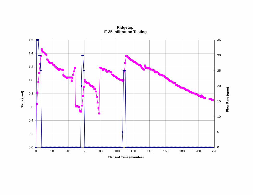
0
5
10
15
20
25
30
35
0.0
0.2
0.4
0.6
0.8
1.0
1.2
1.4
1.6
0 20 40 60 80 100 120 140 160 180 200 220
Flow
Rat
e (g
pm)
Stag
e (fe
et)
Elapsed Time (minutes)
RidgetopIT-35 Infiltration Testing

Enter data in yellow cells.Project: Ridgetop Pit Depth: 6.0 Porosity: 100% Soil Type:Project No: KIT-14-1 Test Date: Effective Width 3.0 Volume/ft (gal/ft): 179.5 1,035 14Location: IT-36 11-Aug-14 Effective Length 8 Standing Water: dry Looks Back Looks back Forward
Time Time into Test (min)
Meter Flow Rate (gpm)
Totalizer reading (gal)
Total Inflow (gal) Staff Gauge (ft) Stage (ft)
Rate of WL Change (in/hr)
Storage Rate (gpm)
Corrected Outflow (gpm)
Infiltration Rate (in./hr) Comments
9:26 0.0 0 Total Flow: 1,035 0.009:27 1.0 25 -0.02 -12.2 -3.19:28 2.0 25 25 0.58 431.3 107.59:29 3.0 25 50 0.70 84.2 21.0 -1.09:30 4.0 25 75 0.84 104.4 26.0 5.69:31 5.0 25 100 0.95 77.8 19.4 7.49:32 6.0 25 125 1.05 70.6 17.6 9.09:33 7.0 5 130 1.14 64.1 16.0 8.69:34 8.0 0 130 1.12 -14.4 -3.6 8.8 35.39:35 9.0 0 130 1.07 -35.3 -8.8 9.3 37.49:36 10.0 0 130 1.02 -37.4 -9.3 5.4 21.69:37 11.0 0 130 0.99 -21.6 -5.4 7.4 29.59:38 12.0 0 130 0.95 -29.5 -7.4 5.7 23.09:39 13.0 0 130 0.92 -23.0 -5.7 1.6 6.59:40 14.0 0 130 0.91 -6.5 -1.6 4.5 18.09:41 15.0 0 130 0.88 -18.0 -4.5 4.7 18.79:42 16.0 0 130 0.86 -18.7 -4.7 4.3 17.39:43 17.0 0 130 0.83 -17.3 -4.3 2.9 11.59:44 18.0 0 130 0.82 -11.5 -2.9 12.6 50.49:45 19.0 0 130 0.75 -50.4 -12.6 3.4 13.79:46 20.0 0 130 0.73 -13.7 -3.4 5.2 20.99:47 21.0 0 130 0.70 -20.9 -5.2 3.4 13.79:48 22.0 0 130 0.68 -13.7 -3.4 3.4 13.7 Average:9:49 23.0 0 130 0.66 -13.7 -3.4 5.0 20.2 209:50 24.0 28 158 0.63 -20.2 -5.0 5.29:51 25.0 28 186 0.76 91.4 22.8 5.09:52 26.0 28 214 0.89 92.2 23.0 7.09:53 27.0 28 242 1.00 84.2 21.0 6.89:54 28.0 0 242 1.12 85.0 21.2 4.39:55 29.0 0 242 1.10 -17.3 -4.3 5.4 21.69:56 30.0 0 242 1.07 -21.6 -5.4 7.2 28.89:57 31.0 0 242 1.03 -28.8 -7.2 5.4 21.69:58 32.0 0 242 1.00 -21.6 -5.4 3.6 14.49:59 33.0 0 242 0.98 -14.4 -3.6 4.3 17.3
10:00 34.0 0 242 0.95 -17.3 -4.3 3.2 13.010:01 35.0 0 242 0.94 -13.0 -3.2 5.2 20.910:02 36.0 0 242 0.91 -20.9 -5.2 4.8 19.410:03 37.0 0 242 0.88 -19.4 -4.8 3.4 13.710:04 38.0 0 242 0.86 -13.7 -3.4 0.310:06 39.4 0 242 0.86 -1.0 -0.3 -1.610:07 40.4 0 242 0.87 6.5 1.6 12.410:08 41.4 0 242 0.80 -49.7 -12.4 7.2 28.810:09 42.4 0 242 0.76 -28.8 -7.2 7.0 28.110:10 43.4 0 242 0.72 -28.1 -7.0 5.7 23.010:11 44.4 0 242 0.69 -23.0 -5.7 5.6 22.310:12 45.4 0 242 0.66 -22.3 -5.6 3.9 15.8 Average:10:13 46.4 0 242 0.63 -15.8 -3.9 3.9 15.8 2210:14 47.4 25 267 0.61 -15.8 -3.9 4.210:15 48.4 25 292 0.73 83.5 20.8 2.010:16 49.4 25 317 0.86 92.2 23.0 4.010:17 50.4 25 342 0.97 84.2 21.0 4.010:18 51.4 0 342 1.09 84.2 21.0 3.6 14.410:19 52.4 0 342 1.07 -14.4 -3.6 4.1 16.610:20 53.4 0 342 1.05 -16.6 -4.1 5.4 21.610:21 54.4 0 342 1.02 -21.6 -5.4 5.2 20.910:22 55.4 0 342 0.99 -20.9 -5.2 5.4 21.610:23 56.4 0 342 0.96 -21.6 -5.4 3.4 13.710:24 57.4 0 342 0.94 -13.7 -3.4 5.4 21.610:25 58.4 0 342 0.91 -21.6 -5.4 3.6 14.410:26 59.4 0 342 0.89 -14.4 -3.6 5.2 20.9
Estimated Rate:
Advance OutwashTotal Flow (gal):

0
5
10
15
20
25
30
35
0.0
0.2
0.4
0.6
0.8
1.0
1.2
1.4
0 20 40 60 80 100 120 140 160 180 200 220 240 260 280
Flow
Rat
e (g
pm)
Stag
e (fe
et)
Elapsed Time (minutes)
RidgetopIT-36 Infiltration Testing
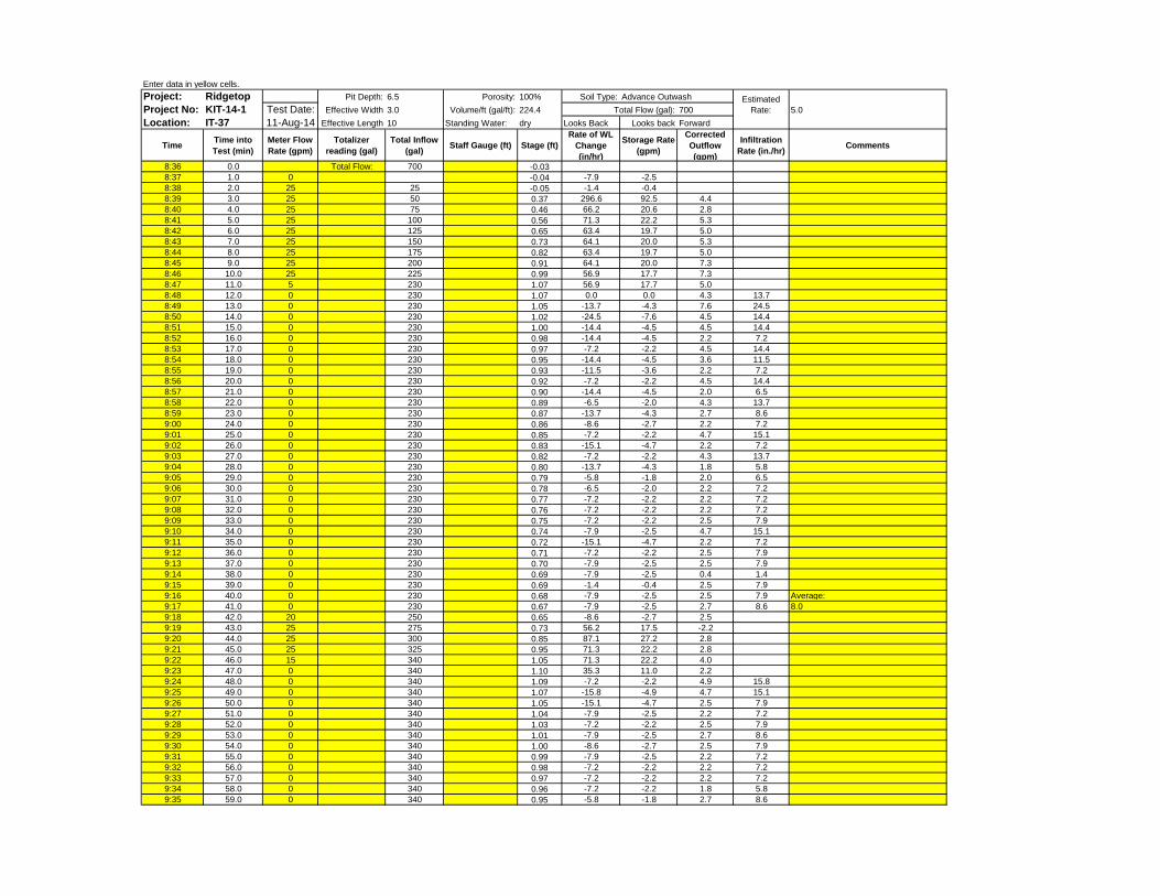
Enter data in yellow cells.Project: Ridgetop Pit Depth: 6.5 Porosity: 100% Soil Type:Project No: KIT-14-1 Test Date: Effective Width 3.0 Volume/ft (gal/ft): 224.4 700 5.0Location: IT-37 11-Aug-14 Effective Length 10 Standing Water: dry Looks Back Looks back Forward
Time Time into Test (min)
Meter Flow Rate (gpm)
Totalizer reading (gal)
Total Inflow (gal) Staff Gauge (ft) Stage (ft)
Rate of WL Change (in/hr)
Storage Rate (gpm)
Corrected Outflow (gpm)
Infiltration Rate (in./hr) Comments
8:36 0.0 Total Flow: 700 -0.038:37 1.0 0 -0.04 -7.9 -2.58:38 2.0 25 25 -0.05 -1.4 -0.48:39 3.0 25 50 0.37 296.6 92.5 4.48:40 4.0 25 75 0.46 66.2 20.6 2.88:41 5.0 25 100 0.56 71.3 22.2 5.38:42 6.0 25 125 0.65 63.4 19.7 5.08:43 7.0 25 150 0.73 64.1 20.0 5.38:44 8.0 25 175 0.82 63.4 19.7 5.08:45 9.0 25 200 0.91 64.1 20.0 7.38:46 10.0 25 225 0.99 56.9 17.7 7.38:47 11.0 5 230 1.07 56.9 17.7 5.08:48 12.0 0 230 1.07 0.0 0.0 4.3 13.78:49 13.0 0 230 1.05 -13.7 -4.3 7.6 24.58:50 14.0 0 230 1.02 -24.5 -7.6 4.5 14.48:51 15.0 0 230 1.00 -14.4 -4.5 4.5 14.48:52 16.0 0 230 0.98 -14.4 -4.5 2.2 7.28:53 17.0 0 230 0.97 -7.2 -2.2 4.5 14.48:54 18.0 0 230 0.95 -14.4 -4.5 3.6 11.58:55 19.0 0 230 0.93 -11.5 -3.6 2.2 7.28:56 20.0 0 230 0.92 -7.2 -2.2 4.5 14.48:57 21.0 0 230 0.90 -14.4 -4.5 2.0 6.58:58 22.0 0 230 0.89 -6.5 -2.0 4.3 13.78:59 23.0 0 230 0.87 -13.7 -4.3 2.7 8.69:00 24.0 0 230 0.86 -8.6 -2.7 2.2 7.29:01 25.0 0 230 0.85 -7.2 -2.2 4.7 15.19:02 26.0 0 230 0.83 -15.1 -4.7 2.2 7.29:03 27.0 0 230 0.82 -7.2 -2.2 4.3 13.79:04 28.0 0 230 0.80 -13.7 -4.3 1.8 5.89:05 29.0 0 230 0.79 -5.8 -1.8 2.0 6.59:06 30.0 0 230 0.78 -6.5 -2.0 2.2 7.29:07 31.0 0 230 0.77 -7.2 -2.2 2.2 7.29:08 32.0 0 230 0.76 -7.2 -2.2 2.2 7.29:09 33.0 0 230 0.75 -7.2 -2.2 2.5 7.99:10 34.0 0 230 0.74 -7.9 -2.5 4.7 15.19:11 35.0 0 230 0.72 -15.1 -4.7 2.2 7.29:12 36.0 0 230 0.71 -7.2 -2.2 2.5 7.99:13 37.0 0 230 0.70 -7.9 -2.5 2.5 7.99:14 38.0 0 230 0.69 -7.9 -2.5 0.4 1.49:15 39.0 0 230 0.69 -1.4 -0.4 2.5 7.99:16 40.0 0 230 0.68 -7.9 -2.5 2.5 7.9 Average:9:17 41.0 0 230 0.67 -7.9 -2.5 2.7 8.6 8.09:18 42.0 20 250 0.65 -8.6 -2.7 2.59:19 43.0 25 275 0.73 56.2 17.5 -2.29:20 44.0 25 300 0.85 87.1 27.2 2.89:21 45.0 25 325 0.95 71.3 22.2 2.89:22 46.0 15 340 1.05 71.3 22.2 4.09:23 47.0 0 340 1.10 35.3 11.0 2.29:24 48.0 0 340 1.09 -7.2 -2.2 4.9 15.89:25 49.0 0 340 1.07 -15.8 -4.9 4.7 15.19:26 50.0 0 340 1.05 -15.1 -4.7 2.5 7.99:27 51.0 0 340 1.04 -7.9 -2.5 2.2 7.29:28 52.0 0 340 1.03 -7.2 -2.2 2.5 7.99:29 53.0 0 340 1.01 -7.9 -2.5 2.7 8.69:30 54.0 0 340 1.00 -8.6 -2.7 2.5 7.99:31 55.0 0 340 0.99 -7.9 -2.5 2.2 7.29:32 56.0 0 340 0.98 -7.2 -2.2 2.2 7.29:33 57.0 0 340 0.97 -7.2 -2.2 2.2 7.29:34 58.0 0 340 0.96 -7.2 -2.2 1.8 5.89:35 59.0 0 340 0.95 -5.8 -1.8 2.7 8.6
Estimated Rate:
Advance OutwashTotal Flow (gal):

0
5
10
15
20
25
30
35
0.0
0.2
0.4
0.6
0.8
1.0
1.2
0 20 40 60 80 100 120 140 160 180 200 220 240 260 280
Flow
Rat
e (g
pm)
Stag
e (fe
et)
Elapsed Time (minutes)
RidgetopIT-37 Infiltration Testing
Stage (ft) Meter Flow (gpm)

Enter data in yellow cells.Project: Ridgetop Pit Depth: 7.5 Porosity: 100% Soil Type:Project No: KIT-14-1 Test Date: Effective Width 2.5 Volume/ft (gal/ft): 140.3 1,024 15.4Location: IT-38 7-Aug-14 Effective Length 7.5 Standing Water: dry Looks Back Looks back Forward
Time Time into Test (min)
Meter Flow Rate (gpm)
Totalizer reading (gal)
Total Inflow (gal) Staff Gauge (ft) Stage (ft)
Rate of WL Change (in/hr)
Storage Rate (gpm)
Corrected Outflow (gpm)
Infiltration Rate (in./hr) Comments
10:04 0.0 0 Total Flow: 1,024 0.1110:05 1.0 0 0.11 0.0 0.010:06 2.0 0 0.11 -0.7 -0.110:07 3.0 25 25 0.32 156.2 30.4 4.510:08 4.0 25 50 0.47 105.1 20.5 4.210:09 5.0 25 75 0.62 106.6 20.8 6.510:10 6.0 25 100 0.75 95.0 18.5 8.310:11 7.0 25 125 0.87 85.7 16.7 7.010:12 8.0 25 150 1.00 92.2 18.0 9.910:13 9.0 25 175 1.10 77.8 15.1 9.910:14 10.0 15 190 1.21 77.8 15.1 9.710:15 11.0 0 190 1.25 27.4 5.3 8.3 42.510:16 12.0 0 190 1.19 -42.5 -8.3 8.3 42.510:17 13.0 0 190 1.13 -42.5 -8.3 5.6 28.810:18 14.0 0 190 1.09 -28.8 -5.6 6.9 35.310:19 15.0 0 190 1.04 -35.3 -6.9 5.5 28.110:20 16.0 0 190 1.00 -28.1 -5.5 5.5 28.110:21 17.0 0 190 0.96 -28.1 -5.5 5.6 28.810:22 18.0 0 190 0.92 -28.8 -5.6 5.6 28.810:23 19.0 0 190 0.88 -28.8 -5.6 5.6 28.810:24 20.0 0 190 0.84 -28.8 -5.6 3.8 19.410:25 21.0 0 190 0.82 -19.4 -3.8 4.2 21.610:26 22.0 0 190 0.79 -21.6 -4.2 5.5 28.110:27 23.0 0 190 0.75 -28.1 -5.5 4.2 21.610:28 24.0 0 190 0.72 -21.6 -4.2 4.1 20.910:29 25.0 0 190 0.69 -20.9 -4.1 4.1 20.910:30 26.0 0 190 0.66 -20.9 -4.1 4.1 20.910:31 27.0 0 190 0.63 -20.9 -4.1 4.2 21.610:32 28.0 0 190 0.60 -21.6 -4.2 4.1 20.9 Average:10:33 29.0 0 190 0.57 -20.9 -4.1 4.2 21.6 2210:34 30.0 0 190 0.54 -21.6 -4.2 2.8 14.410:35 31.0 20 210 0.52 -14.4 -2.8 6.010:36 32.0 25 235 0.62 72.0 14.0 1.610:37 33.0 25 260 0.79 120.2 23.4 4.210:38 34.0 25 285 0.94 106.6 20.8 7.010:39 35.0 25 310 1.07 92.2 18.0 7.310:40 36.0 7 317 1.19 90.7 17.7 4.3 22.310:41 37.0 0 317 1.21 13.7 2.7 5.5 28.110:42 38.0 0 317 1.17 -28.1 -5.5 5.5 28.110:43 39.0 0 317 1.13 -28.1 -5.5 4.2 21.610:44 40.0 0 317 1.10 -21.6 -4.2 4.1 20.910:45 41.0 0 317 1.07 -20.9 -4.1 5.6 28.810:46 42.0 0 317 1.03 -28.8 -5.6 4.1 20.910:47 43.0 0 317 1.00 -20.9 -4.1 4.2 21.610:48 44.0 0 317 0.97 -21.6 -4.2 4.1 20.910:49 45.0 0 317 0.95 -20.9 -4.1 4.3 22.310:50 46.0 0 317 0.91 -22.3 -4.3 3.9 20.210:51 47.0 5 322 0.89 -20.2 -3.9 5.0 25.710:52 48.0 25 347 0.89 0.0 0.0 5.810:53 49.0 25 372 1.02 98.6 19.2 5.610:54 50.0 15 387 1.16 99.4 19.4 5.510:55 51.0 0 387 1.23 49.0 9.5 4.2 21.610:56 52.0 0 387 1.20 -21.6 -4.2 5.6 28.810:57 53.0 0 387 1.16 -28.8 -5.6 4.2 21.610:58 54.0 0 387 1.13 -21.6 -4.2 4.2 21.610:59 55.0 0 387 1.10 -21.6 -4.2 3.5 18.011:00 56.0 0 387 1.07 -18.0 -3.5 4.1 20.911:01 57.0 0 387 1.05 -20.9 -4.1 4.1 20.911:02 58.0 0 387 1.02 -20.9 -4.1 4.1 20.911:03 59.0 0 387 0.99 -20.9 -4.1 4.1 20.9
Estimated Rate:
Advance OutwashTotal Flow (gal):

0
5
10
15
20
25
30
35
0.0
0.2
0.4
0.6
0.8
1.0
1.2
1.4
0 20 40 60 80 100 120 140 160 180 200 220 240 260 280 300
Flow
Rat
e (g
pm)
Stag
e (fe
et)
Elapsed Time (minutes)
RidgetopIT-38 Infiltration Testing
Stage (ft) Meter Flow (gpm)

Enter data in yellow cells.Project: Ridgetop Pit Depth: 4.0 Porosity: 100% Soil Type:Project No: KIT-14-1 Test Date: Effective Width 3.0 Volume/ft (gal/ft): 179.5 1,215 23Location: IT-39 7-Aug-14 Effective Length 8 Standing Water: dry Looks Back Looks back Forward
Time Time into Test (min)
Meter Flow Rate (gpm)
Totalizer reading (gal)
Total Inflow (gal) Staff Gauge (ft) Stage (ft)
Rate of WL Change (in/hr)
Storage Rate (gpm)
Corrected Outflow (gpm)
Infiltration Rate (in./hr) Comments
9:23 0.0 0 Total Flow: 1,215 0.489:24 1.0 0 0.45 -20.9 -5.29:25 2.0 0 0.40 -30.2 -7.59:26 3.0 0 0 0.36 -28.8 -7.2 6.8 27.49:27 4.0 0 0 0.33 -27.4 -6.8 5.2 20.99:28 5.0 0 0 0.30 -20.9 -5.2 7.0 28.19:29 6.0 0 0 0.26 -28.1 -7.0 7.7 31.09:30 7.0 0 0 0.22 -31.0 -7.7 5.4 21.69:31 8.0 0 0 0.19 -21.6 -5.4 3.4 13.7 Average:9:32 9.0 25 25 0.17 -13.7 -3.4 3.8 249:33 10.0 25 50 0.28 85.0 21.2 9.29:34 11.0 25 75 0.37 63.4 15.8 9.29:35 12.0 15 90 0.46 63.4 15.8 8.09:36 13.0 0 90 0.50 28.1 7.0 7.0 28.19:37 14.0 0 90 0.46 -28.1 -7.0 7.2 28.89:38 15.0 0 90 0.42 -28.8 -7.2 5.4 21.69:39 16.0 0 90 0.39 -21.6 -5.4 4.8 19.49:40 17.0 0 90 0.36 -19.4 -4.8 7.0 28.19:41 18.0 0 90 0.32 -28.1 -7.0 5.2 20.99:42 19.0 0 90 0.30 -20.9 -5.2 7.4 29.59:43 20.0 0 90 0.25 -29.5 -7.4 7.0 28.19:44 21.0 0 90 0.22 -28.1 -7.0 6.8 27.49:45 22.0 0 90 0.18 -27.4 -6.8 5.2 20.99:46 23.0 0 90 0.15 -20.9 -5.2 7.0 28.1 Average:9:47 24.0 25 115 0.11 -28.1 -7.0 3.8 269:48 25.0 25 140 0.23 85.0 21.2 7.49:49 26.0 25 165 0.33 70.6 17.6 9.29:50 27.0 20 185 0.41 63.4 15.8 6.29:51 28.0 0 185 0.49 55.4 13.8 3.6 14.49:52 29.0 0 185 0.47 -14.4 -3.6 5.7 23.09:53 30.0 0 185 0.44 -23.0 -5.7 5.4 21.69:54 31.0 0 185 0.41 -21.6 -5.4 5.2 20.99:55 32.0 0 185 0.38 -20.9 -5.2 7.0 28.19:56 33.0 0 185 0.34 -28.1 -7.0 5.2 20.99:57 34.0 0 185 0.31 -20.9 -5.2 7.0 28.19:58 35.0 15 200 0.27 -28.1 -7.0 9.49:59 36.0 25 225 0.30 22.3 5.6 9.9
10:00 37.0 25 250 0.39 60.5 15.1 10.810:01 38.0 5 255 0.47 56.9 14.2 3.2 12.910:02 39.0 0 255 0.48 7.2 1.8 5.4 21.610:03 40.0 0 255 0.45 -21.6 -5.4 7.0 28.110:04 41.0 0 255 0.41 -28.1 -7.0 5.4 21.610:05 42.0 0 255 0.38 -21.6 -5.4 7.2 28.810:06 43.0 0 255 0.34 -28.8 -7.2 5.4 21.610:07 44.0 0 255 0.31 -21.6 -5.4 7.2 28.810:08 45.0 0 255 0.27 -28.8 -7.2 5.4 21.610:09 46.0 0 255 0.24 -21.6 -5.4 6.3 25.210:10 47.0 0 255 0.20 -25.2 -6.3 6.8 27.410:11 48.0 0 255 0.16 -27.4 -6.8 7.2 28.810:12 49.0 0 255 0.12 -28.8 -7.2 5.2 20.9 Average:10:13 50.0 0 255 0.10 -20.9 -5.2 7.2 28.8 2510:14 51.0 0 255 0.06 -28.8 -7.2 7.4 29.510:15 52.0 0 255 0.01 -29.5 -7.4 7.0 28.110:16 53.0 0 255 -0.03 -28.1 -7.0 7.2 28.810:17 54.0 0 255 -0.07 -28.8 -7.2 8.8 35.310:18 55.0 0 255 -0.11 -35.3 -8.8 3.6 14.410:19 56.0 0 255 -0.13 -14.4 -3.6 0.0 0.010:20 57.0 0 255 -0.13 0.0 0.0 1.6 6.510:21 58.0 0 255 -0.14 -6.5 -1.6 0.0 0.010:22 59.0 0 255 -0.14 0.0 0.0 -1.4 -5.8
Estimated Rate:
Advance OutwashTotal Flow (gal):

0
5
10
15
20
25
30
35
0.0
0.1
0.2
0.3
0.4
0.5
0.6
0.7
0 20 40 60 80 100 120 140 160 180 200 220 240
Flow
Rat
e (g
pm)
Stag
e (fe
et)
Elapsed Time (minutes)
RidgetopIT-39 Infiltration Testing
Stage (ft) Meter Flow (gpm)

Enter data in yellow cells.Project: Ridgetop Pit Depth: 10.0 Porosity: 100% Soil Type:Project No: KIT-14-1 Test Date: Effective Width 2.0 Volume/ft (gal/ft): 112.2 300 4.60Location: IT-40 26-Aug-14 Effective Length 7.5 Standing Water: dry Looks Back Looks back Forward
Time Time into Test (min)
Meter Flow Rate (gpm)
Totalizer reading (gal)
Total Inflow (gal) Staff Gauge (ft) Stage (ft)
Rate of WL Change (in/hr)
Storage Rate (gpm)
Corrected Outflow (gpm)
Infiltration Rate (in./hr) Comments
10:42 0.0 0 Total Flow: 300 0.0210:43 1.0 20 20 0.37 249.1 38.8 -14.310:44 2.0 20 40 0.67 220.3 34.3 -4.310:45 3.0 20 60 0.89 156.2 24.3 -2.210:46 4.0 20 80 1.09 142.6 22.2 1.010:47 5.0 20 100 1.26 121.7 19.0 3.510:48 6.0 15 115 1.41 105.8 16.5 0.510:49 7.0 15 130 1.53 92.9 14.5 0.310:50 8.0 15 145 1.67 94.3 14.7 1.610:51 9.0 15 160 1.78 85.7 13.4 1.610:52 10.0 15 175 1.90 85.7 13.4 1.610:53 11.0 15 190 2.02 85.7 13.4 2.710:54 12.0 15 205 2.13 79.2 12.3 2.710:55 13.0 15 220 2.24 79.2 12.3 18.310:56 14.0 0 220 2.21 -20.9 -3.3 2.010:57 15.0 0 220 2.20 -13.0 -2.0 2.2 14.410:58 16.0 0 220 2.18 -14.4 -2.2 1.0 6.510:59 17.0 0 220 2.17 -6.5 -1.0 2.9 18.711:00 18.0 0 220 2.14 -18.7 -2.9 2.1 13.711:01 19.0 0 220 2.12 -13.7 -2.1 2.2 14.411:02 20.0 0 220 2.10 -14.4 -2.2 1.0 6.511:03 21.0 0 220 2.09 -6.5 -1.0 1.1 7.211:04 22.0 0 220 2.08 -7.2 -1.1 2.5 15.811:05 23.0 0 220 2.06 -15.8 -2.5 1.0 6.511:06 24.0 0 220 2.05 -6.5 -1.0 2.1 13.711:07 25.0 0 220 2.03 -13.7 -2.1 1.0 6.511:08 26.0 0 220 2.02 -6.5 -1.0 1.0 6.511:09 27.0 0 220 2.01 -6.5 -1.0 2.0 13.011:10 28.0 0 220 2.00 -13.0 -2.0 2.1 13.711:11 29.0 0 220 1.98 -13.7 -2.1 1.1 7.211:12 30.0 0 220 1.97 -7.2 -1.1 1.0 6.511:13 31.0 0 220 1.96 -6.5 -1.0 1.1 7.211:14 32.0 0 220 1.95 -7.2 -1.1 1.7 10.811:15 33.0 0 220 1.93 -10.8 -1.7 1.0 6.511:16 34.0 0 220 1.92 -6.5 -1.0 1.2 7.911:17 35.0 0 220 1.91 -7.9 -1.2 2.2 14.411:18 36.0 0 220 1.89 -14.4 -2.2 1.2 7.911:19 37.0 0 220 1.88 -7.9 -1.2 0.6 3.611:20 38.0 0 220 1.88 -3.6 -0.6 0.9 5.8 Average:11:21 39.0 0 220 1.87 -5.8 -0.9 1.0 6.5 8.711:22 40.0 0 220 1.86 -6.5 -1.0 1.0 6.511:23 41.0 0 220 1.85 -6.5 -1.0 1.0 6.511:24 42.0 0 220 1.84 -6.5 -1.0 2.0 13.011:25 43.0 0 220 1.82 -13.0 -2.0 1.1 7.211:26 44.0 0 220 1.81 -7.2 -1.1 1.1 7.211:27 45.0 0 220 1.80 -7.2 -1.1 0.9 5.811:28 46.0 0 220 1.80 -5.8 -0.9 1.1 7.211:29 47.0 0 220 1.79 -7.2 -1.1 1.5 9.411:30 48.0 0 220 1.77 -9.4 -1.5 1.1 7.211:31 49.0 0 220 1.76 -7.2 -1.1 1.1 7.211:32 50.0 0 220 1.75 -7.2 -1.1 1.1 7.211:33 51.0 0 220 1.74 -7.2 -1.1 0.9 5.811:34 52.0 0 220 1.74 -5.8 -0.9 0.3 2.211:35 53.0 0 220 1.73 -2.2 -0.3 1.0 6.511:36 54.0 0 220 1.72 -6.5 -1.0 1.0 6.511:37 55.0 0 220 1.71 -6.5 -1.0 1.0 6.511:38 56.0 0 220 1.71 -6.5 -1.0 1.0 6.511:39 57.0 0 220 1.70 -6.5 -1.0 2.1 13.711:40 58.0 0 220 1.68 -13.7 -2.1 1.0 6.511:41 59.0 0 220 1.67 -6.5 -1.0 1.0 6.5
Estimated Rate:
Glacial tillTotal Flow (gal):

0
5
10
15
20
25
30
35
0.0
0.5
1.0
1.5
2.0
2.5
0 20 40 60 80 100 120 140 160 180 200 220
Flow
Rat
e (g
pm)
Stag
e (fe
et)
Elapsed Time (minutes)
RidgetopIT-40 Infiltration Testing
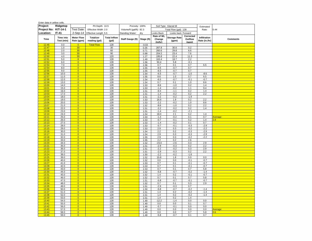
Enter data in yellow cells.Project: Ridgetop Pit Depth: 10.5 Porosity: 100% Soil Type:Project No: KIT-14-1 Test Date: Effective Width 2.0 Volume/ft (gal/ft): 82.3 128 0.44Location: IT-41 2-Sep-14 Effective Length 5.5 Standing Water: dry Looks Back Looks back Forward
Time Time into Test (min)
Meter Flow Rate (gpm)
Totalizer reading (gal)
Total Inflow (gal) Staff Gauge (ft) Stage (ft)
Rate of WL Change (in/hr)
Storage Rate (gpm)
Corrected Outflow (gpm)
Infiltration Rate (in./hr) Comments
12:46 0.0 0 Total Flow: 128 -0.0312:47 1.0 30 30 0.35 267.8 30.6 0.212:48 2.0 30 60 0.71 260.6 29.8 6.612:49 3.0 30 90 0.99 204.5 23.4 7.612:50 4.0 30 120 1.27 195.8 22.4 11.312:51 5.0 8 128 1.49 163.4 18.7 2.212:52 6.0 0 128 1.56 50.4 5.8 -0.112:53 7.0 0 128 1.56 0.7 0.1 0.7 6.512:54 8.0 0 128 1.55 -6.5 -0.7 0.712:55 9.0 0 128 1.55 -6.5 -0.7 0.712:56 10.0 0 128 1.54 -6.5 -0.7 -1.0 -8.612:57 11.0 0 128 1.55 8.6 1.0 0.7 6.512:58 12.0 0 128 1.54 -6.5 -0.7 -0.1 -0.712:59 13.0 0 128 1.54 0.7 0.1 1.0 8.613:00 14.0 0 128 1.53 -8.6 -1.0 0.2 1.413:01 15.0 0 128 1.53 -1.4 -0.2 1.1 9.413:02 16.0 0 128 1.51 -9.4 -1.1 0.2 1.413:03 17.0 0 128 1.51 -1.4 -0.2 0.2 2.213:04 18.0 0 128 1.51 -2.2 -0.2 -1.913:05 19.0 0 128 1.53 16.6 1.9 0.2 2.213:06 20.0 0 128 1.53 -2.2 -0.2 1.0 8.613:07 21.0 0 128 1.52 -8.6 -1.0 0.2 2.213:08 22.0 0 128 1.51 -2.2 -0.2 0.2 1.413:09 23.0 0 128 1.51 -1.4 -0.2 -2.113:10 24.0 0 128 1.54 18.0 2.1 0.2 1.413:11 25.0 0 128 1.53 -1.4 -0.2 0.1 0.7 Average:13:12 26.0 0 128 1.53 -0.7 -0.1 0.2 1.4 2.813:13 27.0 0 128 1.53 -1.4 -0.2 0.1 0.713:14 28.0 0 128 1.53 -0.7 -0.1 -0.3 -2.913:15 29.0 0 128 1.53 2.9 0.3 -0.2 -2.213:16 30.0 0 128 1.54 2.2 0.2 -0.3 -2.913:17 31.0 0 128 1.54 2.9 0.3 -0.3 -2.913:18 32.0 0 128 1.55 2.9 0.3 -0.2 -2.213:19 33.0 0 128 1.55 2.2 0.2 2.613:20 34.0 0 128 1.52 -23.0 -2.6 0.3 2.913:21 35.0 0 128 1.51 -2.9 -0.3 0.2 2.213:22 36.0 0 128 1.51 -2.2 -0.2 0.3 2.913:23 37.0 0 128 1.51 -2.9 -0.3 0.2 2.213:24 38.0 0 128 1.50 -2.2 -0.2 -1.813:25 39.0 0 128 1.52 15.8 1.8 0.0 0.013:26 40.0 0 128 1.52 0.0 0.0 -0.1 -0.713:27 41.0 0 128 1.53 0.7 0.1 -0.1 -0.713:28 42.0 0 128 1.53 0.7 0.1 -0.1 -0.713:29 43.0 0 128 1.53 0.7 0.1 0.7 5.813:30 44.0 0 128 1.52 -5.8 -0.7 -0.2 -1.413:31 45.0 0 128 1.52 1.4 0.2 -0.1 -0.713:32 46.0 0 128 1.52 0.7 0.1 0.7 5.813:33 47.0 0 128 1.51 -5.8 -0.7 -0.1 -0.713:34 48.0 0 128 1.52 0.7 0.1 0.3 2.913:35 49.0 0 128 1.51 -2.9 -0.3 0.713:36 50.0 0 128 1.50 -5.8 -0.7 -0.2 -1.413:37 51.0 0 128 1.51 1.4 0.2 -0.2 -1.413:38 52.0 0 128 1.51 1.4 0.2 -0.2 -1.413:39 53.0 0 128 1.51 1.4 0.2 1.413:40 54.0 0 128 1.49 -12.2 -1.4 0.0 0.013:41 55.0 0 128 1.49 0.0 0.0 0.1 0.713:42 56.0 0 128 1.49 -0.7 -0.1 0.0 0.013:43 57.0 0 128 1.49 0.0 0.0 0.0 0.0 Average:13:44 58.0 0 128 1.49 0.0 0.0 0.7 5.8 0.613:45 59.0 0 128 1.48 -5.8 -0.7 0.1 0.7
Estimated Rate:
Glacial tillTotal Flow (gal):

0
5
10
15
20
25
30
35
0.0
0.2
0.4
0.6
0.8
1.0
1.2
1.4
1.6
1.8
0 20 40 60 80
Flow
Rat
e (g
pm)
Stag
e (fe
et)
Elapsed Time (minutes)
RidgetopIT-41 Infiltration Testing

APPENDIX D
Borehole Infiltration Testing and Hydraulic Conductivity Analyses
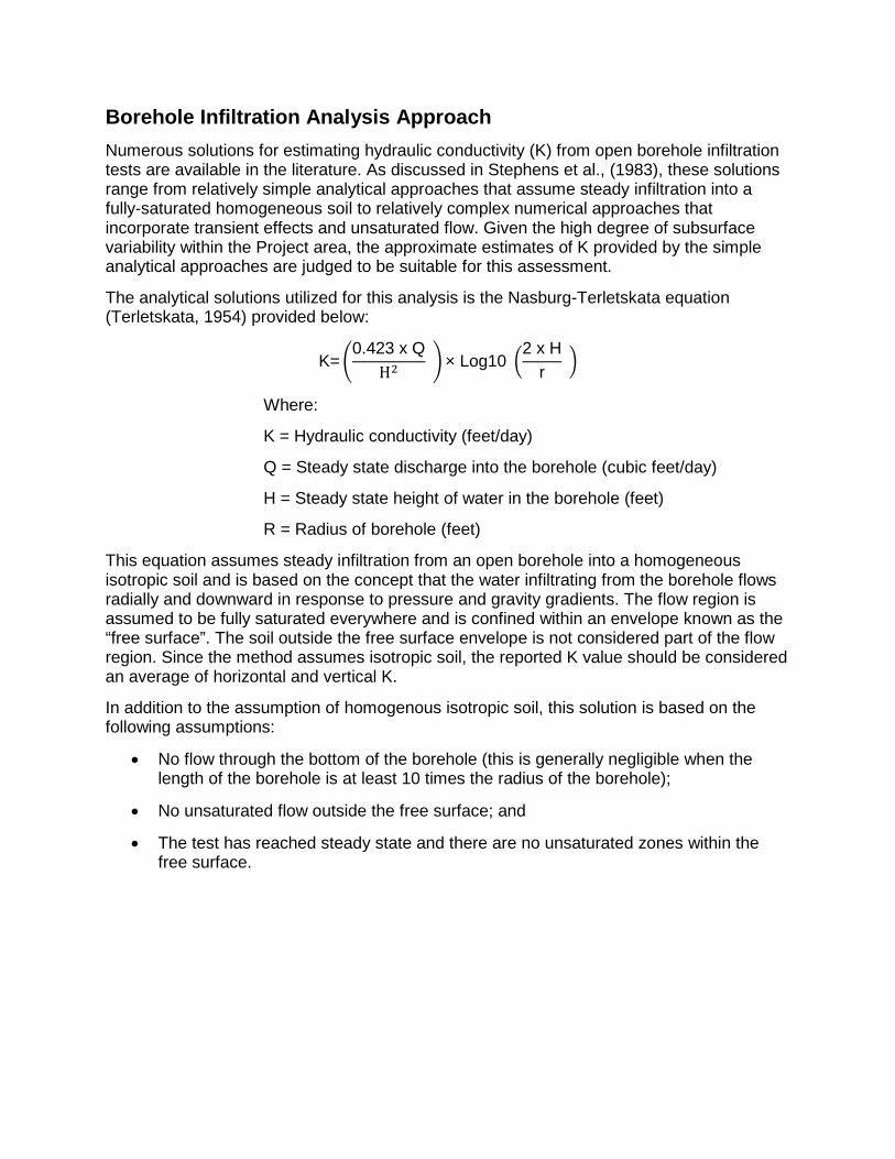
Borehole Infiltration Analysis Approach Numerous solutions for estimating hydraulic conductivity (K) from open borehole infiltration tests are available in the literature. As discussed in Stephens et al., (1983), these solutions range from relatively simple analytical approaches that assume steady infiltration into a fully-saturated homogeneous soil to relatively complex numerical approaches that incorporate transient effects and unsaturated flow. Given the high degree of subsurface variability within the Project area, the approximate estimates of K provided by the simple analytical approaches are judged to be suitable for this assessment.
The analytical solutions utilized for this analysis is the Nasburg-Terletskata equation (Terletskata, 1954) provided below:
K=�0.423 x Q
H2 �× Log10 �2 x H
r �
Where:
K = Hydraulic conductivity (feet/day)
Q = Steady state discharge into the borehole (cubic feet/day)
H = Steady state height of water in the borehole (feet)
R = Radius of borehole (feet)
This equation assumes steady infiltration from an open borehole into a homogeneous isotropic soil and is based on the concept that the water infiltrating from the borehole flows radially and downward in response to pressure and gravity gradients. The flow region is assumed to be fully saturated everywhere and is confined within an envelope known as the “free surface”. The soil outside the free surface envelope is not considered part of the flow region. Since the method assumes isotropic soil, the reported K value should be considered an average of horizontal and vertical K.
In addition to the assumption of homogenous isotropic soil, this solution is based on the following assumptions:
• No flow through the bottom of the borehole (this is generally negligible when the length of the borehole is at least 10 times the radius of the borehole);
• No unsaturated flow outside the free surface; and
• The test has reached steady state and there are no unsaturated zones within the free surface.

Table D-1: Summary of Borehole Infiltration Tests
Kindred Hydro, Inc.9/16/14Ridgetop Aug 2014 Borehole Infiltration Testing.xlsx
Table D-1: Summary of Borehole Infiltration TestsPage 1 of 4
Borehole B-101 B-102Total Depth 50 60
Tested Interval (depth in ft) 40-50 40-60Tested Interval USCS Class SM SP to SM
Soil Type outwash outwashEstimated K Values using Nasburg-Terletskata SolutionK (ft/day) 11.8 5.1K (inch/hr) 5.9 2.6K (cm/sec) 4.2E-03 1.8E-03Vertical Infiltration Rate ObservationVertical K (inch/hr) 8.2 N/AN/A = Not available because test did not reach constant rate of decline during the test.

9/16/14C:\Users\Scott\OneDrive @ Kindred Hydro, Inc-\Projects\Ridgetop\Data\Analyses\Ridgetop Aug 2014 Borehole Infiltration Testing.xlsx
B-101 Borehole Infiltration TestKIT-14-1 Ridgetop Boulevard
Total Flux (gal)= 829Ave= 9.9 7.5 8.2 0.5
Date-TimeTime
(min.) Head (ft)Inflow (gpm)
Inf. Rate (in/hr)
Spec. Cap. (gpm/ft)
11:14:53 0.00 -0.01 0.00 Depth of Borehole (ft) 5011:15:53 1.00 0.38 6.00 Tested Interval (depth in feet) 40-5011:16:53 2.00 0.45 6.00 Tested Interval USCS Classification SM11:17:53 3.00 0.31 6.00 Tested Interval Soil Type outwash11:18:53 4.00 0.53 6.00 Depth of Seepage (ft) none11:19:53 5.00 0.78 6.00 7.7 Borehole Radius (ft) 0.25011:20:53 6.00 0.95 6.00 6.3 Piezometer Installed? Yes11:21:53 7.00 1.09 6.00 5.5 Casing Stickup (ft) None11:22:53 8.00 1.32 6.00 4.5 Casing Diameter (ft) 0.1711:23:53 9.00 1.67 6.00 3.6 Depth to Sandpack (ft) 30.011:24:53 10.00 2.12 6.00 2.8 Height of Sandpack (ft) 20.011:25:53 11.00 3.02 6.00 2.0 Sandpack Drainable Porosity 0.311:26:53 12.00 4.27 6.00 1.4 Native Soil Drainable Porosity 0.211:27:53 13.00 4.63 6.00 1.3 Volume H2O/ft of borehole (sf) 0.2011:28:53 14.00 5.01 6.00 1.2 Average head (H) during test (ft) 9.911:29:53 15.00 5.13 6.00 1.2 Steady Flux (Qs) (gpm) 7.511:30:53 16.00 5.03 6.00 1.2 Steady Flux (Qs) (cf/day) 1443.911:31:53 17.00 3.39 6.00 1.8 H/r 39.6811:32:53 18.00 3.46 6.00 1.711:33:53 19.00 5.97 6.00 1.0 K (ft/day) 11.811:34:53 20.00 5.91 6.00 1.0 K (in./hr) 5.911:35:53 21.00 5.84 6.00 1.0 K (cm/sec) 4.2E-0311:36:53 22.00 5.81 6.00 1.0 All depths are below ground surface.11:37:53 23.00 5.94 6.00 1.011:38:53 24.00 5.98 6.00 1.011:39:53 25.00 6.24 6.00 1.011:40:53 26.00 6.07 6.00 1.011:41:53 27.00 6.21 6.00 1.011:42:53 28.00 6.15 6.00 1.011:43:53 29.00 6.24 6.00 1.011:44:53 30.00 6.20 6.00 1.011:45:53 31.00 6.28 6.00 1.011:46:53 32.00 6.22 6.00 1.011:47:53 33.00 6.16 6.00 1.011:48:53 34.00 6.33 6.00 0.911:49:53 35.00 6.25 6.00 1.011:50:53 36.00 6.34 6.00 0.911:51:53 37.00 6.39 6.00 0.911:52:53 38.00 6.43 6.00 0.911:53:53 39.00 6.57 6.00 0.911:54:53 40.00 6.43 6.00 0.911:55:53 41.00 6.03 6.00 1.011:56:53 42.00 6.08 6.00 1.011:57:53 43.00 5.96 6.00 1.011:58:53 44.00 5.94 6.00 1.011:59:53 45.00 5.24 6.00 1.112:00:53 46.00 5.63 6.00 1.112:01:53 47.00 5.66 6.00 1.112:02:53 48.00 5.97 0.00
Borehole Characteristics
K Using Nasburg-Terletskata Method
Exploration B-101
0
20
40
60
80
100
120
0
2
4
6
8
10
12
0 20 40 60 80 100 120 140 160 180
Infil
trat
ion
Rate
(inc
h/hr
)
Head
(ft)
and
Flo
w R
ate
(gpm
)
Time (minutes)
Borehole Infiltration Test
Head (ft) Inflow (gpm) Infiltration Rate (inch/hr)
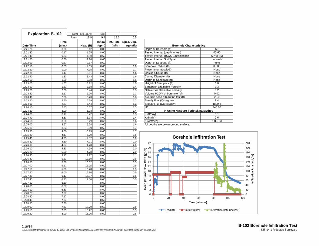
9/16/14C:\Users\Scott\OneDrive @ Kindred Hydro, Inc-\Projects\Ridgetop\Data\Analyses\Ridgetop Aug 2014 Borehole Infiltration Testing.xlsx
B-102 Borehole Infiltration TestKIT-14-1 Ridgetop Boulevard
Total Flux (gal)= 688Ave= 19.9 9.4 19.0 0.5
Date-TimeTime
(min.) Head (ft)Inflow (gpm)
Inf. Rate (in/hr)
Spec. Cap. (gpm/ft)
12:21:20 0.00 0.12 0.00 Depth of Borehole (ft) 6012:21:30 0.17 1.25 8.60 Tested Interval (depth in feet) 40-6012:21:40 0.33 1.90 8.60 Tested Interval USCS Classification SP to SM12:21:50 0.50 2.26 8.60 Tested Interval Soil Type outwash12:22:00 0.67 3.17 8.60 Depth of Seepage (ft) none12:22:10 0.83 4.55 8.60 1.9 Borehole Radius (ft) 0.08312:22:20 1.00 4.95 8.60 1.7 Piezometer Installed? None12:22:30 1.17 5.31 8.60 1.6 Casing Stickup (ft) None12:22:40 1.33 5.43 8.60 1.6 Casing Diameter (ft) None12:22:50 1.50 5.58 8.60 1.5 Depth to Sandpack (ft) None12:23:00 1.67 5.72 8.60 1.5 Height of Sandpack (ft) 0.012:23:10 1.83 6.18 8.60 1.4 Sandpack Drainable Porosity 0.312:23:20 2.00 6.44 8.60 1.3 Native Soil Drainable Porosity 0.212:23:30 2.17 6.70 8.60 1.3 Volume H2O/ft of borehole (sf) 0.0212:23:40 2.33 6.70 8.60 1.3 Average head (H) during test (ft) 20.012:23:50 2.50 6.79 8.60 1.3 Steady Flux (Qs) (gpm) 9.412:24:00 2.67 6.44 8.60 1.3 Steady Flux (Qs) (cf/day) 1809.612:24:10 2.83 6.37 8.60 1.3 H/r 240.0012:24:20 3.00 6.08 8.60 1.412:24:30 3.17 6.42 8.60 1.3 K (ft/day) 5.112:24:40 3.33 5.94 8.60 1.4 K (in./hr) 2.612:24:50 3.50 5.29 8.60 1.6 K (cm/sec) 1.8E-0312:25:00 3.67 5.24 8.60 1.6 All depths are below ground surface.12:25:10 3.83 5.09 8.60 1.712:25:20 4.00 5.15 8.60 1.712:25:30 4.17 5.79 8.60 1.512:25:40 4.33 4.52 8.60 1.912:25:50 4.50 4.21 8.60 2.012:26:00 4.67 4.28 8.60 2.012:26:10 4.83 4.29 8.60 2.012:26:20 5.00 4.28 8.60 2.012:26:30 5.17 7.77 8.60 1.112:26:40 5.33 16.10 8.60 0.512:26:50 5.50 16.62 8.60 0.512:27:00 5.67 16.75 8.60 0.512:27:10 5.83 16.78 8.60 0.512:27:20 6.00 16.90 8.60 0.512:27:30 6.17 16.97 8.60 0.512:27:40 6.33 17.00 8.60 0.512:27:50 6.50 8.6012:28:00 6.67 8.6012:28:10 6.83 8.6012:28:20 7.00 8.6012:28:30 7.17 8.6012:28:40 7.33 8.6012:28:50 7.50 8.6012:29:00 7.67 18.70 8.60 0.512:29:10 7.83 18.72 8.60 0.512:29:20 8.00 18.76 8.60 0.5
Borehole Characteristics
K Using Nasburg-Terletskata Method
Exploration B-102
0
20
40
60
80
100
120
140
160
180
200
220
0
2
4
6
8
10
12
14
16
18
20
22
0 20 40 60 80 100 120
Infil
trat
ion
Rate
(inc
h/hr
)
Head
(ft)
and
Flo
w R
ate
(gpm
)
Time (minutes)
Borehole Infiltration Test
Head (ft) Inflow (gpm) Infiltration Rate (inch/hr)


APPENDIX E
Estimate of Deep Infiltration Drain Capacity

Table E-1: Estimated Infiltration Drain Capacity
Kindred Hydro, Inc.9/23/14Ridgetop deep drain capacity.xlsx
Table E-1: Estimated Infiltration Drain CapacityPage 1 of 1
Parameter Units
40 ft deep 60 ft deep 80 ft deep 8" Dia. WellWelded 8" Dia.
ScreenHydraulic Conductivity (K) ft/d 11.8 11.8 11.8 11.8 11.8Well Depth ft 40 60 80 80 80Maximum Head ft 35 55 75 75 75Depth to Advance Outwash ft 19 19 19 19 19Screened Interval Length ft 20 40 60 60 60Well Diameter ft 0.50 0.50 0.50 0.67 1.00Screen Type Telescope-SS Telescope-SS Telescope-SS Telescope-SS Welded-SSCalculated ValuesH/r ft 80 160 240 179 120Open Screen Area/foot sf 0.15 0.15 0.15 0.16 0.18Screen Capacity (0.1 feet/sec) cf/sec 131 262 393 430 486Capacity at H=Screened Length cf/sec 0.06 0.21 0.43 0.45 0.49Capacity at H=Maximum Head cf/sec 0.10 0.28 0.54 0.57 0.61Capacity at H=Maximum Head gpm 46 127 243 255 274
Parameter Units
40 ft deep 60 ft deep 80 ft deep 8" Dia. WellWelded 8" Dia.
ScreenHydraulic Conductivity (K) ft/d 5.1 5.1 5.1 5.1 5.1Well Depth ft 40 60 80 80 80Maximum Head ft 35 55 75 75 75Depth to Advance Outwash ft 31 31 31 31 31Screened Interval ft 10 30 50 50 50Well Diameter ft 0.50 0.50 0.50 0.67 1.00Screen Type Telescope-SS Telescope-SS Telescope-SS Telescope-SS Welded-SSCalculated ValuesH/r ft 40 120 200 149 100Open Screen Area/foot sf 0.15 0.15 0.15 0.16 0.18Screen Capacity (0.1 feet/sec) cf/sec 65 196 327 358 405Capacity at H=Screened Length cf/sec 0.01 0.05 0.13 0.14 0.15Capacity at H=Maximum Head cf/sec 0.03 0.10 0.20 0.21 0.23Capacity at H=Maximum Head gpm 12 44 91 95 103
Note: Red shading indicates well capacity is limited by the transmitting capacity of the well screen.
Results Based on B-101 Conditions
Results Based on B-102 Conditions
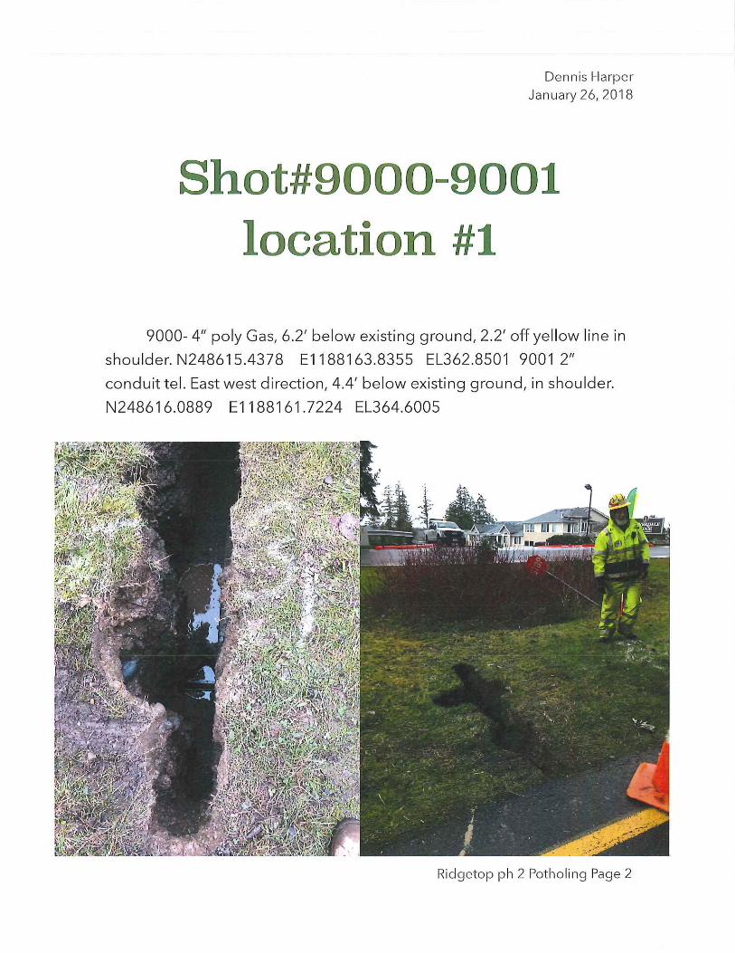

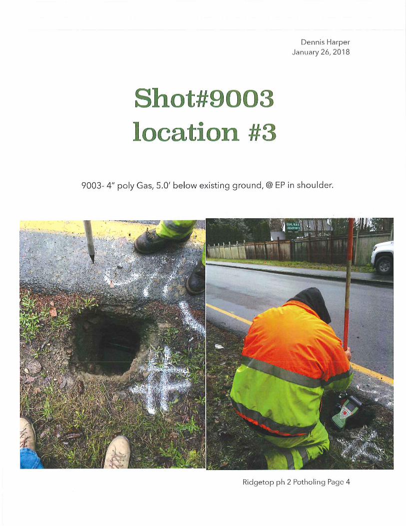
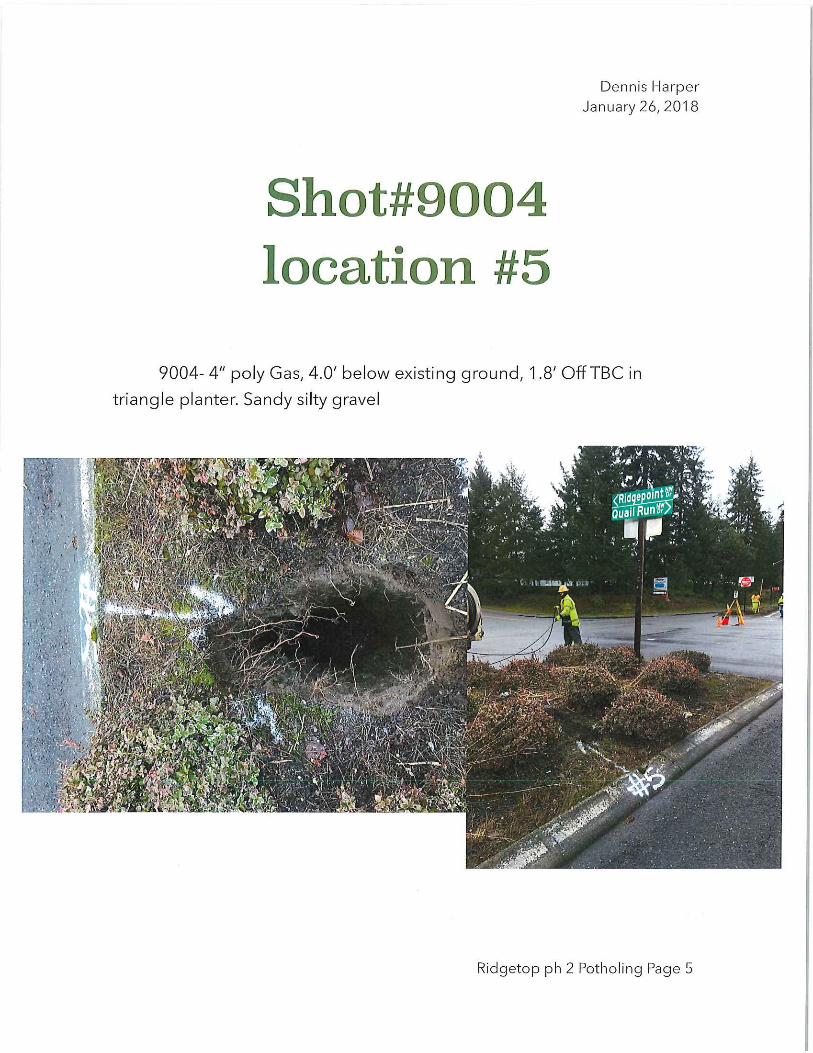


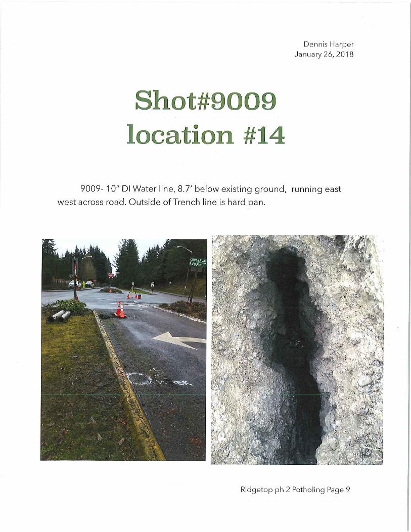


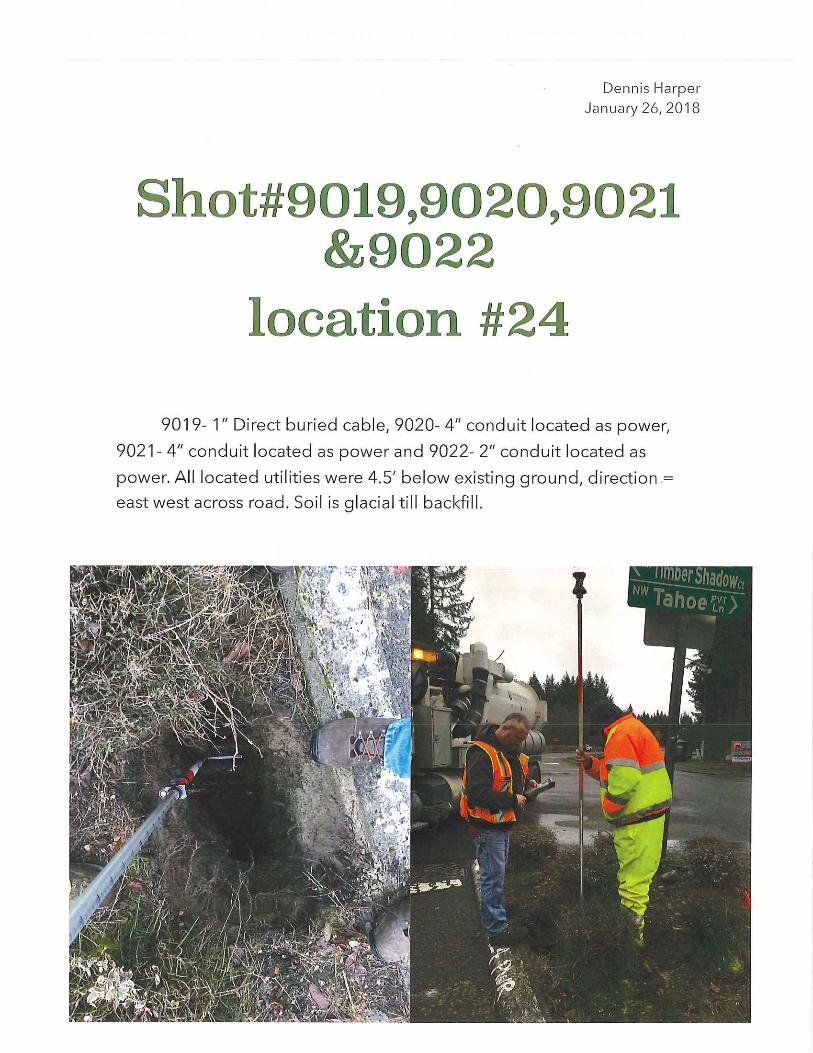


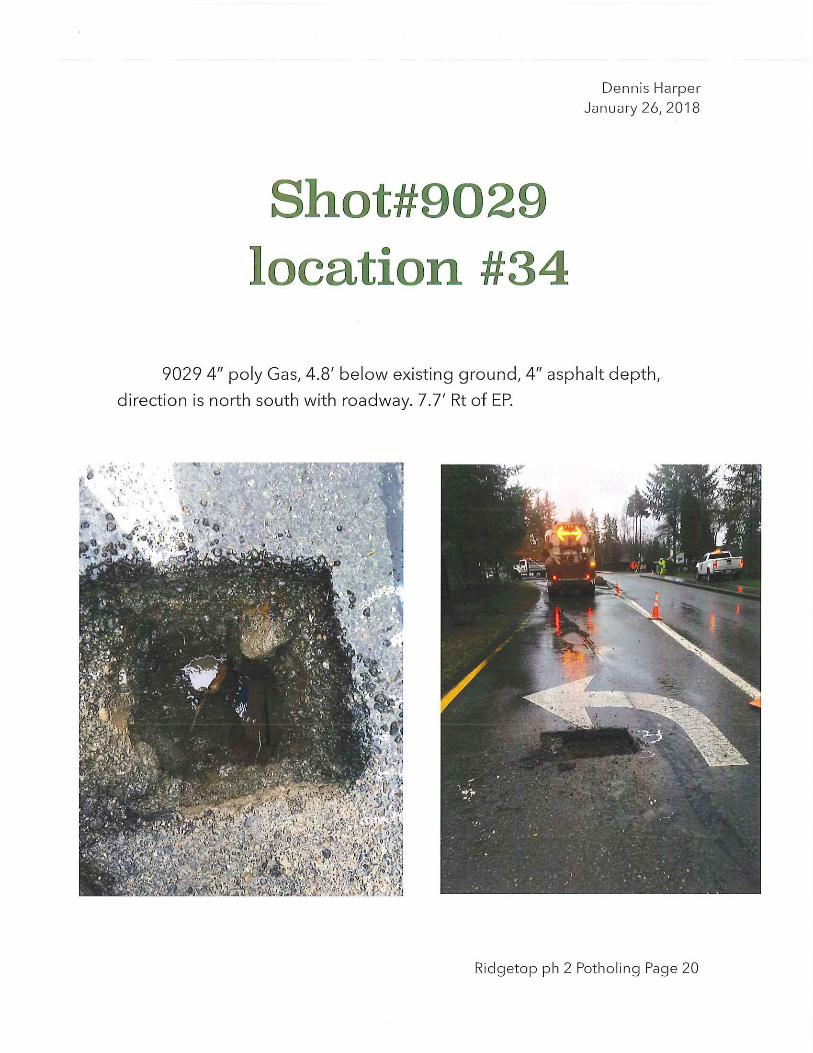


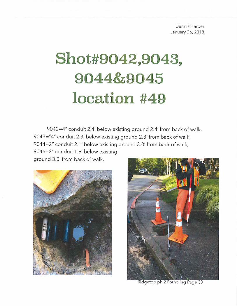


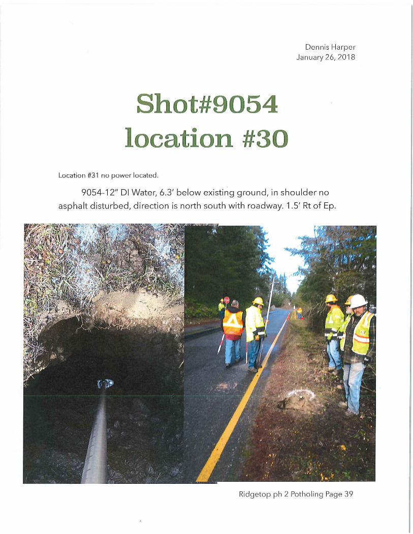


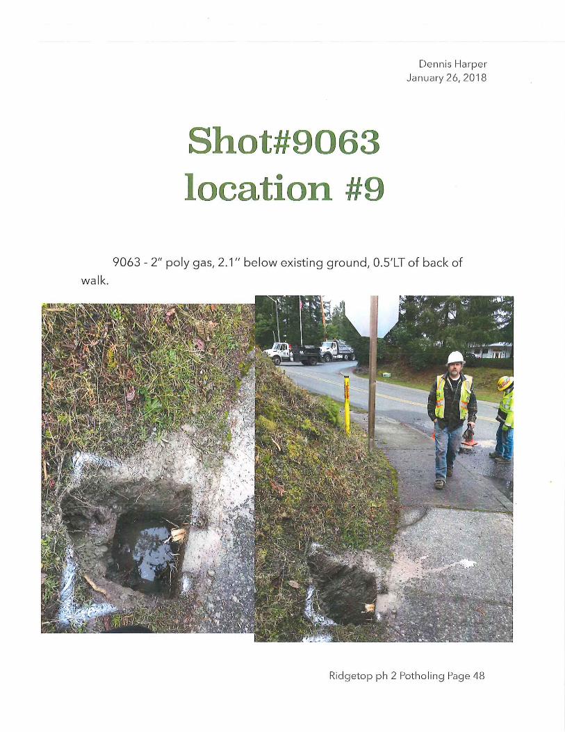


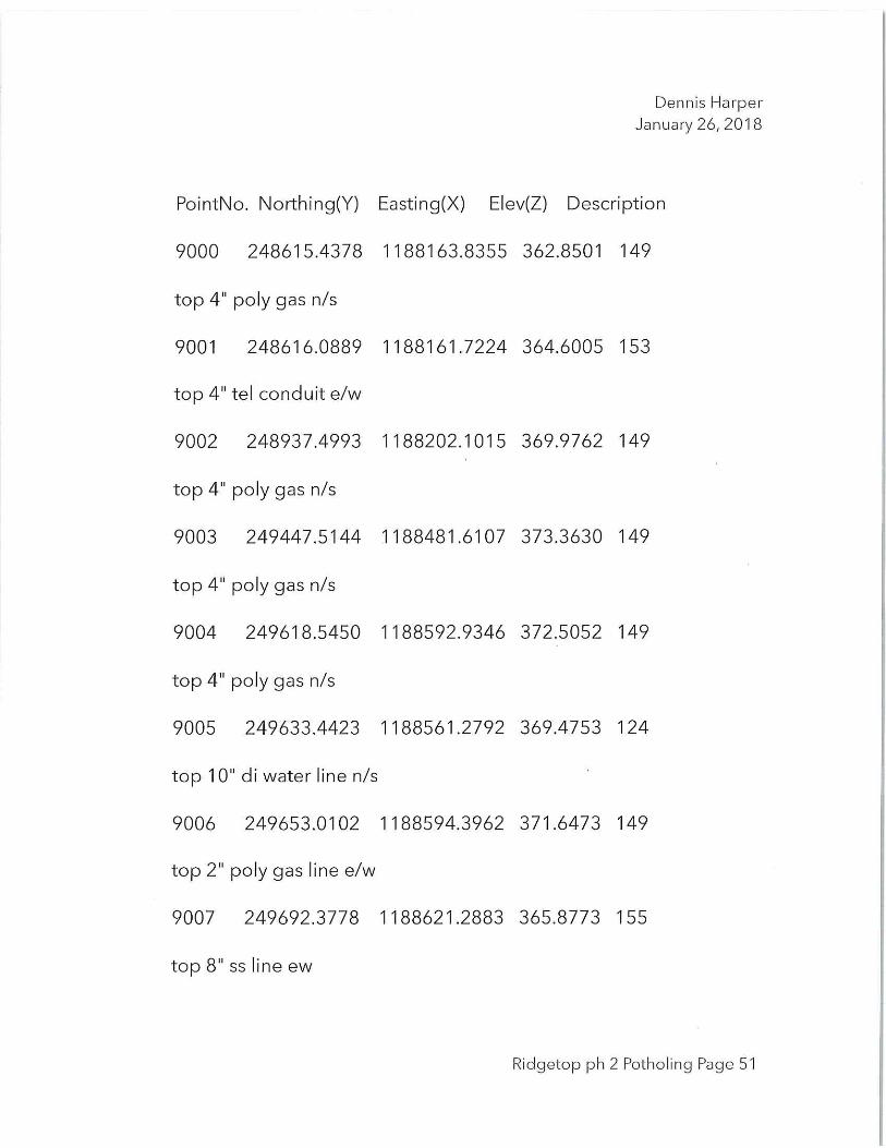


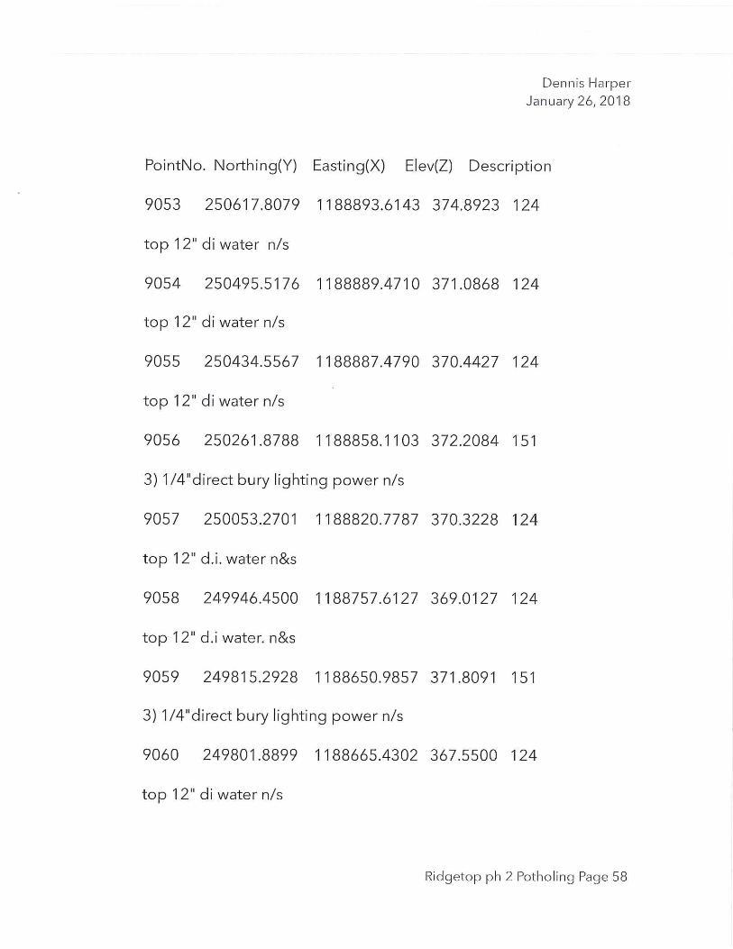

RIDGETOP BLVD NW IMPROVEMENTS PROJECT PHASE 2
THIS PAGE INTENTIONALLY LEFT BLANK

WASHINGTON STATE DEPARTMENT OF ECOLOGY
STORMWATER FACILITY
SPECIFICATIONS INSERT
General Partial funding of this project is being provided by the Washington State Department of Ecology’s (Ecology) Stormwater Grant Program.
Compliance with State and Local Laws The construction of the project, including all subcontracted work, shall conform to the applicable requirements of state and local laws and ordinances.
State Interest Exclusion It is anticipated that this project will be funded in part by the Washington State Department of Ecology. Neither the State of Washington nor any of its departments or employees are, or shall be, a party to this contract or any subcontract.
Third Party Beneficiary Partial funding of this project is being provided through the Washington State Department of Ecology Stormwater Grant Program. All parties agree that the State of Washington shall be, and is hereby, named as an express third-party beneficiary of this contract, with full rights as such.
Access to the construction site and to records The contractor shall provide for the safe access to the construction site and to the contractor's records by Washington State Department of Ecology personnel.
The Contractor shall maintain accurate records and accounts to facilitate the Owner’s audit requirements and shall ensure that all subcontractors maintain auditable records.
These Project records shall be separate and distinct from the Contractor’s other records and accounts.
All such records shall be available to the Owner and to Washington State Department of Ecology personnel for examination. All records pertinent to this project shall be retained by the Contractor for a period of three (3) years after the final audit.
Protection of the Environment No construction related activity shall contribute to the degradation of the environment, allow material to enter surface or ground waters, or allow particulate emissions to the atmosphere, which exceed state or federal standards. Any actions that potentially allow a discharge to state waters must have prior approval of the Washington State Department of Ecology.

Inadvertent Discovery of Archeological Resources The contractor shall obtain a copy of the Inadvertent Discovery Plan from the Project Owner. The contractor shall keep a copy of the inadvertent discovery plan for the project on the work site at all times. The contractor shall immediately stop all work if human remains, cultural, or archeological resources are discovered in the course of construction. The contractor shall follow the inadvertent discovery plan in dealing with the human remains, cultural, or archeological resources.
Project Signs The Contractor shall display Ecology’s logo in a manner that informs the public that the project received financial assistance from the Washington State Stormwater Grant Program.
Utilization of Minority and Women Business Enterprises All bidders are encouraged to utilize certified minority-owned and women-owned businesses to the extent possible in the performance of this contract. All prospective bidders or persons submitting qualifications should take the following steps, when possible.
1. Include qualified minority and women's businesses on solicitation lists. 2. Assure that qualified minority and women's businesses are solicited whenever
they are potential sources of services or supplies. 3. Divide the total requirements, when economically feasible, into smaller tasks or
quantities to permit maximum participation by qualified minority and women's businesses.
4. Establish delivery schedules, where work requirements permit, which will encourage participation of qualified minority and women's businesses.
5. Use the services and assistance of the State Office of Minority and Women's Business Enterprises (OMWBE) and the Office of Minority Business Enterprises of the U.S. Department of Commerce, as appropriate.
All prospective bidders must provide a list of the MBE/WBE subcontractors they intend to use during the project. This list must be provided with the bid package.
Revised 3/25/15