Table of Contents - EIL Tender portal
249
Click on the Document Title to go to that section of the document Table of Contents Document Number Rev. Document Title Page Number A538-010-XB-MR- 0080-5-RFQ A ENQUIRY DOCUMENT 2 A538-010-XB-MR- 0080 A SWITCHBOARDS: HV (INDOOR) WITH VCB 102 A538-010-16-50-TR- 0080 A INSTRUCTIONS TO VENDORS 109 A538-010-16-50-VR- 0080 A VENDOR DATA REQUIREMENTS 120 A538-010-16-50-SP- 0080 A JOB SPECIFICATION FOR HV SWITCHBOARD (INDOOR) WITH VCB 123 A538-010-16-50-DS- 0080 A DATA SHEET FOR HV SWITCHBOARD (020-HT-201) 132 A538-010-16-50-DS- 0081 A DATA SHEET FOR HV SWITCHBOARD (020-HT-202) 136 A538-010-16-50-DS- 0082 A DATA SHEET FOR HV SWITCHBOARD (030-HT-201) 140 A538-010-16-50-DS- 0083 A HV SWBD HARDWARE DATASHEET 144 A538-010-16-50-DS- 0084 A HV SWITCHBOARD (FEEDER DETAILS OF 020-HT-201) 156 A538-010-16-50-DS- 0085 A HV SWITCHBOARD (FEEDER DETAILS OF 020-HT-202) 158 A538-010-16-50-DS- 0086 A HV SWITCHBOARD (FEEDER DETAILS OF 030-HT-201) 159 A538-010-16-50-DS- 0087 A DATA SHEET FOR NUMERICAL RELAY 161 6-51-0001 6 Specification for HV switchboards. 168 6-51-0055 2 Specification for numerical relays & substation automation system 184 6-51-0081 4 Specification for electrical equipment installation. 199 6-51-0087 3 Specification for field inspection, testing and commissioning of electrical installations 214 6-81-1001 3 ITP for HV switchboards 222 6-78-0001 0 Specification for Quality Mgt. System Requirements from Bidders 229 6-78-0003 0 Specification for Documentation Requirement from Suppliers 238 Page 1 of 249
-
Upload
khangminh22 -
Category
Documents
-
view
3 -
download
0
Transcript of Table of Contents - EIL Tender portal

Click on the Document Title to go to that section of the document
Table of ContentsDocument Number Rev. Document Title Page
NumberA538-010-XB-MR-0080-5-RFQ
A ENQUIRY DOCUMENT 2
A538-010-XB-MR-0080
A SWITCHBOARDS: HV (INDOOR) WITH VCB 102
A538-010-16-50-TR-0080
A INSTRUCTIONS TO VENDORS 109
A538-010-16-50-VR-0080
A VENDOR DATA REQUIREMENTS 120
A538-010-16-50-SP-0080
A JOB SPECIFICATION FOR HV SWITCHBOARD (INDOOR) WITHVCB
123
A538-010-16-50-DS-0080
A DATA SHEET FOR HV SWITCHBOARD (020-HT-201) 132
A538-010-16-50-DS-0081
A DATA SHEET FOR HV SWITCHBOARD (020-HT-202) 136
A538-010-16-50-DS-0082
A DATA SHEET FOR HV SWITCHBOARD (030-HT-201) 140
A538-010-16-50-DS-0083
A HV SWBD HARDWARE DATASHEET 144
A538-010-16-50-DS-0084
A HV SWITCHBOARD (FEEDER DETAILS OF 020-HT-201) 156
A538-010-16-50-DS-0085
A HV SWITCHBOARD (FEEDER DETAILS OF 020-HT-202) 158
A538-010-16-50-DS-0086
A HV SWITCHBOARD (FEEDER DETAILS OF 030-HT-201) 159
A538-010-16-50-DS-0087
A DATA SHEET FOR NUMERICAL RELAY 161
6-51-0001 6 Specification for HV switchboards. 1686-51-0055 2 Specification for numerical relays & substation automation system 1846-51-0081 4 Specification for electrical equipment installation. 1996-51-0087 3 Specification for field inspection, testing and commissioning of
electrical installations214
6-81-1001 3 ITP for HV switchboards 2226-78-0001 0 Specification for Quality Mgt. System Requirements from Bidders 2296-78-0003 0 Specification for Documentation Requirement from Suppliers 238
Page 1 of 249

Page 1 of 6
EIL Office Complex, Sector – 16, Gurgaon – 122001, INDIA
REQUEST FOR QUOTATION (RFQ)
*RFQ No.: AS/A538-010-XB-MR-0080/005 Date: 08-12-2014
To, M/s
Client : Consortium of BPCL & IOCL Project: Kochi Coimbatore Erode Salem LPG Pipeline Project MR No.: A538-010-XB-MR-0010 Rev. B Item: SWITCHBOARDS : HV (INDOOR) WITH VCB Due Date & Time: 06.01.2015 & Up to 1200 Hrs. (IST)
PRE BID MEETING At 1000 Hours (IST) on 17.12.2014 (**) at EIL Office Complex, Sector – 16, Gurgaon – 122001, India
UNPRICED BID OPENING: At 1400 Hours (IST) on 06.01.2015 (**) at EIL Office Complex, Sector – 16, Gurgaon – 122001, India
PRICED BID OPENING: TIME & VENUE SHALL BE INTIMATED LATER.
(**)If the particular day is happened to be a declared holiday in EIL, New Delhi, the next working day shall be considered.
GENTLEMEN,
1. Online Bids are requested under competitive bidding on e-procurement basis for the captioned subject item in complete accordance with the documents attached.
1.1 Bidders can download the complete enquiry document from the web address http:tenders.eil.co.in or http://eprocure.gov.in/eprocure/app.
1.2 E-Bids are required to be submitted only through Central Public Procurement Portal (CPPP) of Government of India, on or before the bid submission date and time. Bidders are required to register themselves at http://eprocure.gov.in/eprocure/app. No registration fee would be charged from the bidders.
1.3 Bidders are required to upload the bid along with all supporting documents & priced part on the e-tendering website (http://eprocure.gov.in/eprocure/app) only.
1.4 Bidders to refer E-Tendering methodology attached with the RFQ.
Various links such as “Help for Contractor”, “Information about DSC”, “FAQ”, “Resources Required”, “Bidders Manual Kit” etc. are available on home page of http://eprocure.gov.in/eprocure/app facilitating vendors to participate in the bidding process. Bidder are advised to download & utilize the available information/documents under these links for activities like Registration in CPPP, obtaining User ID & Password, uploading & submission of e-bids etc. Bidders are advised in their own interest to carefully go through Instructions for E-tendering and other related document available against various help links so as to ensure that bids are uploaded in E-tendering website well before the closing date and time of bid submission.
Page 2 of 249

Page 2 of 6
1.5 NIC Portal mandates that the bidders are to be registered on the portal before any enquiry can be issued to them. In order to expedite issue of enquiries, the enquiry is being issue through EIL Tender Portal and also being published on Central Public Procurement Portal. The enquiry shall be issued to the bidders on the NIC e-Procurement Portal as soon as their registration is completed in the NIC Portal (https://eprocure.gov.in/eprocure/app ).
1.6 All those vendors who have still not registered on the NIC Portal are required to register on the same (immediately after issue of enquiry on EIL portal but not later than ten days before the bid due date) for facilitating issue of enquiry to them on the NIC Portal failing which it will not be possible for them to upload their bids. Pursuant to registration, the vendors are also required to login in EIL tender portal and update NIC’s registration details and inform the undersigned regarding the same for the subject enquiry.
In any case, the enquiry shall be issued on NIC portal to NIC registered vendors about one week before the bid due date. Therefore, all those bidders who have not complied with the above registration requirements will not be issued this enquiry on NIC portal and will not be eligible to bid. Request for extension in due date of submission of bids due to non registration or delayed registration in NIC portal shall not be entertained.
1.7 The bid has to be necessarily submitted on the NIC Portal and only those bidders who are issued the enquiry through NIC Portal will be eligible to submit their bids. In case a bidder does not register on the NIC Portal and as a consequence, cannot be issued the enquiry through NIC Portal, it shall be deemed that he is not interested in bidding against this enquiry and no further correspondence will be entertained.
1.8 In future, EIL shall be issuing all enquiries through NIC Portal alone and bidders who do not register with NIC Portal may not be able to submit their bids. Therefore, it is in the interest of the bidders that they register on the NIC Portal at the earliest.
2. The vendor registration on NIC Portal is a very user friendly process. However, in case of any doubt, the vendor may also contact the undersigned.
3. In the event of failure in bidder’s connectivity with EIL/CPPP website during the last few hours on account of problem on bidders account, they are likely to miss the deadline for bid submission. Due date extension request due to this reason will not be entertained. In view of the same, bidders are advised to upload their bid in advance.
4. Commercial requirements are specified in the attached General Purchase Conditions, Special Purchase Conditions, Instructions to Bidders, Terms & Conditions for Site Work (applicable if MR calls for Scope of Site Work), Terms & Conditions for Supervision of Erection, Testing & Commissioning (applicable if MR calls for supervision), Agreed Terms & Conditions (ATC) questionnaire etc. The ATC should be duly filled in, signed & stamped, scanned and uploaded with your bid.
5. Bidders are advised to submit quotations based on strictly on the specifications, terms & conditions contained in the RFQ documents and not to stipulate any deviation.
6. Addendum / corrigendum to the RFQ documents if issued must be signed and submitted along with the bid.
7. The order, if any, will be issued by our above-mentioned client.
8. Please submit your Acknowledgement against the RFQ on EIL’s website http:tenders.eil.co.in\newtenders within the due date & time, with reasons(s) of not participating in the RFQ in case of regret/negative acknowledgment.
9. As Purchaser intends to contract directly with suppliers of the goods for which bids are invited, the bids should be prepared by the suppliers and submitted directly. Purchaser reserves the right to reject offers made by intermediaries.
10. Online Bids/ Offer through CPP Portal only shall be accepted. Bids/ Offer through Email or fax/ Telex/Telegraphic or received through any other mode shall not be accepted and rejected.
Page 3 of 249
Page 3 of 6
11. Completion / Delivery Period :
11.1 SUPPLY: 9 (Nine) Months on FOT Site basis from the date of Fax of Acceptance. Date of receipt of all material at site shall be considered the date of delivery.
11.2 SITE WORK : Within 4 Months from the intimation of site readiness. 15 (Fifteen) days advance notice period shall be given for site readiness. Date of handing over of work after completing all the site activities mentioned in the Material / Purchase Requisition shall be considered as date of completion.
12. Validity of Offer : The offer should be valid for Four (4) months from final bid due date.
13. Comprehensive Insurance (Transit/Marine-cum-storage-cum-erection till handing over of equipment) shall be taken care by the Supplier & charges of the same shall be included in the quoted prices. Agreed Terms & Conditions (ATC) for Indian Bidders enclosed with this RFQ document stands modified to this extent.
14. Price Reduction Schedule: Price Reduction Schedule towards delay in delivery shall be applicable as per clause no. 20.0 of GPC of RFQ subject to following modification: “Price Reduction schedule shall be @ 1% of Total order value (TOV) (Supply + Site work) of per week of delay or part thereof subject to maximum of 10% of total order value (TOV) (Supply + Site work). Wherever the supply period and site work are indicated as two separate periods and notice of site readiness is required for site work, intervening period, if any shall not be considered, while calculating the price schedule for delay.
The Bidder shall be contractually committed to the periods – FOT Site (for supply) as well as completion period (for site work). In case of delays in dispatches beyond the contractual FOT Site period, the Bidder shall raise invoices after deducting applicable deduction on account of Price Reduction Schedule. However, the final settlement of Price Reduction Schedule shall be based on completion period. In case price reduction applicable on delayed completion period is less than that deducted on account of delayed supplies, the excess deduction can be claimed back by the Contractor. “
15. The bidder shall bear all costs associated with the preparation and submission of its bid, and the Purchaser/Consultant shall in no case be responsible or liable for these costs regardless of the conduct or outcome of the bidding process.
16. Canvassing in any form by the Bidder or by any other agency on their behalf may lead to disqualification of their bid.
17. E-bids received online shall be opened at EIL office on due date and time as specified above. Bids shall be opened in presence of representatives of bidders who choose to attend the same. Such representative shall submit Bid Acknowledgement Number generated by the Portal/System after successfully Bid Submission online. Time and Date of opening of Price Bids of technically and commercially acceptable bidders shall be notified to the qualified and acceptable bidders at a later date. However, bidder can also view unpriced / priced Bid Opening online in their office/remote end itself. The bidder’s representatives, who are present, shall sign a register evidencing their attendance.
18. Bidders to note that price changes against Technical / commercial clarifications, in line with terms & conditions of enquiry documents are not allowed. In case any bidder gives revised prices / price implications against such clarifications, their bid shall be liable for rejection.
19. Payment Terms: Payment term shall be as under:
19.1 For Supply, Transportation & Site Work: Payment Term shall be as per clause No.13.1.3 & 13.1.6 of Special Purchase Conditions (SPC).
19.2 For Training at Site: 100% payment against final bill to be submitted by seller after completion of training duly certified by site –in-charge.
19.3 For Training at Bidder’s Works: 100% payment against final bill to be submitted by seller after completion of training duly certified by Purchaser.
Page 4 of 249

Page 4 of 6
20. Bidders are requested to quote as per their capability registered in EIL.
21. EIL reserves the right to use in-house information for assessment of bidder’s capability for consideration of bid.
22. If any of quoted rates/prices/charges are repeated in the bid, then higher of them shall be considered for evaluation and lower for ordering.
23. In case any bidder is found to be involved in cartel formation, his bid will not be considered for evaluation / placement of order. Such bidder will also be debarred from bidding in future.
24. We reserve the right to make any changes in the terms and conditions of purchase and to reject any or all the bids.
25. Net Worth
Net worth of the bidder should be positive as per the audited financial results for the immediate preceding financial year. The offer of the bidder whose net worth is “Negative” in the immediate preceding financial year shall not be considered for further evaluation. However, Indian Central Public Sector Undertakings / Enterprises shall be exempted from the requirement of Positive Net Worth Criteria.
Please submit copy of your complete Annual Financial Statement including Auditor’s Report and Schedule of Reserve & Surplus, Balance Sheet & Profit/Loss account and including all notes and schedules forming part of Audited Annual reports for the immediate preceding financial year determination of net-worth of the Bidder.
26. Bidders are requested to submit following Networth details in their Login of EIL’s Tender Portal before downloading the Enquiry : a) From Financial Month/ Year _____________ to Month/ Year _________________ b) Net worth (Positive/ Negative) ________________ c) Upload Audited Financial Statements (Browse/ Attach) : _______________________
27. Where any provisions of Instructions to Bidders, Special Purchase Conditions and General Purchase Conditions is in conflict or at variance with any provisions of RFQ Cover Letter, RFQ Cover Letter shall over-ride such provision(s) of Instructions to Bidders, Special Purchase Conditions and General Purchase Conditions only to the extent of such repugnancy or variation.
28. PRE-BID MEETING: The bidder(s) or his official representative are invited to attend a pre-bid
meeting which will take place at the above mentioned venue, date and time.
a) Bidders are requested to submit their queries by e-mail to us latest by 15-December-2014. These questions shall be replied during the pre-bid meeting. After pre-bid meeting on 17-Dec-2014, no further queries will be entertained from the bidder.
b) Record notes of meetings, including the text of questions raised (without identifying the source of the query) and the responses given will be transmitted to all the vendors.
c) Non-attendance of the pre-bid meeting will not be a cause for disqualification of a bidder
Page 5 of 249
Page 5 of 6
29. Contact Persons for this RFQ are:
Mr. C. Kapuria, AGM (C&P), Tel No. 0124-380 2104/2168/2169, email: [email protected]/ [email protected]/ [email protected]
*Please specify RFQ No.: AS/A538-010-XB-MR-0080/005 in all Correspondence. THIS IS NOT AN ORDER Very truly yours, For & on Behalf of consortium of BPCL & IOCL
(C. Kapuria) AGM(C&P) ENGINEERS INDIA LIMITED Enclosure: As per List Attached
Page 6 of 249

Page 6 of 6
LIST OF ENCLOSURES
DOCUMENT
A) Request For Quotation (RFQ)
B) Commercial document:
i) Price Schedule Format
ii) Instruction to Bidder (ITB)
iii) General Purchase Conditions including Addendum to GPC
iv) Terms and Conditions for Site Work including Erection, Testing and Commissioning
v) Special Purchase Conditions (SPC)
vi) Agreed Terms & Conditions (For Indian Bidders)
vii) Integrity Pact
viii) E-tendering Methodology
C) Technical document:
Material Requisition (MR) No. : A538-010-XB-MR-0080 Rev. A
Page 7 of 249

1
234
5
6
7
8
9
10
11
12
BIDDER: M/s
Note: Bidder must upload this document duly signed and stamped with both unpriced & priced offer.
Inspection of items supplied by bidders shall be in the scope of EIL. In case bidder sourcing materials from abroad, the bidder shall arrange inspection through EIL, if required.
Bidder confirms that he has noted the contents of the preamble to the price schedule format , price schedule, Bidding Document, MaterialRequisition and quoted his prices accordingly without any deviation.
Bidder to note that all the items of the MR are grouped together forming a single group consisting of MR Item S.No. 01.00, 02.00,
04.00 and 07.00 along with corresponding Freight charges inidcated in the Price Schdeule. Bidder must quote all items falling
under the group. Evaluation and Ordering shall be done on bottomline basis.
Quoted prices are firm and fixed till complete execution of the entire order. Price variation on account of variation in Foreign Exchange rateis not allowed .
Bidder shall furnish built-in CIF value if any, against each item, giving details of description of goods, qty. rate of Custom Duty etc. in attached Format-"CIF/CD".
Comprehensive Insurance (Transit/Marine-cum-storage-cum-erection till handing over of equipment) has been taken care by the
Seller & charges of the same have been included in the quoted prices.
Itemised Prices for 2 years operation & maintenance spares shall be furnished as per Instruction to Vendor enclosed in MR and shall not be included in the quoted supply prices. Quoted 2 years operation & maintenance spares shall not be considered for Evalaution.
Supply price of Laptop 1, Laptop 2 and Mandatory Spares shall not include their respective freight charges. Bidder must quote the
freight in percentage seperately in the last column of price schedule. Clause 7 & Clause 8 of ITV (doc. No. A538-010-16-50-TR-080,
Rev.A) regarding Freight charges stands modified to this extent.
Bidder must quote the prices in enclosed Price Schedule formats only. The formats shall not be changed and/or retyped. For any deviationto the formats, offer may be rejected.
Scope of supply including Testing, Inspection, documentation etc., shall be strictly as per Material Requisition and RFQ Document.
Bidder to clearly indicate 'Quoted' / 'Not Quoted' against each Sr. No. in the price column in the unpriced Price Schedule. Bidders mustsubmit Price part of above Price schedule in their Priced Bid and Unpriced part with the Unpriced Bid. Bidders must also submit thisPreamble duly signed and stamped with both unpriced & priced offer.
Bidder shall furnish prices/ details as above, in accordance with Instructions To Bidders (ITB).
PREAMBLE TO PRICE SCHEDULE (INDIAN BIDDERS)
NAME OF BIDDER: M/S __________________________
RFQ NO.: AS/A538-010-XB-MR-0080/005
ITEM : SWITCHBOARDS : HV (INDOOR) WITH VCB.
Page 8 of 249

RFQ NO. AS/A538-010-XB-MR-0080/005
ITEM SL. NO. AS
PER MR.QTY.
01.00
PERCENTAGE FREIGHT CHARGES
(APPLICABLE ON FOT DESP. POINT
PRICE of MR Item sl. no 01.00)
EXCLUDING CENVATABLE SERVICE
TAX PLUS EDU. CESS THEREON
UPTO PROJECT SITE
01.01 1 NO.
01.02 1 NO.
01.03 1 NO.
01.04 1 NO.
01.05 1 NO.
01.06 1 NO.
01.07 1 NO.
01.08 1 NO.
01.09 1 NO.
SUPPLY OF FOLLOWING ITEMS AS PER COMPLETE SCOPE OF MR.
NO. A538-010-XB-MR-0080.
(FOR DETAILS OF BUILT IN CIF VALUE OF IMPORT CONTENT, REFER
FORMAT - CIF/CD ATTACHED.)
TAG NO. 020-HT-201; 6.6KV, 630A, 40 KA(1SEC), TP SWITCHBOARD
AT AS PER DATASHEET NO. A538-010-16-50-DS-0080/0083/0084
_______________
TAG NO. 020-HT-202; 6.6KV, 630A, 40KA (1SEC), TP SWITCHBOARD
AS PER DATASHEET NO. A538-010-16-50-DS-0081/0083/0085
TAG NO. 030-HT-201; 11KV,630A, 40 KA(1SEC), TP SWITCHBOARD
AS PER DATASHEET NO. A538-010-16-50-DS-0082/0083/0086
TAG NO. LAPTOP-01; LAPTOP AS PER SL. NO. 29.0 OF JOB
SPECIFICATION (A538-010-16-50-SP-0080) FOR IOCL TERMINAL AT
KOCHI
TAG NO. LAPTOP-02; LAPTOP AS PER SL. NO. 29.0 OF JOB
SPECIFICATION (A538-010-16-50-SP-0080) FOR BPCL TERMINAL AT
KOCHI
TAG NO. EARTHING TRUCK 20; EARTHING TRUCKS & ACCESSORIES
FOR NEW 6.6KV SWITCHBOARDS AS SPECIFIED IN INSTRUCTIONS
TO VENDOR
TAG NO. LIFTING TRUCK 20; LIFTING TRUCK & ACCESSORIES FOR
THE NEW 6.6KV SWITCHBOARDS AS MENTIONED IN INSTRUCTIONS
TO VENDOR
TAG NO. EARTHING TRUCK 30; EARTHING TRUCKS & ACCESSORIES
FOR NEW 11KV SWITCHBOARDS AS SPECIFIED IN INSTRUCTIONS TO
VENDOR
TAG NO. LIFTING TRUCK 30; LIFTING TRUCK & ACCESSORIES FOR
THE NEW 11KV SWITCHBOARDS AS MENTIONED IN INSTRUCTIONS
TO VENDOR
AMOUNT ON FOT DESPATCH POINT BASIS
(INR)
_______________
_______________
PRICE SCHEDULE FORMAT (INDIAN BIDDERS)
ITEM : SWITCHBOARDS : HV (INDOOR) WITH VCB
NAME OF BIDDER: M/S __________________________
DESCRIPTION OF ITEM QUOTED PRICE
_______________
_______________
_______________
_______________
_______________
_______________
_______________
Page 9 of 249

RFQ NO. AS/A538-010-XB-MR-0080/005
PRICE SCHEDULE FORMAT (INDIAN BIDDERS)
ITEM : SWITCHBOARDS : HV (INDOOR) WITH VCB
NAME OF BIDDER: M/S __________________________
DESCRIPTION OF ITEM QUOTED PRICE
01.10 1 LOT
01.11 1 LOT
02.00
02.01 1 LOT
02.02 1 LOT
02.03 1 LOT
02.10 1 LOT
02.11 1 LOT
04.00
PERCENTAGE FREIGHT CHARGES
(APPLICABLE ON FOT DESP. POINT
PRICE OF MANDATORY SPARES )
EXCLUDING CENVATABLE SERVICE
TAX PLUS EDU. CESS THEREON
UPTO PROJECT SITE
04.01 1 NO.
04.02 1 NO.
04.03 1 NO.
05.00
06.00
QUOTED SEPERATELY IN THE ENCLOSED FORMATSUPPLY OF RECOMMENDED SPARES FOR TWO (2) YEARS NORMAL
OPERATION AND MAINTENANCE .
UNIT RATES FOR ADDITION / DELETION PURPOSE.
SUPPLY OF MANDATORY SPARES FOR FOLLOWING ITEMS AS PER
LIST MENTIONED IN INSTRUCTIONS TO VENDOR.
TAG NO. {04}020-HT-201; FOR S.NO. 01.01
_______________TAG NO. {04}020-HT-202; For Sr. No. 01.02
TAG NO. {04}030-HT-201; For Sr. No. 01.03
AMOUNT ON FOT DESPATCH POINT BASIS
(INR)
_______________
_______________
_______________
TAG NO. {02}030-HT-201; FOR S.NO. 01.03 ______________________________
TAG NO. {02}ENGG. CONSOLE-1; FOR S.NO. 01.10 ______________________________
TAG NO. {02}ENGG. CONSOLE-2; FOR S.NO. 01.11 ______________________________
SITE WORK OF FOLLOWING ITEMS AS PER COMPLETE SCOPE AS
MENTIONED AGAINST SL. NO 02.00 (SHEET 2OF6) OF MR. NO.
A538-010-XB-MR-0080.
AMOUNT
(INR)
TAG NO. {02}020-HT-201; FOR S.NO. 01.01 ______________________________
TAG NO. {02}020-HT-202; FOR S.NO. 01.02 ______________________________
_______________
TAG NO. ENGG. CONSOLE-1; ENGG. CUM OPERATOR WORK
STATION ALONG WITH AUTOMATION HARDWARE, FURNITURES
FOR IOCL IMPORT TERMINAL.
TAG NO. ENGG. CONSOLE-2; ENGG. CUM OPERATOR WORK
STATION ALONG WITH AUTOMATION HARDWARE,FURNITURES
FOR BPCL DISPATCH TERMINAL.
_______________
_______________
Page 10 of 249

RFQ NO. AS/A538-010-XB-MR-0080/005
PRICE SCHEDULE FORMAT (INDIAN BIDDERS)
ITEM : SWITCHBOARDS : HV (INDOOR) WITH VCB
NAME OF BIDDER: M/S __________________________
DESCRIPTION OF ITEM QUOTED PRICE06.01 1 LOT
06.02 1 LOT
07.00
07.01 LS
07.02 LS
07.03 LS
07.04 LS
07.05 LS
TAG NO.: {07}TRAINING-020-AUT; TRAINING ON AUTOMATION
SYSTEM AT BPCL DISPATCH TERMINAL AS PER INSTRUCTIONS TO
VENDOR ENCLOSED IN MR. _______________
TAG NO.: {07}TRAINING-030-REL; TRAINING ON NUMERICAL
RELAYS AT IOCL IMPORT TERMINAL AS PER INSTRUCTIONS TO
VENDOR ENCLOSED IN MR.
_______________
TAG NO.: {07}TRAINING-020-REL; TRAINING ON NUMERICAL
RELAYS AT BPCL DISPATCH TERMINAL AS PER INSTRUCTIONS TO
VENDOR ENCLOSED IN MR.
_______________
TAG NO.: {07}TRAINING-030-AUT; TRAINING ON AUTOMATION
SYSTEM AT IOCL IMPORT TERMINAL AS PER INSTRUCTIONS TO
VENDOR ENCLOSED IN MR.
_______________
UNIT RATES FOR CARRYING OUT SPECIFIC TESTS AS PER THE
INSTRUCTIONS TO VENDOR ENCLOSED IN MR.QUOTED SEPERATELY IN BIDDER'S FORMAT
TRAINING FOR FOLLOWING ON NUMERICAL RELAYS AS PER
INSTRUCTIONS TO VENDOR ENCLOSED IN MR.
AMOUNT
(INR)
TAG NO.: {07} TRAINING; TRAINING ON NUMERICAL RELAYS AT
MANUFACTURER'S WORKS AS PER INSTRUCTIONS TO VENDOR
ENCLOSED IN MR.
_______________
UNIT RATES FOR ADDITION / DELETION PURPOSE AS PER
INSTRUCTIONS TO VENDOR ENCLOSED IN MR.QUOTED SEPERATELY IN BIDDER'S FORMAT
Page 11 of 249

RFQ NO.: AS/A538-010-XB-MR-0080/005
ITEM : SWITCHBOARDS : HV (INDOOR) WITH VCB
For Item Sl . No. as per MR
Description of Imported Items
Qty. (Unit____)
*
CUSTOM TARRIF
NO.
BASIC CUSTOMS DUTY
(%)
CVD + EDU.
CESS ON CVD (%)
EDU. CESS ON CUSTOM DUTY (%)
SAD (%) TOTAL CUSTOM DUTY
(%)
Price in Figures
Price in Words
1 2 4 5 6 7 8 9
*UNIT TO BE SPECIFIED BY BIDDER
FORMAT - "CIF/CD"
ENCLOSURE TO PRICE SCHEDULE FOR SUPPLY (INDIAN BIDDERS)
3
TOTAL CIF VALUE
NAME OF BIDDER: M/S __________________________
DETAILS OF BUILT-IN-CIF VALUE OF IMPORT CONTENT CONSIDERED AND INCLUDED IN QUOTED FOT DESPATCH POINT
DESCRIPTION CIF value of Import Content included in quoted supply prices for column
(2) Qty. (In Rs)
RATE OF IMPORT DUTY INCLUDED IN QUOTED SUPPLY PRICES
Page 12 of 249

NAME OF BIDDER:
S. NO. Item Tag Nos. Description of spare
parts
Qty
(Unit_____)*
Unit FOT Despatch Point
Price including P&F
(INR)
Total FOT Despatch Point
Price including P&F
(INR)
Transportation Charges up to
Site including Service Tax in
percentage of price mentioned
in column 6
1 2 3 4 5 6 7
*UNIT TO BE SPECIFIED BY BIDDER
PRICE SCHEDULE FOR 2 YEARS OPERATION & MAINTENANCE SPARES (FOR INDIGENOUS
BIDDER)
RFQ NO.: AS/A538-010-XB-MR-0080/005
ITEM : SWITCHBOARDS : HV (INDOOR) WITH VCB
--------------------------------------------------------
Page 13 of 249

Page 1 of 12
KOCHI - COIMBATORE - ERODE - SALEM LPG PIPELINE PROJECTS
FOR
CONSORTIUM OF
BHARAT PETROLEUM CORPORATION LTD. &
INDIAN OIL CORPORATION LTD.
INSTRUCTIONS TO BIDDERS (ITB)
Page 14 of 249

Page 2 of 12
INDEX 1. SCOPE OF BID .......................................................................................................... 3 2. ELIGIBLE BIDDERS ................................................................................................... 3 3. ONE BID PER BIDDER .............................................................................................. 3 4. COST OF BIDDING .................................................................................................... 3 5. SITE VISIT, IF APPLICABLE ...................................................................................... 3 6. CONTENTS OF BIDDING DOCUMENT ..................................................................... 4 7. CLARIFICATION ON BIDDING DOCUMENTS ........................................................... 4 8. AMENDMENT OF BIDDING DOCUMENTS ............................................................... 4 9. LANGUAGE OF BID ................................................................................................... 4 10. DOCUMENTS COMPRISING THE BID ...................................................................... 5 11 BID PRICES ............................................................................................................... 5 12 BID CURRENCY AND PAYMENT .............................................................................. 7 13 BID VALIDITY ............................................................................................................. 7 14 OFFER WITHOUT ANY DEVIATION .......................................................................... 8 15 AGENTS/CONSULTANTS/REPRESENTATIVES/RETAINERS/ASSOCIATES .......... 8 16 SUBMISSION OF BIDS .............................................................................................. 8 17 DEADLINE FOR SUBMISSION OF BID ..................................................................... 8 18 LATE BIDS / UNSOLICITED BIDS / BID SUBMISSION AT OTHER PLACE .............. 8 19 MODIFICATION AND WITHDRAWAL OF BIDS ......................................................... 8 20 UN-PRICED BID OPENING ........................................................................................ 8 21 PROCESS TO BE CONFIDENTIAL ............................................................................ 9 22 CONTACTING THE OWNER/ OWNER REPRESENTATIVE ..................................... 9 23 EXAMINATION OF BIDS AND DETERMINATION OF RESPONSIVENESS .............. 9 24 PRICE CHANGES / IMPLICATIONS AFTER OPENING OF TECHNICAL BIDS ........ 9 25 PRICE BID OPENING ................................................................................................ 9 26 ARITHMETIC CORRECTIONS ................................................................................. 10 27 CONVERSION TO SINGLE CURRENCY ................................................................. 10 28 BID REJECTION CRITERIA ..................................................................................... 10 29 PRICE EVALUATION & COMPARISON AND LOADING CRITERIA ........................ 10 30 OTHER CRITICAL POINTS FOR EVALUATION OF OFFER ARE AS UNDER ........ 11 31 PRICE CHANGES / IMPLICATIONS AFTER OPENING OF PRICE BIDS ................ 11 32 AWARD OF WORK .................................................................................................. 11 33 QUANTITY VARIATION............................................................................................ 11 34 OWNER'S RIGHT TO ACCEPT ANY BID AND TO REJECT ANY BID..................... 11 35 NOTIFICATION OF AWARD .................................................................................... 11 36 WAIVER OR TRANSFER OF THE AGREEMENT .................................................... 12 37 CARTEL FORMATION ............................................................................................. 12 38 INFORMATION TO BE FURNISHED BY FOREIGN SUPPLIERS/
CONTRACTORS / CONSULTANTS ....................................................................... 12 39 ORDER OF PRECEDENCE ..................................................................................... 12
Page 15 of 249

Page 3 of 12
A. GENERAL:
1. SCOPE OF BID 1.1. EIL hereinafter "the Consultant" on behalf of the Purchaser/Owner/BPCL as defined in the
General Purchase Conditions, hereinafter "the Owner" wishes to receive bids as described in the Bidding Documents hereinafter shall also mean RFQ documents.
1.2. SCOPE OF WORK: The scope of work shall be as defined in the MR included in the RFQ.
1.3. The successful bidder will be expected to complete the Scope of work within the period stated in Bidding Document.
1.4. Throughout this Bidding Documents, the term "bid" and "tender" and their derivatives ("bidder/ tenderer", "Bid/tendered/tender", "bidding/tendering", etc.) are synonymous, and day means calendar day. Singular also means plural.
2. ELIGIBLE BIDDERS
2.1 A bidder shall not be affiliated with a firm or entity:
(i.) that has provided consulting services related to the work to the OWNER during the preparatory stages of the works or of the project of which the works form a part, or
(ii.) that has been hired by the OWNER as engineer/consultant for the contract.
2.2 The bidder shall not be under a declaration of ineligibility by OWNER for corrupt or fraudulent practices as defined at clause no.21 of SPC
3. ONE BID PER BIDDER 3.1 A bidder (i.e. the bidding entity) shall, on no account submit more than one bid either directly
(as a single bidder or as a member of consortium) or indirectly (as a sub-contractor) failing which following actions shall be initiated:
(i)
(ii) -
-ll be evaluated with the
proposed alternative sub-contractor only. Hence, every bidder shall ensure in his own interest that his proposed sub-contractor is not submitting alternative/ multiple.
4. COST OF BIDDING 4.1 The bidder shall bear all costs associated with the preparation and submission of the bid, and
OWNER / CONSULTANT, will in no case be responsible or liable for this cost, regardless of the conduct or outcome of the bidding process.
5. SITE VISIT, IF APPLICABLE
5.1. The bidder is advised to visit and examine the site or / locations of warehouse and its surroundings and obtain for itself, at its own responsibility, all the information that may be necessary for preparing the bid and entering into the Contract. The cost of visiting the site shall be at the bidder's own expense.
5.2. The bidder or any of its personnel or agents will be granted permission by the Owner to enter upon its premises and land for the purpose of such visits, but only upon the express condition
Page 16 of 249

Page 4 of 12
that the bidder, its personnel, and agents will indemnify the Owner and its personnel and agents from and against all liabilities in respect thereof, and will be responsible for death or personal injury, loss of or damage to property, and any other loss, damage, costs, and expenses incurred as a result of the inspection.
B. BIDDING DOCUMENT. CLARIFICATION AND AMENDMENT
6. CONTENTS OF BIDDING DOCUMENT 6.1 The Bidding Documents has been hosted on EIL Website
http://tenders.eil.co.in/newtenders/, other websites mentioned in the RFQ covering letterNotice Inviting Bid/ Letter Inviting Bid and also in https://eprocure.gov.in/eprocure/app.
6.2 The bidder is expected to examine Bidding Documents, bidding guidelines received from EIL or available on EIL website, all instructions, formats, terms, specifications and drawings etc., enclosed in the Bidding Documents. The invitation for bid (bidding) together with all its attachment thereto, shall be considered to be read, understood and accepted by the bidder. Failure to furnish all information required by the Bidding Documents or submission of a bid not substantially responsive to the bidding documents in every respect will be at bidder's risk and may result in the rejection of the Bid.
7. CLARIFICATION ON BIDDING DOCUMENTS, IF APPLICABLE
7.1 A prospective bidder requiring any information or clarification of the Bidding Documents, may notify the Consultant in writing only in the enclosed format by e-mail/fax at Consultant's mailing address indicated in the bidding document (Asst. General Manager (C&P), Engineers India Ltd., El Annexe, 2nd Floor, Bhikaiji Cama Place, New Delhi - 110066, India. Fax No. 0091 11 26167664 / 26191714). All question/ queries should be referred to EIL at least 3 (three) days prior to date of pre-bid meeting. Reply to Pre-Bid Queries shall be hosted on http://tenders.eil.co.in & https://eprocure.gov.in/eprocure/app. The response to pre-bid queries shall not form part of the bidding document unless issued as an amendment. Any modification of the Bidding Document, which may become necessary as a result of the pre-bid discussion, shall be intimated to all bidders through the issue of an Addendum/Amendment.
8. AMENDMENT OF BIDDING DOCUMENTS 8.1 At any time prior to the deadline for submission of bids, the Owner/Consultant may, for any
reason, whether on its own requirement or in response to a clarification requested by prospective bidders, modify the Bidding Documents by issuing addenda. Any addendum thus issued shall be part of the Bidding Documents. The addendum will be hosted on the EIL's website http://tenders.eil.co.in & https://eprocure.gov.in/eprocure/app. All the bidders who have raised the queries in pre-bid meeting, shall be informed by e-mail about the addendum for their reference. Bidders have to take into consideration of all the addendum(s) / corrigendum (s) issued/ web hosted, before submitting the bid.
8.2 The Owner/Consultant may, at its discretion, extend the date of submission of Bids in order
to allow the bidders a reasonable time to furnish their most competitive bid taking into account the amendments issued.
C. PREPARATION OF BIDS 9. LANGUAGE OF BID 9.1. The Bid prepared by the bidder, all correspondence/drawings and documents relating to the
bid exchanged by the bidder with the Owner/Consultant shall be in English Language alone provided that any printed literature furnished by the bidder may be written in another language so long as accompanied by an English translation, in which case, for the purpose of interpretation of the bid, the English translation shall govern.
Page 17 of 249

Page 5 of 12
9.2. In the event of submission of any document/ certificate by the Bidder in a language other than English, the English translation of the same duly authenticated by Chamber of Commerce of Bidder's country shall be submitted by the Bidder.
10. DOCUMENTS COMPRISING THE BID 10.1. No Physical Bids / Offers shall be permitted. The offers/bids submitted online through Central
Public Procurement Portal (CPPP) of Government of India (http://eprocure.gov.in/eprocure/app) shall only be considered for evaluation and ordering. Bidders are required to upload the Bid/offer along with all supporting documents including Priced bid on the E-Tendering website (http://eprocure.gov.in/eprocure/app) only. However, bidder are required to submit the following documents in original in the manner
respective RFQ/Bidding Document No. and shall be send to AGM (C&P), Engineers India Limited, EI Annexe, 4th Floor, Bhikaiji Cama Place, R.K Puram, Ring Road, New Delhi-110066 on or before the Bid submission Due Date. However, bidders are required to upload the scanned copies of all relevant documents on E-tendering website along with the e-bid.
1. Integrity Pact (as applicable). 2. Any other document to be submitted in original as per Bidding Document/RFQ.
10.2. The bid shall be submitted by uploading relevant document in respective covers provided in the e-tendering website.
10.2.1 TECHNO-COMMERCIAL/UNPRICED BID: Unpriced Bids shall contain followings;
a. Integrity Pact, if applicable, duly signed & stamped
b. each item.
c. Agreed Terms & Conditions (For Indian/Foreign Bidder as applicable)
d. Terms & Conditions for Supervision (For Indian / Foreign Bidders), if applicable, duly signed and stamped on each page
e. All technical documents required as per Material Requisition.
f. Any other information required in the RFQ/ Bidding Documents or considered relevant by the bidder.
10.2.2 PRICE BID: Priced Bid shall consist of Price Schedule Formats duly filled.
11 BID PRICES 11.1. Prices shall be furnished strictly in the appropriate Price Schedule format(s) enclosed with the
bidding document. Quoted prices shall be net of discount, if any. Conditional discounts, if offered by a bidder, shall not be considered for evaluation.
11.2. Price quoted by the bidder, shall remain firm & fixed until completion of the contract and will not be subject to any variation, except statutory variation in taxes, duties & levies pursuant to relevant provisions of Special Purchase Conditions.
11.3. The bidder shall quote the price for item in the Price Schedule after careful analysis of cost involved for the performance of complete work considering all parts of the RFQ/Bidding Documents. In case, any activity though specifically not covered but is required to complete the work as per scope of work, scope of supply, specifications, standards, drawings, GPC, SPC or any other part of RFQ Document, the prices quoted shall deemed to be inclusive of cost incurred for such activity.
11.4. Domestic bidder to consider Merit rate of custom duty for their import content. Bidder shall
Page 18 of 249
Page 6 of 12
ascertain the applicable merit rate of customs duty and shall be solely responsible towards applicability and correctness of such rates. The evaluation and ordering shall be carried out based on the merit rates of customs duty considered by the bidder. The bidder(s) must indicate quantity, CIF value & rate of custom duty considered in the Price Schedule.
11.5. Owner will not . No concessional form shall be issued for VAT also.
11.6. Indian Bidders shall indicate the following in their offer:
11.6.1. FOT despatch Point price of item including packing & forwarding, (such price to include fabrication /manufacturing of item, all costs as well as duties and taxes paid or payable on components and raw materials incorporated or to be incorporated in the goods, inspection testing etc.) but excluding applicable taxes and duties on finished shall be firm and fixed on account of Foreign Exchange variation due to incorporation of import content, if any.
11.6.2. FOT despatch Point price shall be exclusive of Excise Duty (including Cess) and CST (without concessional form) or VAT (without concessional form) which will be applicable on the finished goods.
11.6.3. Item wise Transportation Charges upto respective project site exclusive of Service Tax and Ed Cess thereon. Transit Insurance and Road permit shall be arranged by Owner for the materials directly consigned to the Owner.
11.6.4. Site work Prices, if applicable as per MR for the scope of work mentioned in MR / RFQ
Documents, exclusive of Service Tax but inclusive of VAT on Work Contracts. All necessary taxes & duties and registration, if required for carrying out the site activities shall be done by the bidder and cost towards the same shall be included in quoted site work prices.
11.6.5. Training , Post Warranty/Annual Maintenance and Per-diem Supervision Charges shall be exclusive of Service tax, if applicable as per MR.
11.6.6. Bidder shall indicate the following separately:
11.6.6.1 CIF value (in Indian Rupees) of import for raw material and components incorporated or to be incorporated in the goods and included in quoted price. The bidder shall provide description of such material, quantity, rate, value etc.
11.6.6.2 Merit rate of Import Duties (rate) considered on above CIF value of import for raw material and components and included in the quoted prices.
11.6.6.3 If a bidder does not furnish built-in CIF value and confirmed that quoted prices are firm and
fixed, in that case bidder will not be entitled to claim any variation in the Import Duties even if bidder has quoted their prices considering Import Duties.
11.6.6.4 Variation in price due to customs duty rate will be dealt with separately after receipt of materials at site against documentary evidence.
11.7. Foreign Bidders shall indicate the following in their offer: 11.7.1 Bidders shall submit their prices on FOB -International Port of Exit basis and also quote for
Ocean Freight charges upto the port of entry- Kochi (India) as detailed out in the price schedule.
11.7.2 The request for separate FOB Price and Ocean Freight is merely to facilitate the comparison
of bids and will not in any way limit Owner's right to order on different terms.
11.7.3 In case of award, initially the purchase order (PO) shall be placed on FOB basis and Owner reserves the right to convert the same to CFR basis before Contractual Delivery Date based on shipping details of consignment (complete in all respect) indicated in the bid/post
Page 19 of 249

Page 7 of 12
award. Therefore, the quoted Ocean Freight Charges should be valid up to Contractual Delivery Date.
11.7.4 FOB Prices quoted shall be inclusive of all applicable taxes, packing & forwarding etc. applicable upto FOB - International Port of Exit.
11.7.5 Site work Prices, if applicable as per MR for the scope of work mentioned in MR / RFQ Documents exclusive of cenvatable Service Tax but inclusive of VAT on Work Contracts. All necessary taxes & duties registration, if required for carrying out the site activities shall be done by the bidder and cost towards the same shall be included in quoted site work prices.
11.7.6 Training, Post Warranty/Annual Maintenance and Per-diem Supervision Charges, if applicable
as per MR, shall be exclusive of cenvatable Service Tax.
11.7.7 Indian Income Tax applicable rate & concession if any (under Double Taxation Avoidance Agreement (DTAA) etc.). Bidder to provide PAN No. along with offer.
11.7.8 Concessional rate of Custom Duty:
a) The bidder must ascertain and confirm along with supporting documents in the bid, if any Customs Duty exemption / waiver is applicable to the products being supplied by him under any multi-lateral / bi-lateral trade agreement between India and bidder's country.
b) The bidder shall be liable to provide all documentation to ensure availment of the exemption /
waiver. In case the bidder defaults on this due to any reason, whatsoever, he shall be liable to bear the incremental Customs Duty applicable, if any.
c) Any Customs Duty applicability on account of any change in the bi-lateral / multi-lateral
agreement shall be to bidder's account.
d) Documentation to be furnished for availing the exemption / waiver of Customs Duty shall be specifically listed in the Letter of Credit also as the pre-requisite for release of payment against shipping documents and this documentation shall necessarily form a part of shipping documents.
12 BID CURRENCY AND PAYMENT 12.1 Bidding currency shall be Indian Rupees for Indian bidders and US Dollars / EUROs /
Indian Rupees for foreign bidders in accordance with RBI guidelines.
12.2 A bidder expecting to incur a portion of his expenditure in the performance of Order in more than one currency (limited to maximum two currencies) (In case foreign bidder supply some minor components of supply from their Indian subsidiary/Branch Office) and wishing to be paid accordingly shall indicate the same in the bid. In such a case, the bid shall be expressed in different currencies with the respective amounts in each currency together making up the total price.
12.3 Currency once quoted will not be allowed to be changed. Owner/EIL shall not be compensating for any exchange rate fluctuation.
12.4 Payment shall be released to the supplier in the currency of quote.
13 BID VALIDITY 13.1 The bid shall remain valid for acceptance for period mentioned in RFQ/Notice Inviting Bid
(NIB) from the final bid due date. Owner/EIL may reject a bid valid for a shorter period being non-responsive.
13.2 In exceptional circumstances, prior to expiry of the original bid validity period, the Owner/EIL
Page 20 of 249

Page 8 of 12
may request that the bidder extend the period of validity for a specified additional period. The requests and the responses thereto shall be made in writing (by fax/post/e-mail).
14 OFFER WITHOUT ANY DEVIATION Owner/EIL will appreciate submission of offer based on the terms and conditions in the enclosed SPC, GPC, ITB, Scope of Work, and Technical Specification etc. to avoid wastage of time and money in seeking clarifications on technical/ commercial aspect of the offer. Bids having
except deviations for which loading is defined in Clause No. 29 below.
15 AGENTS/CONSULTANTS/REPRESENTATIVES/RETAINERS/ASSOCIATES Owner would prefer to deal directly with the manufacturers/ principals abroad without involving any Indian agent. Agents/consultants/representatives/retainers/associates bids found at any stage of evaluation i.e. from un-priced bid opening till priced bid opening shall be liable for rejection.
16 SUBMISSION OF BIDS 16.1 No Physical bids / offers shall be permitted. The offers submitted through Central Public
Procurement Portal (CPPP) of Government of India shall only be considered for evaluation & ordering. Bidders are required to upload the bid along with all supporting documents including priced bid on the e-tendering website (http://eprocure.gov.in/eprocure/app.) only.
17 DEADLINE FOR SUBMISSION OF BID 17.1 The E-Bids must be submitted on or before the last date and time mentioned in the RFQ.
17.2 The Owner / EIL may, in exceptional circumstances and at its discretion, on giving reasonable
notice to all prospective bidders, extend the deadline for the submission of e-bids in which case all rights and obligations of the Owner /EIL and bidders, previously subject to the original deadline will thereafter be subject to deadline as extended.
18 LATE BIDS / UNSOLICITED BIDS / BID SUBMISSION AT OTHER PLACE 18.1 No bid will be received after the deadline of submission of bid.
18.2 Unsolicited bids or bids being submitted to address other than one specifically stipulated in the
bid documents will not be considered for opening / evaluation / award.
19 MODIFICATION AND WITHDRAWAL OF BIDS 19.1 The Bidder may modify or withdraw its Bid after the Bid's submission but prior to the due date
- -tender portal.
19.2 No bid shall be modified subsequent to the deadline for submission of bids.
19.3 No bid shall be allowed to be withdrawn in the interval between the deadline for submission of bids and the expiration of the period of bid validity specified by the bidder.
19.4 - noted
that once -submit their bid against this RFQ. In case a Bidder desires to change his bid for any reason before bid due date, Bidder
- 20 UN-PRICED BID OPENING 20.1 The un-priced Bids shall be opened online through e-tender portal, at the specified date and
time given in the RFQ document or extended otherwise. The Bidders who have submitted their
Page 21 of 249

Page 9 of 12
Bid will be able to view online the name & status of all the Bidders at their respective windows, after un-priced Bid opening by Owner/Consultant.
20.2 Only those bidders, whose bids are technically and commercially acceptable, will be informed the date, time and venue for price bid opening.
D. E-BID OPENING AND EVALUATION 21 PROCESS TO BE CONFIDENTIAL
Information relating to the examination, clarifications, evaluation and comparison of bids, and recommendations for the award of Order shall not be disclosed to bidders or any other person officially concerned with such process.
22 CONTACTING THE OWNER/ OWNER REPRESENTATIVE 22.1 From the time of the bid opening to the time of the award, if any bidder wishes to contact the
Owner for any matter relating to the bid, it should done in writing.
22.2 Any effort by a bidder to influence the Owner/EIL in any manner in respect of bid evaluation or award will result in the rejection of that bid.
23 EXAMINATION OF BIDS AND DETERMINATION OF RESPONSIVENESS 23.1 The Owner/EIL will examine the bids to determine whether they are complete, whether any
computational errors have been made, whether the documents have been properly signed, and whether the bids are generally in order.
23.2 Prior to the detailed evaluation, the Owner/EIL will determine whether each bid is of acceptable quality, is generally complete and is responsive to the RFQ/Bidding Documents. For the purposes of this determination, a responsive bid is one that conforms to all the terms, conditions and specifications of the RFQ without deviations, objections, conditionality or reservations.
23.3 Bidder shall not be allowed to submit any Price Implication or Revised Price after submission of Bid, unless there is change in the stipulations of the RFQ/ Bidding Document and such changes are incorporated through an Amendment. In case Exceptions and Deviations submitted by Bidder along with Bid are not considered as acceptable and no Amendment is issued, then in such a case the Bidders would be required to withdraw such Exceptions/Deviations in favour of stipulations of the RFQ and Bidders would not be eligible for submission of Price Implication/Revised Price, failing which such Bid(s) shall be considered as non responsive and rejected.
23.4 The Owner/EIL determination of a bid's responsiveness is to be based on the contents of the bid itself without recourse to extrinsic evidence. If a bid is not responsive, it will be rejected by the Owner/EIL, and may not subsequently be made responsive by the bidder by correction of the nonconformity.
24 PRICE CHANGES / IMPLICATIONS AFTER OPENING OF TECHNICAL BIDS 24.1 In the event of any suo-moto increase in price sought by a Bidder subsequent to the bid due
date and which is not as a result of any change in scope of supply or terms and conditions, the bid of such a Bidder shall be rejected.
24.2 In the event of any suo-moto decrease in price sought by a Bidder subsequent to the bid due date and which is not as a result of any change in scope of supply or terms and conditions, the reduction in price shall not be considered for evaluation however the same shall be considered for ordering in case the bidder happens to be lowest.
25 PRICE BID OPENING 25.1 The Owner/EIL shall inform the time, date and venue for price bid opening to all such bidders
who qualify pursuant to bid evaluation.
Page 22 of 249

Page 10 of 12
25.2 The Owner/EIL will open price bids of all bidders notified to attend price bid opening in presence of authorised bidders' representatives present at the time of priced bid opening. The bidder's representatives who are present shall sign bid-opening register evidencing their attendance.
25.3 The bidder's name, prices, and such other details as the Owner/EIL, at its discretion, may consider appropriate will be announced and recorded at the time of bid opening.
26 ARITHMETIC CORRECTIONS If there is correction/wrong entry or a difference between the values entered in figures and in words, the following procedure shall be adopted for evaluation: i) When there is a difference between the rate in figures and in words for an item, the
rate which corresponds to the amount worked out by the Bidder for the item based on the notional quantity specified, shall be taken as correct.
ii) When the rate quoted by the Bidder in figures and words tallies but the amount is incorrect, the rate quoted by the Bidder shall be taken as correct
iii) When there is a difference between the rate in figures and in words for an item and it
is not possible to ascertain the correct rate as detailed above, the higher of rates quoted for the item in words and figure shall be adopted as the quoted rate for the purpose of evaluation. In the event that such a bid is determined as the lowest bid, the lower of the rates shall be considered for ordering.
iv) If the total amount written against an item does not correspond to the rate written in
figures and if the rate in words is not written by the bidder, then the higher of the rates, i.e. higher of the rate worked out by dividing the amount by the notional quantity and the rate quoted shall be considered for evaluation. In the event that such a bid is determined as the lowest bid, the lower of the rates shall be considered for ordering.
v) Any uncalled for lump sum/ percentage or adhoc reduction/ increase in prices, offered
by the Bidders after opening of the prices, shall not be considered. However, if reduction is from the recommended Bidder, such reduction shall be taken into account for arriving at the contract value.
vi) If prices etc. are not filled up in the PRICED BID and are not as per the requirements
of the Bidding Document, the same shall be omitted from evaluation.
27 CONVERSION TO SINGLE CURRENCY
reference rate of foreign exchange published on the day of opening of the Price Bids. In case RBI holiday on date of Priced Bid Opening, exchange rates published on immediate preceding day shall be considered.
28 BID REJECTION CRITERIA The bidders shall adhere to the following provisions of the Bidding Document without taking any deviations, failing which the Bid shall be considered to be non-responsive and may be rejected.
i) Defects liability period/ Guarantee Period. ii) Delivery schedule/ Time Period of Completion iii) Bids with Price Variation Clause (PVC) without variation formula and ceiling. iv) Insufficient validity period. v) Advance payment vi) Non compliance to Integrity Pact, if applicable Where the bid value is Rs. 1 Crore &
above
29 PRICE EVALUATION & COMPARISON AND LOADING CRITERIA
Page 23 of 249
Page 11 of 12
29.1 Evaluation criteria for comparison of bids shall be as per Annexure-II of Special Purchase Conditions (SPC).
29.2 Commercial loading of offers in case of deviations specified by the Bidder against RFQ terms & conditions shall be as per Annexure-III of Special Purchase Conditions (SPC).
30 OTHER CRITICAL POINTS FOR EVALUATION OF OFFER ARE AS UNDER 30.1 The prices quoted in the price bid is to be considered for evaluation and no cognizance will be
given to the supplementary/supporting document attached to the price bid, break-up of prices, etc.
30.2 In case bidder intend not to quote for certain item/tags/groups as applicable, then the bidder shall mention "Not Quoted (NQ)" in respective cells of price schedule. Wherever cell is found blank in the price schedule, then it shall be treated as "Not Quoted (NQ)" and evaluation of bids shall be carried out accordingly.
30.3 Purchase Preferences as applicable shall be considered as per clause no.33 of GPC.
31 PRICE CHANGES / IMPLICATIONS AFTER OPENING OF PRICE BIDS 31.1 After opening of price bid, if the party increases the price, though within the validity period and
even though the offer remains lowest, the bid should be rejected. Such bidders shall be debarred for future enquiries for such action of bidders as a penal measure.
31.2 Suo-moto Price reduction after price bid opening are to be ignored for evaluation. However, if the same party happens to be the lowest based on original price bids, the benefit of such reduction may be availed of.
E. AWARD OF CONTRACT
32 AWARD OF WORK 32.1 The Owner/EIL will award the order to the successful bidder (s) whose bid has been
determined to be lowest.
33 QUANTITY VARIATION 33.1 The Owner/EIL reserves the right to vary the quantity of goods, if specified in MR, without any
change in quoted unit price or other terms and conditions.
33.2 Owner/EIL reserves the right to delete the requirement of any one or more items of MR without assigning any reason.
34 OWNER'S RIGHT TO ACCEPT ANY BID AND TO REJECT ANY BID The Owner/EIL reserves the right to accept or reject any bid, and to annul the bidding process and reject all bids at any time prior to award of the order without thereby incurring any liability to the affected bidder or bidders or any obligations to inform the affected bidder or bidders of the ground for Owner/EIL's action.
35 NOTIFICATION OF AWARD 35.1 Prior to the expiration of period of bid validity Owner /EIL will notify the successful bidder in
writing by fax/e-mail that his bid has been accepted. The notification of award / Fax of Acceptance will constitute the formation of the Order.
35.2 The Delivery Schedule shall commence from the date of notification of award / Fax of Acceptance (FOA).
Page 24 of 249

Page 12 of 12
35.3 Award of Contract/Order will be by issuing Fax of Acceptance (FOA) of your bid. FOA will contain price, delivery and other salient terms of bid and RFQ Document.
Bidder will be required to confirm receipt of the same by returning "Copy of the FOA" duly signed and stamped by the bidder as a token of acknowledgement to Owner and EIL. On receipt of acknowledgement without any deviation / condition, detail Purchase Order / Contract will be issued in quadruplicate. Three copies of the same without any condition / deviation will be returned duly signed and stamped by the bidder as a token of acknowledgement to Owner and EIL.
36 WAIVER OR TRANSFER OF THE AGREEMENT 36.1 The successful bidder shall not waive the Agreement or transfer it to third parties, whether in
part or in whole, nor waive any interest that is included in the Agreement without the prior written permission of the Owner.
37 CARTEL FORMATION 37.1 In case any bidder is found to be involved in cartel formation, his bid will not be considered for
evaluation /placement of order. Such bidder will also be debarred from bidding in future.
38 INFORMATION TO BE FURNISHED BY FOREIGN SUPPLIERS/ CONTRACTORS / CONSULTANTS It is mandatory for the foreign supplier/contractor/consultant to furnish the following information in case his receipts are subject to tax deduction at source in India:
i) PAN No. as per the Indian Income Tax requirements failing which the bidder
shall be responsible for any additional tax deduction at source as per the provisions of the Indian Income Tax Act/Rules and the same shall be deducted from the payment made tobidder.
ii) Tax Residency Certificate (TRC) containing prescribed particulars as per the enclosed
Appendix-A from the Government of foreign country in order to claim the benefits of DTAA as per the Indian Income Tax requirements failing which the relief under DTAA will not be available and consequently the higher rate of withholding tax @25% will be applicable and deducted from the payment made to supplier/contractor/consultant (i.e., non-resident taxpayer). The TRC shall be duly verified by the Government of the country of which the assess claims to be a resident for the purposes of tax.
iii) In additional to TRC, bidder in order to claim the benefits of DTAA shall also submit
additional information in form no. 10F (enclosed as Appendix-B). Form 10F has to be signed & verified by the assesses himself.
If some information is already contained in TRC, the bidder shall not be required to provide that information in Form no. 10F but even then Form no. 10F is required to be provided by the bidder. However, the bidder may write Not Applicable in the relevant column in case that information is already contained in TRC.
The above shall be furnished before release of any payment or within one month of the release of Order, whichever is earlier failing submission of the above information, any additional tax liability on purchaser, will be deducted from the payment due to the bidder.
39 ORDER OF PRECEDENCE The Instructions to Bidders (ITB) shall supplement to the Special Purchase Conditions (SPC) and General Purchase Conditions (GPC). Where any portion of Special Purchase Conditions (SPC) and/or General Purchase Conditions (GPC) is in conflict with or at variance with any provisions of Instructions to Bidders, the provisions of Instructions to Bidders shall over-ride such provision(s) of Special Purchase Conditions (SPC) and /or General Purchase Conditions (GPC), only to the extent of such repugnancy or variation.
Page 25 of 249

Page 1 of 24
Bharat Petroleum Corporation Limited General Purchase Conditions The following conditions shall be applicable for all procurement unless specifically mentioned in the Special Purchase Conditions. INDEX 1. DEFINITIONS 2. REFERENCE FOR DOCUMENTATION 3. RIGHT OF OWNER TO ACCEPT OR REJECT TENDER 4. LANGUAGE OF BID 5. PRICE 6. TAXES AND DUTIES 7. INSPECTION 8. SHIPPING 9. INDIAN AGENT COMMISSION 10. ORDER AWARD / EVALUATION CRITERIA 11. CONFIRMATION OF ORDER 12. PAYMENT TERMS 13. GUARANTEE/WARRANTY 14. PERFORMANCE BANK GUARANTEE 15. PACKING & MARKING 16. DELIVERY 17. UNLOADING AND STACKING 18. TRANSIT INSURANCE 19. VALIDITY OF OFFER 20. DELIVERY DATES AND PRICE REDUCTION SCHEDULE 21. RISK PURCHASE CLAUSE 22. FORCE MAJEURE CLAUSE 23. ARBITRATION CLAUSE 24. INTEGRITY PACT (IP) 25. RECOVERY OF SUMS DUE 26. CONFIDENTIALITY OF TECHNICAL INFORMATION 27. PATENTS & ROYALTIES 28. LIABILITY CLAUSE 29. COMPLIANCE OF REGULATIONS 30. REJECTION, REMOVAL OF REJECTED GOODS AND REPLACEMENT 31. NON-WAIVER 32. NEW & UNUSED MATERIAL 33. PURCHASE PREFERENCE CLAUSE 34. CANCELLATION 35. ANTI COMPETITIVE AGREEMENTS/ABUSE OF DOMINANT POSITION 36. ASSIGNMENT 37. GOVERNING LAW 38. AMENDMENT 39. SPECIAL PURCHASE CONDITIONS 40. Expediting 41. Spare Part 42. Part order & Repeat Order 43. Oils & Lubricants 44. Jurisdiction 45. Address 46. Notices
Page 26 of 249

Page 2 of 24
Bharat Petroleum Corporation Limited General Purchase Conditions 1. DEFINITIONS:
The following expressions used in these terms and conditions and in the purchase order shall have the meaning indicated against each of these:
1.1. OWNER: Owner means Bharat Petroleum Corporation Limited (a Government of India
enterprise), a Company incorporated in India having its registered office at Bharat Bhavan, 4 & 6 Currimbhoy Road, Ballard Estate, Mumbai 400038 and shall include its successors and assigns (hereafter called BPCL as a short form).
1.2. VENDOR: Vendor means the person, firm or the Company / Corporation to whom this
Request for quotation (RFQ)/purchase order is issued and shall include its successors and assigns.
1.3. INSPECTOR: Person/agency deputed by BPCL for carrying out inspection,
checking/testing of items ordered and for certifying the items conforming to the purchase order specifications..
1.4. GOODS / MATERIALS: means any of the articles, materials, machinery, equipments,
supplies, drawing, data and other property and all services including but not limited to design, delivery, installation, inspection, testing and commissioning specified or required to complete the order.
1.5. SITE / LOCATION: means any Site where BHARAT PETROLEUM CORPORATION
LTD. desires to receive materials any where in India as mentioned in RFQ. 1.6. means the agreement for supply of goods/ materials between
Owner and Vendor, for a fixed period of time (i.e till validity of Rate Contract, with no commitment of contractual quantity) on mutually agreed terms and conditions. The actual supply of goods/ materials shall take place only on issue of separate purchase orders for required quantity as and when required by Owner.
1.7. FIRM PROCUREMENT means the agreement between the parties for mutually
agreed terms and conditions with commitment of Quantity Ordered. 2. REFERENCE FOR DOCUMENTATION: 2.1. The number and date of Collective Request for Quotation (CRFQ) must appear on all
correspondence before finalization of Rate Contract / Purchase Order. 2.2. After finalization of Contract / Purchase Order: The number and date of Rate Contract /
Purchase Order must appear on all correspondence, drawings, invoices, dispatch advices, (including shipping documents if applicable) packing list and on any documents or papers connected with this order.
2.3. In the case of imports, the relevant particulars of the import Licence shall be duly indicated in the invoice and shipping documents as well as on the packages or consignments.
Page 27 of 249

Page 3 of 24
3. RIGHT OF OWNER TO ACCEPT OR REJECT TENDER :
The right to accept the tender will rest with the Owner.
4. LANGUAGE:
The Bid and all supporting documentation and all correspondence whatsoever exchanged by Vendor and Owner, shall be in English language only.
5. Price :
Unless otherwise agreed to the terms of the RFQ, price shall be :
Firm and no escalation will be entertained on any ground, except on the ground of statutory levies applicable on the tendered items.
6. TAXES AND DUTIES:
All vendors shall have VAT / CST/GST/Service tax registration in the concerned State and vendor shall quote their TIN number in the quotation.
6.1. EXCISE DUTY: 6.1.1. Excise duty extra as applicable at the time of delivery within scheduled delivery period
will be payable by BPCL against documentary evidence. Vendor shall mention in their offer, the percentage of excise duty applicable at present. Any upward variation in excise
. 6.1.2. In case Excise Duty is not applicable at present : Excise duty due to change in turn over is
not payable. If applicable in future, the same will be borne by vendor. 6.1.3. Owner may shall take CENVAT Credit on the material supplied for both excise duty and
cess component and accordingly Excise duty / Cess should be quoted separately wherever applicable.
Vendor shall ask the transporter of the goods to hand over the copy of excise invoice
.
6.2. SALES TAX / VAT/GST : 6.2.1. Sales Tax as applicable at the time of delivery within scheduled delivery period will be
payable by BPCL. Vendor shall give details of local sales tax and/oror central sales tax currently applicable in their offer. The rates with form C" and
6.2.2. Input VAT Credit may be claimed by BPCL, wherever applicable. Vendor shall submit
the TAX invoice. 6.3 Service tax :
Page 28 of 249
Page 4 of 24
All vendors shall have service tax registration wherever applicable. BPCL may also claim CENVAT Credit on service tax. The vendor should quote service tax separately, if applicable. Vendor shall submit the TAX invoice. Vendor is required to furnish serially numbered and signed invoice / bill / challan containing the following details:
a) Name, address and registration number of the service provider b) Name and address of person receiving taxable service c) Description, classification and value of taxable service provided d) Service Tax Payable
6.4 FREIGHT AND OCTROI : 6.4.1 Freight: Firm freight charges to be quoted as indicated in the Tender documents. Freight
shall be payable after receipt of the Material(s) at the site, unless otherwise specified. 6.4.2. Octroi and entry taxes, if any, shall be invoiced separately and shall be re-imbursed by
BPCL at actuals after receipt of the Material(s) at the Site against the submission of original documentary evidence for proof of payment of the related octroi and entry taxes, as the case may be.
6.5. NEW STATUTORY LEVIES :
All new statutory levies leviable on sale of finished goods to owner , if applicable are payable extra by BPCL against documentary proof, within the contractual delivery period.
6.6 Variation in Taxes/Duties
Any increase/decrease in all the above mentioned statutory levies on the date of delivery during the scheduled delivery period on finished materials will be on BPCL's account. Any upward variation in statutory levies after contractual delivery date shall be to
7. INSPECTION : 7.1. Materials shall be inspected by EIL / BPCL approved third party inspection agency if
applicable before dispatch of materials. However, arranging and providing inspection responsibility and in no way shall affect the delivery
schedule. 7.2. Scope of Inspection shall be as per RFQ. Our registered third party inspection agencies
are /LRIS/CEIL/DNV///EIL/ as amended time to time unless otherwise specified in the Special Purchase Conditions.
7.3. Unless otherwise specified, the inspection shall be carried out as per the relevant
standards/scope of inspection provided alongwith the Tender Enquiry/Purchase Order. 7.4. BPCL may, at its own expense, have its representative(s) witness any test or inspection.
advise the Vendor in advance whether it intends to have its representative(s) be present at any of the inspections.
Page 29 of 249

Page 5 of 24
7.5. Even if the inspection and tests are fully carried out, the Vendor shall not be absolved
from its responsibilities to ensure that the Material(s), raw materials, components and other inputs are supplied strictly to conform and comply with all the requirements of the Contract at all stages, whether during manufacture and fabrication, or at the time of Delivery as on arrival at site and after its erection or start up or consumption, and during the defect liability period. The inspections and tests are merely intended to prima-facie satisfy BPCL that the Material(s) and the parts and components comply with the
not be anywise reduced or discharged bec shall have examined, witnessed the tests or required any chemical or physical or other tests or shall have stamped or approved or certified any Material(s).
7.6. Although material approved by the Inspector(s), if on testing and inspection after receipt
of the Material(s) at the location, any Material(s) are found not to be in strict conformity with the contractual requirements or specifications, BPCL shall have the right to reject the same and hold the Vendor liable for non-performance of the Contract.
8. SHIPPING : 8.1 SEA SHIPMENT : All shipment of materials shall be made by first class direct vessels, through the
chartering wing, Ministry of Surface Transport as per procedure detailed hereunder. The Foreign Supplier shall arrange with Vessels Owners or Forwarding Agents for proper storage of the entire Cargo intended for the project in a specific manner so as to faciliate and to avoid any over carriage at the port of discharge. All shipment shall be under deck unless carriage on deck is unavoidable.
The bills of lading should be made out in favour of `Bharat Petroleum Corporation Ltd..
or order'. All columns in the body of the Bill of Lading namely marks and nos., material description, weight particulars etc., should be uniform and accurate and such statements should be uniform in all the shipping documents. The freight particulars should mention the basis of freight tonnage, heavy lift charges, if any, surcharge, discount etc. clearly and separately. The net total freight payable shall be shown at the bottom.
SHIPPING DOCUMENTS : All documents viz. Bill of Lading, invoices, packing list, freight memos, country of
origin certificates, test certificate, drawings and catalogues should be in English language.
In addition of the bill of lading which should be obtained in three stamped original plus
as many copies as required, invoices, packing list, freight memos,(if the freight particulars are not shown in the bills of lading), country of origin certificate, test / composition certificate, shall be made out against each shipment in as many number of copies as shown below.
Page 30 of 249

Page 6 of 24
The bill of lading, invoice and packing list specifically shall show uniformly the mark and numbers, contents case wise, country of origin, consignees name, port of destination and all other particulars as indicated under clause 2. The invoice shall show the unit rates and net total F.O.B. prices. Items packed separately should also be invoiced and the value shown accordingly. Packing list must show apart from other particulars actual contents in each case, net and gross weights and dimensions, and the total number of packages. All documents should be duly signed by the Vendor's authorised representatives.
In the case of FOB orders, Shipping arrangements shall be made by the Chartering Wing Of the Ministry of Surface Transport, New Delhi through their respective forwarding
agents. The names and addresses of forwarding agents shall be as per Special Purchase Conditions. Supplier shall furnish to the respective agents the full details of consignments such as outside dimension, weights (both gross and net) No of packages, technical description and drawings, name of supplier, ports of loading, etc. 6 weeks notice shall be given by the supplier to enable the concerned agency to arrange shipping space.
The bill of lading shall indicate the following : Shipper : Goverment of India Consignee : Bharat Petroleum Corporation Ltd. In case of supplies from USA, Export Licences, if any required from the American
Authorities shall be Obtained by the U.S. Suppliers. If need be assistance for obtaining such export licences would be available from India Supply Mission at Washington.
8.2 AIRSHIPMENT : In case of Airshipment, the materials shall be shipped through freight consolidator
(approved by us). The airway bill shall be made out in favour of BHARAT PETROLEUM CORPORATION LTD.
TRANSMISSION OF SHIPPING DOCUMENTS : Foreign Supplier shall obtain the shipping documents in seven complete sets including
three original stamped copies of the Bill of Lading as quickly as possible after the shipment is made, and airmail as shown below so that they are received at least three weeks before the Vessels arrival. Foreign Supplier shall be fully responsible or any delay and / or demurrage in clearance of the consignment at the port due to delay in transmittal of the shipping documents.
If in terms of letter or otherwise, the complete original set of documents are required to
be sent to BPCL through Bank the distribution indicated below will confine to copies of documents only minus originals. Documents BPCL (Mumbai) Bill of Lading 4 (including 1 original) Invoice 4
Page 31 of 249

Page 7 of 24
Packing List 4 Freight Memo 4 Country of Origin Certificate 4 Third party inspection certificate 4 Drawing 4 Catalogue 4 Invoice of Third Party 4 for inspection charges whenever applicable. 9. INDIAN AGENT COMMISSION : Any offer through Indian agents will be considered only after authorization mentioning
them as Indian agents, is received from Vendor. Indian agents commission if applicable will be payable only in Indian currency. Indian agents should be registered with Directorate General of Supplies and Disposals, Government of India and agency commission will be payable only after registration with DGS&D, New Delhi.
10. ORDER AWARD / EVALUATION CRITERIA :
Unless otherwise specified, Order award criteria will be on lowest quote landed price basis. Landed price will be summation of Basic Price, Packing & Forwarding Charges, Excise Duty, Sales Tax, Freight, Inspection, Octroi, Supervision of Installation & Commissioning and other taxes & levies, loading etc, if any, reduced by cenvat/vat credit as applicable.
11. CONFIRMATION OF ORDER :
The vendor shall acknowledge the receipt of the purchase order within 10 days of mailing the same. The vendor shall sign, stamp the acknowledgement copy of the purchase order and return the same to BPCL.
12. PAYMENT TERMS : 12.1. Unless otherwise specified, 100% payment shall be made within 30 days from date of
receipt and acceptance of materials at Site against submission of Peformance Bank Guarantee (PBG) for 10% of basic order value if PBG is applicable for the tender.
12.2. In the case of imports, payment will be made on submission of original documents
directly to Owner (Telegraphic Transfer-TT) or through Bank (Cash against documents-CAD) or through irrevocable Letter of Credit.
12.3. Unless otherwise mentioned, the specified documents (All documents listed below (one
original and two copies)) should be submitted to originator of P.O. (the name and contact details of whom are given in PO) and payments for despatches will be made by the originator of Purchase Order :
a) Invoice b) Excise invoice c) The Lorry Receipt of the consignment d) Packing list for the consignment
Page 32 of 249

Page 8 of 24
e) Note, wherever applicable
f) Manufacturers Test/Composition Certificate, wherever applicable g) Drawing(s)/Catalogue(s) covering the Material(s) , wherever applicable h) Guarantee/Warranty Certificate(s), wherever applicable. i) Original Receipt for Octroi/other statutory levies as applicable. j) Performance Bank Guarantee as applicable.
13. GUARANTEE/WARRANTY : 13.1. Materials shall be guaranteed against manufacturing defects, materials, workmanship and
design for a period of 18 months from the date of commissioning or 24 months from the date of dispatch whichever is earlier. Warranty for replacement of material / accessories should be provided free of charges at our premises. The above guarantee/warranty will be without prejudice to the certificate of inspection or material receipt note issued by us in respect of the materials.
13.2. All the materials including components and sub contracted items should be guaranteed by
the vendor within the warranty period mentioned above. In the event of any defect in the d location at
risk and cost on due notice. 13.3. In case, vendor does not replace / repair the material on due notice, rejected material will
Material after
Alternatively, BPCL reserves the right to have the material repaired / replaced at the locations concerned,
13.4. The Vendor shall provide similar warrantee on the parts, components, fittings,
accessories etc. so repaired and / or replaced. 14. PERFORMANCE BANK GUARANTEE : 14.1. Vendor will have to provide Performance Bank Guarantee for 10% of the basic value of
purchase order unless otherwise specified. This bank guarantee shall be valid (shall remain in force) for guarantee period (as mentioned in the guarantee clause), with an invocation period of six months thereafter. In the case of Indigenous vendors, the Performance Bank Guarantee shall be given on a non-judicial stamp paper of appropriate value (currently Rs 100). PBG format is as per Annexure I.
In case, PBG is not provided by the Vendor, 10% of the basic value shall be retained in lieu of PBG, till the expiry of guarantee and claim period. In the case of imports, the Supplier shall furnish the Performance Bank Guarantee (as per Annexure I) through the following : a) Branches of Indian scheduled banks operating in their Country. b) Foreign bank operating in their Country which is counter guaranteed by branches of
Indian scheduled banks operating in their Country/India. c) Indian branches of foreign banks. d) Foreign bank operating in their Country counter guaranteed by their Indian branch
Page 33 of 249

Page 9 of 24
However, in respect of c) and d) above, the Indian branch of foreign banks should be recognized as scheduled bank by Reserve Bank of India.
14.2. If Vendor wants to submit the PBG at Contract level to avoid multiple number of PBG
(i.e. PBG issued against every purchase/call off order) then the validity of PBG will be calculated as mentioned below :
14.2.1. Validity of PBG = Rate Contract Issue Date (Start Date of Rate Contract) + Rate
Contract Period (validity of Rate Contract) + Contractual Delivery Period of material + Contractual Guarantee period + 6 month (for invocation / Claim).
15. PACKING & MARKING : 15.1 PACKING : 15.1.1 Packing shall withstand the hazards normally encountered with the means of transport
for the goods of this purchase order including loading and unloading operation both by crane and by pushing off.
In the case of imports, all equipments / materials shall be suitably packed in weather
proof, seaworthy packing for ocean transport under tropical conditions and for rail or road or other appropriate transport in India. The packing shall be strong and efficient enough to ensure safe preservance upto the final point of destination.
Raw/Solid wood packaging material of imported items has to be appropriately treated &
marked as per International Standard of Phytosanitary Measures (ISPM-15") for material originating from the contracting countries to the International Plant Protection Convention or the members of Food & Agriculture Organization. Material from non-contracting parties would have to be accompanied by a phytosanitary certificate of the treatment endorsed. The Custom Officer at Indian Port shall not release the material without appropriate compliance of the above provisions w.e.f. 01.11.2004.
15.1.2 The packing specification incorporated herein are supplementary to the internal and
external packing methods and standards as per current general rules of J.R.A. Good Tariff Part-I. All packaging shall be done in such a manner as to reduce volume as much as possible.
15.1.3 Fragile articles should be packed with special packing materials depending on the type of
Materials and the packing shall bear the words "HANDLE WITH CARE GLASS FRAGILE, DON'T ROLL THIS END UP. THIS END DOWN," to be indicated by arrow.
15.1.4 Chemicals in powder form, catalyst, refractories and like materials etc. shall be packed in
drums, cans and tins only. However, Catalyst may be supplied in Jumbo bags. 15.1.5 The hazardous materials shall be packed in accordance with the applicable rules,
regulations and tariff of all cognizant Government Authorities and other Governing bodies. It shall be the responsibility of the seller of hazardous materials to designate the material as hazardous and to identify each material by its proper commodity name and its hazardous material class code.
Page 34 of 249
Page 10 of 24
15.1.6 All package requiring handling by crane should have sufficient space at appropriate place
to put sling of suitable dia (strength). Iron/Steel angle should be provided at the place where sling marking are made to avoid damage to package/ equipment while lifting.
15.1.7 Item shipped in bundles must be securely tied with steel wire or strapping. Steel
reinforcing rods, bars, pipes, structural members etc. shall be bundled in uniform lengths and the weight shall be within the breaking strength of the securing wire or strapping.
In the case of imports, for bundles the shipping marks shall be embossed on metal or
similar tag and wired securely on each end. 15.1.8 All delicate surface on equipment/materials should be carefully protected and printed
with protective paint/compound and wrapped to prevent rusting and damage. 15.1.9 All mechanical and electrical equipment and other heavy articles shall be securely
fastened to the case bottom and shall be blocked and braced to avoid any displacement/shifting during transit.
15.1.10 Attachments and spare parts of equipment and all small pieces shall be packed separately
in wooden cases with adequate protection inside the case and wherever possible should be sent along with the main equipment. Each item shall be suitably tagged with identification of main equipment, item denomination and reference number of respective assembly drawing. Each item of steel structure and furnaces shall be identified with two erection markings with minimum lettering height of 15mm. Such markings will be followed by the collection numbers in indelible ink/paint. A copy of the packing list shall accompany the materials in each package.
15.1.11 All protrusions shall be suitably protected by providing a cover comprising of tightly
bolted wooden disc on the flanges. All nozzles, holes and openings and also all delicate surfaces shall be carefully protected against damage and bad weather. All manufactured surfaces shall be painted with rust proof paint.
In the case of imports, for bulk uniform material when packed in several cases,
progressive serial numbers shall be indicated on each case. 15.1.12 Wherever required, equipment/materials instruments shall be enveloped in polythene
bags containing silicagel or similar dehydrating compound. 15.1.13 Pipes shall be packed as under:
a. Upto 50mm NB in wooden cases/crates.
b. Above 50mm NB and upto 100mm NB in bundles and should be strapped at minimum three places.
c. Above 100mm NB in loose.
15.1.14 Pipes and tubes of stainless steel, copper etc. shall be packed in wooden cases
irrespective of their sizes.
Page 35 of 249

Page 11 of 24
15.1.15 Pipes with threaded or flanged ends shall be protected with suitable caps covers, before packing.
In the case of imports, all pipes and sheets shall be marked with strips bearing progressive no.
15.1.16 Detailed packing list in waterproof envelope shall be inserted in the package together
with equipment/materials. One copy of the detailed packing list shall be fastened outside of the package in waterproof envelope and covered by metal cover.
15.1.17 The supplier shall be held liable for all damages or breakages to the goods due to the
defective or insufficient packing as well as for corrosion due to insufficient protection. 15.1.18 Packaged equipment or materials showing damage defects or shortages resulting from
improper packaging materials or packing procedures or having concealed damages or
All packages which require special handling and transport should have their Centres of Gravity and the points at which they may be slung or gripped clearly indicated and
both in English/Hindi Languages.
In the case of imports, a distinct colour splash in say red black around each package crate
/ bundle shall be given for identification. 15.1.19 Along with the packed material, supplier should attach material list, manuals/instructions
and also the Inspection certificate/release note, wherever applicable. 15.2. MARKING :
The following details to be written on the side face of packing:
a) Purchase Order Number b) Vendor Name c) Batch no with Manufacturing date d) Procedure (in brief) for handling e) Date of dispatch etc.
15.3 Imported items :
On three sides of the packages, the following marks shall appear, clearly visible, with indelible paint and on Vendor's care and expenses. BHARAT PETROLEUM CORPORATION LIMITED
Page 36 of 249

Page 12 of 24
(With detailed address as given in Special Purchase Conditions) From : To : Bharat Petroleum Corpn.Ltd. (With detailed address as given in Special Purchase Conditions) Order no. Rev. no. Item : Equipment Nomenclature : Net weight : Kgs. Gross weight : Kgs. Case No. of Total cases : Dimensions : Import Licence No. NOTE :
Marking shall be bold - minimum letter height 5 cm. For every order and every shipment, packages must be marked with serial progressive numbering.
Top heavy containers shall be so marked either Top Heavy or Heavy Ends. When packing material is clean and light coloured, a dark black stencil paint shall be acceptable. However, where packaging material is soiled or dark, a coat of flat zinc white paint shall be applied and allowed to dry before applying the specific markings. In case of large equipments like vessels, heat exchangers, etc. the envelope containing the documents shall be fastened inside a shell connection, with an identifying arrow sign "documents" using indelible paint.
16. DELIVERY : 16.1. Unless otherwise mentioned, Vendor is requested to quote their best delivery schedule from the date of receipt of Purchase order. 16.2. Time being the essence of this contract, the delivery mentioned in the purchase order
shall be strictly adhered to and no variation shall be permitted except with prior authorization in writing from the Owner. Goods should be delivered, securely packed and in good order and condition, at the place of delivery and within the time specified in the purchase order for their delivery.
16.3. The contractual delivery period is inclusive of all the lead time for engineering /
procurement of raw material, the manufacturing, inspection / testing, packing, transportation or any other activity whatsoever required to be accomplished for effecting the delivery at the required delivery point.
16.4. Unless otherwise specified, Material(s) shall not be despatched without prior inspection
and/or testing and Release Order/Material(s) Acceptance Certificate issued by the Inspector(s).
Page 37 of 249

Page 13 of 24
16.5. BPCL shall have the right to advise any change in despatch point or destination in respect of any Material(s). Any extra expenditure incurred by the Vendor on this account supported by satisfactory documentary evidence, will be reimbursed to the Vendor by BPCL.
17. UNLOADING AND STACKING :
Unloading and stacking will be arranged by BPCL. The Vendor shall send BPCL information of the proposed consignment well in advance by telegram/fax/e-mail/courier to enable BPCL to take necessary action.
18. TRANSIT INSURANCE :
Unless otherwise mentioned, 18.1. Transit Insurance shall be covered by BPCL against its Mega Package Policy. 18.2 In the case of imports, insurance against all marine and transit risk shall be covered under
the Owner's marine policy. However, the Vendor shall ensure that in effecting shipments clear bill of lading are obtained and the carrier's responsibility is fully retained on the Carriers so that the consignee's interests are fully secured and are in no way jeopardized.
18.2. The Vendor shall send BPCL information of the proposed consignment well in advance
by telegram/fax/e-mail/courier to enable BPCL to take necessary action for the transit insurance of the consignment. Any failure by the Vendor to do so shall place the
18.3. In the case of imports, as soon as any shipment is made, the Foreign Supplier shall send
advance information by way of Telex message to Bharat Petroleum Corporation Ltd., (with detailed address as given in Special Purchase Conditions) giving particulars of the shipments, vessels name, port of shipment, bill of lading number and date, total FOB and freight value.
19 VALIDITY OF OFFER:
The rates quoted against this tender shall be valid for a period of 90 Days from the date of opening of the tender unless otherwise specified in the Special Purchase Conditions.
20. DELIVERY DATES AND PRICE REDUCTION SCHEDULE : 20.1. The time and date of Delivery of Material(s) as stipulated in the Contract shall be adhered
to on the clear understanding that the Price(s) of the Material(s) has/have been fixed with reference to the said Delivery date(s).
20.2. If any delay is anticipated by the Vendor in the delivery of the Material(s) or any of them
beyond the stipulated date(s) of Delivery, the Vendor shall forthwith inform BPCL in writing of such anticipated delay and of the steps being taken by the Vendor to remove or reduce the anticipated delay, and shall promptly keep BPCL informed of all subsequent developments.
Page 38 of 249

Page 14 of 24
20.3. The delivery period quoted must be realistic & specific. The inability of successful Vendors to execute orders in accordance with the agreed delivery schedule will entitle BPCL, at its options, to :
20.3.1. Accept delayed delivery at prices reduced by a sum equivalent to one percent ( 1%) of
the basic value of any goods not delivered for every week of delay or part thereof, limited to a maximum of 10% of the total basic order value. LR date will be considered as delivery completion date for calculation of price reduction in the case of ex works contract. Date of receipt of materials at owners premises shall be considered for calculation of price reduction for F.O.R destination contract.
In the case of imports, the contractual delivery date shall be considered from the date of
week (to take care of transit time for receipt of L/c) plus the delivery schedule as indicated by the vendors.
delivery shall be taken from the date of purchase order plus one week (to take care of transit time for receipt of order) plus delivery period.
Further the date of B/L or House airway bill shall be considered to find out the delay with respect to contractual delivery date. In case of FOB shipments if the vessel is not available then the intimation by vendors regarding readiness of the goods for the shipment shall be considered for calculating the delay if any. So vendor shall inform the readiness of material for shipment on FOB (Free on Board)basis / FCA (Free on Carrier) basis.
20.3.2. Cancel the order in part or full and purchase such cancelled quantities from elsewhere on account at the risk and cost of the vendor, without prejudice to its right under 20.3.1 above in respect of goods delivered.
21. RISK PURCHASE CLAUSE :
BPCL reserves the right to curtail or cancel the order either in full or part thereof if the vendor fails to comply with the delivery schedule and other terms & conditions of the order. BPCL also reserves the right to procure the same or similar materials/equipment through other sources at vendor's entire risk, cost and consequences. Further, the vendor agrees that in case of procurement by the owner from other sources the differential amount paid by the owner shall be on account of the vendor together with any interest and other costs accrued thereon for such procurement.
22. FORCE MAJEURE CLAUSE :
(A) Definition Force Majeurecombination of events or circumstances that affects the performance by the vendor of its obligations pursuant to the terms of this Agreement (including by preventing, hindering or delaying such performance), but only if and to the extent that such events and circumstances are not within the reasonable control and were not reasonably foreseeable and the effects of which the vendor could not have prevented or overcome by acting as a Reasonable and Prudent person or, by the exercise of reasonable skill and care. Force Majeure events and circumstances
Page 39 of 249

Page 15 of 24
shall in any event include the following events and circumstances to the extent they or their consequences satisfy the requirements set forth above in this Clause:
(i) the effect of any element or other act of God, including any storm, flood, drought, lightning, earthquake, tidal wave, tsunami, cyclone or other natural disaster;
(ii) fire, accident, loss or breakage of facilities or equipment, structural collapse or explosion;
(iii) epidemic, plague or quarantine;
(iv) air crash, shipwreck, or train wreck;
(v) acts of war (whether declared or undeclared), sabotage, terrorism or act of public enemy (including the acts of any independent unit or individual engaged in activities in furtherance of a programme of irregular warfare), acts of belligerence of foreign enemies (whether declared or undeclared), blockades, embargoes, civil disturbance, revolution, rebellion or insurrection, exercise of military or usurped power, or any attempt at usurpation of power;
(vi) radioactive contamination or ionizing radiation;
( B) Notice and Reporting:
( i ) The Vendor shall as soon as reasonably practicable after the date of commencement of the event of Force Majeure, but in any event no later than two (7) days after such commencement date, notify the BPCL in writing of such event of Force Majeure and provide the following information:
(a) reasonably full particulars of the event or circumstance of Force Majeure and the extent to which any obligation will be prevented or delayed;
(b) such date of commencement and an estimate of the period of time required to enable the vendor to resume full performance of its obligations; and
(c) all relevant information relating to the Force Majeure and full details of the measures the vendor is taking to overcome or circumvent such Force Majeure.
(ii) The Vendor shall, throughout the period during which it is prevented from performing, or delayed in the performance of, its obligations under this Agreement, upon request, give or procure access to examine the scene of the Force Majeure including such information, facilities and sites as the other Party may
Page 40 of 249
Page 16 of 24
reasonably request in connection with such event. Access to any facilities or sites shall be at the risk and cost of the Party requesting such information and access.
(C) Mitigation Responsibility:
(i) The Vendor shall use all reasonable endeavours, acting as a Reasonable and Prudent Person, to circumvent or overcome any event or circumstance of Force Majeure as expeditiously as possible, and relief under this Clause shall cease to be available to the Vendor claiming Force Majeure if it fails to use such reasonable endeavours during or following any such event of Force Majeure.
(ii) The Vendor shall have the burden of proving that the circumstances constitute valid grounds of Force Majeure under this Clause and that it has exercised reasonable diligence efforts to remedy the cause of any alleged Force Majeure.
(iii) The Vendor shall notify BPCL when the Force Majeure has terminated or abated to an extent which permits resumption of performance to occur and shall resume performance as expeditiously as possible after such termination or abatement.
(D) Consequences of Force Majeure. Provided that the Vendor has complied and continues to comply with the obligations of this Clause and subject to the further provisions:
(i) the obligations of the Parties under this Agreement to the extent performance thereof is prevented or impeded by the event of Force Majeure shall be suspended and the Parties shall not be liable for the non-performance thereof for the duration of the period of Force Majeure; and
(ii) the time period(s) for the performance of the obligations of the Parties under this Agreement to the extent performance thereof is prevented or impeded by the event of Force Majeure shall be extended for the duration of the relevant period of Force Majeure except as provided herein.
(E) Force Majeure Events Exceeding 60 Days
(i) If an event or series of events (alone or in combination) of Force Majeure occur, and continue for a period in excess of 60 consecutive days, then BPCL shall have the right to terminate this agreement, whereupon the Parties shall meet to mitigate the impediments caused by the Force Majeure event.
Page 41 of 249

Page 17 of 24
23. ARBITRATION CLAUSE : 23.1 Any dispute or difference of any nature whatsoever, any claim, cross-claim, counter-claim or set off of BPCL/Vendor against omission or on account of any of the parties hereto arising out of or in relation to this Contract shall be referred to the Sole Arbitration of Director (Marketing) / of BPCL as the case may be or to some officer of BPCL who may be nominated by them. 23.2. In the event the Arbitrator being unable or refusing to act for any reason whatsoever, the
said Directors of BPCL shall designate another person to act as an Arbitrator in accordance with the terms of the said Contract/Agreement. The Arbitrator newly appointed shall be entitled to proceed with the reference from the point at which it was left by his predecessor.
23.3. It is known to the parties herein that the Arbitrator appointed hereunder is an employee of
the Corporation and may be Share holder of the Corporation. 23.4. The award of the Arbitrator so appointed shall be final, conclusive and binding on all the
parties to the contract and the law applicable to arbitration proceedings will be the Arbitration and Conciliation Act, 1996 or any other enactment in replacement thereof.
23.5. The language of the proceedings will be in English and the place of proceedings will be
Mumbai. 23.6. The parties hereby agree that the Courts in the city of Mumbai alone shall have
jurisdiction to entertain any application or other proceedings in respect of anything arising under this Agreement and any Award or Awards made by the Sole Arbitrator hereunder shall be filed, if required, in the concerned Courts in the City of Mumbai alone. (Legal)
24. INTEGRITY PACT (IP) :
Vendors are requested to sign & return our pre-signed IP document , if applicable. This document is essential & binding. Vendor's failure to return the IP document duly signed along with Bid Document may result in the bid not being considered for further evaluation.
25. RECOVERY OF SUMS DUE :
Whenever, any claim against vendor for payment of a sum of money arises out of or under the contract, the owner shall be entitled to recover such sums from any sum then due or when at any time thereafter may become due from the vendor under this or any other contract with the owner and should this sum be not sufficient to cover the recoverable amount of claim(s), the vendor shall pay to BPCL on demand the balance remaining due.
26. CONFIDENTIALITY OF TECHNICAL INFORMATION :
Page 42 of 249
Page 18 of 24
Drawing, specifications and details shall be the property of the BPCL and shall be returned by the Vendor on demand. The Vendor shall not make use of drawing and specifications for any purpose at any time save and except for the purpose of BPCL. The Vendor shall not disclose the technical information furnished to or organized by the Vendor under or by virtue of or as a result of the implementation of the Purchase Order to any person, firm or body or corporate authority and shall make all endeavors to ensure that the technical information is kept CONFIDENTIAL. The technical information imparted and supplied to the vendor by BPCL shall at all time remain the absolute property of BPCL. Imparting of any confidential information by the Vendor will be breach of contract.
27. PATENTS & ROYALTIES :
The vendor shall fully indemnify BPCL and users of materials specified herein/supplied at all times, against any action, claim or demand, costs and expenses, arising from or incurred by reasons of any infringement or alleged infringement of any patent, registered design, trademark or name, copy right or any other protected rights in respect of any materials supplied or any arrangement, system or method of using, fixing or working used by the vendor. In the event of any claim or demand being made or action sought against BPCL in respect of any of the aforesaid matter, the vendor shall be notified thereof immediately and the vendor shall at his/its own expense with (if necessary) the assistance of BPCL (whose all expense shall be reimbursed by the vendor) conduct all negotiations for the settlement of the same and/or litigation which may arise thereof.
28. LIABILITY CLAUSE :
In case where it is necessary for employees or representatives of the Vendor to go upon the premises of owner, vendor agrees to assume the responsibility for the proper conduct of such employees/representatives while on said premises and to comply with all applicable Workmen's Compensation Law and other applicable Government Regulations and Ordinances and all plant rules and regulations particularly in regard to safety precautions and fire hazards. If this order requires vendor to furnish labour at site, such vendor's workmen or employees shall under no circumstances be deemed to be in owner's employment and vendor shall hold himself responsible for any claim or claims which they or their heirs, dependent or personal representatives, may have or make, for damages or compensation for anything done or committed to be done, in the course of carrying out the work covered by the purchase order, whether arising at owner's premises or elsewhere and agrees to indemnify the owner against any such claims, if made against the owner and all costs of proceedings, suit or actions which owner may incur or sustain in respect of the same.
29. COMPLIANCE OF REGULATIONS :
Vendor warrants that all goods/Materials covered by this order have been produced, sold, dispatched, delivered and furnished in strict compliance with all applicable laws, regulations, labour agreement, working condition and technical codes and statutory requirements as applicable from time to time. The vendor shall ensure compliance with the above and shall indemnify owner against any actions, damages, costs and expenses of any failure to comply as aforesaid.
30. REJECTION, REMOVAL OF REJECTED GOODS AND REPLACEMENT:
Page 43 of 249

Page 19 of 24
In case the testing and inspection at any stage by inspectors reveal that the equipment, materials and workmanship do not comply with specification and requirements, the same shall be removed by the vendor at his/its own expense and risk, within the time allowed by the owner. The owner shall be at liberty to dispose off such rejected goods in such manner as he may think appropriate. In the event the vendor fails to remove the rejected goods within the period as aforesaid, all expenses incurred by the owner for such disposal shall be to the account of the vendor. The freight paid by the owner, if any, on the inward journey of the rejected materials shall be reimbursed by the vendor to the owner before the rejected materials are removed by the vendor. The vendor will have to proceed with the replacement of the equipment or part of equipment without claiming any extra payment if so required by the owner. The time taken for replacement in such event will not be added to the contractual delivery period.
31. NON-WAIVER :
Failure of the Owner to insist upon any of the terms or conditions incorporated in the Purchase Order or failure or delay to exercise any rights or remedies herein, or by law or failure to properly notify Vendor in the event of breach, or the acceptance of or payment of any goods hereunder or approval of design shall not release the Vendor and shall not be deemed a waiver of any right of the Owner to insist upon the strict performance thereof or of any of its or their rights or remedies as to any such goods regardless of when such goods are shipped, received or accepted nor shall any purported oral modification or revision of the order by BPCL act as waiver of the terms hereof. Any waiver to be effective must be in writing. Any lone incident of waiver of any condition of this agreement by BPCL shall not be considered as a continuous waiver or waiver for other condition by BPCL.
32. NEW & UNUSED MATERIAL :
All the material supplied by the vendor shall be branded new, unused and of recent manufacture.
33. PURCHASE PREFERENCE CLAUSE :
Owner reserves its right to allow Public Sector Enterprises (Central/State), purchase preference as admissible/applicable from time to time under the existing Govt. policy. Purchase preference to a PSE shall be decided based on the price quoted by PSE as compared to L1 Vendor at the time of evaluation of the price bid. Owner reserves its right to allow Micro and Small Enterprises (MSEs) and MSEs owned by Scheduled Caste (SC) or the Scheduled tribe (ST) entrepreneurs, purchase preference as admissible/applicable from time to time under the existing Govt. policy. Purchase preference to a MSE and a MSE owned by SC/ST entrepreneurs shall be decided based on the price quoted by the said MSEs as compared to L1 Vendor at the time of evaluation of the price bid.
34. CANCELLATION :
Page 44 of 249

Page 20 of 24
34.1. BPCL reserves the right to cancel the contract/purchase order or any part thereof through a written notice to the vendor if.
34.1.1. The vendor fails to comply with the terms of this purchase order/contract. 34.1.2. The vendor becomes bankrupt or goes into liquidation. 34.1.3. The vendor fails to deliver the goods on time and/or replace the rejected goods promptly. 34.1.4. The vendor makes a general assignment for the benefit of creditors. 34.1.5. A receiver is appointed for any of the property owned by the vendor. 34.2. Upon receipt of the said cancellation notice, the vendor shall discontinue all work on the
purchase order matters connected with it. BPCL in that event will be entitled to procure the requirement in the open market and recover excess payment over the vendor's agreed price if any, from the vendor and also reserving to itself the right to forfeit the security deposit if any, made by the vendor against the contract. The vendor is aware that the said goods are required by BPCL for the ultimate purpose of materials production and that non-delivery may cause lossof production and consequently loss of profit to the BPCL. In this-event of BPCL exercising the option to claim damages for non delivery other than by way of difference between the market price and the contract price, the vendor shall pay to BPCL, fair compensation to be agreed upon between BPCL and the vendor. The provision of this clause shall not prejudice the right of BPCL from invoking the provisions of price reduction clause mentioned in 20.3.1 as aforesaid.
35. ANTI COMPETITIVE AGREEMENTS/ABUSE OF DOMINANT POSITION :
The Competition Act, 2002 as amended by the Competition (Amendment) Act, 2007 (the Act), prohibits anti- competitive practices and aims at fostering competition and at protecting Indian markets against anti- competitive practices by enterprises. The Act prohibits anti- competitive agreements, abuse of dominant position by enterprises, and regulates combinations (consisting of acquisition, acquiring of control and M&A) wherever such agreements, abuse or combination causes, or is likely to cause, appreciable adverse effect on competition in markets in India. BPCL reserves the right to approach the Competition Commission established under the Act of Parliament and file information relating to anti-competitive agreements and abuse of dominant position. If such a situation arises, then Vendors are bound by the decision of the Competitive Commission and also subject to penalty and other provisions of the Competition Act.
36. ASSIGNMENT The Vendor can / does not have any right to assign his rights and obligations under these general purchase conditions without the prior written approval of BPCL. 37. GOVERNING LAW These General Purchase Conditions shall be governed by the Laws of India. 38. AMENDMENT
Page 45 of 249

Page 21 of 24
Any amendment to these General Purchase Conditions can be made only in writing and with the mutual consent of the parties to these conditions. 39. SPECIAL PURCHASE CONDITIONS In case of a conflict between the clauses, terms and conditions of General Purchase Conditions and Special Purchase condition, the clauses, terms and conditions of Special Purchase Condition will have an overriding effect over General Purchase Conditions and the same shall be applicable. 40. EXPEDITING
Engineers India Limited have been assigned to expedite both manufacture and shipment of equipment and testing materials covered by the Purchase Order.
-shop at any time and they shall be provided all necessary assistance and information to help them perform their job. In order to facilitate overall execution of the order within the contractual delivery date, Vendor shall furnish to CONSULTANT within 4 weeks of receipt of Purchase Order the required number of copies of documents such as but not limited to schedules/PERT charts, unpriced copies of sub-orders/sub-contracts, phased programme of itemwise manufacturing, testing and delivery and any other information/documentation as may be called for by BPCL/CONSULTANT. Vendor shall furnish Progress Report at the end of each month to CONSULTANT/BPCL
41. OILS & LUBRICANTS
The first filling of oils and lubricants, if any required for every equipment shall be included in the price and appropriate products manufactured by Bharat Petroleum Corporation shall be used. In case, the particular oils and lubricants are not manufactured by BPCL, same of other Government Oil Company can be used. The Vendor shall also recommend the quality/quantity of oils and lubricants required for one year continuous operation.
42. SPARE PARTS
The Vendor must furnish itemised and priced list of mandatory spare parts required for two years operation of the main equipment and prime movers also. The Vendor shall provide the necessary cross sectional drawing to identify the spare parts numbers and their location as well as an interchange ability chart.
43. PART ORDER/REPEAT ORDER
Vendor without any limitation whatsoever and also accept repeat order during a period of Twelve months after placement of purchase order at the same unit prices, terms and conditions. All lumpsum charges, if any, shall be pro-rata on value basis on acceptance of part order
44. JURISDICTION
The contract shall be governed by and constructed according to the laws in force in INDIA. The contractor hereby submits to the jurisdiction of the Courts situated at New Delhi for the purpose of actions and proceedings arising out of the contract and the courts at New Delhi only will have the jurisdiction to hear and decide such actions and proceedings.
Page 46 of 249

Page 22 of 24
45. ADDRESS
Ch. Manager (Pipeline Projects) Bharat Petroleum Corporation Ltd Plot A 5 & 6, Sector 1 Noida UP 201301 Fax 0120-2474368
Note : Performance banK guarantee shall be mailed to the address given in clause no. 41 above. 46. NOTICES
Any notices to be given hereunder by a Party to the other shall be in English and delivered by hand or sent by courier or facsimile to the other Party at the address or facsimile number stated below or such other address or number as may be notified by the relevant Party from time to time: BPCL _______________________ _______________________ _______________________
Vendor _______________________ _______________________ _______________________
Please sign & return all the pages of GPC as a token of your acceptance of all the terms & conditions as mentioned above.
Page 47 of 249
Page 23 of 24
Annexure I
PERFORMANCE BANK GUARANTEE (On Non-judicial paper for appropriate value)
To, Bharat Petroleum Corporation Limited --------------------------------- -------------------------------- Dear Sir,
which expression shall include its successors and assigns) having awarded to M/s. (Name)
which expression shall wherever the subject or context so permits include its successors and assigns) a supply Purchase order
and Special Purchase Conditions of the Company and upon the /or
(ten percent)of the total contract value.
expression shall include its successors and assigns) hereby jointly and severally undertake and guarantee to pay to the Company in -----(Currency) forthwith on demand in writing and without protest or demur of any and all moneys any wise payable by the Vendor to the Company under in
expenses and other moneys anywise payable in respect to the above as specified in any notice of demand made by the Company to the Bank with reference to this Guarantee upto an aggregate
AND the Bank hereby agrees with the Company that i. This Guarantee/undertaking shall be a continuing guarantee and shall remain valid and
irrevocable for all claims of the Company and liabilities of the vendor arising upto and
This date shall be 6 months from the last date of guarantee period.
ii. This Guarantee / Undertaking shall be in addition to any other guarantee or security of
whatsoever that the Company may now or at any time otherwise have in relation to the
the Company shall have full authority to take recourse to or reinforce this security in preference to the other security(ies) at its sole discretion, and no failure on the part of the Company in enforcing or requiring enforcement of any other security shall have the effect of releasing the Bank from its liability hereunder.
iii. The Company shall be at liability without reference to the Bank and without effecting the
obligations and /or liabilities under or in connection with the said supply contract and to
Page 48 of 249

Page 24 of 24
vary the terms vis a vis the vendor of the said supply contract or to grant time and / or indulgence to the vendor or to reduce or to increase or otherwise vary the prices of the total contract value or to release or to forbear from enforcement all or any of the obligations of the vendor under the said supply contract and / or the remedies of the Company under any other security(ies) now or hereafter held by the Company and no such dealing(s), variation(s), reduction(s), increase(s) or the indulgence(s) or arrangement(s) with the vendor or release or forbearance whatsoever shall have the effect of releasing the Bank from its full liability to the Company hereunder or of prejudicing rights of the Company against the Bank.
iv. This Guarantee /Undertaking shall not be determined by the liquidation or winding up
ordissolution or change of constitution or insolvency of the vendor but shall in all respects and for all purposes be binding and operative until payment of all moneys payable to the Company in terms hereof.
v. The Bank hereby waives all rights at any time inconsistent with the terms of the
Guarantee /Undertaking and the obligations of the Bank in terms hereof shall not be anywise affected or suspended by reason of any dispute or disputes having been raised by the vendor (whether or not pending before any Arbitrator, officer, Tribunal or Court) or any denial of liability by the vendor or any other order of communication whatsoever by the vendor stopping or preventing or purporting to stop or prevent any payment by the Bank to the Company in terms hereof.
vi. The amount stated in any notice of demand addressed by the Company to the Guarantor
as liable to be paid to the Company by the vendor or as suffered or incurred by the Company on account of any losses or damages of costs, charges and or expenses shall as between the Bank and the Company be conclusive of the amount so liable to be paid to the Company or suffered or incurred by the Company, as the case may be and payable by the Guarantor to Company in terms hereof.
Yours faithfully, (Signature) NAME & DESIGNATION NAME OF THE BANK NOTES:
Page 49 of 249

AMENDMENT TO GENERAL PURCHASE CONDITIONS (GPC)
KOCHI COIMBATORE ERODE SALEM LPG PIPELINE PROJECT
Clause No.
Existing Provision/Description of GPC Amended provision
1.1 OWNER: Owner means Bharat Petroleum Corporation Limited (a Government of India enterprise), a Company incorporated in India having its registered office at Bharat Bhavan, 4 & 6 Currimbhoy Road, Ballard Estate, Mumbai 400038 and shall include its successors and assigns (hereafter called BPCL as a short form).
OWNER: Owner means Consortium of Bharat Petroleum Corporation Limited (BPCL) & Indian Oil Corporation Limited (IOCL) and shall include its successors and assigns (hereafter called Consortium of BPCL & IOCL as a short form).
23.6 The parties hereby agree that the Courts in the city of Mumbai alone shall have jurisdiction to entertain any application or other proceedings in respect of anything arising under this Agreement and any Award or Awards made by the Sole Arbitrator hereunder shall be filed, if required, in the concerned Courts in the City of Mumbai alone. (legal)
The parties hereby agree that the Courts in the city of New Delhi alone shall have jurisdiction to entertain any application or other proceedings in respect of anything arising under this Agreement and any Award or Awards made by the Sole Arbitrator hereunder shall be filed, if required, in the concerned Courts in the City of New Delhi alone.
General Bharat Petroleum Corporation Limited (BPCL)
Bharat Petroleum Corporation Limited (BPCL) wherever mentioned in the GPC shall mean Consortium of Bharat Petroleum Corporation Limited (BPCL) & Indian Oil Corporation Limited (IOCL)
Page 50 of 249

Page 1 of 12
BPCL JOB NO. A538
KOCHI COIMBATORE SALEM ERODE PIPELINE PROJECT
Terms and Conditions for Site Work including Erection, Testing and Commissioning
1. LOCATION OF WORKSITE:
M/s Consortium of BPCL & IOCL (Owner) has undertaken to lay an Onshore LPG pipeline from Kochi in the state of Kerala to Salem via Coimbatore in the State of Tamilnadu. The intending bidder should inspect the site and make himself familiar with site conditions and available communication facilities.
2. WATER SUPPLY:
In case water is required, the Contractor shall arrange for water and further distribution, pipe net works at his cost and such distribution shall have the prior approval of Owner.
3. POWER SUPPLY:
In no case Owner shall supply electric power to the vendor. The contractor shall make his own arrangements at his cost. All electrical works (both temporary and permanent) will be done as per Indian Electricity Act and rules framed there under, and also specific regulations of BPCL prevailing at site. The temporary lines will be removed after completion of work.
4. ACCOMODATION FOR CONTRACTOR’S SUPERVISORY STAFF AND LABOUR ETC:
The Contractor shall make his own arrangements for the accommodation of labour, Engineers/Supervisors deputed for carrying out erection, testing and commissioning.
5. LAND FOR CONTRACTOR’S FIELD OFFICE, GODOWN AND WORK SHOP:
OWNER will at his own discretion and convenience and for the duration of the execution of the work make available as near to the work site as possible, land for construction of contractor’s field office, godown, workshop and assembly yard required for the execution of the work. The contractor shall at his own cost construct all these temporary buildings and provide suitable water supply, power supply and sanitary arrangement approved by the Engineer-in-Charge of Owner. However, in case of non availability of land by Client doesnot provide Contractor a reason for Cost and time implication. However at Kochin Refinery/other working LPG plants land may /may not available for making gowdown / work shop / tempory office ..
Page 51 of 249

Page 2 of 12
6. EQUIPMENTS, TOOLS AND PLANT:
All equipments, vehicles, tools and plants and materials brought to site by the contractor form his resources shall have distinctive identification marks and the description and quantity of such inflow shall be intimated to BPCL/EIL in writing by the contractor. All construction materials brought by the contractor shall have prior approval regarding quality and quantity by BPCL/EIL. The contractor shall also provide without extra cost necessary enclosures, containers and protective materials for proper storage of materials inside, whenever so instructed by BPCL /EILwithout any extra cost.
No material or equipment or tools etc shall be taken out of the work-site without the written consent of BPCL.
BPCL shall not be responsible for the safety to protection of the materials of the contractor and the contractor shall make his own arrangements for proper watch and ward for his materials.
7. RULES AND REGULATIONS AT SITE:
The contractor shall ensure that all rules and regulations as effected from time to time by the Owner and/or EIL are strictly observed by the Contractor’s personnel.
The contractor shall not permit the entry to the site of any person not directly connected with the execution of the Contract without prior permission of the Engineer-in-charge.
8. WORKMANSHIP:
The entire job shall be done in accordance with the approved drawings and specifications. The drawings and specifications are intended to be self-explanatory but should any discrepancy arise on any thing contained therein, explanation shall sought from EIL/BPCL.
All the work covered under the material requisition shall be done to the entire satisfaction of EIL/BPCL who shall determine the quality, acceptability and fitness of the work. The contractor shall provide necessary and sufficient tools, plant, equipment etc. for proper execution of work to the satisfaction of EIL/BPCL.
9 WORK ON HOLIDAYS AND OUTSIDE NORMAL WORKING HOURS :
The contractor shall generally restrict his working hour to the normal working hours but may be permitted to work extra hours and on Sunday and holidays on prior request at least 24 hours in advance and around the clock depending upon the urgency of the work.
Page 52 of 249

Page 3 of 12
10. SUB-CONTRACTORS:
No part or whole of this work covered in the requisition or interest therein shall in a manner be assigned or sublet by the contractor except where EIL/BPCL has given written consent therefore.
11. CONTRACTOR’S LIABILITY NOT LIMITED BY SUB-CONTRACT:
Notwithstanding and subletting with such approval the Contractor shall be and shall remain solely responsible for the quality and quantity of materials and workmanship and for the proper and expeditious execution of the work as if such sub-letting has not taken place.
If any sub-Contractor engaged upon the work executes any work, which in the opinion of BPCL is not in accordance with the specifications, BPCL may, by written notice to the contractor require him to terminate such sub-contract and sub-contractor shall immediately leave the work. No action by BPCL under the above clause shall relieve the contractor of any of his liabilities or give rise to any right to compensation, extension of time or otherwise.
12. OTHER AGENCIES AT WORKS :
The contractor may have to execute work in such a place and condition where other agencies also will be engaged for other work. No claim shall be entertained for execution of work under such circumstances. However, completion time for erection agreed will be subject to the condition that contractor’s work is not hampered by other
agencies.
13. SUPERVISION:
The contractor shall provide to the satisfaction of BPCL sufficient and qualified staff to supervise the execution of works. Such staff shall give, to BPCL or his representative, all necessary information and facilities for such inspection or testing and examining any part of works.
The contractor shall ensure that all his supervisor’s staff and workmen conduct
themselves in a proper manner. They shall all be persons who are familiar with and skilled at the jobs allocated to them. If and whenever any of the Contractor’s staff is
found guilty of any misconduct or be incompetent or insufficiently qualified in the performance of his duties the vendor shall remove him from the site at once if directed by BPCL.
The contractor shall ensure that replacements for such persons removed from site are provided immediately and the work is not allowed to suffer delay on that account.
Page 53 of 249

Page 4 of 12
13. INSPECTION OF WORKS :
BPCL and or EIL will have full power and authority to inspect the works at any time, either on the site or at the contractor’s premises. The contractor shall afford or procure
every facility and assistance to carry out such inspection. On no account will the contractor be allowed to proceed with work of any type unless such work has been inspected and entries are made in the site inspection register by BPCL/EIL.
14 ASSISTANCE TO BPCL :
The contractor shall render such assistance and supply such labour as may be required by BPCL in connection with the works. Cost of all such assistance and requirement shall be deemed to be included and covered by the prices quoted in the offer. The contractor shall make available to BPCL all necessary instruments and assistance in checking the setting out of works and taking measurements of works without extra cost to BPCL.
15. ACTION IN CASE OF BAD OR DELAYED WORK :
Where it is found by BPCL, the performance of work by the contractor is not satisfactory in respect of workmanship, deployment of sufficient labour or equipment delay, in execution of work or any other matter, BPCL shall have to right to engage labour at normal ruling rates and get the work executed through his own or any other agency and debit the cost in excess of the value as per order to the contractor and the contractor shall have no right to claim compensation thereof. In such a case BPCL shall have the right to utilize the materials and tools brought by the contractors for the same work.
16. NOTICE OF CLAIMS FOR ADDITIONAL PAYMENT:
Should the Contractor consider that he is entitled to any extra payment or compensation or making any claims whatsoever in respect of the works, he shall forthwith give notice in writing to BPCL that he intends to claim extra payment. Such notice shall be given to BPCL within ten days from the ordering of any work or happening of any event upon which the contractor bases such claims and such notice shall contain full particulars of the nature of such claims with full details and amount claimed. Failure on the part of the contractor to put forward any claim with the necessary particulars as above within the time above specified shall be an absolute waiver thereof. No commission by BPCL to reject any such claim and no delay in dealing therewith shall be waiver by BPCL of any rights in respect thereof.
17 INSURANCE:
Page 54 of 249
Page 5 of 12
Comprehensive Insurance (Transit/Marine-cum-storage-cum erection till handing over of equipment) shall be taken care by the supplier& charges of the same shall be included in the quoted prices. All other insurance including but not limited to workmen compensation, third party liability etc, as required by the applicable laws shall be arranged by the vendor and the quoted price is inclusive of the charges for the same.
18. PERMITS, LICENCES ETC:
The contractor shall obtain all permits, licences or other authorization as are required for his work in terms of the order, from local State or Central Authorities. He shall comply with all rules, regulations and other statutory obligations under the State of Union Legislative enactments. The contractor shall pay all fees and other legally demandable compensation to any person, body or firm. BPCL shall not be responsible, either directly or indirectly, in any manner whatsoever for any omissions of the Contractor under this clause.
19 LOCAL AND OTHER AUTHORITIES NOTICES AND FEES:
The contractor shall comply with and give notices required by any Act or by any regulations or bye-law of any local or other public authority who have any jurisdiction with regard to the contractor’s work and shall pay and indemnify BPCL against any
fees/or charges legally demandable under such Act, regulation or by law in respect of the works.
20. CONTRACTOR’S LIABILITY :
It is responsibility of the Contractor to meet all claims for compensation under the workmen’s Compensation Act or under any other law in respect of accidents or injury
including death suffered by workmen engaged by him for carrying out the work undertaken by the contractor. The Contractor will also be responsible and liable in respect of claims for damage to property or persons arising from or in the course of execution of the work undertaken by him. The contractor shall keep BPCL fully indemnified in respect of claims under the Workmen’s Compensation Act and all other
claims aforesaid and the contractor shall not under any circumstances raise any dispute with regard to the same.
21. CONTRACTOR’S EQUIPMENT :
a) A list of equipment, which the contractor proposes to bring to Site to carry out the Work has been made part of this Contract. The contractor shall ensure that these equipments as well as such other equipments required to carry out the work are brought to site at the appropriate time to achieve the promised completion date.
b) Equipment brought to Site will remain at Site and shall not be allowed to be taken out without the written consent of the Engineer-in-charge. Certified capacity
Page 55 of 249
Page 6 of 12
charts for heavy equipment should be submitted to EIL prior to operation of the equipment.
c) The contractor shall clearly mark all his tools and equipment with an identification symbol and/or number.
22. CONTRACTOR’S CONSTRUCTION SCHEDULE AND MANPOWER, MACHINERY AND MATERIALS REQUIREMENT CHART :
i) The Construction Schedule and Manpower, Machinery and Materials requirement chart agreed between EIL and the contractor is made part of this contract. The following comprise the Construction Schedule and Manpower, Machinery and Materials requirement chart.
a) Construction Schedule showing Chart and finish dates for various Operations involved in the execution of the Contract and how the various start and finish dates are tied up with the completion date.
b) Manpower requirement (separately for Supervisory manpower) at various phases of contract execution.
c) Machinery and Construction equipment requirement at various phases of Contract execution.
d) Procurement Schedule for materials in the contractor’s scope of supply
e) Contractor’s organization chart.
The contractor shall ensure compliance with the Construction Schedule and Manpower, Machinery and Materials Schedule and make every effort to bring in additional manpower, machinery and materials as required to ensure timely completion of the work.
23 MATERIALS FURNISHED BY OWNER/EIL:
a) The Owner/EIL shall issue from their stores at site such materials, if any , agreed to be furnished to the contractor elsewhere in this Contract. The contractor shall collect such materials from the Owner’s stores and transport to his work site at the contractor’s cost.
b) The contractor shall inspect such materials as soon as receive by the contractor and shall bring to the attention of the Engineer-in-charge any shortage/damage or other defects noticed before taking over the materials. Materials once taken over will be deemed to have been received in good condition and in correct quantities except for intrinsic defects, which cannot be observed by visual and dimensional inspection and weighment.
Page 56 of 249

Page 7 of 12
c) Upon receipt by the contractor the responsibility for any and all loss, damage and/or misuse of such materials shall rest with the contractor.
d) All materials furnished by Owner/ EIL shall be properly stored and systematic records of receipts, issue and disposal will be maintained. Periodic inventory shall be made available to Owner/EIL whenever so required by Engineer-in- Charge.
e) All materials furnished by Owner/EIL shall be utilized as directed by Engineer-in- charge or in the absence of such direction most economically. The contractor shall be responsible for the return to the Owner/EIL of all surplus materials, as determined by the Engineer-in-charge.
f) For materials furnished by the Owner/EIL that is lost, damaged or unaccounted, deductions shall be made from payments to the contractor at rates specified elsewhere in the Contract or in the absence of such a provision in the contract at a rate determined by the Engineer-in-charge, which shall include besides the cost of materials, levies, taxes and duties paid, procurement expenses, freight (air, sea and land) handling charges, insurance expediting and inspection charges as per the Schedule of rates of the Owner/EIL.
g) Surplus from materials furnished by the contractor shall after acceptance of work revert to the Ownership of the contractor.
24 PROTECTION TO WORK NOT TAKEN OVER BY OWNER/EIL :
Until such time the work is taken over by Owner/EIL, the contractor shall be responsible for proper protection including proper fencing, guarding, lighting, flagging, watching and for the provision of temporary foot-ways, guards and fences as far as may be rendered necessary by reason of the work, for the protection of foot passengers, vehicles, animals and to the properties of the Owner/EIL, occupiers of adjoining property and the public. The contractor shall during the progress of work properly cover up and protect any part of the work liable to damage by exposure to the weather and shall take every reasonable precaution against accident or damage to the work from any cause.
25 COMMUNICATION FACILITIES :
Contractor has to make their own arrangement for communication at all the locations of work at his own cost and expense. Lack of communication facilities will not form ground for extension to completion date.
26 EMPLOYMENT LIABILITY :
The contractor shall be solely and exclusively responsible for engating or employing persons for the execution of work. All employees engaged by the contractor shall be on his/their pay roll and paid by him/them. All disputes or differences between contractor and/his/their employees shall be settled by him/them. BPCL has absolutely no liability
Page 57 of 249

Page 8 of 12
whatsoever concerning the employees of the contractor. The contractor shall indemnify BPCL against all loss or damage or liability arising out of or in course of his/their employees.
The contractor shall make regular and full payment of wages and salaries to his employees and furnish necessary proof wherever required by BPCL. In case of any complaint by any employees of the contractor or his sub- contractor regarding non- payment of wages, salaries or other dues, BPCL reserves the right to make such payment directly to such employee or sub-contractor of the contractor and recover the amount in full from the bills of the contractor and the contractor shall not claim any compensation or reimbursement thereof. The contractor shall comply with the minimum Wages of his employees and also of employees of his sub-contractor.
27 SAFETY SECURITY :
The contractor shall adhere to and enforce all safety and fire protection rules in force during the performance of the work. The contractor shall take immediate steps to safety and security for each different type of works as required to guard against accident and hazardous and unsafe working conditions and shall comply promptly with BPCL’s
additional instructions when given. BPCL reserves the right to reject entry to the Contractor’s workmen either individually or wholly without assigning any reason.
Prior to commencement of the awarded work, the Contractor shall furnish a list of employees whom he intends to take in for his job to the Engineer-in-charge of BPCL.
28 FIRST AID FACILITIES :
Contractor has to make their own arrangement for first aid facilities at all the working locations for their work force .
29 HOUSE KEEPING
During the work in progress, the contractor should maintain good house keeping at the work-site and after completion of the work, leave the buildings, etc, with the adjacent area cleared.
Also, after erection the area should be cleared of any temporary structures built by the vendor.
30 NOTICE FOR ERECTION
The contractor shall start the erection work within Days/Months as specified in the Time Schedule of RFQ Document.
31 OTHER FACILITIES :
Page 58 of 249

Page 9 of 12
Unless specifically agreed elsewhere in the Contract, the Owner/EIL shall not provide any other facilities to the contractor and the contractor shall arrange at his own cost and expenses for plumbing, lighting, construction air or steam, sanitary facilities, petrol and other fuels and lubricants for all contractor’s equipments temporary construction of
buildings, construction and fabrication equipment, storage materials, tools, machinery (including consumables, costly and sophisticated fittings, instruments, etc), scaffolding, temporary erection bolts, all hand tools as required, welding equipment, packers and shims, and all other items required to complete the work.
32 DEWATERING :
The contractor will keep his assigned areas free of water and must assume the costs for all pumping conditions including shoring and shuttering as required. The contractor will tie in all his dumping operations to the existing sewer or drain system all as directed by the Engineer-in-charge. The contractor will he held responsible for all damage which may be caused of result from water backing up or flowing over through floors or any part of the work or which any of his operation may cause to flow elsewhere.
33 COMPLIANCE WITH STATUTORY REGULATIONS :
a) The contractor shall be assumed to be familiar with all central, state and local regulations in force as applicable to the operations he is performing.
b) It shall be sole responsibility of the contractor to execute the Contract in strict accordance with such statutory regulations in force and or to obtain necessary exemption certificates.
c) Any modifications/alterations deletion and/or addition that has to be carried out to meet statutory requirements shall be done at the cost and expense of the contractor. The contractor shall not be entitled to any extension in completion date to carry out changes, in order to meet statutory requirements.
d) The contractor shall at his cost and expense obtain and furnish Owner/EIL with all statutory certificates/permits, and/or exemption certificates by that are required, to put into operation, the work completed by the contractor.
HYPOTHECATION BOND:
For fee issue material, the Contractor shall furnish a hypothecation bond as per proforma before commencement of dispatches. This bond shall be executed on a Stamp Paper.
Page 59 of 249

Page 10 of 12
DRAFT FOR HYPOTHECATION BOND
AN AGREEMENT made this_____________ day of ___________two thousand and _________
BETWEEB _______________________________LIMITED a Company incorporated under the Indian Companies Act and having its registered office ____________(hereinafter called “the
Contractor) of the one part and BPCL, A company incorporated under the Indian Companies Act 1956 and having its registered office at ______________, hereinafter called “the Owner” of the
other part.
WHEREAS
1) The Owner has entered into an agreement with the Contractor for ____________ upon the terms and conditions detailed in the Contract No. dated
2) One of the terms and conditions of the said Contract is that the Owner shall advance to the Contractor a sum of Rs.____________ of the contract price against depsatch of materials.
3) The Owner has at the request of the Contractor agreed to advance to the Contractor the said sum of Rs. Against hypothecation of materials dispatched by the contractor for purpose of the said contract.
NOW IT IS HEREBY AGREED AS FOLLOWS:
1) THAT in pursuance of the said agreement and in consideration of the promises the whole of the contractor’s materials which are now or hereinafter from time to time during
the continuance of this security shall be brought to or stored in or being or about the Owner’s lands and buildings at____________in the district of ______________ or wherever also the name may be(including any materials in course of transit) hereinafter called the “said materials”) with the benefit of all rights relating hereto shall be and stand
hypothecated to the Owner and its assign by way of the said sum of Rs._______in manner hereinafter appearing together with all relative interest charges and costs (as between attorney and client) and expenses.
2) THAT the Contractor shall refund to the Owner the said sum of Rs_________on demand by the Owner if the contractor shall commit any breach of the said contract or if the said sum becomes otherwise refundable to the Owner under the said Contract.
3) THAT subject as hereinafter provided the Contractor shall not except with the prior written consent of the Owner during the continuance of this security, pledge or otherwise charge of encumber the said materials or any part theeof over which the charge hereby
Page 60 of 249
Page 11 of 12
created in favour of the Owner shall extend or be expressed or intended to extend nor do or permit any act whereby the security here before expressed to be given to the Owner shall be in any way prejudicially affected.
4) THAT the contractor shall at all times and from time to time insure the said materials/keep it insured to its full value against fire, strikes, riots and civil commotion and all other risk as required by the Owner with Insurance Companies approved of by the Owner and the Contractor will on demand produce the policies of insurance and the receipts for insurance premium receipts as aforesaid the contractor shall be liable to refund the entire amount remaining outstanding out of the advance on the date of such failure.
5) THAT in the event of loss, destruction by fire or otherwise or damages to the said materials or any part thereof the Owner shall be entitled to recover and receive all moneys payable in respect of the insurance. In the event of the Owner nor receiving the amount payable in respect of the insurance wholly or partially for any reason whatsoever the Contractor shall be bound to pay to the Owner on demand the said sum,
6) THAT all sums of money recovered or received under the last proceeding clause may at the option of the Owner be applied towards the liquidation and satisfaction of the said sum and if any part of the insurance moneys shall remain in the hand of the Owner after such application thereof as aforesaid the Owner shall be entitled to apply the samd towards any other sum or sums of money which may be due from the Contractor to the Owner on any other account or any other transaction or transactions whatsoever. If after settlement of all claims of the Owner against the Contractor any surplus shall remain, such surplus shall remain at the disposal of the Contractor but if the sum or sums realised from the insurance be insufficient to cover the moneys due to the Owner as aforesaid the Contractor agrees to forthwith repay to the Owner the deficiency.
7) THAT the Owner, its agents and nominees shall be entitled at all times and without notice to the contractor but at the contractor’s risk and expenses and if so required as
attorney and the name of the contractor to enter any place where the said materials may be and inspect value and/or possession of (so that they become pledged) all or any part of the said materials if the said sum or any part thereof become payable under clause 2 hereof and to recover receive or remove and/or sell by public auction or private contractor or otherwise dispose of or deal with all or any part of the said materials and to enforce realize settle compromise and deal with any rights aforesaid without being bound to exercise any of these powers or being liable for an losses in the exercise thereof and without prejudice to the Owner’s rights and remedies of suit or otherwise and
notwithstanding there may be any pending suit or other proceeding.
Page 61 of 249

Page 12 of 12
8) THAT in the event of any conflict between the provisions of these presents and the said contract the provisions of these presents shall prevail and in the event or any dispute or difference arising over the construction of effect of these presents the settlement of which has not been hereinbefore expressly provided for, the same shall be referred to the Arbitrators as per General Purchase Conditions, whose decision shall be final and provisions of these Indian Arbitration Act for the time being in force shall apply to any such reference.
IN WITNESS WHEREOF the said Contractor and the Owner have hereunto set their respective hands the day and year first above written.
Signed, sealed and delivered in the presence of :
Witness: Signature
Name
Address
Signed for an on behalf of BPCL in the presence of :
Witness: Signature
Name
Address
Page 62 of 249

EIL-A538 Page 1 of 17
KOCHI - COIMBATORE - ERODE - SALEM LPG PIPELINE PROJECTS
FOR
CONSORTIUM OF
BHARAT PETROLEUM CORPORATION LTD. (BPCL)
& INDIAN OIL CORPORATION LTD. (IOCL)
SPECIAL PURCHASE CONDITIONS (SPC)
Page 63 of 249

EIL-A538 Page 2 of 17
INDEX 1.0 DEFINITIONS .................................................................................................... 3 2.0 BIDDER S SCOPE ............................................................................................ 3 3.0 BID VAILIDTY .................................................................................................... 3 4.0 DELIVERY SCHEDULE / COMPLETION PERIOD ........................................... 4 5.0 DESPATCH INSTRUCTIONS ............................................................................ 4 6.0 PACKING, MARKING AND SHIPMENT .......................................................... 4 7.0 INSURANCE ...................................................................................................... 4 8.0 INSPECTION ..................................................................................................... 5 9.0 INDEPENDENT BIDDER ................................................................................... 5 10.0 TAXES & DUITES ............................................................................................. 5 11.0 RECOVERY OF CUSTOM DUTY, EXCISE DUTY AND SALES TAX .............. 7 12.0 PERFORMANCE BANK GUARANTEE (PBG)/CONTRACT PERFORMANCE
BANK GUARANTEE (CPBG): .......................................................................... 7 13.0 PAYMENT TERMS ............................................................................................ 7 14.0 DEDUCTION AT SOURCE .............................................................................. 11 15.0 LIMITATION OF LIABILITY ............................................................................. 11 16.0 STATUTORY APPROVAL .............................................................................. 11 17.0 FINANCIAL DETERRENT FOR VIOLATION OF HSE .................................... 11 18.0 LIEN ................................................................................................................. 11 19.0 SETTLEMENT OF DISPUTE BETWEEN GOVT. DEPT./ PUBLIC SECTOR
UNDERTAKINGS ............................................................................................ 11 20.0 INTEGRITY PACT / INDEPENDENT EXTERNAL MONITORS ...................... 11 21.0 FRAUDULENT PRACTICES ........................................................................... 12 22.0 EVALUATION CRITERIA FOR COMPARISON OF BIDS .............................. 12 23.0 COMMERCIAL LOADING OF OFFERS IN CASE OF DEVIATIONS ............. 12 EVALUATION CRITERIA FOR COMPARISON OF BIDS............................................. 13 COMMERCIAL LOADING OF OFFERS IN CASE OF DEVIATIONS .......................... 15
Page 64 of 249
EIL-A538 Page 3 of 17
SPECIAL PURCHASE CONDITIONS (SPC)
1.0 DEFINITIONS 1.1. In addition to meaning ascribed to certain capitalis General Purchase Conditions
(GPC) ed terms shall have the meaning as ascribed to such term GPC e meaning ascribed
to such term hereunder shall prevail:
1.1.1. Definitions
RFQ Documents shall mean documents issued to the bidder
Effective Date shall mean the date on which Bidderbe date of Fax of Acceptance (FOA).
1.2. Interpretations
1.2.1. Where any portion of the GPC is repugnant to or at variance with any provisions of the SPC then, unless a different intention appears, the provisions of the SPC shall be deemed to govern the provisions of the GPC, and SPC provisions shall prevail to the extent of such repugnancy or variations exist.
1.2.2. In RFQ Documents unless otherwise stated specifically, the singular shall include the plural and vice versa wherever the context so requires.
1.2.3. Notwithstanding the sub-division of the RFQ Documents into separate sections and volumes every part of each shall be deemed to be supplementary to and complementary of every other part and shall be read with and into the Agreement so far as it may be practicable to do so.
1.2.4. All headings, subtitles and marginal notes to the clauses of the GPC, SPC or to the Specifications or to any other part of RFQ Document are solely for the purpose of giving a concise indication and not a summary of the contents thereof, and they shall never be deemed to be part thereof or be used in the interpretation or construction thereof.
1.2.5. The terms fully capitalized and/or initial capitalized shall be interchangeable and shall have the meaning as assigned to fully capitalized term or initial capitalised term.
1.2.6. obligations. In RFQ documents at all such places where obligations are confined to Purchaser
means/ requires.
1.2.7. are synonymous.
2.0 BIDDER Bidder including Technical Specifications; (b) preparation of Quality Assurance / Quality control programme; (c)
by Purchaser and obtaining Inspection Release Note; (e) obtaining despatch clearance; (f) Packing; and (g) Loading on truck/trailer and transportation upto site for Indian Bidder/ loading on ship at FOB/FCA port of exit including stowing as applicable for foreign bidder.
3.0 BID VAILIDTY 3.1 The bid shall remain valid for acceptance for period mentioned in RFQ from the final bid due
date. Owner/EIL shall reject a bid valid for a shorter period being non-responsive.
3.2 In exceptional circumstances, prior to expiry of the original bid validity period, the Owner/EIL may request that the bidder extend the period of validity for a specified additional period. The requests and the responses thereto shall be made in writing (by fax/post/e-mail).
3.3 The validity of recommended spares (If applicable as per MR) for 2 years normal operation and maintenance will be 12 months beyond the validity of bid.
Page 65 of 249

EIL-A538 Page 4 of 17
4.0 DELIVERY SCHEDULE / COMPLETION PERIOD 4.1 All goods under the scope of the Bidder shall be delivered as per delivery schedule / completion
period specified in Request for Quotation (RFQ) and no variation shall be permitted.
4.2 Failing to meet the delivery schedule / completion period will be subject to Price Reduction and/or other remedies available to the Purchaser in RFQ Documents.
4.3 Price Reduction Schedule (PRS) shall be applicable as per Clause 20 of GPC subject to condition that the contractual delivery/completion date shall be reckoned from the date of Fax of Acceptance in all cases.
4.4 Where erection/testing/commissioning supervision, commissioning assistance is required as per RFQ Documents / Material requisition, penalty for non mobilization/delay in mobilization as per order shall be applicable. The penalty shall generally be 1.5 times the per diem rate for each day of delay of reporting to site and shall be in addition to price reduction for delayed delivery.
4.5 For Indian Bidder, date of LR/GR shall be considered as date of delivery or date of receipt of material at site shall be the date of delivery as specified in RFQ Cover Letter /Fax of acceptance/Purchase Order. For Foreign Bidder, date of clean Bill of Lading /Airway Bill shall be considered as date of Delivery.
5.0 DESPATCH INSTRUCTIONS 5.1 Bidder shall obtain despatch clearance from the purchaser prior to despatch.
5.2 Following despatch documents are required to be submitted by the Bidder immediately after shipment is made.
Commercial Invoice Dispatch instructions/ clearance by Purchaser/Consultant. Inspection Release Note by Purchaser / Consultant. LR/ GR / Clean Bill of Lading/Airway Bill. Packing List Test Certificates (NDT reports, MTC, etc. as per MR) Certificate of Measurement and Weight List of documents as specified in Bidder Data Requirement in Material Requisition &
counter signed & stamped by Purchaser / Consultant. In addition to above documents in case of Foreign Bidder following documents are also required to be submitted
ETA Kochi Seaport /Airport (In case of CFR/CPT Contract) Documents pertaining to ocean/air freight (In case of CFR/CPT Contract) Country of origin certificate
6.0 PACKING, MARKING AND SHIPMENT 6.1 The Bidder wherever applicable shall after proper painting, pack and crate all goods for
sea/road/rail transportation in such a manner so as to protect it from damage and deterioration. The Bidder shall be held responsible for all damages due to improper packing. The Bidder shall ensure sizing or packing of all oversized consignments in such a way that availability of carrier and/or road/rail route is properly taken into consideration.
6.2 Bidder shall comply with the Packing, Marking and Shipping Instructions as in respective documents given as part of RFQ Document.
7.0 INSURANCE 7.1 For cases where only supply is involved and where divisible scope of supply and site work with
separate delivery /completion period for respective scope of work is specified, Transit insurance , marine insurance and comprehensive (transit cum marine, storage, erection, till handing over of equipment) insurance, as applicable shall be excluded from the biddershall be arranged by the owner.
Page 66 of 249

EIL-A538 Page 5 of 17
7.2 For purchases involving indivisible/turnkey works where single time schedule of completion is specified, the comprehensive (transit cum marine, storage, erection, till handing over of equipment) insurance shall be in the scope of bidder/contractor.
8.0 INSPECTION 8.1 Inspection of Imported Items against orders on Foreign Bidders shall be carried out by EIL. No
additional charges shall be payable to seller on account of the same. In the case of a foreign bidder sourcing items from India, the inspection shall be carried out by EIL, no additional charges shall be payable to seller on account of the same.
8.2 Inspection of items supplied by Indian bidders shall be in the scope of EIL. In case Indian party sourcing materials from abroad, the bidder shall arrange inspection through EIL, if required.
8.3 the Owner.
9.0 INDEPENDENT BIDDER It is expressly understood and agreed that Bidder is an independent party and that neither the Bidder/ its personnel are servants, agents or employees of Purchaser/ Consultant nor the Bidder has any kind of interest in other Bidders.
10.0 TAXES & DUITES 10.1 EXCISE DUTY (Applicable only for Indian Bidder / Indigenous Supplies):
Quoted Price should be exclusive of Excise Duty including Ed Cess applicable on Finished Goods. Applicable rate of Excise Duty including Ed Cess should be indicated by the bidder in Price Schedule / Annexure-1 to Agreed Terms and Conditions.
10.2 CENTRAL SALES TAX (CST) / VAT (Applicable only for Indian Bidder / Indigenous Supplies):
Quoted Price should be exclusive of CST (without concessional form) or VAT (without concessional form) applicable on the finished goods. Applicable rate should be indicated by the bidder in Price Schedule / Annexure-1 to Agreed Terms and Conditions.
Owner shall not . No concessional form shall be issued for VAT.
10.3 IMPORT DUTIES (Applicable only for Indian Bidder):
Quoted Price shall be inclusive of Import Duties on the import content if any in the supply. Bidder to indicate CIF value of the import content and applicable merit rate of Import Duties on the import content in the Price Schedule / Annexure-1 to Agreed Terms and Condition. Statutory variation on Import Duties within the 2/3rd of account against submission of the documentary evidence and shall be given as per CIF value and applicable merit rate of import duties indicated by the bidder in their offer. Any increase in the rate of Import Duties on CIF value beyond the 2/3rd of contractual completion period shall be
assed on to the Owner.
Owner shall not issue Project Authority Certificate (PAC) / Import License to the Bidders.
10.4 SERVICE TAX:
10.4.1 TRANSPORTATION CHARGES (Applicable only for Indian Bidders):
Quoted Transportation charges shall be exclusive of applicable Service Tax including Ed Cess. Applicable rate of Service Tax including Ed Cess should be indicated by the bidder in Price Schedule / Annexure-1 to Agreed Terms and Conditions.
10.4.2 SUPERVISION / TRAINING CHARGES:
Quoted Supervision / Training Charges shall be exclusive of applicable Service Tax including Ed Cess. Indian Bidder to indicate applicable rate of Service Tax including Ed Cess on Supervision / Training Charges in Price Schedule.
Page 67 of 249

EIL-A538 Page 6 of 17
For Foreign Bidder Service Tax on Supervision / Training Charges shall be paid by the Owner directly.
10.4.3 SITE WORK:
Quoted Site Work Prices shall be exclusive of applicable Service Tax. Bidder to indicate applicable rate of Service Tax including Ed Cess on Site Work Charges in Price Schedule.
For cases where only supply is involved and where divisible scope of supply and site work with separate delivery /completion period for respective scope of work is specified, Bidder to quote their rates exclusive of Service tax at full rate.
10.4.4 VAT ON WORK CONTRACTS:
Quoted Site Work Prices shall be inclusive of applicable VAT on Work Contracts.
VAT on Work Contracts as applicable shall be deducted at source and TDS certificate shall be issued to the Bidder.
The bidder has to be a registered dealer under the State VAT Act before getting payment for his works contract. The contractor has to produce an authenticated copy of the certificate of registration under State VAT Act or furnish an undertaking for getting so registered.
10.5 OCTROI / ENTRY TAX:
10.5.1 For cases where only supply is involved and where divisible scope of supply and site work with separate delivery /completion period for respective scope of work is specified: Entry Tax / Octroi on supply component shall be reimbursed by purchaser against documentary evidence.
10.5.2 For purchases involving indivisible/turnkey works where single time schedule of completion is specified: Entry Tax / Octroi on material brought by the Seller to site for execution of work at site shall be borne by the Seller and quoted prices should be inclusive of such Entry Tax / Octroi. No variation on any account (including Statutory) on such entry tax/octroi shall be paid by the Owner.
10.6 ADDITIONAL TAXES & DUTIES (Applicable for Indian Bidder)
Within the contractual delivery period, if any new taxes and/or duties come into force the same will be reimbursed to bidder against documentary evidence. However any new or additional taxes/ duties imposed after contractual delivery shall be to Bidder
10.7 Owner may claim Cenvat /input tax credit on CVD/ Additional CVD / service tax / VAT / Excise Duty and education cess as per the relevant statutes in force. Excise/customs duty, CVD, Service Tax, education cess and VAT / CST as applicable shall be payable against proper invoice as per statutes enabling Owner to claim Cenvat /input tax credit.
10.8 In case of Foreign Bidder quoted FOB Prices shall be inclusive of all charges inclusive of all applicable taxes & duties, applicable upto FOB International Port of Exit.
10.9 All necessary taxes & duties registration, if required for carrying out the site activities shall be done by the bidder and cost towards the same shall be included in quoted prices.
10.10 Any Statutory variation in Excise Duty, Sales Tax and Service Tax , within the contractual
However, in case of delay in delivery beyond the contractual date, for reasons attributable to seller, any increase in these rates shall be borne by seller, whereas any decrease shall be passed on to the owner. Owner shall take input credit as applicable. No variation on any account (including Statutory) on VAT on Works Contract shall be paid by the Owner.
10.11 Further, in case of delay in delivery, due to reasons attributable to seller, any new or additional
10.12 For the purpose of applicability of statutory variations on taxes and duties (including imposition of any new taxes/duties/levies, etc.) under above terms, each staggered delivery of lots (due in a specific month as per delivery schedule for bulk items) shall be considered as delivery date for the respective lot(s).
Page 68 of 249
EIL-A538 Page 7 of 17
11.0 RECOVERY OF CUSTOM DUTY, EXCISE DUTY AND SALES TAX In case of Indian Bidders, if the Statutory Variation entitles the employer to recover the amount (irrespective of contractual delivery) such amount will be recovered from any bill of the Bidder immediately on enforcement of such variation under intimation to the Bidder.
12.0 PERFORMANCE BANK GUARANTEE (PBG)/CONTRACT PERFORMANCE BANK GUARANTEE (CPBG):
12.1 Performance Bank Guarantee for 10% of total order value shall be furnished by successful bidders in format for orders of all values. However orders placed against Press/Open Enquiries and orders placed on Foreign bidders, Contract Performance Bank Guarantee (CPBG) shall be furnished by successful bidder Within 15 days from the date of Fax of Acceptance.
13.0 PAYMENT TERMS In partial modification of the payment terms as mentioned in the General Purchase Conditions, the following payment terms shall be applicable.
13.1 PAYMENT TERMS (INDIAN BIDDERS):
13.1.1 Where the Material Requisition is only for supply of materials and there is no Bidder Data Requirement specified in MR e.g., bulk piping items etc.
100% alongwith transportation charges within 30 days after receipt and acceptance of materials at site *[and on submission of a performance bank guarantee for 10% of total order value, valid till the full guarantee period plus six months' claim period].
13.1.2 Where the Material Requisition calls for Bidder drawings/Technical Documentation.
13.1.2.1 Supply:
13.1.2.1.1 85% payment alongwith transportation charges within 30 days of receipt and acceptance of materials at site upon satisfactory completion of order including receipt of relevant technical documentation as specified in MR.
13.1.2.1.2 15% payment after receipt of final technical documentation as per Purchase Requisition against EIL's certification *[and on submission of performance bank guarantee for 10% of total order value, valid till full guarantee period plus six months claim period ].
13.1.2.2 Transportation charges:
100% within 30 days after receipt of materials at site.
13.1.3 Where supply of materials and erection or site work are in the scope of bidder and package items.
13.1.3.1 Supply:
13.1.3.1.1 85 % within 30 days after receipt of equipment /materials at BPCL's site. Billing schedule to be furnished by the Bidder in case pro-rata payments are required and EILs certification.
13.1.3.1.2 15% within 30 days after handing over of the successfully commissioned equipment to BPCL, on
certification *[and on submission of performance bank guarantee for 10% of total order value (Supply plus Site Work), valid till full guarantee period plus six months claim period.] Wherever commissioning is not in Bidderover of equipment.
13.1.3.1.3 For cases where divisible scope of supply and site work with separate delivery /completion period for respective scope of work is specified following;
In case owner intimation regarding availability of work front at site is not given upto 6 (Six) months after receipt of all supplies at site, then last 15% payment shall be released against submission of a Bank Guarantee of equivalent amount valid for 1 (One) year in addition to
Page 69 of 249

EIL-A538 Page 8 of 17
submission of performance bank guarantee for 10% of total order value (Supply plus Site Work), valid till full guarantee period plus six months claim period.
13.1.3.2 Transportation charges:
100% within 30 days after receipt of materials at site.
13.1.3.3 Erection/ Site work:
13.1.3.3.1 90% against monthly running bills (based on agreed billing schedule), duly certified by EIL.
13.1.3.3.2 10% within 30 days after final handing over of equipment package to BPCL at site.
13.1.4 Other items (Pumps, Compressors, Switch gears etc.)
13.1.4.1 Supply:
13.1.4.1.1 85% payment against receipt of material at site along with duly certified bill from EIL. Billing schedule to be furnished by the Bidder in case pro-rata payments are required.
13.1.4.1.2 15 % payment after receipt of final documents as required in Purchase Requisition against EIL's certification *[and on submission of performance bank guarantee for 10% of total order value, valid till full guarantee period plus six months claim period]
Or
Where Scope of Work involves Erection, Testing & Commissioning / Demonstration of Performance Guarantee:
15% payment after commissioning /demonstration of Performance Guarantee (if applicable) and on receipt of final documents as required in Purchase Requisition along with *[ performance bank guarantee for 10% of total order value, valid till full guarantee period plus six months claim period].
In case Erection, Testing & Commissioning / Demonstration of Performance Guarantee is delayed beyond 6 months from the date of receipt of material at site ,for the reasons attributable to Owner, last 15% payment shall be released against submission of additional BG of equivalent amount valid for 1 year, and on receipt of final documents as required in Purchase Requisition along with *[ performance bank guarantee for 10% of total order value, valid till full guarantee period plus six months claim period] . However in the event of delay in conducting the performance guarantee run, the bidder is not relieved of his responsibility to carry out the performance run. No additional payment shall be made for visit of bidder to site for demonstrating the performance, if the same is included in the scope of bidder. Bill shall be certified by EIL.
Note : * In case of Press Enquiries Bidders are required to submit Contract Performance and on submission
of performance bank guarantee for 10% of total order value (Supply plus Site Work), valid till full guarantee period plus six months claim period.
13.1.4.2 Transportation charges:
100% within 30 days after receipt of materials at site.
13.1.5 Payment of per diem charges for supervision of Erection and Commissioning
100% of invoice amount shall be paid on completion of services against submission of Invoice after the time sheet duly certified by EIL/BPCL Site In Charge. Payment shall be made after deducting income tax at applicable rates. Service tax, if any, shall be paid on submission of service Tax invoice.
13.1.6 General:
a) Excise duty, Service Tax and VAT shall be released only on receipt of Cenvatable / Vatable copy of corresponding Invoice.
Page 70 of 249

EIL-A538 Page 9 of 17
b) No initial advance payment shall be made by the Owner against supplies as well as services (i.e., transportation, erection, site work etc.). If a bidder insists on the same, the offer shall be rejected.
c) Bank Guarantee(s) shall be issued through Scheduled commercial bank in India/ Indian Branch of foreign Bank, directly to the Owner as per pro-forma enclosed and Bidder shall enclose copy of the same along with invoice.
d) All payments shall be released within 30 days of receipt of invoice and all requisite documents, complete in all respects.
e) Billing schedule shall be submitted to EIL & BPCL by the bidder for approval within 30 days from the date of Purchase order wherever specified in the purchase order. No payment against pro-rata dispatch shall be made without approval of billing schedule.
13.2 PAYMENT TERMS (FOREIGN BIDDERS):
13.2.1 Where the Material Requisition is only for supply of materials
13.2.1.1 100% of FOB order value shall be paid through an irrevocable letter of credit against submission of Shipping Documents. The letter of credit shall be established only on receipt
Bank Guarantee of 10% towards performance valid till full guarantee period plus six months claim period.
13.2.1.2 Transportation:
In case of Purchase order placed on FOB Port of Exit basis, ocean transportation from FOB Port of Exit to Designated Indian Port shall be arranged by Owner through their nominated freight forwarder. Bidder shall arrange handing over of the material to freight forwarder at the designated port of exit.
In cases Purchase order placed on CFR basis, Owner reserves the right to ask the bidder to arrange shipment through the bidder eight forwarder at the quoted freight rates & full Ocean Freight charges shall be released on receipt of despatch/ shipping documents along with Documents pertaining to Ocean Freight.
In case of award, initially the purchase order (PO) shall be placed on FOB basis and Owner reserves the right to convert the same to CFR basis within Contractual Delivery Date based on shipping details of consignment (complete in all respect) indicated in the bid. Therefore, the quoted Ocean Freight Charges should be valid till Contractual Delivery Date.
13.2.2 Where the Material Requisition calls for supply of material and erection or site work
in the scope of bidder and package items.
13.2.2.1 Supply:
13.2.2.1.1 90% of FOB Supply value payment through an irrevocable letter of credit against submission of Shipping Documents.
13.2.2.1.2 10% of FOB Supply value through direct wire transfer through banking channels on completion of erection or site work as per purchase order against submission of final documents of certificate for completion of activity by BPCL site.
acceptance/Order along with submission of Bank Guarantee for 10% of total order value (Supply plus Site work) Towards Performance valid till full guarantee period plus six months claim period.
13.2.2.2 Site Work:
13.2.2.2.1 100% of amount for erection or site work shall be paid through direct wire transfer as per normal banking channels on completion of erection or site work as per purchase order against submission of certificate for completion of work by EIL.
13.2.2.3 Transportation:
Page 71 of 249

EIL-A538 Page 10 of 17
In case of award, initially the purchase order (PO) shall be placed on FOB basis and Owner reserves the right to convert the same to CFR basis within Contractual Delivery Date based on shipping details of consignment (complete in all respect) indicated in the bid. Therefore, the quoted Ocean Freight Charges should be valid till Contractual Delivery Date.
In case of Purchase order placed on FOB Port of Exit basis, ocean transportation from FOB Port of Exit to Designated Indian Port shall be arranged by Owner through their nominated freight forwarder. Bidder shall arrange handing over of the material to freight forwarder at the designated port of exit.
For order placed on CFR basis, Owner reserves the right to ask the bidder to arrange shipment through the bidder & full Ocean Freight charges shall be released on receipt of despatch/ shipping documents along with Documents pertaining to Ocean Freight.
13.2.3 Payment of Per Diem Charges for Supervision of Pre-Commissioning & Commissioning:
100% of invoice amount through direct wire transfer as per normal banking channels on completion of supervision activity on submission of Invoice, time sheet duly certified by Site-In-charge at Owner site, legible copy of visa (showing date of entry and date of exit from India) and passport (showing Name and Nationality of the Personnel). Payment shall be made after deducting income tax at applicable rate.
13.2.4 General:
i) No initial advance payment shall be made by Owner against supplies as well as services (i.e., transportation, erection, site work etc.). If a bidder insists on the same, the offer shall be rejected.
ii) All Bank Guarantee(s) shall be issued through Scheduled Commercial bank in India or Indian branch of Foreign Bank as per pro-forma enclosed. All Bank Guarantees will be issued directly to Owner by the bank.
iii) All bank charges and stamp duties payable outside India in connection with payments shall be borne by the Bidder. All bank charges and stamp duties payable in India shall be borne by Owner except L/C amendment charges for delays in delivery and confirmation charges for confirmed L/C (if required to seller) shall be borne by Bidder.
iv) Billing schedule shall be submitted to EIL & Owner by the bidder for approval within 30 days from the date of Purchase order wherever specified in the purchase order. No part shipment shall be made without approval of billing schedule.
v) Witholding tax shall be deducted at source as per the Govt. of India Law.
13.2.5 TRAINING
13.2.5.1 AT SITE: 100% payment against final bill to be submitted by seller after completion of training duly certified by site-in-charge.
13.2.5.2 AT BIDDER payment against final bill to be submitted by seller after completion of training duly certified by purchaser.
13.2.6 ANNUAL MAINTENANCE CONTRACT:
100% payment shall be paid at the end of each quarter of the contractual year against quarterly progressive bills to be submitted by Seller duly certified by Site-in-Charge.
Notes:
a) In case any foreign bidder offers in dual currency (Foreign as well Indigenous) the combination of payment terms as mentioned above shall be applicable for respective parts / components.
b) The Invoice shall be made after adjusting:
Price Reduction for delay in Delivery pursuant to subject clause mentioned in SPC & GPC, if applicable.
Page 72 of 249

EIL-A538 Page 11 of 17
c) For Indian bidder, 100% taxes and duties shall be released subject to bidder furnishing proper invoices issued in accordance with relevant rules for enabling Owner to avail CENVAT benefits.
14.0 DEDUCTION AT SOURCE 14.1 Purchaser will release the payment to the Bidder after effecting deductions as per applicable laws in
force. Owner shall deduct VAT on Works Contract as applicable & shall furnish TDS certificate to bidder.
14.2 Purchaser will release payments to the Bidder after offsetting all dues to the Purchaser payable by the Bidder under the Contract.
15.0 LIMITATION OF LIABILITY Notwithstanding anything contrary contained herein, the aggregate total liability of Bidder under the Contract or otherwise shall be limited to 100% of contract value. However, neither party shall be liable to the other party for any indirect and consequential damages, loss of profits or loss of production.
16.0 STATUTORY APPROVAL Approval from any authority (i.e. Inspector of Boiler, Electrical Inspector etc.) required as per statutory rules and regulations of Central / State Government shall be the responsibility of bidder and the quoted prices shall be inclusive of the same.
The application on behalf of the OWNER for submission to relevant authorities along with copies of required certificate complete in all respects shall be prepared and submitted by the bidder well ahead of time so that the actual construction / commissioning of the work is not delayed for want of the approval / inspection by concerned authorities. The bidder shall arrange the inspection of the works by the authorities and necessary coordination and liaison work in this respect shall be the responsibility of the bidder. Reimbursement by the OWNER of the statutory fees payable by bidder (as per advance approval of OWNER) may be provided for, subject to submission of receipt.
The bidder shall carry out any change / addition required to meet the requirements of the statutory authorities, within the quoted rates. The inspection and acceptance of the work by statutory authorities shall be the responsibility of the bidder. List of all documents, drawings, forms, affidavits etc required for the approvals shall be submitted by the bidder.
17.0 FINANCIAL DETERRENT FOR VIOLATION OF HSE The financial deterrent / penalty for violation of HSE mentioned elsewhere in the RFQ documents shall stand replaced as per Annexure-I enclosed.
18.0 LIEN Bidder shall ensure that the Scope of Supply supplied under the Agreement shall be free from any
claims of title/liens from any third party. In the event of such claims by any party, Bidder shall at his own cost defend, indemnify and hold harmless Purchaser or its authorised representative from such disputes of title/liens, costs, consequences etc.
19.0 SETTLEMENT OF DISPUTE BETWEEN GOVT. DEPT./ PUBLIC SECTOR UNDERTAKINGS THIS CLAUSE STANDS DELETED
20.0 INTEGRITY PACT / INDEPENDENT EXTERNAL MONITORS 20.1 Integrity Pact shall be applicable as per RFQ requirement:
20.2 Proforma of Integrity Pact (IP) attached shall be returned by the Bidder/s along with the bid documents, duly signed by the same signatory who is authorized to sign the bid documents. All the
Page 73 of 249
EIL-A538 Page 12 of 17
pages of the Integrity Pact shall be duly signed. Bidder's failure to submit the IP duly signed shall result in the bid not being considered for further evaluation.
20.3 Bidders may raise disputes/complaints, if any, with the nominated Independent External Monitor, mentioned below:
T.S.KRISHNAMURTHY Flat NO.9, Gokul Tower
Next to Mookambika Complex No.7, C P Ramaswamy Road Alwarpet Chennai-600 018
044-24993077 044-24993079 Mobile- 9444999555
SHRI JANKI BALLABH
Flat No. 605, Varsova Vainayak CO-OP. HSG. SOC. HSG Plot No. 8, Near Versova Telephone Exchange, Versova, Andheri (West), Mumbai -400 053
022 - 2635 3456 (RES) Mobile 9833363066
21.0 FRAUDULENT PRACTICES 21.1 The OWNER requires that Bidders/Bidders/Contractors observe the highest standard of ethics
order to influence the award of a Contract to the detriment of the OWNER, and includes collusive practice among bidders ( prior to or after bid submission ) designed to establish bid prices at artificial non-competitive levels and to deprive the OWNER of the benefits of free and open competition.
21.2 The OWNER will reject a bid for award if it determines that the bidder recommended for award has engaged in fraudulent practices in competing for the Contract in question.
Bidder is required to furnish the complete and correct information/ documents required for evaluation of their bids, if the information/ documents forming basis of evaluation is found to be false/ forged, the same shall be considered adequate ground for rejection of bids and forfeiture of Earnest Money Deposit.
21.3 In case, the information/ document furnished by the Bidder/bidder/Contractor forming basis of evaluation of his bid is found to be false/ forged after the award of the contract, OWNER shall have full right to terminate the contract and get the remaining job executed at the risk & cost of such Bidder/Bidder/ Contractor without any prejudice to other rights available to OWNER under the contract such as forfeiture of PBG/CPBG, withholding of payment etc.
21.4 In case, this issue of submission of false document comes to the notice after execution of work, OWNER shall have full right to forfeit any amount due to the Bidder/Bidder/Contractor along with forfeiture of PBG/Security Deposit furnished by the Bidder/Bidder/Contractor.
21.5 Further, such Bidder/Bidder/ Contractor shall be put on Blacklist/ Holiday/Negative List of OWNER debarring them from future business with OWNER and EIL for a time period, as per the prevailing policy of OWNER and EIL.
22.0 EVALUATION CRITERIA FOR COMPARISON OF BIDS Evaluation criteria for comparison of bids shall be as per Annexure-II enclosed.
23.0 COMMERCIAL LOADING OF OFFERS IN CASE OF DEVIATIONS Commercial loading of offers in case of deviations specified by the Bidder against RFQ terms & conditions shall be as per Annexure-III enclosed.
Page 74 of 249

EIL-A538 Page 13 of 17
ANNEXURE-II
EVALUATION CRITERIA FOR COMPARISON OF BIDS
1.1. Where only Indian Bids are under comparison
Bids shall be evaluated on the basis of landed cost at Site inclusive of freight, taxes & duties as applicable except octroi/entry tax.
Commercial loading, if applicable, shall be done on FOT dispatch point price exclusive of freight, taxes & duties.
1.2. Where only Foreign Bids are under comparison
Bids shall be evaluated on CFR/CPT basis considering firm Ocean/Airfreight as quoted by bidders
In case of pipes. wherever the bidder has not indicated/included stowage charges, the FOB price shall be loaded @ 10% of the bidder's quoted ocean freight. The seller shall not be allowed to change port of shipment after quoting unless the bidder absorbs any additional cost on account of the change.
Comparison shall be done on equivalent Indian Rupees considering RBI reference rate of foreign exchange published on the day of opening of the Price Bids. In case RBI holiday on date of Priced Bid Opening, exchange rates published on immediate preceding day shall be considered.
Commercial loading, if applicable, shall be done on FOB price.
1.3. Where Indian as well as Foreign Bids are under comparison
Domestic Bidders:
Bids shall be evaluated on the basis of landed cost at Site inclusive of freight, taxes & duties as applicable except octroi/entry tax.
Commercial loading, if applicable, shall be done on FOT dispatch point price exclusive of freight, taxes & duties.
Foreign Bidders:
Bids shall be evaluated on the basis of landed cost at Site including all duties, taxes and transportation charges as under except octroi/entry tax.
Sr. No. Head Basis 1. F.O.B./FCA Price Basis As quoted by the bidder (including stowage
charges in case of pipes*)
*Stowage charges, if not included in the quoted FOB Price, the same shall be loaded @ 10% of ocean freight quoted by the bidder.
2. Add Ocean/ Air Freight: Firm freight as quoted by bidders up to designated Seaport/Airport of Entry in India.
3. Add Marine insurance @1% of FOB price
4. Add Customs Duty Prevailing rate of Customs Duty based on Merit rate, CVD, SAD and any other duties as applicable (CIF value plus Landing Charges
Page 75 of 249

EIL-A538 Page 14 of 17
Sr. No. Head Basis @ 1% of CIF Value).
5. Add Port Handling & CHA charges
@ 3% of CIF value
6. Add Inland freight charges from Port of Entry in India to project site(s)
1% of landed cost, i.e., S. No. 1 to 5
7. Add L/c Charges @ 0.75 % of FOB/FCA Price
8. Commercial Loadings, If any.
On FOB value
9. FOT SITE PRICE Sum (1 to 8)
Comparison shall be done on equivalent Indian Rupees considering RBI reference rate of foreign exchange published on the day of opening of the Price Bids. In case RBI holiday on date of Priced Bid Opening, exchange rates published on immediate preceding day shall be considered.
1.4. Cost of Mandatory (Insurance) spares if identified in the Material Requisition, commissioning spares and special tools and tackles will be included for price evaluation of bids, but costs of Spares for two years normal operation and maintenance shall be excluded.
1.5. Cost of loading towards Technical Parameters (Utilities etc.) wherever applicable shall be carried out.
1.6. CENVAT benefits on excise duty, CVD/SAD, Service tax as well as the VAT applicable shall not be considered for evaluation and comparison of bids.
1.7. Wherever site work, AMC/PWMC, training, supervision etc. are required as per MR/RFQ, the same shall be considered for evaluation
Page 76 of 249
EIL-A538 Page 15 of 17
ANNEXURE-III
COMMERCIAL LOADING OF OFFERS IN CASE OF DEVIATIONS 1.1 Basis of Loading
The Foreign Bids shall be loaded on FOB Port of Exit prices and the Indian Bids shall be loaded on FOT Dispatch Point prices.
1.2 Payment Terms
1.2.1. Any differential payment terms offered by an Indian bidder as against the terms specified in the RFQ/ GPC shall be loaded at 15% (simple interest) for the applicable period as under:
Final payment against dispatch document - one month
1.2.2. Foreign bidders shall not be permitted to offer differential payment terms as against the terms specified in the RFQ/ GPC and in case they insist, their offer shall be rejected.
1.2.3. Any payment before dispatch of material shall be considered as Advance Payment. If a bidder insists for Advance Payment, his offer shall be rejected.
1.3 Performance Bank Guarantee (PBG)
1.3.1. Performance Bank Guarantee shall be required in all cases of supplies of all values. In case a bidder offers to give a PBG for less than 10% of order value, or for a lesser period than what is provided in GPC, loading shall be done for the differential amount and/ or the differential period. For differential period / amount loading, the following example will amplify the methodology (if GPC specifies 10% PBG for 24 months + 6 months claim period = Total 30 months)
For differential period:
Period offered by bidder Loading 10% for 30 months - No loading
10% for 21 months - 10% x 9/30 = 3%
10% for 18 months - 10% x 12/30 =4%
10% for 12 months - 10% x 18/30 = 6%
10% for 6 months - 10% x 24/30 = 8%
For differential Amount:
Other than 10%: To be loaded by percentage by which PBG is short of 10%.
1.3.2. In case, bidder does not agree to submit the PBG, 10% payment shall be deducted and withheld till the guarantee period.
1.3.3. In case, bidder does not agree to submit the PBG or agree for deduction as per 1.3.2 above, the offer shall be liable for rejection.
1.4 Delayed Deliveries (considering GPC clause of 1% un-delivered order value (UDOV) ~ 10% total order value (TOV)
In case a Bidder does not accept the delayed delivery clause and/or takes any deviation (indicates penalty clause/Liquidated Damages in place of Price Reduction Clause) or takes
Page 77 of 249

EIL-A538 Page 16 of 17
exception to the percentage rate mentioned in GPC, the offer of such bidder(s) shall be loaded as under:
1% UDOV to 10%TOV No loading
1% UDOV to 10% UDOV 5%
1% UDOV to less than10% TOV Differential between the Offered % and 10%
Any other deviation/Liquidated damages/ penalty or non acceptance of price reduction schedule
10%
In case of Package/Turnkey enquiry :
1% TOV to 10%TOV No Loading
1% TOV to less than 10% TOV Differential between the Offered % and 10%
Any other deviation/Liquidated damages/ penalty or non acceptance of price reduction schedule
10%
1.5 Price variation :
Bidders must quote firm & fixed prices unless price variation is specified in the RFQ. Where price variation is permitted as per RFQ, the loading there to shall be as follows
a) Firm Price No loading b) In case of Price Variation formula with
ceiling Loading by ceiling percentage offered.
c) No formula or no ceiling specified by Bidder (This shall be resorted to only after putting efforts with Bidder and obtaining BPCL's approval)
Offer shall be rejected.
1.6 Freight charges:
If a bidder does not quote freight charges, his offer shall be loaded with maximum freight charges as quoted by the other bidders. If bidder happens to be L1 even after loading the freight charges shall be absorbed by bidder.
1.7 Indian taxes / duties :
In case a bidder states that taxes/duties are not applicable at present and will be charged as applicable at the time of delivery, then his bid shall be loaded by the maximum rate of taxes/duties applicable.
1.8 Supervision Charges :
Supervision Charges quoted by the Bidder on pre-diem basis shall be loaded for the number of supervision mandays to be considered for evaluation as specified in the Material Requisition/Enquiry document
Page 78 of 249

EIL-A538 Page 17 of 17
If a bidder does not quote Supervision charges, his offer shall be loaded with maximum Supervision charges as quoted by the other bidders. In the event of award, Supervision charges shall be absorbed by bidder for estimated man days. Any extra mandays beyond estimated mandays shall be payable extra at actuals subject to maximum Supervision charges by which prices have been loaded.
1.9 Delivery
The required delivery period will be stipulated in the RFQ and the bids with longer than required delivery shall be liable for rejection.
1.10 Utilities
Cost loading in respect of utilities etc. will be considered as per rates specified in respective MRs.
Where ever standard baseline can be established for the power and utility consumptions, the same shall be incorporated in the tender document and suitable acceptance criteria shall be specified in the SPC.
Page 79 of 249

EIL-ATC (I)-A538 Page 1 of 8
CONSORTIUM OF BHARAT PETROLEUM CORPORATION LTD. (BPCL) AND INDIAN OIL CORPORATION LTD. (IOCL)
KOCHI COIMBATORE ERODE SALEM LPG PIPELINE PROJECT (Job No. A538)
AGREED TERM & CONDITIONS (ATC) (FOR INDIAN BIDDERS/INDIGENOUS ITEMS/WORK)
Vendor Name: M/s ______________________________________________________________ RFQ No. : __________________________________________________________________
_____________ Tel. No. ___________________Mob. No. ______________________ Fax No. ________________ Contact Person: ___________________________ E-mail _________________________________ 1. ALL CORRESPONDENCE MUST BE IN ENGLISH LANGUAGE ONLY. 2. ALL THE
CLAUSES DULY CONFIRMED/ PRECISELY REPLIED TO BY THE VENDOR, SHALL BE ENCLOSED.
3. ALL COMMERCIAL TERMS ARE GIVEN/CONFIRMED IN THE QUESTIONNAIRE ITSELF
AND NOT ELSEWHERE IN THE QUOTATION. IN CASE OF CONTRADICTION, THE SAME GIVEN HEREIN SHALL PREVAIL.
4. FAILURE ON THE PART OF VENDOR IN SUBMITTING THIS DULY FILLED-UP
"QUESTIONNAIRE WITH UNPRICED BID AND/OR UPLOADING / SUBMITTING
5. YOUR OFFER SHALL BE IN TOTAL COMPLIANCE WITH RFQ DOCUMENTS
CONTAINING COMMERCIAL AND TECHNICAL SPECIFICATIONS INCLUDING GENERAL / TECHNICAL NOTES AND SCOPE OF SUPPLY INCLUDING DOCUMENTATION AS PER MATERIAL REQUISITION (MR) AND SUBSEQUENT TECHNICAL/COMMERCIAL AMENDMENT AND TECHNICAL/COMMERCIAL CORRIGENDUM, IF ANY.
SL. NO.
DESCRIPTION
1 Quoted supply prices are on FOT despatch point basis inclusive of Packing & Forwarding.
Confirmed
2 Specify Despatch Point
Refer Annexure-1 to ATC
3 a) b) c)
Confirm firm transportation charges exclusive of Service Tax and Ed Cess, upto project site, has been quoted separately by you in Price Schedule.
Percentage of Service Tax as applicable extra on Freight Statutory Variation on Service Tax on Transportation Charges shall be paid by the owner against documentary evidence within completion period.
a. Confirmed , Quoted in Price
Schedule
b. Refer Annexure-1 to ATC
c. Confirmed
4 Transit Insurance shall be taken by the Owner & charges of the same shall be borne by Owner.
Confirmed
Page 80 of 249

EIL-ATC (I)-A538 Page 2 of 8
SL. NO.
DESCRIPTION
5. a. b.
c.
Excise Duty applicable extra in percentage. Any variations in ED at the time of supplies for any reasons including variation due to turn-over shall be borne by the seller. Only statutory variations within Contractual Deliver Date shall be borne by Purchaser. If Excise Duty is not applicable at present due to any reason, the same shall be borne by vendor if it becomes applicable later.
a. Refer Annexure-1 to ATC
b. Confirmed
c. Confirmed
6. a. b.
Confirm Excise Duty will not be applicable on transportation charges. If Excise Duty is not applicable on transportation charges presently, and if it becomes applicable at the time of delivery due to any reasons other than statutory, the same will be borne by the Vendor. Confirm acceptance.
a. Confirmed
b. Confirmed
7. a. b. c. d. e.
Central Sales Tax applicable extra in percentage without
VAT applicable extra: If CST / VAT is not applicable at present due to any reason, the same shall be borne by vendor if it becomes applicable later. Confirm CST/ VAT will not be applicable on transportation charges. If CST / VAT is not applicable on transportation charges presently, and if it becomes applicable at the time of delivery due to any reasons other than statutory, the same will be borne by the Vendor. Confirm acceptance.
a. Refer Annexure-1 to ATC
b. Refer Annexure-1 to ATC
c. Confirmed
d. Confirmed
e. Confirmed
8. Any new or additional taxes/ duties and any increase in the existing taxes/duties imposed after Contractual Delivery/Completion Date whereas any corresponding decrease in the existing taxes/ duties shall be passed on to the Owner.
Confirmed
9.
Spares Parts: Confirm item wise unit price (FOT Despatch Point) of following spare parts as required in Material Requisition (MR) have been included indicating itemised quantity. i) Mandatory Spares are included quoted as per MR. ii) Commissioning spares as specified in MR are included in
the quoted Price. iii)Special Tools & Tackles as specified in the MR are
included in the quoted prices. iv) Confirm spares wherever required as per MR have been
included in the quoted price and list of spares is also furnished.
Confirmed
Confirmed (if Applicable as per MR)
Confirmed (if Applicable as per MR)
Confirmed (if Applicable as per MR)
Confirmed (if Applicable as per MR)
Page 81 of 249

EIL-ATC (I)-A538 Page 3 of 8
SL. NO.
DESCRIPTION
10. a. b. c. d.
e.
Site Work: For Site Work, if in the scope of the Bidder as per MR, please confirm the following: Confirm that quoted site work prices are exclusive of Service Tax & inclusive of all other applicable taxes & duties including VAT on Work Contract Tax. Percentage of Service Tax as applicable extra on Site Work.
No variation in VAT on Work Contracts on any account (Including statutory variation) shall be paid by the owner. Statutory Variation within contractual completion dtae/period on Service Tax on Site work shall be paid by the owner against documentary evidence. If Service tax is not applicable at present on site work due to any reason, the same shall be borne by vendor if it becomes applicable later.
a. Confirmed
b. Refer Annexure-1 to ATC
c. Confirmed
d. Confirmed
e. Confirmed
11 a.
b. c. d.
Supervision / Training Charges: Charges for Supervision / Training / Annual Maintenance Contract, if in the scope of the Bidder as per MR have been indicated by bidder separately in the Price Schedule. Percentage of Service Tax as applicable extra on Supervision / Training / Annual Maintenance Contract
Per-diem rate for supervision has been quoted in accordance with the Terms & Conditions for Supervision enclosed with the RFQ Documents. Where erection/testing/ commissioning supervision, commissioning assistance is required as per RFQ Documents / Material requisition, penalty for non mobilization/delay in mobilization as per order shall be applicable. The penalty shall generally be 1.5 times the per diem rate for each day of delay of reporting to site and shall be in addition to price reduction for delayed delivery.
a. Confirmed, Quoted in Price
Schedule
b. Refer Annexure-1 to ATC
c. Confirmed
d. Noted & Confirmed
12. Confirm documentation charges as per MR are included in quoted prices.
Confirmed
13. Price Reduction for delay in completion/ delivery: a) Confirm acceptance of price reduction schedule for delay in
deliveries / completion as specified in GPC / RFQ Cover sheet. Liquidated damages or penalty are not acceptable.
b) In case of delay, vendor will reduce the invoice amount by
applicable reduction.
a. Confirmed
b. Confirmed
14. Delivery Schedule/ Completion Period: Please confirm delivery schedule/completion period as specified in the RFQ document
Confirmed
15.
Payment Term: as per
respective clause given in RFQ covering letter & SPC.
Confirmed
Page 82 of 249

EIL-ATC (I)-A538 Page 4 of 8
SL. NO.
DESCRIPTION
16. a. b.
Part Order: Confirmed acceptance to Part Order (As per MR / RFQ Requirement). The quantities against a particular item will not be split. Any charges quoted extra as lumpsum shall be applicable prorata on value basis in the event of part order.
a. Confirmed.
b. Confirmed
17. Repeat Order: Confirm Acceptance to Repeat Order as per RFQ Covering Letter /ITB / SPC / GPC (Indian).
Confirmed
18.
Performance Bank Guarantee: a) In the event of award of order, submission of Performance
Bank Guarantee/ Contract Performance Bank Guarantee (for Press Enquiries) for 10% of total contract value valid till full guarantee period plus 6 months. Contract Performance Bank Guarantee (in case of Press Enquiries shall be submitted within fifteen days from the Date of FOA.
b) The Performance Bank Guarantee shall be strictly as per
enclosed proforma and shall be from any Indian Scheduled Bank or branch of an International Bank situated in India and registered with Reserve Bank of India as scheduled foreign Bank.
a. Confirmed
b. Confirmed
19. Guarantee / Warranty
a) Materials shall be guaranteed against manufacturing defects, materials, workmanship and design for a period of 18 months from the date of commissioning or 24 months from the date of dispatch whichever is earlier. Warranty for replacement of material / accessories should be provided free of charges at our premises. The above guarantee/warranty will be without prejudice to the certificate of inspection or material receipt note issued by us in respect of the materials.
b) All the materials including components and sub contracted items should be guaranteed by the vendor within the warranty period mentioned above. In the event of any defect in the material, the vendor will replace / repair the matecost on due notice.
c) In case, vendor does not replace / repair the material on due notice, rejected material will be sent to the vendor on
rectification of defects shall be dispatched by the vendor
right to have the material repaired / replaced at the
responsibility.
d) The Vendor shall provide similar warrantee on the parts, components, fittings, accessories etc. so repaired and / or replaced.
a. Confirmed
b. Confirmed
c. Confirmed
d. Confirmed
Page 83 of 249

EIL-ATC (I)-A538 Page 5 of 8
SL. NO.
DESCRIPTION
e)
20. Firmness of prices: Confirm quoted prices shall remain firm and fixed till complete execution of order. Price Variation shall not be considered on any account.
Confirmed
21. a.
b. c.
Testing and Inspection charges: Goods supplied including built in imported contents (if any which require inspection in the country of origin) shall be subjected to stage wise and final inspection as specified in MR by EIL and no extra charges shall be payable by owner towards the same. Travel, Living and Personnel expenses of
Representative shall be borne by Owner. Quoted prices are:
i) Inclusive of all testing and inspection charges (if applicable) as per MR.
ii) Inclusive of all IBR/IGC/NACE charges (if applicable) as
required in the Material Requisition. iii) Inclusive of all statutory certification charges PESO/CCOE
etc. (if applicable) as required in the Material Requisition Is your shop approved by IBR/CCE authority, if yes, indicate validity. i. IBR ii. CCE
a. Confirmed
b. Confirmed
i) Confirmed
ii) Confirmed
iii) Confirmed
c. IBR Approved
22. a. b. c. d. e. f. g. h.
Import Content: If your offer is based on certain imported raw materials required for equipments/ materials offered, please specify the following : Confirm that quoted prices are based on Merit rate of Customs duty, CVD, Educational Cess and SAD as applicable. Indicate rate of Import Duties considered and included in the quoted prices. Indicate brief description/ specification with itemised CIF value and country of origin of imported material. Indicate classification with tariff no. under which Vendor intends to import. Confirm prices shall be firm on account of variation in foreign exchange rate. Owner shall not provide any import license. Quoted prices are after considering the benefit of CENVAT on CVD including Edu. Cess. In case material is directly dispatched from port, CVD amount shall be reimbursed subject to submission of bill of entry documents along with CVD invoice. Any upward variation due to change in Customs Duty
a. Confirmed
b. Refer Annexure-1 to ATC
c. Refer Annexure-1 to ATC
d. Refer Annexure-1 to ATC
e. Confirmed
f. Noted
g. Confirmed
h. Confirmed i. Confirmed
Page 84 of 249

EIL-ATC (I)-A538 Page 6 of 8
SL. NO.
DESCRIPTION
i. classifications shall be absorbed by the vendor. However, any reduction in customs duty due to change in classification shall be passed on to Owner.
j. k.
Statutory variations, if any, in the rate of Import Duties upto 2/3rd . Any increase in price due to increase in the rate of Import Duties, due to any reasons, whatsoever, beyond the 2/3 rd contractual delivery period, shall be to vendor's account. However, any decrease in Import Duties rate at the time of actual clearance of imported materials shall be passed on to Owner.
i. Confirmed
k. Confirmed
l. m.
The CIF Value(s) indicated by the vendor shall be deemed to be the maximum value(s) for the purpose of payment of variation in custom duty and/or other statutory variations, if any, thereon. Variation in price due to Customs duty rate will be dealt separately after receipt of material at site, against documentary evidence.
l. Confirmed
m. Confirmed
23. a) b) c)
Confirm your offer is in total compliance with RFQ Document containing technical specifications including General / Technical notes, scope of supply including documentation as per Material Requisition (MR) and subsequent amendment and corrigendum, if any. Confirm your offer is in total compliance with RFQ documentation containing commercial terms and conditions as per the following documents, without any deviation: i) Instruction to Bidders (ITB) ii) Special Purchase Condition (SPC) iii) General Purchase Conditions (GPC) iv) Terms & Conditions of Site work / HSE Specification
v) Integrity Pact. vii) Addendum / Corrigendum / Amendments, if any viii) RFQ Covering Letter/Notice Inviting Bid ix) Terms & Condition of Supervision Any deviation to Terms & Conditions shall lead to rejection of offer, except deviations for which loading is defined in the RFQ Documents
Confirmed
Confirmed
Confirmed
Confirmed
Confirmed (if Applicable as per MR)
Confirmed
Confirmed Confirmed Confirmed (if Applicable as per MR) Noted
24. Whether any of the Directors of Bidder is a relative of any Director of Owner/EIL or the Bidder is a firm in which any Director of Owner/EIL or his relative is a Partner or the Bidder is a private company in which any director of Owner/EIL is a member or Director.
Confirmed No relation
25. Please confirm you have not been banned or delisted by any Government or Quasi Government agencies or PSUs. If you have been banned, then this fact must be clearly stated. This does not necessarily be cause for disqualification. However if this declaration is not furnished the bid shall be rejected as non-responsive.
Not Banned
Page 85 of 249

EIL-ATC (I)-A538 Page 7 of 8
SL. NO.
DESCRIPTION
26. 26.1 26.2
Please confirm you have uploaded the following in the E-Tendering Portal: UNPRICED OFFER- without any Deviations & ATC in Unpriced Cover PRICED OFFER Duly filled Price Schedule in PRICE COVER
Confirmed
Confirmed
27 Please confirm that you have quoted strictly for items based on your registration/approval with EIL as on date of issue of RFQ.
Confirmed
28 Any claim arising out of order shall be sent to Owner in writing with a copy to EIL within 3 months from the date of last despatch. In case the claim is received after 3 months, the same shall not be entertained by Consultant/ Owner.
Confirmed
29 Printed terms and conditions, if any, appearing in quotation, shall not be applicable in the event of order. In case of contradiction between the confirmations given above and terms & conditions mentioned elsewhere in the offer, the confirmation given/confirmed herein above shall prevail.
Confirmed
30 Confirm that is positive as per the immediate preceding yfinancial results & annual financial results submitted along with unpriced bid.
Confirmed
NAME:
SIGNATURE & SEAL:
Page 86 of 249
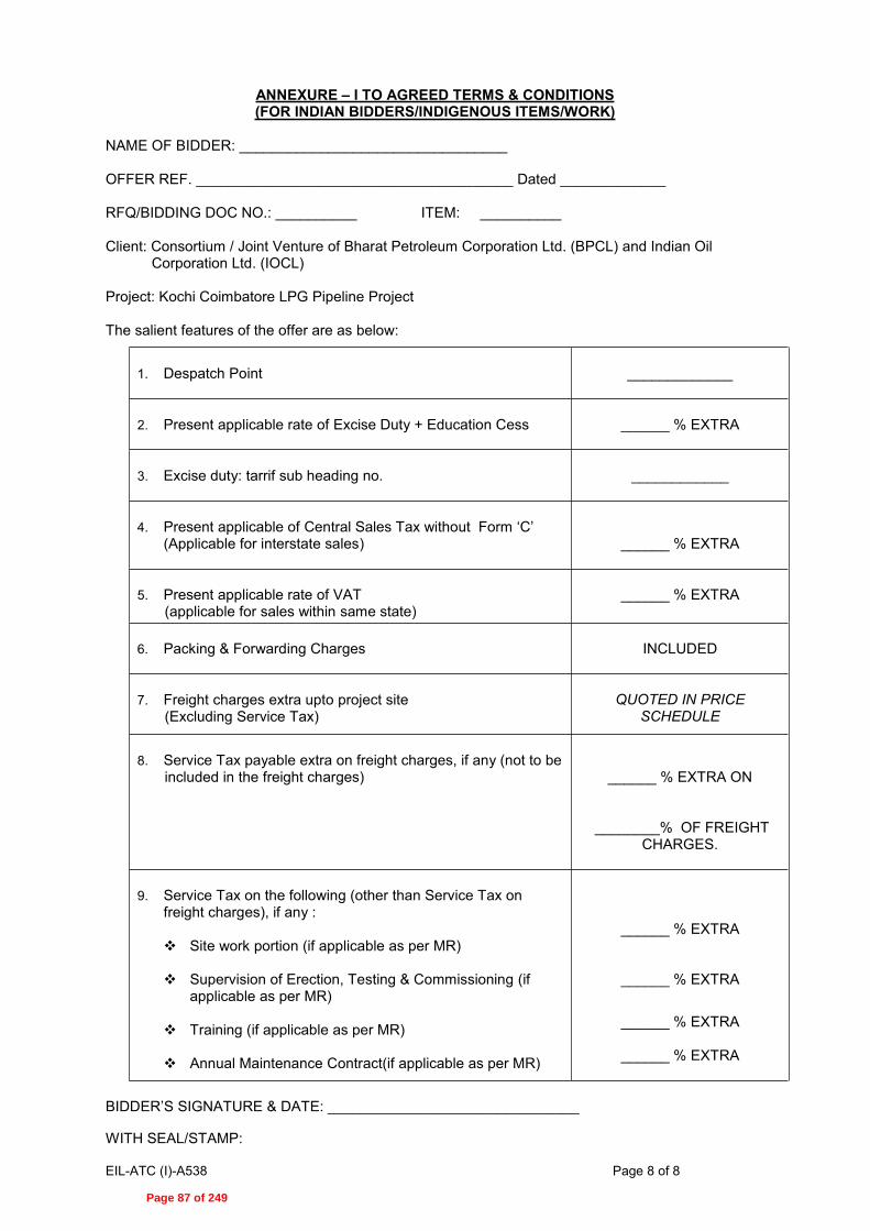
EIL-ATC (I)-A538 Page 8 of 8
ANNEXURE I TO AGREED TERMS & CONDITIONS (FOR INDIAN BIDDERS/INDIGENOUS ITEMS/WORK)
NAME OF BIDDER: _________________________________ OFFER REF. _______________________________________ Dated _____________ RFQ/BIDDING DOC NO.: __________ ITEM: __________ Client: Consortium / Joint Venture of Bharat Petroleum Corporation Ltd. (BPCL) and Indian Oil
Corporation Ltd. (IOCL) Project: Kochi Coimbatore LPG Pipeline Project The salient features of the offer are as below:
1. Despatch Point
_____________
2. Present applicable rate of Excise Duty + Education Cess
______ % EXTRA
3. Excise duty: tarrif sub heading no.
____________
4. Present applicable of Central Sales Tax without Form
(Applicable for interstate sales)
______ % EXTRA
5. Present applicable rate of VAT
(applicable for sales within same state)
______ % EXTRA
6. Packing & Forwarding Charges
INCLUDED
7. Freight charges extra upto project site
(Excluding Service Tax)
QUOTED IN PRICE
SCHEDULE
8. Service Tax payable extra on freight charges, if any (not to be
included in the freight charges)
______ % EXTRA ON
________% OF FREIGHT CHARGES.
9. Service Tax on the following (other than Service Tax on
freight charges), if any :
Site work portion (if applicable as per MR)
Supervision of Erection, Testing & Commissioning (if applicable as per MR)
Training (if applicable as per MR)
Annual Maintenance Contract(if applicable as per MR)
______ % EXTRA
______ % EXTRA
______ % EXTRA
______ % EXTRA
SIGNATURE & DATE: _______________________________
WITH SEAL/STAMP:
Page 87 of 249

Government eProcurement System
D S C f o r F o r e i g n N a t i o n a l s Version 1.0
Procedure for obtaining Digital Signature by Foreign Vendors
This document gives the procedure to be followed by bidders who are resident of countries other
than India for participating in Online Tendering Activity.
As per the IT ACT 2000, all bidders who participate in the online bidding process in this site
should possess a valid Digital Signature issued by any of the Digital Signature Certificate (DSC)
vendors approved by CCA, India (https://cca.gov.in). The following document gives the procedure
that is generally followed by various vendors.
Generally, the documents that are required to be submitted by Foreign Nationals are as follows:
1. Identity Proof (ID Proof) of the person in whose name DSC has to be issued (E.g.
Passport copy)
2. Bank account statement in country of residence, duly attested by Indian Embassy / High
Commission / Consulate / Apostille in the country where the applicant is currently
located. (At least 6 months of Bank transactions) with the proof indicating the account is
owned by the Individual.
3. Copy of the Trade license attested by any one of the authorities as specified in Point 2
above.
4. As the Individual is representing the company, an Authorization on company’s letter head
as given in the form
5. Copy of the Authorization letter or invitation letter from department for the
participation in the tender by any one of the tender inviting authority.
As of now, it is learnt that GNFC, TCS, eMudhra issue DSCs with the above procedure. The
copy of the nCodes, TCS and eMudhra Format is enclosed as Annexure; the Copies of other
vendors will be made available on receipt of information from these vendors.
Note: The Information given by the vendors is attached for facilitating the Foreign Nationals to
procure DSCs from the Indian CA authorized vendors for information purpose only as shared by
the respective CA's.
Please find below the details of various vendors and procedure for obtaining DSC:
GNFC
Tata Consultancy Services
eMudhra
Page 88 of 249

Page 89 of 249

Page 90 of 249

Page 91 of 249

Page 92 of 249

Page 93 of 249

Page 94 of 249

Page 95 of 249
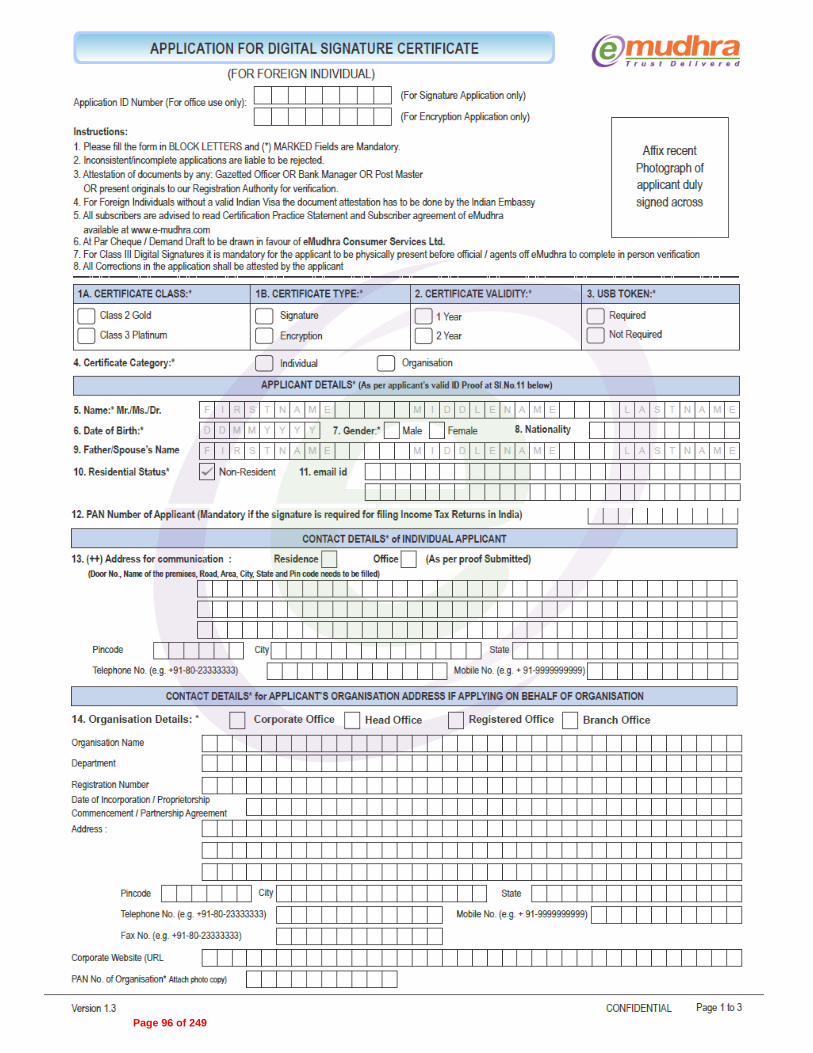
Page 96 of 249

Page 97 of 249

Page 98 of 249

Dated 02‐06‐2014 Page 1
Annexure – 1
E-TENDERING METHODOLOGY
Instructions for Online Bid Submission: The bidders are required to submit soft copies of their bids electronically on the CPP Portal (URL: http://eprocure.gov.in) only, using valid Digital Signature Certificates. The instructions given below are meant to assist the bidders in registering on the CPP Portal, prepare their bids in accordance with the requirements and submitting their bids online on the CPP Portal.
More detailed information useful for submitting online bids on the CPP Portal may be obtained at:
https://eprocure.gov.in/eprocure/app .
REGISTRATION
1) Bidders are required to enroll on the e-Procurement module of the Central Public Procurement Portal (URL: https://eprocure.gov.in/eprocure/app) by clicking on the link “Click here to Enroll” on the CPP Portal is free of charge.
2) As part of the enrolment process, the bidders will be required to choose a unique username and assign a password for their accounts.
3) Bidders are advised to register their valid email address and mobile numbers as part of the registration process and submit in EIL tender portal for updation of records (http://tenders.eil.co.in) . These details would be used for any communication from the CPP Portal.
4) Upon enrolment, the bidders will be required to register their valid Digital Signature Certificate (DSC) (Class II or Class III Certificates with signing key usage) issued by any Certifying Authority recognized by CCA India (e.g. Sify / TCS / nCode / eMudhra etc.), with their profile.
5) Foreign Bidders have to refer “DSC details for foreign Bidders” for Digital signature Certificates requirements which comes under Download Tab at https://eprocure.gov.in/eprocure/app and the remaining part is same as above and below.
6) Only one valid DSC should be registered by a bidder. Please note that the bidders are responsible to ensure that they do not lend their DSC’s to others which may lead to misuse.
7) Bidder then logs in to the site through the secured log-in by entering their user ID / password and the password of the DSC / e-Token.
SEARCHING FOR TENDER DOCUMENTS
1) There are various search options built in the CPP Portal, to facilitate bidders to search active tenders by several parameters. These parameters could include Tender ID, organization name, location, date, value, etc. There is also an option of advanced search for tenders, wherein the bidders may combine a number of search parameters such as organization name, form of contract, location, date, other keywords etc. to search for a tender published on the CPP Portal.
2) Once the bidders have selected the tenders they are interested in, the same can be moved to the respective ‘My Tenders’ folder. This would enable the CPP Portal to intimate the bidders through SMS / e-mail in case there is any corrigendum issued to the tender document.
Page 99 of 249

Dated 02‐06‐2014 Page 2
3) The bidder should make a note of the unique Tender ID assigned to each tender, in case they want to obtain any clarification / help from the Helpdesk.
PREPARATION OF BIDS
1) Bidder should take into account any corrigendum published on the tender document before submitting their bids.
2) Please go through the tender advertisement and the tender document carefully to understand the documents required to be submitted as part of the bid. Please note the number of covers in which the bid documents have to be submitted, the number of documents - including the names and content of each of the document that need to be submitted. Any deviations from these may lead to rejection of the bid.
3) Bidder, in advance, should get ready the bid documents to be submitted as indicated in the tender document and generally, they can be in PDF / XLS / RAR / DWF formats. Bid documents may be scanned with 100 dpi with black and white option. However, Price Schedule / SOR shall be strictly in RAR format without altering any contents of the formats uploaded by EIL in their Bidding Document.
4) To avoid the time and effort required in uploading the same set of standard documents which are required to be submitted as a part of every bid, a provision of uploading such standard documents (e.g. PAN card copy, annual reports, auditor certificates etc.) has been provided to the bidders. Bidders can use “My Space” area available to them to upload such documents. These documents may be directly submitted from the “My Space” area while submitting a bid, and need not be uploaded again and again. This will lead to a reduction in the time required for bid submission process.
SUBMISSION OF BIDS
1) Bidder should log into the site well in advance for bid submission so that he/she upload the bid in time i.e. on or before the bid submission time. Bidder will be responsible for any delay due to other issues.
2) The bidder has to digitally sign and upload the required bid documents one by one as indicated in the tender document.
3) Bidder has to select the payment option as “offline” to pay the tender fee / EMD as applicable and enter details of the instrument.
4) Bidder should prepare the EMD as per the instructions specified in the tender document. The original should be posted/couriered/given in person to the Tender Processing Section, with in 7 calendar days of the date of Unpriced bid opening. The details of the DD/any other accepted instrument, physically sent, should tally with the details available in the scanned copy and the data entered during bid submission time. Otherwise the uploaded bid will be rejected.
5) A Price Bid format has been provided with the tender document to be filled by all the bidders. Bidders are requested to note that they should necessarily submit their financial bids in the format provided and no other format is acceptable. Bidders are required to download the Price Bid file, open it and complete the cells with their respective financial quotes and other details (such as name of the bidder). No other cells should be changed. Once the details have been completed, the bidder should save it and submit it online, without changing the filename. If the Price Bid file is found to be modified by the bidder, the bid will be rejected.
Page 100 of 249

Dated 02‐06‐2014 Page 3
6) The server time (which is displayed on the bidders’ dashboard) will be considered as the standard time for referencing the deadlines for submission of the bids by the bidders, opening of bids etc. The bidders should follow this time during bid submission.
7) All the documents being submitted by the bidders would be encrypted using PKI encryption techniques to ensure the secrecy of the data. The data entered cannot be viewed by unauthorized persons until the time of bid opening. The confidentiality of the bids is maintained using the secured Socket Layer 128 bit encryption technology. Data storage encryption of sensitive fields is done.
8) The uploaded tender documents become readable only after the tender opening by the authorized bid openers.
9) Upon the successful and timely submission of bids, the portal will give a successful bid submission message & a bid summary will be displayed with the bid no. and the date & time of submission of the bid with all other relevant details.
10) The bid summary has to be printed and kept as an acknowledgement of the submission of the bid. This acknowledgement may be used as an entry pass for any bid opening meetings.
RETENDER
1) Please note that if Tender has been retendered, than it is mandatory for the bidder to submit their offer again on CPP Portal.
ASSISTANCE TO BIDDERS
1) Any queries relating to the tender document and the terms and conditions contained therein should be addressed to the Tender Inviting Authority for a tender or the relevant contact person indicated in the tender.
2) Any queries relating to the process of online bid submission or queries relating to CPP Portal in general may be directed to the 24x7 CPP Portal Helpdesk. The contact number for the helpdesk is 1800 3070 2232.
Page 101 of 249

ENGINEERS INDIA LIMITED
NEW DELHI Client: BPCL
Project: KOCHI-COIMBATORE- SALEM LPG PIPELINE
File Name: C:\Users\Arunima\Desktop\a.pdf
Thi
s dr
awin
g, d
esig
n an
d de
tails
giv
en o
n th
is f
orm
at a
re th
e pr
oper
ty o
f E
NG
INE
ER
S IN
DIA
LIM
ITE
D. T
hey
are
mer
ely
loan
ed o
n th
e bo
rrow
er's
exp
ress
agr
eem
ent t
hat t
hey
will
not
be
repr
oduc
ed, c
opie
d, e
xhib
ited
or u
sed,
exc
ept i
n th
e lim
ited
way
per
mitt
ed b
y a
wri
tten
cons
ent g
iven
by
the
lend
er to
the
borr
ower
for
the
inte
nded
use
. EIL
-164
1-51
5 R
ev.1
A4-
210x
297.
Sheet 1 of 6
ITEM DESCRIPTION: SWITCHBOARDS: HV (INDOOR) WITH VCB
GROUP ITEM CODE: 13BA DESTINATION: As per Commercial Documents
MR CATEGORY: II DELIVERY PERIOD: As per Commercial Documents
DOCUMENT NUMBER( Always quote the Document Number given below as reference )
26/11/2014 16
JOB NO. UNIT/ AREA
MAINCOST
CENTRE
DOC.CODE
SR. NO. REV. DATE
50
DIVN. DEPT.
ORIGINATOR
NOTES :12
3
This page is a record of all the Revisions of this Requisition.The nature of the Revision is briefly stated in the "Details" column below, theRequisition in its entirety shall be considered for contractual purposes.Vendor shall note the MR category and shall submit his offer in line with therequirements included in attached 'Instructions to Bidders'.
REV. DATE BY CHK. APPD. DETAILS
A 26/11/2014 SH RG MKS
MATERIAL REQUISITION (TOP SHEET)
010 XB MR 0080 AA538
This is a system generated approved document and does not require signature.
Page 102 of 249

ENGINEERS INDIA LIMITED
NEW DELHI Client: BPCL
Project: KOCHI-COIMBATORE- SALEM LPG PIPELINE
File Name: C:\Users\Arunima\Desktop\a.pdf
Thi
s dr
awin
g, d
esig
n an
d de
tails
giv
en o
n th
is f
orm
at a
re th
e pr
oper
ty o
f E
NG
INE
ER
S IN
DIA
LIM
ITE
D. T
hey
are
mer
ely
loan
ed o
n th
e bo
rrow
er's
exp
ress
agr
eem
ent t
hat t
hey
will
not
be
repr
oduc
ed, c
opie
d, e
xhib
ited
or u
sed,
exc
ept i
n th
e lim
ited
way
per
mitt
ed b
y a
wri
tten
cons
ent g
iven
by
the
lend
er to
the
borr
ower
for
the
inte
nded
use
. EIL
-164
1-51
5 R
ev.1
A4-
210x
297.
Sheet 2 of 6
REQUISITION NO. REV.
AA538-010-XB-MR-0080
SR. NO.TAG NO/
ITEM CODE/ [ ID. NO. ] DESCRIPTION QUANTITY
01.00
02.00
Design, engineering, manufacture,procurement of materials and bought outcomponents, assembly at shop, inspection,testing at manufacturer's works, packing,supply & delivery of the following 6.6kV & 11kV switchboards including supply ofall commissioning spares & special toolsand tackles & documentation as per theenclosed EIL standard specifications,instructions to vendors, jobspecification, data sheets etc. and othercodes and standards attached or referred.
Unloading at site, handling,transporation to store and from store towork site, storage at site, assembly atsite, installation, testing (board &numerical relay), pre-commissioing,painting (board), insulationtesting(board), commissioing (board,numerical relay & engg.console),performance guarantee run, handing overto client and other field works includingcivil-structural works for boards(including base frame) for the followingas per enclosed EIL standardspecifications, instructions to vendor,
01.01
01.02
01.03
01.04
01.05
01.06
01.07
01.08
01.09
01.10
01.11
020-HT-201
020-HT-202
030-HT-201
LAPTOP-01
LAPTOP-02
EARTHING TRUCK20
EARTHING TRUCK30
LIFTING TRUCK-20
LIFTING TRUCK-30
ENGG. CONSOLE-1
ENGG. CONSOLE-2
6.6kV, 630A, 40 kA(1sec), TP switchboardat as per datasheet no. A538-010-16-50-DS-0080/0083/0084
6.6kV, 630A, 40kA (1sec), TP Switchboardas per datasheet no. A538-010-16-50-DS-0081/0083/0085
11kV,630A, 40 kA(1sec), TP switchboard asper datasheet no. A538-010-16-50-DS-0082/0083/0086
Laptop as per sl. no. 29.0 of jobspecification (A538-010-16-50-SP-0080)for IOCL terminal at kochi
Laptop as per sl. no. 29.0 of jobspecification (A538-010-16-50-SP-0080)for BPCL terminal at kochi
Earthing trucks & accessories for new6.6kV switchboards as specified ininstructions to vendor.
Earthing trucks & accessories for new11kV switchboards as specified ininstructions to vendor.
Lifting truck & accessories for new 6.6kVswitchboards as specified in instructionsto vendor.
Lifting truck & accessories for new 11kVswitchboards as specified in instructionsto vendor.
Engg. cum operator work station alongwith automation hardware, furnitures forIOCl import terminal
Engg. cum operator work station alongwith automation hardware,furnitures forBPCL dispatch terminal
1 Nos
1 Nos
1 Nos
1 Nos
1 Nos
1 Nos
1 Nos
1 Nos
1 Nos
1 Lot
1 Lot
A1
A1
A1
A1
A1
A1
A1
A1
A1
A1
A1
Page 103 of 249

ENGINEERS INDIA LIMITED
NEW DELHI Client: BPCL
Project: KOCHI-COIMBATORE- SALEM LPG PIPELINE
File Name: C:\Users\Arunima\Desktop\a.pdf
Thi
s dr
awin
g, d
esig
n an
d de
tails
giv
en o
n th
is f
orm
at a
re th
e pr
oper
ty o
f E
NG
INE
ER
S IN
DIA
LIM
ITE
D. T
hey
are
mer
ely
loan
ed o
n th
e bo
rrow
er's
exp
ress
agr
eem
ent t
hat t
hey
will
not
be
repr
oduc
ed, c
opie
d, e
xhib
ited
or u
sed,
exc
ept i
n th
e lim
ited
way
per
mitt
ed b
y a
wri
tten
cons
ent g
iven
by
the
lend
er to
the
borr
ower
for
the
inte
nded
use
. EIL
-164
1-51
5 R
ev.1
A4-
210x
297.
Sheet 3 of 6
REQUISITION NO. REV.
AA538-010-XB-MR-0080
SR. NO.TAG NO/
ITEM CODE/ [ ID. NO. ] DESCRIPTION QUANTITY
03.00
04.00
05.00
06.00
07.00
08.00
09.00
job specifications, data sheets etc.
Transportation from Vendors work/ shop tosite for the following as per theenclosed standard specifications,instructions to vendors, jobspecification, data sheets etc
Supply of Mandatory Spares as per listmentioned in instructions to vendor
Supply of Two Years Operation andMaintenance Spares, as per enclosedinstructions to vendorUnit Rates
Providing training on numerical relays asper enclosed instructions to vendor(Refer note-2)
<< DELETED >>
Drawings and documents as per attached
Lot
Lot
02.01
02.02
02.03
02.10
02.11
03.01
03.02
03.03
03.06
03.07
03.08
03.09
03.10
03.11
04.01
04.02
04.03
06.01
06.02
07.01
07.02
07.03
07.04
07.05
{02}020-HT-201
{02}020-HT-202
{02}030-HT-201
{02}ENGG. CONSOLE-1
{02}ENGG. CONSOLE-2
{03}020-HT-201
{03}020-HT-202
{03}030-HT-201
{03}EARTHING TRUCK20
{03}EARTHING TRUCK30
{03}LIFTING TRUCK-20
{03}LIFTING TRUCK-30
{03}ENGG. CONSOLE-1
{03}ENGG. CONSOLE-2
{04}020-HT-201
{04}020-HT-202
{04}030-HT-201
{07}TRAINING
{07}TRAINING-30-REL
{07}TRAINING-20-REL
{07}TRAINING-30-AUT
{07}TRAINING-20-AUT
For Item 01.01
For Item 01.02
For Item 01.03
For Sr. No. 01.10
For Sr. No. 01.11
For Item 01.01
For Item 01.02
For Item 01.03
For Sr. No. 01.06
For Sr. No. 01.07
For Sr. No. 01.08
For Sr. No. 01.09
For Sr. No. 01.10
For Sr. No. 01.11
For Item 01.01
For Item 01.02
For Item 01.03
Unit Rates of items for addition/deletion purpose, as per the enclosedinstructions to vendor.
Unit Rates for Specific tests as per theenclosed instructions to vendor.
Training on numerical relays atmanufacturer's works as per enclosedinstructions to vendor
Training on numerical relays at IOCLimport terminal as per enclosedinstructions to vendor
Training on numerical relays at BPCLdispatch terminal as per enclosedinstructions to vendor
Training on automation system at IOCLimport terminal as per enclosedinstructions to vendor
Training on automation system at BPCLdispatch terminal as per enclosedinstructions to vendor
1 Lot
1 Lot
1 Lot
1 Lot
1 Lot
1 Nos
1 Nos
1 Nos
1 Nos
1 Nos
1 Nos
1 Nos
1 Lot
1 Lot
1 Lot
1 Lot
1 Lot
1
1
1 Lot
1 Lot
1 Lot
1 Lot
1 Lot
A1
A1
A1
A1
A1
A1
A1
A1
A1
A1
A1
A1
A1
A1
A1
A1
A1
A1
A1
A1
A1
A1
Page 104 of 249

ENGINEERS INDIA LIMITED
NEW DELHI Client: BPCL
Project: KOCHI-COIMBATORE- SALEM LPG PIPELINE
File Name: C:\Users\Arunima\Desktop\a.pdf
Thi
s dr
awin
g, d
esig
n an
d de
tails
giv
en o
n th
is f
orm
at a
re th
e pr
oper
ty o
f E
NG
INE
ER
S IN
DIA
LIM
ITE
D. T
hey
are
mer
ely
loan
ed o
n th
e bo
rrow
er's
exp
ress
agr
eem
ent t
hat t
hey
will
not
be
repr
oduc
ed, c
opie
d, e
xhib
ited
or u
sed,
exc
ept i
n th
e lim
ited
way
per
mitt
ed b
y a
wri
tten
cons
ent g
iven
by
the
lend
er to
the
borr
ower
for
the
inte
nded
use
. EIL
-164
1-51
5 R
ev.1
A4-
210x
297.
Sheet 4 of 6
REQUISITION NO. REV.
AA538-010-XB-MR-0080
SR. NO.TAG NO/
ITEM CODE/ [ ID. NO. ] DESCRIPTION QUANTITY
Vendor Data requirement for all suppliesand services covered above in Sr.Nos.1.00to Sr.No.8.00
Vendors shall quote prices in EIL Price Schedule except for Sr.No.9.00. Price fordocumentation is implied to be included in the prices quoted against Sr.No.1.00 toSr.No.8.00
Vendor to note that the numbers given in square '[]' and curly '{}' brackets arenot for their use and meant for store purpose only. Items shall be tagged as permain equipment Tag No. only.
Note:Bidder to note that,one fixed price is to be quoted for grouped items. The groupsof items are identified by A1 where A1 indicates one group and so on.Grouped items shall not be split ordered.
Page 105 of 249

ENGINEERS INDIA LIMITED
NEW DELHI Client: BPCL
Project: KOCHI-COIMBATORE- SALEM LPG PIPELINE
File Name: C:\Users\Arunima\Desktop\a.pdf
Thi
s dr
awin
g, d
esig
n an
d de
tails
giv
en o
n th
is f
orm
at a
re th
e pr
oper
ty o
f E
NG
INE
ER
S IN
DIA
LIM
ITE
D. T
hey
are
mer
ely
loan
ed o
n th
e bo
rrow
er's
exp
ress
agr
eem
ent t
hat t
hey
will
not
be
repr
oduc
ed, c
opie
d, e
xhib
ited
or u
sed,
exc
ept i
n th
e lim
ited
way
per
mitt
ed b
y a
wri
tten
cons
ent g
iven
by
the
lend
er to
the
borr
ower
for
the
inte
nded
use
. EIL
-164
1-51
5 R
ev.1
A4-
210x
297.
Sheet 5 of 6
REQUISITION NO. REV.
AA538-010-XB-MR-0080
LIST OF ATTACHMENTS
SL.No. DOCUMENT TITLE DOCUMENT NO.
REVISION
REV. REV. REV. REV.DATE DATE DATE DATE
Format for Vendor Drawing/Document Submission Schedule
Vendor data requirement
Instructions to Vendor
Job specification
6.6kV HV Switchboard datasheet (020-HT-201)6.6 kV HV Switchboard datasheet (020-HT-202 )11 kV HV Switchboard datasheet (030-HT-201)Hardware Datasheet
Numerical Relay Datasheet
6.6 kV Feeder List (020-HT-201)6.6 kV Feeder List (020-HT-202)11 kV Feeder List (030-HT-201)
EIL Standard specification forHV Switchboard (20 sheets)Specification for NumericalRelaysSpecification for ElectricalEquipment InstallationSpecification for Fieldinspection, testing andcommissioing of electricalinstallation
Standard Inspection Test Planof HV Switchboards
Specification for Qualitymanagement System from BiddersSpecification forDocumentation Requirement fromSuppliers
1
2
3
4
5
6
7
8
9
10
11
12
13
14
15
16
17
18
19
EIL-1641-1923Rev.1
A538-010-16-50-VR-0080
A538-010-16-50-TR-0080
A538-010-16-50-SP-0080
A538-010-16-50-DS-0080
A538-010-16-50-DS-0081
A538-010-16-50-DS-0082
A538-010-16-50-DS-0083
A538-010-16-50-DS-0087
A538-010-16-50-DS-0084
A538-010-16-50-DS-0085
A538-010-16-50-DS-0086
6-51-0001
6-51-0055
6-51-0081
6-51-0087
6-81-1001
6-78-0001
6-78-0003
A
A
A
A
A
A
A
A
A
A
A
6
2
4
3
3
0
0
26/11/2014
24/11/2014
24/11/2014
24/11/2014
24/11/2014
24/11/2014
24/11/2014
24/11/2014
24/11/2014
24/11/2014
24/11/2014
15/10/2013
12/06/2014
21/05/2014
10/06/2014
21/11/2013
04/06/2009
04/06/2009
FORMATS
VDR
INSTRUCTIONS TO VENDORS
JOB SPECIFICATION
DATASHEET
DATASHEET - FEEDER LISTS
STANDARD SPECIFICATIONS
INSPECTION & TEST STANDARDS
QUALITY REQUIREMENTS
Page 106 of 249

ENGINEERS INDIA LIMITED
NEW DELHI Client: BPCL
Project: KOCHI-COIMBATORE- SALEM LPG PIPELINE
Sheet 6 of 6
File Name: C:\Users\Arunima\Desktop\a.pdf
Thi
s dr
awin
g, d
esig
n an
d de
tails
giv
en o
n th
is f
orm
at a
re th
e pr
oper
ty o
f E
NG
INE
ER
S IN
DIA
LIM
ITE
D. T
hey
are
mer
ely
loan
ed o
n th
e bo
rrow
er's
exp
ress
agr
eem
ent t
hat t
hey
will
not
be
repr
oduc
ed, c
opie
d, e
xhib
ited
or u
sed,
exc
ept i
n th
e lim
ited
way
per
mitt
ed b
y a
wri
tten
cons
ent g
iven
by
the
lend
er to
the
borr
ower
for
the
inte
nded
use
. EIL
-164
1-51
5 R
ev.1
A4-
210x
297.
REQUISITION NO. REV.
AA538-010-XB-MR-0080
LIST OF ATTACHMENTS
SL.No. DOCUMENT TITLE DOCUMENT NO.
REVISION
REV. REV. REV. REV.DATE DATE DATE DATE
In case of any subsequent revision of MR or PR, only revised sheets of theattachments listed above shall be issued alongwith the revision.
GENERAL NOTES:
Page 107 of 249

Eng
inee
rs In
dia
Lim
ited
Clie
nt: B
PC
L
S.N
o.E
quip
men
t Num
ber
Form
Ele
ctro
nic
(E)/
Prin
t (P
)R
emar
ks
Ven
dor
Dra
win
g/ D
ocum
ent S
ubm
issi
on S
ched
ule
Pro
ject
: KO
CH
I-CO
IMB
ATO
RE
- SA
LEM
LP
G P
IPE
LIN
EV
endo
r N
ame:
Con
tact
Per
son(
EIL
):E
IL O
rigi
natin
g D
epar
tmen
t: E
LEC
TRIC
AL
PR
No.
:
Dat
e of
LO
I:
PO
No.
:D
ate
of P
O:
Form
at N
o.: E
IL-1
641-
1923
Rev
.1
Drg
./ D
oc. N
omen
clat
ure
as p
er E
IL V
endo
r Dat
aR
equi
rem
ent
Sch
edul
edda
te o
f 1st
Sub
mis
sion
Cat
egor
yR
evie
w (R
) /R
ecor
ds (I
)V
endo
r Drg
./ D
oc. T
itle
Ven
dor D
rg. /
Doc
. Num
be
Sta
tus
Dat
e
Add
ress
:
Con
tact
Per
son:
Pho
ne:
City
:
Em
ail:
Fax:
Item
Des
crip
tion:
SW
ITC
HB
OA
RD
S: H
V (
IND
OO
R)
WIT
H V
CB
Page 108 of 249

INSTRUCTIONS TO VENDOR HV SWITCHBOARD (INDOOR) WITH VCB
PROJECT : KCESPL CLIENT : BPCL
DOCUMENT NO.
A538-010-16-50-TR-0080, Rev. A
Page 1 of 11
A 24.11.2014 ISSUED WITH MR SH RG MKS Rev. No
Date Purpose Prepared
by Checked
by Approved
by
Format No. EIL 1641-1924 Rev. 1 Copyright EIL – All rights reserved
INSTRUCTIONS TO BIDDER HV SWITCHBOARD (INDOOR)
WITH VCB
PROJECT : KOCHI-COIMBATORE-ERODE -SALEM LPG PIPELINE OWNER : M/s BPCL CONSULTANT : ENGINEERS INDIA LIMITED JOB NO. : A538
Page 109 of 249

INSTRUCTIONS TO VENDOR HV SWITCHBOARD (INDOOR) WITH VCB
PROJECT : KCESPL CLIENT : BPCL
DOCUMENT NO.
A538-010-16-50-TR-0080, Rev. A
Page 2 of 11
Format No. EIL 1641-1924 Rev. 1 Copyright EIL – All rights reserved
1.0 SPECIAL INSTRUCTIONS TO BIDDERS
1.1 All items of the MR shall be ordered on one vendor only. The MR items shall not be split for the purpose of order placement.
1.2 Bidders to note that no correspondence shall be entered into or entertained after the bid submission.
1.3 Bidders shall submit quotations only for those items, which they can supply strictly as per MR specifications and for the switchboard rating for which they are enlisted with EIL.
1.4 The submission of prices by the bidder shall be construed to mean that bidder has confirmed compliance with all technical specifications of the corresponding item(s).
1.5 If the offer contains any technical deviations and / or if the bid does not include complete scope and technical/ performance data required to be submitted with the bid, the offer shall be liable for rejection. In this regard, bidder shall also note that, if any deviations are considered in offer, same shall be mentioned in sheet called ‘DEVIATION LIST’. Other deviations mentioned in elsewhere of the offer shall be considered as void.
1.6 Bidder to note that the equipment shall comply with the requirements of latest revision of codes & standards attached or referred with the MR document. In case of any conflict between the various documents, the most stringent one shall be followed and Owners/ EIL decision in this regard shall be final and binding.
1.7 Bidders to note that a pre bid meeting can be held in which the bidder can seek any clarification/ confirmation, if required. Bidder shall also ensure that this meeting shall be attended by both technical and commercial personnel of the bidder who had thoroughly gone through the bid document beforehand, so that all issues are finally resolved in this meeting.
1.8 Bidder shall note that bill of material furnished with the offer will be retained for information only and shall not be contractual binding. All materials and components as required to meet MR specifications and functional requirement shall be included in the bidder’s scope without any cost and time implication to the purchaser.
2.0 BIDDER SHALL ENSURE COMPLIANCE TO THE FOLLOWING:
2.1 Bidder has submitted the un-priced copy of priced schedule exactly as per the format attached with the RFQ. It is to be noted that, in case of any mis-match with respect to the format, offer shall be liable for rejection without any further review/seeking clarifications from bidder.
2.2 Bidder has quoted for all items as per item description exactly as specified in MR and confirmed compliance to the scope of MR.
2.3 Bidder has quoted for unit rates for all specified items/components for addition/ deletion purpose.
2.4 Bidder has quoted for unit rates for conducting Type tests on switchboard & breakers. 2.5 Bidder has quoted for 2 years Operation and Maintenance spares along with recommended
quantity and unit price as per schedule format (refer sl. no. 9.0) 2.6 Commissioning spares, as required, are included in bidder’s scope of supply and price for
same is deemed to be included in the respective supply of items listed in MR. 2.7 Bidder has included the supply of one set of recommended tools, tackles and special
equipment required for the maintenance of the breakers and panels, and price for the same shall be included in the base price.
2.8 Bidder has quoted for site activity/works for item nos. 02.01/02.02/02.03/02.08/02.09 listed in MR.
2.9 Bidder has quoted for training on numerical relays at manufacturer’s works & at different sites where switchboard shall be located.
2.10 Bidder has quoted for training on automation system at different sites where Engineering Console-1 & Engineering Console -2 shall be located.
Page 110 of 249

INSTRUCTIONS TO VENDOR HV SWITCHBOARD (INDOOR) WITH VCB
PROJECT : KCESPL CLIENT : BPCL
DOCUMENT NO.
A538-010-16-50-TR-0080, Rev. A
Page 3 of 11
Format No. EIL 1641-1924 Rev. 1 Copyright EIL – All rights reserved
2.11 Bidder has furnished duly filled-in HV switchboard data sheet No. A538-010-16-50-DS-0080/0081/0082 (Part-II) and numerical relay datasheet A538-010-16-50-DS-0087 for each rating, along with the bid.
2.12 Bidder has submitted all documents required with the offer as listed in Vendor Data Requirement (VDR) form and the bidder duly signs the VDR form.
2.13 Makes of all electrical equipments/components/ devices shall be exactly as specified in the approved sub-vendor list mentioned in ‘Annexure-1’ (page no. 10 of 11).
2.14 Bidder has furnished overall dimensions for offered switchboard. 2.15 Bidder has furnished confirmation that there is no deviation to other MR specifications and
data sheets attached with this MR. In case of deviation, the offer shall be rejected without raising any query to bidder. Bidder’s deviation if any due to inherent design & accepted by EIL in earlier executed projects, can be resolved/discussed during detailed engineering.
2.16 Bidder has furnished foundation plan and cutout details for offered switchboards. 2.17 All the offered switchboards and vacuum circuit breakers are type tested. New design/breaker
models, not supplied in past EIL projects shall not be offered. Copies of valid type test certificates for the following tests conducted on identical design of offered equipments shall be furnished with the offer:- a) Short time current withstand test (panel & breaker). b) Heat run test (panel). c) Internal arc test for panel (location: cable chamber, busbar chamber & breaker chamber) d) Impulse voltage withstand test (panel & breaker). e) Duty cycle test for each type of breaker.
2.18 The switchgear shall be qualified as classification IAC according to IEC 62271-200 with regard to its mechanical strength in the event of an internal arc. The test performance shall be in conformity with accessibility type AFLR. The test shall be executed for all separate compartments within the functional unit containing HV equipment, i.e., bus-bar compartment, circuit breaker compartment and cable compartment.
2.19 Bidder shall note the following regarding current value & time duration for internal arc- a) 020-HT-201 & 030-HT-201 shall be internal arc tested for 40kA for 1 sec. time duration. b) 020-HT-202 shall be internal arc tested for 40kA for 1 sec. time duration. Requirements of this test shall be as per IEC 62271-200. Quotation to be submitted for those items only for which these type test certificates are available.
3.0 EARTHING SWITCH/EARTHING TRUCK (REFER MR SR. NO. 01.06, 01.07)
In case offered panels are provided with integral earth switch, separate earthing truck is not required for cable/bus earthing. In case of separate earthing carriage/truck is considered, then same shall be provided for 11kV and 6.6KV switchboard as per description mentioned below. a. MR sl. No. 01.07 : One set of earthing truck for bus side earthing and one set of earthing
truck for cable side earthing for 11KV switchboard (030-HT-201) to be installed at IOCL import terminal at Kochi.
b. MR sl. No. 01.06 : One set of earthing truck for bus side earthing and one set of earthing truck for cable side earthing for 6.6KV switchboards (020-HT-201 & 020-HT-202) to be installed at BPCL dispatch terminal at Kochi.
Along with offer, bidder shall highlight the earthing arrangement of all offered switchboard.
Page 111 of 249

INSTRUCTIONS TO VENDOR HV SWITCHBOARD (INDOOR) WITH VCB
PROJECT : KCESPL CLIENT : BPCL
DOCUMENT NO.
A538-010-16-50-TR-0080, Rev. A
Page 4 of 11
Format No. EIL 1641-1924 Rev. 1 Copyright EIL – All rights reserved
4.0 LIFTING TRUCK (REFER MR SR. NO. 01.08, 01.09)
In case of cassette mounted design is being offered by bidder, then only below mentioned items shall be applicable. Lifting truck and accessories, as applicable, shall be provided for 11kV and 6.6KV switchboard as per description mentioned below. a. MR sl. No. 01.09 : One no. of lifting truck for withdrawal of cassette mounted vacuum
circuit breakers from the switchboard panel for 11KV switchboard (030-HT-201) to be installed at IOCL import terminal at Kochi.
b. MR sl. No. 01.08 : One no. of lifting truck for withdrawal of cassette mounted circuit breakers from the switchboard panel for 6.6KV switchboards (020-HT-201 & 020-HT-202) to be installed at BPCL dispatch terminal at Kochi.
5.0 AUTOMATION SYSTEM (REFER MR SL. NO. 01.10 & 01.11)
Redundant communication LAN made of twisted pair Cu cable shall be made with in the switchboard. Each numerical relay shall be hooked up with this redundant LAN through ethernet switch. Finally this redundant LAN shall be extended upto engineering cum operator consol (Engg. Console-1 or Engg. Console-2). Located at nearby control room. Supply of engineering cum operator console along with LAN cable, Ethernet switch, patch cord, other automation hardware along with furniture are in scope of bidder. Maximum 4 nos. relay shall be connected to one (1) ethernet switch. 20% spare port shall be provided in ethernet switch with min. one (1) at each switch. For quotation purpose, 250 mtr. LAN cable (twisted pair cu) shall be considered.
6.0 SITE ACTIVITIES/WORK (REFER MR SR. NO. 02.00)
In addition to the requirement of standard specification mentioned (6-51-0081 & 6-51-0087), installation, testing and commissioning of supplied switchboards vide MR sl. no. 02.01/02.02/02.03 shall also comply with the following requirements.
6.1 Testing and commissioning of all numerical relays along with relay setting for all the feeders at site including supply, installation and testing of application software as required for numerical relays & engineering cum operator console are included in the bidder’s scope of work. During detailed engineering stage, relay parameterization documents shall be furnished for review & approval.
6.2 Testing & commissioning of all switchboards are also included in bidder’s scope of work. 6.3 It shall be noted that, installation, testing & commissioning of automation system are also
included in bidder’s scope. Laying & termination of LAN cable from substation to
engineering console located at control are in scope of bidder. Accordingly lump sum price for this site work shall be quoted against at sl. no. 02.08 (for IOCL import terminal) & 02.09 (BPCL dispatch terminal).
6.4 For testing and commissioning activities; bidder shall be required to depute their representative for actual number of days as per site requirement.
6.5 All test equipments required for testing and commissioning at site shall be brought by bidder at his own expense.
6.6 In addition to base frame of switchboard, additional framework base channels for embedding in the concrete/welding to the insert plates of concrete surface shall be supplied and erected by the vendor. Necessary 6mm thick chequered plates to blind unused openings shall be supplied and erected by the vendor. Bidder shall be responsible for coordinating with the purchaser for structural/civil interface for complete installation engineering.
6.7 The minor civil work (civil work except equipment foundation) as required and also repair of civil work damaged during erection.
Page 112 of 249

INSTRUCTIONS TO VENDOR HV SWITCHBOARD (INDOOR) WITH VCB
PROJECT : KCESPL CLIENT : BPCL
DOCUMENT NO.
A538-010-16-50-TR-0080, Rev. A
Page 5 of 11
Format No. EIL 1641-1924 Rev. 1 Copyright EIL – All rights reserved
6.8 It is Bidder’s responsibility to provide material storage facility at site, transportation of material from Bidder’s store to the site of erection. Owner will provide open space for
storage facilities at site. 6.9 Bidder shall make arrangement for machinery (cranes/trailers), skilled/ unskilled labour,
tools and tackles, testing equipments, all consumable materials (if any), base channels, and charger support, etc. as required for completion of work. Electrical power shall be arranged by owner.
6.10 Bidder shall keep the site clean during erection and remove all the temporary facilities etc. immediately after the commissioning is completed.
6.11 Bidder to specifically note that supply & installations of structural support for switchgear panels are also included in the bidder’s scope of work.
6.12 Feeder Differential Protection (Only for 020-HT-201, MR sl. no.01.01) a. Supply, laying & termination of multimode FO cable (if feeder differential is required) in
numerical relay (length: 2500mtr.) along with all other accessories has been included in bidder’s scope. Unit price of FO cable shall also to be quoted. Route & laying arrangement shall be informed by owner. Also, trench to be provided by owner.
b. If feeder differential is envisaged at incomer of 020-HT-201, then one no. differential relay (numerical type) along with three (3) nos. PS class CT shall be supplied as loose item. Same shall be fitted at upstream 6.6kV switchboard located in onsite substation of kochi refinery complex. Site work i.e. mounting of CT in existing 6.6kV panel along with wiring are also included in bidder’s scope of work. Relays located at upstream board & other relay located at incomer of 020-HT-201 shall be connected with each other through FO cable.
c. Knee point voltage of PS class CT shall be calculated based on upstream transformer capacity as 25MVA & impedance voltage as 9%.
Price for carrying out these site activities shall be included in MR sl. no. 02.01.
7.0 TRANSPORTATION TO DESTINATION POINT (REFER MR ITEM. NO. 03.00)
Bidder to note the following destination details for various MR Item nos. covered under this MR:- a) BPCL dispatch terminal at Kochi :- MR item nos.03.01(020-HT-201),
03.02(020-HT-202), 03.05, 03.06, 03.08, 03.11
b) IOCL import terminal at Kochi :- MR item nos.03.03(030-HT-201), 03.04, 03.07, 03.09, 03.10
Notes:- (i) Lump sum transportation price for all the items mentioned at sl. no. 5.0 (Automation
system) shall be considered by bidder for quotation against MR item nos. 03.10 & 03.11.
(ii) Transportation cost of ‘Laptop-01’ to IOCL import terminal & ‘Laptop-02’ to BPCL dispatch terminal shall be included in supply price of these items quoted at MR sl. no. 01.04 & 01.05.
8.0 MANDATORY SPARES (MR ITEM. NO. 04.00)
Bidder shall quote for mandatory spares (the rate shall be inclusive of packing and transportation at particular destination point described at cl. no. 6.0 above) along with unit rate and quantity as per the price schedule format.
Page 113 of 249
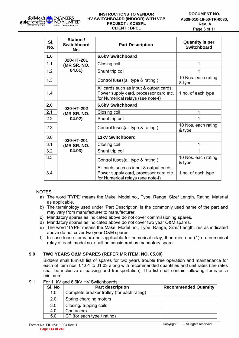
INSTRUCTIONS TO VENDOR HV SWITCHBOARD (INDOOR) WITH VCB
PROJECT : KCESPL CLIENT : BPCL
DOCUMENT NO.
A538-010-16-50-TR-0080, Rev. A
Page 6 of 11
Format No. EIL 1641-1924 Rev. 1 Copyright EIL – All rights reserved
NOTES: a) The word ‘TYPE’ means the Make, Model no., Type, Range, Size/ Length, Rating, Material
as applicable. b) The terminology used under ‘Part Description’ is the commonly used name of the part and
may vary from manufacturer to manufacturer. c) Mandatory spares as indicated above do not cover commissioning spares. d) Mandatory spares as indicated above do not cover two year O&M spares. e) The word ‘TYPE’ means the Make, Model no., Type, Range, Size/ Length, res as indicated
above do not cover two year O&M spares. f) In case loose items are not applicable for numerical relay, then min. one (1) no. numerical
relay of each model no. shall be considered as mandatory spare.
9.0 TWO YEARS O&M SPARES (REFER MR ITEM. NO. 05.00)
Bidders shall furnish list of spares for two years trouble free operation and maintenance for each of item nos. 01.01 to 01.03 along with recommended quantities and unit rates (the rates shall be inclusive of packing and transportation). The list shall contain following items as a minimum
9.1 For 11kV and 6.6kV HV Switchboards: Sl. No Part description Recommended Quantity
1.0 Complete breaker trolley (for each rating) 2.0 Spring charging motors
3.0 Closing/ tripping coils 4.0 Contactors 5.0 CT (for each type / rating)
Sl. No.
Station / Switchboard
No. Part Description
Quantity is per Switchboard
1.0 020-HT-201 (MR SR. NO.
04.01)
6.6kV Switchboard
1.1 Closing coil 1
1.2 Shunt trip coil 1
1.3 Control fuses(all type & rating ) 10 Nos. each rating & type
1.4 All cards such as input & output cards, Power supply card, processor card etc. for Numerical relays (see note-f)
1 no. of each type
2.0 020-HT-202 (MR SR. NO.
04.02)
6.6kV Switchboard
2.1 Closing coil 1 2.2 Shunt trip coil 1
2.3 Control fuses(all type & rating ) 10 Nos. each rating & type
3.0 030-HT-201 (MR SR. NO.
04.03)
11kV Switchboard
3.1 Closing coil 1 3.2 Shunt trip coil 1 3.3 Control fuses(all type & rating ) 10 Nos. each rating
& type
3.4 All cards such as input & output cards, Power supply card, processor card etc. for Numerical relays (see note-f)
1 no. of each type
Page 114 of 249

INSTRUCTIONS TO VENDOR HV SWITCHBOARD (INDOOR) WITH VCB
PROJECT : KCESPL CLIENT : BPCL
DOCUMENT NO.
A538-010-16-50-TR-0080, Rev. A
Page 7 of 11
Format No. EIL 1641-1924 Rev. 1 Copyright EIL – All rights reserved
Sl. No Part description Recommended Quantity
6.0 PT (for each type / rating) 7.0 Spare vacuum bottles 8.0 Control circuit fuses (for each type & rating) 9.0 Indicating lamps (Cluster LED type) 10.0 Control switches/ MCB (for each type & rating) 11.0 Breaker pads (Male) (for each type and rating) 12.0 Terminal blocks
9.2 Protection Relays
Sl. No Part description Recommended Quantity
1.0 Protection relays (for each type )
10.0 UNIT RATES FOR ADDITION / DELETION (REFER MR ITEM. NO. 06.01)
Bidder shall quote unit price for addition/ deletion of modules and components, which may be required to execute at a later date, for the switchboard specified at MR SR. NO.01.01 to 01.03. The price shall include all accessories, wiring, mounting etc. as required. a. Each type of fully equipped feeder as per Switchboard hardware data sheets (A538-010-
16-50-DS-0083) & feeder list (A538-010-16-50-DS-0084/0085/0086) b. Each type of empty panel with bus bars & support insulators. c. Each type of dummy panel with bus bars & support insulators d. Each type of add-on panel for termination of cables specified in the switchboard data
sheet e. Each rating of circuit breaker f. PTs and CTs of each rating & class g. Each type of protection and auxiliary relays h. Each type of measuring instrument (ammeter, voltmeter, energy meter etc.) i. Each type of selector switch, switch, push button and indicating lamp j. Lock-out relay k. Each type of transducers l. Relay LAN cable (twisted pair Cu) m. Multimode FO cable n. Ethernet switch o. Adopter panel with bus bars & support insulators p. Contactors q. Tri-vector meter r. Summation CTs s. Unit price for laying of FO cable with HDPE duct (supply inclusive) t. Unit price for laying of twisted pair cu cable Bidder shall note that, if prices quoted against sl. no. 6.01 are operated at later date, then price quoted against sl. no. 02.00 (for site work) & 03.00 (transportation to site) shall also be operated.
11.0 UNIT RATES FOR TYPE TESTS (REFER MR ITEM. NO. 06.02)
11.1 Bidder shall quote unit price for carrying out the following type tests on each type of switchboards:
a. Short time current withstand test (for panel & breaker). b. Heat run test (for panel only). c. Internal arc test for panel (Busbar chamber, breaker chamber & cable chamber). d. Impulse voltage withstand test (for panel & breaker). e. Duty cycle test for breaker.
Page 115 of 249

INSTRUCTIONS TO VENDOR HV SWITCHBOARD (INDOOR) WITH VCB
PROJECT : KCESPL CLIENT : BPCL
DOCUMENT NO.
A538-010-16-50-TR-0080, Rev. A
Page 8 of 11
Format No. EIL 1641-1924 Rev. 1 Copyright EIL – All rights reserved
11.2 Unit prices quoted against above shall be operated only for addition/deletion purpose in case where these type tests are additionally `required’ to be conducted on purchaser’s specific requirement.
11.3 Bidder shall furnish the following type test certificates along with bid. The validity requirements for the type test certificates for HV switchboards and breakers shall be as per the table given below:
S.No. Type Test Location Validity
1. Short Circuit Withstand Capacity Panel & breaker
Upto 5 years from the final bid opening date or design change whichever is earlier
2. Insulation withstand capacity Panel & breaker Till any design change
3. Internal Arc Fault Busbar chamber, breaker chamber & cable chamber
Till any design change
4. Duty Cycle Circuit Breaker Till any design change
In case the type tests on the offered design of switchboards & breaker do not meet the above criteria, all required type tests shall be conducted by the successful bidder on the offered design of equipments after order finalization without any extra cost and delivery impact.
12.0 TRAINING ON NUMERICAL RELAYS (REFER MR SR. NO. 07.00)
Bidder shall quote lump sum price separately for vendor’s works/site training as detailed below:
12.1 MR item 07.01: Providing training for FIVE (5) numbers OWNER's Engineers for a period of minimum three (3) days at manufacturer's works on the supplied Numerical Relays.
12.2 MR Item 07.02: Providing training for THREE (3) numbers Owner's Engineers for a period of minimum three (3) days at IOCL import terminal on supplied Numerical Relays.
12.3 MR Item 07.03: Providing training for THREE (3) numbers Owner's Engineers for a period of minimum three (3) days at BPCL dispatch terminal on supplied Numerical Relays.
12.4 MR Item 07.04: Providing training for THREE (3) numbers Owner's Engineers for a period of minimum three (3) days at IOCL import terminal on automation system.
12.5 MR Item 07.05: Providing training for THREE (3) numbers Owner's Engineers for a period of minimum three (3) days at BPCL dispatch terminal on automation system.
12.6 Training on numerical relays shall include the following as minimum:- a. Familiarization of supplied numerical relay & its operating software b. Day to day operating procedure c. Relay parameterization from laptop/relay front panel d. Typical relay faults & its solution e. Preventive maintenance (if any)
12.7 Training on automation system shall include the following as minimum:- a. Familiarization of supplied hardware/software b. Day to day operating procedure/monitoring c. Relay parameterization from engineering cum operator works station d. How to engineer relay data from console e. How to add/delete new IEDs f. Typical relay faults & its solution
Page 116 of 249

INSTRUCTIONS TO VENDOR HV SWITCHBOARD (INDOOR) WITH VCB
PROJECT : KCESPL CLIENT : BPCL
DOCUMENT NO.
A538-010-16-50-TR-0080, Rev. A
Page 9 of 11
Format No. EIL 1641-1924 Rev. 1 Copyright EIL – All rights reserved
g. Preventive maintenance (if any) Bidder’s quotation on Training as per sl. nos. 07.01 to 07.05 shall be considered for evaluation and ordering.
13.0 EXCLUSIONS
The following work is specifically excluded from the scope of supply, erection, testing and commissioning:
a. Major civil work for switchboards i.e. preparation of floor cut outs. b. Supply, laying and termination of HV cables. c. Termination of MV control cables (however inter-panel wiring shall be in the scope of
the bidder).
Page 117 of 249

INSTRUCTIONS TO VENDOR HV SWITCHBOARD (INDOOR) WITH VCB
PROJECT : KCESPL CLIENT : BPCL
DOCUMENT NO.
A538-010-16-50-TR-0080, Rev. A
Page 10 of 11
Format No. EIL 1641-1924 Rev. 1 Copyright EIL – All rights reserved
ANNEXURE-1
LIST OF APPROVED MAKES FOR EQUIPMENTS/COMPNENTS
ITEM RECOMMENDED ELECTRICAL VENDOR
Fuse Switch Combination Unit (Item Code : 14SA)
C & S Electric Ltd, GE India Industrial Pvt Ltd, Havells India Ltd, Novateur Electrical & Digital Systems, Larsen & Toubro Ltd-Ahmednagar, Siemens Limited, Standard Electricals Ltd.,
Fuses (Item Code : 14FA)
Cooper Bussman India Pvt Ltd, GE India Industrial Pvt Ltd, Novateur Electrical & Digital Systems, Larsen & Toubro Ltd-Ahmednagar, Siemens Limited,
Instrument Transformer (CT/PT) – HV (Item Code : 14IB)
ABB Ltd (Baroda), Electrical Controls & Systems, Kappa Electricals, Kalpa Electrikal Pvt Ltd, Pragati Electricals Pvt Ltd, Megawin Switchgear P Ltd.
Meters (Item Code : 14MC)
Automatic Electric Ltd, Meco Instruments Pvt Ltd, Nippen Electrical Instruments Co, Rishabh Instruments Pvt Ltd., Secure Meters Limited
Push Buttons & Indicating Lamps (Item Code : 14PB)
C & S Electric Ltd, Essen Deinki, Hotline Switchgear & Controls, Larsen & Toubro Ltd-Powai, Precifine Products Pvt. Ltd, Siemens Limited, Shri Tulsi Switchgears Pvt Ltd, Teknic Controls, Schneider Electric India Pvt Ltd
MCB (Item Code : 14MA)
ABB Ltd, C & S Electric Ltd, Havells India Ltd, Novateur Electrical & Digital Systems, Indiana Current Control Ltd, Legrand (India) Pvt. Ltd, Siemens Limited, Standard Electricals Ltd, Schneider Electric India Pvt Ltd
Control Switches (Breaker) (Item Code : 14CE)
Alstom T & D India Ltd, Reliable Electronic Components Pvt Ltd, Switron Devices
Timers (Item Code : 14TA)
Electronic Automation Pvt Ltd, Larsen & Toubro Ltd-Ahmednagar, Siemens Limited
Control Switches / Selector Switches (Item Code : 14CF)
Alstom T & D India Ltd, Hotline Switchgear & Controls, Kaycee Industries Ltd,Larsen & Toubro Ltd-Ahmednagar, Reliable Electronic Components Pvt Ltd, Siemens Limited, Switron Devices
Aux. Relays (Item Code : 14AB)
ABB Ltd (Bangalore), Alstom T & D India Ltd, Jyoti Limited,
Protection Relays (Numerical)
ABB Ltd (Baroda), Alstom T & D India Ltd, Easun Reyrolle Ltd, GE India Industrial Pvt Ltd, Schweitzer Engineering Laboratories, Siemens Limited
Relays (Conventional)
ABB Ltd (Baroda), Alstom T & D India Ltd, Easun Reyrolle Ltd.
Page 118 of 249

INSTRUCTIONS TO VENDOR HV SWITCHBOARD (INDOOR) WITH VCB
PROJECT : KCESPL CLIENT : BPCL
DOCUMENT NO.
A538-010-16-50-TR-0080, Rev. A
Page 11 of 11
Format No. EIL 1641-1924 Rev. 1 Copyright EIL – All rights reserved
NOTES:
1. Vendor may procure material from any of OWNER’s approved vendors. However current validity and range of approval as per enlistment letter, workload, stability and solvency need to be verified by the Vendor before placement of order.
2. For components other than the above, vendor shall submit past track record for the proposed sub-vendors and obtain written approval from Owner / EIL before placing order.
Contactors (Item Code : 14CD)
ABB Ltd (Bangalore), C & S Electric Ltd, GE India Industrial Pvt Ltd, Larsen & Toubro Ltd-Ahmednagar, Siemens Limited, Schneider Electric India Pvt Ltd
Vacuum Interrupter (Item Code : 14VA)
ABB Global Industries & Services Ltd, Crompton Greaves Ltd, Megawin Switchgear P Ltd
Earth leakage circuit breaker (ELCB) (Item Code : 14EA)
ABB Ltd, GE India Industrial Pvt Ltd, Havells India Ltd, Novateur Electrical & Digital Systems, Legrand (India) Pvt. Ltd, Siemens Limited, Schneider Electric India Pvt Ltd
Page 119 of 249

VENDOR DATA REQUIREMENTS
FOR
HV SWITCHBOARDS (VCB)
A 26-NOV-2014 ISSUED WITH MR SH RG MKS
Rev.No.
Date Purpose Prepared by Checked by Approved by
VENDOR DATA REQUIREMENTSFOR
HV SWITCHBOARDS (VCB) of 3
Document No.A538-010-16-50-VDR-0080
Rev. A
Page 1
Format No. EIL-1642-1924 Rev.1 Copyright EIL - All rights reserved
Page 120 of 249

VENDOR DATA REQUIREMENTS
The following drawings/documents marked " " shall be furnished by the bidder.
HV SWITCHBOARD
S.NO.
DESCRIPTION WITHBID
POST ORDERREMARKSFOR
REVIEWFOR
RECORD
WITHDATABOOK
(FINAL)
1. Schedule of Vendor Documents
2. Confirmation of Technical Compliance
3. Data Sheets (Duly filled-in)
4. Dimensional/Assembly Drawings : GADrawings (Elevation and Plan) of switchboardincluding clearance requirements
5. Dimensional/Assembly Drawings : InstallationPlan including foundation, cutout and mountingdetails
6. Dimensional/Assembly Drawings : CrossSectional View
7. Dimensional/Assembly Drawings : Bus DuctGA Drawing
8. Dimensional/Assembly Drawings : Bus DuctTermination Drawing
9. Dimensional/Assembly Drawings : CubicleArrangement Drawing
10. Dimensional/Assembly Drawings : ComponentDrawing
11. Dimensional/Assembly Drawings : Name PlateDrawing
12. Dimensional/Assembly Drawings :Arrangement of cable termination
13. Dimensional/Assembly Drawings : GA drawingof Data Concentrator, HMI
14. Electrical Wiring Drawings : Single LineDiagram
15. Electrical Wiring Drawings : Logic Diagram16. Electrical Wiring Drawings : Control Schematics
17. Electrical Wiring Drawings : Wiring Diagramand Terminal Details
18. Electrical Wiring Drawings : Interpanel WiringDiagram
19. Electrical Wiring Drawings : SystemArchitecture
20. Bill Of Material
21. Calculations for : CT/PT burdens, Vk, Im, RCTetc. for class PS CT's
22. Relay Characteristic Curve
23. Relay settings for motor protection relays
VENDOR DATA REQUIREMENTSFOR
HV SWITCHBOARDS (VCB) of 3
Document No.A538-010-16-50-VDR-0080
Rev. A
Page 2
Format No. EIL-1642-1924 Rev.1 Copyright EIL - All rights reserved
Page 121 of 249

Notes :
1. "TICK" denotes applicability.
2. Post order, drawing / document review shall commence only after approval of Document Control Index (DCI).
3. All post order documents shall be submitted / approved through EIL eDMS portal.
4. Final documentation shall be submitted in hard copy (Six prints) and soft ( two CDs/DVDs ) in addition to
submission through EIL eDMS.
5. Refer - 6-78-0001: Specification for quality management system from Bidders.
6. Refer - 6-78-0002: Specification for documentation requirements from Contractors.
7. Refer - 6-78-0003: Specification for documentation requirement from Suppliers.
8. All drawings & documents shall be submitted in A4 or A3 paper sizes. Documents in higher paper size shall
be submitted in exceptional circumstances or as indicated in the MR/Tender.
9. Post order- The schedule of drawing / data submission shall be mutually agreed between EIL & the bidder /
contractor / supplier during finalization of Document Control Index (DCI).
10. "@" indicates submission of documents to Inspection Agency.
11. Bill of Material shall form part of the respective drawing.
S.NO.
DESCRIPTION WITHBID
POST ORDERREMARKSFOR
REVIEWFOR
RECORD
WITHDATABOOK
(FINAL)
24. Auxiliary Power Requirement Data (AC & DC)
25. Inspection & Test Plan (ITP) -For review byInspection Dept.
26. Test Records
27. Type Test Certificate for Panel, Breakers & Busducts
28. List of Mandatory Spares
29. List of Maintenance Spares
30. List of Commissioning Spares
31. List of Special Tools & Tackles
32. Data Books/ Manuals : Installation Manual
33. Data Books/ Manuals : Operating/ MaintenanceManual
34. Data Books/ Manuals : Catalogues/ Brochures
35. Equipment storage procedure at site
36. Relay Parameterisation
37. Data Mapping Details
38. ECS I/O List
VENDOR DATA REQUIREMENTSFOR
HV SWITCHBOARDS (VCB) of 3
Document No.A538-010-16-50-VDR-0080
Rev. A
Page 3
Format No. EIL-1642-1924 Rev.1 Copyright EIL - All rights reserved
Page 122 of 249

JOB SPECIFICATION HV SWITCHBOARD (INDOOR) WITH VCB
PROJECT : KCESPL CLIENT : BPCL
DOCUMENT NO.
A538-010-16-50-SP-0080, Rev. A
Page 1 of 9
A 24.11.2014 ISSUED WITH MR SH RAHUL MKS Rev. No
Date Purpose Prepared
by Checked
by Approved
by
Format No. EIL 1641-1924 Rev. 1 Copyright EIL – All rights reserved
JOB SPECIFICATION FOR HV SWITCHBOARD (INDOOR)
WITH VCB
PROJECT : KOCHI-COIMBATORE-ERODE-SALEM LPG PIPELINE
OWNER : M/s BPCL CONSULTANT : ENGINEERS INDIA LIMITED JOB NO. : A538
Page 123 of 249

JOB SPECIFICATION HV SWITCHBOARD (INDOOR) WITH VCB
PROJECT : KCESPL CLIENT : BPCL
DOCUMENT NO.
A538-010-16-50-SP-0080, Rev. A
Page 2 of 9
Format No. EIL 1641-1924 Rev. 1 Copyright EIL – All rights reserved
1.0 GENERAL
In addition to the requirement of the enclosed standard specification; 6-51-0001; HV switchboards shall also comply with the following. In case of conflict among data sheets, standard specifications and the job specification, the most stringent requirements shall govern.
2.0 Selection, sizing and suitability of all components shall be the bidder’s responsibility. The equipment as required for safe and satisfactory operation shall be considered included in Bidder’s scope even if not specifically mentioned. Over voltage factor of PT shall be considered as 1.2 continuously & 1.5 for 30 seconds.
3.0 Hardware data sheet for feeders include only the major components like relays, meters and controls switches. Any auxiliary relays, timers, switches, etc., as required, while developing the control schematics and for safe operation, even if these are not specifically included, shall be supplied by the Bidder without any price and time implication.
4.0 The Bidder shall be solely responsible to coordinate the relay characteristics with relay supplier for the proper selection of all CTs with special care to select class PS CTs. CT ratios/ details, load details, cable sizes, feeder nos., name plate details etc. for all feeders at switchboards shall be finalized at the time of review of vendor drawings which shall be taken care by the Bidder without any impact on cost and time to Owner.
5.0 Surge arrestors are to be provided for all out going feeders in case of VCB in line with Cl. No. 6.1.10 of standard specification 6-51-0001.
6.0 CT ratios of all feeders are tentative. CT ratio shall be finalized during drawing
review. Vendor shall not raise any claim for additional price and time for these
changes being done during review. The VA burden, knee-point voltage, CT resistance and magnetizing current, as applicable shall be decided based on relay manufacturer’s recommendation and calculations, if any, shall be furnished by the
vendor for Owner/ EIL’s review before proceeding with manufacturing. 7.0 The enclosure class for switchboards shall be IP-4X minimum. 8.0 For both bus bar and cable side earthing, fail-safe solenoid interlock along with
indication lamp & alarm shall be provided so that the earthing truck with links cannot be racked in service position unless permissible command from interlock scheme is available. In case of incoming cable, earthing status for cable being live shall be taken from respective line PT/upstream breaker interlock. Further in case of non-availability of control supply, the solenoid interlock shall prevent rack in operation of earthing truck. Instruction plates shall be provided on each breaker panel indicating sequential operational practice of cable/bus side earthing.
9.0 Each breaker panel shall be provided with Local/ Remote selector switch and Auto/manual selector switch. When Local/ Remote selector switch is in Local mode, CB closing from local shall be permitted and CB closing from station PLC shall be blocked. When the switch is in remote mode, CB closing shall be permitted from station PLC but blocked from local. Simultaneous monitoring and CB tripping are permitted both from station PLC and local. In this project, common drive logic shall be part of station PLC. Accordingly, breaker line up/tripping shall be considered in ‘AUTO’ mode & in ‘MANUAL’ modes. In case of ‘AUTO’ mode, first drive logic shall be executed at station PLC acquiring all DIs from switchboards & accordingly breaker shall be lined up for pump operation. In case of ‘MANUAL’ mode, execution of drive logic shall be blocked at station PLC & breaker lined up shall be done manually. However, tripping operation of breaker either by electrical fault (86-1) or by process trip (86-2) shall be independent of ‘AUTO/MANUAL’ selection.
Page 124 of 249

JOB SPECIFICATION HV SWITCHBOARD (INDOOR) WITH VCB
PROJECT : KCESPL CLIENT : BPCL
DOCUMENT NO.
A538-010-16-50-SP-0080, Rev. A
Page 3 of 9
Format No. EIL 1641-1924 Rev. 1 Copyright EIL – All rights reserved
10.0 Design calculations for selection of relay setting, relay coordination, providing relay setting table etc for all feeders (Incomers, bus coupler, transformers etc.) is included in the Bidder’s scope and deviation to this is not acceptable. Documents to be submitted during detailed engineering for review/approval.
10.1 The electrical data and characteristics for electrical loads shall be furnished to the Bidder at the time of drawing review.
10.2 Any other data required for relay setting to be done by the Bidder shall be provided during engineering stage.
11.0 Dummy panels and rear extensions, as required, for cable terminations, mounting of relays, meters, control components etc. shall be supplied as required without time-cost implication to owner. Requirement of dummy panels shall be finalized during detailed engineering. Rear cable chamber provided for the switchboard shall be of height similar to other vertical panels.
12.0 Breaker rating as specified in the data sheet is ‘in-panel’ rating at design ambient. Bidder may select higher rating of breaker if there is de-rating factor for ‘in-panel’ rating at design ambient.
13.0 Bidder shall ensure that, rating of all electrical components installed inside the panel shall be calculated as ‘In-panel’ rating at design ambient temperature.
14.0 Spring charging motors as well as breaker control circuit shall be suitable for 110V DC power supply.
15.0 All metering devices i.e voltmeter, ammeters, kWH meters etc. provided in switchgear shall be of analogue type, apart from metering facility available in the numerical relays.
16.0 Fail Safe Scheme shall be provided for all transformer feeders. Auxiliary contactors as required shall be provided to meet this requirement. Detailed scheme shall be reviewed during detail engineering without any time and cost implication.
17.0 Electrical/mechanical interlocking shall be provided between incomers and bus couplers of switchboard (020-HT-201 & 030-HT-201) such that any one incomer and bus coupler in ‘ON’ at a time.
18.0 For all the breaker feeders, ‘Trip circuit not healthy contact’ (relay 95 contact) to be wired in the closing circuits of breakers. Such that in case trip circuit is not healthy then breaker cannot be closed.
19.0 For VFD feeder, bidder to note that two nos. shunt trip coils shall be provided for Vacuum circuit breaker. One operating at 110V DC & another operating at 230V AC UPS. Power supply shall be provided by owner.
20.0 I/O interface of individual breaker panels with station PLC:-
Incoming breaker feeder (020-HT-201, 020-HT-202 & 030-HT-201) a. Breaker is in service mode & ‘ON’ condition feedback b. Breaker is in service condition & ‘OFF’ condition feedback c. Breaker is in test mode feedback d. Spring charged feedback e. Trip circuit healthy feedback f. Numerical relay un-healthy feedback g. Breaker ready to close feedback h. Breaker tripped on electrical fault (86-1) i. Breaker tripped on process command (86-2) j. Breaker tripped through TNC switch feedback k. Breaker racked out & earthing truck inserted feedback l. Local/Remote selection from station PLC
Page 125 of 249

JOB SPECIFICATION HV SWITCHBOARD (INDOOR) WITH VCB
PROJECT : KCESPL CLIENT : BPCL
DOCUMENT NO.
A538-010-16-50-SP-0080, Rev. A
Page 4 of 9
Format No. EIL 1641-1924 Rev. 1 Copyright EIL – All rights reserved
m. Emergency shut down tripping from station PLC n. Close command from station PLC o. Open command from station PLC p. Voltage, current & energy feedback to station PLC (020-HT-201 & 030-HT-201)
through hard connectivity Outgoing individual breaker feeder (020-HT-201, 030-HT-201 & 020-HT-202)
a. Breaker is in service mode & ‘ON’ condition feedback b. Breaker is in service mode & ‘OFF’ condition feedback c. Breaker is in test mode feedback d. Spring charged feedback e. Trip circuit healthy feedback f. Numerical relay un-healthy feedback g. Breaker ready to close feedback h. Breaker tripped on electrical fault (86-1) i. Breaker tripped on process command (86-2) j. Breaker tripped through TNC switch feedback k. Breaker racked out & earthing truck inserted feedback l. Local/Remote selection from station PLC m. Auto/Manual selection from station PLC n. Emergency shut down tripping from station PLC o. Close command from station PLC p. Open command from station PLC q. Voltage, current & energy feedback to station PLC (020-HT-201 & 030-HT-201)
through soft communication Operation/controlling of bus coupler is not envisaged from station PLC as the same is being considered through auto change over scheme only which shall be built up with in switchboard only (020-HT-201 & 030-HT-201). General requirements
a. DC supply-1 fail indication to station PLC/SCADA b. DC supply-2 fail indication to station PLC/SCADA c. Space heater bus energized indication to station PLC/SCADA a. Tripping of outgoing breaker (located before VFD transformer/distribution
transformer) through push button installed at transformer cabinet/VFD b. For VFD transformer feeder, ESD trip of breaker from VFD panel push button.
Bidder shall note that, potential free contacts for each of these conditions shall be made available at common terminal block for remote wiring to station PLC. If breaker has been tripped on electrical fault (86-1), then nature of fault has to be displayed at station PLC/SCADA. Suitable arrangement shall be made in switchboard. Bidder shall also note that, common drive logic for auto operation pump along with breaker line up shall be finalized during detailed engineering stage. Accordingly, suitable modification in control scheme shall be carried out by bidder (if required) to accommodate the common drive logic. If any additional hardware (contactors, auxiliary
Page 126 of 249
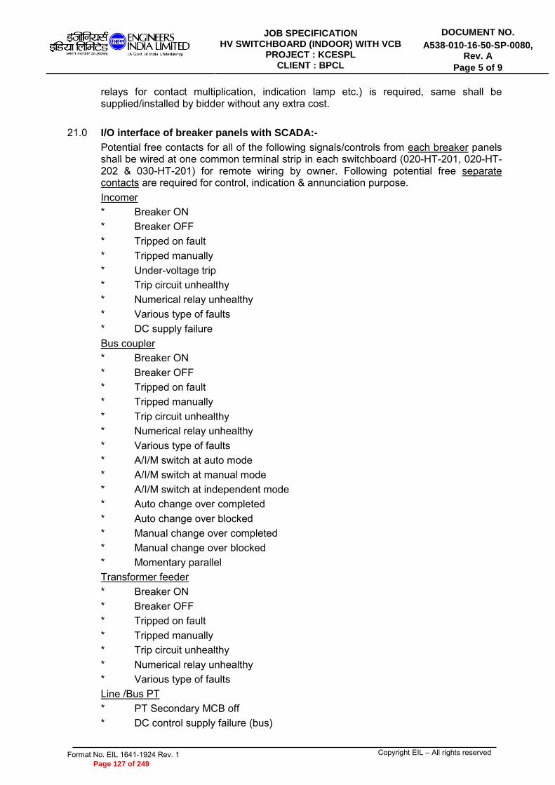
JOB SPECIFICATION HV SWITCHBOARD (INDOOR) WITH VCB
PROJECT : KCESPL CLIENT : BPCL
DOCUMENT NO.
A538-010-16-50-SP-0080, Rev. A
Page 5 of 9
Format No. EIL 1641-1924 Rev. 1 Copyright EIL – All rights reserved
relays for contact multiplication, indication lamp etc.) is required, same shall be supplied/installed by bidder without any extra cost.
21.0 I/O interface of breaker panels with SCADA:-
Potential free contacts for all of the following signals/controls from each breaker panels shall be wired at one common terminal strip in each switchboard (020-HT-201, 020-HT-202 & 030-HT-201) for remote wiring by owner. Following potential free separate contacts are required for control, indication & annunciation purpose. Incomer * Breaker ON * Breaker OFF * Tripped on fault * Tripped manually * Under-voltage trip * Trip circuit unhealthy * Numerical relay unhealthy * Various type of faults * DC supply failure Bus coupler * Breaker ON * Breaker OFF * Tripped on fault * Tripped manually * Trip circuit unhealthy * Numerical relay unhealthy * Various type of faults * A/I/M switch at auto mode * A/I/M switch at manual mode * A/I/M switch at independent mode * Auto change over completed * Auto change over blocked * Manual change over completed * Manual change over blocked * Momentary parallel Transformer feeder * Breaker ON * Breaker OFF * Tripped on fault * Tripped manually * Trip circuit unhealthy * Numerical relay unhealthy * Various type of faults Line /Bus PT * PT Secondary MCB off * DC control supply failure (bus)
Page 127 of 249

JOB SPECIFICATION HV SWITCHBOARD (INDOOR) WITH VCB
PROJECT : KCESPL CLIENT : BPCL
DOCUMENT NO.
A538-010-16-50-SP-0080, Rev. A
Page 6 of 9
Format No. EIL 1641-1924 Rev. 1 Copyright EIL – All rights reserved
Common alarm * DC Control Supply failure
In this regard, bidder shall also note that, signals generated through/available from numerical relay shall also be made available through Ethernet for soft communication with PLC/SCADA through Modbus TCP/IP. Protocol converter (IEC-61850 to Modbus TCP/IP) is also to be considered (without any cost implication) as PLC/SCADA side protocol is not finalised till date. The transducers shall have electrical isolation between input and output. The accuracy class of transducer shall be 0.5. The transducers shall be protected against input and output voltage surges. The transducers shall be suitable for minimum 125% continuous overload in the input voltage/current parameter.
22.0 Indicating lamps shall employ LEDs. LEDs provided for indication shall be cluster type with adequate brightness and minimum 2Nos LEDs chips per light. LEDs shall be connected in parallel and each LED chip having diameter not less than 3mm. LED shall have low voltage glow protection.
23.0 All relays, metering and control components shall be mounted on the panel front only.
24.0 All CT secondary shall be star connected and cast resin insulated type.
25.0 Name plate details for all outgoing feeders of HV switchboard shall have information such as feeder number, panel number, equipment description, tag no, kW rating/current rating as minimum.
26.0 Load details, cable sizes, feeder nos, name plate details etc. for all outgoing feeders of HV switchboard shall be finalized at the time of drawing review which shall be taken care of by bidder without any cost & time implication to purchaser.
27.0 Nickel plated brass single compression glands and tinned copper cable lugs for incoming and outgoing feeders of all switchboards are included in bidder’s scope of supply. Undrilled gland plates shall be provided for all the HV switchboards.
28.0 CHANGEOVER SCHEME FOR TWO INCOMERS AND ONE BUS-COUPLER
The Auto /manual changeover scheme is described in brief is as follows:
28.1 FACILITY TO BE PROVIDED
a) Auto changeover between the two incomers and one bus-coupler shall be in such a way that two incomer breakers are 'ON' at a time and bus-coupler breaker is normally open.
Page 128 of 249

JOB SPECIFICATION HV SWITCHBOARD (INDOOR) WITH VCB
PROJECT : KCESPL CLIENT : BPCL
DOCUMENT NO.
A538-010-16-50-SP-0080, Rev. A
Page 7 of 9
Format No. EIL 1641-1924 Rev. 1 Copyright EIL – All rights reserved
b) Bus-coupler breaker is made 'ON' automatically in case the incoming supply at incomer breaker no. 1 or 2 fails and the respective breaker trips on under voltage only.
c) Manual closing of bus-coupler with momentary paralleling (through check synchro relay) of both the incoming supplies to facilitate taking out any incomer breaker for maintenance.
d) Blocking of auto transfer (i.e. closing of bus-coupler) if any incomer breaker trips due to a fault i.e. through element (86).
e) Tripping of incomer on under voltage shall be blocked, if both the incomers simultaneously experience an under voltage.
28.2 NORMAL OPERATING CONDITION
a) Incomer no. 1 and 2 breakers are 'ON'. Bus-coupler breaker is 'OFF'.
28.3 INITIATION OF AUTO-CHANGEOVER
a) When incoming supply to breaker no. 1 or 2 fails; the respective incomer is tripped through under voltage relays and a timer. The time delay is in the range of 0.5 to 5 sec. Breaker trip on under voltage is blocked in case of power failure on both the incomers.
b) The voltage on healthy bus section has been above the set value of normal voltage for a specified duration (settable through a timer 0.5-5 sec.) and the incomer breaker of healthy bus is closed in service position.
c) Bus-coupler is open and in-service position.
d) Auto/Independent/ Manual switch is set for 'AUTO' operation.
28.4 CLOSING OF BUS-COUPLER BREAKER
Bus-coupler will close if the following conditions are met:
a) One of the incomer breakers has tripped on under voltage.
b) The residual voltage on the bus, which has lost supply, is less than 40% of normal voltage.
c) Incoming voltage of healthy incomer has been above 80% of normal voltage for a specific settable duration (through timer 0.5 sec - 5.0 sec)
d) Auto/ Independent / Manual switch is set for 'AUTO' operation.
28.5 SPECIFIC BLOCKING OF AUTO TRANSFER
a) Bus-coupler should not close, if any of the two incomers trips due to faults.
b) Both incomer trips on under voltage.
28.6 MANUAL TRANSFER
a) It is possible to trip incomer no. 1 or 2 after closing the bus-coupler to facilitate maintenance as required. Manual transfer would permit momentary paralleling and as such check synchronizing relay shall be provided to ensure system safety.
b) When supply is again available at incomer breaker after auto-changeover has already taken place, it is possible to restore the system to normal operating condition by operating trip selector switch (meant for tripping incomer no. 1 or 2 or bus-coupler) and by setting Auto/ Independent/ Manual switch in 'Manual' mode.
Page 129 of 249

JOB SPECIFICATION HV SWITCHBOARD (INDOOR) WITH VCB
PROJECT : KCESPL CLIENT : BPCL
DOCUMENT NO.
A538-010-16-50-SP-0080, Rev. A
Page 8 of 9
Format No. EIL 1641-1924 Rev. 1 Copyright EIL – All rights reserved
c) In manual transfer, the closing circuit shall be completed through contacts of check synchronizing relay.
29.0 LAPTOP
One (1) no. industrial grade laptop loaded with full version relay parameterization software along with (including one CD ROM containing full version relay parameterization software) associated material such as patch cord, interconnecting cable etc. shall be supplied for each substation (IOCL import terminal & BPCL dispatch terminal). System configuration shall be latest proven model and upgradeable. The minimum configuration shall be i3, 3.3GHz processor, 500GB SATA HDD, 4GB DDR3 RAM, DVD R/RW, color LED screen (15.6 inch). Operating system shall be Windows 2008. Two (2) nos. CD containing full version of relay software shall also be supplied.
Following min. functions shall be made available on the laptop PC.
- Window based display of switchboard SLDs - ON / OFF status of circuit breakers - Display of electrical system/metering parameters - Alarm handling - Event handling - Reports - Logs and trends - Number of digital I/Os shall be worked out by the vendor as per the typical
list included in the MR.
30.0 ENGINEERING CUM OPERATOR WORK STATION (ENGINEERING CONSOLE)
Engineering cum operator work station shall be installed at air conditioned room located in nearby control room. Same is required for monitoring purpose of HV & MV system including exchange of diagnostic information, data and control. Further this console shall have the facility to communicate with purchaser’s centralized control/monitoring system (SCADA) through Modbus TCP/IP. Following minimum facilities shall be available at this console.
- Operating status monitoring - Data logging - Relay parameterization - Event recording. - Annunciation - View of historical data and generating trends - Preparation of maintenance schedule Engineering cum operator works station shall be of industrial grade suitable for continuous operation at ambient temp of 450 C along with colored printer (A3 size paper) and its associated furniture. Engineering console shall have user-friendly software (full version) for interactive display of down stream HV/MV feeder data in single window feature. Software shall have the capability to display of system parameters, reports, alarm annunciation, daily and monthly data logging, continuous polling, relay monitoring, relay supervision, fault disturbance record of each relay, graphic representation and trending of data etc. Supply of all interconnecting cables (including cable termination and accessories e.g. conduits etc.) from each switchboard to this console is in the scope of the bidder. All software shall be written for operating on a common plant wide operating system platform. The offered system shall comply with standard IEC 60073 Basic and safety
Page 130 of 249

JOB SPECIFICATION HV SWITCHBOARD (INDOOR) WITH VCB
PROJECT : KCESPL CLIENT : BPCL
DOCUMENT NO.
A538-010-16-50-SP-0080, Rev. A
Page 9 of 9
Format No. EIL 1641-1924 Rev. 1 Copyright EIL – All rights reserved
principles for Man machine interface, marking and identification-coding principles for indication devices and actuators.
31.0 NUMERICAL RELAYS
31.1 All numerical relays shall be of latest advanced version and shall comply with enclosed Standard Specification No. 6-51-0055 for Numerical Relays.
31.2 All protective relays shall be numerical type of one make only. It shall be possible to save minimum 5 records of each event.
31.3 Selected models of numerical relays shall have metering, control, status and protective functions.
31.4 All control and protection schemes shall be a part of numerical relay and all logic shall be inbuilt within the offered relay.
31.5 Lockout element shall be a part of numerical relay and the same shall be separate for process trip and normal trip.
31.6 All numerical relays shall be communicable type suitable for IEC-61850. Same shall have RJ-45 port at the rear for upstream communication over ethernet and RS-232/USB port at front side for communicating with Laptop.
31.7 For time stamping, SNTP protocol has been envisaged. Accordingly, all numerical relays shall be suitable for the same.
31.8 Bidder shall note that, internal dual redundant LAN shall be constructed inside the board which shall include suitable nos. of ethernet switch. All numerical relays shall be hooked up to that ethernet based LAN. Two (2) no. ports of that ethernet based LAN per switchboard shall be made available for owner for upstream communication. Maximum 4 nos. relays shall be connected to one (1) ethernet switch.
31.9 Offered numerical relays shall have min. 16 nos. DI & min. 16 nos. DO. Control schematic shall be prepared in such way that, min. 20% spare DI/DO shall be available for client’s use.
31.10 All the DI/DOs shall be fully programmable at site. Fixed type DI/DO shall not be acceptable.
31.11 Offered numerical relays shall be suitable for 1A or 5A CT input as well as 230V AC supply or 110V DC power supply.
31.12 All the data as available in the relay including the status of DI should be considered to be communicated to SCADA. The data required for final configuration shall be finalized during engineering. Similarly whether specified or not, serial interface shall have no limitation for data transfer to SCADA. However data as required for SCADA interface shall be decided during engineering.
31.13 The requirement of numerical relays and integration shall be in compliance with the requirement given in attached data sheet, and specification.
31.14 Scheme of switchboard shall be engineered to achieve the control logic, as required, through relay logic.
31.15 In case of differential protection, separate numerical relay shall be supplied along with main numerical protection relay.
Page 131 of 249

Format No: EIL 1650-3001A Rev.2 Copyrights EIL - All rights reserved
Datasheet No.A538-010-16-50-DS-0080
Rev. APage 1 of 3
PURCHASER'S DATA
Project KCES LPG Pipeline Location KOCHI
Client M/s BPCL Unit Despatch Terminal KR
A Site conditions1 Maximum ambient temperature: 46 °C 3 System Breaking capacity 40 kA
2 Minimum ambient temperature: 1 °C 3.1 % D.C. Component As per IEC
3 Design ambient temperature: 45 °C 4 System making capacity 100 kA (peak)
4 Relative humidity: % 5 Type of Circuit Breaker
Shunt Trip Coil-1 :
Shunt Trip Coil-2 :
(See Note-2)5 Altitude above MSL: <1000 m 6 Duty Cycle of C.B. 0-3min-CO-3 min-CO
6 Environment: 7 Suitability for Cap. Switching Not Reqd
B Operating conditions 8 Surge supressor for Motor Feeder. Reqd1 Voltage 6.6 kV ± 10% 9 IDMTL Relay type 1 sec.
2 Frequency 50 Hz ± 3% 10 Provision of earthing Required
3 Number of Phases 3 Earthing truck Bidder to decide4 System Fault Level 40 kA Earthing switch Bidder to decide5 System Earthing Resistance Earthed D Miscellaneous6 Auxiliary Supply 1 Interface with ECSa. AC 240 V 2 Incoming Power Entryb. DC 110 V 3 Cable EntryC Electrical Data 4 Separate bolted removable Reqd.(Gland plate
1 Busbar current rating (inside 630 A gland palte for cable entry drilled at side)
panel at design temp.) 5 Cable glands and lugs for 2 1 sec. Short Circuit withstand cable termination Required
capacity 40 kA at 6.6 kV 6 Painting/Paint shade 632 as per IS:5
Note:1) Marked particulars may be referred in respective switchboard feeder detail data sheet.
MANUFACTURER'S DATA
A Switchboards 020-HT-2011 Make 9 Recommended clearances
2 Type designation Front mm
3 Degree of protection Rear mm
4 Max. overall weight of C.B. panel Kg Above mm
5 Overall dimensions of C.B. panel 10 Shock loading on foundation
a Width mm 11
b Depth mm terminated inside the panel
c Height mm a. without rear extension panel
6 Overall dimensions of dummy / b. with rear extension panel
adaptor panel of each type c. size of rear extension panel
a Width mm 12 Clearance in air
b Depth mm a. Phase to Phase (min.) mm
c Height mm b. Phase to Earth (min.) mm
7 Overall weight and dimensions of 13 Busbar current rating at design
largest shipping section ambient temperature A
a Weight Kg 14
b Width mm a. Horizontal main busbar size
c Depth mm (No. of flats x size of each flat)
d Height mm b. Horizontal main busbar size as
8 Overall dimensions of each swbd. tested at CPRI for full short ckt.
including all dummy/adaptor/rear withstand as per specification
extension panels requirement (No. of flats x size
Width of each flat)
Depth c. Vertical dropper size
Height (No. of flats x size of each flat)
DATA SHEET FORHV SWITCHBOARD (020-HT-201)
PROJECT : KCESPLCLIENT : B.P.C.L.
VCB/SF6
110/220V DC
110/230V UPS AC
Reqd./Not Reqd.
Cable/Bus Duct
Top/Bottom
2) For all HV circuiit breakers feeding HV VFDs, second shunt trip coil operating on different control supply shall be provided.
Max. size/no. of cables that can be
Busbar (separately for each swbd)
Page 132 of 249

Format No: EIL 1650-3001A Rev.2 Copyrights EIL - All rights reserved
A 24.11.2014 ISSUED WITH MR SH RG MKS
Rev. No Date Purpose Prepared by Checked by Approved by
Page 133 of 249

Format No: EIL 1650-3001A Rev.2 Copyrights EIL - All rights reserved
Datasheet No.A538-010-16-50-DS-0080
Rev. APage 2 of 3
15 Horizontal main busbar/Vertical b Removable FRP shrouds for all Yes/No
busbar material Al/Cu busbar joints and tap-off
16 Insulating material (Busbar supports) connections provided
17 Earth busbar size 50x6 c Arc propagation barrier in busbar Yes/No
18 Earth busbar material Copper compartment provided
19 1 min. power frequency withstand d Breaker service, test and drawn-
voltage (rms) 20 kV out position provided Yes/No
19.1 Over voltage factor for PTs 1.9 for 30 sec. e Distinct overall lockable door for
20 Impuse withsatnd voltage (peak) 60 kVp breaker compartment provided Yes/No
20.1 Wave shape of impulse voiltage f Automatic safety shutter provided Yes/No
21 1 sec. short ckt. Withstand capacity 40 kA g Independent pressure release
22 Peak dynamic withsatnd capacity 100 kA flaps provided for all HV
23 Windows at the rear side of panels Required/Not Required compartments Yes/No
for thermography h Wire mesh for all louvered
24 Safety Features openings provided Yes/No
a Heat shrinkable sleeves, rated to i Suitable intrlocks to preventwithstand the system line to line faulty operation as per Cl. 4.4.10
voltage for one min., provided Yes/No of spec. 6-51-0001 provided Yes/No
on busbar
B Circuit Breaker1 Type VCB 16 Power required for closing W/VA
2nd shunt trip coil for VFD feeders Yes/No
2 Make 17 Power required for spring
3 Type Designation charging motor W/VA
4 Circuit Breaker mounting in panel Truck/cassette @ 18 Breaker is trip free Yes/No
5 No. of poles/phase 19 Closing mechanism
6 Current rating (in free air) A at 20 Provision of manual spring
7 Current rating inside the panel at charging provided Yes/No
specified design tempeature A 21 Mechanical Trip PB provided Yes/No
8 Short time rating ( 1sec.) kA 22 Mech. On/Off indicator provided Yes/No
9 Symmetrical breaking capapcity kA 23 Operation counter provided Yes/No
9.1 % D.C. Component 24 Time taken for spring charging sec.
10 Peak making current kA 25 No. of aux. contacts and their NO +
11 1 min. dry withsatnd voltage current ratings NC , A
(power frequency) kV 26 Interrupter12 Duty Cycle a Make
13 Total openeing time m sec. b Pressure switch for monitoring
14 Total closing time m sec. Yes/No
15 Power required for opening W/VA c
27 LOTO (Lock-Out Tag-Out)
Provision for mechanical
locking arrangement
@ Lifting truck shall be provided for cassette type circuit breaker.
Note: Vendor shall furnish the dimensins of various types/ratings of swbds., CB panels and dummy/adaptor panels separately.
DATA SHEET FORHV SWITCHBOARD (020-HT-201)
PROJECT : KCESPLCLIENT : B.P.C.L.
mm2
oC
of SF6 gas pressure provided
Re-filling arrangement of SF6
Provided/Not Provided
Page 134 of 249

Format No: EIL 1650-3001A Rev.2 Copyrights EIL - All rights reserved
Datasheet No.A538-010-16-50-DS-0080
Rev. APage 3 of 3
27 Supressora Type designation
b Make
28 Derating reqd. for Cap. Switching %
29 Earthing System Integral earthing/
Separate earthing
carriage
30 Copies of following test cerificates
enclosed :
30.1 For each type of offered circuit
breaker panel with breaker
a. Short Circuit tests (Peak and 1 sec.
withstand)
b Heat run test
c Internal arc test
d Impulse and power freq. withstand
30.2 For each type of offered circuit breaker (in panel)
a. Short Circuit test duties
* Switchboard offered shall be of proven design and shll havbe been successfully type tested. Type test
certificates for an exactly identical design of offered switchboard shall be furnished by bidders. These
test reports shall not be more than 5 years old, as on the final bid opening date. In case these type tests
have not been conducted during the last 5 years, bidder shall conduct these type tests on the offered
design of switchboard before despatch without any cost and delievery impact.
DATA SHEET FORHV SWITCHBOARD (020-HT-201)
PROJECT : KCESPLCLIENT : B.P.C.L.
Yes/No *
Page 135 of 249

Format No: EIL 1650-3001A Rev.2 Copyrights EIL - All rights reserved
Datasheet No.A538-010-16-50-DS-0081
Rev. APage 1 of 3
PURCHASER'S DATA
Project KCES LPG Pipeline Location KOCHI
Client M/s BPCL Unit Despatch Terminal KR
A Site conditions1 Maximum ambient temperature: 46 °C 3 System Breaking capacity 40 kA
2 Minimum ambient temperature: 1 °C 3.1 % D.C. Component As per IEC
3 Design ambient temperature: 45 °C 4 System making capacity 100 kA (peak)
4 Relative humidity: % 5 Type of Circuit Breaker
Shunt Trip Coil-1 :
Shunt Trip Coil-2 :
5 Altitude above MSL: <1000 m 6 Duty Cycle of C.B. 0-3min-CO-3 min-CO
6 Environment: 7 Suitability for Cap. Switching Not Reqd
B Operating conditions 8 Surge supressor for Motor Feeder. Reqd1 Voltage 6.6 kV ± 10% 9 IDMTL Relay type 1 sec.
2 Frequency 50 Hz ± 3% 10 Provision of earthing Required
3 Number of Phases 3 Earthing truck Bidder to decide4 System Fault Level 40 kA Earthing switch Bidder to decide5 System Earthing Resistance Earthed D Miscellaneous6 Auxiliary Supply 1 Interface with ECSa. AC 240 V 2 Incoming Power Entryb. DC 110 V 3 Cable EntryC Electrical Data 4 Separate bolted removable Reqd.(Gland plate
1 Busbar current rating (inside 630 A gland palte for cable entry drilled at side)
panel at design temp.) 5 Cable glands and lugs for 2 1 sec. Short Circuit withstand cable termination Required
capacity 40 kA at 6.6 kV 6 Painting/Paint shade 632 as per IS:5
Note:1) Marked particulars may be referred in respective switchboard feeder detail data sheet.
MANUFACTURER'S DATA
A Switchboards 020-HT-2021 Make 9 Recommended clearances
2 Type designation Front mm
3 Degree of protection Rear mm
4 Max. overall weight of C.B. panel Kg Above mm
5 Overall dimensions of C.B. panel 10 Shock loading on foundation
a Width mm 11
b Depth mm terminated inside the panel
c Height mm a. without rear extension panel
6 Overall dimensions of dummy / b. with rear extension panel
adaptor panel of each type c. size of rear extension panel
a Width mm 12 Clearance in air
b Depth mm a. Phase to Phase (min.) mm
c Height mm b. Phase to Earth (min.) mm
7 Overall weight and dimensions of 13 Busbar current rating at design
largest shipping section ambient temperature A
a Weight Kg 14
b Width mm a. Horizontal main busbar size
c Depth mm (No. of flats x size of each flat)
d Height mm b. Horizontal main busbar size as
8 Overall dimensions of each swbd. tested at CPRI for full short ckt.
including all dummy/adaptor/rear withstand as per specification
extension panels requirement (No. of flats x size
Width of each flat)
Depth c. Vertical dropper size
Height (No. of flats x size of each flat)
DATA SHEET FORHV SWITCHBOARD (020-HT-202)
PROJECT : KCESPLCLIENT : B.P.C.L.
VCB/SF6
110/220V DC
110/230V UPS AC
Reqd./Not Reqd.
Cable/Bus Duct
Top/Bottom
Max. size/no. of cables that can be
Busbar (separately for each swbd)
Page 136 of 249

Format No: EIL 1650-3001A Rev.2 Copyrights EIL - All rights reserved
A 24.11.2014 ISSUED WITH MR SH RG MKS
Rev. No Date Purpose Prepared by Checked by Approved by
Page 137 of 249

Format No: EIL 1650-3001A Rev.2 Copyrights EIL - All rights reserved
Datasheet No.A538-010-16-50-DS-0081
Rev. APage 2 of 3
15 Horizontal main busbar/Vertical b Removable FRP shrouds for all Yes/No
busbar material Al/Cu busbar joints and tap-off
16 Insulating material (Busbar supports) connections provided
17 Earth busbar size 50x6 c Arc propagation barrier in busbar Yes/No
18 Earth busbar material Copper compartment provided
19 1 min. power frequency withstand d Breaker service, test and drawn-
voltage (rms) 20 kV out position provided Yes/No
19.1 Over voltage factor for PTs 1.9 for 30 sec. e Distinct overall lockable door for
20 Impuse withsatnd voltage (peak) 60 kVp breaker compartment provided Yes/No
20.1 Wave shape of impulse voiltage f Automatic safety shutter provided Yes/No
21 1 sec. short ckt. Withstand capacity 40 kA g Independent pressure release
22 Peak dynamic withsatnd capacity 100 kA flaps provided for all HV
23 Windows at the rear side of panels Required/Not Required compartments Yes/No
for thermography h Wire mesh for all louvered
24 Safety Features openings provided Yes/No
a Heat shrinkable sleeves, rated to i Suitable intrlocks to preventwithstand the system line to line faulty operation as per Cl. 4.4.10
voltage for one min., provided Yes/No of spec. 6-51-0001 provided Yes/No
on busbar
B Circuit Breaker1 Type VCB 16 Power required for closing W/VA
2nd shunt trip coil for VFD feeders Yes/No
2 Make 17 Power required for spring
3 Type Designation charging motor W/VA
4 Circuit Breaker mounting in panel Truck/cassette @ 18 Breaker is trip free Yes/No
5 No. of poles/phase 19 Closing mechanism
6 Current rating (in free air) A at 20 Provision of manual spring
7 Current rating inside the panel at charging provided Yes/No
specified design tempeature A 21 Mechanical Trip PB provided Yes/No
8 Short time rating ( 1sec.) kA 22 Mech. On/Off indicator provided Yes/No
9 Symmetrical breaking capapcity kA 23 Operation counter provided Yes/No
9.1 % D.C. Component 24 Time taken for spring charging sec.
10 Peak making current kA 25 No. of aux. contacts and their NO +
11 1 min. dry withsatnd voltage current ratings NC , A
(power frequency) kV 26 Interrupter12 Duty Cycle a Make
13 Total openeing time m sec. b Pressure switch for monitoring
14 Total closing time m sec. Yes/No
15 Power required for opening W/VA c
27 LOTO (Lock-Out Tag-Out)
Provision for mechanical
locking arrangement
@ Lifting truck shall be provided for cassette type circuit breaker.
Note: Vendor shall furnish the dimensins of various types/ratings of swbds., CB panels and dummy/adaptor panels separately.
DATA SHEET FORHV SWITCHBOARD (020-HT-202)
PROJECT : KCESPLCLIENT : B.P.C.L.
mm2
oC
of SF6 gas pressure provided
Re-filling arrangement of SF6
Provided/Not Provided
Page 138 of 249
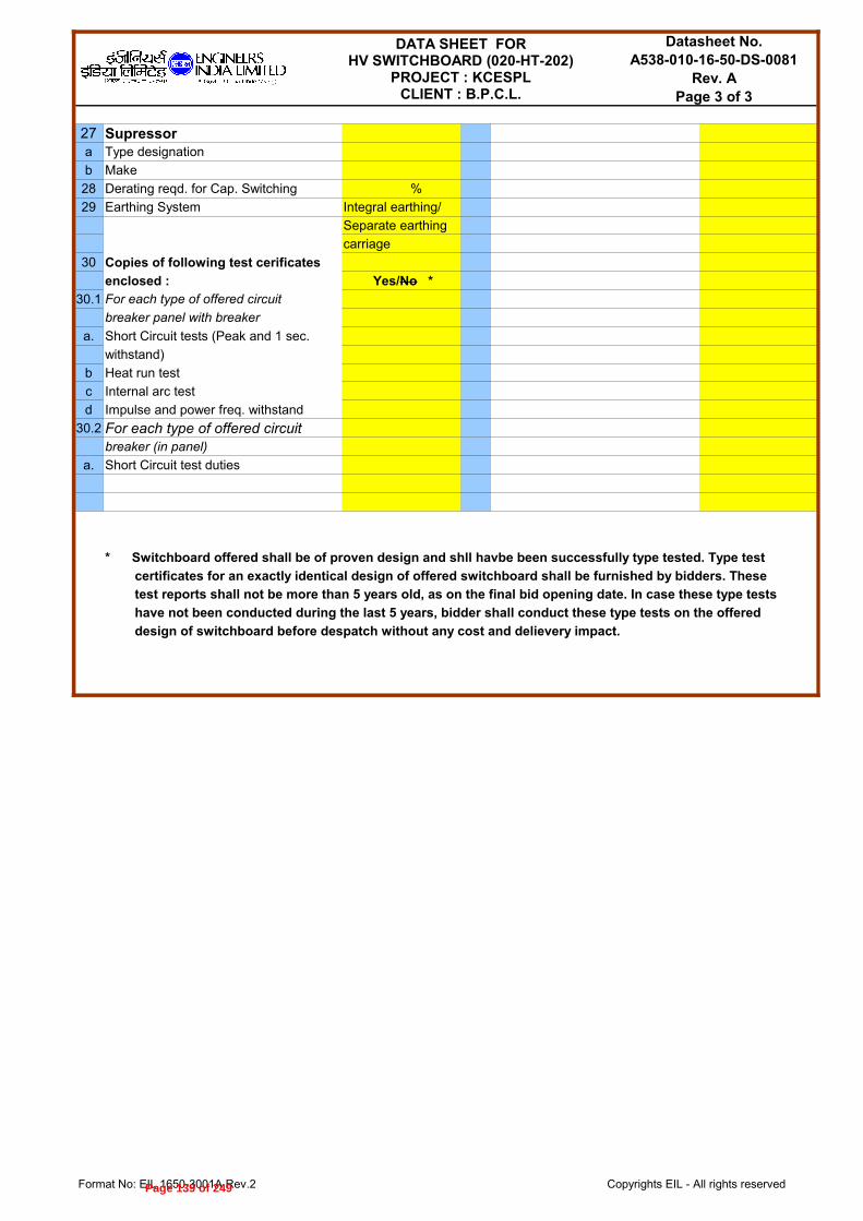
Format No: EIL 1650-3001A Rev.2 Copyrights EIL - All rights reserved
Datasheet No.A538-010-16-50-DS-0081
Rev. APage 3 of 3
27 Supressora Type designation
b Make
28 Derating reqd. for Cap. Switching %
29 Earthing System Integral earthing/
Separate earthing
carriage
30 Copies of following test cerificates
enclosed :
30.1 For each type of offered circuit
breaker panel with breaker
a. Short Circuit tests (Peak and 1 sec.
withstand)
b Heat run test
c Internal arc test
d Impulse and power freq. withstand
30.2 For each type of offered circuit breaker (in panel)
a. Short Circuit test duties
* Switchboard offered shall be of proven design and shll havbe been successfully type tested. Type test
certificates for an exactly identical design of offered switchboard shall be furnished by bidders. These
test reports shall not be more than 5 years old, as on the final bid opening date. In case these type tests
have not been conducted during the last 5 years, bidder shall conduct these type tests on the offered
design of switchboard before despatch without any cost and delievery impact.
DATA SHEET FORHV SWITCHBOARD (020-HT-202)
PROJECT : KCESPLCLIENT : B.P.C.L.
Yes/No *
Page 139 of 249

Format No: EIL 1650-3001A Rev.2 Copyrights EIL - All rights reserved
Datasheet No.A538-010-16-50-DS-0082
Rev. APage 1 of 3
PURCHASER'S DATA
Project KCES LPG Pipeline Location KOCHI
Client M/s BPCL Unit IOCL Import Terminal
A Site conditions1 Maximum ambient temperature: 46 °C 3 System Breaking capacity 40 kA
2 Minimum ambient temperature: 1 °C 3.1 % D.C. Component As per IEC
3 Design ambient temperature: 45 °C 4 System making capacity 100 kA (peak)
4 Relative humidity: % 5 Type of Circuit Breaker
Shunt Trip Coil-1 :
Shunt Trip Coil-2 :
(See Note-2)5 Altitude above MSL: <1000 m 6 Duty Cycle of C.B. 0-3min-CO-3 min-CO
6 Environment: 7 Suitability for Cap. Switching Not Reqd
B Operating conditions 8 Surge supressor for Motor Feeder. Reqd1 Voltage 11 kV ± 10% 9 IDMTL Relay type 1 sec.
2 Frequency 50 Hz ± 3% 10 Provision of earthing Required
3 Number of Phases 3 Earthing truck Bidder to decide4 System Fault Level 40 kA Earthing switch Bidder to decide5 System Earthing Resistance Earthed D Miscellaneous6 Auxiliary Supply 1 Interface with ECSa. AC 240 V 2 Incoming Power Entryb. DC 110 V 3 Cable EntryC Electrical Data 4 Separate bolted removable Reqd.(Gland plate
1 Busbar current rating (inside 630 A gland palte for cable entry drilled at side)
panel at design temp.) 5 Cable glands and lugs for 2 1 sec. Short Circuit withstand cable termination Required
capacity 40 kA at 11 kV 6 Painting/Paint shade 632 as per IS:5
Note:1) Marked particulars may be referred in respective switchboard feeder detail data sheet.
MANUFACTURER'S DATA
A Switchboards 030-HT-2011 Make 9 Recommended clearances
2 Type designation Front mm
3 Degree of protection Rear mm
4 Max. overall weight of C.B. panel Kg Above mm
5 Overall dimensions of C.B. panel 10 Shock loading on foundation
a Width mm 11
b Depth mm terminated inside the panel
c Height mm a. without rear extension panel
6 Overall dimensions of dummy / b. with rear extension panel
adaptor panel of each type c. size of rear extension panel
a Width mm 12 Clearance in air
b Depth mm a. Phase to Phase (min.) mm
c Height mm b. Phase to Earth (min.) mm
7 Overall weight and dimensions of 13 Busbar current rating at design
largest shipping section ambient temperature A
a Weight Kg 14
b Width mm a. Horizontal main busbar size
c Depth mm (No. of flats x size of each flat)
d Height mm b. Horizontal main busbar size as
8 Overall dimensions of each swbd. tested at CPRI for full short ckt.
including all dummy/adaptor/rear withstand as per specification
extension panels requirement (No. of flats x size
Width of each flat)
Depth c. Vertical dropper size
Height (No. of flats x size of each flat)
DATA SHEET FORHV SWITCHBOARD (030-HT-201)
PROJECT : KCESPLCLIENT : B.P.C.L.
VCB/SF6
110/220V DC
110/230V UPS AC
Reqd./Not Reqd.
Cable/Bus Duct
Top/Bottom
2) For all HV circuiit breakers feeding HV VFDs, second shunt trip coil operating on different control supply shall be provided.
Max. size/no. of cables that can be
Busbar (separately for each swbd)
Page 140 of 249

Format No: EIL 1650-3001A Rev.2 Copyrights EIL - All rights reserved
A 24.11.2014 ISSUED WITH MR SH RG MKS
Rev. No Date Purpose Prepared by Checked by Approved by
Page 141 of 249

Format No: EIL 1650-3001A Rev.2 Copyrights EIL - All rights reserved
Datasheet No.A538-010-16-50-DS-0082
Rev. APage 2 of 3
15 Horizontal main busbar/Vertical b Removable FRP shrouds for all Yes/No
busbar material Al/Cu busbar joints and tap-off
16 Insulating material (Busbar supports) connections provided
17 Earth busbar size 50x6 c Arc propagation barrier in busbar Yes/No
18 Earth busbar material Copper compartment provided
19 1 min. power frequency withstand d Breaker service, test and drawn-
voltage (rms) 28 kV out position provided Yes/No
19.1 Over voltage factor for PTs 1.9 for 30 sec. e Distinct overall lockable door for
20 Impuse withsatnd voltage (peak) 75 kVp breaker compartment provided Yes/No
20.1 Wave shape of impulse voiltage f Automatic safety shutter provided Yes/No
21 1 sec. short ckt. Withstand capacity 40 kA g Independent pressure release
22 Peak dynamic withsatnd capacity 100 kA flaps provided for all HV
23 Windows at the rear side of panels Required/Not Required compartments Yes/No
for thermography h Wire mesh for all louvered
24 Safety Features openings provided Yes/No
a Heat shrinkable sleeves, rated to i Suitable intrlocks to preventwithstand the system line to line faulty operation as per Cl. 4.4.10
voltage for one min., provided Yes/No of spec. 6-51-0001 provided Yes/No
on busbar
B Circuit Breaker1 Type VCB 16 Power required for closing W/VA
2nd shunt trip coil for VFD feeders Yes/No
2 Make 17 Power required for spring
3 Type Designation charging motor W/VA
4 Circuit Breaker mounting in panel Truck/cassette @ 18 Breaker is trip free Yes/No
5 No. of poles/phase 19 Closing mechanism
6 Current rating (in free air) A at 20 Provision of manual spring
7 Current rating inside the panel at charging provided Yes/No
specified design tempeature A 21 Mechanical Trip PB provided Yes/No
8 Short time rating ( 1sec.) kA 22 Mech. On/Off indicator provided Yes/No
9 Symmetrical breaking capapcity kA 23 Operation counter provided Yes/No
9.1 % D.C. Component 24 Time taken for spring charging sec.
10 Peak making current kA 25 No. of aux. contacts and their NO +
11 1 min. dry withsatnd voltage current ratings NC , A
(power frequency) kV 26 Interrupter12 Duty Cycle a Make
13 Total openeing time m sec. b Pressure switch for monitoring
14 Total closing time m sec. Yes/No
15 Power required for opening W/VA c
27 LOTO (Lock-Out Tag-Out)
Provision for mechanical
locking arrangement
@ Lifting truck shall be provided for cassette type circuit breaker.
Note: Vendor shall furnish the dimensins of various types/ratings of swbds., CB panels and dummy/adaptor panels separately.
DATA SHEET FORHV SWITCHBOARD (030-HT-201)
PROJECT : KCESPLCLIENT : B.P.C.L.
mm2
oC
of SF6 gas pressure provided
Re-filling arrangement of SF6
Provided/Not Provided
Page 142 of 249

Format No: EIL 1650-3001A Rev.2 Copyrights EIL - All rights reserved
Datasheet No.A538-010-16-50-DS-0082
Rev. APage 3 of 3
27 Supressora Type designation
b Make
28 Derating reqd. for Cap. Switching %
29 Earthing System Integral earthing/
Separate earthing
carriage
30 Copies of following test cerificates
enclosed :
30.1 For each type of offered circuit
breaker panel with breaker
a. Short Circuit tests (Peak and 1 sec.
withstand)
b Heat run test
c Internal arc test
d Impulse and power freq. withstand
30.2 For each type of offered circuit breaker (in panel)
a. Short Circuit test duties
* Switchboard offered shall be of proven design and shll havbe been successfully type tested. Type test
certificates for an exactly identical design of offered switchboard shall be furnished by bidders. These
test reports shall not be more than 5 years old, as on the final bid opening date. In case these type tests
have not been conducted during the last 5 years, bidder shall conduct these type tests on the offered
design of switchboard before despatch without any cost and delievery impact.
DATA SHEET FORHV SWITCHBOARD (030-HT-201)
PROJECT : KCESPLCLIENT : B.P.C.L.
Yes/No *
Page 143 of 249

Page 144 of 249

Page 145 of 249

Page 146 of 249
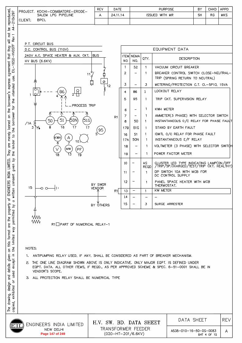
Page 147 of 249

Page 148 of 249

Page 149 of 249

Page 150 of 249
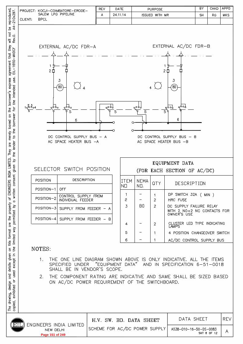
Page 151 of 249

Page 152 of 249
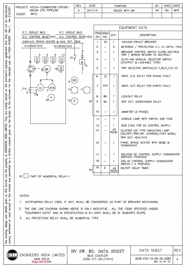
Page 153 of 249

Page 154 of 249

Page 155 of 249

Format No: EIL 1650-3054B Rev.1 Page 1 of 2 Copyrights EIL - All rights reserved
Data sheet No.A538-010-16-50-DS-0084
Rev.No. A
A 24.11.2014 ISSUED WITH MR SH RG MKSRev. Date Purpose Prepared Checked Approved
Project : KCES LPG Pipeline Client : BPCL Fault Level (1 sec.)
Unit : Despatch Terminal At BPCL Kochi Refinery Bus current : 630A Auto-transfer Required
Switchboard No.: 020-HT-201 Voltage Rating : Execution : Single front, compartmentalised & drawout type
Location : Despatch Terminal At BPCL Kochi Refinery Frequency : 50Hz ± 3%
Feeder Nameplate Inscription Bus Section CT Primary current rating (A)*
Remarks
Description Rating (KW/KVA)# Left Middle Metering Protection
1 2500KVA 1 VCB-630 300/1A 2R x 3C x 240 SHT.1
2 2500KVA 1 VCB-630 300/1A 2R x 3C x 240 SHT.1
4 Bus coupler-1 2500KVA 1 VCB-630 630/1A 2R x 3C x 240 SHT.2
Bus PT-1 - 1 - - - SHT.3
Bus PT-2 - 1 - - - SHT.3
6 1700kW 1 VCB-630 250/1A 2R x 3C x 240 SHT.4
7 1700kW 1 VCB-630 250/1A 2R x 3C x 240 SHT.4
8 450 kW 1 VCB-630 70/1A 3C x 185 SHT.4
9 450 kW 1 VCB-630 70/1A 3C x 185 SHT.4
10 500 kVA 1 VCB-630 50/1A 3C x 185 SHT.4
HV SWITCHBOARDFEEDER DETAILS OF 020-HT-201
: 40 kA (1sec)
:
6.6kV ± 10% (TP)
S. No.
Breaker Rating/Feeder Designation
Max. Cable Size (mm²), XLPE insulated, Al
conductor
Reference data sheet (A538-010-16-50-DS-0013)Panel No.
@Feeder No.
#Scheme No.@
Incomer-1 from upstream HT switchboard (From Kochi Refinery offsite substation)
300/1(5P10) 300/1(CL.PS)
Incomer-2 from upstream HT switchboard (From Kochi Refinery offsite substation)
300/1(5P10) 300/1(CL.PS)
MLP VFD020-PM-CF-101A
MLP VFD020-PM-CF-101B
Booster Pump VFD(020-PC-CF-102A)
Booster Pump VFD(020-PC-CF-102B)
Distribution Transformer(020-TR-001)
Page 156 of 249

Format No: EIL 1650-3054B Rev.1 Page 2 of 2 Copyrights EIL - All rights reserved
Feeder Nameplate Inscription Bus Section CT Primary current rating (A)*
Remarks
Description Rating (KW/KVA)# Left Middle Metering Protection
S. No.
Breaker Rating/Feeder Designation
Max. Cable Size (mm²), XLPE insulated, Al
conductor
Reference data sheet (A538-010-16-50-DS-0013)Panel No.
@Feeder No.
#Scheme No.@
11 500 kVA 1 VCB-630 50/1A 3C x 185 SHT.4
12 Spare Trafo Feeder 500 kVA 1 VCB-630 50/1A 3C x 185 SHT.4
13 Spare Booster Pump feeder 450 kW 1 VCB-630 70/1A 3C x 185 SHT.4
14 Spare MLP feeder 1700kW 1 VCB-630 250/1A 2R x 3C x 240 SHT.4
Notes :
1 CT ratio indicated here are preliminary and shall be finalised during drawing approval stage.there shall be no cost and time impact to purchaser on account of this.
2 Dummy panel with flexibles shall be provided for switchboards located in substations having expansion joints in the building.3 Cable sizes shown here is indicative. Same shall be finalised during drawing review without any cost & time implication
to purchaser.
Distribution Transformer(020-TR-002)
Page 157 of 249

Format No: EIL 1650-3054B Rev.1 Page 1 of 1 Copyrights EIL - All rights reserved
Data sheet No.A538-010-16-50-DS-0085
Rev.No. A
A 24.11.2014 ISSUED WITH MR SH RG MKSRev. Date Purpose Prepared Checked Approved
Project : KCES LPG Pipeline Client : BPCL Fault Level (1 sec.)
Unit : Despatch Terminal At BPCL Kochi Refinery Bus current : 630A Auto-transfer Not Required
Switchboard No.: 020-HT-202 Voltage Rating : Execution : Single front, compartmentalised & drawout type
Location : Despatch Terminal At BPCL Kochi Refinery Frequency : 50Hz ± 3%
Feeder Nameplate Inscription Bus Section CT Primary current rating (A)*
Remarks
Description Rating (KW/KVA)# Left Middle Metering Protection
1 1700 KW 1 VCB-630 - 2R x 3C x 240 SHT.6
2 1700 KW 1 VCB-630 - 2R x 3C x 240 SHT.6
4 Bus coupler-1 1 VCB-630 - 2R x 3C x 240 SHT.5
6 1700 KW 1 VCB-630 - 2R x 3C x 240 SHT.7
7 1700 KW 1 VCB-630 - 2R x 3C x 240 SHT.7
Notes :
1 Dummy panel with flexibles shall be provided for switchboards located in substations having expansion joints in the building.2 Cable sizes shown here is indicative. Same shall be finalised during drawing review without any cost & time implication
to purchaser.
HV SWITCHBOARDFEEDER DETAILS OF 020-HT-202
: 40 kA (1sec)
:
6.6kV ± 10% (TP)
S. No.
Breaker Rating/Feeder Designation
Max. Cable Size (mm²), XLPE insulated, Al
conductor
Reference data sheet (A538-010-16-50-DS-0013)Panel No.
@Feeder No.
#Scheme No.@
Incomer-1 from upstream HT switchboard (020-HT-201)
Incomer-2 from upstream HT switchboard (020-HT-201)
MLP Motor020-PM-CF-101A
MLP Motor020-PM-CF-101B
Page 158 of 249

Format No: EIL 1650-3054B Rev.1 Page 1 of 2 Copyrights EIL - All rights reserved
Data sheet No.A538-010-16-50-DS-0086
Rev.No.A
A 24.11.2014 ISSUED WITH MR SH RG MKSRev. Date Purpose Prepared Checked Approved
Project : KCES LPG Pipeline Client : BPCL/IOCL Fault Level (1 sec.)
Unit : IOCL Import Terminal At Puthuvypeen Kochi Bus current : 630A Auto-transfer Required
Switchboard No.: 030-HT-201 Voltage Rating : Execution : Single front, compartmentalised & drawout type
Location : IOCL Import Terminal At Puthuvypeen. Kochi Frequency : 50Hz ± 3%
Feeder Nameplate Inscription Bus Section CT Primary current rating (A)*
Remarks
Description Rating (KW/KVA)# Left Middle Metering Protection
1 Incomer-1 (From KSEB) 1000KVA 1 VCB-630 60/1A 60/1A 3C x 240 SHT.11
2 Incomer-2 (From KSEB) 1000KVA 1 VCB-630 60/1A 60/1A 3C x 240 SHT.11
3 Bus coupler-1 - 1 VCB-630 60/1A - SHT.10
4 Bus PT-1 - 1 - - - SHT.9
5 Bus PT-2 - - - - SHT.9
6 380 kW 1 VCB-630 30/1A 3C x 185 SHT.12
7 380 kW VCB-630 30/1A 3C x 185 SHT.12
8 315 kVA 1 VCB-630 20/1A 3C x 185 SHT.12
9 315 kVA VCB-630 20/1A 3C x 185 SHT.12
10 Spare Trafo Feeder 315 kVA 1 VCB-630 20/1A 3C x 185 SHT.12
11 Spare feeder for Mainline Pump 380 kW VCB-630 30/1A 3C x 185 SHT.12
Notes :
1 CT ratio indicated here are preliminary and shall be finalised during drawing approval stage.there shall be no cost and time impact to purchaser on account of this.
2 Dummy panel with flexibles shall be provided for switchboards located in substations having expansion joints in the building.
HV SWITCHBOARDFEEDER DETAILS OF 030-HT-201
: 40 kA (1sec)
:
11kV ± 10% (TP)
S. No.
Breaker Rating/Feeder Designation
Max. Cable Size (mm²), XLPE insulated, Al
conductor
Reference data sheet (A538-010-16-50-DS-0013)Panel No.
@Feeder No.
#Scheme No.@
MLP VFD030-PM-CF-101A
MLP VFD030-PM-CF-101B
Distribution Transformer(020-TR-001)
Distribution Transformer(020-TR-002)
Page 159 of 249

Format No: EIL 1650-3054B Rev.1 Page 2 of 2 Copyrights EIL - All rights reserved
Feeder Nameplate Inscription Bus Section CT Primary current rating (A)*
Remarks
Description Rating (KW/KVA)# Left Middle Metering Protection
S. No.
Breaker Rating/Feeder Designation
Max. Cable Size (mm²), XLPE insulated, Al
conductor
Reference data sheet (A538-010-16-50-DS-0013)Panel No.
@Feeder No.
#Scheme No.@
3 Cable sizes shown here is indicative. Same shall be finalised during drawing review without any cost & time implicationto purchaser.
Page 160 of 249

Page 1 of 7
Format No: 1650-2017 Rev.3 Copyrights EIL - All rights reserved
Datasheet No.
A538-010-16-50-DS-0087
Rev.No. A
Rev. Date Purpose Prepared Checked Approved
A 24.11.2014 ISSUED WITH MR SH RG MKS
PURCHASER'S DATA
A PROJECT DATA
1 Project details 2 SITE CONDITIONS
a Project : KCES LPG Pipeline a Ambient tempeature
b Client : BPCL b MIN 1 °C MAX 46 °C Design 45 °C
c Location : KOCHI, KERALA c Humidity : 89%
d Unit : BPCL DESPATCH TERMINAL d Altitude : < 1000 m
IOCL IMPORT TERMINAL e Atmospheric condtion : Tropical, Corrosive & Dusty
f Installation : Indoor inside pnl
B RELAY SELECTION
1 RELAY FUNCTIONS 4 INPUT POWER SUPPLY
a Only Protection a Site selectable feature
b Protection and metering b Input supply : 110V DC
c Protection and metering and control : 240V AC
d Ethernet commuication :
e Password protection
a. For write
b. For both read and write
2 CONSTRUCTION FEATURE 5 CT/ PT INPUT TO RELAY
a Enclosure type : IP5X a Current operated relays
b Terminal size- sqmm : 2.5 for control a1 Main CT input :
for external wires : 4 for CT/ PT a2 CT for sensitive EF :
c Mounting : Flush or back up EF
d Drawout feature : as per 6-51-0055 b Voltage operated relays
e Display type : AlphaNumeric LCD b1 PT input :
+ LED Indication
3 SPECIAL REQUIREMENT IF ANY c Comprehensive relay
a Applicable standards: IEC c1 Main CT input : 3 CTs, 4wire
b Distance for cable capacitance up to 1000 m c2 PT input : 3phase, 4wire
for application where field contacts are c3 CT for sensitive EF : 1 CT, 2 wire input
directly wired to relay e.g. Motor start/ stop or back up EF (Yes for IC& TR FDR)
d CT Secondary current : 1A/5A site selectable
1A for Differential CT
C RELAY PROTECTION/ METERING FUNCTIONS
(where no check box is shown, the requirement is minimum but not limited. Refer SWBD data sht for fdr wise protection)
1 Curernt operated relays 2 Voltage operated relays
a. 3 phase O/C element (50, 51) a. 3 phase O/V element with time delay (59+2)
* I > * I >> * I>>> * OV> * OV>>
Characteristics as per IEC
* Inverse (normal, very, extremely, long) b. 3 phase U/V element with time delay (27+2)
and definite time for I > and I >> * UV> * UV>>
* Definite time for I >>> Characteristics as per IEC
* Inverse (normal, very, extremely, long)
b. E/F relay (50N, 51N, 51G) and definite time for UV > , UV>>
* * * c. Under/ Over Frequency element with time delay
Characteristics as per IEC (81U/ 81O)
* Inverse (normal, very, extremely, long) * Settable under voltage restraint
* df/dt element
* * Number of stages with u/f
* Number of stages with df/dt
c. Metering/ event recording d. Synchrocheck function
* 3 phase/ line currents e Metering/ event recording
* Disturbance record * 3 phase/ line Voltages
* Breaker trip/ close status * Disturbance record
DATASHEET : NUMERICAL RELAYPROJECT : KCESPLCLIENT : B.P.C.L.
IO
> IO
>> IO
>>>
and definite time for IO >, I
O >>
Definite time for IO>>>
TICK FOR SELECTION
TICK FOR SELECTION
TICK FOR SELECTION
Page 161 of 249
Page 2 of 7
Format No: 1650-2017 Rev.3 Copyrights EIL - All rights reserved
Datasheet No.
A538-010-16-50-DS-0087
Rev.No. A
DATASHEET : NUMERICAL RELAYPROJECT : KCESPLCLIENT : B.P.C.L.
* Relay faults * Breaker trip/ close status
* Trip Values * Relay faults
Page 162 of 249

Page 3 of 7
Format No: 1650-2017 Rev.3 Copyrights EIL - All rights reserved
Datasheet No.
A538-010-16-50-DS-0087
Rev.No. A
DATASHEET : NUMERICAL RELAYPROJECT : KCESPLCLIENT : B.P.C.L.
* Trip Values
C RELAY PROTECTION/ METERING FUNCTIONS
(where no check box is shown, the requirement is minimum but not limited. Refer SWBD data sht for fdr wise protection)
3 Motor Protection relay 5 Special protection relays
a. Protection elements * Part of main relay
* Thermal overload (49) * Separate relay
* OC protection with doubling feature (50) a. Differential relays 020-HT-201 INCOMER
* EF protection (50N) * BUS
* Locked Rotor protection * Feeder Low Imp
* Maximum start time * Trafo
* Maximum number of starts * Machine
* Negative phase sequence b. Distance relays (67, 67N) Not required
* Under voltage delayed trip c. Restricted EF (64R) Not required
* EF Through CBCT d. Generator protection Not required
* Single phasing e. Distance protection Not required
b. Metering/ events f. Reverse power relay Not required
* 3 phase/ line current
* Hour run 6 Other relay Features
* KW, KWH, pf a. Analog inputs 4-20mA
* Disturbance record * RTD/ BTD-MPR Not REQD
* Plot start characteristic * WTI-Trafo relay REQD.
* Trip values 500KVA & ABOVE
* Start time WTI= Winding temperature indicator
* Start current OTI= Oil temperature indicator
c. Control
* Breaker close in test mode b. Out put relays
* Reacceleartion logic * Number of relays 10 NOS
* Breaker trip * Contact rating 2A, 220V DC
* RTD/BTD input NA * Reset Hand reset
FUNCTIONS part of numerical relay
4 Comprehensive numerical relay c. Lock out function (86)
a. Current op elements d. Trip circuit supervision(95)
(51, 50, 51N, 50N, 51G) e. Watch dog
b. Voltage op elements (59, 27, 2, 81U, 81O) f. Time stamp
c. Control function g. Modular construction
* Breaker close/ trip from relay for easy and quick replacement
* Breaker close/ trip on serial of faulty PCB/circuit
* All control & ptotection schemes shall
be a part of relay & all logic shall be
be inbult within the selected relay
* Digital I/P As required
* Motor Feeder control function
D SERIAL COMMUNICATION AND RELAY INTEGRATION
1 Relay integration 3 Redundancy requirement for DC/MMI
a Communication ports at Relay a Ports at STAR coupler
* Relay front : RS 232/USB * For each relay Not Applicable
* Relay back : RJ-45 * For DC Not Applicable
b Protocol : IEC61850 b Data concentrator (DC)
of relay LAN * Power supply card Not Applicable
c Requirment of data concentrator (DC) * Communication port for Dual Redundant
* Integraton through DC each relay LAN
* Directly to MMI * Communication Processor Dual Redundant
d Topology Ethernet Ring
e Data concentrators Not Required
4 Serial communication from DC to MMI/ ECS RTU
a DC to MMI
TICK FOR SELECTION
TICK FOR SELECTION
Page 163 of 249

Page 4 of 7
Format No: 1650-2017 Rev.3 Copyrights EIL - All rights reserved
Datasheet No.
A538-010-16-50-DS-0087
Rev.No. A
DATASHEET : NUMERICAL RELAYPROJECT : KCESPLCLIENT : B.P.C.L.
2 Redundancy * Topology
a Relay LAN /serial * Protocol
* Redundant (serial)
* Non redundant (star) b DC to ECS-RTU
Page 164 of 249

Page 5 of 7
Format No: 1650-2017 Rev.3 Copyrights EIL - All rights reserved
Datasheet No.
A538-010-16-50-DS-0087
Rev.No. A
DATASHEET : NUMERICAL RELAYPROJECT : KCESPLCLIENT : B.P.C.L.
b From DC to MMI c Scan time As per 6-51-0055
* Redundant
* Non redundant 5 Other requirement
c From DC to ECS-RTU a Time synchronization
* Redundant b Remote relay parameterization
* Non redundant c Annunciation at MMI
MANUFACTURER'S DATA
1 NUMERICAL RELAYS TYPES (AS PER NOTE 1.0)
Feeder type INCOMER BUS PT BUS TIE MOTOR TRANSFORMER PLANT
Rel
ay s
elec
tio
n
Main relay
*Indicate equivalent
NEMA no. of element
offered inMainRelay
* lockout feature 86
* trip ckt sup 95
* relay model & extra
element for syn mot
Differential relay
CT circuit supervision
REF relay
Direction relay
Reverse Power
Impedance relay
protection relays
No
s o
f S
eria
l P
ort RS232
RS485
RS422
FO
An
alo
g i
np
ut
RTD -PT100
BTD- PT100
WTI input
OTI input
No
s o
f D
I * DI used by MFR
* DI avaialble for
customer interlock
* DI for auto C/O logic
Pro
toco
l
* Main relay
* Special relays
* Protocol for relay
setting from remote
An
y o
ther
dat
a
* 86 with all special
Page 165 of 249

Page 6 of 7
Format No: 1650-2017 Rev.3 Copyrights EIL - All rights reserved
Datasheet No.
A538-010-16-50-DS-0087
Rev.No. A
DATASHEET : NUMERICAL RELAYPROJECT : KCESPLCLIENT : B.P.C.L.
RE
MA
RK
S
2 DATA CONCENTRATOR AND RELAY INTEGRATION NA
a Model no. g Serial Interface -ECS-RTU
Make * Topology
* Protocol
b Input power supply * Type of Port
* Voltage * Cable type
* Power reqt
h Number of Digital Input/ Aanalog Input (4-20mA)
c Redundancy * DI for substation eqpt
* Power supply * Spare DI
* Communication processor * AI as per project data sht
* Communication port * Spare AI
* Relay LAN /Serial communication
* ECS-RTU interface I Maximum Scan Time
* MMI interface * Status
* events
d Serial interface/ Relay LAN * Data acqusition (analog)
* Topology * Disturbance record download time
* Protocol j Other features
Nos of relay in each * * Spare capacity for
* Topology additional devices for
relay LAN
* Type of port * Time synchronization
* Cable type options
* Power walk in time
f Serial interface- MMI * Restoration time of communication of DC with NR & MMI
* Topology *After detecting break in serial loop
* Protocol *After switchover of supply from
* Type of Port normal to reduandant
* Cable type *After failure of normal & redundant
supply&restoration of same
*Time required for synchronisation with
external clock
3 Standard features of relay/ system architecture
Vendor to provide data as applicable for the product
NOTES:
1.0 RELAY TYPE SHALL BE REVIEWED DURING DETAIL ENGG. AND ANY CHANGE (AS REQD.) TO MEET THE SPEC. REQUIREMENT SHALL BE PROVIDED BY BIDDER WITHOUT ANY TIME AND COST IMPLICATION
Page 166 of 249

Page 7 of 7
Format No: 1650-2017 Rev.3 Copyrights EIL - All rights reserved
Datasheet No.
A538-010-16-50-DS-0087
Rev.No. A
DATASHEET : NUMERICAL RELAYPROJECT : KCESPLCLIENT : B.P.C.L.
RELAY TYPE SHALL BE REVIEWED DURING DETAIL ENGG. AND ANY CHANGE (AS REQD.) TO MEET THE SPEC. REQUIREMENT SHALL BE PROVIDED BY BIDDER WITHOUT ANY TIME AND COST IMPLICATION
Page 167 of 249

t31
etrone
ENGINEERS SPECIFICATION
INDIA LIMITED FOR
Govt of Ind. 1J„0ert*ng) HIGH VOLTAGE SWITCHBOARDS
STANDARD SPECIFICATION No.
6-51-0001 Rev. 6 Page 1 of 16
*AT Rig-1461sY
fo-R
Trrw feitu SPECIFICATION
FOR HIGH VOLTAGE SWITCHBOARDS
\IM4r100.4 3-
6. 15.10.2013 REVISED & ISSUED SPECIFICATION
AS STANDARD VB HK UAP/JMS SC
5. 28.04.2010 REVISED & ISSUED SPECIFICATION
AS STANDARD HK SA NS/JMS ND
4. 03.03.2005 REVISED & ISSUED SPECIFICATION
AS STANDARD RM AKT AAN SKG
3. 31.12.2001 REVISED & ISSUED SPECIFICATION
AS STANDARD RM AAN VPS MMR
2. 15.07.1996 REVISED & ISSUED SPECIFICATION
AS STANDARD AP VPS SG AS
1. 22.05.1987 ISSUED AS STANDARD SPECIFICATION PVR KVS SG GNT/AK
Rev. No Date Purpose Prepared
by Checked
by
Standards Committee Convenor
Standards Bureau
Chairman
Approved by
Format No. 8-00-0001-F1 Rev. 0 Copyright EIL — All rights reserved Page 168 of 249

ENGINEERS SPECIFICATION
INDIA LIMITED FOR IA Go. of indo Undettalmg) HIGH VOLTAGE SWITCHBOARDS
STANDARD SPECIFICATION No.
6-51-0001 Rev. 6 Page 2 of 16
Itgar Ofaidg elecrwe LINJP9.11
Abbreviations:
A Ampere AC Alternating Current BIS Bureau of Indian Standards BS British Standard CNT Close-Neutral-Trip CPRI Central Power Research Institute CRCA Cold Rolled Cold Annealed CT Current Transformer DC Direct Current EPDM Ethylene Propylene Diene Monomer FRP Fiber Reinforced Polyester HV High Voltage Hz Hertz IAC Internal Arc Classification IEC International Electro-Technical Commission IEEE Institute of Electrical & Electronics Engineer IP Ingress Protection kV Kilo Volt kW Kilo Watt kWH Kilo Watt Hour LED Light Emitting Diode LOTO Lock-Out Tag-Out LSC Loss of Service Continuity MCB Miniature Circuit Breaker MCC Motor Control Center MCCB Moulded Case Circuit Breaker NEMA National Electrical Manufacturers Association NO Normally Open Contact NC Normally Close Contact PO Purchase Order PT Potential Transformer PU Polyurethane PVC Poly Vinyl Chloride RAL Reichs-Ausschuss fur Lieferbedingungen SF6 Sulphur Hexafluoride SWG Standard Wire Gauge VCB Vacuum Circuit Breaker VDE Verband Deutscher Elektrotechniker VFD Variable Frequency Drive VT Voltage Transformer XLPE Cross linked Poly Ethylene
Electrical Standards Committee
Convenor: Mr. U A Patro
Members: Mr. B.R. Bhogal
Ms. Sumita Anand
Mr. Parag Gupta
Mr. A K Chaudhary (Inspection)
Ms. N P Guha (Projects)
Format No. 8-00-0001-F1 Rev. 0
Copyright EIL — All rights reserved Page 169 of 249

■31 ENGINEERS SPECIFICATION
ligar faWg INDIA LIMITED FOR G" Unde"") HIGH VOLTAGE SWITCHBOARDS
STANDARD SPECIFICATION No.
6-51-0001 Rev. 6 Page 3 of 16
4111W! ewWe 401.001111
CONTENTS
1.0 SCOPE. 4
2.0 CODES AND STANDARDS 4
3.0 GENERAL REQUIREMENTS 5
4.0 SITE CONDITIONS 5
5.0 DESIGN AND FABRICATION REQUIREMENTS .5
6.0 SWITCHBOARD COMPONENTS 11
7.0 INSPECTION, TESTING AND ACCEPTANCE 15
8.0 PACKING AND DESPATCH 16
Format No. 8-00-0001-F1 Rev. 0
Copyright EIL — All rights reserved Page 170 of 249

ENGINEERS SPECIFICATION
$1g-ar fdf7111~
ajeg INDIA LIMITED FOR HIGH VOLTAGE SWITCHBOARDS
STANDARD SPECIFICATION No.
6-51-0001 Rev. 6 Page 4 of 16
oiren rwcrxt LIM ..iNsn+.1,
1.0 SCOPE
This specification covers the design, manufacture, testing, packing and supply of indoor, drawout type High Voltage Switchboards up to and including 33 kV, incorporating Vacuum or SF6 circuit breakers.
2.0 CODES AND STANDARDS
2.1 The equipment shall comply with the requirements of latest revision of the following standards issued by BIS, unless otherwise specified:
IS: 5 IS: 1248
IS: 2071 IS: 2544 IS: 2705 IS: 3156 IS: 3231 IS: 3427
IS: 3618 IS: 5082
IS: 5578 IS: 6005 IS: 9920 IS: 9921 IS: 10601 IS: 11353
IS: 12729 IS: 13118 IS: 13703 IEC 60282-1 IS/IEC 60470
IS/IEC 62271 (Part 1, 102, 105, 200) IEC 62271
Colours for ready mixed paints and enamels Direct acting indicating analogue electrical measuring instruments and their accessories High Voltage Test Technique Porcelain post-insulators for systems with nominal voltage greater than1000V Current transformers Voltage transformers Electrical relays for power system protection AC Metal enclosed switchgear and control gear for rated voltages above lkV up to and including 52 kV Phosphate treatment of iron and steel for protection against corrosion Wrought aluminium and aluminium alloy bars, rods, tubes and sections for electrical purposes Guide for marking of insulated conductors Code of practice for phosphating of iron and steel High voltage switches for rated voltage above 1 kV AC disconnectors (isolators) and earthing switches for voltage above 1000V Dimensions of terminals of high voltage switchgear and controlgear Guide for uniform system of marking and identification of conductors & apparatus terminals Common High voltage Switchgear and Controlgear standards High Voltage Alternating Current Circuit Breakers Low voltage fuses for voltages not exceeding 1000V AC or 1500V DC. High voltage fuses — Current Limiting fuses High Voltage Switchgear Alternating Current Contactors and Contactor based motor starters High Voltage Switchgear and Controlgear
High Voltage Switchgear and Controlgear
2.2 In case of imported equipment, standards of the country of origin shall be applicable, if these standards are equivalent or stringent than the applicable Indian standards.
2.3 The equipment shall also conform to the provisions of Indian Electricity rules and other statutory regulations currently in force in the country.
2.4 In case Indian standards are not available for any equipment, standards issued by IEC/BSNDE/IEEE/NEMA or equivalent agency shall be applicable.
2.5 In case of any contradiction between various referred standards/specifications/data sheet and statutory regulations the following order of priority shall govern:
- Statutory regulations - Data sheets - Job specification - This specification
Codes and standards
Format No. 8-00-0001-F1 Rev. 0
Copyright EIL — All rights reserved Page 171 of 249

ENGINEERS SPECIFICATION
$11g ZIT Wes w INDIA LIMITED FOR G" M in" Undert*"9) HIGH VOLTAGE SWITCHBOARDS
STANDARD SPECIFICATION No.
6-51-0001 Rev. 6 Page 5 of 16
lotion
3.0 GENERAL REQUIREMENTS
3.1 The offered equipment shall be brand new with state of art technology and proven field track record. No prototype equipment shall be offered.
3.2 Vendor shall ensure availability of spare parts and maintenance support services for the offered equipment for at least 15 years from the date of supply.
3.3 Vendor shall give a notice of at least one year to the end user of equipment and EIL before phasing out the product/spares to enable the end user for placement of order for spares and services.
4.0 SITE CONDITIONS
4.1 The switchboards shall be suitable for installation and satisfactory operation in a pressurised sub-station or in a substation with restricted natural air ventilation in a tropical, humid and corrosive atmosphere.
4.2 The switchboards shall be designed to operate under site conditions as specified in the data sheets. If not specifically mentioned therein, a design ambient temperature of 40°C and an altitude not exceeding 1000 metres above mean sea level shall be considered.
4.3 All equipments described in this specification are intended for continuous duty operation, as per nameplate rating under the specified ambient conditions, unless indicated otherwise.
5.0 DESIGN AND FABRICATION REQUIEMENTS
5.1 Enclosure and Protection
5.1.1 The High Voltage Switchboard shall be metal-enclosed and shall comprise of standard pre-fabricated, cold-rolled, sheet steel units, assembled to form a rigid, freestanding, dead-front structure. As a minimum, 2mm (14 SWG) CRCA sheet steel shall be used for all front and rear doors and covers, and 1.6mm (16 SWG) CRCA sheet steel for inter-panel partitions. Wherever required, stiffeners shall be provided to increase stiffness of large size doors and covers.
As an alternative to CRCA, Aluzinc/pre-galvanised sheet steel can also be provided for internal inter-panel partitions only. However, all external surface shall be of CRCA with specified paint shade.
5.1.2 Vertical panels shall be assembled to form a continuous line-up of uniform height both for HV chamber as well as control chamber. Rear extension panels shall also be of full height.
5.1.3 The switchboards shall be totally enclosed and vermin-proof. If necessary, openings for natural ventilation shall be provided. These shall be louvered and provided with wire mesh having opening less than 1 mm. Design of louvers/ opening shall be such that the arc does not come out in case of internal arc. The same shall be type tested for internal arc, as specified. The enclosure shall have complete protection against approach to live parts or contact with internal moving parts (IP-4X) as per IS: 3427.
5.1.4 All openings, covers and doors shall be provided with suitable Neoprene/ XLPE/ EPDM gaskets around the perimeter to make the switchboard dust and vermin proof.
5.1.5 Each unit of the switchgear shall have necessary internal sheet metal barriers to form separate compartments for circuit breaker, busbars, instruments and relays, cable connections etc. Compartments for cable connections shall allow cable termination and connection work with the switchgear energised. Suitable interlock shall be provided such that cable compartment can be opened only when earth switch is ON or Earthing truck is inserted.
5.1.6 The panel shall be internal arc tested as per IS/IEC 62271-200 requirements for full short circuit current and for a duration of 0.1 second (minimum) unless specified otherwise in job specification/ datasheet and shall be qualified to comply with all the 5 criteria as per IS/IEC
Format No. 8-00-0001-F1 Rev. 0
Copyright EIL — All rights reserved Page 172 of 249

ENGINEERS SPECIFICATION
0?-zir faaeg INDIA LIMITED FOR Go" in" Unde""ng) HIGH VOLTAGE SWITCHBOARDS
STANDARD SPECIFICATION No.
6-51-0001 Rev. 6 Page 6 of 16
rwcrx1,151,3■IVISA,
62271-200. Independent pressure relief devices shall be provided for all I-1V compartments, i.e. bus bar, cable and breaker compartments and each compartment shall have type test certificate for internal arc classification (IAC) as per IS/IEC 62271-200 for the short circuit current and duration as specified. IAC test shall be conducted on the offered panel variants such as smallest width panel, panel with louvers, panel with thermography window and any other variants (as applicable) as per job requirements. The panel shall also be AFLR tested as per IS/IEC 62271-200 requirements.
5.1.7 All identical equipment and corresponding parts shall be fully interchangeable.
5.1.8 Safety barriers / shutters shall be provided to permit personnel to work safely within an empty compartment with the bus bars energised. Loss of Service Continuity (LSC) category of the switchgear shall be LSC2B as per IS/IEC-62271-200.
5.1.9 It shall be possible to extend the switchgear in either direction at a later date. Ends of bus bars shall be suitably drilled for this purpose. Panels at extreme ends shall have openings, which shall be covered with plates screwed to the panel. Details of drilled holes in bus bar and openings in the panels, provided for future extension shall be clearly shown in the vendor drawings.
5.1.10 The drawout carriage on the switchboard shall have three positions: "Service", "Test" and "Drawout" viz:
"Full in" or "Service" position - In this position both power and control circuits shall be connected. This shall be the normal operating position of the circuit breaker.
"Test" position - The power contacts shall be disconnected in this position but the control connections shall not be disturbed, it shall be possible to close and trip the breakers in this position.
- "Draw out" Position - both power and control circuits shall be disconnected in this position. Alternatively, "Test Position" with the secondary control circuit disconnected may be provided in lieu of "Draw out Position"
Circuit breaker operation shall be possible only in "Service" and "Test" positions. The circuit breaker shall be lockable in "Test" / "Draw-out" positions. Automatic safety shutters shall be provided to ensure the inaccessibility of all live parts after the carriage is drawn out.
There shall be a distinct overall door for the breaker compartment, which can be closed with the carriage in drawout position and it shall be lockable type.
5.1.11 All circuit breaker modules of the same rating shall be inter-changeable. Suitable interlocks shall be provided to prevent the following operations:
"Plugging in" or "drawing out" of a closed breaker.
"Plugging in" a breaker with the earthing isolator closed.
"Closing" of the earthing isolator with the breaker "plugged in".
-
Pulling out the auxiliary circuit plug with the breaker in the service position. Pushing in the breaker to the service position, with the auxiliary circuit plug not in position.
Additionally, the following shall also be provided:
-
All operations such as breaker rack-in, breaker rack-out, breaker On/Off, spring charging, earth switch On/Off etc. shall be possible only with panel door closed.
Pad locking arrangement shall be provided for rack in operation of breaker as well as for the panel door meeting LOTO requirements.
LOTO arrangement shall include provision for the following:
a) Provision for hooking lockout devices by multiple lock arrangement to prevent opening of panel door and racking-in of circuit breaker.
Format No. 8-00-0001-F1 Rev. 0 Copyright EIL — All rights reserved
Page 173 of 249

$'1g-ZTE fell5ieg 111121I 2770,12- m13705.11
ENGINEERS SPECIFICATION INDIA LIMITED FOR IA Goof of indo Undetaiong) HIGH VOLTAGE SWITCHBOARDS
STANDARD SPECIFICATION No.
6-51-0001 Rev. 6 Page 7 of 16
b) Provision for attaching tag-out device for warning against energisation and to provide information regarding date of isolation, agency working on the equipment, etc.
c) Provision for Hasp such that the same shall be put-in and closed in the locking arrangement of the breaker/switch and panel door.
5.1.12 All hardware shall be corrosion-resistant. All joints and connections of the panel members shall be made by zinc-passivated high-quality Grade 8.8 or superior steel bolts, nuts and washers, secured against loosening.
5.1.13 Suitable eyebolts/ lifting clamps shall be provided for the lifting of the panel/shipping section. The bolts, when removed shall not leave any opening in the panels.
5.1.14 If specified in datasheet, light/ arc/ pressure based sensors with controller shall be provided to quickly detect internal arc and immediately initiate tripping action.
5.1.15 Thermo-graphy window for infrared electrical inspection shall be provided if specified in the datasheet. The switchgear with thermo-graphy window shall be type tested and certified for internal arc faults as per IS/IEC 62271-200 requirements.
5.2 Accessibility
5.2.1 All relays, metering, and control components shall be mounted on the panel front only. However, auxiliary contact multiplier relays with auto reset can be mounted inside the panel.
5.2.2 The switchgear shall be considered to be accessible to authorized personnel having access all around and shall be tested for following type of accessibility as per IS/IEC 62271-200:
Type of accessibility AFLR where Accessibility type A Restricted to authorised personnel only F for front side L for lateral side R for rear side
5.2.3 Checking and removal of components shall be possible without disturbing adjacent equipment. All equipment shall be easily accessible. It shall be possible to set all measuring relays and instruments in-situ without de-energising the switchboard. All mounted equipment shall have identification tags of self-sticking PVC tapes at the rear also. In addition, permanent identification details shall be provided on the panel. Mounting of relays for a particular breaker feeder panel shall be limited to that particular feeder only.
5.2.4 All terminals shall be shrouded with plastic covers to prevent accidental contact.
5.3 Bus Bar
5.3.1 The switchboard shall comprise of 3-phase bus bars which shall extend through all units of the switchgear line-up. The main bus bars shall have uniform cross-section throughout their length and shall be sized to carry continuously the rated current specified in the data sheet.
5.3.2 Bus bars shall be of high conductivity electrolytic aluminium or copper supported on insulators made of non-hygroscopic, non-inflammable material with tracking index equal to or more than that defined in Indian standards. Self supporting busbars can also be accepted provided the same is type tested design.
5.3.3 Bus bars shall be housed in a separate chamber and shall be accessible for inspection. Wire guards /cover shall be provided inside the enclosure to avoid accidental contact when the cover is removed.
5.3.4 Both bus bars and the supports shall be adequately sized and braced to withstand the specified short-circuit current for 1 second. Dynamic stresses shall be calculated on the basis of the specified peak short-circuit current. All bus supports shall be of non-carbonising material, resistant to acids and alkalies.
Format No. 8-00-0001-F1 Rev. 0 Copyright Ell — All rights reserved
Page 174 of 249
ENGINEERS SPECIFICATION
fgz-jr faWes w INDIA LIMITED FOR 'A Gov' of
Undertaking) HIGH VOLTAGE SWITCHBOARDS
STANDARD SPECIFICATION No.
6-51-0001 Rev. 6 Page 8 of 16
1.01VR elecnr, miavasni
5.3.5 Bus bars shall be insulated by using heat-shrinkable sleeves suitable for withstanding heat under worst operating condition. The sleeves shall be rated to withstand the system line-to-line voltage for 1 minute. This shall be verified by a type test in which the line voltage will be applied between the sleeved main bus bar and an aluminium foil wrapped closely around the insulation over a length of at least 500mm.
5.3.6 All bus bar joints and all tap-off connections from the main horizontal bus bars shall be provided with removable FRP/PU/PVC shrouds. The material of the shrouds shall be flame retardant (FR).
5.3.7 Bus bars shall be prominently marked with Red, Yellow and Blue colour rings/ stickers for easy phase identification at regular interval and at every power tap off point.
5.3.8 The thermal design of the bus bars shall be based on installation of the switchgear in poorly ventilated conditions. The cooling air volume shall take into account only the bus bar enclosure.
5.3.9 The hot spot temperature of busbars, including joints, at design ambient temperature shall not exceed 90°C under normal operating conditions while for silver plated joints, the allowable maximum temperature shall be 115°C in line with IS/IEC-62271-1.
5.3.10 Only zinc passivated high tensile strength high-quality Grade 8.8 or superior steel bolts, nuts and washers shall be used for all busbar joints and supports.
5.3.11 The current rating as defined for switchboard and components in data sheet/job specification are for design ambient temperature at site conditions and for being inside the cubicle at fully loaded condition. The vendor shall suitably derate the nominal rating to suit the above condition.
5.4 HV Power Connections
5.4.1 The incoming power connection shall be through XLPE cables / busduct and outgoing power connection shall be through XLPE cables, as indicated in the data sheet. Ample space for connection of these cables shall be provided at the rear of the switchboards. In order to avoid accidental contact in the cable compartment while carrying out inspection by opening the rear cover, a removable expanded metal barrier/ wire mesh shall be provided in the cable compartment. In order to facilitate infra-red electrical inspection through thermography window, metal barrier/ wire mesh may not be provided. Unless otherwise specified, the power cable shall enter the switchboard from the bottom. Non-magnetic cable gland plates shall be provided for feeders wherever single core cables are used.
5.4.2 The switchboard shall be supplied complete with supports for clamping outgoing and incoming cables. The head-room available between cable gland plate and terminal lugs shall not be less than 600 mm for switchgear up to 11 kV, and 900 mm for 22 and 33 kV cables.
5.4.3 In case the standard panel depth cannot accommodate the specified number of cables, a rear extension panel of full height shall be provided. An earth strip shall also be brought to this extension panel.
5.4.4 Unless otherwise specified, all power cables shall enter the switchgear from the bottom.
5.5 Auxiliary Wiring and Terminals
5.5.1 Inside the cubicles, the wiring for control, signalling, protection and instrument circuits shall be done with BIS approved, PVC insulated, flame retardant low smoke (FRLS) type, copper conductor wire. The insulation grade shall be 660 V. The wiring shall preferably be enclosed in plastic channels or neatly bunched together. Wiring between I-W breakers or cable compartments to relay and metering compartments shall be routed through flexible conduits.
5.5.2 A minimum of 10% spare terminals shall be provided on each terminal block. Conductors shall be terminated with adequately sized compression-type lugs for connection to equipment terminals and strips. Stranded conductors shall be soldered at the ends/ crimped with suitable
Format No. 8-00-0001-F1 Rev. 0
Copyright EIL — All rights reserved Page 175 of 249

.3rifaq_iel ENGINEERS SPECIFICATION FOR
HIGH VOLTAGE SWITCHBOARDS
STANDARD SPECIFICATION No.
6-51-0001 Rev. 6 Page 9 of 16
Ewes 1,1ren efroye an.3trom)
INDIA LIMITED (A Govt of Inch,' Undertalong)
lugs before connections are made to the terminals. Sufficient terminals shall be provided on each terminal block to ensure that not more than one outgoing wire is connected per terminal. Terminal strips shall preferably be separated from power circuits by metal barriers or enclosures. All spare contacts of auxiliary relays, timers, etc shall be wired up to the terminals.
5.5.3 Each wire shall be identified at both ends by correctly sized PVC ferrules. Shorting links shall be provided for all CT terminals.
5.5.4 PVC insulated copper conductor of cross section 1.5 mm2 may normally be used provided the control fuse rating is 10A or less. For 16A control fuse circuit 2.5 mm2 copper conductors shall be used. Each wire shall be terminated at a separate terminal. CT Circuit wiring shall be done with 2.5 mm2 copper conductors. Shorting links / suitable shorting arrangement for shorting CT secondary shall be provided.
5.5.5 Unless otherwise specified, all control cables shall enter the switchgear from the bottom.
5.5.6 Supporting facilities shall be provided for clamping the control cables.
5.5.7 All inter-panel control wiring within each shipping section shall be by switchgear vendor. The inter-panel wiring shall be taken through PVC sleeves or suitable grommets. For inter-panel wiring between the shipping sections, wires in rolls of the required length, connected at one point, shall be supplied with the panel for connection at site.
5.6 Control and Indication
5.6.1 Breaker tripping, closing and spring charging devices shall be fed with DC control power supply. The rated DC voltage shall be as specified in the data sheet. The power supply for breaker opening, closing and indication devices shall be arranged as follows:
a. One DC feeder shall be provided for each bus section. The bus coupler panel may be fed from any of the two supplies.
b. One separate, single-phase power supply shall be provided for each bus section for feeding space heaters, etc. Supply voltage shall be 240 V AC, unless otherwise specified.
Provision to receive DC and AC control supply shall preferably be provided in bus-coupler panel / bus PT panel.
5.6.2 Breaker positions (CLOSE, OPEN, spring-charged, test position, service position) shall be indicated mechanically. Electrical indications, with colours as given below, shall also be provided:
Breaker 'CLOSED' Red lamp
Breaker 'OPEN' Green lamp
Breaker 'Auto-trip' Amber lamp
Trip circuit healthy White lamp
Spring charging Blue lamp
5.6.3 A common DC control supply fail indication shall be provided for each bus section with a blue coloured lamp.
5.7 Earthing Connections
All cubicles shall be connected to an earth bus bar running throughout the length of the switchboard. The minimum earth bus bar size shall be 30 x 6 mm2 copper, up to short-circuit withstand capacity of 31.5 kA, and 50 x 6 mm2 copper, for a short-circuit withstand capacity above 31.5 kA. All doors and movable parts shall be connected to the earth bus with flexible copper connections. Provision shall be made to connect the earthing bus bar to the plant earthing grid at two ends. All non current-carrying metallic parts of the equipment and components shall be earthed. The earth bus shall be brought back to the cable compartment,
Format No. 8-00-0001-F1 Rev. 0 Copyright EL — All rights reserved
Page 176 of 249

■-11 ENGINEERS SPECIFICATION Ifgar feVeg INDIA LIMITED FOR
A G'of n" Unde"'"g) HIGH VOLTAGE SWITCHBOARDS
STANDARD SPECIFICATION No.
6-51-0001 Rev. 6 Page 10 of 16
■Hr,-er r1000105-13U-95.
and earthing bolts shall be provided to ground cable armour. The mating surfaces of all bolted parts shall be zinc passivated to ensure continuity between them.
5.8 Space Heaters
The panels shall be provided with space heaters to prevent moisture condensation, and maintain cubicle temperature 5°C above the ambient. The space heaters shall be located at the bottom of the panel, and shall be controlled through a double pole MCB and a thermostat with an adjustable setting range of 30 to 70°C. The thermostat shall preferably be located in the metering or relay chamber. Space heaters shall be supplied from 240V AC auxiliary bus for space heater.
5.9 Panel Supporting Frame
The panels shall be suitable for installation on panel supporting frame, to be supplied by others. The panels shall be suitable for tack welding, directly to this frame.
5.10 Nameplates
5.10.1 The switchgear shall be provided with durable and clearly legible nameplate in accordance with Table-1 of IS/IEC 62271-200 requirements.
5.10.2 A nameplate with the switchboard designation shall be fixed at the top of the central panel. A separate nameplate giving details for each feeder compartment of all panels shall be provided. Danger plate (Red) shall be provided at the front and rear for each panel.
5.10.3 The nameplates for feeder compartments shall be in two parts. One part shall have necessary details pertaining to the compartment's number of vertical panel of the switchboards. The other parts shall be removable and shall contain all details regarding the feeder number for drives/equipment controlled by the particular module as per approved single line diagram.
5.10.4 Blank nameplates shall be provided for all spare and vacant modules.
5.10.5 Nameplate or polyester adhesive stickers shall be provided for each equipment mounted inside the switchboard. Special warning plates shall be provided on removable covers or doors giving access to cable terminals and bus bars.
5.10.6 Special warning labels shall be provided inside the switchboards also, wherever considered necessary. Identification tags shall be provided inside the panels matching with those shown on the circuit diagram.
5.10.7 Engraved nameplates shall preferably be of 3- ply (Black-White-Black) lamicoid sheets or anodised aluminium. However back engraved perspex sheet nameplates may also be acceptable. Nameplates shall be fastened by screws and not by adhesives.
5.11 Painting
5.11.1 All metal surfaces shall be thoroughly cleaned and degreased to remove mill scale, rust, grease and dirt. Fabricated structures shall be pickled and then rinsed to remove any trace of acid. The under surface shall be prepared by applying a coat of phosphate paint and a coat of yellow zinc chromate primer. Alternately, supplier's standard paint procedure as per their ISO standard is also acceptable. The under surface shall be made free from all imperfections before undertaking the finishing coat.
5.11.2 After preparation of the under surface, the switchboard shall be spray painted with two coats of epoxy based final paint or shall be powder coated.
5.11.3 Colour shade of final paint shall be as RAL 7032 unless specified otherwise.
5.11.4 The finished panels shall be dried in stoving ovens in dust free atmosphere. Panel finish shall be free from imperfections like pinholes, orange peels, runoff paint etc. Vendor shall supply final paint (1 litre per switchboard) in non-returnable container for final touch up at site.
Format No. 8-00-0001-F1 Rev. 0 Copyright EIL — All rights reserved
Page 177 of 249

2.14 ENGINEERS SPECIFICATION FOR
HIGH VOLTAGE SWITCHBOARDS
STANDARD SPECIFICATION No.
6-51-0001 Rev. 6 Page 11 of 16
OgZif fa54eg INITer 247[Fre CRI Jsgr>41,
INDIA LIMITED IA Govt of India Unclertak.9)
5.11.5 All unpainted steel parts shall be Zinc passivated or suitably treated to prevent rust formation. If these parts are moving elements then they shall be greased. Aluzinc/ pre-galvanised sheet, wherever provided, need not be painted.
6.0 SWITCHBOARD COMPONENTS
6.1 Circuit Breakers
6.1.1 Vacuum or SF6 circuit breakers shall be used in the switchboard. The exact type and rating of breakers shall be as indicated in the data sheet. Breaker transport trolleys required for cassette-mounted breakers shall be provided for each switchboard. Number of trolleys to be provided shall be as per data sheet.
6.1.2 Vacuum circuit breakers shall be designed to have low switching-over voltage levels and with a long switching life. The interrupter shall be leak-free.
6.1.3 In case of SF6 circuit breaker, each pole shall be provided with a pressure switch to monitor the gas pressure with local indication / lockout, and remote annunciation in the event of SF6 gas leakage.
6.1.4 The breakers shall have at least 6 normally open (NO) and 6 normally closed (NC) spare auxiliary contacts for purchaser's use. If these are not available, auxiliary relays shall be used to multiply the auxiliary contacts of the breakers.
6.1.5 The breakers shall have a motor-operated, spring-charging mechanism. It shall also be possible to charge the springs manually. The closing spring shall get re-charged (for subsequent closing) soon after a closing shot and prior to breaker tripping. In case the limit switch fails to cut out the spring-charging motor with the springs fully charged, the motor shall be automatically de-coupled or else positive isolation (at both ends) of power supply to spring charging motor shall be ensured. The control circuit shall be suitable for local as well as remote control. Breakers shall be trip-free and shall have an anti-pumping device. The breaker operating duty shall be O-3min.-CO-3min.-CO, unless otherwise agreed.
6.1.6 Operating Mechanism
a) Electric power operating mechanism shall be motor wound spring charged stored energy type. However, manual-operating mechanism may be of the spring charging stored energy type or spring assisted type. For circuit breakers with electrical power operating mechanism, provision shall also be made for manual spring charging. Closing time of circuit breakers with manual operating mechanism shall be independent of the speed of the operating handle.
b) All stored energy operating mechanisms shall be equipped with the following features:
i) Failure of springs, vibrations or shocks shall not cause unintended operation of breaker or prevent intended tripping operation.
ii) Closing of circuit breakers shall be prevented unless the spring is fully charged.
c) All electrical power operating mechanisms shall be suitable for remote operation and shall be equipped with following features:
i) Provided with motors operable on AC or DC control supplies as specified.
ii) Provided with emergency manual charging facility. The motor shall be automatically, decoupled (mechanically) once the manual-charging handle is inserted.
iii) Closing operation of circuit breaker shall automatically initiate charging of the spring for the next closing operation without waiting for tripping of circuit breaker.
Format No. 8-00-0001-F1 Rev. 0 Copyright EIL - All rights reserved
Page 178 of 249

ENGINEERS SPECIFICATION
taig& INDIA LIMITED FOR °""' HIGH VOLTAGE SWITCHBOARDS
STANDARD SPECIFICATION No.
6-51-0001 Rev. 6 Page 12 of 16
eircme Jgor
iv) Closing operation shall be completed once the closing impulse is given and the first device in the control scheme has responded even though the control switch / Push Button is released, provided no counter trip impulse is present.
6.1.7 Circuit breaker trip and closing coils, in case of electrically operated breakers, and trip coil in case of mechanically operated breakers and circuit breaker indication shall be suitable for satisfactory operation on a control supply system indicated in data sheets/job specification. Additional second shunt trip coil (operating on different control voltage supply) shall also be provided if specified in the datasheet.
6.1.8 All circuit breakers shall be provided with mechanically operated emergency trip device. This device shall be available on the front of the panel. Mechanically operated 'closing' device shall be provided for all breakers. However mechanical closing shall be inhibited for all circuit breakers in service position.
6.1.9 The breakers shall be provided with anti pumping & trip free feature. Each breaker shall be also provided with an operation counter.
6.1.10 For all HV VFD feeders, breaker shall be provided with one no. shunt trip coil and with undervoltage release. However, in case it is not possible to provide undervoltage release in the standard design, as an alternative, two shunt trip coils shall be provided. One shunt trip coil shall be suitable for switchgear DC control supply while second shunt trip coil shall be suitable for external AC control supply. The control supply voltage level shall be as specified in data sheet.
6.1.11 Metal Oxide surge suppressors shall be provided on all outgoing vacuum circuit breakers to limit the over voltage to a maximum of 2.2 p.u. rated peak line to earth voltage. Sizing calculations for surge suppressor shall be provided post order.
6.1.12 Line PT shall be mounted in a separate drawout carriage. In case of truck mounted breaker, line PT shall be provided in a separate panel.
6.1.13 The complete breaker assembly should have inter-changeability with breakers of identical ratings.
6.1.14 For switchgears specified with double tier circuit breaker arrangement, the outgoing feeder breakers shall have double tier arrangement and incomer breakers with Line/bus PT shall be housed in one vertical panel. In double tier arrangement, sheet steel partitions shall be provided for each compartment. Compartmentalization shall be such that maintenance of one breaker is possible without disturbing the adjacent breaker compartment. Suitable trolley(s) shall be supplied for drawing out the breakers in upper tier. The maximum height of the operating handle/switches/reset knobs/pushbuttons shall not exceed 1900 mm and minimum height shall not be below 300 mm.
6.1.15 An integral earthing system, or a separate earthing carriage/truck, shall be provided. In case of a separate earthing carriage, the necessary trolleys for bus-side and cable-side earthing shall be supplied. After withdrawing the circuit breaker, this can be inserted to facilitate earthing of cables and bus bars. Earthing truck shall be complete with the PT and voltmeter, giving audio-visual indication and solenoid interlock to prevent closing of bus side earthing truck on live busbars. Suitable interlock shall also be provided for Earthing switch. Earthing truck/ earthing switch operation shall be only with door closed.
Integral earthing truck/earthing switch shall be suitable for short time withstand current and peak withstand current rating equal to the corresponding breaker withstand rating.
6.1.16 Number and type of earthing trucks shall be as specified elsewhere.
Format No. 8-00-0001-F1 Rev. 0 Copyright EIL — All rights reserved
Page 179 of 249

ENGINEERS SPECIFICATION
0g-a tiajeg INDIA LIMITED FOR ,.112",f eiecnreA513,1;f.1)
STANDARD SPECIFICATION No.
6-51-0001 Rev. 6 Page 13 of 16
IA Govt of Ind* Undertaking) HIGH VOLTAGE SWITCHBOARDS
6.2 Fuse Contactor Units
For outgoing feeders requiring fuse contactor (as specified in job specification/ datasheet), following shall be complied with:
Fuse contactors shall be fully drawable type.
Contactors shall comply with IS/IEC-60470 and shall be suitable for intermittent duty class 0.1 as well as for uninterrupted duties. The minimum short circuit breaking capacity of the contactor shall be at least 6 kA at rated voltage.
Anti-pumping device (APD) shall be included to prevent "pumping actions" of mechanisms.
Overvoltage surge diverters shall be installed if required to keep high over-voltages during operating conditions within acceptable values.
Contactors for motor starters and capacitor Bank feeders shall be of the latched type. The tripping supply shall be obtained from the DC tripping and closing supply. Motor contactor panels shall be provided with restarting facilities as specified in job specification/ datasheet.
Fuse links shall be in accordance with IEC 60282-1 and shall have high rupturing capacity. They shall be short circuit current limiting type. Fuses shall be provided with striker pin arrangement tripping the contactor.
Fuses for motor starters shall have a time-current characteristic suitable for the method of starting.
Correct discrimination shall be established between fuse characteristics and contactor breaking capacities. This shall ensure that overload and fault currents are safely interrupted by the appropriate devices avoiding any risk of welding or other damage to the contactor.
6.3 Instrument Transformers
Current and voltage transformers shall be cast-resin insulated. The primary and secondary terminals shall be marked indelibly and easily approachable for termination and testing etc.
6.3.1 Current transformer
i) Current transformers shall conform to IS: 2705. The short-time rating shall be equal to that of the switchboard. They shall be mounted on the stationary part of the switchboard. The CT ratings shall be as shown in the data sheet. Protective CTs shall have an accuracy class of 5P and an accuracy limit factor greater than 10. CTs for instruments shall have an accuracy class of 1.0 and an accuracy limit factor less than 5.0. For numerical relays having protection and metering functions, dual rated CT shall be provided suitable for protection class and metering class. One leg of the CTs shall be earthed. Separate CTs shall be provided for Differential and Restricted Earth fault protection.
ii) All CTs shall be star connected. Interposing CT (ICT) shall be provided (if required) for differential protection of transformers having star-delta connection.
iii) Proper access to each set of CTs shall be provided for repair / maintenance.
6.3.2 Potential transformer
i) The potential transformers shall conform to IS: 3156. The potential transformers shall be of drawout-type, and shall be provided with 4 pole miniature circuit breakers with auxiliary contacts on the secondary side.
Format No. 8-00-0001-F1 Rev. 0
Copyright EIL — All rights reserved Page 180 of 249

ENGINEERS SPECIFICATION ig-zif Oa& INDIA LIMITED FOR
G" Und'i*"9) HIGH VOLTAGE SWITCHBOARDS
STANDARD SPECIFICATION No.
6-51-0001 Rev. 6 Page 14 of 16
14117,1c-femrt an,3705,)
ii) The drawout mechanism shall disconnect the PT from the busbars. The primary connection shall be disconnected before the PT becomes accessible. Neutral point of the star connected PTs both on the primary and secondary sides shall be earthed.
iii) The PTs shall have an over-voltage factor of 1.9 for 30 seconds, and an accuracy class of 1.0 from 10% to 120% of normal voltage. PT selected shall be compatible with system grounding.
iv) The primary rated voltage shall be equal to the rated voltage V of the system, or V/43, if the PT is connected between phase and neutral.
v) If not otherwise specified, the secondary voltage shall be 110 V, or 110/43 V. The burden and class of accuracy shall be as specified in data sheets. For directional relays, either a 3-phase 5-limb PT, or 3 single-phase PTs with secondary windings connected in open delta shall be provided.
6.4 Measuring Instruments
All analogue instruments shall be of square pattern, 96 x 96 mm, flush-mounted type. Measuring instruments shall be provided, as specified in the data sheet. All required auxiliary equipment such as shunts, transducers, CTs, PTs, etc, shall be included in the scope of the switchboard supplier. The accuracy class for all instruments shall be 1.0 as per IS: 1248.
Digital instruments shall also be acceptable, provided specific approval of EIL/Owner for make and model is obtained before placement of switchboard order.
6.4.1 Ammeters and voltmeters
Analogue meters shall be of moving-iron type. The range shall be as indicated on the drawings. Ammeters for motor feeders shall have a non-linear compressed scale above rated current to indicate motor starting current.
6.4.2 kW / kWh meters
The kW / kWh meters shall be suitable to measure unbalanced loads on a 3-phase, 3-wire system. The kW meters shall operate on a PT secondary voltage of 110 V.
6.4.3 Frequency meters
These shall be of direct-reading or digital type and shall operate on a PT secondary voltage of 110V. The standard range shall be 45-50-55 Hz.
6.4.4 Power factor meters
Power factor meters shall operate on a PT secondary voltage of 110 V. The CT secondary current shall be as shown on the relevant drawings. The standard range shall be 0.5 lead-1.0-0.5 lag.
6.4.5 Digital meters shall be provided, if specified in job specification/data sheets. All digital meters shall be highly reliable, accurate, compact and self powered. Digital meter data shall be saved in case of power failure. Field programming from front of the meter shall be possible and shall have RS232/485 port in case specified in the job specification/data sheet.
6.5 Relays
6.5.1 Type of relay i.e. electromechanical, static or numerical shall be as defined in data sheet / job specification.
6.5.2 All electromechanical protective relays shall be back-connected, of drawout type, suitable for flush mounting, and fitted with dust-tight covers. Alternatively, "plug-in" type relays will also be acceptable. Auxiliary relays are acceptable in fixed execution.
Format No. 8-00-0001-F1 Rev. 0 Copyright EIL — All rights reserved
Page 181 of 249

ENGINEERS SPECIFICATION
ligZIE RAG INDIA LIMITED FOR IA Govt Of lode UndeItakIn9) HIGH VOLTAGE SWITCHBOARDS
STANDARD SPECIFICATION No.
6-51-0001 Rev. 6 Page 15 of 16
1.1e7, riecnte AA Jr,131.1,
6.5.3 The protective relay cases shall have a provision for insertion of a test plug at the front for testing and calibration using an external power supply without disconnecting the permanent wiring. The insertions of the test plug shall automatically short circuit the CTs and permit extension of external power supply to the relay.
6.5.4 All protective relays shall have hand reset facility and clear operating indication, e.g. flags for electro-mechanical type relays or light emitting diodes for static/numerical type relays. It shall be possible to reset the flag without opening the relay case.
6.5.5 All tripping relays (electrical fault trip) shall be of lockout type with hand-reset contacts, and shall be suitable to operate on the specified voltage. These relays shall have self coil cut off contacts, and shall be provided with hand-reset operation indicators. However, for process trip, the lock out relay shall be self reset type Tripping relays will be acceptable in non-drawout cases.
6.5.6 The tripping relay shall be suitable for satisfactory operation from 50% to 110% of the specified control supply voltage.
6.6 Auxiliary Equipment
6.6.1 Auxiliary relays and contactors:
Auxiliary relays and contactors shall generally be used for inter-locking and multiplying contacts. Auxiliary contacts shall be capable of carrying the maximum anticipated current.
6.6.2 Control Switches:
i) All control switches shall be rotary type, having a cam-operated contact mechanism otherwise stated. Circuit breaker control switches shall be 3-position CNT, spring return to neutral from both Close and Trip positions. They shall have pistol-grip handles and shall be lockable.
ii) Ammeter selector switches shall have a make-before-break feature on its contacts. The selector switch shall generally have four positions, three positions for reading 3-phase currents and the fourth position for OFF. The voltmeter selector switch shall also have four positions, three positions shall be used to measure phase-to-phase voltages and the fourth position shall be for OFF.
6.6.3 Timers:
For re-acceleration duty, timers unless otherwise stated, shall be pneumatic type and shall have adjustable time setting of 0-60 seconds. Alternatively static timer may be considered. The time settings, where specified, shall be accurately set before despatch of the switchboard. Timer provided for control of capacitor feeder shall have minimum setting of 0-5 minutes.
6.6.4 Indicating Lamps:
Clustered LED type indicating light with minimum 8mm diameter size shall be provided for indications. The LED shall have a low glow voltage protection and shall not glow on voltage leakage.
7.0 INSPECTION, TESTING AND ACCEPTANCE
7.1 During fabrication, the switchboard shall be subject to inspection by EIL / Owner, or by an agency authorised by the Owner, to assess the progress of work, as well as to ascertain that only quality raw material is used. The manufacturer shall furnish all necessary information concerning the supply to EIL / Owner's inspectors.
7.2 For testing requirements refer Inspection & Test Plan No. 6-81-1001.
Format No. 8-00-0001-F1 Rev. 0
Copyright EIL — All rights reserved Page 182 of 249

STANDARD SPECIFICATION No.
6-51-0001 Rev. 6 Page 16 of 16
INIT, elrowe C013,70,.1)
k31 ENGINEERS SPECIFICATION Ige_jr 02-'eg INDIA LIMITED FOR
HIGH VOLTAGE SWITCHBOARDS
8.0 PACKING AND DESPATCH
The switchboard shall be divided into several shipping sections for protection and ease of handling during transportation. All outgoing feeders shall be packed as separate shipping sections. The equipment shall be properly packed for selected mode of transportation i.e. ship/rail or trailer. The panels shall be wrapped in polyethylene sheets before being placed in wooden crates/cases to prevent damage to the finish. Crates/cases shall have skid bottoms for handling. Special notations such as 'Fragile', 'This side up', 'Weight', 'Owner's particulars', `PO number.' etc., shall be clearly marked on the package together with other details as per purchase order.
The equipment may be stored outdoors for long periods before installation. The packing should also be suitable for outdoor storage in areas with heavy rains and high ambient temperature unless otherwise agreed.
Copyright EIL — All rights reserved Format No. 8-00-0001-F1 Rev. 0 Page 183 of 249

SUBSTATION AUTOMATION SYSTEM
SPECIFICATION k31 ENGINEERS FOR
INDIA LIMITED NUMERICAL RELAYS & IA Govt ol India undertaking)
SPECIFICATION NO.
6-51-0055 Rev. 2
Page 1 of 15 rtrmtct trnJoo.0
Wt)‹ii
kaie11 VTITT
RiR fq-r-4krr
SPECIFICATION FOR
NUMERICAL RELAYS & SUBSTATION AUTOMATION SYSTEM
2 12-06-14 REVISED AND ISSUED AS STANDARD SPECIFICATION
/ SV
1 24-03-09 REVISED AND ISSUED AS STANDARD SPECIFICATION SKM AK
0 12-08-02 ISSUED AS STANDARD SPECIFICATION RCS AAN
Rev. No Date Purpose
Prepared by
Checked by
SC
JMS ND
VPS GRR
Standards Standards Committee Bureau Convenor Chairman
Approved by
Format No. 8-00-0001-F1 Rev. 0 Copyright EIL — All rights reserved Page 184 of 249

t31
1.1277 ewcnrc'013WFA) NUMERICAL RELAYS & SUBSTATION AUTOMATION SYSTEM
ENGINEERS SPECIFICATION
INDIA LIMITED FOR
IA Govt of India Undenakong)
SPECIFICATION NO.
6-51-0055 Rev. 2
Page 2 of 15
Abbreviations:
AC : Alternating Current LCD : Liquid Crystal Display
BS : British Standard LED : Light Emitting Diode
BTD : Bearing Temperature Detector HMI : Human Machine Interface
CBCT Core Balance Current Transformer TCP-IP Transmission Control Protocol- Internet Protocol
CPU : Central Processing Unit MOG : Magnetic Oil Gauge
CT : Current Transformer NEMA : National Electrical Manufacturers Association
DC : Direct Current NO : Normally Open
DCS Distributed Control System OTI : Oil Temperature Indicator
ECS : Electrical Control Station PC : Personal Computer
EMI : Electromagnetic Interference PCB : Printed Circuit Boards
FIFO : First in first out PLC : Programmable Logic Controller
FO : Fibre Optic PT : Potential Transformer
GPS : Global Positioning System PVC Poly Vinyl Chloride
HV : High Voltage REF : Restricted Earth Fault
I/O Input/output RSTP : Rapid Spanning Tree Protocol
ICT : Intermediate Current Transformer RTD : Resistance Temperature Detector
IDMTL Inverse Definite Minimum Time Lag RTU : Remote Terminal Unit
IEC : International Electrotechnical SNTP : Simple Network Time Protocol Commission
IEEE : Institute of Electrical and Electronics SOE : Sequence of event Engineers
IP : Ingress Protection VDE : Verband Deutscher Elecktrotechniker
IRIG- B : Inter-Range Instrumentation Group WTI : Winding Temperature Indicator Subcarrier Channel-B
KEMA : Keuring Electrotechnisch Materieel Arnhem
LAN : Local Area Network
Electrical Standards Committee
Convenor :
Mr. BR Bhogal
Members : Ms. S. Anand Mr. Parag Gupta Mr. M.K. Sahu Mr. A.K. Chaudhary (Inspection) Ms. N.P. Guha (Projects)
Format No. 8-00-0001-F1 Rev. 0
Copyright EIL —All rights reserved Page 185 of 249

ENGINEERS SPECIFICATION
w INDIA LIMITED FOR « ern~› (A Govt ol Inda UndettakIng) NUMERICAL RELAYS &
SUBSTATION AUTOMATION SYSTEM
SPECIFICATION NO.
6-51-0055 Rev. 2
Page 3 of 15
CONTENTS
1.0 SCOPE 4
2.0 CODES AND STANDARDS 4
3.0 SITE CONDITIONS 4
4.0 GENERAL REQUIREMENTS 4
5.0 TECHNICAL REQUIREMENTS 5
6.0 SUBSTATION AUTOMATION SYSTEM 9
7.0 INSPECTION, TESTING AND ACCEPTANCE 11
8.0 PACKING AND DESPATCH 12
Format No. 8-00-0001-F1 Rev. 0 Copyright EIL — All rights reserved
Page 186 of 249
SPECIFICATION ■31 ENGINEERS FOR ~g. INDIA LIMITED
IA Govt ol In0. Undertalong) NUMERICAL RELAYS & SUBSTATION AUTOMATION SYSTEM
SPECIFICATION NO.
6-51-0055 Rev. 2
Page 4 of 15 1.11Z71 r,rmict ,1,1~11
1.0 SCOPE
The intent of this specification is to define the minimum requirement of design, manufacture, testing, packing and dispatch of numerical relays. The specification also defines the requirement of communication and integration for Substation Automation System.
2.0 CODES AND STANDARDS
2.1 The equipment shall comply with the requirements of latest revision of following IEC standards / equivalent Indian Standards, unless otherwise specified:
IEC 60068 : Environmental Testing
IEC 60073 : Basic safety principles for man machine interface, marking & identification — Coding principles for indicators and actuators
IS/IEC 60529 : Degree of protection provided by enclosure (IP Code)
IEC 60255 : Electrical relays
IEC 61000 : Electromagnetic compatibility (EMC)
IEC 61850 : Communication networks & systems in substations
2.2 In case of imported equipment, standards of the country of origin shall be applicable, if there standards are equivalent or more stringent than the applicable IEC / Indian standards.
2.3 The equipment shall also conform to the provisions of CEA regulations and other statutory regulations currently in force in the country.
2.4 In case Indian standards are not available for any equipment, standards issued by IEC / BS / VDE / IEEE / NEMA or equivalent agency shall be applicable.
2.5 In case of any contradiction between various referred standard/ specification/ data sheet and statutory regulation, most stringent requirements shall prevail. However, Owner's decision in this regard will be final and binding.
3.0 SITE CONDITIONS
3.1 The relay shall be tropicalised, for satisfactory operation when installed in a panel located in a pressurised substation with restricted natural air ventilation, in tropical humid and corrosive atmosphere. Relay shall be designed to perform all its functions and operate under site conditions specified in numerical relay data sheet. If not specifically mentioned there in, a design ambient temperature of 40°C and an altitude not exceeding 1000M above the mean sea Level shall be cons idered.
4.0 GENERAL REQUIREMENTS
4.1 The equipment offered shall be brand new with state of the art technology with proven field track record of similar type and model or model in same series with additional features. No prototype equipment shall be offered.
4.2 Vendor shall ensure availability of spare parts and maintenance support services for the offered equipment at least for 15 years from the date of supply.
4.3 Vendor shall give a notice of at least one year to the end user of equipment and EIL before phasing out the product/spares to enable the end user for placement of order for spares and services.
4.4 In case of relays manufactured outside India, the relay manufacturer through his Indian establishment or associate in India shall provide application, testing, commissioning, after sales service and other necessary support for minimum of 15 years to customer. Their Indian establishment or associate company in India shall also maintain adequate inventory of each type of relay or spares to meet the requirement arising during project execution and plant operation. Relay manufacturer shall possess a signed Memorandum of Understanding with their Indian associate for providing customer support
Format No. 8-00-0001-F1 Rev. 0
Copyright EIL — All rights reserved Page 187 of 249

ENGINEERS SPECIFICATION
INDIA LIMITED FOR IA Govt of Incha Undertafong) NUMERICAL RELAYS &
SUBSTATION AUTOMATION SYSTEM
SPECIFICATION NO.
6-51-0055 Rev. 2
Page 5 of 15
5.0 TECHNICAL REQUIREMENTS
5.1 Auxiliary Power Supply
Unless otherwise specified, numerical relays, data concentrator, Ethernet switches, gateway & HMI shall be suitable to accept both AC/DC supplies with range 110V to 240V with tolerance of ± 15%. The auxiliary power supply shall preferably be site-selectable requiring no additional hardware.
5.2 Basic Requirement and Construction Details
5.2.1 Relay shall be suitable for flush mounting. The relay enclosure front shall be dust tight having degree of protection minimum as IP5X.
5.2.2 Relay terminals shall be suitable for termination of 1.5/2.5/4 sq mm wires, for all hardwired connections.
5.2.3 Relay shall be modular with plug in type PCB for easy replacement. The relay terminals shall be easily accessible for testing and commissioning.
5.2.4 Current operated relay shall have provision for minimum 3 number phase CT inputs and 1 number CBCT input. Voltage operated relay shall have provision of minimum 3 numbers PT inputs. The exact number of CT and PT inputs shall be based on the schematic requirements, relays shall be selected accordingly.
5.2.5 CT shorting link shall be provided at terminal block as required.
5.2.6 All numerical relays shall have key pad/ keys to allow relay setting from relay front. All hand-reset relays shall also have reset button on relay front. Self reset or hand reset feature of the relay shall be software selectable and password protected.
5.2.7 Relay shall be suitable for 1 A or 5A CT secondary. CT secondary 1A or 5A shall either be software selectable or by providing suitable link. Selection between IA or 5A should be possible at site.
5.2.8 Relays shall have self-diagnostic feature with indication of relay failure on relay front. Relay faults (Self- diagnostic) shall be communicated and annunciated to substation automation system.
5.2.9 Relays shall, as a minimum, have protection functions as per feeder equipment data sheets. Other functions such as metering and control shall be provided, if specified in data sheets/job specifications.
5.3 Software Security
The relays shall be provided with suitable security (pass word protection) against unauthorized WRITE ACCESS for change in relay setting. However it should be possible to view metering, protection settings, status and event data as READ ONLY without password protection.
5.4 Display and Indication
5.4.1 All relays shall have LCD display along with LED indications for display of settings, status, faults and events. Relays for generator protection, switchyard and GIS shall be provided with medium size LCD display having facility for graphical display of mimic with upto 15 objects on each page.
5.4.2 LCD display shall be backlit and temperature compensated up to 55°C for contrast and legibility.
5.4.3 Relays shall have 3 fixed LEDs for Relay ON/Control supply ON, fault trip & relay unhealthy apart from freely configured LEDs.
5.5 Protection Functions
5.5.1 Over Current/Earth Fault Protection
i) This section describes over current & earth fault protection function, which mainly include different setting stages such as low set, high set and high set instantaneous (51, 50, 51N,
Format No. 8-00-0001-F1 Rev. 0 Copyright EIL —All rights reserved
Page 188 of 249

Oga- fdf51- c-ircnr, L1113~) (A Govt ol Indo undenaxng)
ENGINEEFZS SPECIFICATION
INDIA LIMITED FOR
NUMERICAL RELAYS & SUBSTATION AUTOMATION SYSTEM
SPECIFICATION NO.
6-51-0055 Rev. 2
Page 6 of 15
50N). Over current protection function provided should have IDMTL characteristic for low set and high set stages and definite time delay for high set instantaneous stage.
ii) Over current relay shall be three phase type with 4 elements; 3 elements for inverse and definite time delay over current and one element for inverse and definite time delay earth fault current. Selection of inverse or definite time feature shall be user selectable.
iii) The IDMTL characteristic (for 51 and 51N) shall be as per IEC. The inverse characteristics shall include normal inverse, very inverse, extremely inverse, long inverse and shall be soft ware selectable. Inverse element shall have two or more stages (low and high set) for selection of required inverse characteristic to achieve close protection as required.
Definite time characteristic shall have minimum 2 stages with adjustable current and time setting.
iv) Relay shall also have separate current input from CBCT for measured earth fault current element. It shall be possible to connect earth fault element either through CBCT or to be connected residually. Minimum setting current for sensitive earth fault element shall be 1%.
v) Directional overcurrent & earth fault element shall be provided, wherever required.
vi) Voltage biased overcurrent / earth fault element shall be provided wherever required.
5.5.2 Motor Protection
i) Motor protection relay shall have all protection function such as over current, thermal (over load), locked rotor current, zero sequence, negative sequence, maximum number of start, motor overload pre-alarm, motor re-acceleration, lock out, inhibit of over current protection during motor starting through contactor feeders, hour run count, inhibit start after elapse of maximum number of starts etc.
ii) The relay shall be provided with 6 Nos. RTD and 2 Nos. BTD analog inputs, if specified in the data sheet / job specification. Alternatively, external RTD/BTD module having interface with numerical relay can be provided. The numerical relay with RTD / BTD inputs shall be suitable for shielded triad cable of conductor size 1.5sqmm copper, unless otherwise specified.
iii) Separate motor differential protection shall be provided, wherever specified.
5.5.3 Transformer Protection
i) In addition to overcurrent & earth fault function, wherever required, the main numerical relay shall also include standby earth fault protection function (51G) for the transformer. The standby earth fault shall operate from a separate neutral CT input and shall have definite time / IDMTL characteristics as per IEC.
ii) Wherever the transformer requires restricted earth fault protection (64R), separate numerical relay shall be provided. 64R function can be included as a part of main differential protection relay (87T), unless otherwise specified. For details of transformer differential protection relay refer Cl. 5.5.6.
iii) Transformer auxiliary protection (OTI/WTI/Buchholz/MOG etc) shall be included as a part of numerical relay.
iv) Transformer differential protection shall be provided, wherever specified.
5.5.4 Generator Protection
i) Medium Voltage Generators (415V) shall have all protection functions such as voltage restrained overcurrent (51V), standby earth fault (51G), negative sequence (46), Reverse power (32), under voltage (27), overvoltage (59), thermal overload (49), PT fuse failure monitoring function (60), generator differential (87G) as a minimum.
ii) In addition to the above, HV generators (turbine / diesel engine driven) shall have additional protection functions such as rotor back up earth fault (64R)-1st and 2nd stage, low forward
Format No. 8-00-0001-F1 Rev. 0
Copyright EIL —All rights reserved Page 189 of 249

fffliteg IHRFi vtrotrv on~) NUMERICAL RELAYS &
SUBSTATION AUTOMATION SYSTEM
ENGINEERS SPECIFICATION
INDIA LIMITED FOR
IA Govt of InOia Undeflaiong)
SPECIFICATION NO.
6-51-0055 Rev. 2
Page 7 of 15
power flow (37), loss of excitation (40), under frequency (81U), rate of change of frequency (df/dt) unless otherwise specified.
iii) If specified in the datasheet, additional protection functions such as field overcurrent, over frequency (810), back up impedance (21), over fluxing (99), out of step shall be provided as a part of generator protection numerical relay.
iv) The generator protection functions can be included as a part of one numerical relay or a separate numerical relays can be provided.
5.5.5 Voltage Operated Protection Functions
i) These functions include under voltage (27), over voltage (59), ON delay and OFF delay timers, phase sequence voltage, neutral displacement and Synchro-check functions etc.
ii) The under voltage and overvoltage protective function shall have different stages with IDMTL and definite time characteristics.
iii) If specified in datasheet, the relay shall have under and over frequency function along with frequency supervised Rate of change or average rate of change of frequency function.
5.5.6 Differential Protection
Suitable differential protection shall be provided as required as per data sheet / job specification for the specific application such as for generator, transformer, overall generator & transformer, motor, feeder, bus section etc. The following requirements, as applicable, shall be complied:
i) Differential protection shall be either high impedance or low impedance type. In case of high impedance type, suitable non linear resistor shall be provided to limit the peak overvoltage.
ii) Transformer differential protection shall have suitable harmonic restraint feature to avoid maltripping during switching.
iii) For transformer differential protection, necessary correction for ratio error and for transformer primary and secondary vector grouping shall be taken care in the relay itself without additional ICTs. The required relay setting for this shall be programmable.
iv) Bus differential relay shall have feature for CT supervision and check differential.
v) In case separate hard-wired relay is used for check differential, the status/ event of same shall be communicated through the numerical relay provided for main differential application.
vi) Unless otherwise specified, the differential relays such as generator differential, transformer differential, overall generator transformer differential, motor differential, feeder differential etc. shall be suitable for cable connection between CTs and relay using 2.5 sq.mm., Cu conductor, PVC insulated, armoured cable. However for differential protections provided for feeders having long lengths, armoured FO cable may be considered. In cases where FO cable is not suitable, shielded twisted pair cable of conductor size 1.5sqmm copper shall be specifically mentioned by the bidder in the offer for EIL/Owner's acceptance on case to case basis.
5.6 Metering Functions
The metering function shall be provided as required and same shall be built inside the numerical relays.
5.7 Control Functions
5.7.1 The control function shall be built inside the numerical relays. For this purpose relays shall have all graphical PLC/Boolean logic functions such that complete control logic of the feeder along with all necessary interlocks as required can be developed inside the relay.
Format No. 8-00-0001-F1 Rev. 0 Copyright EIL — All rights reserved
Page 190 of 249

ge-a tt 1~1 232,,,I2 A51~9)
ENGINEERS INDIA LIMITED IA Govt of InOia Unclertatong)
SPECIFICATION FOR
NUMERICAL RELAYS & SUBSTATION AUTOMATION SYSTEM
SPECIFICATION NO.
6-51-0055 Rev. 2
Page 8 of 15
f£(‘
5.7.2 Relays for motor feeder shall be equipped with all control functions and interlocks related to motor feeder. If reacceleration is a part of motor feeder, the control function shall also cover reacceleration logic.
5.7.3 Relays shall have sufficient integral I/Os to take care of complete feeder logic. External I/O module for implementation of logics is not acceptable.
5.8 Lock Out (86), Trip Circuit Supervision (95), Auxiliary Relays and Timer Functions
5.8.1 Unless otherwise specified the numerical relays shall have built in lock out function. For motor feeders additional built-in lockout element shall be provided to receive process trip signals. Lock out elements shall be self reset or hand reset and shall be software selectable.
5.8.2 The numerical relays shall have built in trip circuit supervision function, unless otherwise specified.
5.8.3 Auxiliary relays/ Timers function etc as required for control schematics shall be programmable as a part of numerical relay. The number of such elements as required for schematic shall be considered.
5.8.4 Timer function shall be programmable for both ON/OFF delays.
5.9 Disturbance/ Event Recording and Data Storage
5.9.1 Breaker trip/ close status, relay faults, trip values, event data and disturbance record data shall be stored in the relay in non-erasable memory or memory backed up by lithium battery. Under no circumstances such as withdrawal of power to the relays shall the status, data and events in the memory get erased. Unless otherwise specified, it should be possible to store total 10 seconds of disturbance recording and 200 sequence of event records. Subsequent events shall be overwritten following principle of FIFO.
5.9.2 All disturbances/ events shall be time stamped within the relay.
5.10 Input/ Output Interface, Filters and Galvanic Isolation
5.10.1 Voltage (through PT) input to relay, shall be 110V +/- 10%, unless otherwise specified.
5.10.2 Out put relays shall have 4 numbers spare NO contacts; each shall separately be programmable for either hand reset or self- reset.
5.10.3 Contacts of pushbuttons from field, interlocks from DCS/ other switchboards shall be wired to the relay as binary input using 1.5/2.5sqmm, multi core, copper conductor cables. The distance between push buttons/ interlock to switchboard may be considered as 1000m, unless otherwise specified. The pick-up voltage for BIs/BOs shall be site selectable. The additional components as required to overcome the cable capacitance effect shall be considered as a part of supply of relay. The binary input to relay from field contacts and interlocks shall be momentary type. Logic to latch the momentary contact, as required shall be built as a part of protection relay.
5.10.4 All I/Os shall have galvanic isolation. Analog inputs shall be protected against switching surges, harmonics etc.
5.11 Relay Communication
5.11.1 All numerical relay shall have RS232/RJ45/USB port on the front for hooking laptop.
5.11.2 At the rear numerical relays shall have suitable communication port for communication with data concentrator/ HMI/ Station bus. The type of port shall be selected based on method of communication (Serial or Ethernet) and type of physical transmission medium (twisted pair copper or fiber optic). For serial communication, the relay port shall be RS485 or FO (fiber optic) and for Ethernet (IEC 61850 based) communication same shall be RJ45or FO.
5.11.3 The communication protocol shall be selected to transfer all information including time stamp data from relay to data concentrator/ substation HMI. The relays shall communicate on industry open protocol such as IEC 60870-5-103/IEC 61850/ Modbus-RTU / Modbus TCP-IP or any other open protocol.
Format No. 8-00-0001-F1 Rev. 0
Copyright EIL —All rights reserved Page 191 of 249

Ogzu 1a2es elr.rt 3.~) NUMERICAL RELAYS &
SUBSTATION AUTOMATION SYSTEM
ENGINEERS SPECIFICATION
INDIA LIMITED FOR IA Govt of Incha Undettalong)
SPECIFICATION NO.
6-51-0055 Rev. 2
Page 9 of 15
5.11.4 For IEC 61850 based communication, each relay shall be suitable for communicating with minimum three numbers client devices.
6.0 SUBSTATION AUTOMATION SYSTEM
Substation automation system broadly comprises of numerical relays, data concentrator panels (as required), HMI, laptop, printers and their associated software for monitoring of the electrical system.
6.1 Communication
Communication is the backbone of any substation automation system. It is through this medium, the monitoring of various parameters takes place effectively.
6.1.1 Serial Communication
i) Data concentrator shall have two serial ports (1 no. in each CPU module) for simultaneous remote communication on relay LAN. The relays shall be multi-dropped on RS485 through single drop from LAN to each relay. In the event of either failure of any relay or break in LAN cable or failure of port at data concentrator, the redundant hardware shall ensure healthy communication between relay and data concentrator (refer Figure-1).
ii) Alternatively, relays shall communicate in star topology using star coupler. Communication from relays to star coupler shall be through single communication port. Communication from star coupler to data concentrator shall be through redundant communication link (each link part of separate star coupler unit). RS485 to FO converters wherever required shall be part of offered relay/ other hardware. Star coupler shall be provided with dual power supply module
iii) The maximum number of relays in one loop shall be decided so as to achieve maximum scan time as 500 ms for status input and maximum 6 sec for analog and historical data considering total number of serial loop and star coupler as a total integration. The above scan time does not include screen refresh rate at HMI.
iv) For sequence of event recording, time discrimination between two events shall be maintained to 1 m sec or better.
6.1.2 IEC-61850 based Communication
i) Ethernet switches shall provide error free communication in harsh substation environment and shall be immune to EMI. The Ethernet switches shall comply to IEC 61850-3 and shall be KEMA approved or equivalent.
ii) For real time deterministic performance, managed Ethernet switch shall be considered in the Ethernet network. The switch shall support following features:
- Full duplex operation
- Priority Queuing
- Virtual LAN (VLAN)
- Rapid Spanning tree
- Multicast filtering
iii) Dedicated Ethernet switches shall be provided for each switchboard. 20% spare ports shall be provided in each Ethernet switch.
iv) Ethernet switch shall have dual DC power supply facility.
v) Communication between relay and HMI shall be provided as follows:
Redundant Ethernet communication architecture shall have RSTP topology. Numerical relays shall be hooked up to Ethernet switch in star topology and the switches (within the switchboard) shall be further connected in ring (refer Figure 2).
Format No. 8-00-0001-F1 Rev. 0
Copyright EIL —All rights reserved Page 192 of 249

SPECIFICATION ENQNEERS
$'fgzir 2ffleg INDIA LIMITED FOR Govt ol lnOa Undertak.ng) NUMERICAL RELAYS &
SUBSTATION AUTOMATION SYSTEM
SPECIFICATION NO.
6-51-0055 Rev. 2
Page 10 of 15
Alternatively, from each switch (within the switchboard) redundant communication link shall be extended to two number backbone switches to be located within the switchboard (refer Figure 3).
For hooking up to HMI/gateway for upper level connectivity, redundant communication link either from any two switches within the ring or from back bone switches shall be further extended and hooked up to two numbers master Ethernet switches dedicated for hooking HMI/gateway/printers/GPS etc. From HMI redundant communication link shall be extended to the master Ethernet switches.
6.2 Data Concentrator
6.2.1 Data concentrator shall be supplied to facilitate communication with relays on open protocol.
6.2.2 As a minimum data concentrator shall have separate power supply module, CPU module and I/0 module. To achieve redundant architecture, either separate data concentrator shall be considered or data concentrator shall have redundant power supply module and redundant CPU module. The CPU module shall have sufficient communication ports depending on relay LAN requirement.
6.2.3 Data concentrator shall provide gateway to upper level control system on Ethernet/ 1EC61850 protocol/Modbus-RTU protocol or protocol as specified in the data sheet. The communication to upper level control system shall be redundant as per data sheet/ system architecture.
6.2.4 Data concentrator shall have binary and analog (4 to 20mA) I/0 cards suitable for interface requirement specified in data sheet. Unless otherwise specified, 20% 1/0s shall be considered as spare. Alternatively, a separate Data Acquisition Unit may be supplied for binary and analog interface.
6.2.5 Data concentrator shall have required number of ports for relay LAN/ star couplers. Number of relay LAN/ star couplers shall be as per project requirement. 20% or minimum 2 Nos. spare ports whichever is maximum shall be provided for future extensions.
6.2.6 Data concentrator shall have required number of RS232/ RS422/RJ45 ports for connection to Laptop PC and substation HMI having operator's work station and engineering station PC.
6.2.7 Data concentrator shall have redundant RS485/ FO/ Ethernet port for communication to substation HMI and upper level ECS-RTU. Hook up to upper level system shall be carried out by extending serial connectivity from each communication ports in two CPU modules.
6.3 Gateway
6.3.1 Gateway for upper level connectivity if separately provided shall have redundancy in power supply module, CPU module. Alternatively, redundant gateways can be provided.
6.3.2 In case of IEC-61850 based communication, if gateway is envisaged, gateway shall have binary and analog (4 to 20mA) I/0 cards suitable for interface requirement specified in datasheet. Unless otherwise specified, 20% 1/0s shall be considered as spare. Alternatively, a separate Data Acquisition Unit may be supplied for binary and analog interface with communicates to ethernet switch on IEC-61850 protocol.
6.4 Human Machine Interface (HMI)
6.4.1 Following functions as a minimum shall be a part of HMI:
Display of Single Line Diagram
- Feeder status monitoring
- Data logging
Relay parameterization
- Event recording
- Historical data & trending
- Annunciation
Format No. 8-00-0001-F1 Rev. 0
Copyright EIL — All rights reserved Page 193 of 249

ENGINEERS SPECIFICATION
FOR $1g-ar ffl2eg INDIA LIMITED Govt of Indta Undertalong) NUMERICAL RELAYS &
SUBSTATION AUTOMATION SYSTEM
SPECIFICATION NO.
6-51-0055 Rev. 2
Page 11 of 15
6.4.2 Human machine interface shall include engineering and operator function. Engineering and operator workstations shall be separate.
6.4.3 HMI shall be of industrial grade suitable for continuous operation at design ambient temperature with restricted natural ventilation.
6.4.4 HMI shall be of latest version of industrial grade PC and the same shall be provided with 21" color monitor (TFT flat screen) with non glare glass filters to minimize glare from external lighting.
6.4.5 Operator workstation shall have user friendly software for interactive display of substation data in multiwindow feature. Software shall have capability to display substation single line diagrams, display of electrical system parameters, reports, alarm annunciation, daily and monthly data logging, continuous polling, relay monitoring, relay supervision, fault disturbance record of each relay, graphic representation and trending of data etc. The offered system shall comply with requirements of IEC for basic and safety requirements for Human-machine interface.
6.4.6 Engineering workstation shall have software for engineering, detailed self diagnostic for maintenance, trouble shooting and changing parameters. Further, it shall also have facility to program and configure numerical relays, data concentrator and other intelligent devices. In addition engineering work station shall have all the facilities as provided for operator workstation.
6.4.7 The HMI system shall be provided with color laser jet A3 printer for generating hardcopy of alarm, event and logging report. The printing shall be on demand, unless otherwise agreed.
6.4.8 If specified, separate laptop shall be provided. The laptop shall include all functionalities as specified for HMI system and the same shall be provided with required licensed software, hardware, accessories and material. System configuration shall be latest proven model and upgradable.
6.4.9 HMI system shall be provided with all associated furniture for PC, printer etc.
6.5 Time Synchronization
6.5.1 All internal clocks of numerical relay, data concentrator, SOE modules, HMI etc. shall always work in synchronism such that there is one and only one system-wide time. GPS shall be considered to synchronize with an external satellite clock. The time synchronization accuracy shall be ± 1.0 msec or better.
6.5.2 The GPS system shall consist of GPS antenna, lightning arrestor, GPS receiver/server and associated cables.
6.5.3 The time synchronization shall be carried out either through communication over substation relay LAN or by considering dedicated time synchronization channel. In case of synchronization through relay LAN, the communication protocol shall support to carry time synchronization message to the relays/data concentrator/HMI and maintain the desired accuracy. In case of time synchronization through dedicated time synchronization channel, relays, data concentrator and HMI shall be provided with IRIG- B port and the same shall be directly hooked up to GPS receiver.
6.5.4 In Ethernet based communication network, GPS receiver shall be directly hooked up to Ethernet LAN and all internal clocks of HMI and numerical relays shall be updated using SNTP protocol.
7.0 INSPECTION, TESTING AND ACCEPTANCE
7.1 During assembly, EIL / Owner or his authorized representative shall be permitted to assess the progress of work as well as to ascertain that quality raw material is used for the same. All assistance as required during inspection shall be given to inspector.
7.2 For testing requirements refer Inspection & Test Plan No. 6-81-1055.
Format No. 8-00-0001-F1 Rev. 0
Copyright EIL —All rights reserved Page 194 of 249
k-11 g-111d2-eg NUMERICAL RELAYS &
SUBSTATION AUTOMATION SYSTEM
ENGINEERS SPECIFICATION
INDIA LIMITED FOR (A Govt of India Underlaking)
SPECIFICATION NO.
6-51-0055 Rev. 2
Page 12 of 15
8.0 PACKING AND DESPATCH
The equipment shall be properly packed for transportation by ship/rail or trailer. All equipments shall be wrapped in polyethylene sheets before being placed in wooden crates/ cases with fillers to prevent damage to the finish. Crates/cases shall have skid bottoms for handling. Special notations such as `Fragile', `This side up', `centre of gravity', `weight', `Owner's particulars',
nos.' etc. shall be clearly marked on the package together with other details as per purchase order.
Format No. 8-00-0001-F1 Rev. 0
Copyright EIL -All rights reserved Page 195 of 249

_T r— I
I
REDUNDANT DATA CONCENTRATOR
I L
I
I NR-1
I NR-2 I NR-3
I
EJ
L
NR-1 I NR-1
1NR-2 1NR-2
1NR-3 I NR-3
NR-n
L_
LAPTOP
LAPTOP
PRINTER
/\
E _J L T
L_11 22-1 LIJ L.4]
ETHERNET SWITCH-2
L
12 I 11 . I. I. I I n
EW S 0 W S
L2J LiJ L4J ETHERNET SWITCH-1
GPS Clock With Annetna
to ECS (on specified protocol)
to DCS (MODBUS-TCP/IP)
DATA CONCENTRATOR-1
rr
I I I
'I I I I I I I I I I
j_
DATA CONCENTRATOR-2
II I I 1 li I I I i i I I I j_l I I L
I L L
ENGINEERS SPECIFICATION
INDIA LIMITED FOR
v<NT,?vmsrvAm~/ 1,4 Govt Indla Undeltak.,.2) NUMERICAL RELAYS &
SPECIFICATION NO.
6-51-0055 Rev. 2
Page 13 of 15 SUBSTATION AUTOMATION SYSTEM
FIGURE 1: TYPICAL ARCHITECTURE FOR SERIAL COMMUNICATION
Copyright EIL — All rights reserved Format No. 8-00-0001-F1 Rev. 0 Page 196 of 249

ti— (IEC-61 850)
12J
ETHERNET SWITCH-n
12J
ETHERNET SWITCH-1 121 I 1 'I -I
LAPTOP
LAPTOP
,/MN
GPS Clock With Annetna
I
191?1 - I - 1-1-121
r
1 1 LLI L2J LIJ LAJ Lit
MASTER ETHERNET SWITCH-1
L
r—
HV SWITCHBOARD
J L
MV SWITCHBOARD
Note: connectivity to DCS is envisaged from ECS RTU. Where ECS RTU is not envisaged, gateway shall be considered as part of Substation Automation System
to ECS r- I I
= JJ to DCS
ECS RTU or
GATEWAY
EWS
PRINTER
JJ
—
1 I
NR-111
N R —
I I
I NR-1H NR-21- NR-31- —
iNR-n — — — {NR-n
11J L2J
ETHERNET SWITCH-1
— i
ETHERNET SWITCH-n
1 I
I I NR-1}-, I NR-2}--; I N R —
I NR-1H I NR-21- [ NR-3f- —
1NR-n _J INR-n
L1J I2J L3J MASTER
ETHERNET SWITCH-2 121 3 I I. 1-1-1n1
NUMERICAL RELAYS & SUBSTATION AUTOMATION SYSTEM
ENGINEERS SPECIFICATION
INDIA LIMITED FOR
1711WI cyrmrt an,~) IA Govt of lntlia UndenakIng)
SPECIFICATION NO.
6-51-0055 Rev. 2
Page 14 of 15
FIGURE 2: TYPICAL ARCHITECTURE FOR IEC-61850 COMMUNICATION
Format No. 8-00-0001-F1 Rev. 0
Copyright EIL —All rights reserved Page 197 of 249
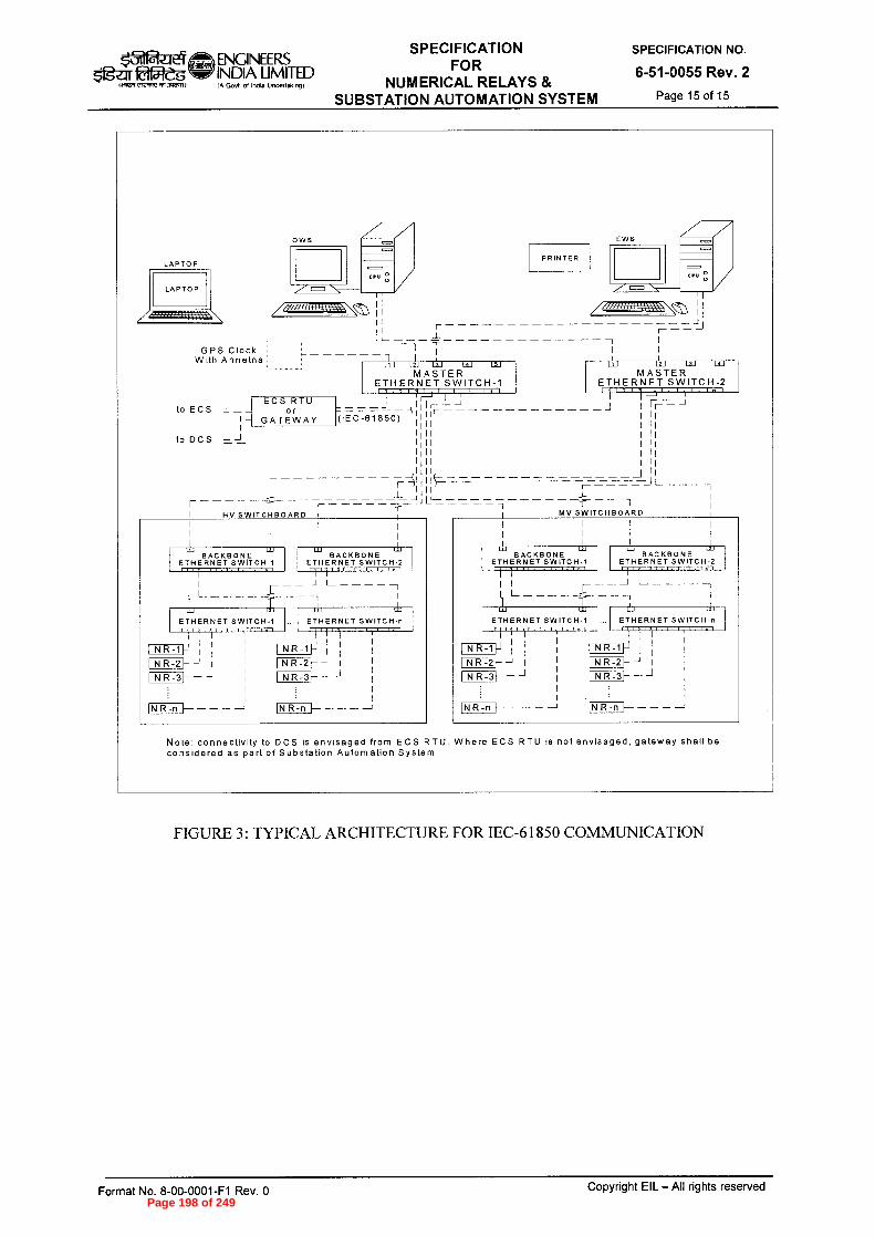
$'gzirlaa4-eg «Iirrt c`le nnI1 M 3Vi6AI I A Govt ol InOia Undenaking)
ENGINEERS SPECIFICATION
INDIA LIMITED FOR
NUMERICAL RELAYS & SUBSTATION AUTOMATION SYSTEM
GPS Clock With Annetna
L1J L2] L3J LsJ LSJ MASTER
ETHERNET SWITCH-1
LAPTOP
LAPTOP
to DCS
r HV SWITC1f1BOARD
lZ BACKBONE
ETHERNET SWITCH-1
UJ UJ BACKBONE
ETHERNET SWITCH-2
1 I I __J
UJ
ETHERNET SWITCH-n
NR-11-1 NR-21- I —
1NR-1P 1 11 I NR-2}-- I I NR-31----1
I
1NR-n — — —
tZ uJ BACKBONE
ETHERNET SWITCH-1
I NR-11-1 I NR-21---J I I —
1.1.1 BACKBONE
ETHERNET SWITCH-2
LU üJ
ETHERNET SWITCH-n . v I
IN R -n — — —
to ECS -) (IEC-61850)
27.=
I I 1 1=
I t 1> I I. In I
_ I 1 1,1 I- I- In I
ti
-r MV SWITCHBOARD
ECS RTU or
GATEWAY
LiJ L2J L3J L9.J
MASTER ETHERNET SWITCH-2
Note: connectivity to DCS is envisaged from ECS RTU. Where ECS RTU is not envisaged, gateway shall be considered as part of Substation Automation System
EWS
PRINTER
/,\ JJ r
J_
SPECIFICATION NO.
6-51-0055 Rev. 2
Page 15 of 15
FIGURE 3: TYPICAL ARCHITECTURE FOR IEC-61850 COMMUNICATION
Format No. 8-00-0001-F1 Rev. 0
Copyright EIL —All rights reserved Page 198 of 249

r"_111 Reig $'g?;ir
ENGINEERS INDIA LIMITED IA Govt of Ilioia Undertakingt
SPECIFICATION FOR ELECTRICAL EQUIPMENT
INSTALLATION
STANDARD SPECIFICATION No.
6-51-0081 Rev. 4 Page 1 of 15
fqxja ̀CID Tzrp-ir9r NfffhT
SPECIFICATION FOR ELECTRICAL EQUIPMENT
INSTALLATION
4 21.05.14 REAFFIRMED & ISSUED AS SPECIFICATION FA SA BRB SC
3 25.04.08 REVISED & ISSUED AS SPECIFICATION RKS SSM JMS VC
2 28.02.03 REVISED & ISSUED AS SPECIFICATION HKM RSG VPS SKG
1 26.08.97 REVISED & ISSUED AS STANDARD SPECIFICATION
RR VPS SG AS
0 28.08.81 ISSUED AS STANDARD SPECIFICATION RR RR SGG
Rev. No
Date Purpose Prepared
by Checked
by
Standards Committee Convenor
Standards Bureau
Chairman
Approved by
Format No. 8-00-0001-F1 Rev. 0
Copyright EIL — All rights reserved Page 199 of 249

$11gui&W-eg rycnrc ~I)
ENGINEERS INDIA LIMITED IA Govt of India Undeffoloogf
SPECIFICATION FOR ELECTRICAL EQUIPMENT
INSTALLATION
STANDARD SPECIFICATION No.
6-51-0081 Rev. 4 Page 2 of 15
Abbreviations:
AC Alternating Current ACDB AC Distribution Board AL Aluminium BIS Bureau of Indian Standards CCoE Chief Controller of Explosives CD Compact Disc CEA Central Electricity Authority CIMFR Central Institute of Mining and Fuel Research CT Current Transformer CTC Carbon Tetrachloride CU Copper DC Direct Current DCDB DC Distribution Board DGMS Directorate General of Mines and Safety Ex(d) Flameproof FRP Fibre Reinforced Plastic HV High Voltage IR Insulation Resistance IS India Standard LV Low Voltage HMI Human Machine Interface MV Medium Voltage OISD Oil Industry Safety Directorate OSR Oil Surge Relay OTI Oil Temperature Indicator PF Power Factor PI Polarisation index PRV Pressure relief Valve PT Potential Transformer SLD Single Line Diagram UPS Uninterrupted Power Supply VRLA Valve Regulated Lead Acid WTI Winding Temperature Indicator
Electrical Standards Committee
Convener: Mr. B.R. Bhogal
Members: Ms. S. Anand Mr. Parag Gupta Mr. M. K. Sahu Mr. A.K. Choudhury (Inspection)
Ms. N.P. Guha (Projects)
Format No. 8-00-0001-F1 Rev. 0 Copyright EIL — All rights reserved
Page 200 of 249

‘3-11R_Jt4 ENGINEERS INDIA LIMITED
SPECIFICATION FOR ELECTRICAL EQUIPMENT
INSTALLATION
STANDARD SPECIFICATION No.
6-51-0081 Rev. 4 Page 3 of 15
orrrn c,craddaJnadfan IA Govt of India Undeftalong)
CONTENTS
1.0 SCOPE 4
2.0 CODES AND STANDARDS 4
3.0 INSTALLATION OF EQUIPMENT 4
4.0 EQUIPMENT COMMISSIONING 14
5.0 LIST OF CONSTRUCTION EQUIPMENT 14
Copyright EIL — All rights reserved Format No. 8-00-0001-F1 Rev. 0 Page 201 of 249
ENGINEERS $11g-a 22-g INDIA LIMITED
aiT7ii CRI dYtn.
(A Govt of lochA UnderfAk(.9)
SPECIFICATION FOR ELECTRICAL EQUIPMENT
INSTALLATION
STANDARD SPECIFICATION No.
6-51-0081 Rev. 4 Page 4 of 15
1.0 SCOPE
This specification defines the requirements for the installation, field inspection, testing and commissioning of electrical equipment, forming part of electrical power distribution and utilisation system, including Communication and Fire alarm system.
2.0 CODES AND STANDARDS
2.1 The work shall be carried out in the best workmanlike manner in conformity with this specification, EIL Installation Standards, layout drawings and to the following specifications/ codes of practice of Bureau of Indian Standards and OISD standards.
SP-30 (BIS) National Electrical Code.
IS:7816 Guide for testing Insulation resistance of rotating machines.
IS:10028 (Part-2) Code of practice for selection, Installation and maintenance of transformers; Part 2 : Installation.
OISD 137 Inspection of Electrical Equipment.
OISD 147 Inspection and safe practices during electrical installations
2.2 In addition to the above it shall be ensured that the installation conforms to the requirements of the following as applicable:
a. CEA Regulations.
b. Regulations laid down by CEA/Electrical Inspectorate.
c. Regulations laid down by CCoE/DGMS (as applicable).
d. The petroleum rules (Ministry of Industry Government of India).
e. Any other regulations laid down by central/state/local authorities and Insurance agencies.
3.0 INSTALLATION OF EQUIPMENT
Prior to start of installation of the electrical equipment, Contractor shall verify that equipment and complete materials have been received. Handling, shifting to required site location, installation, testing and commissioning of all electrical equipment shall be done by contractor with utmost care. Manufacturer's instructions and the requirements given in their technical manuals shall be strictly adhered. The substation/switchgear room wherein the equipment shall be installed shall be kept clean, dry and free from all debris. Panel floor cutouts not in immediate use shall be suitably covered to avoid any mishap. When handling the switchboard panels, care shall be taken to observe the correct lifting arrangements and to make sure that slings are attached to the manufacturer's designated lifting points,where applicable. No parts shall be subjected to undue strains or sudden stresses which could cause damage to the equipment.
The lifting position mark indicated on packing casing shall be adhered to strictly, for keeping it in required vertical position.
Contractor shall check and report to the Engineer-in-charge about any damaged item and / or missing component for getting the same replaced as per specifications. During installation, all accessories and loose items shall also be inspected by the contractor before their assembly/mounting.
Format No. 8-00-0001-F1 Rev. 0 Copyright EIL — All rights reserved
Page 202 of 249

ENGINEERS INDIA LIMITED (A Govt ol InOla Undedalong)
SPECIFICATION FOR ELECTRICAL EQUIPMENT
INSTALLATION
STANDARD SPECIFICATION No.
6-51-0081 Rev. 4 Page 5 of 15
Otait 1~,.r2",1,77,1713,21,)
3.1 Switchboards and Bus Ducts
3.1.1 The term switchboard here includes all HV / MV/ LV switchboard panels, motor control centers, power and lighting distribution boards, UPS panels, ACDB, Battery charger panels, DCDB etc.
The switchboard panels shall be handled with care, avoiding any impact to the equipment. Dragging of the panels directly on floor shall be avoided. Roller bars may be used for shifting of panels. Use of a crane and trailer shall be made for handling of equipment. The switchboard panels shall be properly supported on the truck or trailer by means of ropes to avoid any chance of tilting. The switchboards shall be lifted after ensuring that panel supports, nuts and bolts are all intact and tightened. While lifting the panels in packed conditions, utmost care shall be taken to avoid any damage to insulators, bushings, metering and protective equipment and if specified in the tender document tyre mounted hydraulic trolley shall be used.
The panels shall be preferably kept inside the packing cases till foundations are ready. Proper rain/sun/dust protection shall be ensured till switchboards are installed.
3.1.2 The switchboard panels shall be installed on prepared foundations or floor cutouts. Steel base channels shall be welded to inserts provided in floor slab. Cross members shall be provided at the junctions of each shipping section and other places as required.. It shall be ensured that the base plate level of HV switchboard shall match with the finished floor level.
The foundation pockets and the grouted bolts shall be cured for a minimum period of 48 hours. Proper level of base frames shall be maintained throughout and shall be checked with water level/spirit level. Steel Shims shall be provided below base frame wherever required.
3.1.3 The switchboard panels shall be taken out from the packed cases and shifted one by one to their proper place. Al1 the panels shall be assembled, aligned and leveled. Alignment of panels shall be checked in both longitudinal and lateral directions. It shall be ensured that panel to panel coupling bolts, bus bar links etc. fit properly without any strain on any part. No new holes for jointing of the panels other than those recommended by the vendor shall be drilled. No gaps shall be left between the panels. Gap if any found between panels shall be suitably sealed using sealing compound or T-profile. The lifting, racking in and out operation of the breaker and all other motions shall be free from any obstruction.
The panels shall be checked for correct vertical position using Plumb line and spirit levels. The switchboard panels shall be tack welded at suitable intervals to base channel.
After erection of switchboard panels, all uncovered portions of floor cutouts shall be covered with 6 mm thick removable chequered plates finished with floor level. The design of the chequered plates shall be such that the maximum allowable deflection is L/200 (where L is the span of the chequered plates in meters) for a live load of 500 kg./sq. meters.
Additional stiffer shall be provided at the bottom if required. Suitable lifting arrangements shall be provided for chequered plates. The chequered plates shall be painted with a coat of red oxide zinc chromate primer after proper surface preparation as per specifications. Where specified, panels' cutouts provided for future use shall be filled with lean concrete.
3.1.4 After completion of Installation of switchboards, all the cubicles, switchboard components such as switches, starters, CT and PT chambers, bus bar chamber shall be cleaned and checked for tightness of all the components.
Vacuum circuit breakers shall be checked for integrity of bottle seals. A11 loosely supplied items shall be fitted up. Bus bar sections or links shall be inserted and where specified, of high
Format No. 8-00-0001-F1 Rev. 0 Copyright EIL All rights reserved
Page 203 of 249

ENGINEERS Ordie'g INDIA LIMITED
IA Govt of Intha Undertaking)
SPECIFICATION FOR ELECTRICAL EQUIPMENT
INSTALLATION
STANDARD SPECIFICATION No.
6-51-0081 Rev. 4 Page 6 of 15 eivavv'dv~)
voltage equipment shall be insulated. Interconnection wiring between shipping sections shall be done by contractor.
All the wiring connections shall also be checked. Contact resistance of all bus bar joints and contactors shall be checked. Insulator shall be checked for any damage. All the starters, switches, contacts shall be cleaned with CTC where required.
A11 the moving parts shall be checked for easy and free movement. Hinges of panel doors shall be lubricated to give free and noise less movement. A11 openings shall be kept completely closed to avoid ingress of any foreign particles inside the panel.
Functional scheme verification of individual feeder shall be carried out and minor wiring modifications in the panel wiring, if required shall be done as per the directions of Engineer-in-charge. Special attention shall be paid to CT circuits' polarity, wiring continuity and correctness in the protection as well as measurement circuits. Auto transfer scheme shall be simulated and verified. During the course of scheme verification tests, defective components if any shall be taken out, after bringing to the notice of Engineer-in-charge. The same shall be replaced by component supplied by owner.
3.1.5 Where switchboard is damp or having a low IR value due to damaged insulators/ bushings/any other insulated parts, or any other reason, the entire switchboard shall be dried-up according to the instruction of the Engineer-in-charge for the IR value to improve to a safe level for commissioning. Care shall be taken to protect the surrounding insulation from direct local heating during the drying up process.
3.1.6 All the metering instruments, protective relays and other relays and contactors shall be tested as per manufacturer's recommendations and according to the instructions of the Engineer-in-charge. Protection relays shall be inserted and connected and settings adjusted as required by the Engineer- in- charge
3.1.7 All moving parts, of closing/tripping mechanism, racking in and racking out mechanism, spouts and shutter closing mechanism shall be checked for proper operation. A11 the auxiliary contacts of breaker shall be checked-up, cleaned and contact pressure measured.
3.1.8 All the control wiring, PTs, bushings, bus bars, other live parts of switchgear, incoming and outgoing cables shall be meggered.
3.1.9 Electrical simulation tests shall be carried out for all the protective, alarm and annunciation relays and external interfaces to ascertain proper functioning.
3.1.10 Safety insulation mats of approved make and of required voltage grade shall be provided in the sub-station.
3.1.11 Pre-Commissioning Check List
Before commissioning any switchboard, following points shall be checked and ensured for safe energising of the switchboard:
i. That the installation of equipment to be commissioned is complete in all respects with its auxiliaries and all other mounting including earthing. Openings in floor within and outside panels have been sealed off. All cover and door gaskets are intact to make the enclosure vermin proof.
ü. That all the metering instruments have been checked and found in working order. Indicating lamps are healthy and are in correct position. All power and control fuses are of proper rating.
Format No. 8-00-0001-F1 Rev. 0 Copyright EIL — All rights reserved
Page 204 of 249

ENGINEERS g INDIA LIMITED
(A GoV1 ol Ind. Unde(l.k,n91
SPECIFICATION FOR ELECTRICAL EQUIPMENT
INSTALLATION
STANDARD SPECIFICATION No.
6-51-0081 Rev. 4 Page 7 of 15
iii. That the polarity test and ratio test of all the PTs and CTs is complete and phase sequence of CTs conforms to the correct vector group connections. Wiring continuity and correctness are ensured in the protection and measurement circuits. Polarity of D.C. supply for all the circuits is correct.
iv. That the high voltage tests of incoming and outgoing cables have been conducted and results are satisfactory.
v. That all the protective relays including both conventional and microprocessor based numerical relays and thermal overload relays/electronic motor protection relays have been tested for secondary injection tests. (Primary injection tests shall be carried out for differential protection, Restricted Earth fault protection at full / reduced current to ensure correctness of complete wiring). Relay settings, status indications, fault annunciations, data logging, display of switchboard SLDs shall be verified from HMI in case the same is provided.
vi. That IR Value has been recorded for bus bars, circuit breaker, incoming and outgoing cables, control wiring and potential transformers. Where required joint resistance of bus bars have been recorded and found to be satisfactory. All the surroundings and panels have been cleaned and temporary earth leads have been removed.
vii. Following tests shall be ensured for all CTs
- Insulation resistance test
Ratio test through primary injection
Polarity test
Knee point voltage for class PS CTs
viii. Following tests shall be ensured for all PTs
Insulation resistance test
Ratio test through primary injection
- Polarity test
ix. Following tests shall be ensured for all breakers
- Insulation resistance test
- Breaker closing, opening sequence using 3 pole timers
- High voltage test both in open and close condition for HV breaker
Contact resistance of all three poles using 100A DC Kit
x. Following tests shall be ensured for all meters
- Calibration of meters
Functional verification and settings
xi. Following tests shall be ensured for all relays
Secondary injection test
- Relay settings
Timing check with timers
- Any other test recommend by the supplier
xii. Following tests shall be ensured for all bus bars
- Tightness of all nuts/bolts using Torque wrench
IR value
- Contact resistance using 100A DC Kit
- Cleaning of bus bar chamber using vacuum cleaner
- Conducting jelly shall be applied on AL/CU joints as per manufacturer's recommendations
- HV test in case of HV switchboard
Format No. 8-00-0001-F1 Rev. 0 Copyright EIL — All rights reserved
Page 205 of 249

k31naf t I ENGINEERS $1gzir INDIA LIMITED
Ift Govt of Incha Undertaking)
SPECIFICATION FOR ELECTRICAL EQUIPMENT
INSTALLATION
STANDARD SPECIFICATION No.
6-51-0081 Rev. 4 Page 8 of 15
1~7tYleaHt an .3~1
xiii Following tests/Checks shall also be performed on the switchboards
Functional verification of individual feeders including all spare feeders
Simulation test for under voltage tripping of related feeders such as motor feeder, capacitor feeders etc
Verification of control supply schemes
Stability test for all differential protections
Simulation test for bus auto/manual change over scheme
Checks for all panel illuminations, indicating lamps, sockets
All upstream and down stream interlocks
3.1.12 Bus Ducts
The bus ducts as per issued drawings will be supplied in parts and all the parts shall be assembled and the bus bar connections shall be made at site. The insulators in bus ducts shall be inspected for any possible damage during transit and the defective ones shall be replaced. The insulators shall be cleaned. Contact surface of bus bars, bus bar bolts and nuts shall be thoroughly cleaned. Petroleum jelly shall then be applied and bolted connection made. The bus duct enclosure shall be checked for earth continuity and then earthed at two places. The bus duct shall be properly supported between switchgear and transformer. The opening in the wall where the bus duct enters the switchgear room shall be completely sealed to avoid rain water entry. Expansion joints, flexible connections etc. supplied by the manufacturer of the bus duct shall be properly connected. The bus duct levelling shall be checked with spirit level and pendulum weight.
Pre-commissioning check list
Before commissioning any bus duct, following points shall be checked and ensured for safe energising of the bus ducts
All joints are tightened using torque trench Cleaning of bus duct chamber with vacuums cleaner Silica gel breather shall be connected if supplied. If required, silica gel shall be reactivated as per the instruction of engineer in charge. Space heater circuit shall be checked and tripping through thermostat shall be ensured Contact resistance shall be measured for all phases/neutral using 100A DC kit High voltage test in case of HV bus ducts
3.2 Transformers
Transformers on receipt at site shall be unloaded by means of crane or lifting devices of adequate capacity. All lifting lugs shall be used to avoid unbalanced lifting and undue stresses on lugs. Lifting lugs if any provided for partial lifting (e.g. for active part, conservator) etc. shall not be used for lifting complete transformer. Parts other than those identified for lifting of the transformer shall not be used for lifting. While slinging, care shall be taken to avoid slings touching other parts.
3.2.1 Before lifting transformer, it shall be ensured that all cover bolts are tightened fully. In case when it is necessary to use jacks for lifting, projections provided for the purposes of jacking shall be used . Lifting jacks shall not be used under the valves or radiator tubes. For transporting transformers from stores to site, the transformers shall be loaded on a suitable capacity truck or trailer. The transformers shall be properly supported by steel ropes and stoppers on the trailer to avoid tilting of the transformers in transit due to jerks and vibrations. At no instance, the transformer shall be kept on bare ground. Where it is not possible to
Format No. 8-00-0001-F1 Rev. 0
Copyright EIL — All rights reserved
Page 206 of 249

k5-11 ENGINEERS
Og-LITI&2eg INDIA LIMITED aiWn 4,1 .3~1/
(A Govt ol Indla Undertaking)
SPECIFICATION FOR ELECTRICAL EQUIPMENT
INSTALLATION
STANDARD SPECIFICATION No.
6-51-0081 Rev. 4 Page 9 of 15
unload the transformer directly on a foundation, it shall be unloaded on a properly built wooden sleeper platform. A transformer shall never be left without putting stoppers to the wheels.
3.2.2 Transformers shall be examined, for any sign of damage in transit. Particular attention shall be given to the following in this regard.
i. Dents on tank wall or cooling tubes, radiators ü. Damage to protruding parts like valves, sight glass etc.
Loosening of bolts due to vibration in transit. iv. Cracked or broken bushings. v. Oil leakage particularly along welds.
If any thing adverse is noted, the same shall be brought to the notice of Engineer- in- charge.
3.2.3 Contractor shall examine the transformer base, oil pit, fire walls and foundations made by the civil contractor. It shall be ensured that oil spills can not propagate along cable trenches. Any discrepancy noted will be brought to the notice of Engineer- in- charge. Transformers shall be placed on channels or rails over concrete foundations. The transformers shall be levelled, aligned and checked for free movement on the channels or rails. Stoppers shall be provided to the transformers immediately to prevent any movement. Normally transformers upto 1000 kVA rating shall be received duly fitted with radiator tubes, conservator tanks, valves, wheels and other accessories. While the transformers of above 1000 kVA rating may be supplied with loose accessories. All the accessories like radiators, cooling fans, valves, conservator tanks, explosion vent pipe, bushings and other devices which are supplied in different packages shall be checked for any transit damage and cleaned thoroughly before fixing on the transformer. All loosely supplied parts shall be assembled as per manufacturer's instruction manuals/ drawings and documents. All the connections for CTs bushings and other wiring shall be checked for tightness and correctness before replacing the lid or tightening all the bolts. Gravels shall be filled in the transformer bay, soak pit as per requirement.
3.2.4 Topping of transformer with oil
Before topping up with oil, transformer shall be fitted with all accessories such as valves, gauges, thermometers etc. Oil samples shall be taken from each drum and tested for determination of dielectric strength. Any sign of leakage of the barrel or of its having been opened shall be recorded and reported. It is necessary to filter the oil before the transformers are filled. It shall be ensured in oil filling operation that no air pockets are left in the tank and that no dust or moisture enters the oil. All air vents shall be opened. Oil shall be filled through a streamline oil filter using metal hose. To prevent aeration of the oil, the transformer tank shall be filled through the bottom drain valve. In a transformer with conservator tank, the rate of oil flow shall be reduced when the level is almost upto the bottom of the main cover to prevent internal pressure from rupturing the pressure relief-pipe diaphragm. Sufficient time shall be allowed for the oil to permeate the transformers and also for the locked -up air bubbles to escape. Any air accumulation in the buchholz relay shall be released.
3.2.5 Transformer Oil
i. Sample of oil from the transformer shall be taken from the bottom of the tank.
ii. Testing of Oil For dielectric test, the oil shall be tested as described in IS: 335. The oil shall also be tested for acidity in accordance with the methods prescribed.
3.2.6 Drying out of the transformers, if required, shall be carried out and record maintained in accordance with IS: 10028. Normally a streamline filter shall be used for drying-up. IR value
Format No. 8-00-0001-F1 Rev. 0 Copyright EIL — All rights reserved
Page 207 of 249
01 ENGINEERS
ogur 015:1&g INDIA LIMITED
14~ ,le'crn( 0,1 3,121,1) (A Govt of India Undettakingi
SPECIFICATION FOR ELECTRICAL EQUIPMENT
INSTALLATION
STANDARD SPECIFICATION No.
6-51-0081 Rev. 4 Page 10 of 15
versus time of both windings along with OTI/WTI and filtrations machine temperature curve for IR value Vs time shall also be plotted and recorded during the drying-up process.
Precautions when drying
i. The maximum sustained temperature to which transformer oil may be subjected shall be limited to 80° C.
ü. The transformer shall be carefully monitored throughout the drying out process and all observations shall be carefully recorded.
Drying out shall be continued so that the insulation resistance as prescribed in the standard code of practice is attained and the value remains constant for more than 12 hours. However, a minimum number of cycles shall be done for each transformer as found necessary by the Engineer-in-charge. Generally a Megger reading of 2 megohms / kV at 60° C temperature. with a 5 kV Megger may be a rough indication for stopping the dehydration.
3.2.7 The following work on transformers shall be performed by the contractor if specifically called for:
i. Before finally commissioning the transformer it may sometimes be desired to run it for a few hours on short-circuit, applying a low voltage, approximately equal to the impedance voltage of the transformer. During this process, regular readings of the insulation resistance of the winding to earth and winding to winding and temperature against time shall be recorded.
ü. Testing of radiator tubes for any leakage and rectifying these by welding / brazing.
3.2.8 Pre-commissioning Check List
Before commissioning of any transformer, the following points shall be checked for safe energisation of the transformer:
i. All the accessories have been fixed properly and transformer body and neutral are properly earthed. The transformer dehydration is over and results are satisfactory and approved by the Engineer-in-charge. In case transformers are idle for more than one month after dehydration, transformer oil has been given at least two circulations.
ü. Oil level, in the transformer conservator tank and all the bushings is upto the marked point and the oil has been tested for dielectric strength and acidity.
Silicagel is in reactivated condition. The breather pipe is clear from any blocking and contains oil upto the proper level.
iv. The explosion vent diaphragm does not have any dents. Accumulation of any oil and air had been released.
v. Operation of off-load and on-load tap changers on all the tap positions is satisfactory. The mechanical parts of the on-load tap changer are lubricated. Motor IR value has been taken and found satisfactory. Tap position mechanical indicator on the transformer and tap position indication meter on the control panel are reading the same tap positions. Tap changer limit switches are operating satisfactorily on the maximum and minimum tap positions. On-load tap changer contact pressure and resistance is as per manufacturers recommendations. Oil level of tap changer tank is upto the required level and oil has been tested for dielectric strength. The tap setting on which the off load tap switch is locked shall be recorded. Generally the off-load tap switch shall be kept on nominal tap.
Format No. 8-00-0001-F1 Rev. 0 Copyright EIL — All rights reserved
Page 208 of 249

ENGINEERS INDIA LIMITED (A Govt of India Unde(tak,ngj
SPECIFICATION FOR ELECTRICAL EQUIPMENT
INSTALLATION
STANDARD SPECIFICATION No.
6-51-0081 Rev. 4 Page 11 of 15
51gzu 2a1-"dg c-wert ams..)
vi. Buchholz relay has been tested and checked up for any friction in the movement, and floats are free. All the other protective relays, alarm and annunciation relays have been tested.
vii. Metering equipment has been tested and polarity test of PT's and transformer winding is satisfactory. Phase sequence and connections have been checked for proper vector group.
viii. Ratio test and winding resistance on all the tap positions is satisfactory.
ix. Gaps of arcing horns for the bushings where provided are in order and earth connections for the surge diverters have been checked.
x. Winding and oil temperature thermometer pockets contain oil and the winding and oil temperature settings on dial gauges are in order.
xi. Transformers fitted with fans for forced air cooling have been checked up for starting and stopping of the fans both in manual and auto mode and air-displacement has been verified.
xii. Simulation tests for all external interface connection alarm, annunciation and trip circuits have been checked and are in order.
xiii. Insulation resistance of all the control circuits and IR value of the transformer windings and all the incoming and outgoing cables have been checked.
xiv. Valves in the cooling system and valve between the buchholz relay and the conservator tank are in open position.
xv. Setting of all the protective relays is at the desired value and DC Trip supply is healthy.
xvi. Magnetic, current and magnetic balance test have been conducted
xvii Simulation test for WTI,OTI,PRV,OSR
xviii Settings of WTI/OTI as per the instruction of the manufacturer
xix Earth resistance value for the neutral earthing
3.2.9 Observations after Commissioning
After switching on the transformer the following points shall be observed and recorded.
i. The inrush magnetizing current and no-load current.
ü. Alarm, if any, or if any relay flag has operated.
Voltage and current on all the three phases.
iv. Transformer hum or abnormal noise.
v. Circulation of oil and leakages.
vi. Record current, voltage, cooling air temperature, winding temperature and oil temperature readings, hourly for 24 hours.
vii. Cable end boxes for any over-heating.
3.3. HV and MV MOTORS
3.3.1 All the motors generally would be erected by the mechanical contractor.
3.3.2 Electrical contractor shall keep the motor space heater energised as per the directions of Engineer-in-charge. Electrical contractor shall measure the insulation resistance of motor windings and PI in case of HV motors. Insulation resistance of the motors shall be measured between the winding of the machine and its frame by means of a 500 / 1000 V Meggar in case of 415 V motors. A minimum value of 1 megohm for 415 V motors shall be considered a safe value. In case of lower I.R. Value, the insulation value shall be improved by any of the following methods as directed by the Engineer-in-charge.
Format No. 8-00-0001-F1 Rev. 0 Copyright EIL — All rights reserved
Page 209 of 249

ENGINEERS Og'zIr faf-Zs INDIA LIMITED
IA Govt ot Intha Undertakmg
SPECIFICATION FOR ELECTRICAL EQUIPMENT
INSTALLATION
STANDARD SPECIFICATION No.
6-51-0081 Rev. 4 Page 12 of 15 ei2LIW,R13,,g1,11)
i. Blowing hot air from external source.
ii. Putting the motor in oven.
iii. Placing heaters or lamps around and inside after making suitable guarding and covering arrangements so as to conserve the heat.
In case the insulation is low, the following method of drying has to be adopted, after consultation with Engineer-in-charge. During drying the temperature rise of winding shall not exceed the permissible value for the class of insulation used.
i. By locking the motor so that it can not rotate and then applying such a low voltage to the stator terminals so as to pass full load current in the stator keeping the stator winding temperature below 90° C . In this case a close watch shall be kept for any possible overheating and I.R. Values vs. temperature shall be plotted and heating continued till I.R. value becomes steady.
ü. By blasting hot air from external source, Maximum temperature of winding while drying shall be 70° C to 80° C (thermometer) or 90° C to 95° C by resistance method. Heating shall be done slowly first till steady temperature of winding is reached after 4 to 5 hours, and for large machines after 10 hours. A record has to be kept for drying process, with half an hour readings and, till steady temperature is reached. In case it is essential, the drying process can be supplemented by blower.
3.3.3 It shall be ensured that the motor leads are correctly connected in the terminal box, as indicated in the `Name Plate'. The covers of all terminal boxes shall be properly fixed, the gaskets intact. The control circuit shall be tested for proper functioning as per circuit diagram.
3.3.4 In case of synchronous machines, slip rings and brush gear shall be polished and brushes shall be fixed in their holders with clearance and pressure as recommended by the manufacturers.
3.3.5 Before commissioning, the ventilation and cooling system of the motor must be inspected. In case of motor with forced ventilation the air inlet shall be examined to ensure that it is free from moisture and any foreign material. It shall also be ensured that recommended flow and pressure of air is available to produce the required cooling effect.
3.3.6 The motor control gear shall also be carefully examined, the over-load settings may be reduced or time lags bypassed from protective gear to ensure rapid tripping of switchgear in event of faults. The direction of rotation of a new motor specially of large capacity , and phase sequence of supply shall be kept in view while joining and connecting to the motor terminals
3.3.7 Finally the motor shall be started on no-load after decoupling, and shall be allowed to run for a minimum period of 4 hours, or for a time as instructed by Engineer-in-charge. Attention shall be given to the proper running of the bearings, vibration or unusual noises if any. Voltage, starting current, no load current, stator winding and bearing temperature shall be recorded after every 1 hour during this test. Direction of rotation shall be checked and recorded. Normally the motors run in clockwise direction as viewed from the driving end with reference to the phase sequence R, Y, B.
3.3.8 After switching off the motor, the insulation resistance of the motor shall be recorded under hot and cold conditions.
3.3.9 If the no load test run is found satisfactory, the motor shall be allowed to run for 8 hours and all readings shall be recorded.
3.3.10 The following work on motors, may be performed by the contractor if specifically called for.
Format No. 8-00-0001-F1 Rev. 0 Copyright EIL — All rights reserved
Page 210 of 249

■31 $'fgu Offleg
1.2T
ENGINEERS INDIA LIMITED (A Govt of India Untleltakmgl
SPECIFICATION FOR ELECTRICAL EQUIPMENT
INSTALLATION
STANDARD SPECIFICATION No.
6-51-0081 Rev. 4 Page 13 of 15
i. The proper level of bearing oil has to be checked. The condition of grease in bearings shall be checked and in case it is necessary, complete replacement of bearing with specified grade of grease after proper cleaning of the bearing shall have to be done. Wherever external greasing facility exists, the condition of grease may be checked by pumping some new grease of specified grade at start. If the grease coming out is deteriorated grease shall be replaced.
ü. All the motors, motor exciter set and induction generators directly coupled or coupled through reduction gears shall be checked for abnormal vibration, if any Large rated HV motors with journal type bearings are liable to get damaged from shock, rough handling during transit. Any minor defect in a race or roller may give rise to considerable amount of vibration and noise. Contractor shall check and bring to the attention of Engineer-in-charge any defect noticed in this regard.
Due care shall be taken to avoid any damage to bearing insulation wherever provided.
3.4. Batteries/Battery charger
Battery (Lead acid, Nickel Cadmium or VRLA type as specified) shall be erected on stands and insulators supplied by the manufacturer of the batteries. The installation shall be done as per the layout drawings and manufacturer's instructions. Electrolyte if required / as applicable shall be filled as per manufacturer's instructions. Interrow connections shall be made with the leads supplied by the manufacturer. Functional check shall be done on the battery charger including battery charging and discharging, recharging as per the recommendation of the manufacturer.
3.5. Neutral Earthing Resistor
The neutral earthing resistor shall be inspected for any damage to the resistor grid and other components. The resistor shall be levelled and installed. All covers etc. shall be checked for tightness to ensure that the enclosure of the resistor is dust, vermin and weatherproof. Earthing conductors shall be taken from the out end terminal of the resistor, for connection to earth electrodes and to the main grid. Check such as IR, operation of space heater, earth resistance shall be done before the commissioning.
3.6 Welding Receptacles
The welding receptacles shall be erected on steel/concrete structures as per the drawings. In isolated places a separate support shall be fabricated and installed.
3.7 Push Button/Control Stations
The push buttons / control stations shall be installed near to the motors to be controlled. Individual channel supports shall be installed as per EIL standard. If control stations for hazardous areas are to be supplied by contractor, these shall be of Ex (d) type, tested by CIMFR and approved by CCoE or other applicable certifying authorities. All outdoor push buttons / control stations shall preferably have integral canopies for additional weather protection. The canopy shall be made of 2 mm thick galvanized sheet steel or FRP where these are not integral with the equipment.
3.8 Gang operated Isolators/outdoor Disconnectors
The isolators shall be transported to site in the dismantled condition. All the insulators may be also supplied loose. The contractor shall inspect, clean, assemble and install the isolator on the base structure previously fabricated, erected and levelled by him. The operating mechanism
Format No. 8-00-0001-F1 Rev. 0 Copyright EIL — All rights reserved
Page 211 of 249

■31 ENGINEERS 5ga. 22-- g INDIA LIMITED
Govt of Incha Undertalongt
SPECIFICATION FOR ELECTRICAL EQUIPMENT
INSTALLATION
STANDARD SPECIFICATION No.
6-51-0081 Rev. 4 Page 14 of 15
shall be installed on the structure and connected to the isolator poles. The operating mechanism shall be tested by slowly bringing the isolator to the closed position and carrying out the necessary adjustment as per the manufacturer's instructions. The earthing switches, frames and operating handle etc. shall be earthed.
3.9 Contractor shall provide the following items in substation, as per CEA Regulations.
3.9.1 Fire buckets filled with clean dry sand and ready for immediate use for extinguishing fires and fere extinguisher (carbon dioxide, dry chemical extinguisher etc.) suitable for dealing with electric fires shall be conspicuously marked and kept.
3.9.2 First aid boxes containing ointments and medicines for immediate treatment of injuries (As prescribed by Indian Red Cross Society or equivalent).
3.9.3 Instructions of restoration of persons suffering from electric shock in English, Hindi and Local language of the district shall be affixed in a conspicuous place.
3.9.4 Danger boards (HV., MV.) shall be provided on transformer bay gate, switchboards, entrance to switchgear room and at other places as required by Engineer-in-charge.
3.10 The Communication system and Fire alarm system panels and equipment shall be installed complying to manufacturer's instructions. The location of field station (call back station unit, break glass unit, telephone set etc.) shown on the drawing are indicative. The exact location shall be decided at site by contractor in consultation with Engineer-in-charge. Correct type of equipment with regard to hazardous protection as specified on drawing shall be adhered to by contractor, for installation.
4.0 EQUIPMENT COMMISSIONING
4.1 Field inspection, testing and commissioning of the complete electrical installation shall be carried out as per EIL specification no. 6-51-0087.
After the equipment is installed properly in accordance with drawings and specifications, contractor shall carry out all pre-commissioning checks and tests as per EIL format in the presence of Engineer-in-charge and test readings shall be recorded and furnished to EIL in triplicate.
4.2 All equipment layout drawings shall be marked by the Contractor for "AS BUILT STATUS" and two sets of hard copies shall be submitted to EIL.
5.0 LIST OF CONSTRUCTION EQUIPMENT
The contractor shall have all necessary construction equipment, tools and tackles and testing instruments to carry out the erection works and to commission the system as specified. These shall include but not be limited to the following, and these shall be brought to site by contractor before the start of work.
5.1 Equipment
i. Portable grinder.
ü. Portable welding machine.
üi Portable gas cutting / welding set.
iv. Pipe threading machine.
v. Pipe bending machine (hydraulic).
Format No. 8-00-0001-F1 Rev. 0 Copyright EIL — All rights reserved
Page 212 of 249
ENGINEERS $11g-a[R6 UINDIA LIMITED
IA Govt or Indo Undertaking)
SPECIFICATION FOR ELECTRICAL EQUIPMENT
INSTALLATION
STANDARD SPECIFICATION No.
6-51-0081 Rev. 4 Page 15 of 15 (.T-rn an,ram
vi. Portable drill machine suitable to take up drilling for different sizes as per requirement.
vii Dewatering pump sets (diesel driven).
viii. Power Hacksaw.
ix. Conduit dye set.
x. Hydraulic crimping machine with round/hexagonal dye set.
xi. Hand crimping tool.
xii. Portable electric blowers, vacuum cleaners.
xiii. Miscellaneous items such as slings, pulleys, tarpaulins, wooden sleepers, ladders. etc. as required.
xiv. Safety belts, safety goggles, and gloves.
xv. Separate tool kit for each Electrician.
xvi. Hydraulic/Hand held grease gun
5.2 Test Instruments
i. Insulation tester 1000 V hand driven.
ü. Insulation tester 2500 V motor/hand driven.
Insulation tester 5000 V motor/hand driven
iv. Phase sequence indicator.
v. Earth Resistance tester.
vi. Single phase variac
vii. 3 phase variac of adequate capacity.
viii. Secondary and primary injection testing kit.
ix. Multimeter, both analogue and digital
x. Portable Ammeters, Wattmeters, P.F. meters.
xi. Portable Voltmeters.
xii. Clip on meters of different ranges.
xiii. Tacho-meter.
xiv. Kelvins double bridge for measurement of very low resistance.
xv. D.C. high -pot test kit.
xvi. A.C. high -pot test kit.
xvii. Oil filtration machine of adequate capacity.
xviii. Lux Meter to measure illumination levels.
xix. Breaker timing 3 pole kit
xx. Timers
xxi. 100A DC milli volt drop(Contact resistance) kit
xxii. Vibration measuring Instrument
xxiii. Thermo meters
Format No. 8-00-0001-F1 Rev. 0 Copyright EIL — All rights reserved
Page 213 of 249
gfga faWs lair,i237,15,2,131,05.)
ENGINEERS INDIA LIMITED IA Govt of Indla Undertalong)
SPECIFICATION FOR FIELD INSPECTION, TESTING AND
COMMISSIONING OF ELECTRICAL INSTALLATIONS
SPECIFICATION No.
6-51-0087 Rev. 3
Page 1 of 8
-ftw #f-~ PiRkurr, -crftwr
SPECIFICATION FOR
FIELD INSPECTION, TESTING AND
COMMISSIONING OF ELECTRICAL INSTALLATIONS
3 10.6.14 REAFFIRMED & ISSUED AS STANDARD SPECIFICATION AKG SA BRB *". SC
2 03.03.09 REVISED & ISSUED AS STANDARD SPECIFICATION RKS NS JMS ND
1 14.07.03 REVISED & ISSUED AS STANDARD SPECIFICATION
HKM RSG VPS SKG
0 02.08.01 ISSUED AS STANDARD SPECIFICATION UAP RR VPS MI
Rev. No Date Purpose
Prepared by
Checked by
Standards Committee Convenor
Standards Bureau
Chairman
Approved by
Copyright EIL — All rights reserved Format No. 8-00-0001-F1 Rev. 0 Page 214 of 249

k31 laW5
iairerf r-freA, asl,~7,)
ENGINEERS INDIA LIMITED A GoN of Indla Undeltaking)
SPECIFICATION FOR FIELD INSPECTION, TESTING AND
COMMISSIONING OF ELECTRICAL INSTALLATIONS
SPECIFICATION No.
6-51-0087 Rev. 3 Page 2 of 8
Abbreviations:
AC Alternating Current AFC Approved for Construction BIS Bureau of Indian Standards CCOE Chief Controller of Explosives CEA Central Electricity Authority DC Direct Current DCS Distributed Control System DGMS Director General for Mines and Safety ECS Electrical Control Station GI Galvanized Iron HV High Voltage IS Indian Standard MV Medium Voltage OISD Oil Industry Safety Directorate
Electrical Standards Committee
Convenor: Mr. BR Bhogal
Members: Ms. S. Anand Mr. Parag Gupta Mr. M.K. Sahu Mr. A.K. Chaudhary (Inspection) Ms. N.P. Guha (Projects)
Format No. 8-00-0001-F1 Rev. 0 Copyright EIL — All rights reserved
Page 215 of 249

ENG1NEERS INDIA LIMITED IA Govt ol Ind. Undertaiong)
SPECIFICATION FOR FIELD INSPECTION, TESTING AND
COMMISSIONING OF ELECTRICAL INSTALLATIONS
SPECIFICATION No.
6-51-0087 Rev. 3
Page 3 of 8
fawres,
CONTENTS
1.0 SCOPE 4
2.0 CODES AND STANDARDS 4
3.0 FIELD INSPECTION, TESTING AND COMMISSIONING 4
4.0 RECORDS 8
Copyright EIL — All rights reserved Format No. 8-00-0001-F1 Rev. 0 Page 216 of 249

k`5112..itq ENGINEERS SPECIFICATION FOR FIELD INSPECTION, TESTING AND
COMMISSIONING OF ELECTRICAL INSTALLATIONS
SPECIFICATION No.
6-51-0087 Rev. 3
Page 4 of 8
$'1gz:IT ft- s I.R77 c`F,1,4, CA3PC1171)
INDIA LIMITED IA Govt of India Undertalong)
1.0 SCOPE
This specification covers the requirements for the field inspection, testing and commissioning of Electrical Equipment and Installation, forming part of electrical power distribution and utilisation system.
2.0 CODES AND STANDARDS
2.1 The field inspection, testing and commissioning of electrical equipment shall be carried out in line with this specification and the latest edition of following Indian Standards and OISD standards.
SP-30(BIS) National Electrical Code. IS 1255 Code of practice for installation and maintenance of power cables up
to & including 33 kV rating. IS-7816 Guide for testing Insulation resistance of rotating machines. IS 10810(Part 43) Method of Test for cables; Part 43 Insulation resistance. IS 10810(Part 45) Method of Test for cables; Part 45 High voltage test. IS 12729 HV Switchgears OISD 137 Inspection of Electrical Equipment. OISD 147 Inspection and safe practice during electrical installation.
2.2 In addition to the above it shall be ensured that the installation conforms to the requirements of the following as applicable:
a. CEA Regulations
b. Regulations laid down by CEA / Electrical Inspectorate.
c. Regulations laid down by Tariff Advisory Committee/Loss prevention council. d. Regulations laid down by CCoE/DGMS (as applicable). e. The petroleum rules (Ministry of Industry, Government of India). f. Any other regulations laid down by central / state / local authorities / insurance
agencies
3.0 FIELD INSPECTION, TESTING AND COMMISSIONING
3.1 Contractor shall carry out complete field inspection, testing and commissioning of electrical equipment as per Inspection & Test plans.
3.2 Before the completed installation or an addition to the existing installation is put into service, inspection / pre-commissioning checks and tests shall be carried out by contractor. In the event of defects being found out, the same shall be rectified and the installation retested as applicable.
3.3 The pre-commissioning inspection among other requirements shall include visual inspection, checking the workmanship of the installation, the rating of equipment, safety clearances, sizes of cables installed, conformance to the AFC document, soundness of switchgear bus connections, wiring properly dressed and labeled, sealing of unused cable entries, checking of all safety interlocks, control/interface functions as per requirement etc.
3.4 Visual inspection for soundness of bus bar connections of busducts, terminal connections of equipment/motor shall be carried out. It shall be ensured that no foreign materials are present inside busduct and equipment terminal boxes. After the visual inspection, all the covers of terminal boxes, inspection chambers shall be refitted with gaskets, bolts & nuts as per equipment manufacturer's instructions.
Format No. 8-00-0001-F1 Rev. 0 Copyright EIL — All rights reserved
Page 217 of 249

k31 ENGINEERS Og-ar 2f5:1-g INDIA LIMITED
(A GoN cd InEia Und<rlAk(A9)
SPECIFICATION FOR FIELD INSPECTION, TESTING AND
COMMISSIONING OF ELECTRICAL INSTALLATIONS
SPECIFICATION No.
6-51-0087 Rev. 3
Page 5 of 8 (~1 ~srz as,:ror.)
3.5 Pre-commissioning tests shall include but not be limited to the following:
Continuity test for each winding and power and control circuits.
Insulation test for each winding and power and control circuit
High voltage test for cables
- Dielectric strength test on transformer oil.
- Checking the correctness of wiring schemes, control circuit interlocks for intended functioning.
- Verification of phase sequence.
Testing of all types of relays/releases for required operation.
- Testing of measuring instruments for proper functioning.
- Earth continuity test for all circuits.
Checking of safety features for correctness of operation, etc.
Checking of all wired interface contacts (analogue, digital input/output contacts) for DCS and ECS interface, at panel and equipment terminal chambers as applicable.
(Electrical contractor shall co-ordinate with other agencies involved for the above and provide support services for checking interfaces of electrical equipment and the intended functioning)
Earth resistance measurement for each earth electrode, and the earthing system as a whole.
Lighting installation shall be tested for correct illumination levels, with fittings installed. Fittings shall be operated only with specified type of a lamp or tube.
3.6 After the above tests and inspection are completed, control circuits shall be tested for correct operation under all operating combinations and proved correct before applying power to main circuit.
3.7 Plant Communication, Fire alarm detection and telephone system shall be checked for correct operation and intended function.
3.8 A close visual inspection of electrical equipment in hazardous areas shall be made to ensure that equipment is suitable for the classified zone and gas group and correctly installed, with all covers, bolts, nuts and hardwares intact and there is no physical damage mark seen on the enclo sure
3.9 Site Acceptance Test procedure for specific equipment shall be furnished by the respective equipment vendor. The contractor shall provide necessary assistance to the equipment vendor to perform Site acceptance testing to enable the equipment vendor to perform the same.
3.10 All pre-commissioning checks and tests shall be carried out as per the directions of Engineer- in-charge. In addition to the equipment manufacturer's instructions, pre-commissioning check requirements shall also be complied. All tests shall be carried out by contractor in the presence of EIL/Owner' s representatives
3.11 The contractor shall bring to site all required tools, tackles, and testing instruments for carrying out field testing. Contractor shall use only calibrated measuring and test instruments and shall maintain valid calibration records.
Format No. 8-00-0001-F1 Rev. 0
Copyright EIL — All rights reserved Page 218 of 249

$tigzrr fa2es IN■fn
ENGINEERS INDIA LIMITED IF GoN of lndN Underfakrogf
SPECIFICATION FOR FIELD INSPECTION, TESTING AND
COMMISSIONING OF ELECTRICAL INSTALLATIONS
SPECIFICATION No.
6-51-0087 Rev. 3 Page 6 of 8
3.12 The Insulation Resistance test values for various electrical equipment shall be as below:
3.12.1 Cables
The insulation resistance test values for cables shall be as per following table:
Rated voltage of the Cable DC Test Voltage in Volts Minimum Insulation resistance in Mega ohms
Lighting and power circuit wiring
250 1
650/1100V grade cables 1,000 10
1,900/3,300V grade cables 1,000 200
3,800/6,600V grade cables 1,000 200
6,350/11,000V grade cables 5,000 200
8,700/15,000V grade cables 5,000 200
12,700/22,000V grade cables 5,000 200
19,000/33000V grade cables 5,000 200
3.12.2 IIV, MV and Miscellaneous Switchboards
The insulation resistance test values for the switchboards shall be as per following table:
Rated voltage of the Switchboard
DC Test Voltage in Volts Minimum Insulation resistance in Mega ohms
33,000V 5,000 200
11,000V 5,000 200
6,600V 1,000 200
3,300V 1,000 200
415V 1,000 100
240V 500 10
110V 500 10
3.12.3 Generators and Motors
3.12.4 The insulation resistance test values for the Generators and Motors shall be as per following table:
Rated voltage of the Generators and Motors
DC Test Voltage in Volts Minimum Insulation resistance in Mega ohms at 40 °C
11,000V 5,000 120
6,600V 1,000 80
3,300V 1,000 50
415V 1,000 15
240V 500 12
Format No. 8-00-0001-F1 Rev. 0 Copyright EIL — All rights reserved
Page 219 of 249

ENGINEERS SPECIFICATION FOR FIELD INSPECTION, TESTING AND
COMMISSIONING OF ELECTRICAL INSTALLATIONS
SPECIFICATION No.
6-51-0087 Rev. 3 Page 7 of 8
I f ~5 irr0n twor,on )
INDIA LIMITED in Govt ol IndU Undertalong)
3.12.5 Transformers
3.12.6 The insulation resistance test values for the Transformers shall be as per following table:
Rated voltage of the Transformers
DC Test Voltage in Volts Minimum Insulation resistance in Mega ohms at 40 °C
Up to 600V 1,000 100
601 to 5000V 2,500 1,000
5001 to 15,000V 5,000 5,000
15001 to 35,000V 5,000 10,000
3.12.7 It shall be ensured that during insulation tests, electronic devices and components that are liable to get damaged on applied test voltage shall be disconnected from circuit. The instructions of equipment/panel manufacturer shall be followed strictly in this regard.
3.13 High-voltage Testing
3.13.1 DC high voltage test shall be conducted as per following table on all HV feeder cables and also on 1100 V grade cables where straight through joints have been made.
Rated Voltage of Cable (kV)
TEST VOLTAGE (kV) BETWEEN Duration (Minutes)
U. / U* Any Conductor and Metallic Sheath/ Screen/Armour
Conductor to Conductor (For Unscreened Cables)
0.65/1.1 3 3 5
1.9/3.3 5 9 5
3.3/3.3 9 9 5
3.8/6.6 10.5 18 5
6.6/6.6 18 18 5
6.35/11 18 30 5
11/11 30 30 5
12.7/22 37.5 - 5
19/33 60 - 5
*U. : Phase Voltage
U : Line Voltage
The cable cores must be discharged on completion of DC high voltage test and cable shall be kept earthed until it is put into service.
DC test voltage for old cables shall be 1.5 times rated voltage or less depending on the age of cables, repair work or nature of jointing work carried out, etc. In any case, the test voltage shall not be less than the rated voltage.
Format No. 8-00-0001-F1 Rev. 0
Copyright EIL — All rights reserved Page 220 of 249
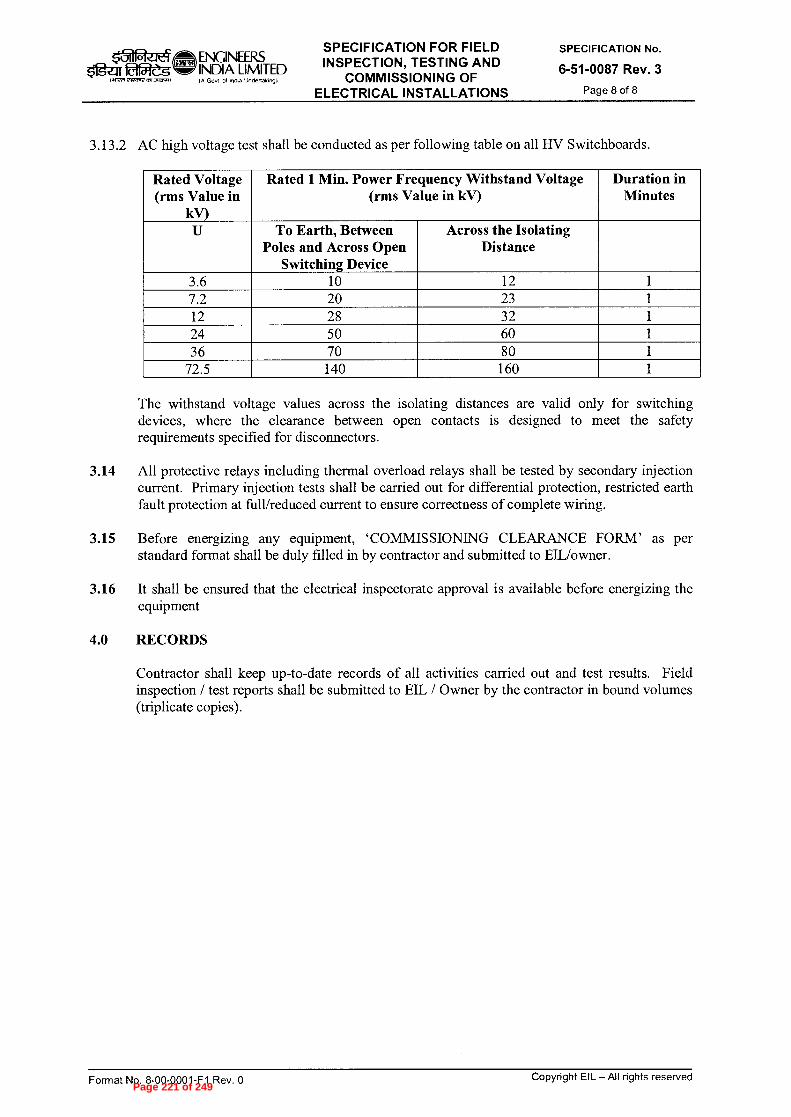
ENGINEERS mar faZ5 INDIA LIMITED
IA Gosn of Intha Undertakog)
SPECIFICATION FOR FIELD INSPECTION, TESTING AND
COMMISSIONING OF ELECTRICAL INSTALLATIONS
SPECIFICATION No.
6-51-0087 Rev. 3
Page 8 of 8 l aiWn 23~ ag,o.)
3.13.2 AC high voltage test shall be conducted as per following table on all HV Switchboards.
Rated Voltage (rms Value in
kV)
Rated 1 Min. Power Frequency Withstand Voltage (rms Value in kV)
Duration in Minutes
U To Earth, Between Poles and Across Open
Switching Device
Across the Isolating Distance
3.6 10 12 1 7.2 20 23 1 12 28 32 1 24 50 60 1 36 70 80 1
72.5 140 160 1
The withstand voltage values across the isolating distances are valid only for switching devices, where the clearance between open contacts is designed to meet the safety requirements specified for disconnectors.
3.14 All protective relays including thermal overload relays shall be tested by secondary injection current. Primary injection tests shall be carried out for differential protection, restricted earth fault protection at full/reduced current to ensure correctness of complete wiring.
3.15 Before energizing any equipment, `COMMISSIONING CLEARANCE FORM' as per standard format shall be duly filled in by contractor and submitted to EIL/owner.
3.16 It shall be ensured that the electrical inspectorate approval is available before energizing the equipment
4.0 RECORDS
Contractor shall keep up-to-date records of all activities carried out and test results. Field inspection / test reports shall be submitted to EIL / Owner by the contractor in bound volumes (triplicate copies).
Format No. 8-00-0001-F1 Rev. 0
Copyright EIL — All rights reserved Page 221 of 249

ZOOZ't,0'0£ uo4ewawaidw! 10} panssi
G)
0 'Aat,I Ld-L000-00-8 '0N leiwod
Copyright EIL — All rights reserved
Aq peAwddv
aanIWW00
NOILVDIAIDadS
ül
O
rs.) O
panssmj pue pas!Aau
G)
cn
c)
L00•60'8Z panss!aj pue pas!Aau
O
c-)
37
Pag
e 22
2 o
f 24
9

0 lted Ld-1000-00-8 "oN Tewiod
Copyright EIL —All rights reserved
STANDARD SPECIFICATION NO.
DD
CfQ 0
•
Aall 1001-18-9
4 p, z -,
>
ro
cr
r-,
,-ri
tri
c z -1
o
5
.-=
-.
tTi
P;
-1
=
o
4-
n'-r
1 ...
.. cA
o
> o
n
rii
4
CD
a,
QD
CD
'•
'-t
QD
`''' •
c:,
92. ...
E r" '' '' '' '' '' ''' Z
Z
"1
-ri
'-r
1 tri
t5
Innc
-)(-
)1,:,
›-t:
›-
....
E
Fi),- a
,- cc)
Cf0
ci)
-̀C c
i = j
i 3 i
),'-'
E C-
I ' ‘-
• 9
R )
6D
( .1)
'"-
" —
».c
, -0
a ''''
g
c . )
• " 7
Dr)
7. )
cut : , . :
a . g , ;
g _
.: .5. gc
r ...L2, - CD
, ,)
c. -7,• -
' : 6-
-6' -
o
■-c, o
'-d
.-:
,,,
o
"'-.
til
■-■
$=0 o
o
o
-' >
eD
-ci g
; -,
-•
-•
coe'
o
o
,(-tt-'
ii)' ;=
,'
o ,--
, :....,
,, . o-
,-. :,,,. .• o
o
-1
c,
(CD
') c)
o o
. (1)
c "
's (1
) H
'<:,-
<
a..
c" ::3
rr
l -.
4
-,L=3,--
- rr,
" ....---.
f:2-
,2.,
ji),
,-,
< C
D 0
CD
CD
C7)
eD P
o $:,)
CD
,..,'-' •
(D ,.
...
<1)
cfc
? "
FD,
0 =
',1 ~
tC) H
(1)
(/)
,-, (/
) CD
0
e. •
O
H
CD
c,
.-1 (
-) -
CD
f:)
.•
p e
s
cn
CD
,--F
cm
u,
■-1-
■-■.,
" C
/D
CA
`''' •
',/
,' o-'
'-d
c>" ,_
,
-,-
,-, (
. cn
co
a -
c5
::,, -
, ›<
c,...
. o
eD
,, c
l c)
<
clo
('-')
r'
,_.
.--,
—
o-
o
5-i `"•-
+ o
',:5
-1
c'o
s:, )o
,,
o
4
00
fC) C
l..
0
er,
r),")
r ••
n (*
Cf
Q g
° •G
,--
t 0 1
:' r---
- 1=D
CD
P3
5
o c
r
tri
:,)
(-)
'<-5- o
'-r1
cn
.-1
.-I
C7
0
co
(-
) o
a.
6'
zt
CDt•
'"C-D •
co
cp
s:0
'CA"
rn
e)
ci)
rri
..c
44
b"
o-
o
,. ,z-i•
d
cp
to
'-cs lw
E.
C.)
'-''
15-.
= c
'g
r- ›-
ci
p)
cr
',2:.,
ii
o.
cp
n
<,H
,HcJ
to'-o
'-o.ri,z
i' -o-o
zzz4
4 4
4
,H -
0 n
n <
4
o
o H
(I)
0
4H
`)
n
tri ^-•
o 1-d
C)
C
H '-
3zJ ,o
'-c .c1
'.t i-c
i '.-L
'-oz z
z 4
4
44
O
CD
(I)
CD
z...
„-■ CD
pp
o o
o
.-1 C
D
pD o
(-c
, CD
AD
?,
,, ,-
. ,-
, f=
1.. '-1
Q't
• ,̀.2
, cl s
:ND
."-.1"' '''' •
" °
zt
'"--1- ;
:d. o ,--
, '''' ''''
o.. c
o ;=0
o.,
,..
..,
o'-'
..7.•
--..,
,...,,
';' {-1
; o "
'c
i; i't,
r)
CIQ
t--, -,
...,
_... up
. ■-c
l ',,,
,' (7
C?
,....
<-,
< .
r2
=L
, '.6.
"
ct,
d ,':•_L
,.,
n „
'-
'.-1
e., C
D
4.
o
H
»t
-. ■-•
•) eD
f0
-c:
f 1:
).• .-
'') ,..
) o
" c
i) 5
' - -
, " (
"(') a
c)
o >
< 0
.• o
,-,
- ..
.,
cg g
+'
dd %
_ a,
,..
, -.
• c./
) t-,
,....
.• .-
" -
CD
p.,,
..,, 1
.■•
et o (
•-,
CD
et
CD
rb'''
'"'t
o
6:
). CD
QD
1.1
- . r
- cp
,-.
',c-;,"'
• e
. • ,—
, re.
0
r) C
D o
nr)
g b
---
v,
=',..)
- H
,-,-. r
-'its
H (
1-) '-<
-t o c
) cro
r)
..sd,
cs-
cr
, (4
,':
-I•
— o
.' s.:"
.h c
i, ,-,
- CD
fZ)..
›'-'
'''''•
C) '
-'•
til
o ,
-,,
r--t r
2
o
,.. f=
1-
0 $
:\ )
<
CD
`-'
=c) ,.:
h'-
'.
eD
sH
,..t.
a ,-
/ CD
6."'
-' cm
-
CD
re
CD
4
`
v,
o
,_ .-
-r C
) e
r
0
(!•)•
c4
'-<
,C
) rD
cp "
o
•.-
1,)
"'' 5
. a7
CfQ >
C)
›:) (I)
■-n
o CfQ
(1)
cp
,-..,,
■-n
:L,
CfQ
CD
.-- •
C)
=
er
(-)
cD
n
5. o o o
(-D ,-
,-.
‘<
o
a ,
. CD"
QD
0
,--S
(c)
0
QD
UD
O
Cr) •
O
Pag
e 22
3 o
f 24
9

0 7\92:1 L3-1,000-00-9 '0N 4eLwoj
Copyright EIL — All rights reserved
3.0 INSPECTION AND TEST REQUIREMENTS:
PO/PR/ Standards referred there in/Job specifications/Approved documents.
O
This Inspection and Test Plan covers the minimum testing requirements of indoor, draw out type High Voltage Switchboards up to and including 33 KV.
:adODS O'I
.nall 1001-18-9
STANDARD SPECIFICATION NO.
(.‘J
IN.)
ts.)
0
l•—■
0
7.
W
0
In process Inspection
Incoming Material like Insulators, Bus Bars,
Fabricated items, Bus Bar sleeves , Cable wire(FR), instrument transformers ,
Relays, Indicating Instruments, Switches,
Breakers, Vacuum Bottles etc
Material Inspection
Procedures
STAGE/ ACTIVITY
Visual, Dimensional, Operational checks, Review of Manufacturer's Certificates etc. as
applicable
CHARACTERISTICS
■—■
CD
:
QUANTUM OF CHECK
H
H
CD
H
co
C I 1
■—
# CD
--
„,
C)
0 D
eE
' CD
.—
t c",
v)
0
C)
C1.,
v)
CD
,—t
C)
r3.
cn
. pp cr
'
1
SUB SUPPLIER
SCOPE OF INSPECTION
SUPPLIER
7ci
:
ri1
■—■
■.-3
id
›-~
Pag
e 22
4 o
f 24
9

0 "nal{ Ld-1.000-00-9 "oN lewiod patuasaJ IIV —113 400doo
rM c z
o rM
STANDARD SPECIFICATION NO. 1-
-, 0
(..,)
I \ )
(....)
.,—`
C,)
0 t
'l
•
CA
'--')
Cfg CD
r20
"
C/)
CD 5 cr
,..
Final Inspection
Wiring checks
Breaker Truck Assembly
STAGE/ ACTIVITY
ACCEPTANCE TESTS:
•
Visual check including layout, Tag plates, Paint shade, Bus marking and sleeving, Joint shrouding, Identification and location of components etc
•
Dimension check including operational height, Bus bar size, Clearances, Creepage distances, Compartmentalization, cable gland size, Paint thickness etc.
•
Verification of Bus bar support arrangement with respect to type tested panel drawings and provision for external cable termination.
•
Bill of material check.
Size, termination, ferruling, continuity
•
Mechanical Operation including spring charging mechanism, Breaker opening / closing at normal and worst voltage conditions, Opening / closing time and simultaneous closing of all poles, Contact resistance measurement, Gas leakage check (for SF6 breakers), Power Frequency Test.
e1 :
e)
-.3
rM
-.3 ,-, n
--
o
©
c'
,--
o
o
(:,='
cr)
tri ;2
—
c,
,-
-.1 r-' c
l, H
° 5
' .0
5 -
: ° cr
`-<
ct
.
QUANTUM OF CHECK
,-1
'4' ■-■
n)
co
up
cn
>li
CA
CD
eD
c)
0
c5
'0
n
scl.
0
cn
a
---
Suppliers Test Records
■-3
(,,7_, , . . i
c 'i)
cn
'Ci
Cn
CD
rD
c
) r
/—
.0
c)
c::,_
0
cn
■-t
Cl.
---
r)
i 1
.
SUB SUPPLIER
SCOPE OF INSPECTION
SUPPLIER t.1
--1
1-0
i....1
Pag
e 22
5 o
f 24
9

0 AG21 L3-1000-00-9 'oN
IDGAJ8Sal S41.1öp ily - ii3 ;460doo
11 STANDARD SPECIFICATION NO.
ro
CfQ tft
-I=•
i•-)
c4
CD
Switchgear Assembly
C/)
,-r-
(-)
,—, n
cic? o
,
E: ›
. •:-
.., c
n cn
CD
Cr
STAGE/ ACTIVITY
TYPE TESTS:
•
Short time current withstand test
•
Temperature Rise test.
• .
.
. .
•
,.. "
" - z c
Ê ,-,:
, .--,
4
_,,, —
CD
(-)
(1)
(')
.-
.P c
o 5-
-t O.
s>,>
-, c
x,
o
94 ›
...-6T
) c'D
cL
,
a. s=
0 '-'
"
.-- .
0
o
pp
'-' .
C)
71
°
C
'-i
a') '
-°
rp
C>
cn
'—: .
-C
(1)
:::i .
,-1
;
(1)
'ic:i
(D
(--)
cc,
• 9:
..
. $:,)
5
$:D
• <-
, . ,--■
• cp
»,, .
,3
0) ,:5
•■-t
...
• ,--
(„0
`-<
0, °
w.,`' <
-4,c/'
'c.$ c
r-9:
9 8
) o
c>
o
,H
, -:-
CD
O
" "
'•
cD
•-•
0•
Cl.,
<
cr'
c>
;»
oL.
-....
ct>
-• ,
-,-
cn
c")
c>
0
CD
CD
Cr
:=,s
,-,
,-t,
,-,
C)
.(7) •
4e• n)
FL>
, ,,,,
c)
°
,-,-
,::,
o
o
,-,.
c>
.-n •-
•.,
'" 4
z-
;:,,
—•
<,
-,- c
m
co
-,a
Q.,
,-1
o
0
.--"
C ,.
., ,4
0)
_, . . „c> . ;Th
. , .( 1 )
(..Ds •
0-'
'- °
0)
. ..-t
,-1
.---
, CA
c-7
,.5
o
:,,
o
o
o
co
r4
':',-
6;-..'
oL..
.-o
{PD
°
-cs
Ci0
-•-
:,>
='
o
o
,-t
...•
i=■ '"-
: 1DD
,-+
•
c>
P>
-,
-•
elD
cn
• c>
., ,„,
r:,,
• fD,)
(1)
i
CD
CD
Cr
0)
c)
2• 2
.- '0
="
cp
,..„, ‘-
n
o-
‘.<
.,;•
• r, o
co
cn
c-n". s
'I''
'''
e)
L■!«.) .
,-,
,.,-,
_.
*
+'. 0, .,
0
Cir0
0D
0
.
C.
v)
C.. '
---
?).'
.
.
hi
C5 ''
'o
,--,
,-,.
.7-''.
C/)
. C)
0D
E5
Q
., 0
P
,> c>
CD
><
o
CD
.-"
$SD
'-h
,-t
o
•-.<
•-1
o
o'-')
o
s:»
,..., "
$:,,
..2 •
o -
- .
E7>
co
..) -•
■
- .--
9+
2,
,,
CD
•
2-
.
rp .-t
°
cA
-,--.
°
0-'
o
..,i
CD
,-,.
6-
,...,
o
■-t
C4
CN
. .
co
F)■-
sc>,>.,
,.,,_ •
c>
o
,....
FL
=
'-') tr
cr
cp
CD
CD
CL.
r>0
,c).,
cr
-9
:=':
po
Cf' •
• .'t
-x--
o
c
-•-)
,-,-
, ,
o
•-4,
›.'
cr
c),_,
rt,'"
'"
s>0
co
'4 "
ci>
Cil
cp
• 5
cr
5
CHARACTERISTICS
Sample Basis
■—■
C)
CD
c'''
QUANTUM OF CHECK
Test Agency Reports
,-1
"" •
■••-■
CD
ro
cn
cr, '
"1:3
X
C/D
CD
eD
c>
r,
ocL
, .-I
cn
O
. s"--
r)
C
i 1
SUB SUPPLIER
SCOPE OF INSPECTION
*
SUPPLIER
* *
M
.1:1
~
Pag
e 22
6 o
f 24
9
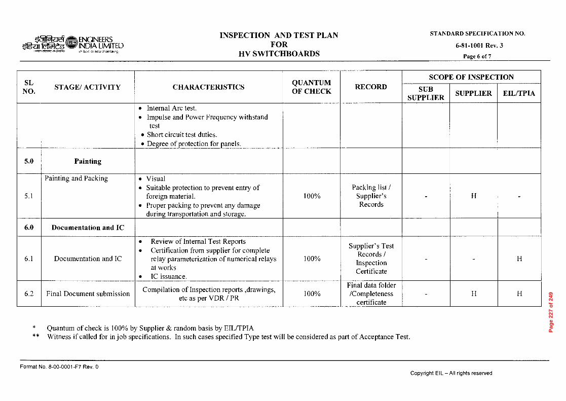
0 'Ae2:1 L3-1000-00-9 '0N eW.103 pamesai s4q6!-I IIV —113 41.160doo
STANDARD SPECIFICATION NO.
£ 'Aall 1001-18-9
o■
i\.)
o, __,
cr■
7::::,
t.,
.-
cri
7:=
z v
) 0
C''
Final Document submission
Documentation and IC
Documentation and IC
Painting and Packing
Painting
STAGE/ ACTIVITY
Compilation of Inspection reports ,drawings, etc as per VDR / PR
•
Review of Internal Test Reports
• Certification from supplier for complete relay parameterization of numerical relays at works
•
IC issuance.
•
Visual
•
Suitable protection to prevent entry of foreign material.
•
Proper packing to prevent any damage during transportation and storage.
•
Internal Arc test.
•
Impulse and Power Frequency withstand test
•
Short circuit test duties.
•
Degree of protection for panels.
CHARACTERISTICS
c)
%00 I
c>
QUANTUM OF CHECK
Final data folder /Completeness
certificate
Supplier's Test Records / Inspection Certificate
Packing list / Supplier' s Records
o g
SUB SUPPLIER
SCOPE OF INSPECTION
z
z
SUPPLIER
z z
,-, r ri:
Pag
e 22
7 o
f 24
9

0 'ned L3-1000-00-8 '0N ew.iod Pemesoi s11-161.1 11V —113 41-160d00
STANDARD SPECIFICATION NO.
£*ita2i I001-18-9
t...) 0
-3 Z
r,
5-
0
r>
CD ',-
„- •
-- .
C,i
2-
C)
CA
c
cc,
o,___
, CIA
et
=,
v,
•
c
v>
-cs
r>
•-n 0
-t.
o
.--:
c
CD
s>,>
- 9
zt
5-
ro
CI
ZI
AD
CD
C
) ,-.
4.
CD.-
<
.--:
,-4
-. ?"'>
' F
D ci)
C7
ci)
("D
■–f-
•
.–$
rà,
.—.
.C)
Cr
cp
'41'
co
s:»
cf)
'ts
ro
ro
c
O
)
• `-<
1--ND
Cl.,
Cl.,
Cl)
0
•
...
AD
Cl.
IDD
.-t
C)..
.-
r.
cn
CD
CD
o
,-,-
-s
..-1
Ct.--:
—.
CD .
st
co
CD
C)
.-I
CD
0
...
.«..
cn
c->
o
o
'ts
cr
co
cn
r:
4;
ro
cn
o
'ts
,...
cp
ri's
r>
..4-
• c.
cn 5...;
CD
Pag
e 22
8 o
f 24
9

Page 229 of 249

Page 230 of 249

Page 231 of 249

Page 232 of 249

Page 233 of 249

Page 234 of 249

Page 235 of 249

Page 236 of 249

Page 237 of 249

Page 238 of 249
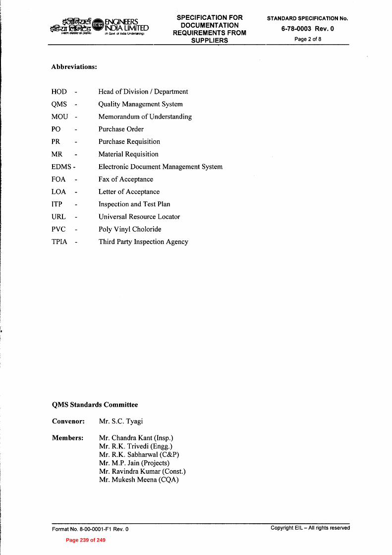
Page 239 of 249

Page 240 of 249

Page 241 of 249

Page 242 of 249

Page 243 of 249
Page 244 of 249

Page 245 of 249

Page 246 of 249
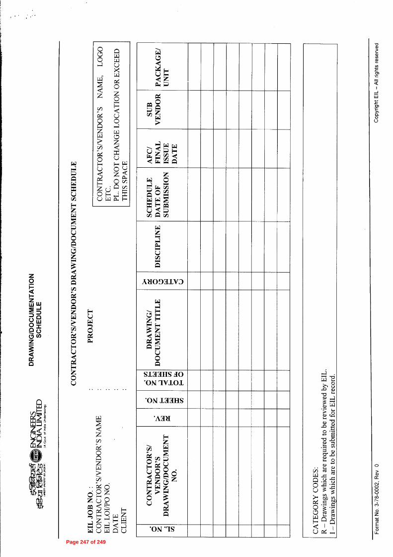
Page 247 of 249

Page 248 of 249

Page 249 of 249