T 1000 PLUS INTRODUCTORY GUIDE - Userequip.
108
DATE: 27/11/2011 DOC.MIE92093 REV. 1.35 T 1000 PLUS INTRODUCTORY GUIDE
-
Upload
khangminh22 -
Category
Documents
-
view
0 -
download
0
Transcript of T 1000 PLUS INTRODUCTORY GUIDE - Userequip.

DATE: 27/11/2011
DOC.MIE92093 REV. 1.35
T 1000 PLUS INTRODUCTORY GUIDE

DOC. MIE92093 Rev. 1.34 Page 2 of 108
REVISIONS SUMMARY VISA
N PAGE DATE
1 All 20/10/2008 Issued Lodi
1.28 26 2/02/2010 Added the paragraph
test results handling
Lodi
1.28
-1
17, 37 1/10/2010
Added the TD1000
model and the 15 Hz
Lodi
1.34 11 –13;
41
7/9/2011 Revised to issue 1.34;
removed the serial
I/F
Lodi
1.35 39 27/11/2011 Added the FT1000
connection
Lodi

DOC. MIE92093 Rev. 1.34 Page 3 of 108
SHORT FOREWORD ...................................................................................... 5
INTRODUCTION ............................................................................................. 6
1 TEST SET EXPLANATION ...................................................................... 9
1.1 CONNECTION TO THE RELAY AND POWER-ON ........................................... 9 1.2 TEST CONTROL .......................................................................................... 10 1.3 CURRENT GENERATION ............................................................................. 14 1.4 AC VOLTAGE GENERATION FROM MAIN OUTPUT ..................................... 18 1.5 DC VOLTAGE GENERATION FROM MAIN OUTPUT .................................... 18 1.6 AC VOLTAGE GENERATION FROM THE AUXILIARY OUTPUT..................... 19 1.7 DC VOLTAGE GENERATION FROM THE AUXILIARY OUTPUT .................... 23 1.8 AUXILIARY CONTACTS .............................................................................. 24 1.9 THE TIMER ................................................................................................. 24 1.10 FINDING RELAY THRESHOLDS ................................................................ 26
1.10.1. Introduction ........................................................................ 26 1.10.2. First threshold trip and drop-off ............................... 27 1.10.3. Second threshold trip and drop-off......................... 28
1.11 FINDING RELAY TIMINGS ....................................................................... 28 1.12 TEST RESULTS HANDLING ...................................................................... 30 1.13 BASIC TEST PRINCIPLES ........................................................................ 32
1.13.1. Introduction .......................................................................... 32 1.13.2. Parameter vs. time characteristic ........................... 33 1.13.3. Parameter vs. parameter characteristic .............. 34
1.14 USE OF THE TEST SET AS A MULTIMETER ............................................. 37 1.15 TD1000 MODEL: AC CURRENT GENERATION FROM THE AUXILIARY
OUTPUT .............................................................................................................. 39 1.16 FILTERING HEAVY BURDEN DISTORTION WITH THE FT1000 OPTION 40
2 TEST SET AND POP-UP MENU .......................................................... 42
2.1 THE FRONT PANEL ..................................................................................... 42 2.2 DISPLAY AND CONTROL LIGHTS ............................................................... 44 2.3 THE POP-UP MENU .................................................................................... 45
3 WHAT’S INSIDE? .................................................................................... 61
3.1 PHYSICAL DESCRIPTION ........................................................................... 61 3.2 DETAILED FUNCTION DESCRIPTION ......................................................... 65
3.2.1 Main auxiliary transformer, XTF10330 (3) ............. 65 3.2.2 Auxiliary transformer, XTF10245 (4) ........................ 66 3.2.3 Main output transformer, XTF10345 (5) ................. 68 3.2.4 Main front board PWA11398 (17)................................ 68 3.2.5 MISU T1000 board PWA11402 (26) ........................... 68

DOC. MIE92093 Rev. 1.34 Page 4 of 108
3.2.6 CONV T1000 board PWA11401 (16)........................... 69 3.2.7 INTE ON-OFF T 1000 board PWA11400 (7) ........... 70 3.2.8 MICR T 1000 board PWA41300 (15) .......................... 70 3.2.9 AP-50 AC Voltage board PWA11396 (10) ............... 70 3.2.10 Protection fuses ................................................................... 70 3.2.11 Connectors summary ........................................................ 71
4 THE HELL, IT DOESN’T WORK ......................................................... 73
4.1 INTRODUCTION ......................................................................................... 73 4.2 ERROR MESSAGES .................................................................................... 74 4.3 TROUBLE SHOOTING ................................................................................. 76
4.3.1 Auxiliary supplies .................................................................. 79 4.3.2 No power at power-on ........................................................ 79
4.4 AUXILIARY DC VOLTAGE FAULT ..................................................... 80 4.5 AUXILIARY AC VOLTAGE FAULT ............................................................... 83 4.6 NO OUTPUT FROM THE MAIN CURRENT AND VOLTAGE ........................... 84 4.7 DOES NOT MEASURE THE MAIN CURRENT ............................................... 85 4.8 THE BACKLIGHT OR THE DISPLAY DOES NOT OPERATE .......................... 85 4.9 THE AC VOLTAGE MEASUREMENT IS NOT STABLE .................................. 88 4.10 THE TRIP INPUT IS NOT DETECTED OR TIMING ERROR ........................ 88 4.11 PROBLEMS DURING UPGRADE ................................................................ 90 4.12 THE ENCODER IS BROKEN ...................................................................... 91 4.13 THE THERMAL ALARM DOES NOT DISAPPEAR ........................................ 92 4.14 AN AUXILIARY SWITCH DOES NOT OPERATE......................................... 92 4.15 THE FAULT CANNOT BE FIXED ................................................................ 93 4.16 CALIBRATION .......................................................................................... 96
4.16.1 Introduction .......................................................................... 96 4.16.2 Calibration procedure ..................................................... 96 4.16.3 T 1000 PLUS output calibration ................................ 97 4.16.4 T 1000 PLUS external meas. calibration .............. 99 4.16.5 Phase angle measurement calibration ................ 100
APPENDIX 1 SPARE PARTS LIST ..................................................... 105
APPENDIX 2: MENU SELECTIONS FLUX DIAGRAM ................ 108

DOC. MIE92093 Rev. 1.34 Page 5 of 108
SHORT FOREWORD
Dear T 1000 PLUS user,
I often wondered why the user’s manual is not very much used,
even if it includes valuable information. As me too I am a user of
such manuals, the answer I have given myself is that valuable
information are concealed somewhere in the thick thing, and I do
not have time to waste to find it. So, either the manual is actually
of help, or I ignore it.
This is why I decided to split the T 1000 PLUS manual in three:
specification, with all performance details; application manual,
with instructions about how to use it one its operation is
understood; introductory guide, with the device description and
basic information. The idea is that you may read once the
introductory guide or the specification, while you need to follow
application examples more than once; so, why not to split the
manual in three?
Have a good work with T 1000 PLUS!
Primo Lodi
Q&A Manager

DOC. MIE92093 Rev. 1.34 Page 6 of 108
INTRODUCTION
The single phase relay test set mod. T 1000 PLUS is suited for the
testing and adjustments of the following types of relays; the table
lists also the paragraph that explains the test procedure.
Type of relay IEEE code PARAGRAPH
- Distance* 21 1.12
- Synchronizing 25 1.8
- Over/under-voltage 27 - 59 1.2
- Power, varmetric or wattmetric 32 - 92 1.4
- Under current 37 1.1
- Loss of field 40 1.10
- Reverse phase current 46 1.4
- Instantaneous overcurrent 50 1.1
- Ground fault 50N 1.1
- Timed overcurrent 51 1.1
- Power factor 55 1.4
- Directional overcurrent 67 1.5
- Directional ground fault 67N 1.5
- Automatic reclose 79 1.11
- DC voltage 80 1.3
- Frequency 81 1.6
- Frequency rate of change 81 1.7
- Motor protection 86 1.1
- Differential ** 87 1.1
- Directional voltage 91 1.5
- Tripping relay 94 1.9
- Voltage regulation 1.2
- Thermal 1.1
- Timers 1.9
* For distance relays three T 1000 PLUS are necessary.
** Differential starter circuit
In addition to the above, T 1000 PLUS can test:
. Converters: V; I; φ°; p.f.; W; VAr; f., both 0 to 5 and 4 to 20
mA.
. Energy meters, single phase or three phase.

DOC. MIE92093 Rev. 1.34 Page 7 of 108
The instrument contains three separate generators:
. Main generator, which generates either AC current, AC voltage;
DC voltage;
. Auxiliary a.c voltage generator, that generates an independent,
phase shifting a.c voltage;
. Auxiliary DC voltage generator, that generates the DC voltage
that feeds the relay under test.
All outputs are adjustable and metered at the meantime on the
large, graphic LCD display. With the multi-purpose knob and the
LCD display it is possible to enter the MENU mode that allows
setting many functions, which make T 1000 PLUS a very powerful
testing device, with manual and semi-automatic testing
capabilities, and with the possibility to transfer test results to a
PC via the USB interface. These results can be recorded,
displayed and analyzed by the powerful TDMS software, which
operates with all WINDOWS versions, and allows creating a data
base of all tests in the plant.
The basic T 1000 PLUS function is to generate current and
voltages and to stop generation as the relay trips. Test results are
kept in memory, and can be transferred to a PC at a later time,
along with settings.
The ease of operation has been the first goal of T 1000 PLUS: this
is why the LCD is graphic, and so large. With it, the dialogue in
MENU mode is made easy. Besides, all T 1000 PLUS outputs are
continuously measured, and output values are displayed, with no
extra effort to the operator. Also the show waveform feature can
be of help: any doubt about strange measurements, distortion
and so on can be solved.
This is also why we have added the reduced power feature.
Modern relays have a very low burden. As current output is a low
impedance voltage generator, adjusting low currents and/or
current on low burdens is quite difficult because one has to
operate at the very beginning of the adjustment knob. In this
situation it is possible to connect resistors in series; however, one
must be careful not to exceed the maximum current rating, and
the wiring is more complicated. The solution to this problem is
just to reduce the available power: this is easily performed via

DOC. MIE92093 Rev. 1.34 Page 8 of 108
the multi-function knob. With less power, the maximum voltage is
reduced by a factor of 4.4; the adjustment span on the knob is
increased accordingly.
Additional features are:
. Two meters, current and voltage, with independent inputs, allow
measuring T 1000 PLUS outputs or any other source;
. Two auxiliary contacts, that allow simulating the circuit breaker;
. A set of resistors allows easing output adjustment.
The instrument is housed in a transportable aluminum box, that
is provided with removable cover and handles for ease of
transportation.
NOTE: WINDOWS is a trademark of MICROSOFT inc.

DOC. MIE92093 Rev. 1.34 Page 9 of 108
1 TEST SET EXPLANATION
1.1 CONNECTION TO THE RELAY AND POWER-ON
At first, be sure that the main control knob (6) is turned (rotated)
to the zero position (complete counter-clockwise). The reason is
that the current generator is actually a high current voltage
generator. If the output is connected to the load (typically low
impedance), as soon as the test is started, a very high current
can circulate in the circuit.
Next connect the mains supply cable to the instrument and then
to the supply. THE SUPPLY VOLTAGE MUST BE THE SAME AS
INDICATED ON THE PLATE.
Power-on T 1000 PLUS: a diagnostic sequence controls:
. Key microprocessor board components;
. Auxiliary supply voltages.
If something is wrong, the operator is alerted by a message.
At the end of it, default selections are active; T 1000 PLUS is in
the OFF state.
Perform the first selections, according to the type of relay to be
tested:
. Main output socket, acting on the selector push-button (57).
. Auxiliary AC voltage: range; type of generation; value. NOTE: to
perform the range selection, the output must be ON, and the
value reduced to the minimum.
. Auxiliary DC voltage: range; value. NOTE: to perform the range
selection, the output must be ON, and the value reduced to the
minimum.
. Start and Stop timer inputs.
Connect the relay to be tested to the output sockets that have
the indication light (LED) on.
The following is the list of protections that avoid damaging T 1000
PLUS in case of errors.

DOC. MIE92093 Rev. 1.34 Page 10 of 108
. Fuse on the mains supply.
. Thermal NTC sensor on the main and auxiliary transformers. In
case of over-temperature, an alarm message is displayed.
. Thermal sensors on the SCR that controls current injection, and
of the internal temperature. In case of over-temperature, an
alarm message is displayed.
1.2 TEST CONTROL
The T 1000 PLUS front panel is explained in next paragraph.
T 1000 PLUS generation is controlled by the two keys < (55) and
> (56).
Settings and menu selections are controlled by the multi-function
knob with switch (22): see next paragraph for menu selections
description. At power-on T 1000 PLUS generation is OFF, as
confirmed by LED (50). The ON selection serves for finding relay
thresholds; selections ON+TIME and OFF+TIME serve to measure
relay timing.
The following flow diagram summarises all available test control
selections.
The performance of T 1000 PLUS in Normal Test mode is the
following.
. OFF: main outputs are not generated; Vac aux is generated,
and it can be either the pre-fault value or the fault value,
DOC. MIE92093 Rev. 1.34 Page 11 of 108
according to selections; Vdc aux is generated. In this condition,
any trip of Stop input is ignored.
. ON: timer starts; main outputs are generated; Vac aux has the
fault value; Vdc aux does not change. In this situation any trip at
Stop input is detected; it is possible to verify and memorize the
relay threshold, both trip and reset. As the relay trips, the TRIP
LED (43) turns on for 5 seconds; during 5 seconds, parameters at
trip are displayed; then, the standard measurement is restored.
Test results can be saved according to Save selections.
. From OFF to ON + TIME: main outputs are generated and the
timer starts according to selections; as Stop trips or resets, T
1000 PLUS returns to OFF, the TRIP LED (43) turns on and
parameters at trip are displayed until ON or ON+TIME are
selected. Test results can be saved according to Save selections.
. From ON to OFF + TIME: main outputs are removed the timer
starts according to selections; as STOP is sensed, T 1000 PLUS
returns OFF, the TRIP LED (43) turns on and parameters at trip
are displayed until ON or ON+TIME are selected. Test results can
be saved according to Save selections.
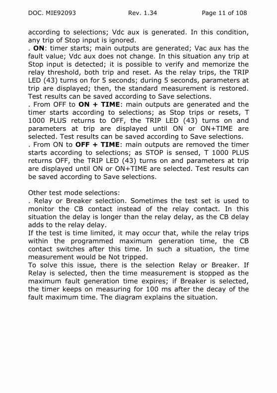
Other test mode selections:
. Relay or Breaker selection. Sometimes the test set is used to
monitor the CB contact instead of the relay contact. In this
situation the delay is longer than the relay delay, as the CB delay
adds to the relay delay.
If the test is time limited, it may occur that, while the relay trips
within the programmed maximum generation time, the CB
contact switches after this time. In such a situation, the time
measurement would be Not tripped.
To solve this issue, there is the selection Relay or Breaker. If
Relay is selected, then the time measurement is stopped as the
maximum fault generation time expires; if Breaker is selected,
the timer keeps on measuring for 100 ms after the decay of the
fault maximum time. The diagram explains the situation.

DOC. MIE92093 Rev. 1.34 Page 12 of 108
. Trip + pulse time: the timer measures the delay and the
duration of the trip impulse.
. Reclose test. It is possible to select via menu the test of a
reclosing scheme. Two selections are available, according to the
type of recloser under test.
In the first operating mode, T1000 PLUS is connected as follows:
Trip command to the STOP input; Reclose command to the START
input. As Reclose is detected, the test set automatically applies
current after the programmable reclaim time delay TD. The test
set measures and stores the relay trip delay, and the delay
between trip leading or falling edge and RECLOSE trailing edge
(see figure 4). The test set waits the close command up to 9999
s.
The sequence is repeated the programmed N times; after this, a
last fault is issued, and the test set verifies that there is no Close
command. On the last fault, the test set waits up to 10 times the
last Close delay before stopping the test.
During this operation, the auxiliary contact A1 can be used to
simulate the CB position: this is mandatory for the test of some
Recloser. The test starts with the CB position Closed; at the end
of the last test, it comes back to Closed.
FAULT
RELAY
CB
MAX TIME
0.1 s
DELAY

DOC. MIE92093 Rev. 1.34 Page 13 of 108
FAULT 1 2
TRIP (STOP) 1 2
RECLOSE 1
(START)
TIME MEAS.
Figure 4: Measure of Delay and Reclose times
The second operating mode refers to pole mounted CB’s. In this
mode, there is only one signal coming from the device under test:
the position of the CB. In this mode, the operation is the
following.
In this test mode the test set is edge triggered; the CB position is
connected to the STOP input, and, from the Closed – Open
position, the test set derives the Start and Stop commands, to
perform the test as above.
Other Fault injection selections:
. Maintained (default):
.. ON mode: fault outputs are generated until OFF is selected.
.. ON+TIME or OFF+TIME: as the STOP input is sensed, T 1000
PLUS returns OFF.
. Momentary: in ON mode, main outputs are generated until the
> push-button is pressed;
OPEN
CLOSED
(START)
(STOP)
D1 R1 D2 R2
TD

DOC. MIE92093 Rev. 1.34 Page 14 of 108
. Timed: in all modes (ON; ON+TIME; OFF+TIME), fault outputs
are generated for the programmed maximum time; after this, T
1000 PLUS returns OFF. Any trip after this time is not sensed.
. External. This mode allows for the synchronization of more T
1000 PLUS: they start generating upon reception of the START
input, that is selected in External mode.
. OFF delay: fault parameters can be maintained for the specified
time after relay trips: this allows simulating the circuit breaker
delay.
Test power selection: it allows reducing the available power; this
increases the adjustment sensitivity for low current tests on low
burden relays.
Save selections:
. No automatic saving.
. Automatic test data saving as relay trips. A pop-up window
confirms the saving and tells the test number.
. Test data can be saved after confirmation. After relay trip,
pressing the multi-function knob the operator can save the test
result.
. Manual test data saving. This selection can be used any time: it
serves if the trip is confirmed by a light and not by a contact.
Auxiliary contacts delays: the switch of the auxiliary contacts can
be timed with respect to test start.
1.3 CURRENT GENERATION
If the following current limits and time duration of main current
outputs are trespassed, the generation is interrupted, and the
operator is warned by an alarm message.

DOC. MIE92093 Rev. 1.34 Page 15 of 108
1) MAXIMUM POWER 300 VA
RANGE A AC
CURR. OUTPUT
A
MAX. POWER
VA
MAX. BURDEN
Ohm
LOAD TIME
s
RECOV. TIME
min
100 30 300 0.33 STEADY -
50 440 0,17 30 min 100
75 600 0.1 600 45
100 750 0.075 60 15
150 900 0.04 3 10
250 1000 0.016 1 5
40 12 300 2 STEADY -
20 450 1.1 30 min 100
30 600 0.66 600 45
40 800 0.5 60 15
60 900 0.25 3 10
80 1000 0.15 1 5
10 5 400 16 STEADY -
7.5 600 10 15 min 45
10 800 8 60 15
15 900 4 5 10
20 1000 2.5 2 5
NOTE: if the current generation lasts less than the maximum
value, the recovery time is proportionally reduced. For instance, if
you tested at 100 A during 6 s, the test set will pause during 1.5
min, or 90 s.
The following table shows the values of the current sunk from the
supply.
RANGE
A AC
CURR.
OUTPUT A
SUPPLY
CURR. @ 230 V
A
SUPPLY
CURR. @ 115 V
A
100 30 1.5 3
50 2.5 5
75 3.7 7.4
100 5 10
150 7.5 15
250 12.3 N.A.

DOC. MIE92093 Rev. 1.34 Page 16 of 108
40 12 1.6 3.2
20 2.6 5.2
30 4 8
40 5.2 10.4
60 7.8 15.6
80 10.5 N.A.
10 5 2.2 4.4
7.5 3.3 6.6
10 4.4 8.8
15 6.6 13.2
20 8.8 N.A.
NOTE: with the supply of 115 V, the current sunk at maximum
current outputs is too high; so, these outputs are not available.
2) MAXIMUM POWER 60 VA
RANGE
A AC
CURRENT
OUTPUT
A
MAXIMUM
POWER
VA
LOAD
TIME
s
RECOVERY
TIME
min
100 30 60 STEADY -
38 10 min 45
53 60 10
70 0.75 2
40 12 60 STEADY -
17 10 min 45
23 60 10
36 1 2
10 5 60 STEADY -
6 10 min 45
7 60 2
10 1,5 2
This generator serves for the test of current, power, directional,
distance relays, where current or current and voltage are
necessary. The procedure is the following.
. At first, be sure that the main control knob (6) is turned
(rotated) to the zero position (complete counter-clockwise).
. Power-on T 1000 PLUS.

DOC. MIE92093 Rev. 1.34 Page 17 of 108
. Select by the push-button (57) the measurement on the desired
output sockets (13), according to the maximum current to be
generated: the LED turns on; the AC voltage value is displayed.
. Connect the relay to be tested to sockets (13). Consider that for
tests of 40 A up it is necessary to connect the relay by a wire
having at least a cross section of 10 sq. mm; for lower currents, a
cross section of 2.5 sq. mm can be used.
. Press ON and adjust the output current to the desired value with
knob (6).
. After you have started the test, if the burden is a short circuit
made of a short cable, you measure at zero knob position a
current that usually is less than 3% of the range. This value does
not influence at all the measurement of the current you are
generating: it is not an error of the measurement
instrument. If the current is a problem, select the 60 VA power,
and/or connect resistors in series.
. There are two more possible problems: the desired current
cannot be reached; the adjustment is difficult because the current
is reached too easily.
.. If it is impossible to reach the desired value, this is because the
burden is too high. Very often the problem comes from
connection wires; so, to perform the test it is necessary either to
shorten them, or to increase the cross section (or both).
.. If the adjustment is reached within 1/5th of the knob rotation,
then it is possible to increase the ease of adjustment by reducing
the test power as follows.
TEST CONTROL > TEST POWER (Power) ESC
.. It is also possible to increase the ease of adjustment by
connecting a resistor of the set in series to the relay. Resistors
are rated 50 W; so, compute the resistance value as follows:
(RESISTANCE) = 50 / (TEST CURRENT)^2
Maximum test current values are resumed here below.
RESISTANCE 0.5 1 22 470 1000 2200
MAX ITEST 10 7 1.5 0.3 0.2 0.15
Note that the test starts and stops as the current passes the zero.

DOC. MIE92093 Rev. 1.34 Page 18 of 108
1.4 AC VOLTAGE GENERATION FROM MAIN OUTPUT
If the current of 3.5 A is exceeded on main AC voltage output,
the generation is interrupted, and the operator is warned by an
alarm message.
This generator serves for the test of synchronism relays, where
two voltages are necessary. The procedure is the following.
. At first, be sure that the main control knob (6) is turned
(rotated) to the zero position (complete counter-clockwise).
. Power-on T 1000 PLUS.
. Select by the push-button (57) the measurement on output
sockets (60): the LED turns on; the AC voltage value is displayed.
. There are two ranges available: 250 V (full power); 57 V
(reduced power). The default at power-on is full power; if 57 V
are enough, for a better adjustment, reduce the voltage as
follows.
TEST CONTROL > TEST POWER (Power) ESC
. Adjust the output voltage to the desired value with knob (6).
. Connect the relay to be tested to sockets (60). Check that the
adjusted voltage does not drop as you connect the relay; else,
this would mean that T 1000 PLUS is overloaded (or that you are
connecting to a live wire). In this situation, remove the cause of
error and connect again.
1.5 DC VOLTAGE GENERATION FROM MAIN OUTPUT
If the current of 3.5 A is exceeded on main DC voltage output,
the generation is interrupted, and the operator is warned by an
alarm message.
This generator serves for the test of timers and all devices that
are driven by a DC voltage. The auxiliary DC voltage generator
cannot be used to this purpose as it is continuously generated: no
time measurement can be performed. To this purpose, act as
follows.
. At first, be sure that the main control knob (6) is turned
(rotated) to the zero position (complete counter-clockwise).
. Power-on T 1000 PLUS.
DOC. MIE92093 Rev. 1.34 Page 19 of 108
. Select by the push-button (57) the measurement on output
sockets (61): the LED turns on; the DC voltage value is
displayed.
. There are two ranges available: 300 V at 300 W continuous (full
power); 68 V at 60 W continuous (reduced power). The default
at power-on is full power; if necessary, reduce the power as
follows.
TEST CONTROL > TEST POWER (Power) ESC
. Adjust the output voltage to the desired value with knob (6).
. Connect the relay to be tested to sockets (61). Check that the
adjusted voltage does not drop as you connect the relay; else,
this would mean that T 1000 PLUS is overloaded (or that you are
connecting to a live wire). In this situation, remove the cause of
error and connect again.
1.6 AC VOLTAGE GENERATION FROM THE AUXILIARY OUTPUT
The auxiliary AC voltage is used to test relays that need voltage
and current at the meantime. In this situation, the voltage is
continuously generated; usually, it is adjusted to the nominal
value, and it is not changed during all tests. It is possible to
phase shift the current with respect to voltage; selections are the
following.
. Power-on T 1000 PLUS: the output voltage is zero. Press the
push-button (70) to enable or disable the output; when enabled,
light (62) is ON, and the AC voltage value is displayed on the
screen.
. There are three ranges available from 45 Hz up: 65; 130 or 260
V AC; the power is 30 VA continuous; 40 VA peak for 1 minute.
For increased power and accuracy, it is better to select the range
that is closest to the value to be generated. The default at
power-on is 65 V; if necessary, select the desired range.
. At lower frequencies, the maximum output and power
decrease. The table summarizes the situation at 15 Hz and 33.33
Hz.

DOC. MIE92093 Rev. 1.34 Page 20 of 108
RANGE @
50 Hz
VMAX @
15 Hz
POWER @
15 Hz
VMAX @
33.3 Hz
POWER @
33.3 Hz
V V VA@
VOUT
V VA@
VOUT
65 25 8 @ 22.5 V 55 35 @ 55 V
130 50 12 @ 45 V 110 35 @ 110
V
260 100 15 @ 90 V 220 35 @ 220
V
DO NOT EXCEED THE MAXIMUM VOLTAGES OF THE ABOVE
TABLE: THE OUTPUT WOULD BE DISTORTED!
. The operating mode is pre-selected as Fault: do not change it.
Do not change also the pre-selected frequency, as Locked to
mains. Last, set the desired current phase angle; however, to
perform this, T 1000 PLUS must be ON, and some current must
circulate. Selections are performed as follows.
AUX VAC/VDC > Aux Vac control > Range > (Range) RET
Phase > Reference:
current > (Phase) ESC
NOTE: to perform the range selection, the output must be ON
(press push-button (70)), and the value reduced to the minimum,
else the test set alerts to reduce it.
This performed, adjust the voltage to the desired value with knob
(20). Eventually, connect the relay to be tested to sockets (62).
Check that the adjusted voltage does not change or the overload
message pops up as you connect the relay; else, this would mean
that T 1000 PLUS is overloaded (or that you are connecting to a
live wire). In this situation, remove the cause of error and
connect again (reset the alarm if it popped up).
Execute the test, modifying the phase angle as necessary.
This output is also used for the test of voltage relays, frequency
relays, synchronism relays; frequency rate of change relays. In
these instances, it is necessary to use the Pre-fault + Fault
selection. This feature allows adjusting two different values: the

DOC. MIE92093 Rev. 1.34 Page 21 of 108
pre-fault voltage, that simulates the situation prior to fault, and
the fault voltage.
The pre-fault voltage adjustment is performed by the control
knob, while knob (20) adjusts the fault value. Voltage output
selection is automatic: pre-fault voltage with test stopped; fault
voltage with test started. The switch from a value to the other
one is performed without falling to zero. The main current or
voltage is generated at the zero crossing; the fault one is
generated at the meantime of main voltage or current. The
selection of the reference is performed automatically, following
the selection of main output measurement. If the main DC
voltage is selected the reference is taken on the main AC voltage.
The Pre-fault + Fault selection is performed as follows.
AUX VAC/VDC > Aux Vac control > Mode > Pre-fault+Fault
> Pre-fault amplitude ESC
Once the nominal voltage is adjusted to the pre-fault value, it is
possible to change the amplitude (V, SYN relays) or frequency (F,
SYN relays), or angle (SYN relays: in this instance, the angle is
referred to V main rather than to I main) or frequency rate of
change (dF relays) of the fault voltage.
The pre-fault (nominal) frequency is always the mains one; the
fault one is adjusted by the control knob, in the range 40 Hz to
500 Hz. Switching from nominal frequency to fault frequency is
performed without altering the output voltage amplitude and
phase. The frequency adjustment is performed as follows.

DOC. MIE92093 Rev. 1.34 Page 22 of 108
AUX VAC/VDC > Aux Vac control > Frequency > Adjust >
(Frequency value) ESC
The angle adjustment is performed as explained above; the
difference is that the adjustment is applied only when T 1000
PLUS is ON; with the instrument OFF, the pre-fault voltage is
normally in phase with the current. It is also possible to phase
shift the pre-fault voltage with respect to the fault voltage. This
parameter is necessary during the test of distance relays, when
phase to phase faults are simulated: as test starts, the auxiliary
voltage changes amplitude and phase with respect to the pre-
fault value.
The pre-fault angle adjustment is performed as follows.
AUX VAC/VDC > Aux Vac control > Mode > Pre-fault+Fault
> Phase (phase) ESC
This angle is referred to the fault voltage; so, for its adjustment is
not necessary to have T 1000 PLUS ON.
Last, it is possible to test frequency rate of change relays, by
setting both the starting frequency, as before, and the frequency
ROC range, with range from ± 0.01 to ± 99.99 Hz/s. The
frequency change stops at 40 or 70 Hz. The frequency ROC
adjustment is performed as follows.
AUX VAC/VDC > Aux Vac control > Frequency > Adjust >
Frequency ROC (ROC) ESC

DOC. MIE92093 Rev. 1.34 Page 23 of 108
As test starts, the frequency goes to the pre-set frequency, and
from that value starts increasing or decreasing with the pre-set
ROC.
NOTE: The auxiliary AC voltage is protected by an electronic
circuit that stops the voltage generation and opens the
connection to outputs socket in case of overload (short circuit
included). In case of intervention, an alarm message is displayed.
Via the control knob the operator can reset the alarm and close
the relay to restore operation.
The auxiliary AC voltage is also protected by a thermo switch that
intervenes in case of over-heating. In case of intervention, an
alarm message is displayed.
1.7 DC VOLTAGE GENERATION FROM THE AUXILIARY OUTPUT
The second auxiliary generator can be used to supply the
auxiliary DC voltage for the relay to be tested. To this purpose,
the voltage is available at sockets (63), after pressing the push-
button (69). Use this generator as follows.
. Power-on T 1000 PLUS: the output voltage is zero. Press the
push-button (69) to enable or disable the output; when enabled,
light (63) is ON, and the DC voltage value is displayed on the
screen.
. There are two ranges available: 130 or 240 V DC; the power is
90 W. For increased power and accuracy, it is better to select the
range that is closest to the value to be generated. The default at
power-on is 130 V; if necessary, select the desired range as
follows.
AUX VAC/VDC > Aux Vdc control > (Range) ESC
NOTE: to perform the range selection, the output must be ON
(press push-button (69)), and the value reduced to the minimum,
else the test set alerts to reduce it.
This performed, adjust the voltage to the desired value.
Eventually, connect the relay to be tested to sockets (63). Check
that the adjusted voltage does not change as you connect the

DOC. MIE92093 Rev. 1.34 Page 24 of 108
relay; else, this would mean that T 1000 PLUS is overloaded (or
that you are connecting to a live wire). In this situation, if it is not
a connection error, it is possible to reduce the voltage until the
voltage does not drop: relays tolerate a wide range of DC supply
voltages.
The auxiliary DC voltage is protected by a current limiter. The
user notices the low voltage and removes the overload. The fuse
protects the case of counter-feed.
1.8 AUXILIARY CONTACTS
- The two auxiliary outputs have make and break contacts, that
close (open) at test start after the programmed delay, and open
(close) as current is cut off after the STOP input is sensed.
Contacts can be used to simulate the circuit breaker state.
- Possibility to delay the auxiliary contacts switch with respect to
test start. Delay range: from 0 to 999.99 s.
- Contacts range: 5 A; 250 V AC; 120 V DC
1.9 THE TIMER
Timer inputs are protected against wrong selections. If the
voltage free input is selected and a voltage is applied less than
250 V ac or 275 V DC, circuits will not be damaged.
Characteristics of Start and Stop inputs:
. Inputs do not have any common point, and are opto-coupled
from the instrument at 1.35 kV AC;
. Inputs connection: two banana sockets per input;
. Type of input: either clean or under voltage; maximum input:
250V a.c or 275 V DC;
. Inputs may be independently selected as Normal Open or
Normal Close or Edge: the latter means that the timer is stopped
by any transition;
. Selections are displayed on the front panel by 10 dedicated
lights;

DOC. MIE92093 Rev. 1.34 Page 25 of 108
. For both inputs, when the input is closed or with voltage an LED
turns on;
. When the relay intervenes the TRIP light turns on;
. Inputs protection: if the voltage free input is selected and a
voltage is applied, no damage occurs, provided that the voltage is
within the specified limits.
. When the input is with voltage, it is possible to select the
voltage threshold. Low threshold is for voltages between 24 and
48 V; high threshold is for voltages above 100 V .
The timer offers a number of possible selections to permit many
different types of testing depending on the selection by the
operator. The following flow shows all possible selections.
The default selection is the following.
. Timer start: internal; as test is started. External start allows
synchronizing more T 1000 PLUS.
. Timer stop: external. Internal stop means that the timer is
stopped as T 1000 PLUS goes OFF.
With this selection, the timer meters the elapsed time between
START and STOP. Alternative selections:
.. Elapsed time plus the duration of STOP input; the selection is
performed as follows:
TEST CONTROL > Test mode > Trip + pulse time ESC
.. Impulse counting:: this mode is foreseen for the test of energy
meters. Maximum input frequency: 10 kHz; voltage threshold can
be set as for tripping. It is possible to select this mode via menu,
and to set the number of impulses; the test set measures the
time corresponding to the set number of complete periods applied
to STOP input after ON and during all generation, and measures

DOC. MIE92093 Rev. 1.34 Page 26 of 108
the corresponding energy (if selected). The selection is performed
as follows:
TIMER START/STOP > STOP > External > Count > (number
of counts) ESC
If the count is selected on START, time measurement will be
performed after the set number of counts has expired: this serves
to pass the start-up of the energy meter.
Input thresholds. When the contact has voltage applied, two
thresholds can be selected. The low setting applies to nominal
voltages of 24 and 48 V; the high setting to 110 V up. The
selection is performed as follows:
TIMER START/STOP > STOP > External > Clean-voltage >
Voltage threshold ESC
Time can be metered as seconds or cycles (second is the default).
The selection is performed as follows:
TIMER START/STOP > Units > s or Cycles ESC
1.10 FINDING RELAY THRESHOLDS
1.10.1. Introduction
There are different types of relay characteristic curves: time
depending or independent; single threshold or multiple
thresholds. For all of them, all the test set can do is to generate
fault parameters, and to verify the corresponding trip time.
Let us consider the following example, that applies to an
overcurrent relay with two time-independent thresholds: I> and
I>>. Of this relay we want to measure the thresholds, both trip
and re-set, and the timings.

DOC. MIE92093 Rev. 1.34 Page 27 of 108
1.10.2. First threshold trip and drop-off
The first session is finding threshold I>, that is the limit between
no trip and trip (with long delays). With any other type of single-
threshold relay, the procedure is the same, provided that the
corresponding parameter is changed.
. Select ON; slowly increase the current.
. As the relay trips, pressing the multi-function knob tripping
values can be saved.
The value in memory is the current as the relay trips. This value
is the threshold one only if the current has increased very little
after the threshold was passed. In order to increase the accuracy,
reduce the speed of variation or use a not-timed relay output.
Next, we find the drop-off threshold for I>.
From the trip current above, slowly decrease the current; as the
relay resets, save test result.
The value in memory is the current as the relay resets. As the
reset timing is usually very short, it is usually fairly accurate.
The TRIP light (43) turns on during 5 s; during this time trip
values are held, and after this time the actual reading is displayed
again.

DOC. MIE92093 Rev. 1.34 Page 28 of 108
1.10.3. Second threshold trip and drop-off
The second session is finding threshold I>>. The problem is that
the test result criterion is no more to find the limit between no
trip and trip; it is instead to find the limit between two different
timings: what we have shown as t>, for currents less than I>>,
and t>> for currents more than I>>. There are many ways to
perform the test; we suggest taking advantage of the Timed
generation option, as follows.
. Start from a current more than I>; select ON+TIME, and check
for time response. Take note of the timing t>. Compute tmax as
80% of t>.
. Set the maximum test duration as tmax: the relay will not trip
until you enter the I>> zone.
. Select ON+TIME, and start the test: the test goes OFF with no
message. Slowly increase the test current and repeat the tests,
until the relay trips within tmax: this is the threshold; pressing
the multi-function knob tripping values can be saved.
NOTE: this procedure applies to any multi-threshold relay,
including distance relays. For these latter relays, as the
Impedance vs. time curve has increasing steps (more delay for
higher fault impedance) the limit will be found setting a fault
voltage (at the given current) and then decreasing it.
Finding the drop-off threshold for I>> is impossible, unless if
there is a separate trip for the instantaneous threshold. In fact,
after the relay trips in I>>, reducing the current keeps the relay
tripped for I>, and the I>> reset threshold cannot be measured.
1.11 FINDING RELAY TIMINGS
After having measured the threshold of the relay, in the manner
stated before, it is possible to measure the intervention time of
the relay. Relevant timings are: trip and drop-off delays; they can
be tested on over-current (voltage, frequency..) relays, or on
under-current (voltage, frequency..) relays.
Available test selections are:
. Over-current relay trip delay: from OFF to ON+TIME;
. Over-current relay drop-off delay: from ON to OFF+TIME;

DOC. MIE92093 Rev. 1.34 Page 29 of 108
. Under-current relay trip delay: from ON to OFF+TIME;
. Under-current relay drop-off delay: from OFF to ON+TIME.
All these tests are performed after having pre-adjusted the
desired test current (or set of parameters).
Let us consider for example the timing test of an over-something
relay, where the trip contact is Normal Open. The test is
performed as follows.
. First thing, select the Maintained fault injection, as follows
. Set the “Automatic save at trip” function, as follows.
. Set the timer with the following selections:
I
t
5A) Overcurrent relay trip delay
5B) Undercurrent relay trip delay
I
t
Stop
Stop
FAULT
FAULT
Trip delay
Trip delay

DOC. MIE92093 Rev. 1.34 Page 30 of 108
. Now, press ON and pre-adjust the first set of fault parameters:
as the relay trips, don’t save test result; go OFF.
. Select ON+TIME: as the relay trips, test goes OFF; pressing the
multi-function knob tripping values can be saved. The TRIP LED
(43) turns on and parameters at trip are displayed until ON or
ON+TIME are selected. Confirm save results pressing the multi-
function knob, and proceed with other test currents, until all
points to be tested are measured.
Now we can measure the drop-off timing.
. First thing, select the NC level for the relay reset contact:
. Now, press ON and pre-adjust the same set of fault parameters.
. Select OFF+TIME: as the relay resets, pressing the multi-
function knob drop-off values can be saved. Confirm save results
pressing the multi-function knob, and proceed.
With different test values, other timings can be measured.
1.12 TEST RESULTS HANDLING
Before performing a test, it is important to program the test
header, that includes the following information:
Plant name;
Operator;
Serial number (of the relay under test);
Model/manufacturer (of the relay under test);
Feeder (protected by the relay).
The header is found selecting Results > Header.
All tests performed after setting the header will be grouped
together: the TDMS software will group them together, and will
allow to show test results with a single result table and diagram.
Once a relay has been tested, it is important to change at least
the relay serial number, so that results of different relays are not
mixed together. If a relay has more than one curve, it is possible
to give different headers, just by adding a suffix letter to the
serial number.
Once selected the Header, the following window is displayed.

DOC. MIE92093 Rev. 1.34 Page 31 of 108
The operation to input the header is the following.
After having entered, if you move the knob it will move
between: arrow up; Plant name; arrow down, Return.
If you press the arrow up or down, you will scroll through:
Plant name, Operator, Serial number, Model/manuf.,
Feeder.
Once you have reached the desired description, select it
and press: the description goes in reverse, and you can
edit it.
The editor is performed as follows. If you turn the knob, it
will reach a number of selections in the bottom, and then
the line with the alphabet letters; at the end of this, there
is a double arrow, that, if pressed, replaces letters with
digits.
The input is performed reaching for a letter with the knob,
and pressing it: the letter is copied into the description.
After the letters, you can select also: /_., .
Commands on the bottom line are: Delete the letter after
the cursor; Delete all the description; move one letter left;
move one letter right; OK, to be pressed at the end of the
editing, before going to another description.
At the end of all editing, press the return arrow.
During a test, results can be memorized selecting Test control >
Save. Four selections are available:
Don’t save;
Automatic at trip;
Confirm at trip;
Manual.
With the selection Automatic at trip, data are immediately saved
as soon as the relay trips: this is to be selected when a series of
ON+TIME tests are performed.
With the selection Confirm at trip, as soon as the relay trips it is
possible to save data pressing MENU and then Yes: this is to be
selected when you are adjusting parameters and you want to be

DOC. MIE92093 Rev. 1.34 Page 32 of 108
sure to save the correct data. Save is performed both in ON mode
and in ON+TIME mode.
With the selection Manual, it is possible to save data at any time,
pressing MENU and then Yes, even if the relay did not trip. As
already explained, a threshold is verified with two tests: with a
value the relay trips, with a slightly different value the relay does
not trip. This is to be selected when you are looking for the no-
trip limit of a threshold.
Once results are saved, it is possible to review or to delete them
with the command Results > Show results. The display shows
the list of the relay serial numbers, followed by the number of
tests performed with the same header.
Pressing on the relay serial number you access a window with:
Plant name, Serial number, operator. You can: return, delete
escape. Pressing Delete, a confirmation message is displayed.
Pressing Yes, all results are deleted; pressing No, you return to
the results list.
If you go to the number of tests and press, tests are shown one
after the other, as they have been recorded. Here you can read
the results, and delete the ones that you want, after
confirmation.
1.13 BASIC TEST PRINCIPLES
1.13.1. Introduction
In the years many different types of protection relays have been
developed:
. With different technologies (electromechanical, solid state,
microprocessor);
. Different ways of setting the same values;
. Other performances (multiple thresholds, conditioning signals).
Testing relays allows a wide range of different modes to get the
same result; so, for the first thing the user must choose the type
of test to be performed.

DOC. MIE92093 Rev. 1.34 Page 33 of 108
The easiest type of test is to check the settings. In this instance it
is sufficient to generate the relevant parameters (voltage,
current, angle) with values close to the settings. With two timing
tests, little below and little above the settings, it is possible to
test that they are correct, within a specified tolerance.
For instance, testing an over-current relay set at 10 A can be
performed with two delay tests: at 9.5 A (-10%) the relay should
not trip; at 10.5 A (+5%) it should trip; also the timing can be
tested.
A more complex and complete test is the control of the complete
characteristic curve of the relay. There are two types of
characteristic curves:
- Parameter vs. time: it displays the trip time as the parameter
changes. Examples are: current vs. time, for an over-current
relay; impedance vs. time for a distance relay. It is understood
that for currents less than the threshold, or for impedances
higher than the general starter, no trip occurs.
- Parameter vs. parameter: they display the trip limit of a
parameter vs. another one; other variables are kept constant. For
example, the current vs. voltage curve of an earth fault relay,
that applies for a given range of phase shifts. Other examples: P
vs. Q curve for a reverse power relay; R vs. X curve for a
distance relay; R vs. X curve for a loss of field relay.
The key difference between these types of curves is that the first
one can be tested with timing tests, while the other one is a
collection of threshold tests, where one of the variables is kept
constant. As a consequence, the first type of curves is easily
tested, with a multiple delay test; the second one requires an
analysis of the shape of the curve.
1.13.2. Parameter vs. time characteristic
As an example of the parameter vs. time curve, we consider the
characteristic curve of a time-dependent overcurrent relay.

DOC. MIE92093 Rev. 1.34 Page 34 of 108
I-t over-current relay curve
The curve means that:
. If the test current is less than I> no trip occurs;
. For current more than I> and less than I>> trip time is a
function of the test current;
. For currents more than I>> the trip time is t>>.
This curve can easily be tested by selecting ON+TIME tests at
increasing test currents. The user can decide how many tests to
perform to reach the desired confidence that test results match
with the nominal curve.
1.13.3. Parameter vs. parameter characteristic
As an example of the parameter vs. parameter curve, let us
consider the characteristic curve of an earth fault directional
relay.
First of all, the curve applies only if the test is executed at given
angles between current and voltage. Then, at these angles, the
curve means that for current and voltages below it there is no
trip, while above it the relay trips. In the curve the trip time is
not shown, yet this is the parameter to be measured in order to
understand if we are below or above the curve. This means that
each point of the curve is a threshold limit between trip and no
trip; the threshold can be found moving one parameter and
t
I
t>>
I> I>>

DOC. MIE92093 Rev. 1.34 Page 35 of 108
keeping the other one constant. However, we must be careful
before executing the test.
I-V directional relay curve
For instance, in order to find the point A it is apparent that the
procedure is:
. Set the voltage;
. Increase the current until the relay trips.
However, in order to find the point B the best procedure is:
. Set the current;
. Increase the voltage until the relay trips.
In fact, if we search the point B threshold keeping constant the
test voltage, a minor error on the voltage would cause a big error
on the current. The same problem would occur testing point A at
constant current.
The test of this relay should be split in two: constant voltage for
the first half; constant current in the second half. In conclusion,
when we perform the test we should consider how does the
variable parameter move on the characteristic plane, and avoid
asymptotic situations.
As a second example of the parameter vs. parameter curve,
consider the following curve: it is the general starter of some type
of distance relays.
V
IImin
Vmin
A
B

DOC. MIE92093 Rev. 1.34 Page 36 of 108
The area to the right is the trip zone; to the left it is the no trip
zone. The test strategy should be the following:
. For points A, B, D: set the test voltage and increase the current
until the relay trips;
. For point C, set the test current and decrease the voltage
until the relay trips
As third example we can study the problem of testing a loss of
field relay, that has the following characteristic.
X
RA
B
CD
V
I
A
I V 0
V M I N
V N
I V N
B
C
D

DOC. MIE92093 Rev. 1.34 Page 37 of 108
The area of intervention is the one within the circle with the
centre in the negative X axis. The first problem is to convert R
and X into the corresponding V, I, angle; then, the current is
set at IN, and only voltage and phase are modified. The test is
performed as follows:
. For point A, set the angle at 270°, start from V=0 and increase
V until the relay trips;
. For point B, set the angle at 270°, start from V higher than
the setting and decrease V until the relay trips;
. For point C, set for V the average of A and B, start from an
angle greater than 270° and reduce it until the relay trips. In a
similar way, for D, start from an angle smaller than 270° and
increase it until the relay trips.
. For other points, you have to decide whether to take the angle
constant and change the voltage or vice versa; you should choose
the variation that is not tangent to the characteristic curve.
1.14 USE OF THE TEST SET AS A MULTIMETER
The test set can be used as a powerful multimeter, as it allows
measuring:
. Voltage, AC and DC;
. Current; AC and DC;
. Frequency;
. Impedance and its components;
. Power (active, reactive, apparent, power factor);
. Phase angle: with respect to the mains or between two inputs.
This feature allows also to check the outputs generated by the
test set itself. The marking CAT II means that these inputs are
suitable for the measurement of voltage or currents connected to
the mains.
It is important not to exceed the maximum ratings, as marked.
The low current input is protected by a fuse; all other inputs are
not protected: if the rating is exceeded, this could cause the
permanent fault of the corresponding input.
. Prior to the measurement, enter the MENU selection, and enable
the display of the parameter you desire.
. For the measurement of voltage or current, just connect to the
corresponding input.

DOC. MIE92093 Rev. 1.34 Page 38 of 108
. The frequency is measured only on the voltage input: connect it
and select the F measurement.
. The measurement of the impedance or of the resistance of a
component fed by an external source is performed as follows.
.. Open the circuit, and connect the component to the
external current measurement;
. Connect the component terminals to the external voltage
measurement: this avoids errors caused by the connection
leads and by the current measurement circuit;
. Select the desired measurement (Z+ φ, or R+X);
. Close the circuit, taking care not to exceed the current
limits. The measurement does not change as soon as current
and voltage are high enough: this confirms the correct
measurement.
. For power measurements of an external source proceed as
follows.
.. Open the circuit, and connect the component to the
external current measurement;
. Connect the component terminals to the external voltage
measurement: this avoids errors caused by the connection
leads and by the current measurement circuit. Take care not
to exchange leads, otherwise the power will be displayed with
a negative sign;
. Select the desired measurement (P, Q or S, p.f.);
. Close the circuit, taking care not to exceed the current
limits: the measured power is displayed.
. For phase angle measurement, first of all select if you want to
measure the angle of your current or voltage with respect to the
mains, or current with respect to voltage. NOTE: if one of the
values is low, the measurement with respect to the mains is more
stable. Then, connect the voltage or current (or both), taking care
of the positive sign, that must be connected to the red socket:
the measured angle is displayed.
The following table summarizes the available measurements.

DOC. MIE92093 Rev. 1.34 Page 39 of 108
N. PARAMETER , AC
INPUTS
DERIVED
FROM
FORMULA UNITS
1 ACTIVE POWER, P Iext, Vext;
φ
P = I*V*cos
(φ)
W
REACTIVE POWER, Q Iext, Vext;
φ
Q =
I*V*sin(φ)
VAr
2 APPARENT POWER, S Iext, Vext S= I*V VA
POWER FACTOR, p.f. φ p.f. = cos(φ) -
3 IMPEDANCE, Z and φ Iext, Vext,
φ
Z = V/I Ohm,
°
4 ACTIVE IMPEDANCE
COMP., R
Iext, Vext;
φ
R = Z*
cos(φ)
Ohm
REACTIVE IMPEDANCE
COMP., X
Iext, Vext;
φ
X = Z*
sin(φ)
Ohm
5 FREQUENCY, F Vext - Hz
6 PASE ANGLE, IE TO V2 Φ, IE-V2;
ref. V2
- °
PASE ANGLE, VE TO V2 Φ, VE-V2;
ref. V2
- °
1.15 TD1000 MODEL: AC CURRENT GENERATION FROM THE
AUXILIARY OUTPUT
The TD1000 model has an additional feature: it allows generating
up to 20 A AC from the auxiliary output.
The selection is performed as follows:
AUX VAC/IAC > AUX VAC/IAC CONTROL > RANGE > 20 A
Take care : this output is not a current source : it is a low
voltage, high current source.
All selections available for the auxiliary voltage outputs apply to
the current output: frequency range, angles, prefault – fault.
When this output is selected, the measurement becomes A rather
than V.
. At lower frequencies, the maximum output and power
decrease. The table summarizes the situation at 15 Hz and 33.33

DOC. MIE92093 Rev. 1.34 Page 40 of 108
Hz: these values are higher than those of the standard T1000
PLUS.
RANGE @
50 Hz
VMAX @
15 Hz
POWER @
15 Hz
VMAX @
33.3 Hz
POWER @
33.3 Hz
V V VA@
VOUT
V VA@
VOUT
3 1.8 20 @ 20 A;
14 @ 10 A
3.2 40 @ 20 A;
25 @ 10 A
65 35 8 @ 35 V 65 45 @ 65 V
130 70 14 @ 70 V 130 35 @ 130
V
260 140 30 @ 140
V
260 35 @ 260
V
1.16 FILTERING HEAVY BURDEN DISTORTION WITH THE FT1000
OPTION
Some very old electromechanical relays may have very inductive
loads, which change in value during the test. As the test set
current output is the ratio of applied voltage divided by the
burden impedance, the inductance change causes current
changes.
The optional FT1000 opposes to such changes, and smoothes
them away. The option includes an inductor, which adds to the
burden, but stabilizes the current.
The connection schematic is the following one (case of 10 A).
First of all, Select the operating frequency at 50 Hz or 60 Hz.
FT1000 RELAY
I1
IN
C 10A

DOC. MIE92093 Rev. 1.34 Page 41 of 108
Next, all you have to do is to connect FT1000 in series to the
T1000 selected output: the FT1000 range shall be the same or
greater than the one of T1000.

DOC. MIE92093 Rev. 1.34 Page 42 of 108
2 TEST SET AND POP-UP MENU
2.1 THE FRONT PANEL

DOC. MIE92093 Rev. 1.34 Page 43 of 108
The following list includes the key components inside T 1000
PLUS; see the schematic on last page.
1) Main supply fuse, rated T10A, incorporated in the supply
socket.
2) Power-on switch.
6) Main outputs adjustment.
8) Earth socket.
13) Output sockets for main current output.
19) Auxiliary DC voltage fuse, F2A.
20) Adjustment of auxiliary AC voltage output.
21) Adjustment of auxiliary DC voltage output (not available on
the model TD1000 – 15 Hz).
22) MENU control knob, with switch.
23) Display.
24) Resistors set.
31) Internal START selection light.
32) Normal Open START selection light.
33) Normal Closed START selection light.
34) Under voltage START selection light.
35) Voltage clean START selection light.
36) Internal STOP selection light.
37) Normal Open STOP selection light.
38) Normal Closed STOP selection light.
39) Under voltage STOP selection light.
40) Voltage clean STOP selection light.
41) START input closed or with voltage light.
42) STOP input closed or with voltage light.
43) TRIPPED condition recognized light.
44) 100 A range selection light.
45) 40 A range selection light.
46) 10 A range selection light.
47) 300 VA (normal power) selection light.
48) 60 VA (reduced power) selection light.
49) ON + TIME light: current is generated and time metered until
STOP is detected.
50) OFF light: no current generation.
51) ON light: current is generated.

DOC. MIE92093 Rev. 1.34 Page 44 of 108
52) OFF + TIME light: current is removed and time metered until
STOP is detected.
53) Main AC voltage selection light.
54) Main DC voltage selection light.
55 and 56) START and STOP push-buttons.
57) Push-button for the selection of main output.
60) Main AC voltage safety sockets.
61) Main DC voltage safety sockets.
62) Auxiliary AC voltage (also current on TD1000) safety sockets
and light: ON = output available.
63) Auxiliary DC voltage safety sockets and light: ON = output
available.
64) Sockets for the connection to the external Start input.
65) Sockets for the connection to the Stop input.
66) Auxiliary outputs Normal Open and Normal Closed contacts.
67) External current meter safety sockets.
68) External voltage meter safety sockets.
69) Auxiliary DC voltage ON-OFF switch.
70) Auxiliary AC voltage ON-OFF switch.
71) USB interface connector.
2.2 DISPLAY AND CONTROL LIGHTS
At power-on, the following control lights turn on (default
situation):
. START: INT (31); NO VOLTAGE (35);
. STOP: NORMAL OPEN (37) and NORMAL CLOSED (38) (EDGE
selection); NO VOLTAGE (40);
. TEST OFF (50);
. MENU SELECTION: 100 A SOCKET (44);
. POWER: 300 VA (47).
These lights change according to program selections.
At power-on and during the standard operation the display shows
the measurements of: main AC current (or main AC voltage or
main DC voltage, according to selection); auxiliary AC voltage;
auxiliary DC voltage; elapsed time. To the left is the area for the
access to the menu selection.

DOC. MIE92093 Rev. 1.34 Page 45 of 108
After power-on, the auxiliary AC voltage is available at sockets
(62) after pressing the push-button (70), and can be adjusted
with the knob (20). Also the auxiliary DC voltage is available at
sockets (63) after pressing the push-button (69), and can be
adjusted with the knob (21).
When the menu is accessed, the measurements are displayed
without the headings. If some further measurement is selected
(external measurements, power..) they are displayed below the
menu, and only while the menu is not accessed.
2.3 THE POP-UP MENU
The following is the list of features that are menu selected. The
menu is operated by means of the control knob marked MENU,
that incorporates a switch. The menu is entered pressing the
knob and selecting the item moving the knob. Once the item has
bee found and programmed, pressing the arrow the menu moves
back of one step, so that other programming can be performed;
else, selecting ESC the menu returns to the main window.
During this operation the display shows output measurements, in
reduced format. After confirmation, menu messages disappear,
and measurements are displayed in the standard format.
Any setting can be saved to and recalled from the memory. Up to
10 settings can be stored and recalled; setting no. 0 is the default
one, and pops up at power-on. Settings are permanently stored
in the memory; new settings can be written to the same address
after confirmation. For normal mode operation it is possible to
recall the standard setting, that cannot be modified.
During the test, test results can be stored in the memory (up to
500 results may be stored). At the end of test, settings and test
results can be transmitted to a PC provided with TDMS. The
software allows saving test results, examining them and so on.
The specification of TDMS is given in a separate document.
When the PC is connected, settings can also be created and
transferred into T 1000 PLUS using TDMS.

DOC. MIE92093 Rev. 1.34 Page 46 of 108
The flux diagram of menu selections can be found in Appendix 1.
LEVEL1 LEVEL 2 LEVEL
3
LEV. 4 FUNCTION
TEST
CONTROL
Test
mode
Normal
(default)
Measures the time
delay from START
(internal, external) to
STOP (internal,
external).
Trip + pulse
time
Measures the time
delay from START
(internal, external) to
STOP (internal,
external), and the
duration of STOP.
Reclose
mode
TD;
No.
reclose
Two delays are
measured: fault to
STOP; STOP to
START (reclose
command). At
START, a new fault is
generated after TD
(0-999.99 s), until
the number of
reclose (max 49) is
reached.
Fault
injection
Maintained
(default)
Generation lasts
indefinitely
Momentary Generation lasts until
the ON button is
pressed

DOC. MIE92093 Rev. 1.34 Page 47 of 108
External Generation starts
upon reception of the
START input: this
allows synchronising
T 1000 PLUS. When
selected, the fault is
injected as soon as
the selected
condition on START
input is met.
Timed Max
time
Generation lasts for
the pre-set time
duration. Max time
999 s.
OFF
delay
T delay The main output OFF
is delayed by the set
amount of time or
cycles.
Output
power
300 VA
(default) – 60
VA
Selection of full (300
VA) or reduced (60
VA) power
Save Don’t save
(default)
Test data are not
saved
Automatic, at
trip
As relay trips data
are saved to the next
memory location
Confirm, at trip As relay trips data
can be saved, after
confirmation
Manual When selected,
generated values are
saved.
Auxiliary
contacts
Timing Sets the contact
timings with respect
to test start
LEVEL
1
LEVEL
2
LEVEL
3
LEVEL
4
FUNCTION

DOC. MIE92093 Rev. 1.34 Page 48 of 108
TIMER
START/
STOP
Start INT (default) Timer starts when ON
or ON+TIME are
activated and outputs
generated.
EXT NO-NC-
EDGE
After ON or ON+TIME,
timer starts on the
external input. External
START input Normally
Open, or Normally
Closed, or Both
(EDGE).
CLEAN-
24 V – 80
V
After ON or ON+TIME,
timer starts on the
external input. External
START input without or
with voltage. If with
voltage, two voltage
thresholds are
available: 24 or 80 V.
COUNT Timer enters the
counting mode; it is
possible to program
the number of
transitions prior to
time measurement.
After ON or ON+TIME,
the test set waits for
these transitions
before measuring the
time.
Stop INT Timer stops when the
current of the main
generator is
interrupted.
EXT
(def.t)
NO-NC-
EDGE
(def.t)
Timer stops when the
STOP input is detected.
External STOP input
Normally Open or
Normally Closed or
Both (EDGE).

DOC. MIE92093 Rev. 1.34 Page 49 of 108
CLEAN-
24 V – 80
V
Timer stops when the
STOP input is detected.
External STOP input
without or with
voltage. If with
voltage, two voltage
thresholds are
available: 24 or 80 V.
COUNT Timer enters the
counting mode; it is
possible to program
the number N of
transitions to be
detected. After ON or
ON+TIME, the time
from the first valid
input to input N+1 is
measured; the
corresponding energy
can be read on the
display.
Timer s (default) Time duration metered
in seconds
cycles Time duration metered
in cycles

DOC. MIE92093 Rev. 1.34 Page 50 of 108
LEVEL
1
LEV.
2
LEV.
3
LEVEL
4
LEVEL 5 FUNCTION
AUX
VAC/
VDC
Aux
Vac control
Range 65 (default) ;
130 ; 260 V.
Mode
Fault (default)
The auxiliary
AC voltage is
adjusted by
the dedicated
knob, and is
available after
pressing the
ON-OFF
pushbutton. If
the auxiliary
voltage should
be applied
along with the
main current
or voltage, go
to next
selection.

DOC. MIE92093 Rev. 1.34 Page 51 of 108
Prefault
+ Fault
Prefault
Amplitud
e
Sets the pre-
fault auxiliary
AC voltage
amplitude.
Entering this
selection in
OFF mode, the
pre-fault
voltage is
generated and
displayed, and
adjusted by
the multi-
function knob.
NOTE: the
fault voltage is
generated
pressing ON or
ON+TIME, and
it is adjusted
as usual by the
knob.
Prefault
Phase
(0..359°)
Sets the pre-
fault auxiliary
voltage phase
with respect to
the fault
voltage; the
angle is
adjusted by
the multi-
function knob.
The pre-set
value is not
metered.

DOC. MIE92093 Rev. 1.34 Page 52 of 108
Prefault
duration
Sets the
duration of the
pre-fault
auxiliary
voltage. When
ON or
ON+TIME are
pressed, the
pre-fault will
be generated
at the mains
frequency for
the selected
duration; then
the fault
voltage is
generated, at
the
programmed
frequency.
Prefault
frequenc
y
The prefault
frequency of
the auxiliary
voltage may be
programmed.
The selected
frequency is
applied when
outputs are
OFF.
Freque
ncy
Locked to mains
(default)
If “Locked”,
the auxiliary
voltage is at
the mains
frequency.
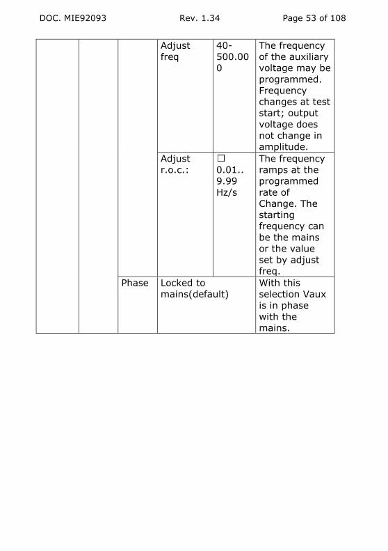
DOC. MIE92093 Rev. 1.34 Page 53 of 108
Adjust
freq
40-
500.00
0
The frequency
of the auxiliary
voltage may be
programmed.
Frequency
changes at test
start; output
voltage does
not change in
amplitude.
Adjust
r.o.c.:
0.01..
9.99
Hz/s
The frequency
ramps at the
programmed
rate of
Change. The
starting
frequency can
be the mains
or the value
set by adjust
freq.
Phase Locked to
mains(default)
With this
selection Vaux
is in phase
with the
mains.

DOC. MIE92093 Rev. 1.34 Page 54 of 108
Adjust phase Vaux
- mains
The fault
auxiliary
voltage can be
phase shifted
with respect to
the mains. The
measured
angle is
displayed. Test
must be ON;
for a correct
angle
measurement,
the auxiliary
voltage must
be more than
20% of the
range. Phase is
adjusted by
the
multifunction
knob.

DOC. MIE92093 Rev. 1.34 Page 55 of 108
Adjust phase Vaux
– I main
The fault
auxiliary
voltage can be
phase shifted
with respect to
the main
current. The
measured
angle is
displayed. Test
must be ON;
for a correct
angle
measurement,
current and
voltage must
be more than
20% of the
range. Phase is
adjusted by
the
multifunction
knob.

DOC. MIE92093 Rev. 1.34 Page 56 of 108
Adjust phase Vaux
– V main
The fault
auxiliary
voltage can be
phase shifted
with respect to
the main
voltage. The
measured
angle is
displayed. Test
must be ON;
for a correct
angle
measurement,
both voltages
must be more
than 20% of
the range.
Phase is
adjusted by
the
multifunction
knob.
Aux
Vdc control
Range 130 V (default)
or 240 V. If
this selection
has to be
changed, it’s
necessary to
adjust the
voltage output
to the
minimum by
the dedicated
knob.

DOC. MIE92093 Rev. 1.34 Page 57 of 108
LEVEL1 LEVEL 2 LEVEL 3 LEVEL 4 FUNCTION
METERS Internal Units of I Normal If selected,
current
values are
displayed in
A.
I/IN I
N
If selected,
displayed
values are
defined as
I/IN, that
can be
defined.
Units of V Normal If selected,
voltage
values are
displayed in
V.
V/VN V
N
If selected,
displayed
values are
defined as
V/VN (phase
voltage),
that can be
defined.
Externa
l I
Enabled AC
(default) -
DC
With
selection AC
the meter
performs
the true rms
measureme
nt; with
selection
DC, the
measureme
nt is
performed
on the
average.

DOC. MIE92093 Rev. 1.34 Page 58 of 108
10A – 20
mA
Selects the
current
input socket
Waveform If selected,
the current
waveform is
displayed
Externa
l V
Enabled AC
(default) -
DC
With
selection AC
the meter
performs
the true rms
measureme
nt; with
selection
DC, the
measureme
nt is
performed
on the
average.
Shunt : 1
– 1000
mOhm
If the
voltage is
coming from
a current
dropping on
a shunt,
specifying
the shunt
value the
current is
displayed;
default 100
mOhm.
Waveform If selected,
the voltage
waveform is
displayed

DOC. MIE92093 Rev. 1.34 Page 59 of 108
LEVEL1 LEVEL 2 LEVEL 3 FUNCTION
METERS
(continue
d)
Other
internal
None (default) No extra
measurement
displayed
Active power P; W
Reactive power Q; VAr
Impedance module Z, Ohm
Impedance argument φ, °
Active impedance
component
R, Ohm
Reactive impedance
component
X, Ohm
Apparent power S; VA
Power factor p.f. = cos(φ V-I)
Active energy (AC) Ea; Wh
Reactive energy (AC) Er; VArh
Other
externa
l
None (default) No extra
measurement
displayed
Active power P; W
Reactive power (AC) Q; VAr
Impedance module Z, Ohm
Impedance argument φ, °
Active impedance
component
R, Ohm
Reactive impedance
component (AC)
X, Ohm
Phase, I (AC) φ, Vmain-Iext;
reference Vaux
Phase, V (AC) φ, Vmain-Vext;
reference Vaux
Apparent power (AC) S; VA
Power factor p.f. = cos(φ V-I)
Frequency of V (AC) f, Hz
Active energy (AC) Ea; Wh
Reactive energy (AC) Er; VArh

DOC. MIE92093 Rev. 1.34 Page 60 of 108
Note: measurements marked AC apply only if both inputs are
selected as alternate current.
LEVEL1 LEVEL 2 LEVEL 3 LEVEL
4
FUNCTION
RESULTS Test header Groups results
Show results Display result
Delete Selected
result(s)
All results
CONFIGU-
RATION
Settings Save to
address
1..10 Saves current
settings to X
Restore
address
1..10 Restores settings
from X
Restore
default
1..10 Restores default
settings
Language UK, FR, SP, PT,
GE, IT
Select the desired
language
Display Speed Slow The displayed
value is refreshed
every 1000 ms
Fast The displayed
value is refreshed
every 300 ms
Hold
mode
Hold
trip
As relay trips,
test data
measured 4
periods before
trip are held.
Hold
min
As relay trips, the
minimum value
within 0.5 s is
held.
Hold
max
As relay trips, the
maximum value
within 0.5 s is
held.
LCD
Contrast
It allows to adjust
the LCD contrast

DOC. MIE92093 Rev. 1.34 Page 61 of 108
3 WHAT’S INSIDE?
3.1 PHYSICAL DESCRIPTION
The test set is contained in an housing, to which it is fixed by
means of nine screws that are located below it: see the following
picture.
After removal, the test set is shown in the following picture.
MOUNTING SCREWS

DOC. MIE92093 Rev. 1.34 Page 62 of 108
The mechanical components are:
. The front plate, on which are mounted: the VARIAC transformer,
all interfacing components and the front board;
. The base plate, on which are mounted all other components;
. Four L-shaped legs on the corners plus a central rod keep
together the two plates.
The following is the list of the most important components
3) Main transformer for the auxiliary voltage outputs, XTF10330.
4) Transformer for the auxiliary supplies, XTF10245.
5) Main outputs transformer, XTF10345.
6) Main outputs adjustment VARIAC.
7) INTE ON-OFF printed circuit board; code YWA11400.
9) Auxiliary DC voltage board; code YWA11395.
10) AP-50 auxiliary AC voltage amplifier; code PWA11396.
11) Back panel board ; code PWA11399.
12) Output current measurement transformer.
14) Auxiliary voltage amplifier output transformer.
15) Microprocessor board code PWA41300.

DOC. MIE92093 Rev. 1.34 Page 63 of 108
16) Converter board code PWA11401.
17) Front panel board; code PWA11398.
24) Resistors set.
26) MISU T 1000 PLUS board code PWA11402.
27) Protection fuses board, code PWA11416.
The arrangement is shown in the figure and pictures below.
The picture above shows the base with the auxiliary DC and AC
modules removed. The following picture shows the front panel
with the front control board. 5
4
12
11

DOC. MIE92093 Rev. 1.34 Page 64 of 108
On the upper corner are mounted the control cards: they are:
MICROT 1000 PLUS, PWA41300; CONVT 1000 PLUS, PWA11401;
INTET 1000 PLUS, PWA11400. they are connected to the back-
panel PWA11399, and to the front panel via three flat cables.
6
17
26

DOC. MIE92093 Rev. 1.34 Page 65 of 108
Their location is shown in the drawing below. Cards are kept in
place by the piece of aluminium sheet on the right, and also by
the threaded bar between the boards. If a board is failing, it is
necessary to remove the two screws as shown, and to un-tighten
the nut of the threaded bar, as shown; in case some component
touches it, it is necessary to remove it.
The small MISUT 1000 PLUS board is mounted on the front panel.
The voltage amplifier AP50, PWA11396, and the DC voltage
module, YWA11395, are mounted on the base plate, and are
connected via cables and flat cables.
3.2 DETAILED FUNCTION DESCRIPTION
The following is the list of the most important boards: for each
board is provided the explanation of the key functions performed.
3.2.1 Main auxiliary transformer, XTF10330 (3)
The main auxiliary transformer (3) has the following secondary
windings. For connections, see the schematic at the end of this
manual.

DOC. MIE92093 Rev. 1.34 Page 66 of 108
VOLTAGE
V
POWER
VA
PURPOSE GOES TO
150 120 Supply of auxiliary DC voltage
module YWA11395 (9)
PWA11395
J800-1; 4
11.5 3 Auxiliary supply for auxiliary
DC voltage module
YWA11395
PWA11395
J800-2, 3
50 60 Low power test supply 2 WAY
CONN.
36 x 2 35 x 2 Power supply of auxiliary AC
voltage board PWA11396 (10)
PWA11396
J1-1; 2; 3
15.2 x 2 10 x 2 General auxiliary ± 15 V
supply for all analog circuits
PWA11399
JP 10
12 10 General auxiliary + 5 V
supply for all digital circuits
PWA11399
JP 8
10 10 General auxiliary + 12 V
unregulated supply (relays, ..)
PWA11399
JP 9
4.5 7 Unregulated + 5 V supply for
the display back-light
PWA11399
JP 7
3.2.2 Auxiliary transformer, XTF10245 (4)
The auxiliary transformer (4) has the following secondary
windings. For connections, see the schematic at the end of this
manual.
VOLTAGE
V
POWER
VA
PURPOSE GOES TO
7 + 15 7 + 5 V and ± 15 V
auxiliary supply for AC
voltage board PWA11396
(10)
PWA11396
J2-1, 2, 3
19 2 START wetting voltage PWA11399
JP 1
19 2 STOP wetting voltage PWA11399
JP 4
4.5 0.4 Mains synchronization
signal
PWA11399
JP 7
7 1 PWA11398
J817-1, 2
8 2 V DC measurement
circuit supply
PWA11398
J815-1, 2

DOC. MIE92093 Rev. 1.34 Page 67 of 108
10 1 Positive voltage for the
buffer of AC voltage
board PWA11396 (10)
PWA11396
J2-4, J1-6
10 1 Negative voltage for the
buffer of AC voltage
board PWA11396 (10)
PWA11396
J1- 4, 5
11.5 x 2 1.5 x 2 I measurement circuit
supply
PWA11398
J812-1, 2,
3
11.5 x 2 1.5 x 2 V measurement circuit
supply
PWA11398
J812-4, 5,
6
The following drawing shows the back panel board (11) and the
JP points, where many wires are soldered.

DOC. MIE92093 Rev. 1.34 Page 68 of 108
3.2.3 Main output transformer, XTF10345 (5)
The main output transformer (5) has the following secondary
windings. For connections, see the schematic at the end of this
manual.
VOLTAGE
V
POWER
VA
PURPOSE
225 +
296
125 Main DC voltage
Main AC voltage (same common)
90+
25+
10
400
300
300
10 A output (60 s maximum)
40 A output (60 s maximum)
100 A output (60 s maximum)
(same common)
3.2.4 Main front board PWA11398 (17)
The board includes many different circuits:
START/STOP contacts filters.
Back-light supply and contrast adjustment.
Push-buttons.
LED’s.
Three isolated AC to DC auxiliary voltage generators for the
following measurement circuits: 600 V AC external; I AC/DC
external; V DC internal.
Control and discharge of the filter capacitor for the main DC
voltage generation.
Reduced power selection relay.
Auxiliary relay.
Transformer and shunt for the auxiliary AC voltage and
current measurement.
At the end of the document are given the mounting layout and
the connectors disposition.
3.2.5 MISU T1000 board PWA11402 (26)
The board includes three isolated circuits for the
measurement of: 600 V external input; I external inputs (25
mA and 10 A); internal auxiliary DC V supply.

DOC. MIE92093 Rev. 1.34 Page 69 of 108
All circuits have: gain selections; high accuracy amplifiers;
high accuracy isolated op amps.
Analog outputs are taken to CONV1000, for the ADC
conversion.
3.2.6 CONV T1000 board PWA11401 (16)
TASK 1: to convert all analog measurement signals (the
above + main I + main V AC + main V DC + auxiliary V AC)
into digital signals. This is performed by two 12-bit, 4
channels each parallel ADC converters.
TASK 2: to generate a squared waveform in phase with the
mains input, and to square the AC current and voltage signals
for the phase meter. Three circuits with amplifiers, limiters,
comparators perform this task.
TASK 3: to generate a sinusoidal waveform, with controlled
frequency and amplitude, that will be passed to the auxiliary
AC voltage amplifier (10). This is made by the local micro DSP
processor that generates the inputs for two DAC’s, that
control the amplitude and the waveform, at 10 kHz.
On the board is located a set of 8 switches; their meaning is
summarized in the following table.
Dip
number
Meaning
1 CONV type: see dip 4
2 T 1000 PLUS at 15 Hz . ON = 15 Hz;
OFF = 40..70 Hz
3 T 1000 PLUS power. ON = more power;
OFF = normal.
4 CONV type: dip sw4 ON , dip sw1 OFF = CONV
rev 2
CONV type: dip sw4 OFF , dip sw1 OFF = CONV
rev 0
CONV type: dip sw4 ON , dip sw1 ON = CONV
rev 1
5 T 1000 PLUS normal / C: OFF normal, ON = C
6 AP50 : OFF normal, ON = 500V (T 1000 PLUS-
E)
7 Main Vac: OFF normal, ON = 500V (T 1000
PLUS-E)
8 Force download : OFF =no , ON = force download

DOC. MIE92093 Rev. 1.34 Page 70 of 108
3.2.7 INTE ON-OFF T 1000 board PWA11400 (7)
TASK 1: to detect the START and STOP inputs closed – open
situation via two isolated constant current generator circuits,
with wet/dry selection and opto-isolated logic output.
TASK 2: to drive the ON-OFF of the test set. There are two
SCR’s pairs (one per phase) in opposing mounting, mounted
on heat sinks. SCR characteristics: 600 V AC; 20 A steady;
200 A peak.
TASK 3: diagnostic circuits of the main auxiliary supplies.
3.2.8 MICR T 1000 board PWA41300 (15)
The microprocessor board is the same as the one of the DRTS
family, but without the two PLA’s. It is controlling the test set
operation, test and results handling and the communication with
the PC, but not the AC waveform generation, that is controlled by
a dedicated slave microprocessor.
3.2.9 AP-50 AC Voltage board PWA11396 (10)
The amplifier receives the AC signal to be amplified from
CONV1000 board. The signal is first isolated by an high accuracy
opto-isolation op amp; then it goes to the op amp that controls
the loop. The output goes to a level shifter and booster amplifier;
the power output is a class AB amplifier, made of a
complementary pair of power transistors, having the following
ratings: 140 V, 20 A, 250 W; TO-3 metal case.
The output of transistors goes to the primary of transformer (14),
that has three outputs: 65, 130, 260 V. These outputs are taken
to three relays of the same board, that perform the range
selection. The selected secondary goes to the AC voltage output.
Output power is 30 VA at the selected range; maximum currents
are: 460 mA at 65 V; 230 mA at 130 V; 115 mA at 260 V.
An additional circuit stabilizes the power DC supplies.
3.2.10 Protection fuses
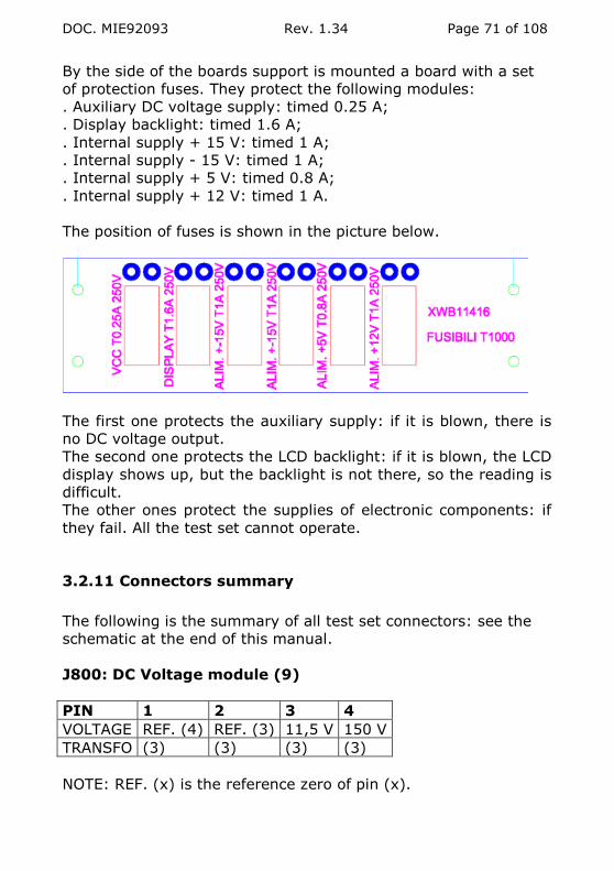
DOC. MIE92093 Rev. 1.34 Page 71 of 108
By the side of the boards support is mounted a board with a set
of protection fuses. They protect the following modules:
. Auxiliary DC voltage supply: timed 0.25 A;
. Display backlight: timed 1.6 A;
. Internal supply + 15 V: timed 1 A;
. Internal supply - 15 V: timed 1 A;
. Internal supply + 5 V: timed 0.8 A;
. Internal supply + 12 V: timed 1 A.
The position of fuses is shown in the picture below.
The first one protects the auxiliary supply: if it is blown, there is
no DC voltage output.
The second one protects the LCD backlight: if it is blown, the LCD
display shows up, but the backlight is not there, so the reading is
difficult.
The other ones protect the supplies of electronic components: if
they fail. All the test set cannot operate.
3.2.11 Connectors summary
The following is the summary of all test set connectors: see the
schematic at the end of this manual.
J800: DC Voltage module (9)
PIN 1 2 3 4
VOLTAGE REF. (4) REF. (3) 11,5 V 150 V
TRANSFO (3) (3) (3) (3)
NOTE: REF. (x) is the reference zero of pin (x).

DOC. MIE92093 Rev. 1.34 Page 72 of 108
J812: MAIN BOARD (17)
PIN 1 2 3 4 5 6
VOLTAGE 11,5 V REF. (1-3) 11,5 V 11,5 V REF. (4-6) 11,5 V
TRANSFO (4) (4) (4) (4) (4) (4)
J815: MAIN BOARD (17)
PIN 1 2
VOLTAGE 8 V REF. (1)
TRANSFO (4) -
J817: MAIN BOARD (17)
PIN 1 2
VOLTAGE 7 V REF. (1)
TRANSFO (4) (4)
J820: MAIN BOARD (17)
PIN 1 2
VOLTAGE 4,5 V REF. (1)
TRANSFO (3) (3)
J1: AP-50 (10)
PIN 1 2 3 4 5 6
VOLTAGE 38 V REF. (1-3) 38 V 10 V REF. (4) REF. (J2-4)
TRANSFO (3) (3) (3) (4) (4) (4)
J2: AP-50 (10)
PIN 1 2 3 4
VOLTAGE REF. (2-3) 7 V 15,5 V 10 V
TRANSFO (3) (3) (3) (4)

DOC. MIE92093 Rev. 1.34 Page 73 of 108
4 THE HELL, IT DOESN’T WORK
4.1 INTRODUCTION
Sometimes, when my ears whistle, I wonder if it is because of
some of my customers being angry at us because the test set
doesn’t work: according to Murphy’s law, when it was most
necessary. We at ISA do our best efforts to filter the so-called
infant mortality of electronic components prior to delivery of all
our test sets; and this after extensive testing of prototypes and
pre-production units.
Yet, sometimes faults occur, because everything dies, including
electronic components; so, please, before shooting at us, see if
the following instructions can serve you to fix the problem. If not,
e-mail us the problem, not forgetting to mention the unit’s
serial number: our business is to minimize your downtime. My
e-mail address is:
Last, our experience is that our test sets withstand very heavy
duty cycles for long wiles, if correctly used; most problems arise
because of:
. Lack of grounding in the mains supply;
. Voltage or current neutral is connected to earth;
. Severe spikes on the mains (spikes are not always so kind to
respect standard limits);
. Transit, with the associated drops and thermal cycling;
. Errors, such as the connection to live wires, or generating
current on a short circuit with the handle completely turned to the
maximum current.
Please mention in your e-mail how did the fault occur: this serves
us for our continuous improvement program.

DOC. MIE92093 Rev. 1.34 Page 74 of 108
4.2 ERROR MESSAGES
The test set performs a number of tests at power-on and during
the generation. The following table lists all the messages, and the
corrective action.
A) TESTS AT POWER-ON (and runtime)
ERROR MESSAGE CONSEQUENCE CORRECTIVE
ACTION
+ 15 V supply failure If the error is not
confirmed it is
possible to continue;
else, the test cannot
proceed
(NOTE 1)
Try some power
on – off; if
persists, three
steps:
. Check the
fuses;
. Try to replace
the CONV board;
. Return the
test set.
- 15 V supply failure If the error is not
confirmed it is
possible to continue;
else, the test cannot
proceed
(NOTE 1)
Try some power
on – off; if
persists, three
steps:
. Check the
fuses;
. Try to replace
the CONV
board;
. Return the
test set.
NVM access If the error is not
confirmed it is
possible to continue;
else, the test cannot
proceed
(NOTE 1)
Fault in the
MICR board:
replace it

DOC. MIE92093 Rev. 1.34 Page 75 of 108
B) RUNTIME TESTS
ERROR
MESSAGE
CONSEQUENCE CORRECTIVE
ACTION
60 VA IAC supply
time
The test lasted
too long; tests
are blocked for
the specified
duration
Wait until the
message disappears
300 VA IAC
supply time
The test lasted
too long; tests
are blocked for
the specified
duration
Wait until the
message disappears
IAC while VDC
supplied
Generation is
stopped
The test set is
sensing a burden
both on main IAC
and VAC or VDC,
what is forbidden.
Remove one of the
burdens
MAIN VAC The main AC
voltage is
overloaded;
generation is
stopped
Reduce voltage or
burden of main AC
voltage
MAIN VDC The main DC
voltage is
overloaded;
generation is
stopped
Reduce voltage or
burden of main DC
voltage
AUXILIARY VAC The auxiliary AC
voltage is
overloaded;
generation is
stopped
Reduce voltage or
burden of the
auxiliary voltage
ERROR
OVERLOAD
RECOVERY xxx s
If you try to
restart before
the above
message
Wait until the
message disappears

DOC. MIE92093 Rev. 1.34 Page 76 of 108
disappears, the
test set informs
you about the
residual time
OVERTEMP
POWER
TRANSFORMER
Generation is
stopped
(NOTE 1)
The main
transformer
temperature is too
high because of
heavy loads or very
long test duration:
wait until it cools
down. If it does not
disappear, see the
text.
OVERTEMP
SCR’S HEAT
Generation is
stopped
(NOTE 1)
The temperature of
the SCR that drives
the test is too high
because of heavy
loads or very long
test duration: wait
until it cools down
OVERTEMP T
1000 PLUS
ENGINE
Generation is
stopped
(NOTE 1)
The test set
temperature is too
high because of
heavy loads or very
long test duration:
wait until it cools
down
NOTE 1: Sometimes the alarm is false, i.e. the fault is in the
diagnostic circuits (they also can fail), and the test set is OK. In
this case, you can proceed by pressing the buttons <, > and the
control wheel at power on. TAKE CARE, because this operation
skips ALL faults, and the test set is no more providing alarms in
case of too long test duration during high current generation:
MAKE THESE TESTS AS SHORT AS POSSIBLE!
4.3 TROUBLE SHOOTING

DOC. MIE92093 Rev. 1.34 Page 77 of 108
The following table summarizes main faults, cause of fault and
correction. When in the correction you find “see text”, please
proceed with the following paragraphs.
SYMPTOM POSSIBLE CAUSE CORRECTION
Problems after
transport
Heavy shock Open T 1000 PLUS
and check for
loose boards or
connections
At power-on does
not turn on
Mains supply fuse
open
Other causes
See text
The variable
transformer gets
very hot as soon
as the test set is
powered-on
The INTE board is
faulty
Replace INTE
After the general
over-temperature
alarm message it
does not turn on
The power
transformer was
over-heated
Wait at least 30
minutes before
trying again: it
needs time to cool
down.
The auxiliary DC
voltage is not
generated
The protection fuse
was broken by a
contact with a live
wire.
One protection fuse
is blown
Replace fuse (19).
Replace fuse on
the fuses board.
Replace fuses on
the module (see
text below)
The auxiliary
contact does not
close
The contact was
over-loaded and
permanently
damaged
Send back for
repair.
It is impossible to
measure on the 20
mA range
The input was
overloaded; the
PTC protection is
not restored
Wait 15 minutes
before trying
again.
No generation of I
main
Damaged INTE ON-
OFF
See text
No measurement
of I main
Broken connection See text

DOC. MIE92093 Rev. 1.34 Page 78 of 108
Measurements are
completely false
The microprocessor
has lost its
correction factors
Go to the
calibration
procedure and
repeat it.
The display is dark Protection fuse
blown
See text
Unstable auxiliary
AC voltage
measurement.
Fault of AC voltage
generation circuit
See text
The TRIP input is
not detected
Damaged INTE ON-
OFF
See text
Over-load alarm
on the auxiliary AC
voltage cannot be
restored; AC
voltage cannot be
generated.
Fault of AC voltage
amplifier.
Contact your agent
for support,
detailing:
. test set number;
. how did it occur
A knob
(adjustment,
multi-function
wheel) does not
turn
Friction against the
front panel
. Remove the
plastic (blue)
protection on the
front of the knob:
you gain access to
a nut;
. You can un-
tighten the nut:
the knob is free;
. Slightly withdraw
the knob,
interpose one or
two sheets of
paper between
knob and front
panel, and tighten
back the knob.
Removing the
paper, the knob
will be free of
turning.

DOC. MIE92093 Rev. 1.34 Page 79 of 108
4.3.1 Auxiliary supplies
On the edge of the CONV board are mounted a number of ring-
shaped test points. They carry the key auxiliary supplies, which
operate the test set. The arrangement of the test points is the
following.
If any of these voltages is missing, the test set cannot operate: it
is necessary to find out if it is a problem of blown fuse, or repair
the auxiliary voltage circuit. If the main auxiliary transformer (3)
is damaged, it can be replaced with the following procedure.
The replacement transformer comes cabled with all crimped
connectors, in order to ease the replacement. There are eight
remaining wires that are to be soldered directly to the small fuse
board. The two transformers are perfectly identical: wires come
out from the same position and have the same colours. The
replacement procedure is he following.
- Unscrew the faulty transformer.
- Place the new transformer in the same position.
- Unsolder the first wire from the fuse board.
- Solder in the same place the new wire fro the new transformer,
having the same colour.
- Proceed until all wires have been soldered.
4.3.2 No power at power-on
The mains fuse is located in the power supply plug, in the small
drawer. Replace it.
At power-on, almost no power (50 W) should be drawn from the
mains. If the power is more, the most likely faulty component is
the auxiliary DC voltage circuit; next, it is the auxiliary AC voltage
circuit.
To ascertain this, it is necessary to remove:

DOC. MIE92093 Rev. 1.34 Page 80 of 108
. three connectors from the DC voltage generator: two bigger,
white, one on the front, one on the rear, plus one flat cable;
. Five connectors from the AC voltage amplifier: four white,
mounted on top of the board, plus a flat cable.
After this, power-on, and verify that the display operates, and
that the LED’s on the front panel turn on with the default values.
If so, re-insert the modules one after the other, in order to detect
which one is faulty.
In case of DC voltage generator, see here below what else to do;
in case of the AC voltage amplifier, it should be replaced.
4.4 AUXILIARY DC VOLTAGE FAULT
If the output voltage cannot be adjusted, then the fault can be
located in the adjustment potentiometer. In this instance, the
behaviour is the following:
- Select the 130 V range: the output is fixed at about 10 V;
- Select the 240 V range: the output is fixed at about 20 V.
The potentiometer is easily replaced as follows:
. Remove the test set from the container;
. The potentiometer is soldered to the control board by two wires:
unsolder them;
. Remove the plastic cap from the knob: the nut blocks the knob
to the potentiometer. Un-tighten the knob and remove it: you get
access to the nut that holds the potentiometer to the front panel.
. Unscrew it, replace the potentiometer, screw it back, solder
wires, mount the knob so that it does not touch the front panel.
Take care not to exchange the four-wire connector from
the transformer with the four-wire connector to the AC
voltage amplifier: see the picture below.

DOC. MIE92093 Rev. 1.34 Page 81 of 108
If the potentiometer was not the problem and fuse (19) is OK, it
is possible that the fuse on the fuses board is blown, or that one
of the fuses mounted on the board has blown up. In this instance,
proceed as follows.
. Open the test set, as explained above, and locate the fuse on
the fuses board. Check it and replace if necessary.
. If OK, locate fuses on the auxiliary DC voltage board (see
picture below).
. Check fuses and replace them if necessary. They are 20 mm
long; F1 is F3.15A; F2 is F2A.
. If a fuse is blown, replace it, power-on and check if the DC
voltage is available. If it is OK, the fuse was weak; if it is not,
there is a fault on the board, that needs to be replaced.
4 wires with different colours: they come from
the transformer
4 wires with the same colour
4 wires with the same colour
4 wires with different colours: they come from the transformer

DOC. MIE92093 Rev. 1.34 Page 82 of 108
The last test is to remove the connector J800 coming from the big
round power transformer, and located on the rear of the module.
The connector has 4 pins: the voltage between pins 1 and 4
should be 155 V AC nominal; between pins 2 and 3 should be
11.5 V AC nominal. If this is correct, the module is faulty; else,
the power transformer is faulty.
The module can be removed by un-screwing the two screws
below it, and it can be withdrawn from its mounting position
without removing other cables.
When setting back the board, if the short cable with 4-way
connectors has been removed on both sides, take care because it
is not symmetrical: you have to mount it back so that the ferrite
that protects two wires is towards the outside of the test set
(bottom side).
F1 F 3.15 A
F2 F 2 A

DOC. MIE92093 Rev. 1.34 Page 83 of 108
4.5 AUXILIARY AC VOLTAGE FAULT
Possible modes for AC voltage fault are:
. Over-load message at power-on, that cannot be re-set;
. Over-load message even with a minimum load;
. No AC voltage output.
In such instances, the most likely cause of fault is the amplifier
(10), PWA11396. You should open the test set, disconnect the
five connectors, remove the amplifier by unscrewing the four
screws below it, replace with the new one and verify that the test
set is operational. In order to be able to remove the amplifier,
first remove the DC voltage module (two screws), so that you can
take it away moving it to the left.
When fitting back the connectors, cables are short or with
different pin numbers, so that they cannot be exchanged, unless
for two 6-way connectors towards the bottom of the test set. The
correct location is sketched below (see the picture above)
If, after the replacement of the amplifier, the problem is still
there, it is possible to go to a further investigation as follows.
. Open the test set, and look at the AP-50 amplifier from the
edge, and below it, at the location of the connector that receives
the flat cable: see the picture below.

DOC. MIE92093 Rev. 1.34 Page 84 of 108
. Verify the signals as summarized in the following table.
PIN 1 2 3 4 5 6 7
SIGNAL Ext meas 80 V
0 Vin 0 Vin 0-2 V AC
Range sel
H = 260 V;
L = 130
V
+ 12 V Ext meas 10 V
PIN 8 9 10 11 12 13 14
SIGNAL 0 Range sel H =
260/130 V;
L = 65 V
- 15 V
+ 15 V 0 H =close
L = open relay
+ 5 V
The AC signal between pins 2 and 4 is coming from the CONV
board: it is 2 V AC when the output is at maximum.
4.6 NO OUTPUT FROM THE MAIN CURRENT AND VOLTAGE
This is the case when you can start the test, but no output is
generated from the main current and voltage outputs. In this
situation the fault is located in the INTE ON-OFF board (7), that is
located in the boards pack. The replacement is very fast: just
PIN 2
PIN 1

DOC. MIE92093 Rev. 1.34 Page 85 of 108
follow the instructions above for the opening of T 1000 PLUS and
board replacement.
4.7 DOES NOT MEASURE THE MAIN CURRENT
Remove T 1000 PLUS from the container. Just below the output
sockets there are two yellow wires going to the metering current
transformer. These yellow wires are made of a single enameled
wire coming from the secondary of the measurement
transformer: it is possible that they broke, and so you loose the
measurement. The fixing is easy: just solder the wires, taking
care to peel the enamel so that it can be soldered.
If this is not the cause of the problem, further tests:
. On the main board, close to the point where the transformer is
soldered, is located the resistor R71, rated 1 Ohm: verify that it is
correctly soldered.
. Generate 1 A on the 10 A output, and measure the voltage
across the 1 Ohm resistor: you should measure 50 mV
(Transformer ratio 200//1; 10 turns make the ratio 20//1).
. The voltage drop across the shunt is taken to the CONV board
via a 12-way flat cable, of the type FLEXSTRIP, located in the
center of the board. These connectors are rather hard to fit: press
it very well on both sides.
. Last, it is possible that there is a fault on the CONV board where
the measurement is performed: if this is the case, the board has
to be replaced. Prior to this, verify that the voltages on the CONV
board test points (see 3.4.2 above) are correct.
4.8 THE BACKLIGHT OR THE DISPLAY DOES NOT OPERATE
1. The display backlight does not turn on.
The backlight is supplied by a DC to DC converter that is mounted
on the main board, that is mounted below the front panel. If the
backlight does not turn on, the converter is likely to be faulty.
The converter replacement is performed as follows.
. Remove T 1000 PLUS from the container.
. Go to the left side: the sketch below shows the main
components.
. The converter is mounted as shown in the design below.

DOC. MIE92093 Rev. 1.34 Page 86 of 108
. First of all, verify that the two-way, AMP type white connector is
correctly fit, and that wires are not loose.
. Next, try to re-solder the four connecting pins of the converter
to the main board: we once had a case of poor soldering.
. If this is not enough, it is necessary to replace the converter. To
this purpose, we suggest to remove the faulty one by cutting pins
as short as possible, so that cleaning holes is easier; then, solder
the new converter.
2. The display does not operate.
In this situation, verify the following.
. The three FLATSTRIP cables from the control board back panel
to the main board could be not completely fit in, as they are
rather hard: check it.

DOC. MIE92093 Rev. 1.34 Page 87 of 108
. Verify the voltages on the test points of the CONV board, as
explained above. If some voltage is missing, then the auxiliary
transformer should be replaced.
. The display is connected to the main front board via a number
of pins, located in the center of the display: verify that there is no
dirt causing a short circuit between them.
. If everything is OK, there is also the possibility that the MICR
board is faulty: replace it.
. If changing the MICR board the fault is still there, it is necessary
to return the test set to ISA for the replacement of the display,
that involves a difficult labor.

DOC. MIE92093 Rev. 1.34 Page 88 of 108
4.9 THE AC VOLTAGE MEASUREMENT IS NOT STABLE
First of all, check that there is no unplugged connector or broken
wire. Next, it is necessary to understand if the problem is in the
measurement or if the output is actually unstable. To this
purpose, connect the output to an AC voltage meter and verify
the reading. If it is unstable as well, the problem is in the
amplifier; otherwise, it is in the measurement circuit.
In the first instance, amplifier, we have to verify if the problem
comes from the adjustment potentiometer. To this purpose,
proceed as follows:
. Go to the menu and select PREFAULT + FAULT;
. In the PREFAULT mode, the output voltage is adjusted by the
multi-function knob, and not by the potentiometer: please verify
the output. If it is stable, the problem is located in the
adjustment knob. If it is unstable, it can be located on the AP/50
amplifier, or on the CONV board. The problem when replacing
CONV is that, as it hosts the measurement circuits, after
replacing it, it is necessary to repeat the calibration. It is up to
you if you want to receive the replacement boards or to deliver
the test set to us.
In the second instance, the fault is in the measurement, we have
to replace the CONV board, with the problem explained above.
4.10 THE TRIP INPUT IS NOT DETECTED OR TIMING ERROR
There is a possibility that the problem is coming from the
selections performed on the input. In fact, we can select the
contact as free of voltage or with voltage (LED's on the front
panel show the active selection); besides, if it is with voltage, we
can select two thresholds: low for voltages above 24 V; high for
voltages above 110 V. In case of doubt, please select the default
settings: both inputs are selected without voltage. Note that if
you select the inputs as voltage free, and apply 12 to 24 V, the
detection becomes uncertain.
When the voltage clean trip input is selected, a voltage of about
20 V DC can be measured on START or STOP inputs; when the

DOC. MIE92093 Rev. 1.34 Page 89 of 108
contact closes, a current of about 10 mA flows though it and
detects the contact status. If with this selection the closed contact
is not detected, and 20 V are not applied, the fault is located in
the INTE ON-OFF board (7), that is located in the boards pack.
The replacement is very fast: just follow the instructions above
for the opening of T 1000 PLUS and board replacement.
If the replacement of the INTE ON-OFF board is not solving the
problem, check the following.
. There are two connectors on the front board: they carry the
START and STOP inputs. Check that they are OK.
. These wires are soldered to the back-panel board, on test points
marked START and STOP respectively. Test that they are
correctly soldered by putting a jumper into the sockets and
verifying that the wires are short-circuited.
STOP
START P

DOC. MIE92093 Rev. 1.34 Page 90 of 108
. Last, on the test points shown above as STOP SUPPLY and
START SUPPLY are soldered the wires that supply the START and
STOP circuits for the voltage free selection, and that come from
the auxiliary transformer located below the boards: if a voltage is
missing, the transformer should be replaced.
If there is a doubt about the timing metered by T 1000 PLUS,
please proceed as follows.
. First of all, go to the CONFIG selection; settings, and select
RESTORE DEFAULT: this avoids that some exotic setting is the
cause of the problem.
. Next, connect a jumper to the STOP input. Start the ON+TIME
test: the timer should display 0 to 2 ms.
. Now, go to the TEST CONTROL selection, and to the AUXILIARY
CONTACT. Set the timing of 10 ms. Connect the C, NO contacts of
the auxiliary output to STOP inputs. Start ON-+TIME: it should
display 10 to 12 ms. You can test more with different timings of
the auxiliary contact.
4.11 PROBLEMS DURING UPGRADE
If during the Upgrade operation the power went off, and the test
set is no more operational, to recover the situation proceed as
follows.

DOC. MIE92093 Rev. 1.34 Page 91 of 108
- Remove (or unlock a little) the metal bar that fixes the two
aluminium columns.
- Remove the two connectors placed on the INTE board.
- Remove the INTE board, and then the pack MICRO + CONV.
- Open the pack MICRO + CONV.
- Change the position of the mini-dip switch N. 8 on the CONV
board (it is OFF; it must be set ON).
- Insert again all the boards (and the INTE connectors too).
- Turn on the test set.
- At this point , the instrument should be connect to your PC.
Execute the firmware download.
Verify that the new firmware version appears; if yes, you have
to turn off and set the dipswitch N. 8 to OFF (as it was initially).
4.12 THE ENCODER IS BROKEN
In this instance, it is necessary to have some skill and patience.
The procedure is the following.
. During the time, we have used three different type of encoder
mounting; they are:
1. The front-end printed circuit board does not allow to
access the encoder;
2. The front-end printed circuit board allows to access the
encoder, which does not carry a small PCB;
3. The front-end printed circuit board allows to access the
encoder, which carries a small PCB.
Before proceeding, shoot a picture at the encoder, so that we can
understand your situation. If you recognize the case 1, the test
set should be returned us.
. You have in your hands the new encoder: it must replace the
faulty one. This means that you have to dismount the old one,
unsolder the five wires going to it, solder them to the new one,
mount it.
. It is necessary to gain access to the faulty encoder. If you look
at it, it is surrounded by other components: no access. It is
necessary to remove the DC voltage generator board, and also to
remove the variable transformer: remove the control knob, and
dismount it removing the three screws below the knob.
. Now you have room enough to operate. Remove the encoder:
the five wires going to it are long enough to allow you keeping it
in your hand.

DOC. MIE92093 Rev. 1.34 Page 92 of 108
. Unsolder the first wire, and solder it to the new encoder, in the
same position: with this procedure you are sure not to exchange
wires.
. At the end of soldering, mount back the new encoder, power-on
and check that it is correctly operational. After this, complete the
mounting of the test set.
4.13 THE THERMAL ALARM DOES NOT DISAPPEAR
The thermal alarm is given by either of two thermal switches put
in series: one is located on the main transformer; the other one is
located on the AP-50 amplifier. One of them is faulty.
In order to understand which one is faulty, proceed as follows:
. Dismount the AP-50 amplifier (four screws from below), and lift
it enough to reach for the thermal sensor: it ends with two wires,
that go to a connector.
. Disconnect the connector, and perform a temporary short circuit
on the mating connector.
. Power-on. If the error signal disappears, the fault is on the AP-
50 sensor (unless AP-50 is actually hot); else, the fault is on the
sensor mounted on the power transformer (5).
. On the Main Output Transformer there is a thermistor with two
pink wires leaving it, screwed below the holding disk. Its value at
rest is 10 kOhm. For a temporary fix, replace it with a 10 kOhm
resistor until the replacement arrives.
4.14 AN AUXILIARY SWITCH DOES NOT OPERATE
Auxiliary switches are protected by fuses located on the front
board, inside the test set, and connected in series to the C
contact of the relay. If one of the two is not operating, very likely
the fuse is opened. The intervention procedure is the following.
. Open the test set.
. Protection fuses are located by the side of the auxiliary relay:
see the picture.

DOC. MIE92093 Rev. 1.34 Page 93 of 108
. The fuse to the right protects the auxiliary contact no. 1.
Replace the fuse and verify again.
. If the fuse is not the problem, it is possible, even if quite
difficult, to unsolder the relay and to replace it.
4.15 THE FAULT CANNOT BE FIXED
If the fault is too hard to be fixed, you have to deliver T 1000
PLUS back to your agent. We have encountered problems caused
by a poor packing of instruments that have been delivered us for
calibration or repair. In order to avoid such inconveniences,
please apply the following procedure.
First of all, compile the following form, and attach it to the
instrument. Please do not forget to compile it.
With the instrument should come the mains supply cable. The
user’s manual originally delivered with the test set is not
necessary.
Cover the instrument itself with a polyester film, in order to
protect it against dust and foam.
The instrument should be protected by anti-shock foam having a
minimum thickness of 5 cm ON ALL SIDES.
Use a new carton box as a container. On the box apply the UP
and the FRAGILE labels.
In the box the instrument will be placed horizontal or standing;
not upside down.
If the set is heavier than 20 kg it is better to use also a pallet:
this ensures that the box will not be packed upside down.
Last but not least, do not declare an high value for customs: this
expedites clearance of the good and lowers fees.

DOC. MIE92093 Rev. 1.34 Page 94 of 108
INSTRUMENT RETURN FORM
DATE ________________________________________
AGENT _______________________________________
COUNTRY _____________________________________
TYPE OF INSTRUMENT __________________________
SERIAL NO. ___________________________________
INSTRUMENT RETURNED FOR:
CALIBRATION ____
REPAIR ____
In case of repair, please specify the following.
DATE OF FAULT _________________________________
REPORTED BY E-MAIL, PHONE ______________________
COMPANY ______________________________________
USER’S REFERENCE _______________________________
FAULT DESCRIPTION
_______________________________________________
_______________________________________________
_______________________________________________
_______________________________________________
_______________________________________________
_______________________________________________
_______________________________________________
_______________________________________________
_______________________________________________
_______________________________________________
_______________________________________________
_______________________________________________
_______________________________________________
_______________________________________________

DOC. MIE92093 Rev. 1.34 Page 95 of 108
HOW DID IT OCCUR
_______________________________________________
_______________________________________________
_______________________________________________
_______________________________________________
_______________________________________________
_______________________________________________
_______________________________________________
_______________________________________________
_______________________________________________
LOCAL ANALYSIS OR ATTEMPTS TO REPAIR
_______________________________________________
_______________________________________________
_______________________________________________
_______________________________________________
_______________________________________________
_______________________________________________
_______________________________________________
_______________________________________________
RECOMMANDATIONS AND NOTES
_______________________________________________
_______________________________________________
_______________________________________________
_______________________________________________
_______________________________________________
_______________________________________________
_______________________________________________

DOC. MIE92093 Rev. 1.34 Page 96 of 108
4.16 CALIBRATION
4.16.1 Introduction
T 1000 PLUS does not need to be calibrated, as metering circuits
employ high stability components.
It is suggested to check the unit every 2 years, by comparing T
1000 PLUS measurements to external meters. Tests should be
performed with an high accuracy multi-meter, that should
guarantee a maximum AC measurement error of 0.1%, both for
voltage and current. Besides, as such multi-meters do not have
current ranges greater than 2 A, for the test of the high current
ranges it is necessary a class 0.1 measurement Current
Transformer. The adoption of lower-class instruments may cause
false interventions, that introduce errors into the test set. . Last,
as internal generators follow the mains, it should be stable
enough to allow for a stable generation.
At the end of the test, if deviations are not acceptable it is
possible to enter the calibration mode, as explained in the
followings.
4.16.2 Calibration procedure
The calibration mode is accessed by pressing push-buttons < and
> at the meantime, and powering on T 1000 PLUS. After a
confirmation message, the following window is opened.
The calibration is divided in two: measurements and phase
angles.
For the measurements, after the selection, the following window
is opened.

DOC. MIE92093 Rev. 1.34 Page 97 of 108
4.16.3 T 1000 PLUS output calibration
Calibrations are divided between external measurements and
internal generators. Starting from an internal generator, for
instance Main IAC, the following window is opened.
The three current outputs are displayed; for each output are
shown the measurement ranges that the test set will
automatically select, according to the input value. There are two
columns of squared dots for each range: the left one, marked of,
refers to the off-set calibration; the right one, marked m, refers
to the measurement calibration. Squares are white when the
calibration has not yet been performed, then they become black.
The operating mode is the following:
. Select the range to be calibrated.
. Set to zero the adjustment knob.
. With no output, ad just the off-set: it will be performed with an
open circuit for current outputs, and with a short-circuit with
voltage outputs.
Following the example of main IAC output, the following is the
window for the calibration of the 1 A range.

DOC. MIE92093 Rev. 1.34 Page 98 of 108
. The first thing is the off-set calibration: to this purpose, remove
the connection to the meter, then select RESET: as you click on
it, the square dot to the left side turns white:
. Now, press SET: the square dot turns black, and the calibration
is done.
. On the upper part of the screen it is displayed the nominal
current to be used for the calibration of the selected range: in our
instance, it is 1 A. To the right, there are two adjustment
parameters: COARSE and FINE, and then the measurement. The
CARSE and FINE values are just calibration parameters, with no
direct meaning for the measurement.
. Connect the meter to the output to be calibrated; then, press >
to generate the output. The external meter measures the output;
T 1000 PLUS displays its measurement. Adjust the current until
the external meter displays a value within 5% of the nominal
calibration value. NOTE: on order to ease the calibration, you can
use the power resistors to put them in series to the output.
Go to the COARSE adjustment, and modify it (reduce it to
increase the measurement) until the T 1000 PLUS measurement
is the minimum less than the external one; then, go to the FINE
adjustment (increase it to increase the measurement) in order to
get the best match with the external meter (the difference should
be less than 0.2% of the reading).
. Press the return icon to confirm. Go to the next range: T 1000
PLUS goes OFF.
. In our instance, next range is 19.99; the calibration value is 11
A. Repeat the above procedure, and then do the same for all
ranges of the other outputs, 40 A and 100 A.

DOC. MIE92093 Rev. 1.34 Page 99 of 108
. Next is the calibration of the AC voltage output: the window is
the following.
.
. Here there are four ranges to calibrate. The procedure is the
same as above, but the off-set is calibrated by putting a short
circuit on the output.
. The main DC voltage output is similar to the above. The
auxiliary AC voltage output calibration opens the following screen.
. Also here, the calibration is performed with the output short-
circuited. The auxiliary DC voltage output window is the following.
. In this instance, DON’T MODIFY THE OFFSET CALIBRATION: the
minimum value for the DC voltage is not zero. Just calibrate the
measurement.
4.16.4 T 1000 PLUS external meas. calibration

DOC. MIE92093 Rev. 1.34 Page 100 of 108
Now you can proceed with the external measurements
calibration. For this operation, IT IS NECESSARY TO HAVE AN
EXTERNAL SOURCE, SUCH AS A DRTS TEST SET: T1000 ittself
cannot be used to source the inputs.
. The window for the external IAC measurement is the following
one.
. NOTE: the first two calibrations will be performed on the 25 mA
input; the other two on the 10 A input. Also here, first calibrate
the offset (open circuit, and then the gain, inputting a current
close to the one displayed.
. Calibrations are divided in two: AC calibration and DC
calibration. The following is the widow for the 600 V input.
4.16.5 Phase angle measurement calibration
. Once these calibrations are finished, you can calibrate phase
angle measurements. To this purpose it is necessary to use a
phase meter with a measurement error of 0.2° maximum. The
phase angle measurement calibration is performed taking into
account the selected phase reference. The first window that
opens is the following one.

DOC. MIE92093 Rev. 1.34 Page 101 of 108
1) Angle Auxiliary AC Voltage (reference) – Main AC
current.
Once the selection is performed, the following window is opened.
The calibration has to be performed for each voltage and current
range: nine calibrations in all. Connect the auxiliary AC voltage
output to input 1 of the reference phase meter, and the main
current output to input 2 of the reference phase meter. Take
care to connect the T1000 black sockets to the negative
inputs of the phase meter.
Press the key >: T1000 goes ON. Adjust at 57 V the auxiliary AC
voltage output, and at 5 A the main current output. Go to the first
angle to be adjusted, and press the button: the squared dot will
turn white, and the phase meter to the right displays the internal
measurement.
Rotate the knob until the internal phase meter measurement is
equal to the external one : pressing the knob, the correction
factor is saved, and the square dot turns black.
The adjustment will be repeated on all main current outputs, with
current values of 10 A for the 40 A sockets, and 20 A for the 100

DOC. MIE92093 Rev. 1.34 Page 102 of 108
A sockets: the auxiliary AC voltage will be the same for all
ranges.
2) Angle Auxiliary AC Voltage (reference) – Main Voltage.
Once the selection is performed, the following window is opened.
Connect the auxiliary AC voltage output to input 1 of the
reference phase meter, and the main AC voltage output to input
2 of the reference phase meter. Take care to connect the
T1000 black sockets to the negative inputs of the phase
meter.
Both voltage outputs are adjusted at 57 V. on the 62.5 V range,
and the main voltage output, The adjustment procedure is the
same described above.
3) Angle Auxiliary AC Voltage (reference) – External
Current.
Once the selection is performed, the following window is opened.
Connect the auxiliary AC voltage output to input 1 of the
reference phase meter, and the external AC current input to
input 2 of the reference phase meter. Take care to connect the
T1000 black sockets to the negative inputs of the phase
meter.
The external AC current can be generated by the main AC current
generator; it is advisable to connect in series a resistor of the

DOC. MIE92093 Rev. 1.34 Page 103 of 108
resistor set. Press the key >, and adjust 1 A for the first
calibration, and 5 A for the second one. The procedure is the
same as above.
4) Angle Auxiliary AC Voltage (reference) – External
Voltage.
Once the selection is performed, the following window is opened.
Connect the auxiliary AC voltage output to input 1 of the
reference phase meter, and the external AC current input to
input 2 of the reference phase meter. Take care to connect the
T1000 black sockets to the negative inputs of the phase
meter.
For this adjustment, you can use the Auxiliary voltage output as
the external voltage: they will surely be in phase. However, as
the smallest External voltage range is 20 V, it is necessary to
reduce the 65 V Auxiliary voltage output to a smaller value: this
is performed taking advantage of the auxiliary resistors set.
Connect the Auxiliary voltage output to the 2200 Ohm, and the
Auxiliary voltage zero to 100 Ohm; the External voltage input is
taken from the partition, as shown in the following figure.

DOC. MIE92093 Rev. 1.34 Page 104 of 108
With this connection, the voltage to VEXT is about 10 V when the
input is 65 V: this is to be used for the angle calibration of the 20
V External input range. For other ranges, the partitioning is not
necessary.
The program alerts if a scale is not calibrated. At the end of the
session, all parameters are saved in the non volatile FLASH
EPROM.
common
black

DOC. MIE92093 Rev. 1.34 Page 105 of 108
APPENDIX 1 SPARE PARTS LIST
The following is the suggested list of spare parts for a duration of
five years and for up to five test sets.
The reference is made to the list of components.
1) N. 10 Fuses in the supply socket (1), rated T10A, code
XFU22101.
2) N. 10 Fuses of the auxiliary DC voltage (19), rated F2A, code
XFU23109.
3) N. 1 DC to DC converter for the display (23) backlight, code
XCA10348.
4) N. 1 Encoder with switch, for MENU control knob (22), code
XCM10160.
5) N. 1 Printed circuit board INTE ON-OFF (7), code PWA11400.
6) N. 1 Auxiliary DC voltage supply module (9), code YWA11395.
7) N. 1 Auxiliary AC voltage amplifier AP-50 (10), code
PWA11396.

J819- 3
RO SSO
BLU 0V
100A
0.5 QUADRI
CONNETTORE VOLANTE
NERO 0V
M ARRO NE
XTF20404
1 3
4
2
5
6
0.5 QUADRI L= cm
VCC
BI ANCO
12 PIN
1
G I ALLO 0V
ARANCI O NE 0V
BLU 0V
0.25 QUADRI
F
BLU 4. 5V( 11 )
BI ANCO
BI ANCO 0V
BLU
0
VISTA LATO FILI
TP14
I NTE O N- O FF PWA11400
J804- 1
J804- 2J808
VI O LA
XTF10245
1
4
2
32.5 QUADRI
MODIFICA 1
NERO
0.5 QUADRI L= cm
0.5 QUADRI L=20 cm
P1
SERI ALE RS232
594837261
M
BI ANCO
0.25 QUADRI
( 17 )
G I ALLO 11. 5V
M ARRO NE
PICCOLO
12 PIN
( 18 )
YWA11395 VCC
J806
J818- 1
J818- 2
J818- 3
J818- 4
J800- 1
J800- 2
J800- 3
J800- 4
BI ANCO 296V
BLU
J818
0.5 QUADRI
M
BLU 8V
22R
0.5 QUADRI L=20 cm
RO SSO 0V
0.25 QUADRI
( 8 )
4
BLU
( 9 )
Fr iday, Febr uary 14, 2003
10093 3
CABLAG G I O T1000
A2
1 1
Tit le
Size Docum ent Num ber Rev
Dat e: Sheet of
Designer Check and Approval
0.5 QUADRI L=20 cm
12 cm 0.5 QUADRI
CONNETTORE DI XTF20404
0.5 QUADRI
F
G I ALLO 225V
0.5 QUADRI L=20 cm
BLU 0V
NERO 10V
0.25 QUADRI
( 10 )
0
NERO 0V
NERO 0V
NTC 10K
1 2
PRESA + FI LTRO
T
F
N
0.5 QUADRI L=20 cm
TP13
1
12
10 GIRI
4
VERDE
BI ANCO
XTF10330
1
4
2
3
VARI AC
0.5 QUADRI L=20 cm
VI O LA
TERRA
0.25 QUADRI
9 POLI
( 14 )
( 12 )
PWA11398 BP APPO G G I O
TP17
TP18
TP19
TP20
TP9
TP10
TP11
TP12
TP13
TP14
TP3
TP6
TP5
TP4
TP2
TP15
TP16
J809- 1
J809- 2
J809- 3
J809- 4
J810- 1
J810- 2
J810- 3
J810- 4
J821
J818- 1
J818- 2
J818- 3
J818- 4
J819- 2
J819- 3
J813- 1
J813- 2
J813- 3
TP7TP8
J801
J802
J803
J812- 1
J812- 2
J812- 3
J812- 4
J812- 5
J812- 6
J816- 1
J816- 2
J816- 3
J816- 4
J816- 5
J816- 6
J817- 1
J817- 2
J815- 1
J815- 2
J820- 1
J820- 2
J811- 1
J811- 2
J808- 1
J808- 2
J819- 5
J819- 4
J819- 1
J819- 6
470R
CONNETTORE VOLANTE
0.5 QUADRI L=20 cm
( 19 )
DI SPLAY
-
-
VARI STO R275V J819- 3
BI NCO
G I ALLO 11. 5V
RO SSO
VERDE
0.5 QUADRI
0.5 QUADRI L=20 cm
30 cm
5uH
0.25 QUADRI
( 1 )
( 13 )
PWA11396 AP50
J5
J2- 1
J2- 2
J2- 3
J2- 4
J4- 1
J4- 2
J4- 3
J4- 4
J4- 5
J4- 6
J6
J1- 1
J1- 2
J1- 3
J1- 4
J1- 5
J1- 6
40A
VCC
( 20 )
0.5 QUADRI L=8cm
M ARRO NE 90V
0.5 QUADRI L=20 cm
12
CO NV T1000
J805
J802
VERDE 0V
RO SA 0V
12
1
FUSIBILI
230V = T5A 250V
110V = T10A
250VM ARRO NE 38V
G RI G I O 0V
1
M ARRO NE 19V
BLU
SW1TERM O SWI TCH
12
VI O LA 0V
1 QUADRO FASTON
VCA
100K M ULTI G I RO
13
2
VAC
( 21 )
0.5 QUADRI L=8cm
BLU 0V
BLU 10V
RO SSO
RO SSO
1KSOPRA
1
M ARRO NE 0V
4 GIRI
12 GIRI
1R
110V
VI O LA
RO SSO
0.25 QUADRI
12 POLI
( 22 )
( 2 )
G I ALLO 11. 5V
100K M ULTI G I RO
13
2
1234
BLU 10V
XTF10345
1
5
6
4
7
8
9
10
2
3
1112
13
14
M ARRO NE 38V
12
4
F
RO SSO 0V
J6
123456
PASSANTE
TP10
VERDE
1 QUADRO FASTON
110V
J4 ( AP50 )
VCC
( 23 )
( 3 )
BLU
T2XTF10245
1
5
6
4
78
910
1112
1314
15
18
19
2
3
24
2526
2728
29
3031
32
33
AC
VERDE 25V
6K8
M ARRO NE
1
M
TP11
BI ANCO
1
1234
110V
BI ANCO 11. 5V
VERDE 15. 2V
VERDE 15. 2V
0.25 QUADRI
( 4 )
NERO
28 cm
M
J816 ( BP )
TP9
ARANCI O NE 0V
RO SA 4. 5V
XTF20034
G I ALLO
VERDE 10V
FUSI BI LE T2A
10A
1.5 QUADRI
BI ANCO 0V
4.5cm
0.25 QUADRI
0.5 QUADRI
NERO 15. 5V
SOPRA
( 7 )
1
( 24 )
F
2.5 QUADRI
1 QUADRO
G I ALLO
G I ALLO 50V
FUSI BI LE RI PRI STI NABI LE 5A
0.5 QUADRI
14 PIN
100R
( 5 )
MEDIO
( 25 )
RO SSO 0V
RO SSO 12V
12
RO SSO
MONTATO
SU AP50
TP12
1.5 QUADRI
RO SSO 7V
0.5 QUADRI L= cm
NERO 150V
16 PIN
PWA11399 BP SEG NALI
TSM - 1
TSM - 2
J801
J802
J803
J805
J806
19Vac-1 JP1
19Vac-2 JP1
19Vac-1 JP4
19Vac- JP4
4. 5Vac- 1
4. 5Vac- 2
17Vac-1 JP2
17Vac-2 JP117Vac-1 JP5
17Vac-2 JP5
TSA-1
TSA-2
15. 2Vac
15. 2Vac
0
12Vac-1
12Vac-2
10Vac-1
10Vac-2
START-1
START-2
STO P-1
STO P-2
J838
J831
J835
0.25 QUADRI
( 6 )
0
I NTERRUTTO RE LUM I NO SO
( 15 )
RO SSO
VI O LA
NERO
XTF10330
1
5
6
4
7
89
1011
12
1314
15
1617
1819
2021
22
2
3
23
24
12 20 cm 0.5 QUADRI
G I ALLO 11. 5V
BI ANCO
0
9 POLI L = 55
1 QUADRO
0.5 QUADRI L= cm
ENCO DER
-
-
-
-
-
16 PIN
VI O LA 19V
0R5
1.5 QUADRI
AC
0.25 QUADRI
( 16 )
M I CRO T1000
J801
J802
RO SSO 7V
XTF10345
1
4
2
3
GROSSO
2K2
1 QUADRO


APPENDIX 2: MENU SELECTIONS FLUX DIAGRAM