Sun following system adjustment at the UTFSM
12
Sun following system adjustment at the UTFSM A. Georgiev * ,1 , P. Roth, A. Olivares Department of Mechanical Engineering, UTFSM, Valparaiso, Chile Received 2 June 2003; accepted 12 September 2003 Abstract The ‘‘Evaluaci on Solar’’ Laboratory of the Technical University Federico Santa Maria (UTFSM) in Valparaiso exists since 1957. Some types of sun following systems using instruments for different types of solar measurements were created during the mentioned period in this Laboratory. A solar tracking unit INTRA was recently installed in the UTFSM. It is considered a modern measuring and registering system for actual measuring of radiation in digital form, easier to store and to process. The action of the sun tracker is autonomous, which makes it a flexible tool to support direct radiation measurements. A special device was designed and constructed to support the measuring instruments. Three Eppley pyrheliometers were mounted on the unit and connected with an automatic registering system. An additional UV mea- suring sensor will be mounted soon. The realized measurements were compared with the results obtained manually from a K&Z pyrheliometer. The difference between both types of pyrheliometers is very small, which is a good precondition for using the INTRA sun tracker for precise measurements in the future. Ó 2003 Elsevier Ltd. All rights reserved. Keywords: Sun tracker; Pyrheliometer; Adjustment; Measurements 1. Introduction The construction of a mechanism to follow the path of the sun is not a recent problem. The first attempt in Chile was completely mechanical, done by Finster in 1962 [1]. Later, Saavedra pre- sented a mechanism with an automatic electronic control [2]. It was used to orient an Eppley Energy Conversion and Management 45 (2004) 1795–1806 www.elsevier.com/locate/enconman * Corresponding author. Current address: P.O. Box 7, 4023 Plovdiv, Bulgaria. Tel.: +359-32-680-829; fax: +359-32- 270-270. E-mail addresses: [email protected], [email protected] (A. Georgiev). 1 On leave from Department of Mechanics, Technical University of Sofia, branch Plovdiv, Bulgaria. 0196-8904/$ - see front matter Ó 2003 Elsevier Ltd. All rights reserved. doi:10.1016/j.enconman.2003.09.024
-
Upload
independent -
Category
Documents
-
view
3 -
download
0
Transcript of Sun following system adjustment at the UTFSM

Energy Conversion and Management 45 (2004) 1795–1806www.elsevier.com/locate/enconman
Sun following system adjustment at the UTFSM
A. Georgiev *,1, P. Roth, A. Olivares
Department of Mechanical Engineering, UTFSM, Valparaiso, Chile
Received 2 June 2003; accepted 12 September 2003
Abstract
The ‘‘Evaluaci�on Solar’’ Laboratory of the Technical University Federico Santa Maria (UTFSM) in
Valparaiso exists since 1957. Some types of sun following systems using instruments for different types of
solar measurements were created during the mentioned period in this Laboratory. A solar tracking unit
INTRA was recently installed in the UTFSM. It is considered a modern measuring and registering systemfor actual measuring of radiation in digital form, easier to store and to process. The action of the sun
tracker is autonomous, which makes it a flexible tool to support direct radiation measurements. A special
device was designed and constructed to support the measuring instruments. Three Eppley pyrheliometers
were mounted on the unit and connected with an automatic registering system. An additional UV mea-
suring sensor will be mounted soon. The realized measurements were compared with the results obtained
manually from a K&Z pyrheliometer. The difference between both types of pyrheliometers is very small,
which is a good precondition for using the INTRA sun tracker for precise measurements in the future.
� 2003 Elsevier Ltd. All rights reserved.
Keywords: Sun tracker; Pyrheliometer; Adjustment; Measurements
1. Introduction
The construction of a mechanism to follow the path of the sun is not a recent problem. The firstattempt in Chile was completely mechanical, done by Finster in 1962 [1]. Later, Saavedra pre-sented a mechanism with an automatic electronic control [2]. It was used to orient an Eppley
* Corresponding author. Current address: P.O. Box 7, 4023 Plovdiv, Bulgaria. Tel.: +359-32-680-829; fax: +359-32-
270-270.
E-mail addresses: [email protected], [email protected] (A. Georgiev).1 On leave from Department of Mechanics, Technical University of Sofia, branch Plovdiv, Bulgaria.
0196-8904/$ - see front matter � 2003 Elsevier Ltd. All rights reserved.
doi:10.1016/j.enconman.2003.09.024

1796 A. Georgiev et al. / Energy Conversion and Management 45 (2004) 1795–1806
pyrheliometer. Maldonado designed and built a sun tracker at UTFSM [3]. The position of thesun was calculated with a computing program or sensed by a servo control, and the system en-sured reliable automatic orientation of a pyrheliometer (Fig. 1).
The INTRA unit, mounted recently in the UTFSM, is considered representative of the newgeneration of sun trackers (Fig. 2). Two types of sun trackers are normally used. The first type
Fig. 1. Automatic sun following system with a pyrheliometer built in UTFSM [3].
Fig. 2. Sun following unit INTRA sun tracker, with tracker mounting base and support for measuring instruments,
mounted in the UTFSM ‘‘Evaluaci�on Solar’’ Laboratory.
A. Georgiev et al. / Energy Conversion and Management 45 (2004) 1795–1806 1797
does not run on active control. In this case, the pointing accuracy is very small due to installationerrors (it is not recommended to assemble sun trackers with installation errors over 0.5�). Thesecond type of sun tracker, which is actively controlled, are very accurate at good weather con-ditions but has ‘‘start up problems’’. When the sky is cloudy, other problems appear if it is usedfor automatic following. It seems that both types are not well adjusted for field applications. TheINTRA tracker combines the advantages of both trackers and avoids their disadvantages. It isconstructed as an ‘‘intelligent’’ tracker [4–6].
This article has the objective to present the installation of a modern sun tracking unit, theINTRA tracker, mounted at UTFSM with its support for measuring instruments, power supply,automatic test measurements with pyrheliometers and the comparison with data obtained man-ually by another pyrheliometer. The completed sun following system appears to be a reliablemechanism to be used for reliable quantitative measurements in this part of the world.
2. Technical characteristics of INTRA sun tracker
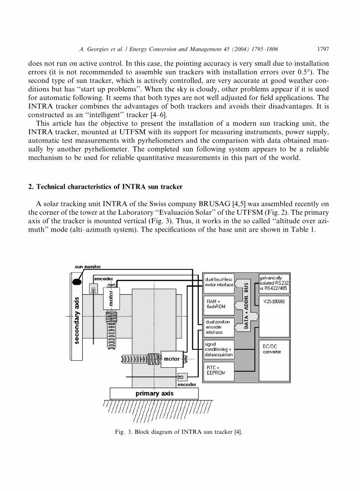
A solar tracking unit INTRA of the Swiss company BRUSAG [4,5] was assembled recently onthe corner of the tower at the Laboratory ‘‘Evaluaci�on Solar’’ of the UTFSM (Fig. 2). The primaryaxis of the tracker is mounted vertical (Fig. 3). Thus, it works in the so called ‘‘altitude over azi-muth’’ mode (alti–azimuth system). The specifications of the base unit are shown in Table 1.
Fig. 3. Block diagram of INTRA sun tracker [4].

Table 1
Specifications of INTRA sun tracker
Mechanical specifications
Mass 25 kg (base unit)
Physical dimensions D� W � H (mm): 350· 318 · 318 (base unit)
Configuration Altitude over azimuth axis
Motors Brushless DC Motor on each axis (Minimotor, Type 2444 S BL1 K315 with
attached gear type 30/1S/66:1 MM529)
Gear Worm drive, ratio 150:1 coupled with 1:1 (toothed) belt drive to 66:1 gear, which is
directly coupled to the motor
Position encoders Coding disks that are attached directly to primary and secondary axis, respectively
Resolution 9380 cnts per 360� corresponding to a resolution of 0.038�Maximum capacity 30 kg or 90 Nm shared among both flanges or 20 kg/60 Nm total on single flange
Maximum speed 100�/min (either axis)
Electrical specifications
Supply voltage 24 V DC nominal (minimum: 10 V, maximum: 30 V)
Current (at 24V) (without heater)
Peak 2 A maximum
Operating <500 mA (typical)
Standby <50 mA (typical)
Fuse Type EU £5 · 20 mm, 3.15 A, slow
Serial interface RS232-C or RS422 or RS485 (selectable), default settings are: 9600 Baud, 8 data,
1 stop bit, no parity
Protection All electrical lines to and from the tracker are filtered and protected with 1.5 kW
transorb-type diodes
Operational specifications
General Built for operational outdoor use
Temperature )30 to 50 �C, )46 to 50 �C with heater option
Pointing ±0.25� maximum pointing error (±0.1� typical, after several days ofoperation during good weather conditions)
1798 A. Georgiev et al. / Energy Conversion and Management 45 (2004) 1795–1806
2.1. Hardware overview [4]
The sun tracker case contains a controller board and a sun monitor. Thus, it is a compact unit,which needs an external power supply of 24 V DC nominal for its autonomous operation (Fig. 3).The memory (RAM) and the clock (RTC) are powered with a back up power supply, allowingoperation during power failures.
The primary and secondary axes have identical hardware. Each one of the drives uses a wormgear driven by a brushless DC motor. Encoder disks on both axes allow decoding of axes positionwith a resolution better than 0.05�. An index mark that determines the hardware zero position ofthe axes is situated on each encoder disk.
The sun monitor of the INTRA unit, a 4 quadrant silicon diode, allows the measurement of theresulting pointing errors. The diameter of its active area is 1.88 mm. The sun monitor is installedin a tube with a 0.9 mm aperture at a distance of 5 mm from the surface of the diode, giving auseful aperture angle of approximately ±5�. However, the monitor will ‘‘saturate’’ at this angleand yield 5� deviations for angles up to approximately ±15�.

A. Georgiev et al. / Energy Conversion and Management 45 (2004) 1795–1806 1799
2.2. Working modes [4]
The sun tracker can work in any one of the following 3 modes:
• Clock mode––Here, the tracker uses the date/time information of its RTC and calculates theposition of the sun. All the pointing errors appearing during this work in the day are storedfor later analysis. A rewind to the morning position of INTRA is performed when the sun dis-appears behind the (mathematical) horizon. Analysis of the data of the pointing errors duringthe day follows for the next day. An improved set of parameters is computed to compensateeventual installation errors. The new data will be used the next day to compute in a more accu-rate way the path of the sun.
• Sun mode––The tracker uses the signal of the sun monitor to control actively the pointing. Incase the intensity decreases below a certain level, automatic change to the clock mode happens,and the pointing errors are collected and used for analysis during the night. The INTRA unitworks during the night in clock mode. The use of this mode is recommended because it leads tothe best pointing results, especially during the period following initial installation.
• Remote mode––The primary and secondary values are set by commands (for example of theoperator) sent to the tracker using its serial interface. No special operations are done duringthe night in this mode. The primary and secondary values are measured in the astronomicalsystem. That is slightly different from the tracker system (installation errors computed by thetracker).
• The so called monitor mode is available, too, and is used to configure the INTRA sun tracker inthe non-operational mode.
3. Installation of the tracker
3.1. Mechanical and electrical preparation
For installation in the Laboratory, a special concrete stand was constructed to support the unit(Fig. 2). Metal parts were anodized because of this permanent work under seaside outdoorconditions.
Additionally, the support to hold the measuring instruments was designed and built (Fig. 2). Ithas five grooves where different measuring instruments can be installed. The used material isaviation grade duralumin.
A Brown & Sharpe MicroVal 454 Coordinate Measuring Machine was used to measure theparallelism between four of the grooves (excepting the most distant one from the trackers body).The test was done as follows. The same pyrheliometer was put consistently in every one of the fourgrooves. Its face looking to the sun was measured on three points, defining a plane. Then, thedeviation between every two planes was measured. The results were as follows:
40 5900, 20 36
00, 10 58
00, 40 2
00, 60 52
00, 40 22
00,
the biggest difference being is not more than 70, a difference small enough.
1800 A. Georgiev et al. / Energy Conversion and Management 45 (2004) 1795–1806
A 24 V DC/3A fixed voltage power supply FPS was installed to power the sun tracker unit. Itwas safety tested according to EN 61010. Later on, two 12 V batteries will be added to providepower during net failures.
3.2. Electronic preparation
As said before, the INTRA tracker is designed as an intelligent tracker. It combines theadvantages of sun controlled and calculated path trackers without their disadvantages. Using itsbuilt in solar sensor, it will learn from its pointing errors, and after running a few days with goodweather conditions, it calculates the specific path for its location and its pointing exactitude will bewithin the specified maximum error of ±0.25� [4].
The tracker has been adjusted at the factory. As the producer cannot characterize the trackerfor the installation in our Laboratory, there will always be some misalignment due to installationerrors between the astronomical system and the system of the tracker. The tracking will be asgood as our installation is.
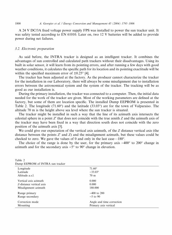
During the primary installation, the tracker was connected to a computer. Then, the initial dataneeded for the work of the tracker are given. Most of the working parameters are defined at thefactory, but some of them are location specific. The installed Dump EEPROM is presented inTable 2. The longitude (71.60�) and the latitude (33.03�) are for the town of Valparaiso. Thealtitude 70 m is the height above sea level where the sun tracker is situated.
The tracker might be installed in such a way that the line of its azimuth axis intersects thecelestial sphere in a point Z 0 that does not coincide with the true zenith Z and the azimuth axis ofthe tracker may have been fixed in a way that direction south does not coincide with the zeroposition of the azimuth axis [5].
We could give our expectation of the vertical axis azimuth, of the Z distance vertical axis (thedistance between the points Z 0 and Z) and the misalignment azimuth, but these values could bechecked to zero. We gave the values of 0 and only in the last case––180�.
The choice of the range is done by the user, for the primary axis )400� to 200� change inazimuth and for the secondary axis )5� to 90� change in elevation.
Table 2
Dump EEPROM of INTRA sun tracker
Longitude 71.60�Latitude )33.03�Altitude a.s.l. 70 m
Vertical axis azimuth 0.000
Z-distance vertical axis 0.000
Misalignment azimuth 180.000
Range primary )400 to 200
Range secondary )5 to 90
Correction mode Angle and time correction
Mounting Primary axis vertical

A. Georgiev et al. / Energy Conversion and Management 45 (2004) 1795–1806 1801
If the tracker is expected to be installed with negligible misalignment, the answer ‘‘no correc-tion’’ can be selected for the Correction Mode. Normally, it is better to choose ‘‘angle and timecorrection’’. Then, INTRA figures out its misalignment by examining the movement of the sun.After the tracker determined its misalignment with a precision of 0.05 degrees in every degree offreedom, further computations of the misalignment parameters are no longer calculated. Thecorrection status changes to �alignment errors corrected�. Then, the tracking unit uses itsastronomy information to correct the time errors of the internal real time clock.
After that, the tracker was tested successfully by the procedure described above, and mea-surements can begin.
4. Measurements
4.1. Preparation
Three pyrheliometers of the company ‘‘The Eppley Laboratory, Inc.’’ were mounted on thesupport for measuring instruments (Fig. 4). They have the following parameters:
Type: horizontal surfaceModel: 15Constant: 3.75 mV/(cal/(cm2 min)) or 186.08 mV/(W/m2)
Type: normal incidenceModel: NIPConstant: 5.19 mV/(cal/(cm2 min)) or 134.45 mV/(W/m2)
Fig. 4. INTRA sun tracker with three Eppley pyrheliometers.

Fig. 5. Manual measurement with Kipp & Zonen pyrheliometer.
1802 A. Georgiev et al. / Energy Conversion and Management 45 (2004) 1795–1806
Type: normal incidenceModel: NIPConstant: 5.15 mV/(cal/(cm2 min)) or 135.49 mV/(W/m2)
The signal obtained from the pyrheliometers is some mV. Amplifiers are used to get a signalable to be fed to an analog to digital converter card, and some computer software is used to storethe data.
These pyrheliometers have been compared with the Eppley group of reference standards. Thedelivered value of the constant for the instruments is mentioned above.
A pyrheliometer of the type Kipp & Zonen was used for manual measurements (Fig. 5). It hasthe following parameters:
Resistance of thermopile: 68.5 XTemperature factor: ½1þ 0:002ðt � 20�Þ�Constant: 11.4 mV/(cal/(cm2 min)) or 61.21 mV/(W/m2)
All the pyrheliometers were calibrated shortly before the measurements.
4.2. Implementation
Measurements were done with the mentioned pyrheliometers, automatically with the Eppley,manually with the Kipp & Zonen.

A. Georgiev et al. / Energy Conversion and Management 45 (2004) 1795–1806 1803
The values registered in the computer are divided by the amplification factor (for the differentchannels it had the values 335.4; 305.9 and 306.6). The obtained value has the dimension alreadyin mV. The following equation is used to obtain the measured radiation in W/m2:
Fig. 6
Kipp
I ¼ x � ð697:8=sÞ ð1Þ
where I is irradiance, W/m2; x is output voltage of the pyrheliometer, mV; s is the constant of thepyrheliometer, mV/(cal/(cm2 min)).
The radiation measured with the Kipp & Zonen pyrheliometer is calculated by means of anequation similar to Eq. (1)
I ¼ x � ð697:8=sÞ � ½1þ 0:002 � ðt � 20�Þ� ð2Þ
where t is ambient temperature, �C.We chose the data of four measurements (three in clock mode and one in sun mode). They are
presented in six figures (the different Eppley pyrheliometers are distinguished by their constant).Figs. 6 and 7 show the operation of the sun tracker in clock mode at 24.12.02 (The registeredradiation was very changeable, the difference between the Eppley pyrheliometers data is verysmall, but their comparison with the K&Z pyrheliometer data shows sometimes big differences,mainly due to their different time constants.) The measurements done during the sun trackeroperation in clock mode (Fig. 8) and sun mode (Fig. 9) on 26.12.02 show relatively stable radi-ation during the day. Additionally, all the measurements during both days––24.12.02 (Fig. 10)
. Comparison of the irradiance measured automatically with three Eppley pyrheliometers and manually with
& Zonen pyrheliometer on 24.2.2002 in clock mode (first part of the day).

Fig. 7. Comparison of the irradiance measured automatically with three Eppley pyrheliometers and manually with
Kipp & Zonen pyrheliometer on 24.12.2002 in clock mode (second part of the day).
Fig. 8. Comparison of the irradiance measured automatically with three Eppley pyrheliometers and manually with
Kipp & Zonen pyrheliometer on 26.12.2002 in clock mode (first part of the day).
1804 A. Georgiev et al. / Energy Conversion and Management 45 (2004) 1795–1806
and 26.12.02 (Fig. 11) are presented. The comparison between the automatic and manually ob-tained curves shows good coincidence.

Fig. 9. Comparison of the irradiance measured automatically with three Eppley pyrheliometers and manually with
Kipp & Zonen pyrheliometer on 26.12.2002 in sun mode (second part of the day).
Fig. 10. Comparison of the irradiance measured automatically with three Eppley pyrheliometers and manually with
Kipp & Zonen pyrheliometer on 24.12.2002.
A. Georgiev et al. / Energy Conversion and Management 45 (2004) 1795–1806 1805
5. Conclusions
Measurements were implemented automatically with three Eppley pyrheliometers and manu-ally with a Kipp & Zonen pyrheliometer. The fair coincidence difference of about 60 W/m2, about

Fig. 11. Comparison of the irradiance measured automatically with three Eppley pyrheliometers and manually with
Kipp & Zonen pyrheliometer on 26.12.2002.
1806 A. Georgiev et al. / Energy Conversion and Management 45 (2004) 1795–1806
6% at 1000 W/m2 between the radiations measured with the different pyrheliometers, shows thatfor successful future measurements with this installation, the instruments must be calibratedagainst the PMO6 cavity radiometer of the National Meteorological Society.
The created installation is very good for two main purposes:
• to measure the direct component in the visible part of the solar spectrum;• the UV A+B components to detect changes of the ozone column.
The system enables study of:
• the direct radiation needed for concentrating solar collector technologies;• the validation of the global radiation components obtained independently;• the measurements of the ozone column and its comparison with data obtained by satellite.
References
[1] Finster C. El heliostato de la Universidad Santa Maria. Scientia 1962;1l9:5–20.
[2] Saavedra AS. Dise~no de un servomecanismo seguidor solar para un instrumento registrador de la irradiaci�on solar
directa. Memoria, Universidad T�ecnica Federico Santa Maria, Valpara�ıso, Chile, 1963.[3] Maldonado JA. Dise~no y construcci�on de un sistema de control autom�atico para el posicionamiento de un
pirheli�ometro. Memoria, Universidad T�ecnica Federico Santa Maria, Valpara�ıso, Chile, 1983.[4] BRUSAG. Sensorik & messtechnische Entwicklungen, INTRA Installation Manual, INTRA/DOC/206-BRU,
St€afa, Switzerland, Version 2.31, 1998.
[5] BRUSAG. Sensorik & messtechnische Entwicklungen, INTRA Reference Manual, INTRA/DOC/207-BRU, St€afa,Switzerland, Version 2.31, 1998.
[6] BRUSAG. Sensorik & messtechnische Entwicklungen, Electronic catalogue, <http://www.brusag.ch/>, 2002.