Obstacles Avoidance for Car-like Robots Integration and Experimentation on Two Robots
Upload
institut-imageCategory
view
1download
0
Study of an External Passive Shock-absorbing
Mechanism for Walking Robots
Anthony David, Jean-Remy Chardonnet, Abderrahmane Kheddar, Kenji
Kaneko, Kazuhito Yokoi
To cite this version:
Anthony David, Jean-Remy Chardonnet, Abderrahmane Kheddar, Kenji Kaneko, KazuhitoYokoi. Study of an External Passive Shock-absorbing Mechanism for Walking Robots. Hu-manoids’08: 8th International Conference on Humanoid Robots, Dec 2008, Daejeon, SouthKorea. IEEE-RAS, pp.435-440. <lirmm-00536303>
HAL Id: lirmm-00536303
http://hal-lirmm.ccsd.cnrs.fr/lirmm-00536303
Submitted on 15 Nov 2010
HAL is a multi-disciplinary open accessarchive for the deposit and dissemination of sci-entific research documents, whether they are pub-lished or not. The documents may come fromteaching and research institutions in France orabroad, or from public or private research centers.
L’archive ouverte pluridisciplinaire HAL, estdestinee au depot et a la diffusion de documentsscientifiques de niveau recherche, publies ou non,emanant des etablissements d’enseignement et derecherche francais ou etrangers, des laboratoirespublics ou prives.
Study of an External Passive Shock-absorbingMechanism for Walking Robots
Anthony DavidJRL AIST/CNRS
Jean-Remy ChardonnetLIRMM - CNRSJRL AIST/CNRS
Abderrahmane KheddarLIRMM - CNRSJRL AIST/CNRS
Kenji KanekoIS - AIST
Kazuhito YokoiIS - AIST
JRL AIST/CNRS
Abstract—This paper proposes a compliant sole as an ex-ternal shock-absorbing mechanism and investigates its effectcomparatively to an ankle-located joint-flexible mechanism. Theproposed mechanism is mounted under the HRP-2 humanoidfeet only using simulation. The comparative evaluation has beenconducted for contact resulting from walking using the HRP-2 embedded pattern-generator. The characteristics of the solematerial, Young and Poisson coefficients, are set following an ad-hoc minimization of their influence on the vertical accelerationand lateral inclination. Preliminary results suggest that thesolution proposed is worth to be considered further and to bedeveloped for real application use.
I. I NTRODUCTION
A walking gait is generated by successive interactionsbetween the humanoid’s feet and the environment. This in-teraction is made through discreet contact formation, contactholding and contact release. The robustness of the walkinggait depends in part on the quality of these interactions. Afast displacement of the robot requires precise control of theseinteractions and involves the capabilities for the hardware todeal with high impact forces. Furthermore, the future use ofhumanoid robots will not be made only on flat floors withsmooth lands, as it is the case nowadays. In such case, it ismore difficult to model with accuracy the environment. Thisinduces premature contacts with the environment which createimpacts and then vibrations on the robot’s structure. Indeed,these impacts can excite mechanical resonance frequenciesofthe robot. Consequently, the movement of the robot is more orless jerky. In order to have smooth movements and to protectthe robot structure and its embedded mechatronics, the robotmust be able to absorb these impacts. To deal with this problemtwo directions are undertaken.
The first approach consists in using internal passive mecha-nisms. For example, shock-absorbing mechanisms are imple-mented in the feet of the robots. Bruneauet. alproposes a footcombined from four rigid bodies linked by flexible-joints [1]and claimed the difficulty in using finite-element method formodeling these flexibilities. The feet are composed of fourbodies, related by three rotary joints with torsion spring-dampers. Internal passive mechanisms have been used foralmost all humanoid robots such as Asimo [2] and HRP-2 [3].The impact absorption mechanism of Asimo is composed ofrubber bushes inserted into a guide. It deforms elasticallyinthe vertical direction upon a force being transmitted from thesole. The shock-absorbing mechanism of HRP-2 is composed
of three rubber bushes with dampers and connects the end linkof each ankle to the sole link. Since the material of the rubberbushes is elastic, the bushes absorb the impacts.
The second approach consists in using external passivemechanisms. For example, Yamaguchiet. al use multi-composite soles with a complex arrangement [4]. This mech-anism allows also to detect the landing path surface and toabsorb the impact impulses. External passive mechanisms canalso be used to protect robots when falling. The UKEMImethod [5] is based on the utilization of flexible materialsfixed on different points of the robot HRP-2P. These flexiblematerials allow to absorb impact and, so, to protect the robot.
The objective of this work is to investigate a shock-absorbing system consisting in a compliant sole covering therigid structure of each foot and interacting directly with thefloor. Unlike the compliant elements described in [5], ourcompliant sole is not present only to absorb impacts but therobot must also be able to walk with it. Depending on itsdesign, it can also be helpful for walking, as explained, forexample, in [1] [6]. Furthermore, external shock-absorbingmechanisms that were previously introduced are not modeledanalytically, whereas here we propose to integrate the ana-lytical model of our sole in the simulator presented in [7][8]. These investigations are made, in particular, for the robotHRP-2 but our method extends to other humanoid robots.In a first time a sole composed of one compliant materialis studied. Unlike the compliant sole developed in [9], ourcompliant sole will interact directly with the environment(itis not a compliant link between two rigid plates) and doesnot have internal sensors, like potentiometers. The secondstep is to evaluate, in simulation, the capacities of this soleto absorb shocks during walking gaits. For this purpose,the results obtained are compared with the shock absorbingmechanism implemented on HRP-2 [10]. Note that having anexternal deformable sole has also other benefits such as betteradhesive properties and adapting, through deformation, totheirregularities of the terrain. In fact the idea is to investigate anall-in-one solution through an external sole foot-cover.
The organization of this paper is as follows. In Section II,the analytical models used are recalled. Next, in Section III,a simulation study to determinate the characteristics of thecompliant sole is presented. Section IV discusses a compar-ative study between two shock-absorbing mechanisms: thecompliant soles and the compliant joints.
II. M ODELING
We considered a compliant sole consisting simply on a par-allelepiped shape mounted under each HRP-2 foot. To studythis solution, one needs to model correctly the deformationof the sole and to extend the dynamic model of the rigidarticulated structure to take into account this deformation.These two models (rigid robot structure and the deformablesole) are discussed separately and they are then summed-up.The models are written in 3-dimensions. Cartesian coordinates(~x, ~y, ~z), with ~z being the opposite direction to the gravity, areused. The simulation’s numerical integration time-step isδt.
A. Analytical models for poly-articulated rigid bodies
In order to compute impact impulses or contact forces whencontacts occur during walking, a constraint-based method isused because it proves to be very robust and require fewparameters to set independently from the integration numericalmethod compared to penalty-based method. Constraint-basedmethod requires writing relative velocities between pairsofpotential contacts and split each pair of contact into orthog-onal (normal) and tangent spaces. At the orthogonal spacethe Signorini non penetration constraint is written in termsof a complementary condition between the normal velocityand impact impulse or contact force (depending whether thecontact is new or holding). In the tangent space the Coulombfriction constraint acts as a constraint, see [7] for more details.
1) Contact force model:The robot moves according to thefollowing well-established dynamic equation:
M(q)q + C(q, q) + G(q) = Γ + JTc (q)Fc (1)
with M(q) the inertia matrix of the robot;C(q, q) the centrifu-gal and Coriolis forces vector;G(q) the gravity forces vector;Γ the joint torques vector (including zeros for non-actuatedjoints);Jc(q) the Jacobian matrix;Fc the contact forces vector;q the configurations vector (including robot attitude: positionand orientation of the body in space).
Because of the presence of friction and impacts, we considerprojection of contact constraints in the velocity space, avoidingproblems described in [11]. Letni be the unit normal vectordefined for each potential contacti. The perpendicular planto the vectorni is defined by the couples of vectorsti =(t1i, t2i). A plan/plan contact can be discretized intom contactpoints.
Since the floor is static, relative operational accelerationvector a of the contact points can be written using theconfiguration acceleration vectorq as:
a = Jcq + Jcq (2)
Combining (1) and (2) gives the link betweena and thecorresponding contact force vectorFc:
a = JcM−1JT
c Fc + JcM−1[Γ − C − G] + Jcq
= Λ−1Fc + afree
(3)
with Λ = (JcM−1JT
c )−1 the inverse of the operationalinertia matrix (also called the Delassus operator);afree the freeaccelerations vector of the contact points.
Finally, the velocity update is obtained by integrating (3)with an explicit Adams formula of order 1:
vt = vt−δt + (Λ−1F tc + afree)δt
= Λ−1δtF tc + afreeδt + vt−δt = WF t
c + vfree
(4)
with W = Λ−1δt; v the velocities vector of the contactpoints;vfree the free velocities vector of the contact points. TheCoulomb friction model is used as an additional constraint,that is:‖Fcit
‖ ≤ µiFcin.
2) Impact impulse model:The impacts are determinedwith an event-based approach and are therefore consideredas instantaneous. This hypothesis of instantaneous impacts,involves an abrupt change at the velocity level and, conse-quently, a discontinuity at the acceleration level. As for thecontact forces model, the velocity of the given impact pointi, depends on whether the impact remains (or not) inside thefriction cone, that is [12]:
v+
in= −ǫv−
in= −ǫJcin
q−
‖pcit‖ < µipcin
sticking
‖pcit‖ = µipcin
v+
it∥∥v+
it
∥∥ sliding
(5)
with v+
inthe normal velocity of the impact pointi just after
the impact;v−
inthe normal velocity of the impact pointi just
before the impact;ǫ the coefficient of restitution;pcitthe
tangential impact impulse vector andpcinthe normal impact
impulse. Eq. (5) is completed, for each of them impact points,with the following equations linking the impact impulse vectorpc to the velocity vectorv+: pc = Λ(v+ − Jcq
−).
B. Analytical model of compliant soles
Now, we consider that contact’s position or velocity are thesum contribution of two connected sub-systems: a rigid and adeformable parts. The position of any point on the sole is thesum of the rigid motion induced by the robot structure and thedeforming motion induced by sole flexibility. For this, a FiniteElement Model is used in order to model the deformation ofthe compliant soles and integrate them in the previous rigidbody analytical model. This approach is based on [13].
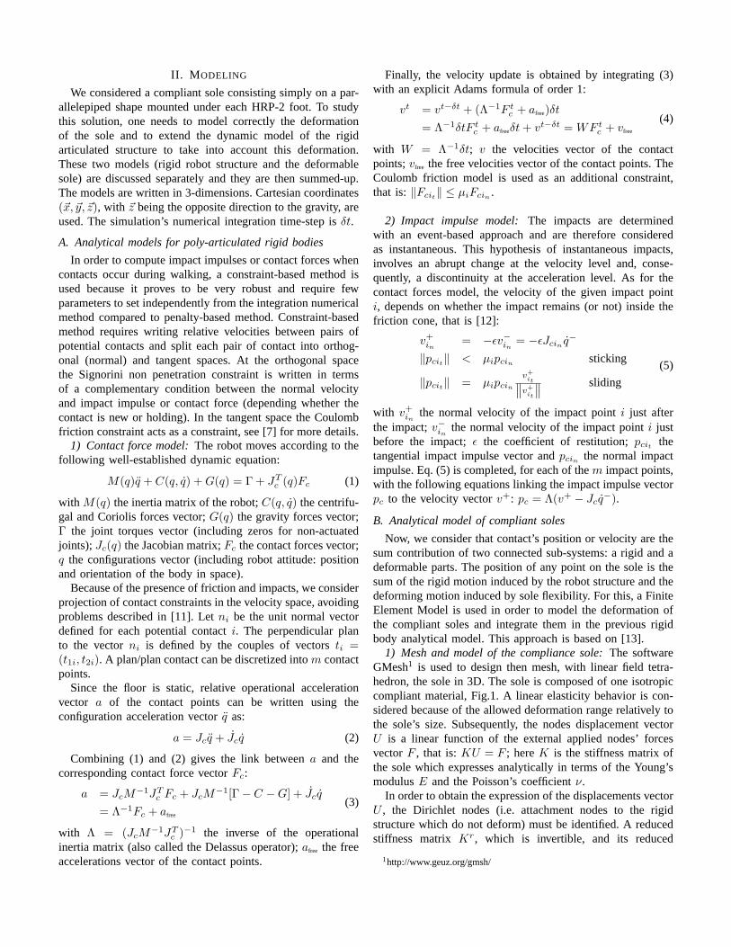
1) Mesh and model of the compliance sole:The softwareGMesh1 is used to design then mesh, with linear field tetra-hedron, the sole in 3D. The sole is composed of one isotropiccompliant material, Fig.1. A linear elasticity behavior iscon-sidered because of the allowed deformation range relatively tothe sole’s size. Subsequently, the nodes displacement vectorU is a linear function of the external applied nodes’ forcesvectorF , that is:KU = F ; hereK is the stiffness matrix ofthe sole which expresses analytically in terms of the Young’smodulusE and the Poisson’s coefficientν.
In order to obtain the expression of the displacements vectorU , the Dirichlet nodes (i.e. attachment nodes to the rigidstructure which do not deform) must be identified. A reducedstiffness matrix Kr, which is invertible, and its reduced
1http://www.geuz.org/gmsh/
displacements vectorUr are obtained by simply deleting thelines and columns corresponding to the Dirichlet nodes.
Fig. 1. The meshed sole mounted on the rigid part of each HRP-2 feet.
2) The complete contact force model:Here the rigid anddeformable sub-systems are combined. This consists simplyin adding the deformation velocities vector,Uc, of the surfacenodes that are contacting in eq. (4), such that:
vt = WF tc + vfree + U t
c (6)
Uc can be written as follows:
U tc =
U tc − U t−dt
c
dt=
K−1c F t
c − U t−dtc
dt(7)
with Kc the stiffness matrix of the surface nodes in contact.The vectorUc and the matrixKc are obtained using a classicalcondensation operation:
[Kcc Kcn
Knc Knn
][Uc
Un
]=
[Fc
Fn
](8)
where the indexc denotes the nodes that are in contact andn
the remaining nodes.In order to obtain a linear relation only betweenUc and
Fc but taking into account the influence of the other nodes,eq. (8) is developed:
KccUc + KcnUn = Fc (9)
KncUc + KnnUn = Fn (10)
Un is then isolated in eq. (10) and its expression is introducedin eq. (9). As there is no external forces applied on internalnodes (Fn = 0), the expression ofFc is:
Fc =[Kcc − KcnK−1
nn Knc
]Uc = KcUc (11)
Finally, with eqs. (7) and (11), eq. (6) becomes:
vt =
(W +
K−1c
dt
)
︸ ︷︷ ︸W
F tc +
(vfree −
U t−dtc
dt
)
︸ ︷︷ ︸vfree
= WF tc + vfree
(12)
This model is similar to the rigid bodies model given by eq. 4.When the robot is equipped with compliant soles, a specific
model describing the impact is not needed since there isno abrupt change at the velocity level for the rigid part ofthe robot. The compliant soles gradually change the velocityprofile of the robot along the normaln.
C. Analytical model of compliant joints
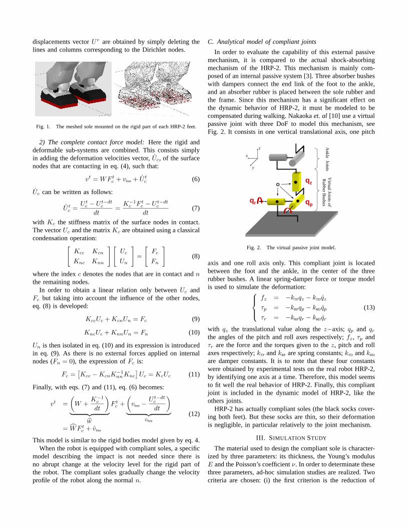
In order to evaluate the capability of this external passivemechanism, it is compared to the actual shock-absorbingmechanism of the HRP-2. This mechanism is mainly com-posed of an internal passive system [3]. Three absorber busheswith dampers connect the end link of the foot to the ankle,and an absorber rubber is placed between the sole rubber andthe frame. Since this mechanism has a significant effect onthe dynamic behavior of HRP-2, it must be modeled to becompensated during walking. Nakaokaet. al [10] use a virtualpassive joint with three DoF to model this mechanism, seeFig. 2. It consists in one vertical translational axis, one pitch
Ankle Joints
Virtual Joints of
Rubber Bushes
x
y
z
Oqz
qpqr
Fig. 2. The virtual passive joint model.
axis and one roll axis only. This compliant joint is locatedbetween the foot and the ankle, in the center of the threerubber bushes. A linear spring-damper force or torque modelis used to simulate the deformation:
fz = −kTPqz − kTDqz
τp = −kRPqp − kRDqp
τr = −kRPqr − kRDqr
(13)
with qz the translational value along thez−axis; qp and qr
the angles of the pitch and roll axes respectively;fz, τp andτr are the force and the torques given to thez, pitch and rollaxes respectively;kTP andkRP are spring constants;kTD andkRD
are damper constants. It is to note that these four constantswere obtained by experimental tests on the real robot HRP-2,by identifying one axis at a time. Therefore, this model seemsto fit well the real behavior of HRP-2. Finally, this compliantjoint is included in the dynamic model of HRP-2, like theothers joints.
HRP-2 has actually compliant soles (the black socks cover-ing both feet). But these socks are thin, so their deformationis negligible, in particular relatively to the joint mechanism.
III. S IMULATION STUDY
The material used to design the compliant sole is character-ized by three parameters: its thickness, the Young’s modulusE and the Poisson’s coefficientν. In order to determinate thesethree parameters, ad-hoc simulation studies are realized.Twocriteria are chosen: (i) the first criterion is the reductionof

the acceleration peaks of the reference point along the gravitydirection –it is along this direction that the effects of theimpact are the most dominant, and (ii) the second criterionis the lateral inclination of the waist. These two criteria haveantagonistic effects. Indeed, the more compliant the sole is, themore important acceleration’s peaks reduction is –the velocityof the robot is damped progressively. However, the morecompliant the sole is, the more important its deformation is;consequently, the more important the waist inclination is.Thisresults very likely in highly unbalanced robot that will be hardto control. In view of all this discussion, it appears clearly thata compromise is to be found between these two criteria.
The thickness of the sole is taken to be2cm (max allowed,it can be optimized as well). The most important issue isto be sure that the maximum deformation never reaches theplastic domain in practical use, since in this case, the behaviorswitches to a rigid body.
For each of the two other parameters a range is chosen.For a perfect isotropic material, the theorytical value of thePoisson’s coefficient is0.25. Furthermore, this coefficient isalways inferior to0.5. If ν is equal to0.5, the material isperfectly incompressible. So, the following variation range ischosen:ν ∈ [0.01 · · · 0.49]. Concerning the Young’s modulus,an elastic material, as gum or rubber for example, is desired.The gum has a Young modulus between1.5MPa and5.0MPa.So, the following range is chosen:E ∈ [1 · · · 10]MPa.
Two series of simulations are realized, one for each pa-rameter. For the reduction of the acceleration peaks alongthe gravity direction, the robot is dropped above the groundfrom a height of1cm. It is in standing position with straightlegs. The maximum acceleration along the gravity directionismeasured. For the lateral inclination, the robot starts with astanding position on the ground. It waist inclination is zero.Next, the waist inclination tends, gradually, toward a desired14.3◦. The difference between this desired inclination and themeasured inclination is determined. This difference is duetothe presence of the compliant sole.
00.1
0.20.3
0.40.5
02
46
810
x 106
15.1
15.2
15.3
15.4
15.5
nuE (MPa)
Ang
le (
degr
ee)
Fig. 3. Evolution of the waist inclination.
00.1
0.20.3
0.40.5
02
46
810
x 106
20
40
60
80
100
120
140
160
nuE (MPa)
Acc
eler
atio
n (m
/sec2 )
Fig. 4. Evolution of the maximum acceleration of the referencepoint alongz.
Fig. 3 summarizes the results obtained for the inclination ofthe waist and Fig. 4 summarizes the results obtained for themaximum acceleration of the reference point along the gravitydirection. The previous remark concerning the antagonisticeffect of these criteria is visible.
Considering these results, the following parameters arechosen:E = 4.0MPa andν = 0.3. These parameters givean acceptable inclination of the waist and a good decreaseof the maximum acceleration of the reference point along thegravity direction.
IV. COMPARATIVE STUDY
In order to measure the contribution of the proposed shockabsorbing mechanism (the compliant sole), the results of threedifferent simulations are compared. Firstly, HRP-2 is simulatedwithout any shock absorbing mechanism, i.e. without anycompliance. The results of this simulation are the reference tomeasure the contribution of each shock-absorbing mechanism.Secondly, HRP-2 is simulated with the real shock absorbingmechanism using the model recalled in section II-C. Thiscorresponds to what is embedded on the real HRP-2. Thirdly,HRP-2 is simulated with the proposed shock absorbing mech-anism, i.e. with the compliant soles. For each of the threesimulations, the robot motion is made by the same referencecontrol law. The reference trajectory is provided by the patterngenerator described in [14]. The reference trajectory allowssimulating a walking gait, where the robot avoids an obstaclein the spanning. This walking gait is composed of six stepsand lasts six seconds. The maximum velocity of the referencepoint is equal to0.3m/sec, and the maximum length step is0.45m. The reference trajectory is played directly with simplePD controls.
The evolution of a reference point, located on the waist ofHRP-2, along thez axis is compared. This axis correspondsto the opposite direction of gravity. Along this axis the effectsof impacts, between the feet and the ground, and the effects ofthe compliant elements are the most visible. The evolution of
0 1 2 3 4 5 60.659
0.66
0.661
0.662
0.663
0.664
0.665
0.666
0.667
Time (s)
Var
iatio
n of
pos
ition
s (m
)
no compliancejoint compliancesole compliance
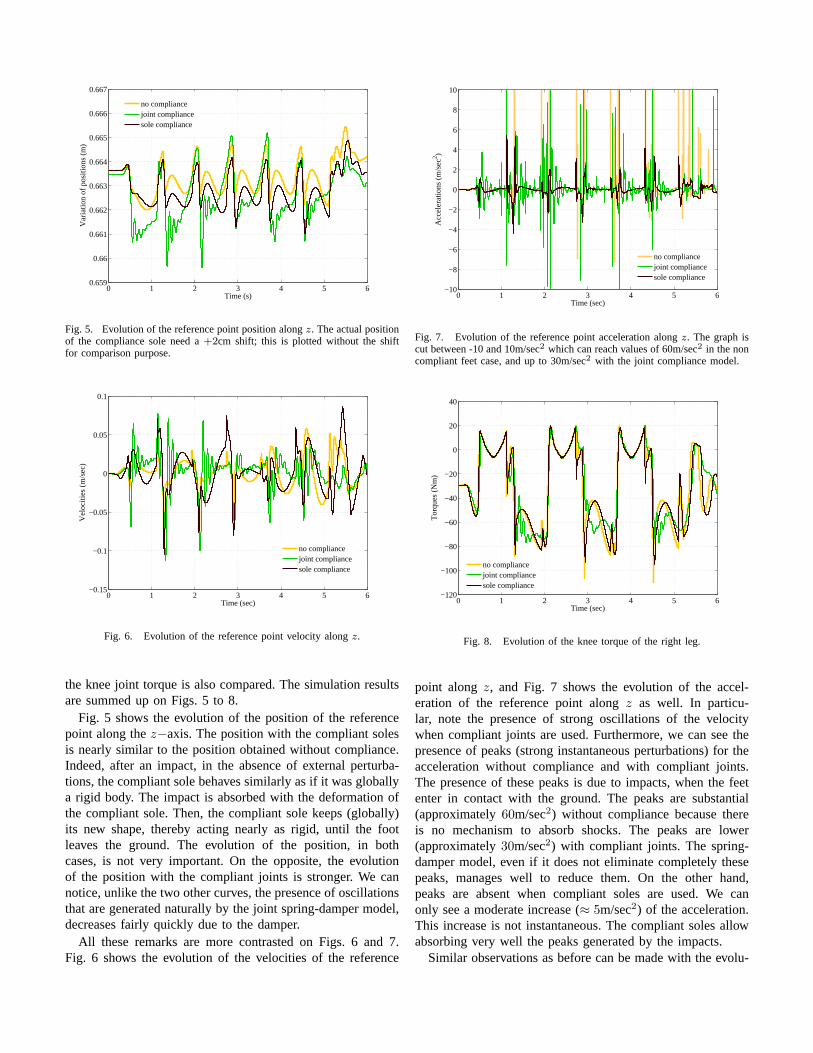
Fig. 5. Evolution of the reference point position alongz. The actual positionof the compliance sole need a+2cm shift; this is plotted without the shiftfor comparison purpose.
0 1 2 3 4 5 6−0.15
−0.1
−0.05
0
0.05
0.1
Time (sec)
Vel
ociti
es (
m/s
ec)
no compliancejoint compliancesole compliance
Fig. 6. Evolution of the reference point velocity alongz.
the knee joint torque is also compared. The simulation resultsare summed up on Figs. 5 to 8.
Fig. 5 shows the evolution of the position of the referencepoint along thez−axis. The position with the compliant solesis nearly similar to the position obtained without compliance.Indeed, after an impact, in the absence of external perturba-tions, the compliant sole behaves similarly as if it was globallya rigid body. The impact is absorbed with the deformation ofthe compliant sole. Then, the compliant sole keeps (globally)its new shape, thereby acting nearly as rigid, until the footleaves the ground. The evolution of the position, in bothcases, is not very important. On the opposite, the evolutionof the position with the compliant joints is stronger. We cannotice, unlike the two other curves, the presence of oscillationsthat are generated naturally by the joint spring-damper model,decreases fairly quickly due to the damper.
All these remarks are more contrasted on Figs. 6 and 7.Fig. 6 shows the evolution of the velocities of the reference
0 1 2 3 4 5 6−10
−8
−6
−4
−2
0
2
4
6
8
10
Time (sec)
Acc
eler
atio
ns (
m/s
ec2 )
no compliancejoint compliancesole compliance
Fig. 7. Evolution of the reference point acceleration alongz. The graph iscut between -10 and 10m/sec2 which can reach values of 60m/sec2 in the noncompliant feet case, and up to 30m/sec2 with the joint compliance model.
0 1 2 3 4 5 6−120
−100
−80
−60
−40
−20
0
20
40
Time (sec)
Tor
ques
(N
m)
no compliancejoint compliancesole compliance
Fig. 8. Evolution of the knee torque of the right leg.
point alongz, and Fig. 7 shows the evolution of the accel-eration of the reference point alongz as well. In particu-lar, note the presence of strong oscillations of the velocitywhen compliant joints are used. Furthermore, we can see thepresence of peaks (strong instantaneous perturbations) for theacceleration without compliance and with compliant joints.The presence of these peaks is due to impacts, when the feetenter in contact with the ground. The peaks are substantial(approximately60m/sec2) without compliance because thereis no mechanism to absorb shocks. The peaks are lower(approximately30m/sec2) with compliant joints. The spring-damper model, even if it does not eliminate completely thesepeaks, manages well to reduce them. On the other hand,peaks are absent when compliant soles are used. We canonly see a moderate increase (≈ 5m/sec2) of the acceleration.This increase is not instantaneous. The compliant soles allowabsorbing very well the peaks generated by the impacts.
Similar observations as before can be made with the evolu-
tion of the joint torques. For example, that of the knee ofthe right leg (see Fig.8) have light oscillations when jointcompliance is used. The two other curves do not exhibit theseoscillations.
To sum-up, the absence of compliance involves the presenceof strong instantaneous perturbations (peaks) when each footenters in contact with the ground. Outside these phases ofimpacts, the behavior of HRP-2 is smoother. The presenceof the compliant joints decreases the intensity of the peaks.However, these compliant joints induce oscillations and disturbthe tracking control law. The resulting behavior of HRP-2 is thus not completely smoother. Finally, the presence ofcompliant soles seems to solve both problems. The compliantsoles remove the peaks without generating oscillations. Thebehavior is nearly continuous during impact phases and thetracking is good between two impacts.
Nevertheless, we must note that the four constants of thecompliant joint were determined to represent the behavior ofthe real shock-absorbing mechanism that is actually mountedon HRP-2. The real system is not made of point flexiblejoints. More importantly, the parameters characterizing theactual shock absorbing mechanism of HRP-2 have not beenoptimized only for walking. They result from a compromiseto satisfy other requirements, among which the constraintsrelated to the design of the real mechanism (material used,integration, fabrication, etc.) which are limiting factors. Fur-thermore, the real shock-absorbing mechanism works also asa mechanical low-pass filter and respond to other issues thatare not disclosed. Therefore, the comparison is certainly notfair; it should be seen only as a tendency.
V. CONCLUSION AND PERSPECTIVE
The presence of compliant soles allows absorbing the pertur-bations generated by the impacts. Furthermore, contrary tothecompliant joint model, the compliant sole preserves a behaviorclose to the rigid non-compliant model when the contact holds.The control of the robot can consequently be realized withgood precision, without being disturbed by any oscillations.However, a more complete study will be necessary in orderto evaluate the capacity of the compliant sole to work as amechanical low-pass filter, as the shock-absorbing mechanismof HRP-2.
Moreover the intrinsic design of the sole allows the compli-ance to be located on the external part of the foot, contrary tothe shock-absorbing mechanisms that are located between tworigid parts of the robot (body structure and an external nearlyrigid plate). Therefore, the compliant sole has an infinite num-ber of DoF. It is not the case for internal mechanisms whichhave a finite and guided number of DoF. These infinite DoFoffers good adhesive and adaptation to roughness capabilitiesin addition of a pressure distribution along all the compliantsurface.
As explained in the introduction, this work is preliminaryinvestigation prior to the development of a more optimizedcompliant sole for the humanoid robots. For example, a morerefined shape could include an artificial toe joint only by
tapering the front part of the sole. So, the next step willconsist in improving the design for a new compliant solehaving eventually more complex composition. In particular,it will be interesting to compose with more than one materialin order to have a better absorption of impacts and a lessresidual deformation of the compliant sole with high adhesiveand local deformation at the contacting surface.
ACKNOWLEDGMENT
This research was partially supported by Grant-in Aid forJSPS Fellows.
REFERENCES
[1] O. Bruneau, F. B. Ouezdou, and J.-G. Fontaine, “Dynamic walk of abipedal robot having flexible feet,” inIEEE/RSJ International Confer-ence on Intelligent Robots and Systems, Maui, USA, October 2001, pp.512–517.
[2] K. Hirai, M. Hirose, Y. Haikawa, and T. Takenaka, “The developmentof honda humanoid robot,” inProceedings of IEEE International Con-ference on Robotics and Automation, Leuven, Belgium, May 1998, pp.1321–1326.
[3] K. Kaneko, F. Kanehiro, S. Kajita, H. Hirukawa, T. Kawasaki, M. Hirata,K. Akachi, and T. Isozumi, “Humanoid robot hrp-2,” inProceedingsof IEEE International Conference on Robotics and Automation, NewOrleans, USA, April 2004, pp. 1083–1090.
[4] J. Yamaguchi and A. Takanishi, “Multisensor foot mechanism withshock absorbing material for dynamic biped walking adapting to un-known uneven surfaces,” inProceedings of IEEE International Con-ference on Multisensor Fusion and Integration for Intelligent systems,Washington DC, USA, December 1996, pp. 233–240.
[5] K. Fujiwara, F. Kanehiro, S. Kajita, K. Kaneko, K. Yokoi,andH. Hirukawa, “Ukemi: Falling motion control to minimize damage tobiped humanoid robot,” inProceedings of IEEE International Confer-ence on Intelligent RObots and Systems, Lausanne, Switzerland, October2002, pp. 2521–2526.
[6] S. Miyakoshi and G. Cheng, “Examing human walking characteristicswith a telescopic compass-like biped walker model,” inIEEE Inter-national Conference on Systems, Man and Cybernetics, Tokyo, Japan,October 2004, pp. 1538– 1543.
[7] J.-R. Chardonnet, S. Miossec, A. Kheddar, H. Arisumi, H. Hirukawa,F. Pierrot, and K. Yokoi, “Dynamic simulator for humanoids usingconstraint-based method with static friction,” inProceedings of IEEE In-ternational Conference on Robotics and Biomimetics, Kunming, China,December 2006, pp. 1366–1371.
[8] J.-R. Chardonnet, F. Keith, A. Kheddar, K. Yokoi, and F. Pierrot,“Interactive dynamic simulator for humanoid with haptic feedback,” inProceedings of the 17th CISM-IFToMM Symposium on Robot Design,Dynamics and Control, Tokyo, Japan, July 2008, pp. 317–324.
[9] J. Yamaguchi, A. Takanishi, and I. Kato, “Experimental developmentof a foot mechanism with shock absorbing material for acquisition oflanding surface position information and stabilization of dynamic bipedwalking,” in Proceedings of IEEE International Conference on Roboticsand Automation, Nagoya, Japan, May 1995, pp. 2892–2899.
[10] S. Nakaoka, S. Hattori, F. Kanehiro, S. Kajita, and H. Hirukawa,“Constraint-based dynamics simulator for humanoid robots with shockabsorbing mechanisms,” inProceedings of IEEE International Confer-ence on Intelligent RObots and Systems, San Diego, USA, October 2007,pp. 3641–3647.
[11] D. Baraff, “Fast contact force computation for nonpenetrating rigidbodies,” inSIGGRAPH, Orlando, USA, July 1994, pp. 23–34.
[12] W. J. Stronge,Impact Mechanics, C. U. Press, Ed. Press Syndicate ofthe University of Cambridge, 2000.
[13] C. Duriez, F. Dubois, A. Kheddar, and C. Andriot, “Realistic hapticrendering of interacting deformable objects in virtual environments,”IEEE Transactions on Visualization and Computer Graphics, vol. 12,no. 1, pp. 36–47, January 2006.
[14] O. Stasse, B. Verrelst, P.-B. Wieber, B. Vanderborght,P. Evrard,A. Kheddar, and K. Yokoi, “Modular architecture for humanoidwalk-ing pattern prototyping and experiments,”Advanced Robotics, SpecialIssue on Middleware for Robotics –Software and Hardware Module inRobotics System, vol. 22, no. 6, pp. 589–611, 2008.
Copyright © 2022 FDOKUMEN